Hog 4 Lighting Control System - Preworks
480
Hog 4 Lighting Control System User Manual Version 3.15.1 - EN 1 High End Systems
-
Upload
khangminh22 -
Category
Documents
-
view
0 -
download
0
Transcript of Hog 4 Lighting Control System - Preworks

Hog 4 Lighting Control SystemUser Manual
Version 3.15.1 - EN
1High End Systems

Hog 4 Lighting Control System: User Manual
High End Systems
by Chris Muenchow
Copyright
© High End Systems, Inc. 2020, All Rights Reserved.
Changes
Information and specifications in this document are subject to change without notice. High End Systems, Inc. assumes noresponsibility or liability for any errors or inaccuracies that may appear in this manual.
Trademarks
The High End Systems, Flying Pig Systems, and Hog 4 logos are registered trademarks of High End Systems, Inc.
All other brand names and product names used in this book are trademarks, registered trademarks, or trade names of theirrespective holders.
FCC Information
The equipment referenced in this manual has been tested and found to comply with the limits for a Class A digital device,pursuant to part 15 of the FCC rules. These limits are designed to provide reasonable protection against harmful interferencewhen the equipment is operated in a commercial environment. This equipment generates, uses, and can radiate radio frequencyenergy and, if not installed and used in accordance with the instruction manual, may cause harmful interference to radiocommunications. Operation of this equipment in a residential area is likely to cause harmful interference, in which case theuser will be required to correct the interference at his own expense.
Product Modification Warning
High End Systems products are designed and manufactured to meet the requirements of United States and Internationalsafety regulations. Modifications to the product could affect safety and render the product non-compliant to relevant safetystandards.
Mise En Garde Contre La Modification Du Produit
Les produits High End Systems sont conçus et fabriqués conformément aux exigences des règlements internationaux desécurité. Toute modification du produit peut entraîner sa non conformité aux normes de sécurité en vigueur.
Produktmodifikationswarnung
Design und Herstellung von High End Systems entsprechen den Anforderungen der U.S. Amerikanischen und internationalenSicherheitsvorschriften. Abänderungen dieses Produktes können dessen Sicherheit beeinträchtigen und unter Umständengegen die diesbezüglichen Sicherheitsnormen verstoßen.
Avvertenza Sulla Modifica Del Prodotto
I prodotti di High End Systems sono stati progettati e fabbricati per soddisfare i requisiti delle normative di sicurezza sta-tunitensi ed internazionali. Qualsiasi modifica al prodotto potrebbe pregiudicare la sicurezza e rendere il prodotto nonconforme agli standard di sicurezza pertinenti.
Advertencia De Modificación Del Producto
Los productos de High End Systems están diseñados y fabricados para cumplir los requisitos de las reglamentaciones deseguridad de los Estados Unidos e internacionales. Las modificaciones al producto podrían afectar la seguridad y dejar alproducto fuera de conformidad con las normas de seguridad relevantes.
製品変更に対する警告
High End Systems 製品はアメリカ合衆国及び、国際安全基準の必要条件を満たすよう設計及び製造されています。この為、製品に対する変更は安全に対して影響を及ぼす場合及び、関連安全基準に満たない状態にする場合があります。
2High End Systems

Important Safety Information
Instructions pertaining to continued protection against fire, electric shock, and injury to persons are found in Safety Warnings(p.430).
Please read all instructions prior to assembling, mounting, and operating this equipment.
Important: Informations De Sécurité
Les instructions se rapportant à la protection permanente contre les incendies, l'électrocution et aux blessures corporellesse trouvent dans Informations Importantes Sur La Sécurité (p.431).
Veuillez lire toutes les instructions avant d'assembler, de monter ou d'utiliser cet équipement.
Wichtige Sicherheitshinweise
Sicherheitsanleitungen zum Schutz gegen Feuer, elektrischen Schlag und Verletzung von Personen finden Sie in WichtigeHinweise Für Ihre Sicherheit (p.431).
Vor der Montage, dem Zusammenbau und der Inbetriebnahme dieses Geräts alle Anleitungen sorgfältig durchlesen.
Informazioni Importanti Di Sicurezza
Le istruzioni sulla protezione da incendi, folgorazione e infortuni sono contenute nell Sezione 34.5, «Importanti InformazioniDi Sicurezza».
Si prega di leggere tutte le istruzioni prima di assemblare, montare e azionare l'apparecchiatura.
Informacion Importante De Seguridad
En el Información Importante De Seguridad (p.432) se encuentran instrucciones sobre protección continua contra incendios,descarga eléctrica y lesiones personales.
Lea, por favor, todas las instrucciones antes del ensamblaje, montaje y operación de este equipo.
重要な安全に関する情報
継続した火災、感電、及び、人の負傷からの保護に関する指示は、安全に関する情報 (p.434) を参照して下さい。
この装置を組み立て、設置、操作等を行う前に全ての指示を読んで下さい。
Warranty Information
Limited Warranty: Unless otherwise stated, your product is covered by a two year parts and labour limited warranty. It isthe owner's responsibility to furnish receipts or invoices for verification of purchase, date, and dealer or distributor. If purchasedate cannot be provided, date of manufacture will be used to determine warranty period.
Returning an Item Under Warranty for Repair: It is necessary to obtain a Return Material Authorization (RMA) numberfrom your dealer or point of purchase BEFORE any units are returned for repair. The manufacturer will make the final de-termination as to whether or not the unit is covered by warranty.
Any Product unit or parts returned to High End Systems must be packaged in a suitable manner to ensure the protectionof such Product unit or parts, and such package shall be clearly and prominently marked to indicate that the package containsreturned Product units or parts and with an RMA number. Accompany all returned Product units or parts with a writtenexplanation of the alleged problem or malfunction. Ship returned Product units or parts to: 2105 Gracy Farms Lane, Austin,Texas 78758, USA.
Note: Freight Damage Claims are invalid for products shipped in non-factory boxes and packing materials.
Freight: All shipping will be paid by the purchaser. Under no circumstances will freight collect shipments be accepted.
REPAIR OR REPLACEMENT AS PROVIDED FOR UNDER THIS WARRANTY IS THE EXCLUSIVE REMEDY OF THECONSUMER. HIGH END SYSTEMS, INC. MAKES NO WARRANTIES, EXPRESS OR IMPLIED, WITH RESPECT TO ANYPRODUCT, AND HIGH END SPECIFICALLY DISCLAIMS ANY WARRANTY OF MERCHANTABILITY OR FITNESSFOR A PARTICULAR PURPOSE. HIGH END SHALL NOT BE LIABLE FOR ANY INDIRECT, INCIDENTAL OR CON-
3High End Systems

SEQUENTIAL DAMAGE, INCLUDING LOST PROFITS, SUSTAINED OR INCURRED IN CONNECTION WITH ANYPRODUCT OR CAUSED BY PRODUCT DEFECTS OR THE PARTIAL OR TOTAL FAILURE OF ANY PRODUCT REGARD-LESS OF THE FORM OF ACTION, WHETHER IN CONTRACT, TORT (INCLUDING NEGLIGENCE), STRICT LIABILITYOR OTHERWISE, AND WHETHER OR NOT SUCH DAMAGE WAS FORESEEN OR UNFORESEEN.
Warranty is void if the product is misused, damaged, modified in any way, or for unauthorized repairs or parts. This warrantygives you specific legal rights, and you may also have other rights specific to your locality.
Third Party Software Acknowledgements
AMD: This product uses the Catalyst fglrx drivers.
Boost: The product include Boost software distributed under the Boost Software License, Version 1.0, http://www.boost.org/LI-CENSE_1_0.txt.
Botan: This product includes software developed by the Botan Project and its contributors. Copyright © 1999-2005 TheBotan Project. All rights reserved.
Libtar: This product includes software developed by the University of Illinois Board of Trustees and Mark D. Roth. Copyright© 1998-2003 University of Illinois Board of Trustees. Copyright © 1998-2003 Mark D. Roth. All rights reserved.
QT: The Qt GUI Toolkit is Copyright (C) 2011 Nokia Corporation and/or its subsidiary(-ies). Contact: Nokia Corporation([email protected]). Qt is available under the LGPL version 2.1 (GNU Lesser General Public License version 2.1).
X11(TM) and X Window System(TM): is a trademark of The XFree86 Project, Inc.
XFree86: is a trademark of The XFree86 Project, Inc.
Xorg: Xorg is copyright software, provided under licenses that permit modification and redistribution in source and binaryform without fee. Xorg is copyright by numerous authors and contributors from around the world. Licensing informationcan be found at http://www.x.org. Refer to the source code for specific copyright notices.
4High End Systems

Declaration of ConformityAccording to ISO/IEC Guide 22 and EN45104
High End SystemsManufacturer's name:
High End SystemsDistributor's name:
2105 Gracy Farms Lane, Austin TX 78758, USADistributor's address:
Declares that the product:
Hog 4Product Name:
AllProduct Number:
AllProduct Options:
Conforms to the following EEC directives:
73/23/EEC, as amended by 93/68/EEC
89/336/EEC, as amended by 92/31/EEC and 93/68/EEC
Equipment referred to in this declaration of conformity was first manufactured in compliance with thefollowing standards in 2002:
EN60950:2000Safety:
EN55103-1:1996 (E2)EMC:
EN55103-2:1996 (E2)
I, the undersigned, hereby declare that the equipment specified above conforms to the above Directivesand Standards.
Kenneth Stuart Hansen, Compliance Engineer
30 June 2012
iHigh End Systems

Table of Contents1: Getting Started ......................................................................................................... 15
1.1 About this Manual ............................................................................................ 151.2 Manual Symbols .............................................................................................. 15
2: Hog 4 OS Fundamentals ............................................................................................ 172.1 The Command Line ......................................................................................... 17
2.1.1 Command Line Syntax ........................................................................... 172.1.2 The Status Bar ........................................................................................ 18
2.2 The Graphical User Interface ............................................................................ 202.2.1 Window Management .......................................................................... 20
2.3 Abstraction ..................................................................................................... 252.3.1 Referring to Fixtures ................................................................................ 262.3.2 Real World Units .................................................................................... 262.3.3 Complex Parameters ............................................................................. 262.3.4 Interchangeable Fixtures ....................................................................... 26
2.4 Tracking .......................................................................................................... 262.5 HTP and LTP ..................................................................................................... 272.6 Colour Matching ............................................................................................. 28
2.6.1 Colour Models ...................................................................................... 282.6.2 The Colour Matching System .................................................................. 29
2.7 Palettes and Directories .................................................................................... 302.7.1 Automatic Naming of Directory Items ...................................................... 322.7.2 Colour Coding Directory Items ................................................................ 33
2.8 Spreadsheets .................................................................................................. 352.8.1 Compact Mode ................................................................................... 362.8.2 Aggregation ......................................................................................... 362.8.3 Cut, Copy and Paste ............................................................................. 39
2.9 Editors ............................................................................................................ 392.9.1 Editor Window Controls .......................................................................... 392.9.2 Changing Parameter Values in the Editor ................................................ 40
2.10 Modifier Keys ................................................................................................. 412.11 Undo and Redo ............................................................................................. 412.12 The File Browser .............................................................................................. 42
2.12.1 Moving, Copying, Deleting and Renaming Files ...................................... 422.12.2 Creating New Folders ........................................................................... 432.12.3 Ejecting Disks ....................................................................................... 432.12.4 Burning files to CD ................................................................................ 43
3: Setting Up the System ................................................................................................ 453.1 Setting Up the Console ..................................................................................... 45
3.1.1 Starting Up the Console .......................................................................... 453.1.2 Start Processor ...................................................................................... 453.1.3 Adjusting the Date and Time .................................................................. 473.1.4 Calibrating the Touch Screens ................................................................ 473.1.5 Adjusting the Touschscreen LCD Backlight ............................................... 483.1.6 Changing the LCD Backlight Timeout ...................................................... 483.1.7 External Touchscreens / Displays ............................................................. 483.1.8 Keyboard ............................................................................................. 503.1.9 Trackball ............................................................................................... 513.1.10 Shutting Down and Restarting the Console ............................................. 513.1.11 Locking the Console for Access ............................................................. 52
iiHigh End Systems

3.1.12 Mounting Accessories to Hog 4-18 ......................................................... 543.2 DMX Processor 8000 Setup ................................................................................ 54
3.2.1 Setting the Net Number ......................................................................... 543.2.2 Setting the Port Number ........................................................................ 543.2.3 Setting IP Addresses for the HogNet Adapter on a DMX Processor8000 ............................................................................................................ 543.2.4 Setting the DMX Processor DMX Output Refresh Rate ................................ 553.2.5 Setting the DMX Processor back to Defaults ............................................. 553.2.6 Locking the DMX Processor Front Panel Controls ....................................... 563.2.7 Backlight Off Time ................................................................................. 563.2.8 Watchdog ........................................................................................... 563.2.9 Resetting the DMX Processor .................................................................. 563.2.10 Checking a DMX Processor's Status ........................................................ 57
3.3 HogNet Network .............................................................................................. 583.3.1 Configuring Console Network Adapters ................................................... 583.3.2 Port Number ......................................................................................... 623.3.3 Node Types and Net Numbers ................................................................ 633.3.4 Connecting Multiple Consoles ............................................................... 633.3.5 Configuring the Network for Client/Server ................................................ 643.3.6 Configuring the Network for Console Fail over .......................................... 653.3.7 Configuring the Network for Console Tracking ......................................... 683.3.8 More than One Show on the Network ..................................................... 693.3.9 Connecting to an Existing Network ......................................................... 703.3.10 Network File Sharing ............................................................................. 70
3.4 Art-Net and E1.31(sACN) .................................................................................. 713.4.1 Identifying the FixtureNet Port ................................................................. 713.4.2 Configuring the FixtureNet Port ............................................................... 723.4.3 Configuring Art-Net Output .................................................................... 733.4.4 Configuring E1.31(sACN) Output ............................................................ 73
3.5 Adding Playback Wings ................................................................................... 743.6 Virtual Playback Wings ..................................................................................... 773.7 High End Systems USB DMX Widgets ................................................................... 78
3.7.1 High End Systems DMX Widget Status LEDs ............................................... 793.8 ETC Gadget II .................................................................................................. 80
3.8.1 Gadget II Refresh Rates ......................................................................... 803.8.2 Gadget II Status LED .............................................................................. 81
3.9 Hog 4 PC with ETCnomad Key .......................................................................... 814: Shows ...................................................................................................................... 82
4.1 Launch a New Show ........................................................................................ 824.2 Launch an Existing Show .................................................................................. 824.3 Connect to a Network Show ............................................................................. 824.4 Change the Currently Loaded Show ................................................................. 834.5 Automatically Launch a Show at Console Startup .............................................. 834.6 Managing Show Data ...................................................................................... 84
4.6.1 Recovering Show Files from a console that won't boot .............................. 844.7 Startup Comment Macros ................................................................................ 854.8 Backing Up Your Show ..................................................................................... 864.9 Optimizing Show Files ....................................................................................... 864.10 User Preferences ............................................................................................ 87
4.10.1 Desklight, Worklight, and Vent Light Preferences ...................................... 874.10.2 Touchscreen Backlight Brightness .......................................................... 87
iiiHigh End Systems
Hog 4 Lighting Control System

4.10.3 Trackball and Trackball Ring Preferences ................................................ 874.10.4 Center Wheel Preferences .................................................................... 894.10.5 Encoder Wheel Button Options ............................................................. 914.10.6 Keys and Button Preferences ................................................................. 914.10.7 Importing and Exporting Show Preferences ............................................ 91
4.11 Merging Shows ............................................................................................... 924.11.1 Merging Fixture Types ............................................................................ 934.11.2 Merging Fixtures ................................................................................... 934.11.3 Merging Programming .......................................................................... 944.11.4 Dependencies ..................................................................................... 964.11.5 How Patching is handled when merging shows ....................................... 964.11.6 Merging Examples ................................................................................ 96
4.12 Importing/Exporting Cuelist Data ..................................................................... 974.12.1 Exporting Cuelist Data to an XML File ..................................................... 974.12.2 Importing Cuelist Data from an XML File ................................................. 974.12.3 Importing Cuelist Data from Reaper ...................................................... 984.12.4 Importing Cuelist Data from Inqscribe .................................................... 99
4.13 Importing/Exporting Fixture and Patch Data .................................................... 1014.13.1 Exporting Fixture and Patch Data to an XML File .................................... 1014.13.2 Importing Fixture and Patch Data from an XML File ................................ 101
4.14 Users ............................................................................................................ 1024.14.1 Managing Users ................................................................................. 1024.14.2 Chat ................................................................................................. 103
4.15 Tips for Working With Large Shows .................................................................. 1035: Adding, Patching, and Managing Fixtures .................................................................. 105
5.1 Adding Fixtures .............................................................................................. 1055.2 Assigning User Numbers to Fixtures ................................................................... 1065.3 Assigning Dotted User Numbers to Fixtures ........................................................ 1075.4 Compound Fixtures ........................................................................................ 108
5.4.1 Compound Fixture Explode .................................................................. 1085.5 Fixture Aggregation ....................................................................................... 1095.6 Patching Fixtures ............................................................................................ 109
5.6.1 Patching DMX Protocol Fixtures ............................................................. 1105.6.2 Patching Video Protocol Fixtures ........................................................... 117
5.7 Replicating Fixtures ........................................................................................ 1195.8 Changing the Fixture Type .............................................................................. 1195.9 Removing a Fixture from the Show ................................................................... 1205.10 Creating Palettes and Groups Automatically ................................................... 1205.11 Configuring Fixtures ....................................................................................... 121
5.11.1 Fixture Configuration ........................................................................... 1225.11.2 Parameter Configuration ..................................................................... 124
5.12 Auto-Patch .................................................................................................. 1286: Selecting Fixtures and Modifying Parameters .............................................................. 129
6.1 Selecting Fixtures ............................................................................................ 1296.1.1 Selecting Single Fixtures ........................................................................ 1296.1.2 Selecting Multiple Fixtures ..................................................................... 1296.1.3 Selecting fixtures with dotted user numbers ............................................ 1306.1.4 Select All ............................................................................................. 1356.1.5 Inverting the Selection .......................................................................... 1356.1.6 Sub Selections ..................................................................................... 1356.1.7 Lateral Selections ................................................................................. 136
ivHigh End Systems
Hog 4 Lighting Control System

6.1.8 Deselecting Fixtures .............................................................................. 1376.1.9 Reselecting Fixtures .............................................................................. 137
6.2 Selection Order ............................................................................................. 1386.2.1 Reverse, Shuffle and Reorder ................................................................ 138
6.3 Modifying Parameters .................................................................................... 1386.3.1 Intensity .............................................................................................. 1396.3.2 Position ............................................................................................... 1406.3.3 Continuous Parameters: Colour and Beam ............................................ 1416.3.4 Slotted Parameters: Colour and Beam ................................................... 1436.3.5 Working with Colour ............................................................................ 1436.3.6 Fine Control ........................................................................................ 1476.3.7 Touching Parameters ........................................................................... 1476.3.8 Copying Parameter Settings ................................................................. 1496.3.9 Restoring Default Values ...................................................................... 150
6.4 Fanning ........................................................................................................ 1516.4.1 Using the Fan Key ................................................................................ 1516.4.2 In the Programmer Window .................................................................. 1526.4.3 With the Command Line ...................................................................... 1526.4.4 Fanning Options .................................................................................. 1526.4.5 Multi-part Fanning ............................................................................... 1536.4.6 Fanning with Segments and Buddying ................................................... 154
6.5 Removing Values ........................................................................................... 1556.5.1 Removing Entire Fixtures from an Editor .................................................. 1566.5.2 Removing Kinds from an Editor .............................................................. 1566.5.3 Removing Individual Parameters from an Editor ...................................... 156
6.6 Separating Parameters ................................................................................... 1567: Groups ................................................................................................................... 158
7.1 Auto-Generating Groups ................................................................................. 1587.2 Recording Groups .......................................................................................... 1587.3 Naming Groups ............................................................................................. 1587.4 Using Groups in Programming .......................................................................... 1597.5 Editing Group Contents .................................................................................. 159
7.5.1 Removing Fixtures from Groups .............................................................. 1597.6 Deleting Groups ............................................................................................. 1607.7 Copying and Moving Groups .......................................................................... 1607.8 Insert, Merge and Replace ............................................................................. 161
8: Palettes .................................................................................................................. 1628.1 Recording a Palette ....................................................................................... 162
8.1.1 Naming a Palette ................................................................................. 1628.2 Using Palettes in Programming ........................................................................ 1638.3 Editing Palette Contents ................................................................................. 163
8.3.1 Updating Palettes with Different Parameter Types ................................... 1648.4 Deleting Palettes ............................................................................................ 1658.5 Copying and Moving Palettes ......................................................................... 1658.6 Record Options ............................................................................................. 166
8.6.1 Global, Per Fixture Type, and Per Fixture ................................................. 1668.6.2 Recording Palettes with Kind Masking .................................................... 1688.6.3 Palette Timing ..................................................................................... 1698.6.4 Reference Palettes .............................................................................. 1708.6.5 Direct Palettes ..................................................................................... 170
8.7 Insert, Merge and Replace ............................................................................. 171
vHigh End Systems
Hog 4 Lighting Control System

9: Directory Windows ................................................................................................... 1729.1 Types of Directories ......................................................................................... 1729.2 Mask (IPBCE Palette Directories Only) ............................................................... 1729.3 Color Coding ................................................................................................ 173
9.3.1 Coloring the entire button .................................................................... 1749.4 Button Sizes ................................................................................................... 1759.5 Show Fewer Buttons ....................................................................................... 1769.6 Buttons Across Option ..................................................................................... 1779.7 Show Auto Color Swatch ................................................................................ 1789.8 Spreadsheet View .......................................................................................... 179
10: Media Picker ......................................................................................................... 18110.1 Media Picker Overview ................................................................................. 18110.2 Media Picker Window Options ....................................................................... 18110.3 CITP Previews in the Media Picker .................................................................. 182
10.3.1 Supported CITP Media Server Clients ................................................... 18310.3.2 Configuring Processors for CITP Discovery ............................................. 18310.3.3 Patching fixtures to CITP discovered fixtures .......................................... 18310.3.4 Refreshing CITP Previews ..................................................................... 18410.3.5 Disabling CITP on Processors ............................................................... 184
10.4 Catalyst Previews in the Media Picker ............................................................. 18510.4.1 Configuring Processors for Catalyst Previews ......................................... 18510.4.2 Patching Catalyst fixtures to Catalyst Media Servers .............................. 18510.4.3 Refreshing Catalyst Previews ............................................................... 18610.4.4 Disabling Catalyst Preview Fetching on Processors ................................ 186
10.5 Adding Previews to Pre-v2.0.0 Show Files ......................................................... 18610.6 Renaming & Customizing Preview Images ...................................................... 18710.7 Managing Preview Packages ........................................................................ 188
11: Cues and Cuelists .................................................................................................. 18911.1 Recording a Cue .......................................................................................... 189
11.1.1 Recording to a Cuelist on a Master ....................................................... 18911.1.2 Programmer contents after Recording a Cue ....................................... 18911.1.3 Insert, Merge and Replace .................................................................. 18911.1.4 Numbering Cues ................................................................................ 19011.1.5 Naming Cues ..................................................................................... 190
11.2 Record Options ............................................................................................ 19011.2.1 Recording Selected Fixtures Only ......................................................... 19011.2.2 Record, Remove Values from Cues ...................................................... 191
11.3 Deleting Cues .............................................................................................. 19111.4 Copying and Moving Cues ............................................................................ 192
11.4.1 Copying Cues .................................................................................... 19211.4.2 Moving Cues ..................................................................................... 192
11.5 Renumbering Cues within a Cuelist ................................................................ 19311.6 Editing Cue Contents .................................................................................... 193
11.6.1 Viewing Different Cues in the Editor ...................................................... 19411.7 Working with Tracking .................................................................................... 195
11.7.1 Tracking Values Backwards When Recording ......................................... 19511.7.2 Stopping Values from Tracking Forward ................................................. 19611.7.3 Deleting without Tracking Forward ........................................................ 19711.7.4 Blocking Cues .................................................................................... 19811.7.5 Unblocking ........................................................................................ 199
11.8 Mark Cues (Move in Black) ............................................................................ 200
viHigh End Systems
Hog 4 Lighting Control System

11.8.1 How to Mark to a Cue ......................................................................... 20011.8.2 Fade Mark verses Time Marks .............................................................. 20111.8.3 Marking the First Cue in a Cue List ........................................................ 20211.8.4 Cuelist Feedback for Mark Cues .......................................................... 202
11.9 Understanding Cuelists .................................................................................. 20311.10 Naming Cuelists .......................................................................................... 20411.11 Deleting Cuelists .......................................................................................... 20511.12 Copying and Moving Cuelists ....................................................................... 205
11.12.1 Copying Cuelists ............................................................................... 20611.12.2 Moving Cuelists ................................................................................. 20611.12.3 Insert, Merge and Replace ................................................................ 206
12: Scenes ................................................................................................................. 20712.1 Recording Scenes ......................................................................................... 207
12.1.1 Recording to the Scene Directory ........................................................ 20712.1.2 Recording to a Physical Master ............................................................ 20712.1.3 Naming a Scene ................................................................................ 207
12.2 Deleting Scenes ........................................................................................... 20812.3 Copying and Moving Scenes ........................................................................ 20812.4 Editing Scene Contents ................................................................................. 20812.5 Scene Timing ............................................................................................... 20912.6 Insert, Merge and Replace ............................................................................ 20912.7 Toggling Scenes On/Off in Playback .............................................................. 210
13: Timing ................................................................................................................... 21113.1 Timing Basics ................................................................................................ 21113.2 Fade, Delay, and Path .................................................................................. 212
13.2.1 Fade Time ......................................................................................... 21213.2.2 Delay Time ........................................................................................ 21313.2.3 Paths ................................................................................................ 21413.2.4 Assigning Cue Timings in the Cuelist Window ........................................ 214
13.3 Individual Parameter Timings ......................................................................... 21613.3.1 Assign Parameter Timings using Wheels ................................................. 21713.3.2 Assign Parameter Timings with the Command Line ................................ 21813.3.3 Assign Parameter Timings in an Editor .................................................. 21913.3.4 Fanned Timings .................................................................................. 221
13.4 Cue Wait Timing ........................................................................................... 22213.4.1 Learn Timing ...................................................................................... 22313.4.2 Clock Triggers .................................................................................... 224
13.5 Loops and Links ............................................................................................ 22613.5.1 Creating a Link .................................................................................. 22613.5.2 Creating a Loop ................................................................................ 22713.5.3 Tracking Through Loops ...................................................................... 228
14: Effects ................................................................................................................... 23014.1 Table Effects ................................................................................................ 230
14.1.1 Effect Tables ...................................................................................... 23014.1.2 Table Effect Attributes ......................................................................... 23114.1.3 Building Table Effects in the Effects Engine ............................................ 23414.1.4 Building Table Effects in Editors ............................................................. 23514.1.5 Effect Spread ..................................................................................... 23614.1.6 Building Table Effects using Palettes ...................................................... 23614.1.7 Tracking Table Effects ......................................................................... 23714.1.8 Cue Timing and Table Effects .............................................................. 237
viiHigh End Systems
Hog 4 Lighting Control System

14.2 Effect Palettes .............................................................................................. 23914.2.1 Predefined Effect Palettes ................................................................... 23914.2.2 Adjusting Predefined Effects ............................................................... 24014.2.3 Recording an Effect Palette ................................................................ 24014.2.4 Using Effect Palettes in Programming ................................................... 24114.2.5 Editing Effect Palettes ......................................................................... 24214.2.6 Deleting Effect Palettes ...................................................................... 24214.2.7 Copying and Moving Effect Palettes .................................................... 242
15: Kinds and Wheelsets .............................................................................................. 24415.1 Kinds ........................................................................................................... 244
15.1.1 Fixed Kinds ......................................................................................... 24415.1.2 User Kinds .......................................................................................... 244
15.2 Wheelsets .................................................................................................... 24616: Advanced Programming ........................................................................................ 249
16.1 Selecting from What is Onstage ..................................................................... 24916.2 Bringing Parameter Values Into the Programmer .............................................. 250
16.2.1 Suck ................................................................................................. 25016.2.2 Using Live and Touch .......................................................................... 25116.2.3 Using Copy to Bring Values into an Editor .............................................. 253
16.3 Highlight and Lowlight .................................................................................. 25316.3.1 Customising Highlight ......................................................................... 25416.3.2 Lowlight ............................................................................................ 254
16.4 Auto Update ................................................................................................ 25516.5 Editing Discreetly .......................................................................................... 256
16.5.1 Fade Changes ................................................................................... 25616.5.2 Blind ................................................................................................. 257
16.6 Parking ........................................................................................................ 25716.6.1 Viewing and Editing What is Parked ..................................................... 258
17: Playback .............................................................................................................. 26017.1 Physical Master Playback ............................................................................... 260
17.1.1 Attaching Cuelists, Scenes, and Batches to Physical Masters ................... 26017.1.2 Moving and Copying between Physical Masters .................................... 26017.1.3 Detaching from a Physical Master ........................................................ 26017.1.4 Configuring Physical Master Playback Controls ...................................... 26117.1.5 Playback Commands ......................................................................... 264
17.2 Virtual Master Playback ................................................................................. 26817.2.1 Running Cuelists, Scenes, and Batches from the Directory Windows ........ 26817.2.2 Using the Play Controls Toolbar to Play a Cuelist, Scene, or Batch ........... 26917.2.3 Running Virtual Masters from the Command Line .................................. 270
17.3 Choosing and Selecting Masters .................................................................... 27017.4 Releasing Masters ......................................................................................... 270
17.4.1 Release Time ...................................................................................... 27117.4.2 Auto Release ..................................................................................... 27217.4.3 Resetting Cuelists on Release ............................................................... 27317.4.4 Releasing on Another Go .................................................................... 273
17.5 Master Playback Options ............................................................................... 27417.5.1 Master Timing and Rate Settings ........................................................... 27517.5.2 Cuelist Wrapping ................................................................................ 27617.5.3 Cue Only ........................................................................................... 27617.5.4 Action of go when Looping ................................................................. 27717.5.5 Action of Halt when Halted ................................................................. 277
viiiHigh End Systems
Hog 4 Lighting Control System

17.6 Latest Take Precedence (LTP) ......................................................................... 27717.6.1 Asserting One Cuelist Over the Others .................................................. 27817.6.2 Multiple Cuelists with Effects ................................................................ 27917.6.3 Changing a Cuelist's Priority ................................................................ 280
17.7 Highest Takes Precedence (HTP) .................................................................... 28117.8 Understanding Feedback .............................................................................. 282
17.8.1 Control and Playback Toolbar Feedback .............................................. 28217.8.2 Cuelist Feedback ............................................................................... 28417.8.3 The Output Window ........................................................................... 28517.8.4 The Levels View Window ..................................................................... 287
17.9 Advanced Playback ..................................................................................... 28917.9.1 Adjusting the Playback and Effect Rate/Tempo of a Master ................... 28917.9.2 Adjusting the Effect Size of a Master ..................................................... 29017.9.3 Adjusting Effect Tempo of a Master with Tap Tempo .............................. 29117.9.4 Manually Cross-fading Cuelists ............................................................. 29117.9.5 IPCB Faders ....................................................................................... 29217.9.6 Using a Cuelist as a Chase .................................................................. 29317.9.7 Cuelists and Tracking .......................................................................... 29617.9.8 Triggering Automatic Tasks When a Cue Runs ........................................ 29617.9.9 Playback Masking .............................................................................. 296
17.10 Grand Master .............................................................................................. 29717.10.1 GM Key ............................................................................................ 29717.10.2 DBO Key ........................................................................................... 29817.10.3 Flash key below the Grand Master ...................................................... 298
17.11 Group Masters ............................................................................................. 29917.12 Batches ...................................................................................................... 300
17.12.1 Creating Batches .............................................................................. 30017.12.2 Modifying Batch Contents ................................................................. 30117.12.3 Using Batches ................................................................................... 30117.12.4 Capturing ........................................................................................ 30117.12.5 Batch Master LED Feedback .............................................................. 30217.12.6 Batch Master Playback Bar Feedback ................................................ 302
18: Pages ................................................................................................................... 30318.1 How Pages Are Used ..................................................................................... 30318.2 Creating a New Page ................................................................................... 30318.3 Changing Page ........................................................................................... 304
18.3.1 Options When Changing Page ............................................................ 30418.3.2 Matching Levels When Changing Page ............................................... 30518.3.3 Restoring Activity When Changing Pages ............................................. 306
18.4 Modifying Pages .......................................................................................... 30718.4.1 Copying Lists, Scenes and Group Masters to a Page .............................. 30718.4.2 Moving Lists, Scenes and Group Masters to a Page ............................... 30818.4.3 Removing Lists, Scenes and Group Masters from a Page ........................ 30818.4.4 Clearing Lists, Scenes and Group Masters from a Page .......................... 308
18.5 Copying and Moving Pages .......................................................................... 30918.6 Deleting Pages ............................................................................................ 30918.7 The Template Page ...................................................................................... 310
19: Command Keys ..................................................................................................... 31119.1 Command Key Overview .............................................................................. 31119.2 Creating Command Keys .............................................................................. 31119.3 Copying, Moving, and Deleting Command Keys ............................................. 311
ixHigh End Systems
Hog 4 Lighting Control System

19.4 Changing the Action of a Command Key ...................................................... 31219.5 Command Key Feedback ............................................................................. 313
20: Plots ..................................................................................................................... 31420.1 Introduction to Plots ...................................................................................... 31420.2 Creating Plots .............................................................................................. 31520.3 Editing Plots ................................................................................................. 316
20.3.1 Fixtures .............................................................................................. 31620.3.2 Gangs .............................................................................................. 31720.3.3 PixelMaps ......................................................................................... 31720.3.4 Show Items ........................................................................................ 31820.3.5 Shapes ............................................................................................. 31920.3.6 Tips for editing multiple plot objects ..................................................... 32120.3.7 Aligning Plot Objects using the Background Grid .................................. 321
20.4 Using Plots ................................................................................................... 32220.4.1 Fixture Selection ................................................................................. 32220.4.2 Navigation (zoom/scroll) .................................................................... 32320.4.3 Feedback ......................................................................................... 32320.4.4 Show/Hide Fixture Numbers ................................................................ 32420.4.5 Executing Show Items in Plots .............................................................. 32420.4.6 Exporting Plots ................................................................................... 324
20.5 PixelMapping ............................................................................................... 32520.5.1 PixelMap Layers ................................................................................. 32520.5.2 Programming lighting fixtures to use PixelMaps ...................................... 32620.5.3 Programming PixelMap Layers ............................................................ 32620.5.4 PixelMap Layer Effects ....................................................................... 32720.5.5 Managing PixelMap Layer Content ..................................................... 327
21: MIDI ..................................................................................................................... 33021.1 MIDI Show Control ......................................................................................... 330
21.1.1 Mapping and Enabling MSC Devices .................................................... 33021.1.2 Using MIDI Show Control ...................................................................... 331
21.2 MIDI Note and CC Input ................................................................................ 33121.2.1 MIDI Map Editor ................................................................................. 332
21.3 MIDI Note and CC Output ............................................................................. 33621.4 MIDI Timecode ............................................................................................. 339
21.4.1 Configuring MIDI Timecode Input Devices ............................................ 33921.4.2 View Incoming MIDI Timecode ............................................................ 34021.4.3 Triggering Cues from MIDI Timecode .................................................... 34021.4.4 Editing Timecode Values ..................................................................... 34121.4.5 Simulating MIDI Timecode ................................................................... 341
22: Open Sound Control .............................................................................................. 34322.1 Introduction to OSC ...................................................................................... 34322.2 Configuring OSC Input .................................................................................. 34322.3 Configuring OSC Output ............................................................................... 34422.4 OSC Mappings ............................................................................................ 345
22.4.1 OSC Playback Mappings .................................................................... 34522.4.2 OSC Midi Note Mappings ................................................................... 34522.4.3 OSC Button Mappings ........................................................................ 34622.4.4 OSC Fader and Encoder Mappings ..................................................... 34722.4.5 OSC Status Mappings ........................................................................ 348
22.5 OSC over WiFi .............................................................................................. 34823: Linear Timecode (LTC) ............................................................................................ 349
xHigh End Systems
Hog 4 Lighting Control System

23.1 LTC Input into Console .................................................................................. 34923.2 LTC Input into a DMX Processor 8000 .............................................................. 35023.3 Viewing Incoming LTC .................................................................................. 35023.4 Triggering Cues from LTC ............................................................................... 35123.5 Editing Timecode Values for a Cue ................................................................ 35223.6 Simulating LTC .............................................................................................. 353
24: Macros ................................................................................................................. 35424.1 Intro to Macros ............................................................................................. 35424.2 Comment Macros ........................................................................................ 354
24.2.1 Entering Comment Macro Commands ................................................ 35724.2.2 Additional Comment Macro Syntax ..................................................... 357
24.3 Keystroke Macros ......................................................................................... 35824.3.1 Recording Keystroke Macros ............................................................... 35824.3.2 Naming Keystroke Macros .................................................................. 35924.3.3 Keystroke Macro Playback .................................................................. 35924.3.4 Editing Keystroke Macros .................................................................... 36124.3.5 Deleting Keystroke Macros .................................................................. 36224.3.6 Copying and Moving Keystroke Macros ............................................... 363
25: Direct Control of DMX Channels .............................................................................. 36425.1 The DMX Output Window .............................................................................. 36425.2 Manually specifying DMX Channel Values ...................................................... 36425.3 Setting DMX Channels to Art-Net In ................................................................ 36525.4 Reverting DMX Channels to HogNet Control ................................................... 36525.5 DMX Test ..................................................................................................... 366
26: Reporting .............................................................................................................. 36726.1 Creating, Running, and Managing Report Queries .......................................... 36726.2 Organizing and Saving Report Results ............................................................ 36826.3 Using Report Results to Edit Programming ....................................................... 368
27: Fixture Library ........................................................................................................ 36927.1 Introduction ................................................................................................. 36927.2 Download and Install Fixture Libraries .............................................................. 36927.3 Request Fixture Types from High End Systems ................................................... 37027.4 Build Fixture Types using Fixture Builder ............................................................. 370
27.4.1 Creating a Fixture Type from Scratch .................................................... 37027.4.2 Creating a Fixture Type from an Existing Type ........................................ 37127.4.3 Fixture Builder Basic View .................................................................... 37227.4.4 Fixture Builder Advanced View ............................................................ 37427.4.5 Fixture Builder Functions Tab ................................................................ 37527.4.6 Building a Fixture Type ......................................................................... 37527.4.7 Exporting Fixture Types to a Library ....................................................... 37627.4.8 Exporting Fixture Types to XML ............................................................. 37627.4.9 Importing Fixture Types from XML ......................................................... 37727.4.10 Fixture Builder Terminology ................................................................. 37727.4.11 Fixture Builder Practice Tutorial ............................................................ 37927.4.12 Manually Building Compound Fixtures ................................................. 384
28: Visualizer Connectivity ........................................................................................... 38628.1 Connectivity Overview ................................................................................. 38628.2 Installing the Hog Connectivity Driver on the Visualizer PC ................................ 38628.3 Physically Connecting the Console to the Visualizer ......................................... 38828.4 Configuring the Visualizer PC for Connectivity ................................................. 389
28.4.1 Network Settings on the Visualizer PC ................................................... 389
xiHigh End Systems
Hog 4 Lighting Control System

28.4.2 WYSIWYG Configuration ..................................................................... 39028.4.3 WYSIWYG Console Edition Configuration .............................................. 39228.4.4 Vectorworks Vision Configuration ........................................................ 39328.4.5 Capture Configuration ....................................................................... 393
28.5 Configuring the Console for Visualizer Connectivity ......................................... 39428.5.1 Enabling the Visualizer Stream on the Console ...................................... 39428.5.2 Configuring a Show for Visualizer Connectivity ..................................... 394
28.6 Autofocus .................................................................................................... 39528.7 Visualizer Troubleshooting .............................................................................. 395
29: Updating Software ................................................................................................. 39729.1 Console Software Update ............................................................................. 39729.2 Console Software Full Install ........................................................................... 39829.3 Create a USB Flash Drive for full install of Hog 4 OS v3.9.0 and higher ................. 39929.4 Create a USB Flash Drive for full install of Hog 4 OS v3.8.0 and lower ................... 40029.5 DMX Processor Software Update ................................................................... 40129.6 DMX Processor Software Full Install ................................................................. 40229.7 Upgrading HedgeHog 4 Consoles (2015 and later) .......................................... 40429.8 Upgrading Hog 2 USB DMX Widgets ............................................................... 406
30: Hog 4 PC .............................................................................................................. 40830.1 Software Installation ...................................................................................... 40830.2 Software Removal ........................................................................................ 41030.3 Operation ................................................................................................... 410
30.3.1 Using the Hog 4 PC Interface .............................................................. 41031: Cheat Sheets ......................................................................................................... 413
31.1 QWERTY Keyboard Shortcuts .......................................................................... 41331.2 Hog 4 OS Key Combinations .......................................................................... 41531.3 DMX Processor 8000 Front Panel Button Combinations ...................................... 41831.4 Front Panel Diagrams .................................................................................... 41931.5 Decimal to Hex Conversion Chart .................................................................. 420
32: Troubleshooting ..................................................................................................... 42132.1 Console won't startup ................................................................................... 42132.2 No DMX Output from Console's built-in DMX Outputs ....................................... 42132.3 No ArtNet Output from console's FixtureNet Port .............................................. 42232.4 The console appears to have crashed or frozen .............................................. 42332.5 Console isn't talking to DP8000 ....................................................................... 42332.6 Playback controls don't behave as expected ................................................. 42332.7 ETCnomad Key not recognized by Hog 4 PC ................................................... 42432.8 The Front Panel Reboots Unexpectedly .......................................................... 42432.9 How to Report Problems to Support ............................................................... 424
32.9.1 Reporting Problems with the Console ................................................... 42432.9.2 Reporting Problems with Hog 4 PC ...................................................... 42532.9.3 Reporting Problems with the User Manual ............................................ 42632.9.4 About Software Version Numbering ..................................................... 426
33: Service ................................................................................................................. 42733.1 Replacing the Screens .................................................................................. 42733.2 Replacing Faders ......................................................................................... 427
33.2.1 Replacing faders on Hog 4, Full Boar 4, and Playback Wing 4 ................. 42733.2.2 Replacing faders on Road Hog 4 and Nano Hog 4 ............................... 428
33.3 Cleaning Faders .......................................................................................... 42833.3.1 Cleaning faders on Hog 4, Full Boar 4, and Playback Wing 4 .................. 42833.3.2 Cleaning faders on Road Hog 4 and Nano Hog 4 ................................. 429
xiiHigh End Systems
Hog 4 Lighting Control System

33.3.3 Cleaning faders on HedgeHog 4 ......................................................... 42933.4 How to Add Rear Rack Ears to HPU ................................................................ 429
34: Safety Information ................................................................................................. 43034.1 Safety Warnings ............................................................................................ 430
34.1.1 For Continued Protection Against Fire ................................................... 43034.1.2 For Continued Protection Against Electric Shock ................................... 430
34.2 Informations Importantes Sur La Sécurité ........................................................ 43134.2.1 Pour Une Protection Permanente Contre Les Incendies .......................... 43134.2.2 Pour Une Protection Permanente Contre Les Chocs Électriques ............. 431
34.3 Wichtige Hinweise Für Ihre Sicherheit .............................................................. 43134.3.1 Zum Schutz Vor Brandgefahr ............................................................... 43134.3.2 Zum Schutz Gegen Gefährliche Körperströme ...................................... 431
34.4 Información Importante De Seguridad ........................................................... 43234.4.1 Para Protección Continua Contra Incendios ......................................... 43234.4.2 Para La Protección Continua Contra Electrocuciones ........................... 432
34.5 Importanti Informazioni Di Sicurezza ............................................................... 43334.5.1 Per Prevenire Incendi .......................................................................... 43334.5.2 Per Prevenire Le Scosse Elettriche ........................................................ 433
34.6 Vigtig Sikkerhedsinformation .......................................................................... 43334.7 安全に関する情報 .......................................................................................... 434
34.7.1 警告: 火災からの継続的な保護の為に ....................................................... 43434.7.2 警告: 感電に対する継続的な保護の為に ................................................... 434
35: Technical Specifications ......................................................................................... 43535.1 Hog 4 .......................................................................................................... 435
35.1.1 Input and Output Connections ............................................................ 43535.1.2 Power, Weight and Dimensions ............................................................ 435
35.2 Hog 4-18 ..................................................................................................... 43635.2.1 Input and Output Connections ........................................................... 43635.2.2 Power, Weight and Dimensions ........................................................... 436
35.3 Full Boar 4 .................................................................................................... 43735.3.1 Input and Output Connections ........................................................... 43735.3.2 Power, Weight and Dimensions ........................................................... 437
35.4 HPU ............................................................................................................ 43835.4.1 Input and Output Connections ........................................................... 43835.4.2 Power, Weight and Dimensions ........................................................... 438
35.5 Road Hog 4 ................................................................................................. 43935.5.1 Input and Output Connections ........................................................... 43935.5.2 Power, Weight and Dimensions ........................................................... 439
35.6 Road Hog 4-21 ............................................................................................. 44035.6.1 Input and Output Connections ........................................................... 44035.6.2 Power, Weight and Dimensions ........................................................... 440
35.7 HedgeHog 4 ................................................................................................ 44135.7.1 Input and Output Connections ............................................................ 44135.7.2 Power, Weight and Dimensions ............................................................ 441
35.8 HedgeHog 4 (Jan 2015 and later) .................................................................. 44235.8.1 Input and Output Connections ........................................................... 44235.8.2 Power, Weight and Dimensions ........................................................... 442
35.9 HedgeHog 4X (2020 model) .......................................................................... 44335.9.1 Input and Output Connections ........................................................... 44335.9.2 Power, Weight and Dimensions ........................................................... 443
35.10 Nano Hog 4 ............................................................................................... 444
xiiiHigh End Systems
Hog 4 Lighting Control System

35.10.1 Input and Output Connections .......................................................... 44435.10.2 Power, Weight and Dimensions .......................................................... 444
35.11 DMX Processor 8000 .................................................................................... 44535.11.1 Input and Output Connections .......................................................... 44535.11.2 Power, Weight and Dimensions ........................................................... 445
35.12 Playback Wing 4 ......................................................................................... 44635.12.1 Input and Output Connections .......................................................... 44635.12.2 Power, Weight and Dimensions .......................................................... 44635.12.3 Performance ................................................................................... 446
35.13 Master Wing 4 ............................................................................................. 44735.13.1 Input and Output Connections .......................................................... 44735.13.2 Power, Weight and Dimensions .......................................................... 44735.13.3 Performance ................................................................................... 447
35.14 Hog 4 PC ................................................................................................... 44836: End User License Agreement .................................................................................. 449Glossary .................................................................................................................... 454Index ......................................................................................................................... 464
xivHigh End Systems
Hog 4 Lighting Control System

Section 1: Getting Started
1.1 About this ManualThis manual describes the Hog 4 OS as it pertains to the Hog 4 range of consoles (Hog 4-18, Hog 4, FullBoar 4, HPU, Road Hog 4, HedgeHog 4, Nano Hog 4, Rack Hog 4, and Hog 4 PC).
Some of the information contained in this manual will only apply to specific consoles in the Hog 4 familybut that information will be clearly identified as console specific.
In this manual the word ‘key’ is used to indicate a hardware button on the console's front panel. Forexample: ‘press the Enter key’. The word ‘button’, when used in this manual, refers to ‘virtual’ buttonsthat can be pressed on the touch screens or clicked on with the Trackball or mouse.
This manual can be read in any order but if you haven't used a Hog 4 console before you may want tostart with the Hog 4 OS Fundamentals (p.17)
You can open your console's built in User Manual at any time by pressing the Help button on the WindowControl Toolbar, at the top of the right-hand screen.
1.2 Manual SymbolsThe following formatting conventions are used in the text of this manual:
XXXX - text that is italicized and underlined indicates a reference to a term in the glossary.
XXXX - dark red text indicates the name of an interface element such as a button, key, or window.
[XXXX] - dark red text inside a set of brackets indicates a button that has a label specific to the show thatis created by the console or the user.
XXXX - dark blue text indicates information that you should literally input into the Hog 4 OS verbatim.
[XXXX] - dark blue text inside a set of brackets indicates the manual is only describing the type of in-formation that you should input into the Hog 4OS.
XXXX, XXXX, XXXX- dark red text separated by commas indicates key or button presses that are sequential.
XXXX + XXXX - dark red text followed by + indicates a key or button press that is held down while thesecond key or button is pressed.
XXXX → XXXX → XXXX - dark red text mixed with arrows indicates a sequence of operations that navigateyou through windows and toolbars.
You will also find important or useful information highlighted:
15High End Systems

! Caution
Information regarding potential hazards to the equipment or your personnel.
» Important
Information regarding items require special attention.
Tip
Information to help you be more productive in your programming.
16High End Systems
Section 1: Getting Started

Section 2: Hog 4 OS Fundamentals
2.1 The Command LineThe majority of user input into Hog 4 OS is handled through the command line. Keystrokes and buttonpresses accumulate on the Command Line Toolbar where users build executable commands such as re-cording a cue. In some cases command line input is executed immediately but in most cases you mustpress Enter to confirm that the command is complete. To remove any unwanted keystrokes from thecommand line press the Backspace key once. To completely clear the command line double-press theBackspace key.
2.1.1 Command Line Syntax
The basic order and structure of the Hog 4 OS command line syntax is: Source, Mask, Command, Options,Destination.
• Source: The source is the object within the show that you want to take data from.It might be a palette, scene, cue, or the editable editor. With most commands thesource object is not modified.
• Mask: The Mask is a filter for when you only want some of the data from that object.There are two types of mask: a fixture mask specifies only data for certain fixtures(for example Cyberlight 1); a kind mask specifies only data for certain kinds (forexample Colour, Beam). If no mask is specified then the entire contents of the currentactive editor are included in the command.
• Command: The Command is the operation you want to perform. Commands in-clude Copy, Record, Delete, Move, Merge, Knockout. Some of these only need asource to be specified, others only need a destination, but they all have the samesyntactical form.
• Options: The behaviour of some commands (for example Record) can be alteredwith options. These usually appear on a pop-up toolbar once the command key ispressed.
• Destination: The destination is the object that will be affected by the command.Again it might be a palette, cue, scene or the editable editor. If the destinationalready exists, and the action to take is unclear, then you will be asked what theconsole should do.
17High End Systems

Some examples of command line syntax are shown in the table below. Note that a final press of the Enterkey is required to tell the console to the command is complete and ready to be executed. If the the com-mand line text turns red then the syntax is invalid.
CommentsDestina-tion
OptionsCom-mand
MaskSource
Records a position palette to location 1 in theposition palette directory.No source is given, so the content of the currenteditor is assumed.
Position 1Record
The Replace option (on the Record Options Tool-bar) ensures that the new palette replaces thepreviously recorded palette.
Position 1ReplaceRecord
The Copy command takes the Position 1 paletteas its source.
Position 2CopyPosition1
This example combines using a source and a re-cord option.
Position 2ReplaceCopyPosition1
Here Group 2 acts as a mask for the record com-mand, so that only fixtures in Group 2 are recordedinto the Position 3 palette.
Position 3RecordGroup2
Here the parameter values of fixtures in Group 3are copied from Cue 1 to Cue 5. The Position op-tion applied to the copy command means thatonly position parameters are included.
Cue 5CopyPositionCue 1Group 3
2.1.2 The Status Bar
To the right of the command line is the Status Bar which provides basic information about the status ofthe console as well as connected network items.
The table below describes many of the different items shown on the Status Bar:
18High End Systems
Section 2: Hog 4 OS Fundamentals

ExamplesDescription
- No tasks running
- Tasks are running
- Task failureClick on the task status icon to open the task status windowand dismiss failure icon.
System Task Status
- Keystroke macros idle
- Keystroke macro playing
- Keystroke macro recording
Kestroke Macro Status
CMD (command key mode)KIND (kind key mode)
Function Key Mode
ADD (additive)SUB (subtractive)
Kind Masking Mode
Click on chat icon to open the chat window.Chat Status
--- (pointer mode)POS (position mode)POS, ortho (position ortho mode)
Trackball mode
Abc (normal mode)MAP (keyboard shortcuts enabled)
Keyboard Mode
Page 1 (click on this area to open page directory)Name of the current page
ProgrammerCurrent editor
Master 10Currently chosen master
- Network is stable
- Data is syncing across consoles
- DP on network needs software upgrade
- Network Fault, check connections
Network status
16:28Local console time(Hour:Minute)
19High End Systems
Section 2: Hog 4 OS Fundamentals

2.2 The Graphical User InterfaceIn addition to the conventional command line, the Hog 4 OS uses a graphical user interface similar tothose found on personal computers. The advantages of the graphical user interface are far-reaching, andwill become fully apparent as you get more familiar with Hog 4 OS.
Key features of the GUI are:
• You can work with on-screen controls and windows using the touch screen orthrough a pointer controlled by the built in Trackball, or an external mouse. Left-clicking the mouse is the same as touching the screen and is used for selecting oractivating controls, while right-clicking brings up a context-sensitive range of menuoptions.
• The Soft Keys adjacent to the touch screens provide another method of accessingfunctions, changing to match whichever toolbar is docked along that edge of thescreen.
• The graphical environment is highly customisable, giving you complete control ofthe console and individual window layout. For example, you can rearrange columnheaders in list windows (e.g. the Cuelist and Programmer windows) to prioritiseinformation that is most pertinent to a specific show or user. Information displayedcan also be sorted or filtered. When a user logs out these preferences and settingsare stored, and retrieved again on logging in.
2.2.1 Window Management
Opening Windows
Windows can be opened in five ways:
• Press and hold on the touchscreen: Press and hold on any empty section of thetouchscreen (double click also works); this will bring up a menu window whichcontains button options for converting the menu window into a system windowsuch as the programmer or output window. The initial size of the menu windowdepends on where you press the screen. For example, pressing and holding in oneof the four corners of the screen will opens a quarter sized menu window whilepressing and holding in the middle of the screen close to the Hog 4 logo will opena menu window that is full screen.
• From a Toolbar: Some windows may have a dedicated button that can be pressed;the Programmer, for example.
• With the Open Key: To open a window using console keys, hold down Open andpress the window's associated key or button. For example:
• Open + Position : opens the Position Directory window.
• Open + List : opens the Cuelist Directory window.
20High End Systems
Section 2: Hog 4 OS Fundamentals

• Open + Choose : opens the Cuelist window for the chosenmaster.
You can also hold down the Open key to gain access the second level of the maintoolbar with buttons for many of the console's windows, such as the Output andParked windows.
• From the Command Line: You can specify the window to be opened using thecommand line, and then press the Open key. For example:
• Position 5 Open : opens the editor window for PositionPalette 5.
• Cue 4 / 8 Open : opens the editor window for Cue 8 inthe cuelist on Master 4.
• Double Pressing Keys: You can also open some windows by double-pressing theappropriate key:
• Position, Position : opens the Position Directory window.
Tip
If you prefer not to use the double-press shortcut to open windows, then assign the double-press time to zero to disable it: see Keys and Button Preferences (p.91).
Closing Windows
Windows can be closed using the button located at the top right of the window. Windows can alsobe closed by pressing Open + Backspace.
Window Control
The Window Control Toolbar is located at the top of the right-hand touch screen and provides a quickand easy way to manipulate windows. Its functions are also available as keyboard shortcuts.
21High End Systems
Section 2: Hog 4 OS Fundamentals

ShortcutFunctionButton
Page Up, Page Down, Page Left and Page Right scrollthe currently selected window. The cursor isn't moved.
Open + [slash]Copy creates a copy of the selected window. This ishelpful when you need to view two parts of the samewindow at once.
Open + [plus] or [minus]Size rotates through a range of set positions and sizes forthe selected window within its current screen. The optionsare full screen, and top, bottom, left and right half andquarter screens. Holding down the Pig key while pressingSize rotates through the options in the reverse order.
Open + @Move Screen moves the selected window betweentouch-screens and external displays.
Open + FullMaximise toggles the size of the currently selected win-dow between full screen and its previous size.
Open + ThruFocus switches between windows in turn, bringing eachto the front.
Open + .The unlock button allows the positions and sizes of allwindows to be changed by the Trackball or mouse (butnot the toolbar buttons). Windows are unlocked whenthis button is enabled.
Open + BackspaceClose closes the front-most window.
Using the Mouse or Trackball
To move a window, click and hold on the window's top status bar whilst dragging it to its new position.To move a toolbar click and hold its left-hand edge and drag to its new position.
Windows can be resized by clicking and holding on corners until the resize arrow appears. You can thendrag the corner to make the window bigger or smaller.
Note that you can only use the mouse or Trackball to move and resize windows if you have unlocked
them with the button on the window control toolar. Keeping the windows locked is useful when usingthe touch screens, so that you do not accidentally drag or resize windows with their title bars or borders.You can still move and resize windows with the buttons on the toolbar.
Scrolling Window Contents
When a window's contents is too great to fit inside the window, scroll bars appear along the right andbottom edges of the window. You can scroll by pressing or clicking and then dragging on the scroll bar'sslider, or by pressing or clicking on the arrows at the ends of the scroll bar.
22High End Systems
Section 2: Hog 4 OS Fundamentals

In addition, you can scroll window contents by holding down the Open key and using the Trackball, I-Wheel or parameter wheels to scroll.
Desktop Views
Figure 2.1. The View Toolbar
Desktop views allow you to store arrangements of windows for quick access so you do not have to re-open and re-arrange windows to perform specific tasks. For example, you could create a programmingview that shows the group, palette and effects directories along with the Programmer window. A playbackview could display the cuelist and scene directories, and the Output window.
Desktop views are managed by the View Toolbar at the top of the left-hand touch screen (see Figure 2.1,“The View Toolbar”) and the Views Directory (see Figure 2.2, “The Views Directory”). You can open the ViewsDirectory by holding down the Open key and pressing the View button on the View Toolbar.
Figure 2.2. The Views Directory
Tip
When you create a new show, it automatically contains desktop views for palettes, cuelists,output and the Programmer.
Recording a Desktop View
To record a desktop view using the View Toolbar:
1. Arrange the console's windows as you want them stored in the desktop view.
2. Hold down the Record key and press one of the numbered buttons on the ViewToolbar.
23High End Systems
Section 2: Hog 4 OS Fundamentals

Naming a Desktop View
To name a desktop view using the View Toolbar:
1. Press the Set key together with the appropriate button on the View Toolbar. TheQuickname window will open.
2. Enter a name, and click on OK.
To name a desktop view using the Views Directory:
1. Open + View : opens the Views Directory.
2. Select the button for the view you want to name. Make sure that the Guard buttonis depressed, otherwise you will activate the view instead of just selecting it.
3. Press the Set key. The Quickname window will open.
4. Enter a name, and click on OK.
Tip
You can also assign view names, and add comments to them, in the spreadsheet view ofthe Views Directory. See Desktop View Options (p.24).
Recalling a Desktop View
You can recall desktop views in two ways:
• With the View Toolbar: located at the top of the left hand screen. The views eachhave their own button, and are loaded in pages of ten onto the toolbar. You canload the next page by pressing the Next button at the right hand end of the toolbar,while Pig + Next loads the previous page.
• With the Views Directory window: press the view's button in the Views Directorywindow. Make sure that the Guard button is not depressed, otherwise you willonly select the view, rather than activating it.
Desktop View Options
By default, when you recall one desktop view it replaces the previous one, so that all windows not partof the new view are closed. However, you can set views so that they are additive instead:
1. Open + View : opens the Views Directory.
2. Select the directory's spreadsheet view.
3. Select the view's cell in the Additive column.
4. Press the Set key to toggle between Yes and No.
24High End Systems
Section 2: Hog 4 OS Fundamentals

Figure 2.3. The Views Directory in Spreadsheet View
Deleting a Desktop View
To delete a desktop view using the View Toolbar:
1. Hold down the Delete key and press the appropriate button on the View Toolbar.
2. Press OK to confirm.
To delete a view using the Views Directory:
1. Open + View : opens the Views Directory.
2. Check that the directory's Guard button is depressed, so that you can select buttonswithin the directory without activating them.
3. Press the appropriate directory button and then the Delete key.
4. Click OK to confirm the delete.
Tip
If you prefer not to be asked to confirm the delete action, select Don't Ask Me Again in theconfirmation window. You can re-enable the confirmation by going to Setup → Preferences→ Programming and selecting Confirm before deleting directory items.
2.3 AbstractionA key advantage to the Hog 4 OS is that you don't have to worry about the technicalities of how eachlighting manufacturer implements the features of their lighting fixtures because the Hog 4 OS acts as alayer between you and the lighting hardware, automatically converting ‘abstract’ ideas of intensity,colour, and so on into the specific instructions that the fixtures need, defined by their DMX protocol.
25High End Systems
Section 2: Hog 4 OS Fundamentals

2.3.1 Referring to Fixtures
The Hog 4 OS treats every fixture as a single entity. Every fixture is assigned a user number that allowsusers to easily recall a fixture and manipulate it's feature set no matter how many parameters it has. Formore information on giving your fixtures custom user numbers , see Assigning User Numbers to Fixtures(p.106).
Hog 4 OS treats conventional lights, consisting of a luminaire controlled by a dimmer, as a special kindof fixture known as a ‘desk channel’. A desk channel has only one parameter: intensity.
2.3.2 Real World Units
Fixture parameters are described as far as possible in real world units. For example, rotation is describedin degrees while chases are described in beat per minute. This speeds up programming and allows fixturesof different types to be selected and adjusted at the same time: for example, you can assign several fixturesof different types to all strobe at 10 Hz without having to worry about the different DMX values requiredby each fixture to achieve this. Hog 4 OS will give you the best possible match between fixtures; the onlylimitations are those of the fixtures themselves.
2.3.3 Complex Parameters
Some fixtures put more than one parameter onto a single DMX address. For example, a fixture mightuse DMX values in the range 0-127 for intensity, 128-250 for strobe, and 251-255 for fixture reset. TheHog 4 OS separates such functions into independent parameters, so that you do not need to rememberthe detailed workings of a particular fixture; in the example given above, the intensity, strobe and resetfunctions all appear as separate parameters, so there is no possibility of going from strobe into reset.With parameters that share a DMX address, changing the value of one will override the value of all theothers, since there can only be one DMX value. In the case of our example, assigning a strobe speed willoverride any intensity value; the console will show a ~ in place of the intensity value to indicate that thishas happened.
2.3.4 Interchangeable Fixtures
Any fixture already programmed into a show can be replaced by a fixture of a different type at any timeand Hog 4 OS will as far as possible convert the programmed data to apply to the new fixture type. Ifthe new fixture has more limited capabilities than the old one, this is handled as gracefully as possible.For more on replacing fixtures, see Changing the Fixture Type (p.119).
2.4 TrackingAll Hog 4 family consoles are tracking by default which means the Hog 4 OS records only changed cuedata into cues and scenes allowing unchanged data that was recorded in previous cues and scenes totrack through until a change is recorded for that particular fixture parameter.
Below is an example of how a series of cues might be seen by a viewing audience:
26High End Systems
Section 2: Hog 4 OS Fundamentals

CBAFixture:
10050100Cue 1
5025100Cue 2
7575100Cue 3
With a non-tracking console, each value would have to be recorded into each cue as displayed above.However, with a tracking console such as the Hog 4, the only data that really needs to be recorded ismuch simpler as shown in the table below:
CBAFixture:
10050100Cue 1
5025Cue 2
7575Cue 3
As you can see fixture A only has to be recorded at 100% in cue 1 because that value will track all theway from cue 1 to cue 3. On the other hand, since fixtures B and C change value in each cue, the trackingconsole needs to have unique values recorded in each cue.
When discussing the contents of a cue or the state of playback on stage, the following terms are commonlyused:
• Hard Values / Touched Values: Values programmed into the current cue
• Tracked Values / Transparent Values: Values assigned
• State: The summation of both tracked and hard-coded values in playback. TheHog 4 OS automatically recalls the state of any cue regardless of whether or notthe cuelist was played in order; this allows the console operator to jump aroundand play cues out of order while preserving the way the cue was meant to look.
2.5 HTP and LTPTraditional theater desks that are not designed to handle moving lights will work on a Highest TakesPrecedence (HTP) basis. This means that if a fixture's intensity is being controlled by two different partsof the console, such as a playback and a sub-master, the intensity will be at the highest of the two levels.For example, if in the playback fixture 1 is at 50%, and in the sub-master it is at 100%, then the level seenon stage will be 100%. If the sub-master is reduced to 40%, then the on-stage level will be 50%, becausethe level in the playback is higher and will take precedence.
This system generally works well for non-moving light consoles, but moving lights introduce a problem.Parameters other than intensity don't have ‘higher’ and ‘lower’ values: a colour of red is not higher orlower than green, and a pan of 50% is not higher or lower than one of 20%. Working with moving lightsneeds a new way to decide the precedence, called Latest Takes Precedence (LTP).
With this system, the fixture parameters are at the value they have been most recently assigned. In ourexample, moving the sub-master to 40% would result in a level of 40%, because this is the latest instructionand will take precedence. The sub-master would effectively ‘grab’ control of the parameter from theplayback. Of course, running another cue in the playback might grab it back again.
27High End Systems
Section 2: Hog 4 OS Fundamentals

Many moving light consoles use HTP for intensity and LTP for all other parameters. By default, Hog 4OS uses LTP for all parameters, but you can assign individual cuelists to use HTP for intensities (allother parameters are still LTP); see Highest Takes Precedence (HTP) (p.281).
2.6 Colour MatchingFixtures of different types use different methods to perform colour mixing. Sending the same parametervalues to fixtures of different types might produce a different colour on each type. For example, sendingC=50%, M=50%, Y=0% will always produce a shade of blue, but it'll be a different blue with differentfixture types.
Usually, you have to compensate for this yourself by manually creating colour palettes by eye to producesimilar colours on all fixture types. This is a time consuming process, and later restricts you to using thepalettes you have already set up.
The Hog 4 OS's colour matching system provides a new way to choose colours, without these problems.
2.6.1 Colour Models
Traditionally, colour mixing fixtures use the CMY (Cyan, Magenta, Yellow) system to uniquely defineeach colour they can produce. With the increasing popularity of LED fixtures, the RGB (Red, Green,Blue) system is also becoming more common. These two systems are called ‘colour models’. Any colourcan be represented equally well by either of these two colour models - they are just different ways ofconveying the same information. Many other colour models exist, perhaps the most useful of which (forlighting control, anyway) is the HSI (Hue, Saturation, Intensity) system:
Hue: This is the term used to specify the colours position in the possible range acolours, from red, going through yellow, green, cyan, blue and magenta, and finallyreturning to red. As the range ‘wraps around’, you can visualise it as a circle withthe colours positioned around the edge, with red at the top, green at the lowerright, blue at the lower left, and the intermediate colours in between. The anglebetween 0 and 360 degrees specifies the hue of the colour: red has a hue of 0 degrees,yellow has a hue of 60 degrees, and cyan has a hue of 180 degrees; see Figure 2.4,“The HSI Colour Wheel”.
Saturation: This is how ‘strong’ or ‘pale’ the colour is. Pale colours have low satur-ations, while strong colours have high saturations. Saturation is specified as apercentage between 0% (white) and 100% (the strongest possible saturation).
Intensity: This is simply a measure of how much light is being emitted, from 0%(black) to 100% (the brightest possible). This is identical to the dimmer control onmost fixtures.
28High End Systems
Section 2: Hog 4 OS Fundamentals

Figure 2.4. The HSI Colour Wheel
With these three pieces of information (hue, saturation and intensity), every possible colour can be rep-resented. As most fixtures already feature a dimmer to control the intensity, it is only necessary to specifythe Hue and Saturation to uniquely represent any colour.
The Hue and Saturation of White Light
White is defined as the colour with 0% saturation; the hue doesn't matter. However, while tungsten andarc lamps both produce ‘white’ light, when you compare them side to side their colours are considerablydifferent. The tungsten lamp has a ‘warmer’ colour with a higher red and yellow content, while arc lampsusually have a ‘cooler’ light with more blue in it. One version of white is not more ‘correct’ than theother, so either may be chosen to be the reference point depending on the situation. In a theatrical envir-onment where tungsten sources are more common tungsten white is likely to be most appropriate base.In other environments predominantly using arc sources, it will be more convenient to use arc white; forinformation on changing the white point, see Using Colour Matching (p.145).
2.6.2 The Colour Matching System
The Hog 4 OS's colour matching system is based on a fixture library that contains colour calibration datafor the fixture types in use. This calibration ensures that fixtures of different types can easily be assignedto the same colour, including to a chosen definition of ‘white’. It can also be used for fixtures that havenot been calibrated, but the colours that will be produced may not match the colours from fixtures thatdo have calibration data.
You can choose colours using the parameter wheels to assign cyan, magenta and yellow values or hueand saturation values, or you can use the on-screen visual colour picker; see The Colour Picker (p.145).
It is preferable to program using Hue and Saturation whenever possible. The advantages are:
• Selecting colours using Hue and Saturation or the colour picker will produce thesame visual colour output on all calibrated fixture types.
• You can use fanning and effects on Hue and Saturation to produce attractive looksquickly.
29High End Systems
Section 2: Hog 4 OS Fundamentals

• When you use Hue and Saturation to pick a colour, Hog 4 OS will automaticallyuse the best possible DMX value settings for each fixture type to achieve maximumlight output from each fixture.
• You can cross-fade from a saturated red to a saturated green without the saturationchanging. The cross-fade will work through all the saturated colours between redand green, rather than taking an unexpected path to get there, as can happen whenusing CMY programming.
• Cross-fades between colours recorded using Hue and Saturation will remainmatched on all fixtures through the progress of the cross-fade. This produces abetter, more even-looking colour cross-fade.
Tip
It is strongly recommended that you do not change between the HSI and CMY systemswithin a show.
2.7 Palettes and DirectoriesPalettes help to simplify the programming process by allowing pre-defined lighting ‘elements’ to becreated and then used as required. Once you have created a palette, such as a particular set of positionsettings with moving lights, you can recall those settings instantly, and record them into cues. Palettesare stored in windows called directories.
A great advantage of palettes is that when you record a cue using the palette, the cue contains a referenceto the palette, rather than the parameter values that the palette contains. If, later, you change the palettethen all cues that have been recorded using the palette are also changed. This is especially useful if, forexample, the position of a piece of set on stage is moved, and moving lights have been programmed tolight it. The palette can be updated once to accommodate the change, rather than in every cue. For moreinformation, see Palettes (p.162).
Palettes allow intensity, position, colour and beam parameters to be recorded as easily accessible‘building blocks’ to be used when programming. Palettes are stored in classified directories. For inform-ation on directories see Directory Windows (p.172)
When you use a palette to assign parameter values in the Programmer, and then record the contents ofthe Programmer as a scene or cue, the Hog 4 OS records a reference to the palette rather than numericalvalues for the parameters. During playback, the console refers to the parameter values stored within thepalette when outputting cue data to the stage. Because of this referencing, when you modify a palette'scontent, the cues and scenes that were programmed using it will, in effect, be automatically updatedwith the new values. The palette is said to be ‘referenced’ in the cue. This is a very powerful feature thatallows you to make global changes to the show very simply and quickly, rather than having to re-programevery cue individually.
If you wish to make a palette that is just a programming tool, where later changes to the palette will notcause cues, scenes and other palettes recorded with it to be updated, then you can use direct palettes.With direct palettes, actual parameter values are placed into cues, rather than references. See DirectPalettes (p.170).
30High End Systems
Section 2: Hog 4 OS Fundamentals

Tip
Hog 4 OS can automatically generate a useful set of palettes based on the fixtures in yourshow: see Creating Palettes and Groups Automatically (p.120).
Directory windows give you quick access to groups, palettes, scenes, cuelists and so on, and they allwork in essentially the same way.
DescriptionApplies ToDisplay
Shows the parameter types recorded in the palette. I = intensity, P = position,C = colour, B = beam, E = effect, T = time. SeeRecording Palettes with Kind Masking (p.168).
Palettes. . C .
The palette is a direct palette. See Direct Palettes (p.170).Palettes
The palette contains references to other palettes. SeeReference Palettes (p.170).
Palettes
The palette is the Highlight Palette. See Customising Highlight (p.254).Palettes
The palette is the Lowlight Palette. See Customising Highlight (p.254).Palettes
The cuelist is a chase. See Using a Cuelist as a Chase (p.293).Cuelists
The cuelist has timecode active. See MIDI (p.330).Cuelists
The cuelist has clock triggers that are enabled. See Clock Triggers (p.224).Cuelists
The page is the template page. See The Template Page (p.310).Pages
The page has a Restore Activity macro defined. SeeRestoring Activity When Changing Pages (p.306).
Pages
You can rename the selected button (with the red border) by pressing the Set key. You can also hold Setand press any button to rename it.
At the top of the window there are four buttons common to all directories:
Switches the directory to a spreadsheet view.
Prints the contents of the window.
Configure allows you to control various aspects of how the directorywindow displays information.
When guard is enabled the buttons in the directory will not activatewhen touched but rather token on the command line.
31High End Systems
Section 2: Hog 4 OS Fundamentals

Figure 2.5. A Typical Directory in Spreadsheet View
Tip
You can override the effect of the Guard button by holding down the Pig key while pressinga directory button.
2.7.1 Automatic Naming of Directory Items
When you create or copy a directory item, the console automatically generates a name for the new item.For example, if you have two position palettes and them create a third, the new one will be recordedinto location 3 in the directory and named ‘Position 3’. If you then copy this position palette, the copywill be recorded into location 4 in the directory and named ‘Copy of Position 3’.
You can customise how the console automatically generates these names in the Default Naming paneof the User Preferences window; see Figure 2.6, “The Default Naming pane of the User Preferences window”.To open the Default Naming pane:
• Setup → Preferences → Default Naming
To customise the generated labels:
1. Click or press on the text box for the required type of directory (group, intensity,position, and so on). Labels for when the new directory item is created by recordingor by copying are handled in separate text boxes.
2. Set, [new label text], Enter : type in the label you want.
3. Alternatively, click or press on the arrow at the right hand end of the text box toget a list of useful labels. Click on the one you want.
You can use special tags to have the console insert text into the name for you, according to the directoryname and the location in the directory:
• &d: the directory name
32High End Systems
Section 2: Hog 4 OS Fundamentals

Figure 2.6. The Default Naming pane of the User Preferences window
• &D: the directory name (dynamic)
• &n: the directory number
• &N: the directory number (dynamic)
• &o: the original text. This is used when a directory item is copied; the original textis the name of the item that has been copied.
Lowercase tags are resolved once only, when the name is applied, while uppercase tags remain unresolveduntil the name is displayed (known as ‘dynamic’). So, pressing Set and entering the name of colourpalette 3 as ‘&d &n’ will assign the name to be ‘Colour 3’. If you assign the name to be ‘&D &N’, thename will also be assigned to ‘Colour 3’. The difference is that moving this palette to position 4 willautomatically correct the name to ‘Colour 4’.
2.7.2 Colour Coding Directory Items
Each directory window allows for unique colour coding of each button within the directory. The defaultcolour for new directory items is standard grey. When you copy a directory item, the console will auto-matically copy the directory item's custom colour as well.
33High End Systems
Section 2: Hog 4 OS Fundamentals

Note: The playback bar, view toolbar, and commands keys automatically reflect the color-coding of theobjects that they display. Color-coding for these objects can only be changed in the directory and the isthus reflected everywhere that object is shown.
To customise a directory item in button view:
1. Using the mouse, right click on the directory button to open the right click menu.
2. Click on one of the 15 options to assign the directory item this colour.
3. Alternatively, click on Custom to select a custom colour from a colour wheel orclick None to select the standard grey colour. Click on Auto to have palettes inthe Colour directory automatically determine the button color based upon thedominate colour value recorded in the palette.
To customise a directory item in spreadsheet view:
1. Select the Colour cell and press Set to open the colour selection menu.
2. Click on one of the 15 preset colours to assign the directory item this colour.
3. Alternatively, click on Choose to select a custom colour from a colour wheel orclick None to select the standard grey colour. Click on Auto to have palettes inthe Colour directory automatically determine the button color based upon thedominate colour value recorded in the palette.
34High End Systems
Section 2: Hog 4 OS Fundamentals

Tip
You can select multiple buttons or cells by clicking and dragging to assign the same colourto multiple items.
2.8 SpreadsheetsSimilar to Excel spreadsheets, many windows in the Hog 4 OS such as the programmer, output window,and cue editors are presented as spreadsheets.
All of the spreadsheets in the Hog 4 OS share a common set of features:
• To resize a spreadsheet column: Place the cursor over the right-hand edge of thecolumn header. The cursor will change to a double-ended arrow. Click and dragto resize the column.
• To move a spreadsheet column: Click and drag on the column header.
• To hide a spreadsheet column: Right-click on the column header, and choose Hide.
• To show a hidden spreadsheet column: Right-click on a column header, andchoose the name of the column from the menu.
• To sort the spreadsheet: Right-click on a column header and select Sort to sort thespreadsheet by the values in that column. Select Sort again to the reverse the direc-tion of the sort. You can also right-click on a column header and select Sub-sort toassign a second level of sorting. For example, if you sort the Fixture window byfixture type, and sub-sort by Patch, then all the Desk Channels will be showngrouped together, in the order of their patch address.
• To select all the cells in a spreadsheet column: Double-click on the columnheader at the top of the spreadsheet.
• To select a single spreadsheet cell: Click or press in the cell. You can use thecursor keys below the Trackball to change which cell is selected. If the cell is editable,it will have a red border.
35High End Systems
Section 2: Hog 4 OS Fundamentals

• To select a range of cells in a spreadsheet: You can click or press and then dragacross a range of cells to select them all. Alternatively, you can click in the first cell,press and hold Thru, and click in the last cell; this is useful if you want to select alarge range and need to scroll the window.
• To edit the contents of cells in a spreadsheet: Click or press in the cell and pressthe Set key, or double-click in the cell. Type in the new value, and press Enter. Thisworks for both a single selected cell and a range. Cells that are editable have a redborder when selected. Cells labeled Colour in cuelists and scenes will open thecolour selection dialog to allow you to colour code the cell.
2.8.1 Compact Mode
In editor windows such as the Programmer, you can use compact mode to save space and get more in-formation onto the screen without having to scroll; see Figure 2.7, “A spreadsheet with and without CompactMode”. In compact mode, fixtures only have columns for the actual parameters that they have, ratherthan for all the parameters of any fixture in the editor. The console uses the display space more efficientlyby having multiple columns for fixture types with few parameters, such as desk channels.
You can toggle compact mode on and off with the Compact button in the window's toolbar.
Figure 2.7. A spreadsheet with and without Compact Mode
Note that you cannot sort a spreadsheet that is in compact mode.
2.8.2 Aggregation
In windows such as the Programmer, it is often useful to keep fixtures of the same type together; this isknown as ‘aggregation’. The spreadsheet effectively becomes a list of fixtures in fixture type order, withheadings in the list separating each fixture type; see Figure 2.8, “A Spreadsheet with Aggregation TurnedOn”.
To use aggregation:
36High End Systems
Section 2: Hog 4 OS Fundamentals

Figure 2.8. A Spreadsheet with Aggregation Turned On
1. Make sure the spreadsheet is sorted by Fixture Type: right click on the Type columnand select Sort. If the Type column isn't visible, right click on any column headingand select Type.
2. Press to open the Configuration window.
3. Select Enable Aggregation.
4. Click on OK.
Note that aggregation is always on if the spreadsheet is in compact mode; see Compact Mode (p.36).
Tip
Aggregation is turned on by default in all editors, such as the Programmer.
Collapsing Aggregated Sections
You can collapse aggregated sections to hide all the rows in that section; see Figure 2.9, “An AggregatedSpreadsheet With Collapsed Rows”. To collapse an aggregate section, right click the black heading bar andselect Collapse.
To expand the aggregation section again, right click the section's black heading bar and select Expand.
37High End Systems
Section 2: Hog 4 OS Fundamentals

Figure 2.9. An Aggregated Spreadsheet With Collapsed Rows
Priority of Aggregated Sections
You can change the position of an aggregation section in the list by altering its priority. Raising a section'spriority will make it appear nearer the top of the spreadsheet.
To move an aggregate row up or down in priority, right click the section's black header bar and thenselect Raise Priority or Lower Priority.
Jumping Between Aggregated Sections
You can quickly bring aggregated sections into view using the Jump Toolbar located on the upper rightof a spreadsheet window, see Figure 2.10, “The Jump Toolbar”. This has a button for each aggregationsection; clicking a button will scroll the list to bring the section into view.
Figure 2.10. The Jump Toolbar
To enable the jump toolbar:
1. Press to open the Configuration window.
2. Select Enable Jump Toolbar.
3. Click on Apply.
38High End Systems
Section 2: Hog 4 OS Fundamentals

Tip
The jump toolbar is turned on by default in all editors, such as the Programmer.
2.8.3 Cut, Copy and Paste
You can copy and paste the contents of selected cells using the traditonal right-click Copy and Pastemethod or by using Pig + Copy : for copying cells and Pig + Move : for pasting cells.
2.9 EditorsEditors are windows where you can view and assign the parameter values of fixtures. The most importanteditor in the Hog 4 OS is the programmer which acts as the default active editor for all parameter changeswhen no other editors are open or active. Individual cues, scenes, and palettes can all be opened in editors.Editing parameter values works in essentially the same way for all of editors; see Selecting Fixtures andModifying Parameters (p.129).
Figure 2.11. A Typical Editor
You can open an editor window for any cue, scene or palette by holding down the Open key and selectingit from its directory window. Alternatively, you can use the command line:
• Cue 1 Open : opens an editor for Cue 1 and makes it editable.
2.9.1 Editor Window Controls
The main part of an editor window shows the fixture parameter values in a spreadsheet view, with eachrow representing a single fixture; see Spreadsheets (p.35).
At the top of the window there are three toolbars with buttons: the Editor Values Toolbar toolbar, theEditor Toolbar, and the Jump Toolbar. The following sections describe the buttons that are commonacross all editors; some editors have additional buttons that are specific to that type of editor, and theseare described in the relevant part of the manual.
39High End Systems
Section 2: Hog 4 OS Fundamentals

The Editor Values Toolbar
The Editor Values Toolbar has buttons for: Value, Fade, Delay, Path, Size, Rate, Offset, Length, Table,and N Shot. Use these buttons to display the different kinds of information associated with the fixture'sparameters; see Fade, Delay, and Path (p.212).
The Editor Toolbar
The Editor Toolbar has the following buttons:
PurposeButton
Press this to make the contents of the editor editable, rather than just to view it. Instructions givento the command line, or using the parameter wheels and I-Wheel, are directed to the editableeditor.
In cue editors, press this to see all the parameters that will appear on stage, including those thathave tracked through from earlier cues in the cuelist. With Show State deselected, only the hardvalues actually recorded in the cue are displayed.
Press Show Palettes to see the palette name, rather than the parameter value; see Palettes (p.162).
Press this to have parameter values changed in this editor fade rather than snap onto stage; seeFade Changes (p.256).
Press this to toggle compact mode on and off. Compact mode fits more information into theeditor without having to scroll. However, the column for a particular parameter won't necessarilybe aligned across different fixture types, so sorting is not possible.
Reports. This allows you to print the contents of the window.
Configure. This allows you to control various aspects of how the editor window displays information.
The Jump Toolbar
The Jump Toolbar has a button for each type of fixture currently in the editor, allowing you to quicklyjump to the parameter values for that type of fixture. The Jump Toolbar only appears if aggregation isturned on; see Aggregation (p.36).
2.9.2 Changing Parameter Values in the Editor
To make changes to the contents of an editor, you need to have its Edit button selected. You can have upto eight editors open, but only one can be editable at a time, and the parameter wheels, I-Wheel andcommand line all operate on the contents of the currently editable editor. If you have several editorsopen at once, you can use the Edit button to determine which one you are controlling (even if it is notthe front-most window) or to ‘lock’ the editor to prevent accidental changes.
Tip
When you open an editor, all the fixtures within the editor are automatically selected. Thisaids quick editing of cues or palettes. You can also deselect the Select All on active editoroption under the Misc tab of the preference window so that editors can be opened andclosed without changing fixture selection.
40High End Systems
Section 2: Hog 4 OS Fundamentals

After you have finished editing a cue, scene or palette, press the Update key to apply changes. Until youdo this, changes won't show up if you run the cue or scene, or use the palette. The exception to this iswhen you are working in the Programmer, when the Update key will perform the Auto Update function;see Auto Update (p.255).
If you hold down the Update key, the Update Toolbar will appear. This allows you to select whichparameter types are recorded, whether changes should track forwards, and whether references shouldbe allowed when recording palettes. See Stopping Values from Tracking Forward (p.196) and Reference Palettes(p.170).
If you close the editor without updating, you will be asked whether you want to save or discard thechanges, or cancel the closing of the editor.
Tip
The name of the current editable editor is shown in the Command Line Toolbar. By default,it is the Programmer. The name of the item being edited appears in the title bar of the editorwindow.
2.10 Modifier KeysThe Hog 4 family of consoles all share a common set of useful multi-purpose modifier keys that whenheld down extend the base functionality of other keys and wheels on the front panel similar way to aShift or Control key works on personal computers. There are several modifier keys but the core modifierkeys in the Hog 4 OS are Pig, Open, Delete, Backspace, Set, Cue and Move.
Pig Key Modifier Examples:
1. Pig + I-Wheel : Changes wheel to proportional intensity mode.
2. Pig + Move : Pastes information into the selected location.
Hog 4 OS Key Combinations (p.415) has a full list of commands that use the Pig key.
2.11 Undo and RedoThe Undo button found on the Main Toolbar is similar to the undo command found in computer applic-ations, allowing the user to work back through the last commands entered by the user, undoing themeach time the button is pressed. In the Hog 4 OS the undo key is global, working back through operations
41High End Systems
Section 2: Hog 4 OS Fundamentals

in chronological order, and you can go back all the way to the point at which you logged on to the console(generally, this is when you started the console up). In cases where multiple consoles are networked to-gether the undo task will only undo actions of the local desk.
Pressing the Pig button, together with the Undo button, will redo the last undone action. Again, if youhave gone back through several undos, you can redo repeatedly until you get back to the most recentaction.
The undo and redo feature works on your show data, but generally not on other things.
Undo is not available for:
• Changes to the fixture selection in the Programmer. However, the selection maychange as a side effect of an undo action.
• Changes to Control Panel settings, and other things not directly related to yourprogrammed show.
• Changes to window positions and views, and the like.
If undo is not available, you will always be asked to confirm important changes before they take place.
2.12 The File BrowserYou can browse and organize several different kinds of system files in the File Browser pane of the ShowManager window; see Figure 4.2, “The Show Manager Window”. On the left is a list of the main consolefolders and the console's drives. Clicking on one of these will display its contents in the right hand list.
The browser shows the name, description, and creation date and time of the file, as well as the versionnumber of the library used to create the show in parentheses. If the show is marked as modified, thenthe library has been altered through a library merge.
2.12.1 Moving, Copying, Deleting and Renaming Files
To move a file:
• Drag and drop files to destinations in the left hand folder list. Generally, you willfind dragging with the mouse or Trackball much easier than using the touchscreen.
To copy a file:
• Drag and drop files while holding down the Pig key (or the Control key on anexternal keyboard).
To delete a file:
• Right-click on the file and select Delete from the contextual menu. You will beasked to confirm the action.
To rename a file:
42High End Systems
Section 2: Hog 4 OS Fundamentals
• Right-click on the file and select Rename from the contextual menu. Type in thenew name and press Enter.
Tip
You can also copy and paste files by right-clicking on them and selecting Copy or Paste fromthe contextual menu.
2.12.2 Creating New Folders
You can create sub-folders in the Shows and Libraries folders to help organise your work:
1. Click on the folder you want to make a new folder in.
2.Click on the button.
3. Enter a name for the folder and press Enter.
Note that you cannot create folders on a CD-ROM.
Tip
You can also create a new folder inside an existing one by right clicking on it and using thecontextual menu.
2.12.3 Ejecting Disks
You cannot eject a disk in the console' CD drive if it is in use. Before ejecting, make sure that you don'thave the disks folder selected in the File Browser. If a disk will not eject, check that you are not browsingits contents elsewhere, and that the console is not currently accessing it.
2.12.4 Burning files to CD
To burn files onto a recordable CD:
1. Setup → Shows → CD Burning : see Figure 2.12, “The CD Burning pane of the ShowManager window”.
2. Select a file to be copied in the left-hand list, and click the Add to CD button tomove it to the right-hand list. You may be asked to archive the file before addingit to the list; click OK to agree to this.
3. Repeat for all the files you want to copy to the CD.
4. Insert a recordable CD into the CD drive, located under the console's front wristrest.
5. Press the Burn button, and then the Start Burn button in the CD Burning window.The window will show the progress of the writing operation.
43High End Systems
Section 2: Hog 4 OS Fundamentals

Figure 2.12. The CD Burning pane of the Show Manager window
Tip
You can use drag and drop to move files to the CD Master list. Note that files will always becopied, not moved.
44High End Systems
Section 2: Hog 4 OS Fundamentals

Section 3: Setting Up the System
3.1 Setting Up the Console
3.1.1 Starting Up the Console
To power on and start up the console plug one end of a standard IEC power cable into any 100-220 VACpower source and plug the other end into the console's dedicated IEC power port and then turn thepower switch on the back of the console to the on position. Make sure that any external bootable mediasuch as bootable USB flash drives or CDs are removed from the console before booting as the consolemay try to boot to that media instead of to the installed operating system. When the console has finishingbooting you will see the Hog 4 OS start screen. Your console is now ready for operation.» Important
Using an ungrounded power source leads to a greater risk of shock and may cause the mo-torized faders on the Hog 4 and Full Boar 4 consoles to not function properly. Always makesure that the power source for your console is properly grounded.
Figure 3.1. Start Screen, your console is ready to use
3.1.2 Start Processor
Pressing the start processor button on the Hog start screen launches a processor on the console whichenables the console to connect to shows on the HogNet network and utilize the console's hardware toprovide DMX, ArtNet, and sACN output similar to the traditonal function of a rackmount DP8000. If aconsole is shut down, restarted, or powercycled while running as a processor the console will automat-ically launch the processor again when it boots. Processor mode is also available on Hog 4 PC but requiresan ETC Nomad key or High End Sytems widget to license output.
45High End Systems

The processor window provides basic details about the processor's connection status, IP addresses, netnumber, port number, and software version.
Figure 3.2. Processor Window
To adjust the HogNet IP and/or FixtueNet IP of the processor:
1. Press the Quit button on the processor window
2. Select Log Off from the Quit menu
3. Press the Control Panel button on the Hog Start screen
4. Adjust the IP settings in the HogNet and FixtureNet tabs and press Apply
5. Close the Control Panel window and press Start Processor on the launch screen
6. The console will now run as a processor using the IP settings you specified.
To adjust the Port Number and Net Number of the processor:
1. Press the Quit button on the processor window
2. Select Log Off from the Quit menu
3. Press the Control Panel button on the Hog Start screen
4. Select the StartUp tab of the Control Panel.
5. Adjust the net number value located under the Processor section and/or adjustthe Port Number value located under the Network section. When you are finishedpress Apply
6. Close the Control Panel window and press Start Processor on the launch screen
7. The console will now run as a processor using the settings you specified.
46High End Systems
Section 3: Setting Up the System

Tip
The "run processor" option located in the console section of the startup tab in the control panel relates to whether or not a local processorwill run when launching shows or connecting to shows on the console.This setting has no effect on the standalone "start processor" option.
To upgrade or downgrade the software version of the processor running on a console simply upgradeor downgrade the console as described in Console Software Update (p.397).
The number of universes each console is licensed to operate when running as a processor is shown thetable below.
Processor Mode CapabilityHardware Platform
16 UniversesHog 4-18
16 UniversesHog 4
12 UniversesFull Boar 4
12 Universes (must be licensedvia Nomad Key or HES Wid-get)
Hog 4 PC
8 UniversesRoad Hog 4
6 UniversesHedgeHog 4X
4 UniversesHedgeHog 4, 4N, 4S
3.1.3 Adjusting the Date and Time
The console has a built in clock which is shown at the far right end of the command line toolbar. Tochange the console's date, time, and time zone open the Control Panel and navigate to the Time and Datetab. To change the format in which the console displays the date and time in your show file open thePreferences window and navigate to theAppearance tab. The format preference is stored in the showfile and will change based on which show file you load.
Note: In order to permanately store changes made to the time and date of the console you must restartthe Hog 4 OS or properly shutdown/reboot the console. Simply switching the console's power switchoff/on will result in any time and date changes being lost.
3.1.4 Calibrating the Touch Screens
The touch screens may occasionally need to be calibrated. To recalibrate the touchscreens beforelaunching a show, select the Touchscreens button in the Start window. Touch each target as it appearssequentially; see Figure 3.3, “The Calibration Screen”. After the calibration sequence is complete, pressEnter. You can press the Set key to start the process again if necessary. You can also calibrate the touchscreens at any time while loaded in a show by pressing the Calibrate Touch Screens button in the Displayspane of the Control Panel. Users can also start the touchscreen calibration at any time on their consoleby holding the Setup key and pressing the encoder wheel button below the first main encoder wheel.
47High End Systems
Section 3: Setting Up the System

Figure 3.3. The Calibration Screen
3.1.5 Adjusting the Touschscreen LCD Backlight
You can adjust the brightness of the built-in touchscreens by adjusting the LCD backlight settings of theconsole (Hog 4 and Full Boar 4 only). To adjust the LCD backlight hold down the Setup key and adjustthe parameter wheels labelled Left Backlight or Right Backlight.
Tip
If you find the graphics on the screens are too bright, you can change the console's colourscheme to a darker one in Setup → Preferences → Appearance.
3.1.6 Changing the LCD Backlight Timeout
The backlights that illuminate the console's primary touch screens switch off automatically after a periodof time if the console is idle. You can adjust the amount of time the backlights will wait before switchingoff in the Appearance pane of the User Preferences window:
1. Setup → Preferences → Appearance
2. Adjust the Backlight Off time located at the bottom of the pane, either by pressingthe arrows to increment or decrement the value, or by clicking on the value,pressing Set and typing in a new value.
3. Select OK to apply and close.
Tip
Once the Hog displays are asleep you can wake them up by pressing any key. It is a goodidea to use the Pig key as this will prevent you from accidentally changing any data withinthe show.
3.1.7 External Touchscreens / Displays
A wide variety of external displays and USB touchscreens are supported by Hog 4 series consoles. Whenan external touchscreen is required High End Systems recommends using Master Wing 4 or PlaybackWing 4 for the greatest level of compatability and integration.
48High End Systems
Section 3: Setting Up the System

For stand-alone touchscreen monitors High End Systems recommends using plug'n play "WindowsCompatible" touchscreens that do not require proprietary drivers.
The touchscreens listed below have been tested for compatibility by High End Systems:
Part NumberSizeModelManufacturer
UM.VT2AA.00123"T232LAcer
ET.VT3HE.00123"T230HAcer
1RNV223"P2314TDell
E2014Tt20"E2014TtDell
09XJW21.5"S2240TbDell
P2418HT23.8"P2418HTDell
All Part No.12"AccuTouch ET1229LELO
E43253212"AccuTouch ET1215LELO
E10304717"AccuTouch ET1725LELO
E23207015.6"iTouch ET1519LELO
E17602618.5"iTouch ET1919LELO
E10776622"Intellatouch Plus ET2201LELO
1303100010913.3"on-Lap 1303iGeChich
HT225HPBREJ0121.5"HT225HPBHannspree
PL2252MT22"Prolite T2252MTSiiyama
PL2235M22"Prolite T2235MSCiiyama
T2364t23"T2364tLenovo
VS1502323"TD2340VIEWSONIC
To connect an external display and/or touchscreen to your console:
1. Power off the console.
2. Connect the external display's video signal cable to one of the video output con-nections on the back of the console. A video adapter may be required (see tip be-low).
3. If using a touschscreen: connect a USB cable from the touchscreen to one of theUSB ports on the console.
4. Turn on the console.
5. In most cases each external monitor's native resolution will be detected by theconsole and no further adjustments to resolution will be required. In cases wherethe external monitor's resolution is not properly set automatically, press the controlpanel button on the start screen to open the control panel.
6. Select the "displays" tab of the control panel. Use the appropriate drop downmenus to select a custom or preset monitor resolution, orientation, and/or positionfor the external display and then press the apply button.
7. If using a touchscreen: press the first encoder wheel button while holding downthe setup key on the front panel. This will start the touchscreen calibration utility.
49High End Systems
Section 3: Setting Up the System

8. Touch all of the calibration targets on both the internal and external touchscreendisplays. Once calibration is complete the cursor should follow your finger onboth the internal and external touchscreen displays.
Tip
The Hog 4-18 display port output connections are compatable with native display port displaysas well as with ACTIVE display port video adapters.
The Hog 4-18's display port outputs are NOT compatible with PASSIVE display port video ad-apters.
The Full Boar 4’s DVI-D output connections do not support analog output to VGA displayssuch as those featured on the older Full Boar 3 playback and programming wings.
The Road Hog 4's VGA output is not supported. Although some VGA monitors may work onthis port it is advised to only use the DVI-D output on the back of the Road Hog 4.
3.1.8 Keyboard
Using an External Keyboard
You can connect an external keyboard to the console via the console's USB ports. Choose a keyboardmodel, and assign the keyboard layout according to the language of the keyboard you have connected,in the Keyboard pane of the Control Panel.
You can adjust the timings for Repeat Delay, Repeat Period, and Double Press in the Key Timings paneof the User Preferences window.
Tip
You can use an external keyboard to control many of the console's functions, as well as en-tering numbers and text; see QWERTY Keyboard Shortcuts (p.413).
Using the On-screen Keyboard
Figure 3.4. The On-screen Keyboard
You can use the on-screen keyboard to enter text when an external keyboard is not present. Whenprompted to insert text, press the Set key to launch a touch-screen keyboard. You can use the Pig key as
50High End Systems
Section 3: Setting Up the System

a 'shift' for uppercase characters. Press the Enter key when you have finished typing. To close the on-screen keyboard without making any changes, press Set instead of Enter.
3.1.9 Trackball
Using an External Trackball
External USB trackballs can be connected to the console via the console's USB ports. Most external USBtrackballs are supported only as an external mouse with left and right click capabilities however a selectset of trackballs (listed below) are fully supported as functional Hog 4 OS trackballs (support for all fourtrackball buttons and support for the use of the trackball in both pointer and POS mode):
Kensington Expert Mouse (Model K64325)
Kensington Orbit Wireless Mobile Trackball (Model K72352US)
Kensington SlimBlade Trackball (Model K72327US)
3.1.10 Shutting Down and Restarting the Console
To properly shut down or restart the console while running a show: Setup → Quit and select one of theoptions in the quit pop-up menu:
• Shut Down: Shutting down the console exits the software completely. All Art-Net,sACN, and 5-pin DMX transmission from the console is completely turned off.Processors attached to the show will stop transmitting Art-Net and sACN but willcontinue to output 5-pin DMX at a low 2 Hz refresh rate until they are poweredoff. Please note that shutting down the console does not power off the desk. Tocompletely turn off the console's power flip the power switch to the off position.For HedgeHog consoles press and hold the power switch for 3 seconds. If theconsole is shutdown while running in "processor mode" then it will return to pro-cessor mode when rebooted.
• Restart Console: Restarting the console exits the Hog software completely, resetsthe computer, and re-boots the console to the start window. All Art-Net, sACN,and DMX 5-pin transmission from the console is turned off. Processors attachedto the show will stop transmitting Art-Net and sACN but will continue to outputDMX 5-pin at a low 2 Hz refresh until powered off or loaded into another show.If the console is restarted while running in "processor mode" then it will return toprocessor mode when it finishes rebooting.
• Log Off: Log off closes the current show file and returns to the user to the startwindow. If the console is in processor mode then logging off will return the userto the start window. The contents of the programmer as well as any cuelists orscenes that were active in playback will continue to output from the 5-pin DMXoutputs of the console and processors at a low 2 Hz refresh rate until you log ontoanother show or until the console is powered off. Art-Net and sACN transmissionis completely turned off on the console and processors upon log off.
In all cases your show data is automatically saved to disk.
51High End Systems
Section 3: Setting Up the System

3.1.11 Locking the Console for Access
Consoles can be locked for access while a show is loaded by hitting the setup key on the console frontpanel and then pressing the lock button on the quit toolbar. Consoles can also be locked remotely byenabling the "lock local access" button under the security tab of the console settings window for theconsole on the network you wish to lock.
When the console is locked the user cannot access any part of the show file or change any dmx outputto the stage. To unlock the console enter the PIN code you have setup for your console using the touchscreen, the numeric keypad on the front panel, or an external keyboard. When a custom lock image isused the onscreen keypad will auto-hide after a few seconds. If the onscreen keypad is not shown onthe displays then press the pig key on the console's front panel or the Ctrl key on the keyboard and theonscreen keypad will reappear.
Figure 3.5. The Lock Window Requesting Pin
By default the lock code for consoles is 1234. To change the lock PIN code for the console open the networkwindow, right click on the console you want to change the settings for, click on settings, and navigateto the security tab. Change the PIN code to the desired value and hit apply.
52High End Systems
Section 3: Setting Up the System

Figure 3.6. Security Settings Tab of Console Settings Window
If you forget the passcode and are locked out of the console you will need to powercycle the console andrelaunch the show in order to regain access to the show. Lock pin codes are stored per show and perconsole.
Custom Lock Screen Image
To specify a custom lock screen image:
1. Open the Control Panel and select the Displays tab.
2. Press the Set Lock Image button.
3. Choose an image file using the file browser window that pops up and then pressOK.
The following formats are supported for custom lock images: JPEG, PNG, and BMP.
High End Systems recommends the following image resolutions for each console:
1920 x 1080Hog 4-18
1280 x 768Hog 4
1366 x 768Full Boar 4
1600 x 480HPU
1920 x 1080Full Boar 4 (2016 and later model)
1680 x 1050Road Hog 4
1280 x 800HedgeHog 4
To revert the console back to the standard lock screen image press the Reset" Lock Image button in thedisplays tab of the control panel. Custom lock screen images are stored per console and persist for allshow files loaded on the console. Lock screen images are NOT stored per show.
53High End Systems
Section 3: Setting Up the System

3.1.12 Mounting Accessories to Hog 4-18
The Hog 4-18 console features two 5/8" spigot receivers; one on the left arm and one right arm of theconsole. These mounting receivers can be used to attached accessories arms for mounting monitors,laptops, tablets, and other devices to the console.
3.2 DMX Processor 8000 SetupTo set up a DMX Processor 8000 first plug in mains power at any voltage between 100 and 240V AC.The DMX Processor 8000's most fundamental settings are available using the built in front panel menusystem.
To navigate through the front panel menu system of the DMX Processor 8000:
Move the cursor through the options backwards.
Select the option currently highlighted by the cursor.
Move the cursor through the options forwards.
3.2.1 Setting the Net Number
The net number is displayed on the main screen of the DMX Processor in the top right-hand corner. Toassign the net number:
1. Main → Network : navigate to the Network Configuration screen.
2. Assign the net number to any value between 01 and 99.
3. OK : return to the Main screen.
3.2.2 Setting the Port Number
To assign the Port Number:
1. Main → Network : navigate to the Network Configuration screen.
2. Assign the Port Number as required.
3. OK : return to the Main screen.
3.2.3 Setting IP Addresses for the HogNet Adapter on a DMX Processor 8000
By default, DMX Processor 8000s are set to use DHCP to get an IP address automatically from a Hogconsole. You can turn this off in the IP Config screen:
1. Main → Network → Console → Console Link Config : navigate to the IP Configscreen.
2. Set DHCP On or Off.
54High End Systems
Section 3: Setting Up the System

3. OK : return to the Console Link Status screen.
4. Close : return to the Network Configuration screen.
5. OK : return to the Main screen.
You may want to assign a fixed or ‘static’ IP address, perhaps if the Hog system is sharing a networkwith non-lighting devices such as personal computers. You should contact your system administratorto determine the optimum settings for your network.
To assign a static IP address:
1. Main → Network → Console → Console Link Config : navigate to the IP Configscreen.
2. Set DHCP Off.
3. Set the IP Address and Subnet Mask as required.
4. OK : return to the Console Link Status screen.
5. Close : return to the Network Configuration screen.
6. OK : return to the Main screen.
3.2.4 Setting the DMX Processor DMX Output Refresh Rate
You can use set the DMX Processor's dmx output refresh rate from 2HZ to 42HZ. The default dmx refreshrate for a new show is 25HZ.
To set the dmx refresh rate of a DMX Processor locally using the on-board LCD panel:
1. Select DMX from the main menu.
2. Use the front panel buttons to set the desired dmx refresh rate.
1. Setup → Network on the Setup Toolbar. Select the required DMX Processor in thenetwork window and click Settings.
2. Select the dmx tab of the dmx processor settings window.
3. Enter the desired dmx refresh rate in the dmx refresh rate field and press apply.NOTE: In order to achieve rates above 29Hz users must first set the inter-slot timeof the processor to 0 microseconds. For refresh rates below 29Hz users can chooseto use either 0ms or 20ms as the inter-slot time.
3.2.5 Setting the DMX Processor back to Defaults
In the Control Panel screen you can set the DP back to it's factory default settings:
• Main → Control PanelSet to Defaults.
55High End Systems
Section 3: Setting Up the System

3.2.6 Locking the DMX Processor Front Panel Controls
You can use the Lock function to lock the DMX Processor's controls. The default PIN is 1234; a new PINcan be assigned from a Hog console via Setup → Network on the Setup Toolbar. Select the required pro-cessor in the network window and click Settings. Change PIN and OK to apply and close the window.
To lock the DMX Processor locally:
• In the Control Panel, select Lock : the Enter PIN to Unlock screen will appear.
To unlock the DMX Processor locally:
• Enter your chosen 4-digit code number, and cursor right to confirm. The codenumber will be the default 1234 if you have not changed it to your own.
You can lock and unlock remotely from a console via the processor settings window for each specificprocessor:
1. Setup → Network : the Network button can be found on the Setup Toolbar.
2. Select the required processor in the Network window and click Settings to openthe processor settings window.
3. Lock or unlock the DMX Processor and OK to apply and close the window.» Important
Make sure that you keep a record of your lock code close to hand if your DMX Processor islocated away from the console. The DMX Processor cannot be unlocked without it or aconsole operator.
3.2.7 Backlight Off Time
Selecting Backlight in the Control Panel opens a screen where you can assign the delay time before thebacklight goes off. The Permanent setting keeps the light on continually.
3.2.8 Watchdog
The Watchdog feature automatically restarts the DMX Processor if its software stops running for somereason. Watchdog is on by default, and generally it is best to leave it switched on. However, if you suspectthat an DMX Processor is not working correctly, you may want to turn Watchdog off so that you can seeany error messages before restarting it:
1. In the Control Panel, select Watchdog.
2. Deselect the Watchdog check box, and select OK.
3.2.9 Resetting the DMX Processor
There are two types of reset: soft and hard. Soft Reset resets the DMX Processor so that it re-initialisescommunication with the network. Hard Reset is equivalent to turning off and on the DMX Processor'smains power. You can do both types of reset from the Control Panel. In addition, you can reset a DMX
56High End Systems
Section 3: Setting Up the System

Processor by right clicking on its entry in the Network window of the console (Setup → Network) andselecting Reset Node.
3.2.10 Checking a DMX Processor's Status
The indicator lights on the front of a DMX Processor 8000 display its status on the network.
OffBlinkingOnLight
Not Connected to ashow
ConnectingConnected to a showStatus
No DMX sending2Hz Keep AliveDMX Data outputDMX Data
Art-Net not configuredArt-Net configured, but notconnected
Art-Net outputNet Data
No USB Device foundUSB Device found but notconfigured
USB Device connectedand active
USB
HogNet not connectedHogNet activityLink light for HogNetconnection
HogNet
Fixture not connectedFixture activityLink light for fixture con-nection
FixtureNet(Art-Net)
Normal activityFast: bootloader activeSlow: updating firmware
Writing flash memoryWrite
57High End Systems
Section 3: Setting Up the System

3.3 HogNet NetworkOn the back of every Hog 4 OS console is a dedicated Base-T Ethernet jack that can be used for connectingto a network of DMX Processors, computers, and other consoles. If there is more than one Ethernet jackon the back of the console, then the jack labeled HogNet should be used. The Ethernet jacks on someHedgeHog 4 and Road Hog 4 consoles may not labeled in which case the HogNet port is the Ethernetjack on the RIGHT when viewing the console from the rear (see backpanel drawing below) The hardwareon personal computers running Hog 4 PC will vary but at least one 100 Base-T Ethernet hardware devicemust be properly installed and enabled in order for Hog 4 PC to successfully communicate to othernodes on a network.
Figure 3.7. HogNet and FixtureNet Connections on back panel of Road Hog 4 Console
All components of a Hog network should be connected using category 5 Ethernet cables and using atleast a 100mb Ethernet switch or router. Gigabit switches are also HogNet compatible.
The simplest HogNet network consists of a console and a DMX Processor connected to the lighting rig.Only slightly more complex is the case of a system with a single console and several DMX Processorsconnected together with an Ethernet switch. Large systems can have several consoles, Hog 4 PC systems,and DMX Processors, controlling large lighting rigs.
3.3.1 Configuring Console Network Adapters
At the top of the HogNet tab in the Control Panel, is a drop down menu of all the installed network ad-apters usable by the Hog OS. The Hog 4 console will only list one network adapter and it will be greyedout while Windows computers running Hog 4 PC might have more than one network adapter listeddepending on how many network adapters are installed and enabled on the computer.
58High End Systems
Section 3: Setting Up the System

Figure 3.8. The Network pane of the Control Panel
After selecting an adapter from the drop down menu, the area below the menu will show the adapter’scurrent status:
• A link status of Up indicates the adapter is connected to a network and is ready tobe configured to communicate to other network devices.
• A link status of Disconnected indicates the adapter is running but is unable tocommunicate to other nodes because the network cable is not connected to a net-work.
• A link status of Down indicates the adapter is either disabled or in an unstable stateand is not usable for show operation.» Important
Only network adapters with a link state of UP will be able to communicate with other nodeson the network. If none of the listed adapters are in the UP state then the Hog 4 OS will notoperate on a network and will instead operate as a standalone console using a loopbackaddress.
Configuring an IP Address for the HogNet Network Adapter
In order for a network adapter to properly communicate on a network it must be configured with an IPaddress setting that is compatible with other devices on the network. There are three main options whenconfiguring an IP address for a HogNet adapter:
Default IP address: select this option to use an IP address of 172.31.0.1.
Obtain an IP address using DHCP: select this option when running the console on a network that containsa DHCP server such as a DHCP router or a Hog console running a DHCP server.» Important
If you choose to obtain an IP address using DHCP on the console and no DHCP server ispresent on the network, then the console will revert to a loopback address of 127.0.0.1 which
59High End Systems
Section 3: Setting Up the System

is not a usable network address for network show operation. In this case you should use acustom IP address.
Custom IP address: This option allows you to specify the IP address and subnet mask settings of theConsole. This option is most commonly used on networks where a DHCP server is not present butmultiple unique IP addresses need to be specified.
Enabling the DHCP Server
In addition to being DHCP client compatible, all network enabled consoles are also capable of runninga DHCP server themselves. Enabling DHCP allows the console to hand out IP addresses to other consoles,DMX Processors, and computers on the network without needing to manually configure static IP addressesfor every device on the network.
Choosing BOOT Server ONLY
Included in the DHCP server options of the console is the Boot server. The Boot server process is separatefrom the DHCP server and is used by Hog consoles to provide remote software imaging for the DMXProcessor 8000. You can select options to either run only a Boot server (with or without a custom addressrange) or to run both a Boot server and a DHCP server. When running both, the custom address rangeapplies to both the DHCP server and the Boot server.
Using a Custom DHCP Server Range
Sometimes in more complex networks where more than one DHCP server is present, specifying a customDHCP server range is necessary to avoid IP address conflicts. Using a custom DHCP address range appliesto both the DHCP server and the Boot server processes. To use a custom DHCP range on your consoleenable the Use custom address range button and specify the start and end addresses in the fields belowthe button.
Firewalls and Hog 4 PC
Firewalls help to provide increased network security by controlling access to private networks andcomputers based on the public IP address of the client. Since the Hog 4 OS depends on multi-cast networktraffic for communication to other system devices it is encouraged that users configure their networkand computer firewalls and security settings to allow for HogNet network traffic. For some firewall ap-plications this might mean turning off the firewall completely.
Configuring HogNet Network Settings on a DMX Processor
In the front panel menu system of the DMX Processor 8000 is a network configuration menu used toconfigure IP address settings for that particular node. This menu can be accessed by first selecting Network,HogNet, HogNet Config.
Configuring the IP addresses and subnet addresses on Hog processors follow the exact same rules andprincipals as outlined for network adapters consoles in Configuring Console Network Adapters (p.58)
60High End Systems
Section 3: Setting Up the System

Typical HogNet Network Configurations
Example A: A single console and single DMX Processor.
Example B: The console is a DHCP server, and all other nodes obtain an IP address from it.
61High End Systems
Section 3: Setting Up the System

Example C: A DHCP Router serves all components.
Example D: All components have a custom unique static IP address.
3.3.2 Port Number
Since multiple shows can be run on a single network, each show server running on the network musthave its own port number to keep lighting data for each show on the network separated. Nodes connectingto the show server must then have the same port number as the show server console. For example, aconsole running a show server on the network on port 6600 means other nodes such as DMX Processorson the network will need a port number of 6600 as well to join that same show.
62High End Systems
Section 3: Setting Up the System

3.3.3 Node Types and Net Numbers
There are two elements that help to identify a node’s role in a network show: node type and net number.The node type is inherent to device hardware and cannot be changed. For example, a Hog 4 is a “console”node type while a DMX Processor 8000 is a processor node type. Secondly, there is the device’s netnumber. The net number is a user-configurable setting that further defines the node’s role in a networkshow. For example, a DMX Processor 8000 set to net number 1 means the DMX Processor 8000 will loadand output patch information stored in the show file for DMX Processor 8000 #1.» Important
Within a single node type each device must be set to a unique net number. For example youcannot set two physical processors to net number 1 in a show. Only one of the processors willactually load show data while the other DP will sit idle as a duplicate. Consoles are the onlyexception to the duplicate net number rule. Individual consoles can be set to identical netnumbers which allows them to fully track one another in terms of their current page, chosenmaster, and playback state. This “tracking” feature, when combined with the fail over func-tionality discussed in Configuring the Network for Console Fail over (p.65) provides the userwith the ability to configure a tracking backup console on the network.
3.3.4 Connecting Multiple Consoles
Multiple Hog consoles can be connected together in various configurations when running on the sameport number. Client/Server configuration allows multiple users to program on the same show file.Console Fail over provides network backup of two or more consoles running the same show. ConsoleTracking creates redundancy of all console functions across multiple consoles. You should link all consolesand network devices to an Ethernet switch using certified Category 5 non-crossover cables.
63High End Systems
Section 3: Setting Up the System

3.3.5 Configuring the Network for Client/Server
Running the Console as a Show Server
When the Run Server option located in the StartUp tab of the control panel is checked, the console isenabled as a show server. A show server console is able to do three main things that it would not otherwisebe able to do as a client:
1. Start New Shows
2. Launch existing shows from disk
3. Connect to and sync a local copy of show data from other show server consoleson the network.
Since consoles that are enabled as show servers continuously sync and store local copies of show dataduring programming, setting up more than one show server in your network allows for continued show
64High End Systems
Section 3: Setting Up the System

operation should one console fail. This is method of redundancy is called “fail over”. See Configuring theNetwork for Console Fail over (p.65)
Running the Console as a Client
When the Run Server option located in the StartUp tab of the control panel is not checked, the consolewill operate only as a client to other show server consoles on the network. As a client, the console willnot keep a local copy of the network show file and as a result will be forced to log off the connected showsession if all show servers running on the network are logged off.
Tip
The generic word server is often mentioned when working with a Hog 4 OS system. There arethree types of servers that are at work in a networked Hog show. The DHCP server managesIP address assignments to other consoles, nodes, and computers on the network through theuse of Dynamic Host Control Protocol (DHCP). A Show server refers to the server process runningon the console, which manages show data and distribution. The DHCP server and the Showserver are independent of one another and do not need to be running on the same console.The Boot server process is used by Hog consoles to provide remote software imaging for theDMX Processor 8000.
3.3.6 Configuring the Network for Console Fail over
When two or more show server consoles are connected to a network show, a feature known as fail overis automatically enabled, allowing for one of the consoles to “fail” without causing a loss of control overthe show data or dmx output. Each show server on the network has the ability to take over control ofthe show should one of the other show server consoles suffer from power loss, a severed network con-nection, or localized failure. Users are encouraged to run at least two networked show server consolesin live performance situations in the event that, if one console fails, the show can remain running on thesecondary console while the first console is recovered.
65High End Systems
Section 3: Setting Up the System

To enable console fail over:
1. Connect two consoles via an Ethernet switch.
2. Enable the Run Server option in the StartUp tab of the control panel on each console.
3. Configure the primary console as Net number 1 and the secondary console as Netnumber 2.
4. Log on primary console and then connect secondary console.
After configuring the network for fail over, each console connected to the show will monitor the statusof the primary console (the console that first loaded the show on the network) for any failures or forcedlog offs.
In the event that the primary console suffers a critical error or is disconnected from the network, allother consoles connected to the show will post the message shown below, notifying the user that a failover has occurred and indicated which of the other server consoles has taken over as the active showserver (primary console).
If you see this message, first check to see if the original primary console is still physically connected tothe network, then power cycle the original primary console and reconnect it to the show.
66High End Systems
Section 3: Setting Up the System

In the event that the console operator intentionally logged off the primary console, all other consolesconnected to the show will post the fail over message shown below to indicate that the primary serverconsole has logged off and another server console has assumed the role as the active show server (primaryconsole).
Since this message is the direct result of the primary console being willfully logged off from the showthere is no need to perform any troubleshooting. Simply reconnect the logged off console to the showand it will once again participate as a show server console on the network.
Understanding Multi-Server Fail over Behavior
Below are some specific rules and examples that describe how the Hog 4 OS works when setup in aMulti-Console / Multi-Server environment:
1. The server that initially launches a show is the active server. Other servers that join the show arebackup servers. The active server replicates it's copy of the show to all backup servers as they join theshow, replacing any existing copy of the show on the backup servers.
2. If all servers stay connected to the network and remain visible to each other, then all servers will havethe same copy of the show. New data created on any console will immediately replicate to all servers.
3. If any server logs off, then the remaining servers will continue to store the show and can replicate theshow to new consoles that log on. As long as at least one server is always available, then consoles canlog off and log on at will.
4. If any server logs off the show and later rejoins, it will always rejoin as a backup server, and the activeserver will replicate it's current copy of the show to the backup.
5. If all servers log off at the same time then any server can initially launch the show, since all serverswill have the same data. However, the last server to shut down will also clean up the database, so it'spreferable that this be the initial server when starting up next time. So it's preferable to designate a singleconsole to store the "master" copy of the show, and ensure it's always the first server to start and the lastserver to shut down.
6. If some servers log off, then new data continues to be replicated to the remaining servers. If all serversthen log off, some consoles will have newer data (the consoles that remained logged in), and some willhave older data (the consoles that logged off early). Launching a server using an older copy of the showmakes that the active server, and any servers that then join will be backup servers and the old data willbe replicated to them. That includes servers that may have had a newer copy of the show. So here is oneway that new show data may be lost, replaced with old show data from a console that never saw it.
Understanding Multi-Server Partitioning and Rejoining
1. All servers in a networked show constantly check for connectivity to each other. If connectivity isbroken for more than a few seconds, the servers consider themselves isolated from the servers they can't
67High End Systems
Section 3: Setting Up the System

reach. This is called a partitioned network. The servers within each partition will continue to replicatechanges amongst each other, so newly created data will be replicated amongst all servers in a partition.However, since there are multiple partitions that can't communicate with each other, there are multiple(different) copies of the show.
2. A partition can happen very easily. For example, by disconnecting a server's network cable for a fewseconds, then reconnecting it, it will be partitioned from the rest of the servers.
3. Even after a severed network connection is repaired and connectivity is restored to all servers, theywill still artificially remain partitioned. There is no way to automatically merge different copies of theshow. There simply is no way for the software to know which copy of the show is "correct", since con-flicting changes may be made within each partition. Since Hog 4 OS can't automatically resolve the dif-ferences, the servers artificially maintain the partition. So each partition's copy of the show is maintainedonly within that partition, and new data is only replicated within each partition.
4. Although the partitions are artificially maintained, all consoles will continue to have control over allaspects of the show that they have connectivity to.
5. Logging a console off a show and rejoining allows that console to rejoin a partition is was previouslyexcluded from. If multiple partitions exist, there is no guarantee which partition it will join.
6. After shutting everything down, different consoles will have different data, based on the partitionthey were in. Copies of the show from a partition that didn't see any changes will essentially be "old".Changes made in other partitions will be saved on those consoles, but they may be consideredbackup/client consoles, and thus they are not expected to store the master copy of the data.
7. Data loss is a real risk if the master server is briefly disconnected from the other consoles then recon-nected. In this case it will remain artificially partitioned from the other consoles, even though it will beshown as online in the Network Window. New data created on your consoles will be replicated amongstthose consoles (since they have their own partition), but the master server won't see any of it since itstays isolated in its own partition. After logging off all consoles, their partition is gone, and they willeach have a current copy of the show with all new changes. The master server will have an old (unmod-ified) copy of the show. If it's rebooted and it initially launches the show, it will still be using it's oldcopy. The consoles can now rejoin the master server, but their current copy of the show will be replacedwith the old show from the master server.
8. To avoid data loss, it recommend that users log off every console/server that's NOT in the partitionthat has (or will have) the current copy of the show. So in the above case, the only recourse is to leavethe consoles online, log off the master server, and log on the master server to the show. It will then rep-licate the current show from the consoles.
3.3.7 Configuring the Network for Console Tracking
Console tracking allows two or more consoles to track each other in terms of the chosen page, the chosenmaster, and playback state while still maintaining individual desktop/programmer experiences betweenthe desks. A backup secondary networked show server console set to the same net number as the primaryconsole is recommended when setting up Hog control systems for live shows. This creates system re-dundancy and protects from total loss of control should the primary console fail.
68High End Systems
Section 3: Setting Up the System

To enable Console Tracking:
1. Connect two consoles via an Ethernet switch.
2. Enable the Run Server option located in the StartUp tab of the control panel onat least one of the consoles. You can choose to enable the Run Server option onboth consoles to also engage fail over functionality.
3. Set both consoles to Net number 1.
4. Log the primary console to a show and then connect the secondary console to thesame show.
The two consoles will now mirror each other in terms of chosen master, current page, and playback state.
3.3.8 More than One Show on the Network
If you want to run more than one show on the same network, you need to choose a port number for eachshow. The default port number is 6600, so the second show could be on 6601, the third on 6602, and soon. You need to assign the port number of each console system and network device according to theshow it is used with.
69High End Systems
Section 3: Setting Up the System

3.3.9 Connecting to an Existing Network
You can connect the console to an existing Ethernet network if desired. Contact the administrator of thenetwork to obtain the correct network settings.» Important
You should disable the DHCP server of the console before connecting to an existing computernetwork, otherwise it may interfere with the correct operation of the network.
3.3.10 Network File Sharing
You can connect to drives on a local network or remote computer to transfer show files. Only compressedshow file backup (.tar.gz or .shw) files can be transferred with Network File Sharing.
Mapping Network Drives
Network drives are available within the Start window and the Backup window.
To map a network drive:
1. Connect a remote computer or network to the HogNet network.
2. Click the Browse button in the Start or Backup window.
3.Click on the Map Network Drive button.
4. Enter data for the following fields in the Connect to Network Disk window. De-pending upon your network drive configuration, not all fields may be required.
• Server name: the host name or IP address of the remotecomputer
• Share name: the name of the shared directory on the remotecomputer
• Username: the user name to access the shared directory onthe remote computer (if required)
• Password: the password to access the shared directory onthe remote computer (if required)
• Domain: if the user account is a member of a windows do-main, enter that domain name here, otherwise leave thisfield blank.
5. Check the box if you want the connection to be saved with the console. If thisoption is not selected, then this mapping will be lost when the console is rebootedor power cycled.
6. Check the box to save the password if you wish to have the password for thedrive mapping saved with the above option.
70High End Systems
Section 3: Setting Up the System

Accessing Network Drives
Once a network drive is mapped, it will appear in the Start and Backup windows under the consoleheading as a valid drive to browse to. Sub folders of the primary networked drive will also be available.
Disconnecting Network Drives
When browsing a network drive, the Eject button is available in the top right corner of the browsewindow. Pressing this button will un-map and disconnect the network drive.
3.4 Art-Net and E1.31(sACN)Art-Net and E1.31 (also known as streaming ACN) are two communication protocols supported by theHog 4 OS that allow for DMX512 data to be sent over Ethernet. While each protocol is unique in termsof specification and implementation, they both provide the ability to carry many DMX universes overa single cat 5 Ethernet cable. This section of the manual will help you to understand how to properlyconfigure your console or Hog 4 PC to output Art-Net and E1.31.
Art-Net / sACN Output CapabilityPlatform
16 universesHog 4-18 Console
16 universesHog 4 Console
16 universesDMX Processor 8000
12 universesFull Boar 4 Console
8 universesRoad Hog 4 Console
6 universesHedgeHog 4x
4 universesHedgeHog 4
12 universes **Hog 4 PC
** ArtNet and sACN output for a Hog 4 PC universe is enabled by connecting and mapping a DMXwidget and/or an ETCNomad license key to the dmx universe.
3.4.1 Identifying the FixtureNet Port
The FixtureNet port is the Ethernet port Hog 4 OS uses to send Art-Net and/or E1.31 data to fixtures,media servers, and DMX converters that are capable of receiving these protocols over Ethernet. TheFixtureNet port is located on the rear panel of the console as well as on the rear panel of the DMX Processor8000. Depending on the age of your DMX Processor 8000 the port will either be labeled FixtureNet orFixture Link.
When using Hog 4 PC you have the option to select which of your computer's network adapters will actas the FixtureNet port for outputting Art-Net and/or E1.31.
To assign one of your computer's network adapters to act as the Hog 4 PC FixtureNet port:
1. Control Panel → FixtureNet
71High End Systems
Section 3: Setting Up the System

2. Select a network adapter from the list of available adapters at the top of the win-dow. If only one network adapter is available then it will be selected automaticallyand the drop down box will be greyed out. If no network adapters are availablethe drop down menu will be blank and greyed out.» Important
Hog 4 PC will only output Art-Net and sACN for universes 1 thru 8 and a USB DMX Widget mustbe connected and assigned to the matching universe.» Important
It is recommended that you do not combine HogNet and Art-Net or E1.31(sACN) within thesame network. This can produce network errors and unreliable data. When using Hog 4 PCyou have the ability to assign both HogNet and Art-Net/E1.31 to a single adapter but usingseparate network adapters is strongly advised.
3.4.2 Configuring the FixtureNet Port
In order to successfully output Art-Net or E1.31 from your console, DMX Processor 8000, or Hog 4PC,you must first properly configure the FixtureNet's IP address to settings that are appropriate for yournetwork.
To configure DMX Processor 8000's FixtureNet from the DP8000 front panel:
• Network → Fixture → FixtureNetConfig
To configure DP8000's FixtureNet from the console:
1. Setup → Network : open the Network window.
2. Select the DMX Processor 8000 and press Settings.
3. Select the FixtureNet pane of the DMX Processor Settings window;
To configure the Hog 4 console or Hog 4 PC's assigned FixtureNet port from the console:
1. Setup → Network : open the Network window.
2. Select the DMX Processor 8000 assigned to net number 1 (or whichever DMXProcessor is associated with the local internal DMX Processor 8000 in your show)and press Settings.
3. Select the FixtureNet pane of the DMX Processor Settings window.
From these configurations menus you can configure the FixtureNet's IP address (source address) in oneof two ways:
• Obtain an IP address using DHCP: select this option when running the Art-Netside of the console on a network that contains a DHCP server such as a DHCProuter. When using DHCP, the IP Address, Netmask, and Gateway fields will begrayed out. The information contained with them is not relevant to the DHCPconfiguration.
72High End Systems
Section 3: Setting Up the System

» Important
If you select Obtain an IP address using DHCP on the console and noDHCP server is present on the FixtureNet network then the FixtureNetadapter will revert to a loopback address of 127.0.0.1.
• Use Custom IP Settings: This option allows you to specify the IP address andsubnet mask settings of the FixtureNet adapter. This option is most commonlyused on networks where a DHCP server is not present. Once selected you will needto enter the IP Address, Netmask, and Gateway for this device on the network.
3.4.3 Configuring Art-Net Output
Art-Net output is configured using the Outputs tab of the Processor Settings window.
1. Setup → Network : open the Network window.
2. Select a processor and press Settings.
3. Select the Output pane of the Proceesor Settings window.
4. Press the Add Mapping(s) button.
5. Use the Add Mapping(s) dialogue pop-up dialogue to specify a universe rangeto map, enable the Art-Net option, and press Ok.
6. An ArtNet output mapping entry will be added to the table with following con-figurable properties:
• Destination: configure ArtNet output destination toBroadcast or enter an IP address for unicast.
• Port: configure the Art-Net output subnet (0-15) and uni-verse (0<15) or single combined decimal value.
• Changes Only: check this box to transmit only changes toArt-Net data.
7. Once the ArtNet mapping is configured to your liking press okay or apply toconfirm the changes.
3.4.4 Configuring E1.31(sACN) Output
E1.31 Output is configured using the Outputs pane of the Processor settings window.
1. Setup → Network : open the Network window.
2. Select the processor and press Settings.
3. Select the Output pane of the Processor Settings window.
4. Press the Add Mapping button.
5. Use the Add Mapping(s) dialogue pop-up dialogue to specify a universe range(start universe < end universe), enable the sACN option, and press Ok.
73High End Systems
Section 3: Setting Up the System

6. An sACN output mapping entry will be created in the table with following con-figurable properties:
• Destination: configure the multi-cast address or specify anIP address for Unicast
• Port: configure the sACN universe.
• sACN Priority: configure the sACN universe priority.
• Channel Priority: enable and configure sACN per channelpriorities.
• Changes Only: check this box to transmit only changes toArt-Net data.
7. Once the sACN mapping is configured to your liking press okay or apply toconfirm the changes.
E1.31 supports two styles of priority. The first is a per-universe priority that defines a single priority forall of the slots within the universe. The second style, per-channel priority, allows a separate priority beassigned to each individual channels within that universe. Not all E1.31 receivers support per-channelpriority. On those receivers that support per-channel priority, the per-universe priority will be ignoredwhen per-slot priority is enabled.
• Priority : : double-click on the sACN universe priority cell to prioritize the E1.31data being sent for that universe of data. Valid settings range from 0 to 200, withhigher numbers representing higher priority.
• Per Channel Priority : : double-click on the Per Channel cell and use the pop-upmenu to configure the per-slot priority values for individual slots within that uni-verse. Valid settings range from 0 to 200. Higher numbers represent higher priority.A slot priority of 0 indicates that the slot should be ignored.
• –/ + : click these keys to expand or reduce the number of E1.31 configurations fora specific DMX universe.
When E1.31 is configured and fixtures are patched, the Net Data LED on the DMX Processor 8000 willilluminate to indicate E1.31 Output.
3.5 Adding Playback WingsThe physical playback controls of all Hog 4 Series consoles (including Hog 4 PC) can be expanded throughthe use of external USB playback wings.
The following playback wings are supported:
• PlayBack Wing 4 - 10 masters / motorized faders / play, pause, play backwards,flash, skip fwd/bck controls / 15.6" touchscreen display
• MiniWing 4 - 10 masters / manual faders / play, pause, flash, and skip fwd/bckcontrols
74High End Systems
Section 3: Setting Up the System

• Master Wing 4 - 30 fader-less masters / play, flash, skip fwd/bck controls / 15.6"touchscreen display
• Hog 3 Mini Playback Wing - 10 masters / manual faders / play, pause, flash, skipfwd/bck controls
• Road Hog 3 / Full Boar 3 Playback Wing - 10 masters / manual faders / play,pause, flash, skip fwd/bck controls / 12" touchscreen display
The following playback wings were supported on Hog 4 OS v3.9.0 and older but are no longer supported:
• Xwing - 40 masters / manual faders / play, pause, flash, skip fwd/bck controls /4x LCD backlight displays
To attach a playback wing to the console:
1. Apply AC power to the wing and connect the wing to the console via USB.
For wings with a display, connect the DVI or VGA port on the back of the wingto one of the Console's display outputs. An adapter may be required.
2. Setup → Control Panel → Wings : open the Wings pane of the Control Panel window(see Figure 3.9, “Wings pane of the Control Panel with active front panel and wingdocking assignments”).
3. Use the Docking Assignment drop down menus to assign the playback wing's IDnumber to one or more playback bars.
4. Press the Dock button to activate a playback bar's docking assignment.
Docking a playback bar to its docking assignment can also be accomplished byholding the center Choose key on the console front panel and pressing the numberon the numeric keypad that coordinates with the playback bar. For example, todock Playback Bar 1 press and hold the center Choose key and then press the 1key on the numeric keypad.
Figure 3.9. Wings pane of the Control Panel with active front panel and wing dockingassignments
75High End Systems
Section 3: Setting Up the System

5. To show/hide a playback bar on the desktop, toggle it's button in the ControlPanel. Playback Bars can also be shown/hidden on the desktop by holding thePig key and pressing the number on the numeric keypad that coordinates withthe playback bar. For example, to show/hide Playback bar 1 press and hold thePig key and then press the 1 key on the numeric keypad.
6. Once a playback bar is displayed on the desktop it can be enhanced to show moreinformation. Right click on a playback bar to display the following options:
• Hide Playback Bar: completely hides the playback bar fromthe desktop. Show/hide settings for playback bars are storedper physical console; not per show.
• Beacon Wing: flashes the choose keys of the wing assignedto the playback bar.
• Align Hog4Wing: aligns the playback bar's masters to matchthe physical layout of a Playback Wing 4 or Master Wing 4.This option is stored per playback bar, per show.
• Toggle Dock Indicator: toggles on/off a dock button on theplayback bar. This option is stored per playback bar, pershow and is turned off for new shows.
• Toggle Header: toggles on/off a header row that displaysthe playback bar's number and docking assignment. Whenthe header is displayed in bold white text, the docking as-signment is active. When the header text is displayed inregular grey text, the docking assignment is NOT active.This option is stored per playback bar, per show and isturned off for new shows.
7. For wings with a built-in display: use the Displays tab of the Control Panel toconfigure the console's external monitor output settings.
NOTE: The Full Boar 4’s DVI-D monitor output connections do not support analogoutput to VGA displays such as those featured on the older Full Boar 3 playbackand programming wings.
76High End Systems
Section 3: Setting Up the System

3.6 Virtual Playback WingsTo display a Virtual Wing Window on the console:
1. Press and hold the touchscreen to bring up the menu window press the VirtualWing button in the menu window -OR- Hold the open key and select virtual wingfrom the main toolbar.
2. Use the scroll box at the top of the Virtual Wing Window to assign a playback barto the Virtual Wing Window.
3. To adjust which physical controls are displayed in the Virtual Wing Window click
on the button. All Virtual Wing window settings are stored per window andcan be stored/recalled in views.
Figure 3.10. The Virtual Wing Window
77High End Systems
Section 3: Setting Up the System

3.7 High End Systems USB DMX WidgetsThe High End Systems USB DMX Widgets listed in the table below are supported by all Hog 4 OSConsoles, Hog 4 PC, and DMX Processor 8000.
Single Widget (1 Universe)
Super Widget (4 Universes)
Super Duper Widget (8 Universes)
High End Systems USB DMX widgets can be mapped to any of the DMX universes being processed bythe hardware platform it is connected to.
The table below shows the number of DMX universes processed by each hardware device. Multiplewidgets can be connected and mapped to these dmx universes.
DMX Processing CapabilityHardware Platform
16 UniversesHog 4-18
16 UniversesHog 4
16 UniversesDMX Processor 8000
12 UniversesFull Boar 4
12 UniversesHog 4 PC
8 UniversesRoad Hog 4
6 UniversesHedgeHog 4X
4 UniversesHedgeHog 4, 4N, 4S
78High End Systems
Section 3: Setting Up the System

Mapping a High End Systems USB DMX widget to a universe provides two benefits:
1. Physical 5-pin DMX output for the universe
2. Unlocks Art-Net & sACN output for the universe (Hog 4 PC Only)
To connect and map a High End Systems Widget:
1. Connect the DMX widget via USB to a Hog Console, Windows PC, or Processor.
2. Start a new show or launch an existing show on the console.
3. Setup → Network; opens the Network window.
4. Click on the processor to which the DMX widget is attached. (this is most likelyDMX Processor #1)
5. Press the Settings button at the top of the network window to open the processorsettings window.
6. Select the Output pane of the processor Settings window.
7. Press the Add Mapping(s) button to create a new universe mapping on the pro-cessor.
8. Use pop up window to specify a universe range and enable the Widget option.Click OK.
9. A new widget mapping will be added to the processor. The destination cell dis-plays the dmx widget type and ID. The port cell displays the widget's physicaldmx port.
10. Click OK or APPLY to confirm the mapping. All of the widget's status LEDs exceptfor "RX Mode" should now be illuminated and the widget should be outputtingdmx.
3.7.1 High End Systems DMX Widget Status LEDs
OffSlow BlinkingOnLED
widget is not transmit-ting dmx
not implementedwidget is transmitting dmxTX Mode
not implementednot implementednot implementedRX Mode
widget is not outputtingdmx
widget has lost connec-tion to active DP and wid-get is transmitting DMX ata 2HZ keep alive refreshrate
widget is outputting dmxDMX OK
DMX widget is notmapped to an activeDP
not implementwidget is mapped andconnected to an activeDP
Active
widget has not loadedits firmware
not implementedwidget has loaded itsfirmware
Link
79High End Systems
Section 3: Setting Up the System

3.8 ETC Gadget IIThe following ETC output devices are supported by Hog 4 OS Consoles and Hog 4 PC:
ETC Part NumberDevice Name
4267A1004Gadget II
The ETC Gadget II is a two port DMX output device that can be mapped to universes that are licensedfor processing by the console or PC to which it is connected.
To connect and map an ETC Gadget II for DMX output:
1. Connect the Gadget II via USB to the console or PC. If using Hog 4 PC then anETCnomad key is also required for output. Gadget II is not compatible with DMXProcessor 8000.
2. Start a new show or launch an existing show file.
3. Open the Network window (Setup → Network)
4. Click on one of the processors listed in the network window and press the settingsbutton to open the Processor Settings window.
5. Select the “Outputs” tab in the processor Settings window.
6. Press the Add Mapping button.
7. Use the pop up dialogue to specify a universe range and select the Widget typeoption. Click OK to confirm.
8. A new widget mapping will be added to the processor. The destination cell dis-plays the Gadget type and ID. The port cell displays the Gadget's physical dmxport.
Hog 4 PC: A yellow ! icon in the license priority column for a Gadget II mappingindicates an ETCnomad key is not found and the Gadget II will not output.
9. Click OK or APPLY to confirm the mapping. The Gadget II's status LEDs shouldnow be flashing green.
3.8.1 Gadget II Refresh Rates
Gadget II outputs DMX at the refresh rates listed in the table below when operated with Hog 4 OS consolesand Hog 4 PC.
Gadget II OutputProcessor Refresh Rate
19 Hz10 < 25 Hz
27 Hz26 < 29 Hz
34 Hz30 < 35 Hz
40 Hz36 < 40 Hz
80High End Systems
Section 3: Setting Up the System

3.8.2 Gadget II Status LED
StatusLED
Device is Enumerating USBSolid Red
USB is Enumerated / Firmware OKSolid Green
Receiving commands from the USB HostBlinking green
awaiting firmware from host computerSlow Blinking Red
loading firmware from host computerRapid Blinking Red
3.9 Hog 4 PC with ETCnomad KeyAn ETCnomad Key is small USB device that unlocks the following features when attached to a computerrunning Hog 4 PC:
• Universes mapped to the local processor are licensed for output up to the key'smaximum paramater count
• OSC and Midi input for Encoders and Faders are enabled in Hog 4 PC
Only one ETCnomad Key can be plugged into the computer at one time. Stacking keys is not supported.
ETCnomad keys currently do not add functionality to consoles.
81High End Systems
Section 3: Setting Up the System

Section 4: Shows
4.1 Launch a New ShowTo launch a new show:
1. Press the Launch New Show button in the start window.
2. Use the browser window to select the directory where you wish to store the show,give it a name, and then press the finish button.
3. Congratulations! You are now running a new show file.
TIP
If the launch new show button is greyed out or unavailable make sure that the "run server"option is checked in the start screen's settings window. If "run server" is checked but the newshow button is still greyed out then it's possible another console is running a show on the sameport on the network.
4.2 Launch an Existing ShowTo launch an existing show press the Launch Existing Show button in the start window to launch the lastlaunched show file. Alternatively you can press the Browse button to select from existing shows on your
console's hard drive, a USB flash drive, or a CD. Show files with a icon are "ready to launch" existing
show files. Show files that have a icon are archived show files and will need to be extracted to thehard drive in order to load. The un-archiving process is done automatically by the console but willslightly lengthen the amount of time needed to launch the show.
4.3 Connect to a Network ShowTo connect to a show already running on the network look at the "connect to show" section of the startwindow. If a show is running on the network and on the same port number then it's file name will showup on the button. Pressing the button will connect the console to that show.
If "No Show found" is displayed on the button then it's possible your network settings may need to bereconfigured in order to connect to a network show. First check the following :
• Make sure your console is set to the same port number as the server console on thenetwork.
82High End Systems

• Check that your console's IP address settings are correct for that particular networksetup.
4.4 Change the Currently Loaded ShowIf you are logged into a show but want to change to a different show:
1. Setup → Quit
2. Select Log Off.
3. In the Start window, either launch a new show or browse to launch an existingshow.
4.5 Automatically Launch a Show at Console StartupYou can assign the Hog 4 OS to automatically launch an existing show file at startup:
1. Setup → Control Panel → Startup
2. Select Enable Auto Launch.
3. Choose a show file you wish to auto-launch.
4. Assign a delay time which will determine how long the console will wait beforethe show is automatically launched.
At startup, a pop-up window will tell you that the show will be launched automatically after the assigneddelay; see Figure 4.1, “The Auto Launch window”. Click Load Now to ignore the remaining delay and launchthe show immediately. Click Cancel to return to the Start window. If you specified a delay of 0 seconds,the delay window will not be displayed.
Figure 4.1. The Auto Launch window
83High End Systems
Section 4: Shows

4.6 Managing Show DataAll show data is stored on the internal hard disk of the console. Show files and folders are stored in theShows folder while libraries are stored in the Libraries folder.
As you edit your show file all of your changes are immediately saved to the console's internal hard disk.In the event of power failure the Hog 4 OS will have already saved the show data to disk so that noneof your work is lost.
You can use the Show Manager window (see Figure 4.2, “The Show Manager Window”) to backup yourcurrent show file, check the integrity of your current show file's data, or to move, copy, and delete existingshows files. Please note that the currently loaded show file cannot be deleted or renamed.
To open the Show Manager:
• Setup → Shows
Figure 4.2. The Show Manager Window
4.6.1 Recovering Show Files from a console that won't boot
In the rare even that the console will not boot into the Hog 4 OS, the show files stored on the console'shard drive can be recovered and copied to an external USB flash drive using the following procedure:
1. Turn off console power.
2. Connect USB keyboard to the console (use built-in keyboard on Hog 4 Console)
3. Ensure that all other USB devices are disconnected from the console.
84High End Systems
Section 4: Shows

4. Turn on console power.
5. Hold down the escape key on the external keyboard while booting.
6. Follow the instructions on the screen.
4.7 Startup Comment MacrosYou can assign comment macros to be executed when a show file is launched. Comment macros can beused to automate a variety of tasks such as recalling views or changing pages. Startup comment macrosare assigned in the Misc pane of the User Preferences window:
• Setup → Preferences → Misc
For details of the macro syntax, see Macros (p.354).
Tip
Startup macros only execute when the show file is initially launched. Any consoles joining anetwork show will not execute the startup macro.
85High End Systems
Section 4: Shows

4.8 Backing Up Your ShowIt is recommended that you backup your show file regularly by saving a compressed copy of your showfile on the console's hard disk or on a USB Flash Drive. Backup files are small in size and are also easyto transfer from one console to another. Compressed backups provide a method for reverting to olderarchives of your show file should a major problem occur with your show file.
Use the following steps to make a compressed show file backup:
1. Setup → Shows → Current Show
2. Click Backup.
3. Browse to a location on the hard drive or an external disk to save the backup file.
4. Click OK. A compressed copy of your show will be saved with ‘_bck’ appendedto its file name.
Tip
You should backup your show files to external media regularly so that if something catastrophichappens to you console or internal hard drive you can still access the backups.
The Hog 4, and Full Boar 4 consoles also feature a quick backup button on the bottom right hand sideof the right screen's main toolbar. Clicking on the "backup" button will quickly generate a backup ofyour show file in the shows directory using your show file's name. If other backups with the same nameexist in the shows directory the console will automatically append the new backup file with a number.
4.9 Optimizing Show FilesWhen working with show files originally created with older versions of the Hog 4 OS or Hog 3 OS it issometimes beneficial to optimize the show file's data to take advantage of the latest methods used bythe Hog 4 OS to compress and store show data. Running the compress show utility can sometimes helpto significantly reduce the size of a show file, improve log on/off times, speed up show backups, and/orimprove network reliability.
1. Setup → Shows → Current Show
2. Click compress show.
3. The console will now scan the look data in the show (cues, palettes, scenes, etc.)and re-write the data in the show file using the most current and optimizedmethods utilized in the Hog 4 OS.
86High End Systems
Section 4: Shows

4.10 User PreferencesSettings within the User Preferences window are stored per user as part of the show file. If a show hasmore than one user the console will prompt the operator to select a user when the show is launched.(see Users (p.102))
4.10.1 Desklight, Worklight, and Vent Light Preferences
You can individually adjust the brightness of the console's desklights, worklight, and front panel keyLEDs by holding down the Setup key and adjusting the coordinating parameter wheel.
The vent light brightness level on the Hog 4, Full Boar 4, and Road Hog 4 consoles is controlled by aslider that is located in the Appearance pane of the User Preferences window. The vent light will turnoff during periods of console inactivity as determined by the Changing the LCD Backlight Timeout (p.48)setting. Similar to the desk lights, the vent light will come on at full intensity on a cold boot before youhave loaded a show file.
The desklights on most of the consoles in the Hog 4 family feature both blue and white LEDs, with theexception of HedgeHog 4 which only has white led desklights. By default the desklights are white duringnormal activity and turn blue during periods of inactivity as determined by the Changing the LCD BacklightTimeout (p.48) setting. If you prefer the desklights to always be blue, you can select Use Blue Desklightsin the Appearance pane of the User Preferences window.
4.10.2 Touchscreen Backlight Brightness
You can adjust the brightness of each of the console's touchscreen backlights by holding down the Setupkey and adjusting the coordinating parameter wheel.
4.10.3 Trackball and Trackball Ring Preferences
The Trackball and it's outer ring have two modes:
• Pointer Mode: The trackball controls the on-screen pointer, like a mouse on apersonal computer while the trackball ring acts as a vertical scroll wheel.
• Position Mode: The trackball lights up in blue and controls the position (pan andtilt) of fixtures while the trackball ring controls whichever function is assigned toit in the Trackball tab of the User Preferences window.
You can switch between the two modes by pressing the top right Trackball key.
To lock the Trackball to one mode:
1. Setup → Preferences → Trackball
2. Select Pointer or Position from the drop down menu to lock the Trackball in thatmode. Select Toggles to restore the ability to change modes with the top rightTrackball key.
3. Select OK to apply and close.
87High End Systems
Section 4: Shows

Tip
Make sure you have an external mouse connected if you lock the Trackball in position mode,and you don't want to control the on screen pointer only by pressing the touchscreens.
Trackball Keys
You can configure the function of the four keys surrounding the Trackball according to the current mode(pointer or position). For example, in pointer mode you can have Right Click, Left Click, Flip and BallMode mapped while in position mode you could have Flip, Next, Ortho Toggle and Ball Mode mapped.The Trackball keys are assigned in the Track Ball pane of the User Preferences window; see Figure 4.3,“The Track Ball pane of the User Preferences window”.
Figure 4.3. The Track Ball pane of the User Preferences window
The following navigation functions are available:
• Ball Mode: switches the Trackball between position and pointer modes.
• Ortho Toggle: switches the Trackball between Ortho and Normal. When in positionmode, with ortho on, the Trackball will only control pan or tilt, not both at thesame time. This can be useful for accurately setting fixtures.
88High End Systems
Section 4: Shows

• Right Click: the same as a right-click with the mouse. This is usually used to bringup a contextual menu with commands such as copy and paste.
• Left Click: the same as left-click with the mouse.
• Open: mimics the open button on the front panel
• Set: the same as the Set key, but closer to the Trackball for quick cell editing. (notcompatible with trackball POS mode)
• Close Window: closes the active window.
• Toggle Kind Keys/Cmd keys: toggles the function keys between kind mode andcommand key mode.
In addition, the following fixture and playback functions are available:
• Next: sub-selects the next fixture in the current selection. See Sub Selections (p.135).
• Back: sub-selects the previous fixture in the current selection. See Sub Selections(p.135).
• Select All: selects all the fixtures currently in the Programmer. See Select All (p.135).
• Flip: changes the pan and tilt of a moving head fixture to point at the same positionon the stage, but from the other end of its movement range. See Flip (p.141).
• Fade Changes: toggles the state of the Fade Changes button in the active editor.See Fade Changes (p.256).
• Next Page: advances to the next page in the page directory. See Changing Page(p.304).
• Out: assigns the current selection's intensity to zero; see Intensity (p.139).
The default settings for the Trackball keys are:
Position ModePointer ModeTrackball Key
Func Keys ModeFuncs Key Modetop left
ball modeball modetop right
nextleft clickbottom left
flipright clickbottom right
4.10.4 Center Wheel Preferences
The user preference for which fixture functions are assigned to the center wheel on the front panel ofthe Hog 4 is managed in the Center Wheel pane of the User Preferences window. In this window youcan assign as many functions as you like to the center wheel by dragging functions from left hand sideof the window to the wheel display on the right hand side of the window. To delete functions from thecenter wheel click on the function in the right hand pane of the preferences window to highlight thefunction in blue and then press the delete key on the console front panel.
89High End Systems
Section 4: Shows

When a fixture selection is made functions assigned to the center wheel will be displayed on the toolbarlocated at the bottom of the front panel's center display. Functions that you've assigned to the centerwheel will only be displayed if they are valid for your current fixture selection.
To cycle the center wheel through the functions press the button to the bottom right of the center wheel.The action of the button to the bottom left of the center wheel is determined by the Encoder Wheel Optionspreference (see See Encoder Wheel Button Options (p.91)). The inner part of the center wheel acts exactlylike the main encoder wheels on the desk. The outer spring loaded ring of the center wheel acts morelike a shuttle whereby a move in either direction will initialize a value change at a fixed rate. The moreyou turn the ring the high the rate of change.
90High End Systems
Section 4: Shows

4.10.5 Encoder Wheel Button Options
You can adjust the action that occurs when pressing the grey encoder wheel button (located to bottomleft of each encoder wheel) in the Programming pane of the User Preferences window:
FunctionSetting
makes encoder wheel adjustments more refined (same as holding pigkey) when encoder wheel button is held down
Fine Mode (de-fault)
changes the feature mode of the function assigned to the encoderwheel when the encoder wheel button is pressed
Cycle FeatureMode
opens a direct entry dialogue box for the encoder wheel when buttonis pressed (similar to holding set and turning encoder wheel)
Set
sets wheel to max value when button is pressed first time; sets wheelto minimum value when pressed second time
Max/Min
sets wheel to negative value when button is pressed first time; setswheel back to positive value when pressed second time
Neg/Pos
increments wheel by one real world value when button is pressed(decreases wheel value by one when holding pig and pressing button)
Adjust by One
4.10.6 Keys and Button Preferences
You can adjust various key timings in the Key Timings pane of the User Preferences window:
FunctionSetting
When you hold down a key, this is the delay before it starts torepeat.
Key repeat delay
When you hold down a key, this is the time between repeats.Key repeat period
When you press a key twice within this time, the console inter-prets this as a double-press.
Key double press time
Note: these timings only apply to the physical keys on the console's front panel, and not to the on-screenbuttons.
Tip
Double-pressing a key is often a shortcut way of opening the window associated with thekey; for example, double pressing the Beam key will open the Bean directory window. If youprefer not to use the double-press shortcuts, then assign the double-press time to zero to disableit.
4.10.7 Importing and Exporting Show Preferences
You can export the user preference settings as a separate file so that you can later import them into anyshow that you are working on. To export your user preferences:
1. Setup → Preferences : open the User Preferences window.
2. Click on the Export button, and select a location to save the preferences file to.
To load your preferences into the current show:
91High End Systems
Section 4: Shows

1. Setup → Preferences : open the User Preferences window.
2. Click on the Import button, browse to the location of your preferences files, andselect a preferences file to import.
4.11 Merging ShowsShow merging allows you to take the programming from one show and merge it into another show. Tomerge show files you must first load the show you want to merge data into. This is known as the currentshow. The show you then select to merge data in from is called the source show.
To select a source show to merge in:
1. Setup → Shows → Current Show : opens the Current Show pane of the ShowManager.
2. Press Merge to be guided through the merge process. The Merge Show windowwill open; see Figure 4.4, “The Source Location page of the Merge Show window”.
3. Choose a source show file. Note that if you have chosen a backup (.bck or .shw)file, it may take a few extra moments for the console to uncompress the show fileand read its contents.
4. Once you have chosen a source show, you will be offered several options for datathat can be merged: Fixture Types, Fixtures, and Programming (user kinds, groups,palettes, plots, cuelists, scenes, pages, macros, views, and reports).
Figure 4.4. The Source Location page of the Merge Show window
92High End Systems
Section 4: Shows

4.11.1 Merging Fixture Types
Once you have selected a source show, Hog 4 OS compares the fixture types contained within each showfile and creates a list of fixture types which have changed; see Figure 4.5, “The Type Merge page of the MergeShow window”.
Figure 4.5. The Type Merge page of the Merge Show window
An expanding tree shows the fixture types that do not match exactly and will explain what their differencesare:
• Newer: the fixture type in the source show is a newer revision.
• Older: the type in the source show is an older revision.
• Not In Show: the type is in the source show but not the current show.
If you want to see all fixture types in the source show file even if they match the fixture types destinationshow, press Show Same Revision.
Select the fixture types to merge by clicking on their check boxes. The Deselect All button allows you toclear the current selection and start again. Press Next to continue.
4.11.2 Merging Fixtures
After choosing to merge fixture types, you can merge the fixtures used in the two shows; see Figure 4.6,“The Fixture Merge page of the Merge Show window”. If you choose not to merge fixtures, you will not beable to merge any programming other than macros, views, and reports.
93High End Systems
Section 4: Shows

Figure 4.6. The Fixture Merge page of the Merge Show window
There are two options for merging fixtures:
Append: appending fixtures will add a copy of all of the fixtures from the source show into the currentshow. Any programming that is merged from the source show will use the appended fixtures and allprogramming in the current show will continue to use the same fixtures as before.
Replace: replacing fixtures will match fixtures from the source show with fixtures in the current showusing a combination of the fixture type and user number. If a match is made, the fixture in the currentshow is replaced with the one in the source show and all programming in the source and current showthat used that fixture will use the merged fixture. If no match is made, the source fixture is appended tothe current show as above.» Important
If you merge fixtures and then merge programming, because both the source show and thecurrent show are using the same fixture, any programming from the source show using thatfixture will overwrite the programming in the current show.
4.11.3 Merging Programming
After merging fixtures, you can merge the programming (user kinds, groups, palettes, plots, cuelists,scenes, pages, macros, views, and reports) from the source show; see Figure 4.7, “The Group Merge pageof the Merge Show window”.
94High End Systems
Section 4: Shows

Figure 4.7. The Group Merge page of the Merge Show window
When merging programming the following merge methods are available from the drop down menu inthe Merge field:
• Append: appends all of the programming from the source show to the currentshow.
• Append Different: appends programming from the source show if programmingof the same type and name cannot be found in the current show.
• Merge By Name: merges source show programming into the current show whenprogramming objects of the same type and name cannot be found in the currentshow; if programming objects of the same type and name already exists in thecurrent show then the source show programming is not merged in.
• Merge By Number: merges source show programming into the current show whenprogramming objects of the same type and number cannot be found in the currentshow; if programming objects of the same type and number already exists in thecurrent show then the source show programming is not merged in.
• Replace: replaces current show programming with source show programmingwhen programming object numbers match; appends source show programmingobjects that do match current show programming objects.
After selecting the merge method, you can select which programming objects to merge by clicking oneach item displayed in the window. Items highlighted in blue are selected for merging.
Tip
You cannot replace palettes in the current show because you could replace a palette withone that doesn't contain programming for fixture parameters that other programming expectsit to have.
95High End Systems
Section 4: Shows

4.11.4 Dependencies
In order to merge certain parts of a show, you must have chosen to merge other parts:
• To merge groups, you must have merged fixtures.
• To merge palettes, you must have merged fixtures.
• To merge cuelists and cues, you must have merged fixtures and palettes.
• To merge scenes, you must have merged fixtures and palettes.
• To merge batches, you must have merged fixtures, groups, palettes, cuelists, andscenes.
• To merge pages, you must have merged fixtures, cuelists, and scenes.
• To merge plots, you must have merged fixtures.
4.11.5 How Patching is handled when merging shows
When performing a show merge the console will automatically do the following:
• Fixtures appended to the current show file will maintain their patch informationunless their patch information conflicts with patch information already used byfixtures in the current show file; in the case that patch conflicts exist then the ap-pended fixtures will be added to the current show file without patch information.
• Fixtures in the source show file that are replacing fixtures in the current show filewill use the patch information of the current show file.
To summarize: Hog 4 OS will always protect the patch records of the current show file and will onlyallow appended fixtures to bring their patch records into the current show file provided that conflictsdon't exist.
4.11.6 Merging Examples
Example 1: You have programmed your show on two separate consoles (perhaps one controlling movingfixtures and one controlling conventional fixtures) and you want to merge the shows for playback onone console. Each show file contains identical palette and cuelist structures, but they just control theirown fixtures.
In this case, Append fixtures and Merge By Name for all programming.
Example 2: You have two shows programmed using the same rig, which you now want to merge. Eachshow contains exactly the same fixtures.
In this case, Replace fixtures, and Append Different all of the programming (assuming all of the program-ming has unique names).
96High End Systems
Section 4: Shows

4.12 Importing/Exporting Cuelist DataThis section covers which types of cuelist data can be imported/exported and the file formats supportedfor each.
4.12.1 Exporting Cuelist Data to an XML File
To export all fundamental cuelist data from a show file into an XML document:
1. List → Open : opens list directory window.
2. Press the Cuelist Export button located at the top of the list directory window.
3. Select a file location for export, give the file a name, and press okay.
4. Once the export is complete a dialogue box will appear confirming export iscomplete. Press okay.
4.12.2 Importing Cuelist Data from an XML File
WARNING: Importing cuelist data into a show is an "all or none" process and is done on a replacementbasis. All cuelist data written in the imported XML document will be included in the import and willoverwrite the data in the show file with the data supplied in the XML document. However, XML datadoes not modify, delete, or alter fixture programming data in the show file. XML import onlyadds/modifies non-look data such as cuelist and cue names.
To import an XML file containing cuelist data into a show:
1. List → Open : opens list directory window.
2. Press the Cuelist Import button located at the top of the list directory window.
3. Select an XML file to import and press okay.
4. If the import process is successful a dialogue box will appear confirming importis complete. Press okay.
5. If non-conforming data or markup errors are detected the XML import WILLNOT complete and an error dialogue box will appear. Press the details button onthe error to see more information about the errors detected in the XML document.Make note of the errors mentioned in the dialogue box, make the necessary ad-justments to the XML document in a separate XML editor on your PC, save thefile, and then re-attempt to import into Hog 4 OS.
Creating XML Files for Hog Cuelist Import
The following cuelist data is supported for XML import into Hog 4 OS show files and should beformatted as demonstrated below:
Core Data: XML identification header, show name, software version XML was created with
Sample XML :
97High End Systems
Section 4: Shows

<?XML version="1.0" encoding="UTF-8"?>
<Hog xmlns:xsi="http://www.w3.org/2001/XMLSchema-instance">
<Show name="TestShow" maj_version="3" min_version="4" patch_version="0" build="1225"/>
Cuelists: number, name, comments, color coding
Sample XML Data :
<Cuelist number="1" name="Main List" comment="Main Cuelist for Show" color="174 255 0"/>
Cues: number, name, comments, trigger data (wait, halt, follow, timecode, clock), milliseconds, time,start time
Sample XML Data:
<Cue number="1" name="PreShow" comment="Red Curtain Wash" trigger="wait" milliseconds="1000"/>
4.12.3 Importing Cuelist Data from Reaper
Regions/Markers created in Reaper (a dedicated Digital Audio Workstation Application) can be exportedto a separate csv file that can be imported into Hog show files. Importing Reaper Region/Marker datadoes not modify, delete, or alter fixture programming data in the show file. Imported Reaper data onlyadds/modifies non-look data such as cuelist names, cue names, and timecode values for cues.
Exporting Reaper Regions and Markers to a csv file
1. Ensure the Reaper project timeline is set to Hours:Minutes:Seconds:Frames (thiscan be set by right clicking on the timeline area of the Reaper application)
2. Open the Marker/Region Manager Window in Reaper (ctrl+alt+shft+R)
3. Look at the top right hand corner of the Marker/Region Manager Window andensure the "marker" and "region" options are both checked
4. Right click inside the Marker/Region Manager window and select "Export re-gions/markers..."
5. Select an easy to access destination such as the desktop or an external USB flashdrive and click okay. A separate csv file will now be created in that location whichcan be imported into Hog 4 OS using the import instructions provided in thischapter.
How Hog 4 OS interprets Reaper Data
• Regions are imported as cuelists and markers are imported as cues. Therefore,markers contained within a region's timespan are interpreted as cues within acuelist.
• If no regions are found in the csv file exported from Reaper then all markers willbe imported into as a single cuelist which will be appended to the end of the listdirectory.
98High End Systems
Section 4: Shows

• Markers are assigned cue numbers according to their relative timecode positionwithin a region; therefore, a marker's ID number has no correlation to the cuenumber it is assigned during import.
• Regions are assigned cuelist numbers according to their ID number in Reaper;therefore, a Region's ID number in Reaper and the cuelist number it is assignedduring import are directly correlated.
• The import will fail if reaper project contains regions that don't have markers. Besure to check that all the regions in the Reaper project have at least one markerwithin them.
• Importing Reaper data will not modify, delete, or alter fixture programming datain the show file. Importing Reaper data only adds/modifies non-look data suchas cuelist and cue names and associated timecode values.
Importing a Reaper region/marker csv file into a show
1. List → Open : opens list directory window.
2. Press the Cuelist Import button located at the top of the list directory window.
3. Select the Region/Marker csv file previously exported from Reaper and pressokay.
4. If the import is successful a dialogue box will appear confirming the import iscomplete. Press okay.
5. If non-conforming data or errors are detected the import WILL NOT completeand an error dialogue box will appear. Press the details button on the error to seemore information about the errors detected in the csv file. Make note of the errorsmentioned in the dialogue box, make the necessary adjustments in Reaper, re-export the region/marker csv file from Reaper, and then re-attempt to importinto Hog 4 OS.
4.12.4 Importing Cuelist Data from Inqscribe
Transcript data created using Inqscribe (a dedicated transcript notation application) can be exported toa separate XML file which can be imported into Hog show files. Importing Inqscribe data does notmodify, delete, or alter any existing cuelists data or fixture programming data in the show file. ImportingInqscribe data only results in a single new cuelist being appended to the show that contains the datatranscribed in the Inqscribe project.
Exporting Inqscribe transcripts to an XML file
1. Open the Inqscribe transcript settings window. Make sure the "inserted timecodeformat" is set to one of the bracketed formats (if the timecode entries in the tran-script are not bracketed the import will not succeed).
2. Create a transcript in Inqscribe. Refer to How Hog 4 OS interprets Inqscribe Data(p.100) for help with creating a transcript that is compatible for Hog cuelist import.
3. Click on File, Export, and select XML.
99High End Systems
Section 4: Shows

4. Select an easy to access target destination such as the desktop or an external USBflash drive and click export. A separate XML file will now be created in that loca-tion which can be imported into Hog 4 OS using the import instructions providedin this chapter.
How Hog 4 OS interprets Inqscribe Data
• Each Inqscribe XML document is imported as a single cuelist which is appendedto the end of the list directory as a new cuelist.
• It is not possible to alter existing cuelist data using the cuelist import feature withInqscribe exported XML files.
• A bracketed timecode entry in the Inqscribe transcript is interpreted as a singlecue entry with a time-code wait column value.
• Plain text following a timecode entry is interpreted as the cue name for the cuethat is generated for that timecode entry.
• WARNING: A plain text entry MUST follow each and every timecode entry inyour transcript, otherwise the XML export from Inscribe will not conform to theHog import standard and cue data be missing/incorrect.
Here is an example of an Inscribe Transcript that is compatible with Hog cuelistimport:
[00:00:10.12] Opening
[00:00:16.08] Add US Truss
[00:00:22.01] Color Change
[00:00:37.14] Tilt DS Fixtures
[00:00:53.23] Add Blue Pars
[00:01:18.03] Fan out to audience
[00:01:29.04] DSC Spot Solo
[00:01:39.19] Fade Out
Importing an Inqscribe XML file into a show
1. List → Open : opens list directory window.
2. Press the Cuelist Import button located at the top of the list directory window.
3. Select the XML file previously exported from Inqsribe and press okay.
4. If the import is successful a dialogue box will appear confirming the import iscomplete. Press okay.
5. If non-conforming data or errors are detected the import WILL NOT completeand an error dialogue box will appear. Press the details button on the error to seemore information about the errors detected in the XML file. Make note of the errors
100High End Systems
Section 4: Shows

mentioned in the dialogue box, make the necessary adjustments in Inqsribe, re-export the XML file from Inqscribe, and then re-attempt to import into Hog 4 OS.
4.13 Importing/Exporting Fixture and Patch DataThis section covers which types of fixture data and patch data can be imported/exported and the fileformats supported for each.
4.13.1 Exporting Fixture and Patch Data to an XML File
To export all fundamental fixture and patch data from a show file into an XML document:
1. Fixture → Open : opens the fixture window.
2. Press the Export Patch button located at the top of the fixture window.
3. Select a file location for export, give the file a name, and press okay.
4. Once the export is complete a dialogue box will appear confirming export iscomplete. Press okay.
4.13.2 Importing Fixture and Patch Data from an XML File
Importing fixture and patch data into a show file adds new fixtures to the show specified in the XMLdocument that do not already exist in the show file and also overwrites any existing data for fixturesthat match the fixture type and user number data specified in the XML document. Imported data includesDMX patch records, IP address patch records, pan/tilt invert settings, patch notes, and so forth. Second,the import will schedule any fixtures specified in XML document that are not already in the show (alongwith any supplemental patch data or fixture information for those fixtures). Importing fixture and patchdata will NEVER modify, delete, or alter any fixture programming in the show file. Importing Fixtureand Patch data only adds and/or modifies the scheduled fixtures and their patch information.
To import an XML file containing fixture and patch data into a show:
1. Fixture → Open : opens fixture window.
2. Press the Import Patch button located at the top of the fixture window.
3. Select an XML file to import and press okay.
4. If the import process is successful a dialogue box will appear confirming importis complete. Press okay.
5. If non-conforming data or errors are detected the XML import WILL NOT completeand an error dialogue box will appear. Press the details button on the error to seemore information about the issues detected in the XML document. Make note ofthe errors mentioned in the dialogue box, make the necessary adjustments to theXML document in a separate XML editor on your PC, save the file, and then re-attempt to import.
101High End Systems
Section 4: Shows

Tip
The console creates any missing DPs in the show to accommodatethe patch points used in the imported XML fixture import file. XML fixtureimport does not require physical DPs to be attached or running. Whenimporting fixtures via XML, Hog 4 OS schedules fixtures using the librarycurrently selected in the fixture schedule window. If the selected fixturelibrary is a special library such as one downloaded from the FTP siteor if the selected library is "invalid", then the fixture XML import will failbecause the fixtures cannot be found.
4.14 UsersUsers are managed in the users tab of the show manager window. Each user in a show file has its owncustomizable set of preferences (see User Preferences (p.87)) and is able to send messages in the chatwindow from their designated user name. A single user called “User A” will be created for all new andpre-existing show files when loaded in Hog 4 OS v3.6.0. When more than one user exists in a show filethe console will prompt the operator to select a user when logging into the show file.
4.14.1 Managing Users
To add a new user to a show:
1. Setup → Shows : opens the show manager window.
2. Select the Users tab.
3. Type a name in the “create” field and press enter.
To remove an existing user from a show:
1. Setup → Shows : opens the show manager window.
2. Select the Users tab.
3. Select any user in the window so that it is highlighted in blue.
4. Press the remove button and confirm.
Note: Local and Remotely logged on users cannot be removed. Only user accounts that are not loggedonto the show can be removed.
To switch to another user in a show:
1. Setup → Shows : opens the show manager window.
2. Select the Users tab.
3. Select the user you wish to switch to so that it is highlighted in blue.
4. Press the switch button and confirm.
102High End Systems
Section 4: Shows

To clone an existing user in a show:
1. Setup → Shows : opens the show manager window.
2. Select the Users tab.
3. Select a user in the window so that it is highlighted in blue.
4. Press the clone button.
To rename an existing user in a show:
1. Setup → Shows : opens the show manager window.
2. Select the Users tab.
3. Select a user in the window so that it is highlighted in blue.
4. Press the set key.
5. Type in a new name and then press enter to confirm.
4.14.2 Chat
To start a global show-wide chat with other users logged onto the same show via the HogNet network:
1. Click on the chat icon on the main toolbar. The chat icon is a white speech bubblewith blue text.
2. Type in the message field of the chat window and press enter to send.
3. Chat messages are tagged with the user name of the sender and are viewable byall consoles and all users logged onto the show.
If the chat window is closed when a new messages is posted by another user on the network the chaticon will turn green to indicate there are unread messages. Chats are also broadcast from the consolevia OSC and can be received using the path hog/status/chatline/
Tip
Chat is not only useful for communicating between networked consoles but also a great toolfor typing messages to other operators on a single console system which may be shared bymultiple operators for given show.
4.15 Tips for Working With Large ShowsShows that operate hundreds of moving lights and/or thousands of LED fixtures inherently demandmore resources. Listed below are a few tips on how to craft large shows in Hog 4 OS so that the workloadis manageable by both the console and processors running the show.
• Unblock cuelists. This reduces cue sizes which helps editors to load faster and takesup less memory on all the processors running the show.
103High End Systems
Section 4: Shows

• Only Mark cues that need marking. When a cue is marked the processors have todo twice the amount work and with really large cues containing tens of thousandsof parameters the result is often a delay in output or a drop in refresh rate.
• Balancing, or evenly spreading, the number of fixtures patched to each processordoes not improve any single processor's memory usage and only slightly improvesrefresh rate output performance.
• Eliminate redundant fixtures from the show that output the same values in yourprogramming and just double-patch a single copy of the fixture.
• Turn off "select all fixtues when activated" under the Programming tab of the UserPreferences window. This reduces the amount of time a large cue takes to open inan editor especially if the media picker and/or palette directories are open.
• Aggregate fixtures using dotted users numbers so that clusters of fixtures can beselected using more memorable whole numbers. For example fixture 40.20 couldbe fixture 20 in row 40, whereby selecting fixture 40 would select all fixtures inrow 40.
• Keep each plot window under 1,000 fixtures when possible. Create separate plotsfor different areas of the stage to reduce the load on any single plot window. Thisreduces the amount of drawing any single open plot window has to do and alsoimrpoves desktop responsiveness when making large fixture selections. If morethan 1,000 fixtures are needed in a single plot for the purposes of PixelMappingthen only open that plot window to adjust its layout or properties as the desktopmight feel sluggish as it tries to refresh the plot window.
104High End Systems
Section 4: Shows

Section 5: Adding, Patching, and Managing Fixtures
5.1 Adding FixturesTo add a fixture to a show:
1. Open + Fixture : opens the Fixture window.
2. Press the Add Fixtures button in the top left hand corner of the Fixture window.The Fixture Schedule window will open with a list of fixture personalities in thecurrent show file as well as fixtures that are part of the currently chosen FixtureLibrary.
• The currently chosen fixture library is listed at the bottomof the fixture selection window. To add fixtures from anotherlibrary you must first install the library onto your console.See Download and Install Fixture Libraries (p.369) for details.
• Each fixture is listed under its manufacturer, while conven-tional fixtures such as Desk Channels and Scroller-Dimmersare listed under Generic.
• Unverified fixtures are shown with a robot icon and awarning to indicate they have not been verified by HighEnd Systems. Be sure to test these fixture types with a realfixture in the appropriate mode before programming theminto the show. If adjustments to the fixture type are needed,follow the steps listed in Creating a Fixture Type from an Ex-isting Type (p.371)
• The DMX Footprint column displays each fixture's totaldmx channel count. This can often be helpful when determ-ining which fixture you should schedule when severalmodes or options exist.
• To filter the names of the fixtures to more quickly find theexact fixture type you are looking for type a fixture nameinto the Search fixture name field at the top of the window.
• To filter the list of fixtures to only the fixtures currentlyscheduled in the show by click on the Limit to fixture in usebutton at the top of the Fixture window.
• To view the individual parts of compound fixtures click onthe Show Compound Parts button. This is recommended foradvanced users only.
3. Click on the fixture type that you want to add and use the count column to inputthe number fixtures of that type your wish to add to the show.
105High End Systems

4. Press the OK button. The fixtures have now been added to the fixture windowwhere they can be assigned user numbers and patched to dmx outputs. To addmore fixtures to the show repeat this procedure from step 1.
5.2 Assigning User Numbers to FixturesThe User Number is the number used to select a particular fixture when programming. By default, Hog4 OS gives each fixture type its own range of user numbers. However, if you manually re-assign morethan one fixture to the same user number, the console will display an asterisk next to the fixture's usernumber in the Fixture window to indicate that user number is not unique in the show file:
To change the User Number:
1. Open + Fixture
2. Select the fixture's Num cell (short for User Number).
3. Set, [new number], Enter
To change several User Numbers at once:
1. Open + Fixture
2. Select a range of User Number cells by pressing or clicking, and then dragging.
3. Set, [new number], Enter : allocates a range of User Numbers starting with thenumber that you enter and increments the remaining user numbers by one.
106High End Systems
Section 5: Adding, Patching, and Managing Fixtures

Tip
You can renumber the fixtures in your show so that each one has a unique number irrespectiveof its type. By doing this you never have to specify the type when selecting fixtures, whichcan speed up programming. See Selecting Fixtures (p.129).
5.3 Assigning Dotted User Numbers to FixturesDotted user numbers are composed of a whole number and a part number. For example, you may assigna fixture a dotted user number of 1.3 whereby 1 is the whole number portion of the fixture and 3 is thepart number portion of the fixture. Utilizing dotted user numbers can help to reduce the amount ofwhole numbers used in a show, gives the user the ability to aggregate fixtures, and take advantage ofthe advanced fixture selection mechanisms explained in Selecting Fixtures (p.129).
To change a fixture's user number to a dotted user number:
1. Open + Fixture
2. Select the fixture's Num cell (short for User Number).
3. Set, [new number].[new number], Enter
To change the user numbers of several fixtures to dotted user numbers at once:
1. Open + Fixture
2. Select a range of User Number cells by clicking/pressing and dragging.
107High End Systems
Section 5: Adding, Patching, and Managing Fixtures

3. Set, [whole number] / [parts per whole number], Enter. This syntaxwill allocate a range of User Numbers to the selected cells starting with the spe-cified whole number and will increment the value of each of the selected cells byone part number until the specified number of parts per whole number is reachedat which point the whole number value will increase by one.
Example A: [1] / [3] will assign the selected user num cells values of [1] , [1.1] ,[1.2] , [1.3] , [2] , [2.1] , and so on.
Example B: [1.1] / [3] will assign the selected user num cells values of [1.1] , [1.2], [1.3] , [2.1] , [2.2] , [2.3] , [3.1] , and so on.
Example C: [1.1] / [1] will assign the selected user num cells values of [1.1] , [2.1], [3.1] , and so on.
5.4 Compound FixturesCompound fixtures are single fixture entities comprised of one or more selectable fixture parts. Compoundfixtures are added to a show using the fixture schedule window the same way as ordinary fixtures. Oncea compound fixture is scheduled all of its parts can be viewed in the fixture window by enabling theshow details button at the top of the fixture window. The part numbers assigned to the individual partsof a compound fixture can be modified in the fixture window when show details is enabled by clickingon the part number cell and pressing the set key. Please note that every part number within a singlecompound fixture must be unique and that dot (period) is a legitimate part number on its own.
Example of a compound SHAPESHIFTER fixture shown in the fixture window when the show detailsbutton is enabled:
All parts of a compound fixture can be selected by entering the whole number assigned to the compoundfixture on the command line and pressing enter. Individual parts of a compound fixture can be selectedby entering the whole number and part number of the fixture part on the command line and pressingenter. See Selecting Fixtures (p.129) for more details on selecting compound fixtures and aggregated fixtureswith dotted user numbers.
5.4.1 Compound Fixture Explode
The parts of a compound fixture can be broken up into individual stand-alone fixtures by opening thefixture window, selecting the compound fixture, and pressing the Compound Explode at the top of thefixture window. The new individual fixtures that result from the compound explode retain their pro-gramming but now function as regular stand-alone fixtures that can be patched, programmed, andchange typed on an individual basis.
108High End Systems
Section 5: Adding, Patching, and Managing Fixtures

5.5 Fixture AggregationSometimes a cluster of fixtures, although separate and independent from one another, frequently needto be selected and programmed together while still maintaining the ability to be selected, programmed,and patched individually. Hog 4 OS solves this problem with a feature called fixture aggregation. Toaggregate fixtures, simply assign dotted user numbers to the fixtures you wish to cluster together, ensuringthat they share a common whole number and unique part numbers. For details on how to assign dotteduser numbers to fixtures refer to Assigning Dotted User Numbers to Fixtures (p.107).
To select all fixtures in an aggregation: enter the common whole number shared among the fixtures onthe command line and press enter.
To select an individual fixture in an aggregation: enter the whole number and part number of the fixtureon the command line and press enter.
The fixture selection mechanisms described in Selecting Fixtures (p.129) can also be used to further sub-select, range select, or laterally select specific fixtures in the aggregated fixture cluster.
» Important
Compound fixtures cannot be aggregated.
5.6 Patching FixturesOnce fixtures have been added to a show they must be patched so that the console knows where to sendcontrol data for the fixtures (the address) and what type of data to send to the fixtures (the protocol).Many fixtures, such as moving lights, are assigned a dmx address and utilize the DMX-512 protocol forremote control of their various parameters whereas other devices such as video switchers are assignedan IP address and utilize IP protocols for remote control of their device parameters. The following sub-chapters provide instructions on how to patch fixtures using these protocols.
109High End Systems
Section 5: Adding, Patching, and Managing Fixtures

5.6.1 Patching DMX Protocol Fixtures
The vast majority of moving lights and dimmers receive their control data using a control protocol calledDMX-512. Under this protocol, fixtures are controlled via dmx channels and are assigned a dmx address(also known as the ‘start address’). The number of dmx channels occupied by a fixture beyond its startaddress varies by fixture and by mode so it is important to ensure the fixture type scheduled in the showmatches the fixture that is hung the lighting rig.» Important
When the "show details" button is enabled in the fixture window the dmx patch points for acompound fixture's individual parts are displayed, however these internal patch points arefixed and cannot be modified. To identify the true patch point of a compound fixture turnoff the "show details" button.
To patch a fixture using the DMX protocol:
1. Setup → Patch : this opens the Fixture window.
2. Select a fixture by entering its user number on the command line. Press the Patch@ button to open the Fixture Patch window.
3. Select a universe from the Fixture Patch window. To patch to a universe that isn'tlisted, press the Add Universe(s) button.
4. Click or press on a DMX universe. The usage column provides a basic graphicalview of which addresses are already occupied.
5. Use the keypad to type in a number for the fixture's DMX start address on thecommand line. If an address is not supplied on the command line the next freedmx address of the selected universe will be used.
6. Click on OK or press Enter.
110High End Systems
Section 5: Adding, Patching, and Managing Fixtures

Figure 5.1. The Fixture Patch window
You can also use the keypad to patch fixtures. For example, to patch Studio Color 1 to Universe 4, address17:
• Fixture 1 @ 4/17 Enter
To patch further fixtures to the same universe you can use the shorthand:
• Fixture 2 @ 33 Enter
To patch a fixture at the next available address on the same universe:
• Fixture 3 @ Enter
Patching Several Fixtures at Once
If you select several fixtures and patch them, Hog 4 OS will allocate them to a continuous range of DMXaddresses, assigning each fixture's patch address so that it follows on from the last.
For example, to patch 5 Studio Colors, starting at DMX address 1:
1. Open + Fixture : open the Fixture window
2. Fixture 1 Thru 5 Patch @ 1 , Enter : You can use the @ key as an alternative tothe Patch @ button.
Studio Colors 1 to 5 will now have the incremental patch addresses of 1:1, 1:17, 1:33, 1:49, and 1:65. Notethat the fixtures selected do not have to be from a contiguous range, and they can be of different types.
111High End Systems
Section 5: Adding, Patching, and Managing Fixtures

Tip
When you patch a range of fixtures, Hog 4 OS takes the selection order into account, so thatFixture 1 Thru 10 @ 1 patches the fixtures starting with Fixture 1 and going up in numerical order,while Fixture 10 Thru 1 @ 1 patches the fixtures starting with Fixture 10 and going down in reversenumerical order.
Patching Fixtures to Multiple DMX Addresses
You can patch one fixture to multiple different DMX addresses; this can be useful with desk channels,where you want one desk channel to control several dimmer channels. This is sometimes known as ‘softpatching’.
To patch a fixture to a second DMX address, select the fixture again and patch it as before. Alternatively,using the command line:
• Fixture [Desk Channel] 1 @ 1/1 + 2/5, Enter : patches the desk channel to universe1, address 1, and to universe 2, address 5.
Similarly, you can patch a fixture multiple times so as to fill a specified range of DMX addresses. Thiscan be useful if you want to soft patch a desk channel to a continuous series of dimmer DMX addresses.
• Fixture [Desk Channel] 1 @ 1 Thru 10, Enter : patches the desk channel to each ad-dress between 1 and 10.
Tip
You don't have to patch fixtures before you start programming. Once the fixtures have beenadded they can be programmed. However, without a patch you will not be able to outputDMX.
Patching Fixtures with DMX Gaps
To specify a dmx channel gap when patching press the @ key a second time when the “fixture patch”window is open. This will put the word “Gap” on the command line. Input a numerical value after theword Gap and press enter.
Example:
[1<3 @ 1 Gap 5] will result in the following patch if the fixtures being patched are 3 channels each:
Fixture 1 occupies Dmx channels 1 < 3 (then a five channel gap: 4,5,6,7,8)
Fixture 2 occupies Dmx channels 9 < 11 (then a five channel gap: 12,13,14,15,16)
Fixture 3 occupies Dmx channels 17 < 19
Patching Fixtures with DMX Offsets
To specify an offset to be used between the start addresses of fixtures when patching press the @ key athird time when the “fixture patch” window is open. This will put the word “Offset” on the commandline. Input a numerical value after the word Offset and press enter.
112High End Systems
Section 5: Adding, Patching, and Managing Fixtures

Example:
[1<3 @ 1 Offset 5] will result in the following patch if the fixtures being patched are 3 channels each:
Fixture 1 occupies Dmx channels 1 < 3
Fixture 2 occupies Dmx channels 6 < 8
Fixture 3 occupies Dmx channel 11 < 13
Finding Unused DMX Addresses
Figure 5.2. The Universe View of the Fixture window
To see an overview of all patched fixtures in the Fixture window enable Universe View button at the topof the fixture window; see Figure 5.2, “The Universe View of the Fixture window”. Universe View shows aspreadsheet with start address, fixture type and user number for each universe. Additional rows showwhere there is an available space in the allocated addresses. This is useful for finding free address rangeswhen patching additional fixtures to established universes. To show this view:
• Setup → Patch → Universe View.
Press the Fixture View button to return the Fixture window to its normal view.
Assigning Universes to Processors
Universes must be mapped to processors in order to achieve DMX, Art-Net, or SACN output. To mapuniverses to a processor:
113High End Systems
Section 5: Adding, Patching, and Managing Fixtures

1. Open the network window.
2. Select a processor from the list of processors and press the Settings button at thetop of the network window. If the processor you wish to configure isn't listed inthe network window then press the Add Processor button at the top of the networkwindow. The Add Processor window will open. Choose a net number for the newprocessor and click ok. Then open the settings window for the newly added pro-cessor.
3. Select the Output tab of the processor settings window.
4. Press the Add Mapping button.
5. Use the Add Mapping(s) dialogue window to specify a range of universes to mapand then enable one or more of the mapping type buttons. Press ok when finished.
6. The console will now map the universe to the processor using a default set ofvalues. To customize a mapping simply click on any one of its properties in themapping table and press the set key.
7. Press the apply or ok button to confirm and store the mapping.
To remove a processor from a show file:
1. Setup → → Network : open the Network window.
2. Right click on the processor you wish to remove from the show file and select theRemove Processor option. A confirmation dialog will open. Press OK to un-mapand remove the processor from the show.
Fixtures with Multiple DMX Patch Points
Some fixture types consist of several separate elements that work together, each with their own DMXaddress. An example is a par-can with a scroller, which operationally you want to treat as a single fixture(‘a light that can change brightness and colour’) but that physically consists of a dimmer-controlled lampand a colour scroller that have separate and often non-sequential patch points. Similarly, some movingfixtures such as the Vari*Lite VL5 consist of the moving head with its own control electronics, fed by anexternal dimmer.
114High End Systems
Section 5: Adding, Patching, and Managing Fixtures

Figure 5.3. Examples of Fixtures requiring Multiple Patch Points
With such fixtures, there are two or more DMX start addresses, which may not be numerically adjacent,and indeed may be on different universes and processors. Hog 4 OS handles this by giving these fixturesmultiple ’Patch Points‘, which you address separately in the Fixture Patch window.
For example, to patch the fixture with a scroller (of fixture type ‘Scroller Dimmer’) shown in Figure 5.3,“Examples of Fixtures requiring Multiple Patch Points”:
1. Setup → Patch : Open the Fixture window.
2. Fixture [Scroller Dimmer] 1 @ : Opens the Fixture Patch window.
3. Select the Fixture Patch Point (for the scroller) from the drop down list in the topright corner of the Fixture Patch window:
4. Click DMX 2 to select the second DMX universe.
5. [501] Enter : Enter the DMX address for the scroller.
6. Fixture [Scroller Dimmer] 1 @ : Opens the Fixture Patch window again.
7. Click DMX 4 to select the fourth DMX universe.
8. Select the Intensity Patch Point (for the dimmer) from the drop down list.
115High End Systems
Section 5: Adding, Patching, and Managing Fixtures

9. [2] Enter : Enter the DMX address for the dimmer.
In the Fixture window, these types of fixture will span more than one row - one for each Patch point; seeFigure 5.4, “A Fixture with Multiple Patch Points”.
Figure 5.4. A Fixture with Multiple Patch Points
Cloning Universes
Cloning a Universe will copies all of the fixture patch points and associated with the selected universeto another universe.
To clone the patching of one universe to another:
1. Setup → Patch → Universe View : open the Fixture window in Universe View.
2. Select the universe to clone by clicking on the column in the spreadsheet. The se-lected universe is highlighted in blue.
3. Press Clone Universe. The Clone Universe window will open; see Figure 5.5, “TheClone Universe window”.
4. Select a destination universe. Click on OK when you have finished.
Figure 5.5. The Clone Universe window
If cloning will overwrite patch information in the destination, you will be asked for confirmation. Theconsole will only unpatch previous fixtures that are in the way of new ones; the rest of the destinationuniverse will be untouched.
Tip
You can also move patching from one universe to another by cloning the patch to the newuniverse, and then unpatching the old universe; see Unpatching Fixtures from DMX Channels(p.117).
116High End Systems
Section 5: Adding, Patching, and Managing Fixtures

Unpatching Fixtures from DMX Channels
You can unpatch a fixture in order to re-patch it with a different start address, or to stop output beingsent to it. Unpatching does not erase any programming for the fixture in groups, palettes, cues and soon.
There are two ways to unpatch. Unpatching by fixture removes all patching information for that fixture,even if it has been patched to several start addresses or has multiple patch points. Unpatching by startaddress only unpatch a specific start address, leaving other start addresses associated with the fixtureintact.
Unpatching by Fixture
To unpatch all patch information associated with a fixture:
1. Setup → Patch : open the Fixture window.
2. Select the fixture by clicking on it, then press Unpatch at the top of the Fixturewindow. This un-patches the fixture, but leaves all programming for the fixtureintact.
Unpatching by DMX Address
To unpatch a specific DMX start address change the Fixture window to Universe View.
1. Setup → Patch : open the Fixture window.
2. Universe View : change the Fixture window to Universe View.
When Universe View is selected, the Unpatch @ button is available on the top toolbar of the Fixturewindow. To unpatch start address 200 in the currently selected DMX universe (highlighted in blue):
• Unpatch @ 200
To unpatch several start addresses:
• Unpatch @ 2/200 + 3/300
To unpatch a range of start addresses:
• Unpatch @ 200 Thru 300 : un-patches all start addresses between 200 and 300.
To unpatch an entire universe:
1. Click or press on the universe to unpatch, so that it is highlighted in blue.
2. Press Unpatch Universe at the top of the Fixture window and confirm that youwant to unpatch.
5.6.2 Patching Video Protocol Fixtures
Hog 4 OS supports direct control (via FixtureNet) of a variety of Ethernet based video switching devicesas listed below:
117High End Systems
Section 5: Adding, Patching, and Managing Fixtures

• Barco MatrixPro-II SD/HD/3G-SDI 8x8, 16x16, 32x32
• Blackmagic Smart VideoHub 12x12, 20x20, 40x40
• Lightware MX 4x4, MX 6x6, MX 8x4, MX 8x8, MX 9x9, MX 12x12, MX 16x16
• AJA KUMO 16x16, 32x32
Each of these devices utilizes its own proprietary IP protocol for remote control, however, each deviceis patched and configured using the same Hog 4 OS procedure described below.
To patch and configure a video protocol fixture:
1. Setup → Patch : this opens the Fixture window.
2. Press the Patch Media button located at the top of the fixture window.
3. Select the dedicated tab for the video switcher type to be patched. If a dedicatedtab for the video switcher is not shown in the media patch window, then the videoswitcher fixture has not yet been scheduled in the show.
4. Fill in the appropriate data for each of the listed fixtures and press okay. See belowfor addition info:
• Node: the DP8000 whose FixtureNet port is connected tothe same network as the video switcher's network port
• Address: the IP address of the video switcher
• Output: the physical output on the video switcher that thefixture will control
Figure 5.6. The Patch Media Window
! Caution
Hog 4 PC supports the patching of video protocol devices but does not support their controlvia the local Ethernet adapter. Control of video protocol devices is supported on consolesand external DP8000s only.
118High End Systems
Section 5: Adding, Patching, and Managing Fixtures

5.7 Replicating FixturesYou can expand your show to accommodate a larger rig using the Replicate Fixture function. This willcreate copies of fixtures, including all their programming. To replicate fixtures:
1. Setup → Patch : open the Fixture window.
2. Select one or more fixtures in the Fixture window by clicking on its numberedbutton in the left hand column.
3. Press Replicate Fixture, located in the toolbar at the top of the Fixture window.
Figure 5.7, “Fixture window, before and after replicating” shows the contents of the Fixture window beforeand after replicating fixtures.
The new fixtures are an exact copy of the originals, and will be added to every palette, cue and scenethat contains programming for the original fixture. The comment cell shows you which fixture it is acopy of. New fixtures are given User Numbers that follow on sequentially from the original fixtures'numbers, but they are not patched or added to any groups. An asterisk will appear next to User Numbersthat may now conflict with existing ones.
Figure 5.7. Fixture window, before and after replicating
5.8 Changing the Fixture TypeIt is sometimes useful to change the type of a fixture, for example because of production changes whereone fixture of one type is replaced by another of a different type, or because the rig has been changed,perhaps by adding a scroller to a desk channel fixture such as a Par. Hog 4 OS supports change typefunctionality between compound fixture types and standard fixture types, but does not support changetype functionality between one compound fixture type and another compound fixture type. It is alsoimportant to note that when changing a compound fixture type to a standard fixture type, the originalcompound type is cloned (not changed) to a standard type fixture that is added to the show (the originalcompound type fixture and the new standard type fixture will exist side-by-side in the show and willhave no reference to one another).
To change the fixture type:
1. Setup → Patch
119High End Systems
Section 5: Adding, Patching, and Managing Fixtures

2. Select the fixtures you want to change by clicking on the numbered button in theleft-hand column.
3. Press the Change Type button and select the new fixture type from the list.
4. Hog 4 OS cannot change a fixture's type while it is patched. You will be asked ifyou want to unpatch any patched fixtures; don't forget to re-patch them afterwards.
Figure 5.8, “Changed Fixture Type” shows the contents of the Fixture window before and after changingthe fixture type.» Important
Changing a fixture's type may cause ambiguities in any programming that has already takenplace. Whilst Hog 4 OS translates all real world figure data, including colour and beam,between fixture functions, it cannot match the performance of a higher specification unitwith a greater number of functions to that of a lower specification unit.
Figure 5.8. Changed Fixture Type
5.9 Removing a Fixture from the ShowTo remove a fixture:
1. Setup → Patch : open the Fixture window.
2. Fixture 1 Remove : Select the fixture(s) you want to remove, and press Remove.
3. You will be asked to confirm. Select OK.» Important
If you remove a fixture, all of its associated programming in groups, palettes, cues and so onwill be removed from the show. To disable a fixture while retaining its programming, unpatchit; see Unpatching Fixtures from DMX Channels (p.117).
5.10 Creating Palettes and Groups AutomaticallyHog 4 OS can create groups and palettes automatically, based on the fixtures in your show. This rapidlygives you a set of ‘building blocks’ to start programming with. To use the Auto Palettes function:
1. Setup → Patch : open the Fixture window.
120High End Systems
Section 5: Adding, Patching, and Managing Fixtures

2. Click on the Auto Palettes button (located in the toolbar at the top of the Fixturewindow) and select from the options in the Auto Palettes window.
3. Click on Generate.
You can choose to have the console automatically make:
• Groups: If the Make Default Groups button is depressed, the console will makegroups for each fixture type. You can specify the repeat multiple for the groups tobe created. For example, with a value of 3 Group 1 will contain fixtures 1, 4, 7, 10…,Group 2 fixtures 2, 5, 8, 11…, Group 3 fixtures 3, 6, 9, 12…. If the Make Note Groupsbutton is depressed, the console will generate groups based on any notes that havebeen added to fixtures in the fixture window. A single fixture can have multiplenotes (single notes are separated by commas in the notes field) and as a result willbe included in multiple groups auto-generated by the "make note groups" feature.
• Intensity Palettes: If the Make Intensity Palettes button is depressed, the consolewill make intensity palettes.
• Position Palettes: If the Make Position Palettes button is depressed, the console willmake position palettes.
• Colour Palettes: If the Make Colour Palettes button is depressed, the console willmake colour palettes. If you press the adjacent Separate by Wheel button, the consolewill create separate colour palettes for each colour wheel in fixtures that have morethan one. This ensures that you can use the palettes to program looks that use bothwheels simultaneously, without the palettes conflicting with each other. Autogenerated Colour palettes that make use of colour mixing information will auto-matically have their buttons colour coded with appropriate custom colour selections.
• Beam Palettes: If the Make Beam Palettes button is depressed, the console willmake beam palettes. If you press the adjacent Separate by Wheel button, the consolewill create separate beam palettes for each beam effect wheel in fixtures that havemore than one. This ensures that you can use the palettes to program looks thatuse both wheels simultaneously, without the palettes conflicting with each other.
The Auto Palettes window also allows you to choose the alignment spacing of the palette's directorywindow. The alignment spacing controls how many palettes are displayed across the directory window;for example 6 for a half screen window, 12 for a full screen window.
For more information on groups and palettes, see Groups (p.158) and Palettes (p.162).
5.11 Configuring FixturesEach fixture has a variety of settings that control how Hog 4 OS handles it. Settings that control how thefixture as a whole behaves are configured in the Fixture window, while settings that are specific to indi-vidual parameters are configured in the Edit Fixtures window.
121High End Systems
Section 5: Adding, Patching, and Managing Fixtures

5.11.1 Fixture Configuration
In addition to a fixture's patch information, the Fixture displays a number of important fixture attributeswhich are organized into separate columns. Some of these attributes are editable while others are read-only.
Note
Notes can be used to create a note(s) for a fixture, such as its location or intended use. Notes can also beused when auto-generating palettes to quickly create groups based on notes.
To add a note to a fixture:
1. Open + Fixture
2. Select the fixture's Note cell.
3. Set [text of note] Enter : Type in the note text.
Tip
Fixture notes can be displayed in editors such as the Programmer, but this is turned off bydefault. To display notes, right click on any column header in the editor, and select Note.
Patch Note
Patch Notes can be used to attach a comment to a fixture regarding its patching.
To add a Patch Note:
1. Open + Fixture
2. Select the fixture's Patch Note cell.
3. Set[text of note]Enter : Type in the note text.
IP Address
The IP address column displays the fixture's IP address which is currently used for CITP and VideoPatch records. The IP address column is read-only and is hashed out for fixtures that are not CITP capableor video patch capable.
Preview Package
When the "show details" button is enabled at the top of the Fixture window a column labeled PreviewPackage will appear. The preview package column allows the user to view/modify the selected previewpackage for a fixture. This is useful when there is a need to switch a fixture between a cached CITP previewpackage, a customized preview package, and/or the default library preview package for that fixturetype.
122High End Systems
Section 5: Adding, Patching, and Managing Fixtures

Icon
When the "show details" button is enabled at the top of the Fixture window a column labeled Icon willappear. The icon column allows the user to view/modify the icon assigned to the fixture. Icons are usedto represent the fixture when it is added to plots. Some fixtures in the fixture library already have anicon pre-defined for their fixture type when scheduled but can be customized by the user once scheduled.
Size
When the "show details" button is enabled at the top of the Fixture window a column labeled Size willappear. The size column allows the user to view/modify the fixture's icon size. This is most useful whenadding the fixture to plots.
Color
When the "show details" button is enabled at the top of the Fixture window a column labeled Color willappear. The color column allows the user to view/modify the color assigned to a fixture. Color codinga fixture can help to make it easier to identify in the plot window.
Swap Axes
Depending on a fixture's orientation in the rig, you may want to swap its pan and tilt axes. For example,if units are rigged facing across the stage rather than facing up or down stage, then swapping the axeskeeps the Trackball movement and the fixture movement the same. This also ensures that fixtures selectedin groups all move in the same direction as the Trackball is moved.
Fixtures that are rigged in other positions, for example on the stage floor as opposed to hanging, thencombinations of swap axes and pan invert and/or tilt invert may be required.
To swap axes:
1. Open + Fixture
2. Scroll to the desired fixture, and select its SwpAxes cell.
3. Press Set, and choose Swap to swap axes.
Pan Invert / Tilt Invert
Depending on a fixture's orientation in the rig, you may want to invert its pan and/or tilt moment. Forexample, if units are rigged on the stage floor as opposed to hanging, then a pan and/or tilt invert maybe required.
To invert pan and/or tilt:
1. Open + Fixture
2. Scroll to the desired fixture, and select either its Pan Invert or Tilt Invert cell.
3. Press Set, and choose Yes to invert the axis.
123High End Systems
Section 5: Adding, Patching, and Managing Fixtures

Intensity % (proportional patch)
You can use intensity percentage (also know as proportional patching) to change the intensity valueoutput by the console to a fixture, relative to the intensity value that has been programmed. All intensityvalues for the fixture are reduced in proportion, so that with a proportional patch of 80%, a programmedintensity of 100% would be output as an intensity of 80%, and one of 50% would be output as 40%. Youcan use this to limit the maximum intensity of a fixture so that it never goes above 80%, for example, byassigning the proportional patch to 80%. Please note that reductions to the output of a fixture caused bychanges to the intensity % value are not reflected in the values shown in the output window. This is be-cause reductions to the fixtures intensity output are calculated in dmx only and therefore can only beviewed in the dmx output window.
To assign a fixture's intensity % (proportional patch):
1. Open + Fixture
2. Select the Intensity % cell for the fixture required.
3. Set, [percentage], Enter : enter a percentage.
4. To return the proportional patch to normal, assign the value to 100%.
You can assign a proportional patch value of above 100%. For example, if you patch at 200%, the intensityvalue that the console outputs will be twice that programmed. A programmed value of 25% will give50% output, and 50% will give 100%. Programmed levels above 50% will not, regrettably, give fixtureintensities above 100%.
Note that if you proportionally patch a fixture, its intensity will still be displayed on the console in therange 0 to 100%, even though the output value will be varying over the range defined by the proportionalpatch value.
Colour Calibration
When the "show details" button is enabled at the top of the fixture window a column labeled Col Calwill appear and shows whether the fixture has colour calibration data in the fixture library. You cannotedit this column, but it is useful to be able to check if the fixture is colour calibrated when working withthe Colour Picker; see Working with Colour (p.143).
Parked
When the "show details" button is enabled at the top of the Fixture window a column labeled Parkedwillappear and shows whether the fixture has any of its parameters parked in output. You cannot edit thiscolumn, but it is useful to be able to check if the fixture is parked.
5.11.2 Parameter Configuration
You can configure settings that are specific to individual parameters in the Edit Fixtures window (Figure 5.9,“The Edit Fixtures window”):
• Setup → Patch → Edit Fixtures
124High End Systems
Section 5: Adding, Patching, and Managing Fixtures

Figure 5.9. The Edit Fixtures window
You can select a fixture type from the list on the left hand side of the window. The main part of thewindow then shows the configurable settings for each fixture of that type. The numbered buttons in theJump Toolbar at the top of the window take you quickly to a particular fixture of that type.
Pressing the Sort by Function button in the top left of the window changes the view, so that the main listgroups each parameter together for all the fixtures of the type selected in the list. This is often the easiestway to work in the window, as you can easily click or press and then drag to select a range of cells toedit. For example, you could assign in one action the default value for the pan parameter of all the StudioColor 575 fixtures in the show; see Figure 5.10, “The Edit Fixtures window sorted by Function”.
125High End Systems
Section 5: Adding, Patching, and Managing Fixtures

Figure 5.10. The Edit Fixtures window sorted by Function
Assigning Minimums and Maximums for Parameters
When fixtures are placed close to obstacles, such as trussing or set pieces, it may be important to limitmovement to prevent accidental damage, especially when the fixture is out of view of the operator.However, other functions can also be limited, for example to implement a house or event policy on theuse of strobe lighting.
Note that limits can only be assigned for continuous parameters, not slotted ones.
To assign limits:
1. Setup → Patch → Edit Fixtures
2. Select the Minimum cell of the parameter you wish to limit.
3. Set, [new value], Enter : Enter a value as a real world unit. In the case of panand tilt, it will be a plus or minus number of degrees from the fixture's defaultposition.
4. Repeat to assign the Maximum value.
Assigning a Custom Default
The default value is the value that the parameter will take when no playbacks or editors are controllingit. Fixtures also go to their default setting when the console starts up.
To assign a custom default:
1. Setup → Patch → Edit Fixtures
2. Select the Default cell of the desired parameter.
3. Set, [new value], Enter : Enter a value as a real world unit.
126High End Systems
Section 5: Adding, Patching, and Managing Fixtures

Assign a Parameter Offset
This setting allows you to offset the range of values over which a parameter varies. For instance if onefixture is hung at an angle to the bar, so that it has a different pan centre-point from all the others onthat bar, then you could assign an offset so that the fixture appeared to line up from a programming andoperating point of view.
To assign a parameter offset:
1. Setup → Patch → Edit Fixtures
2. Select the Offset cell of the desired parameter.
3. Set, [new value], Enter : Enter a value as a real world unit.» Important
Applying an offset to a parameter after you have programmed values for it into your showwill mean that those values will also be offset.
Naming Slots
Some fixture parameters are continuously variable, for example CMY colour mixing. On the other handsome parameters, for example gobo or colour wheels, work in discrete increments or ‘slots’.
The Fixture Library loaded into Hog 4 OS defines the fixture's default slots, displayed on the Slot Toolbar,in palettes and the Programmer. When custom gobos or colours are used, you can customise the showfile to display a suitable name for each gobo or colour slot, chosen from those in the fixture library.
To name a slot parameter:
1. Setup → Patch → Edit Fixtures
2. For the desired fixture, scroll right and select the Slot cell for the parameter re-quired.
3. Press Set, select the desired slot name from the list, and press Enter.
Releasable Parameters
Fixture parameters move to their default values when they are released. You can prevent specific fixtureparameters from returning to their default values, so that they hold their current value until they areassigned to a new programmed value:
1. Setup → Patch → Edit Fixtures : open the Edit Fixtures window.
2. Click on the Releasable cell for the required fixture parameter.
3. Press the Set key to assign the fixture parameter to be releasable or not as required.
127High End Systems
Section 5: Adding, Patching, and Managing Fixtures

5.12 Auto-PatchAuto-patch is an easy way to quickly detect and patch fixtures that are connected and properly configuredon the console's FixtureNet port. The following fixtures are currently supported by Hog 4 OS for auto-patch:
Arkaos MediaMaster (Software v5.0.3, 5.2.2, 5.3.1)High End Systems Axon HD (Software v1.0.3)High End Systems Axon HD Pro (Software v1.0.3)High End Systems DL.HD (Software v1.0.3)High End System MMS-100 (Software v1.0.3)
! Caution
The IP address of the fixture/mediaserver must be set within subnetwork of the Hog console'sFixtureNet port. Failing to do so will result in the fixture/mediaserver not being detected. If thefixture/mediaserver is set to obtain an IP address using DHCP and no DHCP server is present,users are advised to set the console's fixture net port to 169.254.1.1 with a netmask of 255.255.0.0which will ensure auto-IP compatibility.
To auto-patch fixtures connected to the console's FixtureNet network:
1. Open the Fixture Window.
2. Click on the Auto-Patch button.
3. The console will begin searching for fixtures that are auto-patch compatible. Oncethe search is complete a list of auto-patchable fixtures will appear in the "selectfixtures to auto-patch" window.
4. Select the fixtures you wish to auto-patch and press okay.
5. Hog 4 OS will use the information supplied by the fixtures to:
• Schedule the fixtures.
• Patch the fixtures to the appropriate dmx channels usingthe lowest available universe.
• Establish an Art-Net output mapping to the fixture in theOutputs tab of the processor node settings window.
6. If conflicts exist between the show's current patch and the fixture's settings, Hog4 OS will complete as much of the auto-patch as possible and display a warningmessage for any part of the process that did not succeed.
128High End Systems
Section 5: Adding, Patching, and Managing Fixtures

Section 6: Selecting Fixtures and Modifying Parameters
6.1 Selecting FixturesThere are three ways to select fixtures: using the command line with the numeric keypad, visually se-lecting and clicking on the fixture's number in the programmer, or by selecting groups from the groupsdirectory.
6.1.1 Selecting Single Fixtures
To select a single fixture visually in the programmer or other open editor, click on the fixture's numberin the Num column of the spreadsheet.
To select a single fixture using the command line type the fixture's user number using the keypad andthen press enter. For example, to select Studio Color number 1. If more than one fixture in the show filehas the same user number then you must first specify the fixture type as demonstrated below.
For fixtures with dotted user numbers enter the whole number part of the user number to select all usernumbers that match the whole number. If you want to select a specific dotted numbered fixture enterthe entire user number including the whole number, the dot, and the part number. For complete detailson selection syntax with dotted user numbers see Selecting fixtures with dotted user numbers (p.130).
• Fixture, [Studio Color 575], 1 : when you press the Fixture key, types of availablefixtures will appear at the bottom of the right hand touch screen, where you canselect [Studio Color 575]:
Hog 4 OS maintains the type of the last fixture selected. If, for example, Studio Colors are selected thenall fixture numbers entered into the command line will refer to Studio Colors until a new fixture type isselected.
Tip
Repeated pressing of the Fixture key will cycle through the available fixture types.
Note that throughout this manual, the examples generally assume that you have assigned user numbersso that they are unique.
6.1.2 Selecting Multiple Fixtures
You can select more than one fixture using the +, – and Thru keys. For example:
1+5, Enter : selects fixtures 1 and 5.
129High End Systems

1Thru5, Enter : selects fixtures 1 to 5.
1Thru5– 4 : selects fixtures 1 to 5, but not 4.
1Thru5+7 : selects 1 to 5 and also 7.
5ThruEnter : selects from fixture 5 of the current type through to the last fixture of the current type.
ThruEnter : selects all fixtures of the current type.
Note that selections are cumulative, building the total selection, until the selection is used to perform anaction on the selected fixtures. After that, subsequent selections start from nothing, unless you use + or– to add or subtract from the previous selection.
Tip
To select all fixtures of a particular type, press the Fixture key then Pig + [Fixture type] from thetoolbar at the bottom of the right-hand touch screen.
6.1.3 Selecting fixtures with dotted user numbers
Selecting fixtures with dotted user numbers can be done in a variety of ways. The tables listed in thissection demonstrate all of the supported selection syntax mechanisms supported by the Hog 4 OS forfixtures with dotted user numbers.
The following examples assume all of the fixtures on the right hand side of the table are scheduled inthe show while the user numbers highlighted in blue are fixtures that have been selected as a result ofthe syntax entered on the left hand side of the table:
130High End Systems
Section 6: Selecting Fixtures and Modifying Parameters

Figure 6.1. All Portion Selections
131High End Systems
Section 6: Selecting Fixtures and Modifying Parameters

Figure 6.2. Whole Portion Only Selections
132High End Systems
Section 6: Selecting Fixtures and Modifying Parameters

Figure 6.3. Part Portion Selections
133High End Systems
Section 6: Selecting Fixtures and Modifying Parameters

Figure 6.4. Part Portion Selections with .0
Tip
Open ended fixture selections stop when a break (gap) in the whole portion of the usernumbers is detected. In addition, open ended selections made within a range of part numberportions will stop if a break (gap) is discovered in the part number portion of the selection.
134High End Systems
Section 6: Selecting Fixtures and Modifying Parameters

6.1.4 Select All
You can select all the fixtures in the Programmer by pressing the ALL key on the front panel of theconsole or by using the All button on the Select Toolbar. For example:
1. Studio Colors 1 to 5 are in the Programmer, but not selected.
2. Main Toolbar → Select : open the Select Toolbar
3. All : the selection is now Studio Colors 1 to 5.
Figure 6.5. The Select Toolbar
6.1.5 Inverting the Selection
You can invert the current selection of fixtures so that the fixtures in the editor that were previously notselected become the new selection. For example:
1. Studio Colors 1 to 5 are in the Programmer.
2. Fixture 1 + 3 + 5 : select Studio Colors 1, 3 and 5:
3. Main Toolbar → Select : open the Select Toolbar
4. Invert : the selection is now Studio Colors 2 and 4:
6.1.6 Sub Selections
Sub selections can be made from within the current selection, using the Next and Back keys, and theOdd, Even and Random buttons on the Select Toolbar:
• Main Toolbar → Select
Random: The Random button selects a single fixture at random from the current active selection in theProgrammer.
135High End Systems
Section 6: Selecting Fixtures and Modifying Parameters

Even and Odd: The Even and Odd buttons on the Select Toolbar select the even and odd fixtures fromthe current selection, according to the Selection Order (p.138). Note that the selection order is not relatedto fixture user numbers, so the sub selection produced by Odd might contain even-numbered fixtures.
Pig + Even and Odd: To select even or odd fixtures from the current selection based upon fixture usernumbers, use Pig + Even or Pig + Odd. For fixtures with dotted user numbers, only the whole numberportion of the user number is considered when determining odd and even selections when pig is helddown.
Next and Back: The Next and Back keys on the console select a single fixture (or fixture part) fromwithin the current selection. Repeatedly pressing Next or Back steps forwards or backwards throughthe current selection, with the order determined by the Selection Order (p.138).
Group + Next and Back: Holding Group while pressing the Next and Back keys on the console selectsthe next/previous segment of fixtures as established by the segments and buddying parameters. Forexample if 16 fixtures are selected in segments of 4, and "next by segment" is turned on, then holdingGroup while pressing Next will select fixtures 1<4, then 5<8, and so on. If "next by segment" is turnedoff, then holding Group while pressing Next will select a fixture from each of the four segments.
Fixture + Next and Back: Holding Fixture while pressing the Next and Back keys on the console selectsthe next/previous whole number fixture (and any applicable fixture parts) within the current fixtureselection.
Dot + Next and Back: Holding down the dot (period) key while pressing the Next and Back keys on theconsole selects the next/previous fixture part of the currently selected whole number fixture(s).
Tip
When the Trackball is in position mode, the bottom left Trackball key also acts as a Next key.This can make it very fast to work through a selection of fixtures assigning their position.
6.1.7 Lateral Selections
Lateral selections can only be used for fixtures in the show that have dotted user numbers (1.1, 1.2, etc).Much like sub selections, lateral selections are based on the current selection. However, unlike sub-selec-tions, lateral selections do not select fixtures within the current selection. Instead, lateral selectionscompare the whole number portions of the currently selected fixtures to other fixtures in the show tomake a new selection. The table below shows six lateral selection syntaxes that can be used:
136High End Systems
Section 6: Selecting Fixtures and Modifying Parameters

ResultSyntax
Selects fixtures in the show that have a whole number portionthat matches the whole number portion of any fixtures in thecurrent selection but will not select the fixture if it has a partnumber portion. This is primarily used to allow users to select themain or master portion of a compound fixture.
[.] [enter]
Selects fixtures in the show that have a whole number portionthat matches any whole number portion of any fixtures in thecurrent selection.
[.] [.] [enter]
Selects fixtures in the show with user numbers that match thewhole numbers portions of the current fixture selection and thatcontain the specified dotted part number.
[.] [#] [enter]
Selects fixtures in the show with user numbers that match thewhole number portions of the current fixture selection and thatfall within the specified part number range.
[.] [#] [thru] [.] [#][enter]
Selects fixtures in the show with user numbers that match thewhole number portions of the current fixture selection and thathave a part number. If the fixture doesn't have a part number itwon't be selected.
[.] [0] [enter]
Selects fixtures in the show with user numbers that match thewhole number portions of the current fixture selection and thatfall within the specified open ended part number range.
[thru] [.] [#]
Tip
Lateral selections are not additive selections; they are new selections. This means that regard-less of whether or not an edit has been made to the current selection, making a lateral selec-tion will start a completely new selection unless [+] is used when making the lateral selectionin which case the lateral selection will be added to the current selection.
6.1.8 Deselecting Fixtures
To deselect all selected fixtures, press the Backspace key when the command line is empty.
To deselect specific fixtures, use the – key:
• – Fixture 1 : deselects Fixture 1.
Alternatively, you can deselect a fixture visually in the Programmer or editor window by clicking on itsnumber in the Num column.
6.1.9 Reselecting Fixtures
You can recall the last sub selection made before deselecting fixtures by pressing Previous on the SelectToolbar.
137High End Systems
Section 6: Selecting Fixtures and Modifying Parameters

6.2 Selection OrderThe order in which you select fixtures is significant in controlling how fanning and effects are appliedto them; see Fanning (p.151) and Effects (p.230). For example, applying a fan or effect after selecting fixtures1-5 can appear different than if you selected fixtures 1 + 3 + 2 + 4 + 5.
The selection order is relevant during programming, and is recorded as part of groups, but it is not re-corded in palettes, cues or scenes.
Tip
Because the console records the selection order as part of groups, you can select the groupand use the Next and Back keys to sub-select each fixture in a particular order. By controllingthe selection order when you record the group, you can then work through a series of fixturesin the order they are physically positioned in the rig, instead of in numerical order.
6.2.1 Reverse, Shuffle and Reorder
You can change the selection order of fixtures in predefined ways. The Reverse, Shuffle, and Reorderbuttons are on the Select Toolbar and Fanning Toolbar:
• Main Toolbar → Select : open the Select Toolbar.
Reverse: reverses the selection sequence, so that the last is first and the first is last. For example, the fixtureselection 1-5 becomes 5-1.
Shuffle: randomises the selection order of the current selection. For example, the fixture selection 1-5becomes 3 + 5 + 2 + 1 + 4.
Reorder: sorts the selection order to match the User Number order. For example, the fixture selection 3+ 5 + 2 + 1 + 4 becomes 1-5.
Tip
The Reverse, Shuffle, and Reorder buttons can also be found on the Fanning Toolbar, whichyou can open by pressing and holding the Fan key. See Fanning (p.151).
6.3 Modifying ParametersOnce fixtures are selected within an editor, you can modify their parameters.
Hog consoles provide several ways to adjust the different parameter types:
• Command Line: Use for intensity and selecting palettes.
• I-Wheel: Use for intensity.
138High End Systems
Section 6: Selecting Fixtures and Modifying Parameters

• Trackball: Use for position (pan and tilt). Use the top-right Trackball key to switchthe Trackball between controlling the on-screen pointer and the position of selectedfixtures.
• Parameter Wheels: Use for all fixture functions. To change the parameter typecurrently controlled by the parameter wheels, select one of the fixed kind keys onthe front panel: Intensity, Position, Colour, Beam, Effect, and Time or one of the userkind keys on the front panel. For consoles that don't have a dedicated user kindkeys on the front panel you may select user kinds using the kinds directory as longas the guard button for the kinds directory is turned off.
If the fixture has more parameters of a particular type than there are parameterwheels you can press the parameter type keys to page through the parameters.
• Center Wheel: Functions assigned to the center wheel in the user preferences canbe adjusted using the inner wheel and outer jog shuttle controls of the center wheel.(Hog 4 Console Only)
• Slot Toolbar: Use for parameters that have discrete rather than continuous values(known as ‘slotted’), such as the positions of a colour wheel. This gives you button-press control of the possible values.
The Slot Toolbar also has buttons to access the control functions: Enable, Modeand Control.
• Spreadsheet: You can directly edit a parameter's value in an editor's spreadsheetview. Click on the cell, press Set, type in a value and press Enter.
• Colour Picker: You can assign hue and saturation values for a fixture's colour usingthe Colour Picker. See The Colour Picker (p.145).
• Gel Picker: You can assign the colour of fixtures to match a colour filter fromvarious manufacturers' ranges using the Gel Picker. See The Gel Picker (p.146).
6.3.1 Intensity
Fixture intensities can either be assigned from the keypad or using the I-Wheel, as well as the parameterwheels and by editing directly in the editor spreadsheet.
With the @ Key
To assign intensities using the @ key and the numeric keypad:
• Fixture 4 @ 70, Enter : assigns Fixture 4 to 70%.
• Fixture 4 @ 5, Enter : assigns Fixture 4 to 50% (not 5%).
• Fixture 4 @ 05, Enter : assigns Fixture 4 to 5%.
To assign fixtures to full or zero:
• Fixture 4 Full : assigns Fixture 4 to full.
• Fixture 4 Out : assigns Fixture 4 to zero. The Out button is on the Main Toolbar.
139High End Systems
Section 6: Selecting Fixtures and Modifying Parameters

The intensity of a fixture can be changed relative to its current level, for example:
• Fixture 4 @ + 5, Enter : increases the intensity of Fixture 4 by 50%.
• Fixture 4 @ – 10, Enter : reduces the intensity of Fixture 4 by 10%.
The intensity of a fixture can be scaled proportionally, for example:
• Fixture 4 @ / 70, Enter : scales the intensity of Fixture 4 to 70% of its original value.
• Fixture 4 @ / 120, Enter : scales the intensity of Fixture 4 to 120% of its originalvalue.
With the i-Wheel;
On the Hog 4 Console and on Hog 4 PC only: Moving the I-Wheel changes the level of the selected fixtures.When selecting several fixtures and adjusting levels, the wheel will maintain relative differences betweenthem, so that all intensities change by the same amount. For example, if fixture 1 is at 10%, 2 at 50% andthe wheel is increased by 10%, then fixture 1 will move to 20% and 2 will move to 60%.
By holding the Pig key whilst using the wheel, intensities will be increased or decreased in proportionto their individual level. For example, if fixture 1 is at 10%, 2 at 50% and the wheel is increased by 10%,then fixture 1 will move to 11% and 2 will move to 55%.
On the Hog 4 Console and Hog 4 PC only: The Nudge Up and Nudge Down keys can be used to increaseand decrease the intensity by a preset amount. The size of the increment is 10% by default, but you canchange it in the Programming pane of the User Preferences window.
Using Pig + Nudge Up and Pig + Nudge Down will create a half nudge step. It will increase or decreasethe intensity by half of the assigned amount. For instance if the nudge value is set to +10% a Pig + NudgeUp will produce +5%.
Remainder Dim
The Rem Dim button on the Main Toolbarsets the intensity of any unselected fixtures in the current editorto 0%. The Rem Dim button is disabled by default in new shows. To enable the Rem Dim button open thepreferences window and turn off the "Disable Rem Dim Button" located under the programming tab.
6.3.2 Position
Using the Trackball
To switch the Trackball from controlling the cursor to controlling fixture position, press the top rightselection key adjacent to the Trackball. When controlling fixture position the Trackball will glow blue,and can be used in two modes. To change mode press the top right Trackball selection key.
• Position Mode: In the default mode, the pan and tilt of the fixture follows themovement of the Trackball.
• Ortho Mode: Ortho mode helps the accurate positioning of fixtures by constrainingpan while changing tilt, or vice versa.
140High End Systems
Section 6: Selecting Fixtures and Modifying Parameters

The Status Bar at the right hand end of the Command Line Toolbar shows when the Trackball is in Pos-ition Mode with the legend 'POS', and when it is in Ortho Mode with the legend 'Ortho'.
You can assign the way that fixtures move in relation to the Trackball. See Swap Axes (p.123).
Tip
An external mouse will always control the graphical pointer, so you can keep the Trackballin position mode to save having to change modes as you program.
Using the Parameter Wheels
The pan and tilt parameters also appear on the parameter wheels after the Position key is depressed, andcan be used as an alternative to the Trackball.
Flip
With some moving lights, there is more than one combination of pan and tilt that results in the beamhitting the same point on the stage. You may sometimes want to change the pan and tilt combinationbeing used, for example to ensure that the fixture takes the most direct route during a position change.
The Flip function cycles the selected fixtures through the possible combinations in turn. To do this, selectthe fixture or fixtures and press Flip on the Main Toolbar.
Holding the Pig key down while pressing Flip cycles through the combinations the other way.
Tip
When the Trackball is in position mode, the top left Trackball key also acts as a Flip key, forquick access while positioning fixtures.
6.3.3 Continuous Parameters: Colour and Beam
Colour and beam parameters can be either discrete (known as ‘slotted’) or continuous. An example ofa slotted parameter is the gobo and colour wheels in a moving light, which can be assigned to valuessuch as Gobo 1 and Colour 3. Examples of continuous parameters are the colour mixing controls onsome moving lights, irises, and variable-speed strobes; these can be assigned to a percentage or real-world value. It is sometimes useful to treat slotted parameters as continuous; for example, you mightwant to assign a gobo or colour wheel part way between two positions to achieve a particular effect.Hog 4 OS allows you to treat such parameters as either slotted or continuous when assigning values tothem.
To control continuous colour and beam parameters:
1. Press the appropriate parameter type key : Colour or Beam or any user kind keythat contains colour and beam functions. The Wheels Toolbar shows the availableparameters and their current value; see Figure 6.6, “Wheels Toolbar for the BeamParameters of a Studio Spot 575”.
2. If the selected fixture has more parameters of the selected type than there arewheels, the Wheelsets Toolbar will open; see Figure 6.7, “The Wheelsets Toolbar for
141High End Systems
Section 6: Selecting Fixtures and Modifying Parameters

a Studio Spot 575”. Page through the available parameters by pressing the para-meter type key again, or select a button on the toolbar.
3. Adjust the parameter value using the parameter wheels.
Figure 6.6. Wheels Toolbar for the Beam Parameters of a Studio Spot 575
Figure 6.7. The Wheelsets Toolbar for a Studio Spot 575
Some parameters that appear on the parameter wheels have more than one mode. These modes areshown as a list on the Wheels Toolbar, and you can select the modes by clicking on the wheel's buttonon the toolbar.
Direct Value Entry
For parameters appearing on the parameter wheels, you can hold Set, then press the associated buttonon the Wheels Toolbar to open a direct value entry dialog; see Figure 6.8, “The Wheels Toolbar Direct EntryDialog”
Figure 6.8. The Wheels Toolbar Direct Entry Dialog
Enter a value for the parameter in the direct value entry box and select any available modes. Press Enterto complete the direct value entry.
Snapping to a Single Value
When you have several fixtures selected, you can make all the values of a parameter the same as that ofthe first fixture:
• Press and hold the / key while turning the appropriate parameter wheel.
Jumping to Endstop Values
You can assign a parameter to its endstop values:
142High End Systems
Section 6: Selecting Fixtures and Modifying Parameters

• Press and hold the + key and adjust the appropriate parameter wheel clockwiseto assign the parameter to its maximum value, and anticlockwise to assign theparameter to its minimum value.
Inverting Parameter Values
Some parameters have values either side of zero; for example, gobo rotation speed. You can invert suchparameters so that they have the same value but the other side of zero. In the case of gobo rotation, thisreverses the direction whilst maintaining the current speed. To invert a parameter:
• Press and hold the – key and adjust the appropriate parameter wheel.
6.3.4 Slotted Parameters: Colour and Beam
To control slotted colour and beam parameters such as gobo and colour wheels:
1. Press the appropriate parameter type key : Colour or Beam. The Slot Toolbar showsthe available parameters; see Figure 6.9, “The Slot Toolbar for a Studio Spot 575”.
2. Click on the required parameter, and an additional toolbar will open showing theavailable slot positions; see Figure 6.10, “The Colour Slots Toolbar for a Studio Spot575”.
3. Select a slot from the available slot positions.
Figure 6.9. The Slot Toolbar for a Studio Spot 575
Figure 6.10. The Colour Slots Toolbar for a Studio Spot 575
6.3.5 Working with Colour
Fixtures that have continuously variable colour mixing create colour in different ways. The two mainsystems are:
• CMY: this system is used by most moving lights that have continuous colourmixing; the colour is controlled by three parameters: Cyan (C), Magenta (M) andYellow (Y). Fixtures that use the CMY system start by producing white light, andthen filter out the unwanted colours to leave the desired colour; higher parametervalues produce a greater filtering effect, so that setting them all to 100% producesblack. To avoid wasting the light intensity of the fixture, you should always keepat least one of the CMY parameters at 0%, setting the other two at higher valuesto get more saturated colours. For example, values of 0%C, 0%M, 20%Y will producea pale yellow tint, while 0%C, 100%M, 0%Y will produce a fully saturated magenta.
143High End Systems
Section 6: Selecting Fixtures and Modifying Parameters

Mixing two of the colours will produce further shades, so 50%C, 0%M, 50%Y willproduce a middle-saturation green.
• RGB: this system is used mainly by fixtures based on LEDs. The colour is controlledby three parameters: Red (R), Green (G) and Blue (B); with the three parametersat 0% the fixture produces no light output, and the higher than value of theseparameters, the greater the fixture's total light output. If the three parameters haveequal values, then the light output will be white (within the limits of the technolo-gies used). Use one or two of the parameters to get the colour you want, and thenadd the other(s) to de-saturate it (‘dilute’ it towards white). For example, valuesof 0%R, 0%G, 100%B will produce a bright, saturated blue, while 80%R, 80%G,100%B will produce a bright, blue tint. 50%R, 100%G, 100%B will produce a middle-saturation cyan.
While Hog 4 OS allows you to control the CMY or RGB parameters of fixtures directly, this method hasseveral disadvantages:
• With both the RGB and CMY systems, it is difficult to remember what combinationof settings will achieve the colour you want.
• With both systems, colour and fixture intensity are linked. Under the CMY system,giving all three parameters values above 0% unnecessarily reduces the light output;with the RGB system, fixtures often don't provide a separate intensity parameterso you have to control it with the colour parameters. However, it is usually muchmore convenient when programming to keep colour and intensity completelyseparate.
• The different colour systems, together with different lamp types used, make itdifficult to match colours between fixtures of different types. Furthermore, duringcross-fades colours tend not to remain matched through the duration of the cue,producing uneven colour fades.
Hog 4 OS solves these problems by using a third colour system: Hue and Saturation (HS). Under the HSsystem, a fixture's colour is determined by two parameters:
• Hue: the colour's position in the possible range of colours, from red, going throughyellow, green, cyan, blue and magenta, and finally returning to red. As the range‘wraps around’, you can visualise it as a circle with the colours positioned aroundthe edge, with red at the top, green at the lower right, blue at the lower left, andthe intermediate colours in between. The angle between 0 and 360 degrees specifiesthe hue of the colour: red has a hue of 0 degrees, yellow has a hue of 60 degrees,and cyan has a hue of 180 degrees. See Figure 6.11, “The Colour Wheel”.
• Saturation: how ‘strong’ or ‘pale’ the colour is. Pale colours have low saturations,while strong colours have high saturations. Saturation is specified as a percentagebetween 0% (white) and 100% (the strongest possible saturation).
144High End Systems
Section 6: Selecting Fixtures and Modifying Parameters

Figure 6.11. The Colour Wheel
When you program with the HS parameters, Hog 4 OS stores all values as HS, and converts them toCMY or RGB as required when sending DMX data to the fixtures. As part of this process, the console isable to match the colours of different fixture types; see Using Colour Matching (p.145).
The Hue and Saturation parameters of fixtures with continuous colour mixing are controlled in the sameway as other continuous parameters; see Continuous Parameters: Colour and Beam (p.141). You can also usethe Colour Picker and Gel Picker; see The Colour Picker (p.145) and The Gel Picker (p.146).
Using Colour Matching
One of the advantages of the Hog 4 OS's HS colour system is its ability to match colours across differentfixture types. Assigning the Hue and Saturation parameters of two different types of fixtures will setthem to the same visual colour (within the limitations of the fixtures), but it might send different DMXvalues to each. Furthermore, they will maintain that match through a cross-fade, ensuring even colourfades.
For colour matching to work, the fixtures need to have a colour calibration in the fixture library; you cancheck this in the Fixture window:
• Setup → Patch
If the fixture has Yes in the Col Cal column, then it has a colour calibration. Fixtures that are not calibratedwill use a standard DMX mapping to determine hue and saturation.
The Colour Picker
You can use the Colour Picker to graphically select Hue and Saturation values. To open the Colour Picker:
• Hold down the Open key and select HS Picker.
Or:
• Pig + Open + Colour
There is also a button to open the Colour Picker in the Colour Directory window.
145High End Systems
Section 6: Selecting Fixtures and Modifying Parameters

Figure 6.12. The Colour Picker
The Colour Picker will change its display according to the fixture selection:
• With no fixtures selected, you just see the colour wheel with saturated coloursaround the outside, and paler colours towards the centre.
• When a calibrated fixture is selected, a dashed line will be superimposed on thecolour wheel. This line represents the fixture's gamut, or range of colours that itcan achieve. To select any colour within this range, simply click on it. The new se-lection will be marked by a superimposed cross and circle. If you select a colouroutside the fixture's gamut, one marker (‘X’) indicates the colour that was chosen,while a second (‘O’) indicates the closest colour that the fixture can produce. Thetwo markers are joined by a line to indicate they are related.
• Fixtures that do not have colour mixing capabilities do not appear in the ColourPicker.
• If you have several different fixture types selected, the lines on the colour pickerchange to display the range of colours that all of the selected fixtures can achieve(shown as a dotted line), as well as the range of colours that at least one of the fix-tures can achieve (shown as a dashed line). When you select a colour, a single targetmarker (‘X’) is displayed, connected to a series of ‘O’ markers, one for each fixturetype.
• The Colour Picker also displays the gamuts and markers for fixtures that are cur-rently in the editor, but not selected. These are shown in grey.
• Fixtures that are not color calibrated use a standard HS method and the ColourPicker will appear without any dashed lines.
The Gel Picker
You can use the Gel Picker to select colours matched to traditional gels. Clicking on a button in the GelPicker sets the Hue and Saturation parameters of the selected fixtures to values that match the selectedcolour as closely as possible.
146High End Systems
Section 6: Selecting Fixtures and Modifying Parameters

You can select colours from the Lee, Rosco E-Colour, Rosco Supergel and GamColor ranges, using thebuttons in the toolbar at the top of the window. You can also select whether to match to the gel as itwould appear in a Par 64 or similar conventional tungsten source, or in a Source 4, which has a slightlybluer light output.
There is a button to open the Gel Picker in the Colour Directory window.
Figure 6.13. The Gel Picker
Note that the Gel Picker colours are not palettes, and will not be embedded in programming; they aresimply shortcuts to the appropriate HS values. Gel Picker colours are a closer match when applied tocolour calibrated fixtures than non calibrated ones.
6.3.6 Fine Control
Holding the Pig key and moving the encoder wheel allows fine adjustment of the currently selectedparameter, so that each turn of the wheel will change the parameter value by a smaller amount. This isuseful for making exact adjustments to values.
6.3.7 Touching Parameters
When you start to record your programming as cues you will find that only the parameters that youhave assigned values to are stored; these are known as ‘Hard Values’. This is important because incuelists values track through until they are changed, and this allows different playbacks to interact tocreate a single onstage look. For a complete explanation of tracking, see Tracking (p.26).
However you will sometimes want to ensure that a value is stored at its current value in a cue or palette.To do this you can Touch it:
147High End Systems
Section 6: Selecting Fixtures and Modifying Parameters

• To touch all parameters of the current selection simply press the Touch key on theMain Toolbar.
• To touch only the parameters of a particular kind, press the appropriate parametertype key followed by Touch. For example:
• Position Touch : touches all position parameters of the selec-ted fixtures.
• To touch a single parameter you can hold the Touch button while moving thatparameter's wheel slightly. The current value will be touched without modificationfrom the parameter wheel.
Untouched values appear in the editor with a white background. Once you have touched parametervalues they are available for recording in the same way as any value that you have assigned. They areshown with a blue background, indicating that they have been modified:
Using Pig + Touch
You can bring parameter values into an editor without touching them using Pig + Touch. As the parametershaven't been touched, they won't be recorded as part of the contents of the editor. This can be useful ifyou want to have the parameter values in the editor in order to copy them to other fixtures.
For example, to copy parameter values from fixtures 1-5 that are on stage to fixtures 6-10 in the currenteditor:
1. 1 Thru 5 Pig + Touch : select the fixtures 1-5, and bring their onstage values intothe editor without touching them:
2. Copy 6 Thru 10, Enter : copy the parameter values to fixtures 6-10:
148High End Systems
Section 6: Selecting Fixtures and Modifying Parameters

3. Record : the contents of the editor is recorded with only fixtures 6-10, not 1-5.
If the above example had used Touch instead of Pig + Touch, then you would have to untouch orknockout 1-5 before recording.
Tip
Values with a dark or light blue background in the Programmer or editor are recordable, whilethose with a white or gray background are not recordable.
6.3.8 Copying Parameter Settings
You can copy the parameter values of one fixture to another.» Important
If you copy parameter settings between fixtures of different types, only those parameters thatthe fixtures have in common will be copied.
Using the Command Line
To copy from the current selection:
• Copy 8 Enter : copies the parameters of the current selection to fixture 8.
To copy from specified fixtures:
• Fixture 1 Thru 4 Copy 8 Thru 11, Enter : copies the parameter settings of Fixtures 1-4 to 8-11.
To copy parameter values from the fixtures of one group to the fixtures of another group within an editor:
• Group 1 Copy Fixture Group 2 Enter : copies the parameter values of the fixturesin group 1 to the fixtures in group 2.
You can add parameter, location and destination masks to any copy command:
• 1 Thru 4 Intensity Copy List 3 Cue 1 Fixture 8 Thru 11, Enter : copies the intensitiesof fixtures 1 to 4 in the current selection to fixtures 8 to 11 in cue 1 of cuelist 3.
149High End Systems
Section 6: Selecting Fixtures and Modifying Parameters

You can use Copy to reverse the order of values. For example, if fixture 1 is at 10%, fixture 2 at 20%, andfixture 3 is at 30%:
• 1 Thru 3 Copy 3 Thru 1 Enter : the fixtures will now be at 30%, 20% and 10%respectively.
Tip
When you press the Copy key, the words ‘Copy to’ appear on the command line. This is auseful reminder of the syntax of the copy command.
In the Programmer or Editor Window
You can copy fixture data by using the Copy and Paste commands: click the right-hand mouse orTrackball button on the desired cell(s) in the editor window and select Copy or Paste from the menu.
You can also use the Pig key to copy and paste selected cells:
• Pig + Copy : copy
• Pig + Record : paste
Copy Options
By default, when you copy parameter values from one fixture to another, the console will copy exactlythe data from one fixture to another, including any palette references. You can optionally have the hardvalues from within the referenced palette copied to the destination instead of the palette references:
1. Fixture 1 : select the fixture you want to copy.
2. Copy
3. Deselect the Allow Refs button on the copy toolbar.
4. 8 : select the fixture to copy to.
5. Enter : copies the parameters of Fixture 1 to Fixture 8, converting any palette ref-erences to hard values.
Tip
You can copy a fixture to itself with Allow Refs deselected to convert palette references tohard values.
6.3.9 Restoring Default Values
You can reset parameter values to their default settings by using the . (point) key or Pig + . keys as amodifier. Default values for parameters can be set in the Edit Fixtures window.
When using the . key as a modifier, modes such as gobo rotate will be restored to default value but thecurrent mode will remain (gobo rotate). When using the Pig + . keys as a modifier, modes such as goborotate will be restored to default value and default mode (index).
To restore the default value for a single parameter of the current selection:
150High End Systems
Section 6: Selecting Fixtures and Modifying Parameters

• Press and hold the . key or Pig + . keys and turn the appropriate parameter wheel.
To restore the default values of a parameter kind for the current selection:
• Press and hold the . key or Pig + . keys and press the appropriate kind key.
To restore the default values for all parameters of the current selection:
• Press and hold the . key or Pig + . keys and press the Fixture key.
6.4 FanningFanning allows you to assign a parameter across several fixtures, so that the parameter values are equallyspaced. For example, if you have five fixtures all at 50% intensity, you can use fanning easily to assignintensities of 30, 40, 50, 60 and 70% across five fixtures. Note that in this example, the middle value ofthe five stays the same, and the end values change the most, while the other values change proportionally.
You can fan any values including parameters and timings. For example, you can use fanning with position:suppose that you have seven moving lights on an upstage position, all pointing downstage towards theaudience. You could fan the Pan parameters so that the centre fixture still points downstage, and theothers turn progressively out to stage left and right.
The fixture selection order is significant when fanning; see Selection Order (p.138). The value change whenfanning is always relative to its current value; if there is no current value the parameter will fan from itsdefault value.
Tip
Choosing the initial, or ‘base’, value is important when fanning, as the parameter valuescannot go below 0% or above 100%. Make sure that you leave enough of the value rangefor the value to fan into.
6.4.1 Using the Fan Key
To fan a parameter:
1. 1 Thru 5 @ 30, Enter : select the fixtures and assign the intensities to 30%:
151High End Systems
Section 6: Selecting Fixtures and Modifying Parameters

2. Press and hold the Fan key, whilst slowly moving the I-Wheel. The fixtures ateither end of the range take the values 10% and 50%, with those in between evenlyspread across the intervening range:
6.4.2 In the Programmer Window
To fan a parameter:
1. Select a range of cells, for example the intensity cells of Studio Colors 1 to 5.
2. Set 10 Thru 50, Enter : The fixtures at either end of the range take the values 10%and 50%, with those in between evenly spread across the intervening range.
You can also fan backwards; continuing the above example:
• Set 50 Thru 10 , Enter : Studio Color 1 has an intensity of 50% and Studio Color5 an intensity of 10%.
You can also fan several columns at once, fanning both Pan and Tilt for example.
6.4.3 With the Command Line
To fan intensities from the command line:
• 1 Thru 5 @ 10 Thru 50, Enter : The fixtures at either end of the range take the values10% and 50%, with those in between evenly spread across the intervening range.
You can also fan backwards:
• 1 Thru 5 @ 5 Thru 10, Enter : fixture 1 has an intensity of 50% and fixture 5 an in-tensity of 10%.
6.4.4 Fanning Options
By default, fanning adjusts parameter values proportionally from the centre of the fixture selection. Youcan have fanning work in other ways:
• Fan Normal: As described above, the middle fixture remains unchanged, whilethe first and last fixtures' values change the most, in opposite directions. For ex-ample:
152High End Systems
Section 6: Selecting Fixtures and Modifying Parameters

3030303030Before fanning:
5040302010After fanning:
• Fan From Start: The first fixture in the selection order remains unchanged, whilethe last one's value changes the most. For example:
3030303030Before fanning:
7060504030After fanning:
• Fan From End: The last fixture in the selection order remains unchanged, whilethe first one's value changes the most. For example:
3030303030Before fanning:
3040506070After fanning:
• Fan To Centre: the middle fixture remains unchanged, while the first and last fix-tures' values change the most, in the same direction. For example:
3030303030Before fanning:
5040304050After fanning:
You can set the fanning mode from the Fanning Toolbar:
• Press and hold the Fan key to display the Fanning Toolbar; see Figure 6.14, “TheFanning Toolbar”.
All subsequent fans will follow the currently selected fanning mode, until the editor is cleared.
Figure 6.14. The Fanning Toolbar
6.4.5 Multi-part Fanning
With the command line, you can enter multi-part fanning:
• 1 Thru 9 @ 10 Thru 50 Thru 10 : The fixtures at either end of the range takethe value of 10%, that in the middle 50%, and the others spread between:
102030405040302010
You can fan in as many parts as you want, separating values with the Thru key. Note that multi-partfanning only works with the command line, not when editing values in the spreadsheet.
153High End Systems
Section 6: Selecting Fixtures and Modifying Parameters

6.4.6 Fanning with Segments and Buddying
Segmenting and buddying allows you to control the way that parameters are fanned to make complexpatterns. The Segments... button on the main toolbar reflects the current segment/buddying settings ofthe console. To change segment and buddying settings press the Segments... button on the Main Toolbar.A Segments and Buddying toolbar will then appear. Press Enter or click on the toolbar's Close buttonwhen you have made your selection.
Figure 6.15. The Segments Toolbar
The segments toolbar displays the current segment and buddying size and has buttons to increase anddecrease the segment size and the buddying. There are also shortcuts for common segment sizes andoptions for nexting by segment and buddying parts.
Note that segments and buddying are only used during fanning; segment and buddying information isnot recorded into cues and palettes; only the resulting parameter values are recorded.
• Segmenting: Segmenting a fixture selection is achieved by setting a segment sizeon the segments toolbar (represented as "segments of x"). Fanning is repeated foreach segment. For example, segmenting twelve fixtures into "segments of three"will result in the fan pattern shown in the figure below:
• Buddying: The buddying number puts the fixtures into ‘gangs’ that all take thesame value. For example, fanning a selection of twelve fixtures with a buddyingvalue of three would result in fixtures 1 to 3 having the same parameter value,fixtures 4 to 6 having the same value, and so on:
154High End Systems
Section 6: Selecting Fixtures and Modifying Parameters

• Buddy Parts: When buddy parts is enabled the individual parts of compound fix-tures and aggregated fixtures are treated as one fixture when fanning values. Forexample, when fanning intensity across a group of a compound fixtures such asLED bars composed of multiple cells, the standard fanning behavior results in afanning between each cell. Enabling the buddy parts option buddies the cells ofthe LED bars so that they are treated as single fixture which produces fanningbetween each fixture and not each cell.
Tip
By default the segment and buddying options are retained even after pressing the Clear key.To reset the segment and buddying options when Clear is pressed, enable the option in Setup→ Preferences → Programming.
6.5 Removing ValuesAs well as assigning values for parameters, you will sometimes want to remove parameter values fromeditors. For example:
• You no longer want to use a particular fixture in a cue, scene or palette.
• You decide to have the colour of several fixtures controlled by a different cueliston another playback. To do this, you need to remove colour parameter values, sothat they don't take over control of the colour parameters under the LTP rule. SeeHTP and LTP (p.27).
Tip
If you want to clear the entire contents of an editor, use the Clear key.
155High End Systems
Section 6: Selecting Fixtures and Modifying Parameters

6.5.1 Removing Entire Fixtures from an Editor
To remove selected fixtures from an editor (known as ‘knocking out’), press the Knockout button on theMain Toolbar. For example:
• Fixture 1 Thru 5 Knockout : removes Fixtures 1 to 5 from the editor.
• Group 2 Knockout : removes all fixtures in Group 2 from the editor.
6.5.2 Removing Kinds from an Editor
You can remove specific parameter types from the selected fixtures in an editor using fixed kinds or userkinds keys:
• Colour, Knockout : Select the parameter type and press Knockout
6.5.3 Removing Individual Parameters from an Editor
You can remove individual parameters from the selected fixtures in an editor:
• Hold Knockout and move the relevant parameter wheel, or press the relevantbutton on the Slot Toolbar.
• Hold Backspace and move the relevant parameter wheel.
• Hold Backspace and press the relevant parameter type key; this gives single-handed operation.
• You can remove the values from the currently highlighted cells in the Programmerby pressing Pig + Backspace.
6.6 Separating ParametersWhen recording a cue, scene or palette, Hog 4 OS only records parameters that have been changed ortouched since the last cue was recorded. See Tracking (p.26) and Working with Tracking (p.195).
However, some parameter types are treated as a single fixture ‘attribute’, so for example when you touchone of the three colour parameters of a colour mixing fixture (cyan, magenta or yellow), the other twoare automatically touched at either their current value from playback, or at their default values.
For most purposes this provides the results that you would expect but there may be situations whereyou want to separate the linked parameters, for example to run separate chases with the cyan, magentaand yellow parameters.
By default, Hog 4 OS links all position parameters together, and all colour parameters together. You canseparate linked parameter types in the kinds editor window for both fixed and user kinds:
1. Hold Open key and select the Kinds; button from the setup toolbar.
156High End Systems
Section 6: Selecting Fixtures and Modifying Parameters

2. Toggle separating parameters on and off by pressing the parameter type buttons;see Figure 6.16, “A Kind Editor for the Colour kind with separate parameters turnedon.”.
Figure 6.16. A Kind Editor for the Colour kind with separate parameters turned on.
157High End Systems
Section 6: Selecting Fixtures and Modifying Parameters

Section 7: Groups
7.1 Auto-Generating GroupsThe quickest and easiest way to create groups is via the auto-palettes button in the fixture window.Several group options exist when auto-paletting including how many different group combinations foreach fixture type you want to generate (maximum group repeat) and whether you would like to generategroups based on notes written in the patch window (make group notes).
When the "Make Note Groups" option is turned on a set of groups (in addition to the normally generatedgroups) will be created based on the fixture notes written in the notes column of the fixture window.For example, if you add a "downstage wash" note to Solaspots 1<5, then a auto-generating groups withthe note option turned on will result in a "downstage wash" group being created that contains Solaspots1<5. See Creating Palettes and Groups Automatically (p.120) for more details on this feature.
7.2 Recording GroupsWhen recording a group, only the active fixture selection is recorded, not all the fixtures currently in theeditor. To record a group:
1. Select the desired fixtures in the Programmer or editor.
2. Record, Group : the Group Directory window opens.
3. Select the destination location in the Group Directory window.
4. Alternatively, enter a number on the keypad and press Enter.
5. If the destination location is already used, you will be asked to choose an option:Insert, Merge and Replace (p.161).
When you record a group the selection order is also saved. This controls how fanning and effects areapplied to the fixtures in the group, and is significant when using the Next and Back buttons; see SelectionOrder (p.138), Fanning (p.151) and Effects (p.230).
Tip
Hog 4 OS can automatically generate a useful set of groups based on the fixtures in yourshow: see Creating Palettes and Groups Automatically (p.120).
7.3 Naming GroupsYou can give a group a name that will be displayed in the Group Directory window:
158High End Systems

1. Open + Group : opens the Group Directory window.
2. Select the group to be named.
3. Set [name] Enter : type in the name.
Tip
You can name a group, cue, scene or palette immediately after recording it by pressing theSet key. The Quickname window will open, and you can enter the name and select OK.
7.4 Using Groups in ProgrammingYou use groups in the same way that you would use fixture selections, for example:
• Group 1, Enter : selects all the fixtures in Group 1.
• Group 1 @ 50, Enter : selects all the fixtures in Group 1 and sets their intensity to50%.
• Group 1 + Fixture 3 @ 50, Enter : you can mix fixture and group selections.
One particularly useful syntax to use with groups is the / key:
• Group 1 / Group 3 : selects only fixtures that are in both groups.
7.5 Editing Group ContentsTo edit a group's contents, select the group within the Programmer or editor, make changes to the selectionand re-record the group. Hog 4 OS will ask you to choose from Insert, Merge and Replace (p.161). SelectReplace to update the group with the new selection.
7.5.1 Removing Fixtures from Groups
You can remove the fixtures that are currently selected in the Programmer or editor from a previouslyrecorded group. If you have a fixture selected in the Programmer or editor that is not in the group, thatfixture is ignored.
For example, if you have a group containing fixtures 1-5, and you want to remove Fixture 2:
1. Fixture 2, Enter : select the fixture you want to remove.
2. Record, Remove : the Remove button is on the Record Options Toolbar at thebottom of the right-hand screen.
3. Group 5, Enter : removes Fixture 2 from Group 5.
159High End Systems
Section 7: Groups

7.6 Deleting GroupsTo delete a group:
1. Group 1 Delete : deletes group 1.
2. Click OK to confirm the delete.
Or from the group directory:
1. Press and hold Delete whilst selecting the group to be deleted from directory.
2. Release the Delete key. A dialog will appear asking you to confirm the delete.
3. Click OK.
You can also delete several groups at once:
1. Group 1 Thru 5 Delete : deletes groups 1 through 5.
2. Click OK to confirm the delete.
Or from the group directory:
1. Press and hold Delete whilst selecting all the groups to be deleted from directory.
2. Release the Delete key. A dialog will appear asking you to confirm the delete.
3. Click OK.
Tip
If you prefer not to be asked to confirm the delete action, select Don't Ask Me Again in theconfirmation window. You can reenable the confirmation by going to Setup → Preferences→ Programming and selecting Confirm before deleting directory items.
7.7 Copying and Moving GroupsTo make a copy of a group:
• Group 1 Copy Group 2 Enter : copies the contents of Group 1 to Group 2.
Similarly, to move a group to a new location:
• Group 1 Move Group 2 Enter : moves Group 1 to Group 2.
If the destination group already exists, you will be asked to choose an option: Insert, Merge and Replace(p.161).
To copy parameter values from the fixtures of one group to the fixtures of another group within an editor:
160High End Systems
Section 7: Groups

• Group 1 Copy Fixture Group 2 Enter : copies the parameter values of the fixturesin group 1 to the fixtures in group 2.
Similarly with masking options:
• Group 1 Intensity Copy Fixture Group 2 Enter : copies the intensity values of thefixtures in group 1 to the fixtures in group 2.
7.8 Insert, Merge and ReplaceWhen recording or copying a group, if the destination location already has a group recorded in it, youwill be prompted with record options of Insert, Merge or Replace.
If you are moving a group, only the Insert option is available.
• Insert: creates a new destination group. The new group will be assigned a freelocation just before the one chosen, using a point number if necessary.
• Merge: Incorporates the new information into the destination group.
• Replace: Overwrites the group information in that destination.
Tip
If you know that you are about to record, copy or move a group to an existing destination,you can pre-select Insert, Merge or Replace from the Record Options Toolbar. This appearsafter you press the Record, Copy or Move keys.
161High End Systems
Section 7: Groups

Section 8: Palettes
8.1 Recording a PaletteThere are five palette directories (intensity, position, colour, beam, effects) into which users can recordpreset values for easy recall during show programming. The Hog 4 OS determines which function valuesare recorded into palettes based the kind masking specified at the time of recording. If the kind mask isempty (no kinds selected) at the time of recording then the palette directory's kind mask settings willdetermine which function values are recorded into the palette.
By default, Hog 4 OS records the appropriate parameter values of all fixtures in the Programmer or ed-itor, not just those of the selected fixtures. To only record from selected fixtures, see Recording Only SelectedFixtures (p.169).
To record, for example, a position palette:
1. In the Programmer or editor, assign the position parameters of the desired fixturesas you want them in the palette.
2. Record Position : the Position Directory opens.
3. [Palette 2] : choose a location in the directory.
Or, using the command line:
• Record Position 2 Enter
If you leave out the palette location:
• Record Position, Enter
the palette will be recorded in the next available location.
If the destination palette already exists, you will be asked to choose an option: Insert, Merge and Replace(p.171).
8.1.1 Naming a Palette
You can give a palette a name that will be displayed in the Palette Directory:
1. Open + Position : opens the Position Directory.
2. Check that the Guard button is selected, so that you don't accidentally activate apalette when pressing its button in the directory.
3. Select the palette to be named by pressing its button in the directory.
4. Set [name] Enter : type in the name.
162High End Systems

Tip
To name a palette immediately after recording it, pressing the Set key will open a Quicknamewindow. Enter the palette name and select OK.
8.2 Using Palettes in ProgrammingIn the Programmer or editor, you can apply a palette by selecting it from its directory window. Thepalette will be applied to the current fixture selection, as long as the palette contains parameter inform-ation for the selected fixtures. Doing so assigns the parameter value to be a reference to the palette. Apalette that puts all Studio Colors in the rig to deep red will therefore apply this immediately to anyStudio Colors that are in the current selection; see Figure 8.1, “Example of Parameters set to reference aPalette”.
For example:
1. Open + Colour : open the Colour Directory window.
2. 3 Thru 5 : select the fixtures.
3. [Colour 2] : select the palette from the Colour Directory window.
Or, using the command line:
• 3 Thru 5 Colour 2 Enter
Figure 8.1. Example of Parameters set to reference a Palette
8.3 Editing Palette Contents
Figure 8.2. The Palette Editor window
163High End Systems
Section 8: Palettes

You can change the parameter values that are applied when a palette is referenced during playback byediting the palette's contents in an editor window, see Figure 8.2, “The Palette Editor window”. For example,to open Colour Palette 2 for editing:
1. Open + Colour : opens the Colour Directory.
2. Open + [Colour 2] : opens the palette editor for Colour Palette 2.
3. Alternatively using the command line : Colour 2 Open
4. Press the Edit button in the editor window to select this as your current editor.
Within the editor, you can assign fixture parameters and timing in the same way as in the Programmer;see Individual Parameter Timings (p.216). Press Update after editing to save the changes to the palette. Formore information on working with editors, see Editors (p.39).
Tip
When you open a palette for editing, you may only appear to see one fixture when you re-corded several. This is due to the way palettes can be ‘global’, with a single set of parametervalues that can be applied to any fixture; see Global, Per Fixture Type, and Per Fixture (p.166).
8.3.1 Updating Palettes with Different Parameter Types
Palettes contain one or more parameter types. If you edit a palette and add values for parameters of atype that was not previously in the palette, and then update the palette, these values will not be stored.If you want to change the parameter types that a palette contains, you need to select the type from thePalette Masking Toolbar:
For example, suppose that you wanted to add a gobo (a beam parameter) to the existing Colour Palette2:
1. Open + Colour : opens the Colour Directory.
2. Open + [Colour 2] : opens the palette editor for Colour Palette 2.
3. Press the Edit button in the editor window to select this as your current editor.
4. Select the B (Beam) button on the Palette Masking Toolbar.
5. Edit the fixture parameter values to assign the required gobo.
6. Press Update to save the changes.
164High End Systems
Section 8: Palettes

Tip
You can also use the Palette Masking Toolbar to quickly remove all values of a particularparameter type from a palette by deselecting the appropriate button before updating.
8.4 Deleting Palettes» Important
Deleting a palette will remove all references to the palette that have been recorded in cues,scenes and other palettes, and replace the references with numerical parameter values.Creating a new palette in the same location will not replace the references, which are re-moved once the palette is deleted.
To delete a palette using the command line:
1. Colour 1 Delete : deletes Colour Palette 1.
2. Click OK to confirm the delete.
Or, from the palette directory:
1. Press and hold Delete whilst selecting the palette to be deleted from directory.
2. Release the Delete key. A dialog will appear asking you to confirm the delete.
3. Click OK.
Tip
If you prefer not to be asked to confirm the delete action, select Don't Ask Me Again in theconfirmation window. You can re-enable the confirmation by going to Setup → Preferences→ Programming and selecting Confirm before deleting directory items.
8.5 Copying and Moving PalettesTo make a copy of a palette in a new location:
1. Open + Colour : open the Colour directory.
2. Make sure that the Guard button is pressed, so that you do not accidentally applypalettes when trying to select them.
3. Select the palette that you want to copy by pressing its button in the directory.
4. Press the Copy key.
5. Press the button of the location in the directory you want to copy the palette to.
165High End Systems
Section 8: Palettes

Or, using the command line:
• Colour 2 Copy Colour 3 Enter : copies the contents of Colour Palette 2 to ColourPalette 3.
• Group 5 Colour 2 Copy Colour 3 Enter : copies fixtures that are in Colour Palette2 and Group 5 into Colour Palette 3.
Similarly, to move a palette to a new location:
• Colour 2 Move Colour 3 Enter : moves the contents of Colour Palette 2 to ColourPalette 3, leaving 2 empty.
If the destination palette already exists, you will be asked to choose an option: Insert, Merge and Replace(p.171).
Tip
References to palettes refer to the palette, not its location in the directory. If you move apalette from location 3 to location 4, references to the palette still refer to it in its new location,not to another palette you put in location 3.
8.6 Record Options
8.6.1 Global, Per Fixture Type, and Per Fixture
When you record a palette, parameter values can be recorded as global, per fixture type, or per fixture.The three kinds work in different ways when you apply the palette to fixtures during programming:
• Global: the palette's parameter values are applied to all selected fixtures that havethat parameter. For example, a colour palette containing hue and saturation para-meters is applied to all selected fixtures that have hue and saturation.
• Per Fixture Type: the palette's parameter values are applied to all fixtures of thattype. For example, a palette containing parameter values for Studio Color 575s willonly be applied to selected Studio Color 575s.
• Per Fixture: the palette's parameter values are applied only to those specific fixturesthat are both in the palette and selected in the editor. For example, a palette con-taining parameter values for Studio Color 575 1 will only be applied to that fixture(and only then if it is selected).
By default, the following rules determine how the palette is recorded:
1. Position palettes are always recorded Per Fixture.
2. If all the fixtures to be recorded have exactly the same parameter values, then thepalette is recorded as Global.
3. Otherwise the palette is recorded Per Fixture.
166High End Systems
Section 8: Palettes

In the palette's editor, the parameter values in a Global palette will appear as All Types. Similarly, a palettewith Per Fixture Type values will show them grouped by fixture type; see Figure 8.3, “A Palette withGlobal Parameter Values”, Figure 8.4, “A Palette with Per Fixture Type Values” and Figure 8.5, “A Palette withPer Fixture Values”. Make sure that you have aggregation turned on; see Aggregation (p.36).
Figure 8.3. A Palette with Global Parameter Values
Figure 8.4. A Palette with Per Fixture Type Values
Figure 8.5. A Palette with Per Fixture Values
You can override the default settings using the Record Options Toolbar; for example to record a singlefixture's parameter values as per fixture:
1. Assign the parameters of the fixture as required.
2. Press Record.
3. The Record Options Toolbar will appear on the bottom of the right-hand touchscreen. Select Per Fixture.
4. Press the key to choose the palette type, for example Colour. The Palette Directorywill open.
5. Select the palette location by pressing it in the Palette Directory window.
Similarly, to force a palette with one of each fixture type to be recorded as Per Fixture Type rather thanthe default Per Fixture, use the Per Fixture Type button on the Record Options Toolbar.
167High End Systems
Section 8: Palettes

Forcing a palette to be Per Fixture Type can be useful if you want a palette that contains programmingfor more than one type of fixture, but that you can apply to any fixture of a type included in the palette.For example, you want to create a ‘red’ palette that can be applied to both Studio Colors and StudioSpots. If you select the first Studio Spot and make red then select the first Studio Color and make red(with different parameter values) and record this as palette, it will by default be by fixture and workonly for those two fixtures. However if you select Per Fixture Type when recording, then the palette willwork for all Studio Spots and all Studio Colors, assigning them the same values as was used to createthe palette.
8.6.2 Recording Palettes with Kind Masking
The Hog 4 OS determines which function values are recorded into palettes based on the kind maskingspecified at the time of recording. If the kind mask is empty (no kinds are selected) then the directory'skind mask will determine which function values are recorded into the palette. In this section we willlook at using kind masking as a method for filtering which function values are recorded into palettes.
The Palette Directory will display which fixed kinds are included in each palette, indicated by I for in-tensity, P for position, C for colour, B for beam, E for effect, T for time and L for control; see Figure 8.6,“Example of Palettes containing different parameter types”.
Figure 8.6. Example of Palettes containing different parameter types
Masking Using the Record Options Toolbar
To specify masking when recording a palette using the Record Options Toolbar:
1. Assign the parameters of the fixtures as required.
168High End Systems
Section 8: Palettes

2. Press Record. The Kind Mask menu will automatically pop up above the recordoptions toolbar and displays a grid of buttons containing all of the fixed kindsand user kinds included in your show. See Figure 8.7, “The Record Options Toolbar”.(If kind masking menu does not automatically appear then check the "Automat-ically show kind masking toolbar" option in Programming pane of the user pref-erences window)
3. Deselect which kinds you do not want to include in the palette by toggling offthe buttons.
4. Press one of the fixed kind keys to choose a palette type destination, for exampleColour. The Palette Directory will open.
5. Select a palette location in the directory by pressing on any button in the PaletteDirectory window.
Figure 8.7. The Record Options Toolbar
Masking Using the Command Line
When recording a palette using the command line, you can choose which fixed kinds and/or user kindfunctions you want to start off with in the mask by listing them on the command line before the Recordcommand:
• Colour Position Record Colour 3 Enter : records the colour and position parametersof the Programmer or editor contents into Colour Palette 3.
Recording Only Selected Fixtures
By default, all fixtures currently in the Programmer or editor are recorded. To record only selected fixtures:
1. Fixture 2 : select the fixture(s) you want to record in the palette.
2. Record
3. On the Record Options Toolbar press : Selected
4. Position, Enter : records only the position values for fixture 2 into the next availableposition palette, rather than values for all fixtures in the Programmer.
8.6.3 Palette Timing
To include timing when recording palettes ensure that the "Time" kind in the kind masking menu is se-lected after pressing record; see Masking Using the Record Options Toolbar (p.168).
169High End Systems
Section 8: Palettes

You can also record palettes that contain only timing information (no function values) by only maskingin "Time" when recording the palette. For example, to record a time only colour palette with a fade timeof 6 seconds:
1. Assign any values to the fixture functions you want to create a timing palette for.
2. Assign a fade time to the fixture functions such as 6 seconds.
3. Time Record Colour 2 Enter : records only the timing information that was in theprogrammer into Colour Palette 2.
You can also edit timings in the palette's editor. See Editing Palette Contents (p.163).
8.6.4 Reference Palettes
When you record a cue using a palette, a reference to the palette is recorded instead of a numerical valuefor the parameters. Similarly, you can record palettes using other palettes, so that the new palette containsreferences rather than numerical values. A palette recorded in this way is known as a reference palette,
and is marked in the palette directory window by this icon:
Reference palettes are useful when you want to create palettes to use as simple ‘building blocks’ whichyou then make more complex building blocks from. For example, you might create a position palettethat focuses some Studio Spot 575s onto the lead singer, and further position palettes that position otherfixtures onto the remaining band members. You could then make an ‘All Band’ position palette withone fixture lighting each band member, in which each fixture references another palette, instead ofhaving parameter values. If the drum riser was later moved, you could adjust the position palette thatfocused onto it, and the change would not only be updated in all scenes and cues programmed with thatpalette, but also all programming done with the ‘All Band’ palette.
By default, palettes are not recorded as reference palettes; any fixture parameters assigned using anotherpalette is recorded as a numerical value. If you want to record a palette as a reference palette, select theAllow Refs record option:
1. Assign the parameters of the fixtures using other palettes as required.
2. Press Record.
3. The Record Options Toolbar will appear at the bottom of the right-hand touchscreen. Press the Allow Refs button.
4. Press a key to choose the palette type, for example Colour. The Palette Directorywill open.
5. Select the palette location by pressing it in the Palette Directory window.
8.6.5 Direct Palettes
Normally, when you use a palette to assign parameter values for recording in a cue or scene, a referenceto the palette is inserted rather than numerical values. To insert numerical values instead of references,use direct palettes. Cues and scenes recorded using direct palettes will not update if the palette is laterchanged, because they contain ordinary parameter values rather than references to a palette.
170High End Systems
Section 8: Palettes

You can use a palette as a direct palette on a one-off basis as you program, or you can assign it to always
act as a direct palette; a direct palette is shown in the directory with this icon:
To temporarily use an existing palette as a direct palette when calling it into the Programmer or editor:
• 1 @ Colour 1 : the @ key indicates that the palette should be used in direct mode.
To create a direct palette:
1. Assign the fixtures as required.
2. Record
3. As Direct
4. [Position 2], Enter : choose a location for the palette.
To convert an existing palette to a direct palette:
1. Open + Colour : open the appropriate Palette Directory.
2.Set the directory window to spreadsheet view by pressing this button:
3. Select the Is Direct cell for the palette you want to change, and press Set to togglethe value to Yes.
Note that converting a palette to a direct palette will not alter any programming done previously usingthe palette; cues and scenes already recorded will still contain references to the palette. Only subsequentprogramming will be effected.
8.7 Insert, Merge and ReplaceWhen recording or copying a palette, if the destination location already has a palette recorded in it, youwill be prompted with record options of Insert, Merge or Replace.
If you are moving a palette, only the Insert option is available.
• Insert: creates a new destination palette. The new palette will be assigned a freelocation just before the one chosen, using a point number if necessary.
• Merge: incorporates the new information into the destination palette. If the samefixtures and parameters are in both palettes, the new values will replace the old.
• Replace: overwrites the palette information in that destination.
Tip
If you know that you are about to record, copy or move a palette to an existing destination,you can pre-select Insert, Merge or Replace from the Record Options Toolbar. This appearsafter you press the Record, Copy or Move keys.
171High End Systems
Section 8: Palettes

Section 9: Directory Windows
9.1 Types of DirectoriesDirectory windows are the windows that allow users to access recorded data such as palettes, cuelists,scenes, pages, effects, kinds, and groups using a grid of buttons. Directory windows and their contentscan be displayed in a number of ways. The following sections in this chapter will cover the differentoptions available for directory windows.
9.2 Mask (IPBCE Palette Directories Only)The Palette Directories (IPCBE) mask settings determine which fixed function kinds are recorded intopalettes for that directory if the command line kind mask is blank at the time of recording (no kinds se-lected). To change which kinds are included in the directory's mask open the configuration window forthat directory, navigating to the mask tab, and enable/disable the individual function kinds in the menu.
172High End Systems
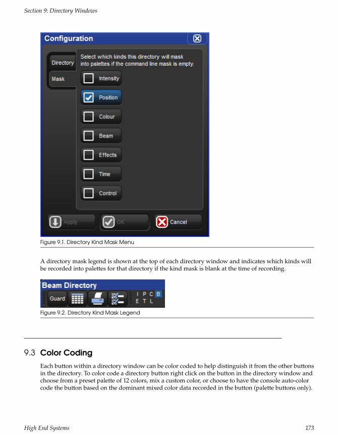
Figure 9.1. Directory Kind Mask Menu
A directory mask legend is shown at the top of each directory window and indicates which kinds willbe recorded into palettes for that directory if the kind mask is blank at the time of recording.
Figure 9.2. Directory Kind Mask Legend
9.3 Color CodingEach button within a directory window can be color coded to help distinguish it from the other buttonsin the directory. To color code a directory button right click on the button in the directory window andchoose from a preset palette of 12 colors, mix a custom color, or choose to have the console auto-colorcode the button based on the dominant mixed color data recorded in the button (palette buttons only).
173High End Systems
Section 9: Directory Windows

Figure 9.3. Right Click Color Coding Menu
9.3.1 Coloring the entire button
By default each directory window displays color coding using an outline around the directory buttons.If you prefer that the console color the entire background of the directory buttons click on
theicon to open the window configuration menu and enable the "Color Code Entire Button" option. Theoption to color code the entire button is unique for each directory and is also stored when you record adirectory window into a view.
174High End Systems
Section 9: Directory Windows

Figure 9.4. Color Coding Entire Button
9.4 Button SizesBy default each directory window displays its buttons using a medium size. To change the displayedbutton sizes in any directory window open the window configuration menu by clicking on the
icon located at the top of the directory window. Locate the drop down menu option called "button sizes".Here you will see the option to display the directory's buttons in three different sizes: small, medium,and large. Set the button size menu option to the desired setting and press okay. The button size optionyou select for each directory is unique to that directory and is also stored when you record a directorywindow into a view.
175High End Systems
Section 9: Directory Windows

Figure 9.5. Button Sizes Option
9.5 Show Fewer ButtonsBy default directory windows display both active buttons (buttons that contain data) and inactive buttons(buttons with no data). In some cases you may wish to hide the inactive buttons in the directory. To hidethe inactive buttons in a directory click on
theicon to open the window configuration menu and enable the "show fewer buttons" option. The optionto show fewer buttons is unique to each directory and is also stored when you record a directory windowinto a view.
176High End Systems
Section 9: Directory Windows

Figure 9.6. Show Fewer Buttons Option
9.6 Buttons Across OptionBy default each directory window will display as many buttons across as can possibly fit into the dimen-sions of the directory window as it is sized on the screen. The buttons across option allows users tospecify exactly many cells across the directory window should draw before starting a new row of buttons.This is handy for users who like to cycle directory windows through different sizes but would preferthe button layout remains the same. A horizontal scrollbar is displayed in cases where the “buttonsacross” value is greater than the number of buttons that the directory window can physically fit acrossthe window due to its current size. For legacy Hog behavior use the “auto” option. To change the buttonsacross option for any directory window click on
theicon to open the window configuration menu and adjust the buttons across value. The option to changethe number of buttons across the directory window is unique to each directory and is also stored inviews.
177High End Systems
Section 9: Directory Windows

Figure 9.7. Buttons Across Option
9.7 Show Auto Color SwatchThe "show auto color swatch" option is available only in palette directory windows and is only usefulin cases where the user has programmed color mixing values into a palette within that directory. Whenthis option is turned on any buttons in the directory window that contain palettes with color mixingdata will display a small color swatch in the middle of the button to indicate a dominant mixed color isrecorded in that palette. To enable the "auto color swatch" option click on
theicon and enable the "show auto color swatch" option. The option to show the auto color swatch is uniqueto each directory window and is also stored when you record a directory window into a view.
178High End Systems
Section 9: Directory Windows

Figure 9.8. Auto Color Swatch Option
9.8 Spreadsheet ViewBy default directory windows are displayed as a grid of touch-sized buttons, however you can also viewthe contents of any directory as a spreadsheet by clicking on
thebutton. When in list view the directory buttons can be selected and/or applied by pressing on it's numberin the num column. The option to display a directory in list view is unique to each directory and is alsostored when you record a directory window into a view.
179High End Systems
Section 9: Directory Windows

Figure 9.9. Spreadsheet View vs. Button View of Colour Directory
180High End Systems
Section 9: Directory Windows

Section 10: Media Picker
10.1 Media Picker OverviewThe media picker is a tabbed, graphical window that allows users to view and select slotted functionvalues for the current fixture selection using previews.
To open the media picker window hold the open key and press the “media picker” button on the maintoolbar or press Pig + Open + Beam on the console front panel.
When a fixture selection is made the console will populate the media picker with previews as definedby the preview package assigned to that fixture. See section 10.6 for details on how preview packagesare created and how to manage them.
In general, automated lighting fixtures will display previews for slotted functions such as strobe, gobo,color, and prism, while digital media servers such as the DL.HD will display previews for media files,3-D objects, and masks. Preview selections made in the media picker window are applied to the currentactive editor.
Figure 10.1. Media Picker Window
10.2 Media Picker Window OptionsThe media picker has several options for how previews are displayed in the window:
181High End Systems

1. Merged Different (default on) : when this option is turned on the media pickerwindow merges previews for content across the current fixture selection even ifthe preview images do not match. When in this mode a "page turn" icon will appearin the upper right corner for preview that is not the same across the entire fixtureselection.
2. Show/hide dmx value (default on) : shows and hides the dmx value of the pre-views displayed in the media picker.
3. Show/hide name : shows and hides the preview names in the media picker.
4. Reverse Display Order : reversed the order in which the previews are displayedin the media picker.
5. Search Filter : input text to filter the contents of the media picker window.
6. Preview Refresh Button : click the refresh button to obtain the latest librarydefined media previews for the selected fixtures; most commonly used for refresh-ing media patched CITP fixtures.
7. Package Status Icon : icon indicating the health status of the preview package forthe current fixture selection. Click on the icon for a detailed view of all runnningand completed preview package tasks.
8. Function Tabs : fixture functions such as gobo wheels, color wheels, media indexes,etc. are grouped into selectable tabs for easy navigation.
10.3 CITP Previews in the Media PickerBy default the media picker displays previews for fixtures using a default preview package for that fixturetype as supplied by the fixture library. However, the media picker can also display previews that havebeen downloaded and cached from connected CITP enabled fixtures. In this section we will review whichCITP clients are supported by the Hog 4 OS for previewing, how to configure the DP8000 for CITP fixture
182High End Systems
Section 10: Media Picker

discovery, how to associate fixtures to CITP media servers in the patch window, and finally how to usethe patch window to refresh CITP media preview packages.
10.3.1 Supported CITP Media Server Clients
Hog 4 OS supports the following CITP Media server clients:
• Arkaos MediaMaster (software versions 3.2.2, 4.2.1, 5.0.1, 5.2.2, 5.3.1)
• Coolux Pandoras Box (software version 4.7)
• Green Hippo Hippotizer (software versions 3.2.1, 3.2.2, 3.2.3, 3.2.4, 4.2, 4.3, 4.4, 4.5)
• High End Systems Axon (software version 2.1.2 or greater)
• High End Systems DL.2 (software version 2.1.2 or greater)
• High End Systems DL.3 (software version 2.1.2 or greater)
• High End Systems DLV (software version 2.1.1 or greater)
• High End MMS-100 (software version 2.1.1 or greater)
• PRG Mbox Studio & Mbox Mini (software versions 3.6.1, 3.8, 3.9, 3.10, 4.3)
• D3 Technologies d3 Designer (software version 14 and 14.1 with Video Modules v15,v16 )
10.3.2 Configuring Processors for CITP Discovery
In order for the console to properly discover CITP enabled fixtures on the FixtureNet network, the Fix-tureNet adapter for the processor must be properly configured:
1. Open the node settings window for the processor that is connected via FixtureNetto the CITP enable fixtures
2. Select the FixtureNet tab of the node settings window
3. Ensure that the IP address and subnet settings are appropriate for the networkenvironment in which the CITP discovered fixtures are connected. This is similarto configuring the FixtureNet adapter for Art-Net and sACN output. To betterensure connectivity it is recommended that the IP address assigned to the Fix-tureNet adapter be within in the same sub-network as the CITP fixtures it isreeving preview thumbnails from.
10.3.3 Patching fixtures to CITP discovered fixtures
Once a fixture is scheduled into the patch window and patched to a DMX output, the fixture can thenbe patched to a CITP fixture that has been discovered on the FixtureNet network of any active processorconnected to the console. Follow these steps to patch a fixture to a CITP discovered fixture:
1. Open the patch window
2. Select the fixture(s) you wish to associate with a CITP fixture in the rig
3. Press the "patch media" button at the top of the patch window
183High End Systems
Section 10: Media Picker

4. Select the IP address of a discovered CITP fixture from the media patch window
5. Press okay. You will now see the IP address of the CITP fixture in the patch win-dow listed for the fixtures you selected in step 2.
6. With the fixtures still selected press the "refresh media" button at the top of thepatch window to fetch previews from the CITP fixture.
! Caution
If the IP address of a discovered CITP fixture in the rig changes you will need to perform the"patch media" task again.
Tip
Selecting "None" from the list of CITP discovered fixtures in the media patch window will disas-sociate/unpatch the selected fixtures from CITP discovered fixtures and revert the fixture tousing the default preview package supplied by the fixture library.
10.3.4 Refreshing CITP Previews
The content stored on CITP discovered fixtures may change during the programming of your show. Forexample, the video clip file used in the opening scene might have been changed on the media server.The console is not automatically made aware of these content changes and so it is necessary to requestnew previews from the fixture in order to update the cached preview package on the console. Followthese steps to update cached CITP previews on the console:
1. Select the fixture(s) you wish to refresh the media.
2. Open the fixture window or the media picker window.
3. Press the "refresh media" button at the top of the fixture window or press the re-fresh button at the top of the media picker window. A green and white animatedrefresh icon will appear at the top right of the media picker window to the rightof the search field. The media refresh is finished when the status animation changesto a green check mark (this indicates a successful refresh) or yellow exclamationpoint (this indicates there was an issue refreshing the media previews for the se-lected fixtures; click on the yellow exclamation point for details).
10.3.5 Disabling CITP on Processors
By default CITP is enabled on all DP8000s in new shows. To disable CITP on a processor:
1. Open the node settings window for the processor
2. Select the CITP tab of the node settings window
3. Deselect the enable button and hit apply
184High End Systems
Section 10: Media Picker

10.4 Catalyst Previews in the Media PickerIn addition to CITP and fixture library defined preview packages, the Hog 4 OS is also capable of dis-playing previews for content stored on Catalyst media servers. In this section we will review how toconfigure processors for downloading Catalyst previews, how to associate Catalyst fixtures to Catalystmedia servers in the patch window, and how to use the patch window to refresh cache Catalyst previewpackages on the console.
10.4.1 Configuring Processors for Catalyst Previews
In order for the console to properly fetch and display thumbnail previews for Catalyst media servers ona processor's FixtureNet network, the FixtureNet adapter for the processor must be properly configured:
1. Open the node settings window for the processor that is connected via FixtureNetto the Catalyst media servers
2. Select the FixtureNet tab of the node settings window
3. Ensure that the IP address and subnet settings are appropriate for the networkenvironment in which the Catalyst media servers are connected. This is similarto configuring the FixtureNet network adapter for Art-Net and sACN output. Tobetter ensure connectivity it is recommended that the IP address assigned to theFixtureNet adapter be within in the same sub-network as the Catalyst it is receivingpreview thumbnails from.
10.4.2 Patching Catalyst fixtures to Catalyst Media Servers
Once a Catalyst fixture is scheduled in the patch window and patched to a DMX output, the Catalystfixture can then be patched to a Catalyst media server that is connected to the FixtureNet network ofany active processor connected to the console. Follow these steps to patch a Catalyst fixture to a Catalystmedia server:
1. Open the patch window
2. Select the Catalyst fixture(s) you wish to associate with a Catalyst media serverin the rig
3. Press the "patch media" button at the top of the patch window
4. Select the Catalyst tab in the media patch window
5. Enter the IP Address of the Catalyst media server
6. Press okay. You will now see the IP address of the Catalyst media server in thepatch window listed for the Catalyst fixtures you selected in step 2. This will nowassociate the Catalyst fixtures in your show file with the Catalyst media serversin the rig as long as the Catalyst media server's IP remains the same.
7. With the fixtures still selected press the "refresh media" button at the top of thepatch window to fetch previews from the Catalyst
185High End Systems
Section 10: Media Picker

! Caution
If the IP address of a Catalyst Media server in the rig changes you will need to perform the"patch media" task again.
Tip
Entering an IP address of 0.0.0.0 in the Catalyst tab of the media patch window will disassoci-ate/unpatch the selected fixtures from Catalyst media servers and revert the fixture to usingthe preview thumbnails in the fixture library.
10.4.3 Refreshing Catalyst Previews
Catalyst media server content may change during the programming of your show. For example, thevideo clip file used in the opening scene might have been changed on the Catalyst media server. Theconsole is not automatically made aware of these content changes and so it is necessary to request newpreview thumbnails from the Catalyst media server. Follow these steps to update the previews on theconsole:.
1. Open the patch window
2. Select the fixture(s) you wish to refresh the media
3. Press the "refresh media" button at the top of the patch window. A green andwhite animated refresh icon will appear at the top right of the media picker win-dow to the right of the search field. The media refresh is finished when the icondisappears.
10.4.4 Disabling Catalyst Preview Fetching on Processors
By default Catalyst thumbnail preview fetching is enabled on all processors in new shows. To disableCatalyst thumbnail preview fetching on a processor:
1. Open the node settings window for the processor
2. Select the Catalyst tab of the node setting window
3. Deselect the enable button and hit apply
10.5 Adding Previews to Pre-v2.0.0 Show FilesHog 4 OS and Hog 3 OS show files built with fixture library v4.7 and older will not display library basedpreview thumbnails in the media picker until the fixtures in the show file are updated using the followsteps:
1. Open the patch window
2. Select the fixture(s) you wish to update with library based preview thumbnails
3. Press the "refresh media" button at the top of the patch window
186High End Systems
Section 10: Media Picker

10.6 Renaming & Customizing Preview ImagesUsers can define custom names and images for fixture previews using the media picker. For example,if a fixture in the rig has a custom gobo installed the user may want to change the library defined previewimage to a custom image or change the library defined preview name to a custom name in order to betterrepresent the custom gobo being used in the rig.
Customizing preview images and/or names in your show can be done using the follow steps:
1. Open the media picker window
2. Select the fixture(s) you want to customize
3. In the media picker window select the preview you wish to change
4. Hit the [set] key
5. Use the text field to rename the preview and/or click on the "Change..." buttonto browse for a custom image. Images can be imported from a USB flash drive orchosen from the thumbnail library folder on the console. (supported image formats:JPEG, PNG, GIF)
6. The custom preview name and image you chose will now appear anywhere thatpreview is presented in the show such as on the slot toolbar, in the media picker,and in direct entry menus.
Figure 10.2. Media Picker Window
187High End Systems
Section 10: Media Picker

10.7 Managing Preview PackagesTo view which preview package a fixture is using open the fixture window and locate the "previewpackage" column for that fixture. Listed in this column will be the name of the preview package currentlybeing used by the fixture to display preview names and thumbnails on the slot toolbar, in the editors,and in the media picker.
To change which preview package a fixture is using double click on the preview package cell and selectfrom the list of available packages in the menu.
Default Library Packages: Are the packages defined by the fixture library. These packages containpreviews based on manufacturer documentation and stock fixture configuration.
Custom Packages: Are created when the user has modified the default library preview package for fixtureor set of fixtures by adding custom images or names to the previews for that fixture. Once a custompackage is created for one fixture, other fixtures of that same type can also be assigned to use this previewpackage using the fixture window.
Cached Packages: Are created when a fixture's previews are downloaded via CITP. In this case a "cached"preview package for that fixture will be created. Like custom packages, cached packages can also be as-signed to other fixtures of the same type using fixture window.
Figure 10.3. Fixture Window
Tip
Custom preview packages and CITP cached preview packages can be associated withmore than one fixture of the same type. For example, you can create a custom previewpackage for Solaspot fixture 1 and then use the fixture window to assigned Solaspot fixtures2<10 to the same preview package enabling those fixtures to display the same custom pre-views. Likewise you can utilize a single CITP cached preview package by assigning it to multiplefixtures your show.
188High End Systems
Section 10: Media Picker

Section 11: Cues and Cuelists
11.1 Recording a CueTo record a look created in the Programmer or editor as a cue within a cuelist, you need to specify acuelist and cue number to record to. If the cuelist does not yet exist, Hog 4 OS will create it automatically.
For example, to record Cue 4 into Cuelist 2:
• Record List 2 Cue 4 Enter
11.1.1 Recording to a Cuelist on a Master
You can choose a master rather than a cuelist when recording a cue. This will record the cue to thecuelist currently attached to the chosen master, or create a cuelist if it doesn't exist. For example:
1. Press the Choose key above Master number 10. The Choose key will light up toshow that Master 10 is the chosen master.
2. Record 1 Enter : records Cue 1 in the cuelist attached to Master 10, creating it ifnecessary.
To record more cues:
• Record 1.5 Enter : inserts a new cue numbered 1.5 into the cuelist on the currentlychosen master.
• Record Enter : appends the cue to the end of the cuelist attached to the currentlychosen master.
• Record Choose : appends the cue to the end of the cuelist of the selected master.This allows the current master to remain chosen while recording cues onto othermasters.
11.1.2 Programmer contents after Recording a Cue
When you record a cue, the values remain in the Programmer, but the background colour changes fromblue to grey. This indicates that the parameter values in the Programmer are no longer touched, and soare available for recording to another cuelist, but not to the same cuelist. You can keep the values in theProgrammer to act as the basis for the next cue on the same list, but because of tracking, only the changedparameter values will be recorded. For an overview of tracking, see Tracking (p.26).
11.1.3 Insert, Merge and Replace
When recording, copying or moving a cue, if the destination location already has a cue recorded in it,you will be prompted with record options of Insert, Merge or Replace:
189High End Systems

• Insert: creates a new destination cue. The new cue will be assigned a free locationlower than the one chosen, using a point number if necessary.
• Merge: Incorporates the new information into the destination cue. If the same fix-tures and parameters are in both cues, the new values being merged will take pri-ority.
• Replace: Overwrites the cue information in that destination.
If you are copying a cue, all three options are available. If you are moving a cue, only the Insert optionis available.
Tip
If you know that you are about to record, copy or move a cue to an existing destination, youcan pre-select Insert, Merge or Replace from the Record Options Toolbar. This appears afteryou press the Record, Copy or Move keys.
11.1.4 Numbering Cues
If you leave out the cue number when recording cues, Hog 4 OS will give the cue the next whole numberin the list. If you specify a cue number, you can use numbers with up to five digits before the decimaland four digits after; for example: 11111.1111. This can be useful to insert cues between previouslyrecorded ones.
You can later renumber a complete cuelist; see Renumbering Cues within a Cuelist (p.193).
11.1.5 Naming Cues
You can give a cue a name that will be displayed in the Cuelist window and on the Playback Bar:
1. Open + Choose : opens the Cuelist window of the selected master.
2. Select the cue's name cell.
3. Set [name] Enter : type in the name.
Tip
To name a cue immediately after recording it, press the Set key. This will open a Quicknamewindow. Enter the cue name and select OK.
11.2 Record Options
11.2.1 Recording Selected Fixtures Only
Normally, recording a cue records the total contents of the Programmer or editor, but you can chooseto record only the currently selected fixtures. For example:
190High End Systems
Section 11: Cues and Cuelists

1. Select the fixtures that you want to record.
2. Record
3. Press Selected on the Record Options Toolbar.
4. Choose : records the selected fixtures as a new cue in the cuelist on the selectedmaster.
11.2.2 Record, Remove Values from Cues
You can remove the contents of the Programmer or editor from a previously recorded cue. For example,you might have made changes to a cue, and you want the changes to track through subsequent cues (seeTracking (p.26) for an explanation of tracking). To remove parameter values:
1. Ensure that the parameters that you want to remove are in the Programmer. Theparameter values do not matter, only that the parameters have values.
2. Record, Remove : the Remove button is on the Record Options Toolbar at the bottomof the right-hand screen.
3. Cue 5, Enter : removes the selected parameter values from Cue 5.
To remove a whole fixture ensure that all parameters are selected. You can do this by selecting the fixtureand pressing the Touch button on the Main Toolbar.
11.3 Deleting CuesTo delete a cue:
1. Cue 1 Delete : deletes Cue 1 in the currently chosen cuelist.
2. Click OK to confirm the delete.
Or:
1. List 1 Cue 1 Delete : deletes cue 1 in cuelist 1.
2. Click OK to confirm the delete.
Tip
If you prefer not to be asked to confirm the delete action, select Don't Ask Me Again in theconfirmation window. You can re-enable the confirmation by going to Setup → Preferences→ Programming and selecting Confirm before deleting directory items.
You can delete a range of cues:
1. List 1 Cue 1 Thru 4 Delete : deletes Cues 1 to 4 in Cuelist 1.
2. Click OK to confirm the delete.
191High End Systems
Section 11: Cues and Cuelists

Tip
To delete a cue ‘cue only’, so that changes caused by deleting the cue don't track throughto later cues, see Deleting without Tracking Forward (p.197).
11.4 Copying and Moving Cues
Tip
Copying or moving cues affect hard values only; the cue you wish to copy/move may alsocontain tracked values that create the current onstage state. If you wish to copy this lookrather than just changes made by the current cue, use Copy and Move with State; see UsingState (p.198).
11.4.1 Copying Cues
To make a copy of a cue in the same cuelist:
1. Make sure that the cuelist you want to work with is on the currently chosenmaster.
2. Cue 1 Copy Cue 2 Enter : copies the contents of Cue 1 to Cue 2.
To copy in a cuelist other than the chosen one, or to copy between cuelists, specify the cuelist with theList key. For example:
• List 1 Cue 1 Copy List 2 Cue 2 Enter : copies the contents of Cue 1 of Cuelist 1 toCue 2 of Cuelist 2.
To copy a range of cues:
• List 1 Cue 1 Thru 4 Copy List 2 Cue 2 Enter : copies the contents of cues 1 to 4 ofCuelist 1 to Cuelist 2, starting at Cue 2.
If the destination cue(s) already exist, you will be asked to choose an option: Insert, Merge and Replace(p.189).
11.4.2 Moving Cues
To move a cue to a new location:
• Cue 1 Move Cue 2 Enter : moves the cue from 1 to Cue 2, effectively removingCue 1.
If the destination cue(s) already exist, you will be asked to choose an option: Insert, Merge and Replace(p.189).
192High End Systems
Section 11: Cues and Cuelists

11.5 Renumbering Cues within a CuelistIf your cuelist has many point cues (1.2, 1.5, 2.5, etc.) or if cues have been deleted, you may wish to re-number the cues so that they are all whole numbers. You can renumber cuelists using the Renumberbutton; press More on the Main Toolbar:
• Renumber, Choose : renumber cues in the cuelist on the selected master, startingat 1 and increasing by 1.
• List 1 Cue 3 Thru Renumber, Enter : renumber all cues from Cue 3 upwards inCuelist 1, starting at Cue 3 and increasing by 1.
• List 1 Cue 3 Thru 10 Renumber, Enter : renumber Cues 3 through 10 in Cuelist 1,starting at Cue 3, finishing at Cue 10, with other cue numbers equally spacedbetween.
Alternatively, you can specify the range of new numbers to be given:
• List 1 Cue 3 Renumber 5, Enter : renumber cue 3 as cue 5, in cuelist 1.
• List 1 Cue 3 Thru 10 Renumber 20, Enter : renumber cues 3 through 10, in cuelist1, with new numbers starting at 20. The rest of the new numbers will have thesame order and spacing as before.
• List 1 Cue 3 Thru 10 Renumber 20 Thru 30, Enter : renumber cues 3 through 10 incuelist 1, starting at 20, finishing at 30, with other cue numbers equally spacedbetween.
Note that renumbering does not moves cues within the cuelist; if you try to renumber Cue 5 as Cue 3,you will get an error message. You should use Move for this purpose; see Copying and Moving Cues (p.192).» Important
Using Renumber will affect the number column and numeric entries in the Name column.Also, renumber will not rewrite macros or links that refer to renumbered cues; you will needto update these manually.
11.6 Editing Cue ContentsYou can edit the contents of a cue in an editor window: see Figure 11.1, “The Cue Editor window”. To openthe current cue of the chosen master:
• Cue, Open
Or:
• Cue, Cue
193High End Systems
Section 11: Cues and Cuelists

To open a specific cue in a specific cuelist, for example Cue 2 of Cuelist 1:
1. Open + List : opens the Cuelist Directory window.
2. Open + [Cuelist 1] : opens the Cuelist window for Cuelist 1.
3. Open + [Cue 2] : opens the Cue Editor for Cue 2.
Alternatively, using the command line:
• List 1 Cue 2 Open
You can also preview a cue using View Cue in the Cuelist window; however, you will need to press theEdit button in the Cue Editor window to select this as your current editor in order to make any changes.
If the cue to be edited is on stage, selecting Edit will enable blind mode until changes are updated, or Editis deselected, see Blind (p.257). You can leave the mode otherwise by pressing the Blind key.
Figure 11.1. The Cue Editor window
Within the editor, you can assign fixture parameters and timing in the same way as in the Programmer.See Selecting Fixtures and Modifying Parameters (p.129). Once you have made changes be sure to press theUpdate key to save them, the Cue Editor will then automatically close.
11.6.1 Viewing Different Cues in the Editor
In addition to the usual functions available in all editors, described in Editors (p.39), the Cue Editorwindow has controls that allow you to select which cue is displayed:
• Next and Back: The Next and Back buttons to allow you to easily step through thecues in the cuelist to view or edit them.
• View Cue: You can jump to another cue by typing its number in to the View Cuebox and pressing the Enter key.
• Follow Current: If you select the Follow Current button, the Cue Editor windowwill always show the current cue as the cuelist is played back. If you use Next,Back or View Cue to view another cue, or if you edit the current cue, then FollowCurrent is disabled.
194High End Systems
Section 11: Cues and Cuelists

• Follow Next: This is similar to Follow Current, except that the next cue is displayedrather than the current one. When the last cue is played, the first cue in the cuelistis displayed.
Tip
As well as the buttons in the Cue Editor window, you can also step through the cues usingthe Next and Back keys while holding down the Cue key.
11.7 Working with TrackingHog 4 OS uses tracking, which gives it some very powerful abilities. Tracking can also add extra com-plexity, but Hog 4 OS has several functions that make working with tracking straightforward. For a de-tailed discussion about tracking, see Tracking (p.26).
11.7.1 Tracking Values Backwards When Recording
You can use the Track Backwards feature when you record a cue to assign the parameter values to thelast cue they appeared in, rather than the cue being recorded. For example, suppose that you have aseries of cues with intensity values for three fixtures:
321Fixture:
505050Cue 1
6060Cue 2
70Cue 3
If you assign all three fixtures to 100% and record with merge into Cue 3 (see Insert, Merge and Replace(p.189) for recording with merging), you would get these values:
321Fixture:
505050Cue 1
6060Cue 2
100100100Cue 3
However, if you did the same thing with Track Backwards, you would get:
321Fixture:
1005050Cue 1
10060Cue 2
100Cue 3
The value of 100% has been applied to the last cue that the intensity parameter had a value in.
If you Track Backwards a parameter that hasn't been given a value since the start of the cuelist, the valueis added to the first cue in the cuelist.
195High End Systems
Section 11: Cues and Cuelists

To record a cue with Track Backwards, select the Track Backward button on the Record Options Toolbarthat appears after you press the Record key:
1. Fixture 1 Thru 3 @ 100 Enter.
2. Record Cue 3
3. Select Track Backwards on the Record Options Toolbar.
4. Enter
Tip
You can also Track Backwards when you update cues using Auto Update; see Auto Update(p.255).
11.7.2 Stopping Values from Tracking Forward
When you insert a new cue into a cuelist, or merge changes into an existing cue, the new values trackforwards into later cues in the cuelist. For example, your cuelist has Cues 1 to 4, and Cue 1 has Fixture1 programmed into it at 30%, so that it tracks through the subsequent cues:
321Fixture:
1005030Cue 1
60100Cue 2
50Cue 3
40Cue 4
You now insert a Cue 2.5 with Fixture 1 at 100%. Because cues 3 and 4 do not change the intensity ofFixture 1, it will remain at 100% for the rest of the cuelist:
321Fixture:
1005030Cue 1
60100Cue 2
100Cue 2.5
50Cue 3
40Cue 4
You may want to record the new cue so that parameter values in the new cue return to their originalvalue in the next cue (so that the inserted cue does not change the original looks due to tracking):
321Fixture:
1005030Cue 1
60100Cue 2
100Cue 2.5
5030Cue 3
40Cue 4
196High End Systems
Section 11: Cues and Cuelists

Hog 4 OS allows you to record a cue between other cues without destroying existing tracking values.To do this, record the inserted cue without tracking forwards by deselecting the Track Forward buttonon the Record Options Toolbar that appears after pressing the Record key. For example:
1. Press the Record key.
2. Deselect Track Forward on the Record Options Toolbar.
3. Cue 2.5 Enter : insert Cue 2.5 into the cuelist on the currently chosen master.
This is sometimes referred to as recording ‘cue only’ as the changes only affect the recorded cue and donot track into subsequent cues. Note that you can only turn tracking forwards off when you insert a newcue into a cuelist or when you merge values into a cue, not when adding new cues to the end of a cuelist.» Important
When recording or merging as ‘cue only’ any parameter values that did not previously existin a cuelist, an ‘Off’ indication will be placed into the subsequent cue for these parameters.This Off indication will release the parameter value back to its previous state (as if it were notprogrammed in the list).
11.7.3 Deleting without Tracking Forward
When you delete a cue, this can have unexpected consequences on later cues in the cuelist if the deletedcue contained parameter values that tracked through to contribute to the state of the later cues. For ex-ample, you have the following cues:
321Fixture:
1005030Cue 1
6080100Cue 2
50Cue 3
40Cue 4
If you now delete Cue 2, Fixture 1 will track from Cue 1 through Cues 3 and 4 at 30%, rather than goingto the expected 100% in Cues 3 and 4:
321Fixture:
1005030Cue 1
50Cue 3
40Cue 4
You can prevent this happening by deleting the cue ‘cue only’ which adds any values that previouslytracked through from the deleted cue into the next cue:
321Fixture:
1005030Cue 1
5080100Cue 3
40Cue 4
To delete a cue without tracking the changes forwards:
197High End Systems
Section 11: Cues and Cuelists

1. List 1 Cue 3 : select the cue to be deleted.
2. Press and hold the Delete key. The Record Options Toolbar will appear.
3. Deselect Track Forward from the Record Options Toolbar.
4. Release the Delete key.
11.7.4 Blocking Cues
Blocking cues prevent changes made earlier in the cuelist from tracking through to subsequent cues inthe cuelist.
Using State
You can create blocking cues using the State button on the Record Options Toolbar. For example, supposethat you have the following cues:
321Fixture:
1005030Cue 1
60100Cue 2
50Cue 3
40Cue 4
to turn Cue 4 into a blocking cue, you copy it to itself ‘with state’:
1. Cue 4 Copy State Cue 4 Enter : the State button is on the Record Options Toolbarthat appears when you press Copy.
2. Select Replace.
The values are now:
321Fixture:
1005030Cue 1
60100Cue 2
50Cue 3
504030Cue 4
Because of tracking, when you copy a cue to another location you only copy the hard values, so you donot create a new cue that actually represents the on-stage look that you would get by running the originalcue.
To copy both hard and tracked values, you can use Copy and State:
• List 1 Cue 5 Copy State List 2 Cue 1 Enter : creates a new cue in Cuelist 2 that isthe state of Cue 5 in Cuelist 1.
198High End Systems
Section 11: Cues and Cuelists

11.7.5 Unblocking
Unblocking removes redundant hard parameter values. A parameter value is redundant in a cue if it isthe same as the value for that parameter in the previous cue in the same cuelist. For example:
4321Channel:
50500100Cue 1
10050Cue 2
5010010050Cue 3
In this cuelist, the values for channels 1, 3 and 4 are redundant in cue 3. After unblocking, the values inthe cuelist would be:
4321Channel:
50500100Cue 1
10050Cue 2
100Cue 3
To unblock cues, use the Unblock button in the Main Toolbar:
• Cue3Unblock, Enter : unblock cue 3 on the currently chosen master.
• List1Cue3Unblock, Enter : unblock cue 3 of cuelist 1.
• Cue 1 Thru 10 Colour Unblock, Enter : unblock only colour parameters in cues 1through 10 of the cuelist on the currently chosen master.
• List 1 Cue 3 Group 10 Colour Unblock, Enter : unblock only the colour parametersof fixtures in Group 3, in cue 3 of cuelist 1.
To unblock complete cuelists:
• List 1 Unblock, Enter
Or on a master:
• Unblock Choose
Tip
Unblocking obeys the linked parameter preferences assigned in Setup → Preferences →Programming. For example, if position parameters are not separated and Pan is blocking butTilt is not, Pan will not be unblocked. For more on linked functions, see Separating Parameters(p.156)» Important
Unblocking will remove parameter values from blocking cues, so any future changes to sub-sequent cues will be tracked through the whole cuelist.
199High End Systems
Section 11: Cues and Cuelists

11.8 Mark Cues (Move in Black)A Mark cue is a special designator for a cue that looks at the previous cue and any fixtures with an in-tensity of zero after completion of the cue. If a fixture meets these requirements, the mark cue allows thefixture(s) to ‘preset’ for the next cue by executing the cross-fade for all parameters except intensity. Thisallows the fixture(s) to ‘move in black’ as they change to their new parameter values. When the next cueis later executed, only the intensity parameter changes as all other parameters will already be at theirnew values due to the mark. The timing used to mark a cue is determined by the mark method youchoose. See Fade Mark verses Time Marks (p.201) for details on the different timing methods you can usewhen marking cues.
11.8.1 How to Mark to a Cue
There are several methods to assign a cue to mark:
• Select the Mark cell of a cue, press Set, and then Enter. If you wish to "time mark"the cue, then first input a time using the keypad and then Enter. To remove themark from a cue select the Mark cell of the cue, press Set, hit Backspace, and thenEnter.
• Enable the Mark Fade New Cues or Mark Time New Cues option in the CuelistOptions window. All new cues will be created with the mark type. Note that whenMark Time New Cues is selected all newly recorded cues will get a 2s mark timeby default.
200High End Systems
Section 11: Cues and Cuelists

• Toggle the Mark Fade or Mark Time button in a Cue Editor window of the cue youwish to mark.
11.8.2 Fade Mark verses Time Marks
Cues can be marked with either a fade mark or a time mark. While the basic principles of marking are thestill the same, the timing in which the mark is executed varies between the two methods.
A Fade mark uses the fade and delay times assigned in the marked cue to mark fixtures. Fade markingoccurs on a fixture by fixture basis, so several fixtures could be marking at different times and rates de-pending upon their individual cue data in the marked cue.
In the fade mark example below, when cue 2 completes its 2 second fade to 0% intensity, cue 3 willautomatically play all of its data except intensity in a 5 second fade. Then when cue 3 is played only theintensity will cross-fade at 5 seconds. The fixtures will have moved from centre to left and changed fromred to green automatically while in ‘black’.
ColourPositionIntensityFadeMark
RedCentre100%2sCue 1
RedCentre0%2sCue 2
GreenLeft100%5sFadeCue 3
201High End Systems
Section 11: Cues and Cuelists

A Time mark uses the time you enter into the mark column to mark fixtures. Time marking occurs at asingle uniform rate so all fixture parameters will mark at the same rate regardless of the data in the nextcue.
In the time mark example below, when cue 2 completes its 2 second fade to 0% intensity, cue 3 willautomatically play all of its data except intensity in a 0s second fade. Then when cue 3 is played onlythe intensity will cross-fade at 5 seconds. The fixtures will have moved from centre to left and changedfrom red to green automatically while in ‘black’.
ColourPositionIntensityFadeMark
RedCentre100%2sCue 1
RedCentre0%2sCue 2
GreenLeft100%5s0sCue 3
Tip
Marking occurs with the intensity parameter for standard fixtures as well as I Red, I Green, andI Blue parameters for RGB fixtures such as LEDs.
11.8.3 Marking the First Cue in a Cue List
If the first cue in a list is assigned to mark, it will only mark after the last cue in the list is played. By re-cording a blank cue prior to the first cue in the list, you can create a mark cue for the first look of a show.For example:
ColourPositionIntensityFadeMark
----Cue 0.5
BlueRight100%0,2sFadeCue 1
-Left50%2sCue 2
When cue 0.5 plays it will mark cue 1 so that cue 1 will fade up intensities on stage after the fixtures arealready in position and color. Furthermore, since the intensity time of cue 1 is assigned to 2 seconds andthe other parameters are assigned to zero, the mark cue will occur as quickly as possible.
11.8.4 Cuelist Feedback for Mark Cues
The following figures show the different states of a marking cue.
Figure 11.2. Cue 3 with a Fade Mark
202High End Systems
Section 11: Cues and Cuelists

Figure 11.3. Cue 3 Actively Fading into its Mark
Figure 11.4. Cue 3 Fully Marked
11.9 Understanding CuelistsCuelists are lists of cues, usually used to play back the cues in a defined order. A cue number is specificto each cuelist, not the entire console, so there can be a cue 1 for cuelists 1, 2 and 3. Cuelists are held inthe Cuelist Directory (Figure 11.5, “The Cuelist Directory window”), and it is possible to copy or move cuesbetween cuelists; see Copying and Moving Cues (p.192).
To open the Cuelist Directory:
• Open + List
Alternatively:
• List, List
203High End Systems
Section 11: Cues and Cuelists

Figure 11.5. The Cuelist Directory window
To open a cuelist (Figure 11.6, “The Cuelist window”):
• Open + [Cuelist 1] : select a cuelist from the Cuelist Directory.
Or with the command line:
• List 1 Open
Or:
• Open + Choose : select the master with the cuelist.
Tip
Cuelist windows can be set to always show the same cuelist or to follow the currently chosenmaster: see Cuelist Feedback (p.284).
11.10 Naming CuelistsYou can name cuelists:
1. Open + List : open the Cuelist Directory.
2. Check that the Guard button is selected, so that you don't accidentally activate acuelist when pressing its button in the directory.
3. Select the cuelist.
4. Set [name] Enter : type in the name.
Tip
You can rename a cuelist when it is attached to a master by pressing Set + Choose.
204High End Systems
Section 11: Cues and Cuelists

Figure 11.6. The Cuelist window
11.11 Deleting CuelistsTo delete a cuelist:
1. List 1 Delete : deletes cuelist 1.
2. Click OK to confirm the delete.
Or from the cuelist directory:
1. Open + List : open cuelist directory.
2. Check that the Guard button is selected, so that you don't accidentally activate acuelist when pressing its button in the directory.
3. Delete, [Cuelist 1] : delete the cuelist. You will be asked to confirm the action.
Tip
If you prefer not to be asked to confirm the delete action, select Don't Ask Me Again in theconfirmation window. You can re-enable the confirmation by going to Setup → Preferences→ Programming and selecting Confirm before deleting directory items.
Tip
To detach a cuelist from its master rather than deleting it completely from the show file, holdDelete while pressing the master's Choose button. This removes the cuelist from the masterbut not from the cuelist directory.
11.12 Copying and Moving CuelistsCuelists can be copied and moved within the Cuelist Directory. To open the Cuelist Directory:
• Open + List
205High End Systems
Section 11: Cues and Cuelists

11.12.1 Copying Cuelists
To make a copy of a cuelist:
• List 1 Copy List 2 Enter : copies Cuelist 1 to Cuelist 2.
If the destination cuelist already exists, you will be asked to choose an option: Insert, Merge and Replace(p.206).
11.12.2 Moving Cuelists
To move a cuelist to a new location within the Cuelist Directory:
• List 1 Move List 2 Enter : moves Cuelist 1 to Cuelist 2.
If the destination cuelist already exists, you will be asked to choose an option: Insert, Merge and Replace(p.206).
11.12.3 Insert, Merge and Replace
When copying or moving a cuelist, if the destination location already has a cuelist in it, you will beprompted with record options of Insert, Merge or Replace:
• Insert: creates a new destination cuelist. The new cuelist will be assigned a freelocation just before the one chosen, using a point number if necessary.
• Merge: Incorporates the source information into the destination cuelist. If the cuenumbers are in both cuelists, the new parameter values of the cues will replace theold.
• Replace: Overwrites the cuelist information in that destination.
If you are copying a cuelist, all three options are available. If you are moving a cuelist, only the Insertoption is available.
Tip
If you know that you are about to copy or move a cuelist to an existing destination, you canpre-select Insert, Merge or Replace from the Record Options Toolbar. This appears after youpress the Record, Copy or Move keys.
206High End Systems
Section 11: Cues and Cuelists

Section 12: Scenes
12.1 Recording ScenesYou can record scenes either directly to a physical master for immediate playback, or to the Scene Dir-ectory.
12.1.1 Recording to the Scene Directory
To record a scene:
1. Create the look for the scene in the Programmer or editor.
2. Record, Scene : the Scene Directory window opens.
3. Select the destination location in the Scene Directory window.
4. Alternatively, enter a number on the keypad and press Enter.
12.1.2 Recording to a Physical Master
You can record a scene directly to a physical master. Hog 4 OS will automatically put it in the nextavailable location in the Scene Directory:
1. Create the look for the scene in the Programmer or editor.
2. Record, Scene
3. Press the Choose key above the desired physical master.
12.1.3 Naming a Scene
You can give a scene a name that will be displayed in the Scene Directory window:
1. Open + Scene : open the Scene Directory.
2. Check that the Guard button is selected, so that you don't accidentally activate ascene when pressing its button in the directory.
3. Select the scene.
4. Set [name] Enter : type in the name.
Tip
To name a scene immediately after recording it, pressing the Set key will open a Quicknamewindow. Enter the scene name and select OK.
207High End Systems

12.2 Deleting ScenesTo delete a scene:
1. Scene 1 Delete
2. Click OK to confirm the delete.
Tip
If you prefer not to be asked to confirm the delete action, select Don't Ask Me Again in theconfirmation window. You can re-enable the confirmation by going to Setup → Preferences→ Programming and selecting Confirm before deleting directory items.
You can delete a range of scenes:
1. Scene 1 Thru 4 Delete : deletes scenes 1 to 4.
2. Click OK to confirm the delete.
Tip
To detach a scene from its master rather than deleting it completely, hold Delete whilepressing the master's Choose button. This removes the scene from the master but not fromthe scene directory.
12.3 Copying and Moving ScenesTo make a copy of a scene:
• Scene 1 Copy Scene 2 Enter : copies the contents of Scene 1 to Scene 2.
Similarly, to move a scene to a new location:
• Scene 1 Move Scene 2 Enter : moves Scene 1 to Scene 2, effectively deleting 1.
If the destination scene already exists, you will be asked to choose an option: Insert, Merge and Replace(p.209).
12.4 Editing Scene ContentsYou can edit the contents of a scene in an editor window. For example, to open Scene 1 for editing:
1. Open + Scene : opens the Scene Directory.
208High End Systems
Section 12: Scenes

2. Open + [Scene 1] : opens the scene editor for Scene 1.
3. Alternatively using the command line : Scene 1 Open
4. Press the Edit button in the editor window to select this as your current editor.
Within the editor, you can assign fixture parameters and timing in the same way as in the Programmer;see Selecting Fixtures and Modifying Parameters (p.129). For general information on working with editors,see Editors (p.39).
12.5 Scene TimingScene timing controls the fade-in and delay of a scene when it is run on a master.
You assign and edit scene timings in the same way as for cues; see Fade, Delay, and Path (p.212). You canassign scene timing in the Programmer before recording the scene, or later in the scene editor. You canalso assign the fade time of a scene from the command line. For example, to give Scene 1 a fade time of6 seconds:
• Scene 1 Time 6 Enter
You can also record fade times with a mask. For example:
• Scene 1 Fixture 1 + 2 Colour Time 4 Enter : sets the fade time for the colour para-meter values of fixtures 1 and 2 in Scene 1.
12.6 Insert, Merge and ReplaceWhen recording, copying or moving a scene, if the destination location already has a scene recorded init, you will be prompted with record options of Insert, Merge or Replace:
• Insert: creates a new destination scene. The new scene will be assigned a free loca-tion just before the one chosen, using a point number if necessary.
• Merge: Incorporates the new information into the destination scene. If the samefixture parameters are in both scenes, the new values will replace the old.
• Replace: Overwrites the scene information in that destination.
If you are copying a scene, all three options are available. If you are moving a scene, only the Insert optionis available.
Tip
If you know that you are about to record, copy or move a scene to an existing destination,you can pre-select Insert, Merge or Replace from the Record Options Toolbar. This appearsafter you press the Record, Copy or Move keys.
209High End Systems
Section 12: Scenes

12.7 Toggling Scenes On/Off in PlaybackTo configure a scene so that it can be toggled on/off in the scene directory, open the options windowfor the scene and look for an option called “action at end of scene”. Choose one of the following optionsthat provides "toggle-like" functionality:
• Add Release End Cue: The scene will release when played if it is already onstage.This option allows for the scene to be manually toggled on/off by pressing its cellin the scene directory when guard is turned off.
• Auto-Release at End: The scene will automatically release after its cross-fade iscomplete. This option is useful for users who want to trigger a scene and have itautomatically release on its own. To extend the period for which a scene is inplayback before it is automatically released, record a dummy desk channel intothe scene with a cross fade that is equal to the length of time you want the sceneto be onstage before it releases.
210High End Systems
Section 12: Scenes

Section 13: Timing
13.1 Timing BasicsWith Hog 4 OS you can assign individual cross-fade timings for each parameter of each fixture, givingyou complete control of how each parameter changes during a cue. Because of this, there are no cueparts as found on some other consoles. Hog 4 OS gives you easy ways to assign timings for the wholecue, for individual fixtures and by parameter type (intensity, position, colour, beam, and so on) as wellas for each parameter.
You can control three aspects of timing in the Hog 4 OS:
• The speed and manner in which the transition of parameter values happens whena cue/scene is played back. See Fade, Delay, and Path (p.212).
• The time a cue/scene waits before it is triggered. See Cue Wait Timing (p.222).
• The order in which cues in a cuelist are played back. See Loops and Links (p.226).
The different types of timing values are:
• Fade time: The time that it takes fixture parameters to change from their initialvalue to their value in the cue that is being played back. You can assign a singlefade time for the cue, or have separate fade-in and fade-out times. The fade-in timeis the fade time for parameters belonging to fixtures that are increasing in intensity,while the fade-out time is the fade time for parameters belonging to fixtures thatare decreasing in intensity.
• Delay time: The time between the cue being triggered and parameter valuesstarting to change. As with fade times, you can assign a single delay time, or haveseparate in delay and out delay times. The in delay time is the delay between thecue being triggered and parameters belonging to fixtures that are increasing in in-tensity starting to change, while the out delay time is the delay between the cuebeing triggered and parameters belonging to fixtures that are decreasing in intensitystarting to change.
• Path: How parameter values change during the fade. The simplest path is a straightline, so that parameter values change smoothly and evenly throughout the fade,but you can use paths that make all of the change happen at the start of the fade,for example.
The different types of trigger values are:
• Wait time: The time from the previous cue being triggered to the current cue beingtriggered.
• Follow-on time: The time from the end of the previous cue to the current cue beingtriggered.
• Timecode: A specific timecode value when a cue is triggered; see Triggering Cuesfrom MIDI Timecode (p.340).
211High End Systems

• Clock: A real-world time and date value when a cue is triggered; see Clock Triggers(p.224).
Figure 13.1, “Cue timings” shows how the main kinds of timing and triggering values control the playbackof cues.
Figure 13.1. Cue timings
Hog 4 OS allows you to assign timings to each parameter of each fixture in a cue, scene or palette. Often,you will want to assign the same value to every fixture parameter; this is described in Fade, Delay, andPath (p.212). Assigning timings for individual parameters is described in Individual Parameter Timings(p.216).
13.2 Fade, Delay, and PathYou can assign fade time and delay times, as well as paths, to cues and scenes. Cues recorded withoutassigning any time information will be given the default time; this can be adjusted in the Default Timingpane of the User Preferences window.
13.2.1 Fade Time
To record a cue with a fade time other than the default:
1. Create the desired look for the cue in the Programmer.
2. Fixture Enter : select all the fixtures currently in the Programmer.
3. Time 7 Enter : assign a fade time of 7 seconds.
4. Record Cue 1 Enter : record the cue on the currently chosen master.
212High End Systems
Section 13: Timing

To assign times greater than 1 minute, enter the number of minutes followed by the number of seconds:
• Time 140 Enter : select a fade time of 1 minute 40 seconds.
To change the time of an already recorded cue:
1. Cuelist 1 : select the cuelist unless the desired cuelist or master is already thechosen master.
2. Cue 2 Time 7 Enter : assigns a fade time of 7 seconds.
Different Fade-in and Fade-out Times
You can assign different fade-in and fade-out times (known as a ‘split time’) using the / key. For example:
1. Create the desired look for the cue in the Programmer.
2. Fixture Enter : select all the fixtures currently in the Programmer.
3. Time 7 / 10 Enter : select a fade-in time of 7 seconds, and a fade-out time of 10seconds.
4. Record : record the cue on the currently selected master.» Important
Hog 4 OS's definition of fade-in and fade-out times is different to that used by some otherconsoles. Some consoles use fade-in and fade-out times for intensity parameters only andhave a separate time for all other parameters; Hog 4 OS has fade-in and fade-out times foreach individual parameter. Also, with some consoles the fade-out time applies when the cuegoes out, so that cue 2's fade-out time takes effect during the change from cue 2 to cue 3rather than (as with Hog 4 OS) cue 1 to cue 2.
Fade Time with Masks
You can record fade times with a mask. For example:
• Cue 1 Fixture 1 + 2 Colour Time 4 Enter : sets the fade time for the colour parametervalues of Fixtures 1 and 2 in Cue 1.
Tip
If you want to assign individual times for several fixtures or fixture parameters, you can editthem in the Cue Editor window by clicking on its Fade button; see Individual Parameter Timings(p.216).
13.2.2 Delay Time
You can create a delay between the cue being triggered and the fade times beginning to execute by as-signing the Delay time:
1. List 1 Open : open the cuelist.
2. Select the cue's Delay cell and press Set.
213High End Systems
Section 13: Timing

3. 5, Enter : enter the delay time. As with fade times you can assign separate delaytimes for the incoming and outgoing parts of the cue, for example 3/5.
Alternatively, you can use the command line, pressing the Time key twice to assign the delay time:
• Cue 2 Time Time 5 Enter
Tip
Note that the Delay time should not be confused with the Wait time; see Cue Wait Timing(p.222).
13.2.3 Paths
Paths determine the way parameter values change during a cue. For example, with the simplest (linear)path, an intensity parameter travels from its start value to its end value at a steady rate for the durationof the cue. The paths available are shown in Figure 13.2, “Path Types”.
To select a path for a cue:
1. List 1 Open : open the Cuelist window.
2. Select the cue's Path cell and press Set. The Crossfade Paths window will open.
3. Select the path type required for the incoming and outgoing parts of the cue.
4. Press OK
Tip
The shape of the paths described above applies when the cue is asserted. When it is released,the path is effectively reversed. For example, attributes with a ‘Start’ path will snap on the Goof a cue, but will snap at the very end of that cue being released (behaving like an ‘End’path).
13.2.4 Assigning Cue Timings in the Cuelist Window
You can edit fade or delay times in the Cuelist window. Assigning fade or delay times here will assignthe new value to all the parameters of all the fixtures in the cue.
1. Open + Choose : open the cuelist of the desired master.
2. Click in the cell for the fade or delay time of the desired cue, and press Set.
3. Type in a time value, and press Enter.
When entering a time value, it should be in the form:
[hours] h [minutes] m [seconds] s / [hours] h [minutes] m [seconds] s
For example:
• 2s : 2 seconds in and out times.
• 2s/5s : 2 seconds in, 5 seconds out.
214High End Systems
Section 13: Timing

DescriptionPath
Uses the default path from the fixture's library definition. This isgenerally Linear for continuous parameters and Start for slottedparameters.
Default
Fades at a steady rate for the duration of the cue.Linear
Snap change at the beginning of the cue.Start
Snap change at the end of the cue.End
The parameters overshoot their destination and then return to it.Over
The parameters move first in the opposite direction before goingto their destination.
Under
The parameters change more slowly at the start and end of thecue than in the middle.
Damped
The parameters change more slowly at the end of the cue.Brake
The parameters change more slowly at the start of the cue.Speed Up
The parameters follow a chaotic, sawtooth fade over the courseof the cue.
Shake
Figure 13.2. Path Types
• 1m : 1 minute in and out times.
• 1m10s : 1 minute and 10 seconds in and out times.
• 1h10m30s/1h : 1 hour, 10 minutes and 30 seconds in time, and 1 hour out time.
Use the H, M and S buttons that appear when editing a fade or delay time cell to enter the H, M and Stext into the cell. Alternatively, you can use an external keyboard.
Note that if you enter 140 the time will be 1 minute 40 seconds, not 140 seconds (2 minutes 20 seconds).
215High End Systems
Section 13: Timing

To assign paths directly in the Cuelist window:
1. Click in the Path cell for the desired cue, and press Set.
2. Choose a path from the displayed list; see Figure 13.3, “Selecting a Path in a CuelistWindow”.
The In path is applied when a fixture is increasing in intensity during the cross-fade, and the Out path when a fixture is decreasing in intensity.
3. Press OK.
Figure 13.3. Selecting a Path in a Cuelist Window
The different types of path are explained in Paths (p.214).
13.3 Individual Parameter TimingsWhen you record a cue, all of the fixture parameters in the cue are assigned the default fade, delay andpath values. Similarly, when you assign timings to a cue after recording, the timing value is applied toall fixture parameters in the cue. However, you can assign fade, delay or path values to individualparameters in the Programmer, and these settings are then included when you record cues and scenes,and (optionally) palettes. You can also assign timings to parameters in the cue, scene and palette editors.Note that you can only assign timings for a parameter that has a value in the editor.
To display parameter fade times, delay times or paths in an editor, select the Fade, Delay or Path buttonsfrom the top left of the editor window.
216High End Systems
Section 13: Timing

You can assign the individual timings of parameters using the parameter wheels, the command line ordirectly in editor windows. You can also assign timings to all parameters of a fixture using the parameterwheels or the command line.» Important
If you assign individual timings for parameters and subsequently assign an overall cue time,then the individual parameter timings will be replaced by the overall cue time.
13.3.1 Assign Parameter Timings using Wheels
To assign fade and delay timings to all the parameters of a fixture:
1. Select the fixtures that you want to assign timings to, making sure that they havebeen given parameter values.
2. Press the Time key.
3. The Wheels Toolbar will show the available timing types (Fade In, Fade Out,Delay In and Delay Out) together with their current settings; see Figure 13.4, “TheWheels Toolbar showing Timing”.
4. Use the parameter wheels to assign the desired Fade In, Fade Out, Delay In andDelay Out.
Note that if you want to see the timings that you have assigned in the editor, you can select the Fade orDelay views using the buttons in the top left of the editor window. You don't have to be in these viewsto assign timings, however.
Figure 13.4. The Wheels Toolbar showing Timing
To assign fade and delay timings to specific parameter types:
1. Select the fixtures that you want to assign timings to, making sure that they havebeen given parameter values.
2. Press the Time key.
3. The Wheels Toolbar will show the available timing types.
4. Click on Fade In, Fade Out, Delay In or Delay Out and select a parameter type; seeFigure 13.5, “Selecting Parameter Types from the Wheels Toolbar”.
5. Use the parameter wheels to assign the desired timing.
217High End Systems
Section 13: Timing

Figure 13.5. Selecting Parameter Types from the Wheels Toolbar
To assign a path to all the parameters of a fixture:
1. Select the fixtures that you want to assign a path to, making sure that they havebeen given parameter values.
2. Press the Time key.
3. The Slot Toolbar will show buttons for All, In and Out; see Figure 13.6, “The SlotToolbar showing Paths”.
4. Choose In to assign a path to be applied to the parameters when the fixture theybelong to is increasing in intensity during the cross-fade. Choose Out to assign apath to be applied to parameters when the fixture they belong to is decreasing inintensity during the cross-fade. Choose All to assign a path to be applied to para-meters of fixtures irrespective of whether their intensity is increasing or decreasing.
The Paths Toolbar will open; see Figure 13.7, “The Paths Toolbar”.
5. Select the desired path from the Paths Toolbar. The different types of path areexplained in Paths (p.214).
Figure 13.6. The Slot Toolbar showing Paths
Figure 13.7. The Paths Toolbar
13.3.2 Assign Parameter Timings with the Command Line
To assign the fade time for all parameters of a fixture:
218High End Systems
Section 13: Timing

1. Fixture 1 : select the fixtures you want to assign a time to, making sure that theyhave been given parameter values.
2. Time 4, Enter : assigns the fade time to 4 seconds.
To assign separate fade in and fade out times:
1. Fixture 1 : select the fixtures you want to assign a time to, making sure that theyhave been given parameter values.
2. Time 4 / 7, Enter : assigns the Fade In time to 4 seconds and the Fade Out time to7 seconds.
To assign a fade time for a particular parameter type:
1. Fixture 1 : select the desired fixtures.
2. Colour Time 4, Enter : assigns the fade time of the colour parameters to 4 seconds.
To assign a delay time, press the Time key twice:
1. Fixture 1 : select the desired fixtures.
2. Time Time 2, Enter : pressing Time twice assigns the delay time.
To assign a path, press the Time key three times:
1. Fixture 1 : select the desired fixtures.
2. Time Time Time 2, Enter : enter a number to represent the path.
Select the path by entering a number; the mapping is the same as the order they appear on the pathtoolbar, starting at zero for the default path.
13.3.3 Assign Parameter Timings in an Editor
To assign fade or delay times directly in the spreadsheet of an editor:
1. View the required timing type by pressing either the Fade or Delay button in thetop left of the editor window.
2. Click in the cell for the desired parameter, or click and drag to select a range ofcells.
3. Press Set.
4. Type in a time value, and press Enter.
When entering a time value, it should be in the form:
• [hours] h [minutes] m [seconds] s / [hours] h [minutes] m[seconds] s
For example:
• 2s : 2 seconds in and out times.
219High End Systems
Section 13: Timing

Figure 13.8. The Cue Editor window with Fade selected
• 2s/5s : 2 seconds in, 5 seconds out.
• 1m : 1 minute in and out times.
• 1m10s : 1 minute and 10 seconds in and out times.
• 1h10m30s/1h : 1 hour, 10 minutes and 30 seconds in time, and 1 hour out time.
Use the H, M and S buttons that appear when editing a fade or delay time cell to enter the H, M and Stext into the cell. Alternatively, you can use an external keyboard.
Tip
If you enter 120, this will be interpreted as 1 minute 20 seconds. To have the console interpretit as 120 seconds (i.e. 2 minutes), enter 120s.
To assign paths directly in the spreadsheet of an editor:
1. Press the Path button in the top left of the editor window.
2. Click in the cell for the desired parameter, or click and drag to select a range ofcells.
3. Press Set.
4. Choose a path from the displayed list; see Figure 13.9, “Selecting a Path in an Editor”.
The In path is applied when the fixture is increasing in intensity during the cross-fade, and the Out path when the fixture is decreasing in intensity.
5. Press OK.
220High End Systems
Section 13: Timing

Figure 13.9. Selecting a Path in an Editor
The different types of path are explained in Paths (p.214).
13.3.4 Fanned Timings
You can fan timings across multiple fixtures, just as you can fan colour or position. For example, to fantimes across 10 fixtures:
• Fixture 1 Thru 10 Time 5 Thru 14 Enter : fans the fade times of Fixtures 1 through 10between 5 and 14 seconds:
Similarly, you can fan delay times:
• Fixture 1 Thru 5 Time Time 5 Thru 10 Enter : fans the delay times of Fixtures 1 through5 between 5 and 10 seconds.
221High End Systems
Section 13: Timing
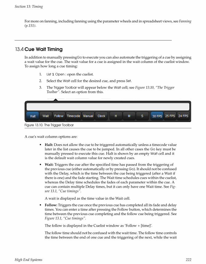
For more on fanning, including fanning using the parameter wheels and in spreadsheet views, see Fanning(p.151).
13.4 Cue Wait TimingIn addition to manually pressingGo to execute you can also automate the triggering of a cue by assigninga wait value for the cue. The wait value for a cue is assigned in the wait column of the cuelist window.To assign how long a cue timing:
1. List 1 Open : open the cuelist.
2. Select the Wait cell for the desired cue, and press Set.
3. The Trigger Toolbar will appear below the Wait cell; see Figure 13.10, “The TriggerToolbar”. Select an option from this.
Figure 13.10. The Trigger Toolbar
A cue's wait column options are:
• Halt: Does not allow the cue to be triggered automatically unless a timecode valuelater in the list causes the cue to be jumped. In all other cases the Go key must bemanually pressed to execute this cue. Halt is shown by an empty Wait cell and itis the default wait column value for newly created cues.
• Wait: Triggers the cue after the specified time has passed from the triggering ofthe previous cue (either automatically or by pressing Go). It should not be confusedwith the Delay, which is the time between the cue being triggered (after a Wait ifthere is one) and the fade starting. The Wait time schedules cues within the cuelist,whereas the Delay time schedules the fades of each parameter within the cue. Acue can contain multiple Delay times, but it can only have one Wait time. See Fig-ure 13.1, “Cue timings”.
A wait is displayed as the time value in the Wait cell.
• Follow: Triggers the cue once the previous cue has completed all its fade and delaytimes. You can enter a time after pressing the Follow button, which determines thetime between the previous cue completing and the follow cue being triggered. SeeFigure 13.1, “Cue timings”.
The follow is displayed in the Cuelist window as ‘Follow + [time]’.
The follow time should not be confused with the wait time. The follow time controlsthe time between the end of one cue and the triggering of the next, while the wait
222High End Systems
Section 13: Timing

time controls the time between the triggering of one cue and the triggering of thenext.
• Timecode: Triggers the cue when the specified timecode value is received. SeeMIDI Timecode (p.339). The timecode value will be displayed in the wait cell.
• Manual: A manual cue can only be triggered by pressing the Go key. This meansthe cuelist will stop until the Go key is pressed, irrespective of any wait, follow ortimecode triggers that later cues in the list may have.
Manual cues are useful because the word ‘Manual’ appears in the Cuelist windowto remind the operator that they need to press the Go key. They are also useful toprevent times being recorded into the Wait column when using Learn Timing (p.223).
• Clock: Triggers the cue when the specified real-world time and date is reached onthe Hog 4 OS built in clock; see Clock Triggers (p.224).
13.4.1 Learn Timing
Learn Timing allows you to assign a cue's wait time value by manual executing the cues with the Gokey when the learn timing option is selected for the cuelist. If a timecode clock assigned to that list isrunning when learn timing is enabled then the wait value recorded into the wait cell will be a timecodevalue.
To use Learn Timing with timecode:
1. Open, Choose : open the Cuelist window of the required cuelist.
2. Options → Cuelist Options : open the Cuelist pane of the Cuelist Options window.
3. Select Enable Timecode, and choose a timecode source. Close the Options window.
4. In the Cuelist window, click View Timecode. The Timecode Toolbar will open.
5. If your timecode source is not currently running, click Simulate on the TimecodeToolbar to have the console create a timecode source. Controls for the timecodewill appear.
6. In the Cuelist window, select Learn Timing.
7. Start the timecode, and press the Go key when the timecode reaches the time thatyou want each cue to go. A timecode frame value will appear in the Wait cell foreach cue.
8. When you have finished, deselect Learn Timing.
Now when you run the timecode, the cues will be triggered when the timecode reaches each cue's assignedframe. For more information on timecode, see MIDI Timecode (p.339).
To use Learn Timing without timecode:
1. Open, Choose : open the Cuelist window of the required cuelist.
2. Ensure that Enable Timecode is not selected.
3. Select Learn Timing.
223High End Systems
Section 13: Timing

4. Press the Go key to run the first cue, and again to run subsequent cues after therequired time interval. A time value equivalent to the duration between Go presseswill appear in the Wait cell for each cue.
5. When you have finished, deselect Learn Timing.
Now when you run the first cue, the subsequent cues will be triggered at the same intervals as whenyou ran them manually.
Tip
Learn Timing will only set a trigger on a cue that is currently set to Halt - that is, it has an emptyWait cell. To remove existing wait times from cues, select the wait cell(s) and press Set. SelectHalt from the toolbar.
13.4.2 Clock Triggers
To assign a cue to be triggered at a particular time and date using Hog 4 OS's internal clock:
1. List 1 Open : open the cuelist.
2. Select the Wait cell for the desired cue, and press Set.
3. The Trigger Toolbar will appear below the Wait cell; see Figure 13.10, “The TriggerToolbar”.
4. Select Clock; the Clock Trigger window will open:
5. Adjust the Start Time and Start Date to assign a single shot trigger.
224High End Systems
Section 13: Timing

6. If you want the trigger to recur at regular intervals, check the Recurrence Patterncheck box. Then click the frequency (Time, Daily, Weekly, Monthly, Yearly) withwhich you want the trigger to recur, and select options for the specified frequency.
Tip
The next valid trigger date and time is shown at the bottom of theClock Trigger window.
7. Click OK.
Once you have set a clock trigger, the cuelist window will now indicate the trigger time and type in thecue’s Wait column:
To enable or disable the clock functions on a cuelist, toggle the Enable Clock button in the cuelist window:
Tip
You can also enable or disable the clock functions for a cuelist in the Cuelist Cuelist Optionswindow, or using macros; see Macros (p.354).
Clock Recurrence Patterns
Clock triggers can be programmed to trigger on a regularly scheduled interval such as every hour, day,or week based on the provided start time of the trigger and selected recurrence pattern. To set a recurrencepattern for a clock trigger check the Recurrence Pattern check box. Then select the frequency (Time,Daily, Weekly, Monthly, Yearly) for which the trigger should recur. A set of more complex options arethen provided to further customize the recurrence pattern.
225High End Systems
Section 13: Timing

For daily triggers, a recurrence value of "every 0 days" nullifies the recurrence pattern and thus the clocktrigger will only fire once on the start time specified.
For weekly triggers, a recurrence value of "every 0 weeks" indicates that the clock trigger will fire on thedays specified but only for the upcoming week. For example, a weekly pattern value of "every 0 weeks"with the Monday and Tuesday options checked will fire the clock trigger on the upcoming Monday andTuesday and then stop recurring.
The Clock Toolbar
The Clock Toolbar shows the time and date according to the Hog 4 OS clock, and information about thenext cue due to be triggered. To open the Clock Toolbar:
• Open + Clock : the Clock Toolbar will open on the left touchscreen:
The Clock Toolbar will automatically update its fields according to the next valid trigger.
Tip
You can assign the format of the date and time in the Appearance pane of the Preferenceswindow. The Clock Toolbar, Cuelist triggers and the Command Line Toolbar clock will displayin the selected format.
13.5 Loops and LinksNormally cues in a cuelist will be replayed in numerical order, but you can use links to change this.Links can be used to jump to other points in the cuelist, or to create loops.
Unlike some consoles, Hog 4 OS creates a link as a special type of cue, rather than an attribute of an or-dinary cue. Because it is a separate item in the cuelist, you can move cues within the list without disturbingthe link.
Tip
When a cuelist gets to the end, it will link back to the first cue by default, so there is no needto put a link in.
13.5.1 Creating a Link
To create a link:
1. Open + [Cuelist 1] : open the cuelist window.
2. Play the cues in the list until the current cue (shown by -> in the wait column) isthe cue before where you want the link.
226High End Systems
Section 13: Timing

3. Click on the Insert Link button in the window. The link cue will be inserted afterthe current cue.
4. Select the Fade cell of the link.
5. Set [cue number] Enter : assign the cue number to be linked to.
You can delete link cues in the same way as any other type of cue. For example:
• Cue 3.5 Delete
13.5.2 Creating a Loop
To create a loop, you need to have two things:
• A link that points to a cue earlier in the cuelist.
• All the cues in the loop (between the linked-to cue and the link cue) must be as-signed with wait or follow triggers; see Cue Wait Timing (p.222).
Hog 4 OS will recognise this as a loop; see Figure 13.11, “A Cuelist with a Loop”.
Figure 13.11. A Cuelist with a Loop
Exiting Loops
You can determine when the cuelist stops looping and continues with cues after the loop. The optionsare:
• Forever: the loop will run indefinitely until you press the Go key.
• Count: the cuelist will loop the assigned number of times. Assigning a count ofzero will make the cuelist ignore the link.
• Timed: the cuelist will loop until the assigned time period has elapsed.
To assign the looping behaviour:
227High End Systems
Section 13: Timing

1. Open + [Cuelist 1] : open the cuelist window.
2. Select the link cue's Delay cell, and press Set.
3. Select an option from the Loops Toolbar:
4. If you have selected Count or Timed, enter a count or timed value.
You can also configure what happens when you press the Go key during a loop; see Action of go whenLooping (p.277).
13.5.3 Tracking Through Loops
By default, Hog 4 OS's feature ensures that, when you use links to change the order of cue playback, thecues appear on stage as if they had been played back in the order they appear in the cuelist.
Sometimes, however, you might want to track through links rather than maintain state. For example,you are creating a loop where the first time through you want the four fixtures to come on one at a time,and throughout the loop you want them to alternate colour between red and blue. To do this, you mightplot:
Fixture 4Fixture 3Fixture 2Fixture 1Cue
ColourInt.ColourInt.ColourInt.ColourInt.
BlueRedBlueRed50%1
RedBlueRed50%Blue↓2
BlueRed50%Blue↓Red↓3
Red50%Blue↓Red↓Blue↓4
Link to Cue 15
The idea is that the intensity of the next fixture is brought to 50% in each cue, and that these values thentrack through for the duration of the loop (shown by the arrows). However, because of the MaintainState function, when the cuelist loops back to cue 1 Hog 4 OS will make cue 1 look as it would have ifyou had run the cuelist in order. The result is that fixtures 2 to 4 will go out, just as they were the firsttime round the loop.
To stop this happening, you need to enable Track Through Loops, in the Cuelist Options window:
1. Open List 1 : open the cuelist window.
2. Press Options and select the Track Through Loops tick box.
Note that Track Through Loops also applies when the cuelist automatically loops back to the start of thelist after you play back the last cue in the list.
228High End Systems
Section 13: Timing

» Important
The Track Through Loops option applies to the whole cuelist. Using it may have unintendedconsequences when playing back other cues in the cuelist out of sequence.
229High End Systems
Section 13: Timing

Section 14: Effects
14.1 Table EffectsEffects can be used to create a repeating change or ‘movement’ in the value of fixture parameters. Effectsare recorded as part of cues, scenes and palettes.
Table effects are effects applied to fixture functions using wave tables that apply mathematical functions(such as sine or tangent) to values against time. Table effects have seven main attributes: table, size, rate,offset, length, bounce, direction, and sync. Each effect table also has its own timing parameters for fade,delay, and path.
There are three ways to apply table effects to a fixture selection:
Predefined Effect Palettes: A range of pre-programmed effects can be found in the effects directorywindow that can be quickly applied and then tweaked if desired
The Effects Engine: A special editor window where users can assign and edit the effects values for thecurrent fixture selection.
Using the Programmer / Cue Editors: You can assign and edit effects values for specific fixture in editorssuch as the programmer just as you do with other values.
14.1.1 Effect Tables
One of the main components of a table effect is the effect table iteself, which applies a mathematicalfunction (such as sine or tangent) to the parameter values. The available tables, and how the parametervalue varies over time,are shown in Figure 14.1, “Effect Tables”.
Note that the effects table varies the value of the parameter either side of its base level, represented bythe dotted line in the diagrams. The three types of random table are weighted differently, biasing therandom parameter values towards the low, high or middle part of the possible range.
Using Effect Tables
Listed below are examples of combinations of effects tables in use:
• Circular Motion: A Sine table is applied to pan and tilt, with tilt given an Offsetof 90 degrees.
• Square Motion: A Sawtooth table is applied to pan and tilt, with tilt given an Offsetof 90 degrees.
• Can-Can Motion: A Step table is applied to pan, a Sine table is applied to tilt.
• Fly In Motion: A Step table is applied to pan, a Ramp table is applied to tilt.
• Blue Step Colour Effect: A Mark On table is applied to cyan and magenta.
• Iris Chase: A Sawtooth table is applied to the iris.
230High End Systems

StepTangentSine
Inverse RampRampSawtooth
SpiralMark OffMark On
Random 3Centre-weighted
Random 2High-weighted
Random 1Low-weighted
Figure 14.1. Effect Tables
Tip
You can create many of these useful combinations of tables using the predefined effectspalettes; see Predefined Effect Palettes (p.239).
14.1.2 Table Effect Attributes
The appearance of the effect table through a combination of adjustments to its attributes: rate, size, offset,begin, end, start, length, direction, bounce, and N-shot.
Rate
The effect rate controls the speed of the effect in cycles per minute assuming the master rate is set to100% rate.
Adjusting an effect's rate will increase or decrease the number of cycles it completes per minute. Whencombining effects, you can use the rate attribute to build a specific look. For example, if you create aneffect where a fixture performs a circular motion fading in on the first circuit, out on the second, thenthe effect on the intensity parameter would need to be half of the rate on the position parameters.
The following diagram shows how the value of a parameter assigned to the sawtooth table changes overtime, with different rate values:
Beats
The beats parameter of an effect represents how many beats it takes to complete the effect cycle. Thebeats parameter is only meaningful when programming effects into masters where effect tempo is used.
231High End Systems
Section 14: Effects

A larger beat value results in fewer effect cycles at a given tempo whereas a smaller beat value resultsin more effect cycles at the same given tempo. An effect programmed with a beat value of 1 will playbackat the exact same rate as established by the master's effect tempo. For more information on using effecttempo and effect tap tempo please refer to Adjusting Effect Tempo of a Master with Tap Tempo (p.291).
Size
The range over which the parameter value varies. This is described in terms appropriate for the parameter,for example degrees for position parameters, or slots for slotted colour parameters.
For example, applying a Sine wave with the default size of 5Hz to a base value strobe rate of 5Hz willvary it from 0Hz through to 10Hz. You can decrease this range by adjusting the size: 2Hz will give arange between 3Hz and 7Hz.
When combining effects, adjusting specific parameters' effect sizes will change the look of the effect. Forexample, a circle effect comprising of a sine table on the pan and tilt can be modified to look like an elipseby altering the size of either pan or tilt.
The following diagram shows how the value of a parameter assigned to the sawtooth table changes overtime, with different size values:
Offset
The offset sets the effect start and finish point for each effect, so they can be staggered. It is assigned indegrees.
For example, to create an intensity ripple across a range of fixtures, divide 360 degrees by the numberof fixtures and offset each fixture by multiples of this amount. For example, with six fixtures offset at 0,60, 120, 180, 240, 300 degrees. The easiest way to do this is to use fanning; see Fanning (p.151).
The following diagram shows how the value of a parameter assigned to the sawtooth table changes overtime, with different offset values:
232High End Systems
Section 14: Effects

Begin , End, Start
The begin and end values of an effect represent the limits that the function value will hit as it passesthrough the effect table. The begin and end values can be edited diretly in the effects editor window orin the programmer / cue editor. Be aware that editing the begin and end values an effect result in anadjustment to the base value for that fixture function as well.
The start value of an effect is the real world value at which the function will start the effect. The startvalue of an effect is directly tied to the offset value of an effect.
The following diagram shows the begin, end, and start points of a simple efffect:
Length
The length is the proportion of the effect's period that it is active for. It is assigned as a percentage.
The following diagram shows how the value of a parameter assigned to the sawtooth table changes overtime, with different length values:
N Shot
This is the number of times that the effect repeats before finishing. A dash (—) in the N Shot cell denotesthat the effect will run indefinitely.
Bounce
When bounce is enabled for an effect the fixture function will run one direction through the effect cycleand then reverse direction to run through the cycle in the oppositie direction and will continue to alternatethe direction in which it runs through the cycle.
233High End Systems
Section 14: Effects

Direction
The direction of an effect determines whether the selected wave table will be applied to the function ina forward or reverse direction.
Sync
Allows users to synchronize the timing of effects across fixtures and/or across parameters within andthroughout different playbacks. For example, using the global sync option for all effects in a show willensure that the effects in the show will always look the same no matter how or when its cues/scenes areplayed back.
14.1.3 Building Table Effects in the Effects Engine
To apply an effect:
1. In the Programmer or editor, select the required fixtures and assign their baseparameter values. These settings will be the ‘underlying’ state for the effect: forexample, the center position of a fixture doing a circular movement effect. Equally,an intensity ripple between 0-100% will need a base value of 50% in order to usethe full length of the effect.
2. Open + Effect : the Effects Engine and Effect Directory will open.
3. In the Effects Engine, select the Table cells for the fixture parameters that youwant to apply the effect to.
4. Press Set, choose the effect table from the menu and press Enter.
Figure 14.2. The Effects Engine
Once the effect table is assigned, you can modify the effect attributes either by editing the values in thespreadsheet or using the parameter wheels when the Effect key is selected.
Tip
You can quickly edit the attributes of all one parameter type (All Intensity, All Position, AllColour, All Beam) or for all parameters within the top five rows of the Effects Engine.
234High End Systems
Section 14: Effects

To edit the values in the spreadsheet:
1. Select the cells for the parameters that you want to edit, and press Set.
2. Type a new value, and press Enter.
Or, using the parameter wheels:
1. Press the Effect key.
2. Select the individual parameters that you want to edit in the left hand Functioncolumn of the Effects Engine window.
3. Adjust the Size, Rate, Offset and Length parameter wheels as required.
Note that the parameter wheels only control the current effects row, selected using the buttons in theFunction column. There are buttons for all parameter types, for all intensity, all colour, all position, allbeam, and for each individual parameter type.
Tip
All effect attributes can be fanned using the Fan key and parameter wheels; remember toselect the required parameter types in the Effects Engine Functioncolumn first. You can alsoenter a value of, say, 50 Thru 80 in a cell of the Effects Engine window. See Fanning (p.151).
14.1.4 Building Table Effects in Editors
Effects can be assigned directly to specific fixtures and their attributes in any editor including the Pro-grammer. This is helpful when you wish to make small changes without opening the Effects Engine.Effect types are assigned and edited in the Table view, whilst effect attributes can be adjusted in the Size,Rate, Offset, Length, Table and N Shot views. The views are selected by buttons at the top of the Program-mer or editor window.
For example, to create an offset circle effect using fixtures in positions from the current onstage look:
1. Main Toolbar → Programmer : open the Programmer.
2. 1 Thru 5 Position Suck : sucks position information from fixtures 1 through 5 thatare currently live on stage.
3. Table : select the Table view in the Programmer; the pan and tilt column will read[Off].
4. Select all pan and tilt cells of the selected fixtures by clicking and dragging.
5. Set → Sine, Enter : choose the Sine table from the drop-down menu and confirmby pressing Enter.
6. Select Offset : select the Offset view in the Programmer; the pan and tilt columnwill read [0-Deg].
7. Select all pan and tilt cells of the selected fixtures by clicking and dragging.
8. Set 1 Thru 288 Enter : offset pan and tilt equally across the fixtures.
Once you have applied an effect to a parameter, it will appear in the Value view of the Programmer oreditor with the effects symbol next to the value:
235High End Systems
Section 14: Effects

Tip
When assigning effect parameters such as Offset, remember that values 0 and 360 Degreesare the same. Fanning a range of fixtures from 0 through to 360 degrees of offset will meanthat the first and last fixtures will share the same offset value.
14.1.5 Effect Spread
Effect Spread is an offset control mechanism that appears on the 5th encoder wheel of Hog 4 and FullBoar 4 consoles and on the second encoder wheel page of all other consoles when the effect kind is selected.The effect spread is a simple way to spread the effect offset evenly among the selected fixtures. For ex-ample, an effect spread of 100% evenly distributes the effect offset values for the currently selected fixturesfrom 0 to 360 degrees so that every fixture within the selection has a unique offset. The effect spreadvalue is not stored in cues, scenes or palettes. Instead the effect spread is treated as a front-end tool toestablish individual offsets among selected fixtures. The effect spread value is cleared following anychanges to the individual fixture's offset values and/or any changes made to the fixture selection. Effectspread is not shown in editor windows or the effect engine as it is only a manipulation control of theoffset values for effects. To achieve a negative effect spread hold the minus key while turning the effectspread encoder to the left. Switching between a negative effect spread and a positive effect spread reversesthe perceived direction of the effect from fixture to fixture.
14.1.6 Building Table Effects using Palettes
Effects can also be built using two palettes and the correct command line syntax. This is helpful whenyou wish to make an effect that is bound by the values stored in two specific palettes. The syntax forbuilding an effect between two palettes is Effect @ [Palette] thru [Palette]. When performing this syntaxthe console will construct a 5 bpm sine wave effect between the two palettes in the effect editor for theselected fixtures.
For example, to create an effect between position palette 1 and position palette 2:
1. Make a fixture selection (ensure the fixture selection consists of fixtures that havevalues stored in position palettes 1 and 2)
2. Effect @ Position 1thru Position 2 Enter
236High End Systems
Section 14: Effects

» Important
The palettes used to build table effects are not referenced in the effect. Therefore, once theeffect is recorded into a cue, scene, or palette any references to the original palettes usedto build the effect are lost.
14.1.7 Tracking Table Effects
By default, effects values track through to subsequent cues until a new value for the particular parameteris reached. You can turn effects on and off, set them to track through in the Table column of the EffectsEngine, Programmer or editor.
In the Programmer for example:
1. Select Table view.
2. Select the cell of the parameter for which you want to turn the effect off or allowto track through, and press Set.
3. Select Off or Track from the drop down menu.
14.1.8 Cue Timing and Table Effects
When you record a cue, scene or palette that includes effects values, each fixture parameter has its fade,delay and path value in the usual way; see Individual Parameter Timings (p.216). These timings controlhow the fixture parameter changes from its starting value to its underlying value in the cue or scene, asthe cue or scene is played back.
You can assign separate effects timings (fade, delay and path) to control how the effects movementchanges as the cue or scene is played back. Figure 14.3, “Controlling Effect Transitions with Timing” showshow different timing values control how a parameter with a step effect changes during playback of acue.
237High End Systems
Section 14: Effects

Figure 14.3. Controlling Effect Transitions with Timing
You can assign effect fade times using the command line:
1. Fixture 1 : select the fixtures you want to assign an effect time to, making sure thatthey have been given parameter values.
2. Effect Time 4, Enter : assigns the effect fade time to 4 seconds.
238High End Systems
Section 14: Effects

To assign a effect delay time:
1. Fixture 1 : select the desired fixture(s).
2. Effect Time Time 2, Enter : pressing Time twice assigns the delay time.
You can also view and assign effect timing values in the Effects Engine window:
14.2 Effect Palettes
14.2.1 Predefined Effect Palettes
You can quickly apply effects to the current selection using predefined effects palettes in the Effect Dir-ectory; see Figure 14.4, “The Effect Directory”. Effects palettes for parameter functions not available in thecurrent selection will be greyed out; for example the Iris Step palette is not available for Studio Color 575sas they do not have an iris parameter.
To open the Effect Directory:
• Open + Effect
Or:
• Effect, Effect
239High End Systems
Section 14: Effects

Figure 14.4. The Effect Directory
To apply an effects palette:
1. 1 Thru 5 @ 50 Enter : select the required fixtures and assign an intensity value
2. Effect 13 Enter : assigns Effect Palette 13. Studio Colors 1 to 5 fade their intensitybetween 0 and 100%.
You can also select the effect palette by pressing or clicking on its button in the Effect Directory window.
14.2.2 Adjusting Predefined Effects
Once you have applied a predefined effects palette to the selected fixtures, you can alter the attributes(Rate, Size, Offset and Length) of the effect using the parameter wheels; for explanations of the differentattributes, see Table Effect Attributes (p.231). The Wheels Toolbar shows the current parameter value beingassigned by each wheel whenever the Effect key is selected; see Figure 14.5, “The Wheels Toolbar showingEffect Attributes”. For more on the different effect attributes see Table Effect Attributes (p.231).
Figure 14.5. The Wheels Toolbar showing Effect Attributes
14.2.3 Recording an Effect Palette
You can record any combination of effect parameter values into a palette:
1. In the Programmer or editor, select the fixtures, and assign the required effects.You can do this directly in an editor or using the Effects Engine.
2. Record, Effect : the Effect Directory window opens.
240High End Systems
Section 14: Effects

3. Select a location by pressing a button in the directory window.
This will only record parameters that have been touched in the Effect window, and does not include theparameters' underlying values. To include underlying intensity, position, colour, beam and time inform-ation use the mask function:
1. Select the fixtures, and assign the desired effect table.
2. Record, Effect
3. Select Mask from the Record Options Toolbar, and select the parameter types thatyou wish to record: Use I for intensity, Use P for position, Use C for colour, Use Bfor beam, and Use T for time values.
For more on masking when recording palettes, see Recording Palettes with KindMasking (p.168).
4. Select a location from the Effect Directory window.
Naming an Effect Palette
You can give an effect palette a name that will be displayed in the Effect Directory:
1. Open + Effect : opens the Effect Directory.
2. Check that the Guard button is selected, so that you don't accidentally activate apalette when pressing its button in the directory.
3. Select the palette to be named.
4. Set [name] Enter : type in the name.
Tip
To name an effect palette immediately after recording it, pressing the Set key will open aQuickname window. Enter the palette name and select OK.
14.2.4 Using Effect Palettes in Programming
In the Programmer or editor, you can apply an effect by selecting it from the Effect Directory. The effectwill be applied to the current fixture selection, providing that it contains parameter information for theselected fixtures. An iris step effect cannot therefore be applied to a fixture that has no iris function. Bydefault, predefined effect palettes are direct; see Direct Palettes (p.170).
For example:
1. Open + Effect : open the Effect Directory window.
2. 1 Thru 5 : select the fixtures.
3. [Effect 1] : select the effect from the Effect Directory window.
Or, using the command line:
• 1 Thru 5 Effect 1 Enter
241High End Systems
Section 14: Effects

14.2.5 Editing Effect Palettes
You can edit an effect palette by opening it in an editor window; you can then edit its contents in thesame way as you edit values in any editor. See Building Table Effects in Editors (p.235).
To open an effect in an editor:
1. Open + Effect : open the Effect Directory.
2. Open + [Effect 1] : open the editor for [Effect 1].
You can select the editor view (Table, Size, Rate, Offset, Length, N Shot) you wish to edit in. Also ensurethat the editor is active with its Edit button selected.
You can also open an effects palette with the command line. For example:
• Effect 1 Open
14.2.6 Deleting Effect Palettes
To delete an effect palette using the command line:
1. Effect 1 Delete : deletes Effect Palette 1.
2. Click OK to confirm the delete.
Or, from the Effect Directory:
1. Press and hold Delete whilst selecting the palette to be deleted from directory.
2. Release the Delete key. A dialog will appear asking you to confirm the delete.
3. Click OK.
Tip
If you prefer not to be asked to confirm the delete action, select Don't Ask Me Again in theconfirmation window. You can re-enable the confirmation by going to Setup → Preferences→ Programming and selecting Confirm before deleting directory items.
14.2.7 Copying and Moving Effect Palettes
To make a copy of an effect palette in a new location:
• Effect 1 Copy; Effect; 2 Enter : copies the contents of Effect Palette 1 to Effect Palette2.
• Effect; 1 Position; 2 Copy Effect 2 Enter : copies fixtures that are in Effect Palette 1and in Position 2 into Effect Palette 2.
Similarly, to move an effect palette to a new location:
• Effect; 1 Move Effect; 2 Enter : moves the contents of Effect Palette 1 to EffectPalette 2, leaving 1 empty.
242High End Systems
Section 14: Effects

If the destination effect palette already exists, you will be asked to choose an option: Insert, Merge andReplace (p.171).
243High End Systems
Section 14: Effects

Section 15: Kinds and Wheelsets
15.1 KindsKinds are collections of fixture functions organized into wheelsets. The wheelsets determine how thefixture functions assigned to the kind will cordinate with the console's main encoder wheels when thekind is selected and a fixture selection is made. Kinds are stored in the kinds directory and exist in twodifferent forms: fixed kinds and user kinds.
15.1.1 Fixed Kinds
Fixed kinds are automatically generated by the console and collectivity contain all of the fixture functionsused in your show. Every function of every fixture scheduled in your show will exists in one of theseven fixed kinds: Intensity, Position, Colour, Beam, Effects, Time, or Control. The fixed kinds can beselected using dedicated front panel keys or by clicking on their respective buttons in the kinds directory.The kinds directory can be openned by holding Open and then selecting Kinds from the main toolbar atthe bottom of the right hand screen.
When a new fixture type is added to a show through the fixture scheduler its functions are automaticallypopulated in the fixed kinds and organized onto wheelsets based on a default master wheelset templateestablished by the Hog 4 OS. Fixed kinds cannot be deleted or moved. This is why they are known as"fixed" kinds.
Functions that are marked with a lock icon on the wheelsets within a fixed kind cannot be deleted. Thisis because those functions are considered to be permanent residents of that fixed kind and are funda-mental to the masking scheme of that fixed kind. However, you can add additional functions to a fixedkind if you wish. For example, you can add a colour mixing function such as Cyan to the fixed positionkind if you desire. Be aware that any additional functions you add to a wheelset in a fixed kind will notfunction as part of that fixed kind's masking. The arrangement of the functions on the wheelsets withina fixed kind are completely customizable regardless of whether or not they are marked with a lock icon.
15.1.2 User Kinds
User kinds, unlike fixed kinds, are not automatically generated when adding fixtures to the show. Userkinds are custom built by the user, allowing you to create smaller collections of fixture functions onfewer wheelsets.
User kinds are stored in the kinds directory and are also accessable using the 12 function keys on thefront panel of the console (when the function keys are set to kind mode). To toggle the function keysbetween "Kind" mode and "Command" mode hold down Pig and press Enter. The mode of the functionkeys is displayed on the main toolbar. To open the kinds directory hold the open key and press the"kinds" button on the main toolbar. Note: The user kind keys on the Road Hog 4 console do not haveLCD displays. Once created, user kinds can be selected by pressing the cordinating function key on thefront panel or by selecting the kind from the kinds directory when guard is turned off. If you create morethan 12 user kinds the console will automatically change the last function key on the front panel to anext button. You can create as many user kinds as you want.
244High End Systems

Figure 15.1. Fixed Kinds in the Kinds Directory
Figure 15.2. User Kinds as displayed in the Kinds Directory and on the Front Panel
Tip
TIP: To quickly edit a user kind simply hold Open and press the user kind's button on the frontpanel.
Manually Creating User Kinds
To manually create a new user kind:
1. Open + Kinds opens the Kinds Directory Window.
2. Press Record and then press any empty cell in the Kinds Directory window.
245High End Systems
Section 15: Kinds and Wheelsets

Auto-generating User Kinds
You can auto-generate user kinds for your show by pressing the auto-kind button a the top of the kindsdirectory or fixture schedule window. Auto-generated user kinds are based on pre-defined families offunctions established by the Hog 4 OS. For example, Cyan, Magenta, Yellow, Hue, and Saturation areall part of the colour mixing family as defined in the Hog 4 OS library model, therefore a fixture thatfeatures they functions would automatically generate a user kind containing CMY and HS functions.
Deleting Users Kinds
To delete a user kind:
1. Open + Kinds opens the Kinds Directory Window.
2. Press and hold Delete and then press the cell of the kind you wish to delete in theKinds Directory window.
Copying and Moving Users Kinds
To copy a user kind:
1. Open + Kinds opens the Kinds Directory Window.
2. Click on an existing user kind in the Kinds Directory, press the Copy key, andthen click on any empty cell in the Kinds Directory window.
To move a user kind:
1. Open + Kinds opens the Kinds Directory Window.
2. Click on an existing User Kind in the Kinds Directory, press Move and then clickon any empty cell in the Kinds Directory window.
15.2 WheelsetsWheelsets are the building blocks of both fixed kinds and user kinds. They specify how fixture funtionsassigned within a kind are displayed on the console's main encoder wheels when a fixture selection ismade.
Note: The center wheel located below the center touchscreen on the Hog 4 console's front panel is configured sep-arately from the wheelsets established in the fixed or user kinds. For more information on the center wheel's functionassignments: Center Wheel Preferences (p.89)
Every effort has been made by the developers of the Hog 4 OS to provide you with a logical wheelsetarrangement by default but sometimes a re-arrangement of the functions within a wheelset or a re-ar-rangement of the wheelsets themselves is neccessary. This section is intended to increase your under-standing of how to manage the wheelsets in your show.
To access the wheelset for any particular fixed or user kind:
246High End Systems
Section 15: Kinds and Wheelsets

Figure 15.3. Auto Kinds Button in the Kinds Directory
1. Open + Kinds opens the Kinds Directory Window.
2. Hold Open and click on any existing kind in the Kinds Directory
Within each kind editor are two main sections. On the left is a list of functions. On the right is a graphicalinterface showing sets of encoder wheels arranged in groups of five. Each one of these groups of encoderwheels is called a wheelset.
Figure 15.4. Wheeslets displayed in a kind editor
Wheels are holding places for fixture functions and cordinate with the encoders on the front panel. Youwill notice that several wheelsets can exist within a single kind editor.
247High End Systems
Section 15: Kinds and Wheelsets

To assign a function to a wheelset: Click and drag a function from the list of functions on the left handside of the window to any wheel on one of the wheelsets.
To delete a function from a wheelset: Click on the function. It will highlight in blue. Press the backspacekey on the front panel. The function will be deleted from the wheelset.
To add a wheelset: Click and drag a function from the list of functions on the left hand side of the windowto wheel on the greyed out wheelset at the bottom of the right hand side side of window.
To delete an entire wheelset:Click anywhere on the wheelset's frame. The wheelset will highlight inblue. Press delete. The entire wheelset and its contained functions will be deleted.
To move a function on a wheelset: Click and drag the function you wish to move.
Tip
Functions marked with a lock icon and wheelsets containing functions marked with a lockicon cannot be deleted.
248High End Systems
Section 15: Kinds and Wheelsets

Section 16: Advanced Programming
16.1 Selecting from What is OnstageYou can select fixtures from what is on stage using the Live key. Fixtures are considered to be on stageif their intensities are non-zero. If you wish to select fixtures that are onstage but have intensity valuesat zero then you can use Pig + Live.
Below are some examples of how live can be used:
• Live Enter : selects all fixtures that are on stage with intensities above 0.
• Pig + Live Enter : selects all fixtures that are on stage regardless of intensity.
You can apply a mask to the selection. This allows you to select all fixtures that are onstage that are as-signed to particular values or palettes. For example:
• Live @ 50 : selects fixtures that are on stage at 50%.
• Live @ 50 Thru 80 : selects fixtures that are on stage at 50% to 80%.
• Live @ 0 : selects fixtures that are at 0%.
Using a palette as a mask:
• Live [Blue] : selects fixtures that are on stage that are at their ‘Blue’ palette settings.
You can use the Live and / keys together to select fixtures that are both live on stage and in a specifiedfixture selection:
• Live 1 Thru 5 selects fixtures that are in the range 1 to 5 that are live on stage.
• Live / Group 1 selects fixtures that are in Group 1 that are live on stage.
Note that in all the above examples using the Live key only selects fixtures; it does not alter values inthe Programmer or editor.
Tip
Fixtures that do not have an intensity parameter such as a colour scroller are always consideredlive on stage and will be selected when using the Live key.
249High End Systems

16.2 Bringing Parameter Values Into the ProgrammerSometimes you will end up with a look onstage or in a cue, scene or palette that you want to reuse infurther programming. There are various ways in which you can bring those fixtures and parametervalues into the Programmer or editor.
16.2.1 Suck
You can use Suck to assign fixture parameters to the values that they currently have ‘on stage’. It doesn'tassign parameters that are at their default value which helps to prevent redundant values which cancause problems by blocking values that should track through. The Suck button is located on the MainToolbar.
You need to have fixtures selected before using the Suck command. For example, if Group 3 containsStudio Color 575s 1 to 3:
• Group 3 Suck : assigns the fixtures in Group 3 to their current on stage values:
Similarly, you can apply this to palettes, scenes and cues, using the Live key to bring in fixtures and theirparameter values that are on stage:
250High End Systems
Section 16: Advanced Programming

• Live [Red Palette], Suck : fixtures on stage assigned to Red Palette are brought intothe Programmer:
Or, you can use a mask to bring particular parameter type values from specific palettes that are on stage.For example, to bring the intensity values of [Red Palette] into the editor:
• Live [Red Palette], Intensity Suck : the intensity values of fixtures on stage assignedto Red Palette are brought into the Programmer:
16.2.2 Using Live and Touch
Using Live and Touch together touches all parameters that belong to fixtures that are at non-zero intensityon stage, including parameters at their default values. This is similar to suck, except that it will bring all
251High End Systems
Section 16: Advanced Programming

values into the Programmer or editor, including those that are at their default values. The Touch buttonis located on the Main Toolbar.
For example, if Studio Color 575s 1 to 3 are in the output with an intensity of 100%:
• Live Touch : brings all the parameters of Studio Color 575s 1 to 3 into the Program-mer, not just the intensity values (as suck would):
You can select the parameter types to touch:
• Live Colour Touch : only the colour parameters are touched:
252High End Systems
Section 16: Advanced Programming

16.2.3 Using Copy to Bring Values into an Editor
You can bring parameter values from a palette, scene or cue into an editor such as the Programmer usingCopy:
• Cue 1 Copy, Enter : copies the contents of Cue 1 of the currently chosen cuelistinto the current editor.
You can chose which fixtures or parameter types are copied into the Programmer. For example:
• Cue 1 Position Copy, Enter : copies only the position values from Cue 1 into thecurrent editor.
16.3 Highlight and LowlightPressing the Highlight key temporarily adjusts the selected fixtures to ‘open white’, with intensity at fulland all other parameters at their default settings. This function can be useful when you want to see thebeam of a fixture on a lit stage, when assigning focus positions for example. Highlight only changes the
253High End Systems
Section 16: Advanced Programming

parameter values in the output, not in the current cue or in the Programmer or editor, and highlight hasthe highest priority when the console determines a parameter's output value.
Highlight will remain active until you press the Highlight key again, and you can use the Next and Backkeys to highlight in turn each fixture in the current selection.
You can release each parameter from highlight by adjusting its value in the Programmer or editor, lettingyou modify parameters whilst keeping the fixture beam as visible as possible. For example, supposethat you have a Studio Spot 575 subtly lighting a part of the stage setting with a dark blue breakup gobo,softened using the frost parameter and with the iris controlling the beam size. The piece of set that theStudio Spot is lighting has been moved, and you need to refocus it while keeping the rest of the lightingstate on stage so that rehearsals can continue. To do this using Highlight:
1. Select the Studio Spot in the Programmer.
2. Press the Highlight key. The Studio Spot will retain its position on stage, but theintensity will go to full, the colour to white, the gobo and frost to open, and theiris to 100%, so that you can see the beam clearly on the lit stage.
3. Adjust the pan and tilt parameters to position the Studio Spot as required.
4. Adjust the iris parameter to give the correct beam size.
5. Press the Highlight key again to release the colour, gobo and frost parameters fromHighlight, so that they return to their original programmed values. The valuesfor pan, tilt and iris retain their new values in the Programmer.
6. Press Update and OK to record the changes in the appropriate cue; see Auto Update(p.255).
16.3.1 Customising Highlight
By default, highlight brings intensity to full, with all colour and beam parameters at their default values.However, you can use a palette to assign the highlight values for each parameter of each fixture. Thiscan be useful as the default highlight values for some parameters may not be what you want; for example,you may prefer to leave zoom, focus and iris settings unaltered by Highlight so that you can see theprogrammed beam size and edge quality.
To assign a pre-existing palette to be the highlight palette, right-click it in the palette directory and selectit as the highlight palette. The highlight palette is shown by the
icon in the palette directory window.
Tip
You can use masking when creating the highlight palette to ensure that all the requiredparameter types are included; see Recording Palettes with Kind Masking (p.168).
16.3.2 Lowlight
By default, the parameters of fixtures that are not selected when you use highlight remain at their currentoutput values. You can customise the output values of these parameters during highlight by creating a
254High End Systems
Section 16: Advanced Programming

lowlight palette. For example, you could create a lowlight palette that sets the intensity of all fixtures to30%, to give the highlighted fixture greater contrast.
Note that lowlight only affects parameter values of the non-selected fixtures in the current editor. Para-meter values being output by playbacks will not be affected.
To assign a pre-existing palette to be the lowlight palette, right-click it in the palette directory and selectit as the lowlight palette. The lowlight palette is shown by the
icon in the palette directory window.
Tip
You can use masking when creating the lowlight palette to ensure that all the requiredparameter types are included; see Recording Palettes with Kind Masking (p.168).
16.4 Auto UpdateWhen you are programming a complex show, the look on stage may be built up from cuelists and sceneson several masters. You can change the look by assigning fixture parameter values in the Programmer,but it is difficult to know which cue or scene is contributing which values to the total on stage. Hog 4OS's Auto Update feature automatically suggests the appropriate cues, palettes and scenes to merge thechanges into, allowing you to choose how the updates are performed.
Figure 16.1. The Auto Update window
When you have finished editing in the Programmer you can merge the parameter values into the currentlyplaying cues, palettes and scenes by pressing the Update key. The Auto Update window will open,
255High End Systems
Section 16: Advanced Programming

showing which cuelists, cues, palettes and scenes are contributing to the look on stage so that you canchoose which to update
For cuelists, you have several choices:
• Either update the current cue in the cuelist, or track the programming backwardsso that the new values are merged into the last cue with a hard value for thatparameter; see Tracking Values Backwards When Recording (p.195).
• If you have existing programming that refers to a palette, you can choose to updatethe palette instead of adding new parameter values to a cue. In this case, theseupdates will be performed first, and anything left in the Programmer after this willbe used to update the selected cue or Track Backwards.
For scenes, you have the option to merge the programming into the scene, or into the palettes that arereferred to in that scene.
Once you have chosen your options, press OK to perform the update. Note that the parameter valuesremain in the Programmer.
Tip
If there is no playback on stage when you press Update, the Auto Update window will notappear and the Update key press is ignored.
When you press the Update key, the Update Toolbar will also appear; see Figure 16.2, “The Update Toolbar”.This allows you to select which parameter types are updated, whether changes should track forwards,and whether references should be allowed when updating palettes. See Recording Palettes with KindMasking (p.168), Stopping Values from Tracking Forward (p.196) and Reference Palettes (p.170).
Figure 16.2. The Update Toolbar
16.5 Editing DiscreetlyIt is often useful to make changes to parameter values discreetly, or without them appearing on stageat all; during a rehearsal or performance for example. To do this, use Hog 4 OS's Fade Changes and Blindfunctions.
16.5.1 Fade Changes
If you select the Fade Changes button in an editor window, any changes you make will appear on stageover the current time settings for the changed parameters. For example, if you have intensity values in
256High End Systems
Section 16: Advanced Programming

the Programmer with a fade time of ten seconds, and you select all of the fixtures and press @ 0 Enter,all of the lights would fade to 0 over 10 seconds. This is useful for making changes on the fly during aperformance.
Parameters that don't have timing values in the Programmer will fade in the default time, which youcan assign in the Default Timing pane of the User Preferences window:
• Setup → Preferences → Default Timing
Press the Fade Changes button again to revert to having parameter values appear in the output instantly.
To view and assign time values for parameters, see Individual Parameter Timings (p.216).
Tip
You can set a trackball key turn Fade Changes on and off; see Trackball Keys (p.88).
16.5.2 Blind
Blind mode allows you to continue programming and editing cues, groups, palettes and scenes withoutchanging the onstage parameter values of fixtures. The Blind key is located above the Trackball; whenin blind mode, the Blind key will illuminate.
Note that when you turn off blind mode all parameter values that you have changed in the Programmeror editor will instantly appear on stage.
To exit blind mode gracefully, hold down the Pig key while pressing Blind; parameters will fade to theirnew values in the assigned or default fade time. Alternatively, select Fade Changes in the editor youare using prior to turning blind on or off.
Tip
Using Pig + Blind on Hog 4 OS is equivalent to using the Try Cue key on the Wholehog II.
16.6 ParkingSometimes it is useful to lock certain parameter values of fixtures independently from programming,playback and the Grand Master. For example, you might want to lock a particular dimmer at a certainlevel as a working light, or point a fixture to provide light for maintenance whilst a rehearsal or program-ming is in progress. Park is also helpful for dealing with a fixture malfunction, locking its pan and tiltso that it doesn't make a noise as it tries to move during the show.
Parking holds a fixture's parameters on stage, but still allows you to edit the data in the Programmer orother editors.
To park fixture parameter values:
1. Fixture 1 @ 50 : Select fixture(s) and assign the parameter(s) you wish to park.
2. More → Park : Select Park from the More options of the Main Toolbar.
257High End Systems
Section 16: Advanced Programming

To unpark fixtures, select the fixtures, set any value for the parked parameters, and hold the Pig keywhile pressing Park.
Both the park and unpark commands will accept a parameter mask on the command line, for example:
• Position Park : parks only position parameters of the selected fixtures.
16.6.1 Viewing and Editing What is Parked
You can view which fixtures have parked parameters in the Fixture window and the Output window,and you can view and edit parked parameters in the Parked Output window. Parked parameters are alsoindicated in the Wheels Toolbar.
The Fixture Window
To view which fixtures have parked parameters in the Fixture window:
• Open + Fixture : the Fixture window opens; see Figure 16.3, “The Parked column ofthe Fixture window”.
Figure 16.3. The Parked column of the Fixture window
The Output Window
Parked parameters are shown in the Output window with black text on an orange background. Whenthe Output window Source view is selected the word ‘Parked’ is displayed.
The Parked Output Window
You can view and modify the parked settings of fixtures in the Parked Output window; see Figure 16.4,“The Parked Output window”. To open the Parked Output window:
• Open + Parked : the Parked button is on the toolbar that appears when you pressthe Open key.
258High End Systems
Section 16: Advanced Programming

Within this window you can edit parameter values in the same way as in any editor. You can knockoutfixtures or parameter values to stop them being parked, or add or modify parameter values to park them.
Figure 16.4. The Parked Output window
The Wheels Toolbar
Parked parameters are shown in the Wheels Toolbar with an orange background or hatch pattern.
• Solid orange outline: all selected fixtures have the parameter on this wheel parked.
• Diagonal line orange background: some of the selected fixtures have the parameteron this wheel parked.
259High End Systems
Section 16: Advanced Programming

Section 17: Playback
17.1 Physical Master PlaybackHog consoles have ten physical playback masters that cuelists, scenes, batches, and inhibitive submasters(groups) can be attached to for playback. Each physical master has one set of physical controls: a fader,a Go, key, a Halt/Back key, a Back key and a Flash key. Additional physical playback masters can beadded to your console by adding a playback wing or executor wing. The following sections will coverhow to configure and attach playback objects to physical masters and how to manipulate what thephyical controls of a master are assigned to do.
17.1.1 Attaching Cuelists, Scenes, and Batches to Physical Masters
Cuelists, Scenes, and batches are automatically attached to a master when you create them using theRecord, Choose syntax; see Recording to a Cuelist on a Master (p.189). However, if the cuelist, scene, orbatch was created using the directory window then follow these steps to attach it to a physcial master:
• List or Scene 1 Move Choose : attaches Cuelist 1 onto the chosen master.
Tip
You can move a cuelist, scene, or batch to multple physical masters on a single page as wellas across multiple pages. See Pages (p.303).
17.1.2 Moving and Copying between Physical Masters
Moving a cuelist between masters will detach it from its original master. Copying a cuelist betweenmasters will leave the cuelist in its original location, and attach a copy of the cuelist to the new location.
To move a cuelist:
1. Press the Choose key of the master that you want to move the cuelist from.
2. Move
3. Press the Choose key of the master that you want to move the cuelist to.
To copy (and so duplicate) a cuelist:
1. Press the Choose key of the master that you want to copy the cuelist from.
2. Copy
3. Press the Choose key of the master that you want to copy the cuelist to.
17.1.3 Detaching from a Physical Master
To detach a cuelist from a master:
260High End Systems

• Delete + Choose : detaches the cuelist from the chosen master.
Note that this will not delete the cuelist itself or remove it from the cuelist directory, only detach it fromthe master.
17.1.4 Configuring Physical Master Playback Controls
Once attached to a physical master, cuelists, scenes, and batches can be played back using the hardwarekeys located below the physical master's choose key as well as via the console's main playback keys(located to the right of master 10 on Hog 4 / Full Boar 4, located to the left master 1 on Road Hog 4, andlocated to the right of master 5 on HedgeHog 4).
Hog 4 OS uses mappings called "control sets" to define which playback commands are executed whena hardware key is pressed. Every cuelist, scene, and batch has five interchangeable master control sets(standard, intensity, playback rate, effect rate, effect size) and one main control set. This following twosections will cover how to access and customize these control sets as well as how to use them in playback.
Tip
Holding down the PIG key while pressing any one of a master's playback keys will release thatmaster regardless of the function assigned to that key.
Master Control Sets
Every cuelist, scene, and batch has five interchangeable master control sets (standard, intensity, playbackrate, effect rate, and effect size) which contain playback command mappings for the physical master'sGo, Halt/Back, Back, Flash, and Fader controls. When a cuelist, scene, or batch is attached to a physicalmaster, the standard control set is used by default.
To configure the master control sets for a cuelist, scene, or batch already assigned to a physical masterhold the pig key and then press the [choose] key coordinating with physical master to which thelists/scene/batch is assigned.
To configure the master control sets for a cuelist, scene, or batch not already assigned to a physicalmaster open the master window using the open syntax (example: [List] [1] [Open]) and then press theoptions button at the top of the master window.
See Figure 17.1, “Master Control Sets”.
261High End Systems
Section 17: Playback

Figure 17.1. Master Control Sets
To change the master control set used by cuelist, scene, or batch when it is attached to a physical master,hold the choose key for the physical master and select a different control set using the button menu locatedabove the fader. The active control set will be highlighted in blue.
Figure 17.2. Master Control Set Assignment
262High End Systems
Section 17: Playback

The fader assignment for the currently active control set on a physical master can also be hot-swappedwithout needing to access the master options window. To hot-swap the fader for a contol set, hold chooseand press one of the onscreen encoder wheel toolbar buttons (located above the encoder wheels). Thecurrent fader assignment for the active control set will be indicated with a blue outline. For example, inthe figure below the current fader assignment for the active control set is intensity (outline in blue).Pressing on the "playback rate" encoder wheel button using the touchscreen or mouse would switch thefader assignment under the current control set to scale playback rate.
Figure 17.3. Fader Assignment Hot Swap
Tip
Pressing or clicking on the Playback Bar is equivalent to pressing that master's Choose key.
Main Control Set
The main playback controls, typcially positioned to the right of master 10 (see Figure 17.4, “The MainPlayback Controls”) act upon the currently chosen master as well as any selected masters. The playbackcommands executed by the main controls are configurable for each cuelist, scene, or batch.
To configure the main controls for a cuelist, scene, or batch already assigned to a physical master holdthe pig key and then press the [choose] key coordinating with physical master to which thelists/scene/batch is assigned. Navigate to the "main" tab.
To configure the main controls for a cuelist, scene, or batch not already assigned to a physical masteropen the master window using the open syntax (example [List] [1] [Open]) and then press the optionsbutton at the top of the master window. Navigate to the "main" tab.
263High End Systems
Section 17: Playback

Figure 17.4. The Main Playback Controls
17.1.5 Playback Commands
Below is a list of the commands that can be assigned to the playback keys within a physical master controlset and the main controls:
264High End Systems
Section 17: Playback

Commands assignable to all keys:
Options and NotesCommand
Disables the controlNone
Asserts the master. Deselect Use default cuelist time to enter your ownassert time for the master, overriding the cuelist's assert time.
Assert
Releases the master. Deselect Use default cuelist time to enter yourown release time for the master, overriding the cuelist's release time.
Release
Go's the master. Deselect Use default cuelist time to enter your ownfade time for the master, overriding the cuelist's time.
Go
Halts the master, stopping any fades that are in progress. SelectUse Fade Time to use the previous cue’s fade time when going back-
Halt
wards instead of the cuelist’s Back Time. Select Trigger Cuelist Macroto trigger the previous cue's macro when going backwards.
Reverses the currently running crossfade. DeselectUse default cuelist time to enter your own back time for the master,overriding the cuelist's back time.
Back
Goes to the first cue in the cuelist.Restart
Enters the Goto command into the command line, so that you canenter a cue number and press Enter to go to that cue.
Goto cmdline
Enter a cue number to go to in the Target Cue cell. DeselectUse default cuelist time to enter your own fade time, overriding thecue's time.
Goto
Go instantly to the next cue.Skip forward
Go instantly to the previous cue.Skip back
Adjusts the playback rate of the master by applying a scaling valueto the base playback rate of the master.
Scale PlaybackRate
• Temporary: When temporary is turned on scalingwill be applied when button is pressed down andreleased when when button is released.
• Action and Value: When action = "multiply" thenbutton press will multiply scaling value by thevalue specified; when action = "set" then buttonpress will change rate scaling value to valuespecified.
Adjusts the effect rate of the master by applying a scaling value to thebase effect rate of the master.
Scale Effect Rate
• Temporary: When temporary is turned on scalingwill be applied when button is pressed down andreleased when when button is released.
• Action and Value: When action = "multiply" thenbutton press will multiply scaling value by thevalue specified; when action = "set" then buttonpress will change rate scaling value to valuespecified.
265High End Systems
Section 17: Playback

Commands assignable to all keys:
Adjusts the effect size of the master by applying a scaling value to thebase effect size of the master.
• Temporary: When temporary is turned on scalingwill be applied when button is pressed down andreleased when when button is released.
• Action and Value: When action = "multiply" thenbutton press will multiply scaling value by thevalue specified; when action = "set" then buttonpress will change rate scaling value to valuespecified.
Scale Effect Size
Adjusts scaling based on fader's control assignment. (i.e. if fader is as-signed to "Scale Playback Rate" then a button assigned to "Scale FaderAssignment" will scale the playback rate).
• Temporary: When temporary is turned on scalingwill be applied when button is pressed down andreleased when when button is released.
• Action and Value: When action = "multiply" thenbutton press will multiply scaling value by thevalue specified; when action = "set" then buttonpress will change rate scaling value to valuespecified.
Scale Fader As-signment
266High End Systems
Section 17: Playback

Commands Assignable to Fader Control
Options and NotesCommand
Disables the controlNone
The fader controls fixture intensities being output by the master.I Fader
• Go Off Zero: The cuelist is triggered when thefader is moved from zero, as if you had pressedthe Go key.
• Release At Zero: The cuelist is released when thefader returns to zero; seeReleasing Masters (p.270).
The fader controls the crossfading between cues manually: move thefader to the bottom to ‘pick up’ the next cue, then move it up to startthe crossfade.
Manual cross-fader
The fader manually controls the crossfading of the intensity, position,colour, and beam parameters of the current cue. When the fader isat the top of its travel the current cue will be 100% crossfaded ontostage. When the fader is at the bottom of its travel the current cue willbe completely released.
IPCB crossfader
The fader adjusts the playback rate of the master by applying a scalingvalue to the base playback rate of the master.
Scale PlaybackRate
• Upper Bound: : Determines the amount of scalingapplied to the master when the fader is at topof travel (Full).
• Lower Bound: Determines the amount of scalingapplied to the master when the fader is at bot-tom of travel (0).
The fader adjusts the effect rate of the master by applying a scalingvalue to the base effect rate of the master.
Scale Effect Rate
• Upper Bound: Determines the amount of scalingapplied to the master when the fader is at topof travel (Full).
• Lower Bound: Determines the amount of scalingapplied to the master when the fader is at bot-tom of travel (0).
The fader adjusts the effect size of the by applying a scaling value tothe base effect size of the master.
Scale Effect Size
• Upper Bound: Determines the amount of scalingapplied to the master when the fader is at topof travel (Full).
• Lower Bound: Determines the amount of scalingapplied to the master when the fader is at bot-tom of travel (0).
267High End Systems
Section 17: Playback

Commands Assignable only to the Flash key
OptionsNotesCommand
Disables the controlNone
Level: proportion of the programmedintensity that contents are flashed to.If programmed levels are 80% and theflash level is set to 50% the flashedoutput intensity will be 40%.Go On Flash : goes the master whenthe Flash key is pressed.Release on Off releases the masterwhen the Flash key is released.Solo: sends intensity output of all otherphysical and virtual masters to zerowhile the Flash key is held.Latching: action of the Flash key ismaintained until it is pressed a secondtime.* Latching the flash key can also beaccomplished even when the latchoption is turned off by pressing the pigkey while the flash key is held, thenreleasing the flash key, and then re-leasing the pig key.
Brings the intensity to a specifiedlevel regardless of the assign-ment of the fader. To specificallyflash the assignment of the faderplease use "Flash Fader at".
Flash intensity at
Flashes fader assignment to levelspecified in the options. This issimilar to "flash instensity at" ex-cept it flashes the command as-signed to the fader and insteadof flashing intensity.
Flash Fader at
Flashes the command assignedto the fader to its highest level.
Flash Fader Full
Flashes the command assignedto the fader to its lowest level.
Flash Fader Zero
Flashes the command assignedto the fader to either is highestor lowest level depending on theposition of the fader. Its the faderlevel is at 50% or higher then flashlevel is 0%. If the fader level isbelow 50% then the flash level is100%.
Flash Fader Op-posite
17.2 Virtual Master PlaybackYou can run cuelists without assigning them to a physical master by using virtual masters. An almostunlimited number of virtual masters running different cuelists can be in operation at any one time.
You can operate virtual masters from directory windows or from the command line.
Tip
You can press List + Release to release all running cuelists playing back as virtual masters.
17.2.1 Running Cuelists, Scenes, and Batches from the Directory Windows
You can run cuelists, scenes, and batches from their respective directory windows using the steps below:
• Open the list, scene, or batch directory window.
For example to open the list directory window: Open + List or List, List
Make sure that the Guard button at the top of the directory window is deselected. Now pressing andreleasing any button in the directory will play back that object as if Go had been pressed. In addtion,
268High End Systems
Section 17: Playback

holding your finger down on the directory button is the equivalent of holding that master's Choose key,which allows you to use the central playback controls to act upon that virtual master.
The buttons in the directory are coloured to show the cuelist status:
• Green: actively cross-fading
• Red: paused in the middle of a cross-fade.
• Purple: releasing.
• Grey: overridden / stomped on by another cuelist or scene
• Blue: active on stage and halted
• Teal: active on stage, halted, and running effects.
• Orange: actively marking values.
• Dark Blue: active onstage, halted, and controlling fixtures that are assigned to aplot.
17.2.2 Using the Play Controls Toolbar to Play a Cuelist, Scene, or Batch
To run a cuelist, scene, or batch from the master window:
1. Open the master window for the cuelist, scene, or batch.
For example: [List 1], Open
2. Press the Play Controls button at the top of the master window. The on-screenplayback controls will appear:
269High End Systems
Section 17: Playback

The controls are, from left to right, the Go, Halt/Back, Skip Back, Skip Forward, and Release buttons. Thesecontrols function independently from their front panel equivalents and always execute based on howthey are labeled.
17.2.3 Running Virtual Masters from the Command Line
To run a virtual master from the command line type in the object's name, followed by its number, followedby enter. For example, to send a go command to cuelist 1 you would type List 1, Enter . So send a gocommand to scene 1 you would type Scene 1, Enter .
17.3 Choosing and Selecting MastersAt all times one of the physical masters of the console is chosen. When a master is chosen its choose LEDwill be illuminated, the title of the master will be shown on the playback bar with a blue background,and the master's name will be announced on the main toolbar. The chosen master can be controlled usingthe play, halt, back, and pause keys in the main playback section of the console. The chosen master alsodirectly receives commands from the command line such as record, goto, and delete when a destinationis not otherwise specified. There can only be one chosen master at a time. To choose a master simplypress the choose button associated with that master.
Masters can also be selected. Selected masters respond to rate wheel changes and the main playbackcontrols but only the choosen master will receive commands from the command line. To select a masterhold down the choose key of one master while pressing the choose keys of other masters. When selectingmultiple masters the last choose key to be released will become the choosen master. When a master isselected it's choose LED will flash and the title of the master will be shown on the playback bar with astriped blue background.
Figure 17.5. Example: Master 1 is chosen / Masters 2 thru 4 are selected
17.4 Releasing MastersReleasing a playback object such as scene or cuelist relinquishes its control of all fixture parametersprogrammed into that cuelist or scene.
To release a cuelist or scene that is assigned to a physical master:
1. Press the choose key for the physical master that you wish to release.
2. Press the Release key located in the main playback section of the console.
270High End Systems
Section 17: Playback

Or:
• Release + Choose : use the Choose key of the master with the cuelist you wish torelease.
When a cuelist is released its current cue indicator will remain on the last cue played so that when thecuelist is played again it will playback the same cue as when it was released.
To have the cuelist return to the first cue in the list when it is released turn on the reset on release option.See Resetting Cuelists on Release (p.273).
Tip
You can release all playbacks at once by pressing Pig + Release.
If no other cuelists or scenes are active when you release a cuelist or scene, then releasing returns allfixture parameters to their default values. A fixture's default parameter values will be determined bythe Fixture Library; you can change the default values in the Edit Fixtures window, see Assigning aCustom Default (p.126).
If you have other cuelists or scenes active, then control of fixture parameters may be transferred to oneof them; see Latest Take Precedence (LTP) (p.277).
17.4.1 Release Time
When you release a cuelist and fixture parameters go to their default values, they do so over the releasetime, and this change may be visible if you have fixtures that are visibly live on stage (i.e. with intensitiesabove zero). To assign the cuelist's release time:
1. Open + Choose : open the Cuelist window for the cuelist on the selected master.
2. Options → Cuelist : open the Options window and select the Cuelist pane.
Alternatively, press Pig + Choose to open the Options window for the selectedmaster.
3. Select the Release Time cell:
271High End Systems
Section 17: Playback

4. Set 5, Enter : assign the desired release time.
You can also set a default release time for all newly created cuelists in the Cuelist pane of the User Prefer-ences window:
• Setup → Preferences → Cuelist
Tip
If you have assigned a release time to a cuelist, and you want to revert to the default releasetime, press the Default button adjacent to the Release Time cell.
17.4.2 Auto Release
You can use auto release options to send fixture parameters to their default values at the end of a show,or to relinquish control of parameters for use by other cuelists when a cuelist is no-longer needed.
There are two Auto Release options for cuelists:
• Auto-release at End: Use this to automatically release the Cuelist at the completionof the fade and delay times of the last cue.
• Add Release End Cue: After the last cue has run another press of the Go key willrelease the cuelist rather than running the first cue again.
You can assign auto release options in the Playback Options window of each cuelist:
1. Open + Choose → Options → Cuelist
2. Select the desired release option from the Action at End of List menu:
272High End Systems
Section 17: Playback

You can also assign the default Auto Release options for new cuelists in the Action at End of List menuin the Cuelist pane of the User Preferences window:
• Setup → Preferences → Cuelist
17.4.3 Resetting Cuelists on Release
You can assign a cuelist to reset when released so it will proceed from the first cue when Go is pressedagain. You can assign Reset on Release in the Playback Options window of each cuelist:
1. Open + Choose → Options → Cuelist
2. Select Reset on Release:
Alternatively, you can turn on Reset on Release for all new cuelists in the Cuelist pane of the User Prefer-ences window:
• Setup → Preferences → Cuelist
17.4.4 Releasing on Another Go
When running several cuelists or scenes in a show, you may want a cuelist or scene to release when an-other cuelist or scene is triggered. This effectively gives the cuelist or scene the lowest possible playback
273High End Systems
Section 17: Playback

priority; for more on playback priority, see Changing a Cuelist's Priority (p.280). You can enabled the Releaseon Other Go option in the Playback Options window of each cuelist:
1. Open + Choose → Options → Cuelist
2. Select Release on Other Go:
Alternatively, you can turn on Release on Other Go for all new cuelists in the Cuelist pane of the UserPreferences window:
• Setup → Preferences → Cuelist
17.5 Master Playback OptionsThe priority, timing, and other various properties of a master that affect how it is played back are con-figured using the master's Playback Options window. This is the same for all master types (cuelist, scene,batch, group).
1. Open + Choose : opens the Master window.
2. Options : opens the Master's Playback Options window.
Alternatively, you can quickly access many of the master options from the options toolbar by holdingdown the Choose key of the master:
Tip
You can quickly open the playback options for a master by holding the Pig key and pressingthe master's Choose key.
274High End Systems
Section 17: Playback

Figure 17.6. The Cuelist Pane of the Playback Options Window
You can configure the default playback options for new cuelists, scenes, and batches in the User Prefer-ences window:
• Setup → Preferences → , select the Cuelist, Scene, or Batch tab
You can also customise the function of each of the master controls and main controls; see Physical MasterPlayback (p.260).
Tip
You can revert all of the playback options of the Cuelist, Scene, or Batch tab by pressing theReset to Defaults button in the bottom left corner of the window.
17.5.1 Master Timing and Rate Settings
You can assign several settings that control cuelist timing:
275High End Systems
Section 17: Playback

NotesDefaultTiming Function
The time over which parameter values go to their de-fault values when the cuelist is released; seeReleasing Masters (p.270). Using the [global] option willrefer the cuelist to use the global release time estab-lished in the show manager window under the showsettings tab.
2sRelease Time
The time in which parameters go to their values determ-ined by the cuelist when the cuelist is asserted; seeAsserting One Cuelist Over the Others (p.278). Using the[global] option will refer the cuelist to use the globalassert time established in the show manager windowunder the show settings tab.
2sAssert Time
The time in which the cuelist steps back to the previouscue when the Halt key is pressed twice (to first halt thecuelist and then send it back). Using the [global] optionwill refer the cuelist to use the global back time estab-lished in the show manager window under the showsettings tab.
2sBack Time
Default proportion rate of the cuelist. A rate of 50% willdouble all cue timings, a rate of 200% will halve all cuetimings.
100%Playback Rate
Releases previous cue's tracking values as you advancethe list to the next cue. Tracking values are releasedusing the total fade time of the cue being played.
OffCue Only
Tip
If you have assigned a release, assert or back time to a cuelist, and you want to revert to thedefault time, press the Default button adjacent to the appropriate cell.
17.5.2 Cuelist Wrapping
Wrapping decides what happens to a cuelist when it reaches the final cue. Configure the wrapping inthe Action at End of List menu:
• Wrap to beginning of list: Pressing Go after the final cue is reached sends thecuelist to its first cue.
• Add release end cue: Pressing Go after the final cue is reached releases the list andsends it to its first cue.
• Auto-release at end: The cuelist is released as soon as the last cue in the cuelist hascompleted all its fade and delay times.
• Don't allow wrapping: The cuelist stays on the final cue until released or sentbackwards.
17.5.3 Cue Only
Cue Only enables a cuelist to playback cue data one cue at a time (otherwise known as a non-trackingcuelist). For example: any cue data in cue 1 is released as you play cue 2 so that only data from cue 2 is
276High End Systems
Section 17: Playback

onstage. The release time of the previous cue is determined by the longest fade time in the cue beingplayed.
17.5.4 Action of go when Looping
When the cuelist is performing a continuous loop with the use of a link cue, you can configure the effectof pressing the Go key using the Action of Go When Looping menu:
NotesAction
Jumps the cuelist to the link cue at the end of the loop. Use await time on the cue after the link if you want to go to that cueautomatically when exiting the loop.
Exit loop immediately
Allows the loop to proceed to the last cue before jumping tothe link cue at the end of the loop. Use a wait time on the cueafter the link if you want to go to that cue automatically whenexiting the loop.
Exit loop at end
Jumps immediately to the first cue in the loop.Restart
Stops at the next cue in the loop.Stop at next
Advances the cuelist forward by a single cue when go is pressed.Go Next
For more information on loops, see Loops and Links (p.226).
17.5.5 Action of Halt when Halted
By default, pressing the Halt key when a cue is halted steps the cuelist back a cue in the assigned backtime, see Master Timing and Rate Settings (p.275). You can change this action using the Action of Halt WhenHalted menu:
NotesAction
The current cue remains halted.None
The cuelist crossfades into the previous cue using the back timeassigned to the cuelist.
Back
The current cue continues to fade.Resume
The cuelist is released, see Releasing Masters (p.270).Release
Toggles effects between running at 0 BPM and the programmedrate
Toggle FX
17.6 Latest Take Precedence (LTP)Because Hog consoles can simultaneously run ten cuelists on masters (and more if virtual masters andplayback wings are used) the question arises as to which master actually has control over a particularfixture parameter. To decide which master takes precedence Hog 4 OS applies the following rules:
• For intensity parameters: by default, intensity parameters are controlled on a LatestTakes Precedence (LTP) basis, therefore the value of an intensity parameter that
277High End Systems
Section 17: Playback

appears in several cuelists will be output from the cuelist with the highest playbackpriority; see Changing a Cuelist's Priority (p.280).
• For position, colour and beam parameters: Hog 4 OS always deals with position,colour and beam parameters on a Latest Takes Precedence (LTP) basis. If severalmasters have programming for the same parameter then the value from the mostrecently activated master will override the value from previously activated masters.Parameters that are only programmed into a single master will remain at that value.When you release the most recently activated master, control will be returned tothe previously activated master. Alternatively you can assert a previously activatedmaster's parameters so that they override the most recently activated master; seeAsserting One Cuelist Over the Others (p.278). You can prevent an (LTP) parameterfrom being overridden by master actions or assertions by giving its cuelist a highplayback priority; see Changing a Cuelist's Priority (p.280).
Tip
The Programmer, or the current editor with blind mode off, will always have priority over allmasters and virtual masters.
17.6.1 Asserting One Cuelist Over the Others
When you have several cuelists active at the same time, control of fixture parameters programmed intoone cuelist may be taken by another cuelist that also has programming for that fixture parameter. Forexample, if Cuelist 1 has programming for desk channels 1-3, and Cuelist 2 has programming for deskchannels 3-6, then running a cue in Cuelist 2 will override the intensity parameter of desk channel 3.
You may want to return control of desk channel 3 to Cuelist 1 without having to run a cue in Cuelist 1;this is known as asserting Cuelist 1. Asserting a cuelist forces all fixture parameters to their programmedvalue in the cuelist.
To assert parameters on the cuelist attached to Master 3, for example, press and hold the Choose key forMaster 3, and press the Assert key.
The Assert Time
When you assert a cuelist, the parameters that have been asserted change to their new values over theassert time. The default is 2 seconds, but you can assign your preferred assert time for each cuelist:
1. Open + Choose → Options → Cuelist
2. Select the Assert Time cell:
278High End Systems
Section 17: Playback

3. Set 5, Enter : change the assert time to 5 seconds.
Alternatively, you can assign the Assert Time for all new cuelists in the Cuelist pane of the User Preferenceswindow:
• Setup → Preferences → Cuelist
Tip
If you have assigned an assert time to a cuelist, and you want to revert to the default asserttime, press the Default button adjacent to the Assert Time cell.
17.6.2 Multiple Cuelists with Effects
If a cuelist contains parameters that are running an effect, when another cuelist or scene changes theunderlying values of those parameters the effect continues to run. Use Pile-Add FX to allow the secondcuelist or scene to override the effect as well as the underlying values.
For example, to allow the cuelist on Master 10 override effects running on other masters:
1. Open + Choose : open the Cuelist window for Master 10.
2. Options : open the cuelist's Playback Options window.
3. Select the Cuelist pane and select Pile-Add FX:
279High End Systems
Section 17: Playback

17.6.3 Changing a Cuelist's Priority
Under the LTP rule, the most recent action determines the value of a fixture parameter; see Latest TakePrecedence (LTP) (p.277). However, you can override this precedence by assigning cuelists different prior-ities, so that cuelists with a higher priority take precedence over those with a lower one. If their priorityis equal, then the LTP rule is used to determine which cuelist will take precedence and determine theparameter's value.
A cuelist's default priority is 0, and you can assign the priority value in increments of 10. For example,if the priority of the cuelist attached to Master 5 is at default (0) and the priority of that on Master 4 is50, then a Go triggered on Master 5 will not override common parameters currently active on Master 4.Conversely, you can apply a minus priority so if the cuelist on Master 3 has a priority of -50, commonparameters on Master 5 will override those on Master 3.
To change a cuelist's priority:
1. Open + Choose → Options → Cuelist
2. Select the Playback Priority cell:
3. Set 50, Enter : change the priority to 50.
Alternatively, you can assign the Playback Priority for all new cuelists in the Cuelist pane of the UserPreferences window:
280High End Systems
Section 17: Playback

• Setup → Preferences → Cuelist
In the event that two or more cuelists share the same priority level, normal LTP rules are applied.
Persist on Override
Hog 4 OS automatically releases cuelists when all of their parameter contents have been overridden byother cuelists. However, sometimes it is useful to return to a cuelists's look when overriding cuelistshave been released; in this case you can use Persist on Override. When this option is activated, theoverridden cuelist will not automatically release and will remain active when the overriding cuelist islater released.
To turn Persist on Override on for a cuelist:
1. Open + Choose → Options → Cuelist
2. Select Persist on Override:
Alternatively, you can assign Persist on Override for all new cuelists in the Cuelist pane of the User Pref-erences window:
• Setup → Preferences → Cuelist
17.7 Highest Takes Precedence (HTP)You can switch a cuelist's precedence from LTP to HTP, allowing intensity parameters that have pro-gramming to be output at their highest level rather than the most recently activated level. For example,you may have a series of intensity chases that you wish to fade in and out over a stage look withoutoverriding the intensity information of the original look, or when touring with smoke machines youmay wish to manually boost the level of smoke programmed into the main cuelist to combat changes inair conditioning or venue size at specific points in the show.
To assign a cuelist's precedence to HTP:
1. Open + Choose → Options → Cuelist
2. Select Use HTP:
281High End Systems
Section 17: Playback

Alternatively, you can turn on Use HTP for all new cuelists in the Cuelist pane of the User Preferenceswindow:
• Setup → Preferences → Cuelist» Important
If you have an HTP master with the fader up (i.e. intensities above zero), then using Releaseor Pig + Release has no effect on the intensity parameters. To release the intensities of HTPmasters, bring the fader to zero. For more on releasing cuelists, see Releasing Masters (p.270).
17.8 Understanding FeedbackThere are several ways in which you can tell the status of the console's output:
• The status of masters is shown by the playback control key LEDs and the on-screenPlayback Bar.
• You can use a master window to follow the progress of running cuelists.
• The total output of all fixtures' parameter values is shown in the Output window,and the total output of all fixture's intensities is shown in the Levels View window.
17.8.1 Control and Playback Toolbar Feedback
Playback Control LEDs
The LEDs of the playback controls give information about the cuelist's status:
• Go key (Green): When solidly lit, indicates that a forward crossfade is in progress.When flashing, indicates a forward crossfade has been paused.
282High End Systems
Section 17: Playback

• Halt/Back key (Red): When solidly lit, indicates that the master is active and con-trolling parameters. When flashing slowly, indicates that its control of parametershas been overridden by other playbacks. When flashing quickly, indicates themaster is releasing.
• PlayBackwards key (Green): When solidly lit, indicates an active crossfade to theprevious cue. When flashing, indicates that a crossfade to a previous cue has beenpaused.
• Flash key (Red): When solidly lit, indicates that this playback is controlling intens-ity. When flashing, indicates that its control of intensity has been overridden byother playbacks.
The Playback Bar
Figure 17.7. The Playback Bar
Playback Bars are typically displayed at the bottom of the left touchscreen and give feedback for theobjects assigned to each physical master; see Figure 17.7, “The Playback Bar”. For each master, the PlaybackBar displays the following information:
• If a master is empty, its master number is shown.
• The number and name of the cuelist, scene, group, or batch assign to the master.This is shown in blue if the master has been held over after a page change; seeOptions When Changing Page (p.304).The name and number will appear in lavenderif the master is from a template page; see The Template Page (p.310).
• For lists: the current cue and its overall time followed by the next few cues andtheir times. If you want to see more cues, click and drag the top of the PlaybackBar upwards to make it larger. When a cue in a list is crossfading, it is displayedin green text and the time counts down. If the cuelist has been released, then .... isdisplayed, with the next cue shown below.
• For scenes: the scene and its overall time. When a scene is cross-fading, it is dis-played in green text and the time counts down. If the scene has been released, then.... is displayed, with the scene name shown below.
• For groups: the text "Group" will be written in the master cell. Groups assigned tothe playback bar are commonly referred to as Inhibitive Masters as they can inhibitthe intensity of all fixtures in that group based on the master's fader level.
• For batches: individually numbered cells that represent the lists and scenes assignedto the batch will appear inside the batch's playback bar display. Lists are representedsolely by a number whereas secens are marked with an "s" before the number. Therunning state of each list and scenes is then indicated by the background color ofthe cell.
• Each master's fader level. If the fader is below 100%, then a red bar appears indic-ating the level. It is possible for the position of the physical fader to be different to
283High End Systems
Section 17: Playback

the master level of the cuelist, in which case the vertical bar will be blue; seeMatching Levels When Changing Page (p.305).
• If the cuelist is a chase. If it is, then its rate in BPM is shown; see Using a Cuelist asa Chase (p.293).
• Options set for the cuelist will appear at the bottom of master on the playback bar.The symbols used are shown in the table below:
DescriptionSymbol
The cuelist is working under the HTP rule.
The cuelist is set to Persist on Override. See Changing a Cuelist's Priority (p.280).
The cuelist is set to Release on Other Go. SeeReleasing on Another Go (p.273).
The cuelist has a high priority. See Changing a Cuelist's Priority (p.280).
The cuelist has a low priority. See Changing a Cuelist's Priority (p.280).
The scene uses the master as an IPCB fader. Note that this applies to scenesonly.
The cuelist uses the master as a manual fader. SeeManually Cross-fading Cuelists (p.291).
Using the Playback Bar with Playback Wings
Multiple Playback Bars can be displayed using the Wings pane of the Control Panel or using the frontpanel shortcuts mentioned in Adding Playback Wings (p.74). Once a playback bar is displayed on thedesktop it can be dragged to different locations on the display by clicking and dragging on the draghandle on the left hand side of the playback bar. The recommended location for a playback bar is at thebottom edge of the display as it helps to associate the playback bar with the physical controls of the wingthat is located under the display.
You can also click and drag on the outside edges of the Playback Bar's master area to better align theplayback bar's masters to the physical masters on the hardware.
For information on adding and setting up playback wings, see Adding Playback Wings (p.74).
17.8.2 Cuelist Feedback
The master window for a cuelist shows all of the cues in the cuelist as well as their running state. (seeFigure 17.8, “The Cuelist Window with a Cue Running”):
• Open + Choose
Or:
284High End Systems
Section 17: Playback

• Double click the Playback Bar above the required cuelist.
Or:
• Open + [List 1] : select the cuelist from the cuelist directory.
Figure 17.8. The Cuelist Window with a Cue Running
The current cue is indicated by an arrow in the wait column and a light blue background across the entirecue row. When a cue is triggered the arrow turns green and the letter R(for Running) is displayed; thecue's progress is indicated by the percentage completed in the same column. Pausing a cue will turn thearrow red and the letter H(Halted) is displayed.
Customising Cuelist Feedback
There are several view options selected by buttons at the top of Cuelist window:
• Play Controls: displays alternative play controls at the top of the Cuelist window.These are useful for running virtual masters, see Using the Play Controls Toolbar toPlay a Cuelist, Scene, or Batch (p.269).
• View Cue: opens the current cue (as denoted by an arrow in the wait column) inan editor.
• Follow Cue: selecting Follow Cue from the top of the Cuelist window will makethe list of cues scroll to keep the current cue in view as the cues are played back.
• Follow Chosen: during playback, you may not want to have multiple Cuelistwindows open. Select Follow Chosen from the top of any Cuelist window so Hog4 OS automatically displays the cuelist of the currently chosen master. If FollowChosen is off, the same cuelist will always be shown in the window irrespectiveof the chosen master.
• View Timecode: turn the display of timecode information on or off.
17.8.3 The Output Window
The Output window displays the output value of all parameters controlled by Hog 4 OS from all cuelists,virtual cuelists, scenes, the Programmer and other editors, and parked parameters. It provides an accurateindication of the status of shared parameter values when multiple cuelists are running simultaneously;see Figure 17.9, “The Output Window”.
285High End Systems
Section 17: Playback

To open the Output window:
• Press and hold the Open key, then select Output from the Main Toolbar.
Or:
• Select Output from the View Toolbar at the top of the left hand touchscreen.
Figure 17.9. The Output Window
The Output window by default displays raw parameter values; you can configure it via buttons at thetop of the window to display output information in the following ways:
• Values: displays the raw parameter values.
• Effects: displays the base value before the effect is applied, along with a percentageindication of the effect cycle.
• Sources: displays the source that currently has control of a parameter, for example,the Programmer or a cuelist and cue number.
• Plots: displays the name of the plot that has control of the parameter; if you wantto see the real world value being calculated by the plot for the parameter thenchoose "value" instead of "plots"
• Show Palettes: as with sources, displays the palette that is supplying the parametervalue.
• Compact: Compacts the display of information in the window; see Compact Mode(p.36).
Cross-fading values will appear in the Output window in the following colors:
286High End Systems
Section 17: Playback

17.8.4 The Levels View Window
The Levels View window displays the output value of all intensities controlled by Hog 4 OS from allcuelists, virtual cuelists, scenes, the Programmer and other editors, and parked parameters. It providesan accurate indication of the status of shared intensity values when multiple cuelists are running simul-taneously; see Figure 17.10, “The Levels View Window”.
To open the Levels View window:
• Press and hold the Open key, then select Levels from the Main Toolbar.
287High End Systems
Section 17: Playback

Figure 17.10. The Levels View Window
The Levels View window by default displays raw intensity values; you can configure it via buttons atthe top of the window to display output information in the following ways:
• Values: displays the raw parameter values.
• Source: displays the source that currently has control of an intensity, for example,the Programmer or a cuelist and cue number.
• Plots: displays the name of the plot that has control of the parameter; if you wantto see the real world value being calculated by the plot for the parameter thenchoose "value" instead of "plots"
• Show Palettes: as with source, displays the palette that is supplying the intensityvalue.
Cross-fading values will appear in the Levels View window in the following colors:
288High End Systems
Section 17: Playback

17.9 Advanced Playback
17.9.1 Adjusting the Playback and Effect Rate/Tempo of a Master
The playback and effect rate/tempo of a master (cuelist, scene, chase) can be adjusted several differentways:
• Changing the playback and effect rate/tempo fields in the cuelist/scene optionswindow: The simplest way to adjust the playback and effects rate/tempo of amaster (cuelist, scene, chase) is to open the options window for that master andmodify the playback and effect rate fields. Any modifications made to the playbackand effect rate/tempo fields in the options window are stored and persisted forthat cuelist/scene as the "base rate".
• Holding choose and adjusting the main encoder wheels: Press and hold theChoose key for a master and use the parameter wheels to adjust the playback andeffects rate/tempo. Any modifications made to the playback and effect rates viathe encoder wheels are stored and will persist for that cuelist/scene as the "baserate".
289High End Systems
Section 17: Playback

• Using the Rate Wheel: The wheel located on the left hand side of the console isknown as the rate wheel. The rate wheel allows users to make temporary modific-ations to the base playback and effects rate/tempo for the chosen and selectedmasters. To toggle the rate wheel mode (playback, effect, none) press the rate keylocated below the rate wheel. The rate wheel's mode is displayed on the mainplayback bar (base rate + rate wheel modification). Moving the rate wheel in theupward direction will increase the selected rate while moving the wheel in thedownward direction will decrease the selected rate. To clear the rate wheel'smodifications for the active rate mode of the rate wheel press the restore key locatedabove the rate thruster. You can also clear rate wheel modifications by holdingchoose for a master and pressing the encoder wheel button for the matching rateon the main encoder wheels. To permanently store the rate wheel's modificationsfor a cuelist/scene master hold the pig key and press the restore key. You can alsopermanently add the rate wheel's modifications into the base rate of a master byholding choose and turning the encoder wheel matching the rate on the main en-coder wheel. Any rate thruster modifications that are not stored are be lost whenthe master is released.
• Assigning the fader of the master to "Scale Playback Rate" or "Scale Effect Rate"in the cuelist/scene options window: Assigning the physical fader control of amaster to "Scale Playback Rate" or "Scale Effect Rate" allows users to utilize thephysical fader of the master to scale (multiply & divide) the base playback rate (orbase effect rate) of the master. The middle of the fader travel always equals 1xscaling (no scaling applied) while moving the fader up or down adjusts the associ-ated rate by multiplying/dividing against the base playback/effect rate. The upperand lower boundary options of the scale options determine how much scaling isapplied as the fader is moved.
• Assigning the button controls of the master to "Scale Playback Rate" or "ScaleEffect Rate" in the cuelist/scene options window": Assigning any of the physicalbutton controls of the master to "Scale Playback Rate" or "Scale Effect Rate" allowsusers to scale (multiply & divide) the base playback rate (or base effect rate) of themaster with a single button press.
17.9.2 Adjusting the Effect Size of a Master
The effect size of a master (cuelist, scene, chase) can be adjusted several different ways:
• Changing the effect size field in the cuelist/scene options window: The simplestway to adjust the effect size for a master (cuelist, scene, chase) is to open the optionswindow for that master and directly modify the effect size field. Any modificationsmade to effect size field in the options window are stored and persisted as the "basesize".
• Holding choose and adjusting the main encoder wheels: Press and hold theChoose key for a master and then use the parameter wheels to adjust the effectssize for the selected master. Any changes you make the base effect size for a masterare stored and will persist as the "base size".
• Assigning the physical fader of the master to "Scale Effect Size" in the cuel-ist/scene options window: Assigning the physical fader control of a master to"Scale Effect Size" allows users to utilize the physical fader to scale (multiply &
290High End Systems
Section 17: Playback

divide) the base effect size of the master. The middle of the fader travel alwaysequals 1x scaling (no scaling applied) while moving the fader up or down will beginto adjust the size of the effects playing back on the master by multiplying/dividingthe base effect size of the cuelist/scene. The upper and lower boundary options ofthe "Scale Effect Size" option determine how much scaling will be applied to themaster's base effect size when the fader is moved.
• Assigning the button controls of the master to "Scale Effect Size" the cuelist/sceneoptions window: Assigning any of the physical button controls of the master to"Scale Effect Size" allows users to scale (multiply & divide) the base effect size ofthe master with a single button press.
Tip
Pressing an encoder wheel cell on the touchscreen while holding choose for a master willassign the physical fader for that master to the coordinating fader function (scale playbackrate, scale effect rate, scale effect size, intensity). The current fader assignment of a masteris indicated by a blue outline around the coordinating encoder wheel cell on the touchscreen.
17.9.3 Adjusting Effect Tempo of a Master with Tap Tempo
Effect Tap tempo is a mechanism that allows operators to set the cuelist/scene effect tempo by holdingany choose key on the front panel of the console and tapping on the pause key of a master to set its effecttempo. As the tapping rate is captured, it is applied as the base effect tempo of the cuelist/scene.
Tap Tempo is most useful when the effects programmed into the master are recorded with effect ratesthat have beat equivalents.
Here are some common effect tap tempo examples:
• An effect programmed with a rate of 60 bpm (1 beat) will perfectly match the tappedtempo
• An effect programmed with a rate of 30 bpm (2 beats) will be 1/2 as fast as thetapped tempo
• An effect programmed with a rate of 120 bpm (1/2 beats) will be 2x as fast as thetapped tempo
For more information regarding the beats construct of an effect refer to Beats (p.231).
17.9.4 Manually Cross-fading Cuelists
You can assign any cuelist to be operated manually, allowing you to perform the cross-fades from onecue to the next manually using the fader. Once a cuelist's Manual Fade option is selected, the Master'sfader will no longer control intensity but instead the cross-fade progress of all parameters from the currentcue to the next; starting when moved from any end stop, finishing when the opposite end stop is reached.
If you select Manual Fader mode when the fader is at 50%, a manual fade cannot take place until thefader is moved to and then from an end stop, further moves from end stops will manually work throughthe cuelist sequentially.
To assign a cuelist's Manual Fade function:
291High End Systems
Section 17: Playback

1. Open + Choose → Options → Master
2. Select Manual Crossfader from the Fader menu:
Manual cross-fade mode will be indicated on the Playback Bar above the selectedmaster by
.
Tip
You can still run cues to time when manual fader mode is selected by pressing the master'sGo key. Note that you have no individual fader control of intensity and accidentally movinga fader will start to run the next cue manually.
17.9.5 IPCB Faders
You can adjust the output values of any intensity, position, colour or beam parameter information inany cuelist by assigning its fader as a IPCB fader.
To assign a cuelist to use the IPCB fader function:
1. Open the Programmer from the Main Toolbar. In the Programmer select the fixturesand parameters that you wish to adjust with the fader, then assign a maximumlevel.
2. Record 1 Enter : record the cue to the chosen master.
3. Pig + Choose → Playback Options : open the options window for the cuelist'smaster.
4. In the Master pane, select IPCB Crossfader from the Fader drop down menu.
You can now adjust the value of the parameters contained in the IPCB fader cue by adjusting the master’sfader level.
292High End Systems
Section 17: Playback

17.9.6 Using a Cuelist as a Chase
You can use a cuelist to make a chase. Any wait times are ignored, and each cue becomes a step in thechase where the rate is set in Beats Per Minute(BMP).
To use a cuelist as a chase:
1. Open + Choose → Options → Cuelist
2. Select Is a Chase:
The Playback Bar displays Chase and the playback rate (which defaults to 120 bpm):
Each cue step is by default equivalent to a beat, so to set a chase that advances every second the rateneeds to be 60 bpm. By holding down the master's Choose key you can modify the playback rate, effectrate, and effect size on the parameter wheels:
When you select Is a Chase the Cuelist pane of the Playback Options window, the following chase optionsappear:
• Playback Rate: the speed of the chase defined in Beats Per Minute (bpm).
• Crossfade: the amount of each step that a cross-fade is active for, as a percentage.
293High End Systems
Section 17: Playback

• Step Length: by default each cue step is the equivalent to a beat. This is helpfulwhen you enter a rate using Tap Sync, but then wish the chase to step at half ordouble speed. For more on Tap Sync, see Adjusting Chase Rate with Tap Sync (p.295).
• Direction: four directions are available: Up, stepping up through cue numbers;Down, stepping down through cue numbers; Random, stepping randomly throughcue numbers; and Bounce, stepping up then down through cue numbers.
You can also configure the following loop types in the Cuelist pane of the Playback Options window:
294High End Systems
Section 17: Playback

• Continuous: the chase steps indefinitely until paused or released.
• Stop On Last: the chase stops at the last cue in the cuelist until released or triggeredagain with a Go.
• Release On Last: the cuelist chase is released when it reaches the final step.
• Stop On First: the chase completes one cycle and stops on the first cue untiltriggered again.
If any loop type other than continuous is chosen then you can assign the number of cycles the chasecompletes before the loop behaviour is actioned. Selecting Release on Stop releases the chase cuelisteither when it stops because of an actioned loop behaviour or because of a manual stop using the Haltkey.
Tip
The Playback Options of a master can be quickly accessed by holding Pig and pressing themaster's Choose key.
Adjusting Chase Rate with Tap Sync
A cuelist chase can be manually synced to a beat, such as a piece of music, using Tap Sync. Once syncedHog 4 OS maintains the chase rate until a new one is assigned.
295High End Systems
Section 17: Playback

To adjust the rate of a chase using Tap Sync, hold down the Choose key of the master the chase is attachedto, while pressing the master's Go key repeatedly to the required beat. Hog 4 OS will learn the speed ofthe chase from you, in a minimum of two beats; after this, you can release the Choose key.
Note that you can only use Tap Sync with chases loaded onto physical masters, not virtual ones.
17.9.7 Cuelists and Tracking
You can define how a cuelist deals with tracking in the Cuelist pane of the Playback Options window(shown in Figure 17.6, “The Cuelist Pane of the Playback Options Window”):
• Open + Choose → Options → Cuelist
The options are:
NotesDefaultOption
Use this to run the cuelist without tracking. Anyparameter that has no value in a cue will go to itsdefault value, rather than tracking through from theprevious cue.
OffCue Only
Determines whether parameter values track fromthe end of a loop back to the beginning. SeeTracking Through Loops (p.228) for a full description.
OffTrack Through Loops
17.9.8 Triggering Automatic Tasks When a Cue Runs
You can use Trigger Macros to perform a variety of tasks when a cue runs. Macros are simple text in-structions placed in the cue's Macro cell:
1. Open + Choose : open the Cuelist window.
2. Select the Macro cell for the desired cue, and press Set.
3. Type in the Macro command, then press Enter.
For a full description of the available macro commands, see Macros (p.354).
Tip
You can display a list of available commands on the console by selecting the Macro cell inthe Cuelist window and pressing the Set key.
Tip
You can enable trigger macros to occur when using the Back key to go backwards througha cuelist.
17.9.9 Playback Masking
You can mask which fixture function kinds that a cuelist or scene will playback by applying a playbackmask to that cuelist or scene. Playback masking does not determine how data is recorded into a list or
296High End Systems
Section 17: Playback

scene and does not change existing recorded data. Playback masking only determines which parts ofthe already recorded cue/scene data will be executed when that cuelist or scene is played. Follow theseinstructions to enable and configure playback masking for a cuelist or scene:
1. Pig + Choose : opens the options window.
2. Enable the Mask Playback button. A mask icon will now appear on the cuelist orscene in the directory window as well as on the playback bar.
3. Press the Select Playback Mask... button.
4. Select which fixture function kinds you want to enable for playback in that cuelistor scene. Kinds that are selected will play back. Kinds that are not selected willnot playback.
5. Any changes made to a cuelist or scene's playback mask (including enabling/dis-abling the playback mask) will be reflected in output the next time that cuelist orscene is played or asserted.
17.10 Grand MasterThe Grand Master inhibits the intensities of all fixtures on the console, including those within the Pro-grammer. Parked intensities are NOT effected by the Grand Master level.
Hog and Full Boar 4 feature a dedicated grand master fader on the far left side of the console whereasRoad Hog 4, HedgeHog 4, and Hoglet 4 do not have a dedicated grand master fader and utilize the faderon master 1 as a grand master fader.
The Grand Master fader can be disabled under the misc tab of the user preferences window. Disablingthe grand master fader only disables the physical fader's ability to change the grand master level. Thegrand master level can always be adjusted by holding down the grand master display on playback bar0 and dialing the fifth main encoder wheel (fourth main encoder wheel on Road Hog 4, HedgeHog 4,and Hoglet 4).
17.10.1 GM Key
Since the Nano Hog 4, Road Hog 4, and HedgeHog 4 consoles do not have a dedicated Grand Masterfader, master 1 is utilized as the grand master. However, it is still possible to assign a cuelist or scene tomaster 1 which will cover the grandmaster portion of the playback bar in which case master 1 and it'scorresponding fader and buttons will no longer act as a control for the Grand Master but rather as acontrol for the cuelist or scene assigned to master 1. In this case the grandmaster can be accessed byholding down the GM key.
The GM key's red LED indicates the state of the Grand Master:
• Off: Grand Master level is at 100%
• On: Grand Master level is at 0%
• Slow flashing: Grand Master level is between 1% and 99%
• Fast flashing: DBO is engaged
297High End Systems
Section 17: Playback

When the GM key is used in conjunction with master 1 on the console, it is possible for the position ofmaster 1's physical fader to be different from the Grand Master's actual level. If this happens, then whenthe GM key is held down the Grand Master's level will be shown using a blue bar and the level of master1's physical fader shown as a small red line. To recapture the Grand Master's level with the physicalfader, move the physical fader until it is at the same level as the blue bar; at this point the fader will takecontrol of the Grand Master level in the normal way.
Holding the PIG key while pressing the GM key acts as a virtual DBO key. When DBO is engaged thered LED on the GM key will flash quickly, the playback bar will display DBO in blue text, all intensityoutput will go to 0% (with the exception of parked values), and the grand master's fader level will beignored.
17.10.2 DBO Key
The DBO key is located above the Grand Master on the Hog 4 and Full Boar 4 consoles and can be usedto toggle the show between dead blackout and using the grand master's level.
The DBO key's red LED indicates it's status:
• Off: DBO is not engaged and Grandmaster fader has control.
• Fast Flashing: DBO is engaged and all fixture intensities will be restricted to 0%with the exception of parked intensities. When the DBO key is disengaged its redLED will turn off and the Grandmaster fader will regain control.
To completely disable the DBO key open the preferences window (setup → prefer-ences) and select the Misc tab. Deselect the "enable DBO" button and press apply.
Tip
Road Hog 4, HedgeHog 4, and Nano Hog 4 do not have a dedicatedDBO key, however the DBO can still be engaged/disengaged byholding pig and pressing the GM key.
17.10.3 Flash key below the Grand Master
The Flash key below the Grand Master fader is a non-latching key that can be assigned in the user pref-erences window to send the grand master's level to zero, to full, or to whichever value is opposing thegrandmaster's current fader position.
The flash key below the grandmaster indicates the state of the Grand Master using its red LED:
• Off: Grand Master is at 100%.
• Fast Flashing: Grand Master fader is below 100%
298High End Systems
Section 17: Playback

17.11 Group MastersGroup Masters (sometimes referred to as inhibitive sub-masters) can be used to inhibit the intensity ofa group of fixtures throughout the entire system. There are two types of group masters:
Physical Group Masters: created by assigning a group to a physical master.
Virtual Group Masters: groups in the group directory (not attached to a physical master on the currentpage). The intensity level of a Virtual Group Master is adjusted by holding down a group's cell in thegroup directory and dialing the fifth (or fourth) main encoder.
When a group master's level is inhibited it proportionally reduces the intensities of the fixtures withinthe group through the entire show (playback, editors, etc). For example, if fixtures 1<4 are in the pro-grammer with intensities at 0%, 50%, 80% and 100%, then inhibiting a group that contains these fixtureswill affect the intensity output as the fixtures as follows:
4321Fixture:
10080500Group Master at100%
5040250Group Master at50%
0000Master at 0%
Pressing the Flash key of an inhibitive master is the same as momentarily changing its fader level to 0%,taking all fixture intensities controlled by the inhibitive master to 0%. Intensity values are restored whenyou release the key.
Here are some important things to note about group masters:
• The group directory indicates when a group master’s intensity level has been in-hibited by displaying the group master's level any time it is below 100%
• If a group master's level is actively affecting fixtures on stage then a red stripe willalso appear on the group master’s cell in the group directory.
• Group + Release resets all virtual group masters back to 100% (remember, virtualgroup masters are groups that are not attached to a master on the current page).
• When the group directory is displayed in list view a location column displays thepage (p) and master (m) to which an inhibited group is attached.
• By default, group master intensity levels are persisted through page changes andremain in the background as virtual group masters. To disable this feature andforce group masters back to 100% once they are no longer attached to a physicalmaster on a page, then disable the Leave Inhibitive Masters in Background optionlocated in the Misc section of the Preferences Window.
• The release time of a group master can be adjusted in the master options windowof a physical group master or by holding down a virtual group master in the groupdirectory and adjusting the group's release time on the main toolbar.
To create a physical group master using the command line:
299High End Systems
Section 17: Playback

1. Record a group containing the required fixtures. See Recording Groups (p.158).
2. Group [group number] Move Choose
The Playback Bar will show the group name above the chosen master. When the master level is less than100%, the Playback Bar will also display a bar showing the level. When the Flash key is pressed, thePlayback Bar will display BO; see Figure 17.11, “The display of Group Masters on the Playback Bar”.
Figure 17.11. The display of Group Masters on the Playback Bar
17.12 BatchesA batch is a playback object that is used to send playback and fader messages to a collection of lists andscenes. Batches are stored in the batch directory (Pig + Open + List) and can be assigned to the playbackbar like any other playback object.
17.12.1 Creating Batches
Batches are created by moving multiple lists and/or scenes to a master on the playback bar or to a batchcell in the batch directory window.
To create a batch on the playback bar:
300High End Systems
Section 17: Playback

• List or Scene, #, +, #, Move, Choose
Tip
To create a single item batch on the playback bar use the list/scene number twice in themove operation. For example: List, 1, +, 1 Move, Choose creates a batch that only containslist 1.
To create a batch in the batch directory:
• List or Scene, #, +, #, Move, then press an empty cell in the batch directory window(the batch directory window can be opened by pressing Pig + Open + List)
17.12.2 Modifying Batch Contents
To add a list or scene to an existing batch on the playback bar:
• List or Scene, #, Move, then press the choose key for an existing batch on theplayback bar.
To add a list or scene to an existing batch in the batch directory:
• List or Scene, #, Move, then press an existing batch cell in the batch directory.
To remove a list or scene from an existing batch on the playback bar:
• List or Scene, #, Move, Move, then press the choose key for the batch you wish toremove the lists/scene from on the playback bar.
To remove a list or scene from an existing batch in the batch directory:
• List or Scene, #, Move, Move, then press an existing batch cell in the batch directory.
Tip
When the move key is pressed twice the command line will change from “move to” to “removefrom”.
17.12.3 Using Batches
When a batch's physical controls are manipulated, the commands mapped to those controls will be sentto all of the lists/scenes assigned to the batch. For example, if a batch is assigned to master 10 and itsfader is assigned to Scale Playback, then moving the fader on the batch master will scale the playbackof all the lists/scenes assigned to the batch regardless of the individual fader assignments for eachlist/scene.
17.12.4 Capturing
When dealing with simple batch commands such "go" and "release", batch execution is pretty easy tounderstand as all member of the batch will simply perform the command. However, when it comes tovariable parameters such as intensity or playback scaling, it is possible that one or more of the lists/scenes
301High End Systems
Section 17: Playback

assigned to the batch may differ from the batch's physical level. The default behavior of a batch is to notchange the level of the list/scene until the batch’s level has moved through (captured) the level of theassigned list/scene. In some cases it might be desirable to immediately capture the level all of thelists/scenes assigned to the batch without needing to move through their level. To accomplish this holdthe PIG key while moving the fader of the batch.
17.12.5 Batch Master LED Feedback
The led feedback for a batch assigned to a physical master is exactly the same as if any single list or scenewas assigned to the master, however, the batch will account for the highest running state of all thelists/scenes assigned to it. For example, if 1 out of 4 of the lists assigned to a batch are cross-fading thenthe green play LED will illuminate on the batch. The play LED will not turn off until all lists within thebatch are finished cross-fading.
17.12.6 Batch Master Playback Bar Feedback
When a batch is assigned to a physical master the batch's number and name are displayed at the top ofthe master. The lists and scenes assigned to the batch are displayed inside the master. Scenes are indicatedby a lowercase "s" preceding the scene number. The state of each list/scene is indicated by the backgroundcolor of its cell.
In the figure shown below Batch 1 is displayed on the playback bar. List 11 and scene 33 are assigned tothe batch as they are shown inside the master. Based on the background of each cell we can see that list11 is running and scene 33 is onstage but not cross-fading.
Figure 17.12. Batch Example
» Important
Lists and scenes are displayed inside batch masters according to the order in which theywere added to the batch. This is also the order in which the lists and scenes are internally ex-ecuted by batch. Since "latest takes precedence", this means that if list 1 is assigned to abatch after list 2, and both are of equal priority, then list 1 will stomp any overlapping fixtureparameters also being controlled by list 2.
302High End Systems
Section 17: Playback

Section 18: Pages
18.1 How Pages Are UsedPages allow you to predefine layouts of cuelists, scenes and group masters, so that they can be loadedquickly on to the available playback masters.
For a concert, for example, cuelists can be organized in one page per song, so that before each performanceit is possible to re-arrange the pages to reflect the current running order of the songs. One cuelist can beused several times within a page or on several pages, or it can be unique to a specific page. A templatepage can define certain masters to be the same on every page.
18.2 Creating a New PageSelecting a page that currently does not exist will automatically create a blank page and load it onto themasters. Cuelists, scenes and group masters can then be assigned to the masters on the newly createdpage.
To create a new page:
1. Open + Page : opens the Page Directory.
2. Make sure that Guard is not selected in the Page Directory, otherwise you willnot be able to create a new page using this method.
3. Press a button in the Page Directory where you want to create the new page. Anew, blank page is created.
4. Set [name] Enter : name the page.
Or, using the command line:
1. Page [number] Enter : a new, blank page is created.
2. Set [name] Enter : name the page.» Important
When you create a new, blank page, it is automatically loaded onto the physical playbackmasters. By default, any cuelists, scenes and group masters that were previously loaded willbe released, and their contents will no longer be output from the console. You can changethis behaviour; see Options When Changing Page (p.304).
303High End Systems

18.3 Changing PageChanging the page loads a different set of cuelists, scenes and/or group masters onto the physicalplayback masters. You can do this in several ways:
• Press the Next Page key to go to the next page in the Page Directory. To go to theprevious page hold Pig and press Next Page.
• Using the command line : Page [number] Enter.
• Select the desired page from the Page Directory window. Check that the Guardbutton in the directory window is not selected.
• Use a macro within a cuelist; see Macros (p.354).
• Set a trackball key to select the next page; see Trackball Keys (p.88).
The current page is shown in the status area at the right hand end of the Command Line Toolbar:
Tip
You can control which page loads next when you use Next Page to change pages by havingthe pages in the desired order in the Page Directory. See Copying and Moving Pages (p.309).
18.3.1 Options When Changing Page
The actions a console takes when the current playback page is changed can be found under the Misc tabof the User Preferences window. Listed below are descriptions of those options:
• Release All: cuelists, scenes, and batches attached to masters will be released whenthe page is changed.
• Hold Over If Active: active cuelists, scenes, and batches will remain active, continueto be displayed on the playback bar, and will be decorated with a pin icon. Held-over masters remain on the playback bar until you release them at which time theyare replaced by the new contents of the master on the current page.
• Leave In Background: active cuelists, scenes, and batches will remain active in thebackground when the page is changed.
• Remember intensity values: When this option is enabled the master intensityvalue of cuelists, scenes, and batches are persisted through page changes and re-leases. When this option is disabled cuelists, scenes, and batches will individuallyrevert their master intensity values to 100% when they are released.
• Remember scale values: When this option is enabled scaling adjustments madeto the playback rate, effect rate, and effect size of cuelists and scenes are persisted
304High End Systems
Section 18: Pages

through page changes and releases. When this option is disabled, scaling adjust-ments are individually extinguished when a cuelists, scene, or batch is released.
• Leave Inhibitive Masters in Background: When this option is enabled the intensityvalue of all group masters (both virtual and physical) will persist through pagechanges. When this option is disabled the intensity value of physical group masterswill revert to 100% when a page change results in a group master no longer beingpresent on a physical master.
The default preferences for new shows files are Release All and Leave Inhibitive Masters in Backgroundon page changes. To change these settings in the User Preferences window:
• Setup → Preferences → Misc : see Figure 18.1, “The Misc pane of the User Preferenceswindow”.
Figure 18.1. The Misc pane of the User Preferences window
To manually hold over a cuelist, scene, or group assigned to a physical master when changing pages,hold the physical master's Choose key when changing the page.
To remove a held over master simply release it.
18.3.2 Matching Levels When Changing Page
When you change page using Leave In Background, it is possible for the actual position of the physicalmaster faders to be different to the stored master level of the cuelist. For example, if you have the phys-ical fader at 100% while on Page 1, then go to Page 2 and reduce the physical fader to 50%, and then goback to Page 1 the console must resolve the difference between the stored value of the master and thenew physical position of the fader ; see Figure 18.2, “Matching Levels when Changing Page”. If this situation
305High End Systems
Section 18: Pages

happens on a Hog 4 or Full Boar 4 console the built-in motorized faders will automatically adjust them-selves to match the master's stored level. Console such as the Road Hog 4 and Nano Hog 4 that do notfeature motorized faders or for connected wing hardware that does not feature motorized faders, themaster level of the cuelist will be shown on the Playback Bar in blue, together with a red dot showingthe physical fader position. This state is known as having the fader "unlocked". To "relock" (rematch)the levels, move the fader until it is at the same level as the blue bar; at this point the fader will takecontrol of the cuelist master level in the normal way.
Figure 18.2. Matching Levels when Changing Page
18.3.3 Restoring Activity When Changing Pages
You can trigger cues to go and assign masters to specific fader levels when changing page by using RestoreActivity. To do this, you capture the desired activities as a macro, which is later executed when the pageis loaded.
To capture page activity:
1. Page + Open : open the Page Directory.
2. Go to the desired page, and assign the page activity: you can playback cuelistsand scenes, and set fader levels. For example, Master 1 Go, Master 4 at 50%,Master 8 at 25%.
3. Select Capture Activity from the Page Directory to store the activity as a macro forthe page.
To directly edit a page's macro:
1. Page + Open : open the Page Directory.
306High End Systems
Section 18: Pages

2. Select
to change to the spreadsheet view.
3. Select the Macro cell and press the Set key. Type in the macro you require, andpress Enter.
For details of the macro syntax, see Macros (p.354).
Tip
You can display a list of available macro commands on the console by selecting the Macrocell and pressing the Set key.
To clear the macro:
1. Page + Open : open the Page Directory.
2. Deselect
to change to the button view.
3. Right click on the page and select Clear Activity Macros from the contextual menu.
Similarly, you can enable or disable Restore Activity without deleting the macro itself by right clickingon the page and selecting from the contextual menu. A
icon will appear as a reminder that Restore Activity is on.
18.4 Modifying PagesYou can copy or move cuelists, scenes and group masters to a page, or remove them, as well as clearingthe whole page. If you change which cuelists, scenes or group masters are assigned to the current page,then that assignment will automatically be recorded as part of the page. Changes made to cuelists, scenesand group masters (such as editing their contents) remain with that item, and not with the page.
18.4.1 Copying Lists, Scenes and Group Masters to a Page
Copying a cuelist to a page creates a new cuelist which is independent of the one it is a copy of. Anychanges made to this new cuelist will not effect the original cuelist. To copy an existing cuelist to a page:
• List 2 Copy Choose : copies cuelist 2 to the selected master.
You can also copy a cuelist from one master to another:
1. Choose : press the Choose key of the master with the cuelist you want to copy.
307High End Systems
Section 18: Pages

2. Copy
3. Choose : press the Choose key of the master you want to copy the cuelist to.
You can copy scenes and group masters in the same way.
18.4.2 Moving Lists, Scenes and Group Masters to a Page
Moving a cuelist to a page does not create a new cuelist, so changes made to the cuelist will affect allother uses of that cuelist on other pages. To move an existing cuelist to a page:
• List 2 Move Choose : moves cuelist 2 to the selected master.
You can also move a cuelist from one master to another:
1. Choose + Move : press the Choose key of the master with the cuelist you want tomove.
2. Choose : press the Choose key of the master you want to move the cuelist to.
You can move scenes and group masters in the same way.
18.4.3 Removing Lists, Scenes and Group Masters from a Page
To remove a cuelist, scene or group master from a page:
• Delete + Choose
Note that this will only remove the item from the master; the item will not itself be deleted from theshow.
18.4.4 Clearing Lists, Scenes and Group Masters from a Page
To clear all cuelists, scenes and group masters from the current page:
1. Open + Page : opens the Page Directory window.
2. Press Clear Current Page in the Page Directory.
Note that clearing the current page will remove items from the masters; the items themselves will notbe deleted from the show.» Important
When you clear the current page, any cuelists, scenes and group masters that were previouslyloaded onto the physical masters will be released, and their contents will no longer be outputfrom the console.
308High End Systems
Section 18: Pages

18.5 Copying and Moving PagesYou can copy and move pages:
1. Open + Page : open the Page Directory.
2. Make sure that the Guard button is selected, otherwise pressing a directory buttonwill activate the page, rather than just selecting it.
3. [Page 1] Copy [Page 3] : copies Page 1 to Page 3.
Similarly, using the command line:
• Page 2 Move Page 4,Enter : moves Page 2 to Page 4.
Tip
The order of the pages in the directory determines which page you get when changing pagesusing the Next Page key. You can copy and move your pages so that they appear in thecorrect order for your show. You can then go through the performance using Next Pagerather than selecting from the directory.
18.6 Deleting PagesTo delete a page:
1. Page 1 Delete
2. Click OK to confirm the delete.
You can delete a range of pages:
1. Page 1 Thru 4 Delete
2. Click OK to confirm the delete.
Note that you cannot delete the current page. Deleting a page does not delete cuelists or scenes from theshow.
Tip
If you prefer not to be asked to confirm the delete action, select Don't Ask Me Again in theconfirmation window. You can re-enable the confirmation by going to Setup → Preferences→ Programming and selecting Confirm before deleting directory items.
309High End Systems
Section 18: Pages

18.7 The Template PageThe template page specifies which cuelists will appear on specific masters for every page without phys-ically having to load them onto the same masters on all pages. For example, you could have a primarycuelist containing the commonly used cues of the show, which you want available on the same master,regardless of which page you are on. When you move this cuelist to a master on the Template page, itwill then appear on the same master of all pages. If a normal page and a template page have a cueliston the same master, the normal page's cuelist will override the template page's cuelist.
To make a page into the template page:
1. Open + Page : opens the Page Directory window.
2. Right-click on the page, and select Set As Template Page from the menu.
To turn off the template page, right-click on the template page and select Clear Template Page from themenu. There can only be one template page; assigning a new template page will restore the previousone to a normal page. The template page is shown by a
symbol in the directory window.
Since the template page typically does not relate to a specific portion of your production (a song for ex-ample), template pages are never loaded from the Next Page key. When cycling through pages with thiskey, the template page will be skipped. You can always directly load the template page using either thepage directory or the command line.
Cuelists, scenes and group masters that appear on a master of a page because they originate from thetemplate page are shown in blue on the Playback Bar by default; see Figure 18.3, “Playback Bar withMaster 10 loaded from the Template Page”. You can turn this off in Setup → Preferences → Misc bydeselecting Highlight Template.
Figure 18.3. Playback Bar with Master 10 loaded from the Template Page
If the template page is the current page, the entire Playback Bar, including empty masters, are also shownin blue; see Figure 18.4, “The Playback Bar with the Template Page loaded”.
Figure 18.4. The Playback Bar with the Template Page loaded
310High End Systems
Section 18: Pages

Section 19: Command Keys
19.1 Command Key OverviewCommand Keys are user-created single button executers that trigger existing show objects includingpalettes, groups, views, lists, scenes, and keystroke macros. Command keys are stored in the commandsdirectory and are also accessable using the 12 function keys on the front panel of the console (when thefunction keys are set to command mode). To toggle the function keys between kind mode and commandmode hold down Pig and press Enter. The mode of the function keys is displayed on the main toolbar(KIND / CMD). To open the command directory hold the open key and press the "Commands" buttonon the main toolbar.
19.2 Creating Command KeysCommand keys are created by using the "move" syntax of the console to assign existing show objects toempty cells in the commands directory or to blank function keys on the front panel (when the console'sfunction keys are set to CMD mode). Please note that the original show objects are not actually beingmoved.
Here is an example of how to create a command key for cuelist 1:
1. List 1
2. Move
3. Press any empty cell in the command directory or press any empty function keyon the front panel (if the console's function keys are set to command mode)
Tip
When command keys are created they automatically inherit the name and color-coding ofthe show object that they are linked to. Changing the name or color-coding of a commandkey will change the name and color-coding of the show object it is linked to and vice-versa.
19.3 Copying, Moving, and Deleting Command KeysCommand keys can be copied, moved, and deleted using both the commands directory and the functionkeys on the front panel (when the console's function keys are set to command mode).
To delete a command key: Press and hold delete; then press a command key on the front panel or inthe commands directory.
311High End Systems

To move a command key: Press and hold move; then press a command key on the front panel or in thecommands directory; after you release the move key press any empty command key on the front panelor empty cell in the commands directory.
To copy a command key: Press and hold copy; then press a command key on the front panel or in thecommands directory. after you release the copy key press any empty command key on the front panelor empty cell in the commands directory.
19.4 Changing the Action of a Command KeyThe action that occurs when a command key is pressed can be configured by viewing the commandsdirectory in spreadsheet view and editing the "Action" cell.
Figure 19.1. Command directory in list view; selecting an action
Not all command keys have the same action options. The list of available actions for a Command Keydepends on the capitiblities of the show object that it is linked to:
For Command Keys linked to Groups, Pages, Views, Keystroke Macros & IPCBE Palettes: The onlyavailable action is "Select"
For Command Keys linked to Lists and Scenes: The available actions include "Go", "Pause", "Back",and "Flash". The default action is "Go".
Tip
Holding down the PIG key while pressing a command key linked to a lists or scene will releasethat list or scene.
312High End Systems
Section 19: Command Keys

19.5 Command Key FeedbackWhen a command key is executed the function key associated with that command key will provide thefollowing feedback to indicate the running state of the show object linked to the command key:
For Command Keys linked to Groups, Pages, & IPCBE Palettes: Blue LED on indicates the object isselected; Blue LED off indicates the object is not selected
For Command Keys linked to Lists, Scenes, & Keystroke Macros: Blue LED on indicates the object isonstage; Blue LED off indicates the object is not onstage (released); Fast flashing blue LED indicates thelinked object is actively executing (cross-fading, running, releasing); slow flash blue LED indicates thelinked object is paused
For Command Keys linked to Views : No LED feedback is provided for command keys linked to viewsas views are simply recalled when executed and do not have a status
The commands directory also provides feedback for the running state of the show objects linked to bythe command keys.
313High End Systems
Section 19: Command Keys

Section 20: Plots
20.1 Introduction to PlotsPlots are user created graphical layouts that contain programable objects. Once built, plots can be usedto select fixtures, gather fixture feedback, apply PixelMapping and palette values to fixtures, and executeshow items such as cuelists and scenes.
Plots are stored in the plots directory. To open the plots directory window hold the Open key and pressthe Plots button on the main toolbar or press Pig + Open + Fixture on the console front panel.
Figure 20.1. The Plots Directory
To open a plot hold the Open key and press the coordinating plot button in the directory. You can alsoopen a plot using the command line by pressing Pig + Fixture (this will put the word plot on the commandline), specifying a plot number, and then Open. For example: Pig + Fixture,1, Open will open plot 1.
Figure 20.2. Example of a Basic Plot
314High End Systems

20.2 Creating PlotsPlots can be created as entirely blank or pre-populated with fixtures.
To create a blank plot:
1. Ensure that no fixtures are currently selected.
2. Record
3. Pig + Fixture ("plot" should now appear on the command line after record)
4. Use the numeric keypad to enter the plot number you wish to create.
5. Enter
6. A new and entirely blank plot has now been created.
To create a plot pre-populated with fixtures:
1. Select the fixtures you want to have in your new plot.
2. Record
3. Pig + Fixture ("plot" should now appear on the command line after record)
4. Use the numeric keypad to enter the plot number you wish to create.
5. Enter
6. A new plot has now been created containing a box gang that contains all of thefixtures you selected in step 1.
NOTE: You can also use the plots directory to create a new plot by pressing on a blank directory buttonin the plots directory window after pressing record.
315High End Systems
Section 20: Plots

20.3 Editing PlotsFive types of objects can be added to a plot: fixtures, gangs, PixelMaps, show items and shapes. In thissection we will review how to add, remove, and edit these different types of objects.
20.3.1 Fixtures
To add fixtures to a plot:
1. Open the plot (Pig + Fixture, #, Open)
2. Enable the fixture edit button at the top of the plot window.
3. Click the add fixtures tab of the properties pane located on the right side of theplot window.
4. If you are adding multiple fixtures then use the buttons listed under the add fix-tures tab to choose a gang arrangement.
5. Make a fixture selection.
6. Touch (or left click) and drag across the plot window to add the fixtures.
7. The fixtures are now added to the plot using the selected gang type.
To remove fixtures from a plot:
1. Enable the fixture edit button at the top of the plot window.
2. Select the fixtures in the plot you wish to remove (fixture selection can either bedone directly in the plot window or by using the command line or groups).
3. Press the Delete button in the properties pane located on the right side of the plotwindow.
To edit a fixture (change its properties):
1. Enable the fixture edit button at the top of the plot window.
2. Select the fixture(s) you wish to edit.
3. Use the properties pane located on the right side of the plot window to adjust thefixture's position and/or rotation, icon type/size, and color-coding. You can alsoreposition a fixture by using the mouse or touchscreen to click and drag the fixtureinto position. Note: fixtures that are attached to gang must first be detached
316High End Systems
Section 20: Plots

(dragged off the gang) in order to be custom positioned. Also be aware thatchanging the icon or color-coding for a fixture in one plot will change the assignedicon and color-coding for that fixture in all plots as this property is shared show-wide.
20.3.2 Gangs
Gangs are collections of fixtures arranged in geometrical shapes. Gangs can be resized, rotated, and alsohave several options for how the fixtures are ordered within the gang. In this section we will reviewhow to edit and delete gangs.
To remove a gang:
1. Enable the gang edit button at the top of the plot window.
2. Select the gang you wish to delete.
3. Press the Delete button in the properties pane located on the right side of the plotwindow; the gang and all the fixtures attached to it will be deleted from the plot.
To edit a gang (change its properties):
1. Enable the gang edit button at the top of the plot window.
2. Select the gang you wish to edit.
3. Use the properties pane located on the right side of the plot window to adjust thegang's position, size, fixture layout, fixture ordering, etc...). You can also repositionthe gang by using the mouse or touchscreen to click and drag the gang into posi-tion. Similarly, you can resize and rotate the gang using the blue object handlesthat appear when the gang is selected (circle handle for gang rotation / squarehandle for gang sizing).
20.3.3 PixelMaps
PixelMaps are rectangular plot objects which can be used to map the pixels of rich media content (photosand videos) onto lighting fixtures through a process known as PixelMapping. In this section we willdiscuss how to add/remove PixelMaps in plots. For more detailed information on PixelMapping referto section 20.4.
To add a PixelMap:
1. Enable the PixelMap edit button at the top of the plot window
2. Click on the add PixelMap tab of the properties pane located on the right side ofthe plot window
317High End Systems
Section 20: Plots

3. Touch (or left click) and drag across the plot window to draw a pixel map
To remove a PixelMap:
1. Enable the gang edit button at the top of the plot window.
2. Select the gang you wish to delete.
3. Press the Delete button in the properties pane located on the right side of the plotwindow.
To edit a pixelmap (change its properties):
1. Enable the PixelMap edit button at the top of the plot window.
2. Select the PixelMap you wish to edit.
3. Use the properties pane located on the right side of the plot window to adjust thePixelMap's position, size, rotation, and layer assignments). You can also repositionthe PixelMMap by using the mouse or touchscreen to click and drag the PixelMapinto position. Similarly, you can resize and rotate the PixelMap using the blueobject handles that appear when the PixelMap is selected.
20.3.4 Show Items
Show items such as lists, scenes, and views can be added plots and are displayed similar to how theyare shown in their native directory window. Once a show item is added to a plot it can be executed inthe plot by pressing on it. If the pig key is held when a show item is pressed in the plot window thenthe show item will not execute but rather token its name onto the command line allowing for even morecomplex operations (similar to guard in the directory window).
To add a show item to a plot:
1. Enable the show item edit button at the top of the plot window.
2. Click on the add show item tab of the properties pane located on the right sideof the plot window.
318High End Systems
Section 20: Plots

3. Use the dropdown menus to pick the show item you wish to add to the plot.
4. Touch (or left click) and drag across the plot window to draw the show item intothe plot.
To remove a show item from the plot window:
1. Enable the show item edit button at the top of the plot window.
2. Select the show item you wish to delete.
3. Press the Delete button in the properties pane located on the right side of the plotwindow.
To edit a show item (change its properties):
1. Enable the show item edit button at the top of the plot window.
2. Select the show item you wish to edit.
3. Use the properties pane located on the right side of the plot window to adjust theshow item's position, size, rotation, and the actual show item it is linked to.
20.3.5 Shapes
Shapes are simple plot objects that have various fill and outline options and can also display text. Thesupported image formats for filling shapes include JPG, PNG, BMP, and TIFF. In this section we willdiscuss how to add/remove and edit shapes in plots.
To add a shape to a plot:
1. Enable the shape edit button at the top of the plot window.
2. Click on the add shape tab of the properties pane located on the right side of theplot window.
3. Touch (or left click) and drag across the plot window to draw a default rectangleshape.
4. Once the default rectangle shape is added to the plot it can be changed to anyshape using the properties pane located to the righ of the plot window.
To remove a shape:
1. Enable the shape edit button at the top of the plot window.
2. Select the shape you wish to delete.
319High End Systems
Section 20: Plots

3. Press the Delete button in the properties pane located on the right side of the plotwindow.
To edit a shape (change its properties):
1. Enable the shape edit button at the top of the plot window.
2. Select the shape you wish to edit.
3. Use the properties pane located on the right side of the plot window to adjust theshape's position, size, rotation, fill color, border color (this also affects the labelcolor), label, image assignment, etc. You can also resize and rotate the shape usingthe blue object handles that appear when the shape is selected (circle handle forrotation / square handle for resizing from center / _| handle for resizing fromthe top left corner).
Assigning a fill image to a Shape
To assign a fill image to a shape:
1. Enable the shape edit button at the top of the plot window.
2. Select a shape to edit.
3. Press the "select" button in the properties pane for the "image" attribute.
4. An Image File dialogue box will appear. Select an image from the list of imagesand press okay. If images are not listed in the Image File dialogue box then proceedto Importing Images from a USB Flash Drive (p.320) for details on how to import im-ages into the show.
Importing Images from a USB Flash Drive
To import an image file from a USB Flash drive into the image file list:
1. Use a personal computer to copy the image file you wish to import to an externalUSB flash drive.
2. Insert the USB flash drive into the console.
3. Click on the "Import Image File" button at the top of the Image File dialogue box.
320High End Systems
Section 20: Plots

4. Browse to the external USB flash drive and select an image to import. Press okayto confirm.
5. The image has now been imported and is available for assignment to image rect-angles for all plots in the show unless the image is manually deleted using theright click menu in the Image File dialogue box.
20.3.6 Tips for editing multiple plot objects
This section will cover some handy shortcuts and tips for editing multiple plot objects at once. Thesetips can help you to build complex plots more quickly and symmetrically.
To equalize the properties of multiple plot objects:
1. First select a plot object that has a property value that you want to apply to otherobjects in the plot (for example, you may want to align objects to have the sameX position as one of the objects already in the plot)
2. Now select the plot objects you wish to adjust to match the first plot object youselected
3. Hold the / key on the front panel of the console
4. Press the up or down scroll button for the property you want to equalize all theselected objects to (for example, if you want all the selected plot objects to alignhorizontally then press the up or down arrow button for the X position propertywhile holding the / key)
20.3.7 Aligning Plot Objects using the Background Grid
An alignment grid with customizable sizing can be toggled on/off in plot windows by pressing the gridbutton at the top of the plot window. To adjust the grid size change the numeric value in the scroll boxlocated directly to the right of the grid button. When the alignment grid is enabled the center of plotobjects will snap to the vertices of the plot grid when they are moved via click-n-drag. To override thesnap-to-grid feature hold the Pig key when moving objects in the plot window. The position of objectsdoes not change when the grid is toggled on/off or resized. The snap-to-grid feature only affects an objectwhen the object is being moved.
321High End Systems
Section 20: Plots

20.4 Using PlotsPlots can be used to accomplish a variety of important programming tasks. In this section we will reviewhow to make simple and complex fixture selections using the plot window, how to navigate the plotwindow, and how to use the plot window to quickly view feedback for fixtures.
20.4.1 Fixture Selection
Fixture selections made in plots are sent to the current active editor and can be used in conjunction withcommand line and group directory fixture selections as well. In this section we review the selection toolsavailable in the plot window and the plot window fixture selection syntax.
There are three selection tool buttons at the top of the plot window. These tools can be used for selectingfixtures when programming looks and also for selecting fixtures, gangs, and PixelMaps when editingplots:
Path Selection Tool: selects fixtures by drawing a line through the fixtures youwish to select. Based on the order in which fixtures are touched by the line asyou draw it.
Rectangle Selection Tool: selects fixtures by drawing a rectangle around thefixtures you wish to select. Any fixture that is entirely inside the rectangle willbe selected. If a fixture is only partially inside the rectangle it will not be selec-ted. Fixtures inside the selection rectangle are selected in the order in whichthey are touched.
Lasso Encompassing Selection Tool: selects fixtures by drawing a free formcircle around the fixtures you wish to select. Any fixture that is entirely insidethe lasso will be selected. If a fixture is only partially inside the lasso it will notbe selected. Fixtures inside the selection lasso are selected in order in whichthey aretouched.
Plot window fixture selections follow many of the same rules as the selections made using the commandline. The syntax for selecting fixtures in plots is as follows:
322High End Systems
Section 20: Plots

• Fixture selections made in a plot are added to the current fixture selection until anedit is made. Once an edit is made, such as adjusting pan/tilt, then a new fixtureselection is started.
• Holding the + key while selecting fixtures in a plot adds those fixtures to the currentfixture selection.
• Holding the - key while selecting fixtures in a plot removes those fixtures from thecurrent fixture selection.
• Tapping on an a fixture that is already selected will deselect the fixture.
20.4.2 Navigation (zoom/scroll)
Plots are 2-dimensional layouts that can be zoomed and scrolled to ensure good visibility and easy selec-tion.
There are three main ways to zoom in and out of the plot window:
1. Use the zoom tool at the top left hand corner of the plot window.
2. Hold Open and turn the third encoder wheel on the front panel.
3. Hold Open and turn the trackball ring.
There are three main ways to scroll the plot window horizontally and vertically:
1. Use the scroll bars in plot window.
2. Hold Open and turn the first and second main encoder wheels on the front panel.
3. Hold Open and move the trackball up/down/left/right.
20.4.3 Feedback
The plot window provides feedback for the fixtures in the plot in terms of intensity and mixed color(CMY, HS, RGB) where as show item objects display feedback similar to how they are represented inthe item's native directory window.
Note: Slotted colors, gobos, and other media are not yet supported in the plot feedback system.
323High End Systems
Section 20: Plots

Figure 20.3. Example of Plot Window with Feedback
20.4.4 Show/Hide Fixture Numbers
The user numbers displayed inside of fixtures in a plot window can be shown/hidden by toggling the# button at the top of plot window. The show/hide number setting is stored per plot window and ispersisted in views.
20.4.5 Executing Show Items in Plots
Show items (such as lists and scenes) in a plot can be executed simply by pressing on them item in theplot window (make sure the edit button for "show items" is turned off at the top of the plot window).Holding the pig key and pressing a show item will not execute the show item but rather token its nameonto the command line allowing for even more complex operations.
20.4.6 Exporting Plots
There are two buttons at the top of a plot window that allow you to export the plot:
• Export Display: generates an image file (.PNG) of the current plot view (similarto print screen).
• Export Extents: generates a vector graphics file (.SVG) file of the entire plot.
324High End Systems
Section 20: Plots

20.5 PixelMappingOne of the more complex objects that can be added to a plot is a PixelMap. A PixelMap allows the fixturesinside of it to dynamically change their parameter values based on the PixelMap Layer content beingsent to the PixelMap. This process is called PixelMapping. Section 20.2.3 covers how to add and removePixelMaps in a plot. In this section we will discuss how to add and assign PixelMap Layers to PixelMaps,how to program fixtures to use PixelMap values, and how to manage PixelMap Layer content.
20.5.1 PixelMap Layers
PixelMaps are responsible for mapping media content onto lighting fixtures, but, they do not supply themedia content themselves. The content comes from programmable fixtures known as PixelMap layers,which are added to the show using the fixture window. Once added to the show PixelMap layers arethen assigned to PixelMaps.
To add a PixelMap layer fixture to the show:
1. Open the patch window.
2. Click on the fixture schedule button.
3. Look under the "Hog" manufacturer for a fixture called "PixelMap Layer"
4. Use the count column to specify how many PixelMap layer fixtures you want toadd to the show.
5. Click OK on the fixture schedule window.
To assign a PixelMap Layer fixture to a PixelMap:
1. Open the plot containing the PixelMaps to which you wish to assign PixelMaplayers.
2. Enable the PixelMap edit button at the top of the plot window.
3. Select a PixelMap in the plot.
4. Locate the "Pixel Map" section of the properties tray located on the right handside of the plot window.
5. Under the text label "Layer fixture patch" you will see all of the PixelMap layersscheduled in the show.
6. Select the layers to assign them to the pixel map.
IMPORTANT NOTE: Regardless of the user numbers you assigned to the PixelMaplayers, they are layered onto PixelMaps using the order in which you select themin step 6. Layer order is important when working with multiple layers as Z position
325High End Systems
Section 20: Plots

is not adjustable: High numbered layers will always appear on top of lownumbered layers.
20.5.2 Programming lighting fixtures to use PixelMaps
PixelMaps are applied to fixtures very similar to how IPCB palettes are applied to fixtures.
To assign a fixture's parameters to a PixelMap:
1. Make a fixture selection
2. Open the plots directory (Pig + Open + Fixture)
3. At the top of the plots directory choose which fixture parameters you wish topixelmap (RGB, CMYI, HSI)
4. Select a plot from the plot directory (be sure to choose a plot in which the currentlyselected fixtures are plotted inside a PixelMap)
5. The parameter values of the current fixture selection are now assigned to the plotin the editor. This means that those fixture values will now be determined by thecontent being passed into the PixelMaps in that plot.
6. Now select and program the PixelMap layers assigned to the PixelMaps in thereferenced plot.
! Caution
Deleting a plot automatically removes any references to that plot inall existing cues and palettes.
20.5.3 Programming PixelMap Layers
PixelMap Layers are used to send media content to PixelMaps which are then output to the mappedlighting fixtures. In the previous section we discussed how to program lighting fixtures to listen toPixelMaps. In this section we will discuss how to program the PixelMap layers to output content to thePixelMaps they are assigned to.
To program a PixelMap Layer:
1. Select a PixelMap Layer by entering its user number in the command line andpressing Enter.
2. Adjust the intensity parameter to the desired level.
3. Choose a media folder and media file using the encoder wheels or the MediaPicker window (Pig + Open + Beam opens the media picker window).
4. The PixelMap layer will now output the selected content to the PixelMaps it isassigned to.
5. Use the other programmable parameters of the PixelMap Layer fixture such asscaling, position, rotation, effects, and play speed to create dynamic and interestingpixelmapping output.
326High End Systems
Section 20: Plots

20.5.4 PixelMap Layer Effects
Pixelmap layers can be programmed using the following effect mode and effect modifier parameterswhich are located under the color kind:
Transparent Black (mod 1 = grayscale select, mod 2 = transparency level, mod 3 = tolerance)
Transparent White (mod 1 = grayscale select, mod 2 = transparency level, mod 3 = tolerance)
Transparent Color (mod 1 = hue select, mod 2 = saturation select, mod 3 = tolerance)
Tiling (mod 1 = x axis, mod 2 = y axis, mod 3 = z axis)
Note: these effects are only available when using revision 3 or greater of the PixelMap Layer fixture typein the fixture library.
20.5.5 Managing PixelMap Layer Content
A PixelMap layer is a programmable fixture that supplies media content to PixelMaps. When a PixelMaplayer fixture is added to a show a small collection of stock media content is also added to the show'sPixelMap Content Package. The PixelMap Content Package is shared by all PixelMap layers in the showand is organized using a folder and file structure similar to how many standalone media servers storecontent.
Adding custom content to the PixelMap Content Package is easy. In this section we will review how toimport media into the PixelMap Content Package, how to assign dmx values to the folders and files inthe PixelMap Content Package, which file types are supported for import, and how to choose and optimizecontent to ensure smooth playback and effective visual representation.
Importing Custom Media to the PixelMap Content Package
The PixelMap Content Package supports up to 255 folders which can contain up to 255 media files each.All custom media added to the PixelMap Content Package is stored in the show file and is included inshow file backups.
To add custom media content to the PixelMap Content Package:
1. Put the custom content you wish to import into the show onto a USB Flash Drive.
2. Insert the USB Flash Drive into one of the console’s USB ports.
3. Open the shows window on the console (Press Setup key on front panel and selectShows from the main toolbar).
4. Select the PixelMap Content tab of the shows window. On the left hand side ofthe window you will see a normal file browser where you can access files andfolders on both the internal hard drive as well as on external drives such as USBflash drives. On the right hand side of the window is a browser that allows youto see the contents of the PixelMap Content Package. (Note: If the PixelMapContent tab doesn't show up in the shows window then you have not yet sched-uled a PixelMap layer in your show and will need to do so first).
5. Create a new folder in the PixelMap Content Package by clicking on the newfolder icon at the top of the window or by right clicking in the browser and select-ing "new folder".
327High End Systems
Section 20: Plots

6. Give the folder a dmx address assignment by right clicking on the folder and se-lecting "renumber". Enter a numeric value and confirm by pressing Enter.
7. Use the browser on the left hand side of the window to locate media stored onthe external USB flash drive that you inserted into the console in step 2.
8. Drag and drop the media files you wish to import from the USB flash drive intothe folder you created in step 6. Hold pig to select multiple files. You can alsodrag entire folders of content from the USB Flash Drive to the PixelMap ContentPackage as long as the folder you are importing does not contain sub-folders.
9. All files imported into the PixelMap Content Packages are automatically assigneda dmx address. To manually change the dmx address assignment of a file in thePixelMap Content Package right click on the file and select "renumber". Enter anumeric value and confirm by pressing Enter.
Note: If you wish to have more control over how the console auto-assigns dmxaddresses to files during import, then simply prefix the names of the folders andfiles you are importing with a three digit number that coincides with the desireddmx address value. For example, if you import a file named “023 BigBird.png”it will automatically be assigned a dmx address value of 23.
! Caution
Any folders or files in the PixelMap Content Package that do not have a dmx address assign-ment will still show up in the media picker window but will not be selectable for output.
File Types Supported for PixelMap Content Package Import
The following file types have successfully been tested and are supported for import into the PixelMapContent Package:
Image Formats
• JPEG
• PNG
• TIFF
• BMP
• GIF (only first frame of animated GIFs will be imported)
Video Formats
• H.264
• MPEG-4 Part 2
• MPEG-2
• Cinepack
• Windows Media Video
328High End Systems
Section 20: Plots

Choosing and Optimizing PixelMapping Content
When media content is imported into the PixelMap Content Package it is automatically optimized forplayback in the PixelMap layer, however certain measures should be taken when choosing and preparingcontent for import to ensure a more reliable import, smoother playback, and effective mapping. Hereare some basic tips for choosing and preparing content for import:
Images:
• Even though high resolution content can be imported most of the resolution isthrown away during import. For faster import conversion it is best to use lowerresolution image files.
• Remove black pixels from images in favor of transparency and save image as PNG;this will give you more flexibility when using multiple layers in a single PixelMap.
• Avoid images that feature complex objects such as faces, logos, or text unless youare using a very dense grid of target fixtures in your PixelMap.
Movies:
• Trim videos to 60 seconds or shorter in length (longer videos will get cut off at 60seconds).
• Choose videos that loop seamlessly.
• Choose video files with frame rates of 30 fps or less and that have a high numberof key frames.
• Even though most HD (1080p and 720p) video content can be directly imported tothe PixelMap Content Package most of the resolution is thrown away during import.For faster conversion during import it is best to use lower resolution video filessuch as 352×240 (Video CD) or 720×480(DVD).
• Avoid using video files that feature complex objects such as faces, logos, or textunless you are using a very dense grid of target pixel fixtures to display this content.
329High End Systems
Section 20: Plots

Section 21: MIDI
21.1 MIDI Show ControlMIDI Show Control (MSC) is supported on all consoles in the Hog family including Hog 4 PC and canbe used to send & receive basic playback control messages to and from third party show control devices.This section will cover how to connect and configure MSC devices on the console.
21.1.1 Mapping and Enabling MSC Devices
To map and enable a MSC device for Input/Output:
1. Connect the output end of a third party MSC device to the "MIDI In" port on theback of the console and/or the input end of a third party MSC device to the "MIDIOut" port of the console. If you are using an external USB MIDI device such as aUSB keyboard or an external USB MIDI Widget to send/receive MSC then connectthe external USB MIDI device to one of the USB ports on the console. Please notethat only generic "USB MIDI Class" devices are supported. Any USB MIDI devicesthat require proprietary drivers may work with Hog 4 PC as long as the specificdriver is installed on the Windows machine but these types of USB devices thatrequire specific drivers will not work with Hog 4 OS consoles.
2. Open the Network window. [Setup → Network]
3. Select a console from the list of devices in the network window and then pressthe Settings button.
4. Select the MIDI Configuration tab of the Console Settings Window.
5. Map a MIDI device to one of the eight indexes by pressing the blue plus buttonlocated to the far right of the index, then select a MIDI device from the devicedrop down menu and press Apply. (On Hog 4, Hog 4-18, and Full Boar 4 consolesthe built-in MIDI device will be listed as "LTCMIDI".)
6.Press the config button located to the right of the device mapping.
7. In the MIDI Options window enable the MSC In and/or MSC Out options thenclick OK. Please note that MIDI device index mappings are stored on the consolewhile MIDI Options are stored in the show file.
330High End Systems

21.1.2 Using MIDI Show Control
Hog 4 OS recognises and sends the following MSC commands:
MSC DataMSC CommandHog 4 OS Com-mand
cue number, cuelist number0x1 GOGo
cuelist number0x2 STOPHalt
cuelist number0x3 RESUMEResume
time=0, cue number, cuelist number0x4 TIMED_GOSkip Forward
time=0, cue number, cuelist number0x4 TIMED_GOSkip Back
cuelist number0xb GO_OFFRelease
page number0x1d OPEN_CUE_PATHChange Page
MIDI show control is enabled by default for all cuelists and scenes. You can assign a cuelist or scene toignore incoming MIDI Show Control commands:
1. Open + Choose → Options → Cuelist
2. Select Ignore MSC In.
Similarly you can prevent the MIDI Show Control commands for a cuelist being sent out from the console:
1. Open + Choose → Options → Cuelist
2. Select Suppress MSC Out.
Tip
MSC doesn't distinguish between cues and scenes as Hog 4 OS does, so there are no MSCcommands to control scenes. To work round this, you can send an MSC command with aCUE_PATH value of 5. Hog 4 OS will treat the cue number as a scene number instead.
21.2 MIDI Note and CC InputMIDI Notes and MIDI Control Change Messages (CC) are part of the MIDI standard that can be usedto control console features such as front panel keys, faders, screen soft keys, and comment macros.
To enable MIDI note and controller message input for the console:
1. Connect the output end of a third party MIDI device to the "MIDI In" port on theback of the console. If you are using an external USB MIDI device such as a USBkeyboard or an external USB MIDI Widget to receive MIDI then connect the ex-ternal USB MIDI device to one of the USB ports on your console. Please note thatonly generic "USB MIDI Class" devices are supported. Any USB MIDI devicesthat require proprietary drivers may work with Hog 4 PC as long as the specificdriver is installed on the Windows machine but these types of USB devices thatrequire specific drivers will not work with Hog 4 OS consoles.
331High End Systems
Section 21: MIDI

2. Open the Network window. [Setup → Network]
3. Select a console from the list of devices in the network window and then pressthe Settings button.
4. Select the MIDI Configuration tab of the Console Settings Window.
5. Map a MIDI device to one of the listed indexes by pressing the blue plus buttonlocated to the far right of the index, then select a MIDI device from the devicedrop down menu and press Apply. (On Hog 4, Hog 4-18, and Full Boar 4 consolesthe built-in MIDI device will be listed as "LTCMIDI".)
6.Press the config button located to the right of the device mapping to openthe MIDI Options window.
7. In the MIDI Options window enable the Notes In option. This enables both MIDINote and Controller Change message input.
8. Use the Map drop down menu to assign a MIDI Map to the index. If no MIDIMaps are available then use the MIDI Map Editor described in MIDI Map Editor(p.332) to create a MIDI Map. Click OK.
Tip
MIDI device index mappings are stored on the console while MIDI Options are stored in theshow file.
21.2.1 MIDI Map Editor
The MIDI Map Editor Window allows operators to create custom mappings of MIDI Note and Controllerinput messages to Hog 4 OS functions such as keystrokes, faders, encoders, and comment macros.
To open the MIDI Map Editor Window press the Setup key on the front panel, then press the MIDIbutton on the setup toolbar, and press the MIDI Macros button from the menu.
Each entry in the MIDI Map table represents a MIDI input signal and a resulting Hog activity. For exampleMIDI Note 1 on channel 1 could be assigned to trigger a GM1 comment macro. Please refer to the sectionsbelow for details on how to create, rename, edit, and delete MIDI maps as well as information regardinghow the different modes utilized for MIDI Controller messages.
Creating MIDI Maps
To create a new MIDI Map:
1. Open the MIDI Map Editor Window (press the Setup key on the front panel, thenpress the MIDI button on the setup toolbar, and then press the Map Editor buttonfrom the menu.)
2. Use the current map drop down menu to select the "New Map..." option.
Renaming MIDI Maps
To rename a MIDI Map:
332High End Systems
Section 21: MIDI

1. Open the MIDI Map Editor Window (press the Setup key on the front panel, thenpress the MIDI button on the setup toolbar, and then press the Map Editor buttonfrom the menu.)
2. Use the current map drop down menu to select the MIDI map you wish to rename.
3. Press the rename button located to the right of the current map drop down menu.
• Type in the desired name of the MIDI Map and press OK to confirm.
Deleting MIDI Maps
To delete a MIDI Map:
1. Open the MIDI Map Editor Window (press the Setup key on the front panel, thenpress the MIDI button on the setup toolbar, and then press the MIDI Macrosbutton from the menu.)
2. Use the current map drop down menu to select the MIDI map you wish to delete
3. Press the delete button located to the right of the current map drop down menu
• Press OK to confirm.
Editing MIDI Maps using Learn Mode
Learn Mode provides a quick and easy method for buidling a MIDI Map by simply wiggling physicalcontrols on a MIDI Device and then pressing/moving a Hog 4 feature such as a front panel key, encoder,or fader.
To activate Learn Mode in the MIDI Map Editor simply enable the Learn button at the top of the window.
When Learn Mode is activated all front panel events are captured into the Hog Function field for thecurrently selected row. Please note that fader movements still affect output when Learn Mode is activated.To help you to identify that this is occuring the command line background will turn grey and flash “!!!MIDI Map Learn mode Enabled !!!” in red text while Learn mode is turned on.
In practice here is how Learn mode works:
1. Operator sends a MIDI message to console which automatically selects or createsa MIDI entry in the table.
2. Operator presses a Hog front panel key (wiggles a Hog Encoder or moves a HogFader ).
3. The MIDI mapping table assign the Hog action to the selected table row.
Here are some other important things to know about Learn mode:
• Hog 4 front panel key presses assign the Hog Function of the current row to theHog 4 front panel Key. Multiple front panel key presses replace the action withthe current Hog 4 key.
• Even without a MIDI device present, operators can manually select a row or createa new one, then press a Hog 4 front panel key to associate it with the new entry.
333High End Systems
Section 21: MIDI

• Users can exit Learn mode without a touch screen by using a mouse / trackball
Editing MIDI Maps Manually
Editing MIDI Maps manually is a straight forward process.
To add a new entry to the map simply press the "add" button at the top of the mapping table and usethe pop up wizard to create the desired type and range of MIDI table entries.
To remove one or more entries from the map simply click and drag to highlight the entries in the tableand then press the remove button.
To edit existing entries in the mapping table simply double click on the attribute.
Picking the right Mode for MIDI Controller Messages
Since control messages are sent is a variety of ways based on the MIDI device, the following modes canbe assigned to a MIDI Controller entry. These modes cannot be automatically detected by Hog 4 OS,therefore 7-bit Relative Mode is used by default for all controller type entries in the mapping table untilthe operator assigns the entry to the most appropriate mode.
• 7-bit Relative
• 7-bit Absolute
• 7-bit Binary
• 14-bit Relative
• 14-bit Absolute
• 14-bit Binary
Features of Relative Mode:
• When mapped to a Hog wheel the first value change of a controller will be ignoredas we cannot determine delta until two values are provided
• A repeated value of 0 is treated as a negative delta
• A repeated value of 127 is treated as a positive delta
• If the MIDI device does not repeat controller values of 0 and 127 then relative modewill not work properly
• If the MIDI device does not output a full range of control values (0 thru 127) thenrelative mode will not work properly.
• This mode is recommended for mapping MIDI knobs to Hog wheels and encoders
Features of Absolute Mode:
• Maps the MIDI value directly to the value of the Hog function with some scaling
• This mode is recommended when mapping MIDI faders to Hog faders or whenmapping MIDI knobs to Hog faders
Features of Binary Mode:
334High End Systems
Section 21: MIDI

• Maps MIDI controller value of 127 to a key press and a value of 0 to a key up.
• This mode is recommended when mapping MIDI controllers to Hog keys
7-bit vs 14-bit:
14-bit messages are two standard 7-bit MIDI CC messages combined to form a single 14 MIDI CC datapoint and are always sent as a pair as Course byte , Fine byte. Hog 4 OS cannot detect this based on inputfrom the MIDI controller and therefore you will have to manually configure mappings for 14-bit vs 7-bit based on your knowledge of the MIDI controller product you are using.
Assigning MIDI Maps to Devices
MIDI hardware devices and MIDI Maps are associated with MIDI Indexes, therefore they have a rela-tionship to one another through the index.
To assign an existing MIDI Map to an index via the network window:
1. Open the Console Settings window for the Node/Index you wish to configure
2. Select the MIDI Configuration tab
3. Click on the config button for the index your wish to assign a map to.
4. In the MIDI Configuration window use the drop down menu to assign a MIDIMap to the MIDI index. Click OK to confirm.
To assign a MIDI Map to an index via the MIDI Map Editor window:
1. Open the MIDI Map Editor window and select a MIDI Map in the current mapmenu
2. Press the Assign to Device button at the bottom of the MIDI Map Editor Window.
3. Click on one or more of the devices listed in the pop up menu to assign the currentmap to the index associated with the device.
335High End Systems
Section 21: MIDI

21.3 MIDI Note and CC OutputTo configure the console for MIDI Note and Control Change message output:
1. Connect the input end of a third party MIDI device to the "MIDI Out" port on theback of the console. If you are using an external USB MIDI device such as a USBMIDI Widget then connect the external USB MIDI device to one of the USB portson your console. Please note that only generic "USB MIDI Class" devices aresupported. Any USB MIDI devices that require proprietary drivers may workwith Hog 4 PC as long as the specific driver is installed on the Windows machinebut these types of USB devices that require specific drivers will not work withHog 4 OS consoles.
2. Open the Network window. [Setup → Network]
3. Select a console from the list of devices in the network window and then pressthe Settings button.
4. Select the MIDI Configuration tab of the Console Settings Window.
Figure 21.1. The MIDI Configuration pane of the Console Settings window
5. Map a MIDI device to one of the listed indexes by pressing the blue plus buttonlocated to the far right of the index, then select a MIDI device from the devicedrop down menu and press Apply. (On Hog 4, Hog 4-18, and Full Boar 4 consolesthe built-in MIDI device will be listed as "LTCMIDI".)
336High End Systems
Section 21: MIDI

6.Press the config button located to the right of the device mapping to openthe MIDI Options window.
7. In the MIDI Options window enable the Notes Out option and then click OK. Pleasenote that selecting a MIDI Map is not required for MIDI Note output as the mapcurrently only applied to MIDI Note input.
Figure 21.2. The MIDI Options window with Notes Out turned on
To send a MIDI note from the console:
1. Open the MIDI Macros window (press the Setup key on the front panel, thenpress the MIDI button on the setup toolbar, and then press the MIDI Macrosbutton from the menu.)
2. Create a new entry in the MIDI Macros window by filling out the fields locatedat the top of the window and then press the Add button.
337High End Systems
Section 21: MIDI

3. Select the comment macro field for any cue, scene, or page and press the Set keyon the front panel.
4. Select the MIDI note entry you created in Step 4 from the drop down menu andpress Enter. The comment macro will be prefixed with "MN" which indicates itsa MIDI note message followed by the name of the message.
5. When the cue/scene/page is executed the referenced MIDI note message will besent from all attached MIDI devices with MSC Out enabled.
338High End Systems
Section 21: MIDI

21.4 MIDI TimecodeUp to 8 MIDI Timecode input devices can be mapped to a console (or Hog 4 PC). When MIDI Timecodeis received by a console or Hog 4 PC it is also automatically available to all consoles connected to theshow.
21.4.1 Configuring MIDI Timecode Input Devices
Follow these steps to connect and configure a MIDI timecode device on a console:
1. Connect the output end of a third party MIDI Timecode device to the "MIDI In"port on the back of the console. If you are using an external USB MIDI device toreceive MIDI Timecode then connect the external USB MIDI device to one of theUSB ports on the console. Please note that only generic "USB MIDI Class" devicesare supported. Any USB MIDI devices that require proprietary drivers may workwith Hog 4 PC as long as the specific driver is installed on the Windows machinebut these types of USB devices that require specific drivers will not work withHog 4 OS consoles.
2. Open the Network window. [Setup → Network]
3. Select a console from the list of devices in the network window and then pressthe Settings button.
4. Select the MIDI Timecode tab of the Console Settings Window.
Figure 21.3. The MIDI Timecode pane of the Console Settings window
339High End Systems
Section 21: MIDI

5. Map a MIDI device to one of the eight indexes by pressing the blue plus buttonlocated to the far right of the index, then select a MIDI device from the devicedrop down menu and press Apply. (On Hog 4, Hog 4-18, and Full Boar 4 consolesthe built-in MIDI device will be listed as "LTCMIDI".)
21.4.2 View Incoming MIDI Timecode
To view incoming timecode for a specific MIDI device navigate to the MIDI Timecode tab of the ConsoleSettings window and enable the "View Timecode Toolbar" button on the appropriate device mapping.
The timecode toolbar can also be displayed for a MTC device by pressing the View Timecode button atthe top of the master window for any cuelist that is assigned to receive timecode from that device.
The Timecode Toolbar displays the incoming timecode type, format, value, and frame regeneration.Frame Regeneration occurs when the console does not receive a clean timecode signal and must makeup for the missing frames in order to prevent missed cues. You can set how many frames of timecodeare generated by the console before timecode is lost in the timecode settings window by clicking on theword movie slate icon in the timecode toolbar.
Figure 21.4. The Timecode Toolbar
21.4.3 Triggering Cues from MIDI Timecode
Each cuelist can be assigned to listen to different timecode sources from different consoles. To selectMIDI timecode as the source:
1. Open → Choose : open the Cuelist window.
2. Options → Cuelist : go to the Cuelist pane of the Playback Options window.
3. Select a MIDI timecode source from the drop down list:
4. Ensure that the Enable Timecode button is selected.
Tip
The Enable Timecode button at the top of a cuelist's master window allows for quick enablingand disabling of timecode input for that specific cuelist.
To trigger a cue from timecode:
1. Open → Choose : open the Cuelist window.
2. Select the Wait cell for the cue, and press Set.
340High End Systems
Section 21: MIDI

3. From the toolbar, select Timecode.
4. Enter a timecode value in hours, minutes, seconds and frames, in the formhh/mm/ss.ff, then press Enter.
As well as entering timecode values manually, you can use Hog 4 OS's learn timing function to quicklyassociate timecode values with cues; see Learn Timing (p.223).
By default, cuelists will follow the incoming timecode, even if the timecode skips forwards or backwards;generally, this is a useful behaviour as, for example, you might ‘rewind’ the timecode during rehearsalsto repeat a part of the show, and the cuelist will automatically go to the correct cue. Sometimes you maywant to prevent a cuelist going backwards if the timecode goes backwards. You can do this using TriggerForwards Only:
1. Open + Choose → Options → Cuelist
2. Select Trigger Forwards Only.
21.4.4 Editing Timecode Values
To change the timecode value used to trigger a cue:
1. Open → Choose : open the Cuelist window.
2. Select the Wait cell for the cue, and press Set.
3. From the toolbar, select Timecode.
4. Enter a timecode value in hours, minutes, seconds and frames, in the formhh/mm/ss.ff, then press Enter.
You may need to change the timecode value for one cue, and then change the timecode values for sub-sequent cues by the same amount, to keep the same relative timings. For example, you might have aseries of cues where each one is triggered by timecode one second after the previous one. If the timecodevalue triggering the first cue needs to be increased by 12 frames, you may want the values for all thesubsequent cues to also be increased by 12 frames to maintain the 1 second separation. Hog 4 OS allowsyou to do this easily:
1. Open → Choose : open the Cuelist window.
2. Click and drag to select the Wait cells for the range of cues you want to edit.
3. Press Set.
4. Edit the timecode value of the first cell then press Enter. All the selected timecodevalues will be adjusted by the same amount of time added or subtracted from thefirst value.
21.4.5 Simulating MIDI Timecode
You can temporarily simulate MIDI timecode on the console using the Timecode Toolbar.
To simulate MIDI timecode:
341High End Systems
Section 21: MIDI

1. Press the simulate button on the Timecode Toolbar. Simulate is now enabled andall external timecode input for that source will be ignored.
2. Press the play button next to the simulate button to simulate timecode from thecurrent clock value as displayed for that timecode toolbar.
TIP
Using the jump toolbar you can jump the simulated timecode value to six different jumppoints. To change the jump points click on the word "TIMECODE" on the far left hand side ofthe timecode toolbar. A drop down menu will appear with a set of fields allowing you tochange the simulated jump points.
342High End Systems
Section 21: MIDI

Section 22: Open Sound Control
22.1 Introduction to OSCOpen Sound Control (OSC) is a modern network based communication protocol that can be used tosend a variety of control messages between OSC enabled devices. OSC input is supported on everyconsole in the Hog 4 family including Hog 4 PC. When configured properly OSC will enable you to useOSC enabled controllers such as a synthesizers, electronic music instruments, production audio software,and mobile phone apps such as Touch OSC to control the basic functions of the Hog 4 OS.
22.2 Configuring OSC InputTo bring OSC messages into the console:
1. Connect your OSC controller to a physical network port that is attached to thesame local area network as the console's HogNet port.
2. Setup → Network : opens the network window
3. Right click on the console number and select Settings : opens the Settings window
4. In the Open Sound Control pane, enable OSC In and assign the input port to matchthe output port of your OSC output device. For your convenience the console'sIP address is also listed to the right of the port number to assist in configuring theoutput of your other OSC devices.
Figure 22.1. The OSC pane of the Console Settings window
343High End Systems

22.3 Configuring OSC OutputTo send OSC messages from the Console:
1. Connect your OSC controller to a physical network port that is attached to thesame local area network as the console's HogNet port.
2. Setup → Network : opens the network window
3. Right click on the console number and select Settings : opens the Settings window
4. In the Open Sound Control pane, enable OSC Out and assign the output port tomatch the input port of your OSC output device. You must specify the IP addressyou wish to output to as well as which protocol you wish to use for OSC output.
Figure 22.2. The OSC pane of the Console Settings window
344High End Systems
Section 22: Open Sound Control

22.4 OSC Mappings
22.4.1 OSC Playback Mappings
Hog 4 OS uses the following OSC paths for sending and receiving playback messages:
DataOSC Command PathHog 4 OS
cuelist #/ hog / playback / go / 0Go a Cuelist
cuelist #.cue #/ hog / playback / go / 0Go a specific cue in alist (goto)
cuelist #/ hog / playback / halt / 0Halt a Cuelist
cuelist #/ hog / playback / resume / 0Resume a halted cuelist
cuelist #/ hog / playback / release / 0Release a Cuelist
scene #/ hog / playback / go / 1Go a Scene
scene #/ hog / playback / halt / 1Halt a Scene
scene #/ hog / playback / release / 1Release a Scene
macro #/ hog / playback / go / 2Go a Macro
macro #/ hog / playback / halt / 2Halt a Macro
macro #/ hog / playback / release / 2Release a Marco
22.4.2 OSC Midi Note Mappings
Hog 4 OS uses the following OSC paths for receiving Midi Note input:
For example, Hog 4 OS recognizes / hog / midi / on / 1 / 10 as "note on" for note 10 on channel 1.
DataOSC Command PathHog 4 OS
velocity/ hog / midi / on / channel # / note #Midi Note On
velocity/ hog / midi / off / channel # / note #Midi Note Off
Note: if velocity = 0, then message is treated as note off
345High End Systems
Section 22: Open Sound Control

22.4.3 OSC Button Mappings
Hog 4 OS uses the following OSC paths for receiving front panel key commands:
OSC Command PathKey
/ hog / hardware / choose / master #Choose
/ hog / hardware / go / master #Go
/ hog / hardware / pause / master #Pause
/ hog / hardware / goback / master #Back
/ hog / hardware / flash / master #Flash
/ hog / hardware / ewheelbutton / #Encoder Wheel Button
/ hog / hardware / iwheelupi-Wheel Up Button
/ hog / hardware / iwheeldowniWheel Down Button
/ hog / hardware / pigPig
/ hog / hardware / periodPeriod
/ hog / hardware / upArrow Up
/ hog / hardware / downArrow Down
/ hog / hardware / leftArrow Left
/ hog / hardware / rightArrow Right
/ hog / hardware / at@ key
/ hog / hardware / minus-
/ hog / hardware / plus+
/ hog / hardware / slash/
/ hog / hardware / backspaceBackspace
/ hog / hardware / h#Function keys
/ hog / hardware / maingoMain Play
/ hog / hardware / mainhaltMain Pause
/ hog / hardware / mainbackMain Back
/ hog / hardware / mainchooseCenter Choose
/ hog / hardware / skipfwdSkip Forward
/ hog / hardware / skipbackSkip Back
A data value of 1 = Key Press On
A data value of 0 = Key Press Off
346High End Systems
Section 22: Open Sound Control

OSC Command PathKey
/ hog / hardware / zero0
/ hog / hardware / one1
/ hog / hardware / two2
/ hog / hardware / three3
/ hog / hardware / four4
/ hog / hardware / five5
/ hog / hardware / six6
/ hog / hardware / seven7
/ hog / hardware / eight8
/ hog / hardware / nine9
A data value of 1 = Key Press On
A data value of 0 = Key Press Off
22.4.4 OSC Fader and Encoder Mappings
Hog 4 OS uses the OSC paths listed in the table below for receiving fader and encoder commands.
DataIncoming OSC Command PathFront Panel Fader/En-coder
0= toggle off1 = toggle on
/ hog / hardware / posmodeTrackball POS Mode
X,Y values/ hog / hardware / trackballTrackball Position
0 < 255 fader value/ hog / hardware / fader / 0Grand Master Fader
-20 < 20 variable value/ hog / hardware / encoderwheel / #Main Encoder Wheels
-20 < 20 variable value/ hog / hardware / ratewheelRate Wheel
-20 < 20 variable value/ hog / hardware / iwheeli-Wheel
347High End Systems
Section 22: Open Sound Control

22.4.5 OSC Status Mappings
Hog 4 OS outputs the following status messages to OSC controllers:
ExampleOSC Command PathHog 4 OS
hog / status / led / clear/ hog / status / led / buttonname
Front Panel LED Status
hog / status / commandline/ hog / status / commandlineThe Command Line
hog / status / encoderwheel3/ label
/ hog / status / encoder-wheel# / label
Encoder Wheel Labels
hog / status / encoderwheel3/ value
/ hog / status / encoder-wheel# / value
Encoder Wheel Values
/ hog / status / h1 / line1/ hog / status / h# / line1Function Key Labels (Line 1)
/ hog / status / h1 / line2/ hog / status / h# / line2Function Key Labels (Line 2)
/ hog / status / chatline1/ hog / status / chatline1Most Recent Chat Message
/ hog / status / chatline2/ hog / status / chatline2Second Most Recent ChatMessage
/ hog / status / chatline3/ hog / status / chatline3Third Most Recent Chat Mes-sage
22.5 OSC over WiFiSending and receiving OSC over WIFI is supported by Hog 4 OS through the use of 3rd party wirelessrouters, however, High End Systems does not recommend using OSC over Wifi for critical show tasksfor several reasons:
• Reliability : Some mobile OSC software applications such as TouchOSC onlysupport UDP (User Datagram Protocol) communications which do not includeerror-checking. This means that Hog 4 OS cannot verify that OSC messages sentby the console will be received by mobile clients and vice-versa.
• Interference: Wireless routers that operate in the 2.4 GHz radio spectrum aresubject to large amounts of interference due to the popularity of the 2.4 GHz radioband for consumer-grade wireless devices. Other electronics such as microwavesare know to emit interference in the 2.4 GHz band. The spacing of the communic-ation channels used within the 2.4 GHz spectrum is also narrow. Therefore, in caseswhere OSC over WiFi is to be used, High End Systems recommends only usingwireless routers and mobile devices that support 5 GHz radio transmission usingthe 802.11 AC Wireless specification.
• Multi-Cast Routing: The HogNet network (in which the OSC messages are integ-rated) utilizes multi-cast network traffic for communication between consoles andDPs which can present a challenge to the processors housed in low cost wirelessrouters.
High End Systems cannot guarantee the performance of UDP based wireless OSC messaging systems.All Wifi based OSC setups should be well-tested before being trusted for live show operation.
348High End Systems
Section 22: Open Sound Control

Section 23: Linear Timecode (LTC)
23.1 LTC Input into ConsoleLinear Timecode (LTC) is a form of SMPTE timecode encoded into an audio signal. The Hog 4 OS canlisten to LTC by inputting the LTC signal directly into the back of the Hog 4-18, Hog 4, or Full Boar 4.The Road Hog 4 and HedgeHog 4 consoles do not have an LTC input built into the back of the consoleand therefore require that a USB LTC widget be attached.
To bring LTC into the system through the console:
1. Connect the LTC source (timecode generator) to the LTC IN port on the console'srear panel using a balanced 3-pin XLR connector (you can plug in up to eight ex-ternal USB LTC widgets to the console for addition LTC inputs).
2. Open the Network window. [Setup → Network]
3. Click on the DP8000 that is associated with console's built in outputs and thenpress the Settings button at the top of the network window. This is typically DP8000#1 unless you have configured the console's internal DP8000 to run on a differentnet number.
NOTE: You must be running an internal DP8000 on the console to bring LTC inputinto the desk as LTC input is handled by the DP8000 process.
4. Select the Linear Timecode tab in the DMX Processor 8000 Settings window.
5. Map an LTC Widget to one of the eight indexes by pressing the blue plus buttonlocated to the far right of the index, then select an LTC Widget from the devicedrop down menu and press Apply.
349High End Systems

23.2 LTC Input into a DMX Processor 8000Linear Timecode (LTC) is a form of SMPTE timecode encoded into an audio signal. The Hog 4 OS canlisten to LTC by inputting the LTC signal to a USB LTC widget attached to a DP8000.
To bring LTC into the system using a DMX Processor 8000:
1. Connect an external USB LTC widget to one of the USB ports on the rear panelof the DMX Processor 8000 (up to 8 USB LTC widgets are supported on the DP8000;each LTC input is mapped to an "Index")
2. Connect the LTC source to the LTC widget using a balanced 3-pin XLR connector.
3. Open the Network window. [Setup → Network]
4. In the network window select the DP8000 to which you connected the LTC Widget.
5. Press the Settings button at the top of the network window to open the DMXProcessor 8000 Settings window.
6. Select the Linear Timecode tab of the DMX Processor 8000 Settings window.
7. Map an LTC Widget to one of the eight indexes by pressing the blue plus buttonlocated to the far right of the index, then select an LTC Widget from the devicedrop down menu and press Apply.
23.3 Viewing Incoming LTCYou can view the incoming LTC being processed by any DP8000 by opening the Timecode Toolbar asso-ciated with that DP8000:
350High End Systems
Section 23: Linear Timecode (LTC)

1. Setup → Network : open the Network window.
2. Select the DP8000 in the list that you wish to view incoming LTC (for LTC inputsdirectly into a console this is going to be the DP8000 that is running internally onthat console)
3. Settings : opens the Settings window
4. Select the Linear Timecode tab of the DP8000 settings window.
5. Click on the view timecode toolbar button associated with the LTC index youwish to view.
If you have a cuelist with a timecode source assigned in the options for that cuelist then you can openthe Timecode Toolbar with the View Timecode button in the Cuelist window.
From left to right the Timecode Toolbar displays the logical name of the timecode source, the indexnumber for that source, the timecode type, the timecode format, the timecode clock value, and thenumber of frames generated by the console / the number frames the console is configured to auto-gen-erate when the incoming timecode source stutters or drops out.
Figure 23.1. The Timecode Toolbar
23.4 Triggering Cues from LTCCuelist can be assigned to listen to a single LTC source. To select an LTC timecode source for a cuelist:
1. Open → Choose : opens the Cuelist window.
2. Options → Cuelist : go to the Cuelist pane of the Playback Options window.
3. Select LTC timecode source from the drop down list. Each source will have a nodename and an index.
4. Once you have chosen the timecode source ensure that the Enable Timecodebutton is selected.
Tip
There is an Enable Timecode button in the Cuelist window, so you can easily enable and dis-able timecode during programming and playback without having to open the PlaybackOptions window each time.
To trigger a cue from timecode:
1. Open → Choose : open the Cuelist window.
2. Select the Wait cell for the cue, and press Set.
3. From the toolbar, select Timecode.
351High End Systems
Section 23: Linear Timecode (LTC)

4. Enter a timecode value in hours, minutes, seconds and frames, in the formhh/mm/ss.ff, then press Enter.
As well as entering timecode values manually, you can use Hog 4 OS's learn timing function to quicklyassociate timecode values with cues; see Learn Timing (p.223).
By default, cuelists will follow the incoming timecode, even if the timecode skips forwards or backwards;generally, this is a useful behaviour as, for example, you might ‘rewind’ the timecode during rehearsalsto repeat a part of the show, and the cuelist will automatically go to the correct cue. Sometimes you maywant to prevent a cuelist going backwards if the timecode goes backwards. You can do this using TriggerForwards Only:
1. Open + Choose → Options → Cuelist
2. Select Trigger Forwards Only.
23.5 Editing Timecode Values for a CueTo change the timecode value used to trigger a cue:
1. Open → Choose : open the Cuelist window.
2. Select the Wait cell for the cue, and press Set.
3. From the toolbar, select Timecode.
4. Enter a timecode value in hours, minutes, seconds and frames, in the formhh/mm/ss.ff, then press Enter.
You may need to change the timecode value for one cue, and then change the timecode values for sub-sequent cues by the same amount, to keep the same relative timings. For example, you might have aseries of cues where each one is triggered by timecode one second after the previous one. If the timecodevalue triggering the first cue needs to be increased by 12 frames, you may want the values for all thesubsequent cues to also be increased by 12 frames to maintain the 1 second separation. Hog 4 OS allowsyou to do this easily:
1. Open → Choose : open the Cuelist window.
2. Click and drag to select the Wait cells for the range of cues you want to edit.
3. Press Set.
4. Edit the timecode value of the first cell then press Enter. All the selected timecodevalues will be adjusted by the same amount of time added or subtracted from thefirst value.
352High End Systems
Section 23: Linear Timecode (LTC)

23.6 Simulating LTCYou can temporarily simulate timecode, perhaps because the actual LTC source is not available duringprogramming. Timecode simulation is controlled from the Timecode Toolbar.
To simulate timecode:
1. Press the simulate button on the Timecode Toolbar. Simulate is now enabled andall external timecode input for that LTC source will be ignored.
2. Press the GO button located to the right of the simulate button to simulate time-code.
TIP
Using the jump toolbar you can jump the simulated timecode to six different jump points byclicking on the jump button and then clicking on one of the six jump buttons. To change thejump button values click on the word "TIMECODE" on the far left hand side of the timecodetoolbar. A drop down menu will appear with a set of fields allowing you to change the jumppoints.
353High End Systems
Section 23: Linear Timecode (LTC)

Section 24: Macros
24.1 Intro to MacrosThere are two types of macros you can use to automate tasks on the console. Comment Macros are placedin the macro field of cuelist and other objects to trigger activity on the console. Keystroke Macros allow asequence of screen and button presses to be recorded for later playback.
24.2 Comment MacrosComment Macros are simple, short-hand, system level commands that can be executed when show islaunched, a page is loaded, or a cue or scene is played. Please refer to tables below for a comprehensivelist of comment macro commands.
Controlling Masters
NotesExampleSyntaxCommentMacro
Use ‘*’ for the current chosenmaster. If you omit the cuenumber, the next cue willGo.
GM1/3GM[master]/[cue]Go Master
Go next cue on a range ofmasters.
GM2>7GM[range]Go Master
HM1,3:HM2>7HM[master or range]Halt Master
AM1:AM2>7AM[master or range]Assert Master
RM1:RM2>7RM[master or range]Release Master
Equivalent to Pig + Release.RARARelease All
Releases all masters exceptthe one with the macro.
RORORelease Others
Fades master 2 to 50% in 2seconds. To fade in 0s omitthe timing portion of themacro.
FM2/50t2FM[master]/[level][timing]Fade Master
Fades the grand master to10% in 3 seconds. To fadethe grand master in 0s omitthe timing portion of themacro.
FGM10t3FGM[level][timing]Fade GrandMaster
CM1CM[master]Choose Master
354High End Systems

Controlling Cuelists
NotesExampleSyntaxCommentMacro
If you omit the cue number,the next cue will Go.
GL1.5, GL2/5GL[list]/[cue]Go Cuelist
HL1,6HL[list]Halt Cuelist
AL10AL[list]Assert Cuelist
RL4,7,9RL[list]Release Cuelist
Controlling Batches
NotesExampleSyntaxCommentMacro
GB12GB[batch]Go Batch
HB1HB[batch]Halt Batch
AB10AB[batch]Assert Batch
RB4RB[batch]Release Batch
Controlling Scenes
NotesExampleSyntaxCommentMacro
GS12GS[scene]Go Scene
HS4HS[scene]Halt Scene
AS1AS[scene]Assert Scene
RS6,20RS[scene]Release Scene
Controlling Pages, Playback Bars, and Views
NotesExampleSyntaxCommentMacro
CP3CP[page]Change Page
Goes to the next page in thePage Directory, skipping thetemplate page and blankpages.
CP+CP+Next Page
Goes to the previous pagein the Page Directory, skip-ping the template page andblank pages.
CP-CP-Previous Page
RV2RV[view]Recall View
Docks the specified play-back bar to its docking as-signment.
DPB2DPB#Dock PlaybackBar
355High End Systems
Section 24: Macros

Controlling Timecode
NotesExampleSyntaxCommentMacro
Enables timecode for theselected cuelist.
ET2ET[cuelist]Enable Time-code
DT2DT[cuelist]Disable Time-code
DP8000 node type: d
Console node type: h
OTd1/1
OTh1/1
OT[nodetype][netnum]/[indexnum]Open TimecodeToolbar
Enabling / Disabling Clock Triggers
NotesExampleSyntaxCommentMacro
Enables clock triggers forCuelist 2
EC2EC[cuelist]Enable Clock
Disables clock triggers forCuelist 2
DC2DC[cuelist]Disable Clock
Sending MIDI strings
ExampleSyntaxCommentMacro
MSh1/90 47 3FMS[node type][node number]/[MIDI message]MIDI String
Midi strings can be used to send System Exclusive Midi Messages or Midi Note Messagesbut must be written using hex values (see Decimal to Hex Conversion Chart (p.420)). Listedbelow is a break down of how a midi string comment macro would be formatted forsending a midi note: MSh1 - indicates midi string will be sent from Hog Console with netnumber 1 [ forward slash ] 9 - indicates note on (8 indicates note off) 0 - midi channelnumber (0 in hex = 0 in decimal) [ SPACE ] 47 - midi note number (47 in hex = 71 indecimal) [ SPACE ] 3F - velocity (3F in hex = 63 in decimal) A simpler method for sendingmidi notes via comment macros is explained in the "sending midi notes" section below.
Sending MIDI Notes
ExampleSyntaxCommentMacro
MNGoLaserMN[reference to entry]MIDI Note
In order to utilize midi note comment macros the user must first create entries in the "MidiNotes" window which can be opened by holding the Open key on the front panel andselecting the "Midi Notes" button on the open toolbar. Once a midi note message entryhas been created in the Midi Note Window it will appear in the comment macro dropdown menu for cues, scenes, and pages. If the details of a midi note entry are changedin the midi note window then any cues and scenes, or pages referencing that entry willalso be updated.
Enable and Disable MIDI Note and Controller Message Input/Output
ExampleSyntaxCommentMacro
ENIh1/1ENI[node type][net number]/[index]Enable Notes In
DNIh1/1DNI[node type][net number]/[index]Disable Notes In
ENOh1/1ENO[node type][net number]/[index]Enable NotesOut
DNOh1/1DNO[node type][net number]/[index]Disable NotesOut
356High End Systems
Section 24: Macros

Controlling Network Devices
NotesExampleSyntaxCommentMacro
Resets the selected network device. Forthe device type, use the following lettercodes: H for Wholehog, D for processor .
RNH3[node type][net number]Reset Node
Controlling Keystroke Macros
NotesExampleSyntaxMacro
Runs Macro 2GK2GK [macro number]GK
Pauses Macro 2HK2HK [macro number]HK
Stops Macro 2RK2RK [macro number]RK
Tip
You can display and select from a list of available macro commands on the console by se-lecting the Macro cell and pressing the Set key.
24.2.1 Entering Comment Macro Commands
To enter a comment macro command into a macro cell:
1. Select the macro cell, and press Set.
2. Select a command from the drop down menu.
3. Enter the specific information for the macro, such as the master number.
4. Press Enter to finish or select another macro and repeat. If you add a further macrocommand, the ‘:’ will be entered automatically.
Alternatively:
1. Select the macro cell, and press Set.
2. Enter the macro command manually using the keyboard.
3. Press Enter to finish.
Note that if you enter an invalid command, then the cell will revert to being empty when you press Enter.
24.2.2 Additional Comment Macro Syntax
For some comment macro commands such as fading masters you can specify the execution timing ofthe macro by adding a "t" followed by a numerical value in seconds:
FM10/1t10
Also within a comment macro command, you can specify multiple targets separated with commas:
RS6,20
or a range with a right angle-bracket:
357High End Systems
Section 24: Macros

HM2>7
You can have multiple comment macros executed by one cue by separating them with colons:
HM1,3:HM2>7
You can also send commands to a specified network device, using H (Hog) to refer to a console, D to referto a DMX Processor, and IOP to refer to an MIDI/Timecode Processor. For example:
GM1H2 : will Go master 1 on console number 2.
RND3 : will reset DMX Processor number 3.
24.3 Keystroke MacrosKeystroke Macros are a series of keystrokes, screen events, and encoder movements that are recordedinto an object similar to a cuelist. When the Keystroke Macro is executed, the recorded key presses andactions are regenerated. Keystroke Macros can be executed manually or triggered by Comment Macros.
24.3.1 Recording Keystroke Macros
Key presses, screen events, and encoder movements can be recorded interactively and are always recordedinto Keystroke Macros in the Macro directory. To begin recording key presses:
1. Record, Macro: the Macro Directory opens.
2. [Macro 2]: choose a location in the directory
Or, using the commend line, press:
• Record, Macro, 2, Enter
If you leave out the Macro location:
• Record, Macro, Enter
The Keystroke Macro will be recorded in the next available location. If the destination Macro alreadyexists, a pop-up will offer options: Insert, Merge, Replace.
When the Keystroke Macro begins recording, the Macro key LED will flash red and the keystroke macrostatus icon on the status toolbar will turn red to signify that recording has commenced.
All subsequent button presses, screen events, and encoder movements will be recorded into the specifiedKeystroke Macro. The time interval between the previous and current button press will also be recorded.Only one macro can be recorded at a time; the console will not allow you to record another macro whileone is being recorded.
To stop the recording of a Keystroke Macro:
• Pig + Macro key.
358High End Systems
Section 24: Macros

The Macro key LED will stop flashing and the kestroke macro icon on the status toolbar will turn grey.
24.3.2 Naming Keystroke Macros
You can give a Macro a name that will be displayed in the Macro Directory window:
1. Open + Macro : open the Macro Directory
2. Check that the Guard button is selected, so that you don't accidentally active aMacro when pressing its button in the directory.
3. Select the Macro.
4. Set, [Name], Enter: type in the name
Tip
To name a Macro immediately after recording it, press the Set key to open a Quicknamewindow. Enter the Macro name and press OK to select.
24.3.3 Keystroke Macro Playback
Every time a Keystroke Macro is recorded, it will automatically recall the state of the windows at thetime of the recording. This assures that when a macro is run that the windows are set up in the correctplaces for touch screen presses. At the time of macro playback, the current onscreen windows will bereplaced with that of the macro.
If the macro does not contain any specific touch screen presses, you can delete the Recall View step fromthe macro list. See Comment Macros (p.354) for editing information.
Tip
While macros provide users with increased functionality, they can also cause severe problemsif misused, even causing the console to lock up.
During macro playback, manual functions may become unavailable or interfere with the macro playback.For instance, if you enter information on the command line as the macro is doing the same, the resultingcommand line structure may become invalid.
Macros have no intelligence; avoid recoding sequences that access items that are likely to be moved ordeleted. For example, consider the macro sequence where a cuelist is opened and some edit operationsare then performed on this cuelist. The cuelist is then deleted from the cuelist directory, and the macroreplayed. No cuelist window will open since the cuelist no longer exists, so all the subsequent edit oper-ations will occur on whatever window was below it, possible altering the contents of unintended items.
When opening a window it will appear in the position in which it was last used. This means that unlessthe window is open when the macro is recorded, there is no guarantee that it will open in the right placewith the macro is replayed. For example, consider recording a macro with a blank set of screens. Thegroup window is opened and a couple of buttons are touched, then recording is stopped. Move thegroup window to the other touch screen and close it. When the macro is replayed, the group windowwill get opened on the other touch screen, but all the touch screen presses will still be on the original(blank) touch screen.
359High End Systems
Section 24: Macros

It is also possible to speed up a macro so that it runs faster than the console can keep up with. Thisproblem tends to manifest itself as key presses being missed out when replaying the macro. Increasingthe amount of time in the Wait column of the macro will solve this problem. The size of the wait requiredvaries depending upon the number of things the desk is trying to do at once, and the complexity of thetask initiated by the preceding key presses.
To stop the playback of a running macro:
1. Macro + Release
2. Alternatively, Pig + Macro.
Running a Keystroke Macro from the Macro Directory Window
1. Open the keystroke Macros directory window: Open + Macro -or- Macro, Macro
2. Make sure that the Guard button in the Macro Directory window is deselected.
3. Press a Macro button in the directory to play it. During Macro playback, the MacroLED will illuminate green and the keystroke macro icon on the status toolbar willturn green to signify that a keystroke macro is in playback. The Macro button inthe directory will also provide feedback to show the Macro's running status.
Running a Keystroke Macro from the Macro Window
1. Open + Macro: open the Macro Directory Window.
2. Check that the Guard button is depressed.
3. Open + [Macro 4]: open the required Macro.
4. Press the Play Controls button in the Macro window. The on-screen playbackcontrols will appear:
The controls are, from left to right, the Go,Pause, and Stop buttons.
During Macro playback, the Macro LED will illuminate green and the keystrokemacro icon on the status toolbar will turn green. If the keystroke macro is paused,the Macro key LED will flash green.
Running Keystroke Macros from the Command Line
To run a Keystroke Macro from the command line:
Macro 1, Enter: sends a start command to Macro 1.
360High End Systems
Section 24: Macros

During keystroke macro playback, the Macro LED will illuminate green and the keystroke macro iconon the status toolbar will turn green.
Tip
Keystroke Macros can also be triggered within cuelists or scenes by using a Comment Macro.See Comment Macros (p.354) for more information.
24.3.4 Editing Keystroke Macros
You can edit the contents of a Macro in an editor window. For example, to open Macro 1 for editing:
1. Open + Macro: opens the Macro Directory.
2. Open + [Macro 1]: opens the Macro editor for Macro 1.
3. Alternatively, using the command line: Open Macro 1
Figure 24.1. The Macro Window
The Keystroke Macro window has six columns that define each step of the macro.
• Wait: The Wait time is the time between the triggering of the previous step andthe next step to be triggered.
• Name: The name of the step.
• Command: Type of command used in this step.
• Command Data: The data that is applied to the selected command. The type ofcommand selected will determine the type of available command data.
• Duration: The amount of time for the command data to be applied. This informationis useful for encoder movements and flash key presses.
• Comment: A notes field.
Each of the above fields can be edited by selecting the appropriate cell and pressing Set. Command andCommand Data fields will display available selections. See Figure 24.2, “Command Data Selection”
361High End Systems
Section 24: Macros

Figure 24.2. Command Data Selection
Deleting Keystroke Macro Steps
To delete a macro step:
1. Press and hold Delete whilst selecting the macro step to be deleted from the Macrowindow.
2. Release the Delete key. A dialog will appear asking you to confirm the delete.
3. Click OK.
24.3.5 Deleting Keystroke Macros
To delete a keystroke macro:
1. Macro 1 Delete: deletes Macro 1.
2. Click OK.
Or, from the macro directory:
1. Press and hold Delete whilst selecting the macro to be deleted from the MacroDirectory window.
2. Click OK.
Tip
For advanced Macro control, you may wish to delete either of the first two default steps ofa macro. The first step is a recall view and the second step clears the command line.
362High End Systems
Section 24: Macros

Tip
If you prefer not to be asked to confirm the delete action, select Don't Ask Me Again in theconfirmation window. You can re-enable the confirmation by going to Macro → Preferences→ Programming and selecting Confirm before deleting directory items.
24.3.6 Copying and Moving Keystroke Macros
To make a copy of a macro in a new location:
1. Open + Macro: open the Macro Directory.
2. Check that the Guard button is depressed so you do not accidentally apply macroswhen trying to select them.
3. Select the macro that you want to copy by pressing its button in the directory.
4. Press and hold the Copy key.
5. Press the button of the location in the directory you want to copy the macro to.
Or, using the command line:
• Macro 2 Copy Macro 3 Enter: copies the contents of Macro 2 to Macro 3.
Similarly, to move a macro to a new location:
• Macro 2 Move Macro 3 Enter: moves the contents of Macro 2 to Macro 3 leaving 2empty. If the destination macro already exists, you will be asked to choose an option:Insert, Merge or Replace.
Insert, Add Steps, and Replace
When recording or copying a macro, if the destination location already has a macro recorded in it, youwill be prompted with record options of Insert, Add Steps, or Replace. If you are moving a macro, onlythe Insert option is available.
• Insert: creates a new destination for the macro. The new macro will be assigned afree location just before the one chosen, using a point number if necessary.
• Add Steps: adds the macro steps from the source macro into the destination macro.All new information is appended to the end of the current macro steps.
• Replace: overwrites the macro information in that destination.
Tip
If you know that you are about to record, copy or move a macro to an existing destination,you can pre-select Insert, Merge or Replace from the Record Options Toolbar. This appearsafter you press the Record, Copy or Move keys.
363High End Systems
Section 24: Macros

Section 25: Direct Control of DMX Channels
25.1 The DMX Output WindowBy default the DMX channel values output by a processor are controlled by patched fixture data asprogrammed in the Hog show file. However, you may wish to override these values with manuallyentered DMX values or with Art-Net values streaming into the console from a remote third party Art-Net source such as another console. Both of these tasks can be accomplished in the DMX output windowby following the instructions outlined in this chapter.
Figure 25.1. DMX Output Window
25.2 Manually specifying DMX Channel ValuesTo manually set a dmx channel or group of channels to a specific value:
1. Open the DMX Output window (press SETUP on the front panel and select theDMX button on the main toolbar)
2. Use the drop down menus at the top of the DMX Output window to select aprocessor and universe.
3. Double click on the desired dmx channel cell in the spreadsheet (or highlight agroup of dmx channel cells and press set)
4. Enter a valid dmx value (0 thru 255)
364High End Systems

5. Press Enter to confirm (the value will now be displayed in blue)
25.3 Setting DMX Channels to Art-Net InHog 4 OS supports routing Art-Net Input from external sources on the Fixture Net network to DMXProcessor Outputs. Hog 4 OS does not support DMX In for console control or signal routing.
To set a dmx channel or group of dmx channels to values based on a remote Art-Net source:
1. Open the DMX Output window (press the SETUP key on the front panel and selectthe DMX button on the main toolbar)
2. Use the down menus at the top of the DMX Output window to select a processorand universe.
3. Select the desired dmx channel cell in the spreadsheet (or highlight a group ofdmx channel cells)
4. Press the "Set to Art-Net Input" button in the top (the value will now be displayedin red)
5. Open the network window
6. Select the corresponding processor and press the settings button.
7. Select the Input tab of the Processor Settings Window.
8. Press the Add Maping button.
9. Use the scroll boxes to select a range of universe for which you want to configureArtNet Input. Press OK.
10. It is important to note that a universe can only have one ArtNet Input mappingper processor.
11. Modify the port value (incoming ArtNet Sub/Uni) for each mapping as needed.
12. Press Apply or Ok.
13. The processor will now route the incoming Art-Net stream to the universe andoutput to the channels set to Art-Net input in the dmx window.
! Caution
Do not configure a processor's Art-Net input and output settings for a given universe to thesame Art-Net subnet/universe.
25.4 Reverting DMX Channels to HogNet ControlTo set a dmx channel or group of dmx channels back to values generated by Hog programming:
365High End Systems
Section 25: Direct Control of DMX Channels

1. Select the desired dmx channel cell in the DMX output window's spreadsheet (orhighlight a group of dmx channel cells)
2. Press the "Set to HogNet Input" button at the top of the window (the value willnow be displayed in black)
Tip
All DMX channel value changes made in the dmx output window are stored with the showfile and are persisted through log off/on as well as through show backups.
25.5 DMX TestDMX Test allows users to temporarily set a dmx channel or group of dmx channels to a custom "value"as set in the scroll box at the top of the window when the coordinating cells are selected in the dmxoutput window:
1. Toggle on the Test button at the top of the dmx output window.
2. Select any dmx channel cell or group of dmx channel cells in the DMX outputwindow spreadsheet.
Tip
The dmx test feature can be used to perform a traditional "dimmer check" by toggling on theTest button in the dmx output window, selecting a dmx channel cell in the spreadsheet, andusing the cursor left and right keys to go through the dmx channels for that universe.
366High End Systems
Section 25: Direct Control of DMX Channels

Section 26: Reporting
26.1 Creating, Running, and Managing Report QueriesThe reporting tool of the Hog 4 OS enables users to quickly search for specific programming in the currentshow file by creating custom queries that search for specific show data. For example, you may want toidentify which fixtures in the show are referencing position palette 12 in list 43. This data can quicklybe found by running a report that queries for this data.
Reports are generated by running a report query which identifies which data you want the console tosearch for. This section will cover how to build, save, delete, and run report queries.
Follow these instructions of for building a new query:
1. Hold the OPEN key and press the “Report” button on the main toolbar to opena new reporting window.
2. Choose an option from the drop down menu for “Find programming thatmatches”:
- When set to “all of the following” the console will only return data that matchesall the query statements.
- When set to “any of the following” the console will return data that matches anyof the query statements.
3. At least one query statement is required in the query pane of the report windowin order for the console to successfully run the report. To add or subtract querystatements use the + and X buttons to the right of each query statement.
4. Once you are finished editing the query press the “Run” button.
5. The console will now run the query against the data in the show file and post theresults of the query in the bottom half of the reporting window.
Follow these instruction to save a query:
1. Create a query in the query section of the report window.
2. Press the “Save Query” button.
3. Name the query in the save query dialogue box.
4. Press OK
5. The saved query will be listed in the query drop down menu at the top left of thereport window. To recall a saved query simply select the query from the dropdown menu.
Follow these instruction to delete a query:
1. Select a saved query from the "queries" drop down menu at the top left of the re-port window.
367High End Systems

2. Press the “Delete Query” button
Tip
If you have a show file that contains reporting queries that you findparticularly useful and that you wish to use in other show files then youcan use the show merge utility to merge those report queries intoother show files.
26.2 Organizing and Saving Report ResultsBy default the results of a report are aggregated and sorted by container (list/scene) and then furthersorted by location, fixture, and function/value. However, you can custom sort, sub-sort, and sub-aggregatethe results as you wish. To master sort and master aggregate the report results right click on any one ofthe column headers and select “sort”. You can add other column headers into your master sort & aggreg-ation by right clicking on a column header and selecting “sub-aggregate”. For example, you can sort andaggregate the reporting results by container and then sub-aggregate by location so that each aggregateheader encapsulates data reported for each cue in a list (e.g. List 1 - Cue 1).
Once a report is run and the data is organized to your liking you can export the results as a CSV file ora PDF document by pressing the corresponding button in the report window. A file browser will popup allowing you to select a storage location for the saved report.
26.3 Using Report Results to Edit ProgrammingClicking on any “location” cell in the report results will open that location inside of an editor. This allowsusers to view the data in the original editor, make changes, and update the look if necessary. Note:Function values cannot be edited directly in the report results sheet. You must first click on the locationcell to open the data in an editor.
368High End Systems
Section 26: Reporting

Section 27: Fixture Library
27.1 IntroductionA fixture library is a dedicated file installed into the libraries folder on the console that contains dmxmappings called "fixture types" which provide Hog 4 OS with a model for controlling a fixture's pro-grammable parameters. When new fixtures are introduced to the market new fixture types must becreated to enable control of those fixtures in the Hog 4 OS. To ensure that Hog programmers have controlover the latest fixtures, a Full Fixture Library is automatically installed with each Hog 4 OS Softwarerelease. In addition, full library updates and individual fixture type libraries (based on user requests)are made available on the High End Systems website between console software releases. This sectionwill cover how to download and install fixture libraries from the High End Systems website, how tosubmit a request to High End for fixture types not yet available online, and how to build your own fixturetypes using the Fixture Builder utility included in Hog 4 OS v3.9.0 and greater.
27.2 Download and Install Fixture LibrariesIn most cases the best way to ensure you have the latest Hog 4 OS fixture library on your console is toensure you are running the latest version of Hog 4 OS. However, sometimes High End will release fulllibrary updates as well as smaller single fixture libraries on the High End System website between softwarereleases in order to ensure users have the most up-to-date information as possible. This section willcover how to install these full libraries onto a Hog 4 series console.
To install a fixture library onto console:
1. Download a supported fixture library from the web.
The latest full fixture library can be found at www.highend.com
2. Copy the downloaded fixture library to a USB flash drive.
3. Insert USB flash drive into the console.
4. Navigate to the Hog 4 OS start screen and click on the File Browser button.
5. Use the file browser window to drag and drop the fixture library file from theUSB flash drive into the libraries directory on the console.
6. The fixture library is now installed on the console.
To schedule fixtures from the different fixture libraries installed on the console:
1. Open the Fixture Window.
2. Click on the Add Fixtures button.
3. Click on the Select Library button at the bottom of the fixture schedule window.
369High End Systems

4. Choose the installed fixture library you want to schedule fixtures from and pressokay.
5. Use the fixture schedule window to schedule fixtures from the fixture library youselected in step 4.
27.3 Request Fixture Types from High End SystemsIn some cases the latest fixture libraries available may not contain the certain fixture types needed for ashow. To submit a request to High End Systems to build the fixture type visit:
http://request.highend.com/submit
Please allow up to 14 days for libraries to be completed.
27.4 Build Fixture Types using Fixture BuilderIn some cases a fixture type may not be available in the full fixture library and is needed in a shortertime frame then can be delivered through a fixture request on the High End Systems website. Or it maybe the case that the fixture you need to control is custom made or a slight variation of a popular fixturealready in the fixture library. In these cases the fixture builder included in Hog 4 OS is a great way tobuild, export, and share fixture types. This section will cover how to create, build, and export fixturetypes in Hog 4 OS using the fixture builder utility included in Hog 4 OS v3.9.0 and greater.
Libraries can be built from a blank canvas or can be copied from existing fixtures within the library(when using V4 libraries).
27.4.1 Creating a Fixture Type from Scratch
To create a fixture type from scratch:
1. Open the fixture window (open + fixture)
2. Click on the fixture builder button located at the top of the fixture window.
3. In the fixture builder window select the New Type... option from the current typedrop down menu.
4. A new blank fixture type will be created and a set of tabs will populate along theleft hand side of the window (Summary, Basic, Advanced, Functions).
5. Use the summary tab of the fixture builder to specify the fixture type's manufac-turer, name, revision, author, and any notes you wish to add.
6. The fixture type's core dmx channel information, defaults, and options can nowbe created/edited using the basic, advanced, and function tabs. The best place tostart is with the basic tab which is described in more detail in Fixture Builder BasicView (p.372).
370High End Systems
Section 27: Fixture Library

27.4.2 Creating a Fixture Type from an Existing Type
In some cases you may need to create a fixture type that is loosely based on an established fixture typethat is already available in the full fixture library. In this case it is recommended that you create a fixturetype using data from an existing type using these steps:
1. Open the fixture window (open + fixture)
2. Click on the fixture builder button located at the top of the fixture window.
3. In the fixture builder window select the Copy Type... option from the current typedrop down menu.
4. A window will pop up allowing you to choose an existing type from the Hog 4fixture library currently being reference by the fixture scheduler.
Choose a fixture type from the list, then press the okay button.
5. Use the summary tab to make any desired adjustments to the fixture manufacturer,type name, revision, author, or notes. It is recommended to at least modify thefixture name to help differentiate it from the fixture it was copied from.
6. The fixture type can now be edited using the basic, advanced, and function tabsin the fixture builder. In most cases, altering and/or supplementing the copiedfixture type data is most easy to accomplish using the advanced tab which is de-scribed in Fixture Builder Advanced View (p.374).
371High End Systems
Section 27: Fixture Library

27.4.3 Fixture Builder Basic View
The basic tab of the fixture builder provides a simplified user interface for adding and modifying thebasic dmx attributes of a fixture type. The first thing you will notice about the basic view are the largegrey boxes labeled on the left with a number. These blocks represent the dmx channels of the fixture andare called dmx channel blocks. The diagram below shows the anatomy of a dmx channel block.
Figure 27.1. Basic View Diagram
(1) Describes which function(s) are controlled by this channel.
(2) Removes the function definition and leaves the dmx channel block as "unused".
(3) Dmx channel number.
(4) Adds/Removes individual entries for the dmx channel.
(5) Adds a new dmx channel block to the fixture profile.
To add a new dmx channel block click on the blue plus symbol located in the "add channel" box.
To remove a dmx channel block click on the upper most red X button located in the dmx channel box.
To move a dmx channel block up or down, click and drag the dmx channel block.
To add/remove dmx entry use the blue plus and red x buttons within each dmx channel block.
372High End Systems
Section 27: Fixture Library

When adding new dmx channel blocks to a fixture, the console will display a menu of template itemsthat can be used as a starting point for defining each dmx channel block. In some cases a template maydescribe multiple dmx channel blocks depending the fixture attribute. For example, 16-bit intensity is a2 channel function that occupies two dmx channel blocks.
Figure 27.2. Template Menu
373High End Systems
Section 27: Fixture Library

27.4.4 Fixture Builder Advanced View
The advanced tab of the fixture builder provides a detailed and fully comprehensive view of a fixturetype's dmx channel structure and allows for advanced editing of each dmx channel. Unlike the basicview, the advanced view give users access to every fixture function and feature supported by Hog 4 OSand allows for more complex relationships between fixture functions to be established through qualifiers(see Fixture Builder Terminology (p.377) for details on qualifiers).
The advanced view organizes the fixture type's dmx channel information into a collapsible tree structure.The black aggregation bars with white text represent the dmx channels. Nested within each channel aredmx entries (function/feature definitions) that make up the channel. To the right of the tree view is theedit pane which provides a contextual interface with menus and buttons that update based on the selectedrow in the tree view.
Figure 27.3. Advanced View Diagram
To add a new dmx channel, select a pre-existing dmx channel aggregation header (white text / blackbackground) and then press the add above or add below button in the edit pane.
To remove a dmx channel, select the dmx channel's aggregation header (white text / black background)and then press the delete button at the bottom of the edit pane.
To move a dmx channel up or down, select the dmx channel's aggregation header (white text / blackbackground) and then press the move up or move down button in edit pane.
To add/remove/move a dmx entry select the dmx entry row in the tree and then use the coordinatingbuttons in the edit pane.
374High End Systems
Section 27: Fixture Library

27.4.5 Fixture Builder Functions Tab
The functions tab of the fixture builder contains a summary of all of the function/feature pairings usedin the fixture type and allows for customization of the following:
Default Feature
Some functions only have one feature while others have several. When more than one feature is usedfor a function, use the default feature column in the functions tab to establish the fixture's default featurefor that function.
Default Value
The "default value"column in the functions tab allows you to customize the default value for each func-tion/feature pairing. The default value is used by Hog 4 OS to determine which real world value to revertto when the fixture is released. To edit a default value double-click on the cell containing the value, inputthe desired value, and press enter.
Virtual Intensity
In some cases a fixture's dmx profile may not have a dedicated intensity channel but rather several dmxchannels controlling the light output of the fixture. The most common example is when a fixture hasred, green, and blue LEDs that combine to make "white" light. Hog 4 OS simplifies the control of thesefixture types through a concept known as virtual intensity.
To establish virtual intensity for a fixture type, click the virtual intensity check-box option for eachfunction/feature you want to include in the fixture's virtual intensity operation. For example, if you arebuilding a fixture type that has I-Red, I-Green, and I-Blue functions, then clicking the virtual intensityoption for each one of these functions will result in the console creating a virtual intensity function thatcontrols all of these parameters together. When a fixture with virtual intensity is built, the virtual intensityfunction will simply appear to the programmer as "intensity".
! Caution
Intensity functions described with only a single dmx value are not eligible to be included invirtual intensity.
27.4.6 Building a Fixture Type
To build a fixture type in the fixture builder:
1. Select the fixture type you wish to build in the fixture builder's current type dropdown menu.
2. Press the build type button at the top of the fixture builder window.
3. The fixture type is now copied into current show file and can be scheduled usingthe fixture scheduler. If you wish to export the fixture type to a library for use inanother show then please refer to Exporting Fixture Types to a Library (p.376).
375High End Systems
Section 27: Fixture Library

27.4.7 Exporting Fixture Types to a Library
Exporting a fixture type from the fixture builder into a new or existing library file is a simple processthat allows you to stuff multiple custom fixture types into a single, portable, and sharable fixture libraryfile.
To export a fixture type to a fixture library:
1. Open fixture builder and use the current type drop down menu to select the fixturetype you wish to export.
2. Press the export button at the top of the fixture builder window.
3. When the file browser pops up you can do one of two things:
(1) Type in a new unique name to create a wholly new fixture library that willcontain just the single type you are exporting. Then press enter.
(2) Select an existing fixture library already installed in the libraries directory onthe console. This will add the fixture type to that library. Then press enter.
4. The fixture type will now be exported into the new (or pre-existing) fixture library.If you wish to archive the fixture library for use on other console proceed to thenext step.
5. Insert a USB flash drive into one of the USB ports on the console.
6. Open the shows window (setup, shows) and select the file browser tab.
7. In the file browser, navigate to the library folder on the console's hard drive. Hereyou will find the fixture libraries installed on the console. Click and drag the de-sired fixture library from the library folder to the USB flash drive.
8. The console will prompt you to name the library archive. Give the archive a suit-able name and press okay.
9. The fixture library is now archived on the USB flash drive an can be installed onany Hog 4 OS console running Hog 4 OS v3.9.0 or greater using the steps outlinedin Download and Install Fixture Libraries (p.369).
27.4.8 Exporting Fixture Types to XML
To export fixture types from fixture builder to an XML file:
1. Press the Export XML button at the top of the fixture builder window.
2. Select the fixture type(s) you want to include in the XML file and press okay.Please note that fixture types copied from the fixture library are encrypted whenexported and therefore cannot be edited using third party XML editor software.
3. Use the file browser to select a location for the XML file and press okay.
4. The resulting XML document can be viewed/edited on a Macintosh or Windowscomputer using a standard text editor or XML editor program. High End Systemsrecommends using an XML editor application that can validate the XML file usingthe Hog fixture library XML Schema Definition (XSD) which is referenced by all
376High End Systems
Section 27: Fixture Library

XML files exported by the Hog 4 OS fixture builder. Here are some cross-platformoffline XML editing programs to consider:
• Oxygen [www.oxygenxml.com]
• Exchanger [www.exchangerxml.com]
• XMLmind [www.xmlmind.com]
27.4.9 Importing Fixture Types from XML
Fixture builder can import fixture types from XML files that are properly formatted and validated againstthe Hog fixture library XSD which is available online at [http://schema.hogfour.com/fixture.xsd].
To import an XML file containing fixture types into fixture builder:
1. Press the Import XML button at the top of the fixture builder window.
2. Select the XML file you wish to import using the file browser and then press OK.
3. All of the fixture types describe in the XML file are now copied into fixturebuilder.
27.4.10 Fixture Builder Terminology
A variety of terminology used in the fixture builder is described in this section.
DMX: represents the dmx value or range of dmx values that will output from the console when thespecified real world values are programmed by the console operator. For example, a dmx channel entrywith a dmx value of 0<255, a function of intensity, a feature of variable, and a real world value of 0<100%will result in a dmx output of 0 when the fixture's intensity is at 0%, a dmx output of 255 when the fixture'sintensity is at 100%, and a variably scaled dmx value when the intensity is between 0% and 100%.
Function: represents the hardware component of a fixture that Hog 4 OS is attempting to control. Inmany cases the dmx protocol documents provided by a fixture manufacturer will list functions that arenot available in fixture builder. In these cases a loose translation into an established Hog 4 OS functionis required.
Feature: a sub-component of functions that further describes how the function operates in the fixture.Some functions may have multiple features. For example, Strobe is a function with multiple featuresincluding Rate, Random, and Random Sync. Function/feature pairings are the basic building blocks ofa fixture type's dmx profile. Much like fixture functions, most manufacturers do not describe fixturefeatures exactly the same as the Hog 4 OS fixture builder and a loose translation will be required.
Value: (short for real-world value) represents the programmable real world value or range of values fora given function. For example, slotted colour wheels are defined using real-world values such as "Orange"and "Congo" whereas a variable functions such as Intensity are described using real world values suchas 0% and 100%. Fixture builder's pop-up menu system will suggest the most common real world valueranges but you should always attempt to input the real world values ranges that most accurately matchthe fixture's dmx channel documents.
377High End Systems
Section 27: Fixture Library

Tip
Each function/feature combination used in a fixture type must be defined on all dmx channelswhere that function is used. For example, if strobe/rate is used on dmx channel 9 andstrobe/random is used in dmx channel 10, then strobe/rate must also be defined on dmxchannel 10 and strobe/random must also be defined on dmx channel 9.
Unused: if a dmx channel is unused Hog 4 OS will output a constant dmx value of 0 for the correspondingdmx channel when the fixture is patched.
Attached Channel: increases the dmx capacity of a function from 8-bit to 16-bit. For example, if dmxchannel 1 is assigned to the Pan function and dmx channel 2 is attached to dmx channel 1 then dmxchannel 1 will act as coarse control for Pan and dmx channel 2 will act as fine control for Pan.
Qualifiers: used to specify any conditions that must be met in order for a function/feature to output aspecific value or range of values. Multiple qualifiers can be added to a single function/feature entrywithin a dmx channel. One example is a slotted colour wheel with offsets. In this case the main func-tion/feature pairing is ColourOffset/Offset which is defined with dmx value range (such as 0<10) anda real world value range (such as -50% > 50%) and is qualified by ColourSlot/Index with a specific realworld value (such as red). In most cases a dmx value is not required for qualifiers. Qualifiers can onlybe added/removed/edited in fixture builder's advanced view.
None: can be used as a dmx value to indicate that no changes will occur to the dmx output for a dmxchannel regardless of whether the specified real world value conditions have been met.
ANY: can be used as a function, feature, or real world value.
• When ANY is used as a function the console will output the dmx value specifiedin the dmx channel entry regardless of any other conditions. Therefore, using ANYas a function for a dmx channel entry results in that dmx channel outputting aconstant dmx value. The constant option in fixture builder's basic view is the sameas setting the function to ANY.
• When ANY is used as a feature the console will output the dmx value specified inthe dmx channel entry regardless of which feature is active in the programmer/play-back. This similar to assigning ANY to a function but allows for the function tospecified on the dmx channel. This is not very common.
• When ANY is used as a real world value the console will output the dmx valuespecified in the dmx channel entry if the specified feature is active in playback/pro-grammer.
Tip
Fixture builder automatically creates coordinating cyan, magenta,yellow, hue, and saturation functions when I-Red, I-Green, and I-Blueconstructs are described in a fixture's dmx channel description andhave dmx value range of 0 thru 255 and a real world value range of0% thru 100 %.
378High End Systems
Section 27: Fixture Library

27.4.11 Fixture Builder Practice Tutorial
The following fixture builder tutorial provides step-by-step instructions for creating, building, and ex-porting a fixture type that is capable of controlling the essential functions of the High End Systems Unofixture. Please refer to the DMX chart shown in the figure below as part of the tutorial.
Figure 27.4. Uno DMX Chart
1. Open the fixture window (open + fixture) and click on the Fixture Builder buttonlocated at the top of the fixture window.
2. In the fixture builder window, use the "current type" drop down menu to selectcreate new...
379High End Systems
Section 27: Fixture Library

3. Select the summary tab in the fixture builder window and fill in the fixture inform-ation as shown in the figure below:
Figure 27.5. Fill in the fixture summary
4. Select the basic tab in the fixture builder window.
5. Click on the red X located to the far right of the dmx block for channel 1 to removeintensity. Click OK to confirm the remove.
6. Click on the blue plus button for channel 1. A template menu containing commonfixture components will appear. Refer back to the Uno Dmx chart and look atchannels 1 through 4. The first thing you'll notice is that channels 1 thru 4 controlthe Pan and Tilt constructs of the fixture. You'll also notice that pan and tilt eachoccupy two dmx channels (one for coarse control and one for fine control of eachparameter). This is known as 16-bit Pan and 16-bit Tilt. Press the 16 bit buttonlisted next to Pan & Tilt in the template menu for channel 1. Notice how fixturebuilder automatically fills in channels 1 thru 4. Channels 1 and 3 are labeled asPan and Tilt while channels 2 and 4 are attached to channels 1 and 3. This is how16-bit channels are represented in fixture builder.
7. Next we need to defined the real world values for pan and tilt. Refer to the dmxchart. As you can see no adjustments need to be made to Pan as the Uno's valueshappen to match the template's pre-filled values. However, you will need to typein new real world values for Tilt (-132.5 < 132.5).
8. Now let's move on to defining dmx channel 5. Once again, refer to the dmx chartfor the Uno. Here we see that channel 5 is defined as "colour mode". Since "colourmode" is not a native function in Hog 4 OS we must use an alternative function.In this case we will use "Control Mode". Since basic view doesn't have a "ControlMode" option in the template menu we need to switch to advanced view. Clickon the advanced tab in the fixture builder.
9. In the advanced view you will see a tree view of all of the dmx channels that we'vespecified in the fixture so far. Now we are going to add and define dmx channel5. Click on the black header for channel 4 and then press the Add Below buttonlocated in the edit menu on the right. This will add channel 5 to the channel tree.
380High End Systems
Section 27: Fixture Library

10. Now we will add a series of dmx entries for channel 5. To add the first dmx entrypress the Add Value button. Refer to the Uno's dmx chart. The dmx value of thefirst entry on dmx channel 5 is 0. Click on the dmx cell, input a dmx value of 0and confirm by pressing the green check mark button. Next we will select "ControlMode" as the function, "Variable" as the feature, and 0 as the real world value.
11. Continue adding dmx entries to channel 5 using the "add below" button and fillin the appropriate values until channel 5 looks like the figure shown below.
Figure 27.6. Fixture Builder Tutorial, Uno Channel 5
12. Now let's go back to basic view and add a definition for dmx channel 6. Click onthe Basic tab.
13. Click on the blue plus button in the "Add channel" rectangle to begin definingchannel 6. Once again we need to refer to the dmx chart. Here we see that channels6 thru 10 control the I Red, I Green, I Blue, and I White functions of the fixture.Let's quickly assign channels 6 thru 9 to these functions by choosing the RGBWcomponent from the basic view's template menu. The fixture builder will auto-matically fill in the function definitions for channels 6 thru 9.
14. Now we move on to dmx channel 10. As you can see in the dmx chart, channel10 is a shutter (strobe) channel. Press the blue plus button in the "Add channel"rectangle, then press the Basic button in the Strobe section of the template menu.This will auto-populate channel 10 with a few strobe function/feature combina-tions. Since these entries don't match the dmx profile of the Uno, we will need toedit them.
15. Refer back to the dmx chart. The Uno has three different strobe modes definedin channel 10. Each of these modes (or features) needs to be added to channel 10in the fixture builder. Since these entries only establish the strobe modes (features)and do not specify a real world value, each entry should have a real world valueof ANY. Once you are finished, channel 10 should look like the figure below.
381High End Systems
Section 27: Fixture Library

Figure 27.7. Fixture Builder Tutorial, Uno Channel 10
16. Now click on the blue plus button in the dotted "Add channel" rectangle to addchannel 11 to the fixture. Refer to the dmx chart. As you will see channel 11 alsocontrols the strobe function of the fixture but more specifically controls the rateof each strobe mode. Channel 11 also has a shutter open and shutter closed value.We are going to use the Complex strobe option from the template menu in basicview to establish a starting point for editing channel 11. Use the graphical interfacein basic view to make dmx channels 10 and 11 to look like the figure below.
Figure 27.8. Fixture Builder Tutorial, Uno Channels 10/11
17. You might be questioning why we added a strobe/shutter definition to dmxchannel 11 and channel 10. The reason is that Hog 4 OS must initialize everyfunction/feature pair for all channels that refer to a specific function.
382High End Systems
Section 27: Fixture Library

18. By now you should be getting the hang of adding and removing dmx channelsand dmx entries. Let's move forward with adding and defining channel 12 usingthe 16-bit intensity component from the template menu. The reason we are usingthe 16-bit intensity component is because the fixture's intensity parameter is splitinto two dmx channels. Much like 16-bit Pan and 16-bit Tilt, the first dmx channelin the intensity's definition is for coarse control while the second dmx channel isfor fine control.
19. Now we are ready to define channel 14 of our fixture which is mSpeed. Controllingthe fixture's mSpeed value is NOT necessary since Hog 4 OS has it's own program-mable timing for every function and feature. Therefore, channel 14 should be as-signed to a "Constant" dmx value of 0. Select Constant in the template menu andset the dmx value to 0. This will ensure the fixture's mSpeed is always set to 0seconds.
20. Finally we've reach channel 15. Look at the dmx chart. Channel 15 is a controlchannel. Click on the blue plus button in the dotted "Add channel" box to addchannel 15.
21. Select Fixture Control from the template menu. Use the fixture builder basic viewto edit the dmx entries for channel 15 so that they match the dmx protocol.
Figure 27.9. Fixture Builder Tutorial, Uno Channel 15
22. Congratulations! You have now finished defining all of the dmx channels of theUno tutorial fixture.
23. Select the Functions tab of the fixture builder. The functions tab lists all of the fix-ture's functions and features in an easy to read spreadsheet. The default valuesand virtual intensity assignments can also be edited using the functions view.
24. The Uno has dedicated 16-bit intensity functions assigned to dmx channels 12and 13, which means we do not need to add virtual intensity to the Uno profile.Un-check the virtual intensity option for all functions.
25. The default features and default real world values also don't need to be alteredsince the Uno's dmx profile matches the pre-populated default values providedby the console. However, it might be good idea to experiment with changing thedefaults as a part of your learning experience with this tutorial.
26. The next step is to the build the fixture type so that it can be scheduled and patchedin the current show file. Press the Build Type button located at the top of the fixturebuilder window. If fixture builder finds any errors a dialogue box will pop upand the build process will fail until you correct the errors.
383High End Systems
Section 27: Fixture Library

27. When the fixture build succeeds a prompt will appear alerting you that the buildwas successful.
28. Open the fixture window and click on the "Fixture Schedule" button. Use the fixtureschedule dialogue to search for the fixture type you created. It should show upas "Uno Tutorial" and be listed under the High End manufacturer. An icon indic-ating the fixture was built in the fixture builder will also be displayed next to thefixture name. Schedule and patch the fixture to the appropriate dmx output andbegin testing the fixture profile with a real fixture if available. The dmx windowis another way to verify the dmx output is working as expected when controllingthe fixture.
29. Once you have tested the tutorial fixture you can export it to a fixture library sothat it can be used across consoles and with different show files. To export thefixture type to a fixture library select the fixture in the fixture builder using thecurrent type drop down menu and press the export button at the top of the fixturebuilder window. When the file browser pops up, select a name for the library andpress okay. This will export the fixture type into a new fixture library which willbe located in the library folder of the console.
30. To copy the fixture library to a USB flash drive go to the open the shows window(setup, shows) and select the File Browser tab. Drag the fixture library from thelibraries folder on the console to the USB drive. You will be prompted to namethe library archive. Give the library archive a name and press OK. The fixturelibrary is now written on the USB flash drive. The library archive can be installedon any console running Hog 4 OS v3.9.0 or greater using the steps outlined in theDownload and Install Fixture Libraries (p.369) section of this help manual.
27.4.12 Manually Building Compound Fixtures
Althought the fixture builder does have an interface for building compound fixture types it is still possibleto create and build compound fixtures using the XML import/export tools of the fixture builder and anoffline editing using a simple text editor or XML editor application. Refer to the procedure listed belowfor instructions on how to create and import compound fixtures:
1. Launch a new or existing show.
2. Open the fixture window (open + fixture) and click on the Fixture Builder buttonlocated at the top of the fixture window.
3. Use the fixture builder to create fixtures that represent the parts of the compoundfixture you wish to create. For example "Wash 1000 Master" type and "Wash 1000Cell". Make sure all of these fixtures are built with the same manufacturer name.
4. Click the XML Export button at the top of the fixture builder.
5. Select the fixture types that will make up the different parts of the compoundfixture you are building. Click OK.
6. Use the browser to select a drive location that you can easily access and click OK.
7. Open the exported XML file on a Mac or PC using a text editor or XML editorapplication.
384High End Systems
Section 27: Fixture Library

8. Locate the last closing </Types> tag that appears in the document. This will bevery close to the end of the document.
9. Copy and paste the following text after the final tag </Types> tag:
<CompoundTypes>
<CompoundType name="EDIT" revisionId="0">
<History revision="0" author="EDIT" date="2020-01-31" comment="EDIT"/>
<Origin>User</Origin>
<Icon type="circle" size="medium"/>
<Parts>
<Part number="0" type="EDIT" plotX="0" plotY="0"/>
<Part number="0.1" type="EDIT" plotX="0" plotY="0"/>
</Parts>
</CompoundType>
</CompoundTypes>
10. Replace the word EDIT in the pasted text with the appropriate values as describedbelow:
• The CompoundType name value is the name of the com-pound fixture that appears in the fixturer scheduler.
• The type value for each compound fixture part must be thename of one of the types described in the XML document.
• To add more parts to the compound fixture simply copyand paste a part definition and assign it to a part number.
11. Save the XML file once you are done editing. Please note that the XML file willfail XSD schema validation due to a lack of a UUID but this will not impact yourability to import the fixture type into a show.
12. Import the XML document into the fixture builder using the XML Import button.
13. Once the XML import is complete the compound fixture type and the individualfixture types included in the compound fixture will be available in the fixturescheduler. Please note that the compound fixture itself will not appear in the fixturebuilder. Editing the compound fixture requires editing the XML file and importingit to the fixture builder again.
385High End Systems
Section 27: Fixture Library

Section 28: Visualizer Connectivity
28.1 Connectivity OverviewIn addition to Art-Net, sACN, and DMX, Hog 4 OS consoles can control visualizers through a directvisualizer stream via the console's FixtureNet port. For most applications this requires installation of theHog 4 Connectivity Driver on the visualization computer. Installation of the Hog Connectivity Driveris NOT required if running the Capture v2019 (or newer) application or a Capture v2019 (or newer)presentation file since CITP is supported for Hog visualizer streaming.
This section describes how to install the Hog 4 Connectivity application on your visualiser computer,how to physically connect the console to the visualizer PC, and how to configure both the visualizer PCand Console to enable direct Hog Visualizer Connectivity.
Visualizer applications that support direct Hog Visualizer streaming:
Capture: www.captures.se
Light Converse: www.lightconverse.com
Martin Show Designer: www.lighthouse.nl
Vectorworks Vision: www.vectorworks.net/vision
WYSIWYG/Cast: www.cast-soft.com
For visualizer product information, software licensing, and instructions on visualizer operation, pleasecontact the visualizer manufacturer directly.
28.2 Installing the Hog Connectivity Driver on the Visualizer PCThe current Hog 4 Connectivity installation application can be downloaded from the High End Systemswebsite: www.highend.com. The connectivity driver is also automatically installed with Hog 4 PC. Install-ation of the Hog Connectivity Driver is NOT required if running the Capture v2019 (or newer) applicationor a Capture v2019 (or newer) presentation file since CITP is supported for Hog visualizer streaming.
To install the connectivity application using the dedicated installer:
1. Double click the HogConnect_x-x-x-x.msi file to launch the install wizard.
2. The Hog Connect installer will check your operating system and windows installerversions, and then display the welcome screen. Press Next to begin the installationprocess.
386High End Systems

3. The wizard displays an End User License Agreement. Select I accept the terms inthe License Agreement and then press Next to continue.
4. A Ready to Install screen will appear with instructions on beginning or cancelingthe installation. Press Install to begin installing.
5. The installation only takes a few seconds. When the installation is complete, pressFinish to exit the installer.
387High End Systems
Section 28: Visualizer Connectivity

28.3 Physically Connecting the Console to the Visualizer
• Connect the console's FixtureNet port to any Ethernet port on the visualizer PCusing a standard Cat5 or Cat6 Ethernet cable. Switches and routers can also beused inline to connect the console to the visualizer PC.
388High End Systems
Section 28: Visualizer Connectivity

28.4 Configuring the Visualizer PC for Connectivity
28.4.1 Network Settings on the Visualizer PC
1. Navigate to the network and sharing center of your Visualizer PC by right clickingon the network icon on the windows desktop and select properties. If the networkicon is not shown on your desktop then do a search for "network and sharingcenter" on your PC and click on the appropriate search result to open the networkand sharing center window.
2. Click on "change adapters settings" located in the left hand pane of the networkand sharing center window.
3. Ensure that the network adapter associated with the Ethernet port you connectedthe Cat5 cable to is enabled and assigned an IP address that is within the samesub-network as the console's FixtureNet port. This can be accomplished by assign-ing the network adapter a static IP address or by using a DHCP router in thenetwork and assigning the network adapter to "obtain an IP address automatically".A typical static IP address configuration is shown in the image below.
Note: In some cases it may be necessary to also right click and disable the other network adapters includingbluetooth and wireless network adapters to ensure the visualizer application is sending data to the ap-propriate network adapter.
389High End Systems
Section 28: Visualizer Connectivity

28.4.2 WYSIWYG Configuration
To configure WYSIWYG:
1. In WYSIWYG open the Device Manager : Live → Device Manager
2. Click on New to add an additional device. Select Wholehog DP8000 as the newdevice:
3. The device window will now display the Wholehog DP8000,
Double click on this device or select it and press Properties. The Properties windowwill open:
390High End Systems
Section 28: Visualizer Connectivity

4. In the Address field enter a value of 1,2,3, or 4. If you enter a value of 1 then theoutput ports listed below will act as Hog visualizer outputs 1>16. If you enter anaddress value of 2, then the output ports displayed below will be interpreted asHog visualizer outputs 17-32 although they are labeled output ports 1<16. ClickOK to close this window.
5. Bind the Hog output ports to the universes in your WYSIWYG show.
6. Once the universes are bound to the DP8000, press the connect button in the devicemanager window.
391High End Systems
Section 28: Visualizer Connectivity

The DP8000 will now show a "connected" status which indicates that WYSIWYGis now ready to receive a visualizer data stream from a console. Please note thatthe "connected" status does not mean WYSIWYG is receiving a visualizer streamfrom a console. Proceed to Physically Connecting the Console to the Visualizer (p.388)for instructions on how to configure the console to send a visualizer data streaminto WYSIWYG.
Tip
Select the "connect on load" option in the device manager window of WYSIWYG to avoidhaving to manually press the connect button each time you load that particular WYSIWYGproject file.
Also, click on the "Bind AutoFocus" option in WYSIWYG's device manager to enable theAutofocus feature described in Autofocus (p.395)
28.4.3 WYSIWYG Console Edition Configuration
When using some versions of Console Edition (CE) WYSIWYG to connect directly to a Hog system onlyone universe of visualization is possible at a time. If your version of CE is limited to one universe, youwill need to specify which universe is active within the WYSIWYG file:
392High End Systems
Section 28: Visualizer Connectivity

1. With the WYSIWYG file open, go to the Live Module and select Edit → Universes.
2. The Visualization Universe Selection window will open. This window will displayall the currently configured universes within your drawing. Use this window toselect the universe you wish to visualize from the console.
28.4.4 Vectorworks Vision Configuration
Set the dmx provider in Vectorworks Vision to the Hog connectivity driver using the following steps:
1. Click the "Dmx" option at the top of the Vision Window and select the "ChangeDMX Provider" menu option.
2. In the "Select DMX Provider" pop up menu select "Hog Net" and click okay.
28.4.5 Capture Configuration
Capture 2018 older:
• Installation of the Hog Connectivity Driver on the visualizer computer is required.
• On the console select the "Hog Connectivity" protocol and "Capture" manufacturerin the visualizer node settings
• In Capture set the project console link and universe bindings to "Auto" or "Hog3/4" when available.
393High End Systems
Section 28: Visualizer Connectivity

Capture 2019 and newer:
• Hog Connectivity and CITP protocols are both supported.
• Installation of the Hog Connectivity driver is not required if the CITP protocol isused.
• The CITP visualizer streaming protocol is compatible with Hog 4 OS consoles andboth the Windows and Macinstosh versions of Capture as well as Presentation filesgenerated by Capture v2019 and greater.
• In Capture set the project console link to "Auto" and also set the universe bindingsto "Auto".
28.5 Configuring the Console for Visualizer Connectivity
28.5.1 Enabling the Visualizer Stream on the Console
1. Navigate to the start screen of Hog 4 OS and click on the Control Panel button.
2. Select the Startup tab.
3. Enable the "Run Visualizer Stream" button and click okay.
28.5.2 Configuring a Show for Visualizer Connectivity
1. Load a new or existing show file on your console.
2. Open the network window (setup, network).
3. Click on the visualizer node listed in the network window.
4. Click on the settings button located at the top of the network window. This willopen the visualizer settings window.
5. Enter the IP address of the visualizer PC into the "visualizer IP address" field.
If a visualizer is already running on the network you can use the "detected visu-alizers" drop down menu to auto-populate the IP address and visualizer protocoland manufacturer fields.
In you are using WYSIWYG, all steps listed in WYSIWYG Configuration (p.390)must be completed in order for WYSIWYG to be listed as detected visualizer.
6. Select the appropriate visualizer protocol and manufacturer using the drop downmenus. Use of the CITP protocol for visuzalier streaming to Capture requiresCapture Version 2019.0.13 or greater.
7. Click okay to apply the changes. The Hog 4 console will now stream all of theuniverses directly to visualizer using the FixtureNet port on the back of the console.
394High End Systems
Section 28: Visualizer Connectivity

28.6 AutofocusVisualizers can send information back to your Hog console to allow lights to be automatically positionedto a particular location on stage, rather than individually positioning the fixtures using the console’scontrols. This feature is called Autofocus and works when using the Hog Connectivity protocol forvisualizer streaming.
When Autofocus is properly enabled and configured, selecting and deselecting fixtures as well as assigningintensity, iris, pan, tilt, and CMY colour mixing values to fixtures in the visualizer application results inthose same selections and values appearing in the active editor or programmer on the Hog console.
Please refer to the users manual for each respective visualizer application for further details on how toenable and configure visualizer files to utilize the Autofocus feature.
28.7 Visualizer Troubleshooting
1. The visualizer node is showing as "idle" or "offline" in the network window.
Ensure that the "Run Visualizer Stream" option is turned on in the settings window of the Hog 4OS start screen.
2. The visualizer node is not appearing in the network window.
Ensure that the "Run Visualizer Stream" option is turned on in the settings window of the Hog 4OS start screen.
3. WYSIWYG isn't showing up in the "detected visualizers" drop down menu of the visualizernode settings window.
Go to WYSIWYG and open the device manager window. Ensure all listed DP8000s show a statusof "connected". If the listed DP8000s show a status of "connected" and the console still isn't auto-detecting WYSIWYG in the visualizer node settings window, then proceed with manually enteringthe IP address of the WYSIWYG computer and select WYSIWYG from the visualizer manufacturer.Auto-detection may not be supported by your network's configuration.
4. The visualizer node is running but there appears to be a noticeable delay in responsiveness inthe visualizer.
If you are using the Hog Connectivity protocol then turn off all art-net output from the console'sinternal DP8000. A lack of responsiveness can also be due to an underpowered graphic card installedon the visualizer machine.
5. The visualizer node is running but I am getting garbled fixture output in the visualizer.
Ensure that the correct visualizer manufacturer and protocol is selected in the visualizer node set-tings window on the console. Then check that the universe patch settings for each DP and universeare set appropriately in the visualizer node settings window on the console. If using the CITPvisualizer streaming protocol with Capture ensure that capture 2019.0.13 or newer is installed.
6. The visualizer node is running but I am getting absolutely no output data in the visualizer.
395High End Systems
Section 28: Visualizer Connectivity

Ensure that the visualizer IP address and manufacturer settings are correct in the visualizer nodesettings window on the console.
For WYSIWYG, ensure the DP8000s listed in the device manager show a status of "connected".
7. I've tried everything and the settings all look correct in the console and in the visualizer applic-ation but it still isn't working.
Ensure that the visualizer's IP address and console's IP address are set within the same subnetwork.If you are unsure what this means then try using the IP address settings from the example figurein section 29.3 and try again. If you continue to have trouble contact HES support for further assist-ance.
396High End Systems
Section 28: Visualizer Connectivity

Section 29: Updating Software
29.1 Console Software UpdateHog console software can be updated using an fpspkg update installer package downloadable from theHigh End website. Hog 4 PC is upgraded using an separate installer package. For details on installing/up-grading Hog 4 PC see Hog 4 PC (p.408).
! Caution
Updating console software removes all manually installed fixture libraries from the console.
To update software on a Hog 4 Series Console:
1. Download the latest Software update installer from the High End website (oncedownloaded the file name will be Hog4_X-X-X-X.fpspkg where the Xs representedthe software version number). Be sure to also check the release notes for the spe-cific software version as special install instructions may also apply.
2. Copy the software update installer file to a USB Flash drive.
3. Insert the USB Flash drive containing the software update file into any USB sloton the console.
4. Press the Software Update button located at the bottom of the start window.
5. Browse to the USB flash drive and select the appropriate sofware update file, andpress OK.
6. Hog 4 OS will continue with the software upgrade without further interaction.Upgrades typically take less than 25 seconds to complete unless otherwise notedin the release notes. When the upgrade completes, all dialogue boxes will closeand the start screen will reappear. Check the splash screen to ensure the consoleis running the upgraded software version.
397High End Systems

29.2 Console Software Full InstallOccasionally a ‘full install’ of the Hog 4 OS may need to be performed on a console. Performing a fullinstall completely erases and replaces the Hog OS core operating system and clears the console of anysaved show files. A full install is not typically required unless specified in the release notes. In somecases a full install may be advised by support staff to restore console functionality.» Important
Ensure that all show data is backed up. A Full Install erases all data on the console's harddrive.
To perform a full install:
1. Ensure that all show data is backed up onto an external media device. See BackingUp Your Show (p.86).
2. Power OFF the console.
3. Download the latest Full Install file from the High End Systems website.Note: The Hog 4 OS full install file has an .iso file extension.
4. Create a Full Install USB flash drive.Refer to Create a USB Flash Drive for full install of Hog 4 OS v3.9.0 and higher (p.399)for instructions.
5. Insert the Full Install USB flash drive into one of the USB ports on the console.Do not use the USB ports located in the front drawer of Hog 4-18.
6. Connect an external USB keyboard to the console. The built-in keyboard on theHog 4 and Hog 4-18 can be used.
7. Power ON the console.
8. Wait for the “System Installation” screen to appear.
9. To begin the installation process press Enter on the external USB keyboard.-Or- use the touchscreen or trackball to click the "continue" button.-Or- use the enter key on the console's front panel if the blind key is flashing.
10. The installation will now take several minutes to complete.
11. When the installation procedure is complete a "console installation complete"message will appear.
12. Remove the Full Install USB flash drive from the console.
13. Press the Enter key on the external USB keyboard.-Or- use the touchscreen or trackball to click the "continue" button.-Or- press the [enter] key on the console's front panel if the [blind] key is flashing.
14. The console will now reboot and the newly installed software will now run.
398High End Systems
Section 29: Updating Software

29.3 Create a USB Flash Drive for full install of Hog 4 OS v3.9.0 and higherThe following procedure demonstrates how to create a Full Install USB flash drive for use with all Hog4 OS Consoles.
This procedure is NOT compatible for full installs of Hog 4 OS v3.8.0 and lower. For full installs of Hog4 OS v3.8.0 and older please refer to Create a USB Flash Drive for full install of Hog 4 OS v3.8.0 and lower(p.400).
1. Download and install the Etcher application to your Windows PC or MacintoshComputer. ( http://www.etcher.io/ )
2. Insert a 2GB or larger USB flash drive into one of your computer's USB ports andmake sure it is the only external USB drive connected to your computer.
3. Launch the Etcher Application.
4. Click the "select image" button in the Etcher application.
5. Use the file browser pop-up to select the full restore file that you downloadedfrom the High End Systems website.
6. Click the FLASH button in the Etcher application.
7. When Etcher has finished flashing the USB flash drive a “Flash Complete” messagewill appear.
8. Remove the USB flash drive from the computer. Don’t worry if the USB flashdrive led is flashing.
9. Proceed with step four of the full install procedure: Console Software Full Install(p.398).
399High End Systems
Section 29: Updating Software

29.4 Create a USB Flash Drive for full install of Hog 4 OS v3.8.0 and lowerThe following procedure demonstrates how to use a Windows Computer to create a Full Install USBflash drive for use with all Hog 4 OS Consoles.
This procedure is NOT compatible for full installs of Hog 4 OS v3.9.0 and higher. For full installs of Hog4 OS v3.9.0 and higher please refer to Create a USB Flash Drive for full install of Hog 4 OS v3.9.0 and higher(p.399).
1. Download and install Linux Live's "USB Stick Maker" to your Windows PC. ( ht-tp://www.linuxliveusb.com/ )
2. Insert a 2GB or larger USB flash drive into one of your Windows computer's USBports.
3. Launch the Linux Live USB Creator application.
4. In step 1 of Linux Live select the USB flash drive that you plugged into the com-puter.
5. In step 2 of Linux Live click on the ISO/IMG/ZIP button.
6. Use the browser that pops up to select the full restore file you downloaded fromthe HES website.
7. Skip step 3 of Linux Live.
8. In step 4 of Linux Live enable the following options:
• Hide created files on key
• Format the key in Fat32
9. Click on the lightning bolt in step 5 of Linux Live.
10. A notification will pop up warning you that your USB flash drive contents willbe erased. Click okay.
11. When Linux Live is finished it will alert you.
12. Remove the USB flash drive from the computer.
13. Proceed with step four of the full install procedure: Console Software Full Install(p.398).
400High End Systems
Section 29: Updating Software

29.5 DMX Processor Software UpdateWhen updating console software it is also necessary to update the software on all attached dmx processorsas well.
1. Connect the console's HogNet Ethernet port and the Dmx Processor's HogNetEthernet port to the same physical Ethernet network.
2. Ensure the console and the DMX Processor are both powered on, set to the sameport number, and have their HogNet adapters set to IP addresses that are withinthe same subnetwork.
3. On the console: Setup → Network : (opens the Network window).
4. The network window will display any connected dmx processors that have amismatched software version under the "Upgradeable Nodes" section.
5. Press the upgrade nodes button at the top of the network window.
6. All attached nodes requiring an upgrade should begin and finish the upgradeprocess within 2 minutes.
7. If the dmx processor upgrade is failing or if the console does not recognize theDMX Processor then proceed to the next step.
8. Turn off the mains power to the dmx processor.
9. Load a new show on the console and open the control panel window. (Setup ->Control Panel).
10. Navigate to the network tab in the control panel and ensure that the "EnableDHCP Server" and "Enable Boot Server" buttons are enabled.
11. With the dmx processor still turned off, hold down the all three front panel buttonsand then power the dmx processor on. The display should now read "Forcingsoftware reload".
12. The dmx processor will download its software from the console and reboot. TheDP's net number and port number settings will be set back to defaults.
13. If the dmx processor still isn't updating then try performing a DMX ProcessorFull Install.
401High End Systems
Section 29: Updating Software

29.6 DMX Processor Software Full Install
The following procedure will install a full copy of the DMX Processor software ontothe DMX Processor. The procedure is usually only necessary in cases where softwareupdates are failing or when the compact flash drive inside the DMX Processor hasbeen replaced.
1. Insert a USB Flash drive with at least 1 GB of total capacity into a Windows PCrunning Windows 7, Windows Vista, or Windows 10.
2. Hold the Windows key on your keyboard and then press the R key.
3. In the run dialogue box type "cmd" and press enter (allow permissions if promp-ted). A black command line terminal window will open.
4. At the command prompt window type "diskpart" and press enter.
5. At the diskpart> prompt type "list disk" and press enter.
6. Look at the disk size to determine which disk is the USB flash drive.
7. Type "select disk #" where the # is the disk number. Then press enter.
8. Type "clean" and press enter.
9. Type "create partition primary" and press enter.
10. Type "active" and press enter.
11. Type "exit" and press enter.
12. Open a file browser window and identify the drive letter associated with the USBflash drive.
13. Go back to the command prompt window an type "format ?: /fs:fat32 /q" (replacethe ? with the drive letter for the USB flash drive as identified in the previousstep).
14. Type "DP_RESTORE" as the text label for the volume and press enter.
15. Download the latest DP8K Restore zip file from the DMX Processor product pageon the High End Systems website.
16. Unzip the DP8K Restore zip file onto the USB flash drive (note: the extracted filesshould be in the root directory on the USB flash drive and not in a folder)
17. Remove the USB flash drive from the Windows PC and insert the USB flash driveinto one of the USB ports on the back of the DMX Processor.
18. Power off the DMX Processor.
19. Power on the DMX Processor (do not press any buttons on the front panel of theDMX Processor while powering on).
20. The DMX Processor will automatically perform a full software install. This processwill take approximately 2 minutes to complete. Once complete the display willread “HES: Remove External USB”.
402High End Systems
Section 29: Updating Software

21. Remove the USB Flash drive from the dmx processor. The DMX Processor willnow reboot.
22. The DMX Processor is now ready for normal operation. Please note that you willneed to reset the port number, net number, and IP address settings on the DMXProcessor, as these are lost during the full install process.
! Warning
Do not leave the USB stick created in this procedure plugged into aDMX processor during normal operation as this will cause an unwantedsoftware install each time the DMX processor is reset.
403High End Systems
Section 29: Updating Software

29.7 Upgrading HedgeHog 4 Consoles (2015 and later)All HedgeHog 4 consoles manufactured in January 2015 or later that have the motherboard back planeexposed on the rear of the console are built using the exact same internal and external hardware.Therefore, the platform (or model) of the desk is not determined by the physical components of the deskbut rather by an encrypted software certificate installed on the console. This allows any HedgeHog 4console manufactured in January 2015 or later that has its motherboard back plane exposed on the rearof the console to be upgraded/downgraded to any one of the platforms listed in the table below withoutthe need for new hardware or physical changes to the desk.
DMXFixture NetExternal MonitorHogNetPlatform
4 universes4 universesYESNOHedgeHog 4
4 universes4 universesYESNOHedgeHog 4S
4 universes4 universesYESYESHedgeHog 4N
6 universes6 universesYESYESHedgeHog 4X
To change the platform (model) of a HedgeHog 4 console manufactured in January 2015 or later:
1. Power on the HedgeHog 4 console. Press the Control Panel button on the startscreen to open the control panel.
2. Navigate to the diagnostics tab of the control panel window. Press the ConsoleUpgrade button.
3. The console upgrade utility wizard will now appear. Press Next to begin.
4. Select the platform (model) you wish to upgrade to and press Next.
5. Contact a High End Systems Sales representative and provide them with the up-grade code shown on the screen as well as which console platform (model) youare upgrading from and which console model you are wanting to upgrade to.The High End Systems sales representative will provide you with the currentpricing for the upgrade and will process your order.
404High End Systems
Section 29: Updating Software

6. Once your HedgeHog 4 upgrade order is complete, High End Systems will sendyou a validation code. Enter the validation code into the upgrade wizard andpress Next.
7. Press the Finish. The console will now reboot and operate as the new platform(model).
405High End Systems
Section 29: Updating Software

29.8 Upgrading Hog 2 USB DMX WidgetsSome older USB DMX Widgets (single universe) are compatible only with Hog 2. These USB DMXwidgets will need to be upgraded to be compatible with Hog 4 OS. Please contact your High End Systemsdealer for pricing and details. When purchasing, you need to provide your Widget serial number andWidget ID number. Once the upgrade is purchased, you will receive an Upgrade Kit for each USB DMXWidget. This kit contains labeling, hardware, software, and a unique authorization code compatible onlywith the specified widget serial number.
After receiving your upgrade kit, follow these steps to upgrade your USB DMX Widget:
1. Connect your USB DMX Widget(s) that match the serial numbers on the includedauthorization sheet to your Hog 4 OS console or Windows PC running Hog 4 PC.
2. Press the control panel button in the start screen of the Hog 4 OS. Navigate to thediagnostics tab of the control panel and press the Widget Upgrades button.
3. The widget upgrade utility wizard will now appear. Press Next to begin.
4. Select a Widget ID number from the drop down menu. To confirm the identityof the selected widget, press the Beacon button to flash the LEDs on the widget.If the drop down menu displays ‘No DMX Widgets found!’, check your USBconnections. Press Next to continue to the next step.
5. Enter the authorization code for the selected widget and press Next (the authoriz-ation code is delivered with the Widget Upgrade Kit). If the code is incorrect anerror message will be displayed. Re-enter the proper authorization code. Codesare unique for each USB DMX Widget and will not function unless they matchthe expected serial number and Widget ID number.
406High End Systems
Section 29: Updating Software

6. Once complete, the widget will be fully upgraded. You can now select UpgradeAnother to upgrade another widget, or press Finish to exit the application. In theevent of an error, a message will be displayed. Please contact High End Systemssupport for further assistance; see How to Report Problems to Support (p.424).
407High End Systems
Section 29: Updating Software

Section 30: Hog 4 PC
30.1 Software InstallationHog 4 PC is a free software program that runs Hog 4 OS on Windows based computers and can be usedas an offline editor, backup server, or stand alone controller.
Hog 4 PC system requirements:
• Operating System: Windows 10 (32-bit or 64-bit)
• Processor: Dual Core 1.7Ghz or faster
• Memory: 2GB minimum
• Hard Drive: 5GB of free hard drive space
Since Hog 4 OS makes use of multiple processes communicating via TCP/IP sockets, some Windowscomputer configurations may prevent the Hog 4 PC processes from communicating with each other.Windows firewall, Windows Defender, and aftermarket software security products may block TCP/IPcommunications needed to run Hog 4 PC or some of its services. Please ensure that exceptions for theindividual Hog 4 PC processes are enabled.
Not meeting the system requirements, a lack of an enabled network connection, or multiple active networkconnections, and/or firewall settings can all result in Hog 4 PC communication failures. These commu-nication failures typically cause the Splash Screen to repeatedly display ‘Scanning port 6600’ in its statuswindow or other system errors when launching Hog 4 PC.
To install Hog 4 PC:
1. Download the installer for the latest version of Hog 4 PC from the High EndSystems website. Once downloaded the file name will be Hog4PC_X-X-X-X.msiwhere the Xs represented the software version number.
2. Double click on the Hog 4 PC installer file to launch the install wizard.
3. The installer will quickly examine the Operating System and disk space. ClickNext to continue.
408High End Systems

4. A setup screen will appear containing the Hog 4 PC End User License Agreement.Click the check-box to agree to the license terms and condition and then click In-stall.
5. This prompts a screen with instructions for beginning or cancelling the installation.Click Install to begin installing.
6. The installer will now proceed to copy several files onto the computer includinga full fixture library. This can take several minutes depending on the computer'shardware.
409High End Systems
Section 30: Hog 4 PC

7. When the installation is complete a confirmation screen will appear. If softwarefor the ETCnomad key was not detected during install then an additional optionto install ETCnomad Key software will appear. High End Systems recommendschecking this option if presented. Click Finish.
8.
If the option to install ETCnomad Key software was selected in step 7 then please wait approximately1 minute after clicking Finish before starting Hog 4 PC or restarting the computer.
30.2 Software RemovalTo remove the Hog 4 PC application from your computer:
1. Launch "Apps and Features" in Windows 10. The easiest way to do this is to pressthe Windows key on your keyboard, type the word "apps", and then press enter.
2. Click on Hog 4 PC in the list of installed programs and then click Uninstall.
30.3 Operation
30.3.1 Using the Hog 4 PC Interface
Hog 4 PC Windows
When Hog 4 PC opens the Start window will be displayed along with the splash screen. Once a showfile is loaded or opened, the two Hog 4 PC default screens will be displayed.
410High End Systems
Section 30: Hog 4 PC

The Front Panel Interface
The front panel of Hog 4 PC looks and behaves very similarly to the front panel of the Hog 4 console.Click on buttons to simulate pressing keys on the console. You can also click and drag to alter the variousencoders or faders. In addition, when you right click on the trackball, it will illuminate blue allowingyou to then left click and drag on the trackball to adjust the pan and tilt of the selected fixtures.
To hold down a single key and make another selection, simply press and hold Shift on your computerkeyboard when you click the key. As long as you are holding shift, this key (and subsequent keys) willremain held down. You can then click on another key, button, cell, or encoder to access further functions.
Right Click Menu
When right clicking in most portions of the Hog 4 PC application, the following options are displayed:
• Workspaces: opens a sub-selection allowing various portions of the front panel tobe displayed.
• Default Positions: restores all Hog 4 PC screens to their default location on theWindows desktop.
• Lock Front Panel Position: toggles the ability to move the Hog 4 PC Front Panelon the Windows desktop.
• Toggle Front Panel: toggles the Front Panel on/off.
• Show All: restores all Hog 4 PC screens to their previous size.
• Minimize: minimizes the current Hog 4 PC screen.
• Minimize All: minimizes all Hog 4 PC screens.
• Maximize: maximizes the current Hog 4 PC screen and hides the title bar.
• Log Off: immediately logs off the show.
Displaying Four Hog 4 PC Windows
By default, only two Hog 4 PC windows are shown. However, the Hog 4 PC software supports the displayof three or four windows if desired. To open these windows:
1. Setup → Control Panel → Displays : open the Displays pane of the Control Panel;see Figure 30.1, “The Displays pane of the Control Panel”.
2. Set the resolutions for External Monitor 1 and External Monitor 2 (which corres-pond to the two external displays on the Hog 4 console).
3. Select OK.
411High End Systems
Section 30: Hog 4 PC

Note that the control panel settings are system specific, so the number of screens will be retained regardlessof the show file that is launched.
Figure 30.1. The Displays pane of the Control Panel
412High End Systems
Section 30: Hog 4 PC

Section 31: Cheat Sheets
31.1 QWERTY Keyboard ShortcutsMany functions of Hog 4 OS's can be executed using a standard QWERTY keyboard. To enable keyboardshorcuts press the Pause/Break key or Control + Q on the keyboard until MAP is shown as the keyboardmode on the Command Line Toolbar; see Figure 31.1, “Keyboard Status in the Command Line Toolbar”. Hog4 OS disables the keyboard shortcuts (MAP mode) when text entry is expected ( for example, afterpressing Set or double clicking in a cell). When a text entry session is completed, MAP mode is automat-ically re-enabled if it was previously enabled.
When keyboard shortcuts are disabled, only the shortcut mapped to the Set key remains functional toallow quick labeling from the external keyboard.
Figure 31.1. Keyboard Status in the Command Line Toolbar
413High End Systems

The following table contains a list of Hog 4 OS functions and their respective US keyboard mappings:
KeystrokeFunctionKeystrokeFunction
] or SpaceMain GoCTRL QToggle Shortcuts
[Main PauseCTRL or F14Pig
LMain BackESC or OOpen
KSkip FwdINSERT or iSet
JSkip BackF11Intensity
GGotoF2Position
ZReleaseF3Colour
ALT Z or F14 + ZPig + ReleaseF4Beam
AAssertF7Effects
ALT + [Tap Tempo (effects)F5Macro
ALT + ]Tap Sync (chases)F1Group
: or ;Next PageF12Fixture
' or @@F9Scene
~ or #FullF10Cue
*, > or XThruF8List
- or _Minus (-)F6Page
= or +Plus (+)RRecord
/ or ?slash (/)EMerge
. or >Point (.)MMove
ALT 1 - 0Choose Master 1-10PCopy
TAB 1 - 0GO Master 1-10D or DeleteDelete
Backspace 1-0Pause Master 1-10UUpdate
CTRL ZUndoVLive
CTRL YRedoTTime
CTRL XVisual CutSSetup
CTRL CVisual CopyFFan
CTRL VVisual PasteHHighlight
CTRL CursorsVisual Select RangeBBlind
BackspaceBackspaceCClear
EnterEnterNNext
\GMYBack
ALT -Center ChooseALT NAll
TAB F1-12Bottom Right toolbar
ALT F1-12Top Right toolbar
414High End Systems
Section 31: Cheat Sheets

31.2 Hog 4 OS Key CombinationsSeveral of the functions of the Hog 4 OS can be accessed through use of the front panel key combinationsand onscreen button combinations found in the tables below.
Programming & Patching
Fades Changes when blinding and un-blindingPig + Blind
UndoPig + Clear
Sends fixture selection through possible flip positions in reverse orderPig + Flip
Un-parks selected fixtures, rather than parking themPig + Park
Touches specified parameters and fixtures but as record ineligiblePig + Touch
Allows fine adjustment of the wheel's valuePig + parameter wheels
inverts the current kind masking scheme for that record operationPig + Record
inverts the current kind masking scheme for that merge operationPig + Merge
Tokens the word "plot" on the command linePig + Fixture
Sets wheel to maximum value when encoder turned clockwiseSets wheel to minimum value when encoder turned counter-clockwise
+ + encoder wheel
Inverts wheel between positive and negative values when available (ex: goborotation)
- + encoder wheel
knocks out the coordinating parameter value for selected fixtures in the currentactive editor
bksp + encoder wheel
Sets wheel to default value. + encoder wheel
Sets wheel to default value and modePig + . + encoder wheel
Sets all parameters of that kind to their default values. + kind button
Opens the fixture window.Open + Fixture
When patching with View by DP enabled, un-patches the selected fixturesPig + @
Increases/decreases intensities in proportion to their individual level.Pig + I-Wheel
415High End Systems
Section 31: Cheat Sheets

Window Control
Opens the Colour Picker windowPig + Open + Colour
Opens the Media Picker windowPig + Open + Beam
Opens the Plots directoryPig + Open + Fixture
Closes active windowOpen + backspace
Cycles through open windows (change fo-cus)
Open + Thru
Maximizes active windowOpen + Full
Moves active window to next screenOpen + @
Copies and splits active windowOpen + /
Sizes active window clockwiseOpen + +
Sizes active window counter-clockwiseOpen + -
Cycles through the possible window sizes inthe reverse order
Pig + Size (on Window Control Toolbar)
Opens view 1-9Open + 1-9
Opens view 10Open + 0
Changes view toolbar to previous page ofviews, rather than next page of views
Pig + Next (on the View Toolbar)
Vertical Window Scroll (up/down)Open + first encoder wheel
Horizontal Window Scroll (left/right)Open + second encoder wheel
Zoom (plot window only)Open + third encoder wheel
Speadsheets
Acts as a right mouse clickPig + Set
Allows for selection of multiple cell items in spreadsheetsPig + arrow keys
Removes values from the currently highlighted cells in the Programmer or editorPig + Backspace
Copies the contents of the currently selected cellsPig + Copy
Pastes into the currently selected cellsPig + Move
Directories
Acts as a right mouse clickPig + Set
Extends directory item selectionPig + arrow keys
Overrides directory Guard buttonPig + button in a directory
File Browser
Acts as a right mouse clickPig + Set
Allows for selection of multiple files (Pig key is acting like control key)Pig + click on file
416High End Systems
Section 31: Cheat Sheets

Playback
Releases all active cuelists and scenesPig + Release
Releases any active cuelists NOT attached to masters on the current pageList + Release
Releases any active scenes NOT attached to masters on the current pageScene + Release
Displays the master's playback rate, effect rate, effect size, and intensity on main en-coder wheels
Holding choose
Console / Debug
Opens the Launched Processes windowPig + Open + Backspace
Opens the Log Viewer windowPig + Open + 1
Opens the debug toolbarPig + Open + 5
Restarts the console if held for 5 seconds.*On Hog 4-18 holding this key combination for 5 secondsshuts down the console,then the keys must be released and held again for 5seconds to boot the console.
Pig + Open + Delete
Misc
Toggles the function keys between Kind Key and Command Keymode
Pig + Enter
Toggles the worklight on and offPig + Setup
RedoPig + Undo
Acts as a shift key, to type upper case charactersPig + text with on-screen keyboard
Calibrate touchscreens; quit calibration by pressing enter keySetup + first encoder wheel button
Adjusts brightness of LCD backlights, front panel LEDs, desklights, andworklight
Setup + encoder wheel
Toggles slot toolbar and encoder wheel toolbar on/offPig + .
Toggles playback bars on/offPig + 0, 1, 2, 3, etc.
417High End Systems
Section 31: Cheat Sheets

31.3 DMX Processor 8000 Front Panel Button CombinationsThe keys on the front panel of the DMX Processor 8000 are used for standard menu navigation. Howeveras the unit boots you can view specific boot information via a scroll bar. Once the DMX Processor 8000is fully booted, it displays the standard menu. In addition the following reset options are available:
Hard Reset: to force a hard reset of the DMX Processor 8000, hold the middle and bottom buttons forfour seconds (use the center and right buttons for older DP8000 units where the front panel buttons arelaid out horizontally). Once the reset begins you will see I/O Board Disconnected on the display.
DMX Board Firmware Reload: to reload the DMX board firmware from the Processor's front panel,hold down any single button the DP8000 front panel as the unit is powered on. Once the process beginsyou will see the DP8000 Bootloader message on the display. After about one minute the firmware willbe reloaded.
CPU Board Firmware Reload and Restore to Defaults: to reload the CPU board firmware hold downall three buttons on the front of the DP8000 as the unit is powered on. The DMX Processor 8000 will thenreload its firmware from the network. Once the process begins you will see the Forcing Software Reloadmessage on the display.
418High End Systems
Section 31: Cheat Sheets

31.4 Front Panel Diagrams
Figure 31.2. Programmer section of the Hog 4 and Hog 4-18 front panel
Figure 31.3. Playback section of the Hog 4 front panel
419High End Systems
Section 31: Cheat Sheets

31.5 Decimal to Hex Conversion Chart
HexDecHexDecHexDecHexDecHexDecHexDecHexDecHexDec
7011260965080406430482032101600
7111361975181416531492133111711
7211462985282426632502234121822
7311563995383436733512335131933
74116641005484446834522436142044
75117651015585456935532537152155
76118661025686467036542638162266
77119671035787477137552739172377
78120681045888487238562840182488
79121691055989497339572941192599
7A1226A1065A904A743A582A421A26A10
7B1236B1075B914B753B592B431B27B11
7C1246C1085C924C763C602C441C28C12
7D1256D1095D934D773D612D451D29D13
7E1266E1105E944E783E622E461E30E14
7F1276F1115F954F793F632F471F31F15
420High End Systems
Section 31: Cheat Sheets

Section 32: Troubleshooting
32.1 Console won't startup
• If a software update has failed the console can get into a state where it either failsto start properly, or it goes immediately to the shutdown screen. A full re-installwill be necessary; see Console Software Full Install (p.398).
32.2 No DMX Output from Console's built-in DMX Outputs
1. Open the control panel (setup, control panel) and select the system info tab. Ensurethe serial number of the internal DMX Widget is being reported. (For HedgeHog4 consoles two DMX Widgets should be reported). If the widget serial is listedthen move to step 2 and continue troubleshooting. If it is listed as "not found"then most likely the widget's power and/or USB cable has been disconnected.Access the inside of the console and confirm the widget has power and a goodUSB connection to the motherboard.
2. Open the network window (setup, network) and make sure the internal processoris reporting "Outputs Active". If the internal processor is reported as "offline" thenlog off the show, click on the control panel button in the start window and selectthe startup tab. Ensure that "run processor" is turned on and set to the appropriatenet number. Log back onto the show and check output again. If console is stillnot outputting DMX then proceed to step 3 and continue troubleshooting.
3. Double check the patch window and ensure that fixtures are patched to the correctuniverses and that those universes have the proper processor assignments. Thissounds like a simple thing to check but in some cases output is failing only dueto a bad patch. If the console is still not outputting dmx then proceed to step 4.
4. Open the network window (setup, network) and click on the processor to whichthe fixtures are patched. Click on the settings button. In the settings windownavigate to the "Output" tab. Ensure that the console's built-in dmx widget outputsare listed in the output map and that they do not show any error icons.
5. If a you have performed all the troubleshooting steps in this section and theproblem continues to persist then please contact High End Systems technicalsupport for further assistance.
421High End Systems

32.3 No ArtNet Output from console's FixtureNet Port
1. Double check the patch window and ensure that your fixtures are patched to thecorrect universe. Then open the node settings window and check that propperArtNet mappings exists for that universe and that no error icons are displayed.This sounds like a simple thing to check but in some cases output is failing onlydue to a bad patch. If you are still not seeing ArtNet output from the consoleproceed to step 2.
2. Open the network window (setup, network) and make sure the internal processoris reporting "Outputs Active". It the processor is being reported as "offline" thenlog off the show and click on the settings button in the start window. Ensure that"run processor" is turned on and set to the appropriate net number. Log back ontothe show and check output again. If console is still not outputting Art-Net theproceed to step 3 and continue troubleshooting.
3. Open the network window (setup, network) and click on the internal DP8000 towhich the fixtures are patched. Click on the settings button. In the node settingswindow navigate to the "FixtureNet" tab. Ensure that the FixtureNet IP addressand subnet are set appropriately for the network. Note: If you make any changesto the FixtureNet IP address or subnet, you must log off and log back onto theshow for those new IP address settings to take effect.
4. Connect a windows computer to the network and run a software application toolsuch as DMX Workshop. These kinds of software applications allow you to seeArtNet streams on the network and can be used to further help in detecting wherethe problems might be occurring.
5. If a you have performed all the troubleshooting steps in this section and theproblem continues to persist then please contact High End Stems technical supportfor further assistance.
422High End Systems
Section 32: Troubleshooting

32.4 The console appears to have crashed or frozenHog 4 OS runs as a series of separate ‘processes’ that can start and stop individually. Often, when theconsole appears to have crashed or frozen, it is only one process that is causing the problem, while therest of the processes are still running normally. In particular, an editor or the desktop may crash, whileplayback continues normally. Before restarting the entire console, therefore, you should see if the problemcan be cured by restarting the individual process:
1. Pig + Open + Backspace : open the Launched Processes window.
2. Kill processes that are not responding by right clicking on them and selecting Kill.
3. Restart the process by right clicking and selecting Restart. An exception is theEditor process which will disappear when killed; you can restart it by re-openingthe Programmer or an editor window.
32.5 Console isn't talking to DP8000
1. Check that the display on the DMX Processor shows ‘Outputs Active’. If it doesnot, then see if it is in the process of getting the show data or connecting, orcrashed. if it has crashed, restart it by disconnecting the mains power, waiting afew moments, and reconnecting it.
2. Check the network cabling. The Link light will be lit on the DMX Processor if thecorrect connection has been made.
3. Check the network settings. The DMX Processor and console both need to be onthe same subnet.
4. Check the port number setting. The DMX Processor and console both need tohave the same Port Number. See HogNet Network (p.58).
5. Check the software. The DMX Processor and console both need to be running thesame version of the software; see DMX Processor Software Update (p.401).
32.6 Playback controls don't behave as expected
• Check that the playback controls haven't been mapped to different functions totheir normal ones. See Configuring Physical Master Playback Controls (p.261).
423High End Systems
Section 32: Troubleshooting

32.7 ETCnomad Key not recognized by Hog 4 PCComponents needed to run the license key were either not installed or are currently missing from Win-dows. Try manually reinstalling the ETCnomad License key drivers by following these steps:
1. Press ⊞ Windows Key + R on the computer's keyboard. This opens a "run" dialoguebox.
2. In the run dialogue box type: C:\Program Files (x86)\High End Sys-tems\Hog 4 PC\haspdinst.exe -i and then press enter.
3. A small installer window will appear. When the installer is complete a confirmationdialogue will appear. Click ok.
4. The ETCnomad License key should now operate as expected.
32.8 The Front Panel Reboots UnexpectedlyCare should be taken when transmitting a personal radio while in close proximity to a console frontpanel. Always keep radio transmitting devices at least eight inches from the console surface.
In the event of a radio transmitting within close proximity of the console, the front panel firmware mayreboot causing a temporary loss of control of the keys and hardware for approximately 20 seconds.During this time the desk lights may dim as well. After 20 seconds the front panel will reboot and normalfunctionality will be restored. If the problems persist, move the radio transmitting device further fromthe console.
32.9 How to Report Problems to SupportWhen reporting problems with the console (known as “bugs”) it is important that the information youprovide is as clear and detailed as possible to ensure that the problem can be fixed.
Please follow the guidelines below.
Please report bugs to:
24/7 phone support: +1-512-836-2242
http://forums.highend.com
32.9.1 Reporting Problems with the Console
Please include the following information in your bug report:
424High End Systems
Section 32: Troubleshooting

1. The piece of hardware that exhibited the problem, including the version numberof the software being used.
2. The actions taken that induce the problem in the first place, including whetherthe problem is repeatable using the same actions.
3. The symptoms of the problem.
4. The network configuration of system.
• The type and number of Hog console systems in use
• How many DMX Processors and MIDI/Timecode Pro-cessors.
• What sort of routers/hubs are being used.
• Other PC's or applications (such as ArtNet, ETCNet, WebServers, and so on) that are sharing the same network.
Once a problem has been reported it will often be necessary for the support team at Flying Pig Systemsto clarify some of the details and obtain additional information. Typically this ends up with a requestfor a copy of the show, so a backup of the show should be transferred to a PC where it can be mailed [email protected].
Tip
The version number of the software installed on your console can be found on the SystemInfo pane of the Control Panel window.
32.9.2 Reporting Problems with Hog 4 PC
In the event of a failure with Hog 4 PC, it is important to provide as much information as possible. Dif-ferent computer configurations, other applications, and additional hardware may all have unexpectedresults. When reporting errors, please provide the following information:
• Name
• Date
• Hog 4 PC software version and build number
• Operating system
• Computer specifications
• Number of displays
• Connected USB devices
• Networked devices
• Other running applications
• Detailed description of the problem including instructions to reproduce (if possible)and the exact syntax used
• List of any errors reported by the software
425High End Systems
Section 32: Troubleshooting

If Hog 4 PC crashes or fails, it will output a .dmp file in the application directory, for example ‘C:\ProgramFiles\Flying Pig Systems\Hog4PC’ (if you accepted the default location when you installed Hog 4 PC).Please send this .dmp file along with your bug report to [email protected].
32.9.3 Reporting Problems with the User Manual
Please include the following information in your bug report:
1. The nature of the problem:
• Missing information.
• Incorrect information.
• Unclear or ambiguous information.
• Unable to find information in the index.
2. The section number where the problem is.
3. The version number of the manual. In printed and PDF editions, you can find thison the title page at the start of the manual. The on-line help within the consoleshows the version on the main contents page; you can go to this page by clicking‘home’ at the bottom of any page.
32.9.4 About Software Version Numbering
The software version number is made up of four parts: the major version number, the minor versionnumber, the current release number, and the build number. For example:
v1.2.3 b512 : 1 is the major number, 2 is the minor version number, 3 is the currentrelease, and 512 is the build.
426High End Systems
Section 32: Troubleshooting

Section 33: Service
33.1 Replacing the Screens
! Caution
Always shut down and disconnect the mains power before removing the front panel.
Damaged screens are easily replaced:
1. With the LCD box in the horizontal (flat) position undo the six screws surroundingthe screen using a 3mm allen key.
2. Carefully remove the front metal work and Soft Key strips (soft key strips are onHog 4 Console Only).
3. With the LCD box in the vertical (upright) position undo the eight screws on theback panel of the screen assembly using a 3mm allen key. Remove the back panelmetal work. (This entire step for Hog 4 Console Only)
4. With the back panel removed carefully remove the eight screws on the back ofthe LCD assembly using a 3mm allen key. Make sure you have somebody holdthe screens from the front of the console while you do this. (This entire step is forHog 4 Console Only)
5. Lift the screens from the console and unplug the cables from behind.
6. Replace with a new screen assembly by performing previous steps in reverse.
33.2 Replacing FadersThis section covers how to replace the faders on Hog 4, Full Boar 4, Playback Wing 4, Road Hog 4, andNano Hog 4.
NOTE: Faders cannot be replaced on the HedgeHog 4 console as they are soldered to the mainboard.
! Caution
Always shut down and disconnect the mains power before removing the front panel.
33.2.1 Replacing faders on Hog 4, Full Boar 4, and Playback Wing 4
1. Pull off the fader handles for the fader that you wish to replace.
427High End Systems

2. Undo the four front panel screws with a 3mm allen key (plus the two thumbscrews in the armrest on the Hog 4 console) , and carefully lift off the front panelfrom the edge closest to you.
3. Gently unplug the fader's cable lead from the main board.
4. Unscrew the fader's two front panel screws from the top side of the front panelusing a 2mm allen key and remove the fader.
5. Fit the new fader in place ensuring that it sits completely flat against the PCB.
6. Connect the new fader's cable led to the main board.
7. To re-assemble follow disassembly steps in reverse order.
33.2.2 Replacing faders on Road Hog 4 and Nano Hog 4
1. Remove each of the 10 fader handles from the front panel of the console.
2. Loosen the setscrews inside each of the four encoder wheels using a 5/64” allenkey and gently remove each of the four encoder wheels.
3. Remove the four front panel screws with a 3mm allen key (if on a Nano Hog 4 4,also remove the additional two screws on the back of the front panel), and carefullylift off the front panel from the edge closest to you.
4. Remove the 16 hex-head crosshead screws from the backside of the front panel(if on a Nano Hog 4, 15 hex-head crosshead screws) using either a P2 crossheadscrewdriver or a (6.5 mm) nut driver.
5. Remove the 4 small crosshead screws with a P1 crosshead screwdriver.
6. Identity which fader you wish to remove and gently unplug it's cable lead fromthe main board.
7. Press the black plastic clips on the fader from the backside of the main board.
8. Remove desired fader.
9. Replace fader and re-assemble the console by following the disassembly steps inreverse order.
33.3 Cleaning FadersFaders are often unnecessarily discarded when all they need is a cleaning. This section will cover howto clean the faders on all of the consoles in the Hog 4 family.
33.3.1 Cleaning faders on Hog 4, Full Boar 4, and Playback Wing 4
1. Remove the dirty fader. See Replacing Faders (p.427).
2. Wipe the tracks with a dry, clean tissue. Do not use solvents.
3. Replace the cleaned fader. See Replacing Faders (p.427).
428High End Systems
Section 33: Service

33.3.2 Cleaning faders on Road Hog 4 and Nano Hog 4
1. Remove each of the 10 fader handles from the console.
2. Loosen the setscrews inside each of the four encoder wheels using a 5/64” allenkey and gently remove each of the four encoder wheels.
3. Remove the four front panel screws with a 3mm allen key (if on a Nano Hog 4 4,also remove the additional two screws on the back of the front panel), and carefullylift off the front panel from the edge closest to you.
4. Remove the 16 hex-head crosshead screws on the backside of the front panel (ifon a Nano Hog 4, 15 hex-head crosshead screws) with either a P2 crossheadscrewdriver or a (6.5mm) nut driver.
5. Remove the 4 small crosshead head screws with a P1 crosshead screwdriver.
6. Wipe the tracks with a dry, clean tissue. Do not use solvents.
7. Re-assemble the console by following the disassembly steps in reverse order.
33.3.3 Cleaning faders on HedgeHog 4
1. Remove each of the 10 fader handles from the console.
2. Remove the 10 front panel screws with a 3mm allen key and carefully lift off thefront panel from the edge closest to you.
3. Unplug the ribbon cable that connects the left main board to the right mainboard.
4. Remove the 12 hex-head crosshead screws on the backside of the left mainboardwith either a P2 crosshead screwdriver or a (6.5mm) nut driver.
5. Wipe the tracks with a dry, clean tissue. Do not use solvents.
6. Re-assemble the console by following the disassembly steps in reverse order.
33.4 How to Add Rear Rack Ears to HPUThe following instructions describe how to assemble and attach the rear rack mounting assembly kit(sold separately) to the HPU:
1. Attach the rail adapters to the rear chasis brackets using the 10-32 x .5 screws fromthe kit. Note: the rack adapters have 4 screw holes to account for different rackdepths but only two screws are required for secure assembly.
2. Attach the rear chasis brackets to the rear of the HPU using two 6-32 x .25 screwsper bracket.
3. Use the remaining 10-32 x .5 screws to secure the HPU to the rear rails to a 19"rack enclosure.
429High End Systems
Section 33: Service

Section 34: Safety Information
34.1 Safety Warnings
34.1.1 For Continued Protection Against Fire
• Only connect this equipment to a branch circuit having a maximum overloadprotection of 20 A.
34.1.2 For Continued Protection Against Electric Shock
1. If this equipment was received without a line cord plug, attach the appropriateline cord plug according to the following code:
• brown - live
• blue - neutral
• green/yellow - earth
2. As the colours of the cores in the mains lead of this equipment may not correspondwith the coloured markings identifying the terminals in your plug, proceed asfollows:
• the core which is coloured green and yellow must be con-nected to the terminal in the plug which is marked with theletter E or by the earth symbol , or coloured green or greenand yellow.
• the core which is coloured blue must be connected to theterminal which is marked with the letter N or coloured black.
• the core which is coloured brown must be connected to theterminal which is marked with the letter L or coloured red.
3. Class I equipment. This equipment must be earthed.
4. Equipment suitable for dry locations only. Do not expose this equipment to rainor moisture.
5. Disconnect power before servicing.
6. Refer servicing to qualified personnel; no user serviceable parts inside.
430High End Systems

34.2 Informations Importantes Sur La Sécurité
34.2.1 Pour Une Protection Permanente Contre Les Incendies
• Cet appareil comporte une protection de 20 A contre les surcharges électrique.
34.2.2 Pour Une Protection Permanente Contre Les Chocs Électriques
1. Si cet équipement est livré sans prise sur le câble d'alimentation, veuillez connecterla prise de courant selon le code suivant:
• marron - phase
• bleu - neutre
• vert/jaune - terre
2. Débrancher le courant avant d'effectuer des réparations.
3. Cet équipement doit être uniquement utilisé dans des endroits secs. Ne pas l'ex-poser à la pluie ou l'humidité.
4. À l'intérieur de l'équipement il n'y a pas de pièces remplaçables par l'utilisateur.Confiez l'entretien à un personnel qualifié.
5. Equipement de Classe I. Cet équipement doit être mis à la terre.
34.3 Wichtige Hinweise Für Ihre Sicherheit
34.3.1 Zum Schutz Vor Brandgefahr
• Dieses Gerät darf nur an eine Zweigleitung mit einem Überlastungsschutz vonhöchstens 20 A angeschlossen werden.
34.3.2 Zum Schutz Gegen Gefährliche Körperströme
1. Wenn dieses Gerät ohne einen Netzkabelstecker erhalten wurde, ist der ents-prechende Netzkabelstecker entsprechend dem folgenden Code anzubringen:
• Braun - Unter Spannung stehend
• Blau - Neutral
• Grün/Gelb - Erde
431High End Systems
Section 34: Safety Information

2. Da die Farben der Leitungen im Hauptanschluss möglicherweise nicht mit denfarbigen Markierungen die die Anschlussklemmen identifizieren übereinstimmen,fahren sie wie folgt fort:
• Die Grün und Gelb gefärbte Leitung muss im Stecker mitder mit dem Buchstaben E oder dem Erde Symbol markier-ten , oder der Grün und Gelb gefärbten Anschlussklemmeverbunden werden.
• Die blau gefärbte Leitung muss mit der mit dem BuchstabenN oder der Schwarz gefärbten Anschlussklemme verbundenwerden.
• Die Braun gefärbte Leitgun muss mit der mit dem Buch-staben L markierten oder rot gefärbten Anschlussklemmeverbunden werden.
3. Dieses Gerät gehört zur Klasse I. Dieses Gerät muß geerdet werden.
4. Diese Geräte sind nur zum Einbau in trockenen Lagen bestimmt und müssen vorRegen und Feuchtigkeit geschützt werden.
5. Vor Wartungsarbeiten stets den Netzstecker ziehen.
6. Servicearbeiten sollten nur von Fachpersonal ausgeführt werden. Das Gerät enthältkeine wartungsbedürftigen Teile.
34.4 Información Importante De Seguridad
34.4.1 Para Protección Continua Contra Incendios
• Este equipo debe conectarse a un circuito que tenga una protección máxima contralas sobrecargas de 20 A.
34.4.2 Para La Protección Continua Contra Electrocuciones
1. Si se recibió este equipo sin el enchufe de alimentacion, monte usted el enchufecorrecto según el clave siguente:
• moreno - vivo
• azul - neutral
• verde/amarillo - tierra
2. Desconecte el suministro de energía antes de prestar servicio de reparación.
3. Este equipo se adecua a lugares secos solamente. no lo exponga a la lluvia ohumedad.
432High End Systems
Section 34: Safety Information

4. Derive el servicio de reparación de este equipo al personal calificado. El interiorno contiene repuestos que puedan ser reparados por el usuario.
5. Equipo de Clase I. Este equipo debe conectarse a la tierra.
34.5 Importanti Informazioni Di Sicurezza
34.5.1 Per Prevenire Incendi
• Questa apparecchiatura e' da collegarsi ad un circuito con una protezzione dasovraccarico massima di 20 amperes.
34.5.2 Per Prevenire Le Scosse Elettriche
1. Se questa apparecchiatura è stata consegnata senza una spina del cavo di ali-mentazione, collegare la spina appropriata del cavo di alimentazione in base aiseguenti codici:
• marrone - sotto tensione
• blu - neutro
• verde/giallo - terra
2. Disinnestare la corrente prima di eseguire qualsiasi riparazione.
3. Questa apparecchiatura e' da usarsi in ambienti secchi. Non e' da essere espostane alla pioggia ne all' umidita'.
4. Per qualsiasi riparazione rivolgersi al personale specializzato. L' utente non deveriparare nessuna parte dentro l' unita'.
5. Aparecchio di Classe I. Questa apparecchiatura deve essere messa a terra.
34.6 Vigtig SikkerhedsinformationAdvarsel: Beskyttelse mod elektrisk chock.
VIGTIGT! LEDEREN MED GUL/GROEN ISOLATION MAA KUN TILSLUTTES KLEMME MAERKETELLER .
433High End Systems
Section 34: Safety Information

34.7安全に関する情報
34.7.1警告: 火災からの継続的な保護の為に
• この装置には分岐回線への接続の為の最大 20 A の過負荷防止機構を持っています。
34.7.2警告: 感電に対する継続的な保護の為に
1. プラグの付いていない状態でこの装置を受け取った場合は、以下のコード表にしたがって、適切にプラグを取り付けて下さい。:
• Brown(茶色) - Live(ライブ)
• Blue(青) - Neutral(ニュートラル)
• Green/Yellow(緑/黄色) - Earth(アース)
2. ここで説明されている各部品に関する色があなたの持っているプラグの端末の色と対応していない場合があります。以下にしたがって接続して下さい。:
• Green/Yellow(緑/黄色)のケーブルを、プラグの端末にE もしくは アースのシンボル の表記のある物に接続するか、Green/Yellow(緑/黄色)の物に接続して下さい。
• Blue(青)のケーブルを、プラグの端末に N が表記された物もしくは 黒に塗られた物に接続して下さい。
• Brown(茶色)のケーブルを、プラグの端末に L が表記された物もしくは 赤に塗られた物に接続して下さい。
3. この装置は Class I 機器です。この為この装置はアースしなければなりません。
4. この装置は乾燥した状態でのみ使用出来ます。この装置を雨又は湿気にさらさないで下さい。
5. 修理点検を行う場合は事前に電源を切り離して下さい。
6. 整備点検の項目 は資格を持った技師の為の物です。; ユーザーによって修理点検を行えるパーツは存在していません。
434High End Systems
Section 34: Safety Information

Section 35: Technical Specifications
35.1 Hog 4
35.1.1 Input and Output Connections
V-Lock style locking IEC 320 connector (5A/250V rated cablesupplied) 100-240 VAC, 3.2-2A, 50-60 Hz 1 x 5x20mm 5A T fuse
Mains in:
Musical Instrument Digital Interface input, output, and thruports
MIDI in,out,thru:
3-pin XLR Linear Timecode InputLTC In:
3 x DVI-I single link female connectorsDVI out:
2 x Neutrik Ethercon; Gigabit Ethernet portEthernet:
Universal Serial Bus 2.0 ports (6 rear, 1 inside front utility tray, 1inside armrest)
USB:
8 x Neutrik 5 pin female XLR Galvanized IsolatedDMX out:
Built-in Miniature QWERTY keyboardKeyboard:
35.1.2 Power, Weight and Dimensions
300WPower:
75 lbs (34 kg)Weight:
40.5” (1028.7mm) wide28.49” (723.7mm) deep6.49” (164.75mm) high
Dimensions with ScreenDown:
40.5” (1028.7mm) wide28.49” (723.7mm) deep16.43” (417.39mm) high
Dimensions with Screen Up:
435High End Systems

35.2 Hog 4-18
35.2.1 Input and Output Connections
V-Lock style locking IEC 320 connector (5A/250V rated cablesupplied) 100-240 VAC, 3.2-2A, 50-60 Hz 1 x 5x20mm 5A T fuse
Mains in:
Musical Instrument Digital Interface input, output, and thruports
MIDI in,out,thru:
3-pin XLR Linear Timecode InputLTC In:
2 x Gigabit Ethernet portEthernet:
Universal Serial Bus 2.0 ports (6 rear, 2 inside front utility tray)USB:
3 x Display Port female connectorsVideo out:
8 x Neutrik 5 pin female XLR Galvanized IsolatedDMX out:
Built-in Miniature QWERTY keyboardKeyboard:
2 x 5/8" spigot receiversMounting:
35.2.2 Power, Weight and Dimensions
120W MaxPower:
92 lbs (42 kg)Weight:
39.1” (994mm) wide29.4” (746mm) deep6.7” (169mm) high
Dimensions with ScreenDown:
39.1” (994mm) wide29.4” (746mm) deep16.9” (430mm) high
Dimensions with Screen Up:
436High End Systems
Section 35: Technical Specifications

35.3 Full Boar 4
35.3.1 Input and Output Connections
IEC 320 connector (5A/250V rated cable supplied) 100-240V,50/60Hz, 5A maximum
Mains in:
2 x 24 pin DVI-D single link female connectorsDVI out:
Universal Serial Bus 2.0 ports (4 rear) Universal Serial Bus 3.0ports (1 top)
USB:
2 x Neutrik Ethercon; Gigabit Ethernet portEthernet:
3-pin XLR Linear Timecode InputLTC In:
Musical Instrument Digital Interface input, output, and thruports
MIDI in,out,thru:
4 x Neutrik 5 pin female XLRDMX Out:
Not included (Generic Class USB keyboards Supported)Keyboard:
35.3.2 Power, Weight and Dimensions
500WPower:
45 lbs (20.41 kg)Weight:
35.49” (901.19mm) wide22.65” (575.36mm) deep9.62” (244.34mm) high
Dimensions:
437High End Systems
Section 35: Technical Specifications

35.4 HPU
35.4.1 Input and Output Connections
V-Lock style locking IEC 320 connector (5A/250V rated cablesupplied) 100-240 VAC, 5A, 50-60 Hz - 1 x 5x20mm 5A T fuse
Mains in:
2x Display Port FemaleDisplay Port:
2x Gigabit Ethernet portEthernet:
1x front 2.0 port6x rear 2.0 ports2x USB Type-C
USB:
8 x Neutrik 5 pin female XLR Galvanized IsolatedDMX out:
35.4.2 Power, Weight and Dimensions
500w MaxPower:
19" (482.6mm) wide14" deep (356.6mm)3.5" (89.1mm) high
Dimensions:
438High End Systems
Section 35: Technical Specifications

35.5 Road Hog 4
35.5.1 Input and Output Connections
IEC 320 connector (5A/250V rated cable supplied) 100-240V,50/60Hz, 5A maximum
Mains in:
1 x DVI-D / 1 x VGA (only 1 can be used at a time)Video out:
3 x Universal Serial Bus 2.0 ports (2 rear, 1 front) 2 x UniversalSerial Bus 3.0 ports (2 rear)
USB:
2 x Gigabit base-TX Ethernet portEthernet:
4 x Neutrik 5 pin female XLRDMX out:
Not included (Generic Class USB keyboards Supported)Keyboard:
35.5.2 Power, Weight and Dimensions
500WPower:
38.6 lbs (17.5 kg)Weight:
26.7” (678.18mm) wide27.61” (701.32mm) deep8.10” (205.8mm) high
Dimensions:
439High End Systems
Section 35: Technical Specifications

35.6 Road Hog 4-21
35.6.1 Input and Output Connections
IEC 320 connector (5A/250V rated cable supplied) 100-240V,50/60Hz, 5A maximum
Mains in:
2 x Display PortVideo out:
4 x Universal Serial Bus 2.0 ports (rear)4 x Universal Serial Bus 3.0 ports (rear)1 x Universal Serial Bus 3.0 (front)
USB:
2 x Gigabit base-TX Ethernet portEthernet:
4 x Neutrik 5 pin female XLRDMX out:
Not included (Generic Class USB keyboards Supported)Keyboard:
35.6.2 Power, Weight and Dimensions
500WPower:
38.6 lbs (17.5 kg)Weight:
26.7” (678.18mm) wide27.61” (701.32mm) deep8.10” (205.8mm) high
Dimensions:
440High End Systems
Section 35: Technical Specifications

35.7 HedgeHog 4
35.7.1 Input and Output Connections
IEC 320 connector (5A/250V rated cable supplied) 100-240V,50/60Hz, 2.5 A maximum
Mains in:
2 x Universal Serial Bus 2.0 ports (rear)USB:
1 x Gigabit base-TX Ethernet portEthernet:
2 x Neutrik 5 pin female XLRDMX out:
Not included (Generic Class USB keyboards Supported)Keyboard:
35.7.2 Power, Weight and Dimensions
250WPower:
17 lbs (7.7 kg)Weight:
20.74” (526.8mm) wide21.83” (554.37mm) deep3.97" (100.78mm) high
Dimensions:
441High End Systems
Section 35: Technical Specifications

35.8 HedgeHog 4 (Jan 2015 and later)
35.8.1 Input and Output Connections
IEC 320 connector (5A/250V rated cable supplied)100-240V, 50/60Hz, 2.5 A maximum
Mains in:
1 x DVI-D / 1 x VGA (only 1 can be used at a time)Video Out:
2 x Universal Serial Bus 2.0 ports (rear)2 x Universal Serial Bus 3.0 ports (rear)
USB:
2 x Gigabit base-TX Ethernet portEthernet:
2 x Neutrik 5 pin female XLRDMX out:
Not included (Generic Class USB keyboards Supported)Keyboard:
35.8.2 Power, Weight and Dimensions
250WPower:
17 lbs (7.7 kg)Weight:
20.74” (526.8mm) wide21.83” (554.37mm) deep3.97" (100.78mm) high
Dimensions:
442High End Systems
Section 35: Technical Specifications

35.9 HedgeHog 4X (2020 model)
35.9.1 Input and Output Connections
IEC 320 connector (5A/250V rated cable supplied)100-240V, 50/60Hz, 2.5 A maximum
Mains in:
2 x Display PortVideo Out:
4 x Universal Serial Bus 2.0 ports (rear)4 x Universal Serial Bus 3.0 ports (rear)
USB:
2 x Gigabit base-TX Ethernet portEthernet:
2 x Neutrik 5 pin female XLRDMX out:
Not included (Generic Class USB keyboards Supported)Keyboard:
35.9.2 Power, Weight and Dimensions
250WPower:
17 lbs (7.7 kg)Weight:
20.74” (526.8mm) wide21.83” (554.37mm) deep3.97" (100.78mm) high
Dimensions:
443High End Systems
Section 35: Technical Specifications

35.10 Nano Hog 4
35.10.1 Input and Output Connections
External DC Power Supply (5.5A/12V)100-240V, 50/60Hz, 1.5A maximum
Mains in:
Type B USB Input SocketUniversal Serial Bus 2.0 ports (2 rear)
USB:
4 x 5-pin XLR DMX Outputs (when DMX output kit is installed)DMX Out:
35.10.2 Power, Weight and Dimensions
5WPower:
18.1 lbs (8.21 kg)Weight:
26.7” (678.18mm) wide13.76” (349.52mm) deep3.54” (89.85mm) high
Dimensions:
444High End Systems
Section 35: Technical Specifications

35.11 DMX Processor 8000
35.11.1 Input and Output Connections
V-Lock style locking IEC 320 connector100-240V, 50/60Hz, 4A maximum
Mains in:
Neutrik 5 pin female XLR Isolated, Half Duplex DMX512 outputs(x8)
DMX out:
EtherCon Gigabit Ethernet port (x2)Ethernet:
USB-A 2.0 High Speed (x2)Expansion:
35.11.2 Power, Weight and Dimensions
200WPower:
2.7KgWeight:
480mm wide280mm deep45mm high
Dimensions:
445High End Systems
Section 35: Technical Specifications

35.12 Playback Wing 4
35.12.1 Input and Output Connections
Built-in Power Supply with IEC 320 connector100-240V, 50/60Hz, 1.5A maximum
Mains in:
DVI-D connectorDigital video in:
Type B USB input socket USB-A 2.0 High Speed (x2)USB:
35.12.2 Power, Weight and Dimensions
75WPower:
27.6 lbs (12.51 kg)Weight:
20.14” (511.56mm) wide24.02” (610.05mm) deep9.62” (244.34mm) high
Dimensions:
35.12.3 Performance
15.6" Diagonal active matrix TFT LCDDisplay:
1366 x 768Native resolution:
31.5 - 80 kHz (H), 56-75 Hz (V)Input frequency:
500:1 (typical)Contrast ratio:
160 x 160 degrees (typical)Viewing angle:
80 ms (typical)Response:
300 cd/m2 (typical)Brightness:
446High End Systems
Section 35: Technical Specifications

35.13 Master Wing 4
35.13.1 Input and Output Connections
Built-in Power Supply with IEC 320 connector 100-240V,50/60Hz, 1.5A maximum
Mains in:
DVI-D connectorDigital video in:
Type B USB input socket USB-A 2.0 High Speed (x2)USB:
35.13.2 Power, Weight and Dimensions
75WPower:
27.2 lbs (12.33 kg)Weight:
20.14” (511.56mm) wide24.02” (610.05mm) deep9.62” (244.34mm) high
Dimensions:
35.13.3 Performance
15.6" Diagonal active matrix TFT LCDDisplay:
1366 x 768Native resolution:
31.5 - 80 kHz (H), 56-75 Hz (V)Input frequency:
500:1 (typical)Contrast ratio:
160 x 160 degrees (typical)Viewing angle:
80 ms (typical)Response:
300 cd/m2 (typical)Brightness:
447High End Systems
Section 35: Technical Specifications

35.14 Hog 4 PC
1.8 GHz Dual Core CPU or fasterProcessor:
Windows 10 (32-bit or 64-bit)Supported Operating Sys-tems:
2GBMemory:
5 GB of free disk spaceHard Disk Space:
1024x768 or higher-resolution monitorScreen Resolution:
448High End Systems
Section 35: Technical Specifications

Section 36: End User License Agreement
Server and Desktop Use Only
THIS SOFTWARE END USER LICENSE AGREEMENT ("EULA") IS A LEGAL AGREEMENT BETWEENHES AND YOU AS AN INDIVIDUAL AND/OR, IF PURCHASED OR OTHERWISE ACQUIRED BYOR FOR AN ENTITY, AN ENTITY. PLEASE READ IT CAREFULLY BEFORE COMPLETING THE IN-STALLATION PROCESS AND USING THE SOFTWARE. IT PROVIDES A LICENSE TO USE THESOFTWARE AND CONTAINS WARRANTY INFORMATION AND LIABILITY DISCLAIMERS. BYSELECTING TO INSTALL AND USING THE SOFTWARE, YOU ARE CONFIRMING YOUR ACCEPT-ANCE OF THE SOFTWARE AND AGREEING TO BECOME BOUND BY THE TERMS OF THISAGREEMENT. IF YOU DO NOT AGREE TO BE BOUND BY THESE TERMS, THEN DO NOT INSTALLTHE SOFTWARE.
1. Definitions
• "HES" means High End Systems, Inc. and its licensors, if any.
• "Software" means only the software program(s) and third party software programs,in each case, supplied by HES herewith, and corresponding documentation, asso-ciated media, printed materials, and online or electronic documentation, and allupdates or upgrades of the above that are provided to you.
2. License Grants
• The Software is licensed not sold to you by HES. The rights granted herein arelimited to HES and its licensor’s intellectual property rights in the Software anddo not include any other patents or intellectual property rights. You own the mediaon which the software is recorded but HES retains ownership of the software itself.
• You agree that HES may audit your use of the Software for compliance with theseterms at any time, upon reasonable notice. In the event that such audit reveals anyuse of the Software by you other than in full compliance with the terms of thisAgreement, you shall reimburse HES for all reasonable expenses related to suchaudit in addition to any other liabilities you may incur as a result of such non-compliance.
• Your license rights under this EULA are non-exclusive.
3. Permitted License Uses and Restrictions
• You may install and use the Software on a single computer that has a Windowsoperating system provided, however, that, notwithstanding anything contrarycontained herein, you may not use the Software on any non-PC product or anyembedded or device versions of the above operating systems, including, but notlimited to, mobile devices, internet appliances, set top boxes (STB), handhelds,PDAs, phones, web pads, tablets, game consoles, TVs, DVDs, gaming machines,home automation systems, kiosks or any other consumer electronics devices ormobile / cable / satellite / television or closed system based service. A license forthe Software may not be shared, installed or used concurrently on different com-puters.
449High End Systems

• Other than in its ordinary intended use, you may not make or distribute copies ofthe Software, or electronically transfer or make available for electronic transfer theSoftware from one computer to another or over a network.
• For downloaded Software only, you may make one extra copy of the Software forbackup archival purposes only provided that the backup copy includes all noticesincluding copyright or other proprietary notices and protections including licensenotices at installation.
• Other than in its ordinary intended use, you may not alter, merge, modify, adaptor translate the Software, or decompile, reverse engineer, disassemble, or otherwisereduce the Software to a human-perceivable form.
• Certain components of the Software may have been or may be made available byHES on its Open Source web site: www.highend.com/open-source/ (“Open-Sourced Components”) You may freely modify or replace only these Open-SourcedComponents provided that the resultant modified software is limited by the otherrestrictions in this Agreement. HES is not obligated to provide any maintenance,technical or other support for any Software incorporating any modified Open-Sourced Components.
• In the event that equipment using the software is sold, rented or leased, the restric-tions of this section must be imposed on any purchaser, renter, leasee or sublicensee.
• You may not modify the Software; create derivative works based upon the Software,and/or reverse compile the software or make any efforts or use the result of effortsto circumvent the copy protection devices (hardware and/or software) used withthe Software.
• You may not export the Software into any country prohibited by the United StatesExport Administration Act and the regulations thereunder.
• In the event that you fail to comply with this EULA, HES may terminate the licenseand you must destroy all copies of the Software (with all other rights of both partiesand all other provisions of this EULA surviving any such termination).
• You shall not use the Software to develop any software or other technology havingthe same primary function as the Software, including but not limited to using theSoftware in any development or test procedure that seeks to develop like softwareor other technology, or to determine if such software or other technology performsin a similar manner as the Software.
4. Ownership
The foregoing license gives you limited license to use the Software. HES and its suppliers retain all right,title and interest, including all copyright and intellectual property rights, in and to, the Software and allcopies thereof. All rights not specifically granted in this EULA, including Federal and InternationalCopyrights, are reserved by HES and its suppliers.
5. Warranty Disclaimer
• HES warrants that the media on which the Software is recorded and delivered byHES is a true and correct copy of the master Software and is so warranted for aperiod of Ninety (90) days from purchase. Your exclusive remedy under this sectionis replacement media upon return of the media with a copy of the purchase receipt.
450High End Systems
Section 36: End User License Agreement

• THE SOFTWARE IS PROVIDED TO YOU FREE OF CHARGE, AND ON AN "AS-IS" BASIS. HES HAS NO OBLIGATION TO PROVIDE TECHNICAL SUPPORT,WARRANTIES OR REMEDIES FOR THE SOFTWARE. You expressly acknowledgeand agree that use of the Software is at your sole risk and that the entire risk as tosatisfactory quality, performance, accuracy and effort is with you.
• AND ITS SUPPLIERS DISCLAIM ALL WARRANTIES AND REPRESENTATIONS,WHETHER EXPRESS, IMPLIED, OR OTHERWISE, INCLUDING THE WAR-RANTIES OF MERCHANTABILITY OR FITNESS FOR A PARTICULAR PURPOSE.ALSO, THERE IS NO WARRANTY OF NON-INFRINGEMENT AND TITLE ORQUIET ENJOYMENT. HES DOES NOT WARRANT THAT THE SOFTWARE ISERROR-FREE OR WILL OPERATE WITHOUT INTERRUPTION. NO RIGHTS ORREMEDIES REFERRED TO IN ARTICLE 2A OF THE UCC WILL BE CONFERREDON YOU UNLESS EXPRESSLY GRANTED HEREIN. THE SOFTWARE IS NOTDESIGNED, INTENDED OR LICENSED FOR USE IN HAZARDOUS ENVIRON-MENTS REQUIRING FAIL-SAFE CONTROLS, INCLUDING WITHOUT LIMITA-TION, THE DESIGN, CONSTRUCTION, MAINTENANCE OR OPERATION OFNUCLEAR FACILITIES, AIRCRAFT NAVIGATION OR COMMUNICATIONSYSTEMS, AIR TRAFFIC CONTROL, AND LIFE SUPPORT OR WEAPONS SYS-TEMS. HES SPECIFICALLY DISCLAIMS ANY EXPRESS OR IMPLIED WAR-RANTY OF FITNESS FOR SUCH PURPOSES.
• IF APPLICABLE LAW REQUIRES ANY WARRANTIES WITH RESPECT TO THESOFTWARE, ALL SUCH WARRANTIES ARE LIMITED IN DURATION TONINETY (90) DAYS FROM THE DATE OF DELIVERY.
• NO ORAL OR WRITTEN INFORMATION OR ADVICE GIVEN BY HES, ITSDEALERS, DISTRIBUTORS, AGENTS OR EMPLOYEES SHALL CREATE AWARRANTY OR IN ANY WAY INCREASE THE SCOPE OF ANY WARRANTYPROVIDED HEREIN.
• (USA only) SOME STATES DO NOT ALLOW THE EXCLUSION OF IMPLIEDWARRANTIES, SO THE ABOVE EXCLUSION MAY NOT APPLY TO YOU. THISWARRANTY GIVES YOU SPECIFIC LEGAL RIGHTS AND YOU MAY ALSOHAVE OTHER LEGAL RIGHTS THAT VARY FROM STATE TO STATE.
• SHALL HAVE NO RESPONSIBILITY IF THE SOFTWARE HAS BEEN ALTEREDIN ANY WAY, OR FOR ANY FAILURE THAT ARISES OUT OF USE OF THESOFTWARE WITH OTHER THAN A RECOMMENDED HARDWARE CONFIG-URATION, PLATFORM OR OPERATING SYSTEM.
6. Limitation of Liability
• NEITHER HES NOR ITS SUPPLIERS SHALL BE LIABLE TO YOU OR ANY THIRDPARTY FOR ANY INDIRECT, SPECIAL, INCIDENTAL, PUNITIVE, COVER ORCONSEQUENTIAL DAMAGES (INCLUDING, BUT NOT LIMITED TO, DAMAGESFOR THE INABILITY TO USE EQUIPMENT OR ACCESS DATA, LOSS OFBUSINESS, LOSS OF PROFITS, BUSINESS INTERRUPTION OR THE LIKE),ARISING OUT OF THE USE OF, OR INABILITY TO USE, THE SOFTWARE ANDBASED ON ANY THEORY OF LIABILITY INCLUDING BREACH OF CONTRACT,BREACH OF WARRANTY, TORT (INCLUDING NEGLIGENCE), PRODUCT LI-ABILITY OR OTHERWISE, EVEN IF HES OR ITS REPRESENTATIVES HAVEBEEN ADVISED OF THE POSSIBILITY OF SUCH DAMAGES AND EVEN IF A
451High End Systems
Section 36: End User License Agreement

REMEDY SET FORTH HEREIN IS FOUND TO HAVE FAILED OF ITS ESSENTIALPURPOSE.
• HES'S TOTAL LIABILITY TO YOU FOR ACTUAL DAMAGES FOR ANY CAUSEWHATSOEVER WILL BE LIMITED TO THE GREATER OF $50 OR THE AMOUNTPAID BY YOU FOR THE SOFTWARE THAT CAUSED SUCH DAMAGE.
• (USA only) SOME STATES DO NOT ALLOW THE LIMITATION OR EXCLUSIONOF LIABILITY FOR INCIDENTAL OF CONSEQUENTIAL DAMAGES, SO THEABOVE LIMITATION OR EXCLUSION MAY NOT APPLY TO YOU AND YOUMAY ALSO HAVE OTHER LEGAL RIGHTS THAT VARY FROM STATE TOSTATE.
• THE FOREGOING LIMITATIONS ON LIABILITY ARE INTENDED TO APPLYTO ALL ASPECTS OF THIS EULA.
7. Basis of Bargain
The Warranty Disclaimer and Limited Liability set forth above are fundamental elements of the basis ofthe agreement between HES and you. HES would not be able to provide the Software on an economicbasis without such limitations. Such Warranty Disclaimer and Limited Liability inure to the benefit of's licensors.
8. U.S. GOVERNMENT RESTRICTED RIGHTS LEGEND
This Software and the documentation are provided with "RESTRICTED RIGHTS" applicable to privateand public licenses alike. Without limiting the foregoing, use, duplication, or disclosure by the US Gov-ernment is subject to restrictions as set forth in this EULA and as provided in DFARS 227.7202-1(a) and227.7202-3(a) (1995), DFARS 252.227-7013 (c)(1)(ii)(OCT 1988), FAR 12.212(a)(1995), FAR 52.227-19, orFAR 52.227-14, as applicable. Manufacturer: High End Systems, Inc., 2105 Gracy Farms Lane, Austin,Texas 78758 USA.
9. (Outside of the USA) Professional/Consumer End Users Only
This software is intended for use by professional end-users with specialized knowledge. The limitationsor exclusions of warranties and liability contained in this EULA do not affect or prejudice the statutoryrights of a consumer, i.e., a person acquiring goods otherwise than in the course of a business. The lim-itations or exclusions of warranties, remedies or liability contained in this EULA shall apply to you onlyto the extent such limitations or exclusions are permitted under the laws of the jurisdiction where youare located.
10. Third Party Software
• The Software may contain third party software which requires notices and/or ad-ditional terms and conditions. Such required third party software notices and/oradditional terms and conditions are located at: www.highend.com/third-partyand are made a part of and incorporated by reference into this EULA. By acceptingthis EULA, you are also accepting the additional terms and conditions, if any, setforth therein.
• MPEG. To the extent that the Software contains MPEG, the following applies: Anyuse of the software other than personal use in any manner that complies with theMPEG standard for encoding video information for packaged media is expresslyprohibited with out a license under applicable patents in the MPEG Patent Portfolio,
452High End Systems
Section 36: End User License Agreement

which License is available form MPEG LA, LLC 250 Steele Street, Suite 300 DenverColorado 80206.
11. Termination
This EULA is effective until terminated. Your rights under this License will terminate automaticallywithout notice from HES if you fail to comply with any term(s) of the EULA. Upon termination of thisEULA, you shall cease use of the Software and destroy all copies, full or partial, of the Software.
12. General
This EULA shall be governed by the internal laws of the State of Texas and of the Federal Laws of theUnited States of America, without giving effect to principles of conflict of laws. You hereby consent tothe exclusive jurisdiction and venue of the state and federal courts sitting in Travis County, Texas to re-solve any disputes arising under this EULA. In each case this EULA shall be construed and enforcedwithout regard to the United Nations Convention on the International Sale of Goods.
This EULA contains the complete agreement between the parties with respect to the subject matterhereof, and supersedes all prior or contemporaneous agreements or understandings, whether oral orwritten. You agree that any varying or additional terms contained in any purchase order or other writtennotification or document issued by you in relation to the Software licensed hereunder shall be of no effect.The failure or delay of HES to exercise any of its rights under this EULA or upon any breach of thisEULA shall not be deemed a waiver of those rights or of the breach.
No HES dealer, agent or employee is authorized to make any amendment to this EULA.
If any provision of this EULA shall be held by a court of competent jurisdiction to be contrary to law,that provision will be enforced to the maximum extent permissible, and the remaining provisions of thisEULA will remain in full force and effect.
All questions concerning this EULA shall be directed to: High End Systems, Inc., Attention: GeneralCounsel, 2105 Gracy Farms Lane, Austin, Texas 78758 USA.
HES and other trademarks contained in the Software are trademarks or registered trademarks of, Inc.in the United States and/or other countries. Third party trademarks, trade names, product names andlogos may be the trademarks or registered trademarks of their respective owners. You may not removeor alter any trademark, trade names, product names, logo, copyright or other proprietary notices, legends,symbols or labels in the Software. This EULA does not authorize you to use 's or its licensors' names orany of their respective trademarks.
Ver 010505
453High End Systems
Section 36: End User License Agreement

Glossary
110 Base-T An older flavour of Ethernet that is slower (10 MBits per second) than the 100 Base-
T used by Hog components. If connected to other equipment that only supportsthis flavour, then Hog components will automatically detect this, and run theirEthernet connections at this slower speed.See Also 100 Base-T.
100 Base-T A flavour of Ethernet that supports data rates of up to 100 MBits per second. AllHog components support this flavour of Ethernet, and comply with all relevantstandards, so networking equipment designed for 100Base-T should be compatiblewith the Hog.See Also 10 Base-T.
Aabstraction layer Hog 4 OS separates (‘abstracts’) the user from the details of how fixtures work. For
example, most values are expressed in real world values such as degrees of rotation,rather than DMX values.
aggregate fixtures when two or more fixtures are assigned dotted user numbers with the same wholenumber portion (1.1, 1.2, 1.3, etc...)
Bblocking cue A blocking cue prevents changes made to earlier cues from tracking through to
later cues.See Also tracking.
buddying During fanning, buddying keeps fixtures in ‘gangs’ that all take the same parametervalue.See Also fanning.
button An on-screen control operated by clicking with the mouse or trackball or touchingthe screen. In this manual the work "key" is reserved for hardware buttons on theconsole's front panel.
Ccell A single rectangle in a spreadsheet, containing a value.
See Also spreadsheet.
chase A series of cues, that run automatically, connected with link and delay attributes.See Also cue, cuelist.
CITP Controller Interface Transfer Protocol: a protocol used by the Hog 4 OS to supplythe media picker with thumbnail previews of content on connected Media ServersSee Also media picker.
command keys User-created single button executers that trigger existing show objects.
454High End Systems

command line A method of entering information into the Programmer, using the numerical keypadand the @ button.See Also programmer.
compound fixture a single fixture entity that is comprised of one or more fixture parts (sometimes ofvarying fixture types).
control set a collection of physical master key mappings. There are five editable control sets:Standard, Intensity, Playback Rate, Effect Rate, and Effect Size
conversion curve A curve that defines the relationship between the plotted parameter value and theDMX value sent to the dimmer or fixture. Conversion curves are like dimmer curvesor profiles on other consoles, and should not be confused with paths. Conversioncurves are properties of the fixture, while the path is a property of a cue.See Also path .
crossfade A transition between two cues, one replacing the other.
cue A look on stage, achieved through the manipulation of fixture parameters recordedas part of a cue list. A cue requires a trigger, either manual or automatic, and hasattributes such as fade, wait and delay times.See Also scene, fade time, wait time, delay time.
cuelist A group of cues that run in a specific order consecutively, or even simultaneously.These may be automatically linked to form a chase, or manually triggered. A cuelistis run from a master.
Ddbo dead black out. Pressing the dbo key on the console will set all intensity output to
0% regardless of the position of the grand master fader.
default value A parameter value which has not been adjusted by the user. This value is assignedby the fixture's Library, and may not always be zero. For example, the default valueof Shutter Open/Strobe Off may be Open.See Also touched value, tracking.
delay time The time the console waits before starting a cue's crossfade.See Also wait time, crossfade, path .
desk channel Single conventional lights that only have intensity control via a dimmer are definedas desk channels by Hog 4 OS. By contrast, automated lights are referred to as fix-tures.
DHCP Dynamic Host Configuration Protocol is a way for a computer to ask a mastercomputer on a network to assign it an IP address when it connects. Many existingnetworks are configured this way, and Hog 4 OS supports this system. You shouldtalk to the administrator of the network you want to connect to find out more.See Also ethernet, IP address.
dimmer curve See conversion curve.
directory A window which displays palettes, scenes or groups.See Also palette.
455High End Systems
Glossary

DMX Short for DMX 512, DMX is the communications protocol most commonly used toconnect lighting consoles to fixtures and dimmers.
DMX address A number between 1 and 512 that identifies a controllable parameter of a fixture.Each fixture or group of dimmers has a ‘start address’, the first of the range of DMXaddresses that it uses.
DMX universe A single DMX output with 512 channels is known as one DMX universe. A Hognetwork may support many universes each with fixture addresses between 1 and512.See Also DMX Processor.
dotted user num-ber
A user number for a fixture that contains a whole number and a part number. Ex-ample: Desk Channel 1.23See Also DMX Processor.
DMX Processor A nineteen inch, rack mounted network node that distributes DMX output. Theremay be many DMX Processors within a lighting control network.See Also node.
Eeditor A window for editing the contents of cues, scenes, groups or palettes.
See Also programmer.
effects engine The Hog 4 OS effects engine provides the opportunity to create movement se-quences. The engine contains library shapes, whilst allowing for custom effects tobe created.
encoder wheel See Parameter Wheel.
ethernet A defined way of connecting computer equipment together. It comes in a varietyof flavours.See Also 10 Base-T, 100 Base-T, IP address.
Ffade time Time in which fixtures crossfade between the parameter levels of two cues - one
incoming, one outgoing.See Also split fade, in time, out time.
fanning A way of quickly assigning fixture parameters to an evenly spaced range of values.For example, you could use fanning to assign the intensity of 10 fixtures to 10%,20% ... 90%, 100% in a single operation.See Also buddying.
fixed kind Fixed kinds are the default collections of functions that collectivity contain all ofthe fixture functions used in your show. There are 7 fixed kinds: Intensity, Position,Colour, Beam, Effects, Time, and Control. The fixed kinds are represented by ded-icated front panel buttons and onscreen menusSee Also kinds.
456High End Systems
Glossary

fixture library A separate data file installed into the libraries folder on the console that containsdmx mappings called "fixture types" which provide Hog 4 OS with a model forcontrolling a fixture's programmable parameters.See Also abstraction layer.
function See parameter.
Ggamut The range of colours that a fixture is capable of producing. Each fixture type has
its own gamut.
gobo Image placed within the optical system of the fixture, projected onto lit object. Alsoknown as a pattern.
graphical user in-terface
A way of displaying information, and allowing the user to work with it, in a visualform. Most personal computers use a GUI with windows, buttons and a pointer.See Also command keys.
group pre-recorded fixture selections, complete with selection order information storedin the group directory. Groups allow the quick selection of multiple fixtures, and,like ordinary fixture selections, can be combined and manipulated in a variety ofways.
GUI See graphical user interface.
Hhard value The output of a master running a cuelist is a mix of hard and soft parameter values.
Hard values are those that are in the current cue, while soft values are those thathave tracked through from previous cues.See Also tracking.
HID Mode A special mode for the console front panel that allows it to be used as a keyboardduring a full software install. Pig + Fan+ Up Cursor Key puts the front panel intoHID Mode. Pig + Fan+ Down Cursor Key takes the front panel out of HID Modeand puts it back into Hog mode.See Also tracking.
HTP Highest Takes Precedence. In this system of operation, the highest value assignedfor a parameter is the one that applies. A fixture can be in cues on two masters, andthe highest level of the two will be the one seen. HTP is only relevant to intensityparameters where the idea of ‘highest’ has meaning.See Also LTP.
hue The colour (pigment) element of colour notation.See Also saturation.
II-Wheel The I-Wheel on the right hand side of the console is used to control fixture intensity.
in time The time of the fade up of the incoming cue during a crossfade. All fixtures thatare increasing in intensity will come up over this time.
457High End Systems
Glossary

See Also split fade, path , fade time.
inhibitive submas-ter
A master that sets a maximum level on a group of fixtures. If the master is at 80%,then the fixtures will never come above 80% in the console's output.
IP address On an Ethernet network, each Hog component has an address, called an IP address,used to identify it. You can usually use the default addresses, but if you are connect-ing to an existing network you may need to specify a different address, accordingto how your network is configured.See Also ethernet.
Kkey A physical button on the console's front panel. The manual reserves the word
"button" for buttons that appear on screen.
kinds Kinds are collections of fixture functions organized into wheelsets. Kinds are storedin the kinds directory and exist in two different forms: fixed kinds and user kinds.See Also fixed kind, user kind.
knockout Knocking out is the process of removing fixtures from the Programmer window,so that they will not be recorded into cues.
LLTP Latest Takes Precedence. In this system of operation, the most recent instruction
to assign the value of a parameter is the one that applies. A cue run on one mastercan take control of fixtures set by a cue in another master.See Also HTP.
Mmaintain state The Hog 4 OS's Maintain State feature eliminates the common problem with
tracking, where playing back cues out of order results in incorrect lighting stateson stage.See Also tracking.
mask A method of selecting information that is specific to a palette, fixture, cue, scene orgroup, when recording, making selections, editing, programming, or playing backcues/scenes. For example the fixed function kinds can be used to mask whichfunction kinds (intensity, position, colour and beam) get record into a cue or palette.
master "Master" is a generic term that can be used to refer to any cuelist, scene, or chasein the show. When a cuelist, scene, or chase is assigned to one of the choose keyson the console it is know as a "physical master"; otherwise it is referred to as a"virtual master".See Also cuelist.
master wing A Hog accessory that increases the number of physical masters available on theconsole by 30.See Also master.
458High End Systems
Glossary

media picker A graphic user interface window that displays selectabled thumnbail previews ofslotted content for the current fixture selectionSee Also CITP.
MIDI Musical Instrument Digital Interface. Allows communication of musical notes,programmes and timing data between electronic instruments and other devicessuch as lighting consoles.See Also timecode.
MIDI Show Con-trol
Subset of MIDI used in the entertainment industry for integrated control of lighting,sound and stage automation.
modifier A key that is used in conjunction with other keys or buttons, to change the effectthat it has. For example, the Pig key.See Also pig key.
multicast A network protocol or language that computers use to talk to each other over Eth-ernet. Hog 4 OS uses this standard protocol, which means that it can safely beconnected to other networks of computers and will not interfere with them. Forshow-critical situations you should run Hog system on its own independent net-work.See Also ethernet.
Nnet number The number that identifies the console when it is operating as part of a network.
node Network nodes are items of equipment connected to the network. Consoles, DMXProcessors and Hog 4 PC systems are all nodes.See Also DMX Processor.
Oon stage The output of the console; more specifically, the fixtures that have non-zero intens-
ities.
open sound con-trol (OSC)
a protocol for communication among computers, sound synthesizers, and othermultimedia devices that is optimized for modern networking technology.
out time The time of the fade of the outgoing cue during a crossfade. All fixtures that aredecreasing in intensity will go down over this time.See Also split fade, path , fade time.
Ppage A preset arrangement of cuelists residing on the masters. Pages can be changed
allowing masters to be used by many cuelists.
palette A stored parameter setting, such as position, for one or more fixtures. Fixtures ofdifferent make or type may share the same palette.See Also directory.
459High End Systems
Glossary

parameter A controllable property of the light produced by a fixture. For example a fresnelhas one attribute: intensity. Moving fixtures have pan and tilt parameters andperhaps colour, beam shape, and so on.
Parameter Wheel A wheel that facilitates the control of fixture parameters. Parameter Wheels arefixture sensitive: once loaded from the fixture library, parameters are allocated lo-gically to the wheels.
patch The assignment of DMX addresses to fixtures.See Also DMX.
patch point The set of information that defines where a fixture is patched, including DMX ad-dress, DMX universe, and DMX Processor. Some fixtures have multiple patchpoints.See Also DMX, DMX address, DMX Processor.
path A way of defining the way that a parameter changes during a fade. You could assigna path that makes the fixture parameter snap to its final value at the start of thefade, for example. Paths should not be confused with conversion curves; paths arethe properties of a cue, while a conversion curves is the property of a fixture.See Also fade time, conversion curve.
pig key The Pig button is a modifier key, and may be used in conjunction with other keysto alter their function.
pile on A system where new objects are added to previous ones, rather than replacingthem. Hog 4 OS can be assigned to pile on desktop views, so that new windowsare opened but ones from the previous view are not closed.
pixelMap recangular plot objects which can be used to map the pixels of rich media content(photos and videos) onto lighting fixtures through a process known as PixelMap-ping.
pixelmap Layer programmable fixtures that are used to send media content to PixelMaps.
playback wing A Hog accessory that increases the number of physical masters available by 10.See Also master.
plot a user created graphical layout that contain programable objects such as fixturesand PixelMaps. Plots can be used to select fixtures, gather fixture feedback, andapply PixelMapping values to fixtures.
point cue A cue who's number contains a decimal point. Point cues are initially given wholenumbers, but a point cue can be inserted between two whole number cues. Forexample, cue 2.5 is a point cue between cues 2 and 3.
port number On a computer network, the port number defines a particular type of networktraffic. In the case of a Hog network, each show running on the network has itsown port number, so that a console can identify and connect to a particular show.
programmer A window where cue and scene data is created or edited. The Programmer takespriority over all commands sent to a fixture elsewhere in the console.
460High End Systems
Glossary

Rrate The adjusted speed at which a recorded cuelists, scenes, chases, and effects are
played. For recorded chases rate is represented in beats per minute. For recordedcues, scenes, scenes, and effects rate is represnted in percentage. For example, a 2scue will playback in 4s when the cuelist it is part of has a rate of 50%.
Rate Wheel The wheel on the left hand side of the Hog 4 console and Hog 4 PC used for adjust-ing playback and effect rates.
remainder dim Used after selecting a fixture or group of fixtures, setting all remaining fixtures toa zero intensity level.
Ssaturation The amount of pigment in colour notation.
See Also hue.
scene a single cue stored in the scene directory that has full timing features but does notbelong to a cuelist. Scenes can be used to store a single look that may be called backfor use in later programming, or to play back many simple looks directly fromphysical or virtual masters.See Also cue, cuelist.
selection order The order in which the user selects fixtures into the Programmer or editor. Hog 4OS remembers this and can apply fanning, or effects according to a fixture's placein the sequence. The sequence is recorded as part of groups and palettes.See Also group, palette.
show server The Hog console that ‘owns’ a show. Other consoles may join the show, but theoriginal console that created the show will remain the show server.
slot A discrete step in a parameter's range, such as the position of a gobo wheel.
SMPTE A form of time code that can be used to synchronise the operation of various con-trollers, for example synchronising lighting to video playback.
Soft Key The Soft Keys are the row of keys above and below the touchscreens. They mimicthe function of toolbars docked along the edge of the screens.See Also toolbar.
soft parametervalue
See tracked value.
split fade A crossfade where the incoming and outgoing cues have different times, causingan imbalanced or dipped fade profile.See Also crossfade, in time, out time.
spreadsheet A way of displaying values in a grid. Hog 4 OS editor windows use a spreadsheetto display parameter values.
suck A console function that will put any values that are "on stage" (in playback from amaster) for the selected fixtures into your current active editor.
461High End Systems
Glossary

switch When you want to connect more than two Hog components together, then youneed a special piece of equipment to allow them to interconnect called an EthernetHub or Ethernet Switch.See Also ethernet.
TTCP/IP A network protocol or language that computers use to talk to each other over Eth-
ernet. Hog 4 OS uses this standard protocol, which means that it can safely beconnected to other networks of computers and will not interfere with them. Forshow-critical situations you should run the Hog system on its own independentnetwork.See Also ethernet.
toolbar A long, thin window with a series of buttons, that generally sits along the top orbottom edge of the screens. When in this position, a toolbar is said to be ‘docked’.See Also Soft Key.
touch screens The two LCD screens on the console, which display and allow the user to selectinformation from them.
touched value A parameter value that has been assigned or edited by the user. Values which arenot touched will remain at their default value.See Also default value, tracking.
timecode A method of synchronising the console with other playback sources, such as music,video or film. Hog 4 OS supports MIDI, Linear Timecode and Video Timecode.See Also MIDI, SMPTE.
timing Cues have several values that control timing: fade, wait, delay and path.See Also fade time, wait time, delay time, path .
tracked value The output of a master running a cuelist is a mix of hard and tracked parametervalues. Hard values are those that are in the current cue, while tracked values arethose that have tracked through from previous cues.See Also tracking.
tracking A method of dealing with cuelists that does not record information in a cue unlessit is a change from the previous cue. This allows multiple cuelists to be running atthe same time without them interfering with each other.See Also hard value, tracked value, touched value, default value.
UUDP A network protocol or language that computers use to talk to each other over Eth-
ernet. Hog 4 OS uses this standard protocol, which means that it can safely beconnected to other networks of computers and will not interfere with them. Forshow-critical situations you should run the Hog system on its own independentnetwork.See Also ethernet.
user kind User kinds are customized kinds built by the user, allowing you to create smallercollections of fixture functions on fewer wheelsets.
462High End Systems
Glossary

See Also kinds.
USB Universal Serial Bus: a means of connecting computer peripherals such as keyboardsand mice. Hog consoles also use USB to connect expansion wings.See Also playback wing.
Vview An user-defined arrangement of windows that can be accessed with a single button
press from the View Toolbar.
virtual master A playback object (cuelist, scene, batch, or group) that is not attached to a physicalmaster on current page but can still be executed by other means such as the com-mand line or directory window.See Also cuelist, master.
visualiser A real-time computer rendering package, that allows the Programmer to createtheir lighting virtually before getting to the venue.
virtual user num-ber
When more than one dotted user number fixtures share a common whole number,that whole number is considered to be a virtual user number for those fixtures ifno other fixtures in the show are assigned to just that pure whole number.
Wwait time The time between the previous cue being triggered and the current one being run
automatically. Not to be confused with the delay time.See Also delay time.
wheelset the building blocks of both fixed kinds and user kinds that specify how fixturefuntions assigned within a kind are displayed on the console's main encoder wheelswhen a fixture selection is made.See Also kinds.
white point A definition of white light used by Hog 4 OS's colour calibration system to matchthe colour of fixtures with different lamp types, such as tungsten and arc.
widget A device that allows the connection of accessories to the console or PC via USB.Such accessories may range from input control panels to DMX outputs.See Also USB.
Zzoom Allows the size of beam/ image to be adjusted whilst maintaining its focus.
463High End Systems
Glossary

Symbols@ key, 139
Aabstraction, 25accessories, 54action of go when looping, 277aggregating fixtures, 109aggregation
collapsing sections, 37jumping between sections, 38section priority, 38spreadsheets, 36
Agreement, 449all button, 135allow refs button
when recording palettes, 170apply patch, 109arrow keys (see keys, cursor)art-net, 71art-net input, 364assert, 278assert time, 278auto kinds, 246auto launch;, 83auto palettes, 120auto release, 272auto update, 255auto-patch, 128autofocus, 395
Bback button, 194back key, 135back time, 275background images
adding, removing, editing plot shapes, 319adding, removing, editing plot show items, 318
backlight off time, 56console touch screens, 48
backup, 86backwards button, 195batches, 300beacon, 74beam
modifying values, 141, 143blind mode, 257blocking, 198
removing blocking, 199
boot server, 60brightness
desklights, 87touch screens, 48
buddying, with fanning, 154bugs
reporting, 424burning a CD, 43button, 15
Ccalibration
colour, 29, 145calibration of touch screens, 47capture activity, 306CD drive
creating a CD, 43ejecting a disk, 43
center wheel, 89, 138chases
setting rate with Tap Sync, 295using cuelist as, 293
chat, 103CITP, 182cleaning
faders, 428client, 65clock, 18
display format, 47clock toolbar, 226clock triggers, 224clock, console, 47clone (see copying fixture parameter values)cloning patching, 116CMY, 28, 143collapse aggregated sections, 37colour
modifying values, 141, 143colour calibration, 29, 145colour coding, 32colour models, 28, 143colour picker, 29, 145colour scheme, 48colour temperature, 29command keys, 311
changing what happens when a command key ispressed, 312copy, move, delete, 311creating, 311feedback, 313
464High End Systems

command line, 20syntax, 17
comment macro (see macro)compact mode (spreadsheets), 36compound fixtures, 108compress show, 86console
locking the console, 52reporting problems, 424
console fail over, 65console tracking, 68control panel
console date and time, 47displays, 48keyboard, 50–51network settings, 82system info, 424
copy, 39copying
cuelists, 206cuelists to pages, 307cues, 192effects, 242fixture parameter values, 149fixtures, 119group masters to pages, 307groups, 160pages, 309palettes, 165parameter values into an editor, 253scenes, 208scenes to pages, 307shows, 42user kinds, 246
creatingeffects, 234pages, 303
creation date, 42cross-fade
manual, 291cue only, 296cuelist
exporting, 97importing, 97
cuelist directory, 30cuelists, 203
copying, 206copying to pages, 307cue only, 276deleting, 205effect rate, 289
effect size, 290feedback, 284IPCB fader mode, 292moving, 206moving to pages, 308naming, 204ordering of cues, 226pages, 303playback, 260playback rate, 289removing from pages, 308renumbering, 193status, 282using as a chase, 293wrapping, 276
cuesclock triggers, 224copying, 192deleting, 191editing contents, 193editing parameter timings, 216editing times, 214follow-on, 222learn timing, 223linking, 226looping, 227manual, 222moving, 192naming, 190numbering, 190ordering, 226paths, 214recording, 189
removing parameter values, 191with a delay time, 213with a fade time, 212with selected fixtures only, 190with state, 198
timing, 211tracking backwards when recording, 195tracking forwards when deleting, 197tracking forwards when inserting, 196triggering, 222triggering from timecode, 340, 351wait time, 222
cursor keys, 105cut, 39
Ddate
465High End Systems
Index

creation, of a show file, 42format, 47setting the console clock, 47
dbodisable, 298
dbo key, 298default value of parameters, 126delay button, 39delay time, 211, 213
fanned, 221deleting
cuelists, 205cues, 191desktop views, 25effects, 242fixtures from groups, 159groups, 160link cues, 226pages, 309palettes, 165scenes, 208shows, 42user kinds, 246
deselecting fixtures, 137desk channels, 26, 105desklights, 87desktop views, 23
deleting, 25naming, 24options, 24recalling, 24recording, 23
DHCP server, 54, 60–61diagrams
front panel, 419direct palettes, 30, 170directories, 30
automatic naming of items, 32colour coding items, 33default item names, 32
directory windows, 172button sizes, 175buttons across, 177color coding, 173color coding entire button, 174list view, 179show auto color swatch, 178show fewer buttons, 176write permissions, 172
discrete parameter values (see slots)displays, 47
dmx address, 25dmx highlight, 366dmx processor, 58
adding for patching, 113dmx refresh rate, 55full install, 402IP address, 54locking the controls, 56mains power, 54net number, 54port number, 54removing, 113reset options, 418resetting, 56status, 57updating software, 401using, 54watchdog, 56
dmx processor 8000technical specifications, 445
dmx refresh rate settingsdmx processor, 55
dmx test, 364dmx widgets, 78
Status LEDs, 79upgrading, 406
dotted user numbers, 109
Eedit button, 40edit fixtures window, 124editing
cue contents, 193cue timings, 214effects, 234, 242group contents, 159palette contents, 163parameter timings in cues, 216scene contents, 208
editor toolbar, 40editor values toolbar, 40editors, 39
bringing in values from onstage, 250clearing the contents of, 155locking, 40which is the current editor?, 18
effect directory, 30effects, 230
copying, 242deleting, 242
466High End Systems
Index

editing, 234, 242engine, 234fanning, 234length, 231moving, 242n-shot, 231naming, 241offset, 231palettes, 240predefined, 239rate, 231setting tempo with Tap Tempo, 291size, 231spread, 236tables, 230timing, 237using in programming, 241
embedded palettes, 162enable aggregation, 36enable jump toolbar, 38enable timecode, 340, 351encoder wheelencoder wheel button
options, 91endstops of parameter values, 142ETCnomad Key, 80–81, 424Ethernet, 58even button, 135export
preferences, 87external
keyboard, 50–51external displays, 48
Ffade button, 39fade changes, 256–257fade time, 211–212
default, 212with masks, 213
faderscleaning, 428replacing, 427
fanning, 151, 221effects, 234fanning toolbar, 152from the command line, 152in spreadsheet view, 152multi-part, 153options, 152
with segments, 154with the fan key, 151
feedbackcuelist, 284
file browser, 42files
sharing over a network, 70fine control of parameter values, 147firewalls, 60fixed kinds, 244fixture builder, 370
terminology and concepts, 377fixture library
fixture builder, 370install, 369request, 370
fixture schedule window, 105fixture types, 92fixture window, 122FixtureNet, 71
IP Address, 72fixtures, 26
adding, 105changing type, 119cloning patching, 116configuring, 121copying, 119copying parameter values, 149deselecting, 137duplicating, 119exporting, 101fixture library, 369generic, 105importing, 101interchangeable, 26inverting pan and tilt, 123inverting the selection, 135lateral selections, 136modes, 105notes, 122patch notes, 122patching, 109proportional patch, 124protocol, 121removing, 120removing from an editor, 156replicating, 119reselecting, 137select all, 135selecting, 129selecting from what is onstage, 249
467High End Systems
Index

selection order, 138sub selections, 135swapping axes, 123timing, 216type, 121unpatching, 117user number, 106–107
flash buttonflash level, 264go on flash, 264latching, 264release on off, 264solo, 264
flip, 141follow chosen, 285follow cue, 285follow current, 194follow next, 194follow-on, 222follow-on time, 211forward button, 196–197front panel diagrams, 419
GGadget II, 80–81generic fixtures, 105global
palettes, 166global button
when recording palettes, 166glossary, 15, 454gm key, 297gobo
reversing rotation, 143grand master, 297
dbo Key, 298flash key, 298gm key, 297
graphical user interface, 20, 410group directory, 30group masters, 299
copying to pages, 307moving to pages, 308removing from pages, 308
groups, 158auto-generate, 158copying, 160creating automatically, 120deleting, 160editing contents, 159
moving, 160naming, 158recording, 158removing fixtures, 159using, 159
guard button, 30, 39, 268
Hhalt, 222
action of halt when halted, 277hard command (see hard value)hard values, 26, 147, 198HedgeHog 4 Console;
upgrading model, 404help
getting started, 15key to this manual, 15
help button, 30, 39highlight, 253
customising, 254highlight palette, 30Hog 4 Consoles
Making A Bootable USB Flash Drive, 399–400technical specifications, 435–437, 439–444
Hog 4 PC, 81, 408interface, 410removing software, 410system requirements, 448upgrading widgets, 406windows, 410–411
Hog consolesreporting problems, 424
Hog-net, 61hold over if active;, 304HPU
rear rack mount, 429technical specifications, 438
HSI, 28HTP, 27, 281hue, 28, 143
Ii-Wheel, 140ignore MSC in;, 331import
preferences, 87inhibitive group masters, 299insert button
with cuelists, 206with cues, 189
468High End Systems
Index

with groups, 161with palettes, 171with scenes, 209
installfixture library, 369
installing software, 397intensity, 28
modifying values, 139interface (see graphical user interface)inverting pan and tilt, 123inverting parameter values, 143inverting the fixture selection, 135IP address, 59, 61
dmx processor, 54with Art-net, 72
IPCB fader mode (with cuelists), 292
Jjump points
in timecode, 341, 353jump toolbar, 38, 40
Kkey, 15
double press time, 91repeat delay, 91repeat period, 91
keyboardexternal, 50–51on-screen, 50shortcuts, 413
keys@, 139back, 135, 194, 261blind, 257choose, 261combinations, 415cursor, 105dbo, 298effect, 234fan, 151flash, 261go, 261halt, 261highlight, 253live, 249, 251meaning of LEDs, 282modifier, 41next, 135, 194next page, 304
nudge up and nudge down, 140open, 20Pig (see Pig key)pig, 148, 257release, 270set, 50skip back, 263skip forward, 263Time, 217trackball, 88update, 40, 255
killing processes, 423kinds, 244
fixed kinds, 244user kinds, 244
knockout button, 155
Llateral selections of fixtures, 136launch existing show, 82
automatically, 83launch macros, 85launch new show, 82launcher
start processor, 45Learn Mode, 333learn timing, 223leave in background;, 304
matching master levels, 305levels view window, 287library
merged status, 42merging, 92
linear timecode (see timecode)link cues, 226links (see link cues)live key, 249, 251locking
console, 52dmx processor, 56
logging off, 51loops, 227
action of go key, 227tracking through, 228
lower priority, 38lowlight, 254lowlight palette, 30LTP, 27, 277
469High End Systems
Index

Mmacro
command syntax, 354when changing pages, 306when cues run, 296when launching a show, 85
maintain state, 228maintenance, 427manual
cross-fade, 291manual cues, 222mark cues, 200mask
syntax, 17when recording effect palettes, 240when recording palettes, 168
maskingplayback, 296when recording fade times, 213
masterdefault rate, 275playback options, 274
master wing 4technical specifications, 447
mastersattaching, 260choosen, 270grand master, 297pages, 303physical, 260selected, 270virtual, 260, 268which is the currently chosen master?, 18
matching Levels, 305media picker, 181
adding custom images and names to previews, 187catalyst, 185CITP, 182media preview package management, 188options, 181–182updating older show files with library definedpreviews, 186
merge buttonwith cuelists, 206with cues, 189with groups, 161with palettes, 171with scenes, 209
merging shows, 92MIDI, 330
MIDI Map Assignment, 335MIDI Map Controller Mode, 334MIDI Map Create, 332MIDI Map Delete, 333MIDI Map Edit, 334MIDI Map Edit Learn Mode, 333MIDI Map Rename, 332MIDI Note Input, 331MIDI Note Output, 336MIDI show control, 330MIDI timecode, 339
Mode, 334modifier keys, 41monitor (see display)mounting, 54move in black (mark cues), 200moving
cuelists, 206cuelists to pages, 308cues, 192effects, 242group masters to pages, 308groups, 160pages, 309palettes, 165scenes, 208scenes to pages, 308shows, 42user kinds, 246
multiplepatch points, 114shows on the network, 69
multiple consoles, 63
Nnaming
cuelists, 204cues, 190desktop views, 24effects, 241groups, 158palettes, 162scenes, 207shows, 42slots, 127
net number, 54, 63, 113network, 58, 61
boot server, 60client, 65connecting to an existing, 70
470High End Systems
Index

console fail over, 65console tracking, 68DHCP server, 60–61dmx processor status, 57dmx processors, 60file sharing, 70firewalls, 60IP address, 61multiple consoles, 63net number, 63port number, 62, 69show server, 64using art-net, 71
network adapter, 58IP address, 59
newshow, 82
next button, 194next key, 135next page key, 304nudge up and nudge down keys, 140numbering
cues, 190(see also renumbering)
Oodd button, 135on-screen keyboard, 50open key, 20OSC (open sound control), 343
input configuration, 343mappings, 344–345output configuration, 344
output window, 285
Ppages, 303
changing, 304clearing, 308copying, 309copying cuelists to, 307copying group masters to, 307copying scenes to, 307creating, 303deleting, 309moving, 309moving cuelists to, 308moving group masters to, 308moving scenes to, 308removing cuelists from, 308
removing group masters from, 308removing scenes from, 308template, 310which is the current page?, 18
palette directory, 30palettes, 30, 162
automatic naming, 32copying, 165creating automatically, 120default names, 32deleting, 165direct, 170editing contents, 163effect, 240global, 166moving, 165naming, 162recording, 162recording with masking, 168recording with timings, 169reference, 170showing references to in editors, 39types of content, 166using in programming, 163
pan (see position)parameter defaults, 270parameter types
removing from an editor, 156parameter wheels, 141
center wheel, 89parameters, 26, 138
default value, 126default values - restoring, 150making non-releasable, 127minimum and maximum values, 126modifying values, 138naming slot values, 127offset value, 127removing value from an editor, 156separating, 156timing, 216
park editor window, 258parking, 257paste, 39patch
exporting, 101importing, 101proportional, 124
patch points, multiple, 114patching, 109
adding DPs, 113
471High End Systems
Index

auto-patch, 128cloning, 116finding unused addresses, 113fixtures to multiple addresses, 112multiple patch points, 114removing DPs, 113several fixtures at once, 111unpatching, 117with gaps, 112
path button, 39paths, 211, 214per fixture button
when recording palettes, 166per fixture type button
when recording palettes, 166persist on override, 281pig key, 41, 148
for copy and paste, 39for fine control of parameter values, 147to unpark parameters, 257when using desktop views, 24when using directories, 30with the i-Wheel, 140
pile-add effects, 279pixelmapping, 325
adding, removing, editing pixelmaps, 317choosing and optimizing content, 329effects, 327importing custom content, 327managing content, 327PixelMaps layers, 325programming PixelMap layers, 326supported file types, 328using PixelMaps in programming, 326
playback (see masking)batches, 300cuelists, 260priority, 277using pages, 303
playback bar, 283, 305displaying, 74
Playback Mask, 296playback priority, 280playback wing, 284
adding, 74playback wing 4
technical specification, 446plots, 314, 324
adding, removing, editing fixtures, 316adding, removing, editing pixelmaps, 317adding, removing, editing plot shapes, 319
adding, removing, editing plot show items, 318creating new, 315editing, 316editing multiple objects, 321feedback, 323grid, 321removing, editing gangs, 317selecting fixtures, 322snap-to-grid, 321using, 322window navigation, 323
point cues, 190pointer mode (see trackball)port number, 62, 69, 82
dmx processor, 54position
flip, 141modifying values, 140
position mode (see trackball)preferences
appearance, 47loading and saving, 87users, 102
prev button, 135priority of aggregated sections, 38priority of cuelists, 280problems
reporting, 424solving, 421
processesrestarting, 423
processor, 45programmer, 39, 129
bringing in values from onstage, 250clearing the contents of, 155contents after recording, 189
proportional patch, 124protocol
of fixtures, 121
Qqualifier, 377quit, 51
Rrack mount
HPU, 429radios
personal - use near the console, 424raise priority, 38
472High End Systems
Index

Rate Wheel, 289real world units, 26record options toolbar
with cuelists, 206with cues, 189with groups, 161with palettes, 171with scenes, 209
Record Options Toolbarwith effect palettes, 240
record options toolbar;, 168recording
CDs, 43cues, 189
removing parameter values, 191with a delay time, 213with a fade time, 212with selected fixtures only, 190with state, 198
desktop views, 23direct palettes, 170effect palettes, 240effects, 234groups, 158link cues, 226pages, 303palettes, 162parameter timings, 216scenes, 207
reference palettes, 170release all, 304release cue, 272release key, 270Release on Other Go, 273release time, 271releasing parameters, 127remainder dim button, 140remember fader values, 304renaming
shows, 42renumbering
cuelists, 193reorder button, 138replace button
with cuelists, 206with cues, 189with groups, 161with palettes, 171with scenes, 209
replacingfaders, 427
touch screens, 427replicating fixtures, 119reporting, 367reselecting fixtures, 137restarting, 51
processes, 423restore activity, 306restoring default parameters values, 150reverse button, 138RGB, 28RGB colour, 143
Ssafety information, 430saturation, 28, 143scene directory, 30scenes, 207
copying, 208copying to pages, 307deleting, 208editing contents, 208effect size, 290moving, 208moving to pages, 308naming, 207recording, 207removing from pages, 308timing, 209
scrolling window contents, 22segments (see fanning)segments, with fanning, 154select all, 135select toolbar, 135selecting fixtures, 129
from what is onstage, 249selection order, 158selection order, the, 138separating parameters, 156servicing, 427set key, 50show
connecting to a running, 82launch automatically, 83launching an existing, 82
show file recovery, 84show manager, 84show palettes button, 39show performance, 103show server, 64, 82shows, 103
473High End Systems
Index

backing up, 86changing current, 83compress show, 86copying, 42creation date, 42deleting, 42managing, 84merging, 92moving, 42multiple, on the network, 69naming, 42renaming, 42updating fixture types, 92users, 102
shuffle button, 138shutting down, 51skip back key, 263skip forward key, 263slots, 143
naming, 127SMPTE (see timecode)soft patching, 112software
updating, 397version numbering, 426
software agreement, 449source button, 39specifications, 435split times, 213spreadsheets, 35
aggregation, 36compact mode, 36
start processor, 45start window, 82starting up, 82startup macros, 85state button, 198status bar, 18sub selections of fixtures, 135Suck button, 250suppress MSC out;, 331swapping axes, 123switching off the console (see shutting down)symbols, 15syntax, 17
Ttables
effects, 230tap sync, 295
tap tempo, 291technical specifications, 435technical support, 421template page, 310template pages, 30theatre
lighting consoles, 27tilt (see position)time
format, 47setting the console clock, 47
timecode, 222, 330editing values, 341, 352jump points, 341, 353simulating, 341, 353triggering cues, 340, 351viewing, 340, 350
timing, 211effects, 237fanned, 221scenes, 209
toggling scenes, 210toolbars
clock, 226editor toolbar, 40editor values toolbar, 40fanning toolbar, 152fanning toolbar;, 138jump toolbar, 40playback bar, 283, 305record options toolbar, 168
with cuelists, 206with cues, 189with groups, 161with palettes, 171with scenes, 209
Record Options Toolbarwith effect palettes, 240
select toolbar, 135Slot Toolbar, 127status bar, 18view toolbar, 23window control toolbar, 21
touch screensbacklight off time, 48brightness, 48calibration, 47replacing, 427
touched values, 189touching parameter, 147touching parameters
474High End Systems
Index

with live, 251with pig, 148
touchscreenbrightness, 87
touchscreens, 48track backwards, 195track forwards, 196–197track through, 147track through loops, 296trackball, 141
keys, 88modes, 87ring, 87using for pan and tilt, 140which is the current mode?, 18
tracked value, 26tracking, 26, 147, 156, 198
cue only, 296mark cues, 200stopping values tracking forwards, 196–197through loops, 228track through loops, 296tracking backwards, 195
trigger forwards only, 340, 351trigger macro, 296triggers, 222turning off the console (see shutting down)type
of fixtures, 121
Uunblock button, 199unblocking, 199undo, 41units
real world, 26universe
cloning, 116unpatching, 117
Universe View, 113unpatching, 117
by DMX address, 117unused channel, 377update key, 40
auto update, 255updating
fixture types, 92software, 397
USB Flash DriveMaking A Bootable USB Flash Drive, 399
Making A Bootable USB Flash Drive on Windows,400
user interface, 20user kinds, 244
auto kinds, 246copying, 246creating new, 245deleting, 246moving, 246
user manualreporting problems, 426
user numbermodifying, 106–107
user preferencescenter wheel, 89console, 48, 50–51, 87–88, 91edit, 140, 156, 212playback defaults, 145, 304
users, 102
Vvalue button, 39version numbering, software, 426video timecode (see timecode)view cue, 194view toolbar, 23views (see desktop views)views directory, 23, 30virtual masters, 268virtual wing, 77visualizer
autofocus, 395visualizers, 386
Wwait time, 211, 222wheelsets, 246white point, 29, 145windows
closing, 21cuelist, 203directory, 30edit fixtures, 124editor, 39fixture schedule, 105fixture window, 122launched processes, 423levels view, 287on Hog 4 PC, 410–411opening, 20
475High End Systems
Index

output, 285park editor, 258scrolling contents, 22show manager, 84spreadsheets, 35Universe View, 113window control toolbar, 21
wingsadding playback wing, 74playback, 284xwing, 74
XXML Export, 376XML Import, 377xwings, 74
476High End Systems
Index