
HIVE - Alberta Beekeepers Commission
209
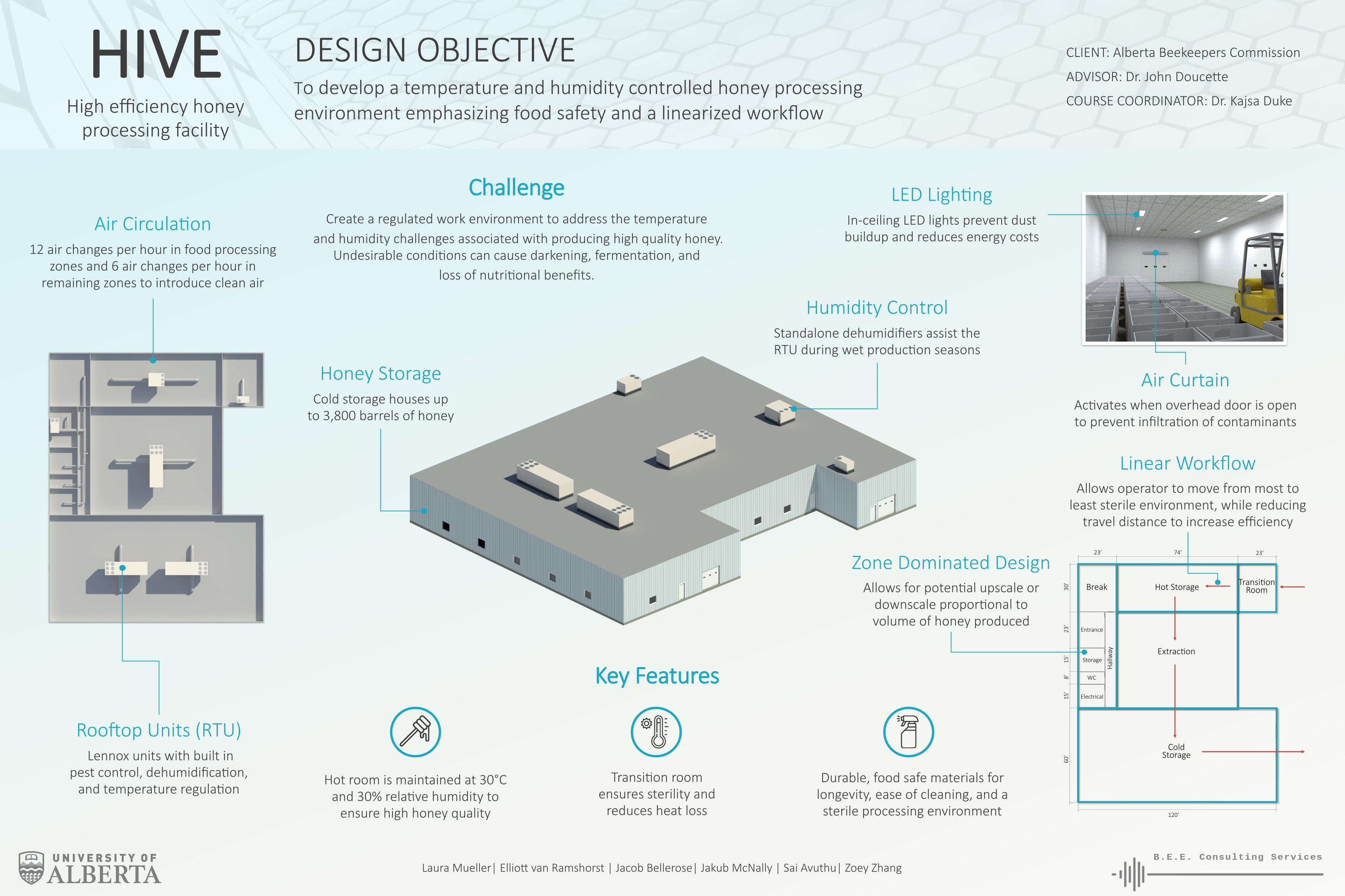
HIVE High efficiency honey processing facility DESIGN OBJECTIVE To develop a temperature and humidity controlled honey processing environment emphasizing food safety and a linearized workflow CLIENT: Alberta Beekeepers Commission ADVISOR: Dr. John Doucee COURSE COORDINATOR: Dr. Kajsa Duke Laura Mueller| Ellio van Ramshorst | Jacob Bellerose| Jakub McNally | Sai Avuthu| Zoey Zhang Air Circulaon 12 air changes per hour in food processing zones and 6 air changes per hour in remaining zones to introduce clean air LED Lighng In-ceiling LED lights prevent dust buildup and reduces energy costs Air Curtain Acvates when overhead door is open to prevent infiltraon of contaminants Rooſtop Units (RTU) Lennox units with built in pest control, dehumidificaon, and temperature regulaon Honey Storage Cold storage houses up to 3,800 barrels of honey Linear Workflow Allows operator to move from most to least sterile environment, while reducing travel distance to increase efficiency Humidity Control Standalone dehumidifiers assist the RTU during wet producon seasons Challenge Create a regulated work environment to address the temperature and humidity challenges associated with producing high quality honey. Undesirable condions can cause darkening, fermentaon, and loss of nutrional benefits. Extracon Hot Storage Cold Storage Transion Room Entrance Storage WC Electrical Break Hallway 23’ 74’ 23’ 30’ 23’ 15’ 8’ 15’ 120’ 60’ Zone Dominated Design Allows for potenal upscale or downscale proporonal to volume of honey produced Hot room is maintained at 30°C and 30% relave humidity to ensure high honey quality Transion room ensures sterility and reduces heat loss Durable, food safe materials for longevity, ease of cleaning, and a sterile processing environment Key Features
-
Upload
khangminh22 -
Category
Documents
-
view
0 -
download
0
Transcript of HIVE - Alberta Beekeepers Commission
HIVE High efficiency honey
processing facility
DESIGN OBJECTIVE To develop a temperature and humidity controlled honey processing environment emphasizing food safety and a linearized workflow
CLIENT: Alberta Beekeepers Commission
ADVISOR: Dr. John Doucette
COURSE COORDINATOR: Dr. Kajsa Duke
Laura Mueller| Elliott van Ramshorst | Jacob Bellerose| Jakub McNally | Sai Avuthu| Zoey Zhang
Air Circulation 12 air changes per hour in food processing
zones and 6 air changes per hour in remaining zones to introduce clean air
LED Lighting In-ceiling LED lights prevent dust buildup and reduces energy costs
Air Curtain Activates when overhead door is open to prevent infiltration of contaminants
Rooftop Units (RTU) Lennox units with built in
pest control, dehumidification, and temperature regulation
Honey Storage Cold storage houses up
to 3,800 barrels of honey
Linear Workflow Allows operator to move from most to
least sterile environment, while reducing travel distance to increase efficiency
Humidity Control Standalone dehumidifiers assist the RTU during wet production seasons
Challenge Create a regulated work environment to address the temperature
and humidity challenges associated with producing high quality honey. Undesirable conditions can cause darkening, fermentation, and
loss of nutritional benefits.
Extraction
Hot Storage
Cold Storage
Transition Room
Entrance
Storage
WC
Electrical
Break
Hal
lway
23’ 74’ 23’
30
’ 2
3’
15
’ 8
’ 1
5’
120’
60
’
Zone Dominated Design Allows for potential upscale or
downscale proportional to volume of honey produced
Hot room is maintained at 30°C and 30% relative humidity to
ensure high honey quality
Transition room ensures sterility and
reduces heat loss
Durable, food safe materials for longevity, ease of cleaning, and a sterile processing environment
Key Features

2-1 Mechanical Engineering BuildingUniversity of Alberta
Edmonton, Alberta T6G 2G8
Honey Packing House Design
Phase III: Final Report
December 2, 2019

Executive Summary
B.E.E Consulting Services (BCS) was contracted by the Alberta Beekeepers Commission to design a honey packing house optimized for excellent honey production. To optimize honey production, a temperature set point of 30℃ and humidity set point of 30% must be maintained in areas where honey supers are stored, followed by ambient temperature and humidity set points in the remainder of the house. In response to client specifications, the HIVE honey house has been produced.
The HIVE honey house provides a high-performance design which utilizes equipment and materials to minimize heat loss and overall operating costs. The layout promotes an efficient workflow to maximize employee productivity. All elements of the design were chosen to meet food safety standards. Detailed analysis was performed to optimize the HVAC system, provide adequate humidification, and to determine the energy consumption of the facility. The total cost of the HIVE Honey House is estimated to be $649,550, with $63,000 of the total cost allocated to the BCS engineering team. A total of 700 hours was spent throughout all three phases of the project.
BCS has recommended future improvements to further refine the concept for the client and to ensure complete design viability.

Table of Contents 1 Introduction ................................................................................................................................................................ 1
2 HIVE ............................................................................................................................................................................ 1
2.1 Concept Refinement............................................................................................................................................ 1
2.1.1 HVAC System ................................................................................................................................................ 1
2.1.2 Air Exchange Rate ........................................................................................................................................ 2
2.1.3 Dehumidifiers ............................................................................................................................................... 2
2.1.4 Overhead Doors and Air Curtains ................................................................................................................ 2
2.1.5 Ceiling Height Required for Ductwork ......................................................................................................... 2
2.1.6 Addition of Emergency Exits ........................................................................................................................ 3
2.2 Design Usability ................................................................................................................................................... 3
2.3 Design Features ................................................................................................................................................... 4
3 Design Analysis Performed ......................................................................................................................................... 7
3.1 Air Exchange Rate ................................................................................................................................................ 7
3.2 Heat Transfer ....................................................................................................................................................... 7
3.3 Temperature Control........................................................................................................................................... 8
3.4 Humidity Control ................................................................................................................................................. 8
3.5 FEA Analysis ......................................................................................................................................................... 9
3.6 Energy Analysis .................................................................................................................................................... 9
3.7 Cost Analysis ...................................................................................................................................................... 10
4 Design Compliance Matrix ........................................................................................................................................ 10
5 Design Rendering and Drawing Package .................................................................................................................. 15
6 Future Considerations .............................................................................................................................................. 15
7 Project Management ................................................................................................................................................ 16
8 Conclusion ................................................................................................................................................................ 17
References ................................................................................................................................................................... 18
Appendices .................................................................................................................................................................. 19
Appendix A: Design Specification Matrix ..................................................................................................................... 20
Appendix B: Design Calculations.................................................................................................................................. 27
Appendix C: CAD and Drawing Package .................................................................................................................... 126
Appendix D: Cost Analysis ......................................................................................................................................... 162
Appendix E: Material Data Sheets ............................................................................................................................. 170
Appendix F: Project Management ............................................................................................................................. 200
List of Figures Figure 1. HIVE Honey House Rendering. ........................................................................................................................ 1 Figure 2. Building Zones ................................................................................................................................................. 2 Figure 3. Features of the HVAC Design. ......................................................................................................................... 4 Figure 4. Complete Honey House Workflow. ................................................................................................................. 5 Figure 5. Overview of the Honey House Workflow. ....................................................................................................... 6 Figure 6. Estimated, Actual, and Project Engineering Hours ....................................................................................... 17 Figure 7. Timecard: Zoey Zhang. ................................................................................................................................ 202 Figure 8. Timecard: Sai Avuthu. ................................................................................................................................. 202 Figure 9. Timecard: Elliott van Ramshorst. ................................................................................................................ 203 Figure 10. Timecard: Jacob Bellerose. ........................................................................................................................ 203 Figure 11. Timecard: Jakub McNally. ......................................................................................................................... 204 Figure 12. Timecard: Laura Mueller. .......................................................................................................................... 204
List of Tables Table 1. Honey House Zones for Temperature Control. ................................................................................................. 1 Table 2. Honey House Final Ceiling Heights by Room. ................................................................................................... 3 Table 3. Number of Air Exchanges Designed per Zone .................................................................................................. 7 Table 4. Total Heating and Cooling Load for Each Zone. ............................................................................................... 8 Table 5. RTU Chosen for Each Zone. .............................................................................................................................. 8 Table 6. Stand-Alone Humidifier Chosen for Each Zone. ................................................................................................ 9 Table 7. HIVE Energy Assessment. ................................................................................................................................. 9 Table 8. Solar PV System Economics. ........................................................................................................................... 10 Table 9. Design Compliance Matrix Rating Descriptions. ............................................................................................ 11 Table 10. HIVE Design Compliance Matrix. .................................................................................................................. 11 Table 11. Total Engineering Hours for Phase 3. ........................................................................................................... 16 Table 12. Revised Sections of the Design Specification Matrix. ................................................................................... 21 Table 13. Design Specification Weighting Criteria. ...................................................................................................... 22 Table 14. Phase 3 Design Specification Matrix. ......................................................................................................... 201
(Word Count: 2457)

1 Introduction Fluctuations in temperature and humidity during the honey packing process adversely affects honey quality and is the biggest challenge a producer must overcome. A good processing facility can make a significant difference for beekeepers by both ensuring the conditions are optimal for honey extraction and providing a comfortable work environment for the long days.
B.E.E Consulting Services (BCS) has been contracted by the Alberta Beekeepers Commission (ABC) to provide a design for a honey packing house that will maintain the temperature and humidity setpoints required for producing the highest quality honey, while remaining competitively priced and compliant with the Safe Food for Canadians Act [1]. BCS has developed the HIVE honey house design to satisfy the clients requirements.
2 HIVE
Figure 1. HIVE Honey House Rendering.
2.1 Concept Refinement Following Phase 2, adjustments were made to the design to improve its overall functionality. These refinements are summarized in Sections 2.1.1 to 2.1.6.
2.1.1 HVAC System In order to improve the final concept, the HVAC system was redesigned to include roof top air handling units (RTUs) that serve different areas of the building. The different temperature control zones in Figure 2 have been outlined in Table 1.
Table 1. Honey House Zones for Temperature Control.
Zone 1 Zone 2 Zone 3 Zone 4 Zone 5 Entrance, Break Room, Storage
Room, Washroom,
Electrical Room and Hallway
Hot Storage Room Transition Room Extraction Room Cold Storage Room
Page 1

2.1.2 Air Exchange Rate Minimum air exchange rates were calculated in Phase 2 based on current code requirements [4]. These rates were increased based on consultation from industry professionals to reduce build up of pollutants in a food processing operation. The air exchange rates in the building have been improved to 6 changes per hour in zones 1 and 3, and 12 changes per hour in zones 2, 4, and 5.
2.1.3 Dehumidifiers Four stand-alone units will be required in the hot storage room to achieve 30% relative humidity.
2.1.4 Overhead Doors and Air Curtains Overhead doors have been included between the areas of food processing and the loading docks to promote food safety and efficient workflow movement through the facility.
Air curtains have been included with the overhead doors at the entrance and exit of the hot room. The air curtains add an extra level of food safety protection for the supers being stored in the hot room and for their movement into the extraction room.
2.1.5 Ceiling Height Required for Ductwork To accommodate the necessary ductwork in each zone, the ceiling height in each room was modified from the client’s initial recommendation of 16 ft. These modifications allow adequate spacing for forklift operations and honey processing equipment. The final height in each room is summarized in Table 2.
Figure 2. Building Zones
Page 2

Table 2. Honey House Final Ceiling Heights by Room.
Zone Room Final Ceiling Height
1
Entrance 14’ 11 1/2” Break Room 15’ 3 1/2”
Storage Room 15’ 6” Washroom 15’ 10”
Electrical Room 15’ 6” Hallway 15’ 5”
2 Hot Storage Room 15’ 3 Transition Room 15’ 5 1/2” 4 Extraction Room 13’ 6” 5 Cold Storage Room 15’
2.1.6 Addition of Emergency Exits Emergency exits have been added to comply with the current code requirements [3].
2.2 Design Usability Many design elements were considered during the development of the HIVE honey house including industrial requirements, human factors, and ergonomics, along with social, environmental, and sustainability factors.
The HIVE honey house was designed to be an industrial food processing facility with a minimum of 12 ft ceilings to accommodate the use of a forklift, a loading dock to move honey supers and processed honey, and overhead doors to separate work areas.
One of the most important considerations made in the design was food safety and compliance with the Safe Food for Canadians Act [1]. Therefore, all materials in the honey processing rooms were chosen to be food safe, air curtains were installed to isolate rooms, and employee workflow was designed in one direction to prevent contamination between rooms.
Another important consideration made in the design was worker efficiency, as the workers must be able to move through the facility quickly to maximize their work. In addition, the temperature set points in each room of the building is important, not only for the honey processing, but also to ensure worker comfort. Aside from the honey processing areas, the HIVE honey house includes amenities such as an employee entrance, break room, storage room, and washroom.
Environmental and sustainability considerations were made by the BCS team to choose a design and equipment that promote efficiency and energy conservation. The building was divided into temperature zones to allow for efficient heating and cooling in all seasons. In addition, insulation and windows were chosen to reduce heat losses. Finally, BCS has included a study of the impact that solar panels could have on the energy needs of the HIVE honey house and can be an add on if chosen by the client.
Page 3

2.3 Design Features HVAC Design
The HIVE design includes roof top air handling units to provide temperature control in the different zones as indicated in Figure 2.
Figure 3. Features of the HVAC Design.
During the honey extraction periods from July to September, a temperature setpoint of 30℃ and a humidity setpoint of 30% is required in Zones 2 and 3. These conditions promote excellent honey quality when the supers enter the facility for extraction. Honey is a hygroscopic fluid and higher humidity promotes browning and unwanted yeast formation, decreasing quality. A temperature setpoint of 20℃ and a humidity setpoint of 45% is preferred in the remainder of the honey house. Stand-alone dehumidifiers have been included in the hot storage room to assist the RTU in maintaining the desired humidity.
During the winter months when honey is not being produced, Zone 1 is kept at a comfortable 20℃ and 45% humidity, whereas the remainder of the honey house is kept at a cooler 16℃ temperature. During the winter months beekeepers can use their honey houses for other purposes, such as building machinery. The reduced temperature lowers operating costs and prevents damage to the building, such as frozen pipes, due to winter conditions.
Page 4
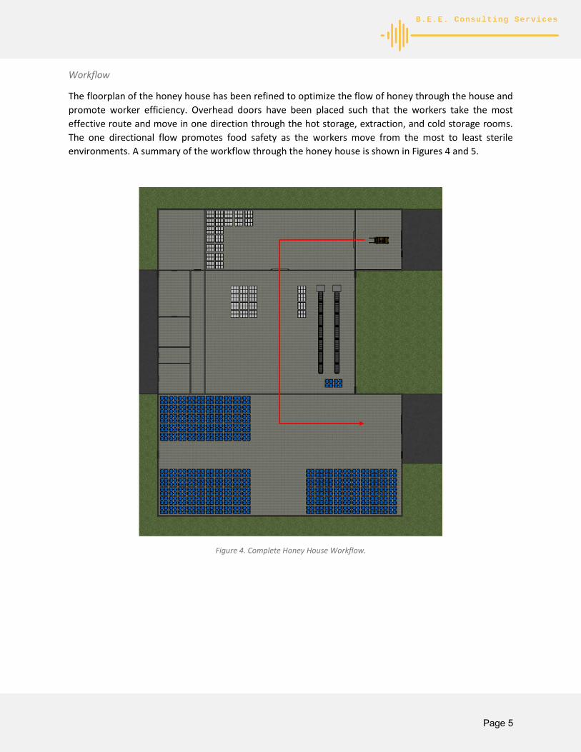
Workflow
The floorplan of the honey house has been refined to optimize the flow of honey through the house and promote worker efficiency. Overhead doors have been placed such that the workers take the most effective route and move in one direction through the hot storage, extraction, and cold storage rooms. The one directional flow promotes food safety as the workers move from the most to least sterile environments. A summary of the workflow through the honey house is shown in Figures 4 and 5.
Figure 4. Complete Honey House Workflow.
Page 5

Step 1. Forklift to receive honey supers from delivery truck in the transition room.
Step 2. Forklift to transport honey supers from transition room and create a stockpile in the hot storage room. Air curtains to remain active while all doors leading to the hot room are open to prevent contaminants.
Step 3. Forklift to transport honey supers from the hot storage room to the extraction room for treatment. 55-gallon drums to be filled after honey has been treated. Air curtain between hot room and extraction room to be activated while door is open.
Step 4. Forklift to transport 55-gallon drums from the extraction room to the cold storage room. Seasons production to remain in storage as required. Honey to be transported out of the building through exit overhead door.
Figure 5. Overview of the Honey House Workflow.
Overhead Doors and Air Curtains
Overhead doors have been placed between the honey processing rooms and at each of the loading docks to promote food safety. The overhead doors have the added benefit of reducing heat transfer between the rooms in the house when compared to conventional methods, such as strip door curtains. As the overhead doors open and close relatively quickly, the efficiency of the workers is not hindered by the presence of the doors.
At the entrance and exit of the hot storage room an air curtain has been coupled with the overhead door. Since the hot storage is the first room that the supers are transported to, the air curtains provide an extra layer of protection to keep this area food safe. The air curtains do not have any notable effect on heat transfer.
Page 6

Food Safe and Durable Materials
The materials chosen in the areas of honey processing have been selected due to their food safe quality. An epoxy coating on the concrete has been chosen as a food safe flooring option, whereas food safe panelling and tiles have been used for the walls and ceiling, respectively. In addition to the food safe materials, durability and cleanability are important qualities the chosen materials must have. This allows them to be sprayed down and sanitized often, while maintaining a long lifespan.
Scalable Design
The HIVE honey house can be scaled to accommodate different levels of honey production because of the zone dominated design. Therefore, with some calculation refinement, the floorplan and mechanical design can be manipulated to suit the needs of many beekeepers.
3 Design Analysis Performed The viability of the final design was developed by performing the following calculations including: Air Exchange Rate, Heat Transfer, HVAC, Humidity, FEA Analysis, Energy Analysis, and Cost Analysis calculations. These calculations are summarized in sections 3.1 to 3.7.
3.1 Air Exchange Rate To ensure the final design conforms to the air exchange rate recommended by BCS, air exchange rate calculations were completed. The project team recommends 6 changes per hour in zones 1 and 3, and 12 changes per hour in zones 2, 4, and 5. These calculations were performed assuming a maximum zone occupancy of 8 people.
Complete air exchange rate calculations for the final design can be found in Appendix B1. A summary of these calculations is shown in Table 3.
Table 3. Number of Air Exchanges Designed per Zone
Zone 1 Zone 2 Zone 3 Zone 4 Zone 5 6 changes/hour 12 changes/hour 6 changes/hour 12 changes/hour 12 changes/hour
The objective of the air exchange rate calculations was to determine the required airflow rate in each zone.
3.2 Heat Transfer To ensure that heat losses are accounted for in the HIVE design, heat transfer calculations were completed.
The goal of these calculations was to determine the total heating and cooling load in each zone to ensure that each zone could be maintained at the required temperature. A 10% safety factor was considered in the calculations to account for any additional heat loads, such as piping losses.
Heat transfer resulting from structural beams have not been considered as there are many variations in beam configurations. Additional civil engineering consultation is required as heat loss through structural beams would cause a decrease in heating load.
Page 7

The air curtain was included in the design for the sole purpose of food safety. It is assumed to have a negligible affect on heat transfer for a conservative heat load estimate.
Complete heat transfer calculations can be found in Appendix B2. A summary of these calculations is shown in Table 4.
Table 4. Total Heating and Cooling Load for Each Zone.
Zone Total Heat Load, including 10% safety factor, [W]
Total Cooling Load, including 10% safety factor, [W]
1 41,030 14,001 2 27,237 8,580 3 16,039 5,510 4 42,149 18,095 5 85,699 29,933
Building Total 212,155 76,119
The heating and cooling loads were used to determine the total heat loss of the building, and to determine the annual energy consumption of the facility.
3.3 Temperature Control Temperature control in the honey house was a crucial specification indicated by the client as temperature during the extraction process can have a significant effect on honey quality. In order to ensure the final design conforms to client standards and code requirements, calculations were performed using the equal friction method to refine an appropriate HVAC system and account for calculated heat losses.
The goal of these calculations was to design a round duct system and to select RTUs. In the final design, economizers were added to the RTUs to create outdoor air circulation based on code requirements [4].
Each RTU is to be ordered with a 14-inch roof curb to allow for sufficient spacing for ducts between the ceiling and roof. Due to its large size, zone 5 will require two identical RTU units in order to meet its airflow requirements.
Complete HVAC calculations for the final design can be found in Appendix B3. A summary of the selected RTUs is shown in Table 5.
Table 5. RTU Chosen for Each Zone.
Zone 1 Zone 2 Zone 3 Zone 4 Zone 5 Lennox Commercial Model: KGA120S4B
Air Volume: 3500 cfm Motor: 786 rpm, 1.22
bhp
Lennox Commercial Model: KGA240S4B
Air Volume: 7250 cfm Motor: 765 rpm, 3.10
bhp
Lennox Commercial Model: LGH060U4E
Air Volume: 1431 cfm Motor: 716 rpm, 0.36
bhp
Lennox Commercial Model: LCH600H4B
Air Volume: 15,000 cfm Motor: 735 rpm, 9.70
bhp
Lennox Commercial Model: LCH600H4B
Air Volume: 12,000 cfm Motor: 610 rpm, 5.15
bhp
3.4 Humidity Control Like temperature, humidity is a crucial specification for the client, as the hygroscopic nature of honey means high humidity can adversely affect honey quality. To ensure humidity conditions can be controlled, humidity calculations were performed to determine the moisture load of the building.
Page 8

The goal of these calculations was to size stand-alone dehumidifiers to accommodate the calculated moisture load for the final design. Each RTU contains its own dehumidifier, which will be used to regulate the zone’s humidity. Due to the humidity requirement of 30% in zone 2, four standalone dehumidification units will be used with the RTU to attain the zone’s humidity requirements.
Complete humidity calculations for the final design can be found in Appendix B4. A summary of the selected dehumidifiers is shown in Table 6.
Table 6. Stand-Alone Humidifier Chosen for Each Zone.
Zone 1 Zone 2 Zone 3 Zone 4 Zone 5
Not Required
Dehumidifier Corporation of America
(DCA) Model: DCA1500T
Not Required Not Required Not Required
3.5 FEA Analysis To ensure the final design achieves appropriate heat transfer, FEA analysis was completed on the final design floor slab when exposed to different exterior conditions.
A simple ANSYS model was created to perform FEA on the concrete floor slab of the building in order to determine the heat losses from the slab to the soil. The temperature distribution from the slab to the soil was developed to illustrate heat losses to the ground. As shown in Appendix B5, the heat loss to the soil is not significant, thus confirming the assumption that heat loss occurs primarily at the perimeter of the slab. BCS recommends the addition of a 2-inch thick polystyrene insulation layer beneath the concrete slab to decrease heat losses. Complete FEA analysis for the final design can be found in Appendix B5.
3.6 Energy Analysis The annual energy consumption was estimated using an average 10-hour work day during the honey production period from July to September, with the non-operational period of the building from October to June. The heating and cooling loads from Section 3.2 were used for this energy analysis.
The HIVE house was estimated to have an annual energy consumption of 74.3 MWh/year, resulting in an annual energy cost of approximately $5,313. Similarly, annual gas consumption was estimated to be 430 GJ/year, resulting in an annual cost in natural gas of approximately $1,336.
Table 7. HIVE Energy Assessment.
HIVE Energy Assessment Annual Estimated Energy Consumption: 74 MWh/Year Current Energy Rate: $71.5 /MWh Annual Estimated Energy Cost: $5,313 /Year Annual Estimated Natural Gas Consumption: 432 GJ/Year Current Natural Gas Rate: $3.09 /GJ Annual Estimated Energy Cost: $1,336 /Year
Page 9

Installing a 41.5 kW roof-top solar power array would be a valuable consideration to offset power costs of the building. This would require an initial investment of $57,990 that would have a 11.9% IRR over a 30-year economic life, with 9 years payback. The Solar PV System is estimated to generate 91.0 MWh/year, resulting in a surplus of 16.7 MWh/year. This would yield an annual credit of $6,506. Table 8 below provides a summary of the solar economic analysis.
Table 8. Solar PV System Economics.
Solar Assessment Solar PV System Rating: 41.5 kW Cost to Install (minus 30% rebate): $57,990 Annual PV Power Generation: 91.0 MWh/Year Annual Energy Surplus: +16.7 MWh/Year Annual Credit from Micro-Generation: $6,505 /Year Payback Period 9 Years
A detailed energy analysis is provided in Appendix B6.
3.7 Cost Analysis For the final design, a detailed cost analysis was completed to determine the total estimated cost of construction and materials. The materials in the final design were chosen to optimize the heat transfer, HVAC, humidity, and air exchange rate values for the building.
The cost of the building was broken down into four sections: substructure, shell, interiors, and services/utilities. The substructure includes the standard foundation and the insulated concrete slab. The slab was specified to be 6”-thick reinforced concrete on grade with 2”-thick expanded polystyrene insulated sheets placed below the slab. The shell consists of all exterior features of the building including: the main steel framing and structure, the exterior walls, windows, doors, and roof finishes. A pre-fabricated steel I-beam kit was chosen to reduce the cost of the main building structure, compared to a wooden structure. The interior includes costs of the drywall, hygienic wall panels, doors, and all wall, floor and ceiling finishes. The services portion includes all plumbing fixtures, HVAC equipment, and electrical components.
The estimates that were obtained for chosen features of the building are included in Appendix D1. Costs of services were determined by researching local industry averages. For materials where costs were not readily available, estimates were referenced from RSMeans data. A 25% contingency charge was added to the cost of the project to account for additional costs from contractor overhead and profit.
The complete cost analysis for the final design can be found in Appendix D2
4 Design Compliance Matrix The design compliance matrix shows the design improvements that BCS made from Phase 2. The design was assigned a score of 6 if it was found to adequately meet the scope and was given an appropriate upgrade if it surpassed expectations. Similarly, the design’s score was reduced if it did not meet
Page 10

expectations. Levels of importance were assigned values between 1 and 10 and descriptions of each level are shown in Table 9. Design specification matrix changes have been outlined in Appendix A1.
Table 9. Design Compliance Matrix Rating Descriptions.
Rating Description Definition 9-10 Crucial Aspect is an essential element to a successful final design 7-8 Important Feature adds significant value to the design 5-6 Desired Required for an effective design but not essential 3-4 Discretionary Not crucial, but desirable for optimizing operations 1-2 Optional Not a compulsory feature, but has the possibility of adding value
Table 10. HIVE Design Compliance Matrix.
Item
Description D
esig
n Au
thor
ity
Impo
rtan
ce (1
-10)
HIV
E: P
hase
2
HIV
E: P
hase
3
Reasoning
1.0 Building Layout and Dimensions
1.1
Building to include an extraction room, hot room, supply storage room, electrical room, an employee washroom, a break room, entrance, and a cold storage room. [A1]
BCS 7 7 7 Final design is spacious but requires the stacking of honey for storage.
1.2
Dimensions to accommodate an extraction line that produces at 3000 lb/hr for a standard workday of 10 hours ABC 8 6 6
Dimensions achieve the specification, but do not provide room for production growth.
1.3
Dimensions to accommodate the storage and easy transport of 600 honey supers
BCS 7 6 6
Dimensions achieve the specification but require stacking of honey for storage and dimensions do not provide room for growth.
1.5
Shall be dimensioned to provide adequate room for maintenance work while following the national fire code
BCS Code [A2]
3 7 7
Adequate room provided for maintenance, but no extra space is provided in the room.
1.6 At least two doors will be placed in the hot room to allow for easy flow of traffic through the room [A1]
BCS 7 6 6 Two doors have been placed to promote efficient movement.
1.7 Ceiling height to be 16ft to accommodate a standard forklift provide space between bees and personnel on the floor [A1]
BCS 5 6 5 Some ceiling heights have been lowered to
Page 11

accommodate required mechanical ductwork.
1.8
Wall height to be 19ft to provide adequate spacing for an in-ceiling air duct system
BCS 5 6 6
Wall height has remained, however some ceilings had to be lowered to accommodate the ductwork.
1.10
Emergency exits will be placed at required locations in agreement with the 2019 national fire code
BCS Code [A2]
10 3 6
Doors have been placed to accommodate the fire code, but verification will be required later by the client.
1.11
Building workflow designed to promote easy transport of honey through the different stages of production ABC 10 7 7
Design has been optimized to promote efficient workflow through the building.
2.0 Building Functionality
2.1
The relative humidity of the hot room will be set to 30% with a tolerance of ±2% ABC 9 6 8
Design has been refined to include a more reasonable and achievable relative humidity set point.
2.2
The temperature of the hot room and transition room will be set to 30°C ± 2°C ABC 9 7 8
HVAC system has been refined to be more viable to achieve this temperature set point.
2.3
The temperature of the equipment room, washroom, entrance, and break room will be 20°C (adjustable to employee comfort) BCS 6 7 8
HVAC system has been refined to be more viable to achieve this temperature set point.
2.4
The chosen ventilation system will provide a full air exchange at a minimum of twelve times per hour in areas of food processing and six times per hour elsewhere [A3]
ABC Code [A3]
8 3 6
HVAC system has been refined to achieve these air exchange rates more effectively.
2.5 One thermostat to be included in each of the extraction and hot rooms BCS 3 5 5
One thermostat has been provided for each of these rooms.
2.6
One SUMP to be installed that will function as a honey receptacle and collect wash water [A1] BCS 5 4 4
Sump addition has been considered but is listed as a future work item for the client.
2.7
Raised outside loading dock to connect to the overhead door to increase super transport efficiency BCS 5 4 4
Loading dock has been provided in the final design, but it is at ground level.
2.8 Extraction, manoeuvring, and hot rooms to each contain a minimum of one floor drain
BCS 6 4 4 Floor drains have been considered but these are
Page 12

Code [A4] [A7]
listed as a future work item for the client.
2.9
Extraction, manoeuvring, and hot rooms floors to have slopes of 1% to the drainage location
BCS Code [A4] [A7]
6 4 4
Floor slope has been considered but is listed as a future work item for the client.
2.10
Building to be supplied with electrical power, natural gas, and water sources BCS
Code [A5]
6 3 3
Energy sources are important, but this is a future consideration for the client.
2.11
Lighting to be installed to provide adequate visibility in all rooms and all periods of the day
BCS Code [A4]
8 6 6
Lighting has been designed by BCS, but future work will be required by the client to ensure code requirements are met.
2.12 Extraction, cold storage, and hot rooms to each include at least one industrial sink with both hot and cold water [A7]
BCS 4 8 8 One sink has been provided in each of these rooms.
3.0 Building Efficiency and Environmental Considerations
3.1 Window frames, and glass, will be chosen to minimize the buildings U factor and heating costs [A6]
BCS 5 7 8 Windows have been chosen to have an effective U factor.
3.2
Insulation to be installed to minimize heat loss while remaining in accordance with building and fire regulations
BCS Code [A2] [A4]
6 8 9
Insulation has been chosen to effectively prevent heat loss and meet minimum U value code requirements.
3.3
Lighting to consist of LED tubes where possible to increase energy efficiency
BCS 3 5 5
LED bulbs chosen to promote efficiency but options, like a skylight, could have been considered to reduce energy more.
3.4
High efficiency mechanical equipment to be selected where possible
BCS 3 5 5
Equipment chosen to meet the heating and cooling requirements of the building. Energy efficiency was a small consideration.
3.5 Environmentally friendly materials to be used where possible BCS 4 5 7
Environmentally friendly materials were chosen and a Solar PV system was proposed.
4.0 Safety and Health Considerations
4.1 Provide method of removing bees from the building ABC 5 3 3
A bee escape has been considered but is listed as future work for the client.
Page 13

4.2 Ceiling and walls will be chosen with smooth, non-absorbent, and easy to clean food-safe materials [A7]
BCS ABC Code [A7]
9 9 9
Wall and ceiling materials have been chosen to be food safe and durable for cleaning.
4.3 All wall to floor joints to be rounded to improve the sealing, leading to easier cleaning [A8]
BCS 9 7 7 Wall to floor joints have been sealed for easy cleaning.
4.4
Floors, windows, walls, ceilings, lighting, and ventilation will be designed to prevent entry of pests into the building [A7]
BCS Code [A7]
9 5 7
Pest entry has been considered and materials put in place to prevent their entry to the building.
4.5 One sink and one toilet will be provided for every ten people working in the honey-house [A1]
BCS 7 8 8 Specification has been met for the workforce indicated by the client.
4.6
Minimum of two doors between the extraction room and bathroom to minimize the risk of cross contamination [A1]
BCS 8 8 8
Requirement has been met with the final design.
5.0 Material Specifications
5.1 Floor to be made of concrete with a durable impervious surface for water resistance and sanitation purposes [A1]
BCS Code [A7]
8 8 8 Chosen flooring is durable and food safe.
5.2 Concrete floor to have a minimum strength of 30 MPa in accordance with CSA A23.1-14 standards [A9]
BCS Code [A9]
8 8 8 Specification has been met by the final design.
5.4 Electrical room to be constructed of fire-resistant material in accordance with the national fire code
BCS Code [A2]
9 8 8
Specification met by design, but future work to be done by the client to ensure code compliance.
6.0 Construction Considerations
6.1 Building will be designed to meet heating specifications based on an assumed minimum temperature of -31.4°C
ABC 8 6 9 Building design based on this minimum outdoor temperature.
6.2 Building will be designed to conform with standards for a F3 building classification [A4]
BCS 7 6 6 Future work by the client required to ensure code compliance.
6.3
B.E.E. Consulting Services to provide client with an engineering drawing package for construction purposes BCS
Other 5 3 5
Drawing package provided for the client but will require future work to meet construction drawing standards.
7.0 Cost
7.1
Designed HVAC system and building will reduce the operational costs of maintaining the required humidity and temperature
BCS 9 8 9
System has been designed to be efficient and consider operating costs.
Page 14

7.2
Building materials and overall design will result in a cost of approximately $570,000. BCS 10 6 8
Building cost has been optimized to conform to the estimated value indicated by the client.
1610
1815
Overall Score
The design compliance matrix has been discussed following Phase 2 and approved by the client.
5 Design Rendering and Drawing Package Design renderings and a drawing package are included in Appendix C.
6 Future Considerations Due to constraints limiting the project team, such as time and expertise, BCS recommends that the following future considerations are investigated by the client.
Dehumidification Requirements
BCS has designed HIVE to control humidity set points during the typical conditions seen in a honey production season. However, as weather conditions fluctuate and wet seasons may occur, dehumidification requirements for the honey may change and the client may decide that more dehumidification may be required to dry out the honey.
Food Safety Requirements
Outside of the building materials and construction, the client may want to consider other methods of promoting food safety such as clean room mats, employee uniforms, cleaning schedules, extraction equipment and processed honey storage racks.
Code and Building Standard Requirements
When applying for permits and performing construction the client should reference the relevant codes and building standards to ensure design compliance.
Structural, Civil and Electrical Requirements
When constructing the design, the client should have industry professionals provide consultation on the electrical, structural, and civil aspects of the building to ensure the viability of the design. BCS is not qualified to provide consultation in this field and cannot ensure the viability of these items, as indicated at the start of the project.
Floor Slope and Sumps
Due to time constraints on the BCS team, floor sloping and sumps will need to be considered by the client.
Page 15

Lighting Requirements
BCS has designed the lighting in the building to the best of their ability, to ensure appropriate light coverage according to code. However, the client will have to ensure code lighting requirements are met when the building is completed, and all equipment is in place.
Bee escapes
Measures have been taken in the HIVE design to prevent bee entry into the building, such as screens on windows and specific diffusers to prevent pest infiltration, therefore bee escapes have not been included in the final design. BCS recommends that pressurized air be used to remove bees from the supers into a secondary container and manually removed from the building, rather than incorporating bee escapes into the building’s construction.
Finite Element Analysis
A simplistic FEA model was developed by the BCS team to explore the heat losses through the floor slab under various environmental conditions. The client should consider more detailed analysis in future work.
7 Project Management In Phase 3 a total of 224 engineering hours were required to complete the final design. These hours have been outlined by team member contribution in Table 11. Complete project team timesheets are shown in Appendix F2.
Table 11. Total Engineering Hours for Phase 3.
Team Member Meeting Hours
Research Hours
Report Writing Hours
Calculation Hours
Design Hours
Total Hours
Elliott 7.5 3.75 8.5 10 0 29.75 Sai 8 0 4 14 8 34 Jake 7 8 0 3 20 38 Zoey 6.5 1 3 10.5 18 39 Jakub 4.25 3 0 16 15 38.25 Laura 7.5 1.5 36 0 0 45 Phase 3 Total 40.75 17.25 51.5 53.5 61 224
The total number of hours spent on the project in Phase 3 was higher than the estimated value of 218 hours in the project schedule revised during Phase 2. The discrepancy in these hours was largely caused by the number of calculations the project team was required to complete to refine the final design and the time required to complete CAD renderings and drawing package. In addition, the time spent compiling a report to summarize the final design was underestimated in Phases 2 and 3.
To date, the BCS team has completed a total of 700 engineering hours, costing $63,000 in consulting fees. Comparisons between the Phase 1 and 2 estimates, and actual engineering hours for the project is shown in Figure 6 below.
Page 16

The final project schedule can be found in Appendix F1.
8 Conclusion BCS has designed the HIVE honey house to optimize production conditions and produce high-quality honey. Through detailed air exchange, heat transfer, HVAC, and humidity calculations, HIVE provides a high-performance design which utilizes equipment and materials to minimize heat losses and to reduce overall operating costs. The resulting concept complies with all necessary building codes and standards. BCS has recommended several future improvements to further refine the concept for the client and to ensure a complete design.
0 50 100 150 200 250 300
Phase 1
Phase 2
Phase 3
Total Hours [h]
Phase 3 Revised EstimateActual Hours SpentPhase 1 Estimate
Figure 6. Estimated, Actual, and Project Engineering Hours
Page 17

References [1] Minister of Justice, Safe Food for Canadians Act, Ottawa, ON: Government of Canada, 2019.
[2] J. Kienholz, Honey House and Equipment Layouts, Alberta Agriculture, 1983.
[3] National Resource Council Canada, National Fire Code – 2019 Alberta Edition, Edmonton, AB: Alberta Municipal Affairs, 2019.
[4] ASHRAE Standing Standard Project Committee 62.1, “Ventilation for Acceptable Air Quality”, ASHRAE Standard 62.1, 2016.
[5] National Resource Council Canada, National Building Code – 2019 Alberta Edition, Edmonton, AB: Alberta Municipal Affairs, 2019.
[6] National Resource Council Canada, National Energy Code of Canada for Buildings 2017, Ottawa, ON: Canadian Commission on Building and Fire Codes, 2017.
[7] Office of Energy Efficiency and Renewable Energy, “Energy Saver: Window Types and Technologies”, U.S. Department of Energy, Energy.gov. [Online]. Available: https://www.energy.gov/energysaver/window-types-and-technologies#277911-tab-1 [Accessed: September 22, 2019].
[8] Canadian Food Inspection Agency, Safe Food for Canadians Regulations 2019, Ottawa, ON: Government of Canada, 2019.
[9] B. F. Detroy, “Honey Removal, Processing and Packing,” Beekeeping in the United States: Agricultural Handbook Number 335, pages 92-102, October 1980. [Online Serial]. Available: https://beesource.com/resources/usda/honey-removal-processing-and-packing/. [Accessed: September 22, 2019].
[10] Occupational Health and Safety, Occupational Health and Safety Regulation 2018, Edmonton, AB: Government of Alberta, 2018.
Page 18

Appendices
Appendix A: Design Specification Matrix
A1 Phase 3 Updated Design Specifications Matrix
Appendix B: Design Calculations
B1 Air Exchange Rate Calculations
B2 Heat Transfer Calculations
B3 HVAC Calculations
B4 Humidity Calculations
B5 FEA Analysis
B6 Energy Analysis
Appendix C: CAD and Drawing Package
C1 CAD Renderings and Drawing Package
Appendix D: Cost Analysis
D1 Cost Analysis Estimates
D2 Complete Building Cost Analysis
Appendix E: Material Data Sheets
E1 Project Material Data Sheets
Appendix F: Project Management
F1 Final Project Schedule
F2 Project Team Timesheets
Page 19

Appendix A: Design Specification Matrix
-
Page 20

Appendix A1: Phase 3 Updated Design Specification Matrix
Through further research and consultations with the client, the project design specifications matrix was updated to guide the team.
The following changes were made:
Section 1.0 - Building Layout and Dimension
The furnace room was eliminated and converted to an electrical room in the final design, as the team changed the building HVAC system to be comprised of several roof top air handling units instead of a single furnace.
Section 2.0 - Building Functionality
The client acknowledged that the previously discussed humidity set point for the hot room was too low, which resulted in a change in the relative humidity setpoint to 30% ± 2%.
Section 6.0 - Construction Considerations
In Phase 2, the client specified that the functional months for the building would be from July to September.
The client indicated the honey house could be used during the non-functional months (October to June), additional building calculations were performed using a minimum outdoor temperature of -31.4℃ and an internal set point of 16°C.
Section 7.0 - Cost
Through discussions with the client and comparing Phase 2 cost estimates to those gathered from existing honey houses in industry, a final construction cost of approximately $570,000 is to be achieved by the project team.
The above matrix changes have been summarized in Table 12. In the revised table all items that were deleted have been crossed out and all items that were added have been underlined.
Table 12. Revised Sections of the Design Specification Matrix.
Item Description Specification Design Authority
Impo
rtan
ce
1.0 Building Layout and Dimensions
1.1 Building Areas
Building to include an extraction room, hot room, supply storage room, furnace electrical room, an employee washroom, a break room, entrance, and a cold storage room. [A1]
BCS 4
Page 21

1.5 Furnace Electrical Room Dimensions
Shall be dimensioned to provide adequate room for maintenance work while following the national fire code
BCS Code [A2] 5
2.0 Building Functionality
2.1 Relative Humidity of Operational Rooms
The relative humidity of the hot room will be set to 18% 30% with a tolerance of ±2% ABC 5
2.4 Air Exchange Rate
The chosen ventilation system will provide a full air exchange at a minimum of every twelve hours twelve times per hour in areas of food processing and six times per hour elsewhere [A3]
ABC Code [A3] 5
5.0 Material Specifications
5.4 Furnace Electrical Room Material
Furnace Electrical room to be constructed of fire-resistant material in accordance with the national fire code
BCS Code [A2] 5
6.0 Construction Considerations
6.1 Temperature Considerations
Building will be designed to meet heating specifications based on an assumed minimum temperature of -2.08°C -31.4℃
ABC 4
7.0 Cost
7.2 Construction Cost Building materials and overall design will lower the building’s construction cost result in a cost of approximately $570,000.
BCS 5
The Phase 3 Design Specification Matrix used the same importance scale as the Phase 1 (shown in Table 13). After adding the revisions shown above in Table 12, the complete Design Specification Matrix for Phase 3 is shown in Table 14.
Table 13. Design Specification Weighting Criteria.
Rating Description Definition 5 Mandatory Essential to the proper function of the design, bound by appropriate codes
and standards 4 Important Needed by client but not critical for overall functionality 3 Necessary Not requested by the client but needed the proper performance of the
design 2 Discretionary Not essential to the design, but desirable for improving operations 1 Optional Not a required feature, but has the potential to add value
*For brevity, the design authorities in the design matrix will be given the following abbreviations:
B.E.E Consulting Services = BCS Alberta Beekeepers Commission = ABC All codes in the design authority column will be labeled as “Code” and referenced.
Page 22

Table 14. Phase 3 Design Specification Matrix.
Item Description Specification Design Authority
Impo
rtan
ce
1.0 Building Layout and Dimensions
1.1 Building Areas
Building to include an extraction room, hot room, supply storage room, electrical room, an employee washroom, a break room, entrance, and a cold storage room. [A1]
BCS 4
1.2 Extraction Room Dimensions
Dimensions to accommodate an extraction line that produces at 3000 lb/hr for a standard workday of 10 hours
ABC 5
1.3 Hot Room Dimensions Dimensions to accommodate the storage and easy transport of 600 honey supers BCS 3
1.5 Electrical Room Dimensions
Shall be dimensioned to provide adequate room for maintenance work while following the national fire code
BCS Code [A2] 5
1.6 Hot Room Accessibility At least two doors will be placed in the hot room to allow for easy flow of traffic through the room [A1]
BCS 2
1.7 Ceiling Height 16ft to accommodate a standard forklift provide space between bees and personnel on the floor [A1]
BCS 3
1.8 Wall Heights 19ft to provide adequate spacing for an in-ceiling air duct system BCS 2
1.10 Emergency Exits Emergency exits will be placed at required locations in agreement with the 2019 national fire code
BCS Code [A2] 5
1.11 Manoeuvrability Building workflow designed to promote easy transport of honey through the different stages of production
ABC 5
2.0 Building Functionality
2.1 Relative Humidity of Operational Rooms
The relative humidity of the hot room will be set to 30% with a tolerance of ±2% ABC 5
2.2 Temperature of Operational Rooms
The temperature of the hot room and transition room will be set to 30°C ± 2°C ABC 5
2.3 Temperature of Employee Rooms
The temperature of the equipment room, washroom, entrance, and break room will be 20°C (adjustable to employee comfort)
BCS 4
2.4 Air Exchange Rate
The chosen ventilation system will provide a full air exchange at a minimum of twelve times per hour in areas of food processing and six times per hour elsewhere [A3]
ABC Code [A3] 5
2.5 Temperature Control One thermostat to be included in each of the extraction and hot rooms BCS 5
Page 23

2.6 Extraction Room SUMP Functionality
One SUMP to be installed that will function as a honey receptacle and collect wash water [A1] BCS 2
2.7 Loading Dock Raised outside loading dock to connect to the overhead door to increase super transport efficiency
BCS 1
2.8 Drainage Extraction, manoeuvring, and hot rooms to each contain a minimum of one floor drain
BCS Code [A4,
A7] 5
2.9 Floor Slope Extraction, manoeuvring, and hot rooms floors to have slopes of 1% to the drainage location
BCS Code [A4,
A7] 5
2.10 Utilities Building to be supplied with electrical power, natural gas, and water sources
BCS Code [A5] 5
2.11 Lighting Lighting to be installed to provide adequate visibility in all rooms and all periods of the day
BCS Code [A4] 5
2.12 Cleaning Water for Operational Rooms
Extraction, cold storage, and hot rooms to each include at least one industrial sink with both hot and cold water [A7]
BCS 3
3.0 Building Efficiency and Environmental Considerations
3.1 Window Design Window frames, and glass, will be chosen to minimize the buildings U factor and heating costs [A6]
BCS 3
3.2 Insulation To be installed to minimize heat loss while remaining in accordance with building and fire regulations
BCS Code [A2,
A4] 3
3.3 Lighting Efficiency Lighting to consist of LED tubes where possible to increase energy efficiency BCS 1
3.4 Equipment Selection High efficiency mechanical equipment to be selected where possible BCS 1
3.5 Material Selection Environmentally friendly materials to be used where possible BCS 1
4.0 Safety and Health Considerations
4.1 Bee Escapes Provide method of removing bees from the building ABC 4
4.2 Wall and Ceiling Materials
Ceiling and walls will be chosen with smooth, non-absorbent, and easy to clean food-safe materials [A7]
BCS ABC
Code [A7] 5
4.3 Wall Joints All wall to floor joints to be rounded to improve the sealing, leading to easier cleaning [A8] BCS 5
4.4 Pest Control Floors, windows, walls, ceilings, lighting, and ventilation will be designed to prevent entry of pests into the building [A7]
BCS Code [A7] 5
4.5 Washroom Facility Requirements
One sink and one toilet will be provided for every ten people working in the honey-house [A1]
BCS 5
Page 24

4.6 Washroom Facility Isolation
Minimum of two doors between the extraction room and bathroom to minimize the risk of cross contamination [A1]
BCS 4
5.0 Material Specifications
5.1 Floor Materials Floor to be made of concrete with a durable impervious surface for water resistance and sanitation purposes [A1]
BCS Code [A7] 5
5.2 Floor Strength Concrete floor to have a minimum strength of 30 MPa in accordance with CSA A23.1-14 standards [A9]
BCS Code [A9] 5
5.4 Electrical Room Material
Electrical room to be constructed of fire-resistant material in accordance with the national fire code
BCS Code [A2] 5
6.0 Construction Considerations
6.1 Temperature Considerations
Building will be designed to meet heating specifications based on an assumed minimum temperature of -31.4°C
ABC 4
6.2 Building Classification Building will be designed to conform with standards for a F3 building classification [A4] BCS 3
6.3 Building Instructions B.E.E. Consulting Services to provide client with an engineering drawing package for construction purposes
BCS Other
Contractors 4
7.0 Cost
7.1 Operations Cost Designed HVAC system and building will reduce the operational costs of maintaining the required humidity and temperature
BCS 4
7.2 Construction Cost Building materials and overall design will result in a cost of approximately $570,000. BCS 5
Page 25

Appendix A References: [A1] J. Kienholz, Honey House and Equipment Layouts, Alberta Agriculture, 1983.
[A2] National Resource Council Canada, National Fire Code – 2019 Alberta Edition, Edmonton, AB: Alberta Municipal Affairs, 2019.
[A3] ASHRAE Standing Standard Project Committee 62.1, “Ventilation for Acceptable Air Quality”, ASHRAE Standard 62.1, 2016.
[A4] ASHRAE Standing Standard Project Committee 62.1, “Ventilation for Acceptable Air Quality”, ASHRAE Standard 90.1, 2016.
[A5] National Resource Council Canada, National Energy Code of Canada for Buildings 2017, Ottawa, ON: Canadian Commission on Building and Fire Codes, 2017.
[A6] Office of Energy Efficiency and Renewable Energy, “Energy Saver: Window Types and Technologies”, U.S. Department of Energy, Energy.gov. [Online]. Available: https://www.energy.gov/energysaver/window-types-and-technologies#277911-tab-1 [Accessed: September 22, 2019].
[A7] Canadian Food Inspection Agency, Safe Food for Canadians Regulations 2019, Ottawa, ON: Government of Canada, 2019.
[A8] B. F. Detroy, “Honey Removal, Processing and Packing,” Beekeeping in the United States: Agricultural Handbook Number 335, pages 92-102, October 1980. [Online Serial]. Available: https://beesource.com/resources/usda/honey-removal-processing-and-packing/. [Accessed: September 22, 2019].
[A9] Occupational Health and Safety, Occupational Health and Safety Regulation 2018, Edmonton, AB: Government of Alberta, 2018.
Page 26

Appendix B: Design Calculations
Page 27

Appendix B1: Air Exchange Rate Calculations
Page 28
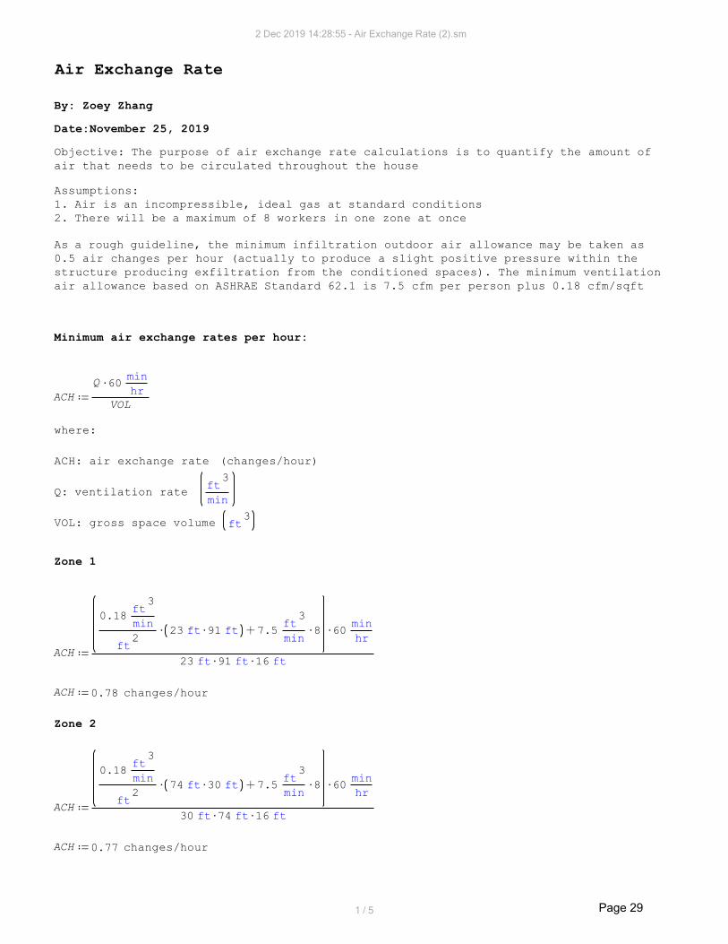
Air Exchange Rate
By: Zoey Zhang
Date:November 25, 2019
Objective: The purpose of air exchange rate calculations is to quantify the amount of
air that needs to be circulated throughout the house
Assumptions:
1. Air is an incompressible, ideal gas at standard conditions
2. There will be a maximum of 8 workers in one zone at once
As a rough guideline, the minimum infiltration outdoor air allowance may be taken as
0.5 air changes per hour (actually to produce a slight positive pressure within the
structure producing exfiltration from the conditioned spaces). The minimum ventilation
air allowance based on ASHRAE Standard 62.1 is 7.5 cfm per person plus 0.18 cfm/sqft
Minimum air exchange rates per hour:
VOL
hr
min60Q
ACH
where:
ACH: air exchange rate (changes/hour)
min
3ft
Q: ventilation rate
3ftVOL: gross space volume
Zone 1
ft16ft91ft23
hr
min608
min
3ft
7.5ft91ft232
ft
min
3ft
0.18
ACH
0.78ACH changes/hour
Zone 2
ft16ft74ft30
hr
min608
min
3ft
7.5ft30ft742
ft
min
3ft
0.18
ACH
0.77ACH changes/hour
2 Dec 2019 14:28:55 - Air Exchange Rate (2).sm
1 / 5 Page 29

Zone 3
ft16ft30ft23
hr
min608
min
3ft
7.5ft30ft232
ft
min
3ft
0.18
ACH
1.00ACH changes/hour
Zone 4
ft16ft61ft74
hr
min608
min
3ft
7.5ft61ft742
ft
min
3ft
0.18
ACH
0.72ACH changes/hour
Zone 5
ft16ft60ft120
hr
min608
min
3ft
7.5ft60ft1202
ft
min
3ft
0.18
ACH
0.71ACH changes/hour
2 Dec 2019 14:28:55 - Air Exchange Rate (2).sm
2 / 5 Page 30

Actual Changes per Hour
In practical applications, food processing buildings will have around 10-12 air
changes per hour. As such zones 2,4 and 5 will have 12 changes per hour. Zones 1 and 3 are
not critical in the honey processing/packing procedure, and will have 6 changes per hour.
This meets the minimum air exchange rates calculated previously.
Zone 1
Break room
3m312.618ft16ft30ft23VOL
hr
6ACH
hr
s3600
VOLACHQ
s
3m
0.521Q
Entrance
3m166.7296ft16ft16ft23VOL
hr
6ACH
hr
s3600
VOLACHQ
s
3m
0.2779Q
Storage
3m108.7367ft16ft16ft15VOL
hr
6ACH
hr
s3600
VOLACHQ
s
3m
0.1812Q
Washroom
3m57.9929ft16ft16ft8VOL
hr
6ACH
hr
s3600
VOLACHQ
2 Dec 2019 14:28:55 - Air Exchange Rate (2).sm
3 / 5 Page 31
s
3m
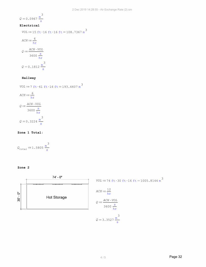
0.0967Q
Electrical
3m108.7367ft16ft16ft15VOL
hr
6ACH
hr
s3600
VOLACHQ
s
3m
0.1812Q
Hallway
3m193.4607ft16ft61ft7VOL
hr
6ACH
hr
s3600
VOLACHQ
s
3m
0.3224Q
Zone 1 Total:
s
3m
1.5805Qtotal
Zone 2
3m1005.8144ft16ft30ft74VOL
hr
12ACH
hr
s3600
VOLACHQ
s
3m
3.3527Q
2 Dec 2019 14:28:55 - Air Exchange Rate (2).sm
4 / 5 Page 32

Zone 3
3m312.618ft16ft30ft23VOL
hr
6ACH
hr
s3600
VOLACHQ
s
3m
0.521Q
Zone 4
3m2045.1559ft16ft74ft61VOL
hr
12ACH
hr
s3600
VOLACHQ
s
3m
6.8172Q
Zone 5
3m3262.1007ft16ft60ft120VOL
hr
12ACH
hr
s3600
VOLACHQ
s
3m
10.8737Q
2 Dec 2019 14:28:55 - Air Exchange Rate (2).sm
5 / 5 Page 33

Appendix B2: Heat Transfer Calculations
Page 34

Heating Load Calculations
By: Zoey Zhang
Date:November 23, 2019
Objective: The purpose of heating and cooling load calculations is to quantify the heating
and cooling loads in areas of the honey packing house. These calculations form the basis for
equipment selection and duct and piping design.
Assumptions:
1. Heat transfer throughout the building and all walls will be steady. Air temperatures
in and outside the building will not likely fluctuate a lot in time. The design will aim
to keep indoor temperatures constant.
2. Heat transfer is one dimensional, and occurs in the normal direction to the wall
surface. No significant heat transfer will take place in the wall in other directions. This
assumption is valid because heat transfer is only driven by the temperature gradient in a
particular direction. Temperature measurements at several locations along one wall surface
will likely be the same, i.e. the surface is isothermal.
3. All material properties will be assumed to have the same thermal conductivity properties
throughout it's entire mass (isothermal)
4. Air is assumed to be an ideal gas
5. The local atmospheric pressure is at 1 atm
6. For walls that have the same temperatures on both sides, it will be assumed that no heat
transfer occurs (i.e. both sides of the wall are at equilibrium)
7. Solar effects are not considered for a worst case load calculation
8. Internal gains of people, lighting, equipment are not considered for a worst case load
calculation
9. All walls, windows, doors, ceilings are above grade. The ground is at grade.
10. Heat loss from a concrete slab floor is mostly through the perimeter rather than the
rather than through the floor to the ground.
11. The total heating load will be a summation of the transmission and infiltration loads
2 Dec 2019 14:27:13 - Heating Load.sm
1 / 27 Page 35

Outdoor and Indoor Conditions
Outdoor
From ASHRAE 2017 Handbook- Fundamentals, the weather information at Grande
Prairie for 99% design conditions were used.
Latitude: 55.180 N
Longitude: 118.880 W
Elevation: 669 m
Heating Dry Bulb Temperature: °C31.4Tout
K241.75Tout
Humidity Ratio:0.1
0.0001g1000
kg1
kg
g0.1W
out
Indoor
The honey house will not be used for processing/packing in the winter. Instead,
it will be used as an equipment storage/building space. Zone 1 will be kept at a
comfortable temperature level(20°C) while the rest of the zones will be kept cooler to
minimalize heating costs (16°C). Indoor humidity for all zones will be at 45% rh
K293.15°C20Tzone1
K289.15°C16Tother_zone
%45RHin
From psychometric charts, humidity ratio is:
0.007g1000
kg1
kg
g7W
zone1
0.005g1000
kg1
kg
g5W
other.zone
2 Dec 2019 14:27:13 - Heating Load.sm
2 / 27 Page 36

Transmission Coefficients
Newton's Law of Cooling:
ΔTAUq
where:
q = total heat transfer W
K2
m
W
U = U factor
2mA = area of surface perpendicular to heat transfer
ΔT = temperature gradient K
and
RT
1U
where
W
K2
mRT= total thermal resistances
For conduction, the following U values are used:
All construction U values are taken from manufacturer's specifications.Spec sheets can be
found in Appendix D
And their R values are calculated as:
W
K2
m0.08R
gypsum
W
K2
m3.33R
window
W
K2
m0.366R
door
W
K2
m7.874R
inner.wall
W
K2
m7.8125R
outer.wall W
K2
m1.29R
overhead
W
K2
m7.874R
roof
2 Dec 2019 14:27:13 - Heating Load.sm
3 / 27 Page 37

For convection, the following R values are used. Values are taken from Table
10, Chapter 26, ASHRAE Handbook-Fundamentals 2017:
W
K2
m0.03R
air.out moving air in winter
W
K2
m0.12R
air.wall still air against vertical surface
W
K2
m0.16R
air.roof still air against horizontal surface, with heat flow moving upwards
Ground (at grade)
ΔTFp
Pq
where:2
mP = perimeter of exposed edge floor
Km
WFp= heat loss coefficient of perimeter
For poured concrete with an uninsulated perimeter, the heat loss coeficient from
Table 24, Chapter 26, ASHRAE Handbook-Fundamentals 2017:
Km
W1.24F
p
Resistance Diagram
2 Dec 2019 14:27:13 - Heating Load.sm
4 / 27 Page 38

For heat transfer through the wall only, all the resistances from conduction and
convection are in series, and the individual R values are added to the total R value.
For heat transfer through the sides where there are windows/doors ,the resistances of
the window and/or door and wall are also approximated as as series-path flow method. A parallel
path flow method can also be used, but the series method is a good approximate.
According to NECB 2017, Table 3.2.2.2, the maximum U values of buildings in Alberta are:
All U values of wall, roof and floor materials meet the requirement of maximum U values
for Zone 7B. Metal frames that provide structural support were not included in the heat
load calculations. Extra structural consulting is required to determine the size and
placement of the metal frame, and were thus excluded from the calculations. However,
the metal frames should decrease the heat load as they are another layer of material added
to the overall thickness, and should not increase the heat load.
2 Dec 2019 14:27:13 - Heating Load.sm
5 / 27 Page 39

Transmission Calculations
Zone 1
Break room
North
Rair.wall
Rair.out
Rconvection
W
K2
m0.85R
convection
Rconvection
1Uair
K2
m
W1.1765U
air
Rgypsum
Router.wall
1Uwall
K2
m
W0.1267U
wall
Rwindow
1Uwindow
K2
m
W0.3003U
window
2 Dec 2019 14:27:13 - Heating Load.sm
6 / 27 Page 40

W2455.0843Tout
Tzone1
ft19ft23Uair
qair
W256.3469Tout
Tzone1
2ft423.7U
wallqwall
W19.0722Tout
Tzone1
2ft13.3U
windowqwindow
W2730.5034qwindow
qwall
qair
qnorth
West
W3202.2839Tout
Tzone1
ft19ft30Uair
qair
W336.8146Tout
Tzone1
2ft556.7U
wallqwall
W19.0722Tout
Tzone1
2ft13.3U
windowqwindow
W3558.171qwindow
qwall
qair
qwest
East
K2
m
W2.7322U
door
W249.205Tother_zone
Tzone1
ft19ft30Uair
qair
W26.8375Tother_zone
Tzone1
ft19ft30Uwall
qwall
W276.042qwall
qair
qeast
Ground
Tout
Tin
PFp
qground
W2059.2337Tout
Tzone1
ft302ft232Km
W1.24q
ground
Roof
K2
m
W1.1765U
air
K2
m
W0.1267U
wall
W3876.4489Tout
Tzone1
ft23ft30Uair
qair
W417.4637Tout
Tzone1
ft23ft30Uwall
qwall
2 Dec 2019 14:27:13 - Heating Load.sm
7 / 27 Page 41

W4293.913qwall
qair
qroof
Break Room Total
W12917.8628qground
qroof
qwest
qeast
qnorth
qbreakroom
2 Dec 2019 14:27:13 - Heating Load.sm
8 / 27 Page 42

Entrance
West
K2
m
W2.7322U
door
W2455.0843Tout
Tzone1
ft19ft23Uair
qair
W244.8516Tout
Tzone1
2ft404.7U
wallqwall
W19.0722Tout
Tzone1
2ft13.3U
windowqwindow
W247.3812Tout
Tzone1
ft2.83ft6.7Udoor
qdoor
W2966.389qdoor
qwindow
qwall
qair
qwest
Ground
Tout
Tin
PFp
qground
W1515.2852Tout
Tzone1
ft162ft232Km
W1.24q
ground
Roof
K2
m
W1.1765U
air
K2
m
W0.1267U
wall
W2067.4394Tout
Tzone1
ft23ft16Uair
qair
W222.6473Tout
Tzone1
ft23ft16Uwall
qwall
W2290.087qwall
qair
qroof
Entrance Total
W6771.7612qground
qroof
qwest
qentrance
2 Dec 2019 14:27:13 - Heating Load.sm
9 / 27 Page 43

Storage
West
K2
m
W2.7322U
door
W1601.1419Tout
Tzone1
ft19ft15Uair
qair
W172.4307Tout
Tzone1
ft19ft15Uwall
qwall
W1773.573qwall
qair
qwest
Ground
Tout
Tin
PFp
qground
W1204.4574Tout
Tzone1
ft162ft152Km
W1.24q
ground
Roof
K2
m
W1.1765U
air
K2
m
W0.1267U
wall
W1348.3301Tout
Tzone1
ft15ft16Uair
qair
W145.2048Tout
Tzone1
ft15ft16Uwall
qwall
W1493.535qwall
qair
qroof
Storage Room Total
W4471.5649qground
qroof
qwest
qstorage
2 Dec 2019 14:27:13 - Heating Load.sm
10 / 27 Page 44

Washroom
West
W853.9424Tout
Tzone1
ft19ft8Uair
qair
W91.963Tout
Tzone1
ft19ft8Uwall
qwall
W945.905qwall
qair
qwest
Ground
Tout
Tin
PFp
qground
W932.4832Tout
Tzone1
ft162ft82Km
W1.24q
ground
Roof
K2
m
W1.1765U
air
K2
m
W0.1267U
wall
W719.1094Tout
Tzone1
ft8ft16Uair
qair
W77.4425Tout
Tzone1
ft8ft16Uwall
qwall
W796.552qwall
qair
qroof
Washroom Total
W2674.9405qground
qroof
qwest
qwashroom
2 Dec 2019 14:27:13 - Heating Load.sm
11 / 27 Page 45

Electrical Room
West
W1601.1419Tout
Tzone1
ft19ft15Uair
qair
W172.4307Tout
Tzone1
ft19ft15Uwall
qwall
W1773.573qwall
qair
qwest
Ground
Tout
Tin
PFp
qground
W1204.4574Tout
Tzone1
ft162ft152Km
W1.24q
ground
Roof
K2
m
W1.1765U
air
K2
m
W0.1267U
wall
W1348.3301Tout
Tzone1
ft15ft16Uair
qair
W145.2048Tout
Tzone1
ft15ft16Uwall
qwall
W1493.535qwall
qair
qroof
Electrical Room Total
W4471.5649qground
qroof
qwest
qelectrical
2 Dec 2019 14:27:13 - Heating Load.sm
12 / 27 Page 46

Hallway
East
W498.4099Tother_zone
Tzone1
2ft1140U
airqair
W53.6749Tother_zone
Tzone1
2ft1140U
wallqwall
W19.2515Tother_zone
Tzone1
ft2.83ft6.7Udoor
qdoor
W571.336qdoor
qwall
qair
qeast
Ground
Tout
Tin
PFp
qground
W2642.0357Tout
Tzone1
ft612ft72Km
W1.24q
ground
Roof
K2
m
W1.1765U
air
K2
m
W0.1267U
wall
W2398.9039Tout
Tzone1
ft61ft7Uair
qair
W258.3435Tout
Tzone1
ft61ft7Uwall
qwall
W2657.247qwall
qair
qroof
Hallway Total
W5870.6194qground
qroof
qeast
qhallway
Zone 1 Total
W37178.3137qhallway
qelectrical
qwashroom
qstorage
qentrance
qbreakroom
qtotal
2 Dec 2019 14:27:13 - Heating Load.sm
13 / 27 Page 47

Zone 2
North
K2
m
W1.1765U
air
K2
m
W0.1267U
wall
W7284.2613Tout
Tother_zone
ft19ft74Uair
qair
W784.4589Tout
Tother_zone
ft19ft74Uwall
qwall
W8068.72qwall
qair
qnorth
Ground
Tout
Tin
PFp
qground
W3726.3044Tout
Tother_zone
ft742ft302Km
W1.24q
ground
Roof
K2
m
W1.1765U
air
K2
m
W0.1267U
wall
W11501.4653Tout
Tother_zone
ft30ft74Uair
qair
W1238.6193Tout
Tother_zone
ft30ft74Uwall
qwall
W12740.085qwall
qair
qroof
Total
W24535.1092qroof
qground
qnorth
qtotal
kW24.5qtotal
2 Dec 2019 14:27:13 - Heating Load.sm
14 / 27 Page 48

Zone 3
North
K2
m
W1.1765U
air
K2
m
W0.1267U
wall
K2
m
W0.3003U
window
W2264.0272Tout
Tother_zone
ft19ft23Uair
qair
W236.3978Tout
Tother_zone
2ft423.7U
wallqwall
W17.588Tout
Tother_zone
2ft13.3U
windowqwindow
W2518.013qwindow
qwall
qair
qnorth
East
K2
m
W1.1765U
air
K2
m
W0.1267U
wall
Roverhead
1Uoverhead
K2
m
W0.77U
overhead
K2
m
W2.7322U
door
W2953.0789Tout
Tother_zone
ft19ft30Uair
qair
W236.3978Tout
Tother_zone
2ft423.7U
wallqwall
W244.1358Tout
Tother_zone
ft9ft8Uoverhead
qoverhead
W228.1298Tout
Tother_zone
ft2.83ft6.7Udoor
qdoor
W3661.742qdoor
qoverhead
qwall
qair
qeast
2 Dec 2019 14:27:13 - Heating Load.sm
15 / 27 Page 49

South
K2
m
W1.1765U
air
K2
m
W0.1267U
wall
W2264.0272Tout
Tother_zone
ft19ft23Uair
qair
W243.8183Tout
Tother_zone
ft19ft23Uwall
qwall
W2507.845qwall
qair
qsouth
Ground
Tout
Tin
PFp
qground
W1898.982Tout
Tother_zone
ft232ft302Km
W1.24q
ground
Roof
K2
m
W1.1765U
air
K2
m
W0.1267U
wall
W3574.7798Tout
Tother_zone
ft30ft23Uair
qair
W384.9763Tout
Tother_zone
ft30ft23Uwall
qwall
W3959.756qwall
qair
qroof
Total
W14546.3387qroof
qground
qsouth
qeast
qnorth
qtotal
kW14.6qtotal
2 Dec 2019 14:27:13 - Heating Load.sm
16 / 27 Page 50

Zone 4
East
K2
m
W1.1765U
air
K2
m
W0.1267U
wall
K2
m
W0.3003U
window
K2
m
W2.7322U
door
W6004.5938Tout
Tother_zone
ft19ft61Uair
qair
W603.2411Tout
Tother_zone
2ft1081.2U
wallqwall
W52.7639Tout
Tother_zone
2ft39.9U
windowqwindow
W456.2596Tout
Tother_zone
2ft2.83ft6.7Udoor
qdoor
W7116.858qdoor
qwindow
qwall
qair
qeast
Ground
Tout
Tin
PFp
qground
W4837.0297Tout
Tother_zone
ft612ft742Km
W1.24q
ground
2 Dec 2019 14:27:13 - Heating Load.sm
17 / 27 Page 51

Roof
K2
m
W1.1765U
air
K2
m
W0.1267U
wall
W23386.3127Tout
Tother_zone
ft61ft74Uair
qair
W2518.526Tout
Tother_zone
ft61ft74Uwall
qwall
W25904.839qwall
qair
qroof
Total
W37858.7268qroof
qground
qeast
qtotal
kW37.9qtotal
2 Dec 2019 14:27:13 - Heating Load.sm
18 / 27 Page 52

Zone 5
North
K2
m
W1.1765U
air
K2
m
W0.1267U
wall
K2
m
W0.3003U
window
W2264.0272Tout
Tother_zone
ft19ft23Uair
qair
W236.3978Tout
Tother_zone
2ft423.7U
wallqwall
W17.588Tout
Tother_zone
2ft13.3U
windowqwindow
W2518.013qwindow
qwall
qair
qnorth
East
K2
m
W1.1765U
air
K2
m
W0.1267U
wall
K2
m
W0.3003U
window
K2
m
W2.7322U
door
K2
m
W0.77U
overhead
W5906.1578Tout
Tother_zone
ft19ft60Uair
qair
2 Dec 2019 14:27:13 - Heating Load.sm
19 / 27 Page 53

W577.855Tout
Tother_zone
2ft1035.7U
wallqwall
W17.588Tout
Tother_zone
2ft13.3U
windowqwindow
W228.1298Tout
Tother_zone
ft2.83ft6.7Udoor
qdoor
W244.1358Tout
Tother_zone
ft9ft8Uoverhead
qoverhead
W6973.866qoverhead
qdoor
qwindow
qwall
qair
qeast
South
K2
m
W1.1765U
air
K2
m
W0.1267U
wall
K2
m
W0.3003U
window
W11812.3157Tout
Tother_zone
ft19ft120Uair
qair
W1234.9928Tout
Tother_zone
2ft2213.5U
wallqwall
W87.9398Tout
Tother_zone
2ft66.5U
windowqwindow
W13135.248qwindow
qwall
qair
qsouth
West
K2
m
W1.1765U
air
K2
m
W0.1267U
wall
K2
m
W0.3003U
window
K2
m
W2.7322U
door
W5906.1578Tout
Tother_zone
ft19ft60Uair
qair
W610.6617Tout
Tother_zone
2ft1094.5U
wallqwall
W35.1759Tout
Tother_zone
2ft26.6U
windowqwindow
2 Dec 2019 14:27:13 - Heating Load.sm
20 / 27 Page 54

W228.1298Tout
Tother_zone
ft2.83ft6.7Udoor
qdoor
W6780.125qdoor
qwindow
qwall
qair
qwest
Ground
Tout
Tin
PFp
qground
W6449.3729Tout
Tother_zone
ft602ft1202Km
W1.24q
ground
Roof
K2
m
W1.1765U
air
K2
m
W0.1267U
wall
W37302.0496Tout
Tother_zone
ft120ft60Uair
qair
W4017.1438Tout
Tother_zone
ft120ft60Uwall
qwall
W41319.193qwall
qair
qroof
Total
W77175.819qroof
qground
qwest
qsouth
qeast
qnorth
qtotal
kW77.2qtotal
2 Dec 2019 14:27:13 - Heating Load.sm
21 / 27 Page 55

Infiltration Heat Loss
ql
qs
qt
qtis the total infiltration heat loss W
Sensible:
Tout
Tin
QCs
qs
where:
qs
is the sensible heat gain due to infiltration W
s
3m
Q is the infiltration rate
Tin
is the indoor temperature K
Tout
is the outdoor temperature K
Ks3
m
W
Cs
is the air sensible heat factor
Latent:
Wout
Win
QCl
ql
where:
ql
is the latent heat gain due to infiltration W
s
3m
Q is the infiltration rate
kg
kg
Win
is the indoor humidity ratio
kg
kgWout
is the outdoor humidity ratio
s3
m
W
Cl
is the air latent heat factor
Elevation Correction
1.1355
5.25595
102.2557766911.23Cs Ks
3m
W
Ks3
m
W1.1355C
s
2778.7972
5.25595
102.2557766913010Cl s
3m
W
s3
m
W2778.7972C
l
2 Dec 2019 14:27:13 - Heating Load.sm
22 / 27 Page 56
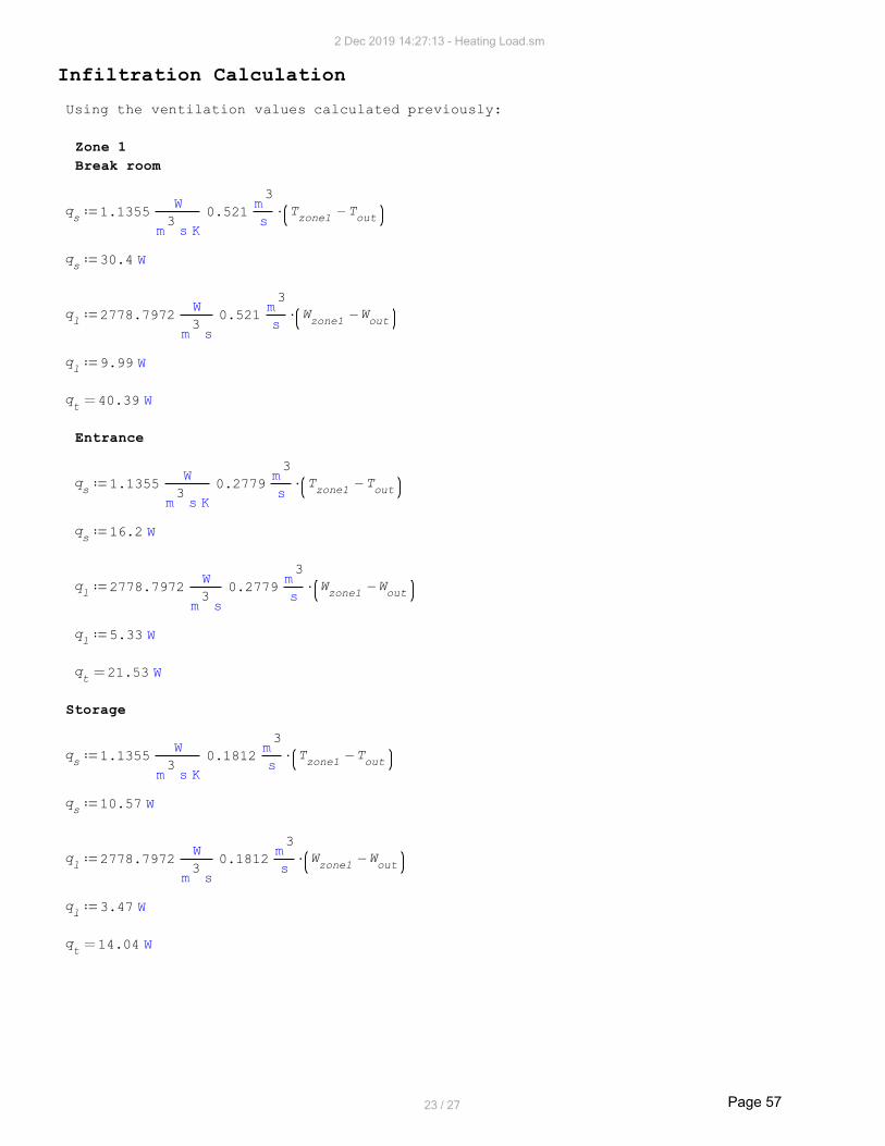
Infiltration Calculation
Using the ventilation values calculated previously:
Zone 1
Break room
Tout
Tzone1s
3m
0.521
Ks3
m
W1.1355q
s
W30.4qs
Wout
Wzone1s
3m
0.521
s3
m
W2778.7972q
l
W9.99ql
W40.39qt
Entrance
Tout
Tzone1s
3m
0.2779
Ks3
m
W1.1355q
s
W16.2qs
Wout
Wzone1s
3m
0.2779
s3
m
W2778.7972q
l
W5.33ql
W21.53qt
Storage
Tout
Tzone1s
3m
0.1812
Ks3
m
W1.1355q
s
W10.57qs
Wout
Wzone1s
3m
0.1812
s3
m
W2778.7972q
l
W3.47ql
W14.04qt
2 Dec 2019 14:27:13 - Heating Load.sm
23 / 27 Page 57

Washroom
Tout
Tzone1s
3m
0.0967
Ks3
m
W1.1355q
s
W5.64qs
Wout
Wzone1s
3m
0.0967
s3
m
W2778.7972q
l
W1.85ql
W7.49qt
Electrical Room
Tout
Tzone1s
3m
0.1812
Ks3
m
W1.1355q
s
W10.57qs
Wout
Wzone1s
3m
0.1812
s3
m
W2778.7972q
l
W3.47ql
W14.04qt
Hallway
Tout
Tzone1s
3m
0.3224
Ks3
m
W1.1355q
s
W18.82qs
Wout
Wzone1s
3m
0.3224
s3
m
W2778.7972q
l
W6.18ql
W25qt
Total Zone 1:
W122qzone1
2 Dec 2019 14:27:13 - Heating Load.sm
24 / 27 Page 58

Zone 2
Tout
Tother_zones
3m
3.3527
Ks3
m
W1.1355q
s
W180.451qs
Wout
Wother.zones
3m
3.3527
s3
m
W2778.7972q
l
W45.65ql
W226.101qt
Zone 3
Tout
Tother_zones
3m
0.521
Ks3
m
W1.1355q
s
W28.0416qs
Wout
Wother.zones
3m
0.521
s3
m
W2778.7972q
l
W7.09ql
W35.1316qt
Zone 4
Tout
Tother_zones
3m
6.8172
Ks3
m
W1.1355q
s
W366.9201qs
Wout
Wother.zones
3m
6.8172
s3
m
W2778.7972q
l
W92.82ql
W459.7401qt
2 Dec 2019 14:27:13 - Heating Load.sm
25 / 27 Page 59

Zone 5
Tout
Tother_zones
3m
10.8737
Ks3
m
W1.1355q
s
W585.2519qs
Wout
Wother.zones
3m
10.8737
s3
m
W2778.7972q
l
W148.1ql
W733.3519qt
2 Dec 2019 14:27:13 - Heating Load.sm
26 / 27 Page 60

Total Heat Loss
A safety factor of 10% was applied to the overall building heat load for allowances
in piping, duct and other losses.
Safety Factor Discussion
From Principles of HVAC Design , 8th edition by Ronald H. Howell, a combined warm-up/safety
allowance of 20% to 25% is fairly common but varies depending
on the particular climate, building use, and type of construction. Engineering judgment
must be applied for the particular project.Since the 99% design conditions were used in
calculations, and since this building is new (air leakage is significantly less compared
to that of older houses), a smaller safety factor of 10% can be applied. A 20% capacity
shortfall typically results in a temperature excursion of at most about one or two degrees.
With a safety factor of 10%, it would roughly translate to a maximum drop of 4°C. In a worst
case scenario, a 4 degree drop would result in the indoor temperatures of 16 and 12 degrees
for Zone 1 and Zones 2,3,4,5 respectively. This drop would not result in dire consequences
such as hypothermia or pipe/duct freezing, and is still a relatively safe temperature
for occupants (although not at optimal human comfort level). A safey factor of 10% also
decreases the amount of energy that the building has to supply throughout the year,
effectively decreasing costs.
2 Dec 2019 14:27:13 - Heating Load.sm
27 / 27 Page 61

Cooling Load Calculations
By: Zoey Zhang
Date:November 24, 2019
Objective: The purpose of heating and cooling load calculations is to quantify the heating
and cooling loads in areas of the honey packing house. These calculations form the basis for
equipment selection and duct and piping design.
Assumptions:
1. Heat transfer throughout the building and all walls will be steady. Air temperatures
in and outside the building will not likely fluctuate a lot in time. The design will aim
to keep indoor temperatures constant.
2. Heat transfer is one dimensional, and occurs in the normal direction to the wall
surface. No significant heat transfer will take place in the wall in other directions. This
assumption is valid because heat transfer is only driven by the temperature gradient in a
particular direction. Temperature measurements at several locations along one wall surface
will likely be the same, i.e. the surface is isothermal.
3. All material properties will be assumed to have the same thermal conductivity properties
throughout it's entire mass (isothermal)
4. Air is assumed to be an ideal gas
5. The local atmospheric pressure is at 1 atm
6. For walls that have the same temperatures on both sides, it will be assumed that no heat
transfer occurs (i.e. both sides of the wall are at equilibrium)
7. All walls, windows, doors, ceilings are above grade. The ground is at grade.
9. Internal gains due to equipment are not considered. The heating load is much greater
than the cooling load, so the internal gains from equipment is negligible.
2 Dec 2019 14:26:15 - Cooling Load.sm
1 / 18 Page 62

Outdoor and Indoor Conditions
Outdoor
From ASHRAE 2017 Handbook- Fundamentals, the weather information at Grande
Prairie at 2% conditions
Latitude: 55.180 N
Longitude: 118.880 W
Elevation: 669 m
Cooling Dry Bulb Temperature: K297.15°C24Tout
Humidity Ratio:10.3
0.0103g1000
kg1
kg
g10.3W
out
s
m11.3Extreme Annual Wind Speed:
Indoor
To keep the honey from crystallizing and absorbing moisture, Zones 2 and 3 will be kept at
30°C and 30% relative humidity, while Zones 1,4 and 5 will be kept at 20°C and 45% relative
humidity for human comfort.
K303.15°C30Tzone2.3
K293.15°C20Tzone1.4.5
%30RHzone2.3
%45RHzone1.4.5
From psychometric charts, humidity ratio is:
0.008g1000
kg1
kg
g8W
zone2.3
0.007g1000
kg1
kg
g7W
zone1.4.5
2 Dec 2019 14:26:15 - Cooling Load.sm
2 / 18 Page 63

External Heat Gain
Wall and roof transmission:
Tin
Tout
AUq
where:
q is the heat transfer rate W
K2
m
W
U is the overall U factor
2mA is the floor area
Tin
is the conditioned space temperature K
Tout
is the adjacent space temperature K
Ground (at grade)
ΔTFp
Pq
where:2
mP = perimeter of exposed edge floor
Km
WFp= heat loss coefficient of perimeter
Fenestration:
Tin
Tout
AUqc
where:
qc
is the fenestration transmission heat gain W
K2
m
W
U is the overall U factor
2mA is the window area
Tin
is the indoor temperature K
Tout
is the outdoor temperature K
IACθΩSHGCθEtb
Aqb
IACD
SHGCD
Etr
Etd
Aqd
where:
qb
is the direct beam solar heat gain W
qb
is the diffuse solar heat gain W
2mA is the window area
2 Dec 2019 14:26:15 - Cooling Load.sm
3 / 18 Page 64

Etb, E
td,E
trare beam, sky diffuse, and ground-reflected diffuse irradiance
SHGCθ is the beam solar heat gain coefficient as a function of incident angle
SHGCDis the diffuse solar heat gain coefficient
IACθΩ is the indoor solar attenuation coefficient for beam solar heat gain coefficient
IACDis the indoor solar attenuation coefficient for diffuse solar heat gain coefficient
total fenestration:
qd
qb
qc
qt
Fenestration Constants:
IACDand IACθΩ are equal to 1.0 because none of the windows are shaded
0.34SGHCθfrom manufacturer's specifications
0.34SGHCD
cosθEb
Etb
where :
2m
W
Eb
is the clear sky beam normal irradiance
θ is the incident angle °
from Environment Canada, the maximum solar incident angle during summer is:
°62θ
YEd
Etd
where:
2m
WEdis the diffuse horizontal irradiance
Y is the ratio of clear-sky diffuse irradiance on a vertical surface to the clear-sky
diffuse irradiance on a horizontal surface
max ,2
cos θ0.313cos θ0.4370.550.45Y
2
cos θ10.2E
dsin θE
bEtr
2 Dec 2019 14:26:15 - Cooling Load.sm
4 / 18 Page 65

From ASHRAE weather data 2017:a conservative estimate of the max solar irradiance
(in June) was used
2m
W899E
b
2m
W110E
d
cos 622
m
W899E
tb
2m
W605.5E
tb
max ,2
cos θ0.313cos θ0.4370.550.45Y
0.82Y
0.8242
m
W110E
td
2m
W90.64E
td
2
cos θ10.2E
dsin θE
bEtr
2m
W47.95E
tr
2 Dec 2019 14:26:15 - Cooling Load.sm
5 / 18 Page 66

External Heat Gain
Zone 1
For this zone, a total zone cooling load was calculated instead of the load per room,
as was done in the heating load calculations. Since the heating load is assumed to be
far greater than the cooling load, the ducts will be sized according to the heating
load. This assumption will be checked later.
North
Rair.wall
Rair.out
Rconvection
W
K2
m0.85R
convection
Rconvection
1Uair
K2
m
W1.1765U
air
Rgypsum
Router.wall
1Uwall
K2
m
W0.1267U
wall
Rwindow
1Uwindow
K2
m
W0.3003U
window
W191.0571Tzone1.4.5
Tout
ft19ft23Uair
qair
W19.9492Tzone1.4.5
Tout
2ft423.7U
wallqwall
Tin
Tout
AUqc
IACθΩSHGCθEtb
Aqb
IACD
SHGCD
Etr
Etd
Aqd
W427.1026
2m
W47.95
2m
W90.64
2ft13.3
0.342
m
W605.5
2ft13.3T
zone1.4.5Tout
2ft13.3U
windowqwindow
W638.109qwindow
qwall
qair
qnorth
2 Dec 2019 14:26:15 - Cooling Load.sm
6 / 18 Page 67

East
Rair.wall
Rair.wall
Rconvection
W
K2
m1.36R
convection
Rconvection
1Uair
K2
m
W0.7353U
air
Rgypsum
Rinner.wall
1Uwall
K2
m
W0.1257U
wall
K2
m
W2.7322U
door
W1181.1077Tzone1.4.5
Tzone2.3
ft19ft91Uair
qair
W197.4735Tzone1.4.5
Tzone2.3
2ft1691U
wallqwall
W96.2573Tzone1.4.5
Tzone2.3
2ft2.83ft6.7Udoor
qdoor
W1474.838qdoor
qwall
qair
qeast
West
K2
m
W1.1765U
air Rdoor
1Udoor
K2
m
W0.1267U
wall
K2
m
W2.7322U
door
W755.9218Tzone1.4.5
Tout
ft19ft91Uair
qair
W79.2411Tzone1.4.5
Tout
2ft1683U
wallqwall
W854.2052
2m
W47.95
2m
W90.642
2ft13.3
0.342
m
W605.52
2ft13.3T
zone1.4.5Tout
22
ft13.3Uwindow
qwindow
W19.2515Tzone1.4.5
Tout
ft2.83ft6.7Udoor
qdoor
2 Dec 2019 14:26:15 - Cooling Load.sm
7 / 18 Page 68

W1708.62qdoor
qwindow
qwall
qair
qwest
Ground
Tin
Tout
PFp
qground
W344.6922Tzone1.4.5
Tout
ft912ft232Km
W1.24q
ground
Roof
K2
m
W1.1765U
air
K2
m
W0.1267U
wall
W915.0632Tzone1.4.5
Tout
ft23ft91Uair
qair
W98.5453Tzone1.4.5
Tout
ft23ft91Uwall
qwall
W1013.608qwall
qair
qroof
Total
W5179.8675qroof
qground
qwest
qeast
qnorth
qtotal
kW5.179qtotal
2 Dec 2019 14:26:15 - Cooling Load.sm
8 / 18 Page 69

Zones 2+ 3
These two zones must be maintained at a constant 30°C, which is greater than the cooling
dry bulb temperature of 24°. Thus, a cooling load calculation is not required for these two
zones, as the heating load is significantly higher. We will select the furnace and ducts
for these two zones based on the heating load.
Zone 4
East
K2
m
W1.1765U
air
K2
m
W0.1267U
wall
K2
m
W0.3003U
window
K2
m
W2.7322U
door
W506.7168Tzone1.4.5
Tout
ft19ft61Uair
qair
W50.9064Tzone1.4.5
Tout
2ft1081.2U
wallqwall
W1281.3078
2m
W47.95
2m
W90.643
2ft13.3
0.342
m
W605.53
2ft13.3T
zone1.4.5Tout
32
ft13.3Uwindow
qwindow
W38.5029Tzone1.4.5
Tout
2ft2.83ft6.7Udoor
qdoor
W1877.434qdoor
qwindow
qwall
qair
qeast
2 Dec 2019 14:26:15 - Cooling Load.sm
9 / 18 Page 70

Ground
Tin
Tout
PFp
qground
W408.1882Tzone1.4.5
Tout
ft612ft742Km
W1.24q
ground
Roof
K2
m
W1.1765U
air
K2
m
W0.1267U
wall
W1973.5285Tzone1.4.5
Tout
ft61ft74Uair
qair
W212.5338Tzone1.4.5
Tout
ft61ft74Uwall
qwall
W2186.062qwall
qair
qroof
Total
W4471.6844qroof
qground
qeast
qtotal
kW4.5qtotal
2 Dec 2019 14:26:15 - Cooling Load.sm
10 / 18 Page 71

Zone 5
North
K2
m
W1.1765U
air
K2
m
W0.1267U
wall
K2
m
W0.3003U
window
W191.0571Tzone1.4.5
Tout
ft19ft23Uair
qair
W19.9492Tzone1.4.5
Tout
2ft423.7U
wallqwall
W427.1026
2m
W47.95
2m
W90.64
2ft13.3
0.342
m
W605.5
2ft13.3T
zone1.4.5Tout
2ft13.3U
windowqwindow
W638.109qwindow
qwall
qair
qnorth
East
K2
m
W1.1765U
air
K2
m
W0.1267U
wall
K2
m
W0.3003U
window
K2
m
W2.7322U
door
2 Dec 2019 14:26:15 - Cooling Load.sm
11 / 18 Page 72

K2
m
W0.77U
overhead
W498.4099Tzone1.4.5
Tout
ft19ft60Uair
qair
W48.7641Tzone1.4.5
Tout
2ft1035.7U
wallqwall
W427.1026
2m
W47.95
2m
W90.64
2ft13.3
0.342
m
W605.5
2ft13.3T
zone1.4.5Tout
2ft13.3U
windowqwindow
W19.2515Tzone1.4.5
Tout
ft2.83ft6.7Udoor
qdoor
W20.6022Tzone1.4.5
Tout
ft9ft8Uoverhead
qoverhead
W1014.13qoverhead
qdoor
qwindow
qwall
qair
qeast
South
K2
m
W1.1765U
air
K2
m
W0.1267U
wall
K2
m
W0.3003U
window
W996.8199Tzone1.4.5
Tout
ft19ft120Uair
qair
W104.2188Tzone1.4.5
Tout
2ft2213.5U
wallqwall
W2135.5129
2m
W47.95
2m
W90.645
2ft13.3
0.342
m
W605.55
2ft13.3T
zone1.4.5Tout
52
ft13.3Uwindow
qwindow
W3236.552qwindow
qwall
qair
qsouth
2 Dec 2019 14:26:15 - Cooling Load.sm
12 / 18 Page 73

West
K2
m
W1.1765U
air
K2
m
W0.1267U
wall
K2
m
W0.3003U
window
K2
m
W2.7322U
door
W498.4099Tzone1.4.5
Tout
ft19ft60Uair
qair
W51.5326Tzone1.4.5
Tout
2ft1094.5U
wallqwall
W854.2052
2m
W47.95
2m
W90.642
2ft13.3
0.342
m
W605.52
2ft13.3T
zone1.4.5Tout
22
ft13.3Uwindow
qwindow
W19.2515Tzone1.4.5
Tout
ft2.83ft6.7Udoor
qdoor
W1423.399qdoor
qwindow
qwall
qair
qwest
Ground
Tout
Tin
PFp
qground
W544.2509Tzone1.4.5
Tout
ft602ft1202Km
W1.24q
ground
Roof
K2
m
W1.1765U
air
K2
m
W0.1267U
wall
W3147.8523Tzone1.4.5
Tout
ft120ft60Uair
qair
W338.9995Tzone1.4.5
Tout
ft120ft60Uwall
qwall
W3486.852qwall
qair
qroof
Total
W10343.2927qroof
qground
qwest
qsouth
qeast
qnorth
qtotal
kW10.34qtotal
2 Dec 2019 14:26:15 - Cooling Load.sm
13 / 18 Page 74

Internal Heat Gain
Occupants:
Nqs.per
qs
Nql.per
ql
where:
qs
is the occupant sensible heat gain W
ql
is the occupant latent heat gain W
person
Wqs.per
is the sensible heat gain per person
person
Wql.per
is the latent heat gain per person
N is the number of occupants
Lighting:
Fsa
Ful
Wqel
where:
qel
is the heat gain from lights W
W is the total light wattage W
Ful
is the lighting use factor
Fsa
is the lighting special allowance factor
Ventilation and Infiltration Air Heat Gain
(Variables were defined previously in the heating load calculations)
ql
qs
qt
2 Dec 2019 14:26:15 - Cooling Load.sm
14 / 18 Page 75

Internal Heat Gain
Occupants
For conservative approach, assume that there is a maximum of 8 people in one zone at
one time. Sensible and latent heat per person is from Table 1, Chapter 18 of ASHRAE
Handbook- Fundamentals. Degree of activity used was heavy lifting. This remains the
same throughout all zones.
8N
W185qs.per
W285ql.per
W1480Nqs.per
qs
W2280Nql.per
ql
Lighting
For commercial applications such as stores,offices and warehouses, the use factor is
generally 1.0. For LED lights, the special allowance factor is 1.0. According to
ASHRAE Standard 90.1 states that there needs to be a minimum of 1.7 watts/sqft for a
manufacturing facility. To make sure we have adequate lighting, we will use 1.8watt/sqft
1Ful
1Fsa
Zone 1
W3767.4Fsa
Ful
ft91ft232
ft
W1.8q
el
Zone 2
W3996Fsa
Ful
ft30ft742
ft
W1.8q
el
Zone 3
W1242Fsa
Ful
ft30ft232
ft
W1.8q
el
Zone 4
W8125.2ft61ft742
ft
W1.8q
el
Zone 5
W12960Fsa
Ful
ft60ft1202
ft
W1.8q
el
2 Dec 2019 14:26:15 - Cooling Load.sm
15 / 18 Page 76

Ventilation and Infiltration Air Heat Gain
Using the ventilation values and heat factors calculated in the air exchange rate and
heating load calculations:
Zone 1
Tzone1.4.5
Touts
3m
1.5805
Ks3
m
W1.1355q
s
W7.12qs
Wzone1.4.5
Wouts
3m
1.5805
s3
m
W2778.7972q
l
W14.49ql
W21.61ql
qs
qt
Zone 2
Tout
Tzone2.3s
3m
3.3527
Ks3
m
W1.1355q
s
W22.84qs
Wzone2.3
Wouts
3m
3.3527
s3
m
W2778.7972q
l
W21.43ql
W44.27ql
qs
qt
Zone 3
Tout
Tzone2.3s
3m
0.521
Ks3
m
W1.1355q
s
W3.55qs
Wzone2.3
Wouts
3m
0.521
s3
m
W2778.7972q
l
W3.33ql
W6.88ql
qs
qt
Zone 4
Tzone1.4.5
Touts
3m
6.8172
Ks3
m
W1.1355q
s
2 Dec 2019 14:26:15 - Cooling Load.sm
16 / 18 Page 77

W30.96qs
Wzone1.4.5
Wouts
3m
6.8172
s3
m
W2778.7972q
l
W62.51ql
W93.47ql
qs
qt
Zone 5
Tzone1.4.5
Touts
3m
10.8737
Ks3
m
W1.1355q
s
W49.39qs
Wzone1.4.5
Wouts
3m
10.8737
s3
m
W2778.7972q
l
W99.71ql
W149.1ql
qs
qt
2 Dec 2019 14:26:15 - Cooling Load.sm
17 / 18 Page 78

Total Cooling Load
The total cooling load is significantly less than the heating load (approximately
1/3 of the total heating load). The assumption while calculating zone 1 gains
were valid.
2 Dec 2019 14:26:15 - Cooling Load.sm
18 / 18 Page 79

Appendix B3: HVAC Calculations
Page 80

HVAC Design Calculations
By: Sai Avuthu
Date: November 21, 2019
Objective:
Size a round duct system using the equal friction method, choose material, duct lengths, and
add dampers to balance system. Rooftop units (RTU) will be selected for each of the five
zones as indicated in the analysis.
Solution Method: The required airflow rate was determined using three different methods.
These methods are explained in further detail below. Typically, the higher value was chosen
as the limiting rate and the ducts were designed for that rate. Some cases such as in Zone 1,
the lower value was chosen due to ease of design and cost considerations. The heat
transfer values taken from the Heat Transfer Calculations were analyzed for the coldest
estimated temperature and therefore, it was more practical to choose a less conservative
airflow rate. In choosing the sizing, advice was taken from industry professionals.
2 Dec 2019 10:05:29 - Phase 3 HVAC.sm
1 / 24
Page 81

Assumptions/Limitations/Constraints
1. Galvanized steel to be used as duct material. Typical material used for HVAC applications.
2. Maximum duct velocity to be 1200fpm in Zone 1 which contains the break room, entrance,
storage room, washroom, electrical room, and the hallway. This limit is set to reduce noise
from the ductwork and provide a quiet, relaxing place for the employees.
3. Maximum duct velocity to be 2200fpm elsewhere (Zones 2-5). To achieve a large amount of
volumetric airflow required for these spacious rooms, a higher upper limit is placed.
4. Rooftop units have Bellmouth entrances to reduce pressure loss.
5. Target pressure drop on the order of 0.1 in.wg/100ft. (Standard)
6. Elbows are pleated to reduce pressure losses and for ease of installation.
7. All diffusers are assumed to have a pressure loss of 0.05 in. wg. (Standard)
8. High efficiency particulate air (HEPA) filter used. While this has a large pressure
loss, it is vital to have from a food safety perspective.
9. Heating and cooling coils assumed to have an air pressure loss of 0.35 in. wg. (Standard)
10. All heat transfer values taken from corresponding heat transfer calculations.
11. Temperature between design supply and design return air temperature assumed to be 8K.
12. For the food safe rooms (hot storage, extraction, and cold storage), an air exchange
rate of 12 exchanges per hour was assumed to comply with food safety restrictions. For
all other rooms, an air exchange rate of 6 exchanges per hour was assumed.
2 Dec 2019 10:05:29 - Phase 3 HVAC.sm
2 / 24
Page 82

Sketch
2 Dec 2019 10:05:29 - Phase 3 HVAC.sm
3 / 24
Page 83

Analysis
in_wgin_wg
All zone air formulas, R_a, and R_p values taken from ANSI/ASHRAE Standard 62.1-2016
Duct sizing, pressure losses, and air velocities taken from Figure A.1 of Introduction to
Thermo-Fluids Systems Design, First Edition. Andre G. McDonald and Hugh L. Magande
Ra -Outdoor airflow rate required per unit area
Rp -Outdoor airflow rate required per person
5Pz
-Maximum number of people in a room at any given time
0.8Ez
-Zone air distribution effectiveness
Ai -Zone floor area (square footage of rooms)
Vbz
-Outdoor airflow required in the breathing zone of the occupiable spaces.
Voz -Zone outdoor airflow provided to ventilation zone by supply air
distribution system
Kkg
kJ1.026c
p -Specific heat capacity of air
K8ΔT -Temperature difference between design supply and design return air
temperature
kPa101.4p
Kkg
J287.1R
K293T20
K303T30
3m
kg1.2054
T20
R
pp20 -Density of air at 20degC and 1 atm in Northern Alberta
3m
kg1.1656
T30
R
pp30 -Density of air at 30degC and 1 atm in Northern Alberta
2 Dec 2019 10:05:29 - Phase 3 HVAC.sm
4 / 24
Page 84
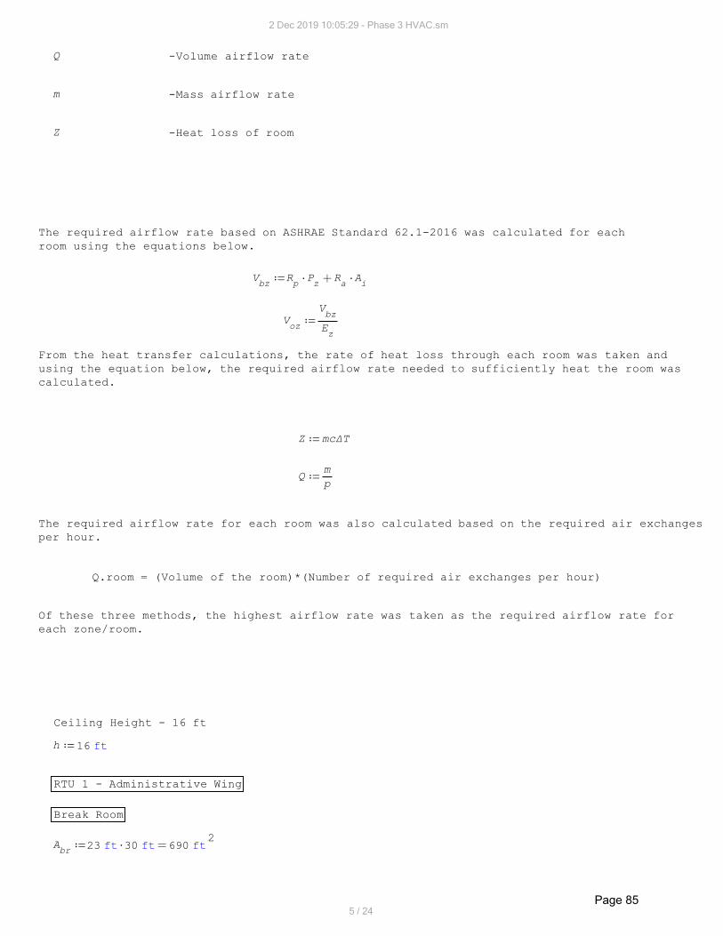
Q -Volume airflow rate
m -Mass airflow rate
Z -Heat loss of room
The required airflow rate based on ASHRAE Standard 62.1-2016 was calculated for each
room using the equations below.
Ai
Ra
Pz
Rp
Vbz
Ez
Vbz
Voz
From the heat transfer calculations, the rate of heat loss through each room was taken and
using the equation below, the required airflow rate needed to sufficiently heat the room was
calculated.
mcΔTZ
p
mQ
The required airflow rate for each room was also calculated based on the required air exchanges
per hour.
Q.room = (Volume of the room)*(Number of required air exchanges per hour)
Of these three methods, the highest airflow rate was taken as the required airflow rate for
each zone/room.
Ceiling Height - 16 ft
ft16h
RTU 1 - Administrative Wing
Break Room
2ft690ft30ft23A
br
2 Dec 2019 10:05:29 - Phase 3 HVAC.sm
5 / 24
Page 85

ASHRAE Standard 62.1
2ft
min
3ft
0.06Rabr
min
3ft
5Rpbr
min
3ft
66.4Abr
Rabr
Pz
Rpbr
Vbzbr
min
3ft
83Ez
Vbzbr
Vozbr
Air Exchange per Hour
3ft11040hA
brVbr
min
3ft
1104min60
hr1
hr
6Vbr
Qbr Airflow rate based on 6 air exchanges per hour
Heat Loss
W14254.08Zbr
s
kg1.7366
ΔTcp
Zbr
mbr
min
3ft
3052.6082p20
mbr
Qbrx
Entrance
2ft368ft16ft23A
ent
ASHRAE Standard 62.1
2ft
min
3ft
0.06Raent min
3ft
5Rpent
min
3ft
47.08Aent
Raent
Pz
Rpent
Vbzent
2 Dec 2019 10:05:29 - Phase 3 HVAC.sm
6 / 24
Page 86

min
3ft
58.85Ez
Vbzent
Vozent
Air Exchange per Hour
3ft5888hA
entVent
min
3ft
588.8min60
hr1
hr
6Vent
Qent
Heat Loss
W7427.62Zent
s
kg0.9049
ΔTcp
Zent
ment
min
3ft
1590.6753p20
ment
Qentx
Storage
2ft240ft16ft15A
st
ASHRAE Standard 62.1
2ft
min
3ft
0.06Rast min
3ft
5Rpst
min
3ft
39.4Ast
Rast
Pz
Rpst
Vbzst
min
3ft
49.25Ez
Vbzst
Vozst
Air Exchange per Hour
3ft3840hA
stVst
min
3ft
384min60
hr1
hr
6Vst
Qst
2 Dec 2019 10:05:29 - Phase 3 HVAC.sm
7 / 24
Page 87

Heat Loss
W4934.165Zst
s
kg0.6011
ΔTcp
Zst
mst
min
3ft
1056.685p20
mst
Qstx
Washroom
2ft128ft16ft8A
wr
ASHRAE Standard 62.1
2ft
min
3ft
0.06Rawr min
3ft
5Rpwr
min
3ft
32.68Awr
Rawr
Pz
Rpwr
Vbzwr
min
3ft
40.85Ez
Vbzwr
Vozwr
Air Exchange per Hour
3ft2048hA
wrVwr
min
3ft
204.8min60
hr1
hr
6Vwr
Qwr
Heat Loss
W2950.674Zwr
s
kg0.3595
ΔTcp
Zwr
mwr
2 Dec 2019 10:05:29 - Phase 3 HVAC.sm
8 / 24
Page 88
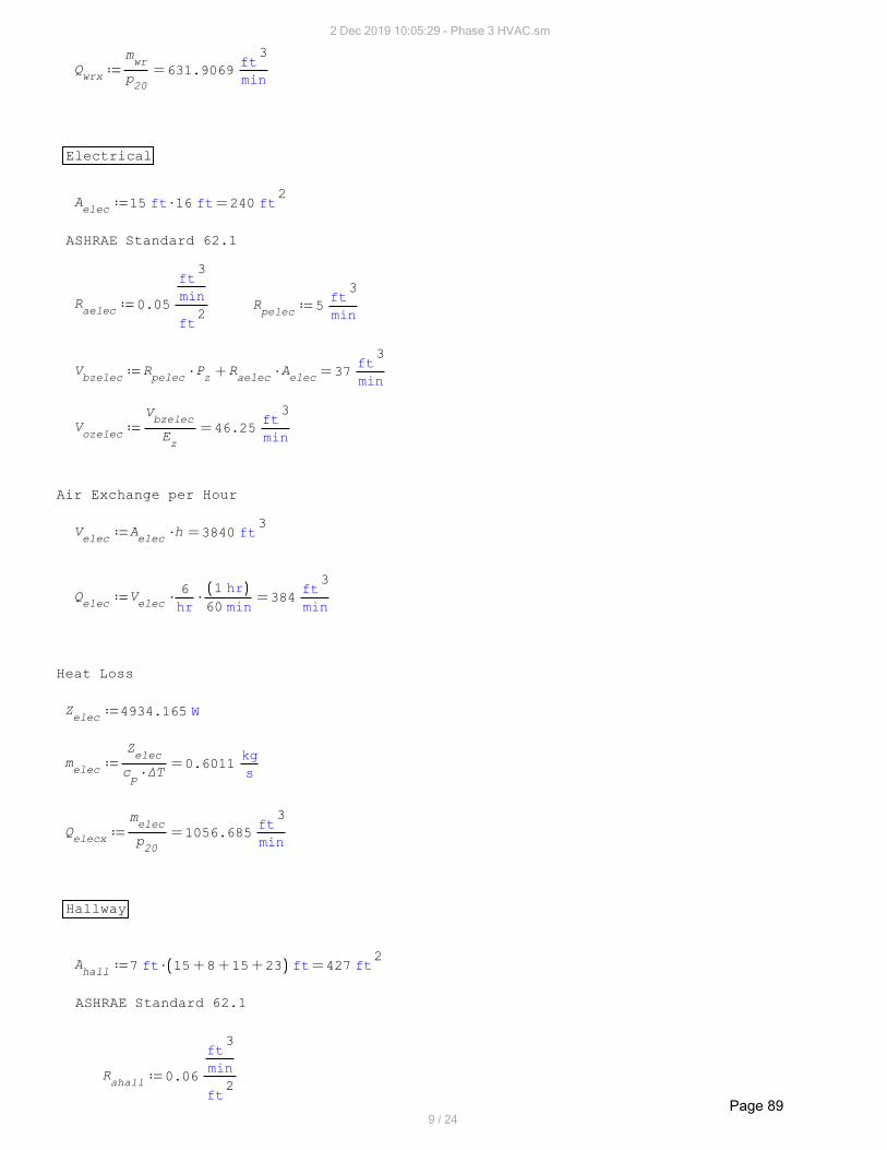
min
3ft
631.9069p20
mwr
Qwrx
Electrical
2ft240ft16ft15A
elec
ASHRAE Standard 62.1
2ft
min
3ft
0.05Raelec min
3ft
5Rpelec
min
3ft
37Aelec
Raelec
Pz
Rpelec
Vbzelec
min
3ft
46.25Ez
Vbzelec
Vozelec
Air Exchange per Hour
3ft3840hA
elecVelec
min
3ft
384min60
hr1
hr
6Velec
Qelec
Heat Loss
W4934.165Zelec
s
kg0.6011
ΔTcp
Zelec
melec
min
3ft
1056.685p20
melec
Qelecx
Hallway
2ft427ft2315815ft7A
hall
ASHRAE Standard 62.1
2ft
min
3ft
0.06Rahall
2 Dec 2019 10:05:29 - Phase 3 HVAC.sm
9 / 24
Page 89

min
3ft
25.62Ahall
Rahall
Vbzhall
min
3ft
32.025Ez
Vbzhall
Vozhall
Air Exchange per Hour
3ft6832hA
hallVhall
min
3ft
683.2min60
hr1
hr
6Vhall
Qhall
Heat Loss
W4934.165Zhall
s
kg0.6011
ΔTcp
Zhall
mhall
min
3ft
1056.685p20
mhall
Qhallx
RTU 1 Total
min
3ft
3348.8Qhall
Qelec
Qwr
Qst
Qent
Qbr
QRTU1
RTU 2 - Hot Storage
2ft2220ft74ft30A
hs
ASHRAE Standard 62.1
2ft
min
3ft
0.06Rahs min
3ft
10Rphs
min
3ft
183.2Ahs
Rahs
Pz
Rphs
Vbzhs
min
3ft
229Ez
Vbzhs
Vozhs
2 Dec 2019 10:05:29 - Phase 3 HVAC.sm
10 / 24
Page 90

Air Exchange per Hour
3ft35520ft16A
hsVhs
min
3ft
7104min60
hr1
hr
12Vhs
Qhs Airflow rate based on 12 exchanges per hour.
Heat Loss
W27237.1Zhs
s
kg3.3184
ΔTcp
Zhs
mhs
min
3ft
6032.0891p30
mhs
Qhsx
min
3ft
7104Qhs
QRTU2
RTU 3 - Transition Room
2ft690ft30ft23A
tr
ASHRAE Standard 62.1
2ft
min
3ft
0.06Ratr min
3ft
5Rptr
min
3ft
66.4Atr
Ratr
Pz
Rptr
Vbztr
min
3ft
83Ez
Vbztr
Voztr
Air Exchange per Hour
3ft11040hA
trVtr
2 Dec 2019 10:05:29 - Phase 3 HVAC.sm
11 / 24
Page 91

min
3ft
1104min60
hr1
hr
6Vtr
Qtr
Heat Loss
W16039.1Ztr
s
kg1.9541
ΔTcp
Ztr
mtr
min
3ft
3552.1138p30
mtr
Qtrx
min
3ft
1104Qtr
QRTU3
RTU 4 - Extraction
2ft4514ft74ft61A
ext
ASHRAE Standard 62.1
2ft
min
3ft
0.12Raext min
3ft
7.5Rpext
min
3ft
579.18Aext
Raext
Pz
Rpext
Vbzext
min
3ft
723.975Ez
Vbzext
Vozext
Air Exchange per Hour
3ft72224hA
extVext
min
3ft
14444.8min60
hr1
hr
12Vext
Qext
Heat Loss
2 Dec 2019 10:05:29 - Phase 3 HVAC.sm
12 / 24
Page 92

W42149.8Zext
s
kg5.1352
ΔTcp
Zext
mext
min
3ft
9026.6664p20
mext
Qextx
min
3ft
14444.8Qext
QRTU4
RTU 5 & 6 - Cold Storage
2ft7200ft120ft60A
cs
ASHRAE Standard 62.1
2ft
min
3ft
0.06Racs min
3ft
10Rpcs
min
3ft
482Acs
Racs
Pz
Rpcs
Vbzcs
min
3ft
602.5Ez
Vbzcs
Vozcs
Air Exchange per Hour
3ft
5101.152hA
csVcs
min
3ft
23040min60
hr1
hr
12Vcs
Qcs
Heat Loss
W85699.9Zcs
s
kg10.441
ΔTcp
Zcs
mcs
min
3ft
18353.2165p20
mcs
Qcsx
2 Dec 2019 10:05:29 - Phase 3 HVAC.sm
13 / 24
Page 93

min
3ft
115202
Qcs
QRTU5 min
3ft
11520QRTU5
QRTU6
Equivalent lengths of all fittings used in analysis:
All lengths taken from Figure A.1 of Introduction to Thermo-Fluids Systems Design,
First Edition. Andre G. McDonald and Hugh L. Magande
Entrances Loss Equivalent Lengths
ft3530
ft
in12
in14Lentrance14ft2530
ft
in12
in10Lentrance10
ft6030
ft
in12
in24Lentrance24ft5530
ft
in12
in22Lentrance22
ft67.530
ft
in12
in27Lentrance27ft6530
ft
in12
in26Lentrance26
ft7530
ft
in12
in30Lentrance30ft7030
ft
in12
in28Lentrance28
ft10030
ft
in12
in40Lentrance40ft8530
ft
in12
in34Lentrance34
Tee Fittings
ft13.333340
ft
in12
in4Lteebranch4
ft3.33338
ft
in12
in5Lteethru5
ft16.666740
ft
in12
in5Lteebranch5
ft4Lteethru6
ft5Lteethru8
ft20Lteebranch6
ft6Lteethru9ft27L
teebranch8
ft33Lteebranch10
ft7Lteethru10
ft40Lteebranch12
ft8Lteethru12
2 Dec 2019 10:05:29 - Phase 3 HVAC.sm
14 / 24
Page 94

ft46.666740
ft
in12
in14Lteebranch14 ft9.33338
ft
in12
in14Lteethru14
ft53.333340
ft
in12
in16Lteebranch16
ft10.66678
ft
in12
in16Lteethru16
ft6040
ft
in12
in18Lteebranch18 ft128
ft
in12
in18Lteethru18
ft8040
ft
in12
in24Lteebranch24
ft13.33338
ft
in12
in20Lteethru20
ft86.666740
ft
in12
in26Lteebranch26 ft14.66678
ft
in12
in22Lteethru22
ft93.333340
ft
in12
in28Lteebranch28
ft10040
ft
in12
in30Lteebranch30
Pleated Elbows Reducers
ft8L90_elbow_6
ft3.33334
ft
in12
in10Lreducer10ft10L
90_elbow_8
ft13L90_elbow_10
ft15L90_elbow_12 ft4.66674
ft
in12
in14Lreducer14
ft17.515
ft
in12
in14L90_elbow_14
ft64
ft
in12
in18Lreducer18ft27.515
ft
in12
in22L90_elbow_22
ft3015
ft
in12
in24L90_elbow_24
ft32.515
ft
in12
in26L90_elbow_26
ft3515
ft
in12
in28L90_elbow_28
2 Dec 2019 10:05:29 - Phase 3 HVAC.sm
15 / 24
Page 95

ft37.515
ft
in12
in30L90_elbow_30
Pressure Losses for each Duct Section
The pressure losses for each duct section was determined based on the total
airflow rate required and the length of the ducts. A targeted pressure loss of
0.1 in.wg/100ft was used to determined duct sizing, actual pressure loss per duct
length, and duct air velocity as shown on the right hand side of the page.
in_wg0.05Pdiff
Diffuser pressure loss (standard)
in_wg0.07PRTU1_MERV13
Pressure loss for MERV 13 filter for RTU 1
in_wg0.11PRTU1_ccoil
Pressure loss for cooling coil for RTU 1
in_wg0.17PRTU1_heat
Pressure loss for heat exchanger for RTU 1
in_wg0.15PRTU1_econ
Pressure loss for economizer for RTU 1
Similarly, the pressure loss for the filter, cooling coil, heat exchanger, and economizer
is given for each RTU.
in_wg0.09PRTU2_MERV13
in_wg0.06PRTU2_ccoil
in_wg0.21PRTU2_heat
in_wg0.06PRTU2_econ
in_wg0.07PRTU3_MERV13
in_wg0.04PRTU3_ccoil
in_wg0.02PRTU3_heat
in_wg0.04PRTU3_econ
in_wg0.48PRTU4
This value includes the pressure loss of the filter,
heating, and economizer.
in_wg0.27PRTU4_ccoil
2 Dec 2019 10:05:29 - Phase 3 HVAC.sm
16 / 24
Page 96

in_wg0.33PRTU5_6
This value includes the pressure loss of the filter,
heating, and economizer.
in_wg0.20PRTU5_6_ccoil
RTU 1 - Administrative Wing Duct size, pressure loss, air velocity
Section 1
ft5L1 22", 0.094" wg/100ft, 1270fpm
min
3ft
3348.8Qelec
Qwr
Qst
Qhall
Qent
Qbr
Q1
in_wg0.5822
PRTU1_econ
PRTU1_heat
PRTU1_ccoil
PRTU1_MERV13
L90_elbow_22
Lentrance22
L1ft100
in_wg0.094P1
Section 2
min
3ft
588.8Qent
Q2
ft6L2 12", 0.076" wg/100ft, 750fpm
in_wg0.0964Pdiff
L90_elbow_12
L2
Lteebranch12ft100
in_wg0.076P2
Section 3
min
3ft
2760Q2
Q1
Q3ft7L
322", 0.079" wg/100ft, 1050fpm
in_wg0.0219Lreducer18
L3
Lteethru22ft100
in_wg0.079P3
Section 4
min
3ft
1104Qbr
Q4ft29L
414", 0.12" wg/100ft, 1050fpm
in_wg0.1398Pdiff
L90_elbow_14
L2
Lreducer14
Lteebranch14ft100
in_wg0.12P4
2 Dec 2019 10:05:29 - Phase 3 HVAC.sm
17 / 24
Page 97

Section 5
min
3ft
1656Q4
Q3
Q5ft10L
518", 0.069" wg/100ft, 950fpm
in_wg0.0483L5
Lteebranch18ft100
in_wg0.069P5
Section 6
min
3ft
683.2Qhall
Q6ft1L
612", 0.1" wg/100ft, 860fpm
in_wg0.106Pdiff
L6
L90_elbow_12
Lteebranch12ft100
in_wg0.1P6
Section 7
min
3ft
972.8Q6
Q5
Q7
14", 0.087" wg/100ft, 900fpmft5L
7
in_wg0.0154L7
Lreducer10
Lteethru14ft100
in_wg0.087P7
Section 8
min
3ft
384Qst
Q8ft11L
810", 0.082" wg/100ft, 700fpm
in_wg0.0967Pdiff
L8
L90_elbow_10
Lteebranch10ft100
in_wg0.082P8
Section 9
min
3ft
588.8Q8
Q7
Q9ft9L
910", 0.17" wg/100ft, 1030fpm
in_wg0.0272L9
Lteethru10ft100
in_wg0.17P9
2 Dec 2019 10:05:29 - Phase 3 HVAC.sm
18 / 24
Page 98

Section 10
min
3ft
204.8Qwr
Q10ft11L
108", 0.08" wg/100ft, 580fpm
in_wg0.0884Pdiff
L90_elbow_8
L10
Lteebranch8ft100
in_wg0.08P10
Section 11
min
3ft
384Qelec
Q11
ft20L11
10", 0.082" wg/100ft, 700fpm
in_wg0.0935Pdiff
L90_elbow_10
2L11
Lteethru10ft100
in_wg0.082P11
Zone 1 Return Air Duct
min
3ft
3348.8QRTU1
Qr1
ft4Lr1
24", 0.06" wg/100ft, 1080fpm
in_wg0.0384Lentrance24
Lr1ft100
in_wg0.06Pr1
The pressure losses through each branch of the administrative wing is given.
in_wg0.6786P2
P1
P1_2
in_wg0.7439P4
P3
P1
P1_3_4
in_wg0.7584P6
P5
P3
P1
P1_3_5_6
in_wg0.7645P8
P7
P5
P3
P1
P1_3_5_7_8
in_wg0.7834P10
P9
P7
P5
P3
P1
P1_3_5_7_9_10
in_wg0.7884P11
P9
P7
P5
P3
P1
P1_3_5_7_9_11
Based on these values, dampers were then added to the sections below to balance the HVAC
system.
Section 2
in_wg0.1098P1_2
P1_3_5_7_9_11
Section 3
in_wg0.0445P1_3_4
P1_3_5_7_9_11
2 Dec 2019 10:05:29 - Phase 3 HVAC.sm
19 / 24
Page 99

Section 5
in_wg0.03P1_3_5_6
P1_3_5_7_9_11
Section 9
in_wg0.0239P1_3_5_7_8
P1_3_5_7_9_11
Section 10
in_wg0.0051P1_3_5_7_9_10
P1_3_5_7_9_11
RTU 2 - Hot Storage
Section 12
min
3ft
35522
Qhs
Q12ft21L
1224", 0.069" wg/100ft, 1130fpm
in_wg0.5725
PRTU2_econ
PRTU2_heat
PRTU2_MERV13
PRTU2_ccoil
Pdiff
L90_elbow_24
2L12
Lentrance27ft100
in_wg0.069P12
Section 13
min
3ft
3552Q12
Q13
ft21L13
24", 0.069" wg/100ft, 1130fpm
in_wg0.5725
PRTU2_econ
PRTU2_heat
PRTU2_MERV13
PRTU2_ccoil
Pdiff
L90_elbow_24
2L13
Lentrance27ft100
in_wg0.069P13
Zone 2 Return Air Duct
min
3ft
7104QRTU2
Qr2
ft4Lr2
18x36", 0.13" wg/100ft, 1650fpm
27" round duct equivalent
in_wg0.093Lentrance27
Lr2ft100
in_wg0.13Pr2
RTU 3 - Transition Room
Section 14
min
3ft
1104Qtr
Q14ft20L
1414", 0.099" wg/100ft, 950fpm
2 Dec 2019 10:05:29 - Phase 3 HVAC.sm
20 / 24
Page 100

in_wg0.3091
PRTU3_econ
PRTU3_heat
PRTU3_MERV13
PRTU3_ccoil
Pdiff
L90_elbow_14
2L14
Lentrance14ft100
in_wg0.099P14
Zone 3 Return Air Duct
min
3ft
1104QRTU3
Qr3
ft4Lr3 10", 0.5" wg/100ft, 1860fpm
in_wg0.145Lentrance10
Lr3ft100
in_wg0.5Pr3
RTU 4 - Extraction
Section 15
min
3ft
7222.42
Qext
Q15ft21L
1526", 0.17" wg/100ft, 1940fpm
in_wg1.1488
PRTU4_ccoil
PRTU4
Pdiff
Lteebranch26
L90_elbow_26
L15
Lentrance26ft100
in_wg0.17P15
Section 16
min
3ft
1104Q14
Q16
ft21L16
26", 0.17" wg/100ft, 1940fpm
in_wg1.1488
PRTU4_ccoil
PRTU4
Pdiff
Lteebranch26
L90_elbow_26
L16
Lentrance26ft100
in_wg0.17P16
Zone 4 Return Air Duct
min
3ft
14444.8QRTU4
Qr4
ft4Lr4 24x48", 0.073" wg/100ft, 1650fpm
40" round duct equivalent
in_wg0.104Lentrance40
Lr4ft100
in_wg0.1Pr4
RTU 5 & 6 - Cold Storage
Section 17
min
3ft
57604
Qcs
Q17ft21L
1724", 0.16" wg/100ft, 1840fpm
2 Dec 2019 10:05:29 - Phase 3 HVAC.sm
21 / 24
Page 101

in_wg0.8856
PRTU5_6_ccoil
PRTU5_6
Pdiff
Lteebranch24
L90_elbow_24
L17
Lentrance24ft100
in_wg0.16P17
Section 18
min
3ft
5760Q17
Q18
24", 0.16" wg/100ft, 1840fpmft21L
18
in_wg0.8856
PRTU5_6_ccoil
PRTU5_6
Pdiff
Lteebranch24
L90_elbow_24
L18
Lentrance24ft100
in_wg0.16P18
Section 19
min
3ft
57604
Qcs
Q19ft21L
1924", 0.16" wg/100ft, 1840fpm
in_wg0.8856
PRTU5_6_ccoil
PRTU5_6
Pdiff
Lteebranch24
L90_elbow_24
L19
Lentrance24ft100
in_wg0.16P19
Section 20
min
3ft
5760Q19
Q20ft21L
2024", 0.16" wg/100ft, 1840fpm
in_wg0.8856
PRTU5_6_ccoil
PRTU5_6
Pdiff
Lteebranch24
L90_elbow_24
L20
Lentrance24ft100
in_wg0.16P20
Zone 5 (RTU 5&6) Return Air Ducts
min
3ft
11520QRTU5
Qr5
24x48", 0.045" wg/100ft, 1210fpmft4L
r5
40" round duct equivalent
min
3ft
11520QRTU5
Qr6
ft4Lr6
in_wg0.0468Lentrance40
Lr5ft100
in_wg0.045Pr5
in_wg0.0468Pr5
Pr6
2 Dec 2019 10:05:29 - Phase 3 HVAC.sm
22 / 24
Page 102

RTU Selection
From the pressure losses in each section and the required airflow rates for each zone,
the following rooftop units were selected:
RTU 1 - Administrative Wing
Rooftop Unit Model: KGA120S4B
Total air volume: 3500 cfm
Motor Specifications: 786 rpm, 1.22 bhp
RTU 2 - Hot Storage
Rooftop Unit Model: KGA240S4B
Total air volume: 7250 cfm
Motor Specifications: 765 rpm, 3.10 bhp
RTU 3 - Transition Room
Rooftop Unit Model: LGH060U4E
Total air volume: 1431 cfm
Motor Specifications: 716 rpm, 0.36 bhp
RTU 4 - Extraction
Rooftop Unit Model: LCH600H4B
Total air volume: 15000 cfm
Motor Specifications: 735 rpm, 9.70 bhp
RTU 5 & 6 - Cold Storage
Rooftop Unit Model: LCH600H4B
Total air volume: 12000 cfm
2 Dec 2019 10:05:29 - Phase 3 HVAC.sm
23 / 24
Page 103

Motor Specifications: 610 rpm, 5.15 bhp
All RTUs can be provided by Lennox Commercial.
Conclusion
The ductwork system has been designed with round ducts as this provides the least pressure
loss. Rectangular ducts were only used for a few return ducts as they cost less to install
for some rooftop units. The material used is galvanized steel. All pressure losses were on
the order of 0.1 in_wg. The air velocity for the administrative wing was limited to be less
than 1200 fpm as this is an employee dwelling area and reduced noise levels are desired.
The transition room, hot storage, extraction room, and cold storage were all limited to be
less than 2200 fpm as this is the industrial standard. Dampers were added in the branches
at the diffusers to balance the system.
2 Dec 2019 10:05:29 - Phase 3 HVAC.sm
24 / 24
Page 104

Appendix B4: Humidity Calculations
Page 105

Moisture Loading For Final Concept
November 26, 2019 Jakub McNally
Hot Room Moisture Loading
Moisture Loading is the measurement of how much water must be removed from the air in order
to maintain a specified humidity level in a Zone. As the Hot Room is the only Zone in which
humidity control is critical, it is the only zone analyzed. We will assume that the other
unit's AC systems will be enough to keep the relative humidities less than 65%, which
is only important for worker comfort and not for product quality. In these calculations,
two target humidity loadings in the hot room will be explored:
The first case is a target relative humidity level of 45% (adequate to maintain honey's
moisture content at 18% or less), and a lower, harder-to-reach target of 30% for rapid
moisture extraction from the honey. A relative humidity lower than the target humidity does
not harm the product quality of the honey, and thus the humidity targets serve as an upper
bounds to the humidity level of the hot room.
Methodology
The worst-case scenario will be examined for this design. This worst-case would assume that
the outdoor weather would be rain (100% relative outdoor humidity), at the greatest possible
outdoor temperature to ensure the maximum mass of moisture in the air. This approach would
require the maximum cooling and reheat loading from the selected RTU in the design to
maintain the hot room temperature at the target 30 degrees Celsius.
This methodology will rely on 6 main methods of moisture loading operating in parallel:
1: Air infiltration into the hot room from both outdoors and surrounding portions of the
building. A hybrid crack-length and fixture area method will be used to determine the air
infiltration, as per the 1997 ASHRAE Fundamentals Handbook.
2: Outdoor air ingestion from cycling the air through the RTU (a portion of the CFM flowing
through the RTU).
3: Air infiltration from opening doors to both other areas of the building and to the
outside.
4: Evapouration of water from the honey in the hot room.
5: Moisture loading from combustion heating of the room and from workers.
6: Water infiltration into the hot room from the outdoors.
Preferred Solution
The most easy to operate a solution would be to use a humidity controller directly on the
RTU, and to set a target humidity and have the unit control the room's humidity. If this
is not possible, the next best solution would be to use an RTU humidity controller in
conjunction with multiple stand-alone dehumidifers that could be switched on by the RTU
controller. A best case scenario with this method would be to use only the RTU to
accomplish dehumidification during low loading (ie. not raining) and the secondary
dehumidifiers during periods of high loading. If the RTU cannot support low loading or
becomes a hinderance at high loading, stand-alone dehumidifiers will be the only devices
used to control room humidity.
Background Information
The maximum estimated external air temp in the region is 310K. This is 5K higher than the
recorded max in the last 5 years according to historical data in the Government of AB.
K310Text
http://agriculture.alberta.ca/acis/alberta-weather-data-viewer.jsp
2 Dec 2019 13:42:13 - Humidity Fina.sm
1 / 11 Page 106

The average wind speed in the area, taken from historical data from the Government of AB,
is:
hr
km20V
w
The water content of the air (absolute humidity) at various temperatures and relative
humidities is as follows:
3m
g43.1341AH
37100 3m
g13.5487AH
3045 3m
g9.0325AH
3030
The air damper on the RTU for the hot room is assumed to be set at 1% fresh air intake.
0.01Damper
From calculations outlined in the heating, cooling, and ducting calculations, the air
flow through the hot room RTU is known to be:
min
3ft
7104AFRTU
From this, we know that the fresh air intake on the RTU is:
min
3ft
71.04DamperAFRTU
AFfresh
The design of the Hot Room and the surrounding rooms is as follows:
EmployeeTransition
AreasRoom
Extraction Room
Note that the temperature of the Transition Room is held at 30 degrees Celsius, the
Break Room is at 20 degrees Celsius, and the Processing Room is at 20 degrees Celsius.
All of these areas will be air conditioned, but not humidity controlled. To determine
the relative humidity of these areas during periods of high external humidity, their
RTUs will be analyzed to determine the humidity drop in the inflow. The internal walls
will be assumed to be 12 inch thick fiberglass insulation (double drywalled) between
structural I-beams. An additional vapor barrier (Tyvek) will also be placed in this wall
on the dry side below the drywall layer.
K303THR
K303TTR
K293TOther
2 Dec 2019 13:42:13 - Humidity Fina.sm
2 / 11 Page 107

Calculation: Air Infiltration
The known data on the air infiltration constants is given below.
Area-based:
2ftmin
3ft
0.01ManuAItyvekTyvek CommercialWrap:
https://www.dupont.com/content/dam/dupont/products-and-services/construction-materials
/building-envelope-systems/documents/K-26060_ABAA_Commercial_Air_Barrier_Systems.pdf
Note that this value is based on various wind loadings, which cause various pressures
on the Tyvek surface which drives this leakage. As Tyvek is on the interior surface,
this pressure differential driving air exchange will be minimal. As such, the average
pressure of the ASTM E283 test was determined to be 116 Pascals. A linear relationship
of the air infiltration rate assumed, and with an assumed pressure difference of
0.03 inwg (7.5 Pa) between the rooms, the Manufacturer's rating for air infiltration
was adjusted as follows:
2ftmin
3ft
0.0006ManuAItyvekPa116.75
Pa7.47AI
tyvek
2ftmin
3ft
0.0100AICFCF Flute Wall Panel (6"):
http://www.mbci.com/documents/astm-e-1646---1680---air-leakage---water-penetration
-testing--insulated-metal-wall-panels/
m
s14102
Pa2
ms
910g
0.02WIBUR
The roof is assumped to be asphalt BUR (built-up-roof), with an integral vapor barrier.
This barrier's water vapor permeance is used in place of air infiltration.
The concrete floor is assumed impermeable.
Effective Area Air Leakage Area per unit or Linear Crack Length based:
2cm12EA
DoorF
Air leakage data taken from 1997 ASHRAEDoor Frame (Each):
FUNDAMENTALS HANDBOOK Chapter 25, Table 3
m
2cm
1EADTDoor Trim (per metre crack):
m
2cm
2EADThreDoor Threshold (per metre crack):
m
2cm
8EADJDoor Jamb (per metre crack):
2cm12EA
SDWSSingle Door, Weather Stripped (Each): 2 to other Interal Rooms,
3 to external environment
2cm6EA
WPSWiring/Pipe Penetrations, Sealed (Each): 4 Total for RTU.
2cm0.15EA
EOGExternal Gasketed Electrical Outlets (Each): Assume 1 by each
external door, 1 every
20 feet in interior.
2 Dec 2019 13:42:13 - Humidity Fina.sm
3 / 11 Page 108

Overhead Door (8' x 9'), Model 418 w/Full weatherseals and insultion:
For the overhead doors, the length of the door components was summed to determine
the air infiltration rate. For the selected size, the door will have 2 panels
and 6 sections. Note that this is for the closed door.
https://www.overheaddoor.com/Documents/sectional-steel-door-systems-brochure.pdf
2cm78.0288ft9EA
DJ2ft8EA
DThre7AI
OD
Air/Moisture Infiltration Calculation:
For air infiltration through the North wall, without fixtures added in:
min
3ft
14.06AICF
ft19ft74AINW
For the South and West Walls, without Fixtures:
min
3ft
1.2182AItyvek
ft9ft8ft19ft30ft74AISWW
For the East Wall:
min
3ft
0.3186AItyvek
ft9ft8ft19ft30AIEW
For the fixtures on the external walls of the building:
The method chosen was the same method as presented in the ASHRAE FUNDAMENTALS HANDBOOK
(1997), Chapter 25.
The stack coefficient of the building is as follows:
K4
cm
2
s
L
0.000290Cs
The Wind Coefficient is as follows (shielding class 1):
2
s
m4cm
2
s
L
0.00420Cw
min
3ft
0.01882
Vw
Cw
THR
Text
Cs1000
EAEOG
3EASDWS
0EADoorF
0EAWPS
4AI
extfixtures
For the internal fixtures (between HR and other areas):
min
3ft
0.0138TOther
THR
Cs1000
AIOD
EASDWS
EADoorF
EAWPS
3EAEOG
5AI
intfixtures
For the internal fixtures between the HR and the transition room:
min
3ft
0.0041K1Cs1000
AIOD
EASDWS
EADoorF
EAWPS
2EAEOG
2AI
TRintfixtures
2 Dec 2019 13:42:13 - Humidity Fina.sm
4 / 11 Page 109

Note that the temperature delta between the rooms was assumed to be 1 degree Kelvin.
The interior humidity of the building must be determined to calculate the moisture
transfer through interior walls. This can be done by determining the absolute humidity
of the other rooms. We will assume that the RTU's are running in the most efficient
manner in the other rooms, and this results in a discharge temperature 5 degrees lower
than the room's target temperature, at 100% relative humidity. This is not an accurate
estimation, but it provides a significant safety margin for further calculations.
For the transition room:
K303Troom
3m
g22.88AH
TR
K298Tdischarge
For the extraction room:
3m
g12.77AH
ERK293Troom
K288Tdischarge
For the employee areas:
3m
g12.77AH
EAK293Troom
K288Tdischarge
Then, by multipling the air intrusion rate by the absolute humidity change, the moisture
ingress can be determined.
hr
kg0.7077AH
3045AH
37100AI
extfixturesAI
NWMI
NorthWall
hr
kg0.0051AH
3045AH
TRAI
TRintfixturesAI
EWMI
EastWall
hr
kg0.0016AH
3045AH
ERAI
intfixturesAI
SWWMI
SouthWestWalls
For the roof, we multiply the permeance by the area and building gauge pressure .
(0.25 inwg).
hr
kg7109.2379Pa62.21ft30ft74WI
BURMI
Roof
We then sum these moisture infiltration values to determine the total moisture
infiltration in the closed building.
hr
kg0.7112MI
RoofMI
SouthWestWallsMI
EastWallMI
NorthWallMoistureInfiltration
45
For the lower humidity environment (30% RH), we repeat:
hr
kg0.8157AH
3030AH
37100AI
extfixturesAI
NWMI
NorthWall
hr
kg0.0076AH
3030AH
TRAI
TRintfixturesAI
EWMI
EastWall
hr
kg0.0078AH
3030AH
ERAI
intfixturesAI
SWWMI
SouthWestWalls
hr
kg0.8311MI
RoofMI
SouthWestWallsMI
EastWallMI
NorthWallMoistureInfiltration
30
Calculation: Outdoor Air Ingestion
2 Dec 2019 13:42:13 - Humidity Fina.sm
5 / 11 Page 110

To calculate outdoor air ingestion, the difference in the moisture content between
the outdoor air and indoor air must be compared, and multiplied by the intake rate.
hr
kg3.5709AH
3045AH
37100AF
freshMoistureIngestion
45
hr
kg4.116AH
3030AH
37100AF
freshMoistureIngestion
30
Calculation: Door Opening Air Infiltration
Due to the doors of the building being opened, air will flow through. For the
man-doors in the hot room, the following calculations were used.
Exterior Doors:
As all exterior doors on the hot room are fire escape doors, it is assumed that
they are never used in operation. As such, they are disregarded. For interior doors,
the air flow is as follows (we neglect the no use infiltration rate as it was
already covered in Part 1):
min
3ft
6.5AIInteriorDoor
From Carrier Handbook of Air Conditioning System
Design (1966), Chapter 6, Table 41
For the overhead doors, we use CFD to model the air flow through the doors.
For the trials when the room has a target humidity of 30% RH, the absolute humidity
rise after 10 minutes of open door time is as follows (with a wind speed of 10 m/s):
3m
g11.9056
3m
kg0.0119056AH
10min K303.5T10min
3m
g2.8731AH
3030AH
10minAH
delta 0.3770RH10min
We apply a safety factor of 25% to this model, and then calculate the moisture added
to the room by multiplying this value by the room volume.
2 Dec 2019 13:42:13 - Humidity Fina.sm
6 / 11 Page 111

kg4.2316ft19ft73ft301.25AHdelta
MIOpenDoor
To get a rate of moisture ingestion, we must assume a required time to dissipate
this added moisture. Here we will assume that this time must be 20 minutes.
hr
kg12.696
hr0.3333
MIOpenDoor
MIOpenDoorRate
If an air curtain were to be used in this situation (with an assumed efficiency of
60%), the moisture transfer rate would fall by 60%, as seen below.
hr
kg5.0784.61MI
OpenDoorRateMI
AirCurtain
For the internal door, CFD analysis revealed a change in the absolute humidity of
the hot room by the following (for an initial humidity of 30%, and 20 minutes of
opening time, with a pressure differential of 0.005 inwg):
3m
g9.0311AH
20min K301T20min
3m
g0.0014AH
3030AH
20minAH
delta
We see a decrease in humidity in the room due to the loss of room pressure to the
extraction room. Because of its low magnitude, the internal door humidity transfer
will be disregarded. An air curtain would bring this value even closer to zero.
Calculation: Honey Evapouration Water
The evaporation of water from the honey is dependent on the amount of honey in the
Hot room. As this can vary, it will be assumed that a maximum loading of 10000 lb will
be in the room. From a study on the hygroscopic properties of honey, honey can lose
up to 1% of its mass with a 50% humidity delta (55% RH is stable for honey at 18% RH).
This setup can only accomplish a 25% humidity delta, and thus the evaporation rate is
0.5% per day. We will apply a safety factor of 2x in case this relationship is not
linear. E. C. Martin, "The Hygroscopic Properties of Honey." Oct 1939.
hr
kg1.89lb10000
day
0.01Honey
evap Evaporation rate of water from honey.
Calculation: Moisture Loading from Combustion/Men
The selected RTU line, the Lennox KGA/B, has the burner circuit separated from the
air circuit. Thus, no combustion products are left in the air circulated in the
building and no humidity is added by combustion. Due to the low amount of time that
will be spent in the Hot Room and the low amount of people - 8 at maximum - the man
loading is disregarded.
Calculation: Water Infiltration
The wall insulation used (CF Flute Panels) has a water infiltration rate of zero.
The BUR roof's water infiltration rate has already been accounted for in Part 1 of the
calculations. Water infiltration via doors is minimized due to the vestibule
(transition room), and thus disregarded.
2 Dec 2019 13:42:13 - Humidity Fina.sm
7 / 11 Page 112

Calculation: Overall Cooling and Heating Load for Humidity Control
To calculate the humidity loading, we must determine
the humidity change when the ingested air travels over the indoor coil. For the Hot Room,
we know that the unit used will be a Lennox KGA/B RTU, 13-25 tons, with humiditrol add-on.
The minimum air flow in the room is 7100 CFM, as determined by the ducting calculations.
https://www.lennoxpros.com/docs/Technical/210824.pdf
A 17.5 ton unit is the minimum unit size that will meet this CFM specification, and the
following calculations will be done based on it. We know the target temperature for the
room and the outdoor temperature and humidity. To achieve the target room humidity, we
must cool the intake air, and liquify the water in the air. The following calculations are
for 45% RH.
kg
kJ151.9h
airinlet kg
kJ63.24h
airroom45 (At 650m ASL, the height of GP)
kg
kJ37.18h
airinletdry
kg
kJ30.14h
airroomdry45
To achieve the targeted humidity, the coil must cool the air to its dew point at a low
enough humidity to have the same absolute humidity as the room. We determine this
temperature is 16 degrees Celsius, with an absolute humidity of:
3m
g13.567AH
16100 kg
kJ47.22h
intermediate45
kg
kJ16.06h
indermediatedry45
This is the minimum air temperature of our cycle. The air will have to be reheated after
to achieve the 30 degree target. Due to the high outdoor intake temperature, the unit
will be able to saturate is cooling capacity of 200000 BTU/hr. Therefore, we can take the
change enthalpies of the air to determine how much energy is going to have to be
extracted to fulfill this, provided the unit would operate by only cooling the outdoor
air (this is not how the unit works in practice).
hr
kg127.0706
3m
kg1.0528AF
freshMassFlow
freshair
hr
BTU12607.6235h
intermediate45hairinlet
MassFlowfreshair
CoolingLoadFresh
hr
BTU1929.4433h
intermediate45hairroom45
MassFlowfreshair
ReheatLoadFresh
Given that there are no glaring issues with this cooling and heating load compared to the
unit capacity, we continue. We then sum the other methods of air escape from the hot room.
min
3ft
15.6336AITRintfixtures
AIintfixtures
AIextfixtures
AINW
AISWW
AIEW
VolumeFlowescape
We can then compare this to the added air per cycle by the RTU.
min
3ft
71.04AFfresh
4.5441VolumeFlow
escape
AFfresh
IntakeEscaperatio
2 Dec 2019 13:42:13 - Humidity Fina.sm
8 / 11 Page 113

We see that the RTU adds in more than 4 times more air than lost. Even with a 2x safety
factor for the air lost due to infiltration, we see that the RTU will still replace it as
part of its general cycle. We know that only RTU air will replace this, as the hotroom
is pressurized to +0.25inwg versus atmosphere. Therefore, we disregard the infiltration
air flow, and only use the fresh air flow for moisture loss calculations.
For the opening of external doors, we assume that outdoor dynamic pressure will overcome
the building's internal pressure and force air in. Therefore, we directly use the
overhead door's CFD result in calculations. We will continue with the air curtain rate.
hr
kg5.0784MI
AirCurtain
Which, when multiplying by the absolute humidity of external air, gives the following
infiltration rate:
min
3ft
69.2965AH
37100
MIAirCurtain
AIAirCurtain
1.0252AI
AirCurtain
AFfresh
IntakeDoorRatio
Once again, we see that this air infiltration rate is approximately equal versus the
RTU's intake rate. Knowing this, we can assume that the system will be able to quickly
stabilize after the door opens due to the ratio between the door flow and fresh air
intake. This leaves the only significant factors to humidity loading being the RTU
intake, door intake, and honey evaporation.
Calculation: Moisture Addition within Room
While the air is in the room, moisture is added directly from the honey, and indirectly
from the air infiltration from the overhead door. However, this infiltration air does
not change the volume of the room, and cycles out some of the air in the building to
replace it through the open door again (see CFD analysis). Thus, we can simply add
the additional moisture caused by these two factors to determine how the room's
moisture will change before being handled by the RTU.
hr
kg6.9684MI
AirCurtainHoney
evapMoistureAddition
rate
Now, we can determine the rate of change in the rooms absolute humidity.
3mhr
kg0.0058
ft19ft30ft74
MoistureAdditionrate
AHdelta
This addition of water changes the enthalpy of the hot room air by the following rate:
hr
BTU16883.7256MoistureAddition
ratekg
kJ2556.3h
delta
However, this calculation is a simplification and assumes that the water can be
extracted in a manner that is 100% efficient. This is not the case.
To calculate the true cooling load, we must determine the properties of the
mix of air going into the coil. First, we start with the internal air's water
content:
hr
kg114.8984MoistureAddition
rateAH
3030AF
freshAF
RTUWaterFlowInternal
30
2 Dec 2019 13:42:13 - Humidity Fina.sm
9 / 11 Page 114

hr
kg168.8628MoistureAddition
rateAH
3045AF
freshAF
RTUWaterFlowInternal
45
3m
g9.6157
AFfresh
AFRTU
WaterFlowInternal30
AHIntakeInternal30
3m
g14.1319
AFfresh
AFRTU
WaterFlowInternal45
AHIntakeInternal45
Now, we mix this flow with the external air, with the 1% damper ratio.
3m
g9.95090.01AH
371000.99AH
IntakeInternal30AH
PreCoil30 kg
kJ52.07h
3030
3m
g14.42190.01AH
371000.99AH
IntakeInternal45AH
PreCoil45 kg
kJ63.24h
3045
kg
kJ54.4408.99
kg
kJ2556.3
kg
3m
0.93AH3030
AHIntakeInternal30
h3030
0.01hairinlet
hPreCoil30
kg
kJ65.5139.99
kg
kJ2556.3
kg
3m
0.94AH3045
AHIntakeInternal45
h3045
0.01hairinlet
hPreCoil45
3m
kg1.07Density
30K304.05TPreCoil30
K303.97TPreCoil45
3m
kg1.06Density
45
Then, we determine how much this charge must be cooled. To reach our absolute humidity
targets, the air must be cooled to a point where it has 100% RH and the target
absolute humidity.
kg
kJ29.46h
intermediate30
hr
BTU5103.0578h
intermediate30hPreCoil30
Density30
AFRTU
CoolingLoad30
hr
BTU5102.2184h
intermediate45hPreCoil45
Density45
AFRTU
CoolingLoad45
hr
BTU5102.9746h
intermediate30h30303
m
kg1.15AF
RTUHeating
Load30
hr
BTU5102.0526h
intermediate45h30453
m
kg1.12AF
RTUHeating
Load45
We note that for both cooling situations, we exceed the units net cooling rating of
200000 BTU/hr. However, we note that we do not exceed the units Gas Heating Output
Rating of 384000 BTU/hr for any case. As such, we will need dehumidifiers to aid
the unit in dehumidifying the room. However, basic units will not offer enough
tonnage to complete this. We also cannot decrease the coil flow rate without
running the risk of freezing the coil.
Assumption: Coil Freezes at less than 360 CFM per Ton of Cooling.
2 Dec 2019 13:42:13 - Humidity Fina.sm
10 / 11 Page 115

Therefore we change the dehumidification unit to an industrial dehumidifier. We
remove the humidtrol unit from the RTU, and only use it for heating and cooling load.
Because we are using a stand-alone dehumidifier, we set our target to 30% RH for unit
selection.
We know the amount of moisture ingestion that we expect for the entire hot room
is as follows:
hr
kg11.0844MoistureAddition
rateAH
3030AH
37100AF
freshMoistureIntake
30
hr
lb24.4368MoistureIntake
30
And we select 4x DCA 1500T Dehumidifier, which will be able to extract 4x 7 lb/hr of
moisture from the air at 30% RH at 30 degrees.
https://dehumidifiers.dehumidifiercorp.com/Asset/1500T-Product-Specification.pdf
We know that the net reheat of the unit is 4x 21500 BTU/hr, but we already calculated
that the RTU will be able to handle the full reheat load.
Therefore our final choice for the dehumidifier is 4x DCA 1500T, with a
reccomendation that any RTU chosen must be able to provide 214000 BTU/hr of heating
without a humidity controller. System efficiency could be increased by setting the
economizer damper to lower than 1%, with the additional note that a forced venting
system with CO2 sensor would be required to maintain code. These dehumidifiers will
be hung below the ceiling from the roof, with one in each corner of the hot room.
The configuration used will be the horizontal inlet and bottom discharge opening
on each dehumidifier.
No additional safety factor is provided due to the safety factors incorporated
into the calculation of the individual moisture loadings in earlier parts. An
additional, non-apparent factor of safety is the 100% RH at 37 degree outside air
that is assumed, as humidity will likely be closer to 95% RH at a much lower
temperature due to the evaporative cooling of rain.
2 Dec 2019 13:42:13 - Humidity Fina.sm
11 / 11 Page 116

Appendix B5: FEA Analysis
Page 117

ANSYS Heat Transfer Analysis
To ensure the final design achieves appropriate heat transfer, ANSYS heat transfer analysis was completed on the final design floor slab when exposed to different exterior conditions.
A simple ANSYS model was created to perform FEA on the concrete floor slab of the building in order to determine the heat losses from the slab to the soil. The temperature distribution from the slab to the soil was developed, and a mesh dependency test was performed to validate the results. To simplify analysis, only the hot room and the cold room were evaluated. The hot room contains the highest temperature set point in the building, and the cold room has the largest floor area. Each of the rooms were analyzed considering winter conditions during the vacant period of the building and summer conditions during the honey production period of the building. The addition of a 2-inch insulation layer beneath the concrete slab was also considered to evaluate the effect on temperature distribution for both rooms. The Table B1 below provides a summary of the material properties and resulting elements and nodes produced for the uninsulated slab in the hot room.
Table B1: Material Properties for Hot Room Analysis of Uninsulated Slab
Soil Concrete Polyurethane Foam
Density (kg/m3) 2650 2300 192
Thermal Conductivity (W/m∙K) 1.9 0.72 0.0045
Nodes 1213248 315385 127987
Elements 733603 62376 75105
In each of the operating periods, the exterior walls of the building and the boundaries of the soil edges were considered to be adiabatic. The bottom surface of the soil was set to 4°C as this is the average temperature of the soil at the frost depth of 10 feet. Hot Room During winter conditions, the hot room is maintained at a temperature of 16°C. The external ambient temperature was defined at -30°C. The temperature distribution through the floor slab without insulation and with insulation is illustrated in Figure B1 and B2 below, respectively.
Page 118

Figure B1: Hot Room Heat Loss in Winter (Uninsulated Slab)
Figure B2: Hot Room Heat Loss in Winter (Insulated Slab)
In summer operating conditions the hot room is maintained at a temperature of 30°C. The external ambient temperature was considered to be 13°C, which is the average ambient temperature in the summer months in Watino, Alberta. The temperature distribution through the floor slab without insulation and with insulation is illustrated in Figure B3 and B4 below, respectively.
Page 119

Figure B3: Hot Room Heat Loss in Summer (Uninsulated slab)
Figure B4: Hot Room Heat Loss in Summer (Insulated Slab)
Cold Room During winter conditions, the cold room is maintained at a temperature of 20°C. The external ambient temperature was defined at -30°C. The temperature distribution through the floor slab without insulation and with insulation is illustrated in Figure B5 and B6 below, respectively.
Page 120

Figure B5: Cold Room Heat Loss in Winter (Uninsulated Slab)
Figure B6: Cold Room Heat Loss in Winter (Insulated Slab)
In summer operating conditions the cold room is maintained at a temperature of 20°C. The external ambient temperature was considered to be 13°C, which is the average ambient temperature in the summer months in Watino, Alberta. The temperature distribution through the floor slab without insulation and with insulation is illustrated in Figure B7 and B8 below, respectively.
Page 121

Figure B7: Cold Room Heat Loss in Summer (Uninsulated Slab)
Figure B8: Cold Room Heat Loss in Summer (Insulated Slab)
As shown in each of the above figures, the addition of a 2”-thick polystyrene insulation layer benath the concrete slab significantly reduces heat losses to the soil.
Page 122

Appendix B6: Energy Analysis
Page 123

Energy Analysis
The annual energy consumption was estimated in a simple spreadsheet model using an average 10-hour work day during the honey production period from July to September, with the non-operational period of the building from October to June. The heating and cooling loads that were determined from the heat transfer analysis presented in Section 3.2 were used for this energy analysis.
The HIVE house was estimated to have an annual energy consumption of 74.3 MWh/year, or 9.29 kWh/hive. At the current regulated energy rate of $71.5/MWh [1], this results in an annual energy cost of approximately $5,313. The annual gas consumption was estimated to be 430 GJ/year, or 54.1 GJ/1000-hives. At the current regulated natural gas price of $3.09/GJ [2], this results in an annual cost in natural gas of approximately $1,336.
Installing a solar power array would be a valuable consideration to offset power costs of the building. A 41.5 kW roof-top solar system would require an initial investment of $57,990 that would have a 11.9% IRR over a 30-year economic life, with 9 years payback. Based on the average monthly sunlight hours in Watino, Alberta [3], the solar system is estimated to generate 91.0 MWh/year, with peak generation between the production months from May to September. This yields a surplus of 16.7 MWh/year; under micro-generation regulations, this electricity can be sent back to the grid and credited for at the current monthly retailer rates. At the 2019 average energy rate of $71.5/MWh, this would yield an annual credit of $6,506.
Figure B9 below provides an illustration of the average monthly sunlight hours in Watino, Alberta, and the corresponding solar PV system power generation.
Figure B9: Solar PV System Monthly Power Generation
0
2,000
4,000
6,000
8,000
10,000
12,000
14,000
0
50
100
150
200
250
300
350
Sola
r Pan
el P
ower
Gen
erat
ion
(kW
h)
Aver
age
Sunl
ight
Hou
rs p
er M
onth
Honey Production Period
(July-Sept)
Page 124

Appendix References
[1] “AUC,” [Online] Available: http://www.auc.ab.ca/Pages/current-rates-electric.aspx [Accessed on: December 1, 2019].
[2] “AUC,” [Online] Available: http://www.auc.ab.ca/Pages/current-rates-gas.aspx [Accessed on: December 1, 2019].
[3] “Climate Date,” [Online] Available: https://en.climate-data.org/north-america/canada/alberta/watino-11379/#temperature-graph [Accessed on: December 1, 2019].
Page 125

Appendix C: CAD and Drawing Package
Page 126

Appendix C1: CAD Renderings and Drawing Package
Page 127

Page 128

B.E.E Consulting Services
Scale
Checked by
Drawn by
Date
Project Name:
Notes:
01
/12
/201
9 09
:47:
26
Title Page
Honey House
Instructor: Dr. Duke
MecE 460
November 30, 2019
Jake Bellerose
Sai Avuthu
HH-100
Page 129

B.E.E Consulting Services
Scale
Checked by
Drawn by
Date
Project Name:
Notes:
02
/12
/201
9 00
:12:
13
Building Schedule
Honey House
Instructor: Dr. Duke
MecE 460
November 30, 2019
Jake Bellerose
Zoey Zhang
HH-200
1.) Supplementary details for lighting, dehumidifiers, floor slopes, a honey SUMP, toilet, sinks, thermostats, structural components, floor drains, electrical connections, natural gas connections, water sources, and bee escapes will be included in future work considerations
Page 130

Building Zones
Administrative Wing
Hot Storage Room
Transition Room
Extraction Room
Cold Storage Room
Hot Storage
Extraction
Cold Storage
Transition Room
Entrance
Break
Storage
Washroom
Electrical
Hal
lway
B.E.E Consulting Services
Scale
Checked by
Drawn by
Date
Project Name:
Notes:
1 : 70
01
/12
/201
9 09
:50:
39
Building Zones
Honey House
Instructor: Dr. Duke
MecE 460
November 30, 2019
Jake Bellerose
Zoey Zhang
HH-300
Page 131

Hot Storage
Extraction
Cold Storage
Transition Room
Entrance
Break
Storage
Washroom
Electrical
23' - 0" 74' - 0" 23' - 0"
60' -
0"
15' -
0"
8' -
0"
15' -
0"
23' -
0"
30' -
0"
120' - 0"
16' - 0" 7' - 0"
23' - 0"
Hal
lway
B.E.E Consulting Services
Scale
Checked by
Drawn by
Date
Project Name:
Notes:
1 : 80
01
/12
/201
9 09
:52:
02
Floor Plan
Honey House
Instructor: Dr. Duke
MecE 460
November 30, 2019
Jake Bellerose
Sai Avuthu
HH-400
1.) Refer to drawings HH-410 to HH-450 for detailed drawings of each room
Page 132
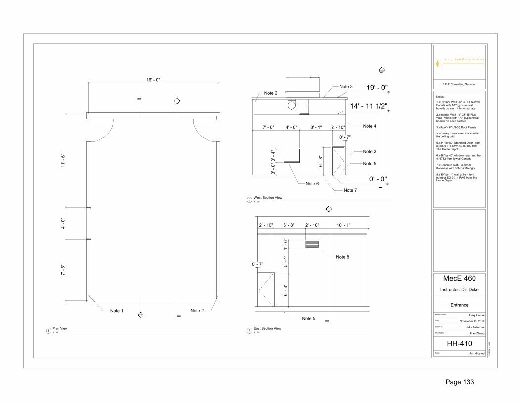
-
---
-
---
16' - 0"
11' -
6"
4' -
0"
7' -
6"
Note 1 Note 2
19' - 0"
14' - 11 1/2"
0' - 0"
7' - 6" 4' - 0" 8' - 1" 2' - 10"
3' -
0"
3' -
4"
6' -
8"
0' - 7"
Note 2
Note 2
Note 3
Note 4
Note 6
Note 5
Note 7
4
HH-412
0' - 7"
2' - 10" 6' - 8" 2' - 10" 10' - 1"
1' -
6"
5' -
4"
6' -
8"
Note 8
Note 5
2
HH-413
B.E.E Consulting Services
Scale
Checked by
Drawn by
Date
Project Name:
Notes:
As indicated
01
/12
/201
9 14
:24:
12
Entrance
Honey House
Instructor: Dr. Duke
MecE 460
November 30, 2019
Jake Bellerose
Zoey Zhang
HH-410
1 : 15
Plan View1
1 : 30
West Section View2
1 : 25
East Section View3
1.) Exterior Wall - 6" CF Flute Wall Panels with 1/2" gypsum wall boards on each interior surface
2.) Interior Wall - 4" CF 45 Flute Wall Panels with 1/2" gypsum wall boards on each surface
3.) Roof - 6" LS-36 Roof Panels
4.) Ceiling - food safe 2' x 4' x 5/8" tile ceiling grid
5.) 34" by 80" Standard Door - item number THDJW184900102 from The Home Depot
6.) 48" by 40" window - part number 416782 from lowes Canada
7.) Concrete Slab - 300mm thickness with 30MPa strength
8.) 30" by 14" wall grille - item number SG-3014 RAG from The Home Depot
Page 133

-
---
-
---
-
---
6' - 1" 2' - 10" 6' - 1" 8' - 0" 15' - 0"
1' -
6"
12' -
0"
19' - 0"
0' - 0"
15' - 6"
15' - 8"Note 1
Note 2
Note 3
Note 4 Note 5
2' - 10" 11' - 7" 2' - 10" 4' - 7" 2' - 10" 11' - 7"
0' - 7" 0' - 7" 0' - 7"
Note 6
6' - 9"2' - 6"6' - 9"
1' -
2"
12' -
2"
Note 2Note 7
Note 1
B.E.E Consulting Services
Scale
Checked by
Drawn by
Date
Project Name:
Notes:
As indicated
01
/12
/201
9 16
:52:
13
Storage Room,Washroom, andElectrical Room
Honey House
Instructor: Dr. Duke
MecE 460
November 30, 2019
Jake Bellerose
Zoey Zhang
HH-411
1 : 25
Plan View1
1 : 40
West Section View2
1 : 40
East Section View3
1 : 40
North Section View4
1.) Interior Wall - 4" CF 45 Flute Wall Panels with 1/2" gypsum wall boards on each surface
2.) 30" by 14" wall grille - item number SG-3014 RAG from The Home Depot
3.) Concrete Slab - 300mm thickness with 30MPa strength
4.) Roof - 6" LS-36 Roof Panels
5.) Ceiling - food safe 2' x 4' x 5/8" tile ceiling grid
6.) 34" by 80" Standard Door - item number THDJW184900102 from The Home Depot
7.) Exterior Wall - 6" CF Flute Wall Panels with 1/2" gypsum wall boards on each interior surface
Page 134

19' - 0"
15' - 3 1/2"
0' - 0"
13' - 0" 4' - 0" 13' - 0"
3' -
0"
3' -
4"
Note 1
Note 4
Note 2 Note 3
Note 5 Note 6
9' - 6"4' - 0"9' - 6"
3' -
4"
3' -
0"
Note 4 Note 1
Note 6
2' - 1" 2' - 10" 8' - 10" 2' - 6" 6' - 9"
6' -
8"
5' -
6"
1' -
2"
Note 7
Note 8
-
---
-
---
-
---
15' -
0"
15' -
0"
11' - 6" 11' - 6"
B.E.E Consulting Services
Scale
Checked by
Drawn by
Date
Project Name:
Notes:
As indicated
01
/12
/201
9 14
:26:
24
Break Room
Honey House
Instructor: Dr. Duke
MecE 460
November 30, 2019
Jake Bellerose
Sai Avuthu
HH-412
1 : 30
West Section View2
1 : 30
North Section View3 1 : 30
South Section View4
1 : 40
Plan View1
1.) Interior Wall - 4" CF 45 Flute Wall Panels with 1/2" gypsum wall boards on each surface
2.) Roof - 6" LS-36 Roof Panels
3.) Ceiling - food safe 2' x 4' x 5/8" tile ceiling grid
4.) Exterior Wall - 6" CF Flute Wall Panels with 1/2" gypsum wall boards on each interior surface
5.) Concrete Slab - 300mm thickness with 30MPa strength
6.) 48" by 40" window - part number 416782 from lowes Canada
7.) 34" by 80" Standard Door - item number THDJW184900102 from The Home Depot
8.) 30" by 14" wall grille - item number SG-3014 RAG from The Home Depot
Page 135

-
---
-
---
61' -
0"
7' - 0"
19' - 0"
15' - 5"
0' - 0"
11' - 7" 2' - 10" 5' - 2" 2' - 10" 12' - 2" 2' - 10" 10' - 10" 2' - 6" 6' - 10" 2' - 10"
0' - 7"1' -
2"
5' -
6"
6' -
8"
Note 2 Note 3
Note 4 Note 1
Note 5
2' - 1" 2' - 10" 2' - 1"
6' -
8"
Note 1
B.E.E Consulting Services
Scale
Checked by
Drawn by
Date
Project Name:
Notes:
As indicated
01
/12
/201
9 14
:22:
17
Hallway
Honey House
Instructor: Dr. Duke
MecE 460
November 30, 2019
Jake Bellerose
Sai Avuthu
HH-4131 : 30
Plan View1
1 : 30
West Section View3
1 : 20
North Section View2
1.) 34" by 80" Standard Door - item number THDJW184900102 from The Home Depot
2.) Roof - 6" LS-36 Roof Panels
3.) Ceiling - food safe 2' x 4' x 5/8" tile ceiling grid
4.) Concrete Slab - 300mm thickness with 30MPa strength
5.) 30" by 14" wall grille - item number SG-3014 RAG from The Home Depot
6.) All hallway walls will be Interior Walls - 4" CF 45 Flute Wall Panels with 1/2" gypsum wall boards on each surface
Page 136
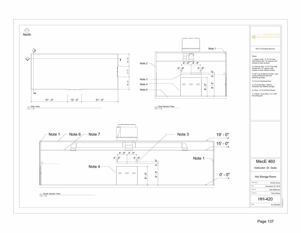
31' - 0" 12' - 0" 31' - 0"
10' -
6"
9' -
0"
10' -
6"
-
---
-
---
Note 5
4' - 0" 4' - 0"
0' - 6" 0' - 6"
8' -
0"
0' -
8"
9' -
3"
Note 3
Note 4
Note 2
Note 1
0' - 0"
15' - 0"
19' - 0"
4' - 0" 4' - 0"9'
- 3
"0'
- 8
"0' - 6"
Note 7Note 6 Note 3
Note 4
8' -
0"
0' - 6"
Note 1
Note 1
B.E.E Consulting Services
Scale
Checked by
Drawn by
Date
Project Name:
Notes:
As indicated
01
/12
/201
9 10
:21:
10
Hot Storage Room
Honey House
Instructor: Dr. Duke
MecE 460
November 30, 2019
Jake Bellerose
Zoey Zhang
HH-420
1 : 60
Plan View1 1 : 30
East Section View2
1 : 30
South Section View3
1.) Interior Wall - 4" CF 45 Flute Wall Panels with 1/2" gypsum wall boards on each surface
2.) Exterior Wall - 6" CF Flute Wall Panels with 1/2" gypsum wall boards on each interior surface
3.) 48" Low Profile Air Curtain - item number WWG32V346 from acklands grainger
4.) 9' by 8' Overhead Door
5.) Concrete Slab - 300mm thickness with 30MPa strength
6.) Roof - 6" LS-36 Roof Panels
7.) Ceiling - food safe 2' x 4' x 5/8" tile ceiling grid
North
Page 137

11' - 6" 11' - 6"
-
---
-
---
6' -
9" 10
' - 6
"9'
- 0
"10
' - 6
"
19' - 0"
15' - 5 1/2"
0' - 0"
Note 4
3' -
4"
3' -
0"
4' - 0"
Note 2
Note 1
Note 3
8' -
0"
9' - 0"
Note 2
Note 2
Note 5 Note 6
Note 7
6' -
8"
Note 8
2' - 10"
B.E.E Consulting Services
Scale
Checked by
Drawn by
Date
Project Name:
Notes:
As indicated
30
/11
/201
9 14
:48:
14
Transition Room
Honey House
Instructor: Dr. Duke
MecE 460
November 30, 2019
Sai Avuthu
Zoey Zhang
HH-430
North
1 : 25
Transition Room - Plan View1
1 : 30
North Section View2
1 : 30
East Section View3
1.) Interior Wall - 4" CF 45 Flute Wall Panels with 1/2" gypsum wall boards on each surface
2.) Exterior Wall - 6" CF Flute Wall Panels with 1/2" gypsum wall boards on each interior surface
3.) 48" by 40" window - part number 416782 from lowes Canada
4.) Concrete Slab - 300mm thickness with 30MPa strength
5.) Roof - 6" LS-36 Roof Panels
6.) Ceiling - food safe 2' x 4' x 5/8" tile ceiling grid
7.) 9' by 8' Overhead Door
8.) 34" by 80" Standard Door - item number THDJW184900102 from The Home Depot
Page 138

32' - 3" 9' - 0" 32' - 9 1/2"
15' -
3"
15' -
3"
15' -
3"
15' -
3"
32' - 6" 9' - 0" 32' - 6"
-
---
-
---
-
---
19' - 0"
13' - 6"
0' - 0"
32' - 6"9' - 0"32' - 6"
8' -
0"
Note 5Note 4 Note 1
Note 6
Note 8Note 7
3' - 5" 9' - 10" 4' - 0" 11' - 3" 4' - 0" 11' - 3" 4' - 0" 9' - 7" 3' - 8"
6' -
8"
3' -
0"
3' -
4"
Note 2 Note 3
Note 1 Note 1
3' - 5" 54' - 2" 3' - 5"
6' -
8" Note 3
B.E.E Consulting Services
Scale
Checked by
Drawn by
Date
Project Name:
Notes:
As indicated
01
/12
/201
9 11
:11:
55
Extraction Room
Honey House
Instructor: Dr. Duke
MecE 460
November 30, 2019
Jake Bellerose
Sai Avuthu
HH-440
1 : 90
Plan View1
1 : 35
North Section View4
1 : 45
East Section View2
1 : 45
West Section View3
1.) Interior Wall - 4" CF 45 Flute Wall Panels with 1/2" gypsum wall boards on each surface
2.) 48" by 40" window - part number 416782 from lowes Canada. Three windows on the east wall
3.) 34" by 80" Standard Door - item number THDJW184900102 from The Home Depot. Two doors on the west wall and two walls on the east wall
4.) Ceiling - food safe 2' x 4' x 5/8" tile ceiling grid
5.) Roof - 6" LS-36 Roof Panels
6.) Exterior Wall - 6" CF Flute Wall Panels with 1/2" gypsum wall boards on each interior surface
7.) 9' by 8' Overhead Door. One overhead door on the south wall and one overhead door on the north wall
8.) Concrete Slab - 300mm thickness with 30MPa strength
Page 139

15' -
0"
15' -
0"
15' -
0"
15' -
0"
10' -
6"
9' -
0"
10' -
6"
15' -
0"
15' -
0"
53' - 9" 12' - 0" 31' - 3 1/2" 11' - 6" 11' - 6"
20' - 0" 20' - 0" 20' - 0" 20' - 0" 20' - 0" 20' - 0"
-
---
-
---
-
---
-
---
19' - 0"
15' - 0"
0' - 0"
8' -
0"
3' -
4"
3' -
0"
55' - 3" 9' - 0" 32' - 6" 9' - 9 1/2" 4' - 0" 9' - 6"
Note 3 Note 4
Note 1 Note 2
18' - 0" 4' - 0" 16' - 0" 4' - 0" 16' - 0" 4' - 0" 16' - 0" 4' - 0" 16' - 0" 4' - 0" 18' - 0"
3' -
0"
3' -
4"
Note 2 Note 5 Note 6 Note 2
Note 4 Note 7
B.E.E Consulting Services
Scale
Checked by
Drawn by
Date
Project Name:
Notes:
As indicated
01
/12
/201
9 12
:21:
00
Cold Storage
Honey House
Instructor: Dr. Duke
MecE 460
November 30, 2019
Jake Bellerose
Sai Avuthu
HH-450-01
1 : 90
Plan View1
1 : 50
North Section View2
1 : 50
South Section View3
1.) Interior Wall - 4" CF 45 Flute Wall Panels with 1/2" gypsum wall boards on each surface
2.) Exterior Wall - 6" CF Flute Wall Panels with 1/2" gypsum wall boards on each interior surface
3.) 9' by 8' Overhead Door
4.) 48" by 40" window - part number 416782 from lowes Canada
5.) Roof - 6" LS-36 Roof Panels
6.) Ceiling - food safe 2' x 4' x 5/8" tile ceiling grid
7.) Concrete Slab - 300mm thickness with 30MPa strength
8.) Refer to drawing HH-450-02 for east and west section views
Page 140

10' - 6" 9' - 0" 9' - 1" 2' - 10" 11' - 7" 4' - 0" 13' - 0"
8' -
0"
6' -
8"
3' -
0"
3' -
4"
Note 1 Note 2 Note 3
13' - 0" 4' - 0" 11' - 7" 2' - 10" 11' - 7" 4' - 0" 13' - 0"
3' -
0"
3' -
4"
6' -
8"
Note 2 Note 3
B.E.E Consulting Services
Scale
Checked by
Drawn by
Date
Project Name:
Notes:
1 : 30
01
/12
/201
9 12
:21:
13
Cold Storage
Honey House
Instructor: Dr. Duke
MecE 460
November 30, 2019
Jake Bellerose
Zoey Zhang
HH-450-02
1 : 30
East Section View1
1 : 30
West Section View2
1.) 9' by 8' Overhead Door
2.) 34" by 80" Standard Door - item number THDJW184900102 from The Home Depot
3.) 48" by 40" window - part number 416782 from lowes Canada
Page 141

RTU 3RTU 4
RTU 1
RTU 2
RTU 5 RTU 6
TR-01
TR-03
HS-01HS-01
HS-03
EX-01
EX-03
CS-01
CS-03
CS-01
CS-03
AW-03
AW-01
WG-01
WG-01
WG-01
WG-01
WG-01
B.E.E Consulting Services
Scale
Checked by
Drawn by
Date
Project Name:
Notes:
1 : 100
02
/12
/201
9 00
:18:
49
HVAC System Layout
Honey House
Instructor: Dr. Duke
MecE 460
November 30, 2019
Jake Bellerose
Zoey Zhang
HH-500
North
1.) Refer to drawing HH-501 for location dimensions of RTUs2.) All RTU units to be ordered with 14" roof curbs
Page 142
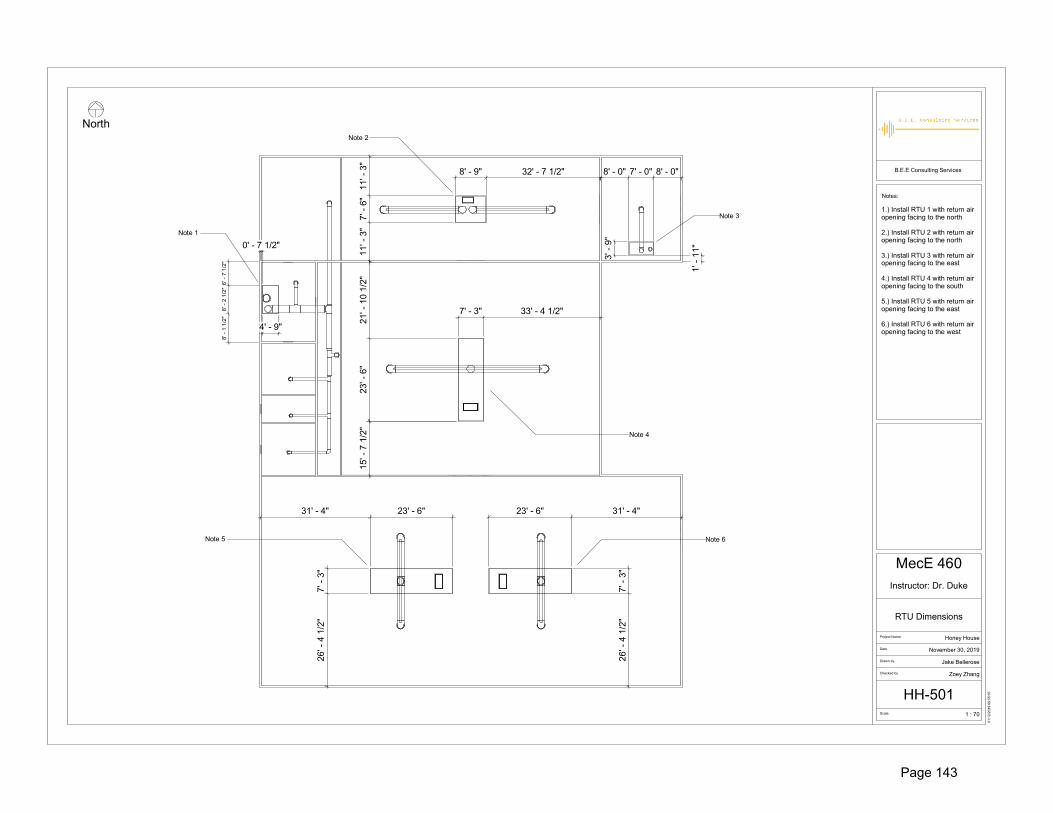
31' - 4" 23' - 6"
7' -
3"
26' -
4 1
/2"
23' - 6" 31' - 4"
7' -
3"
26' -
4 1
/2"
23' -
6"
21' -
10
1/2"
7' - 3" 33' - 4 1/2"
15' -
7 1
/2"
8' - 0" 7' - 0" 8' - 0"
3' -
9"
1' -
11"11
' - 3
"7'
- 6
"11
' - 3
"
8' - 9" 32' - 7 1/2"
6' -
7 1
/2"
8' -
2 1
/2"
8' -
1 1
/2"
4' - 9"
0' - 7 1/2"
Note 1
Note 2
Note 3
Note 4
Note 5 Note 6
B.E.E Consulting Services
Scale
Checked by
Drawn by
Date
Project Name:
Notes:
1 : 70
01
/12
/201
9 09
:55:
55
RTU Dimensions
Honey House
Instructor: Dr. Duke
MecE 460
November 30, 2019
Jake Bellerose
Zoey Zhang
HH-501
North
1.) Install RTU 1 with return airopening facing to the north
2.) Install RTU 2 with return air opening facing to the north
3.) Install RTU 3 with return air opening facing to the east
4.) Install RTU 4 with return air opening facing to the south
5.) Install RTU 5 with return air opening facing to the east
6.) Install RTU 6 with return air opening facing to the west
Page 143

14 1
2
3 13
7
5
6
8
9
10
12
11
13
7
4
ITEM NO. PART NUMBER DESCRIPTION QTY.1 1773K92 Size 14x12 Tee Connector 12 1766K39 Size 12 90 Degree Elbow 1
3 Assem1^Admin Wing 1
4 2013K64 Size 14x10 Reducer 15 1766K667 Size 10 Tee Connector 16 1768K107 Steel Open Duct Trade Size 10, Length 5' 6
7 1766K38 Size 10 90 Degree Elbow 3
8 1768K107 Steel Open Duct Trade Size 10, Length 2' 4
9 1766K667 Size 10x8 Tee Connector 110 1768K107 Steel Open Duct Trade Size 8, Length 5' 2
11 1766K36 Size 8 90 Degree Elbow 1
12 1768K107 Steel Open Duct Trade Size 8, Length 1' 1
13 1768K107 Steel Open Duct Trade Size 10, Length 2' 2
14 1768K107 Size 12 90 Degree Elbow 1
D
C
B
AA
B
C
D
12345678
8 7 6 5 4 3 2 1
DIMENSIONS ARE IN INCHESTOLERANCES:ANGULAR: 0.5 LINEARX = 0.5X.X = 0.1X.XX = 0.025
Galvanized Steel
COMPANY NAME:
Drawn by:
Modeled by:
The Department of Mechanical EngineeringUNIVERSITY OF ALBERTA
TITLE:
SIZE
BPart No: REV
Mass: 201.59SCALE: 1:50
UNLESS OTHERWISE SPECIFIED:
HH-511 SHEET 1 OF 2
DO NOT SCALE DRAWING
Storage, Washroom, Electrical Supply Air
Duct System
Comments:All parts available from McMaster-Carr
MecE 460
SURFACE FINISHm
0.6
Checked by:
Instructor:
Fall 2019
SWE-01 1November 29, 2019
Sai Avuthu
FILE NAME:
MATERIAL:
Zoey Zhang
Jake Bellerose
Dr. Duke
Date:
SOLIDWORKS Educational Product. For Instructional Use Only.Page 144
ewvan
Cross-Out
ewvan
Cross-Out

162.6
27.2
339.0
D
C
B
AA
B
C
D
12345678
8 7 6 5 4 3 2 1
DIMENSIONS ARE IN INCHESTOLERANCES:ANGULAR: 0.5 LINEARX = 0.5X.X = 0.1X.XX = 0.025
Galvanized Steel
COMPANY NAME:
Drawn by:
Modeled by:
The Department of Mechanical EngineeringUNIVERSITY OF ALBERTA
TITLE:
SIZE
BPart No: REV
Mass: 201.59SCALE: 1:50
UNLESS OTHERWISE SPECIFIED:
HH-511 SHEET 2 OF 2
DO NOT SCALE DRAWING
Storage, Washroom, Electrical Supply Air
Duct System
Comments:All parts available from McMaster-Carr
MecE 460
SURFACE FINISHm
0.6
Checked by:
Instructor:
Fall 2019
SWE-01 1November 29, 2019
Sai Avuthu
FILE NAME:
MATERIAL:
Zoey Zhang
Jake Bellerose
Dr. Duke
Date:
SOLIDWORKS Educational Product. For Instructional Use Only.Page 145
ewvan
Cross-Out
ewvan
Cross-Out

17
15
13
10
12
84
5
1
2
3614
16 7
9
11
ITEM NO. PART NUMBER DESCRIPTION QTY.
1 AW-02 Administrative Wing Transition Piece 1
2 1768K107 Steel Open Duct Trade Size 22, Length 1.5' 1
3 1766K45 Size 22 90 Degree Elbow 1
4 1768K107 Steel Open Duct Trade Size 22, Length 5' 2
5 1773K92 Size 22x12 Tee Connector 1
6 1768K107 Steel Open Duct Trade Size 12, Length 5' 1
7 1766K39 Size 12 90 Degree Elbow 1
8 1768K107 Steel Open Duct Trade Size 12, Length 2' 1
9 2013K36 Size 22x18 Reducer 1
10 1766K673 Size 18x18 Tee Connector 1
11 2013K64 Size 18x14 Reducer 1
12 1768K107 Steel Open Duct Trade Size 18, Length 5' 2
13 1768K107 Steel Open Duct Trade Size 14, Length 5' 4
14 1768K107 Steel Open Duct Trade Size 14, Length 2' 4
15 1766K41 Size 14 90 Degree Elbow 1
16 1768K107 Size 12 90 Degree Elbow 1
17 1768K107 Steel Open Duct Trade Size 14, Length 1' 1
D
C
B
AA
B
C
D
12345678
8 7 6 5 4 3 2 1
DIMENSIONS ARE IN INCHESTOLERANCES:ANGULAR: 0.5 LINEARX = 0.5X.X = 0.1X.XX = 0.025
Galvanized Steel
COMPANY NAME:
Drawn by:
Modeled by:
The Department of Mechanical EngineeringUNIVERSITY OF ALBERTA
TITLE:
SIZE
BPart No: REV
Mass: 386.86SCALE: 1:75
UNLESS OTHERWISE SPECIFIED:
HH-514 SHEET 1 OF 2
DO NOT SCALE DRAWING
Break, Hallway, Entrance Supply Air
Duct System
Comments:
All parts available from McMaster-Carr
MecE 460
SURFACE FINISHm
0.6
Checked by:
Instructor:
Fall 2019
BHE-01 1November 30, 2019
Sai Avuthu
FILE NAME:
MATERIAL:
Zoey Zhang
Jake Bellerose
Dr. Duke
Date:
SOLIDWORKS Educational Product. For Instructional Use Only.Page 146
ewvan
Cross-Out

234.8
60.8
483.3
D
C
B
AA
B
C
D
12345678
8 7 6 5 4 3 2 1
DIMENSIONS ARE IN INCHESTOLERANCES:ANGULAR: 0.5 LINEARX = 0.5X.X = 0.1X.XX = 0.025
Galvanized Steel
COMPANY NAME:
Drawn by:
Modeled by:
The Department of Mechanical EngineeringUNIVERSITY OF ALBERTA
TITLE:
SIZE
BPart No: REV
Mass: 386.86SCALE: 1:75
UNLESS OTHERWISE SPECIFIED:
HH-514 SHEET 2 OF 2
DO NOT SCALE DRAWING
Break, Hallway, Entrance Supply Air
Duct System
Comments:
All parts available from McMaster-Carr
MecE 460
SURFACE FINISHm
0.6
Checked by:
Instructor:
Fall 2019
BHE-01 1November 30, 2019
Sai Avuthu
FILE NAME:
MATERIAL:
Zoey Zhang
Jake Bellerose
Dr. Duke
Date:
SOLIDWORKS Educational Product. For Instructional Use Only.Page 147
ewvan
Cross-Out

9.5 31.0
8.0
30.0
25.0
1.5 9.5
24.5
22.0 H7s6 THRU
UP 9
0° R
0.0
3
UP 90° R 0.03
UP 9
0° R
0.0
3
UP 90° R 0.03
DO
WN
90°
R 0
.03
DOWN 90° R 0.03
DOWN 90° R 0.03
DO
WN
90°
R 0
.03
2.0
1/8
D
C
B
AA
B
C
D
12345678
8 7 6 5 4 3 2 1
DIMENSIONS ARE IN INCHESTOLERANCES:ANGULAR: 0.5 LINEARX = 0.5X.X = 0.1X.XX = 0.025
Galvanized Steel, 24 Gauge
COMPANY NAME:
Drawn by:
Modeled by:
The Department of Mechanical EngineeringUNIVERSITY OF ALBERTA
TITLE:
SIZE
BPart No: REV
Mass: 12.66SCALE: 1:10
UNLESS OTHERWISE SPECIFIED:
HH-516 SHEET 1 OF 1
DO NOT SCALE DRAWING
Administrative Wing Supply Air Transition
Comments:
MecE 460
SURFACE FINISHm
0.6
Checked by:
Instructor:
Fall 2019
AW-03 1November 30, 2019
Sai Avuthu
FILE NAME:
MATERIAL:
Zoey Zhang
Jake Bellerose
Dr. Duke
Date:
SOLIDWORKS Educational Product. For Instructional Use Only.Page 148
ewvan
Cross-Out

70.8
26.1
4
3
2
1
ITEM NO. PART NUMBER DESCRIPTION VENDOR QTY.1 AW-03 Administrative Wing Transition Piece McMaster-Carr 1
2 2013K36 Size 24x22 Reducer McMaster-Carr 13 1768K107 Steel Open Duct Trade Size 24, Length 2' McMaster-Carr 2
4 1768K107 Steel Open Duct Trade Size 24, Length 1' McMaster-Carr 1D
C
B
AA
B
C
D
12345678
8 7 6 5 4 3 2 1
DIMENSIONS ARE IN INCHESTOLERANCES:ANGULAR: 0.5 LINEARX = 0.5X.X = 0.1X.XX = 0.025
Galvanized Steel
COMPANY NAME:
Drawn by:
Modeled by:
The Department of Mechanical EngineeringUNIVERSITY OF ALBERTA
TITLE:
SIZE
BPart No: REV
Mass: 69.01SCALE: 1:25
UNLESS OTHERWISE SPECIFIED:
HH-516 SHEET 1 OF 1
DO NOT SCALE DRAWING
Administrative Wing Return Air Duct System
Comments:
MecE 460
SURFACE FINISHm
0.6
Checked by:
Instructor:
Fall 2019
BHE-03 1November 30, 2019
Sai Avuthu
FILE NAME:
MATERIAL:
Zoey Zhang
Jake Bellerose
Dr. Duke
Date:
SOLIDWORKS Educational Product. For Instructional Use Only.Page 149
ewvan
Cross-Out

1
3
2
4
6
5
NOTE: Parts 1768K107-A1, 1768K107-A2 and 1768K107-A3 will be stock parts ordered from McMaster-Carr (ID 1768K107)to be cut to length specified in bill of materials
61.5
276.7
ITEM NO. PART NUMBER DESCRIPTION VENDOR QTY.
1 TR-03 Hot Storage Transition Piece 1
2 1766K46 Size 24 90 Degree Elbow McMaster-Carr 2
3 1768K107-A1 Steel Open Duct Trade Size 24, Length 1'3'' McMaster-Carr 1
4 1768K107 Steel Open Duct Trade Size 24 McMaster-Carr 9
5 1768K107-A2 Steel Open Duct Trade Size 24, Length 1'11'' McMaster-Carr 1
6 1768K107-A3 Steel Open Duct Trade Size 24, Length 1' McMaster-Carr 1
D
C
B
AA
B
C
D
12345678
8 7 6 5 4 3 2 1
DIMENSIONS ARE IN INCHESTOLERANCES:ANGULAR: 0.5 LINEARX = 0.5X.X = 0.1X.XX = 0.025
Galvanized Steel
COMPANY NAME:
Drawn by:
Modeled by:
The Department of Mechanical EngineeringUNIVERSITY OF ALBERTA
TITLE:
SIZE
BPart No: REV
Mass: 272.05SCALE: 1:50
UNLESS OTHERWISE SPECIFIED:
HH-521 SHEET 1 OF 1
DO NOT SCALE DRAWING
Hot Storage Supply Air Duct
Comments:
MecE 460
SURFACE FINISHm
0.6
Checked by:
Instructor:
Fall 2019
HS-01 1November 29, 2019
Zoey Zhang
Drawing Number:
MATERIAL:
Jake Bellerose
Jake Bellerose
Dr. Duke
Date:
SOLIDWORKS Educational Product. For Instructional Use Only.Page 150
ewvan
Cross-Out

24.0 H7s6 THRU
28.5
26.0
22.5
9.5
8.0
23.7
1.5
45.0
9.5
UP 9
0° R
0.0
3
UP 90° R 0.03
UP 9
0° R
0.0
3
UP 90° R 0.03
DO
WN
90°
R 0
.03
DOWN 90° R 0.03
DOWN 90° R 0.03
DO
WN
90°
R 0
.03
2.0
1/8
D
C
B
AA
B
C
D
12345678
8 7 6 5 4 3 2 1
DIMENSIONS ARE IN INCHESTOLERANCES:ANGULAR: 0.5 LINEARX = 0.5X.X = 0.1X.XX = 0.025
Galvanized Steel, 24 Gauge
COMPANY NAME:
Drawn by:
Modeled by:
The Department of Mechanical EngineeringUNIVERSITY OF ALBERTA
TITLE:
SIZE
BPart No: REV
Mass: 9.97SCALE: 1:10
UNLESS OTHERWISE SPECIFIED:
HH-522 SHEET 1 OF 1
DO NOT SCALE DRAWING
Hot Room Supply Air Transition
Comments:
MecE 460
SURFACE FINISHm
0.6
Checked by:
Instructor:
Fall 2019
HR-02 1November 29, 2019
Zoey Zhang
Drawing Number:
MATERIAL:
Sai Avuthu
Jake Bellerose
Dr.Duke
Date:
SOLIDWORKS Educational Product. For Instructional Use Only.Page 151
ewvan
Cross-Out

1
2
3
4
64.9
36.0
72.3
ITEM NO. PART NUMBER DESCRIPTION QTY.1 HS-04 Return Supply Air Piece 18''x36'' 1
2 1964K87 Rectangular Duct 18''x36''x4' 3
3 1964K94 Drive Bracket 64 1964K86 Rectangular Duct 18''x36''x1' 1 D
C
B
AA
B
C
D
12345678
8 7 6 5 4 3 2 1
DIMENSIONS ARE IN INCHESTOLERANCES:ANGULAR: 0.5 LINEARX = 0.5X.X = 0.1X.XX = 0.025
COMPANY NAME:
Drawn by:
Modeled by:
The Department of Mechanical EngineeringUNIVERSITY OF ALBERTA
TITLE:
SIZE
BPart No: REV
Mass: SCALE: 1:25
UNLESS OTHERWISE SPECIFIED:
HH-523 SHEET 1 OF 1
DO NOT SCALE DRAWING
Hot Room Return Air Duct System
Comments:
MecE 460
SURFACE FINISHm
0.6
Checked by:
Instructor:
HR-03 1November 29, 2019
Jake Bellerose
Drawing Number:
MATERIAL:
Zoey Zhang
Jake Bellerose
Dr. DukeFall 2019
Date:
SOLIDWORKS Educational Product. For Instructional Use Only.Page 152
ewvan
Cross-Out

6
2
5
4
1
3
272.2
54.0
ITEM NO. PART NUMBER DESCRIPTION VENDOR QTY.
1 TR-03 Transition Room Transition Piece McMaster-Carr 1
2 1766K41 Size 14 90 Degree Elbow McMaster-Carr 2
3 1768K107 Steel Open Duct Trade Size 14 MxF, Length 5' McMaster-Carr 3
4 1768K107-D1 Steel Open Duct Trade Size 14 MxF, Length 1.5' McMaster-Carr 1
5 1768K107-D2 Steel Open Duct Trade Size 14 FxF, Length 5' McMaster-Carr 1
6 1768K107-D3 Steel Open Duct Trade Size 14 MxF, Length 1' McMaster-Carr 1
D
C
B
AA
B
C
D
12345678
8 7 6 5 4 3 2 1
DIMENSIONS ARE IN INCHESTOLERANCES:ANGULAR: 0.5 LINEARX = 0.5X.X = 0.1X.XX = 0.025
Galvanized Steel
COMPANY NAME:
Drawn by:
Modeled by:
The Department of Mechanical EngineeringUNIVERSITY OF ALBERTA
TITLE:
SIZE
BPart No: REV
Mass: 121.18SCALE: 1:50
UNLESS OTHERWISE SPECIFIED:
HH-531 SHEET 1 OF 1
DO NOT SCALE DRAWING
Transition Room Supply Air Duct System
Comments:
MecE 460
SURFACE FINISHm
0.6
Checked by:
Instructor:
Fall 2019
TR-01 1November 30, 2019
Sai Avuthu
FILE NAME:
MATERIAL:
Zoey Zhang
Jake Bellerose
Dr. Duke
Date:
SOLIDWORKS Educational Product. For Instructional Use Only.Page 153
ewvan
Cross-Out

14.0 H7s6 THRU
18.7
9.5
20.5
9.5 18.5
19.7
1.5
8.0
UP 9
0° R
0.0
3
UP 90° R 0.03
UP 9
0° R
0.0
3
UP 90° R 0.03
DO
WN
90°
R 0
.03
DOWN 90° R 0.03
DOWN 90° R 0.03
DO
WN
90°
R 0
.03
2.0
1/8
D
C
B
AA
B
C
D
12345678
8 7 6 5 4 3 2 1
DIMENSIONS ARE IN INCHESTOLERANCES:ANGULAR: 0.5 LINEARX = 0.5X.X = 0.1X.XX = 0.025
Galvanized Steel, 24 Gauge
COMPANY NAME:
Drawn by:
Modeled by:
The Department of Mechanical EngineeringUNIVERSITY OF ALBERTA
TITLE:
SIZE
BPart No: REV
Mass: 7.20SCALE: 1:8
UNLESS OTHERWISE SPECIFIED:
HH-532 SHEET 1 OF 1
DO NOT SCALE DRAWING
Transition Room Supply Air Transition
Comments:
MecE 460
SURFACE FINISHm
0.6
Checked by:
Instructor:
Fall 2019
TR-02 1November 30, 2019
Sai Avuthu
FILE NAME:
MATERIAL:
Zoey Zhang
Jake Bellerose
Dr. Duke
Date:
SOLIDWORKS Educational Product. For Instructional Use Only.Page 154
ewvan
Cross-Out

2
1
34.6
57.0
ITEM NO. PART NUMBER DESCRIPTION VENDOR QTY.
1 TR-03 Transition Room Transition Piece McMaster-Carr 1
2 1768K107 Steel Open Duct Trade Size 10 FxF McMaster-Carr 1
D
C
B
AA
B
C
D
12345678
8 7 6 5 4 3 2 1
DIMENSIONS ARE IN INCHESTOLERANCES:ANGULAR: 0.5 LINEARX = 0.5X.X = 0.1X.XX = 0.025
Galvanized Steel
COMPANY NAME:
Drawn by:
Modeled by:
The Department of Mechanical EngineeringUNIVERSITY OF ALBERTA
TITLE:
SIZE
BPart No: REV
Mass: 21.07SCALE: 1:15
UNLESS OTHERWISE SPECIFIED:
HH-533 SHEET 1 OF 1
DO NOT SCALE DRAWING
Transition Room Return Air Duct System
Comments:
MecE 460
SURFACE FINISHm
0.6
Checked by:
Instructor:
Fall 2019
TR-03 1November 30, 2019
Sai Avuthu
FILE NAME:
MATERIAL:
Zoey Zhang
Jake Bellerose
Dr. Duke
Date:
SOLIDWORKS Educational Product. For Instructional Use Only.Page 155
ewvan
Cross-Out

1
2
3
4
5
6
537.7
53.7
Scale 1:80
NOTE: Parts 1768K107-C1 and 1768K107-C2 will be stock parts ordered from McMaster-Carr (ID 1768K107)to be cut to length specified in bill of materials
ITEM NO. PART NUMBER DESCRIPTION VENDOR QTY.
1 EX-02 Extraction room Supply Air Transition 1
2 1768K107-C1 Steel Open Duct Trade Size 24, Length 1'3'' McMaster-Carr 1
3 1773K92 Trade Size 20 Aluminum Tee Connector McMaster-Carr 1
4 1768K107 Steel Open Duct Trade Size 24 McMaster-Carr 20
5 1766K46 Size 24 90 Degree Elbow McMaster-Carr 2
6 1768K107-C2 Steel Open Duct Trade Size 24, Length 1'11'' McMaster-Carr 2
D
C
B
AA
B
C
D
12345678
8 7 6 5 4 3 2 1
DIMENSIONS ARE IN INCHESTOLERANCES:ANGULAR: 0.5 LINEARX = 0.5X.X = 0.1X.XX = 0.025
Various
COMPANY NAME:
Drawn by:
Modeled by:
The Department of Mechanical EngineeringUNIVERSITY OF ALBERTA
TITLE:
SIZE
BPart No: REV
Mass: 585.37SCALE: 1:50
UNLESS OTHERWISE SPECIFIED:
HH-541 SHEET 1 OF 1
DO NOT SCALE DRAWING
Extraction Room Supply Air Duct System
Comments:
MecE 460
SURFACE FINISHm
0.6
Checked by:
Instructor:
Fall 2019
EX-01 1November 29, 2019
Zoey Zhang
Drawing Number:
MATERIAL:
Sai Avathu
Jake Bellerose
Dr.Duke
Date:
SOLIDWORKS Educational Product. For Instructional Use Only.Page 156
ewvan
Cross-Out

49.0
1.5 9.5
24.5
26.0 H7 THRU
34.8
30.0
69.5 9.5
8.0
UP 9
0° R
0.0
3
UP 90° R 0.03
UP 9
0° R
0.0
3
UP 90° R 0.03
DO
WN
90°
R 0
.03
DOWN 90° R 0.03
DOWN 90° R 0.03
DO
WN
90°
R 0
.03 2.0
1/8
D
C
B
AA
B
C
D
12345678
8 7 6 5 4 3 2 1
DIMENSIONS ARE IN INCHESTOLERANCES:ANGULAR: 0.5 LINEARX = 0.5X.X = 0.1X.XX = 0.025
Galvanized Steel, Gauge 24
COMPANY NAME:
Drawn by:
Modeled by:
The Department of Mechanical EngineeringUNIVERSITY OF ALBERTA
TITLE:
SIZE
BPart No: REV
Mass: 25.09SCALE: 1:15
UNLESS OTHERWISE SPECIFIED:
HH-542 SHEET 1 OF 1
DO NOT SCALE DRAWING
Extraction Room Supply Air Transition
Comments:
MecE 460
SURFACE FINISHm
0.6
Checked by:
Instructor:
Fall 2019
EX-02 1November 29, 2019
Zoey Zhang
Drawing Number:
MATERIAL:
Sai Avuthu
Jake Bellerose
Dr.Duke
Date:
SOLIDWORKS Educational Product. For Instructional Use Only.Page 157
ewvan
Cross-Out

1
2
3 81.5
48.0
72.3
ITEM NO. PART NUMBER DESCRIPTION VENDOR QTY.
1 CS-04 Return Supply Air Piece 24''x48'' Lennox Commercial 1
2 1964K87 Rectangular Duct 24''x48''x4' McMaster-Carr 93 1964K94 Drive Bracket McMaster-Carr 9 D
C
B
AA
B
C
D
12345678
8 7 6 5 4 3 2 1
DIMENSIONS ARE IN INCHESTOLERANCES:ANGULAR: 0.5 LINEARX = 0.5X.X = 0.1X.XX = 0.025
COMPANY NAME:
Drawn by:
Modeled by:
The Department of Mechanical EngineeringUNIVERSITY OF ALBERTA
TITLE:
SIZE
BPart No: REV
Mass: SCALE: 1:20
UNLESS OTHERWISE SPECIFIED:
HH-543 SHEET 1 OF 1
DO NOT SCALE DRAWING
Extraction Room Return Air Duct System
Comments:
MecE 460
SURFACE FINISHm
0.6
Checked by:
Instructor:
EX-03 1November 29, 2019
Jake Bellerose
Drawing Number:
MATERIAL:
Zoey Zhang
Jake Bellerose
Dr.DukeFall 2019
Date:
SOLIDWORKS Educational Product. For Instructional Use Only.Page 158
ewvan
Cross-Out

1
2
3
4
5
6
526.9
61.3
Scale 1:80
NOTE: Parts 1768K107-B1 and 1768K107-B2 will be stock parts ordered from McMaster-Carr (ID 1768K107)to be cut to length specified in bill of materials
ITEM NO. PART NUMBER DESCRIPTION VENDOR QTY.
1 CS-02 Cold Storage Room Supply Air Transition 1
2 1768K107-B1 Steel Open Duct Trade Size 24, Length 1'3'' McMaster-Carr 1
3 1773K92 Trade Size 20 Aluminum Tee Connector McMaster-Carr 1
4 1768K107 Steel Open Duct Trade Size 24 McMaster-Carr 20
5 1766K46 Size 24 90 Degree Elbow McMaster-Carr 2
6 1768K107-B2 Steel Open Duct Trade Size 24, Length 1'11'' McMaster-Carr 2
D
C
B
AA
B
C
D
12345678
8 7 6 5 4 3 2 1
DIMENSIONS ARE IN INCHESTOLERANCES:ANGULAR: 0.5 LINEARX = 0.5X.X = 0.1X.XX = 0.025
Various
COMPANY NAME:
Drawn by:
Modeled by:
The Department of Mechanical EngineeringUNIVERSITY OF ALBERTA
TITLE:
SIZE
BPart No: REV
Mass: 511.44SCALE: 1:50
UNLESS OTHERWISE SPECIFIED:
HH-551 SHEET 1 OF 1
DO NOT SCALE DRAWING
Cold Storage Supply Air Duct System
Comments:
MecE 460
SURFACE FINISHm
0.6
Checked by:
Instructor:
Fall 2019
CS-01 1November 29, 2019
Jake Bellerose
Drawing Number:
MATERIAL:
Zoey Zhang
Jake Bellerose
Dr. Duke
Date:
SOLIDWORKS Educational Product. For Instructional Use Only.Page 159
ewvan
Cross-Out

88.5
24.0 H7 THRU
44.2
28.0
9.5
23.5
1.5
69.5
9.5
8.0 UP
90°
R 0
.03
UP 90° R 0.03
UP 9
0° R
0.0
3
UP 90° R 0.03
DO
WN
90°
R 0
.03
DOWN 90° R 0.03
DOWN 90° R 0.03
DO
WN
90°
R 0
.03
2.0
1/8
D
C
B
AA
B
C
D
12345678
8 7 6 5 4 3 2 1
DIMENSIONS ARE IN INCHESTOLERANCES:ANGULAR: 0.5 LINEARX = 0.5X.X = 0.1X.XX = 0.025
Galvanized Steel, 24 Gauge
COMPANY NAME:
Drawn by:
Modeled by:
The Department of Mechanical EngineeringUNIVERSITY OF ALBERTA
TITLE:
SIZE
BPart No: REV
Mass: 24.34SCALE: 1:15
UNLESS OTHERWISE SPECIFIED:
HH-552 SHEET 1 OF 1
DO NOT SCALE DRAWING
Cold Storage Supply Air Transition
Comments:
MecE 460
SURFACE FINISHm
0.6
Checked by:
Instructor:
Fall 2019
CS-02 1November 29, 2019
Jake Bellerose
Drawing Number:
MATERIAL:
Zoey Zhang
Jake Bellerose
Dr. Duke
Date:
SOLIDWORKS Educational Product. For Instructional Use Only.Page 160
ewvan
Cross-Out

1
2
3 65.6
48.0
72.3
ITEM NO. PART NUMBER DESCRIPTION VENDOR QTY.
1 CS-04 Return Supply Air Piece 24''x48'' Lennox Commercial 1
2 1964K87 Rectangular Duct 24''x 48''x4' McMaster-Carr 73 1964K94 Drive Bracket McMaster-Carr 12
D
C
B
AA
B
C
D
12345678
8 7 6 5 4 3 2 1
DIMENSIONS ARE IN INCHESTOLERANCES:ANGULAR: 0.5 LINEARX = 0.5X.X = 0.1X.XX = 0.025
COMPANY NAME:
Drawn by:
Modeled by:
The Department of Mechanical EngineeringUNIVERSITY OF ALBERTA
TITLE:
SIZE
BPart No: REV
Mass: SCALE: 1:20
UNLESS OTHERWISE SPECIFIED:
HH-553 SHEET 1 OF 1
DO NOT SCALE DRAWING
Cold Storage Return Air Duct System
Comments:
MecE 460
SURFACE FINISHm
0.6
Checked by:
Instructor:
CS-03 1November 29, 2019
Jake Bellerose
Drawing Number:
MATERIAL:
Zoey Zhang
Jake Bellerose
Dr. Duke Fall2019
Date:
SOLIDWORKS Educational Product. For Instructional Use Only.Page 161
ewvan
Cross-Out

Appendix D: Cost Analysis
Page 162
Appendix D1: Cost Analysis Estimates
Page 163

Cost Analysis
For the final design, a complete cost analysis was completed to determine the total estimated cost of construction and materials. The materials in the final design were chosen to optimize the heat transfer, HVAC, humidity and air exchange rate values for the design. The cost of the building was broken down into four sections: substructure, shell, interiors, and services/utilities. The substructure includes the standard foundation and the insulated concrete slab. The slab was specified to be 6”-thick reinforced concrete on grade with 2”-thick expanded polystyrene insulated sheets placed below the slab. The shell includes all of the exterior features of the building. This is composed of the main steel framing and structure, and the exterior walls, windows, doors, and roof finishes. A pre-fabricated steel I-beam kit was chosen to reduce the cost of the main building structure, compared to a wooden structure. The interiors includes costs of the drywall, hygienic wall panels, doors, and all wall, floor and ceiling finishes. The services portion includes all plumbing fixtures, HVAC equipment, and electrical components. Costs of services were determined by researching local industry averages. For materials where costs were not readily available, estimates were referenced from RSMeans data. A 25% contingency charge was added to the cost of the project to account for additional costs from contractor overhead and profit. The references to price estimates used in this analysis are provided in the appendix references below.
Page 164

Appendix References [1] “Gen Steel,” [Online]. Available: https://gensteel.com/building-faqs/building-customizations/components [Accessed on: November 3, 2019].
[2] “Buildings Guide,” [Online]. Available: https://www.buildingsguide.com/estimates/building-cost-estimate/ [Accessed on: November 3, 2019]
[3] “Natural Resources Canada,” [Online]. Available: http://oee.nrcan.gc.ca/pml-lmp/index.cfm?action=app.formHandler&operation=details-details&ref=31276617&appliance=WINDOWS&nr=1 [Accessed on: November 3, 2019].
[4] “Home Depot,” [Online]. Available: https://www.homedepot.ca/product/jeld-wen-windows-doors-48-inch-x-36-inch-3500-series-sliding-vinyl-window-energy-star-/1000526620 [Accessed on: November 3, 2019].
[5] “Natural Resources Canada,” [Online]. Available: http://oee.nrcan.gc.ca/pml-lmp/index.cfm?action=app.formHandler&operation=details-details&ref=17699986&appliance=WINDOWS&nr=1 [Accessed on: November 3, 2019].
[6] “Natural Resources Canada,” [Online]. Available: http://oee.nrcan.gc.ca/pml-lmp/index.cfm?action=app.formHandler&operation=details-details&ref=33553380&appliance=WINDOWS&nr=1 [Accessed on: November 3, 2019].
[7] “Home Depot,” [Online]. Available: https://www.homedepot.com/p/L-I-F-Industries-36-in-x-80-in-Gray-Flush-Steel-Vision-Light-Commercial-Door-Unit-with-Hardware-UKHG3680L/202516062 [Accessed on: November 3, 2019].
[8] “ThermoStop,” [Online]. Available: http://www.thermostop.com/door-application-guide/general-warehouse [Accessed on: November 3, 2019].
[9] “ThermoStop,” [Online]. Available: http://www.thermostop.com/industrial-sectional-door/energex [Accessed on: November 3, 2019].
[10] “Restoration Master Finder,” [Online]. Available: https://restorationmasterfinder.com/restoration/commercial-fire-sprinkler-systems/ [Accessed on: November 3, 2019].
[11] “Protective Industrial Polymers,” [Online]. Available: https://www.protectiveindustrialpolymers.com/industrial-epoxy-flooring/how-much-cost-industrial-floor-coated/ [Accessed on: November 3, 2019].
[12] “Home Guide,” [Online]. Available: https://homeguide.com/costs/drywall-installation-cost [Accessed on: November 3, 2019].
[13] “All Bright Painting,” [Online]. Available: https://www.allbrightpainting.com/what-is-the-typical-cost-per-square-foot-for-commercial-painting/ [Accessed on: November 3, 2019].
[14] “Home Depot,” [Online]. Available: https://www.homedepot.ca/product/exceliner-fibreglass-reinforced-polyester-resin-wall-panel/1000154234 [Accessed on: November 3, 2019].
Page 165

[15] “Fixr,” [Online]. Available: https://www.fixr.com/costs/install-gutters [Accessed on: November 3, 2019].
[16] “Acklands Grainger,” [Online]. Available: https://www.acklandsgrainger.com/en/product/AIR-CURTAIN%2CLOW-PROFILE%2C48-IN/p/WWG32V346 [Accessed on: December 1, 2019].
[17] “Lowes,” [Online]. Available: https://www.lowes.ca/product/foam-board-insulation/silverboard-eps-laminated-exterior-under-slab-insulation-sheet-2-in-x-4-ft-x-8-ft-382662?&cm_mmc=shopping_google-_-6518864624-_-79428158078-_-pla-305766901822&gclid=Cj0KCQiAw4jvBRCJARIsAHYewPOHc8CORBYqUb9E2YLX1LiZHygFV5FBXp1g9TfQxAOZxDzira7c17QaAhQBEALw_wcB&gclsrc=aw.ds [Accessed on: December 2, 2019].
[18] “Overhead Door,” [Online]. Available: https://www.overheaddoor.com/Documents/sectional-steel-door-systems-brochure.pdf [Accessed on: December 1, 2019].
[19] “Lowes,” [Online]. Available: https://www.lowes.ca/product/sliding-windows/jeld-wen-48-x-40-low-e-double-pane-vinyl-sliding-window-416782 [Accessed on: November 28, 2019].
Page 166

Appendix D2: Complete Building Cost Analysis
Page 167

Project:
Location:
Customer:
Date:
% of Total Unit Price Unit Cost
A Substructure 13.0% $3.06 SQFT $76,229.52
A1010 Standard Foundations
Strip footing, concrete, reinforced, load 2.6 KLF, soil bearing capacity 3
KSF, 8" deep x 16" wide
$0.56 SQFT $9,361.52
Spread footings, 3000 PSI concrete, load 150K, soil bearing capacity 6
KSF, 5' ‐ 6" square x 18" deep
$0.69 SQFT $11,534.73
A1030 Slab on Grade
Slab on grade, 6" thick, non industrial, reinforced $1.81 SQFT $30,257.77
SilveRboard EPS Laminated Exterior Under‐Slab Insulation Sheet (2‐in
x 4‐ft x 8‐ft)
$1.50 SQFT $25,075.50
B Shell 34.4% $3,355.97 SQFT $201,738.00
B2000 Framing and Structure
Pre‐fabricated steel I‐beam building, kit $6.00 SQFT $100,302.00
B2010 Exterior Walls
MBCI CF Flute Insulated Metal Panels $2.97 SQFT $31,185.00
B2020 Exterior Windows
AM Window & Door Solutions, Prima Series, Single Slider, vinyl frame, $250.00 EA $4,000.00
B2030 Exterior Doors
Door, steel 18 gauge, hollow metal, 1 door with frame, no label, 3'‐0"
x 7'‐0" opening
$600.00 EA $3,600.00
Door, steel 24 gauge, overhead, sectional, manual operation, 8'‐0" x 9'‐
0" opening
$2,500.00 EA $12,500.00
B3010 Roof Coverings
Asphalt‐based coating and sealant $3.00 SQFT $50,151.00
C Interiors 13.9% $453.50 SQFT $81,519.19
C1010 Walls
Drywall, 1/2‐inch thick, 4 ft x 8 ft panels, installed, finished $1.60 SQFT $13,571.20
HYGI Polyester resin wall panel, 4 ft x 8 ft, food safe, hygienic $50.00 EA $22,029.69
C1020 Interior Doors
Door, single leaf, kd steel frame, hollow metal, commercial quality,
flush, 3'‐0" x 7'‐0" x 1‐3/8"
$350.00 EA $2,450.00
C3010 Wall Finishes
Painting, interior on plaster and drywall, walls & ceilings, roller work,
primer & 2 coats
$0.40 SQFT $3,392.80
C3020 Floor Finishes
Fluid applied epoxy coating $1.50 SQFT $25,075.50
C3030 Ceiling Finishes
HYGI Polyester resin roof panel, 4 ft x 8 ft, food safe, hygienic $50.00 EA $15,000.00
D Services 18.7% $1,516.44 SQFT $109,754.08
D2010 Plumbing Fixtures
Service sink w/trim for cleaning equipment, incl. faucet $0.10 SQFT $1,671.70
Bathroom, lavatory & water closet, 2 wall plumbing, stand alone $0.15 SQFT $2,507.55
D2020 Domestic Water Distribution
Electric water heater, residential, 100< F rise, 50 gal tank $1,500.00 EA $1,500.00
D2040 Rain Water Drainage
Roof drain, galvanized steel gutters $5.00 FT $2,230.00
D3010 Heat Generating Systems
Lennox RTU, 10 ton, KGA120S4B 1 EA $7,497.00
Lennox RTU, 20 ton, KGA240S4B 1 EA $8,397.00
Lennox RTU, 5 ton, LGH060U4E 1 EA $6,797.00
Lennox RTU, 50 ton, LCH600H4B 1 EA $8,597.00
Lennox RTU, 50 ton, LCH600H4B 2 EA $17,194.00
HIVE House
Watino, Alberta
Paradis Valley Honey Ltd.
December 2, 2019
Item Description
Page 168

D4020 Standpipes
Wet standpipe risers, class III, steel, black, sch 40, 4" diam pipe, 1
floor
$0.45 SQFT $7,522.65
D5010 Electrical Service/Distribution
Service installation, includes breakers, metering, 20' conduit & wire, 3
phase, 4 wire, 120/208 V, 600 A
$0.19 SQFT $3,176.23
Feeder installation 600 V, including RGS conduit and XHHW wire, 200
A
$0.12 SQFT $2,006.04
Switchgear installation, incl switchboard, panels & circuit breaker, 400
A
$0.26 SQFT $4,346.42
D5020 Lighting and Branch Wiring
Receptacles incl plate, box, conduit, wire, 2.5 per 1000 SF, .3 wa s
per SF
$1.00 SQFT $16,717.00
Wall switches, 1.0 per 1000 SF $0.14 SQFT $2,340.38
Miscellaneous power, to .5 watts $0.14 SQFT $2,340.38
LED fixtures recess mounted in ceiling, 0.8 wa per SF, 2700 W total $2.50 SQFT $8,437.50
D5030 Communications and Security
Communication and alarm systems, fire detection, addressable, 25
detectors, includes outlets, boxes, conduit and wire
$0.18 SQFT $3,000.00
Internet wiring, 1 dedicated data/voice outlet $0.02 SQFT $300.00
D5090 Other Electrical Systems
Generator sets, w/battery, charger, muffler and transfer switch,
gas/gasoline operated, 3 phase, 4 wire, 277/480 V, 7.5 kW
$0.19 SQFT $3,176.23
E Equipment & Furnishings 0.00% $0.00 SQFT $0.00
E1090 Other Equipment $0.00 SQFT $0.00
F Special Construction 0.00% $0.00 SQFT $0.00
G Building Sitework 0.00% $0.00 SQFT $0.00
100% $28.07 SQFT $469,240.79
25% $7.02 SQFT $117,310.20
Total Building Cost $35.09 SQFT $586,550.98
SubTotal
Contractor Fees (General Conditions,Overhead,Profit)
Page 169

Appendix E: Material Data Sheets
Page 170

Appendix E1: Project Material Data Sheets
Page 171

www.mbci.com | shop.mbci.com07-18
CF FLUTE
Features and Benefits:• The CF Flute panel utilizes concealed clips and eliminates thermal short circuits.
• The standard exterior surface is 26, 24 or 22 gauge Galvalume® coated steel with silicone polyester or PVDF coatings.
• Insulated metal panels allow for fast assembly times and easy installation, resulting in reduced construction labor costs and earlier business starts.
The traditional styling and distinct vertical lines of the CF Flute panel are ideal for custom-designed or conventional building construction, especially commercial and industrial applications. It can also be used in cold storage applications. The interior skin employs a Mesa profile. The CF Flute panel is available in a width of 42".
Product SpecificationsApplications: Wall (Vertical)
Coverage Widths: 42"
Thicknesses: 2", 2½", 2¾"*, 3", 4", 5", 6"
Lengths:
Attachment: Concealed fastening system
Insulation Material: Non-CFC foamed-in-place polyurethane foam cured to achieve a minimum density of 2.2 pounds
Accessories: Fasteners, sealants, standard and custom trim
Exterior Gauge: 26 (standard); 24, 22 (optional)
Interior Gauge: 26 (standard); 24, 22 (optional)
Exterior Finishes: Stucco-embossed
Interior Finishes: Stucco-embossed, Mesa profile
Exterior Coatings: Signature® 200, Signature® 300, Signature® 300 Metallic
Interior Coating: Igloo White (standard)U-Factors and R-Values**
INSULATED METAL PANELS
8'-0" to 32'-0" for horizontal 8'-0" to 52'-0" for vertical
U-Factor (BTU·/h·ft2·° F) R-Value (h·ft2·° F/BTU)PANEL WIDTH: 42"
75°2" 0.0721
2½" 0.05233" 0.04324" 0.03285" 0.02676" 0.0226
PANEL WIDTH: 42"75°
2" 13.872½" 19.123" 23.154" 30.495" 37.456" 44.25
PANEL WIDTH: 42"40°
2" 0.06922½" 0.04983" 0.04104" 0.03115" 0.02526" 0.0214
PANEL WIDTH: 42"40°
2" 14.452½" 20.083" 24.394" 32.155" 39.686" 46.73
*Available only from Metl-Span's Nevada plant ** Based on ASTM C518, ASTM C1363 and thermal modeling,
75°F and 40° F core mean temp.
Page 172

Descriptions and specifications contained herein were in effect at the time this publication was approved for printing. In a continuing effort to refine and improve products, MBCI reserves the right to discontinue products at any time or change specifications and/or designs without incurring obligation. To ensure you have the latest information available, please inquire or visit our website at www.mbci.com. Application details are for illustration purposes only and may not be appropriate for all environmental conditions, building designs or panel profiles. Projects should be designed to conform to applicable building codes, regulations and accepted industry practices. If there is a conf lict between this manual and project erection drawings, the erection drawings will take precedence. MBCI’s insulated metal panel product line is manufactured by Metl-Span®. 07-18
CATEGORY CHARACTERISTIC TEST METHOD PURPOSE RESULT
ENVIRONMENTAL
Thermal Transmission
ASTM C518 Measure the heat transmission coefficient per unit thickness (k-factor)
0.140 BTU·in/hr·ft2·° F (7.14/inch) at 75° F mean temperature0.126 BTU·in/hr·ft2·° F (7.94/inch) at 40° F mean temperature0.118 BTU·in/hr·ft2·° F (8.47/inch) at 20° F mean temperature
ASTM C1363 Measures the resistance to heat flow (or R-Value) of a construction assembly in a guarded hot box
Varies up to R-8.5/inch of panel thickness at 40° F mean temperature (See Appendix A)
Air Leakage Through Wall Panel Joints ASTM E283
Determines the air leakage characteristics of metal wall panels under specified air pressure differences at ambient conditions
0.01 cfm/ft2 at 20 psf static pressure
Water Penetration Through Wall Panel Joints ASTM E331
Determines the resistance to water penetration of metal wall panels under uniform static air pressure difference
No uncontrolled water penetration through the panel joints at a static pressure of 20 psf
FOAM PROPERTIES
Foam Density ASTM D1622 Determines the apparent density of rigid cellular plastics 2.3 pcf
Foam Compressive Strength ASTM D1621 Determines the behavior of cellular materials under
compressive load15 psi through-thickness22 psi other directions
Foam Tensile Strength ASTM D1623 Measures the tensile strength of the foam from a cored sample
30 psi through-thickness33 psi lowest any other direction
Foam Shear Strength ASTM C273 Measures the shear strength of the foam from a cored sample 16 psi lowest in any direction
FIRE RESISTANCE
Surface Burning Characteristics ASTM E84
Provides comparative measurements of surface flame spread and smoke density measurements relative to that of select grade red oak and fiber-cement board surfaces under specific fire exposure conditions
Flame Spread index of 20,Smoke Developed index of 350
Room Fire Performance
FM 4880Evaluates insulated roof and wall panels, interior finishes or coatings, and exterior wall systems for their performance in regard to fire
Class 1 Rating of wall and roof panels for use in unlimited height structures
NFPA 286 Fire tests for the flammability characteristics of wall and ceiling interior finishes
The Panels meet the criteria of the IBC Section 803.1.2.1
CAN/ULC S101 Standard method of fire endurance tests of building construction and materials
The Panels provide 15-minute remain-in-place fire resistance rating
CAN/ULC S102 Standard method of test for surface burning characteristics of building material and assemblies
Flame Spread index of 0Smoke Developed Index of 45Fuel Contributing Value of 0
CAN/ULC S134 Standard method of fire test of exterior wall assemblies
The Panels meet the criteria published in the standard
CAN/ULC S138 Standard method of test for fire growth of insulated building panels in a full-scale room configuration
The Panels meet the criteria published in the standard
Wall Fire Performance NFPA 285Evaluation of fire propagation characteristics of exterior non-load bearing wall assemblies in regard to fire
Panels meet the requirement of the standard
STRUCTURAL
Uplift Resistance ASTM E72ASTM E330
Provides a standard procedure to evaluate or confirm structural performance under uniform static air pressure difference
See Load Chart Section
Positive Load Resistance ASTM E72Tests the behavior of segments of wall construction under conditions representative of those encountered in service
See Load Chart Section
WALL LISTINGSWall Performance –FM Global®(See Note 1 below)
FM 4881
Sets performance standards for panel walls includ-ing wind load resistance and hail resistanceRequires a Class 1 rating by FM Global Standard 4880 as a prerequisite
See FM Global Approval Guide for Building Products complete listings
CF FLUTE
Notes:1. Wall panels with textured coatings are not approved for the FM 4881 test method.
INSULATED METAL PANELS
Page 173

CF45 INTERIOR WALL
Features and Benefits:• The standard exterior surface is 26 gauge Igloo White coated steel with polyester.
• IMPs allow for fast assembly times and easy installation, resulting in reduced construction labor costs and earlier business starts. Fastening required at top; Bottom only with no additional framing. See load tables on reverse side.
2”, 2½”, 3”, 4“, 5” or 6”
44½”
Exterior
Interior
4”⅛”
The CF45 Interior Wall panel is the optimal choice for interior partitions. The interior and exterior panel faces are identical images with the same profile for each. The profiles have ⅛" ribs that are on 4" on center. The Interior Partition and Ceiling panel is available in a width of 44 ½".
Product SpecificationsApplications: Wall
Coverage Widths: 44½"
Thicknesses: 2", 2½", 2¾"*, 3", 4", 5", 6"
Length: 8'-0" to 52'-0" for vertical embossed8'-0" to 40'-0" for vertical unembossed
Attachment: Tongue-and-groove with exposed fasteners
Insulation Material: Non-CFC foamed-in-place polyurethane foam cured to achieve a minimum density of 2.2 pounds
Accessories: Fasteners, sealants, standard and custom trim
Exterior Gauge: 26, 24, 22
Interior Gauge: 26, 24, 22
Exterior Finishes: Stucco-embossed, Mesa profile
Interior Finishes: Stucco-embossed, Mesa profile
Exterior Coatings: Igloo White
Interior Coating: Igloo White
U-Factors and R-Values*
INSULATED METAL PANELS
www.mbci.com | shop.mbci.com
07-18
Descriptions and specifications contained herein were in effect at the time this publication was approved for printing. In a continuing effort to refine and improve products, MBCI reserves the right to discontinue products at any time or change specifications and/or designs without incurring obligation. To ensure you have the latest information available, please inquire or visit our website at www.mbci.com. Application details are for illustration purposes only and may not be appropriate for all environmental conditions, building designs or panel profiles. Projects should be designed to conform to applicable building codes, regulations and accepted industry practices. If there is a conf lict between this manual and project erection drawings, the erection drawings will take precedence. MBCI’s insulated metal panel product line is manufactured by Metl-Span®.
U-Factor (BTU·/h·ft2·° F) R-Value (h·ft2·° F/BTU)
PANEL WIDTH: 44½"75°
2" 0.07062½" 0.05162¾" 0.04703" 0.04244" 0.03245" 0.02646" 0.0224
PANEL WIDTH: 44½"75°
2" 14.162½" 19.382¾" 21.283" 23.584" 30.865" 37.886" 44.64
PANEL WIDTH: 44½"40°
2" 14.952½" 20.372¾" 22.423" 24.944" 32.795" 40.326" 47.62
PANEL WIDTH: 44½"40°
2" 0.06692½" 0.04912¾" 0.04463" 0.04014" 0.03055" 0.02486" 0.0210
*Available only from Metl-Span's Nevada plant
Page 174

CATEGORY CHARACTERISTIC TEST METHOD PURPOSE RESULT
ENVIRONMENTAL
Thermal Transmission
ASTM C518 Measure the heat transmission coefficient per unit thickness (k-factor)
0.140 BTU·in/hr·ft2·° F (7.14/inch) at 75° F mean temperature0.126 BTU·in/hr·ft2·° F (7.94/inch) at 40° F mean temperature0.118 BTU·in/hr·ft2·° F (8.47/inch) at 20° F mean temperature
ASTM C1363 Measures the resistance to heat flow (or R-Value) of a construction assembly in a guarded hot box
Varies up to R-8.5/inch of panel thickness at 40° F mean temperature (See Appendix A)
Air Leakage Through Wall Panel Joints ASTM E283
Determines the air leakage characteristics of metal wall panels under specified air pressure differences at ambient conditions
0.01 cfm/ft2 at 20 psf static pressure
Water Penetration Through Wall Panel Joints ASTM E331
Determines the resistance to water penetration of metal wall panels under uniform static air pressure difference
No uncontrolled water penetration through the panel joints at a static pressure of 20 psf
FIRE RESISTANCE
Surface Burning Characteristics ASTM E84
Provides comparative measurements of surface flame spread and smoke density measurements relative to that of select grade red oak and fiber-cement board surfaces under specific fire exposure conditions
Flame Spread index of 20,Smoke Developed index of 350
Room Fire Performance FM 4880Evaluates insulated roof and wall panels, interior finishes or coatings, and exterior wall systems for their performance in regard to fire
Class 1 Rating of wall and roof panels for use in unlimited height structures
Wall Fire Performance NFPA 285Evaluation of fire propagation characteristics of exterior non-load bearing wall assemblies in regard to fire
Panels meet the requirement of the standard
WALL LISTINGSWall Performance –FM Global®(See Note 1 below)
FM 4881
Sets performance standards for panel walls includ-ing wind load resistance and hail resistanceRequires a Class 1 rating by FM Global Standard 4880 as a prerequisite
See FM Global Approval Guide for Building Products complete listings
CF-42 & CF-45 PARTITION MESA WALL PANELS PANEL TYPE
THICKNESS (in)
DESIGN CRITERIA ALLOWABLE SPAN (ft)Bending Stress Shear Stress Deflection Limit L/120
Allowable Single Span for Inward and Outward Load of 5 psf
CF-42 OR CF-45MESA/MESA
2" 27.5 77.2 20.2 20.2′
2.5" 29.6 87.7 23.7 23.7′
3" 31.4 97.1 27.0 27.0′
4" 37.6 101.6 33.1 33.1′
5" 42.4 114.5 38.5 38.5′
6" 45.7 126.0 43.5 43.5′
Allowable Single Span for Inward and Outward Load of 10 psf
CF-42 OR CF-45MESA/MESA
2" 18.1 38.5 15.8 15.8′
2.5" 19.5 43.8 18.6 18.6′
3" 20.6 48.5 21.2 20.6′
4" 24.7 50.8 26.0 24.7′
5" 27.9 57.2 30.3 27.9′
6" 30.1 63.3 34.0 30.1′
Notes:1. Wall panels with textured coatings are not approved for the FM 4881 test method.2. Based on panels with 26 gage exterior and 26 gage interior face (min Fy = 33 ksi) for single span condition.3. Allowable span is the lowest value of panel bending strength, shear strength and deflection limit. The spans based on panel stress and deflection design criteria
are derived from E-72 structural testing. The allowable loads are calculated with a factor of safety of 2.0 and 3.0 for bending and shear stresses, respectively and deflection limitation of L/120.
4. The structural capacity of support members and panel attachment to the support members are not considered and must be examined independently.
07-18
INSULATED METAL PANELSINTERIOR PARTITION
Page 175

www.mbci.com | shop.mbci.com
07-18
Features and Benefits:• The LS-36™ panel utilizes a through-fastened attachment.
• The exterior surface is available in 26, 24 or 22 gauge Galvalume® coated steel with silicone polyester or PVDF coatings
• Insulated metal panels allow for fast assembly times and easy installation, resulting in reduced construction labor costs and earlier business starts.
The versatility of the LS-36™ panel offers a multitude of design options and can be utilized for roof or wall applications. The standard exterior skin is smooth but can be embossed if requested. The interior skin is roll-formed with our standard interior Mesa profile.
Product SpecificationsApplications: Roof and Wall
Coverage Widths: 36"
Thicknesses: 1½", 2", 2½", 3", 4", 5", 6"
Lengths: 8'-0" to 50'-0"
Attachment: Exposed fastening system
Insulation Material: Non-CFC foamed-in-place polyurethane foam cured to achieve a minimum density of 2.2 pounds
Accessories: Fasteners, sealants, standard and custom trim
Exterior Gauge: 26, 24, 22
Interior Gauge: 26, 24, 22
Exterior Finishes: Smooth; Embossed
Interior Finishes: Stucco-embossed, Mesa profile
Exterior Coatings: Galvalume Plus® , Signature® 200, Signature® 300, Applied Finishes (wall application only)
Interior Coating: Igloo White (standard)
Roof U-Factors and R-Values*
LS-36™
INSULATED METAL PANELS
U-Factor (BTU·/h·ft2·° F) R-Value (h·ft2·° F/BTU)
PANEL WIDTH: 36"75°
1½" 0.07882" 0.0603
2½" 0.04923" 0.04164" 0.03275" 0.02676" 0.0223
PANEL WIDTH: 36"75°
1½" 12.692" 16.58
2½" 20.333" 24.044" 30.585" 37.456" 44.84
Wall U-Factors and R-Values*
PANEL WIDTH: 36"75°
1½" 0.07832" 0.0602
2½" 0.04913" 0.04144" 0.03265" 0.02686" 0.0227
PANEL WIDTH: 36"75°
1½" 12.772" 16.61
2½" 20.373" 24.154" 30.675" 37.316" 44.05
U-Factor (BTU·/h·ft2·° F) R-Value (h·ft2·° F/BTU)
*Based on ASTM C518, ASTM C1363 and thermal modeling, 75° F core mean temp.
Page 176

Descriptions and specifications contained herein were in effect at the time this publication was approved for printing. In a continuing effort to refine and improve products, MBCI reserves the right to discontinue products at any time or change specifications and/or designs without incurring obligation. To ensure you have the latest information available, please inquire or visit our website at www.mbci.com. Application details are for illustration purposes only and may not be appropriate for all environmental conditions, building designs or panel profiles. Projects should be designed to conform to applicable building codes, regulations and accepted industry practices. If there is a conf lict between this manual and project erection drawings, the erection drawings will take precedence. MBCI’s insulated metal panel product line is manufactured by Metl-Span®. 07-18
LS-36™CATEGORY CHARACTERISTIC TEST METHOD PURPOSE RESULT
ENVIRONMENTAL
Thermal Transmission
ASTM C518 Measure the heat transmission coefficient per unit thickness (k-factor)
0.140 BTU·in/hr·ft2·° F (7.14/inch) at 75° F mean temperature0.126 BTU·in/hr·ft2·° F (7.94/inch) at 40° F mean temperature0.118 BTU·in/hr·ft2·° F (8.47/inch) at 20° F mean temperature
ASTM C1363 Measures the resistance to heat flow (or R-Value) of a construction assembly in a guarded hot box
Varies up to R-8.5/inch of panel thickness at 40° F mean temperature (See Appendix A)
Air Leakage Through Roof Panel Joints ASTM E1680
Determines the resistance of exterior metal roof panel systems to air infiltration resulting from either positive or negative air pressure differences
0.0037 cfm/ft2 at 12 psf static pressure
Water Penetration Through Roof Panel Joints ASTM E1646
Determines the resistance to water penetration of metal roof panels under uniform positive static air pressure differences
No uncontrolled water penetration through the panel joints at a static pressure of 20 psf
FOAM PROPERTIES
Foam Density ASTM D1622 Determines the apparent density of rigid cellular plastics 2.3 pcf
Foam Compressive Strength ASTM D1621 Determines the behavior of cellular materials under
compressive load15 psi through-thickness22 psi other directions
Foam Tensile Strength ASTM D1623 Measures the tensile strength of the foam from a cored sample
30 psi through-thickness33 psi lowest any other direction
Foam Shear Strength ASTM C273 Measures the shear strength of the foam from a cored sample 16 psi lowest in any direction
FIRE RESISTANCE
Surface Burning Characteristics ASTM E84
Provides comparative measurements of surface flame spread and smoke density measurements relative to that of select grade red oak and fiber-cement board surfaces under specific fire exposure conditions
Flame Spread index of 20,Smoke Developed index of 350
Room Fire Performance
FM 4880Evaluates insulated roof and wall panels, interior finishes or coatings, and exterior wall systems for their performance in regard to fire
Class 1 Rating of wall and roof panels for use in unlimited height structures
NFPA 286 Fire tests for the flammability characteristics of wall and ceiling interior finishes
The Panels meet the criteria of the IBC Section 803.1.2.1
CAN/ULC S102 Standard method of test for surface burning characteristics of building material and assemblies
Flame Spread index of 10Smoke Developed Index of 40Fuel Contributing Value of
CAN/ULC S138 Standard method of test for fire growth of insulated building panels in a full-scale room configuration
The Panels meet the criteria published in the standard
CAN/ULC S126 Standard method of test for fire spread under roof-deck assemblies
The Panels meet the criteria published in the standard
STRUCTURAL
Uplift Resistance ASTM E72ASTM E330
Provides a standard procedure to evaluate or confirm structural performance under uniform static air pressure difference
See Load Chart Section
Positive Load Resistance ASTM E72Tests the behavior of segments of wall construction under conditions representative of those encountered in service
See Load Chart Section
ROOF LISTINGS Roof Performance –FM Global® FM 4471
Sets performance requirements for panel roofs including uplift resistance. Requires a Class 1 Rating by FM Global Standard 4880 as a prerequisite.
Class 1-105 Rating at 5'-0" for min. 16 ga.
INSULATED METAL PANELS
Page 177

K-Series Packaged Gas / Electric 7.5 to 12.5 Ton / Page 25
BLOWER DATA
092S AND 102S STANDARD EFFICIENCY BELT DRIVE BLOWER − BASE UNITBLOWER TABLE INCLUDES RESISTANCE FOR BASE UNIT ONLY (NO HEAT SECTION) WITH DRY INDOOR COIL AND AIR FILTERS IN PLACE. FOR ALL UNITS ADD:1 − Wet indoor coil air resistance of selected unit.2 − Any factory installed options air resistance (heat section, economizer, etc.)3 − Any field installed accessories air resistance (duct resistance, diffuser, etc.)Then determine from blower table blower motor output required.See page 29 for blower motors and drives.See page 29 for wet coil and option/accessory air resistance data.MAXIMUM STATIC PRESSURE WITH GAS HEAT - 2.0 in. w.g.
Total Air
Volume cfm
Total Static Pressure − in. w.g.
0.2 0.4 0.6 0.8 1.0 1.2 1.4 1.6 1.8 2 2.2 2.4 2.6
RPM BHP RPM BHP RPM BHP RPM BHP RPM BHP RPM BHP RPM BHP RPM BHP RPM BHP RPM BHP RPM BHP RPM BHP RPM BHP
1750 608 0.05 651 0.03 696 0.06 744 0.22 794 0.60 845 0.95 894 1.24 934 1.38 978 1.47 1047 1.66 1120 1.89 1179 2.15 1230 2.40
2000 615 0.07 657 0.05 702 0.10 748 0.36 797 0.72 846 1.05 892 1.30 933 1.45 977 1.55 1049 1.75 1124 2.00 1181 2.23 1234 2.47
2250 624 0.09 664 0.07 707 0.14 753 0.50 800 0.84 847 1.15 892 1.38 934 1.53 979 1.65 1051 1.86 1126 2.12 1183 2.36 1238 2.62
2500 632 0.11 672 0.09 714 0.29 758 0.64 803 0.97 849 1.26 893 1.48 936 1.63 983 1.75 1052 1.96 1124 2.22 1184 2.49 1241 2.77
2750 641 0.13 680 0.11 721 0.45 763 0.78 807 1.09 852 1.37 896 1.58 940 1.74 989 1.88 1053 2.08 1121 2.34 1185 2.63 1244 2.93
3000 651 0.15 689 0.29 728 0.61 770 0.93 812 1.23 856 1.49 901 1.70 947 1.87 996 2.02 1055 2.21 1120 2.47 1186 2.78 1248 3.10
3250 661 0.17 698 0.46 737 0.78 777 1.09 819 1.38 862 1.63 908 1.84 955 2.01 1004 2.17 1059 2.36 1122 2.62 1189 2.94 1252 3.28
3500 672 0.36 708 0.65 746 0.95 786 1.25 827 1.53 870 1.78 916 1.99 965 2.17 1013 2.33 1065 2.52 1126 2.79 1193 3.12 1257 3.47
3750 684 0.56 719 0.85 756 1.14 795 1.43 836 1.70 880 1.95 927 2.16 976 2.34 1023 2.51 1073 2.71 1133 2.98 1198 3.32 1263 3.67
4000 697 0.78 731 1.05 768 1.34 807 1.62 848 1.89 892 2.13 940 2.34 988 2.53 1034 2.71 1083 2.91 1141 3.19 1205 3.53 1270 3.89
4250 710 1.00 745 1.27 781 1.55 819 1.83 861 2.09 906 2.33 954 2.55 1001 2.74 1046 2.93 1094 3.14 1151 3.42 1214 3.76 1278 4.12
Page 178

K-Series Packaged Gas / Electric 7.5 to 12.5 Ton / Page 26
BLOWER DATA
092H AND 102H HIGH EFFICIENCY BELT DRIVE BLOWER − BASE UNITBLOWER TABLE INCLUDES RESISTANCE FOR BASE UNIT ONLY (NO HEAT SECTION) WITH DRY INDOOR COIL AND AIR FILTERS IN PLACE. FOR ALL UNITS ADD:1 − Wet indoor coil air resistance of selected unit.2 − Any factory installed options air resistance (heat section, economizer, etc.)3 − Any field installed accessories air resistance (duct resistance, diffuser, etc.)Then determine from blower table blower motor output required.See page 29 for blower motors and drives. See page 29 for wet coil and option/accessory air resistance data.MAXIMUM STATIC PRESSURE WITH GAS HEAT - 2.0 in. w.g.
Total Air
Volume cfm
Total Static Pressure − in. w.g.
0.2 0.4 0.6 0.8 1.0 1.2 1.4 1.6 1.8 2.0 2.2 2.4 2.6
RPM BHP RPM BHP RPM BHP RPM BHP RPM BHP RPM BHP RPM BHP RPM BHP RPM BHP RPM BHP RPM BHP RPM BHP RPM BHP
1750 481 0.21 549 0.4 618 0.57 688 0.7 758 0.82 824 0.93 885 1.08 941 1.23 991 1.39 1038 1.54 1082 1.68 1124 1.82 1166 1.95
2000 493 0.29 561 0.47 629 0.64 700 0.77 768 0.9 832 1.02 892 1.17 946 1.33 995 1.49 1041 1.66 1085 1.81 1126 1.97 1167 2.12
2250 507 0.37 574 0.56 643 0.72 712 0.86 779 0.99 842 1.13 900 1.28 953 1.44 1001 1.61 1045 1.78 1088 1.95 1128 2.12 1168 2.3
2500 521 0.46 588 0.64 657 0.81 727 0.95 792 1.09 853 1.24 909 1.4 960 1.57 1007 1.74 1050 1.93 1091 2.11 1130 2.29 1170 2.48
2750 537 0.56 604 0.74 674 0.91 743 1.06 806 1.21 865 1.36 920 1.53 969 1.71 1014 1.89 1055 2.08 1095 2.27 1133 2.47 1172 2.66
3000 554 0.67 622 0.86 692 1.02 760 1.18 822 1.34 878 1.5 931 1.68 979 1.86 1021 2.06 1061 2.26 1099 2.46 1136 2.65 1174 2.85
3250 572 0.78 641 0.98 712 1.15 778 1.32 838 1.49 892 1.66 943 1.84 989 2.03 1030 2.24 1068 2.45 1105 2.65 1141 2.85 1178 3.06
3500 592 0.9 663 1.12 733 1.3 798 1.47 855 1.65 907 1.83 956 2.02 1000 2.22 1039 2.44 1076 2.65 1111 2.86 1146 3.07 1183 3.27
3750 614 1.04 687 1.28 756 1.47 818 1.65 872 1.83 923 2.02 970 2.22 1011 2.43 1049 2.65 1084 2.87 1118 3.09 1152 3.29 1189 3.51
4000 639 1.22 713 1.48 780 1.66 838 1.83 890 2.02 939 2.22 984 2.44 1023 2.66 1059 2.89 1093 3.11 1126 3.33 1160 3.54 1197 3.77
4250 667 1.43 741 1.69 805 1.86 859 2.02 909 2.22 956 2.45 998 2.68 1036 2.92 1070 3.15 1103 3.37 1135 3.59 1169 3.81 1207 4.05
Page 179

K-Series Packaged Gas / Electric 7.5 to 12.5 Ton / Page 27
BLOWER DATA
120S STANDARD EFFICIENCY BELT DRIVE BLOWER − BASE UNITBLOWER TABLE INCLUDES RESISTANCE FOR BASE UNIT ONLY (NO HEAT SECTION) WITH DRY INDOOR COIL AND AIR FILTERS IN PLACE. FOR ALL UNITS ADD:1 − Wet indoor coil air resistance of selected unit.2 − Any factory installed options air resistance (heat section, economizer, etc.)3 − Any field installed accessories air resistance (duct resistance, diffuser, etc.)Then determine from blower table blower motor output required.See page 29 for blower motors and drives.See page 29 for wet coil and option/accessory air resistance data.MAXIMUM STATIC PRESSURE WITH GAS HEAT - 2.0 in. w.g.
Total Air
Volume cfm
Total Static Pressure − in. w.g.
0.2 0.4 0.6 0.8 1.0 1.2 1.4 1.6 1.8 2 2.2 2.4 2.6
RPM BHP RPM BHP RPM BHP RPM BHP RPM BHP RPM BHP RPM BHP RPM BHP RPM BHP RPM BHP RPM BHP RPM BHP RPM BHP
2000 593 0.11 636 0.07 682 0.10 731 0.22 784 0.60 840 0.96 898 1.26 948 1.38 996 1.47 1045 1.57 1092 1.71 1140 1.92 1188 2.32
2250 604 0.15 645 0.11 690 0.15 739 0.39 790 0.74 846 1.08 901 1.34 953 1.48 1002 1.57 1052 1.70 1100 1.86 1149 2.09 1197 2.42
2500 615 0.19 655 0.15 699 0.20 747 0.55 797 0.89 851 1.20 906 1.44 959 1.58 1009 1.68 1059 1.83 1108 2.01 1158 2.26 1206 2.52
2750 626 0.23 666 0.19 709 0.37 755 0.71 805 1.03 858 1.32 912 1.55 966 1.70 1017 1.81 1067 1.97 1117 2.17 1166 2.44 1215 2.71
3000 637 0.27 677 0.24 719 0.55 764 0.87 813 1.18 866 1.45 920 1.67 975 1.82 1026 1.96 1076 2.13 1126 2.35 1176 2.63 1225 2.92
3250 650 0.31 688 0.43 730 0.73 775 1.04 823 1.34 875 1.60 930 1.81 985 1.97 1036 2.12 1086 2.31 1136 2.54 1186 2.83 1235 3.13
3500 663 0.35 700 0.63 741 0.92 786 1.22 834 1.50 886 1.76 942 1.96 997 2.14 1048 2.31 1097 2.51 1147 2.75 1196 3.04 1245 3.35
3750 676 0.57 714 0.84 754 1.12 798 1.41 846 1.68 899 1.93 956 2.14 1010 2.32 1060 2.51 1109 2.72 1158 2.98 1207 3.27 1255 3.58
4000 691 0.79 728 1.05 768 1.33 812 1.61 860 1.88 914 2.12 971 2.34 1023 2.53 1072 2.73 1121 2.95 1169 3.22 1218 3.51 1266 3.83
4250 706 1.03 743 1.28 783 1.55 827 1.82 876 2.09 931 2.33 987 2.55 1037 2.76 1085 2.97 1133 3.20 1181 3.47 1229 3.76 1277 4.08
4500 722 1.27 759 1.52 799 1.78 844 2.05 894 2.31 949 2.56 1003 2.79 1052 3.00 1098 3.22 1145 3.46 1193 3.73 1241 4.03 1289 4.34
4750 739 1.53 776 1.77 817 2.03 862 2.30 913 2.56 968 2.81 1020 3.04 1066 3.27 1112 3.49 1158 3.74 1205 4.01 1253 4.30 1301 4.61
5000 757 1.79 794 2.04 835 2.30 882 2.56 934 2.83 988 3.08 1036 3.32 1081 3.55 1125 3.78 1171 4.02 1218 4.29 1265 4.59 1312 4.89
Page 180

K-Series Packaged Gas / Electric 7.5 to 12.5 Ton / Page 28
BLOWER DATA
120H HIGH EFFICIENCY AND 150S STANDARD EFFICIENCY BELT DRIVE BLOWER − BASE UNITBLOWER TABLE INCLUDES RESISTANCE FOR BASE UNIT ONLY (NO HEAT SECTION) WITH DRY INDOOR COIL AND AIR FILTERS IN PLACE. FOR ALL UNITS ADD:1 − Wet indoor coil air resistance of selected unit.2 − Any factory installed options air resistance (heat section, economizer, etc.)3 − Any field installed accessories air resistance (duct resistance, diffuser, etc.)Then determine from blower table blower motor output required.See page 29 for blower motors and drives. See page 29 for wet coil and option/accessory air resistance data.MAXIMUM STATIC PRESSURE WITH GAS HEAT - 2.0 in. w.g.
Total Air
Volume cfm
Total Static Pressure − in. w.g.
0.2 0.4 0.6 0.8 1.0 1.2 1.4 1.6 1.8 2.0 2.2 2.4 2.6
RPM BHP RPM BHP RPM BHP RPM BHP RPM BHP RPM BHP RPM BHP RPM BHP RPM BHP RPM BHP RPM BHP RPM BHP RPM BHP
2000 497 0.25 558 0.44 624 0.6 694 0.74 764 0.85 830 0.99 889 1.16 943 1.34 994 1.52 1045 1.71 1096 1.89 1146 2.08 1197 2.27
2250 511 0.34 573 0.52 638 0.68 708 0.82 776 0.94 839 1.09 896 1.26 948 1.45 998 1.64 1048 1.83 1098 2.01 1149 2.2 1200 2.4
2500 527 0.44 589 0.62 654 0.78 723 0.91 789 1.05 850 1.21 904 1.39 955 1.58 1003 1.77 1052 1.96 1101 2.14 1152 2.33 1203 2.53
2750 545 0.55 606 0.72 672 0.88 740 1.03 804 1.17 861 1.34 914 1.53 962 1.72 1010 1.92 1057 2.10 1105 2.29 1154 2.47 1206 2.68
3000 564 0.66 626 0.84 692 1.01 759 1.16 819 1.32 874 1.49 924 1.68 971 1.88 1017 2.08 1063 2.26 1110 2.44 1158 2.63 1208 2.83
3250 585 0.79 648 0.98 714 1.14 778 1.31 836 1.48 887 1.66 935 1.86 981 2.06 1026 2.26 1071 2.45 1117 2.63 1163 2.80 1213 3.00
3500 607 0.93 672 1.13 737 1.31 798 1.48 852 1.66 901 1.85 948 2.05 993 2.26 1037 2.46 1081 2.65 1125 2.83 1171 3.01 1221 3.21
3750 632 1.10 698 1.31 762 1.50 819 1.67 869 1.86 915 2.05 961 2.25 1005 2.47 1049 2.68 1092 2.88 1136 3.05 1181 3.24 1231 3.45
4000 660 1.30 726 1.52 787 1.70 838 1.87 885 2.06 930 2.26 974 2.48 1018 2.71 1062 2.93 1105 3.12 1149 3.30 1194 3.49 1245 3.72
4250 691 1.53 755 1.75 810 1.91 857 2.07 901 2.27 945 2.50 990 2.74 1034 2.98 1077 3.20 1120 3.39 1163 3.58 1210 3.79 1262 4.03
4500 724 1.78 783 1.98 831 2.12 874 2.28 917 2.50 962 2.75 1006 3.02 1051 3.27 1094 3.49 1137 3.70 1181 3.89 1228 4.11 1281 4.38
4750 757 2.05 809 2.20 851 2.33 891 2.51 935 2.76 980 3.05 1025 3.33 1070 3.59 1113 3.82 1156 4.03 1201 4.24 1249 4.47 1303 4.75
5000 787 2.31 831 2.43 870 2.57 910 2.78 954 3.06 1000 3.38 1046 3.68 1091 3.95 1135 4.19 1178 4.40 1224 4.62 1272 4.86 1325 5.13
5250 814 2.55 852 2.66 889 2.83 930 3.09 975 3.41 1023 3.76 1070 4.08 1115 4.35 1159 4.59 1203 4.81 1248 5.03 1297 5.27 1350 5.53
5500 835 2.78 871 2.91 909 3.13 952 3.44 999 3.81 1049 4.18 1096 4.51 1142 4.79 1186 5.03 1229 5.24 1275 5.46 1324 5.69 - - - - - -
5750 854 3.01 890 3.19 930 3.48 977 3.86 1027 4.27 1078 4.66 1126 4.99 1171 5.26 1214 5.49 1258 5.70 - - - - - - - - - - - - - - - - - -
6000 871 3.26 910 3.53 955 3.90 1006 4.34 1060 4.80 1111 5.19 1158 5.51 - - - - - - - - - - - - - - - - - - - - - - - - - - - - - - - - - - - -
6250 890 3.57 934 3.94 985 4.41 1041 4.91 1096 5.38 - - - - - - - - - - - - - - - - - - - - - - - - - - - - - - - - - - - - - - - - - - - - - - - -
Page 181

FACTORY INSTALLED OPTIONS/FIELD INSTALLED ACCESSORY AIR RESISTANCE - in. w.g.Air
Volume cfm
Wet Indoor Coil Gas Heat ExchangerEconomizer
FiltersStandard
HeatMedium
HeatHigh Heat MERV 8 MERV 13092, 102 120, 150
1750 0.04 0.04 0.06 0.02 0.02 0.05 0.01 0.032000 0.05 0.05 0.07 0.05 0.06 0.06 0.01 0.032250 0.06 0.06 0.07 0.07 0.08 0.08 0.01 0.042500 0.07 0.07 0.09 0.10 0.11 0.11 0.01 0.052750 0.08 0.08 0.09 0.11 0.12 0.12 0.02 0.053000 0.10 0.09 0.11 0.12 0.13 0.13 0.02 0.063250 0.11 0.10 0.12 0.15 0.16 0.15 0.02 0.063500 0.12 0.11 0.12 0.16 0.17 0.15 0.03 0.073750 0.14 0.13 0.14 0.19 0.20 0.15 0.03 0.084000 0.15 0.14 0.14 0.21 0.22 0.19 0.04 0.084250 0.17 0.15 0.14 0.24 0.28 0.19 0.04 0.094500 0.19 0.17 0.15 0.26 0.32 0.22 0.04 0.094750 0.20 0.18 0.16 0.29 0.37 0.25 0.05 0.105000 0.22 0.20 0.16 0.34 0.43 0.29 0.06 0.105250 0.24 0.22 0.16 0.37 0.47 0.32 0.06 0.115500 0.25 0.23 0.18 0.44 0.54 0.34 0.07 0.125750 0.27 0.25 0.19 0.49 0.59 0.45 0.07 0.126000 0.29 0.27 0.20 0.54 0.64 0.52 0.08 0.13
K-Series Packaged Gas / Electric 7.5 to 12.5 Ton / Page 29
BLOWER DATA
FACTORY INSTALLED BELT DRIVE KIT SPECIFICATIONSNominal
hpMaximum
hpDrive Kit Number RPM Range
2 2.3 1 590 - 8902 2.3 2 800 - 11052 2.3 3 795 - 11953 3.45 4 730 - 9703 3.45 5 940 - 12003 3.45 6 1015 - 13005 5.75 10 900 - 11355 5.75 11 1040 - 13155 5.75 12 1125 - 1425
NOTE - Using total air volume and system static pressure requirements determine from blower performance tables rpm and motor output required. Maximum usable output of motors furnished are shown. In Canada, nominal motor output is also maximum usable motor output. If motors of comparable output are used, be sure to keep within the service factor limitations outlined on the motor nameplate.NOTE – Units equipped with Single Zone VAV Supply Fan option are limited to a motor service factor of 1.0.
POWER EXHAUST FAN PERFORMANCE Return Air System Static Pressure Air Volume Exhausted
in. w.g. cfm 0 3175
0.05 29550.10 26850.15 24100.20 21650.25 19200.30 14200.35 1200
Page 182

Landmark® Packaged Gas / Electric 13 to 25 Ton / Page 29
BLO
WE
R D
ATA
BLO
WE
R T
AB
LE IN
CLU
DE
S R
ES
ISTA
NC
E F
OR
BA
SE
UN
IT O
NLY
WIT
H D
RY
IND
OO
R C
OIL
& A
IR F
ILTE
RS
IN P
LAC
E
FOR
ALL
UN
ITS
AD
D:
1 - W
et in
door
coi
l air
resi
stan
ce o
f sel
ecte
d un
it.
2 - A
ny fa
ctor
y in
stal
led
optio
ns a
ir re
sist
ance
(hea
t sec
tion,
eco
nom
izer
, etc
.) 3
- Any
fiel
d in
stal
led
acce
ssor
ies
air r
esis
tanc
e (h
eat s
ectio
n, d
uct r
esis
tanc
e, d
iffus
er, e
tc.)
Then
det
erm
ine
from
blo
wer
tabl
e bl
ower
mot
or o
utpu
t and
driv
e re
quire
d.
See
pag
e 30
for w
et c
oil a
nd o
ptio
n/ac
cess
ory
air r
esis
tanc
e da
ta.
See
pag
e 30
for f
acto
ry in
stal
led
driv
e ki
t spe
cific
atio
ns.
MIN
IMU
M A
IR V
OLU
ME
REQ
UIR
ED F
OR
DIF
FER
ENT
GA
S H
EAT
SIZE
SS
tand
ard
(S) a
nd M
ediu
m H
eat (
M) -
450
0 cf
m m
inim
um
Hig
h H
eat (
H) -
512
5 cf
m m
inim
umA
ir Vo
lum
e cf
m
TOTA
L ST
ATIC
PR
ESSU
RE
- Inc
hes
Wat
er G
auge
(Pa)
0.20
0.40
0.60
0.80
1.00
1.20
1.40
1.60
1.80
2.00
2.20
2.40
2.60
RPM
BH
PR
PMB
HP
RPM
BH
PR
PMB
HP
RPM
BH
PR
PMB
HP
RPM
BH
PR
PMB
HP
RPM
BH
PR
PMB
HP
RPM
BH
PR
PMB
HP
RPM
BH
P27
5038
50.
3050
50.
5060
00.
7068
00.
9075
51.
1082
01.
30- -
-- -
-- -
-- -
-- -
-- -
-- -
-- -
-- -
-- -
-- -
-- -
-- -
-- -
-30
0039
50.
3551
50.
5561
00.
7568
51.
0076
01.
2082
51.
4588
51.
70- -
-- -
-- -
-- -
-- -
-- -
-- -
-- -
-- -
-- -
-- -
-- -
-32
5040
50.
4052
00.
6061
50.
8569
51.
1076
51.
3083
01.
6089
01.
8595
02.
10- -
-- -
-- -
-- -
-- -
-- -
-- -
-- -
-- -
-- -
-35
0041
50.
4553
00.
7062
00.
9570
01.
2077
51.
4584
01.
7090
02.
0095
52.
2510
052.
55- -
-- -
-- -
-- -
-- -
-- -
-- -
-- -
-37
5042
50.
5054
00.
7563
01.
0571
01.
3078
01.
6084
51.
8590
52.
1596
02.
4510
102.
7010
603.
0011
103.
30- -
-- -
-- -
-- -
-40
0043
50.
5554
50.
8563
51.
1071
51.
4078
51.
7085
02.
0091
02.
3096
52.
6010
202.
9010
703.
2511
153.
5511
603.
8512
054.
1542
5044
50.
6055
50.
9064
51.
2572
51.
5579
51.
8585
52.
1591
52.
4597
02.
8010
253.
1010
753.
4511
203.
7511
654.
1012
104.
4545
0045
50.
7056
51.
0065
51.
3573
01.
6580
02.
0086
52.
3592
52.
6598
03.
0010
303.
3010
803.
6511
304.
0511
754.
3512
154.
7047
5047
00.
7557
51.
1066
01.
4574
01.
8081
02.
1587
02.
5093
02.
8598
53.
2010
403.
5510
853.
9011
354.
2511
804.
6512
255.
0050
0048
00.
8558
51.
2567
01.
6075
01.
9581
52.
3088
02.
7094
03.
0599
53.
4010
453.
8010
954.
1511
404.
5011
854.
9012
305.
3052
5049
50.
9559
51.
3568
01.
7075
52.
1082
52.
5089
02.
9094
53.
2510
003.
6510
504.
0011
004.
4011
504.
8011
955.
2012
355.
6055
0050
51.
0560
51.
4569
01.
8576
52.
2583
52.
6589
53.
0595
53.
4510
103.
8510
604.
2511
104.
7011
555.
1012
005.
5012
405.
9057
5052
01.
1561
51.
6070
02.
0077
52.
4584
02.
8590
53.
2596
03.
6510
154.
1010
654.
5011
154.
9511
605.
3512
055.
8012
506.
2560
0053
01.
3063
01.
7571
02.
1578
52.
6085
03.
0591
03.
4597
03.
9010
254.
3510
754.
8011
205.
2011
705.
6512
156.
1012
556.
5562
5054
51.
4064
01.
9072
02.
3579
52.
8086
03.
2592
03.
7097
54.
1510
304.
6010
805.
0511
305.
5011
755.
9512
206.
4512
656.
9065
0056
01.
5565
02.
0573
02.
5080
53.
0087
03.
4593
03.
9598
54.
4010
404.
8510
905.
3511
405.
8511
856.
3012
256.
7512
707.
2567
5057
01.
7066
52.
2074
52.
7081
53.
2088
03.
7094
04.
2099
54.
6510
455.
1010
955.
6011
456.
1011
906.
6012
357.
1012
757.
6070
0058
51.
8567
52.
3575
52.
9082
53.
4089
03.
9595
04.
4510
054.
9510
555.
4011
055.
9511
556.
4512
006.
9512
407.
4512
858.
0072
5060
02.
0069
02.
6076
53.
1083
53.
6590
04.
1595
54.
6510
155.
2510
655.
7511
156.
2511
606.
7512
057.
3012
507.
8512
908.
3575
0061
52.
2070
02.
7577
53.
3084
53.
8591
04.
4596
54.
9510
205.
5010
756.
0511
256.
6011
707.
1512
157.
6512
608.
2513
008.
7577
5063
02.
4071
53.
0079
03.
5585
54.
1092
04.
7097
55.
2510
305.
8010
806.
3511
306.
9011
807.
5012
258.
0512
658.
6013
059.
1580
0064
02.
5572
53.
2080
03.
8086
54.
3593
04.
9598
55.
5010
406.
1010
906.
7011
407.
2511
857.
8512
308.
4012
759.
0013
159.
6082
5065
52.
8074
03.
4081
04.
0088
04.
6594
05.
2599
55.
8510
506.
4511
007.
0511
507.
6511
958.
2512
408.
8512
809.
4013
2510
.05
8500
670
3.00
750
3.65
825
4.30
890
4.90
950
5.55
1005
6.15
1060
6.80
1110
7.40
1160
8.05
1205
8.65
1250
9.25
1290
9.85
1330
10.4
587
5068
53.
2576
53.
9083
54.
5590
05.
2096
05.
8510
156.
4510
707.
1511
207.
7511
658.
3512
159.
0512
559.
6513
0010
.30
1340
10.9
090
0070
03.
5078
04.
2085
04.
8591
05.
5097
06.
1510
256.
8010
807.
5011
308.
1511
758.
7512
209.
4012
6510
.10
1310
10.8
013
5011
.40
9250
715
3.75
790
4.45
860
5.15
925
5.85
985
6.55
1040
7.20
1090
7.85
1140
8.55
1185
9.20
1230
9.85
1275
10.5
513
1511
.20
- - -
- - -
9500
730
4.00
805
4.75
875
5.45
935
6.15
995
6.90
1050
7.60
1100
8.25
1150
8.95
1195
9.60
1240
10.3
012
8511
.05
- - -
- - -
- - -
- - -
9750
745
4.30
820
5.05
885
5.75
950
6.55
1005
7.20
1060
7.95
1110
8.65
1160
9.40
1205
10.0
512
5010
.80
1295
11.5
0- -
-- -
-- -
-- -
-10
,000
760
4.60
835
5.40
900
6.15
960
6.85
1015
7.60
1070
8.35
1120
9.05
1170
9.80
1215
10.5
012
6011
.25
- - -
- - -
- - -
- - -
- - -
- - -
10,2
5077
54.
9084
55.
6591
06.
4597
07.
2010
308.
0010
808.
7511
359.
5511
8010
.25
1225
11.0
0- -
-- -
-- -
-- -
-- -
-- -
-- -
-- -
-10
,500
790
5.20
860
6.00
925
6.85
985
7.65
1040
8.40
1095
9.20
1145
10.0
011
9010
.70
1235
11.4
5- -
-- -
-- -
-- -
-- -
-- -
-- -
-- -
-10
,750
805
5.55
875
6.40
940
7.25
1000
8.05
1055
8.85
1105
9.65
1155
10.4
512
0011
.20
- - -
- - -
- - -
- - -
- - -
- - -
- - -
- - -
- - -
- - -
11,0
0082
05.
9089
06.
8095
07.
6010
108.
4510
659.
3011
1510
.05
1165
10.9
0- -
-- -
-- -
-- -
-- -
-- -
-- -
-- -
-- -
-- -
-- -
-- -
-
Page 183

Landmark® Packaged Gas / Electric 13 to 25 Ton / Page 30
BLOWER DATAFACTORY INSTALLED BELT DRIVE KIT SPECIFICATIONS
Motor Efficiency Nominal hp Maximum hp Drive Kit Number RPM Range
Standard or High 2 2.30 1 535 - 725Standard or High 2 2.30 2 710 - 965Standard 3 3.45 1 535 - 725Standard 3 3.45 2 710 - 965Standard 5 5.75 3 685 - 856Standard 5 5.75 4 850 - 1045Standard 5 5.75 5 945 - 1185Standard 7.5 8.63 6 850 - 1045Standard 7.5 8.63 7 945 - 1185Standard 7.5 8.63 8 1045 - 1285Standard 10 11.50 7 945 - 1185Standard 10 11.50 10 1045 - 1285Standard 10 11.50 11 1135 - 1365NOTE - Using total air volume and system static pressure requirements determine from blower performance tables rpm and motor output required. Maximum usable output of motors furnished are shown. In Canada, nominal motor output is also maximum usable motor output. If motors of comparable output are used, be sure to keep within the service factor limitations outlined on the motor nameplate. NOTE – Units equipped with MSAV® (Multi-Stage Air Volume) option are limited to a motor service factor of 1.0.
FACTORY INSTALLED OPTIONS/FIELD INSTALLED ACCESSORY AIR RESISTANCE - in. w.g.
Air Volume cfm
Wet Indoor Coil Gas Heat Exchanger
Economizer
Filters Horizontal Roof Curb
180S156H 180H 210S
210H 240H 240S 300H 300S
Standard Heat
Medium Heat
High Heat MERV 8 MERV 13
156H 180H 180S 210H 210S 240H 240S
300H 300S
2750 0.01 0.01 0.02 0.02 0.04 0.05 - - - 0.01 0.03 0.03 - - -3000 0.01 0.01 0.02 0.03 0.04 0.05 - - - 0.01 0.03 0.04 - - -3250 0.02 0.01 0.03 0.03 0.05 0.06 - - - 0.01 0.04 0.04 0.013500 0.02 0.01 0.03 0.03 0.05 0.06 - - - 0.01 0.04 0.05 0.013750 0.02 0.01 0.03 0.04 0.06 0.07 - - - 0.01 0.04 0.05 0.014000 0.02 0.02 0.04 0.04 0.06 0.07 - - - 0.01 0.04 0.06 0.024250 0.02 0.02 0.04 0.04 0.06 0.08 - - - 0.01 0.05 0.07 0.024500 0.02 0.02 0.05 0.05 0.07 0.09 - - - 0.01 0.05 0.07 0.024750 0.02 0.02 0.05 0.05 0.08 0.10 - - - 0.02 0.05 0.08 0.035000 0.03 0.02 0.05 0.05 0.09 0.11 - - - 0.02 0.06 0.08 0.035250 0.03 0.02 0.06 0.06 0.10 0.12 - - - 0.02 0.06 0.09 0.045500 0.03 0.02 0.07 0.06 0.10 0.13 - - - 0.02 0.06 0.10 0.045750 0.03 0.03 0.07 0.06 0.11 0.14 - - - 0.02 0.07 0.11 0.056000 0.04 0.03 0.08 0.07 0.12 0.15 - - - 0.03 0.07 0.11 0.066250 0.04 0.03 0.08 0.07 0.12 0.16 0.01 0.03 0.07 0.12 0.076500 0.04 0.03 0.09 0.08 0.13 0.17 0.02 0.03 0.08 0.13 0.086750 0.05 0.04 0.10 0.08 0.14 0.18 0.03 0.03 0.08 0.14 0.087000 0.05 0.04 0.10 0.09 0.15 0.19 0.04 0.04 0.08 0.15 0.097250 0.06 0.04 0.11 0.09 0.16 0.20 0.05 0.04 0.09 0.16 0.107500 0.06 0.05 0.12 0.10 0.17 0.21 0.06 0.04 0.09 0.17 0.118000 0.07 0.05 0.13 0.11 0.19 0.24 0.09 0.05 0.10 0.19 0.138500 0.08 0.06 0.15 0.12 0.20 0.26 0.11 0.05 0.10 0.21 0.159000 0.09 0.07 0.16 0.13 0.23 0.29 0.14 0.06 0.11 0.24 0.179500 0.10 0.08 0.18 0.14 0.25 0.32 0.16 0.07 0.12 0.26 0.1910000 0.11 0.08 0.20 0.16 0.27 0.35 0.19 0.07 0.12 0.29 0.2110500 0.12 0.09 0.22 0.17 0.30 0.38 0.22 0.08 0.13 0.31 0.2411000 0.14 0.11 0.24 0.18 0.31 0.40 0.25 0.09 0.14 0.34 0.27Page 184

Landmark® Packaged Gas / Electric 13 to 25 Ton / Page 31
BLOWER DATA
POWER EXHAUST FAN PERFORMANCE Return Air System Static Pressure Air Volume Exhausted
in. w.g. cfm 0.00 86300.05 82100.10 77250.15 71100.20 64700.25 57900.30 50600.35 43000.40 35100.45 26900.50 1840
CEILING DIFFUSER AIR THROW DATA
Model No.
Air Volume cfm
1 Effective Throw Range - ft. Model No.
Air Volume cfm
1 Effective Throw Range - ft.RTD11-185S Step-Down
FD11-185S Flush
RTD11-275 Step-Down
FD11-275 Flush
156 180
5600 39 - 49 28 - 37
210 240 300
7200 33 - 38 26 - 355800 42 - 51 29 - 38 7400 35 - 40 28 - 376000 44 - 54 40 - 50 7600 36 - 41 29 - 386200 45 - 55 42 - 51 7800 38 - 43 40 - 506400 46 - 55 43 - 52 8000 39 - 44 42 - 516600 47 - 56 45 - 56 8200 41 - 46 43 - 52
1 Throw is the horizontal or vertical distance an airstream travels on leaving the outletor diffuser before the maximum velocity is reduced to 50 ft. per minute. Four sides open.
8400 43 - 49 44 - 548600 44 - 50 46 - 578800 47 - 55 48 - 59
CEILING DIFFUSER AIR RESISTANCE - in. w.g.
Air Volume
cfm
Step-Down Diffuser Flush DiffuserRTD11-185S RTD11-275
FD11-185S FD11-2752 Ends Open 1 Side/2 Ends
OpenAll Ends & Sides Open 2 Ends Open 1 Side/2 Ends
OpenAll Ends & Sides Open
5000 .51 .44 .39 - - - - - - - - - .27 - - -5200 .56 .48 .42 - - - - - - - - - .30 - - -5400 .61 .52 .45 - - - - - - - - - .33 - - -5600 .66 .56 .48 - - - - - - - - - .36 - - -5800 .71 .59 .51 - - - - - - - - - .39 - - -6000 .76 .63 .55 .36 .31 .27 .42 .296200 .80 .68 .59 - - - - - - - - - .46 - - -6400 .86 .72 .63 - - - - - - - - - .50 - - -6500 - - - - - - - - - .42 .36 .31 - - - .346600 .92 .77 .67 - - - - - - - - - .54 - - -6800 .99 .83 .72 - - - - - - - - - .58 - - -7000 1.03 .87 .76 .49 .41 .36 .62 .407200 1.09 .92 .80 - - - - - - - - - .66 - - -7400 1.15 .97 .84 - - - - - - - - - .70 - - -7500 - - - - - - - - - .51 .46 .41 - - - .457600 1.20 1.02 .88 - - - - - - - - - .74 - - -8000 - - - - - - - - - .59 .49 .43 - - - .508500 - - - - - - - - - .69 .58 .50 - - - .579000 - - - - - - - - - .79 .67 .58 - - - .669500 - - - - - - - - - .89 .75 .65 - - - .74
10,000 - - - - - - - - - 1.00 .84 .73 - - - .8110,500 - - - - - - - - - 1.10 .92 .80 - - - .8911,000 - - - - - - - - - 1.21 1.01 .88 - - - .96
Page 185
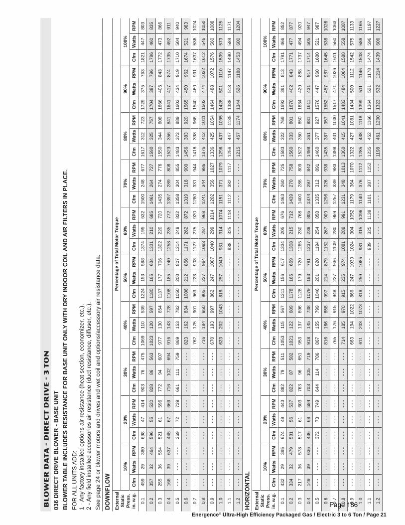
Energence® Ultra-High Efficiency Packaged Gas / Electric 3 to 6 Ton / Page 21
BL
OW
ER
DA
TA
- D
IRE
CT
DR
IVE
- 3
TO
N03
6 D
IREC
T D
RIV
E B
LOW
ER -
BA
SE U
NIT
B
LOW
ER T
AB
LE IN
CLU
DES
RES
ISTA
NC
E FO
R B
ASE
UN
IT O
NLY
WIT
H D
RY IN
DO
OR
CO
IL A
ND
AIR
FIL
TER
S IN
PLA
CE.
FOR
ALL
UN
ITS
ADD
: 1
- Any
fact
ory
inst
alle
d op
tions
air
resi
stan
ce (h
eat s
ectio
n, e
cono
miz
er, e
tc.).
2
- Any
fiel
d in
stal
led
acce
ssor
ies
air r
esis
tanc
e (d
uct r
esis
tanc
e, d
iffus
er, e
tc.).
See
page
24
or b
low
er m
otor
s an
d dr
ives
and
wet
coi
l and
opt
ions
/acc
esso
ry a
ir re
sist
ance
dat
a.D
OW
NFL
OW
Exte
rnal
St
atic
Pr
ess.
in
. w.g
.
Perc
enta
ge o
f Tot
al M
otor
Tor
que
10%
20%
30%
40%
50%
60%
70%
80%
90%
100%
Cfm
Wat
tsR
PMC
fmW
atts
RPM
Cfm
Wat
tsR
PMC
fmW
atts
RPM
Cfm
Wat
tsR
PMC
fmW
atts
RPM
Cfm
Wat
tsR
PMC
fmW
atts
RPM
Cfm
Wat
tsR
PMC
fmW
atts
RPM
0.1
459
2938
069
847
414
903
7647
510
6911
053
912
2415
359
813
7419
563
215
0024
867
716
1731
272
317
2937
576
318
2144
780
3
0.2
357
3246
459
655
520
828
8656
310
2312
059
711
8016
563
413
3121
068
514
6126
472
715
9032
575
717
0438
779
617
9646
083
5
0.3
255
3655
452
161
596
772
9460
797
713
065
411
3717
770
613
0222
072
014
3527
477
615
5034
480
816
6640
684
317
7247
386
6
0.4
166
3963
744
567
669
716
102
694
916
143
728
1108
185
740
1258
235
772
1397
289
808
1523
356
841
1641
417
874
1735
492
911
0.5
- - -
- - -
- - -
369
7273
966
111
175
986
915
378
210
5020
080
712
1424
982
213
5830
485
514
8337
288
916
0343
491
917
1050
494
0
0.6
- - -
- - -
- - -
- - -
- - -
- - -
- - -
- - -
- - -
823
162
834
1006
212
856
1171
262
872
1319
318
900
1456
383
920
1565
450
962
1674
521
983
0.7
- - -
- - -
- - -
- - -
- - -
- - -
- - -
- - -
- - -
762
175
901
963
223
903
1127
275
920
1280
331
944
1416
398
966
1540
460
991
1637
536
1024
0.8
- - -
- - -
- - -
- - -
- - -
- - -
- - -
- - -
- - -
716
184
950
905
237
964
1083
287
968
1241
344
986
1376
412
1011
1502
474
1032
1612
546
1050
0.9
- - -
- - -
- - -
- - -
- - -
- - -
- - -
- - -
- - -
670
193
997
862
247
1007
1040
299
1014
1202
356
1027
1336
425
1054
1464
488
1072
1576
560
1088
1.0
- - -
- - -
- - -
- - -
- - -
- - -
- - -
- - -
- - -
623
202
1043
818
257
1049
981
314
1074
1151
371
1079
1296
437
1095
1426
501
1110
1539
573
1125
1.1
- - -
- - -
- - -
- - -
- - -
- - -
- - -
- - -
- - -
- - -
- - -
- - -
- - -
- - -
- - -
938
325
1118
1112
382
1117
1256
447
1135
1388
513
1147
1490
589
1171
1.2
- - -
- - -
- - -
- - -
- - -
- - -
- - -
- - -
- - -
- - -
- - -
- - -
- - -
- - -
- - -
- - -
- - -
- - -
- - -
- - -
- - -
1215
457
1174
1344
526
1188
1453
600
1204
HO
RIZ
ON
TAL
Exte
rnal
St
atic
Pr
ess.
in
. w.g
.
Perc
enta
ge o
f Tot
al M
otor
Tor
que
10%
20%
30%
40%
50%
60%
70%
80%
90%
100%
Cfm
Wat
tsR
PMC
fmW
atts
RPM
Cfm
Wat
tsR
PMC
fmW
atts
RPM
Cfm
Wat
tsR
PMC
fmW
atts
RPM
Cfm
Wat
tsR
PMC
fmW
atts
RPM
Cfm
Wat
tsR
PMC
fmW
atts
RPM
0.1
432
2939
567
449
443
882
7951
110
5311
556
712
1115
661
713
3420
567
614
6326
072
515
8332
276
916
9239
181
317
9146
685
2
0.2
334
3247
958
156
537
822
8758
210
2112
260
911
7816
565
913
0821
571
214
3927
075
815
6033
380
116
7040
284
317
7147
787
7
0.3
217
3657
851
761
603
763
9665
195
313
769
611
2817
972
012
6523
076
814
0028
680
915
2235
085
016
3442
088
817
3749
492
0
0.4
149
3963
643
668
684
703
105
719
918
145
738
1079
193
781
1237
239
805
1374
297
842
1498
361
881
1611
431
917
1714
505
947
0.5
- - -
- - -
- - -
372
7374
964
411
478
686
715
579
910
4620
182
011
9425
485
813
3531
289
114
6037
792
715
7644
796
016
8052
198
7
0.6
- - -
- - -
- - -
- - -
- - -
- - -
- - -
- - -
- - -
816
166
858
997
214
879
1152
267
909
1296
326
938
1435
387
957
1552
457
987
1645
536
1026
0.7
- - -
- - -
- - -
- - -
- - -
- - -
- - -
- - -
- - -
765
176
915
948
227
936
1109
280
959
1257
339
983
1398
401
1000
1517
471
1026
1611
550
1063
0.8
- - -
- - -
- - -
- - -
- - -
- - -
- - -
- - -
- - -
714
185
970
915
235
974
1081
288
991
1231
348
1013
1360
415
1041
1482
484
1064
1588
558
1087
0.9
- - -
- - -
- - -
- - -
- - -
- - -
- - -
- - -
- - -
663
194
1022
866
247
1030
1024
304
1052
1179
364
1070
1322
427
1081
1434
500
1112
1542
575
1133
1.0
- - -
- - -
- - -
- - -
- - -
- - -
- - -
- - -
- - -
611
203
1073
816
259
1085
981
315
1096
1140
376
1112
1285
438
1118
1399
511
1146
1508
586
1165
1.1
- - -
- - -
- - -
- - -
- - -
- - -
- - -
- - -
- - -
- - -
- - -
- - -
- - -
- - -
- - -
939
325
1138
1101
387
1152
1235
452
1166
1364
521
1178
1474
596
1197
1.2
- - -
- - -
- - -
- - -
- - -
- - -
- - -
- - -
- - -
- - -
- - -
- - -
- - -
- - -
- - -
- - -
- - -
- - -
- - -
- - -
- - -
1198
461
1200
1323
532
1214
1439
606
1227
Page 186

Energence® Ultra-High Efficiency Packaged Gas / Electric 3 to 6 Ton / Page 22
BL
OW
ER
DA
TA
- D
IRE
CT
DR
IVE
- 4
TO
N04
8 D
IREC
T D
RIV
E B
LOW
ER -
BA
SE U
NIT
B
LOW
ER T
AB
LE IN
CLU
DES
RES
ISTA
NC
E FO
R B
ASE
UN
IT O
NLY
WIT
H D
RY IN
DO
OR
CO
IL A
ND
AIR
FIL
TER
S IN
PLA
CE.
FOR
ALL
UN
ITS
ADD
: 1
- Any
fact
ory
inst
alle
d op
tions
air
resi
stan
ce (h
eat s
ectio
n, e
cono
miz
er, e
tc.).
2
- Any
fiel
d in
stal
led
acce
ssor
ies
air r
esis
tanc
e (d
uct r
esis
tanc
e, d
iffus
er, e
tc.).
See
page
24
for b
low
er m
otor
s an
d dr
ives
and
wet
coi
l and
opt
ions
/acc
esso
ry a
ir re
sist
ance
dat
a.D
OW
NFL
OW
Exte
rnal
St
atic
Pr
ess.
in
. w.g
.
Perc
enta
ge o
f Tot
al M
otor
Tor
que
10%
20%
30%
40%
50%
60%
70%
80%
90%
100%
Cfm
Wat
tsR
PMC
fmW
atts
RPM
Cfm
Wat
tsR
PMC
fmW
atts
RPM
Cfm
Wat
tsR
PMC
fmW
atts
RPM
Cfm
Wat
tsR
PMC
fmW
atts
RPM
Cfm
Wat
tsR
PMC
fmW
atts
RPM
0.1
682
4642
089
479
499
1148
131
579
1366
192
651
1551
268
726
1725
348
781
1885
445
840
2031
550
893
2165
669
950
2290
790
993
0.2
583
5251
083
687
562
1105
142
635
1329
204
697
1530
279
756
1695
368
827
1856
466
883
2006
567
925
2149
683
972
2271
813
1023
0.3
484
5960
177
896
629
1062
152
688
1292
217
744
1500
294
800
1675
380
856
1837
479
910
1981
585
958
2125
704
1005
2252
834
1051
0.4
410
6466
672
010
569
710
1916
273
912
5523
179
214
6930
984
116
4539
789
818
0849
895
019
5660
399
221
0072
310
3622
3385
110
76
0.5
- - -
- - -
- - -
662
114
764
961
176
805
1218
244
840
1428
327
895
1615
414
937
1780
515
987
1931
622
1025
2076
741
1066
2205
874
1111
0.6
- - -
- - -
- - -
- - -
- - -
- - -
- - -
- - -
- - -
1182
257
887
1398
341
934
1585
429
974
1751
532
1022
1906
641
1058
2052
758
1095
2186
886
1131
0.7
- - -
- - -
- - -
- - -
- - -
- - -
- - -
- - -
- - -
1145
270
933
1367
354
972
1555
443
1009
1722
548
1056
1874
663
1098
2028
774
1122
2148
903
1167
0.8
- - -
- - -
- - -
- - -
- - -
- - -
- - -
- - -
- - -
1096
287
992
1326
372
1021
1515
462
1056
1693
564
1090
1850
679
1129
1996
792
1157
2111
913
1196
0.9
- - -
- - -
- - -
- - -
- - -
- - -
- - -
- - -
- - -
1047
302
1047
1296
385
1058
1485
476
1090
1664
579
1123
1824
693
1157
1963
807
1188
2073
916
1219
1.0
- - -
- - -
- - -
- - -
- - -
- - -
- - -
- - -
- - -
1010
312
1085
1255
403
1107
1455
491
1125
1635
594
1155
1787
710
1195
1931
818
1216
2036
912
1236
1.1
- - -
- - -
- - -
- - -
- - -
- - -
- - -
- - -
- - -
- - -
- - -
- - -
- - -
- - -
- - -
1425
505
1160
1606
609
1188
1762
717
1216
1883
828
1250
1960
890
1260
1.2
- - -
- - -
- - -
- - -
- - -
- - -
- - -
- - -
- - -
- - -
- - -
- - -
- - -
- - -
- - -
- - -
- - -
- - -
- - -
- - -
- - -
1687
715
1254
1834
827
1275
1848
834
1274
HO
RIZ
ON
TAL
Exte
rnal
St
atic
Pr
ess.
in
. w.g
.
Perc
enta
ge o
f Tot
al M
otor
Tor
que
10%
20%
30%
40%
50%
60%
70%
80%
90%
100%
Cfm
Wat
tsR
PMC
fmW
atts
RPM
Cfm
Wat
tsR
PMC
fmW
atts
RPM
Cfm
Wat
tsR
PMC
fmW
atts
RPM
Cfm
Wat
tsR
PMC
fmW
atts
RPM
Cfm
Wat
tsR
PMC
fmW
atts
RPM
0.1
641
4644
387
582
522
1127
137
614
1334
202
691
1524
280
762
1694
367
827
1866
470
881
1997
581
955
2119
699
1010
2241
830
1058
0.2
568
5050
583
190
582
1097
144
650
1310
211
723
1504
290
793
1671
379
859
1829
484
921
1977
600
986
2106
715
1032
2227
846
1080
0.3
483
5658
477
898
647
1050
155
706
1269
225
777
1470
308
844
1642
396
900
1799
498
957
1953
621
1022
2079
743
1072
2199
873
1118
0.4
398
6266
172
410
670
710
0416
776
412
2824
083
114
3632
589
116
1241
394
117
7751
198
519
3064
010
5520
6275
810
9621
8188
811
40
0.5
- - -
- - -
- - -
671
113
763
957
179
822
1201
250
867
1413
335
921
1588
427
973
1748
530
1025
1906
657
1087
2036
777
1129
2153
904
1170
0.6
- - -
- - -
- - -
- - -
- - -
- - -
- - -
- - -
- - -
1161
265
919
1378
350
964
1552
447
1019
1718
549
1064
1874
676
1124
2000
796
1166
2115
917
1202
0.7
- - -
- - -
- - -
- - -
- - -
- - -
- - -
- - -
- - -
1120
279
970
1344
365
1006
1529
459
1049
1696
564
1093
1850
688
1150
1974
805
1189
2078
922
1228
0.8
- - -
- - -
- - -
- - -
- - -
- - -
- - -
- - -
- - -
1093
288
1003
1310
379
1047
1493
477
1091
1667
583
1131
1818
700
1180
1930
812
1220
2040
919
1246
0.9
- - -
- - -
- - -
- - -
- - -
- - -
- - -
- - -
- - -
1052
302
1051
1275
393
1087
1469
488
1118
1644
595
1158
1779
711
1213
1896
812
1239
1984
903
1265
1.0
- - -
- - -
- - -
- - -
- - -
- - -
- - -
- - -
- - -
1012
314
1096
1241
407
1128
1434
502
1155
1615
610
1191
1747
715
1235
1843
802
1259
1910
865
1276
1.1
- - -
- - -
- - -
- - -
- - -
- - -
- - -
- - -
- - -
- - -
- - -
- - -
- - -
- - -
- - -
1386
516
1201
1571
625
1232
1684
713
1266
1738
760
1277
1760
775
1282
1.2
- - -
- - -
- - -
- - -
- - -
- - -
- - -
- - -
- - -
- - -
- - -
- - -
- - -
- - -
- - -
- - -
- - -
- - -
- - -
- - -
- - -
1620
697
1282
1633
707
1283
1667
736
1296
Page 187

Energence® Ultra-High Efficiency Packaged Gas / Electric 3 to 6 Ton / Page 23
BL
OW
ER
DA
TA
- D
IRE
CT
DR
IVE
- 5
AN
D 6
TO
N06
0/07
4 D
IREC
T D
RIV
E B
LOW
ER -
BA
SE U
NIT
B
LOW
ER T
AB
LE IN
CLU
DES
RES
ISTA
NC
E FO
R B
ASE
UN
IT O
NLY
WIT
H D
RY IN
DO
OR
CO
IL A
ND
AIR
FIL
TER
S IN
PLA
CE.
FOR
ALL
UN
ITS
ADD
: 1
- Any
fact
ory
inst
alle
d op
tions
air
resi
stan
ce (h
eat s
ectio
n, e
cono
miz
er, e
tc.).
2
- Any
fiel
d in
stal
led
acce
ssor
ies
air r
esis
tanc
e (d
uct r
esis
tanc
e, d
iffus
er, e
tc.).
See
page
24
for b
low
er m
otor
s an
d dr
ives
and
wet
coi
l and
opt
ions
/acc
esso
ry a
ir re
sist
ance
dat
a.D
OW
NFL
OW
Exte
rnal
St
atic
Pr
ess.
in
. w.g
.
Perc
enta
ge o
f Tot
al M
otor
Tor
que
10%
20%
30%
40%
50%
60%
70%
80%
90%
100%
Cfm
Wat
tsR
PMC
fmW
atts
RPM
Cfm
Wat
tsR
PMC
fmW
atts
RPM
Cfm
Wat
tsR
PMC
fmW
atts
RPM
Cfm
Wat
tsR
PMC
fmW
atts
RPM
Cfm
Wat
tsR
PMC
fmW
atts
RPM
0.1
743
5842
899
210
049
212
8416
155
615
2623
160
717
2632
767
818
9042
773
720
7255
780
022
2068
684
823
6284
290
124
7899
693
8
0.2
661
6549
792
811
055
612
3117
561
014
7925
166
216
8534
872
618
7244
076
120
5257
482
721
9870
587
623
4486
092
524
6810
1696
9
0.3
579
7156
388
111
860
211
7918
866
314
3127
071
616
5836
275
718
3546
680
720
2459
786
321
7672
490
323
2288
195
224
4810
3599
3
0.4
518
7661
181
812
866
211
2620
271
614
0028
375
116
1838
380
218
1148
383
719
9561
989
821
5374
393
023
0190
097
824
2810
5310
16
0.5
- - -
- - -
- - -
754
138
719
1074
216
768
1352
301
801
1578
403
847
1775
507
881
1972
636
925
2120
769
968
2280
919
1002
2403
1074
1043
0.6
- - -
- - -
- - -
- - -
- - -
- - -
- - -
- - -
- - -
1305
319
850
1551
416
875
1738
529
922
1938
659
963
2098
785
992
2248
945
1037
2383
1090
1064
0.7
- - -
- - -
- - -
- - -
- - -
- - -
- - -
- - -
- - -
1273
330
882
1511
434
917
1714
544
948
1903
681
1000
2064
808
1026
2227
961
1059
2353
1113
1094
0.8
- - -
- - -
- - -
- - -
- - -
- - -
- - -
- - -
- - -
1226
347
928
1470
453
957
1678
564
986
1869
701
1033
2031
830
1058
2195
983
1090
2323
1133
1121
0.9
- - -
- - -
- - -
- - -
- - -
- - -
- - -
- - -
- - -
1178
363
972
1430
470
997
1641
583
1022
1835
720
1065
1998
849
1088
2163
1004
1119
2293
1151
1147
1.0
- - -
- - -
- - -
- - -
- - -
- - -
- - -
- - -
- - -
1147
374
1000
1390
487
1034
1605
601
1057
1800
737
1094
1953
873
1125
2131
1022
1146
2263
1167
1170
1.1
- - -
- - -
- - -
- - -
- - -
- - -
- - -
- - -
- - -
- - -
- - -
- - -
- - -
- - -
- - -
1556
623
1099
1755
756
1129
1920
888
1151
2089
1043
1177
2203
1193
1211
1.2
- - -
- - -
- - -
- - -
- - -
- - -
- - -
- - -
- - -
- - -
- - -
- - -
- - -
- - -
- - -
- - -
- - -
- - -
- - -
- - -
- - -
1875
906
1181
2036
1063
1211
2169
1213
1227
HO
RIZ
ON
TAL
Exte
rnal
St
atic
Pr
ess.
in
. w.g
.
Perc
enta
ge o
f Tot
al M
otor
Tor
que
10%
20%
30%
40%
50%
60%
70%
80%
90%
100%
Cfm
Wat
tsR
PMC
fmW
atts
RPM
Cfm
Wat
tsR
PMC
fmW
atts
RPM
Cfm
Wat
tsR
PMC
fmW
atts
RPM
Cfm
Wat
tsR
PMC
fmW
atts
RPM
Cfm
Wat
tsR
PMC
fmW
atts
RPM
0.1
695
4943
110
5188
470
1280
157
562
1430
314
665
1615
420
753
1798
526
807
1957
656
873
2100
793
925
2228
947
979
2351
1107
1022
0.2
610
5549
597
396
543
1233
166
607
1382
332
715
1589
433
782
1762
547
847
1927
677
905
2079
808
947
2207
965
1002
2332
1126
1043
0.3
525
6156
091
410
461
211
8617
765
713
4734
575
215
6344
681
117
3856
187
319
0769
092
720
4783
097
921
8698
210
2423
0811
4810
69
0.4
461
6661
185
611
569
511
3819
071
413
1235
878
815
2546
485
317
0258
191
118
7770
995
820
2684
499
921
6599
810
4622
8911
6410
88
0.5
- - -
- - -
- - -
822
122
749
1095
202
772
1277
370
823
1486
482
893
1678
593
936
1847
726
987
1995
864
1030
2144
1013
1067
2264
1182
1111
0.6
- - -
- - -
- - -
- - -
- - -
- - -
- - -
- - -
- - -
1242
382
857
1460
494
919
1642
612
972
1827
738
1007
1974
877
1050
2112
1035
1096
2239
1197
1133
0.7
- - -
- - -
- - -
- - -
- - -
- - -
- - -
- - -
- - -
1194
398
901
1421
510
957
1618
624
995
1787
760
1044
1943
896
1079
2091
1048
1115
2208
1213
1158
0.8
- - -
- - -
- - -
- - -
- - -
- - -
- - -
- - -
- - -
1148
413
943
1382
527
993
1582
641
1029
1757
775
1071
1912
914
1107
2059
1065
1142
2184
1223
1176
0.9
- - -
- - -
- - -
- - -
- - -
- - -
- - -
- - -
- - -
1112
424
974
1343
542
1028
1546
657
1061
1727
789
1096
1880
932
1135
2028
1081
1167
2147
1233
1200
1.0
- - -
- - -
- - -
- - -
- - -
- - -
- - -
- - -
- - -
1069
438
1011
1305
557
1062
1510
673
1092
1687
807
1129
1849
948
1162
1996
1095
1191
2110
1238
1221
1.1
- - -
- - -
- - -
- - -
- - -
- - -
- - -
- - -
- - -
- - -
- - -
- - -
- - -
- - -
- - -
1474
688
1122
1652
822
1156
1818
964
1188
1964
1107
1212
2060
1235
1243
1.2
- - -
- - -
- - -
- - -
- - -
- - -
- - -
- - -
- - -
- - -
- - -
- - -
- - -
- - -
- - -
- - -
- - -
- - -
- - -
- - -
- - -
1781
982
1217
1912
1123
1245
2010
1221
1258
Page 188

Energence® Ultra-High Efficiency Packaged Gas / Electric 3 to 6 Ton / Page 24
FACTORY INSTALLED OPTIONS/FIELD INSTALLED ACCESSORY AIR RESISTANCE - in. w.g.Air
Volume cfm
Wet Indoor Coil Gas HeatingEconomizer
Filters
036, 048 060, 074 Medium Heat High Heat MERV 8 MERV 13
800 0.01 - - - 0.02 0.02 0.04 0.04 0.051000 0.02 0.02 0.02 0.02 0.04 0.04 0.071200 0.03 0.04 0.02 0.02 0.04 0.04 0.071400 0.04 0.05 0.02 0.03 0.04 0.04 0.071600 0.05 0.07 0.03 0.04 0.04 0.04 0.071800 0.06 0.08 0.04 0.05 0.05 0.04 0.072000 0.08 0.10 0.04 0.06 0.05 0.05 0.082200 - - - 0.11 0.04 0.07 0.05 0.05 0.082400 - - - 0.13 0.05 0.08 0.05 0.05 0.08
POWER EXHAUST FAN PERFORMANCE Return Air System Static
Pressure in. w.g.
Air Volume Exhausted cfm
0.00 20000.05 19900.10 19240.15 18100.20 16640.25 15070.30 13500.35 1210
BLOWER DATA
CEILING DIFFUSERS AIR RESISTANCE (in. w.g.)
Air Volume - cfmRTD11-95S Step-Down Diffuser FD11-95S
Flush Diffuser
2 Ends Open
1 Side & 2 Ends Open All Ends & Sides Open
1800 0.13 0.11 0.09 0.092000 0.15 0.13 0.11 0.102200 0.18 0.15 0.12 0.122400 0.21 0.18 0.15 0.142600 0.24 0.21 0.18 0.172800 0.27 0.24 0.21 0.203000 0.32 0.29 0.25 0.25
CEILING DIFFUSER AIR THROW DATAAir Volume - cfm 1 Effective Throw - ft.
RTD11-95S FD11-95S2600 24 - 29 19 - 242800 25 - 30 20 - 283000 27 - 33 21 - 29
1 Effective throw based on terminal velocities of 75 ft. per minute.
Page 189

Energence™ Packaged Electric / Electric 35 to 50 Ton / Page 47
BLOWER DATA
BLOWER TABLE INCLUDES RESISTANCE FOR BASE UNIT ONLY WITH DRY INDOOR COIL, ELECTRIC HEAT, ECONOMIZER,ONE ROW REHEAT COIL & AIR FILTERS IN PLACE
Add factory installed options air resistance, then determine from blower table blower motor output and drive kit required. See page 53 for horizontal configured unit air resistance. See page 54 for factory installed options air resistance data. See page 55 for factory installed drive kit specifications.
TOTAL STATIC PRESSURE - 0.2 Thru 2.4 in. w.g. For 2.6 thru 4.6 in. w.g., see next page
Air Volume
cfm
0.20 0.40 0.60 0.80 1.0 1.2 1.4 1.6 1.8 2.0 2.2 2.4
RPM BHP RPM BHP RPM BHP RPM BHP RPM BHP RPM BHP RPM BHP RPM BHP RPM BHP RPM BHP RPM BHP RPM BHP
10,500 460 3.25 500 3.25 535 3.45 575 3.90 620 4.50 670 5.40 715 6.25 755 7.05 790 7.75 820 8.40 850 9.05 - - - - - -
11,000 490 3.70 520 3.75 550 3.90 585 4.25 630 4.85 675 5.65 720 6.55 760 7.40 795 8.20 830 9.00 860 9.70 890 10.40
11,500 520 4.25 540 4.25 565 4.35 600 4.70 635 5.20 680 5.95 725 6.85 765 7.75 805 8.70 840 9.60 870 10.35 900 11.10
12,000 540 4.80 555 4.80 580 4.90 610 5.15 650 5.70 690 6.40 730 7.20 770 8.15 810 9.10 845 10.05 880 10.95 910 11.80
12,500 560 5.45 575 5.45 600 5.50 625 5.70 660 6.15 695 6.75 735 7.55 780 8.60 815 9.55 850 10.50 885 11.50 915 12.35
13,000 580 6.10 600 6.10 620 6.20 645 6.35 675 6.75 705 7.25 745 8.05 785 9.00 820 9.95 860 11.10 895 12.15 925 13.05
13,500 600 6.85 615 6.85 635 6.85 660 7.05 685 7.30 720 7.90 750 8.50 790 9.45 830 10.50 865 11.55 900 12.65 930 13.60
14,000 620 7.60 635 7.60 655 7.65 675 7.75 700 8.05 730 8.50 760 9.05 795 9.85 835 10.95 870 12.00 905 13.15 940 14.30
14,500 640 8.45 660 8.45 675 8.50 690 8.55 720 8.85 745 9.20 775 9.80 805 10.50 840 11.45 875 12.50 910 13.65 945 14.85
15,000 665 9.35 680 9.35 690 9.40 715 9.50 735 9.70 755 9.95 785 10.50 815 11.15 850 12.10 880 13.00 915 14.15 950 15.40
15,500 685 10.35 695 10.35 715 10.35 730 10.40 750 10.55 775 10.90 800 11.35 825 11.90 855 12.65 890 13.70 920 14.70 955 16.00
16,000 705 11.40 720 11.40 735 11.40 750 11.45 770 11.60 790 11.85 810 12.15 840 12.80 865 13.40 895 14.30 930 15.45 960 16.55
16,500 730 12.45 740 12.45 750 12.45 770 12.50 785 12.60 805 12.85 825 13.15 850 13.65 875 14.25 905 15.10 935 16.10 965 17.20
17,000 745 13.65 760 13.65 775 13.65 790 13.65 805 13.75 820 13.90 845 14.30 865 14.65 890 15.25 915 16.00 945 16.95 975 18.05
17,500 770 14.90 780 14.90 795 14.90 805 14.90 820 14.95 840 15.15 860 15.40 880 15.80 905 16.35 925 16.90 955 17.85 980 18.75
18,000 790 16.20 800 16.20 810 16.20 825 16.20 845 16.30 860 16.40 875 16.60 895 16.95 915 17.40 940 18.05 965 18.85 990 19.70
18,500 810 17.60 820 17.60 835 17.60 850 17.60 860 17.60 875 17.75 895 17.95 910 18.20 930 18.65 950 19.15 975 19.90 1000 20.75
19,000 830 19.05 845 19.05 855 19.05 865 19.05 880 19.05 895 19.15 910 19.35 930 19.65 945 19.95 965 20.45 990 21.15 1010 21.85
19,500 855 20.60 865 20.60 875 20.60 885 20.60 900 20.60 915 20.70 930 20.85 945 21.05 960 21.35 980 21.80 1000 22.35 1025 23.20
20,000 875 22.20 885 22.20 895 22.20 910 22.20 920 22.20 935 22.30 945 22.40 965 22.65 980 22.95 995 23.30 1015 23.80 1035 24.45
20,500 895 23.90 905 23.90 915 23.90 930 23.90 940 23.90 950 23.95 965 24.05 980 24.25 995 24.50 1010 24.85 1030 25.35 1050 25.95
21,000 920 25.70 925 25.70 935 25.70 945 25.70 960 25.70 970 25.75 985 25.85 1000 26.00 1010 26.20 1030 26.60 1045 26.95 1065 27.55
21,500 940 27.60 945 27.60 960 27.60 970 27.60 980 27.60 990 27.60 1000 27.65 1015 27.80 1030 28.00 1045 28.30 1060 28.65 1080 29.20
22,000 960 29.55 970 29.55 980 29.55 990 29.55 1000 29.55 1010 29.55 1025 29.65 1035 29.75 1050 29.95 1060 30.15 1075 30.45 1095 31.00
22,500 980 31.65 990 31.65 1000 31.65 1010 31.65 1020 31.65 1030 31.65 1045 31.70 1055 31.80 1065 31.90 1080 32.15 1095 32.45 1110 32.85
NOTE − Minimum CFM requirements for units with electric heat:LCH420 − 9800 cfm, LCH480 − 11,200 cfm, LCH540 − 12,600 cfm, LCH600 − 14,000 cfm.
Page 190

Energence™ Packaged Electric / Electric 35 to 50 Ton / Page 48
BLOWER DATA
BLOWER TABLE INCLUDES RESISTANCE FOR BASE UNIT ONLY WITH DRY INDOOR COIL, ELECTRIC HEAT, ECONOMIZER,ONE ROW REHEAT COIL & AIR FILTERS IN PLACE
Add factory installed options air resistance, then determine from blower table blower motor output and drive kit required. See page 53 for horizontal configured unit air resistance. See page 54 for factory installed options air resistance data. See page 55 for factory installed drive kit specifications.
TOTAL STATIC PRESSURE - 0.2 Thru 2.4 in. w.g. For .2 thru 2.4 in. w.g., see previous page
Air Volume
cfm
2.6 2.8 3.0 3.2 3.4 3.6 3.8 4.0 4.2 4.4 4.6
RPM BHP RPM BHP RPM BHP RPM BHP RPM BHP RPM BHP RPM BHP RPM BHP RPM BHP RPM BHP RPM BHP
8000 - - - - - - - - - - - - - - - - - - - - - - - - - - - - - - - - - - - - - - - - - - - - - - - - - - - - - - - - - - - - - - - - - -
8500 - - - - - - - - - - - - - - - - - - - - - - - - - - - - - - - - - - - - - - - - - - - - - - - - - - - - - - - - - - - - - - - - - -
9000 - - - - - - - - - - - - - - - - - - - - - - - - - - - - - - - - - - - - - - - - - - - - - - - - - - - - - - - - - - - - - - - - - -
9500 - - - - - - - - - - - - - - - - - - - - - - - - - - - - - - - - - - - - - - - - - - - - - - - - - - - - - - - - - - - - - - - - - -
10,000 - - - - - - - - - - - - - - - - - - - - - - - - - - - - - - - - - - - - - - - - - - - - - - - - - - - - - - - - - - - - - - - - - -
10,500 - - - - - - - - - - - - - - - - - - - - - - - - - - - - - - - - - - - - - - - - - - - - - - - - - - - - - - - - - - - - - - - - - -
11,000 - - - - - - - - - - - - - - - - - - - - - - - - - - - - - - - - - - - - - - - - - - - - - - - - - - - - - - - - - - - - - - - - - -
11,500 925 11.70 - - - - - - - - - - - - - - - - - - - - - - - - - - - - - - - - - - - - - - - - - - - - - - - - - - - - - - - - - - - -
12,000 935 12.50 965 13.30 - - - - - - - - - - - - - - - - - - - - - - - - - - - - - - - - - - - - - - - - - - - - - - - - - - - - - -
12,500 945 13.25 975 14.15 1000 14.90 - - - - - - - - - - - - - - - - - - - - - - - - - - - - - - - - - - - - - - - - - - - - - - - -
13,000 955 14.00 980 14.80 1010 15.75 1035 16.60 - - - - - - - - - - - - - - - - - - - - - - - - - - - - - - - - - - - - - - - - - -
13,500 960 14.60 990 15.65 1015 16.50 1045 17.55 1070 18.40 - - - - - - - - - - - - - - - - - - - - - - - - - - - - - - - - - - - -
14,000 970 15.35 1000 16.45 1025 17.35 1050 18.30 1075 19.20 1100 20.15 - - - - - - - - - - - - - - - - - - - - - - - - - - - - - -
14,500 975 15.95 1005 17.10 1035 18.25 1060 19.25 1085 20.20 1110 21.20 1135 22.25 - - - - - - - - - - - - - - - - - - - - - - - -
15,000 980 16.55 1010 17.70 1040 18.95 1070 20.15 1095 21.20 1120 22.30 1140 23.15 1165 24.20 1185 25.10 - - - - - - - - - - - -
15,500 985 17.15 1020 18.55 1045 19.60 1075 20.90 1100 22.00 1125 23.10 1150 24.25 1175 25.40 1195 26.30 1215 27.25 1235 28.15
16,000 995 17.95 1025 19.20 1055 20.50 1080 21.65 1110 23.00 1135 24.20 1160 25.35 1180 26.35 1205 27.55 1225 28.50 1245 29.50
16,500 1000 18.60 1030 19.85 1060 21.20 1085 22.35 1115 23.80 1140 25.00 1165 26.25 1190 27.50 1215 28.80 1235 29.80 1255 30.85
17,000 1005 19.25 1035 20.55 1065 21.90 1095 23.30 1120 24.55 1145 25.80 1170 27.10 1195 28.40 1220 29.75 1245 31.10 1265 32.20
17,500 1010 19.95 1040 21.25 1070 22.60 1100 24.05 1125 25.30 1155 26.90 1180 28.25 1205 29.60 1225 30.70 1250 32.15 1275 33.55
18,000 1020 20.90 1045 21.95 1075 23.35 1105 24.80 1130 26.10 1160 27.70 1185 29.10 1210 30.50 1235 31.95 1260 33.40 1280 34.60
18,500 1025 21.70 1055 23.00 1080 24.15 1110 25.60 1135 26.90 1165 28.55 1190 29.95 1215 31.40 1240 32.90 1265 34.40 - - - - - -
19,000 1035 22.80 1060 23.85 1090 25.20 1115 26.45 1145 28.00 1170 29.40 1195 30.85 1220 32.30 1245 33.85 1270 35.40 - - - - - -
19,500 1045 23.95 1070 24.95 1095 26.10 1125 27.55 1150 28.90 1175 30.25 1200 31.75 1225 33.25 1255 35.10 - - - - - - - - - - - -
20,000 1060 25.35 1080 26.15 1105 27.30 1130 28.50 1155 29.80 1180 31.20 1205 32.65 1235 34.50 - - - - - - - - - - - - - - - - - -
20,500 1070 26.65 1090 27.45 1115 28.55 1140 29.75 1165 31.05 1190 32.45 1215 33.90 - - - - - - - - - - - - - - - - - - - - - - - -
21,000 1085 28.25 1105 29.00 1125 29.90 1150 31.05 1170 32.10 1195 33.45 - - - - - - - - - - - - - - - - - - - - - - - - - - - - - -
21,500 1095 29.70 1115 30.45 1135 31.30 1160 32.45 1180 33.45 - - - - - - - - - - - - - - - - - - - - - - - - - - - - - - - - - - - -
22,000 1110 31.45 1130 32.20 1150 33.00 1170 33.95 - - - - - - - - - - - - - - - - - - - - - - - - - - - - - - - - - - - - - - - - - -
22,500 1125 33.30 1145 34.05 - - - - - - - - - - - - - - - - - - - - - - - - - - - - - - - - - - - - - - - - - - - - - - - - - - - - - -
NOTE − Minimum CFM requirements for units with electric heat:LCH420 − 9800 cfm, LCH480 − 11,200 cfm, LCH540 − 12,600 cfm, LCH600 − 14,000 cfm.
Page 191

Energence™ Packaged Electric / Electric 35 to 50 Ton / Page 49
BLOWER DATAPOWER EXHAUST FANS 1 50% HIGH STATIC OPERATION, NO ERW
Air Volume
cfm
Return Duct Negative Static Pressure - Inches Water Gauge (Pa)
0 0.1 0.2 0.3 0.4 0.5 0.6 0.7 0.8 0.9 1.0
RPM BHP RPM BHP RPM BHP RPM BHP RPM BHP RPM BHP RPM BHP RPM BHP RPM BHP RPM BHP RPM BHP
4000 410 0.75 465 1.00 520 1.25 575 1.50 630 1.80 685 2.15 740 2.50 795 2.85 845 3.25 900 3.70 955 4.15
4500 460 1.10 510 1.35 560 1.60 610 1.90 655 2.20 705 2.55 755 2.90 805 3.30 850 3.70 900 4.15 945 4.55
5000 510 1.50 555 1.75 600 2.05 645 2.40 690 2.70 735 3.10 775 3.40 820 3.85 865 4.25 910 4.70 950 5.15
5500 560 2.00 600 2.25 645 2.60 685 2.95 725 3.30 765 3.70 805 4.05 845 4.50 885 4.90 925 5.35 965 5.85
6000 610 2.55 650 2.90 685 3.25 725 3.60 760 3.95 800 4.40 835 4.80 870 5.20 910 5.65 945 6.10 980 6.55
6500 665 3.30 700 3.65 730 3.95 765 4.35 800 4.75 835 5.20 870 5.60 905 6.10 935 6.50 970 7.00 1005 7.50
7000 715 4.10 745 4.45 780 4.90 810 5.25 840 5.65 875 6.15 905 6.55 940 7.05 970 7.50 1000 8.00 1030 8.50
7500 765 5.05 795 5.45 825 5.85 855 6.30 885 6.75 915 7.20 945 7.65 975 8.15 - - - - - - - - - - - - - - - - - -
8000 815 6.10 845 6.55 870 6.95 900 7.45 930 7.95 955 8.35 - - - - - - - - - - - - - - - - - - - - - - - - - - - - - -
8500 865 7.30 895 7.80 920 8.25 - - - - - - - - - - - - - - - - - - - - - - - - - - - - - - - - - - - - - - - - - - - - - - - -
POWER EXHAUST FANS 1 100% HIGH STATIC OPERATION, NO ERW
Air Volume
cfm
Return Duct Negative Static Pressure - Inches Water Gauge (Pa)
0 0.1 0.2 0.3 0.4 0.5 0.6 0.7 0.8 0.9 1.0
RPM BHP RPM BHP RPM BHP RPM BHP RPM BHP RPM BHP RPM BHP RPM BHP RPM BHP RPM BHP RPM BHP
8000 410 1.45 450 1.70 495 2.05 535 2.35 580 2.70 625 3.10 665 3.50 710 3.95 750 4.40 790 4.85 835 5.35
8500 435 1.70 475 2.00 515 2.35 555 2.70 595 3.05 635 3.45 675 3.85 715 4.30 755 4.75 795 5.25 835 5.75
9000 460 2.05 495 2.35 535 2.70 575 3.05 610 3.40 650 3.85 690 4.30 725 4.70 765 5.20 800 5.65 840 6.20
9500 485 2.40 520 2.70 555 3.05 595 3.45 630 3.85 665 4.25 700 4.70 740 5.20 775 5.65 810 6.15 845 6.65
10,000 510 2.80 545 3.15 580 3.50 615 3.90 650 4.35 680 4.70 715 5.15 750 5.65 785 6.15 820 6.65 855 7.20
10,500 535 3.20 570 3.60 600 3.95 635 4.40 665 4.80 700 5.25 730 5.70 765 6.20 795 6.65 830 7.20 860 7.70
11,000 560 3.70 590 4.05 625 4.50 655 4.90 685 5.35 720 5.85 750 6.30 780 6.75 810 7.25 840 7.75 875 8.40
11,500 585 4.20 615 4.60 645 5.05 675 5.45 705 5.90 735 6.40 765 6.90 795 7.40 825 7.90 855 8.45 885 9.00
12,000 610 4.80 640 5.20 670 5.70 700 6.15 725 6.55 755 7.05 785 7.60 815 8.10 840 8.60 870 9.15 900 9.75
12,500 635 5.40 665 5.90 690 6.30 720 6.80 750 7.30 775 7.75 805 8.30 830 8.80 860 9.40 885 9.90 915 10.55
13,000 660 6.10 690 6.60 715 7.00 740 7.45 770 8.05 795 8.50 820 9.00 850 9.65 875 10.15 900 10.70 930 11.35
13,500 690 6.90 715 7.35 740 7.80 765 8.30 790 8.80 815 9.30 840 9.85 865 10.40 895 11.05 920 11.65 945 12.20
14,000 715 7.65 740 8.15 765 8.65 785 9.10 810 9.60 835 10.15 860 10.70 885 11.30 910 11.90 935 12.50 960 13.10
14,500 740 8.50 765 9.05 785 9.45 810 10.00 835 10.60 860 11.20 880 11.65 905 12.25 930 12.90 955 13.55 975 14.05
15,000 765 9.40 785 9.85 810 10.45 835 11.05 855 11.50 880 12.15 905 12.75 925 13.30 950 13.95 970 14.50 995 15.20
15,500 790 10.35 810 10.85 835 11.45 855 11.95 880 12.60 900 13.15 925 13.80 945 14.35 970 15.05 990 15.65 1015 16.35
16,000 815 11.40 835 11.90 860 12.55 880 13.10 900 13.65 925 14.35 945 14.90 965 15.50 990 16.20 1010 16.85 - - - - - -
16,500 840 12.50 860 13.05 885 13.70 905 14.30 925 14.85 945 15.45 965 16.05 990 16.80 - - - - - - - - - - - - - - - - - -
17,000 865 13.65 885 14.20 905 14.80 925 15.40 950 16.15 970 16.80 - - - - - - - - - - - - - - - - - - - - - - - - - - - - - -
17,500 890 14.85 910 15.50 930 16.10 950 16.75 - - - - - - - - - - - - - - - - - - - - - - - - - - - - - - - - - - - - - - - - - -
18,000 915 16.15 935 16.80 - - - - - - - - - - - - - - - - - - - - - - - - - - - - - - - - - - - - - - - - - - - - - - - - - - - - - -
NOTE - See page 55 for factory installed drive kit specifications. 1 Size power exhaust fans in economizer mode to minimize building static pressure during free” cooling.
Page 192

Energence™ Packaged Electric / Electric 35 to 50 Ton / Page 50
BLOWER DATAPOWER EXHAUST FANS 1 50% HIGH STATIC OPERATION WITH ERW (BY-PASS DAMPERS CLOSED)
Air Volume
cfm
Return Duct Negative Static Pressure - Inches Water Gauge (Pa)
0 0.1 0.2 0.3 0.4 0.5 0.6 0.7 0.8 0.9 1.0
RPM BHP RPM BHP RPM BHP RPM BHP RPM BHP RPM BHP RPM BHP RPM BHP RPM BHP RPM BHP RPM BHP
2500 390 0.35 460 0.50 530 0.70 600 0.90 670 1.15 735 1.40 805 1.70 870 2.00 935 2.35 1005 2.75 1070 3.10
3000 465 0.60 525 0.75 585 1.00 645 1.20 700 1.45 760 1.75 815 2.05 870 2.35 930 2.70 985 3.05 1040 3.45
3500 545 0.95 595 1.15 645 1.35 695 1.60 745 1.90 795 2.20 845 2.50 895 2.85 945 3.20 990 3.55 1040 3.95
4000 620 1.35 665 1.60 710 1.90 755 2.15 800 2.45 840 2.75 885 3.10 930 3.45 975 3.80 1015 4.15 1060 4.60
4500 700 1.95 740 2.25 780 2.55 820 2.85 855 3.10 895 3.45 935 3.80 975 4.20 1015 4.60 1050 4.95 - - - - - -
5000 775 2.70 815 3.00 850 3.30 885 3.65 920 4.00 955 4.35 990 4.70 1025 5.10 1060 5.50 - - - - - - - - - - - -
5500 855 3.60 885 3.90 920 4.25 950 4.60 985 5.00 1015 5.35 1050 5.75 - - - - - - - - - - - - - - - - - - - - - - - -
6000 935 4.70 965 5.05 990 5.35 1020 5.75 1050 6.15 - - - - - - - - - - - - - - - - - - - - - - - - - - - - - - - - - - - -
POWER EXHAUST FANS 1 100% HIGH STATIC OPERATION WITH ERW (BY-PASS DAMPERS CLOSED)
Air Volume
cfm
Return Duct Negative Static Pressure - Inches Water Gauge (Pa)
0 0.1 0.2 0.3 0.4 0.5 0.6 0.7 0.8 0.9 1.0
RPM BHP RPM BHP RPM BHP RPM BHP RPM BHP RPM BHP RPM BHP RPM BHP RPM BHP RPM BHP RPM BHP
5000 445 0.85 505 1.15 565 1.45 625 1.85 680 2.20 740 2.65 800 3.15 855 3.60 910 4.15 970 4.75 1025 5.30
5500 490 1.15 545 1.45 600 1.80 650 2.15 705 2.55 760 3.05 810 3.50 865 4.00 915 4.55 970 5.15 1020 5.70
6000 535 1.45 585 1.80 635 2.15 685 2.60 735 3.00 780 3.45 830 3.95 880 4.50 925 5.00 975 5.60 1020 6.15
6500 580 1.85 625 2.20 670 2.60 715 3.00 760 3.45 805 3.95 850 4.45 895 4.95 940 5.50 985 6.10 1030 6.75
7000 625 2.35 665 2.70 710 3.15 750 3.55 795 4.05 835 4.50 880 5.05 920 5.60 960 6.15 1005 6.80 1045 7.40
7500 670 2.90 710 3.30 750 3.75 790 4.20 825 4.65 865 5.15 905 5.70 945 6.25 985 6.85 1025 7.50 1060 8.05
8000 715 3.50 750 3.90 790 4.40 825 4.85 860 5.35 900 5.90 935 6.45 975 7.05 1010 7.65 1045 8.25 - - - - - -
8500 760 4.20 795 4.65 830 5.15 865 5.65 900 6.20 935 6.75 970 7.30 1000 7.85 1035 8.45 1070 9.10 - - - - - -
9000 800 4.90 835 5.45 870 5.95 900 6.45 935 7.05 970 7.65 1000 8.20 1035 8.85 1065 9.40 - - - - - - - - - - - -
9500 845 5.80 880 6.35 910 6.85 940 7.40 975 8.05 1005 8.60 1035 9.20 1065 9.80 - - - - - - - - - - - - - - - - - -
10,000 890 6.75 920 7.30 950 7.85 980 8.45 1010 9.05 1040 9.65 1070 10.30 - - - - - - - - - - - - - - - - - - - - - - - -
10,500 935 7.85 965 8.45 995 9.05 1020 9.60 1050 10.25 - - - - - - - - - - - - - - - - - - - - - - - - - - - - - - - - - - - -
11,000 980 9.00 1010 9.65 1035 10.25 1060 10.80 - - - - - - - - - - - - - - - - - - - - - - - - - - - - - - - - - - - - - - - - - -
11,500 1025 10.30 1050 10.90 - - - - - - - - - - - - - - - - - - - - - - - - - - - - - - - - - - - - - - - - - - - - - - - - - - - - - -
12,000 1070 11.75 - - - - - - - - - - - - - - - - - - - - - - - - - - - - - - - - - - - - - - - - - - - - - - - - - - - - - - - - - - - -
NOTE - See page 55 for factory installed drive kit specifications. 1 Size power exhaust fans with ERW in economizer mode to minimize building static pressure during free” cooling.
Page 193

Energence™ Packaged Electric / Electric 35 to 50 Ton / Page 51
BLOWER DATAPOWER EXHAUST FANS 1 50% HIGH STATIC OPERATION WITH ERW IN ECONOMIZER MODE (BY-PASS DAMPERS OPEN)
Air Volume
cfm
Return Duct Negative Static Pressure - Inches Water Gauge (Pa)
0 0.1 0.2 0.3 0.4 0.5 0.6 0.7 0.8 0.9 1.0
RPM BHP RPM BHP RPM BHP RPM BHP RPM BHP RPM BHP RPM BHP RPM BHP RPM BHP RPM BHP RPM BHP
3500 380 0.55 435 0.70 495 0.90 555 1.10 615 1.35 675 1.60 730 1.85 790 2.15 845 2.45 900 2.80 960 3.15
4000 430 0.80 485 1.00 535 1.20 585 1.40 640 1.65 690 1.95 740 2.20 790 2.50 845 2.85 895 3.20 945 3.55
4500 485 1.10 530 1.30 575 1.55 625 1.80 670 2.05 715 2.35 760 2.65 805 2.95 855 3.30 900 3.65 945 4.00
5000 540 1.55 580 1.75 620 2.00 665 2.30 705 2.55 745 2.85 790 3.20 830 3.50 870 3.85 910 4.15 950 4.55
5500 590 2.05 630 2.30 670 2.60 705 2.85 745 3.15 780 3.45 820 3.80 855 4.10 895 4.50 930 4.80 970 5.25
6000 645 2.65 680 2.90 715 3.20 750 3.50 785 3.85 820 4.15 855 4.50 890 4.85 925 5.25 960 5.65 995 6.05
6500 700 3.35 730 3.65 765 4.00 795 4.30 830 4.65 860 5.00 890 5.30 925 5.70 955 6.10 990 6.50 1020 6.90
7000 755 4.20 785 4.55 815 4.90 845 5.20 875 5.60 905 5.95 935 6.35 960 6.65 990 7.05 1020 7.45 1050 7.90
7500 805 5.15 835 5.50 865 5.90 890 6.20 920 6.60 945 6.95 975 7.40 1000 7.75 1030 8.20 1060 8.65 - - - - - -
8000 860 6.25 885 6.60 915 7.05 940 7.40 965 7.80 990 8.15 1020 8.65 1045 9.05 1070 9.45 - - - - - - - - - - - -
8500 915 7.55 940 7.90 965 8.35 990 8.75 1015 9.15 1040 9.60 1060 9.95 - - - - - - - - - - - - - - - - - - - - - - - -
POWER EXHAUST FANS 1 100% HIGH STATIC OPERATION WITH ERW IN ECONOMIZER MODE (BY-PASS DAMPERS OPEN)
Air Volume
cfm
Return Duct Negative Static Pressure - Inches Water Gauge (Pa)
0 0.1 0.2 0.3 0.4 0.5 0.6 0.7 0.8 0.9 1.0
RPM BHP RPM BHP RPM BHP RPM BHP RPM BHP RPM BHP RPM BHP RPM BHP RPM BHP RPM BHP RPM BHP
7000 415 1.15 470 1.50 520 1.80 570 2.10 620 2.50 675 2.90 725 3.35 775 3.80 825 4.30 875 4.80 925 5.35
7500 445 1.45 495 1.75 540 2.05 590 2.45 640 2.85 685 3.25 735 3.70 780 4.15 825 4.65 875 5.20 920 5.70
8000 475 1.75 520 2.05 565 2.40 610 2.80 655 3.20 700 3.65 745 4.10 790 4.55 835 5.10 880 5.60 920 6.10
8500 505 2.10 545 2.40 590 2.80 635 3.25 675 3.60 715 4.05 760 4.55 800 5.00 845 5.55 885 6.05 925 6.60
9000 535 2.50 575 2.85 615 3.25 655 3.65 695 4.10 735 4.55 775 5.00 815 5.50 855 6.05 895 6.60 935 7.15
9500 565 2.95 600 3.30 640 3.70 680 4.15 715 4.55 755 5.05 790 5.50 830 6.05 870 6.60 905 7.15 945 7.75
10,000 595 3.45 630 3.80 665 4.20 700 4.65 740 5.15 775 5.65 810 6.10 845 6.65 880 7.15 920 7.80 955 8.35
10,500 625 4.00 660 4.40 690 4.80 725 5.25 760 5.75 795 6.25 830 6.75 865 7.30 900 7.90 935 8.50 965 9.00
11,000 655 4.60 685 4.95 720 5.45 750 5.90 785 6.40 820 6.95 850 7.45 885 8.05 915 8.55 950 9.20 980 9.75
11,500 680 5.15 715 5.65 745 6.10 775 6.60 810 7.15 840 7.65 870 8.20 905 8.80 935 9.40 965 9.95 995 10.55
12,000 710 5.85 740 6.35 775 6.90 805 7.40 835 7.95 865 8.50 895 9.05 925 9.65 955 10.25 985 10.85 1015 11.50
12,500 740 6.65 770 7.15 800 7.70 830 8.25 860 8.80 885 9.30 915 9.90 945 10.50 975 11.15 1005 11.80 1030 12.35
13,000 770 7.50 800 8.05 825 8.50 855 9.10 885 9.70 910 10.20 940 10.85 965 11.40 995 12.10 1020 12.65 1050 13.40
13,500 800 8.40 830 9.00 855 9.50 880 10.00 910 10.65 935 11.20 965 11.90 990 12.50 1015 13.10 1045 13.85 - - - - - -
14,000 830 9.35 855 9.90 885 10.55 910 11.10 935 11.70 960 12.30 985 12.90 1010 13.50 1040 14.25 1065 14.90 - - - - - -
14,500 860 10.40 885 11.00 910 11.55 935 12.15 960 12.75 985 13.40 1010 14.05 1035 14.70 1060 15.40 - - - - - - - - - - - -
15,000 890 11.55 915 12.15 940 12.75 965 13.40 985 13.95 1010 14.60 1035 15.30 1060 16.00 - - - - - - - - - - - - - - - - - -
15,500 920 12.75 945 13.40 965 13.90 990 14.60 1015 15.30 1035 15.85 1060 16.60 - - - - - - - - - - - - - - - - - - - - - - - -
16,000 950 14.00 970 14.55 995 15.25 1020 16.00 1040 16.60 1065 17.35 - - - - - - - - - - - - - - - - - - - - - - - - - - - - - -
16,500 980 15.35 1000 15.95 1025 16.70 1045 17.30 1065 17.95 - - - - - - - - - - - - - - - - - - - - - - - - - - - - - - - - - - - -
17,000 1010 16.80 1030 17.45 1050 18.10 - - - - - - - - - - - - - - - - - - - - - - - - - - - - - - - - - - - - - - - - - - - - - - - -
NOTE - See page 55 for factory installed drive kit specifications. 1 Size power exhaust fans in economizer mode to minimize building static pressure during free” cooling.
Page 194

Energence™ Packaged Electric / Electric 35 to 50 Ton / Page 52
BLOWER DATA
POWER EXHAUST FANSSTANDARD STATIC (1 TWO FAN OPERATION)
Return Duct Negative Static Pressure
Inches Water Gauge
Air Volume cfm
Return Duct Negative Static Pressure
Inches Water Gauge
Air Volume cfm
0 12,100 0.50 57000.05 11,600 0.55 50000.10 11,150 0.60 43000.15 10,600 0.65 38000.20 10,100 0.70 34000.25 9500 0.75 30000.30 8900 0.80 25000.35 8200 0.85 23000.40 7400 0.90 20000.45 6500
1 For one fan operation, use half of the air volume value.
OUTDOOR AIR PERCENTAGE VS. FRESH AIR DAMPER ANGLE - Less ERW
Fresh Air Damper
Opening Angle
Percentage of Outdoor Air Available at Various Return Duct Static Pressures - in. w.g.
0.2 0.4 0.6 0.810° 5% 11% 16% 21%20° 19% 25% 30% 36%30° 34% 39% 44% 50%40° 48% 53% 59% 64%50° 62% 68% 73% 79%60° 77% 82% 87% 93%70° 91% 96% 100% 100%80° 100% 100% 100% 100%
NOTE - Outdoor air percentage will vary when a variable frequency drive (VFD) drive is used on the supply air blower.
1 ERWStatic
Pressure
Percentage of Outdoor Air Available at Various Return Duct Static Pressures0.6 Return Duct Static 0.8 Return Duct Static
in. w.g. 1.2 1.0 0.8 0.6 0.4 0.2 1.2 1.0 0.8 0.6 0.4 0.2
Fresh Air Damper Opening
Angle
10° - - - - - - - - - - - - - - - - - - - - - - - - - - - - - - - - - - - -20° 25% 19% 14% 9% 4% - - - 30% 25% 19% 14% 9% 4%30° 39% 34% 28% 23% 18% 13% 44% 39% 34% 28% 23% 18%40° 54% 48% 43% 38% 32% 27% 59% 54% 48% 43% 38% 32%50° 68% 62% 57% 52% 46% 41% 73% 68% 62% 57% 52% 46%60° 84% 77% 71% 66% 61% 55% 87% 84% 77% 71% 66% 61%70° 97% 91% 86% 81% 75% 70% 100% 97% 91% 86% 81% 75%80° 100% 100% 100% 95% 89% 84% 100% 100% 100% 100% 95% 89%
NOTE - Outdoor air percentage will vary when a variable frequency drive (VFD) drive is used on the supply air blower. 1 See page 56 for Energy Recovery Wheel Specifications.
OUTDOOR AIR PERCENTAGE VS. FRESH AIR DAMPER ANGLE - With ERW1 ERWStatic
Pressure
Percentage of Outdoor Air Available at Various Return Duct Static Pressures0 Return Duct Static 0.2 Return Duct Static 0.4 Return Duct Static
in. w.g. 1.2 1.0 0.8 0.6 0.4 0.2 1.2 1.0 0.8 0.6 0.4 0.2 1.2 1.0 0.8 0.6 0.4 0.2
Fresh Air Damper Opening
Angle
10° - - - - - - - - - - - - - - - - - - - - - - - - - - - - - - - - - - - - - - - - - - - - - - - - - - - - - -20° 9% 4% - - - - - - - - - - - - 14% 9% 4% - - - - - - - - - 19% 14% 9% 4% - - - - - -30° 23% 18% 13% 8% 2% - - - 28% 23% 18% 13% 8% 2% 34% 28% 23% 18% 13% 8%40° 38% 32% 27% 22% 17% 11% 43% 38% 32% 27% 22% 17% 48% 43% 38% 32% 27% 22%50° 52% 46% 41% 36% 31% 25% 57% 52% 46% 41% 36% 31% 62% 57% 52% 46% 41% 36%60° 66% 61% 55% 50% 45% 39% 71% 66% 61% 55% 50% 45% 77% 71% 66% 61% 55% 50%70° 81% 75% 70% 64% 59% 54% 86% 81% 75% 70% 64% 59% 91% 86% 81% 75% 70% 64%80° 95% 89% 84% 78% 73% 68% 100% 95% 89% 84% 78% 73% 100% 100% 95% 89% 84% 78%
Page 195

Energence™ Packaged Electric / Electric 35 to 50 Ton / Page 53
BLOWER DATAAIR RESISTANCEHORIZONTAL AIRFLOW APPLICATIONS
Air Volume
Standard Static Power Exhaust fans
or No Power Exhaust Fans
50% High Static Power Exhaust Fans
100% High Static Power Exhaust Fans
cfm in. w.g. in. w.g. in. w.g.
10,000 .20 .23 .25
10,500 .20 .25 .30
11,000 .20 .25 .30
11,500 .20 .30 .40
12,000 .20 .33 .45
12,500 .20 .35 .50
13,000 .20 .38 .55
13,500 .25 .43 .60
14,000 .25 .45 .65
14,500 .25 .48 .70
15,000 .30 .55 .80
15,500 .30 .58 .85
16,000 .30 .63 .95
16,500 .30 .63 .95
17,000 .30 .68 1.05
17,500 .30 .70 1.10
18,000 .30 .75 1.20
18,500 .30 .78 1.25
19,000 .30 .83 1.35
19,500 .30 .83 1.40
20,000 .30 .90 1.50
20,500 .35 .94 1.60
21,000 .35 .98 1.70
21,500 .35 1.02 1.80
22,000 .35 1.04 1.90
22,500 .35 1.10 2.00
Page 196

Energence™ Packaged Electric / Electric 35 to 50 Ton / Page 54
BLOWER DATAFACTORY INSTALLED OPTIONS AIR RESISTANCEECONOMIZER RETURN AIR DAMPER WITH ERWOutdoor Air Volume
With ERW cfm
Return Duct Negative Static Pressure 0 in. w.g.
0.2 0.4 0.6 0.8 1.0
3250 0.32 0.12 - - - - - - - - -
3500 0.36 0.16 - - - - - - - - -
3750 0.40 0.20 - - - - - - - - -
4000 0.44 0.24 0.04 - - - - - -
4250 0.48 0.28 0.08 - - - - - -
4500 0.52 0.32 0.12 - - - - - -
4750 0.57 0.37 0.17 - - - - - -
5000 0.60 0.40 0.20 - - - - - -
5250 0.65 0.45 0.25 0.05 - - -
5500 0.68 0.48 0.28 0.08 - - -
5750 0.73 0.53 0.33 0.13 - - -
6000 0.76 0.56 0.36 0.16 - - -
6250 0.81 0.61 0.41 0.21 0.01
6500 0.84 0.64 0.44 0.24 0.04
6750 0.89 0.69 0.49 0.29 0.09
7000 0.93 0.73 0.53 0.33 0.13
7250 0.97 0.77 0.57 0.37 0.17
7500 1.01 0.81 0.61 0.41 0.21
7750 1.05 0.85 0.65 0.45 0.25
8000 1.09 0.89 0.69 0.49 0.29
8250 1.13 0.93 0.73 0.53 0.33
8500 1.17 0.97 0.77 0.57 0.37
8750 1.21 1.01 0.81 0.61 0.41
9000 1.25 1.05 0.85 0.65 0.45
WET INDOOR COILAir Volume
cfmWet Indoor Coil
in.w.g.
12,000 0.20
13,000 0.22
14,000 0.24
15,000 0.27
16,000 0.30
17,000 0.33
18,000 0.36
19,000 0.39
20,000 0.42
21,000 0.45
22,000 0.48
Page 197
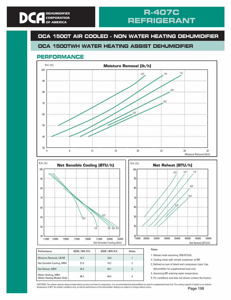
DCA 1500TWH WATER HEATING ASSIST DEHUMIDIFIER
DCA 1500T AIR COOLED - NON WATER HEATING DEHUMIDIFIER
Performance 82DB / 50% R.H. 82DB / 60% R.H. Notes
Moisture Removal, LB/HR 14.7 18.9 1
Net Sensible Cooling, MBH 21.6 19.2 2
Net Reheat, MBH 24.3 29.1 3
Water Heating, MBH 46.2 48.4 4(Water Heating Models Only)
PERFORMANCE
Notes:
1. Reheat mode assuming 1050 BTU/lb.
2. Cooling mode with remote condenser at 95F.
3. Defined as sum of latent and compressor input. Use
dehumidifier for supplemental heat only.
4. Assuming 85F entering water temperature.
5. For conditions and data not shown contact the factory.
R.H. [%]
R.H. [%] R.H. [%]
Moisture Removal [lb/h]
Net Sensible Cooling [lb/h] Net Reheat [BTU/h]
100
90
80
70
60
50
40
30
30
40
50
60
70
80
90
100 100
90
80
70
60
50
40
30
4 8 12 16 20
25000 500004500040000350003000025000200001500023000210001900017000150001300011000
65F 70F 75F
80F
85F
82F
24 28 32
Moisture Removal [lb/h]
Net Sensible Cooling [BTU/h] Net Reheat [BTU/h]
85F
85F
80F
80F
82F
75F
75F
70F
70F
65F
65F
82F
R-407CREFRIGERANT
CAUTIONS: The reheat capacity rating includes latent recovery and heat of compression. It is recommended that dehumidifiers be used for supplemental heat only. The cooling capacity is based on an ambienttemperature of 95˚F. As outside conditions vary, so will the performance of the dehumidifier. Ratings are subject to change without notice. Page 198

1 Over 50ft contact factory2 Water Flow data based on 50% RH + Return Air 82˚F and Pool Water at 85˚F
• Right Side Component Service Access
• Top or Bottom Discharge (Not Field Convertible)
• Extended Surface Filters 2” & 4”
• Outdoor Installation Package
• Outdoor Make Up Air Assembly with Damper & Filter
• External Static Upgrade
• Water Cooled Condenser For Water Heating Or A/C Available
• Motorized Evaporator Bypass Damper
• Remote Ready Delete
• Defrost Timer Package
• Control Options
• Space Heating Options Available
• Other Options Available
W53 N550 HIGHLAND DRIVEP.O. BOX 0917
CEDARBURG, WI 53012PHONE: 262-377-7501
FAX: 262-377-7502E-MAIL: [email protected]
DESIGN SPECIFICATIONS CFM.................................................................................1500External Static Pressure ...................................0.50” H2ORefrigerant ......................R-407C (Factory Charged 20 lbs.)Compressor Type .......................................................ScrollFilter (Quantity: 1) ......................25” x 25” x 1” Fiberglass Drain Connection ...........................................1” Bar DrainDCA 1500T Weight ..................................................470 lbs.DCA 1500TWH Weight ...........................................580 lbs.Liquid Inlet [inches O.D.] (up to 50’)1............................0.5Hot Gas Outlet [inches O.D.] (up to 50’)1 ...................0.75Water Inlet [inches O.D].............................................0.875Water Outlet [inches O.D.].........................................0.875Water Flow G.P.M.2 .........................................................6.0Pressure Drop (Ft. WC)2.................................................5.3
OPTIONAL FEATURES
www.dehumidifiercorp.com
DCA 1500T AIR COOLED - NON WATER HEATING DEHUMIDIFIERDCA 1500TWH WATER HEATING ASSIST DEHUMIDIFIER
Electrical 208/230V 208/230V 460V 575V
Phase/Hz 1/60 3/60 3/60 3/60Compressor B.T.U. 36,600 36,900 36,900 36,900Compressor RLA 19.2 12.2 5.8 4.4Compressor LRA 112 93 48 33Blower Motor H.P. 1 1 1 1Blower Motor FLA 6.4 3.8 1.9 1.5Unit FLA 27.0 17.4 8.4 6.5Maximum Fuse Size 40 25 12 10Minimum Circuit Amp. 31.8 20.5 9.9 7.6
Operating kW 4.11 4.05 4.05 4.04
• MET Laboratory Safety Listed To UL 1995
• 3 Year Parts Warranty
• Single Refrigeration Circuit
• Single Scroll Compressor
• Powder Coated, Galvannealed Steel Cabinet
• Low Ambient Head Pressure Control
• Remote Condenser Ready
• Rifle Tube Refrigeration Coils
• TEFC Blower Motor
• Stainless Steel Condensate Drain Pan
• Standard Microprocessor Control System (WH Models Only)
• ElectroFin Coated Coils
STANDARD FEATURES
R040712
Page 199

Appendix F: Project Management
Page 200

Appendix F1: Final Project Schedule
A final updated project schedule can be found in Table 14.
Table 14. Final Project Schedule.
Appendix F2: Project Team Timesheets
To determine the overall project cost for design work, timecards were collected from the project team. The timecard for each member can be found in Figures 7 through 12.
Page 201

Figure 7. Timecard: Zoey Zhang.
Figure 8. Timecard: Sai Avuthu.
Page 202

Figure 9. Timecard: Elliott van Ramshorst.
Figure 10. Timecard: Jacob Bellerose.
Page 203

Figure 11. Timecard: Jakub McNally.
Figure 12. Timecard: Laura Mueller.
Page 204
ackerman
Stamp