High Integrity Software for for Nuclear Power Plants
425
NUREG/CR-6263 MTR 94W0000114 Vol.2 High Integrity Software for for Nuclear Power Plants Candidate Guidelines, Technical Basis and Research Needs Main Report Manuscript Completed: June 1995 Date Published: June 1995 Prepared by S. Seth, W. Bail, D. Cleaves, H. Cohen, D. Hybertson, C. Schaefer, G. Stark, A. la, B.Ulery The MITRE Corporation 7525 Colshire Drive McLean, VA 22102 Prepared for Division of Systems Technology Office of Nuclear Regulatory Research U.S. Nuclear Regulatory Commission Washington, DC 20555-0001 NRC Job Code L2610 DISTRIBUTION OF MS BOOMm 8 ««
-
Upload
khangminh22 -
Category
Documents
-
view
0 -
download
0
Transcript of High Integrity Software for for Nuclear Power Plants

NUREG/CR-6263 MTR 94W0000114 Vol.2
High Integrity Software for for Nuclear Power Plants Candidate Guidelines, Technical Basis and Research Needs
Main Report
Manuscript Completed: June 1995 Date Published: June 1995
Prepared by S. Seth, W. Bail, D. Cleaves, H. Cohen, D. Hybertson, C. Schaefer, G. Stark, A. la, B.Ulery
The MITRE Corporation 7525 Colshire Drive McLean, VA 22102
Prepared for Division of Systems Technology Office of Nuclear Regulatory Research U.S. Nuclear Regulatory Commission Washington, DC 20555-0001 NRC Job Code L2610
DISTRIBUTION OF MS BOOMm 8 ««

Quotations used from the Utility Requirements Document (URD), NP-6780-L, V3, Ch.10, are reproduced based on the written permission of EPRI.
Quotations used from copyrighted documents of The American Society of Mechanical Engineers (ASME), the International Electrotechnical Commission (IEC), the Institute of Electrical and Electronics Engineers, Inc. (IEEE), and RTCA, Inc. are reproduced with the permission of the respective organizations. Please note that IEEE " . . . takes no responsibility or will assume no liability from the placement and context in this publication." For further information on the materials and standards of these organizations contact them directly at the following addresses:
ASME, 345 East 47th Street, New York, NY 10017 (Phone: 212-705-8500; FAX 212-705-8501)
IEC, 3 rue de Varembe, P.O. Box 131, CH-1211, Geneva 20, Switzerland (Phone: 41-22-919-0211; FAX: 41-22-919-0300; Telex: 414121 leech)
IEEE, 445 Hoes Lane, P.O. Box 1331, Piscataway, NJ 08855-1331 (Phone: 908-562-3800; FAX: 908-562-1571; Telex 833233)
RTCA, Inc., 1140 Connecticut Avenue, N.W., Suite 1020, Washington, DC 20036 (Phone: 202-833-9339; FAX: 202-833-9434; Telex 2407254 RTCA UQ)
NUREG/CR-6263, Vol. 2

DISCLAIMER
This report was prepared as an account of work sponsored by an agency of the United States Government. Neither the United States Government nor any agency thereof, nor any of their employees, make any warranty, express or implied, or assumes any legal liability or responsibility for the accuracy, completeness, or usefulness of any information, apparatus, product, or process disclosed, or represents that its use would not infringe privately owned rights. Reference herein to any specific commercial product, process, or service by trade name, trademark, manufacturer, or otherwise does not necessarily constitute or imply its endorsement, recommendation, or favoring by the United States Government or any agency thereof. The views and opinions of authors expressed herein do not necessarily state or reflect those of the United States Government or any agency thereof.

DISCLAIMER
Portions of this document may be illegible in electronic image products. Images are produced from the best available original document.

ABSTRACT
The work documented in this report was performed in support of the U.S. Nuclear Regulatory Commission to examine the technical basis for candidate guidelines that could be considered in reviewing and evaluating high integrity computer software used in the safety systems of nuclear power plants. The framework for the work consisted of the following software development and assurance activities: requirements specification; design; coding; verification and validation, including static analysis and dynamic testing; safety analysis; operation and maintenance; configuration management; quality assurance; and planning and management. Each activity (framework element) was subdivided into technical areas (framework subelements). The report describes the development of approximately 200 candidate guidelines that span the entire range of software life-cycle activities; the assessment of the technical basis for those candidate guidelines; and the identification, categorization and prioritization of research needs for improving the technical basis. The report has two volumes: Volume 1, Executive Summary, includes an overview of the framework and of each framework element, the complete set of candidate guidelines, the results of the assessment of the technical basis for each candidate guideline, and a discussion of research needs that support the regulatory function; Volume 2 is the main report.
in NUREG/CR-6263, Vol. 2


CONTENTS
SECTION PAGE
Abstract ill
NRC Summary xiii
Acknowledgments xv
1 Introduction 1-1
1.1 Background 1-1 1.2 Objective and Scope 1-2 1.3 Approach 1-3
1.3.11 Candidate Guidelines 1 -4 1.3.2 Technical Basis 1-5 1.3.3 Research Needs 1-10
1.4 Organization of the Report 1-11
2 System Context and Framework 2-1
2.1 Overview 2-1 2.2 System-Software Interface 2-1 2.3 Framework for Software Development and Assurance 2-5 2.4 Framework Subelements 2-8
3 Software Requirements Specification 3-1
3.1 Overview 3-1 3.2 Completeness 3-3
3.2.1 Candidate Guidelines 3-3 3.2.2 Technical Basis 3-4
3.3 Unambiguity 3-12 3.3.1 Candidate Guidelines 3-12 3.3.2 Technical Basis 3-12
3.4 Consistency 3-14 3.4.1 Candidate Guidelines 3-14 3.4.2 Technical Basis 3-14
3.5 Verifiability 3-15 3.5.1 Candidate Guidelines 3-15 3.5.2 Technical Basis 3-15
3.6 Modifiability 3-16 3.6.1 Candidate Guidelines 3-16 3.6.2 Technical Basis 3-17
v NUREG/CR-6263, Vol. 2

SECTION PAGE
3.7 Traceability 3-18 3.7.1 Candidate Guidelines 3-18 3.7.2 Technical Basis 3-19
3.8 Readability 3-21 3.8.1 Candidate Guidelines 3-21 3.8.2 Technical Basis 3-21
3.9 Research Needs 3-23
4 Software Design 4-1
4.1 Overview 4-1 4.2 Modular Design 4-4
4.2.1 Candidate Guidelines 4-4 4.2.2 Technical Basis 4-4
4.3 External Interface 4-7 4.3.1 Candidate Guidelines 4-7 4.3.2 Technical Basis 4-8
4.4 Interfaces to Safety Components 4-10 4.4.1 Candidate Guidelines 4-10 4.4.2 Technical Basis 4-11
4.5 Interface Integrity 4-13 4.5.1 Candidate Guidelines 4-13 4.5.2 Technical Basis 4-13
4.6 Data Integrity 4-15 4.6.1 Candidate Guidelines 4-15 4.6.2 Technical Basis 4-16
4.7 Flow Control 4-19 4.7.1 Candidate Guidelines 4-19 4.7.2 Technical Basis 4-20
4.8 Error Handling 4-22 4.8.1 Candidate Guidelines 4-22 4.8.2 Technical Basis 4-23
4.9 Research Needs 4-27
5 Software Coding 5-1
5.1 Overview 5-1 5.2 Development Environment 5-3
5.2.1 Candidate Guidelines 5-3 5.2.2 Technical Basis 5-3
5.3 Target Environment and Reusable Components 5-7 5.3.1 Candidate Guidelines 5-7 5.3.2 Technical Basis 5-8
5.4 Data Structure 5-11 5.4.1 Candidate Guidelines 5-11 5.4.2 Technical Basis 5-11
NUREG/CR-6263, Vol. 2 vi

SECTION PAGE
5.5 Logic Structure 5-13 5.5.1 Candidate Guidelines 5-13 5.5.2 Technical Basis 5-14
5.6 Research Needs 5-15
6 Software V&V—Static 6-1
6.1 Overview 6-1 6.2 Requirements V&V 6-7
6.2.1 Candidate Guidelines 6-7 6.2.2 Technical Basis 6-7
6.3 Design V&V 6-12 6.3.1 Candidate Guidelines 6-12 6.3.2 Technical Basis 6-13
6.4 Code V&V 6-19 6.4.1 Candidate Guidelines 6-19 6.4.2 Technical Basis 6-19
6.5 Research Needs 6-27
7 Software V&V—Dynamic (Testing) 7-1
7.1 Overview 7-1 7.2 Management Aspects Affecting All Test Levels 7-3
7.2.1 Candidate Guidelines 7-3 7.2.2 Technical Basis 7-3
7.3 Technical Aspects Affecting All Test Levels 7-8 7.3.1 Candidate Guidelines 7-8 7.3.2 Technical Basis 7-9
7.4 Unit Testing - 7-16 7.4.1 Candidate Guidelines 7-16 7.4.2 Technical Basis 7-16
7.5 Integration and System Testing 7-19 7.5.1 Candidate Guidelines 7-19 7.5.2 Technical Basis 7-20
7.6 Installation Testing 7-27 7.6.1 Candidate Guidelines 7-27 7.6.2 Technical Basis 7-27
7.7 Research Needs 7-30
8 Software V&V—General Considerations 8-1
8.1 Overview 8-1 8.2 V&V Plan 8-1
8.2.1 Candidate Guidelines 8-1 8.2.2 Technical Basis 8-2
vii NUREG/CR-6263, Vol. 2

SECTION
8.3 V&V Reports 8-4 8.3.1 Candidate Guidelines 8-4 8.3.2 Technical Basis 8-4
8.4 V&V of Tools 8-7 8.4.1 Candidate Guidelines 8-7 8.4.2 Technical Basis 8-7
8.5 Independence of V&V 8-9 8.5.1 Candidate Guidelines 8-9 8.5.2 Technical Basis 8-9
8.6 Research Needs 8-11
9 Software Safety Analysis 9-1
9.1 Overview 9-1 9.2 Management Aspects 9-3
9.2.1 Candidate Guidelines 9-3 9.2.2 Technical Basis 9-3
9.3 Technical Aspects 9-9 9.3.1 Candidate Guidelines 9-9 9.3.2 Technical Basis 9-10
9.4 Research Needs 9-19
10 Software Operation and Maintenance 10-1
10.1 Overview 10-1 10.2 Software Maintainability 10-4
10.2.1 Candidate Guidelines 10-4 10.2.2 Technical Basis 10-4
10.3 Maintenance Planning 10-8 10.3.1 Candidate Guidelines 10-8 10.3.2 Technical Basis 10-9
10.4 Performance Monitoring 10-15 10.4.1 Candidate Guidelines 10-15 10.4.2 Technical Basis 10-15
10.5 Research Needs 10-18
11 Software Configuration Management 11-1
11.1 Overview 11-1 11.2 Software Configuration Management Plan 11-4
11.2.1 Candidate Guidelines 11 -4 11.2.2 Technical Basis 11-4
11.3 Configuration Identification 11-6 11.3.1 Candidate Guidelines 11-6 11.3.2 Technical Basis 11-7
NUREG/CR-6263, Vol. 2 viii

SECTION PAGE
11.4 Configuration Change Control 11 -9 11.4.1 Candidate Guidelines 11 -9 11.4.2 Technical Basis 11-10
11.5 Configuration Status Accounting 11-12 11.5.1 Candidate Guidelines 11-12 11.5.2 Technical Basis 11-12
11.6 Configuration Audits and Reviews 11-13 11.6.1 Candidate Guidelines 11-13 11.6.2 Technical Basis 11-14
11.7 External Interface Control 11-16 11.7.1 Candidate Guidelines 11-16 11.7.2 Technical Basis 11-16
11.8 Subcontractor and Vendor Control 11-17 11.8.1 Candidate Guidelines 11-17 11.8.2 Technical Basis 11-17
11.9 Automated Support for Configuration Management 11-19 11.9.1 Candidate Guidelines 11-19 11.9.2 Technical Basis 11-19
11.10 Research Needs 11-20
12 Software Quality Assurance 12-1
12.1 Overview 12-1 12.2 Program Plan and Implementation 12-3
12.2.1 Candidate Guidelines 12-3 12.2.2 Technical Basis 12-4
12.3 Research Needs 12-9
13 Software Planning and Management 13-1
13.1 Overview 13-1 13.2 Software Development and Management Plan 13-4
13.2.1 Candidate Guidelines 13-4 13.2.2 Technical Basis 13-4
13.3 Other Plans 13-9 13.3.1 Candidate Guidelines 13-9 13.3.2 Technical Basis 13-10
13.4 Research Needs 13-14
14 Overall Assessment of Technical Basis and Research Needs 14-1
14.1 Overview 14-1 14.2 Summary of Technical Basis Assessment 14-3
14.2.1 Evaluation Summary 14-3 14.2.2 Nature of Gaps in Technical Basis and
Research Needed 14-3
ix NUREG/CR-6263, Vol. 2

SECTION PAGE
14.3 Analysis and Characterization of Research Needs 14-7 14.3.1 A Major Perspective: Domain-Specific
Software Engineering 14-7 14.3.2 Specific Perspectives on Research Needs 14-13
14.4 Categorization of Research Needs 14-19 14.5 Prioritization of Research Needs 14-20
14.5.1 Prioritizing Criteria and Approach 14-20 14.5.2 Results of Prioritization 14-29
14.6 High-Priority Research Needs Supporting the Regulatory Function 14-29
Appendix A Candidate Guidelines and Assessment of Technical Basis A-1
Appendix B Peer Review by Expert Panel B-l
Glossary of Acronyms and Definitions GL-1
Acronyms GL-1 Definitions GL-5
References RE-1
NUREG/CR-6263, Vol. 2 X

FIGURES
FIGURE PAGE
1-1 Template for a Framework Subelement 1-12
2-1 Framework for System Development 2-2
2-2 Framework for Software Development and Assurance 2-6
2-3 Section Coverage of Life-Cycle Activities 2-9
2-4 Framework Elements and Subelements for Developing Candidate Guidelines 2-10
9-1 Dimensions of Interface Hazards 9-17
14-1 Context of Domain Engineering Process 14-9
XI NUREG/CR-6263, Vol. 2

TABLES
TABLE PAGE
3-1 Methods Relevant to Achieving Completeness of SRS 3-9
6-1 Static Code Verification Methods 6-23
9-1 Software Safety Plan Outline 9-5
12-1 Software Life Cycle Documentation 12-8
13-1 Typical Software Planning Documents 13-2
14-1 Summary of Technical Basis Evaluation and Research Needs 14-4
14-2 Research Needs Related to Domain-Specific Software Engineering 14-12
14-3 Classification of Research Needs 14-14
14-4 Research Needs Supporting the Regulatory Function 14-21
14-5 Prioritization of Research Needs 14-30
14-6 Number of Research Needs in Each Priority Group 14-34
14-7 Ranking of High-Priority Research Needs Supporting the Regulatory Function 14-34
NUREG/CR-6263, Vol. 2 xii

NRC SUMMARY
The objective for this project was to provide assistance to the NRC for the development of a technical basis for regulatory positions related to the use of high-integrity software in nuclear power plants. The assistance included the identification of research issues that could enhance a technical basis.
This report contains a comprehensive discussion of the present state of software engineering processes and design attributes in the form of candidate guidelines for the elements of the software life cycle and assurance activities. The candidate guidelines are considered by the contractor to be good practices that are important in the development of high integrity software for nuclear power plants. Most of the design attributes can be found in current software industry standards.
It is emphasized here that the application of the candidate guidelines to regulation and the determination of the need for the research identified in this report require further assessments by the NRC. The assessments will include consideration of the contribution to safety, the degree to which the candidate guidelines have an acceptable technical basis, and the cost-effectiveness of each guideline and research issue.
The NRC's current regulatory position on issues associated with the application of digital computer technology to instrumentation and control (I&C) systems that are important to safety and the NRC's staff actions to resolve these issues are presented in (1) SECY-91-292, Digital Computer Systems for Advanced Light Water Reactors; (2) SECY-93-087, Policy, Technical and Licensing Issues Pertaining to Evolutionary and Advanced Light-Water Reactor (ALWR) Designs, Section II Q, "Defense Against Common-Mode Failures in Digital Instrumentation and Control Systems," April 1993, as clarified by the Staff Requirements Memorandum (SRM) on SECY-93-087, July 1993; (3) the draft Operating Reactors Digital Retrofits Digital System Review Procedure and the draft Branch Technical Position, Digital Instrumentation and Control Systems in Advanced Plants (presented at the Digital Systems Reliability and Safety Workshop, sponsored by the NRC and the National Institute of Standards and Technology, 13-14 September 1993); and (4) Generic Letter 95-02, Use of NUMARC/EPRI Report TR-102348, 'Guideline on Licensing Digital Upgrades,' in Determining the Acceptability of Performing Analog-to-Digital Replacements Under 10 CFR 50.59, April 1995. These documents present the current NRC position on basic safety issues, together with the NRC policy statements with regard to the resolution of these issues. It should be noted that a number of Final Safety Evaluation Reports (FSERs) have been issued approving retrofit and advanced applications of digital I&C safety systems.
xiii NUREG/CR-6263, Vol. 1

/

ACKNOWLEDGMENTS
The work presented in this report involved the analysis, integration, and synthesis of a vast amount of technical information on a broad spectrum of topics related to high integrity software. The guidance provided by NRC staff during the course of this work was invaluable. The authors especially acknowledge the efforts of the following NRC staff members: Robert Brill (NRC Project Officer), Leo Beltracchi, Frank Coffman, John Gallagher, Joe Joyce, Joel Kramer, Jim Stewart, and Jerry Wermiel.
The report also benefited significantly from the peer review provided by a panel consisting of the following experts: Mel Barnes, Taz Daughtrey, Michael DeWalt, Ray Ets, Roger Fujii, Carl Gilbert, Richard Hamlet, Herbert Hecht, Gordon Hughes, Paul Joannou, Ted Keller, Kathryn Kemp, Schlomo Koch, John Matras, John McDermid, Joseph Naser, Ronald Reeves, and Dolores Wallace. Their affiliations are provided in Volume 2, Appendix B. The authors express sincere gratitude to the panel members for the perspectives and the comments they offered. Comments provided by William Agresti, Charles Howell, and Gary Vecellio, who contributed to MITRE's internal peer review, are also gratefully acknowledged. Many MITRE personnel contributed to the success of the Experts' Peer Review Meeting on High Integrity Software for Nuclear Plants, which was held at MITRE, 24-26 May 1994. Special thanks go to William Agresti, who served as the moderator for the meeting, and Brenda Fox, who coordinated all the meeting arrangements.
The preparation of this report, from the working drafts of individual sections to the final integrated product, required various types of technical support activities, which included developing and maintaining computer databases, coordinating the technical information needs of the project team members, and editing. The authors feel especially indebted for the painstaking and conscientious efforts of Tammy Ryan, Brenda Fox, and Sheila McHale, who bore the brunt of this work. Thanks are also due to Susan Gerrard and Dee Krzebetkowski for their support of the project. Finally, Rona Briere of Briere Associates deserves praise and many thanks for her sound advice and valuable suggestions during the final editing of this document.
xv NUREG/CR-6263, Vol. 2

SECTION 1
INTRODUCTION
1.1 Background
The nuclear industry has been cautious in introducing software-based digital technology to the operation and control of safety systems in nuclear power plants. The increasing use of digital technology in nuclear plants is a reflection of the need both to enhance the operational performance of instrumentation and control (I&C) systems, and to alleviate growing concerns regarding the obsolescence of analog systems. Software-based devices and systems offer several advantages, such as greater precision, higher availability due to self-testing, and the ability to implement complex functions and communicate diagnostic and operational data via the plant's communications and computing networks. The I&C systems in advanced reactor designs are expected to make extensive use of digital controls, microprocessors, multiplexing, and fiber-optic transmission.
Other characteristics of software-driven systems, however, have raised safety and licensing issues that concern the specification, design, testing, operation, maintenance, and validation of digital technology. The reliability of software is a primary concern. In general, software errors are less tractable and more difficult to detect than hardware-related errors. A software coding error that causes redundant systems using the same platforms, operating systems, and software to fail could be potentially hazardous [USNRC GL 95-02].
There are numerous standards and methodologies in use today for developing software and assuring its quality. However, most of these have been developed with perspectives or applications in mind that are not specific to nuclear power plant safety systems. Many standards that are well established may not provide the necessary level of detail or breadth of coverage from the standpoint of nuclear power plant safety, and others may not be widely accepted. Several organizations, including the U.S. Nuclear Regulatory Commission (NRC), have sponsored studies to review and compare the applicable attributes of available standards for application to the nuclear industry [NIST NUREG/CR-5930; IAEA, 1993; EPRI, 1992]. In general, these studies reflect considerable concern regarding the lack of sufficiently comprehensive and coherent standards for use by the nuclear power industry.
The NRC's current regulatory position on issues associated with the application of digital computer technology to I&C systems that are important to safety, and the NRC staff actions taken to resolve these issues, are presented in the following documents: (1) Digital Computer Systems for Advanced Light Water Reactors [USNRC SECY-91-292]; (2) Policy, Technical and Licensing Issues Pertaining to Evolutionary and Advanced Light Water Reactor (ALWR) Designs, Section IIQ, "Defense Against Common-Mode Failures in Digital Instrumentation and Control Systems" [USNRC SECY-93-087], as clarified by the Staff Requirements Memorandum [USNRC SRM/SECY-93-087]; and (3) the draft Operating Reactors Digital Retrofits Digital System Review Procedure [USNRC-RETROFITS DRAFT] and the draft Branch Technical
1-1 NUREG/CR-6263, Vol. 2

Position, Digital Instrumentation and Control Systems in Advanced Plants [USNRC-BTP-DRAFT], presented at the Digital Systems Reliability and Safety Workshop, sponsored by the NRC and the National Institute of Standards and Technology (NIST) on 13-14 September 1993 [USNRC-NUREG/CP-0136]. These documents present the current NRC position on basic safety issues, together with the NRC policy statements with regard to the resolution of these issues. It should be noted that a number of Final Safety Evaluation Reports (FSERs) have been issued that approve retrofit and advanced applications of digital I&C safety systems. The NRC is developing additional regulatory guidance for reviewing and approving computer software to be used in the safety systems of nuclear power plants. The work documented in this report is an important part of that overall initiative.
1.2 Objective and Scope
The objective of this work was to provide assistance to the NRC for the development of a technical basis for regulatory positions related to the use of high integrity software in nuclear power plants. This included the identification of research that could enhance the technical basis. An essential step in that direction was the development of candidate guidelines applicable to high integrity safety software. Candidate guidelines with an adequate technical basis could be considered by the NRC in developing regulatory guidance, such as Regulatory Guides or revisions to the Standard Review Plan. Candidate guidelines without an adequate technical basis could be considered by the NRC in developing research projects.
An important assumption, which defined the scope of the candidate guidelines and their technical basis discussed in this report, is that system-level analyses, performed to appropriate standards, will specify all requirements and constraints allocated to the software. Successful development of software requires detailed specifications derived from system considerations, and the present work—especially that related to software requirements specification, design, and safety analysis— rests on that assumption. This subject is discussed further in Section 2.
Furthermore, while it is recognized that several national and international standards recommend safety categorization of systems and associated requirements [ANS-58.14; IEC1226; IEC65A DRAFT; IAEA 50-SG-D3; IAEA 50-SG-D8; Nuclear Electric-TD/NS/REP/0240; ONT HYD, 1990], candidate guidelines for safety system software developed as part of this work were not graded to apply to nuclear plant systems belonging to different safety categories. They apply to the highest-grade safety systems (e.g., reactor protection systems). Any potential relaxation of candidate guidelines for safety systems that might fall into lower safety categories based on their function and degree of system redundancy or diversity was not considered in this study. At present, there is insufficient empirical evidence (see the next subsection) to provide the technical basis for differentiating candidate guidelines for different categories. Also, such a grading or categorization effort would require candidate guidelines to address system-level issues involved in software safety categorization specific to nuclear power plants, as well as cost-benefit considerations, which were not considered in the present work.
NUREG/CR-6263, Vol. 2 1-2

Commercial-off-the-shelf (COTS) and predeveloped software (including compilers) were treated in the present report only to a limited extent within the broader context of the development of new software through various life-cycle stages. While the use of COTS software may involve only selected aspects of the entire software life cycle, its approval involves unique issues. The safety of COTS software must be established to the same rigor as the rest of the safety system software. At present the NRC is considering approaches to address the need for developing guidance on COTS and reusable software as part of other parallel activities.
This report contains a comprehensive discussion of the present state of software engineering processes and design attributes considered to be important in the development of high integrity software for nuclear power plants. Most of the design attributes can be found in current software industry standards and can be readily applied; others require further development before they can be applied.
Finally, the application of the candidate review guidelines to the regulatory process requires further assessment by the NRC of their contribution to safety and the need for additional research. This includes consideration of the cost-effectiveness of each guideline. The regulatory process is not intended to be a deterrent to the application of technology advances, provided that the safety of the final product is maintained or enhanced.
1.3 Approach
The NRC's draft Branch Technical Position for advanced plants [USNRC-BTP DRAFT], which requires an orderly and systematic process for the development of software through its various life-cycle stages, provided a starting point for this work. The draft document suggests that the following software life-cycle stages, along with appropriate documentation, be fully accomplished: planning, requirements specification, design, implementation, integration, validation, installation, and operation and maintenance. The set of software development and assurance activities associated with the software life-cycle helped define a general framework for achieving the objectives of this work. The framework is presented in Section 2 of this report.
The approach taken for developing the technical basis for the candidate guidelines and associated research needs consisted of the following steps:
1. Develop candidate guidelines applicable to each software life-cycle stage.
2. Examine and describe the technical basis for each candidate guideline, where it exists.
3. Identify research needs where the technical basis for a given candidate guideline is insufficient or lacking.
1-3 NUREG/CR-6263, Vol. 2

The following subsections provide the details on those steps.
In implementing this approach, it was important to consider the broad scope of software development and assurance activities. Candidate guidelines were developed based on a judgment of their necessity, usefulness, and practicality. Emphasis was placed on capturing the attributes essential to high integrity software at a level where technical issues could be examined. Also, the decision whether to incorporate or to reference the considerable relevant information from standards and other technical literature into this report involved a similar judgment. These judgments in developing candidate guidelines and in describing and assessing their technical basis were based on a breadth of software engineering experience gained by the authors in providing support across the software life-cycle to various government sponsors, such as the Department of Defense, the Federal Aviation Administration, and the National Aeronautics and Space Administration.
As mentioned in Section 1.1, Background, there is considerable variability with respect to the level of detail and supporting evidence in the existing standards on developing high integrity software. This variability is reflected in the nature of the available technical basis for the candidate guidelines presented in this report. (This is discussed further in Section 1.3.2, Technical Basis.) The approach outlined above provided a systematic methodology for identifying those candidate guidelines whose use would involve considerable subjectivity because of the lack of sufficiently detailed methods, measures, or criteria; and for suggesting research that could enhance the technical basis by minimizing the uncertainty and vagueness in the available guidance for implementing the candidate guidelines considered.
A panel of outside experts with considerable knowledge of software safety and reliability relative to different government and industry programs provided a peer review of this report in its preliminary draft stage. A meeting of the expert panel and cognizant members of the NRC staff was held as part of this process to discuss the peer review comments. Discussions at the meeting were aimed at obtaining the best judgment of, rather than consensus among, the experts. Written comments provided prior to the meeting, as well as meeting discussions, were used in revising the report.
1.3.1 Candidate Guidelines
For each software development or assurance activity (framework element), candidate guidelines were grouped based on their subject matter into technical areas (framework subelements). For example, Interface Integrity is one of the subelements of the framework element Software Design. All the elements and subelements of the framework are presented in Section 2.3, and the manner in which the framework subelements were identified is discussed in Section 2.4.
Certain recent standards that cover a broad range of software development activities and that are generally recognized in the U.S. nuclear industry were the primary sources for deriving candidate guidelines within each framework subelement. These sources, termed the "baseline" in this report, were the following: Standard Criteria for Digital Computers in Safety Systems of Nuclear Power Generating Stations [IEEE7-4.3.2]; the Advanced Light Water Reactor Utility Requirements Document [URD]; and standards such as [IEC880], [ASME-NQA-2a: Part 2.7], and various
NUREG/CR-6263, Vol. 2 1-4

Institute of Electrical and Electronics Engineers (IEEE) standards explicitly referenced within requirements or guidelines contained in [IEEE7-4.3.2] and the [URD]. The NRC's draft regulatory guidance documents [USNRC-BTP DRAFT] and [USNRC-RETROFTTS DRAFT] are included in the baseline as well.
Pertinent statements that describe software attributes relevant to safety were extracted from the baseline to develop the candidate guidelines. Guidance in the standards relative to specific methods or approaches (e.g., object-oriented versus structured analysis in the element on Software Design) or which had little relationship to safety was not extracted. Although statements from the baseline sources range from requirements to nonbinding guidance, they were all considered as components for developing the set of candidate guidelines. For uniformity, all candidate guidelines use "should" in stating the desired software attributes, although "shall" may have been used in the corresponding statement in the baseline source.
Because standards have different objectives, applications, and vintage, it is common to observe overlap, mismatch, or gaps in the scope, nature, completeness, and specificity of guidance on a given topic. Therefore, for each framework subelement, the essential attributes of the guidance contained in the baseline were summarized, and any gaps for which additional guidelines might be considered were identified. The suggested additional guidelines to fill the observed gaps were derived from defense, aviation, aerospace, and nuclear industry standards, including some developed in other countries, which are not encompassed by the baseline, e.g., [DOD-STD-2167A], [RTCA DO-178B], and [MOD55]; from pertinent results of work sponsored by the NRC; and from the researchers' software engineering experience with other government programs.
The process described above was used to develop a set of candidate guidelines for each framework subelement, which summarizes the software safety attributes derived from the baseline and any suggested additional guidelines. The candidate guidelines are not intended to prescribe specific methodologies. Furthermore, they should not be considered as substitutes for the standards from which they were derived. The source standards provide additional details related to the attributes selected for high integrity software.
1.3.2 Technical Basis
The following five criteria stated in [Beltracchi, 1994] were considered in describing and assessing the adequacy of the technical basis for each candidate guideline:
• Criterion 1—The topic has been clearly coupled to safe operations.
• Criterion 2—The scope of the topic is clearly defined.
• Criterion 3—A substantive body of knowledge exists, and the preponderance of the evidence supports a technical conclusion.
• Criterion A—A repeatable method to correlate relevant characteristics with performance exists.
1-5 NUREG/CR-6263, Vol. 2

• Criterion 5—A threshold for acceptance can be established.
In applying the above criteria to assess the technical basis for guidelines on computer software, it is necessary to recognize the unique character of software systems and the maturity level of the software industry. The following paragraphs discuss the general nature of the technical basis that is available for requirements on software, and the manner in which the five criteria were applied to describe and assess the technical basis for the candidate guidelines in this report.
Nature of Available Technical Basis and Safety Rationale
Ideally, the technical basis should be founded on "first principles," such as fundamental physical laws, or on uncontroversial empirical evidence, to provide a strong rationale for a proposed requirement. This ideal is difficult to realize when dealing with software. First, it is necessary to address the applicability of first principles or laws, and the nature of technical information that characterizes satisfactory performance, or conditions leading to failure, for a hardware versus a software component. In the case of hardware, the limiting value of strength or performance can be predicted within a confidence interval using physical laws and correlations among measurable parameters and their effects. For example, the failure of a pipe of a given material composition due to crack propagation can be expressed as a function of the stresses and the parameters governing crack geometry. Using this expression, the limiting value can then be derived for the maximum load to which the pipe can be stressed. The technical basis for a position that constrains the loads below a certain threshold value might consist of repeatable evidence from tests and experiments that conclusively supports the threshold value. Even when the phenomena associated with the behavior of a hardware component are complex, simpler models of such phenomena can be constructed for deriving the necessary properties within uncertainty bounds and verifying these properties by experiment.
In the case of a software system, first principles are not available to provide the kind of technical basis that can be obtained for hardware. A software component is an abstract construct of interlocking concepts involving data sets, relationships among data items, and algorithms. Its inherent properties are described in [Brooks, 1987], [Dijkstra, 1989], and [Booch, 1991]. Like all digitally encoded information, software results in discontinuous behavior, and possibly drastic consequences, with the smallest possible perturbation—the change of a single bit. Even sampling arbitrarily "close" to a fault may not reveal the cause for an observable failure. "There is no meaningful metric in which small changes and small effects go hand in hand, and there never will be" [Dijkstra, 1989]. Furthermore, many problems with developing software arise from its inherent complexity and the nonlinear increase in complexity with size. "From the complexity comes the difficulty of enumerating, much less understanding, all the possible states of the program, and from that comes the unreliability" [Brooks, 1987]. Based on a great deal of research completed on software-based systems in normal environments, it appears that deterministic evaluation of such complex systems is currently an intractable problem [Littlewood and Stringini, 1992; Butler and Finelli, 1993; Bennett, 1991; Zucconi, 1991; Lavine, 1990; Leveson et al., 1991; SAND93-2210].
NUREG/CR-6263, Vol. 2 1-6

In lieu of first principles, the technical basis might rely on empirical evidence that certain requirements will be effective in managing the complexity inherent in software systems, and in minimizing the introduction of defects into the software during its design and coding. Empirical correlations between specific software design characteristics and software reliability could help define the necessary software characteristics and thereby provide the technical basis for requiring those characteristics. However, the maturity of the software industry in relation to the high degree of complexity in software systems is such thai empirical evidence of this nature is not well documented or established in a quantified manner. The majority of judgments on the quality of software are based on good practice, peer review, and expert opinion within the software engineering community [Fenton et al., 1994]. 'There is no evidence that superior design and production methods consistently yield superior products" [Littlewood and Stringini, 1992].
In the absence of first principles or a substantive body of empirical evidence to support requirements on software development, the safety and reliability of the overall system—comprising hardware, software, and user—can be, and generally is, assured by applying the defense-in-depth safety principle, requiring an adequate level of diversity and redundancy in system design (including, where necessary, a combination of analog and digital systems), and emphasizing high quality in implementing system safety objectives [IEEE7-4.3.2:D; NUREG-0493; USNRC-BTP DRAFT]. In addition to applying such safety principles at the system level, a basic principle that underlies the development of high integrity software, and might be applied in ensuring software safety and assessing the value of requirements placed on developing safe software, is that there be complete knowledge and predictability of the software in four domains: functional (outputs for all possible combinations of inputs to a particular function), timing, failure behavior, and resource usage. This principle can be propagated and applied at the different software life-cycle stages. For example, the software testing strategy may be determined by which combination of the testing approaches (functional, structural, and random) comes closest to verifying the software behavior in all four domains. Consistent with this basic principle are other principles, such as those articulated in [ONT HYD, 1990], which mandate the use of various concepts, guidelines, or activities (e.g., the information-hiding concept, trajectory-based random testing, independent verification, safety analysis, configuration management, and personnel training).
The candidate guidelines presented in this report are similar in nature to the high-level requirements or "principles" mentioned in the previous paragraph. Basically, the established and uncontroversial attributes of guidelines for developing high integrity software for safety systems are not different from those for less stringently constrained software, except that much greater emphasis and attention must be given to ensuring conformance to the guidelines. The technical basis for the guidelines generally relies on well-accepted standards that reflect the best practices in the software industry. In terms of its simplicity and reliance on best industry standards, the technical basis for many guidelines for software development is similar to that for the quality assurance of safety-related hardware in nuclear plants [10 CFR Part 50: Appendix B] or for the General Design Criteria; e.g., 'The protection systems shall be separated from control system..." [10 CFR Part 50: Appendix A, Criterion 24]. In general, the relationship to safety does not need much elaboration, as in the following example: "The software design should include self-supervision of control flow and data." Such guidelines for software development and the above
1-7 NUREG/CR-6263, Vol. 2

examples of regulations for nuclear plant safety for which the technical basis is readily apparent may be contrasted with other regulations and guidance that are founded on extensive experimentation, testing, and analyses. An example of the latter is [10 CFR Part 50: Appendix K], which provides the requirements for evaluating the capability of emergency core cooling systems in nuclear power plants.
Finally, in examining the technical basis, all candidate? guidelines in this report were considered to be relevant to the development of high integrity software, without regard to the relative degree to which individual guidelines contribute to safety. For example, the safety rationale for guidelines describing the attributes of completeness of software requirements specification (SRS) might differ from that for guidelines specifying the protection of critical data, or those providing for the control of software configuration items. The technical basis (including the relationship to safety) for the candidate guidelines was not examined from the standpoint of their relative values and impacts.
Description of Technical Basis
Because the guidelines for a given framework subelement are closely coupled, the technical basis was developed and described for the group of guidelines as a whole. The set of five criteria introduced above provide an objective methodology for examining the technical basis. However, given the nature of the available technical basis as discussed in the preceding paragraphs, evaluation of the technical information supporting each candidate guideline against each criterion involved considerable subjectivity. The manner in which the technical basis is described in this report to address the five criteria for each framework subelement is as follows:
• Criterion 1—Relation to Safety. This is described at both the element and subelement levels. The safety relevance of each framework element is indicated before the subelements for that framework element are introduced. The safety rationale is then discussed for the specific set of candidate guidelines considered for each framework subelement, including references to NRC regulations or regulatory guidance and other supporting technical information, as appropriate. The rationale for suggested candidate guidelines that are based on standards or information other than the baseline is made explicit within the discussion. The extent to which the relationship to safety is described has been already indicated above under "Nature of the Available Technical Basis and Safety Rationale."
• Criterion 2—Definition of Scope. The scope of a given framework element is defined in the overview for each framework element, and by the set of candidate guidelines for each subelement. The technical area covered in the subelement is further characterized by the extracted statements from baseline sources. A discussion of the baseline is presented which summarizes the scope and attributes of the candidate guidelines for the subelement.
NUREG/CR-6263, Vol. 2 1-8

• Criterion 3—Body of Knowledge and Evidence. The baseline sources and other standards identified in support of each candidate guideline and those referenced in the discussion of a framework subelement represent the evidence supporting the group of candidate guidelines. This information is also summarized in tabular form for each framework subelement in Appendix A.
• Criterion 4—Availability of a Method. In the present context, this criterion is applied to examine and discuss the availability of potential methods to satisfy the intent of the guidelines. Each framework subelement includes a discussion of the methods, approaches, criteria, or tools that might be used to show how conformance to the guidelines can be reviewed. However, the discussion is not intended to describe all available methods, and reference to a method does not imply its endorsement. The availability of a satisfactory method for implementing a candidate guideline is also indicated in Appendix A.
• Criterion 5—Threshold for Acceptance. There are no cases in the present study where conformance to a candidate guideline could be determined using a predefined quantitative cutoff value for acceptance. For example, while there is guidance for the design of a software component to be modular, and there is some basis for reviewing the degree of modularity, the modularity of a given component could vary depending on the specific application, so that a threshold value does not exist or is subjective. Standards and other literature were reviewed to determine whether they provide sufficient information, such as qualitative evaluation criteria or checklists, to provide a basis for reviewing conformance to a given guideline. The results of this review are discussed along with potential methods for satisfying the guideline. The availability of objective evaluation criteria is summarized for each candidate guideline in the tabular summary of all candidate guidelines in Appendix A.
Assessment of Technical Basis
Because the attributes of candidate guidelines for a given framework subelement were selected from baseline and other sources based on their relationship to safety and relevance to the scope of the topic covered in the subelement (as explained in Section 1.3.1), the first two of the five criteria discussed above, namely those on relation to safety and definition of scope, were not used again in assessing the technical basis. The technical basis for each candidate guideline was evaluated with respect to the remaining three criteria on the strength of the evidence, the availability of a method for satisfying the guidelines, and the availability of objective evaluation criteria for determining conformance to the guidelines.
1-9 NUREG/CR-6263, Vol. 2

The supporting body of knowledge or evidence for the candidate guidelines was judged to be satisfactory, questionable, or unsatisfactory based on the following:
• Satisfactory
(a) One baseline source (as defined in Section 1.3.1) or two other sources support(s) the candidate guideline.
(b) There is no conflicting standard or issue with respect to (a).
• Questionable
Criterion (a) is partially satisfied, or Criterion (b) is not satisfied.
• Unsatisfactory
Criterion (a) is not satisfied.
Similarly, the availability of methods for meeting the candidate guidelines was judged to be satisfactory or unsatisfactory depending on whether or not a method is available, and judged as questionable if there is a significant issue that affects the effectiveness or adequacy of the method identified.
The assessment of the availability of a threshold for acceptance was based on whether different evaluators using an available set of evaluation criteria would come to the same answer (yes or no) concerning the conformance of the software to a given guideUne. In several cases, implementing a candidate guideline involves the use of a standard (e.g., a standard for the development of a formal set of software test plans and specifications). In the cases where such a standard does not provide its own acceptance criteria, or if subjective judgment is also required to assess the quality of items required by the standard, the availability of a threshold was judged to be partial or questionable.
1.3.3 Research Needs
The lack of an adequate technical basis for a candidate guideline, including the presence of issues related to available implementation or review methods within a framework subelement, indicated the need for further work. The intent of the discussion of a research need in this report is to provide briefly the objective and rationale. In identifying research needs, the focus was on addressing generic issues, rather than specific methodologies. In several instances, the evaluation of conformance to a candidate guideline could involve considerable subjectivity on the part of an evaluator, even though appropriate standards for review exist. In these instances, where further research to establish a threshold was considered impractical, no research need was identified, although the threshold for acceptance (technical basis criterion 5) was judged to be questionable.
NUREG/CR-6263, Vol. 2 1-10

The words "research needs" are used here to include any type of further work, such as a survey, which may or may not be characteristically labeled as "research." In the individual sections of this report, where research needs are first identified and discussed, there is little consideration given to identifying the expected primary beneficiary of the results of the research. Since candidate guidelines are of interest to software developers and researchers, as well as to reviewers, there are obvious overlaps with respect to which organization might be interested in, or perform the necessary research identified to fill the gaps in the technical basis: the NRC, the nuclear industry, the software industry, or other research and regulatory organizations. However, as part of an overall assessment in the final section of this report, those research needs which would directly support the NRC's regulatory role have been segregated and prioritized. The prioritization is based on a subjective evaluation that considered the following: (1) relationship to safety; (2) degree of leverage provided by the research, based on the level of maturity of the software industry relative to the life-cycle activity (framework element) where the gap in the technical basis exists; and (3) type of research product, i.e., methods, criteria, measures, empirical data, or tools for implementing a guideline.
1.4 Organization of the Report
Section 2 provides the system context, the framework elements, and where the framework elements are addressed in this report. The framework elements are covered in Sections 3 through 13.
Within Sections 3 through 13, the first subsection, "Overview," provides the necessary background, relation to safety, identification of framework subelements, and structure of the section. This discussion is also intended to provide the technical basis at the element level (technical basis Criteria 1 and 2). Subsections following the overview are organized by framework subelements. In order to maintain consistency, each framework subelement was developed according to the template shown in Figure 1-1. Reference to this template should be helpful to the reader in understanding the context and scope of the discussion of each subelement. The research needs identified for the subelements are collected and described at the end of the section.
Candidate guidelines and research needs introduced and discussed in Sections 3 through 13 are identified by the letters G and R, respectively, followed by two numbers. The first number corresponds to the section number in the report where the candidate guideline or research need is presented, while the second is sequential within that section. For example, [G3-5] and R3-2] are the fifth candidate guideline and the second research need, respectively, in Section 3. Research needs that apply to more than one framework element have been given multiple identification numbers. They are discussed in the section that provides the most appropriate context—given by the first identification number—and have been cross-referenced. For example, the research need [R3-1/R6-1] is discussed in Section 3.
The last section of the report (Section 14) provides an overall assessment of the nature of gaps in the technical basis for candidate guidelines; perspectives on the research needed; and a categorization and prioritization of the research needs.
1-11 NUREG/CR-6263, Vol. 2

X.N Subelement Name (e.g., 4.3, External Interface, of Section 4, Software Design)
X.N.I Candidate Guidelines
Each candidate guideline (G) is mapped to its sources, i.e., the baseline statements (B's) or suggested additions (A's), which are individually identified and discussed as a group under 'Technical Basis." The guidelines are numbered consecutively throughout a given section of the report (e.g., G4-8 is the eighth guideline in Section 4). For example:
G4-8. The software design should thoroughly document each usage of interrupt. [B6] (a) The software design should define processing duration and maximum number of occurrence
constraints for external event processing (e.g., interrupts). [A2] (b) The software design should define the maximum duration for which an interrupt is disabled. [B5]
X.N.2 Technical Basis
Baseline
Presents relevant statements from the baseline sources (technical basis Criteria 2 and 3). For example:
B6. "Interrupt usage and masking shall be thoroughly documented " [IEE880: B2.ed]
Discussion of Baseline
Identifies principal attributes addressed and not addressed by the baseline (technical basis Criteria 1 and 2).
Suggested Additions
Suggests guidelines for areas not addressed by the baseline (technical basis Criterion 2). For example:
A2. The software design should define processing duration and maximum number of occurrence constraints for external event processing (e.g., interrupts).
Rationale
Discusses the relationship to safety of the attributes considered and provides explicit justification for any suggested additional guidelines (technical basis Criteria 1 and 3).
Potential Methods
Discusses the availability of methods, approaches, criteria, or tools to achieve conformance with the candidate guidelines (technical basis Criteria 3,4, and 5).
Assessment
Summarizes evaluation of the strength of the evidence and the availability of methods and threshold (technical basis Criteria 3,4, and 5, respectively) to support the candidate guidelines. Also identifies research needs that would improve the technical basis, which are numbered consecutively within a section and described in the last subsection of a given section. Assessment results are summarized in Appendix A.
Figure 1-1. Template for a Framework Subelement
NUREG/CR-6263, Vol. 2 1-12

For convenience, all the candidate guidelines identified for a framework element, as well as information pertaining to the technical basis for those guidelines and identification numbers of pertinent research needs, are summarized in tabular form in Appendix A. The technical basis information for a candidate guideline shown in the table includes the supporting baseline and other sources, as well as the results of the assessment of the technical basis for each candidate guideline, as discussed in Section 1.3.2.
Appendix B presents a summary of the peer review process, including the names of panel members and the scope of discussions at the Experts' Peer Review Meeting.
A glossary of acronyms and definitions and a complete list of references appear at the end of the report.
In this report, a shorthand method of referencing is used, with the objective of using, where practical, the names or numbers of the standards and reports as they are commonly referenced, and of identifying the organizations involved in their development (e.g., [RTCA DO-178B], [LLNL NUREG/CR-6101], and [IAEA 75-INSAG-3]). If a document number is not given, the year of publication is specified (e.g., [LLNL, 1993]). Most of the references to standards issued by professional societies appear simply by their number (e.g., IEEE830). Where appropriate, section and paragraph numbers are also given, for example, [IEC880: A2.9.1].
1-13 NUREG/CR-6263, Vol. 2

SECTION 2
SYSTEM CONTEXT AND FRAMEWORK
2.1 Overview
Software is an integral part of I&C systems based on digital computer technology. Requirements for the software must be allocated by and derived from the functional and safety requirements of the total system, comprising hardware, software, and human operators. A framework for the development of the total system is shown in Figure 2-1, which is adapted from [Fujii, 1993] and [NIST, 1993].
This section focuses on two aspects of the system framework shown in Figure 2-1. The first, which is discussed in Section 2.2, is the interface between system design and software development. The purpose of the discussion of this aspect is to highlight an important underlying assumption of the work documented herein: that this interface must be clearly and sufficiently defined. The second aspect is the development and assurance of the software components of the system, which provides the specific framework for the work described in this report. This framework for software development and assurance, along with the elements and subelements defined to develop candidate guidelines, is discussed in Section 2.3.
2.2 System-Software Interface
The system design identifies software components, hardware components (including computer hardware), and human operators, and it allocates requirements and constraints to each component. For example, if all software is centralized on a single processor, the system design will identify a single digital processor—hardware component—upon which all of the software components, identified from the software requirements specification (SRS), will reside. In a distributed system, the system design will identify multiple hardware digital components and the software components associated with each of the processors. This relationship between the hardware and software components, i.e., the mapping of the software architecture onto the hardware architecture, taking account of the role of the human operator, is one of the major factors determined from the decomposition of the system design specification into the hardware, software, and human operator components of the design.
The motivation for emphasizing the system-software interface in the context of an operating environment is to enable the development of an SRS and a software design with minimum latent errors. Several studies have been conducted on the sources, nature, and distribution of software defects, and the relative influence of the defects on the quality and cost of software depending on the life-cycle stage in which they were detected [Basili and Perricone, 1984; Davis, 1990; Endres, 1975; Grady, 1992; Jones, 1991; Shumaskas, 1991]. All of these studies underscore the
2-1 NUREG/CR-6263, Vol. 2

System Concept -
System Requirements
System Design
Hardware Hardware Hardware Hardware Planning Requirements Design Fabrication
Hardware Assembly &Test
Software Software S o , t w a r e Coding Software
Analysis uesign jesting Testing
System Integration
Operation & Maintenance
Assurance Activities
Figure 2-1. Framework for System Development

importance of a complete, clear, and correct set of requirements allocated to the software. [Jones, 1991] shows that for a medium to large software system, requirements errors contributed to 50% of total defects in the Severity Level-1 (system or program inoperable) category. [Basili and Perricone, 1984] found that 48% of the errors analyzed in their study were due to the misunderstanding of a software module's specifications or requirements. [Tavolta and Vincena, 1984] provide evidence that "56% of all bugs detected can be traced to errors made during the requirements stage." Citing this and other findings, [Davis, 1990] concludes that there are many requirements errors being made, and that the errors made in requirements specifications are typically incorrect facts (49%), omissions (31%), inconsistencies (13%), ambiguities (5%), and misplaced requirements (2%).
Errors in requirements specifications are also difficult to detect in subsequent testing and are labor-intensive to correct [Boehm, 1975; OECD HALDEN, 1993]. Furthermore, [Grady, 1992] presents evidence to show that the average engineering cost to fix specification defects not found until testing is about 14 times the cost when the defects are found during development of the specifications. Therefore, preventing the insertion of errors in the early stages of software development not only minimizes risk, but also is a cost-effective approach for developing high integrity software.
In order to ensure the correctness and traceability of requirements allocated to the different components of the system—including the software components—in accordance with the safety system design basis, a complete yet concise description of the system must be available. This includes both behavioral and nonbehavioral types of requirements: the former define what the system does in terms of all the inputs and outputs, as well how the inputs and outputs interrelate; the latter define the attributes of the system, such as reliability, maintainability, capacity, and standards compliance. For a complex system composed of subsystems and components, the requirements are often decomposed and presented in a hierarchical manner. A typical example of the nature of requirements that must be derived from the system design and system requirements for a subsystem or component to be implemented in software is provided by Data Item Description (DID) [DI-MCCR-80025A], which is associated with several military development standards, including [DOD-STD-2167A]. This DID, which is used throughout the Army, Navy, and Air Force, prescribes the following list of engineering requirements for a software component:
External interface requirements
Capability requirements
Internal interfaces
Data element requirements
Adaptation requirements
- Installation-dependent data - Operational parameters Sizing and timing requirements
2-3 NUREG/CR-6263, Vol. 2

Safety requirements
Security requirements
Design constraints
Software quality factors
Human performance and human engineering requirements
- Human information processing capabilities and limitations - Foreseeable human errors under both normal and extreme conditions - Implications for the total system environment (e.g., training, support and
operational environment)
• Requirements traceability
The DID provides additional details on these topics of requirements. Similar requirements are contained in [DI-IPSC-81433] referenced by [MIL-STD-498], which is the latest version of the standard, but implemented to a lesser extent.
Among the industry standards that provide guidance on system-software interface requirements are [IEEE830] and [IEEE7-4.3.2]. The latter provides examples of requirements allocated to different components of the system that should be considered simultaneously. Some of these examples are listed below to further illustrate the details requiring definition in the interface between software and the rest of the system:
• Fault detection, diagnostic, and recovery capabilities for the system, subsystem, replaceable unit, network software (if applicable), system software (if applicable), and application software.
• Requirements for responses to design basis events, including computer-unique failure modes, such as those caused by invalid answers, overflow, late responses, early responses, duplicate messages, and precision errors; the requirements may be to continue operation, fail-stop, or fail-silent, but should be consistent with the safety criteria and functional requirements of the system.
• Support for maintenance personnel in on-line and off-line modes, particularly to verify the functionality of the equipment after the replacement of any system element (including software).
• Operator-machine interface requirements, including specification of the display of any safety parameters and other human factors issues.
• Timing, response time, throughput, and performance requirements.
• Functional diversity or defense-in-depth, as required.
NUREG/CR-6263, Vol. 2 2-4

At the system level, there are various NRC regulations and regulatory guidance documents that apply to the design and development of I&C systems for nuclear power plants. For example, guidance on applying the NRC's General Design Criteria on protection systems [10 CFR Part 50: Appendix A, Criteria 20-25] to safety-related I&C systems is provided in the Standard Review Plan [NUREG-0800: Chapter 7], Regulatory Guides (e.g., [USNRC RG-1.118 and 1.152]), and several professional society standards endorsed by the NRC. The latter include [IEEE323], [IEEE338], [IEEE379], [IEEE384], and [IEEE603]. Other applicable standards are [ANS-50.1], [ANS-58.14], and those referenced in [USNRC-RETROFTTS DRAFT] and [USNRC-BTP DRAFT]. It is noted here that [USNRC RG 1.152] endorses the use of [IEEE7-4.3.2, 1982 version]; this is not the latest version of [IEEE7-4.3.2], issued in 1993, from which the above examples of interface requirements were drawn. (A revision to [USNRC RG-1.152] which endorses the latest version of [IEEE7-4.3.2] is being issued for public comment.)
The standards applicable to nuclear power plant I&C systems, such as those mentioned in the preceding paragraph, do not provide detailed requirements on the system-software interface or guidance on issues related to system decomposition and interrelationships among the system-components—hardware, software, and human operators—for advanced digital applications based on computer technology. However, it was explicitly assumed in developing the candidate guidelines and technical basis as documented herein, that the necessary systems analysis has been properly conducted, and the system-software interface is completely defined. The types of constraints placed on the software by system design decisions are emphasized, where appropriate, in the discussion of the candidate guidelines and their technical basis in the following sections of this report.
2.3 Framework for Software Development and Assurance
Once the system-software interface has been defined, and the requirements for the software are reflected in the SRS, the development of the software can be initiated. The software development component of the overall system development, which is shown separately in Figure 2-2, provided the framework for the development of candidate guidelines in this report. This framework incorporates the main ideas from [USNRC-BTP DRAFT], [NIST, 1993], [LLNL NUREG/CR-6101], and standards such as [ASME-NQA-2a], [IEEE1012], and [IEEE1074]. It depicts two principal aspects of the software development process: activities and products.
The framework classifies activities as relating to either development or assurance. Although the classification and the name of an element in the framework may overlap with existing roles and responsibilities of a certain group within an organization, the discussion of that framework element in this report does not define associated roles and responsibilities. The purpose of the representation in Figure 2-2 is to highlight the primary emphasis of the various types of activities, and not to show assignment of responsibilities. Also, the illustration does not imply a preference for or endorsement of any particular process model (e.g., waterfall or spiral). In particular, the timing of the activities shown may vary and overlap depending on the process model selected, and the deliverables needed might be different in number and content. In applications involving
2-5 NUREG/CR-6263, Vol. 2

Activities Products
c
I
. Planning Audit
• Software Management Plan • Training Plan • Software Development Plan • Operation* Plan • Software CIA Plan • Maintenance Plan • Integration Plan • Software V&V Plan • Installation Plan • Software CM Plan • Software Safety Plan
Requirements Audit
Requirements Specification Requirements Safety Analysis V&V Requirements Analyais Report CM Requirements Report
Design Audit
• Design Specification • Hardware & Software Architecture (tllocatlon et
software functlontllty to hardwtn component*) • Design Safety Analysis • V&V Design Analysis Report • CM Design Report
Implementation Audit
Code Listings Code Safety Analysis V&V Implementation Analysis • Test Report CM ImplemenaUon Report
Integration Audit
• System Build Documents • Integration Safety Analysis • V&V Integration Analysis & Test Report • CM Integration Report
Validation Audit
• Validation Safety Analysis • V&V Validation Analysis Test •Report • CM Validation Report
Installation Audit
NOTE: This chart depicts software development activities without endorsing any particular process model.
• Operations Manuals • Installation Configuration Tables • Maintenance Manuals • Installation Safety Analysis • V&V Installation Analysis* Test Report • CM Installation Report
s^^SISl • Change Safety Analysis • V&V Change Report • CM Change Report
q> o c I (0
Software Verification and Validation
Software Safety Analysis
Software Configuration Management
Software Qua itv Assurance
Software Proiect Management
Figure 2-2. Framework for Software Development and Assurance

programmable logic controllers (PLCs) containing proprietary executive software, design and coding activities of the application software are usually merged because of their direct correspondence. Distinctions among software specification, design, and coding activities may also be blurred in a mathematical (formal methods) development approach where refinements of a mathematical specification might be taken down directly to the code level. With these caveats, the framework depicts the following software life-cycle activities:
• Software planning • Software requirements analysis • Software design • Software coding and component testing • Software integration testing • Software system testing • Software installation testing • Software operation and maintenance
The software assurance activities are closely coupled with the development activities and are performed throughout the life cycle. They provide oversight of, and support to, software development so that the generated products meet the safety requirements, are of the necessary quality, and are within cost and schedule. The software assurance activities are the following:
• Software verification and validation • Software safety analysis • Software configuration management • Software quality assurance • Software project management
Figure 2-2 also shows the types of audits* and products (e.g., plans, analyses, reports, and code listings) associated with the life-cycle activities. This information, which is taken from [USNRC-BTP DRAFT] and [LLNL NUREG/CR-6101], is simply mapped to the life-cycle activities considered in this report, with the terms used for those products being retained. The audit activities provide opportunities to review the products, to gain insights into the development process, and to ensure that safety requirements are not compromised. The audits serve to verify that the software development process and the associated documentation are adequate. The type of information and the level of detail to be reviewed during a specific audit activity will correspond to the set of development activities completed, which will differ depending on the specific process model chosen for software development. For example, the level of detail for a product at the design audit stage in the spiral process differs from the level of detail for a product at the same stage in the waterfall process because the former involves several iterations or passes through the successive stages of software development. The audit activities extend from the planning stage through the installation stage.
The products in Figure 2-2 either are the result of a development activity or serve as input (for example, to assurance activities) for ensuring the correctness and the quality of the final software system. The minimum set of products recommended by [LLNL NUREG/CR-6101] is shown in Figure 2-2. Considerable information regarding the scope and outline of the documents is given and discussed in that report.
* See definitions of Audit and Auditor in the Glossary 2-7 NUREG/CR-6263, Vol. 2

The organization of the candidate guidelines and the related discussion in this report map directly to the elements in the framework of Figure 2-2. However, depending on the technical content of a given framework element, and in order to avoid overlapping discussion, some elements have been combined or regrouped. For example, the candidate guidelines for the four successive levels of software testing and for verification and validation (V&V), all of which are depicted in the framework as separate Ufe-cycle activities, are presented herein within the following three sections of this report: V&V—Static, V&V—Dynamic (Testing), and V&V—General Considerations. This regrouping allows focus on the two separate technical aspects of V&V—static analyses and dynamic testing—that are important to both software development and software assurance. Similarly, software planning and software project management are combined in the section on Software Planning and Management. The planning for each life-cycle activity is also discussed in the individual section corresponding to that framework element. Figure 2-3 shows how the sections of this report cover the various elements in the framework.
2.4 Framework Subelements
As mentioned in Sections 1.3 and 1.4, the discussion of the candidate guideUnes and technical basis pertaining to a framework element was structured by subdividing the element into a set of subelements. The subelements were the result of grouping interrelated subject matter that needs to be addressed for a given life-cycle activity into relatively distinct technical areas. For example, the guidance from various standards relative to how the integrity of the boundaries of software modules should be maintained and how errors during safety-critical processing should be handled was separated and summarized into the separate subelements, Interface Integrity and Error Handling, respectively, within the framework element on Software Design. In general, the standards that treated a particular life-cycle activity in detail provided a reasonably adequate initial set of subelements for the different technical areas to be addressed. This set of subelements was subsequently adjusted to some extent as additional standards were reviewed and as overlapping areas among framework elements were identified. All of the subelements in the framework are shown in Figure 2-4.
NUREG/CR-6263, Vol. 2 2-8

&
Section Coverage • &
<& S? sr « * &
,J£6£?S Life-Cycle Activity <$r cfF <*0v cp . 0 v o>- c,o> <=>*>' <$>' y c,c
Software Planning V Software Requirements Analysis V Software Design V Software Coding and Component Testing V 4 Software Integration Testing 4 Software System Testing 4 Software Installation Testing V Software Operation and Maintenance 4
Software Verification and Validation (V&V) V V V Software Safety Analysis 4 Software Configuration Management V Software Quality Assurance V Software Project Management V
Figure 2-3. Section Coverage of Life-Cycle Activities

Candidate Guidelines
Requirements Specification
(Section 3) Completeness Unamblguity Consistency Verifiablllty Modiflabllity Traceabitity Readability
Design (Section 4)
Modular Design External Interface Interfaces to Safety Components Interface Integrity Data Integrity Row Control Error Handling
Safety Analysis (Section 9)
Management Aspects Technical Aspects
Coding (Section 5)
Development Environment Target Environment and Reusable Components Data Structure Logic Structure
Operation and Maintenance (Section 10)
Software Maintainability Maintenance Planning Performance Monitoring
V&V—Static (Section 6)
Requirements V&V Design V&V Code V&V
Configuration Management
(Section 11) Software Configuration Management Plan Configuration Identification Configuration Change Control Configuration Status Accounting Configuration Audits and Reviews External Interface Control Subcontractor and Vendor Control Automated Support for Configuration Management
V&V—Dynamic (Testing) (Section 7)
• Management Aspects Affecting All Test Levels
• Technical Aspects Affecting All Test Levels
• Unit Testing • Integration and System
Testing « Installation Testing
Quality Assurance (Section 12)
Program Plan and Implementation
V&V—General Considerations
(Section 8) • V&V Plan • V&V Reports • V&V of Tools • Independence of V&V
Planning and Management
(Section 13) Software Development and Management Plan Other Plans
Figure 2-4. Framework Elements and Subelements for Developing Candidate Guidelines

SECTION 3
SOFTWARE REQUIREMENTS SPECIFICATION
3.1 Overview The software requirements specification (SRS) is the highest-level software specification of a software component of a system. Its scope is defined by the collection of system requirements that are allocated by the system design to that software component. As discussed in Section 2.2 on the system-software interface, precise specification of the software requirements is essential to provide the assurance that the software will serve its intended purpose. The SRS specifies the externally visible behavior of the software component in the context of the entire system, and how the software will interact with the remainder of the system. This includes specification of not only the functions the software must perform, but also nonfunctional requirements, such as design constraints and quality attributes (e.g., reliability). The SRS specifies what a software component must do and what it must not do.
There is typically a separate SRS for each software component identified by the system design. Some standards, e.g., [DOD-STD-2167A], distinguish an interface requirements specification (IRS) from an SRS. This report does not distinguish between an SRS and an IRS since the prescribed interaction between a software component and other software or hardware components is part of the software component's externally visible behavior, and is therefore covered in the definition of an SRS. The logical SRS may, in fact, be expressed in several physically distinct documents, or as an on-line interactive computer database that can be presented in various forms or views for tracking or browsing.
Standards and guidelines exist for the organization and outline of information in an SRS (e.g., [DOD-STD-2167A], [IEEE830], and [LLNL NUREG/CR-6101]). This report does not address particular formats or outlines for presenting information in an SRS, but presents candidate guidelines regarding what information should be included in the SRS for a nuclear plant and the desired attributes or properties of that information. The following seven attributes of an SRS, which also constitute the seven subelements of this framework element, were considered for developing candidate guidelines:
• Completeness—All necessary requirements are included.
• Unambiguity—Requirements are interpreted the same way by all readers.
• Consistency—Requirements do not conflict with each other.
• Verifiability—A practical method exists to verify that each requirement is satisfied.
• Modifiability—Requirements are easy to modify correctly.
• Traceability—Software requirements trace to the system requirements/design, and the software design can be traced to the software requirements.
• Readability—Readers can easily read and understand all requirements.
3-1 NUREG/CR-6263, Vol. 2

Each of these attributes contributes to the value an SRS brings to an assurance argument. However, the first four are more important than the last three because they affect correctoess, while the last three determine usability. In the context of high integrity software, there may be some value to an SRS that is correct, but difficult to use, whereas there is less value to an SRS that is easy to use, but wrong or imprecise.
Judging the quality of an SRS by a set of attributes, such as those listed above, is generally accepted software engineering practice. For example, [IEEE830] lists the following as characteristics of a good SRS: unambiguous, complete, verifiable, consistent, modifiable, traceable, and usable during operation and maintenance. The readability attribute considered in this section, taken together with modifiability and traceability, covers the important aspects of the [TJEEE830] attribute "usable during operation and maintenance." [LLNL NUREG/CR-6101] recommends that an SRS "should be correct, consistent, unambiguous, verifiable, and auditable" [LLNL NUREG/CR-6101: p. 71], and discusses the meaning of "correct" and "auditable" [LLNL NUREG/CR-6101: p. 15]. Based on that discussion, all the SRS attributes given in [LLNL NUREG/CR-6101], including "correct" and "auditable," are covered by the seven attributes discussed in this section.
The candidate guidelines for software requirements in this section provide a basis for V&V of software requirements. They define the evidence needed to verify that the as-built software requirements possess the required attributes, perhaps using checklists such as those given in [LLNL NUREG/CR-6101: 4.2] or [LLNL, 1993: 11.2]. This evidence consists of some representation (in hard-copy, electronic, or combined media) of the requirements and the results of those V&V tasks whose goal was to show that the software requirements possess the required attributes. The role played by the SRS in V&V activities is described in Section 6 of this report.
Relation to Safety
A system is typically developed from a hierarchy of specification and design documents. In the development of ordinary systems, the top of the hierarchy is the statement of system requirements. In the development of high integrity systems, there is, in addition to and prior to the statement of system requirements, a statement of the specific hazards that the system must avoid or minimize. From this statement of hazards is derived a set of system safety requirements, which form a subset of the system requirements. In the case of a reactor protection system, the set of system safety requirements may be identical to the set of system requirements. The system design allocates requirements at the system level to individual components (hardware, software, human operators). Any software requirement that is a prerequisite to the system's meeting a system safety requirement is a software safety requirement. Again, in the case of a reactor protection system, the set of software safety requirements may be identical to the set of software requirements. In making an argument that a software component is "safe," it is important to show that the implementation of the component satisfies the software safety requirements. The SRS therefore has an important role in the overall argument that software is "safe." Safety analysis and types of safety requirements are described in more detail in Section 9 of this report.
NUREG/CR-6263, Vol. 2 3-2

It must be emphasized that an SRS can be judged "safe" only with respect to a specific system context. This context includes the following:
• An enumeration of hazards the system must avoid or niinimize
• A set of system requirements, including those (system safety requirements) whose purpose is to avoid or minimize the hazards
• A system design that allocates system requirements to components in the system design
• An analysis demonstrating that the system design ensures that the system requirements will be met
This report assumes that such a system context is given.
Organization
The remainder of this section presents candidate guidelines for SRS and their technical basis under seven subelements, which correspond to the seven attributes defined above:
• Completeness • Unambiguity • Consistency • Verifiability • Modifiability • Traceability • Readability
These subelements are covered, respectively, in Sections 3.2 through 3.8. Research needs are presented in Section 3.9.
3.2 Completeness
3.2.1 Candidate Guidelines
G3-1. For each software input, the SRS should specify the following [Bl, B4-B6, B9-B11]:
• Data format requirements • Precision and accuracy requirements • How often the input must be read
G3-2. For each software output, the SRS should specify the following [Bl, B4-B6, B9-B11]:
• Data format requirements • Precision and accuracy requirements • How often the output must be updated
3-3 NUREG/CR-6263, Vol. 2

G3-3. The SRS should specify each abnormal hardware condition or event that the software must detect. Abnormal hardware conditions and events include failure of input or output device, processor, and memory. [B12]
G3-4. The SRS should specify each abnormal software condition or event that the software must detect. Abnormal software conditions and events include failure of software services at the operating-system level and failure of logic in application-level software (only general types of such failures can be identified prior to software design). [B12]
G3-5. The SRS should specify the time-dependent input-to-output relation (i.e., the required functions) that the software component must implement. That is, the SRS should specify allowed sequences of outputs given any combination of sequences of inputs and abnormal conditions/events. "Sequence" here means an ordered list of <time, value> (or <time, event>) pairs, including startup of processing, response to interrupts, response for no input, and response to variation in sampling of data. The specification should cover all possible values (valid or invalid) of inputs. [A2, B1-B6, B8-B12]
G3-6. The time-dependent input-to-output relation specified by the SRS should not permit any behavior that would violate any requirement (including safety requirements) that the system design allocates to the software component or any requirement that is derived from general system requirements. [A 1, B1-B6, B8-B13]
G3-7. The SRS should specify the maximum percentage of available resources (processor, dynamic memory, mass storage, network capacity) that the software may use and should specify timing requirements, including speed, recovery time, and response time. [B1,B9(1),B10-B11]
G3-8. The SRS should specify reliability requirements for the software. [B3, B11(d)]
G3-9. Software maintainability requirements should be analyzed and specified prior to system design. These requirements should address coding standards and design constraints, as well as requirements for the supporting tools and documentation. [B 11(d), A3]
G3-10. The SRS should specify necessary design constraints (conformance to standards, hardware constraints). [B1, B7, B9(3), B11(c)]
3.2.2 Technical Basis
Baseline
The following excerpts from baseline standards (with underlining added to emphasize the key portions) were considered in the development of the above candidate guidelines.
B1. "The M-MIS [Man-Machine Interface Systems] Designer shall develop a software requirement specification which clearly describes each software requirement (function, performance, design constraints, and attributes of the software and external interfaces)." [URD: 6.1.2.4]
NUREG/CR-6263, Vol. 2 3-4

B 2. 'The software functional requirements represent an expansion of the functions which are assigned to the computer system and which are to be implemented by the computer system." [IEC880:4]
B 3. "The software reliability requirements represent an expansion of the reliability requirements of the computer system. They shall be derived in a similar way to the functional requirements." (TEC880:4]
B4. The SRS shall cover interface between the computer system and the plant operator. [IEC880: 4.3, A2.3]
B 5. The SRS shall cover interface between the computer system and other systems. [IEC880: 4.4, A2.4]
B6. The SRS shall contain complete specification of system functions. The performance of the system shall be stated. The system data structure and relationships should be described, including database characteristics and identification of all data elements. [IEC880: 4.5, A2.5]
B7. The SRS shall cover constraints between hardware and software. [EBC880: 4.6, A2.6]
B8. The SRS shall cover special operating conditions. [IEC880:4.7, A2.7]
B9. "An SRS is complete if it possesses the following qualities:
(1) Inclusion of all significant requirements, whether relating to functionality, performance, design constraints, attributes or external interfaces.
(2) Definition of the responses of the software to all realizable classes of input data in all realizable classes of situations. Note that it is important to specify the responses to valid and invalid input values.
(3) Conformity to any SRS standard that applies to it. If a particular section of the standard is not applicable, the SRS should include the section number and an explanation of why it is not applicable.
(4) Full labeling and referencing of all figures, tables, and diagrams in the SRS and definition of all terms and units of measure." [IEEE830:4.3.2]
BIO. "Requirements for timing and sizing should be included to ensure adequate resources for execution time, clock time, and memory allocation are provided to support the critical requirements." [BEEE7-4.3.2: F2.3.3.b]
3-5 NUREG/CR-6263, Vol. 2

B l l . "Software requirements documentation shall outline the requirements that the proposed software must satisfy. The requirements shall, as applicable, address the following:
(a) functionality—the functions the software is to perform;
(b) performance—the time-related issues of software operation such as speed, recovery time, response time, etc.;
(c) design constraints imposed on implementation phase activities—any elements that will restrict design options:
(d) attributes—non-time-related issues of software operation such as portability, acceptance criteria, access control, maintainability, etc.; and
(e) external interfaces—interactions with people, hardware, and other software." [ASME-NQA-2a: Part 2.7, 6.2]
B12. "Abnormal conditions and events (ACEs-)... include external events as well as conditions internal to the computer hardware or software." [BEEE7-4.3.2: Fl]
B13. "Software requirements should be evaluated to identify those that are essential to accomplishing the safety function (i.e., critical requirements). These critical requirements should be evaluated against the ACE to assess their significance." [IEEE7-4.3.2: F2.3.3.a]
Discussion of Baseline
The baseline sources require that the SRS state all the functional and nonfunctional requirements on the software [B1-B13]. More details on some of these requirements, such as interfaces, are provided in [LLNL NUREG/CR-6101].
A criterion for completeness that is implied but not explicidy stated in the baseline is that the SRS for a software component should cover all system requirements allocated via the system design to that software component, including safety requirements.
The nonbinding Appendix F of [IEEE7-4.3.2] addresses the subject of abnormal conditions and events (ACEs). ACEs include external events, as well as conditions internal to the computer hardware or software. These events can be design basis events and conditions, invalid input data, failure of input or output device(s), failure of processor or memory, failure of software services at the operating-system level, or failure of logic in application-level software [B12]. However, [IEEE7-4.3.2] does not explicitly require the SRS to specify the software's reaction to each ACE.
Quality attributes of software listed in the baseline [B3, Bl 1(d)] include reliability and maintainability. Specifying and achieving both of these attributes are important for high integrity software, with reliability being the more critical.
NUREG/CR-6263, Vol. 2 3-6

Suggested Additions
A1. The time-dependent input-to-output relation (i.e., the required functions) specified by the SRS should not permit any behavior that would violate any requirement (including safety requirements) that the system design allocates to the software component or any requirement that is derived from general system requirements.
A2. The SRS should specify allowed sequences of outputs given any combination of sequences of inputs and abnormal conditions/events. "Sequence" here means an ordered list of <time, value> (or <time, event>) pairs, including startup of processing, response to interrupts, response for no input, and response to variation in sampling of data.
A3. Software maintainability requirements should be analyzed and specified prior to system design. These requirements should address coding standards and design constraints, as well as requirements for the supporting tools and documentation.
Rationale
Since the SRS specifies what is required of the software component if the component is to fulfill its role in the system design, there can be little assurance that the implementation of the component will be correct if the SRS is not complete with respect to the system requirements. The SRS needs to state explicitly all the software requirements needed to satisfy those system safety requirements that have been allocated to the software component.
[LLNL NUREG/CR-6101: 3.2.2] discusses the importance of requirements safety analysis based on the system hazard analysis. The system safety requirements are allocated to the software component via system design decisions. To be complete, the SRS may have to specify what the software must not do, as well as what it must do [Al].
[RTCA DO-178B] is more explicit than the baseline sources on the relation between software requirements and system requirements:
"Each system requirement that is allocated to software should be specified in the high-level requirements" [RTCA DO-178B: 5.1.2.c].
"High-level requirements that address system requirements allocated to software to preclude system hazards should be defined" [RTCA DO-178B: 5.1.2.d].
[A2] will ensure that the software response to ACEs is documented so that it can be evaluated against the system safety requirements. Similarly, [ONT HYD, 1990: B.l.Li] requires the SRS to "define required response to all expected types of errors and failure modes identified by the hazard analysis of the system.... Indicate all cases for which error recovery must be attempted or for which fail-safe action must be taken."
3-7 NUREG/CR-6263, Vol. 2

The last addition [A3] reflects the importance of maintainable software. Specific criteria are needed to ensure that the software will have the desired characteristics. [ONT HYD, 1990: A.0] specifically requires that the Design Input Documentation "defines a l l . . . maintainability requirements of the subsystem, clearly identifying the safety requirements." Similar statements to provide maintainability requirements are made regarding other documents. Example areas for maintainability requirements analysis include installation procedures, testing procedures, downtime for maintenance, and anticipated growth (including enhancements and increased load requirements). Additional candidate guidelines and discussion relative to maintainability are provided in Section 10.2 on Software Maintainability.
Potential Methods
There are several approaches to achieving a complete SRS, including general methods, such as the use of trace tables to show that all allocated system requirements are addressed, and the use of standards, such as document outlines and checklists, to ensure that no category is omitted. The following discussion of methods shows that the above guidelines can be met in practice. There is no clear justification for requiring any of these methods over the others, and none provides a complete approach. Table 3-1 summarizes the advantages and disadvantages of the categories of methods discussed in this section.
The traditional notation for specifying software requirements is natural language because it is expressive, flexible, and well-known. However, the ambiguous and imprecise nature of natural language has caused problems in producing complete requirements and communicating about them. In relatively new application areas where the requirements have not been fully defined by the client (customer or user), rapid prototyping is a useful method for achieving complete requirements because clients can detect missing requirements more easily from a running prototype than from a list of requirements [Davis et al., 1993]. However, since a prototype cannot show that a system will not behave in a certain way, prototyping is not particularly useful for showing that safety requirements have been completely stated.
The problems involved in specifying requirements have motivated the search for other, more precise methods, such as finite state machines and stimulus-response models, which are more pertinent to nuclear power plant applications [IAEA, 1993].
One method comes from control theory models; an example is found in [Parnas et al., 1990 and 1991]. In Parnas' approach, the specification of software requirements identifies four kinds of mathematical variables, which can be grouped as follows: those variables in the physical environment which the software must monitor and/or control (monitored variables and controlled variables, respectively) and those variables whose value the software can read and/or change (input variables and output variables, respectively). The specification describes the types, formats, and valid ranges of the input and output variables, and how the variables are accessed. It describes three kinds of time-dependent relations: (1) the relation between monitored and controlled variables, (2) the relation between output and controlled variables, and (3) the relation between monitored and input variables. In each case, the specification accounts for the entire domain of the relation. A fourth relation—that holding between input and output variables—is considered to be part of the software design, rather than part of the specification. The logical conjunction of this
NUREG/CR-6263, Vol. 2 3-8

Table 3-1. Methods Relevant to Achieving Completeness of SRS
Method Advantages Disadvantages
Reuse of existing complete specification.
The new specification is based on an existing specification whose completeness has been demonstrated.
Adaptations of the original specification may introduce gaps or inconsistencies.
Natural-language specifications.
Easy for the customer to understand.
Natural-language specifications contain imprecise and ambiguous statements.
Prototyping. Some aspects of the behavior of the prototype are taken to embody the requirements; thus it is easy for the customer to assess the validity of these requirements. Useful in specifying computer-human interfaces.
Not all aspects of a prototype's behavior can be taken to embody the requirements. For example, a prototype is not expected to embody requirements for robustness, reliability, and performance. Also, a prototype is not useful in stating that a system must not behave in a certain way.
Level 1 of the use of formal methods: quasi-formal methods (e.g., Parnas1
approach; Statecharts).
These methods are more precise than natural language. Tool support exists for some of these methods.
Typically, the syntax and semantics of the notations used in quasi-formal methods are not rigorously defined. It may not be possible to reason about the behavior of a system specified in a quasi-formal notation.
Levels 2 and 3 of the use of formal methods.
Formal specification languages make it possible to construct detailed proofs that the specification guarantees some desirable property (or excludes the possibility of some undesirable property). Thus it is possible to gain a high degree of assurance that such a specification is complete.
Specifications written in formal specification languages may be difficult to understand. Construction of formal proofs is expensive.
3-9 NUREG/CR-6263, Vol. 2

fourth relation, the relation between the monitored and input variables, and the relation between the output and controlled variables implies the relation between the monitored and controlled variables. This approach is required by [ONT HYD, 1990] and was adopted for the Darlington shutdown system software. It should be noted that this approach does not necessarily address all ACEs that could arise during execution of a function; for example, it does not necessarily address how a function might behave if memory were exhausted.
A second approach derives from control theory and the state machine abstraction. Leveson's Requirements State Machine Language is an example [Jaffe et al., 1991]. Leveson has recently used this notation to specify the collision avoidance logic for the Traffic Alert and Collision Avoidance System (TCAS). Statemate [Harel et al., 1990] is a commercially available tool that is based on Statecharts [Harel, 1987]. The intuitive, graphical representations of state-based specifications are considered an advantage. Also, certain high integrity properties can be given quite directly; for example, it is easy to check that each transition out of a hazardous state leads to a nonhazardous state. Additional state-oriented methods include decision tables, transition tables, and Petri nets [Fairley, 1985]. A specification based on a state machine generally includes some design detail that a "pure" requirements specification would not include. This might be seen as a disadvantage. Also, certain analyses of state-based specifications may be computationally intractable. Thus, the general algorithm to determine whether one configuration of concurrent states is reachable from another configuration of concurrent states is one of exponential complexity.
The two classes of methods discussed above may be called quasi-formal in that they use notations that are formalized to some degree. Additional related quasi-formal methods are discussed in [Fairley, 1985], [Davis, 1990], and [Sommerville, 1992]. These include languages and methods such as PSL/PSA, RSL/REVS, SADT, and PAISLey. Several quasi-formal methods are based on a stimulus-response approach: Box-Structured Systems [Mills, 1988], Requirements Language Processor (RLP) [Davis, 1990], and Specification and Description Language (SDL) [Davis, 1990].
A third general approach is the use of more formal specification languages. Formality can be seen as a matter of degree rather than as an absolute quality. [NASA CR4551: pp. 15-19] classifies the extent of formal methods into four levels of increasing rigor:
• Level 0—No use of formal methods
• Level 1—Use of concepts and notation from discrete mathematics
• Level 2—Use of formalized specification languages with some mechanized support tools
• Level 3—Use of fully formal specification languages with comprehensive support environments, including mechanized theorem proving or proof checking
The quasi-formal classes of methods discussed above would fall into Level 1, while the more formal specification languages discussed in this third general approach correspond to Levels 2 and 3. [IEEE830: 4.3.1] states that using a formal requirements specification language is a way to avoid ambiguity. [IEC880:4.10] states that the use of formal specification languages may help in making an SRS complete. [LLNL NUREG/CR-6101: 4.2.1] recommends the use of a formal requirements specification language for functional, performance, reliability, and security requirements. However, none of these sources requires the use of formal specification languages.
NUREG/CR-6263, Vol. 2 3-10

A formal specification language has a well-defined syntax and semantics, and (at Level 3) a proof theory that permits reasoning about the specification to show (1) that certain requirements are consistent with each other, (2) that a set of requirements has certain properties, or (3) that a more detailed specification or design implements a more abstract specification or design. It may be observed that graphical specification notations can be as well defined as nongraphical specification languages, and that there are well-formed diagrams just as there are well-formed statements. [Wing, 1990] surveys formal specification languages; [NASA CR4551] specifically addresses the role of formal methods in certification of digital systems for avionics systems; [AIAA-R-013] surveys the use of formal methods on 12 development projects; and [OECD HALDEN, 1993] summarizes the experiences with the X-SPEX specification system. [IEC880] states that "the use of a formal specification language may be a help to show coherence and completeness of the software functional requirements." [RTCA DO-178B] mentions formal methods under "Alternative Methods" [RTCA DO-178B: 12.3.1], because formal methods are less mature than methods cited in other sections. [MOD55: Part 2] requires the use of a formal specification language for the SRS. The present state of the art is that most formal specification languages are complex and difficult to learn. It appears that "no single formal approach will be adequate for describing all of the properties of safety critical systems. Combinations of methods may, however, provide the necessary capabilities. . . . It is likely, however, that problems will arise in combining formal methods in this way. It may, for example, not be possible to combine the proof systems associated with the different methods, making complete verification impossible" [LLNL UCRL-CR-109416].
It is possible to ensure that the specification of an individual function is complete by ensuring that the specification determines a value for all possible combinations of input values, including those cases where the input values are undefined. Specifying functions in tabular format [Parnas et al., 1990] is one way of documenting function specifications and detecting whether they are complete.
The general method for identifying ACEs is covered in Section 9, on Software Safety Analysis.
In addition to the methods described thus far, methods more specifically oriented to data analysis can be used for specifying and analyzing data requirements. These methods include the relational model [Date, 1986] and the entity-relation approach [Chen, 1976].
The easiest method of achieving completeness would be to use or adapt an existing complete set of requirements that had been used for a similar system. If one does not exist, but multiple similar systems have been built, a common standard set can be developed by using domain modeling or domain analysis methods (e.g., see [Arango, 1994] and [Rich and Waters, 1988]). This method of reusing requirements based on domain models could be viewed as an extension of the system modeling that has long been a standard method in requirements analysis, but is more powerful because of the focus on a specific application domain. It applies to many of the subelements in this section in addition to Completeness, and is specifically discussed in the context of Modifiability.
Assessment
The technical basis for the Completeness subelement is considered satisfactory for all the candidate guidelines in terms of evidence provided in the baseline and other sources, and methods exist for meeting the guidelines. However, there are issues regarding the adequacy and maturity of available methods for candidate guidelines [G3-4] (abnormal software), [G3-5] (time-dependent relations), [G3-6] (requirements violation), [G3-8] (reliability requirements), and [G3-9] (maintainability
3-11 NUREG/CR-6263, Vol. 2

requirements). Thresholds exist for the candidate guidelines except for [G3-9] (maintainability requirements) and [G3-10] (design constraints); for these two the threshold is considered unsatisfactory. In addition, thresholds for candidate guidelines [G3-4] (abnormal software), [G3-5] (time-dependent relations), [G3-6] (requirements violation), and [G3-8] (reliability requirements) are evaluated as questionable.
Research items, described in Section 3.9, that apply to gaps in the technical basis are the following: developing review criteria based on domain analysis of nuclear power plant software systems [R3-1/R6-1]; determining whether a common requirements language and notation can be used for both system and software levels [R3-2/R6-2]; determining techniques for formal specification of fault detection and recovery [R3-3/R6-3]; establishing measures for software reliability and maintainability [R3-4/R6-4, R3-5/R6-5]; and identifying common software performance requirements [R3-10]. Appendix A shows specifically which of the above candidate guidelines are addressed by each of these research items.
3.3 Unambiguity
3.3.1 Candidate Guidelines
G3-11. The SRS should be unambiguous. Each requirement should have only one interpretation. [B1,B2,B3]
3.3.2 Technical Basis
Baseline
The following excerpts from baseline standards (with underlining added to emphasize the key portions) were considered in the development of the above candidate guideline.
B1. 'The requirements shall be unequivocal " [IEC880: 4.9]
B2. "An SRS is unambiguous if—and only if—every requirement stated therein has only one interpretation.
(1) As a minimum, this requires that each characteristic of the final product be described using a single unique term.
(2) In cases where a term used in a particular context could have multiple meanings, the term must be included in a glossary where its meaning is made more specific." [IEEE830: 4.3.1]
B 3. "SRS writers who use a natural language must be especially careful to review their requirements for ambiguity." [IEEE830:4.3.1.1]
NUREG/CR-6263, Vol. 2 3-12

Discussion of Baseline
The baseline sources agree that specifications should be unambiguous. A specification is unambiguous if each term used has only one definition, and if the syntactic and semantic rules assign only one interpretation for each diagram, sentence, expression, or formula used.
Suggested Additions
None.
Rationale
Since an ambiguous statement of a requirement can be interpreted in more than one way, ambiguous requirements specifications are more likely to lead to errors in design and implementation.
Potential Methods
The use of well-defined standard terms helps avoid ambiguity. [Fagan, 1976] and [Freedman, 1990: F.2] provide checklists of words that cause ambiguity and should therefore be avoided or at least handled carefully in an SRS. Another approach is to use quasi-formal methods as described earlier in the subsection on Completeness.
[IEEE830:4.3.1.2] suggests the use of a formal requirements specification language as a way to avoid the ambiguity inherent in natural language. Where there exists a formal notation (possibly one that includes graphical elements) that is suitable for stating a set of requirements and is supported by automated checking for conformance with syntactic and semantic rules, the requirements can be expressed in such a notation and automatically checked. For the purpose of avoiding ambiguity, it is not necessary for the formal notation to have an associated proof theory. A number of formal notations have tool support. Examples are Statemate, Z, VDM, and RSL. [BNL, 1993] and [Gerhart et al., 1991] survey a number of these. [NASA CR4551: pp. 156-166] discusses issues involved in the selection of tools that support formal methods, including a checklist for evaluating formal specification languages and their supporting tools.
Assessment
The technical basis for the Unambiguity subelement is considered satisfactory in terms of evidence and available methods. However, the threshold of acceptance is considered questionable because it is difficult to determine whether the SRS contains ambiguities without the use of a mathematically based notation. In fact, it is the use of natural language that is most likely to introduce ambiguities into an SRS. Beyond developing more checklists, such as those given in [Fagan, 1976] and [Freedman, 1990: F.2], other research to help determine that a natural-language specification is free of ambiguities does not appear to be appropriate. Furthermore, since such checklists do not purport to be complete, their use cannot be the basis of a truly objective criterion. However, the broader issue of what methods of presentation and notation reduce ambiguity is useful to investigate. Research item [R3-6/R6-6] on relative intelligibility of specifications address this gap in the technical basis.
3-13 NUREG/CR-6263, Vol. 2

3.4 Consistency
3.4.1 Candidate Guidelines
G3-12. The SRS should be consistent. The SRS should not contain requirements that contradict or conflict with each other. [B1, B2]
3.4.2 Technical Basis
Baseline
The following excerpts from baseline standards (with underlining added to emphasize the key portions) were considered in the development of the above candidate guideline.
B1. 'The presentation shall be sufficiently . . . free from contradiction . . . as far as possible. The document shall be . . . consistent." [IEC880: A2.9.1]
B 2. "An SRS is consistent if and only if no set of individual requirements described in it conflict." [IEEE830: 4.3.4]
Discussion of Baseline
The two baseline sources say essentially the same thing, that no requirements in a specification should conflict or contradict each other.
Suggested Additions
None.
Rationale
If two requirements contradict each other, at least one of them is incorrect, and if the implemented software satisfies one of them, it does not satisfy the other.
Potential Methods
The use of well-defined standard terms helps achieve consistency. Computer-aided software engineering (CASE) tools are available that can help enforce consistency through data dictionaries.
Another approach is to use quasi-formal methods as described earlier in the Completeness discussion. If the specification is written in a notation with a well-defined syntax and semantics, inconsistencies are less likely to be introduced, and it is possible to automate certain low-level consistency checks. For example, it may be possible to detect that one requirement assumes an input on temperature to be given in degrees Fahrenheit, while a second requirement assumes the same input to be given in degrees Centigrade.
NUREG/CR-6263, Vol. 2 3-14

The use of a formal specification language facilitates the process of reasoning about a specification to show that requirements are not inconsistent with each other.
If multiple notations are used to represent requirements, tools that can translate between the notations help establish and maintain consistency.
Assessment
The technical basis for the Consistency subelement is considered satisfactory for the candidate guideline in terms of evidence provided in the baseline and other sources, and methods exist for meeting the guideline. However, there are issues regarding the adequacy and maturity of some of the available methods. Also, no objective-threshold of acceptance exists for the guideline. The research item [R3-7/R6-7] on consistency of specifications is proposed to address issues regarding available methods and threshold of acceptance in the technical basis of this subelement.
3.5 Verifiability
3.5.1 Candidate Guidelines
G3-13. Every requirement in the SRS should be verifiable. A method or process should exist (inspection, demonstration, analysis, or testing) that can show that an implementation fulfills the requirement. [B1-B4]
3.5.2 Technical Basis
Baseline
The following excerpts from baseline standards (with underlining added to emphasize the key portions) were considered in the development of the above candidate guideline.
B1. "Each requirement shall be defined such that its achievement can be verified and validated objectively by a prescribed method Ce.g. inspection, demonstration, analysis, or testing)." [URD: 6.1.2.4]
B2. 'The requirements shall be . . . testable or verifiable " [IEC880:4.9]
B3. "An SRS is verifiable if and only if every requirement stated therein is verifiable. A requirement is verifiable if and only if there exists some finite... process with which a person or machine can check that the software product meets the requirement." [IEEE830: 4.3.3]
B 4. "An item can be called a software requirement only if its achievement can be verified and validated." [ASME-NQA-2a: Part 2.7, 6.2]
3-15 NUREG/CR-6263, Vol. 2

Discussion of Baseline
The baseline sources agree that each software requirement must be verifiable by some existing method or process.
Suggested Additions
None.
Rationale
If there is no practical method of showing that software meets a particular requirement, there can be no assurance that the software will behave as required.
Potential Methods
One informal method of achieving verifiable requirements is to have them reviewed by testers [Davis et al., 1993], or to have the test specification written at the same time as the SRS. Quasi-formal and formal specifications, because of their precision, are methods that can assist in achieving verifiable requirements specifications. In addition, executable specifications and executable prototypes constructed from specifications can be a check that requirements are verifiable, although not all requirements can be expressed in executable form [Luqi and Ketabchi, 1988]. [BNL, 1993] also emphasizes the importance of this method for modeling the system at the specification stage.
Assessment
The technical basis for the Verifiability subelement is considered satisfactory for the candidate guideline in terms of supporting evidence and available methods. However, the threshold of acceptance is considered questionable for this subelement's candidate guideline. The following research is proposed to improve the technical basis of this subelement: research in measuring software reliability and maintainability [R3-4/R6-4, R3-5/R6-5], and research in relating tests to specifications [R3-8/R6-8, R3-9].
3.6 Modifiability
3.6.1 Candidate Guidelines
G3-14. The SRS should be written and structured so that modifications can be demonstrated to be correct. [B2(l)]
G3-15. The SRS should not contain redundant requirements. The same requirement should not appear in more than one place in the SRS. [Bl, B2(2)]
NUREG/CR-6263, Vol. 2 3-16

3.6.2 Technical Basis
Baseline
The following excerpts from baseline standards (with underlining added to emphasize the key portions) were considered in the development of the above candidate guidelines.
B1. 'The presentation shall be sufficiently... non-redundant as far as possible." [IEC880: A2.9.1]
B2. "An SRS is modifiable if its structure and style are such that any necessary changes to the requirements can be made easily, completely, and consistently. Modifiability generally requires an SRS to:
(1) Have a coherent and easy-to-use organization, with a table of contents, an index, and explicit cross-referencing.
(2) Not be redundant: that is, the same requirement should not appear in more than one place in the SRS." DEEE830:4.3.5]
Discussion of Baseline
The key point (in the main part of [B2]) is that it should be easy to identify and locate changes to be made in an SRS. The SRS is modifiable if, in addition to being readable, traceable, and consistent, it is structured such that any necessary changes to the requirements can be made easily, completely, and consistently. The comments regarding nonredundancy and presentation—index, table of contents—apply particularly to hard-copy presentation formats [Bl, B2(2)].
Suggested Additions
None.
Rationale
As the requirements specification is changed during system development and maintenance, errors are less likely to be introduced if the specification is relatively easy to modify. It should be noted that the definition of redundancy, which is clear in the context of hard-copy presentation, becomes less clear in the context of interactive hypertext tools, which may present the same underlying requirement in multiple contexts or views. The important requirement to avoid redundancy is to have adequate links and controls that avoid introducing inconsistencies into the SRS when a requirement is modified (for example, by ensuring that when a requirement is changed in one view or context, it changes in all views or contexts in which it may appear).
3-17 NUREG/CR-6263, Vol. 2

Potential Methods
A specification is more likely to be easy to modify if it is written in a notation that is supported by tools that check for ambiguities and inconsistencies (see the earlier discussion in the sections on Unambiguity and Consistency). In general, a specification that has an interactive presentation—for example, one that has direct links between the definition of an item and the uses of that item—is easier to modify than one that has only a hard-copy presentation. If only a hard copy is available, nonredundancy becomes more important in order to achieve modifiability. Trace tables also help in modifying requirements and propagating changes correctiy.
Reuse, especially based on domain models, addresses modifiability on a more fundamental level. The frequent changing of requirements has long been recognized as a serious but seemingly unavoidable problem. Modifiability would be less critical if requirements did not have to be changed, which would occur if the requirements and their context were better understood. One of the most important benefits of domain analysis and domain models is broader understanding of the appUcation domain and the major classes of software systems it covers, which tends to stabilize the requirements for those systems and thus reduce the need for modification. This comes about through capturing the knowledge of experienced practitioners in the domain, which is a relatively new method in software engineering, but has a long history in more mature engineering disciplines.
Assessment
The technical basis for the Modifiability subelement is considered satisfactory for both candidate guidelines in terms of evidence provided in the baseline and other sources; however, existing methods for meeting the guidelines are evaluated as questionable. No threshold exists for candidate guideline [G3-14] (correctness of modifications), and the threshold for [G3-15] (no redundant requirements) is evaluated as questionable. The proposed research item on consistency of specifications [R3-7/R6-7] is relevant to improving the technical basis of both candidate guidelines, and in addition, the research item on measuring maintainability [R3-5/R6-5] addresses the technical basis of candidate guideline [G3-14].
3.7 Traceability
3.7.1 Candidate Guidelines
G3 -16. It should be possible to trace (1) between software requirements and system requirements/design, and (2) between software requirements and software design/code. [Bl, B2]
G3 -17. The SRS should explicitly identify all those requirements that are relevant to the software's performing its safety function. [B3]
G3-18. The SRS should justify the inclusion of any software design or implementation detail. [A1.B4-B6]
NUREG/CR-6263, Vol. 2 3-18

3.7.2 Technical Basis
Baseline
The following excerpts from baseline standards (with underlining added to emphasize the key portions) were considered in the development of the above candidate guidelines.
B1. "An SRS is traceable if the origin of each of its requirements is clear and if it facilitates the referencing of each requirement in future development or enhancement documentation. Two types of traceability are recommended:
(1) Backward traceability (that is, to previous stages of development) depends upon each requirement explicitly referencing its source in previous documents.
(2) Forward traceability (that is, to all documents spawned by the SRS) depends upon each requirement in the SRS having a unique name or reference number.
When a requirement in the SRS represents an apportionment or a derivative of another requirement, both forward and backward traceability should be provided." riEEE830: 4.3.6]
B2. "Software requirements shall be traceable throughout the remaining stages of the software development cycle." [ASME-NQA-2a: Part 2.7,6.2]
B 3. "Software requirements should be evaluated to identify those that are essential to accomplishing the safety function (i.e., critical requirements)." [IEEE7-4.3.2: F2.3.3.a]
B4. 'The software requirements describe the product, not the project. They shall describe
what has to be done and not how it has to be done." [IEC880:4]
B5. "The document shall be free of implementation details " [IEC880: A2.9.1]
B6. 'This means the following requirements shall be met:
(1) The SRS must correctly define all of the software requirements but no more. (2) The SRS should not describe any design, verification, or project management
details, except for required design constraints.
Such a properly written SRS limits the range of valid solutions but does not specify any particular design and thus provides the supplier with maximum flexibility." [IEEE830: 4.2]
3-19 NUREG/CR-6263, Vol. 2

Discussion of Baseline
The baseline sources include the standard criteria of forward and backward traceability [Bl, B2]. In addition, in the context of high integrity software systems, it is important for the SRS to identify explicidy the collection of requirements that are relevant to the software's performing its safety function [B3].
[B4], [B5], and [B6(2)] address the unnecessary inclusion of design or implementation detail in software requirements, which may limit the range of acceptable implementations and make it more difficult to discern the essential requirements. However, there are potential cases where the inclusion of design or implementation detail may be appropriate. This situation is addressed below as a suggested addition and then described in the rationale that follows.
Suggested Additions
A1. The SRS should justify the inclusion of any software design or implementation detail.
Rationale
An SRS should be complete, it should not specify unnecessary functionality, and it should not impose unnecessary design constraints. To say that an SRS should be traceable is to say that it should be easy to demonstrate these properties. Explicit identification of safety requirements makes it easier for those involved in V&V to allocate their efforts more efficiently. The specification should distinguish these requirements from those that are not relevant to the safety function.
Inclusion of functionality that is not derived from the system specification and design may invalidate system-level safety arguments. If, for example, the SRS specifies an operator command that is not specified in the system specification, one might draw conclusions about the human-computer interface which would not hold true for the implemented system. As an illustration, suppose the system specification describes three operator commands—"start," "stop," and "reset"—but also includes a "pause" command that is activated when the operator enters a "P" followed by a carriage return. The fact that the system as implemented allows the operator to pause processing will not be apparent to someone who reads only the system specification and system design.
The unnecessary inclusion of design detail in software requirements may limit the range of acceptable implementations and make it more difficult to discern the essential requirements. On the other hand, inclusion of design detail in an SRS may be justified on the basis of system safety concerns or system design decisions [Al]. An example of design detail dictated by system safety concerns is that the software may be constrained not to allocate memory dynamically. An example of design detail dictated by system design decisions is the choice of a particular target processor, which may limit the choice of software implementation languages. [TBEE830: 5.3.1(2)] also
NUREG/CR-6263, Vol. 2 3-20

discusses safety-related situations where this may occur: "It is not always practical to consider the design as being completely isolated from the SRS. Security or safety considerations may impose requirements that reflect directly into design constraints; for example, the need to:
(a) Keep certain functions in separate modules (b) Permit only limited communication between some areas of the program (c) Compute check sums for critical quantities"
Potential Methods
In general, while one system requirement may map to one or more software requirements, one software requirement may also map to one or more system requirements. It is often suggested that the traceability between system requirements and software requirements be summarized in a matrix (or a trace table) [Davis, 1990]. However, CASE tools make it possible to improve on the matrix format by having direct hypertext links between requirements that can be browsed interactively.
It may be possible to partition the specification such that safety requirements are logically and physically segregated from more general requirements (e.g., by placing them in separate sections). The more general solution is to adopt a naming or labeling convention that distinguishes safety requirements from other requirements.
Assessment
The technical basis for the Traceability subelement is considered satisfactory for all the candidate guidelines in terms of evidence provided in the baseline and other sources, and sufficient methods exist for meeting the guidelines. Threshold exists and is satisfactory for the guidelines except for [G3-18] (software design inclusion), which is considered questionable because there is a threshold for whether a justification is given, but not for whether design was included. However, a subjective judgment on this issue is considered to be adequate; therefore no research is proposed.
3.8 Readability
3.8.1 Candidate Guidelines
G3-19. Requirements in the SRS should be readable. [B1, B2]
3.8.2 Technical Basis
Baseline
The following excerpts from baseline standards (with underlining added to emphasize the key portions) were considered in the development of the above candidate guideline.
B1. "Software functional requirements shall be presented according to a standard whose formality should not preclude readability." [IEC880:4.9]
3-21 NUREG/CR-6263, Vol. 2

B2. "The software functional requirements shall be presented in a manner which is easy to understand for all user groups." [IEC880: A2.9.1]
Discussion of Baseline
Of the baseline sources, [IEC880] explicitly mentions readability.
The baseline requirements cover readability at a high level, but offer no specific guidance. Moreover, trade-offs are inherent in trying to achieve the goal of readability. First, "high" readability for one person (e.g., software analyst familiar with a formal notation) may be "low" readability for another (e.g., user). Second, readability goes beyond natural or even mathematical language to interactive methods and tools that can be exploited. Third, along with readability, other, even more important qualities, such as completeness and unambiguity, must be taken into account, which may necessitate formal standardized notation. In producing readable specifications, one must therefore consider the following issues:
• The differing needs of heterogeneous classes of readers: customer, user, domain specialist, system engineer, software analyst, software designer, programmer, tester
• Exploitation of human factors research
• The need for standardization of languages and representation notation
• The need to use formal languages
• Exploitation of any existing domain-specific language and notation
Suggested Additions
None.
Rationale
Readability is essential if an SRS is to be useful to the system engineer, software developer, certifier, and user or customer.
Potential Methods
Hard-copy specifications are more readable if they contain complete indexes and explicit cross-references. Trace tables are an important form of cross-referencing. Standardizing on a notation or language also helps.
In general, a specification that is accessible both interactively (browsing) and in hard copy is likely to be more readable than one available only in hard copy. Many quasi-formal methods use tables or other structured presentations that help readability.
Measures of readability of text can be used for natural language specifications. The Kincaid index [Bailey, 1989] and the Fog Index [Weiss, 1991] are measures of reading grade level of difficulty based on the average number of words in a sentence and the number of syllables in the words. The
NUREG/CR-6263, Vol. 2 3-22

Automated Readability Index [Bailey, 1989] is also a measure of reading grade level, but it substitutes the number of letters for the number of syllables in words. The index can then be computed automatically by style checking tools such as Grammatik [Weiss, 1991]. These methods give some indication of the readability of natural language specifications, but are insufficient for the purpose by themselves.
Several other approaches attempt to address the heterogeneous problem. [Sommerville, 1992] suggests using a combination of requirements definition (in natural language) and a formal specification. [Hall, 1990] suggests using a formal specification and paraphrasing it for customers or users if they are unfamiliar with the formal language. Tools for translating between different notations also help readability by allowing more readers to view the specification in their own familiar notation.
Assessment
The technical basis for the Readability subelement is considered satisfactory for the candidate guideline in terms of evidence provided in the baseline and other sources, but there are issues regarding the adequacy and maturity of some of the methods. No threshold exists for the guideline. The research item on intelligibility of specifications [R3-6/R6-6] is proposed to improve the technical basis for this subelement.
3.9 Research Needs
R3-1. Develop regulatory review criteria based on domain analysis of nuclear power plant software systems
Relevant Candidate Guidelines: [G3-4], [G3-5], [G3-6], [G3-10], [G6-1], [G6-2]
Objectives: (1) Produce generic models of nuclear power plant software systems that represent the standard behavior of the major plant types, and can be used as the foundation for analyzing and developing new systems. (2) Identify standard or common sets of software requirements that can be reused in the requirements specification of new systems. (3) Develop review criteria for assessing an SRS based on (1) and (2).
Rationale: System safety principles, methods, and analysis techniques have some maturity and are reasonably well understood. These include simplicity; use of proven components; redundancy; diversity; and various types of analysis, such as hazard analysis, failure modes and effects analysis, and fault-tree analysis. A common theme among these principles is a shared, experience-based understanding of the nuclear power plant (NPP) domain—a concept that is not unique to this domain, but is shared historically by all engineering disciplines and domains. In the NPP domain, the understanding encompasses the common requirements, architectures, components, constraints, and hazards of each type of NPP, as well as the range and nature of variations from plant to plant.
3-23 NUREG/CR-6263, Vol. 2

Various standards developed by the nuclear industry (e.g., [ANS-50.1] and [ANS-58.14]), as well as regulatory guidance such as the detailed review criteria contained in [NUREG-800], represent this aggregation of experience-based understanding at the plant systems level. However, these standards do not provide the requirements, guidelines, or criteria for software design or architecture that would help meet the system-level requirements or ensure software integrity. Thus, there exists a major gap in mapping the system to the software.
Applying to software the basic system safety principle of use of proven components or technology suggests that codifying and using previously validated domain models, specifications, and specification templates will contribute to safety in a manner analogous to the system level. The task of approving an SRS can also be accomplished more efficiently if the SRS is adapted from previously approved specifications.
In general, the application of system safety principles to software is best supported by the emerging software systems technology called "domain engineering." Within a given application domain, domain engineering addresses all aspects of software, including requirements, design, and code; how they relate to each other; and how they relate to the system requirements and design. Domain engineering addresses the scope of all software systems in an application domain, rather than the traditional software development focus on a single system. The basic underlying assumption that drives this approach is the traditional engineering philosophy that all aspects of a domain or family of systems—requirements, design, and components—become mature, well-understood, and less risky with experience in building and using these systems, and that this understanding and reduced risk, in turn, support the safety principle of proven knowledge, technology, and components. In this report, the term "domain-specific software engineering" is used to mean the standard software industry term "domain engineering" to avoid confusion with the notion of nuclear domain engineering.
Domain-specific software engineering integrates several research needs identified in this report and is described in more detail in Section 14. The part of domain-specific software engineering that directly affects requirements, and is therefore applicable to this research need, is domain analysis. Domain analysis is defined as "the process of identifying and organizing knowledge about some class of problems—the problem domain—to support the description and solution of those problems" [Arango and Prieto-Diaz, 1991: p. 9]. As applied to the NPP application domain, domain analysis involves identifying or creating the following:
• Models that describe the behavior of software in a system context, i.e., that relate the behavior of the software to the larger (NPP) systems
• Common requirements, constraints, and hazards among plants (of a given type)
• Variations among plants, including how software requirements can be adapted or customized for a specific plant
NUREG/CR-6263, Vol. 2 3-24

The issues identified in the models can be used to enhance the completeness of the specification by forcing the analysis to show that an issue identified in the model has been addressed in the current specification. This approach allows the capture and codification of an experience base for safety system development.
Initially, the scope of each domain analysis would be an NPP type. Ultimately, a domain analysis of the broader domain of all NPPs would be useful in capturing what is common among the requirements, constraints, and hazards of all NPP types.
The understanding gained from this research would be useful both in producing software requirements (and safety requirements) for a given NPP safety system, and in producing review criteria for evaluating whether those software requirements are complete, understood, and "proven." This is important both in specifying and in verifying software requirements.
R3-2. Determine common notation for or translation between system-level engineering and software safety requirements
Relevant Candidate Guidelines: [G3-4], [G3-5], [G3-6], [G3-10], [G6-1], [G6-2]
Objective: Determine whether a common notation can be used for both system and software levels in nuclear power plant safety system requirements; if so, indicate what that notation would be, and if not, determine whether a standard translation between the system and software levels for this particular domain can be used.
Rationale: The issue here is that system-level requirements language and notation are application domain-specific, while software engineering has its own requirements languages and notations. Part of the difficulty in communicating and verifying requirements is that something often gets lost or garbled in the translation. Therefore, there is a need for a clear link between system and software requirements in the form of either a common notation or a standard translation. This link does not necessarily imply the use of formal methods.
This research potentially is part of the domain-specific software engineering activity introduced in research need [R3-1] and described in Section 14.
R3-3. Determine techniques for formal specification of fault detection and recovery
Relevant Candidate Guidelines: [G3-4], [G6-1], [G6-2]
Objective: Develop techniques for stating formally how software should detect and recover from faults. This includes techniques for (1) enumerating hardware and software faults that software must detect, (2) specifying corrective action after detection of failure, (3) specifying redundancy management, and (4) specifying diversity management.
3-25 NUREG/CR-6263, Vol. 2
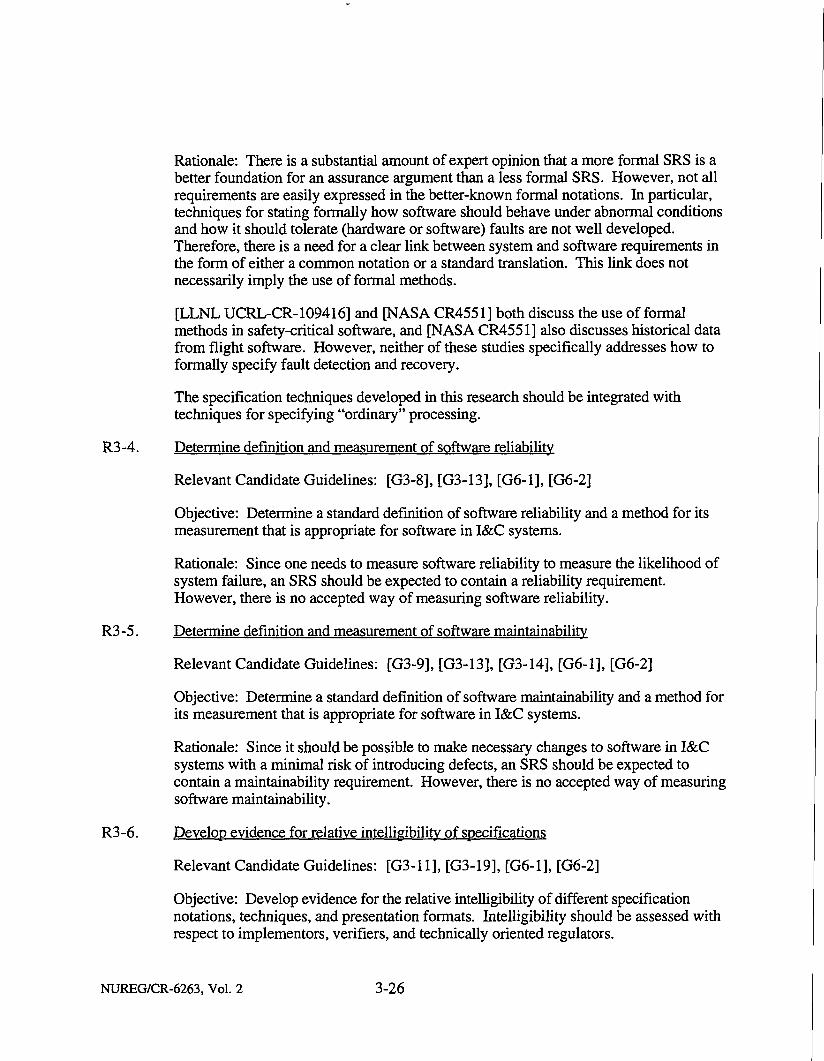
Rationale: There is a substantial amount of expert opinion that a more formal SRS is a better foundation for an assurance argument than a less formal SRS. However, not all requirements are easily expressed in the better-known formal notations. In particular, techniques for stating formally how software should behave under abnormal conditions and how it should tolerate (hardware or software) faults are not well developed. Therefore, there is a need for a clear link between system and software requirements in the form of either a common notation or a standard translation. This link does not necessarily imply the use of formal methods.
[LLNL UCRL-CR-109416] and [NASA CR4551] both discuss the use of formal methods in safety-critical software, and [NASA CR4551] also discusses historical data from flight software. However, neither of these studies specifically addresses how to formally specify fault detection and recovery.
The specification techniques developed in this research should be integrated with techniques for specifying "ordinary" processing.
R3-4. Determine definition and measurement of software reliability
Relevant Candidate Guidelines: [G3-8], [G3-13], [G6-1], [G6-2]
Objective: Determine a standard definition of software reliability and a method for its measurement that is appropriate for software in I&C systems.
Rationale: Since one needs to measure software reliability to measure the likelihood of system failure, an SRS should be expected to contain a reliability requirement. However, there is no accepted way of measuring software reliability.
R3-5. Determine definition and measurement of software maintainability
Relevant Candidate Guidelines: [G3-9], [G3-13], [G3-14], [G6-1], [G6-2]
Objective: Determine a standard definition of software maintainability and a method for its measurement that is appropriate for software in I&C systems.
Rationale: Since it should be possible to make necessary changes to software in I&C systems with a minimal risk of introducing defects, an SRS should be expected to contain a maintainability requirement. However, there is no accepted way of measuring software maintainability.
R3-6. Develop evidence for relative intelligibility of specifications
Relevant Candidate Guidelines: [G3-11], [G3-19], [G6-1], [G6-2]
Objective: Develop evidence for the relative intelligibility of different specification notations, techniques, and presentation formats. Intelligibility should be assessed with respect to implementors, verifiers, and technically oriented regulators.
NUREG/CR-6263, Vol. 2 3-26

Rationale: From a regulatory point of view, a specification should be intelligible to implementors, verifiers, and technically oriented regulators (and secondarily to other stakeholders, including customers). Informal, natural language specifications may be readable, but are often imprecise, whereas formal specifications may be precise, but difficult to understand.
Evidence may be developed by extrapolating from existing human factors research in other areas or by organizing small experiments. The research should address, among other things, graphical and tabular specification notations and hypertext presentation formats.
R3-7. Develop tools to maintain consistency of software specifications and translate between notations
Relevant Candidate Guidelines: [G3-12], [G3-14], [G3-15], [G6-1], [G6-2]
Objectives: (1) Develop computer-aided software requirements engineering tools that can maintain specifications written in multiple notations and translate between notations (see [Hsia et al., 1993]). (2) Develop the capability to store requirements specifications once, but to browse and maintain the set of specifications from any of several views, notations, or languages. These tools should also be able to perform some basic consistency checks (these are discussed in Section 6 on V&V—Static).
Rationale: To be readable, modifiable, and maintainable, a specification may have to combine different means of expression. For example, data flows might be most clearly communicated by means of diagrams, while an input-output transform function might be most clearly communicated by means of a formula in standard mathematical or logical notation. However, manually producing parallel versions of requirements could introduce errors and inconsistencies. Ideally, tools would reliably project the various means of expression or visualization from a single underlying representation.
R3-8. Develop tools to measure test coverage of specifications
Relevant Candidate Guidelines: [G3-13], [G6-1], [G6-2]
Objective: Develop methods of measuring automatically how well a set of test cases covers a set of requirements.
Rationale: There are two important kinds of software testing: structural (glass-box) and functional (black-box). Functional testing of a software component should be based on that component's SRS. To produce evidence that a set of functional tests is adequate, one should be able to measure the degree to which a set of test cases covers the requirements in an SRS. There is currently no automated way to do this.
3-27 NUREG/CR-6263, Vol. 2

R3-9. Develop repeatable method and tools to generate test cases from specifications
Relevant Candidate Guidelines: [G3-13]
Objective: Develop a repeatable method for generation of test cases or test specifications from an SRS expressed in a formal or other precise notation, and automate this method.
Rationale: Since a testable requirement is verifiable, the production of test cases for a requirement is a means of demonstrating that the requirement is verifiable. If test cases or test specifications could be generated automatically, there would be a repeatable method for demonstrating verifiability.
R3-10. Identify common safety software performance requirements based on domain-specific experience
Relevant Candidate Guidelines: [G3-5], [G3-6]
Objective: Identify common software requirements that specify time-dependent software behavior that accounts for hazards and abnormal events, based on domain-specific experience.
Rationale: The software industry, including the application domain of NPPs, has experience in translating system performance goals into SRSs, but the commonalities among requirements of similar software systems for each of the various plant types have not been identified and codified. If this information were captured, it could be reused and could mature more rapidly into "proven" requirements. The scope of this research is requirements that specify time-dependent behavior that accounts not only for any combination of input sequences, but also for all hazards and abnormal events. This emphasis on the safety issues related to performance, and especially timing, would be the focus of this research.
This research should make use of the results of NRC-sponsored research on real-time performance documented in [LLNL NUREG-6083].
This research potentially is part of the domain-specific software engineering activity introduced in research need [R3-1] and described in Section 14.
NUREG/CR-6263, Vol. 2 3-28

SECTION 4
SOFTWARE DESIGN
4.1 Overview This section discusses the candidate guidelines for software design from the standpoint of ensuring safety and satisfying the requirements specified in the SRS. The candidate guidelines presented here make explicit the constraints placed on the software by the decisions made at the system level. The subelements for this framework element were defined using an approach that involves multiple views of a design, where each view highlights an important aspect of the design. Within each view, those areas that could compromise the integrity and the robustness of the software design were identified as subelements for which guidelines are required. The approach of using multiple views of a design is based on a general framework for dealing with complex problems presented in [Yeh et al., 1984].
The views used to identify and define the subelements were decomposition, interaction, behavior, and data model. The decomposition view shows how the software is divided into manageable components after it has been allocated to hardware components in the system design. The subelements Modular Design, External Interface, and Interfaces to Safety Components were defined using this view. The interaction view shows the interfaces between the components, where the interaction can be related to control or data. This view defined the subelements on Interface Integrity and Flow Control. The behavior view shows the dynamics of the software in terms of states or processes. It defined the subelement on Error Handling. Finally, the data model view, which shows the set of data with attributes required to support the software, defined the subelement on Data Integrity.
The scope and safety significance of each subelement is discussed below:
• Modular Design. This subelement focuses on guidelines to enhance the quality of software by explicitly separating functionality among components with clearly defined interfaces. This approach to software design has two main safety benefits: (l)it minimizes the ripple effect of design changes in a component on related components, and (2) it minimizes the propagation of abnormal conditions to a few neighboring components (i.e., validating input at the interface to detect erroneous data). In addition, a modular design is easier to understand because it divides the problem into a manageable set of interrelated components [Booch, 1991; Meyer, 1988]. In recognizing this benefit, the British Ministry of Defense states: "Comprehension of the SCS [safety critical software] may be assisted if the design is broken into a hierarchy of modules such that each module is small enough to be understood as a whole" [MOD55: Part 2, 30.3.3].
• External Interface. This subelement focuses on guidelines ensuring that all specified external events are addressed so that other processing, specifically safety processing, will continue without interruption. Levi states the importance of encapsulating external interfaces: "Assuring the predictability of device response times
4-1 NUREG/CR-6263, Vol. 2
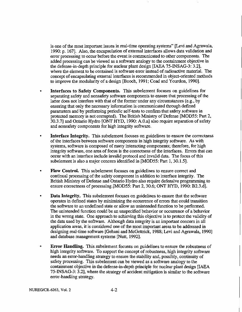
is one of the most important issues in real-time operating systems" [Levi and Agrawala, 1990: p. 167]. Also, the encapsulation of external interfaces allows data validation and error processing to occur before the event is communicated to other components. The added processing can be viewed as a software analogy to the containment objective in the defense-in-depth principle for nuclear plant design [IAEA 75-INSAG-3: 3.2], where the element to be contained is software error instead of radioactive material. The concept of encapsulating external interfaces is recommended in object-oriented methods to improve the modularity of a design [Booch, 1991; Coad and Yourdon, 1990].
Interfaces to Safety Components. This subelement focuses on guidelines for separating safety and nonsafety software components to ensure that processing of the latter does not interfere with that of the former under any circumstances (e.g., by ensuring that only the necessary information is communicated through defined parameters and by performing periodic self-tests to confirm that safety software in protected memory is not corrupted). The British Ministry of Defense [MOD55: Part 2, 30.3.7] and Ontario Hydro [ONT HYD, 1990: A.O.a] also require separation of safety and nonsafety components for high integrity software.
Interface Integrity. This subelement focuses on guidelines to ensure the correctness of the interfaces between software components in high integrity software. As with systems, software is composed of many interacting components; therefore, for high integrity software, one area of focus is the correctness of the interfaces. Errors that can occur with an interface include invalid protocol and invalid data. The focus of this subelement is also a major concern identified in [MOD55: Part 1,30.1.5].
Flow Control. This subelement focuses on guidelines to ensure correct and continual processing of the safety component in addition to interface integrity. The British Ministry of Defense and Ontario Hydro also require defensive programming to ensure correctness of processing [MOD55: Part 2,30.6; ONT HYD, 1990: B2.3.d].
Data Integrity. This subelement focuses on guidelines to ensure that the software operates in defined states by minimizing the occurrence of errors that could transition the software to an undefined state or allow an unintended function to be performed. The unintended function could be an unspecified behavior or occurrence of a behavior in the wrong state. One approach to achieving this objective is to protect the validity of the data used by the software. Although data integrity is an important concern in all application areas, it is considered one of the most important areas to be addressed in designing real-time software [Gehani and McGettrick, 1988; Levi and Agrawala, 1990] and database management systems [Nutt, 1992].
Error Handling. This subelement focuses on guidelines to ensure the robustness of high integrity software. To support the concept of robustness, high integrity software needs an error-handling strategy to ensure the stability and, possibly, continuity of safety processing. This subelement can be viewed as a software analogy to the containment objective in the defense-in-depth principle for nuclear plant design [IAEA 75-INSAG-3: 3.2], where the strategy of accident mitigation is similar to the software error-handling strategy.
NUREG/CR-6263, Vol. 2 4-2

Relation to Safety
Software design contributes to safety in a fundamental manner, such as by establishing well-defined functions and interfaces for software components, and by providing uniform strategies for preventing and responding to anticipated abnormal conditions or errors. These design objectives are also important to achieving high reliability and maintainability, which are key attributes of high integrity software. Candidate guidelines and discussion relative to software reliability and maintainability are provided in Section 7.5 on Integration and System Testing and Section 10.2 on Software Maintainability, respectively.
The safety importance of each subelement of Software Design has already been discussed above. In addition, the subelements lend support to implementing at the software level certain basic safety criteria for Class IE systems in nuclear power plants, as indicated below.
The subelement External Interface supports IEEE Std 603's "Completion of Protective Action Criterion" objective [IEEE603: 5.2] by proposing guidelines to ensure that no safety processing (or protective action) will be interrupted by an event arising from external interfaces.
The subelement Interfaces to Safety Components supports IEEE Std 603's "Independence" objective [IEEE603: 5.6] by separating safety and nonsafety software components to ensure that safety functions can be performed following any error (or design basis event).
The subelements Interface Integrity, Flow Control, and Data Integrity support IEEE Std 603's "System Integrity Criterion" objective of ensuring the accomplishment of safety functions under the full range of applicable conditions enumerated in the design basis [IEEE603: 5.5] by focusing on guidelines to ensure the correctness of the interfaces among software components and the validity of data being communicated among components. Like the hardware system, a software system is composed of many interacting components, so that the system integrity can be affected by an error occurring as part of the interaction between components or by corruption of data used by the components.
The subelement Error Handling provides guidelines to ensure that the software is robust so that it is able to recover from an error, when possible, to allow safety processing to be performed. This software design approach supports IEEE Std 603's "Single-Failure Criterion" objective [IEEE603: 5.1]: "Safety systems shall perform all safety functions required for a design basis event in the presence of (1) any single detectable failure within the safety systems . . . . "
Organization
The remainder of this section presents candidate guidelines for software design and their technical basis under seven subelements:
• Modular Design • External Interface • Interfaces to Safety Components • Interface Integrity ° Flow Control • Data Integrity 0 Error Handling
4-3 NUREG/CR-6263, Vol. 2

These subelements are covered in Sections 4.2 through 4.8, respectively. Research needs are presented in Section 4.9.
4.2 Modular Design
4.2.1 Candidate Guidelines G4-1. The software design should be divided into components using the information-hiding
principle to produce components with interfaces that remove the design's implementation detail (or volatile design features). [Bl, B3, B7]
G4-2. The critical data structures and related operations in the software design should be encapsulated within components. [Al]
G4-3. The degree of modularity for a component as a minimum should be based on the following:
• Ease of understanding, taking into account both functional and structural complexity [B2, B6]
• Minimal ripple effect of changes [B4, B5] • Cohesiveness of components [B7, B8]
4.2.2, Technical Basis
Baseline
The following excerpts from baseline standards (with underlining added to emphasize the key portions) were considered in the development of the above candidate guidelines:
B l . "The program structure should be based on a decomposition into modules." [IEC880: 5.1.Lb]
B2. 'The program structure should be simple and easy to understand, both in its overall design and in its details. Tricks, recursive structures and unnecessary code compaction should be avoided." [IEC880: 5.1.1 .c]
B3. "At an early design stage it should be identified which characteristics of the software to be developed and its functional requirements are likely to change during its life cycle." [IEC880:Bl.a.aa]
B4. "During further design stages modules should be chosen such that the most probable modifications result in the change of one or two modules only." [IEC880: Bl.a.ab]
B5. "The program structure should permit the implementation of anticipated changes with a minimum of effort." [IEC880: B2.a.ac]
NUREG/CR-6263, Vol. 2 4-4

B6. 'The software development plan in accordance with IEEE7-4.3.2, Criteria for Programmable Digital Computer Systems in Safety Systems of Nuclear Power Generating Stations, shall include requirements and methodology for achieving modularity." [URD: 6.1.3.4]
B7. "The software design shall use a hierarchical design structure and principles of modular design with coherent, cohesive modules." [URD: 6.1.3.7]
B 8. "The software designer shall consider defining a summation widely used in other parts of the software as 'utilities' which can be shared by several other software modules rsicl." [URD: 6.1.3.18]
Discussion of Baseline
Although there are many criteria for decomposing a design into components, the baseline recommends one approach that uses anticipated changes (or volatile design features) as a criterion [Bl, B3, B7]. The motivation for this approach is that if volatile design features are isolated from the rest of the system, there will be minimum interdependency between components, and thus minimum effect when those features are changed. The approach is based on the information-hiding principle [Parnas, 1972], which is defined as follows:
"Information hiding. A software development technique in which each module's interfaces reveal as litde as possible about the module's inner workings and other modules are prevented from using information about the module that is not in the module's interface specification. See also: encapsulation." [IEEE610.12]
This approach is also required by Ontario Hydro [ONT HYD, 1990: 2.4.3,2 and B2.8]. In addition, the baseline suggests that the degree of modularity for a component should be based on the following:
• Ease of understanding [B2, B6] • Minimal ripple effect of changes [B4, B5] • Cohesiveness of components [B7, B8]
These attributes of modularity are used in various software design methods, such as structured design [Page-Jones, 1988], object-oriented design [Booch, 1991; Coad and Yourdon, 1990], and layered virtual machine [Nielson and Shumate, 1988: 26.6]. However, the baseline does not clearly define all the criteria for evaluating a good modular design (e.g., coupling).
Suggested Additions
A1. The critical data structures and related operations in the software design should be encapsulated within components.
4-5 NUREG/CR-6263, Vol. 2

Rationale
The traditional definition of modularity covers coupling and cohesion, where coupling is the degree of interdependency between components, and cohesion is the degree of intradependency of a component functionality. As defined in [Page-Jones, 1988], the types of coupling—ranging from most desirable to least—are data, tramp, stamp, bundling, control, hybrid, common, and content. Using the same ordering, the types of cohesion are functional, sequential, communicational, procedural, temporal, logical, and coincidental. Currently, the definition of modularity has been expanded to incorporate new modern software engineering principles (e.g., the information-hiding principle). [Meyer, 1988] provides a fairly complete definition of modularity, consisting of five criteria:
1. Modular decomposability—characterizes a design that decomposes a new problem into several subproblems.
2. Modular composability—characterizes a design that produces a new system by combining its components.
3. Modular understandability—characterizes a design that consists of components that can be understood separately.
4. Modular continuity (static)—characterizes a design that minimizes the effect of a change in a component specification to one or a few components.
5. Modular protection (dynamic)—characterizes a design that minimizes the effect of error on neighboring components.
In addition to using the information-hiding principle as a criterion for design decomposition, [Al] provides an additional criterion that will enhance the cohesion attribute of a component because the representation of data and related operations are contained in the component. Also, monitoring of the data is easier to perform because related operations in a data structure use the same interface [Booch, 1991; Gehani and McGettrick, 1988; Meyer, 1988]. Furthermore, the application of [Al] will produce components that support data coupling, the most desirable type of coupling for modularity [Page-Jones, 1988].
Potential Methods
In terms of available design methods that produce a modular design, use of the information-hiding principle (as required in the baseline) for design decomposition is a good approach. This approach has become a fundamental part of many available methods. For example, the software cost reduction (SCR) method [Britton and Parnas, 1981] decomposes the design into various types of modules using the information-hiding principle as a criterion. Object-oriented methods [Booch, 1991; Coad and Yourdon, 1990; Meyer, 1988; Shlaer and Mellor, 1988; Rumbaugh et al., 1991] use the information-hiding principle and the abstraction principle to identify the objects in a problem.
NUREG/CR-6263, Vol. 2 4-6

[Meyer, 1988] identifies five methods that can be combined to achieve the modularity criteria defined: linguistic modular units, few interfaces, small interfaces (weak coupling), explicit interfaces, and information hiding. Note that the baseline and the references for defining modularity are still qualitative rather than quantitative.
During the design process, the software engineer should study trade-offs between the functional and structural complexity in the design [Parnas, 1972]. A general consideration is that the degree of modularity should not greatly increase the structural complexity of the design. In particular, " . . . the interface between the modules requires careful attention, as too many small modules may lead to a complex data flow that itself is hard to follow" [MOD55: Part 2,30.3.3]. However, functional complexity is much more important to safety than is structural complexity because it may decrease understanding of the software, which could increase the potential for errors [LLNL, 1992]. This position is also supported in [LLNL, 1993 DRAFT: A.1.5.17]. Both functional and structural complexity affect the ease of understanding, which is addressed in the candidate guideline [G4-3].
Assessment
The technical basis for the Modular Design subelement is considered satisfactory for all the candidate guidelines except for candidate guideline [G4-3] (degree of modularity), for which improvement is needed both in the methods for evaluating modularity in the context of modern software engineering principles (e.g., information hiding), and in establishing a threshold. Although there are various measures that indirectly indicate the extent of modularity for a design, there is no consensus on the acceptable threshold values for these measures. For this candidate guideline, research item [R4-1] is proposed to identify the acceptable ranges for those measures that best indicate the degree of modularity in a design.
4.3 External Interface
4.3.1 Candidate Guidelines
G4-4. The software design should encapsulate external interface components that are separated from the application program in order to achieve the following [B2]:
• Prevent abnormal conditions and events (ACEs) from propagating to other components. [Bl]
• Ensure protocol compatibility between the application software and the external interface. [B1,B2]
• Ensure uninterrupted safety processing. [B4]
G4-5. The software design should encapsulate the processing of asynchronous or synchronous events from an external interface into a component. [Al]
G4-6. The software design should use interrupts only to simplify the system. [B3]
4 - 7 NUREG/CR-6263, Vol. 2
V"iwZ:K" -'M.& •"-'M"<&j^y- ^Sx-y^W^:"'--?i-<"^Z£%v>l:-.± '" ^"" '•-.••^tv.'

G4-7. The validation and error processing for an external interface should be thoroughly documented in the design specification. [A3]
G4-8. The software design should thoroughly document each usage of interrupt. [B6]
(a) The software design should define processing duration and maximum number of occurrence constraints for external event processing (e.g., interrupts). [A2]
(b) The software design should define the maximum duration for which an interrupt is disabled. [B5]
4.3.2 Technical Basis
Baseline
The following excerpts from baseline standards (with underlining added to emphasize the key portions) were considered in the development of the above candidate guidelines:
B1. "Interface design considerations, including interfaces with other modules of the system, both internal and external should be reviewed. The major areas of concern with interfaces are properly defined protocols, and control and data linkages. External interfaces should be evaluated to verify that communication protocol in the design is compatible with interfacing requirements. The interfaces evaluation should support claims of redundancy management, partitioning, and ACE containment. Potential interface and timing problems include interrupts handled incorrectly, incorrect input and output timing, and subroutine/module mismatch." [IEEE7-4.3.2: F2.3.4.e]
B2. 'The software should be partitioned so that aspects which handle such functions as
- computer external interfaces, - real-time signals, - store allocation, - special functions, - mapping standard 'functions' on to the particular computer hardware;
are separated from 'application' programs with well defined interfaces between them." [IEC880: B2.a.ab]
B3. "Interrupts may be used if they simplify the system." [IEC880: B2.ea]
B4. "Software handling of interrupts must be inhibited during critical parts (e.g., time critical, critical to data changes) of the executed function." [IEC880: B2.eb]
B 5. "If interrupts are used, parts not interruptible should have a defined maximum computation time, so that the maximum time for which an interrupt is inhibited can be calculated." [IEC880: B2.ec]
B6. "Interrupt usage and masking shall be thoroughly documented." [IEC880: B2.ed]
NUREG/CR-6263, Vol. 2 4-8

Discussion of Baseline
The baseline recommends that external interfaces be implemented (or encapsulated) in components that are separated from the application program [B2] in order to achieve the following:
• Prevent ACEs from propagating to other components [B1].
• Ensure protocol compatibility between the application software and the external interface [B1,B2].
• Ensure uninterrupted safety processing [B4].
On the use of interrupts in designing external interfaces, the baseline recommends a careful evaluation of each use. Specifically, it recommends that interrupts be used only to simplify the system [B3] and states that each usage shall be thoroughly documented [B6]. Because the control software for a nuclear plant sometimes has to interface with external devices via asynchronous events, it is more realistic to evaluate each use of interrupt than to totally preclude its use. Also, in an effort to produce a predictable design, the baseline recommends that processing not related to servicing interrupts have a defined maximum computation time, so that the maximum duration for which an interrupt is disabled can be determined [B5].
Suggested Additions
A1. The software design should encapsulate the processing of asynchronous or synchronous events from an external interface into a component.
A2. The software design should define processing duration and maximum number of occurrence constraints for external event processing (e.g., interrupts).
A3. The validation and error processing for an external interface should be thoroughly documented in the design specification.
Rationale
[Al] will ensure that each event is addressed to ensure the predictability of the software. More specifically, if asynchronous events are not addressed, then the specified requirements are not fully satisfied (e.g., an interrupt may cause a delay in the current processing). [A2] will ensure that timing aspects related to events are specified and available for design refinement and validation activities. The combination of [A2] and [B5] will ensure that high integrity software has deterministic execution time bounds. This concept is also recommended in [LLNL NUREG/CR-6083:2.2.1] and [LLNL, 1993 DRAFT: A. 1.8.4] to enhance the verifiability of the software system. In addition to timing constraints, [A3] will ensure that the information required to evaluate the external interface design, as required in [Bl], is available. This suggested addition is supported by recommendations contained in [IEEE1016: 5.3.7, 5.3.9, and 6.2.3].
4-9 NUREG/CR-6263, Vol. 2

Potential Methods
The technique of encapsulating external interfaces is widely discussed in the technical literature on real-time system design [Britton et al., 1981; Levi and Agrawala, 1990; Nielsen and Shumate, 1988]. Recent design methods that address design refinement related to external interfaces include Ada Design Approach for Real Time [Gomaa, 1989] and entity-life modeling [Sanden, 1994].
These methods propose differing approaches to reduce the design complexity due to interrupts. For example, Gomaa addresses reduction of complexity due to concurrency in a design as part of his task identification criteria. The criteria are used during the transformation from a dataflow model to a tasking model. Gomaa recommends encapsulating external events as tasks, and then combining synchronous events with closely related timing characteristics into a single task (i.e., temporal task cohesion). This reduces the number of tasks in a design and hence the complexity of the scheduling in the design. On the other hand, Sanden starts the design process with a set of heuristic models that help identify a minimum set of processes while maximizing concurrency. One of his heuristic models selects the longest processing thread that contains the most nonoverlap processing. Hence the complexity in the design is reduced by having the minimum number of processes, but concurrency is not reduced. Discussions related to this topic are also found in Sections 4.1, on Modular Design, and 4.5, on Interface Integrity.
Assessment
In general, the technical basis for the External Interface subelement is considered satisfactory. Candidate guideline [G4-7] would be strengthened by additional references. Since the threshold of acceptance for candidate guidelines [G4-6], [G4-7], and [G4-8] is questionable, research item [R4-2] is proposed to define important dependencies in these three guidelines between system and software concerns in designing external interface components. These dependencies could be used to develop evaluation criteria for ensuring the completeness of the external interface design.
4.4 Interfaces to Safety Components
4.4.1 Candidate Guidelines
G4-9. Safety components should be identified to increase the focus on support for prevention of unnecessary interaction from nonsafety components. [B2]
G4-10 The interfaces between safety and nonsafety components should be carefully designed to prevent unnecessary interactions with nonsafety component processing. [B1, B3]
(a) The software design should ensure that only the necessary information is communicated between safety and nonsafety components. [Al]
(b) The software design should use self-checking to ensure the accuracy of data produced for use in safety components. [A2]
(c) The software design should ensure that all communication between safety and nonsafety components is through their defined parameters. [B5]
NUREG/CR-6263, Vol. 2 4-10

G4-11. Safety software should reside in protected memory and periodically perform self-test to confirm that it has not been corrupted. The time interval between checks should be determined based on the safety importance of the function being performed. [B4, A3]
4.4.2 Technical Basis
Baseline
The following excerpts from baseline standards (with underlining added to emphasize the key portions) were considered in the development of the above candidate guidelines:
B1. "Data communication between safety channels or between safety and nonsafety systems shall not inhibit the performance of the safety function." [IEEE7-4.3.2: 5.6]
B2. "Software modules that implement critical functions should be identified. Potential problems may occur in interfacing and communicating data to other modules, incompatibility of word format or data structure, synchronization with other modules for purposes of data sharing, etc." [IEEE7-4.3.2: F2.3.4.g]
B3. "Nonsafety modules should be evaluated to provide adequate confidence that they do not adversely affect safety software." [TEEE7-4.3.2: F2.3.4.h]
B4. 'The M-MIS FMan-Machine Interface Systems! Designer shall establish and document the vital software required to reside in protective memory. As a minimum, all software required to perform protective or control functions for safety-related systems shall reside in protective memory." [URD: 6.1.3.17]
B5. 'They [subroutines and procedure] should communicate exclusively via their parameters to their environment." [IEC880: B4.b.bb]
Discussion of Baseline
The baseline recommends that safety components be identified [B2]. It also recommends that the interfaces between safety and nonsafety components be carefully designed to prevent unnecessary interactions from nonsafety component processing [Bl, B3]. This concept is emphasized as well in design evaluation criteria proposed by [LLNL NUREG/CR-6101:4.4.2.3 2(d), 4.3.3.3 1(d)]. The approach suggested for interface design involves ensuring that all communication between safety and nonsafety components is through their parameters [B5]. This approach forces all communication to be explicit, thus avoiding side-effects among components. The baseline states that safety software shall reside in protected memory [B4]. Although the baseline suggests an approach to separating safety and nonsafety components, additional guidelines are needed to enhance the quality of the interface design.
4-11 NUREG/CR-6263, Vol. 2

Suggested Additions
Al. The software design should ensure that only the necessary information is communicated between safety and nonsafety components.
A2. The software design should use self-checking to ensure the accuracy of data produced for use in safety components.
A3. Periodic self-test should be performed to confirm that the storage of the software instructions has not been corrupted. The period of these checks should be determined based on the safety importance of the function being performed.
Rationale
Ideally, a total separation of safety and nonsafety components would prevent any adverse effect on safety functionality. However, system components need to communicate, either to synchronize processing or to transfer data. [Al] will ensure that only the necessary information is communicated between safety and nonsafety components [Meyer, 1988]. For example, an unwanted coupling relationship exists when data is being passed among several components before it is actually used (i.e., stamp coupling). This is a typical issue in structured design [Page-Jones, 1988]. Also, [A2] will ensure the accuracy of the data transferred to a safety component.
Although the baseline, [B4], recommends storing safety software in protected memory, [A3] strengthens this recommendation further by requiring that the content in protected memory be verified periodically to ensure its integrity.
Potential Methods
The main approach to separating safety and nonsafety processing is to allocate them to separate software components with clearly defined interfaces. This implies that modularity and interface integrity are important concerns in achieving the stated goal (refer to Sections 4.2 on Modular Design and 4.5 on Interface Integrity for discussion of available techniques in these two areas, and to Section 4.6 on Data Integrity for discussion of available techniques for protecting critical data).
Assessment
The body of knowledge and evidence for all candidate guidelines in the Interfaces to Safety Components subelement is satisfactory except for [G4-10(b)], which is considered unsatisfactory in this regard. Acceptance thresholds for candidate guidelines [G4-10], [G4-10(a)], [G4-10(b)], and [G4-11] are questionable. Research item [R4-6] on fault-tolerant architectures is proposed to provide additional guidance and thresholds for these four candidate guidelines [G4-10, G4-10(a), G4-10(b), G4-11]. In addition, research item [R4-1] on measuring modularity addresses candidate guideline [G4-10(a)] (limiting communication between safety and nonsafety components).
NUREG/CR-6263, Vol. 2 4-12

4.5 Interface Integrity
4.5.1 Candidate Guidelines
G4-12. The software should perform parameter validation by checking the range of data used in communications to ensure that its value is within the defined domain. [B2, B7]
G4-13. The software should perform protocol validation by doing the following:
• Checking whether the requested action satisfies the conditions defined in the assertions stated for the interface. [B4, B6]
• Verifying the permission for the called component before performing the action requested. [B3]
G4-14. (a) The software should perform a plausibility check on the data being communicated to ensure that its value is accurate. [B1, B7]
(b) Communications messages should contain sufficient information to check for the completeness, correctness, correct ordering, and timeliness of the message data (e.g., sumchecks, sequence number timestamp). [Al]
4.5.2 Technical Basis Baseline
The following excerpts from baseline standards (with underlining added to emphasize the key portions) were considered in the development of the above candidate guidelines:
B1. "Plausibility checks shall be performed (defensive programming)." [IEC880: B3.a]
B 2. "The correctness of any kind of parameter transfer should be checked, including parameters type verification." [IEC880: B3.d.db]
B 3. "Called routines should check whether the calling module is entitled to do so."
[IEC880: B3.d.dd]
B4. "Assertions should be used." [IEC880: B3.d.dfJ
B5. The [EEC880] subsection on "Subroutines and Procedures," which contains guidelines on designing interfaces for subroutines and procedures. [IEC880: B4.b]
B6. "Interface design considerations, including interfaces with other modules of the system, both internal and external should be reviewed. The major areas of concern with interfaces are properly defined protocols, and control and data linkages The
4-13 NUREG/CR-6263, Vol. 2

interfaces evaluation should support claims of redundancy management, partitioning, and ACE containment. Potential interface and timing problems include interrupts handled incorrectly, incorrect input and output timing, and subroutine/module mismatch." [IEEE7-4.3.2: F2.3.4.e]
B7. "Software design shall incorporate defensive techniques. Software design shall anticipate beyond the design basis because the software cannot discriminate between design basis and beyond design basis. The software shall include limits checks . . . out-of-range of design inhibits which prevent erroneous entries, logic check for erroneous input data due to communication errors, etc. to prevent software instability. erroneous calculation or control other adverse results." [URD: 6.1.3.3]
Discussion of Baseline
The baseline specifies use of defensive programming techniques in designing interfaces between components. These techniques include the following:
• Parameter validation by checking the lower and upper bounds of data used in communications to ensure that its value is within the defined domain [B2, B7].
• Protocol validation by checking whether the requested action satisfies the conditions defined in the assertions stated for the interface. The use of assertions prevents protocol errors by explicitly identifying assumptions and conditions for the interfaces (i.e., pre- and post-conditions) [B4, B6]. Besides assertions, the baseline recommends that the called-component verify the permitting authority of the caller-component before performing the action requested [B3].
• Plausibility check on data to ensure that the value of the data being communicated is accurate [B1, B7]. This aspect is also a focus in the software design evaluation criteria in [LLNL NUREG/CR-6101: 4.3.2.3 3(c)].
The set of defensive programming techniques specified in the baseline is adequate to address interface integrity concerns.
Suggested Additions
A1. Communications messages should contain sufficient information to check for the completeness, correctness, correct ordering, and timeliness of the message data (e.g., sumchecks, sequence number timestamp).
Rationale
Since this subelement proposes candidate guidelines that involve various types of validation (i.e., parameter validation, protocol validation, and plausibility check), [Al] ensures that the required information is identified so that it can be provided in support of the validation suggested in the candidate guidelines.
NUREG/CR-6263, Vol. 2 4-14

Potential Methods
In designing defensive programming techniques, the software engineer should consider programming language constructs to achieve the objective of defensive programming (e.g., strong typing). In addition, Section 4.2 on Modular Design should be referred to for additional discussion on developing a component's interfaces. Meyer provides a good discussion of the various aspects of designing assertions for a component in the Eiffel language [Meyer, 1988: Chapter 7].
The software engineer should study tradeoffs between a component's performance and the defensive programming techniques used for [G2-3(a)] and [G2(b)]. For example, the overhead from having assertions may cause the performance of the component to be too slow. Thus, assertions may not be appropriate. Meyer raises another interesting point regarding assertions:
"One of the main sources of complexity in programs is the constant need to check whether data passed to a processing element (routine) satisfy the requirements for correct processing . . . . Redundant checking may seem harmless, but it is not. It hampers efficiency, of course; but even more important is the conceptual pollution that it brings to software systems. Complexity is probably the single most important enemy of software quality. The distribution of redundant checks all over a software system destroys the conceptual simplicity of the system, increases the risk for errors, and hampers such qualities as extendibility, understandability and maintainability." [Meyer, 1988:7.3.2, p. 117]
Assessment
The technical basis for the Interface Integrity subelement is considered satisfactory for all the candidate guidelines in terms of evidence provided in the baseline and other sources, except for [G4-14(b)] (communications messages), which is considered unsatisfactory in this regard. Sufficient methods exist for meeting all the guidelines. Threshold exists for all the guidelines except [G4-14(b)] (communications messages), for which it is questionable. Research item [R5-5/R4-7] is proposed to address the deficiency in the technical basis for this candidate guideline. This research, which also supports coding guidelines in Section 5 of this report, would increase awareness of defensive programming constructs in existing programming languages so that evaluation criteria for proper usage of these constructs could be defined.
4.6 Data Integrity
4.6.1 Candidate Guidelines
G4-15. The software design should explicitly identify the critical data and its usage context. Critical data is any data needed to maintain plant power operation, maintain plant safety, permit plant maneuvering, or establish operating limits and margin. [B5, A6]
4-15 NUREG/CR-6263, Vol. 2

G4-16. The software should protect and monitor data storage. [B1, B2]
(a) The software design for data storage should address diversity and redundancy. [B5]
(b) The software design should balance symmetric operation types (e.g., create-delete and open-close) to prevent corruption of data. [A4]
G4-17. The software should use a defensive technique for data storage. [B3]
(a) Each variable should be assigned a default value when it becomes available. [B3]
(b) The use of techniques that allow critical data overwriting (e.g., circular structure) should be justified. [A3]
(c) The software should define attributes for time tag, quality tag, and identification tag to be used for important data. [B6]
G4-18. The software design should include the consideration of security aspects as part of designing for data integrity. [A5]
G4-19. The software should implement access control for data storage. [B4]
(a) The software design specification should specify the sequence of accesses for the set of critical data and shared data. [Al]
(b) The software design should ensure that only authorized access to data is allowed. [A2]
4.6.2 Technical Basis
Baseline
The following excerpts from baseline standards (with underlining added to emphasize the key portions) were considered in the development of the above candidate guidelines:
Bl. "Memory contents shall be protected or monitored." [IEC880: B3.c]
B 2. "Evaluation of data structure and intended use should be performed for data dependencies that circumvent isolation, partitioning, data aliasing, and fault containment issues affecting safety and the control or mitigation of ACEs. Potential data handling problems including incorrect initialized data, accessed or stored data, scaling or units of data, dimensioned data, and scope of data should be reviewed." [IEEE7-4.3.2: F2.3.4.c; d]
B3. "Software design shall incorporate defensive techniques. Software design shall anticipate beyond the design basis because the software cannot discriminate between design basis and beyond design basis. The software shall... assign default values to
NUREG/CR-6263, Vol. 2 4-16

prevent software instability, out-of-range of design inhibits which prevent erroneous entries, logic check for erroneous input data due to communication errors, etc. to prevent software instability, erroneous calculation or control other adverse results." [URD: 6.1.3.3]
B4. 'The use of public or global variables (those known to more than one software module) shall be located in a common region and defined." [URD: 6.1.3.14.h]
B 5. The software design shall provide "sufficient redundancy and diversity of data storage so that a single event or failure cannot cause the loss of critical data. Critical data is any data needed to maintain plant power operation, maintain plant safety, permit plant maneuvering, or establish operating limits and margin." [URD: 6.1.3.20.b]
B 6. "Provide appropriate time tags, data quality tags, and data identification tags" for critical data. [URD: 6.1.3.20.C]
Discussion of Baseline
Generally, data integrity refers only to the accuracy or validity of data [Date, 1986]; however, in this report the scope of data integrity also includes aspects of security that have a direct effect on safety. Based on this definition, errors can occur in three contexts: (1) wrong initial state, (2) corruption of data due to storage medium failure, or (3) problems arising during access and update of data. The baseline specifies requiring default values to address error context (1) [B2, B3]. Also, the baseline specifies that data be protected and monitored using diversity and redundancy of data storage to address error context (2) as described above [Bl, B2, B4, B5, B6]. The implementation (coding) aspects of defensive techniques are considered further in the discussion of Logic Structure in Section 5.5. For error context (3), the baseline lacks detailed guidelines for access control [Bl, B4], Therefore, additional guidelines are required.
Suggested Additions
A1. The software design specification should specify the sequence of accesses for the set of
critical data and shared data.
A2. The software design should ensure that only authorized access to data is allowed.
A3. The use of techniques that allow critical data overwriting (e.g., circular structure) should be justified.
A4. The software design should balance symmetric operation types (e.g., create-delete and open-close) to prevent corruption of data.
A5. The software design should include consideration of security aspects as part of designing for data integrity.
A6. The software design should explicidy identify the critical data and their usage context.
4-17 NUREG/CR-6263, Vol. 2

Rationale
Although the baseline, [B5], defines critical data as "any data needed to maintain plant power operation, maintain plant safety, permit plant maneuvering, or establish operating limits and margin," [A6] will ensure that critical data is explicitly identified to avoid misunderstanding. This concept is emphasized as a design evaluation criterion in [LLNL NUREG/CR-6101:4.3.3.3, 2(a)].
Generally, I&C software needs to interface with sensors as part of monitoring setpoints. This functionality requires that the sensor data being processed be as current as possible. [Al] will ensure that the data is not compromised because of logic errors (i.e., out-of-sequence reading of sensor data just before it is updated). Also, [Al] will help identify potential problems with data access by explicitly showing the relationships among anticipated accesses. The ideas in [Al] are discussed widely in the technical literature on topics such as operating systems, database development [Nutt, 1992], and real-time systems design [Sanden, 1994]. Also, the access to critical data is emphasized as a design evaluation criterion in [LLNL NUREG/CR-6101: 4.3.3.3, 2 (b, c)]. Since there is overlap in concerns between data integrity and security (e.g., data access), [A5] expands the definition of data integrity to include security concerns. [A2] will partially address unauthorized access of data by requiring that the software validate access requests against the specified security requirements [Air Force AFISC SSH 1-1: 7.3; Cullyer, 1993].
[A3] will prevent corruption of data value due to accidentally overwriting a storage location when using a circular data structure or de-allocating a storage location that is still being referenced. In addition, by avoiding dynamic memory allocation, the software engineer can avoid one cause of memory leakage because of inaccessible memory location after de-allocation [SofTech WO-126; SofTechWO-123].
[A4] will ensure a check-balance approach to the usage of related operations on the data structure (e.g., leaving a file open after use). The ideas in [A4] are commonly discussed in the technical literature on object-oriented methods [Booch, 1991; Coad and Yourdon, 1990; Cox, 1986; Meyer, 1988].
Potential Methods
In implementing a defensive technique for data storage, the software engineer should select programming languages having built-in constructs that will enforce some of the basic guidelines (e.g., allow Ada strong typing to ensure that data value is within a valid range).
In terms of available methods to address data access control, [Sanden, 1994] proposes using an order rule list to coordinate access of shared data between processes. This list includes all shared data requiring coordinated access, and access to resources on the list must always be acquired in the same sequence. For example, if resource 3 is required, then a process must obtain resources 1 and 2 before acquiring resource 3. The order rule list approach is similar to the precedence graph concept used in operating systems, compilers, parallel programming, and computer architecture [Nutt, 1992]. Both approaches help avoid deadlock situations in the software.
NUREG/CR-6263, Vol. 2 4-18

During the design process, the software engineer should study trade-offs between the granularity of the data being controlled and the delay time from waiting to access the data (i.e., selective mutual exclusion) in the context of specified performance requirements. Note that the smaller the granularity of the data being controlled, the smaller the delay time in accessing the data, but the greater the complexity of synchronization design for data access [Gehani and McGettrick, 1988].
Assessment
The technical basis for the Data Integrity subelement is considered satisfactory for all the candidate guidelines in terms of evidence provided in the baseline and other sources. Satisfactory methods exist for meeting all of the guidelines. Threshold of acceptance exists for all the candidate guidelines, but is considered questionable for [G4-16], [G4-16(a)], [G4-17], [G4-17(b)], [G4-18], and [G4-19(b)]. Research items [R4-3], [R4-5], and [R4-6] are intended to enhance the technical basis for this subelement in terms of identifying architectures that satisfy requirements and developing design evaluation criteria. Appendix A shows specifically which of the above candidate guidelines are addressed by each of these research items.
4.7 Flow Control
4.7.1 Candidate Guidelines
G4-20. The degree of diversity and redundancy for high integrity software should be evaluated to determine what constitutes adequate support for diversity and redundancy at the system level. [B8]
G4-21. Software design should include self-supervision of control flow and data. [B1, B2, B3, B7]
(a) The software should use timers to monitor safety processing for possible occurrence of blocking. [B5, B6]
(b) The software should ensure that self-checking processing will not prevent timely system response in any circumstance. [B2]
(c) The software should use plausibility checks for safety-related calculations. [B4]
(d) The software should have on-line diagnostics that include both plausibility checks and periodic testing of hardware status. [B1, B3, B9, B10, B11]
4-19 NUREG/CR-6263, Vol. 2
~mr -•'#>.-'• ?&:." jfei.t>f.-:

4.7.2 Technical Basis
Baseline
The following excerpts from baseline standards (with underlining added to emphasize the key portions) were considered in the development of the above candidate guidelines:
B1. "The computer system software shall continuously supervise both itself and the hardware (A2.8). This is considered a primary factor in the achievement of the overall system reliability requirements." [IEC880:4.8,4.8.1-5]
B2. 'The software design shall include self-supervision of control flow and data. On failure detection, appropriate action shall be taken in accordance with Sub-clause 4.8." [IEC880: 5.1.1.a]
B3. The "Self-supervision" section in Appendix A of DEC880], which discusses failures
and design principles to consider in the design of self-supervision. [EEC880: A2.8]
B4. "Plausibility checks shall be performed (defensive programming)." [IEC880: B3.a]
B 5. "Counters and reasonableness traps (relay runners) should insure that the program structure has been run through correctly." [IEC880: B3.d.da]
B6. 'The run time of critical parts should be monitored (e.g.. by a watchdog timer)." [D3C880: B3.d.de]
B7. 'The software design shall include self-supervision of control flow and data." [URD: 6.1.3.14.C]
B8. "The M-MIS Designer shall evaluate the diversity and redundancy requirements of each computer-based system and specify the degree of redundancy and diversity it shall have. The M-MIS Designer shall consider the need for a hardwired backup system to the computer-based system, thereby eliminating the need for diversity in the software. Design requirements and validation testing acceptance criteria of the diverse approaches shall be the same." [URD: 6.1.6.2]
B9. "Comprehensive diagnostic routines shall be performed during initialization. The diagnostic routines have provisions to be bypassed during maintenance; however, it must be ensured that the diagnostics are run prior to putting the equipment back in service." [URD: 6.1.3.15]
BIO. "The computer system shall have as much on-line diagnostics as practical to detect fatal failures. Failures shall be annunciated to the plant operating staff. All diagnostic errors shall be recorded on the on-line printer with date and time tags." [URD: 6.1.4.3]
NUREG/CR-6263, Vol. 2 4-20

B11. 'The computer system shall have the capability of performing periodic testing to check the status of the hardware as well as performing comparative measurement of the software for malfunction or unauthorized changes to the software." [URD: 6.1.4.4]
Discussion of Baseline
The baseline states that designers of high integrity software shall evaluate the need for diversity and redundancy [B8]. This guideline is a recent draft NRC Staff Position that cites the benefits of design diversity for high integrity software [USNRC-BTP DRAFT]. Also, the baseline specifies that software design include self-supervision of processing flow (i.e., control flow and data flow) [Bl, B2, B3, B7]. For supervision of processing flow, the baseline recommends using timers to monitor safety processing for possible occurrences of blocking [B5, B6]. As an example, the safety processing could be trapped in a loop because of a corrupted exit condition. Furthermore, the baseline states that self-checking processing shall not prevent timely system response in any circumstance [B2]. Another specified technique for control of processing flow is to use plausibihty checks for safety-related calculations [B4]. In addition, the baseline specifies having on-line diagnostics in the software design that include both plausibihty checks and periodic testing of hardware status [B1, B3, B9, B10, B11]. The techniques specified by the baseline to address processing flow are adequate.
Suggested Additions
None.
Rationale
The importance of flow control to ensure correct and continual processing of safety components has been stated in the Overview. Since the candidate guidelines derived from the basehne to address processing flow are adequate, there is no additional guideline recommended.
Potential Methods
Available approaches for implementing design diversity are N-version programming and recovery blocks. In N-version programming, identical inputs are given to multiple implementations of a given specification. Then a monitor collects the N outputs for the decision algorithm, which determines what output should be used. In a recovery blocks design, there are various recovery points between redundant processes where the intermediate results are validated. If the results are not consistent, then the processing is rolled back to a previous recovery point, and the processing is repeated.
The HALDEN PODS/STEM projects [OECD HALDEN, 1993] highlight one benefit of constructing diverse versions of critical software: having two versions of the software allows one to conduct back-to-back testing of the software with large numbers of test cases. A recommendation emerging from the study is that two diverse versions of all software components
4-21 NUREG/CR-6263, Vol. 2

of the system be developed; these diverse versions should be used in back-to-back testing, and for high integrity applications. Both versions (with comparison logic) should be in the operational system. The idea of having functionally diverse software for high integrity software systems is recommended as well in the Class IE Digital Systems Studies report [SoHaR NUREG/CR-6113: Chapter 5], which also discusses techniques for fault tolerance and fault avoidance.
However, an issue with N-version programming is that the assumption of independence does not seem to hold; that is, faults in the versions tend to produce identical incorrect outputs (common-mode failures). "Faults that always generate identical incorrect outputs are never detected. If the faults ever exhibit different behavior, then the chances of detecting them depend upon how often they cause different outputs" [Knight and Ammann, 1989]. Given two implementations of a function, there is no way to quantify the probability that both will not fail on the same inputs. Therefore, there is no way to quantify the increase in reliability that would result from combining two implementations and a comparator (or three implementations and a voter). More generally, without a good definition of diversity, there is no way to quantify diversity. [Leveson, 1991] asserts that the N-version systems with which the author is familiar have versions that are "extremely similar in design and coding." Existing experimental evidence suggests that there is a non-negligible probability that "diverse" implementations will fail on the same inputs [Knight and Leveson, 1986]. Including diverse versions of a function is not a justification for relaxing standards that would apply to a single version of the function.
An issue related to recovery blocks design is the domino effect, which " . . . could conceivably spread to other processes and continue from recovery point to recovery point (like falling dominos) until the entire software system was rolled back to its initial state, thus discarding all information gathered during its operative life" [Knight and Ammann, 1989].
Assessment
The technical basis for the Flow Control subelement is considered satisfactory for all of the candidate guidelines in terms of evidence and methods. Thresholds are considered questionable for candidate guidelines [G4-20], [G4-21], [G4-21(b)], and [G4-21(d)]. Research item [R4-3] addresses the safety issues, including diversity and redundancy [G4-20], and research items [R4-5] and [R4-6] address the self-supervision issues of [G4-21], [G4-21(b)], and [G4-21(d)].
4.8 Error Handling
4.8.1 Candidate Guidelines
G4-22. (a) The software design should define processing for internal ACEs not specified in theSRS. [Al]
(b) The processing of internal ACEs should be identified as derived requirements and be included in the safety analysis for the software so that potential effects at the system level can be identified. [A5]
NUREG/CR-6263, Vol. 2 4-22

G4-23. The software design should have a global error-handling strategy to maintain consistency in the processing of errors. [A7]
(a) The software design should define a limit on ACE propagation, and guidelines for ACE handler design. [A4]
(b) The identification for ACEs should use a descriptive name to convey its usage context. [A2]
(c) The software design should define a central facility for reporting ACEs and capturing their contextual information. [A3]
(d) The software design should produce well-defined outputs for ACE processing. [Bl]
(e) The software design should ensure that any status information returned from the called service is evaluated before the processing continues. [A6]
G4-24. ACEs associated with a component should be identified. [B4]
G4-25. The occurrence of an ACE should not interrupt safety processing. Protection against critical failures should be provided through strategies for fault-tolerant design and quality control. [B2, B3, B4]
G4-26. A performance margin should be provided. The computer system should be designed with a sufficient performance margin to perform as designed under conditions of maximum stress. Those conditions include data scan, data communication, data processing, algorithm processing, analytical computation, control request servicing, display processing, operator request processing, and data storage and retrieval, at a minimum. Thus the computer system should be designed with reasonable expansion capability that would permit an owner to add other functions in the future. [B5]
4.8.2 Technical Basis
Baseline
The following excerpts from baseline standards (with underlining added to emphasize the key portions) were considered in the development of the above candidate guidelines:
Bl. "If a failure is detected the system shall produce a well defined output." [IEC880: B3.b]
B2. The "Error Checking" section in Appendix B of [IEC880], which identifies various typical error situations that require checking. [IEC880: B3.d]
4-23 NUREG/CR-6263, Vol. 2

B3. "In addition to design basis conditions identified in IEEE Std 603-1991. the computer shall be designed to perform its safety function when subjected to all conditions, external or internal, that have significant potential for defeating the safety function . . . . If the design basis identifies a safety system preferred failure mode, failures of the computer shall not preclude the safety system from being placed in that mode. Performance of the computer restart operations shall not result in the safety system being inhibited from performing its function." [IEEE7-4.3.2: 5.5.1]
B4. The nonbinding appendix "Identification and Resolution of Abnormal Conditions and Events" of IEEE7-4.3.2, which describes aspects of ACEs that should be addressed in each software development activity. [IEEE7-4.3.2: Appendix F]
B5. "The computer system shall be designed with a sufficient performance margin to perform as designed under conditions of maximum stress. Conditions of maximum stress include data scan, data communication, data processing, algorithms processing, analytical computation, control request servicing, display processing, operator request processing, and data storage and retrieval, as a minimum; however, they are not limited to these functions. In addition, the computer system shall be designed with reasonable expansion capability which would permit an Owner to add some functions in the future." [URD: 6.1.4.1]
Discussion of Baseline
The definition of ACEs for this report is adopted from [IEEE7-4.3.2]: "ACEs include external events as well as conditions internal to the computer hardware or software." The baseline recommends that any ACE associated with a component's interface be identified [B4]. Also, the baseline states that ACE processing shall produce well-defined outputs [Bl], and that the occurrence of ACEs shall not interrupt safety processing [B2, B3, B4]. For example, if a data item is outside of the predicted range, there should be a predefined strategy to handle this contingency, such as repeating the operation, obtaining the data from an alternative source, or communicating with the user. Furthermore, the baseline specifies that error recovery design consider the preferred failure mode so as to not prevent the software from being placed in that mode. Overall, the baseline provides only high-level guidance for ACE processing. As an example, [B4] discusses identifying ACEs, but does not explicitly require that the processing for ACEs be described. Therefore, there is a need to define more detailed guidelines for ACE processing.
[B5] addresses the initial design. There also needs to be a program to monitor and maintain the performance margins and expansion capability over the life of a system. Monitoring of conditions of maximum stress during operations can provide a better understanding of the conditions that are most stressful, the resources that are in demand, and the extent of the demand.
Failure to maintain excess performance capacity may lead to performance degradation or loss of service under maximum stress conditions. In a multitasking environment, performance degradation has the greatest impact on low-priority tasks. Habitual neglect of low-priority tasks may create a safety risk. It is therefore important to maintain a sufficient performance margin for continued safety.
NUREG/CR-6263, Vol. 2 4-24

Suggested Additions
A1. The software design should define processing for internal ACEs not specified in the
SRS.
A2. The identification for ACEs should use a descriptive name to convey its usage context.
A3. The software design should define a central facility for reporting ACEs and capturing their contextual information.
A4. The software design should define a limit on ACE propagation, and guidelines for ACE handler design.
A5. The processing of internal ACEs should be identified as derived requirements and be included in the safety analysis for the software so that potential effects at the system level can be identified.
A6. The software design should ensure that any status information returned from the called service is evaluated before the processing continues.
A7. The software design should have a global error-handling strategy to maintain consistency in the processing of errors.
Rationale
There could be error situations (e.g., initialization status or buffer overflow) that arise from software design or implementation, and therefore should not be expected to be documented in the SRS. Hence, [Al] will ensure that ACE documentation and processing are as complete as possible when combined with the results from software safety analysis (refer to Section 9, on Software Safety Analysis, for a discussion of methods for identifying ACEs from external interfaces). This guideline is also required by Ontario Hydro [ONT HYD, 1990: B.2.1.b]. In addition, [A5] will ensure that the defined processing for internal ACEs does not introduce new hazards at the system level.
[Hoare, 1981] expresses concern about exceptions for the following reason:
"The danger of exception handling is that an 'exception' is too often a symptom of some entirely unrelated problem. For example, a floating point overflow may be the result of an incorrect pointer use some forty-three seconds before; and that was due perhaps to programmer oversight, transient hardware fault, or even a subtle compiler bug."
This is a valid concern, which can be addressed partially by [A2] and [A3]. [A2] will ensure that the definition and usage scope of ACEs is as narrow as possible to facilitate the interpretation [SPC, 1992: 3.5] of ACEs during debugging (i.e., finding out the exact cause). Furthermore, by capturing contextual information for ACEs through a centralized monitoring function (central facility) within the software, as recommended by [A3], the specific conditional variables that cause an ACE can be determined. These conditional variables must be specified in the design. Note that the approach of [A3] supports only static evaluation of conditions causing ACEs.
4-25 NUREG/CR-6263, Vol. 2

The processing of ACEs should be consistent to simplify the design. [Ausnit et al., 1985] recommends that since " . . . exceptions form part of a module's interface,... a programmer should never propagate an exception not specified in the design. Neither should a programmer 'absorb' a system-wide exception—that is, handle the exception without re-raising it—when the design does not call explicitly for this to be done." In addition, the British Ministry of Defense recommends:
"these checks should be added according to a coherent plan; the Standard adopts the approach that inputs from a module with the highest level of assurance do not require checking, but those from any module that was developed to a lower level should be checked. If an error is detected, the software should take action in accordance with the fault containment strategy for the module decided during the system and software design stages. The checks performed should be documented in the Design Description." [MOD55: Part 2, 30.6.2]
The Ontario Hydro standard also recommends the same concept [ONT HYD, 1990: A.O.f, B.2.3.a]. All these recommendations are captured in [A4] and [A7]. Moreover, even with a well-structured error-handling strategy defined, the adoption and usage of the defined features for error handling are required. Hence, [A6] will ensure that status information returned from called services is evaluated before the processing continues.
Potential Methods
The application of the above candidate guidelines to a software design should take into account the constructs available in the target programming language for designing the most efficient error-handling strategy. For example, software design implementation in Ada can take advantage of the existing constructs of the Ada programming language for addressing error handling, such as exception and exception handler. In terms of programming languages where exception is not a predefined construct (e.g., the C programming language), one can take advantage of the strategy of return code as part of the services' interface (e.g., return code from a function in the C programming language). However, a software engineer should define guidelines for using return code clearly so as to avoid the diluted usage of return code for completion status and error. In addition, this is a perfect situation for focusing more on using a central error-processing facility to capture as much contextual information and provide as descriptive an output as possible.
Guidance on performance margin, including analysis, allocation, and monitoring of the utilization of processing resources, is provided in [MIL-STD-498].
Assessment
The technical basis for the Error Handling subelement is considered satisfactory for most of the candidate guidelines in terms of evidence provided in the baseline and other sources. The candidate guidelines [G4-22(a)] (internal ACEs), [G4-22(b)] (processing of internal ACEs), and [G4-23(c)] (reporting facility) require additional supporting evidence. Satisfactory methods exist for meeting
NUREG/CR-6263, Vol. 2 4-26

the candidate guidelines in this subelement, except for [G4-23(b)], which is considered questionable in this regard. The threshold of acceptance is considered questionable for candidate guidelines [G4-22(a)], [G4-22(b)], [G4-23(d)], [G4-24], [G4-25], and [G4-26]. Research item [R4-4] addresses the thresholds of acceptable design for these candidate guidelines, as well as methods for candidate guideline [G4-23(b)]. In addition, research item [R4-6] on identifying fault-tolerant software architectures addresses the threshold for performance margin [G4-26].
4.9 Research Needs
R4-1. Develop quantitative measures for evaluating modularity
Relevant Candidate Guidelines: [G4-3], [G4-10(a)]
Objective: Develop criteria for evaluating modularity that are based on accepted software engineering principles.
Rationale: Practical limits on modularity exist because of the trade-off between functional complexity (within components), which tends to decrease with greater modularity, and structural complexity (between components), which tends to increase with greater modularity. This proposed effort would help in assessing conformance with the candidate guidelines for modularity.
The traditional definition of modularity covers coupling and cohesion, where coupling is the degree of interdependency between components, and cohesion is the degree of intradependency of a component functionality. Currently, the definition of modularity is expanded to incorporate accepted software engineering principles (e.g., the information-hiding principle).
A potential source of data for this proposed research is a design assessment framework for Ada and Concurrent FORTRAN software [Mularz et al., 1990; Bundy and Mularz, 1991]. This framework is supported by a set of tools that captures and presents information in multiple design views, where each view shows the degree of support for a specific set of software engineering principles, such as information hiding or data abstraction. Currently, this design assessment framework is being extended for C and C++.
R4-2. Define criteria for acceptable design and use of software interrupts
Relevant Candidate Guidelines: [G4-6], [G4-7], [G4-8]
Objective: Define thresholds of acceptable design and use of software interrupts to assist in evaluating whether guidelines for minimizing the use of software interrupts have been followed.
4-27 NUREG/CR-6263, Vol. 2

Rationale: Because software design with interrupts is complex and error-prone, guidelines and standards for high integrity software (such as [EEC880]) often restrict or prohibit the use of interrupts. Candidate guidelines under the External Interface subelement of Software Design in this report include using interrupts only to simplify the system [G4-6], and thoroughly documenting error processing and interrupts [G4-7, G4-8]. These guidelines are consistent with [IEC880]. However, there are no clear criteria or thresholds for evaluating whether these guidelines have been met, for example, whether the use of an interrupt in a given system actually simplified the system. Therefore, more research is needed to define thresholds for meeting these guidelines.
R4-3. Identify proven software architectures or designs that satisfy system safety principles (including diversity and redundancy) in software systems
Relevant Candidate Guidelines: [G4-16], [G4-16(a)], [G4-17], [G4-18], [G4-19(b)], [G4-20]
Objective: Determine approaches to standard system safety principles, such as diversity and redundancy, that are applicable to software design, and identify software architectures or designs that have been proven to satisfy these system safety principles in software safety design.
Rationale: System safety principles, such as diversity and redundancy in system design, are well understood, but their application to software is not well understood, in part because it is not straightforward. For example, redundancy in physical systems increases the reliability of the system because the physical parts fail independently. However, since software is a logical rather than a physical entity and fails because of errors triggered by certain sequences of input data, redundant software components receive identical input data streams and fail in exactly the same way (common mode failure). Therefore, software must use different approaches to satisfy this general principle.
The premise of this proposed research is that safe software systems exist and can be identified as such. The architectures or designs of these systems should be analyzed to determine how they satisfy system safety principles. The designs themselves and their role in safety should be codified and made available, for example, in the form of a guide or database (which also captures the results of other domain-specific software engineering research needs, as discussed in Section 14).
This research should make use of the NRC-sponsored research related to defense-in-depth in reactor protection systems being performed at Lawrence Livermore National Laboratories (LLNL).
This research potentially is part of the domain-specific software engineering activity introduced in research need [R3-1] and described in Section 14.
NUREG/CR-6263, Vol. 2 4-28

R4-4. Define criteria for acceptable design of error handling and performance margin
Relevant Candidate Guidelines: [G4-22(a)], [G4-22(b)], [G4-23(b)], [G4-23(d)], [G4-24], [G4-25], [G4-26]
Objective: Define thresholds of (1) design of error handling to determine whether candidate guidelines for processing ACEs are satisfied, and (2) performance margin, to determine whether sufficient margin has been included in the design.
Rationale: Adequate error handling is one of the most important areas of the design and implementation of high integrity software systems because this aspect of the software is most closely tied to safety functions, particularly in terms of responding to hazards and abnormal events. Review of these systems must have a way to determine the adequacy of error handling. However, several candidate guidelines under the Error Handling subelement of Software Design in this report have a questionable threshold for evaluating whether the guidelines have been met. These include guidelines related to processing ACEs [G4-22, G4-22(a), G4-23(b), G4-23(d), G4-24, G4-25] and providing a sufficient performance margin [G4-26]. Therefore, more research is needed to define thresholds for meeting these guidelines.
R4-5. Develop criteria for evaluating self-monitoring designs that use watchdog processing on a separate coprocessor
Relevant Candidate Guidelines: [G4-16], [G4-21], [G4-21(b)], [G4-21(d)]
Objective: Develop criteria for evaluating self-monitoring designs that use watchdog processing on a separate coprocessor to perform flow control processing, including checking processing duration and correctness of processing flow.
Rationale: This approach assumes that a separate coprocessor is used to perform self-checking processing, which includes watchdog processing [Nygren, 1993]. Processing that can be allocated to the watchdog processor includes both timing and flow control verification. For example, when the processing enters a procedure, a start-signature (including timestamp) of a procedure is sent to the watchdog processor, and when the processing exits a procedure, an end-signature of a procedure is sent to the watchdog processor. The application must communicate with the watchdog during system operation.
In evaluating this type of design, two factors are important. First, the interface between the application and the watchdog must be correct, and second, the performance and timing constraints of the application must account for the overhead and processing sequence of communicating with the watchdog. Although the guidelines in the baseline recognize that there is processing overhead associated with using a watchdog timer approach for self-checking (i.e., [B2] in the Flow Control subelement), the set of steps for reducing this overhead is eventually bounded by the resources available in the underlying hardware. This research should address all these issues in developing the evaluation criteria.
4-29 NUREG/CR-6263, Vol. 2

This research should also make use of the results of NRC-sponsored research on realtime performance documented in [LLNL NUREG-6083].
R4-6. Identify software architectures that use self-monitoring functions and other approaches to fault tolerance and still satisfy performance requirements
Relevant Candidate Guidelines: [G4-10], [G4-10(a)], [G4-10(b)], [G4-11], [G4-16], [G4-17], [G4-17(b)], [G4-21], [G4-21(b)], [G4-21(d)], [G4-26]
Objectives: (1) Assess the risk of failure of software architectures due to the use of self-monitoring functions and other approaches to fault tolerance, and (2) identify architectures that use these approaches, but have been proven to satisfy timing constraints.
Rationale: There is some risk that the additional software required to support self-monitoring functions, as well as other approaches to fault tolerance, could increase the risk of failures, particularly if the monitoring functions are not adequately isolated from the primary functions. Research is needed to assess these risks for high integrity software, and identify (proven) software architectures that include the self-monitoring and other functions without violating the timing constraints. This includes addressing trade-offs among approaches to self-monitoring, such as using the same processor for application and monitoring functions versus using a separate coprocessor for monitoring (as described in research need [R4-5]).
This research should make use of the results of NRC-sponsored research on real-time performance documented in [LLNL NUREG-6083].
This research potentially is part of the domain-specific software engineering activity introduced in research need [R3-1] and described in Section 14.
R4-7. Develop criteria for evaluating programming language capability to support defensive programming techniques
Relevant Candidate Guidelines: [G4-14(b)], [G5-l(a)], [G5-l(b)], [G5-2], [G5-12], [G5-15]
This is discussed as [R5-5].
NUREG/CR-6263, Vol. 2 4-30

SECTION 5
SOFTWARE CODING
5.1 Overview
The candidate guidelines presented in the Software Design section of this report are intended to ensure that most design aspects are defined in order to reduce the complexity of a software component design. This section provides additional candidate guidelines for the coding stage of high integrity software to ensure its predictable execution. Testing of a software component is discussed in Section 7 on Software V&V—Dynamic (Testing).
The subelements for this framework element were defined by focusing on both external and internal aspects that could affect the correctness of the source code. The external aspects are as follows:
• Development Environment. Automated support has been shown to help reduce the need for human effort and the associated risk of introducing human errors. In addition, the ability of tools to enforce software development guidelines (e.g., for coding) is very beneficial for high integrity software development. However, automated support also has its negative aspects. Depending on the maturity of a tool and the degree to which a development environment is integrated, errors can be introduced into the software products [IAEA, 1993: 12.2.1, p. 199]. Therefore, the development environment for high integrity software needs to be analyzed for characteristics that might introduce errors resulting in a system hazard. Example situations where this could occur are as follows:
- Errors from the use of development tools (e.g., code generators, compilers) - Errors during the transfer of information between tools in an environment
• Target Environment and Reusable Components. The safety of the environment in which the developed software will execute is an important consideration in the safety of the overall system. In implementing software for a specific platform, it is often required that the new software interface with other software environments (e.g., operating system, reusable software components) in order to take advantage of existing services or perform machine-specific operations. This approach has the potential to improve the quality of high integrity software systems by taking advantage of the proven aspects of reusable products (i.e., previous testing and usage). However, only the interface information for these environments is typically provided, and the implementation details may be proprietary. Without detailed knowledge of the implementation, the software integrity might be compromised by behavior not documented in the interface information. For example, an undocumented abnormal condition and event (ACE) could be propagated to the application software for which no corresponding ACE handler is defined. (Note: Although this subelement contains some guidelines relating to the use of commercial off-the-shelf [COTS] products in the development of high integrity software, the topic of certifying COTS products is addressed only at a relatively high level to avoid duplicating the efforts of ongoing NRC-sponsored work at LLNL.)
5-1 NUREG/CR-6263, Vol. 2

The internal aspects that could affect the source code are as follows:
• Data Structure. A major aspect of implementing software designs is the representation of data using available constructs from a programming language. The structure of data greatly affects the quality of the overall design and, in turn, the implementation. For example, the degree of modularity for a design is improved by the grouping of data structures and related operations within a component. This approach leads to high cohesion and low coupling of (i.e., fewer interactions amongst) modules. Besides affecting the quality of a software design, data structure representation may indirecdy introduce errors in the source code if the representation is too complex. For example, a usage error could be introduced because the pointer was updated incorrectly in a multilevel data structure that is interconnected through the use of pointers.
• Logic Structure. In addition to the data structure aspect of a program, the implementation of the software logic needs to be carefully reviewed to ensure its correctness and support for the desired quality in high integrity application. Besides the relationship to quality, a nonstructured approach to coding the logic could introduce errors that can compromise system integrity (e.g., a complex expression may introduce interpretation errors).
Relationship to Safety
In terms of its safety importance, the role of software coding is complementary to the roles of SRS and software design, because without correct implementation and defensive programming the safety requirements and design of the software could be compromised. For example, the processing of a safety component could be interrupted due to an undocumented abnormal condition in the target environment of the software.
Preventing the introduction of errors while ensuring a predictable behavior of the software is an overall objective of the coding phase of software development, which is already emphasized in the above discussion of each subelement. In addition, the subelements on Data Structure and Logic Structure focus on reducing the complexity of the implementation, thereby enhancing its verifiability. Thus, the subelements support the basic safety criteria for Class IE systems in nuclear power plants, especially the "Quality Criterion" [IEEE603: 5.3] and the "System Integrity Criterion" [IEEE603: 5.5].
Organization
The remainder of this section presents candidate guidelines for software coding and their technical basis under four subelements:
• Development Environment • Target Environment and Research Components • Data Structure • Logic Structure
These subelements are covered in Sections 5.2 through 5.5, respectively. Research needs are presented in Section 5.6.x
NUREG/CR-6263, Vol. 2 5-2

5.2 Development Environment
5.2.1 Candidate Guidelines
G5-1. (a) The development environment should consist of proven tools with vendor support. [B3, B7, B9]
(b) Besides satisfying the development requirements, development tools should comply with a standard or an industry benchmark that requires a certification process, if such a standard or benchmark exists. [A3]
G5-2. The tools in the development environment should be tested for the intended application area before use. [B3, B5]
(a) Evaluations of development tools should be based on safety requirements identified in safety analysis. [Al]
(b) Each tool should be analyzed for unique features that might directly or indirecdy introduce errors into the implementation (i.e., during usage or transfer of data). [A2]
G5-3. The development environment should consist of a minimum number of different tools. [B6]
G5-4. The development environment should be maintained under configuration management. [B1,B4]
G5-5. High-level programming languages should be used to implement the software design. Otherwise, the justification for the language selection should be provided. [B8, BIO, B12]
G5-6. The use of assembly language to implement the software design should be limited to special cases, such as optimization. [B2]
G5-7. There should be detailed programming guidelines for each language used in the implementation. [B11,A4]
5.2.2 Technical Basis
Baseline
The following excerpts from baseline standards (with underlining added to emphasize the key portions) were considered in the development of the above candidate guidelines:
B1. "Software tools shall be identified and controlled under configuration management." [IEEE7-4.3.2: 5.3.3]
5-3 NUREG/CR-6263, Vol. 2

B2. "If an assembler language is used, extended programming rules shall be followed." [IEC880: B5.c]
B3. Appendix D of [IEC880], which defines language, translator, and linkage editor aspects that should be supported for high integrity software systems development. [IEC880: Appendix D]
B 4. "The M-MIS Designer shall prepare a comprehensive plan for the development and implementation of the M-MIS design which includes at least the following... Apian for controlling the configuration of . . . design tools, e.g., computer analysis software and program compilers." [URD: 3.1.2.4 b]
B 5. "The M-MIS Designer shall prepare a comprehensive plan for the development and implementation of the M-MIS design which includes at least the following... Apian for developing and qualifying the tools, including software and human factors evaluation tools, that will be used in the design, development, and testing of the M-MIS." [URD: 3.1.2.4 c]
B6. "A minimum number of different compilers.... programming languages, and other support software packages shall be used. A specific programming application should be restricted to one programming language . . . wherever possible." [URD: 6.1.3.9]
B7. "Compilers . . . and other support software shall be chosen from commercially available proven software packages. New or untried compilers . . . shall be avoided." [URD: 6.1.3.10]
B8. "Programming shall be done in a commonly accepted high level language (e.g.. FORTRAN or 'O appropriate for the algorithms to be programmed. Assembly language shall be used only where sufficient performance cannot be achieved through use of a high level language or where it is justified based on other requirements of this chapter. In any event, the use of assembly language should be restricted to low level routines." [URD: 6.1.3.11]
B9. 'The M-MIS Designer shall provide a plan for providing support of all software. including application programs as well as compilers . . . and other support software: the plan shall indicate the time periods over which such support will be provided." [URD: 6.1.3.13]
BIO. "A single high level language shall be used throughout the entire system to the extent feasible." [URD: 6.1.3.14 d]
B l l . "Assembly languages should not be used for [RPS] and safety systems and control systems programs except in those cases where they are required in order to meet timing or hardware interface constraints." [URD: 6.1.3.14 e]
B12. "High level languages should be used rather than machine oriented ones." [BEC880: Appendix D,D1 (f)]
NUREG/CR-6263, Vol. 2 5-4

Discussion of Baseline
The baseline specifies that the selected development environment consist of proven tools with vendor support [B3, B7, B9; OECD HALDEN, 1993: p. 9], and that the tools in the development environment be tested for the intended application area before use [B3, B5]. These recommendations are consistent with the principle of proven technology for the design of a nuclear plant:
"Proven technology principle: Technologies incorporated into design have been proven by experience and testing. Significant new design features or new reactor types are introduced only after thorough research and prototype testing at the component, systems or plant level, as appropriate." [IAEA 75-INSAG-3]
[RTCA DO-178B: 4.2.2] requires analysis of a compiler to identify constructs that may not produce straightforward translation of source to object code. This analysis may consist of a vendor documentation review, inspection of generated object code, and execution of standard test suites.
In terms of reducing development risks, the baseline states that the environment shall consist of a minimum number of different tools [B6] and that it shall be maintained under configuration management [Bl, B4] during development. (Refer to Section 8.4, on V&V of Tools and Section 11, on Software Configuration Management for additional discussion.)
In general, the baseline emphasizes guidelines on aspects of compilers that affect the correctness of software. Therefore, additional guidelines are required to expand the scope of the baseline to any tools in the environment that have the potential to affect software quality.
Since the purpose of the development environment is to help software engineers improve their productivity, the choice of programming language will influence the selection of tools for the environment. In addition, the use of compilers and the strong typing feature of programming languages to enforce programming correctness is very beneficial in high integrity software development. Recognizing this, the baseline specifies that only high-level programming languages be used in the software implementation of high integrity software systems [B8, BIO, B12; IAEA, 1993: 7.3.1]. In addition, the baseline specifies that the use of assembly language be limited to special cases, such as optimization [B2; LLNL NUREG/CR-6101:4.4.1.1], and that detailed programming guidelines be followed [Bll].
Suggested Additions
A1. Evaluations of development tools should be based on safety requirements identified in safety analysis.
A2. Each tool should be analyzed for unique features that might directly or indirectly introduce errors into the implementation (i.e., during usage or transfer of data).
A3. Besides satisfying the development requirements, development tools should comply with a standard or an industry benchmark that requires a certification process, if such a standard or benchmark exists.
5-5 NUREG/CR-6263, Vol. 2

A4. There should be detailed programming guidelines for each language used in the implementation.
Rationale
Since a development environment usually consists of many different tools, a detailed evaluation of all tools in the environment is not feasible. Yet, given the safety significance of high integrity software, the potential for introducing errors into the implementation needs to be mitigated. [Al] provides a strategy that guides tool evaluations based on the tools' potential effect on software integrity, with the evaluation criteria being consistent with the required level of safety defined in the software safety analysis [MOD55: Part 1, 36; IAEA, 1993: 12.3.1, p. 121].
[A2] emphasizes that errors can be introduced by development tools; therefore, analysis of tool-specific features is required. Also, knowledge of the differences between the test (or simulation) environment and the target environment will improve the detection of errors that might be hidden by incompatibility between the environments. This idea is recognized in [IAEA, 1993: 4.3.5(3)] and [RTCA DO-178B: 12.2].
The British Ministry of Defence requires that "criteria shall be defined for the assurance and evaluation of tools and support software for each level of safety integrity used in the project, either by direct definition or by reference to existing standards" [MOD55: Part 1, 36.2]. This requirement is based on the belief that products complying with standards requiring a certification process (e.g., test suite) are more reliable than other tools because they have passed the established performance threshold defined by the standard [MOD55: Part 2,36.5.1; IAEA, 1993: 7.3.2, p. 72]. Hence, [A3] strengthens [B3], [B7], and [B9] by focusing on proven tools that comply with industry standards [IAEA, 1993: 12.3.3, p. 123].
[A4] will support consistency in the implemented software. The resulting consistency will enhance the ability to detect certain types of errors and to maintain the software.
The technical basis for the degree of qualification of tools and previously developed or purchased software is not well established, i.e., there is no consensus on the issue in the baseline standards or literature and little or no empirical evidence of what level of qualification is required for an adequate safety case. Standards range from the position that full V&V of tools and COTS software is required, to the position that if the software resulting from use of a tool undergoes full V&V, then no particular V&V requirements need to be levied on the tool (see Section 8.4 on V&V of Tools). In the face of this general lack of technical basis, this report adopts the following philosophy:
• All created or modified safety software (where safety software means software that is part of the installed safety system) should undergo full V&V as described in Sections 6, 7, and 8, whether the software was created manually or automatically.
• All other software (e.g., reused, COTS, tools) should be verifiable and should undergo a level of V&V that depends on the extent to which the safety argument relies on that software, and on how proven the software is.
NUREG/CR-6263, Vol. 2 5-6

The second item does not define how to measure either degree of reliance or degree of proof; this reflects the lack of measurement and empirical evidence for defining these dependencies more precisely. However, in this report, candidate guidelines are provided for certain types of software addressed by the second item: development and runtime tools are addressed in this section; Section 7.3 discusses testing of tools and previously developed or purchased software (candidate guidelines [G7-10] and [G7-11]) and; Section 8.4 discusses V&V issues related to tools (candidate guidelines [G8-5] and [G8-6]).
Potential Methods
The following references contain descriptions of general criteria for tool evaluation that can be used or adapted for high integrity software development:
• Verification and Validation Guidelines for High Integrity Systems [SoHaR, 1993: 6.5.3]
Class IE Digital Systems Studies [SoHaR NUREG/CR-6113: 4.4.6 & Appendix A]
• IEEE Recommended Practice for the Evaluation and Selection of CASE Tools [IEEE1209]
Assessment
The technical basis for the Development Environment subelement is considered satisfactory for all the candidate guidelines in terms of evidence provided in the baseline and other sources. Methods for meeting the candidate guidelines are considered sufficient, except for [G5-2(a)] (development tools), which is considered questionable in this regard. Research needs [R5-3] (criteria for certifying reusable components) and [R5-4] (feasibility of using COTS products) would support the development of methods for [G5-2(a)]. The threshold of acceptance is questionable for candidate guidelines [G5-l(a)], [G5-l(b)], [G5-2], [G5-2(b)], [G5-3], and [G5-6]; research items [R5-1] (evaluation criteria for development environments) and [R5-5/R4-7] (evaluation criteria for programming language capabilities) address this need to strengthen the threshold for these candidate guidelines, with one exception: no research is proposed for [G5-6] (limiting use of assembly language), because a practical threshold can be established based on subjective judgment.
5.3 Target Environment and Reusable Components
5.3.1 Candidate Guidelines
G5-8. (a) The target environment and reusable products should be tested for the intended application before use. [B1, B3]
(b) The target environment and reusable product evaluations should be based on safety requirements identified in safety analysis. [Al]
5-7 NUREG/CR-6263, Vol. 2

G5-9. The target environment and reusable products should be selected from proven products with vendor support. [B5]
(a) There should be a plan describing the strategy and the time period for which vendor support is obtained for the target environment and reusable products. [B6]
(b) The target environment and reusable products used in implementing the software design should comply with industry interface standards, when they exist (e.g., POSIX [IEEE1003.1]). [A4]
(c) If a target environment or a reusable product was not developed in accordance with a process standard required for its development, then the development organization should analyze and test the software to ensure that the product complies with product standards and provide the necessary documentation. [A2]
(d) For a target environment and reusable products that are COTS, the development organization should obtain maintenance guarantees from the vendor. [A3]
G5-10. The target environment or reusable products should be maintained "as delivered" under configuration management. [B4]
G5-11. Dependency on the target environment's services (e.g., operating system services) should be minimized. [B2]
5.3.2 Technical Basis
Baseline
The following excerpts from baseline standards (with underlining added to emphasize the key portions) were considered in the development of the above candidate guidelines:
B1. Appendix D of [IEEE7-4.3.2] on "Qualification of Existing Commercial Computers," which discusses steps that should be followed to provide adequate confidence that existing commercial computers are of high quality and reliability to allow their use in safety systems. [IEEE7-4.3.2: Appendix D]
B2. The [TEC880] subsection on "Operating System," which contains guidelines on minimizing dependency on the operating system by only using the required functions, which should have clearly defined interfaces. [IEC880: B2.c]
B3. 'The purchasing organization procuring 'off-the-shelf software shall perform acceptance test (or verification and/or validation) on the computer configuration fonl which the software is to be applied. The purchasing organization shall plan, design, and carry out the test in accordance with the software requirements specification." [URD: 6.1.2.12]
NUREG/CR-6263, Vol. 2 5-8

B4. "Operating System software shall remain 'as delivered' from the computer vendor or commercial software house. Modifications, alterations, or writing application software integral to the operating system shall not be permitted." [URD: 6.1.3.5]
B5. " . . . Operating systems, and other support software shall be chosen from commercially available proven software packages. New or untried... operating systems shall be avoided." [URD: 6.1.3.10]
B6. 'The M-MIS Designer shall provide a plan for providing support of all software . . . and other support software: the plan shall indicate the time periods over which such support will be provided." [URD: 6.1.3.13]
Discussion of Baseline
The baseline specifies that the selected target environment and previously developed (reusable) software be tested for the intended application area before use [Bl, B3]. Also, the selection shall be made from proven products with vendor support [B5]. The baseline also requires that the development organization generate a plan describing the strategy and time for provision of vendor support [B6]. These guidelines are consistent with the principle of proven technology for the design of a nuclear plant, which was cited from [IAEA 75-INS AG-3] in the discussion of the baseline for the previous subelement.
To minimize development risk, the baseline states that the target environment and reusable software shall be maintained "as delivered" under configuration management [B4]. In an effort to minimize potential effects from the target environment, the baseline also recommends that the use of the target environment's services be limited in high integrity software systems (e.g., operating system services) [B2],
Suggested Additions
A1. The target environment and reusable product evaluations should be based on safety requirements identified in safety analysis.
A2. If a target environment or a reusable product was not developed in accordance with established process standards, then the development organization should analyze and test the software, to ensure that the product complies with product standards and provide the necessary documentation.
A3. For a target environment and reusable products that are COTS, the development organization should obtain maintenance guarantees from the vendor.
A4. The target environment and reusable products used in implementing the software design should comply with industry interface standards, when they exist (e.g., POSTX [IEEE1003.1]).
5-9 NUREG/CR-6263, Vol. 2

Rationale
[Al] will ensure that any evaluation of the target environment or reusable components is consistent with the required level of safety requirements [MOD55: Part 1, 36; IAEA, 1993: 12.3.1, p. 121; RTCA DO-178B: 12.1.7]. Although using COTS products in software development has its advantages, their use in the context of high integrity software systems should be carefully evaluated. Some COTS usage issues for high integrity software, as described in [IAEA, 1993: 13.2], are as follows:
• It is difficult to determine the extent to which a COTS product supports a relevant standard when the product was not developed in accordance with that standard.
• It is difficult to perform V&V for COTS products when the documentation supplied is incomplete.
• It is difficult to evaluate the interface design of COTS products when the internal design is not available.
[A2] and [A3] will ensure that the above issues are explicitly addressed during the development process.
In terms of selecting proven products, the British Ministry of Defence states: "Criteria shall be defined for the assurance and evaluation of tools and support software for each level of safety integrity used in the project, either by direct definition or by reference to existing standards" [MOD55: Part 1, 36.2]. This requirement is based on the belief that products complying with standards having a certification process (e.g., test suit) are more reliable than other products because they have met an established performance threshold defined by the standard [MOD55: Part 2, 36.5.1; IAEA, 1993: 7.3.2, p. 72]. Hence, [A4] strengthens [B5] and [B6] by requiring that products comply with industry interface standards, when such standards exist. Selecting products that comply with an interface standard enhances the maintainability of the system because there will usually be other products that comply with that standard that can be interchanged.
Potential Methods
In addition to the baseline, certification guidelines for the target environment and reusable components can be found in the British Ministry of Defence Standard [MOD55: 36], and guidelines for reusable software can be found in Software Considerations in Airborne Systems and Equipment Certification [RTCA DO-178B: 12.1].
In cases where the use of target environment services is required, the protection against unanticipated events can be addressed by adopting a layered design approach. An example is the Layered Virtual Machine [Nielson and Shumate, 1988]. This approach builds an interface layer that encapsulates the target environment services and provides an equivalent interface to any component requiring those services. Inside the interface layer, an additional facility can be used to trap any undocumented event from the target environment, as well as to perform error processing. However, this approach has limitations that must be considered. One such limitation is that the overhead for the calling service will increase because of the added processing in the interface layer. Therefore, during coding, an engineer should reevaluate the degree of protection in the design, along with the specified performance requirements.
NUREG/CR-6263, Vol. 2 5-10

Assessment
The technical basis for the Target Environment and Reusable Components subelement is considered satisfactory in terms of evidence provided in the baseline and other sources for all the guidelines except [G5-9(c)] (target environment standards) and [G5-9(d)] (long-term maintenance guarantees), which are considered questionable in this regard. Methods for meeting the guidelines are considered sufficient, except for [G5-8(a)] (testing), [G5-8(b)] (safety requirements), [G5-9] (proven products), and [G5-9(a)] (strategic plan), which are considered questionable. Threshold exists for the guidelines, but it is considered questionable for [G5-8(a)], [G5-9], [G5-9(a)], [G5-9(c)], [G5-9(d)], and [G5-11]. Research items [R5-3] and [R5-4] on the certification of reusable components and the feasibility of using COTS products, respectively, address the evidence, method, and threshold gaps for these candidate guidelines. In addition, research item [R5-2] (attributes of target environment) addresses the method and threshold gaps of [G5-8(a)] and [G5-8(b)].
5.4 Data Structure
5.4.1 Candidate Guidelines
G5-12. Data structures should be evaluated to ensure the correct usage. [B3]
G5-13. Common variables should be grouped together. [B4]
G5-14. Installation-specific data should not be hardcoded. [B5]
G5-15. Array structures should be accessed using simple addressing mechanisms. [B2]
G5-16. When addressing an array, its bounds should be checked. [B1]
G5 -17. Each data type and subtype should have a defined range. [A 1 ]
G5-18. The nesting of data record structures should be kept to a minimum and presented clearly. [A2]
5.4.2 Technical Basis
Baseline
The following excerpts from baseline standards (with underlining added to emphasize the key portions) were considered in the development of the above candidate guidelines:
B1. "When addressing an array its bounds should be checked." [IEC880: B3.d.dc]
B2. The [IEC880] subsection on "Addressing and Arrays," which contains guidelines that emphasize using a simple addressing mechanism. [TEC880: B4.d]
5-11 NUREG/CR-6263, Vol. 2

B3. "Evaluate the data structure and usage in the code to provide adequate confidence that the data items are defined and used properly." [EEEE7-4.3.2: F2.3.5 c]
B4. 'The use of public or global variables (those known to more than one software module) shall be located in a common region and defined." [URD, 1993: 6.1.3.14 h]
B5. "Constants which are used to tune the system or parameters which can be changed for a specific set of plant conditions shall not be hardcoded into the code." [URD, 1993: 6.1.3.17.1]
Discussion of Baseline
The baseline recommends that data structures for high integrity software be evaluated to ensure that data are defined and used as intended (e.g., properly initialized and manipulated by operators that are appropriate for the data type) [B3; Schulmeyer, 1990: 10, pp. 169-170]. It also states that common variables shall be grouped together [B4], and installation-specific data shall not be hardcoded [B5]. In terms of array data structure, the baseline recommends using array structures with simple addressing mechanisms [B2; LLNL NUREG/CR-6101: 4.4.1.2]. Also, during addressing, an array's bounds should be checked [Bl]. Although the above guidelines are a good set for review of the data structure, the baseline lacks guidelines on developing the data structure so as to reduce the complexity of the design.
Suggested Additions
Al. Each data type and subtype should have a defined range.
A2. The nesting of data record structures should be kept to a minimum and presented clearly.
Rationale
[Al] supports the objective of ensuring that every aspect of the software is predictable by forcing defined ranges for all data types in high integrity software. [A2] will reduce the complexity of the data structure by reducing the nesting of record structures.
Potential Methods
Even though the baseline provides general guidelines for data structures, the constructs and features of a target programming language must be taken into account during coding if an efficient implementation is to result. For guidelines specific to a programming language, one should refer to the standard for the chosen programming language. Examples of programming language standards/guidebooks are as follows:
• Ada Quality and Style: Guidelines for Professional Programmers [SPC, 1992] • Recommended C Style and Coding Standards [Cannon et al., 1990] • Programming in C++ Rules and Recommendations [ETS Lab, 1992]
Also, C Traps and Pitfalls [Koenig, 1989] discusses and provides examples of potential problems encountered in experience.
NUREG/CR-6263, Vol. 2 5-12

In addition to referring to a prograrnming language standard, one should take advantage of the vast technical literature that discusses and provides examples of standard data structure implementation (e.g., stacks). An example reference is Software Components with Ada: Structures, Tools and Subsystems [Booch, 1989].
Assessment
The technical basis for the Data Structure subelement is considered satisfactory for all the candidate guidelines in terms of evidence provided in the baseline and other sources. Satisfactory methods exits for meeting all the guidelines. Satisfactory thresholds exist for all the guidelines except [G5-12] (evaluation) and [G5-15] (accessing array structures), for which the threshold is considered questionable. Research item [R5-5/R4-7] is intended to provide additional threshold information on the evaluation and accessing of data structures for these two candidate guidelines by examining programming language capabilities for supporting the guidelines.
5.5 Logic Structure
5.5.1 Candidate Guidelines
G5-19. The logic structure of a component should contain only one entry point and one exit point. [B1,B2]
G5-20. The nesting of logic structures should be kept to a minimum and presented clearly. [Bll]
G5-21. (a) Multiple complex operations should not be attempted in a single statement. [B3]
(b) Parentheses should be used for multiple arithmetic operations in a statement to show the precedence order of the operations, even if not required by the compiler's rules for evaluation of arithmetic expressions. [Al]
G5-22. Branch and loop structure should be handled cautiously. [B4]
(a) Backward branches should be avoided; loop statements should be used instead. [B5]
(b) No branch into loop structure should occur. [B6]
(c) No branch out of a loop should occur unless it leads to the end of the loop. [B7]
(d) "Go to" statements should be avoided. [B8]
(e) Each case-controlled statement should specify all case conditions, and a default branch should be reserved for failure handling. [B9]
(f) Each loop structure should be constrained with a maximum limit or a termination condition. [B4]
5-13 NUREG/CR-6263, Vol. 2

5.5.2 Technical Basis
Baseline
The following excerpts from baseline standards (with underlining added to emphasize the key portions) were considered in the development of the above candidate guidelines:
B l . 'The program structure should be simple and easy to understand, both in its overall design and in its details. Tricks, recursive structures and unnecessary code compaction should be avoided." [IEC880: 5.1.1 c]
B2. "A module should have only one entry. Although multiple exits may be sometimes
necessary, single exits are recommended." [IEC880: B2.b.bb]
B3. "Simple arithmetic expressions shall be used instead of complex ones." [TDEC880: B2.f]
B4. "Branches and loops should be handled cautiously." [IEC880: B4.a.]
B5. "Backward going branches should be avoided, loop statements should be used instead
(only for higher level languages)." [IEC880: B4.a.ab]
B6. "Branch into loops, modules or subroutines must be barred." [IEC880: B4.a.ac]
B7. "Branches out of loops should be avoided, if they do not lead exactly to the end of the loop. Exception: failure exit." [IEC880: B4.a.ad]
B 8. "As a special measure to support program proving and verification computed GOTO or SWITCH statements as well as label variables should be avoided." [EEC880: B4.a.af]
B9. "Where a list of alternative branches or case controlled statements are used, the list of branch or case conditions must be an exhaustive list of possibilities. The concept of a 'default branch' should be reserved for failure handling." [IEC880: B4.a.ag]
BIO. "Loops should only be used with constant maximum loop variable ranges." [EEC880:
B4.a.ah]
B l l . "Nested Structures shall be handled with care." [BEC880: B4.c]
Discussion of Baseline Only [IEC880] provides detailed guidelines for logic structure that are not specific to a programming language. The major aspects of the [IEC880] coding guidelines relate to how programming language statements should be written (e.g., the use of branches.) Overall, the recommendations and requirements from the baseline are intended to ensure the predictability of program execution and to simplify the logic structure. These recommendations also can be found in some form in various programming guides. For example, the ideas in [Bl] and [B2] are also recommended in [ESA-PSS-05-0: 5.3.2.1, pp. 1-42].
NUREG/CR-6263, Vol. 2 5-14

Suggested Additions
A1. Parentheses should be used for multiple arithmetic operations in a statement to show the precedence order of the operations, even if not required by the compiler's rules for evaluation of arithmetic expressions.
Rationale
Although most high-level languages have defined precedence order for arithmetic operators, [Al] will enhance the readability and verifiability of the implementation. Also, it will avoid ambiguity in a statement [Kernighan and Plauger, 1974; SPC, 1992], and guard against potential compiler differences.
Potential Methods
Even though the baseline provides general guidelines for logic structure, the constructs and features of a target programming language must be taken into account during coding in order to have an efficient implementation. For guidelines specific to a programming language, one should refer to the standard for the chosen programming language. Examples of programming language standards/guidebooks are as follows:
• Ada Quality and Style: Guidelines for Professional Programmers [SPC, 1992] • Recommended C Style and Coding Standards [Cannon et al., 1990] • Programming in C++ Rules and Recommendations [ETS Lab, 1992]
Also, C Traps and Pitfalls [Koenig, 1989] discusses potential problems encountered in experience.
Assessment
The technical basis for the candidate guidelines in the Logic Structure subelement is satisfactory, with the exception that the threshold of acceptance for [G5-22] (branch and loop structure) is questionable. Research item [R5-6] addresses this gap by identifying tradeoffs of coding techniques, such as branch and loop restrictions, with other software qualities, such as complexity.
5.6 Research Needs
R5-1. Define evaluation criteria for development environments for producing high integrity software
Relevant Candidate Guidelines: [G5-l(a)], [G5-l(b)], [G5-2], [G5-2(b)], [G5-3]
Objective: Assess development environments for producing high integrity software, and define criteria for evaluating the adequacy of an environment for this purpose, including degree of integration and support for configuration control.
5-15 NUREG/CR-6263, Vol. 2

Rationale: Part of the evaluation of the process of developing a high integrity software system involves evaluating the adequacy of the software environment used in the development. Even though many publications address evaluation of individual tools for high integrity software system development, there is no standard set of criteria for the overall tool environment in which the software is developed and tested. The necessary criteria need to be commensurate with the desired quality in high integrity software development. For example, the degree of integration among tools is very important to high integrity software development because each time data is transferred manually between tools, there is an opportunity for introducing error as part of the translation. The configuration control of all software products, including requirements, design, code, and tests and test data, is another important aspect of the development process.
R5-2. Define evaluation criteria for target environments for operating high integrity software systems
Relevant Candidate Guidelines: [G5-8(a)], [G5-8(b)]
Objective: Assess target environments for operating high integrity software systems, and define criteria for evaluating the adequacy of a target environment, including degree of integration and run-time support features.
Rationale: The safe operation of a software system depends not only on the quality of the application software, but also on the run-time environment in which it executes. The scope of this proposed research is what might be called the "system software," which includes the operating system, database management system, communications and networking software, and monitoring software. Criteria, such as the degree of integration among these support systems, as well as more specific features, such as appropriate support for re-entrancy, garbage collection, and deadlock detection, need to be developed to assess the adequacy and safety of the target environment, because these support systems can affect the safety of the overall system.
R5-3. Define framework and criteria for certification of reusable components
Relevant Candidate Guidelines: [G5-2(a)], [G5-8(a)], [G5-8(b)]t [G5-9], [G5-9(a)], [G5-9(c)],[G5-9(d)],[G5-ll]
Objective: Define an evaluation framework and develop criteria for certification of reusable components to be used in high integrity application software systems.
Rationale: As described in [IAEA, 1993], there are advantages and disadvantages to using components not produced by the development organization. Many of the disadvantages are the result of the informal relationship between the development organization and the source of the reusable components, with the development organization typically having little knowledge of the context or pedigree of the components. Evaluation criteria for reusable components are critical for certifying the quality and safety of the components, but these certification criteria are not clearly defined.
NUREG/CR-6263, Vol. 2 5-16

The results of this research could be used to gather information for safety arguments showing that the reusable components support the stated safety requirements.
Many of the issues concerning certification of reusable components also apply to certification of COTS software. There is ongoing NRC-sponsored research on Testing Commercial Safety-Related Software at LLNL.
This research potentially is part of the domain-specific software engineering activity introduced in research need [R3-1] and described in Section 14.
R5-4. Determine feasibility of and criteria for using COTS products in high integrity software systems
Relevant Candidate Guidelines: [G5-2(a)], [G5-8(a)], [G5-8(b)], [G5-9], [G5-9(a)], [G5-9(c)], [G5-9(d)], [G5-11]
Objective: Determine the feasibility of using COTS in high integrity software systems, and identify tradeoffs from both the technical and organizational perspectives (e.g., what leverage a development organization has with a vendor in obtaining a guarantee for long-term support, and how long the vendor will be in business).
Rationale: [IAEA, 1993] describes several problems associated with using COTS in high integrity software systems, for which the proposed solutions are only partial. For example, a recommended solution for mitigating risks with a COTS product is quoted below:
"The developer of the NPP [nuclear power plant] software must ensure that either (a) he possesses a copy of all documentation needed to maintain the item and is technically able and legally empowered to do so, or (b) the long-term maintenance of the item to the appropriate software standard is guaranteed by a contract with the developer of the NPP software..." [IAEA, 1993: p. 129].
Part (a) of the above recommendation bears risks in the sense that maintenance of someone else's software is difficult, and modifying a COTS product may terminate its support from the vendor. The development organization is then forced to maintain a unique product, in which case some of the technical and financial benefits of using COTS are no longer applicable.
The results of this research could be used as a basis for developing detailed guidelines for COTS usage in high integrity software systems.
This research may overlap with ongoing NRC-sponsored research on Testing Commercial Safety-Related Software and Assessment of Vendor Programs for Digital I&C Systems at LLNL. In addition, a guidebook prepared for the U.S. Army on an architectural framework of standard software services available as COTS products may also be relevant to this proposed research [MITRE MTR-93W157].
5-17 NUREG/CR-6263, Vol. 2

This research potentially is part of the domain-specific software engineering activity introduced in research need [R3-1] and described in Section 14.
R5-5. Develop criteria for evaluating programming language capability to support defensive programming techniques
Relevant Candidate Guidelines: [G4-14(b)], [G5-l(a)] t [G5-l(b)], [G5-2], [G5-12], [G5-15]
Objective: Develop criteria for evaluating the capability and efficiency of existing high-order languages to support accepted software engineering principles and the defensive programming techniques specified in the above candidate guidelines.
Rationale: Even with a complete list of design criteria, the degree of compliance will depend on the ease of implementing the required constructs in the chosen programming language. Also, the available programming languages that can support the candidate guidelines range from a formal language with mathematical notations to a high-level language with defined constructs for supporting defensive programming. As a starting point, the survey results on programming languages in a Class IE system could be used to focus on programming languages currently being used [SoHaR NUREG/CR-6113].
This research would help establish clearer thresholds for evaluating compilers and other language support tools for use in the development environment, as described in guidelines [G5-l(a)], [G5-l(b)L and [G5-2], and would support defensive programming techniques specified in the candidate guidelines, including checking for correctness of data in communications messages [G14-4(b)] and using data structures correctly [G5-12, G5-15]. The research should evaluate different approaches and give the cost/benefit of each. Also, the results of the survey would help identify a language that allows a programmer to strive for program correctness and not rely fully on formal language. As an example, the Eiffel language provides constructs that directly support assertion as part of the language. Thus, a programmer has the benefit of moving toward program correctness in a conventional language. The results of this proposed research could be used to evaluate the efficiency of programming language constructs in implementing defensive programming techniques.
R5-6. Identify tradeoffs in requiring coding techniques to enhance source code verifiability
Relevant Candidate Guidelines: [G5-22]
Objective: Identify the tradeoffs involved in requiring certain practices (e.g., no nested loop structures) to achieve complete verification.
Rationale: Given the limitations of existing test methods for completely verifying all aspects of a program (e.g., limitations of dataflow testing methods with loop or nested loop structures), there are certain practices that can improve the verifiability of the source code, but may increase or decrease other software qualities (e.g., complexity).
NUREG/CR-6263, Vol. 2 5-18

SECTION 6
SOFTWARE V&V—STATIC
Sections 6,7, and 8 discuss Software Verification and Validation (V&V) as it relates to both software development and software assurance. As explained in Section 2.3, the activities related to the four successive levels of testing shown in Figure 2-2 and the V&V that occurs throughout the life cycle have been grouped into three areas for presentation in these three sections:
• Static V&V is presented in this section • Dynamic (testing) V&V is presented in Section 7 • General V&V considerations are presented in Section 8
This section begins with a general overview of V&V, including additional details on how the subject is covered in die three sections. Following the overview, this section presents the static aspects of V&V.
6.1 Overview
V&V activities take place throughout the software life cycle and constitute an important part of the safety assurance argument for high integrity software. The discussion that follows defines V&V and indicates what aspects of V&V are covered in this section and other sections of this report. The source material for the approach to V&V reflected in this report includes baseline sources [ASME-NQA-2a; URD; IEC880; IEEE1012; E3EE610.12; IEEE7-4.3.2; IEEE829; USNRC-BTP DRAFT; USNRC-RETROFITS DRAFT], and other sources [IAEA, 1993; LLNLTask 9; LLNLNUREG/CR-6101; SAIC NUREG/CR-6018; SoHaR, 1993; Boehm, 1981].
The following extracts from [IEEE7-4.3.2] and [ASME-NQA-2a: Part 2.7] illustrate the generic requirement for V&V:
• "V&V, including regression testing, shall be performed in die development and modification of software V&V shall provide adequate confidence that the safety system requirements and requirements defined at each stage of development, including handling of credible abnormal conditions, have been implemented. V&V shall address computer software and hardware, noncomputer hardware, and the integration of these items. V&V shall also include system testing of the final integrated hardware, software, firmware and interfaces." [IEEE7-4.3.2: 5.3.4]
• "Software verification and validation activities shall:
(a) ensure that die software adequately and correctly performs all intended functions; and
(b) ensure that the software does not perform any unintended function that either by itself or in combination with other functions can degrade the entire system." [ASME-NQA-2a: Part 2.7,4]
6-1 NUREG/CR-6263, Vol. 2

• "Software verification shall be performed during the software development to ensure that the products of a given cycle phase fulfill the requirements of the previous phase or phases." [ASME-NQA-2a: Part 2.7,4.1]
The basis of V&V in most of these sources is the IEEE software V&V standard [IEEE1012] published in 1986, although a few sources base their definitions on the IEEE software glossary [IEEE610.12] published in 1990. The scope and definitions of V&V in all these sources are approximately the same, but there are some differences that are sufficient to cause potential confusion. The following definitions are cited to clarify how the terms are defined for this report.
[IEEE1012] defines V&V terms as follows (italics added for emphasis):
Verification:
Validation:
"The process of determining whether or not the products of a given phase of the software development cycle fulfill the requirements established during the previous phase."
'The process of evaluating software at the end of the software development process to ensure compliance with software requirements.
[IEEE610.12] defines V&V terms as follows (italics added for emphasis):
Verification:
Validation:
V&V:
"(1) The process of evaluating a system or component to determine whether the products of a given development phase satisfy the conditions imposed at the start of that phase. . . . (2) Formal proof of program correctness."
"The process of evaluating a system or component during or at the end of the development process to determine whether it satisfies specified requirements."
'The process of determining whether the requirements for a system or component are complete and correct, the products of each development phase fulfill the requirements or conditions imposed by the previous phase, and the final system or component complies with specified requirements."
[Boehm, 1981, p. 37] defines V&V as follows:
Verification "An integral part of the achievement of each program engineering life-and Validation cycle sub-goal is the verification and validation that the intermediate
software products do indeed satisfy their objectives."
Verification:
Validation:
"To establish the truth of correspondence between a software product and its specification (from the Latin Veritas, 'truth')."
"To establish the fitness or worth of a software product for its operational mission (from the Latin valere, 'to be worth')."
NUREG/CR-6263, Vol. 2 6-2

Informally, these definitions translate to—
Verification: "Are we building the product right?"
Validation: "Are we building the right product?"
The distinctions among these sets of definitions, which have propagated through the other sources listed above, include the following:
• [IEEE1012] uses the term "software" in its definitions, while [IEEE610.12] is more explicitly system-oriented. This may be an artifact of the evolution over time toward a system perspective—[IEEE610.12] was written later. For purposes of V&V of high integrity software for nuclear plants, a system orientation is important. The addition of formal verification in [IEEE610.12] is further evidence of the evolution of the industry over time.
• [IEEE1012] portrays validation as addressing only the end software product, while [IEEE610.12] expands this to "a system or component during or at the end" of development. Furthermore, [IEEE610.12] defines "V&V" as a single term. This treatment in [IEEE610.12] tends to blur somewhat the distinction between verification and validation.
• "V&V" is treated as a single entity in several of the source documents, most notably in [IEEE1012: Table 1; DBEE7-4.3.2; IAEA, 1993] and to some extent in [LLNL Task 9], but verification and validation are treated as separate activities in others [ASME-NQA-2a; IEC880; SoHaR, 1993].
• The relation of verification and validation to other concepts, such as static reviews and testing, is also discussed in the various sources. In general, verification uses more analysis and review methods, occurs more during development, and focuses more on software, while validation uses more testing methods, occurs more at the end of development, and focuses more on the system. However, both verification and validation can use reviews or tests, occur during or at the end of development, and address the software component or the system.
• When V&V is covered in more than one place in a source document, the split is usually not between verification and validation, but along some dimension such as testing V&V and other V&V. Part of the rationale for separating out the testing part of V&V is that testing coincides with the scope of [IEEE829].
Based on analysis of the above material in the context of high integrity software for nuclear plants, the definitions of verification and validation (as separate terms) used in this report are those in [Boehm, 1981] and the definition of V&V (as a combined term) used in this report is that given in [IEEE610.12]. Validation is much more difficult to achieve than verification, because the criterion (whether the right product is being built) requires more subjective judgment than the criterion for verification. Most V&V methods relate more to verification than validation, but some requirements validation methods are discussed in this section (on static V&V). For the most part, V&V is treated as a single term in Sections 6,7, and 8.
6-3 NUREG/CR-6263, Vol. 2

V&V covers a variety of techniques that can range in rigor from informal reviews to repeatable tests to formal proofs. Although more rigor is assumed to be a better assurance argument, very rigorous V&V can be extremely expensive, and the experimental evidence to date is mixed on the additional benefit versus the additional cost beyond some threshold. Nevertheless, high-integrity safety-critical applications require rigorous V&V and will therefore tend to push the development and maturation of more rigorous and formal V&V methods.
V&V coverage in this report is divided among several sections as follows:
This section (V&V—Static)
- V&V of software requirements and design
- All static V&V (reviews, walkthroughs, inspections, static analysis methods) throughout the development cycle
- Analysis such as executable specifications and prototyping for requirements V&V, execution of program design language (PDL) for design V&V, and execution of dynamic models of code (such as Petri nets) for code analysis
° Section 7 (V&V—Dynamic Testing)
- General management and technical aspects of testing - Component testing - Integration testing - System testing - Installation testing
° Section 8 (V&V—General Considerations)
- Overall V&V plan - V&V reports - Supporting tools - Independence
° Section 10 (Operation and Maintenance)
- Maintenance V&V (V&V plan revision, anomaly evaluation, change assessment)
Safety analysis overlaps and is sometimes associated with V&V. In this report, software safety analysis is covered in Section 9. Some aspects of safety analysis activities and methods that are closely related to V&V are also mentioned in this section.
NUREG/CR-6263, Vol. 2 6-4

Relation to Safety
The relationship of software V&V to safety is that V&V provides evidence that certain classes of errors will not occur. Individual V&V activities form a chain of arguments whose conclusion is that the system performs according to specifications. However, V&V cannot guarantee safety. Confidence in the safety of a software system depends to a considerable extent on how thoroughly the V&V activities have demonstrated that the source code, software design, and software requirements have satisfied those system safety requirements allocated to the software.
[Forder et al., 1993] discusses the notion of a "safety case":
'The safety case is the documentation of the reasons why [the] system is believed to be safe to be deployed and it reflects the design and assessment (analysis) work carried out in the development process. In many situations the safety case (or a summary thereof) will be the major deliverable to certification, that is formal approval by some appropriate authority that a system is fit to be used. The safety case should contain a record of all hazards, known as a hazard log, and reasoned arguments, based on the safety analysis, why the anticipated operation of the system, given the anticipated inputs and failures, will not lead to the identified hazards. In practice, these arguments will reflect design information reliability calculations, safety analyses, and perhaps proofs of program properties."
The safety case is made at the system level. However, in I&C systems that include software, software V&V is an important component of the safety case.
Validation attempts to show that a system as represented satisfies what was desired, and verification attempts to demonstrate consistency between two representations of a system (or statements of constraints on a system). At the system level, the important representations (or statements of constraints) are as follows:
• Statement of the specific hazards the system must avoid or rninimize
• System safety requirements (a special subset of the system requirements)
• System design, which allocates system safety requirements to software and hardware components and to human procedures
In the context of high integrity software systems, the most important system-level V&V activities attempt to demonstrate the following:
• The system safety requirements ensure that the specific hazards are avoided or rninimized.
• The system design (with its allocation of requirements and constraints) ensures that the system requirements and, in particular, system safety requirements will be met.
6-5 NUREG/CR-6263, Vol. 2

At the software level, the important representations (or statements of constraints) are as follows:
• Software requirements specification (SRS)
• Software safety requirements (a special subset of the software requirements)
• Software design, which allocates software requirements and software safety requirements to software components. (There may actually be several layers of software design, each higher level acting as specification for the lower level.)
• Source code
• Object code
In the context of high integrity systems, the most important software-level V&V activities attempt to demonstrate the following:
The statement of software requirements—safety and nonsafety—adequately addresses the safety requirements allocated to the software in the system design.
The highest level of software design satisfies the software requirements—safety and nonsafety.
Each level in the software design satisfies the software requirements—safety and nonsafety—in the higher levels of the software design.
The source code satisfies the software requirements—safety and nonsafety—in the lowest level of the software design.
The object code implements the behavior specified in the source code.
In addition to the foregoing general discussion, there are some unique aspects of static V&V (the topic of this section) that are safety-related. V&V of both requirements and design consists of static methods that form the key part of the chain of arguments that software is safe. The importance of the correctness and completeness of requirements, as well as design, has been stressed in this report. Static V&V of code, such as inspections and formal methods, is also part of the chain. Formal verification of code is a static method that is likely to become more prominent in the next decade as part of developing the safety case.
Organization
The remainder of this section presents candidate guidelines for static V&V and their technical basis under three subelements:
• Requirements V&V Design V&V Code V&V
These subelements are covered in Sections 6.2 through 6.4, respectively. Research needs are presented in Section 6.5.
NUREG/CR-6263, Vol. 2 6-6

6.2 Requirements V&V
6.2.1 Candidate Guidelines
G6-1. V&V of the software requirements should demonstrate that the requirements are complete. It should address functional, performance, timing and sizing, database, security, interface, and software quality attribute requirements; identification of safety requirements; abnormal conditions and events (ACEs) and the responses to them; and special operating conditions. [B1,B2]
G6-2. V&V of the software requirements should demonstrate that the requirements are unambiguous, consistent, verifiable, modifiable, traceable, and readable. These requirement quality attributes are defined by the candidate guidelines on SRS. [B1, B2, Al]
6.2.2 Technical Basis
Baseline
The following excerpts from baseline standards (with underlining added to emphasize the key portions) were considered in the development of the above candidate guidelines.
B1. "Software requirements ACE identification evaluates software and interface requirements and identifies errors and deficiencies that could contribute to an ACE. The compatibility of software requirements and hardware design should be an underlying issue in the performance of these activities that include the following:
a. Software requirements should be evaluated to identify those that are essential to accomplishing the safety function (i.e., critical requirements). These critical requirements should be evaluated against the ACE to assess their significance.
b. Requirements for timing and sizing should be included to ensure adequate resources for execution time, clock time, and memory allocation are provided to support the critical requirements.
c. In designs involving the integration of multiple software systems, consideration should be given for interdependencies and interactions between the components of the system.
d. Existing software should be evaluated to ensure adequate confidence that no unintended functions detrimental to the operation of the safety system are introduced." [IEEE7-4.3.2: F2.3.3]
6-7 NUREG/CR-6263, Vol. 2

B2. The following V&V tasks required by ITEEE10121 for the requirements phase:
"(1) Software requirements traceability analysis. Trace SRS requirements to system requirements in concept documentation. Analyze identified relationships for correctness, consistency, completeness, accuracy.
(2) Software requirements evaluation. Evaluate SRS requirements for correctness, consistency, completeness, accuracy, readability, and testability. Assess how well SRS satisfies software system objectives. Assess the criticality of requirements to identify key performance or critical areas of software.
(3) Software requirements interface analysis. Evaluate SRS with hardware, user, operator, and software interface requirements documentation for correctness, consistency, completeness, accuracy, and readability." [IEEE1012: Table 1, 5.3(l)-(3)]
Discussion of Baseline
This report assumes that the purpose of software requirements V&V is to generate adequate evidence that the software requirements possess those qualities they are required to possess. In this sense, the candidate guidelines for Requirements V&V should have a basis in the candidate guidelines on SRS, and in the sources for those guidelines, including [Heninger, 1980], [ONT HYD, 1990: Bl.l.i], and [Davis et al., 1993].
[Bl] is guidance from the nonbinding appendix on ACEs in [IEEE7-4.3.2]. It is also addressed in Section 3, on SRS, under the Completeness subelement. In the context of V&V, it concerns assurance that the software requirements are complete with respect to ACEs. [B2] addresses traceability analysis and interface requirements, which (as described in Section 3) are considered to be part of the requirements addressed in this report.
The baseline does not specify that Requirements V&V demonstrate that the software requirements are unambiguous and modifiable.
The concept of completeness of software requirements used in this report includes the concept of correctness, as discussed in Section 3.
Suggested Additions
Al. V&V of the software requirements should demonstrate that the requirements are unambiguous and modifiable. These quality attributes are defined by the candidate guidelines on SRS.
NUREG/CR-6263, Vol. 2 6-8

Rationale
In the context of high integrity systems, the most important goal of software requirements V&V is to demonstrate that the specified software requirements and software safety constraints satisfy the requirements and safety constraints allocated to the software in the system design. The SRS quality attributes most central to this goal are completeness, unambiguity, and consistency. The SRS quality attribute of verifiability is also primary, but is related to safety in a different way: if a requirement is not verifiable, it is not possible to verify its implementation. The SRS quality attributes of modifiability, traceability, and readability are related to safety indirectly, in that they make it easier to verify that software requirements are complete, unambiguous, and consistent.
Potential Methods
[LLNL NUREG/CR-6101:4.2.1.3,4.2.2.3] provides a checklist that applies to V&V of software requirements. [SAIC NUREG/CR-6018] ranks a number of V&V methods by effectiveness and cost-benefit metrics. Methods related to each of the quality attributes of an SRS are discussed below.
Completeness
Many of the methods discussed in Section 3 for achieving requirements completeness can also be used to verify that completeness. These methods include trace tables, standard checklists, quasi-formal and formal methods, and analysis of ACEs. The latter is related to software safety requirements analysis, which is discussed in Section 9, on Software Safety Analysis.
More generally, to show that a set of software requirements is complete, one demonstrates that derived software requirements (including specific software safety constraints) satisfy the requirements and safety constraints allocated to the software in the system design. The nature of this demonstration is affected by the "distance" between the system requirements and system design on the one hand, and the software requirements on the other. In some cases, the software requirements may be stated at a high level; that is, they may be free of software design detail. The distance between system requirements or design and software requirements is then very small; it is even possible that some of the software requirements are expressed identically to some of the system requirements. To the extent that the distance is small, the task of demonstrating completeness is simpler. More commonly, however, the software requirements include some software design detail. In addition, the notation used to express the software requirements may be very different from that used to express the system requirements and design. In these cases, the distance is greater, and the task of demonstrating completeness more complex.
Where the distance between system requirements or design and software requirements is small, constructing a simple mapping between the two may be sufficient. For example, a requirement that the value of a sensor be read not less frequently than once per second might be a system requirement and a software requirement in the same form. The statement in the system requirements can then be mapped directly to the statement in the software requirements—an assertion that the software requirements are complete with respect to those functions covered by the mapping. Where the distance is greater, such a simple mapping is not sufficient, and some sort of
6-9 NUREG/CR-6263, Vol. 2

argument is required. For example, suppose the system requirement is that there be two independent readings of a sensor in each 1-second period; that within each 1-second period, two independent readings must occur within 100 milliseconds of each other; and that the arithmetic mean of the two readings will be compared with some limit. While this might also appear as a software requirement, the software requirements might include some degree of design detail as well; for example, they might specify two tasks and a synchronization and communication scheme that could meet the system requirement. A demonstration of completeness would then require some argument that the software requirements regarding the tasks, their synchronization, and their communication satisfy the system requirement that was allocated to the software component.
There is no simple way to characterize an adequate argument for completeness or adequate documentation of that argument. The following are examples of acceptable arguments:
• The argument that the specification of a function is complete since it covers the entire domain of the function could be implicit in the form of the specification. For example, if the function is specified in the tabular style favored by [Parnas et al., 1991], the completeness of the function specification can easily be determined by comparing the Boolean expressions that label the columns of the table. If the disjunction of the Boolean expressions evaluates to TRUE, then the specification covers all possible cases; if, in addition, the conjunction of any two expressions evaluates to FALSE, then the specification is deterministic. The steps of the argument are readily reconstructed from the tabular specification itself. The output of the V&V effort might be a simple assertion that the completeness of functions specified by function tables was verified by inspection. This assertion can be spot-checked.
• If a software specification is expressed as a state machine in which state transitions may be conditional on the current configuration of the machine, on Boolean expressions over variables, and on the occurrence of events, one might wish to demonstrate that the specification satisfies certain safety constraints. For example, one might wish to show that the software can never be waiting for operator input when the value of a monitored variable has exceeded a limit for a certain period of time. There are analytic techniques for demonstrating such properties, and analyses have been automated for some specification notations. [Atlee and Gannon, 1993] discusses one such analysis tool; [Jaffe et al., 1991] discusses other aspects of specifications that are amenable to automated analysis. If automated analysis were used, the output of the V&V effort might be the output of the tool, together with two kinds of information: (1) a precise specification of the analytic task the tool performs, and (2) the history of the development and subsequent use of the tool.
Whatever method or combination of methods is chosen for demonstrating completeness—simple tracing of requirements, inspection, analysis, or formal proof—enough information must be presented so that the V&V effort can be reconstructed to assess its thoroughness.
NUREG/CR-6263, Vol. 2 6-10

Unambiguity
One way to show that requirements are unambiguous is to express them in a notation having a well-defined syntax and semantics. Demonstrating that requirements are unambiguous then amounts to demonstrating that, given the syntactic and semantic rules of the notation, each identifier or symbol used in the requirements has only one definition, and each statement has only one meaning. Methods for this approach include the quasi-formal and formal specification languages and tools described in the SRS section. The tools help automate the checking of ambiguity. As noted in the SRS section, graphical "languages" can be as well defined as nongraphical languages, and we can speak of unambiguous diagrams just as we speak of unambiguous statements.
Consistency
One demonstrates that a set of software requirements is consistent by comparing related requirements (requirements that reference a common entity, such as common data or objects) to ensure that they are compatible with each other. Certain kinds of inconsistencies can be detected by analysis. If the requirements are written in a notation with a well-defined syntax and semantics, a type-checking tool can detect incompatible uses of a single entity. For example, a type-checker could discover that one requirement assumes an input on temperature to be given in degrees Fahrenheit, while a second requirement assumes the same input to be given in degrees Centigrade. The quasi-formal and formal methods discussed in Section 3, along with formal verification, can assist in achieving and verifying consistency.
More subtle types of inconsistencies arise in connection with timing requirements. For example, in a fault-tolerant real-time system, each of several concurrent processes may be required to put out a periodic heartbeat, and this period may need to be very short so that failures can be detected promptly. Unless there is sufficient processing capacity on the target processors and sufficient communications capacity on the network, the heartbeat requirement may turn out to be incompatible with timing allocations for the various functional threads.
Verifiability
One checks that requirements are verifiable by inspection. Requirements that are alleged to be verifiable should be inspected by someone experienced in verification techniques. Stringent requirements for reliability or availability may be difficult to verify, but methods for verifying reliability include analysis, field experience, and testing [TEEE7-4.3.2: 5.15].
Modifiability
Requirements are modifiable if, in addition to being readable, traceable, and consistent, they are free of redundancies. One checks that requirements are free of redundancies by inspection. Each subset of requirements that traces to a single system requirement is examined to detect overlapping or duplicate requirements. Automated tools (e.g., tools that generate cross-reference listings) may provide information that can help in detecting redundancies.
6-11 NUREG/CR-6263, Vol. 2

Traceability
One checks that requirements are traceable by actually tracing software requirements to system requirements and vice versa using trace tables or interactive links. Thus, in demonstrating that requirements are complete, one is also demonstrating that they are traceable. Automated tools can demonstrate traceability and maintain traceability information.
Readability
One can inspect requirements with the express goal of finding statements that are difficult to understand, and obtain feedback from multiple types of readers, including customers, users, developers, and testers. However, readability is ultimately a subjective judgment. Readability indexes, as discussed in Section 3, can provide some indication of the readability of natural language requirements, but are not sufficient by themselves.
Assessment
The technical basis for the Requirements V&V subelement is considered satisfactory for the candidate guidelines in terms of evidence-provided in the baseline and other sources. Multiple methods are available for meeting the guidelines, but they are not yet adequate to provide satisfactory and repeatable requirements V&V. In particular, methods for requirements validation are lacking. Therefore, methods for both of these guidelines ([G6-1] and [G6-2]) are rated as questionable. No threshold exists for [G6-2] (quality attributes), and the threshold for [G6-1] (completeness of requirements) is considered questionable.
Eight research items are proposed to address these concerns: domain analysis of nuclear power plant software systems [R3-1/R6-1]; common requirements language and notation for system and software [R3-2/R6-2]; techniques for formal specification of fault detection and recovery [R3-3/R6-3]; measures for software reliability and maintainability [R3-4/R6-4, R3-5/R6-5]; relative intelligibility of specifications [R3-6/R6-6]; specification consistency and translation tools [R3-7/R6-7]; and tools to measure test coverage of specifications [R3-8/R6-8]. All of these refer to research needs described in Section 3 as research items [R3-1] through [R3-8], because the same set addresses both the specification of requirements (Section 3) and the verification of requirements (this subelement).
6.3 Design V&V
6.3.1 Candidate Guidelines
G6-3. V&V of the software design should demonstrate that the design correctly implements the software requirements. V&V should demonstrate that the software design is complete in the following ways:
• The highest level of software design satisfies the software requirements and the software safety constraints. [B1-B4]
NUREG/CR-6263, Vol. 2 6-12

• Each level in the software design satisfies the requirements and safety constraints of the next-highest level of the software design. [Al]
G6-4. V&V of the software design should demonstrate that the design is consistent. [B2, B3]
G6-5. V&V of the software design should demonstrate that the design is traceable to the software requirements:
Each part of the design can be traced to one or more software requirements. [B3]
There is adequate justification for any functionality in the software design that is not specified in the software requirements. [B3]
Parts of the design that are relied upon in any way to implement software safety constraints are readily distinguished from parts that are not, and there is evidence that this partitioning of the design is correct. \B 1]
G6-6. V&V of the software design should demonstrate that the software design is testable. [B3]
6.3.2 Technical Basis
Baseline
The following excerpts from baseline standards (with underlining added to emphasize the key portions) were considered in the development of the above candidate guidelines.
B1. "Software design ACEs identification consists of the following types of activities to provide adequate confidence that no new ACEs are introduced:
a. Equations, algorithms, and control logic should be evaluated for potential problems including logic errors, forgotten cases or steps, duplicate logic, extreme conditions neglected, unnecessary functions, misinterpretation, missing condition test, checking wrong variable, and iterating loop incorrecdy, etc.
b. Potential computational problems, including equation insufficient or incorrect, precision loss, and sign convention fault, etc., should be evaluated.
c. Evaluation of data structure and intended use should be performed for data dependencies that circumvent isolation, partitioning, data aliasing, and fault containment issues affecting safety, and the control or mitigation of ACEs.
d. Potential data handling problems, including incorrect initialized data, accessed or stored data, scaling or units of data, dimensioned data, and scope of data should be evaluated.
6-13 NUREG/CR-6263, Vol. 2

e. Interface design considerations, including interfaces with other modules of the system, both internal and external, should be reviewed. The major areas of concern with interfaces are properly defined protocols, and control and data linkages. External interfaces should be evaluated to verify that communication protocol in the design is compatible with interfacing requirements. The interfaces evaluation should support claims of redundancy management, partitioning, and ACE containment. Potential interface and timing problems include interrupts handled incorrectly, incorrect input and output timing, and subroutine/module mismatch.
f. Adequate confidence that the design fits within the identified system constraints. The impacts of the physical environment on this analysis can include such items as the location and relation of clocks to circuit cards and the timing of a bus latch when using the longest safety timing constraint to fetch data from the most remote circuit card.
g. Software modules that implement critical functions should be identified. Potential problems may occur in interfacing and communicating data to other modules, incompatibility of word format or data structure, synchronization with other modules for purposes of data sharing, etc.
h. Nonsafety modules should be evaluated to provide adequate confidence that they do not adversely affect safety software." [IEEE7-4.3.2: F2.3.4]
B2. "The design verification addresses:
a) the adequacy of the software performance specification for the software functional requirements with respect to consistency and completeness down to and including the modular level:
b) the decomposition of the design into functional modules and the manner of specification with reference to:
- feasibility of the performance required; - testability for further verification; - readability by the development and verification team; - maintainability to permit further evolution;
c) the respect of quality requirements." [IEC880: 6.2.2]
B3. The following tasks required by riEEE10121 for V&V of the design phase:
"(1) Design traceability analysis. Trace SDD [software design document] to SRS and SRS to SDD. Analyze identified relationships for correctness, consistency, completeness, and accuracy.
NUREG/CR-6263, Vol. 2 6-14

(2) Design evaluation. Evaluate SDD for correctness, consistency, completeness, accuracy, and testability. Evaluate design for compliance with established standards, practices, and conventions. Assess design quality.
(3) Design interface analysis. Evaluate SDD with hardware, operator, and software interface requirements for correctness, consistency, completeness, and accuracy. At a minimum, analyze data items at each interface." [IEEE1012: Table 1]
B4. Requirement of [ASME NQA-2a] for "review of the software design to ensure that the requirements are addressed." [ASME NQA-2a: Part 2.7,3.2]
Discussion of Baseline
[B1] is guidance from the nonbinding appendix on ACEs in [IEEE7-4.3.2]. It is concerned with assurance that the software design is complete with respect to ACEs. In addition, [Bl] requires that safety-critical portions of me design be identified as such. [B3(3)] also addresses interface requirements.
The baseline recognizes that there may, in fact, be more than one layer of design [B2(a)], but does not explicitly indicate that each higher level acts as specification for the next-lowest level.
Suggested Additions
A1. V&V of the software design should demonstrate that each level in the design satisfies the requirements and safety constraints of the next-highest level of the software design.
Rationale
Software design encompasses all levels of representation between the SRS and the source code. Design V&V checks that a design is complete, that is, that all levels of the design satisfy the software requirements, and in particular the software safety constraints, given in the SRS. Successful design V&V thus increases confidence that the source code will correctly implement the software requirements, assuming that the source code correctly implements the design.
Since an inconsistent design contains contradictions, checking a design for inconsistencies increases confidence that the design can be correctly implemented in code.
One aspect of testability is especially important in designs: the functional (design) specifications must be good enough to permit functional testing of the components.
[Davis, 1988] describes how each level in a software design satisfies the specifications at the next-highest level [Al]. A top-level design is traceable if each of its parts can be traced to the software requirements; a lower-level design is traceable if each of its parts can be traced to the next-highest level of design. Unless the design is traceable, it is very difficult to show that the design is complete. In addition, showing that a design is traceable increases confidence that it does not have added functionality not included in the software requirements. Thus demonstrating traceability reveals unintended functions.
6-15 NUREG/CR-6263, Vol. 2

Potential Methods
[LLNL NUREG/CR-6101: 4.3.2.3,4.3.3.3] is a list of questions to be asked in assessing a design. [SAIC NUREG/CR-6018] ranks a number of V&V methods by effectiveness and cost-benefit metrics. [IEEE1012: Table 2] also suggests a number of optional methods that are described in an appendix to the standard. The following subsections discuss methods of showing that a design is complete, consistent, traceable, and testable.
Completeness
Two general techniques can assist in identifying ACEs that can adversely affect safety functions: fault-tree analysis begins with a violation of a safety constraint (a hazard) and works backward to identify sufficient causes; failure modes and effects analysis hypothesizes a failure and works forward to identify resulting hazards.
V&V should show that the highest level of software design is complete with respect to the software requirements, and that each lower level of the design is complete with respect to the next-highest level. This is similar to showing that an SRS is complete with respect to the system requirements and system design (see the discussion of Requirements V&V in Section 6.2). In verifying the completeness of a software design, special consideration should be given to the following:
• Demonstrating that the design for a particular function (i.e., the "function specification") covers the entire domain of the function.
• Demonstrating that all ACEs are identified and handled. The refinement of software requirements into software design introduces additional sources of ACEs. More details on this topic are included in Section 9, on Software Safety Analysis.
• Demonstrating that the design is compatible with constraints on timing and resource utilization (processor, network, dynamic memory, mass storage).
As is the case with Requirements V&V, there is no simple way to characterize an adequate argument for completeness or adequate documentation of that argument. The particular form an argument will take depends on the distance between the software design and the software requirements (or on the distance between the lower and higher levels of the software design). The examples given under "Completeness" in the discussion of Requirements V&V can apply also to software design. Additional examples are as follows:
• Consider the argument that a software design will allow each of several processing threads to complete execution within its allotted time. The design of each thread might be expressed as processing steps in pseudocode or as statements in a formal design or specification language. Some steps might be common to several threads. Each step could be assigned minimum, nominal, and maximum execution times. A table showing the assigned times for each processing step, the predicted sums for each processing thread, and the allocations for each thread would constitute the argument. The times assigned for each processing step would constitute specifications for the next-lowest level of the design.
NUREG/CR-6263, Vol. 2 6-16

• Consider the argument that a function will fail-safe. Perhaps the function operates as a continuous loop over the following steps:
1. Read the values of several sensors in succession. 2. Compute a function of these values and the values from the previous cycle. 3. Save the new sensor values. 4. Set a critical variable with the result of step 3.
The design might be expressed as a state machine, with a separate state representing successful completion of each of the processing steps. In addition to having a transition to the next normal processing step, each state in the machine might also have a transition to some termination state on the detection of a failure. This transition could set the critical variable to a safe state. An argument that the function will fail-safe could simply state that the design shows that either the function is executing correctly or the critical variable has been assigned a safe value. Of course, this imposes important requirements on the source code or the next-lowest level of design. In particular, it requires that all serious errors will be detected within some time limit and that the transition to the termination state will succeed. Petri net models can be used for this type of design analysis.
Whatever method is chosen for demonstrating completeness—simple mapping of design to SRS, inspection, analysis, or formal proof—enough information must be presented so that the V&V effort can be reconstructed to assess its thoroughness.
Consistency
V&V should show that a software design is internally consistent. This is similar to showing that an SRS is internally consistent (see the discussion of Requirements V&V in Section 6.2). One demonstrates that a design is consistent by comparing its related parts (including parts that reference a common entity or that rely on each other in some way, such as synchronization or timing constraints) to ensure that they are compatible with each other. Certain kinds of inconsistencies can be detected by analysis. If the design is written in a notation with a well-defined syntax and semantics, a type-checking tool can detect incompatible uses of a single entity. For example, a type-checker could discover that in an invocation of a subprogram or an instantiation of an object, the actual parameters are given in the wrong order. Other kinds of incompatibility may require more complex analyses. For example, an intricate design for reporting errors may conceal unintended recursion, in effect requiring that the error reporting process invoke itself if a secondary error is encountered in attempting to report a primary error. Control flow analysis can uncover recursion of this sort. Another example is a data structure designed as a sorted list. Two different modules using this list may be designed with conflicting expectations about how the list is sorted. Automated analysis is typically not sophisticated enough to detect an inconsistency of this kind. Inspection of the insert and search algorithms, or more formal attempts to prove that the algorithms achieve their stated purpose, would be required to reveal the inconsistency.
6-17 NUREG/CR-6263, Vol. 2

Traceability
V&V should show that the highest level of a software design is traceable to the software requirements and that each lower level of the design is traceable to the next-highest level. This is similar to showing that the SRS is traceable to the system requirements and system design (see the discussion of Requirements V&V in Section 6.2). Automated tools can maintain traceability information that relates a software design to software requirements, and each lower level of a design to the next-highest level.
Dependency analysis techniques [Podgurski and Clarke, 1990] can identify every part of a design upon which a particular function relies. This can be useful in identifying those parts of the design that are relied upon in any way to implement software safety constraints. In addition to considering conventional control flow and data flow dependencies, one must also consider time-dependent behavior, for example, one component's waiting for a response from another component or for access to a shared resource.
Testability
It is important that the functional (design) specifications be good enough to permit functional testing of the components. For most real-time systems, a test case is more than a single set of inputs applied to some initial state. Rather, it is necessary to apply a series of inputs over time (a trajectory) and then apply a final set of inputs to the system in the state resulting from the trajectory. Systems designs may differ in the length of trajectories required for valid test cases. If the trajectories are very long, statistical testing may become impractical. Thus, a design that requires long trajectories in testing is less testable than one that requires only short trajectories. [Parnas et al., 1990] discusses trajectory-based testing; this includes testing of the internal states defined by the system algorithms.
Assessment
The technical basis for the Design V&V subelement is considered satisfactory for all the candidate guidelines in terms of evidence provided in the baseline and other sources, and methods exist for meeting the guidelines. However, there are issues regarding the adequacy and maturity of the methods for [G6-3] (complete design), [G6-4] (consistent design), and [G6-6] (testable design). These methods are evaluated as questionable. Questionable threshold exists for the guidelines, except for [G6-3], whose threshold is evaluated as unsatisfactory.
Two research items are proposed to address these concerns. Research item [R6-9] addresses the gaps for [G6-3], [G6-4], and [G6-5] (traceable design), while research item [R6-10] addresses design testability [G6-6].
NUREG/CR-6263, Vol. 2 6-18

6.4 Code V&V
6.4.1 Candidate Guidelines
G6-7. V&V of the code should demonstrate that the code correctly implements the software design. V&V should demonstrate that the source code satisfies the requirements and safety constraints in the lowest level of the software design. As a special consideration, V&V should identify sources of ACEs introduced in coding and demonstrate that these cannot prevent the software from satisfying the safety constraints. [B1-B5]
G6-8. V&V should demonstrate that there is adequate two-way traceability between the source code and the design specifications, and that no unintended functionality has been added. [B5(l)]
G6-9. V&V should demonstrate that the source code and object code are compatible with constraints on timing and resource utilization (processor, network, memory, mass storage). [B3,B4]
G6-10. V&V should demonstrate that the object code is a correct translation of the source, that is, that the object code implements the behavior specified in the source code. [B2]
6.4.2 Technical Basis
Baseline
The following excerpts from baseline standards (with underlining added to emphasize the key portions) were considered in the development of the above candidate guidelines.
B1. 'The M-MIS Designer shall perform code analysis to verify that the computer program, as coded, correctly implements the specified design." [URD: 6.1.2.10]
B2. "Code analysts should examine the program's source Imputl language and its compiled or assembled object code, using a variety of techniques. The equations and logic of the source language program should be reconstructed, either manually or using automated aids, and compared to those specified in the design to identify errors made in translating the design into programming language. [URD: 6.1.2.10; Rational, 1990]
B 3. 'The following are elements which should be considered in this effort [V&V of software implementation]:
a. algorithm analysis: The algorithm is stable over the entire range of input and timing parameters. It takes into account precision problems that might result in underflow and overflow conditions. It results in a series of contradictory outputs in the presence of noise close to a threshold value.
6-19 NUREG/CR-6263, Vol. 2

b. database analysis: The system level database design takes into account all data dependencies. Mechanisms that are used to maintain the consistency and currency of state variables are included. How 'stale' values are detected are stated. The methods used to reconstitute lost values needed for critical calculations (if any) are included as well as methods used to detect and recover from an invalid database element or record for a system or subsystem.
c. control flow analysis: Control flow of the main line portions of the code may account for a relatively small percentage of the total branching in a module. Of particular interest is the exception handling and rarely used code segments that can contribute disproportionately to the total failure rate.
d. sizing and timing analysis: Static calculations can be done to assess the feasibility of meeting response time requirements allocated from the system level to the software components. Such calculations should include the appropriate overhead factors for device drivers, system software (if any), and other co-resident software modules." [D3EE7-4.3.2: E2.2.8.2]
B4. "Software Code ACEs Identification: Items for consideration at this stage may include:
a. Evaluate equations, algorithms, and control logic for potential problems, including logic errors, forgotten cases or steps, duplicate logic, neglect of extreme conditions, unnecessary functions, misinterpretation, missing condition tests, wrong variable checked, and incorrect iteration of loop, etc.
b. Confirm the correctness of algorithms, accuracy, precision, and equation discontinuities, out of range conditions, breakpoints, erroneous inputs, etc.
c. Evaluate the data structure and usage in the code to provide adequate confidence that the data items are defined and used properly.
d. Provide adequate interface compatibility of software modules with each other and with external hardware and software.
e. Provide adequate confidence that the software operates within the constraints imposed upon it by the requirements, the design, and the target computer to ensure that the program operates within these constraints.
f. Examine noncritical code to provide adequate confidence that it does not adversely affect the function of critical software. As a general rule, safety software should be isolated from nonsafety software. The intent is to prove that this isolation is complete.
g. Provide adequate confidence that the results of coding activities are within the timing and sizing constraints." [IEEE7-4.3.2: F2.3.5]
NUREG/CR-6263, Vol. 2 6-20

B5. The following tasks required by [TEEE1012] for V&V of the implementation phase:
"(1) Source code traceability analysis. Trace source code to corresponding design specification(s) and design specification(s) to source code. Analyze identified relationships for correctness, consistency, completeness, and accuracy.
(2) Source code evaluation. Evaluate source code for correctness consistency, completeness, accuracy, and testability. Evaluate source code for compliance with established standards, practices, and conventions. Assess source code quality.
(3) Source code interface analysis. Evaluate source code with hardware, operator, and software interface design documentation for correctness, consistency, completeness, and accuracy. At a minimum, analyze data items at each interface.
(4) Source code documentation evaluation. Evaluate draft code-related documents with source code to ensure completeness, correctness, and consistency." [IEEE1012: Table 1]
B 6. "Implementation phase software verification activities shall consist of the examination of source code listings to assure adherence to coding standards and conventions." [ASME-NQA-2a: Part 2.7, 3.3]
Discussion of Baseline
There is a certain amount of overlap between [B3] and [B4]; the former is from the nonbinding appendix on V&V [IEEE7-4.3.2: E], while the latter is from the nonbinding appendix on ACEs [IEEE7-4.3.2: F]. Isolation in [B4(f)] is presumed to mean separation via modularization or encapsulation of safety versus nonsafety functions.
[B5(3)] distinguishes interface requirements from other requirements. As noted in Section 3, that distinction is not made in this report; the specification for a unit of code is assumed to include the required interface for that unit.
[B5(2)] requires one to "assess source code quality." As stated, this is not specific enough to be a basis for V&V. [B5(2)] also requires one to "evaluate source code for compliance with established standards, practices, and conventions"; this, as well as [B6], is more appropriate to software quality assurance than to V&V, and is not addressed further in this section.
Most of the baseline items, including [B2], address source code. However, [B2] is the only baseline source that also specifically mentions the need to verify object code, i.e., code that is the output of a compiler or an assembler.
Suggested Additions
None.
6-21 NUREG/CR-6263, Vol. 2

Rationale
To increase confidence that software will fulfill its safety function, will not introduce hazards, and will otherwise behave as specified, one constructs a chain of arguments from software requirements to object code. Demonstrating that the source code correctly implements the software design and the object code is a correct translation of the source code represents the last two links in this chain. Special attention must be given to ACEs since a code may introduce ACEs that could not be identified in the design.
Code analysis is a useful V&V technique, but it is not adequate by itself and must be supplemented by other techniques [USNRC-SER/EPRI DRAFT]. Testing is perhaps the most common of these.
Potential Methods
Table 6-1 provides a description of several static code verification methods (i.e., methods other than code execution testing). This table is a partial reproduction of UEC880: Table E4.1] Note that "WHILE" loops are generally difficult to assess, including by program proving (see the last column of the first row of the table).
[TEEE1012] describes the following optional static methods for code V&V: algorithm analysis, control flow analysis, database analysis, data flow analysis, sizing and timing analysis, and source code walkthroughs. [LLNL NUREG/CR-6101:4.4.2.3] is a list of questions to be asked in assessing code.
The following paragraphs discuss methods of demonstrating that source code fulfills requirements, that object is a correct translation of source, that source code traceability is adequate, that code does not contain unintended functionality, and that code is compatible with constraints on timing and resource utilization.
It is possible to generate source code automatically from specifications or designs. Automatically generated code needs V&V as much as does manually produced code. However, for automatically generated code, it is possible to offer a different sort of demonstration. One might demonstrate that the code generation tool is guaranteed to produce code that is correct with respect to its specification. In general, this will be difficult to do. In particular, it is difficult to demonstrate that a tool is guaranteed to produce code that handles specific ACEs correctly. If automatically generated code is not verified by the same means as manually produced code, then the code generation tool must be subjected to the same degree of V&V that would apply to the code it generates. This argument holds for compilers as well as application generators. For additional information, see the subelement V&V of Tools in Section 8.
NUREG/CR-6263, Vol. 2 6-22

Table 6-1. Static Code Verification Methods
Overview of verification method
Method Aim Major advantages
Problem during application, major
disadvantages
Cost and effort compared with
development cost Result Relationship to other methods Assessment
Program proving Provide a basis for comparison with specifications
Rigorous statement on correctness achievable
No formalism available for finding loop assertions or loop invariants; error prone
In the same order of magnitude or higher
Correct/not correct, as far as proof is correct
Some aspects to be used with analysis
Possibly the only reasonable way for general "WHILE" loops
Program analysis Brings good results with simple programs
Some program constructs are difficult to analyze
Free from some specific error types as far as analysis was deep enough
Same kind of thinking from program proving is used
Manual analysis To provide a basis for a meaningful test or for a comparison with specifications
Can be performed without additional tools
Error prone Slightly less than development cost
Free from some specific error types as far as analysis was deep enough
Same kind of thinking from program proving is used
Should be used if no automatic tool available
Automated analysis
As above sometimes restricted to some vaguer quality measurement
- Only limited hand work
- Results quickly obtained
- Many tools require additional hand work
- Some results of such tools are difficult to interpret
Depending on the available tool, much lower than development cost
Free from some specific error types as far as analysis was deep enough
Same kind of thinking from program proving is used
Should be used as widely as possible
Most promising approach
Reproduced with permission of the International Electrotechnical Commission (IEC). This table is a partial reproduction of IEC880: Table E4.1.

Satisfying Requirements and Safety Constraints
One can identify several important subgoals contributing to a demonstration that source code satisfies requirements and safety constraints specified in the lowest level of design.
• Identification of all code that implements the safety constraints.
Dependency analysis techniques [Podgurski and Clarke, 1990] can identify all code upon which a particular function relies. This is analogous to design dependency analysis described above in the discussion of Design V&V in Section 6.3.
• Demonstration that each functional code unit performs its specified function correctly.
For the purposes of Code V&V, the subprogram is often the most convenient functional unit; however, there are cases where it may be more convenient to consider a block of statements or a collection of subprograms to be a functional unit. For each functional unit, the V&V must do the following:
- State clearly any preconditions that are necessary for the unit to terminate successfully.
- Show that the code for the unit is correct for all cases (all inputs) that are consistent with its preconditions.
- Show that the unit is executed only when its preconditions are fulfilled.
One approach to demonstrating that the code for a unit is correct for all its inputs is to begin with a statement of the desired postconditions. From the postconditions, one can derive progressively finer subgoals, which become verification conditions. Invoking a (usually implicit) set of rules that define how each statement in the programming language can affect the truth value of a verification condition, one progresses through the statements of the code unit, showing that the verification conditions hold. If performed manually, a completely formal verification of this type is an enormous and error-prone effort. There are verification condition generators and theorem provers for subsets of some programming languages; however, the technology is immature, and these tools are not used widely.
A second approach is to reverse engineer code back to its specification. One then compares the reverse-engineered specification with the original specification. [SoHaR, 1993: 6.3.3] cites one tool currently under development that partially automates this approach. If performed manually, the reverse engineering and comparison should be performed by persons who are not aware of the original specification.
° Demonstration that ACEs are identified and handled properly.
The refinement of software design into source code introduces many additional sources of ACEs. Examples are the following: division by zero, numeric overflow and underflow, assignment of an out-of-range value to a variable, attempt to apply an out-of-
NUREG/CR-6263, Vol. 2 6-24

range array index value, and failure to handle all cases in a multiway branch. Programming languages differ in the extent to which they detect these conditions. The V&V should show, for every context in which the condition is syntactically possible, either that the condition cannot arise in execution or that it will be detected and handled appropriately.
• Demonstration that the code is free of anomalies that can be stated independently of (or with only minimal knowledge of) particular algorithms.
Some anomalies can be detected by analyses that require no particular knowledge of the algorithm implemented by the code. Some of these analyses are readily automated. For example, standard data flow techniques can detect references to variables that have not been given an initial value. Control flow analysis can detect recursion (which may or may not be intended) and, in certain languages, unhandled exceptions. Analysis of concurrent systems for the possibility of deadlock can be done; however, the analysis can become so complex that it is impractical. Dependency analysis makes explicit the static dependencies between sections of code. Such analysis can show every statement on which a given value assignment can depend; in this way, an implementation error that manifests itself as a missing or unnecessary dependency can be detected. The analysis can be automated; however, the degree of assurance afforded by the analysis is not great. This is due partly to the existence of "false anomalies," such as apparent data flow errors caused, by memory-mapped input/output (I/O).
Certain coding practices make it more difficult to verify that code meets its functional specification. For example, use of dynamic storage allocation and pointer variables makes it possible to have several aliases for a single storage location; this limits the effectiveness of automated data flow analysis. These practices should therefore be avoided.
Two general techniques can assist in identifying ACEs that can adversely affect safety functions. Fault-tree analysis begins with a violation of a safety constraint (a hazard) and works backward to identify sufficient causes. [Leveson et al., 1991] discusses fault-tree analysis at the code level. Failure modes and effects analysis hypothesizes a failure and works forward to identify resulting hazards. (See Section 9, on Software Safety Analysis, for more details on safety analysis techniques.)
Demonstration of Code Traceability
Code traceability to design specifications can be demonstrated by reviewing the code with the design specifications and can be documented in a trace table. Tool support is also available, in the form of both separate traceability databases and integrated development support tools (such as the Rational environment for Ada) that facilitate forming and maintaining the links as the code is developed.
6-25 NUREG/CR-6263, Vol. 2

Unintended Functionality
This category includes both unnecessary code and code that implements unintended functionality.
Several types of automated analyses can detect code that is not needed. Data flow analysis can detect variables, parameters, and constants that are declared but not used; it can also detect "dead definitions"—assignments of values to variables that are not used before being overwritten. Control flow analysis can detect subprograms that are not called and unreachable code within a subprogram. Tools that perform these types of analysis are becoming common in computer-aided software engineering (CASE) and integrated software environment toolsets. However, these automated analyses are able to detect only a subset of the actual possibilities. The problems they attack are unsolvable in general, and the use of a tool should not give a false sense of security; it should be viewed as one of several V&V approaches.
Code that implements unintended functionality is most likely to be detected in the process of verifying that code satisfies its requirements and safety constraints.
Constraints on Timing and Resource Utilization
One demonstrates that the source code and object code are compatible with constraints on timing and resource utilization (processor, network, dynamic memory, mass storage) by constructing worst-case estimates for execution paths. Note that verification of loop termination conditions and maximum depth of recursion is a prerequisite for determining worst-case execution paths. Certain coding practices make it more difficult to verify that code is compatible with constraints on resource utilization.
Translation to Object
There are two complementary approaches to demonstrating that the translation of source code to object code is correct. First, one can demonstrate that the compiler itself is correct and will therefore always translate correctly. In most cases, one does not attempt to conduct an independent V&V of a compiler (see research item [R8-3] in Section 8, on Software V&V—General Considerations, for further discussion of this point). Rather, one relies on an independent agency's certification of a compiler, and on evidence that the compiler is widely used and currently maintained [SoHaR, 1993: 6.5.2].
Second, one can demonstrate that the object code for a particular system is a correct translation of the source. To do this, one can reconstruct aspects of the source from the object, and then compare the reconstructed source with the original source. [SoHaR, 1993: 6.3.3] cites a tool that partially automates this task.
Both of the above approaches are recommended since it is not likely that either will be carried out with absolute rigor and completeness [SoHaR, 1993: 6.5.2].
NUREG/CR-6263, Vol. 2 6-26

Assessment
The technical basis for the Code V&V subelement is considered satisfactory for all the candidate guidelines in terms of evidence provided in the baseline and other sources. Methods exist for meeting the guidelines, but there are issues regarding the adequacy and maturity of the methods for [G6-7] (correct implementation), [G6-9] (compatibility with timing constraints), and [G6-10] (correct object code). No threshold exists for guideline [G6-7], which is therefore rated as unsatisfactory with respect to the threshold criterion. The threshold is questionable for [G6-8] (traceability to design), [G6-9], and [G6-10]. Three research items are proposed to address these concerns: [R6-11] (reverse engineering in code V&V), [R6-12] (automated code analysis), and [R6-13] (criteria for formal verification of source code).
6.5 Research Needs
Research needs related to the SRS, [R3-1] through [R3-8] (see Section 3.9), apply also to requirements V&V, and hence are listed below as V&V research needs [R6-1] through [R6-8], respectively.
R6-1. Develop regulatory review criteria based on domain analysis of nuclear power plant software systems
Relevant Candidate Guidelines: [G3-4], [G3-5], [G3-6], [G3-10], [G6-1]. [G6-2]
This is discussed as [R3-1].
R6-2. Determine common notation for or translation between system-level engineering and software requirements
Relevant Candidate Guidelines: [G3-4], [G3-5], [G3-6], [G3-10], [G6-1], [G6-2]
This is discussed as [R3-2].
R6-3. Determine techniques for formal specification of fault detection and recovery
Relevant Candidate Guidelines: [G3-4], [G6-1], [G6-2]
This is discussed as [R3-3].
R6-4. Determine definition and measurement of software reliability
Relevant Candidate Guidelines: [G3-8], [G3-13], [G6-1], [G6-2]
This is discussed as [R3-4].
6-27 NUREG/CR-6263, Vol. 2

R6-5. Determine definition and measurement of software maintainability
Relevant Candidate Guidelines: [G3-9], [G3-13], [G3-14], [G6-1], [G6-2]
This is discussed as [R3-5].
R6-6. Develop evidence for relative intelligibility of specifications
Relevant Candidate Guidelines: [G3-11], [G3-19], [G6-1], [G6-2]
This is discussed as [R3-6].
R6-7. Develop tools to maintain consistency of specifications and translate between notations
Relevant Candidate Guidelines: [G3-12], [G3-14], [G3-15], [G6-1], [G6-2]
This is discussed as [R3-7].
R6-8. Develop tools to measure test coverage of specifications
Relevant Candidate Guidelines: [G3-13], [G6-1], [G6-2]
This is discussed as [R3-8].
R6-9. Define thresholds for evaluating design completeness, consistency, and traceability to requirements
Relevant Candidate Guidelines: [G6-3], [G6-4], [G6-5]
Objectives: (1) Develop methods for demonstrating that a design is complete and consistent, and (2) define thresholds for determining the adequacy of design completeness, consistency, and traceability to requirements.
Rationale: Design V&V guidelines in this report include demonstrating that the software is complete [G6-3], consistent [G6-4], and traceable to the software requirements [G6-5]. However, there are no clear criteria or thresholds for evaluating whether these guidelines have been met. For example, in the traceability guideline, is there sufficient evidence that the safety partitioning of the design is correct? Also needed are improved methods for demonstrating that a design is complete and consistent. Therefore, more research is needed to define both methods and thresholds for meeting these guidelines.
This research need should make use of the results of NRC-sponsored research on Software Verification and Validation (V&V) at LLNL.
NUREG/CR-6263, Vol. 2 6-28

R6-10. Develop measure of design testability
Relevant Candidate Guideline: [G6-6]
Objective: Develop one or more design testability measures.
Rationale: While one can define a notion of testability, a practical means of measuring testability requires research. One potential measure is trajectory length in trajectory-based testing [Parnas et al., 1990], which is discussed in more detail in Section 6.3, on Design V&V, above.
R6-11. Identify reverse engineering support for code V&V
Relevant Candidate Guidelines: [G6-7], [G6-8], [G6-9]
Objective: Identify reverse engineering capabilities, such as producing specifications from source code and source code from object code, that could support code V&V for high integrity software.
Rationale: Reverse engineering object code to source code and source code to specification were mentioned above as a method of verifying code. There is potential for automating these reconstructions. Automation would make the method more attractive, and in the future this method could possibly be mandated for software V&V in high integrity software.
R6-12. Survey automated support for code analysis
Relevant Candidate Guidelines: [G6-7], [G6-8], [G6-9], [G6-10]
Objective: Survey automated support for code analysis that is appropriate for high integrity software systems.
Rationale: Typically, automated analysis cannot demonstrate that source code correctly implements particular functions, but it can show the absence of classes of faults, identify potential causes of ACEs, and demonstrate conformance with particular coding or design practices. [IEC880: Table E4.1] states that automated analysis of code is the most promising code verification method. The goal would be to adopt a required set of code analysis techniques. This would require some preliminary research: for each of several programming languages, one would have to define each technique unambiguously and investigate how difficult it would be to automate that technique in the language. In addition, techniques for verifying that object code is correct with respect to its source code (i.e., that the compilation was done correctly) are needed.
6-29 NUREG/CR-6263, Vol. 2

The results of research in automated code analysis could be used to detect certain types of errors and inconsistencies in code, and to generally improve code verification capabilities. The results would also be useful in examining reusable code. Potential data sources for this research are "CUP" Software Analysis Tool [MITRE WP-29217] and Visualizing Static Design Structures in Large Ada Systems: An Empirical Study [MITRE WP-92W331].
This research need may overlap with NRC-sponsored research on Software Verification and Validation (V&V) atLLNL.
R6-13. Develop evaluation criteria for formal verification of source code
Relevant Candidate Guidelines: [G6-7], [G6-8], [G6-9]
Objective: Develop evaluation criteria for determining whether a formal verification of source code in a high integrity software system has been performed satisfactorily.
Rationale: Experiments have been conducted with formal verification of source code for some time because of their potential benefit for software quality and safety. However, there is a lack of standard techniques for assessing the adequacy of a formal verification effort. Because of the stringent requirements of safety and the potential of this method for supporting those requirements, this method of verification should be given more emphasis.
This research need may overlap with NRC-sponsored research programs on Formal Methods and Software Verification and Validation (V&V) at LLNL.
NUREG/CR-6263, Vol. 2 6-30

SECTION 7
SOFTWARE V&V—DYNAMIC (TESTING)
7.1 Overview
Dynamic software testing is a subset of both software development and V&V that involves executing the software to determine whether actual results match expected results, or to estimate the reliability of the software. Testing has multiple goals. Among them are the following: (1) exposing failures unique to execution (e.g., timing, iteration of logic and data, introduction of unknown paths caused by program interrupts); (2) confirming the understanding of the software achieved through static analysis techniques; and (3) demonstrating compliance with functional, performance, and interface requirements. Software dynamic testing consists of several levels, usually starting with unit or component testing and ending with complete system testing at the factory, or, in some cases, tests conducted in the field. The discussion in this report assumes four levels: unit or component, integration, system, and installation testing. Each level is important in observing test failures at the time that level is completed.
The objective of unit testing is to execute a module to ensure that it behaves as specified in the design document, that all of the module interfaces behave as expected, and that even out-of-range data values do not result in unintended behavior. Usually, unit tests are devised based on a knowledge of the design ("white box" testing), and structural coverage is assessed. The design document is used as input to generate the unit test plan and procedures.
Integration testing refers to the "building block" portion of time during software development. The primary goal is to determine how units interact as larger composite items. That is, verified major design items (e.g., files, subsystems, previously developed software) are added one at a time to a verified base which is used to support the integration testing of further major design items. The purpose of integration testing is to demonstrate that the implementation of those major design items provides the overall functionality, performance, and reliability required. In addition to statically verified and component-tested modules, the inputs to the integration test are an approved integration test plan, including procedures and test cases. The modules are grouped into major design items and tested according to the plan. The outputs from integration testing are a test report and an integrated system ready for system testing.
System testing is carried out once all of the major design items have been integrated with each other and with any hardware subsystems. Its purpose is to detect inconsistencies in the interaction between hardware and software by exercising the complete system against the SRS and the system specification. This is the first time the entire system can be tested against the software requirements. The inputs to system testing are the SRS, the system specification, the system test specification with procedures and test cases, and the integrated system. The outputs are a test report and a system ready for installation.
7-1 NUREG/CR-6263, Vol. 2

Installation testing is a form of demonstrative testing that occurs at the customer facility. Its purpose is to ensure that the system can be installed, properly configured, and executed in the customer's execution environment. Thus, it includes not only the integrated system, but also the user documentation that will accompany it—user guides, reference manuals, and so on. The inputs to installation testing are the production environment, integrated system, user documentation, and acceptance test plan with procedures. The outputs are a test report and a usable system. Installation testing is referred to as "Commissioning tests" in [IEC880] and as "Site Acceptance V&V" in [D3EE7-4.3.2]. It demonstrates that the software system functions properly in the larger operational context.
Relation to Safety
As pointed out in [Parnas et al., 1990], " . . . a shift from analog technology to software brings with it a need for much more testing." Furthermore, [Humphrey, 1990] states that "if a software product has not been tested, it will not work." Thus, it may not be safe. In making an argument that a software component is safe, it is important to demonstrate that the system behaves as expected under both normal and abnormal conditions. Testing, therefore, has an important role in the overall argument that software is safe. Section 9, on Software Safety Analysis, discusses the safety analysis aspects of software testing.
Both management and technical aspects of the test process must be considered. Evidence of good test planning is necessary to the assurance argument for high integrity software. Metzger states that without good test planning, "all that you can do then is fumble and pray that baseline designing and unit testing have been done so well that things fall into place easily" [Metzger, 1973]. Furthermore, [URD: 3.1.3.6.1] states: "Many problems in existing plants can be traced to inadequate testing . . . . " Consistent and complete test reporting and management also contribute to the safety assurance argument by ensuring independence and objectivity in the decision process. The strategy adopted in choosing test cases and executing tests has an effect on the types of failures that are observed and the faults that are discovered and corrected in the software. As software becomes more critical, behavior under stressful or anomalous conditions becomes more important. Thus, it is important that the testing strategy provide evidence of the software being stressed thoroughly using a mix of testing techniques during the test process. Software reliability estimation can provide assurance that the final system implementation performs together with the hardware and the operational environment without failure for a known time. While this information is necessary to a safety argument, it is not sufficient. Finally, if the software cannot be installed properly by the plant operating staff, future updates will put the plant at risk. Thus, evidence of complete and correct installation is also relevant to the software safety argument.
Organization and Scope
This section covers all four test levels, although the integration and system test levels have been combined into a single subsection. Test activities are relevant to both software development and software V&V. Static V&V activities, as well as the overall scope and definitions of V&V, are covered in a separate section (Section 6), while Section 8 discusses general considerations. However, because some baseline documents do not explicitly call for a dynamic testing activity except as a part of the V&V activity, and because of the inherent coupling between testing and V&V, there is some overlap between this section and Section 8.
NUREG/CR-6263, Vol. 2 7-2

Both management and technical aspects are included in this section. Management aspects describe the contents of the test plans and data collected to manage the testing effort. They include statements such as the following:
"The M-MIS [Man-Machine Interface System] design process shall define the test requirements for both systems and components in formal test plans" [URD: 3.1.3.6.1].
Technical aspects outline the techniques used in each test phase and include statements such as the following:
"A set of complementary testing approaches may be used, including a combination of statistical and systematic testing" [IEC880: El].
Section 7.2 covers management aspects that affect all four testing levels, such as planning and management reporting. Section 7.3 identifies technical aspects that can be applied at all testing levels. Sections 7.4 through 7.6 address specific aspects of the various testing levels. Section 7.7 discusses testing research needs.
7.2 Management Aspects Affecting All Test Levels
7.2.1 Candidate Guidelines
G7-1. A formal set of test plans and specifications should be developed in accordance with [IEEE829]. [B1-B6]
G7-2. Software test reporting should be in accordance with [IEEE829]. These reports include the test-item transmittal report, test log, test-incident report, and test summary report. [B5, B6, B7, B9]
G7-3. The team that conducts the testing should define, collect, and analyze metrics related to the progress, effectiveness, and content of each test phase. [B8, Al]
7.2.2 Technical Basis
Baseline
The following excerpts from baseline standards (with underlining added to emphasize the key portions) were considered in the development of the above candidate guidelines.
B1. "Testing shall be performed to validate the hardware and software as a system in accordance with the safety systems requirements to be satisfied by the computer system. The computer system validation shall be conducted in accordance with a formal validation plan (F.M5 V [IEC880: 8]
7-3 NUREG/CR-6263, Vol. 2

B2. "Integrated system verification shall be conducted in accordance with a formal test plan." [IEC880:7.5]
B3. The software test specification "shall be based upon a detailed examination of the software function requirements and shall give detailed information on these tests to be performed addressing each of the components of the software (modules and their constituents). The software test specification shall include:
a) the environment in which the tests are run;
b) the test procedure;
c) acceptance criteria i.e., a detailed definition of the criteria to be fulfilled in order to accept modules and major software components on subsystem and system level;
d) error detection and corrective action procedures;
e) a list of all documents that should be produced during the code verification phase." [EEC880: 6.2.3.1]
B4. "The M-MIS design process shall define the test requirements for both systems and components in formal test plans. . . . All testing required to justify the M-MIS design, prepare the systems for operation, and tests required after the systems are in service and after maintenance, shall be included. As a minimum, each test plan shall:
• Identify the items to be tested, including their version or revision where appropriate;
• Identify all features of the system under test which are not to be tested and the reasons why;
• Describe the overall test approach;
• Specify the test case specifications;
• Specify the acceptance criteria;
• Specify test environment;
• Specify the test equipment;
• Identify group responsible for performing the test, e.g., manufacturer, special test group, startup test organization, etc.;
NUREG/CR-6263, Vol. 2 7-4

• Identify the test staffing needs and associated skill levels;
• Specify a test sequence and provide an estimate of the time to carry out the tests." [URD: 3.1.3.6.1]
B5. "A Software Verification and Validation Plan (SWP) shall be developed to describe each phase of the software life cycle: the verification and validation tasks; tools, techniques, methods and criteria; inputs and outputs; schedule; resources; risks and assumptions; and roles and responsibilities for accomplishing verification and validation of the software. The plan shall meet the requirements of ANSI/TEEE Std. 730. ANSI/IEEE Std. 829. and ANSI/IEEE Std. 1012." [URD: 6.1.2.6]
B6. "Guidelines for testing methods can be found in IEEE 829. 'Software Test Documentation.'" [USNRC-BTP DRAFT: 1.3]
B7. 'The software test report shall present the results of the test program described in the software test specification It shall also include the resolution of all software deficiencies and test discrepancies discovered during the test. The software test report shall include the following items both for the module and major design levels:
a) hardware configuration used for the test;
b) storage medium used and access requirements of the final code tested;
c) input test listing;
d) output test listing;
e) additional data regarding timing, sequence of events, etc.;
f) conformance with acceptance criteria given in the test specification;
g) error incident log which describes the character of the error and the remedies taken by the design team." [IEC880: 6.2.3.2]
B8. 'The test program shall be designed and carried out, first, with the objective of finding programming errors and, second, with the intent to validate that the software performs correctly.... It is the Plant Designer's responsibility to justify how much testing is required. It is acceptable to use the guidelines established in IEEE Std. 1012 and IEEE Std. 981.1 and 981.2 to determine the testing required." [URD: 6.1.5.6]
B9. 'The review team shall review system and component test plans for factory and startup testing, shall witness the testing, and review the test results." [URD: 3.1.4.4.4]
7-5 NUREG/CR-6263, Vol. 2

Discussion of Baseline
Test planning is an important aspect of software development and, more specifically, of the safety assessment process. Without good test planning, resources may be wasted, and important system functions may not be executed during test, which could lead to failures during operations. [Bl] through [B6] recommend formal test planning. [B4], [B5], and [B6] provide guidance on the contents of the test plans. Because these plans are used by other system development activities (e.g., quality assurance, systems engineering) the word "formal" in the baseline requirements refers to the document signature and change control process, not the method of testing or validation.
[B5] is included in the baseline set because it provides specific guidance on the test plan requirements. While it is stated in the context of a V&V plan, using [B5] and [B6] will ensure that the plan conforms to a standard structure (i.e., [IEEE829]) against which plan completeness, as well as the consistency of the schedule with the allocated resources, can be assessed. [IEEE829], Standard for Software Test Documentation, lists a 16-item outline for a test plan. [B4] lists a 10-item outline, but [B5] and [B6] specify use of [IEEE829] for a V&V plan. [B3] lists only 5 items that the plan should contain. In addition to the items from [B6], [EEEE829] requires a description of the features to be tested, failure criteria (in addition to acceptance criteria), test schedule, test risks and contingencies, test deliverables, and approvals. Since [IEEE829] is more complete in its requirements for a test plan than [URD] or [IEEE880], it is recommended in candidate guideline [G7-1].
[B5], [B6], [B7], and [B9] specify documentation to support the evaluation of the testing effort. [B7] requires the test report to include the resolution of discrepancies. Unfortunately, this is practical only as the report undergoes iterations based on resolution and successful retest. [B7] is also incomplete in two respects. First, the report should require that software configuration used in the test be called out (noting the operating system and test harness versions). Both the STEM project at HALDEN and the Mission Control Center Upgrade at Johnson Space Center experienced problems in running tests when an upgraded version of the operating system was installed [OCED HALDEN, 1993; NASA, JSC-25519]. Second, an error incident log as specified in item (g) is not sufficient. Experience from the STEM and PODS projects at HALDEN shows that detailed failure reports are needed, containing (in addition to the items in [B6]) the time and date of the failure, the test input data, the data for the last "n" cycles of the test prior to the failure, the test personnel, etc. Finally, the test report documentation should be consistent with the test planning specified in [Bl] through [B5]. Thus, it should follow [JJ3EE829].
[IEEE829] also lists seven companion documents associated with the test plan: test-design specification, test-case specification, test-procedure specification, test-item transmittal report, test log, test-incident report, and test summary report. This information is also used by quality assurance and configuration management personnel to plan their activities, in addition to being necessary for a complete software risk assessment.
Effective management of the testing effort is necessary to ensure appropriate system coverage within the schedule and resource constraints of the system development. [B8] requires the plant designer to estimate the amount of testing required, and allows the use of metrics defined in
NUREG/CR-6263, Vol. 2 7-6

[IEEE982.1] and [IEEE982.2] to help manage the testing effort. Neither of the remaining baseline documents addresses management of the testing effort. None of the baseline documents require the collection and analysis of data related to the progress, content, or effectiveness of the testing. This data is necessary during a project for a manager or reviewer to assess the quality of the testing activity. It is needed for historical reasons to analyze error trends, to measure the effect of changes to the test process, and to improve future project planning.
Suggested Additions
Al. The team that conducts the testing should define, collect, and analyze metrics related to the progress, effectiveness, and content of each test phase.
Rationale
Software test management involves tradeoffs among computer resources, staffing, schedule, and the need to gain a certain level of confidence in the software. Understanding the effectiveness of testing and presenting objective evidence related to the test process can aid in the assessment of confidence. For example, coverage measurements and measurements of the observed failure rate during test provide valuable insights into the testing needs. Understanding the schedule associated with achieving higher levels of confidence is also paramount in making a system release decision. Thus, testing metrics are clearly coupled to safe operations. In addition, test management is closely related to the activities of configuration management and quality assurance (discussed in Sections 11 and 12 of this report, respectively). All three activities are involved in controlling testing and in ensuring that tests are conducted in accordance with plans and specifications.
Two types of testing metrics should be collected. One is process-related metrics that identify the status of the testing effort in terms of effort, efficiency, and schedule. The second is product-related metrics that identify the status of the product in terms of the number of defects identified, the amount of coverage achieved, and the time to observed failure. [Al] states that both types of metrics should be collected to make assessments of testing progress (e.g., tests planned vs. those actually completed), effectiveness (e.g., tests that encounter design faults and trigger software failures), and content (e.g., branch coverage, function coverage) from the time of the critical design review until the system is installed in the customer's facility. The definition, collection, and analysis of metrics related to the testing effort are carried out by the Army [Beavers et al., 1991], the Air Force [MITRE M88-1], and the NASA Johnson Space Center Mission Operations Directorate [NASA JSC-25519]. Automated tools for analyzing the data and making forecasts from the information are available on some platforms.
Potential Methods
[IEEE982.1] and [IEEE982.2] provide a comprehensive list of metrics for assessing the reliability of software systems. [Stark et al., 1992] reviews five system test phase metrics and recommends the use of metrics for test management. [AIAA-R-013] is a recommended practice in the aerospace industry for estimating software reliability during the system test phase. Both the U.S. Army Software Test and Evaluation Panel (STEP) and the Mission Operations
7-7 NUREG/CR-6263, Vol. 2

Directorate at Johnson Space Center require several test phase metrics to ensure the quality of the delivered system [Beavers et al., 1991; NASA JSC-25519]. [Humphrey, 1990] recommends that testers measure success by bugs found. "Each test should be planned against yield criterion (bugs per test run) that is determined from prior experience. The tester's goal is to produce test cases that increase the yield, while the developer's goal is to produce code that reduces the test yield." This method should be coupled with an assessment of the input/output space each test case impacts.
Another potential method is suggested by [Petschenik, 1985]. He tracks the success of a test plan by the "effectiveness metric." The effectiveness of each test phase uses the defects found at the subsequent levels by the formula
test phase effectiveness = (defects avoided x 100) / (defects avoided + defects missed)
To use this formula, the unique defects found in level / are labeled as the defects avoided, and the unique defects found in all levels after / are the defects missed. For example, if 50 faults are found during code inspections and 25 faults are found during component test through installation test, the effectiveness of the inspections can be calculated as (50 x 100)/(50 + 25) = 67%. Since operations is an extension of testing, and bugs are reported, tracked, and corrected, the metric can be used by defining a fixed time period, say, the first year of operation, so that projects in the field for a different number of years are not inadvertently compared. Thus, there is a repeatable method for correlating relevant characteristics with test performance.
The "method" for test documentation includes following the guidelines in [JJEEE829] for each document, and having a broad-based review team made up of designers, programmers, testers, managers, safety engineers, and users, since each group has a different view of the system and will review different aspects of the plan.
Assessment
The technical basis for this subelement on the management aspects of testing is considered satisfactory for all the guidelines in terms of evidence provided in the baseline and other sources. Methods exist for meeting the guidelines, but there are issues regarding the adequacy and maturity of the methods for [G7-3] (testing metrics), as well as threshold. This guideline is therefore evaluated as questionable for both methods and threshold, and research items [R7-8] and [R7-9] are proposed to address these issues.
7.3 Technical Aspects Affecting All Test Levels
7.3.1 Candidate Guidelines
G7-4. The software test specifications for safety functions should specify response to failure under test, including suspension of testing, analysis, changes, configuration management of changes, resumption of testing, and rules for retesting. [B1, B9]
G7-5. The expected results for each test case should be defined so as to prevent misinterpretation of results. [B2, B9]
NUREG/CR-6263, Vol. 2 7-8

G7-6. The software test specifications should be traceable to the SRS and the software design. [A1.B3.B4]
G7-7. The test plans and specifications should be reviewed for completeness, consistency, and feasibility. [A2]
G7-8. Implementation of the software test plan should be repeatable and should include regression test cases. [A3]
G7-9. At a minimum, functional, structural, and random testing should be performed on all software and data that is resident on the computer at run time (i.e., applications software, network software, interfaces, operating systems, and diagnostics). [B4, B5, B6]
G7-10. Testing of previously developed or purchased software should be conducted in accordance with [IEEE1228: 4.3.11], Previously Developed or Purchased Software. Activities include testing the previously developed or purchased software both independently o/and with the project's software. [A4]
G7-11. The design, development, testing, and documentation of software tools and techniques developed in support of developing and testing the safety system software should entail the same rigor and level of detail as the safety system software. [B8]
7.3.2 Technical Basis
The following excerpts from baseline standards (with underlining added to emphasize the key portions) were considered in the development of the above candidate guidelines.
Baseline
B1. [IEEE829] requires that the response to test failures be specified, including the following:
• Test Plan: "Specify the criteria used to suspend all or a portion of the testing activity on the test items associated with this plan. Specify the testing activities which must be repeated, when testing is resumed." [TEEE829: 3.2.8]
• Test-Procedure Specification: "Describe the actions necessary to deal with anomalous events which may occur during execution." [IEEE829: 6.2.4.10]
B2. "For each test, the expected results shall be predefined in order to avoid interpreting errors as correct results (e.g., the program executes successfully but the results or output data are incorrect)." [URD: 6.1.5.8]
B3. 'The review shall explicitly include confirmation that the design documentation provides adequate traceability of the design features (including human factors design features) to the testing which confirms their adequacy." [URD: 3.1.4.4.5]
7-9 NUREG/CR-6263, Vol. 2

B4. The software test specification "shall be based upon a detailed examination of the software function requirements." [EEC880: 6.2.3.1]
B5. "The plan shall identify the validation for static and dynamic cases. The computer system shall be exercised by static and dynamic simulation of input signals present during normal operation, anticipated operational occurrences and accident conditions requiring computer system action. Each reactor safety function should be confirmed by representative tests of each trip or protection parameter singly and in combination." [IEC880: 8]
B6. "The verification plan shall be prepared by a verification team addressing
a) selection of verification strategies, either systematic, random or both, with test case selection according to either required functions, special features of program structure, or both, see Appendix E;
e) evaluation of verification results gained from verification equipment directly and from tests: evaluation of whether the reliability requirements are met." [IEC880: 6.2.1]
B7. "M-MIS equipment shall be considered proven if:
It has at least three years of documented, satisfactory service as modules of subsystems in power plant applications similar to that in LWRs [light water reactors] or it has at least three years of documented, satisfactory service in other than power plant applications which are similar to the use in the ALWR [advanced light water reactor] M-MIS; or
It has satisfactorily completed a defined program of prototype testing which has been designed to verify its performance in the ALWR M-MIS application." [URD: 3.2.1]
B8. "The design, development, testing, and documentation of tools and techniques shall entail the same rigor and level of detail as other deliverable software." [URD: 6.1.5.2]
B9. "Specify all of the outputs and features (for example, response time) required of the test items. Provide the exact value (with tolerances where appropriate) for each required output or feature." [IEEE829: 5.2.4]
Discussion of Baseline
As a part of testing, the baseline specifies that the expected results for each test be defined so as to prevent misinterpretation of results [B2, B9]. [Bl] addresses what criteria and actions should be specified in response to test failures. When a safety function is involved, analysis and retest actions should not be left ad hoc.
NUREG/CR-6263, Vol. 2 7-10

[B3] and [B4] require traceability of the test cases to the requirements and design.
The type of testing that is carried out has an effect on the types of failures that are observed and the kinds of faults that are discovered and corrected in the software. Both [Hamlet and Taylor, 1989] and [Shimeall and Leveson, 1991] demonstrate that no single test strategy can lead to observation of all failures. [Shimeall and Leveson, 1991] compares a variety of static and dynamic test techniques, and finds that procedures that allow instrumenting of code to examine internal states are the most effective, but each technique uncovers certain bug classes. Thus, the test designer needs to prescribe a mix of test strategies to reduce the risk of failure during operations. [B6] specifies a required mix: functional testing, structural testing, and operational profile testing. Functional testing is aimed primarily at establishing compliance with requirements. Structural testing identifies paths or internal states that have or have not been executed. Operational profile testing is intended to establish the reliability of the software under various operational workload scenarios. Random testing is a technique that can be used during functional testing to generate large amounts of input data based on statistical distributions of values on each input variable.
[Duran and Ntafos, 1984] concludes: "Although the most cost effective mix of testing strategies is difficult to determine and will vary from case to case, a powerful mix would be to begin with random testing, followed by extremal/special [sic] values testing, while keeping track of the branch coverage achieved. The testing mix would conclude with tests to cover any remaining untested branches." Additionally, [SoHaR, 1993] recommends "for the test process a combination of functional, structural, and statistical testing . . . . " The STEM project found that operational profile testing is the worst strategy for detecting faults, but that random testing is very effective for detecting failures (in both the quantity of failures found and the time to detect) [OECD HALDEN, 1993]. While [OECD HALDEN, 1993] recommends back-to-back testing as a strategy for developing a test oracle, the results of [Shimeall and Leveson, 1991] cast doubt on the technique. Thus, more research is needed in this area. Ontario Hydro requires functional, structural, and operational profile testing [ONT HYD, 1990]. Military standards [DOD-STD-1679] and [MEL-STD-1644] require random test data selection (random testing) such that all functions and interfaces of the software are exercised (functional testing).
[IEC880: Appendix E4] describes and evaluates several test techniques that are categorized as either statistical or systematic testing. Systematic testing methods described include crash test, various types of path testing, data movement testing, and timing testing. [B5] and [B6] require that the verification team select a system-specific strategy using either systematic, random, or a mix of the testing techniques. Appendix E4 recommends using the statistical techniques as a complement to the systematic approaches, and provides several tables that outline test strategies, fault goals, and the point when a particular test should be applied.
Nonbinding Appendix D2.3.2 in [TEEE7-4.3.2] notes the potential need for "special tests" to show compliance with functional and performance requirements, and resolution of abnormal conditions and events (ACEs), allocated to the software component. None of the baseline requirements provide a reviewer with guidance for evaluating a proposed testing strategy.
7-11 NUREG/CR-6263, Vol. 2

[B7] is intended to allow incorporation of commercial off-the-shelf (COTS) software into the ALWR. This is important for cost, schedule and possibly reliability reasons. [B7] indicates that software may be regarded as "proven" if it has been used in applications similar to that for which it is intended. However, applying to software—especially software in safety systems—the same criteria applied to proven hardware appears to be premature. Without quantitative requirements for software reliability and clear definitions of the operational profile, the criteria specified in [B7] for "satisfactory service" or "satisfactorily completed" cannot be met. The software may have been run in a different environment, which would clearly call into question the extent to which it can be considered "proven" in the current environment. Furthermore, it is not clear how the three-year time period was determined and to what version of the product it applies. Software prototyping is encouraged, as is the use of existing software that has had extensive, documented, satisfactory service in applications with an operational profile similar to the intended use. However, prototyped and existing software should still undergo integration, system, and installation testing. [B7] is not incorporated into a candidate guideline because the current capabilities for prototyping and reuse of software are not sufficiently mature to permit setting aside or substantially reducing the requirement for testing. Exceptions may be possible on a case-by-case basis. The conflict of this approach with the approach defined in [A4] below implies that the feasibility of certifying existing software by testing is a high-priority research need.
[B8] addresses the testing of tools developed along with the safety software, as opposed to previously developed or COTS tools. Many operational software failures have been traced to defects or errors in "home-grown" tools such as test harnesses. [B8] states that these developed tools used in the development and test environment shall be tested to the same level of rigor and detail as other deliverable software. These tools are not proven and therefore must be qualified via the same means available for qualifying newly created safety software. The underlying philosophy of this approach is discussed as part of the Rationale in Section 5.2.2 of this report.
Suggested Additions
Al. The software test specifications should be traceable to the SRS.
A2. The test plans and specifications should be reviewed for completeness, consistency, and feasibility.
A3. Implementation of the software test plan should be repeatable and should include regression test cases.
A4. Testing of previously developed or purchased software should be conducted in accordance with [IEEE1228: 4.3.11], Previously Developed or Purchased Software. Activities include testing the previously developed or purchased software both independently of and with the project's software.
Rationale
The test specification links the SRS and the software design to the item under test. It includes a description of the strategy for testing, plus test scripts and expected results. [Beizer, 1983] states that "test planning can uncover at least as many problems as the actual tests themselves."
NUREG/CR-6263, Vol. 2 7-12

In a high integrity system, the test specification is an indicator of how the developer intends to demonstrate compliance with the SRS and the software design. While the management guidelines given in Section 7.2 require documentation in accordance with [BEEE829], they do not provide a list of attributes for determining whether a submitted document is technically acceptable. No baseline source defines quality attributes (e.g., completeness, consistency, feasibility) or measures of these attributes to make evaluation of a test document by a reviewer objective. A consistent set of criteria is necessary to evaluate test specifications. [Al], [A2], and [A3] address this issue. [Al] provides a method for assessing completeness. A possible criterion is 100 percent traceability from the SRS to the test plan; however, since there may be requirements in the SRS that are not dynamically testable but can be demonstrated statically, the actual criteria will be set by the plant owner. Note that [B3] requires traceability to the design, but does not state a criterion. (Traceability to code is covered by [G7-15] in the next subelement.) [RTCA DO-178B] is more explicit than the baseline sources on the relation between test cases and traceability to the requirements and design:
"To satisfy the software testing objectives:
• Test cases should be based primarily on the software requirements.
• Test cases should be developed to verify correct functionality and to establish conditions that reveal potential errors.
• Software requirements coverage analysis should determine what software requirements were not tested.
• Structural coverage analysis should determine what software structures were not exercised." [RTCA DO-178B: 6.4]
[A2] addresses the review of test plans and specifications for completeness, correctness, consistency, and feasibility of the tests. These criteria are from [Parnas et al., 1990], [Ould and Unwin, 1986], and [IEEE1012]. [IEEE1012] identifies the goal of a test walkthrough as to "ensure that the planned testing is correct and complete and that the test results are properly interpreted by participating in walkthroughs of test documentation."
[A3] recommends that the software test plan provide a repeatable set of tests and criteria. Repeatable means being able to run the same test case in the same environment and getting the same result. [ONT HYD, 1990] specifies this as one of their criteria for a good test plan. Also, [URD] requires that "the M-MIS equipment shall be designed and built from the outset in full recognition of the need for maintenance and extensive testing and inspections on the installed M-MIS equipment throughout its life cycle" [URD: 2.1.5]. This requirement extends to the need for repeatable tests and criteria for upgrades and regression test cases. Software regression tests also need to be coordinated with periodic surveillance testing of nuclear safety systems, as defined in [IEEE338].
[A4] addresses the perceived gap in the baseline regarding the safety analysis of the software. The section of [IEEE 1228] referenced in [A4] describes the approval process for previously developed or purchased software and describes how the results of software testing will be used to
7-13 NUREG/CR-6263, Vol. 2

show testing coverage for all software safety requirements. Using [EEEE1228] establishes common criteria for the content of the tests, and the evidence required to determine whether each software safety requirement has been addressed by one or more tests.
Potential Methods
In test plan reviews, the example in [BEEE829] could be used as a guide for content and organization. Unfortunately, much of the work involved in reviewing test plans is done manually by inspection. [Parnas et al., 1990] advocates inspecting test plans by comparing them with the SRS to ensure that test coverage is adequate. [Ould and Unwin, 1986] provide the following checklist for assessing technical completeness of the test plan:
• Are all appropriate design requirements included?
• Are all interfaces of the software exercised?
• Does the plan describe how results will be checked?
• Does the plan provide "set-up" and "close-down" procedures?
• Are "critical" functions tested?
• Is the user interface tested?
• Are all error messages and error-handling features tested?
• Are appropriate metrics identified for monitoring the progress and sufficiency of the testing?
In addition to this list, the following questions should also be asked to ensure the management completeness of the test plan:
• Does the plan identify or reference procedures for tracking failures, correcting faults, and performing regression tests?
• Does the plan describe how the test team will interact with the designers, quality assurance, and configuration management?
• Does the plan describe how the results will be presented (and subsequently analyzed)?
The following questions outlined in [Ould and Unwin, 1986] are given for consistency and feasibility review.
• Consistency
- Do the allocated resources make sense with respect to the planned activities?
NUREG/CR-6263, Vol. 2 7-14

- Is the order of testing consistent in that a base of integrated subsystems is always used to support the software under test?
- Is there conflicting usage of external or internal items?
• Feasibility
- What activities need special hardware or software?
- Will the resources be available when required?
- Is there sufficient margin or mechanisms for unforeseen circumstances?
Simulation of the test process with assumptions about the resources, activity constraints, quality, and test size may also be used to review the test plan for consistency and feasibility.
It is important to have a broad-based review team made up of designers, programmers, testers, managers, safety engineers, and users, since each group has a different view of the system and will review different aspects of the plan.
An analogous set of test cases or suites from previous testing of successful critical systems (e.g., Darlington [ONT HYD, 1990]) can be used as a model to develop test cases for the current system. This approach is limited, of course, by the similarity of the SRS, the design, and the operational environment for the systems involved.
Random and functional test sets and simulation scenarios can be developed from the SRS and the run-time environment specification. This would be done in parallel with design and development.
Assessment
The technical basis for this subelement on the general technical aspects of testing is considered satisfactory for all the candidate guidelines in terms of evidence provided in the baseline and other sources. While methods exist for meeting the guidelines, there are issues regarding the adequacy and maturity of some methods and thresholds. Specifically, there are issues related to methods for development of test oracles [G7-5]; review of specifications [G7-7, G7-8]; and certification of previously developed or purchased software [G7-10, G7-11]. Moreover, thresholds are less than satisfactory for all the candidate guidelines except [G7-5]. Research item [R7-1] involves evaluation of test strategies, and supports all the guidelines in this subelement. [R7-9] (test plan review criteria) and [R7-20] (test plan execution models) address the issues with candidate guidelines [G7-4], [G7-7], and [G7-8]. Finally, [R7-3] (certifying existing software) and [R7-4/R9-5] (accelerated test methods) are aimed at improving the technical basis for [G7-10]and[G7-ll].
7-15 NUREG/CR-6263, Vol. 2

7.4 Unit Testing
7.4.1 Candidate Guidelines G7-12. Each unit should be tested on the target platform or with actual external interface
devices if they are available to verify that the unit complies with the specified requirements and implements the design correctly. [Al, B2, B3, B5]
G7-13. The unit test effort should use both code execution and source code review and analysis. [B2]
G7-14. Unit test specifications should be developed according to [IEEE1008], IEEE Standard for Software Unit Testing. [B3]
G7-15. Test cases should be developed that execute all functions designed into the code. The coverage should be monitored, and paths not executed should be identified. The risk associated with the nonexecuted paths should be evaluated and tested. Unit test coverage should be based on criteria in [IEC880: Appendix E]. [A2, Bl, B4]
7.4.2 Technical Basis
Baseline
The following excerpts from baseline standards (with underlining added to emphasize the key portions) were considered in the development of the above candidate guidelines:
B1. Appendix E in [IEC880] on "Software Testing" presents test coverage criteria for systematic and statistical testing approaches.
B2. "The test program shall utilize both human-based testing (e.g., source code walkthrough team audits) 'and computer-based testing." [URD: 6.1.5.5]
B3. "The Plant Designer shall develop a systematic and documented testing program. The software testing shall follow the program outlined in IEEE Std. 1008, IEEE Standard for Software Unit Testing." [URD: 6.1.5.1]
B4. "Unit and module testing are forms of structural testing as they deal with testing the internal structure of the code. Structural testing is accomplished through either branch testing or path testing.... All branches or paths that affect the safety function should be tested. The remaining branches and paths should be evaluated and tested as appropriate." [IEEE7-4.3.2: E2.1.5.2]
B5. 'The test program shall be designed and carried out, first, with the objective of finding programming errors and, second, with the intent to validate that the software performs correctly." [URD: 6.1.5.6]
NUREG/CR-6263, Vol. 2 7-16

Discussion of Baseline
The baseline recommends that after a software unit has been coded, it should be tested to verify that it implements the design correctly [B4, B5]. Also, the baseline states that the test effort shall use both human-based (i.e., source code review and analysis) and computer-based (i.e., code execution) testing [B2]. Both [Bl] and [B4] define test coverage criteria. [B3], by requiring the use of [IEEE1008], allows the plant designer to select the features to be tested and identify the risk associated with unselected elements.
Although [Bl] requires unit test cases to ensure 100 percent path coverage for a unit, this objective is difficult to achieve technically because, as stated in [Dyer, 1993]:
'The first problem with path testing is the large number of paths that can typically be defined by the number of branch conditions and loops in software. Attempting to address all combinations of branch conditions generally results in a combinatorial explosion of the tests to be defined. Loops just add to this problem, particularly where loop variables are not fixed but set by inputs received during execution. The second problem with path testing is the identification of infeasible paths which can not be executed because of contradictions in the combination of conditional statements. The analysis to weed out the infeasible paths is nontrivial for software of any reasonable complexity."
Given the problems described above, the level of path coverage required for high integrity software in order to have a high confidence level is not clear. This issue needs to be clarified through research.
Suggested Additions
Al. Unit testing should be performed on the target platform or with actual external interface devices, if they are available.
A2. Test specifications should cover safety functions and should specify coverage metrics. Test cases should be developed that execute all functions designed into the code. The structural coverage (e.g., linear code sequence and jumps [LCSAJ]) should be monitored, and paths not executed should be identified. There should be a strategy for carrying out all tests that cannot be performed directly.
Rationale
Recognizing that there are differences between the development environment (e.g., the debugger) and the actual target platform or external interface devices, [Al] will ensure mat the testing environment is as close to the actual operating environment as possible. This approach will allow detection of early interface problems and support testing of ACEs associated with external devices.
The intent of [A2] is to ensure that test specifications for safety functions address coverage of the computer program statement branches for both true and false conditions, and all loops for zero, one, and many iterations, including initialization and termination conditions. This may not
7-17 NUREG/CR-6263, Vol. 2

always be possible. For example, on the PODS project, read-only memory (ROM) checksum functions were tested by simulating the ROM with an array in which the designers could stipulate corruption. This example illustrates why all tests that cannot be carried out directly should be identified and a strategy provided to cope with the problems.
As indicated by [Clarke et al., 1985], there is a hierarchy among test coverage criteria. The all-paths criterion is the most extensive and would deliver the most conclusive test results. It is also impractical since it requires an infinite (in most cases) number of paths to be tested. The next step down in the hierarchy is the data flow path criterion, which is based on testing all definition-use (DU) paths (i.e., sequences of statements defined by program control flow, for example, a path from a variable's definition to its use). [Woodward et al., 1980] shows that LCSAJ coverage criteria are more effective at finding faults than branch or statement coverage criteria, and [Weyuker, 1990] demonstrates that this may represent a practical goal for well-written code. At the bottom of the hierarchy are branch testing and statement testing. These are the least effective methods, but are offered as a base point with a finite test set. [A2] is consistent with the Ontario Hydro specification [ONT HYD, 1990] and is more stringent than nonbinding Appendix E of [IEEE7-4.3.2]. The rationale for the more demanding standard is the experience of HALDEN and the requirements of [RTCA DO-178B]. [OECD HALDEN, 1993] uses coverage as the primary measure of test effectiveness, and finds that 100 percent branch or statement coverage is not sufficient to measure test completeness; it recommends that data coverage also be measured. Data coverage confirms that the data coupling between the code components and the data in look-up tables has been exercised. [RTCA DO-178B] recommends the use of requirements-based and structural test coverage, and establishes the following coverage criteria:
"Every point of entry and exit in the program has been invoked at least once, every condition in a decision in the program has taken all possible outcomes at least once, every decision in the program has taken all possible outcomes at least once, and each condition in a decision has been shown to independently affect the decisions outcome. A condition is shown to independently affect a decision's outcome by varying just that condition while holding fixed all other possible conditions."
Potential Methods
Typically, the approaches to component testing can be grouped as black-box or white-box testing. Black-box testing refers to testing a component interface without knowledge of its structure; this approach is usually used to verify compliance with the specified requirements. White-box testing refers to testing a component with specific knowledge of its structure. In terms of completeness, each method has been shown to be incapable of detecting all categories of faults. For example, path coverage alone is not sufficient for a complete test because a missing path specified in the design document will not be detected [OECD HALDEN, 1993]. Therefore, a test program should combine different test approaches to obtain the broadest coverage possible. The test criteria for data and logic can be satisfied with available white-box test methods, and the test criteria for interface can be satisfied with available black-box test methods. Some references that provide an overview of various test approaches and related issues are [SAIC NUREG/CR-6018], [Ould and Unwin, 1986], and [White, 1987]. These references can be used as a guide in selecting the most appropriate combination of test approaches. DEEE1008] describes a unit testing process.
NUREG/CR-6263, Vol. 2 7-18

In terms of documentation, a general practice is to have a software development file (SDF) for each component in order to store information about the component during the development. The SDF should contain requirements allocated to the component, the design for the component, the test cases defined (Unit Test Plan), and component test results. The information in the SDF is only for informal test during the development. Once a component has successfully completed its component testing, it is evaluated for transition to formal testing [DOD-STD-2167A].
Automated tools for assessing the coverage of a test execution on code are available for most platforms. They should be used.
Assessment
Overall, the technical basis for the Unit Testing subelement in terms of evidence provided is satisfactory. [G7-12] is evaluated as unsatisfactory in terms of methods and threshold since the definition of "correctly implements the design" is subjective. Research needs [R7-5] (effectiveness of back-to-back testing) and [R7-18] (flexibility of test methods to changes) are intended to address the issues associated with [G7-12].
Candidate guideline [G7-15] (test coverage) is questionable in terms of method, and both [G7-14] (use of [IEEE 1008]) and [G7-15] are evaluated as questionable in terms of threshold. Research items [R7-6] (criteria for adequate path coverage) and [R7-9] (review of test plans) address the issues for both of these candidate guidelines. In addition, research items [R7-19/R9-7] and [R7-20] address the need for better test suite development and simulation models to assist in meeting candidate guideline [G7-15].
7.5 Integration and System Testing
7.5.1 Candidate Guidelines
G7-16. The integration and system-level tests should be developed and the test results evaluated by individuals who are familiar with the system specification and who did not participate in the development of the system. [B1, B2, B3, B4]
G7-17. The software tests should provide 100 percent system interface coverage during integration test. [Bl]
G7-18. Test cases should include execution of extreme and boundary values, exception handling, long run times, utilization of shared resources, workloads with periods of high demand and extreme stress, and special timing conditions. [A2, BIO, B13, B14]
G7-19. Test cases should stress the system's performance to determine under what conditions tasks fail to meet their deadlines and whether a fixed subset of critical tasks will always meet their deadlines under transient overload conditions. The response time to urgent events, the schedulability, the performance margin, and the stability of the system should be assessed. [A2, B9, BIO]
7-19 NUREG/CR-6263, Vol. 2

G7-20. A simulator with failure injection capability that uses the complete software system in its target processors should be used as an environment for system testing. [A3, B11, B12]
G7-21. Software reliability growth should be measured during the software system test. A description of the model(s) used should be supplied. The description should include a list of assumptions made in constructing the model and all information necessary to enable verification. [A1,B5, B6]
G7-22. The reliability of the software should be demonstrated using a reliability demonstration test. A description of the operational profile used should be supplied. The description should include a list of assumptions made in constructing the profile and all information necessary to enable verification. [B7, B8]
G7-23. Testing should include system users, i.e., operators and maintenance personnel, to evaluate interfaces, system performance, and system response. [B1,B10, B11.B13]
7.5.2 Technical Basis
Baseline
The following excerpts from baseline standards (with underlining added to emphasize the key portions) were considered in the development of the above candidate guidelines.
B1. 'The [integrated system verification] plan shall identify the tests for each computer system interface requirement. The integrated system test shall be developed and the test results evaluated by individuals who are familiar with the system specification and who did not participate in the development of the system." [IEC880: 7.5]
B2. "The individual or group responsible for development of the software shall not perform the testing of that software. Someone other than the software developer shall decide if the requirements and goals of the software have been met." [URD: 6.1.5.7]
B3. "In addition, a continuous verification and validation effort is performed in parallel to the design by an independent team (see Section 3.1.4) particularly in the difficult software area to assure the final product meets the requirements, and is robust and resistant to inadvertent errors." [URD: 2.2.2]
B4. 'The level of detail shall be such that an independent group can execute the verification plan and reach an objective judgment on whether or not the software meets its performance requirements.
Note. - The requirement for an independent group implies verification either by an individual or an organization which is separate from the individual or organization developing the software. The most appropriate way is to engage a verification team.
The management of the verification team shall be separate and independent from the management of the development team." [IEC880: 6.2.1]
NUREG/CR-6263, Vol. 2 7-20

B5. "The software reliability requirements represent an expansion of the reliability requirements of the computer system. They shall be derived in a similar way to the functional requirements." [IEC880:4]
B6. "When qualitative or quantitative reliability goals are required, the proof of meeting the goals shall include software used with the hardware. The method for determining reliability may include combinations of analysis, field experience, or testing. Software error recording and trending may be used in combination with analysis, field experience, or testing." [IEEE7-4.3.2: 5.15]
B7. "When adequate reliability data is not available in MIL-HDBK-217E, Reliability Prediction of Electronic Equipment, or other equivalent published sources, the M-MIS Designer shall perform reliability tests to determine the mean failure rate, or MTBF. of M-MIS components. Statistical analyses of the results of the reliability testing can be used to determine the one-sided, low end 95 percent confidence interval for the mean failure rate or MTBF of the components tested which shall then be used in the reliability analyses. These reliability tests shall be performed using methods which are generally consistent with the guidelines provided in MIL-STD-781. Reliability Test Methods, Plans, and Environments of Engineering Development, Qualification, and Production; furthermore, the statistical analyses shall be consistent with the guidelines provided in MIL-HDBK-338, Electronic Reliability Design Handbook. The tests and analyses shall be documented and independently reviewed in the M-MIS design process." [URD: 3.5.4.1.2]
B8. "A reliability evaluation shall be required to provide assurance that the final system design, including all modules, performs together with the hardware in accordance with system requirements." [URD: 6.1.6.3]
B9. "Testing shall include debugging and verification of performance requirements." [URD: 6.2.2.21]
BIO. 'The computer system shall be designed with a sufficient performance margin to perform as designed under conditions of maximum stress. Conditions of maximum stress include data scan, data communication, data processing, algorithms processing, analytical computation, control request servicing, display processing, operator request processing, and data storage and retrieval, as a minimum; however, they are not limited to these functions [URD: 6.1.4.1]. The system or M-MIS designer shall measure the performance of the system to demonstrate the excess capacity of the system." [URD: 6.1.4.2]
B11. "As the design proceeds, it is to be tested at successive stages using mockups, prototypes and simulations, and data collected to support the design decisions and specific features. Finally, the integrated design is to be validated using full-scope simulation. The iterative testing and evaluation of the design shall specifically include the human in the loop, for example, including operators in walkthroughs at mockups, in partial or prototype simulations of work stations and full-scale simulators, and including maintenance personnel in mockups and prototypes of maintenance interfaces." [URD: 2.2.8]
7-21 NUREG/CR-6263, Vol. 2

B12. 'The validation testing of the M-MIS performed on the control room simulator shall include simulation of the postulated failures and recovery from them [that is, hypothesized failures]." [URD: 3.1.3.4]
B13. 'The testing shall assure that the control systems exhibit an adequate and stable response when the process parameters are varied. The M-MIS Designer shall establish the range over which the process parameters shall be varied to demonstrate control system stability and provide justification for the range selected." [URD: 6.1.5.11.2]
B14. "Each reactor safety function should be confirmed by representative tests of each trip or protection parameter singly and in combination." [IEC880: 8]
Discussion of Baseline
All three baseline documents require an independent review of the results of the testing phase at a minimum. [B1] through [B4] specify that an independent test team be able to execute the tests, while the nonbinding appendix of [IEEE7-4.3.2: E2.1.5] states that "testing may be performed by the designer or by person(s) other than the original designer. If testing is performed by the designer, the results must be documented and independent reviews subsequently performed." From a safety perspective, the most stringent of [Bl] through [B4] requirements should be adopted. Many experts agree that it is impossible to test one's own design in an unbiased way [Parnas et al , 1990; Humphrey, 1990; SoHaR, 1993]. IBM's Cleanroom experiments [Currit et al., 1986] and the National Research Council [NASA ASEB, 1993] also support the idea of independent testing. [Parnas et al., 1990] suggests that test plans should not be available to designers because " . . . if the designers know what tests will be performed, they will use those tests in their debugging. The result is likely to be a program that will pass the tests but is not reliable in actual use." Thus the preponderance of expert opinion and the results of limited experimentation indicate that system testing should be carried out by a totally independent team.
For this report, the [AIAA-R-013] definition of software reliability is used: the probability that the software system functions without failure for a specified time in a specified environment. Three phrases in this definition must be examined for relevance to a safety application. The first is "without failure." Failure must be defined by the plant owner, the plant designer, and the reviewer. It is based on the ACE analysis and previous systems experience.
The second phrase is "for a specified time." Time traditionally means execution hours of the software, but can also be stated in units that are natural to the application, such as miles in a car or pages in a copier. Thus in a safety system, time could mean "demand." If this is the case, so-called "data domain" models should be evaluated for use in safety applications, rather than more standard "time domain" approaches. For a description of "data domain" vs. "time domain" models, see [NSWC-TR-82-171].
The final key phrase is "in a specified environment." The environment consists of the frequency with which functions are requested, the sensors from which the software gets its data, and the hardware platform on which the software executes. Software reliability is very sensitive to the environment in which the software executes. [Musa, 1993] and [Juhlin, 1992] discuss operational profile development.
NUREG/CR-6263, Vol. 2 7-22

[B5], [B6], and [B8] do specify that the reliability requirement is system reliability; that is, at least hardware and software are included in the calculation. No mention is made of procedural or human failures in these requirements, although [URD] requires a simulator to provide the necessary assurance that an appropriate reduction in operator error has been achieved. [B5] and [B6] place the responsibility for developing quantitative reliability requirements on the designer.
[B6] and [B7] require that field experience, test procedures, or alternative analysis techniques be used to estimate the reliability of the software components. [B6] allows for combinations of analysis, field experience, or testing. [B7] specifies the use of [MIL-HDBK-217E] for making reliability predictions. This is obviously for electronic components only, but it points out a key issue: there are no such published sources for reliability of commercial software, such as compilers or operating systems, that may be used in safety systems. [B7] and [B8] provide two options for certifying purchased or other acquired software for use in these systems. [B7] describes reliability tests as specified in [MEL-STD-781]. Note that while [ML-STD-781] has a primary focus on hardware, [Rome Lab, 1992] discusses two techniques for reliability demonstration testing of software components.
As stated, the baseline does not propose quantitative reliability objectives for use by a designer or reviewer considering a specific system. Furthermore, it does not require that software reliability predictions be made throughout the design and development. It also does not describe a software reliability evaluation environment. [B6] does require review of the techniques used to estimate the software reliability.
The nonbinding [1EEE7-4.3.2: Appendix H] offers a method for developing system reliability predictions that include the "correct response probability" of the software. The correct response probability as discussed in Appendix H is similar to making reliability predictions using the Nelson model described in [Nelson, 1978]. Theoretically, this approach is valid for safety applications, but its accuracy should be demonstrated and compared with that of similarly made and accepted hardware reliability estimates.
[B9] and [BIO] require that testing be carried out to demonstrate the performance requirements and stability of the system when control parameters are varied. It also requires measurement of the capacity of the system under maximum stress loads. It does not state how much "margin" should be planned for or how many functions an owner should be expected to add over a given period of time. The rationale in [URD] states that "the central processing unit and peripherals should have enough capacity to perform their intended functions without skipping a function because there is insufficient idle time allotment. There should be a sufficient margin in capacity to permit the owner to expand the system. It is good engineering practice to have approximately 40 percent idle capacity when the system is fully stressed" [URD: 6.1.4.1]. Some Air Force projects require a 50 percent spare processor and memory capacity at delivery to allow growth in functionality [MITRE M88-1; McQuage, 1992]. These are important planning and testing criteria. They are also tied to safety, since the workload of the system has a profound effect on the number of failures experienced.
[B11] and [B12] do not require use of any specific test strategy, but do require the use of simulations to validate the design in operational scenarios that include postulated failures and recovery actions. These requirements do not provide guidance for evaluating a proposed testing strategy.
7-23 NUREG/CR-6263, Vol. 2

[Bll] specifically includes system users (i.e., operators and maintenance personnel) as part of the testing process to evaluate interfaces, system performance, and system response. While not specifically stated, this point is also implied in [BIO] and [B13]. With people who must maintain the software participating in the testing process, many failures are uncovered because of their use of unanticipated command sequences, attempted short-cuts to performing specific operational scenarios, and misunderstandings of system performance. These types of failures are important to uncover and correct in testing so that they do not become serious problems in the field.
[B13] and [B14] are as close as the baseline documents come to specifying tests for rare conditions and periods of high stress. This omission leads to the following suggested additions.
Suggested Additions
Al. Software reliability should be estimated and demonstrated throughout the system test. A description of the model(s) and operational profiles used should be supplied. The description should include a list of assumptions made in constructing the model and profiles, as well as all necessary information to enable verification.
A2. Test cases should include execution of abnormal events, extreme and boundary values, exceptions, utilization of shared resources, workloads with periods of high demand and extreme stress, long run times, and special timing conditions.
A3. A simulator with failure injection capability that uses the complete software system in its target processors should be used as an environment for system testing.
Rationale
There is strong motivation for suggesting the estimation and demonstration of software reliability [Al]. [Jones, 1994] identifies software reliability measurement as a key technology for high-quality software development organizations. [Parnas et al., 1990] states: "Mathematical models show that it is practical to predict the reliability of software, provided that one has good statistical models of the actual operating conditions." Several industries currently use software reliability measurement to assess the risk associated with software in their systems [Musa et al., 1987; NASA JSC-25519; Schneidewind and Keller, 1992]. Ontario Hydro conducts a reliability test "to demonstrate (using statistically valid random testing), that the executable code (integrated with the target hardware and any pre-developed software) satisfies the software reliability requirements specified in the SRS" [ONT HYD, 1990:4.4.4]. Example software reliability requirements from other sources are the following:
• From [DOD-STD-1679]: 'The system shall execute for me time required to fulfill system's mission (at least 25 hours for systems designed to operate continuously for more than one day)."
• From [Dunham, 1986]: "The working figure of 10"9 for a ten-hour flight is used as a requirement for system failure probability by NASA-Langley Research Center."
• From [Littlewood, 1991]: "The failure rate for certification of the French-developed Airbus avionics is required to be no greater than 10"9 failures/hour."
NUREG/CR-6263, Vol. 2 7-24

From [Pulkkinen, 1993]: "STUK's nuclear power-plant guideline YVL 2.8 requires that the probability of an error occurring in a rapid shut-down be (with 90% confidence) less than 10"5 per incident."
• From [Littlewood and Strigini, 1993]: "A safety-critical processor for urban trains must fail with a probability of less than lO 1 2 per hour."
Even though these requirements exist, it is beyond the current state of the art to demonstrate these failure rates [Littlewood and Strigini, 1993; Butler and Finelli, 1993; Shimeall and Leveson, 1991]. [Littlewood, 1991] and [Musa et al., 1987] have shown that current techniques are capable of demonstrating failure rates of 10 - 4 per hour (to high confidence levels) by testing.
[Iyer and Rosetti, 1985] finds that the workload significantly affects the way failures are encountered and concludes that suites of tests should include heavy workload conditions with high user demand. [Tang and Iyer, 1991] also demonstrates that faults are highly correlated across machines because of shared resources. [JPL, 1978] provides rules for testing systems with many sensors and effectors that may not have full advantage of the target environment resources. These include exercising each operating state, evaluating deadlocks, thrashing, and sensitivity to special timing conditions. Thus, a suite of tests should include a large number of tests that focus on heavy workloads, shared resources, and timing conditions. Furthermore, [Eckhardt et al., 1991] shows that exception handling of multiple unlikely events causes software failures in operational systems that have undergone thorough "best practice" testing. [Hecht, 1992] and [Hecht and Crane, 1994] also report on the effect of rare conditions. They find that rarely executed code (such as redundancy management, exception handling, system initialization, and calibration routines) and code that experiences multiple rare conditions (e.g., prior anomalies) have significantly higher failure rates than frequently executed code with no or one prior anomaly. Thus, [A2] is a necessary requirement for safety components.
[Shooman and Richeson, 1983] demonstrates that when using a flight crew training simulator with the flight software embedded in the design, it is possible to forecast accurately the number of failures during a mission. [JPL, 1978] also recommends simulating hardware failures and special system conditions when possible. Its recommendation includes using hardware simulation to stress the software design. [RTCA DO-178B: 6.4.1] states: "More than one test environment may be needed to satisfy the objectives for software testing. An excellent test environment includes the software loaded into the target computer and tested in a high fidelity simulation of the target computer environment." This supports the position on simulation given in [B7]. This simulator should be used to address a key phrase in the definition of software reliability (i.e., "in a specified environment"). [Myers, 1976] calls out serviceability tests and human factors tests as necessary for ensuring that the system is usable. Serviceability tests involve inducing the most likely system failures and assessing the information provided by the system, as well as its behavior. Human factors tests identify the operations that will be difficult or inconvenient for the operating staff. Both types of tests include the actual documentation in circumstances that closely approximate the real environment. The foregoing discussion provides the basis for [A3].
7-25 NUREG/CR-6263, Vol. 2

Potential Methods
The independence of the test team can be established by having different reporting channels within the development organization, or by using a different organization.
As potential methods for estimating reliability throughout the life cycle, [AIAA-R-013] and [RADC-TR-87-171] offer approaches for predicting the reliability of the software based on attributes of the development process.
A method for obtaining quantitative reliability measures is given in [AIAA-R-013], which describes a recommended practice for conducting a software reliability prediction during design and an assessment during test using time-domain models. Other approaches have been suggested [IEEE7-4.3.2: Appendix H; Nelson, 1978; NSWC-TR-82-171]. Procedures for statistical tests for estimating reliability are described in [ONT HYD, 1990: CIO].
Rare conditions and stress test sets are difficult to develop from the SRS and the run-time environment specification. However, as pointed out by [Royce, 1993] and [Hecht and Crane, 1994], almost all large software projects formally perform disposition of and log information about software failures. The independent test team should have a catalog of test conditions that enumerates workload scenarios or events that are likely to expose failures. This catalog would greatly enhance test case development and is thus a high-priority research need.
Assessment
The technical basis for candidate guideline [G7-16] (degree of independence) is satisfactory except in terms of threshold, and research item [R8-4/R7-21] is proposed to address the independence issue.
The technical basis for guideline [G7-17] is considered satisfactory in terms of evidence and threshold, but the method is not clear. Research need [R7-12] addresses one concern of this guideline, that is, the impact of automated monitoring tools.
Candidate guidelines [G7-18] and [G7-19] (performance stress) are questionable in terms of both method and threshold. Research needs [R7-2/R8-1/R9-4] (empirical study of software failures), [R7-4/R9-5] (accelerated test methods), [R7-7/R9-6] (measurement of "stress"), and [R7-19/R9-7] (tools for test suite development) address methods for the development of integration and system-level test cases, and the identification of thresholds to support guidelines [G7-18] and [G7-19].
The technical basis for guidelines [G7-20], [G7-21], and [G7-22] is not adequate because the required reliability threshold is not clear. Methods exist for meeting these guidelines, but these methods for [G7-21] are immature and need a better foundation. Therefore, these guidelines are evaluated as questionable. Several research items are proposed to address these problems: [R7-20] (test execution models) addresses the fault injection issue of [G7-20], while [R7-10], [R7-11], and [R7-13] through [R7-16] address the gaps in [G7-21] and [G7-22].
The technical basis for guideline [G7-23] is considered satisfactory.
NUREG/CR-6263, Vol. 2 7-26

7.6 Installation Testing
7.6.1 Candidate Guidelines
G7-24. Installation tests should be executed independently by the plant operating staff, to the extent practical in the plant simulator and eventually in the plant itself. [B1, A4]
G7-25. Installation tests should include tests for the presence of all necessary files, as well as the contents of the files; hardware devices; and all software components (e.g., underlying executive version, firmware in displays, and anything to which the software could be sensitive). [Al]
G7-26. Installation tests should test response, calibration, functional operation, and interaction with other systems. Interfaces that were simulated during integration or factory acceptance testing should be exercised. [B3, A5]
G7-27. Installation tests should include those operations that are judged to be difficult or inconvenient for the operating staff. [A2]
G7-28. Installation tests should include conditions in which periodic in-service tests are carried out and new releases are installed. This includes regression tests, as well as support for periodic surveillance testing of nuclear plant safety systems described in [IEEE338]. [B5.A3]
Gl-29. All installation data, including test results, should be under configuration control. 034]
7.6.2 Technical Basis
Baseline
The following excerpts from baseline standards (with underlining added to emphasize the key portions) were considered in the development of the above candidate guidelines.
B1. "The M-MIS design process shall include the preparation of test plans and generic procedures for the testing to be performed on the M-MIS components and systems after they are installed in the plant and the testing to be performed by the Plant Owner operating staff as part of the initial plant startup." [URD: 3.1.3.6.3]
B2. "The review team shall review system and component test plans for factory and startup testing, shall witness the testing, and review the test results. The review shall explicitly include the testing performed to verify and validate the human factors features of the M-MIS." [URD: 3.1.4.4.4]
B3. "A test program shall be provided to verify the integrity of the installed computer-based safety system with respect to response, calibration, functional operation and interaction with other systems. A commissioning test plan, consisting of acceptance criteria, test cases and test environment shall be established." [D3C880: 10.1]
7-27 NUREG/CR-6263, Vol. 2

B4. "Software change procedures following installation shall require a rigorous set of review, testing, and qualification requirements before modifications can be approved." [URD: 6.1.6.3]
B5. "The equipment should be designed and configured to readily support in-service testing by incorporating good human factors principles, avoiding the use of undesirable features such as addition of test jumpers or lifting of leads, and providing built-in test features, including self diagnostics for continuous on-line testing and automated functional testing for periodic surveillance testing." [URD: 10-2.2.4]
Discussion of Baseline
The baseline requires that an installation test plan with sufficient detail be executed by the plant owner operating staff. This plan is to be reviewed by an independent group that also witnesses the test and reviews the results. In addition to the above requirements, [IEEE7-4.3.2: E2.2.11] states: "Site acceptance V&V is accomplished through a testing activity in the nuclear power generating station. Site acceptance testing should be utilized to provide adequate confidence of the following: (a) no damage has occurred due to shipment or installation, (b) computer is compatible with the nuclear power generating station, and (c) correctness of interfaces to other systems that may have been simulated during Factory Acceptance Testing." The "damage . . . due to shipment" reflects a hardware perspective. In the case of software, although media could be damaged during shipment, a more pertinent check is to make sure nothing changed during delivery or installation.
[B3], [B4], and [IEEE7-4.3.2: E2.2.11] provide guidance directed toward a regression test suite and strong configuration management that ensures the proper installation and calibration of the system. [URD] adds concerns on the usability of the system by the plant operating staff [Bl, B2]. Both types of testing should be performed during installation test. Some tests may be impractical or dangerous in the plant; obviously, these tests should be avoided during installation testing.
[B5] identifies the need to test the in-service test probes and software, as well as the results of the self-diagnostics.
Suggested Additions
Al. Installation tests should include tests for the presence of all necessary files, as well as the contents of the files; hardware devices; and all software components (e.g., underlying executive version, firmware in displays, and anything to which the software could be sensitive).
A2. Installation tests should include those operations that are judged to be difficult or inconvenient for the operating staff.
A3. To the extent practical, installation tests should include conditions in which periodic in-service tests are carried out and new releases are installed. This includes regression tests, as well as support for periodic surveillance testing of nuclear plant safety systems described in [IEEE338].
NUREG/CR-6263, Vol. 2 7-28

A4. To the extent practical, installation tests should first be executed in the plant simulator.
A5. Installation tests should ensure correct operation by exercising all devices and interfaces that were simulated during integration or factory acceptance testing.
Rationale
Plant operators may be required to select options, allocate files and libraries, ensure that an appropriate hardware configuration is available, and set up interfaces with other programs already installed during an installation procedure. One purpose of installation testing is to find mistakes made during the installation process. [Bl] and [Al] support this goal. Since [B2] requires that the installation tests evaluate the human factors features of the system, the tests should include difficult operations [A2] and periodic in-service tests that will be run by the operating staff without support from the development organization [A3]. The definition of "difficult or inconvenient operation" must be negotiated between the operating staff and the designer prior to installation. The tests should use the current available documentation and procedures for executing the tests since, regardless of code quality, poor documentation generally results in poor human factors and poor system performance because of servicing problems. [A4] allows many of the procedural problems to be evaluated prior to tests in the plant environment. [A5] formalizes the intent of [IEEE7-4.3.2: Appendix E2.2.11]. This addition addresses the need for actual hardware-software interactions to be demonstrated to the plant operating staff.
Potential Methods
Inspection of the test plan and procedures by the quality assurance organization, the operating staff, and an independent team, as well as witnessing of the installation itself, are currently the best methods for verifying that the guidelines for this subelement have been met. Configuration management also has a critical role during delivery and installation.
Assessment
The technical basis for the Installation Testing subelement is considered satisfactory for all the candidate guidelines except [G7-25] and [G7-27] in terms of evidence provided in the baseline and other sources. These two guidelines plus [G7-28], all of which relate to the content of installation tests, are less than satisfactory in terms of methods. The only satisfactory threshold is for [G7-29]. Two research items are proposed to address these gaps: [R7-4/R9-5] (test acceleration techniques) and [R7-17] (methods to specify installation test cases). No research item is proposed for candidate guideline [G7-24] (independent testing by plant staff), even though it is considered questionable in terms of threshold. The extent to which independent testing by plant staff must be conducted will involve subjective judgment.
7-29 NUREG/CR-6263, Vol. 2

7.7 Research Needs
R7-1. Determine relative efficiency of test strategies and resources required for each
Relevant Candidate Guidelines: [G7-4], [G7-5], [G7-6], [G7-7], [G7-8], [G7-9], [G7-10], [G7-11]
Objective: Determine (1) which testing strategy identifies the most failures in the software, and (2) which resources are required to implement each strategy.
Rationale: Testing experience reports are rare in the literature. Additional research is needed on the ability of various testing strategies to trigger failures and the resources (e.g., failure identification effort, fault resolution effort, and computer time) required as a function of execution time, test runs, and types of failures (e.g., logic, data).
R7-2. Conduct empirical study of software failures in high integrity systems
Relevant Candidate Guidelines: [G7-18], [G7-19], [G8-3], [G8-4], [G9-8]
Objectives: (1) Collect failure information, and identify failure trends and patterns: classify the information by cause, circumstance, and severity of results so the industry can understand which failures are the most common and under what conditions they occur. (2) Identify ways in which the defects leading to the failures could have been identified prior to the failure occurring. (3) Determine why the safeguards in place to prevent such defects from occurring failed.
Rationale: A valuable and challenging undertaking would be an empirical study of software failures. As pointed out by [Royce, 1993] and [Hecht and Crane, 1994], almost all large software projects formally perform disposition of and log information about software failures. There is a need for collection and dissemination on a larger scale, especially trends and patterns, which could then be analyzed to address frequently occurring errors. The American Institute for Aeronautics and Astronautics (AIAA) has identified a potential set of information [AIAA-R-013].
Research on software failures in high integrity systems could have several benefits. First, it could lead to more detailed guidelines on required V&V methods. Second, it could help prioritize elements of the review of high integrity software systems. Third, it could lead to more refined requirements regarding the ways a high integrity software system must monitor and record its own performance. Fourth, it could serve to prioritize elements of software safety research. Fifth, it could enable industry to address faults in a concerted way through changes in practices and tools, and to certify that common faults have been eliminated.
This research potentially is part of the domain-specific software engineering activity introduced in research need [R3-1] and described in Section 14.
NUREG/CR-6263, Vol. 2 7-30

R7-3. Determine extent of testing required to certify existing software
Relevant Candidate Guidelines: [G7-10], [G7-11]
Objectives: (1) Determine the extent of testing required to certify existing software. (2) Develop a rudimentary software reliability database of commonly used tools.
Rationale: While there is a need for dynamic testing of existing software (e.g., COTS tools), there are conflicting standards on the extent of testing required. [URD: 3.2.1] indicates that software may be regarded as "proven" if it has been used in applications similar to that for which it is intended, in which case the software must be tested only as part of the system, not as a separate component. However, applying to software— especially software in safety systems—the same criteria that have been used to define proven equipment appears to be premature. Without quantitative requirements for software reliability and clear definitions of the operational profile, the criteria specified in [URD: 3.2.1] for "satisfactory service" or "satisfactorily completed" cannot be met. Furthermore, [IEEE 1228] requires more stringent testing, including testing the previously developed or purchased software independently of and with the project's software. The differences between these standards necessitate research to produce empirical data that indicates the real requirements.
A set of cost/benefit analyses could be carried out on typical software (e.g., compilers, operating systems, interpreters, databases) to evaluate the effectiveness and the tradeoffs of these practices. Reliability data on tools should be collected and tracked.
The results of this research would be useful in identifying the cost/benefit of implementing the candidate guidelines on testing previously developed or purchased software, and in sorting tools into "reliability classes" based on their failure rates.
This research need may overlap with NRC-sponsored research on Testing Commercial Safety-Related Software and vendor assessment at LLNL.
R7-4. Develop methods for accelerating software testing
Relevant Candidate Guidelines: [G7-10], [G7-11], [G7-18], [G7-19], [G7-25], [G7-27], [G7-28], [G9-8]
Objectives: (1) Develop test acceleration methods to expose "endurance issues" related to software execution or other performance circumstances that take relatively long time periods to be encountered and exposed. (2) Optimize the strategy associated with reliability demonstration testing for systems with requirements that are not currently attainable.
Rationale: It is costly to expose failures associated with long run times, such as storage allocation (e.g., whether the installer allocated enough storage for a full day's audit log without overflow), and to demonstrate the reliability of a software product using sequential sampling.
7-31 NUREG/CR-6263, Vol. 2

R7-5. Determine the effectiveness of back-to-back testing
Relevant Candidate Guideline: [G7-12]
Objective: Evaluate back-to-back testing vs. other "oracle" development and test techniques to determine the overall effectiveness of the former.
Rationale: A major problem with testing is to produce an "oracle," i.e., a procedure for stating whether a program execution is correct. Manual precalculation of expected results is not practical given the size of the input space; thus [OECD HALDEN, 1993]. uses back-to-back testing of diverse programs, with good results. However, the results of [Shimeall and Leveson, 1991] cast doubt on this technique.
Results of research on techniques to produce an "oracle" for testing would be useful for moving closer to the goal of having the expected results for each test case clearly defined so as to prevent misinterpretation of results, and would also contribute to the evaluation of test strategies identified in [R7-1].
R7-6. Identify criteria for evaluating adequacy of path coverage in software testing
Relevant Candidate Guidelines: [G7-14], [G7-15]
Objective: Identify (1) the type of test coverage that is required to make a safety case, and (2) the threshold for adequate path coverage for high integrity software.
Rationale: It is impractical to require that test cases achieve 100 percent path coverage at either the component or the system level because of limitations in current testing technologies. However, high integrity software needs to be verified thoroughly if there is to be the highest confidence that it is correct and free of latent errors.
Furthermore, as pointed out in [OECD HALDEN, 1993], existing coverage measures do not provide all of the information necessary to assess completeness of testing. The HALDEN project recommends measuring data coverage as well as statement and branch coverage during testing, and [RTCA DO-178B] recommends the modified condition/decision criterion.
Results of research in this area would help test reviewers assess the adequacy of path coverage of tests.
R7-7. Evaluate dynamic complexity and measurements of stress
Relevant Candidate Guidelines: [G7-18], [G7-19], [G9-8]
Objectives: (1) Define the concepts of stress and rare condition so that measures of coverage for these concepts can be defined. (2) Validate the utility of relative complexity in test case development.
NUREG/CR-6263, Vol. 2 7-32

Rationale: Research on the dynamic complexity and measurements of "stress" of software would help in managing the test process. For example, [Munson, 1993] presents results that show the relative complexity of a program as it executes. It shows that by monitoring the spikes in complexity, one can identify stressful operating scenarios that are likely to cause timing or other subtle problems in realtime systems.
Results of research to evaluate the dynamic complexity and measurements of stress would help practitioners and regulators develop completeness criteria for their test suites.
R7-8. Develop metrics for evaluating test effectiveness and test progress
Relevant Candidate Guideline: [G7-3]
Objective: Develop (1) metrics that indicate the benefit-to-cost ratio of additional software testing, based on the testing that has already been done and the results of those tests, and (2) profiles of software test duration for a safety application.
Rationale: Data on the productivity and efficiency of testers is available, but it is sparse. Metrics that show the benefit-to-cost ratio of additional testing would be good indicators of testing progress, and profiles of software test duration would enable comparison of a development project with industry convention or averages for safety applications. These would assist the regulator in process evaluation.
R7-9. Develop criteria for reviewing test plans and specifications
Relevant Candidate Guidelines: [G7-3], [G7-4], [G7-7], [G7-8], [G7-14], [G7-15]
Objective: Develop a set of criteria for use during the review and development of software test plans and specifications.
Rationale: Quality attributes for test plans and specifications are not well defined or measurable.
Research in this area would provide testers and reviewers with guidance on the development and analysis of these test documents so that test planning and specification could be improved.
R7-10. Evaluate reliability demonstration test techniques
Relevant Candidate Guidelines: [G7-21], [G7-22]
Objective: Compare approaches for reliability demonstration testing, such as those defined in [Rome Lab, 1992].
Rationale: It is difficult to apply reliability growth models to systems with a low number of faults, which is probably the case for high integrity software developed with good quality assurance practices.
7-33 NUREG/CR-6263, Vol. 2
A - t f - : - . ^ ' ^ ^ - a ^ - i 4 ; g o " . ' ' • , ^ 1 . ^ ^ ' " ^ ' • , 'AJC -J'.fc^:

This research should use the results of the NRC-sponsored research on Software Safety and Reliability at LLNL.
R7-11. Develop procedures for reliability prediction and allocation
Relevant Candidate Guidelines: [G7-21], [G7-22]
Objective: Develop procedures for software reliability prediction in order to allocate reliability to software components and evaluate designs (as is commonly done for hardware reliability) prior to software testing.
Rationale: Software reliability growth models rely on data generated after the design and coding, hence have little impact on the planning and design stages of the project. [Zahedi and Ashrafi, 1991] propose a software allocation model. This approach and others should be evaluated. The approach to evaluating designs offered by the AIAA [AIAA-R-013] needs more validation, as does the approach outlined in [RADC-TR-87-171]. This implies two avenues of research: first, developing accurate means of predicting the fault density of a design, and second, understanding the characteristics of the "fault exposure ratio" (i.e., the number of failures experienced per fault in the code). Evidence from 13 projects reported in [Musa et al., 1987] suggests that the fault exposure ratio may be constant or close to it. This should be verified over a larger number of projects. Another potential data source is a report on assessment of software reliability techniques and their applicability [MITRE WP-92W186].
The results of this research could be used in regulatory review of the process to estimate reliability in the design stage of the project.
This research need overlaps with NRC-sponsored research on Software Safety and Reliability at LLNL.
R7-12. Evaluate impact and fidelity of automated software monitoring test tools
Relevant Candidate Guideline: [G7-17]
Objective: Evaluate (1) the impact of invasive coverage measurement tools with respect to timing and sizing of the system, which is necessary to build better tools and understand capacity issues, and (2) the applicability of predictions based on training simulators to real-world performance.
Rationale: Testing requires cooperative application of several sophisticated tools, including a static concurrency analyzer, a coverage assessment utility, and a "programmable" run-time scheduler enabling checkout of specific synchronization behavior. Development of useful test harnesses takes into account the context of debugging and upgrades; thus large amounts of recomputation are not necessary since some previous test runs and associated coverage may still be relevant.
NUREG/CR-6263, Vol. 2 7-34

R7-13. Evaluate proposed reliability assessment techniques
Relevant Candidate Guidelines: [G7-21], [G7-22]
Objective: Evaluate proposed reliability assessment techniques, including (1) the accuracy of the "correct response probability" measure described in [IEEE7-4.3.2: Appendix H], and (2) "data-domain" models as proposed in [Nelson, 1978].
Rationale: The nonbinding [IEEE7-4.3.2: Appendix H] offers a method for developing system reliability predictions that include the "correct response probability" of the software. The correct response probability as discussed in Appendix H is similar to making reliability predictions using the Nelson model described in [Nelson, 1978]. Theoretically, this approach is valid for safety applications, but its accuracy should be demonstrated and compared with that of similarly made and accepted hardware reliability estimates.
The results of this research could be used to begin establishing an accepted technique for measuring the reliability of high-integrity software.
R7-14. Develop adaptable software operational profiles for each generic class of safety systems and a measure of their fit to specific systems
Relevant Candidate Guidelines: [G7-21], [G7-22]
Objectives: (1) Analyze data from each generic class of safety systems to produce data input profiles for each; (2) validate the profiles against the approaches described in [Musa, 1993] and [Juhlin, 1992]; and (3) develop a measure that indicates how well a specific system fits the generic profile.
Rationale: [OECD HALDEN, 1993] concludes that none of the software reliability growth models represent an entirely adequate fit to any of the data sets to which they are applied. The proposed research is based on two approaches to defining accurate software operational profiles for a software reliability test, outlined by [Musa, 1993] and [Juhlin, 1992]. First, actual data from existing systems should be collected and analyzed to produce "empirical" data input profiles for each generic class of safety systems (e.g., reactor protection system). Second, the definition of the operational profile should be investigated to see whether there are good statistical models of the actual operating conditions. A measure needs to be developed that would indicate how well a specific system placed into operation fits the generic profile. The Cleanroom method depends on accurate models to obtain valid results in its statistical testing, which detects errors in the same proportion in which they would occur in operation.
This research potentially is part of the domain-specific software engineering activity introduced in research need [R3-1] and described in Section 14.
7-35 NUREG/CR-6263, Vol. 2

R7-15. Extend software reliability models using coverage measurement
Relevant Candidate Guidelines: [G7-21], [G7-22]
Objective: Develop software reliability models that account for different types of coverage.
Rationale: [Chen et al., 1992] demonstrates that, in the absence of test coverage information, software reliability models tend to be optimistic, and argues that estimates could be improved by accounting for the structural coverage obtained during testing.
The results of research on extending software reliability models using coverage measurement would support regulatory review by providing additional criteria for the notion of "satisfactory service" as called out in [URD: 3.2.1], and would provide more accurate reliability growth estimates for software development.
R7-16. Develop techniques for estimating the reliability of distributed systems
Relevant Candidate Guidelines: [G7-21], [G7-22]
Objective: Develop models for distributed systems with common software platforms (i.e., operating systems, databases), and for unique application services executing on different hardware platforms connected by networks.
Rationale: Most software reliability growth models are based on centralized architectures. [Musa et al., 1987] outlines an approach to handling distributed systems, but the data collection and subsequent analysis are not practical for current practice.
R7-17. Develop methods for specifying installation test cases
Relevant Candidate Guidelines: [G7-25], [G7-26], [G7-27], [G7-28]
Objective: Develop techniques for specifying installation test cases based on scenarios found in design or operations documentation.
Rationale: Little research has been published on the definition of installation test cases. Guidelines [G7-25] through [G7-28] outline the contents of installation test cases, but the evidence, methods, or thresholds are not sufficient for all of these guidelines.
R7-18. Determine flexibility of test methods to changes
Relevant Candidate Guideline: [G7-12]
Objective: Identify the set of assumptions for available test methods, and determine how they support the flexibility of test cases when applied to modified components.
NUREG/CR-6263, Vol. 2 7-36

Rationale: For any testing method, the implicit assumptions that are part of the method must be understood if the method is to be used correctly and effectively. For example, if a testing method selects test data from a partition within the valid data space, the software engineer has made an assumption about the error distribution within the data space. The test cases defined from this approach may be most appropriate for the original version of the component. However, if the component is modified, the test cases may no longer be valid because the assumption about error distribution may not remain valid [White, 1987].
The expected benefits from research on the flexibility of test methods to changes are (1) providing reviewers with the ability to evaluate the effectiveness of proposed test cases during the validation process based on the ability of the test cases to remain valid as the component is changed, and (2) providing a basis for evaluating the validity of the existing test results of reusable products for the development at hand.
R7-19. Develop tools to assess coverage of a test suite based on design
Relevant Candidate Guidelines: [G7-15], [G7-18], [G7-19], [G9-8]
Objective: Compare a set of test procedures with a design, prior to coding, to examine the amount of coverage the current test suite would attain.
Rationale: Automated tools for assessing the coverage of a test execution on code are available for most platforms. The possibility of moving this area one step earlier in the life cycle (to the design stage) would be a useful research topic. The results of this research would allow testers to build better test suites earlier in the development cycle and possibly discover defects in the design.
R7-20. Develop simulation models of executing test plans
Relevant Candidate Guidelines: [G7-4], [G7-7], [G7-8], [G7-15], [G7-20]
Objective: Develop simulation models of executing a given test plan. The models would account for the test team's interaction with other organizational constraints, and would show the effects on effort, schedule, and quality of using this plan vs. alternatives.
Rationale: Reviewing test plans for impacts on the overall product quality, delivery schedule, and effort is a difficult, manual task.
R7-21. Determine interaction protocols for V&V activities
Relevant Candidate Guidelines: [G7-16], [G8-8]
This is discussed as [R8-4].
7-37 NUREG/CR-6263, Vol. 2
,:rr. "-fcS£-r- *.-#-fc/ ^ , ^ ^ y&rr-£*J*ri.

SECTION 8
SOFTWARE V&V—GENERAL CONSIDERATIONS
8.1 Overview
The general V&V considerations presented in this section constitute a subset of V&V that covers four V&V areas: plans, reports, tools, and independence of V&V. Overall aspects of V&V, including definitions, are described in Section 6. That section also specifically addresses the static analysis aspects of V&V. Dynamic (testing) aspects of V&V are covered in Section 7.
The general V&V activities described in this section may be performed by developers or by a V&V group.
Relation to Safety
While the importance of V&V to safety was described in Section 6, it is worth highlighting the specific safety significance of the V&V considerations presented in this section. A V&V plan is the starting point in the chain of V&V activities that span the life cycle. Therefore, it can compromise the entire V&V effort, and thus the safety system software, if it is inadequate. Tools used in V&V can also result in safety problems if they are faulty, either through errors of commission or omission. Sufficient independence of the V&V effort is also needed, because the software development team may make assumptions or have technical biases that could result in software errors that are difficult to discover.
Organization
The remainder of this section presents candidate guidelines for the general aspects of V&V and their technical basis under four subelements:
V&V Plan V&V Reports V&V of Tools
• Independence of V&V
These subelements apply across the software life cycle phases. They are covered, respectively, in Sections 8.2 through 8.5. Research needs are presented in Section 8.6.
8.2 V&V Plan
8.2.1 Candidate Guidelines
G8-1. A software V&V plan should be developed. This plan should meet the requirements of [IEEE1012], including in particular the rninimum requirements for critical software in [IEEE1012] and [D3C880]. [B1-B5]
8-1 NUREG/CR-6263, Vol. 2

8.2.2 Technical Basis
Baseline
The following excerpts from baseline standards (with underlining added to emphasize the key portions) were considered in the development of the above candidate guideline.
B1. "A V&V plan shall be prepared to confirm the correctness and completeness of the design. The V&V plan shall specify activities and tests that shall be inspected, witnessed, performed, or reviewed by competent individual(s) or group(s) other than those who developed the original design. The V&V plan shall be reviewed by competent individual(s) or group(s) other than those who developed the plan. Guidance for the development of V&V plans is available in IEEE Std 1012-1986 and IEC Std Pub 880. 1986." [IEEE7-4.3.2: 5.3.4]
B2. "A Software Verification and Validation Plan CSWP) shall be developed to describe each phase of the software life cycle: the verification and validation tasks; tools, techniques, methods and criteria; inputs and outputs; schedule; resources; risks and assumptions; and roles and responsibilities for accomplishing verification and validation of the software. The plan shall meet the requirements of ANSI/IEEE Std. 730, ANSI/IEEE Std. 829, and ANSI/IEEE Std. 1012." [URD: 6.1.2.6]
B 3. "Concurrently with the phases of the software development cycle described above a software verification plan shall be established. The plan shall document all the criteria, the techniques and tools to be utilized in the verification process. It shall describe the activities to be performed to evaluate each item of software and each phase to show whether the functional and reliability requirements specification is met. The level of detail shall be such that an independent group can execute the verification plan and reach an objective judgment on whether or not the software meets its performance requirements." [IEC880: 6.2.1]
B4. "Software verification and validation activities shall be planned and performed for each system configuration which may impact the software." [ASME-NQA-2a: Part 2.7,4]
B 5. "Requirements phase activities include the preparation of plans for software verification and validation typically called the software verification and validation plan." [ASME-NQA-2a: Part 2.7, 3.1]
Discussion of Baseline
The baseline sources are sufficiently detailed on the requirement for a software V&V plan. Invocation of [IEEE 1012] also requires (indirectly, via 1012 itself) the use of standards for quality assurance plans [IEEE730.1], configuration management plans [IEEE828], and test documentation [IEEE829]. The execution of V&V according to the V&V plan is performed as part of the management of a project, usually in accordance with a software development plan. The management context of the V&V plan is described in Section 13, on Software Planning and Management.
NUREG/CR-6263, Vol. 2 8-2

Suggested Additions
None.
Rationale
The existence of a good V&V plan can increase confidence in the prediction that a developer will undertake an acceptable V&V program. A plan is an indicator that the development organization knows how it will proceed and how it will handle anomalous situations. It organizes the V&V activities, provides visibility of these activities to the customer and to management, and provides direction to V&V personnel. While a plan by itself does not assure safe software, it plays an important role in the success of a V&V program by establishing control and visibility of the V&V activities.
The recommended standards include IEEE software quality assurance plans [IEEE730.1], software test documentation [IEEE829], and V&V plans [IEEE1012], as well as the baseline standard [IEC880].
Potential Methods
The primary aid in developing a V&V plan is the set of standards indicated in the guideline. In addition, [LLNL NUREG/CR-6101:4.1.4] provides a list of questions to be asked in assessing software V&V plans.
The V&V plan describes activities to be undertaken and methods to be used in showing that the source code is consistent and complete with respect to the software design, that the software design is consistent and complete with respect to the software requirements, and that the software requirements are consistent and complete with respect to the system design and requirements. That is, the V&V plan specifies activities that are capable of demonstrating the goals given in the subsections on Requirements V&V, Design V&V, and Code V&V in Section 6; these subsections also discuss associated methods. [IEEE1012] gives additional information on methods.
Assessment
The technical basis for the V&V Plan subelement is considered satisfactory for the guideline in terms of evidence provided in the baseline and other sources, and available methods. An adequate standard exists for the V&V plan [TEEE1012], although it is not considered a sufficiently objective threshold for evaluating the acceptability of a V&V plan because it does not include its own
8-3 NUREG/CR-6263, Vol. 2

acceptance criteria. Therefore, the threshold of acceptance is evaluated as questionable, but no research is proposed because subjective assessment of V&V plans against the standard is considered acceptable at the current time.
8.3 V&V Reports
8.3.1 Candidate Guidelines
G8-2. The results of software requirements V&V, design V&V, and code V&V should be documented in accordance with [IEEE1012]. [B1-B5]
G8-3. The V&V reports should be part of the development of the safety case, i.e., should give the reasoning that would lead one to believe that the software correctly implements all safety-related requirements and constraints. This reasoning should address the adequacy of the evidence provided by each V&V effort that is reported on. [Al]
G8-4. All data from the development process, including V&V reports of failures, anomalies, and corrective actions, should be available for inspection. [A2]
8.3.2 Technical Basis
Baseline
The following excerpts from baseline standards (with underlining added to emphasize the key portions) were considered in the development of the above candidate guidelines.
B1. "A Software Verification and Validation Report [SWRI shall be developed which describe[s] the results of the execution of the software verification and validation. This includes the results of all reviews, audits, and tests required by the SVVP. The reviews, audits, and tests shall meet the requirements of ANSI/IEEE Stds. 829 and 1028." [URD: 6.1.2.7].
B2. "The result of the design verification shall be documented in a report (F.M5'). This
report shall include:
- items which do not conform to the software functional requirements;
- items which do not conform to the design standards; - modules, data, structures and algorithms poorly adapted to the problem."
[IEC880: 6.2.2].
NUREG/CR-6263, Vol. 2 8-4
<»

B3. "The results of software verification and validation activities shall be documented." [ASME-NQA-2a: Part 2.7,4].
B4. [USNRC-BTP DRAFT] contains a table identifying V&V products. It identifies the following reports: V&V Requirements Analysis Report: V&V Design Analysis Report: V&V Test Unit Report; V&V Integration Test Report; V&V Test and Analysis Report; V&V Installation Test Report; V&V Change Report: and V&V Anomaly Reports and V&V Test Anomaly Reports for different phases.
B5. [TEEE1012: 3.6.1] describes four required V&V reports: (1) Task Reporting: (2) V&V Phase Summary Report: (3) Anomaly Report: and (4) V&V Final Report. The final report contents are described as follows: "The Final Report shall include the following information:
(a) Summary of all life-cycle V&V tasks
(b) Summary of task results
(c) Summary of anomalies and resolutions
(d) Assessment of overall software quality
(e) Recommendations" [IEEE1012: 3.6.1(4)]
Discussion of Baseline
Of the various reports identified in [B4], the following are relevant to this section: V&V Requirements Analysis Report, V&V Design Analysis Report, and V&V Anomaly Reports. [B4] does not identify any V&V report at the code level other than a V&V Unit Test Report and a V&V Test Anomaly Report. It should also identify a code V&V report to document V&V of code by means other than testing.
[Bl] cites [IEEE829] and [IEEE1028]. [IEEE829] covers test documentation; testing is covered in Section 7 of this report. [EEEE1028] provides guidance on generic V&V activities: technical review, software inspection, walkthrough, and audit. [ONT HYD, 1990] presents a set of guidelines common to all V&V reports.
The documentation of V&V efforts is the logical place for a license applicant to state the "safety case," that is, the reasons why the software is believed to be safe. This is not explicitly stated in the baseline sources.
Suggested Additions
A1. The V&V reports should be part of the development of the safety case, i.e., should give the reasoning that would lead one to believe that the software correctly implements all safety-related requirements and constraints. This reasoning should address the adequacy of the evidence provided by each V&V effort that is reported on.
8-5 NUREG/CR-6263, Vol. 2

A2. All data from the development process, including V&V reports of failures, anomalies, and corrective actions, should be available for inspection.
Rationale
Documentation of V&V activities constitutes some of the most important evidence needed to provide confidence in the safety of a software system. This confidence depends to a considerable extent on how thoroughly the V&V activities have demonstrated that the source code, software design, and software requirements have satisfied those system safety requirements allocated to the software.
The safety case is made at the system level. However, in I&C systems that include software, software V&V is an important component of the safety case. The safety case for software is the set of reasoned arguments that the software correctly implements all safety-related requirements and constraints that have been allocated to the software in the system design [Al].
The recommendation that failure and corrective action reports be made available [A2] "arises because any failure reduces confidence in previously conducted verification" [SoHaR, 1993: 6.2.2]. [SoHaR, 1993: 6.2.2] also recommends that all "failure and corrective action reports from factory test, installation at the site, and operational failures from similar installations" be made available. A complete set of development records provides additional process information for a reviewer, as well as the context for the failure and corrective action reports.
Potential Methods
Particular V&V methods, including discussion of what constitutes an acceptable safety argument, are described in the subsections on Requirements V&V, Design V&V, and Code V&V in Section 6. Generally accepted guidance on documenting technical reviews, software inspections, walkthroughs, and audits can be found in [D3EE1028].
[ONT HYD, 1990: C.1-C.5] contains more particular guidelines for a Requirements Review Report, Design Review Report, Design Verification Report, Code Review Report, and Code Verification Report.
Assessment
The technical basis for the V&V Reports subelement is considered satisfactory for all the candidate guidelines in terms of evidence and methods, except for [G8-3] (development of safety case), which is evaluated as questionable for both. No threshold exists for guideline [G8-3], and the threshold is questionable for [G8-4] (make data available for inspection). Research item [R7-2/R8-1/R9-4] (empirical study of software failures) is proposed to address these concerns for [G8-3] and [G8-4].
NUREG/CR-6263, Vol. 2 8-6

8.4 V&V of Tools
8.4.1 Candidate Guidelines
G8-5. Automatically generated source code that becomes part of the operational system should be subject to the same degree of V&V as manually produced code. [Al]
G8-6. A tool that is used in a V&V argument should be subject to a degree of V&V that is appropriate to (a) the criticality of the tool in the V&V argument and (b) the criticality of the argument in the overall safety argument. [A2]
8.4.2 Technical Basis
Baseline
The following excerpts from baseline standards (with underlining added to emphasize the key portions) were considered in the development of the above candidate guidelines.
B1. 'The design, development, testing, and documentation of tools and techniques shall entail the same rigor and level of detail as other deliverable software." [URD: 6.1.5.2].
B2. "Software tools shall be identified within the software development process. V&V tasks of witnessing, reviewing, and testing are not required for software tools, provided the software that is produced using the tools is subject to V&V activities that will detect flaws introduced by the tools." [IEEE7-4.3.2: 5.3.3]
B 3. "Equipment used for validation shall be calibrated. Hardware and software tools used for this validation need no special verification. They should, however, be shown to be suited to their purpose." [IEC880: 8]
Discussion of Baseline
[B1] requires the same standard for software tools as for delivered application software. [B2] and [B3] require a lesser standard for V&V of software tools. The baseline does not discuss the role of code generators and does not distinguish the handling of safety requirements.
Suggested Additions
A1. Automatically generated source code that becomes part of the operational system should be subject to the same degree of V&V as manually produced code.
A2. A tool that is used in a V&V argument should be subject to a degree of V&V that is appropriate to (a) the criticality of the tool in the V&V argument and (b) the criticality of the argument in the overall safety argument.
8-7 NUREG/CR-6263, Vol. 2

Rationale
A code generation tool [Al] has a very different role from that of a support tool, such as a data flow analysis tool. The output of the code generation tool becomes part of the operational system. A defect in the code generation tool can result in a defect in the operational system: the tool can cause the defect in the operational system. Accordingly, the output code must undergo full V&V. In addition, the generator itself is subject to the same V&V approach as other tools, as discussed in relation to candidate guidelines [G5-1], [G5-2], [G7-11], and [G8-6]. The underlying philosophy of this approach is discussed as part of the Rationale in Section 5.2.2 of this report.
The rationale for [A2] is given in [USNRC-SER/EPRI DRAFT], which discusses the level of V&V to be applied to development tools versus developed safety software, and concludes that it is not necessary to perform the highest level of V&V on the tools that help develop the safety software if the most rigorous V&V activities are applied independently to the code produced by the tools. This is also consistent with [EEEE7-4.3.2: 5.3.3].
Potential Methods
The following examples illustrate different degrees of V&V:
• If there is a tool that produces source code directly from a design, and one wishes to dispense with direct code V&V (demonstrating that the code correctly implements the design), one must demonstrate that the tool always produces correct results. One must demonstrate that the tool always produces code that meets its functional specification, correctly handles all possible abnormal conditions and events (ACEs), complies with constraints on timing and resource utilization, and does not contain unintended functionality. Such a demonstration will be very difficult, if not impossible, in the likely case that the user of the tool does not have a great deal of information about its internal construction or its prior V&V results.
• Should a theorem prover be used to demonstrate that a clock synchronization algorithm will achieve its specified goal, and should the output of the theorem prover constitute the only evidence that the algorithm is correct, the theorem prover plays a critical role in a critical argument. In this case, one must either demonstrate that the theorem prover functions correctly in all cases, or inspect its output.
• Suppose a data flow analysis tool is used to detect references to uninitialized variables. This kind of anomaly can also be caught while verifying that each subprogram performs its specified function correctly. While the immediate argument (i.e., there are no references to uninitialized variables) is critical to the overall safety argument, the tool is not critical to the immediate argument. In such a case, it is sufficient to spot check the output of the data flow analysis tool.
NUREG/CR-6263, Vol. 2 8-8

Assessment
The technical basis for the V&V Tools subelement is considered unsatisfactory for candidate guideline [G8-5] and questionable for [G8-6] in terms of evidence provided in the baseline and other sources. Methods exist for meeting the guidelines, but the methods are evaluated as questionable for both candidate guidelines. Threshold is satisfactory for guideline [G8-5], but for [G8-6] is considered questionable. Two research items are proposed to address these concerns: [R8-2] (method for assessing compiler risk) and [R8-3] (assessment of risk of using automatic code generators).
8.5 Independence of V&V
8.5.1 Candidate Guidelines
G8-7. Software V&V should be performed by individuals other than those who designed the software. [B1.B5]
G8-8. The V&V process should be audited by an independent organization. [B1, Al]
8.5.2 Technical Basis
Baseline
The following excerpts from baseline standards (with underlining added to emphasize the key portions) were considered in the development of the above candidate guidelines.
B1. 'The V&V plan shall specify activities and tests which shall be inspected, witnessed, performed, or reviewed by competent individuals') or groupf s*) other than those who developed the original design. The V&V plan shall be reviewed by competent individual(s) or group(s) other than those who developed the plan." [IEEE7-4.3.2: 5.3.4]
B 2. "The level of detail [of the software verification plan] shall be such that an independent group can execute the verification plan and reach an objective judgment on whether or not the software meets its performance requirements." [TEC880: 6.2.1]
B 3. "The requirements for an independent group implies verification either by an individual or an organization which is separate from the individual or organization developing the software. The most appropriate way is to engage a verification team." [TEC880: 6.2.1]
B4. "The management of the verification team shall be separate and independent from the management of the development team." [TEC880: 6.2.1]
8-9 NUREG/CR-6263, Vol. 2

B 5. "Software verification and validation shall be performed by individuals other than those who designed the software." [ASME-NQA-2a: Part 2.7,4]
Discussion of Baseline
Three parameters define the degree of independence of the V&V effort: technical, managerial, and financial. The degree of independence required by [Bl], [B2], [B3], and [B5] is not clear. V&V must be performed by individuals other than the developers, but the degree of organizational independence is not specified. [B4] states that the management of V&V shall be different from the management of development, but it is not clear whether this refers to the immediate level of management or to all levels of management. [Bl] requires the participation of individuals other than the developers, but allows that participation to range from actually performing V&V activities to merely reviewing the performance of others.
In some formal development methods (e.g., Cleanroom), a single team is responsible for both the creation and verification of specifications, design, and code. [SoHaR, 1993] suggests that it is not necessary for V&V activities to be performed by a separate organization; however, the report recommends that an independent organization audit the conduct of the V&V activities.
Suggested Additions
A1. The V&V process should be audited by an independent organization.
Rationale
Some level of independence of the V&V process is generally regarded as important. The rationale is that the software development team may make assumptions or have technical biases that could result in software errors that are difficult to discover. An impartial objective V&V team can apply a fresh viewpoint to the software design, and thereby, it is believed, increase the likelihood of detecting these types of errors. An independent organization is defined here as a team whose integrity cannot be compromised by prior knowledge of the software development process, or by management pressures from parties interested in licensing the software. In independent design assessment and independent testing for the software-based primary protection system for Sizewell B in the United Kingdom, the word "independent" is interpreted as meaning "unconnected with the designer/manufacturer, separate from the main project activities, and unrestricted in technical scope, with a frank reporting regime" [Hunns and Wainright, 1991].
However, there is a lack of empirical evidence to indicate the extent of independence required. For example, the authors of [SoHaR, 1993: 6.2.2] report that they "have not found any evidence that shows that a high degree of organizational independence of the verifier results in more reliable software." Hence, the requirement indicated in [Al] is modest, i.e., independent auditing of the V&V process.
Potential Methods
NRC requirements on quality assurance contained in [10 CFR Part 50: Appendix B] provide the general framework to ensure authority and organizational freedom, including sufficient independence from cost and schedule, in performing V&V activities. However, the degree of independence is an issue in implementing the broad requirements.
NUREG/CR-6263, Vol. 2 8-10

Assessment
The technical basis for the Independence V&V subelement is considered satisfactory for both candidate guidelines ([G8-7] and [G8-8]) in terms of evidence and methods. The threshold for candidate guideline [G8-8] is questionable; thus, research item [R8-4/R7-21] is proposed to address the issue of independence threshold by developing interaction protocols.
8.6 Research Needs
R8-1. Conduct empirical study of software failures in high integrity systems
Relevant Candidate Guidelines: [G7-18], [G7-19], [G8-3], [G8-4], [G9-8]
This is discussed as [R7-2] in Section 7.
R8-2. Develop method for assessing high-level language compiler risks
Relevant Candidate Guidelines: [G8-5], [G8-6]
Objectives: (1) Collect empirical data on the kinds of compiler errors and their frequencies of occurrence. (2) Use this information to develop guidelines for selection and use of compilers.
Rationale: Guidance is needed regarding the risk introduced by commercially available compilers. The risk is that the compiler does not correctly translate source code into object code and therefore may affect plant safety. Many compiler defects pose a risk to safety, but not all. For example, a compiler may abort when attempting to translate a particular construct; this poses a problem for the software developer, but does not constitute a safety problem. The research should address whether higher-level language compilers or optimizing compilers are less deterministic and therefore higher-risk. Guidelines might include a recommendation not to use the optimizing function.
The results of this research would directly benefit reviewers in assessing the overall risk of using specific compilers, and would help in formulating realistic guidance for compiler usage for high integrity software systems, including the safety implications of changing compilers or upgrading to new versions of the same compiler.
R8-3. Assess risk of using automatic code generators
Relevant Candidate Guidelines: [G8-5], [G8-6]
Objectives: (1) Determine the risk of using automatic code generators relative to using manual code generation. (2) Produce guidelines on the use of code generators.
Rationale: The use of automatic source code generators could vastly reduce the cost of producing code on the one hand, but could make the software even less tangible, and hence much more difficult to justify, on the other hand. The results would be useful for both organizations performing V&V and reviewers assessing V&V.
8-11 NUREG/CR-6263, Vol. 2

R8-4. Determine interaction protocols for V&V activities
Relevant Candidate Guidelines: [G7-16], [G8-8]
Objective: Develop a protocol for interaction between software development and V&V groups that ensures independence, but does not compromise effectiveness.
Rationale: The conventional wisdom is that software V&V must be independent to be effective. For example, [10 CFR Part 50: Appendix B] says that "the verification or checking process shall be performed by individuals or groups other than those who performed the original design, but who may be from the same organization." [SoHaR, 1993] identifies some possible tradeoffs with the degree of independence. A protocol is needed that provides an independent perspective (i.e., avoids repeating the same errors as the development because of over-familiarity with the approach used), but still addresses the issues accurately and competently (i.e., based on sufficient knowledge and understanding of the system concept and requirements).
NUREG/CR-6263, Vol. 2 8-12

SECTION 9
SOFTWARE SAFETY ANALYSIS
9.1 Overview
The purpose of software safety analysis is to demonstrate that the system is safe when the software operates both as intended and in the presence of abnormal conditions and events (ACEs), including computer-unique failure modes. Inadequacies in the specification of requirements for a software component and errors in the design or coding of that component are examples of software hazards that, in combination with specific demands placed on the software—acting as triggers—could lead to an accident. [Connolly, 1993] states: "software by itself does not harm anyone, but the instruments it controls and the information it collects from those instruments can cause damage. Therefore, since accidents in complex computer-controlled systems involve hardware, software, and human failures, software procedures to avoid hazards must be considered as part of overall system safety." The importance of considering software safety in the context of its associated hardware, environment, and operators, and the need to address software interfaces with these elements, have been emphasized in [IEEE1228], [MIL-STD-882B and C], and [Air Force AFISC SSH 1-1: 4.1], as well as by several experts (e.g., [Leveson, 1991; Knight, 1993; Raheja, 1991]).
In addition, several authors have pointed out that mishaps are almost always caused by multiple factors, and the relative contribution of each factor is usually not clear [Hammer, 1972; Perrow, 1974; Hope et al., 1983; Frola and Miller, 1984]. Factors cited for problems experienced when computers are used to control complex processes include poor management practices [Peterson, 1971; Kletz, 1983], complexity and coupling [Perrow, 1974], inadequate design foresight and specification errors [Ericson, 1981; Griggs, 1981; Taylor, 1982], and lack of system-level methods and viewpoints [Leveson, 1986].
The software safety analysis activity and the candidate guidelines presented in this section assume that a system-level hazard analysis has been completed such that the software safety analysis can concentrate on the ACE analysis necessary to ensure the robustness of the software. [IEEE 1228: 4.4.1] provides the foundation for a relationship between system-level hazard analysis and software safety analysis by requiring the identification of hazardous system states, sequences of actions that can cause the system to enter a hazardous state, sequences of actions intended to return the system from a hazardous to a nonhazardous state, and actions intended to mitigate the consequences of accidents. Furthermore, the standard explicitly requires the system-level design to identify those functions that will be performed by the software and to specify the software safety-related actions that will be required of the software. These provide the starting point for the software safety plan (SSP), which is the subject of [IEEE1228] and is described in considerable detail therein. In discussing the SSP recommended in [D3EE1228], [LLNL NUREG/CR-6101: 3.1.5] states that "the entire SSP could be included within a global reactor safety plan. The software safety organization referred to in [TEEE1228] could be part of the system safety organization."
9-1 NUREG/CR-6263, Vol. 2

Consistent with the guidance provided in [IEEE1228], as well as [IEEE7-4.3.2], the SSP provides for the conduct of software safety analyses at various successive points during the software development process, corresponding to the types of life-cycle products available and the levels of detail in these products. These analyses include software safety requirements analysis, software safety design analysis, software safety code analysis, software safety test analysis, and software safety change analysis. Because a system is composed of many types of components working together to achieve a defined purpose, the safety analyses evaluate implementation features at various component levels using top-down or bottom-up methods in order to discover and investigate potential vulnerabilities of the system. These, in turn, often help identify additional requirements or alternative solutions that will enhance the system's ability to prevent accidents from occurring or to mitigate the consequences of accidents.
To ensure that software safety analysis methods are consistent with system-level analyses, including hazard-related information, [Air Force AFISC SSH 1-1: 7.1.1] recommends that "hardware and software trees can be linked together at their interfaces to allow the entire system to be analyzed. This is extremely important since software safety procedures cannot be developed in a vacuum, but must be considered part of the overall system safety." Furthermore, because the software is already constrained by its allocated requirements, these requirements can be used to ensure that there is a proper flow-down or traceability of system/subsystem-level concerns to the software.
This section focuses on the SSP and the associated software safety analyses, which are the major aspects of software safety assurance. The candidate guidelines for software analysis are presented under two subelements:
• Management Aspects—includes the development and contents of the SSP and related documents
• Technical Aspects—addresses software safety analyses, including safety requirements, design, code, test, and change analyses
Relation to Safety
The safety importance of this framework element is self-evident and intrinsic to safety assurance. The development and rigorous implementation of an SSP that provides for thorough software safety analyses through the various stages of the development process is an essential part of assuring system safety.
Organization
The remainder of this section presents the candidate guidelines, technical basis, and research needs for the software safety activity. Management Aspects and Technical Aspects are addressed in Sections 9.2 and 9.3, respectively. Research needs for the element are discussed in Section 9.4.
NUREG/CR-6263, Vol. 2 9-2

9.2 Management Aspects
9.2.1 Candidate Guidelines G9-1. Prior to initiating the development of safety-critical software, a comprehensive software
safety plan should be developed in accordance with PEEE1228]. [Bl]
G9-2. There should be a single person responsible for the software safety program, and this individual should have sufficient organizational independence and authority from the development organization to ensure that the program is conducted properly. [B2]
G9-3. Documentation of the results of safety analyses required for safety-critical systems may be independent or integrated with other project documents [B4]. The set of information required from safety analyses should include the following [B3, B4]:
• Results of software safety requirements analysis • Results of software safety design analysis • Results of software safety code analysis • Results of software safety test analysis • Results of software safety change analysis
G9-4. Each completed set of information used in or resulting from a safety analysis activity should be maintained under configuration control to ensure that changes are controlled, and only current data are distributed. [B5]
9.2.2 Technical Basis
Baseline
The following excerpts from baseline standards (with underlining added to emphasize the key portions) were considered in the development of the above candidate guidelines.
B1. "Planning activities result in a number of documents which are used to control the development process. Six are recommended here: a Software Management Plan, a Software Development Plan, a Software Quality Plan, a Software Safety Plan, a Software Verification and Validation (V&V) Plan, and a Software Configuration Management Plan. These are discussed in detail in the referenced ANSI/IEEE standards." [USNRC-BTP DRAFT]
B2. " . . . The plan shall identify one person to be responsible for the overall conduct of the software safety program. This individual and other personnel responsible for software safety activities shall have sufficient organizational autonomy and authority to ensure proper conduct of the software safety program. The accomplishment of software safety program activities may be performed by dedicated safety personnel, or may be integrated with and performed by personnel performing other activities in the normal course of software development." [IEEE1228: 4.3.1]
9-3 NUREG/CR-6263, Vol. 2

B 3. Requirement that the following documents be produced by the software development activities (i.e., Software Planning through Operation and Maintenance) [USNRC-BTP DRAFT: A, pp. 3-5]:
Software safety plan Requirements safety analysis Design safety analysis Code safety analysis Integration test safety analysis Validation test safety analysis Installation test safety analysis Change safety analysis
B4. " . . . the Plan shall specify whether the organization elects to prepare independent safety documents or to integrate the safety documentation with other project documents . . . . Whichever form is chosen, this section of the Plan shall define the content of all such documentation. At a minimum, the following additional documentation requirements shall be satisfied for all safety-critical software:...
(k) Results of software safety requirements analysis (1) Results of software safety design analysis (m) Results of software safety code analysis (n) Results of software safety test analysis (o) Results of software safety change analysis" [IEEE1228: 4.3.5]
B 5. "Software configuration management shall be in force during all phases of the software life cycle, from initiation of development through software retirement, and shall include control of project documentation . . . . " [IEEE1228: 4.3.7]
Discussion of Baseline
[ASME-NQA-2a], [URD], [IEEE7-4.3.2], and [IEC880] do not specifically mention SSPs, although they provide multiple activities and criteria to be used in developing safety-critical software systems. For example, [IEEE7-4.3.2: F2] states that "a thorough process for identification and resolution of these ACEs is essential to computer development," implying that a plan for identifying, classifying, tracking, and managing these ACEs is needed. Baseline requirement [Bl] states that an SSP is a necessary document to control the software development process. [B1] does not, however, reference [IEEE 1228] as an approach to addressing this requirement.
The baseline documents require multiple activities that address various aspects of software safety. These activities need to be planned and coordinated with other activities and plans associated with the software development.
[IEEE 1228] specifies that the SSP have the outline shown in Table 9-1. It also discusses the contents of the plan. There is no evidence that [IEEE 1228] has ever been used in practice; thus there has been no critical evaluation of its effectiveness. Furthermore, it is not clear what resources
NUREG/CR-6263, Vol. 2 9-4

Table 9-1. Software Safety Plan Outline
1. Purpose
2. Definitions, acronyms and abbreviations, and references
3. Software safety management 3.1. Organization and responsibilities 3.2. Resources 3.3. Staff qualifications and training 3.4. Software life cycle 3.5. Documentation requirements 3.6. Software safety program records 3.7. Software configuration management activities 3.8. Software quality assurance activities 3.9. Software verification and validation activities
3.10. Tool support and approval 3.11. Previously developed or purchased software 3.12. Subcontract management 3.13. Process certification
4. Software safety analyses 4.1. Software safety analyses preparation 4.2. Software safety requirements analysis 4.3. Software safety design analysis 4.4. Software safety code analysis 4.5. Software safety test analysis 4.6. Software safety change analysis
5. Post-development 5.1. Training 5.2. Deployment
5.2.1. Installation 5.2.2. Startup and transition 5.2.3. Operations support
5.3. Monitoring 5.4. Maintenance 5.5. Retirement and notification
6. Plan approval
Reproduced from [IEEE1228]. The IEEE takes no responsibility or will assume no liability from the placement and context in this publication. Information is reproduced with the permission of the IEEE.
9-5 NUREG/CR-6263, Vol. 2

are required to implement the standard, nor is there experience with the level of detail required in the documentation and record keeping required by the standard. The benefit of [IEEE1228] is that the SSP will conform to a standard structure, allowing an assessment of completeness and consistency with other required plans.
With regard to management of the system-software safety program, the baseline recommends that there be a single person responsible for the program, and that this individual have sufficient organizational independence and authority from the developer to ensure that the program is conducted properly. As interpreted in [B2], this does not mean that the development team should not execute the plan, only that a manager with the same level of authority as the development manager should be responsible for the software safety program.
The standard [IEEE 1228], from which [B4] is derived, describes the types of results that must be obtained and documented from the software safety analyses conducted at various life-cycle stages. A few examples of results from each analysis are provided below to illustrate the nature of these requirements:
• Software safety requirements analysis
- An identification of hazards and relevant associated software requirements
- The software safety design constraints and guidelines
- The software safety test requirements and inputs to the test planning process
• Software safety design analysis
- The effect of design techniques for partitioning the software into design elements on analyses and tests for safety
- The relationship between system hazards and the software design elements that may affect or control these system hazards
- An evaluation of the software architecture for supporting the system goals for redundancy and separation of safety-critical software functions
- Tests required for the integration of subsystems and systems that will demonstrate that the software supports the system safety goals
• Software safety code analysis
- Identification of the specific analyses performed on each software element, including the code analysis tools used, and the rationale for their selection
- Detailed software safety test requirements suggested by the analyses
- An evaluation of the compliance of the code with the safety requirements
NUREG/CR-6263, Vol. 2 9-6

Software safety test analysis
- The relationship between each software safety test and the software safety requirement supported by the test
- The evidence that can be used to determine whether each software safety requirement has been satisfactorily addressed by one or more software tests
- An assessment of the risk associated with the implementation, as indicated by the analyses of the software tests
• Software safety change analysis
- The techniques used to determine which safety software design elements are affected by changes
- The documentation to be revised to accurately reflect all software safety changes
- The analyses that must be performed, and the extent to which regression testing is to be performed as a consequence of modifications to the system or its environment
For documenting the results of safety analysis activities, [B3] recommends seven documents, while [B4] recommends only five, choosing to combine the three test documents into a single volume. [B3] is part of the plans and procedures to be developed in accordance with the Inspection, Tests, Analyses and Acceptance Criteria (TTAAC) and Design Acceptance Criteria (DAC) for advanced light water reactors (ALWRs). While [B3] does not characterize the contents of these documents, [B4], i.e., [IEEE1228], does. One concern about software safety analysis activities and other activities (e.g., design and V&V) that overlap with safety analysis is the potential for resulting in unnecessary effort or documentation. Recognizing this concern, the baseline specifies that additional documentation required for safety-critical systems may be independent or integrated with other project documents [B4]. This approach is also recommended in [LLNL NUREG/CR-6101].
[B5] requires the results of the software safety analysis to be maintained under configuration control. This is also emphasized in [Air Force AFISC SSH 1-1: 7.3.2.2]. Doing so will ensure the correctness, accuracy, and control of information used in or generated from safety analysis activities, and will ensure that appropriate personnel are notified when changes to results are implemented.
Suggested Additions
None.
Rationale
The SSP is the foundation of subsequent software safety analysis activities. Its importance was discussed in Section 9.1.
9-7 NUREG/CR-6263, Vol. 2

SSPs are also described in many documents outside of the baseline. For example, [MOD55] describes a safety plan as follows:
"18. Safety Plan
18.1 A Safety Plan specifically for safety-critical software (SCS) shall be developed by the Design Authority in the earliest phases of a project and not later than project definition, showing the detailed safety planning and control measures that will be employed. This plan shall be updated at the commencement of each subsequent project phase.
18.2 The Safety Plan shall specify the management and technical procedures and practices to be applied to the development of SCS so that the requirements of this Standard are met and evidence of conformance is recorded....
18.3 The Safety Plan shall describe the resources and organizations required by this Standard. It shall identify key staff by name, including the leader of the Design Team, the leader of the V&V team and the Independent Safety Auditor....
18.4 The Design Authority shall rigorously apply the Safety Plan throughout the project lifecycle." [MOD55: 18]
[DOD-STD-2167A] states the following:
"4.2.3 Safety Analysis. The contractor shall perform the analysis necessary to ensure that the software requirements, design, and operating procedures minimize the potential for hazardous conditions during the operational mission. Any potentially hazardous conditions or operating procedures shall be clearly identified and documented."
[LLNL NUREG/CR-6101] also states the following:
'The Software Safety Plan (SSP) is required for safety-critical applications, such as reactor protection systems, to make sure that system safety concerns are properly considered during the software development" [LLNL NUREG/CR-6101: 3.1.5].
Potential Methods
Assessment of an SSP's adherence to the standard format can be accomplished by comparing the contents of the developer's plan with [IEEE 1228]. However, the content of the plan must be assessed manually through inspection. It is important to have a broad-based, experienced review team to spot inconsistencies with other planning activities and identify pitfalls.
The organizational roles and responsibilities can be assessed by a site visit and through interviews.
[LLNL NUREG/CR-6101] characterizes the contents of the documents described under [G9-3] by listing questions those results (or associated activities) should address. This checklist is a tool to assist in manually evaluating the analysis results.
NUREG/CR-6263, Vol. 2 9-8

Auditing the configuration management process is necessary to ensure that the safety analysis plans and results are being submitted, controlled, and distributed in a timely manner. It is important to ensure that distribution lists are maintained and updated for each document, and that master copies of documents are retained in project files.
Assessment
While candidate guideline [G9-1] requiring an SSP is well supported by several source documents, evaluation of the plan will involve subjectivity. None of the baseline sources requires the use of metrics for evaluating progress against the plan. The recently issued standard [IEEE 1228] calls for metrics in software development, but not for software safety management. The standard has not accumulated sufficient experience from large numbers of developers. The threshold of acceptance for [G9-1], therefore, is considered questionable. Research item [R9-1] (techniques for creating and evaluating SSPs) is proposed to address this need. The technical basis for [G9-2], [G9-3], and [G9-4] is considered satisfactory, except that [G9-3] is also evaluated as questionable in terms of threshold; research item [R9-3] (safety analysis techniques) is proposed to address this.
9.3 Technical Aspects
9.3.1 Candidate Guidelines
G9-5. Software requirements essential to accomplishing the safety function should be analyzed to identify ACEs that could prevent the software (if implemented as given in the SRS) from meeting all software safety requirements. [B2, B3, B6]
G9-6. The design of software essential to accomplishing the safety function should be analyzed to identify ACEs that could prevent the software (if implemented as given in the design) from meeting all software safety requirements given in the SRS. [Bl, B2, B4, B7]
G9-7. The safety-critical code should be analyzed to identify ACEs that, when executed, could prevent it from meeting all software safety requirements addressed in the software design. [B2, B5, B8]
G9-8. Test cases should be derived from the ACE analysis to include execution of rare conditions (abnormal events, extreme and boundary values, exceptions, long run times, etc.), utilization of shared resources, workloads with periods of high demand and extreme stress, and special timing conditions. [B2, B9, BIO, Bll , B12, B13, A2]
G9-9. Software safety analysis should be performed on all changes to specifications, requirements, design, code, systems, equipment, test plans, descriptions, procedures, cases, and testing, unless it can be shown to be unnecessary because of the nature of the change. The starting point of the change analysis should be the highest level within the system that is affected by the proposed change. [B2, B14]
9-9 NUREG/CR-6263, Vol. 2

G9-10. Software change analysis should show that the change does not create a hazard, does not impact on a previously resolved hazard, does not make a currently existing hazard more severe, and does not adversely affect any high integrity computer software component. Software change analysis should verify that all affected documentation accurately reflects all safety-related changes that have been made in the software. [B2, B15]
G9-11. The safety framework for a high integrity software system should be examined for adverse conditions arising from the overlaps between safety issues and security issues. [Al]
9.3.2 Technical Basis
Baseline
The following excerpts from baseline standards (with underlining added to emphasize the key portions) were considered in the development of the above candidate guidelines.
B1. "An abnormal conditions review can also be used to ensure that the design operates properly under abnormal-mode conditions and to ensure that the system rejects unpermitted inputs (including out of range inputs). This review is primarily directed at the internal structure of the system software and is used to complement the functional testing and evaluate integrated system integrity." [USNRC-RETROFITS DRAFT: 3, p. 4]
B2. Requirement that the following be produced and documented [USNRC-BTP DRAFT: A, pp. 3-5]:
• Software safety plan • Requirements safety analysis • Design safety analysis • Code safety analysis • Integration test safety analysis • Validation test safety analysis • Installation test safety analysis • Change safety analysis
B 3. "Software requirements ACE identification evaluates software and interface requirements and identifies errors and deficiencies that could contribute to an ACE. The compatibility of software requirements and hardware design should be an underlying issue in the performance of these activities which include:
a. Software requirements should be evaluated to identify those that are essential to accomplishing the safety function (i.e., critical requirements). These critical requirements should be evaluated against the ACE to assess their significance.
b. Requirements for timing and sizing should be included to ensure adequate resources for execution time, clock time, and memory allocation are provided to support the critical requirements.
NUREG/CR-6263, Vol. 2 9-10

c. In designs involving the integration of multiple software systems consideration should be given for interdependencies and interactions between the components of the system.
d. Existing software should be evaluated to ensure adequate confidence that no "unintended functions" detrimental to the operation of the safety system are introduced." [IEEE7-4.3.2: F2.3.3]
"Software design ACEs identification consists of the following types of activities to provide adequate confidence that no new ACEs are introduced:
a. Equations, algorithms, and control logic should be evaluated for potential problems including logic errors, forgotten cases or steps, duplicate logic, extreme conditions neglected, unnecessary functions, misinterpretation, missing condition test, checking wrong variable, and iterating loop incorrectly, etc.
b. Potential computational problems, including equation insufficient or incorrect, precision loss, and sign convention fault, etc., should be evaluated.
c. Evaluation of data structure and intended use should be performed for data dependencies that circumvent isolation, partitioning, data aliasing, and fault containment issues affecting safety, and the control or mitigation of ACEs.
d. Potential data handling problems, including incorrect initialized data, accessed or stored data, scaling or units of data, dimensioned data, and scope of data, should be evaluated.
e. Interface design considerations, including interfaces with other modules of the system, both internal and external should be reviewed. The major areas of concern with interfaces are properly defined protocols, and control and data linkages. External interfaces should be evaluated to verify that communication protocol in the design is compatible with interfacing requirements. The interfaces evaluation should support claims of redundancy management, partitioning, and ACE containment. Potential interface and timing problems include interrupts handled incorrectly, incorrect input and output timing, and subroutine/module mismatch.
f. Adequate confidence should be provided to ensure that the design fits within the identified system constraints. The impacts of the physical environment on this analysis can include such items as the location and relation of clocks to circuit cards and the timing of a bus latch when using the longest safety timing constraint to fetch data from the most remote circuit card.
g. Software modules which implement critical functions should be identified. Potential problems may occur in interfacing and communicating data to other modules, incompatibility of word format or data structure, synchronization with other modules for purposes of data sharing, etc.
9-11 NUREG/CR-6263, Vol. 2

h. Nonsafety modules should be evaluated to provide adequate confidence that they do not adversely affect safety software." [IEEE7-4.3.2: F2.3.4]
B 5. "Items for consideration at this stage [source code] may include the following:
a. Equations, algorithms, and control logic should be evaluated for potential problems, including logic errors, forgotten cases or steps, duplicate logic, extreme conditions neglected, unnecessary functions, misinterpretation, missing condition test, wrong variable checked, and iterating loop incorrectly, etc.
b. Confirm the correctness of algorithms, accuracy, precision, and equation discontinuities, out of range conditions, breakpoints, erroneous inputs, etc.
c. Evaluate the data structure and usage in the code to provide adequate confidence that the data items are defined and used properly.
d. Provide adequate interface compatibility of software modules with each other and with external hardware and software.
e. Provide adequate confidence that the software operates within the constraints imposed upon it by requirements, the design, and the target computer to ensure that the program operates within these constraints.
f. Examine noncritical code to provide adequate confidence that it does not adversely affect the function of critical software. As a general rule, safety software should be isolated from non-safety software. The intent is to prove that mis isolation is complete.
g. Provide adequate confidence that the results of coding activities are within the timing and sizing constraints." [IEEE7-4.3.2: F3.3.5]
B6. Discussion of software safety requirements analysis. [IEEE1228: A.l]
B7. Discussion of software safety design analysis. [IEEE1228: A.2]
B8. Discussion of software safety code analysis. [TEEE1228: A.3]
B9. Discussion of software safety test analysis. [IEEE 1228: A.4]
BIO. "Analyses . . . will be performed on the results of testing of software safety-critical design elements." [IEEE1228: 4.4.5]
NUREG/CR-6263, Vol. 2 9-12

B11. 'The computer system shall be designed with a sufficient performance margin to perform as designed under conditions of maximum stress. Conditions of maximum stress include data scan, data communication, data processing, algorithms processing, analytical computation, control request servicing, display processing, operator request processing, and data storage and retrieval, as a minimum; however, they are not limited to these functions [URD: 6.1.4.1]. The system or M-MIS designer shall measure the performance of the system to demonstrate the excess capacity of the system." [URD: 6.1.4.2]
B12. "The testing shall assure that the control systems exhibit an adequate and stable response when the process parameters are varied. The M-MIS Designer shall establish the range over which the process parameters shall be varied to demonstrate control system stability and provide justification for the range selected." [URD: 6.1.5.11.2]
B13. "Each reactor safety function should be confirmed by representative tests of each trip or protection parameter singly and in combination." [IEC880: 8]
B14. " . . . Define the software safety-related activities that will be carried out in response to changes made in assumptions, specifications, requirements, design, code, systems, equipment, test plans, environment, user documentation and training materials." [IEEE1228: 4.4.6]
B15. Discussion of software safety change analysis. "The starting point of the software change analysis is the safety-critical design elements that are effected directly or indirectly by the change. Software change analysis [shows] that the change does not create a hazard, does not impact on a previously resolved hazard, does not make a currently existing hazard more severe, and does not adversely affect any safety-critical design element." [IEEE1228: A.5]
Discussion of Baseline
The baseline defines a continuous software safety analysis activity that refines its results as more detailed life-cycle products become available. [MEL-STD-882B: Task Section 300] also describes the hazard analyses that need to be performed at various points in the software development process. The descriptions of these activities are from the process level, with direct reference to documentation and formal reviews required in [DOD-STD-2167A]. [ONT HYD, 1990] requires that only a code hazards analysis be completed.
In terms of heuristics for identifying software hazards, [B3], [B4], and [B5] give criteria and guidance on identification of ACEs at the levels of software requirements, design, and source code. Safety analysis procedures consistent with the baseline are also outlined in [LLNL Task 15 DRAFT]. [ONT HYD, 1990] provides a ten-item checklist to help identify failure modes and potential sources of failure. Although [Bl] is described under the V&V subsection, the approach described is also applicable to identifying potential hazards.
9-13 NUREG/CR-6263, Vol. 2

[B6], [B7], and [B8] describe, respectively, the safety requirements analysis, the safety design analysis, and the safety code analysis that should be performed. These analyses could support the identification of ACEs. The safety requirements analysis includes "criticality" analysis, specification analysis, timing and sizing analysis, and software system analysis. The safety design and safety code analyses consist of the following more specific analyses relating to the design and implementation stages, respectively, of the software life cycle: logic analysis, data analysis, interface analysis, constraint analysis, functional analysis, timing and sizing analysis, and reliability prediction. The standard [IEEE 1228] referenced here provides significant additional information on all these analyses in the context of the results to be derived and documented as part of the SSP. The specific types of analyses mentioned above involve safety requirements, design, and coding considerations that are similar or bear close relationship to those discussed in relation to the candidate guidelines in Sections 3,4, and 5, respectively.
[B9] through [B13] relate to software safety test analysis which should demonstrate that safety requirements are correctly implemented and the software functions safely within its specified environment. The various levels and types of testing have already been discussed in Section 7. Baseline requirements [B11-B13], which are also discussed in Section 7.5, require that testing be carried out to demonstrate the performance and stability of the system under stress conditions. However, they do not specify that these tests should be traceable to the ACE analysis for the safety-critical components. This omission leads to a suggested addition discussed below.
In addition to the usual software change analysis activities that would, for example, verify that the new software meets its requirements and that the design correctly implements those requirements, it is necessary to check specifically for any compromise to the safety of the software system. [B14] and [B15] address this issue. [MIL-STD-882B], [10 CFR Part 50: 50.59] and [NUMARC 90-12: V.C] also address system requirements for change control as it relates to safety. Software must comply with those requirements since software components are an integral part of the system. [MIL-STD-973: 5.4.2.3.2 (g)] defines a set of justification codes for engineering change proposal (ECP), where one code in the set is used to identify the ECP for correction of a deficiency to ehminate a hazardous condition.
Although the baseline identifies the needs and provides the basis for software safety analysis, there is an issue about whether software safety analysis is a distinct activity or an essential part of other development and V&V activities. This issue is complicated by the different names organizations give to activities that can be characterized as software safety analysis. For example, [URD], [IEC880], and [ASME-NQA-2a] do not mention software hazard analysis or safety analysis, although they have requirements that definitely fit in this realm and explicitly or implicitly are part of V&V. On the other hand, [EPRITR-102348] describes a set of activities called "failure analysis" that includes references to software hazard analysis activity without a detailed description. Also, the body of [IEEE7-4.3.2] does not explicitly mention software safety analysis; however, its nonbinding Appendix F on ACEs addresses the technical issues that [NIST, 1993:4.5.1] and [LLNL NUREG/CR-6101] address under the topics "software hazard analysis" or "software safety analysis." CNote that the scope of [IEEE7-4.3.2: F] is greater than software hazard analysis; ACEs at the system level are also addressed.) Furthermore, the latest version of System Safety Program Requirements [MIL-STD-882C] alters the previous version by no longer requiring a separate activity for software hazard analysis, which further complicates the issue (the detailed description
NUREG/CR-6263, Vol. 2 9-14

of software hazard analysis activities in Version B was merged into system safety, and discussions of certain topics were removed in Version C). However, [IAEA, 1993: 8.3.9, pp. 84-85] indicates:
'This [software hazard analysis] can be done in a way which is separate and complementary to functional verification—safety verification can detect situations where the functional requirements specify an unsafe process Safety verification is important for safety-critical systems and software because it focuses on safety rather than functionality. However for this reason, it should be used in addition to—not instead of—other verification."
The existence of this issue indicates that good planning must clearly delineate the roles and responsibilities for the safety analysis and the V&V analysis throughout the life cycle.
Suggested Additions
A1. The safety framework for a high integrity software system should be examined for adverse conditions arising from the overlaps between safety issues and security issues.
A2. Test cases should be derived from the ACE analysis to include execution of rare conditions (abnormal events, extreme and boundary values, exceptions, etc.), utilization of shared resources, stressful workloads, long run times, and special timing conditions.
Rationale
A thorough safety analysis identifies system vulnerabilities, which increases confidence in the system's ability to prevent accidents from occurring. If an activity similar to software safety analysis is not performed, there can be no assurance that all identifiable safety-related issues have been addressed, or that the software implements appropriate mechanisms (as specified by the allocated requirements) to enhance the system's ability to prevent accidents.
Safety hazards can be introduced into a system by inadequate or improper security measures related to the access to or manipulation of critical data [Cullyer, 1993]. A guideline such as [Al] is needed to ensure that proper consideration is given to the identification of hazardous conditions that could arise from unanticipated interactions between safety- and security-related processing. The Department of Defense has established procedures for implementing security and control measures to protect critical software components [Air Force AFISC SSH 1-1:7.3].
[ONT HYD, 1990] identifies several conditions that could lead to an unsafe state: changes in random access memory (RAM) variables and read-only memory (ROM) constants that may become corrupted, spurious input conditions, and failures in software that checks for failures. As pointed out in Section 7.5, several authors [Iyer and Rosetti, 1985; Tang and Iyer, 1991; JPL, 1978; Eckhardt et al., 1991; Hecht, 1992; Hecht and Crane, 1994] have identified resource constraints and workload changes as primary drivers in critical failures. Tests that create environmental conditions to demonstrate that a critical software component handles identified ACEs are a must. Thus, [A2] is a necessary requirement for safety components.
9-15 NUREG/CR-6263, Vol. 2

Potential Methods
Developing any complex system requires weighing alternative and conflicting goals. Resolving conflicting goals and deciding among alternatives in a consistent and well-reasoned manner (rather than by default or by the whim of some individual programmer) requires that safety requirements be separated and identified and that responsibilities be assigned. [Leveson, 1986] states that system requirements can be separated into those related to the mission and those related to safety while the mission is being accomplished. Furthermore, [Air Force AFISC SSH 1-1: 6.1.1, p. 9] states, "It is normally cost prohibitive to analyze all system software [to] the same depth [since]..., when integrated with the requirements levied upon the software, [safety analysis] will identify those programs, routines, or modules that are critical to system safety and must be examined in-depth." Hence, only safety components or components that interact directly with safety components need be involved in the analysis.
The methods for software safety analysis need to identify concerns not addressed at either the system or the software requirements level. The available methods for safety analysis range from informal checklists to systematic analytical methods (some of which are discussed below), and include both static and dynamic modeling (or execution). However, since software safety is a new field, there are few mature methods for software safety analysis. According to [Leveson, 1986], 'There are no software safety techniques that have been widely used and validated." Currently, proposed methods for software safety analysis are typically generalizations of methods used for system hazard analysis. This was also recognized in a recent survey of software hazard analysis methods:
"Some of the techniques recommended by standards to conduct software hazard analysis are dated and/or are based on traditional hardware hazard analysis techniques. These techniques often were developed prior to the appearance of current software engineering methods and tools which perform the same functions." [NIST Task 3 Report: 5, p. 5-1]
In terms of checklists that can be used for software safety analysis, [Lutz, 1993] has compiled a set of questions that capture certain interface heuristics for identifying areas where additional requirements are needed. Other checklists are contained in [LLNL NUREG/CR-6101: 4.2.2.3, 4.3.3.3,4.4.2.3] and [Air Force AFISC SSH 1-1: 8]. In general, the heuristics or checklists address two important dimensions of hazards: (1) values associated with variables (data domain), and (2) timing (protocols). This is summarized in graphical form in Figure 9-1.
Based on a generalization of system safety analysis methods, the industry has adopted several tools for identifying hazards and the significance of a specific failure, spanning the entire software process. However, these tools have significant limitations that restrict their scope and usefulness. Analysis to identify all possible failure modes for software and all hardware fault/software interactions is not tractable [SAND93-2210]. Since software design faults are not predictable to a high degree of confidence using current analysis techniques, the emphasis in software safety analyses is on proving that an ACE is prevented by the system or control software, rather than on deriving a probabilistic estimation of events as is done in similar analyses for hardware.
Besides the well-documented failure modes and effects analysis for safety assurance of hardware, which has been adapted for software [Hall et al., 1983; Mazur, 1994], two other analytic methods
NUREG/CR-6263, Vol. 2 9-16

Data Domain Low
Early j ^ - ^ Late
Protocols ; " I ;
High
Figure 9-1. Dimensions of Interface Hazards
are associated with software safety analysis: fault-tree analysis and event-tree analysis (see [LLNL NUREG/CR-6101: A.2.2, A.2.3, A.2.4], and references cited therein, for discussion of these techniques). These techniques are discussed below from the standpoint of the issues they involve.
Fault-tree analysis for software (or "soft tree") begins with a statement of a hazard taken as a Boolean proposition. Moving backward through a design (from consequences to causes), it determines the conditions that would have to hold true for the statement of the hazard to be true. The goal of the analysis is to demonstrate either that the necessary conditions can never be true or that their occurrence is sufficiently unlikely. [Leveson, 1991] and [Leveson and Harvey, 1987] discuss the use of fault-tree analysis in software. It is important to distinguish fault-tree analysis at the system level from that at the software level. Suppose the statement of the hazard is already contained in the set of requirements and constraints allocated to a software component in a system design (called here the "allocated requirements"); that is, the allocated requirements explicitly state that the software component should prevent the condition from occurring. In this case, there is no methodological difference between a software fault-tree analysis and any argument using predicate or prepositional logic to show that the software satisfies a particular allocated requirement. On the other hand, suppose that the statement of the hazard is not contained in the allocated requirements. In this case, there is no a priori reason to suppose that the software should preclude the hazardous condition. What is required, in this case, is not a software fault-tree analysis, but a more complete set of allocated requirements, which is the concern of system design.
Also, the following should be kept in mind when using fault-tree analysis for software:
"It is important to understand that a fault tree is not a model of all possible system failures or all possible causes for system failure... fault tree is not in itself a quantitative model. It is a qualitative model that can be evaluated quantitatively and often is." [NUREG-0492]
and
"The primary disadvantage here is that, when using a fault tree method for hypothetical analysis of a loss event, the analysis is subjective since the analyst must choose which events to evaluate. The risk is that not all possible events will be considered. Because the soft tree is also a costly exercise, certain decisions must be made as to the extent of the
9-17 NUREG/CR-6263, Vol. 2

analysis and, hence, the likelihood that potential loss events will be overlooked is further increased. Also, the soft tree does not consider timing in its evaluation, but only simultaneous failure events, and it only evaluates what is there to evaluate and does not consider the potential impact of unintentional omissions that may also adversely impact overall system safety." [Vincoli, 1993: 14, p. 165]
Event-tree analysis postulates the occurrence of an event or condition in a design (called here the "postulated event"). Moving forward through the design (from causes to consequences), it determines whether the postulated event can result in a hazardous condition. As with fault-tree analysis, it is important to distinguish event-tree analysis at the system level from that at the software level. Suppose that the postulated event is one whose occurrence could arise without the contribution of a software component; for example, a hardware device might fail, or a particular sequence of sensor readings might occur. In this case, the allocated requirements either do or do not specify how the software should respond to the postulated event. If the response is specified, then the event-tree analysis amounts to demonstrating that the software component behaves as specified for the given external event. If the response of the software is not specified in the system design, there are no valid assumptions about the software's response. In this case, a system-level analysis and verification is needed to determine whether (1) additional requirements and constraints should be allocated to the software component, or (2) the behavior of the software component under the postulated event truly cannot affect safety. Suppose, on the other hand, that the postulated event is one whose occurrence arises through the operation of the software component; for example, the software might attempt to divide by zero or address memory that is outside the range of an array. A considerable proportion of the statements in a typical program could cause such internal events to occur. One could choose to conduct an event-tree analysis for a randomly selected subset of possible internal events. More systematically, however, one could attempt to demonstrate that a software component ensures that some allocated requirement (whether an "ordinary" functional requirement or a safety constraint) will consider relevant internal events. Thus, those aspects of event-tree analysis that are meaningful at the software level could be incorporated under software V&V. [LLNL NUREG/CR-6101: A.2.3, A.2.4] and [NIST Task 3 Report: 3.2] indicate an absence of literature on the use of event-tree analysis for software.
Emulation analysis is a technique that "determines the ability of established software programming to detect specific hardware and/or software faults purposely introduced into the microprocessing system. Usually, output results from the tested system are compared to those of a controlled, uninfested [hardware] system to determine if all faults were properly detected" [Vincoli, 1993: 9, p. 165]. There are several issues related to this method. First, this method seems appropriate only in verifying diagnostic software components. In addition: "Timing in emulation analysis is much slower than that of the actual program; therefore, the results may not accurately predict true bit coverage under real-time operation conditions. The method is also quite costly to perform" [Vincoli, 1993: 14, p. 165].
Nuclear Safety Cross-Check Analysis (NSCCA) has a framework for addressing safety and security issues together, which could be adopted for safety analysis activity at all levels. [Air Force AFISC SSH 1-1: 7.3] describes this framework: "The NSCCA process has two components: technical and procedural. The technical component evaluates the software by analysis and test to
NUREG/CR-6263, Vol. 2 9-18

ensure that it satisfies the system's nuclear safety objectives. The procedural component implements security and control measures to protect against sabotage, collusion, compromise, or alteration of critical software components, tools, and NSCCA results." Using this framework to address safety issues has the advantage of addressing the overlaps between the security guidelines and the safety guidelines in high integrity software systems.
An important research need [R7-2/R8-1/R9-4] discussed in Section 7, on Software V&V— Dynamic (Testing), is the development of a critical events catalog. This catalog enumerates workload scenarios or events that have exposed critical failures. A list of potential ACEs would greatly enhance ACE analysis and test case development. While this research need is not reiterated here, its importance is.
[NUMARC 90-12: V.C, p. 29] contains a set of questions that can be used to determine the safety significance of each proposed change.
Assessment
Because of the limitations and the issues related to available software safety analysis methods discussed above, the technical basis for this subelement, in general, is considered less than satisfactory. In terms of supporting evidence, the candidate guidelines are satisfactory. However, there are issues regarding the adequacy and maturity of the available methods for meeting the candidate guidelines in this subelement. Thresholds are questionable for most of the guidelines. Based on the assessment of this subelement, two research items, [R9-2] (identification of common software-related ACEs) and [R9-3] (methods of applying safety analysis techniques), are proposed to improve the overall technical basis for candidate guidelines [G9-5] through [G9-10]. In addition, the following research needs discussed in other sections also support guidelines [G9-8] and [G9-10]: [R7-2/R8-1/R9-4] (empirical study of software failures); [R7-4/R9-5] (accelerated test methods); [R7-7/R9-6] (measurement of "stress"); [R7-19/R9-7] (coverage of test suite); and [R10-3/R9-8] (safety impact of modifications).
9.4 Research Needs
R9-1. Develop techniques for creating and evaluating software safety plans
Relevant Candidate Guideline: [G9-1]
Objective: Identify criteria for creating, evaluating, and monitoring software safety plans.
Rationale: There is little experience in applying [IEEE1228], Standard for Software Safety Plans, to software development projects, and in monitoring project progress and activity against the plans. Research is needed to develop techniques necessary for creating such a plan, and for monitoring actual project progress against planned progress. Aspects of such research include the need to develop appropriate metrics for use in project tracking and assessment, as required in [IEEE1228:4.3.5(f)].
9-19 NUREG/CR-6263, Vol. 2

R9-2. Identify common software-related ACEs or hazards based on domain-specific experience
Relevant Candidate Guidelines: [G9-5], [G9-6], [G9-7], [G9-8], [G9-9], [G9-10]
Objective: Identify a set of ACEs or hazards that software must address, based on domain-specific experience with software systems for each type of plant, including requirements, design, and code levels.
Rationale: The candidate guidelines call for the identification of ACEs and hazards that software must address in performing safety analyses for requirements, design, code, test, and change. The approach proposed here for these analyses is analogous to identifying a common set of potential design basis accidents at the system level based on experience. [IEEE7-4.3.2] has broadened this concept to software in the form of ACEs. This research would identify a set of actual ACEs and hazards that software must address, based on experience with past or existing domain-specific software systems and depending on the particular application and functions for which the new software system is designed. This set would include ACEs and hazards identified at the system level and allocated to software via the software requirements (identified currently in the software safety requirements analysis), as well as ACEs and hazards potentially introduced within the various forms of software itself (identified currently in the software design, code, and perhaps test safety analyses).
This research potentially is part of the domain-specific software engineering activity introduced in research need [R3-1] and described in Section 14.
R9-3. Determine methods of applying safety analysis techniques to software in a way that adequately covers the safety issues
Relevant Candidate Guidelines: [G9-3], [G9-5], [G9-6], [G9-7], [G9-8], [G9-9], [G9-10]
Objective: Determine methods of combining software safety analysis (for requirements, design, code, and test), testing, static analysis, and formal verification in a way that adequately covers the safety issues.
Rationale: The application of fault-tree and event-tree analysis to software can become impractical because of the many combinations of potential hazards involved in considering statement errors. [Connolly, 1993] documents experiences in applying fault-tree and event-tree analysis to software development for medical equipment at Hewlett-Packard, showing a 50 percent increase in defects discovered through hazard avoidance testing. However, the article also cautions about prohibitive cost implications.
NUREG/CR-6263, Vol. 2 9-20

Further research is needed to enhance understanding of the most effective way to mix safety analysis, testing, static analysis, and formal verification in demonstrating safety. The resolution of this issue would enhance the selection or definition of methods for software safety analyses that can be conducted within sustainable resource bounds and can be considered as complementary to other assurance activities, such as V&V and quality assurance.
This research may overlap with NRC-sponsored research on Safety Hazards Analysis Criteria atLLNL.
R9-4. Conduct empirical study of software failures in high integrity systems
Relevant Candidate Guidelines: [G7-18], [G7-19], [G8-3], [G8-4], [G9-8]
This is discussed as [R7-2].
R9-5. Develop methods for accelerating software testing
Relevant Candidate Guidelines: [G7-10], [G7-11], [G7-18], [G7-19], [G7-25], [G7-27], [G7-28], [G9-8]
This is discussed as [R7-4]
R9-6. Evaluate dynamic complexity and measurements of stress
Relevant Candidate Guidelines: [G7-18], [G7-19], [G9-8]
This is discussed as [R7-7].
R9-7. Develop tools to assess coverage of a test suite based on design
Relevant Candidate Guidelines: [G7-15], [G7-18], [G7-19], [G9-8]
This is discussed as [R7-19].
R9-8. Develop techniques for evaluating software modifications and limiting the safety impact of modifications
Relevant Candidate Guidelines: [G9-10], [G10-8]
This is discussed as [R10-3].
9-21 NUREG/CR-6263, Vol. 2

SECTION 10
SOFTWARE OPERATION AND MAINTENANCE
10.1 Overview
Software operation focuses on delivering system utility, including system operation and operational support services. Software maintenance refers to those activities required to keep a software system operational and responsive to users' needs. More specifically, it refers to the "modification of a software product after delivery to correct faults, to improve performance or other attributes, or to adapt the product to a modified environment" [IEEE1219].
Experience with large software systems, including high integrity systems, shows that changes to the software are inevitable and should be anticipated to occur during the 40- to 60-year period for which nuclear power plants are expected to operate. Software changes are considered to fall into one of three general categories [EBEE1219; IEEE610.12]:
• Corrective—Corrective changes are made specifically to correct software faults (bugs) found either through user trouble reports or through maintenance quality control. A fault is a defect in the implementation that results in nonconformance to the SRS.
• Adaptive—Adaptive changes are necessary because of changes in the environment of the operational software. The latter changes include enhancements to the underlying computing platform (e.g., new operating system, new hardware), as well as changes to interfaces used by the operational software (e.g., new communications subsystems, new database interfaces). Adaptive changes reflect changes to the SRS, but not to the system requirements.
• Perfective—Perfective changes (also called enhancements) are performed in response to new or modified requirements in accordance with user requests. New service functions, new capabilities, and increased capacity are examples of such changes. Perfective changes are specified as new system requirements and reflected in the SRS.
Software does not "wear out" like hardware. As a result, software maintenance involves roughly the same technology (e.g., formal languages, automated tools) and engineering activities (e.g., requirements analysis through testing) as new development. Nevertheless, many factors distinguish maintenance from new development, and these differences must be accounted for in establishing guidelines to ensure that safety is not compromised. For example, operational support services rely upon software engineers to monitor software performance, resolve software-related problems, and integrate new capabilities and technology. These engineers rely upon certain characteristics of the system, such as "as-built" specifications, and clear traceability of behaviors to modules and design characteristics to rationales.
10-1 NUREG/CR-6263, Vol. 2

During the operation and maintenance phase, software engineers must also contend with certain constraints. Examples of such constraints include the need to monitor and change the operational system without significantly disrupting service, the need to respond quickly to problem reports and to make changes frequently, the existence of multiple installation sites, and technology constraints imposed by a pre-existing system.
Another area of particular importance is the transition to maintenance support that often occurs after a system has been accepted into operation. This includes the transfer of products, such as development tools and test cases, and the transfer of knowledge, such as that necessary to develop procedures and perform design tradeoffs. The support organization is usually distinct from the development organization, which involves an entirely new team to maintain the software. Lack of planning for a smooth transition to post-development support activities is a leading source of difficulties for software maintenance, resulting in a large backlog of maintenance requests.
Because the factors driving maintenance decisions are not always the same as those during development, different engineering and risk management approaches are commonly taken. For instance, whereas full V&V is appropriate for the initial release, limited V&V may be feasible for minor upgrades. However, the V&V must provide the assurance that the modification was correctly designed and incorporated into the program. Maintaining control over the effects of changes (e.g., keeping design documentation up-to-date) is another consideration, which is discussed in Section 11, on Software Configuration Management.
Relation to Safety
The modification of an operational system may have a direct effect on operational safety. It is also true that the failure to respond to problem reports in a timely manner may jeopardize safety. Operational safety requires continuing software engineering support to correct software deficiencies before they contribute to operational mishaps that can impact safety. Safety-related software engineering activities that pertain directly to maintenance include planning and design for maintenance, decisions regarding the need for change, the actual modification of an operating system, and V&V activities.
The need to plan and design for maintenance is recognized in [IEEE603]:
"Components and modules shall be of a quality that is consistent with minimum maintenance requirements and low failure rates." [IEEE603: 5.3]
"Safety system equipment shall be designed manufactured, inspected, installed, tested, operated, and maintained in accordance with a prescribed quality assurance program (ASME-NQA-1)." [IEEE603: 5.3]
'The safety systems shall be designed to facilitate timely recognition, location, replacement, repair, and adjustment of malfunctioning equipment." [IEEE603: 5.10]
NUREG/CR-6263, Vol. 2 10-2

Above all else, the safety of the operating system must be demonstrable at all times. [10 CFR Part 50: 50.65] states: "Each holder of an operating license . . . shall monitor the performance or condition of structures, systems, or components, against licensee-established goals, in a manner sufficient to provide reasonable assurance that such structures, systems, and components . . . are capable of fulfilling their intended functions.... When the performance or condition of a structure, system, or component, does not meet established goals, appropriate corrective action shall be taken." During the software operation and maintenance phase, this means that all operational anomalies are promptly logged and their impact on safety assessed. Any proposed changes to software that constitute a change to the facility as described in its safety analysis report would be governed by the requirements of [10 CFR Part 50: 50.59].
Organization
The remainder of this section discusses the following subelements in the area of operation and maintenance:
• Software Maintainability • Maintenance Planning • Performance Monitoring
Software Maintainability refers to "the ease with which a software system or component can be modified to correct faults, improve performance or other attributes, or adapt to a changed environment" [BEEE610.12]. It is also considered to include properties that facilitate tasks such as performance monitoring and change impact analysis. These properties are established prior to the operation and maintenance phase, particularly through the SRS. Candidate guideline [G3-9] on analyzing and specifying maintainability requirements has already been introduced and discussed in Section 3, on SRS.
Maintenance Planning addresses activities that may be critical to successful operational software support. The discussion of this subelement is not limited to activities that occur during the operation and maintenance phase, but includes preparatory activities as well. Rather than repeating guidance that applies more or less equally during software development, the discussion here focuses on those activities (e.g., continuity of software engineering activities and V&V) requiring special consideration from the perspective of providing operational software support.
Performance Monitoring focuses specifically on a set of software engineering activities required to maintain confidence in an operational system. Performance monitoring is a topic that is sometimes excluded from discussions of software operation and maintenance because software maintenance is usually viewed as being driven by external maintenance requests, rather than including proactive measures to assess the software. Performance monitoring is also largely a system-level concern, but requires significant software engineering support.
10-3 NUREG/CR-6263, Vol. 2

10.2 Software Maintainability
10.2.1 Candidate Guidelines
G10-1. Software should be designed to simplify and reduce the amount and difficulty of the maintenance required over the lifetime of the software. It should be designed for maintenance in accordance with accepted human factors engineering principles. [B1,B2]
G10-2. A baseline, not only of the software, but also of the documentation and support tools (e.g., computer-aided software engineering (CASE) tools and test cases), should be maintained as a basis for continuing support. The baseline should include all items necessary to maintain the system. The consistency and integrity of this baseline should be maintained. [Al]
10.2.2 Technical Basis
Baseline
The following excerpts from baseline standards (with underlining added to emphasize the key portions) were considered in the development of the above candidate guidelines.
B1. "The M-MIS shall be designed to simplify and reduce the amount and difficulty of the maintenance required over the lifetime of the plant." [URD: 3.7]
B2. "The M-MIS shall be designed for maintenance in accordance with good human factors engineering principles. EPRINP-4350, Human Engineering Design Guidelines for Maintainability, shall be utilized by the M-MIS Designer to assist in placing proper emphasis on human factors." [URD: 3.7.7]
B3. "A minimum number of different compilers, operating systems, programming languages, and other support software packages shall be used. A specific programming application should be restricted to one programming language and one operating system, wherever possible." [URD: 6.1.3.9]
B4. "The M-MIS Designer shall establish a design standard to be used during the design phase. The standard shall describe coding convention, color convention, code format, code documentation format, and all other standards which will ensure uniformity in the software design. Consideration shall be given to the use of graphical techniques, and structured analysis and design methodology." [URD: 6.1.2.8]
B5. "Programming shall be done in a commonly accepted high level language (e.g., FORTRAN or 'C') appropriate for the algorithms to be programmed. Assembly language shall be used only where sufficient performance cannot be achieved through use of a high level language or where it is justified based on other requirements of this chapter. In any event, the use of assembly language should be restricted to low level routines." [URD: 6.1.3.11]
NUREG/CR-6263, Vol. 2 10-4

B6. "The software shall be designed with descriptive statements or comments incorporated into the source program." [URD: 6.1.2.9]
Discussion of Baseline
The maintainability requirements for software are unclear. There is only a general and vague requirement to consider future maintenance needs [Bl]. A similar statement occurs in [ONT HYD, 1990: 2.4.1]: "The software shall be structured so that those items most likely to require modification can be changed reliably and efficiently. Also, the rationale for design decisions must be evident to a third party."
More specific requirements, such as those used for hardware, have not been formulated for software. For example, [LLNL NUREG/CR-6101] states: "Maintainability is a measure of the length of time it will take to restore a failed application to usable status. This may be merely a restart of the software system; the measure does not usually include the amount of time required to identify and fix bugs." This definition also does not address enhancements or the broader range of support services that depend on the quality of the software.
[URD: 3.7.4] specifies the time to detect and replace a faulty module as less than 4 hours average, with a maximum of 8 hours for any single module. However, [USNRC-SER/EPRI DRAFT] notes: "By letter dated July 23,1990, EPRI responded that this section does not address correction of software errors."
Human Engineering Design Guidelines for Maintainability [EPRI NP-4350], referenced in [B2], provides a strong foundation for defining system-specific maintainability requirements. For example, one detailed requirement states: 'The M-MIS Designer shall systematically identify the tasks required to maintain the M-MIS equipment, including definition of skills, tools, test equipment, access, etc. These tasks shall include any testing required to return the equipment to service after maintenance is complete. The results of this analysis shall be provided as part of the M-MIS design" [URD: 3.7.7.1]. Unfortunately, many of the detailed requirements in [URD: 3.7.7] are not applicable to software.
The remaining baseline requirements specify mechanisms for achieving maintainability, rather than focusing on the underlying needs. They are referenced and discussed below under potential methods for achieving maintainability.
In summary, specific maintainability requirements for software have not been identified (e.g., [URD: 3.7.4] does not apply), but techniques for improving maintainability have. Candidate guideline [G3-9] on software maintainability has already been introduced and discussed in Section 3. Furthermore, as noted under Relation to Safety in the Overview of Software Design (Section 4.1), software maintainability is integral to, and an important aspect of software design. Many candidate guidelines presented for software design that simplify and isolate design aspects, such as those related to modular design, encapsulation of external interface components, and interfaces to safety components, would enhance software maintainability.
10-5 NUREG/CR-6263, Vol. 2

Suggested Additions
Al. A baseline, not only of the software, but also of the documentation and support tools (e.g., CASE tools and test cases), should be maintained as a basis for continuing support. The baseline should include all items necessary to maintain the system. The consistency and integrity of this baseline should be maintained.
Rationale
According to [NIST, 1993: 3.6.1], "The objectives of the software operation and maintenance process are . . . the software system meets its requirements throughout its operation [and] the software system meets its requirements when modifications are made to it, and documentation (especially the user's manual is modified appropriately) [sic]." Software maintainability may be required for the continuing availability and safety of the system if any of the following needs are anticipated: rapid response time for modifications (corrections, enhancements, or adaptations); high volume of modifications over the life of the system; or certain analysis activities, such as change impact analysis or root cause analysis of failures.
The premise that operational software support is required and will include modifications to the software is well founded. An indirect relation to safety can be argued on the basis that resources that might otherwise be directed toward safety considerations might be redirected to other maintenance concerns. The more direct argument is based on the fact that operational software support is needed to rectify software deficiencies that impact safety. These needs include the identification and resolution of safety-related software issues. Maintainability refers to those system characteristics which facilitate this operational function.
The identification and resolution of software problems is a continuing function, with some of the safety concerns being more immediate than others. For example, in the long term, the ability to maintain the software may be compromised by economic considerations, or by the increasing difficulty of maintenance tasks that often result from years of patching and a gradual loss of intellectual control over the software. Immediate concerns include the ability to review problem reports and monitor performance.
[Al] addresses the need for a well-defined baseline that is fundamental to operation and maintenance activities. Just as hardware parts cannot be replaced without available spares, operational software cannot be maintained efficiently without access to the tools and source code from which it is generated. [JJEEE7-4.3.2: 5.3.3] supports this position as follows: "Software tools shall be identified within the software development process Software tools shall be identified and controlled under configuration management." [DOD-STD-2167A: 4.6.1] contains a similar requirement: "Regenerable and maintainable code. The contractor shall provide to the contracting agency deliverable code that can be regenerated and maintained using commercially available, Government-owned, or contractually deliverable support software and hardware that has been identified by the contracting agency."
NUREG/CR-6263, Vol. 2 10-6

Potential Methods
Baseline requirements [B3] through [B6] represent potential methods for achieving maintainability that generally should be followed. They address the need to reduce or manage complexity.
Minimizing redundant engineering tools, such as multiple programming languages, can be especially important to the maintenance organization, which may be responsible for software developed by multiple vendors [B3]. Design standards [B4] represent another example of a general rule: uniformity reduces complexity. In general, it is important to consider the diversity of styles and technology that must be maintained when giving individual vendors (or programmers) the freedom to adopt varying, local standards.
Maintainers require much more than modularized, well-commented code from the developers [B6]. Maintainers rely upon a collection of items, including, for example, the source code, documentation, test cases, and support tools. They also rely upon many quality characteristics of this collection, including, for example, consistency and conformance to standards. These characteristics apply to the whole, as well as to the individual items.
[DOD-STD-2167A: 4.6.4] specifies in a separate Data Item Description (DID) the format and content for each required document. The following requirement indicates which documents are required for operation and maintenance: "The contractor shall develop and deliver the following software support and operational documentation as required by the Contract Data Requirements List (CDRL):
Computer Resources Integrated Support Document (CRISD) Computer System Operator's Manual (CSOM) Software User's Manual (SUM) Software Programmer's Manual (SPM) Firmware Support Manual (FSM)."
Early delivery of the CRISD, CSOM, and SUM provides a basis for assessing the maintainability of the system and software.
Assessment
Although the technical basis for the Software Maintainability subelement is considered satisfactory with respect to the strength of supporting evidence, there are issues regarding the adequacy and maturity of available methods for [G10-1] (simplification and human factors engineering principles). Considerable subjectivity is involved in judging the extent to which design simplification can be achieved and the nature of software changes that can be anticipated. Therefore, no threshold exists for [G10-1], and the threshold is evaluated as questionable for [G10-2] (baseline). Research items [R10-1] (design guidelines for maintainability) and [R10-2] (typical changes during maintenance) are proposed to gain a better understanding of maintenance requirements and to improve the technical basis of these candidate guidelines.
10-7 NUREG/CR-6263, Vol. 2

Maintenance Planning
Candidate Guidelines
Maintenance planning should emphasize continuity of activities from initial development through deployment to operational support to meet the same criteria and rigor as applicable to the initial development. [Al]
Maintenance plans should identify all resources used or generated during software development that will be needed to provide continuing support during the operation and maintenance phase. They should also describe any procedures required for transitioning these items to the support organization, including the training required to familiarize new staff with the software system and support procedures. [A2]
Maintenance planning should address the full range of software engineering activities. It should, at a minimum, address the full scope of [IEEE1219]. [A3]
Change management procedures should explicitly address the operational need to be responsive to maintenance requests. Such procedures must address how information from the following three viewpoints is recorded and used for planning: operational need, engineering alternatives, and programmatic constraints. Separate procedures should be required for scheduled builds and emergency maintenance. [A4]
Once computer hardware, software, or firmware has been procured as a commercial grade item, and accepted through a commercial grade dedication process, this commercial dedication should be maintained as follows [B7]:
• Changes to the computer hardware, software, or firmware commercially dedicated should be traceable through formal documentation.
• Changes to the computer hardware, software, or firmware commercially dedicated should be evaluated in accordance with the process which formed the basis for the original acceptance.
• A written evaluation should be performed by the commercial dedicator to provide adequate confidence that all changes to the computer hardware, software, or firmware commercially dedicated have been performed in accordance with the approved design and the V&V process. This evaluation should include consideration of the potential impact of computer hardware revisions on software or firmware.
• Any changes by the original product designer to the approved design or V&V process should be evaluated in accordance with the design or V&V steps required by standard [IEEE7-4.3.2].
• Commercial grade dedication of computer hardware, software, or firmware for a specific safety system application cannot be construed as an approval for use of the commercially dedicated item for all safety system applications.
NUREG/CR-6263, Vol. 2 10-8
10.3
10.3.1 G10-3.
G10-4.
G10-5.
G10-6.
G10-7.

G10-8. V&V of modifications to software should be performed in accordance with [IEEE1012]. It should provide the assurance that the modification was correctly designed and properly incorporated, and that no other software or system functions are adversely impacted by the modification. [Bl, B2, B3, B4]
10.3.2 Technical Basis
Baseline
The following excerpts from baseline standards (with underlining added to emphasize the key portions) were considered in the development of the above candidate guidelines.
B1. "Operation and maintenance activities involve the actual use of the computer system in the operating reactor, and making any required changes to it. Changes may be required due to errors in the system or requirements for additional functionality. Safety analyses. V&V analyses and CM ("configuration management] activities are all recommended as part of the maintenance process." [USNRC-BTP DRAFT: p. 5]
B2. "V&V. including regression testing, shall be performed in the development and modification of software " [IEEE7-4.3.2: 5.3.4]
B3. "A formal modification control procedure shall be established including verification and validation." [IEC880: 9]
B4. "Software change procedures following installation shall require a rigorous set of review, testing, and qualification requirements before modifications can be approved." [URD: 6.1.6.3]
B5. 'The M-MIS Designer shall establish a software maintenance plan which complies with IEEE Std. 828 and IEEE Std. 1042. The M-MIS Designer shall specify software maintenance goals necessary for the Plant Owner to maintain the same level of quality established by the M-MIS Designer." [URD: 6.1.7.3]
B6. 'The software life cycle, as a minimum, shall contain the following phases and activities:... Transfer of Responsibility." [URD: 6.1.2.3]
B7. "Maintenance of Commercial Dedication" [IEEE7-4.3.2: D2.3.4]:
"Once computer hardware, software, or firmware has been procured as a commercial-grade item and accepted through a commercial-grade dedication process, the following guidelines for the maintenance of this commercial dedication are recommended:
a. Changes to the computer hardware, software, or firmware commercially dedicated should be traceable through formal documentation.
10-9 NUREG/CR-6263, Vol. 2

b. Changes to the computer hardware, software, or firmware commercially dedicated should be evaluated in accordance with the process that formed the basis for the original acceptance.
c. A written evaluation should be performed by the commercial dedicator to provide adequate confidence that all changes to the computer hardware, software, or firmware commercially dedicated have been performed in accordance with the approved design, and V&V process. If any elements of the approved process have been omitted during the computer hardware, software, or firmware revision process, further approval should be required. Included in this evaluation should be consideration of the potential impact that computer hardware revisions may have on software or firmware.
d. Changes by the original product designer to the approved design or V&V process should be evaluated. If the changes involve the addition of design or V&V steps required by this standard, further approval by the commercial dedicator is not necessary. If the changes involve the elimination of design or V&V steps required by this standard, further approval should be required.
e. Commercial-grade dedication of computer hardware, software or firmware for a specific safety system application cannot be construed as an approval for use of the commercially dedicated item for all safety system applications. Use of this item in safety system applications beyond those included in the baseline dedication requires evaluation of the appropriateness of previous dedication activities associated with the new application. Any required capabilities not already addressed should be accepted through the commercial dedication process."
Discussion of Baseline
The baseline documents contain few statements that directly address software maintenance. However, the baseline addresses activities, such as CM and V&V (in [Bl] and [B2]), that must continue throughout the life of a software system. "The trend today is to discuss lifecycle not so much by phase, but by processes necessary to produce assured software" [NIST NUREG/CR-5930: p. 14].
It should be noted that [B7] is specifically limited to commercial grade items. A commercial-grade item is defined in [B7] as "an item satisfying (a), (b), and (c) below
(a) not subject to design or specification requirements that are unique to nuclear facilities;
(b) used in applications other than nuclear facilities;
(c) is to be ordered from the manufacturer/supplier on the basis of specifications set forth in the manufacturer's published product description (for example, catalog)."
NUREG/CR-6263, Vol. 2 10-10

Commercial-grade dedication refers to "a process of evaluating (which includes testing) and accepting commercial-grade items to obtain adequate confidence of their suitability for safety application" [IEEE7-4.3.2: 3.1.2].
The need to ensure continuity of software engineering activities into the operational phase is not emphasized. Certain statements in the baseline (i.e., [B5] and [B6]) reveal the implicit assumption that there will be a discontinuity in support.
The emphasis on activities such as CM and V&V does not address the operational need for the support organization to be responsive to maintenance requests. It is important that the support organization continuously monitor maintenance requests, assess their impact on safe operations, and make any required changes in a timely manner.
The software maintenance plan is required to comply with standards for software CM [B5]. The emphasis on CM is appropriate, but maintenance planning should not be equated with CM planning. The full range of engineering activities should be addressed in the software maintenance plan.
In summary, guidance is lacking in the following areas: planning for continuing software engineering support after the initial system release, and the need to provide a service that is responsive to operational needs.
Suggested Additions
A1. Planning should emphasize continuity of activities from initial development through deployment to operational support to meet the same criteria and rigor as applicable to the initial development.
A2. Maintenance plans should identify all resources used or generated during software development that will be needed to provide continuing support during the operation and maintenance phase. They should also describe any procedures required for transitioning these items to the support organization, including the training required to familiarize new staff with the software system and support procedures.
A3. Maintenance planning should address the full range of software engineering activities. It should, at a minimum, address the full scope of [IEEE1219].
A4. Change management procedures should explicitly address the operational need to be responsive to maintenance requests. Such procedures should address how information from the following three viewpoints is recorded and used for planning: operational need, engineering alternatives, and programmatic constraints. Separate procedures are required for scheduled builds and emergency maintenance.
10-11 NUREG/CR-6263, Vol. 2

Rationale
A lack of planning for a smooth transition to post-deployment support activities is common and a leading source of difficulties for software maintenance. Failure to recognize the continuing nature of software support may lead to the accumulation of a backlog of maintenance requests as the support team struggles to gain familiarity with and control over the system. [Al] is intended to address this problem. It is based on a similar statement found in [ONT HYD, 1990: D.l.l b]: "The development, verification, and support plan portion of the SDP [software development plan] shall... treat each of development and maintenance [activities] as an integral, continuous, and interactive process."
[A2] is needed to satisfy the preceding requirement. The support organization, if distinct from the development organization, must acquire the tools and other resources needed to sustain a significant software engineering effort. The engineers must understand the system's design and the technology used to build and manage the system. Apart from an organizational transfer of responsibility, some consideration should be given to resources and transition procedures simply to ensure continued availability of the resources and to transfer local knowledge to new personnel.
[A2] derives from statements in [MIL-STD-SDD: 5.1.4]: 'The contractor shall identify all resources used or generated during software development that will be needed by the support agency. The contractor shall develop and record plans for transitioning the deliverable software and associated elements of the software engineering and test environments to the support agency. This planning shall include all applicable items in the Software Support Plan (SSP) DID (see 6.3)."
[A3] on comprehensive planning and management is needed to ensure continued safety, not only to fully implement the support function, but also to ensure that critical information is shared, and that operational support can be provided in a timely and effective manner. Limited attention to key activities, such as CM and V&V, is insufficient. The IEEE standard for software maintenance [IEEE1219] directly references many additional IEEE standards (including [TEEE828] and [IEEE1042]), providing a broad and solid basis for software maintenance.
[A4] derives from the fact that, "over the lifetime of a [software] product, the requirement for change is inevitable" [IAEA, 1993]. With reference to the operation and maintenance phase, [ASME-NQA-2a: Addenda, 3.6] states that "Further activity shall consist of maintenance of the software to remove latent errors (corrective maintenance), to respond to new or revised requirements (perfective maintenance), or to adapt the software to changes in the operating environment (adaptive maintenance). Software modifications shall be approved, documented, verified and validated, and controlled."
Emergency procedures are needed to guide actions when conditions are perceived to be exceptional. They are needed to ensure that the risks assumed when taking emergency actions do not exceed the risks inherent in the precipitating circumstances. For example, emergency procedures must indicate under what circumstances patches may be made directly to an operational system without following the standard CM and V&V procedures for a full release.
NUREG/CR-6263, Vol. 2 10-12

Potential Methods
Potential methods for meeting the candidate guidelines for maintenance planning include the following:
• General:
- [IEEE 1219] defines a process for performing software maintenance. It prescribes requirements for the process, control, and management of the planning, execution, and documentation of the software maintenance activities.
- PSO9000-3], "Guidelines for the application of ISO 9001 to the development, supply and maintenance of software," is broadly applicable to maintenance. This standard addresses the contractual basis for quality assurance. It is particularly relevant to regulatory circumstances because it focuses on the tangible evidence of trustworthy software engineering procedures. Section 5.10 focuses specifically on maintenance.
• Checklists for the contents of a software maintenance plan:
- [BEEE1219: A3] summarizes planning activities, and includes a checklist for the contents of a maintenance plan.
- [LLNL, 1993: 11.1.8] contains a software maintenance plan checklist. This list might be used in conjunction with the software development plan checklist in Section 11.1.2 to address software engineering activities more completely during the operation and maintenance phase.
- [LLNL NUREG/CR-6101] limits the definition of software maintenance to the process of correcting faults in the software product that led to failures during operation. Section 3.1.9 defines the activities required to track and correct problems. Guidance to the assessor is offered in Section 4.1.9.
• Preparing for transition to operational support:
- [MIL-STD-498] addresses transition support from the development perspective, identifying those items a development contractor should prepare for a support agency. Sections 5.13 and 5.14 list activities required of the contractor in preparation for software use and support, and software delivery, respectively. Section 5.1.5 and the referenced DID provide guidance on software transition planning.
• Problem tracking procedures and data collection forms:
- Procedures often emphasize collecting data on predicted and actual effort in order to manage costs. This emphasis does not pertain directly to safety, but the need to control change and to monitor the source of problems is clearly safety-related.
10-13 NUREG/CR-6263, Vol. 2

- [ASME-NQA-2a] identifies the need for problem reporting and corrective action. It briefly summarizes the responsibilities of a software maintenance organization.
- [ESA-PSS-01-40: Annex 2] lists a minimum set of data required for "residual hazards." This information addresses system-level considerations that should be integrated in the problem-tracking system used by the software maintenance organization.
- PEC880: 9] outlines a formal modification control procedure that addresses procedures for tracking maintenance requests and the scope of software engineering activities required to implement a modification.
- [MIL-STD-498: Appendix C] lists requirements for a category and priority classification scheme for problems detected during testing and evaluation. This same scheme is applicable during maintenance, and is more detailed and complete than its predecessor in [DOD-STD-2167A].
- [IEEE 1219: A5] cites numerous forms that may be used to perform software maintenance. None of these forms is unique to maintenance.
V&V:
- [IEEE 1012] presents a comprehensive approach to V&V throughout the life-cycle phases that clearly identifies mechanisms for managing change. It describes the minimum V&V tasks for the operation and maintenance phase: V&V plan revision, anomaly evaluation, proposed change assessment, and phase task iteration. However, the extent to which V&V must be repeated for software modifications is an issue.
Assessment
The technical basis for the Maintenance Planning subelement is considered satisfactory for all the candidate guidelines in terms of supporting evidence. Methods are also considered satisfactory, except for candidate guideline [G10-8], which is evaluated as questionable in this regard. Threshold of acceptance is satisfactory for [G10-5], [G10-6], and [G10-7], but does not exist for [G10-3] and is questionable for [G10-4] and [G10-8]. Research item [R10-4] (assessing maintenance capability) addresses the threshold issue of [G10-4] (maintenance plans and staff), and research items [R10-3/R9-8] and [R10-5] (V&V of modifications) address the gaps in [G10-8] (assuring correct modifications). No research is proposed to address the questionable threshold for [G10-3] (plan continuity of activities from development to operation), because this is a guideline for which sufficient guidance is available on methods to make a subjective determination on the threshold of acceptance.
NUREG/CR-6263, Vol. 2 10-14

10.4 Performance Monitoring
10.4.1 Candidate Guidelines
G10-9. A plan should be developed for a systematic and documented performance monitoring program. Performance monitoring requirements should be analyzed and specified prior to the initial system design. The necessary supporting tools and procedures should be considered during system design. Software monitoring should be performed at specified internal software boundaries, not limited to external observations of system performance. [B1, B2, B3, Al]
G10-10. Performance of software should be monitored. Utilization of processing resources should be monitored and reallocated as necessary to satisfy the performance requirements. Known failure modes, observed failure rates, and any anomalous behavior should be addressed within the context of the safety analysis report. Software anomalies should be routinely collected and reported. [Bl, B2, B3, A2]
10.4.2 Technical Basis
Baseline
The following excerpts from baseline standards (with underlining added to emphasize the key portions) were considered in the development of the above candidate guidelines.
B1. "The testability, calibration, and bypass requirements of IEEE-279 shall be supported in a software-based design. Periodic testing shall exercise the hardware and software sufficiently to confirm operability of the system. Some level of continuous test capability (such as monitoring watchdog timers) should reside in the software to verify computer operation. The M-MIS Designer shall be responsible for identifying total errors and for designing continuous tests to detect the errors, to the extent practical." [URD: 6.1.5.9]
B2. "The design, development, testing, and documentation of tools and techniques shall entail the same rigor and level of detail as other deliverable software." [URD: 6.1.5.2]
B3. "During the operation and maintenance phase, computer performance, including correct operation should be closely monitored. As the need to make revisions to the computer arises, the appropriate design process steps, including V&V should be adhered to." [ffiEE7-4.3.2:E2.2.12]
Discussion of Baseline
The baseline does not sufficiently address the need for operational monitoring of software failures. Because software does not fail in the same sense as hardware, the monitoring of software failures and the associated corrective actions are not analogous to hardware practices.
10-15 NUREG/CR-6263, Vol. 2

In a multitasking environment, failed processes may be restarted automatically. In a fault-tolerant design (such as N-version programming, recovery blocks, or exception handlers), internal failures should be monitored closely. Monitoring should not be restricted to those failures which propagate to the external system boundary (where they affect operations).
Baseline requirement [B2] is intended "to ensure that the quality level of the control or monitoring software/hardware is not degraded by using unqualified tools" [URD: 6.1.5.2]. Experience with other critical software applications (electronic switching systems) shows that outages are commonly due to deficiencies in the software used to recover from hardware failures. It is therefore important not to underestimate the critical role of monitoring and recovery.
Suggested Additions
Al. A plan should be developed for a systematic and documented performance monitoring program. Performance monitoring requirements should be analyzed and specified prior to the initial system design. The necessary supporting tools and procedures should be considered during system design. Software monitoring should be performed at specified internal software boundaries, not limited to external observations of system performance.
A2. Performance of software should be monitored. Utilization of processing resources should be monitored and reallocated as necessary to satisfy the performance requirements. Known failure modes, observed failure rates, and any anomalous behavior should be addressed within the context of the safety analysis report. Software anomalies should be routinely collected and reported.
Rationale
During the operation and maintenance phase, much continues to be learned about the performance requirements and actual performance characteristics of a system. This is true of individual components, as well as the system as a whole. [Al] and [A2] provide for safe operations that take into account what can be learned about die system during operations in order to make improvements to the design and maintain the integrity of the implementation.
Early statements of software requirements are based on estimates of the operational load, capacity, and various other system elements. Demand may also grow or shift as a result of enhancements (e.g., added peripherals, software functions) or component degradation (e.g., failed hardware, partitioned memory) during the operation and maintenance phase. The actual requirements can be determined most accurately by measurements taken when the system is operational.
If performance monitoring mechanisms are to be effective, they must be considered during system design to ensure that the monitoring is feasible and does not disrupt operations. The system design may be affected by the need to make internal behavior visible or to provide the computing resources required by the monitoring equipment and procedures.
NUREG/CR-6263, Vol. 2 10-16

Monitoring of internal software behavior can lead to the detection and correction of software design faults before they contribute to system failure. Chronic component failures may contribute to multiple-mode system failures. Masking of failures by fault-tolerant designs (e.g., exception handlers or recovery mechanisms) may lead to a false sense of safety. Collecting and reporting of software anomalies and other results of monitoring contributes to a better understanding of the overall system from the standpoint of long-term operation and maintenance, especially when the same or similar software system is used at other reactor units.
During the operation and maintenance phase, actions must be taken to ensure that the system continues to meet safety requirements. These actions include the monitoring itself, additional safety analyses based on operational data, and modifications to the system to account for known deficiencies.
Many of the suggested additions derive from a requirement found in [MIL-STD-498:4.2.5]: 'The developer shall analyze contract requirements concerning computer hardware resource utilization (such as maximum allowable use of processor capacity, memory capacity, input/output device capacity, auxiliary storage device capacity, and communications/network equipment capacity). The developer shall allocate computer hardware resources among the CSCIs [computer software configuration items], monitor the utilization of these resources for the duration of the contract, and reallocate or identify the need for additional resources as necessary to meet contract requirements."
Potential Methods
[NAVY AVIONINST 5235.1: 8] provides guidance on computer resource utilization (CRU), particularly the software metrics that should be collected and analyzed to aid the software management process and to establish a database for projecting development costs for future programs. The CRU metrics track planned and actual use of total installed memory, input/output for each external and internal bus, and processor throughput (and any others as specified in the System Segment Specification). The initial CRU estimates are updated at major milestones. Planned and actual CRU are reported monthly after System Design Review.
[NAVY AVIONINST] also recommends that bus timing budgets for each target computer be tracked. The timing budget is defined as the amount of resource utilized per frame of the target's capacity. A frame is defined as the time period [usually in milliseconds] within which a number of defined events occur. There could be several different frames defined for a particular target resource, and each frame should be tracked separately.
Assessment
Overall, the technical basis for the Performance Monitoring subelement is considered satisfactory, with the exception that the threshold is evaluated as questionable for candidate guideline [G10-9] (performance monitoring program). Research item [R10-6] (survey monitoring experience) is proposed to strengthen the technical basis for this candidate guideline.
10-17 NUREG/CR-6263, Vol. 2

10.5 Research Needs
R10-1. Develop design guidelines for software maintainability
Relevant Candidate Guideline: [G10-1]
Objective: Develop design guidelines for maintainability to simplify and reduce the amount and difficulty of the maintenance required over the lifetime of the plant.
Rationale: The requirement to "design for maintenance in accordance with good human factors engineering principles" [URD: 3.7.7] applies to software much as it applies to hardware. Detailed guidelines analogous to those in [URD: 3.7.7] should be developed for critical software, then added to the list of software maintainability requirements. This may require considerable effort because the hardware requirements are sometimes only remotely suggestive of corresponding software requirements. For example, the hardware requirement to provide "appropriate protection against inadvertent actuation, shorting out of terminals, dropping of parts" might suggest a software requirement to provide appropriate protection against inadvertent references to out-of-bounds data values or memory locations and against service requests with unanticipated side effects. This would have the benefit of limiting the associated risks when software is modified.
R10-2. Identify typical safety-significant software changes during maintenance phase
Relevant Candidate Guidelines: [G10-1], [G10-2]
Objective: Gather empirical data to identify typical safety-significant software changes during the operation and maintenance phase of high integrity software for nuclear plants.
Rationale: Research is needed to determine the operational requirements for software maintenance. There is a need for empirical data showing the types and quantity of changes typically required during the operation and maintenance phase of high integrity software for nuclear plants. Some analysis should also be performed of the impact on operational safety of delays and high maintenance costs. This information could be used to define characteristics required of the software to improve its maintainability. The information could also be used to develop guidelines for maintenance reviews.
This research potentially is part of the domain-specific software engineering activity introduced in research need [R3-1] and described in Section 14.
NUREG/CR-6263, Vol. 2 10-18

R10-3. Develop techniques for evaluating software modifications and limiting the safety impact of modifications
Relevant Candidate Guidelines: [G9-10], [G10-8]
Objectives: (1) Determine what types of software modifications could raise safety concerns; (2) develop techniques for limiting and mitigating the safety effects of those modifications; and (3) based on the results of (1) and (2), develop criteria for evaluating whether software modifications are safe.
Rationale: As noted in Section 10.1, there are many circumstances under which operational software may be modified. Criteria are needed for determining what types of software modifications could raise safety concerns.
Certain changes to software might not involve any significant safety issue. Examples include reformatting of the source code, correction of a fault that leads to division by zero, and a change whose effect is limited to an internal software component boundary.
Other software changes may be such that their effects can be mitigated through a proper implementation approach and adherence to practices such as the following:
(a) Limited interaction among software components (loose coupling) (b) Explicit interfaces (e.g., no hidden assumptions, no side effects) (c) Fault-tolerant design, and analysis strategies for handling violations to the items
(a) and (b) (d) Proper documentation of (a) through (c), and a compatible update strategy
The development of criteria for evaluating the safety significance of changes to software would be valuable for regulatory review in support of implementing the requirements of [10 CFR Part 50: 50.59].
R10-4. Establish guidelines for assessing maintenance capability
Relevant Candidate Guideline: [G10-4]
Objective: Establish guidelines for assessing an organization's capability to maintain a given system.
Rationale: Technical expertise with large software systems is maintained in part through the continuity of maintenance activities. If these activities slow, expertise and knowledge about the system and maintenance procedures may be lost. Much critical information is not recorded and therefore may be lost as a result of a period of funding shortages, the loss of critical personnel, or the stability of a maturing or lightly used system.
10-19 NUREG/CR-6263, Vol. 2

Guidance is needed to assess an organization's capability to maintain a given system. Assessments might be used prior to the transition to a new support organization, or at points throughout the maintenance phase. Such assessments are necessary to ensure dependable operational support.
The following are potential data sources for this research:
• Software Maintenance Assessment Team Member's Guide [MITRE MTR-93W133]. This document describes an approach called the Software Maintenance Process Assessment (SMPA), which was tailored from the Software Engineering Institute's (SEI's) Software Process Assessment (SPA) for software maintenance. This effort was performed for the Army Materiel Command (AMC).
• DA3 Software Sustaining Engineering Metrics Handbook, developed for NASA [MITRE MTR-92W169]. This document describes metrics that address efforts relating to both corrective and adaptive software maintenance activities.
• The Baseline Assessment Guidebook [MITRE WP-93W132]. This document describes the baseline assessment required before the transfer of software systems from the development organization to a software support activity (SSA) in the context of [DOD-STD-2167A].
R10-5 Develop guidance to better specify the level of V&V effort required for modified systems
Relevant Candidate Guideline: [G10-8]
Objectives: (1) Review the types and quantity of maintenance requests commonly encountered in safety-critical software, and (2) develop guidance to define the level of V&V effort required to assure the safety of modified systems.
Rationale: The cost of full V&V efforts is justified prior to the initial and subsequent major releases. The necessary safety assurances are less clear for minor revisions, or under emergency circumstances where there may be safety risks associated with the associated delay. In fact, although emergency actions are commonly taken in support of operational systems, it may be that few shortcuts are justified for safety-critical systems under any circumstances. Initial research should include a review of the types and quantity of maintenance requests commonly encountered in safety-critical software in order to better understand the urgency of such requests and the associated risks.
NUREG/CR-6263, Vol. 2 10-20

Guidance is therefore needed to define the level of V&V effort required to assure the safety of modified systems. Finding ways to specify and optimize the extent to which V&V must be repeated for software modifications would free resources for other critical tasks. Exploring the relationships between software design alternatives and incremental V&V would also help define the requirements for software maintainability.
R10-6. Survey industry experience with software performance monitoring
Relevant Candidate Guideline: [G10-9]
Objective: Compile a detailed survey of industry experience with software performance monitoring. This survey should address monitoring requirements, as well as monitoring techniques (automated and manual) associated with specific types of high integrity software technology.
Rationale: [10 CFR Part 50: 50.65: (a)(3)] states that "performance and condition monitoring activities and associated goals and preventive maintenance activities shall be evaluated at least annually, taking into account, where practical, industry-wide operating experience."
Research is needed to compile this experience and establish detailed guidelines for performance monitoring. These guidelines should specifically address the requirements and monitoring mechanisms associated with individual fault-tolerant software design strategies (e.g., the need for the executive controller in an N-version design to log dissenting votes). They should also address human activities, such as problem reporting and impact analysis.
10-21 NUREG/CR-6263, Vol. 2
'^-•.-' U&V.; ir&i-'W-S.-, SKK™ :M:-. ~^-"str

SECTION 11
SOFTWARE CONFIGURATION MANAGEMENT
11.1 Overview
Although software configuration management (SCM) is sometimes viewed narrowly as simply the management of source code in a library, it is more generally accepted as a process that applies to the entire software life cycle. The specific objectives of SCM are described in [RTCA DO-178B: 7.1, p. 35] as follows:
"a. Provide a defined and controlled configuration of the software throughout the software life cycle.
b. Provide the ability to consistently replicate the Executable Object Code for software manufacture or to regenerate it in case of a need for investigation or modification.
c. Provide control of process inputs and outputs during the software life cycle that ensures consistency and repeatability of process activities.
d. Provide a known point for review, assessing status, and change control by control of configuration items and the establishment of baselines.
e. Provide controls that ensure problems receive attention and changes are recorded, approved, and implemented.
f. Provide evidence of approval of the software by control of the outputs of the software life cycle processes.
g. Aid the assessment of the software product compliance with requirements.
h. Ensure that secure physical archiving, recovery, and control are maintained for the configuration items."
SCM generally begins with the creation of an SCM plan (SCMP). This plan should address the SCM management organization and the procedures, activities, schedules, and resources necessary to perform SCM for the software system. A generally accepted definition of the basic SCM activities includes the following:
• Configuration identification (which includes identifying, naming, and acquiring configuration items, as well as establishing baselines)
• Configuration change control (which includes requesting, evaluating, approving or disapproving, and implementing changes)
11-1 NUREG/CR-6263, Vol. 2

Configuration status accounting
• Audits and reviews
In addition, [IEEE828], [IEEE1042], [LLNL NUREG/CR-6101: 3.1.3,4.1.3], and others define the following additional activities as part of SCM:
• Interface control (i.e., control of interfaces to organizations and items outside the scope of the SCMP)
• Subcontractor and vendor control
Finally, an SCMP must address tools for automated support of the above SCM activities.
Regulations pertaining to configuration management (CM) for nuclear power plants at the system level are included in [10 CFR Part 50]. The portions of [10 CFR Part 50] that apply to CM, at least to some degree, are Section 50.59 (2a, b, and c) and the following sections of Appendix B:
"Document Control" • "Control of Purchased Material, Equipment, and Services" • "Identification and Control of Materials, Parts, and Components" • "Handling, Storage, and Shipping" • "Nonconforming Materials, Parts, or Components" • "Corrective Action" • "Quality Assurance Records"
For advanced plants, [10 CFR Part 52: 52.83] establishes that "all provisions of 10 CFR Part 50 and its appendices" are also applicable to the plant design. Therefore, configuration requirements would clearly be applicable to software development efforts for advanced nuclear power plants to the extent that the software is to be part of safety-related structures, systems, or components.
The criteria established in [10 CFR Part 50: Appendix B] tend to be broad in scope, addressing the organizational and programmatic requirements for elements of CM. As such, they are as applicable to developing software as they are to designing reactor hardware, even though the specific techniques employed to implement the criteria may differ between hardware and software applications.
The focus of this section is on the software aspects of CM. Certain important aspects of configuration change control, namely software change analysis and the need to perform safety analysis of the changes, have already been addressed by candidate guidelines [G9-9] and [G9-10] and discussed in Section 9, on Software Safety Analysis. This limits the scope of the discussion on configuration change control in this section.
NUREG/CR-6263, Vol. 2 11-2

Relation to Safety
SCM contributes to software safety both directly and indirectly in several important ways. It contributes to software safety directly by ensuring the integrity of the executable code (i.e., that the code is complete and consistent) with respect to the components that constitute a particular version of the software. It contributes to software safety indirectly by providing a process and procedures that ensure the following:
• That the various products constituting the software system (e.g., software requirements specification [SRS], design, code) have been examined for consistency after changes have been made.
• That the impacts of software modifications are evaluated before the changes are made.
• That the software has been tested according to established project standards after changes have been made.
In this indirect role, SCM works in conjunction with software quality assurance (SQA), operation and maintenance, and other aspects of software development to ensure that required activities are performed at appropriate points in time. In most cases, the work itself is not performed by the SCM activity or organization; SCM simply directs work to be performed within some other activity. For example, one responsibility of SCM is to ensure that software is adequately tested after changes are made. This task is accomplished by invoking the V&V activities that actually perform the testing, which then report back to SCM when the testing is completed. Similarly, SCM ensures the proper completion of software safety change analysis (discussed in Sections 9.2 and 9.3, on the management and technical aspects, respectively, of software safety analysis). In this way, SCM serves as an additional monitor of the software development process, thereby increasing confidence in the safety and reliability of the resulting software.
The importance of SCM in high integrity systems is established in [ANS-3.2: 5.2.25] and [BPNL NUREG/CR-4640: 9.1]. The safety rationale for CM has also been stated as follows in a "good practice" document for the nuclear utility industry [INPO GP-DE-101: 5.2, p. 3]:
'The ability to quickly determine 'what, where, why, and how many,' is central to the performance of most corporate and plant functions. Some of the most important uses are as follows:
• Configuration Management provides the engineering organizations involved in plant modifications with the technical information necessary to make safe and knowledgeable changes to the plant hardware, software and documents.
• Configuration Management provides the plant organization with the background material necessary to safely change plant operating, maintenance, training, QA/QC [quality assurance/quality control], and test procedures.
11 -3 NUREG/CR-6263, Vol. 2

• Configuration Management reduces operating, maintenance, testing and procurement uncertainties and delays through the availability of accurate documentation (e.g., drawings, specifications, and analysis).
• Configuration Management supports the procurement process by ensuring that accurate information is available to support conformance of material and equipment with the design requirements through documents such as certificates of origin, vendor manuals, on-site inspections, environmental qualifications, and seismic qualifications.
• Configuration Management ensures accurate licensing documents such as FSAR [Final Safety Analysis Report] and technical specification change analyses."
Organization
The remainder of this section is organized as follows. The first subsection presents candidate guidelines and their technical basis for an overall SCMP. Subsequent subsections present candidate guidelines and their technical basis for subelements corresponding to each of the SCM activities described above: Configuration Identification, Configuration Change Control, Configuration Status Accounting, Configuration Audits and Reviews, External Interface Control, and Subcontractor and Vendor Control. These are followed by a subsection on the subelement Automated Support for Configuration Management. The final subsection addresses research needs for the SCM element.
11.2 Software Configuration Management Plan
11.2.1 Candidate Guidelines
Gl 1-1. An SCM plan should be established in accordance with [IEEE828]. This standard should apply to the entire software life cycle. [Bl, B3, B4, B5]
Gl 1-2. SCM should meet the guidelines specified in [IEEE1042], [ASME-NQA-2a: Part 2.7, 5], and [ASME-NQA-1]. [B2, B6]
11.2.2 Technical Basis
Baseline
The following excerpts from baseline standards (with underlining added to emphasize the key portions) were considered in the development of the above candidate guidelines:
B1. 'The Plant Designer shall establish a Software Configuration Management Plan in accordance with IEEE Std. 828. This standard shall apply to the entire software life cycle." [URD: 6.1.2.19]
NUREG/CR-6263, Vol. 2 11-4

B2. "Software configuration management shall meet the guidelines specified in ANSI/IEEE Std. 1042." [URD: 6.1.2.18]
B3. "Software configuration management shall be performed in accordance with ASME NQA-2a-1990: Part 2.7, Section 5 . . . . Guidance for the development of software configuration management plans can be found in IEEE Std. 828-1990 " [IEEE7-4.3.2: 5.3.5]
B4. "All software code and documentation should be kept under strict configuration management control The configuration management plan should follow the guidelines of IEEE 828-1983. Software Configuration Management Plans " [USNRC-RETROFTTS DRAFT: 5]
B5. All of [IEEE828], which establishes requirements for an SCMP.
B6. All of [IEEE1042], which provides guidelines for creation of an SCMP in accordance with [IEEE828].
B7. 'The software configuration management plan shall be prepared within the ANSI/ASME NQA-1-1983 requirements for organizational structure, terminology, and documentation standards, practices, and conventions." [IEEE1033.1:4]
Discussion of Baseline
An SCMP describes the management organization, policies and procedures, activities, resources, and schedules that constitute the SCM process for a given software development. All of the baseline documents call for establishment of an SCMP, recognizing the importance of SCM to the quality, safety, and reliability of a software system, as well as the importance of establishing SCM throughout the software development process. Also, all of the baseline documents are based on or refer to [IEEE828] and [IEEE1042] for development of the SCMP.
Suggested Additions
None.
Rationale
The baseline standards, along with subordinate guidelines and standards, recognize the importance of SCM to both safety and nonsafety software. Consequently, they call for the establishment of an SCMP as a necessary step in defining an SCM program.
Documents outside the baseline also point out the need for an SCMP and refer to [IEEE828] and [IEEE1042]. For example, [LLNL NUREG/CR-6101:4.1.3.1, p. 56] states: "A safety-related software project should have an SCMP. The plan should provide for baseline definition, change authorization, and change control." [LLNL NUREG/CR-6101:4.1.3.2, p. 56] states: 'The SCMP may be organized according to IEEE Standard 828 and IEEE Guide 1042." It also describes several pages of detailed requirements for an SCMP, based on [IEEE828] and [LLNL NUREG/CR-6101:3.1.3].
11-5 NUREG/CR-6263, Vol. 2

DEEE828] applies to both safety and nonsafety software. "IEEE Standard 828-1990 establishes the minimum required contents of a Software Configuration Management (SCM) Plan. It is supplemented by IEEE Std 1042-1987, which provides approaches to good software configuration management planning. This standard applies to the entire life cycle of critical software; for example, where failure could impact safety or cause large financial or social losses. It also applies to noncritical software and to software already developed" [IEEE828: 1.1]. In general, the information required in [IEEE828] is similar to that required in the contractor's Configuration Management Plan (CMP) described in [MIL-STD-973: Section 5 and Appendix A]. However, the CMP is required to address data management needs with regard to computer-aided acquisition and logistic support (CALS).
Potential Methods
Guidelines for the establishment of an SCMP are specified in detail in [IEEE 1042]. Also, [DOE 5480.CM: 11 (1), pp. 13-14] should be reviewed to ensure that the SCMP is as complete as possible.
Assessment
The technical basis for the SCMP subelement is considered satisfactory for the guidelines in terms of evidence provided in the baseline and other sources, and sufficient methods and threshold exist for all the guidelines.
11.3 Configuration Identification
11.3.1 Candidate Guidelines
Gl 1-3. SCM configuration identification should be defined and performed in accordance with [IEEE828] and [IEEE 1042]. [B4, B5]
Gl 1-4. The software configuration items and support or test software items to which SCM will be applied should be identified. The software configuration items should include both commercially purchased and custom-developed software. [B1]
Gl 1-5. A configuration baseline should be defined at the completion of each major phase of the software development. Approved changes created subsequent to the baseline should be added to the baseline. The baseline should define the most recently approved software configuration.
A labeling system for configuration items should be implemented that does the following:
• Uniquely identifies each configuration item.
• Identifies changes to configuration items by revision.
NUREG/CR-6263, Vol. 2 11-6

• Provides the ability to uniquely identify each configuration of the revised software available for use. [B2]
Gl 1-6. A document transfer package that identifies the configuration-controlled items required to be maintained throughout the software life cycle should be developed. It should contain the information required for the plant owner to maintain the software at the same level established by the software developer. [B5]
11.3.2 Technical Basis
Baseline
The following excerpts from baseline standards (with underlining added to emphasize the key portions) were considered in the development of the above candidate guidelines:
B1. 'The Plant Designer shall identify the software configuration items and support or test software items to which the Software Configuration Management will be applied. The software configuration items shall include commercially purchased software and custom developed software." [URD: 6.1.2.20]
B2. "A configuration baseline shall be defined at the completion of each major phase of the software development.... A baseline shall define the most recent approved software configuration.
A labeling system for configuration items shall be implemented that:
(a) uniquely identifies each configuration item:
(b) identifies changes to configuration items by revision: and
(c) provides the ability to uniquely identify each configuration of the revised software available for use." [ASME-NQA-2a: 5.1]
B3. Requirements for identification, naming, and acquisition (i.e., placement of items in controlled software libraries) of configuration items. [IEEE828: 2.3.1]
B4. Issues to consider when defining an SCMP for configuration identification. [IEEE1042: 3.3.1]
B5. 'The Plant Designer shall be responsible for providing a document transfer package to the Plant Owner which identifies the configuration controlled items required to be maintained throughout the software life cycle. The document transfer package shall contain the required information for the Plant Owner to maintain the software at the same level which the Plant Designer had established." [URD: 6.1.2.21]
11-7 NUREG/CR-6263, Vol. 2

Discussion of Baseline
The baseline recommends that the identified configuration items include both commercially purchased and custom-developed software components that implement the application, as well as support or test software components [Bl, B4]. In terms of identification of configuration items, the baseline recommends that each configuration item be given a unique identification, which includes the revision number [B2, B3]. Also, the baseline recommends that the established identification strategy be applicable throughout the life cycle [B5].
Suggested Additions
None.
Rationale
According to [RTCA DO-178B: 7.2.1, p. 36], "The objective of the configuration identification activity is to label unambiguously each configuration item (and its successive versions) so that a basis is established for the control and reference of configuration items." Also, "the objective of baseline establishment is to define a basis for further software life cycle process activity and allow reference to, control of, and traceability between configuration items" [RTCA DO-178B: 7.2.2, p. 36]. Consequently, the required elements of configuration identification and baseline establishment are as follows:
• To determine how configuration items and their versions are to be named.
• To specify the activities required to define, track, store, and retrieve configuration items.
• To define procedures for establishing and changing a baseline.
• To protect configuration items from inadvertent change.
The baseline requirements for configuration identification adequately cover the required elements.
Potential Methods
Components, units, or documents associated with software can be labeled using numbering schemes or a hierarchy of mnemonics or English names. A baseline is an important part of labeling because it provides a common point of reference for defining, developing, or changing a software product [BPNL NUREG/CR-4640].
[IEEE1042: 3.3.1] uses the term configuration identification instead of labeling, and describes it as a critical, yet difficult task of SCM. Configuration identification should reflect the structure of the computer program. It is critical because the identification scheme exists throughout the life
NUREG/CR-6263, Vol. 2 11-8

of the computer program, and the line of management responsibility must correspond with the structure of the software being managed. A well-constructed configuration identification scheme is necessary to a smoothly running SCM operation.
What makes configuration identification difficult is that "at the time the scheme is constructed, the structure of the computer program is rarely known to the level of detail required during the development process" [IEEE1042: 3.3.1, p. 23]. SCM has historically kept the two levels of identification separate: (1) the identification of configuration items and components (typically defined in documentation), and (2) the labeling of files or parts. The first level is associated with released programs. The second level is more unique to software and is constrained by the support software used in generating code. File labels are generally identified with mnemonics unique to a project. They need to be correlated back to the identification scheme. SCM, then, not only must set identification schemes for both of these levels, but also must devise a method for relating the two levels.
In terms of maintaining the configuration of vendor manuals, |TNPO 84-028] contains a set of guidelines and procedures that is applicable to both software and hardware.
Assessment
The technical basis for the Configuration Identification subelement is considered satisfactory for all the guidelines in terms of evidence provided in the baseline and other sources, and sufficient methods exist for meeting the guidelines. Threshold exists for the guidelines, except for [Gl 1-6] (document transfer package), where it is considered questionable. However, no research is needed.
11.4 Configuration Change Control
11.4.1 Candidate Guidelines
Gl 1-7. Configuration control procedures should be defined and performed in accordance with [IEEE828] and [IEEE1042]. [Bl, B2, B3, B4]
11-9 NUREG/CR-6263, Vol. 2

11.4.2 Technical Basis
Baseline
The following excerpts from baseline standards (with underlining added to emphasize the key portions) were considered in the development of the above candidate guidelines:
Bl . "Changes to software shall be formally documented. This documentation shall contain a description of the change, the rationale for the change, and the identification of affected baselines. The change shall be formally evaluated and approved by the organization responsible for the original design, unless an alternate organization has been given the authority to approve the changes. Only authorized changes shall be made to the software baselines." [ASME-NQA-2a: 5.2]
B2. Adequate procedures shall be established to . . . provide for the following tasks of the library function:
- the procedure shall ensure that no module or revision is entered into the library until it has been verified;
- the procedure shall ensure that the system integration is performed using the proper revision levels of the individual modules;
- the procedure shall provide for an index of the use of each module in the system so that the impact of future revisions to the modules can be adequately assessed;
- the procedure shall be conducted in such a way that the overall quality assurance plan is met." [IEC880: 7.3]
B3. Requirements for requesting, evaluating, approving, and implementing changes to baselined configuration items. [IEEE828: 2.3.2]
B4. Issues to consider when defining an SCMP for configuration control. [IEEE 1042: 3.3.2]
Discussion of Baseline
Taken together, the baseline requirements cover the required elements of configuration control, which include the following:
° Documentation of the configuration control process [Bl, B3, B4]
° Formal and documented request, evaluation, and approval or disapproval of changes [B1,B2,B3,B4]
NUREG/CR-6263, Vol. 2 11-10

• Analysis and maintenance of version and phase traceability [B1, B2]
• Formal establishment and release of new versions [B1, B3, B4]
Suggested Additions
None.
Rationale
Software configuration control and change analysis are required for any software system to ensure the general correctness of the modified software system; however, for a high integrity system, special attention must be focused on detecting changes that could adversely impact safety. Candidate guidelines [G9-9] and [G9-10] and their technical basis, discussed in Section 9, address the safety analysis aspects of changes to software.
Potential Methods
[BPNL NUREG/CR-4640] states that the purpose of configuration change control is to provide the controls necessary for managing and controlling the change process. The mechanics of processing changes should be defined in the SCMP, with appropriate signoff procedures incorporated. [BPNL NUREG/CR-4640] notes that change control boards (CCBs) have proven to be most effective in the SCM of large projects and critical software. The SCMP should define the formal structure of the CCB, most importantly, the scope of its authority.
[IEEE1042: 3.3.2.1] elaborates on some of these ideas, noting that the levels of authority required to make changes can vary, depending on the system or contract. The following factors can also affect the level of authority needed:
• Changes to internally controlled software tools may require less authority than man-rated or critical software.
• Changes to code in the development cycle usually require less control than changes to the same code after the software has been released.
• Changes made during the requirements analysis phase affect software specifications less than do changes during operational use.
• Changes to draft versions of documents require less control than changes to final versions.
• Changes to software distributed to multiple sites and users requires a different level of control than those to software distributed to a restricted site or to few users.
11-11 NUREG/CR-6263, Vol. 2

Finally, "the level of control needed to authorize changes to developmental baselines also depends on the level of the element in relation to the system as a whole (for example, a change in logic affecting one or a few units has less impact on the system than an interface between CI [configuration item(s)], especially if the CI are developed by different organizations)" [IEEE1042: 3.3.2.1].
Assessment
The technical basis for the Configuration Change Control subelement is considered satisfactory in terms of evidence provided in the baseline and other sources, and methods and threshold exist for the guideline, which are considered satisfactory as well.
11.5 Configuration Status Accounting
11.5.1 Candidate Guidelines
Gl 1-8. Configuration status accounting should be performed in accordance with [IEEE828] and [IEEE1042]. [B1,B2,B3]
11.5.2 Technical Basis
Baseline
The following excerpts from baseline standards (with underlining added to emphasize the key portions) were considered in the development of the above candidate guideline:
B1. 'The information that is needed to manage a configuration shall be documented. This information shall identify the approved configuration, the status of proposed changes to the configuration, the status of approved changes, and information to support the functions of configuration identification, and configuration control." [ASME-NQA-2a: 5.3]
B2. The "Configuration Status Accounting" section of [IEEE8281 on the activities of recording and reporting the status of configuration items. [IEEE828: 2.3.3]
B3. The "Configuration Status Accounting" section of |TEEE1042] on the CM-related information needed for each activity. [IEEE1042: 3.3.3]
Discussion of Baseline
The objective of configuration status accounting is to record and report the status of configuration items. The baseline requirements satisfy that objective.
NUREG/CR-6263, Vol. 2 11-12

Suggested Additions
None.
Rationale
To perform the activities required by an SCM program, it is necessary to have access to information regarding the current status of items under configuration control. The baseline requirements [Bl], [B2], and [B3] adequately address that requirement; however, the requirements of [Bl] and [MIL-STD-973: 5.5] are covered in greater detail in [B2] and [B3].
Potential Methods
Potential methods for configuration status accounting are described in [IEEE1042: 3.3.3], as follows:
"The concern is with the acquisition of the right information at the right time so reports may be made when they are needed. In essence, this is a typical data management problem. Status accounting may be literally thought of as an accounting system; many of the concepts used to track the flow of funds through accounts may be used to track the flow of software through its evolution. Using this accounting analogy, separate accounts can be established for each CI. Individual transactions can then be tracked through each account as they occur. The configuration status accounting function, at a minimum, is basically reporting the transactions occurring between SCM-controlled entities."
Additional methods and details are provided in [IEEE 1042].
Assessment
The technical basis for the Configuration Status Accounting subelement is considered satisfactory in terms of evidence provided in the baseline and other sources, and methods and threshold exist for the guideline, which are considered satisfactory.
11.6 Configuration Audits and Reviews
11.6.1 Candidate Guidelines
Gl 1-9. Configuration audits and reviews should be performed in accordance with [IEEE828] and [IEEE1042]. [B1,B2]
11-13 NUREG/CR-6263, Vol. 2

11.6.2 Technical Basis
Baseline
The following excerpts from baseline standards (with underlining added to emphasize the key portions) were considered in the development of the above candidate guideline:
Bl. The "Configuration Audits and Reviews" section of [IEEE8281 on the different aspects to consider during a configuration audit and review. [IEEE828: 2.3.4]
B2. The "Audits and Reviews" section of [IEEE10421 on the purpose of Section 3.4 of the SCMP in verifying the consistency between the product and the baseline. [IEEE1042: 3.3.4]
Discussion of Baseline
Configuration audits determine the extent to which a configuration item reflects its required physical and functional characteristics. Configuration reviews are management tools for establishing a baseline. Configuration audits and reviews are adequately covered in the baseline documents.
Suggested Additions
None.
Rationale
Configuration audits and reviews are generally accepted as one of the traditional activities of an SCM program. In addition to [Bl] and [B2], [BPNL NUREG/CR-4640] calls for audits and reviews as follows:
"As with any established SQA [software quality assurance] procedure, the SCM process should be audited and reviewed. The configuration items can be audited when the baseline is released. The amount of audits involved will vary according to the baseline being released. The criteria for the audit, including the roles of its participants, should be set in the SCM plan. At a minimum, audits should be performed whenever a product baseline is established, whenever the product baseline is changed, or whenever a new version of the software is released."
The requirements for configuration audits and reviews provided by the referenced baseline standards are similar to those required by [MDL-STD-973].
NUREG/CR-6263, Vol. 2 11-14

Potential Methods
Methods for configuration audits and reviews are described in [IEEE1042: 3.3.4]. Configuration audits and reviews ensure that "the procedures used to verify that the software product (executable code) matches the configuration item descriptions in the specifications and documents, and that the package being reviewed is complete" [IEEE1042: 3.3.4]. Audits are a check on the completeness of a computer program product: a means by which organizations ensure that developers have satisfied any external obligations. The level of legal liability for the external obligations determines the formality and rigor of the audit. During audits, any root cause should be identified and anomalies corrected.
Usually, the organization responsible for quality assurance conducts audits of SCM processes (e.g., change processing functions, and operation of the library[ies]). These audits and reviews are distinct from those performed within the scope of an SCM activity or organization to verify that a software or firmware product is composed of a consistent, well-defined collection of parts.
Generally, there are two types of audits conducted prior to the release or update of a product baseline: a physical configuration audit (PCA) and a functional configuration audit (FCA).
'The PCA portion of the audit consists of determining that all items identified as being part of the configuration are present in the product baseline. The audit must also establish that the correct version and revision of each part are included in the product baseline and that they correspond to information contained in the baseline's configuration status report.
The FCA portion is similar, in that someone acknowledges having inspected or tested each item to determine that it satisfies the functions defined in the specifications or contract(s) for which it was developed. The objectives of a PCA/FCA are for the developers to provide notice that contractual obligations are nearing completion, and to provide sufficient evidence for the clients or user organization to accept the product and initiate the transition into operational usage." [IEEE1042: 3.3.4, p. 31]
An alternative source for checklists and forms for various configuration audits is IMBL-STD-973: 5.6].
Assessment
The technical basis for the Configuration Audits and Reviews subelement is considered satisfactory in terms of evidence provided in the baseline and other sources, and methods and threshold exist for the guideline, which are considered satisfactory as well.
11-15 NUREG/CR-6263, Vol. 2

11.7 External Interface Control
11.7.1 Candidate Guidelines
Gl 1-10. SCM interfaces to other (non-SCM-related) activities, organizations, or items should be defined in accordance with [IEEE828] and [IEEE1042]. [Bl, B2]
11.7.2 Technical Basis
Baseline
The following excerpts from baseline standards (with underlining added to emphasize the key portions) were considered in the development of the above candidate guideline:
Bl . The "Interface Control" section of nEEE8281 on management of the interface baseline between configuration items. [TEEE828: 2.3.5]
B2. The "Interface Control" section of [IEEE 1042] on maintaining configuration control over interface information. [IEEE 1042: 3.2.3]
Discussion of Baseline
Interface control activities coordinate changes to configuration items with items outside the scope of the SCMP. The requirements for interface control are adequately addressed in [Bl] and [B2].
Suggested Additions
None.
Rationale
SCM procedures are likely to interface with other procedures, organizations, or items outside the scope of SCM proper. For example, changes to hardware components may impact the software. In that case, there may be a hardware- or system-level CCB that needs to interface with the software CCB. There will also be interfaces to software items that are not part of the software system under development, such as the software tools used to develop, build, verify, and load the software system. The management of these interfaces is important in preventing problems from arising in software system development [NUMARC 90-12: H; MIL-STD-973: 4.3.7].
Potential Methods
Methods for interface control are discussed in [IEEE1042: 3.2.3, p. 20-21], which describes " . . . how SCM disciplines are coordinated and . . . used to manage interfaces throughout the project's life. All types of interfaces should be considered and the roles and composition of the
NUREG/CR-6263, Vol. 2 11-16

various CCB, SCCB, and other activities and practices used for interface control defined." [IEEE1042: 3.2.3] also discusses methods for handling organizational, phase, software, and hardware interface elements.
An alternative method for managing important interfaces in computer-based system development is to establish a working group that manages the definition and documentation for each interface [MIL-STD-973: 5.3.7.2].
Assessment
The technical basis for the External Interface Control subelement is considered satisfactory in terms of evidence provided in the baseline and other sources, and methods and threshold exist for the guideline, which are considered satisfactory as well.
11.8 Subcontractor and Vendor Control
11.8.1 Candidate Guidelines
G11 -11. Software configuration items should include commercially purchased software and subcontractor-developed software. SCM on such software should be performed in accordance with [IEEE828] and [IEEE1042]. [B4, B5]
Gl 1-12. After the code has been tested and verified on the purchasing organization's system, the software should be placed under configuration management. From this point forward, the code should be handled and treated as software developed by the organization, and the software life cycle is implemented. [Bl]
G11 -13. The software engineer should maintain records of all commercially purchased software, including the version numbers of the software used to perform calculations and the dates they were run. In addition, the purchasing organization should have a systematic means of informing all past code users of updates, of bugs that have been identified and fixed, and of planned changes to the software. [B2]
11.8.2 Technical Basis
Baseline
The following excerpts from baseline standards (with underlining added to emphasize the key portions) were considered in the development of the above candidate guidelines:
Bl. "After the code has been tested and/or verified on the purchasing organization's system, the software shall be place under configuration management. From this point forward, the code shall be handled and treated as software developed by the organization, and the software life cycle is implemented." [URD: 6.1.2.14]
11-17 NUREG/CR-6263, Vol. 2

B2. "The software engineer shall maintain records of all commercially purchased software, the version numbers of the software used to perform calculations, the dates they were run, etc. In addition, the purchasing organization shall have a systematic means of informing all past code users of updates, of bugs that have been identified and fixed, and of planned changes to the software." [URD: 6.1.2.16]
B3. "The Plant Designer shall identify the software configuration items and support or test software items to which the Software Configuration Management will be applied. The software configuration items shall include commercially purchased software and custom developed software." [URD: 6.1.2.20]
B4. The "Subcontractor and vendor" section of |"IEEE828]. which discusses aspects of controlling activities to incorporate items outside the project into the project configuration items. [IEEE828: 2.3.6]
B5. The "Supplies Control" section of [TEEE10421 on the configuration considerations for subcontractor and vendor software. [TEEE1042: 3.5]
Discussion of Baseline
The baseline documents state that SCM procedures must apply to purchased and subcontractor-developed software, as well as contractor-developed software.
Suggested Additions
None.
Rationale
To ensure the safety and integrity of a software system, it is important that SCM procedures apply to the entire software system, including purchased and subcontractor-developed software. The baseline requirements adequately address this need.
Potential Methods
Generally, subcontractors are responsible for only the portion of the work that their organizations are tasked to perform. The contractor is ultimately responsible for the integration of subcontracted work with the final product.
Possible methods for integrating subcontractor SCM identified in [IEEE1042: 3.5.1] include the following:
" 1. Specifying or providing a library management tool and monitoring its use.
2. Letting the subcontractor(s) promote code to . . . [the] software generation system and controlling it in the same fashion as is done in-house.
NUREG/CR-6263, Vol. 2 11-18

3. Obtaining the source for all subcontractor deliveries and recompiling and relinking it using the buyer's software generation tools."
Additional details and methods for subcontractor and vendor control are discussed in [IEEE1042: 3.5].
Assessment
The technical basis for the Subcontractor and Vendor Control subelement is considered satisfactory for all the guidelines in terms of evidence provided in the baseline and other sources, and methods and threshold exist for all the guidelines, which are considered satisfactory as well.
11.9 Automated Support for Configuration Management
11.9.1 Candidate Guidelines
Gl 1-14. There should be automated support for SCM, particularly for change control, defect recording, and status accounting. Such automated support should be selected and applied in accordance with [IEEE 1042]. [Bl]
11.9.2 Technical Basis
Baseline
The following excerpt from baseline standards (with underlining added to emphasize the key portions) was considered in the development of the above candidate guideline:
B1. Guidance on various classes and uses of automated tools for SCM. [IEEE 1042: 2.4 and 3.4]
Discussion of Baseline
The baseline document discusses the use of automated tools for SCM. Since the use of tools is necessary and inevitable, their proper use, based on accepted standards, is essential to safety.
Suggested Additions
None.
11-19 NUREG/CR-6263, Vol. 2

Rationale
[DEEE1042: 3.4] states that "manual SCM methods may be perfectly adequate for small projects"; however, software development for a nuclear power plant safety system would not be a small project. CM on a large system is a laborious, repetitive, and error-prone activity, if performed manually. To increase the likelihood that SCM will be performed correctly, automated tools are required. An explicit guideline recognizing that fact is also required. [Nuclear Electric-TD/NS/REP/0240] contains similar guidance.
Potential Methods
Tools for automated support of CM are discussed in [IEEE1042: 2.4 and 3.4].
Assessment
The technical basis for the Automated Support for Configuration Management subelement is considered satisfactory in terms of evidence provided in the baseline and other sources, and satisfactory tools and threshold exist for the candidate guideline.
11.10 Research Needs
There were no research needs identified for this element. A few candidate guidelines for which threshold for acceptance is questionable can be implemented using subjective evaluation based on the guidance available in consensus standards.
NUREG/CR-6263, Vol. 2 11-20

SECTION 12
SOFTWARE QUALITY ASSURANCE
12.1 Overview The regulatory basis for establishing a quality assurance program for nuclear power plants and fuel cycle facilities is well established in [10 CFR Part 50]. [10 CFR Part 50: Appendix B] establishes quality assurance requirements pertinent to all activities affecting the safety-related functions of systems, structures, and components (SSCs). The criteria addressed in Appendix B apply to activities including "design, purchasing, fabricating, handling, shipping, inspecting, cleaning, erecting, installing, testing, operating, maintaining, repairing, refueling, and modifying." The specific criteria identified in [10 CFR Part 50: Appendix B] for nuclear power plant quality assurance programs are as follows:
• Organization • Quality assurance program • Design control • Procurement document control • Instructions, procedures, and drawings • Document control • Control of purchased material, equipment, and services • Identification and control of materials, parts, and components • Control of special processes • Inspection • Test control • Control of measuring and test equipment • Handling, storage, and shipping • Inspection, test, and operating status • Nonconforming materials, parts, or components • Corrective action • Quality assurance records • Audits
For advanced plants, [10 CFR Part 52] establishes that "all provisions of 10 CFR Part 50 and its appendices" are also applicable to the advanced plant designs. Therefore, quality assurance requirements would clearly be applicable to software development efforts for advanced nuclear power plants to the extent that the software is part of safety-related SSCs.
As specified in [10 CFR Part 50: Appendix B], the functions of quality assurance "are those of (a) assuring that an appropriate quality assurance program is established and effectively executed and (b) verifying, such as by checking, auditing, and inspection, that activities affecting the safety-related functions have been correcdy performed." The 18 criteria established in Appendix B tend to be broad in scope, addressing the organizational and programmatic requirements for the quality
12-1 NUREG/CR-6263, Vol. 2

assurance program. As such, they are as applicable to developing software (or to dedicating commercial-grade software items) as they are to designing reactor hardware, even though the specific techniques used to implement the criteria may differ between hardware and software applications. The focus of this section is on the software aspects of quality assurance, specifically, how the broad guidance provided in [10 CFR Part 50: Appendix B] should be implemented relative to software projects. The candidate guidelines developed herein for software quality assurance (SQA) are not sufficiently specific for commercial off-the-shelf (COTS) software. Efforts are under way at LLNL to support the development of NRC guidance on COTS.
Relation to Safety
The safety basis for a quality assurance program stems from the fact that nuclear power plants include SSCs that prevent or mitigate the consequences of postulated accidents that could cause undue risk to the health and safety of the public. When software is to be used in safety-related I&C systems, a failure of the software could itself contribute to undue risk to the health and safety of the public. [10 CFR Part 50: Appendix A] specifically states that "the protection system shall be designed for high functional reliability and inservice testability commensurate with the safety functions to be performed." It is this correlation between software quality and system quality that is reflected in [USNRC RG-1.152]. The quality assurance program implements a heightened level of vigilance to assure, to the extent possible, that the SSCs involved will perform their intended safety functions. [10 CFR Part 50: Appendix A] states in Criterion 1 that the "quality assurance program shall be established and implemented in order to provide adequate assurance that [safety-related] structures, systems, and components will satisfactorily perform their safety function." The specific SSCs (including software-driven I&C systems) that fall under the purview of the quality assurance program are identified in [USNRC RG-1.152] as being safety-related if "they are relied upon to remain functional during and following design basis events to ensure (1) the integrity of the reactor coolant pressure boundary, (2) the capability to shut down the reactor and maintain it in a safe condition, or (3) the capability to prevent or mitigate the consequences of accidents that could result in potential offsite exposures comparable to the 10 CFR Part 100 guidelines." Proper qualification of the personnel who perform activities affecting quality is addressed in [10 CFR Part 50: Appendix B], which states that the quality assurance program shall provide for the indoctrination and training of such personnel, and that suitable proficiency shall be achieved and maintained.
Organization
The next subsection presents candidate guidelines and technical basis for SQA under the subelement Program Plan and Implementation. The final subsection addresses research needs for SQA.
NUREG/CR-6263, Vol. 2 12-2

12.2 Program Plan and Implementation
12.2.1 Candidate Guidelines
G12-1. An SQA program should be established in accordance with the 18 criteria identified in [10 CFR Part 50: Appendix B], Quality Assurance Criteria for Nuclear Power Plants and Fuel Reprocessing Plants. [B1, B2, B4]
G12-2. An SQA plan should be in existence for each new software project at the start of the software life cycle, or for procured software when it enters the purchaser's organization. [B3, B6]
G12-3. The SQA plan should address all quality assurance procedures required during all phases of the software life cycle. [B7]
G12-4. The tasks of quality assurance should be run generally in parallel with the other tasks of the life cycle. [B5]
G12-5. A set of management policies, goals, and objectives is necessary to guide the implementation and application of the SQA program. Upper levels of management should recognize that SQA is a vital part of the software development process, and that software development, implementation, operation, and maintenance are similar to other engineering processes subject to quality assurance requirements. This recognition by upper management should be translated into a commitment through policies that set software quality goals; establish SQA functions; and authorize the resources in terms of people, money, and equipment necessary to perform the tasks. [Al]
G12-6. SQA personnel should possess technical experience in software development, specification, design, and testing. Senior technical staff are preferable to administrative project management staff. SQA personnel should have technical currency. [A2]
G12-7. The SQA organization should have a charter, with each element of the organization defined and its responsibility outlined. The elements responsible for SQA should be independent from those responsible for software development. [A3]
G12-8. The interfaces between the SQA organization and the software development organization should be carefully defined. [A4]
G12-9. The organizational elements responsible for each SQA task should be identified. [A5]
G12-10. The SQA program should provide in-depth training in the elements of software engineering and SQA for all personnel performing activities affecting quality. This includes training in software design and development techniques, as well as SQA procedures. [A6]
12-3 NUREG/CR-6263, Vol. 2

G12-11. The SQA plan should identify the documentation to be prepared during the development, verification, use, and maintenance of the particular software system. It should identify the organizational elements responsible for the origination, V&V, maintenance, and control of the required documentation. It should also identify the specific reviews, audits, and associated criteria required for each document. It should identify the tools, techniques, and methodologies to be followed during the audits; checks and other functions that will ensure the integrity of the software products; required documentation; and the management structure and methodology to be employed. [A7]
G12-12. SQA audits should evaluate the adherence to and effectiveness of the prescribed procedures, standards, and conventions provided in SQA program documentation. The internal procedures, the project SQA plans, configuration management, and contractually required deliverables, from both the physical and functional perspectives, should be audited throughout the life cycle. The SQA audit consists of visual inspection of documents, and nondocument products, to determine whether they meet accepted standards and requirements. [A8]
12.2.2 Technical Basis
The following excerpts from baseline standards (with underlining added to emphasize the key portions) were considered in the development of the above candidate guidelines.
B1. The SQA program should be established in accordance with the 18 criteria of [10 CFR Part 50: Appendix B], referenced in both [URD] and [USNRC-SER/EPRI DRAFT].
B 2. The SQA program should be consistent with the 18 criteria of [ASME-NQA-1 ], referenced in [IEEE7-4.3.2].
B 3. "A plan(s) for assuring software quality assurance shall be in existence for each new software project at the start of the software life cycle, or for procured software when it enters the purchaser's organization." [ASME-NQA-2a: Part 2.7, 6.1], referenced in [IEEE7-4.3.2]
B4. SQA should be implemented for software programs associated with safety-related structures, systems, and components. [USNRC RG-1.152], referenced in [USNRC-SER/EPRI DRAFT]
B 5. "The tasks of quality assurance should be run generally in parallel with the other tasks of the life cycle." [IEC880]
B6. "A quality assurance plan shall exist or be established at an early stage either as a part of the computer system specification or as a companion document." [IEC880]
B7. "These plans should address all quality assurance procedures required during all phases of the software life cycle." [IEC880]
NUREG/CR-6263, Vol. 2 12-4

Discussion of Baseline
The baseline documents used to identify candidate guidelines on SQA provide endorsements of, or references to, additional quality assurance standards. [IEEE7-4.3.2] endorses the guidance of [ASME-NQA-2a: Part 2.7], which, in turn, addresses several topics, including the activities associated with the various phases of the software development life cycle, software V&V activities, configuration control, and documentation for software. [ASME-NQA-2a: Part 2.7] is to be used in conjunction with [ASME-NQA-1], which, in turn, provides prescriptive guidelines for implementing the 18 criteria contained in [10 CFR Part 50: Appendix B]. [IEC880] provides requirements for "each stage of software generation," and is applicable to SQA in that one of the functions of quality assurance as specified in [10 CFR Part 50: Appendix B] is that of verifying that "activities affecting the safety-related functions have been correctly performed." The specific requirements associated with each phase of the software development life cycle as identified in [IEC880] are addressed in the respective sections of this report. The additional requirements specific to the SQA program are identified as items [B5] through [B7] in the baseline above. Guidelines for the configuration management process, both for the software under development and its accompanying documentation, are provided in detail in Section 11 of this report.
From the standpoint of completeness, [USNRC-SER/EPRI DRAFT: 6.1.2] indicates that quality assurance requirements in accordance with (1) [10 CFR Part 50: Appendix B], (2) [ASME-NQA-2a: Part 2.7], (3) [USNRC RG-1.152], and (4) [IEEE7-4.3.2,1982 Version] will be acceptable. [USNRC RG-1.152] endorses the guidance of [IEEE7-4.3.2,1982 Version] as an acceptable method for designing, verifying, and implementing software and validating computer systems used in safety-related systems of nuclear power plants. The basic content of the other three standards specified as acceptable for establishing a quality assurance program has already been discussed.
[USNRC-SER/EPRI DRAFT: 6.1.6] also recommends the use of such guidance documents as [BPNL NUREG/CR-4640], [IEEE730.1], and [IEEE829]. [BPNL NUREG/CR-4640] provides recommendations for establishing and implementing SQA programs in accordance with the requirements of [10 CFR Part 50: Appendix B]. Included are management aspects of an SQA program, references for specific tools and techniques for quality assurance activities, criteria for assessing software quality, and an example of a checklist to be used for an SRS review. [IEEE730.1] serves as a form and content guide for the preparation of an SQA plan. The SQA plan is required to be in existence for each new software project at the start of the software life cycle in accordance with the requirements of [ASME-NQA-2a: Part 2.7, 6.1]. [IEEE829] defines the purpose, outline, and content of the basic documents associated with software testing activities. These requirements are addressed in Section 7 of this report.
The baseline standards, in conjunction with the guidelines and subordinate standards they endorse, provide a broad framework for the structure and content of an SQA program. As addressed in [BPNL NUREG/CR-4640], however, there is still a need "to delineate those techniques that must be an integral part of the development, operation and management of software systems to be applied to the design and operation of facilities regulated by 10 CFR Part 50." It is necessary, then, to provide some additional guidance regarding these techniques. This guidance must fall within the confines of the broad quality assurance framework, yet be specifically suited to the development of high integrity software.
12-5 NUREG/CR-6263, Vol. 2

Suggested Additions
A1. A set of management policies, goals, and objectives is necessary to guide the implementation and application of the SQA program. Upper levels of management must recognize that SQA is a vital part of the software development process and that software development, implementation, operation, and maintenance are similar to other engineering processes subject to quality assurance requirements. This recognition by upper management must be translated into a commitment through policies that set software quality goals; establish SQA functions; and authorize the resources in terms of people, money, and equipment necessary to perform the tasks. [BPNL NUREG/CR-4640]
A2. SQA personnel should possess technical experience in software development, specification, design, and testing. Senior technical staff are preferable to administrative project management staff. SQA personnel should have technical currency. [BPNL NUREG/CR-4640]
A3. The SQA organization should have a charter, with each element of the organization defined and its responsibility outlined. The elements responsible for SQA should be independent from those responsible for software development. [BPNL NUREG/CR-4640]
A4. The interfaces between the SQA organization and the software development organization should be carefully defined. [BPNL NUREG/CR-4640]
A5. The organizational elements responsible for each SQA task should be identified. [BPNL NUREG/CR-4640]
A6. The SQA program should provide in-depth training in the elements of software engineering and SQA for all personnel performing activities affecting quality. This includes training in software design and development techniques, as well as SQA procedures. [BPNL NUREG/CR-4640]
A7. The SQA plan should identify the documentation to be prepared during the development, verification, use, and maintenance of the particular software system. It should identify the organizational elements responsible for the origination, V&V, maintenance, and control of the required documentation. It should also identify the specific reviews, audits, and associated criteria required for each document. It should identify the tools, techniques, and methodologies to be followed during the audits; checks and other functions that will ensure the integrity of the software products; required documentation; and the management structure and methodology to be employed. [BPNL NUREG/CR-4640]
NUREG/CR-6263, Vol. 2 12-6

A8. SQA audits should evaluate the adherence to and effectiveness of the prescribed procedures, standards, and conventions provided in SQA program documentation. The internal procedures, the project SQA plans, configuration management, and contractually required deliverables, from both the physical and functional perspectives, should be audited throughout the life cycle. The SQA audit consists of visual inspection of documents, and nondocument products, to determine whether they meet accepted standards and requirements. [BPNL NUREG/CR-4640]
Rationale
The foundation for SQA is [10 CFR Part 50: Appendix B]. The requirements set forth in this Federal regulation form the basis for U.S. nuclear power industry consensus standards such as [ASME-NQA-1]. Additionally, international standards, such as [ISO9001], address the same issues identified in [10 CFR Part 50: Appendix B]. [ISO9001] provides implementation guidelines for a quality assurance program at a level of depth similar to that in [ASME-NQA-1]. The main difference is that [ISO9001] places its primary emphasis on the performance aspects of achieving a quality product, whereas [10 CFR Part 50: Appendix B] places more emphasis on the assurance aspects of verifying that the quality assurance program is properly implemented.
Several quality assurance standards identify the need for an SQA plan to be developed at the start of each new software project. The requirement in [ASME-NQA-2a: Part 2.7] is the preferred guideline since it addresses both developed and procured software. [IEC880] clearly articulates the need for the SQA plan to address requirements necessary during all phases of the software life cycle, and for quality assurance activities to run in parallel with the other tasks of the life cycle. While inspection and testing of the end product is an important function of SQA, [BPNL NUREG/CR-4640] indicates that it is the prevention of defects during the software development activities that demands the most attention of SQA.
The suggested additions to the baseline requirements address specific recommendations in the areas of management responsibilities, personnel experience, organization and interfaces, and SQA activities as addressed in [BPNL NUREG/CR-4640]. These recommendations cover the implementation of the broad quality assurance requirements set forth in [10 CFR Part 50: Appendix B], but are interpreted from the unique perspective of their inclusion in the various phases of the software development process.
Potential Methods
The candidate guidelines identified above represent both the broad content of the baseline standards and the application-specific requirements related to software development identified under "Suggested Additions." Candidate guidelines [G12-1] through [G12-4] establish the baseline requirements and their range of applicability within the various phases of the software development cycle. Guidelines [G12-5] through [G12-10] establish organizational and programmatic requirements specifically suited to the SQA process. Finally, guidelines [G12-11] and [G12-12] address specific activities that should be undertaken in the SQA program in accordance with the requirements of guidelines [G12-1] through [G12-10].
12-7 NUREG/CR-6263, Vol. 2

Potential criteria for use in performing the document reviews and audits identified in guidelines [G12-11] and [G12-12] are contained in [LLNL NUREG/CR-6101]. In accordance with a notional life-cycle model containing 8 unique phases, [LLNL NUREG/CR-6101] identifies 11 distinct program plans and 15 supporting documents required for a minimum documentation set. These documents (listed in Table 12-1) are mandatory, although additional documentation may be required by other plans. (The V&V plan and the configuration management plan are singled out as two plans that will probably require additional documentation.) This document set encompasses a major portion of the development products identified in the framework for software development in Figure 2-2 in Section 2. In addition to specifying the content of these documents, [LLNL NUREG/CR-6101: Chapter 4] provides recommendations, guidelines, and assessment questions that can be used when assessing the work processes or products associated with each document.
Assessment
The technical basis for the Program Plan and Implementation subelement is considered satisfactory for all me guidelines in terms of evidence provided in the baseline and other sources, and methods exist for meeting the guidelines. Thresholds exist for all of the guidelines, although some are questionable, and their implementation will involve subjectivity. These candidate guidelines are [G12-5] (management policies and objectives), [G12-6] (technical experience), and [G12-10] (in-depth training). However, no additional research is suggested because there is considerable guidance information that is already available.
Table 12-1. Software Life-Cycle Documentation [LLNL NUREG/CR-6101]
Program Plans Other Documents
Software requirements specification Requirements safety analysis
Software project management plan Hardware/software architecture Software quality assurance plan Software design specification Software configuration management plan Design safety analysis Software verification & validation plan Unit development folders Software safety plan Code safety analysis Software development plan System build specification Software integration plan Integration safety analysis Software installation plan Validation safety analysis Software maintenance plan Installation procedures Software training plan Operations manuals Software operations plan Installation configuration tables
Installation safety analysis Change safety analysis
NUREG/CR-6263, Vol. 2 12-8

12.3 Research Needs No research needs were identified for this element. Implementation of several of the candidate guidelines will involve subjective evaluation since precise thresholds do not exist; however, sufficient guidance is available in the baseline and other sources for this purpose. As explained in Section 1.2 on Objective and Scope, an important area not sufficiently examined in this report relates to the use of COTS products. The NRC has ongoing research in this area, being performed atLLNL.
12-9 NUREG/CR-6263, Vol. 2

SECTION 13
SOFTWARE PLANNING AND MANAGEMENT
13.1 Overview Planning and management activities begin before software development starts, are conducted throughout the software development cycle, and continue through software operation and maintenance. These activities are an integral part of all software system development and have been the subject of much analysis and study, resulting in several standards designed to provide guidance for new software development projects.
The planning process focuses on the identification and scheduling of activities and resources required to complete a future project successfully. The management process is concerned with following these plans, and controlling plan evolution, monitoring project activity and progress, and imposing risk mitigation actions, including setting alternate plans in place whenever events make following the original plans infeasible.
Table 13-1 lists a set of typical planning documents that cover the requirements for planning activities contained within the baseline documents. Document standards generally provide both content and format. Any individual development organization may elect to use the given format or to select other formats. Regardless of the specific format chosen, the content required by the standards is necessary for effective planning for software development organizations. Thus regardless of the format in which development organizations document their plans, there should be a clear mapping from that format to the content required by the baseline requirements and standards. Table 13-1 includes the names of the plans, sample applicable standards if they exist, and references to the sections within this report where the plans are described. Within this report, the plans and their content are described in the sections dedicated to the relevant life-cycle activity, with the exception of the software project management plan (SPMP), the software development plan (SDP), and the software safety plan (SSP), which are covered in this section.
Various standards and other sources, including the baseline, use different terms for the document(s) describing software development and management plans. While several sources refer to these simply as management plans, [USNRC-BTP DRAFT] calls for separate plans for software development and software management. The problem with terminology is discussed further in Section 13.2. In the discussion within this section, the generic term "software development and management plan" has been used—except when discussing a plan specified in a particular standard—to refer to a document that describes the plans for the broad scope of planning activities addressed by the standards on SPMP and SDP mentioned in Table 13.1.
13-1 NUREG/CR-6263, Vol. 2

Table 13-1. Typical Software Planning Documents
Plan Applicable Standard Where Described in This Document
Software project management plan Software development plan
[IEEE1058.1] [ML-STD-498] [DOD-STD-2167A]
Section 13.2
Software safety plan [IEEE1228] Section 9.2
Software quality assurance plan [IEEE730.1] [DOD-STD-2167A]
Section 12.2
Software test plan [IEEE829] [DOD-STD-2167A
Section 7.2
Software verification and validation plan
[IEEE1012] Section 8.2
Software configuration management plan
[IEEE828] Section 11.2
Software integration plan [MIL-STD-498] [DOD-STD-2167A]
Section 7.2
Software maintenance plan [IEEE1219] Section 10.3
Relation to Safety
The development of software that is important to safety demands significantly greater management and technical attention than that required by less stringently constrained software products. The reason for this increased attention is the critical need for high integrity software to perform its safety functions correctly. Since software cannot be tested exhaustively to certify its safe behavior before deployment, extreme care must be taken during its development to minimize the insertion of defects and to maximize the detection and removal of defects before it is placed into service. A critical part of this care must be guaranteed by the observance of well-planned development processes, monitored and controlled by effective management practices. The objectivity required for safety planning is also discussed in Section 8, on Software V&V— General Considerations, and Section 9, on Software Safety Analysis.
NUREG/CR-6263, Vol. 2 13-2

The importance of software project planning is emphasized by the Capability Maturity Model (CMM) as a key process area. [CMU/SEI-93-TR-24] states:
"The purpose of Software Project Planning is to establish reasonable plans for performing the software engineering and for managing the software project. These plans are the necessary foundation for managing the software project (as described in Software Project Tracking and Oversight). Without realistic plans, effective project management cannot be implemented."
While there is nothing unique to the management process that is necessitated by safety-related software, certain aspects must be emphasized. In addition, safety requirements imposed on software necessitate an additional activity not normally conducted during software development, namely, software safety planning. These aspects are discussed in the following subsections.
According to [IAEA, 1993]:
"Management practices for software development projects are prime factors in determining the success or failure of the resultant software product in fully meeting its requirements. Management decisions touch on every aspect of the software production processes and insufficient management experience or poor management decisions can render otherwise good development teams ineffectual.
With respect to safety, accident investigations often find that the root causes of accidents are management weaknesses. The degree of safety achieved in any system is directly related to the priority and emphasis that management assigns to safety relative to other system goals."
[DEC880] emphasizes this view by noting that projects are normally divided into phases that have informal recognition by the relevant activities. Moreover:
"For safety related applications, these phases shall be formalized and none of the identified phases shall be omitted" [IEC880: 3].
[LLNLNUREG/CR-6101: 3.1] states:
"Fundamental to the effective management of any engineering project is the planning that goes into the project. This is especially true where extreme reliability and safety are of concern. While there are general issues of avoiding cost and schedule overruns, the particular concern here is safety. Unless a management plan exists, and is followed, the probability is high that some safety concerns will be overlooked at some point in the project lifetime, or lack of time near the end of the development period will cause safety concerns to be ignored, or testing will be abridged. It should be noted that the time/money/safety tradeoff is a very difficult management issue requiring very wise judgment. No project manager should be allowed to claim 'safety' as an excuse for unconscionable cost or schedule overruns. On the other hand, the project manager should also not be allowed to compromise safety in an effort to meet totally artificial schedule and budget constraints."
13-3 NUREG/CR-6263, Vol. 2

Safety and cost-effectiveness are not mutually exclusive, and their coupling should be recognized as part of the planning process, such as scheduling the necessary tradeoff decisions.
Organization
The remainder of this section presents candidate guidelines, technical basis, and research needs for planning and management processes and their associated and required documentation. The software development and management plan is discussed in Section 13.2 and the rest of the planning documents in Section 13.3. Research needs identified for the Software Planning and Management element are presented in Section 13.4.
13.2 Software Development and Management Plan
13.2.1 Candidate Guidelines
G13-1. Prior to initiating the development of safety-critical software, project management personnel should develop a comprehensive software development and management plan for the entire life cycle. This plan, as well as other supporting plans for the successive life-cycle phases, should be updated as necessary and maintained under configuration control. [B1, B2, A1 ]
13.2.2 Technical Basis
Baseline
The following excerpts from baseline standards (with underlining added to emphasize the key portions) were considered in the development of the above candidate guideline.
Bl. "Project Management is a critical element of software quality assurance and covers the entire software life cycle, including both the development and operational phases. ANSI/IEEE Standard 1058.1 provides guidance on a software project management plan." [URD: 6.1.2.3]
B2. "Planning activities result in a number of documents which are used to control the development process. Six are recommended here: a Software Management Plan, a Software Development Plan, a Software Quality Plan, a Software Safety Plan, a Software Verification and Validation (V&V) Plan, a Software Configuration Management Plan. These are discussed in detail in the referenced ANSI/IEEE standards." [USNRC-BTP DRAFT]
NUREG/CR-6263, Vol. 2 13-4

Discussion of Baseline
The baseline requirements describe planning for each of the major software life-cycle activities and describe several types of planning documents, many of which overlap considerably. Underlying all of these documents are two documents, the SPMP and the SDP, which articulate how the overall development process is to be conducted and, as such, implicitly reference all the other plans.
Baseline requirement [Bl], as extracted from [URD], specifies an SPMP, emphasizes the coverage of management over the entire range of project phases, and cites [IEEE1058.1] as an applicable standard for this plan. Baseline requirement [B2], as extracted from [USNRC-BTP DRAFT], specifies a software management plan and a software development plan, and references certain IEEE standards. However, it does not specifically reference standards on software development and planning, such as [IEEE1058.1]. [ffiEE7-4.3.2], [ASME-NQA-2a], and [IEC880] do not specifically cite a development and management plan.
[LLNL NUREG/CR-6101: 3.1.6] draws a distinction between the development and management plans as follows:
"The Software Development Plan provides necessary information on the technical aspects of the development project, that are required by the development team in order to carry out the project.... The [SPMP]... document is directed at the project management personnel, so emphasizes the management aspects of the development effort. The [SDP] document emphasizes the technical aspects of the development effort, and is directed at the technical personnel."
However, [IEEE1058.1: 1.1, par. 4] on SPMP states:
"This standard for software project management plans incorporates and subsumes the software development plans described in ANSI/IEEE Std. 729-1983 and ANSI/IEEE Std. 730."
There is a lack of consensus regarding what the development and management planning document is to be called, but there is agreement on the required content. Requirements for the content of a development plan are described in [URD: 3.1.2.4] as follows:
"The M-MIS designer shall prepare a comprehensive plan for the development and implementation of the M-MIS design which includes at least the following:
• An M-MIS design development and implementation schedule, which includes specific milestones, updating and tracking capability, and which is consistent with the overall ALWR [Advanced Light Water Reactor] plant schedule;
• A plan for controlling the configuration of the design and design tools, e.g., computer analysis software and program compilers;
13-5 NUREG/CR-6263, Vol. 2

• A plan for developing and qualifying the tools, including software and human factors evaluation tools, that will be used in the design, development, and testing of the M-MIS;
• A plan for accomplishing the interaction between the M-MIS design team and the various plant systems designers, including formal methods for communicating and controlling system interfaces;
° Provisions for engineering, operations, health physics, and maintenance personnel representing the utility user to actively participate throughout the entire design development and implementation, testing and installation;
° A plan and method(s) for assuring that applicable requirements, including those in Chapter 10 and in other chapters of this requirements document, are consistently and systematically addressed in the design process." [URD: 3.1.2.4]
Suggested Additions
Al. The software development and management plan, as well as other supporting plans for the successive life cycle phases, should be updated as necessary and maintained under configuration control.
Rationale
To set the stage for an effective and efficient development activity, all aspects of the software development effort need to be planned carefully and realistically, with the results of the planning formally documented to serve as the basis for project management. This perspective is reflected widely across the software development industry and has resulted in several standards that address the format of, and provide a technical basis for, a software development and management plan.
For example, [DOD-STD-2167A: 4.1.1] states:
"The contractor shall implement a process for managing the development of the deliverable software. The contractor's software development process for each CSCI [Computer Software Configuration Item] shall be compatible with the contract schedule for formal reviews and audits. The software development process shall include the following major activities, which may overlap and may be applied iteratively or recursively:
a. System Requirements Analysis/Design b. Software Requirements Analysis c. Preliminary Design d. Detailed Design e. Coding and CSU [computer software unit] Testing f. CSC [Computer Software Configuration] Integration and Testing g. CSCI Testing h. System Integration and Testing"
NUREG/CR-6263, Vol. 2 13-6

[DOD-STD-2167A: 4.1.3] further states:
'The contractor shall develop plans for conducting the activities required by this standard. These plans shall be documented in a Software Development Plan (SDP). Following contracting agency approval of the SDP, the contractor shall conduct the activities required by this standard in accordance with the SDP. With the exception of scheduling information, updates to the SDP shall be subject to contracting agency approval."
PSO9000-3: 5.4.1] states:
'The development plan should cover the following:
a) the definition of the project, including a statement of its objectives and with reference to related purchaser or supplier products;
b) the organization of the project resources, including the team structure, responsibilities, use of subcontractors and material resources to be used;
c) development phases (as defined in 5.4.2.1);
d) the project schedule identifying the tasks to be performed, the resources and time required for each and any interrelationships between tasks;
e) identification of related plans, such as
quality plan, configuration management plan, integration plan, test plan."
[ISO9000-3: 5.4.2.2] further defines the development plan as follows:
'The development plan should define how the project is to be managed, including the identification of
a) schedule of development, implementation and associated deliveries; b) progress monitoring, control, and reporting; c) organizational responsibilities, resources and work assignment; d) organizational and technical interfaces between different groups."
[ONT HYD, 1990: 5.1] agrees with this perspective by specifying that the SDP is the output from the project planning process. [ONT HYD, 1990: D.l] states:
'The SDP provides the comprehensive plan for the management of the software engineering process."
13-7 NUREG/CR-6263, Vol. 2

[RTCA DO-178B: 4.3] is also in agreement, stating:
"The Software Development Plan . . . defines the software life cycle(s) and software development environment."
[Al] is intended explicitly to ensure that, as the development of software proceeds and evolves, changes to the overall software development and management plan and to the supporting project plans for individual life-cycle phases are reviewed, approved, and controlled through formal procedures. The importance of realistic plans and of effective project management has already been stressed in various applicable standards referenced in the overview and preceding discussion [CMU/SEI-93-TR-24; IAEA, 1993; LLNLNUREG/CR-6101; DOD-STD-2167A]. More specifically, [IEEE1058.1: 3.1.3] requires the overall software development and management plan to " . . . specify the plans for producing both scheduled and unscheduled updates . . . [and] specify the mechanisms used to place the initial version . . . under change control and to control subsequent changes . . . . "
Potential Methods
Assessment of a software development and management plan should be based on its content, as opposed to its format. [CMU/SEI-93-TR-25: 4.3.7] states:
"The key practices describe a number of process-related documents, each one covering specific areas of content. The key practices do not require a one-to-one relationship between the documents named in the key practices and the actual work products of an organization or project. Nor is there an intended one-to-one relationship to documents specified by the DOD or to standards such as [DOD-STD-2167A] or IEEE software standards. The key practices require only that the applicable contents of these documents be part of the organization's or project's written work products."
Verification of the appropriateness of the content of a software development and management plan can be accomplished by comparing the content of [IEEE1058.1] with that of the document provided by the developers. Verification of actual progress against planned progress can be accomplished by monitoring the former, as determined through reviews and metrics, and comparing it with the latter.
Assessment of a software development and management plan can be supported by the CMM developed by the Software Engineering Institute (SEI). The CMM provides guidance for assessing the maturity level of a software development organization. [CMU/SEI-93-TR-24: 1.2] defines software process maturity as follows:
" . . . the extent to which a specific process is explicitly defined, managed, measured, controlled, and effective."
NUREG/CR-6263, Vol. 2 13-8

Level 2 of the model, the Repeatable Maturity Level, specifically addresses software project planning as one of the key process areas. The SEI has developed two methods " . . . for appraising the maturity of an organization's execution of the software process: software process assessment and software capability evaluation" [CMU/SEI-93-TR-24:4].
The focus of software process assessment differs from that of software capability evaluation:
"Software process assessments are used to determine the state of an organization's current software process, to determine the high-priority software process-related issues facing an organization, and to obtain the organizational support for software process improvement.
Software capability evaluations are used to identify contractors who are qualified to perform the software work or to monitor the state of the software process used on an existing software effort." [CMU/SEI-93-TR-24]
A tool for determining the process capability of an organization to meet performance expectations is the Software Development Maturity Evaluation (SDME) [MTTRE MTR-94W30-33].
Assessment
The baseline and other referenced documents provide ample support for the candidate guideline on a software development and management plan. While satisfactory methods are available to evaluate the quality of the plan, the threshold for its acceptance is subjective and is judged as questionable. This gap is addressed by research items [R13-1] (develop evaluation criteria) and [R13-2] (examine previous plans).
13.3 Other Plans
13.3.1 Candidate Guidelines
G13-2. The following planning documentation should be developed:
Software safety plan Software quality assurance plan Software test plan Software verification and validation plan Software configuration management plan Software integration plan Software maintenance plan
Each plan should be completed prior to the development phase in which that plan will be applied. These plans should conform to the requirements stated in the software development and management plan. If the cited document formats are not used, developers should provide a mapping of their documentation to the content requirements specified by these formats. [B1-B12]
13-9 NUREG/CR-6263, Vol. 2

13.3.2 Technical Basis
Baseline
The following excerpts from baseline standards (with underlining added to emphasize the key portions) were considered in the development of the above candidate guideline.
Bl . "Planning activities result in a number of documents which are used to control the development process. Six are recommended here: a Software Management Plan, a Software Development Plan, a Software Quality Plan, a Software Safety Plan, a Software Verification and Validation (V&V) Plan, a Software Configuration Management Plan. These are discussed in detail in the referenced ANSI/IEEE standards." [USNRC-BTP DRAFT]
B2. "Implementation activities include writing and analyzing the actual code, using some programming language. Documents include the actual Code Listings, a Code Safety Analysis, an Integration Plan, an Integration Test Plan, a V&V Unit Test Report, a V&V Test Anomaly Report, and a CM Implementation Report." [USNRC-BTP DRAFT]
B3. "Integration activities are those activities that bring software, hardware and instrumentation together to form a complete computer system. Documents include the System Build Documents, a Validation Plan, a Validation Test Plan, an Integration Test Safety Analysis, a V&V Integration Test Report, a V&V Test Anomaly Report, and a CM Integration Report." [USNRC-BTP DRAFT]
B4. "Validation is the process of moving the complete computer system from the developer's site to the operational environment within the actual reactor protection system. The completion of installation provides the operator with a documented operational computer system. Nine documents are recommended: the Operations Manuals, the Installation Configuration Tables, Training Manuals, Maintenance Manuals, the Maintenance Plan, an Installation Safety Analysis, a V&V Installation Test Report, a V&V Anomaly, and a CM Installation Report." [USNRC-BTP DRAFT]
B5. "A quality assurance plan shall exist or be established at an early stage either as a part of the computer system specification (see Clause 4) or as a companion document." [IEC880: 3.2]
B6. 'The M-MIS design process shall define the test requirements for both systems and components in formal test plans. These test plans shall include the testing necessary to substantiate the adequacy of the human factors of the M-MIS design. All testing required to justify the M-MIS design, prepare the systems for operation, and tests required after the systems are in service and after maintenance, shall be included." [URD: 3.1.3.6.1]
NUREG/CR-6263, Vol. 2 13-10

B7. "Concurrently with the phases of the software development cycle described above a software verification plan shall be established. The plan shall document all the criteria, the techniques and tools to be utilized in the verification process. It shall describe the activities to be performed to evaluate each item of software and each phase to show whether the functional and reliability requirements specification is met. The level of detail shall be such that an independent group can execute the verification plan and reach an objective judgment on whether or not the software meets its performance requirements." [EEC880: 6 .2.1]
B8. 'Testing shall be performed to validate the hardware and software as a system in accordance with the safety systems requirements to be satisfied by the computer system. The computer system validation shall be conducted in accordance with a formal validation plan. The plan shall identify the validation for static and dynamic cases." UEC880:8]
B9. Implementation of "a plan for controlling the configuration of the design and design tools, e.g., computer analysis software and program compilers " [URD: 3.1.2.4]
BIO. "Software configuration management shall be performed in accordance with ASME NQA-2a-1990 Part 2.7, Section 5 Guidance for the development of software configuration management plans can be found in IEEE Std 828-1990 " [IEEE7-4.3.2: 5.3.5]
Bll. 'The M-MIS Designer shall provide a plan for providing support of all software. including application programs as well as compilers, operating systems, and other support software; the plan shall indicate the time periods over which such support will be provided." [URD: 6.1.3.13]
B12. 'The M-MIS Designer shall establish a software maintenance plan which complies with IEEE Std. 828 and IEEE Std. 1042. The M-MIS Designer shall specify maintenance goals necessary for the Plant Owner to maintain the same level of quality established by the M-MIS Designer." [URD: 6.1.7.3]
Discussion of Baseline
The baseline cites documentation for the planning of each of the major software life-cycle activities, and describes several types of planning documents, many of which overlap considerably. For example, [USNRC-BTP DRAFT] lists 11 plans that are used to control the development process. These plans, summarized in baseline requirements [Bl] to [B4], are as follows:
Software management plan Software development plan Software quality plan Software safety plan Software verification and validation plan
13-11 NUREG/CR-6263, Vol. 2

Software configuration management plan Software integration plan Software integration test plan Software validation plan Software validation test plan Software maintenance plan
[IEEE7-4.3.2] states the requirements for the following plans:
• Software quality assurance plans [IEEE730.1] • Software configuration management plans [IEEE828] • Software verification and validation plans [IEEE1012]
[IEC880] lists the following plans:
Quality assurance plan Software verification plan System integration plan Computer system validation plan Training plan Commissioning test plan
[LLNL NUREG/CR-6101: 3.1], "Planning Activities," refers to a minimal set of planning documents:
Software project management plan Software quality assurance plan Software configuration management plan Software verification and validation plan Software safety plan Software development plan Software integration plan Software installation plan Software maintenance plan Software training plan Software operations plan
[LLNLNUREG/CR-6101: 3.1] also states:
"The actual time at which these documents will be produced depends on the life cycle used by the software developer. The Software Project Management Plan will always need to be done early in the life cycle, since the entire management effort is dependent on it."
The baseline provides a comprehensive list of required planning documents that span the software development life cycle, but each baseline document has a somewhat different list, so the overall collection of documents shows duplication. On the other hand, none of the baseline
NUREG/CR-6263, Vol. 2 13-12

documents provide the necessary format for a software integration plan or a software maintenance plan. Reference is made here again to Table 13-1, which provides the list of applicable standards for development of the various plans. The list includes standards in areas not explicitly covered by the baseline. Plans not normally associated with software development, including the software operation plan and software training plan, are cited by [LLNL NUREG/CR-6101]. These plans are necessary, however, for operation of the system (including the software), and are discussed in Section 10, on Software Operation and Maintenance.
Suggested Additions
None.
Rationale
All aspects of the software development effort need to be planned carefully and realistically, and the results of the planning must be formally documented to serve as the basis for project management. The baseline requirements provide a complete list of planning documents that cover the entire software development life cycle. The contents of these planning documents are common to most other planning document standards, including [DOD-STD-2167A], [MOD55: Annex B], [RTCA DO-178B], and [ISO9000-3]. However, as noted in the above "Discussion of Baseline," there is considerable overlap among these documents as described by the various baseline sources. This overlap necessitates the development of effective methods to facilitate the assessment and review of planning documents submitted by developers.
Potential Methods
Methods for assessing the content of these plans are described elsewhere in this document, as noted in Table 13-1.
Assessment
While the candidate guideline on the various specified plans is adequately supported by standards and methods providing for their contents and evaluation, there are issues concerning the verification of the plans. Therefore, the threshold of acceptance for the guideline is judged to be questionable. Research item [R13-1] (evaluation criteria) is intended to address this gap in the technical basis.
13-13 NUREG/CR-6263, Vol. 2

13.4 Research Needs R13-1. Streamline software management and development plans, and develop criteria for
evaluating them
Relevant Candidate Guidelines: [G13-1], [G13-2]
Objectives: (1) Develop mechanisms for extracting the relevant information from various software management and development plans and assessing it for consistency with the software safety plan; (2) develop a rationale for merging certain plans that are likely to create conflicts; and (3) develop criteria for evaluating plans.
Rationale: The diversity of software management and development plans and formats for mese plans makes it an imposing task for any organization to verify the conformance, completeness, and accuracy of plans submitted. While the overall contents of the plans are remarkably consistent across the standards, the differences in format make document analysis particularly difficult. Research is needed into the definition and development of effective and efficient mechanisms for extracting the relevant information and assessing it for consistency with the software safety plan, and for ensuring that such verification can be performed. Also needed is the development of a rationale for merging certain plans that are likely to create conflicts. As discussed in Section 13.2, the SEICMM provides a basis for this research.
The proposed research effort should include the development of procedures for evaluating SPMPs. This would include the definition and selection of appropriate progress metrics that are inexpensive to implement and maintain, and have a high fidelity to the actual progress achieved.
The results of this research could be used to facilitate regulatory review of software management and development plans as part of process review.
This research may overlap with NRC-sponsored research on vendor assessment at LLNL.
R13-2. Examine previous management plans to identify past experience
Relevant Candidate Guideline: [G13-1 ]
Objective: To increase the quality and appropriateness of SPMP content by identifying and incorporating successful past practices affecting project performance.
Rationale: According to [CMU/SEI-93-TR-24: 1.3]:
'To achieve lasting results from process improvement efforts, it is necessary to design an evolutionary path that increases an organization's software process maturity in stages."
NUREG/CR-6263, Vol. 2 13-14

Also,
"Planning and managing new projects is based on experience with similar projects. An objective in achieving Level 2 is to institutionalize effective management processes for software projects, which allow organizations to repeat successful practices developed on earlier projects, although the specific processes implemented by the projects may differ." [CMU/SEI-93-TR-24: 2.1.2]
Examining historical experience with SPMPs used for software in the nuclear power industry would assist in increasing the quality and appropriateness of the plans in terms of their content. In order to draw valid conclusions, it would be crucial to identify factors not common to all projects that could affect the performance of specific projects. In addition, the examination of historical experience would depend on good documentation and the availability of staff with that experience. The scope of such a research project should be well focused. Structured project reviews during and at the end of software development projects should be examined as part of the work. Until such research is conducted, the value of past experience may not be fully applied to future projects.
This research potentially is part of the domain-specific software engineering activity introduced in research need [R3-1] and described in Section 14.
13-15 NUREG/CR-6263, Vol. 2

SECTION 14
OVERALL ASSESSMENT OF TECHNICAL BASIS AND RESEARCH NEEDS
14.1 Overview
This section provides an overall assessment of the technical basis and research needs of all the framework elements addressed in the preceding sections of this report. The goals of this section are: (1) to analyze the research needs from several different perspectives, (2) to separate the research needs into those that support the regulatory function versus those that support the industry in engineering safe software, and (3) to prioritize the research needs so that the critical needs can be given more focus and attention. Note that the line between regulatory and industry research needs is subjective, as is the prioritization of research needs.
A summary assessment of the gaps identified in the technical basis for candidate guidelines and a discussion of research needed to address the gaps is provided in Section 14.2. Analysis and characterization of research needs is discussed in Section 14.3, categorization of the research needs is discussed in Section 14.4, and prioritization is discussed in Sections 14.5 and 14.6. The following provides a brief discussion of the scope of these sections.
Summary of Technical Basis Assessment
The assessment of technical basis for candidate guidelines was initiated in the preceding sections of this report, where the technical basis of each guideline was evaluated using a set of five criteria, and the research needed to address gaps in the technical basis was described. The results of these assessments of the technical basis for each candidate guideline and a mapping of research needs to the candidate guidelines are presented in Appendix A. Section 14.2 summarizes those results to provide an overall assessment of the technical basis for the candidate guidelines and the identified research needs.
Analysis and Characterization of Research Needs
The research needs are analyzed and characterized in Section 14.3 according to several different perspectives. One major perspective—a common theme among many of the identified research needs—is that of domain-specific software engineering, i.e., software engineering that is specific to an application area. This important approach to software safety provides a clearer link between the software and the system, and captures and exploits the experience of developing multiple software systems in an application domain (in this case, nuclear power plant safety systems) in a manner analogous to standardization in more mature engineering disciplines. Following that discussion, several more specific perspectives on the research needs are discussed, including relation to safety, maturity level of different areas of software engineering (such as requirements specification or design), and type of research based on the nature of the gap being addressed (such as developing measures, defining criteria, or developing tools). All individual research needs are characterized using these perspectives.
14-1 NUREG/CR-6263, Vol. 2

Categorization of Research Needs
To some degree, each of the identified research needs is expected to benefit both the engineering of software and the regulatory function. For example, research needs that are intended to produce the technical basis for evaluation criteria clearly support the regulatory function; i.e., they are expected to have a direct and positive effect on the NRC's capability to perform regulatory reviews and audits. But since the development organizations in the industry must review and verify their own software in anticipation of NRC review for licensing purposes, the industry also would be clearly interested in this research. On the other hand, research needs that are intended to produce methods or tools for producing and maintaining software clearly support the industry, but the regulatory reviewer must also know the issues and approaches related to software development, both to review the process of development and to make informed regulatory and licensing decisions about the software product. Therefore, the NRC may be expected to have an interest in these research needs.
Nevertheless, the second goal, to separate the research needs into those that support the regulatory function versus those that support the industry in engineering safe software, is based on the expectation that the identified research needs provide differential support: some of the research needs directly support the regulatory function, some provide more support to the industry in engineering safe software, and others provide substantial support to both functions. Thus, the research needs identified in this section fall into the following three categories:
• Category A: Research needs that directly support the regulatory function
• Category B: Research needs that provide substantial support both to the regulatory function and to industry
• Category C: Research needs that support primarily industry, i.e., support the engineering of safe software
The distinction among these three categories is subjective. Section 14.4 provides additional details, as well as illustrative examples, that indicate how the lines among these three categories were drawn, and then describes the support for the regulatory function provided by each research need in Categories A and B.
Prioritization of Research Needs
The final goal, to prioritize the research needs so that the critical needs can be given more focus and attention, was addressed for all research needs in all three categories. Several prioritization criteria were defined, based on the three specific perspectives which are discussed in Section 14.3. An overall priority rating was then assigned to each research need based on its ratings against the individual prioritization criteria. Details on the prioritization approach and the results for all research needs, as well as the assigned category for each research need, are presented in Section 14.5. High-priority research needs in Categories A and B are then discussed and ranked in Section 14.6.
NUREG/CR-6263, Vol. 2 14-2

It should be noted that the NRC process for determining the need for further regulatory research on a given topic involves the consideration of cost/benefit analysis. Such an analysis was not performed as part of the current effort.
14.2 Summary of Technical Basis Assessment
A summary of the evaluation of the technical basis of the candidate guidelines is presented next, followed by a general discussion of the identified gaps and resultant research needs.
14.2.1 Evaluation Summary
The technical basis for the candidate guidelines has been described in previous sections of this report using the following five criteria, as discussed earlier in Section 1.3.2:
• Criterion 1—Relation to safety • Criterion 2—Definition of scope • Criterion 3—Body of knowledge and evidence • Criterion 4—Availability of a method • Criterion 5—Threshold of acceptance
Criteria 1 and 2 (relation to safety and definition of scope) were the basis for developing all the candidate guidelines; that is, each candidate guideline captures some attribute that is relevant to developing safe software, and has a defined scope. Each candidate guideline was then evaluated on the basis of Criteria 3,4, and 5. The detailed results are shown in Appendix A. Table 14-1 presents a summary of those results. The numbers shown in the table reflect the number of candidate guidelines under each framework element that were given each rating (satisfactory, questionable, or unsatisfactory) for evidence, method, and threshold. It also shows the number of candidate guidelines that meet all technical basis criteria. As seen in this table, threshold for acceptance (Criterion 5) is questionable or unsatisfactory for a majority of the candidate guidelines. Also, issues exist in the method of implementing about a quarter of the guidelines (Criterion 4). These results indicate that a considerable degree of subjectivity will be involved in reviewing conformance to the candidate guidelines. The last column in the table shows the total number of research needs identified for each element.
14.2.2 Nature of Gaps in Technical Basis and Research Needed
As seen from the above summary of the evaluation of the technical basis for the candidate guidelines, the application of the set of five criteria—especially the last criterion, related to the availability of a threshold for acceptance—is most challenging from the standpoint of the current scientific foundation for developing high integrity software. Many of the gaps in technical basis identified in this report are related to two broad areas of concern that reflect the general lack of maturity of software engineering and that pose problems in developing high integrity software.
14-3 NUREG/CR-6263, Vol. 2

Table 14-1. Summary of Technical Basis Evaluation and Research Needs
Framework Element
Number of Candidate Guidelines for Which Technical Basis Criteria are Satisfied (Y), Questionable (Q),
or Not Satisfied (N)
Number of
Research Needs*
Section Number
in Report N a m e
Number of Candidate
Guidelines
Criterion 3 Criterion 4 Criterion 5 All (Evidence) (Methods) (Threshold) Criteria Y Q N Y Q N Y Q N Y
Number of
Research Needs*
3 4 5 6 7 8
9 10 11 12 13
Requirements Specification Design Coding V&V—Static V&V—Dynamic V&V—General Considerations Safety Analysis Operation and Maintenance Configuration Management Quality Assurance Planning and Management
Total
19 49 37 10 29
8
11 10 14 12 2
19 0 0 10 9 0 6 8 5 6 43 4 2 47 2 0 24 25 0 22 35 2 0 32 5 0 22 15 0 20 10 0 0 2 8 0 0 7 3 0 27 2 0 14 13 2 7 17 5 5 5 2 1 5 3 0 3 4 1 2
11 0 0 5 6 0 3 8 0 3 10 0 0 8 2 0 4 4 2 4 14 0 0 14 0 0 13 1 0 13 12 0 0 12 0 0 9 3 0 9 2 0 0 2 0 0 0 2 0 0
10 7 6
13 21 4
8 6 0 0 2
3 4 5 6 7 8
9 10 11 12 13
Requirements Specification Design Coding V&V—Static V&V—Dynamic V&V—General Considerations Safety Analysis Operation and Maintenance Configuration Management Quality Assurance Planning and Management
Total 201 188 10 3 151 48 2 91 94 16 84 77*
*The total number of distinct research needs is 61 after subtracting 16 research needs that support two or more framework elements. For example, [R3-1] and [R6-1], which are counted separately in the above table, are identical.
Key: Y = Yes (Satisfactory) Q = Questionable N = No (Unsatisfactory)

These two areas are (1) lack of standardized software solutions for specific applications within the domain that software supports, and (2) lack of an empirical foundation based on measurement, analysis, and experimentation. The progress in these areas is slow, partly because of the inherent differences between the software product and the physical products of more traditional engineering fields. The digital nature of software precludes the traditional benefits of approximation and continuity, as discussed in Section 1.3.2. A brief discussion of the two areas of concern and the need to focus on research related to both process and product is presented below.
Lack of Standardized Specific Software Solutions
The first area, the lack of standardized software solutions to specific applications, is a major factor that distinguishes software engineering from other, more mature engineering disciplines. This factor has two aspects. The first reflects underlying similarities between software engineering and traditional engineering disciplines (i.e., ways in which engineering disciplines gain maturity), while the second reflects underlying differences between software engineering and traditional engineering disciplines (i.e., ways in which software is inherently different in terms of its role in technology).
Underlying similarities. Engineering practice in traditional engineering disciplines is to solve specific groups of problems and to use or build upon those solutions, rather than create a new solution each time for a related problem. For example, in the design of nuclear power plants, a common set of detailed designs has evolved for emergency electric power supplies, and is used even when plant designs differ in other aspects. Accepted designs eventually become codified in standards, which are used to evaluate and certify the design of new systems. On the other hand, in the brief history of software engineering, the practice thus far has tended to emphasize general methods that were intended to support the creation of custom software for any application area. The only evaluation criteria that have been available examine the process used to create the new design against a standard process, rather than examining the design against a standard design. But there is no reason why standard software architectures and designs should not emerge and provide the same benefits as in other disciplines. For example, since reactor protection systems (RPS) of light-water reactors have generally similar types of constraints and requirements, an accepted and eventually standardized RPS software architecture and design, with perhaps minor variations, should emerge and serve as a criterion for evaluating the design of RPS software systems.
Underlying differences. Engineering practice in traditional engineering disciplines includes a set of standard application problems and a closely related set of standard solutions, where both problem and solution are substantially within the discipline or the application domain. Software engineering, however, is different because software always forms part of the solution for some problem in a separate application domain, and in this sense does not "own" a problem space. Software is always part of a larger system. This separation of problem domain from (software) solution domain, which necessitates a translation in terminology and viewpoint, is a major reason for the difficulty experienced in correctly specifying software requirements. An important part of this problem is the difficulty of specifying the interface between the system and the software, as discussed in Section 2.2, on system-software interface. What is needed is
14-5 NUREG/CR-6263, Vol. 2

the concept of a conventional, standard solution, similar to that expressed above. In this case, instead of a standard design, the appropriate solution would be a standard relation (i.e., an interface or a translation); for example, "system requirement X should normally translate into software requirements A and B."
Several of the research needs set forth in this report are intended to address both aspects discussed above; i.e., they could facilitate the standardization of various aspects of software systems that are targeted specifically for nuclear power plant safety systems. The general approach is called domain-specific software engineering, or domain engineering (see Section 14.3.1). It is viewed as an important theme cutting across the research needs because it benefits both industry and the regulatory function.
Lack of Empirical Foundation
The second broad area of significant gaps is the lack of an empirical foundation. Despite the amount of effort expended to date in the area of software metrics, there is little empirical foundation for software measurement and experimentation. Most of the "evidence" provided in the software literature is not based on the results of controlled experiments, but is instead either anecdotal evidence or "advocacy research" [Fenton et al., 1994]. Even "common-sense" claims, such as the notion that the use of formal notation leads to higher-quality specifications, are not necessarily supported by the experimental evidence. (In fact, [Naur, 1993] found evidence that the use of a formal notation can lead to more defects.) In addition, a lack of analytic methods and tools with which to analyze and assess software has been part of this problem. For example, the size and complexity of large software systems in terms of number of states or number of potential paths have caused scale-up problems in formal verification of software or determination of the path coverage of tests. Given the lack of useful measures, analysis tools, and experimental evidence, together with the significance of demonstrating the safety of software, the approach taken herein to identifying and prioritizing research needs in the present work has emphasized experimentation in order to facilitate progress in this difficult area.
Product- and Process-Related Research
Because of the difficulty of assessing the quality of new software products, the currently accepted approach is to supplement the product assessment with an assessment of the process used to develop the software. The assumption is that certain "disciplined" processes tend to increase the quality and safety of the software that is produced. This approach is expected to continue playing a major role in software development and assurance until the two areas of concern discussed above are remedied. Therefore, the identified research needs span the life cycle and include both product- and process-related research.
NUREG/CR-6263, Vol. 2 14-6

14.3 Analysis and Characterization of Research Needs
14.3.1 A Major Perspective: Domain-Specific Software Engineering
The perspective that characterizes a significant number of the research needs identified in this report is domain-specific software engineering, presented here in more detail as a solution to some of the problems introduced in Section 14.2.2. A rationale for this approach in general is articulated in [Jackson, 1994]. Instead of focusing attention on the software domain as a general solution that fits all problems, the approach involves specializing solutions to fit a given problem area or application. There is potential for codifying and standardizing all aspects of software systems, including requirements, architectures, design, code, and the mapping between system and software, all of which become proven or standardized when that potential is realized in the application area. The manner in which these proven aspects of software support the regulatory function is the same as that for traditional engineering: as the software becomes accepted, standardized, and proven, it will be codified and used for developing regulatory acceptance criteria. In the case of high integrity software, the proven or standardized aspects will strengthen the basis for acceptance.
In the context of this report, domain-specific software engineering means software engineering specific to nuclear power plant safety applications. This section addresses the following questions about this perspective:
• What is domain-specific software engineering? • What is its status in current software practice? • What conditions are required for its use? • Does nuclear power plant safety software meet these conditions? • Which identified research needs are related to this perspective?
What is domain-specific software engineering?
Domain-specific software engineering, or domain engineering, is an extension of the software reuse concept. It involves focusing on a specific software-supported application domain (in this case, nuclear power plant safety systems) and providing the following information or "assets," based on experience and analysis:
• Models of the behavior of software-supported systems in the application domain, and their interfaces with other systems and with humans; for example, standard RPS operator interfaces.
• Standard software requirements specifications that cover the set of systems in the domain; for example, standard system faults that the software must handle as abnormal conditions and events (ACEs).
14-7 NUREG/CR-6263, Vol. 2

• One or more standard software architectures and lower-level designs that map to the standard specifications; for example, standard interrupts or timing mechanisms, and standard design to handle faults.
• Code that implements the design and satisfies the requirements; for example, standard fault-handling code.
An important part of this information is the mapping between the system and the software, i.e., which system requirements and designs relate to which software requirements and design, again based on experience—a knowledge of what works. All of this information is, to some degree, generic and adaptable so that specific systems can be produced in the domain.
The context of domain engineering may be explained in terms of a process that includes two major elements: domain engineering, which determines the standard reusable assets of a domain as listed above; and application engineering, which uses the standard assets to produce specific software systems in the domain. This general process is illustrated in Figure 14-1.
What is its status in current software practice?
Domain engineering is an emerging approach in software engineering. It is a major initiative, for example, in the Department of Defense [DOD, 1992]. The software engineering discipline has now matured to the point where the notion that every new software system is unique (i.e., has unique requirements and therefore a unique custom-built architecture and design) is giving way to the understanding that software systems within application domains have much in common, and that this commonality can be exploited [Hooper, and Chester, 1991]. Stability and standardization in the system requirements and architectures in an application area lead to stability in the requirements of the software systems in that application area [DOD, 1992].
An overview of domain engineering and domain analysis is given in [Prieto-Diaz and Arango, 1991] and [Arango, 1994]. Various methods of domain analysis and domain engineering are described in [DISA, 1993], [Gomaa et al., 1994], [Holibaugh, 1993], [Kang et al., 1990], and [SPC, 1992a]. Examples of applying some of the methods are provided in [DISA, 1994], [O'Connor et al., 1994], [STARS, 1994], [STARS, 1995a], and [STARS, 1995b].
What conditions are required for its use?
An important requirement for the success of domain engineering is enough experience of software systems in the given domain to yield a body of knowledge that spans the application domain, i.e., understanding of the application models, requirements, software architectures, design, code, and technology, and their relations. This body of knowledge must be understood by the appropriate community of practitioners. In the context of the objectives of this work, the necessary condition for this important approach to contribute to the safety of nuclear power plants is that there be growing experience with software systems supporting nuclear power plant safety systems to produce the required body of knowledge.
NUREG/CR-6263, Vol. 2 14-8
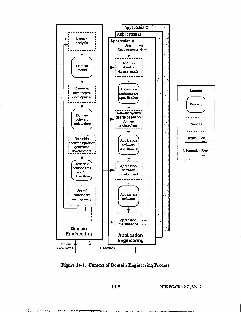
«'-i Domain ^ J analysis
Domain model
Software architecture development
Domain software
architecture
Reusable asset/component
generator development
Reusable components
and/or generators
Asset/ component
maintenance
Domain Engineering
Domain Knowledge t
I Application C j Application B
Application A User ••HI
Requirements ^ ~
Analysis based on
domain model
Application performance specification
| Software system ^Jdesign based on
• domain ! architecture
Application software
architecture V J
| Application H software ! development
Application software
i„,i Application }~ • maintenance • -
Application Engineering
Feedback
Legend
Product
Process
Product Flow •
Information Flow
Figure 14-1. Context of Domain Engineering Process
14-9 NUREG/CR-6263, Vol. 2

For domain engineering to be cost-beneficial, a second requirement is that a future potential exists; i.e., the number of future software systems that will exploit the results of the domain engineering effort is large enough to justify the investment.
Does nuclear power plant safety software meet these conditions?
Even though digital instrumentation and control (I&C) systems are relatively new, there does appear to be a developing body of knowledge about these systems that span the application domain, considering the significant number of nuclear power plants in the United States and abroad that have implemented, or are in the process of designing and implementing I&C systems based on digital computer technology. Examples in the United States include digital retrofits to reactor protection and emergency cooling systems by various vendors; and several non-safety-related I&C software functions that are also applicable to safety software, such as protocols for interfacing with external devices, software strategies for fault tolerance, and interaction with humans. Even more examples exist in the United Kingdom, Canada, France, and Japan, where modern plants such as Sizewell-B and Darlington have been designed and built with more extensive or full-scale digital applications. The accumulated body of knowledge is considered sufficient for this approach—the domain engineering of software for nuclear power plants, or for more specific parts of this domain—to be initiated. In particular, there appears to be sufficient stability to proceed by targeting specific parts of the domain, such as RPS, that have a greater degree of maturity and standardization, and a narrower range of variability.
It is understood that the domain of nuclear power plant software systems is still evolving. However, an increasing number of existing nuclear power plants are retrofitting digital systems. Furthermore, the concept of standardization, which is central to domain engineering, is also embodied in NRC regulations [10 CFR Part 52] that provide for standard design certification of future nuclear power plants. Under these regulations, the NRC has already approved two Advanced Light Water Reactor (ALWR) standard designs. These and other standardized designs, which are under development, also provide the potential for use of the results of the domain engineering effort.
It is also noted here that when detailed system-level guidelines for defining the system-software interface become available, they will provide considerable impetus to the domain engineering of software for nuclear plant I&C systems. This is in addition to the advantages these system-level guidelines will offer toward developing complete and accurate software requirements specifications, the importance of which is discussed in Section 2.2.
NUREG/CR-6263, Vol. 2 14-10

Which identified research needs are related to this perspective?
Several of the research needs described in this report relate to the domain engineering approach (see Table 14-2). The potential role of each of these research needs in the domain-specific software engineering effort is summarized as follows:
Research needs [R3-1/R6-1], [R3-2/R6-2], and [R3-10] provide standard models and software safety requirements that can be reused and adapted to each new system.
• [R4-3] and [R4-6] provide standard safety architectures.
• [R5-3] and [R5-4] support certification of reusable code.
• [R7-2/R8- 1/R9-4] provides an understanding of standard software failure patterns that can be used to avoid these failures in future systems.
• [R7-14] provides software operational profiles that can be used to generate realistic test suites and to support reliability measurement.
• [R9-2] provides a common set of ACEs that are identified through a combination of operational experience and reuse of the results of safety analyses.
• [R10-2] provides typical software changes that occur during maintenance, which can be used to anticipate these changes in the design of new systems.
• [R13-2] provides reusable plans, including approaches to the management of safety analysis, as well as general staffing, cost, and schedule estimates.
In defining the application domain that applies in this case, namely, nuclear power plant safety systems, it is useful to distinguish two types of functions performed by the software. The first is concerned with performing the plant safety functions themselves. These safety functions are identified at the system level and flow down through the software requirements, design, and code. The second type is concerned with maintaining the integrity of the system and software elements that perform the primary safety functions, such as error checking and fault tolerance. The integrity functions are partially identified at the system level, but are significantly expanded within the software itself. The domain engineering perspective on the research needs identified in the present work addresses the software aspects of both types of functions: plant safety functions, which predominantly are specific to the nuclear power plant safety systems; and integrity functions, which might be common to other application domains, e.g., mission-critical aviation and space systems, or to software systems in general.
While all the research needs related to domain engineering support the integrity functions, some of them directly support plant safety functions as well. For example, the goal of [R4-3] is to identify proven software architectures that satisfy safety principles and functions; this directly addresses how software performs its role in supporting system safety functions. Another example is [R3-2], which directly supports the safety functions by linking (through notation or translation) the software safety requirements to the system safety requirements, thereby addressing one of the major problem areas that exists in software engineering in general and safety applications in particular.
14-11 NUREG/CR-6263, Vol. 2

Table 14-2. Research Needs Related to Domain-Specific Software Engineering
Number* Title
R3-1/ R6-1
Develop regulatory review criteria based on domain analysis of nuclear power plant software systems
R3-2/ R6-2
Determine common notation for or translation between system-level engineering and software safety requirements
R3-10 Identify common safety software performance requirements based on domain-specific experience
R4-3 Identify proven software architectures or designs that satisfy system safety principles (including diversity and redundancy) in software systems
R4-6 Identify software architectures that use self-monitoring functions and other approaches to fault tolerance and still satisfy performance requirements
R5-3 Define framework and criteria for certification of reusable components
R5-4 Determine feasibility of and criteria for using COTS products in high integrity software systems
R7-2/R8-1/ R9-4
Conduct empirical study of software failures in high integrity systems
R7-14 Develop adaptable software operational profiles for each generic class of safety systems and a measure of their fit to specific systems
R9-2 Identify common software-related ACEs or hazards based on domain-specific experience
R10-2 Identify typical safety-significant software changes during maintenance phase
R13-2 Examine previous management plans to identify past experience
*The first number corresponds to the section number in this report (Volume 2), while the second is sequential within that section. For example, R3-1 is the first research need in Section 3. A research need applicable to more than one framework element has multiple identification numbers, and is discussed in the section identified by the first number. For example, [R3-1/R6-1] is discussed in Section 3.
NUREG/CR-6263, Vol. 2 14-12

14.3.2 Specific Perspectives on Research Needs
To understand how the research needs are interrelated and to provide a basis for their later prioritization, it was useful to examine them from several different specific perspectives in addition to the domain-specific software engineering theme described above. In this section, the following perspectives are addressed: relation to safety; leverage of software engineering area based on its maturity; and type of research. These perspectives were used to classify each research need; the results are summarized in Table 14-3.
The first perspective is the relative relationship to safety. Although all the research needs identified in this report are related in some fashion to safety, they can still be distinguished by how directly they relate to safety. For example, research need [R3-4/R6-4]—measurement of software reliability—is directly related to safety because there is a strong relation between reliability and safety, and a good measure of reliability is important in the direct assessment of safety. On the other hand, research need [R3-5/R6-5]—measurement of software maintainability—is less directly related to safety because a software system could be safe when it is licensed and yet be difficult to maintain. Although there is still a positive relationship between maintainability and safety, the correlation is judged to be much lower than that between reliability and safety. Other research needs fall between these two positions. For example, research need [R7-8]—metrics for evaluating test effectiveness—is related to safety in the sense that the quality and completeness of testing are an important part of making the safety case, But a software system could still be safe without a metric for evaluating test effectiveness. Thus, research needs in this group are judged to have a moderate relation to safety. In Table 14-3, these three levels of relation to safety are respectively designated as high (H) for direct, moderate (M), and low (L) for indirect.
The second perspective is the relative leverage of the software engineering area to which the research need is related, based on its maturity, where an area corresponds to the framework elements addressed in Sections 3 through 13 of this report. Although the discipline of software engineering as a whole is relatively immature, as stated in Section 14.2, there are differential levels of maturity within the discipline. Research in the various elements could be expected to have a degree of leverage inversely related to the level of maturity; i.e., the least mature would have the greatest leverage or potential for improvement. Leverage of the framework elements was assessed as follows:
• The elements of Software Requirements Specification (Section 3) and Software Safety Analysis (Section 9) are considered here as the least mature, and therefore as having the most leverage. The difficulty of specifying valid software requirements and understanding them has been experienced by most software practitioners and is discussed widely in the literature (e.g., [Boehm, 1981]; [Davis, 1990]; [Sommerville, 1992]). As discussed in Section 2 of this report, a majority of errors detected in software are due to incorrect or misinterpreted specifications. Furthermore, errors introduced in the requirements appear to be the most difficult to detect; i.e., they remain hidden until late in the V&V process [Boehm, 1975; OECD HALDEN, 1993]. Software safety analysis (Section 9) is the area of least experience. Techniques have not been sufficiently proven to be included in emerging standards such as the IEEE standard for software safety plans [IEEE1228].
14-13 NUREG/CR-6263, Vol. 2

Table 14-3. Classification of Research Needs
Number* Title Relation to Safety Leverage
Research Type
R3-1/ R6-1
Develop regulatory review criteria based on domain analysis of nuclear power plant software systems
H H Domain
R3-2/ R6-2
Determine common notation for or translation between system-level engineering and software safety requirements
H H Domain
R3-3/ R6-3
Determine techniques for formal specification of fault detection and recovery
H H Method
R3-4/ R6-4
Determine definition and measurement of software reliability
H H Measure
R3-5/ R6-5
Determine definition and measurement of software maintainability
L H Measure
R3-6/ R6-6
Develop evidence for relative intelligibility of specifications M H Data
R3-7/ R6-7
Develop tools to maintain consistency of software specifications and translate between notations
M H Tool
R3-S7 R6-8
Develop tools to measure test coverage of specifications M H Tool
R3-9 Develop repeatable method and tools to generate test cases from specifications
M H Tool
R3-10 Identify common safety software performance requirements based on domain-specific experience
H H Domain
R4-1 Develop quantitative measures for evaluating modularity L M Measure
R4-2 Define criteria for acceptable design and use of software interrupts
H M Criteria
R4-3 Identify proven software architectures or designs that satisfy system safety principles (including diversity and redundancy) in software systems
H M Domain
*For explanation of research need identification numbers, see footnote to Table 14-2 or Section 1.4.
NUREG/CR-6263, Vol. 2 14-14

Table 14-3. Classification of Research Needs (Continued)
Number* Title Relation to Safety Leverage
Research Type
R4-4 Define criteria for acceptable design of error handling and performance margin
H M Criteria
R4-5 Develop criteria for evaluating self-monitoring designs that use watchdog processing on a separate coprocessor
H M Criteria
R4-6 Identify software architectures that use self-monitoring functions and other approaches to fault tolerance and still satisfy performance requirements
H M Domain
R5-1 Define evaluation criteria for development environments for producing high integrity software
L L Criteria
R5-2 Define evaluation criteria for target environments for operating high integrity software systems
L L Criteria
R5-3 Define framework and criteria for certification of reusable components
H L Domain
R5-4 Determine feasibility of and criteria for using COTS products in high integrity software systems
H L Domain
R5-5/ R4-7
Develop criteria for evaluating programming language capability to support defensive programming techniques
M L Criteria
R5-6 Identify tradeoffs in requiring coding techniques to enhance source code verifiability
M L Data
R6-9 Define thresholds for evaluating design completeness, consistency, and traceability to requirements
M M Criteria
R6-10 Develop measure of design testability L M Measure
R6-11 Identify reverse engineering support for code V&V M M Method
R6-12 Survey automated support for code analysis M M Tool
R6-13 Develop evaluation criteria for formal verification of source code
M M Criteria
14-15 NUREG/CR-6263, Vol. 2
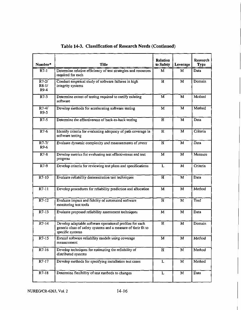
Table 14-3. Classification of Research Needs (Continued)
Number* Title Relation to Safety Leverage
Research Type
R7-1 Determine relative efficiency of test strategies and resources required for each
M M Data
R7-2/ R8-1/ R9-4
Conduct empirical study of software failures in high integrity systems
H M Domain
R7-3 Determine extent of testing required to certify existing software
M M Method
R7-4/ R9-5
Develop methods for accelerating software testing M M Method
R7-5 Determine the effectiveness of back-to-back testing H M Data
R7-6 Identify criteria for evaluating adequacy of path coverage in software testing
H M Criteria
R7-7/ R9-6
Evaluate dynamic complexity and measurements of stress H M Data
R7-8 Develop metrics for evaluating test effectiveness and test progress
M M Measure
R7-9 Develop criteria for reviewing test plans and specifications L M Criteria
R7-10 Evaluate reliability demonstration test techniques H M Data
R7-11 Develop procedures for reliability prediction and allocation M M Method
R7-12 Evaluate impact and fidelity of automated software monitoring test tools
H M Tool
R7-13 Evaluate proposed reliability assessment techniques M M Data
R7-14 Develop adaptable software operational profiles for each generic class of safety systems and a measure of their fit to specific systems
H M Domain
R7-15 Extend software reliability models using coverage measurement
M M Method
R7-16 Develop techniques for estimating the reliability of distributed systems
H M Method
R7-17 Develop methods for specifying installation test cases L M Method
R7-18 Determine flexibility of test methods to changes L M Data
NUREG/CR-6263, Vol. 2 14-16

Table 14-3. Classification of Research Needs (Concluded)
Number* Title Relation to Safety Leverage
Research Type
R7-19/ R9-7
Develop tools to assess coverage of a test suite based on design
L M Tool
R7-20 Develop simulation models of executing test plans L M Tool
R8-2 Develop method for assessing high-level language compiler risks
M L Method
R8-3 Assess risk of using automatic code generators H L Data
R8-4/ R7-21
Determine interaction protocols for V&V activities L L Method
R9-1 Develop techniques for creating and evaluating software safety plans
M H Method
R9-2 Identify common software-related ACEs or hazards based on domain-specific experience
H H Domain
R9-3 Determine methods of applying safety analysis techniques to software in a way that adequately covers the safety issues
H H Method
R10-1 Develop design guidelines for software maintainability L L Method
R10-2 Identify typical safety-significant software changes during maintenance phase
M L Domain
R10-3/ R9-8
Develop techniques for evaluating software modifications and limiting the safety impact of modifications
M L Method
R10-4 Establish guidelines for assessing maintenance capability L L Method
R10-5 Develop guidance to better specify the level of V&V effort required for modified systems
L L Method
R10-6 Survey industry experience with software performance monitoring
L L Data
R13-1 Streamline software management and development plans, and develop criteria for evaluating them
L L Criteria
R13-2 Examine previous management plans to identify past experience
L L Domain
14-17 NUREG/CR-6263, Vol. 2
" T v . vY- ; ' ^~"~ ; o- ' - : - " " . ' . ' ^ . • • ' • • : , y . r , . i . fc/.-vj • ••<.'••>•'• '.w

• The next level of leverage is reflected in the elements of Software Design (Section 4), Software V&V—Static (Section 6), and Software V&V—Dynamic (Testing) (Section 7). There is considerable experience in these areas of software practice, but significant problems remain. For example, in the design area, the principle of modularity is well understood and universally practiced, while the higher-level topic of software architectures is just beginning to be studied (see [Shaw and Garlan, 1994]). In V&V, although there has been considerable experience in testing, and significant progress has been made, achieving complete test coverage of software systems and testing attributes, such as reliability, are major problem areas. Static V&V has been a more recent area of increased attention, and significant progress has already been made in code analysis techniques, but further work is needed.
° The elements having least leverage, relatively, are Software Coding (Section 5); V&V—General Considerations, such as planning and reporting (Section 8); Software Operation and Maintenance (Section 10); Software Configuration Management (Section 11); Software Quality Assurance (Section 12); and Software Planning and Management (Section 13). The industry has the most experience with these elements, and the remaining problems are less significant than those for the other elements. These elements have also achieved the most standardization.
In Table 14-3, these three levels of leverage are respectively designated as high (H) for highest leverage, moderate (M), and low (L).
The third perspective is the type of research. The various research needs were categorized into the following types:
• Developing methods for implementing or satisfying candidate guidelines ("Method" in Table 14-3 under "Research Type").
• Developing measures of a software quality or attribute ("Measure" in Table 14-3).
• Defining criteria for evaluation of software, including thresholds for determining whether candidate guidelines have been met ("Criteria" in Table 14-3).
• Collection of empirical data for detection of patterns or assessment of methods ("Data" in Table 14-3).
• Development of a tool to automate a process or method, to support software development or regulatory review, or both ("Tool" in Table 14-3).
• Identification of common or reusable software objects and relations that would support the development of research products such as criteria and measures—a category that denotes research needs related to the domain-specific software engineering theme ("Domain" in Table 14-3).
NUREG/CR-6263, Vol. 2 14-18

14.4 Categorization of Research Needs
As discussed earlier, some of the research needs directly support the regulatory function (designated in this report as "Category A"), some are more related to developing methods and tools for the industry to use in producing safe software (designated as "Category C"), and others support both of these functions ("Category B"). In this subsection, the distinction among these categories is explained further, and additional information is provided about the research needs in Categories A and B.
Category A research needs provide a more objective and precise way to evaluate a certain aspect of software and assess whether a safety-significant function or attribute has been satisfied. An example is research need [R3-4/R6-4], which is concerned with measurement of software reliability.
This research would directly support the regulatory function because the results could make it easier and more defensible for the regulatory review to determine the adequacy of the software being evaluated for licensing. An example of a Category C research need is [R7-20], which is to develop models for executing test plans. This research would support the engineering of the software, in this case test planning and management, but not necessarily the regulatory function. However, as noted in Section 14.1, both the NRC and industry would be expected to have some degree of interest in—and benefit from—all the research needs.
Category B research needs provide substantial support for both the regulatory function and industry. For example, an objective of several of the research needs is to develop a method or tool that would help produce safe software, but these research needs also address certain safety issues and tradeoffs, and the research would produce results that could be expected to be useful in the regulatory review of the software. Thus these needs support the software engineering industry, but the regulatory review also needs to be based on an awareness of the issues and tradeoffs involved in order to assess whether a risk is acceptable or a problem has been adequately addressed.
More specifically, the research needs that fall into Category B are in two general groups. The basis for the first group is that the regulatory function includes process review (as opposed to reviewing only the final product) and includes performing some level of V&V activities. An example of the process review function is research need [R7-9], which concerns reviewing test plans and specifications. An example of performing V&V activities is the research proposed in [R6-11], which would identify reverse engineering support for code V&V. The second group consists of research needs related to the domain-specific software engineering theme. This research would provide support for software development in that common software objects, such as requirements, architectures, and code, could be used in building new systems, rather than all objects being custom-developed for each new system. However, the standardization of these objects would provide a strong basis for developing regulatory acceptance criteria, as described previously. Therefore, the research in this group would produce both standard products and standard evaluation criteria.
14-19 NUREG/CR-6263, Vol. 2

The research needs in Categories A and B, and the rationale for their importance to the regulatory function, are presented in Table 14-4. The general rationale for support provided by the domain-specific software engineering research needs to the regulatory function is provided in the preceding paragraph; the rationale provided in Table 14-4 for these research needs is the additional support they provide to the regulatory function. Research needs in Category C are identified later in Table 14-5, which provides the results of the prioritization.
14.5 Prioritization of Research Needs
14.5.1 Prioritizing Criteria and Approach The criteria discussed in the previous section were used to prioritize research needs in all three categories (A, B, and C). It should be reiterated that prioritizing the research needs was subjective, but the approach described here was an attempt to do so on as well-defined a basis as possible. The approach did not involve cost-benefit analyses. The criteria for prioritization were based on the three perspectives described in Section 14.3.2: relation to safety; degree of leverage, which is related to the maturity of the software engineering area (framework element); and type of research. The prioritization according to relation to safety and leverage maps directly to the high/moderate/low ratings of those characteristics described in Section 14.3.2; i.e., the equivalent priorities are high/medium/low. The mapping of the type of research to priority is explained in the following paragraphs.
Three types of research—labeled in Table 14-3 as "Domain," "Measure," and "Criteria"— were rated as high-priority. The importance and value of the domain engineering theme has been described in preceding sections; the research needs in this group provide the broadest support to both regulatory and software engineering functions. Defining measures and criteria for evaluation is also important because it addresses the lack of useful and valid measures of software properties and other acceptance criteria, which currently hinders the evaluation of software systems in general and high integrity software systems especially. The research needs of these two types support primarily the regulatory function.
Two types of research were rated as medium-priority. These correspond to "Method" and "Data" in Table 14-3. Identifying potential methods is rated as medium-priority because it supports developing safe software and satisfying the guidelines, which, while important, are secondary in the context of regulatory and evaluation functions. Gathering empirical data is also rated as medium-priority. It addresses the important need to provide a foundation of empirical evidence for certain practices, but its support for the regulatory function is more indirect.
The "Tool" type was rated as low-priority. It addresses the automation of support for software development and assurance. While tools are helpful and make the job easier, they are less important than the other research types, which can be viewed as providing the foundation on which the tools could be built. Determining what to do is more fundamental than developing a tool to help do it.
NUREG/CR-6263, Vol. 2 14-20

Table 14-4. Research Needs Supporting the Regulatory Function
Number* Category Title Importance to Regulatory Function
R3-1/ R6-1
B Develop regulatory review criteria based on domain analysis of nuclear power plant software systems
Developing and clearly defining new software requirements that are consistent with system requirements is one of the most significant problem areas in software engineering. But experience with existing requirements for nuclear power plant safety software systems exists and can be exploited. This research would provide common models showing the relationship between the system and the software, common software requirements satisfying system requirements and designs, and common review criteria that could be used to evaluate the specific software requirements for a new system. This research potentially is part of the domain-specific software engineering activity.
R3-2/ R6-2
B Determine common notation for or translation between system-level engineering and software safety requirements
The translation of safety system requirements and constraints to software requirements is not straightforward and not well understood. Part of the difficulty is the difference in notation between die system and software levels. This research would provide standard notation for representing both system and software requirements, or at least a standard mapping between system and software requirements, that could be used to evaluate the specific software requirements for a new system. This research potentially is part of the domain-specific software engineering activity.
R3-4/ R6-4
A Determine definition and measurement of software reliability
There is currently no adequate way to measure the ultra-high levels of software reliability required for nuclear power plant safety systems. This research would establish a standard definition of reliability and a method of measuring reliability for I&C systems; the resulting criteria could be used in regulatory review to evaluate software reliability requirements and assess whether they have been met.
R3-5/ R6-5
A Determine definition and measurement of software maintainability
Maintainability is currently measured indirectly at best. This research would establish a standard definition of maintainability and a more direct method of measuring maintainability for I&C systems; the resulting criteria could be used in regulatory review to evaluate software maintainability requirements and assess whether they have been met.
R3-8/ R6-8
B Develop tools to measure test coverage of specifications
Functional testing of a software component should be based on that component's software requirements specification. To produce evidence tiiat a set of functional tests is adequate, one should be able to measure the degree to which a set of test cases covers the requirements in a software requirements specification. There is currently no automated way to do this. This research would provide methods of and tools for measuring how well a set of test cases covers a set of requirements. Regulatory review could use these results to evaluate the process; that is, when test cases are produced, they could be evaluated before the tests are executed to determine the extent to which they cover each of the requirements.
For explanation of research need identification numbers, see footnote to Table 14-2 or Section 1.4.
14-21 NUREG/CR-6263, Vol. 2

Table 14-4. Research Needs Supporting the Regulatory Function (Continued)
Number* Category Title Importance to Regulatory Function
R3-10 B Identify common safety software performance requirements based on domain-specific experience
The software industry has experience in translating system performance goals into software requirements specifications, but the commonalities among requirements of similar software systems for each of the various nuclear plant types have not been identified and codified. If this information were captured, it could be reused and could mature more rapidly into "proven" requirements. This research would identify common software requirements specifying time-dependent software behavior that accounts for hazards and abnormal events, based on domain-specific experience. These requirements could be used in regulatory review to assess whether system performance and timing constraints have been accurately represented in the software requirements. This research potentially is part of the domain-specific software engineering activity.
R4-1 A Develop quantitative measures for evaluating modularity
Modularity is an established way to reduce risk in the design by separating complex problems into manageable parts, but there is currently no established measure of modularity. This research would develop quantitative criteria, based on accepted software engineering principles of information hiding, for evaluating modularity. These criteria could be used in the regulatory review of the design to determine whether there is adequate modularity to reduce the risk.
R4-2 A Define criteria for acceptable design and use of software interrupts
System design determines where interrupts are needed in the software design, but software interrupts are known to be error-prone. This research would examine system design constraints to determine how to minimize the need for interrupts in software designs. The results could be used in regulatory review to determine whether the interrupt issue has been addressed properly and interrupts kept to a minimum.
R4-3 B Identify proven software architectures or designs that satisfy system safety principles (including diversity and redundancy) in software systems
While system safety principles such as diversity and redundancy in system design are well understood, their application to software is not well understood, in part because it is not straightforward. However, the premise of this research is that safe software systems exist and can be identified as such. The architectures and designs of these systems would be analyzed to determine how they satisfy system safety principles. This research would provide standard architectures and designs proven to satisfy safety principles. These could be used to evaluate the specific software design in a new system. This research potentially is part of the domain-specific software engineering activity.
R4-4 A Define criteria for acceptable design of error handling and performance margin
Adequate error handling is one of the most important areas of design and implementation of high integrity software systems because this part of the software is most closely tied to safety functions, particularly in terms of responding to abnormal events. Regulatory review of these systems should have a way to determine the adequacy of error handling. This research would provide a threshold that could be used to determine the acceptability of the error-handling design of a new system.
NUREG/CR-6263, Vol. 2 14-22

Table 14-4. Research Needs Supporting the Regulatory Function (Continued)
Number* Category Title Importance to Regulatory Function
R4-5 A Develop criteria for evaluating self-monitoring designs that use watchdog processing on a separate coprocessor
No criteria are available to evaluate self-monitoring designs that use watchdog processing on a separate coprocessor to perform flow control processing, including checking processing duration and correctness of processing flow. This research would provide more objective and precise criteria for evaluating the design of this type of system to ensure that the monitoring does not interfere with safety.
R4-6 B Identify software architectures that use self-monitoring functions and other approaches to fault tolerance and still satisfy performance requirements
There is some risk that the additional software required to support self-monitoring functions, as well as other approaches to fault tolerance, could increase the risk of failures, particularly if the monitoring functions are not adequately isolated from the primary functions. This research would assess these risks for high integrity software, and identify (from an experience basis) standard software architectures that include the self-monitoring and other fault-tolerant functions without violating the timing constraints. This would include addressing tradeoffs among approaches to self-monitoring, such as using the same processor for application and monitoring functions versus using a separate coprocessor for monitoring (as described under research need [R4-5]). This research potentially is part of the domain-specific software engineering activity.
R5-1 A Define evaluation criteria for development environments for producing high integrity software
Part of the evaluation of the process of developing a high integrity software system involves evaluating the adequacy of the software environment used in the development. Even though many publications address evaluation of individual tools for high integrity software system development, there is no standard set of criteria for the overall tool environment in which the software is developed and tested. This research would provide criteria for evaluating the adequacy of the development environment, for example, whether the tools are sufficiently integrated.
R5-3 B Define framework and criteria for certification of reusable components
There are safety advantages to using components that have been successfully used in other safety systems, rather than developing new components. However, there are also disadvantages, partly because the development organization typically has little knowledge of the context or pedigree of a component, which can affect its use and its safety in the new system. Evaluation criteria for reusable components are critical for certifying the quality and safety of the components, but these certification criteria are not clearly defined. This research would define an evaluation framework and develop criteria for certification of reusable components. These could be used in regulatory review to evaluate whether code developed in another, perhaps unknown, context is safe to use in a new high integrity system. This research potentially is part of the domain-specific software engineering activity.
14-23 NUREG/CR-6263, Vol. 2

Table 14-4. Research Needs Supporting the Regulatory Function (Continued)
Number* Category Title Importance to Regulatory Function
R5-4 B Determine feasibility of and criteria for using COTS products in high integrity software systems
There are problems associated with using COTS products in high integrity software systems for which the proposed solutions are only partial. For example, maintenance of someone else's software is difficult, and modifying a COTS product may terminate its support from the vendor. This research would provide standard rules or guidelines for using COTS products in high integrity software systems, and identify tradeoffs from both the technical and organizational perspectives. These could be used to evaluate whether specific COTS products are safe to use in a new high integrity system. This research potentially is part of the domain-specific software engineering activity.
R6-9 A Define thresholds for evaluating design completeness, consistency, and traceability to requirements
Part of regulatory review is evaluating the design of safety functions. However, an auditor does not have clear criteria or thresholds for evaluating whether the design is adequate, and whether design guidelines have been met. This research would support that function by providing thresholds of completeness, consistency, and traceability to requirements that could be used as objective criteria for determining the acceptability of the design in these areas.
R6-10 B Develop measure of design testability
It is difficult to evaluate whether the candidate guideline of producing a testable design has been met. This measure would provide more objective means of making that determination in the regulatory review.
R6-11 B Identify reverse engineering support for code V&V
It is assumed that the regulatory function will include performing at least some key V&V activities. Reverse engineering could be used in the regulatory review as part of static code analysis.
R6-12 A Survey automated support for code analysis
Under the assumption that regulatory review will include V&V activities, this research would provide tools covering many aspects of static code analysis.
R6-13 A Develop evaluation criteria for formal verification of source code
Formal verification of source code offers potential benefit for software quality and safety. However, there is a lack of standard techniques for assessing the adequacy of a formal verification effort. This research would develop evaluation criteria for regulatory review to determine whether a formal verification of source code in a high integrity software system has been performed satisfactorily.
R7-1 B Determine relative efficiency of test strategies and resources required for each
Testing experience reports are rare in the literature. Additional research is needed on the ability of various testing strategies to trigger failures, and the resources required as a function of execution time, test runs, and types of failures. This research would determine which testing strategy identifies the most failures in the software and what resources are required to implement each strategy. The regulatory review could use the results of this research to evaluate the adequacy of test strategies either before or after the tests are run.
NUREG/CR-6263, Vol. 2 14-24

Table 14-4. Research Needs Supporting the Regulatory Function (Continued)
Number* Category Title Importance to Regulatory Function
R7-2/ R8-1/ R9-4
B Conduct empirical study of software failures in high integrity systems
Almost all large software projects perform disposition of and log information about software failures, but there has been little collection and dissemination of this information on a larger scale. This research would provide an understanding of standard software failure patterns and a list of common errors or failures in existing software systems. These could be used to evaluate whether the software for a new system has been tested for these errors, and to demonstrate that they are not present. This research potentially is part of the domain-specific software engineering activity.
R7-3 A Determine extent of testing required to certify existing software
Certification of existing software (see research need [R5-3]) can potentially be done through a combination of static analysis; review of pedigree, including process and usage; and testing. This research would explore what is required for certification through testing, including the extent of testing with the new system being developed. The results could be incorporated into regulatory guidelines for assessing whether the testing of existing software is adequate for certification in a new system.
R7-6 A Identify criteria for evaluating adequacy of path coverage in software testing
Since it is impossible to cover all paths in testing a software system, it is important to determine a threshold and types of coverage required that are possible to achieve, and at the same time reduce to an acceptable level the risk involved in not testing some of the paths. Although testing in general is partially mature and understood in software engineering, criteria for path coverage are inadequate. Regulatory review could use these criteria to evaluate specified tests to determine whether they meet the threshold and cover the necessary types of paths.
R7-8 B Develop metrics for evaluating test effectiveness and test progress
Data on die productivity and efficiency of testers is available, but it is sparse. This research would provide metrics showing the benefit-to-cost ratio of additional testing, which would be good indicators of testing progress, and profiles of software test duration, which would enable comparison of a development project with industry convention or averages for safety applications. These would assist the regulator in process evaluation.
R7-9 B Develop criteria for reviewing test plans and specifications
Quality attributes for test plans and specifications are not well defined or measurable. This research would provide auditors with guidance on the analysis of these test documents as part of regulatory review.
R7-10 B Evaluate reliability demonstration test techniques
It is difficult to apply reliability growth models to systems with a low number of faults, including high integrity software developed with good quality assurance practices. This research would compare approaches for reliability demonstration testing and produce guidance that could be incorporated into regulatory review for assessing whether an adequate approach was used in a new system.
14-25 NUREG/CR-6263, Vol. 2

Table 14-4. Research Needs Supporting the Regulatory Function (Continued)
Number* Category Title Importance to Regulatory Function
R7-11 B Develop procedures for reliability prediction and allocation
Software reliability growth models rely on data generated after the design and coding, hence have little impact on the planning and design stages of the project. This research would develop procedures for software reliability prediction in order to allocate reliability to software components and evaluate designs (as is commonly done for hardware reliability) prior to software testing. The results of this research could be used in regulatory review of the process to estimate reliability in the design stage of the project.
R7-14 B Develop adaptable software operational profiles for each generic class of safety systems and a measure of their fit to specific systems
[OECD HALDEN, 1993] concludes that none of the software reliability growth models represent an entirely adequate fit to any of the data sets to which they are applied. This research would provide standard software operational profiles of data input to the software system. These could be used in the regulatory review to determine whether realistic test suites were used (especially statistical testing) and to evaluate the reliability of a new system. This research potentially is part of the domain-specific software engineering activity.
R7-16 B Develop techniques for estimating the reliability of distributed systems
Most software reliability growth models are based on centralized architectures. Safety systems are increasingly using a distributed software architecture, which requires more complex reliability growth models. This research would develop models for distributed systems with common software platforms (i.e., operating systems, and databases) and for unique application services executing on different hardware platforms connected by networks. The techniques developed could be used in regulatory review to estimate the reliability of these distributed systems.
R8-2 A Develop method for assessing high-level language compiler risks
Some risk is introduced into safety systems by commercially available compilers. The risk is that the compiler does not correctly translate source code into object code and therefore may affect plant safety. Many compiler defects pose a risk to safety, but not all. For example, a compiler may abort when attempting to translate a particular construct; this poses a problem for the software developer, but does not constitute a safety problem. This research would address whether high-level language compilers or optimizing compilers are less deterministic and therefore higher-risk. The results of this research would directly benefit auditors in assessing the overall risk of using specific compilers by formulating realistic guidance for compiler usage for high integrity software systems, including the safety implications of changing compilers or upgrading to new versions of the same compiler.
NUREG/CR-6263, Vol. 2 14-26

Table 14-4. Research Needs Supporting the Regulatory Function (Continued)
Number* Category Title Importance to Regulatory Function
R8-4/ R7-21
B Determine interaction protocols for V&V activities
The conventional wisdom is that software V&V must be independent to be effective. However, there are some tradeoffs with the degree of independence. This research would develop interaction protocols that would provide an independent perspective (i.e., avoid repeating the same errors as in the development because of over-familiarity with the approach used), but still address the issues accurately and competently (i.e., based on sufficient knowledge and understanding of the system concept and requirements). These protocols could be incorporated into criteria for regulatory review of V&V activities.
R9-1 B Develop techniques for creating and evaluating software safety plans
There is little experience in applying standards for safety plans, such as [TEEE1228], to software development projects, and in monitoring project progress and activity against the plans. This research would develop techniques necessary for creating such a plan, and for monitoring actual project progress against planned progress. The results could be incorporated into safety plan evaluation criteria for regulatory review.
R9-2 B Identify common software-related ACEs or hazards based on domain-specific experience
The identification of ACEs that software must address currently relies on performing, for each new system, safety analyses for requirements, design, code, test, and change. This research would provide a list of the minimum number of standard ACEs that could occur and that the new software system must prevent or mitigate. This list could be used to evaluate whether the new software system has addressed all the items on die list. This research potentially is part of me domain-specific software engineering activity.
R10-2 B Identify typical safety-significant software changes during maintenance phase
There is a lack of empirical data showing the types and quantity of changes typically required during die operation and maintenance phase of software systems. This research would provide typical software changes that occur during maintenance of high integrity software for nuclear plants. The identified set of changes could be used in the regulatory review to determine whether these changes have been anticipated and accounted for in die design of die new system. This research potentially is part of the domain-specific software engineering activity.
R10-3/ R9-8
B Develop techniques for evaluating software modifications and limiting the safety impact of modifications
There are many circumstances under which operational software may be modified. Criteria are needed for determining what types of software modifications could raise safety concerns. Certain changes to software might not involve any significant safety issue, while others might be such that their effects could be mitigated through a proper implementation approach and adherence to certain practices. This research would develop techniques for evaluating software modifications and limiting the safety impact of those modifications. The results would be valuable for regulatory review in support of implementing the requirements of [10 CFR Part 50:50.59].
14-27 NUREG/CR-6263, Vol. 2

Table 14-4. Research Needs Supporting the Regulatory Function (Concluded)
Number* Category Title Importance to Regulatory Function
R13-1 B Streamline software management and development plans, and develop criteria for evaluating them
The diversity of software management and development plans and formats for these plans makes it an imposing task for any organization to verify the conformance, completeness, and accuracy of plans submitted. While the overall contents of the plans are remarkably consistent across the standards, the differences in format make document analysis particularly difficult. This research would develop effective and efficient mechanisms for extracting the relevant information and assessing it for consistency with the software safety plan, and for ensuring that such verification could be performed. It would also develop a rationale for merging certain plans that are likely to create conflicts. The results of this research would be useful in regulatory review of software management and development plans as part of process review.
NUREG/CR-6263, Vol. 2 14-28

14.5.2 Results of Prioritization
All of the research needs were individually rated as high-, medium-, or low-priority according to each of the three perspectives. An overall priority rating of high/medium/low was then computed based on the three individual ratings, as well as consideration of whether the research need overlaps to some degree with current ongoing NRC research. Specifically, the overall rating is the average of the three individual ratings (relation to safety, leverage, and type), where average is defined as the rating obtained from assigning 1,2, and 3 to high, medium, and low, respectively, computing the average, rounding to the nearest number, and translating back to high, medium, or low. In addition, if a research need was judged to overlap to some degree with current NRC research, its overall rating was lowered one level (unless it was already low).
The results of prioritizing the research needs are presented in Table 14-5. In the "Overall Priority" column, an asterisk (*) indicates research needs that overlap to some degree with current NRC research and whose priority was therefore lowered.
Table 14-6 provides a summary of the number of research needs in each category that fall into the high-, medium-, and low-priority groups. Fourteen research needs were rated as high-priority. Eight of these high-priority research needs fall in Category B, which supports both industry and the regulatory function; they are also related to domain-specific software engineering and its role in providing proven technology.
14.6 High-Priority Research Needs Supporting the Regulatory Function
Twelve of the fourteen high-priority research needs that are in Categories A and B were ranked subjectively based on overall considerations (without regard to category). The resulting priority sequence is shown in Table 14-7. The research needs that are potentially part of domain engineering have "Domain" following their titles in this table. A discussion of the importance of these research needs to the regulatory function is part of Table 14-4. The following provides the rationale for the ranking of each of these research needs.
1. rR3-l/R6-l]: Develop regulatory review criteria based on domain analysis of nuclear power plant software systems
This is considered to be the most important research need for several reasons. First, it addresses the problem of lack of understanding of the interplay between software and the system context in which it is defined. Second, it captures common or standard proven requirements and criteria for evaluating requirements (not just the process of developing requirements); this should contribute to resolving for nuclear power plant safety software the largest problem area in software engineering in general, namely, specifying, understanding, and verifying software requirements. This research is the most substantial part—the anchor— of the domain-specific software engineering effort, whose importance has been described earlier in this section. Once the nuclear power plant software community understands what the requirements should be, those requirements can be used for new systems and incorporated into standard review criteria, rather than created anew for each system.
14-29 NUREG/CR-6263, Vol. 2

Table 14-5. Prioritization of Research Needs
Number(l) Title Category Relation to Safety Leverage Type
Overall Priority(2)
R3-1/ R6-1
Develop regulatory review criteria based on domain analysis of nuclear power plant software systems
B H H H H
R3-2/ R6-2
Determine common notation for or translation between system-level engineering and software safety requirements
B H H H H
R3-3/ R6-3
Determine techniques for formal specification of fault detection and recovery
C H H M H
R3-4/ R6-4
Determine definition and measurement of software reliability
A H H H H
R3-5/ R6-5
Determine definition and measurement of software maintainability
A L H H M
R3-6/ R6-6
Develop evidence for relative intelligibility of specifications
C M H M M
R3-7/ R6-7
Develop tools to maintain consistency of software specifications and translate between notations
C M H L M
R3-8/ R6-8
Develop tools to measure test coverage of specifications
B M H L M
R3-9 Develop repeatable method and tools to generate test cases from specifications
C M H L M
R3-10 Identify common safety software performance requirements based on domain-specific experience
B H H H H
R4-1 Develop quantitative measures for evaluating modularity
A L M H M
R4-2 Define criteria for acceptable design and use of software interrupts
A H M H H
R4-3 Identify proven software architectures or designs that satisfy system safety principles (including diversity and redundancy) in software systems
B H M H H
R4-4 Define criteria for acceptable design of error handling and performance margin
A H M H H
(1) For explanation of research need identification numbers, see footnote to Table 14-2 or Section 1.4. (2) An asterisk (*) in this column indicates that the priority level was lowered by one priority level because the
identified research need may overlap with ongoing NRC research.
NUREG/CR-6263, Vol. 2 14-30

Table 14-5. Prioritization of Research Needs (Continued)
NumberW Title Category Relation to Safety Leverage Type
Overall Priority^2)
R4-5 Develop criteria for evaluating self-monitoring designs that use watchdog processing on a separate coprocessor
A H M H M*
R4-6 Identify software architectures that use self-monitoring functions and other approaches to fault tolerance and still satisfy performance requirements
B H M H H
R5-1 Define evaluation criteria for development environments for producing high integrity software
A L L H M
R5-2 Define evaluation criteria for target environments for operating high integrity software systems
C L L H M
R5-3 Define framework and criteria for certification of reusable components
B H L H L*
R5-4 Determine feasibility of and criteria for using COTS products in high integrity software systems
B H L H L*
R5-5/ R4-7
Develop criteria for evaluating programming language capability to support defensive programming techniques
C M L H M
R5-6 Identify tradeoffs in requiring coding techniques to enhance source code verifiability
C M L M M
R6-9 Define thresholds for evaluating design completeness, consistency, and traceability to requirements
A M M H M
R6-10 Develop measure of design testability B L M H M
R6-11 Identify reverse engineering support for code V&V
B M M M M
R6-12 Survey automated support for code analysis
A M M L L*
R6-13 Develop evaluation criteria for formal verification of source code
A M M H L*
R7-1 Determine relative efficiency of test strategies and resources required for each
B M M M M
R7-2/ R8-1/ R9-4
Conduct empirical study of software failures in high integrity systems
B H M H H
R7-3 Determine extent of testing required to certify existing software
A M M M L*
14-31 NUREG/CR-6263, Vol. 2

Table 14-5. Prioritization of Research Needs (Continued)
NumberW Title Category Relation to Safety Leverage Type
Overall Prioriry(2)
R7-4/ R9-5
Develop methods for accelerating software testing
C M M M M
R7-5 Determine the effectiveness of back-to-back testing
C H M M M
R7-6 Identify criteria for evaluating adequacy of path coverage in software testing
A H M H H
R7-7/ R9-6
Evaluate dynamic complexity and measurements of stress
C H M M M
R7-8 Develop metrics for evaluating test effectiveness and test progress
B M M H M
R7-9 Develop criteria for reviewing test plans and specifications
B L M H M
R7-10 Evaluate reliability demonstration test techniques
B H M M M
R7-11 Develop procedures for reliability prediction and allocation
B M M M L*
R7-12 Evaluate impact and fidelity of automated software monitoring test tools
C H M L M
R7-13 Evaluate proposed reliability assessment techniques
C M M M M
R7-14 Develop adaptable software operational profiles for each generic class of safety systems and a measure of their fit to specific systems
B H M H H
R7-15 Extend software reliability models using coverage measurement
C M M M M
R7-16 Develop techniques for estimating the reliability of distributed systems
B H M M M
R7-17 Develop methods for specifying installation test cases
C L M M M
R7-18 Determine flexibility of test methods to changes
C L M M M
R7-19/ R9-7
Develop tools to assess coverage of a test suite based on design
C L M L L
R7-20 Develop simulation models of executing test plans
C L M L L
NUREG/CR-6263, Vol. 2 14-32

Table 14-5. Prioritization of Research Needs (Concluded)
Number'*' Title Category Relation to Safety Leverage Type
Overall Priority(2)
R8-2 Develop method for assessing high-level language compiler risks
A M L M M
R8-3 Assess risk of using automatic code generators
C H L M M
R8-4/ R7-21
Determine interaction protocols for V&V activities
B L L M L
R9-1 Develop techniques for creating and evaluating software safety plans
B M H M M
R9-2 Identify common software-related ACEs or hazards based on domain-specific • experience
B H H H H
R9-3 Determine methods of applying safety analysis techniques to software in a way that adequately covers the safety issues
C H H M H
R10-1 Develop design guidelines for software maintainability
C L L M L
R10-2 Identify typical safety-significant software changes during maintenance phase
B M L H M
R10-3/ R9-8
Develop techniques for evaluating software modifications and limiting the safety impact of modifications
B M L M M
R10-4 Establish guidelines for assessing maintenance capability
C L L M L
R10-5 Develop guidance to better specify the level of V&V effort required for modified systems
C L L M L
R10-6 Survey industry experience with software performance monitoring
C L L M L
R13-1 Streamline software management and development plans, and develop criteria for evaluating them
B L L H M
R13-2 Examine previous management plans to identify past experience
C L L H L*
14-33 NUREG/CR-6263, Vol. 2
' " " ^ ? I ? T ••''-'- '.'." '_ " I W . ' A : ; 4 B I " V « ' T

Table 14-6. Number of Research Needs in Each Priority Group
Category High-Priority Medium-Priority Low-Priority Total A (Regulatory) B (Both) C (Industry)
4 8 2
6 12 15
3 4 7
13 24 24
Total 14 33 14 61
Table 14-7. Ranking of High-Priority Research Needs Supporting the Regulatory Function
Priority Rank Number Title Category
1 R3-1/ R6-1
Develop regulatory review criteria based on domain analysis of nuclear power plant software systems (Domain)
B
2 R9-2 Identify common software-related ACEs or hazards based on domain-specific experience (Domain)
B
3 R4-3 Identify proven software architectures or designs that satisfy system safety principles (including diversity and redundancy) in software systems (Domain)
B
4 R3-4/ R6-4
Determine definition and measurement of software reliability A
5 R7-14 Develop adaptable software operational profiles for each generic class of safety systems and a measure of their fit to specific systems (Domain)
B
6 R3-2/ R6-2
Determine common notation for or translation between system-level engineering and software safety requirements (Domain)
B
7 R3-10 Identify common safety software performance requirements based on domain-specific experience (Domain)
B
8 R7-2/ R8-1/ R9-4
Conduct empirical study of software failures in high integrity systems (Domain)
B
9 R4-6 Identify software architectures that use self-monitoring functions and other approaches to fault tolerance and still satisfy performance requirements (Domain)
B
10 R4-4 Define criteria for acceptable design of error handling and performance margin
A
11 R4-2 Define criteria for acceptable design and use of software interrupts A 12 R7-6 Identify criteria for evaluating adequacy of path coverage in
software testing A
*For explanation of research need identification numbers, see footnote to Table 14-2 or Section 1.4.
NUREG/CR-6263, Vol. 2 14-34

2. rR9-2]: Identify common software-related ACEs or hazards based on domain-specific experience
This research need is perhaps the one most closely tied to safety among all the research needs identified in this report. Articulating and understanding the set of ACEs or hazards that can occur in nuclear power plant systems and software would help establish ways to avoid or mitigate them in current and future software systems. This research need is also an important part of the domain-specific software engineering effort, although it is somewhat more specific than the previous research need [R3-1/R6-1]. For these reasons, it is nearly as important as the previous research need, and the two should be worked together.
3. fR4-3]: Identify proven software architectures or designs that satisfy system safety principles (including diversity and redundancy1) in software systems
Although the area of design in general is relatively mature in software engineering, the application of system safety principles to software design presents a new challenge because software cannot simply apply the methods and implementation approaches in the same way that they are understood and applied at the system level. The application of these principles to software is problematic because of the fundamental differences between software and the physical systems on which the safety principles and methods matured. For example, redundancy works for physical systems whose components wear out differentially, but does not work analogously for software because all copies of the software will have the same faults. Even attempts to achieve independence, and thereby avoid common-mode failures, through software design diversity (in the form of N-version programming) have been less than successful because the resulting versions do not appear to be mutually independent.
Therefore, the importance of this research is that it would identify proven architectures and designs based on experiential evidence. Increasing experience in domain-specific software engineering has resulted in greater recognition of the importance of a good software architecture to the overall quality of and confidence in software systems. Software architectures and designs that have proven themselves to be successful in meeting safety principles could be used in the regulatory review to evaluate whether the software design for a new system is adequate in this respect. This research is associated with research need [R3-1/R6-1] in that architectures and designs identified in this research would correspond to the requirements and domain models identified in [R3-1/R6-1]. This research is ranked high because of the proven technology and the broad scope involved, but is ranked lower than the above two research needs because they offer more direct leverage in terms of supporting requirements and safety analysis.
4. fR3-4/R6-41: Determine definition and measurement of software reliability
This research need is important in several respects. First, it defines a measure that can be used in the regulatory function. There is currently no adequate way to measure the ultra-high levels of software reliability required for nuclear power plants. The immaturity of software with regard to lack of measurement, as discussed earlier in Section 14.2, makes regulating software much more difficult. This research is intended to establish such a measure; the resulting
14-35 NUREG/CR-6263, Vol. 2

criteria could be used in the regulatory review to evaluate software reliability requirements and assess whether they have been met. Second, reliability is very important because it is directly tied to safety. Third, this research need is related to requirements specifications, which, as indicated above, may be the biggest problem area for software development, as well as for V&V, because it would enable more precise reliability values to be specified as well as verified. It therefore addresses an important gap in the current ability to determine the reliability of a software system, or of a nuclear power plant safety system that includes software. This research goal would be difficult to achieve quickly, but it is important. It is ranked lower than the previous three research needs because it is concerned with the measure of a single attribute and does not contribute directly to the proven technology argument as they do.
5. [R7-14]: Develop adaptable software operational profiles for each generic class of safety systems and a measure of their fit to specific systems
This research is important because it would establish a realistic profile or model of the pattern of data input to the software system. This is needed as the basis for statistical testing, and would also support the evaluation of reliability. This research need is important because of its relation to safety and to the domain engineering effort, but is ranked lower than the previous research needs because it is considered to offer slightly lower leverage than the requirements, safety, reliability, and architecture issues that constitute those research needs.
6. fR3-2/R6-2"|: Determine common notation for or translation between system-level engineering and software safety requirements
This research would provide a common proven mapping between the notation of the system requirements and that of the software requirements, and would therefore provide further system-software links. This is an important issue, but the reason this research is ranked lower than the previous ones is the narrower scope of the issue involved. This research supports the domain analysis effort in [R3-1/R6-1] and should be worked in conjunction with that effort.
7. rR3-10"|: Identify common safety software performance requirements based on domain-specific experience
This research serves a role analogous to that of [R9-2] (common ACEs or hazards); however, in this part of the domain-specific software engineering effort, the common artifacts produced would be safety software performance requirements. These requirements would help ensure that timing constraints are met. Although this is an important area, this research need is ranked lower than those above because its scope is more narrow.
8. [R7-2/R8-1/R9-41: Conduct empirical study of software failures in high integrity systems
An understanding of software failure patterns in the system context could provide valuable feedback that would help resolve many of the errors and minimize failures in future systems. The resulting codified information could be incorporated into standard regulatory review criteria. This research is important because of its general relation to safety and to the proven
NUREG/CR-6263, Vol. 2 14-36

technology argument of domain engineering. However, its leverage as test-related research is rated as somewhat lower than that of most of the previous research needs, and its relation to safety is perhaps slightly less direct as well.
9. fR4-61: Identify software architectures that use self-monitoring functions and other approaches to fault tolerance and still satisfy performance requirements
This research supports research need [R4-3], but focuses more on the tradeoff between self-monitoring and fault tolerance versus performance and timing requirements. This is important, but the narrower focus of the research, along with its somewhat lower leverage as design-related research, lowers its ranking below that of the previous research needs.
10. fR4-4]: Define criteria for acceptable design of error handling and performance margin
This research would provide criteria needed to adequately perform the regulatory review of software design with regard to meeting safety requirements. The general rationale for its ranking is similar to that for [R4-6] above; however, this research addresses somewhat lower-level design than the architectural issues addressed in [R4-6], and it does not contribute directly to domain engineering. These two differences are responsible for the slightly lower ranking of this research.
11. fR4-21: Define criteria for acceptable design and use of software interrupts
This research also provides criteria needed to adequately perform the regulatory review of software design with regard to meeting safety requirements. The general rationale for its ranking is similar to that for [R4-4] above, but this research is focused on the more narrowly defined issue of the design and use of interrupts, and that results in the slightly lower ranking of this research.
12. fR7-61: Identify criteria for evaluating adequacy of path coverage in software testing
This research is important because it would provide criteria for evaluating path coverage during software testing, which is related to safety. It is impossible to cover all paths in testing a software system, so it is important to determine a threshold and achievable types of coverage, and at the same time reduce to an acceptable level the risk involved in not testing some of the paths. Although testing in general is partially mature and understood in software engineering, criteria for path coverage are inadequate. Regulatory review could use these criteria in evaluating specified tests to determine whether they meet the threshold and cover the required types of paths. This research need is ranked last among the high-priority research needs because of a combination of the following: its leverage as test-related research is somewhat lower than that of most of the previous needs, its relation to safety is slightly less direct, and it does not directly support the proven technology argument of the domain engineering effort.
14-37 NUREG/CR-6263, Vol. 2

APPENDIX A
CANDIDATE GUIDELINES AND TECHNICAL BASIS
Contents
Section Element Name Page 3. Software Requirements Specification A-3
4. Software Design A-9
5. Software Coding A-19
6. Software V&V—Static A-25
7. Software V&V—Dynamic (Testing) A-28
8. Software V&V—General Considerations A-36
9. Software Safety Analysis A-38
10. Software Operation and Maintenance A-41
11. Software Configuration Management A-46
12. Software Quality Assurance A-51
13. Software Planning and Management A-54
A-1 NUREG/CR-6263, Vol. 2


Table A. Candidate Guidelines and Assessment of Technical Basis
Criteria for Evaluation of Technical Basis 1. Relation to Safety 2. Definition of Scope 3. Body of Knowledge and Evidence 4. Existence of a Method 5. Threshold for Acceptance
Since Criteria 1 and 2 were used in selecting and developing the candidate guidelines, they were not used again in assessing the technical basis. Section 1.3 provides a discussion of the assessment of the technical basis, and defines the assessment criteria. The assessment results are shown in the table as Y (Satisfactory), Q (Questionable), or N (Not Satisfactory).
Identification Numbers of Candidate Guidelines and Research Needs The first number corresponds to the number of the section in the report in which the candidate guidelines and the research needs for each element are presented, while the second is sequential within the section. For example, [G3-5] and [R3-2] are the fifth candidate guideline and the second research need, respectively, in Section 3, on SRS. A research need
>• applicable to more than one framework element has multiple identification numbers, and is discussed in the section of the report identified by the first number. For example, u> [R3-1/R6-1] is discussed in Section 3.
Acronyms are defined at the end of the table.
No. Candidate Guideline
Technical Basis Assessment of
Technical Basis: Criterion
Research Need No. Candidate Guideline Baseline Sources Other Sources 3 4 5
Research Need
3. Software Requirements Specification
O
8 ON W
#A<.* .''"<-'/;' \:",i •• N V '-< V"""N->.-.':-'•"•>' '• --p ; ' '<"'' , / . '".'• ';-• v • »"' :*'?'''., ' ' \> 'h' - ™ ' ^ \ ' ' V , "'<• V V ' >Davis.et'aL;,;1993;/>^ '"T-xT'TT"" O x^V'/^x- <!• - V " >•' • : ' • . : , : >>-•' • '
S^fti*iir«j. .»^«M*5sm1l«it?r,- *.^f|>«^tOefti^tt* "T *""jCjini^lete»ea»; •* •'' -•/ •'•:•':•".'V'.i'" =;"'%%' ?';">-,i-! < 9 . - « • : : • : ' > • • • • : < ' ^ ; * - - v
G3-1 For each software input, the SRS should specify the following: • Data format requirements • Precision and accuracy requirements • How often the input must be read
-URD: 6.1.2.4 -IEC880: 4 .3, A2.3 -IEC880: 4 .4, A2.4 -IEC880: 4.5, A2.5 -IEEE830: 4.3.2 -IEEE7-4.3.2: F2.3.3.b -ASME-NQA-2a: Part
2.7, 6.2
- O N T H Y D , 1990: B . l . l . g
-RTCA D0-178B: 11.9 -LLNLNUREG/CR-6101
Y Y Y

o 9 AN to ON U)
to
Table A. Candidate Guidelines and Assessment of Technical Basis (Continued)
No. Candidate Guideline
Technical Basis Assessment of
Technical Basis: Criterion
Research Need No. Candidate Guideline Baseline Sources Other Sources 3 4 5
Research Need
4*.
G3-2 For each software output, the SRS should specify the following: • Data format requirements • Precision and accuracy requirements • How often the output must be updated
-URD: 6.1.2.4 -IEC880: 4.3, A2.3 -IEC880: 4.4, A2.4 -IEC880: 4.5, A2.5 -IEEE830: 4.3.2 -IEEE7-4.3.2: F2.3.3.b -ASME-NQA-2a: Part 2.7, 6.2
-ONT HYD, 1990: B.l.l.g
-RTCA D0-178B: 11.9 -LLNLNUREG/CR-6101
Y Y Y
G3-3 The SRS should specify each abnormal hardware condition or event that the software must detect. Abnormal hardware conditions and events include failure of input or output device, processor, and memory.
-IEEE7-4.3.2: Fl -ONT HYD, 1990: B.l.l.i
-RTCA D0-178B: 11.9 -LLNL NUREG/CR-6101
Y Y Y
G3-4 The SRS should specify each abnormal software condition or event that the software must detect. Abnormal software conditions and events include failure of software services at the operating-system level and failure of logic in application-level software (only general types of such failures can be identified prior to software design).
-IEEE7-4.3.2: Fl -ONT HYD, 1990: B.l.l.i
-RTCA D0-178B: 11.9 -LLNL NUREG/CR-6101
Y Q Q R3-1/R6-1 R3-2/R6-2 R3-3/R6-3

Table A. Candidate Guidelines and Assessment of Technical Basis (Continued)
No. Candidate Guideline
Technical Basis Assessment of
Technical Basis: Criterion
Research Need No. Candidate Guideline Baseline Sources Other Sources 3 4 5
Research Need
I to
"ON
2 to
G3-5 The SRS should specify the time-dependent input-to-output relation (i.e., the required functions) that the software component must implement. That is, the SRS should specify allowed sequences of outputs given any combination of sequences of inputs and abnormal conditions/events. "Sequence" here means an ordered list of <time, valuo (or <time, event>) pairs, including startup of processing, response to interrupts, response for no input, and response to variation in sampling of data. The specification should cover all possible values (valid or invalid) of inputs.
-URD: 6.1.2.4 -IEC880:4 -IEC880: 4.3, A2.3 -IEC880: 4.4, A2.4 -IEC880: 4.5, A2J 1
-IEC880: 4.7, A2.7 -IEEE830: 4.3.2 -IEEE7-4.3.2: F2.3.3.b -ASME-NQA-2a: Part 2.7, 6.2
-IEEE7-4.3.2: Fl
-ONTHYD, 1990: B.l.l.d, B.l.l.e, B.l.l.i
Y Q Q R3-1/R6-1 R3-2/R6-2
R3-10
G3-6 The time-dependent input-to-output relation specified by the SRS should not permit any behavior that would violate any requirement (including safety requirements) that the system design allocates to the software component or any requirement that is derived from general system requirements.
-URD: 6.1.2.4 -IEC880: 4 -IEC880: 4.3, A2.3 -IEC880: 4.4, A2.4 -IEC880: 4.5, A2.5 -IEC880: 4.7, A2.7 -IEEE830: 4.3.2 -IEEE7-4.3.2: F2.3.3.b -ASME-NQA-2a: Part 2.7, 6.2
-IEEE7-4.3.2: Fl -IEEE7-4.3.2: F2.3.3.a
-RTCA DO-178B: 5.1.2.d
-LLNLNUREG/CR-6101: 3.2.2
Y Q Q R3-1/R6-1 R3-2/R6-2
R3-10
G3-7 The SRS should specify the maximum percentage of available resources (processor, dynamic memory, mass storage, network capacity) that the software may use and should specify timing requirements, including speed, recovery time, and response time.
-URD: 6.1.2.4 -IEEE830: 4.3.2(1) -IEEE7-4.3.2: F2.3.3.b -ASME-NQA-2a: Part 2.7, 6.2
-RTCA D0-178B: 11.9 -LLNL NUREG/CR-6101
Y Y Y

Table A. Candidate Guidelines and Assessment of Technical Basis (Continued)
No. Candidate Guideline
Technical Basis Assessment of
Technical Basis: Criterion
Research Need No. Candidate Guideline Baseline Sources Other Sources 3 4 5
Research Need
G3-8 The SRS should specify reliability requirements for the software. -IEC880: 4 -ASME-NQA-2a: Part 2.7, 6.2(d)
-ONT HYD, 1990: B.l.l.j
-LLNLNUREG/CR-6101: 4.2.1
Y Q Q R3-4/R6-4
G3-9 Software maintainability requirements should be analyzed and specified prior to system design. These requirements should address coding standards and design constraints, as well as requirements for the supporting tools and documentation.
-ASME-NQA-2a: Part 2.7, 6.2(d)
-ONT HYD, 1990: A.O Y Q N R3-5/R6-5
G3-10 The SRS should specify necessary design constraints (conformance to standards, hardware constraints).
-URD: 6.1.2.4 -IEC880: 4.6, A2.6 -IEEE830: 4.3.2(3) -ASME-NQA-2a: Part 2.7, 6.2(c)
-ONT HYD, 1990: B.l.l.b
-LLNLNUREG/CR-6101
Y Y N R3-1/R6-1 R3-2/R6-2
Sdftware:, R^q^eM^hW/Splclfiettttdhr • VnamMgiiity v ; \ ; 'o'"->''^'/ : ''"• ;1 < - • ' • •- ' ' " ' . - * - '
;>.Y" ;; V *'
.v..v ''/. G3-11 The SRS should be unambiguous. Each requirement should have
only one interpretation. -IEC880: 4.9 -IEEE830: 4.3.1 -IEEE830: 4.3.1.1
-Fagan, 1976 -Freedman, 1990: F2 -BNL, 1993 -Gehart et al., 1991 -NASA CR4551: pp. 156-166
Y Y Q R3-6/R6-6

Table A. Candidate Guidelines and Assessment of Technical Basis (Continued)
No. Candidate Guideline
Technical Basis Assessment of
Technical Basis: Criterion
Research Need No. Candidate Guideline Baseline Sources Other Sources 3 4 . 5
Research Need
Software Requirements Specification: Consistency, V ; :
' ' - • ^ \ *; .>
* '< - -s " \ ' , "
" -\).- ?,. - -' •. c * ''__ - "
\"'^ ^'- ' ,, -
G3-12 The SRS should be consistent. The SRS should not contain requirements that contradict or conflict with each other.
-IEC880: A2.9.1 -IEEE830: 4.3.4
-Fagan, 1976 -Freedman, 1990: F2 -BNL, 1993 -Gehart et al., 1991 - N A S A C R 4 5 5 1 :
pp. 156-166
Y Q N R3-7/R6-7
Software Requirements Specification: VerlflabHity
" • ' \ * * ^ % ' " v.
'"•:': ..",' * Vv''•*"'•. "*;}';•>'•'• • ' -c _, v o ,.
G3-13 Every requirement in the SRS should be verifiable. A method or process should exist (inspection, demonstration, analysis, or testing) that can show that an implementation fulfills the requirement.
-URD: 6.1.2.4 -1EC880: 4.9 -IEEE830: 4.3.3 -ASME-NQA-2a: Part
2.7, 6.2
-Davis et al., 1993 -Luqi and Ketabchi, 1988 -BNL, 1993
Y Y Q R3-4/R6-4 R3-5/R6-5 R3-8/R6-8
R3-9
Software Requirements Specification: Modinability r ' >"<* ' < , < " ^ ' V V, , *
i ; v : ;t vV/.'-'v *- -V-\''-
' ** ' ^ <••• - - ' s
G3-14 The SRS should be written and structured so that modifications can be demonstrated to be correct.
-IEEE830: 4.3.5(1) Y Q N R3-5/R6-5 R3-7/R6-7
G3-15 The SRS should not contain redundant requirements. The same requirement should not appear in more than one place in the SRS.
-IEC880: A2.9.1 -IEEE830: 4.3.5(2)
Y Q Q R3-7/R6-7

Table A. Candidate Guidelines and Assessment of Technical Basis (Continued)
No. Candidate Guideline
Technical Basis Assessment of
Technical Basis: Criterion
Research Need No. Candidate Guideline Baseline Sources Other Sources 3 4 5
Research Need
Software Requirements Specification: TraceaWHty : ' ; / ; ' / ; " . > ' . . ' , . ' . • ' • . , . ' " : ' .
, - "- " , '. •] ','. '.'!" ,",,
• i ' • ' • ' • . ; . ; . / ' "'//f ''/*
•l-'*M /,, - /,'_, '"- -
G3-16 It should be possible to trace (1) between software requirements and system requirements/design, and (2) between software requirements and software design/code.
-IEEE830: 4.3.6 -ASME-NQA-2a: Part 2.7, 6.2
-Davis, 1990 Y Y Y
G3-17 The SRS should explicitly identify all those requirements that are relevant to the software's performing its safety function.
-IEEE7-4.3.2: F2.3.3.a -LLNLNUREG/CR-6101 Y Y Y
G3-18 The SRS should justify the inclusion of any software design or implementation detail.
-IEC880: 4 -IEC880: A2.9.1 -IEEE830: 4.2 -IEEE830: 5.3.1(2)
-Davis, 1990 Y Y Q None Needed
Software Requirements Specification: Readability < " •* ,"• >
:" '<••?" r : '" •'" ' *- - ' ,'. -
G3-19 Requirements in the SRS should be readable. -IEC880: 4.9 -IEC880: A2.9.1
-Sommerville, 1992 -Hall, 1990 -Bailey, 1989 -Weiss, 1991
Y Q N R3-6/R6-6

Table A. Candidate Guidelines and Assessment of Technical Basis (Continued)
No. Candidate Guideline
Technical Basis Assessment of
Technical Basis: Criterion
Research Need No. Candidate Guideline Baseline Sources Other Sources 3 4 5
Research Need
4. Software Design
Software Design; Modular Design , \ h " ' ' * s j
.-Booch, 1991 -Meyer, 1988 -MOD55: Part 2, 30,3.3 -LLNLJNUREG/CR 6090: 5.1.3
-Page-Jones, 1988 .„. • , , :
. , , ,
• . - \
'- - v
;" t,\
'-" • ' • - . " ' " ' ' -
G4-1 The software design should be divided into components using the information-hiding principle to produce components with interfaces that remove the design's implementation detail (or volatile design features).
-IEC880: 5.1.l.b -IEC880: Bl.a.aa -URD: 6.1.3.7
-Parnas, 1972 -IEEE610.12 -ONTHYD, 1990: 2.4.3, 2 & B2.8
-Britton and Parnas, 1981
-Booch, 1991 -Meyer, 1988
Y Y Y
G4-2 The critical data structures and related operations in the software design should be encapsulated within components.
-Booch, 1991 -Gehani and McGettrick, 1988
-Meyer, 1988 -Page-Jones, 1988 -Shlaer and Mellor, 1988 -Rumbaugh et al., 1991 -Coad and Yourdon, 1990
Y Y Y

Table A. Candidate Guidelines and Assessment of Technical Basis (Continued)
No. Candidate Guideline
Technical Basis Assessment of
Technical Basis: Criterion
Research Need No. Candidate Guideline Baseline Sources Other Sources 3 4 5
Research Need
G4-3 The degree of modularity for a component as a minimum should be based on the following:
• Ease of understanding, taking into account both functional and structural complexity
• Minimal ripple effect of changes • Cohesiveness of components
-IEC880: 5.1.1.C -URD: 6.1.3.4 -IEC880: Bl.a.ab -IEC880: B2.a.ac -URD: 6.1.3.7 -URD: 6.1.3.18
-Booch, 1991 -Coad and Yourdon, 1990
-Nielson and Shumate, 1988: 26.6
-Page-Jones, 1988
Y Q Q R4-1
So t twa ' r iC l^gBt^
V " ' ^ ' " - '
:&vtandAgriwala, '-. J990rp-.l'67l W.'#'' •4mK,7^lH^KQ'Si3d:. -Bjwchj 1991'.:} (^yp --C^ad'and Yourcion; •' •''JV
'-IEEB6XJ3: J5;2' ;';'-^\
/,.-«.--, If,') -,
G4-4 The software design should encapsulate external interface components that are separated from the application program in order to achieve the following:
• Prevent ACEs from propagating to other components. • Ensure protocol compatibility between the application
software and the external interface. • Ensure uninterrupted safety processing.
-IEEE7-4.3.2: F2.3.4.e -IEC880: B2.a.ab -IEC880: B2.eb
Y Y Y

Table A. Candidate Guidelines and Assessment of Technical Basis (Continued)
No. Candidate Guideline
Technical Basis Assessment of
Technical Basis: Criterion
Research Need No. Candidate Guideline Baseline Sources Other Sources 3 4 5
Research Need
G4-5 The software design should encapsulate the processing of asynchronous or synchronous events from an external interface into a component.
-Booch, 1991 -Coad and Yourdon, 1990
-Levi and Agrawala, 1990
-Nielsen and Shumate, 1988
-Britton et al., 1981
Y Y Y
G4-6 The software design should use interrupts only to simplify the system.
-IEC880: B2.ea Y Y Q R4-2
G4-7 The validation and error processing for an external interface should be thoroughly documented in the design specification.
-IEEE1016-1987: 5.3.7, 5.3.9, 6.2.3
Q Y Q R4-2
G4-8 The software design should thoroughly document each usage of interrupt.
-IEC880: B2.ed Y Y Q R4-2
G4-8 (a) The software design should define processing duration and maximum number of occurrence constraints for external event processing (e.g., interrupts).
-LLNLNUREG/CR-6083: 2.2.1
-LLNL, 1993 DRAFT: A. 1.8.4
Y Y Y
G4-8 (b) The software design should define the maximum duration for which an interrupt is disabled.
-IEC880: B2.ec -LLNLNUREG/CR-6083: 2.2.1
-LLNL, 1993 DRAFT: A. 1.8.4
Y Y Y

Table A. Candidate Guidelines and Assessment of Technical Basis (Continued)
No. Candidate Guideline
Technical Basis Assessment of
Technical Basis: Criterion
Research Need No. Candidate Guideline Baseline Sources Other Sources 3 4 5
Research Need
Software" -Beilgm"" Interfaces ;%-,. Safety;;{Cotej^nents': ;-;/,_'=, 1 -' ', '*''"*,
VlEEE60f3:'5.6': :";.!, '•'::
rONT HVD, 1990: M a
7T7'"Z >{
-M--P Sip ;"/fV: .7;,;. %
G4-9 Safety components should be identified to increase the focus on support for prevention of unnecessary interaction from nonsafety components.
-IEEE7-4.3.2: F2.3.4.h Y Y Y
G4-10 The interfaces between safety and nonsafety components should be carefully designed to prevent unnecessary interactions with nonsafety component processing.
-IEEE7-4.3.2: 5.6 -IEEE7-4.3.2: F2.3.4.i
-LLNLNUREG/CR-6101: 4.4.2.3 2(d), 4.3.3.3 1(d)
Y Y Q R4-6
G4-10 (a) The software design should ensure that only the necessary information is communicated between safety and nonsafety components.
-Meyer, 1988 -Page-Jones, 1988
Y Y Q R4-1 R4-6
G4-10 (b) The software design should use self-checking to ensure the accuracy of data produced for use in safety components.
N Y Q R4-6
G4-10 (c) The software design should ensure that all communication between safety and nonsafety components is through their defined parameters.
-IEC880: B4.b.bb -Meyer, 1988 Y Y Y
G4-11 Safety software should reside in protected memory and periodically perform self-test to confirm that it has not been corrupted. The time interval between checks should be determined based on the safety importance of the function being performed.
-URD: 6.1.3.17 Y Y Q R4-6

Table A. Candidate Guidelines and Assessment of Technical Basis (Continued)
No. Candidate Guideline
Technical Basis Assessment of
Technical Basis: Criterion
Research Need No. Candidate Guideline Baseline Sources Other Sources 3 4 5
Research Need
Software Design: Interface Integrity • -MOD55J Part I, 30X5
-IEEE603:5.5 j
". * - , ' ' ' "*' •'( '\:'« •'?!
G4-12 The software should perform parameter validation by checking the range of data used in communications to ensure that its value is within the defined domain.
-IEC880: B3.d.db -URD: 6.1.3.3
-Meyer, 1988: Chapter 7 Y Y Y
G4-13 The software should perform protocol validation by doing the following:
• Checking whether the requested action satisfies the conditions defined in the assertions stated for the interface.
• Verifying the permission for the called component before performing the action requested.
-IEC880: B3.d.df -IEEE7-4.3.2: F2.3.4.e -IEC880: B3.d.dd
-Meyer, 1988: 7.3.2, p.117
Y Y Y
G4-14 (a) The software should perform a plausibility check on the data being communicated to ensure that its value is accurate.
-IEC880: B3.a -URD: 6.1.3.3
-LLNLNUREG/CR-6101: 4.3.2.3.3(c)
Y Y Y
G4-14 (b) Communications messages should contain sufficient information to check for the completeness, correctness, correct ordering, and timeliness of the message data (e.g., sumchecks, sequence number timestamp).
N Y Q R5-5/R4-7

p
8 s> ON U)
Table A. Candidate Guidelines and Assessment of Technical Basis (Continued)
No. Candidate Guideline
Technical Basis Assessment of
Technical Basis: Criterion
Research Need No. Candidate Guideline Baseline Sources Other Sources 3 4 5
Research Need
> I
Software Design: :'Data Integrity;-, ' / . ; ' • :• <•
-Gehaniahd McGettrick, 1988
-Levi and Agrawala, 1990 ,
•Nutt, 1992 -IEEE603:5.5 -Date, 1986
'' "'
G4-15 The software design should explicitly identify the critical data and its usage context. Critical data is any data needed to maintain plant power operation, maintain plant safety, permit plant maneuvering, or establish operating limits and margin.
-URD: 6.1.3.20.D -LLNLNUREG/CR-6101: 4.3.3.3 2(a)
Y Y Y
G4-16 The software should protect and monitor data storage. -IEC880: B3.c -IEEE7-4.3.2: F2.3.4.c;d
Y Y Q R4-3 R4-5 R4-6
G4-16 (a) The software design for data storage should address diversity and redundancy.
- URD: 6.1.3.20.b -LLNLNUREG/CR-6101: 4.3.3.3 2(a)
Y Y Q R4-3
G4-16 (b) The software design should balance symmetric operations types (e.g., create-delete and open-close) to prevent corruption of data.
-Booch, 1991 -Coad and Yourdon, 1990
-Cox, 1986 -Meyer, 1988
Y Y Y
G4-17 The software should use a defensive technique for data storage. -URD: 6.1.3.3 Y Y Q R4-3 R4-6

Table A. Candidate Guidelines and Assessment of Technical Basis (Continued)
No. Candidate Guideline
Technical Basis Assessment of
Technical Basis: Criterion
Research Need No. Candidate Guideline Baseline Sources Other Sources 3 4 5
Research Need
G4-17 (a) Each variable should be assigned a default value when it becomes available.
-URD: 6.1.3.3 Y Y Y
G4-17 (b) The use of techniques that allow critical data overwriting (e.g., circular structure) should be justified.
-SofTech WO-126 -SofTech WO-123
Y Y Q R4-6
G4-17 (c) The software should define attributes for time tag, quality tag, and identification tag to be used for important data.
-URD: 6.1.3.20.C Y Y Y
G4-18 The software design should include the consideration of security aspects as part of designing for data integrity.
-Air Force AFISCSSH 1-1: 7.3
-Cullyer, 1993
Y Y Q R4-3
G4-19 The software should implement access control for data storage. -URD: 6.1.3.14.h -Sanden, 1994 Y Y Y
G4-19 (a) The software design specification should specify the sequence of accesses for the set of critical data and shared data.
-Nutt, 1992 -Sanden, 1994 -LLNLNUREG/CR-6101: 4.3.3.3 2(b-c)
Y Y Y
G4-19 (b) The software design should ensure that only authorized access to data is allowed.
-Air Force AFISC SSH 1-1: 7.3
-Cullyer, 1993
Y Y Q R4-3

9 Table A. Candidate Guidelines and Assessment of Technical Basis (Continued)
No. Candidate Guideline
Technical Basis Assessment of
Technical Basis: Criterion
Research Need No. Candidate Guideline Baseline Sources Other Sources 3 4 5
Research Need
Software Design: \fjiovifCopk6l_ ';„';- •;'':•;,',/. •'• "'''"-', / ; - ;' •',
• : , • 'IS •JvfcODSS: £art;:2, 30.6, '••••4 i ' . l : i
mm. G4-20 The degree of diversity and redundancy for high integrity software
should be evaluated to determine what constitutes adequate support for diversity and redundancy at the system level.
-URD: 6.1.6.2 -USNRC-BTP DRAFT -Knight and Ammann, 1989
-Leveson, 1991 -OECD HALDEN, 1993 -SoHaRNUREG/CR-6113: Chapter 5
Y Y Q R4-3
G4-21 Software design should include self-supervision of control flow and data.
-IEC880: 4.8, 4.8.1-5 -IEC880: 5.1.1.a -IEC880: A2.8 -URD: 6.1.3.14.C
Y Y Q R4-5 R4-6
G4-21 (a) The software should use timers to monitor safety processing for possible occurrence of blocking.
-IEC880: B3.d.da -IEC880: B3.d.de
Y Y Y
G4-21 (b) The software should ensure that self-checking processing will not prevent timely system response in any circumstance.
-IEC880: 5.1.1.a Y Y Q R4-5 R4-6
G4-21 (c) The software should use plausibility checks for safety-related calculations.
-IEC880: B3.a Y Y Y

Table A. Candidate Guidelines and Assessment of Technical Basis (Continued)
No. Candidate Guideline
Technical Basis Assessment of
Technical Basis: Criterion
Research Need No. Candidate Guideline Baseline Sources Other Sources 3 4 5
Research Need
G4-21 (d) The software should have on-line diagnostics that include both plausibility checks and periodic testing of hardware status.
-IEC880: 4.8, 4.8.1-5 -IEC880: A2.8 -URD: 6.1.3.15 -URD: 6.1.4.3 -URD: 6.1.4.4
Y Y Q R4-5 R4-6
Software Design: Error Handiing \* - ' ' v '^ f^ - -1 . ^ ' { ( ' " "* " -' < ' „ ' - -
JMeyer; 1988 ' . • ... -IAEA 75-mSAG-3:3,1*
^EE<K>3;';54-< .» V* ,'J $' -' ' IS£
>"t'f;.-':'-* '•''•>'. -" ff -' "",'
G4-22 (a) The software design should define processing for internal ACEs not specified in the SRS.
-ONTHYD, 1990: B.2.1.b
Q Y Q R4-4
G4-22 (b) The processing of internal ACEs should be identified as derived requirements and be included in the safety analysis for the software so that potential effects at the system level can be identified.
-ONTHYD, 1990: B.2.1.b
Q Y Q R4-4
G4-23 The software design should have a global error-handling strategy to maintain consistency in the processing of errors.
-ONT HYD, 1990: A.O.f, B.2.3.a
-Ausnit et al., 1985 -MOD55: Part 2, 30.6.2
Y Y Y
G4-23 (a) The software design should define a limit on ACE propagation, and guidelines for ACE handler design.
-Ausnit et al., 1985 -MOD55: Part 2, 30.6.2 -ONT HYD, 1990: A.O.f, B.2.3.a
Y Y Y

Table A. Candidate Guidelines and Assessment of Technical Basis (Continued)
N o . Candidate Guideline
Technical Basis Assessment of
Technical Basis: Criterion
Research Need N o . Candidate Guideline Baseline Sources Other Sources 3 4 5
Research Need
G4-23 (b) The identification for ACEs should use a descriptive name to convey its usage context.
-Hoare, 1981 -SPC, 1992: 3.5
Y Q Y R4-4
G4-23 (c) The software design should define a central facility for reporting ACEs and capturing their contextual information.
-Hoare, 1981 Q Y Y None Needed
G4-23 (d) The software design should produce well-defined outputs for ACE processing.
-IEC880: B3.b Y Y Q R4-4
G4-23 (e) The software design should ensure that any status information returned from the called service is evaluated before the processing continues.
-ONT HYD, 1990: A.O.F, B.2.3.a
Y Y Y
G4-24 ACEs associated with a component should be identified. -IEEE7-4.3.2: Appendix F
Y Y Q R4-4
G4-25 The occurrence of an ACE should not interrupt safety processing. Protection against critical failures should be provided through strategies for fault-tolerant design and quality control.
-IEC880: B3.d -IEEE7-4.3.2: 5.5.1 -IEEE7-4.3.2: Appendix F
Y Y Q R4-4

Table A. Candidate Guidelines and Assessment of Technical Basis (Continued)
No. Candidate Guideline
Technical Basis Assessment of
Technical Basis: Criterion
Research Need No. Candidate Guideline Baseline Sources Other Sources 3 4 5
Research Need
G4-26 A performance margin should be provided. The computer system should be designed with a sufficient performance margin to perform as designed under conditions of maximum stress. Those conditions include data scan, data communication, data processing, algorithm processing, analytical computation, control request servicing, display processing, operator request processing, and data storage and retrieval, at a minimum. Thus the computer system should be designed with reasonable expansion capability that would permit an owner to add other functions in the future.
-URD: 6.1.4.1 -M1L-STD-498 Y Y Q R4-4 R4-6
5. Software Coding
Software Coding: Development Environment
;
-IAEA, 1993! 12.2.1, .P.. 1?9 •-. -EBEE603: 5.3 -SoHaR, 1993: 6.5;3 -SoHaR NUREG/CR*
6113: 4.4.6, App. A, -iEEE1209
.. <., 1 ' '. -
• •': •
G5-1 (a) The development environment should consist of proven tools with vendor support.
-IEC880: Appendix D -URD: 6.1.3.10 -URD: 6.1.3.13
-OECDHALDEN, 1993: p. 9
-IAEA75-INSAG-3
Y Y Q R5-1 R5-5/R4-7

8 t
Table A. Candidate Guidelines and Assessment of Technical Basis (Continued)
No. Candidate Guideline
Technical Basis Assessment of
Technical Basis: Criterion
Research Need No. Candidate Guideline Baseline Sources Other Sources 3 4 5
Research Need
O
G5-1 (b) Besides satisfying the development requirements, development tools should comply with a standard or an industry benchmark that requires a certification process, if such a standard or benchmark exists.
-MOD55: Part 1, 36.2 -MOD55: Part 2, 36.5.1 -IAEA, 1993: 7.3.2, p. 72
-IAEA, 1993: 12.3.3, p. 123
-RTCA DO-178B: 4.2.2
Y Y Q R5-1 R5-5/R4-7
G5-2 The tools in the development environment should be tested for the intended application area before use.
-IEC880: Appendix D -URD: 3.1.2.4 c
-IAEA75-INSAG-3 -OECD HALDEN, 1993: p. 9
Y Y Q R5-1 R5-5/R4-7
G5-2 (a) Evaluations of development tools should be based on safety requirements identified in safety analysis.
-MOD55: Part 1, 36 -IAEA, 1993: 12.3.1, p. 121
Y Q Y R5-3 R5-4
G5-2 (b) Each tool should be analyzed for unique features that might directly or indirectly introduce errors into the implementation (i.e., during usage or transfer of data).
-IAEA, 1993: 4.3.5 (3) -RTCA DO-178B: 12.2
Y Y Q R5-1
G5-3 The development environment should consist of a minimum number of different tools.
-URD: 6.1.3.9 Y Y Q R5-1
G5-4 The development environment should be maintained under configuration management.
-IEEE7-4.3.2: 5.3.3 -URD: 3.1.2.4 b
Y Y Y

Table A. Candidate Guidelines and Assessment of Technical Basis (Continued)
No. Candidate Guideline
Technical Basis Assessment of
Technical Basis: Criterion
Research Need No. Candidate Guideline Baseline Sources Other Sources 3 4 5
Research Need
G5-5 High-level programming languages should be used to implement the software design. Otherwise, the justification for the language selection should be provided.
-URD: 6.1.3.11 -URD: 6.1.3.14 d -IEC880: Appendix D, Dl.f
-IAEA, 1993: 7.3.1 Y Y Y
G5-6 The use of assembly language to implement the software design should be limited to special cases, such as optimization.
-IEC880: B5.c -LLNLNUREG/CR-6101: 4.4.1.1
Y Y Q None Needed
G5-7 There should be detailed programming guidelines for each language used in the implementation.
-URD: 6.1.3.14 e Y Y Y
Software Coding: Target Environment and Reusable ..i' ' Components ' ' - . " ' • ' •' ''' •'';, " •' - . < ' , - . - • • 1 •
-tEEE603211 ,-: ;<
.fclOD55:36 \ /•. -RTCADp*J78B:12;t
{ , i " '•<••
' - ' •*>," * ^ \ , "- %
G5-8 (a) The target environment and reusable products should be tested for the intended application before use.
-IEEE7-4.3.2: Appendix D -URD: 6.1.2.12
-IAEA75-INSAG-3 Y Q Q R5-2 R5-3 R5-4
G5-8 (b) The target environment and reusable product evaluations should be based on safety requirements identified in safety analysis.
-MOD55: Part 1, 36 -IAEA, 1993: 12.3.1, p. 121
-RTCA DO-178B: 12.1.7
Y Q Y R5-2 R5-3 R5-4
G5-9 The target environment and reusable products should be selected from proven products with vendor support.
-URD: 6.1.3.10 -IAEA 75-INSAG-3 Y Q Q R5-3 R5-4

Table A. Candidate Guidelines and Assessment of Technical Basis (Continued)
N o . Candidate Guideline
Technical Basis Assessment of
Technical Basis: Criterion
Research Need N o . Candidate Guideline Baseline Sources Other Sources 3 4 S
Research Need
G5-9 (a) There should be a plan describing the strategy and the time period for which vendor support is obtained for the target environment and reusable products.
-URD: 6.1.3.13 -IAEA75-INSAG-3 Y Q Q R5-3 R5-4
G5-9 (b) The target environment and reusable products used in implementing the software design should comply with industry interface standards, when they exist (e.g., POSIX [IEEE1003.1]).
-MOD55: Part 1, 36.2 -MOD55: Part 2, 36.5.1 -IAEA, 1993: 7.3.2, p. 72
-IEEE1003.1
Y Y Y
G5-9 (c) If a target environment or a reusable product was not developed in accordance with a process standard required for its development, then the development organization should analyze and test the software to ensure that the product complies with product standards and provide the necessary documentation.
-IAEA, 1993: 13.2 Q Y Q R5-3 R5-4
G5-9 (d) For a target environment and reusable products that are COTS, the development organization should obtain maintenance guarantees from the vendor.
-IAEA, 1993: 13.2 Q Y Q R5-3 R5-4
G5-10 The target environment or reusable products should be maintained "as delivered" under configuration management.
-URD: 6.1.3.5 Y Y Y
G5-11 Dependency on the target environment's services (e.g., operating system services) should be minimized.
-IEC880: B2.c Y Y Q R5-3 R5-4

Table A. Candidate Guidelines and Assessment of Technical Basis (Continued)
No. Candidate Guideline
Technical Basis Assessment of
Technical Basis: Criterion
Research Need No. Candidate Guideline Baseline Sources Other Sources 3 4 5
Research Need
Software Coding; Data Structure • • ; • - V .-;-IEEB<503: 5.5 ' !"-;.*•". 4BEE603t 5.3, . "/-/./; -Boocn,"'19i89^;,V:>-/--ri - "**' •' >> ** •}
••^H J ' ; ' - - - ' . -
7\, ! ' .-*'
G5-12 Data structures should be evaluated to ensure the correct usage. -IEEE7-4.3.2: F2.3.5 c -Schulmeyer, 1990: 10, pp. 169-170
Y Y Q R5-5/R4-7
G5-13 Common variables should be grouped together. -URD: 6.1.3.14 h Y Y Y
G5-14 Installation-specific data should not be hardcoded. -URD: 6.1.3.17.1 Y Y Y
G5-15 Array structures should be accessed using simple addressing mechanisms.
-IEC880: B4.d -LLNLNUREG/CR-6101: 4.4.1.2
Y Y Q R5-5/R4-7
G5-16 When addressing an array, its bounds should be checked. -IEC880: B3.d.dc Y Y Y
G5-17 Each data type and subtype should have a defined range. -SPC, 1992 -Canon et al., 1990 -ETS Lab, 1992
Y Y Y
G5-18 The nesting of data record structures should be kept to a minimum and presented clearly.
-SPC, 1992 -Canon et al., 1990 -ETS Lab, 1992
Y Y Y

Table A. Candidate Guidelines and Assessment of Technical Basis (Continued)
No. Candidate Guideline
Technical Basis Assessment of
Technical Basis: Criterion
Research Need No. Candidate Guideline Baseline Sources Other Sources 3 4 5
Research Need
•?• •-•";-' • •<'\- - - : - ; •>., ;. f } • ,<• • > ,•• V . V-, :-, , , - / - , ' , • ' f. • . ' - ' " , - v ' ' • - y
V ' - ' r y V*. '*'• '•'•>" '* '•••''•'' '••x-iy-rPi'
mm mm •Xs-.fs: :,;..;-/I
IfSfi G5-19 The logic structure of a component should contain only one entry
point and one exit point. -IEC880: 5.1.1 c -IEC880: B2.b.bb
-ESA-PSS-05-0: 5.3.2.1, p. 1-42
Y Y Y
G5-20 The nesting of logic structures should be kept to a minimum and presented clearly.
-IEC880: B4.c Y Y Y
G5-21 (a) Multiple complex operations should not be attempted in a single statement.
-IEC880: B2.f Y Y Y
G5-21 (b)Parentheses should be used for multiple arithmetic operations in a statement to show the precedence order of the operations, even if not required by the compiler's rules for evaluation of arithmetic expressions.
-Kernighan and Plauger, 1974
-SPC, 1992
Y Y Y
G5-22 Branch and loop structure should be handled cautiously. -IEC880: B4.a Y Y Q R5-6
G5-22 (a) Backward branches should be avoided; loop statements should be used instead.
-IEC880: B4.a.ab Y Y Y
G5-22 (b) No branch into loop structure should occur. -IEC880: B4.a.ac Y Y Y

Table A. Candidate Guidelines and Assessment of Technical Basis (Continued)
No. Candidate Guideline
Technical Basis Assessment of
Technical Basis: Criterion
Research Need No. Candidate Guideline Baseline Sources Other Sources 3 4 5
Research Need
G5-22 (c) No branch out of a loop should occur unless it leads to the end of the loop.
-IEC880: B4.a.ad Y Y Y
G5-22 (d) "Go to" statements should be avoided. -IEC880: B4.a.af Y Y Y
G5-22 (e) Each case-controlled statement should specify all case conditions, and a default branch should be reserved for failure handling.
-IEC880: B4.a.ag Y Y Y
G5-22 (f) Each loop structure should be constrained with a maximum limit or a termination condition.
-IEC880: B4.a Y Y Y
6. Software V&V—Static
Software V&V—Static: Requirements V&V • • . . . ' • " ' . ; ' . " ' ' ' ' " ' ' . - - . \ '' ''
>s ° - * \
G6-1 V&V of the software requirements should demonstrate that the requirements are complete. It should address functional, performance, timing and sizing, database, security, interface, and software quality attribute requirements; identification of safety requirements; ACEs and the responses to them; and special operating conditions.
-IEEE7-4.3.2: F2.3.3 -IEEE1012: Table 1, 5.3 (1H3)
-LLNLNUREG/CR-6101: 4.2.1.3, 4.2.2.3
-Heninger, 1980 -ONTHYD, 1990: Bl.l.i
-Davis et al., 1993 -SAIC NUREG/CR-6018 -Parnas et al., 1991 -Atlee and Gannon, 1993 -Jaffe et al., 1991
Y Q Q R3-1/R6-1 R3-2/R6-2 R3-3/R6-3 R3-4/R6-4 R3-5/R6-5 R3-6/R6-6 R3-7/R6-7 R3-8/R6-8

8
s>
Table A. Candidate Guidelines and Assessment of Technical Basis (Continued)
No. Candidate Guideline
Technical Basis Assessment of
Technical Basis: Criterion
Research Need No. Candidate Guideline Baseline Sources Other Sources 3 4 5
Research Need
to ON
G6-2 V&V of the software requirements should demonstrate that the requirements are unambiguous, consistent, verifiable, modifiable, traceable, and readable. These requirement quality attributes are defined by the candidate guidelines on SRS.
-IEEE7-4.3.2: F2.3.3 -IEEE1012: Table 1,5.3 (1H3)
-LLNLNUREG/CR-6101: 4.2.1.3, 4.2.2.3
-Heninger, 1980 -ONT HYD, 1990: Bl.l.i
-Davis et al., 1993 -SAIC NUREG/CR-6018
Y Q N R3-1/R6-1 R3-2/R6-2 R3-3/R6-3 R3-4/R6-4 R3-5/R6-5 R3-6/R6-6 R3-7/R6-7 R3-8/R6-8
Software -V&'v^tati«',Resign-.y&V; , : <' ' ; - ' , . • * - v" '
,., ,- , . ,\- _,, > _'-
- <. , ' y .
"s
G6-3 V&V of the software design should demonstrate that the design correctly implements the software requirements. V&V should demonstrate that the software design is complete in the following ways:
• The highest level of software design satisfies the software requirements and the software safety constraints.
• Each level in the software design satisfies the requirements and safety constraints of the next-highest level of the software design.
-IEEE7-4.3.2: F2.3.4 -IEC880: 6.2.2 -IEEE1012: Table 1 -ASME-NQA-2a: Part 2.7, 3.2
-Davis, 1988 -LLNLNUREG/CR-6101: 4.3.2.3, 4.3.3.3
-SAICNUREG/CR-6108
Y Q N R6-9
G6-4 V&V of the software design should demonstrate that the design is consistent.
-IEC880: 6.2.2 -IEEE1012: Table 1
Y Q Q R6-9

Table A. Candidate Guidelines and Assessment of Technical Basis (Continued)
No. Candidate Guideline
Technical Basis Assessment of
Technical Basis: Criterion
Research Need No. Candidate Guideline Baseline Sources Other Sources 3 4 5
Research Need
to -4
o s ts>
2
G6-5 V&V of the software design should demonstrate that the design is traceable to the software requirements:
• Each part of the design can be traced to one or more software requirements.
• There is adequate justification for any functionality in the software design that is not specified in the software requirements.
• Parts of the design that are relied upon in any way to implement software safety constraints are readily distinguished from parts that are not, and there is evidence that this partitioning of the design is correct.
-IEEE1012: Table 1 -IEEE7-4.3.2: F2.3.4
-Podgurski and Clarke, 1990
Y Y Q R6-9
G6-6 V&V of the software design should demonstrate that the software design is testable.
-IEEE1012: Table 1 -Parnas et al., 1990 Y Q Q R6-10
Software V&V—Static: Code V&V - ,. ' . . . . . ,> ,, "
** - •-,'-. •
G6-7 V&V of the code should demonstrate that the code correctly implements the software design. V&V should demonstrate that the source code satisfies the requirements and safety constraints in the lowest level of the software design. As a special consideration, V&V should identify sources of ACEs introduced in coding and demonstrate that these cannot prevent the software from satisfying the safety constraints.
-URD: 6.1.2.10 -Rational, 1990 -IEEE7-4.3.2: E2.2.8.2 -IEEE7-4.3.2: F2.3.5 -IEEE1012: Table 1
-USNRC-SER/EPRI DRAFT -LLNLNUREG/CR-6101: 4.4.2.3
-Podgurski and Clarke, 1990
-SoHaR, 1993: 6.3.3 -Leveson et al., 1991
Y Q N R6-11 R6-12 R6-13

Table A. Candidate Guidelines and Assessment of Technical Basis (Continued)
No. Candidate Guideline
Technical Basis Assessment of
Technical Basis: Criterion
Research Need No. Candidate Guideline Baseline Sources Other Sources 3 4 5
Research Need
G6-8 V&V should demonstrate that there is adequate two-way traceability between the source code and the design specifications, and that no unintended functionality has been added.
-IEEE1012: Table 1 Y Y Q R6-11 R6-12 R6-13
G6-9 V&V should demonstrate that the source code and object code are compatible with constraints on timing and resource utilization (processor, network, memory, mass storage).
-IEEE7-4.3.2: E2.2.8.2 -IEEE7-4.3.2: F2.3.5
Y Q Q R6-11 R6-12 R6-13
G6-10 V&V should demonstrate that the object code is a correct translation of the source, that is, that the object code implements the behavior specified in the source code.
-URD: 6.1.2.10 -Rational, 1990
-SoHaR, 1993: 6.3.3, 6.5.2
Y Q Q R6-12
7. Software V&V—Dynamic (Testing)
Software ,y&V*-]pyriaini«i (Testing); Management Aspects Affecting All - t e s t •,Levels ~ : --, ' , >V - >'' '"'• • •:
* " \ <• -1EEE982;1- -•'-',; V %EE982.2:-:-'.- / - . ' . "
-Humphrey, i990 . /
\\ '){•- S *
G7-1 A formal set of test plans and specifications should be developed in accordance with [IEEE829].
-IEC880: 8 -IEC880: 7.5 -IEC880: 6.2.3.1 -URD: 3.1.3.6.1 -URD: 6.1.2.6 -USNRC-BTP DRAFT: 1.3
Y Y Y

Table A. Candidate Guidelines and Assessment of Technical Basis (Continued)
No. Candidate Guideline
Technical Basis Assessment of
Technical Basis: Criterion
Research Need No. Candidate Guideline Baseline Sources Other Sources 3 4 5
Research Need
G7-2 Software test reporting should be in accordance with [IEEE829]. These reports include the test-item transmittal report, test log, test-incident report, and test summary report.
-URD: 6.1.2.6 -USNRC-BTP DRAFT:
1.3 -URD: 3.1.4.4.4 -IEC880: 6.2.3.2
Y Y Y
G7-3 The team that conducts the testing should define, collect, and analyze metrics related to the progress, effectiveness, and content of each test phase.
-URD: 6.1.5.6 -Beavers et al., 1991 -MITRE M88-1 -NASA JSC-25519 -Stark et al., 1992
Y Q Q R7-8 R7-9
Software V&V^rDynamic (Testing): Technical Aspects ; Affecting AH "Test Levels
"' - ;' r ' ' ' " ' . ' ; - " • • \ . '-_ fi "•-
-•; y , . - '-
. ,•• ,- \ , , <t
G7-4 The software test specifications for safety functions should specify response to failure under test, including suspension of testing, analysis, changes, configuration management of changes, resumption of testing, and rules for retesting.
-IEEE829: 3.2.8 -IEEE829: 6.2.4.10 -IEEE829: 5.2.4
Y Y Q R7-1 R7-9 R7-20
G7-5 The expected results for each test case should be defined so as to prevent misinterpretation of results.
-URD: 6.1.5.8 -IEEE829: 5.2.4
Y Q Y R7-1
G7-6 The software test specifications should be traceable to the SRS and the software design.
-URD: 3.1.4.4.5 -IEC880: 6.2.3.1
-Beizer, 1983 -RTCA DO-178B
Y Y Q R7-1

Table A. Candidate Guidelines and Assessment of Technical Basis (Continued)
No. Candidate Guideline
Technical Basis Assessment of
Technical Basis: Criterion
Research Need No. Candidate Guideline Baseline Sources Other Sources 3 4 5
Research Need
o
G7-7 The test plans and specifications should be reviewed for completeness, consistency, and feasibility.
-Ould and Unwin, 1986 -IEEE1012: Table 2 -IEEE1012: Appendix -Parnas et al., 1990
Y Q N R7-1 R7-9 R7-20
G7-8 Implementation of the software test plan should be repeatable and should include regression test cases.
-URD: 2.1.5 -ONTHYD.1990 -IEEE338
Y Q Q R7-1 R7-9 R7-20
G7-9 At a minimum, functional, structural, and random testing should be performed on all software and data that is resident on the computer at run time (i.e., applications software, network software, interfaces, operating systems, and diagnostics).
-IEC880: 6.2.3.1 -IEC880: 8 -IEC880: 6.2.1
-Hamlet and Taylor, 1989
-Shimeall and Leveson, 1991
-Duran and Ntafos, 1984 -SoHaR, 1993 -OECD HALDEN, 1993 -ONTHYD.1990 -DOD-STD-1679 -MIL-STD-1644
Y Y Q R7-1
G7-10 Testing of previously developed or purchased software should be conducted in accordance with [IEEE1228: 4.3.11], Previously Developed or Purchased Software. Activities include testing the previously developed or purchased software both independently of and with the project's software.
-URD: 3.2.1 -IEEE1228: 4.3.11 Y Q Q R7-1 R7-3
R7-4/R9-5

Table A. Candidate Guidelines and Assessment of Technical Basis (Continued)
No. Candidate Guideline
Technical Basis Assessment of
Technical Basis: Criterion
Research Need No. Candidate Guideline Baseline Sources Other Sources 3 4 5
Research Need
G7-11 The design, development, testing, and documentation of software tools and techniques developed in support of developing arid testing the safety system software should entail the same rigor and level of detail as the safety system software.
-URD: 6.1.5.2 -RTCA DO-178B: 4.2.2 Y Q N R7-1 R7-3
R7-4/R9-5
Software V^V^Dytoainlc (Testing); . tJnli^ TejsUiog '^^'•r}'S ;rSAIcHupG/(JR.i5018 W d ana ttawin; 1986 -White, J987^V ;: •-.-;.
L ' - " ' -
V .c i i" ". '• V . ;
G7-12 Each unit should be tested on the target platform or with actual external interface devices if they are available to verify that the unit complies with, the, specified, requirements and implements the design correctly.
-URD: 6.1.5.5 -URD: 6.1.5.1 -URD: 6.1.5.6
-IEEE1008 Y N N R7-5 R7-18
G7-13 The unit test effort should use both code execution and source code review and analysis.
-URD: 6.1.5.5 Y Y Y
G7-14 Unit test specifications should be developed according to [IEEE1008], IEEE Standard for Software Unit Testing.
-URD: 6.1.5.1 -IEEE1008 Y Y Q R7-6 R7-9
G7-15 Test cases should be developed that execute all functions designed into the code. The coverage should be monitored, and paths not executed should be identified. The risk associated with the nonexecuted paths should be evaluated and tested. Unit test coverage should be based on criteria in [IEC880: Appendix E].
-IEEE7-4.3.2: E2.1.5.2 -IEC880: Appendix E
-Clarke et al., 1985 -Weyuker, 1990 -ONTHYD, 1990 -OECDHALDEN.1993 -RTCA DO-178B -Woodward et al., 1980
Y Q Q R7-6 R7-9
R7-19/R9-7 R7-20

Table A. Candidate Guidelines and Assessment of Technical Basis (Continued)
No. Candidate Guideline
Technical Basis Assessment of
Technical Basis: Criterion
Research Need No. Candidate Guideline Baseline Sources Other Sources 3 4 5
Research Need
Software V&V««~i)ynamic'(Testing)j /Integration and••.• System-Testing,-;'-•/'.''-;_'.-v. ',, '"'-,V. ". ' '" '-,'-'
< , - ', - . Y -
-' ' " ,"< * \ , ' " H'V ::V :-
G7-16 The integration and system-level tests should be developed and the test results evaluated by individuals who are familiar with the system specification and who did not participate in the development of the system.
-URD: 2.2.2 -URD: 6.1.5.7 -IEC880: 6.2.1 -IEC880: 7.5
-Parnas et al., 1990 -Humphrey, 1990 -SoHaR, 1993 -NASA-ASEB, 1993 -Curit et al., 1986
Y Y Q R8-4/R7-21
G7-17 The software tests should provide 100 percent system interface coverage during integration test.
-IEC880: 7.5 -Parnas et al., 1990 Y Q Y R7-12
G7-18 Test cases should include execution of extreme and boundary values, exception handling, long run times, utilization of shared resources, workloads with periods of high demand and extreme stress, and special timing conditions.
-URD: 6.1.5.11.2 -URD: 6.1.4.2 -IEC880: 8
-Iyer and Rosetti, 1985 -Tang and Iyer, 1991 -JPL, 1978 -Eckhardt et al., 1991 -Hecht, 1992 -Hecht and Crane, 1994 -MITRE M88-1 -McQuage, 1992
Y Q Q R7-2/ R8-1/R9-4 R7-4/R9-5 R7-7/R9-6 R7-19/R9-7

Table A. Candidate Guidelines and Assessment of Technical Basis (Continued)
No. Candidate Guideline
Technical Basis Assessment of
Technical Basis: Criterion
Research Need No. Candidate Guideline Baseline Sources Other Sources 3 4 5
Research Need
G7-19 Test cases should stress the system's performance to determine under what conditions tasks fail to meet their deadlines and whether a fixed subset of critical tasks will always meet their deadlines under transient overload conditions. The response time to urgent events, the schedulability, the performance margin, and the stability of the system should be assessed.
-URD: 6.2.2.21 -URD: 6.1.4.2
-Iyer and Rosetti, 1985 -Tang and Iyer, 1991 -JPL, 1978 -Eckhardt et al., 1991 -Hecht, 1992 -Hecht and Crane, 1994 -MITRE M88-1 -McQuage, 1992
Y Q Q R7-2/ R8-1/R9-4 R7-4/R9-5 R7-7/R-6
R7-19/R9-7
G7-20 A simulator with failure injection capability that uses the complete software system in its target processors should be used as an environment for system testing.
-URD: 2.2.8 -URD: 3.1.3.4
-Shooman and Richeson, 1983
-JPL, 1978 -Myers, 1976 -RTCADO-178B
Y Y Q R7-20
G7-21 Software reliability growth should be measured during the software system test. A description of the model(s) used should be supplied. The description should include a list of assumptions made in constructing the model and all information necessary to enable verification.
-IEC880: 4 -IEEE7-4.3.2: 5.15
-Jones, 1994 -Parnas et al., 1990 -Musa et al., 1987 -Schneidewind and Keller, 1992
-NASA JSC-25519 -AIAA-R-013 -Nelson, 1978 -ONT HYD, 1990: 4.4.4
Y Q Q R7-10 R7-11 R7-13 R7-14 R7-15 R7-16
AN

Table A. Candidate Guidelines and Assessment of Technical Basis (Continued)
No. Candidate Guideline
Technical Basis Assessment of
Technical Basis: Criterion
Research Need No. Candidate Guideline Baseline Sources Other Sources 3 4 5
Research Need
G7-22 The reliability of the software should be demonstrated using a reliability demonstration test. A description of the operational profile used should be supplied. The description should include a list of assumptions made in constructing the profile and all information necessary to enable verification.
-URD: 3.5.4.1.2 -URD: 6.1.6.3
-Musa et at., 1987 -Rome Lab, 1992 -MIL-STD-781 -AIAA-R-013 -RADC-TR-87-171 -MIL-HDBK-217E -Juhlin, 1992
Y Y Q R7-10 R7-11 R7-13 R7-14 R7-15 R7-16
G7-22 The reliability of the software should be demonstrated using a reliability demonstration test. A description of the operational profile used should be supplied. The description should include a list of assumptions made in constructing the profile and all information necessary to enable verification.
-URD: 3.5.4.1.2 -URD: 6.1.6.3
-Musa et at., 1987 -Rome Lab, 1992 -MIL-STD-781 -AIAA-R-013 -RADC-TR-87-171 -MIL-HDBK-217E -Juhlin, 1992
Q R7-10 R7-11 R7-13 R7-14 R7-15 R7-16
G7-23 Testing should include system users, i.e., operators and maintenance personnel, to evaluate interfaces, system performance, and system response.
-IEC880: 7.5 -URD: 6.1.4.1 -URD: 6.1.4.2 -URD: 2.2.8 -URD: 6.1.5.11.2
Y Y Y
$ott'warfe'^y'&y^bynanilc', > (Testing):" - •, Installation ''Testing"
G7-24 Installation tests should be executed independently by the plant operating staff, to the extent practical in the plant simulator and eventually in the plant itself.
-URD: 3.1.3.6.3
- •
Y Y Q None Needed
G7-25 Installation tests should include tests for the presence of all necessary files, as well as the contents of the files; hardware devices; and all software components (e.g., underlying executive version, firmware in displays, and anything to which the software could be sensitive).
-IEEE7-4.3.2: E2.2.11 Q Q Q R7-4/R9-5 R7-17

Table A. Candidate Guidelines and Assessment of Technical Basis (Continued)
No. Candidate Guideline
Technical Basis Assessment of
Technical Basis: Criterion
Research Need No. Candidate Guideline Baseline Sources Other Sources 3 4 5
Research Need
G7-26 Installation tests should test response, calibration, functional operation, and interaction with other systems. Interfaces that were simulated during integration or factory acceptance testing should be exercised.
-IEC880: 10.1 -IEEE7-4.3.2: E2.2.11
Y Y Q R7-17
G7-27 Installation tests should include those operations that are judged to be difficult or inconvenient for the operating staff.
-URD: 3.1.4.4.4 Q N N R7-4/R9-5 R7-17
G7-28 Installation tests should include conditions in which periodic in-service tests are carried out and new releases are installed. This includes regression tests, as well as support for periodic surveillance testing of nuclear plant safety systems described in [IEEE338].
-URD: 10.2.2.4 Y Q N R7-4/R9-5 R7-17
G7-29 All installation data, including test results, should be under configuration control.
-URD: 6.1.6.3 -IEEE7-4.3.2: E2.2.11
Y Y Y

Table A. Candidate Guidelines and Assessment of Technical Basis (Continued)
No. Candidate Guideline
Technical Basis Assessment of
Technical Basis: Criterion
Research Need No. Candidate Guideline Baseline Sources Other Sources 3 4 5
Research Need
8. Software V&V—General Considerations
Software -Y&V^Generat Considteratloust V&V Plan ,.-.'. -'':,''''. ', * „ ' > , ,'* '.'.'
H - i ' ' ' '
/ '" ' / '".r'S'-h G8-1 A software V&V plan should be developed. This plan should meet
the requirements of [IEEE1012], including in particular the minimum requirements for critical software in [IEEE1012] and [IEC880].
-IEEE7-4.3.2: 5.3.4 -URD: 6.1.2.6 -IEC880: 6.2.1 -ASME-NQA-2a: Part 2.7,4
-ASMENQA-2a:Part 2.7, 3.1
-IEEE1012
-LLNLNUREG/CR-6101: 4.1.4
-IEEE730.1 -IEEE829
Y Y Q None Needed
Software y&V—General Considerations:-, • V&V,Reports. -', - • - , " * ' • . ' - ' : • • ' : • ; - .
t _ '' - ', * ' >
'"•'.'; <: i r v o . ; -• -; !V r -- J"; -'' '„ G8-2 The results of software requirements V&V, design V&V, and code
V&V should be documented in accordance with [IEEE1012]. -URD: 6.1.2.7 -IEC880: 6.2.2 -ASME-NQA-2a: Part 2.7,4
-USNRC-BTP DRAFT -IEEE1012: 3.6.1(4) -IEEE1028 -IEEE829
-ONTHYD, 1990 Y Y Y

Table A. Candidate Guidelines and Assessment of Technical Basis (Continued)
No. Candidate Guideline
Technical Basis Assessment of
Technical Basis: Criterion
Research Need No. Candidate Guideline Baseline Sources Other Sources 3 4 5
Research Need
G8-3 The V&V reports should be part of the development of the safety case, i.e., should give the reasoning that would lead one to believe that the software correctly implements all safety-related requirements and constraints. This reasoning should address the adequacy of the evidence provided by each V&V effort that is reported on.
-Forder et al, 1993 Q Q N R7-2/ R8-1/R9-4
G8-4 All data from the development process, including V&V reports of failures, anomalies, and corrective actions, should be available for inspection.
-SoHaR, 1993: 6.2.2 -ONTHYD, 1990: C1-C5
Y Y Q R7-2/ R8-1/R9-4
Software V&V—General Considerations: V&V of Tools .-. -: ' ' " \-V- ;'\:'Y'.- :'.-'':-v:-""' v
V ..•" Y
• ! < • ; • ' • , ' :
G8-5 Automatically generated source code that becomes part of the operational system should be subject to the same degree of V&V as manually produced code.
N Q Y R8-2 R8-3
G8-6 A tool that is used in a V&V argument should be subject to a degree of V&V that is appropriate to (a) the criticality of the tool in the V&V argument and (b) the criticality of the argument in the overall safety argument.
-USNRC-SER/EPRI DRAFT
Q Q Q R8-2 R8-3

Table A. Candidate Guidelines and Assessment of Technical Basis (Continued)
No. Candidate Guideline
Technical Basis Assessment of
Technical Basis: Criterion
Research Need No. Candidate Guideline Baseline Sources Other Sources 3 4 S
Research Need
9. Software Safety Analysis
£oftWa1r&: "Btft^x ^ ' ^ l ^ ' ^ ^ ^ W ^ H ^ f r ^ - ' ' / . V ;"'.^.' «ltitljD/rfl;3.^; x \;, _,; .* ,c ; x
4^$|^82B ; ! •,";".'/' m G9-1 Prior to initiating the development of safety-critical software, a
comprehensive software safety plan should be developed in accordance with [IEEE 1228].
-IEEE1228 -USNRC-BTP DRAFT
-MOD55 -LLNLNUREG/CR-6101
Y Y Q R9-1
G9-2 There should be a single person responsible for the software safety program, and this individual should have sufficient organizational independence and authority from the development organization to ensure that the program is conducted properly.
-1EEE1228: 4.3.1 -MOD55 Y Y Y

Table A. Candidate Guidelines and Assessment of Technical Basis (Continued)
No. Candidate Guideline
Technical Basis Assessment of
Technical Basis: Criterion
Research Need No. Candidate Guideline Baseline Sources Other Sources 3 4 5
Research Need
G9-3 Documentation of the results of safety analyses required for safety-critical systems may be independent or integrated with other project documents. The set of information required from safety analyses should include the following:
• Results of software safety requirements analysis • Results of software safety design analysis • Results of software safety code analysis • Results of software safety test analysis • Results of software safety change analysis
-IEEE1228: 4.3.5 -USNRC-BTP DRAFT: A, pp. 3-5
-IEEE7-4.3.2: F2
-LLNL NUREG/CR-6101 -MOD55
Y Y Q R9-3
G9-4 Each completed set of information used in or resulting from a safety analysis activity should be maintained under configuration control to ensure that changes are controlled, and only current data are distributed.
-IEEE1228: 4.3.7 -Air Force AFISCSSH 1-1: 7.3.2.2
Y Y Y
Software ., Safety : Analysis: Technical Aspectsv \:
11EEB1228.;, ;;• ,-/' "v. :
f > , ' , '
4lErSTD-882Bj task ,r -.'Section^bd';.?-'.:^" >DOD'STD-2i67A ^'"' -^NTWVDH990-Sxr^1 ;:|AEA,,%93;«»3.9:>; . ;^p.;84^85';-.- .'- -' .',\ .NIST, 1993; ,4.54 «., .UJHVNUR^/CR>6101 r^veson* J991 '--\'
; 1 V, ^ \ "
vy .?•..-,.,
G9-5 Software requirements essential to accomplishing the safety function should be analyzed to identify ACEs that could prevent the software (if implemented as given in the SRS) from meeting all software safety requirements.
-USNRC-BTP DRAFT: A, pp. 3-5
-IEEE7-4.3.2: F3.3.3
-LLNL Task 15 DRAFT Y Q Q R9-2 R9-3

Table A. Candidate Guidelines and Assessment of Technical Basis (Continued)
No. Candidate Guideline
Technical Basis Assessment of
Technical Basis: Criterion
Research Need No. Candidate Guideline Baseline Sources Other Sources 3 4 5
Research Need
4* O
G9-6 The design of software essential to accomplishing the safety function should be analyzed to identify ACEs that could prevent the software (if implemented as given in the design) from meeting all software safety requirements given in the SRS.
-IEEE7-4.3.2: F3.3.4 -USNRC-BTP DRAFT: A, pp. 3-5
-USNRC-RETROFITS DRAFT: 3, p. 4
-LLNLTask 15 DRAFT Y Q Q R9-2 R9-3
G9-7 The safety-critical code should be analyzed to identify ACEs that, when executed, could prevent it from meeting all software safety requirements addressed in the software design.
-IEEE7-4.3.2: F3.3.5 -USNRC-BTP DRAFT: A, pp. 3-5
-LLNLTask 15 DRAFT Y Q Q R9-2 R9-3
G9-8 Test cases should be derived from the ACE analysis to include execution of rare conditions (abnormal events, extreme and boundary values, exceptions, long run times, etc.), utilization of shared resources, workloads with periods of high demand and extreme stress, and special timing conditions.
-IEEE1228: 4.4.5 -USNRC-BTP DRAFT: A, pp. 3-5
-URD: 6.1.4.2 -URD: 6.1.5.11.2 -IEC880: 8
-Iyer and Rosetti, 1985 -Tang and Iyer, 1991 -Tausworthe, 1978 -Eckhardt et al., 1991 -Hecht, 1992 -Hecht and Crane, 1994 -LLNLTask 15 DRAFT
1 Q R7-2/ R8-1/R9-4 R7-4/R9-5 R7-7/R9-6 R7-19/R9-7
R9-2 R9-3
G9-9 Software safety analysis should be performed on all changes to specifications, requirements, design, code, systems, equipment, test plans, descriptions, procedures, cases, and testing, unless it can be shown to be unnecessary because of the nature of the change. The starting point of the change analysis should be the highest level within the system that is affected by the proposed change.
-USNRC-BTP DRAFT: A, pp. 3-5
-IEEE1228: 4.4.6
-10 CFR 50: 50.59 -NUMARC 90-12: V.C -MIL-STD-973:
5.4.2.3.2(g) -LLNLTask 15 DRAFT
Y Q Q R9-2 R9-3

Table A. Candidate Guidelines and Assessment of Technical Basis (Continued)
No. Candidate Guideline
Technical Basis Assessment of
Technical Basis: Criterion
Research Need No. Candidate Guideline Baseline Sources Other Sources 3 4 5
Research Need
G9-10 Software change analysis should show that the change does not Jcreate a hazard, does not impact on a previously resolved hazard, does not make a currently existing hazard more severe, and does not adversely affect any high integrity computer software component. Software change analysis should verify that all affected documentation accurately reflects all safety-related changes that have been made in the software.
-USNRC-BTP DRAFT: A, pp. 3-5
-IEEE1228: A.5
-10 CFR Part 50: 50.59 -EPRI TR-102348 -NUMARC 90-12: V.C -MIL-STD-973:
5.4.2.3.2(g) -LLNLTask 15 DRAFT
Y Q Q R9-2 R9-3
R10-3/R9-8
G9-11 The safety framework for a high integrity software system should be examined for adverse conditions arising from the overlaps between safety issues and security issues.
-Air Force AFISCSSH 1-1: 7.3
-Cullyer, 1993
Y Y Y
10. Software Operation and Maintenance
Software Operation and. Maintenances - Software Maintainability
', '' .N1ST/1993: 3.6.1 -DOD-STD-2167A: 4.6.1 -ONTHYD,l99ChA.p . . •• ;
> '- j ., .' v ' ,'» ' '* '
G10-1 Software should be designed to simplify and reduce the amount and difficulty of the maintenance required over the lifetime of the software. It should be designed for maintenance in accordance with accepted human factors engineering principles.
-URD: 3.7 -URD: 3.7.7
-ONTHYD, 1990:2.4.1 -LLNLNUREG/CR-6101 -URD: 3.7.4 -EPRI NP-4350
Y Q N R10-1 R10-2
G10-2 A baseline, not only of the software, but also of the documentation and support tools (e.g., CASE tools and test cases), should be maintained as a basis for continuing support. The baseline should include all items necessary to maintain the system. The consistency and integrity of this baseline should be maintained.
-IEEE7-4.3.2: 5.3.3 -DOD-STD-2167A: 4.6.1 Y Y Q R10-2

Table A. Candidate Guidelines and Assessment of Technical Basis (Continued)
No. Candidate Guideline
Technical Basis Assessment of
Technical Basis: Criterion
Research Need No. Candidate Guideline Baseline Sources Other Sources 3 4 5
Research Need
Software .O^brtIdi>\.,^d>.'iWi^teiiii«ic'e!_.' "fMat_ntiehanc'ie;;. ->%'-' P ;ia'nnlng""4' : '.,^ v Vi - /- ' ' / ' ' "•'/>' '"'"<?*<„ -.'{'•- <••••' "*r"*'-'J' -V «*"''•-" <•'*•-'
' |1EEE828'V'. ••-'";« %•& >f'
(Addenda; 34;;. :b'i3f--^sd90o6o^3.;>c/>#;c -LLNLNUREG/CR-6101
mm §§§ if if m
mm.
ip ':^yM lift mm m
m 'mm mm
G10-3 Maintenance planning should etnphasize continuity of activities from initial development through deployment to operational support to meet the same criteria and rigor-as applicable to the initial development.
-ONTHYD, 1990: D.l.l b
Y Y N iNone iNeeoea
G10-4 Maintenance plans should identify all resources used or generated during software development that will be needed to provide continuing support during the operation and maintenance phase. They should also describe any procedures required for transitioning these items to the support organization, including the training required to familiarize new staff with the software system and support procedures.
-MIL-STD-498: 5.1.4 Y Y Q R10-4
G10-5 Maintenance planning should address the full range of software engineering activities. It should, at a minimum, address the full scope of [IEEE1219].
-IEEE1219 -IEEE828 -IEEE1042
Y Y Y

Table A. Candidate Guidelines and Assessment of Technical Basis (Continued)
No. Candidate Guideline
Technical Basis Assessment of
Technical Basis: Criterion
Research Need No. Candidate Guideline Baseline Sources Other Sources 3 4 5
Research Need
G10-6 Change management procedures should explicitly address the operational need to be responsive to maintenance requests. Such procedures must address how information from the following three viewpoints is recorded and used for planning: operational need, engineering alternatives, and programmatic constraints. Separate procedures should be required for scheduled builds and emergency maintenance.
-ASMENQA-2a: Addenda, 3.6
-IAEA, 1993 Y Y Y

Table A. Candidate Guidelines and Assessment of Technical Basis (Continued)
No. Candidate Guideline
Technical Basis Assessment of
Technical Basis: Criterion
Research Need No. Candidate Guideline Baseline Sources Other Sources 3 4 5
Research Need
I
G10-7 Once computer hardware, software, or firmware has been procured as a commercial grade item, and accepted through a commercial grade dedication process, this commercial dedication should be maintained as follows:
• Changes to the computer hardware, software, or firmware commercially dedicated should be traceable through formal documentation.
• Changes to the computer hardware, software, or firmware commercially dedicated should be evaluated in accordance with the process which formed the basis for the original acceptance.
• A written evaluation should be performed by the commercial dedicator to provide adequate confidence that all changes to the computer hardware, software, or firmware commercially dedicated have been performed in accordance with the approved design and the V&V process. This evaluation should include consideration of the potential impact of computer hardware revisions on software or firmware.
• Any changes by the original product designer to the approved design or V&V process should be evaluated in accordance with the design or V&V steps required by standard [IEEE7-4.3.2].
• Commercial grade dedication of computer hardware, software, or firmware for a specific safety system application cannot be construed as an approval for use of the commercially dedicated item for all safety system applications.
-IEEE7-4.3.2: D2.3.4 Y Y Y

Table A. Candidate Guidelines and Assessment of Technical Basis (Continued)
No. Candidate Guideline
Technical Basis Assessment of
Technical Basis: Criterion
Research Need No. Candidate Guideline Baseline Sources Other Sources 3 4 5
Research Need
G10-8 V&V of modifications to software should be performed in accordance with [IEEE1012]. It should provide the assurance that the modification was correctly designed and properly incorporated, and that no other software or system functions are adversely impacted by the modification.
-USNRC-BTP-DRAFT: p. 5
-IEEE7-4.3.2: 5.3.4 -IEEE1012 -IEC880: 9 -URD: 6.1.6.3
-NIST NUREG/CR-5930: p. 14
Y Q Q R10-3/R9-8 R10-5
Software Operation and Maintenance: Performance Monitoring . _ ; > . " . . / ' ' : - - ' • , ; , .
. " , ' • • • • ' * • • . . " . . :
-Mn^STD4$8:42,4 *v v. v\: ->v:
G10-9 A plan should be developed for a systematic and documented performance monitoring program. Performance monitoring requirements should be analyzed and specified prior to the initial system design. The necessary supporting tools and procedures should be considered during system design. Software monitoring should be performed at specified internal software boundaries, not limited to external observations of system performance.
-URD: 6.1.5.9 -URD: 6.1.5.2 -IEEE7-4.3.2: E2.2.12
Y Y Q R10-6
G10-10
Performance of software should be monitored. Utilization of processing resources should be monitored and reallocated as necessary to satisfy the performance requirements. Known failure modes, observed failure rates, and any anomalous behavior should be addressed within the context of the safety analysis report. Software anomalies should be routinely collected and reported.
-URD: 6.1.5.9 -URD: 6.1.5.2 -IEEE7-4.3.2: E2.2.12
-NAVYAVIONIST 5235.1: 8
Y Y Y

Table A. Candidate Guidelines and Assessment of Technical Basis (Continued)
No. Candidate Guideline
Technical Basis Assessment of
Technical Basis: Criterion
Research Need No. Candidate Guideline Baseline Sources Other Sources 3 4 5
Research Need
11. Software Configuration Management
Software Configuration Management: ; SCM Plan . ,°~ '•'-•'-> ,."';'.'' -'.'; •' ':,. " • ' ' • ' " : . - • . , ' - • " ' ' • ' • ' ' , ' . , - ; ; ; , - • '•''
, ' ' ' 'f * / ' i ' - i .;*'."
; •;-''.' ••-'* "vt
Gll-1 An SCM plan should be established in accordance with [IEEE828]. This standard should apply to the entire software life cycle.
-URD: 6.1.2.19 -1EEE7-4.3.2: 5.3.5 -USNRC-RETROFTTS DRAFT: 5 -IEEE828
-LLNLNUREG/CR-6101: 4.1.3.1, p.56
-MIL-STD-973, Section 5 and Appendix A
Y Y Y
Gll-2 SCM should meet the guidelines specified in [IEEE1042], [ASME-NQA-2a: Part 2.7,5], and [ASME-NQA-1].
-URD: 6.1.2.18 -IEEE1042 -IEEE828 -ASME-NQA-2a: Part 2.7,5
-ASME-NQA-1
-LLNLNUREG/CR-6101 Y Y Y
Software Configuration Management: Configuration Identification ° - - y •. i . . • ; : . ' . " ; .
-INPO 84-028 , '- ,1 > ' \ ! *"
Gll-3 SCM configuration identification should be defined and performed in accordance with [IEEE828] and [IEEE1042].
-IEEE1042: 3.3.1 -URD: 6.1.2.21 -IEEE828
Y Y Y

Table A. Candidate Guidelines and Assessment of Technical Basis (Continued)
No. Candidate Guideline
Technical Basis Assessment of
Technical Basis: Criterion
Research Need No. Candidate Guideline Baseline Sources Other Sources 3 4 5
Research Need
-J
2
Gll-4 The software configuration items and support or test software items to which SCM will be applied should be identified. The software configuration items should include both commercially purchased and custom-developed software.
-URD: 6.1.2.20 -RTCA DO-178B: 7.2.1 p. 36
Y Y Y
Gll-5 A configuration baseline should be defined at the completion of each major phase of the software development. Approved changes created subsequent to the baseline should be added to the baseline. The baseline should define the most recently approved software configuration.
A labeling system for configuration items should be implemented that does the following:
• Uniquely identifies each configuration item. • Identifies changes to configuration items by revision. • Provides the ability to uniquely identify each
configuration of the revised software available for use.
-ASME-NQA-2a: 5.1 -RTCA DO-178B: 7.2.1, p. 36
-BPNL NUREG/CR-4640
Y Y Y
Gll-6 A document transfer package that identifies the configuration-controlled items required to be maintained throughout the software life cycle should be developed. It should contain the information required for the plant owner to maintain the software at the same level established by the software developer.
-URD: 6.1.2.21 -RTCA DO-178B: 7.2.2, p. 36
Y Y Q None Needed

Table A. Candidate Guidelines and Assessment of Technical Basis (Continued)
No. Candidate Guideline
Technical Basis Assessment of
Technical Basis: Criterion
Research Need No. Candidate Guideline Baseline Sources Other Sources 3 4 5
Research Need
Software Configuration M&nalementV'-'- Configuration -':, '„, Change ; . C o n t r o l ; >'*'; ?;(,-'"-;';.';' -"> '>; -,\ --.-*_ -//"', - •• ;-.-'--;''-', ' K ' *f' ' / v&MiMt' •';,, , y ' .'•• •
Gll-7 Configuration control procedures should be defined and performed in accordance with [IEEE828] and [IEEE1042].
-IEEE828: 2.3.2 -IEEE1042: 3.3.2 -ASME-NQA-2a: 5.2 -IEC880: 7.3
-BPNL NUREG/CR-4640 Y Y Y
Software Configuration Management: Configuration . Status' Accounting .'•*;' •
.^ ' " ' ' • • ' . " • ' • /V '4/"«" r " •'•%': .-
Gll-8 Configuration status accounting should be performed in accordance with [IEEE828] and [IEEE1042].
-IEEE828: 2.3.3 -IEEE1042: 3.3.3 -ASME-NQA-2a: 5.3
-MIL-STD-973: 5.5 Y Y Y
Software Configuration Management: Configuration-Audits, and . Reviews^ - :,." • ' •.' ' ; . " •'"' ; -: : \
/ ' „ ' '• - ! - ' - ' " ' .'. "'
Gll-9 Configuration audits and reviews should be performed in accordance with [IEEE828] and [IEEE1042].
-IEEE828: 2.3.4 -IEEE1042: 3.3.4
-BPNL NUREG/CR-4640 -MIL-STD-973
Y Y Y

Table A. Candidate Guidelines and Assessment of Technical Basis (Continued)
No. Candidate Guideline
Technical Basis Assessment of
Technical Basis: Criterion
Research Need No. Candidate Guideline Baseline Sources Other Sources 3 4 5
Research Need
Software Configuration Management: External Interface \V ;V,;.i !; ;i" ;";: 'v. ' s *
...v.^v^v* '.•*-.i»« 3 ' - , ^
Gll-10
SCM interfaces to other (non-SCM-related) activities, organizations, or items should be defined in accordance with [IEEE828] and [IEEE1042].
-IEEE828: 2.3.5 -IEEE1042: 3.2.3
-NUMARC 90-12: H -MIL-STD-973: 4.3.7
Y Y Y
Software Configuration Management: Subcontractor amd Veridor'Control- ' ' ,-,';• , ' ;> ' - ;•-- ' \ - , - V v : - ' ' - - > ; >•",",
v " ss i l s .. "i <' '' - •• \
" V ~ T ,>;!T,,\' '",'- :}''< \ ,\ - • • • : ; . • %
-f' *: „' ;-"
Gll-11
Software configuration items should include commercially purchased software and subcontractor-developed software. SCM on such software should be performed in accordance with [IEEE828] and [IEEE1042].
-IEEE828: 2.3.6 -IEEE1042: 3.5
Y Y Y
Gll-12
After the code has been tested and verified on the purchasing organization's system, the software should be placed under configuration management. From this point forward, the code should be handled and treated as software developed by the organization, and the software life cycle is implemented.
-URD: 6.1.2.14 Y Y Y

Table A. Candidate Guidelines and Assessment of Technical Basis (Continued)
No. Candidate Guideline
Technical Basis Assessment of
Technical Basis: Criterion
Research Need No. Candidate Guideline Baseline Sources Other Sources 3 4 5
Research Need
Gll-13
The software engineer should maintain records of all commercially purchased software, including the version numbers of the software used to perform calculations and the dates they were run. In addition, the purchasing organization should have a systematic means of informing all past code users of updates, of bugs that have been identified and fixed, and of planned changes to the software.
-URD: 6.1.2.16 Y Y Y
Software Configuration Management; Automated -Support for' Configuration Mansgenjent • - -, *-.• '•/ , , ' -.•••:^ -. ; _ • • _ - - ' . , ; - - ' w ' - . . '
7 : . ' "'•':•'''.";-?!'.;'-'';'
•,/ >< "'' ' s V
' ' • > • - : ' ' ' . ' ' : ' ' • '
Gll-14
There should be automated support for SCM, particularly for change control, defect recording, and status accounting. Such automated support should be selected and applied in accordance with [IEEE1042].
-IEEE1042: 2.4 and 3.4 -Nuclear Electric TD/NS/REP/0240
Y Y Y

Table A. Candidate Guidelines and Assessment of Technical Basis (Continued)
No. Candidate Guideline
Technical Basis Assessment of
Technical Basis: Criterion
Research Need No. Candidate Guideline Baseline Sources Other Sources 3 4 5
Research Need
12. Software Quality Assurance
Software Quality Assurance: , Program Plan and : Implementation
• . . ' . . ' " '
•10 CFR Part 50: , Appendix B -ASME-NQA-l v -ISO9001 ~ASME-NQA-2a Part 2,7 •BPNLNUREG/CR- . ' 4640 ,-...
-USNRCRG-U52 : «J0 CFR Part 52 .-.. -10 CFR Part 50: ;. Appendix A
--.- .^ ' f " '
- .' ,\ <!C
G12-1 An SQA program should be established in accordance with the 18 criteria identified in [10 CFR Part 50: Appendix B], Quality Assurance Criteria for Nuclear Power Plants and Fuel Reprocessing Plants.
-10 CFR Part 50: Appendix B
-IEEE7-4.3.2 -USNRC-SER/EPRI DRAFT
-ISO9001 -ASME-NQA-1
Y Y Y
G12-2 An SQA plan should be in existence for each new software project at the start of the software life cycle, or for procured software when it enters the purchaser's organization.
-IEEE7-4.3.2 -IEC880 -ASME-NQA-2a: Part 2.7, 6.1
Y Y Y
G12-3 The SQA plan should address all quality assurance procedures required during all phases of the software life cycle.
-IEC880 Y Y Y

Table A. Candidate Guidelines and Assessment of Technical Basis (Continued)
No. Candidate Guideline
Technical Basis Assessment of
Technical Basis: Criterion
Research Need No. Candidate Guideline Baseline Sources Other Sources 3 4 5
Research Need
to
G12-4 The tasks of quality assurance should be run generally in parallel with the other tasks of the life cycle.
-IEC880 Y Y Y
G12-5 A set of management policies, goals, and objectives is necessary to guide the implementation and application of the SQA program. Upper levels of management should recognize that SQA is a vital part of the software development process, and that software development, implementation, operation, and maintenance are similar to other engineering processes subject to quality assurance requirements. This recognition by upper management should be translated into a commitment through policies that set software quality goals; establish SQA functions; and authorize the resources in terms of people, money, and equipment necessary to perform the tasks.
-BPNLNUREG/CR-4640 -ASME-NQA-1
Y Y Q None Needed
G12-6 SQA personnel should possess technical experience in software development, specification, design, and testing. Senior technical staff are preferable to administrative project management staff. SQA personnel should have technical currency.
-BPNL NUREG/CR-4640 -ASME-NQA-1
Y Y Q None Needed
G12-7 The SQA organization should have a charter, with each element of the organization defined and its responsibility outlined. The elements responsible for SQA should be independent from those responsible for software development.
-BPNL NUREG/CR-4640 -ASME-NQA-1
Y Y Y
G12-8 The interfaces between the SQA organization and the software development organization should be carefully defined.
-BPNL NUREG/CR-4640 -ASME-NQA-1
Y Y Y

Table A. Candidate Guidelines and Assessment of Technical Basis (Continued)
No. Candidate Guideline
Technical Basis Assessment of
Technical Basis: Criterion
Research Need No. Candidate Guideline Baseline Sources Other Sources 3 4 5
Research Need
G12-9 The organizational elements responsible for each SQA task should be identified.
-BPNL NUREG/CR-4640 -ASME-NQA-1
Y Y Y
G12-10
The SQA program should provide in-depth training in the elements of software engineering and SQA for all personnel performing activities affecting quality. This includes training in software design and development techniques, as well as SQA procedures.
-BPNL NUREG/CR-4640 -ASME-NQA-1
Y Y Q None Needed
G12-11
The SQA plan should identify the documentation to be prepared during the development, verification, use, and maintenance of the particular software system. It should identify the organizational elements responsible for the origination, V&V, maintenance, and control of the required documentation. It should also identify the specific reviews, audits, and associated criteria required for each document. It should identify the tools, techniques, and methodologies to be followed during the audits; checks and other functions that will ensure the integrity of the software products; required documentation; and the management structure and methodology to be employed.
-BPNL NUREG/CR-4640 -ASME-NQA-1 -LLNL NUREG/CR-6101
Y Y Y
G12-12
SQA audits should evaluate the adherence to and effectiveness of the prescribed procedures, standards, and conventions provided in SQA program documentation. The internal procedures, the project SQA plans, configuration management, and contractually required deliverables, from both the physical and functional perspectives, should be audited throughout the life cycle. The SQA audit consists of visual inspection of documents, and nondocument products, to determine whether they meet accepted standards and requirements.
-BPNL NUREG/CR-4640 -ASME-NQA-1 -LLNL NUREG/CR-6101
Y Y Y

Table A. Candidate Guidelines and Assessment of Technical Basis (Continued)
No. Candidate Guideline
Technical Basis Assessment of
Technical Basis: Criterion
Research Need No. Candidate Guideline Baseline Sources Other Sources 3 4 5
Research Need
13. Software Planning and Management
Software Planning and Management: Software -„•' Development, and Management Plan ;. ' 1 . , ; , : ' ; ' }, ' ;. '
-eMU/SEI-93-TR-,24 ; ••<•< " . , : • > '<
!~ '/'• -4''
' ' ! , ' : '•'••'".• ','•',.
G13-1 Prior to initiating the development of safety-critical software, project management personnel should develop a comprehensive software development and management plan for the entire life cycle. This plan, as well as other supporting plans for the successive life-cycle phases, should be updated as necessary and maintained under configuration control.
-URD: 6.1.2.3 -USNRC-BTP DRAFT -IEEE1058.1 -URD: 3.1.2.4
-LLNLNUREG/CR-6101 -DOD-STD-2167A -ISO9000-3 -RTCA DO-178B -ONTHYD, 1990 -MIL-STD-498 -MITRE MTR-94W30-33
Y Y Q R13-1 R13-2

Table A. Candidate Guidelines and Assessment of Technical Basis (Concluded)
No. Candidate Guideline
Technical Basis Assessment of
Technical Basis: Criterion
Research Need No. Candidate Guideline Baseline Sources Other Sources 3 4 5
Research Need
Software Planning and Management:. Other Plans. ' '-
" ' : \
• 4* • *
G13-2 The following planning documentation should be developed: • Software safety plan • Software quality assurance plan • Software test plan • Software verification and validation plan • Software configuration management plan • Software integration plan • Software maintenance plan
Each plan should be completed prior to the development phase in which that plan will be applied. These plans should conform to the requirements stated in the software development and management plan. If the cited document formats are not used, developers should provide a mapping of their documentation to the content requirements specified by these formats.
-USNRC-BTP DRAFT -IEC880: 3.2 -URD: 3.1.3.6.1 -IEEE7-4.3.2: 5.3.5 -IEC880: 6.2.1 -IEC880: 8 -URD: 3.1.2.4 -URD: 6.13.13 -URD: 6.1.7.3
-LLNLNUREG/CR-6101 -DOD-STD-2167A -MOD55: Annex B -RTCA DO-178B -ISO9000-3
Y Y Q R13-1
ACRONYMS:
ACEs Abnormal Conditions and Events CASE Computer-Aided Software Engineering COTS Commercial off-the-Shelf SCM Software Configuration Management Plan SQA Software Quality Assurance SQAP Software Quality Assurance Plan SRS Software Requirements Specification V&V Verification and Validation

APPENDIX B PEER REVIEW BY EXPERT PANEL
A panel of well-recognized experts with considerable knowledge of software safety and reliability provided a peer review of the preliminary draft version of this report. The panel members were selected to provide diverse perspectives from the standpoint of their expertise on software development and application for different government and industry programs, including aerospace, aviation, defense, and nuclear. The panel was balanced also with respect to the roles of a practitioner (developer, auditor, or researcher) in the software engineering field. The names and affiliations of the panel members are listed in Table B.
All panel members were requested to provide comments on the following:
• The adequacy of the candidate guidelines and the completeness of the technical basis considered by MITRE
• Additional technical basis that could be used to justify the guidelines, the need for additional technical basis, and how that could be found
• Issues or additional candidate guidelines to be considered
• Additional research or further work that might be performed, either by the NRC or the industry, to supply an adequate technical basis
• The relative significance and priority of issues and research needs
A meeting was held at MITRE on 24-26 May 1994 to discuss the review comments and to derive information and judgments based on the experience of the experts. Obtaining consensus among the experts on issues was not the objective of the meeting.
Based on an analysis and consolidation of written comments received prior to the meeting, the agenda for the meeting focused on areas where discussion among the experts would be helpful. These areas included certain general topics relative to the context of the work and specific topics related to the following life-cycle activities: software requirements specification (SRS), software design and coding, and software testing and verification and validation (V&V). The major topics were as follows.
General
• Structure of the report and its sections
• Framework elements and life-cycle terminology
• Assumptions with respect to system-level considerations
• Safety categorization of software requirements
• Commercial-off-the-shelf (COTS)/predeveloped software (ongoing NRC activities)
B-l NUREG/CR-6263, Vol. 2

Table B. Expert Panel Members
Name Organization
Mr. Mel Barnes*
Mr. Taz Daughtrey*
Mr. Michael P. DeWalt
Mr. Agu R. (Ray) Ets
Mr. Roger Fujii
Mr. Carl Gilbert
Prof. Richard Hamlet
Dr. Herbert Hecht
Mr. Gordon Hughes
Mr. Paul K. Joannou
Mr. Ted Keller*
Ms. Kathryn Kemp
Mr. Shlomo Koch
Mr. John R. Matras
Prof. John A. McDermid
Dr. Joseph Naser
Mr. Ronald R. Reeves
Ms. Dolores Wallace
AEA Technology (U.K.)
Babcock & Wilcox
U.S. Federal Aviation Administration
Smartware Associates
Logicon Strategic & Information Systems
Westinghouse ITTC
Portland State University
SoHaR, Inc.
Nuclear Electric (U.K.)
Ontario Hydro (Canada)
LORAL Corporation
National Aeronautics and Space Administration
Computech Integrated Systems
Science Applications International Corporation
University of York (U.K.)
Electric Power Research Institute
Tennessee Valley Authority
National Institute of Standards and Technology
*Experts who provided review comments, but did not attend the Experts' Peer Review Meeting.
NUREG/CR-6263, Vol. 2 B-2

• Nature of the candidate guidelines
• Criteria for evaluating technical basis
Software Requirements Specification and Safety Analysis
• Solution independence of requirements (Should the SRS include design or implementation detail?)
• Safety requirements (meaning of this phrase at the system and software levels; relationships to functional requirements)
• Software requirements attributes (e.g., completeness and readability) and software attributes (e.g., reliability)
• Maturity of formal requirements/methods
• Scope and basis for safety analysis
Software Design and Coding
• Rationale for diversity (tradeoff between reliability and complexity; emphasis at the system level)
• Timing aspects in design
• COTS (commercial grade dedication and vendor support)
• Tool selection criteria
• "Safe" subset of a programming language
• Heuristics for evaluating information hiding
Software Testing and V&V
• Specification and measurement of test coverage
• Approach for structure testing
• Estimation and prediction of reliability
• Definition and treatment of V&V
• V&V independence
• Testing for unintended functions
B-3 NUREG/CR-6263, Vol. 2

While discussions at the meeting provided views and opinions of the experts on specific issues, the written comments covered a much broader range of technical areas discussed in the report. The consideration of both written comments and insights gained from the meeting helped refine the candidate guidelines and enhance the technical basis. These improvements, along with NRC staff and internal review comments, were incorporated into this report.
NUREG/CR-6263, Vol. 2 B-4

GLOSSARY OF ACRONYMS AND DEFINITIONS
ACRONYMS A CEs abnormal conditions and events AD ART ADA Design Approach for Real-Time AIAA American Institute for Aeronautics and Astronautics ALWR Advanced Light Water Reactor AMC Army Materiel Command A N S American Nuclear Society ANSI American Nuclear Society Institute ASEB Aeronautics and Space Engineering Board ASME American Society of Mechanical Engineers
B N L Brookhaven National Laboratory B PNL Battelle Pacific Northwest Laboratory B TP Branch Technical Position
C ALS Computer-Aided Acquisition and Logistic Support CASE computer-aided software engineering C CB change control board CFR Code of Federal Regulations CI configuration item CM configuration management CMM Capability Maturity Model CMP configuration management plan CMU Carnegie-Mellon University COTS commercial off-the-shelf CPU central processing unit CRISD Computer Resources Integrated Support Document C R U computer resource utilization CSC computer software configuration CSCI computer software configuration item CSOM Computer System Operator's Manual C S U computer software unit
D A C Design Acceptance Criteria DID Data Item Description DIS A Defense Information System Agency DOD Department of Defense DOE Department of Energy
G-l NUREG/CR-6263, Vol. 2

ECMA European Computer Manufacturers Association ECP Engineering Change Proposal ELM Entity-Life Modeling EPRI Electric Power Research Institute Inc. ESA European Space Agency ETA event-tree analysis ETS Lab Ellemtel Telecommunications Systems Laboratories
FCA functional configuration audit FSAR Final Safety Analysis Report FSER Final Safety Evaluation Report FSM Firmware Support Manual FTA fault-tree analysis
I/O input/output I&C instrumentation and control IAEA International Atomic Energy Agency IEC International Electrotechnical Commission IEEE Institute of Electrical and Electronics Engineers INPO Institute of Nuclear Power Operations INSAG International Nuclear Safety Advisory Group IRS interface requirements specification ISO International Organization for Standardization ITAAC Inspections, Tests, Analyses, and Acceptance Criteria
JPL Jet Propulsion Laboratory JSC Johnson Space Center
LCSAJ linear code sequence and jumps LLNL Lawrence Livermore National Laboratory
M-MIS Man-Machine Interface System MIL-STD Military Standard MOD (British) Ministry of Defence MTBF Mean Time Between Failures
NASA National Aeronautics and Space Administration NIST National Institute of Standards and Technology NRC U.S. Nuclear Regulatory Commission NPP nuclear power plant NSCCA Nuclear Safety Cross-Check Analysis NSWC Naval Surface Weapons Center NUMARC Nuclear Utilities Management and Resource Council
NUREG/CR-6263, Vol. 2 G-2

ONT HYD Ontario Hydro
PCA physical configuration audit PDL program design language PH A preliminary hazard analysis PLC programmable logic controller
QA/QC quality assurance/quality control
RADC Rome Air Development Center RAM random access memory RLP Requirements Language Processor ROM read-only memory R P S reactor protection system RTCA Radio Technical Commission for Aeronautics
SAIC Science Applications International Corporation S C M software configuration management S CMP software configuration management plan SCR software cost reduction S C S safety-critical software SDD software design document SDL Specification and Description Language SDME Software Development Maturity Evaluation S D P software development plan SEI Software Engineering Institute SER Safety Evaluation Report SMPA Software Maintenance Process Assessment SPAs Software Process Assessments S P C Software Productivity Consortium SPM Software Programmer's Manual S PMP software project management plan SQA software quality assurance SQAP software quality assurance plan SRCA Safety Requirements/Criteria Analysis S RM Staff Requirements Memorandum S R S software requirements specification S S A Software Support Activity S S C s systems, structures, and components S S P software safety plan STEP U.S. Army Software Test and Evaluation Panel SUM Software User's Manual S V VP software verification and validation plan SVVR software verification and validation report
G-3 NUREG/CR-6263, Vol. 2

TCAS Traffic Alert and Collision Avoidance System
URD Advanced Light Water Reactor Utility Requirements Document U S Q unreviewed safety question
V&V verification and validation VDM Vienna Development Method
NUREG/CR-6263, Vol. 2 G-4

DEFINITIONS
Abnormal conditions and Conditions and events identified as a result of system events (ACE) considerations or from specific design and implementation, which
have the potential for defeating the safety function. Thus, ACEs include conditions and events external to the computer system, as well as those internal to computer hardware or software. The latter are termed as internal ACEs. Examples of system considerations are design bases conditions, failure modes of system components, and human error. Examples of specific design and implementation (internal ACEs) are system interface incompatibility, buffer overflows, input/output timing, initialization status, and out-of-sequence events. ACEs affecting the integrity of any particular safety system are distinct from, but potentially related to, Design Basis Events (see definition) that affect plant integrity. Design Basis Events should be addressed as part of the system considerations in identifying ACEs. [Based on information in IEEE7-4.3.2.]
Acceptance test A series of system tests performed on the delivered software. Usually the acceptance of the software is made contingent upon the successful completion of these tests. This term is also used for fault-tolerant software or defensive programming in which acceptance test is the means of checking computational results for on-line error detection [SoHaR NUREG/CR-6113].
Accident An unplanned event or series of events resulting in death, injury, occupational illness, or damage to or loss of equipment or property, or damage to the environment (synonym for "mishap") [MIL-STD-882C: 3.2.4].
Accuracy A qualitative assessment of correctness, or freedom from error [IEEE610.12].
Application program A computer program that performs a task related to the process being controlled, rather than to the functioning of the computer itself [IEC880].
Assembler A program which translates assembly programming language into object code [Nuclear Electric-TD/NS/REP/0240].
G-5 NUREG/CR-6263, Vol. 2

Audit An independent examination of processes against agreed quality management arrangements (Nuclear Electric-TD/NS/REP/0240].
Auditor (Reviewer)
Availability
Back-to-back testing
Black-box testing
Branch testing
Build
CASE (computer-aided software engineering) tools
Class IE
Code
As used in this report, this term always refers to a qualified professional in the industry who independently audits, reviews, examines or verifies. This not withstanding, the term also refers to an individual who might perform any additional audits or reviews on behalf of the NRC.
The probability that a system will perform its required function when it is required for use [Nuclear Electric-TD/NS/REP/0240].
Testing in which two or more variants of a program are executed with the same inputs, the outputs are compared, and errors are analyzed in case of discrepancies UEEEE610.12].
An approach to devise test data without any knowledge of the software under test or any aspect of its structure [SoHaR NUREG/CR-6113].
A testing strategy which selects test data so that each predicate decision assumes a true and a false outcome at least once for a specified fraction of predicates during the test set execution [SoHaR NUREG/CR-6113].
An operational version of a system or component that incorporates a specified subset of the capabilities that the final product will provide.
Software tools that assist with software design, requirements traceability, code generation, testing, and other software engineering activities UEEE610.12].
The safety classification of the electric equipment and systems that are essential to emergency reactor shutdown, containment isolation, reactor core cooling and containment, and reactor heat removal, or are otherwise essential in preventing a significant release of radioactive material to the environment [IEEE384] (see also "safety systems").
A uniquely identifiable sequence of instructions and data which is part of a module (e.g., main program, subroutine, and macro) [SoHaR NUREG/CR-6113].
NUREG/CR-6263, Vol. 2 G-6

Common-mode failure
Compiler
Completeness
Component
Computer
Computer program
Computer system
Condition coverage
Configuration management
Common-mode failures (CMFs) are causally related failures of redundant or separate equipment; thus (1) CMF of identical redundant blocks in different channels or (2) CMF of different subsystems or echelons of defense. CMF embraces all causal relationships, including severe environments, design errors, calibration and maintenance errors, and consequential failures.
A program which translates a high-level language, such as Pascal or Ada, into assembly language or object code [Nuclear Electric-TD/NS/REP/0240].
The degree to which all of the software's required functions and design constraints are present and fully developed in the software requirements, software design, and code [ONT HYD, 1990].
One of the parts that make up a system, some of which may be broken down into more components; it may be personnel (e.g., operator, user), procedures, materials, tools, equipment (hardware), facilities, or software; synonymous with "module" and "unit" [IEEE610.12; MIL-STD-882B].
A programmable functional unit that consists of one or more associated processing units and peripheral equipment, that is controlled by internally stored programs, and that can perform substantial computation, including numerous arithmetic operations or logic operations, without human intervention during a run [IS02382/1].
A set of ordered instructions and data that specify operations in a form suitable for execution by a digital computer [IEC880].
A functional unit, consisting of one or more computers and associated software, that uses common storage for all or part of a program and also for all or part of the data necessary for the execution of the program [D3C880].
The test is completed only when each condition in a compound predicate assumes all possible outcomes at least once [SoHaR NUREG/CR-6113].
The process of identifying configuration items, controlling changes, and maintaining the integrity and traceability of the configuration [SoHaR NUREG/CR-6113].
G-7 NUREG/CR-6263, Vol. 2

Consistency
Correctness
Coverage
CPU
Data
Data flow testing
Decision coverage
Dependability
Design
The degree of uniformity, standardization, and freedom from contradiction among the documents or parts of a system or component [IEEE610.12].
The degree to which software or its components is free from faults and/or meets specified requirements and/or user needs [IEEE610.12].
A measure of the representativity of the situations to which a system is submitted during its validation, compared with the actual situations it will be confronted with during its operational life. See also test coverage [SoHaR NUREG/CR-6113].
Central processing unit, an electronic device capable of interpreting and acting upon instructions in the form of machine code; for example, a micro-processor [Nuclear Electric-TD/NS/REP/0240].
A representation of facts, concepts, or instructions in a formalized manner suitable for communication, interpretation, or processing by a computer [IEC380].
The selection of test data that exercise certain paths from a point in a program where a variable is defined to points at which that variable definition is subsequently used. By varying the required combinations of definitions and uses, a family of test data selection and adequacy criteria can be defined [SoHaR NUREG/CR-6113].
A specified fraction of decisions tested in a computer program where every predicate decision in the program has executed a true and a false outcome at least once [SoHaR NUREG/CR-6113].
Trustworthiness of a computer system such that reliance can justifiably be placed on the service it delivers [SoHaR NUREG/CR-6113].
The process of (and result of) synthesizing a solution to meet the requirements of an application [Nuclear Electric-TD/NS/REP/0240].
NUREG/CR-6263, Vol. 2 G-8

Design basis Information which identifies the specific functions to be performed by a structure, system, or component of a facility, and the specific values or ranges of values chosen for controlling parameters as reference bounds for design. These values may be (1) restraints derived from generally accepted state-of-the-art practices for achieving functional goals, or (2) requirements derived from analysis (based on calculation and/or experiments) of the effects of a postulated accident for which a structure, system, or component must meet its functional goals [10 CFR Part 50: 50.2].
Design basis events Postulated events defined as conditions of normal operation, including anticipated operational occurrences, design basis accidents, external events, and natural phenomena for which the plant must be designed to ensure safety functions (i) through (iii) of safety-related equipment (see "safety system").
Design fault A fault in the design caused by a mistake in the design phase of a system. A design fault causes an error, remaining undetected in a part of the system until specific conditions affecting that part of the system are such that the produced result does not conform to the intended function. This results in a failure of that part of the system. If the conditions appear again, the same results will be produced [IEC65A DRAFT].
Diversity Existence of different means of performing a required function (e.g., other physical principles, other ways of solving the same task) [IEC880].
Domain A distinct functional area that can be supported by a class of software systems with similar requirements and capabilities. A domain may exist before there are software systems to support it. [NIST, 1994].
Domain-specific software The engineering of a class or family of software systems that engineering support a domain.
Domain testing A testing strategy that involves the selection of test points that lie on and "just off' the boundaries of the subsets of the input domains (input data) associated with program paths [SoHaR NUREG/CR-6113].
Dynamic analysis Analysis which requires execution of the program using input data [SoHaR NUREG/CR-6113].
G-9 NUREG/CR-6263, Vol. 2

Encapsulation
Error
Error detection
Fail-safe
Failure
Fault
Fault tolerance
Fault tree analysis
FMEA
FMECA
The process of hiding all of the details of an object that do not contribute to characteristics essential in a given context [SoHaR NUREG/CR-6113].
An error is that part of the system state which is liable to lead to failure. A failure occurs because the system is erroneous [TEC65 A DRAFT].
The action of identifying that a system state is erroneous [SoHaR NUREG/CR-6113].
A design property of an item in which the specified failure mode is predominantly in a safe direction [IEC65A DRAFT].
A system failure occurs when the delivered service deviates from the intended service. A failure is the effect of an error on the intended service [IEC65A DRAFT].
The cause of an error is a fault (e.g., hardware defect, software defect) which resides, temporarily or permanently, in the system [IEC65A DRAFT].
The built-in capability of a system to provide continued correct execution in the presence of a limited number of hardware or software faults ITEC880].
A "top-down" approach used to determine the combination of failures and operating circumstances which could lead to a particular hazard or undesirable event [Nuclear Electric-TD/NS/REP/0240].
Failure modes and effects analysis, used to determine the effect of each mode of failure of each component of the system, i.e., a "bottom-up" approach [Nuclear Electric-TD/NS/REP/0240].
Failure modes, effects and criticality analysis, an extension of FMEA where each component failure is ranked according to the seriousness of its effect and its probability of occurrence, i.e., according to the associated risk [Nuclear Electric-TD/NS/REP/0240].
NUREG/CR-6263, Vol. 2 G-10

Formal method The integration of formal notation usage and theorem-proving techniques into the specification, design, implementation, and validation stages of a system's development, e.g., VDM, Z, HOL, LOTOS, or LUSTRE/SAGA [Nuclear Electric-TD/NS/REP/0240].
Formal notation A language or notation whose syntax and semantics are precisely and unambiguously defined and which supports reasoning about specifications expressed in it [Nuclear Electric-TD/NS/REP/0240].
Formal specification Use of formal notation to express system functional requirements and/or software design specifications. Typical notations include algebra (including Boolean algebra), set theoretic notation, petri nets, predicate calculus, VDM, and Z [Nuclear Electric-TD/NS/REP/0240].
A black-box approach in which the functional properties of the requirements or specifications are identified, and test data are selected to specifically test each of those functions [SoHaR NUREG/CR-6113].
A condition that is prerequisite to a mishap (or accident) [MIL-STD-882C: 3.2.4].
The identification of potential hazards and the identification of the events leading to those hazards [Nuclear Electric-TD/NS/REP/0240].
Hazard and operability study, a form of FMEA where the effects of deviations from the normal parameters of the process being controlled are explored [Nuclear Electric-TD/NS/REP/0240].
High integrity software Software that can and must be trusted to work dependably in some critical function, and whose failure to do so may have catastrophic results, such as serious injury, loss of life or property, business failure, or breach of security. Some examples include software used in safety systems of nuclear power plants, transportation systems, medical devices, electronic banking, automatic manufacturing, and military systems [NIST NUREG/CR-5930].
High-level language A type of programming language which allows software to be written in a more readily understandable form than object code through use of powerful control and data handling constructs [Nuclear Electric-TD/NS/REP/0240].
Functional testing
Hazard
Hazard analysis
HAZOP
G-ll NUREG/CR-6263, Vol. 2

Information hiding
Initialize
Integration test
Integrity
Life cycle
Machine code
Maintainability
Mistake
Modifiability
Modularity
Each software component's interfaces disclose as little as possible about the component's inner workings, and other components are prevented from using information about the component that is not in the component's interface specification [IEEE610.12].
To set counters, switches, addresses, or contents of storage devices to zero or other starting values at the beginning of, or at prescribed points in, the operation of a computer program [ESC880].
A set of modules tested together, ensuring that the combined specifications of these modules are met as the modules interact and communicate [SoHaRNUREG/CR-6113].
Condition of being unimpaired [SoHaR NUREG/CR-6113].
The series of stages which take place between identifying the need for a system and its eventual decommissioning [Nuclear Electric-TD/NS/REP/0240].
The programming language capable of being directly interpreted and executed by the processor or microprocessor used in the programmable electronic system (PES) [Nuclear Electric-TD/NS/REP/0240].
The extent to which the code facilitates updating to satisfy new requirements, to correct deficiencies, or to move to a similar computer system. This implies that the code is understandable, testable, and modifiable [BPNL NUREG/CR-4640].
Human error or fault. A human action (in carrying out any system life-cycle activity) that may result in unintended system behavior (failure) [IEC65A DRAFT].
Characteristics of the design and implementation of the code that facilitate incorporation of changes, once the nature of the desired change has been determined [BPNL NUREG/CR-4640].
The software attribute that provides a structure of highly independent computer program units that are discrete and identifiable with respect to translating, testing, and combining with other units [IEC880].
NUREG/CR-6263, Vol. 2 G-12

Mutation testing The construction of tests designed to distinguish between mutant (deliberately altered) programs that differ by a single mutation transformation (e.g., one symbol is changed) [SoHaR NUREG/CR-6113].
N-version programming The software system is implemented in a number of different versions by different teams and these versions are executed in parallel. Their outputs are compared using a voting system and inconsistent outputs are rejected. At least three versions of the system should be available [Sommerville, 1992].
An object has state, behavior, and identity; the structure and behavior of similar objects are defined in their common class [SoHaR NUREG/CR-6113].
A low-level representation of software not normally in a directly executable form, but in a form which incorporates relocation information in addition to the instruction information [Nuclear Electric-TD/NS/REP/0240].
A method of implementation in which programs are organized as cooperative collections of objects, each of which represents an instance of some class, and whose classes are all members of a hierarchy of classes united via inheritance relationships [SoHaR NUREG/CR-6113].
Operating system software Software which has been created as a separate product for a particular microprocessor and which is used with applications software written for that microprocessor to provide commonly used functions, such as input and output of data to standard devices and ports [Nuclear Electric-TD/NS/REP/0240].
Oracle A procedure to test whether program execution is correct.
Partition testing A testing strategy in which a program's input domain is divided into subdomains which are "the same" such that it is sufficient to randomly select an element from each subdomain in order to determine program faults [SoHaR NUREG/CR-6113].
Path The thread of execution through a piece of software. The sequence of branches followed at program decision points will uniquely identify the path taken [Nuclear Electric-TD/NS/REP/0240].
Object
Object code
Object-oriented programming
G-13 NUREG/CR-6263, Vol. 2

Path testing A testing strategy which selects test data so that each path through a program or segment is traversed at least once during the test set execution [SoHaR NUREG/CR-6113].
Programmable electronic system, a system containing one or more central processing units (CPUs). Devices known as programmable logic controllers (PLCs) are considered a particular type of PES [Nuclear Electric-TD/NS/REP/0240].
A type of PES used mainly to perform Boolean operations on discrete logical input states and set discrete output states [Nuclear Electric-TD/NS/REP/0240].
The extent to which the code can be operated easily and well on computer configurations other than its current one [BPNL NUREG/CR-4640].
An expression associated with every branch point of a program which evaluates to true or false, and thereby determines which branch exit will be followed.
A declaration that forms part of the interface of a class, object, or module, but that is not visible to any other classes, objects, or modules except those that represent subclasses [SoHaR NUREG/CR-6113].
Protection system A system whose role is to continually monitor a process or system and initiate corrective action when a hazardous state, or potentially hazardous state, arises [Nuclear Electric-TD/NS/REP/0240].
Public A declaration that forms part of the interface of a class, object, or module, and that is visible to all other classes, objects, and modules that have visibility to it [SoHaR NUREG/CR-6113].
Quality The totality of features and characteristics of a product, process, or service that bear on its ability to satisfy stated or implied needs [IEC65A DRAFT].
Quality attributes Non-time-related requirements that software must meet, such as usability, efficiency, reliability, maintainability, and portability [NIST, 1993].
PES
PLC
Portability
Predicate
Protected
NUREG/CR-6263, Vol. 2 G-14

Random testing
Readability
Recovery blocks
Redundancy
Regression testing
Reliability
Reusability
Reviewer
Risk
A testing strategy which uses realistic test data randomly chosen using distributions typical of what will be encountered in practice [SoHaR NUREG/CR-6113].
The extent to which software requirements, design, or coding (as applicable) can be easily understood by reading (e.g., use in complex expressions of mnemonic variable names and parentheses, even if they are unnecessary) [BPNL NUREG/CR-4640].
This is a finer-grain approach to fault tolerance where a program unit contains a test to check for failure and alternative code which allows the system to back-up and repeat the procedure if the test detects a failure. Unlike N-version programming, the different operation implementations are executed in sequence rather than in parallel and the test for a fault is independently derived. A common failure in all units which would be accepted in an Inversion system might be detected in a system with recovery blocks. Experiments with this technique have been successful [Sommerville, 1992].
Provision of alternative (identical or diverse) elements or systems so that any one can perform the required function regardless of the state of operation or failure of any other [IAEA 50-SG-D8].
Systematic repetition of testing to verify that only desired changes are present in modified programs [SoHaR NUREG/CR-6113].
The probability that a system or component will correctly perform its required function, on demand or continuously, over a designated period of time [Nuclear Electric-TD/NS/REP/0240].
The extent to which a program or its pieces can be used in other applications. Reusability is related to the packaging and scope of the functions that programs perform [BPNL NUREG/CR-4640].
See discussion under "Auditor."
A measure derived from the probability of failure occurring and the severity of failure modes [Nuclear Electric-TD/NS/REP/0240].
G-15 NUREG/CR-6263, Vol. 2

Robustness The extent to which the code can continue to perform despite some violation of the assumptions in its specification. Robustness implies, for example, mat the program will handle inputs or intermediate calculated variables that are out of range or in different format or type than specified, without degrading the performance of functions not dependent on the inputs or variables [BPNL NUREG/CR-4640].
Run-time checking Checks performed during the execution of the program [SoHaR NUREG/CR-6113].
Safety The likelihood of a system continuing to operate without a hazardous event arising within a given period of time [Nuclear Electric-TD/NS/REP/0240].
Safety case A formal document or argument presenting an overall justification that a particular system meets its safety requirements [Nuclear Electric-TD/NS/REP/0240].
Safety system A term often used in the nuclear industry to refer to a "safety-related" system that is "relied upon to remain functional during and following design basis events to ensure (i) the integrity of the reactor coolant pressure boundary, (ii) the capability to shut down the reactor and maintain it in a safe shutdown condition, and (iii) the capability to prevent or mitigate the consequences of accidents that could result in potential offsite exposures comparable to the 10 CFR part 100 guidelines" [10 CFR Part 50: 50.49]. Safety-related electric equipment, including an electrical portion of a safety-related system, e.g., software-based instrumentation and control system, is referred to as Class IE equipment (see also "Class IE"). The standard [ffiEE603] defines a safety system exactly the same as the safety-related system defined in NRC regulations. However, the term safety system may be used in a broader sense, and it may or may not denote a safety-related system [ANS-58.14].
NUREG/CR-6263, Vol. 2 G-16

Safety-critical software
Safety-related
Self-diagnostics
Semantic analysis
Semantics
Software
Software configuration item
Software diversity
Software error detection
Software hazard
Software that falls into one or more of the following categories: (1) software whose inadvertent response to stimuli, failure to respond when required, response out of sequence, or response in combination with other responses can result in an accident; (2) software that is intended to mitigate the results of an accident; (3) software that is intended to recover from the results of an accident [Booch, 1991]. In the context of nuclear plants, this term refers to software used in the safety system of a nuclear plant.
See the discussion under "safety system."
The action of determining the cause of an error in location and nature taken by the object system itself [SoHaR NUREG/CR-6113].
A technique to examine the functional relationships between program inputs and outputs for all possible paths through the program [Nuclear Electric-TD/NS/REP/0240].
The relationships of characters and notations, or groups of these, to their meanings, independent of the manner of their interpretation and use [Nuclear Electric-TD/NS/REP/0240].
Intellectual creation comprising the programs, procedures, rules, and any associated documentation pertaining to the operation of a data processing system [IEC65A DRAFT].
An aggregation of software that is treated as a single entity in the software configuration management process [IEEE610.12].
An approach to the production of software involving the provision of identical services from separate software designs and implementation [SoHaR NUREG/CR-6113].
The activity, or action, to identify an error in the software.
A software condition that is a prerequisite to an accident [Booch, 1991].
G-17 NUREG/CR-6263, Vol. 2

Software life cycle
Software modification
Software redundancy
Source code
Spiral model
Statement testing
Static analysis
Strong typing
Structured analysis
The period of time that starts when a software product is conceived and ends when the product is no longer available for use [IEC880]. The software life cycle in the present report includes the following: planning, requirements, design, coding, testing (including unit, integration, system, and installation testing), and operation and maintenance.
A change to an already agreed-upon document leading to a change to the executable code or its data [HEC880].
Extra programs provided to integrate the hardware redundancy into the complete fault-tolerant system [SoHaR NUREG/CR-6113].
The representation of a software component from which the associated object code is produced by using a compiler and/or assembler [Nuclear Electric-TD/NS/REP/0240].
A cyclical representation of the software development process. Its inductive and synthetic nature accommodates reuse and prototyping. Its risk-driven approach facilitates the best mix of existing approaches to a given product [SoHaR NUREG/CR-6113].
Testing where every statement in the program is to be executed by the test data set at least once [SoHaR NUREG/CR-6113].
A set of techniques for examining the structure and likely behavior of software without executing it. The principal techniques are control flow analysis, data flow analysis, information flow analysis, and semantic analysis [Nuclear Electric-TD/NS/REP/0240].
A characteristic of a programming language according to which all expressions are guaranteed to be type-consistent [SoHaR NUREG/CR-6113].
A disciplined approach to requirements analysis where the requirements are recorded in a hierarchical fashion using defined notations [Nuclear Electric-TD/NS/REP/0240].
NUREG/CR-6263, Vol. 2 G-18

Symbolic execution
Syntax
System
System test
Technical basis
Test case
Test coverage
Test design
Test driver
A testing approach where input variables assume symbolic values and are interpreted by the program to express the output variables in terms of these symbols. These output variable expressions can then be examined to see if the program is computing the functions intended [SoHaR NUREG/CR-6113].
The relationship among characters or notations, or groups of these, independent of their meanings or the manner of their interpretation and use [Nuclear Electric-TD/NS/REP/0240].
A composite, at any level of complexity, of personnel, procedures, materials, tools, equipment, facilities, and software. The elements of this composite entity are used together in the intended operational or support environment to perform a given task or achieve a specific production, support, or mission requirement [MIL-STD-882B].
Test where the entire software system is tested against the system specification [SoHaR NUREG/CR-6113].
A technical basis exists when (1) the topic has been clearly coupled to safe operations; (2) the scope of the topic is clearly defined; (3) a substantive body of knowledge exists, and the preponderance of the evidence supports a technical conclusion; (4) a repeatable method to correlate relevant characteristics with performance exists; and (5) a threshold for acceptance can be established [Beltracchi, 1994].
A set of test inputs, execution conditions, and expected results developed for a particular objective, e.g., to exercise a particular program path [IEEE610.12].
The fraction of elementary program structural elements (path, branch, etc.) that have been executed at least once by the test case set [SoHaR NUREG/CR-6113].
The test approach and associated tests [IEEE610.12].
Used to provide input data to the module under test, which are normally furnished by other modules or external sources. The test driver, together with the data collection means, is sometimes referred to as a test harness [SoHaR NUREG/CR-6113].
G-19 NUREG/CR-6263, Vol. 2

Test procedure Detailed instructions for the set-up, execution, and evaluation of results for a given test case [IEEE610.12].
Testability
Testing
Traceability
Understandability
Unintended function
Unit test
Unreviewed safety question (USQ)
The degree to which software or a software component facilitates the establishment of test criteria and the performance of tests to determine whether those criteria have been met [IEEE610.12].
Validation by physically exercising the component or system concerned [Nuclear Electric-TD/NS/REP/0240].
Those attributes of software that provide a thread from requirements to implementation with respect to the specific development and operational environment [BPNL NUREG/CR-4640].
The extent to which software requirements, design, and code are clear to the reader. Understandability implies that variable names or symbols are used consistently, modules of code are self-descriptive, and the control structure is simple or in accordance with a prescribed standard. The program should contain no hidden meanings or operating characteristics that come to light only later, after use [BPNL NUREG/CR-4640].
A function performed by software which is not specified in the design [SoHaRNUREG/CR-6113].
A test in which each unit (or module, a component item in a program) is individually tested to ensure that its performance meets its stated specification. Also known as module or component test [SoHaR NUREG/CR-6113].
A proposed change, test, or experiment shall be deemed to involve an unreviewed safety question (i) if the probability of occurrence or the consequences of an accident or malfunction of equipment important to safety previously evaluated in the safety analysis report may be increased; or (ii) if a possibility for an accident or malfunction of a different type than any evaluated previously in the safety analysis report may be created; or (iii) if the margin of safety as defined in the basis for any technical specification is reduced [10 CFR Part 50: 50.59].
NUREG/CR-6263, Vol. 2 G-20

Validation
Verification
Waterfall model
White box testing
The test and evaluation of the integrated computer system (hardware and software) to ensure compliance with the functional, performance, and interface requirements PEC880].
The process of determining whether or not the product of each phase of the digital computer system development process fulfills all the requirements imposed by the previous phase JTEC880].
A model which stipulates that software be developed in successive stages. It emphasizes the feedback loops between stages and provides a guideline to confine the feedback loops to successive stages to minimize the expensive rework involved in feedback across many stages [SoHaR NUREG/CR-6113].
An approach which explicitly uses the program structure to develop test data [SoHaR NUREG/CR-6113].
G-21 NUREG/CR-6263, Vol. 2

REFERENCES
[10CFRPart50]
[10CFRPart52]
[AIAA-R-013]
[Air Force AFISC SSH 1-1]
[ANS-3.2]
[ANS-50.1]
[ANS-58.14]
[Arango, 1994]
[Arango and Prieto-Diaz, 1991]
[ASME-NQA-1]
[ASME-NQA-2a]
U.S. Government, "Domestic Licensing of Production and Utilization Facilities," Code of Federal Regulations, Title 10, Part 50.
U.S. Government, "Early Site Permits; Standard Design Certification; and Combined Licenses for Nuclear Power Plants," Code of Federal Regulations, Title 10, Part 52.
American Institute for Aeronautics and Astronautics (AIAA), Recommended Practice for Software Reliability, ANSI/AIAA R-013-1992, Washington, DC, 1992.
System Safety Handbook, Headquarter Air Force Inspection and Safety Center, AFISC SSH 1-1, September 5,1985.
American Nuclear Society, Administrative Controls and Quality Assurance for the Operational Phase of Nuclear Power Plants, ANSI/ANS 3.2-1988.
American Nuclear Society, Nuclear Safety Design Criteria for Light Water Reactors, ANSI7ANS 50.1-1993, Draft, January 1993.
American Nuclear Society, Safety Classification Criteria for LWR Nuclear Power Plants, ANSI/ANS 58.14-1991, Draft, August 1991.
G. Arango, "Domain Analysis Methods," Software Reusability, W. Schafer, R. Prieto-Diaz, and M. Matsumoto, Editors, Ellis Horwood, pp. 17-49,1994.
G. Arango and R. Prieto-Diaz, "Part 1—Introduction and Overview: Domain Analysis Concepts and Research Directions," in Domain Analysis and Software Systems Modeling, IEEE Computer Society Press, Los Alamitos, CA, 1991.
American Society of Mechanical Engineers, Quality Assurance Program Requirements for Nuclear Power Plants, ASME NQA-1-1989, March 31, 1990.
American Society of Mechanical Engineers, Quality Assurance Requirements of Computer Software for Nuclear Facility Applications, Part 2.7, ASME NQA-2a-1990, May 31,1990.
RE-1 NUREG/CR-6263, Vol. 2

[Atlee and Gannon, 1993]
[Ausnit et al., 1985]
[Bailey, 1989]
[Basili and Perricone, 1984]
[Beavers et al., 1991]
[Beizer, 1983]
[Beltracchi, 1994]
[Bennett, 1991]
[BNL, 1993]
[Boehm, 1975]
[Boehm, 1981]
[Booch, 1989]
Joanne M. Atlee and John Gannon, "State-Based Model Checking of Event-Driven System Requirements," IEEE Transactions on Software Engineering, Vol. 19, No. 1, pp. 24-40, January 1993.
Christine Ausnit et al., Ada in Practice, Springer-Verlag, New York, 1985.
Robert Bailey, Human Performance Engineering Using Human Factors/Ergonomics to Achieve Computer System Usability, 2nd Edition, Prentice Hall, Englewood Cliffs, NJ, 1989.
V. R. Basili and B. T. Perricone, "Software Errors and Complexity: An Empirical Investigation," Communications of the ACM, Vol. 27, No. 1, pp. 42-52, January 1984.
J. K. Beavers et al., "U.S. Army Software Test and Evaluation Panel (STEP) Software Metrics," Proceedings of the Annual Oregon Workshop on Software Metrics, Silver Falls, OR, March 1991.
B. Beizer, Software Testing Techniques, 2nd Edition, Van Nostrand Reinhold, 1983.
L. Beltracchi, "NRC Research Activities," Proceedings of the Digital Systems Reliability and Nuclear Safety Workshop, September 13-14,1993, conducted by the U.S. Nuclear Regulatory Commission, in cooperation with the National Institute of Standards and Technology, NUREG/CP-0136, p. 39, March 1994.
P. A. Bennett, "Forwards to Safety Standards," Software Engineering Journal, pp. 37-40, March 1991.
J. A. Edmonds, Survey and Assessment of Specification Methods for Use in Safety-Critical Software Development, Brookhaven National Laboratory, December 10,1993.
Barry Boehm et al., "Some Experience with Automated Aids to the Design of Large-Scale Reliable Software," IEEE Transactions on Software Engineering, Vol. 1, No. 1, pp. 125-133, March 1975.
Barry Boehm, Software Engineering Economics, Prentice Hall, Englewood Cliffs, NJ, 1981.
Grady Booch, Software Components with Ada: Structures, Tools and Subsystems, Benjamin/Cummings, California, 1989.
NUREG/CR-6263, Vol. 2 RE-2

[Booch, 1991]
[BPNL NUREG/CR-4640]
[Britton and Parnas, 1981]
[Britton et al., 1981]
[Brooks, 1987]
[Bundy and Mularz, 1991]
[Butler and Finelli, 1993]
[Cannon et al., 1990]
[Chen, 1976]
[Chen et al., 1992]
[Christian, 1991]
[Clarke et al., 1985]
Grady Booch, Object Oriented Design with Applications, Benjamin/Cummings, California, 1991.
J. L. Bryant and N. P. Wilburn, Handbook of Software Quality Assurance Techniques Applicable to the Nuclear Industry, Battelle Pacific Northwest Laboratory, NUREG/CR-4640, August 1987.
K. H. Britton and D. L. Parnas, A-7E Software Module Guide, NRL Report 4702, Naval Research Laboratory, Washington, DC, December 1981.
K. H. Britton, et al., "A Procedure for Designing Abstract Interfaces for Device Interface Modules," Proceedings of the 5th International Conference on Software Engineering, pp. 195-204, March 1981.
Frederick P. Brooks Jr., "No Silver Bullet: Essence and Accidents of Software Engineering," Computer, April 1987.
G. Bundy and D. Mularz, "Experience with the Design Assessment of Large Ada Systems," Proceedings of the 1st International Conference on Software Quality, Dayton, OH, October 1991.
Ricky Butler and George Finelli, "The Infeasibility of Quantifying the Reliability of Life-Critical Real-Time Software," IEEE Transactions on Software Engineering, Vol. 19, No. 1, pp. 3-12, January 1993.
L. Cannon et al., Indian Hill C Style and Coding Standards: Recommended C Style and Coding Standards, July 1990.
P. P. Chen, "The Entity-Relationship Model: Toward a Unified View of Data," ACM Transactions Database Systems, Vol. 1, No. 1, pp. 9-36, March 1976.
M. Chen et al., "Effect of Testing Techniques on Software Reliability Estimates Obtained Using Time-Domain Models," Proceedings of the 10th Annual Software Reliability Symposium, Denver, CO, pp. 116-123, June 1992.
Flaviu Christian, "Understanding Fault-Tolerant Distributed Systems," Communications of the ACM, Vol. 34, No. 2, pp. 56-78, February 1991.
L. A. Clarke, et al., "A Comparison of Data Flow Path Selection Criteria," Proceedings of the 8th International Conference on Software Engineering, London, pp. 244-251, August 1985.
RE-3 NUREG/CR-6263,Vol.2

[CMU/SEI-93-TR-24]
[CMU/SEI-93-TR-25]
[Coad and Yourdon, 1990]
[Connolly, 1993]
[Cox, 1986]
[Cullyer, 1993]
[Currit et al., 1986]
[Date, 1986]
[Davis, 1988]
[Davis, 1990]
[Davis et al., 1993]
[Dijkstra, 1989]
[DI-IPSC-81433]
M. C. Paulk, et al., Capability Maturity Model for Software (Version 1.1), Software Engineering Institute Technical Report CMU/SEI-93-TR-24,1993.
M. C. Paulk, et al., Key Practices of the Capability Maturity Model (Version 1.1), Software Engineering Institute Technical Report CMU/SEI-93-TR-25,1993.
P. Coad and E. Yourdon, Object-Oriented Analysis, Prentice Hall, New York, 1990.
Brian Connolly, "A Process for Preventing Software Hazards," Hewlett Packard Journal, pp. 41-52, June 1993.
Brad J. Cox, Object-Oriented Programming: An Evolutionary Approach, Addison-Wesley, Massachusetts, 1986.
John Cullyer, 'The Technology of Safety and Security," The Computer Bulletin, Series IV, Vol. 5, Part 5, pp. 10-13, October 1993.
P. A. Currit et al., "Certifying the Reliability of Software," IEEE Transactions on Software Engineering, Vol. 12, No. 1, pp. 3-11, January 1986.
C. J. Date, An Introduction to Database Systems, Addison-Wesley, Reading, MA, 1986.
Alan Davis, "A Taxonomy for the Early Stages of the Software Development Life Cycle," Journal of Systems and Software, Vol. 8, pp. 297-311,1988.
Alan Davis, Software Requirements Analysis and Specification, Prentice Hall, New York, 1990.
Alan Davis et al., Identifying and Measuring Quality in a Software Requirements Specification, First International Software Metrics Symposium, Baltimore, MD, pp. 141-152, May 1993.
Edsger W. Dijkstra, "A Debate on Teaching Computer Science," Communications of the ACM, Vol. 32, No. 12, December 1989.
U.S. Department of Defense, Software Requirements Specification, Data Item Description (DID) associated with [MIL-STD-498], December, 1994.
NUREG/CR-6263, Vol. 2 RE-4

[DI-MCCR-80025A]
[DISA, 1993]
[DISA, 1994]
[DOD, 1992]
[DOD-STD-1679]
[DOD-STD-2167A]
[DOE 5480.CM]
[Dunham, 1986]
[Duran and Ntafos, 1984]
[Dyer, 1993]
[Eckhardt et al., 1991]
[ECMA-149]
[Endres, 1975]
U.S. Department of Defense, Software Requirements Specification, Data Item Description (DID) associated with [DOD-STD-2167A], DD Form 1664, April 1989.
Defense Information Systems Agency, Center for Information Management (DISA/CIM), Domain Analysis and Design Process, Version 1, Software Reuse Program, Doc. No. 1222-04-210/30.1, Washington, DC, March 30,1993.
Defense Information Systems Agency, Software Systems Engineering Directorate, Procurement Domain Analysis and Design Pilot Project Report, Version 2.4, Falls Church, VA, October 17,1994.
U.S. Department of Defense, DOD Software Reuse Initiative, DOD Software Reuse Vision and Strategy, Technical Report 1222-04-210/40, July 1992.
U.S. Department of Defense, Software Development, DOD-STD-1679, October 22,1983.
U.S. Department of Defense, Defense System Software Development, DOD-STD-2167A, 1988.
U.S. Department of Energy, Operational Configuration Management Program, DOE 5480.CM, January 29,1993.
J. R. Dunham, "Experiments in Software Reliability: Life-Critical Applications," IEEE Transactions on Software Engineering, Vol. 12, No. 1, pp. 110-123, January 1986.
J. W. Duran and S. C. Ntafos, "An Evaluation of Random Testing," IEEE Transactions on Software Engineering, Vol. 10, No. 4, pp. 438-444, July 1984.
Michael Dyer, The Cleanroom Approach to Quality Software Development, Wiley, 1993.
D. E. Eckhardt et al., "An Experimental Evaluation of Software Redundancy as a Strategy for Improving Reliability," IEEE Transactions on Software Engineering, Vol. 17, No. 7, pp. 692-702, July 1991.
European Computer Manufacturers Association, Portable Common Tool Environment (PCTE): Abstract Specification, ECMA-149, December 1990.
A. Endres, "An Analysis of Errors and Their Causes in System Programs," Proceedings of the International Conference on Software Engineering, pp. 327-336, April 1975.
RE-5 NUREG/CR-6263, Vol. 2

[EPRI, 1992]
[EPRINP-4350]
[EPRITR-102348]
[Ericson, 1981]
[ESA-PSS-01-40]
[ESA-PSS-05-0]
[ETS LAB, 1992]
[Fagan, 1976]
[Fairley, 1985]
[Fenton et al., 1994]
[Forderetal., 1993]
[Freedman, 1990]
Siddharth Bhatt and Laurent Chanal, Comparison of International Standards for Digital Safety Systems Verification and Validation, Electric Power Research Institute, September 9-11,1992.
Electric Power Research Institute Inc., Human Engineering Design Guidelines for Maintainability, EPRI NP-4350, December 1985.
Nuclear Management and Resources Council/Electric Power Research Institute (NUMARC/EPRI) Report, Guideline on Licensing Digital Upgrades, EPRI TR-102348, December 1993.
C. A. Ericson, "Software and System Safety," Proceedings of the 5th International Safety System Conference, Denver, CO, System Safety Society, pp. IQ-B-l-ni-B-ll, June 1981.
European Space Agency, System Safety Requirements for ESA Space Systems and Associated Equipment, ESA-PSS-01-40, Noordivijk, The Netherlands, September 1988.
European Space Agency, ESA Software Engineering Standards, Issue 2, ESA-PSS-05-0, February 1991.
Ellemtel Telecommunications Systems Laboratories, Programming in C++ Rules and Recommendations, Sweden, Alvsjo, April 1992.
Michael Fagan, "Design and Code Inspection to Reduce Errors in Program Development," IBM Systems Journal, Vol. 15, No. 3,1976.
Richard Fairley, Software Engineering Concepts, McGraw Hill, New York, 1985.
N. Fenton et al., "Science and Substance: A Challenge to Software Engineers," IEEE Software, Vol. 11, No. 4, pp. 86-95, July 1994.
Justin Forder et al., "SAM—A Tool to Support the Construction, Review and Evolution of Safety Arguments," Directions in Safety-Critical Systems: Proceedings of the Safety-Critical Systems Symposium, F. Redmil and T. Anderson, Editors, Springer-Verlag, pp. 195-216,1993.
Daniel Freedman and Gerald Weinberg, Handbook of Walkthroughs, Inspections, and Technical Reviews: Evaluating Programs, Projects, and Products, Dorset House, New York, 1990.
NUREG/CR-6263, Vol. 2 RE-6

[Frola and Miller, 1984]
[Fujii, 1993]
[Gehani and McGettrick, 1988]
[Gerhart et al., 1991]
[Gomaa, 1989]
[Gomaa et al., 1994]
[Grady, 1992]
[Griggs, 1981]
[HALDEN, 1993]
F. R. Frola and C. O. Miller, System Safety in Aircraft Management, Logistics Management Institute, Washington, DC, January 1984.
R. Fujii, "How Much Software Verification and Validation is Adequate for Nuclear Safety?," Proceedings of the Digital Systems Reliability and Nuclear Safety Workshop, September 13-14,1993, conducted by the U.S. Nuclear Regulatory Commission, in cooperation with the National Institute of Standards and Technology, NUREG/CP-0136, p. 250, March 1994.
Narain Gehani and Andrew McGettrick, Concurrent Programming, Addison-Wesley, New York, 1988.
S. Gerhart et al., Formal Methods Transition Study Final Report, Technical Report STP-FT-322-91(P), Microelectronics and Computer Technology Corporation, Austin, TX, August 1991.
H. Gomaa, "Structuring Criteria for Real-Time System Design," in Proceedings of the 11th International Conference on Software Engineering, ACM-SIGSOFT, Pittsburgh, PA, May 15-18, pp. 290-301,1989.
H. Gomaa et al., "A Prototype Domain Modeling Environment for Reusable Software Architectures," Proceedings of the 3rd International Conference on Software Reuse: Advances in Reuse, IEEE Computer Society Press, W. Frakes, editor, Los Alamitos, CA, November 1-4,1994, pp. 74-83,1994.
Robert B. Grady, Practical Software Metrics for Project Management and Process Improvement, Prentice Hall, Englewood Cliffs, NJ, 1992.
J. G. Griggs, "A Method of Software Safety Analysis," Proceedings of the 5th International System Safety Conference, Denver, CO, System Safety Society, pp. m-D-l-III-D-18, June, 1981.
OECD Halden Reactor Project, A Lessons Learned Report on Software Safety and Software V&V, August 24,1993. This report is not publicly available at this time. A summary of past and current Halden Reactor Project activities, including those related to formal development methods, software diversity, dynamic testing, static analysis, and software reliability measures, is provided in G. Dahll and T. Sivertsen, "Halden Project Activities on Software Dependability," Flins International Workshop, Mol, Belgium, September 14-16 1994.
RE-7 NUREG/CR-6263, Vol. 2

[Hall, 1990]
[Hall et al., 1983]
[Hamlet and Taylor, 1989]
[Hammer, 1972]
[Harel, 1987]
[Harel et al., 1990]
[Hecht, 1992]
[Hecht and Crane, 1994]
[Heninger, 1980]
[Hoare, 1981]
[Holibaugh, 1993]
[Hooper and Chester, 1991]
Anthony Hall, "Seven Myths of Formal Methods," IEEE Software, Vol. 7, No. 5, pp. 11-19, September 1990.
F. M. Hall et al., "Hardware/Software FMECA," in Proceedings of the Annual Reliability and Maintainability Symposium, Institute of Electrical and Electronics Engineers, Orlando, FL, January 23-27, pp. 320-327, New York, 1983.
D. Hamlet and R. Taylor, Partition Testing Does Not Inspire Confidence, Technical Report TR 89-6, Portland State University, Portland, OR, August 1989.
W. Hammer, Handbook of System and Product Safety, Prentice Hall, Englewood Cliffs, NJ, 1972.
David Harel, "Statecharts: A Visual Formalism for Complex Systems," Science of Computer Programming, Vol. 8, pp. 231-274,1987.
David Harel et al., "Statemate: A Working Environment for the Development of Complex Reactive Systems," IEEE Transactions on Software Engineering, Vol. 16, No. 4, pp. 403-^14, April 1990.
H. Hecht, Investigation of Shuttle Software Errors, Final Report prepared for Polytechnic University and NASA Langley Research Center, NASA Grant, NAG-1-1272, April 1992.
H. Hecht and P. Crane, "Rare Conditions and Their Effect on Software Failures," Proceedings of the Annual Reliability and Maintainability Symposium, Anaheim, CA, pp. 334-337, January 1994.
Kathryn Heninger, "Specifying Software Requirements for Complex Systems: New Techniques and Their Application," IEEE Transactions on Software Engineering, Vol. SE-6, No. 1, January 1980.
C. A. R. Hoare, Response to letters in "ACM Forum," Communications of the ACM, Vol. 24, No. 7, pp. 477-478, 1981.
R. Holibaugh, Joint Integrated Avionics Working Group (JIAWG) Object-Oriented Domain Analysis Method (JODA), Special Report CMU/SEI-92-SR-3, Software Engineering Institute, November 1993.
J. W. and R. O. Chester, Software Reuse: Guidelines and Methods, Plenum Publishing Corporation, New York, 1991.
NUREG/CR-6263, Vol. 2 RE-8

[Hope et al., 1983]
[Hsiaetal., 1993]
[Humphrey, 1990]
[Hunns and Wainright, 1991]
[IAEA, 1993]
[IAEA, 1994]
[IAEA 50-SG-D3]
[IAEA 50-SG-D8]
[IAEA 75-INSAG-3]
[IEC65A DRAFT]
[IEC880]
[IEC1226]
S. Hope et al., "Methodologies for Hazard Analysis and Risk Assessment in the Petroleum Refining and Storage Industry," Hazard Prevention, pp. 24-32, July/August 1983.
Pei Hsia et al., "Status Report: Requirements Engineering," IEEE Software, Vol. 10, No. 6, pp. 75-79, November 1993.
W. S. Humphrey, Managing the Software Process, Addison-Wesley, Massachusetts, 1990.
D. M. Hunns and N. Wainright, "Software-base Protection for Sizewell B: The Regulator's Perspective," Nuclear Engineering International, pp. 38-40, September 1991.
International Atomic Energy Agency, State of the Art Report on Software Important to Safety in Nuclear Power Plants, Draft, May 13,1993; subsequently published as "Software Important to Safety in Nuclear Power Plants," Technical Report Series No. 367, 1994.
International Atomic Energy Agency, "Development and Implementation of Computerized Operator Support Systems in Nuclear Installations," Technical Report Series No. 372, 1994.
International Atomic Energy Agency, "Protection Systems and Related Features—A Safety Guide," Safety Series No. 50-SG-D3,1984.
International Atomic Energy Agency, "Safety-Related Instrumentation and Control Systems for Nuclear Power Plants—A Safety Guide," Safety Series No. 50-SG-D8,1984.
International Nuclear Safety Advisory Group, "Basic Safety Principles for Nuclear Power Plants," Safety Series No. 75-INSAG-3, International Atomic Energy Agency, Austria, 1988.
International Electrotechnical Commission, Functional Safety: Safety-Related Systems, D5C 65A, Draft, Subcommittee 65A: System Aspects, February 2,1994.
International Electrotechnical Commission, Software for Computers in the Safety Systems of Nuclear Power Stations, mC Standard 880,1986.
International Electrotechnical Commission, The Classification of Instrumentation and Control Systems Important to Safety, IEC Standard 1226,1993.
RE-9 NUREG/CR-6263, Vol. 2

DEEE7-4.3.2, 1982 Version]
PEEE7-4.3.2]
DEEE279]
[IEEE323]
[IEEE338]
[IEEE379]
[IEEE384]
[IEEE603]
[IEEE610.12]
[IEEE730.1]
[IEEE828]
[IEEE829]
Institute of Electrical and Electronics Engineers, Inc., Application Criteria for Programmable Digital Computer Systems in Safety Systems of Nuclear Power Generating Stations, ANSI/IEEE-ANS-7-4.3.2-1982.
Institute of electrical and Electronics Engineers, Inc., Standard Criteria for Digital Computers in Safety Systems of Nuclear Power Generating Stations, ANSI/IEEE7-4.3.2-1993; including Correction Sheet issued December 27,1994.
Institute of Electrical and Electronics Engineers, Inc., Criteria for Protection Systems for Nuclear Power Generating Stations, ANSI/IEEE 279-1971, June 1971.
Institute < if Electrical and Electronics Engineers, Inc., Qualifying Class IE Equipment for Nuclear Power Generating Stations, ANSI/IEEE 323-1993.
Institute of Electrical and Electronics Engineers, Inc., Criteria for the Periodic Surveillance Testing of Nuclear Power Generating Station Safety Systems, ANSI/IEEE 338-1987.
Institute of Electrical and Electronics Engineers, Inc., Application of the Single-Failure Criterion to Nuclear Power Generating Station Safety Systems, ANSI/IEEE 379-1988.
Institute of Electrical and Electronics Engineers, Inc., Criteria for Independence of Class IE Equipment and Circuits, ANSI/IEEE 384-1981.
Institute of Electrical and Electronics Engineers, Inc., Standard Criteria for Safety Systems for Nuclear Power Generating Stations, IEEE 603-1991, December 31,1991.
Institute of Electrical and Electronics Engineers, Inc., IEEE Standard Glossary of Software Engineering Terminology, ANSI/IEEE 610.12-1990.
Institute of Electrical and Electronics Engineers, Inc., IEEE Standard for Software Quality Assurance Plans, ANSI/IEEE 730.1-1989, January 22,1990.
Institute of Electrical and Electronics Engineers, Inc., Software Configuration Management Plans, ANSI/IEEE 828-1990.
Institute of Electrical and Electronics Engineers, Inc., IEEE Standard for Software Test Documentation, ANSI/IEEE 829-1983, September 6,1991.
NUREG/CR-6263, Vol. 2 RE-10

[IEEE830]
[IEEE982.1]
[IEEE982.2]
[EEEE1003.1]
[IEEE1008]
[IEEE1012]
[BEEE1016]
[IEEE1028]
[IEEE1033]
[IEEE1042]
[IEEE1058.1]
[IEEE1074]
[IEEE1209]
Institute of Electrical and Electronics Engineers, Inc., IEEE Guide to Software Requirements Specifications, ANSI/IEEE 830-1984.
Institute of Electrical and Electronics Engineers, Inc., Standard Dictionary of Measures to Produce Reliable Software, ANSI/IEEE 982.1-1988.
Institute of Electrical and Electronics Engineers, Inc., Guide for the Use of Standard Dictionary of Measures to Produce Reliable Software, ANSI/IEEE 982.2-1988.
Institute of Electrical and Electronics Engineers, Inc., Portable Operating System Interface (POSIX)for Computer Environment, IEEE 1003.1-1988.
Institute of Electrical and Electronics Engineers, Inc., IEEE Standard for Software Testing, ANSI/IEEE 1008-1987.
Institute of Electrical and Electronics Engineers, Inc., IEEE Standard for Software Verification and Validation Plans, ANSI/IEEE 1012-1986.
Institute of Electrical and Electronics Engineers, Inc., IEEE Recommended Practice for Software Design Descriptions, ANSI/BEEE 1016-1987.
Institute of Electrical and Electronics Engineers, Inc., IEEE Standard for Software Reviews and Audits, IEEE 1028-1988, Corrected Edition, June 30 1989.
Institute of Electrical and Electronics Engineers, Inc., Recommended Practice for Application of ANSI/IEEE 828 to Nuclear Power Generating Stations, ANSI/IEEE 1033-1985.
Institute of Electrical and Electronics Engineers, Inc., Guide to Software Configuration Management, ANSWEEE 1042-1987.
Institute of Electrical and Electronics Engineers, Inc., Standard for Software Project Management Plans, ANSI/IEEE-1058.1, 1987.
Institute of Electrical and Electronics Engineers, Inc., IEEE Standard for Developing Software Life Cycle Processes, IEEE 1074-1991.
Institute of Electrical and Electronics Engineers, Inc., IEEE Recommended Practice for the Evaluation and Selection of CASE Tools, IEEE 1209-1992.
RE-11 NUREG/CR-6263, Vol. 2

[EEEE1219]
[D3EE1228]
[INPO 84-028]
[INPO GP-DE-101]
[ISAS67.04]
[ISO9000-3]
[ISO9001]
[IS02382/1]
[ISO/JJBC JTCI/SC7]
[Iyer and Rosetti, 1985]
[Jackson, 1994]
[Jaffe etal., 1991]
Institute of Electrical and Electronics Engineers, Inc., IEEE Standard for Software Maintenance, IEEE 1219-1992, December 3,1992.
Institute of Electrical and Electronics Engineers, Inc., IEEE Standard for Software Safety Plans, IEEE 1228-1994.
Institute of Nuclear Power Operations, Control of Vendor Manuals, Good Practice MA-304, INPO 84-028, September 1984.
Institute of Nuclear Power Operations, Configuration Management, Good Practice DE-101, March 1986.
Instrument Society of America, Setpointsfor Nuclear Safety-Related Instrumentation, ANSI/ISA S67.04-1988.
International Organization for Standardization, Quality Management and Quality Assurance Standards —Part 3: Guidelines for the Application of ISO 9001 to the Development, Supply and Maintenance of Software, ISO 9000-3-1991.
International Organization for Standardization, Quality Systems —Model for Quality Assurance in Design/ Development, Production, Installation, and Servicing, ISO Standard 9001-1987, June 19,1987.
International Organization for Standardization, Data Processing—Vocabulary Part 01: Fundamental Terms, ISO Standard 2382/1-1984.
International Organization for Standardization, Information Technology —Mapping of Relevant Software Engineering Standards—Standards Relevant to ISO/IEC JCTI/SC7 —Software Engineering, Technical Report, Draft, Version 2.0, December 20,1993.
R. K. Iyer and D. J. Rosetti, "Effect of System Workload on Operating System Reliability: A Study on IBM 3081," IEEE Transactions on Software Engineering, Vol. 11, No. 12, pp. 1438-1448, December 1985.
Michael Jackson, "Problems, Methods and Specialisation," Software Engineering Journal, Vol. 9, No. 6, pp. 249-255, November 1994.
M. S. Jaffe et al., "Software Requirements Analysis for Real-Time Process-Control Systems," IEEE Transactions on Software Engineering, Vol. 17, No. 3, pp. 241-257, March 1991.
NUREG/CR-6263, Vol. 2 RE-12

[Jones, 1990] Cliff B. Jones, Systematic Software Development Using VDM, 2nd Edition, Prentice Hall, New York, 1990.
[Jones, 1991]
[Jones, 1994]
[JPL, 1978]
[Juhlin, 1992]
[Kang et al., 1990]
[Kelly et al., 1992]
[Kernighan and Plauger, 1974]
[Kletz, 1983]
[Knight, 1993]
[Knight and Ammann, 1989]
[Knight and Kienzle, 1992]
Capers Jones, Applied Software Measurement: Assuring Productivity and Quality, McGraw Hill, New York, 1991.
Capers Jones, The Path to Software Excellence: Becoming Best in Class, Presentation to University of Houston School of Business, Software Productivity Research Inc., Burlington, MA, January 1994.
R. C. Tausworthe, Standardized Development of Computer Software, Part n , Jet Propulsion Laboratories, Pasadena, CA, 1978.
B. D. Juhlin, "Implementing Operational Profiles to Measure System Reliability," Proceedings of the 3rd International Symposium on Software Reliability Engineering, Raleigh, NC, October 1992.
K. C. Kang et al., Feature-Oriented Domain Analysis (FODA) Feasibility Study, Technical Report CMU/SEI-90-TR-21, Software Engineering Institute, November 1990.
John C. Kelly et al., "An Analysis of Defect Densities Found During Software Inspections," Journal of Systems and Software, Vol. 17, pp. 111-117,1992.
B. Kernighan and P. J. Plauger, Elements of Programming Style, McGraw Hill, New York, 1974.
T. Kletz, "Human Problems with Computer Control," Hazard Prevention, pp. 24-26, March/April 1983.
J. Knight, "Interaction Between Systems and Software Engineering in Safety-Critical Systems," Proceedings of the Digital Systems Reliability and Nuclear Safety Workshop, NUREG/CP-0136, Rockville, MD, pp. 133-138, September 13-14,1993.
John Knight and Paul Ammann, Design Fault Tolerance, DESIGN_FAULT_TOL_89028-N, Software Productivity Consortium, Herndon, VA, 1989.
John Knight and Darrell Kienzle, Software Safety: A Formal Approach, Department of Computer Science, Computer Science Report No. TR-92-03, University of Virginia, January 20,1992.
RE-13 NUREG/CR-6263, Vol. 2

[Knight and Leveson, 1986]
[Knight and Myers, 1993]
[Koenig, 1989]
[Laprie et al., 1990]
[Lavine, 1990]
[Leveson, 1986]
[Leveson, 1991]
[Leveson et al., 1991]
[Leveson and Harvey, 1987]
[Levi and Agrawala, 1990]
[Littlewood, 1991]
[Littlewood and Strigini, 1992]
[Littlewood and Strigini, 1993]
John Knight and Nancy Leveson, "An Experimental Evaluation of the Assumption of Independence in Multiversion Programming," IEEE Transactions on Software Engineering, Vol. 12, No. 1, pp. 96-109, January 1986.
John Knight and E. Ann Myers, "An Improved Inspection Technique," Communications of the ACM, Vol. 36, No. 11. pp. 51-61, November 1993.
Andrew Koenig, C Traps and Pitfalls, Addison-Wesley, 1989.
Jean-Claude Laprie et al., "Definition and Analysis of Hardware—and Software—Fault Tolerant Architectures," IEEE Computer, Vol. 32, No. 7, pp. 39-51, July 1990.
C. Lavine, "Risk of Computer-Controlled Systems to Human Safety," WESCON/90 Conference Record, Electronics Convention Management, Los Angeles, CA, pp. 758-762, 1990.
Nancy Leveson, "Software Safety: Why, What, and How," Computing Surveys, Vol. 18, No. 2, June 1986.
Nancy Leveson, "Software Safety in Embedded Computer Systems," Communications of the ACM, Vol. 34, No. 2, pp. 34-46, February 1991.
Nancy Leveson et al., "Safety Verification of Ada Programs Using Software Fault Trees," IEEE Software, Vol. 8, No. 4, pp. 48-59, July 1991.
Nancy Leveson and P. Harvey, "Analyzing Software Safety," IEEE Transactions on Software Engineering, SE-13, 1987.
Shem-Tov Levi and Ashok Agrawala, Real-Time System Design, McGraw Hill, New York, 1990.
Bev Littlewood, Limits to Evaluation of Software Dependability in Software Reliability and Metrics, N. Fenton and B. Littlewood, editors, Elsevier Applied Science, pp. 81-110,1991.
Bev Littlewood and Lorenzo Strigini, "The Risks of Software," Scientific American, pp. 62-75, November 1992.
Bev Litdewood and Lorenzo Strigini, "Validation of Ultrahigh Dependability for Software-Based Systems," Communications of the ACM, Vol. 36, No. 11, pp. 69-80, November 1993.
NUREG/CR-6263, Vol. 2 RE-14

[LLNL, 1992]
[LLNL, 1993 DRAFT]
[LLNL, 1993]
[LLNL NUREG/CR-6082]
[LLNL NUREG/CR-6083]
[LLNL NUREG/CR-6090]
[LLNL NUREG/CR-6101]
[LLNL Task 9]
[LLNL Task 15 DRAFT]
[LLNL UCRL-CR-109416]
[Luqi, 1992]
[Luqi and Ketabchi, 1988]
J. Dennis Lawrence, Workshop on Developing Safe Software: Final Report, Lawrence Livermore National Laboratory, November 30,1992.
F. W. Ploof and G. G. Preckshot, Critical Assessment of Software Design Factors, Draft, Lawrence Livermore National Laboratory, Livermore, CA, 1993.
Warren Persons, Verification Audit Report for GE NUMAC Product Line, Version 1.0, Draft, Lawrence Livermore National Laboratory, April 29,1993.
Lawrence Livermore National Laboratory, Data Communications, Lawrence Livermore National Laboratory, NUREG/CR-6082, August 1993.
G. G. Preckshot, Reviewing Real-Time Performance of Nuclear Reactor Safety Systems, Lawrence Livermore National Laboratory, NUREG/CR-6083, August 1993.
J. Palomar and R. Wyman, The Programmable Logic Controller and Its Application in Nuclear Reactor Systems, Lawrence Livermore National Laboratory, NUREG/CR-6090, September 1993.
J. Dennis Lawrence, Software Reliability and Safety in Nuclear Reactor Protection Systems, Lawrence Livermore National Laboratory, NUREG/CR-6101, June 11,1993.
Warren Persons, Proposed Approach to Task 9 Software Verification and Validation (V&V), Draft, Lawrence Livermore National Laboratory, September 10,1993.
J. Dennis Lawrence, An Outline of Software Safety Analysis Procedures, DRAFT, Version 1.0, Lawrence Livermore National Laboratory, July 19,1993.
L. G. Williams, Formal Methods in the Development of Safety Critical Software Systems, Version 3.0, Lawrence Livermore National Laboratory, UCRL-CR-109416, April 1992.
Luqi, "Computer-Aided Prototyping for a Command-and-Control System Using CAPS," IEEE Software, Vol. 9, No. pp. 56-67, January 1992.
Luqi and M. Ketabchi, "A Computer-Aided Prototyping System," IEEE Software, pp. 66-72, March 1988.
1,
RE-15 NUREG/CR-6263, Vol. 2

[Lutz, 1993]
[Mazur, 1994]
[McDermid, 1991]
[McQuage, 1992]
[Metzger, 1973]
[Meyer, 1988]
[MIL-HDBK-217E]
[MIL-STD-498]
[MDL-STD-781]
[MIL-STD-882B]
[MIL-STD-882C]
[MIL-STD-973]
[MIL-STD-1644]
[Mills, 1988]
Robyn Lutz, "Targeting Safety-Related Errors During Software Requirements Analysis," Proceedings of the 1st ACM SIGSOFT Symposium on the Foundations of Software Engineering, Los Angeles, CA, pp. 99-106, December 7-10,1993.
M. F. Mazur, "Software FMECA," Fifth International Symposium on Software Reliability Engineering (ISSRE '94), Monterey, CA, October 1994.
J. A. McDermid, "Issues in Developing Software for Safety Critical Systems," Reliability Engineering and System Safety, Vol. 32, pp. 1-24,1991.
N. D. McQuage, "Software Development Data from Fifteen Programs," Proceedings of the Annual Oregon Workshop on Software Metrics, Oregon Center for Advance Technology, Silver Falls, OR, March 1992.
P. W. Metzger, Managing a Programming Project, Prentice Hall, Englewood Cliffs, NJ, 1973.
Bertrand Meyer, Object-Oriented Software Construction, Prentice Hall, New York, 1988.
U.S. Department of Defense, Reliability Prediction of Electronic Equipment, October 27, 1986.
U.S. Department of Defense, Military Standard Software Development and Documentation, December 5, 1994.
U.S. Department of Defense, Reliability Testing for Engineering Development, Qualification, and Production, October 17,1986.
U.S. Department of Defense, System Safety Program Requirements, March 30,1984.
U.S. Department of Defense, System Safety Program Requirements, January 19, 1993.
U.S. Department of Defense, Military Standard Configuration Management, April 17, 1992.
U.S. Department of Defense, Military Standard on Training System Software Engineering Requirements, March 2,1984.
Harlan Mills, "Stepwise Refinement and Verification in Box-Structured Systems," IEEE Computer, Vol. 21, No. 6, pp. 23-36,1988.
NUREG/CR-6263, Vol. 2 RE-16

[MTTREM88-1]
[MITRE MTR-92W169]
[MITRE MTR-93W133]
[MITRE MTR-93W157]
[MITRE MTR-94W30]
[MITRE MTR-94W31]
[MITRE MTR-94W32]
[MITRE MTR-94W33]
[MITRE WP-29217]
[MITRE WP-89W398]
[MITRE WP-92W186]
[MITRE WP-92W331]
H. P. Schultz, Software Reporting Metrics, M88-1, The MITRE Corporation, Bedford, MA, May 1988.
Louise Kern and George Stark, DA3 Software Sustaining Engineering Metrics Handbook, Version 1.0, MTR-92W0000169, The MITRE Corporation, McLean, VA, January 30,1993.
Stephen Rainier, Software Maintenance Assessment Team Member's Guide MTR-93W0000133, The MITRE Corporation, McLean, VA, October 7,1993.
Michael McGlynn and Thomas Walsh, U.S. Army Common Hardware Software (CHS) Commercial-ojf-the-Shelf (COTS) Guidebook, MTR-93W0000157, The MITRE Corporation, McLean, VA, October 23,1993.
Joseph Billi, MITRE Guidance Document: Use of Software Development Maturity Evaluation, MTR 94W0000030, The MITRE Corporation, McLean, VA, May 1994.
Joseph Billi, MITRE Implementation Instructions: Post Award Use of Software Development Maturity Evaluation, MTR 94W0000031, The MITRE Corporation, McLean, VA, May 1994.
Joseph Billi, MITRE Management Plan: Use of Software Development Maturity Evaluation, MTR 94W0000032, The MITRE Corporation, McLean, VA, May 1994.
Joseph Billi, MITRE Implementation Instructions: Source Selection Use of Software Development Maturity Evaluation, MTR 94W0000033, The MITRE Corporation, McLean, VA, May 1994.
D. D. Kilsdonk, CUP Software Analysis Tool, WP-29217, The MITRE Corporation, McLean, VA, January 1,1991.
D. Mularz et al., A Quality Assessment Framework for Ada-Based Designs, WP-89W00398, The MITRE Corporation, McLean, VA, April 30,1990.
William Bail and Gary Vecellio, An Assessment of Software Reliability Techniques and Their Applicability to AN/BSY-2, WP-92W0000186, The MITRE Corporation, McLean, VA, May 31,1992.
Bradford Ulery, Visualizing Static Design Structures in Large Ada Systems: An Empirical Study, WP-92W0000331, The MITRE Corporation, McLean, VA, August 24,1992.
RE-17 NUREG/CR-6263, Vol. 2

[MITRE WP-93W132]
[MOD55]
[MOD56]
[Mularz et al., 1990]
[Munson, 1993]
[Musa, 1993]
[Musa et al., 1987]
[Myers, 1976]
[NASA ASEB, 1993]
[NASACR4551]
[NASAJSC-25519]
[Naur, 1993]
Alicia Anderson et al., The Baseline Assessment Guidebook, WP-93W0000132, The MITRE Corporation, McLean, VA, July 5,1993.
British Ministry of Defense, The Procurement of Safety Critical Software in Defense Equipment, Interim Defense Standard 00-55/Issue 1,1991.
British Ministry of Defense, Hazard Analysis and Safety Classification of the Computer and Programmable Electronic System Elements of Defense Equipment, Interim Defense Standard 0056/Issue 1,1991.
D. Mularz et al., "A Quality Assessment Framework for Ada-Based Designs," Proceedings of the 8th Annual Pacific Northwest Software Quality Conference, Portland, OR, 1990.
J. Munson, "Measuring Complexity and Reliability on the Space Shuttle Primary Avionics Software," Proceedings of the 4th International Symposium on Software Reliability Engineering, ISSRE '93, Denver, CO, November 1993.
J. D. Musa, "Operational Profiles in Software-Reliability Engineering," IEEE Software, Vol. 10, No. 2, pp. 14-32, March 1993.
J. D. Musa et al., Software Reliability: Measurement, Prediction, Application, McGraw Hill, New York, 1987.
G. J. Myers, Software Reliability, Principles and Practices, John Wiley, New York, 1976.
National Research Council, An Assessment of Space Shuttle Flight Software Development Processes, Aeronautics and Space Engineering Board, National Research Council, National Academy Press, Washington, DC, 1993.
John Rushby, "Formal Methods and Digital Systems Validation for Airborne Systems," NASA Contractor Report 4551, NASA, December 1993. (CSL Technical Report, SRI-CSL-93-07, Computer Science Laboratory, Menlo Park, CA, November 1993.)
NASA Johnson Space Center, DA3 Software Development Metrics Handbook, Version 2.1, JSC-25519, NASA Johnson Space Center, Houston, TX, April 1992.
P. Naur, "Understanding Turing's Universal Machine Personal Style in Program Description," Computer Journal, No. 4, pp. 351-371,1993 (cited in [Fenton et al., 1994]).
NUREG/CR-6263, Vol. 2 RE-18

[NAVY AVIONINST 5235.1]
[Nelson, 1978]
[Nielsen and Shumate, 1988]
[NIST, 1993]
[NIST, 1994]
[NIST GCR 93/626]
[NIST NUREG/CR-5930]
[NIST Task 3 Report]
[NSWC-TR-82-171]
[Nuclear Electric-TD/NS/REP/0240]
[NUMARC 90-12]
[NUREG-0492]
[NUREG-0493]
Naval Air Systems Command, AIR-546, Avion Instruction 5235.1, Enclosure "Software Metrics," June 18,1992.
E. Nelson, "Estimating Software Reliability from Test Data," Microelectronics and Reliability, Vol. 17, No. 1, pp. 61-1 A, 1978.
Kjell Nielsen and Ken Shumate, Designing Large Real-Time Systems with Ada, MacGraw Hill, New York, 1988.
National Institute of Standards and Technology, A Framework for the Development and Assurance of High Integrity Software, Draft, October 7,1993.
S. Katz et al., Glossary of Software Reuse Terms, National Institute of Standards and Technology, Gaithersburg, MD, December 1994.
Dan Craigen et al., "An International Survey of Industrial Applications of Formal Methods," National Institute of Standards and Technology, NIST GCR 93/626,1993.
National Institute of Standards and Technology, High Integrity Software Standards and Guidelines, NUREG/CR-5930, NIST SP 500-204, September 1992.
National Institute of Standards and Technology, Review of Software Hazard Analyses, Task 3 Report, Draft, June 4, 1993.
W. H. Farr, A Survey of Software Reliability Modeling and Estimation, Naval Surface Weapons Center, Dahlgren, VA, NSWC-TR-82-171, September 1983.
Gordon Hughes, Guidelines for Using Programmable Electronic Systems in Safety and Safety-Related Applications, Nuclear Electric, December 1993.
Nuclear Management and Resources Council, Inc., Design Basis Program Guidelines, NUMARC 90-12, NUMARC, 1776 Eye Street, N.W. Washington, DC 20006-2496, October 1990.
U.S. Nuclear Regulatory Commission, Fault Tree Handbook, NUREG-0492, January 1981.
U.S. Nuclear Regulatory Commission, A Defense-in-Depth and Diversity Assessment of the RESAR-414 Integrated Protection Systems, NUREG-0493, March 1979.
RE-19 NUREG/CR-6263, Vol. 2

[NUREG-0800]
[NUREG-1242]
[NUREG-1384]
[Nutt, 1992]
[Nygren, 1993]
[O'Connor et al., 1994]
[OECD HALDEN, 1993]
[OECD HALDEN-HPR-323]
[OECD HALDEN HPR-334]
[OECD HALDEN HPR-337]
[ONT HYD, 1990]
[ONTHYD, 1991]
[Ould and Unwin, 1986]
[Page-Jones, 1988]
U.S. Nuclear Regulatory Commission, Standard Review Plan for the Review of Safety Analysis Reports for Nuclear Power Plants, NUREG-0800, June 1987.
Electric Power Research Institute, NRC's Review ofEPRI's ALWR Utility Requirements Document, NUREG-1242, Vol. 2, Pt. 2, pp. 10.6-1-10.6-12, August 1992.
U.S. Nuclear Regulatory Commission, Human Factors Regulatory Research Program Plant FY 1989 to FY 1992, NUREG-1384, Vol. 1, October 1989.
Gary J. Nutt, Centralized and Distributed Operation Systems, Prentice Hall, New Jersey, 1992.
Daniel C. Nygren, "Error Detection in Real-Time," Embedded System Programming, pp. 36-52, October 1993.
J. O'Connor et al., "Reuse in Command-and-Control Systems," IEEE Software, Vol. 11, No. 5, pp. 70-79, September 1994.
OECD HALDEN Reactor Project, A Lessons Learned Report on Software Safety and Software V&V, August 24, 1993.
OECD, PODS (The Project on Diverse Software), OECD HALDEN Reactor Project, HPR-323, June 1985.
OECD, Software Testing and Evaluation Methods Final Report on the Stem Project, OECD HALDEN Reactor Project, HPR-334, May 1988.
OECD, The Computerized Procedure System COPMA System Description and User Interface, OECD HALDEN Reactor Project, HPR-337, June 1989.
Ontario Hydro and Atomic Energy of Canada Limited (AECL), Standard for Software Engineering of Safety Critical Software, December 1990.
A. K. Lee, Guideline for Categorization of Software in Ontario Hydro's Nuclear Facilities with Respect to Nuclear Safety, June 1991.
M. A. Ould and C. Unwin, editors, Testing in Software Development, British Computer Society, University Press, Cambridge, UK, 1986.
The Practical Guide to Structured Systems Design, 2nd Edition, Yourdon Press, Englewood Cliffs, NJ, 1988.
NUREG/CR-6263, Vol. 2 RE-20

[Parnas, 1972]
[Parnas et al., 1990]
[Parnas et al., 1991]
[Perrow, 1984]
[Peterson, 1971]
[Petschenik, 1985]
[Podgurski and Clarke, 1990]
[Potts and Bruns, 1987]
[Prieto-Diaz and Arango, 1991]
[Pulkkinen, 1993]
[RADC-TR-87-171]
[Raheja, 1991]
[Rational, 1990]
D. L. Parnas, "On the Criteria to be Used in Decomposing Systems into Modules," Communications of the ACM, December 1972.
D. L. Parnas et al., "Evaluation of Safety-Critical Software," Communications of the ACM, Vol. 33, No. 6, pp. 636-648, June 1990.
D. L. Parnas et al., "Assessment of Safety-Critical Software in Nuclear Power Plants," Nuclear Safety, Vol. 32, No. 2, pp. 189-198, April-June 1991.
C. Perrow, Normal Accidents: Living with High Risk Technologies, Basic Books, New York, NY, 1984.
D. Peterson, Techniques of Safety Management, McGraw Hill, New York, NY, 1971.
N. H. Petschenik, "Practical Priorities in System Testing," IEEE Software, Vol. 2, No. 5, pp. 18-23, September 1985.
A. Podgurski and L. A. Clarke, "A Formal Model of Program Dependencies and Its Implications for Software Testing, Debugging, and Maintenance," IEEE Transactions on Software Engineering, Vol. 16, No. 9, pp. 965-979, September 1990.
Colin Potts and Glenn Bruns, Requirements by Analogy, STP-258-87, Microelectronics and Computer Technology Corporation, Austin, TX, July 1987.
R. Prieto-Diaz and G. Arango, Domain Analysis and Software Systems Modeling, IEEE Computer Society Press, Los Alamitos, CA, 1991.
U. Pulkkinen, Reliability Analysis of Software-Based Safety Functions, STUK-YTO-TR 53, Finnish Centre for Radiation and Nuclear Safety, Helsinki, Finland, May 1993.
J. McCall et al., Methodology for Software Reliability Prediction, Vol. I & II, RADC-TR-87-171, Rome Air Development Center, November 1987.
Dev Raheja, Assurance Technologies Principles and Practices, McGraw Hill, New York, 1991.
Rational, Ada Guidelines: Recommendations for Designers and Programmers, Application Note 15, California, 1990.
RE-21 NUREG/CR-6263, Vol. 2

[Rich and Waters, 1988] Charles Rich and R. Waters, "The Programmer's Apprentice: A Research Overview," Computer, Vol. 21, No. 11, pp. 11-25, November 1988.
[Rome Lab, 1992]
[Royce, 1993]
[RTCADO-178B]
[Rumbaugh et al., 1991]
[Rushby and von Henke, 1993]
[SAIC NUREG/CR-6018]
[SAND93-2210]
[Sanden, 1994]
[Schneidewind and Keller, 1992]
[Schulmeyer, 1990]
[Shaw and Garlan, 1994]
M. Friedman et al., Reliability Techniques for Combined Hardware and Software Systems, Technical Report for Rome Laboratory, Hughes Aircraft Company, Air Force Systems Command, Griffiss Air Force Base, NY, 1992.
W. Royce, "The Risks of Safety-Critical Systems," Proceedings of the Digital Systems Reliability and Nuclear Safety Workshop, Rockville, MD, pp. 213-215, September 1993.
Radio Technical Commission for Aeronautics (RTCA, Inc.), Software Considerations in Airborne Systems and Equipment Certification, RTCA/DO-178B, 1992.
J. Rumbaugh et al., Object-Oriented Modeling and Design, Prentice Hall, Englewood Cliffs, NJ, 1991.
John Rushby and Friedrich von Henke, "Formal Verification of Algorithms for Critical Systems," IEEE Transactions on Software Engineering, Vol. 19, No. 1, pp. 13-23, January 1993.
L. A. Miller et al., Survey and Assessment of Conventional Software Verification and Validation Methods, Science Applications International Corporation, NUREG/CR-6018, EPRITR-102106, SAIC-91/6660, April 1993.
T. I. Barger et al., Software-based Safety Subsystems for Nuclear Weapons, Sandia National Laboratories, SAND93-2210, November 1993.
Bo Sanden, Software System Construction with Examples in Ada, Prentice Hall, Englewood Cliffs, NJ, 1994.
N. F. Schneidewind and T. W. Keller, "Applying Reliability Models to the Space Shuttle," IEEE Software, pp. 28-33, July 1992.
Gordon Schulmeyer, Zero Detect Software, McGraw Hill, New York, 1990.
M. Shaw and D. Garlan, Software Architecture: Perspectives on an Emerging Discipline, Prentice Hall, 1994.
NUREG/CR-6263, Vol. 2 RE-22

[Shimeall and Leveson, 1991]
[Shlaer and Mellor, 1988]
[Shooman and Richeson, 1983]
[Shumskas, 1991]
[SofTech WO-123]
[SofTech WO-126]
[SoHaR, 1993]
[SoHaR NUREG/CR-6113]
[Sommerville, 1992]
[SPC, 1992]
[SPC, 1992a]
[Stark etal., 1992]
Timothy Shimeall and Nancy Leveson, "An Empirical Comparison of Software Fault Tolerance and Fault Elimination," IEEE Transactions on Software Engineering, Vol. 17, No. 2, pp. 173-182, February 1991.
S. Shlaer and S. J. Mellor, Object-Oriented Systems Analysis: Modeling the World in Data, Yourdon Press, Englewood Cliffs, NJ, 1988.
M. L. Shooman and G. Richeson, "Reliability of Shuttle Mission Control Center Software," 1983 Proceedings of the Annual Reliability and Maintainability Symposium, pp. 125-135, January 1983.
A. F. Shumskas, "Certification of Production— Representative/Productions Software-Intensive Systems for Dedicated Test and Evaluation," Proceedings of the 6th Annual Conference on Computer Assurance, June 1991.
David Auty, Storage Management in Ada Three Reports, SofTech Document WO-123, SofTech Inc., Houston, TX, January 29,1988.
David Auty, Ada Programming Guidelines for Deterministic Storage Management, SofTech Document WO-126, SofTech Inc., Houston, TX, January 19,1988.
SoHaR Incorporated, Verification and Validation Guidelines for High Integrity Systems, Prepared for Harris Corporation, Information Systems Division for Investigations Sponsored by U.S. Nuclear Regulatory Commission and Electric Power Research Institute, October 1993.
H. Hecht et al., Class IE Digital Systems Studies, SoHaR Incorporated, NUREG/CR-6113, October 1993.
Ian Sommerville, Software Engineering, 4th Edition, Addison-Wesley, Reading, MA, 1992.
Software Productivity Consortium, Ada Quality and Style: Guidelines for Professional Programmers, Herndon, VA, 1992.
Software Productivity Consortium, Domain Engineering Guidebook, SPC-92019-CMC, Herndon, VA, December 1992.
G. E. Stark et al., "An Evaluation of Software Testing Metrics for NASAs Mission Control Center," Software Quality Journal, pp. 115-132, June 1992.
RE-23 NUREG/CR-6263, Vol. 2

[STARS, 1994]
[STARS, 1995a]
[STARS, 1995b]
[Swartout and Balzer, 1982]
[Tang and Iyer, 1991]
[Tavolato and Vincena, 1984]
[Taylor, 1982]
[Taylor et al., 1992]
[URD]
[USNRC-BTP DRAFT]
The Navy STARS Demonstration Project Experience Reports, Software Technology for Adaptable, Reliable Systems (STARS), CDRL No. A017R, August 25,1994.
The Army STARS Demonstration Project Experience Report, Software Technology for Adaptable, Reliable Systems (STARS), CDRL No. A011R, February 24,1995.
Space Command and Control Architectural Infrastructure (SCAI) Air Force STARS Demonstration Project Experience Report, Version 2.1, Software Technology for Adaptable, Reliable Systems (STARS), CDRL No. A011-002U, March 8, 1995.
William Swartout and Robert Balzer, "On the Inevitable Intertwining of Specification and Implementation," Communications of the ACM, Vol. 25, No. 7, pp. 438-440, July 1982.
D. Tang and R. K. Iyer, "Impact of Correlated Failures on Dependability in a VAX Cluster System," Proceedings of the 2ndIFIP Working Conference on Dependable Computing for Critical Applications, February 1991.
P. Tavolato and K. Vincena, "A Prototyping Methodology and Its Tool," Approaches to Prototyping, R. Budde et al., Editors, Springer-Verlag, Berlin, pp. 434-446,1984.
J. R. Taylor, "An Integrated Approach to the Treatment of Design and Specification Errors in Electronic Systems and Software," in Electronic Components and Systems, E. Lauger and J. Motoft, Eds., North-Holland, Amsterdam, 1982.
R. N. Taylor et al., "Structural Testing of Concurrent Programs," IEEE Transactions on Software Engineering, Vol. 18, No. 3, pp. 206-215, March 1992.
Electric Power Research Institute, Advanced Light Water Reactor Utility Requirements Document Passive Plant, NP-6780, Chapter 10, "Man-Machine Interface Systems," Vol. UI, Rev. 4,1993.
U.S. Nuclear Regulatory Commission, Draft, Branch Technical Position (HICB), Digital Instrumentation and Control Systems in Advanced Plants, presented at the Digital Systems Reliability and Nuclear Safety Workshop, September 13-14,1993.
NUREG/CR-6263, Vol. 2 RE-24

[USNRC GL 95-02]
[USNRC-NUREG/CP-0136]
[USNRC RG-1.118]
[USNRC RG-1.152]
[USNRC-RETROFTTS DRAFT]
[USNRC SECY-91-292]
[USNRC SECY-93-087]
[USNRC-SER/EPRI DRAFT]
[USNRC SRM/SECY-93-087]
[Vincoli, 1993]
[Voas, 1992]
U.S. Nuclear Regulatory Commission, Use of NUMARC/EPRI Report TR-102348, 'Guideline on Licensing Digital Upgrades,' in Determining the Acceptability of Performing Analog-to-Digital Replacements Under 10 CFR 50.59, Generic Letter 95-02, April 26,1995.
U.S. Nuclear Regulatory Commission, "NRC Research Activities," Proceedings of the Digital Systems Reliability and Nuclear Safety Workshop, September 13-14,1993, conducted by the U.S. Nuclear Regulatory Commission, in cooperation with the National Institute of Standards and Technology, NUREG/CP-0136, March 1994.
U.S. Nuclear Regulatory Commission, Periodic Testing of Electric Power and Protection Systems, Regulatory Guide 1.118, Rev. 2, June 1978.
U.S. Nuclear Regulatory Commission, Criteria for Programmable Digital Computer System Software in Safety Related Systems of Nuclear Power Plants, Regulatory Guide 1.152, November 1985.
U.S. Nuclear Regulatory Commission, Operating Reactors Digital Retrofits, Digital System Review Procedures, Draft, Version 1, presented at the Digital Systems Reliability and Nuclear Safety Workshop, September 13-14,1993.
U.S. Nuclear Regulatory Commission, Digital Computer Systems for Advanced Light Water Reactors, SECY-91-292, September 16,1991.
U.S. Nuclear Regulatory Commission, Policy, Technical, and Licensing Issues Pertaining to Evolutionary and Advanced Light-Water Reactor (ALWR) Designs, SECY-93-087, April 2,1993.
U.S. Nuclear Regulatory Commission, Safety Evaluation Report of Advanced Light Water Reactor Utility Requirements Document Passive Plant, Chapter 10, Man-Machine Interface Systems, Vol. HI, Draft, 1994.
Staff Requirements Memorandum (SRM) on SECY-93-087, July 21,1993.
Jeffrey W. Vincoli, Basic Guide to System Safety, Van Nostrand Reinhold, New York, 1993.
Jeffrey Voas, "PIE: A Dynamic Failure-Based Technique," IEEE Transactions on Software Engineering, Vol. 18, No. 8, pp. 717-727, August 1992.
RE-25 NUREG/CR-6263, Vol. 2

[Weaver, 1981] W. W. Weaver, "Pitfalls in Current Design Requirements,' Nuclear Safety, Vol. 22, No. 3, May/June 1981.
[Weiss, 1991]
[Weyuker, 1990]
[White, 1987]
[Wing, 1990]
[Woodward et al, 1980]
[Yeh et al., 1984]
[Zahedi and Ashrafi, 1991]
[Zucconi, 1991]
Edmond Weiss, How to Write Usable User Documentation, 2nd Edition, Oryx Press, Phoenix, AZ, 1991.
E. J. Weyuker, "The Cost of Data Flow Testing: An Empirical Study," IEEE Transactions on Software Engineering, Vol. 16, pp. 121-128, February 1990.
Lee J. White, "Software Testing and Verification," Advances in Computers, Edited by Marshall C. Yovits, Vol. 26, pp. 335-390, Academic Press, Inc., 1987.
Jeannette Wing, "A Specifier's Introduction to Formal Methods," IEEE Computer, Vol. 23, No. 9, pp. 8-24, September 1990.
M. R. Woodward et al., "Experience with Path Analysis and Testing of Programs," IEEE Transactions on Software Engineering, SE-6, pp. 278-286,1980.
R. T. Yeh et al., Handbook of Software Engineering, C. R. Vick and C. V. Ramamoorthy, Editors, pp. 519-543, 1984.
F. Zahedi and N. Ashrafi, "Software Reliability Allocation Based on Structure, Utility, Price, and Cost," IEEE Transactions on Software Engineering, Vol. 17, No. 4, pp. 345-356, April 1991.
L. Zucconi, Software Safety and Reliability Issues in Safety-related Systems, poster presented at the Thirteenth International Conference on Software Engineering, 1991.
NUREG/CR-6263, Vol. 2 RE-26

NRC FORM 335 (2-891 NRCM1102, 3201.3202
U.S. NUCLEAR REGULATORY COMMISSION
BIBLIOGRAPHIC DATA SHEET (See instructions on the reverse)
2. T ITLE AND SUBTITLE
High Integrity Software for Nuclear Power Plants
Candidate Guidelines, Technical Basis and Research Needs
Main Report
1. REPORT NUMBER (Anlgned by NRC. Add Vol., Supp., Rsv., and Addendum Numbers, If any.)
NUREG/CR-6263 MTR 940000114 Vol. 2
DATE REPORT PUBLISHED MONTH YEAR
June 1995 4. F IN OR GRANT NUMBER
L2610 5. AUTHOR(S)
S. Seth, W. Bail, D. Cleaves, H. Cohen, D. Hybertson. C. Schaefer, G. Stuart, A. Ta, B. Ulery
6. TYPE OF REPORT
Technical 7. PERIOD COVERED (InclusiveDates!
9/93 - 6/95
8, PERFORMING ORGANIZATION — NAME AND ADDRESS (If NRC, provide Division. Office or Region, US. Nuclear Regulatory Commission, and mailing address; ifcontractor, provide name and mailing address.)
The MITRE Corporation 7525 Colshire Drive McLean, VA 22102
9. SPONSORING ORGANIZATION - NAME AND ADDRESS (If NRC. type "Same as above"; if contractor, provide NRC Division, Office or Region, US. Nuclear Regulatory Commission, and mailing address.!
10. SUPPLEMENTARY NOTES
11. ABSTRACT (200 words or less)
The work documented in this report was performed in support of the U.S. Nuclear Regulatory Commission to examine the technical basis for candidate guidelines that could be considered in reviewing and evaluating high integrity computer software used in the safety systems of nuclear power plants. The framework for the work consisted of the following software development and assurance activities: requirements specification; design; coding; verification and validation, including static analysis and dynamic testing; safety analysis; operation and maintenance; configuration management; quality assurance; and planning and management. Each activity (framework element) was subdivided into technical areas (framework subelements). The report describes the development of approximately 200 candidate guidelines that span the entire range of software life-cycle activities; the assessment of the technical basis for those candidate guidelines; and the identification, categorization and prioritization of research needs for improving the technical basis. The report has two volumes: Volume 1, Executive Summary, includes an overview of the framework and of each framework element, the complete set of candidate guidelines, the results of the assessment of the technical basis for each candidate guideline, and a discussion of research needs that support the regulatory function; Volume 2 is the main report.
12. K E Y WO RDS/DESCRIPTO R S (List words or phrases that will assist researchers in locating the report. I
High Integrity Software Nuclear Plant Software Software Standards Safety-Critical Software Standards Nuclear Plant Safety System Software
13. AVAI LABI LITY STATEMENT
Unlimited 14. SECURITY CLASSIFICATION
(This Page!
Unclass i f i ed (This Report!
Unclass i f i ed 15. NUMBER OF PAGES
16. PRICE
NRC FORM 335 (2-89)