The Effect of Conduction on VHF Radar Images Shot in Water-Filled Boreholes
Upload
khangminh22Category
view
1download
0
www.ailunce.com
HF/VHF/UHFFull mode SDR transceiver
Ailunce HS2User manual

www.ailunce.com
1
Summary ……………………………………………...................... 2Accessories and options …………………………........................... 4Specifications ……………………………………........................... 5Panel control and operation ……………………….......................... 8
Front panel ………………………………………….... 8Key Function ……………………………………..….. 9Indicator light ………………………………………... 10Main interface ……………………………............….. 11Band selection operation ………………..…………… 12Different frequency operation ……………..………… 12AF audio setting ……………………………....……... 13RF setting …………………………………......……... 13USB sound card data output format setting ……..…... 14Transceiver frequency offset setting …………...……. 14Transceiver mode setting ………………………......... 15Tune operation ……………………………….…….... 15A/B frequency operation ……………………...….….. 16NR/NB noise suppression setting …………….......…. 16Spectrum and waterfall display setting ………........… 17Spectrum parameter display setting ……….......…...... 17Digital filter operation ………………………….…..... 18Transmitting power setting …………………..….….... 18Application menu operation ………………….….…... 18WFM Radio operation …………………….................. 19Bluetooth setting ……………………………............... 19
Electronic compass operation ……………………......................... 19LoRa digital data transmission operation ……….......................…. 20
Rear panel interface ………………………….....................................…..…... 20Interface definition ……………………....................................………..…...... 22Transmitting operation....................................................................................... 23
SSB communication ………………….......................…………..... 24CW communication ………………….........................………….... 25FM communication ………………….......................……………... 26Relay operation …………………….......................………………. 26AM communication …………………......................……………... 27Data communication RTTY…………......................……………... 27Customize digital pattern mode …..................................…………. 28CAT control ………………………………….................................. 28
Computer third-party software setting operation ….......................... ..........… 29JTDX setting ……………………………....................…................ 29HRD setting ………………………................................................. 29N1mm setting …………………….............................…......…....... 33HDSDR setting …………………….............................….............. 34Mobile APP……………………………......................................... 37PC software ……………………………......................................... 37Receiving advanced operation …………........................................ 37
HS2 firmware upgrade …………………….....................................…...….… 39Warnings ………………………………………............................................... 40Product warranty card……………………………............................................ 48
Directory

www.ailunce.com
Back Homepage2
Summary
HS2 is an ultra-portable full-frequency full-mode SDR radio which is launched by us. The receiving frequency is 300kHz~1.6GHz, and the transmittingband covers 160m~70cm.
HS2 operation modes include SSB, CW,AM, FM, LoRa, and digital modes. It includes all the advanced functions and features of all radio stations.
HS2 is designed with two power supply modes, USB interface, and the DC interface. The power supply voltage range is a 5VDC ~ 32VDC. At the sametime, all power interfaces support anti-reverse connection protection. The power supply can output 2W power when it is powered by a 5VDC interface, alsocan output 30W power when it is powered by 13.8V HF and can output 5W power when it is powered by VHF / UHF.
The display adopts high brightness and high-resolution liquid crystal display, the backlight brightness can be adjusted, and it can also be clearly displayedoutdoors. The panel is designed with a full keyboard, which is convenient for various operations. The keyboard backlight can be adjusted to operate the radioin a dark environment.
The built-in network interface can realize remote operation and remote firmware upgrade. The HAM-BOX mobile APP developed by Retevis company canremotely control the radio, making radio operation more convenient and fast. It has a built-in Bluetooth module, a USB cable integrated sound card, and aserial port, and a USB cable can control the radio.
HS2 has a lot of advanced features that are only available in large base stations. This machine has dual VFO mode, different frequency operation function,intermediate frequency offset adjustment, receiving frequency fine-tuning, intermediate frequency noise suppression, AGC speed selection, RF gainadjustment, squelch control, front attenuator, AM aviation communication reception, AM/FM Broadcast reception, built-in telegraph automatic key,automatic key-point ratio adjustment, built-in CTCSS analog tone, automatic shutdown function (APO), transmission timeout function (TOT); connectionwith computer and computer-aided control function, copy function, etc.
In addition, HS2 has a wide range of options.
www.ailunce.com
Back Homepage3
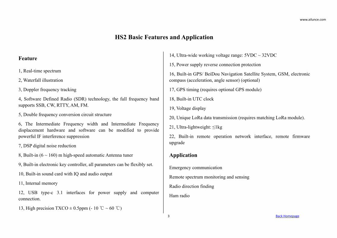
Feature
1, Real-time spectrum
2, Waterfall illustration
3, Doppler frequency tracking
4, Software Defined Radio (SDR) technology, the full frequency bandsupports SSB, CW, RTTY, AM, FM.
5, Double frequency conversion circuit structure
6, The Intermediate Frequency width and Intermediate Frequencydisplacement hardware and software can be modified to providepowerful IF interference suppression
7, DSP digital noise reduction
8, Built-in (6 ~ 160) m high-speed automatic Antenna tuner
9, Built-in electronic key controller, all parameters can be flexibly set.
10, Built-in sound card with IQ and audio output
11, Internal memory
12, USB type-c 3.1 interfaces for power supply and computerconnection.
13, High precision TXCO ± 0.5ppm (- 10℃ ~ 60℃)
14, Ultra-wide working voltage range: 5VDC ~ 32VDC
15, Power supply reverse connection protection
16, Built-in GPS/ BeiDou Navigation Satellite System, GSM, electroniccompass (acceleration, angle sensor) (optional)
17, GPS timing (requires optional GPS module)
18, Built-in UTC clock
19, Voltage display
20, Unique LoRa data transmission (requires matching LoRa module).
21, Ultra-lightweight: ≤1kg
22, Built-in remote operation network interface, remote firmwareupgrade
Application
Emergency communication
Remote spectrum monitoring and sensing
Radio direction finding
Ham radio
HS2 Basic Features and Application

www.ailunce.com
Back Homepage4
Accessories and options
Standard Option
FM Module GPS Module
Bluetooth Module LoRa Module
Built-in Sound Card Electronic Compass Module (Altimeter)
Built-in Automatic Tuner Shortwave Balcony Antenna
Internal Memory External Pulsator
DC Power Cord Bluetooth Hand Microphone
Type-C USB Cable
Wired Hand Microphone

www.ailunce.com
Back Homepage5
Specifications
Transmitter Parameter
Transmitting Architecture SDR
Transmitting Mode SSB,CW,RTTY,AM,FM
Frequency Resolution 1Hz
Transmitting Frequency Range*1/MHz
1.800~2.000;3.500~3.900;5.351.5~5.366.5;7.000~7.200;
10.100~10.150;14.000~14.350;18.068~18.168;21~21.450;
24.890~24.990;28~29.7;50~54;144~146;430~440.
Output Power*2
HF+6m: SSB: 1W~30W, CW: 0.1W~30W, FM: 0.1W~30W, AM: 1W~
5W;
VHF: SSB/CW/FM: 0.5W~5W;
UHF:SSB/CW/FM: 0.5W~5W.
Power ConsumptionTX: 13.8V*5A;
RX: 13.8V*0.35ATypical value, 0.45A(Maximum brightness, audio peak)
Carrier Suppression <50dB
Spurious Suppression
1.8 MHz~54MHz:≥50dB;
144 MHz~146MHz:≥60dB;
430 MHz~440MHz:≥60dB.
Number of Channels 999

www.ailunce.com
Back Homepage6
Receiver Parameter
Receiving Architecture SDR
Receiving Mode SSB,CW,RTTY,AM,FM
Receiving Frequency Range 300kHz~1.6GHz*
Intermediate Frequency Bandwidth 20kHz
Intermediate Frequency ZERO IF
Sensitivity*2
SSB/CW:(BW: 2.4kHz @ 10dB S/N);
0.18μV(1.8~54)MHz;0.25μV(144~146)MHz;
0.25μV(430~440)MHz;AM:( BW: 6kHz @ 10dB S/N);
15μV(0.3~1.8)MHz;2μV(1.8~54)MHz;
2μV(144~146)MHz;2μV(430~440)MHz;
FM:(BW: 15kHz @12dB S/N);0.5μV(28.0~29.7)MHz;
0.25μV(50~54)MHz;0.3μV(144~500)MHz;
0.5μV(430~440)MHz.
Intermediate Frequency suppression ≥70dB
Image Suppression ≥80dB
Audio Output Power 2W(10% distortion rate, 4Ω load, 3kHz)
Spectrum Parameter
Spectrum Bandwidth 48K
Radio Frequency Spectrum FFT

www.ailunce.com
Back Homepage7
Antenna Tuner Parameter
Tuning Frequency Range 1.8 MHz~54MHz
Tuning Impedance Range 16.7Ω~150Ω unbalance (standing wave ratio is better than 1:3)
Tuning Accuracy VSWR: ≤1:1.5
Tuning Time 2s~5s(Full Band 10s)
Tuning Ways Automatic/Manual
Structural Parameter
Size 170mm×120mm×345mm (without protrusions)
Weight <1.5kg
Working Voltage Parameter
Voltage Range Receiving range is 5V~ 32V, transmitting power limit is 5V~ 12V, fullpower output is 12V~18V, transmitting power limit is 18V~32V.
Antenna Interface
Antenna Interface M
Working Environment Parameter
Working Temperature -10℃~60℃
Working Humidity 10%~70%
Note:
*1: The frequency is set according to local laws.
*2: To be calibrated, the final interpretation right belongs to the manufacturer.

www.ailunce.com
Back Homepage8
Panel control and operation
Front panel
①Numeric keyboard
②LCD Monitor
③Function keyboard
④Headphone interface
⑤Wired hand microphone interface
⑥Receiving indicator
⑦Transmitting indicator

www.ailunce.com
Back Homepage9
Key Function
Key Short key Function Long Key Function
Power Switch the standing wave table (VSWR), ALC,MIC audio indication Power on, power off
Band Frequency band selection CW setting
Split Different frequency on, different frequency off Subsonic setting
AF Volume, MIC gain, MIC audio compression,ground bass, treble
Sound source selection
RF Radio frequency gain, Intermediate frequencygain, AGC, SQL, ATT
USB data output format selection
R/X RIT receiving frequency offset, IT transmittingfrequency offset
Transceiver frequency deviation switch
Mode Mode settingUSB/LSB, NFM/WFM switching
Tune Antenna tuner tuningAntenna tuner on and off
A/B A frequency or B frequency A frequency = B frequency

www.ailunce.com
Back Homepage10
NR NB or NR optionsOnly display the spectrum, only display thewaterfall chart, display the spectrum and
the waterfall chart at the same time
DS NR, NB, PEAK threshold setting Turn off NR or NB
PA Transmitting power setting 30W, 5W transmission power gear selection
BW Digital filter selection Spectrum bandwidth setting, spectrum referencelevel setting, spectrum refresh rate setting
Direction key left Left selection or decrement value operation *
Direction key right Right selection or increment value operation *
Direction key up Up choose Fast frequency improvement
Direction key down Down choose Fast frequency reduction
Menu Confirm Application interface, back
Indicator light
Condition Red Light Green Light
On Transmitting Receiving
Flicker Program exception
www.ailunce.com
Back Homepage11
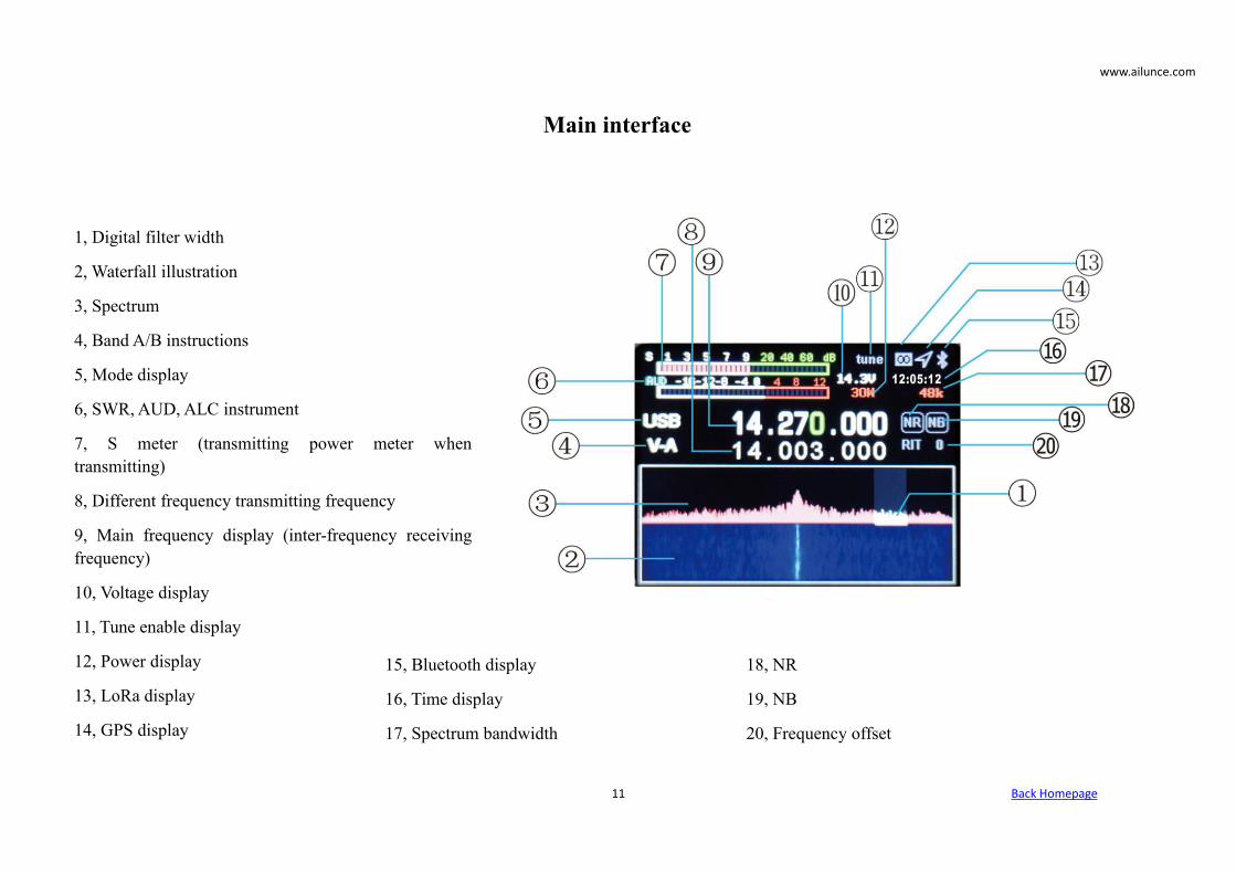
Main interface
1, Digital filter width
2, Waterfall illustration
3, Spectrum
4, Band A/B instructions
5, Mode display
6, SWR, AUD, ALC instrument
7, S meter (transmitting power meter whentransmitting)
8, Different frequency transmitting frequency
9, Main frequency display (inter-frequency receivingfrequency)
10, Voltage display
11, Tune enable display
12, Power display
13, LoRa display
14, GPS display
18, NR
19, NB
20, Frequency offset
15, Bluetooth display
16, Time display
17, Spectrum bandwidth

www.ailunce.com
Back Homepage12
Band Selection Operation
Short press the 【BAND】 button to pop up the frequency band selection interface, press thedirection key to select the frequency band, and press the MENU key to confirm.
Different Frequency
Press【SPLI】 to display the different frequency, then press again to turn off the differentfrequency. Press the left and right direction keys to select the frequency, and press the up anddown direction keys to increase or decrease the frequency. The upper row of frequencies isthe receiving frequency and the lower row is the transmitting frequency. Press 【A/B】 toswitch.

www.ailunce.com
Back Homepage13
AF audio Setting
Short press the 【AF】 button to enter the AFinterface, use the left and right direction keys toselect the setting item, and use the up and downbuttons to set the value.
VOL: Volume
MIC: MIC gain
CMP: MIC Compression ratio
BAS: Bass
TRB: Treble
RF setting
Short press 【RF】 to enter the RF parametersetting interface, use left and right direction keys toselect the setting item and use the up, and downkeys to set the value.
RFG: RF gain
IFG: IF gain
AGC: Automatic gain adjustmentspeed
SQL: Squelch level (FM)
ATT:Attenuation
www.ailunce.com
Back Homepage14
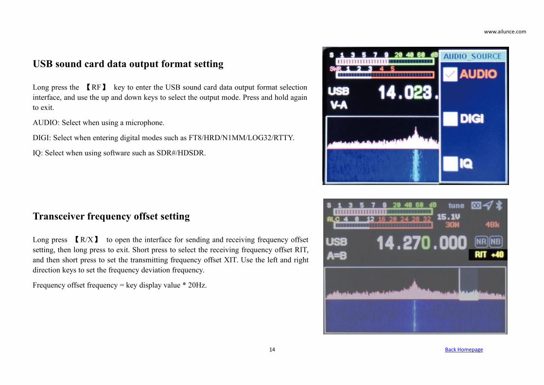
USB sound card data output format setting
Long press the 【RF】 key to enter the USB sound card data output format selectioninterface, and use the up and down keys to select the output mode. Press and hold againto exit.
AUDIO: Select when using a microphone.
DIGI: Select when entering digital modes such as FT8/HRD/N1MM/LOG32/RTTY.
IQ: Select when using software such as SDR#/HDSDR.
Transceiver frequency offset setting
Long press 【R/X】 to open the interface for sending and receiving frequency offsetsetting, then long press to exit. Short press to select the receiving frequency offset RIT,and then short press to set the transmitting frequency offset XIT. Use the left and rightdirection keys to set the frequency deviation frequency.
Frequency offset frequency = key display value * 20Hz.

www.ailunce.com
Back Homepage15
Transceiver mode setting
Short press 【Mode】 button to select the mode.
FM mode: long press to select NFM/WFM.
SSB mode: Long press to select USB/LSB.
Followed by recycling AM, FM, USB/LSB, CW.
Tune operation
1. Short press【Power】key to switch to SWR standing wave instrument.
2. Short press 【Tune】key, HS2 will automatically enter CW mode 5W state long tone transmission. The word TUNE will be displayed on the displayinterface.
3. Observe the SWR value of the standing wave instrument, adjust your antenna feeder system so that the standing wave is displayed below 2, indicatingthat the antenna feeder system is normal, press the【Tune】key again to exit.
4. Long press the【Tune】key to enter the automatic tuning of the unit. The machine will make a short click. After completion, check whether the antennastanding wave is less than 2 or less, otherwise please check your antenna system.
www.ailunce.com
Back Homepage16
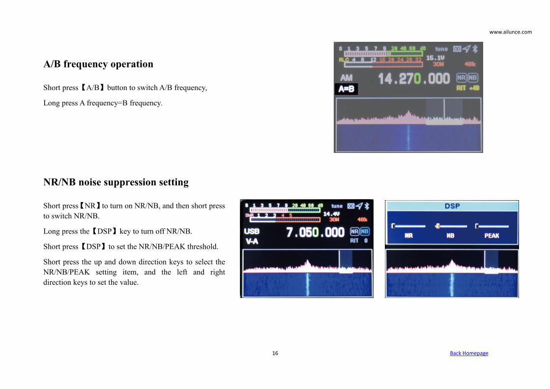
A/B frequency operation
Short press【A/B】button to switch A/B frequency,
Long press A frequency=B frequency.
NR/NB noise suppression setting
Short press【NR】to turn on NR/NB, and then short pressto switch NR/NB.
Long press the【DSP】key to turn off NR/NB.
Short press【DSP】to set the NR/NB/PEAK threshold.
Short press the up and down direction keys to select theNR/NB/PEAK setting item, and the left and rightdirection keys to set the value.

www.ailunce.com
Back Homepage17
Spectrum and waterfall display setting
Long press the【NR】key to select and display the waterfall chart, and long press to select and display the spectrum chart, and long press the waterfall
chart and the spectrum chart to display at the same time.
Spectrum parameter display setting
Long press the【NR】key to select and display the waterfall chart, and long press to select anddisplay the spectrum chart, and long press the waterfall chart and the spectrum chart to display atthe same time.
SPAN: Spectrum bandwidth.
REF: Spectrum reference level.
SPEED: Spectrum refresh rate.

www.ailunce.com
Back Homepage18
Digital filter operation
Short press【BW】key to select digital filter, left or right direction key to select filter bandwidth, short press【BW】
key to ensure filter bandwidth.
Transmitting power setting
Short press【PA】key to select power setting, up and down keys to increase or decrease power. We short press【PA】to launch the power setting. Long press to select 30W mode, then long press to select QRP 5W mode.
Application menu operation
Long press the【Menu】key to enter the menu interface, long press the【Menu】key to exit the menu interface, leftand right, up and down keys to select the application, and short press the【Menu】key to select the application.

www.ailunce.com
Back Homepage19
WFM radio operation
Use the left and right buttons to search for the channel, and the up and down buttons to increase or decrease thevolume. Long press to exit the radio function.
Bluetooth setting
Press the 【Menu】key to select the master-slave mode. Connect the phone, tablet, etc. to the slave mode.
Select the master mode by connecting a Bluetooth headset, etc.
Master mode:
Press the up and down keys to select the function button, and press the 【Menu】key to confirm. Search Bluetoothheadset Select search all Bluetooth slave devices, select Bluetooth slave device to connect.
Electronic compass operation
Enter the menu to directly display the UTC time, latitude and longitude, speed, direction, altitude, etc. received by theGPS module.

www.ailunce.com
Back Homepage20
LoRa data transmission operation
Directly display when receiving message, press the keyboard to input the information, and click TX to transmit theinformation.
Rear panel interface
①Antenna interface
HF/50MHz/144MHz/430MHz antenna port (M type), theoutput impedance is 50Ω.
②DC power interface .
Radio power interface, the specification is 5.5*2.5. Usethe standard DC power cord to connect to a regulatedpower supply or battery. The power supply must be ableto provide a current of 6A@(12~16.8)V to ensure the fullpower output of the radio.
③Sleeve USB interface
It is used to connect the USB cable to the computer andcan output audio, digital and IQ signals.

www.ailunce.com
Back Homepage21
④RS232 serial interface
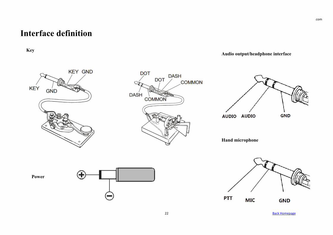
⑤Electric key interface
This interface is a 3.5mm three-core interface, used to connect electronic automatic key control or ordinary hand keys.
⑥Network interface
Used for remote control and remote firmware upgrade.
⑦GPS antenna port
Connect an active GPS antenna.
⑧PTT control output.
PTT transceiver used to control the power amplifier.
⑨Audio output.
Demodulated audio output
It is used for connecting peripheral smart devices, such as external wave wheels.
⑩Host USB interface
The function of this interface is temporarily reserved and used with caution for charging external devices.
⑪Grounding post
Note: To achieve the best performance and ensure safety, you can use a short and thick copper stranded wire to connect this ground terminal to the groundwell.
www.ailunce.com
Back Homepage22
Interface definition
Key
Power
Audio output/headphone interface
Hand microphone

www.ailunce.com
Back Homepage23
Transmitting operation
Please follow my guide to learn how to quickly set up and use your new equipment HS2. You must really want to use it to communicate. Below we willguide you to the first QSO. You will get an unparalleled experience from this brand new device. Now, we begin to understand how to operate it!
●Turn on and off HS2
1. To turn on the radio, simply long-press the power button for one second.
2. To turn off the radio, simply long-press the power button for one second.
●Frequency band selection
1. The frequency range of HS2 is very wide. Short press【Band】to bring up the frequency band menu
2. Short press the arrow keys to select, short press【Menu】to confirm the frequency band.
●Frequency selection
1. Short press the left and right direction keys to select the cursor position, short press the up direction key to adjust the required frequency, and long-pressthe up and down direction keys to quickly select the required frequency.
2. Input the required frequency by the direct numeric keyboard.
For example: if you want to enter 14.270MHz, press the numeric keyboard: 014270000 or 14.270000, and then press the menu key【Menu】to confirm.
●Mode selection
1. The whole HS2 supports LSB, USB, CW, AM, FM. Short press【Mode】key to select, LSB and USB need to long press【Mode】key to switch, CW andCWR long press【Mode】key to switch.
●Transmit power selection
1. Short press【PA】to enter the transmit power adjustment and use the up and down direction keys to adjust the value.
www.ailunce.com
Back Homepage24
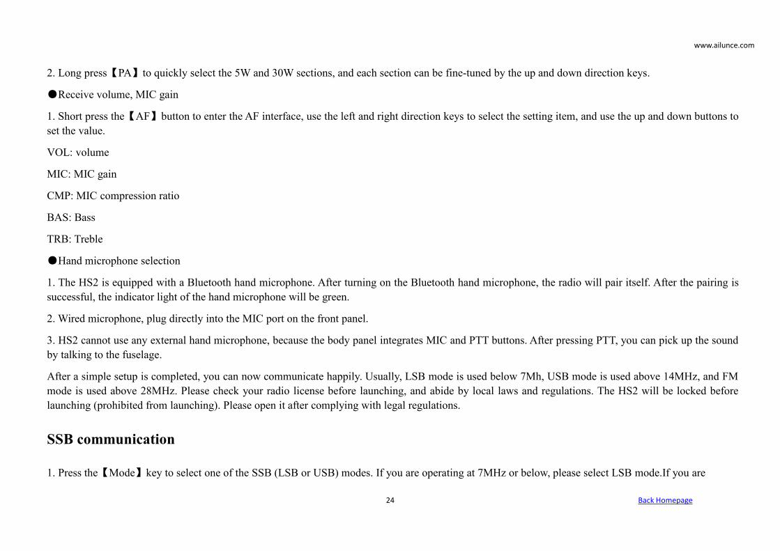
2. Long press【PA】to quickly select the 5W and 30W sections, and each section can be fine-tuned by the up and down direction keys.
●Receive volume, MIC gain
1. Short press the【AF】button to enter the AF interface, use the left and right direction keys to select the setting item, and use the up and down buttons toset the value.
VOL: volume
MIC: MIC gain
CMP: MIC compression ratio
BAS: Bass
TRB: Treble
●Hand microphone selection
1. The HS2 is equipped with a Bluetooth hand microphone. After turning on the Bluetooth hand microphone, the radio will pair itself. After the pairing issuccessful, the indicator light of the hand microphone will be green.
2. Wired microphone, plug directly into the MIC port on the front panel.
3. HS2 cannot use any external hand microphone, because the body panel integrates MIC and PTT buttons. After pressing PTT, you can pick up the soundby talking to the fuselage.
After a simple setup is completed, you can now communicate happily. Usually, LSB mode is used below 7Mh, USB mode is used above 14MHz, and FMmode is used above 28MHz. Please check your radio license before launching, and abide by local laws and regulations. The HS2 will be locked beforelaunching (prohibited from launching). Please open it after complying with legal regulations.
SSB communication
1. Press the【Mode】key to select one of the SSB (LSB or USB) modes. If you are operating at 7MHz or below, please select LSB mode.If you are

www.ailunce.com
Back Homepage25
operating at 14MHz or above, please select USB mode.
2. Short press【Power】key, the screen switches between ALC, SWR, AUD meter display.
3. Press the PTT button on the microphone and speak into the microphone in a normal voice, while observing the AUD meter display. When themicrophone enters the actual voice level, there will be a corresponding amplitude display on the AUD meter. Release the PPT button to return to thereceive mode.
4. If the AUD meter shows too high or too low, you can reset the microphone gain value as follows: Long press the【AF】key for one second to enter theselection mode, select the MIC item in the left and right direction, and set up direction key Set value, long press【AF】key again to exit. Speak into themicrophone until AUD appears at the peak of your voice.
CW communication
When using hand keys, automatic keys, semi-automatic keys, an external electronic key control or a computer-generated keyboard device, please followthe steps below:
1. Insert your 3.5mm (three-phase or two-phase) plug into the KEY jack on the rear panel.
2. Short press【Mode】to select a CW mode (CW or CWR), "CW" mode uses the carrier input on the USB side, and CWR (reverse) mode uses the input onthe LSB side.
3. Long press【BAND】key to enter CW set. Up and down arrow keys on the keyboard
Select an option and use the left and right arrow keys to adjust the settings within the option.
3-1, KEYMODE left and right direction key selection content: manual electric key automatic electric key.
3-2. KEY SPEED automatic key code rate, the greater is the value, the faster is the speed.
3-3. TX-RX CW transmission and reception switching time, the greater is the value, the greater is the delay.
3-4. STF CW sidetone audio.
3-5. STG CW sidetone volume.

www.ailunce.com
Back Homepage26
FM communication
The HS2 supports full-band FM mode transmission and reception. It is usually used for FM communication above 28MHz in short-wave communication.29.6MHz is called the magic band by the HAM community. It will be opened in a short time in the summer of the year, which is very challenging.
1. Short press【Mode】key to find FM mode, long press【Mode】key to switch between WFM mode and NFM mode.
2. HS2 includes FM section FM, you can communicate with ordinary walkie-talkies, or you can go to a local relay station.
3. Short press【RF】key, left and right direction keys are to select SQL, squelch option, up and down direction keys are to set squelch level.
Relay operation
1. Set the required frequency, for example, repeater parameters (downlink 145.670MHz, uplink 144.130MHz, uplink and downlink analog mute 88.5) areset as follows:
1-1. we press SPLI to display the different frequency, and then press to turn off the different frequency. The upper row of frequencies is the receivingfrequency, that is, the relay downlink, press the left and right direction keys to select the frequency, press the up and down direction keys to increase ordecrease the frequency, or directly enter the numeric keyboard: 14567000, the lower row of frequencies is displayed as the transmission frequency, that is,the relay upstream frequency, you need to press the A/B key to switch to the upper row, directly enter 14413000 on the keyboard, and then press the A/Bkey to switch to the lower row.
1-2. Retuned setting mode, long press the【Menu】key, select the【Set】up, down, left, and right direction keys to enter the SYS_SET interface, press theright key to expand the menu, and select the up and down keys T-CTSC transmits dumb audio, R-CTSC receives dumb audio, and the left and rightdirection keys select the value 88.5.
Long press【Menu】to exit to the application menu interfaces, and then long press【Menu】to exit to the radio interface.

www.ailunce.com
Back Homepage27
AM communication
1. Press the【Mode】key to select the AM mode and set the required frequency
2. The AM mode input RF power is 5W
Data communication RTTY
HS2's "RTTY" working mode is based on the long-term use of amateur radio, based on the LSB carrier. If you want to use the USB carrier for "RTTY"operation, you need to set up the user, please refer to the following introduction.
1. Connect your computer and HS2 via USB connection.
2. Long press the RF key to enter the USB sound card data output format selection interface, and use the up and down keys to select the output mode.Press and hold again to exit. Select【DIGI】digital mode.
3. At this time, you can search on the frequency, if there is an RTTY signal, the relevant computer software can decode.

www.ailunce.com
Back Homepage28
Customize digital pattern mode
HS2 cooperates with mobile phone APP software HAM-BOX to realize a custom digital communication mode, which requires the same settings for bothparties.
1. Find the mobile phone Bluetooth search HS2 and pair and connect.
2. Open the mobile phone APP software HAM-BOX and set the relevant communication mode (requires the same communication side). Then the phoneoperation sends a text, pictures, coordinates, etc.
CAT control
HS2 has a CAT system, so you can use a personal computer to control the intercom. Just click with a mouse to complete multiple control operations fullyautomatically, and also supports the control of third-party software packages (such as radio log software for competitions), so that no (additional) operatorcan use HS2 to communicate. The CAT protocol is compatible with FT-817, so choose the FT-817 radio model during CAT control.
For CAT control, a TYPE-C USB cable can be used to connect to the computer. The serial port driver is only suitable for WINDOWS 10 system. TheUSB cable also integrates the sound card function, and only requires a USB to realize CAT control and data transmission. Due to the wide variety ofcomputers,
operating systems, and various applications software, Retevis Electronics does not develop system control software. But HS2 widely supports variousthird-party control software packages.

www.ailunce.com
Back Homepage29
Computer third-party software setting operation
1, JTDX setting
1-1. The computer operating system only supports WIN10. Pleaseuse the TYPE-C USB cable to connect to the computer radio. Aftera successful connection, enter the computer device manager. Youcan view the port (USB serial device COM*). Here I displayCOM4.
1-2. Set the USB mode on the radio terminal, long-press the【RF】key to enter the USB soundcard data output format selection interface, use the up and down keys to select the output mode【DIGI】, and then long press to exit.

www.ailunce.com
Back Homepage30
1-3. Open the FT8 software JTDX setting interface
The radio station chooses FT-817, the port number chooses the COM4 that the computer checksbefore, the PTT way chooses CAT control, just ignore the rest, click test CAT, when connectingsuccessfully it will display green.
1-4, The sound source settings are as follows
1-5. Software working interface after it has been set.

www.ailunce.com
Back Homepage31
2, HRD setting
2-1. The computer operating systemonly supports WIN10. Please use theTYPE-C USB cable to connect to thecomputer radio. After the connectionis successful, enter the computerdevice manager to view the port (USBserial device COM*). I display COM4here.
2-2. Set the USB mode on the radio terminal, long-press the【RF】key to enterthe USB sound card data output format selection interface, use the up anddown keys to select the output mode【DIGI】, and then long press to exit.

www.ailunce.com
Back Homepage32
2-3. When you open the HRD for the first time, the options dialog box will pop upautomatically. Click Connect after the settings are completed according to the figure. Ifthe connection is successful, you will directly enter the software interface. If not, youwill be noticed.
2-4. After successful connection it enters the softwareinterface, the software can operate all the functions of theradio.

www.ailunce.com
Back Homepage33
3, N1mm setting
3-1. the computer operating system only supports WIN10. Please use the TYPE-C USB cable toconnect to the computer radio. After the connection is successful, enter the computer devicemanager. You can view the port (USB serial device COM*). Here I display COM4.
3-2. Set the USB mode on the radio station, long-press the【RF】key to enter the USB soundcard data output format selection interface, use the up and down keys to select the output mode【DIGI】, and then long press to exit.
3-3. Open the N1MM setting menu and set theparameters as shown below.
Click SET to enter the further setting menu.

www.ailunce.com
Back Homepage34
3-4. After a successful setting, the software can fully control the radio station.
4, HDSDR setting
4-1. The computer operating system only supports WIN10. Please use the TYPE-C USB cable toconnect to the computer radio. After a successful connection, enter the computer device manager.You can view the port (USB serial device COM*). Here I display COM4.
www.ailunce.com
Back Homepage35
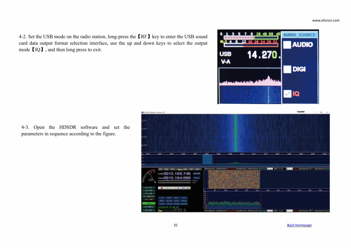
4-2. Set the USB mode on the radio station, long-press the【RF】key to enter the USB soundcard data output format selection interface, use the up and down keys to select the outputmode【IQ】, and then long press to exit.
4-3. Open the HDSDR software and set theparameters in sequence according to the figure.

www.ailunce.com
Back Homepage36
4-4. Select the RX input of the sound card as microphone USBHS2, and select the sound card of the computer as the output.
After it is set, click【Start】on the HDSDR interface to use it.

www.ailunce.com
Back Homepage37
5, Bluetooth adapter and radio realize wireless connection
The Bluetooth adapter is developed by us and the HS2 can realize the wireless connection between the computer and the radio. You can put the radio onthe balcony, and the laptop and tablet computer can control the radio on the sofa in the living room.
Mobile APP
The mobile app HAMBOX is developed by Retevis Company which has fully controlled the radio function, and some functions are free to use.
PC software
The PC software is developed by Retevis Company which has fully controlled the radio function, and some functions are free to use
Receiving advanced operation
HS2's power-on state is the receiving state. In order to get a better listening experience, you need to follow me to understand the advanced operation of themachine.
1. Select the desired frequency, for example, 14.270MHz\USB.
2. Short press the【AF】button to call up the VOL volume adjustment. Use the up and down direction keys to adjust the volume and adjust the appropriatevolume. Short press the【AF】button again to save and exit.
3. Short press the【RF】button to bring up the RF parameter setting interface. Use the left and right direction keys to select the setting item, use the up anddown keys to set the value, and press the【RF】key again to save and exit.
3-1, RFG: RF gain.

www.ailunce.com
Back Homepage38
3-2. IFG: IF gain.
The combination of RFG and IFG enables the receiver to achieve the highest sensitivity and the lowest amount of noise. Generally, you need to increasethese two parameters if you want to hear a very weak signal, but the noise also increases. A balanced state requires careful adjustment. Usually, the IF gaincan be set higher than the RF gain.
3-3, ATT: attenuation. If the signal is particularly strong, you can turn on ATT.
4. Long press the【BW】button to set the spectrum bandwidth, reference level, refresh rate, use the up and down buttons to select the setting item, left andright buttons to set the value, and long-press the【BW】button again to exit. The spectrum display shows other signals within the bandwidth.
4-1, SPAN: spectrum bandwidth, respectively 12K, 24K, 48K width
4-2, REF: spectrum reference level.
4-3, SPEED: spectrum refresh rate.
5. Display setting of the spectrum and waterfall chart
Long-press the NR key to select and display the waterfall chart, long-press to select and display the spectrum chart, and long press to display the tile chartand the waterfall chart at the same time.
6. Digital filter operation, HS2 provides a powerful digital filter.
We short press the BW button to select the digital filter. After the digital filter is turned on, the original white horizontal line on the spectrum is displayed ingreen. Use the left and right buttons to select the filter bandwidth. Press the BW button again to confirm the filter bandwidth and exit.
Different bandwidths can effectively avoid interference signals to achieve excellent listening effects.
7. NR/NB noise suppression setting, usually this option shall cooperate with the digital filter to achieve excellent results.
7-1. we short press【NR】to turn on NR/NB, and short press to switch NR/NB. Press and hold the【DSP】key to turn off NR/NB. Short press【DSP】to setthe NR/NB/PEAK threshold, use the up and down keys to select the NR/NB/PEAK setting item, left and right keys to set the value, and short press【KSP】again to exit.

www.ailunce.com
Back Homepage39
7-2. Find the required signal, turn on NR, usually the effect of NR is more obvious, then press ○6 to open the digital filter to the maximum bandwidth,and then adjust the digital filter bandwidth a little bit. You will find that the noise will be greatly suppressed. At this time, you can also adjust thecombination of the previous RFG and IFG to achieve the best reception effect.
Through the above settings, you have mastered the advanced receiving settings of HS2. Now, let HS2 explore with you in the ocean of radio waves.
HS2 firmware upgrade
1. Open the DfuSe Demo software.
2. Plug the HS2 power supply and connect it to USB.
3. Hold down the BAND key and then hold down the POWER key. At thistime, if the computer is connected to the HS2 normally, ○ 1 will display(STM Device in DFU Mode). Otherwise, please check whether the computeris properly connected to the HS2.
4. Select the firmware file *.dru ○2
5. Hold down the BAND and power keys, click ○3Upgrade
At this point, the upgrade begins, wait for the progress bar to finish, releasethe button, and restart the computer.
6. If you let go of the button or power off halfway, you only need to restartthe operation.

www.ailunce.com
Back Homepage40
Before using this radio, read this guide which contains important operating instructions for safe usage and RF energy awareness andcontrol for compliance with applicable standards and regulations.
RF ENERGY EXPOSURE AND PRODUCT SAFETY GUIDE FOR PORTABLE TWO-WAY RADIOS
This two-way radio uses electromagnetic energy in the radio frequency (RF) spectrum to provide communications between two or more users over adistance.
RF energy, which when used improperly, can cause biological damage.
All Retevis two-way radios are designed, manufactured, and tested to ensure they meet government-established RF exposure levels. In addition,manufacturers also recommend specific operating instructions to users of two-way radios. These instructions are important because they inform users aboutRF energy exposure and provide simple procedures on how to control it.
Please refer to the following websites for more information on what RF energy exposure is and how to control your exposure to assure compliance withestablished RF exposure limits: http://www.who.int/en/
Local Government Regulations
When two-way radios are used as a consequence of employment, the Local Government Regulations require users to be fully aware of and able to controltheir exposure to meet occupational requirements. Exposure awareness can be facilitated by the use of a product label directing users to specific userawareness information. Your Retevis two-way radio has an RF Exposure Product Label. Also, your Retevis user manual or separate safety booklet includesinformation and operating instructions required to control your RF exposure and to satisfy compliance requirements.
Radio License
Governments keep the radios in classification, business two-way radios operate on radio frequencies that are regulated. by the local radio managementdepartments (FCC, ISED, OFCOM, ANFR, BFTK, Bundesnetzagentur...).

www.ailunce.com
Back Homepage41
To transmit on these frequencies, you are required to have a license issued by them. For the detailed classification and the use of your two radios, pleasecontact the local government radio management departments. The use of this radio outside the country where it was intended to be distributed is subject togovernment regulations and may be prohibited.
Unauthorized modification and adjustment
Changes or modifications not expressly approved by the party responsible for compliance may void the user’s authority granted by the local governmentradio management departments to operate this radio and should not be made. To comply with the corresponding requirements, transmitter adjustmentsshould be made only by or under the supervision of a person certified as technically qualified to perform transmitter maintenance and repairs in the privateland mobile and fixed services as certified by an organization representative of the user of those services. Replacement of any transmitter component(crystal, semiconductor, etc.) not authorized by the local government radio management department equipment authorization for this radio could violatethe rules.
FCC Requirements:
This device complies with part 15 of the FCC Rules. Operation is subject to the condition that this device does not cause harmful interference. (Licensedradios are applicable); This device complies with part 15 of the FCC Rules. Operation is subject to the following two conditions:
(Other devices are applicable)
(1) This device may not cause harmful interference, and
(2) this device must accept any interference received, including interference that may cause undesired operation.
NOTE: This equipment has been tested and found to comply with the limits for a Class A digital device, pursuant to part 15 of the FCC Rules. Theselimits are designed to provide reasonable protection against harmful interference when the equipment is operated in a commercial environment. Thisequipment generates, uses, and can radiate radio frequency energy and, if not installed and used in accordance with the instruction manual, may causeharmful interference to radio communications. Operation of this equipment in a residential area is likely to cause harmful interference in which case theuser will be required to correct the interference at his own expense.

www.ailunce.com
Back Homepage42
CE Requirements:
(Simple EU declaration of conformity) Shenzhen Retevis Technology Co., Ltd. declares that the radio
equipment type is in compliance with the essential requirements and other relevant provisions of RED Directive 2014/53/EU and the ROHS Directive2011/65/EU and the WEEE Directive 2012/19/EU; the full text of the EU declaration of conformity is available at the following internet address:www.retevis.com.
Restriction Information
This product can be used in EU countries and regions, including Belgium (BE), Bulgaria (BG), Czech Republic (CZ), Denmark (DK), Germany (DE),Estonia (EE), Ireland (IE), Greece (EL), Spain (ES), France (FR), Croatia (HR), Italy (IT), Cyprus (CY), Latvia (LV), Lithuania (LT), Luxembourg (LU),Hungary (HU), Malta (MT), Netherlands (NL), Austria (AT), Poland (PL), Portugal (PT), Romania (RO), Slovenia (SI), Slovakia (SK), Finland (FI),Sweden (SE) and United Kingdom (UK). For the warning information of the frequency restriction, please refer to the package or manual section.Disposal
The crossed-out wheeled bin symbol on your product, literature, or packaging reminds you that in the European Union, all electrical and electronicproducts, batteries, and accumulators (rechargeable batteries) must be taken to designated collection locations at the end of their working life. Do notdispose of these products as unsorted municipal waste. Dispose of them according to the laws in your area.
IC Requirements:
License-exempt radio apparatus This device contains license-exempt transmitter(s)/receiver(s) that comply with Innovation, Science, and EconomicDevelopment Canada’s license-exempt RSS(s). Operation is subject to the following two conditions:
(1) This device may not cause interference.
(2) This device must accept any interference, including interference that may cause undesired operation of the device.
Le présent appareil est conforme aux CNR d’Industrie Canada applicables aux appareils radio exempts de licence. L’exploitation est autorisée aux deuxconditions suivantes :
(1) l’appareil ne doit pas produire de brouillage;
(2) l’utilisateur de l’appareil doit accepter tout brouillage radioélectrique subi, même si le brouillage est susceptible d’en compromettre le fonctionnement.

www.ailunce.com
Back Homepage43
RF Exposure Information
•DO NOT operate the radio without a proper antenna attached, as this may damage the radio and may also cause you to exceed RF exposure limits. Aproper antenna is an antenna supplied with this radio by the manufacturer or an antenna specifically authorized by the manufacturer for use with this radio,and the antenna gain shall not exceed the specified gain by the manufacturer declared.
•DO NOT transmit for more than 50% of total radio use time, more than 50% of the time can cause RF exposure compliance requirements to be exceeded.
During transmissions, your radio generates RF energy that can possibly cause interference with other devices or systems. To avoid such interference, turnoff the radio in areas where signs are posted to do so.
•DO NOT operate the transmitter in areas that are sensitive to electromagnetic radiation such as hospitals, aircraft, and blasting sites.
Portable Device, this transmitter may operate with the antenna(s) documented in this filing in Push-to-Talk and body-worn configurations. RF exposurecompliance is limited to the specific belt-clip and accessory configurations as documented in this filing and the separation distance between the user andthe device or its antenna shall be at least 2.5 cm.
Mobile Device, during operation, the separation distance between the user and the antenna subjects to actual regulations, this separation distance willensure that there is sufficient distance from a properly installed externally-mounted antenna to satisfy the RF exposure requirements.
Occupational/Controlled Radio, this radio is designed for and classified as”Occupational/Controlled Use Only”, meaning it must be used only during thecourse of employment by individuals aware of the hazards, and the ways to minimize such hazards; NOT intended for use in a Generalpopulation/uncontrolled environment.
General population/uncontrolled Radio, this radio is designed for and classified as “General population/uncontrolled Radio”.
RF Exposure Compliance and Control Guidelines and Operating Instructions
To control your exposure and ensure compliance with the occupational/controlled environment exposure limits, always adhere to the following procedures.
Guidelines
•User awareness instructions should accompany the device when transferred to other users.
•Do not use this device if the operational requirements described herein are not met.

www.ailunce.com
Back Homepage44
Operating Instructions:
•Transmit no more than the rated duty factor of 50% of the time. To Transmit (Talk), push the Push to Talk (PTT) button. To receive calls (listen), releasethe PTT button. Transmitting 50% of the time, or less, is important because the radio generates measurable RF energy exposure only when transmitting interms of measuring for standards compliance.
•Transmit only when people outside the vehicle are at least the recommended minimum lateral distance away from a properly installed according toinstallation instructions, externally mounted antenna.
•When operating in front of the face, worn on the body, always place the radio in a Retevis approved clip, holder, holster, case, or body harness for thisproduct. Using approved body-worn accessories is important because the use of Non-Retevis approved accessories may result in exposure levels, whichexceed the IEEE/ICNIRP RF exposure limits.
population/uncontrolled Use”.
Hand-held Mode
•Hold the radio in a vertical position with the microphone (and other parts of the radio including the antenna) at least 2.5 cm (one inch) away from the noseor lips. The antenna should be kept away from the eyes. Keeping the radio at a proper distance is important as RF exposure decreases with increasingdistance from the antenna.
Phone Mode
•When placing or receiving a phone call, hold your radio product as you would a wireless telephone. Speak directly into the microphone.ElectromagneticInterference/Compatibility
NOTE: Nearly every electronic device is susceptible to electromagnetic interference (EMI) if inadequately shielded, designed, or otherwise configured forelectromagnetic compatibility.
Avoid Choking Hazard
Small Parts. Not for children under 3 years.

www.ailunce.com
Back Homepage45
Turn off your radio power in the following conditions:
•Turn off your radio before removing (installing) a battery or accessory or when charging battery.
•Turn off your radio when you are in a potentially hazardous environments: Near electrical blasting caps, in a blasting area, in explosiveatmospheres (inflammable gas, dust particles, metallic powders, grain powders, etc.).
•Turn off your radio while taking on fuel or while parked at gasoline service stations.To avoid electromagnetic interference and/orcompatibility conflicts
•Turn off your radio in any facility where posted notices instruct you to do so, hospitals or health care facilities (Pacemakers, Hearing Aidsand Other Medical Devices) may be using equipment that is sensitive to external RF energy.
•Turn off your radio when on board an aircraft. Any use of a radio must be in accordance with applicable regulations per airline crewinstructions.
Protect your hearing:
•Use the lowest volume necessary to do your job.
•Turn up the volume only if you are in noisy surroundings.
•Turn down the volume before adding a headset or earpiece.
•Limit the amount of time you use headsets or earpieces at high volume.
•When using the radio without a headset or earpiece, do not place the radio's speaker directly against your ear
•Use carefully with the earphone may be possible excessive sound pressure from earphones and headphones can cause hearing loss
Note: Exposure to loud noises from any source for extended periods of time may temporarily or permanently affect your hearing. Thelouder the radio's volume, the less time is required before
•Your hearing could be affected. Hearing damage from loud noise is sometimes undetectable at first and can have a cumulative effect.

www.ailunce.com
Back Homepage46
Avoid Burns
Antennas
•Do not use any portable radio that has a damaged antenna. If a damaged antenna comes into contact with the skin when the radio is in use,a minor burn can result.
Batteries (If appropriate)
•When the conductive material such as jewelry, keys or chains touch exposed terminals of the batteries, may complete an electrical circuit(short circuit the battery) and become hot to cause bodily injury such as burns. Exercise care in handling any battery, particularly whenplacing it inside a pocket, purse or other container with metal objects
Long transmission
•When the transceiver is used for long transmissions, the radiator and chassis will become hot.
Forbid
•Do not use charger outdoors or in moist environments, use only in dry locations/conditions.
•Do not disassemble the charger, that may result in risk of electrical shock or fire.
•Do not operate the charger if it has been broken or damaged in any way.
•Do not place a portable radio in the area over an air bag or in the air bag deployment area. The radio may be propelled with great force andcause serious injury to occupants of the vehicle when the air bag inflates.
To reduce risk
•Pull by the plug rather than the cord when disconnecting the charger.
•Unplug the charger from the AC outlet before attempting any maintenance or cleaning.
Safety Operation

www.ailunce.com
Back Homepage47
•Contact Retevis for assistance regarding repairs and service.
•The adapter shall be installed near the equipment and shall be easily accessible.
Approved Accessories
•This radio meets the RF exposure guidelines when used with the Retevis accessories supplied or designated for the product. Use of otheraccessories may not ensure compliance with the RF exposure guidelines and may violate regulations.
•For a list of Retevis-approved accessories for your radio model, visit the following website: http://www.Retevis.com
EU Importer:
Importer:Germany Retevis Technology GmbH
Address:Uetzenacker 29,38176 wendeburg

www.ailunce.com
Back Homepage48
Guarantee
Model Number:
Serial Number:
Purchasing Date:
Dealer: Telephone:
User’s Name: Telephone:
Country: Address:
Post Code: Email:
Remarks:
1. This guarantee card should be kept by the user, no replacement if lost.
2. Most new carry a two-year manufacturer’s warranty from the date of purchase. Further details, please readhttps://www.ailunce.com/AfterSaleService/
3. The user can get warranty and after-sales service as below:Contact the seller where you buy.Products Repaired by Our Local Repair Center
4. For warranty service, you will need to provide a receipt proof of purchase from the actual seller for verification.
Exclusions fromWarranty Coverage:
1. To any product damaged by accident. 2. In the event of misuse or abuse of the product or as a result of unauthorized.

www.ailunce.com
Copyright © 2022 FDOKUMEN