Mixed Convection from a Heated Sphere in Bingham Plastic Fluids
Upload
independentCategory
view
1download
0
Heat transfer from rough, protrudi ng discretely heated strips with and without flow acceleration Walid M. Chakroun Center of Research for Experimental Thermal Sciences, Mechanical and Industrial Engineering, Kuwai t University, Safat, Kuwai t
Mesfin W. Medhin and Robert P, Taylor Mechanical Engineering Department, Mississippi State University, Starkvil le, Mississippi, USA
Experimental heat transfer results on the effects of rough, protruding, discretely heated strips are presented. Data are presented for two-dimensional (2-D), distributed heat sources for three cases--flush-mounted smooth, protruding smooth, and protruding rough --under zero pressure gradient and accelerated turbulent boundary-layer conditions. For the zero pressure-gradient cases, experiments are performed on repeated, protruding discretely heated strips using surface roughness as a heat transfer enhancement tech- nique. The accelerated cases are conducted to investigate the existence and strength of a synergistic interaction between boundary-layer flow acceleration and surface roughness as a heat transfer enhancement mechanism. For the zero pressure-gradient cases, it is found that under the conditions of these experiments, significant heat transfer enhancements (10-100%) can be obtained with the rough surface. For the smooth-flush arrangement with acceleration, the Stanton numbers decreased by up to 16% with increasing accelera- tion strength. For the protruding smooth arrangement, the Stanton numbers remain almost constant over all acceleration strengths. For the protruding rough arrangement, the Stan- ton numbers increase by up to 7% with increasing acceleration strength. © 1997 by Elsevier Science Inc.
Keywords: convection heat transfer; surface roughness; acceleration
I n t r o d u c t i o n
This paper presents the results of heat transfer and pumping- power measurements for discretely heated, protruding strips for zero pressure-gradient and accelerated boundary layers. For the zero pressure-gradient experiments, the results are presented for repeated, discretely heated, protruding strips with and without surface roughness. For the accelerated boundary-layer cases, the results of heat transfer measurements are presented for three heating arrangements: flush-mounted smooth, protruding smooth, and protruding rough. Surface roughness has long been consid- ered as a good heat transfer enhancement method for flat plates. The objective of this work is to study whether surface roughness is also a good heat transfer enhancement technique for discretely heated protruding strips. Another objective is to understand the synergistic interaction between boundary-layer flow acceleration and surface roughness for protruding heated strips, where the
Address reprint requests to Dr. W. M. Chakroun, Kuwait Univer- sity, Center of Research for Experimental Thermal Sciences, Mechanical and Industrial Engineering, Kuwait University, P. O. Box 5969, Safat 13060, Kuwait.
Received 14 May 1996; accepted 22 March 1997
Int. J. Heat and Fluid Flow 18: 461-470, 1997 © 1997 by Elsevier Science Inc. 655 Avenue of the Americas, New York, NY 10010
local acceleration parameter
v dU K = - - - - (1)
U 2 dx
was varied in the range 0 to 1.6 × 10 -6. Both three-dimensional (3-D) and two-dimensional (2-D) rib-
type surface roughnesses have long been used as heat transfer enhancement mechanisms in heat-exchanger tubes. The rough- ness not only increases the available heat transfer area but also changes the flow and turbulence structure in the boundary layer, increasing the effective local heat transfer coefficient. One way to view the heat transfer enhancement mechanism with surface roughness is the introduction of additional length scales. The local heat transfer rate can be described by the scale relationship
AT q " ~ - - (2)
f
which indicates that the local heat flux is inversely proportional to the length scale. For smooth-wall constant wall temperature boundary layers, the length scale is the thermal boundary-layer thickness. When surface roughness is added, an additional length scale, that of the roughness, is introduced. Because the rough- ness is much smaller than the boundary-layer thickness, very
0142-727X/97/$17.00 PII S0142-727X(97)OO041-6
Heat transfer from discretely heated strips: W. M. Chakroun
large local heat flux rates exist in the neighborhood of the roughness elements. If the elements are numerous enough to provide a significant fraction of the total heat transfer area, a significant increase in the overall heat transfer can be obtained.
The idea for this research is based on the work of Taylor and Chakroun (1992), which studied surface roughness related to turbine blade heat transfer. These experiments simulated a tur- bine blade with a strip of surface roughness on an otherwise smooth. The experiments were conducted in a turbulent bound- ary layer with a constant surface temperature. The heat transfer rate over the short, rough strip was about double that for the neighboring smooth strip, even though the rough surface had only about 20% more heat transfer area than the smooth surface for the same plan area.
In this paper, the average heat transfer rate is measured for protruding, discretely heated strips for both smooth and rough surfaces. The discrete heating causes the heat transfer rate to be higher than that for isothermal or uniformly heated surfaces. With discrete heat sources, a new thermal boundary layer with relatively high heat flux is initiated at the leading edge of the heated strip. When the strip protrudes above the base surface, a new aerodynamic internal boundary layer is initiated. This also leads to higher heat flux than a corresponding flat surface. The first objective of these experiments is to investigate the effect of adding a third thermal length scale by using rough, protruding plates.
In regular smooth-wall boundary layers, acceleration stretches the turbulent eddies; thus, decreasing the transboundary-layer turbulent diffusion. The Stanton numbers decrease dramatically compared to equivalent zero pressure-gradient flows; hence, counteracting the heat transfer augmentation that the higher velocity scales would indicate. If the acceleration is strong enough, the boundary-layer heat transfer rate will approach that of an equivalent laminar boundary layer, the relaminarization is said to have occurred. A local acceleration parameter of K = 3.0 × 10 -6 is the approximate relaminarization threshold for smooth, fiat plates (Launder 1963; Jones and Launder 1972; Moffat and Kays 1984).
Rough-wall turbulent boundary layers behave differently un- der acceleration. The first extensive heat transfer experiments with accelerated rough-wall boundary-layer flow were those of Coleman (1976) (also, Coleman et al. 1981). His experiments were limited to mild accelerations with a fully rough turbulent
boundary layer over a surface composed of 1.27-mm spheres packed in the most dense array. He found that the fully rough boundary layer's response to the acceleration was opposite to that of the smooth-wall boundary layer, with the Stanton num- bers increasing in the accelerated boundary layer instead of a decreasing one. Chakroun (1992) (also, Chakroun and Taylor 1993) investigated acceleration effects on the rough-wall turbu- lent boundary layer over a wider range of conditions than Cole- man. His experiments were carried out over a smooth and two rough surfaces and included the three rough-wall flow regimes of aerodynamically smooth, transitionally rough, and fully rough flow. (Turbulent flows influenced by surface roughness are usu- ally divided into three regimes. Aerodynamically smooth flows are those where the roughness effects are so small compared to viscous effects that the flow behaves as if the wail were smooth. Fully rough flows are those where the roughness so dominates the momentum transport to the wall that viscous effects are negligible. In turbulent pipe flow, fully rough flows are those where the friction factor is no longer a function of Reynolds number. Transitionally rough flows are those at Reynolds num- bers where viscous and roughness effects are both significant.) His conclusions for fully rough boundary layers were parallel to those of Coleman. This increase in Stanton number interacts synergistically with the increasing velocity scales to yield heat transfer rates higher than would be expected.by simple superpo- sition of observations of accelerated smooth-wall flows and zero pressure-gradient rough-wall flows. The second objective of these experiments is to investigate the interaction between roughness and acceleration when the roughness is on discretely heated, protruding strips.
For a discussion of acceleration effects on the smooth-wall turbulent boundary layer the review of Moffat and Kays (1984) is suggested. For a general review of rough-wall turbulent boundary layers, the review article by Raupach et al. (1991) is recom- mended. For the interaction of surface roughness and accelera- tion Chakroun (1992) is recommended.
E x p e r i m e n t a l a p p a r a t u s a n d m e a s u r e m e n t s
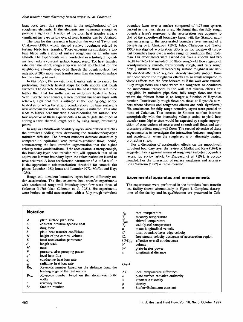
The experiments were performed in the turbulent heat transfer test facility shown schematically in Figure 1. Complete descrip- tions of the facility and its qualification are presented in Cole-
Notation
A C D h H K f M P q"
qc q, Rex
Rew
r St
7"0
plate surface plan area constant pressure specific heat Tw drag force u plate heat transfer coefficient U height of the control volume U= local acceleration parameter (UA)ef f length scale V mass W pressure, also pumping power x local heat flux conductive heat loss rate radiative heat loss rate Greek Reynolds number based on the distance from the leading edge of the test section AT Reynolds number based on the streamwise plate e width v recovery factor p Stanton number tr
total temperature recovery temperature siderail temperature wall (plate) temperature mean longitudinal velocity local boundary-layer edge velocity free-stream velocity upstream of acceleration region effective overall conductance volume plate-heater power longitudinal distance
local temperature difference plate surface radiative emissivity kinematic viscosity density Stefan-Boltzmann constant
462 Int. J. Heat and Fluid Flow, Vol. 18, No. 5, October 1997
I-leer Exchonger
Test Section I I I I Bl°wer Plote H e o t e r ~ " ~
Figure 1 Schematic diagram of the turbulent heat transfer heat facility
man et al. (1991). This facility is a closed-loop wind tunnel with free-stream velocity range of 6 to 67 m/s that was specially designed to conduct convective heat transfer tests with rough surfaces in a (2-D) turbulent boundary layer. The temperature of the circulating air is controlled with an air-to-water heat ex- changer and a cooling water loop. Following the heat exchanger, the air flow is conditioned by a system of honeycomb and screens to deliver a uniform velocity, low-turbulence intensity, controlled temperature air flow at the 10.2 × 50.8-cm inlet of the 2.4-m long test section that contains the test surface. The boundary layer is tripped turbulent at the exit of the 19 : 1 area ratio nozzle (at the entrance of the test section) with a l-ram high x 12-ram wide wooden strip.
As reported by Coleman et al. (1988), a series of qualification tests were conducted with a smooth level test surface (no raised plates) to ensure the fitness of the testing and correctness of the instrumentation, data collection system, and data reduction pro- cedures. Measurements in the nozzle exit plane showed the mean velocity to be uniform within +0.5% and the free-stream turbulence intensity to be less than +0.3%. Measurements 1.1 m downstream of the nozzle exit showed the spanwise variation of momentum thickness to be less than +0.5 %. Profiles of mean velocity and temperature were in good agreement with the usual laws of the wall for fiat-plate turbulent boundary layers. Stanton number data were in excellent agreement with the data of Reynolds et al. (1958), which is the definitive data setup on which the usual Stanton number correlations are based for the turbu- lent boundary layer with an isothermal surface. These qualifica- tion data fell within the scatter of this definitive dataset.
The bottom wall of the test section consists of 24 flat plates that are abutted together to form a continuous surface. Each nickel-plated aluminum plate (about 10-mm thick x 0.1 m in the flow direction) is uniformly heated from below by a custom- manufactured rubber-encased electric heater pad. Design com- putations showed that with this configuration, a plate can be considered to be at a uniform temperature.
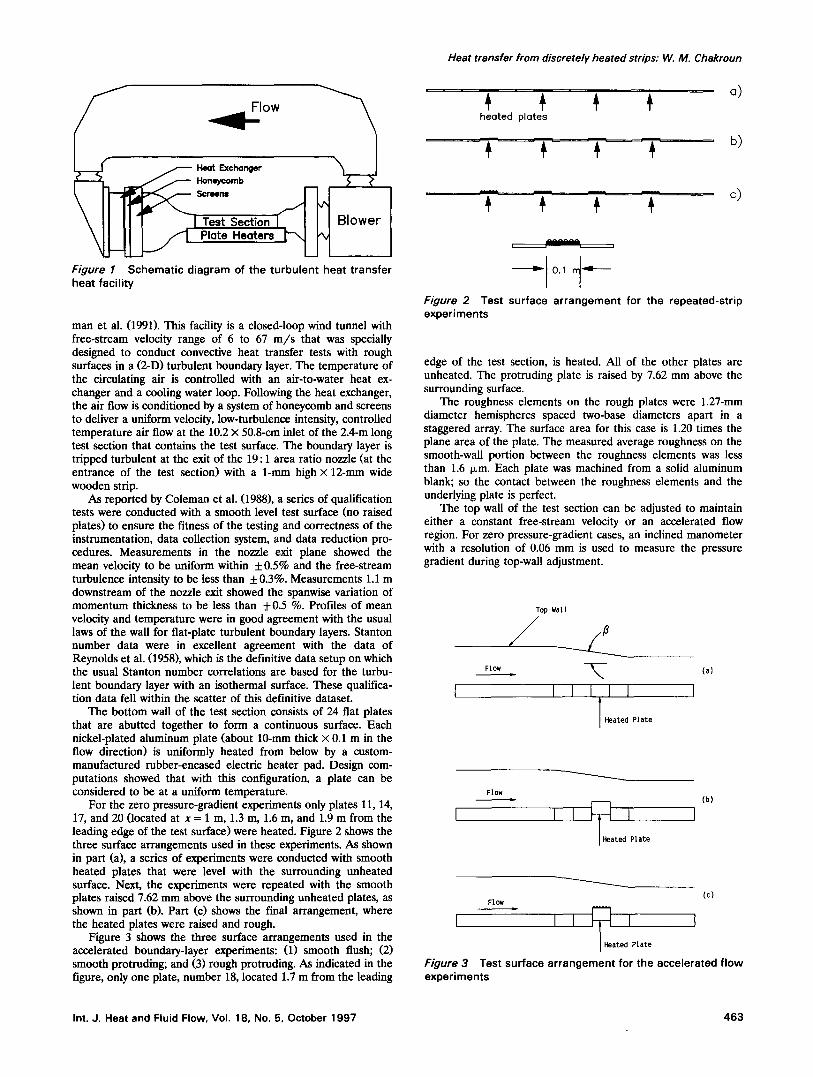
For the zero pressure-gradient experiments only plates 11, 14, 17, and 20 (located at x = 1 m, 1.3 m, 1.6 m, and 1.9 m from the leading edge of the test surface) were heated. Figure 2 shows the three surface arrangements used in these experiments. As shown in part (a), a series of experiments were conducted with smooth heated plates that were level with the surrounding unheated surface. Next, the experiments were repeated with the smooth plates raised 7.62 mm above the surrounding unheated plates, as shown in part (b). Part (c) shows the final arrangement, where the heated plates were raised and rough.
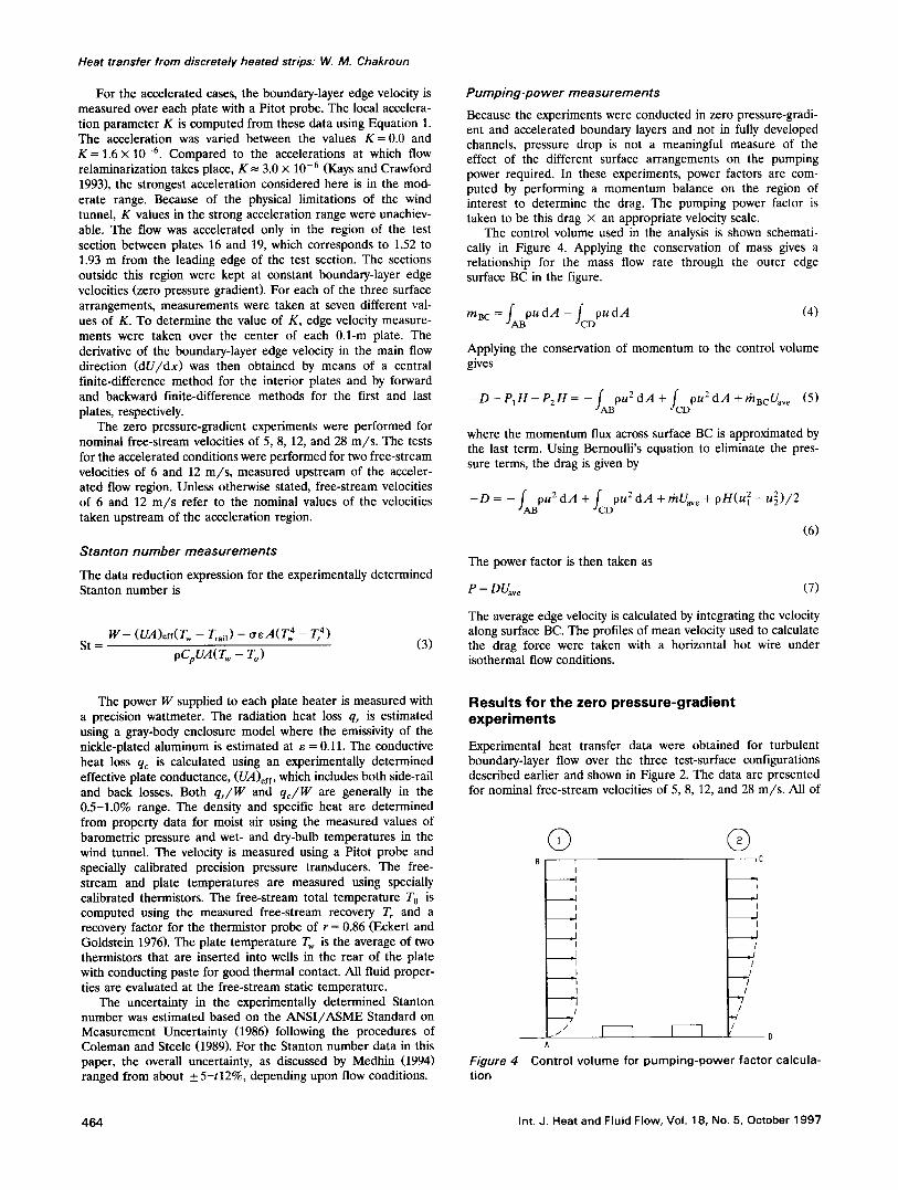
Figure 3 shows the three surface arrangements used in the accelerated boundary-layer experiments: (1) smooth flush; (2) smooth protruding; and (3) rough protruding. AS indicated in the figure, only one plate, number 18, located 1.7 m from the leading
Heat transfer from discretely heated strips: W. M. Chakroun
# # # # °) heoted plotes
b)
^ ^ ~ ^ ^ ^
i i
Figure 2 Test surface arrangement for the repeated-strip experiments
edge of the test section, is heated. All of the other plates are unheated. The protruding plate is raised by 7.62 mm above the surrounding surface.
The roughness elements on the rough plates were 1.27-mm diameter hemispheres spaced two-base diameters apart in a staggered array. The surface area for this case is 1.20 times the plane area of the plate. The measured average roughness on the smooth-wall portion between the roughness elements was less than 1.6 p.m. Each plate was machined from a solid aluminum blank; so the contact between the roughness elements and the underlying plate is perfect.
The top wall of the test section can be adjusted to maintain either a constant free-stream velocity or an accelerated flow region. For zero pressure-gradient cases, an inclined manometer with a resolution of 0.06 mm is used to measure the pressure gradient during top-wall adjustment.
Flow (a}
Top Wa% 1
J ____/ r,.
I I I I
T Heated Plate
Flow
~atedJPlate
(b)
(c) Flow
ated Plate Figure 3 Test surface arrangement for the accelerated flow experiments
Int. J. Heat and Fluid Flow, Vol. 18, No. 5, October 1997 463
Heat transfer from discretely heated strips: W. M. Chakroun
For the accelerated cases, the boundary-layer edge velocity is measured over each plate with a Pitot probe. The local accelera- tion parameter K is computed from these data using Equation 1. The acceleration was varied between the values K = 0.0 and K = 1.6 x 10 -6. Compared to the accelerations at which flow relaminarization takes place, K--- 3.0 x 10 -6 (Kays and Crawford 1993), the strongest acceleration considered here is in the mod- erate range. Because of the physical limitations of the wind tunnel, K values in the strong acceleration range were unachiev- able. The flow was accelerated only in the region of the test section between plates 16 and 19, which corresponds to 1.52 to 1.93 m from the leading edge of the test section. The sections outside this region were kept at constant boundary-layer edge velocities (zero pressure gradient). For each of the three surface arrangements, measurements were taken at seven different val- ues of K. To determine the value of K, edge velocity measure- ments were taken over the center of each 0.1-m plate. The derivative of the boundary-layer edge velocity in the main flow direction (dU/dx) was then obtained by means of a central finite-difference method for the interior plates and by forward and backward finite-difference methods for the first and last plates, respectively.
The zero pressure-gradient experiments were performed for nominal free-stream velocities of 5, 8, 12, and 28 m / s . The tests for the accelerated conditions were performed for two free-stream velocities of 6 and 12 m / s , measured upstream of the acceler- ated flow region. Unless otherwise stated, free-stream velocities of 6 and 12 m / s refer to the nominal values of the velocities taken upstream of the acceleration region.
Stanton number measurements
The data reduction expression for the experimentally determined Stanton number is
W - ( U i ) e f f ( T w - T r a i l ) - c r e A ( T 4 - Tr 4) St = (3)
oCpUA(Tw - To)
Pumping-power measurements
Because the experiments were conducted in zero pressure-gradi- ent and accelerated boundary layers and not in fully developed channels, pressure drop is not a meaningful measure of the effect of the different surface arrangements on the pumping power required. In these experiments, power factors are com- puted by performing a momentum balance on the region of interest to determine the drag. The pumping power factor is taken to be this drag z an appropriate velocity scale.
The control volume used in the analysis is shown schemati- cally in Figure 4. Applying the conservation of mass gives a relationship for the mass flow rate through the outer edge surface BC in the figure.
Applying the conservation of momentum to the control volume gives
- D - P , H - P 2 H = -- fABpU2dA + fcDPU2dA +rh,cUa.,¢ (5)
where the momentum flux across surface BC is approximated by the last term. Using Bernoulli's equation to eliminate the pres- sure terms, the drag is given by
- o = - + f cDou2dA +"Va o
(6)
The power factor is then taken as
P =DUav e (7)
The average edge velocity is calculated by integrating the velocity along surface BC. The profiles of mean velocity used to calculate the drag force were taken with a horizontal hot wire under isothermal flow conditions.
The power W supplied to each plate heater is measured with a precision wattmeter. The radiation heat loss qr is estimated using a gray-body enclosure model where the emissivity of the nickle-plated aluminum is estimated at e = 0.11. The conductive heat loss qc is calculated using an experimentally determined effective plate conductance, (UA)ef f, which includes both side-rail and back losses. Both qJW and qc/W are generally in the 0.5-1.0% range. The density and specific heat are determined from property data for moist air using the measured values of barometric pressure and wet- and dry-bulb temperatures in the wind tunnel. The velocity is measured using a Pitot probe and specially calibrated precision pressure transducers. The free- stream and plate temperatures are measured using specially calibrated thermistors. The free-stream total temperature T O is computed using the measured free-stream recovery T r and a recovery factor for the thermistor probe of r = 0.86 (Eckert and Goldstein 1976). The plate temperature T w is the average of two thermistors that are inserted into wells in the rear of the plate with conducting paste for good thermal contact. All fluid proper- ties are evaluated at the free-stream static temperature.
The uncertainty in the experimentally determined Stanton number was estimated based on the A N S I / A S M E Standard on Measurement Uncertainty (1986) following the procedures of Coleman and Steele (1989). For the Stanton number data in this paper, the overall uncertainty, as discussed by Medhin (1994) ranged from about + 5-t12%, depending upon flow conditions.
Results for the zero pressure-gradient experiments
Experimental heat transfer data were obtained for turbulent boundary-layer flow over the three test-surface configurations described earlier and shown in Figure 2. The data are presented for nominal free-stream velocities of 5, 8, 12, and 28 m/s . All of
Figure 4 tion
© Q B , ,C
I I _1 . [
I ' k _1 _ l
[ ' I _ /
I / "1 " /
I /
J . / /
h
Control vo lume for pumping-power factor calcula-
464 Int. J. Heat and Fluid Flow, Vol. 18, No. 5, October 1997
Heat transfer from discretely heated strips: W. M. Chakroun
80
70
60
J¢ 40
30
20
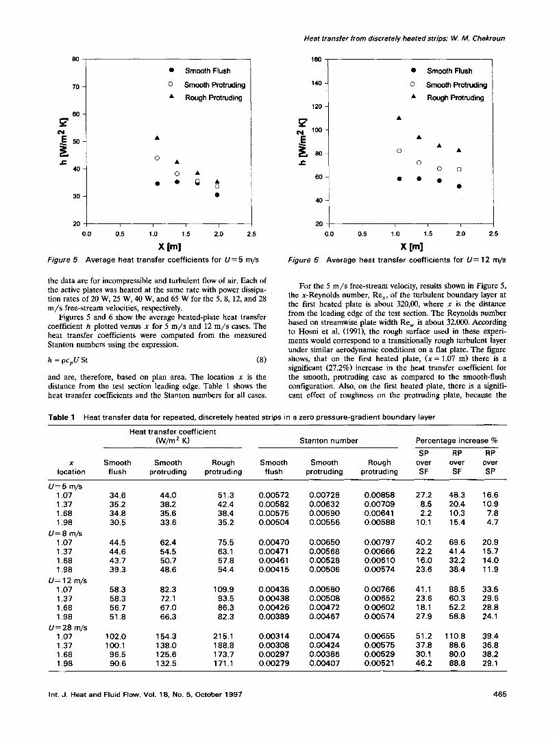
Figure 5
• Smooth Flush
o Smooth Protruding
• Rough Protruding
o
o • • • ~
I I I I
0.0 0.5 1.0 1.5 2.0 2.5
X [m] Average heat transfer coefficients for U= 5 m/s
160
140
120
~ 100
r',
60
40
2O 0.0
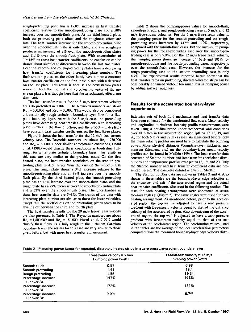
Figure 6
o
l Smooth Flush
o Smooth Protruding
• Rough Protruding
o o o
• •
0.5 1.0 1.5 2.0 2.5
X [m] Average heat transfer coefficients for U= 12 m/s
the data are for incompressible and turbulent flow of air. Each of the active plates was heated at the same rate with power dissipa- tion rates of 20 W, 25 W, 40 W, and 65 W for the 5, 8, 12, and 28 m/s free-stream velocities, respectively.
Figures 5 and 6 show the average heated-plate heat transfer coefficient h plotted versus x for 5 m/s and 12 m/s cases. The heat transfer coefficients were computed from the measured Stanton numbers using the expression.
h = pcpU St (8)
and are, therefore, based on plan area. The location x is the distance from the test section leading edge. Table 1 shows the heat transfer coefficients and the Stanton numbers for all cases.
For the 5 m/s free-stream velocity, results shown in Figure 5, the x-Reynolds number, Re x , of the turbulent boundary layer at the first heated plate is about 320,00, where x is the distance from the leading edge of the test section. The Reynolds number based on streamwise plate width Re,, is about 32,000. According to Hosni et al. (1991), the rough surface used in these experi- ments would correspond to a transitionally rough turbulent layer under similar aerodynamic conditions on a flat plate. The figure shows, that on the first heated plate, (x = 1.07 m) there is a significant (27.2%) increase in the heat transfer coefficient for the smooth, protruding case as compared to the smooth-flush configuration. Also, on the first heated plate, there is a signifi- cant effect of roughness on the protruding plate, because the
T a b l e 1 Heat transfer data for repeated, discretely heated strips in a zero pressure-gradient boundary layer
H e a t transfer coefficient (W/m 2 K) Stanton number
x Smooth Smooth Rough Smooth Smooth Rough location flush protruding protruding flush protruding protruding
Percentage increase %
SP RP RP over over over SF SF SP
U---- 5 m/s 1.07 34.6 44.0 51.3 0.00572 0.00728 0.00858 1.37 35.2 38.2 42.4 0.00582 0.00632 0.00709 1.68 34.8 35.6 38.4 0.00575 0.00590 0.00641 1.98 30.5 33.6 35.2 0.00504 0.00556 0.00588
U= 8 m/s 1.07 44.5 62.4 75.5 0.00470 0.00650 0.00797 1.37 44.6 54.5 6 3 . 1 0.00471 0.00568 0.00666 1.68 43.7 50.7 57.8 0.00461 0.00528 0.00610 1.98 39.3 48.6 54.4 0.00415 0.00506 0.00574
U=12 m/s 1.07 58.3 82.3 109.9 0.00438 0.00580 0.00766 1.37 58.3 72.1 93.5 0.00438 0.00508 0.00652 1.68 56.7 67.0 86.3 0.00426 0.00472 0.00602 1.98 51.8 66.3 82.3 0.00389 0.00467 0.00574
U=28 m/s 1.07 102.0 154.3 215.1 0.00314 0.00474 0.00655 1.37 100.1 138.0 188.8 0.00308 0.00424 0.00575 1.68 96.5 125.6 173.7 0.00297 0.00386 0.00529 1.98 90.6 132.5 171.1 0.00279 0.00407 0.00521
27.2 48.3 16.6 8.5 20.4 10.9 2.2 10.3 7.8
10.1 15.4 4.7
40.2 69.6 20.9 22.2 41.4 15.7 16.0 32.2 14.0 23.6 38.4 11.9
41.1 88.5 33.5 23.6 60.3 29.6 18.1 52.2 28.8 27.9 58.8 24.1
51.2 110.8 39.4 37.8 88.6 36.8 30.1 80.0 38.2 46.2 88.8 29.1
Int. J. Heat and Fluid Flow, Vol. 18, No. 5, October 1997 465
Heat transfer from discretely heated strips." W. /14, Chakroun
rough-protruding plate has a 17.8% increase in heat transfer coefficient relative to the smooth-protruding plate and a 50% increase over the smooth-flush plate. At the third heated plate, both the protruding plate effect and the roughness effect are less. The heat transfer increase for the smooth-protruding plate over the smooth-flush plate is only 2.6%, and the roughness produces an increase of 8% over the smooth-protruding plates and 11.4% over the smooth-flush plate. With uncertainties of 10-15% on these heat transfer coefficients, no conclusion can be drawn about significant differences between the last two plates. Both the smooth- and rough-protruding plates have a decreasing heat transfer coefficients for increasing plate number. The flush-smooth plates, on the other hand, have almost a constant heat transfer coefficient on the first three plates with a decrease on the last plate. This result is because the downstream plates reside on both the thermal and aerodynamic wakes of the up- stream plates. It is thought here that the aerodynamic effects are dominant.
The heat transfer results for the 8 m/s free-stream velocity are also presented in Table 1. The Reynolds numbers are about Re, = 500,000 and Re w = 50,000. This would also be considered a transitionally rough turbulent boundary-layer flow for a fiat- plate boundary layer. As with the 5 m/s case, the protruding plates have decreasing heat transfer coefficients with increasing plate number in the flow direction, and the smooth-flush plates have constant heat transfer coefficients on the first three plates.
Figure 6 shows the heat transfer for the 12 m/s free-stream velocity case. The Reynolds numbers are about Re, = 770,000 and Rew = 77,000. Under similar aerodynamic conditions, Hosni et al. (1991) would classify these conditions as borderline fully rough for a fiat-plate turbulent boundary layer. The results in this case are very similar to the previous cases. On the first heated plate, the heat transfer coefficient on the smooth-pro- truding plate is 41% larger than the one on the smooth-flush plate. The rough plate shows a 34% increase relative to the smooth-protruding plate and an 88% increase over the smooth- flush plate. By the third heated plate, the smooth-protruding plate has an 18% increase over the smooth-flush plate, and the rough plate has a 29% increase over the smooth-protruding plate and a 52% over the smooth-flush plate. The uncertainties in these heat transfer data are 5-8%. The trends of the data with increasing plate number are similar to those for lower velocities, except that the coefficients on the protruding plates seem to be leveling off between the third and fourth plate.
The heat transfer results for the 28 m/s free-stream velocity are also presented in Table 1. The Reynolds numbers are about Re x = 1,800,000 and Rew = 180,000. Hosni et al. (1991) would classify these flows as a fully rough in the turbulent fiat-plate boundary layer. The results for this case are very similar to those given before, but with more heat transfer enhancement.
Table 2 shows the pumping-power values for smooth-flush, smooth-protruding, and rough-protruding cases at 5 m/s and 12 m/s free-stream velocities. For the 5 m/s free-stream velocity, the pumping power for the smooth-protruding and the rough- protruding cases increases by 147% and 172%, respectively, compared with the smooth-flush cases. But the increase in pump- ing power for the rough-protruding case over the smooth-pro- truding case is only 9.9%. For the 12 m/s free-stream velocity, the pumping power shows an increase of 163% and 181% for smooth-protruding and the rough-protruding cases, respectively, over the smooth-flush case. However, the increase for the rough-protruding case to the smooth-protruding case is only 6.7%. The experimental results reported herein show that the heat transfer rates on protruding, discretely-heated strips can be considerably enhanced without too much loss in pumping power by adding surface roughness.
Resul ts for the acce lera ted boundary - l ayer e x p e r i m e n t s
Extensive sets of both fluid mechanics and heat transfer data have been collected for the accelerated flOW cases. Mean velocity and longitudinal turbulence intensity profile measurements were taken using a hot-film probe under isothermal wall conditions over all plates in the acceleration region (plates 17, 18, 19, and 20) for both 6 m/s and 12 m/s cases. As mentioned before, only the mean velocity profiles are used here to calculate the pumping power. More physical distances (boundary-layer thickness, mo- mentum thickness, etc.) on the boundary-layer mean velocity profiles can be found in Medhin (1994). The heat transfer data consisted of Stanton number and heat transfer coefficient distri- butions and temperature profiles over plates 18, 19, and 20. Only the Stanton number and heat transfer coefficient data are pre- sented herein. The complete dataset is given in Medhin.
The Stanton number data are shown in Tables 3 and 4. Also shown in these tables are the boundary-layer edge velocities at the entrances and exit of the accelerated region and the actual heat transfer coefficients discussed in the following section. The tests for each heating arrangement were conducted at seven top-wall angles 13 (Figure 3). The same angles were used for each heating arrangement. As mentioned before, prior to the acceler- ated region, the top wall is adjusted to have a zero pressure gradient with free-stream velocity equal to that of the entrance velocity of the accelerated region. Also downstream of the accel- erated region, the top wall is adjusted to have a zero pressure gradient with free-stream velocity equal to that of the exit velocity of the accelerated region. The acceleration values listed in the tables are the average of the local acceleration parameters computed from the measured boundary-layer edge velocity distri-
Table 2 Pumping-power factor for repeated, discretely heated strips in a zero pressure-gradient boundary layer
Freestream velocity= 5 m/s Freestream velocity= 12 m/s Pumping power (watt) Pumping power (watt)
Smooth flush 0.57 6.98 Smooth protruding 1.41 18.4 Rough protruding 1.55 19.64 Percentage increase 147% 163%
SP over SF Percentage increase 172% 181%
RP over SF Percentage increase 9.9% 6.7%
RP over SP
466 Int. J. Heat and Fluid Flow, Vol. 18, No. 5, October 1997
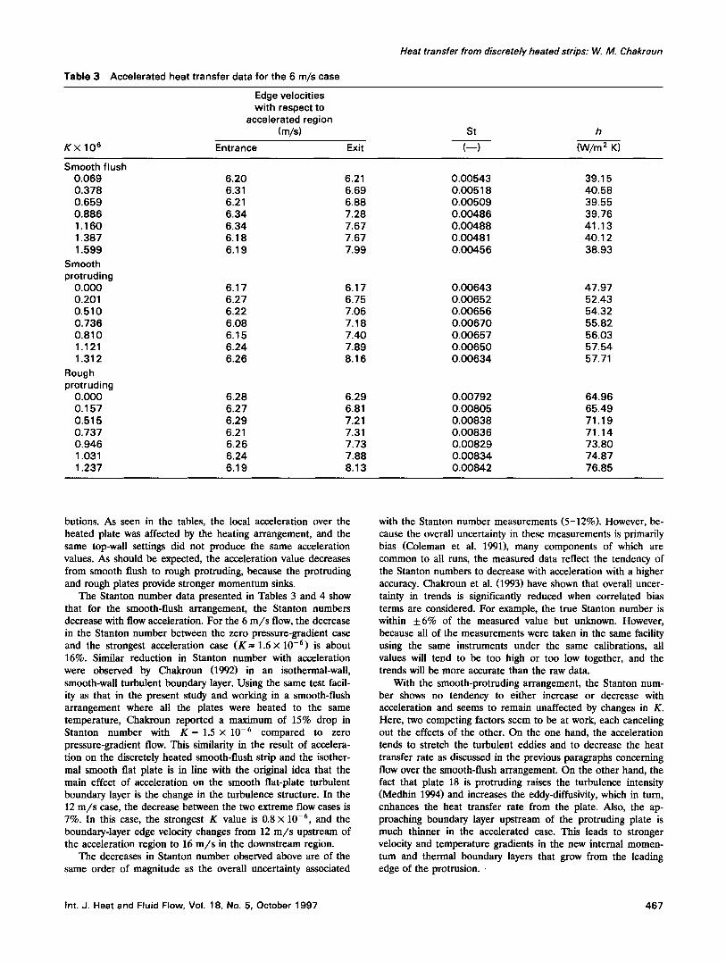
Table 3 Accelerated heat transfer data for the 6 m/s case
Heat transfer from discretely heated strips: W. M. Chakroun
Edge velocities with respect to
accelerated region (m/s)
K × 106 Entrance Exit
St h
(--) (W/m 2 K)
Smooth flush 0.069 6.20 6.21 0.00543 39.15 0.378 6.31 6.69 0.00518 40.58 0.659 6.21 6.88 0.00509 39.55 0.886 6.34 7.28 0.00486 39.76 1.160 6.34 7.67 0.00488 41.13 1.387 6.18 7.67 0.00481 40.12 1.599 6.19 7.99 0.00456 38.93
Smooth protruding
0.000 6.17 6.17 0.00643 47.97 0.201 6.27 6.75 0.00652 52.43 0.510 6.22 7.06 0.00656 54.32 0.736 6.08 7.18 0.00670 55.82 0.810 6.15 7.40 0.00657 56.03 1.121 6.24 7.89 0.00650 57.54 1.312 6.26 8.16 0.00634 57.71
Rough protruding
0.000 6.28 6.29 0.00792 64.96 0.157 6.27 6.81 0.00805 65.49 0.515 6.29 7.21 0.00838 71.19 0.737 6.21 7.31 0.00836 71.14 0.946 6.26 7.73 0.00829 73.80 1.031 6.24 7.88 0.00834 74.87 1.237 6.19 8.13 0.00842 76.85
butions. As seen in the tables, the local acceleration over the heated plate was affected by the heating arrangement, and the same top-wall settings did not produce the same acceleration values. As should be expected, the acceleration value decreases from smooth flush to rough protruding, because the protruding and rough plates provide stronger momentum sinks.
The Stanton number data presented in Tables 3 and 4 show that for the smooth-flush arrangement, the Stanton numbers decrease with flow acceleration. For the 6 m/s flow, the decrease in the Stanton number between the zero pressure-gradient case and the strongest acceleration case (K- -1 .6× 10 -6) is about 16%. Similar reduction in Stanton number with acceleration were observed by Chakroun (1992) in an isothermal-wall, smooth-wall turbulent boundary layer. Using the same test facil- ity as that in the present study and working in a smooth-flush arrangement where all the plates were heated to the same temperature, Chakroun reported a maximum of 15% drop in Stanton number with K = 1.5 × 10 -6 compared to zero pressure-gradient flow. This similarity in the result of accelera- tion on the discretely heated smooth-flush strip and the isother- mal smooth flat plate is in line with the original idea that the main effect of acceleration on the smooth flat-plate turbulent boundary layer is the change in the turbulence structure. In the 12 m/s case, the decrease between the two extreme flow cases is 7%. In this case, the strongest K value is 0.8 × 10 -6, and the boundary-layer edge velocity changes from 12 m/ s upstream of the acceleration region to 16 m/ s in the downstream region.
The decreases in Stanton number observed above are of the same order of magnitude as the overall uncertainty associated
with the Stanton number measurements (5-12%). However, be- cause the overall uncertainty in these measurements is primarily bias (Coleman et al. 1991), many components of which are common to all runs, the measured data reflect the tendency of the Stanton numbers to decrease with acceleration with a higher accuracy. Chakroun et al. (1993) have shown that overall uncer- tainty in trends is significantly reduced when correlated bias terms are considered. For example, the true Stanton number is within +6% of the measured value but unknown. However, because all of the measurements were taken in the same facility using the same instruments under the same calibrations, all values will tend to be too high or too low together, and the trends will be more accurate than the raw data.
With the smooth-protruding arrangement, the Stanton num- ber shows no tendency to either increase or decrease with acceleration and seems to remain unaffected by changes in K. Here, two competing factors seem to be at work, each canceling out the effects of the other. On the one hand, the acceleration tends to stretch the turbulent eddies and to decrease the heat transfer rate as discussed in the previous paragraphs concerning flow over the smooth-flush arrangement. On the other hand, the fact that plate 18 is protruding raises the turbulence intensity (Medhin 1994) and increases the eddy-diffusivity, which in turn, enhances the heat transfer rate from the plate. Also, the ap- proaching boundary layer upstream of the protruding plate is much thinner in the accelerated case. This leads to stronger velocity and temperature gradients in the new internal momen- tum and thermal boundary layers that grow from the leading edge of the protrusion. •
Int. J. Heat and Fluid Flow, Vol. 18, No. 5, October 1997 467
Heat transfer from discretely heated strips: W. M. Chakroun
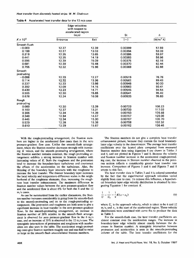
Table 4 Accelerated heat transfer data for the 12 m/s case
Edge velocities wi th respect to
accelerated region (m/s)
K x 10 6 Entrance Exit
St h
( - - ) (W/m 2 K)
Smooth flush - 0.003 12.37 12.39 0.00399 57.89
O. 199 12.27 13.03 0.00394 59.39 0.319 12.35 13,65 0,00386 59.97 0,441 12.35 14.19 0.00383 56.96 0.595 12,39 15,09 0,00375 62.16 0.681 12,39 15,48 0.00370 62.44 0.795 12,32 15.98 0,00369 62.88
Smooth protruding
- 0.098 12.29 12,27 0,00519 76.78 0.114 12.32 13.36 0.00562 89.43 0,237 12.33 13.98 0.00548 90,00 0.392 12.09 14.15 0,00563 93,41 0,430 12.23 14.71 0,00545 94,54 0.565 12.30 15.65 0.00541 95.42 0.678 12.24 16.08 0.00533 95.83
Rough protruding
0.000 12.30 12.39 0.00723 108.23 0.103 12.37 13.31 0.00733 117.03 0.306 12.34 14.39 0.00753 126.68 0.348 12.34 14.57 0.00757 129.08 0.445 12.34 15.30 0.00767 135.70 0.529 12.28 15.38 0.00758 132.32 0,610 12,29 15.87 0.00762 136.46
With the rough-protruding arrangement, the Stanton num- bers are higher in the accelerated flow cases than in the zero pressure-gradient flow case. Unlike the smooth-flush arrange- ment, where the Stanton number decreases strongly with increas- ing K values, and the smooth protruding arrangement, where the Stanton number remains constant, the rough-protruding ar- rangement exhibits a strong increase in Stanton number with increasing values of K. Both the roughness and the protrusion tend to increase the boundary-layer turbulence and counteract the effects of the acceleration on the turbulence. Also, the thinning of the boundary layer interacts with the roughness to increase the heat transfer. The thinner boundary layer increases the local velocity and temperature-difference scales in the neigh- borhood of the roughness elements, thus, increasing the rough- ness heat transfer enhancement. The maximum difference in Stanton number values between the zero pressure-gradient flow and the accelerated flow is about 6% for both the 6 and the 12 m / s cases.
As can be summarized from the earlier discussions, the Stan- ton number increases considerably in going from the smooth-flush to the smooth-protruding and on to the rough-protruding ar- rangement. The protrusion and roughness are both seen to give a significant increase in heat transfer in the zero pressure-gradient flows. In the smooth-protruding arrangement, an increase in Stanton number of 20% relative to the smooth-flush arrange- ment is observed for zero pressure-gradient flow in the 6 m / s case, and an increase of 35% is observed in the 12 m / s case. The synergistic interactions of protrusion and roughness with acceler- ation are also seen in the table. The accelerated rough-protrud- ing cases give Stanton numbers roughly one and one-half to twice as large as the smooth-flush unaccelerated Stanton numbers.
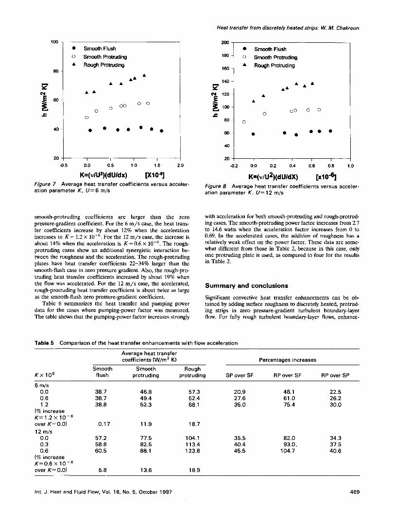
The Stanton numbers do not give a complete heat transfer enhancement picture, because they contain the local boundary- layer edge velocity in the denominator. The average heat transfer coefficients over the heated plate computed from measured Stanton number data using Equation 8 are shown in Tables 3 and 4, and are plotted in Figures 7 and 8. Because the velocity and Stanton number increase in the accelerated rough-protrud- ing case, the increase in Stanton number observed in the previ- ous section reflects a considerably greater heat transfer rate increase. Comparison of Figures 5 and 6 and Figures 7 and 8 attests to this fact.
The heat transfer data in Tables 3 and 4 is colored somewhat by the fact that the experimental approach velocities varied slightly from case to case. To remove this influence, a hypotheti- cal boundary-layer edge velocity distribution is obtained by inte- grating Equation 1 for constant K.
1 1 1 K ( x - x o ) (9)
U U0 v
where U o is the approach velocity, which is taken to be 6 and 12 m/s , and x o is the start of the accelerated region. These velocity distributions were combined with curve fits to produce the data in Table 5.
For the smooth-flush case, the heat transfer coefficients are almost constant over the acceleration ranges. The increase in boundary-layer edge velocity almost exactly balances the de- crease in Stanton number. A synergistic interaction between protrusion and acceleration is seen in the smooth-protruding column of the table. The heat transfer coefficients for the
468 Int. J. Heat and Fluid Flow, Vol. 18, No. 5, October 1997
100
80
60
J¢
40
20
-0.5
• Smooth Flush
o Smooth Protruding
• Rough Protruding
& &
0 0 0
0 0
• • • • • • •
I I I I
0.0 0.5 1.0 1.5 2.0
K=(vlU=)(dUldx) [XIO -e] Figure 7 Average heat t ransfer coefficients versus acceler- ation parameter K, U = 6 m/s
Heat transfer from discretely heated strips: W. M. Chakroun
200
180
160
140
E 12o
,oo .C
80 ©
60
40
20
-0.2
• Smooth Flush
o Smooth Protruding
• Rough Protruding
&&
O0 0 0 0
• • • • • •
I I I I I
0.0 0.2 0.4 0.6 0.8
K=(v/U2)ldUldX) [xl0 "6] 1.0
Figure 8 Average heat transfer coefficients versus acce le r - at ion parameter K, U= 12 m/s
smooth-protruding coefficients are larger than the zero pressure-gradient coefficient. For the 6 m / s case, the heat trans- fer coefficients increase by about 12% when the acceleration increases to K = 1.2 × 10 -6. For the 12 m / s case, the increase is about 14% when the acceleration is K = 0.6 × 10 -6. The rough- protruding cases show an additional synergistic interaction be- tween the roughness and the acceleration. The rough-protruding plates have heat transfer coefficients 22-34% larger than the smooth-flush case in zero pressure gradient. Also, the rough-pro- truding heat transfer coefficients increased by about 19% when the flow was accelerated. For the 12 m / s case, the accelerated, rough-protruding heat transfer coefficient is about twice as large as the smooth-flush zero pressure-gradient coefficient.
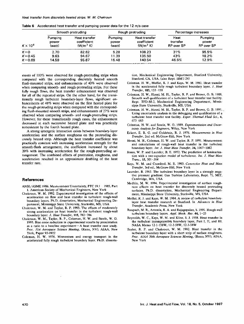
Table 6 summarizes the heat transfer and pumping power data for the cases where pumping-power factor was measured. The table shows that the pumping-power factor increases strongly
with acceleration for both smooth-protruding and rough-protrud- ing cases. The smooth-protruding power factor increases from 2.7 to 14.6 watts when the acceleration factor increases from 0 to 0.69. In the accelerated cases, the addition of roughness has a relatively weak effect on the power factor. These data are some- what different from those in Table 2, because in this case, only one protruding plate is used, as compared to four for the results in Table 2.
Summary and conclusions Significant convective heat transfer enhancements can be ob- tained by adding surface roughness to discretely heated, protrud- ing strips in zero pressure-gradient turbulent boundary-layer flow. For fully rough turbulent boundary-layer flows, enhance-
T a b l e 5 Comparison of the heat transfer enhancements wi th f low acceleration
Average heat transfer coefficients (W/m 2 K)
Smooth Smooth Rough K x 10 s flush protruding protruding
Percentages increases
SP over SF RP over SF RP over SP
6 m/s 0.0 38.7 46.8 57.3 20.9 48.1 22.5 0.6 38.7 49.4 62.4 27.6 61.0 26.2 1.2 38.8 52.3 68.1 35.0 75.4 30.0
(% increase K = 1.2 x 10 -6 over K=O.O) 0.17 11.9 18.7
12 m/s 0.0 57.2 77.5 104.1 35.5 82.0 34.3 0.3 58.8 82.5 113.4 40.4 93.0, 37.5 0.6 60.5 88.1 123.8 45.5 104.7 40.6
(% increase K = 0 . 6 × 10 -6 over K = 0.0) 5.8 13.6 18.9
Int. J. Heat and Fluid Flow, Vol. 18, No. 5, October 1997 469
Heat transfer from discretely heated strips." W. M. Chakroun
Table 6 Accelerated heat transfer and pumping-power data for the 12 m/s case
K × 10 s
Smooth protruding Rough protruding
Pumping Heat transfer Pumping Heat transfer power coefficient power coefficient (watt) (W/m 2 K) (watt) (W/m 2 K)
Percentageincreases
Heat Pumping transfer power
RP over SP RP over SP
K = 0 2.70 82.62 5,28 108.23 31% 95.5% K = 0.45 9.63 94.67 11.39 135.50 43% 18.2% K---- 0.69 14.59 95.87 16.48 140.54 46.5% 12.9%
ments of 110% were observed for rough-protruding strips when compared with the corresponding discretely heated smooth flush-mounted strips, and enhancements of 40% were observed when comparing smooth- and rough-protruding strips. For these fully rough flows, the heat transfer enhancement was observed for all of the repeated strips. On the other hand, for the transi- tionally rough turbulent boundary-layer flows, significant en- hancements of 48% were observed on the first heated plate for the rough-protruding strips when compared with the correspond- ing flush-mounted smooth strips, and enhancements of 27% were observed when comparing smooth- and rough-protruding strips. However, for these transitionally rough cases, the enhancement decreased at each successive heated plate and was practically nonexistent by the fourth heated plate.
A strong synergetic interaction exists between boundary-layer acceleration and the surface roughness on the protruding dis- cretely heated strip. Although the heat transfer coefficient was practically constant with increasing acceleration strength for the smooth-flush arrangement, the coefficient increased by about 20% with increasing acceleration for the rough-protruding ar- rangement. The combined effects of protrusion, roughness, and acceleration resulted in an approximate doubling of the heat transfer rate.
R e f e r e n c e s
ANSI/ASME 1986. Measurement Uncertainty, PTC 19.1--1985, Part 1. American Society of Mechanical Engineers, New York
Chakroun, W. M. 1992. Experimental investigation of the effects of acceleration on flow and heat transfer in turbulent rough-wall boundary layers. Ph.D. dissertation, Mechanical Engineering De- partment, Mississippi State University, Starkville, MS, USA
Chakroun, W. M. and Taylor, R. P. 1993. The effects of moderately strong acceleration on heat transfer in the turbulent rough-wall boundary layer. J. Heat Transfer, 115, 782-786
Chakroun, W. M., Taylor, R. P., Coleman, H. W. and Steele, W. G. 1993. Bias error reduction in experimental results by presentation as a ratio to a baseline experiment--A heat transfer case study. Proc. 31st Aerospace Science Meeting, (Reno, NV), AIAA, New York, Paper 93-0922
Coleman, H. W. 1976. Momentum and energy transport in the accelerated fully rough turbulent boundary layer. Ph.D. disserta-
tion, Mechanical Engineering Department, Stanford University, Stanford, CA, USA, (also Rept. HMT-24)
Coleman, H. W., Moffat, R. J. and Kays, W. M. 1981. Heat transfer in the accelerated fully rough turbulent boundary layer. J. Heat Transfer, 103, 153-158
Coleman, H. W., Hosni, M. H., Taylor, R. P. and Brown, G. B. 1988. Smooth wall qualification of a turbulent heat transfer test facility. Rept. TFD-88-2, Mechanical Engineering Department, Missis- sippi State University, Starkville, MS, USA
Coleman, H. W., Hosni, M. H., Taylor, R. P. and Brown, G. B. 1991.. Using uncertainty analysis in the debugging and qualification of a turbulent heat transfer test facility. Exper. Thermal Fluid Sci., 4, 673-683
Coleman, H. W. and Steele, W. G. 1989. Experimentation and Uncer- tainty Analysis for Engineers, Wiley, New York
Eckert, E. R. G. and Goldstein, R. J. 1976. Measurements in Heat Transfer, 2nd ed. McGraw-Hill, New York
Hosni, M. H., Coleman, H. W. and Taylor, R. P. 1991. Measurement and calculations of rough-wall heat transfer in the turbulent boundary layer. Int. J. Heat Mass Transfer, 34, 1067-1082
Jones, W. P. and Launder, B. E. 1972. The prediction of laminariza- tion with a two-equation model of turbulence. Int. J. Heat Mass Trans., 15, 301-314
Kays, W. M. and Crawford, M. E. 1993. Convective Heat and Mass Transfer, 3rd ed., McGraw-Hill, New York
Launder, B. 1963. The turbulent boundary layer in a strongly nega- tive pressure gradient. Gas Turbine Laboratory, Rept. 71, MIT, Cambridge, MA, USA
Medhin, M. W. 1994. Experimental investigation of surface rough- ness effects on heat transfer for discretely heated protruding surfaces. Ph.D. dissertation, Mechanical Engineering Depart- ment, Mississippi State University, Starkville, MS, USA
Moffat, R. J. and Kays, W. M. 1984. A review of turbulent boundary- layer heat transfer research at Stanford. In Advances in Heat Transfer, Academic Press, New York
Raupach, M. R., Antonia, R. A. and Rajagopalan, S. 1991. Rough-wall turbulent boundary layers. Appl. Mech. Rev. 44, 1-25
Reynolds, W. C., Kays, W. M. and Kline, S. J. 1958. Heat transfer in the turbulent incompressible boundary layer, Part I, II, and III, NASA Memo 12-1-158W, 12-2-58W, 12-3-58W
Taylor, R. P. and Chakroun, W. M. 1992. Heat transfer in the turbulent boundary layer with a short strip of surface roughness. Proc. AIAA 30th Aerospace Sciences Meeting, (Reno, NV), AIAA, New York
470 Int. J. Heat and Fluid Flow, Vol. 18, No. 5, October 1997
Copyright © 2022 FDOKUMEN