Heat Recovery from Compost - NSWAI
81
By MATT SMITH and JOHN ABER Heat Recovery from Compost A Guide to Building an Aerated Static Pile Heat Recovery Composting Facility
-
Upload
khangminh22 -
Category
Documents
-
view
3 -
download
0
Transcript of Heat Recovery from Compost - NSWAI

By MATT SMITH and JOHN ABER
Heat Recovery from Compost A Guide to Building an Aerated Static Pile Heat Recovery Composting Facility

HEAT RECOVERY FROM COMPOST: A Guide to Building an Aerated Static Pile Heat Recovery Composting Facility
2
Table of Contents - Heat Recovery from CompostExecutive Summary .......................................................................................................................................... 3
Technology Overview ....................................................................................................................................... 3
Aerobic Heat Production vs. Anaerobic Biogas Production ........................................................3 Heat Production from Compost ...................................................................................................5 Heat Production from Compost ...................................................................................................6 Acrolab's Isobar Heat Pipe Technology ........................................................................................7 Agrilab's Technologies, LLC Heat Recovery System ....................................................................8 The Value of Heat
Origins of the UNH Project ............................................................................................................................ 10
Planning and Sizing the Facility to Match Operational Demands ......................................................... 11
Feedstock parameters ....................................................................................................................11 Assess Current Hot Water Demand and Location ........................................................................11 Residence Time of Compost within Facility .................................................................................11 Sizing the Facility ..........................................................................................................................12 Areation Floor Design ...................................................................................................................12 Facility Location ............................................................................................................................16
Building a Heat-Recovery Composting Facility ......................................................................................... 17
Ground Prep ..................................................................................................................................17 Underground Slab and Concrete Wall Preparation .....................................................................18 Pouring Concrete Walls .................................................................................................................19 Insulating the Concrete Slab and Setting up the Aeration Ductwork .........................................25 Structural Support (Joints and Pad Reinforcement) ....................................................................27 Installating the Aeration Channels ...............................................................................................28 Pouring the Slab and Finishing tle Composting Floor .................................................................33 Prepping and Pouring the Internal Concrete Apron ....................................................................39 Prepping and Pouring the External Concrete Apron ...................................................................39 Installating the Leachate Network/Prepping & Pouring the Mechanical Room Floorls .............40 Raising the Building ......................................................................................................................41 Setting up the Mechanical Room ..................................................................................................42 Aeration Lines ...............................................................................................................................42 Installating Agrilab Technologies Isobar Heat-Pipe Unit ............................................................46 Installing the Fan Speed and Time Controllers ............................................................................54 Setting up the Aeration Schedule for Heat Recovery ...................................................................55 Testing and Insulating the System ................................................................................................55

HEAT RECOVERY FROM COMPOST: A Guide to Building an Aerated Static Pile Heat Recovery Composting Facility
3
AuthorsMatthew M. Smith, University of New Hampshire Doctoral Student in Natural Resources Contact: [email protected]. John Aber, University of New Hampshire Professor in Natural Resources Contact: [email protected]
Manuscript Design & Edits by UNH Cooperative Extension ~ Holly Young and Siobhan Craig
Suggested CitationSmith, M. and Aber, J. 2014. Heat Recovery from Compost: A guide to building an aerated static pile heat recovery composting facility. UNH cooperative Extension June 2014
(Shown on the front cover: an experimental compost batch with a temperatuer probe.)
The University of New Hampshire Cooperative Extension is an equal opportunity educator and employer. University of New Hampshire, U.S. Department of Agriculture and N.H. counties cooperating.
Cost of the UNH Heat-Recovery Composting Facility ............................................................................. 59
Conclusion.......................................................................................................................................................... 59
Appendix 1: ........................................................................................................................................................ 62Appendix 2: ........................................................................................................................................................ 65Appendix 3: ........................................................................................................................................................ 67Appendix 4: ........................................................................................................................................................ 68Appendix 5: ........................................................................................................................................................ 69Appendix 6: ........................................................................................................................................................ 74Appendix 7: ........................................................................................................................................................ 75Appendix 8: ........................................................................................................................................................ 76Appendix 9: ........................................................................................................................................................ 77
By MATT SMITH and JOHN ABER
The focus of this report is to describe the process of building a heat-recovery composting facility using the aerated static pile (ASP) method, with Agrilab Technologies, LLC Isobar® Heat Pipe Transfer System. In describing this process, a technology review will be presented, followed by detailed information on facility design, specific materials used, cost of the University of New Hampshire (UNH) facility, and cost-saving strategies/considerations for those wanting to install this type of system on their site. Although the primary focus of the UNH facility is research for traditional-sized organic dairies in New England, many of the structural designs, materials list, and cost-saving strategies, will be the same for farmers (organic or conventional) and compost operators wanting to build this type of facility on their site. More specifically, this type of system could be applied to all types of wastes being composted aerobically, whether animal, biosolids, municipal or food. This report can also be used for those considering just an ASP compost facility without the isobar heat exchange unit, as that system can be easily added and attached to the aeration system at a later point, should that be desired.
The ultimate goal of this report is to provide enough detailed information that farmers or compost operators could design their own systems, reducing the amount of time and money that would otherwise be spent on engineering and consulting costs. The cookbook-style descriptions, along with the materials/cost list (Appendix 1) also allow operators to purchase significant portions of the system without having to employ outside contractors, potentially leading to significant cost savings. This report may be used to answer many questions farmers or compost operators
Heat Recovery from Compost A Guide to Building an Aerated Static Pile Heat Recovery Composting Facility
Executive Summarymay have about the technology and whether it is appropriate for their sites. This report will also answer questions policy makers in municipalities may have regarding this type of composting operation and answer many technology and cost questions that are pertinent to loan agencies and investors considering funding this type of operation. The reader is encouraged to reference portions or even the entire report to address these issues to expedite the often timely design and funding portions of these types of projects.
Technology OverviewAerobic Heat Production vs. Anaerobic Biogas Production
An important point to make is that this technology involves aerobic composting, where heat, not biogas (methane - CH4), is being captured and utilized. In this type of aerobic system, CH4 production from lack of oxygen (anaerobic) is an economic loss, representing material that could have been decomposed aerobically. When anaerobic conditions form, the aerobic microbial community, which uses oxygen in its highly efficient metabolic pathway, is replaced by an anaerobic community. These anaerobic microbes use other terminal electron acceptors (nitrate – NO3
-, sulfate – SO42-,
carbon dioxide – CO2, sulfur – S, etc.) that have smaller reduction potentials when compared to oxygen, resulting in a lower energy yielding metabolic system that produces less energy per unit of biomass (Schlesinger 1997). The lower metabolic energy results in only a partial breakdown of the biomass, where intermediates (short-chain fatty acids, alcohols, CO2, hydrogen - H2, ammonia - NH3, SO4
2-, and alcohols) are formed and eventually converted by methanogenic bacteria to CH4, CO2, trace amounts of hydrogen sulfide (H2S) and other gases (Chen et al. 2010, Liebrand and Ling 2009,

HEAT RECOVERY FROM COMPOST: A Guide to Building an Aerated Static Pile Heat Recovery Composting Facility
5
Ciborowski 2001, Rynk et al. 1992). Because there is only a partial breakdown of the biomass, a tremendous amount of chemical energy is left in the bonds and escapes in large quantities through CH4 emissions as opposed to heat in an aerobic system. Unless the end goal is anaerobic digestion with biogas production/capture, this situation poses significant problems for compost operators wanting to explore heat extraction technologies.
They include:
1. Compost quality suffers greatly, as many of the intermediates, especially the fatty acids, can be phytotoxic to plants (Epstein 2011, Misra et al. 2003).
2. Intermediates and some end products (volatile fatty acids, NH3, and H2S) have foul odors (Chiumenti et al. 2005, Wright 2001, Rynk et al. 1992)
3. H2S is highly corrosive (Chen et al. 2010).
4. CH4 is 21 times more potent as a greenhouse gas than CO2 (US EPA 2013).
5. Minimal heat production eliminates the possibility for seed and pathogen destruction in that area of the pile (Misra et al. 2003).
6. With significantly less heat being produced and energy leaving the system through CH4 emissions (Themelis 2005), the efficiency of the heat- recovery system suffers greatly.
Although this paper is not focused on proper composting techniques to prevent anaerobic conditions, some of the general steps to avoid such conditions are to 1) maintain pile oxygen content between 10-18% during the active composting phase (Epstein 2011), and 1-5% during the maturation phase (Chiumenti et al. 2005), 2) ensure the feedstocks are properly mixed, 3) ensure the moisture content is not above 65%, 4) ensure the aeration system does not have any short circuits causing preferential air channels, and 5) have adequate drainage and a properly sloped aeration floor to prevent saturation under the piles. Individuals interested in more specific details concerning the science of the composting should reference the following:
1. Epstein, E. 2011. Industrial composting: Environmental engineering and facilities management. Boca Raton, FL: CRC Press. 334 p.
2. Haug, R.T. 1993. The practical handbook of compost engineering. Boca Raton, FL: Lewis Publishers, 717 pgs.
3. Rynk, R., van de Kamp, M., Willson, G.B., Singley, M.E., Richard, T.L., Kolega, J.J., Couin, F.R., Laliberty, L., Kay, D., Murphy, D.W., Hoitink, H.A.J., and Brinton, W.F. 1992. On-Farm Composting Handbook. Ithaca, NY: Northeast Regional Agricultural Engineering Service (NRAES-54). 186 p.
4. Chiumenti, A., Chiumenti, R., Diaz, L., Savage, G.M., Eggerth, L.L., and Goldstein, N. 2005. Modern composting technologies. Emmaus, PA: JG Press. 111 p.

HEAT RECOVERY FROM COMPOST: A Guide to Building an Aerated Static Pile Heat Recovery Composting Facility
6
Heat Production from Compost
The bio-oxidation of organic material that occurs during composting is an exothermic reaction that continually releases heat, and can be represented by the equation below (Figure 1).
In a compost pile, temperatures will go from ambient → mesophilic → thermophilic → mesophilic → ambient (Epstein 2011). While the exact range for what is qualified as mesophilic or thermophilic varies within the composting world, a general range is 50-1100F for mesophilic and > 1100F for thermophilic. Following pile formation, temperatures will often increase sharply, and reach 130-1400F within the first few days (Figure 2).
Figure 2: Compost Temperature over Compost Age for UNH Experimental Batch 2
Figure 1: Basic Formula for Aerobic Composting

HEAT RECOVERY FROM COMPOST: A Guide to Building an Aerated Static Pile Heat Recovery Composting Facility
7
If heat is not removed, temperatures will increase to the point where the microbes start dying off (≈ > 1500F). In this thermophilic stage, oxygen demand and heat production are highest, as the microbes target and metabolize the most easily digestible materials first (starches, sugars and fats) (Epstein 2011, Rynk et al. 1992). During this stage, the amount of aeration needed for heat removal can be more than 10x the requirement for microbial oxygenation (Rynk et al. 1992). As the composting process continues, the quantity of easily digestible compounds decreases, leaving more difficult substances to process (proteins, cellulose and lignin). At this point, the cumulative metabolic rate (and microbial population) plateaus and begins to decline. As microbial levels decline, so does the pile temperature (Epstein 2011, Chiumenti et al. 2005). With heat extraction as a goal, maintaining pile temperatures between 140-1500F and prolonging the point of plateau and temperature decline are two strategic goals for the operator. Although one may think that maintaining pile temperatures in excess of 1500F would increase the heat recovery from the system that method would actually cause a boom and bust cycle, where the microbes would be subject to temperatures in which they could no longer survive. Although the heat exchange system would perform well during this short phase, the long term heat recovery would suffer, as the heat producers (microbes) would be sacrificed for this temporary gain. Achieving maximum heat production and heat recovery requires the provision of an optimal microbial living environment, where they can thrive and reproduce. Some basic guidelines for optimal composting are:
1. Mixed feedstocks have a combined carbon-to- nitrogen (CN) ratio of 27:1-30:1 (Epstein 2011)
2. Moisture content maintained between 50-60% (Epstein 2011)
3. Oxygen content maintained between 10-18% within pile (Epstein 2011)
4. Maintain pile temperatures under 1500F through aeration and/or turning (Epstein 2011)
5. Free air space should be 35-50% (Chiumenti et al. 2005)
6. pH of 5.5 – 8.0 (Chiumenti et al. 2005)
7. Particle size no larger than 1-3’’ (Chiumenti et al. 2005)
8. Absence of contaminants toxic to microbes (Chiumenti et al. 2005)
Provided the above conditions are met, optimal composting temperatures should be maintained throughout most of the composting process.
Heat Recovery from Compost Recovering heat from compost is typically accomplished through two different approaches. The first involves recirculating water or glycol through tubing buried within a compost pile or concrete slab. The systems using pipe buried within the pile are more suitable for backyard operations, where the time and labor consuming aspects of installing and removing the pipe during pile formation and breakdown, can be absorbed by an enthusiastic homeowner. This method is typically not suitable as a commercial practice where revenue is the goal, as it is labor/time intensive. Problems can also arise if too much heat is removed from the pile, and/or the replacement water is too cold. This scenario can inhibit microbial growth and crash the microbial population, causing putrid conditions. However, if managed properly, this can be a successful option for backyard operations. Readers should reference the following for this method.
1. Pain, I., and Pain, J. 1972. The methods of Jean Pain: Another kind of garden. Commite International Jean Pain, Hof ter Winkelen, Londerzeel, Belgium.
2. Gorton, S. 2012. Compost Power! Cornell Small Farms Program. [Internet]. Available from: <http://smallfarms.cornell.edu/2012/10/01/ compost-power/>.
The system involving buried pipe within a concrete pad is a significant improvement on pipe buried within a pile, as the time and labor aspects of installing and dismantling the pipe are avoided.

HEAT RECOVERY FROM COMPOST: A Guide to Building an Aerated Static Pile Heat Recovery Composting Facility
8
However, the addition of concrete increases the cost of the operation significantly, and is more suitable for commercial operations processing large amounts of biomass. As with the latter system, one has to be careful with how much heat is extracted from the slab, in addition to carefully monitoring the temperature of the makeup water. A Canadian composting facility made this error and was permanently shut down because of foul odors that originated from too much heated water being extracted from their concrete pad, resulting in a microbial crash and putrefaction of their feedstocks, which included fish waste. The aerobic microbial community crashed because the concrete slab cooled down too quickly, creating an unfavorable living environment. If less water were pulled from the system, this approach would have worked. However, there is risk when extracting heat from the concrete slab, as the slab should be considered part of the thermal mass of the pile. Pulling too much heat from one section of the pile (in this case the bottom) risks anaerobic and odorous conditions.
The second approach used to recover heat from a compost pile is to push (forced aeration) or pull (negative aeration) air through the pile. This is most commonly accomplished by placing compost on top of an aeration floor, where perforated PVC pipes are cast into concrete, covered by a perforated cover plate, which is then covered by 8’’ of woodchips. By mechanically moving air through the pile, the aerobic microbes receive needed oxygen, while excess heat is removed, both of which allow for a larger and healthier microbial population (Epstein 2011, Rynk et al. 1992). Heat recovery from a positive aeration system is one option, but has limited applications due to the difficulty in capturing the diffused heat across the pile. The amount of available heat is also limited, as only 13.4% of the heat generated within the pile is contained in the airflow (Themelis 2005). Early research utilizing this technology came from the New Alchemy Institute, where a winter greenhouse was warmed through compost vapor, which had been sent through a biofilter (Fulford 1986). Although limited to mostly horticultural applications, this method serves as a valuable tool for season extension and energy reduction for greenhouse and high tunnel growers in
cooler climates. Readers should reference the following for this method: 1. Fulford, B. 1986. The Composting Greenhouse at New Alchemy Institute: A Report on Two Years of Operation and Monitoring. New Alchemy Institute, Research Report No. 3.
2. City Soil <http://citysoil.org/>
A more effective method in capturing heat from a compost pile is through negative aeration. This method allows an operator to connect multiple aeration lines together and have a single chamber where the combined heated vapor can be directed. In some systems, this heated vapor is sent through a biofilter, where the contaminants are scrubbed and the heat and CO2 are diffused into a greenhouse. However, utilizing only heated airflow limits the available uses of the heat. To optimize heat recovery from a compost pile requires not only negative aeration, but the capture of the energy within the compost water vapor, which accounts for 63% of the energy balance of a pile (Themelis 2005). Furthermore, if this energy is used to heat water, the highest utility is gained, as the heated water can be used in multiple settings for multiple purposes. Agrilab Technologies, LLC developed such a system, by using Acrolab’s Isobar® Heat Pipe technology and the ASP composting method (Agrilab Technologies is a U.S.A. based vendor of the Acrolab Isobar system).
Acrolab’s Isobar® Heat Pipe Technology
Acrolab’s Isobar Heat Pipe is a two-phase super-thermal conductor that provides thermal uniformity across the pipe by immediately transferring heat evenly across the entire pipe (Acrolab 2013). In the most basic sense, the Isobar System is a giant heat exchanger that uses an extremely high-grade stainless steel evacuated pipe filled with a working refrigerant. When heat is applied to the evaporator side of the pipe, the refrigerant inside heats up and vaporizes. That vapor travels the length of the pipe and condenses on the cooler side, releasing the latent heat of condensation. After condensing, the condensate is returned to the warm end of the pipe through capillary action in a metallic wick contained within the isobar (Acrolab 2013). The beauty of this system is that there are no mechanical parts within the isobar (Figure 3).

HEAT RECOVERY FROM COMPOST: A Guide to Building an Aerated Static Pile Heat Recovery Composting Facility
9
Figure 3: Internal Workings of Acrolab's Isobar Heat Pipe (Acrolab 2013)
Agrilab Technologies, LLC Heat Recovery System
The Isobar Composting and Thermal Energy System developed by Agrilab Technologies, uses this technology, by utilizing the metabolic heat generated from aerobic composting and extracting it through negative aeration. Their system uses 6-12 Isobars, 30-60 ft in length, contained within a single unit that has a vapor chamber and a highly insulated bulk storage tank of water (number and length of isobars depends on monthly feedstock tonnage). The Isobars run the length of the unit, with roughly ten feet contained within the sealed bulk storage tank (Figure 4).
Figure 4: Diagram of UNH Isobar Heat Exchange System (Loughberry Manufacturing 2012)

HEAT RECOVERY FROM COMPOST: A Guide to Building an Aerated Static Pile Heat Recovery Composting Facility
10
The system operates by pulling heated vapor from the compost piles, through the aeration network, and into the vapor chamber containing the array of Isobars. The 125-1650F compost vapor is blown across the portion of Isobars located within the vapor chamber, where the water condenses on the cooler surface, transferring the latent heat of condensation to the pipe (≈2260 kJ/kg). The energy released to the pipe (which originated from the microbial metabolism), is used to vaporize the refrigerant within the pipe. The vapor within the Isobar travels through the pipe into the section of the unit contained within the highly insulated bulk storage tank of water. The cooler water in the tank causes the vapor within the pipe to condense, once again transferring the latent heat of condensation, only this time it is transferred from inside the pipe to the water in the bulk storage tank (Figure 4 and Figure 5). The now heated water (typically 100-1400F) can then be used for any application requiring hot water (radiant floor heating, aquaculture, greenhouse, preheater for an anaerobic digester, preheated for a standard hot water system, etc.). Current uses for this type of system can be found in Appendix 2.
Figure 5: Flow Diagram of Agrilab Technologies Heat Recovery System (Agrilab 2013)
As depicted in the figure above, the basic set up for this type of heat-extraction system involves an aeration floor, where perforated PVC pipes are cast into concrete. The pipe is then covered with a wooden cover plate, which is set ¼ - ½’’ below grade. A layer of woodchips is placed on top of the cover plate to prevent small particles from entering the aeration system. From here, compost is piled on top (no greater than 12 ft). Following pile formation, the compost is negatively aerated. The aeration channels are set up into multiple zones and are either hooked up to individual centrifugal fans or a single large fan with damper controls at each aeration zone. The heated exhaust vapor is pulled out of each zone sequentially, ensuring the Isobar heat exchange system is always being exposed to hot compost vapor.

HEAT RECOVERY FROM COMPOST: A Guide to Building an Aerated Static Pile Heat Recovery Composting Facility
11
The Value of Heat
Based on the four farms currently utilizing this system, it has been demonstrated that heat capture of over 1,000 btu/ton/hr over a 120 day composting period is possible (Agrilab Technologies 2013). If managing the system more intensively, heat capture of over 1,500 btu/ton/hr over a 60 day composting period is possible. From a research perspective, UNH plans on utilizing Agrilab’s system and perfecting the methods of heat recovery, to further increase the BTU extraction per ton of biomass and increase the overall economics of the system. Data will be made available in a series of follow-up reports.
Origins of the UNH ProjectThe UNH Heat-Recovery Composting Facility, located in Lee, NH at the UNH Organic Dairy Research Farm, originated three years ago over conversations about how to make the farm a more closed agroecosystem. To reach this goal, all initiatives would have to be profitable, replicable, and desirable for farmers in the region. A large component of these conversations involved reducing the fraction of the farm’s budget spent on energy. A second major component was addressing the farm’s less than desirable manure management, which was an anaerobic pile that would occasionally be spread on the fields. Although this is a common practice on many dairy farms throughout the region, it posed a significant problem for the university farm, which was organic and trying to become a closed agroecosystem. Because the stockpiled manure was not being composted aerobically, significant odors from anaerobic decomposition (primarily H2S and fatty acids), were originating from the pile. The manure piles were also emitting high levels of CH4 and leaching NH3 into an adjacent waterway. This not only posed an environmental problem, but also an economic problem, as the quality of the manure being spread on the fields was compromised through the loss of nitrogen, and the increased presence of phytotoxic fatty acids from the partial decomposition of the material. An unmanaged pile of manure also serves as a breeding ground for biting flies, which pose health concerns for the livestock (Campbell et al. 1993).
The initial solution to the manure management problem was to develop a passive aeration windrow system for the manure and bedding on the farm. The three windrows were 30’L*8’W*4’H. This type of system is very inexpensive and has proved to be successful in composting animal manures (Rynk et al. 1992). Cost savings to the farm were immediately seen by a reduction in material to be spread on the fields (reduction in fuel and labor), and a more stabilized form of nitrogen was being spread (organic N), reducing undesirable runoff. After a year of composting through passive aeration, UNH researchers and a private donor began discussing the possibility of building a heat-recovery composting facility using Agrilab’s Isobar heat pipe technology, to extract the metabolic heat from the microbes within the compost. The construction of such a facility would address two of the main roadblocks in the farm becoming a closed agroecosystem. At the time, only one other facility in the world (Diamond Hill Custom Heifers) was using this technology on a commercial level to extract heat from compost. Their facility (built in 2005) has 2000 heifers and processes 150 tons of compost every month. The UNH Organic Dairy Research Farm produces a fraction of that, at 65 tons per month. As with most composting projects, there are economics of scale that have to be considered. This technology has proven to work at larger operations, but has not been tested on small to mid-sized dairies with under 100 head. Because the farm represents a traditional sized organic dairy in New England, determining the economics of this type of operation was determined to be highly useful. Designs for the UNH facility began in May 2011, construction began August 2012 and the facility was completed in May 2013. For reference, the primary objectives of this research facility are to:
1. Test the technology and prove its economies for small-mid-sized organic dairies.
2. Compare various composting methods to increase the heat production of the system.
3. Compare various uses of the captured heat and determine utilization efficiency
An important point is that a majority of the studies,

HEAT RECOVERY FROM COMPOST: A Guide to Building an Aerated Static Pile Heat Recovery Composting Facility
12
especially under objectives 2 and 3, will be beneficial to any operator using this technology, regardless of whether they are in farming (organic or convention-al) or waste reduction (biosolids, municipal solid waste, food waste, etc.).
Planning and Sizing the Facility to Match Operational DemandsFeedstock Parameters
The first step in designing an ASP composting facility with Agrilab’s heat recovery unit is to determine feedstock quantity, along with the corresponding chemical and physical properties. In assessing feedstock quantity, the smallest of the heat-recovery systems from Agrilab Technologies require 60 yd3 of mixed feedstock per month (Agrilab Technologies 2013). For UNH, the average monthly feedstocks of manure, spent animal bedding, and waste hay is around 250 yds3 (roughly 65 tons of feedstock). An important point regarding the feedstock requirement is that the 60 yd3/month cutoff is 60 yd3 of properly mixed material in proportions suitable for maximum composting/heat recovery. This means analyzing the various feedstock’s CN ratio, moisture content, and bulk density. For optimal composting, you want a CN ratio of roughly 27-30:1, moisture content of 50-55%, and a bulk density of < 1100 lbs/yd3 (Rynk et al. 1992). From this analysis, one can determine whether they have enough biomass of mixed feedstock to achieve the optimal conditions needed for maximum heat recovery. In situations where there is a deficit of material, feedstock can either be brought in from off site, or in some cases stockpiled from other times of the year where that material is in excess. For instance, the carbon source for the UNH facility comes from the bedded pack barn, which is cleaned out only twice a year (May and November). Because it is only cleaned twice a year, the spent bedding has to be stockpiled. Likewise, during the summer months, manure is in shortage because the cows are out at pasture for > 8 hours a day. Excess manure is stored in small windrows to supplement the summer composting recipes. In assessing feedstock quantity, it is important to
realize that a deficit in nitrogen will slow down the composting process, reducing heat recovery, while too much nitrogen will increase temperatures too quickly and result in increased ammonia emissions and lower quality compost (Chiumenti et al. 2005, Rynk et al. 1992).
Assess Current Hot Water Demand and Location
After determining whether the farm has enough biomass (or can obtain enough biomass) in the optimal proportions, the next step is to assess the hot water demand on the farm, and whether the heat recovery unit is economical. From a practical standpoint, if one is already planning on building an ASP composting facility, the added cost of the heat-exchange unit is likely economical. Regardless, assessing the current farm energy demand is valuable as the heat-exchange unit can be sized accordingly, ensuring it is not overbuilt. For UNH, the cost of the farm’s heating and cooling needs is roughly $8,300/year. A majority of this cost originates from heating water to 180-1900F for the various milk sanitization processes that occur on the farm. As a consequence, the primary function of the heat-recovery unit for the UNH facility would be to temper the 500F well water entering the primary water boiler, which is currently being heated by both oil and electricity to achieve the high temperature required for sanitization in the milk house.
Residence Time of Compost within Facility
The next step in the planning phase is to determine the residence time the compost will be in the facility. In making this decision, it is important to consider whether the compost is to be cured in the facility, as that decision will require more space, due to slower turnover. In the case of the UNH facility, we decided to cure the compost in the facility, which was a decision made for research purposes (120 day residence time within facility). Although there are advantages to curing within a facility (faster due to forced aeration, less chance of contamination from seed, will not get saturated by rain), it requires a larger building and a much higher initial capital cost. A smart alternative would be to have a much shorter residence time within the facility, and cure the compost outside under a compost cover, which allows the material to

HEAT RECOVERY FROM COMPOST: A Guide to Building an Aerated Static Pile Heat Recovery Composting Facility
13
breathe, shed rain, prevent seed from entering, and is a fraction of the cost. Managing the system under a shorter residence time (if one has enough biomass) is also strategic from a heat-recovery and economic standpoint, as compost temperatures under this type of system peak during the first week of composting, and gradually decrease over the next few weeks. A shorter residence time would allow for heat extraction to continually occur during the highest heat producing periods of the composting process.
Sizing the Facility
With information on feedstock quantity, and the length of time it will spend in the facility, a total composting volume within the facility can be estimated. With UNH as an example, facility size was based on 250 yd3 of feedstock (manure, waste feed hay, and spent animal bedding) per month, and a compost residence time of 120 days. Because the facility would be loaded in monthly batches, the resulting facility would have to have four bays, each accommodating 250yd3/month. Assuming a pile height of 9 feet, the length and width of the composting floor can be determined based on a combination of site conditions and building design to get the needed volume. In our scenario, each bay would be 32’L*20’W*9’H (215 yd3/month). Although this is 35 yd3 short of the theoretical monthly maximum of feedstock, the facility was reduced in size from the original proposal to save cost (≈ $19,000), and to ensure that the facility would not be overbuilt.
After calculating the dimensions of the composting floor, extra footage has to be added for 1) the mechan-ical room, and 2) walkways within the composting room for exits (code). For UNH, the isobar unit go-ing into the mechanical room had dimensions of 30’L * 34.5’’W * 30’’H w/six isobars. In addition to the Isobar unit, extra space has to be added for the aera-tion pipe and the leachate system. In our scenario, the mechanical room ended up being 10 feet wide * 96 feet long. The composting floor also had an addition-al 8ft concrete apron for an internal walkway to the exits. In sizing a non-research facility, both the width of the mechanical room and the width of the internal
apron could have been reduced by 2 feet each. The UNH facility was intentionally built with extra width at these two locations to better accommodate larger groups visiting the facility.
With information on the size of the composting floor, mechanical room, walkways, and all other needed internal space, a total square footage can be estimated.
For UNH, the resulting facility was 96’L * 50’W * 22’H (4,800 ft2) (Appendix 3). The height of the building was based on the height of the tallest machine that may operate in the facility. For UNH, a clearance of 22 feet was needed to accommodate the dumping of material from the farm’s primary dump truck.
Although our facility was built to handle 215 yd3/month, with a 16 week residence time, a facility of the same size only housing the compost during the active period (≈ 3-4 weeks with this type of technology), could go from processing 215 yd3 (97 wet tons)/month to 860 yd3 (387 wet tons)/month. As mentioned earlier, the residence time the compost stays in the facility greatly affects the amount of biomass that can be processed. As a side note, the UNH facility will likely switch to a much shorter residence time and bring biomass from other UNH farms in the future, after the economic analysis has been completed for a facility handling just 215 yd3/month.
Aeration Floor Design
When designing the aeration floor, the successes and failures of past ASP floor designs were considered to ensure the piles would receive an optimal level of aeration across the entire distance of the pile. It is important to note that there is a decrease in oxygen provided to the pile as distance from the blower increases. For this reason, piles should not be longer than 50-75 feet (Rynk et al. 1992). At the UNH facility, aeration lines were 30 ft in length and were made of 4’’ PVC pipe, which fit within the general recommendation of aeration lines being 4-6’’ in diameter (Epstein 2011, Rynk et al. 1992). Each line had 1/2" diameter holes drilled 6'' on center to serve as the aeration holes.
The specific size of the holes is based on the diameter

HEAT RECOVERY FROM COMPOST: A Guide to Building an Aerated Static Pile Heat Recovery Composting Facility
14
of the pipe and the length of the run. A common formula used to calculate the aeration hole size is:
• Hole diameter = √[(D2*S)/(L*12)]• D = pipe diameter in inches• L= pipe length in feet• S= hole spacing (in)
From a graphical standpoint, this is represented in (Figure 6).
Although pipe with holes pre-drilled are available, it is best to purchase pipe and drill the holes on-site, following the cement pour. The purpose of drilling the holes after the pour is to have the ability to fill the pipes with water to prevent them from moving or floating during the concrete pour, and 2) prevent cement or other debris from getting into the aeration network during the construction process (both issues will be discussed in detail later).
After deciding on pipe diameter, length, hole spacing and hole size, the next step is to determine the spacing between the aeration pipe. Based on past ASP facilities, the general recommendation is to have aeration lines 3-4 feet apart (Epstein 2011). Closer spacing is recommended for materials with a higher
bulk density (manures, sludge, etc.), where higher oxygenation is required. At the UNH facility, aeration lines were set up with research trials in mind, and were spaced to accommodate treatment walls (Appendix 3). In a non-research facility, a uniform spacing within the 3-4’ range would have been used for all the aeration lines, compared to our facility, which had varying spacing.
In addition to having 4’ between each pair of aeration lines, the two externally located lines on either side of the facility, were cast 3’9’’ from the side walls (Figure 7).
Figure 6: Recommended Aeration Hole Diameter by Pipe Length for Aeration Holes 6 and 12’’ on Center
HEAT RECOVERY FROM COMPOST: A Guide to Building an Aerated Static Pile Heat Recovery Composting Facility
15
Figure 7: Aeration Floor Spacing at UNH Compost Facility
The reason to cast the first aeration line 3-4’ away from any wall is to prevent preferential air channels from the Coanda Effect, which is the tendency of moving air or liquid to attach itself to a nearby surface, and flow along it. When composting, walls too close to an aeration channel can serve as this surface and result in preferential airflow on the edges, causing more oxygen/faster decomposition on the sides and less oxygen/slower decomposition in the middle (Chiumenti et al. 2005). As the pile continues to decompose under this situation, the problem can become worse as pile slumping on the edges (from faster decomposition) will cause further preferential airflow in those locations, affecting the decomposition rate in the entire pile. Heat losses will not only occur from reduced decomposition in the
middle of the pile, but will also occur from cold air being sucked into the aeration system from the edges of the piles.
In addition to preventing the Coanda Effect from the side walls, there should also be a 3-4' aeration dead zone along the back mechanical wall. At the UNH facility the 3’ section of each aeration pipe closestto the back push wall did not have aeration holes, andhad a layer of concrete overtop instead of a cover plate(specifics will be discussed in detail in a later chapter) (Figure 8). As with the side walls, maintaining a 3-4’ aeration dead zone along this back wall was to prevent preferential air channeling, which can significantly reduce decomposition rates and heat recovery.

HEAT RECOVERY FROM COMPOST: A Guide to Building an Aerated Static Pile Heat Recovery Composting Facility
16
Figure 8: Aeration Floor Spacing for UNH Compost Facility
Cost Saving Tip # 1 - When deciding on the diameter of pipe, it is important to consider the total airflow requirements of the piles in relation to the pile length. Increasing from a 4’’ diameter PVC aeration channel to a 6’’ diameter channel has significant cost ramifications within the mechanical room of the facility in the thousands of dollars. Because the general aeration setup within the mechanical room of these systems involves two different size increases of PVC beyond what was cast in the aeration floor, a 6’’ PVC diameter aeration pipe would result in a 10’’ upper PVC aeration network within the mechanical room (specific UNH setup will be discussed intensively in following chapters). The increase in cost from 8’’ PVC to 10’’ is several hundred dollars per 10 foot length of pipe and fitting. If the UNH facility were replicated, the difference between 4’’ and 6’’ aeration lines would be at least $7,500 for just the PVC pipe, PVC fittings, flexible couplings, and centrifugal fans. The additional $7,500 for 6’’ vs. 4’’ is a very conservative number, as it does not include:
• Extra cost in shipping weight from the heavier components
• Extra labor in installing heavier and more bulky materials
• Extra sealant required
• Extra support structures (clevis hangers, pipe riser clamps, threaded rods, etc.)
• Contractor markup
A more realistic figure is around $10,000, when all of the other costs are included. This is especially true if the contractor purchased the materials, rather than the owner of the facility. The typical materials markup is over 25%, and represents the time a contractor has to: spec the material, find a vendor, order the material, front the cost, coordinate delivery/unloading/storage, and warranty the product. With the setup for a replicate facility to ours costing $7500 for a 4’’ aeration system, and $15,000 for a 6’’ system, an owner would pay at least an additional $1875 in contractor materials markup for the difference.
When considering cost-reducing strategies for the aeration setup, the primary objective is to ensure the facility is sized appropriately for the aeration demands of the material being composted. Smaller quantities of biomass, biomass with a lower bulk density (more fibrous or larger-sized material), or an aeration floor design with more lines but shorter in length, are all likely candidates for the 4’’ system.

HEAT RECOVERY FROM COMPOST: A Guide to Building an Aerated Static Pile Heat Recovery Composting Facility
17
• Ensure facility has adequate fire lanes on all sides and room for feedstock to be pulled out and piled should an internal smoldering fire occur and require breakup (code requirement for UNH facility).
In addition to the above recommendations, some specific location considerations for a heat-recovery facility using Agrilab’s Isobar System are:
• Ensure an adequate amount of room is available for delivery of Agrilab’s Isobar unit. Although it can be assembled on site, it is preferable to allow for enough room (minimum of 35’) to bring a completely finished unit to the site. Planning of delivery has to be done during the design process to ensure an adequate amount of room is available.
• Minimize distance from hot water production to hot water use. However, the underground insulated PEX pipe used to transfer the hot water from source to sink only loses 2-30F per 100 foot length if buried properly (OWFB 2013). Siting to reduce materials handling should take precedence over hot water end use.
• If planning on attaching a high tunnel or greenhouse, proper facility orientation is needed to ensure shading does not become a problem.
For reference, UNH sited the compost facility in a location that was closest to the feedstocks being composted. The reduction in time for materials handling/ease of use with the actual handling was determined to be the greatest factor in locating the facility (Figure 9).
Cost Saving Tip # 2 - A second cost-saving strategy would be for the owner to purchase all the PVC pipe, PVC fittings, sealant, centrifugal fans, flexible couplings, and support structures themselves, and just have them installed vs. contracted out. An important point to make is that this type of cost-saving strategy often comes with the knowledge that the contractor will not warranty the purchased products (standard practice if owner purchases the materials). Additionally, if there is an insufficient supply of materials during working hours, you will end up paying for workers to sit around and wait for your mistake. When purchasing materials to save cost, it is crucial to ensure that all the supplies (and in some cases, extra) are available to truly save cost. It is also important to sign a contract indicating that you will be purchasing materials XYZ, and that a markup will not be part of the deal, as some contractors will still charge a markup for materials purchased by the owner.
Facility Location
Specific information on the steps involved in siting a facility were omitted from this report, as each farm/compost operation will have tremendous variability with regard to proper location. For reference, detailed information on this topic can be found in The Industrial Composting Handbook (Epstein 2011) and Compost Yard Trimmings and Municipal Solid Waste (EPA 1994). However some basic guidelines are provided below:
• Avoid close proximity to neighbors unless a powerful air filtration system and biofilter are to be used. Single greatest cause of compost facility closures is due to nuisance claims (smell) from neighbors (Epstein 2011).
• Cost Saving Tip # 3 - Site facility as close to feedstocks as possible and try to have straight line transport of feedstocks to the composting bays. Minimizing feedstock handling time by siting and orienting the facility properly can save a tremen-dous amount of money (time, labor, fuel, etc.) with regard to materials handling.

HEAT RECOVERY FROM COMPOST: A Guide to Building an Aerated Static Pile Heat Recovery Composting Facility
18
Figure 9: Aerial View of UNH Organic Dairy Research Farm
Building a Heat-Recovery Composting FacilityThe following sections outline the step-by-step process of building the UNH heat-recovery composting facility, with recommendations to operators on design and the various cost-saving strategies that can be used at their sites. The reader is encouraged to reference the appendices for additional diagrams/specs and cost structure.
Ground Prep
Due to the high variability in soils and site conditions, ground preparation should be assessed by the contractor hired for that particular job. One important consideration that may be slightly different than standard practices is that composting facilities require more attention with regard to drainage. Because there is potential for pollution of waterways from all the nutrients coming from the compost/compost leachate (primarily nitrogen and phosphorus), all drainage from the site should go into a lagoon, or through some form of rain garden or a small portion of an agricultural field, before entering any waterway. At the UNH facility, drainage is directed into a portion
of an agricultural field, which eventually travels into a wetland, emptying into the Lamprey River. Ensuring nutrients are removed from the drainage at the UNH facility is of particular importance because the Lamprey River is designated as Wild and Scenic (Public Law 90-542; 16 U.S.C. 1271 et seq). Any potential eutrophication from the farm would generate unfavorable publicity. Therefore, careful management of any effluent is necessary.
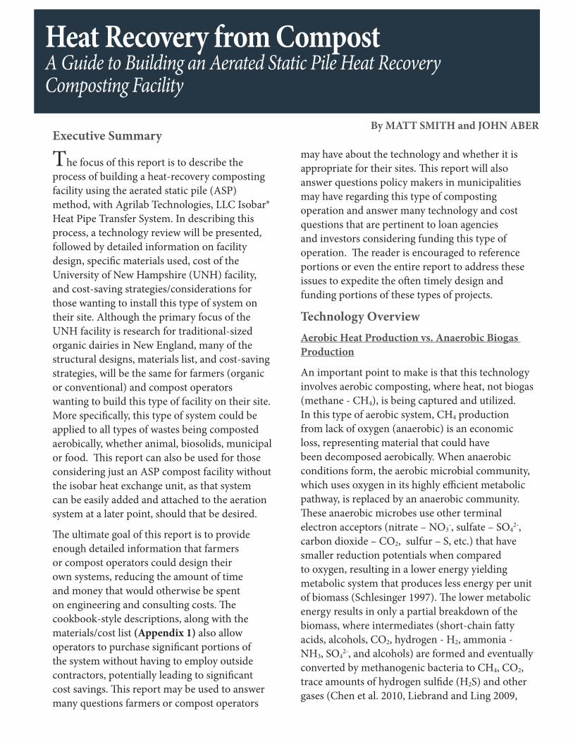
In addition to careful management of drainage coming from the facility, equal attention should be given to potential drainage to the facility. This point was not carefully analyzed at the UNH facility, resulting in a flood during a prolonged period of severe rain. Although there was no significant damage, it took several hours to clean up the flooded aeration lines, and pump the leachate tank. The compost pile that was curing in the facility also dropped in temperature significantly (1000F → 600F), due to an anaerobic base (Figure 10). Had this compost pile been in the early stages of the process, this issue would have been more severe, as the pile may have not recovered, due to clogged aeration lines. As a consequence of this event, the road leading to the facility was regraded and paved.
HEAT RECOVERY FROM COMPOST: A Guide to Building an Aerated Static Pile Heat Recovery Composting Facility
19
Figure 10: UNH Compost Facility Following Storm Event
Underground Slab and Concrete Wall Preparation
Underground cold and hot water lines [(1’’ PEX) Cresline HD-160] were installed prior to concrete forming. Both lines were set in a 5’0’’ trench between the milk house (location of water supply) and the future mechanical room (280 linear feet). The lines were 8’’ apart, and had 6’’ of sand surrounding them in all directions. Compacted backfill was put overtop. The 1’’ PEX cold water line was connected to a ¾’’ PEX line at the entrance of where the mechanical room would be located and led to a frost-proof post hydrant (Campbell CYH-5 Frost Proof Yard Hydrant) in the location of the main composting floor. A second ¾’’ cold water line was also installed off the first line to a freeze-proof post hydrant at the mid-point of the mechanical room. Both hydrant lines were buried below the frost line (4.5’) and were marked and taped to prevent soil from entering the pipe until future hook up.
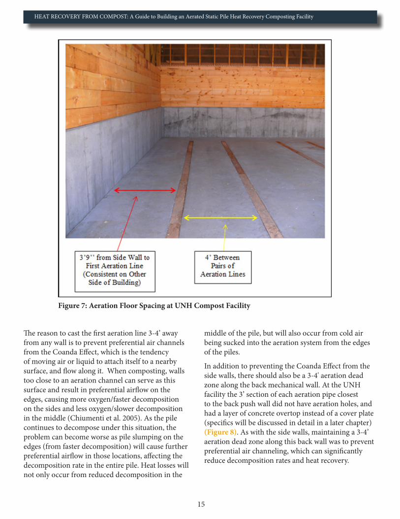
The 1’’ hot water supply and return lines were contained within a heavily insulated pipe (Uponor Pre-Insulated Pipe Systems ASTM Ecoflex Thermal Twin), which are often used for outside wood furnaces (Figure 11).
Figure 11: Insulated Underground PEX Pipe used Be-tween Compost Facility and Milk House
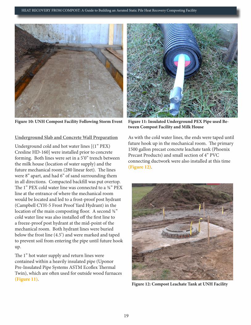
As with the cold water lines, the ends were taped until future hook up in the mechanical room. The primary 1500 gallon precast concrete leachate tank (Phoenix Precast Products) and small section of 4’’ PVC connecting ductwork were also installed at this time (Figure 12).
Figure 12: Compost Leachate Tank at UNH Facility
HEAT RECOVERY FROM COMPOST: A Guide to Building an Aerated Static Pile Heat Recovery Composting Facility
20
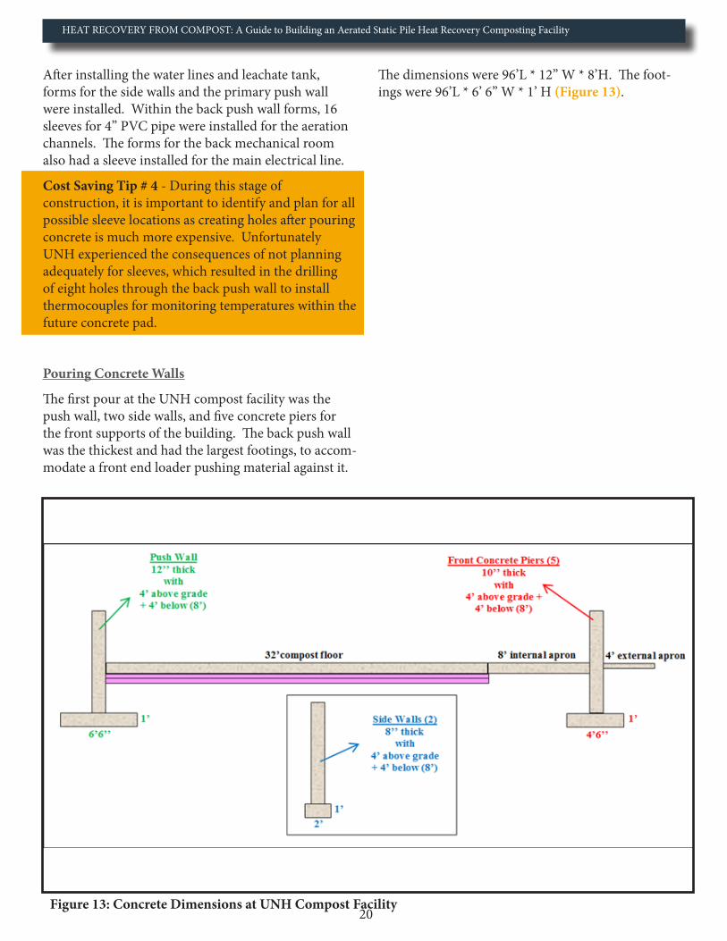
After installing the water lines and leachate tank, forms for the side walls and the primary push wall were installed. Within the back push wall forms, 16 sleeves for 4’’ PVC pipe were installed for the aeration channels. The forms for the back mechanical room also had a sleeve installed for the main electrical line.
Cost Saving Tip # 4 - During this stage of construction, it is important to identify and plan for all possible sleeve locations as creating holes after pouring concrete is much more expensive. Unfortunately UNH experienced the consequences of not planning adequately for sleeves, which resulted in the drilling of eight holes through the back push wall to install thermocouples for monitoring temperatures within the future concrete pad.
Pouring Concrete Walls
The first pour at the UNH compost facility was the push wall, two side walls, and five concrete piers for the front supports of the building. The back push wall was the thickest and had the largest footings, to accom-modate a front end loader pushing material against it.
Figure 13: Concrete Dimensions at UNH Compost Facility
The dimensions were 96’L * 12’’ W * 8’H. The foot-ings were 96’L * 6’ 6’’ W * 1’ H (Figure 13).

HEAT RECOVERY FROM COMPOST: A Guide to Building an Aerated Static Pile Heat Recovery Composting Facility
21
The two side walls had the dimensions of: 40’0’’ L * 8’’ W * 8’0’’ H. The footings were 40’0’’ L * 2’0’’ W * 1’0’’ H. The two side concrete piers in the front of the building had the dimensions of 2’6’’L * 10’’W * 8’0’’H, with footings of 2’6’’ L * 4’6’’W * 1’0’’H (Figure 13 and Figure 14). The three internal piers had dimension of 3’8’’ L * 10’’ W * 8’0’’H, with footings of 3’8’’L *4’6’’W * 1’0’’H (Figure 15). After the walls and piers cured, they were backfilled and brought to grade with compacted fill.
Figure 14: Sidewalls and Footings being poured at UNH Facility
Figure 15: Concrete Piers at the UNH Compost Facility

HEAT RECOVERY FROM COMPOST: A Guide to Building an Aerated Static Pile Heat Recovery Composting Facility
22
The second pour at the UNH facility was the wall and piers for the back mechanical room. The wall had dimensions of 32’3’’ L * 8’’ W * 6’H, with footings of 32’3’’ L * 2’0’’W * 1’0’’H. In addition to this wall, eight concrete piers were cast to continue the structural support for the back of the building. The eight concrete piers were 12’’ * 8’’ * 4’0’’ with footings of 2’0’’ * 1’0’’ (Figure 16 and Figure 17). After the wall and piers cured, they were backfilled and brought to grade with compacted fill.
Figure 16: Back Mechanical Room After First Concrete Pour

HEAT RECOVERY FROM COMPOST: A Guide to Building an Aerated Static Pile Heat Recovery Composting Facility
23
Figure 17: Back Mechanical Room Concrete Dimensions
Cost Saving Tip # 5
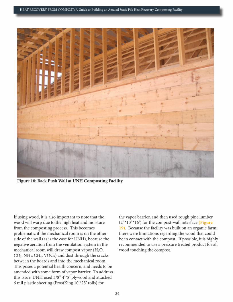
When looking at the amount of concrete poured for the UNH facility (≈ 225 yd3 total), it is easy to see that it was quite costly (Appendix 4). One method UNH used to save cost was to use wood for the remaining 5 ½ feet of wall needed for the three internal sides of the building (reduced concrete requirement by 30 yd3) (Figure 18). Although this strategy saves cost up front, it also results in a portion of wall that will need replacing at some point in the future. For reference, Diamond Hill also used this strategy and has not needed to replace their wall timbers after eight years of composting.
HEAT RECOVERY FROM COMPOST: A Guide to Building an Aerated Static Pile Heat Recovery Composting Facility
24
Figure 18: Back Push Wall at UNH Composting Facility
If using wood, it is also important to note that the wood will warp due to the high heat and moisture from the composting process. This becomes problematic if the mechanical room is on the other side of the wall (as is the case for UNH), because the negative aeration from the ventilation system in the mechanical room will draw compost vapor (H2O, CO2, NH3, CH4, VOCs) and dust through the cracks between the boards and into the mechanical room. This poses a potential health concern, and needs to be amended with some form of vapor barrier. To address this issue, UNH used 3/8’’ 4’*8’ plywood and attached 6 mil plastic sheeting (FrostKing 10’*25’ rolls) for
the vapor barrier, and then used rough pine lumber (2’’*10’’*16’) for the compost-wall interface (Figure 19). Because the facility was built on an organic farm, there were limitations regarding the wood that could be in contact with the compost. If possible, it is highly recommended to use a pressure treated product for all wood touching the compost.

HEAT RECOVERY FROM COMPOST: A Guide to Building an Aerated Static Pile Heat Recovery Composting Facility
25
Figure 19: Vapor Barrier on Back Push Wall at UNH Composting Facility
Cost Saving Tip # 6
A second major cost saving strategy that could be utilized for those installing a high-tension fabric structure, would be to use interlocking concrete waste blocks for the side walls, instead of pouring concrete (Figure 20).
Figure 20: Example Compost Setup Utilizing a High-Tension Fabric Structure with Waste Block Walls (ClearSpan 2013)
HEAT RECOVERY FROM COMPOST: A Guide to Building an Aerated Static Pile Heat Recovery Composting Facility
26
Waste blocks come in various sizes, with the most common for this purpose being 6’L*2’W*2’H and weighting 3600 lbs per block. If buying a trailer load, cost per block is often under $75 per delivered block. Cost savings are often recognized through a reduction in ground preparation associated with the walls and footings, along with a reduction in labor cost associated with forming and pouring the walls. This is especially true if the site has ledge. Had UNH built a similarly-sized fabric structure with waste block side walls, the total materials cost of the interlocking concrete blocks would have been roughly $4,225 ($65/ block * 65 blocks).
If waste blocks are used, it is recommended to utilize blocks for just the side walls, and not the back push wall that contains the aeration channels and isobar unit behind it. The primary reason why the push wall should be poured is that you want a structurally sound wall that will not move, as any movement could break seals in the aeration network and in the worst case scenario, damage the heat-exchange unit. A second reason to avoid blocks for the wall against the mechanical room is due to compost vapors being drawn through the joints of the blocks and into the mechanical room. Because the mechanical room requires ventilation (code), an improperly sealed wall adjacent to compost could actually draw compost vapor through the wall and into the working environment. As with the previous example with the wooden walls, the negative aeration from the air filtration system will pull air into the mechanical room, and if any cracks exist in that back push wall, compost vapor will be pulled through.
Insulating the Concrete Slab and Setting up the Aeration Ductwork
One of the most important steps in building a heat-recovery composting facility is ensuring enough insulation is put underneath the concrete slab, as this cannot be remedied afterward. The goal of insulating the concrete slab is to prevent cold soil temperatures from robbing energy from the slab and aeration ductwork. Insulating also reduces condensation from forming on the bottom of the slab at the hot-cold interface. When any heat within this type of composting system is lost, or moisture condenses on any material other than the heat exchanger, it
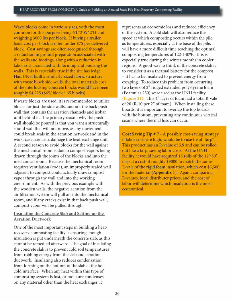
represents an economic loss and reduced efficiency of the system. A cold slab will also reduce the speed at which composting occurs within the pile, as temperatures, especially at the base of the pile, will have a more difficult time reaching the optimal composting temperatures of 122-1400F. This is especially true during the winter months in cooler regions. A good way to think of the concrete slab is to consider it as a thermal battery for the compost – it has to be insulated to prevent energy from escaping. To reduce this problem from occurring, two layers of 2’’ ridged extruded polystyrene foam (Foamular 250) were used at the UNH facility (Figure 21). This 4’’ layer of foam had a total R-vale of 20 (R-10 per 2’’ of foam). When installing these boards, it is important to overlap the top boards with the bottom, preventing any continuous vertical seams where thermal loss can occur.
Cost Saving Tip # 7 - A possibly cost-saving strategy if labor costs are high, would be to use Insul-Tarp®. This product has an R-value of 5.9 and can be rolled out like a tarp, saving labor costs. At the UNH facility, it would have required 15 rolls of the 12’*50’ tarp at a cost of roughly $9000 to match the same R-vale of the rigid foam insulation, which cost $5,500 for the material (Appendix 1). Again, comparing R-values, local distributer prices, and the cost of labor will determine which insulation is the most economical.

HEAT RECOVERY FROM COMPOST: A Guide to Building an Aerated Static Pile Heat Recovery Composting Facility
27
Figure 21: Insulation below Main Composting Floor at UNH Composting Facility
The degree to which the slab is insulated depends on ambient ground temperatures during the winter season. Because the UNH facility is in New Hampshire, where there are cold winters, two layers of insulation are required to separate the system from the cold earth. This recommendation originated out of lessons-learned from the first heat-recovery facility built in Vermont at Diamond Hill Custom Heifers in 2005. The first composting bay they built only had 2’’ of foam insulation, which proved to be inadequate during the winter months. Insulation of the concrete slab is the last place money should be cut if one is planning for heat recovery from compost. A minimum of 2’’ (> R10) should be used in all geographic locations.
After installing the rigid foam insulation, the side walls also have to have a thermal break/expansion joint where the concrete pad meets the concrete walls. The function of this break is to allow for expansion and contraction of the pad, but to also prevent the back and side walls from robbing heat from the much warmer compost floor. To create
this joint, two layers of ½’’ polyethylene foam were used (A.H. Harris ½’’ Polyethylene Expansion Joint Filler). The double layer provided a 1’’ joint and a total R-vale of 6 (Figure 22).

HEAT RECOVERY FROM COMPOST: A Guide to Building an Aerated Static Pile Heat Recovery Composting Facility
28
Figure 22: Thermal Break Installation against Internal Walls at UNH Composting Facility
Structural Support (Joints and Pad Reinforcement)
The next step in the process was to set up the forms to connect the main composting pad to the external concrete apron. To set up the connection between the two slabs, 7/8’’ diameter * 16’’ long greased dowels 12’’ on center from one another were used (Figure 23).
Figure 23: Concrete Slab-Connecting Dowels at UNH Composting Facility

HEAT RECOVERY FROM COMPOST: A Guide to Building an Aerated Static Pile Heat Recovery Composting Facility
29
The dowels were greased to prevent cement from bonding to them, reducing their functionality of allow-ing the slabs to flex and not crack. Duct tape can also be used for this purpose as well.
As with the side wall expansion joint/thermal break, the expansion joint between the two slabs is crucial for both structural reasons, and to prevent heat loss. If the composting floor did not have this joint, the cooler concrete apron without active compost above it, would start robbing heat from the warmer compost floor, reducing the economies of the system. The optimal set up is to have this expansion joint two feet beyond the end of the aeration ductwork, with the idea of having the compost extend up to four feet beyond the joint (Figure 24).
Figure 24: Expansion Joint between Primary Compost Floor and External Concrete Apron
The 4-6 feet of compost beyond the end of the aeration channels with the expansion joint in the middle is to 1) prevent the aeration ductwork from pulling cold air into the system from the tapered portion of the pile, and 2) insulate the aeration ductwork and compost pad at the end of the aeration line.
With insulation and forms in place, the next step was to lay down the welded wire mesh. In doing so, galvanized steel continuous high chair upper supports (4’’ high) were placed on top of the ridged foam insulation to hold the wire mesh at a pre-set level. Wire mesh was then placed on top of the supports to a height of roughly 4’’, with sheets being lapped a minimum of 12’’ and connected to maintain
a continuous structure (Figure 25). The specific dimensions of mesh used at the UNH facility was 6*6 W2.1*W2.1, meaning 6’’spacing longitudinal wire * 6’’ spacing transvers wire, with smooth (W) wire that has a cross sectional area of 2.1 hundredths of a square inch. This material serves to reinforce the concrete pad by increasing the tensile strength. By increasing the tensile strength (up to 30%), you reduce the tensile force caused by expansion/contraction and/or shifts in the sub-base (Aberdeen 1957). An important note is that cracks can still form, but the welded wire mesh will reduce the severity of the crack by spreading the force across a much larger area.
Ensuring the above step is done correctly is very important, as the temperature profile across the concrete pad can be quite variable depending on how the various compost batches are loaded into the facility. Cracks in the concrete floor are of particular concern because of the amount of leachate that drains from the compost.
Installing the Aeration Channels
When installing the 4’’ PVC (Sch 40) aeration channels, two feet of pipe was extended beyond the back push wall through the sleeves and into the mechanical room for future hook up to the aeration network. Expanding joint filler foam was used to fill the gaps between the PVC and sleeves (Figure 26). All PVC was connected using solvent cemented joints, as the temperature within the aeration channels will exceed the 1100F, which is the max recommended temperature for threaded joint connections in Sch 40 pipe (GF Harvel 2013). In sum, each aeration line had 33 ft of PVC (2 ft extending in mechanical room, 1 ft through push wall sleeve, 3 ft unperforated, and 27 ft perforated to the expansion joint), with two 4’’ connecting couplings and one 4’’ end cap.
Each aeration line was held up by six 4’’ pipe risers (only half of the raiser used) and six pairs of ½’’ threaded rods (18’’ long), hammered through the rigid insulation and down into the sub-base (Figure 25). The pipe risers were 5.0’ apart and were used to easily establish 1% grade over the 30’ compost floor from the end of the pipe down to the back push wall. This allows for any leachate from the pile to drain through the aeration ductwork down to the primary leachate system in the mechanical room. Each pair of pipe

HEAT RECOVERY FROM COMPOST: A Guide to Building an Aerated Static Pile Heat Recovery Composting Facility
30
Figure 25: Aeration Line Form Setup Prior to Concrete Pour
raisers was accompanied by a pair of 18’’rebar rods hammered through the insulation and down into the sub-base in the shape of an X (Figure 25). The six pairs of rebar rods were used to prevent the pipe from moving during the concrete pour.
After setting up the pipe risers and supports, the next step was to fill the pipe with water to 1) check for any leaks in the aeration line joints and 2) increase the weight of the pipe to prevent it from floating during the concrete pour. To fill the aeration lines with water, the 2’ section of the pipe on the other side of the back push wall was furnished with a temporary 4’’ flexible rubber end cap (Fernco) and hose bibb (Figure 26). This temporary part can either be made by purchasing a flexible endcap and inserting a hose bibb with washers (method used at UNH), or by purchasing it premade like those from Fernco (HBC-4), and Band-Seal® (0704510). The latter option may end up being less expensive should that single part be on sale.

HEAT RECOVERY FROM COMPOST: A Guide to Building an Aerated Static Pile Heat Recovery Composting Facility
31
Figure 26: Aeration Lines through Back Push Wall with Hose Bibbs
If no leaks are present in the aeration channels, the next step is to install the forms for the aeration channel cover plates. The goal is to have the forms create a lip for a cover plate to sit, and have the plate recessed ¼ - ½’’ below grade. This reduces the possibility of a tractor catching a cover plate when loading/unloading the compost. It also allows for some warpage of the wood without worrying about snagging the plate with a loader. The wooden cover plate forms used at UNH were ½’’ and ¾’’ thick x 6’’ wide ply stacked on top of each other for a total thickness of 1¼’’ (Figure 27).
Figure 27: Aeration Line Forms for Cover Plates

HEAT RECOVERY FROM COMPOST: A Guide to Building an Aerated Static Pile Heat Recovery Composting Facility
32
After concrete pouring, these forms were removed, allowing for a 1’’ cover plate to be recessed ¼’’ below grade. As described previously, the first three feet of each aeration line did not have aeration holes, and did not require a cover plate, as solid concrete was poured over that section of pipe (reducing cold air intrusion).
Cost Saving Tip # 8 - In hindsight, cover plates made of dimensional lumber (2’’ * 6’’ * 10’) would have been a better option and would have reduced the labor cost. Additionally, a thicker cover plate allowing for a greater amount of recession below grade would have been ideal, as the ¼’’ depth ofrecession at the UNH facility may become problematic if the cover plates start warping significantly (greater risk of hitting a plate with a tractor). Below are pictures from the second facility of this kind (Sunset View Farm, Schaghticoke, NY), illustrating how to setup the cover plates with dimensional lumber (Figure 28, 29 and 30).
Figure 28: Alternate Cover Plate Form Setup (Jerose 2013)

HEAT RECOVERY FROM COMPOST: A Guide to Building an Aerated Static Pile Heat Recovery Composting Facility
33
Figure 29: Alternate Cover Plate Form Setup (Jerose 2013)
Figure 30: Alternate Cover Plate Form Setup (Jerose 2013)

HEAT RECOVERY FROM COMPOST: A Guide to Building an Aerated Static Pile Heat Recovery Composting Facility
34
When looking at the three previous figures from the other facility, it is important to note that they placed the pipe directly on the foam insulation, and did not have it raised with pipe raisers and rebar. They also omitted the welded wire mesh. Both of these omissions are not recommended as both reduce the structural integrity of the concrete floor. Placing the aeration pipe directly on the insulation could also pose a significant leachate problem, should one of the aeration pipes (also the floor drain), crack. However, the three previous figures are great for cover plate design and how to use dimensional lumber to achieve the desired cover plate floor recession.
Figure 31: Concrete Pour for Main Composting Floor at UNH Facility
Pouring the Slab and Finishing the Composting Floor
The main composting floor (94’ L *32’ W) received 88 yds of concrete (9 truckloads) to a thickness of 9.5’’. When the concrete was being poured, it was first placed on either side of each aeration pipe, to ensure they were held in place during the rest of the pour (Figure 31).

HEAT RECOVERY FROM COMPOST: A Guide to Building an Aerated Static Pile Heat Recovery Composting Facility
35
After all 16 aeration lines had concrete on either side, the rest of the concrete was poured. When pouring, the welded wire mesh was held up with a metal rake in the few areas that were slumping, ensuring an even level of mesh across the whole surface of the slab. Additionally, the 3' foot portion of concrete closest to the push that did not receive a cover plate was given a 1% slope over 3 feet from the back push wall to allow drainage from that portion of the pile to go into the aeration/drainage pipe. The idea is to prevent leachate from accumulating against the wall, which could potentially enter into the mechanical room should a crack form along the wall. The removal of leachate also reduces the possibility of compost becoming saturated at the base of the pile. If this were to occur, an anaerobic spot would develop, producing methane, and also reducing the heat value of that portion of biomass. Figure 32 illustrates the profile of the main composting floor.
Figure 32: Profile of Compost Pile and Floor at UNH Facility

HEAT RECOVERY FROM COMPOST: A Guide to Building an Aerated Static Pile Heat Recovery Composting Facility
36
After curing, water was released from the aeration lines, and the wooden cover plate forms removed. Each aeration line had 1/2’’ diameter holes drilled 6’’ on center at the apex of the pipe (Figure 33). On some of the aeration lines, concrete had to be gently chipped away to be able to access the pipe to drill a hole. After drilling, the holes were taped to prevent construction material from entering during the rest of the building process.
Figure 33: Drilling of Aeration Holes
Cost Saving Tip # 9 - In hindsight, drilling the holes would have made more sense after the rest of the construction (especially the roof) was done. This would have saved time in taping and untaping the holes. It would also reduce the possibility of water and debris from entering the aeration network.
A second lesson learned regarding the aeration lines was that drilling holes at the apex of the pipe proved to be slightly problematic with regard to drainage of the leachate. At the UNH facility, leachate accumulated along a 10 foot stretch within the aeration channels before being able to drain into the lowest aeration hole by the back push wall (Figure 34). To fix this problem, two 1/8’’ diameter holes were drilled in each aeration line at the lowest point
of the pipe closest to the back push wall. Additional 1/8’’ diameter holes also had to be drilled at a few other low spots along each aeration line to allow for drainage. It is important to prevent this pooling, as it will reduce the longevity of the cover plates. A simple method to assess the floor drainage and where additional leachate holes are needed is to fill each aeration channel with water and drill where pooling occurs.

HEAT RECOVERY FROM COMPOST: A Guide to Building an Aerated Static Pile Heat Recovery Composting Facility
37
Figure 34: Drilling Location for Leachate Holes
After aeration holes were drilled, wooden cover plates made of marine-grade plywood (10’L * 6’’W * ¾’’H) were fabricated on site, and had an arch sawn lengthwise to create a better fit with the aeration channel (Figure 35). Each cover plate had ½’’ holes drilled 6’’ from one another. Unlike the aeration holes in the PVC lines, the aeration holes in the cover plates were drilled slightly off-center from one another to reduce the possibility of the boards splitting down the middle. Additionally, the holes in the cover plates were not directly over the holes in the pipe, eliminating a direct path for fines to be sucked into the aeration system.
Figure 35: Profile of a Cover Plate over an Aeration Line (Plate yet to be drilled)

HEAT RECOVERY FROM COMPOST: A Guide to Building an Aerated Static Pile Heat Recovery Composting Facility
38
Marine-grade plywood was used instead of pressure treated, as the farm is organic and there were concerns about the chemicals in the pressure treated wood leaching into the compost. Ideally, black locust would have been used, as it is naturally rot resistant and is accepted under organic practices. This wood will likely be used when the cover plates need replacing in the future. Figure 36 illustrates the profile and dimensions of the aeration floor at the UNH facility.
Figure 36: Profile of the UNH Aeration Floor and Subfloor
An important point to mention with regard to the PVC and wooden cover plate aeration holes is that they need to be drilled cleanly, without pieces of the material inhibiting the orifice. This was a particular problem noticed at the UNH facility with the marine-grade plywood cover plates, which had a few holes per line that had wood that split out the bottom, affecting the airflow (Figure 37). To correct this issue, we used a 10’’ long ½’’ diameter rasp bit. Before loading the facility for the first time, a quick check of all the PVC aeration line and wooden cover plate orifices is warranted.

HEAT RECOVERY FROM COMPOST: A Guide to Building an Aerated Static Pile Heat Recovery Composting Facility
39
Figure 37: Cover Plate Aeration Hole with Chipping
In addition to ensuring the cover plate and PVC line orifices are clean, the aeration channels themselves should be checked for any welded wire mesh that may impede the ability of the cover plates to rest at the appropriate height. This issue was noticed at the UNH facility, as several of the cover plates were off kilter because of small segments of mesh (Figure 38).
Figure 38: Aeration Line with Welded Wire Mesh Impeding Proper Cover Plate Fit

HEAT RECOVERY FROM COMPOST: A Guide to Building an Aerated Static Pile Heat Recovery Composting Facility
40
Prepping and Pouring the Internal Concrete Apron
The first step in prepping the internal apron (96’L * 8’W * 9.5’’H) was to remove the wooden forms encasing the dowels. After removal, two layers of ½’’ polyethylene foam (A.H. Harris ½’’ Polyethylene Expansion Joint Filler) were used for the expansion joint to provide a 1’’ joint with an R-Vale of 6. Plain 4’’ concrete dobies were then placed on the compacted fill to hold up the 6*6 W2.1*W2.1 welded wire mesh (Figure 39).
Figure 39: Specifications when Pouring the Internal Concrete Pad
Insulation was not put down in this section because little compost (<4ft) would be on top of this portion of the pad, which has the primary function of being a walkway. Additionally, the thermal break should prevent this cooler slab from interacting with the warmer compost slab. A second line of 7/8’’ diameter * 16’’ long greased dowels, 12’’ on center from one another were also installed in the wooden forms to connect the internal apron, to the external concrete apron for a future pour.
Prepping and Pouring the External Concrete Apron
The external concrete apron (96’L*4’W*4’’H) was prepared in a similar fashion to the internal apron — two layers of ½’’ polyethylene foam around the slab-connecting dowels, with 6*6 W2.1*W2.1 welded
wire mesh held up by plain concrete dobies, with no ground-level insulation (Figure 40). Cost Saving Tip # 10 To save money, the thickness of the external slab was reduced by 5 ½’’, reducing the concrete requirement by 6.5 yd3. This cost saving strat-egy could also be used for the internal concrete apron as less thickness is needed as there are no aeration pipes within that portion of floor. UNH looked into this option, but the extra fill and associated labor did not work out economically. However, this may not be the case if a farmer/compost operator were to take the time to prep the ground themselves. This decision will have to be made early on in the process, as the place-ment of the dowels connecting the slabs will have to be adjusted.

HEAT RECOVERY FROM COMPOST: A Guide to Building an Aerated Static Pile Heat Recovery Composting Facility
41
Figure 40: Specifications When Pouring the External Concrete Pad
Installing the Leachate Network and Prepping & Pouring the Mechanical Room Floor
The mechanical room floor (96’L * 9’ 3 ½’’W * 4’’H) was poured the same day as the external apron and was prepared with the same welded wire mesh and plain concrete dobies for risers. However, before the floor was poured, the primary 80’ long 4’’ PVC leachate line was installed against the back push wall with 4’’ riser clamps 4’0’’ on center (21 riser clamps in total), and connected to the 1,500 gallon leachate tank. Along the 80’ leachate line were eight 4’’ – 2’’ PVC wye reducers, located directly under every other aeration line. At a later step, these wye reducers were used to connect the primary leachate line to the 2’’ leachate lines coming from each pair of aeration lines (Figure 41).
Figure 41: Specifications When Pouring Back Mechanical Floor

HEAT RECOVERY FROM COMPOST: A Guide to Building an Aerated Static Pile Heat Recovery Composting Facility
42
Before the pour, the mechanical room also had forms for a 24’’ L * 24’’ W * 12’’ H sump pit. This pit was later covered with a welded grating cover (McNICHOLS GW-100A). The floor on either side of the sump pit was sloped toward the pit to allow for drainage.
Raising the Building
Following the concrete pours, the final carpentry for the pole barn began. Specific step-by-step details about raising a pole barn are not included in this portion of the report, as there are already several detailed documents on the topic, with the Post-Frame Building Handbook: Materials, Design Considerations, Construction Procedures by Carson and Dougherty (1997) being a good example. Written information was also omitted, as the focus of this document is to provide information on the more technical aspects of the facility, which is common whether the operator is building a pole barn, fabric structure, etc. However, the engineering/architectural diagrams used to construct our pole barn are included in Appendix 5 for reference.
Cost Saving Tip # 11 - When considering what type of structure to build, one should understand that the primary purpose of the structure is to enclose the mechanical room and keep the elements off the compost, as wind, rain, and snow reduce the heat recovery of the system. That being said, any structure achieving those objectives would be suitable for achieving the end goal of compost stabilization and heat recovery. For this reason, tension fabric structures like those from ClearSpan will often offer the best economies, unless the farmer/compost operator plans to build the structure themselves and can do so more cheaply. Had UNH decided to go with a fabric structure, the total cost for a similar-sized building (material, delivery, installation, etc.) would have been $62,400.
What is important to note is that, whether a pole barn, fabric structure, or other type of building is used, the steps prior to raising the facility in this report, and those that follow this section, are likely to be the same. For reference, UNH went with the more costly option, as we required a structure that would last for decades and could easily handle eight different bays side by side for the various research treatments. Though our facility was designed for research, the aeration floor
and mechanical room setup would have been the same had we gone with a fabric structure.
Although step-by-step details on raising a pole barn are not provided, there are several operational recommendations worth mentioning. Regardless of structure type, the operator should consider what equipment will be used in the facility and scale the height of the building accordingly. For UNH, the height was based on the potential of a silage truck dumping material onto the compost floor, requiring a building height of 22’.
Cost Saving Tip # 12 -An important point to mention regarding the height of the building is that extra height not only increases cost, but also reduces the ability to re-use warm air escaping from the pile through convection. This becomes important during the winter months, when the make-up air being drawn into the compost pile is cold. During the first winter at the UNH facility, it was discovered that the aeration schedules used in the summer and fall were not suitable for the winter, as too much cold air was being drawn into the piles, cooling them down. In hindsight, it would have been advantageous to have a lower ceiling height as it would have decreased the amount of warm air diffusing into the rafters and increased the amount of warm air that could be reused and drawn back into the compost piles.
A second important consideration is ventilation, and the need to allow these types of compost buildings to breathe. If the building is too tight, it will not only result in the accumulation of bioaerosols, which will cause health concerns for workers, but it will also cause an over accumulation of moisture, which will corrode and eat away at the building itself. Some improperly built composting buildings have even had it snow inside, due to an over accumulation of moisture during the winter. If building a pole barn like the UNH facility, an exaggerated ridge vent will allow for ample ventilation, preventing the accumulation of compost bioaerosols. When constructing the ridge vent, ensure a mesh is installed to prevent birds and wind-driven snow from entering the facility (UNH had to install Cobra mesh following construction for these purposes.) If using a fabric structure, a mesh upper end wall can be used to allow the building to breathe. More expensive mechanical ventilation systems can

HEAT RECOVERY FROM COMPOST: A Guide to Building an Aerated Static Pile Heat Recovery Composting Facility
43
also be added, but are not likely necessary for small-scale operations like the facility UNH represents.
Setting up the Mechanical Room
The setup for the mechanical room will vary based on whether aeration lines have individual blowers with timers and fan speed controllers or the whole system has pneumatic valves and controls with one large blower. UNH ended up having a system with individual blowers run by timers and fan speed controllers. The primary reason for this was due to initial cost estimates provided by the various contractors, which was $36,785 less than a single fan system with pneumatic valves and controllers. However, after facility completion it was determined that the quotes for the single fan system were inaccurate and would not cost any more than the system with individual blowers with timers and fan speed controllers.
If using individual blowers, the layout of the mechanical room will be fairly consistent between facilities. At UNH, all PVC in the mechanical room was Schedule 40, and was connected using solvent cemented joints, as
Figure 42: Specifications for Mechanical Room Ceiling
the temperature within the aeration ductwork will exceed 1100F, which is the max recommended temperature for threaded joint connections in Schedule 40 pipe (GF Harvel 2013). To save cost, the mechanical room was built within the facility and was not a separate entity requiring a second roof. Instead, the ceiling of mechanical room was made of clear corrugated polycarbonate sheets (SUNTUF ®) and was arched away from the back wall to allow compost material to slide off, should it make it that high when unloaded into the facility with a manure spreader (Figure 42).
Aeration Lines
At the UNH facility, aeration lines were set up in pairs (two pairs per bay). Each 4’’ diameter PVC aeration line extended 6’’ into the mechanical room (originally 2’ but cut to 6’’) and was connected to a 4’’ manual butterfly valve (Hayward 4’’) (Figure 43). Some alternative butterfly valve companies are Cepex, Spears, Georg Fischr, Milwaukee, and Colonial Engineering. When selecting the butterfly valves, ensure the interior disc is corrosion resistant, as the compost vapor will eat away at metal.

HEAT RECOVERY FROM COMPOST: A Guide to Building an Aerated Static Pile Heat Recovery Composting Facility
44
Figure 43: Butterfly Valve Connecting Aeration Line to Aeration Header in Mechanical Room
The butterfly valves were connected to an 8’’ PVC elbow, then to a 12’’ section of 8’’ diameter PVC pipe. This was connected to an 8’’ diameter PVC T that was connected to the second aeration line in the pair. Each pair of connected aeration lines were held up by an 8’’ riser clamp with two 18’’H * 5/8’’ diameter galvanized threaded rods, which were screwed into galvanized threaded anchors that were drilled into the concrete (Figure 44). A strip of foam insulation was placed between the PVC and the riser clamp to prevent a cold spot that could cause condensation within the aeration network.
Figure 44: Bottom of Aeration Header at UNH Composting Facility

HEAT RECOVERY FROM COMPOST: A Guide to Building an Aerated Static Pile Heat Recovery Composting Facility
45
Connected to the bottom of each 8’’ T was a 2’’ S-trap with waste, which connected into the primary 4’’ leachate system through a 4’’ – 2’’ wye reducer (Figure 45).
Figure 45: Leachate Hookup Specifications for Each Pair of Aeration Lines
A P-trap with waste could also be used, but would not fit in our situation. The function of the S-tap (or P-trap) is to capture any condensate and to prevent water or gas from being pulled from the leachate tank by the aeration system. Having a waste valve is also important in situations where a bay is empty in the winter and freezing may occur. The trap was not a code requirement in our situation.
After being joined by the 8’’ diameter T, the aeration line goes vertical 32’’ to a 8’’ flexible coupling (Fernco
1056-88 8’’), then to the centrifugal blower fan (Fantech FG 8XL Inline 8’’ Centrifugal Duct Fan), then to another flexible coupling (Fernco 1056-88 8’’), and then another 30’’ vertical section of 8’’ PVC. This section connects to a 10’’ PVC T, which connects into the 80’ long 10’’ diameter PVC central aeration system (Figure 46).

HEAT RECOVERY FROM COMPOST: A Guide to Building an Aerated Static Pile Heat Recovery Composting Facility
46
Figure 46: Diagram of Aeration Header per Pair of Aeration Lines
Flexible couplings were used between the fans because of the ease of removing them should a fan need repair or replacement. The flexible couplings also allow for easy fan removal should one want to switch between aeration systems (positive and negative), as the inline fans just have to be rotated should this be desired.
The central 80’ long 10’’ diameter PVC ductwork, was held up by twenty 10’’ Clevis hangers (Anvil), 4’ on center from one another, with 4’ long * 7/8’’ diameter galvanized steel threaded rods. The threaded rods were set 1½’’ into the wooden rafters with a rod hanger screw anchor. Two common brands of threaded rod hanging systems are HangerMate® and Sammy’s®. An alternative to screw anchors would be to use a ceiling plate with threaded rod receptacle should space be
provided. As with the piper risers, the clevis hangers had a strip of foam placed in between the metal and the PVC to prevent a point of condensation and loss of thermal recovery (Figure 47).
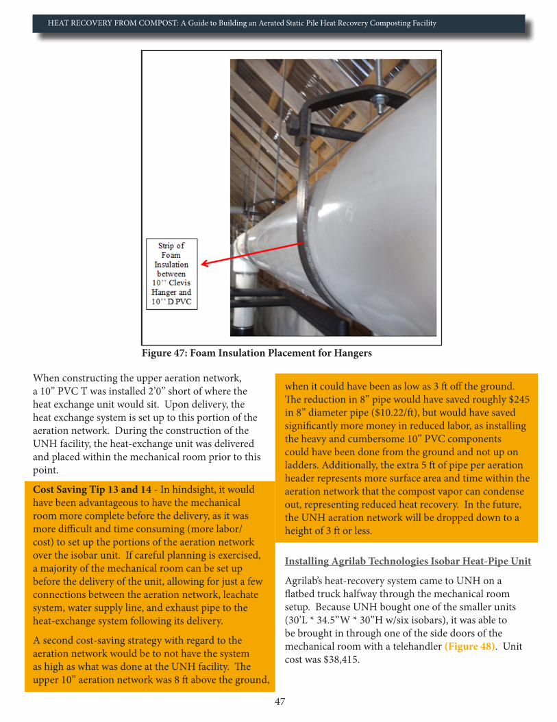
HEAT RECOVERY FROM COMPOST: A Guide to Building an Aerated Static Pile Heat Recovery Composting Facility
47
Figure 47: Foam Insulation Placement for Hangers
When constructing the upper aeration network, a 10’’ PVC T was installed 2’0’’ short of where the heat exchange unit would sit. Upon delivery, the heat exchange system is set up to this portion of the aeration network. During the construction of the UNH facility, the heat-exchange unit was delivered and placed within the mechanical room prior to this point.
Cost Saving Tip 13 and 14 - In hindsight, it would have been advantageous to have the mechanical room more complete before the delivery, as it was more difficult and time consuming (more labor/cost) to set up the portions of the aeration network over the isobar unit. If careful planning is exercised, a majority of the mechanical room can be set up before the delivery of the unit, allowing for just a few connections between the aeration network, leachate system, water supply line, and exhaust pipe to the heat-exchange system following its delivery.
A second cost-saving strategy with regard to the aeration network would be to not have the system as high as what was done at the UNH facility. The upper 10’’ aeration network was 8 ft above the ground,
when it could have been as low as 3 ft off the ground. The reduction in 8’’ pipe would have saved roughly $245 in 8’’ diameter pipe ($10.22/ft), but would have saved significantly more money in reduced labor, as installing the heavy and cumbersome 10’’ PVC components could have been done from the ground and not up on ladders. Additionally, the extra 5 ft of pipe per aeration header represents more surface area and time within the aeration network that the compost vapor can condense out, representing reduced heat recovery. In the future, the UNH aeration network will be dropped down to a height of 3 ft or less.
Installing Agrilab Technologies Isobar Heat-Pipe Unit
Agrilab’s heat-recovery system came to UNH on a flatbed truck halfway through the mechanical room setup. Because UNH bought one of the smaller units (30’L * 34.5’’W * 30’’H w/six isobars), it was able to be brought in through one of the side doors of the mechanical room with a telehandler (Figure 48). Unit cost was $38,415.

HEAT RECOVERY FROM COMPOST: A Guide to Building an Aerated Static Pile Heat Recovery Composting Facility
48
Figure 48: Delivery of Agrilab Technologies Heat Exchange Unit
When delivered, the heat-exchange unit was 1,300 pounds, (weighs 3,800 pounds after the bulk storage tank is filled with water and the isobars are loaded with refrigerant). The unit also came with supports to hold up the vapor portion of the system. Supports included two adjustable steel cradle floor stands and three 24’’ C-shaped steel brackets with a top loop to allow a ½’’ threaded rod to be connected to ceiling studs (11’ threaded rods in our case). For reference, the two floor stands were to carry the bulk of the weight, while the three ceiling supports were to ensure the vapor portion of the unit was at the right slope (Figure 49).
Figure 49: Support Structures for the Heat Exchange Unit

HEAT RECOVERY FROM COMPOST: A Guide to Building an Aerated Static Pile Heat Recovery Composting Facility
49
Due to differences in facility layout, supports for the much heavier bulk storage tank were not included with the isobar unit. Instead, a support structure was built ahead of time and was made of 6’’L * 6’’W * 25’’H wooden beams, 2’’ * 10’’ lumber, and a layer of ½’’ cement board (Figure 50).
Figure 50: Support Structure for Bulk Storage Tank of Water
The layer of cement board was a requirement from the state fire inspector, who was concerned about a 140ºF tank being held up by lumber, which could combust under certain conditions. Across the 30’ span of the heat-recov-ery system was a 4’’ drop, allowing for drainage of condensate and more efficient circulation of the refrigerant.
The isobar unit was connected to the 10’’ PVC aeration ductwork with a 10’’ flexible coupling (Fernco), to allow flex once the compost bays are loaded and the unit heats up. From the flexible coupling to the 10’’ upper T was a 16’’ section of horizontal 10’’ pipe, 10’’ elbow, 16’’ section of horizontal pipe, elbow, and a 4’0’’ section of ver-tical pipe going into the T. The 2’’ leachate drain from the Isobar unit was connected to the 4’’ leachate system through 2’’ PVC pipe and a 4’’ – 2’’ PVC wye reducer (Figure 51).
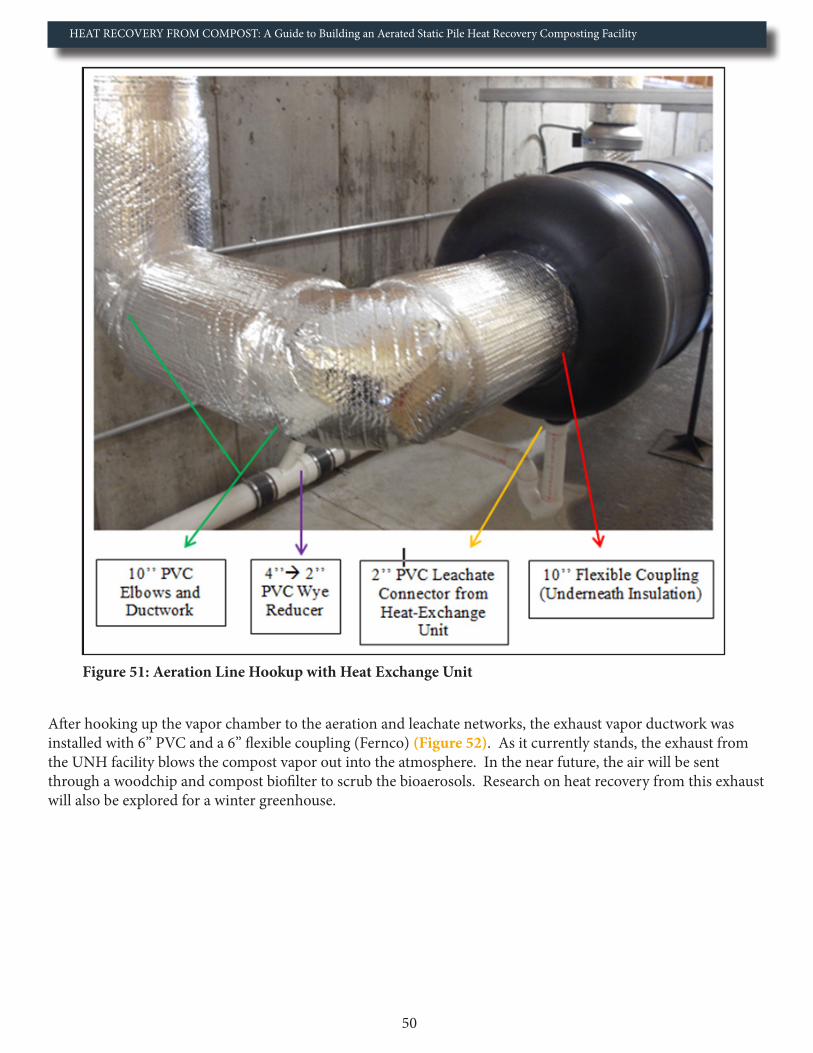
HEAT RECOVERY FROM COMPOST: A Guide to Building an Aerated Static Pile Heat Recovery Composting Facility
50
Figure 51: Aeration Line Hookup with Heat Exchange Unit
After hooking up the vapor chamber to the aeration and leachate networks, the exhaust vapor ductwork was installed with 6’’ PVC and a 6’’ flexible coupling (Fernco) (Figure 52). As it currently stands, the exhaust from the UNH facility blows the compost vapor out into the atmosphere. In the near future, the air will be sent through a woodchip and compost biofilter to scrub the bioaerosols. Research on heat recovery from this exhaust will also be explored for a winter greenhouse.

HEAT RECOVERY FROM COMPOST: A Guide to Building an Aerated Static Pile Heat Recovery Composting Facility
51
Figure 52: Exhaust Line from Aeration Network
The final hook up for Agrilab’s heat-recovery system was to connect 1’’ copper pipe (Type L) to the water lines in the bulk storage tank. From the heat-exchange unit, this copper pipe was connected to a network of hose bibs, which were added for various research needs (Figure 53). A farm/compost operation would not likely need this many lines, and could easily get away with two, in case future hot water demands are needed.
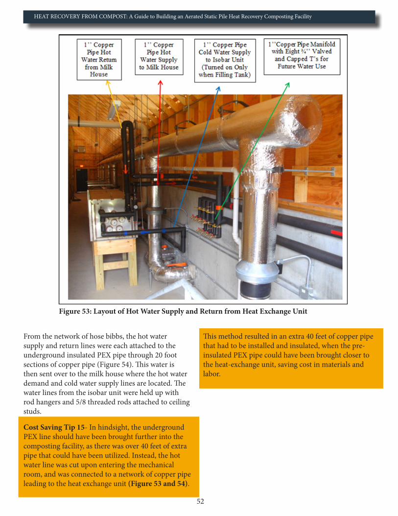
HEAT RECOVERY FROM COMPOST: A Guide to Building an Aerated Static Pile Heat Recovery Composting Facility
52
Figure 53: Layout of Hot Water Supply and Return from Heat Exchange Unit
From the network of hose bibbs, the hot water supply and return lines were each attached to the underground insulated PEX pipe through 20 foot sections of copper pipe (Figure 54). This water is then sent over to the milk house where the hot water demand and cold water supply lines are located. The water lines from the isobar unit were held up with rod hangers and 5/8 threaded rods attached to ceiling studs.
Cost Saving Tip 15- In hindsight, the underground PEX line should have been brought further into the composting facility, as there was over 40 feet of extra pipe that could have been utilized. Instead, the hot water line was cut upon entering the mechanical room, and was connected to a network of copper pipe leading to the heat exchange unit (Figure 53 and 54).
This method resulted in an extra 40 feet of copper pipe that had to be installed and insulated, when the pre-insulated PEX pipe could have been brought closer to the heat-exchange unit, saving cost in materials and labor.
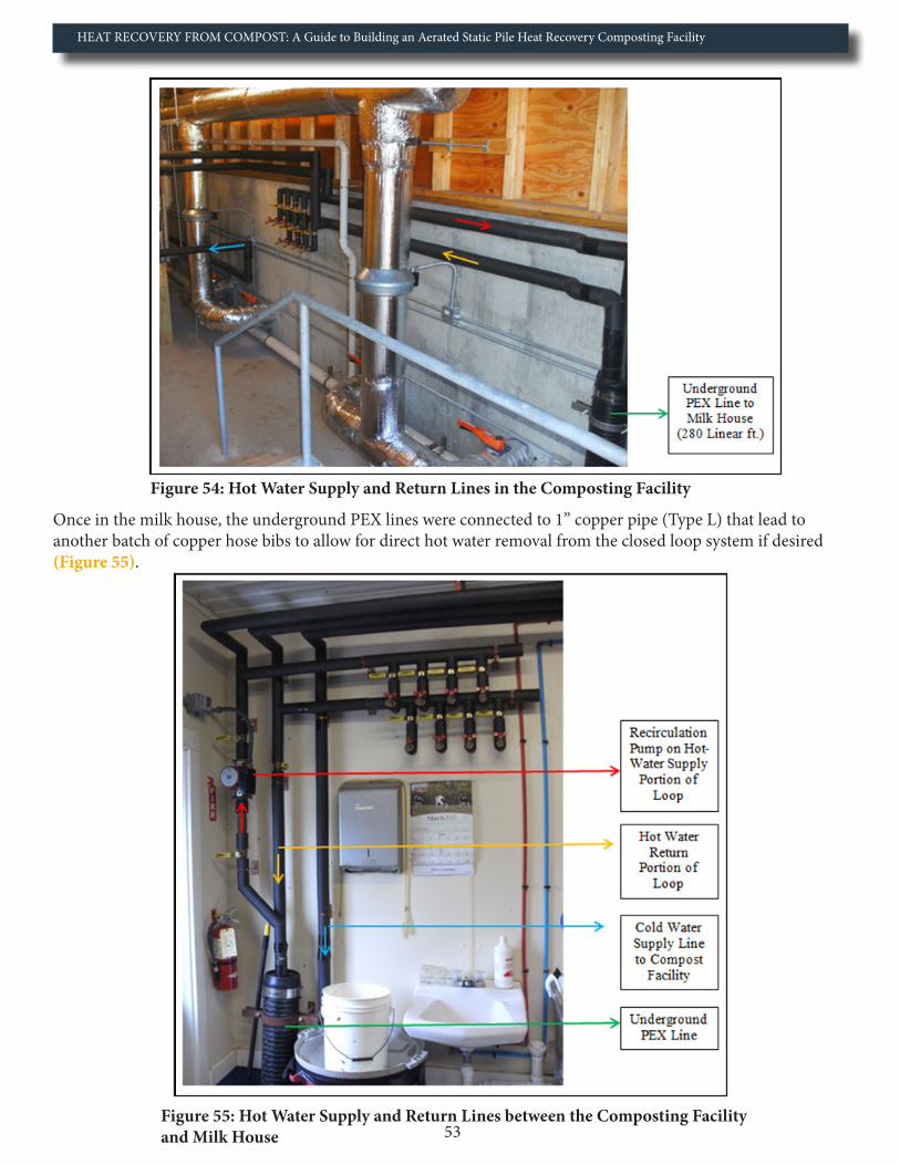
HEAT RECOVERY FROM COMPOST: A Guide to Building an Aerated Static Pile Heat Recovery Composting Facility
53
Figure 54: Hot Water Supply and Return Lines in the Composting Facility
Once in the milk house, the underground PEX lines were connected to 1’’ copper pipe (Type L) that lead to another batch of copper hose bibs to allow for direct hot water removal from the closed loop system if desired (Figure 55).
Figure 55: Hot Water Supply and Return Lines between the Composting Facility and Milk House

HEAT RECOVERY FROM COMPOST: A Guide to Building an Aerated Static Pile Heat Recovery Composting Facility
54
The copper pipe was then connected to a plate heater (GEA #FG10X20-20 with 1 ½ threads), where the hot water from the closed loop transfers energy to a separate cold water line coming from the farm’s well (Figure 56).
Figure 56: Plate Exchanger in Milk House
During this transfer, we expect to see the 500F well water warmed to 1000F, before entering the water heater where it is heated up another 50-700F to serve all the farm’s hot water demands (Figure 57). The range in expected temperature is dependent on how many compost bays are loaded and what time of the season it is.
Figure 57: Primary Farm Hot Water Heater Receiving Tempered Water from the Heat Exchange Unit
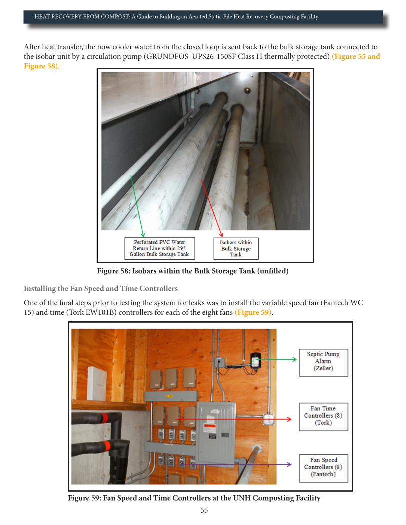
HEAT RECOVERY FROM COMPOST: A Guide to Building an Aerated Static Pile Heat Recovery Composting Facility
55
After heat transfer, the now cooler water from the closed loop is sent back to the bulk storage tank connected to the isobar unit by a circulation pump (GRUNDFOS UPS26-150SF Class H thermally protected) (Figure 55 and Figure 58).
Figure 58: Isobars within the Bulk Storage Tank (unfilled)
Installing the Fan Speed and Time Controllers
One of the final steps prior to testing the system for leaks was to install the variable speed fan (Fantech WC 15) and time (Tork EW101B) controllers for each of the eight fans (Figure 59).
Figure 59: Fan Speed and Time Controllers at the UNH Composting Facility
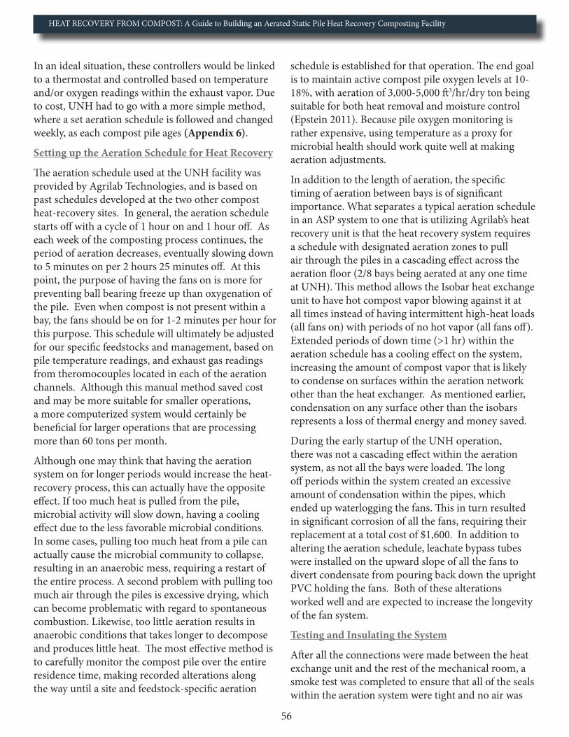
HEAT RECOVERY FROM COMPOST: A Guide to Building an Aerated Static Pile Heat Recovery Composting Facility
56
In an ideal situation, these controllers would be linked to a thermostat and controlled based on temperature and/or oxygen readings within the exhaust vapor. Due to cost, UNH had to go with a more simple method, where a set aeration schedule is followed and changed weekly, as each compost pile ages (Appendix 6).
Setting up the Aeration Schedule for Heat Recovery
The aeration schedule used at the UNH facility was provided by Agrilab Technologies, and is based on past schedules developed at the two other compost heat-recovery sites. In general, the aeration schedule starts off with a cycle of 1 hour on and 1 hour off. As each week of the composting process continues, the period of aeration decreases, eventually slowing down to 5 minutes on per 2 hours 25 minutes off. At this point, the purpose of having the fans on is more for preventing ball bearing freeze up than oxygenation of the pile. Even when compost is not present within a bay, the fans should be on for 1-2 minutes per hour for this purpose. This schedule will ultimately be adjusted for our specific feedstocks and management, based on pile temperature readings, and exhaust gas readings from theromocouples located in each of the aeration channels. Although this manual method saved cost and may be more suitable for smaller operations, a more computerized system would certainly be beneficial for larger operations that are processing more than 60 tons per month.
Although one may think that having the aeration system on for longer periods would increase the heat-recovery process, this can actually have the opposite effect. If too much heat is pulled from the pile, microbial activity will slow down, having a cooling effect due to the less favorable microbial conditions. In some cases, pulling too much heat from a pile can actually cause the microbial community to collapse, resulting in an anaerobic mess, requiring a restart of the entire process. A second problem with pulling too much air through the piles is excessive drying, which can become problematic with regard to spontaneous combustion. Likewise, too little aeration results in anaerobic conditions that takes longer to decompose and produces little heat. The most effective method is to carefully monitor the compost pile over the entire residence time, making recorded alterations along the way until a site and feedstock-specific aeration
schedule is established for that operation. The end goal is to maintain active compost pile oxygen levels at 10-18%, with aeration of 3,000-5,000 ft3/hr/dry ton being suitable for both heat removal and moisture control (Epstein 2011). Because pile oxygen monitoring is rather expensive, using temperature as a proxy for microbial health should work quite well at making aeration adjustments.
In addition to the length of aeration, the specific timing of aeration between bays is of significant importance. What separates a typical aeration schedule in an ASP system to one that is utilizing Agrilab’s heat recovery unit is that the heat recovery system requires a schedule with designated aeration zones to pull air through the piles in a cascading effect across the aeration floor (2/8 bays being aerated at any one time at UNH). This method allows the Isobar heat exchange unit to have hot compost vapor blowing against it at all times instead of having intermittent high-heat loads (all fans on) with periods of no hot vapor (all fans off). Extended periods of down time (>1 hr) within the aeration schedule has a cooling effect on the system, increasing the amount of compost vapor that is likely to condense on surfaces within the aeration network other than the heat exchanger. As mentioned earlier, condensation on any surface other than the isobars represents a loss of thermal energy and money saved.
During the early startup of the UNH operation, there was not a cascading effect within the aeration system, as not all the bays were loaded. The long off periods within the system created an excessive amount of condensation within the pipes, which ended up waterlogging the fans. This in turn resulted in significant corrosion of all the fans, requiring their replacement at a total cost of $1,600. In addition to altering the aeration schedule, leachate bypass tubes were installed on the upward slope of all the fans to divert condensate from pouring back down the upright PVC holding the fans. Both of these alterations worked well and are expected to increase the longevity of the fan system.
Testing and Insulating the System
After all the connections were made between the heat exchange unit and the rest of the mechanical room, a smoke test was completed to ensure that all of the seals within the aeration system were tight and no air was

HEAT RECOVERY FROM COMPOST: A Guide to Building an Aerated Static Pile Heat Recovery Composting Facility
57
leaking out. This is a very important test to complete, as any leaks in the system not only cost money in the form of lost heat, but also pose a health concern due to the compost vapors, which contain high levels of ammonia and other bioaerosols. The smoke test completed at UNH was done by placing a smoke bomb in the sump pit with a board overtop and turning on all the aeration fans. Two joints had to receive marine-grade silicone seal following the test. Once the leaks were sealed, the entire aeration network was double-wrapped with a radiant heat barrier (Reflectix® Insulation), which reflects 97% of radiant heat, has a combined R-Value of 8.4 and is antimicrobial (Reflectix 2013). Five rolls of 48’’ * 100 ft were used. All joints were sealed with foil tape (Reflectix® foil tape) to ensure a proper seal (Figure 60).
Figure 60: UNH Aeration System Insulated with Reflectix

HEAT RECOVERY FROM COMPOST: A Guide to Building an Aerated Static Pile Heat Recovery Composting Facility
58
Following the insulation of the aeration network, the isobar unit and all the water lines were tested to ensure there were no water leaks. In order to do this test, the bulk storage tank had to be filled and the isobars loaded with refrigerant through their Schrader valves. If completing this test in a cold region during the winter, it is imperative that compost batches are loaded prior, and the entire concrete pad and aeration system are above the freezing point, before pumping water into the system (prevent freezing). An alternative, which UNH used, was to wait until warmer temperatures arrived before loading the system with water. The facility was completed March 2013 and was loaded with compost in June, and had the bulk tank and isobars filled the same month.
After testing the Isobar unit and the water lines for leaks, the first compost bay was loaded. The vapor chamber portion of the Isobar unit was insulated with the same radiant heat barrier as the aeration network (Reflectix® Insulation). The bulk storage tank was insulated with 2’’ rigid foil-faced insulation (Thermax ™) (R-13). All the copper pipes were insulated with a double layer of standard closed-cell polyethylene foam pipe insulation (R-12). Following insulation of the Isobar unit, the first bay of the facility was loaded with feedstock.
Two days following the loading of the feedstock, a problem arose from the joint between the mechanical room and the main compost floor. The expanding joint filler (standard spray foam), was breached in two aeration lines and was allowing leachate, compost worms, and a noxious smell into the mechanical room (Figure 61).
Figure 61: Leak through the Back Push Wall

HEAT RECOVERY FROM COMPOST: A Guide to Building an Aerated Static Pile Heat Recovery Composting Facility
59
To fix the problem, every aeration line had the insulation before the butterfly valve pulled away, had 4 inches of expanding joint filler cut out, and was replaced with a new sealer (Figure 62). The new sealer (Leakmaster LV-1) was chosen as it is a water-swelling sealant that has a rubber-like property, which was determined to be more suitable than a standard spray foam due to the expanding/contracting nature of the concrete as it is heated and cooled during and between compost batches. Standard expanding spray foam joint filler is not recommended at future facilities.
Figure 62: Replacement Expanding Joint Filler on the Mechanical Room Side of the Push Wall
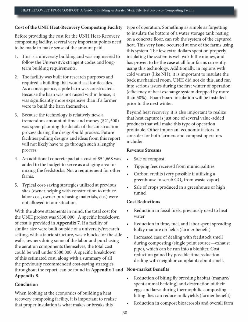
HEAT RECOVERY FROM COMPOST: A Guide to Building an Aerated Static Pile Heat Recovery Composting Facility
60
Cost of the UNH Heat-Recovery Composting Facility
Before providing the cost for the UNH Heat-Recovery composting facility, several very important points need to be made to make sense of the amount paid.
1. This is a university building and was engineered to follow the University’s stringent codes and long- term building requirements.
2. The facility was built for research purposes and required a building that would last for decades. As a consequence, a pole barn was constructed. Because the barn was not raised within house, it was significantly more expensive than if a farmer were to build the barn themselves.
3. Because the technology is relatively new, a tremendous amount of time and money ($21,500) was spent planning the details of the construction process during the design/build process. Future facilities pulling designs and ideas from this report will not likely have to go through such a lengthy process.
4. An additional concrete pad at a cost of $54,668 was added to the budget to serve as a staging area for mixing the feedstocks. Not a requirement for other farms.
5. Typical cost-saving strategies utilized at previous sites (owner helping with construction to reduce labor cost, owner purchasing materials, etc.) were not allowed in our situation.
With the above statements in mind, the total cost for the UNH project was $538,000. A specific breakdown of cost is provided in Appendix 7. If a facility of similar-size were built outside of a university/research setting, with a fabric structure, waste blocks for the side walls, owners doing some of the labor and purchasing the aeration components themselves, the total cost could be well under $300,000. A specific breakdown of this estimated cost, along with a summary of all the previously recommended cost-saving strategies throughout the report, can be found in Appendix 1 and Appendix 8.
Conclusion
When looking at the economics of building a heat recovery composing facility, it is important to realize that proper insulation is what makes or breaks this
type of operation. Something as simple as forgetting to insulate the bottom of a water storage tank resting on a concrete floor, can rob the system of the captured heat. This very issue occurred at one of the farms using this system. The few extra dollars spent on properly insulating the system is well worth the money, and has proven to be the case at all four farms currently using this technology. Additionally, in regions with cold winters (like NH), it is important to insulate the back mechanical room. UNH did not do this, and ran into serious issues during the first winter of operation (efficiency of heat exchange system dropped by more than 50%). Foam board insulation will be installed prior to the next winter.
Beyond heat recovery, it is also important to realize that heat capture is just one of several value-added products that will make this type of operation profitable. Other important economic factors to consider for both farmers and compost operators include:
Revenue Streams
• Sale of compost• Tipping fees received from municipalities • Carbon credits (very possible if utilizing a
greenhouse to scrub CO2 from waste vapor)• Sale of crops produced in a greenhouse or high
tunnel
Cost Reductions
• Reduction in fossil fuels, previously used to heat water
• Reduction in time, fuel, and labor spent spreading bulky manure on fields (farmer benefit)
• Increased ease of dealing with feedstock smell during composting (single point source—exhaust pipe), which can be run into a biofilter. Cost reduction gained by possible time reduction dealing with neighbor complaints about smell.
Non-market Benefits
• Reduction of biting fly breeding habitat (manure/spent animal bedding) and destruction of their eggs and larva during thermophilic composting – biting flies can reduce milk yields (farmer benefit)
• Reduction in compost bioaerosols and overall farm
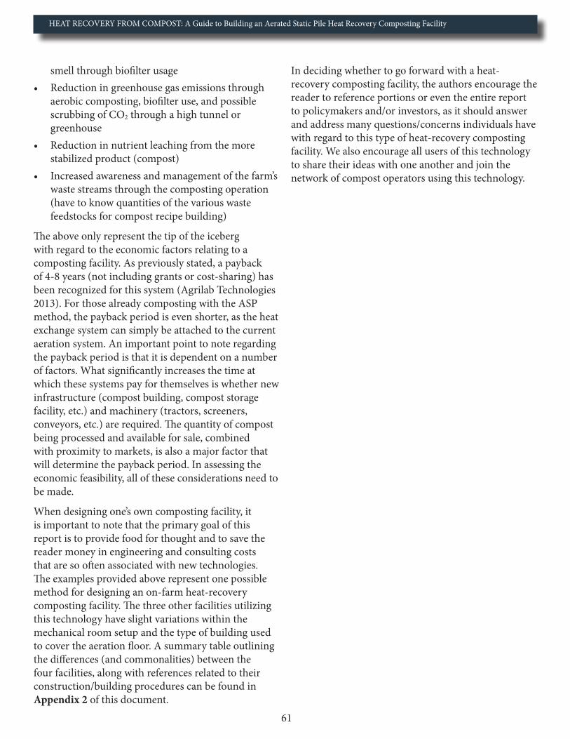
HEAT RECOVERY FROM COMPOST: A Guide to Building an Aerated Static Pile Heat Recovery Composting Facility
61
smell through biofilter usage• Reduction in greenhouse gas emissions through
aerobic composting, biofilter use, and possible scrubbing of CO2 through a high tunnel or greenhouse
• Reduction in nutrient leaching from the more stabilized product (compost)
• Increased awareness and management of the farm’s waste streams through the composting operation (have to know quantities of the various waste feedstocks for compost recipe building)
The above only represent the tip of the iceberg with regard to the economic factors relating to a composting facility. As previously stated, a payback of 4-8 years (not including grants or cost-sharing) has been recognized for this system (Agrilab Technologies 2013). For those already composting with the ASP method, the payback period is even shorter, as the heat exchange system can simply be attached to the current aeration system. An important point to note regarding the payback period is that it is dependent on a number of factors. What significantly increases the time at which these systems pay for themselves is whether new infrastructure (compost building, compost storage facility, etc.) and machinery (tractors, screeners, conveyors, etc.) are required. The quantity of compost being processed and available for sale, combined with proximity to markets, is also a major factor that will determine the payback period. In assessing the economic feasibility, all of these considerations need to be made.
When designing one’s own composting facility, it is important to note that the primary goal of this report is to provide food for thought and to save the reader money in engineering and consulting costs that are so often associated with new technologies. The examples provided above represent one possible method for designing an on-farm heat-recovery composting facility. The three other facilities utilizing this technology have slight variations within the mechanical room setup and the type of building used to cover the aeration floor. A summary table outlining the differences (and commonalities) between the four facilities, along with references related to their construction/building procedures can be found in Appendix 2 of this document.
In deciding whether to go forward with a heat-recovery composting facility, the authors encourage the reader to reference portions or even the entire report to policymakers and/or investors, as it should answer and address many questions/concerns individuals have with regard to this type of heat-recovery composting facility. We also encourage all users of this technology to share their ideas with one another and join the network of compost operators using this technology.

HEAT RECOVERY FROM COMPOST: A Guide to Building an Aerated Static Pile Heat Recovery Composting Facility
62
Appendix 1: Materials List and Estimated Cost of a Similarly-Sized Facility using Cost-Saving Strategies
Item Description Quantity Cost/Unit Total Cost
Aeration Lines
4” PVC Pipe (U.S. Plastics Corp) 515 ft $4.34/ft $ 2,235.10 4” PVC Couplings (U.S. Plastics Corp) 48 $3.35/unit $ 160.804” PVC End Cap (U.S. Plastics Corp) 16 units $4.76/unit $ 76.16Band-Seal End Cap w/hose Bibb (Amazon) 16 units $9.48/unit $ 151.684” Galvanized Steel Pipe Riser (Grainger) 48 units $15.9/unit $ 763.201/2” Diameter Black Threaded Rod (Platinum Fire Supply) 288 ft $8.55/10ft $ 246.241/2” Diameter Rebar Rod (Home Depot) 288 ft $7.47/20ft $ 107.57
4” Foamular 250 Foam (Menards) 2830 ft2$65.50/
4”* 4’*8’ sheet $ 5,527.34
Cover Plate 1/2” Plywood Forms (Lowes) 216 ft2$25.98/4’*8’
sheet $ 175.37
Cover Plate 3/4 Plywood Forms (Lowes) 216 ft2$32.20/4’*8’
Sheet $ 217.35Marine Plywood Cover Plates (GooseBay Inc.) 216 ft2 $95/ 4’*8’ sheet $ 641.25
Mechanical Room Materials4” Hayward Butterfly Valve (U.S. Plastics Corp) 16 units $222.86/unit $ 3,565.766” PVC Elbow (U.S. Plastics Corp) 16 units $25.29/unit $ 404.646” PVC T (U.S. Plastics Corp) 8 units $39.85/unit $ 318.807’2” of 6” PVC Pipe (U.S. Plastics Corp) 60 ft $8.45/ft $ 507.006” Flexible Fernco Coupling (Grainger) 16 units $23.08/unit $ 369.286” Fantech FG6XL Centrifugal Fans (ReWilliams) 8 units $176.90/unit $ 1,415.20Fantech Variable Speed Fan Controllers (Pex Supply) 8 units $15.95/unit $ 127.60 Tork Fan Timers (Grainger) 8 units $161.25/unit $ 1,290.006” Galvanized Steel Anvil Pipe Riser Clamp (Grainger) 8 units $16.46/unit $ 131.685/8 “ Diameter Alloy Steel Threaded Rod (Grainger) 12 ft $28.25/6ft $ 56.50Reflectix Insulation (Home Depot) 5 rolls $129/roll $ 645.00
Upper Aeration Network8” PVC T (U.S. Plastics Corp) 9 units $83.17/unit $ 748.538” PVC Pipe (U.S. Plastics Corp) 80 ft $10.22/ft $ 817.608" PVC End Cap (U.S. Plastics Corp) 2 units $30.27/unit $ 60.54

HEAT RECOVERY FROM COMPOST: A Guide to Building an Aerated Static Pile Heat Recovery Composting Facility
63
Item Description Quantity Cost/Unit Total Cost8” PVC Couplings (U.S. Plastics Corp) 7 units $21.82/unit $ 152.748” Carbon Steel Clevis Hangers (Grainger) 20 units $25.80/unit $ 516.007/8” Diameter Galvanized Steel Threaded Rod (Grainger) 80 ft $82/6 ft $ 1,093.60
Upper Aeration Network to Isobar Unit8” PVC pipe (U.S. Plastics Corp) 8 ft $10.22/ft $ 81.768” PVC Elbow (U.S. Plastics Corp) 2 units $55.35/unit $ 110.708” Flexible Fernco Coupling (Grainger) 1 unit $33.35/unit $ 33.35PVC Solvent Cement - Oatey (Home Depot) 100 oz $7.97/16 oz $ 47.82PVC purple primer - Oatey (Home Depot) 100 oz $14.81/32 oz $ 44.43
Water Lines in Compost Facility1” Type L Copper Pipe (Grainger) 10 ft $64.15/10 ft $ 64.151” Copper T (Pex Supply) 5 units $4.45/unit $ 22.251” Copper Elbow (Pex Supply) 15 units $2.93/unit $ 43.958 oz Oatey Paste Flux for Soldering (Home Depot) 16 oz $4.50/unit $ 9.00Underground PEX Hot Water Supply and Return Line (Outdoor wood furnace boiler.com) 300 ft $6/ft $ 1,800.00Campbell 5’ Frost-Proof Yard Hydrant (Grainger) 2 units 83.10/unit $ 166.20
Water Lines in Compost Facility1” Copper Pipe Type L (Grainger) 115 ft $64.15/10 ft $ 737.731” Copper T (Pex Supply) 6 units $4.45/unit $ 26.701” Copper 90 Elbow (Pex Supply) 27 units $2.93/unit $ 79.11Grundfos UPS 26-150SF Circulating Pump (Plumber Surplus.com) 1 unit $550/unit $ 550.00GEA 100 GPM Plate Exchanger (Pex Supply) 1 unit $1436.95/unit $ 1,436.95
Leachate Network4” PVC Pipe (U.S. Plastic Corp) 80 ft $3.51/ft $ 280.804” - 2” PVC Wye Reducer (U.S. Plastic Corp) 8 units $21.61/unit $ 172.882” PVC Elbows (U.S. Plastic Corp) 16 units $1.20/unit $ 19.202” PVC S-trap with Waste (Home Depot) 8 units $9.95/unit $ 79.602” PVC Pipe (U.S. Plastic Corp) 8 ft $1.24/ft $ 9.922” PVC 450 Elbows (U.S. Plastic Corp) 24 units $1.31/unit $ 31.444” Galvanized Steel Pipe Riser Clamp (Grainger) 21 units $15.9/unit $ 333.905/8” Alloy Steel Threaded Rod (Grainger) 10.5 ft $28.25/6ft $ 49.44Pre-cast 1500 Gallon Leachate Tank (Phoenix Precast Products) 1 unit $1100/unit $ 1,100.00
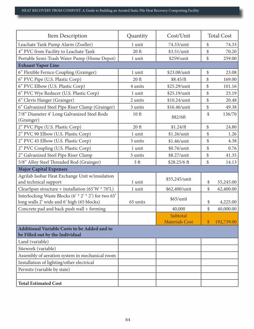
HEAT RECOVERY FROM COMPOST: A Guide to Building an Aerated Static Pile Heat Recovery Composting Facility
64
Item Description Quantity Cost/Unit Total CostLeachate Tank Pump Alarm (Zoeller) 1 unit 74.33/unit $ 74.334” PVC from Facility to Leachate Tank 20 ft $3.51/unit $ 70.20Portable Semi-Trash Water Pump (Home Depot) 1 unit $259/unit $ 259.00Exhaust Vapor Line6” Flexible Fernco Coupling (Grainger) 1 unit $23.08/unit $ 23.086” PVC Pipe (U.S. Plastic Corp) 20 ft $8.45/ft $ 169.006” PVC Elbow (U.S. Plastic Corp) 4 units $25.29/unit $ 101.166” PVC Wye Reducer (U.S. Plastic Corp) 1 unit $25.19/unit $ 25.196” Clevis Hanger (Grainger) 2 units $10.24/unit $ 20.486” Galvanized Steel Pipe Riser Clamp (Grainger) 3 units $16.46/unit $ 49.387/8” Diameter 4’ Long Galvanized Steel Rods (Grainger)
10 ft $82/6ft $ 136/70
2” PVC Pipe (U.S. Plastic Corp) 20 ft $1.24/ft $ 24.802” PVC 90 Elbow (U.S. Plastic Corp) 1 unit $1.26/unit $ 1.262” PVC 45 Elbow (U.S. Plastic Corp) 3 units $1.46/unit $ 4.382” PVC Coupling (U.S. Plastic Corp) 1 unit $0.76/unit $ 0.762” Galvanized Steel Pipe Riser Clamp 5 units $8.27/unit $ 41.355/8” Alloy Steel Threaded Rod (Grainger) 3 ft $28.25/6 ft $ 14.13Major Capital ExpensesAgrilab Isobar Heat Exchange Unit w/insulationand technical support 1 unit $55,245/unit $ 55,245.00ClearSpan structure + installation (65’W * 70’L) 1 unit $62,400/unit $ 62,400.00Interlocking Waste Blocks (6’ * 2’ * 2’) for two 65’ long walls 2’ wide and 6’ high (65 blocks) 65 units $65/unit $ 4,225.00Concrete pad and back push wall + forming 40,000 $ 40,000.00
Subtotal Materials Cost $ 192,739.00
Additional Variable Costs to be Added and to be Filled out by the IndividualLand (variable)Sitework (variable)Assembly of aeration system in mechanical roomInstallation of lighting/other electricalPermits (variable by state)
Total Estimated Cost
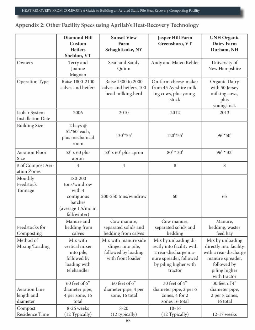
HEAT RECOVERY FROM COMPOST: A Guide to Building an Aerated Static Pile Heat Recovery Composting Facility
65
Appendix 2: Other Facility Specs using Agrilab’s Heat-Recovery Technology
Diamond Hill Custom Heifers
Sheldon, VT
Sunset ViewFarm
Schaghticoke, NY
Jasper Hill FarmGreensboro, VT
UNH Organic Dairy Farm
Durham, NH
Owners Terry and Joanne
Magnan
Sean and Sandy Quinn
Andy and Mateo Kehler University of New Hampshire
Operation Type Raise 1800-2100 calves and heifers
Raise 1300 to 2000 calves and heifers, 100
head milking herd
On-farm cheese-maker from 45 Ayrshire milk-ing cows, plus young-
stock
Organic Dairy with 50 Jersey milking cows,
plus youngstock
Isobar SystemInstallation Date
2006 2010 2012 2013
Building Size 2 bays @ 52*60’ each,
plus mechanical room
130’*55’ 120’*55’ 96’*50’
Aeration FloorSize
52’ x 60 plus apron
53’ x 60’ plus apron 80’ * 30’ 96’ * 32’
# of Compost Aer-ation Zones
4 4 8 8
Monthly Feedstock Tonnage
180-200 tons/windrow
with 4 contiguous
batches (average 1.5/mo in
fall/winter)
200-250 tons/windrow 60 65
Feedstocks for Composting
Manure and bedding from
calves
Cow manure, separated solids and bedding from calves
Cow manure, separated solids and
bedding
Manure, bedding, waster
feed hayMethod of Mixing/Loading
Mix with vertical mixer
into pile, followed by loading with telehandler
Mix with manure side slinger into pile,
followed by loading with front loader
Mix by unloading di-rectly into facility with a rear-discharge ma-
nure spreader, followed by piling higher with
tractor
Mix by unloading directly into facility
with a rear-discharge manure spreader,
followed by piling higher with tractor
Aeration Line length and diameter
60 feet of 6” diameter pipe, 4 per zone, 16
total
60 feet of 6” diameter pipe, 4 per
zone, 16 total
30 feet of 4” diameter pipe, 2 per 6
zones, 4 for 2 zones 16 total
30 feet of 4” diameter pipe, 2 per 8 zones,
16 totalCompost Residence Time
8-26 weeks (12 Typically)
8-20 (12 typically)
10-16 (12 Typically) 12-17 weeks
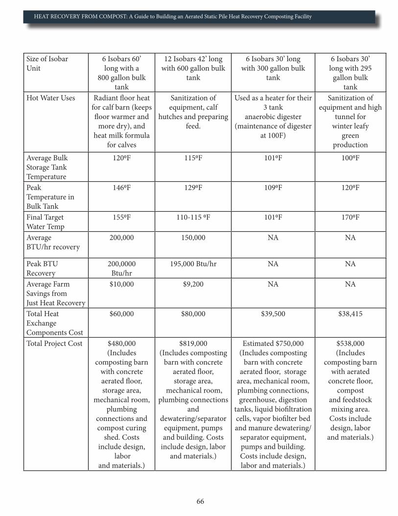
HEAT RECOVERY FROM COMPOST: A Guide to Building an Aerated Static Pile Heat Recovery Composting Facility
66
Size of Isobar Unit
6 Isobars 60’ long with a
800 gallon bulk tank
12 Isobars 42’ long with 600 gallon bulk
tank
6 Isobars 30’ long with 300 gallon bulk
tank
6 Isobars 30’ long with 295
gallon bulk tank
Hot Water Uses Radiant floor heat for calf barn (keeps floor warmer and
more dry), and heat milk formula
for calves
Sanitization of equipment, calf
hutches and preparing feed.
Used as a heater for their 3 tank
anaerobic digester (maintenance of digester
at 100F)
Sanitization of equipment and high
tunnel for winter leafy
green production
Average BulkStorage TankTemperature
1200F 1150F 1010F 1000F
Peak Temperature in Bulk Tank
1460F 1290F 1090F 1200F
Final Target Water Temp
1550F 110-115 0F 1010F 1700F
Average BTU/hr recovery
200,000 150,000 NA NA
Peak BTU Recovery
200,0000 Btu/hr
195,000 Btu/hr NA NA
Average Farm Savings from Just Heat Recovery
$10,000 $9,200 NA NA
Total Heat Exchange Components Cost
$60,000 $80,000 $39,500 $38,415
Total Project Cost $480,000 (Includes
composting barn with concrete aerated floor, storage area,
mechanical room, plumbing
connections and compost curing
shed. Costs include design,
labor and materials.)
$819,000 (Includes composting
barn with concrete aerated floor, storage area,
mechanical room, plumbing connections
and dewatering/separator
equipment, pumps and building. Costs
include design, labor and materials.)
Estimated $750,000 (Includes composting
barn with concrete aerated floor, storage
area, mechanical room, plumbing connections, greenhouse, digestion
tanks, liquid biofiltration cells, vapor biofilter bed and manure dewatering/
separator equipment, pumps and building. Costs include design, labor and materials.)
$538,000 (Includes
composting barn with aerated
concrete floor, compost
and feedstock mixing area.
Costs include design, labor
and materials.)

HEAT RECOVERY FROM COMPOST: A Guide to Building an Aerated Static Pile Heat Recovery Composting Facility
67
Appendix 3: UNH Facility Layout

HEAT RECOVERY FROM COMPOST: A Guide to Building an Aerated Static Pile Heat Recovery Composting Facility
68
Concrete Estimates for UNH Facility
• Concrete Pads ◆ Main composting floor → 32’ * 94.33’ * 9.5’’ = 88 yd3
◆ Internal apron → 8’ * 94.33’ * 9.5’’ = 22 yd3
◆ External apron → 4’ * 96’ * 4’’ = 5 yd3
◆ Mechanical room → 10’ * 94.33’ * 4’’ = 12 yd3
■ Total Concrete for Pads = 127 yd3
• Push Wall and Side Frost Walls ◆ Back push wall footing → 6.5’ * 96’ * 12’’ = 23 yd3
◆ Back push wall → 8’ * 94.33’ * 12’’ = 28 yd3
◆ Side frost wall footing → 2’ * 40’ * 12’’= 3 yd3 * 2 = 6yd3
◆ Side frost wall→ 8’ * 40’ * 8’’ = 8 yd3 = 16yd3
■ Total Concrete for Main Composting Room = 73 yd3
• Mechanical Room Walls ◆ Mechanical room wall footing 1→ 2’ * 32.25’ * 12’’ = 2.4 yd3
◆ Mechanical room wall 1→ 6’ * 32.25 * 8’’= 4.8 yd3
◆ Mechanical room wall footing 2 → 2’ * 10’ * 12’’ = 0.75 yd3
◆ Mechanical room wall 2 → 6’ * 10’ * 8’’ = 1.5 yd3
■ Total Concrete for Mechanical Room = 9.5 yd3
• Concrete Piers ◆ Front concrete pier footings (2) → 2.5’ * 4.5’ * 12’’ = 0.42 * 2 = 0.84 yd3
◆ Front concrete pier (2)→ 8’ * 2.5’ * 10’’ = 0.62 * 2 = 1.24 yd3
◆ Front concrete pier footings (3)→ 3.67’ * 4.5’ * 12’’ = 0.62 * 3 = 1.86 yd3
◆ Front concrete pier (3) → 3.67’ * 8’ * 10’’ = 0.91 * 3 = 1.82 yd3
◆ Mechanical room pier footing→ 2’ * 1’ * 12’’ = 0.07 * 8 = 0.56 yd3
◆ Mechanical room piers (8)→ 4’ * 1’ * 8’’ = 1.09 * 8 = 8.72 yd3
■ Total for Piers = 15 yd3
Total Concrete for Facility = 225 yd3
Appendix 4: Quantity of Concrete used at UNH Facility
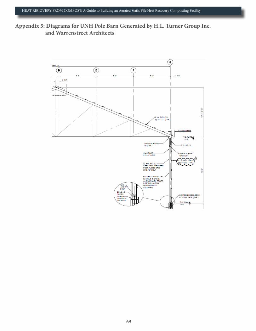
HEAT RECOVERY FROM COMPOST: A Guide to Building an Aerated Static Pile Heat Recovery Composting Facility
69
Appendix 5: Diagrams for UNH Pole Barn Generated by H.L. Turner Group Inc. and Warrenstreet Architects
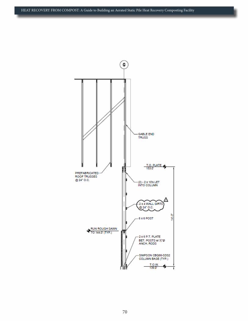
HEAT RECOVERY FROM COMPOST: A Guide to Building an Aerated Static Pile Heat Recovery Composting Facility
70

HEAT RECOVERY FROM COMPOST: A Guide to Building an Aerated Static Pile Heat Recovery Composting Facility
71
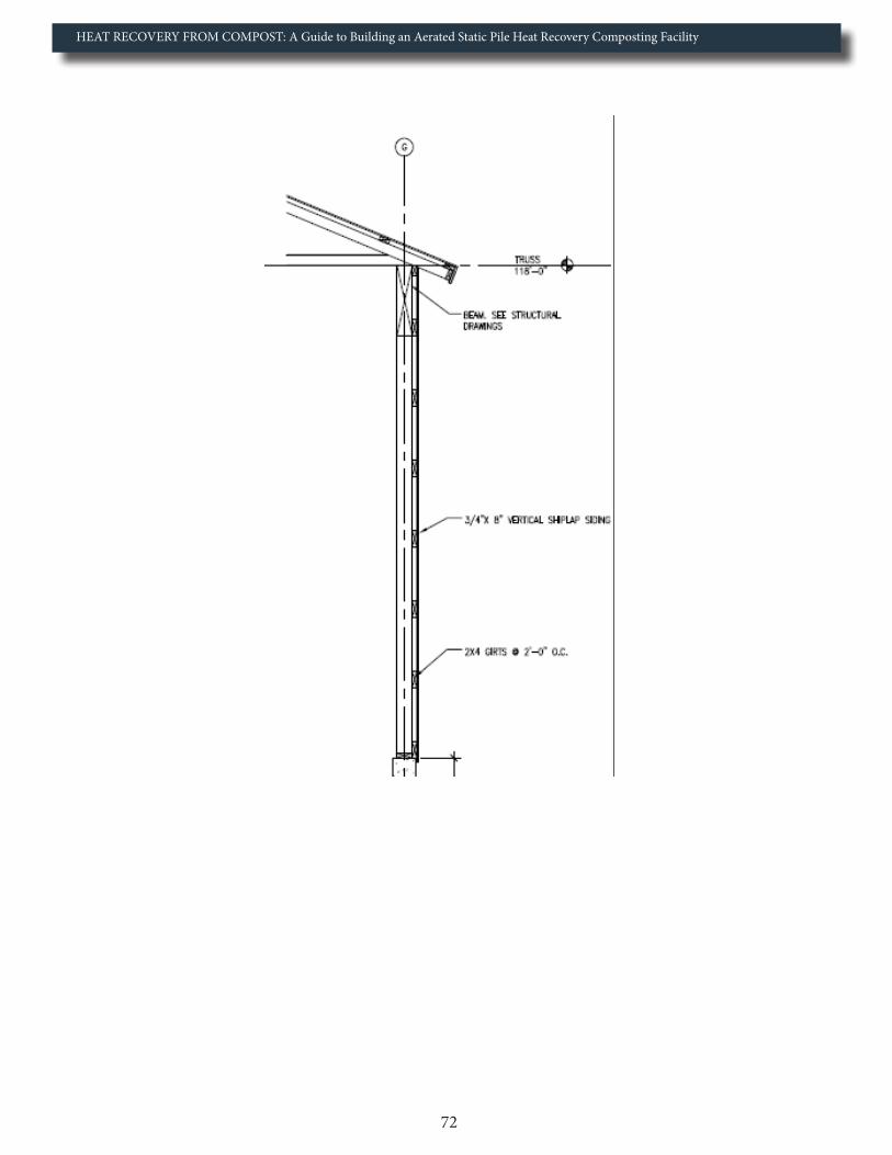
HEAT RECOVERY FROM COMPOST: A Guide to Building an Aerated Static Pile Heat Recovery Composting Facility
72

HEAT RECOVERY FROM COMPOST: A Guide to Building an Aerated Static Pile Heat Recovery Composting Facility
73

HEAT RECOVERY FROM COMPOST: A Guide to Building an Aerated Static Pile Heat Recovery Composting Facility
74
Appendix 6: Tentative Aeration Schedule followed at UNH*
Winodw Age (Weeks) On Time (Minutes) Off Time (Minutes)0 60 901 50 1002 45 1053 40 1104 30 1205 20 1306 15 1357 10 1408 5 1459 5 14510 4 14611 4 14612 3 14713 3 14714 2 14815 2 14816 1 149Note: this table will be revised to stagger on (run) times to run one or two fans at one time
*Inital Recommendations from Agrilab (2013)

HEAT RECOVERY FROM COMPOST: A Guide to Building an Aerated Static Pile Heat Recovery Composting Facility
75
Item CostPreliminary Design Services $ 7,179.00Detailed Design Submission
$ 14,358.00General Requirements (site costs that include temp toilets and office trailer rental, temp telephone and fax connection/usage, temp electrical, temp water, travel, office supplies, cost of superintendent, etc.
$ 74,020.00Sitework
$ 68,284.00Demolition
$ 1,730.00Concrete $ 64,924.00Metals $ 150.00Rough Carpentry $ 66,421.00Finish Carpentry $ 15,316.00Moisture Protection (roof, insulation of all water and aeration lines, water proofing foundations, etc.)
$ 35,580.00Door, Frames and Harware (including 4 standard doors and 4 20’*20’ compost bay doors)
$ 21,685.00Painting
$ 150.00Specialties
$ (100.00) Agrilab technologhies Isobar Unit & Suport $ 52,400.00Mechanical
$ 65,550.00Electrical $ 19,595.00Overhead & Profit $ 29,214.00Other $ 1,675.00Total
$ 538,131.00
Appendix 7: Breakdown of the Cost for the UNH Facility

HEAT RECOVERY FROM COMPOST: A Guide to Building an Aerated Static Pile Heat Recovery Composting Facility
76
Appendix 8: Recommended Cost-Saving Strategies Found Throughout Report1. If possible, use 4’’ diameter PVC pipe in the aeration floor, as 6’’ PVC pipe will likely result in a 10’’ PVC upper
aeration network in the mechanical room, costing thousands of dollars more. Likewise, if using 4’’ PVC in the aeration floor, skipping a PVC size like UNH did (4’’ – 8’’) will result in a 10’’ upper aeration network, costing thousands of dollars more. In our case, this unnecessary skip cost over $10,000 extra.
2. Purchase as many of the components for the aeration system as possible [PVC pipe & fittings, centrifugal fans, flexible couplings, time and speed controllers, insulation (rigid foam for concrete sub-base, thermal joints, pipe insulation, etc.), support structures (clevis hangers, piper riser clamps, threaded rod, etc.), plate exchanger, Isobar heat exchanger, etc.]. As indicated earlier, ensure a contract is established where you are still not paying the contractor for these purchases.
3. Ensure the facility is sited properly to reduce the travel distance between the feedstocks and the compost floor. This is one of the more important cost-saving strategies, as extra time loading or maneuvering around objects will add significant cost over the long run.
4. Ensure all possible holes through the concrete are planned ahead of time and receive sleeves during forming to prevent the need to drill through the concrete.
5. For the primary back push wall, wood can be used for the upper portion of the wall, reducing the cost of con-crete. This cost-saving strategy needs to be looked at carefully though, as it will require a vapor barrier, and the need to replace the wood once every few years.
6. Instead of pouring side walls, investigate the cost of concrete waste blocks. These blocks are commonly used for side walls for fabric structures, and can save significant cost to the operator. UNH received quotes in the 65-$75 range per 2’ * 2’ * 6’ delivered interlocking block (when purchasing a trailer load). This cost-saving strategy will not only reduce concrete costs, but could significantly reduce the ground preparation costs as well.
7. If labor costs are high in the area, a cost comparison between rigid foam insulation and Insul-Tarp is warranted when deciding which insulation to place under the concrete slab.
8. Make the coverplates out of dimensional lumber to save labor cost and increase the recession on the aeration floor.
9. Do not drill the aeration holes until all the construction is complete—this reduces the labor involved in clean-ing, should the holes get plugged with construction material.
10. The concrete aprons (internal and external) and mechanical room slab do not have to have the same thickness as the primary aeration floor.
11. Use a high-tension fabric structure if possible. This represents one of the greatest cost-saving strategies, especially if the operator was not planning on building the structure themselves.
12. Ensure building height is based on the machinery to be used in the compost facility, and is no higher than needed. Higher ceilings reduce the ability to reuse warm air from heat convected from the piles.
13. Before the Isobar unit is delivered, ensure the leachate and aeration systems are complete, with the exception of the short PVC lines that connect to the Isobar unit itself. This will save the labor time associated with having to work around the unit.
14. The upper aeration network does not have to be as high as the one at the UNH facility. If replicating our facility, a height of 3 ft or less would have been appropriate. Significant labor reductions/cost, along with a reduction in materials cost can be achieved. The increased efficiency of the heat exchange network (less vapor pre-condensing prior to the isobar unit) will also increase economic return.
15. If using an underground PEX pipe, use as much of it as possible and bring it right to the Isobar unit, reducing the need for insulating additional PEX or copper pipe. UNH could have run the underground PEX line another 20 feet, reducing the need for 40 feet of copper pipe with the associated cost of labor involved in installing it.

HEAT RECOVERY FROM COMPOST: A Guide to Building an Aerated Static Pile Heat Recovery Composting Facility
77
Appendix 9: Summary Steps to UNH Facility Construction
1. Size Facility - Size according to feedstock quantity, residence time and available funds. Remember to size facility with appropriate aeration dead zones, walkways/internal concrete apron, mechanical room, etc.
2. Ground Preparation – Ensure any potential runoff from facility does not enter neighboring waterways, as high nitrogen and phosphorus levels could cause environmental problems/litigation from those down stream. a. Install underground water lines that go under the concrete footings. b. Install leachate line and tank.
3. Footing and Wall Forming – Install 4’’ sleeves for the aeration lines on the back push wall. Install all other sleeves (electrical, thermocouples, etc.).
4. Pouring Walls and Piers – Following pours, bring ground up to grade with fill.
5. Aeration Floor Forming and Insulation - Lay down pad insulation, supports, welded wire mesh, and pipe risers/rebar rods.
a. Install slab-connecting dowels between aeration floor and internal concrete apron. b. Add in thermal break to all portions of the facility where the concrete pad touches the side walls. c. Lay down aeration lines with PVC going through back wall sleeves and extending 2 feet into mechanical room. Cap PVC ends and fill aeration lines with water.
6. Pouring Aeration Floor - Pour around aeration lines first to hold them in place. Ensure there is a 1% slope across the 3 ft. section of concrete without a cover plate, and at least a 1% slope from the end of the aeration line to the back push wall.
a. After cure, remove PVC flexible end caps from the aeration lines and release the water. Also remove all the forms (slab-connecting and cover plate). b. Fill any gaps around the aeration lines sleeves with Leakmaster LV-1 (or similar product) c. Install cover plates (do not drill yet) d. Install leachate line against the back push wall in the mechanical room.
7. Slab Forming and Insulation for Internal Apron – Lay down concrete dobies and welded wire mesh.
a. Ensure insulation is placed around the dowels from the aeration floor to the internal apron to serve as the thermal break/expansion joint between the two slabs. b. Install dowels to connect internal apron with external apron
8. Pouring Internal Apron – Ensure internal apron has 1% slope toward aeration floor for drainage.
9. External Apron Forming and Insulation – Lay down concrete dobies and welded wire mesh. Ensure insulation is installed around dowels between internal and external concrete aprons.
10. Pouring External Apron – Pour concrete with a 1% slope away from the building

HEAT RECOVERY FROM COMPOST: A Guide to Building an Aerated Static Pile Heat Recovery Composting Facility
78
11. Forming and Insulating Mechanical Room Floor – Install forms for the sump pit
12. Pouring Mechanical Room Floor – Ensure floor is sloped to back floor drain/sump pit.
13. Raising the Building - (pole barn, ClearSpan, etc.)
14. Aeration Line Holes - Drill ½’’ holes in aeration lines and cover plates once the building is raised. Ensure all orifices are properly drilled and are clean.
15. Leachate holes – Fill aeration lines with water and assess where pooling occurs. If aeration holes were drilled at the apex of the pipe, small diameter (1/8’’) will likely be required by the back mechanical wall. Additional leachate holes may also be warranted if low spots exist in the aeration lines.
16. Mechanical Room Aeration Setup - Install aeration ductwork to where the Isobar unit will be installed.
a. Ensure appropriate insulation is placed around all metal components (stands, riser clamps, clevis hangers, etc.) that come into contact with the aeration network. Do not insulate the pipe itself yet. b. Connect all aeration channels to primary leachate network
17. Install aboveground waterlines (cold and hot) to where the Isobar unit will be housed (do not insulate the copper pipe yet).
18. Install isobar unit
a. Hook Isobar unit to aeration, exhaust, leachate and water (cold and hot water supply/return) networks b. Install fan speed and time controllers c. Smoke test aeration system for leaks d. Insulate aeration ductwork e. Fill bulk storage tank f. Test water lines for leaks g. Insulate copper pipe h. Insulate Isobar unit after system has run/tested for leaks

HEAT RECOVERY FROM COMPOST: A Guide to Building an Aerated Static Pile Heat Recovery Composting Facility
79
ReferencesAcrolab. 2013. Isobar heat pipe. [Internet]. Available from: <http://www.acrolab.com/products/isobars-heat-pipes.php>.
Agrilab Technologies, LLC. 2013. Heat capture and aerobic composting: Renewable thermal energy technology. [Internet]. Available from: <http://www.agrilabtech.com/>.
Engineering Toolbox. 2013. Energy content in common energy sources. [Internet]. Available from: <http://www.engineeringtoolbox.com/energy-content-d_868.html>.
Epstein, E. 2011. Industrial composting: Environmental engineering and facilities management. Boca Raton, FL: CRC Press. 334 p.
Campbell, J.B., Catangui, M.A., Thomas, G.D., Boxler, D.J., and Davis, R. 1993. Effects of stable flies (Diptera: Muscidae) and heat stress on weight gain and feed conversion of feeder cattle. J. Agric. Entomol, 10(3), 155-161.
Carlson, N., and Rapport, J.L. 2011. Economic feasibility of dairy manure digester and co-digester facilities in the Central Valley of California. Environmental Science Associates Report 209481.
Carson, J.M., and Dougherty, M. 1997. Post-frame building handbook: Materials, design considerations, construction procedures. NRAES-1, 78 pgs.
Chen, P., Overholt, A., Rutledge, B., and Tomic, J. 2010. Economic assessment of biogas and biomethane production from manure. CALSTART white paper, 22p.
Chiumenti, A., Chiumenti, R., Diaz, L., Savage, G.M., Eggerth, L.L., and Goldstein, N. 2005. Modern composting technologies. Emmaus, PA: JG Press. 111 p.
Ciborowski, P. 2001. Anaerobic digestion of livestock manure for pollution control and energy production: A feasibility assessment. Minnesota Pollution Control Agency, 1-233.
City Soil. 2013. Bioenergy Projects. [Internet]. Available at: <http://citysoil.org/projects- bioenergy.html>.
ClearSpan Fabric Structures. 2013. Picture of compost facility using ClearSpan structure. [Internet]. Available at: <http://www.clearspan.com/wcsstore/EngineeringServices/ClearSpan/ design/images/options/waste_decontamination_foundations_002.jpg>.
Fulford, B. 1986. The Composting Greenhouse at New Alchemy Institute: A Report on Two Years of Operation and Monitoring. New Alchemy Institute, Research Report No. 3.
Georg Fischer Harvel LLC. 2013. PVC Industrial Pipe Temperature Derating. [Internet]. Available at: <http://www.harvel.com/piping-systems/gf-harvel-pvc-industrial-pipe/ schedule-40-80/temperature-derating>.
Goodrich, P.R. 2005. Anaerobic digester systems for mid-sized dairy farms. The Minnesota Project.

HEAT RECOVERY FROM COMPOST: A Guide to Building an Aerated Static Pile Heat Recovery Composting Facility
80
Gorton, S. 2012. Compost Power! Cornell Small Farms Program. [Internet]. Available from: <http://smallfarms.cornell.edu/2012/10/01/compost-power/>.
Haug, R.T. 1993. The practical handbook of compost engineering. Boca Raton, FL: Lewis Publishers, 717 pgs.
H.L. Turner Group Inc. 2013. University of New Hampshire aerobic digestion facility Burley-Demerit Farm Lee, NH. Project Number 3852.
Liebrand, C.B., and Ling, K.C. 2009. Cooperative approaches for implementation of dairy manure digesters. United States Department of Agriculture, Rural Development Research Report 217.
Loughberry Manufacturing. 2013. University of New Hampshire 30’ isobar unit. DWG. NO. B40953.
Misra, R.V., Roy, R.N., and Hiraoka, H. 2003. On-Farm Composting Methods. Food and Agriculture Organization of the United Nations, Land and Water Discussion Paper 2, 1-37.
Outdoor Wood Furnace Boiler. 2013. Choosing the right underground insulated pex pipe for your outdoor wood furnace. [Internet]. Available from: <http://www.outdoor-wood-furnace-boiler.com/index.htm>.
Pain, I., and Pain, J. 1972. The methods of Jean Pain: Another kind of garden. Commite International Jean Pain, Hof ter Winkelen, Londerzeel, Belgium.
Reflectix, Inc. 2013. Technical Literature: Performance information for reflective insulations and radiant barriers. [Internet]. Available from: <http://www.reflectixinc.com/basepage.asp?PageName=Litera ture&PageIndex=734>.
Rynk, R., van de Kamp, M., Willson, G.B., Singley, M.E., Richard, T.L., Kolega, J.J., Couin, F.R., Laliberty, L., Kay, D., Murphy, D.W., Hoitink, H.A.J., and Brinton, W.F. 1992. On-Farm Composting Handbook. Ithaca, NY: Northeast Regional Agricultural Engineering Service (NRAES-54). 186 p.
Schlesinger, W.H. 1997. Biogeochemistry: An analysis of global change. San Diego, CA: Academic Press, 588pp.
Themelis, N. J. (2005). Control of Heat Generation during Composting. Biocycle, 46(1), 28-30.
Warrenstreet Architects. 2013. Aerobic Digestion Facility. Project Number 10171-0001.
United States Department of Agriculture. 2010. National Organic Program; Access to Pasture (Livestock); Final Rule. 7 CFR Part 205.
United States Energy Information Administration. 2013. Heating Fuel Comparison Calculator. [Internet]. Available from: <http://www.eia.gov/tools/faqs/faq.cfm?id=8&t=7>
United States Environmental Protection Agency. 2010. Aerobic digestion capital costs for dairy farms. AgSTAR Fact Sheet.

HEAT RECOVERY FROM COMPOST: A Guide to Building an Aerated Static Pile Heat Recovery Composting Facility
81
United States Environmental Protection Agency. 2013. Greenhouse gas emissions: Methane emissions. [Internet]. Available from: http://epa.gov/climatechange/ghgemissions/gases/ch4.html
United States Environmental Protection Agency. 2006. Market opportunities for biogas recovery systems: A guide to identifying candidates for on-farm and centralization systems. 2006. AgSTAR Program: USEPA, USDA, and DOE Energy and Pollution Prevention, EPA-430-8-06-004.
United States Environmental Protection Agency. 1994. Composting Yard Trimmings and Municipal Solid Waste. Office of Solid Waste and Emergency Response, EPA530-R-94-003.
Wright, P. 2001. Overview of anaerobic digestion systems for dairy farms. Natural Resource Agriculture and Engineering Service, NRAES-143, 1-15.
Wright, P., Inglis, S., Ma, Jianguo., Gooch, C., Aldrich, B., Meister, A., and Scott, N. 2004. Preliminary comparison of five anaerobic digestion systems on dairy farms in New York State. ASAE Annual International Meeting, Paper No. 04-4032.