Healthy Homes Reference Manual - TN.gov
252
U.S. Department of Health and Human Services U.S. Department of Housing and Urban Development Healthy Housing Reference Manual
-
Upload
khangminh22 -
Category
Documents
-
view
1 -
download
0
Transcript of Healthy Homes Reference Manual - TN.gov

U.S. Department of Health and Human ServicesU.S. Department of Housing and Urban Development
Healthy Housing Reference Manual

Healthy Housing Reference Manual
U.S. Department of Health and Human Services
U.S. Department of Housing and Urban Development

List of Figures . . . . . . . . . . . . . . . . . . . . . . . . . . . . . . . . . . . . . . . . . . . . . . . . . . .7List of Tables . . . . . . . . . . . . . . . . . . . . . . . . . . . . . . . . . . . . . . . . . . . . . . . . . . .11Preface . . . . . . . . . . . . . . . . . . . . . . . . . . . . . . . . . . . . . . . . . . . . . . . . . . . . . . .13Acknowledgments . . . . . . . . . . . . . . . . . . . . . . . . . . . . . . . . . . . . . . . . . . . . . . .15Abbreviations and Acronyms . . . . . . . . . . . . . . . . . . . . . . . . . . . . . . . . . . . . . . .17Definitions . . . . . . . . . . . . . . . . . . . . . . . . . . . . . . . . . . . . . . . . . . . . . . . . . . . .19Standards and Organizations . . . . . . . . . . . . . . . . . . . . . . . . . . . . . . . . . . . . . . .23Executive Summary . . . . . . . . . . . . . . . . . . . . . . . . . . . . . . . . . . . . . . . . . . . . . .27
Chapter 1—Housing History and PurposeIntroduction . . . . . . . . . . . . . . . . . . . . . . . . . . . . . . . . . . . . . . . . . . . . . . . . . . . .1-1Preurban Housing . . . . . . . . . . . . . . . . . . . . . . . . . . . . . . . . . . . . . . . . . . . . . . . .1-1
Ephemeral Dwellings . . . . . . . . . . . . . . . . . . . . . . . . . . . . . . . . . . . . . . . . . .1-1Episodic Dwellings . . . . . . . . . . . . . . . . . . . . . . . . . . . . . . . . . . . . . . . . . . .1-1Periodic Dwellings . . . . . . . . . . . . . . . . . . . . . . . . . . . . . . . . . . . . . . . . . . . .1-1Seasonal Dwellings . . . . . . . . . . . . . . . . . . . . . . . . . . . . . . . . . . . . . . . . . . .1-2Semipermanent Dwellings . . . . . . . . . . . . . . . . . . . . . . . . . . . . . . . . . . . . . .1-2Permanent Dwellings . . . . . . . . . . . . . . . . . . . . . . . . . . . . . . . . . . . . . . . . . .1-2
Urbanization . . . . . . . . . . . . . . . . . . . . . . . . . . . . . . . . . . . . . . . . . . . . . . . . . . . .1-2Trends in Housing . . . . . . . . . . . . . . . . . . . . . . . . . . . . . . . . . . . . . . . . . . . . . . . .1-3References . . . . . . . . . . . . . . . . . . . . . . . . . . . . . . . . . . . . . . . . . . . . . . . . . . . . . .1-7Additional Sources of Information . . . . . . . . . . . . . . . . . . . . . . . . . . . . . . . . . . . .1-7
Chapter 2—Basic Principles of Healthy Housing Introduction . . . . . . . . . . . . . . . . . . . . . . . . . . . . . . . . . . . . . . . . . . . . . . . . . . . .2-1Fundamental Physiologic Needs . . . . . . . . . . . . . . . . . . . . . . . . . . . . . . . . . . . . . .2-1Fundamental Psychologic Needs . . . . . . . . . . . . . . . . . . . . . . . . . . . . . . . . . . . . .2-3Protection Against Disease . . . . . . . . . . . . . . . . . . . . . . . . . . . . . . . . . . . . . . . . . .2-3Protection Against Injury . . . . . . . . . . . . . . . . . . . . . . . . . . . . . . . . . . . . . . . . . . .2-5Protection Against Fire . . . . . . . . . . . . . . . . . . . . . . . . . . . . . . . . . . . . . . . . . . . .2-6
Fire Extinguishers . . . . . . . . . . . . . . . . . . . . . . . . . . . . . . . . . . . . . . . . . . . .2-9Protection Against Toxic Gases . . . . . . . . . . . . . . . . . . . . . . . . . . . . . . . . . . . . . . .2-9References . . . . . . . . . . . . . . . . . . . . . . . . . . . . . . . . . . . . . . . . . . . . . . . . . . . . . .2-9Additional Sources of Information . . . . . . . . . . . . . . . . . . . . . . . . . . . . . . . . . . . .2-11
Chapter 3—Housing RegulationsIntroduction . . . . . . . . . . . . . . . . . . . . . . . . . . . . . . . . . . . . . . . . . . . . . . . . . . . .3-1History . . . . . . . . . . . . . . . . . . . . . . . . . . . . . . . . . . . . . . . . . . . . . . . . . . . . . . . .3-1Zoning, Housing Codes, and Building Codes . . . . . . . . . . . . . . . . . . . . . . . . . . . .3-2
Zoning and Zoning Ordinances . . . . . . . . . . . . . . . . . . . . . . . . . . . . . . . . . .3-3Exceptions to the Zoning Code . . . . . . . . . . . . . . . . . . . . . . . . . . . . . . . . . .3-5Housing Codes . . . . . . . . . . . . . . . . . . . . . . . . . . . . . . . . . . . . . . . . . . . . . .3-6Building Codes . . . . . . . . . . . . . . . . . . . . . . . . . . . . . . . . . . . . . . . . . . . . . .3-12
References . . . . . . . . . . . . . . . . . . . . . . . . . . . . . . . . . . . . . . . . . . . . . . . . . . . . . .3-12Additional Sources of Information . . . . . . . . . . . . . . . . . . . . . . . . . . . . . . . . . . . .3-13
1Healthy Housing Reference Manual
Contents

Chapter 4—Disease Vectors and PestsIntroduction . . . . . . . . . . . . . . . . . . . . . . . . . . . . . . . . . . . . . . . . . . . . . . . . . . . .4-1Disease Vectors and Pests . . . . . . . . . . . . . . . . . . . . . . . . . . . . . . . . . . . . . . . . . . .4-1
Rodents . . . . . . . . . . . . . . . . . . . . . . . . . . . . . . . . . . . . . . . . . . . . . . . . . . .4-1Cockroaches . . . . . . . . . . . . . . . . . . . . . . . . . . . . . . . . . . . . . . . . . . . . . . . .4-4Fleas . . . . . . . . . . . . . . . . . . . . . . . . . . . . . . . . . . . . . . . . . . . . . . . . . . . . . .4-6Flies . . . . . . . . . . . . . . . . . . . . . . . . . . . . . . . . . . . . . . . . . . . . . . . . . . . . . .4-7Termites . . . . . . . . . . . . . . . . . . . . . . . . . . . . . . . . . . . . . . . . . . . . . . . . . . .4-8Fire Ants . . . . . . . . . . . . . . . . . . . . . . . . . . . . . . . . . . . . . . . . . . . . . . . . . . .4-13Mosquitoes . . . . . . . . . . . . . . . . . . . . . . . . . . . . . . . . . . . . . . . . . . . . . . . . .4-15
References . . . . . . . . . . . . . . . . . . . . . . . . . . . . . . . . . . . . . . . . . . . . . . . . . . . . . .4-17
Chapter 5—Indoor Air Pollutants and Toxic MaterialsIntroduction . . . . . . . . . . . . . . . . . . . . . . . . . . . . . . . . . . . . . . . . . . . . . . . . . . . .5-1Indoor Air Pollution . . . . . . . . . . . . . . . . . . . . . . . . . . . . . . . . . . . . . . . . . . . . . .5-1
Biologic Pollutants . . . . . . . . . . . . . . . . . . . . . . . . . . . . . . . . . . . . . . . . . . . .5-1Chemical Pollutants . . . . . . . . . . . . . . . . . . . . . . . . . . . . . . . . . . . . . . . . . .5-6
Toxic Materials . . . . . . . . . . . . . . . . . . . . . . . . . . . . . . . . . . . . . . . . . . . . . . . . . .5-13Asbestos . . . . . . . . . . . . . . . . . . . . . . . . . . . . . . . . . . . . . . . . . . . . . . . . . . .5-13Lead . . . . . . . . . . . . . . . . . . . . . . . . . . . . . . . . . . . . . . . . . . . . . . . . . . . . . .5-15Arsenic . . . . . . . . . . . . . . . . . . . . . . . . . . . . . . . . . . . . . . . . . . . . . . . . . . . .5-19
References . . . . . . . . . . . . . . . . . . . . . . . . . . . . . . . . . . . . . . . . . . . . . . . . . . . . . .5-20
Chapter 6—Housing StructureIntroduction . . . . . . . . . . . . . . . . . . . . . . . . . . . . . . . . . . . . . . . . . . . . . . . . . . . .6-1
New Housing Terminology . . . . . . . . . . . . . . . . . . . . . . . . . . . . . . . . . . . . .6-1Old Housing Terminology . . . . . . . . . . . . . . . . . . . . . . . . . . . . . . . . . . . . . .6-6
Foundation . . . . . . . . . . . . . . . . . . . . . . . . . . . . . . . . . . . . . . . . . . . . . . . . . . . . .6-8Vapor Barriers . . . . . . . . . . . . . . . . . . . . . . . . . . . . . . . . . . . . . . . . . . . . . . . . . . .6-10
Crawl Space Barriers . . . . . . . . . . . . . . . . . . . . . . . . . . . . . . . . . . . . . . . . . .6-10Vapor Barriers for Concrete Slab Homes . . . . . . . . . . . . . . . . . . . . . . . . . . .6-10Wall and Ceiling Vapors . . . . . . . . . . . . . . . . . . . . . . . . . . . . . . . . . . . . . . .6-10
House Framing . . . . . . . . . . . . . . . . . . . . . . . . . . . . . . . . . . . . . . . . . . . . . . . . . .6-10Foundation Sills . . . . . . . . . . . . . . . . . . . . . . . . . . . . . . . . . . . . . . . . . . . . .6-10Flooring Systems . . . . . . . . . . . . . . . . . . . . . . . . . . . . . . . . . . . . . . . . . . . . .6-10Studs . . . . . . . . . . . . . . . . . . . . . . . . . . . . . . . . . . . . . . . . . . . . . . . . . . . . .6-11Interior Walls . . . . . . . . . . . . . . . . . . . . . . . . . . . . . . . . . . . . . . . . . . . . . . .6-11Stairways . . . . . . . . . . . . . . . . . . . . . . . . . . . . . . . . . . . . . . . . . . . . . . . . . . .6-12Windows . . . . . . . . . . . . . . . . . . . . . . . . . . . . . . . . . . . . . . . . . . . . . . . . . .6-12Doors . . . . . . . . . . . . . . . . . . . . . . . . . . . . . . . . . . . . . . . . . . . . . . . . . . . . .6-13
Roof Framing . . . . . . . . . . . . . . . . . . . . . . . . . . . . . . . . . . . . . . . . . . . . . . . . . . .6-15Rafters . . . . . . . . . . . . . . . . . . . . . . . . . . . . . . . . . . . . . . . . . . . . . . . . . . . .6-15Collar Beam . . . . . . . . . . . . . . . . . . . . . . . . . . . . . . . . . . . . . . . . . . . . . . . .6-15Purlin . . . . . . . . . . . . . . . . . . . . . . . . . . . . . . . . . . . . . . . . . . . . . . . . . . . . .6-15Ridge Board . . . . . . . . . . . . . . . . . . . . . . . . . . . . . . . . . . . . . . . . . . . . . . . .6-15Hip . . . . . . . . . . . . . . . . . . . . . . . . . . . . . . . . . . . . . . . . . . . . . . . . . . . . . .6-15Roof Sheathing . . . . . . . . . . . . . . . . . . . . . . . . . . . . . . . . . . . . . . . . . . . . . .6-15Dormer . . . . . . . . . . . . . . . . . . . . . . . . . . . . . . . . . . . . . . . . . . . . . . . . . . .6-15
2 Contents

Roofs . . . . . . . . . . . . . . . . . . . . . . . . . . . . . . . . . . . . . . . . . . . . . . . . . . . . . . . . .6-15Asphalt Shingle . . . . . . . . . . . . . . . . . . . . . . . . . . . . . . . . . . . . . . . . . . . . . .6-15EPDM . . . . . . . . . . . . . . . . . . . . . . . . . . . . . . . . . . . . . . . . . . . . . . . . . . . .6-15Asphalt Built-up Roofs . . . . . . . . . . . . . . . . . . . . . . . . . . . . . . . . . . . . . . . .6-16Coal Tar Pitch Built-up Roofs . . . . . . . . . . . . . . . . . . . . . . . . . . . . . . . . . . .6-16Slate Roofs . . . . . . . . . . . . . . . . . . . . . . . . . . . . . . . . . . . . . . . . . . . . . . . . .6-16Tile Roofs . . . . . . . . . . . . . . . . . . . . . . . . . . . . . . . . . . . . . . . . . . . . . . . . . .6-16Copper Roofs . . . . . . . . . . . . . . . . . . . . . . . . . . . . . . . . . . . . . . . . . . . . . . .6-16Galvanized Iron Roofs . . . . . . . . . . . . . . . . . . . . . . . . . . . . . . . . . . . . . . . . .6-16Wood Shingle Roofs . . . . . . . . . . . . . . . . . . . . . . . . . . . . . . . . . . . . . . . . . .6-16Roof Flashing . . . . . . . . . . . . . . . . . . . . . . . . . . . . . . . . . . . . . . . . . . . . . . .6-16Gutters and Leaders . . . . . . . . . . . . . . . . . . . . . . . . . . . . . . . . . . . . . . . . . . .6-16
Exterior Walls and Trim . . . . . . . . . . . . . . . . . . . . . . . . . . . . . . . . . . . . . . . . . . . .6-16Putting It All Together . . . . . . . . . . . . . . . . . . . . . . . . . . . . . . . . . . . . . . . . . . . . .6-17References . . . . . . . . . . . . . . . . . . . . . . . . . . . . . . . . . . . . . . . . . . . . . . . . . . . . . .6-21Additional Sources of Information . . . . . . . . . . . . . . . . . . . . . . . . . . . . . . . . . . . .6-22
Chapter 7—Environmental BarriersIntroduction . . . . . . . . . . . . . . . . . . . . . . . . . . . . . . . . . . . . . . . . . . . . . . . . . . . .7-1Roof . . . . . . . . . . . . . . . . . . . . . . . . . . . . . . . . . . . . . . . . . . . . . . . . . . . . . . . . .7-2Insulation . . . . . . . . . . . . . . . . . . . . . . . . . . . . . . . . . . . . . . . . . . . . . . . . . . . . . .7-3Siding . . . . . . . . . . . . . . . . . . . . . . . . . . . . . . . . . . . . . . . . . . . . . . . . . . . . . . . . .7-3
Fiber Cement . . . . . . . . . . . . . . . . . . . . . . . . . . . . . . . . . . . . . . . . . . . . . . .7-4Brick . . . . . . . . . . . . . . . . . . . . . . . . . . . . . . . . . . . . . . . . . . . . . . . . . . . . .7-4Stucco . . . . . . . . . . . . . . . . . . . . . . . . . . . . . . . . . . . . . . . . . . . . . . . . . . . .7-4Vinyl . . . . . . . . . . . . . . . . . . . . . . . . . . . . . . . . . . . . . . . . . . . . . . . . . . . . .7-5Asbestos . . . . . . . . . . . . . . . . . . . . . . . . . . . . . . . . . . . . . . . . . . . . . . . . . . .7-5Metal . . . . . . . . . . . . . . . . . . . . . . . . . . . . . . . . . . . . . . . . . . . . . . . . . . . . .7-5
References . . . . . . . . . . . . . . . . . . . . . . . . . . . . . . . . . . . . . . . . . . . . . . . . . . . . .7-6
Chapter 8—Rural Water Supplies and Water-quality IssuesIntroduction . . . . . . . . . . . . . . . . . . . . . . . . . . . . . . . . . . . . . . . . . . . . . . . . . . . .8-1Water Sources . . . . . . . . . . . . . . . . . . . . . . . . . . . . . . . . . . . . . . . . . . . . . . . . . . .8-1Source Location . . . . . . . . . . . . . . . . . . . . . . . . . . . . . . . . . . . . . . . . . . . . . . . . .8-2Well Construction . . . . . . . . . . . . . . . . . . . . . . . . . . . . . . . . . . . . . . . . . . . . . . . .8-3
Sanitary Design and Construction . . . . . . . . . . . . . . . . . . . . . . . . . . . . . . . .8-4Pump Selection . . . . . . . . . . . . . . . . . . . . . . . . . . . . . . . . . . . . . . . . . . . . . .8-4
Dug and Drilled Wells . . . . . . . . . . . . . . . . . . . . . . . . . . . . . . . . . . . . . . . . . . . . .8-4Springs . . . . . . . . . . . . . . . . . . . . . . . . . . . . . . . . . . . . . . . . . . . . . . . . . . . .8-6Cisterns . . . . . . . . . . . . . . . . . . . . . . . . . . . . . . . . . . . . . . . . . . . . . . . . . . .8-6
Disinfection of Water Supplies . . . . . . . . . . . . . . . . . . . . . . . . . . . . . . . . . . . . . . .8-7Chlorine Carrier Solutions . . . . . . . . . . . . . . . . . . . . . . . . . . . . . . . . . . . . . .8-9Routine Water Chlorination (Simple) . . . . . . . . . . . . . . . . . . . . . . . . . . . . . .8-9Well Water Shock Chlorination . . . . . . . . . . . . . . . . . . . . . . . . . . . . . . . . . .8-9
Backflow, Back-siphonage, and Other Water Quality Problems . . . . . . . . . . . . . . .8-9Backflow . . . . . . . . . . . . . . . . . . . . . . . . . . . . . . . . . . . . . . . . . . . . . . . . . . .8-9Back-siphonage . . . . . . . . . . . . . . . . . . . . . . . . . . . . . . . . . . . . . . . . . . . . . .8-10Other Water Quality Problems . . . . . . . . . . . . . . . . . . . . . . . . . . . . . . . . . . .8-10
3Healthy Housing Reference Manual

Protecting the Groundwater Supply . . . . . . . . . . . . . . . . . . . . . . . . . . . . . . . . . . .8-10References . . . . . . . . . . . . . . . . . . . . . . . . . . . . . . . . . . . . . . . . . . . . . . . . . . . . . .8-11Additional Sources of Information . . . . . . . . . . . . . . . . . . . . . . . . . . . . . . . . . . . .8-12
Chapter 9—PlumbingIntroduction . . . . . . . . . . . . . . . . . . . . . . . . . . . . . . . . . . . . . . . . . . . . . . . . . . . .9-1Elements of a Plumbing System . . . . . . . . . . . . . . . . . . . . . . . . . . . . . . . . . . . . . .9-1
Water Service . . . . . . . . . . . . . . . . . . . . . . . . . . . . . . . . . . . . . . . . . . . . . . .9-1Hot and Cold Water Main Lines . . . . . . . . . . . . . . . . . . . . . . . . . . . . . . . . .9-3Water Heaters . . . . . . . . . . . . . . . . . . . . . . . . . . . . . . . . . . . . . . . . . . . . . . .9-7Drainage System . . . . . . . . . . . . . . . . . . . . . . . . . . . . . . . . . . . . . . . . . . . . .9-8
Corrosion Control . . . . . . . . . . . . . . . . . . . . . . . . . . . . . . . . . . . . . . . . . . . . . . . .9-13Water Conservation . . . . . . . . . . . . . . . . . . . . . . . . . . . . . . . . . . . . . . . . . . . . . . .9-13Putting It All Together . . . . . . . . . . . . . . . . . . . . . . . . . . . . . . . . . . . . . . . . . . . . .9-14References . . . . . . . . . . . . . . . . . . . . . . . . . . . . . . . . . . . . . . . . . . . . . . . . . . . . . .9-15Additional Sources of Information . . . . . . . . . . . . . . . . . . . . . . . . . . . . . . . . . . . .9-16
Chapter 10—On-site Wastewater TreatmentIntroduction . . . . . . . . . . . . . . . . . . . . . . . . . . . . . . . . . . . . . . . . . . . . . . . . . . .10-1Treatment of Human Waste . . . . . . . . . . . . . . . . . . . . . . . . . . . . . . . . . . . . . . . .10-1On-site Wastewater Treatment Systems . . . . . . . . . . . . . . . . . . . . . . . . . . . . . . . .10-3
Septic Tank Systems . . . . . . . . . . . . . . . . . . . . . . . . . . . . . . . . . . . . . . . . .10-3Alternative Septic Tank Systems . . . . . . . . . . . . . . . . . . . . . . . . . . . . . . . . .10-6
Maintaining the On-site Wastewater Treatment Systems . . . . . . . . . . . . . . . . . . .10-8Symptoms of Septic System Problems . . . . . . . . . . . . . . . . . . . . . . . . . . . . .10-9Septic Tank Inspection . . . . . . . . . . . . . . . . . . . . . . . . . . . . . . . . . . . . . . . .10-9
References . . . . . . . . . . . . . . . . . . . . . . . . . . . . . . . . . . . . . . . . . . . . . . . . . . . . .10-11Additional Sources of Information . . . . . . . . . . . . . . . . . . . . . . . . . . . . . . . . . . .10-12
Chapter 11—ElectricityIntroduction . . . . . . . . . . . . . . . . . . . . . . . . . . . . . . . . . . . . . . . . . . . . . . . . . . .11-1Flow of Electric Current . . . . . . . . . . . . . . . . . . . . . . . . . . . . . . . . . . . . . . . . . .11-2Electric Service Entrance . . . . . . . . . . . . . . . . . . . . . . . . . . . . . . . . . . . . . . . . . .11-3
Service Drop . . . . . . . . . . . . . . . . . . . . . . . . . . . . . . . . . . . . . . . . . . . . . . .11-3Underground Service . . . . . . . . . . . . . . . . . . . . . . . . . . . . . . . . . . . . . . . . .11-4Electric Meter . . . . . . . . . . . . . . . . . . . . . . . . . . . . . . . . . . . . . . . . . . . . . .11-4
Grounding . . . . . . . . . . . . . . . . . . . . . . . . . . . . . . . . . . . . . . . . . . . . . . . . . . . .11-4Two- or Three-wire Electric Services . . . . . . . . . . . . . . . . . . . . . . . . . . . . . . . . . .11-6Residential Wiring Adequacy . . . . . . . . . . . . . . . . . . . . . . . . . . . . . . . . . . . . . . .11-6Wire Sizes and Types . . . . . . . . . . . . . . . . . . . . . . . . . . . . . . . . . . . . . . . . . . . . .11-7
Reducing Risk . . . . . . . . . . . . . . . . . . . . . . . . . . . . . . . . . . . . . . . . . . . . . .11-7Wire Sizes . . . . . . . . . . . . . . . . . . . . . . . . . . . . . . . . . . . . . . . . . . . . . . . . .11-7Wire Types . . . . . . . . . . . . . . . . . . . . . . . . . . . . . . . . . . . . . . . . . . . . . . . .11-8
Types of Cable . . . . . . . . . . . . . . . . . . . . . . . . . . . . . . . . . . . . . . . . . . . . . . . . .11-8Flexible Cords . . . . . . . . . . . . . . . . . . . . . . . . . . . . . . . . . . . . . . . . . . . . . . . . . .11-9
The Problem . . . . . . . . . . . . . . . . . . . . . . . . . . . . . . . . . . . . . . . . . . . . . . .11-9The Standards . . . . . . . . . . . . . . . . . . . . . . . . . . . . . . . . . . . . . . . . . . . . . .11-9
4 Contents

Safety Suggestions . . . . . . . . . . . . . . . . . . . . . . . . . . . . . . . . . . . . . . . . . . .11-9Wiring . . . . . . . . . . . . . . . . . . . . . . . . . . . . . . . . . . . . . . . . . . . . . . . . . . . . . . .11-10
Open Wiring . . . . . . . . . . . . . . . . . . . . . . . . . . . . . . . . . . . . . . . . . . . . . .11-10Concealed Knob and Tube Wiring . . . . . . . . . . . . . . . . . . . . . . . . . . . . . . .11-10
Electric Service Panel . . . . . . . . . . . . . . . . . . . . . . . . . . . . . . . . . . . . . . . . . . . . .11-10Over-Current Devices . . . . . . . . . . . . . . . . . . . . . . . . . . . . . . . . . . . . . . . . . . . .11-10
Circuit Breakers (Fuseless Service Panels) . . . . . . . . . . . . . . . . . . . . . . . . . .11-11Ground Fault Circuit Interrupters . . . . . . . . . . . . . . . . . . . . . . . . . . . . . . .11-11Arc-fault Circuit Interrupters . . . . . . . . . . . . . . . . . . . . . . . . . . . . . . . . . . .11-12Fused Ampere Service Panel (Fuse Box) . . . . . . . . . . . . . . . . . . . . . . . . . . .11-12
Electric Circuits . . . . . . . . . . . . . . . . . . . . . . . . . . . . . . . . . . . . . . . . . . . . . . . . .11-13Outlet Switches and Junction Boxes . . . . . . . . . . . . . . . . . . . . . . . . . . . . . .11-13Grounding Outlets . . . . . . . . . . . . . . . . . . . . . . . . . . . . . . . . . . . . . . . . . .11-13Polarized Plugs and Connectors . . . . . . . . . . . . . . . . . . . . . . . . . . . . . . . . .11-14
Common Electrical Violations . . . . . . . . . . . . . . . . . . . . . . . . . . . . . . . . . . . . . .11-14Excessive or Faulty Fusing . . . . . . . . . . . . . . . . . . . . . . . . . . . . . . . . . . . . .11-15Cords Run Through Walls or Doorways and Hanging Cords or Wires . . . . .11-15Temporary Wiring . . . . . . . . . . . . . . . . . . . . . . . . . . . . . . . . . . . . . . . . . . .11-16Excessively Long Extension Cords . . . . . . . . . . . . . . . . . . . . . . . . . . . . . . .11-16Dead or Dummy Outlets . . . . . . . . . . . . . . . . . . . . . . . . . . . . . . . . . . . . . .11-16Aluminum Wiring Inside the Home . . . . . . . . . . . . . . . . . . . . . . . . . . . . . .11-16
Inspection Steps . . . . . . . . . . . . . . . . . . . . . . . . . . . . . . . . . . . . . . . . . . . . . . . .11-16References . . . . . . . . . . . . . . . . . . . . . . . . . . . . . . . . . . . . . . . . . . . . . . . . . . . . .11-17Additional Sources of Information . . . . . . . . . . . . . . . . . . . . . . . . . . . . . . . . . . .11-17
Chapter 12—Heating, Air Conditioning, and VentilatingIntroduction . . . . . . . . . . . . . . . . . . . . . . . . . . . . . . . . . . . . . . . . . . . . . . . . . . .12-1Heating . . . . . . . . . . . . . . . . . . . . . . . . . . . . . . . . . . . . . . . . . . . . . . . . . . . . . . .12-4
Standard Fuels . . . . . . . . . . . . . . . . . . . . . . . . . . . . . . . . . . . . . . . . . . . . . .12-4Central Heating Units . . . . . . . . . . . . . . . . . . . . . . . . . . . . . . . . . . . . . . . .12-7Space Heaters . . . . . . . . . . . . . . . . . . . . . . . . . . . . . . . . . . . . . . . . . . . . . .12-12Hydronic Systems . . . . . . . . . . . . . . . . . . . . . . . . . . . . . . . . . . . . . . . . . . .12-14Direct Vent Wall Furnaces . . . . . . . . . . . . . . . . . . . . . . . . . . . . . . . . . . . . .12-15
Cooling . . . . . . . . . . . . . . . . . . . . . . . . . . . . . . . . . . . . . . . . . . . . . . . . . . . . . .12-15Air Conditioning . . . . . . . . . . . . . . . . . . . . . . . . . . . . . . . . . . . . . . . . . . . .12-15Circulation Fans . . . . . . . . . . . . . . . . . . . . . . . . . . . . . . . . . . . . . . . . . . . .12-16Evaporation Coolers . . . . . . . . . . . . . . . . . . . . . . . . . . . . . . . . . . . . . . . . .12-16
Safety . . . . . . . . . . . . . . . . . . . . . . . . . . . . . . . . . . . . . . . . . . . . . . . . . . . . . . . .12-17Chimneys . . . . . . . . . . . . . . . . . . . . . . . . . . . . . . . . . . . . . . . . . . . . . . . . .12-17Fireplaces . . . . . . . . . . . . . . . . . . . . . . . . . . . . . . . . . . . . . . . . . . . . . . . . .12-18
References . . . . . . . . . . . . . . . . . . . . . . . . . . . . . . . . . . . . . . . . . . . . . . . . . . . . .12-19Additional Sources of Information . . . . . . . . . . . . . . . . . . . . . . . . . . . . . . . . . . .12-19
Chapter 13—Energy EfficiencyIntroduction . . . . . . . . . . . . . . . . . . . . . . . . . . . . . . . . . . . . . . . . . . . . . . . . . . .13-1Energy Systems . . . . . . . . . . . . . . . . . . . . . . . . . . . . . . . . . . . . . . . . . . . . . . . . .13-1R-values . . . . . . . . . . . . . . . . . . . . . . . . . . . . . . . . . . . . . . . . . . . . . . . . . . . . . .13-1
5Healthy Housing Reference Manual

Roofs . . . . . . . . . . . . . . . . . . . . . . . . . . . . . . . . . . . . . . . . . . . . . . . . . . . . . . . .13-2Ridge Vents . . . . . . . . . . . . . . . . . . . . . . . . . . . . . . . . . . . . . . . . . . . . . . . .13-3Fan-powered Attic Ventilation . . . . . . . . . . . . . . . . . . . . . . . . . . . . . . . . . .13-3White Roof Surface . . . . . . . . . . . . . . . . . . . . . . . . . . . . . . . . . . . . . . . . . .13-3
Insulation . . . . . . . . . . . . . . . . . . . . . . . . . . . . . . . . . . . . . . . . . . . . . . . . . . . . .13-3Wall Insulation . . . . . . . . . . . . . . . . . . . . . . . . . . . . . . . . . . . . . . . . . . . . .13-4Floor Insulation . . . . . . . . . . . . . . . . . . . . . . . . . . . . . . . . . . . . . . . . . . . . .13-4Doors . . . . . . . . . . . . . . . . . . . . . . . . . . . . . . . . . . . . . . . . . . . . . . . . . . . .13-5Hot Water Systems . . . . . . . . . . . . . . . . . . . . . . . . . . . . . . . . . . . . . . . . . .13-7
Windows . . . . . . . . . . . . . . . . . . . . . . . . . . . . . . . . . . . . . . . . . . . . . . . . . . . . .13-7Caulking and Weather-stripping . . . . . . . . . . . . . . . . . . . . . . . . . . . . . . . . .13-7Replacing Window Frames . . . . . . . . . . . . . . . . . . . . . . . . . . . . . . . . . . . . .13-7Tinted Windows . . . . . . . . . . . . . . . . . . . . . . . . . . . . . . . . . . . . . . . . . . . .13-8
Reducing Heat Loss and Condensation . . . . . . . . . . . . . . . . . . . . . . . . . . . . . . .13-8Glazing . . . . . . . . . . . . . . . . . . . . . . . . . . . . . . . . . . . . . . . . . . . . . . . . . . .13-8Layering . . . . . . . . . . . . . . . . . . . . . . . . . . . . . . . . . . . . . . . . . . . . . . . . . .13-8Other Options . . . . . . . . . . . . . . . . . . . . . . . . . . . . . . . . . . . . . . . . . . . . .13-9
Solar Energy . . . . . . . . . . . . . . . . . . . . . . . . . . . . . . . . . . . . . . . . . . . . . . . . . . .13-9Active Solar Systems . . . . . . . . . . . . . . . . . . . . . . . . . . . . . . . . . . . . . . . . .13-9Passive Solar Systems . . . . . . . . . . . . . . . . . . . . . . . . . . . . . . . . . . . . . . . . .13-10
Conducting an Energy Audit . . . . . . . . . . . . . . . . . . . . . . . . . . . . . . . . . . . . . . .13-10References . . . . . . . . . . . . . . . . . . . . . . . . . . . . . . . . . . . . . . . . . . . . . . . . . . . . .13-11Additional Sources of Information . . . . . . . . . . . . . . . . . . . . . . . . . . . . . . . . . . .13-11
Chapter 14—Residential Swimming Pools and SpasIntroduction . . . . . . . . . . . . . . . . . . . . . . . . . . . . . . . . . . . . . . . . . . . . . . . . . . .14-1Child-proofing . . . . . . . . . . . . . . . . . . . . . . . . . . . . . . . . . . . . . . . . . . . . . . . . .14-1Hazards . . . . . . . . . . . . . . . . . . . . . . . . . . . . . . . . . . . . . . . . . . . . . . . . . . . . . .14-2Public Health Issues . . . . . . . . . . . . . . . . . . . . . . . . . . . . . . . . . . . . . . . . . . . . . .14-2
Diseases . . . . . . . . . . . . . . . . . . . . . . . . . . . . . . . . . . . . . . . . . . . . . . . . . .14-3Injuries . . . . . . . . . . . . . . . . . . . . . . . . . . . . . . . . . . . . . . . . . . . . . . . . . . .14-3
Water Testing Equipment . . . . . . . . . . . . . . . . . . . . . . . . . . . . . . . . . . . . . . . . .14-3Disinfection . . . . . . . . . . . . . . . . . . . . . . . . . . . . . . . . . . . . . . . . . . . . . . . . . . .14-4Content Turnover Rate . . . . . . . . . . . . . . . . . . . . . . . . . . . . . . . . . . . . . . . . . . .14-4Filters . . . . . . . . . . . . . . . . . . . . . . . . . . . . . . . . . . . . . . . . . . . . . . . . . . . . . . . .14-5
High-rate Sand Filters . . . . . . . . . . . . . . . . . . . . . . . . . . . . . . . . . . . . . . . .14-5Cartridge Filters . . . . . . . . . . . . . . . . . . . . . . . . . . . . . . . . . . . . . . . . . . . .14-5Diatomaceous Earth . . . . . . . . . . . . . . . . . . . . . . . . . . . . . . . . . . . . . . . . .14-5Filter Loading Rates . . . . . . . . . . . . . . . . . . . . . . . . . . . . . . . . . . . . . . . . . .14-5
Disinfectants . . . . . . . . . . . . . . . . . . . . . . . . . . . . . . . . . . . . . . . . . . . . . . . . . . .14-5Effect of pH . . . . . . . . . . . . . . . . . . . . . . . . . . . . . . . . . . . . . . . . . . . . . . .14-6Chlorine Disinfectants . . . . . . . . . . . . . . . . . . . . . . . . . . . . . . . . . . . . . . . .14-6
Pool Water Hardness and Alkalinity . . . . . . . . . . . . . . . . . . . . . . . . . . . . . . . . . .14-8Liquid Chemical Feeders . . . . . . . . . . . . . . . . . . . . . . . . . . . . . . . . . . . . . . . . . .14-9
Positive Displacement Pump . . . . . . . . . . . . . . . . . . . . . . . . . . . . . . . . . . .14-9Erosion and Flow-through Disinfectant Feeders . . . . . . . . . . . . . . . . . . . . .14-10
Spas and Hot Tubs . . . . . . . . . . . . . . . . . . . . . . . . . . . . . . . . . . . . . . . . . . . . . .14-10References . . . . . . . . . . . . . . . . . . . . . . . . . . . . . . . . . . . . . . . . . . . . . . . . . . . . .14-11Additional Sources of Information . . . . . . . . . . . . . . . . . . . . . . . . . . . . . . . . . . .14-11
6 Contents

Chapter 1—Housing History and PurposeFigure 1.1. Conditions in the Tenements . . . . . . . . . . . . . . . . . . . . . . . . . . . . . . . . . . . . . . . . . . . . . .1-3Figure 1.2. Levittown, New York . . . . . . . . . . . . . . . . . . . . . . . . . . . . . . . . . . . . . . . . . . . . . . . . . . . .1-6
Chapter 2—Basic Principles of Healthy Housing Figure 2.1. Circa 1890 Icebox . . . . . . . . . . . . . . . . . . . . . . . . . . . . . . . . . . . . . . . . . . . . . . . . . . . . . .2-5Figure 2.2. Smoke Alarm Testing . . . . . . . . . . . . . . . . . . . . . . . . . . . . . . . . . . . . . . . . . . . . . . . . . . . .2-8
Chapter 3—Housing RegulationsFigure 3.1. Example of a Floor Area . . . . . . . . . . . . . . . . . . . . . . . . . . . . . . . . . . . . . . . . . . . . . . . . . .3-5Figure 3.2. Example of an Angle of Light Obstruction . . . . . . . . . . . . . . . . . . . . . . . . . . . . . . . . . . . . .3-5
Chapter 4—Disease Vectors and PestsFigure 4.1. Field Identification of Domestic Rodents . . . . . . . . . . . . . . . . . . . . . . . . . . . . . . . . . . . . . .4-2Figure 4.2. Norway Rat . . . . . . . . . . . . . . . . . . . . . . . . . . . . . . . . . . . . . . . . . . . . . . . . . . . . . . . . . . .4-2Figure 4.3. Roof Rat . . . . . . . . . . . . . . . . . . . . . . . . . . . . . . . . . . . . . . . . . . . . . . . . . . . . . . . . . . . . .4-2Figure 4.4. Signs of Rodent Infestation . . . . . . . . . . . . . . . . . . . . . . . . . . . . . . . . . . . . . . . . . . . . . . . .4-3Figure 4.5. Rodent Prevention . . . . . . . . . . . . . . . . . . . . . . . . . . . . . . . . . . . . . . . . . . . . . . . . . . . . . .4-4Figure 4.6. Live Trap for Rats . . . . . . . . . . . . . . . . . . . . . . . . . . . . . . . . . . . . . . . . . . . . . . . . . . . . . . .4-4Figure 4.7. Kill Traps . . . . . . . . . . . . . . . . . . . . . . . . . . . . . . . . . . . . . . . . . . . . . . . . . . . . . . . . . . . . .4-4Figure 4.8. American, Oriental, German, and Brown-banded Cockroaches . . . . . . . . . . . . . . . . . . . . . .4-5Figure 4.9. American Cockroaches, Various Stages and Ages . . . . . . . . . . . . . . . . . . . . . . . . . . . . . . . .4-5Figure 4.10. Oriental Cockroaches, Various Stages and Ages . . . . . . . . . . . . . . . . . . . . . . . . . . . . . . . . .4-5Figure 4.11. German Cockroaches, Various Stages and Ages . . . . . . . . . . . . . . . . . . . . . . . . . . . . . . . . .4-5Figure 4.12. Brown-banded Cockroaches, Various Stages and Ages . . . . . . . . . . . . . . . . . . . . . . . . . . . .4-5Figure 4.13. Wood Cockroach, Adult Male . . . . . . . . . . . . . . . . . . . . . . . . . . . . . . . . . . . . . . . . . . . . . .4-5Figure 4.14. Reported Human Plague Cases (1970–1997) . . . . . . . . . . . . . . . . . . . . . . . . . . . . . . . . . . .4-6Figure 4.15. Flea Life Cycle . . . . . . . . . . . . . . . . . . . . . . . . . . . . . . . . . . . . . . . . . . . . . . . . . . . . . . . . .4-6Figure 4.16. Housefly (Musca domestica) . . . . . . . . . . . . . . . . . . . . . . . . . . . . . . . . . . . . . . . . . . . . . . . .4-7Figure 4.17. Life Cycle of the Fly . . . . . . . . . . . . . . . . . . . . . . . . . . . . . . . . . . . . . . . . . . . . . . . . . . . . .4-8Figure 4.18. Termite Tube Extending From Ground to Wall . . . . . . . . . . . . . . . . . . . . . . . . . . . . . . . . .4-9Figure 4.19. Termite Mud Shelter Tube Constructed Over A Brick Foundation . . . . . . . . . . . . . . . . . . .4-9Figure 4.20. Differences Between Ants and Termites . . . . . . . . . . . . . . . . . . . . . . . . . . . . . . . . . . . . . . .4-9Figure 4.21. Life Cycle of the Subterranean Termite . . . . . . . . . . . . . . . . . . . . . . . . . . . . . . . . . . . . . . .4-10Figure 4.22. Subterranean Termite Risk in the United States . . . . . . . . . . . . . . . . . . . . . . . . . . . . . . . . .4-11Figure 4.23. Typical Points of Attack by Termites in the Home . . . . . . . . . . . . . . . . . . . . . . . . . . . . . . .4-12Figure 4.24. Construction Techniques That Discourage Termite Attacks . . . . . . . . . . . . . . . . . . . . . . . . .4-14Figure 4.25. Fire Ants . . . . . . . . . . . . . . . . . . . . . . . . . . . . . . . . . . . . . . . . . . . . . . . . . . . . . . . . . . . . .4-14Figure 4.26. Range Expansion of Red Imported Fire Ants (RIFA) in the United States, 1918–1998 . . . .4-15Figure 4.27. Fire Ant Mound . . . . . . . . . . . . . . . . . . . . . . . . . . . . . . . . . . . . . . . . . . . . . . . . . . . . . . . .4-15
Chapter 5—Indoor Air Pollutants and Toxic MaterialsFigure 5.1. Mold Growth in the Home . . . . . . . . . . . . . . . . . . . . . . . . . . . . . . . . . . . . . . . . . . . . . . . .5-7Figure 5.2. Home Carbon Monoxide Monitor . . . . . . . . . . . . . . . . . . . . . . . . . . . . . . . . . . . . . . . . . .5-7Figure 5.3. Environmental Tobacco Smoke and Children’s Exposure . . . . . . . . . . . . . . . . . . . . . . . . . . .5-8Figure 5.4. Wood Products Label . . . . . . . . . . . . . . . . . . . . . . . . . . . . . . . . . . . . . . . . . . . . . . . . . . . .5-10Figure 5.5. EPA Map of Radon Zones . . . . . . . . . . . . . . . . . . . . . . . . . . . . . . . . . . . . . . . . . . . . . . . .5-10Figure 5.6. Radon Entry . . . . . . . . . . . . . . . . . . . . . . . . . . . . . . . . . . . . . . . . . . . . . . . . . . . . . . . . . .5-11Figure 5.7. Home Radon Detectors . . . . . . . . . . . . . . . . . . . . . . . . . . . . . . . . . . . . . . . . . . . . . . . . . .5-12
List of Figures
7Healthy Housing Reference Manual
Figure 5.9. Radon-resistant Construction . . . . . . . . . . . . . . . . . . . . . . . . . . . . . . . . . . . . . . . .5-12Figure 5.10. Arsenic Label. . . . . . . . . . . . . . . . . . . . . . . . . . . . . . . . . . . . . . . . . . . . . . . . . . . .5-19
Chapter 6—Housing StructureFigure 6.1. Housing Structure Terminology, Typical House Built Today . . . . . . . . . . . . . . . . .6-1Figure 6.2. Housing Structure Terminology, Typical House Built Between 1950 and 1980 . . . .6-6Figure 6.3. Foundation. . . . . . . . . . . . . . . . . . . . . . . . . . . . . . . . . . . . . . . . . . . . . . . . . . . . .6-9Figure 6.4. Foundation Cracks . . . . . . . . . . . . . . . . . . . . . . . . . . . . . . . . . . . . . . . . . . . . . . .6-9Figure 6.5. Interior Stairway . . . . . . . . . . . . . . . . . . . . . . . . . . . . . . . . . . . . . . . . . . . . . . . . .6-12Figure 6.6. Classifications of Windows . . . . . . . . . . . . . . . . . . . . . . . . . . . . . . . . . . . . . . . . .6-12Figure 6.7. Three-dimensional View of a Window . . . . . . . . . . . . . . . . . . . . . . . . . . . . . . . . .6-13Figure 6.8. Window Details . . . . . . . . . . . . . . . . . . . . . . . . . . . . . . . . . . . . . . . . . . . . . . . . .6-13Figure 6.9. Wall Framing. . . . . . . . . . . . . . . . . . . . . . . . . . . . . . . . . . . . . . . . . . . . . . . . . . . .6-17
Chapter 7—Environmental BarriersFigure 7.1. Sources of Moisture and Air Pollutants . . . . . . . . . . . . . . . . . . . . . . . . . . . . . . . . .7-1Figure 7.2. Blown Attic Insulation . . . . . . . . . . . . . . . . . . . . . . . . . . . . . . . . . . . . . . . . . . . . .7-3Figure 7.3. Depth of Attic Insulation . . . . . . . . . . . . . . . . . . . . . . . . . . . . . . . . . . . . . . . . . . .7-3Figure 7.4. Attic Insulation . . . . . . . . . . . . . . . . . . . . . . . . . . . . . . . . . . . . . . . . . . . . . . . . . .7-3Figure 7.5. Brick Structural Defect . . . . . . . . . . . . . . . . . . . . . . . . . . . . . . . . . . . . . . . . . . . .7-4Figure 7.6. Corrosion in Piping Resulting From Galvanic Response . . . . . . . . . . . . . . . . . . . .7-5
Chapter 8—Rural Water SuppliesFigure 8.1. U.S. Water Supply by Source . . . . . . . . . . . . . . . . . . . . . . . . . . . . . . . . . . . . . . . .8-1Figure 8.2. Cross Section of a Driven Well . . . . . . . . . . . . . . . . . . . . . . . . . . . . . . . . . . . . . . .8-3Figure 8.3. Well Seal . . . . . . . . . . . . . . . . . . . . . . . . . . . . . . . . . . . . . . . . . . . . . . . . . . . . . . .8-4Figure 8.4. Converted Dug Well . . . . . . . . . . . . . . . . . . . . . . . . . . . . . . . . . . . . . . . . . . . . . .8-4Figure 8.5. Recapped and Sealed Dug Well . . . . . . . . . . . . . . . . . . . . . . . . . . . . . . . . . . . . . .8-5Figure 8.6. Drilled Well. . . . . . . . . . . . . . . . . . . . . . . . . . . . . . . . . . . . . . . . . . . . . . . . . . . . .8-5Figure 8.7. Typical Dug Well . . . . . . . . . . . . . . . . . . . . . . . . . . . . . . . . . . . . . . . . . . . . . . . .8-5Figure 8.8. Sewage in Drainage Ditch . . . . . . . . . . . . . . . . . . . . . . . . . . . . . . . . . . . . . . . . . .8-6Figure 8.9. Drilled Well. . . . . . . . . . . . . . . . . . . . . . . . . . . . . . . . . . . . . . . . . . . . . . . . . . . . .8-6Figure 8.10. Spring Box. . . . . . . . . . . . . . . . . . . . . . . . . . . . . . . . . . . . . . . . . . . . . . . . . . . . . .8-6
Chapter 9—PlumbingFigure 9.1. Typical Home Water System . . . . . . . . . . . . . . . . . . . . . . . . . . . . . . . . . . . . . . . .9-1Figure 9.2. House Service Installation . . . . . . . . . . . . . . . . . . . . . . . . . . . . . . . . . . . . . . . . . .9-2Figure 9.3. Gas Water Heater . . . . . . . . . . . . . . . . . . . . . . . . . . . . . . . . . . . . . . . . . . . . . . . .9-7Figure 9.4. Temperature-pressure Valve . . . . . . . . . . . . . . . . . . . . . . . . . . . . . . . . . . . . . . . . .9-8Figure 9.5. Branch Connections . . . . . . . . . . . . . . . . . . . . . . . . . . . . . . . . . . . . . . . . . . . . . .9-10Figure 9.6. P-trap. . . . . . . . . . . . . . . . . . . . . . . . . . . . . . . . . . . . . . . . . . . . . . . . . . . . . . . . .9-10Figure 9.7. Types of S-traps . . . . . . . . . . . . . . . . . . . . . . . . . . . . . . . . . . . . . . . . . . . . . . . . . .9-10Figure 9.8. Trap Seal: (a) Seal Intact; (b) Fixture Draining; (c) Loss of Gas Seal . . . . . . . . . . . .9-10Figure 9.9. Loss of Trap Seal in Lavatory Sink . . . . . . . . . . . . . . . . . . . . . . . . . . . . . . . . . . . .9-11Figure 9.10. Back-to-back Venting (Toilet). . . . . . . . . . . . . . . . . . . . . . . . . . . . . . . . . . . . . . . .9-11Figure 9.11. Back-to-back Venting (Sink). . . . . . . . . . . . . . . . . . . . . . . . . . . . . . . . . . . . . . . . .9-11Figure 9.12. Wall-hung Fixtures . . . . . . . . . . . . . . . . . . . . . . . . . . . . . . . . . . . . . . . . . . . . . . .9-12Figure 9.13. Unit Vent Used in Bathtub Installation . . . . . . . . . . . . . . . . . . . . . . . . . . . . . . . .9-12Figure 9.14. Toilet Venting. . . . . . . . . . . . . . . . . . . . . . . . . . . . . . . . . . . . . . . . . . . . . . . . . . .9-12Figure 9.15. Janitor’s Sink. . . . . . . . . . . . . . . . . . . . . . . . . . . . . . . . . . . . . . . . . . . . . . . . . . . .9-13Figure 9.16. Common Y-trap. . . . . . . . . . . . . . . . . . . . . . . . . . . . . . . . . . . . . . . . . . . . . . . . . .9-13Figure 9.17. Hose Bib With Vacuum Breaker . . . . . . . . . . . . . . . . . . . . . . . . . . . . . . . . . . . . .9-13
8 List of Figures

Chapter 10—On-site Wastewater TreatmentFigure 10.1. Conventional On-site Septic System . . . . . . . . . . . . . . . . . . . . . . . . . . . . . . . . . .10-1Figure 10.2. Straight Pipe Discharge. . . . . . . . . . . . . . . . . . . . . . . . . . . . . . . . . . . . . . . . . . . .10-2Figure 10.3. Clear Creek Water Contaminated With Sewage. . . . . . . . . . . . . . . . . . . . . . . . . .10-2Figure 10.4. Septic Tank System . . . . . . . . . . . . . . . . . . . . . . . . . . . . . . . . . . . . . . . . . . . . . .10-3Figure 10.5. Septic Tank. . . . . . . . . . . . . . . . . . . . . . . . . . . . . . . . . . . . . . . . . . . . . . . . . . . .10-4Figure 10.6. On-site Sewage Disposal System Site Evaluation Form . . . . . . . . . . . . . . . . . . . .10-5Figure 10.7. Cross-section of an Absorption Field . . . . . . . . . . . . . . . . . . . . . . . . . . . . . . . . .10-5Figure 10.8. Mound System Cutaway . . . . . . . . . . . . . . . . . . . . . . . . . . . . . . . . . . . . . . . . . .10-7Figure 10.9. Low Pressure On-site System . . . . . . . . . . . . . . . . . . . . . . . . . . . . . . . . . . . . . . .10-7Figure 10.10. Plant-rock Filter System . . . . . . . . . . . . . . . . . . . . . . . . . . . . . . . . . . . . . . . . . . .10-8Figure 10.11. Sludge and Scum in Multicompartment Septic Tank . . . . . . . . . . . . . . . . . . . . . .10-10
Chapter 11—ElectricityFigure 11.1. Utility Overview . . . . . . . . . . . . . . . . . . . . . . . . . . . . . . . . . . . . . . . . . . . . . . . .11-3Figure 11.2. Entrance Head. . . . . . . . . . . . . . . . . . . . . . . . . . . . . . . . . . . . . . . . . . . . . . . . . .11-3Figure 11.3. Armored Cable Service Entrance . . . . . . . . . . . . . . . . . . . . . . . . . . . . . . . . . . . .11-4Figure 11.4. Breakers. . . . . . . . . . . . . . . . . . . . . . . . . . . . . . . . . . . . . . . . . . . . . . . . . . . . . . .11-4Figure 11.5. Thin-wall Conduit . . . . . . . . . . . . . . . . . . . . . . . . . . . . . . . . . . . . . . . . . . . . . .11-4Figure 11.6. Electric Meter. . . . . . . . . . . . . . . . . . . . . . . . . . . . . . . . . . . . . . . . . . . . . . . . . . .11-5Figure 11.7. Typical Service Entrance . . . . . . . . . . . . . . . . . . . . . . . . . . . . . . . . . . . . . . . . . .11-5Figure 11.8. Grounding Scheme . . . . . . . . . . . . . . . . . . . . . . . . . . . . . . . . . . . . . . . . . . . . . .11-6Figure 11.9. Grounding. . . . . . . . . . . . . . . . . . . . . . . . . . . . . . . . . . . . . . . . . . . . . . . . . . . . .11-6Figure 11.10. Three-wire Service . . . . . . . . . . . . . . . . . . . . . . . . . . . . . . . . . . . . . . . . . . . . . . .11-7Figure 11.11. Two-wire Service . . . . . . . . . . . . . . . . . . . . . . . . . . . . . . . . . . . . . . . . . . . . . . . .11-7Figure 11.12. Wire Markings. . . . . . . . . . . . . . . . . . . . . . . . . . . . . . . . . . . . . . . . . . . . . . . . . .11-8Figure 11.13. Armored Cable . . . . . . . . . . . . . . . . . . . . . . . . . . . . . . . . . . . . . . . . . . . . . . . . .11-9Figure 11.14. 200-Amp Service Box. . . . . . . . . . . . . . . . . . . . . . . . . . . . . . . . . . . . . . . . . . . . .11-11Figure 11.15. External Power Shutoff and Meter . . . . . . . . . . . . . . . . . . . . . . . . . . . . . . . . . . .11-11Figure 11.16. Ground Fault Circuit Interruptor . . . . . . . . . . . . . . . . . . . . . . . . . . . . . . . . . . . .11-12Figure 11.17. Arc Interrupter . . . . . . . . . . . . . . . . . . . . . . . . . . . . . . . . . . . . . . . . . . . . . . . . .11-12Figure 11.18. Types of Fuses. . . . . . . . . . . . . . . . . . . . . . . . . . . . . . . . . . . . . . . . . . . . . . . . . .11-13Figure 11.19. Appliance Ground and Grounded Plug . . . . . . . . . . . . . . . . . . . . . . . . . . . . . . .11-14
Chapter 12—Heating, Air Conditioning, and VentilatingFigure 12.1. Heat Pump in Cooling Mode . . . . . . . . . . . . . . . . . . . . . . . . . . . . . . . . . . . . . . .12-5Figure 12.2. Piping Hookup for Inside Tank Installation . . . . . . . . . . . . . . . . . . . . . . . . . . . .12-6Figure 12.3. Piping Hookup for Buried Outside Tank . . . . . . . . . . . . . . . . . . . . . . . . . . . . . .12-6Figure 12.4. Minimum Clearance for Pipeless Hot Air and Gravity Warm Air Furnace . . . . . .12-7Figure 12.5. Minimum Clearance for Steam or Hot Water Boiler and Mechanical Warm-air Furnace .12-7Figure 12.6. Heating Ducts Covered With Asbestos Insulation . . . . . . . . . . . . . . . . . . . . . . . .12-7Figure 12.7. Typical Underfeed Coal Stoker Installation in Small Boilers . . . . . . . . . . . . . . . . .12-8Figure 12.8. Cutaway View of Typical High-pressure Gun Burner . . . . . . . . . . . . . . . . . . . . . .12-9Figure 12.9. Gas-fired Boiler . . . . . . . . . . . . . . . . . . . . . . . . . . . . . . . . . . . . . . . . . . . . . . . . .12-9Figure 12.10. Typical Gravity One-pipe Heating System . . . . . . . . . . . . . . . . . . . . . . . . . . . . .12-10Figure 12.11. One-pipe Gravity Water Heating System . . . . . . . . . . . . . . . . . . . . . . . . . . . . . .12-11Figure 12.12. Two-pipe Gravity Water Heating System . . . . . . . . . . . . . . . . . . . . . . . . . . . . . .12-11Figure 12.13. Warm-air Convection Furnace . . . . . . . . . . . . . . . . . . . . . . . . . . . . . . . . . . . . . .12-11Figure 12.14. Cross-sectional View of Building Showing Forced-warm-air Heating System . . . .12-12Figure 12.15. Perforated-sleeve Burner . . . . . . . . . . . . . . . . . . . . . . . . . . . . . . . . . . . . . . . . . . .12-13Figure 12.16. Condition of Burner Flame With Different Rates of Fuel Flow . . . . . . . . . . . . . .12-13Figure 12.17. Wall and Ceiling Clearance Reduction . . . . . . . . . . . . . . . . . . . . . . . . . . . . . . . .12-14
9Healthy Housing Reference Manual

Figure 12.18. Draft in Relation to Height of Chimney . . . . . . . . . . . . . . . . . . . . . . . . . . . . . . .12-14Figure 12.19. Location and Operation of Typical Backdraft Diverter . . . . . . . . . . . . . . . . . . . .12-15Figure 12.20. Split-system Air Conditioner . . . . . . . . . . . . . . . . . . . . . . . . . . . . . . . . . . . . . . .12-16Figure 12.21. External Air-conditioning Condenser Unit . . . . . . . . . . . . . . . . . . . . . . . . . . . . .12-16Figure 12.22. Chimney Plan . . . . . . . . . . . . . . . . . . . . . . . . . . . . . . . . . . . . . . . . . . . . . . . . . .12-17Figure 12.23. Fireplace Construction . . . . . . . . . . . . . . . . . . . . . . . . . . . . . . . . . . . . . . . . . . . .12-18
Chapter 13—Energy EfficiencyFigure 13.1. Roof Components . . . . . . . . . . . . . . . . . . . . . . . . . . . . . . . . . . . . . . . . . . . . . . .13-3Figure 13.2. Potential Effects of Radiant Barriers . . . . . . . . . . . . . . . . . . . . . . . . . . . . . . . . . .13-4Figure 13.3. Common Floor Insulation Flaws . . . . . . . . . . . . . . . . . . . . . . . . . . . . . . . . . . . .13-5Figure 13.4. Insulation Cavity Fill . . . . . . . . . . . . . . . . . . . . . . . . . . . . . . . . . . . . . . . . . . . . .13-6Figure 13.5. Solar Panels . . . . . . . . . . . . . . . . . . . . . . . . . . . . . . . . . . . . . . . . . . . . . . . . . . . .13-9
Chapter 14—Residential Swimming Pools and SpasFigure 14.1. Pool Cover . . . . . . . . . . . . . . . . . . . . . . . . . . . . . . . . . . . . . . . . . . . . . . . . . . . .14-2Figure 14.2. Typical Home Pool Equipment System . . . . . . . . . . . . . . . . . . . . . . . . . . . . . . . .14-5
10 List of Figures

11Healthy Housing Reference Manual
Chapter 8—Rural Water Supplies and Water-quality IssuesTable 8.1. Recommended Minimum Distance Between Well and Pollution Sources . . . . . . . .8-2Table 8.2. Types of Wells for Accessing Groundwater, Well Depths, and Diameters . . . . . . . .8-3Table 8.3. Disinfection Methods . . . . . . . . . . . . . . . . . . . . . . . . . . . . . . . . . . . . . . . . . . . . .8-7Table 8.4. Chlorination Guide for Specific Water Conditions . . . . . . . . . . . . . . . . . . . . . . . .8-8Table 8.5. Preparing a 200-ppm Chlorine Solution . . . . . . . . . . . . . . . . . . . . . . . . . . . . . . . .8-9Table 8.6. Analyzing and Correcting Water Quality Problems . . . . . . . . . . . . . . . . . . . . . . . .8-11
Chapter 9—PlumbingTable 9.1. Fixture Unit Values . . . . . . . . . . . . . . . . . . . . . . . . . . . . . . . . . . . . . . . . . . . . . . .9-9Table 9.2. Sanitary House Drain Sizes . . . . . . . . . . . . . . . . . . . . . . . . . . . . . . . . . . . . . . . . .9-9Table 9.3. Minimum Fixture Service Pipe Diameters . . . . . . . . . . . . . . . . . . . . . . . . . . . . . .9-12
Chapter 10—On-site Wastewater TreatmentTable 10.1. Mound System Advantages and Disadvantages . . . . . . . . . . . . . . . . . . . . . . . . . .10-6Table 10.2. Low-pressure Pipe Systems Advantages and Disadvantages . . . . . . . . . . . . . . . . . .10-7Table 10.3. Plant Rock Filter System Advantages and Disadvantages . . . . . . . . . . . . . . . . . . .10-8Table 10.4. Septic Tank System Troubleshooting . . . . . . . . . . . . . . . . . . . . . . . . . . . . . . . . . .10-10
Chapter 13—Energy EfficiencyTable 13.1. Cost-effective Insulation R-values for Existing Homes . . . . . . . . . . . . . . . . . . . . .13-2Table 13.2. R-values of Roof Components . . . . . . . . . . . . . . . . . . . . . . . . . . . . . . . . . . . . . .13-3Table 13.3. Floor Insulation . . . . . . . . . . . . . . . . . . . . . . . . . . . . . . . . . . . . . . . . . . . . . . . . .13-5
Chapter 14—Residential Swimming Pools and SpasTable 14.1. Pool Water Quality Problem Solving . . . . . . . . . . . . . . . . . . . . . . . . . . . . . . . . .14-7Table 14.2. pH Effect on Chlorine Disinfection . . . . . . . . . . . . . . . . . . . . . . . . . . . . . . . . . .14-8Table 14.3. Chlorine Use in Swimming Pools . . . . . . . . . . . . . . . . . . . . . . . . . . . . . . . . . . . .14-8Table 14.4. Swimming Pool Operating Parameters . . . . . . . . . . . . . . . . . . . . . . . . . . . . . . . .14-9Table 14.5. Spa and Hot Tub Operating Parameters . . . . . . . . . . . . . . . . . . . . . . . . . . . . . . .14-11
List of Tables

12 List of Tables

13Healthy Housing Reference Manual
Housing quality is key to the public’s health. Translating that simple axiom into action is the topic of this book.In the 30 years since the first edition was published, the nation’s understanding of how specific housing con-ditions are related to disease and injury has matured and deepened. This new edition will enable public health
and housing professionals to grasp our shared responsibility to ensure that our housing stock is safe, decent, afford-able, and healthy for our citizens, especially those who are particularly vulnerable and who spend more time in thehome, such as children and the elderly.
The Centers for Disease Control and Prevention and the U.S. Department of Housing and Urban Development(HUD) have worked together with many others to discover the ways to eliminate substandard housing conditions thatharm health. For example, the advances in combating water borne diseases was possible, in part, through standardiza-tion of indoor plumbing and sewage, and the institution of federal, state and local regulations and codes. Childhoodlead poisoning has been dramatically reduced, in part, through the elimination of residential lead-based paint hazards.Other advances have been made to protect people from carbon monoxide poisoning, falls, safety hazards, electrocu-tion, and many other risks.
However, more must be done to control existing conditions and to understand emerging threats that remain poorlyunderstood. For example, nearly 18 million Americans live with the health threat of contaminated drinking watersupplies, especially in rural areas where on-site wastewater systems are prevalent. Despite progress, thousands of chil-dren still face the threat of lead poisoning from residential lead paint hazards. The increase in asthma in recentdecades and its relationship to housing conditions such as excess moisture, mold, settled dust allergens and ventilationremains the subject of intense research. The impact of energy conservation measures on the home environment is stillunfolding. Simple affordable construction techniques and materials that minimize moisture problems and indoor airpollution, improve ventilation, and promote durability and efficiency continue to be uncovered.
A properly constructed and maintained home is nearly timeless in its usefulness. A home is often the biggest singleinvestment people make. This manual will help to ensure that the investment is a sound one that promotes healthyand safe living.
Home rehabilitation has increased significantly in the last few years and HUD has prepared a nine-part series, TheRehab Guide, that can assist both residents and contractors in the rehabilitation process. For additional information,go to http://www.huduser.org/publications/destech/rehabgui.html.
Preface

14 Preface

We acknowledge the suggestions, assistance, and review of numerous individuals and organizations that wentinto the original and current versions of this manual. The revisions to this manual were made by a team ofenvironmental health, housing, and public health professionals led by Professor Joe Beck, Dr. Darryl
Barnett, Dr. Gary Brown, Dr. Carolyn Harvey, Professor Worley Johnson, Dr. Steve Konkel, and Professor CharlesTreser.
Individuals from the following organizations were involved in the various drafts of this manual:
• Department of Housing and Urban Development (HUD), Office of Healthy Homes and Lead HazardControl;
• U.S. Department of Health and Human Services (HHS), Centers for Disease Control and Prevention (CDC),National Center for Environmental Health (NCEH);
• National Healthy Homes Training Center and Network; • National Association of Housing and Redevelopment Officials;• Department of Building, Housing and Zoning (Allentown, Pennsylvania); • Code Enforcement Associates (East Orange, New Jersey); • Eastern Kentucky University (Richmond, Kentucky); • University of Washington; Seattle (Washington); and• Battelle Memorial Institute (Columbus, Ohio).
Specifically, our gratitude goes to the following reviewers:• Dr. David Jacobs, Martin Nee, and Dr. Peter Ashley, HUD; • Pat Bohan, East Central University; • James Larue, The House Mender Inc.; • Ellen Tohn, ERT Associates; • Dr. Stephen Margolis, Emory University; and • Joseph Ponessa and Rebecca Morley, Healthy Homes Training Center.
A special thank-you for assistance from Carolyn Case-Compton, Habitat for Humanity, 123 East Main Street,Morehead, Kentucky. Pictures of a home under construction are courtesy of Habitat for Humanity and John King,home builder and instructor, Rowan County Technical College, Morehead, Kentucky; and Don W. Johnson, buildingphotographer of Habitat for Humanity.
In addition, a special thank you to CAPT Craig Shepherd and CAPT Michael Herring, Commissioned Corps, U.S.Public Health Service, CDC/NCEH/Environmental Health Services Branch for their research and review during theediting of this manual. Special thanks to Pamela S. Wigington and Joey L. Johnson for their hard work preparing thismanual for publication and to Teresa M. Sims for Web publication.
Acknowledgments
15Healthy Housing Reference Manual

16 Acknowledgments

17Healthy Housing Reference Manual
ABS acrylonitrile-butadiene-styreneADA Americans with Disabilities ActAGA American Gas AssociationALA American Lung AssociationANSI American National Standards InstituteAPHA American Public Health AssociationASME American Society of Mechanical EngineersASSE American Society of Structural EngineersASTM American Society for Testing MaterialsATSDR Agency for Toxic Substances and Disease RegistryAWG American Wire GaugeAWWA American Waters Works AssociationBTU British thermal unitCDC Centers for Disease Control and PreventionCFR Code of Federal RegulationsCGA Canadian Gas AssociationCO carbon monoxideCPR cardiopulmonary resuscitationCPSC Consumer Product Safety CommissionCSIA Chimney Safety Institute of AmericaDDT dichlorodiphenyltrichlorethaneDE diatomaceous earthDPD N,N-diethyl-p-phenylene diamineDWV drain, waste, and ventEIFS exterior insulation and finish systemEPA U.S. Environmental Protection AgencyEPDM ethylene propylene dieneterpolymerETS environmental tobacco smokeFHA Federal Housing AdministrationFM Factory MutualGFCI ground fault circuit interrupterHEPA high-efficiency particulate airHHS Health and Human Services, U.S. Department ofHSC Home Safety CouncilHUD Housing and Urban Development, U.S. Department ofHVAC heating, ventilating and air conditioningIAPMO International Association of Plumbing and Mechanical OfficialsICC International Code CouncilIPM integrated pest managementISO International Standard Organizationkg kilogramLPP low-pressure pipeMPMH Military Pest Management HandbookMSS Mechanical Standardization Society of the Valve and Fitting IndustryNCEH National Center for Environmental HealthNCI National Cancer InstituteNIA National Institute on AgingNSF National Science FoundationNTU nephelometric turbidity unit
Abbreviations and Acronyms

18 Abbreviations and Acronyms
ODTS organic dust toxic syndromeOSHA Occupational Safety and Health AdministrationPEX cross-formulated polyethylenePOTW publicly owned treatment worksppm parts per millionpsi pound per square inchPVC polyvinyl chloridePW potable waterRIFA red imported fire antSDWA Safe Drinking Water ActSEER seasonal energy efficiency ratioT&P temperature-pressureTSP trisodium phosphateUF urea-formaldehydeUL Underwriters LaboratoriesUSCB U.S. Census Bureau USDA U.S. Department of AgricultureUSFA U.S. Fire AdministrationUSGS U.S. Geological SurveyUSHA United States Housing AuthorityVA Veteran’s AdministrationVOC volatile organic compoundXRF X-ray fluorescence

19Healthy Housing Reference Manual
Accessory building or structure: a detached building or structure in a secondary or subordinate capacity from themain or principal building or structure on the same premises.
Appropriate authority/Authority having jurisdiction (AHJ): a person within the governmental structure of thecorporate unit who is charged with the administration of the appropriate code.
Ashes: the residue from burning combustible materials.
Attic: any story or floor of a building situated wholly or partly within the roof, and so designed, arranged, or built tobe used for business, storage, or habitation.
Basement: the lowest story of a building, below the main floor and wholly or partially lower than the surface of the ground.
Building: a fixed construction with walls, foundation, and roof, such as a house, factory, or garage.
Bulk container: any metal garbage, rubbish, or refuse container having a capacity of 2 cubic yards or greater and which isequipped with fittings for hydraulic or mechanical emptying, unloading, or removal.
Central heating system: a single system supplying heat to one or more dwelling unit(s) or more than one rooming unit.
Chimney: a vertical masonry shaft of reinforced concrete, or other approved noncombustible, heat-resisting materialenclosing one or more flues, for the purpose of removing products of combustion from solid, liquid, or gaseous fuel.
Dilapidated: in a state of disrepair or ruin and no longer adequate for the purpose or use for which it was originally intended.
Dormitory: a building or a group of rooms in a building used for institutional living and sleeping purposes by four ormore persons.
Dwelling: any enclosed space wholly or partly used or intended to be used for living, sleeping, cooking, and eating.(Temporary housing, as hereinafter defined, shall not be classified as a dwelling.) Industrialized housing and modularconstruction that conform to nationally accepted industry standards and are used or intended for use for living,sleeping, cooking, and eating purposes shall be classified as dwellings.
Dwelling unit: a room or group of rooms located within a dwelling forming a single habitable unit with facilities usedor intended to be used by a single family for living, sleeping, cooking, and eating.
Egress: arrangements and openings to assure a safe means of exit from buildings.
Extermination: the control and elimination of insects, rodents, or other pests by eliminating their harborage places;by removing or making inaccessible materials that may serve as their food; by poisoning, spraying, fumigating,trapping, or any other recognized and legal pest elimination methods approved by the local or state authority havingsuch administrative authority. Extermination is one of the components of integrated pest management.
Fair market value: a price at which both buyers and sellers will do business.
Family: one or more individuals living together and sharing common living, sleeping, cooking, and eating facilities(See also Household).
Definitions

Flush toilet: a toilet bowl that can be flushed with water supplied under pressure and that is equipped with a water-sealed trap above the floor level.
Garbage: animal and vegetable waste resulting from handling, preparation, cooking, serving, and nonconsumption of food.
Grade: the finished ground level adjacent to a required window.
Guest: an individual who shares a dwelling unit in a nonpermanent status for not more than 30 days.
Habitable room: a room or enclosed floor space used or intended to be used for living, sleeping, cooking or eatingpurposes, excluding bathrooms, laundries, furnace rooms, pantries, kitchenettes and utility rooms of less than50 square feet of floor space, foyers, or communicating corridors, stairways, closets, storage spaces, workshops, and hobbyand recreation areas.
Health officer: the legally designated health authority of the jurisdiction or that person’s authorized representative.
Heated water: water heated to a temperature of not less than 120°F–130°F (49°C–54°C) at the outlet.
Heating device: all furnaces, unit heaters, domestic incinerators, cooking and heating stoves and ranges, and other similar devices.
Household: one or more individuals living together in a single dwelling unit and sharing common living, sleeping,cooking, and eating facilities (see also Family).
Infestation: the presence within or around a dwelling of any insects, rodents, or other pests.
Integrated pest management: a coordinated approach to managing roaches, rodents, mosquitoes, and other pests thatcombines inspection, monitoring, treatment, and evaluation, with special emphasis on the decreased use of toxic agents.
Kitchen: any room used for the storage and preparation of foods and containing the following equipment: sink orother device for dishwashing, stove or other device for cooking, refrigerator or other device for cold storage of food,cabinets or shelves for storage of equipment and utensils, and counter or table for food preparation.
Kitchenette: a small kitchen or an alcove containing cooking facilities.
Lead-based paint: any paint or coating with lead content equal to or greater than 1 milligram per square centimeter,or 0.5% by weight.
Multiple dwelling: any dwelling containing more than two dwelling units.
Occupant: any individual, over 1 year of age, living, sleeping, cooking, or eating in or having possession of a dwellingunit or a rooming unit; except that in dwelling units a guest shall not be considered an occupant.
Operator: any person who has charge, care, control or management of a building, or part thereof, in which dwellingunits or rooming units are let.
Ordinary summer conditions: a temperature 10°F (-12°C) below the highest recorded temperature in the locality forthe prior 10-year period.
Ordinary winter conditions: mean a temperature 15°F (-9.4°C) above the lowest recorded temperature in the localityfor the prior 10-year period.
20 Definitions

Owner: any person who alone, jointly, or severally with others (a) shall have legal title to any premises, dwelling, ordwelling unit, with or without accompanying actual possession thereof, or (b) shall have charge, care or control of anypremises, dwelling, or dwelling unit, as owner or agent of the owner, or as executor, administrator, trustee, or guardianof the estate of the owner.
Permissible occupancy: the maximum number of individuals permitted to reside in a dwelling unit, rooming unit, or dormitory.
Person: any individual, firm, corporation, association, partnership, cooperative, or government agency.
Plumbing: all of the following supplied facilities and equipment: gas pipes, gas burning equipment, water pipes,garbage disposal units, waste pipes, toilets, sinks, installed dishwashers, bathtubs, shower baths, installed clotheswashing machines, catch basins, drains, vents, and similarly supplied fixtures, and the installation thereof, together with allconnections to water, sewer, or gas lines.
Privacy: the existence of conditions which will permit an individual or individuals to carry out an activity commencedwithout interruption or interference, either by sight or sound by unwanted individuals.
Rat harborage: any conditions or place where rats can live, nest or seek shelter.
Ratproofing: a form of construction that will prevent the entry or exit of rats to or from a given space or building, orfrom gaining access to food, water, or harborage. It consists of the closing and keeping closed of every opening infoundations, basements, cellars, exterior and interior walls, ground or first floors, roofs, sidewalk gratings, sidewalkopenings, and other places that may be reached and entered by rats by climbing, burrowing, or other methods, by theuse of materials impervious to rat gnawing and other methods approved by the appropriate authority.
Refuse: leftover and discarded organic and nonorganic solids (except body wastes), including garbage, rubbish, ashes, and dead animals.
Refuse container: a watertight container that is constructed of metal, or other durable material impervious to rodents,that is capable of being serviced without creating unsanitary conditions, or such other containers as have beenapproved by the appropriate authority (see also Appropriate Authority). Openings into the container, such as covers anddoors, shall be tight fitting.
Rooming house: any dwelling other than a hotel or motel or that part of any dwelling containing one or morerooming units, or one or more dormitory rooms, and in which persons either individually or as families are housed with orwithout meals being provided.
Rooming unit: any room or group of rooms forming a single habitable unit used or intended to be used for livingand sleeping, but not for cooking purposes.
Rubbish: nonputrescible solid wastes (excluding ashes) consisting of either: (a) combustible wastes such as paper,cardboard, plastic containers, yard clippings and wood; or (b) noncombustible wastes such as cans, glass, and crockery.
Safety: the condition of being reasonably free from danger and hazards that may cause accidents or disease.
Space heater: a self-contained heating appliance of either the convection type or the radiant type and intendedprimarily to heat only a limited space or area such as one room or two adjoining rooms.
Supplied: paid for, furnished by, provided by, or under the control of the owner, operator or agent.
System: the dynamic interrelationship of components designed to enact a vision.
21Healthy Housing Reference Manual

Systems theory: The concept proposed to promote the dynamic interrelationship of activities designed to accomplisha unified system.
Temporary housing: any tent, trailer, mobile home, or other structure used for human shelter that is designed to betransportable and which is not attached to the ground, to another structure, or to any utility system on the same premises formore than 30 consecutive days.
Toxic substance: any chemical product applied on the surface of or incorporated into any structural or decorativematerial, or any other chemical, biologic, or physical agent in the home environment or its immediate surroundings,which constitutes a potential hazard to human health at acute or chronic exposure levels.
Variance: a difference between that which is required or specified and that which is permitted.
22 Definitions

23Healthy Housing Reference Manual
In addition to the standards and organizations listed in this section, the U.S. Justice Department enforces therequirements of the Americans with Disabilities Act (ADA) (http://www.ada.gov) and assures that products fullycomply with the provisions of the act to ensure equal access for physically challenged users.
ABPA The American Backflow Prevention Association, http://abpa.orgDevelops cross-connections; ABPA is an organization whose members have a common interest in protecting drinking water from contamination.
ACI American Concrete Institute, http://www.concrete.org/general/home.aspHas produced more than 400 technical documents, reports, guides, specifications, and codes for the best use of concrete. ACI conducts more than 125 educational seminars each year and has 13 certification programs for concrete practitioners, as well as a scholarship program to promote careers in the industry.
AGA American Gas Association, http://www.aga.orgDevelops standards, tests, and qualifies products used in gas lines and gas appliance installations.
AGC Associated General Contractors of America, http://www.agc.orgIs dedicated to improving the construction industry by educating the industry to employ the finest skills, promoting use of the latest technology and advocating building the best quality projects for owners—public and private.
AMSA Association of Metropolitan Sewerage Agencies, http://www.amsa-cleanwater.orgRepresents the interests of the country’s wastewater treatment agencies.
ANSI American National Standards Institute, http://www.ansi.orgCoordinates work among U.S. standards writing groups. Works in conjunction with other groups such as ISO, ASME, and ASTM.
ARI Air-Conditioning and Refrigeration Institute, http://www.ari.orgProvides information about the 21st Century Research (21-CR) initiative, a private-public sector researchcollaboration of the heating, ventilation, air-conditioning, and refrigeration industry, with a focus on energy conservation, indoor environmental quality, and environmental protection.
ASCE American Society of Civil Engineers, http://www.asce.orgProvides essential value to its members, careers, partners, and the public by developing leadership, advancing technology, advocating lifelong learning, and promoting the profession.
ASHI The American Society of Home Inspectors, http://www.ashi.orgIs a source of information about the home inspection profession.
ASHRAE American Society of Heating, Refrigerating and Air-Conditioning Engineers, http://www.ashrae.orgWrites standards and guidelines that include uniform methods of testing for rating purposes, describe recommended practices in designing and installing equipment and provide other information to guide the industry. ASHRAE has more than 80 active standards and guideline project committees, addressing suchbroad areas as indoor air quality, thermal comfort, energy conservation in buildings, reducing refrigerant emissions, and the designation and safety classification of refrigerants.
Standards and Organizations

24 Standards and Organizations
ASME The American Society of Mechanical Engineers, http://www.asme.orgDevelops standards for materials and testing as well as finished products.
ASSE American Society of Sanitary Engineering, http://www.asse.orgDevelops standards and qualifies products for plumbing and sanitary installations.
ASTM American Society for Testing and Materials, http://www.astm.orgIs one of the largest voluntary standards development organizations in the world-a trusted source for technical standards for materials, products, systems, and services.
AWWA American Water Works Association, http://www.awwa.orgPromotes public health through improvement of the quality of water and develops standards for valves, fittings, and other equipment.
CGA Canadian Gas Association, http://www.cga.caDevelops standards, tests, and qualifies products used in gas lines and gas appliance installations.
CPSC U.S Consumer Product Safety Commission, http://www.cpsc.govProtects the public from unreasonable risks for serious injury or death from more than 15,000 types of consumer products. CPSC is committed to protecting consumers and families from products that pose a fire, electrical, chemical, or mechanical hazard or can injure children.
CRBT Center for Resourceful Building Technology, http://www.crbt.orgContains the online Guide to Resource-Efficient Building Elements, which provides information about environmentally efficient construction materials, including foundations, wall systems, panels, insulation, siding, roofing, doors, windows, interior finishing, and floor coverings.
EPA U.S. Environmental Protection Agency, http://www.epa.govProtects human health and the environment.
FM Factory Mutual, http://fmglobal.comDevelops standards and qualifies products for use by the general public and develops standards for materials, products, systems, and services.
HFHI Habitat for Humanity International, http://www.habitat.orgIs a nonprofit, ecumenical Christian housing ministry. HFHI seeks to eliminate poverty housing and homelessness from the world, and to make decent shelter a matter of conscience and action.
HUD U.S. Department of Housing and Urban Development, http://www.hud.govAs part of the HUD efforts toward eliminating childhood lead poisoning, the Office of Healthy Homes and Lead Hazard Control is sharing local lead ordinances and regulations that have proven effective in helping communities deal with lead-based paint hazards. Also, the design and construction of manufactured housing are regulated by the federal government and must comply with HUD’s Manufactured Home Construction and Safety Standards. Modular and panelized construction must comply with model or local building codes.
IAPMO International Association of Plumbing and Mechanical Officials, http://www.iapmo.orgDeveloped and maintains the Uniform Plumbing Code and the Uniform Mechanical Code.

ICBO The Uniform Building Code (UBC)/International Conference of Building Officials, http://www.iccsafe.orgIs the most widely adopted model building code in the world and is a proven document meeting the needs of government units charged with enforcement of building regulation. Published triennially, the UBC provides complete regulations covering all major aspects of building design and construction relating to fire and life safety and structural safety. The requirements reflect the latest technologic advances available in the building and fire- and life-safety industry.
ICC International Code Council, http://www.iccsafe.orgProduces the most widely adopted and enforced building safety codes in the United States (I-Codes). International Residential Code (IRC) 2003 has been adopted by many states, jurisdictions, and localities. IRC also references several industry standards such as ACI 318, ASCE 7, ASTM, and ANSI standards that cover specific load, load combinations, design methods, and material specifications.
ISO International Standard Organization, http://www.iso.orgProvides internationally recognized certification for manufacturers that comply with high standards of quality control, developed standards ISO-9000 through ISO-9004, and qualifies and lists products suitable for use in plumbing installations.
MSS Manufacturers Standardization Society of the Valve and Fittings Industry, Inc., http://www.mss-hq.comDevelops technical codes and standards for the valve and fitting industry.
NACHI The National Association of Certified Home Inspectors, http://www.nachi.org/index.htmIs the world’s largest, most elite nonprofit inspection association.
NAHB National Association of Home Builders, http://www.nahb.orgIs a trade association representing more than 220,000 residential home building and remodeling industry members. NAHB is affiliated with more than 800 state and local home builders associations around the country. NAHB urges codes and standards development and application that protects public health and safety without cost impacts that decrease affordability and consequently prevent people from moving intonew, healthier, safer homes.
NEC National Electrical Code, http://www.nfpa.orgProtects public safety by establishing requirements for electrical wiring and equipment in virtually all buildings.
NESC National Environmental Services Center, http://www.nesc.wvu.edu/nesc/nesc_about.htmIs a repository for water, wastewater, solid waste, and environmental training research.
NFPA National Fire Protection Association, http://www.nfpa.org/index.aspDevelops, publishes, and disseminates more than 300 consensus codes and standards intended to minimize the possibility and effects of fire and other risks.
NOWRA National Onsite Wastewater Recycling Association, http://www.nowra.orgProvides leadership and promotes the onsite wastewater treatment and recycling industry through education, training, communication, and quality tools to support excellence in performance.
NSF National Sanitation Foundation, http://www.nsf.orgDevelops standards for equipment, products and services; a nonprofit organization now known as NSF International.
25Healthy Housing Reference Manual

UL Underwriters Laboratory, http://www.ul.comHas developed more than 800 Standards for Safety. Millions of products and their components are tested to UL’s rigorous safety standards.
WEF Water Environment Federation, http://www.wef.orgIs a not-for-profit technical and educational organization with members from varied disciplines who work toward the WEF vision of preservation and enhancement of the global water environment. The WEF network includes water quality professionals from 76 member associations in 30 countries.
26 Standards and Organizations

27Healthy Housing Reference Manual
The original Basic Housing Inspection manual was published in 1976 by the Center for Disease Control (nowknown as the Centers for Disease Control and Prevention). Its Foreword stated:
The original Basic Housing Inspection manual has been successfully used for several decades by public health andhousing personnel across the United States. Although much has changed in the field of housing construction andmaintenance, and health and safety issues have expanded, the manual continues to have value, especially as it relates toolder housing.
Many housing deficiencies impact on health and safety. For example, lead-based paint and dust may contribute tolead poisoning in children; water leakage and mold may contribute to asthma episodes; improper use and storage ofpesticides may result in unintentional poisoning; and lack of working smoke, ionization, and carbon monoxide alarms maycause serious injury and death.
Government agencies have been very responsive to “healthy homes” issues. The U.S. Department of Housing andUrban Development (HUD) created an office with an exclusive focus on healthy homes. In 2003, CDC joined HUDin the effort to improve housing conditions through the training of environmental health practitioners, public healthnurses, housing specialists, and others who have interest and responsibility for creating healthy homes.
The revised Basic Housing Inspection manual, renamed the Healthy Housing Reference Manual, responds to theenormous changes that have occurred in housing construction methods and materials and to new knowledge relatedto the impact of housing on health and safety. New chapters have been added, making the manual morecomprehensive. For example, an entire chapter is devoted to rural water supplies and on-site wastewater treatment. Anew chapter was added that discusses issues related to residential swimming pools and spas. At over 230 pages, thecomprehensive revised manual is designed primarily as a reference document for public health and housingprofessionals who work in government and industry.
The Healthy Housing Reference Manual contains 14 chapters, each with a specific focus. All chapters contain annotatedreferences and a listing of sources for additional topic information. A summary of the content of each chapter follows:
Chapter One, Housing History and Purpose, describes the history of dwellings and urbanization and housingtrends during the last century.
Chapter Two, Basic Principles of Healthy Housing, describes the basic principles of healthy housing andsafety—physiologic needs, psychologic needs, protection against injury and disease—and lays the groundworkfor following chapters.
Executive Summary
“The growing numbers of new families and the increasing population in the United States havecreated a pressing demand for additional housing that is conducive to healthful living. Thesedemands are increased by the continuing loss of existing housing through deterioration resultingfrom age and poor maintenance. Large numbers of communities in the past few years have adoptedhousing codes and initiated code enforcement programs to prevent further deterioration of existinghousing units. This growth in housing activities has caused a serious problem for communities inobtaining qualified personnel to provide the array of housing service needed, such as information,counseling, technical advice, inspections, and enforcement. As a result many agencies throughout thecountry are conducting comprehensive housing inspection training courses. This publication hasbeen designed to be an integral part of these training sessions.”

28 Executive Summary
Chapter Three, Housing Regulations, reviews the history of housing regulations, followed by a discussion ofzoning, housing, and building codes.
Chapter Four, Disease Vectors and Pests, provides a detailed analysis of disease vectors that have an impact onresidences. It includes information on the management of mice, rats, cockroaches, fleas, flies, termites, and fire ants.
Chapter Five, Indoor Air Pollution and Toxic Materials, provides information on indoor air pollution, bothbiologic and chemical, and to toxic materials in the home, including methods for controlling these hazards. Theimpact of cockroaches, dust mites, pets, and mold are discussed. Also included is information about the impactof carbon monoxide, ozone, tobacco smoke, volatile organic compounds, radon, and pesticides.
Chapter Six, Housing Structure, contains information about “older” housing construction and new constructionmaterials and methods. The chapter also introduces new terminologies and includes information aboutfoundations, vapor barriers, house framing, roof framing, exterior walls, and roofs.
Chapter Seven, Environmental Barriers, provides information on roofing, insulation, and siding materials.
Chapter Eight, Rural Water Supplies and Water-quality Issues, covers issues related to the drilling and propermaintenance of wells. Research information is provided that indicates that many wells are not properly sealed,allowing for the leakage of contaminated water into wells during hurricanes and periods of significant flooding.
Chapter Nine, Plumbing, provides information on plumbing standards and how they can be accessed, followedby a review of the elements of a residential water delivery system, the types of available hot-water heaters,drainage systems, and methods for water conservation. It also includes a visual synthesis of water systemcomponents during new residential construction.
Chapter Ten, On-site Wastewater Treatment, complements chapter seven by providing information on properon-site methods for the treatment of human waste.
Chapter Eleven, Electricity, expands on information contained in the original manual covering such topics asbreaker systems and polarized plugs and connectors. It also provides a format for the inspection of residentialelectrical systems.
Chapter Twelve, Heating, Air Conditioning, and Ventilation, provides information about types of residentialfuels and heating systems, including solar heating and minor sources of heating (e.g., coal-fired, oil-fired, gas-fired, and electrical space heaters). Chimney and fireplace safety and the variety of cooling systems are alsodiscussed.
Chapter Thirteen, Energy Efficiency, discusses energy efficiency, including R-values and their interpretation, roofventilation, wall and floor insulation, and door and window energy efficiency systems. It also discusses active andpassive solar systems and provides a methodology for conducting a residential energy audit.
Chapter Fourteen, Residential Swimming Pools and Spas, provides information about child safety, pool and spahazards, and diseases. It also provides information on methods for testing and ensuring a safe water system andon methods for spa and pool disinfection. Further, it covers concerns related to unregulated individualresidential pools and spas.

The quality of housing plays a decisive role in the health status of its occupants. Substandard housing conditions havebeen linked to adverse health effects such as childhood lead poisoning, asthma and other respiratory conditions, andunintentional injuries. This new and revised Healthy Housing Reference Manual is an important reference for anyonewith responsibility and interest in creating and maintaining healthy housing.
The housing design and construction industry has made great progress in recent years through the development ofnew innovative techniques, materials technologies, and products. The HUD Rehab Guide series was developed toinform the design and construction industry about state-of-the-art materials and innovative practices in housingrehabilitation. The series focuses on building technologies, materials, components, and techniques rather than onprojects such as adding a new room. The nine volumes each cover a distinct element of housing rehabilitation andfeature breakthrough materials, labor-saving tools, and cost-cutting practices. The nine volumes address foundations;exterior walls; roofs; windows and doors; partitions, ceilings, floors, and stairs; kitchen and baths; electrical/electronics; heating, air conditioning, and ventilation; plumbing; and site work.
Additional information about the series can be found at http://www.huduser.org/publications/destech/rehabgui.htmland http://www.pathnet.org/sp.asp?id=997. This series is an excellent adjunct to the Healthy Housing Reference Manual.
29Healthy Housing Reference Manual

30 Executive Summary

Chapter 1—Housing History and PurposeIntroduction . . . . . . . . . . . . . . . . . . . . . . . . . . . . . . . . . . . . . . . . . . . . . . . . . . . . . . .1-1Preurban Housing . . . . . . . . . . . . . . . . . . . . . . . . . . . . . . . . . . . . . . . . . . . . . . . . . .1-1
Ephemeral Dwellings . . . . . . . . . . . . . . . . . . . . . . . . . . . . . . . . . . . . . . . . . . . .1-1Episodic Dwellings . . . . . . . . . . . . . . . . . . . . . . . . . . . . . . . . . . . . . . . . . . . . .1-1Periodic Dwellings . . . . . . . . . . . . . . . . . . . . . . . . . . . . . . . . . . . . . . . . . . . . . .1-1Seasonal Dwellings . . . . . . . . . . . . . . . . . . . . . . . . . . . . . . . . . . . . . . . . . . . . .1-2Semipermanent Dwellings . . . . . . . . . . . . . . . . . . . . . . . . . . . . . . . . . . . . . . . .1-2Permanent Dwellings . . . . . . . . . . . . . . . . . . . . . . . . . . . . . . . . . . . . . . . . . . . .1-2
Urbanization . . . . . . . . . . . . . . . . . . . . . . . . . . . . . . . . . . . . . . . . . . . . . . . . . . . . . .1-2Trends in Housing . . . . . . . . . . . . . . . . . . . . . . . . . . . . . . . . . . . . . . . . . . . . . . . . . .1-3References . . . . . . . . . . . . . . . . . . . . . . . . . . . . . . . . . . . . . . . . . . . . . . . . . . . . . . . .1-7Additional Sources of Information . . . . . . . . . . . . . . . . . . . . . . . . . . . . . . . . . . . . . .1-7
Figure 1.1. Conditions in the Tenements . . . . . . . . . . . . . . . . . . . . . . . . . . . . . . . . . . . . . . . . . . . . . . . . .1-3Figure 1.2. Levittown, New York . . . . . . . . . . . . . . . . . . . . . . . . . . . . . . . . . . . . . . . . . . . . . . . . . . . . . . .1-6
Chapter 2—Basic Principles of Healthy Housing Introduction . . . . . . . . . . . . . . . . . . . . . . . . . . . . . . . . . . . . . . . . . . . . . . . . . . . . . . .2-1Fundamental Physiologic Needs . . . . . . . . . . . . . . . . . . . . . . . . . . . . . . . . . . . . . . . .2-1Fundamental Psychologic Needs . . . . . . . . . . . . . . . . . . . . . . . . . . . . . . . . . . . . . . .2-3Protection Against Disease . . . . . . . . . . . . . . . . . . . . . . . . . . . . . . . . . . . . . . . . . . . .2-3Protection Against Injury . . . . . . . . . . . . . . . . . . . . . . . . . . . . . . . . . . . . . . . . . . . . .2-5Protection Against Fire . . . . . . . . . . . . . . . . . . . . . . . . . . . . . . . . . . . . . . . . . . . . . . .2-6
Fire Extinguishers . . . . . . . . . . . . . . . . . . . . . . . . . . . . . . . . . . . . . . . . . . . . . .2-9Protection Against Toxic Gases . . . . . . . . . . . . . . . . . . . . . . . . . . . . . . . . . . . . . . . . .2-9References . . . . . . . . . . . . . . . . . . . . . . . . . . . . . . . . . . . . . . . . . . . . . . . . . . . . . . . .2-9Additional Sources of Information . . . . . . . . . . . . . . . . . . . . . . . . . . . . . . . . . . . . . .2-11
Figure 2.1. Circa 1890 Icebox . . . . . . . . . . . . . . . . . . . . . . . . . . . . . . . . . . . . . . . . . . . . . . . . . . . . . . . . .2-5Figure 2.2. Smoke Alarm Testing . . . . . . . . . . . . . . . . . . . . . . . . . . . . . . . . . . . . . . . . . . . . . . . . . . . . . . .2-8
Chapter 3—Housing RegulationsIntroduction . . . . . . . . . . . . . . . . . . . . . . . . . . . . . . . . . . . . . . . . . . . . . . . . . . . . . . .3-1History . . . . . . . . . . . . . . . . . . . . . . . . . . . . . . . . . . . . . . . . . . . . . . . . . . . . . . . . . . .3-1Zoning, Housing Codes, and Building Codes . . . . . . . . . . . . . . . . . . . . . . . . . . . . .3-2
Zoning and Zoning Ordinances . . . . . . . . . . . . . . . . . . . . . . . . . . . . . . . . . . .3-3Exceptions to the Zoning Code . . . . . . . . . . . . . . . . . . . . . . . . . . . . . . . . . . . .3-5Housing Codes . . . . . . . . . . . . . . . . . . . . . . . . . . . . . . . . . . . . . . . . . . . . . . . .3-6Building Codes . . . . . . . . . . . . . . . . . . . . . . . . . . . . . . . . . . . . . . . . . . . . . . . .3-12
References . . . . . . . . . . . . . . . . . . . . . . . . . . . . . . . . . . . . . . . . . . . . . . . . . . . . . . . .3-12Additional Sources of Information . . . . . . . . . . . . . . . . . . . . . . . . . . . . . . . . . . . . . .3-13
Figure 3.1. Example of a Floor Area . . . . . . . . . . . . . . . . . . . . . . . . . . . . . . . . . . . . . . . . . . . . . . . . . . . . .3-5Figure 3.2. Example of an Angle of Light Obstruction . . . . . . . . . . . . . . . . . . . . . . . . . . . . . . . . . . . . . .3-5
1Healthy Housing Reference Manual
Contents

“Safe, affordable housing is a basic necessity for every family.Without a decent place to live, people cannot be productivemembers of society, children cannot learn and familiescannot thrive.”
Tracy Kaufman, Research AssociateNational Low Income Housing Coalition/Low Income Housing Information Servicehttp://www.habitat.org/how/poverty.html; 2003
IntroductionThe term “shelter,” which is often used to define housing,has a strong connection to the ultimate purpose ofhousing throughout the world. The mental image of ashelter is of a safe, secure place that provides both privacyand protection from the elements and the temperatureextremes of the outside world.
This vision of shelter, however, is complex. Theearthquake in Bam, Iran, before dawn on December 26,2003, killed in excess of 30,000 people, most of whomwere sleeping in their homes. Although the homes weremade of the most simple construction materials, manywere well over a thousand years old. Living in a homewhere generation after generation had been raised shouldprovide an enormous sense of security. Nevertheless, theworld press has repeatedly implied that the constructionof these homes destined this disaster. The homes in Iranwere constructed of sun-dried mud-brick and mud.
We should think of our homes as a legacy to futuregenerations and consider the negative environmentaleffects of building them to serve only one or twogenerations before razing or reconstructing them. Homesshould be built for sustainability and for ease in futuremodification. We need to learn the lessons of theearthquake in Iran, as well as the 2003 heat wave inFrance that killed in excess of 15,000 people because ofthe lack of climate control systems in their homes. Wemust use our experience, history, and knowledge of bothengineering and human health needs to constructhousing that meets the need for privacy, comfort,recreation, and health maintenance.
Health, home construction, and home maintenance areinseparable because of their overlapping goals. Manyhighly trained individuals must work together to achievequality, safe, and healthy housing. Contractors, builders,
code inspectors, housing inspectors, environmental healthofficers, injury control specialists, and epidemiologists allare indispensable to achieving the goal of the besthousing in the world for U.S. citizens. This goal is thebasis for the collaboration of the U.S. Department ofHousing and Urban Development (HUD) and theCenters for Disease and Control and Prevention (CDC).
Preurban HousingEarly dwelling designs were probably the result of cultural,socioeconomic, and physical forces intrinsic to theenvironment of their inhabitants. The housing similaritiesamong civilizations separated by vast distances may havebeen a result of a shared heritage, common influences,or chance.
Caves were accepted as dwellings, perhaps because theywere ready made and required little or no construction.However, in areas with no caves, simple shelters wereconstructed and adapted to the availability of resourcesand the needs of the population. Classification systemshave been developed to demonstrate how dwelling typesevolved in preurban indigenous settings [1].
Ephemeral DwellingsEphemeral dwellings, also known as transient dwellings,were typical of nomadic peoples. The African bushmenand Australia’s aborigines are examples of societies whoseexistence depends on an economy of hunting and foodgathering in its simple form. Habitation of an ephemeraldwelling is generally a matter of days.
Episodic DwellingsEpisodic housing is exemplified by the Inuit igloo, thetents of the Tungus of eastern Siberia, and the verysimilar tents of the Lapps of northern Europe. Thesegroups are more sophisticated than those living inephemeral dwellings, tend to be more skilled in huntingor fishing, inhabit a dwelling for a period of weeks, andhave a greater effect on the environment. These groupsalso construct communal housing and often practiceslash-and-burn cultivation, which is the least productiveuse of cropland and has a greater environmental impactthan the hunting and gathering of ephemeral dwellers.
Periodic DwellingsPeriodic dwellings are also defined as regular temporarydwellings used by nomadic tribal societies living in a
Chapter 1: Housing History and Purpose
1-1Healthy Housing Reference Manual

pastoral economy. This type of housing is reflected in theyurt used by the Mongolian and Kirgizian groups and theBedouins of North Africa and western Asia. These groups’dwellings essentially demonstrate the next step in theevolution of housing, which is linked to societaldevelopment. Pastoral nomads are distinguished frompeople living in episodic dwellings by their homogenouscultures and the beginnings of political organization.Their environmental impact increases with their increaseddependence on agriculture rather than livestock.
Seasonal DwellingsSchoenauer [1] describes seasonal dwellings as reflective ofsocieties that are tribal in nature, seminomadic, and basedon agricultural pursuits that are both pastoral andmarginal. Housing used by seminomads for severalmonths or for a season can be considered semisedentaryand reflective of the advancement of the concept ofproperty, which is lacking in the preceding societies. Thisconcept of property is primarily of communal property, asopposed to individual or personal property. This type ofhousing is found in diverse environmental conditions and isdemonstrated in North America by the hogans and armadasof the Navajo Indians. Similar housing can be found inTanzania (Barabaig) and in Kenya and Tanzania (Masai).
Semipermanent DwellingsAccording to Schoenauer [1], sedentary folk societies orhoe peasants practicing subsistence agriculture bycultivating staple crops use semipermanent dwellings.These groups tend to live in their dwellings various amountsof time, usually years, as defined by their crop yields. Whenland needs to lie fallow, they move to more fertile areas.Groups in the Americas that used semipermanentdwellings included the Mayans with their oval houses andthe Hopi, Zuni, and Acoma Indians in the southwesternUnited States with their pueblos.
Permanent DwellingsThe homes of sedentary agricultural societies, whosepolitical and social organizations are defined as nationsand who possess surplus agricultural products, exemplifythis type of dwelling. Surplus agricultural productsallowed the division of labor and the introduction ofother pursuits aside from food production; however,agriculture is still the primary occupation for a significantportion of the population. Although they occurred atdifferent points in time, examples of early sedentaryagricultural housing can be found in English cottages,such as the Suffolk, Cornwall, and Kent cottages [1].
UrbanizationPermanent dwellings went beyond simply providingshelter and protection and moved to the consideration ofcomfort. These structures began to find their way into what isnow known as the urban setting. The earliest availableevidence suggests that towns came into existence around4000 BC. Thus began the social and public health problemsthat would increase as the population of cities increasedin number and in sophistication. In preurban housing,the sparse concentration of people allowed for movementaway from human pollution or allowed the dilution ofpollution at its location. The movement of populationsinto urban settings placed individuals in close proximity,without the benefit of previous linkages and without theability to relocate away from pollution or other people.
Urbanization was relatively slow to begin, but oncestarted, it accelerated rapidly. In the 1800s, only about3% of the population of the world could be found inurban settings in excess of 5,000 people. This was soon tochange. The year 1900 saw the percentage increase to13.6% and subsequently to 29.8% in 1950. The world’surban population has grown since that time. By 1975,more than one in three of the world’s population lived inan urban setting, with almost one out of every two livingin urban areas by 1997. Industrialized countries currentlyfind approximately 75% of their population in an urbansetting. The United Nations projects that in 2015 theworld’s urban population will rise to approximately 55%and that in industrialized nations it will rise to just over 80%.
In the Western world, one of the primary forces drivingurbanization was the Industrial Revolution. The basicsource of energy in the earliest phase of the IndustrialRevolution was water provided by flowing rivers. Therefore,towns and cities grew next to the great waterways. Factorybuildings were of wood and stone and matched the housesin which the workers lived, both in construction and inlocation. Workers’ homes were little different in the urbansetting than the agricultural homes from whence theycame. However, living close to the workplace was adefinite advantage for the worker of the time. When thepower source for factories changed from water to coal,steam became the driver and the construction materialsbecame brick and cast iron, which later evolved intosteel. Increasing populations in cities and towns increasedsocial problems in overcrowded slums. The lack ofinexpensive, rapid public transportation forced manyworkers to live close to their work. These factory areaswere not the pastoral areas with which many werefamiliar, but were bleak with smoke and other pollutants.The inhabitants of rural areas migrated to ever-expanding
1-2 Housing History and Purpose

cities looking for work. Between 1861 and 1911 thepopulation of England grew by 80%. The cities andtowns of England were woefully unprepared to cope withthe resulting environmental problems, such as the lack ofpotable water and insufficient sewerage.
In this atmosphere, cholera was rampant; and death ratesresembled those of Third World countries today. Childrenhad a one in six chance of dying before the age of 1 year.Because of urban housing problems, social reformers suchas Edwin Chadwick began to appear. Chadwick’s Reporton an Enquiry into the Sanitary Condition of the LabouringPopulation of Great Britain and on the Means of itsImprovement [2] sought many reforms, some of whichconcerned building ventilation and open spaces aroundthe buildings. However, Chadwick’s primary contentionwas that the health of the working classes could be improvedby proper street cleaning, drainage, sewage, ventilation,and water supplies. In the United States, Shattuck et al.[3] wrote the Report of the Sanitary Commission ofMassachusetts, which was printed in 1850. In the report,50 recommendations were made. Among those related tohousing and building issues were recommendations forprotecting school children by ventilation and sanitation ofschool buildings, emphasizing town planning and controllingovercrowded tenements and cellar dwellings. Figure 1.1demonstrates the conditions common in the tenements.
In 1845, Dr. John H. Griscom, the City Inspector ofNew York, published The Sanitary Condition of theLaboring Population of New York [4]. His documentexpressed once again the argument for housing reformand sanitation. Griscom is credited with being the first touse the phrase “how the other half lives.” During thistime, the poor were not only subjected to the physicalproblems of poor housing, but also were victimized bycorrupt landlords and builders.
Trends in HousingThe term “tenement house” was first used in America anddates from the mid-nineteenth century. It was oftenintertwined with the term “slum.” Wright [5] notes thatin English, tenement meant “an abode for a person or forthe soul, when someone else owned the property.” Slum,on the other hand, initially was used at the beginning ofthe 19th century as a slang term for a room. By themiddle of the century, slum had evolved into a term for aback dwelling occupied by the lowest members of society.Von Hoffman [6] states that this term had, by the end ofthe century, begun to be used interchangeably withtenement. The author noted that in the larger cities ofthe United States, the apartment house emerged in the
1830s as a housing unit of two to five stories, with eachstory containing apartments of two to four rooms. It wasoriginally built for the upper group of the working class.The tenement house emerged in the 1830s whenlandlords converted warehouses into inexpensive housingdesigned to accommodate Irish and black workers.Additionally, existing large homes were subdivided andnew structures were added, creating rear houses and, inthe process, eliminating the traditional gardens and yardsbehind them. These rear houses, although new, wereno healthier than the front house, often housing up to10 families. When this strategy became inadequate tosatisfy demand, the epoch period of the tenements began.
Although unpopular, the tenement house grew innumbers, and, by 1850 in New York and Boston, eachtenement housed an average of 65 people. During the1850s, the railroad house or railroad tenement wasintroduced. This structure was a solid, rectangular blockwith a narrow alley in the back. The structure wastypically 90 feet long and had 12 to 16 rooms, each about6 feet by 6 feet and holding around four people. Thefacility allowed no direct light or air into rooms exceptthose facing the street or alley. Further complicating thisstructure was the lack of privacy for the tenants. A lack ofhallways eliminated any semblance of privacy. Open sewers,a single privy in the back of the building, and uncollected
1-3Healthy Housing Reference Manual
Figure 1.1. Conditions in the Tenements

garbage resulted in an objectionable and unhygienic place tolive. Additionally, the wood construction common at thetime, coupled with coal and wood heating, made fire anever-present danger. As a result of a series of tenementfires in 1860 in New York, such terms as death-trap andfire-trap were coined to describe the poorly constructedliving facilities [6].
The two last decades of the 19th century saw theintroduction and development of dumbbell tenements, afront and rear tenement connected by a long hall. Thesetenements were typically five stories, with a basement andno elevator (elevators were not required for any buildingof less than six stories). Dumbbell tenements, like othertenements, resulted in unaesthetic and unhealthy places tolive. Garbage was often thrown down the airshafts, naturallight was confined to the first floor hallway, and the publichallways only contained one or two toilets and a sink.This apparent lack of sanitary facilities was compoundedby the fact that many families took in boarders to help withexpenses. In fact, 44,000 families rented space to boardersin New York in 1890, with this increasing to 164,000families in 1910. In the early 1890s, New York had apopulation of more than 1 million, of which 70% wereresidents of multifamily dwellings. Of this group, 80%lived in tenements consisting mostly of dumbbell tenements.
The passage of the New York Tenement House Act of1901 spelled the end of the dumbbells and acceptance ofa new tenement type developed in the 1890s—the parkor central court tenement, which was distinguished by apark or open space in the middle of a group of buildings.This design was implemented to reduce the activity onthe front street and to enhance the opportunity for freshair and recreation in the courtyard. The design oftenincluded roof playgrounds, kindergartens, communallaundries, and stairways on the courtyard side.
Although the tenements did not go away, reform groupssupported ideas such as suburban cottages to bedeveloped for the working class. These cottages were two-story brick and timber, with a porch and a gabled roof.According to Wright [5], a Brooklyn project calledHomewood consisted of 53 acres of homes in a plannedneighborhood from which multifamily dwellings, saloons,and factories were banned.
Although there were many large homes for the well-to-do,single homes for the not-so-wealthy were not abundant.The first small house designed for the individual ofmodest means was the bungalow. According toSchoenauer [1], bungalows originated in India. The
bungalow was introduced into the United States in 1880with the construction of a home in Cape Cod. The bungalow,derived for use in tropical climates, was especially popularin California.
Company towns were another trend in housing in the19th century. George Pullman, who built railway cars in the1880s, and John H. Patterson, of the National CashRegister Company, developed notable company towns.Wright [5] notes that in 1917 the U.S. Bureau of LaborStandards estimated that at least 1,000 industrial firms wereproviding housing for their employees. The provision ofhousing was not necessarily altruistic. The motivationfor providing housing varied from company to company.Such motivations included the use of housing as arecruitment incentive for skilled workers, a method oflinking the individual to the company, and a belief that abetter home life would make the employees happier andmore productive in their jobs. Some companies, such asFirestone and Goodyear, went beyond the company townand allowed their employees to obtain loans for homesfrom company-established banks. A prime motivator ofcompany town planning was sanitation, becausemaintaining the worker’s health could potentially lead tofewer workdays lost due to illness. Thus, in thedevelopment of the town, significant consideration wasgiven to sanitary issues such as window screens, sewagetreatment, drainage, and water supplies.
Before World War I there was a shortage of adequatedwellings. Even after World War I, insufficient funding, ashortage of skilled labor, and a dearth of building materialscompounded the problem. However, the design of homesafter the war was driven in part by health considerations,such as providing good ventilation, sun orientation andexposure, potable pressurized water, and at least oneprivate toilet. Schoenauer [1] notes that, during thepostwar years, the improved mobility of the public led toan increase in the growth of suburban areas, exemplifiedby the detached and sumptuous communities outsideNew York, such as Oyster Bay. In the meantime, theconditions of working populations consisting of manyimmigrants began to improve with the improvingeconomy of the 1920s. The garden apartment becamepopular. These units were well lighted and ventilated andhad a courtyard, which was open to all and well maintained.
Immediately after World War I and during the 1920s, citypopulation growth was outpaced by population growth inthe suburbs by a factor of two. The focus at the time wason the single-family suburban dwelling. The 1920s were atime of growth, but the decade following the Great
1-4 Housing History and Purpose

Depression, beginning in 1929, was one of deflation,cessation of building, loss of mortgage financing, and theplunge into unemployment of large numbers of buildingtrade workers. Additionally, 1.5 million home loans wereforeclosed during this period. In 1936, the housing marketbegan to make a comeback; however, the 1930s wouldcome to be known as the beginning of public housing,with increased public involvement in housingconstruction, as demonstrated by the many laws passedduring the era [5]. The National Housing Act waspassed by Congress in 1934 and set up the Federal HousingAdministration. This agency encouraged banks, building
and loan associations, and others to make loans forbuilding homes, small business establishments, and farmbuildings. If the Federal Housing Administrationapproved the plans, it would insure the loan. In 1937,Congress passed another National Housing Act thatenabled the Federal Housing Administration to takecontrol of slum clearance. It made 60-year loans at lowinterest to local governments to help them buildapartment blocks. Rents in these homes were fixed andwere only available to low-income families. By 1941, theagency had assisted in the construction of more than120,000 family units.
1-5Healthy Housing Reference Manual
1934 Housing Act establishes Federal Housing Administration to insure mortgages and make loans to low-income families; Fannie Mae created.
1937 Housing Act establishes public housing.
1944 Serviceman’s Readjustment Act creates Veteran Administration mortgages; trend toward suburbia begins.
Late 1950s Urban renewal begins; slum clearance developed to promote construction of affordable housing.
1965 Department of Housing and Urban Development created.
1968 Model Cities program launched; fair housing launched through the Civil Rights Act.
1971 Lead-Based Paint Poisoning Prevention Act passed.
1974 Section 8 rental subsidy program begins; Community Development Block Grant program begins.
1977 Urban Development Action Grants begin.
1986 Low-income housing tax credit created.
1987 McKinney Homeless Assistance Act passed; creation of low-income housing tax credit.
1991–1994 Public housing inspection for lead paint.
1992 Residential Lead Hazard Reduction Act passed (Title X of the 1992 Housing and Community Development Act).
1993 Hope VI program begins to redevelop old public housing.
1996 Lead-based paint disclosure becomes law.
1999 HUD and CDC launch the Healthy Homes Initiative.
2000 HUD publishes new lead paint regulations for federally funded assisted housing; President’s Task Force releases federal interagency plan to eliminate childhood lead paint poisoning by 2010.
2001 EPA publishes final standards for lead in paint, dust, and soil in housing.
History of the Department of Housing and Urban Development

During World War II, the focus of home building was onhousing for workers who were involved in the war effort.Homes were being built through federal agencies such asthe newly formed Federal Housing Administration, formedin 1934 and transferred to HUD in 1965. According tothe U.S. Census Bureau (USCB) [7], in the years sinceWorld War II, the types of homes Americans live in havechanged dramatically. In 1940, most homes were consideredattached houses (row houses, townhouses, and duplexes).Small apartment houses with two to four apartments hadtheir zenith in the 1950s. In the 1960 census, two-thirdsof the housing inventory was made up of one-family detachedhouses, which declined to less than 60% in the 1990 census.
The postwar years saw the expansion of suburban housingled by William J. Levitt’s Levittown, on Long Island,which had a strong influence on postwar building andinitiated the subdivisions and tract houses of thefollowing decades (Figure 1.2). The 1950s and 1960s sawcontinued suburban development, with the growing ease oftransportation marked by the expansion of the interstatehighway system. As the cost of housing began to increaseas a result of increased demand, a grassroots movement toprovide adequate housing for the poor began to emerge.According to Wright [5], in the 1970s only about 25% of thepopulation could afford a $35,000 home. According toGaillard [8], Koinonia Partners, a religious organizationfounded in 1942 by Clarence Jordan near Albany,Georgia, was the seed for Habitat for Humanity. Habitatfor Humanity, founded in 1976 by Millard Fuller, isknown for its international efforts and has constructedmore than 150,000 houses in 80 countries; 50,000 of thesehouses are in the United States. The homes are energy-efficient and environmentally friendly to conserve resourcesand reduce long-term costs to the homeowners.
Builders also began promoting one-floor minihomes andno-frills homes of approximately 900 to 1,200 square feet.Manufactured housing began to increase in popularity,with mobile home manufacturers becoming some of themost profitable corporations in the United States in theearly 1970s. In the 1940 census, manufactured housingwere lumped into the “other” category with boats and touristcabins: by the 1990 census, manufactured housing made up7% of the total housing inventory. Many communitiesban manufactured housing from residentialneighborhoods.
According to Hart et al. [9], nearly 30% of all home salesnationwide are of manufactured housing, and more than90% of those homes are never moved once they areanchored. According to a 2001 industry report, thedemand for prefabricated housing is expected to increasein excess of 3% annually to $20 billion in 2005, withmost units being manufactured homes. The largestmarket is expected to continue in the southern part of theUnited States, with the most rapid growth occurring inthe western part of the country. As of 2000, fivemanufactured-home producers, representing 35% of themarket, dominated the industry. This industry, over thepast 20 to 25 years, has been affected by two pieces offederal legislation. The first, the Mobile HomeConstruction and Safety Standards Act, adopted by HUDin 1974, was passed to aid consumers through regulationand enforcement of HUD design and constructionstandards for manufactured homes. The second, the 1980Housing Act, required the federal government to changethe term “mobile home” to “manufactured housing” in allfederal laws and literature. One of the prime reasons forthis change was that these homes were in reality no longermobile in the true sense.
The energy crisis in the United States between 1973 and1974 had a major effect on the way Americans lived,drove, and built their homes. The high cost of bothheating and cooling homes required action, and some ofthe action taken was ill advised or failed to considerhealthy housin concerns. Sealing homes and using untriedinsulation materials and other energy conservation actionsoften resulted in major and sometimes dangerousbuildups of indoor air pollutants. These buildups oftoxins occurred both in homes and offices. Sealingbuildings for energy efficiency and using off-gassingbuilding materials containing urea-formaldehyde, vinyl,and other new plastic surfaces, new glues, and evenwallpapers created toxic environments. These newly sealedenvironments were not refreshed with makeup air andresulted in the accumulation of both chemical and
1-6 Housing History and Purpose
Figure 1.2. Levittown, New York

biologic pollutants and moisture leading to mold growth,representing new threats to both short-term and long-term health. The results of these actions are still beingdealt with today.
References1. Schoenauer N. 6,000 years of housing. New York/
London: W.W. Norton & Company, Inc.; 2000.
2. Chadwick E. Report on an enquiry into thesanitary condition of the labouring population ofGreat Britain and on the means of itsimprovements. London: Clowes and Sons; 1842.
3. Shattuck L, Banks N Jr, Abbot J. Report of theSanitary Commission of Massachusetts, 1850.Boston: Dutton and Wentworth; 1850. Availablefrom URL: http://www.deltaomega.org/shattuck.pdf.
4. Griscom JH. The sanitary condition of thelabouring population of New York. New York:Harper; 1845.
5. Wright G. Building the dream—a social historyof housing in America. Cambridge, MA/London:The MIT Press; 1998.
6. Von Hoffman A. The origins of Americanhousing reform. Cambridge, MA: Joint Centerfor Housing Studies—Harvard University; August1998. p. W98-2.
7. US Census Bureau. Historical census of housingtables—units in structure; 2002. Washington, DC:US Census Bureau; 2002. Available from URL: http://www.census.gov/hhes/www/housing/census/historic/units.html.
8. Gaillard F. If I were a carpenter, twenty years ofHabitat for Humanity. Winston-Salem, NC:John E. Blair; 1996.
9. Hart JF, Rhodes MJ, Morgan JT, Lindberg MB.The unknown world of the mobile home.Baltimore, MD: Johns Hopkins UniversityPress; 2002.
Additional Sources of Information Dolkart A. The 1901 Tenement House Act: chapter 6,cleaning up the toilets. New York: Lower East SideTenement Museum; no date. Available from URL:http://www.tenement.org/ features_dolkart7.html.
Hale EE. Workingmen’s homes, essays and stories, on thehomes of men who work in large towns. Boston: JamesR. Osgood and Company; 1874.
History of plumbing in America. Plumbing andMechanical Magazine. 1987 Jul. Available from URL:http://www.plumbingsupply.com/pmamerica.html.
Housing Act of 1949, The US Committee onAgriculture Glossary.
Lang RE, Sohmer RR. Editors’ introduction, legacy ofthe Housing Act of 1949: the past, present, and future offederal housing and urban policy. Housing Policy Debate2000; 11(2) 291–8. Available from URL:http://www.fanniemaefoundation.org/ programs/hpd/v11i2-edintro.shtml.
Mason JB. History of housing in the US. 1930–1980.Houston, TX: Gulf Publishing Company; 1982.
Passic F. Urban renewal. Morning Star [Albion,Michigan]. 1997 Feb 13; 6. Available from URL:http://www.albionmich.com/ history/histor_notebook/940213.shtml.
Red-lining [definition of ], 535A.1 Definitions, IowaCode 2001: Section 535A.1. Des Moines, IA: The IowaLegislature. Available from URL:http://www.legis.state.ia.us/IACODE/2001/535A/1.html.
Rental Housing On Line. Federal housing acts. PortHuron, MI: Rental Housing On Line; no date. Availablefrom URL: http://www.rhol.org/rental/fedact.htm.
Rental Housing On Line. Government’s role in lowincome housing. Port Huron, MI: Rental HousingOn Line; no date. Available from URL:http://www.rhol.org/rental/housing.htm.
Texas Low Income Housing Information Service. Thepast: special interests, race, and local control; HousingAct of 1949: bipartisan support for public housing.Austin, TX: Texas Low Income Housing InformationService; no date. Available from URL:http://www.texashousing.org/txlihis/ phdebate/past12.html.
US Department of Housing and Urban Development.Fair housing laws and presidential Executive Orders.Washington, DC: US Department of Housing and
1-7Healthy Housing Reference Manual

Urban Development; no date. Available from URL:http://www.hud.gov/ offices/ fheo/ FHLaws/index.cfm.
US Department of Housing and Urban Development.Homes and communities. Washington, DC: USDepartment of Housing and Urban Development; nodate. Available from URL: http://www.hud.gov.
Warth G. Research project looking at red-lining. NorthCounty [California] Times 2002 May 5. Available fromURL: http://www.nctimes.com/ articles/2002/05/05/export8963.txt.
1-8 Housing History and Purpose

“The connection between health and dwelling is one of themost important that exists.”
Florence Nightingale
IntroductionIt seems obvious that health is related to where peoplelive. People spend 50% or more of every day inside theirhomes. Consequently, it makes sense that the housingenvironment constitutes one of the major influences onhealth and well-being. Many of the basic principles of thelink between housing and health were elucidated morethan 60 years ago by the American Public HealthAssociation (APHA) Committee on the Hygiene ofHousing. After World War II, political scientists,sociologists, and others became interested in the relationbetween housing and health, mostly as an outgrowth of aconcern over poor housing conditions resulting from themassive influx into American cities of veterans lookingfor jobs. Now, at the beginning of the 21st century, there isa growing awareness that health is linked not only to thephysical structure of a housing unit, but also to theneighborhood and community in which the house is located.
According to Ehlers and Steel [1], in 1938, a Committeeon the Hygiene of Housing, appointed by APHA,created the Basic Principles of Healthful Housing, whichprovided guidance regarding the fundamental needs ofhumans as they relate to housing. These fundamentalneeds include physiologic and psychologic needs,protection against disease, protection against injury,protection against fire and electrical shock, andprotection against toxic and explosive gases.
Fundamental Physiologic Needs Housing should provide for the following physiologic needs:
1. protection from the elements,
2. a thermal environment that will avoid undue heat loss,
3. a thermal environment that will permit adequateheat loss from the body,
4. an atmosphere of reasonable chemical purity,
5. adequate daylight illumination and avoidanceof undue daylight glare,
6. direct sunlight,
7. adequate artificial illumination and avoidance of glare,
8. protection from excessive noise, and
9. adequate space for exercise and for children to play.
The first three physiologic needs reflect the requirementfor adequate protection from the elements. The lack ofadequate heating and cooling systems in homes cancontribute to respiratory illnesses or even lead to deathfrom extreme temperatures. According to the NationalWeather Service, 98 people died from extremetemperatures in 1996; 62 of these were due to extremecold. Hypothermia occurs when the body temperaturedrops below 96°F (46°C). It can occur in any personexposed to severe cold without enough protection. Olderpeople are particularly susceptible because they may notnotice the cold as easily and can develop hypothermiaeven after exposure to mild cold. Susceptibility to thecold can be exacerbated by certain medications, medicalconditions, or the consumption of alcohol. Hyperthermia isthe name given to a variety of heat-related illnesses. The twomost common forms of hyperthermia are heatexhaustion and heat stroke. Of the two, heat stroke isespecially dangerous and requires immediate medical attention.
According to the National Institute on Aging (NIA) [2],lifestyle factors can increase the risk for hyperthermia:
Unbearably hot living quarters. This would includepeople who live in homes without fans or airconditioners. To help avert the problem, residents shouldopen windows at night; create cross-ventilation by openingwindows on two sides of the building; cover windowswhen they are exposed to direct sunlight and keep curtains,shades, or blinds drawn during the hottest part of the day.
Lack of transportation. People without fans or air conditionersoften are unable to go to shopping malls, movie theaters, andlibraries to cool off because of illness or the lack oftransportation.
Inadequate or inoperable windows. Society has becomeso reliant on climate control systems that when they fail,windows cannot be opened. As was the case in the 2003heat wave in France, many homes worldwide do not evenhave fans for cooling.
Chapter 2: Basic Principles of Healthy Housing
2-1Healthy Housing Reference Manual
Overdressing. Older people, because they may not feelthe heat, may not dress appropriately in hot weather.
Visiting overcrowded places. Trips should be scheduledduring nonrush-hour times and participation in special eventsshould be carefully planned to avoid disease transmission.
Not checking weather conditions. Older people,particularly those at special risk, should stay indoors onespecially hot and humid days, particularly when an airpollution alert is in effect.
USCB [3] reported that about 75% of homes in theUnited States used either utility gas or electricity forheating purposes, with utility gas accounting for about50%. This, of course, varies with the region of thecountry, depending on the availability of hydroelectricpower. This compares with the 1940 census, which foundthat three-quarters of all households heated with coal orwood. Electric heat was so rare that it was not even anoption on the census form of 1940. Today, coal hasvirtually disappeared as a household fuel. Wood all butdisappeared as a heating fuel in 1970, but made a modestcomeback at 4% nationally by 1990. This move over timeto more flexible fuels allows a majority of today’s homesto maintain healthy temperatures, although many housesstill lack adequate insulation.
The fifth through the seventh physiologic concernsaddress adequate illumination, both natural and artificial.Research has revealed a strong relationship between lightand human physiology. The effects of light on both thehuman eye and human skin are notable. According toZilber [4], one of the physiologic responses of the skin tosunlight is the production of vitamin D. Light allows usto see. It also affects body rhythms and psychologichealth. Average individuals are affected daily by bothnatural and artificial lighting levels in their homes.Adequate lighting is important in allowing people to seeunsanitary conditions and to prevent injury, thuscontributing to a healthier and safer environment.Improper indoor lighting can also contribute to eyestrainfrom inadequate illumination, glare, and flicker.
Avoiding excessive noise (eighth physiologic concern) isimportant in the 21st century. However, the concept ofnoise pollution is not new. Two thousand years ago, JuliusCaesar banned chariots from traveling the streets of Romelate at night. In the 19th century, numerous towns andcities prohibited ringing church bells. In the early 20thcentury, London prohibited church bells from ringingbetween 9:00 PM and 9:00 AM. In 1929, New York City
formed a Noise Abatement Commission that was chargedwith evaluating noise issues and suggesting solutions. Atthat time, it was concluded that loud noise affected healthand productivity. In 1930, this same commissiondetermined that constant exposure to loud noises couldaffect worker efficiency and long-term hearing levels. In1974, the U.S. Environmental Protection Agency (EPA)produced a document titled Information on Levels ofEnvironmental Noise Requisite to Protect Public Health andWelfare With an Adequate Margin of Safety [5]. Thisdocument identified maximum levels of 55 decibels outdoorsand 45 decibels indoors to prevent interference withactivities and 70 decibels for all areas to prevent hearingloss. In 1990, the United Kingdom implemented TheHousehold Appliances (Noise Emission) Regulations [6]to help control indoor noise from modern appliances.Noise has physiologic impacts aside from the potential toreduce hearing ability. According to the American Speech-Language-Hearing Association [7], these effects includeelevated blood pressure; negative cardiovascular effects;increased breathing rates, digestion, and stomachdisturbances; ulcers; negative effects on developingfetuses; difficulty sleeping after the noise stops; plus theintensification of the effects of drugs, alcohol, aging, andcarbon monoxide. In addition, noise can reduce attentionto tasks and impede speech communication. Finally, noisecan hamper performance of daily tasks, increase fatigue,and cause irritability.
Household noise can be controlled in various ways.Approaching the problem during initial construction isthe simplest, but has not become popular. For example, inearly 2003, only about 30% of homebuilders offeredsound-attenuating blankets for interior walls. A sound-attenuating blanket is a lining of noise abatementproducts (the thickness depends on the material being used).Spray-in-place soft foam insulation can also be used as asound dampener, as can special walking mats for floors.Actions that can help reduce household noise includeinstalling new, quieter appliances and isolating washingmachines to reduce noise and water passing through pipes.
The ninth and final physiologic need is for adequatespace for exercise and play. Before industrialization in theUnited States and England, a preponderance of thepopulation lived and worked in more rural areas withvery adequate areas for exercise and play. Asindustrialization impacted demographics, more peoplewere in cities without ample space for play and exercise.In the 19th century, society responded with thedevelopment of playgrounds and public parks. Healthfulhousing should include the provision of safe play and
2-2 Basic Principles of Healthy Housing

exercise areas. Many American neighborhoods are severelydeficient, with no area for children to safely play. Newresidential areas often do not have sidewalks or streetlighting, nor are essential services available by footbecause of highway and road configurations.
Fundamental Psychologic NeedsSeven fundamental psychologic needs for healthy housinginclude the following:
1. adequate privacy for the individual,
2. opportunities for normal family life,
3. opportunities for normal community life,
4. facilities that make possible the performance ofhousehold tasks without undue physical andmental fatigue,
5. facilities for maintenance of cleanliness of thedwelling and of the person,
6. possibilities for aesthetic satisfaction in the homeand its surroundings, and
7. concordance with prevailing social standards ofthe local community.
Privacy is a necessity to most people, to some degree andduring some periods. The increase in house size and thediminishing family size have, in many instances, increasedthe availability of privacy. Ideally, everyone would havetheir own rooms, or, if that were not possible, wouldshare a bedroom with only one person of the same sex,excepting married couples and small children. Psychiatristsconsider it important for children older than 2 years tohave bedrooms separate from their parents. In addition,bedrooms and bathrooms should be accessible directlyfrom halls or living rooms and not through other bedrooms.In addition to the psychologic value of privacy, repeatedstudies have shown that lack of space and quiet due tocrowding can lead to poor school performance in children.
Coupled with a natural desire for privacy is the socialdesire for normal family and community life. A wholesomeatmosphere requires adequate living room space andadequate space for withdrawal elsewhere during periods ofentertainment. This accessibility expands beyond the wallsof the home and includes easy communication with centersof culture and business, such as schools, churches,entertainment, shopping, libraries, and medical services.
Protection Against Disease Eight ways to protect against contaminants include thefollowing:
1. provide a safe and sanitary water supply;
2. protect the water supply system against pollution;
3. provide toilet facilities that minimize the dangerof transmitting disease;
4. protect against sewage contamination of the interiorsurfaces of the dwelling;
5. avoid unsanitary conditions near the dwelling;
6. exclude vermin from the dwelling, which mayplay a part in transmitting disease;
7. provide facilities for keeping milk and foodfresh; and
8. allow sufficient space in sleeping rooms tominimize the danger of contact infection.
According to the U.S. EPA [8], there are approximately160,000 public or community drinking water systems in theUnited States. The current estimate is that 42 millionAmericans (mostly in rural America) get their water fromprivate wells or other small, unregulated water systems.The presence of adequate water, sewer, and plumbingfacilities is central to the prevention, reduction, and possibleelimination of water-related diseases. According to thePopulation Information Program [9], water-related diseasescan be organized into four categories:
• waterborne diseases, including those caused byboth fecal-oral organisms and those caused by toxicsubstances;
• water-based diseases;
• water-related vector diseases; and
• water-scarce diseases.
Numerous studies link improvements in sanitation and theprovision of potable water with significant reductions inmorbidity and mortality from water-related diseases.Clean water and sanitation facilities have proven toreduce infant and child mortality by as much as 55%in Third World countries according to studies from the
2-3Healthy Housing Reference Manual

1980s. Waterborne diseases are often referred to as “dirty-water” diseases and are the result of contamination fromchemical, human, and animal wastes. Specific diseasesin this group include cholera, typhoid, shigella, polio,meningitis, and hepatitis A and E. Water-based diseasesare caused by aquatic organisms that spend part of theirlife cycle in the water and another part as parasites ofanimals. Although rare in the United States, thesediseases include dracunculiasis, paragonimiasis,clonorchiasis, and schistosomiasis. The reduction in thesediseases in many countries has not only led to decreased ratesof illness and death, but has also increased productivitythrough a reduction in days lost from work.
Water-related diseases are linked to vectors that breed andlive in or near polluted and unpolluted water. These vectors areprimarily mosquitoes that infect people with the diseaseagents for malaria, yellow fever, dengue fever, andfilariasis. While the control of vectorborne diseases is acomplex matter, in the United States, most of the controlfocus has been on controlling habitat and breeding areasfor the vectors and reducing and controlling human casesof the disease that can serve as hosts for the vector.Vectorborne diseases have recently become a more of aconcern to the United States with the importation of theWest Nile virus. The transmission of West Nile virusoccurs when a mosquito vector takes a blood meal from a birdor incidental hosts, such as a dog, cat, horse, or othervertebrate. The human cases of West Nile virus in2003 numbered 9,862, with 264 deaths. Finally,water-scarce diseases are diseases that flourish wheresanitation is poor due to a scarcity of fresh water. Diseasesincluded in this category are diphtheria, leprosy, whoopingcough, tetanus, tuberculosis, and trachoma. Thesediseases are often transmitted when the supply of freshwater is inadequate for hand washing and basic hygiene.These conditions are still rampant in much of the world,but are essentially absent from the United States due tothe extensive availability of potable drinking water.
In 2000, USCB [10] reported that 1.4% of U.S. homeslacked plumbing facilities. This differs greatly from the1940 census, when nearly one-half of U.S. homes lackedcomplete plumbing. The proportion has continuallydropped, falling to about one-third in 1950 and then toone-sixth in 1960. Complete plumbing facilities aredefined as hot and cold piped water, a bathtub or shower,and a flush toilet. The containment of household sewageis instrumental in protecting the public from waterborneand vectorborne diseases. The 1940 census revealed thatmore than a third of U.S. homes had no flush toilet, with70% of the homes in some states without a flush toilet.
Of the 13 million housing units at the time without flushtoilets, 11.8 million (90.7%) had an outside toilet orprivy, another 1 million (7.6%) had no toilet or privy,and the remainder had a nonflush toilet in the structure.
In contrast to these figures, the 2000 census data demonstratethe great progress that has been made in providing sanitarysewer facilities. Nationally, 74.8% of homes are served bya public sewer, with 24.1% served by a septic tank or cesspool,and the remaining 1.1% using other means.
Vermin, such as rodents, have long been linked toproperty destruction and disease. Integrated pestmanagement, along with proper housing construction, hasplayed a significant role in reducing vermin around themodern home. Proper food storage, rat-proofingconstruction, and ensuring good sanitation outside thehome have served to eliminate or reduce rodent problemsin the 21st century home.
Facilities to properly store milk and food have not only beeninstrumental in reducing the incidence of some foodbornediseases, but have also significantly changed the diet indeveloped countries. Refrigeration can be traced to theancient Chinese, Hebrews, Greeks, and Romans. In thelast 150 years, great strides have been made in usingrefrigeration to preserve and cool food. Vapor compressionusing air and, subsequently, ammonia as a coolant wasfirst developed in the 1850s. In the early 1800s, naturalice was extracted for use as a coolant and preserver offood. By the late 1870s, there were 35 commercial iceplants in the United States and, by 1909, there were 2,000.However, as early as the 1890s, sources of natural ice began to be a problem as a result of pollution and sewagedumped into bodies of water. Thus, the use of natural ice asa refrigerant began to present a health problem. Mechanicalmanufacture of ice provided a temporary solution, whicheventually resulted in providing mechanical refrigeration.
Refrigeration was first used by the brewing and meat-packingindustries; but most households had iceboxes (Figure 2.1),which made the ice wagon a popular icon of the late1800s and early 1900s. In 1915, the first refrigerator, theGuardian, was introduced. This unit was the predecessor ofthe Frigidaire. The refrigerator became as necessary to thehousehold as a stove or sewing machine. By 1937, nearly6 million refrigerators were manufactured in the UnitedStates. By 1950, in excess of 80% of American farms andmore than 90% of urban homes had a refrigerator.
Adequate living and sleeping space are also important inprotecting against contagion. It is an issue not only of
2-4 Basic Principles of Healthy Housing

privacy but of adequate room to reduce the potential for thetransmission of contagion. Much improvement has beenmade in the adequacy of living space for the U.S. familyover the last 30 years. According to USCB [11], theaverage size of new single homes has increased from a1970 average of 1,500 square feet to a 2000 average of2,266 square feet. USCB [11] says that slightly less than5% of U.S. homes were considered crowded in 1990; thatis, they had more than one person per room. However,this is an increase since the 1980 census, when the figurewas 4.5%. This is the only time there has been anincrease since the first housing census was initiated in1940, when one in five homes was crowded. During the1940 census, most crowded homes were found insouthern states, primarily in the rural south. Crowdinghas become common in a few large urban areas, withmore than one-fourth of all crowded units located in fourmetropolitan areas: Houston, Los Angeles, Miami, andNew York. The rate for California has not changedsignificantly between 1940 (13%) and 1990 (12%).Excessive crowding in homes has the potential to increasenot only communicable disease transmission, but also thestress level of occupants because modern urbanindividuals spend considerably more time indoors thandid their 1940s counterparts.
Protection Against InjuryA major provision for safe housing construction isdeveloping and implementing building codes. According
to the International Code Council one- and two-familydwelling code, the purpose of building codes is to provideminimum standards for the protection of life, limb,property, environment, and for the safety and welfare ofthe consumer, general public, and the owners andoccupants of residential buildings regulated by thiscode [12].
However, as with all types of codes, the development ofinnovative processes and products must be allowed to takea place in improving construction technology. Thus,according to the International Code Council one- andtwo-family dwelling code, building codes are notintended to limit the appropriate use of materials,appliances, equipment, or methods by design orconstruction that are not specifically prescribed by thecode if the building official determines that the proposedalternate materials, appliances, equipment or methods ofdesign or construction are at least equivalent of thatprescribed in this code. While the details of what a codeshould include are beyond the scope of this section,additional information can be found athttp://www.iccsafe.org/, the Web site of the InternationalCode Council (ICC). ICC is an organization formed bythe consolidation of the Building Officials and CodeAdministrators International, Southern Building CodeCongress International, Inc., and the InternationalConference of Building Officials [12].
According to the Home Safety Council (HSC) [13], theleading causes of home injury deaths in 1998 were fallsand poisonings, which accounted for 6,756 and5,758 deaths, respectively. As expected, the rates andnational estimates of the number of fall deaths werehighest among those older than 64 years, and stairs or stepswere associated with 17% of fall deaths. Overall, falls werethe leading cause of nonfatal, unintentional injuriesoccurring at home and accounted for 5.6 million injuries.Similar to the mortality statistics, consumer products mostoften associated with emergency department visits includedstairs and steps, accounting for 854,631 visits, and floors,accounting for 556,800 visits. A national survey by HSCfound that one-third of all households with stairs did nothave banisters or handrails on at least one set of stairs.Related to this, homes with older persons were morelikely to have banisters or handrails than were those whereyoung children live or visit. The survey also revealed that48% of households have windows on the second floor orabove, but only 25% have window locks or bars toprevent children from falling out. Bathtub mats ornonskid strips to reduce bathtub falls were used in 63%of American households. However, in senior households
2-5Healthy Housing Reference Manual
Figure 2.1. Circa 1890 Icebox Source: Robert R. McCormick Museum, Wheaton, Illinois

(age 70 years and older), 79% used mats or nonskid strips.Nineteen percent of the total number of homes surveyedhad grab bars to supplement the mats and strips. Significantly,only 39% of the group most susceptible to falls (people aged70 years and older) used both nonskid surfaces and grab bars.
Protection Against FireAn important component of safe housing is to controlconditions that promote the initiation and spread of fire.Between 1992 and 2001, an average of 4,266 Americansdied annually in fires and nearly 25,000 were injured.This fact and the following information from the UnitedStates Fire Administration (USFA) [14] demonstrate theimpact that fire safety and the lack of it have in the UnitedStates. The United States has one of the highest fire deathrates in the industrialized world, with 13.4 deaths permillion people. At least 80% of all fire deaths occur inresidences. Residential fires account for 23% of all firesand 76% of structure fires. In one- and two-familydwellings, fires start in the kitchen 25.5% of the time andoriginate in the bedroom 13.7% of the time. Apartmentfires most often start in the kitchen, but at almost twicethe rate (48.5%), with bedrooms again being the secondmost common place at 13.4%.
These USFA statistics also disclose that cooking is theleading cause of home fires, usually a result of unattendedcooking and human error rather than mechanical failureof the cooking units. The leading cause of fire deaths inhomes is careless smoking, which can be significantlydeterred by smoke alarms and smolder-resistant beddingand upholstered furniture. Heating system fires tend to bea larger problem in single-family homes than inapartments because the heating systems in family homesfrequently are not professionally maintained.
A number of conditions in the household can contributeto the creation or spread of fire. The USFA data indicatethat more than one-third of rural Americans use fireplaces,wood stoves, and other fuel-fired appliances as primary sourcesof heat. These same systems account for 36% of ruralresidential fires. Many of these fires are the result ofcreosote buildup in chimneys and stovepipes. These firescould be avoided by
• inspecting and cleaning by a certified chimneyspecialist;
• clearing the area around the hearth of debris,decorations, and flammable materials;
• using a metal mesh screen with fireplaces andleaving glass doors open while burning a fire;
• installing stovepipe thermometers to monitor fluetemperatures;
• leaving air inlets on wood stoves open and neverrestricting air supply to the fireplaces, thushelping to reduce creosote buildup;
• using fire-resistant materials on walls aroundwood stoves;
• never using flammable liquids to start a fire;
• using only seasoned hardwood rather than soft,moist wood, which accelerates creosote buildup;
• building small fires that burn completely andproduce less smoke;
• never burning trash, debris, or pasteboard in afireplace;
• placing logs in the rear of the fireplace on an adequatesupporting grate;
• never leaving a fire in the fireplace unattended;
• keeping the roof clear of leaves, pine needles,and other debris;
• covering the chimney with a mesh screen sparkarrester; and
• removing branches hanging above the chimney,flues, or vents.
USFA [14] also notes that manufactured homes can besusceptible to fires. More than one-fifth of residential firesin these facilities are related to the use of supplementalroom heaters, such as wood- and coal-burning stoves,kerosene heaters, gas space-heaters, and electrical heaters.Most fires related to supplemental heating equipment resultfrom improper installation, maintenance, or use of theappliance. USFA recommendations to reduce the chanceof fire with these types of appliances include the following:
• placing wood stoves on noncombustible surfacesor a code-specified or listed floor surface;
2-6 Basic Principles of Healthy Housing

• placing noncombustible materials around theopening and hearth of fireplaces;
• placing space heaters on firm, out-of-the-waysurfaces to reduce tipping over and subsequentspillage of fuel and providing at least 3 feet of airspace between the heating device and walls, chairs,firewood, and curtains;
• placing vents and chimneys to allow 18 inches of airspace between single-wall connector pipes andcombustibles and 2 inches between insulatedchimneys and combustibles; and
• using only the fuel designated by themanufacturer for the appliance.
The ability to escape from a building when fire has beendiscovered or detected is of extreme importance. In themodern home, three key elements can contribute to a safeexit from a home during the threat of fire. The first ofthese is a working smoke alarm system. The averagehomeowner in the 1960s had never heard of a smokealarm, but by the mid-1980s, laws in 38 states and inthousands of municipalities required smoke alarms in allnew and existing residences. By 1995, 93% of all single-family and multifamily homes, apartments, nursinghomes, and dormitories were equipped with alarms. Thecost decreased from $1,000 for a professionally installed unitfor a three-bedroom home in the 1970s to an owner-installed $10 unit. According to the EPA [15],ionization chamber and photoelectric are the two mostcommon smoke detectors available commercially.Helmenstein [16] states that a smoke alarm uses one orboth methods, and occasionally uses a heat detector, towarn of a fire. These units can be powered by a 9-volt battery,a lithium battery, or 120-volt house wiring. Ionizationdetectors function using an ionization chamber and a minutesource of ionizing radiation. The radiation source isamericium-241 (perhaps 1/5,000th of a gram), while theionization chamber consists of two plates separated by about acentimeter. The power source (battery or house current)applies voltage to the plates, resulting in one plate beingcharged positively while the other plate is charged negatively.The americium constantly releases alpha particles that knockelectrons off the atoms in the air, ionizing the oxygen andnitrogen atoms in the chamber. The negative plate attractsthe positively charged oxygen and nitrogen atoms, while theelectrons are attracted to the positive plate, generating asmall, continuous electric current. If smoke enters theionization chamber, the smoke particles attach to the ionsand neutralize them, so they do not reach the plate. The
alarm is then triggered by the drop in current between theplates [16].
Photoelectric devices function in one of two ways. First, smokeblocks a light beam, reducing the light reaching the photocell,which sets off the alarm. In the second and morecommon type of photoelectric unit, smoke particlesscatter the light onto a photocell, initiating an alarm. Bothdetector types are effective smoke sensors and both mustpass the same test to be certified as Underwriters Laboratories(UL) smoke detectors. Ionization detectors respond morequickly to flaming fires with smaller combustion particles,while photoelectric detectors respond more quickly tosmoldering fires. Detectors can be damaged by steam or hightemperatures. Photoelectric detectors are more expensivethan ionization detectors and are more sensitive to minutesmoke particles. However, ionization detectors have adegree of built-in security not inherent to photoelectricdetectors. When the battery starts to fail in an ionizationdetector, the ion current falls and the alarm sounds,warning that it is time to change the battery before thedetector becomes ineffective. Backup batteries may be usedfor photoelectric detectors that are operated using thehome’s electrical system.
According to USFA [14], a properly functioning smokealarm diminishes the risk for dying in a fire byapproximately 50% and is considered the single mostimportant means of preventing house and apartment firefatalities. Proper installation and maintenance, however,are key to their usefulness. Figure 2.2 shows a typical smokealarm being tested.
Following are key issues regarding installation andmaintenance of smoke alarms. (Smoke alarms should beinstalled on every level of the home including thebasement, both inside and outside the sleeping area.)
• Smoke alarms should be installed on the ceiling or6–8 inches below the ceiling on side walls.
• Battery replacement is imperative to ensuring properoperation. Typically, batteries should be replaced atleast once a year, although some units aremanufactured with a 10-year battery. A “chirping”noise from the unit indicates the need for batteryreplacement. A battery-operated smoke alarm has alife expectancy of 8 to 10 years.
• Battery replacement is not necessary in units thatare connected to the household electrical system.
2-7Healthy Housing Reference Manual
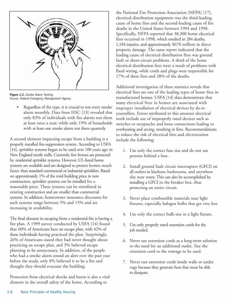
• Regardless of the type, it is crucial to test every smokealarm monthly. Data from HSC [13] revealed thatonly 83% of individuals with fire alarms test themat least once a year; while only 19% of householdswith at least one smoke alarm test them quarterly.
A second element impacting escape from a building is aproperly installed fire-suppression system. According to USFA[14], sprinkler systems began to be used over 100 years ago inNew England textile mills. Currently, few homes are protectedby residential sprinkler systems. However, UL-listed homesystems are available and are designed to protect homes muchfaster than standard commercial or industrial sprinklers. Basedon approximately 1% of the total building price in newconstruction, sprinkler systems can be installed for areasonable price. These systems can be retrofitted toexisting construction and are smaller than commercialsystems. In addition, homeowner insurance discounts forsuch systems range between 5% and 15% and areincreasing in availability.
The final element in escaping from a residential fire is having afire plan. A 1999 survey conducted by USFA [14] foundthat 60% of Americans have an escape plan, with 42% ofthese individuals having practiced the plan. Surprisingly,26% of Americans stated they had never thought aboutpracticing an escape plan, and 3% believed escapeplanning to be unnecessary. In addition, of the peoplewho had a smoke alarm sound an alert over the past yearbefore the study, only 8% believed it to be a fire andthought they should evacuate the building.
Protection from electrical shocks and burns is also a vitalelement in the overall safety of the home. According to
the National Fire Protection Association (NFPA) [17],electrical distribution equipment was the third-leadingcause of home fires and the second-leading cause of firedeaths in the United States between 1994 and 1998.Specifically, NFPA reported that 38,300 home electricalfires occurred in 1998, which resulted in 284 deaths,1,184 injuries, and approximately $670 million in directproperty damage. The same report indicated that theleading cause of electrical distribution fires was groundfault or short-circuit problems. A third of the homeelectrical distribution fires were a result of problems withfixed wiring, while cords and plugs were responsible for17% of these fires and 28% of the deaths.
Additional investigation of these statistics reveals thatelectrical fires are one of the leading types of home fires inmanufactured homes. USFA [14] data demonstrate thatmany electrical fires in homes are associated withimproper installation of electrical devices by do-it-yourselfers. Errors attributed to this amateur electricalwork include use of improperly rated devices such asswitches or receptacles and loose connections leading tooverheating and arcing, resulting in fires. Recommendationsto reduce the risk of electrical fires and electrocutioninclude the following:
1. Use only the correct fuse size and do not usepennies behind a fuse.
2. Install ground fault circuit interrupters (GFCI) onall outlets in kitchens, bathrooms, and anywhereelse near water. This can also be accomplished byinstalling a GFCI in the breaker box, thusprotecting an entire circuit.
3. Never place combustible materials near lightfixtures, especially halogen bulbs that get very hot.
4. Use only the correct bulb size in a light fixture.
5. Use only properly rated extension cords for thejob needed.
6. Never use extension cords as a long-term solutionto the need for an additional outlet. Size theextension cord to the wattage to be used.
7. Never run extension cords inside walls or underrugs because they generate heat that must be ableto dissipate.
2-8 Basic Principles of Healthy Housing
Figure 2.2. Smoke Alarm TestingSource: Federal Emergency Management Agency

Fire ExtinguishersA fire extinguisher should be listed and labeled by anindependent testing laboratory such as FM (FactoryMutual) or UL. Fire extinguishers are labeled according tothe type of fire on which they may be used. Fires involvingwood or cloth, flammable liquids, electrical, or metal sourcesreact differently to extinguishers. Using the wrong type ofextinguisher on a fire could be dangerous and could worsenthe fire. Traditionally, the labels A, B, C, and D have beenused to indicate the type of fire on which an extinguisheris to be used.
Type A—Used for ordinary combustibles such as cloth,wood, rubber, and many plastics. These types of fireusually leave ashes after they burn: Type A extinguishersfor ashes. The Type A label is in a triangle on theextinguisher.
Type B—Used for flammable liquid fires such as oil,gasoline, paints, lacquers, grease, and solvents. Thesesubstances often come in barrels: Type B extinguishers forbarrels. The Type B label is in a square on theextinguisher.
Type C—Used for electrical fires such as in wiring, fuse boxes,energized electrical equipment, and other electrical sources.Electricity travels in currents; Type C extinguishers forcurrents. The Type C label is in a circle on theextinguisher.
Type D—Used for metal fires such as magnesium,titanium, and sodium. These types of fires are very dangerousand seldom handled by the general public; Type D meansdon’t get involved. The Type D label is in a star on theextinguisher.
The higher the rating number on an A or B fire extinguisher,the more fire it can put out, but high-rated units are oftenthe heavier models. Extinguishers need care and must berecharged after every use—a partially used unit might aswell be empty. An extinguisher should be placed in thekitchen and in the garage or workshop. Each extinguishershould be installed in plain view near an escape route andaway from potential fire hazards such as heating appliances.
Recently, pictograms have come into use on fire extinguishers.These picture the type of fire on which an extinguisher isto be used. For instance, a Type A extinguisher has apictogram showing burning wood. A Type C extinguisher has a pictogram showing an electrical cord and outlet. Thesepictograms are also used to show what not to use. Forexample, a Type A extinguisher also show a pictogram of
an electrical cord and outlet with a slash through it (do notuse it on an electrical fire).
Fire extinguishers also have a number rating. For Type Afires, 1 means 1¼ gallons of water; 2 means 2½ gallons ofwater, 3 means 3¾ gallons of water, etc. For Type B andType C fires, the number represents square feet. For example,2 equals 2 square feet, 5 equals 5 square feet, etc.
Fire extinguishers can also be made to extinguish morethan one type of fire. For example, you might have anextinguisher with a label that reads 2A5B. This wouldmean this extinguisher is good for Type A fires with a2½-gallon equivalence and it is also good for Type B fireswith a 5-square-foot equivalency. A good extinguisher tohave in each residential kitchen is a 2A10BC fire extinguisher.You might also get a Type A for the living room andbedrooms and an ABC for the basement and garage.
PASS is a simple acronym to remind you how to operate mostfire extinguishers—pull, aim, squeeze, and sweep. Pull thepin at the top of the cylinder. Some units require thereleasing of a lock latch or pressing a puncture lever. Aimthe nozzle at the base of the fire. Squeeze or press thehandle. Sweep the contents from side to side at the baseof the fire until it goes out. Shut off the extinguisher andthen watch carefully for any rekindling of the fire.
Protection Against Toxic GasesProtection against gas poisoning has been a problem sincethe use of fossil fuels was combined with relatively tighthousing construction. NFPA [17] notes that NationalSafety Council statistics reflect unintentional poisoningsby gas or vapors, chiefly carbon monoxide (CO),numbering about 600 in 1998. One-fourth of theseinvolved heating or cooking equipment in the home. TheU.S. Consumer Product Safety Commission [18] statesthat in 2001 an estimated 130 deaths occurred as a resultof CO poisoning from residential sources; this decrease indeaths is related to the increased use of CO detectors. Inaddition, approximately 10,000 cases of CO-related injuriesoccur each year. NFPA [17] also notes that, similar to firedeaths, unintentional CO deaths are highest for ages 4 yearsand under and ages 75 years and older. Additional informationabout home CO monitoring can be found in Chapter 5.
References1. Ehlers VE, Steel EW. Municipal and rural
sanitation. Sixth edition. New York: McGraw-HillBook Company; 1965. p. 462–4.
2-9Healthy Housing Reference Manual

2. National Institute on Aging. Hyperthermia—toohot for your health, fact sheet health information.Bethesda, MD: US Department of Health andHuman Services; no date. Available from URL:http://www.niapublications.org/engagepages/hyperther.asp.
3. US Census Bureau. Historical census of housingtables—house heating fuel. Washington, DC: USCensus Bureau; 2002. Available from URL:http://www.census.gov/hhes/www/housing/census/historic/fuels.html.
4. Zilber SA. Review of health effects of indoorlighting. Architronic 1993;2(3). Available from URL:http://architronic.saed.kent.edu/v2n3/v2n3.06.html.
5. US Environmental Protection Agency.Information on levels of environmental noiserequisite to protect public health and welfare withan adequate margin of safety. Washington, DC: USEnvironmental Protection Agency; 1974.
6. Public Health, England and Wales. The HouseholdAppliances (Noise Emission) Regulations 1990.London: Her Majesty’s Stationery Office; 1990.
7. American Speech-Language-Hearing-Association.Noise: noise is difficult to define. Rockville, MD:American Speech-Language-Hearing-Association;2003. Available from URL: http://www.asha.org/ public/hearing/disorders/noise.htm.
8. US Environmental Protection Agency. Factoids:drinking water and ground water statistics for2002. Washington, DC: US EnvironmentalProtection Agency, Office of Ground Water andDrinking Water; January 2003. Available from URL:http://www.epa.gov/safewater.
9. Hinrichsen D, Robey B, Upadhyay UD. The healthdimension. In: Solutions for a water-short world.Population Report, Series M, No. 14. Baltimore, MD:Johns Hopkins School of Public Health, PopulationInformation Program; 1998. Available from URL:http://www.infoforhealth.org/pr/m14/m14chap5.shtml
10. US Census Bureau. Historical census of housingtables—plumbing facilities, 2002. Washington,DC: US Census Bureau; 2003. Available from URL:http://www.census.gov/hhes/www/housing/census/historic/plumbing.html.
11. US Census Bureau. Historical census of housingtables—crowded and severely crowded housingunits, 2002. Washington, DC: US CensusBureau; 2003. Available from URL:http://www.census.gov/hhes/ www/housing/ census/historic/crowding.html.
12. International Code Council. Fact sheet. FallsChurch, VA: International Code Council; no date.Available from URL: http://www.iccsafe.org/news/pdf/factssheet.pdf.
13. Home Safety Council. The state of home safety inAmerica—executive summary. Washington, DC:The Home Safety Council; 2002.
14. US Fire Administration. Welcome to the U.S. FireAdministration (USFA) Web site. Washington,DC: Federal Emergency Management Agency,Department of Homeland Security; 2003.Available from URL: http://www.usfa.fema.gov/.
15. US Environmental Protection Agency. Smokedetectors and radiation. Washington, DC: USEnvironmental Protection Agency; 2003. Availablefrom URL: http://www.epa.gov/radiation/sources/smoke_alarm.htm.
16. Helmenstein AM. How do smoke detectors work?Photoelectric & ionization smoke detectors, whatyou need to know about chemistry. New York:About, Inc.; 2003. Available from URL:http://chemistry.about.com/library/weekly/aa071401a.htm.
17. National Fire Protection Association. NFPA factsheets—electrical safety. Quincy, MA: NationalFire Protection Association; 2003. Available fromURL: http://www.nfpa.org/Research/NFPAFactSheets/Electrical/electrical.asp.
18. US Consumer Product Safety Commission.Nonfire carbon monoxide deaths: 2001 annualestimate. Washington, DC: US ConsumerProduct Safety Commission; 2004. Available fromURL: http://www.cpsc.gov/LIBRARY/co04.pdf.
2-10 Basic Principles of Healthy Housing

Additional Sources of Information Barbalace RC. Environmental justice and the NIMBYprinciple. Environmental Chemistry.com: Environmental,Chemistry, and Hazardous Materials Information andResources. Portland, ME; no date. Available from URL:http://environmentalchemistry.com/yogi/hazmat/articles/nimby.html.
Bryant B. The role of SNRE in the environmental justicemovement. Ann Arbor, MI: University of Michigan; 1997.Available from URL: http://www.umich.edu/~snre492/history.html.
Bullard RD. Waste and racism: a stacked deck? ForumAppl Res Public Pol spring 1993.
National Institute on Aging. Hypothermia: a cold weatherhazard, fact sheet health information. Bethesda, MD: USDepartment of Health and Human Services; 2001.Available from URL: http://www.niapublications.org/engagepages/ hypother.asp.
National Weather Service. Natural hazard statistics; nodate. Silver Spring, MD: National Weather Service.Available from URL: http://www.nws.noaa.gov/om/hazstats.shtml.
US Census Bureau. New residential construction(building permits, housing starts, and housingcompletions). Washington, DC: US Census Bureau; nodate. Available from URL:http://www.census.gov/newresconst.
2-11Healthy Housing Reference Manual

2-12 Basic Principles of Healthy Housing

“The poorest man may in his cottage bid defiance to all theforce of the Crown. It may be frail—its roof may shake—thewind may blow through it—the storm may enter, the rainmay enter—but the King of England cannot enter—all hisforce dares not cross the threshold of the ruined tenement!”
William Pitt, March 1763
IntroductionWilliam Pitt, arguing before the British Parliament againstexcise officers entering private homes to levy the CyderTax, eloquently articulated this long-held and cherishednotion of the sanctity of private property. However, aperson’s right to privacy is not absolute. There has alwaysbeen a tension between the rights of property owners to dowhatever they desire with their property and the ability ofthe government to regulate uses to protect the safety,health, and welfare of the community. Few, however,would argue with the right and duty of a city governmentto prohibit the operation of a munitions factory or achemical plant in the middle of a crowded residentialneighborhood.
History The first known housing laws are in the Code of Laws ofHammurabi [1], who was the King of Babylonia, circa1792–1750 BC. These laws addressed the responsibility of thehome builder to construct a quality home and outlined theimplications to the builder if injury or harm came to theowner as a result of the failure to do so. During the Puritanperiod (about 1620–1690), housing laws essentiallygoverned the behavior of the members of the society. Forexample, no one was allowed to live alone, so bachelors,widows, and widowers were placed with other families asservants or boarders. In 1652, Boston prohibited buildingprivies within 12 feet of the street. Around the turn of the18th century, some New England communitiesimplemented local ordinances that specified the size ofhouses. During the 17th century, additional public policieson housing were established. Because the English traditionof using wooden chimneys and thatched roofs led to firesin many dwellings, several colonies passed regulationsprohibiting them.
After the early 17th century came an era of very rapidmetropolitan growth along the East Coast. This growthwas due largely to immigration from Europe and wasspurred by the Industrial Revolution. The most serioushousing problems began in New York about 1840 when
the first tenements were built. In 1867, a report by theNew York Metropolitan Board of Health on livingconditions in tenements convinced the New York Statelegislature to pass the Tenement Housing Act of 1867 [2].The principal requirements of the act included thefollowing:
• Every room occupied for sleeping, if it does notcommunicate directly with the external air, musthave a ventilating or transom window of at least3 square feet to the neighboring room or hall.
• A proper fire escape is necessary on every tenementor lodging house.
• The roof is to be kept in repair and the stairs are tohave banisters.
• At least one toilet is required for every20 occupants for all such houses, and those toiletsmust be connected to approved disposal systems.
• Cleansing of every lodging house is to be to thesatisfaction of the Board of Health, which is to haveaccess at any time.
• All cases of infectious disease are to be reported tothe Board by the owner or his agent; buildings areto be inspected and, if necessary, disinfected orvacated if found to be out of repair.
There were also regulations governing distances betweenbuildings, heights of rooms, and dimensions of windows.Although this act had some beneficial influences onovercrowding, sewage disposal, lighting, and ventilation,perhaps its greatest contribution was in laying a foundationfor more stringent future legislation.
Jacob A. Riis, a Danish immigrant and a police reporter onNew York’s Lower East Side, published a book titled Howthe Other Half Lives—Studies Among the Tenements of NewYork [3], which swayed public opinion in the direction ofhousing reform and resulted in the Tenement House Act of1901. The basic principles established in the TenementHouse Act of 1901 still underlie much of the housingefforts in New York City today [4]. Since 1909, with theestablishment of the Philadelphia Housing Association, that cityhas had almost continual inspection and improvement.Chicago enacted housing legislation as early as 1889 and
Chapter 3: Housing Regulations
3-1Healthy Housing Reference Manual

health legislation as early as 1881. Regulations onventilation, light, drainage, and plumbing were put intoeffect in 1896.
Before 1892, all government involvement in housing wasat a local level. In 1892, however, the federal governmentpassed a resolution authorizing investigation of slumconditions in cities with 200,000 or more inhabitants.Congress appropriated only $20,000 (roughly equal to$390,000 in 2003) to cover the expenses of this project,which limited the number of investigations.
No significant housing legislation was passed in the20th century until 1929 [5], when the New York Statelegislature passed its Multiple Dwelling Law. Other citiesand states followed New York’s example and permittedless strict requirements in their codes. This decreasedwhat little emphasis there was on enforcement.Conditions declined until, by the 1930s, PresidentFranklin D. Roosevelt’s shocking report to the people was“that one-third of the nation is ill-fed, ill-housed, and ill-clothed.” In response to the overwhelming loss of homesduring the Great Depression, Congress passed the UnitedStates Housing Act of 1937, which created the UnitedStates Housing Authority (USHA). This act subsidizedconstruction of new public housing units and requiredthe elimination of at least an equivalent number of unitsfrom the local housing supply that were determined to beinferior. In 1942, the USHA was renamed the FederalPublic Housing Administration and, in 1947, wasrenamed the Public Housing Administration.
The federal government not only encouraged theconstruction of public housing, but took on the role offinancing private housing. In 1938, the Federal NationalMortgage Association was created. (Fannie Mae became aprivate organization in 1968 [6].) Its purpose was toprovide a secondary market for the FHA, created in 1934,and Veterans Administration (VA) mortgage loans. TheServicemen’s Readjustment Act of 1944, also known asthe GI Bill of Rights, created a VA loan programguaranteeing home mortgage loans for veterans. Thislegislation, in conjunction with the FHA loan program,was the impetus for initiating the huge program of homeconstruction and subsequent suburban growth followingWorld War II. In 1946, the Farmers Home Administration,housed in the United States Department of Agriculture(USDA), was created to make loans and grants forconstructing and repairing farm homes and assisting ruralself-help housing groups.
The Housing Act of 1949 allowed “primarily residential”and “blighted” urban areas to be condemned, cleared ofbuildings, and sold for private development. In additionto assisting in slum clearance, this act also provided foradditional public housing and authorized the USDA toprovide farmers with loans to construct, improve, repairor replace dwellings to provide decent, safe, and sanitaryliving conditions for themselves, their tenants, lessees,sharecroppers, and laborers.
Because the many housing responsibilities administeredby various agencies within the federal government provedunwieldy, the Housing and Urban Development Act waspassed in 1965. The U.S. Department of Housing andUrban Development (HUD) was created to centralize theresponsibilities of the Housing and Home Finance Agencyand incorporated the FHA, the Federal NationalMortgage Association, the Public Housing Administration,Urban Development Administration, and the CommunityFacilities Administration.
Zoning, Housing Codes, and Building CodesHousing is inextricably linked to the land on which it islocated. Changes in the patterns of land use in the UnitedStates, shifting demographics, an awareness of the needfor environmental stewardship, and competing uses forincreasingly scarce (desirable) land have all placed addedstress on the traditional relationship between the propertyowner and the community. This is certainly not a newdevelopment.
In the early settlement of this country, following the precedentset by their forefathers from Great Britain, gunpowdermills and storehouses were prohibited from the heavilypopulated portions of towns, owing to the frequent fires andexplosions. Later, zoning took the form of fire districtsand, under implied legislative powers, wooden buildingswere prohibited from certain sections of a municipality.Massachusetts passed one of the first zoning laws in 1692.This law authorized Boston, Salem, Charlestown, andcertain other market towns in the province to restrict theestablishment of slaughterhouses and stillhouses forcurrying leather to certain locations in each town.
Few people objected to such restrictions. Still, the tensionremained between the right to use one’s land and thecommunity’s right to protect its citizens. In 1926, theUnited States Supreme Court took up the issue in Villageof Euclid, Ohio, v. Ambler Realty [7]. In this decision,the Court noted,
3-2 Housing Regulations

“Until recent years, urban life was comparativelysimple; but with great increase and concentration ofpopulation, problems have developed which requireadditional restrictions in respect of the use andoccupation of private lands in urban communities.”
In explaining its reasoning, the Court said,
“the law of nuisances may be consulted not for thepurpose of controlling, but for the helpful aid of itsanalogies in the process of ascertaining the scope of thepolice power. Thus the question of whether thepower exists to forbid the erection of a building of aparticular kind or a particular use is to bedetermined, not by an abstract consideration of thebuilding or other thing considered apart, but byconsidering it in connection with the circumstancesand the locality… A nuisance may be merely theright thing in the wrong place—like a pig in theparlor instead of the barnyard.”
Zoning, housing, and building codes were adopted to improvethe health and safety of people living in communities.And, to some extent, they have performed this function.Certainly, housing and building codes, when enforced,have resulted in better constructed and maintainedbuildings. Zoning codes have been effective insegregating noxious and dangerous enterprises fromresidential areas. However, as the U.S. population hasgrown and changed from a rural to an urban then to asuburban society, land use and building regulationsdeveloped for the 19th and early 20th centuries arecreating new health and safety problems not envisioned inearlier times.
Zoning and Zoning OrdinancesZoning is essentially a means of ensuring that a community’sland uses are compatible with the health, safety, andgeneral welfare of the community. Experience has shownthat some types of controls are needed to provide orderlygrowth in relation to the community plan for development.Just as a capital improvement program governs publicimprovements such as streets, parks and other recreationalfacilities, schools, and public buildings, so zoning governsthe planning program with respect to the use of publicand private property.
It is very important that housing inspectors know the generalnature of zoning regulations because properties inviolation of both the housing code and the zoning ordinancemust be brought into full compliance with the zoningordinance before the housing code can be enforced. In
many cases, the housing inspector may be able toeliminate violations or properties in violation of housingcodes through enforcement of the zoning ordinance.
Zoning ObjectivesAs stated earlier, the purpose of a zoning ordinance is toensure that the land uses within a community areregulated not only for the health, safety, and welfare of thecommunity, but also are in keeping with thecomprehensive plan for community development. Theprovisions in a zoning ordinance that help to achievedevelopment that provides for health, safety, and welfareare designed to do the following:
• Regulate height, bulk, and area of structure. Toprovide established standards for healthful housingwithin the community, regulations dealing withbuilding heights, lot coverage, and floor areas mustbe established. These regulations then ensure thatadequate natural lighting, ventilation, privacy, andrecreational areas for children will be realized.These are all fundamental physiologic needsnecessary for a healthful environment. Safety fromfires is enhanced by separating buildings to meetyard and open-space requirements. Throughrequiring a minimum lot area per dwelling unit,population density controls are established.
• Avoid undue levels of noise, vibration, glare, airpollution, and odor. By providing land-usecategory districts, these environmental stresses uponthe individual can be reduced.
• Lessen street congestion by requiring off-streetparking and off-street loading.
• Facilitate adequate provision of water, sewerage,schools, parks, and playgrounds.
• Provide safety from flooding.
• Conserve property values. Through carefulenforcement of the zoning ordinance provisions,property values can be stabilized and conserved.
To understand more fully the difference between zoningand subdivision regulations, building codes, and housingordinances, the housing inspector must know what cannotbe accomplished by a zoning ordinance. Items thatcannot be accomplished by a zoning ordinance includethe following:
3-3Healthy Housing Reference Manual

• Overcrowding or substandard housing. Zoningis not retroactive and cannot correct existingconditions. These are corrected throughenforcement of a minimum standards housing code.
• Materials and methods of construction. Materialsand methods of construction are enforced throughbuilding codes rather than through zoning.
• Cost of construction. Quality of construction,and hence construction costs, are often regulatedthrough deed restrictions or covenants. Zoningdoes, however, stabilize property values in an areaby prohibiting incompatible development, such asheavy industry in the midst of a well-establishedsubdivision.
• Subdivision design and layout. Design and layoutof subdivisions, as well as provisions for parks andstreets, are controlled through subdivisionregulations.
Content of the Zoning Ordinance Zoning ordinances establish districts of whatever size,shape, and number the municipality deems best forcarrying out the purposes of the zoning ordinance. Mostcities use three major districts: residential (R), commercial(C), and industrial (I). These three may then besubdivided into many subdistricts, depending on localconditions; e.g., R-1 (single-unit dwellings), R-2(duplexes), R-3 (low-rise apartment buildings), and so on.These districts specify the principal and accessory uses,exceptions, and prohibitions [8].
In general, permitted land uses are based on the intensityof land use—a less intense land use being permitted in amore intense district, but not vice versa. For example, asingle-unit residence is a less intense land use than a multiunitdwelling (defined by HUD as more than four livingunits) and hence would be permitted in a residentialdistrict zoned for more intense land use (e.g., R-3). Amultiunit dwelling would not, however, be permitted inan R-1 district. While intended to promote the health,safety, and general welfare of the community, housingtrends in the last half of the 20th century have led anumber of public health and planning officials toquestion the blind enforcement of zoning districts. Theseindividuals, citing such problems as urban sprawl, havestated that municipalities need to adopt a more flexibleapproach to land use regulation—one that encouragescreating mixed-use spaces, increasing population densities,and reducing reliance on the automobile.
These initiatives are often called smart growth programs.It is imperative, if this approach is taken, that bothgovernmental officials and citizens be involved in theplanning stage. Without this involvement, the communitymay end up with major problems, such as overloadedinfrastructure, structures of inappropriate constructioncrowded together, and fire and security issues forresidents. Increased density could strain the existing water,sewer and waste collection systems, as well as fire andpolice services, unless proper planning is implemented.
In recent years, some ordinances have been partially basedon performance standards rather than solely on land-useintensity. For example, some types of industrial developmentsmay be permitted in a less intense use district providedthat the proposed land use creates no noise, glare, smoke,dust, vibration, or other environmental stress exceedingacceptable standards and provided further that adequateoff-street parking, screening, landscaping, and similarmeasures are taken.
Bulk and Height Requirements. Most early zoningordinances stated that, within a particular district, theheight and bulk of any structure could not exceed certaindimensions and specified dimensions for front, side, andrear yards. Another approach was to use floor-area ratiosfor regulation. A floor-area ratio is the relation betweenthe floor space of the structure and the size of the lot onwhich it is located. For example, a floor-area ratio of1 would permit either a two-story building covering 50%of the lot, or a one-story building covering 100% of the lot, asdemonstrated in Figure 3.1. Other zoning ordinancesspecify the maximum amount of the lot that can becovered or merely require that a certain amount of openspace must be provided for each structure, and leave thebuilder the flexibility to determine the location of thestructure. Still other ordinances, rather than specify aparticular height for the structure, specify the angle oflight obstruction that will assure adequate air and light tothe surrounding structures, as demonstrated in Figure 3.2.
Yard Requirements. Zoning ordinances also containminimum requirements for front, rear, and side yards. Theserequirements, in addition to stating the lot dimensions,usually designate the amount of setback required. Mostordinances permit the erection of auxiliary buildings inrear yards provided that they are located at stateddistances from all lot lines and provided sufficient openspace is maintained. If the property is a corner lot,additional requirements are established to allow visibilityfor motorists.
3-4 Housing Regulations

Off-street Parking. Space for off-street parking and off-street loading, especially for commercial buildings, is alsocontained in zoning ordinances. These requirements arebased on the relationship of floor space or seating capacityto land use. For example, a furniture store would requirefewer off-street parking spaces in relation to the floor areathan would a movie theater.
Exceptions to the Zoning CodeNonconforming UsesBecause zoning is not retroactive, all zoning ordinancescontain a provision for nonconforming uses. If a use hasalready been established within a particular district before theadoption of the ordinance, it must be permitted tocontinue, unless it can be shown to be a public nuisance.
Provisions are, however, put into the ordinance to aid ineliminating nonconforming uses over time. Theseprovisions generally prohibit a) an enlargement orexpansion of the nonconforming use, b) reconstruction ofthe nonconforming use if more than a certain portion ofthe building should be destroyed, c) resumption of theuse after it has been abandoned for a period of specifiedtime, and d) changing the use to a higher classification or to
another nonconforming use. Some zoning ordinancesfurther provide a period of amortization during whichnonconforming land use must be phased out.
Variances Zoning ordinances contain provisions for permittingvariances and providing a method for granting thesevariances, subject to certain specified provisions. Avariance may be granted when, owing to the specific conditionsor use of a particular lot, an undue hardship would beimposed on the owner if the exact content of theordinance is enforced. A variance may be granted due tothe shape, topography, or other characteristic of the lot.For example, suppose an irregularly shaped lot is locatedin a district having a side yard requirement of 20 feet on aside and a total lot size requirement of 10,000 square feet.Further suppose that this lot contains 10,200 square feet(and thus meets the total size requirement); however, dueto the irregular shape of the lot, there would be sufficientspace for only a 15-foot side yard. Because a hardshipwould be imposed on the owner if the exact letter of thelaw is applied, the owner of the property could apply tothe zoning adjustment board for a variance. Because thetotal area of the lot is sufficient and a lessening of the
3-5Healthy Housing Reference Manual
Figure 3.1. Example of a Floor Area
Figure 3.2. Example of an Angle of Light Obstruction

ordinance requirements would not be detrimental to thesurrounding property, nor would it interfere with neighboringproperties, a variance would probably be granted. Notethat a variance is granted to the owner under specificconditions. Should use of the property change, thevariance would be voided.
ExceptionsAn exception is often confused with a variance. In everycity there are some necessary uses that do not correspondto the permitted land uses within the district. The zoningcode recognizes, however, that if proper safeguards areprovided, these uses would not have a detrimental effecton the district. An example would be a fire station thatcould be permitted in a residential area, provided thestation house is designed and the property is properlylandscaped to resemble or fit in with the characteristics of theneighborhood in which it is located.
AdministrationZoning inspectors are essential to the zoning processbecause they have firsthand knowledge of a case. Often,the zoning inspector may also be the building inspector orhousing inspector. Because the building inspector orhousing inspector is already in the field makinginspections, it is relatively easy for that individual tocheck compliance with the zoning ordinances. Complianceis determined by comparing the actual land use with thatallowed for the area and shown on the zoning map.
Each zoning ordinance has a map detailing the permittedusage for each block. Using a copy of this map, theinspector can make a preliminary check of the land use inthe field. If the use does not conform, the inspector mustthen contact the Zoning Board to see whether the property inquestion was a nonconforming use at the time of thepassage of the ordinance and whether an exception or variancehas been granted. In cities where up-to-date records aremaintained, the inspector can check the use in the field.
When a violation is observed, and the property ownersare duly notified of the violation, they have the right torequest a hearing before the Zoning Board of Adjustment(also called the Zoning Board of Appeals in some cities).The board may uphold the zoning enforcement officer ormay rule in favor of the property owner. If the action ofthe zoning officer is upheld, the property owner may, ifdesired, seek relief by appealing the decision to the courts;otherwise, the violation must be corrected to conform tothe zoning code.
It is critical for the housing or building inspector and thezoning inspector to work closely in municipalities wherethese positions and responsibilities are separate. Experiencehas shown that illegally converted properties are oftenamong the most substandard encountered in the municipalityand often contain especially dangerous housing code violations.
In communities where the zoning code is enforced effectively,the resulting zoning compliance helps to advance, as wellas sustain, many of the minimum standards of thehousing code such as occupancy, ventilation, light, andunimpeded egress. By the same token, building orhousing inspectors can often aid the zoning inspector byhelping eliminate some nonconforming uses through codeenforcement.
Housing CodesA housing code, regardless of who promulgates it, is basicallyan environmental health protection code. Housing codesare distinguished from building codes in that they coverhouses, not buildings in general. For example, the housingcode requires that walls support the weight of the roof,any floors above, and the furnishings, occupants, etc.,within a building.
Early housing codes primarily protected only physical health;hence, they were enforced only in slum areas. In the1970s, it was realized that, if urban blight and its associatedhuman suffering were to be controlled, housing codesmust consider both physical and mental health and mustbe administered uniformly throughout the community.
In preparing or revising housing codes, local officials mustmaintain a level of standards that will not merely beminimal. Standards should maintain a living environmentthat contributes positively to healthful individual andfamily living. The fact that a small portion of housingfails to meet a desirable standard is not a legitimate reasonfor retrogressive modification or abolition of a standard.The adoption of a housing ordinance that establishes lowstandards for existing housing serves only to legalize andperpetuate an unhealthy living environment. Whereverlocal conditions are such that immediate enforcement ofsome standards within the code would cause unduehardship for some individuals, it is better to allow sometime for compliance than to eliminate an otherwisesatisfactory standard. When immediate health or safetyhazards are not involved, it is often wise to attempt tocreate a reasonable timetable for accomplishing necessarycode modifications.
3-6 Housing Regulations

HistoryTo assist municipalities with developing legislation necessaryto regulate the quality of housing, the American PublicHealth Association (APHA) Committee on the Hygieneof Housing prepared and published in 1952 a proposedhousing ordinance. This provided a prototype on whichsuch legislation might be based and has served as thebasis for countless housing codes enacted in the UnitedStates since that time. Some municipalities enacted it withoutchange. Others made revisions by omitting some portions,modifying others, and sometimes adding new provisions [9].
The APHA ordinance was revised in 1969 and 1971. In 1975,APHA and the CDC jointly undertook the job ofrewriting and updating this model ordinance. The newordinance was entitled the APHA-CDC RecommendedHousing Maintenance and Occupancy Ordinance [10]. Themost recent model ordinance was published by APHA in1986 as Housing and Health: APHA-CDC RecommendedMinimum Housing Standards [11]. This new ordinance isone of several model ordinances available to communitieswhen they are interested in adopting a housing code.
A community should read and consider each elementwithin the model code to determine its applicability totheir community. A housing code is merely a means to anend. The end is the eventual elimination of all substandardconditions within the home and the neighborhood. This endcannot be achieved if the community adopts aninadequate housing code.
ObjectivesThe Housing Act of 1949 [12] gave new impetus toexisting local, state, and federal housing programsdirected toward eliminating poor housing. In passingthis legislation, Congress defined a new nationalobjective by declaring that “the general welfare andsecurity of the nation and the health and livingstandards of its people...require a decent home and asuitable living environment for every American family.”This mandate generated an awareness that the quality ofhousing and residential environment has an enormousinfluence upon the physical and mental health and thesocial well-being of each individual and, in turn, on theeconomic, political, and social conditions in everycommunity. Consequently, public agencies, units ofgovernment, professional organizations and others soughtways to ensure that the quality of housing and theresidential environment did not deteriorate.
It soon became apparent that ordinances regulating thesupplied utilities and the maintenance and occupancy of
dwellings were needed. Commonly called housing codes,these ordinances establish minimum standards to makedwellings safe, sanitary, and fit for human habitation bygoverning their condition and maintenance, theirsupplied utilities and facilities, and their occupancy. The2003 International Code Council (ICC) [13,14]International Residential Code-One- and Two-FamilyDwellings (R101.3) states
“the purpose of this code is to provide minimumrequirements to safeguard the public safety, healthand general welfare, through affordability, structuralstrength, means of egress, facilities, stability, sanitation,light and ventilation, energy conservation, safety tofire and property from fire and other hazardsattributed to the built environment.”
Critical Requirements of an Effective Housing ProgramA housing code is limited in its effectiveness by severalfactors. First, if the housing code does not contain standardsthat adequately protect the health and well-being of theindividuals, it cannot be effective. The best-trainedhousing inspector, if not armed with an adequate housingcode, can accomplish little good in the battle againsturban blight.
A second issue in establishing an effective housing code isthe need to establish a baseline of current housing conditions.A systems approach requires that you establish where youare, where you are going, and how you plan to achieve yourgoals. In using a systems approach, it is essential to knowwhere the program started so that the success or failure ofvarious initiatives can be established. Without thisinformation, success cannot be replicated, because youcannot identify the obstacles navigated nor the elementsof success. Many initiatives fail because programadministrators are without the necessary proof of successwhen facing funding shortfalls and budget cuts.
A third factor affecting the quality of housing codes isbudget. Without adequate funds and personnel, thecommunity can expect to lose the battle against urbanblight. It is only through a systematic enforcement effortby an adequately sized staff of properly trained inspectorsthat the battle can be won.
A fourth factor is the attitude of the political bodieswithin the area. A properly administered housing programwill require upgrading substandard housing throughout thecommunity. Frequently, this results in political pressuresbeing exerted to prevent the enforcement of the code incertain areas of the city. If the housing effort is backed
3-7Healthy Housing Reference Manual

properly by all political elements, blight can be controlledand eventually eliminated within the community. If, however,the housing program is not permitted to choke out thespreading influence of substandard conditions, urbanblight will spread like a cancer, engulfing greater andgreater portions of the city. Similarly, an effort directed atonly the most seriously blighted blocks in the city willupgrade merely those blocks, while the blight spreadselsewhere. If urban blight is to be controlled, it must becut out in its entirety.
A fifth element that limits housing programs is whetherthey are supported fully by the other departments withinthe city. Regardless of which city agency administers thehousing program, other city agencies must support theactivities of the housing program. In addition, great effortshould be expended to obtain the support andcooperation of the community. This can be accomplishedthrough public awareness and public informationprograms, which can result in considerable support orconsiderable resistance to the efforts of the program.
A sixth limitation is an inadequately or improperlytrained inspection staff. Inspectors should be capable ofevaluating whether a serious or a minor problem exists inmatters ranging from the structural stability of a buildingto the health and sanitary aspects of the structure. If theydo not have the authority or expertise, they shoulddevelop that expertise or establish effective and efficientagreements with overlapping agencies to ensure timelyand appropriate response.
A seventh item that frequently restricts the effectiveness ofa housing program is the fact that many housing groupsfail to do a complete job of evaluating housingproblems. The deterioration of an area may be due tofactors such as housing affordability, tax rates, or issuesrelated to investment cost and return. In many cases, theinspection effort is restricted to merely evaluating theconditions that exist, with little or no thought given towhy these conditions exist. If a housing effort is to besuccessful, as part of a systems approach, the question ofwhy the homes deteriorated must be considered. Wasit because of environmental stresses within theneighborhood that need to be eliminated or was itbecause of apathy on the part of the occupants? In eithercase, if the causative agent is not removed, then theinspector faces an annual problem of maintaining thequality of that residence. It is only by eliminating thecauses of deterioration that the quality of theneighborhood can be maintained. Often the regulatoryauthority does not have adequate authority within the
enabling legislation of the code needed to resolve theproblem or there are gaps in jurisdiction.
Content of a Housing CodeAlthough all comprehensive housing codes or ordinancescontain a number of common elements, the provisions ofcommunities will usually vary. These variations stem fromdifferences in local policies, preferences, and, to a lesserextent, needs. They are also influenced by the standardsset by the related provisions of the diverse building,electrical, and plumbing codes in use in the municipality.
Within any housing code there are generally five features:
1. Definitions of terms used in the code.
2. Administrative provisions showing who isauthorized to administer the code and the basicmethods and procedures that must be followed inimplementing and enforcing the sections of thecode. Administrative provisions deal with itemssuch as reasonable hours of inspections, whetherserving violation notices is required, how to notifyabsentee owners or resident-owners or tenants, how toprocess and conduct hearings, what rules to followin processing dwellings alleged to be unfit forhuman habitation, and how to occupy or usedwellings finally declared fit.
3. Substantive provisions specifying the various typesof health, building, electrical, heating, plumbing,maintenance, occupancy, and use conditions thatconstitute violations of the housing code. Theseprovisions can be and often are grouped into threecategories: minimum facilities and equipment fordwelling units; adequate maintenance of dwellingsand dwelling units, as well as their facilities andequipment; and occupancy conditions of dwellingsand dwelling units.
4. Court and penalty sections outlining the basis forcourt action and thepenalty or penalties to whichthe alleged violator will be subjected if provedguilty of violating one or more provisions of the code.
5. Enabling, conflict, and unconstitutionalityclauses providing the date a new or amended codewill take effect, prevalence of more stringentprovision when there is a conflict of two codes,severability of any part of the ordinance thatmight be found unconstitutional, and retention ofall other parts in full course and effect. In any city
3-8 Housing Regulations

following the format of the APHA-CDC RecommendedHousing Maintenance and Occupancy Ordinance[10] the housing officer or other supervisor incharge of housing inspections will also adoptappropriate housing rules and regulations fromtime to time to clarify or further refine theprovisions of the ordinance. When rules andregulations are used, care should be taken that thedepartment is not overburdened with a number ofminor rules and regulations. Similarly, a housingordinance that encompasses all rules and regulationsmight have difficulty because any amendments toit will require action by the political element ofthe community. Some housing groups, inattempting to obtain amendments to anordinance, have had the entire ordinance thrownout by the political bodies.
Administrative Provisions of a Housing CodeThe administrative procedures and powers of the housinginspection agency, its supervisors, and its staff are similar toother provisions in that all are based on the police power ofthe state to legislate for public health and safety. Inaddition, the administrative provisions, and to a lesserextent, the court and penalty provisions, outline how thepolice power is to be exercised in administering andenforcing the code.
Generally, the administrative elements deal withprocedures for ensuring that the constitutional doctrines ofreasonableness, equal protection under the law and dueprocess of law are observed. They also must guard againstviolation of prohibitions against unlawful search and seizure,impairment of obligations of contract, and unlawfuldelegation of authority. These factors encompass items ofgreat importance to housing inspection supervisors suchas the inspector’s right of entry, reasonable hours ofinspection, proper service, and the validity of the provisionsof the housing codes they administer.
Owner of Record. It is essential to file legal actionsagainst the true owners of properties in violation ofhousing codes. With the advent of the computer, this isoften much easier than in the past. Databases that providethis information are readily available from many offices oflocal government such as the tax assessment office. Themethod of obtaining the name and address of the legalowner of a property in violation varies from place toplace. Ordinarily, a check of the city tax records willsuffice unless there is reason to believe these are not up todate. In this case, a further check of county or parishrecords will turn up the legal owner if state law requires
deed registration there. If it does not, the advice of themunicipal law department should be sought about the nextsteps to follow.
Due Process Requirements. Every notice, complaint,summons, or other type of legal paper concerning allegedhousing code violations in a given dwelling or dwellingunit must be legally served on the proper party to be validand to prevent harassment of innocent parties. This mightbe the owner, agent, or tenant, as required by the code. Itis customary to require that the notice to correct existingviolations and any subsequent notices or letters be served bycertified or registered mail with return receipt requested. Thereceipt serves as proof of service if the case has to be takento court.
Due process requirements also call for clarity andspecificity with respect to the alleged violations, both inthe violation notices and the court complaint-summons.For this reason, special care must be taken to be completeand accurate in listing the violations and charges. Toillustrate, rather than direct the violator to repair allwindows where needed, the violator should be toldexactly which windows and what repairs are involved.
The chief limitation on the due process requirement, withrespect to service of notices, lies in cases involvingimmediate threats to health and safety. In these instances,the inspection agency or its representative may, withoutnotice or hearing, issue an order citing the existence ofthe emergency and requiring that action deemednecessary to meet the emergency be taken.
In some areas housing courts on the municipal level haveadvocates that assist both plaintiffs and defendantsprepare for the court process or to resolve the issue toavoid court.
Hearings and Condemnation Power. The purpose of ahearing is to give the alleged violator an opportunity to beheard before further action is taken by the housing inspectionagency. These hearings may be very informal, involvingmeetings between a representative of the agency and theperson ordered to take corrective action. They also maybe formal hearings at which the agency head presides andat which the city and the defendant both are entitled tobe represented by counsel and expert witnesses.
Informal Hearings. A violator may have questions about aviolation notice or the notice may be served at a timewhen personal hardship or other factors prevent a violatorfrom meeting the terms of the notice. Therefore, many
3-9Healthy Housing Reference Manual

housing codes provide the opportunity for a hearing atwhich the violator may discuss questions or problems andseek additional time or some modification of the order.Administered in a firm but understanding manner, thesehearings can serve as invaluable aids in relieving needlessfears of those involved, in showing how the inspectionprogram is designed to help them and in winning theirvoluntary compliance.
Formal Hearings. Formal hearings are often quasijudicialhearings (even though the prevailing court rules ofevidence do not always apply) from which an appeal maybe taken to court. All witnesses must therefore be swornin, and a record of the proceedings must be made. Theformal hearing is used chiefly as the basis for determiningwhether a dwelling is fit for human habitation,occupancy, or use. In the event it is proved unfit, thebuilding is condemned and the owner is given adesignated amount of time either to rehabilitate itcompletely or to demolish it. Where local funds areavailable, a municipality may demolish the building andplace a lien against the property to cover demolition costsif the owner fails to obey the order within the timespecified. This type of condemnation hearing is a veryeffective means of stimulating prompt and appropriatecorrective action when it is administered fairly and firmly.
Procedures for Coping With Common Problems. Severalstates and local communities have developed innovativeways to resolve code violation issues.
Limitation of Occupancy Notification. This techniquewas pioneered in Wilmington, Delaware. It makes itmandatory for property owners in the community toobtain a legal notice from the housing inspection agencyspecifying the maximum number of persons that mayoccupy each of their properties. It also requires these ownersto have a residence, place of business, or an agent for theirproperties within the community. The agent should beempowered to take remedial action on any of theproperties found in violation. In addition, if the propertyis sold, the new owner must obtain a new Limitation ofOccupancy Notification.
Request for Inspections. Several states permit theirmunicipalities to offer a request for inspection service. Fora fee, the housing inspector will inspect a property forviolations of the housing code before its sale so that thebuyer can learn its condition in advance. Many states andlocalities now require owners to notify prospectivepurchasers of any outstanding notice of health risk orviolations they have against their property before the sale.
If they fail to do so, some codes will hold the owner liableto the purchaser and the inspection agency for violations.
Tickets for Minor Offenses. Denver, Colorado, has usedminimal financial fines to prod minor violators and firstoffenders into correcting violations without the cityresorting to court action. There are mixed views aboutthis technique because it is akin to formal police action.Nevertheless, the action may stimulate compliance andreduce the amount of court action needed to achieve it.
Forms and Form Letters. A fairly typical set of forms andform letters are described below. It should be stressed thatinspection forms to be used for legal notices must satisfylegal standards of the code, be meaningful to the ownerand sufficiently explicit about the extent and location ofparticular defects, be adaptable to statistical compilationfor the governing body reports, and be written in a mannerthat will facilitate clerical and other administrative usage.
The Daily Report Form. This form gives the inspectionagency an accurate basis for reporting, evaluating, and, ifnecessary, improving the productivity and performance ofits inspectors.
Complaint Form. This form helps obtain full informationfrom the complainant and thus makes the relativeseriousness of the problem clear and reduces the numberof crank complaints.
No-entry Notice. This notice advises occupants or ownersthat an inspector was there and that they must return acall to the inspector.
Inspection Report Form. This is the most important formin an agency. It comes in countless varieties, but if designedproperly, it will ensure more productivity and morethoroughness by the inspectors, reduce the time spent inwriting reports, locate all violations correctly, and reducethe time required for typing violation notices. Forms mayvary widely in sophistication from a very simple form toone whose components are identified by number for usein processing the case by automation. Some forms are acombined inspection report and notice form in triplicate sothat the first page can be used as the notice of violation, thesecond as the office record, and the third as the guide forreinspection. A covering form letter notifies the violator ofthe time allowed to correct the conditions listed in thereport form.
Violation Notice. This is the legal notice that housingcode violations exist and must be corrected within the
3-10 Housing Regulations

indicated amount of time. The notice may be in the formof a letter that includes the alleged violations or has acopy of these attached. It may be a standard notice form,or it may be a combined report-notice. Regardless of thetype of notice used, it should make the location andnature of all violations clear and specify the exact sectionof the code that covers each one. The notice must adviseviolators of their right to a hearing. It should also indicatethat the violator has a right to be represented by counseland that failure to obtain counsel will not be accepted asgrounds for postponing a hearing or court case.
Hearing Forms. These should include a form letternotifying the violator of the date and time set for the hearing,a standard summary sheet on which the supervisor canrecord the facts presented at an informal hearing, and ahearing-decision letter for notifying all concerned of thehearing results. The latter should include the names of theviolator, inspector, law department, and any other cityofficial or agency that may be involved in the case.
Reinspection Form Letters or Notices. These have thesame characteristics as violation notices except that theycover the follow-up orders given to the violator who hasfailed to comply with the original notice within the timespecified. Some agencies may use two or three types ofthese form letters to accommodate different degrees ofresponse by the violator. Whether one or several are used,standardization of these letters or notices will expedite theprocessing of cases.
Court Complaint and Summons Forms. These formsadvise alleged violators of the charges against them andsummon them to appear in court at the specified timeand place. It is essential that the housing inspectionagency work closely with the municipal law departmentin preparing these forms so that each is done in exactaccord with the rules of court procedure in the relevantstate and community.
Court Action Record Form. This form provides an accuraterunning record of the inspection agency’s court actions andtheir results.
Substantive Provisions of a Housing CodeA housing code is the primary tool of the housinginspector. The code spells out what the inspector may ormay not do. An effort to improve housing conditions can beno better than the code allows. The substantive provisions ofthe code specify the minimal housing conditions acceptableto the community that developed them.
Dwelling units should have provisions for preparing at leastone regularly cooked meal per day. Minimum equipmentshould include a kitchen sink in good working conditionand properly connected to the water supply systemapproved by the appropriate authority. It should provide,at all times, an adequate amount of heated and unheatedrunning water under pressure and should be connected toa sewer system approved by the appropriate authority.Cabinets or shelves, or both, for storing eating, drinking,and cooking utensils and food should be provided. Thesesurfaces should be of sound construction and made ofmaterial that is easy to clean and that will not have a toxicor deleterious effect on food.
In addition, a stove and refrigerator should be provided.Within every dwelling there should be a room that affordsprivacy and is equipped with a flush toilet in good workingcondition.
Within the vicinity of the flush toilet, a sink should beprovided. In no case should a kitchen sink substitute as alavatory sink. In addition, within each dwelling unit thereshould be, within a room that affords privacy, either a bathtubor shower or both, in good working condition. Both thelavatory sink and the bathtub or shower or both should beequipped with an adequate amount of heated andunheated water under pressure. Each should be connectedto an approved sewer system.
Within each dwelling unit two or more means of egress shouldbe provided to safe and open space at ground level. Provisionsshould be incorporated within the housing code to meet thesafety requirements of the state and community involved. Thehousing code should spell out minimum standards for lightingand ventilation within each room in the structure. In addition,minimum thermal standards should be provided.Although most codes merely provide the requirement of agiven temperature at a given height above floor level, thecommunity should give consideration to the use ofeffective temperatures. The effective temperature is a means ofincorporating not only absolute temperature in degrees, butalso humidity and air movement, giving a better indication ofthe comfort index of a room.
The code should provide that no person shall occupy orlet for occupancy any dwelling or dwelling units that donot comply with stated requirements. Generally, theserequirements specify that the foundation, roof, exterior walls,doors, window space and windows of the structure besound and in good repair; that it be moisture-free,watertight and reasonably weather tight and that allstructural surfaces be sound and in good repair.
3-11Healthy Housing Reference Manual

HUD defines a multifamily dwelling unit as one that containsfour or more dwelling units in a single structure. Adwelling unit is further defined as a single unit ofresidence for a family of one or more persons in whichsleeping accommodations are provided but toileting orcooking facilities are shared by the occupants.
Building CodesBuilding codes define what materials and methods aretobe used in the construction of various buildings. Modelbuilding codes have been published by various tradeorganizations such as the Southern Building Code CongressInternational (SBCCI), Building Officials and CodeAdministrators (BOCA), and the International Conference ofBuilding Officials (ICBO). Each of these groupspublished a model building code that was widely used oradapted regionally in the United States. BOCA nationalcodes were used mostly in eastern and Great Lakes states,ICBO uniform codes in western and Midwest states, andSBCCI standard codes in southern states. As a result, theconstruction industry often faced the challenge, and cost,of building to different codes in different areas of the country.
In 1994, BOCA, ICBO, and SBCCI created theInternational Code Council (ICC) to develop a single set ofcomprehensive, coordinated model construction codes thatcould be used throughout the United States and aroundthe world. The first I-Code published was theInternational Plumbing Code in 1995. By 2000, acomplete family of I-Codes was available, including theInternational Building Code. The ICC Performance Code forBuildings and Facilities joined the I-Code family in 2001.
On February 1, 2003, the three organizations (BOCA,SBCCI, and ICBO) were consolidated into the ICC[13,14]. According to ICC Board president, Paul E. Myers,
“The ICC International Codes (I Codes) combinethe strengths of the regional codes without regionallimitations. The ICC is a nonprofit organizationdedicated to developing a single set of comprehensiveand coordinated national codes to make complianceeasier and more cost-effective. I Codes respond to theneeds of the construction industry and public safety.A single set of codes has strong support fromgovernment, code enforcement officials, fire officials,architects, engineers, builders, developers, andbuilding owners and managers.”
References1. Hammurabi’s Code of Laws. Translated by L.W.
King. Available from URL:http://eawc.evansville.edu/anthology/hammurabi.htm.
2. Claghorn KH. The foreign immigrant in NewYork City. Reports of the Industrial Commission,Volume XV. Washington, DC: US GovernmentPrinting Office; 1901.p. 465-92. Available fromURL: http://tenant.net/Community/LES/clag2.html.
3. Riis J. How the other half lives—studies amongthe tenements of New York. New York: CharlesScriber’s Sons; 1890. Available from URL:http://www.bartleby.com/208/.
4. New York City Department of City Planning. NewYork City zoning: zoning history. New York City:New York City Department of City Planning; nodate. Available from URL:http://www.nyc.gov/html/dcp/html/zone/zonehis.html.
5. New York State Multiple Dwelling Law: chapter713 of the Laws of 1929, as amended. Availablefrom URL: http://tenant.net/Other_Laws/MDL/mdltoc.html.
6. Understanding Fannie Mae: our history.Washington, DC: Fannie Mae; 2005. Availablefrom URL: http://www. fanniemae.com/aboutfm/understanding/history.jhtml?p=About+Fannie+Mae&s=Understanding+Fannie+Mae&t=Our+History.
7. Paulson PB. Protecting zoning laws. Atlanta:North Buckhead Civic Association; 2000 18 Mar.Available from URL:http://www.nbca.org/TAP_AJC_3-18.htm.
8. Municipal Code Corporation. Municipal buildingcodes (online library). Tallahassee, FL: MunicipalCode Corporation. Available from URL:http://www.municode.com/resources/online_codes.asp.
9. American Public Health Association. Housingordinance. Am J Public Health 1952Jan;42(1):76–7.
10. US Public Health Service. APHA-CDCrecommended housing maintenance and occupancy
3-12 Housing Regulations

ordinance. Atlanta: US Department of Health andHuman Services; 1975.
11. American Public Health Association. Housingand health: APHA-CDC recommended minimumhousing standards. Washington, DC: AmericanPublic Health Association; 1986.
12. Lang RE, Sohmer RR, editors. Legacy of theHousing Act of 1949: The past, present, andfuture of federal housing and urban policy.Housing Policy Debate 2000;11(2): 291–7.Available from URL:http://www.fanniemaefoundation.org/programs/hpd/pdf/ hpd_ 1102_edintro.pdf.
13. International Code Council. Internationalresidential code 2003. Country Club Hills, IL:ICC; 2003.
14. International Code Council. Internationalbuilding code 2003. Country Club Hills, IL:ICC; 2003.
Additional Sources of InformationAmerican Planning Association. Available from URL:http://www.planning.org/.
Arendt R. “Open Space” zoning: what it is and why itworks. Planners Commission Journal 1992. Availablefrom URL: http://www.plannersweb.com/articles/are015.html.
Bookmark, Inc. Available from URL: http://www.bookmarki.com.
International Code Council. Available from URL:http://www.iccsafe.org.
Rosenberg M. Zoning: residential, commercial, orindustrial? New York: About, Inc.; no date. Availablefrom URL: http://geography.about.com/library/weekly/aa072801a.htm?iam=sherlock_abc/.
US Department of Energy, Land Use Planning. SmartCommunities Network. Washington, DC: US Departmentof Energy; no date. Available from URL: http://www.smartcommunities.ncat.org/landuse/luintro.shtml.
US Department of Housing and Urban Development.Available from URL: http://www.hud.gov/.
US Department of Housing and Urban Development. Finalreport of HUD review of model building codes.Washington, DC: US Department of Housing and UrbanDevelopment; no date. Available from URL:http://www.hud.gov/offices/fheo/disabilities/modelcodes/chapter5.html.
3-13Healthy Housing Reference Manual

3-14 Housing Regulations
Chapter 4—Disease Vectors and PestsIntroduction . . . . . . . . . . . . . . . . . . . . . . . . . . . . . . . . . . . . . . . . . . . . . . . . . . . . . . .4-1Disease Vectors and Pests . . . . . . . . . . . . . . . . . . . . . . . . . . . . . . . . . . . . . . . . . . . . .4-1
Rodents . . . . . . . . . . . . . . . . . . . . . . . . . . . . . . . . . . . . . . . . . . . . . . . . . . . . . .4-1Cockroaches . . . . . . . . . . . . . . . . . . . . . . . . . . . . . . . . . . . . . . . . . . . . . . . . . .4-4Fleas . . . . . . . . . . . . . . . . . . . . . . . . . . . . . . . . . . . . . . . . . . . . . . . . . . . . . . . . .4-6Flies . . . . . . . . . . . . . . . . . . . . . . . . . . . . . . . . . . . . . . . . . . . . . . . . . . . . . . . . .4-7Termites . . . . . . . . . . . . . . . . . . . . . . . . . . . . . . . . . . . . . . . . . . . . . . . . . . . . . .4-8Fire Ants . . . . . . . . . . . . . . . . . . . . . . . . . . . . . . . . . . . . . . . . . . . . . . . . . . . . .4-13Mosquitoes . . . . . . . . . . . . . . . . . . . . . . . . . . . . . . . . . . . . . . . . . . . . . . . . . . .4-15
References . . . . . . . . . . . . . . . . . . . . . . . . . . . . . . . . . . . . . . . . . . . . . . . . . . . . . . . .4-17
Figure 4.1. Field Identification of Domestic Rodents . . . . . . . . . . . . . . . . . . . . . . . . . . . . . . . . . . . . . . . .4-2Figure 4.2. Norway Rat . . . . . . . . . . . . . . . . . . . . . . . . . . . . . . . . . . . . . . . . . . . . . . . . . . . . . . . . . . . . . .4-2Figure 4.3. Roof Rat . . . . . . . . . . . . . . . . . . . . . . . . . . . . . . . . . . . . . . . . . . . . . . . . . . . . . . . . . . . . . . . .4-2Figure 4.4. Signs of Rodent Infestation . . . . . . . . . . . . . . . . . . . . . . . . . . . . . . . . . . . . . . . . . . . . . . . . . .4-3Figure 4.5. Rodent Prevention . . . . . . . . . . . . . . . . . . . . . . . . . . . . . . . . . . . . . . . . . . . . . . . . . . . . . . . . .4-4Figure 4.6. Live Trap for Rats . . . . . . . . . . . . . . . . . . . . . . . . . . . . . . . . . . . . . . . . . . . . . . . . . . . . . . . . . .4-4Figure 4.7. Kill Traps . . . . . . . . . . . . . . . . . . . . . . . . . . . . . . . . . . . . . . . . . . . . . . . . . . . . . . . . . . . . . . . .4-4Figure 4.8. American, Oriental, German, and Brown-banded Cockroaches . . . . . . . . . . . . . . . . . . . . . . .4-5Figure 4.9. American Cockroaches, Various Stages and Ages . . . . . . . . . . . . . . . . . . . . . . . . . . . . . . . . . .4-5Figure 4.10. Oriental Cockroaches, Various Stages and Ages . . . . . . . . . . . . . . . . . . . . . . . . . . . . . . . . . . .4-5Figure 4.11. German Cockroaches, Various Stages and Ages . . . . . . . . . . . . . . . . . . . . . . . . . . . . . . . . . . .4-5Figure 4.12. Brown-banded Cockroaches, Various Stages and Ages . . . . . . . . . . . . . . . . . . . . . . . . . . . . .4-5Figure 4.13. Wood Cockroach, Adult Male . . . . . . . . . . . . . . . . . . . . . . . . . . . . . . . . . . . . . . . . . . . . . . . .4-5Figure 4.14. Reported Human Plague Cases (1970–1997) . . . . . . . . . . . . . . . . . . . . . . . . . . . . . . . . . . . .4-6Figure 4.15. Flea Life Cycle . . . . . . . . . . . . . . . . . . . . . . . . . . . . . . . . . . . . . . . . . . . . . . . . . . . . . . . . . . . .4-6Figure 4.16. Housefly (Musca domestica) . . . . . . . . . . . . . . . . . . . . . . . . . . . . . . . . . . . . . . . . . . . . . . . . . .4-7Figure 4.17. Life Cycle of the Fly . . . . . . . . . . . . . . . . . . . . . . . . . . . . . . . . . . . . . . . . . . . . . . . . . . . . . . . .4-8Figure 4.18. Termite Tube Extending From Ground to Wall . . . . . . . . . . . . . . . . . . . . . . . . . . . . . . . . . . .4-9Figure 4.19. Termite Mud Shelter Tube Constructed Over A Brick Foundation . . . . . . . . . . . . . . . . . . . .4-9Figure 4.20. Differences Between Ants and Termites . . . . . . . . . . . . . . . . . . . . . . . . . . . . . . . . . . . . . . . . .4-9Figure 4.21. Life Cycle of the Subterranean Termite . . . . . . . . . . . . . . . . . . . . . . . . . . . . . . . . . . . . . . . . .4-10Figure 4.22. Subterranean Termite Risk in the United States . . . . . . . . . . . . . . . . . . . . . . . . . . . . . . . . . . .4-11Figure 4.23. Typical Points of Attack by Termites in the Home . . . . . . . . . . . . . . . . . . . . . . . . . . . . . . . . .4-12Figure 4.24. Construction Techniques That Discourage Termite Attacks . . . . . . . . . . . . . . . . . . . . . . . . . .4-14Figure 4.25. Fire Ants . . . . . . . . . . . . . . . . . . . . . . . . . . . . . . . . . . . . . . . . . . . . . . . . . . . . . . . . . . . . . . . .4-14Figure 4.26. Range Expansion of Red Imported Fire Ants (RIFA) in the United States, 1918–1998 . . . . .4-15Figure 4.27. Fire Ant Mound . . . . . . . . . . . . . . . . . . . . . . . . . . . . . . . . . . . . . . . . . . . . . . . . . . . . . . . . . . .4-15
1Healthy Housing Reference Manual
Contents

“Sometimes poor housing is a shorthand way of describingliving conditions of poor people. The poor include the aged,deprived, ethnic minority groups, the infirmed, and familiesheaded by unemployed women. In other words, the peoplemost at risk for illness often live in inferior housing.Therefore, it is a matter of conjecture whether many peoplelive in poor housing because they are sick or are sick becausethey live in poor housing.”
Carter L. Marshall, M.D.Dynamics of Health and Disease Appleton, Century Crofts 1972
IntroductionThe most immediate and obvious link between housing andhealth involves exposure to biologic, chemical, andphysical agents that can affect the health and safety of theoccupants of the home. Conditions such as childhood leadpoisoning and respiratory illnesses caused by exposure toradon, asbestos, tobacco smoke, and other pollutants areincreasingly well understood and documented. However,even 50 years ago, public health officials understood thathousing conditions were linked to a broader pattern ofcommunity health. For example, in 1949, the SurgeonGeneral released a report comparing several health statusindicators among six cities having slums. The publicationreported that:
• the rate of deaths from communicable disease inthese areas was the same as it was for the rest ofthe country 50 years ago (i.e., around 1900);
• most of the tuberculosis cases came from 25% ofthe population of these cities; and
• the infant mortality rate was five times higherthan in the rest of the country, approximatelyequal to what it was 50 years ago.
Housing-related health concerns include asthma episodestriggered by exposure to dust mites, cockroaches, pets,and rodents. The existence of cockroaches, rats, and micemean that they can also be vectors for significantproblems that affect health and well-being. They arecapable of transmitting diseases to humans. According toa 1997 American Housing Survey, rats and mice infested2.7 million of 97 million housing units. A CDC-sponsoredsurvey of two major American cities documented thatnearly 50% of the premises were infected with rats and mice.
This chapter deals with disease vectors and pests asfactors related to the health of households.
Disease Vectors and Pests Integrated pest management (IPM) techniques arenecessary to reduce the number of pests that threatenhuman health and property. This systems approach tothe problem relies on more than one technique to reduceor eliminate pests. It can be visualized best as concentricrings of protection that reduce the need for the mostrisky and dangerous options of control and the potentialfor pests to evolve and develop. It typically involves usingsome or all of the following steps:
• monitoring, identifying, and determining thelevel of threat from pests;
• making the environment hostile to pests;
• building the pests out by using pest-proof buildingmaterials;
• eliminating food sources, hiding areas, andother pest attractants;
• using traps and other physical elimination devices; and
• when necessary, selecting appropriate poisonsfor identified pests.
The above actions are discussed in more detail in thefollowing section on the four basic strategies forcontrolling rodents.
Most homeowners have encountered a problem withrodents, cockroaches, fleas, flies, termites, or fire ants.These pests destroy property or carry disease, or both,and can be a problem for rich and poor alike.
RodentsRodents destroy property, spread disease, compete for humanfood sources, and are aesthetically displeasing. Rodent-associated diseases affecting humans include plague, murinetyphus, leptospirosis, rickettsialpox, and rat-bite fever. Thethree primary rodents of concern to the homeowner are theNorway rat (Rattus norvegicus), roof rat (Rattus rattus), and thehouse mouse (Mus musculus). The term “commensal” isapplied to these rodents, meaning they live at people’s expense.The physical traits of each are demonstrated in Figure 4.1.
Chapter 4: Disease Vectors and Pests
4-1Healthy Housing Reference Manual

Barnett [1] notes that the house mouse is abundantthroughout the United States. The Norway rat(Figure 4.2) is found throughout the temperate regionsof the world, including the United States. The roof ratis found mainly in the South, across the entire nation tothe Pacific coast. As a group, rodents have certainbehavioral characteristics that are helpful inunderstanding them. They are perceptive to touch,with sensitive whiskers and guard hairs on their bodies.Thus, they favor running along walls and between
objects that allow themconstant contact withvertical surfaces. They areknown to have pooreyesight and are alleged tobe colorblind.Contrastingly, they have anextremely sharp sense ofsmell and a keen sense oftaste. The word rodent isderived from the Latin verbrodere, meaning “to gnaw.”
The gnawing tendency leads to structural damage tobuildings and initiates fires when insulation is chewedfrom electrical wires. Rodents will gnaw to gain entranceand to obtain food.
The roof rat (Figure 4.3) is a slender, graceful, and veryagile climber. The roof rat prefers to live aboveground:indoors in attics, between floors, in walls, or in enclosedspaces; and outdoors in trees and dense vine growth.
Contrasted with theroof rat, the Norway ratis at home below theground, living in aburrow. The housemouse commonly isfound living in humanquarters, as suggested byits name. Signs indicativeof the presence of
rodents—aside from seeing live or dead rats and hearingrats—are rodent droppings, runways, and tracks(Figure 4.4). Other signs include nests, gnawings, foodscraps, rat hair, urine spots, and rat body odors. Notethat waste droppings from rodents are often confusedwith cockroach egg packets, which are smooth,segmented, and considerably smaller than a mouse dropping.
According to the Military Pest Management Handbook(MPMH) [2], rats and mice are very suspicious of anynew objects or food found in their surroundings. Thischaracteristic is one reason rodents can survive in dangerousenvironments. This avoidance reaction accounts forprebaiting (baiting without poisoning) in control programs.
4-2 Disease Vectors and Pests
Figure 4.1. Field Identification of Domestic Rodents [2]
Figure 4.2. Norway Rat [3]
Figure 4.3. Roof Rat [4]

Initially, rats or mice begin by taking only small amountsof food. If the animal becomes ill from a sublethal dose ofpoison, its avoidance reaction is strengthened, and apoisoning program becomes extremely difficult tocomplete. If rodents are hungry or exposed to an environmentwhere new objects and food are commonly found, suchas a dump, their avoidance reaction may not be as strong;in extreme cases of hunger, it may even be absent.
The first of four basic strategies for controlling rodents isto eliminate food sources. To accomplish this, it isimperative for the homeowner or occupant to do a goodjob of solid waste management. This requires properstoring, collecting, and disposing of refuse.
The second strategy is to eliminate breeding and nestingplaces. This is accomplished by removing rubbish fromnear the home, including excess lumber, firewood, andsimilar materials. These items should be stored aboveground with 18 inches of clearance below them. Thisheight does not provide a habitat for rats, which have apropensity for dark, moist places in which to burrow.Wood should not be stored directly on the ground, andtrash and similar rubbish should be eliminated.
The third strategy is to construct buildings and otherstructures using rat-proofing methods. MPMH notesthat it is much easier to manage rodents if a structure is
built or modified in a way that prevents easy access byrodents. Tactics for rodent exclusion include building orcovering doors and windows with metal. Rats can gnawthrough wooden doors and windows in a very short timeto gain entrance. All holes in a building’s exterior shouldbe sealed. Rats are capable of enlarging openings inmasonry, especially if the mortar or brick is of poorquality. All openings more than ¾-inch wide should beclosed, especially around pipes and conduits. Cracksaround doors, gratings, windows, and other suchopenings should be covered if they are less than 4 feetabove the ground or accessible from ledges, pipes, orwires (Figure 4.5).
Additional tactics include using proper materials for ratproofing. For example, sheet metal of at least 26-gauge,¼-inch or ½-inch hardware cloth, and cement are allsuitable rat-resistant materials. However, ½-inchhardware cloth has little value against house mice. Tightfittings and self-closing doors should be constructed.Rodent runways can be behind double walls; therefore,spaces between walls and floor-supporting beams shouldbe blocked with fire stops. A proper rodent-proofingstrategy must bear in mind that rats can routinely jump2 feet vertically, dig 4 feet or more to get under afoundation, climb rough walls or smooth pipes up to3 inches in diameter, and routinely travel on electricor telephone wires.
The first three strategies—good sanitation techniques,habitat denial, and rat proofing—should be used initiallyin any rodent management program. Should they fail, thefourth strategy is a killing program, which can vary froma family cat to the professional application ofrodenticides. Cats can be effective against mice, buttypically are not useful against a rat infestation. Over-the-counter rodenticides can be purchased and used by thehomeowner or occupant. These typically are in the redsquill or warfarin groups.
A more effective alternative is trapping. There are avariety of devices to choose from when trapping rats ormice. The two main groups of rat and mouse traps arelive traps (Figure 4.6) and kill traps (Figure 4.7). Trapsusually are placed along walls, near runways and burrows,and in other areas. Bait is often used to attract therodents to the trap. To be effective, traps must bemonitored and emptied or removed quickly. If a ratcaught in a trap is left there, other rats may avoid the traps.A trapping strategy also may include using live traps toremove these vermin.
4-3Healthy Housing Reference Manual
Figure 4.4. Signs of Rodent Infestation [2]

Cockroaches Cockroaches have become well adapted to living with andnear humans, and their hardiness is legendary. In light ofthese facts, cockroach control may become a homeowner’smost difficult task because of the time and specialknowledge it often involves. The cockroach is consideredan allergen source and an asthma trigger for residents.Although little evidence exists to link the cockroach tospecific disease outbreaks, it has bee demonstrated tocarry Salmonella typhimurium, Entamoeba histolytica, andthe poliomyelitis virus. In addition, Kamble and Keith [6]note that most cockroaches produce a repulsive odor thatcan be detected in infested areas. The sight of cockroachescan cause considerable psychologic or emotional distressin some individuals. They do not bite, but they do haveheavy leg spines that may scratch.
According to MPMH [2], there are 55 species ofcockroaches in the United States. As a group, they tend toprefer a moist, warm habitat because most are tropical inorigin. Although some tropical cockroaches feed only onvegetation, cockroaches of public health interest tend tolive in structures and are customarily scavengers.Cockroaches will eat a great variety of materials, includingcheese and bakery products, but they are especially fondof starchy materials, sweet substances, and meat products.
Cockroaches are primarily nocturnal. Daytime sightingsmay indicate potentially heavy infestations. They tend tohide in cracks and crevices and can move freely fromroom to room or adjoining housing units via wall spaces,plumbing, and other utility installations. Entry intohomes is often accomplished through food and beverageboxes, grocery sacks, animal food, and household goodscarried into the home. The species of public health
Figure 4.7. Kill Traps for Rats [2]
Figure 4.5. Rodent Prevention [2]
Figure 4.6. Live Traps for Rats [5]
4-4 Disease Vectors and Pests

interest that commonly inhabit human dwellings(Figures 4.8–4.13) include the following: Germancockroach (Blattella germanica); American cockroach(Periplaneta americana); Oriental cockroach (Blattaorientalis); brown-banded cockroach (Supella longipalpa);Australian cockroach (Periplaneta australasiae); smoky-brown cockroach (Periplaneta fuliginosa); and browncockroach (Periplaneta brunnea).
Four management strategies exist for controllingcockroaches. The first is prevention. This strategyincludes inspecting items being carried into the homeand sealing cracks and crevices in kitchens, bathrooms,exterior doors, and windows. Structural modificationswould include weather stripping and pipe collars. Thesecond strategy is sanitation. This denies cockroaches food,water, and shelter. These efforts include quickly cleaningfood particles from shelving and floors; timely washing ofdinnerware; and routine cleaning under refrigerators,stoves, furniture, and similar areas. If pets are fed indoors,pet food should be stored in tight containers and not leftin bowls overnight. Litter boxes should be cleanedroutinely. Access should be denied to water sources byfixing leaking plumbing, drains, sink traps, and purgingclutter, such as papers and soiled clothing and rags. Thethird strategy is trapping. Commercially available cockroach
Figure 4.8. American, Oriental, German, and Brown- bandedCockroaches [7]
Figure 4.9. American Cockroaches, Various Stages and Ages [7]
Figure 4.10. Oriental Cockroaches, Various Stages and Ages [7]
Figure 4.11. German Cockroaches, Various Stages and Ages [7]
Figure 4.12. Brown-banded Cockroaches, Various Stages andAges [7]
Figure 4.13. Wood Cockroach, Adult Male [7]
4-5Healthy Housing Reference Manual

traps can be used to capture roaches and serve as amonitoring device. The most effective trap placement isagainst vertical surfaces, primarily corners, and undersinks, in cabinets, basements, and floor drains. The fourthstrategy is chemical control. The use of chemicalstypically indicates that the other three strategies have beenapplied incorrectly. Numerous insecticides are availableand appropriate information is obtainable from EPA.
FleasThe most important fleas as disease vectors are those thatcarry murine typhus and bubonic plague. In addition,fleas serve as intermediate hosts for some species of dog androdent tapeworms that occasionally infest people. They alsomay act as intermediate hosts of filarial worms(heartworms) in dogs. In the United States, the mostimportant disease related to fleas is the bubonic plague.This is primarily a concern of residents in the southwesternand western parts of the country (Figure 4.14).
Of approximately 2,000 species of flea, the most commonflea infesting both dogs and cats is the cat fleaCtenocephalides felis. Although numerous animals, bothwild and domestic, can have flea infestations, it is fromthe exposure of domestic dogs and cats that mosthomeowners inherit flea infestation problems. According toMPMH [2], fleas are wingless insects varying from 1 to8½ millimeters (mm) long, averaging 2 to 4 mm, andfeed through a siphon or tube. They are narrow andcompressed laterally with backwardly directed spines,which adapt them for moving between the hairs andfeathers of mammals and birds. They have long, powerfullegs adapted for jumping. Both sexes feed on blood, andthe female requires a blood meal before she can produceviable eggs. Fleas tend to be host-specific, thus feeding ononly one type of host. However, they will infest otherspecies in the absence of the favored host. They are foundin relative abundance on animals that live in burrows andsheltered nests, while mammals and birds with nopermanent nests or that are exposed to the elements tendto have light infestations.
MPMH [2] notes that fleas undergo complete metamorphosis(egg, larva, pupa, and adult). The time it takes tocomplete the life cycle from egg to adult varies accordingto the species, temperature, humidity, and foodavailability. Under favorable conditions, some species cancomplete a generation in as little as 2 or 3 weeks.Figure 4.15 shows the life cycle of the flea.
4-6 Disease Vectors and Pests
Figure 4.14. Reported Human Plague Cases (1970–1997) [8]
Figure 4.15. Flea Life Cycle [2]

Flea eggs usually are laid singly or in small groups amongthe feathers or hairs of the host or in a nest. They areoften laid in carpets of living quarters if the primary hostis a household pet. Eggs are smooth, spherical to oval,light colored, and large enough to be seen with the naked eye. An adult female flea can produce up to 2,000 eggs ina lifetime. Flea larvae are small (2 to 5 mm), white, andwormlike with a darker head and a body that will appearbrown if they have fed on flea feces. This stage is mobileand will move away from light, thus they typically will befound in shaded areas or under furniture. In 5 to 12 days,they complete the three larval stages; however, this maytake several months depending on environmentalconditions. The larvae, after completing development,spin a cocoon of silk encrusted with granules of sand orvarious types of debris to form the pupal stage. The pupalstage can be dormant for 140 to 170 days. In some areasof the country, fleas can survive through the winter. Thepupae, after development, are stimulated to emerge asadults by movement, pressure, or heat. The pupal form ofthe flea is resistant to insecticides. An initial treatment,while killing egg, larvae, and adult forms, will not kill thepupae. Therefore, a reapplication will often be necessary.The adult forms are usually ready to feed about 24 hoursafter they emerge from the cocoon and will begin to feedwithin 10 seconds of landing on a host. Mating usuallyfollows the initial blood meal, and egg production isinitiated 24 to 48 hours after consuming a blood meal.The adult flea lives approximately 100 days, dependingon environmental conditions.
Following are some guidelines for controlling fleas:
• The most important principle in a total flea controlprogram is simultaneously treating all pets and theirenvironments (indoor and outdoor).
• Before using insecticides, thoroughly clean theenvironment, removing as many fleas as possible,regardless of the form. This would include indoorvacuuming and carpet steam cleaning. Specialattention should be paid to source points where petsspend most of their time.
• Outdoor cleanup should include mowing, yard raking,and removing organic debris from flowerbeds andunder bushes.
• Insecticide should be applied to the indoor andoutdoor environments and to the pet.
• Reapplication to heavily infested source points inthe home and the yard may be needed to elimi-nate pre-emerged adults.
FliesThe historical attitude of Western society toward flies hasbeen one of aesthetic disdain. The public health view is toclassify flies as biting or nonbiting. Biting flies includesand flies, horseflies, and deerflies. Nonbiting flies includehouseflies, bottleflies, and screwworm flies. The lattergroup is often referred to as synanthropic because of theirclose association with humans. In general, the presence offlies is a sign of poor sanitation. The primary concern ofmost homeowners is nonbiting flies. According toMPMH [2], thehousefly (Muscadomestica) (Figure4.16) is one of themost widelydistributed insects,occurringthroughout theUnited States, andis usually thepredominant fly species in homes and restaurants. M.domestica is also the most prominent human-associated(synanthropic) fly in the southern United States. Becauseof its close association with people, its abundance, and itsability to transmit disease, it is considered a greater threatto human welfare than any other species of nonbiting fly.Each housefly can easily carry more than 1 million bacteriaon its body. Some of the disease-causing agents transmittedby houseflies to humans are Shigella spp. (dysentery anddiarrhea = shigellosis), Salmonella spp. (typhoid fever),Escherichia coli, (traveler’s diarrhea), and Vibrio cholera(cholera). Sometimes these organisms are carried on thefly’s tarsi or body hairs, and frequently they areregurgitated onto food when the fly attempts to liquefy itfor ingestion.
The fly life cycle is similar across the synanthropic group.MPMH [2] notes that the egg and larval stages develop inanimal and vegetable refuse. Favorite breeding sitesinclude garbage, animal manure, spilled animal feed, and soilcontaminated with organic matter. Favorableenvironmental conditions will result in the eggs hatchingin 24 hours or less. Normally, a female fly will produce500 to 600 eggs during her lifetime.
The creamy, white larvae (maggots) are about ½-inchlong when mature and move within the breeding material
4-7Healthy Housing Reference Manual
Figure 4.16. Housefly [Musca domestica] [9]

to maintain optimum temperature and moistureconditions. This stage lasts an average of 4 to 7 days inwarm weather. The larvae move to dry parts of thebreeding medium or move out of it onto the soil orsheltered places under debris to pupate, with this stageusually lasting 4 to 5 days. When the pupal stage isaccomplished, the adult fly exits the puparium, dries, hardens,and flies away to feed, with mating occurring soon afteremergence. Figure 4.17 demonstrates the typical fly lifecycle.
The control of the housefly is hinged on good sanitation(denying food sources and breeding sites to the fly). Thisincludes the proper disposal of food wastes by placinggarbage in cans with close-fitting lids. Cans need to beperiodically washed and cleaned to remove food debris.The disposal of garbage in properly operated sanitarylandfills is paramount to fly control.
The presence of adult flies can be addressed in variousways. Outside methods include limited placement ofcommon mercury vapor lamps that tend to attract flies.Less-attractive sodium vapor lamps should be used nearthe home. Self-closing doors in the home will denyentrance, as will the use of proper-fitting and well-maintained screening on doors and windows.
Larger flies use homes for shelter from the cold, but donot reproduce inside the home. Caulking entry pointsand using fly swatters is effective and much safer than theuse of most pesticides. Insecticide “bombs” can be used inattics and other rooms that can be isolated from the restof the house. However, these should be applied to areasaway from food, where flies rest.
The blowfly is a fairly large, metallic green, gray, blue,bronze, or black fly. They may spend the winter in homes
or other protected sites, but will not reproduce duringthis time. Blowflies breed most commonly on decayedcarcasses (e.g., dead squirrels, rodents, birds) and indroppings of dogs or other pets during the summer; thus,removal of these sources is imperative. Small animals, onoccasion, may die inside walls or under the crawl space ofa house. A week or two later, blowflies or maggots mayappear. The adult blowfly is also attracted to gas leaks.
TermitesAccording to Gold et al. [11], subterranean termites arethe most destructive insect pests of wood in the UnitedStates, causing more than $2 billion in damage each year.Annually, this is more property damage than that causedby fire and windstorms combined. In the natural world,these insects are beneficial because they break down deadtrees and other wood materials that would otherwiseaccumulate. This biomass breakdown is recycled to thesoil as humus. MPMH [2], on the other hand, notes thatthese insects can damage a building so severely it mayhave to be replaced. Termites consume wood and othercellulose products, such as paper, cardboard, andfiberboard. They will also destroy structural timbers,pallets, crates, furniture, and other wood products. Inaddition, they will damage many materials they do notnormally eat as they search for food. The tunneling effortsof subterranean termites can penetrate lead- and plastic-covered electric cable and cause electrical system failure.In nature, termites may live for years in tree stumps orlumber beneath concrete buildings before they penetratehairline cracks in floors and walls, as well as expansionjoints, to search for food in areas such as interior doorframes and immobile furniture. Termite management costs tohomeowners are exceeded only by cockroach control costs.
Lyon [12] notes that termites are frequently mistaken bythe homeowner as ants and often are referred toerroneously as white ants. Typical signs of termiteinfestations occur in March through June and inSeptember and October. Swarming is an event where agroup of adult males and female reproductives leave thenest to establish a new colony. If the emergence happensinside a building, flying termites may constitute aconsiderable nuisance. These pests can be collected with avacuum cleaner or otherwise disposed of without usingpesticides. Each homeowner should be aware of thefollowing signs of termite infestation:
• Pencil-thin mud tubes extending over the insideand outside surfaces of foundation walls, piers,sills, joists, and similar areas (Figures 4.18 and 4.19).
4-8 Disease Vectors and Pests
Figure 4.17. Life Cycle of the Fly [10]

• Presence of winged termites or their shed wingson windowsills and along the edges of floors.
• Damaged wood hollowed out along the grain andlined with bits of mud or soil. According to Oiet al. [15], termite tubes and nests are made ofmud and carton. Carton is composed of partiallychewed wood, feces, and soil packed together.Tubes maintain the high humidity required forsurvival, protect termites from predators, andallow termites to move from one spot to another.
Differentiating the ant from the dark brown or blacktermite reproductives can be accomplished by noting therespective wings and body shape. MPMH [2] states that atermite has four wings of about equal length and that thewings are nearly twice as long as the body. By comparison, antwings that are only a little longer than the body and the
hind pair is much shorter than the front. Additionally,ants typically have a narrow waist, with the abdomenconnected to the thorax by a thin petiole. Termites donot have a narrow or pinched waist. Figure 4.20a and bdemonstrates the differences between the ant and termite.Entomologists refer to winged ants and termites as alates.
Figure 4.21 shows the life cycle of the termite. In eachcolony, there are three castes or forms of individualsknown as reproductives, workers, and soldiers. Accordingto Lyon [12], the reproductives can be winged orwingless, with the latter found in colonies to serve asreplacements for the primary reproductives. The primaryreproductives (alates) vary in color from pale yellow-brown to coal black, are ½-inch to 3/8-inch in length, areflattened dorsa-ventrally, and have pale or smoke-gray tobrown wings. The secondary reproductives have shortwing buds and are white to cream colored. The workersare the same size as the primary reproductives and arewhite to grayish-white, with a yellow-brown head, andare wingless. In addition, the soldiers resemble workers,
in that they are wingless, but soldiers have large,rectangular, yellowish, and brown heads with large jaws.
MPMH [2] states there are five families of termites foundin the world, with four of them occurring in the UnitedStates. The families in the United States areHodotermitidae (rotten-wood termites), Kalotermitidae(dry-wood termites), Rhinotermitidae (subterranean
4-9Healthy Housing Reference Manual
Figure 4.20a. Ant (Elbowed Antennae: Fore Wings Larger Than Hind;Constricted Waist) [16]
Figure 4.20b. Termite (Beaded Antennae; All Wings Equal) [16]
Figure 4.18. Termite Tube Extending from Ground to Wall [RedArrows] [13]
Figure 4.19. Termite Mud Shelter Tube Constructed Over a BrickFoundation [14]

termites) and Termitidae (desert termites). Subterraneantermites typically work in wood aboveground, but musthave direct contact with the ground to obtain moisture.Nonsubterranean termites colonize above the ground andfeed on cellulose; however, their life cycles and methodsof attack, and consequently methods of control, are quitedifferent. Nonsubterranean termites in the United Statesare commonly called drywood termites.
In the United States, according to MPMH [2], nativesubterranean termites are the most important and themost common. These termites include the genusReticulitermes, occurring primarily in the continentalUnited States, and the genus Heterotermes, occurring inthe Virgin Islands, Puerto Rico, and the deserts of Californiaand Arizona. The appearance, habits, and type of damagethey cause are similar. The Formosan termite (Coptotermesformosanus) is the newest species to become established inthe United States. It is a native of the Pacific Islands andspread from Hawaii and Asia to the United States duringthe 1960s. It is now found along the Gulf Coast, inCalifornia, and in South Carolina, and is expected tospread to other areas as well. Formosan termites causegreater damage than do native species because of theirmore vigorous and aggressive behavior and their ability torapidly reproduce, build tubes and tunnels, and seek outnew items to infest. They have also shown more resistanceto some soil pesticides than native species. Reproductives(swarmers) are larger than native species, reaching up to5/8-inch in length, and are yellow to brown in color.Swarmers have hairy-looking wings and swarm after dusk,unlike native species, which swarm in the daytime.Formosan soldiers have more oval-shaped heads than donative species. On top of the head is an opening thatemits a sticky, whitish substance.
Dry-wood termites (Cryptotermes spp.) live entirely inmoderately to extremely dry wood. They require contactwith neither the soil nor any other moisture source andmay invade isolated pieces of furniture, fence posts,utility poles, firewood, and structures. Dry-wood termitecolonies are not as large as other species in the UnitedStates, so they can occupy small wooden articles, whichare one way these insects spread to different locations.They are of major economic importance in southernCalifornia, Arizona, and along the Gulf Coast. The WestIndian dry-wood termite is a problem in Puerto Rico, theU.S. Virgin Islands, Hawaii, parts of Florida andLouisiana, and a number of U.S. Pacific Island territories.Dry-wood termites are slightly larger than most otherspecies, ranging from ½ inch to 5/8 inch long, and aregenerally lighter in color.
Damp-wood termites do not need contact with dampground like subterranean termites do, but they do requirehigher moisture content in wood. However, onceestablished, these termites may extend into slightly drier wood.
Termites of minor importance are the tree-nesting groups.The nests of these termites are found in trees, posts, and,occasionally, buildings. Their aboveground nests areconnected to soil by tubes. Tree-nesting termites may be aproblem in Puerto Rico and the U.S. Virgin Islands.
The risk for encountering subterranean termites in theUnited States is greater in the southeastern states and insouthwestern California. In the United States, the risk fortermite infestations tends to decrease as the latitudeincreases northward.
Figure 4.22 portrays the geographic risk of subterraneantermites in the United States. Subterranean termites arefound in all states except Alaska and are most abundantin the south and southeastern United States [18].
According to Potter [19], homeowners can reduce the riskfor termite attack by adhering to the following suggestions:
• Eliminate wood contact with the ground. Earth-to-wood contact provides termites withsimultaneous access to food, moisture, and shelterin conjunction with direct, hidden entry into thestructure. In addition, the homeowner oroccupant should be aware that pressure-treatedwood is not immune to termite attack becausetermites can enter through the cut ends and buildtunnels over the surfaces.
4-10 Disease Vectors and Pests
Figure 4.21. Life Cycle of the Subterranean Termite [17]

• Do not allow moisture to accumulate near thehome’s foundation. Proper drainage, repair ofplumbing, and proper grading will help to reducethe presence of moisture, which attracts termites.
• Reduce humidity in crawl spaces. Most buildingcodes state that crawl space area should be ventedat a rate of 1 square foot per 150 square feet ofcrawl space area. This rate can be reduced forcrawl spaces equipped with a polyethylene orequivalent vapor barrier to one square foot per300 to 500 square feet of crawl space area. Ventplacement design includes positioning one ventwithin 3 feet of each building corner. Trimmingand controlling shrubs so that they do notobstruct the vents is imperative. Installling a 4-to 6-mil polyethylene sheeting over a minimum of75% of the crawl space will reduce the crawl-space moisture. Covering the entire floor of thecrawl space with such material can reduce twopotential home problems at one time: excessmoisture and radon (Chapter 5). The barrier willreduce the absorption of moisture from the airand the release of moisture into the air in thecrawl space from the underlying soil.
• Never store firewood, lumber, or other wood debrisagainst the foundation or inside the crawl space.Termites are both attracted to and fed by this typeof storage. Wood stacked in contact with adwelling and vines, trellises, and dense plantmaterial provide a pathway for termites to bypasssoil barrier treatment.
• Use decorative wood chips and mulch sparingly.Cellulose-containing products attract termites,especially materials that have moisture-holdingproperties, such as mulch. The homeowner shouldnever allow these products to contact woodcomponents of the home. The use of crushedstone or pea gravel is recommended as being lessattractive to termites and helpful in diminishingother pest problems.
• Have the structure treated by a professional pestcontrol treatment. The final, and most effective,strategy to prevent infestation is to treat the soilaround and beneath the building with termiticide.The treated ground is then both a repellant andtoxic to termites.
4-11Healthy Housing Reference Manual
Figure 4.22. Subterranean Termite Risk in the United States [18]

Figure 4.23 demonstrates some typical points of attack bysubterranean termites and some faulty construction practicesthat can contribute to subterranean termite infestations.
Lyon [12] notes the following alternative termite controlmeasures:
• Nematodes. Certain species of parasitic roundworms (nematodes) will infest and kill termitesand other soil insects. Varying success has beenexperienced with this method because it isdependent on several variables, such as soilmoisture and soil type.
• Sand as a physical barrier. This would requirepreconstruction planning and would depend ontermites being unable to manipulate the sand tocreate tunnels. Some research in California andHawaii has indicated early success.
• Chemical baits. This method uses wood orlaminated texture-flavored cellulose impregnatedwith a toxicant and/or insect growth regulator.The worker termite feeds on the substance andcarries it back to the nest, reducing or eliminatingthe entire colony. According to HomeReports.com
[20], an additional system is to strategicallyplace a series of baits around the house. Theintention is for termite colonies to encounter oneor more of the baits before approaching thehouse. Once termite activity is observed, the baitwood is replaced with a poison. The termitesbring the poison back to the colony and thecolony is either eliminated or substantiallyreduced. This system is relatively new to themarket. Its success depends heavily on thetermites finding the bait before finding anddamaging the house.
Additional measures include construction techniques thatdiscourage termite attacks, as demonstrated in Figure 4.24.Termites often invade homes by way of the foundation,either by crawling up the exterior surface where theiractivity is usually obvious or by traveling inside hollowblock masonry. One way to deter their activity is to blocktheir access points on or through the foundation. Metaltermite shields have been used for decades to detertermite movement along foundation walls and piers onup to the wooden structure. Metal termite shields shouldextend 2 inches from the foundation and 2 inches down.Improperly installed (i.e., not soldered/sealed properly),damaged, or deteriorated termite shields may allow
Figure 4.23. Typical Points of Attack by Termites in the Home [2]
4-12 Disease Vectors and Pests

termites to reach parts of the wooden floor system.Shields should be made of noncorroding metal and haveno cracks or gaps along the seams. If a house is beingbuilt with metal termite shielding, the shielding shouldextend at least 2 inches out and 2 inches down at a 45°angle from the foundation wall. An alternative to usingtermite shields on a hollow-block foundation is to fill theblock with concrete or put in a few courses of solid orconcrete-filled brick (which is often done anyway to levelfoundations). These are referred to as masonry caps. Thesame approach can be used with support piers in thecrawl space. Solid caps (i.e., a continuously pouredconcrete cap) are best at stopping termites, but are notcommonly used. Concrete-filled brick caps should detertermite movement or force them through small gaps, thusallowing them to be spotted during an inspection [21].
Fire AntsAccording to MPMH [2], ants are one of the mostnumerous species on earth. Ants are in the same order aswasps and bees and, because of their geographicdistribution, they are universally recognized (Figure 4.25).
The life cycle of the fire ant begins with the mating of thewinged forms (alates) some 300 to 800 feet in the air,typically occurring in the late spring or early summer. Themale dies after the mating; and the newly mated queenfinds a suitable moist site, drops her wings, and burrowsin the soil, sealing the opening behind her. Ants undergocomplete metamorphosis and, therefore, have egg, larval,pupal and adult stages. The new queen will begin layingeggs within 24 hours. Once fully developed, she willproduce approximately 1,600 eggs per day over amaximum life span of 7 years. Soft, whitish, legless larvaeare produced from the hatching. These larvae are fed bythe worker ants. Pupae resemble adults in form, but aresoft, nonpigmented, and lack mobility. There are at leastthree distinct castes of ants: workers, queens, and males.Typically, the males have wings, which they retain untildeath. Queens, the largest of the three castes, normallyhave wings, but lose them after mating. The worker,which is also a female, is never winged, except as a rareabnormality. Within this hierarchy, mature coloniescontain males and females that are capable of flight andreproduction. These are known as reproductives, and an
4-13Healthy Housing Reference Manual
1. Cracks in foundation permit hidden points of entry from soil to sill.
2. Posts through concrete in contact with substructural soil. Watch door frames and intermediate supporting posts.
3. Wood-framing members in contact with earthfill under concrete slab.
4. Form boards left in place contribute to termite food supply.
5. Leaking pipes and dripping faucets sustain soil moisture. Excess irrigation has same effect.
6. Shrubbery blocking air flow through vents.
7. Debris supports termite colony until large population attacks superstructure.
8. Heating unit accelerates termite development by maintaining warmth of colony on a year-round basis.
9. Foundation wall too low permits wood to contact soil. Adding topsoil often builds exterior grade up to sill level.
10. Footing too low or soil thrown against it causes wood-soil contact. There should be 8 inches of clean concrete between soil and pier block.
11. Stucco carried down over concrete foundation permits hidden entrance between stucco and foundation if bond fails.
12. Insufficient clearance for inspection also permits easy construction of termite shelter tubes from soil to wood.
13. Wood framing of crawl hole forming wood-soil contact.
14. Mud sill and/or posts in contact with soil.
15. Wood siding and skirting form soil contact. There should be a minimum of 3 inches clearance between skirting and soil.
16. Porch steps in contact with soil. Also watch for ladders and other wooden materials.
17. Downspouts should carry water away fromthe building.
18. Improper maintenance of soil piled against pier footing. Also makes careful inspection impossible.
19. Wall girder entering recess and foundation wall.Should have a 1-inch free air space on both sides and end and be protected with a moisture-impervious seal.
20. Vents placed between joists tunnel air through space without providing good substructural aeration. Vents placed in foundation wall give better air circulation.
Key to Figure 4.23

average colony may produce approximately 4,500 of theseper year. A healthy nest usually produces two nuptialflights of reproductives each year and a healthy, maturecolony may contain more than 250,000 ants. Thoughuncommon among ants, multiple queen colonies (10 to100) occur somewhat frequently in fire ants, resulting inmore numerous mounds per acre.
There are many species of fire ants in the United States.The most important are four species in the genusSolenopsis. Of these, the number one fire ant pest is thered imported fire ant (RIFA) Solenopsis invicta(Figure 4.25). This ant was imported inadvertently fromSouth America in the 1930s through the port of Mobile,
Alabama. RIFAs are now found in more than 275 millionacres in 11 southern states and Puerto Rico. The secondmost important species is the black imported fire ant,S. richteri, which was introduced into the United States in the 1920s from Argentina or Uruguay. It is currentlylimited in distribution to a small area of northernMississippi and Alabama. There are two native speciesof fire ants: the tropical or native fire ant, S. geminata,ranging from South Carolina to Florida and west toTexas; and the Southern fire ant, S. xyloni, which occursfrom North Carolina south to northern Florida, along theGulf Coast, and west to California. The most importantextension of the RIFA range is thought to have occurredduring the 1950s housing boom as a result of thetransportation of sod and nursery plants (Figure 4.26).
RIFAs prefer open and sun-exposed areas. They are foundin cultivated fields, cemeteries, parks, and yards, and eveninside cars, trucks, and recreational vehicles. RIFAs areattracted to electrical currents and are known to nest inand around heat pumps, junction boxes, and similarareas. They are omnivorous; thus they will attack mostthings, living or dead. Their economic effects are felt bytheir destruction of the seeds, fruit, shoots, and seedlingsof numerous native plant species. Fire ants are known totend pests, such as scale insects, mealy bugs, and aphids,for feeding on their sweet waste excretion (honeydew).RIFAs transport these insects to new feeding sites andprotect them from predators. The positive side of RIFAinfestation is that the fire ant is a predator of ticks andcontrols the ground stage of horn flies.
4-14 Disease Vectors and Pests
Figure 4.24. Construction Techniques That Discourage Termite Attacks: Thin Metal Termite Shield Should Extend 2 Inches Beyond Foundation and 2 InchesDown [2]
Figure 4.25. Fire Ants [22]

The urban dweller with a RIFA infestation may findsignificant damage to landscape plants, with reductions inthe number of wild birds and mammals. RIFAs candiscourage outdoor activities and be a threat to younganimals or small confined pets. RIFA nests typically arenot found indoors, but around homes, roadways, andstructures, as well as under sidewalks. Shifting of soil afterRIFAs abandon sites has resulted in collapsing structures.Figure 4.27 shows a fire ant mound with fire ants and ameasure of their relative size.
The medical complications of fire ant stings have beennoted in the literature since 1957. People with disabilities,reduced feeling in their feet and legs, young children, andthose with mobility issues are at risk for sustainingnumerous stings before escaping or receiving assistance.Fatalities have resulted from attacks on the elderly and oninfants. Control of the fire ant is primarily focused on themound by using attractant bait consisting of soybean oil, corn grits, or chemical agents. The bait ispicked up by the worker ants and taken deep into themound to the queen. These products typically requireweeks to work.
Individual mound treatment is usually most effective inthe spring. The key is to locate and treat all mounds inthe area to be protected. If young mounds are missed, thearea can become reinfested in less than a year.
Mosquitoes All mosquitoes have four stages of development—egg,larva, pupa, and adult—and spend their larval and pupalstages in water. The females of some mosquito speciesdeposit eggs on moist surfaces, such as mud or fallenleaves, that may be near water but dry. Later, rain or hightides reflood these surfaces and stimulate the eggs tohatch into larvae. The females of other species deposittheir eggs directly on the surface of still water in suchplaces as ditches, street catch basins, tire tracks, streamsthat are drying up, and fields or excavations that holdwater for some time. This water is often stagnant andclose to the home in discarded tires, ornamental pools,
4-15Healthy Housing Reference Manual
Figure 4.26. Range Expansion of Red Imported Fire Ants [RIFAs] in the United States, 1918–1998 [23]
Figure 4.27. Fire Ant MoundSource: CAPT Craig Shepherd, U.S. PHS; used with permission.

unused wading and swimming pools, tin cans, bird baths,plant saucers, and even gutters and flat roofs. The eggssoon hatch into larvae. In the hot summer months, larvaegrow rapidly, become pupae, and emerge 1 week later asflying adult mosquitoes. A few important spring specieshave only one generation per year. However, most specieshave many generations per year, and their rapid increasein numbers becomes a problem.
When adult mosquitoes emerge from the aquatic stages,they mate, and the female seeks a blood meal to obtainthe protein necessary for the development of her eggs.The females of a few species may produce a first batch ofeggs without this first blood meal. After a blood meal isdigested and the eggs are laid, the female mosquito againseeks a blood meal to produce a second batch of eggs.Depending on her stamina and the weather, she mayrepeat this process many times without mating again. Themale mosquito does not take a blood meal, but may feedon plant nectar. He lives for only a short time aftermating. Most mosquito species survive the winter, oroverwinter, in the egg stage, awaiting the spring thaw,when waters warm and the eggs hatch. A few importantspecies spend the winter as adult, mated females, restingin protected, cool locations, such as cellars, sewers, crawlspaces, and well pits. With warm spring days, thesefemales seek a blood meal and begin the cycle again.Only a few species can overwinter as larvae.
Mosquitoborne diseases, such as malaria and yellow fever,have plagued civilization for thousands of years. Newer threatsinclude Lyme disease and West Nile virus. Organized mosquitocontrol in the United States has greatly reduced theincidence of these diseases. However, mosquitoes can stilltransmit a few diseases, including eastern equine encephalitisand St. Louis encephalitis. The frequency and extent ofthese diseases depend on a complex series of factors.Mosquito control agencies and health departments cooperatein being aware of these factors and reducing the chancefor disease. It is important to recognize that young adultfemale mosquitoes taking their first blood meal do nottransmit diseases. It is instead the older females, who, if theyhave picked up a disease organism in their first blood meals,can then transmit the disease during the second blood meal.
The proper method to manage the mosquito problem ina community is through an organized integrated pestmanagement system that includes all approaches that safelymanage the problem. The spraying of toxic agents is butone of many approaches.
When mosquitoes are numerous and interfere with living,recreation, and work, you can use the various measuresdescribed in the following paragraphs to reduce theirannoyance, depending on location and conditions.
How to Reduce the Mosquito PopulationThe most efficient method of controlling mosquitoes isby reducing the availability of water suitable for larvaland pupal growth. Large lakes, ponds, and streams that havewaves, contain mosquito-eating fish, and lack aquaticvegetation around their edges do not contain mosquitoes;mosquitoes thrive in smaller bodies of water in protectedplaces. Examine your home and neighborhood and take thefollowing precautions recommended by the New JerseyAgricultural Experiment Station [24]:
• dispose of unwanted tin cans and tires;
• clean clogged roof gutters and drain flat roofs;
• turn over unused wading pools and othercontainers that tend to collect rainwater;
• change water in birdbaths, fountains, and troughstwice a week;
• clean and chlorinate swimming pools;
• cover containers tightly with window screen orplastic when storing rainwater for garden useduring drought periods;
• flush sump-pump pits weekly; and
• stock ornamental pools with fish.
If mosquito breeding is extensive in areas such as woodlandpools or roadside ditches, the problem may be too greatfor individual residents. In such cases, call the organizedmosquito control agency in your area. These agencieshave highly trained personnel who can deal with theproblem effectively.
Several commercially available insecticides can be effectivein controlling larval and adult mosquitoes. These chemicalsare considered sufficiently safe for use by the public.Select a product whose label states that the material iseffective against mosquito larvae or adults. For safe andeffective use, read the label and follow the instructions forapplying the material. The label lists those insects that theEPA agrees are effectively controlled by the product.
4-16 Disease Vectors and Pests

For use against adult mosquitoes, some liquid insecticidescan be mixed according to direction and sprayed lightlyon building foundations, hedges, low shrubbery, groundcovers, and grasses. Do not overapply liquid insecticides—excess spray drips from the sprayed surfaces to the ground,where it is ineffective. The purpose of such sprays is toleave a fine deposit of insecticide on surfaces where mosquitoesrest. Such sprays are not effective for more than 1 or 2 days.
Some insecticides are available as premixed products oraerosol cans. These devices spray the insecticide as verysmall aerosol droplets that remain floating in the air andhit the flying mosquitoes. Apply the sprays upwind, sothe droplets drift through the area where mosquitocontrol is desired. Rather than applying too much ofthese aerosols initially, it is more practical to apply thembriefly but periodically, thereby eliminating thosemosquitoes that recently flew into the area.
Various commercially available repellents can bepurchased as a cream or lotion or in pressurized cans, thenapplied to the skin and clothing. Some manufacturers alsooffer clothing impregnated with repellents; coarse,repellent-bearing particles to be scattered on the ground;and candles whose wicks can be lit to release a repellentchemical. The effectiveness of all repellents varies fromlocation to location, from person to person, and frommosquito to mosquito. Repellents can be especiallyeffective in recreation areas, where mosquito control maynot be conducted. All repellents should be used accordingto the manufacturers’ instructions. Mosquitoes areattracted by perspiration, warmth, body odor, carbondioxide, and light. Mosquito control agencies use some ofthese attractants to help determine the relative number ofadult mosquitoes in an area. Several devices are sold thatare supposed to attract, trap, and destroy mosquitoes andother flying insects. However, if these devices areattractive to mosquitoes, they probably attract moremosquitoes into the area and may, therefore, increaserather than decrease mosquito annoyance.
References 1. Barnett DB. Vectors and their control. In: Morgan
MT, editor. Environmental health. 3rd ed.Englewood, CO: Wadsworth Publishing Co.;2002. p. 137–50.
2. Armed Forces Pest Management Board. Militarypest management handbook. Washington, DC:Armed Forces Pest Management Board; no date.Available from URL: http://www.afpmb.org/MPMH/toc.htm.
3. Indiana Department of Natural Resources.Rodent pictures. Lafayette, IN: IndianaDepartment of Natural Resources; no date.Available from URL: http://www.entm.purdue.edu/wildlife/rat_pictures.htm.
4. Arrow Services, Inc. Rats: roof rats. Plymouth,IN: Arrow Services, Inc.; no date. Available fromURL: http://www.arrowpestcontrol.com/pages/rod/roofpic.html.
5. Cobb County Extension Service. Fact sheet onrodents: rats and mice. Marietta, GA: CobbCounty Extension Service; 2003. Available fromURL: http://www.griffin.peachnet.edu/ga/cobb/Horticulture/Factsheets/peskycritters/ratsmice.htm.
6. Kamble ST, Keith DL. Cockroaches and theircontrol. Lincoln, NE: University of NebraskaCooperative Extension; 1995.
7. University of Nebraska-Lincoln. Cockroachpicture gallery. Lincoln, NE: University ofNebraska-Lincoln; no date. Available from URL:http://pested.unl.edu/roachind.htm.
8. Centers for Disease Control and Prevention.Reported human plague cases by county: UnitedStates, 1970–1997. Atlanta: US Department ofHealth and Human Services; no date. Availablefrom URL: http://www.cdc.gov/ncidod/dvbid/plague/plagwest.htm.
9. Leslie M, editor. Netwatch: flys in the Web.Science 2004;306:1269. Available from URL:http://www.sel.barc.usda.gov/diptera/names/images/ science1104.pdf.
10. Oderkirk A. Fly control in poultry barns: poultryfact sheet. Truro, Nova Scotia, Canada: Nova ScotiaDepartment of Agriculture and Marketing; 2001.
11. Gold RE, Howell HN Jr, Glenn GJ. Subterraneantermites. College Station, TX: Texas AgriculturalExtension Service; 1999. Available from URL:http://insects.tamu.edu/extension/bulletins/b6080.html.
12. Lyon WF. Termite control: HYG-2092-03.Columbus, OH: The Ohio State UniversityExtension; 2003. Available from URL:http://ohioline.osu.edu/hyg-fact/2000/2092.html.
4-17Healthy Housing Reference Manual

13. Austin AR. Sample photos of structuralfoundation defects and deficiences. Houston:Diligent Home Inspections; no date.
14. Fumapest Group. Western subterranean termites.Revesby, New South Wales, Australia: FumapestGroup Pty.; no date. Available from URL:http://www.termite.com/termites/western-subterranean-termite.html.
15. Oi FM, Castner JL, Koehler PG. The Easternsubterranean termite. Gainesville, FL: Universityof Florida Cooperative Extension Service; 1997.Available from URL: http://edis.ifas.ufl.edu/BODY_IN031.
16. Ferster B, Deyrup M, Scheffrahn RH. How to tellthe difference between ant and termite alates. FortLauderdale, FL: University of Florida; no date.Available from URL: http://flrec.ifas.ufl.edu/entomo/ants/Ant%20vs%20Termite.htm.
17. Su N-Y. Life cycle of the Formosan subterraneantermite, Coptotermes formosanus Shiraki.Gainesville, FL: University of Florida; no date.Available from URL: http://creatures.ifas.ufl.edu/urban/termites/fst10.htm.
18. Suiter DR, Jones SC, Forschler BT. Biology ofsubterranean termites in the Eastern UnitedStates. Bulletin 1209. Columbus, OH: The OhioState University Extension; no date. Availablefrom URL: http://ohioline.osu.edu/b1209/.
19. Potter MF. Protecting your home against termites.Lexington, KY: University of KentuckyDepartment of Entomology; 2004. Available fromURL: http://www.uky.edu/Agriculture/Entomology/entfacts/struct/ef605.htm.
20. HomeReports.com. Pest and termite controlcompanies. Atlanta: HomeReports.com; no date.Available from URL: http://www.homereports.com/ge/PestControl.htm.
21. North Carolina Cooperative Extension Service.Termite prevention: approaches for newconstruction. Raleigh, NC: North CarolinaCooperative Extension Service; no date. Availablefrom URL: http://www.ces.ncsu.edu/depts/ent/notes/Urban/termites/pre-con.htm.
22. Core J. Update: hot on the trail of fire ants. Agric Res 2003; 51:20-23. Available from URL:http://ars.usda. gov/is/AR/archive/Feb03/ants0203.htm.
23. California Department of Food and Agriculture.First reported occurrence of red imported fire ant;Solenopsis invicta. Sacramento, CA: CaliforniaDepartment of Food and Agriculture; no date.Available from URL: www.cdfa.ca.gov/phpps/pdep/rifa/html/english/facts/rifaTIME.htm.
24. Sutherland DJ, Crans WJ.Mosquitoes in your life.New Jersey Agricultural Experiment StationPublication SA220-5M-86. New Brunswick, NJ:New Jersey Agricultural Experiment Station,Cook College, Rutgers, The State University ofNew Jersey; no date. Available at URL:http://www.rci.rutgers.edu/~insects/moslife.htm.
4-18 Disease Vectors and Pests

Chapter 5—Indoor Air Pollutants and Toxic MaterialsIntroduction . . . . . . . . . . . . . . . . . . . . . . . . . . . . . . . . . . . . . . . . . . . . . . . . . . . . . . .5-1Indoor Air Pollution . . . . . . . . . . . . . . . . . . . . . . . . . . . . . . . . . . . . . . . . . . . . . . . . .5-1
Biologic Pollutants . . . . . . . . . . . . . . . . . . . . . . . . . . . . . . . . . . . . . . . . . . . . . .5-1Chemical Pollutants . . . . . . . . . . . . . . . . . . . . . . . . . . . . . . . . . . . . . . . . . . . . .5-6
Toxic Materials . . . . . . . . . . . . . . . . . . . . . . . . . . . . . . . . . . . . . . . . . . . . . . . . . . . . .5-13Asbestos . . . . . . . . . . . . . . . . . . . . . . . . . . . . . . . . . . . . . . . . . . . . . . . . . . . . . .5-13Lead . . . . . . . . . . . . . . . . . . . . . . . . . . . . . . . . . . . . . . . . . . . . . . . . . . . . . . . . .5-15Arsenic . . . . . . . . . . . . . . . . . . . . . . . . . . . . . . . . . . . . . . . . . . . . . . . . . . . . . . .5-19
References . . . . . . . . . . . . . . . . . . . . . . . . . . . . . . . . . . . . . . . . . . . . . . . . . . . . . . . .5-20
Figure 5.1. Mold Growth in the Home . . . . . . . . . . . . . . . . . . . . . . . . . . . . . . . . . . . . . . . . . . . . . . . . . .5-7Figure 5.2. Home Carbon Monoxide Monitor . . . . . . . . . . . . . . . . . . . . . . . . . . . . . . . . . . . . . . . . . . . . .5-7Figure 5.3. Environmental Tobacco Smoke and Children’s Exposure . . . . . . . . . . . . . . . . . . . . . . . . . . . .5-8Figure 5.4. Wood Products Label . . . . . . . . . . . . . . . . . . . . . . . . . . . . . . . . . . . . . . . . . . . . . . . . . . . . . . .5-10Figure 5.5. EPA Map of Radon Zones . . . . . . . . . . . . . . . . . . . . . . . . . . . . . . . . . . . . . . . . . . . . . . . . . . .5-10Figure 5.6. Radon Entry . . . . . . . . . . . . . . . . . . . . . . . . . . . . . . . . . . . . . . . . . . . . . . . . . . . . . . . . . . . . .5-11Figure 5.7. Home Radon Detectors . . . . . . . . . . . . . . . . . . . . . . . . . . . . . . . . . . . . . . . . . . . . . . . . . . . . .5-12Figure 5.9. Radon-resistant Construction . . . . . . . . . . . . . . . . . . . . . . . . . . . . . . . . . . . . . . . . . . . . . . . . .5-12Figure 5.10. Arsenic Label. . . . . . . . . . . . . . . . . . . . . . . . . . . . . . . . . . . . . . . . . . . . . . . . . . . . . . . . . . . . .5-19
1Healthy Housing Reference Manual
Contents

“Walking into a modern building can sometimes becompared to placing your head inside a plastic bag that isfilled with toxic fumes.”
John BowerFounder, Healthy House Institute
IntroductionWe all face a variety of risks to our health as we go aboutour day-to-day lives. Driving in cars, flying in airplanes,engaging in recreational activities, and being exposed toenvironmental pollutants all pose varying degrees of risk.Some risks are simply unavoidable. Some we choose toaccept because to do otherwise would restrict our abilityto lead our lives the way we want. Some are risks wemight decide to avoid if we had the opportunity to makeinformed choices. Indoor air pollution and exposure tohazardous substances in the home are risks we can dosomething about.
In the last several years, a growing body of scientificevidence has indicated that the air within homes andother buildings can be more seriously polluted than theoutdoor air in even the largest and most industrializedcities. Other research indicates that people spendapproximately 90% of their time indoors. Thus, formany people, the risks to health from exposure to indoorair pollution may be greater than risks from outdoorpollution.
In addition, people exposed to indoor air pollutants forthe longest periods are often those most susceptible totheir effects. Such groups include the young, the elderly,and the chronically ill, especially those suffering fromrespiratory or cardiovascular disease [1].
Indoor Air PollutionNumerous forms of indoor air pollution are possible inthe modern home. Air pollutant levels in the homeincrease if not enough outdoor air is brought in to diluteemissions from indoor sources and to carry indoor airpollutants out of the home. In addition, high temperature andhumidity levels can increase the concentration of somepollutants. Indoor pollutants can be placed into twogroups, biologic and chemical.
Biologic PollutantsBiologic pollutants include bacteria, molds, viruses,animal dander, cat saliva, dust mites, cockroaches, and
pollen. These biologic pollutants can be related to someserious health effects. Some biologic pollutants, such asmeasles, chickenpox, and influenza are transmittedthrough the air. However, the first two are nowpreventable with vaccines. Influenza virus transmission,although vaccines have been developed, still remains ofconcern in crowded indoor conditions and can beaffected by ventilation levels in the home.
Common pollutants, such as pollen, originate fromplants and can elicit symptoms such as sneezing, wateryeyes, coughing, shortness of breath, dizziness, lethargy,fever, and digestive problems. Allergic reactions are theresult of repeated exposure and immunologicsensitization to particular biologic allergens.
Although pollen allergies can be bothersome, asthmaticresponses to pollutants can be life threatening. Asthma isa chronic disease of the airways that causes recurrent anddistressing episodes of wheezing, breathlessness, chesttightness, and coughing [2]. Asthma can be brokendown into two groups based on the causes of an attack:extrinsic (allergic) and intrinsic (nonallergic). Mostpeople with asthma do not fall neatly into either type,but somewhere in between, displaying characteristics ofboth classifications. Extrinsic asthma has a known cause,such as allergies to dust mites, various pollens, grass orweeds, or pet danders. Individuals with extrinsic asthmaproduce an excess amount of antibodies when exposed totriggers. Intrinsic asthma has a known cause, but theconnection between the cause and the symptoms is notclearly understood. There is no antibody hypersensitivityin intrinsic asthma. Intrinsic asthma usually starts inadulthood without a strong family history of asthma.Some of the known triggers of intrinsic asthma areinfections, such as cold and flu viruses, exercise and coldair, industrial and occupational pollutants, food additivesand preservatives, drugs such as aspirin, and emotionalstress. Asthma is more common in children than inadults, with nearly 1 of every 13 school-age childrenhaving asthma [3]. Low-income African-Americans andcertain Hispanic populations suffer disproportionately,with urban inner cities having particularly severeproblems. The impact on neighborhoods, schoolsystems, and health care facilities from asthma is severebecause one-third of all pediatric emergency room visitsare due to asthma, and it is the fourth most prominentcause of physician office visits. Additionally, it is theleading cause of school absenteeism—14 million school
Chapter 5: Indoor Air Pollutants and Toxic Materials
5-1Healthy Housing Reference Manual

days lost each year—from chronic illness [4]. The U.S.population, on the average, spends as much as 90% of itstime indoors. Consquently, allergens and irritants fromthe indoor environment may play a significant role intriggering asthma episodes. A number of indoorenvironmental asthma triggers are biologic pollutants.These can include rodents (discussed in Chapter 4),cockroaches, mites, and mold.
CockroachesThe droppings, body parts, and saliva of cockroaches canbe asthma triggers. Cockroaches are commonly found incrowded cities and in the southern United States.Allergens contained in the feces and saliva of cockroachescan cause allergic reactions or trigger asthma symptoms. Anational study by Crain et al. [5] of 994 inner-city allergicchildren from seven U.S. cities revealed that cockroacheswere reported in 58% of the homes. The CommunityEnvironmental Health Resource Center reports thatcockroach debris, such as body parts and old shells,trigger asthma attacks in individuals who are sensitized tocockroach allergen [6]. Special attention to cleaning mustbe a priority after eliminating the presence of cockroachesto get rid of the presence of any allergens left that can beasthma triggers.
House Dust MitesAnother group of arthropods linked to asthma is housedust mites. In 1921, a link was suggested betweenasthmatic symptoms and house dust, but it was not until1964 that investigators suggested that a mite could beresponsible. Further investigation linked a number of mitespecies to the allergen response and revealed that humidhomes have more mites and, subsequently, more allergens.In addition, researchers established that fecal pelletsdeposited by the mites accumulated in home fabrics andcould become airborne via domestic activities such asvacuuming and dusting, resulting in inhalation by theinhabitants of the home. House dust mites are distributedworldwide, with a minimum of 13 species identified fromhouse dust. The two most common in the United Statesare the North American house dust mite(Dermatophagoides farinae) and the European house dustmite (D. pteronyssinus). According to Lyon [7], house dustmites thrive in homes that provide a source of food andshelter and adequate humidity. Mites prefer relativehumidity levels of 70% to 80% and temperatures of 75°Fto 80°F (24°C to 27°C). Most mites are found inbedrooms in bedding, where they spend up to a third oftheir lives. A typical used mattress may have from100,000 to 10 million mites in it. In addition, carpetedfloors, especially long, loose pile carpet, provide a
microhabitat for the accumulation of food and moisturefor the mite, and also provide protection from removal byvacuuming. The house dust mite’s favorite food is humandander (skin flakes), which are shed at a rate ofapproximately 0.20 ounces per week.
A good microscope and a trained observer are imperativein detecting mites. House dust mites also can be detectedusing diagnostic tests that measure the presence andinfestation level of mites by combining dust samplescollected from various places inside the home withindicator reagents [7]. Assuming the presence of mites,the precautions listed below should be taken if peoplewith asthma are present in the home:
• Use synthetic rather than feather and down pillows.
• Use an approved allergen barrier cover to enclosethe top and sides of mattresses and pillows andthe base of the bed.
• Use a damp cloth to dust the plastic mattresscover daily.
• Change bedding and vacuum the bed base andmattress weekly.
• Use nylon or cotton cellulose blankets rather thanwool blankets.
• Use hot (120°F–130°F [49°C–54°C]) water towash all bedding, as well as room curtains.
• Eliminate or reduce fabric wall hangings, curtains,and drapes.
• Use wood, tile, linoleum, or vinyl floor coveringrather than carpet. If carpet is present, vacuumregularly with a high-efficiency particulate air(HEPA) vacuum or a household vacuum with amicrofiltration bag.
• Purchase stuffed toys that are machine washable.
• Use fitted sheets to help reduce the accumulationof human skin on the mattress surface.
HEPA vacuums are now widely available and have alsobeen shown to be effective [8]. A conventional vacuumtends to be inefficient as a control measure and results ina significant increase in airborne dust concentrations, butcan be used with multilayer microfiltration collection
5-2 Indoor Air Pollutants and Toxic Materials

bags. Another approach to mite control is reducingindoor humidity to below 50% and installing centralair conditioning.
Two products are available to treat house dust mites andtheir allergens. These products contain the activeingredients benzyl benzoate and tannic acid.
PetsAccording to the U.S. Environmental Protection Agency(EPA) [9], pets can be significant asthma triggers becauseof dead skin flakes, urine, feces, saliva, and hair. Proteinsin the dander, urine, or saliva of warm-blooded animalscan sensitize individuals and lead to allergic reactions ortrigger asthmatic episodes. Warm-blooded animalsinclude dogs, cats, birds, and rodents (hamsters, guineapigs, gerbils, rats, and mice). Numerous strategies, such asthe following, can diminish or eliminate animal allergensin the home:
• Eliminate animals from the home.
• Thoroughly clean the home (including floors andwalls) after animal removal.
• If pets must remain in the home, reduce petexposure in sleeping areas. Keep pets away fromupholstered furniture, carpeted areas, and stuffedtoys, and keep the pets outdoors as muchas possible.
However, there is some evidence that pets introducedearly into the home may prevent asthma. Several studieshave shown that exposure to dogs and cats in the firstyear of life decreases a child’s chances of developingallergies [10] and that exposure to cats significantlydecreases sensitivity to cats in adulthood [11]. Manyother studies have shown a decrease in allergies andasthma among children who grew up on a farm and werearound many animals [12].
MoldPeople are routinely exposed to more than 200 species offungi indoors and outdoors [13]. These include moldlikefungi, as well as other fungi such as yeasts andmushrooms. The terms “mold” and “mildew” arenontechnical names commonly used to refer to any fungusthat is growing in the indoor environment. Mold coloniesmay appear cottony, velvety, granular, or leathery, andmay be white, gray, black, brown, yellow, greenish, orother colors. Many reproduce via the production anddispersion of spores. They usually feed on dead organic
matter and, provided with sufficient moisture, can live offof many materials found in homes, such as wood,cellulose in the paper backing on drywall, insulation,wallpaper, glues used to bond carpet to its backing, andeveryday dust and dirt.
Certain molds can cause a variety of adverse humanhealth effects, including allergic reactions and immuneresponses (e.g., asthma), infectious disease (e.g.,histoplasmosis), and toxic effects (e.g., aflatoxin-inducedliver cancer from exposure to this mold-produced toxin infood) [14]. A recent Institute of Medicine (IOM) reviewof the scientific literature found sufficient evidence for anassociation between exposure to mold or other agents indamp indoor environments and the following conditions:upper respiratory tract symptoms, cough, wheeze,hypersensitivity pneumonitis in susceptible persons, andasthma symptoms in sensitized persons [15]. A previousscientific review was more specific in concluding thatsufficient evidence exists to support associations betweenfungal allergen exposure and asthma exacerbation andupper respiratory disease [13]. Finally, mold toxins cancause direct lung damage leading to pulmonary diseasesother than asthma [13].
The topic of residential mold has received increasingpublic and media attention over the past decade. Manynews stories have focused on problems associated with“toxic mold” or “black mold,” which is often a referenceto the toxin-producing mold, Stachybotrys chartarum. Thismight give the impression that mold problems in homesare more frequent now than in past years; however, nogood evidence supports this. Reasons for the increasingattention to this issue include high-visibility lawsuitsbrought by property owners against builders anddevelopers, scientific controversies regarding the degree towhich specific illness outbreaks are mold-induced, and anincrease in the cost of homeowner insurance policies dueto the increasing number of mold-related claims. Modernconstruction might be more vulnerable to mold problemsbecause tighter construction makes it more difficult forinternally generated water vapor to escape, as well as thewidespread use of paper-backed drywall in construction(paper is an excellent medium for mold growth whenwet), and the widespread use of carpeting.
Allergic Health Effects. Many molds produce numerousprotein or glycoprotein allergens capable of causingallergic reactions in people. These allergens have beenmeasured in spores as well as in other fungal fragments.An estimated 6%–10% of the general population and15%–50% of those who are genetically susceptible are
5-3Healthy Housing Reference Manual

sensitized to mold allergens [13]. Fifty percent of the937 children tested in a large multicity asthma studysponsored by the National Institutes of Health showedsensitivity to mold, indicating the importance of mold asan asthma trigger among these children [16]. Molds arethought to play a role in asthma in several ways. Moldsproduce many potentially allergenic compounds, andmolds may play a role in asthma via release of irritantsthat increase potential for sensitization or release of toxins(mycotoxins) that affect immune response [13].
Toxics and Irritants. Many molds also producemycotoxins that can be a health hazard on ingestion,dermal contact, or inhalation [14]. Although commonoutdoor molds present in ambient air, such asCladosporium cladosporioides and Alternaria alternata, donot usually produce toxins, many other different moldspecies do [17]. Genera-producing fungi associated withwet buildings, such as Aspergillus versicolor, Fusariumverticillioides, Penicillium aiurantiorisen, and S. chartarum,can produce potent toxins [17]. A single mold speciesmay produce several different toxins, and a givenmycotoxin may be produced by more than one species offungi. Furthermore, toxin-producing fungi do notnecessarily produce mycotoxins under all growthconditions, with production being dependent on thesubstrate it is metabolizing, temperature, water content,and humidity [17]. Because species of toxin-producingmolds generally have a higher water requirement than docommon household molds, they tend to thrive only underconditions of chronic and severe water damage [18]. Forexample, Stachybotrys typically only grows under continuouslywet conditions [19]. It has been suggested that veryyoung children may be especially vulnerable to certainmycotoxins [19,20]. For example, associations have beenreported for pulmonary hemorrhage (bleeding lung)deaths in infants and the presence of S. chartarum [21–24].
Causes of Mold. Mold growth can be caused by anycondition resulting in excess moisture. Common moisturesources include rain leaks (e.g., on roofs and wall joints);surface and groundwater leaks (e.g., poorly designed orclogged rain gutters and footing drains, basement leaks);plumbing leaks; and stagnant water in appliances (e.g.,dehumidifiers, dishwashers, refrigerator drip pans, andcondensing coils and drip pans in HVAC systems).Moisture problems can also be due to water vapormigration and condensation problems, including unevenindoor temperatures, poor air circulation, soil air entryinto basements, contact of humid unconditioned air withcooled interior surfaces, and poor insulation on indoorchilled surfaces (e.g., chilled water lines). Problems can
also be caused by the production of excess moisturewithin homes from humidifiers, unvented clothes dryers,overcrowding, etc. Finished basements are particularlysusceptible to mold problems caused by the combinationof poorly controlled moisture and mold-supportingmaterials (e.g., carpet, paper-backed sheetrock) [15].There is also some evidence that mold spores from dampor wet crawl spaces can be transported through air currentsinto the upper living quarters. Older, substandardhousing low income families can be particularly prone tomold problems because of inadequate maintenance (e.g.,inoperable gutters, basement and roof leaks), overcrowding,inadequate insulation, lack of air conditioning, and poorheating. Low interior temperatures (e.g., when one or tworooms are left unheated) result in an increase in therelative humidity, increasing the potential for water tocondense on cold surfaces.
Mold Assessment Methods. Mold growth or thepotential for mold growth can be detected by visualinspection for active or past microbial growth, detectionof musty odors, and inspection for water staining ordamage. If it is not possible or practical to inspect aresidence, this information can be obtained usingoccupant questionnaires. Visual observation of moldgrowth, however, is limited by the fact that fungalelements such as spores are microscopic, and that theirpresence is often not apparent until growth is extensiveand the fact that growth can occur in hidden spaces (e.g.,wall cavities, air ducts).
Portable, hand-held moisture meters, for the directmeasurement of moisture levels in materials, may also beuseful in qualitative home assessments to aid inpinpointing areas of potential biologic growth that maynot otherwise be obvious during a visual inspection [14].
For routine assessments in which the goal is to identifypossible mold contamination problems beforeremediation, it is usually unnecessary to collect andanalyze air or settled dust samples for mold analysisbecause decisions about appropriate interventionstrategies can typically be made on the basis of a visualinspection [25]. Also, sampling and analysis costs can berelatively high and the interpretation of results is notstraightforward. Air and dust monitoring may, however,be necessary in certain situations, including 1) if anindividual has been diagnosed with a disease associatedwith fungal exposure through inhalation, 2) if it issuspected that the ventilation systems are contaminated,or 3) if the presence of mold is suspected but cannot beidentified by a visual inspection or bulk sampling [26].
5-4 Indoor Air Pollutants and Toxic Materials

Generally, indoor environments contain large reservoirs ofmold spores in settled dust and contaminated buildingmaterials, of which only a relatively small amount isairborne at a given time.
Common methods for sampling for mold growth includebulk sampling techniques, air sampling, and collection ofsettled dust samples. In bulk sampling, portions ofmaterials with visual or suspected mold growth (e.g., sectionsof wallboard, pieces of duct lining, carpet segments, orreturn air filters) are collected and directly examined todetermine if mold is growing and to identify the moldspecies or groups that are present. Surface sampling inmold contamination investigations may also be usedwhen a less destructive technique than bulk sampling isdesired. For example, nondestructive samples of mold maybe collected using a simple swab or adhesive tape [14].
Air can also be sampled for mold using pumps that pullair across a filter medium, which traps airborne moldspores and fragments. It is generally recommended thatoutdoor air samples are collected concurrent with indoorsamples for comparison purposes for measurement ofbaseline ambient air conditions. Indoor contaminationcan be indicated by indoor mold distributions (bothspecies and concentrations) that differ significantly fromthe distributions in outdoor samples [14]. Captured moldspores can be examined under a microscope to identifythe mold species/groups and determine concentrations orthey can be cultured on growth media and the resultingcolonies counted and identified. Both techniques requireconsiderable expertise.
Dust sampling involves the collection of settled dustsamples (e.g., floor dust) using a vacuum method inwhich the dust is collected onto a porous filter mediumor into a container. The dust is then processed in thelaboratory and the mold identified by culturing viable spores.
Mold Standards. No standard numeric guidelines existfor assessing whether mold contamination exists in anarea. In the United States, no EPA regulations orstandards exist for airborne mold contaminants [26].Various governmental and private organizations have,however, proposed guidance on the interpretation offungal measures of environmental media in indoorenvironments (quantitative limits for fungalconcentrations).
Given evidence that young children may be especiallyvulnerable to certain mycotoxins [18] and in view of thepotential severity or diseases associated with mycotoxin
exposure, some organizations support a precautionaryapproach to limiting mold exposure [19]. For example,the American Academy of Pediatrics recommends thatinfants under 1 year of age are not exposed at all tochronically moldy, water-damaged environments [18].
Mold Mitigation. Common intervention methods foraddressing mold problems include the following:
• maintaining heating, ventilating, and airconditioning (HVAC) systems;
• changing HVAC filters frequently, asrecommended by manufacturer;
• keeping gutters and downspouts in working orderand ensuring that they drain water away from thefoundation;
• routinely checking, cleaning, and drying drip pansin air conditioners, refrigerators, anddehumidifiers;
• increasing ventilation (e.g., using exhaust fans oropen windows to remove humidity when cooking,showering, or using the dishwasher);
• venting clothes dryers to the outside; and
• maintaining an ideal relative humidity level in thehome of 40% to 60%.
• locating and removing sources of moisture(controlling dampness and humidity and repairingwater leakage problems);
• cleaning or removing mold-contaminatedmaterials;
• removing materials with severe mold growth; and
• using high-efficiency air filters.
Moisture Control. Because one of the most importantfactors affecting mold growth in homes is moisture level,controlling this factor is crucial in mold abatementstrategies. Many simple measures can significantly controlmoisture, for example maintaining indoor relativehumidity at no greater than 40%–60% through the useof dehumidifiers, fixing water leakage problems,increasing ventilation in kitchens and bathrooms by usingexhaust fans, venting clothes dryers to the outside,
5-5Healthy Housing Reference Manual

reducing the number of indoor plants, using airconditioning at times of high outdoor humidity, heatingall rooms in the winter and adding heating to outside wallclosets, sloping surrounding soil away from buildingfoundations, fixing gutters and downspouts, and using asump pump in basements prone to flooding [27]. Vaporbarriers, sump pumps, and aboveground vents can also beinstalled in crawlspaces to prevent moisture problems [28].
Removal and Cleaning of Mold-contaminated Materials.Nonporous (e.g., metals, glass, and hard plastics) andsemiporous (e.g., wood and concrete) materialscontaminated with mold and that are still structurallysound can often be cleaned with bleach-and-watersolutions. However, in some cases, the material may notbe easily cleaned or may be so severely contaminated thatit may have to be removed. It is recommended thatporous materials (e.g., ceiling tiles, wallboards, andfabrics) that cannot be cleaned be removed and discarded[29]. In severe cases, clean-up and repair of mold-contaminated buildings may be conducted using methodssimilar to those used for abatement of other hazardoussubstances such as asbestos [30]. For example, insituations of extensive colonization (large surface areasgreater than 100 square feet or where the material isseverely degraded), extreme precautions may be required,including full containment (complete isolation of workarea) with critical barriers (airlock and decontaminationroom) and negative pressurization, personnel trained tohandle hazardous wastes, and the use of full-facerespirators with HEPA filters, eye protection, anddisposable full-body covering [26].
Worker Protection When Conducting Mold Assessmentand Mitigation Projects. Activities such as cleaning orremoval of mold-contaminated materials in homes, as wellas investigations of mold contamination extent, have thepotential to disturb areas of mold growth and releasefungal spores and fragments into the air. Recommendedmeasures to protect workers during mold remediationefforts depend on the severity and nature of the moldcontamination being addressed, but include the use ofwell fitted particulate masks or respirators that retainparticles as small as 1 micrometer or less, disposablegloves and coveralls, and protective eyewear [31].
Following are examples of guidance documents forremediation of mold contamination:
• New York City Department of Health and MentalHygiene. Guidelines on Assessment andRemediation of Fungi in Indoor Environments
(available from URL: http://www.nyc.gov/html/doh/html/epi/moldrpt1.shtml).
• American Conference of Governmental IndustrialHygienists (ACGIH) 1999 document,Biosaerosols: Assessment and Control (can beordered at URL http://www.acgih.org/home.htm).
• American Industrial Hygiene Association (AIHA)2004 document, Assessment, Remediation, andPost-Remediation Verification of Mold inBuildings (can be ordered at URL www.aiha.org)
• Environmental Protection Agency guidance, MoldRemediation in Schools and Commercial Buildings(includes many general principles also applicableto residential mold mitigation efforts; available atURL: http://www.epa.gov/iaq/molds/mold_remediation.html)
• Environmental Protection Agency guidance, ABrief Guide to Mold, Moisture, and Your Home(for homeowners and renters on how to clean upresidential mold problems and how to preventmold growth; available at URL: http://www.epa.gov/iaq/molds/images/moldguide.pdf)
• Canada Mortgage and Housing Corporation,Clean-up Procedures for Mold in Houses,(provides qualitative guidance for moldmitigation; can be ordered at URL:https://www.cmhc-schl.gc.ca:50104/b2c/b2c/init.do?language=en).
Figure 5.1 shows mold growth in the home.
Chemical PollutantsCarbon Monoxide Carbon monoxide (CO) is a significant combustionpollutant in the United States. CO is a leading cause ofpoisoning deaths [32]. According to the National FireProtection Association (NFPA), CO-related nonfiredeaths are often attributed to heating and cookingequipment. The leading specific types of equipmentblamed for CO-related deaths include gas-fueled spaceheaters, gas-fueled furnaces, charcoal grills, gas-fueledranges, portable kerosene heaters, and wood stoves.
As with fire deaths, the risk for unintentional CO death ishighest for the very young (ages 4 years and younger) andthe very old (ages 75 years and older). CO is an odorless,colorless gas that can cause sudden illness and death. It is
5-6 Indoor Air Pollutants and Toxic Materials

a result of the incomplete combustion of carbon.Headache, dizziness, weakness, nausea, vomiting, chestpain, and confusion are the most frequent symptoms ofCO poisoning. According to the American LungAssociation (ALA) [33], breathing low levels of CO cancause fatigue and increase chest pain in people withchronic heart disease. Higher levels of CO can causeflulike symptoms in healthy people. In addition,extremely high levels of CO cause loss of consciousnessand death. In the home, any fuel-burning appliance thatis not adequately vented and maintained can be apotential source of CO. The following steps should befollowed to reduce CO (as well as sulfur dioxide andoxides of nitrogen) levels:
• Never use gas-powered equipment, charcoal grills,hibachis, lanterns, or portable camping stoves inenclosed areas or indoors.
• Install a CO monitor (Figure 5.2) in appropriateareas of the home. These monitors are designed toprovide a warning before potentially life-threatening levels of CO are reached.
• Choose vented appliances when possible and keepgas appliances properly adjusted to decrease thecombustion to CO. (Note: Vented appliances arealways preferable for several reasons: oxygen levels,carbon dioxide buildup, and humidity management).
• Only buy certified and tested combustionappliances that meet current safety standards, ascertified by Underwriter’s Laboratories (UL),American Gas Association (AGA) Laboratories, orequivalent.
• Assure that all gas heaterspossess safety devices thatshut off an improperlyvented gas heater. Heatersmade after 1982 use apilot light safety systemknown as an oxygendepletion sensor. Wheninadequate fresh air exists,this system shuts off theheater before largeamounts of CO canbe produced.
• Use appliances that haveelectronic ignitions insteadof pilot lights. Theseappliances are typically more energy efficient andeliminate the continuous low-level pollutantsfrom pilot lights.
• Use the proper fuel in kerosene appliances.
• Install and use an exhaust fan vented to theoutdoors over gas stoves.
• Have a trained professional annually inspect,clean, and tune up central heating systems(furnaces, flues, and chimneys) and repair themas needed.
• Do not idle a car inside a garage.
The U.S. Consumer Product Safety Commission (CPSC)recommends installing at least one CO alarm per householdnear the sleeping area. For an extra measure of safety,another alarm should be placed near the home’s heatingsource. ALA recommends weighing the benefits of usingmodels powered by electrical outlets versus models powered bybatteries that run out of power and need replacing.Battery-powered CO detectors provide continuous protectionand do not require recalibration in the event of a poweroutage. Electric-powered systems do not provide protectionduring a loss of power and can take up to 2 days torecalibrate. A device that can be easily self-tested and resetto ensure proper functioning should be chosen. The productshould meet Underwriters Laboratories Standard UL 2034.
OzoneInhaling ozone can damage the lungs. Inhaling small amountsof ozone can result in chest pain, coughing, shortness ofbreath, and throat irritation. Ozone can also exacerbate
5-7Healthy Housing Reference Manual
Figure 5.1. Mold Growth in the Home Figure 5.2. Home CarbonMonoxide MonitorSource: U.S. Navy

chronic respiratory diseases such as asthma. Susceptibilityto the effects of ozone varies from person to person, buteven healthy people can experience respiratory difficultiesfrom exposure.
According to the North Carolina Department of Healthand Human Services [34], the major source of indoorozone is outdoor ozone. Indoor levels can vary from 10% ofthe outdoor air to levels as high as 80% of the outdoor air.The Food and Drug Administration has set a limit of0.05 ppm of ozone in indoor air. In recent years, therehave been numerous advertisements for ion generators thatdestroy harmful indoor air pollutants. These devices createozone or elemental oxygen that reacts with pollutants.EPA has reviewed the evidence on ozone generators andstates: “available scientific evidence shows that atconcentrations that do not exceed public health standards,ozone has little potential to remove indoor air contaminants,”and “there is evidence to show that at concentrations thatdo not exceed public health standards, ozone is noteffective at removing many odor causing chemicals” [35].
Ozone is also created by the exposure of polluted air tosunlight or ultraviolet light emitters. This ozone producedoutside of the home can infiltrate the house and reactwith indoor surfaces, creating additional pollutants.
Environmental Tobacco Smoke or Secondhand SmokeLike CO, environmental tobacco smoke (ETS; alsoknown as secondhand smoke), is a product ofcombustion. The National Cancer Institute (NCI) [36],states that ETS is the combination of two forms of smokefrom burning tobacco products:
• Sidestream smoke, or smoke that is emittedbetween the puffs of a burning cigarette, pipe, orcigar; and
• Mainstream smoke, or the smoke that is exhaledby the smoker.
The physiologic effects of ETS are numerous. ETS cantrigger asthma; irritate the eyes, nose, and throat; andcause ear infections in children, respiratory illnesses, andlung cancer. ETS is believed to cause asthma by irritatingchronically inflamed bronchial passages. According to theEPA [37], ETS is a Group A carcinogen; thus, it is aknown cause of cancer in humans. Laboratory analysishas revealed that ETS contains in excess of4,000 substances, more than 60 of which cause cancerin humans or animals. The EPA also estimates thatapproximately 3,000 lung cancer deaths occur each year
in nonsmokers due to ETS. Additionally, passive smokingcan lead to coughing, excess phlegm, and chestdiscomfort. NCI also notes that spontaneous abortion(miscarriage), cervical cancer, sudden infant deathsyndrome, low birth weight, nasal sinus cancer, decreasedlung function, exacerbation of cystic fibrosis, and negativecognitive and behavioral effects in children have beenlinked to ETS [36].
The EPA [37] states that, because of their relative bodysize and respiratory rates, children are affected by ETSmore than adults are. It is estimated that an additional7,500 to 15,000 hospitalizations resulting from increasedrespiratory infections occur in children younger than18 months of age due to ETS exposure. Figure 5.3 showsthe ETS exposure levels in homes with children under age7 years. The following actions are recommended in thehome to protect children from ETS:
• if individuals insist on smoking, increaseventilation in the smoking area by openingwindows or using exhaust fans; and
• refrain from smoking in the presence of childrenand do not allow babysitters or others who workin the home to smoke in the home or near children.
Volatile Organic CompoundsIn the modern home, many organic chemicals are used asingredients in household products. Organic chemicalsthat vaporize and become gases at normal roomtemperature are collectively known as VOCs.
Examples of common items that can release VOCsinclude paints, varnishes, and wax, as well as in manycleaning, disinfecting, cosmetic, degreasing, and hobbyproducts. Levels of approximately a dozen commonVOCs can be two to five times higher inside the home, asopposed to outside, whether in highly industrialized areas
5-8 Indoor Air Pollutants and Toxic Materials
Figure 5.3. Environmental Tobacco Smoke and Children’s Exposure [37]

or rural areas. VOCs that frequently pollute indoor airinclude toluene, styrene, xylenes, and trichloroethylene.Some of these chemicals may be emitted from aerosolproducts, dry-cleaned clothing, paints, varnishes, glues,art supplies, cleaners, spot removers, floor waxes, polishes,and air fresheners. The health effects of these chemicalsare varied. Trichlorethylene has been linked to childhoodleukemia. Exposure to toluene can put pregnant womenat risk for having babies with neurologic problems,retarded growth, and developmental problems. Xyleneshave been linked to birth defects. Styrene is a suspectedendocrine disruptor, a chemical that can block or mimichormones in humans or animals. EPA data reveal thatmethylene chloride, a common component of some paintstrippers, adhesive removers, and specialized aerosol spraypaints, causes cancer in animals [38]. Methylene chlorideis also converted to CO in the body and can causesymptoms associated with CO exposure. Benzene, aknown human carcinogen, is contained in tobacco smoke,stored fuels, and paint supplies. Perchloroethylene, aproduct uncommonly found in homes, but common todry cleaners, can be a pollution source by off-gassing fromnewly cleaned clothing. Environmental Media Services[39] also notes that xylene, ketones, and aldehydes areused in aerosol products and air fresheners.
To lower levels of VOCs in the home, follow these steps:
• use all household products according to directions;
• provide good ventilation when using these products;
• properly dispose of partially full containers of oldor unneeded chemicals;
• purchase limited quantities of products; and
• minimize exposure to emissions from productscontaining methylene chloride, benzene, andperchlorethylene.
A prominent VOC found in household products andconstruction products is formaldehyde. According toCPSC [40], these products include the glue or adhesiveused in pressed wood products; preservatives in paints,coating, and cosmetics; coatings used for permanent-pressquality in fabrics and draperies; and the finish on paperproducts and certain insulation materials. Formaldehydeis contained in urea-formaldehyde (UF) foam insulationinstalled in the wall cavities of homes as an energyconservation measure. Levels of formaldehyde increasesoon after installation of this product, but these levels
decline with time. In 1982, CPSC voted to ban UF foaminsulation. The courts overturned the ban; however, thepublicity has decreased the use of this product.
More recently, the most significant source offormaldehyde in homes has been pressed wood productsmade using adhesives that contain UF resins [41]. Themost significant of these is medium-density fiberboard,which contains a higher resin-to-wood ratio than anyother UF pressed wood product. This product is generallyrecognized as being the highest formaldehyde-emittingpressed wood product. Additional pressed wood productsare produced using phenol-formaldehyde resin. The lattertype of resin generally emits formaldehyde at aconsiderably slower rate than those containing UF resin.The emission rate for both resins will change over timeand will be influenced by high indoor temperatures andhumidity. Since 1985, U.S. Department of Housing andUrban Development (HUD) regulations (24 CFR 3280.308,3280.309, and 3280.406) have permitted only the use ofplywood and particleboard that conform to specifiedformaldehyde emission limits in the construction ofprefabricated and manufactured homes [42]. This limit wasto ensure that indoor formaldehyde levels are below 0.4 ppm.
CPSC [40] notes that formaldehyde is a colorless, strong-smelling gas. At an air level above 0.1 ppm, it can causewatery eyes; burning sensations in the eyes, nose, andthroat; nausea; coughing; chest tightness; wheezing; skinrashes; and allergic reactions. Laboratory animal studieshave revealed that formaldehyde can cause cancer inanimals and may cause cancer in humans. Formaldehydeis usually present at levels less than 0.03 ppm indoors andoutdoors, with rural areas generally experiencing lowerconcentrations than urban areas. Indoor areas thatcontain products that release formaldehyde can have levelsgreater than 0.03 ppm. CPSC also recommends thefollowing actions to avoid high levels of exposure toformaldehyde:
• Purchase pressed wood products that are labeledor stamped to be in conformance with AmericanNational Standards Institute criteria ANSIA208.1-1993. Use particleboard flooring markedwith ANSI grades PBU, D2, or D3. Medium-density fiberboard should be in conformance withANSI A208.2-1994 and hardwood plywood withANSI/HPVA HP-1-1994 (Figure 5.4).
• Purchase furniture or cabinets that contain a highpercentage of panel surface and edges that arelaminated or coated. Unlaminated or uncoated
5-9Healthy Housing Reference Manual

(raw) panels of pressed wood panel products willgenerally emit more formaldehyde than those thatare laminated or coated.
• Use alternative products, such as wood panelproducts not made with UF glues, lumber, or metal.
• Avoid the use of foamed-in-place insulationcontaining formaldehyde, especially UF foaminsulation.
• Wash durable-press fabrics before use.
CPSC also recommends the following actions to reduce existing levels of indoor formaldehyde:
• Ventilate the home well by opening doors andwindows and installing an exhaust fan(s).
• Seal the surfaces of formaldehyde-containingproducts that are not laminated or coated withpaint, varnish, or a layer of vinyl or polyurethane-like materials.
• Remove products that release formaldehyde in theindoor air from the home.
RadonAccording to the EPA [43], radon is a colorless, odorlessgas that occurs naturally in soil and rock and is a decayproduct of uranium. The U.S. Geological Survey (USGS)[44] notes that the typical uranium content of rock andthe surrounding soil is between 1 and 3 ppm. Higherlevels of uranium are often contained in rock such aslight-colored volcanic rock, granite, dark shale, andsedimentary rock containing phosphate. Uranium levelsas high as 100 ppm may be present in various areas of theUnited States because of these rocks. The main source ofhigh-level radon pollution in buildings is surroundinguranium-containing soil. Thus, the greater the level ofuranium nearby, the greater the chances are that buildingsin the area will have high levels of indoor radon.Figure 5.5 demonstrates the geographic variation in radon
levels in the United States. Maps of the individual statesand areas that have proven high for radon are available athttp://www.epa.gov/iaq/radon/ zonemap.html. A freevideo is available from the U.S. EPA: call 1-800-438-4318 and ask for EPA 402-V-02-003 (TRT 13.10).
Radon, according to the California Geological Survey[45], is one of the intermediate radioactive elementsformed during the radioactive decay of uranium-238,uranium-235, or thorium-232. Radon-222 is the radonisotope of most concern to public health because of itslonger half-life (3.8 days). The mobility of radon gas ismuch greater than are uranium and radium, which aresolids at room temperature. Thus, radon can leave rocksand soil, move through fractures and pore spaces, andultimately enter a building to collect in high concentrations.When in water, radon moves less than 1 inch before itdecays, compared to 6 feet or more in dry rocks or soil.USGS [44] notes that radon near the surface of soiltypically escapes into the atmosphere. However, where a house is present, soil air often flows toward thehouse foundation because of
5-10 Indoor Air Pollutants and Toxic Materials
Figure 5.4. Wood Products Label [42]
Figure 5.5. EPA Map of Radon Zones [43]
Zone 1: predicted average indoor radon screening level greater than4 pCi/L [picocuries per liter]
Zone 2: predicted average indoor radon screening level between 2 and4 pCi/L
Zone 3: predicted average indoor radon screening level less than 2 pCi/L
Important: Consult the EPA Map of Radon Zones document [EPA-402-R-93-071] before using this map. This document contains information onradon potential variations within counties.
EPA also recommends that this map be supplemented with any availablelocal data to further understand and predict the radon potential of aspecific area.

• differences in air pressure between the soil and thehouse, with soil pressure often being higher;
• presence of openings in the house’s foundation; and
• increases in permeability around the basement(if present).
Houses are often constructed with loose fill under a basementslab and between the walls and exterior ground. This fillis more permeable than the original ground. Housestypically draw less than 1% of their indoor air from thesoil. However, houses with low indoor air pressures,poorly sealed foundations, and several entry points for soilair may draw up to 20% of their indoor air from the soil.
USGS [44] states that radon may also enter the homethrough the water systems. Surface water sources typicallycontain little radon because it escapes into the air. Inlarger cities, radon is released to the air by municipalprocessing systems that aerate the water. However, inareas where groundwater is the main water supply forcommunities, small public systems and private wells aretypically closed systems that do not allow radon to escape.Radon then enters the indoor air from showers, clotheswashing, dishwashing, and other uses of water. Figure 5.6shows typical entry points of radon.
Health risks of radon stem from its breakdown into“radon daughters,” which emit high-energy alphaparticles. These progeny enter the lungs, attachthemselves, and may eventually lead to lung cancer. Thisexposure to radon is believed to contribute to between15,000 and 21,000 excess lung cancer deaths in theUnited States each year. The EPA has identified levelsgreater than 4 picocuries per liter as levels at whichremedial action should be taken. Approximately 1 in15 homes nationwide have radon above this level,according to the U.S. Surgeon General’s recent advisory[46]. Smokers are at significantly higher risk for radon-related lung cancer.
Radon in the home can be measured either by theoccupant or by a professional. Because radon has no odoror color, special devices are used to measure its presence.Radon levels vary from day to day and season to season.Short-term tests (2 to 90 days) are best if quick results areneeded, but long-term tests (more than 3 months) yieldbetter information on average year-round exposure.Measurement devices are routinely placed in the lowestoccupied level of the home. The devices either measure
the radon gas directly or the daughter products. Thesimplest devices are passive, require no electricity, andinclude a charcoal canister, charcoal liquid scintillationdevice, alpha tract detector, and electret ion detectors [47].All of these devices, with the exception of the iondetector, can be purchased in hardware stores or by mail.The ion detector generally is only available throughlaboratories. These devices are inexpensive, primarily usedfor short-term testing, and require little to no training.Active devices, however, need electrical power and includecontinuous monitoring devices. They are customarilymore expensive and require professionally trained testersfor their operation. Figure 5.7 shows examples of thecharcoal tester (a; left) and the alpha tract detector (b; right).
After testing and evaluation by a professional, it may benecessary to lower the radon levels in the structure. ThePennsylvania Department of Environmental Protection[48] states that in most cases, a system with pipes and afan is used to reduce radon. This system, known as a subslabdepressurization system, requires no major changes to thehome. The cost typically ranges from $500 to $2,500 andaverages approximately $1,000, varying with geographicregion. The typical mitigation system usually has only onepipe penetrating through the basement floor; the pipe alsomay be installed outside the house. The ConnecticutDepartment of Public Health [49] notes that it is morecost effective to include radon-resistant techniques whileconstructing a building than to install a reduction systemin an existing home. Inclusion of radon-resistanttechniques in initial construction costs approximately$350 to $500 [50]. Figure 5.8 shows examples of radon-resistant construction techniques.
5-11Healthy Housing Reference Manual
Figure 5.6. Radon Entry [30]

A passive radon-resistant system has five major parts:
1. A layer of gas-permeable material under thefoundation.
2. The foundation (usually 4 inches of gravel).
3. Plastic sheeting over the foundation, with allopenings in the concrete foundation floor sealedand caulked.
4. A gas-tight, 3- or 4-inch vent pipe running fromunder the foundation through the house to the roof.
5. A roughed-in electrical junction box for the futureinstallation of a fan, if needed.
These features create a physical barrier to radon entry.The vent pipe redirects the flow of air under thefoundation, preventing radon from seeping into the house.
PesticidesMuch pesticide use could be reduced if integrated pestmanagement (IPM) practices were used in the home.IPM is a coordinated approach to managing roaches,
rodents, mosquitoes, and other pests that integratesinspection, monitoring, treatment, and evaluation, withspecial emphasis on the decreased use of toxic agents.However, all pest management options, including natural,biologic, cultural, and chemical methods, should beconsidered. Those that have the least impact on healthand the environment should be selected. Most householdpests can be controlled by eliminating the habitat for thepest both inside and outside, building or screening themout, eliminating food and harborage areas, and safelyusing appropriate pesticides if necessary.
EPA [51] states that 75% of U.S. households used at leastone pesticide indoors during the past year and that 80% ofmost people’s exposure to pesticides occurs indoors.Measurable levels of up to a dozen pesticides have beenfound in the air inside homes. Pesticides used in andaround the home include products to control insects(insecticides), termites (termiticides), rodents (rodenticides),fungi (fungicides), and microbes (disinfectants). Theseproducts are found in sprays, sticks, powders, crystals,balls, and foggers.
Delaplane [52] notes that the ancient Romans killedinsect pests by burning sulfur and controlled weeds withsalt. In the 1600s, ants were controlled with mixtures ofhoney and arsenic. U.S. farmers in the late 19th centuryused copper actoarsenite (Paris green), calcium arsenate,nicotine sulfate, and sulfur to control insect pests in fieldcrops. By World War II and afterward, numerouspesticides had been introduced, including DDT, BHC,aldrin, dieldrin, endrin, and 2,4-D. A significant factorwith regard to these pesticides used in and around thehome is their impact on children. According to a 2003EPA survey, 47% of all households with children underthe age of 5 years had at least one pesticide stored in anunlocked cabinet less than 4 feet off the ground. This iswithin easy reach of children. Similarly, 74% ofhouseholds without children under the age of 5 alsostored pesticides in an unlocked cabinet less than 4 feetoff the ground. This issue is significant because 13% of allpesticide poisoning incidents occur in homes other thanthe child’s home. The EPA [53] notes a report by theAmerican Association of Poison Control Centersindicating that approximately 79,000 children wereinvolved in common household pesticide poisonings orexposures.
The health effects of pesticides vary with the product.However, local effects from most of the products will beon eyes, noses, and throats; more severe consequences,such as on the central nervous system and kidneys and on
Figure 5.7. Home Radon Dectectors [31]
Figure 5.8. Radon-resistant Construction [50]
5-12 Indoor Air Pollutants and Toxic Materials

cancer risks, are possible. The active and inert ingredientsof pesticides can be organic compounds, which cancontribute to the level of organic compounds in indoorair. More significantly, products containing cyclodienepesticides have been commonly associated withmisapplication. Individuals inadvertently exposed duringthis misapplication had numerous symptoms, includingheadaches, dizziness, muscle twitching, weakness, tinglingsensations, and nausea. In addition, there is concern thatthese pesticides may cause long-term damage to the liverand the central nervous system, as well as an increasedcancer risk. Cyclodiene pesticides were developed for useas insecticides in the 1940s and 1950s. The four maincyclodiene pesticides—aldrin, dieldrin, chlordane, andheptachlor—were used to guard soil and seed againstinsect infestation and to control insect pests in crops.Outside of agriculture they were used for ant control;farm, industrial, and domestic control of fleas, flies, lice,and mites; locust control; termite control in buildings, fences,and power poles; and pest control in home gardens. Noother commercial use is permitted for cyclodiene orrelated products. The only exception is the use ofheptachlor by utility companies to control fire ants inunderground cable boxes.
An EPA survey [53] revealed that bathrooms and kitchensare areas in the home most likely to have improperly storedpesticides. In the United States, EPA regulates pesticides underthe pesticide law known as the Federal Insecticide, Fungicide,and Rodenticide Act. Since 1981, this law has requiredmost residential-use pesticides to bear a signal word suchas “danger” or “warning” and to be contained in child-resistant packaging. This type of packaging is designed toprevent or delay access by most children under the age of5 years. EPA offers the following recommendations forpreventing accidental poisoning:
• store pesticides away from the reach of children ina locked cabinet, garden shed, or similar location;
• read the product label and follow all directionsexactly, especially precautions and restrictions;
• remove children, pets, and toys from areas beforeapplying pesticides;
• if interrupted while applying a pesticide, properlyclose the package and assure that the container isnot within reach of children;
• do not transfer pesticides to other containers thatchildren may associate with food or drink;
• do not place rodent or insect baits where smallchildren have access to them;
• use child-resistant packaging properly by closingthe container tightly after use;
• assure that other caregivers for children are awareof the potential hazards of pesticides;
• teach children that pesticides are poisons andshould not be handled; and
• keep the local Poison Control Center telephonenumber available.
Toxic MaterialsAsbestosAsbestos, from the Greek word meaning “inextinguishable,”refers to a group of six naturally occurring mineral fibers.Asbestos is a mineral fiber of which there are severaltypes: amosite, crocidiolite, tremolite, actinolite,anthrophyllite, and chrysotile. Chrysotile asbestos, alsoknown as white asbestos, is the predominant commercialform of asbestos. Asbestos is strong, flexible, resistant toheat and chemical corrosion, and insulates well. Thesefeatures led to the use of asbestos in up to 3,000 consumerproducts before government agencies began to phase itout in the 1970s because of its health hazards. Asbestoshas been used in insulation, roofing, siding, vinyl floortiles, fireproofing materials, texturized paint andsoundproofing materials, heating appliances (such asclothes dryers and ovens), fireproof gloves, and ironingboards. Asbestos continues to be used in some products,such as brake pads. Other mineral products, such as talcand vermiculite, can be contaminated with asbestos. The health effects of asbestos exposure are numerous andvaried. Industrial studies of workers exposed to asbestos infactories and shipyards have revealed three primary healthrisk concerns from breathing high levels of asbestos fibers:lung cancer, mesothelioma (a cancer of the lining of thechest and the abdominal cavity), and asbestosis (a condition inwhich the lungs become scarred with fibrous tissue).The risk for all of these conditions is amplified as thenumber of fibers inhaled increases. Smoking alsoenhances the risk for lung cancer from inhaling asbestosfibers by acting synergistically. The incubation period (fromtime of exposure to appearance of symptoms) of thesediseases is usually about 20 to 30 years. Individuals whodevelop asbestosis have typically been exposed to highlevels of asbestos for a long time. Exposure levels toasbestos are measured in fibers per cubic centimeter of air.Most individuals are exposed to small amounts of asbestos
5-13Healthy Housing Reference Manual

in daily living activities; however, a preponderance ofthem do not develop health problems. According to theAgency for Toxic Substances and Disease Registry(ATSDR), if an individual is exposed, several factorsdetermine whether the individual will be harmed [54].These factors include the dose (how much), the duration(how long), and the fiber type (mineral form anddistribution). ATSDR also states that children may bemore adversely affected than adults [54]. Children breathedifferently and have different lung structures than adults;however, it has not been determined whether thesedifferences cause a greater amount of asbestos fibers tostay in the lungs of a child than in the lungs of an adult.In addition, children drink more fluids per kilogram ofbody weight than do adults and they can be exposedthrough asbestos-contaminated drinking water. Eatingasbestos-contaminated soil and dust is another source ofexposure for children. Certain children intentionally eatsoil and children’s hand-to-mouth activities mean that allyoung children eat more soil than do adults. Familymembers also have been exposed to asbestos that wascarried home on the clothing of other family memberswho worked in asbestos mines or mills. Breathing asbestosfibers may result in difficulty in breathing. Diseasesusually appear many years after the first exposure toasbestos and are therefore not likely to be seen inchildren. But people who have been exposed to asbestosat a young age may be more likely to contract diseasesthan those who are first exposed later in life. In the smallnumber of studies that have specifically looked at asbestosexposure in children, there is no indication that youngerpeople might develop asbestos-related diseases morequickly than older people. Developing fetuses and infantsare not likely to be exposed to asbestos through theplacenta or breast milk of the mother. Results of animalstudies do not indicate that exposure to asbestos is likelyto result in birth defects.
A joint document issued by CPSC, EPA, and ALA, notesthat most products in today’s homes do not containasbestos. However, asbestos can still be found in productsand areas of the home. These products contain asbestosthat could be inhaled and are required to be labeled assuch. Until the 1970s, many types of building productsand insulation materials used in homes routinelycontained asbestos. A potential asbestos problem bothinside and outside the home is that of vermiculite. Accordingto the USGS [55], vermiculite is a claylike material thatexpands when heated to form wormlike particles. It isused in concrete aggregate, fertilizer carriers, insulation,potting soil, and soil conditioners. This product ceasedbeing mined in 1992, but old stocks may still be available.
Common products that contained asbestos in the pastand conditions that may release fibers include the following:
• Steam pipes, boilers, and furnace ducts insulatedwith an asbestos blanket or asbestos paper tape.These materials may release asbestos fibers ifdamaged, repaired, or removed improperly.
• Resilient floor tiles (vinyl asbestos, asphalt, andrubber), the backing on vinyl sheet flooring, andadhesives used for installing floor tile. Sandingtiles can release fibers, as may scraping or sandingthe backing of sheet flooring during removal.
• Cement sheet, millboard, and paper used asinsulation around furnaces and wood-burningstoves. Repairing or removing appliances mayrelease asbestos fibers, as may cutting, tearing,sanding, drilling, or sawing insulation.
• Door gaskets in furnaces, wood stoves, and coalstoves. Worn seals can release asbestos fibersduring use.
• Soundproofing or decorative material sprayed onwalls and ceilings. Loose, crumbly, or water-damaged material may release fibers, as willsanding, drilling, or scraping the material.
• Patching and joint compounds for walls, ceilings,and textured paints. Sanding, scraping, or drillingthese surfaces may release asbestos.
• Asbestos cement roofing, shingles, and siding.These products are not likely to release asbestosfibers unless sawed, drilled, or cut.
• Artificial ashes and embers sold for use in gas-fired fireplaces in addition to other olderhousehold products such as fireproof gloves,stove-top pads, ironing board covers, and certainhair dryers.
• Automobile brake pads and linings, clutch facings,and gaskets.
Homeowners who believe material in their home may beasbestos should not disturb the material. Generally,material in good condition will not release asbestos fibers,and there is little danger unless the fibers are released andinhaled into the lungs. However, if disturbed, asbestosmaterial may release asbestos fibers, which can be inhaledinto the lungs. The fibers can remain in the lungs for a
5-14 Indoor Air Pollutants and Toxic Materials

long time, increasing the risk for disease. Suspectedasbestos-containing material should be checked regularlyfor damage from abrasions, tears, or water. If possible,access to the area should be limited. Asbestos-containingproducts such as asbestos gloves, stove-top pads, andironing board covers should be discarded if damaged orworn. Permission and proper disposal methods should beobtainable from local health, environmental, or otherappropriate officials. If asbestos material is more thanslightly damaged, or if planned changes in the homemight disturb it, repair or removal by a professional isneeded. Before remodeling, determine whether asbestosmaterials are present.
Only a trained professional can confirm suspectedasbestos materials that are part of a home’s construction. Thisindividual will take samples for analysis and submit themto an EPA-approved laboratory.
If the asbestos material is in good shape and will not bedisturbed, the best approach is to take no action andcontinue to monitor the material. If the material needsaction to address potential exposure problems, there aretwo approaches to correcting the problem: repair and removal.
Repair involves sealing or covering the asbestos material.Sealing or encapsulation involves treating the materialwith a sealant that either binds the asbestos fibers togetheror coats the material so fibers are not released. This is anapproach often used for pipe, furnace, and boilerinsulation; however, this work should be done only by aprofessional who is trained to handle asbestos safely.Covering (enclosing) involves placing something over oraround the material that contains asbestos to prevent releaseof fibers. Exposed insulated piping may be covered with aprotective wrap or jacket. In the repair process, theapproach is for the material to remain in positionundisturbed. Repair is a less expensive process than is removal.
With any type of repair, the asbestos remains in place.Repair may make later removal of asbestos, if necessary,more difficult and costly. Repairs can be major or minor.Both major and minor repairs must be done only by aprofessional trained in methods for safely handling asbestos.
Removal is usually the most expensive and, unlessrequired by state or local regulations, should be the lastoption considered in most situations. This is becauseremoval poses the greatest risk for fiber release. However,removal may be required when remodeling or makingmajor changes to the home that will disturb asbestosmaterial. In addition, removal may be called for if
asbestos material is damaged extensively and cannot beotherwise repaired. Removal is complex and must be doneonly by a contractor with special training. Improperremoval of asbestos material may create more of aproblem than simply leaving it alone.
LeadMany individuals recognize lead in the form often seen intire weights and fishing equipment, but few recognize itsvarious forms in and around the home. The Merriam-Webster Dictionary [56] defines lead as “a heavy soft malleableductile plastic but inelastic bluish white metallic elementfound mostly in combination and used especially in pipes,cable sheaths, batteries, solder, and shields againstradioactivity.” Lead is a metal with many uses. It melts easilyand quickly. It can be molded or shaped into thin sheetsand can be drawn out into wire or threads. Lead also isvery resistant to weather conditions. Lead and leadcompounds are toxic and can present a severe hazard tothose who are overexposed to them. Whether ingested orinhaled, lead is readily absorbed and distributedthroughout the body.
Until 1978, lead compounds were an important componentof many paints. Lead was added to paint to promoteadhesion, corrosion control, drying, and covering. Whitelead (lead carbonate), linseed oil, and inorganic pigmentswere the basic components for paint in the 18th and 19thcenturies, and continued until the middle of the 20th century.Lead was banned by CPSC in 1978. Lead-based paint wasused extensively on exteriors and interior trim-work, windowsills, sashes, window frames, baseboards, wainscoting,doors, frames, and high-gloss wall surfaces, such as thosefound in kitchens and bathrooms. The only way to determinewhich building components are coated with lead paint isthrough an inspection for lead-based paint. Almost allpainted metals were primed with red lead or painted withlead-based paints. Even milk (casein) and water-basedpaints (distemper and calcimines) could contain somelead, usually in the form of hiding agents or pigments.Varnishes sometimes contained lead. Lead compounds alsowere used as driers in paint and window-glazing putty. Lead is widespread in the environment. People absorblead from a variety of sources every day. Although leadhas been used in numerous consumer products, the mostimportant sources of lead exposure to children and otherstoday are the following:
• contaminated house dust that has settled onhorizontal surfaces,
• deteriorated lead-based paint,
5-15Healthy Housing Reference Manual
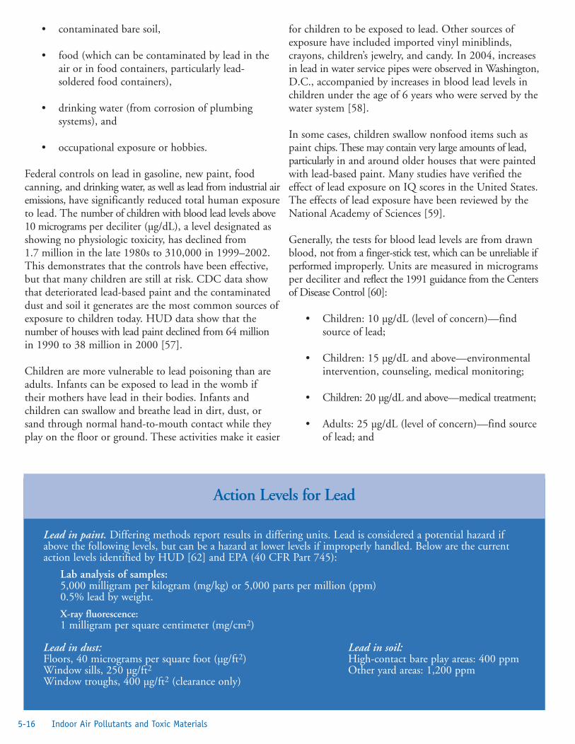
• contaminated bare soil,
• food (which can be contaminated by lead in theair or in food containers, particularly lead-soldered food containers),
• drinking water (from corrosion of plumbingsystems), and
• occupational exposure or hobbies.
Federal controls on lead in gasoline, new paint, foodcanning, and drinking water, as well as lead from industrial airemissions, have significantly reduced total human exposureto lead. The number of children with blood lead levels above10 micrograms per deciliter (µg/dL), a level designated asshowing no physiologic toxicity, has declined from1.7 million in the late 1980s to 310,000 in 1999–2002.This demonstrates that the controls have been effective,but that many children are still at risk. CDC data showthat deteriorated lead-based paint and the contaminateddust and soil it generates are the most common sources ofexposure to children today. HUD data show that thenumber of houses with lead paint declined from 64 millionin 1990 to 38 million in 2000 [57].
Children are more vulnerable to lead poisoning than areadults. Infants can be exposed to lead in the womb iftheir mothers have lead in their bodies. Infants andchildren can swallow and breathe lead in dirt, dust, orsand through normal hand-to-mouth contact while theyplay on the floor or ground. These activities make it easier
for children to be exposed to lead. Other sources ofexposure have included imported vinyl miniblinds,crayons, children’s jewelry, and candy. In 2004, increasesin lead in water service pipes were observed in Washington,D.C., accompanied by increases in blood lead levels inchildren under the age of 6 years who were served by thewater system [58].
In some cases, children swallow nonfood items such aspaint chips. These may contain very large amounts of lead,particularly in and around older houses that were paintedwith lead-based paint. Many studies have verified theeffect of lead exposure on IQ scores in the United States.The effects of lead exposure have been reviewed by theNational Academy of Sciences [59].
Generally, the tests for blood lead levels are from drawnblood, not from a finger-stick test, which can be unreliable ifperformed improperly. Units are measured in microgramsper deciliter and reflect the 1991 guidance from the Centersof Disease Control [60]:
• Children: 10 µg/dL (level of concern)—findsource of lead;
• Children: 15 µg/dL and above—environmentalintervention, counseling, medical monitoring;
• Children: 20 µg/dL and above—medical treatment;
• Adults: 25 µg/dL (level of concern)—find sourceof lead; and
5-16 Indoor Air Pollutants and Toxic Materials
Lead in paint. Differing methods report results in differing units. Lead is considered a potential hazard ifabove the following levels, but can be a hazard at lower levels if improperly handled. Below are the currentaction levels identified by HUD [62] and EPA (40 CFR Part 745):
Lab analysis of samples: 5,000 milligram per kilogram (mg/kg) or 5,000 parts per million (ppm) 0.5% lead by weight.
X-ray fluorescence: 1 milligram per square centimeter (mg/cm2)
Lead in dust: Lead in soil: Floors, 40 micrograms per square foot (µg/ft2) High-contact bare play areas: 400 ppm Window sills, 250 µg/ft2 Other yard areas: 1,200 ppmWindow troughs, 400 µg/ft2 (clearance only)
Action Levels for Lead

• Adults: 50 µg/dL—Occupational Safety andHealth Administration (OSHA) standard formedical removal from the worksite.
Adults are usually exposed to lead from occupationalsources (e.g., battery construction, paint removal) or athome (e.g., paint removal, home renovations). In 1978, CPSC banned the use of lead-based paint inresidential housing. Because houses are periodicallyrepainted, the most recent layer of paint will most likelynot contain lead, but the older layers underneathprobably will. Therefore, the only way to accuratelydetermine the amount of lead present in older paint is tohave it analyzed.
It is important that owners of homes built before 1978 beaware that layers of older paint can contain a great deal oflead. Guidelines on identifying and controlling lead-basedpaint hazards in housing have been published by HUD [61].
Controlling Lead HazardsThe purpose of a home risk assessment is to determine,through testing and evaluation, where hazards from leadwarrant remedial action. A certified inspector or riskassessor can test paint, soil, or lead dust either on-site orin a laboratory using methods such as x-ray fluorescence(XRF) analyzers, chemicals, dust wipe tests, and atomicabsorption spectroscopy. Lists of service providers are
available by calling 1-800-424-LEAD. Do-it-yourself testkits are commercially available; however, these kits do nottell you how much lead is present, and their reliability atdetecting low levels of lead has not been determined.Professional testing for lead in paint is recommended.The recommended sampling method for dust is thesurface wet wipe. Dust samples are collected fromdifferent surfaces, such as bare floors, window sills, andwindow wells. Each sample is collected from a measuredsurface area using a wet wipe, which is sent to alaboratory for testing. Risk assessments can be fairly low-cost investigations of the location, condition, and severityof lead hazards found in house dust, soil, water, anddeteriorating paint. Risk assessments also will addressother sources of lead from hobbies, crockery, water, andwork environments. These services are critical whenowners are seeking to implement measures to reducesuspected lead hazards in housing and day-care centers orwhen extensive rehabilitation is planned.
HUD has published detailed protocols for riskassessments and inspections [61].
It is important from a health standpoint that future tenants,painters, and construction workers know that lead-basedpaint is present, even under treated surfaces, so they cantake precautions when working in areas that will generatelead dust. Whenever mitigation work is completed, it is
5-17Healthy Housing Reference Manual
Deteriorated lead-based paint: Paint known to contain lead above the regulated level that shows signs ofpeeling, chipping, chalking, blistering, alligatoring, or otherwise separating from its substrate.
Dust removal: The process of removing dust to avoid creating a greater problem of spreading lead particles;usually through wet or damp collection and use of HEPA vacuums.
Hazard abatement: Long-term measures to remove the hazards of lead-based paint through replacement ofbuilding components, enclosure, encapsulation, or paint removal.
Interim control: Short-term methods to remove lead dust, stabilize deteriorating painted surfaces, treatfriction and impact surfaces that generate lead dust, and repaint surfaces. Maintenance can ensure thathousing remains lead-safe.
Lead-based paint: Any existing paint, varnish, shellac, or other coating that is equal to or greater than1.0 milligrams per square centimeter (mg/cm2) or greater than 0.5% by weight (5,000 ppm, 5,000micrograms per gram [µg/g], or 5,000 milligrams per kilogram [mg/kg]). For new paint, CPSC hasestablished 0.06% as the maximum amount of lead allowed in new paint. Lead in paint can be measured byx-ray fluorescence analyzers or laboratory analysis by certified personnel and approved laboratories.
Risk assessment: An on-site investigation to determine the presence and condition of lead-based paint,including limited test samples and an evaluation of the age, condition, housekeeping practices, and uses of aresidence.
Definitions Related to Lead
important to have a clearance test using the dust wipemethod to ensure that lead-laden dust generated duringthe work does not remain at levels above those establishedby the EPA and HUD. Such testing is required forowners of most housing that is receiving federal financialassistance, such as Section 8 rental housing. A building orhousing file should be maintained and updated wheneverany additional lead hazard control work is completed.Owners are required by law to disclose information aboutlead-based paint or lead-based paint hazards to buyers ortenants before completing a sales or lease contract [62].
All hazards should be controlled as identified in arisk assessment.
Whenever extensive amounts of lead must be removedfrom a property, or when methods of removing toxicsubstances will affect the environment, it is extremelyimportant that the owner be aware of the issues surroundingworker safety, environmental controls, and proper disposal.Appropriate architectural, engineering, and environmentalprofessionals should be consulted when lead hazardprojects are complex.
Following are brief explanations of the two approaches forcontrolling lead hazard risks. These controls arerecommended by HUD in HUD Guidelines for theEvaluation and Control of Lead-Based Paint Hazards inHousing [61], and are summarized here to focus onspecial considerations for historic housing:
Interim Controls. Short-term solutions include thoroughdust removal and thorough washdown and cleanup, paintfilm stabilization and repainting, covering of lead-contaminated soil, and informing tenants about leadhazards. Interim controls require ongoing maintenanceand evaluation.
Hazard Abatement. Long-term solutions are defined ashaving an expected life of 20 years or more and involvepermanent removal of hazardous paint through chemicals,heat guns, or controlled sanding or abrasive methods;permanent removal of deteriorated painted featuresthrough replacement; removal or permanent covering ofcontaminated soil; and the use of enclosures (such asdrywall) to isolate painted surfaces. The use of specializedencapsulant products can be considered as permanentabatement of lead.
Reducing and controlling lead hazards can be successfullyaccomplished without destroying the character-definingfeatures and finishes of historic buildings. Federal and
state laws generally support the reasonable control of lead-based paint hazards through a variety of treatments,ranging from modified maintenance to selective substrateremoval. The key to protecting children, workers, and theenvironment is to be informed about the hazards of lead,to control exposure to lead dust and lead in soil and leadpaint chips, and to follow existing regulations.
The following summarizes several important regulationsthat affect lead-hazard reduction projects. Owners shouldbe aware that regulations change, and they have aresponsibility to check state and local ordinances as well.Care must be taken to ensure that any procedures used torelease lead from the home protect both the residents andworkers from lead dust exposure.
Residential Lead-Based Paint Hazard Reduction Act of1992, Title X [62]. Part of the Housing and CommunityDevelopment Act of 1992 (Public Law 102-550) [63]. Itestablished that HUD issue Guidelines for the Evaluationand Control of Lead-Based Paint Hazards in Housing [61]to outline risk assessments, interim controls, andabatement of lead-based paint hazards in housing. Title Xcalls for the reduction of lead in federally supportedhousing. It outlines the federal responsibility toward itsown residential units and the need for disclosure of leadin residences, even private residences, before a sale. Title Xalso required HUD to establish regulations for federallyassisted housing (24 CFR Part 35) and EPA to establishstandards for lead in paint, dust, and soil, as well asstandards for laboratory accreditation (40 CFR Part 745).EPA’s residential lead hazard standards are available athttp://www.epa.gov/lead/leadhaz.htm.
Interim Final Rule on Lead in Construction (29 Code ofFederal Regulations [CFR] 1926.62) [64]. Issued byOSHA, these regulations address worker safety, training,and protective measures. The regulations are based in parton personal-air sampling to determine the amount of leaddust exposure to workers.
State Laws. States generally have the authority to regulatethe removal and transportation of lead-based paint andthe generated waste through the appropriate stateenvironmental and public health agencies. Mostrequirements are for mitigation in the case of a lead-poisoned child, for protection of children, or for oversightto ensure the safe handling and disposal of lead waste.When undertaking a lead-based paint reduction program,it is important to determine which laws are in place thatmay affect the project.
5-18 Indoor Air Pollutants and Toxic Materials

Local Ordinances. Check with local health departments,poison control centers, and offices of housing andcommunity development to determine whether any lawsrequire compliance by building owners. Determinewhether projects are considered abatements and willrequire special contractors and permits.
Owner’s Responsibility. Owners are ultimatelyresponsible for ensuring that hazardous waste is properlydisposed of when it is generated on their own sites.Owners should check with their state government todetermine whether an abatement project requires acertified contractor. Owners should establish that thecontractor is responsible for the safety of the crew, toensure that all applicable laws are followed, and thattransporters and disposers of hazardous waste haveliability insurance as a protection for the owner. Theowner should notify the contractor that lead-based paintmay be present and that it is the contractor’sresponsibility to follow appropriate work practices toprotect workers and to complete a thorough cleanup toensure that lead-laden dust is not present after the work iscompleted. Renovation contractors are required by EPAto distribute an informative educational pamphlet(Protect Your Family from Lead in Your Home) tooccupants before starting work that could disturb lead-based paint (http://www.epa.gov/lead/leadinfo.htm#remodeling).
ArsenicLead arsenate was used legally up to 1988 in most of theorchards in the United States. Often 50 applications ormore of this pesticide were applied each year. This toxicheavy metal compound has accumulated in the soilaround houses and under the numerous orchards in thecountry, contaminating both wells and land. Theseorchards are often turned into subdivisions as citiesexpand and sprawl occurs. Residues from the pesticidelead arsenate, once used heavily on apple, pear, and otherorchards, contaminate an estimated 70,000 to 120,000 acresin the state of Washington alone, some of it in areaswhere agriculture has been replaced with housing,according to state ecology department officials and others.
Lead arsenate, which was not banned for use on foodcrops until 1988, nevertheless was mostly replaced by thepesticide dichlorodiphenyltrichloroethane (DDT) and itsderivatives in the late 1940s. DDT was banned in theUnited States in 1972, but is used elsewhere in the world.
For more than 20 years, the wood industry has infusedgreen wood with heavy doses of arsenic to kill bugs and
prevent rot. Numerous studies show that arsenic sticks tochildren’s hands when they play on treated wood, and it isabsorbed through the skin and ingested when they puttheir hands in their mouths. Although most uses ofarsenic wood treatments were phased out by 2004, anestimated 90% of existing outdoor structures are made ofarsenic-treated wood [65].
In a study conducted by the University of North CarolinaEnvironmental Quality Institute in Asheville, woodsamples were analyzed and showed that
• Older decks and play sets (7 to 15 years old) thatwere preserved with chromated copper arsenicexpose people to just as much arsenic on thewood surface as do newer structures (less than1 year old). The amount of arsenic that testerswiped off a small area of wood about the size of a4-year-old’s handprint typically far exceeds whatEPA allows in a glass of water under the SafeDrinking Water Act standard. Figure 5.9 shows asafety warning label placed on wood products.
• Arsenic in the soil from two of every fivebackyards or parks tested exceeded EPA’sSuperfund cleanup level of 20 ppm.
Arsenic is not just poisonous in the short term, it causescancer in the long term. Arsenic is on EPA’s short list ofchemicals known to cause cancer in humans. According to theNational Academy of Sciences, exposure to arsenic causeslung, bladder, and skin cancer in humans, and is suspected asa cause of kidney, prostate, and nasal passage cancer.
5-19Healthy Housing Reference Manual
Figure 5.9. Arsenic Label

References1. US Environmental Protection Agency and the US
Consumer Product Safety Commission. Theinside story: a guide to indoor air quality.Washington, DC: US Environmental ProtectionAgency and the US Consumer Product SafetyCommission, Office of Radiation and Indoor Air;1995. Document #402-K-93-007. Available fromURL: http://www.epa.gov/iaq/pubs/insidest.html.
2. Centers for Disease Control and Prevention.Asthma: speaker’s kit for health care professionals;preface. Atlanta: US Department of Health andHuman Services; no date. Available from URL:http://www.cdc.gov/asthma/speakit/intro.htm.
3. US Environmental Protection Agency.Washington, DC: US Environmental ProtectionAgency; 2004. Asthma facts. EPA #402-F-04-019.Available from URL: http://www.epa.gov/asthma/pdfs/asthma_fact_sheet_en.pdf.
4. Centers for Disease Control and Prevention.Asthma: speaker’s kit for health care professionals;epidemiology. Atlanta: US Department of Healthand Human Services; no date. Available fromURL: http://www.cdc.gov/asthma/speakit/epi.htm.
5. Crain EF, Walter M, O’Connor GT, Mitchell H,Gruchalla RS, Kattan M, et al. Home and allergiccharacteristics of children with asthma in sevenU.S. urban communities and design of an envi-ronmental intervention: The Inner-City AsthmaStudy. Environ Health Perspect2002;119:939–45.
6. Community Environmental Health ResourceCenter. Cockroaches: tools for detecting hazards.Washington, DC: Community EnvironmentalHealth Resource Center; no date. Available fromURL: http://www.cehrc.org/tools/cockroaches/index.cfm.
7. Lyon WF. Entomology, House Dust Mites HYG2157-97. Columbus, OH: The Ohio StateUniversity Extension; 1997. Available from URL:http://ohioline.osu.edu/hyg-fact/2000/2157.html.
8. Morgan WJ, Crain EF, Gruchalla RS, O’ConnorGT, Kattan M, et al. Results of a home-basedenvironmental intervention among urban childrenwith asthma. N Engl J Med 2004;351:1068–80.
9. US Environmental Protection Agency. Sources ofindoor air pollution—biological pollutants.Washington, DC: US Environmental ProtectionAgency; no date. Available from URL:http://www.epa.gov/iaq/biologic.html.
10. Ownby DR. Exposure to dogs and cats in the firstyear of life and risk of allergic sensitization at 6 to7 years of age. JAMA 2002;288(8):963–72.
11. Roost HP. Role of current and childhood expo-sure to cat and atopic sensitization. J Allergy ClinImmunol 1999;104(5):94.
12. Downs SH. Having lived on a farm and protec-tion against allergic diseases in Australia. Clin ExpAllergy 2001;31(4):570–5.
13. Institute of Medicine. Clearing the air: asthmaand indoor air exposures. Washington, DC:National Academies Press; 2000.
14. American Conference of Governmental andIndustrial Hygienists. Macher J, editor.Bioaerosols: assessment and control. Cincinnati,OH: American Conference of Governmental andIndustrial Hygienists; 1999.
15. Institute of Medicine. Damp indoor spaces andhealth. Washington, DC: National AcademiesPress; 2004.
16. Morgan WJ, Crain EF, Gruchalla RS, O’ConnorGT, Kattan M, Evans R 3rd, et al. Results ofhome-based environmental intervention amongurban children with asthma. N Engl J Med2004;351:1068–80.
17. Burge HA, Ammann HA. Fungal toxins and β(1 3)-D-glucans. In: Macher J, editor.Bioaerosols: assessment and control. Cincinnati,OH: American Conference of Governmental andIndustrial Hygienists; 1999.
18. American Academy of Pediatrics, Committee onEnvironmental Health. Toxic effects of indoormolds. Pediatrics 1998;101:712–14.
19. Burge HA, Otten JA. 1999. Fungi. In: Macher J,editor. Bioaerosols: assessment and control.Cincinnati, OH: American Conference ofGovernmental and Industrial Hygienists; 1999.
5-20 Indoor Air Pollutants and Toxic Materials

20. Etzel RA. The “fatal four” indoor air pollutants.Pediatr Ann 2000;29(6):344–50.
21. Dearborn DG, Smith PG, Dahms BB, Allan TM,Sorenson WG, Montana E, et al. Clinical profileof thirty infants with acute pulmonary hemor-rhage in Cleveland. Pediatrics 2002;110:627–37.
22. Etzel RA, Montana E, Sorenson WG, KullmanGJ, Allan TM, Dearborn DG. Acute pulmonaryhemorrhage in infants associated with exposure toStachybotrys atra and other fungi. Arch PediatrAdolesc Med 1998;152:757–62.
23. Flappan SM, Portnoy J, Jones P, Barnes C. Infantpulmonary hemorrhage in a suburban home withwater damage and mold (Stachybotrys atra).Environ Health Perspect 1999;107:927–30.
24. Vesper S, Dearborn DG, Yike I, Allan T,Sobolewski J, Hinkley SF, et al. Evaluation ofStachybotrys chartarum in the house of an infantwith pulmonary hemorrhage: quantitative assess-ment before, during, and after remediation. J.Urban Health Bull N Y Acad Med2000;77(1):68–85.
25. US Environmental Protection Agency. A briefguide to mold, moisture, and your home (EPA402-K-02-003). Washington, DC: USEnvironmental Protection Agency; 2002.Available from URL: http://www.epa.gov/iaq/molds/images/moldguide.pdf.
26. NYC. 2000. Guidelines on assessment and reme-diation of fungi in indoor environments. NewYork City Department of Health, Bureau ofEnvironmental & Occupational DiseaseEpidemiology. Available from URL:http://www.ci.nyc.ny.us/html/doh/html/epi/moldrpt1.shtml.
27. Bush RK, Portnoy JM. The role and abatement offungal allergens in allergic diseases. J Allerg ClinImmunol Suppl 2001;107(3 pt 2):430.
28. Department of Housing and Urban Development,Office of Native American Programs. Mold detec-tion and prevention: a guide for housing authori-ties in Indian Country. Washington, DC:Department of Housing and Urban Development;2001. Available from URL: http://www2.ihs.gov/
IEH/documents/HUD%20Mold%20Detection.pdf.
29. US Environmental Protection Agency. Moldremediation in schools and commercial buildings(EPA 402-K-01-001). Washington, DC: USEnvironmental Protection Agency; 2001.
30. Shaughnessy RJ, Morey PR. Remediation ofmicrobial contamination. In: Macher J, editor.Bioaerosols: assessment and control. Cincinnati,OH: American Conference of Governmental andIndustrial Hygienists; 1999.
31. National Institute of Environmental HealthSciences. Interim final guidelines for the protec-tion and training of workers engaged in mainte-nance and remediation work associated withmold. Report of a national technical workshop,National Institute of Environmental HealthSciences, New York City, 2004 Jan 27–28.
32. Mott JA, Wolfe MI, Alverson CJ, Macdonald SC,Bailey CR, Ball LB, et al. National vehicle emis-sions policies and practices and declining US car-bon monoxide mortality. JAMA 2002;288:988–95.
33. American Lung Association. Carbon monoxidefact sheet. New York: American Lung Association;2004. Available from URL:http://www.lungusa.org/site/pp.asp?c=dvLUK9O0E&b=35375.
34. North Carolina Department of Health andHuman Services. Indoor ozone. Raleigh, NC:North Carolina Department of Health andHuman Services; 2003. Available from URL:http://www.epi.state.nc.us/epi/oee/ozone/indoor.html.
35. US Environmental Protection Agency. Ozonegenerators that are sold as air cleaners: an assess-ment of effectiveness and health consequences.Washington, DC: US Environmental ProtectionAgency; no date. Available from URL:http://www.epa.gov/iaq/pubs/ozonegen.html.
36. National Cancer Institute. Secondhand smoke:questions and answers. Bethesda, MD: NationalCancer Institute; no date. Available from URL:http://www.cancer.gov/cancertopics/factsheet/Tobacco/ETS.
5-21Healthy Housing Reference Manual

37. US Environmental Protection Agency. What youcan do about secondhand smoke as parents, deci-sion-makers, and building occupants.Washington, DC: US Environmental ProtectionAgency; 1993. Available from URL: http://www.epa.gov/smokefree/pubs/etsbro.html.
38. US Environmental Protection Agency. Methylenechloride (dichloromethane). Washington, DC: USEnvironmental Protection Agency; 1992.Available from URL: http://www.epa.gov/ttnatw01/hlthef/methylen.html.
39. Environmental Media Services. Four to avoid.Washington, DC: Environmental Media Services;2002.
40. US Consumer Product Safety Commission. Anupdate on formaldehyde: 1997 revision.Washington, DC: Consumer Product SafetyCommission; 1997. CPSC Document 725.Available from URL: http://www.cpsc.gov/cpscpub/pubs/725.html.
41. US Environmental Protection Agency. Sources ofindoor air pollution—formaldehyde. Washington,DC: US Environmental Protection Agency.Available from URL: http://www.epa.gov/iaq/formalde.html.
42. US Department of Housing and UrbanDevelopment. Formaldehyde emission controlsfor certain wood products. 24 CFR3280.308.Washington, DC: US Department of Housingand Urban Development; 2001. Available fromURL: http://www.hudclips.org/cgi/index.cgi.
43. US Environmental Protection Agency. Assessmentof risks from radon in homes. Washington, DC:US Environmental Protection Agency; 2003.Available from URL: http://www.epa.gov/radon/risk_assessment.html.
44. US Geological Survey. The geology of radon.Reston, VA: US Geological Survey; 1995.Available from URL: http://energy.cr.usgs.gov/radon/georadon/3.html.
45. California Geological Survey. Radon. Sacramento,CA: California Geological Survey; no date.Available from URL: http://www.consrv.ca.gov/cgs/minerals/hazardous_minerals/radon/.
46. US Department of Health and Human Services.Surgeon General releases national health advisoryon radon. Washington, DC: US Department ofHealth and Human Services; 2005. Available fromURL: http://www.hhs.gov/surgeongeneral/pressreleases/sg01132005.html.
47. Brain M, Freudenrich C. How radon works.Atlanta: How Stuff Works; no date. Availablefrom URL: http://home.howstuffworks.com/radon.htm.
48. Pennsylvania Department of EnvironmentalProtection. Mitigating your home or office.Harrisburg, PA: Pennsylvania Department ofEnvironmental Protection; no date. Availablefrom URL: http://www.dep.state.pa.us/dep/deputate/airwaste/rp/radon_division/Mitigation_Info.htm.
49. Connecticut Department of Public Health. Whyshould you build homes with radon-resistant tech-niques? Hartford, CT: Connecticut Departmentof Public Health Radon Program; no date.Available from URL: http://www.dph.state.ct.us/BRS/radon/radon_techniques.htm.
50. US Environmental Protection Agency. Radon-resistant new construction. Washington, DC: USEnvironmental Protection Agency; no date.Available from URL: http://www.epa.gov/radon/construc.html.
51. US Environmental Protection Agency. Pesticidesand child safety. Washington, DC: USEnvironmental Protection Agency; no date.Available from URL: http://www.epa.gov/pesti-cides/factsheets/childsaf.htm.
52. Delaplane KS. Pesticide usage in the UnitedStates: history, benefits, risks, and trends. Athens,GA: Cooperative Extension Service, TheUniversity of Georgia College of Agriculture andEnvironmental Sciences; no date. Available fromURL: http://pubs.caes.uga.edu/caespubs/pubcd/B1121.htm.
53. US Environmental Protection Agency. Sources ofindoor air pollution—pesticides. Washington,DC: US Environmental Protection Agency; nodate. Available from URL: http://www.epa.gov/iaq/pesticid.html.
5-22 Indoor Air Pollutants and Toxic Materials

54. Agency for Toxic Substances and Disease Registry.Public health statement for asbestos. Atlanta: USDepartment of Health and Human Services;2001. Available from URL:http://www.atsdr.cdc.gov/toxprofiles/phs61.html.
55. US Geological Survey. Some facts about asbestos.USGS fact sheet FS-012-01, online version 1.1.Reston, VA: US Geological Survey; March 2001.Available from URL:http://pubs.usgs.gov/fs/fs012-01/.
56. Merriam-Webster, Inc. Merriam-Webster diction-ary. Springfield, MA: Merriam-Webster, Inc.; nodate. Available from URL: http://www.m-w.com/home.htm.
57. Jacobs DE, Clickner RP, Zhou JY, Viet SM,Marker DA, Rogers JW, et al. The prevalence oflead-based paint hazards in U.S. housing. EnvironHealth Perspect 2002;100:A599–606.
58. Centers for Disease Control and Prevention.Blood lead levels in residents of homes with ele-vated lead in tap water—District of Columbia,2004. MMWR 2004; 53(12):268–70. Availablefrom URL: http://www.cdc.gov/mmwr/preview/mmwrhtml/mm5312a6.htm.
59. National Research Council. Measuring lead expo-sure in infants, children and other sensitive popu-lations. Washington, DC: National AcademyPress; 1993.
60. Centers for Disease Control. Preventing lead poi-soning in young children. Report No. 99-2230.Atlanta: US Department of Health and HumanServices; 1991.
61. US Department of Housing and UrbanDevelopment. HUD technical guidelines for theevaluation and control of lead-based paint hazardsin housing. Washington, DC: US Department ofHousing and Urban Development; 1995.Available from URL: http://www.hud.gov/offices/lead/guidelines/hudguidelines/index.cfm.
62. US Department of Housing and UrbanDevelopment. The lead-based paint disclosurerule (Section 1018 of the Residential Lead-BasedPaint Hazard Reduction Act of 1992).Washington, DC: US Department of Housing
and Urban Development; no date. Available fromURL: http://www.hud.gov/offices/lead/disclosurerule/index.cfm.
63. Residential Lead-Based Paint Hazard ReductionAct of 1992, Title X of the Housing andCommunity Development Act of 1992, Pub. L.No. 102-550 (Oct 28, 1992).
64. Occupational Safety and Health Administration.Lead exposure in construction: interim final rule.Fed Reg 1993;58:26590–649.
65. Environmental Working Group. Nationwide con-sumer testing of backyard decks and play setsshows high levels of arsenic on old wood.Washington, DC: Environmental WorkingGroup; 2002. Available from URL:http://www.ewg.org/reports/allhandsondeck/.
5-23Healthy Housing Reference Manual

5-24 Indoor Air Pollutants and Toxic Materials

Chapter 6—Housing StructureIntroduction . . . . . . . . . . . . . . . . . . . . . . . . . . . . . . . . . . . . . . . . . . . . . . . . . . . . . . .6-1
New Housing Terminology . . . . . . . . . . . . . . . . . . . . . . . . . . . . . . . . . . . . . . .6-1Old Housing Terminology . . . . . . . . . . . . . . . . . . . . . . . . . . . . . . . . . . . . . . . .6-6
Foundation . . . . . . . . . . . . . . . . . . . . . . . . . . . . . . . . . . . . . . . . . . . . . . . . . . . . . . .6-8Vapor Barriers . . . . . . . . . . . . . . . . . . . . . . . . . . . . . . . . . . . . . . . . . . . . . . . . . . . . .6-10
Crawl Space Barriers . . . . . . . . . . . . . . . . . . . . . . . . . . . . . . . . . . . . . . . . . . . .6-10Vapor Barriers for Concrete Slab Homes . . . . . . . . . . . . . . . . . . . . . . . . . . . . .6-10Wall and Ceiling Vapors . . . . . . . . . . . . . . . . . . . . . . . . . . . . . . . . . . . . . . . . .6-10
House Framing . . . . . . . . . . . . . . . . . . . . . . . . . . . . . . . . . . . . . . . . . . . . . . . . . . . .6-10Foundation Sills . . . . . . . . . . . . . . . . . . . . . . . . . . . . . . . . . . . . . . . . . . . . . . . .6-10Flooring Systems . . . . . . . . . . . . . . . . . . . . . . . . . . . . . . . . . . . . . . . . . . . . . . .6-10Studs . . . . . . . . . . . . . . . . . . . . . . . . . . . . . . . . . . . . . . . . . . . . . . . . . . . . . . . .6-11Interior Walls . . . . . . . . . . . . . . . . . . . . . . . . . . . . . . . . . . . . . . . . . . . . . . . . . .6-11Stairways . . . . . . . . . . . . . . . . . . . . . . . . . . . . . . . . . . . . . . . . . . . . . . . . . . . . .6-12Windows . . . . . . . . . . . . . . . . . . . . . . . . . . . . . . . . . . . . . . . . . . . . . . . . . . . . .6-12Doors . . . . . . . . . . . . . . . . . . . . . . . . . . . . . . . . . . . . . . . . . . . . . . . . . . . . . . . .6-13
Roof Framing . . . . . . . . . . . . . . . . . . . . . . . . . . . . . . . . . . . . . . . . . . . . . . . . . . . . . .6-15Rafters . . . . . . . . . . . . . . . . . . . . . . . . . . . . . . . . . . . . . . . . . . . . . . . . . . . . . . .6-15Collar Beam . . . . . . . . . . . . . . . . . . . . . . . . . . . . . . . . . . . . . . . . . . . . . . . . . . .6-15Purlin . . . . . . . . . . . . . . . . . . . . . . . . . . . . . . . . . . . . . . . . . . . . . . . . . . . . . . . .6-15Ridge Board . . . . . . . . . . . . . . . . . . . . . . . . . . . . . . . . . . . . . . . . . . . . . . . . . . .6-15Hip . . . . . . . . . . . . . . . . . . . . . . . . . . . . . . . . . . . . . . . . . . . . . . . . . . . . . . . . .6-15Roof Sheathing . . . . . . . . . . . . . . . . . . . . . . . . . . . . . . . . . . . . . . . . . . . . . . . .6-15Dormer . . . . . . . . . . . . . . . . . . . . . . . . . . . . . . . . . . . . . . . . . . . . . . . . . . . . . .6-15
Roofs . . . . . . . . . . . . . . . . . . . . . . . . . . . . . . . . . . . . . . . . . . . . . . . . . . . . . . . . . . . .6-15Asphalt Shingle . . . . . . . . . . . . . . . . . . . . . . . . . . . . . . . . . . . . . . . . . . . . . . . .6-15EPDM . . . . . . . . . . . . . . . . . . . . . . . . . . . . . . . . . . . . . . . . . . . . . . . . . . . . . . .6-15Asphalt Built-up Roofs . . . . . . . . . . . . . . . . . . . . . . . . . . . . . . . . . . . . . . . . . .6-16Coal Tar Pitch Built-up Roofs . . . . . . . . . . . . . . . . . . . . . . . . . . . . . . . . . . . . .6-16Slate Roofs . . . . . . . . . . . . . . . . . . . . . . . . . . . . . . . . . . . . . . . . . . . . . . . . . . . .6-16Tile Roofs . . . . . . . . . . . . . . . . . . . . . . . . . . . . . . . . . . . . . . . . . . . . . . . . . . . .6-16Copper Roofs . . . . . . . . . . . . . . . . . . . . . . . . . . . . . . . . . . . . . . . . . . . . . . . . .6-16Galvanized Iron Roofs . . . . . . . . . . . . . . . . . . . . . . . . . . . . . . . . . . . . . . . . . . .6-16Wood Shingle Roofs . . . . . . . . . . . . . . . . . . . . . . . . . . . . . . . . . . . . . . . . . . . .6-16Roof Flashing . . . . . . . . . . . . . . . . . . . . . . . . . . . . . . . . . . . . . . . . . . . . . . . . .6-16Gutters and Leaders . . . . . . . . . . . . . . . . . . . . . . . . . . . . . . . . . . . . . . . . . . . . .6-16
Exterior Walls and Trim . . . . . . . . . . . . . . . . . . . . . . . . . . . . . . . . . . . . . . . . . . . . . .6-16Putting It All Together . . . . . . . . . . . . . . . . . . . . . . . . . . . . . . . . . . . . . . . . . . . . . . .6-17References . . . . . . . . . . . . . . . . . . . . . . . . . . . . . . . . . . . . . . . . . . . . . . . . . . . . . . . .6-21Additional Sources of Information . . . . . . . . . . . . . . . . . . . . . . . . . . . . . . . . . . . . . .6-22
Figure 6.1. Housing Structure Terminology, Typical House Built Today . . . . . . . . . . . . . . . . . .6-1Figure 6.2. Housing Structure Terminology, Typical House Built Between 1950 and 1980 . . . .6-6Figure 6.3. Foundation. . . . . . . . . . . . . . . . . . . . . . . . . . . . . . . . . . . . . . . . . . . . . . . . . . . . . . . .6-9Figure 6.4. Foundation Cracks . . . . . . . . . . . . . . . . . . . . . . . . . . . . . . . . . . . . . . . . . . . . . . . . . .6-9
1Healthy Housing Reference Manual
Contents

Figure 6.5. Interior Stairway . . . . . . . . . . . . . . . . . . . . . . . . . . . . . . . . . . . . . . . . . . . . . . . . . . .6-12Figure 6.6. Classifications of Windows . . . . . . . . . . . . . . . . . . . . . . . . . . . . . . . . . . . . . . . . . . .6-12Figure 6.7. Three-dimensional View of a Window . . . . . . . . . . . . . . . . . . . . . . . . . . . . . . . . . . .6-13Figure 6.8. Window Details . . . . . . . . . . . . . . . . . . . . . . . . . . . . . . . . . . . . . . . . . . . . . . . . . . . .6-13Figure 6.9. Wall Framing. . . . . . . . . . . . . . . . . . . . . . . . . . . . . . . . . . . . . . . . . . . . . . . . . . . . . .6-17
2 Contents

Chapter 6: Housing Structure
“The Palace of Fine Arts in Mexico City has sunk morethan 10 feet into the ground since it was built 60 yearsago and the most noticeable effect is that the grand stonestairway has disappeared and the entrance is now atstreet level.”
C.B. Crawford, Canadian Building Digest
IntroductionThe principal function of a house is to provideprotection from the elements. Our present society,however, requires that a home provide not only shelter,but also privacy, safety, and reasonable protection of ourphysical and mental health. A living facility that fails tooffer these essentials through adequately designed andproperly maintained interiors and exteriors cannot betermed “healthful housing.”
In this chapter, the home is considered in terms of theparts that have a bearing on its soundness, state of repair,and safety. These are some of the elements that thehousing inspector must examine when making athorough housing inspection.
Figure 6.1 shows a typical house being built andinspected today and includes a terminology key. Both thefigure and the key are available in an interactive formatin the glossary on the U.S. Inspect Web site [1].
Figure 6.2 shows a typical house built between 1950 and1980 and also includes a terminology key. The figuresshow the complexity and the numerous components of ahome. These components form the vocabulary that isnecessary to discuss housing structure inspection issues.
Key to Figure 6.1 (New Housing Terminology)1. Ash dump (see 35)—A door or opening in the
firebox that leads directly to the ash pit, throughwhich the ashes are swept after the fire is burned out.All fireboxes are not equipped with an ash dump.
2. Attic space—The open space within the attic area.
3. Backfill—The material used to refill an excavationaround the outside of a foundation wall or pipetrench.
4. Baluster—One of a series of small pillars that is
Figure 6.1. Housing Structure Terminology, Typical House Being Built Today [1]
6-1Healthy Housing Reference Manual

attached to and runs between the stairs and thehandrails. The spacing between the balusters shouldbe less than 4 inches to prevent small children fromgetting stuck between the balusters. Balusters areconsidered a safety item and provide an additionalbarrier.
5. Baseboard trim—Typically a wood trim board that isplaced against the wall around the perimeter of aroom next to the floor. The intent is to conceal thejoint between the floor and wall finish.
6. Basement window—A window opening installed inthe basement wall. Basement windows areoccasionally below the finish grade level and will besurrounded on the exterior by a window well.
7. Blind or shutter—A lightweight frame in the form ofa door located on each side of a window. They aremost commonly constructed of wood (solid orlouvered panels) or plastic. Originally they weredesigned to close and secure over the windows forsecurity and foul weather. Most shutters now are morelikely decorative pieces that are secured to the housebeside the windows.
8. Bridging—Small pieces of wood or metal strappingplaced in an X-pattern between the floor joists atmidspan to prevent the joists from twisting andsqueaking and to provide reinforcement anddistribution of stress.
9. Building paper/underlayment—Building material,usually a felt paper that is used as a protective barrieragainst air and moisture passage from the areabeneath the flooring as well as providing amovement/noise isolator in hardwood flooring.
10. Ceiling joist—A horizontally placed framingmembers at the ceiling of the top-most living space ofa house that provides a platform to which the finishedceiling material can be attached.
11. Chair rail (not shown)—Decorative trim appliedaround the perimeter of a room such as a formaldining room or kitchen/breakfast nook at theapproximate same height as the back of a chair. It issometimes used as a cap trim for wainscoting (seewainscoting).
12. Chimney—A masonry or in more modernconstruction wood framed enclosure that surrounds
and contains one or more flues and extends above theroofline.
13. Chimney cap—The metal or masonry protectivecoveringat the top of the chimney that seals thechimney shaft from water entry between the chimneyenclosure and the flue tiles.
14. Chimney flues—The space or channel in a chimneythat carries off the smoke and other combustion gasesto the outside air. Most homes will have a terra cottatile flue or a metal flue.
15. Collar beam/tie—A horizontal piece of framinglumber that provides intermediate support foropposite rafters. They are usually located in themiddle to upper third portion of the rafters. It is alsoknown as a collar beam or collar brace.
16. Concrete slab floor—Typically approximately4 inches thick, the concrete slab floor provides anumber of uses. It creates a solid level surface to walkand work on. It provides a separation between thegrade/soil and a potentially livable area. It alsoprovides lateral compression resistance for thefoundation walls, preventing soil pressure fromoutside the foundation from pushing the foundationwalls and footings inward.
17. Corner brace—Diagonal braces placed at the cornersof framed walls to stiffen them and provide extra strength.
18. Cornice—An overhang of a pitched roof at the eaveline that usually consists of a fascia board, a soffit, andany appropriate moldings or vents.
19. Cornice molding—The individual pieces of woodtrim that are applied to the cornice area at the eaves.
20. Door casing/trim—The finish trim details around theperimeter of the door on the interior finished wall.
21. Door frame/jamb—The top and sides of the door toinclude the wall framing as well as the actual doorframe and trim.
22. Downspout—A pipe, usually of metal or vinyl, that isconnected to the gutters and is used to carry the roof-water runoff down and away from the house.
23. Downspout gooseneck—Segmented section ofdownspout that is bent at a radius to allow the
6-2 Housing Structure

downspout to be attached to the house and to followthe bends and curves of the eaves and ground.
24. Downspout shoe—The bottom downspoutgooseneck that directs the water from the downspoutto the extension or splash block at the grade.
25. Downspout strap—Strap used to secure thedownspout to the side of the house.
26. Drain tile—A tube or cylinder that is normallyinstalled around the exterior perimeter of thefoundation footings that collects and directs groundwater away from the foundation of the house. The tilecan be individual sections of clay or asphalt tubing or,in more recent construction, a perforated-plastic draintile that is approximately 4 inches in diameter. Thedrain tile leads either towards a sump or to an exteriordischarge away from the house.
27. Entrance canopy—A small overhanging roof thatshelters the front entrance.
28. Entrance stoop—An elevated platform constructed ofwood framing or masonry at the front entry thatallows visitors to stand above or out of the elements.The platform should be wide enough to allowsomeone to stand on the platform while opening anoutward swinging door such as a storm door even ifone is not present.
29. Exterior siding—The decorative exterior finish on ahouse. Its primary function is to protect the shell ofthe house from the elements. The choice of sidingmaterials varies widely to include wood, brick, metal,vinyl, concrete, stucco, and a variety of manufactured compositions such as compressed wood, compressedcellulose (paper), fiber-reinforced cement, andsynthetic stucco.
30. Fascia—The visible flat front board that caps therafter tail ends and encloses the overhang under theeave that runs along the roof edge. The gutter isusually attached at this location.
31. Fascia/rake board—The visible flat front board thatcaps the rafter tail ends and encloses the overhangunder the eave that runs along the roof edge and atthe edge of the roofing at the gables. The gutter isusually attached to this board at the eaves.
32. Finish flooring (not shown)—The final floor coveringinside the living space of a house. The most commontypes of finishes are carpeting; hardwood flooring;ceramic, composite, or laminate stone tile; parquetpanels; or vinyl sheet flooring.
33. Finished grade line—A predetermined line indicating theproposed elevation of the ground surface around abuilding.
34. Firebox—The cavity in the open face of the fireplacein which the fire is maintained. The firebox leadsdirectly to the fireplace flue. The firebox is constructed offire or refractory brick set in fireclay or reinforcedmortar in traditional masonry fireplaces. The fireboxmay also be constructed of metal or ceramic-coatedmetal panels in more modern prefabricated fireplaces.The walls of the firebox are usually slanted toward theliving space both to direct smoke up toward the flueand to reflect heat into the room.
35. Fireplace cleanout door—The access door to the ashpit beneath the fireplace. On a fireplace that is locatedinside the house, the cleanout door is usually locatedin the lowest accessible level of the house such as thebasement or crawl space. On a fireplace that is locatedat the outside of the house, the cleanout door will belocated at the exterior of the chimney. Not allfireplaces are equipped with a cleanout door.
36. Fireplace hearth—The inner or outer floor of afireplace, usually made of brick, tile, or stone.
37. Flashing (not shown)—The building componentused to connect and cover portions of a deck, roof, orsiding material to another surface such as a wall, achimney, a vent pipe, or anywhere that runoff isheavy or where two dissimilar materials meet. Theflashing is mainly intended to prevent water entry andis usually made of rubber, tar, asphalt, or various metals.
38. Floor joists—The main subfloor framing membersthat support the floor span. Joists are usually made ofengineered wood I-beams or 2×8 or larger lumber.
39. Foundation footing—The base on which thefoundation walls rests. The foundation is wider thanthe foundation wall to spread out the load it isbearing and to help prevent settling.
40. Foundation wall—The concrete block, concrete slabor other nonwood material that extends below or
6-3Healthy Housing Reference Manual

partly below grade, which provides support forexterior walls and other structural pans of the building.
41. Framing studs—A 2×4 or 2×6 vertical framingmember used to construct walls and partitions,usually spaced 12 to 24 inches apart.
42. Gable framing—The vertical and horizontal framingmembers that make up and support the end of a buildingas distinguished from the front or rear side. A gable isthe triangular end of an exterior wall above the eaves.
43. Garage door—The door for the vehicle passage intothe garage area. Typical garage doors consist ofmultiple jointed panels of wood, metal, or fiberglass.
44. Girder—A large beam supporting floor joists at the samelevel as the sills. A larger or principal beam used to supportconcentrated loads at isolated points along its length.
45. Gravel fill—A bed of coarse rock fragments orpebbles that is laid atop the existing soil beforepouring the concrete slab. The gravel serves a dualpurpose of breaking surface tension on the concreteslab and providing a layer that interrupts capillaryaction of subsurface moisture from reaching theconcrete slab. Typically, a polyethylene sheeting willbe installed between the gravel fill and the concreteslab for further moisture proofing.
46. Gutter—A channel used for carrying water run-off.Usually located at the eaves of a house and connectedto a downspout. The primary purpose of the guttersand downspouts is to carry roof water run-off as faraway from the house as possible.
47. Insulation—A manufactured or natural material thatresists heat flow that is installed in a house’s shell tokeep the heat in a house in the winter and thecoolness in the house in the summer. The mostcommon form of insulation is fiberglass, whether inbatts or blown-in material, along with cellulose, rigidfoam boards, sprayed-in foam, and rock wool.
48. Jack/king stud—The framing stud, sometimes calledthe trimmer, that supports the header above awindow, door, or other opening within a bearing wall.Depending on the size of the opening, there may beseveral jack studs on either side of the opening.
49. Mantel—The ornamental or decorative facing arounda fireplace including a shelf that is attached to thebreast or backing wall above the fireplace.
50. Moisture/vapor barrier—A nonporous material, suchas plastic or polyethylene sheeting, that is used toretard the movement of water vapor into walls andattics and prevent condensation in them. A vaporbarrier is also installed in crawl space areas to preventmoisture vapor from entering up through the ground.
51. Newel post—The post at the top and bottom of thehandrails and anywhere along the stair run thatcreates a directional change in the handrails is calledthe newel post. The newel post is securely anchoredinto the underlying floor framing or the stair stringerto provide stability to the handrails.
52. Reinforcing lath—A strip of wood or metal attachedto studs and used as a foundation for plastering,slating or tiling. Lath has been replaced by gypsumboard in most modern construction.
53. Ridge board/beam—The board placed on edge at thetop-most point of the roof framing, into which theupper ends of the rafters are joined or attached.
54. Roofing—The finished surface at the top of the housethat must be able to withstand the effects of theelements (i.e., wind, rain, snow, hail, etc.). A widevariety of materials are available, including asphaltshingles, wood shakes, metal roofing, ceramic andconcrete tiles, and slate, with asphalt shingles makingup the bulk of the material used.
55. Roof rafters—Inclined structural framing membersthat support the roof, running from the exterior wallthe to the ridge beam. Rafters directly support theroof sheathing and create the angle or slope of the roof.
56. Roof sheathing—The material used to cover theoutside surface of the roof framing to provide lateraland rack support to the roof, as well as to provide anailing surface for the roofing material. This materialmost commonly consists of plywood OSB orhorizontally laid wood boards.
57. Sidewalk—A walkway that provides a direct, all-weather approach to an entry. The sidewalk can beconstructed of poured concrete, laid stone, concretepavers, or gravel contained between borders or curbs.
6-4 Housing Structure
58. Sill plate—The horizontal wood member that isanchored to the foundation masonry to provide anailing surface for floors or walls built above.
59. Silt fabric—A porous fabric that acts as a barrierbetween the backfilled soil (see backfill) and the gravelsurrounding the drain tile. This barrier prevents soilparticles from blocking the movement of groundwaterto the drain tile.
60. Soffit/lookout block—Rake cross-bracing betweenthe fly rafters and end gable rafters that the soffit isnailed to.
61. Stair rail—A sturdy handhold and barrier that followsthe outside, and sometimes inside, perimeter of thestairs. The stair rail is used to prevent falls and toprovide a means of additional support when walkingup or down the stairs.
62. Stair riser—The vertical boards that close the spacebetween each stair tread on a set of stairs (see stairstringer and stair tread).
63. Stair stringer—The supporting members in a set ofstairs that are cut or notched to accept the individualtreads and risers (see stair riser and stair tread).
64. Stair tread—The horizontal board in a stairway thatis walked upon (see stair riser and stair stringer).
65. Subfloor—Boards or plywood, installed over joists,on which the finish floor rests.
66. Support post—A vertical framing member usuallydesigned to carry or support a beam or girder. Innewer construction a metal lally (pronounced “lolly”)column is commonly used, as well as 4×4- or 6×6-inch wood posts.
67. Tar—Otherwise known as asphalt, tar is a very thick,dark brown/black substance that is used as a sealant orwaterproofing agent. It is usually produced naturallyby the breakdown of animal and vegetable matter thathas been buried and compressed deep underground.Tar is also manufactured—a hydrocarbon by-productor residue that is left over after the distillation ofpetroleum. It is commonly used as a sealant or patch forroof penetrations, such as plumbing vents and chimneyflashing. Tar is also used as a sealer on concrete andmasonry foundation walls before they have beenbackfilled.
68. Termite shield—A metal flashing that is installedbelow the sill plate that acts as a deterrent to keeptermites from reaching the sill plate.
69. Top plate—The topmost horizontal framing membersof a framed wall. Most construction practices requirethe top plate to be doubled in thickness.
70. Wainscoting—The wooden paneling of the lowerpart of an interior wall up to approximately waist-height or between 36 and 48 inches from the floor.
71. Wall insulation—A manufactured or natural materialthat resists heat flow that is installed in a house’s shellto keep the heat in a house in the winter and thecoolness in the house in the summer. Fiberglass battsare the most common form of wall insulation.
72. Wall sheathing—The material used to cover theoutside surface of the wall framing that provides lateraland shear support to the wall as well as a nailingsurface for the exterior siding.
73. Window casing/trim—The finish trim details aroundthe perimeter of the window on the interior finished wall.
74. Window cripple—Short studs placed between theheader and a top plate or between a sill and sole plate.
75. Window frame/jamb—The top and sides of thewindow, to include the wall framing and the actualwindow frame and trim.
76. Window header—A beam placed perpendicular towall studs above doors, windows, or other openings tocarry the weight of structural loads above the windowor door.
77. Window sash—The framework that holds the glass ina door or window.
78. Window well (not shown)—An excavation around abasement window that prevents the surrounding soilsfrom collapsing into the window. The window wellsurround is normally constructed of formedcorrugated galvanized metal, built-up masonry, orpressure-treated wood.
6-5Healthy Housing Reference Manual

Key to Figure 6.2 (Old Housing Terminology)Fireplace1. Chimney—A vertical masonry shaft of reinforced
concrete or other approved noncombustible, heatresisting material enclosing one or more flues. Itremoves the products of combustion from solid,liquid or gaseous fuel.
2. Flue liner—The flue is the hole in the chimney. Theliner, made of terra cotta or metal, protects the brickfrom harmful smoke gases.
3. Chimney cap—This top is generally of concrete. Itprotects the brick from weather.
4. Chimney flashing—Sheet metal flashing provides atight joint between chimney and roof.
5. Firebrick—An ordinary brick cannot withstand theheat of direct fire, and so special firebrick is used toline the fireplace. In newer construction, fireplaces areconstructed of prefabricated metal inserts.
6. Ash dump—A trap door to let the ashes drop to a pitbelow, where they may be easily removed.
7. Cleanout door—The door to the ash pit or the bottom ofa chimney through which the chimney can be cleaned.
8. Chimney breast—The inside face or front of afireplace chimney.
9. Hearth—The floor of a fireplace that extends into theroom for safety purposes.
Roof10. Ridge—The top intersection of two opposite
adjoining roof surfaces.
11. Ridge board—The board that follows along underthe ridge.
12. Roof rafters—The structural members that supportthe roof.
6-6 Housing Structure
Figure 6.2. Housing Structure and Terminology, Typical House Built Between 1950 and 1980 [2]

13. Collar beam—Not a beam at all; this tie keeps theroof from spreading and connects similar rafters onopposite sides of the roof.
14. Roof insulation—An insulating material (usually rockwool or fiberglass) in a blanket form placed betweenthe roof rafters to keep a house warm in the winterand cool in the summer.
15. Roof sheathing—The boards that provide the basefor the finished roof. In newer construction, roofsheathing is composed of sheets of plywood, ororiented strand board (OSB).
16. Roofing—The wood, asphalt or asbestos shingles—ortile, slate, or metal—that form the outer protectionagainst the weather.
17. Cornice—A decorative element made of moldedmembers, usually placed at or near the top of anexterior or interior wall.
18. Gutter—The trough that gathers rainwater from a roof.
19. Downspout—The pipe that leads the water downfrom the gutter.
20. Storm sewer tile—The underground pipe thatreceives the water from the downspouts and carries itto the sewer. In newer construction, plastic-typematerial have replaced tile.
21. Gable—The triangular end of a building with asloping roof.
22. Barage board—The fascia or board at the gable justunder the edge of the roof.
23. Louvers—A series of slanted slots arranged to keepout rain, yet allow ventilation.
Walls and Floors24. Corner post—The vertical member at the corner of
the frame, made up to receive inner and outer coveringmaterials.
25. Studs—The vertical wood members of the house,usually 2×4s at minimum and spaced every 16 inches.
26. Sill—The board that is laid first on the foundation,and on which the frame rests.
27. Plate—The board laid across the top ends of thestuds to hold them even and tight.
28. Corner bracing—Diagonal strips to keep the framesquare and plumb.
29. Sheathing—The first layer of outer wall coveringnailed to the studs.
30. Joist—The structural members or beams that hold upthe floor or ceiling, usually 2×10s or 2×12s spaced 16 inches apart.
31. Bridging—Cross-bridging or solid. Members at themiddle or third points of joist spans to brace one tothe next and to prevent them from twisting.
32. Subflooring—Typically plywood or particle woodthat is laid over the joists.
33. Flooring paper—A felt paper laid on the rough floorto stop air infiltration and, to some extent, noise.
34. Finish flooring—Hardwood, of tongued and groovedstrips, carpet, or vinyl products (tile, linoleum).
35. Building paper or sheathing—Paper or plasticizedmaterial placed outside the sheathing, not as a vaporbarrier, but to prevent water and air from leaking in.Building paper is also used as a tarred felt undershingles or siding to keep out moisture or wind.
36. Beveled siding—Sometimes called clapboards, with athick butt and a thin upper edge lapped to shedwater. In newer construction, vinyl, aluminum, orfiber cement siding and stucco are more prevalent.
37. Wall insulation—A blanket of wool or reflective foilplaced inside the walls.
38. Metal lath—A mesh made from sheet metal ontowhich plaster or other composite surfacing materialscan be applied. In newer construction, plastersheetrock 4-×8-foot sheets have replaced lath.
Foundation and Basement 39. Finished grade line—The top of the ground at the
foundation.
40. Foundation wall—The wall of poured concrete(shown) or concrete blocks that rests on the footingand supports the remainder of the house.
6-7Healthy Housing Reference Manual

41. Termite shield—A metal baffle to prevent termitesfrom entering the frame.
42. Footing—The concrete pad that carries the entireweight of the house upon the earth.
43. Footing drain tile—A pipe with cracks at the joints,or perforated plastic pipe to allow underground waterto drain away before it gets into the basement.
44. Basement floor slab—The 4- or 5-inch layer ofconcrete that forms the basement floor.
45. Gravel fill—Placed under the slab to allow drainageand to guard against a damp floor.
46. Girder—A main beam upon which floor joists rest.Usually of steel, but also of wood.
47. Backfill—Earth, once dug out, that has been replacedand tamped down around the foundation.
48. Areaway—An open space to allow light and air to awindow. Also called a light well.
49. Area wall—The wall, of metal or concrete, that formsthe open area.
Windows and Doors50. Window—An opening in a building for admitting
light and air. It usually has a pane or panes of glassand is set in a frame or sash that is generally movablefor opening and shutting.
51. Window frame—The lining of the window opening.
52. Window sash—The inner frame, usually movable,that holds the glass.
53. Lintel—The structural beam over a window or dooropening.
54. Window casing—The decorative strips surrounding awindow opening on the inside.
Stairs and Entry55. Entrance canopy—A roof extending over the
entrance door.
56. Furring—Falsework or framework necessary to bringthe outer surface level to the inner surface.
57. Stair tread—The horizontal part of a step that thefoot hits when climbing up or down the stairs.
58. Stair riser—The vertical board connecting one treadto the next.
59. Stair stringer—The sloping board that supports theends of the steps.
60. Newel—The post that terminates the railing.
61. Stair rail—The bar used for a handhold when usingthe stairs.
62. Balusters—Vertical rods or spindles supporting a rail.
FoundationThe word “foundation” is used to mean
• construction below grade, such as footings, cellar,or basement;
• the composition of the earth on which thebuilding rests; and
• special construction, such as pilings and piers usedto support the building.
The foundation bed may be composed of solid rock,sand, gravel, or unconsolidated sand or clay. Rock, sand,or gravel are the most reliable foundation materials.Figure 6.3 shows the three most common foundations forhomes. Unconsolidated sand and clay, though found inmany sections of the country, are not as desirable forfoundations because they are subject to sliding andsettling [1]. Capillary breaks have been identified as a keyway of reducing moisture incursion in new construction [3].
The footing distributes the weight of the building over asufficient area of ground to ensure that the foundationwalls will stand properly. Footings are usually concrete;however, in the past, wood and stone have been used.Some older houses were constructed without footings.
Although it is usually difficult to determine the conditionof a footing without excavating the foundation, a footingin a state of disrepair or lack of a footing will usually beindicated either by large cracks or by settlement in thefoundation walls. This type of crack is called a “Z” crack.
Foundation wall cracks are usually diagonal, starting fromthe top, the bottom, or the end of the wall (Figure 6.4).
6-8 Housing Structure

Cracks that do not extend to at least one edge of the wallmay not be caused by foundation problems. Such wallcracks may be due to other structural problems andshould also be reported.
The foundation walls support the weight of the structureand transfer this weight to the footings. The foundationwalls may be made of stone, brick, concrete, or concreteblocks. The exterior should be moisture proofed witheither a membrane of waterproof material or a coating ofportland cement mortar. The membrane may consist ofplastic sheeting or a sandwich of standard roofing feltjoined and covered with tar or asphalt. The purpose ofwaterproofing the foundation and walls is to preventwater from penetrating the wall material and leaving thebasement or cellar walls damp.
Holes in the foundationwalls are common in manyold houses. These holesmay be caused by missingbricks or blocks. Holes andcracks in a foundation wallare undesirable becausethey make a conveniententry for rats and otherrodents and also indicatethe possibility of furtherstructural deterioration.Basement problems are amajor complaint ofhomeowners [4–9].
Concrete is naturallyporous (12%–18% air).When it cures, surpluswater creates a network ofinterconnected capillaries.These pores let in liquidwater, water vapor, andradon gas. Like a sponge,concrete draws water fromseveral feet away. As concrete ages, the pores get bigger asa result of freezing, thawing, and erosion.
Concrete paints, waterproofing sealers, or cement coatingsare a temporary fix. They crack or peel and cannot stopgases such as water vapor and radon.
Damp basement air spreads mold and radon through thehouse. Efflorescence (white powder stains) and mustyodors are telltale signs of moisture problems.
Basement remodeling traps invisible water vapor, causingmold and mildew. Most basements start leaking within10 to 15 years. The basement walls and floors should besealed and preserved before they deteriorate. The basementfloor should be concrete placed on at least 6 inches ofgravel. The gravel distributes groundwater movementunder the concrete floor, reducing the possibility of thewater penetrating the floor. A waterproof membrane, such asplastic sheeting, should be laid before the concrete isplaced for additional protection against flooding and theinfiltration of radon and other gases.
The basement floor should be gradually, but uniformly,sloped from all directions toward a drain or a series ofdrains. These drains permit the basement or cellar to drain ifit becomes flooded.
6-9Healthy Housing Reference Manual
Figure 6.4. Foundation Cracks [4]
Figure 6.3. Foundation [3]

Water or moisture marks on the floor and walls are signsof ineffective waterproofing or moisture proofing. Cellardoors, hatchways, and basement windows should beweather-tight and rodent-proof. A hatchway can be inspectedby standing at the lower portion with the doors closed; ifdaylight can be seen, the door needs to be sealed or repaired.
Vapor BarriersCrawl Space Vapor BarriersThroughout the United States, even in desert areas, thereis moisture in the ground from groundwater beingabsorbed. Even in an apparently dry crawl space, a largeamount of water is entering. The moisture is drying outas fast as it is entering, which causes high moisture levelsin the crawl space and elsewhere in the house. A solidvapor barrier is recommended in all crawl spaces andshould be required if moisture problems exist [10]. Thisvapor barrier, if properly installed, also reduces theinfiltration of radon gas. Of course, if the moisture iscoming from above ground, a vapor barrier will collectand hold the moisture. Therefore, any source of moisturemust be found and eliminated. The source may be asobvious as sweating pipes, or may be more difficult tospot, such as condensation on surfaces. The solution canbe as simple as applying insulation to exposed sections ofthe piping or complex enough to require power exhaustfans and the addition of insulation and vapor barriers.
The more common causes of moisture problems in a newhome are moisture trapped within the structure duringconstruction and a continuing source of excess moisturefrom the basement, crawl space, or slab. To resolve thispotential problem, 6-mil plastic sheets should be laid asvapor barriers over the entire crawl space floor. The sheetsshould overlap each other by at least 6 inches and shouldbe taped in place. The plastic should extend up theperimeter walls by about 6 inches. The plastic sheetsshould be attached to the interior walls of the crawl spacewith mastic or batten strips. All of the perimeter wallsshould be insulated, and insulation should be between thejoists at the top of the walls. Vents, which may need to beopened in the late spring and closed in the fall, shouldnot be blocked. If not properly managed, moistureoriginating in the crawl space can cause problems withwood flooring and create many biologic threats to healthand property. A properly placed vapor barrier can preventor reduce problem moisture from entering the home.
Vapor Barriers for Concrete Slab HomesStrip flooring and related products should be protectedfrom moisture migration by a slab. Proper on-grade orabove-grade construction requires that a vapor barrier be
placed beneath the slab. Moisture tests should be done todetermine the suitability of the slab before installingwood products. A vapor barrier equivalent to 4- or 6-milpolyethylene should be installed on top of the slab to furtherprotect the wood products and the residents of the home.
Wall and Ceiling Vapor BarriersWall and ceiling vapor barriers should go on the heatedside of the insulation and are necessary in cold climates.Water vapor flows from areas of high pressure (indoors inwinter) through the wall to an area of low pressure(outdoors in winter). People and their pets produceamazing quantities of water vapor by breathing. Additionalmoisture in considerable quantities is created in the homefrom everyday activities such as washing clothes, cooking,and personal hygiene. The purpose of the vapor barrier isto prevent this moisture from entering the wall and freezing,then draining, causing damage. In addition, wet insulation hasvery little insulating value. Insulation with the vaporbarrier misplaced will allow the vapor to condense in theinsulation and then freeze. In cold climates, this ice canactually build up all winter and run out on the floor inthe spring. Such moisture buildup blisters paint, rotssheathing, and destroys the insulating value of insulation.
House FramingMany types of house-framing systems are found invarious sections of the country; however, most framingsystems include the elements described in this section.
Foundation SillsThe purpose of the sill is to provide support or a bearingsurface for the outside walls of the building. The sill is thefirst part of the frame to be placed and rests directly onthe foundation wall. It is often bolted to the foundationwall by sill anchors. In many homes, metal straps arecemented into the foundation wall that are bent aroundand secured to the sill. It is good practice to protect thesill against termites by extending the foundation wall to atleast 18 inches above the ground and using a noncorrodingmetal shield continuously around the outside top of thefoundation wall.
Flooring SystemsThe flooring system is composed of a combination ofgirders, joists, subflooring, and finished flooring that maybe made up of concrete, steel, or wood. Joists are laidperpendicular to the girders, at about 16 inches on center, andthe subflooring is attached to them. If the subfloor is wood, itmay be nailed, glued, or screwed at either right angles ordiagonally to the joists. Many homes are built with woodI-joists or trusses rather on than solid wood joists.
6-10 Housing Structure

In certain framing systems, a girder supports the joistsand is usually a larger section than the joists it supports.Girders are found in framing systems where there are nointerior bearing walls or where the span between bearingwalls is too great for the joists. The most common applicationof a girder is to support the first floor. Often a board knownas a ledger is applied to the side of a wood girder or beamto form a ledge for the joists to rest upon. The girder, inturn, is supported by wood posts or steel “lally columns”that extend from the cellar or basement floor to the girder.
StudsFor years, wall studs were composed of wood and were2×4 inches; but, with the demand for greater energyefficiency in homes, that standard no longer holds true.Frame studs up to 6 inches wide are used to increase thearea available for placing insulation material. Theincreased size in the studs allow for larger spaces betweenjoists.
There are now alternatives to conventional wood studs,specifically, insulated concrete forms, structural insulatedpanels, light-gauge steel, and combined steel and wood[11–13]. The advantages of light-gauge steel include thefollowing:
• weighs 60% less than equivalent wood units andhas greater strength and durability;
• is impervious to termites and other damage-causing pests;
• stays true and does not warp;
• is noncombustible; and
• is recyclable.
The disadvantages of steel include these:
• steel is an excellent thermal conductor andrequires additional external insulation;
• as a new product, it is unfamiliar to craftsmen,engineers, and code officials; and
• a different type of construction tools are required.
The combined steel and wood framing system includeslight-gauge steel studs with 6-inch wooden stud piecesattached to the top and bottom to allow easy attachmentto traditional wood frame materials.
There are two types of walls or partitions: bearing andnonbearing. A bearing wall is constructed at right anglesto support the joists. A nonbearing wall, or partition, actsas a screen or enclosure; hence, the headers in it are oftenparallel to the joists of the floor above.
In general, studs, like joists, are spaced 16 inches oncenter. In light construction, such as garages and summercottages, wider spacing on studs is common.
Openings for windows or doors must be framed in studs.This framing consists of horizontal members (headers)and vertical members (trimmers or jack studs).
Because the vertical spaces between studs can act as fluesto transmit flames in the event of a fire, fire stops areimportant in preventing or retarding fire from spreadingthrough a building by way of air passages in walls, floors,and partitions. Fire stops are wood obstructions placedbetween studs or floor joists to block fire from spreadingin these natural flue spaces.
Interior WallsMany types of materials are used for covering interiorwalls and ceilings, but the principal type is drywall. Thegeneric term “drywall” is typically used when talkingabout gypsum board. It is also called wallboard or referredto by the brand name Sheetrock. Gypsum board is a sheetmaterial composed of a gypsum filler faced with paper. Indrywall construction, gypsum boards are fastened to thestuds either vertically or horizontally and then painted.The edges along the length of the sheet are slightlyrecessed to receive joint cement and tape.
Drywall finish, composed of gypsum board, is a materialthat requires little, if any, wait for application. Otherdrywall finishes include plywood, fiberboard, or wood invarious sizes and forms. Plaster was once quite popular forinterior walls. Plaster is a mixture (usually of lime, sand,and water) applied in two or three coats to lath to form ahard-wall surface. A plaster finish requires a base onwhich plaster can be spread. Wood lath at one time wasthe plaster base most commonly used, but today gypsum-board lath is more popular. Gypsum lath may beperforated to improve the bond and thus lengthen thetime the plaster can remain intact when exposed to fire.Building codes in some cities require that gypsum lath beperforated. Expanded-metal lath also may be used as aplaster base. Expanded-metal lath consists of sheet metalslit and expanded to form openings to hold the plaster.Plaster is applied over the base to a minimum thickness of½ inch. Because wood-framing members may dry after
6-11Healthy Housing Reference Manual

the house is completed, some shrinkage can be expected,which, in turn, may cause plaster cracks to developaround openings and in corners. Strips of lath embeddedin the plaster at these locations prevent cracks. Bathroomshave unique moisture exposure problems and local codeapproved cement board should be used around bath andshower enclosures.
StairwaysThe purpose of stairway dimension standards is to ensureadequate headroom and uniformity in riser and tread size.
Interior stairways (Figure 6.5) should be no less than44 inches wide. The width of a stairway may be reducedto 36 inches when permitted by local or state code inone- and two-family dwellings. Stairs with closed risersshould have maximum risers of 8¼ inches and minimumtreads of 9 inches plus 1 inch nosing. Basement stairs areoften constructed with open risers. These stairs shouldhave maximum risers of 8¼ inches and minimum treadsof 9 inches plus 1-inch nosing. The headroom in all partsof the stair enclosure should be no less than 80 inches.Dimensions of exterior stairways should be the same asthose of interior stairways, except that the headroomrequirement does not apply.
Staircases should have handrails that are between 1¼ and25/8 inches wide, particularly if the staircases have morethan four steps. Handrails should be shaped so they canbe readily grasped for safety and placed so they are easilyaccessible. Handrails should be 41/8 inches from the walland be 34 to 38 inches above the leading edge of thestairway treads. Handrails should not end in any manneror have projections that can snag clothing.
WindowsThe six general classifications of windows (Figure 6.6) areas follows [1]:
• Double-hung sash windows that move up ordown, balanced by weights hung on chains, ropes,or springs on each side;
• Casement sash windows that are hinged at the sideand can be hung so they will swing out or in;
• Awning windows that usually have two or moreglass panes that are hinged at the top and swingout horizontally;
• Sliding windows that usually have two or moreglass panes that slide past one another on ahorizontal track;
• Fixed windows that are generally for increasedlight entry and decorative effect; and
• Skylight windows for increased room illuminationand decoration that can be built to open.
The principal parts of a window, shown in three-dimensional view in Figure 6.7 and face-on and side viewin Figure 6.8, are the following:
6-12 Housing Structure
Figure 6.6. Classifications of Windows [1]Figure 6.5. Interior Stairway [4]

Drip cap—A separate piece of wood projecting over thetop of the window; a component of the window casing.The drip cap protects against moisture.
Window trough—The cut or groove in which the sash ofthe window slides or rests.
Window sill—The shelf on the bottom edge of awindow, either a projecting part of the window frame orthe bottom of the wall recess that the window fits into. Thesill contains the trough and protects against moisture.
Recent technological advancements—new materials,coatings, design, and construction features—make itpossible to choose windows that allow you to balancewinter heating and summer cooling needs withoutsacrificing versatility or style. To ensure that windows,doors, or skylights selected are appropriate for the regionin which they are to be installed, Energy StarCertification labels include a climate region map.
Some window glass is made of tempered glass to resistbreakage. Some windows are made of laminated glass,which resists breakage, but if broken produces glass shardstoo small to cause injury [14]. The glazing, or glass, canbe a solid glass sheet (single glazed) or have two layers ofglass (double glazed) separated by a spacer. Air trappedbetween the glass layers provides some insulation value.Triple-glazed windows have three pieces of glass, or two
layers of glass with a lowemissivity film suspendedbetween them. Triple-glazed windows haveadvantages whereextremes in weather andtemperature are thenorm. They also canreduce soundtransmission to a greaterdegree than can single- ordouble-glazed windows.
DoorsThere are many styles ofdoors both for exteriorand interior use. Exteriordoors must, in additionto offering privacy,protect the interior of thestructure from theelements. Various parts ofa door are the same as thecorresponding parts of awindow. A door’sfunction is bestdetermined by the materialfrom which it is made, how it looks, and how it operates.When doors are used for security, they are typically madefrom heavy materials and have durable, effective locks andhinges. A door that lets in light or allows people to lookout onto the yard, such as a sliding glass door or a frenchdoor, will have multiple panes (also called lights) or be madealmost completely of glass.
Houses have many exterior and interior door options.Exterior doors are typically far sturdier than interior doorsand need to be weather tight and ensure security for thehome. Exterior doors are also more decorative than mostinterior doors and may cost a considerable amount.Typical exterior doors include front entry doors, backdoors, french doors, dutch doors, sliding glass doors,patio doors, and garage doors.
French doors and sliding doors are examples of the twoprimary ways doors open. French doors swing on hinges;sliding doors glide along a track. Some doors, such asdutch doors, have tops and bottoms that swing openindependently.
Most doors are made of wood or materials made to looklike wood. Fiberglass composite and steel doors often have
6-13Healthy Housing Reference Manual
Figure 6.8. Window Details [3]
Figure 6.7. Three Dimensional View of a Window [1]

polymer or vinyl coatings embossed with wood grain;some even have cellulose-based coatings that can bestained like wood doors. Wood doors are made fromevery kind of wood imaginable, hardwoods being themost durable and elegant. Wood doors insulate betterthan glass; composite and steel doors provide even moreinsulation and durability, as well as better security thandoes wood.
Garage DoorsGarage doors open in almost any configuration neededfor the design of the home. Installing most garage doors iscomplex and dangerous enough that only a buildingprofessional should attempt it. Garage doors often includevery strong springs that can come loose and severelyinjure the unsuspecting installer. Garage door springs areunder extreme tension because of the heavy loads theymust lift, which makes them dangerous to adjust. Agarage door may suffer from any of several problems. Themost common problem is that the door becomes difficultto lift and lower. This may be something that can beresolved with simple adjustments, or it may be moreserious. If the door is connected to an electric opener, theopener mechanism can be disconnected from the door bypulling the release cord or lever. If the door then worksmanually, the problem is with the electric opener. A doorthat seems unusually hard to lift may have a problem withspring tension. Wood doors should be properly painted orstained both outside and inside. If only the outside of agarage door is finished, the door may warp and moisturemay cause the paint to peel.
Rules issued by the Consumer Product SafetyCommission on December 3, 1992, specify entrapmentprotection requirements for garage doors [15].
The rules require that residential garage door openerscontain one of the following:
• An external entrapment protection device, such asan electric eye that sees an object obstructing thedoor without having actual contact with theobject. A door-edge sensor is a similar device. Thedoor-edge sensor acts much like the door-edgesensors on elevator doors.
• A constant contact control button, which is awall-mounted button requiring a person to holdin the control button continuously for the door toclose completely. If the button is released beforethe door closes, the door reverses and opens to thehighest position.
• A sticker on all newly manufactured garage dooropeners warning consumers of the potentialentrapment hazard. The sticker is to be placed nearthe wall-mounted control button.
The variety of exterior door systems has increasedsignificantly over the past 5 to 10 years. Many combineseveral different materials to make a realistic, if not actualwood, door that provides both beauty and enhanced security.
Exterior House DoorsExterior door frames are ordinarily of softwood plank,with the side rabbitted to receive the door in the sameway as casement windows. At the foot is a sill, made ofhardwood or other material, such as aluminum, towithstand the wear of traffic and sloped down and out toshed water. Doors often come equipped with door sweepsto conserve energy.
The four primary categories of modern exterior doors aresteel, fiberglass, composites, and wood.
Steel—The most common exterior door sold today issteel. Humidity will not cause a steel door to warp or twist.Steel doors often have synthetic wood-grain embossedfinishes that accept stain. Just about every steel exterior dooris filled with some type of foam. This foam allows the doorsto achieve R-values almost five times that of an ordinarywood door. Metal is often used as a veneer frame. In general,the horizontal members are called rails and the verticalmembers are called stiles. Every door has a top andbottom rail, and some may have intermediate rails. Thereare always at least two stiles, one on each side of the door.
Fiberglass—The second most frequently selected exteriordoor is fiberglass. Fiberglass doors are similar to steel doors,but tend to be much more resistant to denting. (Steeldoors can be dented quite easily.) Fiberglass doors also arestainable and have rich, realistic wood graining. Fiberglassdoors are insulated with foam and have high R-values.
Composite materials—The third most common exteriordoor is made of composite materials. These doors oftenare of two materials blended together. Their compositefiber-reinforced core can be twice as strong as wood. Thiscomposite core will not rot, warp, or twist when subjectedto high levels of humidity.
Wood—The last major category of doors is wood. Solidwood doors range from inexpensive to true works of art.Their downside is that they can warp and bow if not sealedproperly from humidity and will then fit poorly in their frames.
6-14 Housing Structure

Other types of wooden doors are described below.
• Batten doors are often found on older homes.They are made of boards nailed together invarious ways. The simplest is two layers nailed toeach other at right angles, usually with each layerat 45° to the vertical. Another type of batten doorconsists of vertical boards nailed at right angles toseveral (two to four) cross strips called ledgers,with diagonal bracing members nailed betweenthe ledgers. If vertical members corresponding toledgers are added at the sides, the verticals arecalled frames. Batten doors are often found incellars and other places where appearance is not afactor and economy is desired.
• Solid flush doors are perfectly flat, usually on bothsides, although occasionally they are made flushon one side and are paneled on the other. Flushdoors sometimes are solid planking, but they arecommonly veneered and possess a core of smallpieces of white pine or other wood. These pieces are glued together with staggered end joints. Alongthe sides, top, and bottom are glued ¾ inch edgestrips of the same wood, used to create a smoothsurface that can be cut or planed. The front andback faces are then covered with a 1/8-inch to¼-inch layer of veneer. Solid flush doors may beused on both the interior and exterior.
• Hollow-core doors, like solid flush doors, areperfectly flat; but, unlike solid doors, the coreconsists mainly of a grid of crossed wooden slatsor some other type of grid construction. Faces arethree-ply plywood instead of one or two plies ofveneer, and the surface veneer may be any speciesof wood, usually hardwood. The edges of the coreare solid wood and are made wide enough at theappropriate places to accommodate locks andbutts. Doors of this kind are considerably lighterthan solid flush doors. Hollow-core doors areusually used as interior doors.
Many doors are paneled, with most panels consisting ofsolid wood or plywood, either raised or flat, althoughexterior doors frequently have one or more panels of glass.One or more panels may be used, although some have asmany as nine panels. Paneled doors may be used both onthe interior or exterior.
The frame of a doorway is the portion to which the dooris hinged. It consists of two side jambs and a head jamb,
with an integral or attached stop against which thedoor closes.
Roof FramingRaftersOne of a series of structural roof members spanning froman exterior beam or a ridge board. Rafters serve the samepurpose for the roof as joists do for floors, that is,providing support for sheathing and roofing material.They are typically placed on 16-inch centers.
Collar BeamCollar beams are ties between rafters on opposite sides ofthe roof. If the attic is to be used for rooms, the collarbeam may double as the ceiling joist.
PurlinA purlin is the horizontal member that forms the supportfor the rafters at the intersection of the two slopes of agambrel roof.
Ridge BoardA ridge board is a horizontal member that forms a lateraltie to make rafters secure.
HipA hip is like a ridge, except that it slopes. It is the intersectionof two adjacent, rather than two opposite, roof planes.
Roof SheathingThe manner in which roof sheathing is applied dependsupon the type of roofing material. Roof boards may varyfrom tongue-and-groove lumber to plywood panels.
DormerThe term “dormer window” is applied to all windows inthe roof of a building, whatever their size or shape.
RoofsAsphalt ShingleThe principal damage to asphalt shingle roofs is caused bystrong winds on shingles nailed close to the ridge line ofthe roof. Usually the shingles affected by winds are thosein the four or five courses nearest the ridge and in thearea extending about 5 feet down from the edge or rake ofthe roof.
EPDMEthylene propylene diene monomer (EPDM) is a single-ply roofing system. EPDM allows extreme structuralmovement without splitting or cracking and retains itspliability in a wide range of temperatures.
6-15Healthy Housing Reference Manual

Asphalt Built-up RoofsAsphalt roofs may be unsurfaced (a coating of bitumenbeing exposed directly to the weather) or surfaced (withslag or gravel embedded in the bituminous coating).Using surfacing material is desirable as a protectionagainst wind damage and the elements. This type of roofshould have enough pitch to drain water readily.
Coal Tar Pitch Built-up RoofsThis type of roof must be surfaced with slag or gravel. Acoal tar pitch built-up roof should always be used on adeck pitched less than ½ inch per foot; that is, wherewater may collect and stand. This type of roof should beinspected on completion, 6 months later, and then at leastonce a year, preferably in the fall. When the top coatingof bitumen shows damage or has become badlyweathered, it should be renewed.
Slate RoofsThe most common problem with slate roofs is thereplacement of broken slates. Otherwise, slate roofsnormally render long service with little or no repair.
Tile RoofsReplacement of broken shingle tiles is the mainmaintenance problem with tile roofs. This is one of the mostexpensive roofing materials. It requires very little maintenanceand gives long service.
Copper RoofsUsually made of 16-ounce copper sheeting and applied topermanent structures, copper roofs require practically nomaintenance or repair when properly installed. Properinstallation allows for expansion and contraction withchanges in temperature.
Galvanized Iron RoofsThe principal maintenance for galvanized iron roofsinvolves removing rust and keeping the roof well painted.Leaks can be corrected by renailing, caulking, or replacingall or part of the sheet or sheets in disrepair.
Wood Shingle RoofsThe most important factors of wood shingle roofs are theirhigh pitch and exposure, the character of wood, the kind ofnails used and the preservative treatment given theshingles. At one time these roofs were treated withcreosote and coal tar preservatives. Because they are madefrom a flammable material, insurance companiesfrequently have higher rates for wood shingle roofs.
Roof FlashingValleys in roofs (such as gambrel roofs, which have twopitches designed to provide more space on upper floorsand are steeper on their lower slope and flatter toward theridge) that are formed by the junction of two downwardslopes may be open or closed. In a closed valley, the slates,tiles, or shingles of one side meet those of the other, andthe flashing below them may be comparatively narrow. Inan open valley, the flashing, which may be made of zinc,copper, or aluminum, is laid in a continuous strip,extending 12 to 18 inches on each side of the valley, whilethe tiles or slates do not come within 4 to 6 inches of it.The ridges built up on a sloping roof where it runs downagainst a vertical projection, like a chimney or a skylight,should be weatherproofed with flashing. Failure of roofflashing is usually due to exposed nails that have comeloose. The loose nails allow the flashing to lift, resultingin leakage. Flashings made of lead or coated with leadshould not be used.
The use of a thin, self-sticking rubber ice and water shieldunder flashings and on the edge of roofs is now commonpractice. The shield helps reduce leakage and ice backupin cold climates, preventing serious damage to this part ofthe home.
Gutters and LeadersGutters and leaders should be of noncombustiblematerials and should not be made of lead, lead-coatedcopper, or any other formulation containing lead. Theyshould be securely fastened to the structure and spill intoa storm sewer, not a sanitary sewer, if the neighborhoodhas one. When there is no storm sewer, a concrete orstone block placed on the ground beneath the leaderprevents water from eroding the lawn. This stone block iscalled a splash block. Gutters should be checked everyspring and fall and cleaned when necessary. Gutters mustbe placed or installed to ensure that water drainage istaken away from the foundation of the house. Soil aroundthe home should be graded in a manner that also drainsthe water away from the foundation of the home.
Exterior Walls and TrimExterior walls are enclosure walls whose purpose is notonly to make the building weather tight, but to also allowthe building to dry out. In most one- to three-storybuildings they also serve as bearing walls. These walls maybe made of many different materials (Figure 6.9).
Brick is often used to cover framed exterior walls. In thissituation, the brick is only one course thick and is called abrick veneer. It supports nothing but itself and is kept
6-16 Housing Structure

from toppling by tiesconnected to the framewall.
In frame construction,the base material of theexterior walls is calledsheathing. The sheathingmaterial may be square-edge, shiplap,tongue-and-grooveboards, or plywood ororiented strand board(OSB). Sheathing, inaddition to serving as abase for the finishedsiding material, stiffensthe frame to resist swaycaused by wind. It is forthis reason that sheathingis applied diagonally onframe buildings. Its roleis to brace the wallseffectively to keep themfrom racking.
Many types of sidings,shingles, and other
exterior coverings are applied over the sheathing. Vinylsiding; wood siding; brick, cedar, and other wood shinglesor shakes; asphalt; concrete; clapboard; common siding(called bevel siding); composition siding; cement shingles;fiber cement (e.g., Hardiplank); and aluminum siding arecommonly used for exterior coverings. In older homes,asbestos-cement siding shingles can still be found as anexterior application or underneath various types ofaluminum or vinyl siding.
Clapboard and common siding differ only in the lengthof the pieces. Composition siding is made of felt, grit,and asphalt, which are often shaped to look like brick.Asbestos and cement shingles, which were used until theearly 1970s, are rigid and produce a siding that is fire-resistant, but also a health hazard. Cedar wood shinglesand aluminum are manufactured with a backer board thatgives insulation and fire-resistant qualities. Vinyl siding ismanufactured from polyvinyl chloride (PVC), a buildingmaterial that has replaced metal as the prime material formany industrial, commercial, and consumer products.PVC has many years of performance as a constructionmaterial, providing impact-resistance, rigidity, andstrength. The use of vinyl siding is not without controversy,
because PVC is known to cause cancer in humans.Accidental fires in vinyl-sided buildings are more dangerousbecause vinyl produces toxic vapors when heated.
Putting It All TogetherThe next section shows a home being built by Habitat forHumanity.
This small, one-family home represents all of theprocesses that would also be used for a far more expensiveand elaborate dwelling. The homebuilding demonstratedby the following pictures was by an industrial arts class toeducate and train a new generation of construction specialistsand homebuilders.
A. The foundation trench for a new home has horizontal metalrods, also called reinforcement rods or rebar, to increase thestrength of the concrete. After the concrete hardens, aperforated pipe 4 to 6 inches in diameter is placed beside itto collect water and allow it to drain away from thefoundation. This pipe is the footing drain, and the pouredconcrete beside it is the footer. The footing drain isimportant in removing water from the base of the home. Italso serves the secondary purpose of moisture control in thehome and provides a venting route for radon gas. The holesdug near the legs of the workers will be filled with concreteand form the footer that will hold up the porch of the home.
To assist in preventing capillary action from wicking waterfrom the foundation to the wooden structure, a polyethylenesheet is placed over the footer before pouring the concretefoundation, or building a cinderblock foundation.
6-17Healthy Housing Reference Manual
Figure 6.9. Wall Framing [4]
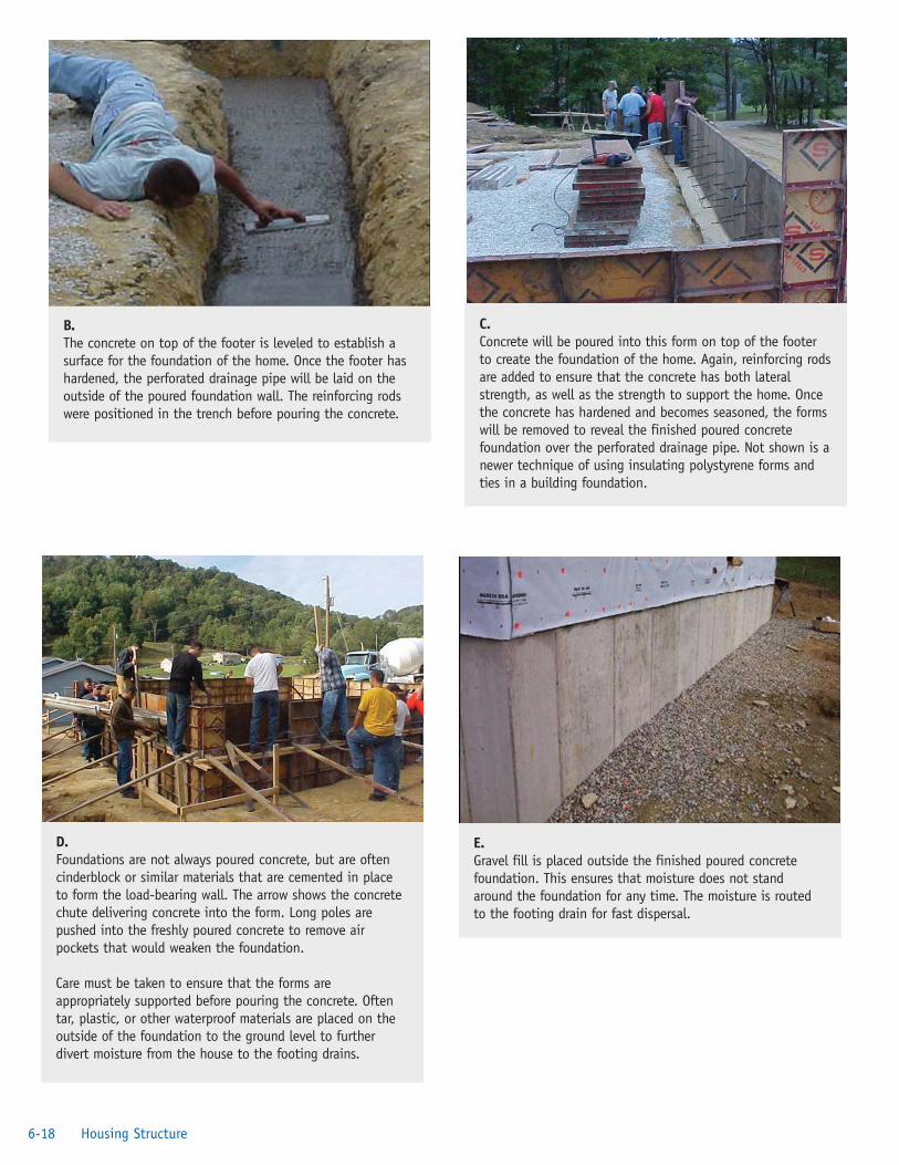
6-18 Housing Structure
E. Gravel fill is placed outside the finished poured concretefoundation. This ensures that moisture does not standaround the foundation for any time. The moisture is routedto the footing drain for fast dispersal.
B. The concrete on top of the footer is leveled to establish asurface for the foundation of the home. Once the footer hashardened, the perforated drainage pipe will be laid on theoutside of the poured foundation wall. The reinforcing rodswere positioned in the trench before pouring the concrete.
C. Concrete will be poured into this form on top of the footerto create the foundation of the home. Again, reinforcing rodsare added to ensure that the concrete has both lateralstrength, as well as the strength to support the home. Oncethe concrete has hardened and becomes seasoned, the formswill be removed to reveal the finished poured concretefoundation over the perforated drainage pipe. Not shown is anewer technique of using insulating polystyrene forms andties in a building foundation.
D. Foundations are not always poured concrete, but are oftencinderblock or similar materials that are cemented in placeto form the load-bearing wall. The arrow shows the concretechute delivering concrete into the form. Long poles arepushed into the freshly poured concrete to remove airpockets that would weaken the foundation.
Care must be taken to ensure that the forms areappropriately supported before pouring the concrete. Oftentar, plastic, or other waterproof materials are placed on theoutside of the foundation to the ground level to furtherdivert moisture from the house to the footing drains.

6-19Healthy Housing Reference Manual
F. A termite shield is established on top of the concrete wall(foundation) just below the sill of the home. The sill istypically made of pressure- and insecticide-treated wood toensure stability and long life.
A cinderblock foundation will be used to support the storageshed attached to the house. Note the potential forinadvertent sabotage of the termite shield if a shield is notinstalled on the top of the cinder block foundation.
G. OSB subfloor, the joist supporting the floor, and the metalbridging that is used to keep the joist from twisting can beseen from the crawl space under the home.
If the material used for the flooring or external sheathing ofthe home is made of plywood or a composition that is notwaterproof, the material must be protected from rain toprevent deterioration and germination of mold spores. Someglues or resins release toxic vapors for years if deteriorationis allowed to begin.
H. The flooring material of thefirst floor of the home is OSBapplied to the subfloor withboth glue and wood screws.Where possible, the screwsshould extend into the subfloor
and the joist below the subfloor to prevent squeaking.
J. The exterior wallframing is composed ofstuds that are 2x6-inchboards. The horizontalmember extending fromone exterior wall to theother is called a girderand is a prime support
for the second floor of the home. The larger studs in theexterior wall are used both for greater strength and to providegreater energy efficiency for the home.
The lintels above the windows and doors distribute theweight of the second floor and roof across the studs that arelocated on each side of the openings in the frame.
K. The joists above the first floorare connected to the centralgirder of the home by steelbrackets. These bracketsprovide a far more effectivealternative than does
toenailing nails to hold the joists in place or to notching thegirder to hold them.
I. The interior wall framing iscomposed of studstraditionally referred to as2×4s. The horizontal memberat the top of the studs iscalled a girt or a ribbon. Inthis case the buildershave used two 2×4s, placingone on top of the other.Because the outside walls
have used studs that are 2×6-inch boards, the girts orribbons on top of these are also double 2×6-inch boards.
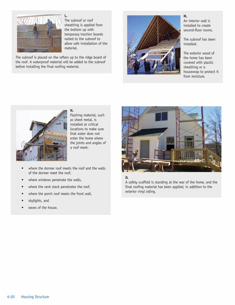
6-20 Housing Structure
L. The subroof or roofsheathing is applied fromthe bottom up withtemporary traction boardsnailed to the subroof toallow safe installation of thematerial.
The subroof is placed on the rafters up to the ridge board ofthe roof. A waterproof material will be added to the subroofbefore installing the final roofing material.
M. An interior wall isinstalled to createsecond-floor rooms.
The subroof has beeninstalled.
The exterior wood ofthe home has beencovered with plasticsheathing or ahousewrap to protect itfrom moisture.
N. Flashing material, suchas sheet metal, isinstalled at criticallocations to make surethat water does notenter the home wherethe joints and angles ofa roof meet:
• where the dormer roof meets the roof and the walls of the dormer meet the roof,
• where windows penetrate the walls,
• where the vent stack penetrates the roof,
• where the porch roof meets the front wall,
• skylights, and
• eaves of the house.
O. A safety scaffold is standing at the rear of the home, and thefinal roofing material has been applied, in addition to theexterior vinyl siding.

References1. US Inspect. Glossary of terms. Chantilly, VA: US
Inspect; no date. Available from URL:http://www.usinspect.com/Glossary/glossary.asp.
2. Center for Disease Control. Housing constructionterminology. In: Basic housing inspection. Atlanta:US Department of Health and Human Services;1976.
3. Building Science Corporation. Read this beforeyou design, build, or renovate. Westford, MA:Building Science Corporation; 2004.
4. Center for Disease Control. Basic housinginspection. Atlanta: US Department of Healthand Human Services; 1976.
5. Wagner JD. Drying out a wet basement. NewYork: This Old House Ventures, Inc.; no date.Available from URL: http://www.thisoldhouse.com/toh/knowhow/interiors/article/0,16417,220912,00.html.
6. Friedman D. Inspecting foundations for structuraldefects. Poughkeepsie, NY: Daniel Friedman;2001. Available from URL: http://www.inspect-ny.com/structure/foundation.htm.
7. Association of Bay Area Governments. Foundations:section 5. Oakland, CA: Association of Bay Area
Governments; 1998. Available from URL:http://www.abag.ca.gov/bayarea/eqmaps/fixit/ch5.
8. Crawford CB. CBD-148: foundationmeasurements. Ottawa, Ontario, Canada:National Research Council; 1972. Available fromURL: http://irc.nrc-cnrc.gc.ca/cbd/cbd148e.html.
9. Hamilton JJ. CBD-184: foundations on swellingor shrinking subsoils. Ottawa, Ontario, Canada:National Research Council; 1977. Available fromURL: http://irc.nrc-cnrc.gc.ca/pubs/cbd/cbd184_e.html.
10. US Department of Housing and UrbanDevelopment. Basements and crawl spaces.Washington, DC: US Department of Housingand Urban Development; 2000. Available fromURL: http://www.hud.gov/offices/hsg/sfh/ref/sfhp1-25.cfm.
11. Bateman BW. Light-gauge steel versesconventional wood framing in residentialconstruction. J Construction Educ1997;2(2):99–108.
12. National Association of Home Builders ResearchCenter. Integrated steel/wood combinationframing. Upper Marlboro, MD: NationalAssociation of Home Builders; no date. Availablefrom URL: http://www.toolbase.org/tertiaryT.asp?DocumentID=4249&CategoryID=1142.
13. Steel Wood Studs. Why use steel wood studs?Reno, NV: Steel Wood Studs; 2001.
14. Canadian Mortgage and Housing Corporation.Understanding window terminology. Ottawa,Ontario, Canada: Canadian Mortgage andHousing Corporation; no date. Available fromURL: http://www.cmhc-schl.gc.ca/en/burema/gesein/abhose/abhose_061.cfm.
15. US Consumer Product Safety Commission. Safetycommission publishes Final Rules for automaticgarage door openers. Washington, DC: USConsumer Product Safety Commission; 1992.Available from URL: http://www.cpsc.gov/cpscpub/prerel/prhtml93/93024.html.
6-21Healthy Housing Reference Manual
P. The front porch of the home is constructed of pressure-treated, insect-resistant lumber. The use of such lumbershould be carefully evaluated with respect to what chemicalshave been used and the potential for human exposure to thetreated wood. Composite wood products and plastic deckingmaterials, collectively called Trex, are available as analternative to pressure-treated wood. A proper hand railingand balusters will be installed.

Additional Sources of InformationCarmody J, Christian J, Labs K, editors. Builder’sfoundation handbook. Oak Ridge, TN: Oak Ridge NationalLaboratory; 1991.
US Department of Housing and Urban Development.Basements and crawl spaces. Washington, DC: USDepartment of Housing and Urban Development; 2000.Available from URL: http://www.hud.gov/offices/hsg/sfh/ref/sfhp1-25.cfm.
6-22 Housing Structure

Chapter 7—Environmental BarriersIntroduction . . . . . . . . . . . . . . . . . . . . . . . . . . . . . . . . . . . . . . . . . . . . . . . . . . . . . .7-1Roof . . . . . . . . . . . . . . . . . . . . . . . . . . . . . . . . . . . . . . . . . . . . . . . . . . . . . . . . . . . .7-2Insulation . . . . . . . . . . . . . . . . . . . . . . . . . . . . . . . . . . . . . . . . . . . . . . . . . . . . . . . .7-3Siding . . . . . . . . . . . . . . . . . . . . . . . . . . . . . . . . . . . . . . . . . . . . . . . . . . . . . . . . . . .7-3
Fiber Cement . . . . . . . . . . . . . . . . . . . . . . . . . . . . . . . . . . . . . . . . . . . . . . . . .7-4Brick . . . . . . . . . . . . . . . . . . . . . . . . . . . . . . . . . . . . . . . . . . . . . . . . . . . . . . . .7-4Stucco . . . . . . . . . . . . . . . . . . . . . . . . . . . . . . . . . . . . . . . . . . . . . . . . . . . . . . .7-4Vinyl . . . . . . . . . . . . . . . . . . . . . . . . . . . . . . . . . . . . . . . . . . . . . . . . . . . . . . . .7-5Asbestos . . . . . . . . . . . . . . . . . . . . . . . . . . . . . . . . . . . . . . . . . . . . . . . . . . . . . .7-5Metal . . . . . . . . . . . . . . . . . . . . . . . . . . . . . . . . . . . . . . . . . . . . . . . . . . . . . . . .7-5
References . . . . . . . . . . . . . . . . . . . . . . . . . . . . . . . . . . . . . . . . . . . . . . . . . . . . . . . .7-6
Figure 7.1. Sources of Moisture and Air Pollutants . . . . . . . . . . . . . . . . . . . . . . . . . . . . . . . . . .7-1Figure 7.2. Blown Attic Insulation . . . . . . . . . . . . . . . . . . . . . . . . . . . . . . . . . . . . . . . . . . . . . . .7-3Figure 7.3. Depth of Attic Insulation . . . . . . . . . . . . . . . . . . . . . . . . . . . . . . . . . . . . . . . . . . . . .7-3Figure 7.4. Attic Insulation . . . . . . . . . . . . . . . . . . . . . . . . . . . . . . . . . . . . . . . . . . . . . . . . . . . .7-3Figure 7.5. Brick Structural Defect . . . . . . . . . . . . . . . . . . . . . . . . . . . . . . . . . . . . . . . . . . . . . .7-4Figure 7.6. Corrosion in Piping Resulting From Galvanic Response . . . . . . . . . . . . . . . . . . . . .7-5
1Healthy Housing Reference Manual
Contents

“The physician can bury his mistakes, but the architect canonly advise his client to plant vines—so they should go as faras possible from home to build their first buildings.”
Frank Lloyd WrightNew York Times, October 4, 1953
IntroductionDamaging moisture originates not only from outside ahome; it is created inside the home as well. Moisture isproduced by smoking; breathing; burning candles;washing and drying clothes; and using fireplaces, gasstoves, furnaces, humidifiers, and air conditioning. Leaksfrom plumbing, unvented bathrooms, dishwashers, sinks,toilets, and garbage disposal units also create moistureproblems because they are not always found before waterdamage or mold growth occurs. Figure 7.1 provides anoverview of the sources of moisture and types of airpollutants that can enter a home.
Solving moisture problems is often expensive and time-consuming. The first step is to do a moisture inventoryto eliminate problems in their order of severity. Problemsthat are easiest and least expensive to resolve should beaddressed first. For example, many basement leaks havebeen eliminated by making sure sump pumps anddownspouts drain away from the house. On the other
hand, moisture seeping though basement or foundationwalls often is very expensive to repair. Eliminating suchmoisture is seldom as simple as coating the interior wall,but often requires expert consultation and excavatingaround the perimeter of the house to install or cleanclogged footing drains. Sealing the outside of thebasement walls and coating the exterior foundation wallwith tar or other waterproofing compounds are often theonly solutions to eliminate moisture.
Moisture condensation occurs in both winter and summer.The following factors increase the probability ofcondensation:
• Homes that are ineffectively insulated and are notsealed against air infiltration in cold climates canresult in major moisture problems.
• Cool interior surfaces such as pipes, windows, tilefloors, and metal appliances; air conditioner coilswith poor outside drainage; masonry or concretesurfaces; toilet tanks; and, in the winter, outsidewalls and ceilings can result in moisture buildupfrom condensation. If the temperature of aninterior surface is low enough to reach the dewpoint, moisture in the air will condense on it andenhance the growth of mold.
Chapter 7: Environmental Barriers
Figure 7.1. Sources of Moisture and Air Pollutants [1]
7-1Healthy Housing Reference Manual

• Dehumidifiers used in regions where outsidehumidity levels are normally 80% or higher havea moisture-collecting tank that should be cleanedand disinfected regularly to prevent the growth ofmold and bacteria. It is best if dehumidifiers havea drain line continuously discharging directly tothe outside or into a properly plumbed trap. Thisis also true in climates where air conditioningunits are used on a full-time or seasonal basis.Their cooling pans provide an excellentenvironment for the growth of allergenic orpathogenic organisms.
• Moisture removed from clothing by clothes driersends up in the dryer vent if it is clogged by lint orimproperly configured. Moisture buildup in thisvent can result in mold growth and, if leakageoccurs, damage to the structure of the home. Thevent over the cooking area of the kitchen alsoshould be checked routinely for moisture or greasebuildup.
RoofThe control of moisture in a home is of paramountimportance. It is no surprise that moisture control beginswith the design and integrity of the roof. Many types ofsurfacing materials are used for roofs-stone, compositionasphalt, plastic, or metal, for example. Some haverelatively short lives and some, such as slate and tile, haveextraordinarily long lives. As in nearly all constructionmaterials, tradeoffs must be made in terms of cost,
thermal efficiency, and longevity. However, all roofs havetwo things in common: the need to shed moisture andprotect the interior from the environment.
When evaluating the roof of a home, the first thing toobserve is the roofline against the sky to see if the roof ’sridge board is straight and level. If the roofline is notstraight, it could mean that serious deterioration has takenplace in the structure of the home as a result of improperconstruction, weight buildup, a deteriorated or brokenridge beam, or rotting rafters. Whatever the cause, the focus ofan inspection must be to locate the extent of the damage.
The next area to inspect is around the flashing on theroof. Flashing is used around any structure that penetratesthe surface of a roof or where the roofline takes anotherdirection. These areas include chimneys, gas vents, atticvents, dormers, and raised and lowered roof surfaces. Oneof the best ways to locate a leak around flashing is to gointo the attic and look carefully. Leaks often arediscovered when it rains; but if it is not raining, theunderside of the roof can be examined with the atticlights off for pinpoints of daylight.
Roofing material should lay relatively flat and should notwave or ripple. The roof should be checked for missing ordamaged shingles, areas where flashing should be installed,elevation changes in roof surfaces, and evidence ofdecomposing or displaced surfaces around the edge of theroof [1–3].
1) Is the roofline of the house straight?
2) Are there ripples or waves in the roof?
3) What is the condition of the gutters and downspouts?
4) What is the condition of the boards the gutters are attached to?
5) Does the flashing appear to be separated or damaged?
6) Is there any apparent damage in the attic or can sunlight be seen through the roof?
7) Is there mold or discoloration on the rafters or roof sheathing?
8) Is there evidence of corrosion between the gutter and downspouts and any metal roofing or aluminum siding?
9) Do the downspouts route the water away from the base or foundation of the home?
10) Are the gutters covered or free of leaves? Are they sagging or separating from the fascia?
11) Does the gutter provide a mosquito-breeding area by holding water?
Roof Inspection
7-2 Environmental Barriers
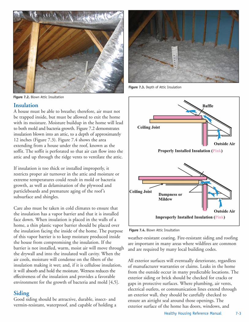
InsulationA house must be able to breathe; therefore, air must notbe trapped inside, but must be allowed to exit the homewith its moisture. Moisture buildup in the home will leadto both mold and bacteria growth. Figure 7.2 demonstratesinsulation blown into an attic, to a depth of approximately12 inches (Figure 7.3). Figure 7.4 shows the areaextending from a house under the roof, known as thesoffit. The soffit is perforated so that air can flow into theattic and up through the ridge vents to ventilate the attic.
If insulation is too thick or installed improperly, itrestricts proper air turnover in the attic and moisture orextreme temperatures could result in mold or bacteriagrowth, as well as delamination of the plywood andparticleboards and premature aging of the roof ’ssubsurface and shingles.
Care also must be taken in cold climates to ensure thatthe insulation has a vapor barrier and that it is installedface down. When insulation is placed in the walls of ahome, a thin plastic vapor barrier should be placed overthe insulation facing the inside of the home. The purposeof this vapor barrier is to keep moisture produced insidethe house from compromising the insulation. If thebarrier is not installed, warm, moist air will move throughthe drywall and into the insulated wall cavity. When theair cools, moisture will condense on the fibers of theinsulation making it wet; and, if it is cellulose insulation,it will absorb and hold the moisture. Wetness reduces theeffectiveness of the insulation and provides a favorableenvironment for the growth of bacteria and mold [4,5].
SidingGood siding should be attractive, durable, insect- andvermin-resistant, waterproof, and capable of holding a
weather-resistant coating. Fire-resistant siding and roofingare important in many areas where wildfires are commonand are required by many local building codes.
All exterior surfaces will eventually deteriorate, regardlessof manufacturer warranties or claims. Leaks in the homefrom the outside occur in many predictable locations. Theexterior siding or brick should be checked for cracks orgaps in protective surfaces. Where plumbing, air vents,electrical outlets, or communication lines extend throughan exterior wall, they should be carefully checked toensure an airtight seal around those openings. Theexterior surface of the home has doors, windows, and
7-3Healthy Housing Reference Manual
Figure 7.2. Blown Attic Insultation
Figure 7.3. Depth of Attic Insulation
Figure 7.4. Blown Attic Insultation

other openings. These openings should be caulkedroutinely, and the drainage gutters along the top shouldbe checked to ensure that they drain properly.
Exterior surface materials include stucco, vinyl, asbestosshingles, brick, metal (aluminum), fiber cement, exteriorplywood, hardwood, painted or coated wood, glass, andtile, some of which are discussed in this chapter [6,7].
Fiber CementFiber cement siding is engineered composite-materialproducts that are extremely stable and durable. Fibercement siding is made from a combination of cellulosefiber material, cement and silica sand, water, and otheradditives. Fiber cement siding is fire resistant and usefulin high-moisture areas.
The fiber cement mixture is formed into siding orindividual boards, then dried and cured using superheatedsteam under pressure. The drying and curing processassures that the fiber cement siding has very low moisturecontent, which makes the product is stable—no warpingor excessive movement—and its surface good for painting.
Weight is a minor concern with fiber cement products:they weigh about 1½ times what comparably sizedcomposite wood products do. Other concerns relate tocutting fiber cement: cutting produces a fine dust withmicroscopic silica fibers, so personal protective equipment(respirator and goggles) are necessary. In addition, specialtools are needed for cutting.
BrickBrick homes may seem on the surface to be nearlymaintenance free. This is true in some cases, but, like allsurfaces, brick also degrades. Although this degradationtakes longer in brick than in other materials, repairingbrick is complex and quite expensive. There are two basictypes of brick homes. One is brick veneer, which is a thinbrick set to the outside of a wooden stud wall. The brickis not actually the supporting wall. Brick veneer typicallyhas the same pattern of bricks around the doors andwindows; a true brick wall will have brick arches or heavysteel plates above the doors and other openings of thebuilding. Some brick walls have wooden studs behind thebrick to provide an area for insulation, plumbing, vents,and wiring. It is important that weep holes and flashingbe installed in brick homes to control moisture.
Improperly constructed building footers can result inmajor damage to the exterior brick surface of a home byallowing moisture, insects, and vermin to enter. A crack,
such as the one in Figure 7.5, isan example of such a failure. Thistype of damage will require muchmore than just a mortar patch.Buildings constructed of concreteblock also experience footerfailure. The damage is reason tonot skimp when installing and inspecting the footing andreinforces the need for appropriate concrete mix, rebar,and footing drains.
StuccoSynthetic stucco (exterior insulation and finish system;EIFS) is a multilayered exterior finish that has been usedin Europe since shortly after World War II, whencontractors found it to be a good repair choice forbuildings damaged during the war. North Americanbuilders began using EIFS in the 1980s, first incommercial buildings, then as an exterior finish to woodframe houses.
EIFS has three layers:
• Inner layer—foam insulation board secured to theexterior wall surface, often with adhesive;
• Middle layer—a polymer and cement base coatapplied to the top of the insulation, thenreinforced with glass fiber mesh; and
• Exterior layer—a textured finish coat.
EIFS layers bond to form a covering that does notbreathe. If moisture seeps in, it can become trappedbehind the layers. With no place to go, constant exposureto moisture can lead to rot in wood and other vulnerablematerials within the home. Ripples in the stucco could bea sign of a problem. On the surface it may look likenothing is wrong, but beneath the surface, the stucco mayhave cracked from settling of the house. With a properlyinstalled moisture barrier, no moisture should be able toseep behind the EIFS, including moisture originatinginside the home. Drains in the foundation can bedesigned to enable moisture that does seep in to escape.
Other signs of problems are mold or mildew on theinterior or exterior of the home, swollen wood arounddoor and window frames, blistered or peeling paint; andcracked EIFS or cracked sealant.
7-4 Environmental Barriers
Figure 7.5. BrickStructural Defect
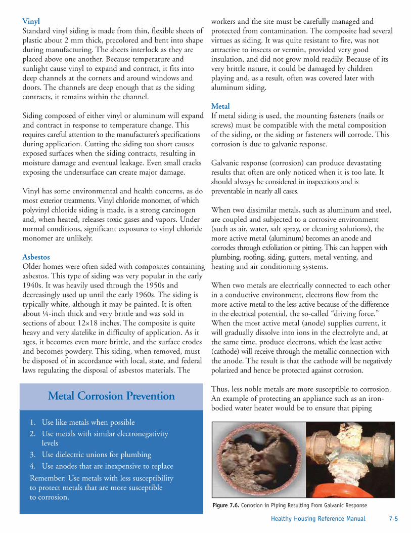
Vinyl Standard vinyl siding is made from thin, flexible sheets ofplastic about 2 mm thick, precolored and bent into shapeduring manufacturing. The sheets interlock as they areplaced above one another. Because temperature andsunlight cause vinyl to expand and contract, it fits intodeep channels at the corners and around windows anddoors. The channels are deep enough that as the sidingcontracts, it remains within the channel.
Siding composed of either vinyl or aluminum will expandand contract in response to temperature change. Thisrequires careful attention to the manufacturer’s specificationsduring application. Cutting the siding too short causesexposed surfaces when the siding contracts, resulting inmoisture damage and eventual leakage. Even small cracksexposing the undersurface can create major damage.
Vinyl has some environmental and health concerns, as domost exterior treatments. Vinyl chloride monomer, of whichpolyvinyl chloride siding is made, is a strong carcinogenand, when heated, releases toxic gases and vapors. Undernormal conditions, significant exposures to vinyl chloridemonomer are unlikely.
AsbestosOlder homes were often sided with composites containingasbestos. This type of siding was very popular in the early1940s. It was heavily used through the 1950s anddecreasingly used up until the early 1960s. The siding istypically white, although it may be painted. It is oftenabout ¼-inch thick and very brittle and was sold insections of about 12×18 inches. The composite is quiteheavy and very slatelike in difficulty of application. As itages, it becomes even more brittle, and the surface erodesand becomes powdery. This siding, when removed, mustbe disposed of in accordance with local, state, and federallaws regulating the disposal of asbestos materials. The
workers and the site must be carefully managed andprotected from contamination. The composite had severalvirtues as siding. It was quite resistant to fire, was notattractive to insects or vermin, provided very goodinsulation, and did not grow mold readily. Because of itsvery brittle nature, it could be damaged by childrenplaying and, as a result, often was covered later withaluminum siding.
MetalIf metal siding is used, the mounting fasteners (nails orscrews) must be compatible with the metal compositionof the siding, or the siding or fasteners will corrode. Thiscorrosion is due to galvanic response.
Galvanic response (corrosion) can produce devastatingresults that often are only noticed when it is too late. Itshould always be considered in inspections and ispreventable in nearly all cases.
When two dissimilar metals, such as aluminum and steel,are coupled and subjected to a corrosive environment(such as air, water, salt spray, or cleaning solutions), themore active metal (aluminum) becomes an anode andcorrodes through exfoliation or pitting. This can happen withplumbing, roofing, siding, gutters, metal venting, andheating and air conditioning systems.
When two metals are electrically connected to each otherin a conductive environment, electrons flow from themore active metal to the less active because of the differencein the electrical potential, the so-called “driving force.”When the most active metal (anode) supplies current, itwill gradually dissolve into ions in the electrolyte and, atthe same time, produce electrons, which the least active(cathode) will receive through the metallic connection withthe anode. The result is that the cathode will be negativelypolarized and hence be protected against corrosion.
Thus, less noble metals are more susceptible to corrosion.An example of protecting an appliance such as an iron-bodied water heater would be to ensure that piping
7-5Healthy Housing Reference Manual
Figure 7.6. Corrosion in Piping Resulting From Galvanic Response
1. Use like metals when possible
2. Use metals with similar electronegativity levels
3. Use dielectric unions for plumbing
4. Use anodes that are inexpensive to replace
Remember: Use metals with less susceptibility to protect metals that are more susceptible to corrosion.
Metal Corrosion Prevention
connections are of similar material when possible andfollow the manufacturer’s good practice and instructions onusing dielectric (not conductors of electricity) unions [8].
Figure 7.6 shows examples of electrochemical kinetics inpipes that were connected to dissimilar metals.
References1. Lawrence Berkeley National Laboratory. Cool
roofing materials database. Berkeley, CA:Lawrence Berkeley National Laboratory,Environmental Energy Technologies Division;2000. Available from URL:http://eetd.lbl.gov/coolroof/.
2. California Energy Commission. Roofing.Sacramento: California Energy Commission; nodate. Available from URL: http://www.con-sumerenergycenter.org/homeandwork/homes/construction/roofing.html.
3. Cazayoux EJ, Bilello RA. Roof materials. BatonRouge, LA: Louisiana State University; no date.Available from URL: http://www.leeric.lsu.edu/bgbb/7/ecep/carpntry/i/i.htm.
4. Department of Energy. Insulation fact sheet.Washington, DC: Department of Energy; 2002.Available from URL: http://www.ornl.gov/sci/roofs+walls/insulation/ins_01.htm.
5. The Old House Web. Insulation: stories and morefrom the Old House Web. Gardiner, ME: TheOld House Web; no date. Available from URL:http://www.oldhouseweb.com/stories/HowTo/HVAC_and_Insulation/Insulation/.
6. The Old House Web. Siding: stories and morefrom the Old House Web. Gardiner, ME: TheOld House Web; no date. Available from URL:http://www.oldhouseweb.com/stories/How-To/Siding/.
7. Vandervort D. House siding and architecturaldetails. Glendale, CA: Hometips.com; no date.Available from URL: http://www.hometips.com/home_improvement/siding.html.
8. University of Wisconsin-Stevens Point. Corrosion,lead, copper: in-home water supplies—are you atrisk? Stevens Point, WI: University of Wisconsin-
Stevens Point; no date. Available from URL:https://www.uwsp.edu/cnr/etf/corros.htm.
7-6 Environmental Barriers

Chapter 8—Rural Water Supplies and Water-quality IssuesIntroduction . . . . . . . . . . . . . . . . . . . . . . . . . . . . . . . . . . . . . . . . . . . . . . . . . . . . . . .8-1Water Sources . . . . . . . . . . . . . . . . . . . . . . . . . . . . . . . . . . . . . . . . . . . . . . . . . . . . .8-1Source Location . . . . . . . . . . . . . . . . . . . . . . . . . . . . . . . . . . . . . . . . . . . . . . . . . . . .8-2Well Construction . . . . . . . . . . . . . . . . . . . . . . . . . . . . . . . . . . . . . . . . . . . . . . . . . .8-3
Sanitary Design and Construction . . . . . . . . . . . . . . . . . . . . . . . . . . . . . . . . . .8-4Pump Selection . . . . . . . . . . . . . . . . . . . . . . . . . . . . . . . . . . . . . . . . . . . . . . . .8-4
Dug and Drilled Wells . . . . . . . . . . . . . . . . . . . . . . . . . . . . . . . . . . . . . . . . . . . . . . .8-4Springs . . . . . . . . . . . . . . . . . . . . . . . . . . . . . . . . . . . . . . . . . . . . . . . . . . . . . . .8-6Cisterns . . . . . . . . . . . . . . . . . . . . . . . . . . . . . . . . . . . . . . . . . . . . . . . . . . . . . .8-6
Disinfection of Water Supplies . . . . . . . . . . . . . . . . . . . . . . . . . . . . . . . . . . . . . . . . .8-7Chlorine Carrier Solutions . . . . . . . . . . . . . . . . . . . . . . . . . . . . . . . . . . . . . . . .8-9Routine Water Chlorination (Simple) . . . . . . . . . . . . . . . . . . . . . . . . . . . . . . .8-9Well Water Shock Chlorination . . . . . . . . . . . . . . . . . . . . . . . . . . . . . . . . . . . .8-9
Backflow, Back-siphonage, and Other Water Quality Problems . . . . . . . . . . . . . . . .8-9Backflow . . . . . . . . . . . . . . . . . . . . . . . . . . . . . . . . . . . . . . . . . . . . . . . . . . . . .8-9Back-siphonage . . . . . . . . . . . . . . . . . . . . . . . . . . . . . . . . . . . . . . . . . . . . . . . .8-10Other Water Quality Problems . . . . . . . . . . . . . . . . . . . . . . . . . . . . . . . . . . . .8-10
Protecting the Groundwater Supply . . . . . . . . . . . . . . . . . . . . . . . . . . . . . . . . . . . . .8-10References . . . . . . . . . . . . . . . . . . . . . . . . . . . . . . . . . . . . . . . . . . . . . . . . . . . . . . . .8-11Additional Sources of Information . . . . . . . . . . . . . . . . . . . . . . . . . . . . . . . . . . . . . .8-12
Figure 8.1. U.S. Water Supply by Source . . . . . . . . . . . . . . . . . . . . . . . . . . . . . . . . . . . . . . . . . .8-1Figure 8.2. Cross Section of a Driven Well . . . . . . . . . . . . . . . . . . . . . . . . . . . . . . . . . . . . . . . .8-3Figure 8.3. Well Seal . . . . . . . . . . . . . . . . . . . . . . . . . . . . . . . . . . . . . . . . . . . . . . . . . . . . . . . . .8-4Figure 8.4. Converted Dug Well . . . . . . . . . . . . . . . . . . . . . . . . . . . . . . . . . . . . . . . . . . . . . . . .8-4Figure 8.5. Recapped and Sealed Dug Well . . . . . . . . . . . . . . . . . . . . . . . . . . . . . . . . . . . . . . . .8-5Figure 8.6. Drilled Well. . . . . . . . . . . . . . . . . . . . . . . . . . . . . . . . . . . . . . . . . . . . . . . . . . . . . . .8-5Figure 8.7. Typical Dug Well . . . . . . . . . . . . . . . . . . . . . . . . . . . . . . . . . . . . . . . . . . . . . . . . . . .8-5Figure 8.8. Sewage in Drainage Ditch . . . . . . . . . . . . . . . . . . . . . . . . . . . . . . . . . . . . . . . . . . . .8-6Figure 8.9. Drilled Well. . . . . . . . . . . . . . . . . . . . . . . . . . . . . . . . . . . . . . . . . . . . . . . . . . . . . . .8-6Figure 8.10. Spring Box. . . . . . . . . . . . . . . . . . . . . . . . . . . . . . . . . . . . . . . . . . . . . . . . . . . . . . . .8-6
Table 8.1. Recommended Minimum Distance Between Well and Pollution Sources . . . . . . . .8-2Table 8.2. Types of Wells for Accessing Groundwater, Well Depths, and Diameters . . . . . . . . .8-3Table 8.3. Disinfection Methods . . . . . . . . . . . . . . . . . . . . . . . . . . . . . . . . . . . . . . . . . . . . . . . .8-7Table 8.4. Chlorination Guide for Specific Water Conditions . . . . . . . . . . . . . . . . . . . . . . . . .8-8Table 8.5. Preparing a 200-ppm Chlorine Solution . . . . . . . . . . . . . . . . . . . . . . . . . . . . . . . . .8-9Table 8.6. Analyzing and Correcting Water Quality Problems . . . . . . . . . . . . . . . . . . . . . . . . .8-11
1Healthy Housing Reference Manual
Contents

“We never know the worth of water till the well is dry.”
Thomas FullerGnomologia, 1732
IntroductionOne of the primary differences between rural and urbanhousing is that much infrastructure that is often takenfor granted by the urban resident does not exist in therural environment. Examples range from fire and policeprotection to drinking water and sewage disposal. Thischapter is intended to provide basic knowledge about thesources of drinking water typically used for homes in therural environment. It is estimated that at least 15% ofthe population of the United States is not served byapproved public water systems. Instead, they use individualwells and very small drinking water systems not coveredby the Safe Water Drinking Act (SDWA); these wells andsystems are often untested and contaminated [1]. Manyof these wells are dug rather than drilled. Such shallowsources frequently are contaminated with both chemicalsand bacteria. Figure 8.1 shows the change in watersupply source in the United States from 1970 to 1990.According to the 2003 American Housing Survey, of the105,843,000 homes in the United States, water isprovided to 92,324,000 (87.2%) by a public or privatebusiness; 13,097,000 (12.4%) have a well (11,276,000drilled, 919,000 dug, and 902,000 not reported) [3].
Water SourcesThe primary sources of drinking water are groundwaterand surface water. In addition, precipitation (rain and
snow) can be collected and contained. The initial qualityof the water depends on the source. Surface water (lakes,reservoirs, streams, and rivers), the drinking water sourcefor approximately 50% of our population, is generally ofpoor quality and requires extensive treatment.Groundwater, the source for the other approximately50% of our population, is of better quality. However, itstill may be contaminated by agricultural runoff orsurface and subsurface disposal of liquid waste, includingleachate from solid waste landfills. Other sources, such asspring water and rain water, are of varying levels of quality,but each can be developed and treated to render it potable.
Most water systems consist of a water source (such as awell, spring, or lake), some type of tank for storage, anda system of pipes for distribution. Means to treat thewater to remove harmful bacteria or chemicals may also berequired. The system can be as simple as a well, a pump,and a pressure tank to serve a single home. It may be acomplex system, with elaborate treatment processes,multiple storage tanks, and a large distribution systemserving thousands of homes. Regardless of system size,the basic principles to assure the safety and potability ofwater are common to all systems. Large-scale watersupply systems tend to rely on surface water resources,and smaller water systems tend to use groundwater.
Groundwater is pumped from wells drilled into aquifers.Aquifers are geologic formations where water pools, oftendeep in the ground. Some aquifers are actually higherthan the surrounding ground surface, which can result inflowing springs or artesian wells. Artesian wells are often
Chapter 8: Rural Water Supplies and Water-quality Issues
8-1Healthy Housing Reference Manual
Figure 8.1. U.S. Water Supply by Source [2]

drilled; once the aquifer is penetrated, the water flowsonto the surface of the ground because of the hydrologicpressure from the aquifer.
SDWA defines a public water system as one that providespiped water to at least 25 persons or 15 service connectionsfor at least 60 days per year. Such systems may be ownedby homeowner associations, investor-owned watercompanies, local governments, and others. Water notfrom a public water supply, and which serves one or onlya few homes, is called a private supply. Private watersupplies are, for the most part, unregulated. Communitywater systems are public systems that serve people year-round in their homes. The U.S. Environmental ProtectionAgency (EPA) also regulates other kinds of public watersystems-such as those at schools, factories, campgrounds,or restaurants-that have their own water supply.
The quantity of water in an aquifer and the waterproduced by a well depend on the nature of the rock,sand, or soil in the aquifer where the well withdrawswater. Drinking water wells may be shallow (50 feet orless) or deep (more than 1,000 feet).
On average, our society uses almost 100 gallons ofdrinking water per person per day. Traditionally, water userates are described in units of gallons per capita per day(gallons used by one person in 1 day). Of the drinkingwater supplied by public water systems, only a smallportion is actually used for drinking. Residential waterconsumers use most drinking water for other purposes,such as toilet flushing, bathing, cooking, cleaning, andlawn watering.
The amount of water we use in our homes varies duringthe day:
• Lowest rate of use—11:30 PM to 5:00 AM,
• Sharp rise/high use—5:00 AM to noon (peakhourly use from 7:00 AM to 8:00 AM),
• Moderate use—noon to 5:00 PM (lull around3:00 PM), and
• Increasing evening use—5:00 PM to 11:00 PM
(second minor peak, 6:00 PM to 8:00 PM).
Source LocationThe location of any source of water under considerationas a potable supply, whether individual or community,should be carefully evaluated for potential sources ofcontamination. As a general practice, the maximumdistance that economics, land ownership, geology, andtopography will allow should separate a water source frompotential contamination sources. Table 8.1 details some ofthe sources of contamination and gives minimumdistances recommended by EPA to separate pollutionsources from the water source.
Water withdrawn directly from rivers, lakes, or reservoirscannot be assumed to be clean enough for humanconsumption unless it receives treatment. Water pumpedfrom underground aquifers will require some level oftreatment. Believing surface water or soil-filtered waterhas purified itself is dangerous and unjustified. Clearwater is not necessarily safe water. To assess the level oftreatment a water source requires, follow these steps:
• Determine the quality needed for the intendedpurpose (drinking water quality needs to beevaluated under the SDWA).
• For wells and springs, test the water forbacteriologic quality. This should be done withseveral samples taken over a period of time to
8-2 Rural Water Supplies and Water-quality Issues
Table 8.1. Recommended Minimum Distance Between Well and Pollution Sources (Horizontal Distance) [1]

establish a history on the source. With fewexceptions, surface water and groundwater sourcesare always presumed to be bacteriologically unsafeand, as a minimum, must be disinfected.
• Analyze for chemical quality, including both legal(primary drinking water) standards and aesthetic(secondary) standards.
• Determine the economical and technical restraints(e.g., cost of equipment, operation andmaintenance costs, cost of alternative sources,availability of power).
• Treat if necessary and feasible.
Well ConstructionMany smaller communities obtain drinking water solelyfrom underground aquifers. In addition, according to thelast census with data on water supply systems, 15% ofpeople in the United States are on individual water supplysystems. In some sections of the country, there may be achoice of individual water supply sources that will supplywater throughout the year. Some areas of the country maybe limited to one source. The various sources of waterinclude drilled wells, driven wells, jetted wells, dug wells,bored wells, springs, and cisterns. Table 8.2 provides amore detailed description of some of these wells.
Regardless of the choice for a water supply source, specialsafety precautions must be taken to assure the potabilityof the water. Drainage should be away from a well. Thecasings of the well should be sealed with grout or some othermastic material to ensure that surface water does not seepalong the well casing to the water source. In Figure 8.2,the concrete grout has been reinforced with steel and adrain away from the casing has been provided to assist inprotecting this water source. Additionally, researchsuggests that a minimum of 10 feet of soil is essential tofilter unwanted biologic organisms from the water source.
However, if the area of well construction has any sourcesof chemical contamination nearby, the local public healthauthority should be contacted. In areas with karsttopography (areas characterized by a limestone landscapewith caves, fissures, and underground streams), wells ofany type are a health risk because of the long distancesthat both chemical and biologic contaminants can travel.
When determining where a water well is to be located,several factors should be considered:
• the groundwater aquifer to be developed,
• depth of the water-bearing formations,
• the type of rock formations that will be encountered,
• freedom from flooding, and
• relation to existing or potential sources of contamination.
Figure 8.2. Cross Section of a Driven Well
Table 8.2. Types of Wells for Accessing Groundwater, Well Depths, and Diameters
8-3Healthy Housing Reference Manual

The overriding concern is to protect any kind of wellfrom pollution, primarily bacterial contamination.Groundwater found in sand, clay, and gravel formations ismore likely to be safer than groundwater extracted fromlimestone and other fractured rock formations. Whateverthe strata, wells should be protected from
• surface water entering directly into the top of the well,
• groundwater entering below ground level withoutfiltering through at least 10 feet of earth, and
• surface water entering the space between the wellcasing and surrounding soil.
Also, a well should be located in such a way that it isaccessible for maintenance, inspection, and pump or pipereplacement when necessary. Driven wells (Figure 8.2) aretypically installed in sand or soil and do not penetratebase rock. They are, as a result, hammered into the groundand are quite shallow, resulting in frequent contamination byboth chemical and bacterial sources.
Sanitary Design and Construction Whenever a water-bearing formation is penetrated (as inwell construction), a direct route of possible watercontamination exists unless satisfactory precautions aretaken. Wells should be provided with casing or pipe to anadequate depth to prevent caving and to permit sealing ofthe earth formation to the casing with watertight cementgrout or bentonite clay, from a point just below thesurface to as deep as necessary to prevent entry ofcontaminated water.
Once construction of the well is completed, the top of thewell casing should be covered with a sanitary seal, anapproved well cap, or a pump mounting that completely
covers the well opening (Figure 8.3). If pumping at thedesign rate causes drawdown in the well, a vent through atapped opening should be provided. The upper end of thevent pipe should be turned downward and suitablyscreened to prevent the entry of insects and foreign matter.
Pump SelectionA variety of pump types and sizes exist to meet the needsof individual or community water systems. Some of thefactors to be considered in selecting a pump for a specificapplication are well depth, system design pressure,demand rate in gallons per minute, availability of power,and economics.
Dug and Drilled WellsDug wells (Figures 8.4 and 8.5) were one of the mostcommon types of wells for individual water supply in theUnited States before the 1950s. They were oftenconstructed with one person digging the hole with ashovel and another pulling the dirt from the hole with arope, pulley, and bucket. Of course, this required a holeof rather large circumference, with the size increasing thepotential for leakage from the surface. The dug well alsowas traditionally quite shallow, often less than 25 feet,which often resulted in the water source being
8-4 Rural Water Supplies and Water-quality Issues
Figure 8.4. Converted Dug Well [1]Figure 8.3. Well Seal

contaminated by surface water as it ran through cracksand crevices in the ground to the aquifer. Dug wellsprovide potable water only if they are properly locatedand the water source is free of biologic and chemicalcontamination. The general rule is, the deeper the well,the more likely the aquifer is to be free of contaminants,as long as surface water does not leak into the wellwithout sufficient soil filtration.
Two basic processes are used to remediate dug wells. Oneis to dig around the well to a depth of 10 feet and installa solid slab with a hole in it to accommodate a well casingand an appropriate seal (Figures 8.4 and 8.5). The dirt isthen backfilled over the slab to the surface, and the casingis equipped with a vent and second seal, similar to adrilled well, as shown in Figure 8.6. This results in aconsiderable reduction in the area of the casing that needsto be protected. Experience has shown that the disturbeddirt used for backfilling over the buried slab will continueto release bacteria into the well for a short time aftermodification. Most experts in well modification suggestinstalling a chlorination system on all dug wells to
disinfect the water because of their shallow depth andpossible biologic impurity during changing drainage andweather conditions above ground. Figure 8.7 shows a dugwell near the front porch of a house and within 5 feet of adrainage ditch and 6 feet of a rural road. This well islikely to be contaminated with the pesticide used totermite-proof the home and from whatever runs off thenearby road and drainage ditch. The well shown is about15 feet deep. The brick structure around the well holdsthe centrifugal pump and a heater to keep the water fromfreezing. Although dangerous to drink from, this well is
8-5Healthy Housing Reference Manual
Figure 8.5. Recapped and Sealed Dug Well [1]
Figure 8.6. Drilled Well [4]
Figure 8.7. Typical Dug Well

typical of dug wells used in rural areas of the UnitedStates for drinking water.
Samples should not be taken from such wells because theyinstill a false sense of security if they are negative for bothchemicals and biologic organisms. The quality of thewater in such wells can change in just a few hoursthrough infiltration of drainage water. Figure 8.8 showsthe septic tank discharge in the drainage ditch 5 feetupstream of the dug well in Figure 8.7. This potentialcombination of drinking water and waste disposal presentsan extreme risk to the people serviced by the dug well.Sampling is not the answer; the water source should bechanged under the supervision of qualified environmentalhealth professionals.
Figure 8.9 shows a drilled well. On the left side of the pictureis the corner of the porch of the home. The well appearsnot to have a sanitary well seal and is likely open to theair and will accept contaminants into the casing. Because the
well is so close to the house, the casing is open, and the landslopes toward the well, it is a major candidate forcontamination and not a safe water source.
Springs Another source of water for individual water supply isnatural springs. A spring is groundwater that reaches thesurface because of the natural contours of the land.
Springs are common in rolling hillside and mountainareas. Some provide an ample supply of water, but mostprovide water only seasonally. Without proper precautions, thewater may be biologically or chemically contaminated andnot considered potable.
To obtain satisfactory (potable) water from a spring, it isnecessary to
• find the source,
• properly develop the spring,
• eliminate surface water outcroppings above thespring to its source,
• prevent animals from accessing the spring area, and
• provide continuous chlorination.
Figure 8.10 illustrates a properly developed spring. Notethat the line supplying the water is well underground, thespring box is watertight, and surface water runoff isdiverted away from the area. Also be aware that the waterquality of a spring can change rapidly.
CisternsA cistern is a watertight, traditionally undergroundreservoir that is filled with rainwater draining from the
8-6 Rural Water Supplies and Water-quality Issues
Figure 8.10. Spring Box [5]
Figure 8.8. Sewage in Drainage Ditch
Figure 8.9. Drilled Well
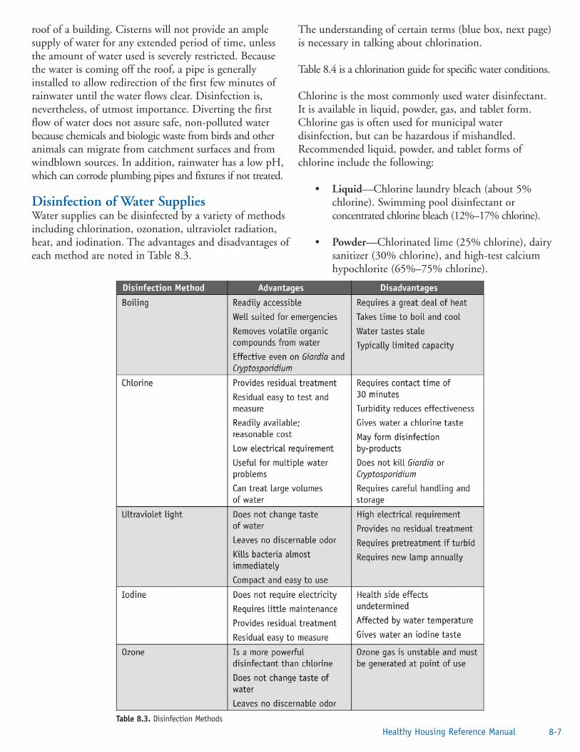
roof of a building. Cisterns will not provide an amplesupply of water for any extended period of time, unlessthe amount of water used is severely restricted. Becausethe water is coming off the roof, a pipe is generallyinstalled to allow redirection of the first few minutes ofrainwater until the water flows clear. Disinfection is,nevertheless, of utmost importance. Diverting the firstflow of water does not assure safe, non-polluted waterbecause chemicals and biologic waste from birds and otheranimals can migrate from catchment surfaces and fromwindblown sources. In addition, rainwater has a low pH,which can corrode plumbing pipes and fixtures if not treated.
Disinfection of Water SuppliesWater supplies can be disinfected by a variety of methodsincluding chlorination, ozonation, ultraviolet radiation,heat, and iodination. The advantages and disadvantages ofeach method are noted in Table 8.3.
The understanding of certain terms (blue box, next page)is necessary in talking about chlorination.
Table 8.4 is a chlorination guide for specific water conditions.
Chlorine is the most commonly used water disinfectant.It is available in liquid, powder, gas, and tablet form.Chlorine gas is often used for municipal waterdisinfection, but can be hazardous if mishandled.Recommended liquid, powder, and tablet forms ofchlorine include the following:
• Liquid—Chlorine laundry bleach (about 5%chlorine). Swimming pool disinfectant orconcentrated chlorine bleach (12%–17% chlorine).
• Powder—Chlorinated lime (25% chlorine), dairysanitizer (30% chlorine), and high-test calciumhypochlorite (65%–75% chlorine).
Table 8.3. Disinfection Methods
8-7Healthy Housing Reference Manual

8-8 Rural Water Supplies and Water-quality Issues
Table 8.4. Chlorination Guide for Specific Water Conditions
Breakpoint chlorination—A process sometimes used to ensure the presence of free chlorine in public water supplies byadding enough chlorine to the water to satisfy the chlorine demand and to react with all dissolved ammonia that mightbe present. The concentrations of chlorine needed to treat a variety of water conditions are listed in Table 8.4.
Chlorine concentration—The concentration (amount) of chlorine in a volume of water is measured in parts per million(ppm). In 1 million gallons of water, a chlorine concentration of 1 ppm would require 8.34 pounds of 100% chlorine.
Contact time—The time, after chlorine addition and before use, given for disinfection to occur. For groundwater systems,contact time is minimal. However, in surface water systems, a contact time of 20 to 30 minutes is common.
Dosage—The total amount of chlorine added to water. Given in parts per million (ppm) or milligrams per liter(mg/L).
Demand—Chlorine solution used by reacting with particles of organic matter such as slimes or other chemicals andminerals that may be present. The difference between the amount of chlorine applied to water and total availablechlorine remaining at the end of a specified contact period.
Parts per million—A weight-to-weight comparison; 1 ppm equals 1 pound per million pounds. Because water weighs8.34 pounds per gallon, it takes 8.34 pounds of any substance per million gallons to equal 1 ppm. In water chemistry,1 ppm equals 1 mg/L.
Residual—The amount of chlorine left after the demand is met; available (free) chlorine. This portion provides a readyreserve for bactericidal action. Both combined and free chlorine make up chlorine residual and are involved in disinfection.Total available chlorine = free chlorine + combined chlorine.
Definitions of Terms Related to Chlorination

• Tablets—High-test calcium hypochlorite(65%–75% chlorine).
• Gas—Gas chlorine is an economical andconvenient way to use large amounts of chlorine.It is stored in steel cylinders ranging in size from100 to 2,000 pounds. The packager fills thesecylinders with liquid chlorine to approximately85% of their total volume; the remaining 15% isoccupied by chlorine gas. These ratios are requiredto prevent tank rupture at high temperatures. It isimportant that direct sunlight never reaches gascylinders. It is also important that the user ofchlorine knows the maximum withdrawal rate ofgas per day per cylinder. For example, themaximum withdrawal rate from a 150-poundcylinder is approximately 40 pounds per day at roomtemperature discharging to atmospheric pressure.
Chlorine Carrier SolutionsOn small systems or individual wells, a high-chlorine carriersolution is mixed in a tank in the pump house and pumpedby the chlorinator into the system. Table 8.5 shows howto make a 200-ppm carrier solution. By using 200 ppm,only small quantities of this carrier have to be added.Depending on the system, other stock solutions may beneeded to better use existing chemical feed equipment.
Routine Water Chlorination (Simple)Most chlorinated public water supplies use routine waterchlorination. Enough chlorine is added to the water tomeet the chlorine demand, plus enough extra to supply0.2 to 0.5 ppm of free chlorine when checked after 20 minutes.
Simple chlorination may not be enough to kill certainviruses. Chlorine as a disinfectant increases ineffectiveness as the chlorine residual is increased and asthe contact time is increased.
Chlorine solutions should be mixed and chlorinatorsadjusted according to the manufacturer’s instructions.Chlorine solutions deteriorate gradually when standing.Fresh solutions must be prepared as necessary to maintain
the required chlorine residual. Chlorine residual should betested at least once a week to assure effective equipmentoperation and solution strengths.
A dated record should be kept of solution preparation,type, proportion of chlorine used, and residual-test results.Sensing devices are available that will automatically shut offthe pump and activate a warning bell or light when thechlorinator needs servicing.
Well Water Shock ChlorinationShock chlorination is used to control iron and sulfate-reducing bacteria and to eliminate fecal coliform bacteriain a water system. To be effective, shock chlorinationmust disinfect the following: the entire well depth, theformation around the bottom of the well, the pressuresystem, water treatment equipment, and the distributionsystem. To accomplish this, a large volume of super-chlorinated water is siphoned down the well to displacethe water in the well and some of the water in theformation around the well. Check specifications on thewater treatment equipment to ensure appropriate protectionof the equipment.
With shock chlorination, the entire system-from thewater-bearing formation through the well-bore and thedistribution system-is exposed to water that has a concentrationof chlorine strong enough to kill iron and sulfate-reducingbacteria. The shock chlorination process is complex andtedious. Exact procedures and concentrations of chlorinefor effective shock treatment are available [6,7].
Backflow, Back-siphonage, and Other WaterQuality ProblemsIn addition to contamination at its source, water canbecome contaminated with biologic materials and toxicconstruction or unsuitable joint materials as it flowsthrough the water distribution system in the home. Waterflowing backwards (backflow) in the pipes sucks materialsback (back-siphonage) into the water distribution system,creating equally hazardous conditions. Other water qualityproblems relate to hardness, dissolved iron and iron bacteria,acidity, turbidity, color, odor, and taste.
BackflowBackflow is any unwanted flow of nonpotable water intoa potable water system. The direction of flow is thereverse of that intended for the system. Backflow may becaused by numerous factors and conditions. For example,the reverse pressure gradient may be a result of either aloss of pressure in the supply main (back-siphonage) orthe flow from a pressurized system through an unprotected
8-9Healthy Housing Reference Manual
Table 8.5. Preparing a 200-ppm Chlorine Solution

cross-connection (back-pressure). A reverse flow in adistribution main or in a customer’s system can be createdby a change of system pressure wherein the pressure at thesupply point becomes lower than the pressure at the pointof use. When this happens, the water at the point of usewill be siphoned back into the system, potentiallypolluting or contaminating it. It is also possible thatcontaminated or polluted water could continue tobackflow into the public distribution system. The point atwhich nonpotable water comes in contact with potablewater is called a cross-connection.
Examples of backflow causes include supplementalsupplies, such as a standby fire protection tank; firepumps; chemical feed pumps that overpower the potablewater system pressure; and sprinkler systems.
Back-SiphonageBack-siphonage is a siphon action in an undesirable orreverse direction. When there is a direct or indirectconnection between a potable water supply and water ofquestionable quality due to poor plumbing design orinstallation, there is always a possibility that the publicwater supply may become contaminated. Some examplesof common plumbing defects are
• washbasins, sterilizers, and sinks with submergedinlets or threaded hose bibs and hose;
• oversized booster pumps that overtax the supplycapability of the main and thus develop negativepressure;
• submerged inlets and fire pumps (if the firepumps are directly connected into the water main,a negative pressure will develop); and
• a threaded hose bib in a health-care facility (whichis technically a cross-connection).
There are many techniques and devices for preventing back-flow and back-siphonage. Some examples are
• Vacuum breakers (nonpressure and pressure);
• Back-flow preventers (reduced pressure principle,double gate-double check valves, swing-connection, and air gap-double diameterseparation);
• Surge tanks (booster pumps for tanks, fire systemmake-up tank, and covering potable tanks); and
• Color coding in all buildings where there is anypossibility of connecting two separate systems ortaking water from the wrong source (blue-potable,yellow-nonpotable, and other-chemical and gases).
An air gap is a physical separation between the incomingwater line and maximum level in a container of at leasttwice the diameter of the incoming water line. If an airgap cannot be installed, then a vacuum breaker should beinstalled. Vacuum breakers, unlike air gaps, must beinstalled carefully and maintained regularly. Vacuumbreakers are not completely failsafe.
Other Water Quality ProblemsWater not only has to be safe to drink; it should also beaesthetically pleasing. Various water conditions affectwater quality. Table 8.6 describes symptoms, causes,measurements, and how to correct these problems.
Protecting the Groundwater Supply Follow these tips to help protect the quality ofgroundwater supplies:
• Periodically inspect exposed parts of wells forcracked, corroded, or damaged well casings;broken or missing well caps; and settling andcracking of surface seals.
• Slope the area around wells to drain surface runoffaway from the well.
• Install a well cap or sanitary seal to preventunauthorized use of, or entry into, a well.
• Disinfect wells at least once a year with bleach orhypochlorite granules, according to themanufacturer’s directions.
• Have wells tested once a year for coliform bacteria,nitrates, and other constituents of concern.
• Keep accurate records of any well maintenance,such as disinfection or sediment removal, thatrequire the use of chemicals in the well.
• Hire a certified well driller for new well construction,modification, or abandonment and closure.
• Avoid mixing or using pesticides, fertilizers,herbicides, degreasers, fuels, and other pollutantsnear wells.
• Do not dispose of waste in dry or abandoned wells.8-10 Rural Water Supplies and Water-quality Issues

• Do not cut off well casings below the landsurface.
• Pump and inspect septic systems as often asrecommended by local health departments.
• Never dispose of hazardous materials (e.g., paint,paint stripper, floor stripper compounds) in aseptic system.
References1. Rhode Island Department of Health and
University of Rhode Island Cooperative ExtensionWater Quality Program. Healthy drinking waters for Rhode Islanders. Kingston, RI: Rhode Island Department of Health and University of Rhode Island Cooperative Extension Water Quality Program; 2003. Available from URL: http://www.uri.edu/ce/wq/has/html/Drinking.pdf.
8-11Healthy Housing Reference Manual
Table 8.6. Analyzing and Correcting Water Quality Problems (continues on next page)

2. US Census Bureau. Historical census of housing graphs: water supply. Washington, DC: US Census Bureau; no date. Available from URL: http://www.census.gov/hhes/www/housing/ census/historic/swgraph.html.
3. US Census Bureau. American housing survey. Washington, DC: US Census Bureau; 2003. Available from URL: http://www.census.gov/hhes/www/housing/ahs/nationaldata.html.
4. National Ground Water Association. Well system material. Westerville, OH: National Ground Water Association; 2003. Available from URL: http://www.ngwa.org/pdf/wellsystemmaterials.pdf.
5. US Environmental Protection Agency. Spring development. Chicago: US Environmental Protection Agency; 2001.
6. Government of Alberta. Shock chlorination—wellmaintenance. Edmonton, Alberta, Canada: Alberta Agriculture, Food & Rural Development;2001.Available from URL: http://www1.agric.gov.ab.ca/$department/deptdocs.nsf/all/wwg411.
7. Boulder GNS Water Well Service and Supply. Chlorination of water systems. Boulder, CO: Boulder GNS Water Well Service and Supply; 2002. Available from URL: http://www.waterwell.cc/CHLORIN.HTM.
8. Iowa State University Diagnosing and solving common water-quality problems. Ames, IA: Iowa State University; 1994. Available from URL: http://www.abe.iastate.edu/HTMDOCS/aen152.pdf.
Additional Sources of InformationAmerican Water Works Association. Available from URL:http://www.awwa.org.
Drexel University: Drinking water outbreaks. Availablefrom URL: http://water.sesep.drexel.edu/outbreaks/.
US Environmental Protection Agency: Ground water anddrinking water. Available from URL:http://www.epa.gov/safewater.
8-12 Rural Water Supplies and Water-quality Issues
Table 8.6. Analyzing and Correcting Water Quality Problems (continued)

Chapter 9—PlumbingIntroduction . . . . . . . . . . . . . . . . . . . . . . . . . . . . . . . . . . . . . . . . . . . . . . . . . . . . . . .9-1Elements of a Plumbing System . . . . . . . . . . . . . . . . . . . . . . . . . . . . . . . . . . . . . . . .9-1
Water Service . . . . . . . . . . . . . . . . . . . . . . . . . . . . . . . . . . . . . . . . . . . . . . . . . .9-1Hot and Cold Water Main Lines . . . . . . . . . . . . . . . . . . . . . . . . . . . . . . . . . . .9-3Water Heaters . . . . . . . . . . . . . . . . . . . . . . . . . . . . . . . . . . . . . . . . . . . . . . . . .9-7Drainage System . . . . . . . . . . . . . . . . . . . . . . . . . . . . . . . . . . . . . . . . . . . . . . .9-8
Corrosion Control . . . . . . . . . . . . . . . . . . . . . . . . . . . . . . . . . . . . . . . . . . . . . . . . . .9-13Water Conservation . . . . . . . . . . . . . . . . . . . . . . . . . . . . . . . . . . . . . . . . . . . . . . . . .9-13Putting It All Together . . . . . . . . . . . . . . . . . . . . . . . . . . . . . . . . . . . . . . . . . . . . . . .9-14References . . . . . . . . . . . . . . . . . . . . . . . . . . . . . . . . . . . . . . . . . . . . . . . . . . . . . . . .9-15Additional Sources of Information . . . . . . . . . . . . . . . . . . . . . . . . . . . . . . . . . . . . . .9-16
Figure 9.1. Typical Home Water System . . . . . . . . . . . . . . . . . . . . . . . . . . . . . . . . . . . . . . . . . .9-1Figure 9.2. House Service Installation . . . . . . . . . . . . . . . . . . . . . . . . . . . . . . . . . . . . . . . . . . . .9-2Figure 9.3. Gas Water Heater . . . . . . . . . . . . . . . . . . . . . . . . . . . . . . . . . . . . . . . . . . . . . . . . . . .9-7Figure 9.4. Temperature-pressure Valve . . . . . . . . . . . . . . . . . . . . . . . . . . . . . . . . . . . . . . . . . . .9-8Figure 9.5. Branch Connections . . . . . . . . . . . . . . . . . . . . . . . . . . . . . . . . . . . . . . . . . . . . . . . . .9-10Figure 9.6. P-trap. . . . . . . . . . . . . . . . . . . . . . . . . . . . . . . . . . . . . . . . . . . . . . . . . . . . . . . . . . . .9-10Figure 9.7. Types of S-traps . . . . . . . . . . . . . . . . . . . . . . . . . . . . . . . . . . . . . . . . . . . . . . . . . . . .9-10Figure 9.8. Trap Seal: (a) Seal Intact; (b) Fixture Draining; (c) Loss of Gas Seal . . . . . . . . . . . .9-10Figure 9.9. Loss of Trap Seal in Lavatory Sink . . . . . . . . . . . . . . . . . . . . . . . . . . . . . . . . . . . . . .9-11Figure 9.10. Back-to-back Venting (Toilet). . . . . . . . . . . . . . . . . . . . . . . . . . . . . . . . . . . . . . . . . .9-11Figure 9.11. Back-to-back Venting (Sink). . . . . . . . . . . . . . . . . . . . . . . . . . . . . . . . . . . . . . . . . . .9-11Figure 9.12. Wall-hung Fixtures . . . . . . . . . . . . . . . . . . . . . . . . . . . . . . . . . . . . . . . . . . . . . . . . . .9-12Figure 9.13. Unit Vent Used in Bathtub Installation . . . . . . . . . . . . . . . . . . . . . . . . . . . . . . . . . .9-12Figure 9.14. Toilet Venting. . . . . . . . . . . . . . . . . . . . . . . . . . . . . . . . . . . . . . . . . . . . . . . . . . . . . .9-12Figure 9.15. Janitor’s Sink. . . . . . . . . . . . . . . . . . . . . . . . . . . . . . . . . . . . . . . . . . . . . . . . . . . . . . .9-13Figure 9.16. Common Y-trap. . . . . . . . . . . . . . . . . . . . . . . . . . . . . . . . . . . . . . . . . . . . . . . . . . . .9-13Figure 9.17. Hose Bib With Vacuum Breaker . . . . . . . . . . . . . . . . . . . . . . . . . . . . . . . . . . . . . . .9-13
Table 9.1. Fixture Unit Values . . . . . . . . . . . . . . . . . . . . . . . . . . . . . . . . . . . . . . . . . . . . . . . . .9-9Table 9.2. Sanitary House Drain Sizes . . . . . . . . . . . . . . . . . . . . . . . . . . . . . . . . . . . . . . . . . . .9-9Table 9.3. Minimum Fixture Service Pipe Diameters . . . . . . . . . . . . . . . . . . . . . . . . . . . . . . . .9-12
1Healthy Housing Reference Manual
Contents

“The society which scorns excellence in plumbing as ahumble activity and tolerates shoddiness in philosophybecause it is an exalted activity will have neither goodplumbing nor good philosophy: neither its pipes nor itstheories will hold water.”
John W. Gardner, Secretary, Department of Health, Education, and Welfare, 1965
IntroductionPlumbing may be defined as the practice, materials, andfixtures used in installing, maintaining, and alteringpiping, fixtures, appliances, and appurtenances inconnection with sanitary or storm drainage facilities, aventing system, and public or private water supplysystems. Plumbing does not include drilling water wells;installing water soften ing equipment; or manufacturingor selling plumbing fixtures, appliances, equipment, orhardware. A plumbing system consists of three parts: anadequate potable water supply system; a safe, adequatedrainage system; and ample fixtures and equipment.
The housing inspector’s prime concern while inspectingplumbing is to ensure the provision of a safe watersupply system, an adequate drainage system, and ampleand proper fixtures and equipment that do notcontaminate water. The inspector must make sure thatthe system moves waste safely from the home andprotects the occupants from backup of waste anddangerous gases. This chapter covers the major featuresof a residential plumbing system and the basic plumbingterms and principles the inspector must know andunderstand to identify housing code violations thatinvolve plumbing. It will also assist in identifying themore complicated defects that the inspector should referto the appropriate agencies. This chapter is not aplumbing code, but should provide a base of knowledgesufficient to evaluate household systems.
Elements of a Plumbing System The primary purposes of a plumbing system are
• To bring an adequate and potable supply of hotand cold water to the inhabitants of a house, and
• To drain all wastewater and sewage dischargefrom fixtures into the public sewer or a privatedisposal system.
It is, therefore, very important that the housing inspectorbe completely familiar with all elements of these systemsso that inade quacies of the structure’s plumbing andother code violations will be recognized. To aid theinspector in understanding the plumbing system, a schematicof a home plumbing system is shown in Figure 9.1.
Water ServiceThe piping of a house service line should be as short aspossible. Elbows and bends should be kept to a minimumbecause they reduce water pressure and, therefore, thesupply of water to fixtures in the house. The houseservice line also should be protected from freezing.Four feet of soil is a commonly accepted depth to burythe line to prevent freezing. This depth varies, however,across the country from north to south. The local or stateplumbing code should be consulted for recommendeddepths. The minimum service line size should be ¾ inch.The minimum water supply pressure should be 40 poundsper square inch (psi), no cement or concrete jointsshould be allowed, no glue joints between different typesof plastic should be allowed, and no female threadedPVC fittings should be used.
The materials used for a house service may be approvedplastic, copper, cast iron, steel, or wrought iron. Theconnections used should be compatible with the type ofpipe used. A typical house service installation is picturedin Figure 9.2. The elements of the service installation aredescribed below.
Corporation stop—The corporation stop is connected tothe water main. This connection is usually made of brass
Chapter 9: Plumbing
9-1Healthy Housing Reference Manual
Figure 9.1. Typical Home Water System [1]
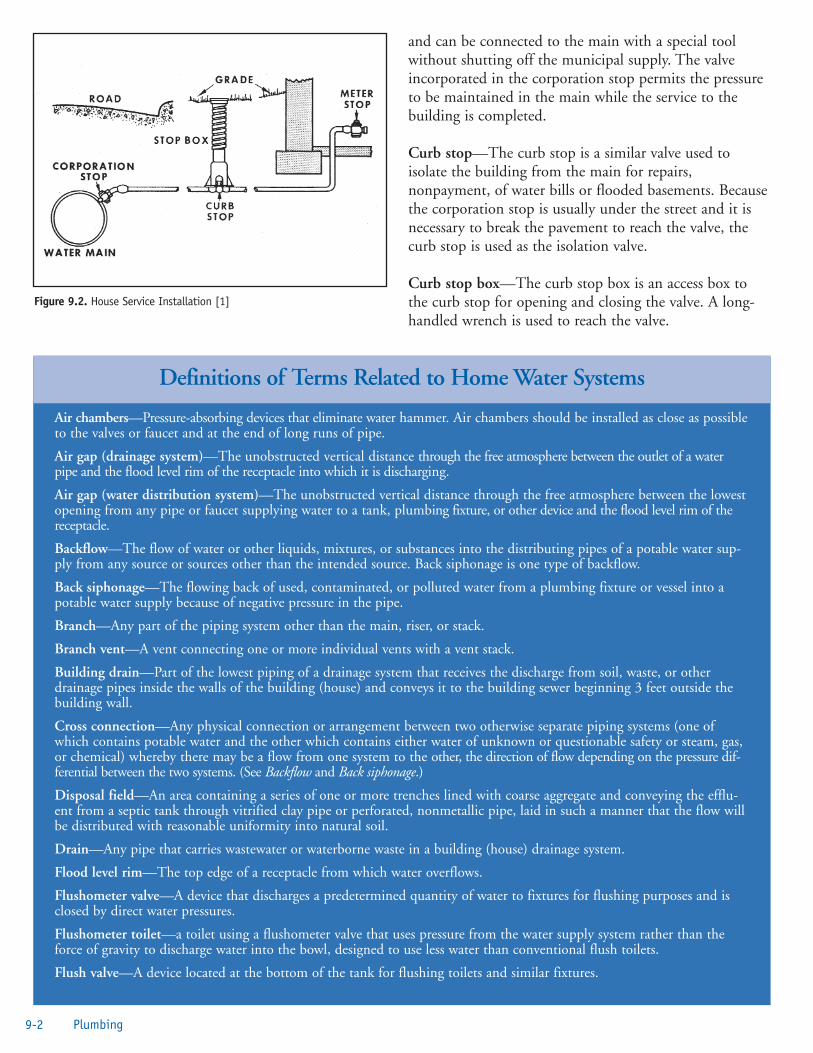
and can be connected to the main with a special toolwithout shutting off the municipal supply. The valveincorporated in the corporation stop permits the pressureto be maintained in the main while the service to thebuilding is completed.
Curb stop—The curb stop is a similar valve used toisolate the building from the main for repairs,nonpayment, of water bills or flooded basements. Becausethe corporation stop is usually under the street and it isnecessary to break the pavement to reach the valve, thecurb stop is used as the isolation valve.
Curb stop box—The curb stop box is an access box tothe curb stop for opening and closing the valve. A long-handled wrench is used to reach the valve.
9-2 Plumbing
Air chambers—Pressure-absorbing devices that eliminate water hammer. Air chambers should be installed as close as possibleto the valves or faucet and at the end of long runs of pipe.
Air gap (drainage system)—The unobstructed vertical distance through the free atmosphere between the outlet of a waterpipe and the flood level rim of the receptacle into which it is discharging.
Air gap (water distribution system)—The unobstructed vertical distance through the free atmosphere between the lowestopening from any pipe or faucet supplying water to a tank, plumbing fixture, or other device and the flood level rim of thereceptacle.
Backflow—The flow of water or other liquids, mixtures, or substances into the distributing pipes of a potable water sup-ply from any source or sources other than the intended source. Back siphonage is one type of backflow.
Back siphonage—The flowing back of used, contaminated, or polluted water from a plumbing fixture or vessel into apotable water supply because of negative pressure in the pipe.
Branch—Any part of the piping system other than the main, riser, or stack.
Branch vent—A vent connecting one or more individual vents with a vent stack.
Building drain—Part of the lowest piping of a drainage system that receives the discharge from soil, waste, or otherdrainage pipes inside the walls of the building (house) and conveys it to the building sewer beginning 3 feet outside thebuilding wall.
Cross connection—Any physical connection or arrangement between two otherwise separate piping systems (one ofwhich contains potable water and the other which contains either water of unknown or questionable safety or steam, gas,or chemical) whereby there may be a flow from one system to the other, the direction of flow depending on the pressure dif-ferential between the two systems. (See Backflow and Back siphonage.)
Disposal field—An area containing a series of one or more trenches lined with coarse aggregate and conveying the efflu-ent from a septic tank through vitrified clay pipe or perforated, nonmetallic pipe, laid in such a manner that the flow willbe distributed with reasonable uniformity into natural soil.
Drain—Any pipe that carries wastewater or waterborne waste in a building (house) drainage system.
Flood level rim—The top edge of a receptacle from which water overflows.
Flushometer valve—A device that discharges a predetermined quantity of water to fixtures for flushing purposes and isclosed by direct water pressures.
Flushometer toilet—a toilet using a flushometer valve that uses pressure from the water supply system rather than theforce of gravity to discharge water into the bowl, designed to use less water than conventional flush toilets.
Flush valve—A device located at the bottom of the tank for flushing toilets and similar fixtures.
Definitions of Terms Related to Home Water Systems
Figure 9.2. House Service Installation [1]

Meter stop—The meter stop is a valve placed on thestreet side of the water meter to isolate it for installationor maintenance. Many codes require a gate valve on thehouse side of the meter to shut off water for plumbingrepairs. The curb and meter stops can be ruined in a shorttime if used very frequently.
The water meter is a device used to measure the amountof water used in the house. It is usually the property ofthe water provider and is a very delicate instrument thatshould not be abused. In cold climates, the water meter isoften inside the home to keep it from freezing. When themeter is located inside the home, the company providingthe water must make appointments to read the meter,which often results in higher water costs unless the meteris equipped with a signal that can be observed from the
outside. The water meter is not shown in Figure 9.2because of regional differences in location of the unit.
Because the electric system is sometimes grounded to anolder home’s water line, a grounding loop device shouldbe installed around the meter. Many meters come with ayoke that maintains electrical continuity even though themeter is removed.
Hot and Cold Water Main LinesThe hot and cold water main lines are usually hung fromthe basement ceiling or in the crawl space of the homeand are attached to the water meter and hot water tankon one side and the fixture supply risers on the other. Thesepipes should be installed neatly and should be supported bypipe hangers or straps of sufficient strength and number to
9-3Healthy Housing Reference Manual
z
Grease trap—See Interceptor.
Hot water—Potable water heated to at least 120°F–130°F (49°C–54°C) and used for cooking, cleaning, washing dishes,and bathing.
Insanitary—Unclean enough to endanger health.
Interceptor—A device to separate and retain deleterious, hazardous, or undesirable matter from normal waste and permitnormal sewage or liquid waste to discharge into the drainage system by gravity.
Main vent—The principal artery of the venting system, to which vent branches may be connected.
Leader—An exterior drainage pipe for conveying storm water from roof or gutter drains to the building storm drain,combined building sewer, or other means of disposal.
Main sewer—See Public sewer.
Pneumatic—Pertaining to devices making use of compressed air as in pressure tanks boosted by pumps.
Potable water—Water having no impurities present in amounts sufficient to cause disease or harmful physiologic effectsand conforming in its bacteriologic and chemical quality to the requirements of the U.S. Environmental ProtectionAgency’s Safe Drinking Water Act or meeting the regulations of other agencies having jurisdiction.
P & T (pressure and temperature) relief valve—A safety valve installed on a hot water storage tank to limit temperatureand pressure of the water.
P-trap—A trap with a vertical inlet and a horizontal outlet.
Public sewer—A common sewer directly controlled by public authority.
Relief vent—An auxiliary vent that permits additional circulation of air in or between drainage and systems.
Septic tank—A watertight receptacle that receives the discharge of a building’s sanitary drain system or part thereof andis designed and constructed to separate solid from liquid, digest organic matter through a period of detention, and allowthe liquids to discharge into the soil outside of the tank through a system of open-joint or perforated piping or through aseepage pit.
Sewerage system—A system comprising all piping, appurtenances, and treatment facilities used for the collection and disposal of sewage, except plumbing inside and in connection with buildings served, and the building drain.
Soil pipe—The pipe that directs the sewage of a house to the receiving sewer, building drain or building sewer.
Soil stack—The vertical piping that terminates in a roof vent and carries off the vapors of a plumbing system.
Stack vent—An extension of a solid or waste stack above the highest horizontal drain connected to the stack, sometimescalled a waste vent or a soil vent.
Definitions of Terms Related to Home Water Systems

prevent sagging. Older homes that have copper pipe withsoldered pipes can pose a lead poisoning risk, particularlyto children. In 1986, Congress banned lead soldercontaining greater than 0.2% lead and restricted the leadcontent of faucets, pipes, and other plumbing materials tono more than 8%. The water should be tested todetermine the presence or level of lead in the water. Untilsuch tests can be conducted, the water should be run forabout 2 minutes in the morning to flush any suchmaterial from the line. Hot and cold water lines shouldbe approximately 6 inches apart unless the hot water lineis insulated. This is to ensure that the cold water line doesnot pick up heat from the hot water line [2].
The supply mains should have a drain valve stop and wastevalve to remove water from the system for repairs. Thesevalves should be on the low end of the line or on the end ofeach fixture riser.
The fixture risers start at the basement main and risevertically to the fixtures on the upper floors. In a one-family dwelling, riser branches will usually proceed fromthe main riser to each fixture grouping. In any event, thefixture risers should not depend on the branch risers forsupport, but should be supported with a pipe bracket.The size of basement mains and risers depends on thenumber of fixtures supplied. However, a ¾-inch pipe isusually the minimum size used. This allows for depositson the pipe due to hardness in the water and will usuallygive satisfactory volume and pressure.
In homes without basements, the water lines arepreferably located in the crawl space or under the slab.The water lines are sometimes placed in the attic;however, because of freezing, condensation, or leaks, thisplacement can result in major water damage to the home.In two-story or multistory homes, the water lineplacement for the second floor is typically between thestuds and, then, for the shortest distance to the fixture,between the joists of the upper floors.
Hot and Cold Water Piping MaterialsCare must be taken when choosing the piping materials.Some state and local plumbing codes prohibit using someof the materials listed below in water distribution systems.
Polyvinyl Chloride (PVC). PVC is used to make plastic
9-4 Plumbing
Storm sewer—A sewer used for conveying rain water, surface water, condensate, cooling water, or similar liquid waste.
Trap—A fitting or device that provides a liquid seal to prevent the emission of sewer gases without materially affectingthe flow of sewage or wastewater through it.
Vacuum breaker—A device to prevent backflow (back siphonage) by means of an opening through which air may be drawnto relieve negative pressure (vacuum).
Vapor lock—A bubble of air that restricts the flow of water in a pipe.
Vent stack—The vertical vent pipe installed to provide air circulation to and from the drainage system and that extendsthrough one or more stories.
Water hammer—The loud thump of water in a pipe when a valve or faucet is suddenly closed.
Water service pipe—The pipe from the water main or other sources of potable water supply to the water-distributing system of the building served.
Water supply system—Consists of the water service pipe, the water-distributing pipes, the necessary connecting pipes, fittings, control valves, and all appurtenances in or adjacent to the building or premises.
Wet vent—A vent that receives the discharge of waste other than from water closets.
Yoke vent—A pipe connecting upward from a soil or waste stack to a vent stack to prevent pressure changes in the stacks.
Definitions of Terms Related to Home Water Systems
pipe. PVC piping has several applications in and around homes such as in underground sprinkler systems, piping for swimming pool pumping systems, and low-pressure drain systems PVC piping is also used for water service between the meter and building [3]. PVC, or polyvinyl chloride, is one of the most commonly used materials in the marketplace. It is in packaging, construction and automotive material, toys, and medical equipment.
PVC contains phthalates, which have been shown in experimental laboratory animal studies to damage the liver and reproductive organs. Phthalates may leach

Chlorinated PVC (CPVC). CPVC is a slightly yellowplastic pipe used inside homes. It has a long service life,but is not quite as tough as copper. Some areas withcorrosive water will benefit by using chlorinated PVCpiping. CPVC piping is designed and recommended foruse in hot and cold potable water distribution systems [4].
Copper. Copper comes in three grades:
• M for thin wall pipe (used mainly inside homes);
• L for thicker wall pipe (used mainly outside forwater services); and
• K, the thickest (used mainly between water mainsand the water meter).
Copper lasts a long time, is durable, and connects well tovalves. It should not be installed if the water has a pH of6.5 or less. Most public utilities supply water at a pHbetween 7.2 and 8.0. Many utilities that have sourcewater with a pH below 6.5 treat the water to raise thepH. Private well water systems often have a pH below6.5. When this is the case, installing a treatment systemto make the water less acidic is a good idea [5].
Galvanized Steel. Galvanized pipe corrodes rather easily.The typical life of this piping is about 40 years. One ofthe primary problems with galvanized steel is that, in
saturated water, the pipe will become severely restrictedby corrosion that eventually fills the pipe completely.Another problem is that the mismatch of metals betweenthe brass valves and the steel results in corrosion.Whenever steel pipe meets copper or brass, the steel pipewill rapidly corrode. Dielectric unions can be usedbetween copper and steel pipes; however, these unionswill close off flow in a short time. The problem withdielectric unions is that they break the grounding effect ifa live electrical wire comes in contact with a pipe. Somecities require the two pipes to be bonded electrically tomaintain the safety of grounded pipes.
PEX. PEX is an acronym for a cross-formulatedpolyethylene. “PE” refers to the raw material used to makePEX (polyethylene), and “X” refers to the cross-linking ofthe polyethylene across its molecular chains. Themolecular chains are linked into a three-dimensionalnetwork that makes PEX remarkably durable within a widerange of temperatures, pressures, and chemicals [6].
PEX is flexible and can be installed with fewer fittingsthan rigid plumbing systems. It is a good choice forrepiping and for new homes and works well for corrosivewater conditions. PEX stretches to accommodate theexpansion of freezing water and then returns to itsoriginal size when water thaws. Although it is highlyfreeze-resistant, no material is freeze-proof.
Kitec. Kitec is a multipurpose pressure pipe that uniquelyunites the advantages of both metal and plastic. It is madeof an aluminum tube laminated to interior and exteriorlayers of plastic. Kitec provides a composite piping systemfor a wide range of applications, often beyond the scope ofmetal or plastic alone. Unlike copper and steel materials,Kitec is noncorroding and resists most acids, saltsolutions, alkalis, fats, and oils.
Poly. Poly pipe is a soft plastic pipe that comes in coilsand is used for cold water. It can crack with age or wearthrough from rocks. Other weak points can be thestainless steel clamps or galvanized couplings.
Polybutylene [Discontinued]. Polybutylene pipe is a softplastic pipe. This material is no longer recommendedbecause of early chemical breakdown. Individuals with ahouse, mobile home, or other structure that haspolybutylene piping with acetal plastic fittings may beeligible for financial relief if they have replaced thatplumbing system. For claims information, call 1-800-392-7591 or go to www.pbpipe.com.
9-5Healthy Housing Reference Manual
from the plastics and may be transferred to foods packaged in PVC. Phthalates show almost no toxicity in adult humans in acute (short-term) doses, even at high doses. However, experimental laboratory animal studies show that continuous chronic exposure can result in toxic effects even at very low dosages. Very young infants do not metabolize phthalates as well as do adults and may be at greater risk for harm. The availability of phthalates in the consumer environment results in prevalent exposure to almost all modern industrial consumers.
Lead is sometimes used as a hardening agent to manu-facture PVC materials. Therefore, it is very important that third-party testing be done on PVC piping. PVC piping should have the stamp of both the testing laboratory and a potable water (PW) mark to indicate that it meets appropriate standards for use as potable water piping.

Hot Water SafetyIn the United States, more than 112,000 people enter ahospital emergency room each year with scald burns. Ofthese, 6,700 (6%), have to be hospitalized. Almost 3,000 ofthese scald burns come from tap water in the home. Thethree high risk groups are children under the age of 5 years,the handicapped, and adults over the age of 65 years. Itonly takes 1 second to get a serious third-degree burnfrom water that is 156°F (69°C). Tap water is too hot ifinstant coffee granules melt in it.
Young children, some handicapped individuals, andelderly people are particularly vulnerable to tap waterburns. Children cannot always tell the hot water faucetsfrom the cold water faucets. Children have delicate skinand often cannot get out of hot water quickly, so theysuffer hot water burns most frequently. Elderly andhandicapped persons are less agile and more prone to fallsin the bath tub. They also may have diseases, such asdiabetes, that make them unable to feel heat in someregions of the body, such as the hands and feet. Third-degree burns can occur quickly—in 1 second at 156°F(69°C), in 2 seconds at 149°F (65°C), in 5 seconds at140°F (60°C), and in 15 seconds at 133°F (56°C).
A tap-water temperature of 120°F–130°F (49°C–54°C) ishot enough for washing clothes, bedding, and dishes.Even at 130°F (54°C), water takes only a few minutes ofconstant contact to produce a third-degree burn. Fewpeople bathe at temperatures above 110°F (43°C), norshould they. Water heater thermostats should be set atabout 120°F (49°C) for safety and to save 18% of theenergy used at 140°F (60°C). Antiscald devices for faucetsand showerheads to regulate water temperature can helpprevent burns. A plumber should install and calibratethese devices. Most hot water tank installations nowrequire an expans ion tank to reduce pressure fluctuationsand a heat trap to keep hot water from escaping up pipes.
Types of Water Flow ControlsIt is essential that valves be used in a water system toallow the system to be controlled in a safe and efficientmanner. The number, type, and size of valves requiredwill depend on the size and complexity of the system. Mostvalves can be purchased in sizes and types to match thepipe sizes used in water system installations. Listed beloware some of the more commonly encountered valves witha description of their basic functions.
Shutoff Valves. Shutoff valves should be installed betweenthe pump and the pressure tank and between the pressuretank and service entry to a building. Globe, gate, and ball
valves are common shutoff valves. Gate and ball valvescause less friction loss than do globe valves; ball valves lastlonger and leak less than do gate valves. Shutoff valvesallow servicing of parts of the system without draining theentire system.
Flow-control Valves. Flow-control valves provide uniformflow at varying pressures. They are sometimes needed toregulate or limit the use of water because of limited waterflow from low-yielding wells or an inadequate pumpingsystem. They also may be needed with some treatmentequipment. These valves are often used to limit flow to afixture. Orifices, mechanical valves, or diaphragm valvesare used to restrict the flow to any one service line orcomplete system and to assure a minimum flow rate to alloutlets.
Relief Valves. Relief valves permit water or air to escapefrom the system to relieve excess pressure. They arespring-controlled and are usually adjustable to relievevarying pressures, generally above 60 psi. Relief valvesshould be installed in systems that may develop pressuresexceeding the rated limits of the pressure tank ordistribution system. Positive displacement andsubmersible pumps and water heaters can develop theseexcessive pressures. The relief valve should be installedbetween the pump and the first shutoff valve and must becapable of discharging the flow rate of the pump. Acombined pressure and temperature relief valve is neededon all water heaters. Combination pressure and vacuumrelief valves also should be installed to prevent vacuumdamage to the system.
Pressure-reducing Valves. A pressure-reducing valve isused to reduce line pressure. On main lines, this allowsthe use of thinner walled pipe and protects houseplumbing. Sometimes these valves are installed onindividual services to protect plumbing.
Altitude Valves. Often an altitude valve is installed at thebase of a hot water tank to prevent it from overflowing.Altitude valves sense the tank level through a pressure lineto the tank. An adjustable spring allows setting the levelso that the valve closes and prevents more inflow whenthe tank becomes full.
Foot Valves. A foot valve is a special type of check valveinstalled at the end of a suction pipe or below the jet in awell to prevent backflow and loss of prime. The valveshould be of good quality and cause little friction loss.
9-6 Plumbing

Check Valves. Check valves have a function similar tofoot valves. They permit water flow in only one directionthrough a pipe. A submersible pump may use severalcheck valves. One is located at the top of the pump toprevent backflow from causing back spin of the impellers.Some systems use another check valve and a snifter valve.They will be in the drop pipe or pitless unit in the wellcasing and allow a weep hole located between the twovalves to drain part of the pipe. When the pump is started,it will force the air from the drained part of the pipe intothe pressure tank, thus recharging the pressure tank.
Frost-proof Faucets. Frost-proof faucets are installedoutside a house with the shutoff valve extending into theheated house to prevent freezing. After each use, the waterbetween the valve and outlet drains, provided the hose isdisconnected, so water is not left to freeze.
Frost-proof Hydrants. Frost-proof hydrants make outdoorwater service possible during cold weather without thedanger of freezing. The shutoff valve is buried below thefrost line. To avoid submerging it, which might result incontamination and back siphoning, the stop-and-wastevalve must drain freely into a rock bed. These hydrantsare sometimes prohibited by local or state health authorities.
Float Valves. Float valves respond to a high water level toclose an inlet pipe, as in a tank-type toilet.
Miscellaneous Switches. Float switches respond to a highand/or low water level as with an intermediate storagetank. Pressure switches with a low-pressure cutoff stop thepump motor if the line pressure drops to the cutoff point.Low-flow cutoff switches are used with submersiblepumps to stop the pump if the water discharge falls belowa predetermined minimum operating pressure. High-pressure cut-off switches are used to stop pumps if thesystem pressure rises above a predetermined maximum.Paddle-type flow switches detect flow by means of apaddle placed in the pipe that operates a mechanicalswitch when flow in the pipe pushes the paddle.
The inadvertent contamination of a public water supplyas a result of incorrectly installing plumbing fixtures is apoten tial public health problem in all communities.Continuous surveillance by environmental healthpersonnel is necessary to know whether such publichealth hazards have developed as a result of additions oralterations to an approved system. All environmentalhealth specialists should learn to recognize the threegeneral types of defects found in potable water supplysystems: backflow, back siphonage, and overhead leakage
into open potable water containers. If identified, theseconditions should be corrected immediately to preventthe spread of disease or poisoning from high concentrationsof organic or inorganic chemicals in the water.
Water HeatersWater heaters (Figure 9.3) are usually powered byelectricity, fuel oil, gas, or, in rare cases, coal or wood.They consist of a space for heating the water and astorage tank for providing hot water over a limited periodof time. All water heaters should be fitted with atemperature-pressure (T&P) relief valve no matter whatfuel is used. The installation port for these valves may befound on the top or on the side of the tank near the top.T&P valves should not be placed close to a wall or doorjamb, where they would be inaccessible for inspection anduse. Hot water tanks sometimes are sold without theT&P valve, and it must be purchased separately. This factalone should encourage individual permitting andinspection by counties and municipalities to ensure thatthey are installed. The T&P valve should be inspected at aminimum of once per year.
A properly installed T&P valve will operate when eitherthe temperature or the pressure becomes too high due toan interruption of the water supply or a faulty thermostat.Figure 9.3 shows the correct installation of a gas water
9-7Healthy Housing Reference Manual
Figure 9.3. Gas Water Heater [1]

heater. Particular care should be paid to the exhaust portof the T&P valve. Figure 9.4 shows the placement of theT&P valve. This vent should be directed to within6 inches of the floor, and care must be taken to avoidreducing the diameter of the vent and creating anyunnecessary bends in the discharge pipe. Most codes willallow only one 90° bend in the vent. The point is toavoid any constrictions that could slow down the steamrelease from the tank to avoid explosive pressure buildup.
Water heaters that are installed on wooden floors shouldhave water collection pans with a drainage tube that drains toa proper drain. The pan should be checked on a regular basis.
Tankless Water Heaters A tankless unit has a heating device that is activated bythe flow of water when a hot water valve is opened. Onceactivated, the heater delivers a constant supply of hotwater. The output of the heater, however, limits the rateof the heated water flow. Demand water heaters areavailable in propane (LP), natural gas, or electric models.They come in a variety of sizes for different applications,such as a whole-house water heater, a hot water source fora remote bathroom or hot tub, or as a boiler to providehot water for a home heating system. They can also beused as a booster for dishwashers, washing machines, and asolar or wood-fired domestic hot water system [7].
The appeal of demand water heaters is not only theelimination of the tank standby losses and the resultinglower operating costs, but also the fact that the heaterdelivers hot water continuously. Most tankless modelshave a life expectancy of more than 20 years. In contrast,storage tank water heaters last 10 to 15 years. Mosttankless models have easily replaceable parts that canextend their life by many years more.
Drainage SystemWater is brought into a house, used, and dischargedthrough the drainage system. This system is a sanitarydrainage system carrying just interior wastewater.
Sanitary Drainage SystemThe proper sizing of the sanitary drain or house draindepends on the number of fixtures it serves. The usualminimum size is 4 inches in diameter. The materials usedare usually cast iron, vitrified clay, plastic, and, in rarecases, lead. The top two pipe choices for drain, waste, andvent (DWV) systems are PVC or ABS. For proper flow inthe drain, the pipe should be sized and angled so that thepipe is approximately half full. This ensures properscouring action so that the solids contained in the wastewill not be deposited in the pipe.
Using PVC in DWV pipe is a two-step process needing aprimer and then cement. ABS uses cement only. In mostcases the decision will be made on the basis of whichmaterial is sold in an area. Few areas stock both materialsbecause local contractors usually favor one or the other.ABS costs more than PVC in many areas, but Schedule40 PVC DWV solid core pipe is stronger than ABS.Their durability is similar.
Size of House Drain. The Uniform Plumbing CodeCommittee has developed a method of sizing housedrains in terms of fixture units. One fixture unit equalsapproximately 7½ gallons of water per minute. This is thesurge flow rate of water discharged from a wash basin inone minute.
All other fixtures have been related to this unit. Fixtureunit values are shown in Table 9.1.
Grade of House Drain. A house drain should be slopedtoward the sewer to ensure scouring of the drain. Theusual pitch of a house or building sewer is a ¼-inch dropin 1 foot of length. The size of the drain is based on thefixture units flowing into the pipe and the slope of thedrain. Table 9.2 shows the required pipe size for the system.
9-8 Plumbing
Figure 9.4. Temperature-Pressure Valve

House Drain Installation. Typical branch connections tothe main are shown in Figure 9.5.
Fixture and Branch Drains. A branch drain is a wastepipe that collects the waste from two or more fixtures andconveys it to the sewer. It is sized in the same way as thesewer, taking into account that all toilets must have aminimum 3-inch diameter drain, and only two toiletsmay connect into one 3-inch drain. All branch drainsmust join the house drain with a Y-fitting as shown inFigure 9.5. The same is true for fixture drains joiningbranch drains. The Y-fitting is used to eliminate, as muchas possible, the deposit of solids in or near theconnection. A buildup of these solids will block the drain.Recommended minimum sizes of fixture drains are shownin Table 9.2.
Traps A plumbing trap is a device used in a waste system toprevent the passage of sewer gas into the structure and yetnot hinder the fixture’s discharge to any great extent. Allfixtures connected to a household plumbing systemshould have a trap installed in the line. The effects ofsewer gases on the human body are well known; many ofthe gases are extremely harmful. In addition, certain sewergases are explosive.
P-trap. The most commonly used trap is the P-trap(Figure 9.6). The depth of the seal in a trap is usually2 inches. A deep seal trap has a 4-inch seal.
As mentioned earlier, the purpose of a trap is to seal outsewer gases from the structure. Because a plumbingsystem is subject to wide variations in flow, and this flow
originates in many different sections of the system,pressures vary widely in the waste lines. These pressuredifferences tend to remove the water seal in the trap. Thewaste system must be properly vented to prevent the trapsfrom siphoning dry, thus losing their water seal andallowing gas from the sewer into the building.
Objectionable Traps. The S-trap and the ¾ S-trap(Figure 9.7) should not be used in plumbing installations.They are almost impossible to ventilate properly, and the¾ S-trap forms a perfect siphon. Mechanical traps wereintroduced to counteract this problem. It has been found,however, that the corrosive liquids flowing in the systemcorrode or jam these mechanical traps. For this reason, mostplumbing codes prohibit mechanical traps.
9-9Healthy Housing Reference Manual
Table 9.2. Sanitary House Drain Sizes
Table 9.1. Fixture Unit Values

The bag trap, an extreme form of S-trap, is seldom found.
Figure 9.7 also shows this type of S-trap.
Traps are used only to prevent the escape of sewer gas intothe structure. They do not compensate for pressurevariations. Only proper venting will eliminate pressureproblems.
VentilationA plumbing system is ventilated to prevent trap seal loss,material deterioration, and flow retardation.
Trap Seal Loss. The seal in a plumbing trap may be lostdue to siphonage (direct and indirect or momentum),back pressure, evaporation, capillary attraction, or wind
effect. The first two are probably the most commoncauses of loss. Figure 9.8 depicts this siphonage process;Figure 9.9 depicts loss of trap seal.
If a waste pipe is placed vertically after the fixture trap, asin an S-trap, the wastewater continues to flow after the
fixture is emptied and clearsthe trap. This is caused by thepressure of air on the water ofthe fixture being greater thanthe pressure of air in the wastepipe. The action of the waterdischarging into the waste piperemoves the air from that pipeand thereby causes a negativepressure in the waste line.
In the case of indirect ormomentum siphonage, theflow of water past the entranceto a fixture drain in the wastepipe removes air from thefixture drain. This reduces theair pressure in the fixturedrain, and the entire assemblyacts as an aspirator. (Figures9.10 and 9.11 show plumbingconfigurations that wouldallow this type of siphonage tooccur.)
Back Pressure. The flow ofwater in a soil pipe variesaccording to the fixtures beingused. Small flows tend to clingto the sides of the pipe, butlarge ones form a slug of wasteas they drop. As this slug ofwater falls down the pipe, theair in front of it becomes
Figure 9.7. Types of S-traps
Figure 9.8. Trap Seal: [a]Seal Intact; [b] FixtureDraining; [c] Loss of GasSeal [1]
Figure 9.5. Branch Connections Figure 9.6. P-trap [1]
9-10 Plumbing

pressurized. As the pressurebuilds, it seeks an escapepoint. This point is either avent or a fixture outlet. If thevent is plugged or there is novent, the only escape for thisair is the fixture outlet. The air pressure forces thetrap seal up the pipe into thefixture. If the pressure is greatenough, the seal is blown outof the fixture entirely. Figures9.8 and 9.9 illustrate thepotential for this type ofproblem. Large water flow pastthe vent can aspirate the waterfrom the trap, while waterflow approaching the trap canblow the water out of the trap.
Vent Sizing. Vent pipe installation is similar to that of soiland waste pipe. The same fixture unit criteria are used.Table 9.3 shows minimum vent pipe sizes.
Vent pipes of less than 1¼ inches in diameter should notbe used. Vents smaller than this diameter tend to clog anddo not perform their function.
Individual Fixture Ventilation. Figure 9.12 shows atypical installation of a wall-hung plumbing unit. Thistype of ventilation is generally used for sinks, drinkingfountains, and so forth. Air admittance valves are oftenused for individual fixtures. Figure 9.13 shows a typicalinstallation of a bathtub or shower ventilation system.Figure 9.14 shows the proper vent connection for toiletfixtures and Figure 9.15 shows a janitor’s sink or slop sinkthat has the proper P-trap. For the plumbing fixture towork properly, it must be vented as in Figures 9.13 and 9.14.
Unit Venting. Figures 9.10 and 9.11 show a back-to-backshared ventilation system for various plumbing fixtures.The unit venting system is commonly used in apartmentbuildings. This type of system saves a great deal of moneyand space when fixtures are placed back-to-back inseparate apartments. It does, however, pose a problem ifthe vents are undersized because they will aspirate thewater from the other trap. Figure 9.16 shows a doublecombination Y-trap used for joining the fixtures to thecommon soil pipe fixture on the other side of the wall.
Wet Venting. Bathroom fixture groupings are commonlywet vented; that is, the vent pipe also is used as a waste line.
Total Drainage SystemThe drain, soil waste, and vent systems are all connected, andthe inspector should remember the following fundamentals:Working vents must provide air to all fixtures to ensurethe movement of waste into the sewer. Improperly ventedfixtures will drain slowly and clog often. They also presenta health risk if highly toxic and explosive sewer gases enterthe home. Correct venting is shown in Figures 9.10–9.15;incorrect venting is shown in Figures 9.8 and 9.9. A wet
9-11Healthy Housing Reference Manual
Figure 9.9. Loss of Trap Seal inLavatory Sink [1]
Figure 9.10. Back-to-back Venting [Toilet]
Figure 9.11. Back-to-back Venting [Sink]

vent can result in one of the traps siphoning the other drywhen large volumes of water are poured down the drain.Wet vents are not permitted by many state plumbingcodes because of the potential for self-siphoning.
Backup of sewage into sinks, dishwashers, and otherappliances is always a possibility unless the system isequipped with air gaps or vacuum breakers. Allconnections to the potable water system must be aminimum of two pipe diameters above the overflow ofthe appliance and, in some cases, where flat surfaces arenear, two and one-half pipe diameters above the overflowof the appliance.
A simple demonstration of how easily siphoning canoccur is to hold a glass of water with food coloring in itwith the tip of a faucet in the colored water. If the sink’svegetable sprayer is directed to a second glass and sprayed,in most cases, the colored water will be aspirated into thefaucet and then out of the sprayer into the second glass.Weed or pest killer attachments that hook to garden hoseswork on the same principle. Figure 9.17 shows an outsidehose bib equipped with a vacuum breaker. In the areas ofthe United States that freeze, these vacuum breakers mustbe removed because they trap water in the area of the linethat can freeze and burst. Many vacuum breakers soldtoday automatically drain to prevent freeze damage.
9-12 Plumbing
Figure 9.12. Wall-hung Fixtures
Figure 9.13. Unit Vent Used in Bathtub Installation
Table 9.3. Minimum Fixture Service Pipe Diameters
Figure 9.14. Toilet Venting

Devices that pull water from a utility may create negativepressures that can damage water piping and pulldangerous substances into the line at the same time.These devices include power sprayers that hook to thehome hose bib (outside faucets) and pressurize the sprayby creating a vacuum on the supply side.
Corrosion ControlTo understand the proper maintenance procedures for theprevention and elimination of water quality problems inplumbing systems, it is necessary to understand theprocess used to determine the chemical aggressiveness ofwater. The process is used to determine when additionaltreatment is needed. Water that is out of balance canresult in many negative outcomes, from toxic water todamaged and ruined equipment.
Water dissolves and carries materials when it is notsaturated. An equilibrium among pH, temperature,alkalinity, and hardness controls water’s ability to createscale or to dissolve material. If water is saturated withharmless or beneficial substances, such as calcium, thenthe threat of damage can be mitigated. The Langeliermethod, developed in the early 1930s, is a process used in
boiler management,municipal watertreatment, andswimming pools toprovide this balance. Inthe Langelier index,saturation over 0.3 isscale forming, and asaturation below 0.3 iscorrosive.
Thesusceptibility ofmetal tocorrosion is asfollows (mostsusceptible toleast susceptible):magnesium, zinc,aluminum,cadmium, mildsteel, cast iron,
stainless steel (active), lead-tin solder, lead, tin, brass, gunmetal, aluminum bronze, copper, copper-nickel alloy,Monel, titanium, stainless steel (passive), silver, gold, andplatinum.
Water ConservationHow much attention should be paid to fixtures that justdrip a little bit of water or that just will not quite shutoff? At 30 drops per minute, you will lose and pay for54 gallons per month. At 60 drops per minute, you willlose and pay for 113 gallons per month. At 120 drops perminute, you will lose and pay for 237 gallons per month.
This is only a small loss of water considering the 5 to7 gallons per flush used by a properly functioning toilet.If the toilet is not properly maintained, the loss of waterand its effect on the monthly water bill can be incredible.Lower flow toilets have been mandated to save preciousand limited resources. Most pre-1992 toilets used up to7 gallons per flush. Toilets have since evolved to use 5.5,then 3.5, and now 1.6 gallons per flush.
With the changes in the water usage laws in 1992, therewere many customer complaints, and plumbers were in thebad position of installing products that nobody wanted touse. New and updated products now work better than theold water wasters.
According to the EPA, in 2000, a typical U.S. family offour spent approximately $820 every year on water and sewerfees, plus another $230 in energy for heating water. Inmany cities, according to the U.S. EPA, water and sewercosts can be more than twice those amounts. Many people donot realize how much money they can save by taking simplesteps to save water, and they do not know the cumulativeeffects small changes can have on water resources andenvironmental quality. Fixing a leaky faucet, toilet, orlawn-watering system can reduce water consumption.Changing to water-efficient plumbing fixtures andappliances can result in major water and energy savings [9,10].
9-13Healthy Housing Reference Manual
Figure 9.15. Janitor’s Sink
Figure 9.16. Common Y-trap
Figure 9.17. Hose Bib With Vacuum Breaker

Summer droughts remind many of the need to appreciateclean water as an invaluable resource. As the U.S. populationincreases, the need for clean water supplies continues togrow dramatically and puts additional stress on our limitedwater resources. We can all take steps to save and conservethis valuable resource.
The EPA [11] suggests the following steps homeownersshould take right away to save water and money:
• Stop leaks!—Check indoor water-usingappliances and devices for leaks. Pay particularattention to toilets that leak.
• Take showers—Showers use considerably lesswater than do baths.
• Replace shower heads—Replacement showerheads are available that reduce water use.
• Turn the water off when not needed—Whilebrushing your teeth, turn the water off until youneed to rinse.
• Replace your old toilet—The largest water userinside the home is the toilet. If a home was builtbefore 1992 and the toilet has never beenreplaced, it is very likely that it is not a water-efficient, 1.6 gallons-per-flush toilet. Choose areplacement toilet carefully to ensure that whatyou make up per individual flush, you do not losebecause you must flush more often.
• Replace your clothes washer—The second largestwater user in the home is the washing machine.Energy Star-rated washers that also have a waterfactor at or lower than 9.5 use 35%–50% lesswater and 50% less energy per load. This savesmoney on both water and energy bills.
• Plant the right plants with proper landscapedesign and irrigation—Select plants that areappropriate for the local climate. Having a 100%turf lawn in a dry desert climate uses a significantamount of water. Also, home owners should considerthe benefits of a more natural landscape or wildscape.
• Water plants only as needed—Most water wastedin the garden is by watering when plants do notneed it or by not maintaining the irrigation system.If manually watering, set a timer and move thehose promptly. Make sure the irrigation controller
has a rain shutoff device and that it isappropriately scheduled. Drip irrigation should beconsidered where practical. Newer irrigationsystems have sensors to prevent watering while itis raining.
Putting It All TogetherThese photographs, taken during construction of a homeby Habitat for Humanity, show various plumbingelements discussed in this chapter.
9-14 Plumbing
A. Hot and cold copper water lines and drain, p-trap and vent,and vent for the washer drain shown. When a house isvacant for awhile, the P-trap should be filled with water toprevent sewer gas from entering the home. Mineral oil addedto the water can slow the loss of fluid in the trap.
B. Hot and cold water pipes, soil pipe, and vent shown.

References1. US Environmental Protection Agency. United
States Environmental Protection Agency guidancefrom hotline compendium: lead ban.Washington, DC: US Environmental ProtectionAgency; 1988. Available from URL:http://www.epa.gov/safewater/wsg/wsg_H19.pdf.
2. Uni-Bell PVC Pipe Association. Handbook ofPVC pipe design and construction. Dallas: Uni-Bell PVC Pipe Association; 2001. Available fromURL: http://www.uni-bell.org/pubs/handbook.pdf.
3. Occupational Safety and Health Administration.Safety hazard information bulletin on the use ofpolyvinyl chloride (PVC) pipe in above ground
installations. Washington, DC: OccupationalSafety and Health Administration; 1988.http://www.osha.gov/dts/hib/hib_data/hib19880520.html.
4. Copper Development Association. Copper inyour home: plumbing, heating, cooling. NewYork: Copper Development Association; no date.Available from URL: http://www.copper.org/copperhome/PHC/phc_home.html.
5. Plastic Pipe and Fittings Association. Cross-linkedpolyethylene. Glen Ellyn, IL: Plastic Pipe andFittings Association; no date. Available fromURL:http://www.ppfahome.org/pex/historypex.html.
6. NAMCO. Determine the total fixture unit load.Dallas: NAMCO; no date. Available from URL:http://www.namco-div.com/booster/sel%20criteria/fixtureload.htm.
7. Energy Efficiency and Renewable EnergyClearinghouse. Demand (tankless orinstantaneous) water heaters. Merrifield, VA:Energy Efficiency and Renewable EnergyClearinghouse; no date. Available from URL:http://www.toolbase.org/tertiaryT.asp?DocumentID=3206&&&CategoryID=0.
8. Public Health-Seattle and King County. Publichealth plumbing program: water supply fixtureunits (WSFU) and minimum fixture branch pipesizes. Seattle, WA: Public Health-Seattle and King
E. Polyethylene waterservice pipe enteringthe home through theconcrete basement wallshown. White plasticadapter shownbetween polyethylenewater service pipe and¾ inch copper waterline. A short distanceabove the adapter is apressure reducingvalve. To the right of
water line is the 4-inch PVC pipe waste water line.
9-15Healthy Housing Reference Manual
C. Vent for the sink and toilet, soil pipe, and cap for toiletconnection shown. A wax or plastic seal shaped like a donutwill be placed on the cap before bolting down the toilet.
D. Mixing and antiscald water flow contro, vent for fixture, hotand cold water lines, and bathtub overflow shown. At thispoint in construction, insulation might be considered for thehot water lines. Water service and waste water line.

County; no date. Available from URL: http://www.metrokc.gov/health/plumbing/wsfu.htm.
9. US Environmental Protection Agency. Developingwater system financial capacity. Washington, DC:US Environmental Protection Agency; 2002.Available from URL:http://www.epa.gov/safewater/dwa/electronic/presentations/pwsoper/fincapacity.pdf.
10. US Environmental Protection Agency. Water andwastewater pricing. Washington, DC: USEnvironmental Protection Agency; no date.Available from URL: http://www.epa.gov/water/infrastructure/pricing/.
11. US Environmental Protection Agency. Usingwater wisely in the home. Washington, DC: USEnvironmental Protection Agency; 2002.Available from URL:http://www.epa.gov/owm/water-efficiency/waterconservation_final.pdf.
Additional Sources of InformationAmerican Backflow Prevention Association. Availablefrom URL: http://www.abpa.org.
American Society of Plumbing Engineers. Available fromURL: http://aspe.org.
American Society of Sanitary Engineering. Available fromURL: http://www.asse-plumbing.org.
American Water Works Association. Available from URL:http://www.awwa.org.
National Sanitation Foundation. Available from URL:http://www. nsf.org/international.
Plumbing-Heating-Cooling Contractors Association.Available from URL: http://www.phccweb.org.
Underwriters Laboratories Inc. Available from URL:http://www.ul.com.
For more water conservation tips and energy saving ideasfor businesses, industries, and individuals, visit the EPA’sWater-use Efficiency Program Web site(http://www.epa.gov/owm/water-effic iency/index.htm).
9-16 Plumbing

Chapter 10—On-site Wastewater TreatmentIntroduction . . . . . . . . . . . . . . . . . . . . . . . . . . . . . . . . . . . . . . . . . . . . . . . . . . . . . .10-1Treatment of Human Waste . . . . . . . . . . . . . . . . . . . . . . . . . . . . . . . . . . . . . . . . . .10-1On-site Wastewater Treatment Systems . . . . . . . . . . . . . . . . . . . . . . . . . . . . . . . . .10-3
Septic Tank Systems . . . . . . . . . . . . . . . . . . . . . . . . . . . . . . . . . . . . . . . . . . . .10-3Alternative Septic Tank Systems . . . . . . . . . . . . . . . . . . . . . . . . . . . . . . . . . . .10-6
Maintaining the On-site Wastewater Treatment Systems . . . . . . . . . . . . . . . . . . . .10-8Symptoms of Septic System Problems . . . . . . . . . . . . . . . . . . . . . . . . . . . . . .10-9Septic Tank Inspection . . . . . . . . . . . . . . . . . . . . . . . . . . . . . . . . . . . . . . . . . .10-9
References . . . . . . . . . . . . . . . . . . . . . . . . . . . . . . . . . . . . . . . . . . . . . . . . . . . . . . .10-11Additional Sources of Information . . . . . . . . . . . . . . . . . . . . . . . . . . . . . . . . . . . . .10-12
Figure 10.1. Conventional On-site Septic System . . . . . . . . . . . . . . . . . . . . . . . . . . . . . . . . . . .10-1Figure 10.2. Straight Pipe Discharge. . . . . . . . . . . . . . . . . . . . . . . . . . . . . . . . . . . . . . . . . . . . . .10-2Figure 10.3. Clear Creek Water Contaminated With Sewage. . . . . . . . . . . . . . . . . . . . . . . . . . .10-2Figure 10.4. Septic Tank System . . . . . . . . . . . . . . . . . . . . . . . . . . . . . . . . . . . . . . . . . . . . . . . .10-3Figure 10.5. Septic Tank. . . . . . . . . . . . . . . . . . . . . . . . . . . . . . . . . . . . . . . . . . . . . . . . . . . . . . .10-4Figure 10.6. On-site Sewage Disposal System Site Evaluation Form . . . . . . . . . . . . . . . . . . . . .10-5Figure 10.7. Cross-section of an Absorption Field . . . . . . . . . . . . . . . . . . . . . . . . . . . . . . . . . . .10-5Figure 10.8. Mound System Cutaway . . . . . . . . . . . . . . . . . . . . . . . . . . . . . . . . . . . . . . . . . . . .10-7Figure 10.9. Low Pressure On-site System . . . . . . . . . . . . . . . . . . . . . . . . . . . . . . . . . . . . . . . . .10-7Figure 10.10. Plant-rock Filter System . . . . . . . . . . . . . . . . . . . . . . . . . . . . . . . . . . . . . . . . . . . . .10-8Figure 10.11. Sludge and Scum in Multicompartment Septic Tank . . . . . . . . . . . . . . . . . . . . . . .10-10
Table 10.1. Mound System Advantages and Disadvantages . . . . . . . . . . . . . . . . . . . . . . . . . . .10-6Table 10.2. Low-pressure Pipe Systems Advantages and Disadvantages . . . . . . . . . . . . . . . . . .10-7Table 10.3. Plant Rock Filter System Advantages and Disadvantages . . . . . . . . . . . . . . . . . . . .10-8Table 10.4. Septic Tank System Troubleshooting . . . . . . . . . . . . . . . . . . . . . . . . . . . . . . . . . . .10-10
1Healthy Housing Reference Manual
Contents

“Technology has made large populations possible; large populations now make technology indispensable.”
Joseph Wood Krutch, Author, 1932
IntroductionThe French are considered the first to use anunderground septic tank system in the 1870s. By themid 1880s, two-chamber, automatic siphoning septictank systems, similar to those used today, were beinginstalled in the United States. Even now, more than acentury later, septic tank systems represent a majorhousehold wastewater treatment option. Fully one-fourthto one-third of the homes in the United States use such asystem [1].
On-site sewage disposal systems are used in rural areaswhere houses are spaced so far apart that a sewer systemwould be too expensive to install, or in areas aroundcities where the city government has not yet providedsewers to which the homes can connect. In these areas,people install their own private sewage treatment plants.As populations continue to expand beyond the reach ofmunicipal sewer systems, more families are relying onindividual on-site wastewater treatment systems andprivate water supplies. The close proximity of on-sitewater and wastewater systems in subdivisions and otherdeveloped areas, reliance on marginal or poor soils foron-site wastewater disposal, and a general lack ofunderstanding by homeowners about proper septic tanksystem maintenance pose a significant threat to publichealth. The expertise on inspecting, maintaining, andinstalling these systems generally rests with theenvironmental health staff of the local county or cityhealth departments.
These private disposal systems are typically called septictank systems. A septic tank is a sewage holding devicemade of concrete, steel, fiberglass, polyethylene, or otherapproved material cistern, buried in a yard, which mayhold 1,000 gallons or more of wastewater. Wastewaterflows from the home into the tank at one end and leavesthe tank at the other (Figure 10.1) [2].
Proper maintenance of septic tanks is a public healthnecessity. Enteric diseases such as cryptospordiosis,giardiasis, salmonellosis, hepatitis A, and shigellosis maybe transmitted through human excrement. Historically,major epidemics of cholera and typhoid fever wereprimarily caused by improper disposal of wastewater. Theearliest epidemiology lesson learned was through theeffort of Dr. John Snow of England (1813–1858) duringa devastating cholera epidemic in London [3]. Dr. Snow,known as the father of field epidemiology, discoveredthat the city's water supply was being contaminated byimproper disposal of human waste. He published a briefpamphlet, On the Mode of Communication of Cholera,suggesting that cholera is a contagious disease caused bya poison that reproduces in the human body and isfound in the vomitus and stools of cholera patients. Hebelieved that the main, although not only, means oftransmission was water contaminated with this poison.This differed from the commonly accepted belief at thetime that diseases were transmitted by inhaling vapors.
Treatment of Human WasteSafe, sanitary, nuisance-free disposal of wastewater is apublic health priority in all population groups, small andlarge, rural or urban. Wastewater should be disposed ofin a manner that ensures that
• community or private drinking water supplies arenot threatened;
• direct human exposure is not possible;
• waste is inaccessible to vectors, insects, rodents, or other possible carriers;
• all environmental laws and regulations are complied with; and
• odor or aesthetic nuisances are not created.
Chapter 10: On-site Wastewater Treatment
10-1Healthy Housing Reference Manual
Figure 10.1. Conventional On-site Septic System [2] Effluent leaves home through a pipe, enters a septic tank, travels through adistribution box to a trench absorption system composed of perforated pipe.

In Figure 10.2, a straight pipe from a nearby homedischarges untreated sewage that flows from a shallowdrainage ditch to a roadside mountain creek in whichmany children and some adults wade and fish. The clearwater (Figure 10.3) is quite deceptive in terms of thehealth hazard presented. A 4-mile walk along the creekrevealed 12 additional pipes that were also releasinguntreated sewage. Some people in the area reportedlyregard this creek as a source of drinking water.
Raw or untreated domestic wastewater (sewage) isprimarily water, containing only 0.1% of impurities thatmust be treated and removed. Domestic wastewatercontains biodegradable organic materials and, very likely,pathogens. The primary purpose of wastewater treatmentis to remove impurities and release the treated effluent
into the ground or a stream. There are various processesfor accomplishing this:
• Centralized treatment—Publicly ownedtreatment works (POTWs) that use primary(physical) treatment and secondary (biologic)treatment on a large scale to treat flows of up tomillions of gallons or liters per day,
• Treatment on-site—Septic tanks and absorptionfields or variations thereof, and
• Stabilization ponds (lagoons)—Centralizedtreatment for populations of 10,000 or less whensoil conditions are marginal and land space is ample.
10-2 On-site Wastewater Treatment
Figure 10.2. Straight Pipe DischargeSource: Donald Johnson; used with permission.
Figure 10.3. Clear Creek Water Contaminated With SewageSource: Donald Johnson; used with permission.
John Snow, a London physician, was among thefirst to use anesthesia. It is his work inepidemiology, however, that earned him hisreputation as a prototype for epidemiologists.Dr. Snow’s brief 1849 pamphlet, On the Mode ofCommunication of Cholera, caused no great stir, andhis theory that the city’s water supply wascontaminated was only one of many proposedduring the epidemic.
Snow, however, was able to prove his theory in1854, when another severe epidemic of choleraoccurred in London. Through painstakingdocumentation of cholera cases and correlation ofthe comparative incidence of cholera amongsubscribers to the city’s two water companies, heshowed that cholera occurred much morefrequently in customers of one water company.This company drew its water from the lowerThames, which become contaminated withLondon sewage, whereas the other companyobtained water from the upper Thames. Snow’sevidence soon gained many converts.
A striking incident during this epidemic has becomelegendary. In one neighborhood, the intersection ofCambridge Street and Broad Street, theconcentration of cholera cases was so great that thenumber of deaths reached over 500 in 10 days.Snow investigated the situation and concluded thatthe cases were clustered around the Broad Streetpump. He advised an incredulous but panickedassembly of officials to have the pump handleremoved, and when this was done, the epidemicwas contained. Snow was a skilled practitioner aswell as an epidemiologist, and his creative use ofthe scientific information of his time is anappropriate example for those interested in diseaseprevention and control [3].
Epidemiology
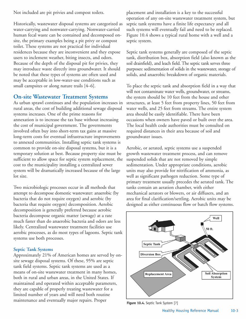
Not included are pit privies and compost toilets.
Historically, wastewater disposal systems are categorized aswater-carrying and nonwater-carrying. Nonwater-carriedhuman fecal waste can be contained and decomposed on-site, the primary examples being a pit privy or composttoilet. These systems are not practical for individualresidences because they are inconvenient and they exposeusers to inclement weather, biting insects, and odors.Because of the depth of the disposal pit for privies, theymay introduce waste directly into groundwater. It shouldbe noted that these types of systems are often used andmay be acceptable in low-water-use conditions such assmall campsites or along nature trails [4–6].
On-site Wastewater Treatment SystemsAs urban sprawl continues and the population increases inrural areas, the cost of building additional sewage disposalsystems increases. One of the prime reasons forannexation is to increase the tax base without increasingthe cost of municipal government. The governmentsinvolved often buy into short-term tax gains at massivelong-term costs for eventual infrastructure improvementsto annexed communities. Installing septic tank systems iscommon to provide on-site disposal systems, but it is atemporary solution at best. Because property size must besufficient to allow space for septic system replacement, thecost to the municipality installing a centralized sewersystem will be dramatically increased because of the largelot size.
Two microbiologic processes occur in all methods thatattempt to decompose domestic wastewater: anaerobic (bybacteria that do not require oxygen) and aerobic (bybacteria that require oxygen) decomposition. Aerobicdecomposition is generally preferred because aerobicbacteria decompose organic matter (sewage) at a ratemuch faster than do anaerobic bacteria and odors are lesslikely. Centralized wastewater treatment facilities useaerobic processes, as do most types of lagoons. Septic tanksystems use both processes.
Septic Tank SystemsApproximately 21% of American homes are served by on-site sewage disposal systems. Of these, 95% are septictank field systems. Septic tank systems are used as ameans of on-site wastewater treatment in many homes,both in rural and urban areas, in the United States. Ifmaintained and operated within acceptable parameters,they are capable of properly treating wastewater for alimited number of years and will need both routinemaintenance and eventually major repairs. Proper
placement and installation is a key to the successfuloperation of any on-site wastewater treatment system, butseptic tank systems have a finite life expectancy and allsuch systems will eventually fail and need to be replaced.Figure 10.4 shows a typical rural home with a well and aseptic system.
Septic tank systems generally are composed of the septictank, distribution box, absorption field (also known as thesoil drainfield), and leach field. The septic tank serves threepurposes: sedimentation of solids in the wastewater, storage ofsolids, and anaerobic breakdown of organic materials.
To place the septic tank and absorption field in a way thatwill not contaminate water wells, groundwater, or streams,the system should be 10 feet from the house and otherstructures, at least 5 feet from property lines, 50 feet fromwater wells, and 25 feet from streams. The entire systemarea should be easily identifiable. There have beenoccasions when owners have paved or built over the area.The local health code authorities must be consulted onrequired distances in their area because of soil andgroundwater issues.
Aerobic, or aerated, septic systems use a suspendedgrowth wastewater treatment process, and can removesuspended solids that are not removed by simplesedimentation. Under appropriate conditions, aerobicunits may also provide for nitrification of ammonia, aswell as significant pathogen reduction. Some type ofprimary treatment usually precedes the aerated tank. Thetanks contain an aeration chamber, with eithermechanical aerators or blowers, or air diffusers, and anarea for final clarification/settling. Aerobic units may bedesigned as either continuous flow or batch flow systems.
10-3Healthy Housing Reference Manual
Figure 10.4. Septic Tank System [7]

The continuous flow type are the most commerciallyavailable units. Effluent from the aerated tank is conveyedeither by gravity flow or pumping to either furthertreatment/ pretreatment processes or to final treatmentand disposal in a subsurface soil disposal system. Varioustypes of pretreatment may be used ahead of the aerobicunits, including septic tanks and trash traps.
The batch flow system collects and treats wastewater overa period of time, then discharges the settled effluent atthe end of the cycle [8].
Aerobic units may be used by individual or clusteredresidences and establishments for treating wastewaterbefore either further treatment/pretreatment or final on-site subsurface treatment and disposal. These units areparticularly applicable where enhanced pretreatment isimportant, and where there is limited availability of landsuitable for final on-site disposal of wastewater effluent.Because of their need for routine maintenance to ensureproper operation and performance, aerobic units may bewell-suited for multiple-home or commercial applications,where economies of scale tend to reduce maintenanceand/or repair costs per user. The lower organic andsuspended solids content of the effluent may allow areduction of land area requirements for subsurfacedisposal systems.
A properly functioning septic tank will removeapproximately 75% of the suspended solids, oil, andgrease from effluent. Because the detention time in thetank is 24 hours or less, there is not a major kill ofpathogenic bacteria. The bacteria will be removed in theabsorption field (drainfield). However, there are soils andsoil conditions that prohibit the ability of a drainfield toabsorb effluent from the septic tank.
Septic tanks are sized to retain the total volume of sewageproduced by a household in a 24-hour period. Normally a1,000-gallon tank is the minimum size to use. State orlocal codes generally require larger tanks as the potentialoccupancy of the home increases (e.g., 1,250 gallons forfour bedrooms) and may require two tanks in successionwhen inadequate soils require alternative systeminstallation. Figure 10.5 shows a typical septic tank.
Distribution boxes are not required by most on-siteplumbing codes or by the U.S. Environmental ProtectionAgency. When used, distribution boxes provide aconvenient inspection port. In addition, if a split systemabsorption field is installed (two separate absorptiontrench systems), the distribution box is a convenient place
to install a diversion valve for annually alternatingabsorption fields.
Absorption Field Site EvaluationThe absorption field has a variety of names, includingleach field, tile field, drainfield, disposal field, andnitrification field. The effluent from the septic tank isdirected to the absorption field for final treatment. Thesuitability of the soil, along with other factors notedbelow, determines the best way to properly treat anddispose of the wastewater.
Most, but unfortunately not all, states require areas notserved by publicly owned sewers to be preapproved foron-site wastewater disposal before home constructionthrough a permitting process. This process typically requires asite evaluation by a local environmental health specialist,soil scientist, or, in some cases, a private contractor. Toassist in the site evaluation process, soil survey maps fromthe local soil conservation service office may be used toprovide general information about soils in the area.
The form shown in Figure 10.6 is typical of those used inconducting a soil evaluation.
Sites for on-site wastewater disposal are first evaluated foruse with a conventional septic tank system. Evaluationfactors include site topography, landscape position, soiltexture, soil structure, internal drainage, depth to rock orother restrictive horizons, and useable area. If the criteriaare met, a permit is issued to allow the installation of aconventional septic tank system. Areas that do not meetthe criteria for a conventional system may meet less-restrictive criteria for an alternative type of system.
10-4 On-site Wastewater Treatment
Figure 10.5. Septic Tank [9]

Many sites are unsuitable for any type of on-sitewastewater disposal system because of severe topographiclimitations, poor soils, or other evaluation criteria. Suchsites should not be used for on-site wastewater disposalbecause of the high likelihood of system failure.
Some states and localities may require a percolation test aspart of the site evaluation process. As a primaryevaluation method, percolation tests are a poor indicatorof the ability of a soil to treat and move wastewaterthroughout the year. However, information obtained bypercolation tests may be useful when used in conjunctionwith a comprehensive soil analysis.
Absorption Field TrenchA conventional absorption field trench (Figure 10.7), alsoknown as a rock lateral system, is the most commonsystem used on level land or land with moderate slopeswith adequate soil depth above the water table or otherrestrictive horizons. The effluent from the septic tankflows through solid piping to a distribution box or, in manycases, straight to an absorption field. With the conventionalsystem and most alternative systems, the effluent flowsthrough perforated pipes into gravel-filled trenches andsubsequently seeps through the gravel into the soil.
The local regulatory agency should be consulted aboutthe acceptable depth of the absorption field trench. Somestates require as much as 4 feet of separation beneath thebottom of the trench and the groundwater. The depth of
absorption field trenches should be at least 18 inches, andideally no deeper than 24 inches. The absorption fieldpipe should be laid flat with no slope. There should be aminimum of 12 to 18 inches of acceptable soil below thebottom of the trench to any bedrock, water table, orrestrictive horizon. The length of the trench should notexceed 100 feet for systems using a distribution box.Serpentine systems may be several hundred feet long andshould be filled with crushed or fragmented clean rock orgravel in the bottom 6 inches of the trench. Perforated4-inch-diameter pipe is laid on top of the gravel thencovered with an additional 2 inches of rock and leveled fora total of 12 inches. A geotextile material or a biodegradablematerial such as straw should be placed over the gravelbefore backfilling the trench to prevent soil from cloggingthe spaces between the rocks.
One or more monitoring ports should be installed in theabsorption area extending to the bottom of the gravel toallow measurement of the actual liquid depth in the
10-5Healthy Housing Reference Manual
Figure 10.6. On-site Sewage Disposal System Site Evaluation Form
Figure 10.7. Cross-section of an Absorption Field [10]

gravel. This is essential for subsequent testing of theadequacy of the system.
As a general rule, using longer and narrower trenches tomeet square footage requirements produces a betterworking and longer lasting ground absorption sewagedisposal system. Studies have shown that as septic systemsage, the majority of effluent absorption by the soil isprovided by lateral movement through the trenchsidewalls. Longer and narrower trenches (such as 400 feetlong by 2 feet wide instead of 200 feet by 4 feet to obtain800 square feet) greatly increase the sidewall area of thesystem for lateral movement of wastewater.
Alternative Septic Tank Systems As the cost of land for home building increases and theavailability of land decreases, land that was onceconsidered unsuitable is being developed. This land oftenhas poor soil and drainage properties. Such sites require aconsiderable amount of engineering skill to design anacceptable wastewater disposal system. In many cases,sites are not acceptable for seepage systems within areasonable cost. These systems are primarily regulated bystate and local government and, before use, approval mustbe obtained from the appropriate regulatory agencies.Even if a site is approved in one state or county jurisdiction, asimilar site may not be approved in another.The primary difficulty with septic tank systems is treatingeffluent in slowly permeable or marginal soils. Low-water-use devices, when installed, may make it possible to use asmall percentage of septic tank systems in marginal soil.However, low-water-use devices are usually required aspart of a larger effort to develop a usable alternativesewage disposal system. Alternative sewage disposal
methods that can be used if regular subsurface disposal isnot appropriate are numerous [11]. Some of the morecommon alternative systems are described below.
Mound SystemsA mound system (Table 10.1) is elevated above thenatural soil surface to achieve the desired verticalseparation from a water table or impervious material. Theelevation is accomplished by placing sand fill material ontop of the best native soil stratum. At least 1 foot ofnaturally occurring soil is necessary for a mound system tofunction properly. Minimizing water usage in the home alsois critical to prevent effluent from weeping through thesides of the mound (Figure 10.8).
When a mound system is constructed, the septic tankusually receives wastewater from the house by gravityflow. A lift station is located in the second compartmentor in a separate tank to pump the effluent up to thedistribution piping in the mound. Floats in the lift stationcontrol the size of the pumped effluent dose. An alarmshould be installed to alert the homeowner of pump failure sothat repairs can be made before the pump tank overfills.
Low-Pressure Pipe SystemsLow-pressure pipe (LPP) systems may also be used wherethe soil profile is shallow. These systems are similar tomounds except that they use naturally occurring soil as itexists on-site instead of elevating the disposal field withsoil fill material. LPP systems are installed with atrenching machine at depths of 12 to 18 inches. The LPPsystem consists of a septic tank, high-water alarm,pumping tank, supply line, manifold, lateral line, andsubmersible effluent pump (Figure 10.9).
10-6 On-site Wastewater Treatment
Table 10.1. Mound System Advantages and Disadvantages

When septic tank effluent rises to the level of the pumpcontrol in the pumping tank, the pump turns on, andeffluent moves through the supply line and distributionlaterals. The laterals contain small holes and are typicallyplaced 3 to 8 feet apart. From the trenches, the effluentmoves into the soil where it is treated. The pump turnsoff when the effluent falls to the lower control. Dosingtakes place one to two times daily, depending on theamount of effluent generated. Pump malfunctions set offan alarm to alert the homeowner. The time between dosesallows the effluent to be absorbed into the soil and alsoallows oxygen to reenter the soil to break down solids thatmay be left behind. If the pump malfunctions, an alarmnotifies the homeowner to contact a qualified septicsystem contractor. The pump must be repaired or replacedquickly to prevent the pump tank from overflowing.Table 10.2 shows the advantages and disadvantages of LPPsystems.
Plant-rock Filter Systems (Constructed Wetlands)Considered experimental in some states, plant-rock filtersystems are being used with great success in Kentucky,Louisiana, and Michigan. Plant-rock filters generallyconsist of a septic tank (two-compartment), a rock filter,and a small overflow lateral (absorption) field. Overflowfrom the septic tank is directed into the rock filter. Therock filter is a long narrow trench (3 to 5 feet wide and60 to 100 feet long) lined with leak-proof polyvinylchloride or butylplastic to which rock is added. A 2- to4-inch-diameter rock is used below the effluent flow lineand larger rock above (Figure 10.10).
Plant-rock filter systems are typically sized to allow1.3 cubic feet of rock area per gallon of total daily wasteflow. A typical size for a three-bedroom house would be468 square feet of interior area. Various width-to-lengthratios within the parameters listed above could be used toobtain the necessary square footage. The trenches caneven be designed in an “L” shape to accommodate smallbuilding lots.
Treatment begins in the septic tank. The partially treatedwastewater enters the lined plant-rock filter cell throughsolid piping, where it is distributed across the cell. Theplants within the system introduce oxygen into the
10-7Healthy Housing Reference Manual
Table 10.2. Low-pressure Pipe Systems Advantages and Disadvantages
Figure 10.9. Low Pressure On-site System [12]
Figure 10.8. Mound System Cutaway [3]

wastewater through their roots. As the wastewaterbecomes oxygenated, beneficial microorganisms and fungithrive on and around the roots, which leads to digestionof organic matter. In addition, large amounts of water arelost through evapotranspiration. The kinds of plants mostwidely used in these systems include cattails, bulrush,water lilies, many varieties of iris, and nutgrass. Wintertemperatures have little effect because the roots are doingthe work in these systems, and they stay alive during thewinter months. Discharge from wetlands systems mayrequire disinfection. The advantages and disadvantages ofthe plant-rock filter system are shown in Table 10.3.
Maintaining On-site Wastewater TreatmentSystemsDos and don’ts inside the house:
• Do conserve water. Putting too much water intothe septic system can eventually lead to systemfailure. (Typical water use is about 60 gallons perday for each person in the family.) The standard
drain field is designed for a capacity of120 gallons per bedroom. If near capacity, systemsmay not work. Water conservation will extend thelife of the system and reduce the chances ofsystem failure.
• Do fix dripping faucets and leaking toilets.
• Do avoid long showers.
• Do use washing machines and dishwashers onlyfor full loads.
• Do not allow the water to run continually whenbrushing teeth or while shaving.
• Do avoid disposing of the following items downthe sink drains or toilets: chemicals, sanitarynapkins, tissues, cigarette butts, grease, cookingoil, pesticides, kitty litter, coffee grounds,disposable diapers, stockings, or nylons.
• Do not install garbage disposals.
• Do not use septic tank additives or cleaners. Theyare unnecessary and some of the chemicals cancontaminate the groundwater.
Dos and don’ts for outside maintenance:
• Do maintain adequate vegetative cover over theabsorption field.
• Do not allow surface waters to flow over the tankand drainfield areas. (Diversion ditches orsubsurface tiles may be used to direct water awayfrom system.)
• Do not allow heavy equipment, trucks, orautomobiles to drive across any part of the system.
10-8 On-site Wastewater Treatment
Figure 10.10. Plant-rock Filter System [12]
Table 10.3. Plant-rock Filter System Advantages and Disadvantages

• Do not dig into the absorption field or buildadditions near the septic system or the repair area.
• Do make sure a concrete riser (or manhole) isinstalled over the tank if not within 6 inches ofthe surface, providing easy access for measuringand pumping solids. (Note: All tanks should havetwo manholes, one positioned over the inletdevice and one over the outlet device.)
There is no need to add any commercial substance to“start” or clean a tank to keep it operating properly. Theymay actually hinder the natural bacterial action that takesplace inside a septic tank. The fecal material, cereal grain,salt, baking soda, vegetable oil, detergents, and vitaminsupplements that routinely make their way from thehouse to the tank are far superior to any additive.
Symptoms of Septic System ProblemsThese symptoms can mean you have a serious septicsystem problem:
• Sewage backup in drains or toilets (often a blackliquid with a disagreeable odor).
• Slow flushing of toilets. Many of the drains willdrain much slower than usual, despite the use ofplungers or drain-cleaning products. This also canbe the result of a clogged plumbing vent or anonvented fixture.
• Surface flow of wastewater. Sometimes liquidseeps along the surface of the ground near yourseptic system. It may or may not have much of anodor and will range from very clear to black incolor.
• Lush green grass over the absorption field, evenduring dry weather. Often, this indicates that anexcessive amount of liquid from the system ismoving up through the soil, instead of down, as itshould. Although some upward movement ofliquid from the absorption field is good, toomuch could indicate major problems.
• The presence of nitrates or bacteria in thedrinking water well indicates that liquid from thesystem may be flowing into the well through theground or over the surface. Water tests availablefrom the local health department will indicatewhether this is a problem.
• Buildup of aquatic weeds or algae in lakes orponds adjacent to your home. This may indicatethat nutrient-rich septic system waste is leachinginto the surface water, which may lead to bothinconvenience and possible health problems.
• Unpleasant odors around the house. Often, animproperly vented plumbing system or a failingseptic system causes a buildup of disagreeable odors.
Table 10.4 is a guide to troubleshooting septic tank problems.
Septic Tank InspectionThe first priority in the inspection process is the safety ofthe homeowner, neighbors, workers, and anyone else forwhich the process could create a hazard.
• Do not enter septic tanks or cesspools.
• Do not work alone on these tanks.
• Do not bend or lean over septic tanks or cesspools.
• Note and take appropriate action regarding unsafetank covers.
• Note unsanitary conditions or maintenance needs(sewage backups, odor, seepage).
• Do not bring sewage-contaminated clothing intothe home.
• Have current tetanus inoculations if working inseptic tank inspection.
Methane and hydrogen sulfide gases are produced in aseptic tank. They are both toxic and explosive. Hydrogensulfide gas is quite deceptive. It can have a very strongodor one moment, but after exposure, the odor may notbe noticed.
Inspection ProcessAs sewage enters a septic tank, the rate of flow is reducedand heavy solids settle, forming sludge. Grease and otherlight solids rise to the surface, forming a scum. Thesludge and scum (Figure 10.11) are retained and breakdown while the clarified effluent (liquid) is discharged tothe absorption field.
Sludge eventually accumulates in the bottom of all septictanks. The buildup is slower in warm climates than incolder climates. The only way to determine the sludge
10-9Healthy Housing Reference Manual

10-10 On-site Wastewater Treatment
Table 10.4. Septic Tank System Troubleshooting
Figure 10.11. Sludge and Scum in Multicompartment Septic Tank [13]

depth is to measure the sludge with a probe inserted throughan inspection port in the tank’s lid. Do not put this job off untilthe tank fills and the toilet overflows. If this happens, damageto the absorption field could occur and be expensive to repair.
Scum MeasurementThe floating scum thickness can be measured with a probe.The scum thickness and the vertical distance from thebottom of the scum to the bottom of the inlet can also bemeasured. If the bottom of the scum gets within 3 inchesof the outlet, scum and grease can enter the absorptionfield. If grease gets into the absorption field, percolation isimpaired and the field can fail. If the scum is near thebottom of the tee, the septic tank needs to be cleaned out.The scum thickness can best be measured through thelarge inspection port. Scum should never be closer than 3inches to the bottom of the baffle. The scum thickness isobserved by breaking through it with a probe, usually a pole.
Sludge MeasurementTo measure sludge, make a sludge-measuring stick using along pole with at least 3 feet of white cloth (e.g., an oldtowel) on the end. Lower the measuring stick into thetank, behind the outlet baffle to avoid scum particles,until it touches the tank bottom. It is best to pump eachtank every 2 to 3 years. Annual checking of sludge level isrecommended. The sludge level must never be allowed torise within 6 inches of the bottom of the outlet baffle. Intwo-compartment tanks, be sure to check both compartments.When a septic tank is pumped, there is no need todeliberately leave any residual solids. Enough will remainafter pumping to restart the biologic processes.
References1. University of California Cooperative Extension,
Calaveras County. Septic tanks: the real poop. SanAndreas, CA: University of California CooperativeExtension, Calaveras County; no date. Availablefrom URL: http://cecalaveras.ucdavis.edu/realp.htm.
2. University of Nebraska-Lincoln. Residential on-site wastewater treatment: septic system anddrainfield maintenance. Lincoln, NE: Universityof Nebraska-Lincoln; 2000. Available from URL:http://ianrpubs.unl.edu/wastemgt/g1424.htm.
3. Rosenberg CE. The cholera years. Chicago: TheUniversity of Chicago Press; 1962.
4. Salvato J, Nemerow NL, Agardy FJ, editors.Environmental engineering. 5th ed. New York:John Wiley and Sons; 2003.
5. Advanced Composting Systems. Phoenixcomposting toilet system. Whitefish, MT:Advanced Composting Systems; no date. Availablefrom URL: http://www.compostingtoilet.com.
6. BioLet USA, Inc. Composting toilets.Newcomerstown, OH: BioLet USA, Inc.; no date.Available from URL: http://www.biolet.com.
7. Mankl K, Slater B. Septic system maintenance.Columbus, OH: The Ohio State University Extension; no date. Available from URL:http://ohioline.osu.edu/aex-fact/0740.html.
8. Hutzler NJ, Waldorf LE, Fancy J. Aerated tanks(aerobic units). In: Performance of aerobictreatment units. Madison, WI: University ofWisconsin - Madison; no date. Available fromURL: http://www.ci.austin.tx.us/wri/treat5.htm.
9. Center for Disease Control. Basic housinginspection. Atlanta: US Department of Healthand Human Services; 1976.
10. Purdue Research Foundation. Environmentaleducation software series. West Lafayette, IN:Purdue Research Foundation; 1989. Availablefrom URL: http://www.inspect-ny.com/septic/trench.gif.
11. North Carolina Cooperative Extension Service.On-site wastewater treatment websites.Jacksonville, NC: North Carolina CooperativeExtension Service; 2002. Available from URL:http://www.ces.ncsu.edu/onslow/staff/drashash/enved/sepsites.html.
12. Clay Township Regional Waste District. Septicsystems. Indianapolis: Clay Township RegionalWaste District; 2004. Available from URL:http://www.ctrwd.org/septics.htm.
13. Jackson Purchase Resource Conservation andDevelopment Foundation, Inc. Septic systems: anoverview. Cynthiana, KY: Jackson Purchase ResourceConservation and Development Foundation, Inc.;no date. Available from URL:http://www.jpf.org/LRV/septic.htm.
10-11Healthy Housing Reference Manual

Additional Sources of InformationAgency for Toxic Substances and Disease Registry. Sciencepage, Office of the Associate Administrator for Science.Atlanta: US Department of Health and Human Services;no date. Available from URL:http://www.atsdr.cdc.gov/science/.
American Society of Civil Engineers. Available fromURL: http://www.asce.org.
Burks BD, Minnis MM. Onsite wastewater treatmentsystems. Madison, WI: Hogarth House, Ltd.; 1994. Textbookand reference manual on all aspects of on-site treatment.
International Code Council. International private sewagedisposal code, 2000. Falls Church, VA: InternationalCode Council; 2000.
National Onsite Wastewater Recycling Association(NOWRA). Available from URL: http://www.nowra.orgor 1-800-966-2942.
National Small Flows Clearinghouse. Available fromURL: http://www.nesc.wvu.edu/nsfc/nsfc_index.htm or1-800-624-8301.
US Army Corps of Engineers. Available from URL:http://www.usace.army.mil.
10-12 On-site Wastewater Treatment

Chapter 11—ElectricityIntroduction . . . . . . . . . . . . . . . . . . . . . . . . . . . . . . . . . . . . . . . . . . . . . . . . . . . . . .11-1Flow of Electric Current . . . . . . . . . . . . . . . . . . . . . . . . . . . . . . . . . . . . . . . . . . . . .11-2Electric Service Entrance . . . . . . . . . . . . . . . . . . . . . . . . . . . . . . . . . . . . . . . . . . . .11-3
Service Drop . . . . . . . . . . . . . . . . . . . . . . . . . . . . . . . . . . . . . . . . . . . . . . . . .11-3Underground Service . . . . . . . . . . . . . . . . . . . . . . . . . . . . . . . . . . . . . . . . . . .11-4Electric Meter . . . . . . . . . . . . . . . . . . . . . . . . . . . . . . . . . . . . . . . . . . . . . . . .11-4
Grounding . . . . . . . . . . . . . . . . . . . . . . . . . . . . . . . . . . . . . . . . . . . . . . . . . . . . . . .11-4Two- or Three-wire Electric Services . . . . . . . . . . . . . . . . . . . . . . . . . . . . . . . . . . .11-6Residential Wiring Adequacy . . . . . . . . . . . . . . . . . . . . . . . . . . . . . . . . . . . . . . . . .11-6Wire Sizes and Types . . . . . . . . . . . . . . . . . . . . . . . . . . . . . . . . . . . . . . . . . . . . . . .11-7
Reducing Risk . . . . . . . . . . . . . . . . . . . . . . . . . . . . . . . . . . . . . . . . . . . . . . . .11-7Wire Sizes . . . . . . . . . . . . . . . . . . . . . . . . . . . . . . . . . . . . . . . . . . . . . . . . . . .11-7Wire Types . . . . . . . . . . . . . . . . . . . . . . . . . . . . . . . . . . . . . . . . . . . . . . . . . . .11-8
Types of Cable . . . . . . . . . . . . . . . . . . . . . . . . . . . . . . . . . . . . . . . . . . . . . . . . . . . .11-8Flexible Cords . . . . . . . . . . . . . . . . . . . . . . . . . . . . . . . . . . . . . . . . . . . . . . . . . . . .11-9
The Problem . . . . . . . . . . . . . . . . . . . . . . . . . . . . . . . . . . . . . . . . . . . . . . . . .11-9The Standards . . . . . . . . . . . . . . . . . . . . . . . . . . . . . . . . . . . . . . . . . . . . . . . .11-9Safety Suggestions . . . . . . . . . . . . . . . . . . . . . . . . . . . . . . . . . . . . . . . . . . . . .11-9
Wiring . . . . . . . . . . . . . . . . . . . . . . . . . . . . . . . . . . . . . . . . . . . . . . . . . . . . . . . . . .11-10Open Wiring . . . . . . . . . . . . . . . . . . . . . . . . . . . . . . . . . . . . . . . . . . . . . . . . .11-10Concealed Knob and Tube Wiring . . . . . . . . . . . . . . . . . . . . . . . . . . . . . . . .11-10
Electric Service Panel . . . . . . . . . . . . . . . . . . . . . . . . . . . . . . . . . . . . . . . . . . . . . . .11-10Over-Current Devices . . . . . . . . . . . . . . . . . . . . . . . . . . . . . . . . . . . . . . . . . . . . . .11-10
Circuit Breakers (Fuseless Service Panels) . . . . . . . . . . . . . . . . . . . . . . . . . . . .11-11Ground Fault Circuit Interrupters . . . . . . . . . . . . . . . . . . . . . . . . . . . . . . . . .11-11Arc-fault Circuit Interrupters . . . . . . . . . . . . . . . . . . . . . . . . . . . . . . . . . . . . .11-12Fused Ampere Service Panel (Fuse Box) . . . . . . . . . . . . . . . . . . . . . . . . . . . . .11-12
Electric Circuits . . . . . . . . . . . . . . . . . . . . . . . . . . . . . . . . . . . . . . . . . . . . . . . . . . .11-13Outlet Switches and Junction Boxes . . . . . . . . . . . . . . . . . . . . . . . . . . . . . . .11-13Grounding Outlets . . . . . . . . . . . . . . . . . . . . . . . . . . . . . . . . . . . . . . . . . . . .11-13Polarized Plugs and Connectors . . . . . . . . . . . . . . . . . . . . . . . . . . . . . . . . . . .11-14
Common Electrical Violations . . . . . . . . . . . . . . . . . . . . . . . . . . . . . . . . . . . . . . . .11-14Excessive or Faulty Fusing . . . . . . . . . . . . . . . . . . . . . . . . . . . . . . . . . . . . . . .11-15Cords Run Through Walls or Doorways and Hanging Cords or Wires . . . . .11-15Temporary Wiring . . . . . . . . . . . . . . . . . . . . . . . . . . . . . . . . . . . . . . . . . . . . .11-16Excessively Long Extension Cords . . . . . . . . . . . . . . . . . . . . . . . . . . . . . . . . .11-16Dead or Dummy Outlets . . . . . . . . . . . . . . . . . . . . . . . . . . . . . . . . . . . . . . . .11-16Aluminum Wiring Inside the Home . . . . . . . . . . . . . . . . . . . . . . . . . . . . . . .11-16
Inspection Steps . . . . . . . . . . . . . . . . . . . . . . . . . . . . . . . . . . . . . . . . . . . . . . . . . . .11-16References . . . . . . . . . . . . . . . . . . . . . . . . . . . . . . . . . . . . . . . . . . . . . . . . . . . . . . .11-17Additional Sources of Information . . . . . . . . . . . . . . . . . . . . . . . . . . . . . . . . . . . . .11-17
Figure 11.1. Utility Overview . . . . . . . . . . . . . . . . . . . . . . . . . . . . . . . . . . . . . . . . . . . . . . . . . .11-3Figure 11.2. Entrance Head. . . . . . . . . . . . . . . . . . . . . . . . . . . . . . . . . . . . . . . . . . . . . . . . . . . .11-3Figure 11.3. Armored Cable Service Entrance . . . . . . . . . . . . . . . . . . . . . . . . . . . . . . . . . . . . . .11-4
1Healthy Housing Reference Manual
Contents

Figure 11.4. Breakers. . . . . . . . . . . . . . . . . . . . . . . . . . . . . . . . . . . . . . . . . . . . . . . . . . . . . . . . .11-4Figure 11.5. Thin-wall Conduit . . . . . . . . . . . . . . . . . . . . . . . . . . . . . . . . . . . . . . . . . . . . . . . . .11-4Figure 11.6. Electric Meter. . . . . . . . . . . . . . . . . . . . . . . . . . . . . . . . . . . . . . . . . . . . . . . . . . . . .11-5Figure 11.7. Typical Service Entrance . . . . . . . . . . . . . . . . . . . . . . . . . . . . . . . . . . . . . . . . . . . .11-5Figure 11.8. Grounding Scheme . . . . . . . . . . . . . . . . . . . . . . . . . . . . . . . . . . . . . . . . . . . . . . . .11-6Figure 11.9. Grounding. . . . . . . . . . . . . . . . . . . . . . . . . . . . . . . . . . . . . . . . . . . . . . . . . . . . . . .11-6Figure 11.10. Three-wire Service . . . . . . . . . . . . . . . . . . . . . . . . . . . . . . . . . . . . . . . . . . . . . . . . .11-7Figure 11.11. Two-wire Service . . . . . . . . . . . . . . . . . . . . . . . . . . . . . . . . . . . . . . . . . . . . . . . . . .11-7Figure 11.12. Wire Markings. . . . . . . . . . . . . . . . . . . . . . . . . . . . . . . . . . . . . . . . . . . . . . . . . . . .11-8Figure 11.13. Armored Cable . . . . . . . . . . . . . . . . . . . . . . . . . . . . . . . . . . . . . . . . . . . . . . . . . . . .11-9Figure 11.14. 200-Amp Service Box. . . . . . . . . . . . . . . . . . . . . . . . . . . . . . . . . . . . . . . . . . . . . . .11-11Figure 11.15. External Power Shutoff and Meter . . . . . . . . . . . . . . . . . . . . . . . . . . . . . . . . . . . . .11-11Figure 11.16. Ground Fault Circuit Interruptor . . . . . . . . . . . . . . . . . . . . . . . . . . . . . . . . . . . . . .11-12Figure 11.17. Arc Interrupter . . . . . . . . . . . . . . . . . . . . . . . . . . . . . . . . . . . . . . . . . . . . . . . . . . .11-12Figure 11.18. Types of Fuses. . . . . . . . . . . . . . . . . . . . . . . . . . . . . . . . . . . . . . . . . . . . . . . . . . . . .11-13Figure 11.19. Appliance Ground and Grounded Plug . . . . . . . . . . . . . . . . . . . . . . . . . . . . . . . . .11-14
2 Contents

'“To electrize plus or minus, no more needs to be knownthan this, that the parts of the tube or sphere that arerubbed, do, in the instant of the friction, attract theelectrical fire, and therefore take it from the thing rubbing;the same parts immediately, as the friction upon them ceases,are disposed to give the fire they have received to any body.”
Benjamin Franklin Franklin’s Discovery of the Positive and Negative States of Electricity, 1747
IntroductionTwo basic codes concerned with residential wiring areimportant to the housing inspector. The first is the localelectrical code. The purpose of this code is to safeguardpersons as well as buildings and their contents fromhazards arising from the use of electricity for light, heat,and power. The electrical code contains basic minimumprovisions considered necessary for safety. Compliancewith this code and proper maintenance will result in aninstallation essentially free from hazards, but notnecessarily efficient, convenient, or adequate for goodservice or future expansion.
Most local electrical codes are modeled after the NationalElectrical Code, published by the National FireProtection Association (NFPA). Reference to the “code”in the remainder of this chapter will be to the NationalElectrical Code, unless specified otherwise [1].
An electrical installation that was safe and adequateunder the provisions of the electrical code at the time of
installation is not necessarily safe and adequate today. Anexample would be the grounding of a home electricalsystem. In the past, electrical systems could be groundedto the home’s plumbing system. Today, many plumbingsystems are no longer constructed of conductive material,but are made of plastic or polyvinyl chloride-basedmaterials. Today, the recommendations for grounding ahome electrical system are to use two 8-foot by 5/8-inchcopper ground rods. These must be spaced 6 feet apartand be connected by a continuous (unbroken) piece ofcopper wire (the size of this wire corresponds to the sizeof the system main). It is also highly recommended thatthe system be grounded to the incoming water line if it isconductive or to the nearest conductive cold watersupply line. Hazards often occur because of overloadingwiring systems or usage not in conformity with the code.This occurs because initial wiring did not provide forincreases in the use of electricity. For this reason, it isrecommended that initial installations be adequate andthat reasonable provisions for system changes be madefor further increases in the use of electricity.
The other code that contains electrical provisions is thelocal housing code. It establishes minimum standards forartificial and natural lighting and ventilation, specifiesthe minimum number of electric outlets and lightingfixtures per room, and prohibits temporary wiring exceptunder certain circumstances. In addition, the housingcode usually requires that all components of an electricalsystem be installed and maintained in a safe condition toprevent fire or electric shock.
Chapter 11: Electricity
11-1Healthy Housing Reference Manual
Ampere—The unit for measuring intensity of flow of electricity. Its symbol is “I.”
Bonding—Applies inert material to metal surfaces to eliminate electrical potential between metal components andprevent components and piping systems from having an elevated voltage potential.
Circuit—The flow of electricity through two or more wires from the supply source to one or more outlets and back to thesource.
Circuit breaker—A safety device used to break the flow of electricity by opening the circuit automatically in the event ofoverloading or used to open or close the circuit manually.
Conductor—Any substance capable of conveying an electric current. In the home, copper wire is usually used.• A bare conductor is one with no insulation or covering.• A covered conductor is one covered with one or more layers of insulation.
Definitions of Terms Related to Electricity
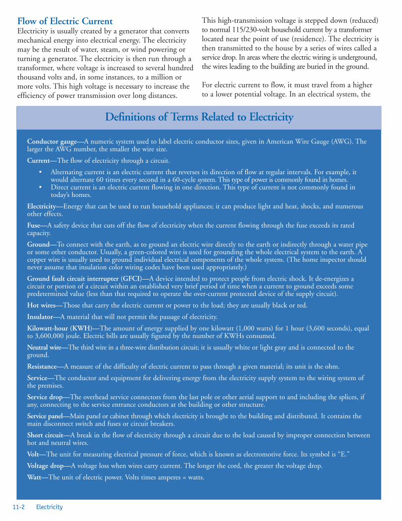
Flow of Electric CurrentElectricity is usually created by a generator that convertsmechanical energy into electrical energy. The electricitymay be the result of water, steam, or wind powering orturning a generator. The electricity is then run through atransformer, where voltage is increased to several hundredthousand volts and, in some instances, to a million ormore volts. This high voltage is necessary to increase theefficiency of power transmission over long distances.
This high-transmission voltage is stepped down (reduced)to normal 115/230-volt household current by a transformerlocated near the point of use (residence). The electricity isthen transmitted to the house by a series of wires called aservice drop. In areas where the electric wiring is underground,the wires leading to the building are buried in the ground.
For electric current to flow, it must travel from a higherto a lower potential voltage. In an electrical system, the
11-2 Electricity
Conductor gauge—A numeric system used to label electric conductor sizes, given in American Wire Gauge (AWG). Thelarger the AWG number, the smaller the wire size.
Current—The flow of electricity through a circuit.
• Alternating current is an electric current that reverses its direction of flow at regular intervals. For example, itwould alternate 60 times every second in a 60-cycle system. This type of power is commonly found in homes.
• Direct current is an electric current flowing in one direction. This type of current is not commonly found intoday’s homes.
Electricity—Energy that can be used to run household appliances; it can produce light and heat, shocks, and numerousother effects.
Fuse—A safety device that cuts off the flow of electricity when the current flowing through the fuse exceeds its ratedcapacity.
Ground—To connect with the earth, as to ground an electric wire directly to the earth or indirectly through a water pipeor some other conductor. Usually, a green-colored wire is used for grounding the whole electrical system to the earth. Acopper wire is usually used to ground individual electrical components of the whole system. (The home inspector shouldnever assume that insulation color wiring codes have been used appropriately.)
Ground fault circuit interrupter (GFCI)—A device intended to protect people from electric shock. It de-energizes acircuit or portion of a circuit within an established very brief period of time when a current to ground exceeds somepredetermined value (less than that required to operate the over-current protected device of the supply circuit).
Hot wires—Those that carry the electric current or power to the load; they are usually black or red.
Insulator—A material that will not permit the passage of electricity.
Kilowatt-hour (KWH)—The amount of energy supplied by one kilowatt (1,000 watts) for 1 hour (3,600 seconds), equalto 3,600,000 joule. Electric bills are usually figured by the number of KWHs consumed.
Neutral wire—The third wire in a three-wire distribution circuit; it is usually white or light gray and is connected to theground.
Resistance—A measure of the difficulty of electric current to pass through a given material; its unit is the ohm.
Service—The conductor and equipment for delivering energy from the electricity supply system to the wiring system ofthe premises.
Service drop—The overhead service connectors from the last pole or other aerial support to and including the splices, ifany, connecting to the service entrance conductors at the building or other structure.
Service panel—Main panel or cabinet through which electricity is brought to the building and distributed. It contains themain disconnect switch and fuses or circuit breakers.
Short circuit—A break in the flow of electricity through a circuit due to the load caused by improper connection betweenhot and neutral wires.
Volt—The unit for measuring electrical pressure of force, which is known as electromotive force. Its symbol is “E.”
Voltage drop—A voltage loss when wires carry current. The longer the cord, the greater the voltage drop.
Watt—The unit of electric power. Volts times amperes = watts.
Definitions of Terms Related to Electricity

hot wires (black or red) are at a higher potential than arethe neutral or ground wire (white or green).
Voltage is a measure of the force at which electricity isdelivered. It is similar to pressure in a water supply system.
Current is measured in amperes and is the quantity offlow of electricity. It is similar to measuring water ingallons per second. A watt is equal to volts times amperes.It is a measure of how much power is flowing. Electricityis sold in quantities of kilowatt-hours.
The earth, by virtue of moisture contained within thesoil, serves as a very effective conductor. Therefore, inpower transmission, instead of having both the hot andneutral wires carried by the transmission poles, one leadof the generator is connected to the ground, which servesas a conductor (Figure 11.1). All electrical utility wires arecarried by the transmission towers and are considered hotor charged. At the house, or point where the electricity isto be used, the circuit is completed by anotherconnection to ground.
The electric power utility provides a ground somewherein its local distribution system; therefore, there is aground wire in addition to the hot wires within theservice drop. In Figure 11.1 this ground can be seen atthe power pole that contains the step-down transformer.
In addition to the ground connection provided by theelectric utility, every building is required to have anindependent ground called a system ground. The systemground is a connection to ground from one of thecurrent-carrying conductors of the electrical system.System grounding, applied to limit overvoltages in theevent of a fault, provides personnel safety, provides apositive means of detecting and isolating ground faults,and improves service reliability. Therefore, the systemground’s main purpose is to protect the electrical systemitself and offers limited protection to the user.The system ground serves the same purpose as the powercompany’s ground; however, it has a lower resistance
because it is closer to the building. The equipmentground protects people from potential harm during theuse of certain electrical equipment. The system groundshould be a continuous wire of low resistance and ofsufficient size to conduct current safely from lightningand overloads.
Electric Service EntranceService DropTo prevent accidental contact by people, the entrancehead (Figure 11.2) should be attached to the building atleast 10 feet above ground. The conductor should clear allroofs by at least 8 feet and residential driveways by 12 feet.For public streets, alleys, roads, and driveways on other thanresidential property, the clearance must be 18 feet.
The wires or conductor should be of sufficient size to carrythe load and not smaller than No. 8 copper wire or equivalent.
For connecting wire from the entrance head to the servicedrop wires, the code requires that the service entranceconductors be installed either below the level of theservice head or below the termination of the serviceentrance cable sheath. Drip loops must be formed onindividual conductors. This will prevent water fromentering the electric service system. The wires that formthe entrance cable should extend 36 inches from theentrance head to provide a sufficient length to connectservice drop wires to the building with insulators. Theentrance cable may be a special type of armored outdoorcable, or it may be enclosed in a conduit. The electricpower meter may be located either inside or outside the
11-3Healthy Housing Reference Manual
Figure 11.1. Utility Overview [2]Figure 11.2. Entrance Head

building. In either instance, the meter must be locatedbefore the main power disconnect.
Figure 11.3 shows an armored cable service entrance witha fuse system. Newer construction will have circuitbreakers, as shown in Figure 11.4. The armored cable isanchored to the building with metal straps spaced every4 feet. The cable is run down the wall and through a holedrilled through the building. The cable is then connected tothe service panel, which should be located within 1 foot ofwhere the cable enters the building. The ground wireneed not be insulated. This ground wire may be eithersolid or stranded copper, or a material with an equivalentresistance.
Figure 11.5 shows the use of thin-wall conduit in a serviceentrance.
Underground ServiceWhen wires are run underground, they must be protectedfrom moisture and physical damage. The opening in thebuilding foundation where the underground service entersthe building must be moisture proof. Refer to local codesfor information about allowable materials for this type ofservice entrance.
Electric MeterThe electric meter (Figure 11.6) may be located inside oroutside the building. The meter itself is weatherproof andis plugged into a weatherproof socket. The electric powercompany furnishes the meter; the socket may or may notbe furnished by the power company.
GroundingThe system ground consists of grounding the neutralincoming wire and the neutral wire of the branch circuits.The equipment ground consists of grounding the metalparts of the service entrance, such as the service switch, aswell as the service entrance conduit, armor or cable.
Figure 11.5. Thin-wall Conduit [2]
Figure 11.3. Armored Cable Service Entrance [2]
Figure 11.4. Breakers [2]
11-4 Electricity

Poor grounding at any point can result in a personproviding a more effective route to ground than theintended ground, resulting in electrocution. This canoccur from damaged insulation allowing electricity toflow into the case or cabinet of the appliance.
The system must be grounded by two 8 foot by 5/8-inchcopper ground rods of at least 8 feet in length driven intothe ground and connected by a continuous (unbroken)piece of copper wire (the size of this wire corresponds tothe size of the system main). It is highly recommendedthat the system also be grounded to the incoming water lineor nearest cold water supply line if it is metal.
The usual ground connection is to a conductive waterpipe of the city water system. The connection should bemade to the street side of the water meter, as shown inFigure 11.7. If the water meter is located near the streetcurb, then the ground connection should be made to thecold water pipe as close as possible to where it enters thebuilding. It is not unusual for a water meter to beremoved from the building for service. If the groundconnection is made at a point in the water piping systemon the building side of the water meter, the groundcircuit will be broken on removal of the meter. Thisbroken ground circuit is a shock hazard if both sides ofthe water meter connections are touched simultaneously.Local or state codes should be checked to determinecompliance with correct grounding protocols.
In increasing instances, the connections between thewater meters and pipes are electrically very poor. In thiscase, if the ground connection is made on the buildingside of the water meter, there may not be an effectiveground. To prevent the two aforementioned situations,the code requires effective bonding by a properly sizedjumper-wire around any equipment that is likely to bedisconnected for repairs or replacement.
Often, the house ground will be disconnected. Therefore,the housing inspector should always check the houseground to see if it is properly connected.
Figure 11.8 shows a typical grounding scheme at theservice box of a residence. In this figure, only thegrounded neutral wires are shown. The neutral strap is aconductive bare metal strip that is riveted directly to theservice box. This conductive strip forms a collectiveground that joins the ground wires from the serviceentrance, branch circuits, and house ground.
Follow these key grounding points:
• Use two metal rods driven 8 feet into the ground.
• Bond around water heaters and filters to assuregrounding.
• If water pipes are used, they must be supplement-ed with a second ground.
• Ground rod must be driven to full depth.
• If ground rod resistance exceeds 25 ohms, installtwo rods at a minimum of 6 feet apart.
• When properly grounded, the metal frame of abuilding can be used as a ground point.
• Do not use underground gas lines as a ground.
• Provide external grounds to other systems such assatellite, telephone, and other services to furtherprotect the electrical system from surges.
11-5Healthy Housing Reference Manual
Figure 11.6. Electric MeterFigure 11.7. Typical Service Entrance [2]

• If the water service pipes to the home are notmetal or if all of the service components in thehome are not metal, then the water system cannotplay a role in grounding.
Bonding is necessary to provide a route for electricity toflow around isolated elements of a piping system toensure electrical potential is minimized for both theprotection of the system from corrosion and to protectindividuals from electrical shock.
Two- or Three-wire Electric ServicesOne of the wires in every electrical service installation issupposed to be grounded. This neutral wire should alwaysbe white. The hot wires are usually black, red, or someother color, but never white.
The potential difference or voltage between the hot wiresand the ground or neutral wire of a normal residentialelectrical system is 115 volts. Thus, where there is a two-wire installation (one hot and one neutral), only 115 voltsare available.
When three wires are installed (two hot and one neutral),either 115 or 230 volts are available. In a three-wiresystem, the voltage between the neutral and either of thehot wires is 115 volts; between the two hot wires, it is230 (Figure 11.9). The major advantage of a three-wiresystem is that it permits the operation of heavy electricalequipment such as clothes dryers, cooking ranges, and airconditioners, the majority of which require 230-voltcircuits. In addition, the three-wire system is split at theservice panel into two 115-volt systems to supply power
for small appliances and electric lights. The result is adoubling of the number of circuits, and, possibly, acorresponding increase in the number of branch circuits,with a reduction in the probability of fire caused byoverloading electrical circuits if the electrical demandsexceed the capacity.
Residential Wiring AdequacyThe use of electricity in the home has risen sharply sincethe 1930s. Many homeowners have failed to repair orimprove their wiring to keep it safe and up to date. In the1970s, the code recommended that the main distributionpanel in a home be a minimum of 100 amps. Because thenumber of appliances that use electricity has continued togrow, so has the size of recommended panels. For anormal house (2,500 to 3,500 square feet), a 200-amppanel is recommended. The panel must be of the breakertype with a main breaker for the entire system (Figure 11.4).Fuse boxes are not recommended for new housing.
This type of service is sufficient in a one-family house ordwelling unit to provide safe and adequate electricity forthe lighting, refrigerator, iron, and an 8,000-watt cookingrange, plus other appliances requiring a total of up to10,000 watts.
Some older homes have a 60-ampere, three-wire service(Figure 11.10). It is recommended that these homes berewired for at least the minimum of 200-amperesrecommended in the code. The 60-amp service is safelycapable of supplying current for only lighting andportable appliances, such as a cooking range and regulardryer (4,500 watts), or an electric hot water heater(2,500 watts), and cannot handle additional majorappliances. Other older homes today have only a 30-ampere,115-volt, two-wire service (Figure 11.11). This system cansafely handle only a limited amount of lighting, a fewminor appliances, and no major appliances. Therefore,this size service is substandard in terms of the modernhousehold’s needs for electricity. Furthermore, it is a firehazard and a threat to the safety of the home and theoccupants.
11-6 Electricity
Figure 11.9. Grounding [2]
Figure 11.8. Grounding Scheme [2]

Wire Sizes and TypesAluminum wiring, used in some homes from the mid1960s to the early 1970s, is a potential fire hazard [3].According to the U.S. Consumer Product SafetyCommission (CPSC), fires and even deaths have beencaused by this hazard. Problems due to expansion cancause overheating at connections between the wire anddevices (switches and outlets) or at splices. CPSC researchshows that homes wired with aluminum wiremanufactured before 1972 are 55 times more likely tohave one or more connections reach fire hazardconditions than are homes wired with copper. Post-1972 aluminum wire is also a concern. Introduction ofaluminum wire alloys around 1972 did not solve most ofthe connection failure problems. Aluminum wiring is stillpermitted and used for certain applications, includingresidential service entrance wiring and single-purposehigher amperage circuits such as 240-volt air conditioningor electric range circuits.
Reducing RiskOnly two remedies for aluminum wiring have beenrecommended by the CPSC: discontinued use of thealuminum circuit or the less costly option of addingcopper connecting “pigtail” wires between the aluminumwire and the wired device (receptacle, switch, or otherdevice). The pigtail connection must be made using onlya special connector and special crimping tool licensed bythe AMP Corporation. Emergency temporary repairsnecessary to keep an essential circuit in service might bepossible following other procedures described by theCPSC, and in accordance with local electrical codes [4,5].
Wire SizesElectric power actually flows along the surface of the wire.It flows with relative ease (little resistance) in some materials,such as copper and aluminum, and with a substantialamount of resistance in iron. If iron wire were used, itwould have to be 10 times as large as copper wire to be aseffective in conducting electricity. In fine electronics, goldis the preferred conductor because of the resistance tocorrosion and the very high conductivity.Electricity is the movement of electrons from an area ofhigher potential to one of lower potential. An analogy tohow electricity flows would be the flow of water along thepath of least resistance or down a hill. All it takes tocreate the potential for electricity is the collection of
11-7Healthy Housing Reference Manual
Figure 11.11. Two-wire Service [2]Figure 11.10. Three-wire Service [2]

electrons and a pathway for them to flow to an area oflesser concentration along a conductor. When a personwalks across a nylon carpet in times of low atmospherichumidity, his or her body will often collect electrons andserve as a capacitor (a storage container for electrons).When that person nears a grounding source, the electronswill often jump from a finger to the ground, creating aspark and small shock.
A number preceded by the letters AWG (American WireGauge) indicates copper wire sizes [6]. As the AWGnumber of the wire becomes smaller, the size and currentcapacity of the wire increases. AWG 14 is mostcommonly found in older residential branch circuits.AWG 14 wires should be used only in a branch circuitwith a 15-ampere capacity or no more than a 1,500-wattdemand. Wire sizes AWG 16, 18, and 20 are progressivelysmaller than AWG 14 and are used for extension wires orlow-voltage systems. Wire of the correct size must be usedfor two reasons: current capacity and voltage drop or loss.
When current flows through a wire, it creates heat. Thegreater the amount of flow, the greater the amount ofheat generated. (Doubling the amperes without changingthe wire size increases the amount of heat by four times.)The heat is electric energy (electrons) that has beenconverted into heat energy by the resistance of the wire.The heat created by the coils in a toaster is an example ofdesigned resistance to create heat. Most heat developed byan electrical conductor is wasted; therefore, the electricenergy used to generate it is also wasted.
If the amount of heat generated by the flow of currentthrough a wire becomes excessive, a fire may result.Therefore, the code sets the maximum permissible currentthat may flow through a certain type and size wire. The blue box provides examples of current capacities forcopper wire of various sizes.
In addition to heat generation, there will be a reduction involtage as a result of attempting to force more currentthrough a wire than it is designed to carry. Certainappliances, such as induction-type electric motors, may bedamaged if operated at too low a voltage.
Wire TypesAll wires must be marked to indicate the maximumworking voltage, the proper type letter or letters for thetype wire specified in the code, the manufacturer’s nameor trademark, and the AWG size or circular-mil area(Figure 11.12). A variety of wire types can be used for awide range of temperature and moisture conditions. Thecode should be consulted to determine the proper wirefor specific conditions.
Types of CableNonmetallic sheathed cable consists of wires wrapped inplastic and then a paper layer, followed by another spirallayer of paper, and enclosed in a fabric braid, which istreated with moisture- and fire-resistant compounds.Figure 11.12 shows this type of cable, which often ismarketed under the name Romex. This type of cable canbe used only indoors and in permanently dry locations.Romex-type wiring is normally used in residentialconstruction. However, when cost permits, it isrecommended that a conduit-based system be used.
Armored cable is commonly known as BX or Flexsteeltrade names. Wires are wrapped in a tough paper andcovered with a strong spiral flexible steel armor. This typeof cable is shown in Figure 11.13 and may be used onlyin permanently dry indoor locations. Armored cable mustbe supported by a strap or staple every 6 feet and within24 inches of every switch or junction box, except forconcealed runs in old work where it is impossible tomount straps.
Cables are also available with other outer coatings of metals,such as copper, bronze, and aluminum for use in a variety ofconditions.
11-8 ElectricityFigure 11.12. Wire Markings [2]
Size wire (AWG) (larger wire, smaller number) #14 #12 #10 #8Maximum capacity in amperes 15 20 30 40
Maximum Current Recommended for AWG Wire Size

Flexible CordsCPSC estimates that about 4,000 injuries associated withelectric extension cords are treated in hospital emergencyrooms each year. About half of the injuries involvefractures, lacerations, contusions, or sprains from peopletripping over extension cords. Thirteen percent of theinjuries involve children younger than 5 years of age;electrical burns to the mouth account for half the injuriesto young children [7].
CPSC also estimates that about 3,300 residential firesoriginate in extension cords each year, killing 50 peopleand injuring about 270 others [7]. The most frequentcauses of such fires are short circuits, overloading thesystem, and damage to or misuse of extension cords.
The ProblemFollowing are CPSC investigations of injuries thatillustrate the major injury patterns associated withextension cords: children putting extension cords in theirmouths, overloaded cords, worn or damaged cords, andtripping over cords:
• A 15-month-old girl put an extension cord in hermouth and suffered an electrical burn. Sherequired surgery.
• Two young children were injured in a fire causedby an overloaded extension cord in their family’shome. A lamp, TV set, and electric heater hadbeen plugged into a single, light-duty extensioncord.
• A 65-year-old woman was treated for a fracturedankle after tripping over an extension cord.
The StandardsThe code says that many cord-connected appliancesshould be equipped with polarized grounding plugs.Polarized plugs can only be inserted one way into theoutlet because one blade is slightly wider than the other.Polarization and grounding ensure that certain parts ofappliances that could have a higher risk of electric shockwhen they become live are instead connected to theneutral, or grounded, side of the circuit. Such electricalproducts should only be used with polarized or groundedextension cords.
Voluntary industry safety standards, including those ofUnderwriter’s Laboratory (UL), now require that general-use extension cords have safety closures, warning labels,rating information about the electrical current, and otherfeatures for the protection of children and otherconsumers.
In addition, UL-listed extension cords now must beconstructed with 16-gauge or larger wire or be equippedwith integral fuses. The 16-gauge wire is rated to carry13 amperes (up to 1,560 watts), as compared with theformerly used 18-gauge cords that were rated for10 amperes (up to 1,200 watts).
Safety SuggestionsThe following are CPSC recommendations [7] forpurchasing and safely using extension cords:
• Use extension cords only when necessary and onlyon a temporary basis.
• Use polarized extension cords with polarizeappliances.
• Make sure cords do not dangle from the counteror tabletops where they can be pulled down ortripped over.
• Replace cracked or worn extension cords withnew 16-gauge cords that have the listing of anationally recognized testing laboratory, safetyclosures, and other safety features.
• With cords lacking safety closures, cover anyunused outlets with electrical tape or with plasticcaps to prevent the chance of a child makingcontact with the live circuit.
• Insert plugs fully so that no part of the prongs isexposed when an extension cord is in use.
• When disconnecting cords, pull the plug ratherthan the cord itself.
• Teach children not to play with plugs and outlets.
• Use only three-wire extension cords for applianceswith three-prong plugs. Never remove the third(round or U-shaped) prong, which is a safetyfeature designed to reduce the risk for shock andelectrocution.
11-9Healthy Housing Reference Manual
Figure 11.13. Armored Cable [2]

• In locations where furniture or beds may bepushed against an extension cord where the cordjoins the plug, use a special angle extension cordspecifically designed for use in these instances.
• Check the plug and the body of the extensioncord while the cord is in use. Noticeable warmingof these plastic parts is expected when cords arebeing used at their maximum rating. If the cordfeels hot or if there is a softening of the plastic,this is a warning that the plug wires orconnections are failing and that the extensioncord should be discarded and replaced.
• Never use an extension cord while it is coiled orlooped. Never cover any part of an extension cordwith newspapers, clothing, rugs, or any objectswhile the cord is in use. Never place an extensioncord where it is likely to be damaged by heavyfurniture or foot traffic.
• Do not use staples or nails to attach extensioncords to a baseboard or to another surface. Thiscould damage the cord and present a shock or firehazard.
• Do not overload extension cords by plugging inappliances that draw a total of more watts thanthe rating of the cord.
• Use special heavy-duty extension cords for high-wattage appliances such as air conditioners,portable electric heaters, and freezers.
• When using outdoor tools and appliances, useonly extension cords labeled for outdoor use.
WiringOpen WiringOpen wiring is a wiring method using knobs, nonmetallictubes, cleats, and flexible tubing for the protection andsupport of insulated conductors in or on buildings andnot concealed by the structure. The term “open wiring”does not mean exposed, bare wiring. In dry locations,when not exposed to severe physical damage, conductorsmay be separately encased in flexible tubing. Tubingshould be in continuous lengths not exceeding 15 feetand secured to the surface by straps not more than4½ feet apart. Tubing should be separated from otherconductors by at least 2½ inches and should have apermanently maintained airspace between them and anyand all pipes they cross.
Concealed Knob and Tube WiringConcealed knob and tube wiring is a wiring methodusing knobs, tubes, and flexible nonmetallic tubing forthe protection and support of insulated wires concealed inhollow spaces of walls and ceilings of buildings. Thiswiring method is similar to open wiring and, like openwiring, is usually found only in older buildings.
Electric Service PanelThe service switch is a main switch that will disconnectthe entire electrical system at one time. The main fuses orcircuit breakers are usually located within the serviceswitch box. The branch circuit fuse or circuit breaker mayalso be located within this box.
According to the code, the switch must be externallyoperable. This condition is fulfilled if the switch can beoperated without the operator being exposed toelectrically active parts. Figure 11.14 shows a 200-ampservice box. Figure 11.15 shows an external “hingedswitch” power shutoff installed on the outside of a home.
Most of today’s older homes do not have hinged switches.Instead, the main fuse is mounted on a small insulatedblock that can be pulled out of the switch. When thisblock is removed, the circuit is broken.
In some installations, the service switch is a “solidneutral” switch, meaning that the switch or a fuse doesnot break the neutral wire in the switch.
When circuit breakers are used in homes instead of fuses,main circuit breakers may or may not be required. If ittakes more than six movements of the hand to open allthe branch-circuit breakers, a main breaker, switch, orfuse will be required ahead of the branch-circuit breakers.Thus, a house with seven or more branch circuits requiresa separate disconnect means or a main circuit breakerahead of the branch-circuit breakers.
Over-current DevicesThe amperage (current flow) in any wire is limited to themaximum permitted by using an over-current device of asize specified by the code. Four types of over-currentdevices are common: circuit breakers, ground fault circuitinterrupters (GFCIs), arc fault circuit interrupters(AFCIs), and fuses. The over-current device of a specificsize is specified by the code. The over-current device mustbe rated at equal or lower capacity than the wire of thecircuit it protects.
11-10 Electricity

Circuit Breakers (Fuseless Service Panels)A circuit breaker looks something like an ordinary electriclight switch. Figure 11.14 shows the service box in a 200-amp fuseless system. Figure 11.15 shows a service switch.There is a handle that may be used to turn power on oroff. Inside is a simple mechanism that, in case of a circuitoverload, trips the switch and breaks the circuit. Thecircuit breaker may be reset by turning the switch to offand then simply resetting the switch to the on position. Acircuit breaker is capable of taking harmless short-periodoverloads (such as the heavy initial current required in thestarting of a washing machine or air conditioner) withouttripping, but protects against prolonged overloads. Afterthe cause of trouble has been located and corrected, poweris easily restored. Fuseless service panels or breaker boxes areusually broken up into the following circuits:
• A 100-ampere or larger main circuit breaker thatshuts off all power.
• A 40-ampere circuit for an appliance such as anelectric cooking range.
• A 30-ampere circuit for a clothes dryer, waterheater, heat pump, or central air conditioning.
• A 20-ampere circuit for small appliances andpower tools.
• A 15-ampere circuit for general-purpose lighting,TVs, VCRs, computers, and vacuum cleaners.
• Space for new circuits to be added if needed forfuture use.
Ground Fault Circuit Interrupters Unlike circuit breakers and fuses, GFCIs are installed toprotect the user from electrocution. These devices provideprotection against electrical shock and electrocution fromground faults or contact with live parts by a groundedindividual. They constantly monitor electrical currentsflowing into a product. If the electricity flowing throughthe product differs even slightly from that returning, theGFCI will quickly shut off the current. GFCIs detectamounts of electricity much smaller than those requiredfor a fuse or circuit breaker to activate and shut off thecircuit. UL lists three types of GFCIs designed for homeuse that are readily available and fairly inexpensive andsimple to install:
• Wall Receptacle GFCI—This type of GFCI(Figure 11.16) is used in place of a standardreceptacle found throughout the house. It fits intoa standard outlet box and protects against groundfaults whenever an electrical product is pluggedinto the outlet. If strategically located, it will alsoprovide protection to downstream receptacles.
• Circuit Breaker GFCI—In homes equipped withcircuit breakers, this type of GFCI may beinstalled in a panel box to protect selected circuits.A circuit breaker GFCI serves a dual purpose: itshuts off electricity in the event of a ground fault
Figure 11.14. 200-Amp Service Box Figure 11.15. External Power Shutoff and Meter
11-11Healthy Housing Reference Manual

and will also trip when a short circuit or anoverload occurs.
• Portable GFCI—A portable GFCI requires nospecial knowledge or equipment to install. Onetype contains the GFCI circuitry in a self-contained enclosure with plug blades in the backand receptacle slots in the front. It can be pluggedinto a receptacle, and the electrical productplugged into the GFCI. Another type of portableGFCI is an extension cord combined with aGFCI. It adds flexibility in using receptacles thatare not protected by GFCIs.
Once a GFCI is installed, it must be checked monthly todetermine that it is operating properly. Pressing the testbutton can check units; the GFCI should disconnect thepower to that outlet. Pressing the reset button reconnectsthe power. If the GFCI does not disconnect the power,have it checked by a qualified, certified electrician. GFCIs should be installed on circuits in the followingareas: garages, bathrooms, kitchens, crawl spaces,unfinished basements, hot tubs and spas, pool electronics,and exterior outlets. However, they are not required onsingle outlets that serve major appliances.
Arc-fault Circuit Interrupters Arc-fault circuit interrupters are new devices intended toprovide fire protection by opening the circuit if an arcingfault is detected. An arcing fault is an electric spark or hotplasma field that extends from the hot wire to a ground.An arc is a luminous discharge of electricity across aninsulating medium or simply a spark across an air gap.Arcs occur every day in homes. For example, an arcoccurs inside the switch when a light is turned on. Toyracecars and trains create arcs. The motors inside hairdyers and power drills have tiny arcs. All of these are
controlled arcs. It is theuncontrolled or nondesignedarc that is a serious fire hazardin the home. The arc-faultcircuit interrupter looks likethe GFCI unit (Figure 11.17),but it is not designed toprotect against electric shock.
Because most electrical wiringin a home is hidden fromview, many arc faults goundetected and continuearcing indefinitely. If left inthis arcing state, the potential
for fire increases. It is estimated that about one third offires are caused by arcing faults. Normal fuses and circuitbreakers are not capable of detecting arc faults and thereforewill not open the circuit and stop the flow of electricity.
Fused Ampere Service Panel (Fuse Box)Fuse-type panel boxes are generally found in older homes.They are as safe and adequate as a circuit breaker ofequivalent capacity, provided fuses of the proper size are used.
A fuse, like a circuit breaker, is designed to protect acircuit against overloading and short circuits and does soin two ways.
When a fuse is blown by a short circuit, the metal strip isinstantly heated to an extremely high temperature, andthis heat causes it to vaporize. A fuse blown by a shortcircuit may be easily recognized because the window ofthe fuse usually becomes discolored.
In a fuse blown by an overload, the metal strip is meltedat its weakest point, breaking the flow of current to theload. In this case, the window of the fuse remains clear;therefore, a blown fuse caused by an overload may also beeasily recognized.
Sometimes, although a fuse has not been blown, thebottom of the fuse may be severely discolored and pitted.This indicates a loose connection because the fuse was notscrewed in properly.
It is critical to check that all fuses are properly rated forthe designed amperage. The placing of a fuse with ahigher amperage than recommended presents a significantfire hazard.
Generally, all fused panel boxes are wired similarly fortwo- and three-wire systems. In a two-wire-circuit panelbox, the black or red hot wire is connected to a terminalof the main disconnect, and the white or light grayneutral wire is connected to the neutral strip, which is thengrounded to the pipe on the street side of the water meter.
In a three-wire system, theblack and red hot wires areconnected to separateterminals of the maindisconnect, and the neutralwire is grounded the same asfor a two-wire system. Beloweach fuse is a terminal towhich a black or red wire is
11-12 Electricity
Figure 11.16. GFCI Figure 11.17. Arc Interrupter
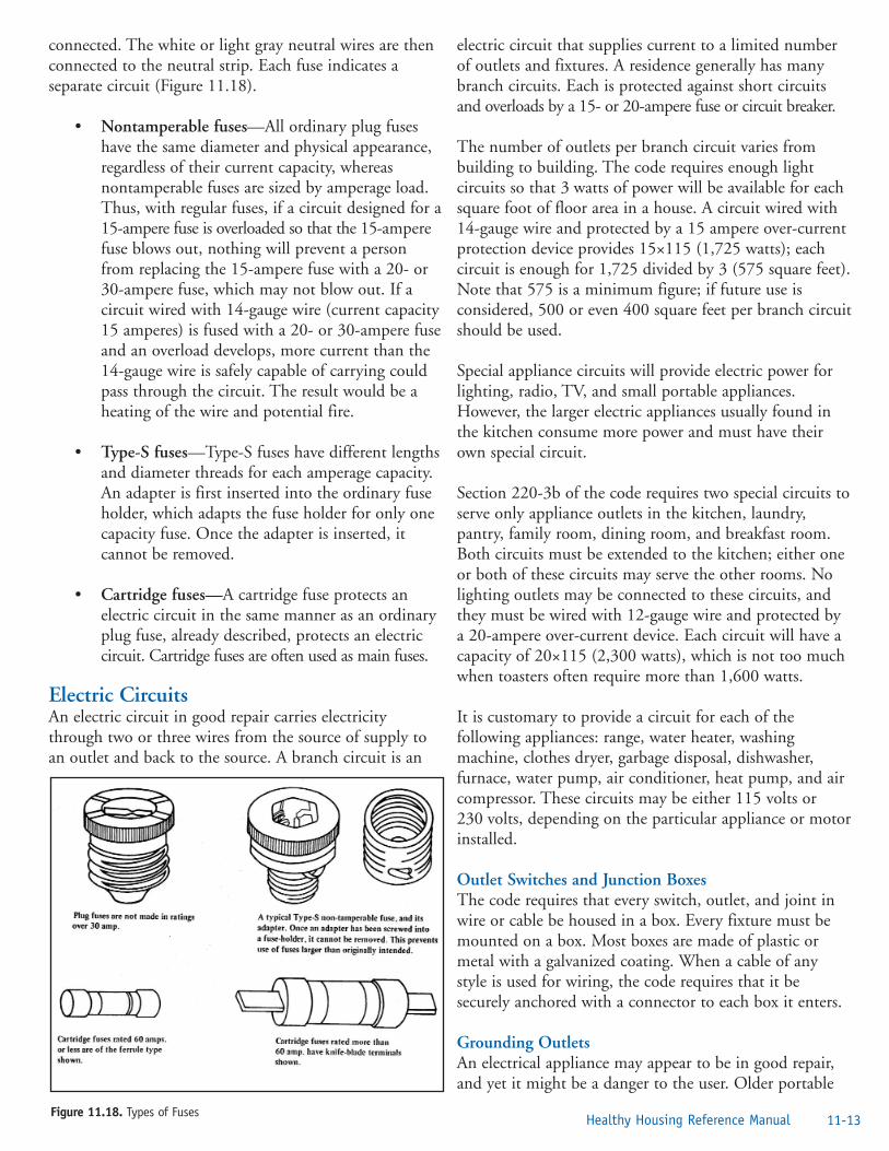
connected. The white or light gray neutral wires are thenconnected to the neutral strip. Each fuse indicates aseparate circuit (Figure 11.18).
• Nontamperable fuses—All ordinary plug fuseshave the same diameter and physical appearance,regardless of their current capacity, whereasnontamperable fuses are sized by amperage load.Thus, with regular fuses, if a circuit designed for a15-ampere fuse is overloaded so that the 15-amperefuse blows out, nothing will prevent a personfrom replacing the 15-ampere fuse with a 20- or30-ampere fuse, which may not blow out. If acircuit wired with 14-gauge wire (current capacity15 amperes) is fused with a 20- or 30-ampere fuseand an overload develops, more current than the14-gauge wire is safely capable of carrying couldpass through the circuit. The result would be aheating of the wire and potential fire.
• Type-S fuses—Type-S fuses have different lengthsand diameter threads for each amperage capacity.An adapter is first inserted into the ordinary fuseholder, which adapts the fuse holder for only onecapacity fuse. Once the adapter is inserted, itcannot be removed.
• Cartridge fuses—A cartridge fuse protects anelectric circuit in the same manner as an ordinaryplug fuse, already described, protects an electriccircuit. Cartridge fuses are often used as main fuses.
Electric CircuitsAn electric circuit in good repair carries electricitythrough two or three wires from the source of supply toan outlet and back to the source. A branch circuit is an
electric circuit that supplies current to a limited numberof outlets and fixtures. A residence generally has manybranch circuits. Each is protected against short circuitsand overloads by a 15- or 20-ampere fuse or circuit breaker.
The number of outlets per branch circuit varies frombuilding to building. The code requires enough lightcircuits so that 3 watts of power will be available for eachsquare foot of floor area in a house. A circuit wired with14-gauge wire and protected by a 15 ampere over-currentprotection device provides 15×115 (1,725 watts); eachcircuit is enough for 1,725 divided by 3 (575 square feet).Note that 575 is a minimum figure; if future use isconsidered, 500 or even 400 square feet per branch circuitshould be used.
Special appliance circuits will provide electric power forlighting, radio, TV, and small portable appliances.However, the larger electric appliances usually found inthe kitchen consume more power and must have theirown special circuit.
Section 220-3b of the code requires two special circuits toserve only appliance outlets in the kitchen, laundry,pantry, family room, dining room, and breakfast room.Both circuits must be extended to the kitchen; either oneor both of these circuits may serve the other rooms. Nolighting outlets may be connected to these circuits, andthey must be wired with 12-gauge wire and protected bya 20-ampere over-current device. Each circuit will have acapacity of 20×115 (2,300 watts), which is not too muchwhen toasters often require more than 1,600 watts.
It is customary to provide a circuit for each of thefollowing appliances: range, water heater, washingmachine, clothes dryer, garbage disposal, dishwasher,furnace, water pump, air conditioner, heat pump, and aircompressor. These circuits may be either 115 volts or230 volts, depending on the particular appliance or motorinstalled.
Outlet Switches and Junction BoxesThe code requires that every switch, outlet, and joint inwire or cable be housed in a box. Every fixture must bemounted on a box. Most boxes are made of plastic ormetal with a galvanized coating. When a cable of anystyle is used for wiring, the code requires that it besecurely anchored with a connector to each box it enters.
Grounding OutletsAn electrical appliance may appear to be in good repair,and yet it might be a danger to the user. Older portable
11-13Healthy Housing Reference ManualFigure 11.18. Types of Fuses

electric drills consist of an electric motor inside a metalcasing. When the switch is depressed, the current flows tothe motor and the drill rotates. As a result of wear,however, the insulation on the wire inside the drill maydeteriorate and allow the hot side of the power cord tocome in contact with the metal casing. This will notaffect the operation of the drill.
A person fully clothed using the drill in the living room,which has a dry floor, will not receive a shock, eventhough he or she is in contact with the electrified drillcase. The operator’s body is not grounded because of thedry floor. If standing on a wet basement floor, theoperator’s body might be grounded; and, when theelectrified drill case is touched, current will pass throughthe operator’s body.
To protect people from electrocution, the drill case isusually connected to the system ground by means of awire called an appliance ground. In this instance, as thedrill is plugged in, current will flow between the shortedhot wire and the drill case and cause the over-currentdevice to break the circuit. Thus, the appliance groundhas protected the human operator. Newer appliances andtools are equipped with two-prong polarized plugs, asdiscussed in the standards section of this manual.
The appliance ground (Figure 11.19) is the third wirefound on many appliances. The appliance ground will beof no use unless the outlet into which the appliance isplugged is grounded. Being in physical contact with aground outlet box grounds the outlet. Having a thirdground wire, or a grounded conduit, as part of the circuitwiring grounds the outlet box.
All new buildings are required to have grounded outlets.A two-lead circuit tester can be used to test the outlet.The circuit tester lights when both of its leads are pluggedinto the two elongated parallel openings of the outlet. Inaddition, the tester lights when one lead is plugged intothe round third opening and the other is plugged into thehot side of the outlet. Most problems can be resolvedusing inexpensive testers resembling a plug with threeleads. These can be purchased in many stores and mosthardware stores for very reasonable prices.
If the conventional two-opening outlet is used, it may begrounded if the screw that holds the outlet cover plate iselectrically connected to the third-wire ground. The testershould light when one lead is in contact with a cleanpaint-free metal outlet cover plate screw and the hot sideof the outlet. If the tester does not light, the outlet is not
grounded. If a two-opening outlet is grounded, it may beadapted for use by a three-wire appliance by using anadapter. The loose-wire portion or screw tab of theadapter should be secured behind the metal screw of theoutlet plate cover. Many appliances, such as electricshavers and some new hand tools, are double insulatedand are safe without having a third ground wire.
Polarized Plugs and ConnectorsPlugs are polarized or unpolarized. Polarization helpsreduce the potential for shock. Consumers can easilyidentify polarized plugs; one blade-the ground prong-iswider than the other. Three-conductor plugs areautomatically polarized because they can only be insertedone way. Polarized plugs are used to connect the most-exposed part of an appliance to the ground wire so that ifyou are touching a ground (such as a pipe, bathtub, orfaucet) and the exposed part of an appliance (the case, thethreaded part of a light bulb socket, etc.), you will not getan electrical shock. Many appliances, such as electricdrills, are doubly insulated so the probability of anyexposed part of the appliance being connected, by a shortor other problem in the appliance, to either wire is verysmall. Such devices often use unpolarized plugs where thetwo prongs of the plug are identical.
Common Electrical ViolationsThe most obvious things that a housing inspector mustcheck are the power supply; the type, location, andcondition of the wiring; and the number and conditions ofwall outlets or ceiling fixtures required by the local code. Inmaking an investigation, the following considerations willserve as useful guides.
11-14 ElectricityFigure 11.19. Appliance Ground and Grounded Plug

• Power supply—Where is it, is it groundedproperly, and is it at least of the minimumcapacity required to supply current safely forlighting and the major and minor appliances inthe dwelling?
• Panel box covers or doors—These should beaccessible only from the front and should besealed in such a way that they can be operatedsafely without the danger of contact with live orexposed parts of the wiring system.
• Switch, outlets, and junction boxes—These alsomust be covered to protect against danger ofelectric shock.
• Frayed or bare wires—These are usually the resultof long use and drying out and cracking of theinsulation, which leave the wires exposed, or ofconstant friction and rough handling of the wire,which cause it to fray or become bare. Wiring inthis condition constitutes a safety hazard. Correctionof such defects should be ordered immediately.
• Electric cords under rugs or other floorcoverings—Putting electric cords in locationssuch as these is prohibited because of the potentialfire hazard caused by continuing contact over aperiod of time between these heat-bearing cordsand the flammable floor coverings. Direct theoccupant to shift the cords to a safe location, explainwhy, and make sure it is done before you leave.
• Ground fault circuit interrupter—All bathroom,kitchen, and workroom outlets-where shockhazard is great-should have GFCI outlets. Checkfor lack of or nonuse of GFCI outlets.
• Bathroom lighting—Bathrooms should include atleast one permanently installed ceiling or walllight fixture with a wall switch and plate locatedand maintained so that there is no danger of shortcircuiting from use of other bathroom facilities orsplashing water. Fixture or cover plates should beinsulated or grounded.
• Lighting of public hallways, stairways, landings,and foyers—A common standard is sufficientlighting to illuminate 10 foot-candles on every partof these areas at all times. Sufficient lightingmeans that people can clearly see their feet on allparts of the stairways and halls. Public halls and
stairways in structures containing less than threedwelling units may be supplied with convenientlylocated light switches controlling an adequatelighting system that may be turned on whenneeded, instead of full-time lighting.
• Habitable room lighting—The standard heremay be two floor convenience outlets (althoughfloor outlets are dangerous unless protected byproper dust and water covers) or one convenienceoutlet and one wall or ceiling electric light fixture.This number is an absolute and often inadequateminimum, given the contemporary widespreaduse of electricity in the home. The minimumshould be the number required to provideadequate lighting and power to accommodatelighting and appliances normally used in each room.
• Octopus outlets or wiring—This term is appliedto outlets into which plugs have been inserted andare being used to permit more than two lights orportable appliances, such as a TV, lamp, or radio,to be connected to the electrical system. Thecondition occurs where the number of outlets isinsufficient to accommodate the normal use ofthe room. This practice overloads the circuit andis a potential source of fire.
• Outlet covers—Every outlet and receptacle mustbe covered by a protective plate to prevent contactof its wiring or terminals with the body,combustible objects, or water.
Following are six situations that can cause danger andshould also be corrected.
Excessive or Faulty FusingThe wire’s capacity must not be exceeded by the fuse orcircuit breaker capacity or be left unprotected by faultyfusing or circuit breakers. Fuses and circuit breakers aresafety devices designed to “blow” to protect againstoverloading the electrical system or one or more of itscircuits. Pennies under fuses are there to bypass the fuse.These are illegal and must be removed. Overfusing isdone for the same reason. The latter can be prevented byinstalling modern fusestats, which prevent use of any fuse of ahigher amperage than can be handled by the circuit it serves.
Cords Run Through Walls or Doorways and Hanging Cords or WiresThis makeshift installation often is the work of anunqualified handyman or do-it-yourself occupant. The
11-15Healthy Housing Reference Manual

inspector should check the local electrical code todetermine the policy regarding this type of installation.
Temporary WiringTemporary wiring should not be allowed, with theexception of extension cords that go directly fromportable lights and electric fixtures to convenience outlets.
Excessively Long Extension CordsCity code standards often limit the length of loose cordsor extension lines to a maximum of 8 feet. This isnecessary because cords that are too long will overheat ifoverloaded or if a short circuit develops and, thus, create afire hazard. This requirement does not apply to speciallydesigned extension cords for operating portable tools andtrouble lights.
Dead or Dummy OutletsThese are sometimes installed to deceive the housinginspector. All outlets must be tested or the occupantsquestioned to see if these are live and functioningproperly. A dead outlet cannot be counted to determinecompliance with the code.
Aluminum Wiring Inside the HomeAlthough aluminum is an excellent conductor, it tends tooxidize on the conducting surface. The nonconductiveoxidized face of the conductor will arc from the remainingconductive surfaces, and this arc can result in fire.
Inspection StepsThe basic tools required by a housing inspector formaking an electrical inspection are fuse and circuit testersand a flashlight. The first thing to remember is that youare in a strange house, and the layout is unfamiliar toyou. The second thing to remember is that you aredealing with electricity-take no chances. Go to the site ofthe ground, usually at the water meter, and check theground. It should connect to the water line on the streetside of the water meter or be equipped with a jumperwire. Do not touch any box or wire until you are sure ofthe ground. Go to the main fuse box or circuit breakerbox and check all fuses and breakers for operationalintegrity (proper amperage range; functional). Note thecondition of the wiring and of the box itself and checkwhether it is over-fused. Examine all wiring in thebasement. Make sure you are standing in a dry spot(concrete poses a particular problem because you cannotdetermine its water content from visual examination)before touching any electrical device. Standing on a drypiece of wood is far safer than standing on concrete. Do
not disassemble the fuse box, circuit breaker, or otherdevices. Decisions must be made on what you see. If indoubt, consult your supervisor.
Note whether any fuse boxes, circuit breakers, or junctionboxes are uncovered. Examine all wiring for frayed or barespots; improper splicing; or rotted, worn, or inadequateinsulation. Avoid all careless touching; when indoubt—DON’T! If you see bare wires, have the ownercall an electrician. Look for wires or cords in use in thebasement. Be certain all switch boxes and outlets are in atight, sound condition. Make sure that the emergencyswitch for an oil burner is at the top of the basementstairs, not on top of the unit.
Bathrooms, kitchens, and utility rooms-where electricshock hazard is great-should have GFCI outlets.
While inspecting the bathroom, also check for dangerousitems, such as radios that are not made for bathroom useor portable electric heaters. Have inappropriate itemsremoved immediately. Such items have killed thousandsof people who touched them after getting out of thebathtub or shower while still wet or because the appliancefell into water the person had contact with.
Electric washer and dryer combinations should have a240-volt circuit, 30-ampere service connected to aseparate fuse or circuit breaker. Washer and dryercombinations and other portable appliances should beserved by sufficiently heavy electrical service. If either ofthese special lines is not available under the above-statedconditions, consult your supervisor.
An electric range needs a 50-ampere, 240-volt circuit. Adishwasher needs a 20-ampere, 120-volt circuit. Aseparate three-wire circuit must be installed for an electricwater heater. Continue your inspection systematicallythrough the house.
To sum up, the housing inspector investigates specifiedelectrical elements in a house to detect any obviousevidence of an insufficient power supply, to ensure theavailability of adequate and safe lighting and electricalfacilities, and to discover and correct any obvious hazard.Because electricity is a technical, complicated field, thehousing inspector, when in doubt, should consult his orher supervisor. The inspector cannot, however, close thecase until appropriate corrective action has been taken onall such referrals.
11-16 Electricity

References1. National Fire Protection Association. National
electrical code handbook 2005. Florence, KY:Thomson Delmar Learning; 2005.
2. Center for Disease Control. Basic housinginspection. Atlanta: US Department of Healthand Human Services; 1976.
3. British Columbia Safety Authority. The factsabout aluminum wiring in the home. NewWestminster, British Columbia, Canada: BritishColumbia Safety Authority; no date. Availablefrom URL: http://www.safetyauthority.ca/services/esp/The_Facts_About_Aluminum_Wiring_In_The_Home.pdf.
4. Consumer Product Safety Commission. May isNational Electrical Safety Month: good news forhomeowners-aluminum wiring fix still available.Washington, DC: Consumer Product SafetyCommission; 2003. Available from URL:http://www.cpsc.gov/CPSCPUB/PREREL/prhtml03/03120.html.
5. Consumer Product Safety Commission. CPSCsafety recommendations for aluminum wiring inhomes. Washington, DC: Consumer ProductSafety Commission; 1974. Available from URL:http://www.cpsc.gov/CPSCPUB/PREREL/prhtml74/74040.html.
6. AWG American wire gauge/diameter/resistance.Cologne, Germany: Bernd Noack; no date.Available from URL:http://www.bnoack.com/data/wire-resistance.html.
7. Consumer Product Safety Commission. Extensioncords fact sheet. Washington, DC: ConsumerProduct Safety Commission; no date. CPSC #16.Available from URL:http://www.cpsc.gov/CPSCPUB/PUBS/16.html.
Additional Sources of InformationCroft T, Summers W. American electricians’ handbook.14th edition, New York: McGraw-Hill Professional; 2002.
Tuck D, Tuck G, Woodson RD. Electrician’s instantanswers. New York: McGraw-Hill Professional; 2003.Black and Decker. The complete guide to home wiring: a
comprehensive manual, from basic repairs to advancedprojects (Black & Decker Home Improvement Library;US edition). Chanhassen, MN: Creative PublishingInternational; 2001.
Sunset Publishing. Basic wiring. 3rd edition. Menlo Park,CA: Sunset Books, 1995.
Hometime.com. Electrical service panel: panelcomponents, circuit breakers, fuses, electrical glossary.Hometime.com; no date. Available from URL:http://www.hometime.com/Howto/ projects/electric/elec_2.htm.
Vandervort D. How your house works: electric systems.Glendale, CA: Hometips.com; no date. Available fromURL: http://www.hometips.com/hyhw/electrical/electric.html.
PNM Resources. Residential subdivisions: electric servicerequirements. In: Electric service guide. Albuquerque,NM: PNM; 2004. Available from URL:http://www.pnm.com/esg/chapters/56-63.pdf.
Textor K. Extension cord basics. Fine Homebuilding2000, 129: 84-9. Available from URL:http://www.taunton.com/finehomebuilding/pages/h00010.asp.
Consumer Product Safety Commission. Repairingaluminum wiring. Washington, DC: Consumer ProductSafety Commission; 1994. CPSC #516. Available fromURL: http://www.cpsc.gov/CPSCPUB/PUBS/516.pdf.
11-17Healthy Housing Reference Manual

11-18 Electricity

Chapter 12—Heating, Air Conditioning, and VentilatingIntroduction . . . . . . . . . . . . . . . . . . . . . . . . . . . . . . . . . . . . . . . . . . . . . . . . . . . . . .12-1Heating . . . . . . . . . . . . . . . . . . . . . . . . . . . . . . . . . . . . . . . . . . . . . . . . . . . . . . . . .12-4
Standard Fuels . . . . . . . . . . . . . . . . . . . . . . . . . . . . . . . . . . . . . . . . . . . . . . . .12-4Central Heating Units . . . . . . . . . . . . . . . . . . . . . . . . . . . . . . . . . . . . . . . . . .12-7Space Heaters . . . . . . . . . . . . . . . . . . . . . . . . . . . . . . . . . . . . . . . . . . . . . . . . .12-12Hydronic Systems . . . . . . . . . . . . . . . . . . . . . . . . . . . . . . . . . . . . . . . . . . . . .12-14Direct Vent Wall Furnaces . . . . . . . . . . . . . . . . . . . . . . . . . . . . . . . . . . . . . . .12-15
Cooling . . . . . . . . . . . . . . . . . . . . . . . . . . . . . . . . . . . . . . . . . . . . . . . . . . . . . . . . .12-15Air Conditioning . . . . . . . . . . . . . . . . . . . . . . . . . . . . . . . . . . . . . . . . . . . . . .12-15Circulation Fans . . . . . . . . . . . . . . . . . . . . . . . . . . . . . . . . . . . . . . . . . . . . . .12-16Evaporation Coolers . . . . . . . . . . . . . . . . . . . . . . . . . . . . . . . . . . . . . . . . . . .12-16
Safety . . . . . . . . . . . . . . . . . . . . . . . . . . . . . . . . . . . . . . . . . . . . . . . . . . . . . . . . . . .12-17Chimneys . . . . . . . . . . . . . . . . . . . . . . . . . . . . . . . . . . . . . . . . . . . . . . . . . . .12-17Fireplaces . . . . . . . . . . . . . . . . . . . . . . . . . . . . . . . . . . . . . . . . . . . . . . . . . . . .12-18
References . . . . . . . . . . . . . . . . . . . . . . . . . . . . . . . . . . . . . . . . . . . . . . . . . . . . . . .12-19Additional Sources of Information . . . . . . . . . . . . . . . . . . . . . . . . . . . . . . . . . . . . .12-19
Figure 12.1. Heat Pump in Cooling Mode . . . . . . . . . . . . . . . . . . . . . . . . . . . . . . . . . . . . . . . .12-5Figure 12.2. Piping Hookup for Inside Tank Installation . . . . . . . . . . . . . . . . . . . . . . . . . . . . . .12-6Figure 12.3. Piping Hookup for Buried Outside Tank . . . . . . . . . . . . . . . . . . . . . . . . . . . . . . . .12-6Figure 12.4. Minimum Clearance for Pipeless Hot Air and Gravity Warm Air Furnace . . . . . . .12-7Figure 12.5. Minimum Clearance for Steam or Hot Water Boiler and Mechanical Warm-air Furnace .12-7Figure 12.6. Heating Ducts Covered With Asbestos Insulation . . . . . . . . . . . . . . . . . . . . . . . . .12-7Figure 12.7. Typical Underfeed Coal Stoker Installation in Small Boilers . . . . . . . . . . . . . . . . .12-8Figure 12.8. Cutaway View of Typical High-pressure Gun Burner . . . . . . . . . . . . . . . . . . . . . . .12-9Figure 12.9. Gas-fired Boiler . . . . . . . . . . . . . . . . . . . . . . . . . . . . . . . . . . . . . . . . . . . . . . . . . . .12-9Figure 12.10. Typical Gravity One-pipe Heating System . . . . . . . . . . . . . . . . . . . . . . . . . . . . . . .12-10Figure 12.11. One-pipe Gravity Water Heating System . . . . . . . . . . . . . . . . . . . . . . . . . . . . . . . .12-11Figure 12.12. Two-pipe Gravity Water Heating System . . . . . . . . . . . . . . . . . . . . . . . . . . . . . . . .12-11Figure 12.13. Warm-air Convection Furnace . . . . . . . . . . . . . . . . . . . . . . . . . . . . . . . . . . . . . . . .12-11Figure 12.14. Cross-sectional View of Building Showing Forced-warm-air Heating System . . . . .12-12Figure 12.15. Perforated-sleeve Burner . . . . . . . . . . . . . . . . . . . . . . . . . . . . . . . . . . . . . . . . . . . . .12-13Figure 12.16. Condition of Burner Flame With Different Rates of Fuel Flow . . . . . . . . . . . . . . .12-13Figure 12.17. Wall and Ceiling Clearance Reduction . . . . . . . . . . . . . . . . . . . . . . . . . . . . . . . . . .12-14Figure 12.18. Draft in Relation to Height of Chimney . . . . . . . . . . . . . . . . . . . . . . . . . . . . . . . .12-14Figure 12.19. Location and Operation of Typical Backdraft Diverter . . . . . . . . . . . . . . . . . . . . . .12-15Figure 12.20. Split-system Air Conditioner . . . . . . . . . . . . . . . . . . . . . . . . . . . . . . . . . . . . . . . . .12-16Figure 12.21. External Air-conditioning Condenser Unit . . . . . . . . . . . . . . . . . . . . . . . . . . . . . .12-16Figure 12.22. Chimney Plan . . . . . . . . . . . . . . . . . . . . . . . . . . . . . . . . . . . . . . . . . . . . . . . . . . . .12-17Figure 12.23. Fireplace Construction . . . . . . . . . . . . . . . . . . . . . . . . . . . . . . . . . . . . . . . . . . . . . .12-18
1Healthy Housing Reference Manual
Contents
“Our climate is warming at a faster rate than ever before recorded.”
D. James Baker NOAA Administrator, 1993–2004
IntroductionThe quotes below provide a profound lesson in the need forhousing to provide protection from both the heat and cold.
“France heat wave death toll set at 14,802: Thedeath toll in France from August’s blistering heatwave has reached nearly 15,000, according to agovernment-commissioned report releasedThursday, surpassing a prior tally by more than3,000.” USA Today, September 25, 2003.
“In the study of the 1995 Chicago heat wave, thoseat greatest risk of dying from the heat were peoplewith medical illnesses who were socially isolatedand did not have access to air conditioning.”Centers for Disease Control and Prevention,Morbidity and Mortality Weekly Report, July 4, 2003.
“3 Deaths tied to cold . . .The bitter cold thatgripped the Northeast through the weekend andiced over roads was blamed for at least three deaths,including that of a Philadelphia man found inside ahome without heat.” Lexington [Kentucky] HeraldLeader, January 12, 2004.
“In many temperate countries, death rates duringthe winter season are 10%–25% higher than thosein the summer.” World Health Organization,Health Evidence Network, November 1, 2004.
This chapter provides a general overview of the heatingand cooling of today’s homes. Heating and cooling arenot merely a matter of comfort, but of survival. Bothvery cold and very hot temperatures can threaten health.Excessive exposure to heat is referred to as heat stress andexcessive exposure to cold is referred to as cold stress.
In a very hot environment, the most serious health risk isheat stroke. Heat stroke requires immediate medicalattention and can be fatal or leave permanent damage.Heat stroke fatalities occur every summer. Heatexhaustion and fainting are less serious types of illnesses.Typically they are not fatal, but they do interfere with aperson’s ability to work.
At very cold temperatures, the most serious concern isthe risk for hypothermia or dangerous overcooling of thebody. Another serious effect of cold exposure is frostbiteor freezing of exposed extremities, such as fingers, toes,nose, and ear lobes. Hypothermia can be fatal ifimmediate medical attention is not received.
Heat and cold are dangerous because the victims of heatstroke and hypothermia often do not notice the
Chapter 12: Heating, Air Conditioning, and Ventilating
12-1Healthy Housing Reference Manual
Air duct—A formed conduit that carries warm or cold air from the furnace or air-conditioner and back again.
Antiflooding Control—A safety control that shuts off fuel and ignition when excessive fuel oil accumulates in theappliance.
Appliance:
High heat—A unit that operates with flue entrance temperature of combustion products above 1,500°F (820°C).
Medium heat—Same as high-heat, except above 600°F (320°C).
Low heat—same as high-heat, except below 600°F (320°C).
Boiler:
High pressure—A boiler furnishing pressure at 15 psi or more.
Low pressure (hot water or steam)—A boiler furnishing steam at a pressure less than 15 psi or hot water not more than 30 psi.
Burner—A device that mixes fuel, air, and ignition in a combustion chamber.
Definitions of Terms Related to HVAC Systems

symptoms. This means that family, neighbors, andfriends are essential for early recognition of the onset ofthe conditions. The affected individual’s survival dependson others to identify symptoms and to seek medical help.Family, neighbors, and friends must be particularlydiligent during heat or cold waves to check onindividuals who live alone.
Although symptoms vary from person to person, thewarning signs of heat exhaustion include confusion andprofuse and prolonged sweating. The person should be
removed from the heat, cooled, and heavily hydrated.Heat stroke signs and symptoms include sudden andsevere fatigue, nausea, dizziness, rapid pulse,lightheadedness, confusion, unconsciousness, extremelyhigh temperature, and hot and dry skin surface. Anindividual who appears disorientated or confused, seemseuphoric or unaccountably irritable, or suffers frommalaise or flulike symptoms should be moved to a coollocation and medical advice should be soughtimmediately.
Carbon monoxide (CO) detector—A device used to detect CO (specific gravity of 0.97 vs. 1.00 for oxygen, a colorlessodorless gas resulting from combustion of fuel). CO detectors should be placed on each floor of the structure at eye leveland should have an audible alarm and, when possible, a digital readout at eye level.
Chimney—A vertical shaft containing one or more passageways.
Factory-built chimney—A tested and accredited flue for venting gas appliances, incinerators and solid or liquid fuel-burning appliances.
Masonry chimney—A field-constructed chimney built of masonry and lined with terra cotta flue or firebrick.
Metal chimney—A field-constructed chimney of metal.
Chimney connector—A pipe or breeching that connects the heating appliance to the chimney.
Clearance—The distance separating the appliance, chimney connector, plenum, and flue from the nearest surface ofcombustible material.
Central cooling system—An electric or gas-powered system containing an outside compressor, cooling coils, and aducting system inside the structure designed to supply cool air uniformly throughout the structure.
Central heating system—A flue connected boiler or furnace installed as an integral part of the structure and designed tosupply heat adequately for the structure.
Collectors—The key component of active solar systems and are designed to meet the specific temperature requirementsand climate conditions for different end uses. Several types of solar collectors exist: flat-plate collectors, evacuated-tubecollectors, concentrating collectors, and transpired air collectors.
Controls:
High-low limit control—An automatic control that responds to liquid level changes and will shut down if they are exceeded.
Primary safety control—The automatic safety control intended to prevent abnormal discharge of fuel at the burner in case of ignition failure or flame failure.
Combustion safety control—A primary safety control that responds to flame properties, sensing the presence of flame and causing fuel to be shut off in event of flame failure.
Convector—A radiator that supplies a maximum amount of heat by convection, using many closely spaced metal finsfitted onto pipes that carry hot water or steam and thereby heat the circulating air.
Conversion—A boiler or furnace, flue connected, originally designed for solid fuel but converted for liquid or gas fuel.
Damper—A valve for regulating draft on coal-fired equipment. Generally located on the exhaust side of the combustionchamber, usually in the chimney connector. Dampers are not allowed on oil- and gas-fired equipment.
Draft hood—-A device placed in and made a part of the vent connector (chimney connector or smoke pipe) from anappliance, or in the appliance itself. The hood is designed to a) ensure the ready escape of the products of combustion inthe event of no draft, back draft, or stoppage beyond the draft hood; b) prevent backdraft from entering the appliance;and c) neutralize the effect of stack action of the chimney flue upon appliance operation.
Definitions of Terms Related to HVAC Systems
12-2 Heating, Air Conditioning, and Ventilating

12-3Healthy Housing Reference Manual
Warning signs of hypothermia include nausea, fatigue,dizziness, irritability, or euphoria. Individuals alsoexperience pain in their extremities (e.g., hands, feet,ears) and severe shivering. People who exhibit thesesymptoms, particularly the elderly and young, should bemoved to a heated shelter and medical advice should besought when appropriate.
The function of a heating, ventilation, and airconditioning (HVAC) system is to provide for more thanhuman health and comfort. The HVAC system produces
heat, cool air, and ventilation, and helps control dust andmoisture, which can lead to adverse health effects. Thevariables to be controlled are temperature, air quality, airmotion, and relative humidity. Temperature must bemaintained uniformly throughout the heated/cooledarea. There is a 6°F to 10°F (-14°C to -12°C) variationin room temperature from floor to ceiling. The adequacyof the HVAC system and the air-tightness of thestructure or room determine the degree of personal safetyand comfort within the dwelling.
Draft regulator—A device that functions to maintain a desired draft in oil-fired appliances by automatically reducing thechimney draft to the desired value. Sometimes this device is referred to in the field as air-balance, air-stat, or flue velocitycontrol or barometer damper.
Fuel oil—A liquid mixture or compound derived from petroleum that does not emit flammable vapor below atemperature of 125°F (52°C).
Heat—The warming of a building, apartment, or room by a furnace or electrical stove.
Heating plant—The furnace, boiler, or the other heating devices used to generate steam, hot water, or hot air, whichthen is circulated through a distribution system. It typically uses coal, gas, oil or wood as its source of heat.
Limit control—A thermostatic device installed in the duct system to shut off the supply of heat at a predeterminedtemperature of the circulated air.
Oil burner—A device for burning oil in heating appliances such as boilers, furnaces, water heaters, and ranges. A burnerof this type may be a pressure-atomizing gun type, a horizontal or vertical rotary type, or a mechanical or natural draft-vaporizing type.
Oil stove—A flue-connected, self-contained, self-supporting oil-burning range or room heater equipped with an integraltank not exceeding 10 gallons; it may be designed to be connected to a separate oil tank.
Plenum chamber—An air compartment to which one or more distributing air ducts are connected.
Pump, automatic oil—A device that automatically pumps oil from the supply tank and delivers it in specific quantitiesto an oil-burning appliance. The pump or device is designed to stop pumping automatically if the oil supply line breaks.
Radiant heat—A method of heating a building by means of electric coils, hot water, or steam pipes installed in thefloors, walls, or ceilings.
Register—A grille-covered opening in a floor, ceiling, or wall through which hot or cold air can be introduced into aroom. It may or may not be arranged to permit closing the grille.
Room heater—A self-contained, freestanding heating appliance (space heater) intended for installation in the spacebeing heated and not intended for duct connection.
Smoke detector—A device installed in several rooms of the structure to warn of the presence of smoke. It should providean audible alarm. It can be battery powered or electric, or both. If the unit is battery powered, the batteries should betested or checked on a routine basis and changed once per year. If the unit is equipped with a 10-year battery, it is notnecessary to replace the battery every year.
Tank—A separate tank connected, directly or by pump, to an oil-burning appliance.
Thimble—A metal or terra cotta lining for a chimney or furnace pipe.
Valve (main shut-off valve)—A manually operated valve in an oil line used to turn the oil supply to the burner on or off.
Vent system—The gas vent or chimney and vent connector, if used, assembled to form a continuous, unobstructedpassageway from the gas appliance to the outside atmosphere to remove vent gases.
Definitions of Terms Related to HVAC Systems

Gas, electricity, oil, coal, wood, and solar energy are themain energy sources for home heating and cooling. Heatingsystems commonly used are steam, hot water and hot air.A housing inspector should have knowledge of the variousheating fuels and systems to be able to determine theiradequacy and safety in operation. To cover fully allaspects of the heating and cooling system, the entire areaand physical components of the system must be considered.
HeatingFifty-one percent of the homes in the United States areheated with natural gas, 30% are heated with electricity,and 9% with fuel oil. The remaining 11% are heated withbottled fuel, wood, coal, solar, geothermal, wind, or solarenergy [1]. Any home using combustion as a source ofheating, cooling, or cooking or that has an attachedgarage should have appropriately located and maintainedcarbon monoxide (CO) gas detectors. According to theU.S. Consumer Product Safety Commission (CPSC),from data collected in 2000, CO kills 200 people andsends more than 10,000 to the hospital each year.
The standard fuels for heating are discussed below.
Standard FuelsGasMore than 50% of American homes use gas fuel. Gasfuels are colorless gases. Some have a characteristic pungentodor; others are odorless and cannot be detected by smell.Although gas fuels are easily handled in heating equipment,their presence in air in appreciable quantities becomes aserious health hazard. Gases diffuse readily in the air,making explosive mixtures possible. A proportion ofcombustible gas and air that is ignited burns with such ahigh velocity that an explosive force is created. Because ofthese characteristics of gas fuels, precautions must betaken to prevent leaks, and care must be exercised whengas-fired equipment is lit.
Gas is broadly classified as natural or manufactured.
• Natural gas—This gas is a mixture of severalcombustible and inert gases. It is one of the richestgases and is obtained from wells ordinarily locatedin petroleum-producing areas. The heat contentmay vary from 700 to 1,300 British thermal units(BTUs) per cubic foot, with a generally acceptedaverage figure of 1,000 BTUs per cubic foot.Natural gases are distributed through pipelines to thepoint of use and are often mixed with manufacturedgas to maintain a guaranteed BTU content.
• Manufactured gas—This gas, as distributed, isusually a combination of certain proportions ofgases produced from coke, coal, and petroleum.Its BTU value per cubic foot is generally closelyregulated, and costs are determined on a guaranteedBTU basis, usually 520 to 540 BTUs per cubic foot.
• Liquefied petroleum gas—Principal products ofliquefied petroleum gas are butane and propane.Butane and propane are derived from natural gasor petroleum refinery gas and are chemicallyclassified as hydrocarbon gases. Specifically,butane and propane are on the borderlinebetween a liquid and a gaseous state. At ordinaryatmospheric pressure, butane is a gas above 33°F(0.6°C) and propane a gas at -42°F (-41°C).These gases are mixed to produce commercial gassuitable for various climatic conditions. Butaneand propane are heavier than air. The heat content ofbutane is 3,274 BTUs per cubic foot, whereas thatof propane is 2,519 BTUs per cubic foot.
Gas burners should be equipped with an automaticshutoff in case the flame fails. Shutoff valves should belocated within 1 foot of the burner connection and on theoutput side of the meter.
Caution: Liquefied petroleum gas is heavier than air;therefore, the gas will accumulate at the bottom ofconfined areas. If a leak develops, care should be taken toventilate the appliance before lighting it.
ElectricityElectricity has gained popularity for heating in manyregions, particularly where costs are competitive withother sources of heat energy, with usage increasing from2% in 1960 to 30% in 2000. With an electric system, thehousing inspector should rely mainly on the electricalinspector to determine proper installation. There are a fewitems, however, to be concerned with to ensure safe use ofthe equipment. Check to see that the units are approvedby an accredited testing agency and installed according tothe manufacturer’s specifications. Most convector-typeunits must be installed at least 2 inches above the floorlevel, not only to ensure that proper convection currentsare established through the unit, but also to allowsufficient air insulation from any combustible flooringmaterial. The housing inspector should check for curtainsthat extend too close to the unit or loose, long-pile rugsthat are too close. A distance of 6 inches on the floor and12 inches on the walls should separate rugs or curtainsfrom the appliance.
12-4 Heating, Air Conditioning, and Ventilating

Heat pumps are air conditioners that contain a valve thatallows switching between air conditioner and heater.When the valve is switched one way, the heat pump actslike an air conditioner; when it is switched the other way,it reverses the flow of refrigerants and acts like a heater.Cold is the absence of energy or calories of heat. To coolsomething, the heat must be removed; to warmsomething, energy or calories of heat must be provided.Heat pumps do both.
A heat pump has a few additions beyond the typical airconditioner: a reversing valve, two thermal expansion valves,and two bypass valves. The reversing valve allows the unitto provide both cooling and heating. Figure 12.1 shows aheat pump in cooling mode. The unit operates as follows:
• The compressor compacts the refrigerant vaporand pumps it to the reversing valve.
• The reversing valve directs the compressed vaporto flow to the outside heat exchanger (condenser),where the refrigerant is cooled and condensed to aliquid.
• The air blowing through the condenser coilremoves heat from the refrigerant.
• The liquid refrigerant bypasses the first thermalexpansion valve and flows to the second thermalexpansion valve at the inside heat exchanger(evaporator) where it expands into the evaporatorand becomes vapor.
• The refrigerant picks up heat energy from the airblowing across the evaporator coil and cool aircomes out at the other side of the coil. The coolair is ducted to the occupied space as air-conditioned air.
• The refrigerant vapor then goes back to thereversing valve to be directed to the compressor tostart the refrigeration cycle all over again.
Heat pumps [3] are quite efficient in their use of energy.However, heat pumps often freeze up; that is, the coils inthe outside air collect ice. The heat pump has to melt thisice periodically, so it switches itself back to air conditionermode to heat up the coils. To avoid pumping cold air intothe house in air conditioner mode, the heat pump alsouses electric strip heaters to heat the cold air that the airconditioner is pumping out. Once the ice is melted, theheat pump switches back to heating mode and turns offthe burners.
Radiant heat warms objects directly with longwaveelectromagnetic energy. The heating panels diffuse heatingenergy rays in a 160° arc, distributing warmth evenly. Thegoal is to achieve no more than a 4°F (-16°C) differencein temperature between floor level and ceiling level.When properly installed, radiant heat warms a roomsooner and at lower temperature settings than do otherkinds of heat. Extreme care must be taken to protectagainst fire hazards from objects in close proximity to theinfrared radiation reflectors. Inspectors dealing with thisheat source should have specialized training. Radiantheating is plastered into the ceiling or wall in some homesor in the brick or ceramic floors of bathrooms. If wires arebare in the plaster, they should be treated as open andexposed wiring. The inspector should be knowledgeableabout these systems, which are technical and relatively new.
Fuel OilFuel oils are derived from petroleum, which consistsprimarily of compounds of hydrogen and carbon(hydrocarbons) and smaller amounts of nitrogen andsulfur. Domestic fuel oils are controlled by rigidspecifications. Six grades of fuel oil—numbered 1through 6—are generally used in heating systems; thelighter two grades are used primarily for domestic heating:
• Grade Number 1—a volatile, distillate oil for usein burners that prepare fuel for burning solely byvaporization (oil-fired space heaters).
• Grade Number 2—a moderate weight, volatile,distillate oil used for burners that prepare oil forburning by a combination of vaporization andatomization. This grade of oil is commonly usedin domestic heating furnaces.
12-5Healthy Housing Reference Manual
Figure 12.1. Heat Pump in Cooling Mode [2]

Heating values of oil vary from approximately 152,000 BTUper gallon for number 6 oil to 136,000 BTU per gallon fornumber 1 oil. Oil is more widely used today than coaland provides a more automatic source of heat andcomfort. It also requires more complicated systems andcontrols. If the oil supply is in the basement or cellar area,certain code regulations must be followed (Figure 12.2)[4–7]. No more than two 275-gallon tanks may beinstalled above ground in the lowest story of any onebuilding. The IRC recommends a maximum fuel oilstorage of 660 gallons. The tank shall not be closer than7 feet horizontally to any boiler, furnace, stove, orexposed flame(s).
Fuel oil lines should be embedded in a concrete orcement floor or protected against damage if they runacross the floor. Each tank must have a shutoff valve thatwill stop the flow if a leak develops in the line to or in theburner itself. A leak-tight liner or pan should be installedunder tanks and lines located above the floor. Theycontain potential leaks so the oil does not spread over thefloor, creating a fire hazard.
The tank or tanks must be vented to the outside, and agauge showing the quantity of oil in the tank or tanksmust be tight and operative. Steel tanks constructedbefore 1985 had a life expectancy of 12–20 years. Tanksmust be off the floor and on a stable base to preventsettlement or movement that may rupture theconnections. Figure 12.3 shows a buried outside tankinstallation. In 1985, federal legislation was passedrequiring that the exterior components of undergroundstorage tanks (USTs) installed after 1985 resist the effectsof pressure, vibration, and movement. Federal regulationsfor USTs exclude the following: farm and residential tanksof 1,100 gallons (420 liters) or less capacity; tanks storingheating oil used on the premises; tanks on or above thefloor of basements; septic tanks; flow-through processtanks; all tanks with capacity of 110 gallons or less; and
emergency spill and overfill tanks [8]. A review of localand state regulations should be completed beforeinstalling underground tanks because many jurisdictionsdo not allow burial of gas or oil tanks.
CoalThe four types of coal are anthracite, bituminous, sub-bituminous, and lignite. Coal is prepared in many sizesand combinations of sizes. The combustible portions ofthe coal are fixed carbons, volatile matter (hydrocarbons),and small amounts of sulfur. In combination with theseare noncombustible elements composed of moisture andimpurities that form ash. The various types differ in heatcontent. Heat content is determined by analysis and isexpressed in British thermal units per pound.
Improper coal furnace operation can result in anextremely hazardous and unhealthy home. Ventilation ofthe area surrounding the furnace is very important toprevent heat buildup and to supply air for combustion.
Solar EnergySolar energy has gained popularity in the last 25 years asthe cost of installation of solar panels and battery storagehas decreased. Improved technology with panels,installation of panels, piping, and batteries has created amuch larger market. Solar energy largely has been used toheat water. Today, there are more than a million solarwater-heating systems in the United States. Solar waterheaters use direct sun to heat either water or a heat-transfer fluid in collectors [3]. That water is then storedfor use as needed, with a conventional system providingany necessary additional heating. A typical system willreduce the need for conventional water heating by abouttwo-thirds, minimizing the cost of electricity or the use offossil fuel and thus the environmental impact associated
12-6 Heating, Air Conditioning, and Ventilating
Figure 12.2. Piping Hookup for Inside Tank Installation [4] Figure 12.3. Piping Hookup for Buried Outside Tank [4]

with their use. The U.S. Department of Housing andUrban Development and the U.S. Department of Energy(DOE) have instituted initiatives to deploy new solartechnologies in the next generation of American housing[3]. For example, DOE has the Million Solar RoofsInitiative begun in 1997 to install solar energy systems inmore than 1 million U.S. buildings by 2010.
Central Heating UnitsThe boiler should be placed in a separate room wheneverpossible, which is usually required in new construction.In most housing inspections, however, the inspector isdealing with existing conditions and must adapt thesituation as closely as possible to acceptable safetystandards. In many old buildings, the furnace is located inthe center of the cellar or basement. This location doesnot lend itself to practical conversion to a boiler room.
Consider the physical requirements for a boiler orfurnace.
• Ventilation—More circulating air is required forthe boiler room than for a habitable room, toreduce the heat buildup caused by the boiler orfurnace and to supply oxygen for combustion.
• Fire protection rating—As specified by variouscodes (fire code, building code, and insuranceunderwriters), the fire regulations must be strictlyadhered to in areas surrounding the boiler orfurnace. This minimum clearance for a boiler orfurnace from a wall or ceiling is shown inFigures 12.4 and 12.5.
Asbestos was used in numerous places on furnaces toprotect buildings from fire and to prevent lost heat.Figure 12.6 shows asbestos-coated heating ducts, forexample. Where asbestos insulation is found, it must be
handled with care (breathing protection and protectiveclothing) and care must be taken to prevent or containrelease into the air [10].
The furnace or boiler makes it difficult to supply air andventilation for the room. Where codes and local authoritypermit, it may be more practical to place the furnace orboiler in an open area. The ceiling above the furnaceshould be protected to a distance of 3 feet beyond allfurnace or boiler appurtenances, and this area should befree of all storage material. The furnace or boiler shouldbe on a firm foundation of concrete if located in the cellaror basement. If codes permit furnace installations on thefirst floor, then they must be consulted for proper settingand location.
Heating BoilersThe term boiler is applied to the single heat source thatcan supply either steam or hot water (a boiler is oftencalled a heater).
12-7Healthy Housing Reference Manual
Figure 12.5. Minimum Clearance for Steam or Hot Water Boiler andMechanical Warm-air Furnace [4]
Figure 12.6. Heating Ducts Covered With Asbestos Insulation
Figure 12.4. Minimum Clearance for Pipeless Hot Air and Gravity Warm AirFurnace [4]

Boilers may be classified according to several kinds ofcharacteristics. They are typically made from cast iron orsteel. Their construction design may be sectional,portable, fire-tube, water-tube, or special. Domesticheating boilers are generally of low-pressure type with amaximum working pressure of 15 pounds per square inch(psi) for steam and 30 psi for hot water. All boilers have acombustion chamber for burning fuel. Automatic fuel-firing devices help supply the fuel and control thecombustion. Hand firing is accomplished by the provision ofa grate, ash pit, and controllable drafts to admit air underthe fuel bed and over it through slots in the firing door. Acheck draft is required at the smoke pipe connection tocontrol chimney draft. The gas passes from thecombustion chamber to the flue passages (smoke pipe)designed for maximum possible transfer of heat from thegas. Provisions must be made for cleaning flue passages.
Cast-iron boilers are usually shipped in sections andassembled at the site. They are generally classified as
• square or rectangular boilers with verticalsections; and
• round, square, or rectangular boilers withhorizontal pancake sections.
Most steel boilers are assembled units with welded steelconstruction and are called portable boilers. Large boilersare installed in refractory brick settings on the site. Abovethe combustion chamber, a group of tubes is suspended,usually horizontally, between two headers. If flue gasespass through the tubes and water surrounds them, theboiler is designated as the fire-tube type. When waterflows through the tubes, it is termed water-tube. Fire-tubeis the predominant type.
Heating FurnacesHeating furnaces are the heat sources used when air is theheat-carrying medium. When air circulates because of thedifferent densities of the heated and cooled air, thefurnace is a gravity type. A fan may be included for theair circulation; this type is called a mechanical warm-airfurnace. Furnaces may be of cast iron or steel and burnvarious types of fuel.
Some new furnaces are as fuel efficient as 95%. Furnaceswith an efficiency of 90% or greater use two heatexchangers instead of one. Energy savings come not onlyfrom the increased efficiency, but also from improvedcomfort at lower thermostat settings.
Fuel-burning FurnacesSome localities throughout the United States still use coalas a heating fuel, including residences, schools, collegesand universities, small manufacturing facilities, and otherfacilities located near coal sources.
In many older furnaces, the coal is stoked or fed into thefirebox by hand. The single-retort, underfeed-typebituminous coal stoker is the most commonly useddomestic automatic-stoking steam or hot-water boiler(Figure 12.7). The stoker consists of a coal hopper, ascrew for conveying coal from hopper to retort, a fan thatsupplies air for combustion, a transmission for drivingcoal feed and fan, and an electric motor for supplyingpower. The air for combustion is admitted to the fuelthrough tuyeres (air inlets) at the top of the retort. Thestoker feeds coal to the furnace intermittently inaccordance with temperature or pressure demands.
Oil burners are broadly designated as distillate, domestic,and commercial or industrial. Distillate burners areusually found in oil-fired space heaters. Domestic oilburners are usually power driven and are used in domesticheating plants. Commercial or industrial burners are usedin larger central-heating plants for steam or powergeneration.
Domestic oil burners vaporize and atomize the oil anddeliver a predetermined quantity of oil and air to thecombustion chambers. Domestic oil burners operateautomatically to maintain a desired temperature.
Gun-type burners atomize the oil either by oil pressure orby low-pressure air forced through a nozzle. The oilsystem pressure-atomizing burner consists of a strainer,pump, pressure-regulating valve, shutoff valve andatomizing nozzle. The air system consists of a power-driven fan and an air tube that surrounds the nozzle andelectrode assembly.
12-8 Heating, Air Conditioning, and Ventilating
Figure 12.7. Typical Underfeed Coal Stoker Installation in Small Boilers [4]

The fan and oil pump are generally connected directly to themotor. Oil pressures normally used are about 100 psi, butpressures considerably in excess of this are sometimes used.
The form and parts of low-pressure, air-atomizing burnersare similar to high-pressure atomizing (gun) burners(Figure 12.8) except for addition of a small air pump anda different way of delivering air and oil to the nozzle or orifice.
The atomizing type burner, sometimes known as aradiant or suspended flame burner, atomizes oil bythrowing it from the circumference of a rapidly rotatingmotor-driven cup. The burner is installed so that thedriving parts are protected from the heat of the flame by ahearth of refractory material at about the grate elevation.Oil is fed by pump or gravity; the draft is mechanical or acombination of natural and mechanical.
Horizontal rotary burners were originally designed forcommercial and industrial use but are available in sizessuitable for domestic use. In this burner, fuel oil beingthrown in a conical spray from a rapidly rotating cup isatomized. Horizontal rotary burners use electric gas orgas-pilot ignition and operate with a wide range of fuels,primarily Numbers 1 and 2 fuel oil. Primary safetycontrols for burner operation are necessary. Anantiflooding device must be a part of the system to stopoil flow if ignition in the burner should fail. Likewise, astack control is necessary to shut off the burner if thestack temperatures are exceeded, thus cutting off all powerto the burner. This button must be reset before startingcan be attempted. The newer models now use electric eye-type control on the burner itself.
On the basis of the method used to ignite fuels, burnersare divided into five groups:
• Electric—A high-voltage electric spark in the pathof an oil and air mixture causes ignition. Thiselectric spark may be continuous or may operateonly long enough to ignite the oil. Electricignition is almost universally used. Electrodes arelocated near the nozzles, but not in the path ofthe oil spray.
• Gas pilot—A small gas pilot light that burnscontinuously is frequently used. Gas pilots usuallyhave expanded gas valves that automaticallyincrease flame size when a motor circuit starts.After a fixed interval, the flame reverts to normalsize (Figure 12.9).
• Electric gas—An electric spark ignites a gas jet,which in turn ignites the oil-air mixture.
• Oil pilot—A small oil flame is used.
• Manual—A burning wick or torch is placed inthe combustion space through peepholes and thusignites the charge. The operator should stand toone side of the fire door to guard against injuryfrom chance explosion.
The refractory lining or material should be an insulatingfireproof bricklike substance, never ordinary firebrick.The insulating brick should be set on end to build a2½-inch-thick wall from furnace to furnace. The size andshape of the refractory pot vary from furnace to furnace.
12-9Healthy Housing Reference Manual
Figure 12.8. Cutaway View of Typical High-pressure Gun Burner [4]Figure 12.9. Gas-fired BoilerSource: HUD

The shape can be either round or square, whichever ismore convenient to build. It is more important to use aspecial cement having properties similar to that of theinsulating refractory-type brick.
Steam Heating SystemsSteam heating systems are classified according to the pipearrangement, accessories used, method of returning thecondensate to the boiler, method of expelling air from thesystem, or the type of control used. The successfuloperation of a steam heating system consists of generatingsteam in sufficient quantity to equalize building heat lossat maximum efficiency, expelling entrapped air, andreturning all condensate to the boiler rapidly. Steamcannot enter a space filled with air or water at pressureequal to the steam pressure. It is important, therefore, toeliminate air and remove water from the distributionsystem. All hot pipelines exposed to contact by residentsmust be properly insulated or guarded. Steam heatingsystems use the following methods to return thecondensate to the boiler:
• Gravity one-pipe air-vent system—One of theearliest types used, this method returnscondensate to the boiler by gravity. This system isgenerally found in one-building-type heatingsystems. The steam is supplied by the boiler andcarried through a single system or pipe toradiators, as shown in Figure 12.10. Return of thecondensate is dependent on hydrostatic head.Therefore, the end of the stream main, where itattaches to the boiler, must be full of water(termed a wet return) for a distance above theboiler line to create a pressure drop balancebetween the boiler and the stream main.
Radiators are equipped with an inlet valve and anair valve. The air valve permits venting of air fromthe radiator and its displacement by steam.Condensate is drained from the radiator throughthe same pipe that supplies steam.
• Two-pipe steam vapor system with return trap—The two-pipe vapor system with boiler return trapand air eliminator is an improvement of the one-pipe system. The return connection of the radiatorhas a thermostatic trap that permits flow ofcondensate and air only from the radiator andprevents steam from leaving the radiator. Becausethe return main is at atmospheric pressure or less,a boiler return trap is installed to equalizecondensate return pressure with boiler pressure.
Water Heating SystemsAll water heating systems are similar in design andoperating principle. The one-pipe gravity water heatingsystem is the most elementary of the gravity systems andis shown in Figure 12.10. Water is heated at the lowestpoint in the system. It rises through a single main becauseof a difference in density between hot and cold water. Thesupply rise or radiator branch takes off from the top ofthe main to supply water to the radiators. After the watergives up heat in the radiator, it goes back to the samemain through return piping from the radiator. This coolerreturn water mixes with water in the supply main andcauses the water to cool a little. As a result, the nextradiator on the system has a lower emission rate and mustbe larger.
Note in Figure 12.11 that the high points of the hotwater system are vented and the low points are drained.In this case, the radiators are the high points and theheater is the low point.
• One-pipe forced-feed system—If a pump orcirculator is introduced in the main near the heaterof the one-pipe system, it becomes a forcedsystem that can be used for much largerapplications than can the gravity type. This systemcan operate at higher water temperatures than thegravity system can. When the water is movingfaster and at higher temperatures, it makes a moreresponsive system, with smaller temperature dropsand smaller radiators for the same heating load.
• Two-pipe gravity system—A one-pipe gravitysystem may become a two-pipe system if the returnradiator branch connects to a second main thatreturns water to the heater (Figure 12.12). Watertemperature is practically the same in the entireradiator.
12-10 Heating, Air Conditioning, and Ventilating
Figure 12.10. Typical Gravity One-pipe Heating System [4]

• Two-pipe forced-circulation system—This systemis similar to a one-pipe forced-circulation systemexcept that it uses the same piping arrangementfound in the two-pipe gravity system.
• Expansion tanks—When water is heated, it tendsto expand. Therefore, an expansion tank is necessaryin a hot water system. The expansion tank, eitheropen or closed, must be of sufficient size topermit a change in water volume within theheating system. If the expansion tank is open, itmust be placed at least 3 feet above the highestpoint of the system. It will require a vent and anoverflow. The open tank is usually in an attic, whereit needs protection from freezing.
The closed expansion tank is found in moderninstallations. An air cushion in the tank compressesand expands according to the change of volumeand pressure in the system. Closed tanks areusually at the low point in the system and close tothe heater. They can, however, be placed at almostany location within the heating system.
Air Heating SystemsGravity Warm-air Heating Systems. These operatebecause of the difference in specific gravity of warm airand cold air. Warm air is lighter than cold air and rises ifcold air is available to replace it (Figure 12.13).
• Operation—Satisfactory operation of a gravitywarm-air heating system depends on three factors:size of warm air and cold air ducts, heat loss ofthe building, and heat available from the furnace.
• Heat distribution—The most common source oftrouble in these systems is insufficient pipe area,usually in the return or cold air duct. The totalcross-section area of the cold duct or ducts mustbe at least equal to the total cross-section area ofall warm ducts.
• Pipeless furnaces—The pipeless hot-air furnace isthe simplest type of hot-air furnace and is suitablefor small homes where all rooms can be groupedabout a single large register. Other pipeless gravityfurnaces are often installed at floor level. These arereally oversized jacketed space heaters. The mostcommon difficulty experienced with this type offurnace is supplying a return air opening ofsufficient size on the floor.
Forced-Warm-Air Heating Systems. The mechanicalwarm-air furnace is the most modern type of warm-airequipment (Figures 12.13 and 12.14). It is the safest typebecause it operates at low temperatures. The principle of a
12-11Healthy Housing Reference Manual
Figure 12.11. One-pipe Gravity Water Heating System [4]
Figure 12.12. Two-pipe Gravity Water Heating System [4]
Figure 12.13. Warm-air Convection Furnace [4]

forced-warm-air heating system is very similar to that ofthe gravity system, except that a fan or blower is added toincrease air movement. Because of the assistance of thefan or blower, the pitch of the ducts or leaders can bedisregarded; therefore, it is practical to deliver heated airin the most convenient places.
• Operation—In a forced-air system, operation ofthe fan or blower must be controlled by airtemperature in a bonnet or by a blower controlfurnace stat. The blower control starts the fan orblower when the temperature reaches a certainpoint and turns the fan or blower off when thetemperature drops to a predetermined point.
• Heat distribution—Dampers in the variouswarm-air ducts control distribution of warm aireither at the branch takeoff or at the warm-airoutlet. Humidifiers are often mounted in thesupply bonnet to regulate the humidity within theresidence.
Space HeatersSpace heaters are the least desirable type of heating fromthe viewpoint of fire safety and housing inspection. Aspace heater is a self-contained, free-standing air-heatingappliance intended for installation in the space beingheated and not intended for duct connection. Accordingto the CPSC, consumers are not using care whenpurchasing and using space heaters. Approximately21,800 residential fires are caused by space heaters a year,and 300 people die in these fires. An estimated 6,000persons receive hospital emergency room care for burninjuries associated with contacting hot surfaces of spaceheaters, mostly in nonfire situations.
Individuals using space heaters should use the heaters inaccordance with the following precautions:
• Read and follow the manufacturer’s operatinginstructions. A good practice is to read aloud the
instructions and warning labels to all members ofthe household to be certain that everyoneunderstands how to operate the heater safely.Keep the owner’s manual in a convenient place torefer to when needed.
• Choose a space heater that has been tested andcertified by a nationally recognized testinglaboratory. These heaters meet specific safetystandards.
• Buy a heater that is the correct size for the areayou want to heat. The wrong size heater couldproduce more pollutants and may not be anefficient use of energy.
• Choose models that have automatic safetyswitches that turn off the unit if it is tipped overaccidentally.
• Select a space heater with a guard around theflame area or heating element. Place the heater ona level, hard, nonflammable surface, not on rugsor carpets or near bedding or drapes. Keep theheater at least 3 feet from bedding, drapes,furniture, or other flammable materials.
• Keep doors open to the rest of the house if youare using an unvented fuel-burning space heater.This helps prevent pollutant build-up andpromotes proper combustion. Follow themanufacturer’s instructions for oil heaters toprovide sufficient combustion air to prevent COproduction.
• Never leave a space heater on when you go tosleep. Never place a space heater close to anysleeping person.
• Turn the space heater off if you leave the area.Keep children and pets away from space heaters.Children should not be permitted to either adjustthe controls or move the heater.
• Keep any portable heater as least 3 feet away fromcurtains, newspapers, or anything that might burn.
• Have a smoke detector with fresh batteries oneach level of the house and a CO detector outsidethe sleeping area. Install a CO monitor near oilspace heaters at the height recommended by themanufacturer.
12-12 Heating, Air Conditioning, and Ventilating
Figure 12.14. Cross-sectional View of Building Showing Forced warm-airHeating System [4]

• Be aware that mobile homes require speciallydesigned heating equipment. Only electric orvented fuel-fired heaters should be used.
• Have gas and kerosene space heaters inspectedannually.
• Do not hang items to dry above or on the heater.
• Keep all heaters out of exit and high-traffic areas.
• Keep portable electric heaters away from sinks,tubs, and other wet or damp places to avoiddeadly electric shocks.
• Never use or store flammable liquids (such asgasoline) around a space heater. The flammablevapors can flow from one part of the room toanother and be ignited by the open flame or by anelectrical spark.
Coal-fired Space Heaters (Cannon Stove)A coal stove is made entirely of cast iron. Coal on thegrates receives primary air for combustion through thegrates from the ash-door draft intake. Combustible gasesdriven from the coal by heat burn in the barrel of thestove, where they receive additional or secondary airthrough the feed door. The side and top of the stoveabsorb the heat of combustion and radiate it to thesurrounding space. Coal stoves must be vented to the flue.
Oil-fired Space HeatersOil-fired space heatershave atmosphericvaporizing-typeburners. The burnersrequire a light grade offuel oil that vaporizeseasily and incomparatively lowtemperatures. Inaddition, the oil mustbe such that it leavesonly a small amount ofcarbon residue and ashwithin the heater. Oilstoves must be vented.
The burner of an oil-fired space heater
consists essentially of a bowl, 8 to 13 inches in diameter,with perforations in the side that admit air for
combustion. The upper part of the bowl has a flame ringor collar. Figure 12.15 shows a perforated-sleeve burner.When several space heaters are installed in a building, anoil supply from an outside tank to all heaters is oftendesirable. Figure 12.16 shows the condition of a burnerflame with different rates of fuel flow and indicates theideal flame height.
Electric Space HeatersElectric space heaters do not need to be vented.
Gas-fired Space HeatersThe three types of gas-fired space heaters (natural,manufactured, and liquefied petroleum gas) have a similarconstruction. All gas-fired space heaters must be vented toprevent a dangerous buildup of poisonous gases. Eachunit console consists of an enamel steel cabinet with topand bottom circulating grilles or openings, gas burners,heating elements, gas pilot, and a gas valve. The heatingelement or combustion chamber is usually cast iron.
Caution: All gas-fired space heaters and their connectionsmust be approved by the American Gas Association(AGA). They must be installed in accordance with therecommendations of that organization or the local code.
VentingUse of proper venting materials and correct installation ofventing for gas-fired space heaters is necessary tominimize harmful effects of condensation and to ensurethat combustion products are carried off. (Approximately12 gallons of water are produced in the burning of
12-13Healthy Housing Reference Manual
Figure 12.15. Perforated-sleeve Burner
Figure 12.16. Condition of Burner Flame with Different Rates of Fuel Flow [4]

1,000 cubic feet of natural gas. The inner surface of thevent must therefore be heated above the dew point of thecombustion products to prevent water from forming inthe flue.) A horizontal vent must be given an upwardpitch of at least 1 inch per foot of horizontal distance.
When the smoke pipe extends through floors or walls, themetal pipe must be insulated from the floor or wallsystem by an air space (Figure 12.17). Sharp bends shouldbe avoided. A 9° vent elbow has a resistance to flowequivalent to that of a straight section of pipe with alength 10 times the elbow diameter. Be sure that vents areof rigid construction and resistant to corrosion by flue gasproducts. Several types of venting material are availablesuch as B-vent and other ceramic-type materials. Achimney lined with firebrick type of terra cotta must berelined with an acceptable vent material if it is to be usedfor venting gas-fired appliances.
The same size vent pipe should be used throughout itslength. A vent should never be smaller than the heateroutlet except when two or more vents converge fromseparate heaters. To determine the size of vents beyondthe point of convergence, one-half the area of each ventshould be added to the area of the largest heater’s vent.Vents should be installed with male ends of inner linerdown to ensure condensate is kept within pipes on a coldstart. The vertical length of each vent or stack should beat least 2 feet greater than the length between horizontalconnection and stack. Remember that the moreconductive the unit, the lower the temperature ofcombustion and the more byproducts of combustion arelikely to be produced. These by-products are sometimesreferred to as soot and creosote. These by-products willbuild up in vents, stacks, and chimneys. They are extremelyflammable and can result in fire in these units that is hot
enough to penetrate the heat shielding and throw burningmaterial onto the roof of the home.
The vent should be run at least 3 feet above anyprojection within 20 feet of the building to place it abovea possible pressure zone due to wind currents (Figure 12.18).A weather cap should prevent entrance of rain and snow.Gas-fired space heaters, as well as gas furnaces and waterheaters, must be equipped with a backdraft diverter(Figure 12.19) to protect heaters against downdrafts andexcessive updrafts. Only draft diverters approved by the AGAshould be used.
The combustion chamber or firebox must be insulatedfrom the floor, usually with airspace of 15 to 18 inches.The firebox is sometimes insulated within the unit andthus allows for lesser clearance firebox combustibles.
Floors should be protected where coal space heaters arelocated. The floor protection allows hot coals and ashes tocool off if dropped while being removed from the ashchamber. Noncombustible walls and materials should beused when they are exposed to heated surfaces. For spaceheaters, a top or ceiling clearance of 36 inches, a wallclearance of 18 inches, and a smoke pipe clearance of18 inches are recommended.
Hydronic SystemsHydronic (circulating water) systems involving traditionalbaseboards can be single-pipe or two-pipe. Radiantsystems are also an option. All hydronic systems requirean expansion tank to compensate for the increase in watervolume when it is heated (i.e., the volume of 50°F [10°C]water increases almost 4% when it is heated to 200°F[93°C]). Single-pipe hydronic systems are mostcommonly used in residences. They use a single pipe withhot water flowing in a series loop from radiator toradiator. Massachusetts has a prototype set of hydronicsystems requirements [11].
12-14 Heating, Air Conditioning, and Ventilating
Figure 12.17. Wall and Ceiling Clearance Reduction [4] Figure 12.18. Draft Relation to Height of Chimney [4]

The drawback to this arrangement is that the temperatureof the water decreases as it moves through each radiator.Thus, larger radiators are needed for those locationsdownstream in the loop. A common solution to this ismultiple loops or zones. Each zone has its owntemperature control with circulation provided by a smallpump or zone valve in each loop. Two-pipe hydronicsystems use a pipe for supplying hot water to the radiatorsand a second pipe for returning the water from theradiators to the boiler.
There are also direct- and reverse-return arrangements.The direct-return system can be difficult to balancebecause the pressure drop through the nearest radiatorpiping can be significantly less than for the farthestradiator. Reverse-return systems take care of the balancingproblem, but require the expense of additional piping.Orifice plates at radiator inlets or balancing valves atradiator outlets can also be used to balance the pressuredrops in a direct-return system.
Direct Vent Wall FurnacesDirect vent wall furnaces are specifically designed forareas where flues or chimneys are not available or cannotbe used. The furnace is directly vented to the outside andexternal air is used to support combustion. The air on theinside is warmed as it recirculates around a sealed chamber.
CoolingAir ConditioningMany old homes relied on passive cooling-opening windowsand doors and using shading devices-during the summermonths. Homes were designed with windows on oppositewalls to encourage cross ventilation and large shade treesreduced solar heat gains. This approach is still viable, andimproved thermal performance (insulating value)windows are available that allow for larger window areasto let in more air in the summer without the heat loss
penalty in the winter. However, increased outdoor noiselevels, pollution, and security issues make relying on openwindows a less attractive option in some locations today.An air conditioning system of some kind may be installedin the home. It may be a window air conditioner orthrough-the-wall unit for cooling one or two rooms, or acentral split-system air conditioner or heat pump. In anyevent, the performance of these systems, in terms ofproviding adequate comfort without excessive energy use,should be investigated. The age of the equipment alonewill provide some indication. If the existing system ismore than 10 years old, replacement should be consideredbecause it is much less efficient than today’s systems andnearing the end of its useful life.
The refrigerant commonly used in today’s residential airconditioners is R-22. Because of the suspicion that R-22depletes the ozone layer, manufacturers will be prohibitedfrom producing units with R-22 in 2010. The leadingreplacements for R-22 are R-134A and R-410A, and newproducts are now available with these nonozone-depletingrefrigerants.
The performance measure for electric air conditionerswith capacities less than 65,000 BTU is the seasonalenergy efficiency ratio (SEER). SEER is a rating ofcooling performance based on representative residentialloads. It is reported in units of BTU of cooling per wattper hour of electric energy consumption. It includesenergy used by the unit’s compressor, fans, and controls.The higher the SEER, the more efficient the system.However, the highest SEER unit may not provide themost comfort. In humid climates, some of the highestSEER units exhibit poor dehumidification capabilitybecause they operate at higher evaporator temperatures toattain the higher efficiency. A SEER of at least 10 isrequired by the National Appliance Energy ConservationAct of 1987 for conventional central split-system air-cooled systems. The Department of Energy announced aSEER of 13 effective January 2006.
Cooling system options vary widely, depending on thelevel of control and comfort desired by the homeowner.Fans can increase circulation and reduce cooling loads,but they may be unsatisfactory in hot climates becausetheir cooling capability is directly limited by outdoorconditions. Radiant barriers can reduce cooling loads invery hot climates. Evaporative coolers can be a relativelyinexpensive and effective method of cooling in dryclimates, such as the Southwest. Electric air conditioningmaintains a comfortable indoor temperature andhumidity even under the most severe outdoor conditions.
12-15Healthy Housing Reference Manual
Figure 12.19. Location and Operation of Typical Backdraft Diverter [4]

More than 75% of new homes in the United States areequipped with some form of central air conditioning:50% of the homes in the Northeast, 75% in the Midwest,95% in the South, and approximately 60% in the West.Electric air conditioning removes moisture from the airand reduces its temperature. It can be a good investmentbecause, in most parts of the country, the payback issignificant when the house is sold.
Electric air conditioners that use the vapor-compression,refrigeration cycle are available in a variety of sizes andconfigurations, ranging from small window units to largecentral systems. The most common form of central airconditioning is a split-system with a warm air furnace(Figure 12.20). The same ductwork is used for distributingconditioned air during the heating and cooling seasons.Supply air is cooled and dehumidified as it passes over anA-shaped evaporator coil. The liquid refrigerantevaporates inside the coil as it absorbs heat from the air.The refrigerant gas then travels through refrigerant pipingto the outdoor unit, where it is pressurized in anelectrically driven compressor, raising its temperature andpressure, and returned to a liquid state in the condenseras it releases, or dumps, the heat to the outdoors. A fandraws outdoor air in over the condenser coil. The use oftwo-speed indoor fans can be advantageous in this type ofsystem because the cooling load often requires higherairflows than the heating load. The lower speed can beused for the heating season and for improveddehumidification performance during the cooling season.The condenser unit for a house air conditioner is shownin Figure 12.21.
Circulation FansAir movement can make a person feel comfortable evenwhen dry-bulb temperatures are elevated. A circulationfan (ceiling or portable) that creates an airspeed of 150 to200 feet per minute can compensate for a 4°F (-16°C)increase in temperature.
Ceiling circulation fans also can be beneficial in theheating season by redistributing warm air that collectsalong the ceiling, but they can be noisy.
Evaporation CoolersIn dry climates, as in the southwestern United States, anevaporative cooler or “swamp” cooler may providesufficient cooling. This system cools an airstream byevaporating water into it; the airstream’s relative humidityincreases while the dry-bulb temperature decreases. A95°F (35°C), 15% relative humidity airstream can beconditioned to 75°F (24°C), 50% relative humidity. Thesimplest direct systems are centrally located and use apump to supply water to a saturated pad over which thesupply air is blown. Indirect systems use a heat exchangerbetween the airstream that is cooled by evaporating waterand the supply airstream. The moisture level of the supplyairstream is not affected as it is cooled.
Evaporation coolers have lower installation and operatingcosts than electric air conditioning. No ozone-depletingrefrigerant is involved. They provide high levels ofventilation because they typically condition and supply100% outside air.
The disadvantages are that bacterial contamination canresult if not properly maintained and they are onlyappropriate for dry, hot climates.
12-16 Heating, Air Conditioning, and Ventilating
Figure 12.20. Split-system Air Conditioner Figure 12.21. External Air-conditioning Condenser Unit

SafetyCooling homes with window air conditioners requiresattention to the maintenance requirements of the unit.The filter must be cleaned or replaced as recommendedby the manufacturer, and the drip pan should be checkedto ensure that proper drainage from the unit is occurring.The pans should be rinsed and disinfected asrecommended by the manufacturer. Both bacteria andfungi can establish themselves in these areas and presentserious health hazards.
Condensation forms on the cooling coils of central airunits inside and outside the home. These units shouldhave a properly installed drip pan and should be drainedaccording to the manufacturer’s instructions. They alsoshould receive routine maintenance, flushing, anddisinfection. In the spring, before starting the airconditioner, the unit should be checked by a professionalor someone familiar with the operation of the system.This is a good time to check drip line(s) for conditionssuch as plugs, cracks, or bacterial contamination becausemany of these lines are plastic. The drip pan should becleaned thoroughly and disinfected if necessary orreplaced. A plugged drip line can cause water damage byoverflow from the drip pan. In the fall, the heat unit alsoshould be checked before starting the system. Care shouldbe taken with both window air conditioning units andcentral air systems to use quality air filters that aredesigned for the specific units and meet the specificationsrequired by the system’s manufacturer.
The housing inspector should be on the alert for unvented,open flame heaters. Coil-type, wall-mounted waterheaters that do not have safety relief valves are notpermitted. Kerosene (portable) units for cooking orheating should be prohibited. Generally, open-flameportable units are not allowed under fire safety regulations.
In oil heating units, other than integral tank units, the oilmust be filled and vented outside the building. Filling oilwithin buildings is prohibited. Cutoff switches should beclose to the entry but outside of a boiler room.
Chimneys Chimneys (Figure 12.22) are often an integral part of abuilding. Masonry chimneys must be tight and sound;flues should be terra cotta-lined; and, where no linings areinstalled, the brick should be tight to permit proper draftand elimination of combustion gases.
Chimneys that act as flues for gas-fired equipment mustbe lined with either B vent or terra cotta. When a portion
of the chimney above the roof either loses insulation orthe insulation peels back, it indicates potential poisonousgas release or water leakage problems and a need forrebuilding. Exterior deterioration of the chimney, ifneglected too long, will permit erosion from within theflues and eventually block the flue opening.Rusted flashing at the roof level will also contribute to thechimney’s deterioration. Efflorescence on the inside wallof the chimney below the roof and on the outside of thechimney, if exposed, will show salt accumulations—atelltale sign of water penetration and flue gas escape and asign of chimney deterioration. During rainy seasons, ifterra cotta chimneys leak, dark areas show the number offlues inside the masonry chimney so they can actually becounted. When this condition occurs, it usually requires2 or 3 months to dry out. After drying out, the mortarjoints are discolored (brown). After a few years of thistype of deterioration, the joints can be distinguishedwhether the chimney is wet or dry. These conditionsusually develop when coal is used and become morepronounced 2 to 5 years after conversion to oil or gas.
An unlined chimney can be checked for deteriorationbelow the roofline by looking for residue deposited at thebase of the chimney, usually accessible through a cleanout(door or plug) or breaching. Red granular or fine powdershowing through coal or oil soot will generally indicate, ifin quantity (a handful), that deterioration is excessive andrepairs are needed.
Unlined chimneys with attached gas units will be devoidof soot, but will usually show similar telltale brick powderand deterioration. Manufactured gas has a greatertendency to dehydrate and decompose brick in chimneyflues than does natural gas. For gas installations in older
12-17Healthy Housing Reference Manual
Figure 12.22. Chimney Plan [4]

homes, utility companies usually specify chimneyrequirements before installlation; therefore, olderchimneys may require the installation of terra cotta liners,nonlead-lined copper liners, stainless steel liners, or transitpipe. Black carbon deposits around the top of thechimney usually indicate an oil burner operation using alow air ratio and high oil consumption. Prolongedoperation in this burner setting results in long carbonwater deposits down the chimney for 4 to 6 feet or moreand should indicate to the inspector a possibility of poorburner maintenance. This will accent the need to be morethorough on the next inspection. This type of conditioncan result from other causes, such as improper chimneyheight, or exterior obstructions, such as trees or buildings,that will cause downdrafts or insufficient draft orcontribute to a faulty heating operation. Rust spots and soot-mold usually occur on deteriorated galvanized smoke pipe.
FireplacesCareful attention should be given to construction of thefireplace (Figure 12.23). Improperly built fireplaces are aserious safety and fire hazard. The most common causes offireplace fires are thin walls, combustible materials such asstudding or trim against sides and back of the fireplace,wood mantels, and unsafe hearths.
Fireplace walls should be no less than 8 inches thick; ifbuilt of stone or hollow masonry units, they should be noless than 12 inches thick. The faces of all walls exposed tofire should be lined with firebrick or other suitable fire-resistant material. When the lining consists of 4 inches offirebrick, such lining thickness may be included in therequired minimum thickness of the wall.
The fireplace hearth should be constructed of brick,stone, tile, or similar incombustible material and shouldbe supported on a fireproof slab or on a brick arch. Thehearth should extend at least 20 inches beyond thechimney breast and no less than 12 inches beyond each sideof the fireplace opening along the chimney breast. Thecombined thickness of the hearth and its supportingconstruction should be no less than 6 inches at any point. It is important that all wooden beams, joists, and studsare set off from the fireplace and chimney so that there isno less than 2 inches of clearance between the woodmembers and the sidewalls of the fireplace or chimneyand no less than 4 inches of clearance between woodmembers and the back wall of the fireplace.
A gas-log set is primarily a decorative appliance. Itincludes a grate holding ceramic logs, simulated embers, agas burner, and a variable flame controller. These sets canbe installed in most existing fireplaces. There are twoprincipal types: vented and unvented. Vented typesrequire a chimney flue for exhausting the gases. They areonly 20% to 30% efficient; and most codes require thatthe flue be welded open, which results in an easy exit pathfor heated room air. Unvented types operate like theburner on a gas stove and the combustion products areemitted into the room. They are more efficient becauseno heat is lost up the flue and most are equipped withoxygen-depletion sensors. However, unvented types arebanned in some states, including Massachusetts andCalifornia. Gas fireplaces incorporate a gas-log set into acomplete firebox unit with a glass door. Some have built-in dampers, smoke shelves, and heat-circulating featuresthat allow them to provide both radiant and convectiveheat. Units can have push-button ignition, remotecontrol, variable heat controls, and thermostats. Gasfireplaces are more efficient than gas logs, with efficienciesof 60% to 80%. Many draw combustion air in from theoutside and are direct vented, eliminating the need for achimney. Some of these units are wall-furnace rated.There are also electric fireplaces that provide theambience of a fire and, if desired, a small amount ofresistance heat. These units have no venting requirements.The advantages are that there are no ashes or flying sparksthat occur with wood-burning fireplaces. They are not
12-18 Heating, Air Conditioning, and Ventilating
Figure 12.23. Fireplace Construction [4]

affected by wood-burning bans imposed in some areaswhen air quality standards are not met. Direct-vented gasor electric models eliminate the need for a chimney.
The disadvantages are that the cost for equipment andrunning the gas line can be high.
References1. US Census Bureau. Rooms, number of bedrooms,
and house heating fuel: 2000. Census 2000Summary File 4 (SF4). Washington, DC: USCensus Bureau; 2000. Available from URL:http://factfinder.census.gov [select Data Sets, thenselect Census 2000 Summary File 4 (SF 4) -Sample Data].
2. National Energy Efficiency Committee. Building:heat pumps; application of heat pumps inSingapore. Singapore: National EnvironmentAgency; 2003. Available from URL:http://www.neec.gov.sg/building/heat_pump.shtm.
3. National Energy Efficiency Committee.Renewables: solar energy. Singapore: NationalEnvironment Agency; no date. Available fromURL: http://www.neec.gov.sg/renewables/solar.shtm.
4. Center for Disease Control. Basic housinginspection. Atlanta: US Department of Healthand Human Services; 1976.
5. Fairfax County. Fuel storage tanks. Fairfax, VA:Fairfax County; 2004. Available from URL:http://www.co.fairfax.va.us/dpwes/construction/fuel_tanks.htm.
6. Wisconsin Department of Commerce.Environmental services—residential fuel oil andgasoline storage tanks. Madison, WI: WisconsinDepartment of Commerce; 2004. Available fromURL: http://www.commerce.state.wi.us/ER/ER-BST-ResTk.html.
7. Michigan Department of Environmental Quality.FAQ: Home heating oil tanks, Lansing, MI:Michigan Department of Environmental Quality;no date. Available from URL:http://www.michigan.gov/deq/0,1607,7-135-3311_4115_4238-9379--,00.html.
8. US Environmental Protection Agency. Overviewof the federal underground storage tank program.Washington, DC: U.S. Environmental ProtectionAgency; no date. Available from URL:http://www.epa.gov/swerust1/overview.htm.
9. US Department of Housing and UrbanDevelopment. Initiatives Programs. Washington,DC: US Department of Housing and UrbanDevelopment; 2004. Available from URL:http://www.hud.gov/offices/cpd/energyenviron/energy/initiatives.
10. US Environmental Protection Agency. Sources ofindoor air pollution—asbestos. Washington, DC:U.S. Environmental Protection Agency; no date.Available from URL: http://www.epa.gov/iaq/asbestos.html.
11. The Commonwealth of Massachusetts Board ofBuilding Regulations and Standards (BBRS).Hydronic system requirements. Boston: TheCommonwealth of Massachusetts Board ofBuilding Regulations and Standards (BBRS); nodate. Available from URL: http://www.mass.gov/bbrs/commntry/cmpxhydr.htm.
Additional Sources of InformationMcQuiston FC, Parker JD, Spitler JD. Heating,ventilation, and air conditioning: analysis and design. 5thed. Hoboken, NJ: John Wiley and Sons, Inc.; 2000.
Kittle JL. Home heating and air conditioning systems.New York: McGraw-Hill; 1990.
Pita EG. Air conditioning principles and systems: anenergy approach. 4th ed. New York: Prentice Hall; 2001.
12-19Healthy Housing Reference Manual

12-20 Heating, Air Conditioning, and Ventilating

Chapter 13—Energy EfficiencyIntroduction . . . . . . . . . . . . . . . . . . . . . . . . . . . . . . . . . . . . . . . . . . . . . . . . . . . . . .13-1Energy Systems . . . . . . . . . . . . . . . . . . . . . . . . . . . . . . . . . . . . . . . . . . . . . . . . . . .13-1R-values . . . . . . . . . . . . . . . . . . . . . . . . . . . . . . . . . . . . . . . . . . . . . . . . . . . . . . . . .13-1Roofs . . . . . . . . . . . . . . . . . . . . . . . . . . . . . . . . . . . . . . . . . . . . . . . . . . . . . . . . . . .13-2
Ridge Vents . . . . . . . . . . . . . . . . . . . . . . . . . . . . . . . . . . . . . . . . . . . . . . . . . .13-3Fan-powered Attic Ventilation . . . . . . . . . . . . . . . . . . . . . . . . . . . . . . . . . . . .13-3White Roof Surface . . . . . . . . . . . . . . . . . . . . . . . . . . . . . . . . . . . . . . . . . . . .13-3
Insulation . . . . . . . . . . . . . . . . . . . . . . . . . . . . . . . . . . . . . . . . . . . . . . . . . . . . . . . .13-3Wall Insulation . . . . . . . . . . . . . . . . . . . . . . . . . . . . . . . . . . . . . . . . . . . . . . .13-4Floor Insulation . . . . . . . . . . . . . . . . . . . . . . . . . . . . . . . . . . . . . . . . . . . . . . .13-4Doors . . . . . . . . . . . . . . . . . . . . . . . . . . . . . . . . . . . . . . . . . . . . . . . . . . . . . . .13-5Hot Water Systems . . . . . . . . . . . . . . . . . . . . . . . . . . . . . . . . . . . . . . . . . . . .13-7
Windows . . . . . . . . . . . . . . . . . . . . . . . . . . . . . . . . . . . . . . . . . . . . . . . . . . . . . . . .13-7Caulking and Weather-stripping . . . . . . . . . . . . . . . . . . . . . . . . . . . . . . . . . .13-7Replacing Window Frames . . . . . . . . . . . . . . . . . . . . . . . . . . . . . . . . . . . . . .13-7Tinted Windows . . . . . . . . . . . . . . . . . . . . . . . . . . . . . . . . . . . . . . . . . . . . . .13-8
Reducing Heat Loss and Condensation . . . . . . . . . . . . . . . . . . . . . . . . . . . . . . . . .13-8Glazing . . . . . . . . . . . . . . . . . . . . . . . . . . . . . . . . . . . . . . . . . . . . . . . . . . . . .13-8Layering . . . . . . . . . . . . . . . . . . . . . . . . . . . . . . . . . . . . . . . . . . . . . . . . . . . . .13-8Other Options . . . . . . . . . . . . . . . . . . . . . . . . . . . . . . . . . . . . . . . . . . . . . . . .13-9
Solar Energy . . . . . . . . . . . . . . . . . . . . . . . . . . . . . . . . . . . . . . . . . . . . . . . . . . . . . .13-9Active Solar Systems . . . . . . . . . . . . . . . . . . . . . . . . . . . . . . . . . . . . . . . . . . .13-9Passive Solar Systems . . . . . . . . . . . . . . . . . . . . . . . . . . . . . . . . . . . . . . . . . . .13-10
Conducting an Energy Audit . . . . . . . . . . . . . . . . . . . . . . . . . . . . . . . . . . . . . . . . .13-10References . . . . . . . . . . . . . . . . . . . . . . . . . . . . . . . . . . . . . . . . . . . . . . . . . . . . . . .13-11Additional Sources of Information . . . . . . . . . . . . . . . . . . . . . . . . . . . . . . . . . . . . .13-11
Figure 13.1. Roof Components . . . . . . . . . . . . . . . . . . . . . . . . . . . . . . . . . . . . . . . . . . . . . . . . .13-3Figure 13.2. Potential Effects of Radiant Barriers . . . . . . . . . . . . . . . . . . . . . . . . . . . . . . . . . . . .13-4Figure 13.3. Common Floor Insulation Flaws . . . . . . . . . . . . . . . . . . . . . . . . . . . . . . . . . . . . . .13-5Figure 13.4. Insulation Cavity Fill . . . . . . . . . . . . . . . . . . . . . . . . . . . . . . . . . . . . . . . . . . . . . . .13-6Figure 13.5. Solar Panels . . . . . . . . . . . . . . . . . . . . . . . . . . . . . . . . . . . . . . . . . . . . . . . . . . . . . .13-9
Table 13.1. Cost-effective Insulation R-values for Existing Homes . . . . . . . . . . . . . . . . . . . . . .13-2Table 13.2. R-values of Roof Components . . . . . . . . . . . . . . . . . . . . . . . . . . . . . . . . . . . . . . . .13-3Table 13.3. Floor Insulation . . . . . . . . . . . . . . . . . . . . . . . . . . . . . . . . . . . . . . . . . . . . . . . . . . .13-5
1Healthy Housing Reference Manual
Contents

“Engineering is the science of economy, of conserving theenergy, kinetic and potential, provided and stored up bynature for the use of man. It is the business of engineering toutilize this energy to the best advantage, so that there maybe the least possible waste.”
William A. Smith1908
IntroductionUsing energy efficiently can reduce the cost of heating,ventilating, and air-conditioning, which account for asignificant part of the overall cost of housing. Energycosts recur month-to-month and are hard to reduce aftera home has been designed and built. The development ofan energy-efficient home or building must be thoughtthrough using a systems approach. Planning for energyefficiency involves considering where the air is comingfrom, how it is treated, and where it is desired in thehome. Improper use or installation of sealing andinsulating materials may lead to moisture saturation orretention, encouraging the growth of mold, bacteria, andviruses. In addition, toxic chemicals may be created orcontained within the living environment. These buildingerrors may result in major health hazards. The majorissues that must be balanced in using a systems approachto energy efficiency are energy cost and availability, long-term affordability and sustainability, comfort andefficiency, and health and safety.
Energy SystemsMaking sound decisions in designing, constructing, orupdating dwellings will ensure not only greater use andenjoyment of the space, but also can significantly lowerenergy bills and help residents avoid adverse healtheffects. Systematic planning for energy efficiency also canassist prospective homeowners in qualifying formortgages because lower fuel bills translate into lowertotal housing and utility payments. Some banks andcredit unions take this into account when qualifyingprospective homeowners for mortgages. “Energy-efficient” mortgages provide buyers with special benefitswhen purchasing an energy-efficient home.
Energy use and efficiency should be addressed in thecontext of selection of fuel types and appliances, locationof the equipment, equipment sizing and backup systems,and programmed use when making decisions on spaceheating, water heating, space cooling, window glazing,
and lighting. Usage variables, such as taking excessivelylong showers, turning off lights when leaving rooms, orusing appliances at full or near-full capacity, may increaseor decrease energy use, depending on occupancy. Manyof these demands can be optimized in the design stage ofhousing for new construction. However, whenremodeling dwellings, making modifications to improveenergy efficiency is often difficult. Preconstructionconsultations with architects and energy specialists canproduce tradeoffs that retain the aesthetics and specialaspects of a dwelling, while making appropriateinvestments in energy efficiency.
A price is paid for poor design and lack of properinsulation of dwellings, both in dollars for utility billsand in comfort of the occupants. The layout of roomsand overall tightness of a house in terms of air exchangeaffect energy requirements. In addition, home occupantsand owners often are called on to make relatively minordecisions affecting total energy consumption, such asselecting lighting fixtures and bulbs and selecting settingsfor thermostats. Buying energy-efficient appliances cansave energy, but the largest reduction in energy use canbe derived from major decisions, such as considering theR-value of roof systems, insulation, and windows.
R-valuesThermal resistance (a material’s resistance to heat flow) israted by R-value. Higher R values mean greaterinsulating power, which means greater household energysavings and commensurate cost savings. Table 13.1 is aguideline for choosing R-values that are right for aparticular home based on the climate, household heatingsystem, and area in which it is located.
Another way of understanding R-value is to see it as theresistance to heat losses from a warmer insidetemperature to the outside temperature through amaterial or building envelope (wall, ceiling or roofassembly, or window). Total heat loss is a function of thethermal conductivity of materials, area, time, andconstruction in a house.
The R-value of thermal insulation depends on the typeof material, its thickness, and its density. In calculatingthe R-value of a multilayered installation, the R-values ofthe individual layers are added. Installing more insulationincreases R-value and the resistance to heat flow. The effectiveness of an insulated wall or ceiling also
Chapter 13: Energy Efficiency
13-1Healthy Housing Reference Manual

depends on how and where the insulation is installed. Forexample, insulation that is compressed will not provide itsfull rated R-value. Also, the overall R-value of a wall orceiling will be somewhat different from the R-value of theinsulation itself because some heat flows around theinsulation through the studs and joists. That is, theoverall R-value of a wall with insulation between woodstuds is less than the R-value of the insulation itselfbecause the wood provides a thermal short-circuit aroundthe insulation. The short-circuiting through metalframing is much greater than that through wood-framedwalls; sometimes the metal wall’s overall R-value can be as
low as half the insulation’s R-value. With careful design,this short-circuiting can be reduced.
RoofsRoofs are composite structures, with composite R-values.The total R-value for the roof components shown inFigure 13.1 is 14.54 (Table 13.2). In general, a compositestructure with a composite R-value of more than R-38provides a substantial barrier to heat loss. Of course, inthe winter the outside air temperature would varysignificantly between locations such as Pensacola, Florida,and Fairbanks, Alaska, and would affect the cost-
13-2 Energy Efficiency
Table 13.1. Cost-effective Insulation R-values for Existing Homes [a;1]

effectiveness of additional insulation and constructionusing various roofing components (Table 13.2).
The location of a house is usually a fixed variable incalculating R-values once the lot is purchased. However,the homeowner should consider the value of additionalinsulation by comparing its cost with the savings resultingfrom the increase in energy efficiency. Roof construction,including components such as ridge vents and insulatingmaterials, is quite important and is often one of the morecost-effective ways to lower energy costs.
Ridge VentsRidge vents are important to roofs for at least threereasons. First, ridge vents help lower the temperature inthe roof structure and, consequently, in the attic and inthe habitable space below. Second, ridge vents androtating turbine vents help prolong the life of the roofingmaterials, particularly asphalt shingles and plywoodsheathing. Third, ridge vents assist in air circulation andhelp avoid problems with excessive moisture.
Fan-powered Attic VentilationAttic ventilators are small fans that remove hot air andreduce attic temperature. Adequate inlet vents areimportant. Typically these vents are located under theeaves of the house. The fan should be located near thepeak of the roof for best performance.
White Roof SurfaceWhite roof surfaces combined with any of the measureslisted above will improve their performance significantly.The white surface reflects much of the sun’s heat andkeeps the roof much cooler than a typical roof.
InsulationInsulation forms a barrier to the outside elements. It canhelp ensure that occupants are comfortable and that thehome is energy-efficient. Ceiling insulation improvescomfort and cuts electricity or natural gas costs forheating and cooling. For instance, the use of R-19insulation in houses in Hawaii [3] could have thefollowing results:
• Reduce indoor air temperature by 4°F (-16°C) inthe afternoon.
• Lower the ceiling temperature, perhaps by morethan 15°F (-9.4°C). Insulation [radiant barrier]can reduce ceiling temperatures from 101°F(38°C) in bright sun on Oahu to 83°F (28°C).(Figure 13.2).
• Reduce or eliminate the need for an air-conditioner.
Energy savings, of course, will vary depending on energyprices. The payback afforded by additional insulation orinvestment in energy conservation measures is the averageamount of time it will require for the initial capital costto be recovered as a result of the savings in energy bills. Apayback of 3 to 5 years might be economic, because theaverage homeowner stays in a home that long. However,payback criteria can vary by individual, and renters, forexample, often face the dilemma of not wanting to makeimprovements for which they may not be able to fullyrealize the benefits. Described below are a few insulationalternatives.
To achieve maximum effect, the method of installationand type of insulation are of considerable importance.The proper placement of moisture barriers is essential. Ifinsulation becomes moisture-saturated, its resistance toenergy loss is significantly reduced. Barriers to moistureshould be installed toward the living area becausesignificant moisture is generated in the home throughrespiration, cooking, and the combustion of heating fuels.
Cellulose or fiberglass insulation is the most cost-effectiveinsulation. Blown-in cellulose or fiberglass and fiberglassbatts are similar in cost and performance. Recycled cellulose
13-3Healthy Housing Reference Manual
Figure 13.1. Roof Components [2]
Table 13.2. Potential Effects of Radiant Barriers [3]

insulation may be available. For the best performance,insulation should be 5 to 6 inches thick. It can be installedin attics of new and existing homes. It is typically the bestchoice for framed ceilings in new homes, but can be costlyto install in existing framed ceilings. It is very importantthat this type of insulation be treated for fire resistance.
Foamboard (R-10, 1.5 to 2 inches) provides more insulationper inch than does cellulose or fiberglass, but is also moreexpensive. It is best where other insulation cannot beused, such as open-beam ceilings. It is applicable for newconstruction or when roofing is replaced on an existinghome. Two common materials are polystyrene andpolyisocyanurate. Polystyrene is better in moist conditions,and polyisocyanurate has a higher R-value per inch(millimeter). However, some of these insulations presentserious fire spread hazards. They should be evaluated toensure that they are covered with fire-retardant materialsand meet local fire and building codes.
Radiant barrier insulation is a reflective foil sheetinstalled under the roof deck like regular roof sheathing.The effectiveness of a radiant barrier (Figure 13.2)depends on its emissivity (the relative power of the surfaceto emit heat by radiation). In general, the shinier the foilthe better. Radiant barrier insulation cuts the amount ofheat radiated from the hot roof to the ceiling below. Itmay be draped over the rafters before the roof is installedor stapled to the underside of the rafters. The shiny sideshould face downward for best performance. Somemanufacturers claim that the radiant barrier prevents up to97% of the sun’s heat from entering the attic.
Wall InsulationAs shown in Table 13.1, it makes sense to insulate to highR-values in the ceiling. Insulation in walls should range
from R-11 in relatively mild climate zones to R-38 inNew England, the northern Midwest, the Great Lakes,and the Rocky Mountain states of Colorado and Wyoming.Insulation requirements vary within climate zones in thesestates and areas as well (for instance, mountainous areasand areas farther north may have more heating-degreedays). The same logic of installing insulation applies toboth ceilings and walls: the insulation should provide abarrier for heat and moisture transfer and buildup frominside the dwelling, where temperatures will generally bein the 68°F to 72°F (20°C to 22°C) range, comparedwith the much colder or hotter temperatures outside. Thekey to heat loss is the difference in temperatures and thetime that the heat transfer takes place over a given area orsurface. The choice of heating system, from gas/oil or heatpump, to electric resistance, will also affect the payback ofadditional wall insulation due to variation in energy fuelprices. For regions identified as “cold,” careful attentionshould be made in selecting energy fuel type; inparticular, a heat pump may not be a practical option.
A homeowner exploring designs and construction methodsshould examine the value of using structural insulatedpanels. The incorporation of high levels of insulationdirectly from the factory on building wall and ceilingcomponents makes them outstanding barriers to heat andmoisture. These integrated systems, if appropriately used,can save substantial amounts of energy when comparedwith traditional stick-built systems using 2×4 or 2×6lumber. Also, building energy-efficient features (as well aselectrical, plumbing, and other elements) directly into thebuilding envelope at the factory can result in labor costsavings over the more traditional methods of construction.
Floor InsulationWarm air expands and rises above surrounding cooler air.This process of heat transfer is called convection. Warmair, which is lighter, rises and, as it cools, falls, creating aconvection current of air. The two other processes of heattransfer are conduction (kinetic energy transferred fromparticle to particle, such as in a water- or electricallyheated floor) and radiation (radiant energy emitted in theform of waves or particles such as in a fireplace or hotglowing heating element). Floor insulation limits all threemodes of heat loss. A warmer floor reduces the temperaturedifference that drives convection. Floor insulation alsodirectly impedes conduction and radiation to the colderair below the floor.
Batt Insulation The advantage of floor insulation lies in adding extraR-value without a significant increase in cost. It is cheaper to
13-4 Energy Efficiency
Figure 13.2. Potential Effects of Radiant Barriers [3]

put more insulation under the floor than to add foamsheathing or change the type of wall construction toaccommodate greater insulation levels.
Like walls, floor cavities should be completely filled withinsulation-without gaps, missing insulation, or cavityvoids. Floor insulation must contact the subfloor andboth joists. In many cases, it is worth the extra cost tobuy enough insulation to fill the entire cavity.
The amount of floor insulation required by some codescan be less than the space available. For example, an R-19fiberglass batt is 6¼ inches thick. A floor framed with2×8s is about 7½ inches deep, while a 2×10 floor is9½ inches deep. A builder following a code’s minimuminsulation level will leave extra space that will allow forgreater heat loss. To avoid this situation, the batt must bepushed up into the cavity. With the proper support, thiscan be done. Springy metal rods are commonly used tohold insulation up in the top of the floor cavity. Anotherviable option is the use of plastic straps. Figure 13.3shows batt insulation improperly applied to the floorabove a crawl space or a basement.
The thickness of typical fiberglass batts can assist thedesigner and the builder in creating a floor system thatworks for the occupants. Table 13.3 shows a list of R-values,along with the associated batt thickness. Individualbrands can vary by as much as 1 inch.
Cavity Fill According to Oikos, a commercial Web site devoted toserving professionals whose work promotes sustainable
design and construction, “Buying a thicker batt may be abetter option than trying to lift a thinner batt into theproper position. Material costs will climb slightly but laborshould be the same. Attaching the insulation support to thebottom of the floor joist will be easier. It could also lead to ahigher quality job because there is less chance forcompression or gaps” (Figure 13.4) [4].
In some areas, it’s common to hang plastic mesh overfloor joists. Installers drop the insulation onto the meshbefore the subfloor isinstalled. However,hanging the meshcreates sagging bellies.Insulation compressesnear the framing andsags in the middle. Meshshould be attached to thebottom of the floorframing [4].
Each stage of increasedfloor insulation, fromR-19 to R-30 or R-30 toR-38, can save energy overthe life of the house. This energy translates into energysavings that are multiples of the initial installation costs.Floor insulation will generate the greatest savings incolder climates; in moderate climates, the targetinsulation level should depend on economics.
Blow-In InsulationA blown-in insulation system allows the builder orinsulator to fill the entire cavity completely, even aroundpipes, wires and other appurtenances. Using well-trainedinstallers will pay dividends in quality workmanship.
DoorsToday there is an endless variety of doors, ranging frommetal doors with or without insulation to hollow core tosolid wood. When properly installed into fitted frames,doors serve as a heat barrier to maintain indoor temperatures.Quality metal doors with insulation are best if they have athermal break between the interior and exterior metalsurfaces; this keeps heat from being transferred from oneside to the other.
Standard DoorsBecause doors take up a small percentage of a wall,insulating them is not as high a priority as is insulatingwalls and ceilings. That said, heat loss follows the path ofleast resistance; therefore, doors should be selected that
13-5Healthy Housing Reference Manual
Figure 13.3. Common Floor Insulation Flaws [4.] Two common flaws in floorinsulation are gaps above the batt and compression of the batt in the cavity.
Source: Reprinted from Energy Source Builder 38 with permission of Iris Communications, Inc.,publisher of Oikos.com.
Table 13.3. Floor Insulation [5]

are functional and add to the energy-efficiency of thehouse. Doors usually have lower R-values than thesurrounding wall.
Storm doors can add R-1 to R-2 to the existing door’s R-value. They are a valuable addition to doors that arefrequently used and those that are exposed to cold winds,snow, and other weather. Screens allow natural breezes tocirculate air from outside, rather than totally relying onair-conditioning, which can be energy intensive.
When considering replacement doors, select insulated,metal foam-core doors. Besides insulation, metal doors
provide good security, seal more tightly, tend to warp less.Metal doors also are more soundproof than conventionalwood doors.
Sliding Glass DoorsAlthough sliding glass doors have aesthetic appeal, theyhave very low R-values and hence are minimally energyefficient. To improve the energy efficiency of existingsliding glass doors, the homeowner should ensure thatthey seal tightly and are properly weather-stripped.Additionally, heavy insulated drapes with weights, whichimpede the airflow, can cut down on heat loss throughsliding glass doors.
13-6 Energy Efficiency
Figure 13.4a. Insulation Cavity Fill [4]. Lath provides a sturdy support for insulation.
Figure 13.4b. Insulation Cavity Fill [4]. Metal rods are available through insulation distributors. They are easy to use,but insulation has to be compressed in the middle.
Figure 13.4c. Insulation Cavity Fill [4]. Mesh should be attached to the bottom of the framing. Draping the mesh overthe joists leads to compression that reduces insulating value.
Figure 13.4d. Insulation Cavity Fill [4]. Polypropylene twine resists rot, mildew, rodents, and other dangers. It is to bestapled every 12 to 18 inches.
Source: Reprinted from Energy Source Builder 38 with permission of Iris Communications, Inc., publisher of Oikos.com.

Door InstallationDoors must be installed as recommended by themanufacturer. Care must be taken to be sure that doorsare installed in a manner that does not trap moisture orallow unintended introduction of air. Numerous types ofsealing materials are available that range from foam toplastic, to metal flanging and magnetic strips.
Hot Water SystemsThe hot water tank can be insulated to make it moreefficient, unless the heat loss is used within the spacewhere it is located. Special insulation is available for thistype of appliance, and insulating it will reduce the energyrequired to deliver the hot water needed by the occupantsof the dwelling. Of course, any pipe that is subject toextreme temperatures also should be insulated to decreaseheat loss.
WindowsWindows by nature are transparent. They allow occupantsof a dwelling to see outside and bring in sunlight andheat from the sun. They make space more pleasant andoften provide lighting for tasks undertaken in the space.Especially in the winter, these desirable characteristicsoffset the heat loss. Heat gain in the summer throughwindows can be undesirable.
Rather than give them up, it is important to use windowsprudently and to keep energy considerations in mind intheir design and their insulating characteristics (air, glass,plastic, or gas filler). Good design takes advantage of daylighting. Weather-stripping and sealing leaks aroundwindows can enhance comfort and energy savings. EnergyStar windows are highly recommended. Housekeepingmeasures can improve the efficiency of retaining heat.Heat loss follows the path of least resistance: caulking,weather-stripped framing, and films can help. Thesemeasures are relatively labor intensive, low to very low incost, and can be quite satisfying to the homeowner ifaccomplished correctly. On the other hand, it is not easyfinding the perfect materials or even replacement parts forold windows.
When working with older windows, remember that thereis the risk for leaded paint and the dispersion of toxic leaddust into the work area. Please refer to the lead section ofChapter 5, Indoor Air Pollutants and Toxic Materials.
Caulking and Weather-Stripping According to the U.S. Department of Energy, caulkingand weather-stripping have substantial housekeeping benefits in preventing energy loss or unwanted heat gain.
CaulkingCaulks are airtight compounds (usually latex or silicone)that fill cracks and holes. Before applying new caulk, oldcaulk or paint residue remaining around a window shouldbe removed using a putty knife, stiff brush, or specialsolvent. After old caulk is removed, new caulk can thenbe applied to all joints in the window frame and the jointbetween the frame and the wall. The best time to applycaulk is during dry weather when the outdoortemperature is above 45°F (7.2°C). Low humidity isimportant during application to prevent cracks fromswelling with moisture. Warm temperatures are alsonecessary so the caulk will set properly and adhere to thesurface [5].
Weather-strippingWeather-stripped frames are narrow pieces of metal, vinyl,rubber, felt, or foam that seal the contact area betweenthe fixed and movable sections of a window joint. Theyshould be applied between the sash and the frame, butshould not interfere with the operation of the window [6].
Replacing Window Frames The heat-loss characteristics and the air tightness of a windowvary with the type and quality of the window frame. Thetypes of available window frames are fixed-pane,casement, double- and single-hung, horizontal sliding,hopper, and awning. Each type varies in energy efficiency.
Correctly installed fixed-pane windows are the mostairtight and inexpensive choice, but are not suited toplaces that require ventilation. The air infiltrationproperties of casement windows (which open sidewayswith hand cranks), awning windows (which are similar tocasement windows but have hinges at the top), andhopper windows (inverted awning windows with hingesat the bottom) are moderate. Double-hung windows,which have top and bottom sashes (the part of thewindow that can slide), tend to be leaky. The advantageof the single-hung window over the double-hung is that ittends to restrict air leakage because there is only onemoving part. Horizontal sliding windows, though suitablefor small, narrow spaces, provide minimal ventilation andare the least airtight.
In buildings with large older windows, there are oftenweight cavity areas that hide counter balances that makeit easy to raise and lower heavy windows. These areasshould be insulated to reduce energy loss.
13-7Healthy Housing Reference Manual

Tinted WindowsAnother way to conserve energy is the installation oftinted windows. Window tinting can be installed that willboth conserve energy and also prevent damaging ultravioletlight from entering the room and potentially fading woodsurfaces, fabrics, and carpeting. Low-emissivity coatings,called low-e coatings, are also available. These coatings aredesigned for specific geographic regions.
Reducing Heat Loss and Condensation The energy efficiency of windows is measured in terms oftheir U-values (measure of the conductance of heat) ortheir R-values. Besides a few highly energy-efficientexceptions, window R-values range from 0.9 to 3.0.When comparing different windows, it is advisable tofocus on the following guidance for R- and U-values:
• R- and U-values are based on standards set by theAmerican Society of Heating, Refrigerating, andAir-Conditioning Engineers [7].
• R- and U-values are calculated for the entirewindow, which includes the frame.
• R- and U-values represent the same style and sizeof windows.
The R-value of a window in an actual house is affected bythe type of glazing material, the number of layers of glass,the amount of space between layers and the nature of thegas filling them, the heat-conducting properties of the frameand spacer materials, and the airtightness associated withmanufacturing.
For windows, rating and approval by the National FenestrationRating Council or equivalent rating and approval isstrongly recommended [8].
Please refer to the window section of Chapter 6, HousingStructure.
GlazingGlazing refers to cutting and fitting windowpanes intoframes. Glass has been traditionally the material of choicefor windowpanes, but that is changing. Several newmaterials are available that can increase the energyefficiency of windows. These include the following:
• Low-emissivity (low-e) glass uses a surface coatingto minimize transmission of heat through thewindow by reflecting 40% to 70% of incidentheat while letting full light pass through the pane.
• Heat-absorbing glass is specially tinted to absorbapproximately 45% of the incoming solar energy;some of this energy passes through the pane.
• Reflective glass has a reflective film that reduces heatgain by reflecting most of the incident solar radiation.
• Plastic glazing materials such as acrylic,polycarbonate, polyester, polyvinyl fluoride, andpolyethylene are stronger, lighter, cheaper, andeasier to cut than glass. However, they are lessdurable and tend to be affected by the weathermore than glass is.
• Storm windows can improve the energy efficiencyof single-pane windows. The simplest example ofstorm windows would be plastic film, available inprepackaged kits, taped to the inside of thewindow frame. Because this can affect visibilityand be easily damaged, a better choice would beto attach rigid or semirigid plastic sheets such asplexiglass, acrylic, polycarbonate, or fiber-reinforced polyester directly to the window frameor mounting it in channels around the frame onthe outside of the building. Care should be takenin installation to avoid ripples or blemishes thatwill affect visibility.
LayeringThe insulating capacity of single-pane windows is minimal,around R-1. Multiple layers of glass can be used to increasethe energy efficiency of windows. Double- or triple-panewindows have air-filled or gas-filled spaces, coupled withmultiple panes that resist heat flow. The space betweenthe panes is critical because the air spaces that are toowide (more than 5/8 inch) or too narrow (less than ½ inch)allow excessive heat transfer. Modern windows use inertgases, such as argon and krypton, to fill the spacesbetween panes because these gases are much moreresistant to heat flow than air is. These gas-filled windowsare more expensive than regular double-pane windows.
• Frame and spacer materials may be aluminum,wood, vinyl, fiberglass, or a combination of thesematerials, such as vinyl- or aluminum-clad wood.
• Aluminum frames are strong and are ideal forcustomized window design, but they conduct heatand are prone to condensation. The deteriorationof these frames can be avoided by anodizing orcoating. Their thermal resistance can be boosted
13-8 Energy Efficiency

using continuous strips of plastic between theinterior and exterior of the frame.
• Wood frames are superior to aluminum frames inhaving higher R-values, tolerance to temperatureextremes, and resistance to condensation. On theother hand, wood frames require considerablemaintenance in the form of painting or staining.Improper maintenance can lead to rot or warping.
• Vinyl window frames made from polyvinylchloride are available in a wide range of styles andshapes, can be easily customized, have moderateR-values, and can be competitively priced. Largewindows made of vinyl frames are reinforcedusing aluminum or steel bars. Vinyl windowsshould be selected only after consideration of theconcerns surrounding the use of vinyl materialsand their off-gassing characteristics.
• Fiberglass frames have the highest R-values andare not given to warping, shrinking, swelling,rotting, or corroding. Fiberglass is not weather-resistant, so it should also be painted. Somefiberglass frames are hollow; others are filled withfiberglass insulation.
• Spacers separating multiple windowpanes in awindow use aluminum to separate glass inmultipane windows, but it conducts heat. Inaddition, in cold weather, the thermal resistancearound the edge of such a window is lower thanthat in the center, allowing heat to escape andcondensation to occur along the edges.
• Polyvinyl chloride foam separators placed alongthe edges of the frame reduce heat loss andcondensation. Window manufacturers use foamseparators, nylon spacers, and insulation materialssuch as polystyrene and rock wool insulationbetween the glass panes inside windows.
Other OptionsShades, shutters, and drapes used on windows inside thehouse reduce heat loss in the winter and heat gain in thesummer. The heat gain during summer can also be minimizedby the use of awnings, exterior shutters, or screens. Thesecost-effective window treatments should be considered beforedeciding on window replacement. By considering orientation,day lighting, storage of or reflection of energy fromsunshine, and materials used within the house and on thebuilding envelope, heat loss and gain can be decreased.
Solar EnergySolar energy is a form of renewable energy available tohomeowners for heating, cooling, and lighting. The moreenergy-efficient new structures are designed to store solarenergy. Remodeled structures may be retrofitted to increaseenergy efficiency by improving insulation characteristics,improving airflow and airtightness of the structure, andenhancing the ability to use solar energy. Solar energysystems are active and passive. Whereas active solar systems usesome type of mechanical power to collect, store, anddistribute the sun’s energy, passive systems use thematerials and design elements in the structure itself.
Active Solar SystemsActive solar systems use devices to collect, convert, anddeliver solar energy. Solar collectors on roofs or othersouth-facing surfaces can be used to heat water and airand generate electricity. Active solar systems can beinstalled in new or existing buildings and periodicallyneed to be inspected and maintained. Active solar energyequipment consists of collectors, a storage tank, piping orductwork, fans, motors, and other hardware. Flat panelcollectors (Figure 13.5) can be placed on the roof or onwalls. Typically, the collector will be a sandwich of one ortwo sheets of glass or plastic and another air space above ametal absorber plate, which is painted black to enhanceheat absorption. After collection, when the sun’s energy isconverted to heat, a transfer is made to a liquid storagetank. The heated liquid travels through coils in the hotwater tank, and the heat is transferred to the water andperhaps the heating system. Most hot water systems use aliquid collector system because it is more efficient and lesscostly than an air-type system.
In the southwest United States, solar roof ponds havebecome popular for solar cooling. Evaporative coolingsystems depend on water vaporization to lower thetemperature of the air. These have been shown to be moreeffective in dry climates than in areas with extremely highrelative humidity.
In certain climates, like those in the Hawaiian Islands,using solar energy is cost-effective for providing hot water.
Figure 13.5. Solar Panels13-9Healthy Housing Reference Manual
Some builders even include it as a standard feature intheir homes. The total cost to the homeowner of solarenergy systems consists of the capital, operational, andmaintenance costs. The real cost of capital may belowered by the availability of tax credits offered at thefederal (to lower federal income taxes) and state levels.
Homeowners and builders can benefit from tax creditsbecause they lower the total upfront investment cost ofinstalling active solar systems. This is the major portion ofthe total cost of using solar energy, because operation andmaintenance costs are small in comparison to initialsystem costs.
Passive Solar SystemsBuildings designed to use passive solar energy havefeatures incorporated into their design that absorb andslowly release the sun’s heat. In cold climates, the designallows the light and heat of the sun to be stored in thestructure, while insulating against the cold. In warmclimates, the best effect is achieved by admitting lightwhile rejecting heat. A building using passive solarsystems may have the following features in the floor plan:
• Large south-facing windows
• Small windows in other directions, particularly onthe north side of the structure
• Designs that allow daylight and solar heat topermeate the main living areas
• Special glass to block ultraviolet radiation
• Building materials that absorb and slowlyreradiate the solar heat
• Structural features such as overhangs, baffles, andsummer shading to eliminate summeroverheating.
Passive design can be a direct-gain system when the sunshines directly into the building, thereby heating it andstoring this heat in the building materials (concrete, stonefloor slabs, and masonry partitions). Alternatively, it maybe an indirect gain system where the thermal mass islocated between the sun and the living space. Isolatedgain is yet another type of system that is separated fromthe main living area (such as a sunroom or a solargreenhouse), with convective loops for space conditioninginto the living space.
Energy Star is a program supported and promoted by theU.S. Environmental Protection Agency (EPA) that helpsindividuals protect the environment through superiorenergy efficiency. For the individual in his or her home,energy-efficient choices can save families about one thirdon their energy bill, with similar savings of greenhousegas emissions, without sacrificing features, style, orcomfort. When replacing household products, look forones that have earned the Energy Star; these productsmeet strict energy-efficiency guidelines set by EPA andthe U.S. Department of Energy. When looking for a newhome, look for one that has earned the Energy Starapproval. If you are planning to make largerimprovements to your home, EPA offers tools andresources to help you plan and undertake projects toreduce your energy bills and improve home comfort [9].In 2004 alone, Americans, with the help of Energy Star,saved enough energy to power 24 million homes andavoid greenhouse gas emissions equivalent to those from20 million cars-all while saving $10 billion.
Conducting an Energy AuditEnergy audits can help identify areas where energyinvestments can be made, thereby reducing energy used inlighting, heating, cooling, or meeting other demands ofhousing occupants. An inspection can evaluate theworthiness or compliance with codes of energy-savingmeasures, including accepted or written standards. Forexample, if a new addition requires the equivalent of R-19insulation in the ceilings, this can be validated in theinspection process. Whereas an audit is generallyinformational, an inspection should validate thatmaterials and workmanship have yielded a structure thatprotects the occupants from the elements, such as rain,snow, wind, cold, and heat. Potentially hazardoussituations within a structure should be evaluated in aninspection. The overall goal of a housing inspection in thecase of energy efficiency is to identify potential hazardousconditions and help to create conditions under which thehealth and welfare of the occupants can be enhanced,rather than put at risk.
The housing inspector should be aware that there isvariation (sometimes quite significant differences) inheating degree days or cooling loads and in relativehumidity conditions within given regions. Local andregional topography, as well as site conditions, can affecttemperatures and moisture.
Numerous Web sites listed in this chapter’s AdditionalSources of Information section discuss the procedures forconducting energy audits. Local and regional utilities
13-10 Energy Efficiency

often offer audit services and assist with selecting cost-effective conservation measures for given areas of theUnited States.
References1. Lawrence Berkeley National Laboratory. Energy
star insulation project: R-value guidelines.Berkeley, CA: Lawrence Berkeley NationalLaboratory; 2004. Available from URL:http://enduse.lbl.gov/Projects/Rvalue.html.
2. RoofHelp.com. R-value. Fort Worth, TX:RoofHelp; 1999. Available from URL:http://www.roofhelp.com/Rvalue.htm.
3. State of Hawaii, Department of Business,Economic Development, and Tourism, EnergyResources and Technology Division. Ceilinginsulation. Honolulu, HI: State of Hawaii,Department of Business, Economic Development,and Tourism; no date. Available fromURL:http://www.hawaii.gov/dbedt/ert/rf_insul.html.
4. Oikos. Filling a floor with batt insulation. EnergySource Builder 1995 [Apr]; 38. Available fromURL: http://oikos.com/esb/38/floorinsulation.html.
5. US Department of Energy. Energy savers: factsheets. Washington, DC: US Department ofEnergy; no date. Available from URL:http://www.eere.energy.gov/consumerinfo/factsheets.html.
6. US Department of Energy. Advances in glazingmaterials for windows. Washington, DC: USDepartment of Energy; 1994.
7. American Society of Heating, Refrigerating andAir-Conditioning Engineers (ASHRAE).Standards; no date. Atlanta: American Society ofHeating, Refrigerating and Air-ConditioningEngineers. Available from URL:http://www.ashrae.org.
8. National Fenestration Rating Council. Search forenergy performance ratings. Silver Spring, MD:National Fenestration Rating Council; no date.Available from URL: http://www.nfrc.org/windowshop/surveybegin.aspx.
9. US Environmental Protection Agency. What isEnergy Star? Washington, DC: US EnvironmentalProtection Agency; no date. Available from URL:http://www.energystar.gov/index.cfm?c=about.ab_index.
Additional Sources of InformationAlliance to Save Energy. Save energy at home. Availablefrom URL: http://www.ase.org/section/_audience/educators/edsavhome/.
Christian J, Kosnay J. Home Calculating whole wall R-values on the Net. Energy Magazine Online,November/December 1999.
Energy Information Administration. Available from URL:http://www.eia.doe.gov.
Environmental Solar Systems. Available from URL:http://www.environmentalsolarsystems.com/systems/.
Enviro$en$e: Common sense solutions to environmentalproblems. Available from URL: http://es.epa.gov/.
Florida Power and Light. Building shell: insulation.Available from URL: http://www.fpl.com/savings/energy_advisor/PA_45.html.
Florida Power and Light. Online home energy survey.Available from URL:http://www.fpl.com/home/ohes/contents/online_home_energy_survey.shtml.
Hawaii Department of Business, Economic Developmentand Tourism. Ceiling insulation. Available from URL:http://www.state.hi.us/dbedt/ert/rf_insul.html.
National Association of State Energy Officials. Availablefrom URL: http://www.naseo.org.
Nexus Energyguide. Available from URL:http://www.energyguide.com/default.asp.
Oak Ridge National Laboratory Buildings TechnologyCenter. Available from URL:http://www.ornl.gov/ORNL/BTC.
Oak Ridge National Laboratory. Whole-wall thermalcalculator performance. Available from URL:http://www.ornl.gov/roofs+walls/whole_wall/wall-a30.html.
13-11Healthy Housing Reference Manual

Oikos. Whole wall R-value ratings. Energy Source Builder#47; October 1996. Available from URL:http://oikos.com/esb/47/wholewall.html.
RoofHelp.com. R-value. Available from URL:http://www.roofhelp.com/Rvalue.htm.
Senate Committee on Energy and Natural Resources.Highlights of the Energy Policy Act of 2003 and theEnergy Tax Incentives Act of 2003. Available from URL:http://energy.senate.gov/news/rep_release.cfm?id=203374.
Trandt J. Americans want energy efficiency. Availablefrom URL: http://healthandenergy.com/energy_efficiency.htm.
US Department of Energy, Energy Efficiency andRenewable Energy. Building envelope. Available fromURL: http://www.eere.energy.gov/EE/buildings_envelope.html.
US Department of Energy, Energy InformationAdministration. Available from URL: http://eia.doe.gov/.
US Environmental Protection Agency. Available fromURL: http://www.epa.gov.
US Environmental Protection Agency, Energy Star.Available from URL: http://www.energystar.gov.
Wilson A. Thermal mass and R-value: making sense of aconfusing issue. EBN 1998 7(4). Available from URL:http://www.buildinggreen.com/features/tm/thermal.cfm.
World Energy Efficiency Association. Available fromURL: http://www.weea.org/.
13-12 Energy Efficiency

Chapter 14—Residential Swimming Pools and SpasIntroduction . . . . . . . . . . . . . . . . . . . . . . . . . . . . . . . . . . . . . . . . . . . . . . . . . . . . . .14-1Child-proofing . . . . . . . . . . . . . . . . . . . . . . . . . . . . . . . . . . . . . . . . . . . . . . . . . . . .14-1Hazards . . . . . . . . . . . . . . . . . . . . . . . . . . . . . . . . . . . . . . . . . . . . . . . . . . . . . . . . .14-2Public Health Issues . . . . . . . . . . . . . . . . . . . . . . . . . . . . . . . . . . . . . . . . . . . . . . . .14-2
Diseases . . . . . . . . . . . . . . . . . . . . . . . . . . . . . . . . . . . . . . . . . . . . . . . . . . . . .14-3Injuries . . . . . . . . . . . . . . . . . . . . . . . . . . . . . . . . . . . . . . . . . . . . . . . . . . . . .14-3
Water Testing Equipment . . . . . . . . . . . . . . . . . . . . . . . . . . . . . . . . . . . . . . . . . . . .14-3Disinfection . . . . . . . . . . . . . . . . . . . . . . . . . . . . . . . . . . . . . . . . . . . . . . . . . . . . . .14-4Content Turnover Rate . . . . . . . . . . . . . . . . . . . . . . . . . . . . . . . . . . . . . . . . . . . . .14-4Filters . . . . . . . . . . . . . . . . . . . . . . . . . . . . . . . . . . . . . . . . . . . . . . . . . . . . . . . . . . .14-5
High-rate Sand Filters . . . . . . . . . . . . . . . . . . . . . . . . . . . . . . . . . . . . . . . . . .14-5Cartridge Filters . . . . . . . . . . . . . . . . . . . . . . . . . . . . . . . . . . . . . . . . . . . . . . .14-5Diatomaceous Earth . . . . . . . . . . . . . . . . . . . . . . . . . . . . . . . . . . . . . . . . . . .14-5Filter Loading Rates . . . . . . . . . . . . . . . . . . . . . . . . . . . . . . . . . . . . . . . . . . . .14-5
Disinfectants . . . . . . . . . . . . . . . . . . . . . . . . . . . . . . . . . . . . . . . . . . . . . . . . . . . . .14-5Effect of pH . . . . . . . . . . . . . . . . . . . . . . . . . . . . . . . . . . . . . . . . . . . . . . . . . .14-6Chlorine Disinfectants . . . . . . . . . . . . . . . . . . . . . . . . . . . . . . . . . . . . . . . . . .14-6
Pool Water Hardness and Alkalinity . . . . . . . . . . . . . . . . . . . . . . . . . . . . . . . . . . . .14-8Liquid Chemical Feeders . . . . . . . . . . . . . . . . . . . . . . . . . . . . . . . . . . . . . . . . . . . .14-9
Positive Displacement Pump . . . . . . . . . . . . . . . . . . . . . . . . . . . . . . . . . . . . .14-9Erosion and Flow-through Disinfectant Feeders . . . . . . . . . . . . . . . . . . . . . .14-10
Spas and Hot Tubs . . . . . . . . . . . . . . . . . . . . . . . . . . . . . . . . . . . . . . . . . . . . . . . . .14-10References . . . . . . . . . . . . . . . . . . . . . . . . . . . . . . . . . . . . . . . . . . . . . . . . . . . . . . .14-11Additional Sources of Information . . . . . . . . . . . . . . . . . . . . . . . . . . . . . . . . . . . . .14-11
Figure 14.1. Pool Cover . . . . . . . . . . . . . . . . . . . . . . . . . . . . . . . . . . . . . . . . . . . . . . . . . . . . . . .14-2Figure 14.2. Typical Home Pool Equipment System . . . . . . . . . . . . . . . . . . . . . . . . . . . . . . . . .14-5
Table 14.1. Pool Water Quality Problem Solving . . . . . . . . . . . . . . . . . . . . . . . . . . . . . . . . . . .14-7Table 14.2. pH Effect on Chlorine Disinfection . . . . . . . . . . . . . . . . . . . . . . . . . . . . . . . . . . . .14-8Table 14.3. Chlorine Use in Swimming Pools . . . . . . . . . . . . . . . . . . . . . . . . . . . . . . . . . . . . . .14-8Table 14.4. Swimming Pool Operating Parameters . . . . . . . . . . . . . . . . . . . . . . . . . . . . . . . . . .14-9Table 14.5. Spa and Hot Tub Operating Parameters . . . . . . . . . . . . . . . . . . . . . . . . . . . . . . . . .14-11
1Healthy Housing Reference Manual
Contents

Chapter 14: Residential Swimming Pools and Spas
“Most people assume if their young child falls into the pool,there will be lots of splashing and screaming, and plenty oftime to react. In reality, a child slips into the water andoften goes under the surface. These drownings can happenquickly and silently-without warning.”
Hal Stratton, Chair U.S. Consumer Product Safety Commission,2002–Present
IntroductionSwimming is one of the best forms of exercise availableand having a residential swimming pool also can providemuch pleasure. Nevertheless, it takes a great deal of workand expense to make and keep the pool water clean andfree of floating debris. Without a doubt, a properlymaintained and operated pool is quite rewarding. Homepools, however, are sometimes referred to as attractivenuisances or hazards. It is essential to be able to evaluatethe risks associated with a pool. A regulatory agent orconsultant must understand the total engineered poolsystem and be capable of identifying all equipment,valves, and piping systems. The piping system for a poolshould be color-coded to assist the pool operator or theowner to determine the correct way to operate theswimming pool. The specific goal is to protect theowners, their families, and others who may be attractedto a residential pool.
Residential pools and spas should provide clean, clear water;water free of disease agents; and a safe recreationalenvironment. In addition, residential pools and spasshould have effective, properly operating equipment andeffective maintenance and operation.
Childproofing Although it seems obvious, close supervision of youngchildren is vital for families with a residential pool. Acommon scenario is a young child leaving the house withoutthe parent or caregiver realizing it. Children are drawn towater, and they can drown even if they know how to swim.All children should be supervised at all times while inand around a pool.
The key to preventing pool tragedies is to provide layersof protection. These layers include limiting pool access, usingpool alarms, closely supervising children, and being preparedin case of an emergency. The U.S. Consumer Product SafetyCommission (CPSC) offers these tips to prevent drowning:
• Fences and walls should be at least 4 feet highand installed completely around the pool. Thefence should be no more than 2 inches abovegrade. Openings in the fence should be amaximum of 4 inches. A fence should be difficultto climb over.
• Fence gates should be self-closing and self-latching. The latch should be out of a smallchild’s reach. The gate should open away fromthe pool; the latch should face the pool.
• Any doors with direct pool access should have anaudible alarm that sounds for 30 seconds. Thealarm control must be a minimum of 54 incheshigh and reset automatically.
• If the house forms one side of the barrier to thepool, then doors leading from the house to thepool should be protected with alarms thatproduce a sound when a door is opened.
• Young children who have taken swimminglessons should not be considered “drown proof”;young children should always be watchedcarefully while swimming.
• A power safety cover-a motor-powered barrierthat can be placed over the water area-can beused when the pool is not in use.
• Rescue equipment and a telephone should bekept by the pool; emergency numbers should beposted. Knowing cardiopulmonary resuscitation(CPR) can be a lifesaver.
• For aboveground pools, steps and ladders shouldbe secured and locked or removed when the poolis not in use.
• Babysitters should be instructed about potentialhazards to young children in and aroundswimming pools and their need for constantsupervision.
• If a child is missing, the pool should always bechecked first. Seconds count in preventing deathor disability.
14-1Healthy Housing Reference Manual

• Pool alarms can be used as an added precaution.Underwater pool alarms can be used inconjunction with power safety covers. CPSCadvises consumers to use remote alarm receivers sothe alarm can be heard inside the house or inother places away from the pool area.
• Toys and flotation devices should be used in poolsonly under supervision; they should not be usedin place of supervision.
• Well-maintained rescue equipment (including aring buoy with an attached line and/or ashepherd’s crook rescue pole should be kept by thepool.
• Emergency procedures should be clearly writtenand posted in the pool area.
• All caregivers must know how to swim, know howto get emergency help, and know CPR.
• Children should be taught to swim (swimmingclasses are not recommended for children underthe age of 4 years) and should always swim with abuddy.
• Alcohol should not be consumed during or justbefore swimming or while supervising children.
• To prevent choking, chewing gum and eatingshould be avoided while swimming, diving, orplaying in water.
• Water depth should be checked before entering apool. The American Red Cross recommends 9 feetas a minimum depth for diving and jumping.
• Rules should be posted in easily seen areas. Rulesshould state “no running,” “no pushing,” nodrinking,” and “never swim alone.” Be sure toenforce the rules.
• Tables, chairs, and other objects should be placedwell away from the pool fence to prevent childrenfrom using them to climb into the pool area.
• When the pool is not in use, all toys should beremoved to prevent children from playing with orreaching for them and unintentionally falling intothe water.
• A clear view of the pool from the house should beensured by removing vegetation and otherobstacles that block the view.
Hazards Numerous issues need to be considered before buildingresidential pools: location of overhead power lines,installation and maintenance of ground fault circuitinterruptors, electrical system grounding, electrical wiringsizing, location of the pool, and type of vegetation nearthe pool. The commonly used solar covers that rest on thesurface of the pool and amplify sunlight do an excellentjob of increasing the pool temperature, and they alsoincrease the risk for drowning. If children or pets fall inand sink below the cover, it can be nearly impenetrable ifthey attempt to surface under it.
Winterizing the pool also can be hazardous. The poolwater in most belowground pools is seldom drainedbecause of groundwater pressure that can damage thestructure of the pool. Therefore, water in most homepools is only lowered below the frost line for winterprotection. In these cases, a pool cover is installed to keepdebris and leaves from filling the pool in the wintermonths. The pool cover becomes an excellent mosquito-breeding area before the pool is reopened in the springbecause of the decomposing vegetation that is on the poolcover, the rain that accumulates on the top of the poolcover during the winter, and the eggs laid on the poolcover in early fall and early spring. The cover alsoprovides ideal conditions for mosquitoes to breed:stagnant water, protection from wind that can sinkfloating eggs, the near absence of predators, and warmwater created by the pool cover collecting heat just belowthe surface (Figure 14.1).
Public Health Issues Current epidemiologic evidence indicates that correctlyconstructed and operated swimming pools are not a
14-2 Residential Swimming Pools and Spas
Figure 14.1. Pool Cover

major public health problem. They are preferable tobathing beaches because of the engineered controlsdesigned into pools. Poorly designed or operated pools,however, can be major public health hazards. Data fromCDC between 1999 and 2000 show that 59 diseaseoutbreaks from 23 states were attributed to recreationalwater exposure and affected an estimated 2,093 people.Of the 59 recreational outbreaks, 44 (74.6%) were ofknown infectious etiology. Of the 36 outbreaks involvinggastroenteritis, 17 (47.2%) were caused by parasites;9 (25.0%) by bacteria; 3 (8.3%) by viruses; 1 (2.8%) by acombination of parasites and bacteria, and the remaining6 (16.7%) were of unknown cause. Of the23 nongastroenteritis-related recreational outbreaks, sevenwere attributed to Pseudomonas aeruginosa, four to free-living amoebae, one to Leptospira species, one toLegionella species, and one to bromide. Sixteen of the17 parasitic recreational water outbreaks involvinggastroenteritis; nine (24.3%) were outbreaks of dermatitis;and six (16.2%) were caused by Cryptosporidium parvum.The seventeenth outbreak was caused by Giardia lamblia(intestinalis). In 1999, an outbreak of Campylobacterjejuni was associated with a private pool that did not havecontinuous chlorine disinfection and reportedly hadducks swimming in the pool [1].
Diseases• Intestinal diseases: Escherichia coli O157:H7,
typhoid fever, paratyphoid fever, amoebic dysentery,leptospirosis, cryptosporidiosis (highly chlorineresistant), and bacillary dysentery can be aproblem where water is polluted by domestic oranimal sewage or waste. Swimming pools havealso been implicated in outbreaks of leptospirosis.
• Respiratory diseases: Colds, sinusitis, and septicsore throat can spread more readily in swimmingareas as a result of close contact, or improperlytreated pool water, coupled with loweredresistance because of exertion.
• Eye, ear, nose, throat, and skin infections: Theexposure of delicate mucous membranes, themovement of harmful organisms into ear andnasal passages, the excessive use of water-treatment chemicals, and the presence of harmfulagents in water can contribute to eye, ear, nose,throat, and skin infections. Close physical contactand the presence of fomites (such as towels) alsohelp to spread athlete’s foot, impetigo, and dermatitis.
InjuriesInjuries and drowning deaths are by far the greatest problemat swimming pools. Lack of bather supervision is a primecause, as is the improper construction, use, and maintenanceof equipment. Injuries include evisceration, electrocution,entrapment, and entanglement. Some particular problemareas include the following:
• lose or poorly located diving board,
• slippery decks or pool bottoms,
• poorly designed or located water slides,
• projecting or ungrated pipes and drains that cancatch hair or body parts,
• drain grates of inadequate size,
• improperly installed or maintained electricalequipment, and
• improperly vented chlorinators and mishandledchlorine materials.
Water Testing EquipmentIt is essential that correct equipment be used and maintainedfor assessing the water quality of both swimming poolsand spas. The operators of pool and spas need to monitora wide range of chemicals that influence pool operationsand water quality. Their equipment should test for chlorine,bromine, pH, alkalinity, hardness, and cyanuric acid buildup. The chlorine should be measurable at a range of 0 to10 parts per million (ppm). Water pH levels should beaccurately measured with an acid or base test. A kit tocheck pool chemical levels usually includes N,N-diethyl-p-phenylene-diamine (DPD) tablet tests for free and totalchlorine, and other one-step tablet tests for pH, totalalkalinity, calcium hardness, and cyanuric acids. Thehomeowner should determine acid or base demand usingan already reacted pH sample in dropper bottles. Papertest strips with multiple tests (including chlorine, bromine,and pH) are also available, but the reliability of these testsvaries greatly. If used, they should be kept fresh, protectedfrom heat and moisture, and checked against other testsystems periodically if water quality problems persist.
Swimming pools are engineered systems, with demandingsafety and sanitary requirements that result in rathersophisticated design standards and water treatmentsystems. The size, shape, and operating system of the poolis based on the following considerations:
14-3Healthy Housing Reference Manual

• the intended use of the pool and the maximumexpected bather loading;
• the selection of skimmers, scuppers, or gutters,depending on the purpose, size, and shape of thepool;
• the recirculation pump, whose horsepower andimpeller configuration are based on the distance,volume, and height of the water to be pumped;
• the filters, which are sized on the volume of waterto be treated and the maximum gallons (liters) ofwater per minute that can be delivered by thepump and the type of filter media selected; and
• the chemical feeder sizes and types, which arebased on the chemicals used, total quantity of thewater in the system, expected use rates, andexternal environmental factors, such as quantity ofsunlight and wind that affect the system.
Disinfection The length of time it takes to disinfect a pool depends,for example, on the type of fecal accident and thechlorine levels chosen to disinfect the pool. If a fecalaccident is a formed stool, the faollowing chlorine levelswill determine the times needed to inactivate Giardia:
Chlorine Levels (ppm) Disinfection Time1.0 45 minutes2.0 25 minutes3.0 19 minutes
These times are based on a 99.9% inactivation of Giardiacysts by chlorine, pH 7.5, and 77°F (25°C). The timeswere derived from the EPA LT1ESWTR DisinfectionProfiling and Benchmarking Technical Guidance Manual[2]. These times do not take into account “dead spots”and other areas of poor pool water mixing.
If the fecal accident is diarrhea, the following chlorinelevels will determine the times needed to inactivateCryptosporidia:
Chlorine Levels (ppm) Disinfection Time1.0 6.7 days 10.0 16 hours20.0 8 hours
A CT value is the concentration (C) of free availablechlorine in parts per million (ppm) multiplied by the
time (T) in minutes (CT value = C×T ). The CT valuefor Giardia is 45 and the value for Cryptosporidia is 9,600. Ifa different chlorine concentration or inactivation time isused, CT values must remain the same. For example, todetermine the length of time needed to disinfect a pool at15 ppm after a diarrheal accident, the following formulais used: C×T = 9,600. Solve for time: T= 9,600÷15 ppm= 10.7 hours. It would, thus, take 10.7 hours to inactivateCryptosporidia at 15 ppm. You can do the same forGiardia by using the CT of 45.
CDC has Web sites that contain excellent informationabout safe swimming recommendations, recreationalwater diseases, and disinfection procedures for fecalaccidents [3,4].
Content Turnover RateThe number of times a pool’s contents can be filteredthough its filtration equipment in a 24-hour period is theturnover rate of the pool. Because the filtered water isdiluted with the nonfiltered water of the pool, theturbidity continually decreases. Once the pool water hasreached equilibrium with the sources of contamination, a6-hour turnover rate will result in 98% clarification if thepool is properly designed. A typical-use pool should havea pump and filtration system capable of pumping theentire contents of the pool though the filters every 6 hours. Todetermine compliance with this 6-hour turnover standard,the following formula is used:
Turnover rate = pool volume (gallons)/flow rate×60 (minutes in hour)
Following is a sample calculation of the pool contentturnover rate using the rate of flow reading from the flowmeter:
Turnover rate = 90,000 (gallons in pool)/180 gallons per minute×60 (minutes in hour)
8.3-hour turnover rate = 90,000 (pool volume ingallons)/10,800
The above pool would not meet the required turnoverrate of 6 hours. The cause could be improperly sizedpiping or restrictions in the piping, an undersized pump,or undersized or clogged filters. This turnover rate wouldprobably result in cloudy water if the pool is used at thenormal bather load. The decreased circulation would alsomake it difficult for the disinfecting equipment to meetthe required levels.
14-4 Residential Swimming Pools and Spas

FiltersPool filters are not designed to remove bacteria, but tomake the water in the pool clear. Normal tap water looksquite dingy if used to fill a pool and, in some cases, thebottom of the pool is not visible. The maximum turbiditylevel of a pool should be less than 0.5 nephelometricturbidity units. Pool filters should be sized to ensure thatthe complete contents of the pool pass through the filteronce every 6 hours. Home pools typically use one of threetypes of filters.
High-rate Sand Filters High-rate sand filters were introduced more than 30 yearsago and reduced the size of the conventional sand filter by80%. The sand filter is the most popular filter on themarket. High-rate sand filters use a silica sand that hasbeen strained to give it a uniform size. It is referred to aspool-grade sand #20 silica. The sand is normally0.45 millimeters (mm) to 0.55 mm in diameter. As waterpasses through the filter, the sharp edges of the sand trapthe dirt from the pool water. When the backpressure ofthe filter increases to 3 to 5 psi, the filter needs to becleaned. This is usually accomplished by reversing theflow of the water through the filter and flushing the dirtout the waste pipe until the water being dischargedappears clear. These filters perform best when used atpressure levels below 15 to 20 gallons per minute,depending on the manufacturer of the filter.
Cartridge FiltersCartridge filters have been around for many years, butonly recently have gained in popularity in the poolindustry. They are similar to the filter on a car engine.The water is passed through the cartridge and returned tothe pool. When the pressure of a cartridge filter increasesapproximately 5 psi, the pump is turned off; and the topof the filter is removed. The cartridge is removed andeither discarded and replaced or, in some cases, washed.
Diatomaceous Earth Diatomaceous earth (DE) is a porous powder made fromthe skeletons of billions of microscopic animals that wereburied millions of years ago. There are two primary typesof DE filters, but they both work the same way. Watercomes into the filter, passes through the DE, and isreturned to the pool. If properly sized and operated, DEfilters are considered by some to provide the highestquality of water. They are capable of filtering the smallestparticle size of all the filter types. It is usually adequate tochange the DE once every 30 days. However, if your poolwater is very dirty, it is not uncommon to change it3–4 times a day until the water is clear. The frequency of
backwashing will depend on many factors, including thesize of your filter, flow rate of your plumbing, and thebather load in your pool. When the pressure reading onthe filter reaches the level set by the manufacturer’smanual, it will be ready for backwashing.
Filter Loading RatesThe specification plate on the side of approved residentialor commercial swimming pool filters contains suchinformation as the manufacturer, type of filter, serialnumber, surface area, and designed loading rate. Knowingthe surface area of the filter permits calculation of thenumber of gallons flowing through the filter per minute.An excessive flow rate can push the media into the poolor force pool solids and materials thought the media,resulting in turbid water. Figure 14.2 shows a typicalhome pool treatment system. Regulations typically specifyhow much water can be filtered through the various typesof pool filtration systems.
DisinfectantsMany disinfectants are used in pools and spas around theworld, including halogen-based compounds (chlorine,bromine, iodine), ozone, and ultraviolet light withhydrogen peroxide. Those used most often are chlorine,bromine, and iodine, and each has advantages and limitations.
14-5Healthy Housing Reference Manual
Figure 14.2. Typical Home Pool Equipment System

Chlorine—Pools can be disinfected with chlorine-releasing compounds, including hypochlorite saltcompounds. Calcium hypochlorite is inexpensive andpopular for cold-water pools, but not suitable for hotpools and spas because it will promote scaling on heatexchangers and piping. Chlorine levels can be rapidlyreduced with high use and regular checks should be madeto ensure maintenance of disinfection. Some adjustmentof pH is required for most forms of chlorine disinfection.When chlorine gas is used, a fairly high alkalinity needsto be maintained to remove the acid formed duringdosing [5]. Sodium hypochlorite is a liquid chlorine, andhas a pH of 13, causing a slight increase in the pH of thepool water, which should be adjusted with an acidicmixture. The sun’s rays will degrade sodium hypochlorite.Chlorinated isocyanate is available in three forms-granular, tablet, and stick. The granular form contains55%–62% available chlorine and the stick and tabletform contain 89% available chlorine [6].
Bromine—Bromine needs to be used at levels twice thoseof chlorine to achieve similar disinfection. Bromine isavailable as the sodium or potassium salts. In the presenceof ammonia, bromine rapidly forms relatively unstableammonia bromamines that possess disinfectionefficiencies comparable to that of free bromine. It is alsounnecessary to destroy ammonia bromamines becausethey do not produce irritating odors [5].
Iodine—Potassium iodide is a white, crystal chemical.This chemical needs an oxidizer, such as hypochlorite, toreact with organic debris and bacteria. Iodine does notreact with ammonia, hair, or bathing suits, or cause eyeirritation, but it can react with metals, producing greenish-colored pool water [6].
Ozone—Ozone is a very powerful oxidant and is effectiveagainst viruses. It can only be generated at the point ofuse and commercial generation units are safe for use.Ozone dosing is only practical where there is watercirculating off-pool because adequate ozone-water mixingis essential for maximum oxidation. Ozone generatorsmay be of the ultraviolet lamp or corona discharge type.The ultraviolet lamp efficiency reduces with time and thelamp and associated activated charcoal filter will needreplacement [5].
Ultraviolet Light—Ultraviolet light, like ozone, issometimes used for off-pool water disinfection.Ultraviolet light has no effect on pH or color and haslittle effect on the chemical composition of the water.However, color, turbidity, and chemical composition of
the water can interfere with ultraviolet light transmission.The water must be adequately treated before ultravioletlight exposure. Hydrogen peroxide is often used for thispurpose as it is relatively safe in low concentrations, isnonflammable, and produces oxygen and water as endproducts. For the ultraviolet light plus hydrogen peroxidesystem to be effective, it must operate 24 hours a day.Ultraviolet light disinfection is not pH dependent, butthe addition of hydrogen peroxide results in slightly acidicconditions [5].
Silver-copper Ionization—Sanitizing can beaccomplished by using an ionizing unit that introducessilver and copper ions into the water by electrolysis, or bypassing an electric current through a silver and copperelectrode. The limiting factors in using this system in thepool and spa are cost, slow bactericidal action, andpotentially high contaminant levels caused by batherloads. Also, black spots can form on pool surfaces if theproper parameters of water chemistry are not maintained.An approved chemical disinfectant must be used with anionizing unit [6].
The effective use of halogen disinfectants is based on thepH, hardness, and alkalinity of the water. Improper pH,hardness, and alkalinity levels in the pool can render highlevels of disinfectant useless in killing disease-causingorganisms. Table 14.1 summarizes water-quality problemsthat affect pools and suggests corrective actions.
Effect of pH The ideal pH to avoid eye irritation is 7.3. Bacteria- oralgae-killing effectiveness is improved with an even lowerpH. National standards typically recommend a range of7.2 to 7.6, which is cost-effective. Table 14.2demonstrates the loss of disinfection as pH increases:
Chlorine DisinfectantsThe options for selecting the form of chlorine disinfectantto use in pools are quite varied, and the choices arecomplex. Table 14.3 gives the properties of each form.Gas chlorine costs the least, and the relative cost of eachform of chlorine increases as you move right across thetable. The cost of the disinfectant tends to be less thehigher the concentration of available chlorine. The safetyissues are more complex than they might appear. Thehazards of gas chlorine are well known. The solid forms ofchlorine, such as calcium hypochlorite, are quite reactive.When exposed to organic compounds, they can generatea great deal of heat and are potentially explosive. Becausesolid chlorine seems inert to the untrained worker, it isoften stored beside motor oil or gasoline or left in where
14-6 Residential Swimming Pools and Spas
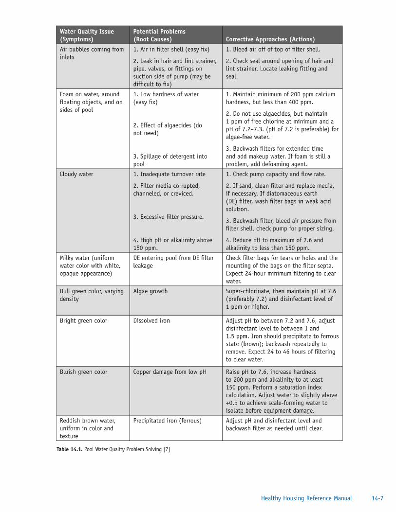
Table 14.1. Pool Water Quality Problem Solving [7]
14-7Healthy Housing Reference Manual
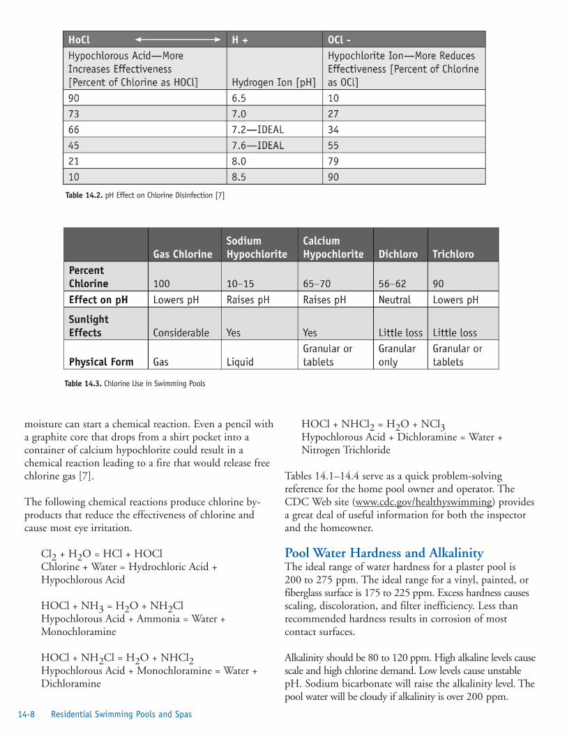
moisture can start a chemical reaction. Even a pencil witha graphite core that drops from a shirt pocket into acontainer of calcium hypochlorite could result in achemical reaction leading to a fire that would release freechlorine gas [7].
The following chemical reactions produce chlorine by-products that reduce the effectiveness of chlorine andcause most eye irritation.
Cl2 + H2O = HCl + HOClChlorine + Water = Hydrochloric Acid +Hypochlorous Acid
HOCl + NH3 = H2O + NH2ClHypochlorous Acid + Ammonia = Water +Monochloramine
HOCl + NH2Cl = H2O + NHCl2Hypochlorous Acid + Monochloramine = Water +Dichloramine
HOCl + NHCl2 = H2O + NCl3Hypochlorous Acid + Dichloramine = Water +Nitrogen Trichloride
Tables 14.1–14.4 serve as a quick problem-solvingreference for the home pool owner and operator. TheCDC Web site (www.cdc.gov/healthyswimming) providesa great deal of useful information for both the inspectorand the homeowner.
Pool Water Hardness and Alkalinity The ideal range of water hardness for a plaster pool is200 to 275 ppm. The ideal range for a vinyl, painted, orfiberglass surface is 175 to 225 ppm. Excess hardness causesscaling, discoloration, and filter inefficiency. Less thanrecommended hardness results in corrosion of mostcontact surfaces.
Alkalinity should be 80 to 120 ppm. High alkaline levels causescale and high chlorine demand. Low levels cause unstablepH. Sodium bicarbonate will raise the alkalinity level. Thepool water will be cloudy if alkalinity is over 200 ppm.
Table 14.2. pH Effect on Chlorine Disinfection [7]
Table 14.3. Chlorine Use in Swimming Pools
14-8 Residential Swimming Pools and Spas

Table 14.4. Swimming Pool Operating Parameters [7]
Liquid Chemical FeedersPositive Displacement PumpA positive displacement pump is preferable to erosiondisinfectant feeders. Positive displacement pumps can beset to administer varied and specific chemical dosage ratesto ensure that a pool does not become contaminated withharmful microorganisms. A positive displacement pumpdoes need routine cleaning, descaling, and servicing.Running a weak muratic acid or vinegar solution throughthe pump weekly can minimize most major servicing of thepump. Most service on the pump involves one of four areas:
1. the check valves are scaled, their springs are weak,or valves are no longer flexible;
2. the diaphragm is cracked, leaking, or not flexible;
3. the drive cam needs replacement or requiresadjustment; or
4. the motor requires replacement.
14-9Healthy Housing Reference Manual

Erosion and Flow-through Disinfectant FeedersThese feeders work by the action of water moving arounda solid cake of chlorine and eroding the cake. The feederswork quite well for smaller pools, but requireconsiderable care and maintenance. The variables thataffect the effectiveness of erosion feeders are
1. solubility of the chlorine cake or tablet;
2. surface area of the cake or tablet;
3. amount of water flowing around the cake ortablet;
4. concentration of chlorine in the cake ortablet; and
5. number of cakes or tablets in the feeder.
Note: For safety reasons, the disinfectant cake must notbe accessible.
Spas and Hot TubsHot tubs (large tubs filled with hot water for one or morepeople) or spas (a tub with aerating or swirling water) areused for pleasure and are increasingly beingrecommended for therapy. The complexity of thesedevices increases with each new model manufactured.Newer models often have both ozone and ultraviolet lightemitters for enhanced disinfection (see Disinfectantssection earlier in this chapter). However, the environmentof the spa and hot tub, if not cleaned and operatedcorrectly, can become a culture medium formicroorganisms. Because the warm water is at the idealtemperature for growth of microorganisms, gooddisinfection is critical. Table 14.5 provides suggested hottub and spa operating parameters. It is essential that allequipment works properly and that the units are cleanedand disinfected on a routine basis. Monitoring the watertemperature is very important and, depending on thehealth of the user, can be a matter of life and death. Timein the heated water should be limited, and thetemperature for pregnant users should be below 103°F(39°C) to protect the unborn baby.
References1. Lee HL, Levy DA, Craun GF, Beach MJ,
Calderon RL. Surveillance for waterborne-diseaseoutbreaks—United States, 1999–2000. MMWR2002; 51(SS08):1–28. Available from URL:http://www.cdc.gov/mmwr/preview/mmwrhtml/ss5108a1.htm.
2. US Environmental Protection Agency.LT1ESWTR Disinfection profiling andbenchmarking: technical guidance manual.Washington, DC: US Environmental ProtectionAgency; 2003. Available from URL:http://www.epa.gov/safewater/mdbp/pdf/profile/lt1profiling.pdf.
3. Centers for Disease Control and Prevention.Healthy swimming. Atlanta: US Department ofHealth and Human Services; no date. Availablefrom URL:http://www.cdc.gov/healthyswimming/.
4. Centers for Disease Control and Prevention. Fecalaccidents response recommendations for aquaticsstaff. Atlanta: US Department of Health andHuman Services; no date. Available from URL:http://www.cdc.gov/healthyswimming/fecalacc.htm.
5. Broadbent C. Guidance on water quality forheated spas. Rundle Mall, South Australia,Australia: Public Environmental Health Service;1996. Available from URL:http://www.dh.sa.gov.au/pehs/publications/monograph-heated-spas.pdf.
6. Michigan State University Pesticide EducationProgram. Swimming pool pest management:category 5A, a training guide for commercialpesticide applicators and swimming pooloperators. Chapter 3: pool disinfectants and pH.East Lansing, MI: Michigan State University; nodate. Available from URL:http://www.pested.msu.edu/BullSlideNews/bulletins/pdf/2621/E2621chap3.pdf.
7. National Swimming Pool Foundation. Certifiedpool-spa operator handbook, 2004. ColoradoSprings, CO: National Swimming PoolFoundation; 2004. Available from URL:http://nspf.org.
Additional Sources of InformationAmerican Academy of Pediatrics. Available from URL:www.aap.org.
American National Standards Institute. Available fromURL: http://www.ansi.org.
American Red Cross. Available from URL:www.redcross.org.
14-10 Residential Swimming Pools and Spas

American Trauma Society. Available from URL:www.amtrauma.org.
Association of Pool and Spa Professionals. Available fromURL: http://www.nspi.org/.
Centers for Disease Control and Prevention, NationalCenter for Injury Prevention and Control. Available fromURL: www.cdc.gov/ncipc/factsheets/drown.htm.
For more information about the CDC fecal accidentrecommendations, go to URL:http://www.cdc.gov/healthyswimming/fecal_response.htm.
For additional information about cryptosporidiosis,go to URL: http://www.cdc.gov/healthyswimming/cryptofacts.htm.
See also Web-based Injury Statistics Query andReporting System (WISQARS) [Online]. (2002).National Center for Injury Prevention and Control,Centers for Disease Control and Prevention. Availablefrom URL: www.cdc.gov/ncipc/wisqars.
Children’s Safety Network. Available from URL:http://www.childrenssafetynetwork.org.
14-11Healthy Housing Reference Manual
Table 14.5. Spa and Hot Tub Operating Parameters [7]
Chlorine Institute, Inc. Available from URL:http://www.cl2.com.
National Safe Kids Campaign. Available from URL:http://www.safekids.org.
National Safety Council. Available from URL:http://www.nsc.org/.
National Swimming Pool Foundation. Available fromURL: http://www.nspf.com/.
Think First National Injury Foundation. Available fromURL: http://www.thinkfirst.org.
US Consumer Product Safety Commission. Availablefrom URL: http://www.cpsc.gov.
14-12 Residential Swimming Pools and Spas