Head Pressure Control Kit - Trane Technologies
16
SAFETY WARNING Only qualified personnel should install and service the equipment. The installation, starting up, and servicing of heating, ventilating, and air-conditioning equipment can be hazardous and requires specific knowledge and training. Improperly installed, adjusted or altered equipment by an unqualified person could result in death or serious injury. When working on the equipment, observe all precautions in the literature and on the tags, stickers, and labels that are attached to the equipment. April 2020 ACC-SVN136H-EN Installation Guide Head Pressure Control Kit Odyssey Split System Cooling and Heat Pumps, 6 to 25 Tons BAYLOAM335: TTA07243A, TTA09043A, TWA07243A/D, TWA09043A/D BAYLOAM336: TTA12043A/C/D, TTA15043D, TTA18043C/D, TTA24043C/D, TTA30043C, TWA12043A/D, TWA18043D, TWA24043D BAYLOAM435: TTA0604DA, TTA07244A, TTA0764DA, TTA09044A, TWA0604DA/D, TWA07244A/D, TWA0764DA/D, TWA09044A/D BAYLOAM436: TTA1014DA/C/D, TTA12044A/C/D, TTA1264DD, TTA15044D, TTA1564DC/D, TTA18044C/D, TTA2014DC/D, TTA24044C/D, TTA2514DC, TTA30044C, TWA1014DA/D, TWA12044A/D, TWA1564DD, TWA18044D,TWA2014DD, TWA24044D BAYLOAMW36: TTA1204WA/C/D, TTA1504WD, TTA1804WC/D, TTA2404WC/D, TTA3004WC, TWA1204WA/D, TWA1804WD, TWA2404WD 380-600 120-277 LINE 2 10 AMP MAX FULL SPEED VARIABLE SPEED BALL BEARING RANGE BALL BEARING RANGE MIN MAX MAX SLEEVE BEARNG DEFAULT SLEEVE BEARNG RANGE MOTOR 2 VAC P/N ICM333-AS3201 MADE IN THE USA LINE 1 / MOTOR 1 USE ONE TERMINAL ONLY SETPOINT Pb-Free, HF, E1/E2, SR N.C. HEAT PUMP VAC CONTROLS
-
Upload
khangminh22 -
Category
Documents
-
view
0 -
download
0
Transcript of Head Pressure Control Kit - Trane Technologies

SSAAFFEETTYY WWAARRNNIINNGGOnly qualified personnel should install and service the equipment. The installation, starting up, and servicing of heating, ventilating, and air-conditioningequipment can be hazardous and requires specific knowledge and training. Improperly installed, adjusted or altered equipment by an unqualified personcould result in death or serious injury. When working on the equipment, observe all precautions in the literature and on the tags, stickers, and labels thatare attached to the equipment.
April 2020 AACCCC--SSVVNN113366HH--EENN
Installation GuideHead Pressure Control KitOdyssey Split System Cooling and HeatPumps, 6 to 25 Tons
BBAAYYLLOOAAMM333355: TTA07243A,TTA09043A, TWA07243A/D,TWA09043A/DBBAAYYLLOOAAMM333366: TTA12043A/C/D,TTA15043D, TTA18043C/D,TTA24043C/D, TTA30043C,TWA12043A/D, TWA18043D,TWA24043DBBAAYYLLOOAAMM443355: TTA0604DA,TTA07244A, TTA0764DA,TTA09044A, TWA0604DA/D,TWA07244A/D, TWA0764DA/D,TWA09044A/DBBAAYYLLOOAAMM443366: TTA1014DA/C/D,TTA12044A/C/D, TTA1264DD,TTA15044D, TTA1564DC/D,TTA18044C/D, TTA2014DC/D,TTA24044C/D, TTA2514DC,TTA30044C, TWA1014DA/D,TWA12044A/D, TWA1564DD,TWA18044D,TWA2014DD,TWA24044DBBAAYYLLOOAAMMWW3366: TTA1204WA/C/D,TTA1504WD, TTA1804WC/D,TTA2404WC/D, TTA3004WC,TWA1204WA/D, TWA1804WD,TWA2404WD
380-600 120-277
LINE 2 10 AMPMAX
FULLSPEED
VARIABLESPEED
BALLBEARINGRANGE
BALLBEARINGRANGE
MIN
MAX
MAXSLEEVEBEARNGDEFAULT
SLEEVEBEARNGRANGE
MOTOR 2
VAC
P/N ICM333-AS3201MADE IN THE USA
LINE 1 / MOTOR 1USE ONE TERMINAL ONLY
SETPOINT
Pb-Free, HF, E1/E2, SR
N.C. HEAT PUMP
VAC
C O N T R O L S
©2020 ACC-SVN136H-EN
IntroductionRead this manual thoroughly before operating orservicing this unit.
Warnings, Cautions, and NoticesSafety advisories appear throughout this manual asrequired. Your personal safety and the properoperation of this machine depend upon the strictobservance of these precautions.
The three types of advisories are defined as follows:
WARNINGIndicates a potentially hazardous situationwhich, if not avoided, could result in death orserious injury.
CAUTIONIndicates a potentially hazardous situationwhich, if not avoided, could result in minor ormoderate injury. It could also be used to alertagainst unsafe practices.
NOTICEIndicates a situation that could result inequipment or property-damage onlyaccidents.
Important Environmental ConcernsScientific research has shown that certain man-madechemicals can affect the earth’s naturally occurringstratospheric ozone layer when released to theatmosphere. In particular, several of the identifiedchemicals that may affect the ozone layer arerefrigerants that contain Chlorine, Fluorine and Carbon(CFCs) and those containing Hydrogen, Chlorine,Fluorine and Carbon (HCFCs). Not all refrigerantscontaining these compounds have the same potentialimpact to the environment. Trane advocates theresponsible handling of all refrigerants-includingindustry replacements for CFCs and HCFCs such assaturated or unsaturated HFCs and HCFCs.
Important Responsible RefrigerantPracticesTrane believes that responsible refrigerant practicesare important to the environment, our customers, andthe air conditioning industry. All technicians whohandle refrigerants must be certified according to localrules. For the USA, the Federal Clean Air Act (Section608) sets forth the requirements for handling,reclaiming, recovering and recycling of certainrefrigerants and the equipment that is used in theseservice procedures. In addition, some states ormunicipalities may have additional requirements thatmust also be adhered to for responsible managementof refrigerants. Know the applicable laws and followthem.
WWAARRNNIINNGGPPrrooppeerr FFiieelldd WWiirriinngg aanndd GGrroouunnddiinnggRReeqquuiirreedd!!FFaaiilluurree ttoo ffoollllooww ccooddee ccoouulldd rreessuulltt iinn ddeeaatthh oorrsseerriioouuss iinnjjuurryy..AAllll ffiieelldd wwiirriinngg MMUUSSTT bbee ppeerrffoorrmmeedd bbyy qquuaalliiffiieeddppeerrssoonnnneell.. IImmpprrooppeerrllyy iinnssttaalllleedd aanndd ggrroouunnddeeddffiieelldd wwiirriinngg ppoosseess FFIIRREE aanndd EELLEECCTTRROOCCUUTTIIOONNhhaazzaarrddss.. TToo aavvooiidd tthheessee hhaazzaarrddss,, yyoouu MMUUSSTT ffoolllloowwrreeqquuiirreemmeennttss ffoorr ffiieelldd wwiirriinngg iinnssttaallllaattiioonn aannddggrroouunnddiinngg aass ddeessccrriibbeedd iinn NNEECC aanndd yyoouurr llooccaall//ssttaattee//nnaattiioonnaall eelleeccttrriiccaall ccooddeess..
WWAARRNNIINNGGPPeerrssoonnaall PPrrootteeccttiivvee EEqquuiippmmeenntt ((PPPPEE))RReeqquuiirreedd!!FFaaiilluurree ttoo wweeaarr pprrooppeerr PPPPEE ffoorr tthhee jjoobb bbeeiinngguunnddeerrttaakkeenn ccoouulldd rreessuulltt iinn ddeeaatthh oorr sseerriioouuss iinnjjuurryy..TTeecchhnniicciiaannss,, iinn oorrddeerr ttoo pprrootteecctt tthheemmsseellvveess ffrroommppootteennttiiaall eelleeccttrriiccaall,, mmeecchhaanniiccaall,, aanndd cchheemmiiccaallhhaazzaarrddss,, MMUUSSTT ffoollllooww pprreeccaauuttiioonnss iinn tthhiiss mmaannuuaallaanndd oonn tthhee ttaaggss,, ssttiicckkeerrss,, aanndd llaabbeellss,, aass wweellll aass tthheeiinnssttrruuccttiioonnss bbeellooww::
•• BBeeffoorree iinnssttaalllliinngg//sseerrvviicciinngg tthhiiss uunniitt,,tteecchhnniicciiaannss MMUUSSTT ppuutt oonn aallll PPPPEE rreeqquuiirreedd ffoorrtthhee wwoorrkk bbeeiinngg uunnddeerrttaakkeenn ((EExxaammpplleess;; ccuuttrreessiissttaanntt gglloovveess//sslleeeevveess,, bbuuttyyll gglloovveess,, ssaaffeettyyggllaasssseess,, hhaarrdd hhaatt//bbuummpp ccaapp,, ffaallll pprrootteeccttiioonn,,eelleeccttrriiccaall PPPPEE aanndd aarrcc ffllaasshh ccllootthhiinngg))..AALLWWAAYYSS rreeffeerr ttoo aapppprroopprriiaattee SSaaffeettyy DDaattaaSShheeeettss ((SSDDSS)) aanndd OOSSHHAA gguuiiddeelliinneess ffoorrpprrooppeerr PPPPEE..
•• WWhheenn wwoorrkkiinngg wwiitthh oorr aarroouunndd hhaazzaarrddoouusscchheemmiiccaallss,, AALLWWAAYYSS rreeffeerr ttoo tthhee aapppprroopprriiaatteeSSDDSS aanndd OOSSHHAA//GGHHSS ((GGlloobbaall HHaarrmmoonniizzeeddSSyysstteemm ooff CCllaassssiiffiiccaattiioonn aanndd LLaabbeelllliinngg ooffCChheemmiiccaallss)) gguuiiddeelliinneess ffoorr iinnffoorrmmaattiioonn oonnaalllloowwaabbllee ppeerrssoonnaall eexxppoossuurree lleevveellss,, pprrooppeerrrreessppiirraattoorryy pprrootteeccttiioonn aanndd hhaannddlliinnggiinnssttrruuccttiioonnss..
•• IIff tthheerree iiss aa rriisskk ooff eenneerrggiizzeedd eelleeccttrriiccaallccoonnttaacctt,, aarrcc,, oorr ffllaasshh,, tteecchhnniicciiaannss MMUUSSTT ppuuttoonn aallll PPPPEE iinn aaccccoorrddaannccee wwiitthh OOSSHHAA,, NNFFPPAA7700EE,, oorr ootthheerr ccoouunnttrryy--ssppeecciiffiicc rreeqquuiirreemmeennttssffoorr aarrcc ffllaasshh pprrootteeccttiioonn,, PPRRIIOORR ttoo sseerrvviicciinnggtthhee uunniitt.. NNEEVVEERR PPEERRFFOORRMM AANNYY SSWWIITTCCHHIINNGG,,DDIISSCCOONNNNEECCTTIINNGG,, OORR VVOOLLTTAAGGEE TTEESSTTIINNGGWWIITTHHOOUUTT PPRROOPPEERR EELLEECCTTRRIICCAALL PPPPEE AANNDDAARRCC FFLLAASSHH CCLLOOTTHHIINNGG.. EENNSSUURREEEELLEECCTTRRIICCAALL MMEETTEERRSS AANNDD EEQQUUIIPPMMEENNTT AARREEPPRROOPPEERRLLYY RRAATTEEDD FFOORR IINNTTEENNDDEEDDVVOOLLTTAAGGEE..
ACC-SVN136H-EN 3
WWAARRNNIINNGGFFoollllooww EEHHSS PPoolliicciieess!!FFaaiilluurree ttoo ffoollllooww iinnssttrruuccttiioonnss bbeellooww ccoouulldd rreessuulltt iinnddeeaatthh oorr sseerriioouuss iinnjjuurryy..
•• AAllll TTrraannee ppeerrssoonnnneell mmuusstt ffoollllooww tthheeccoommppaannyy’’ss EEnnvviirroonnmmeennttaall,, HHeeaalltthh aanndd SSaaffeettyy((EEHHSS)) ppoolliicciieess wwhheenn ppeerrffoorrmmiinngg wwoorrkk ssuucchh aasshhoott wwoorrkk,, eelleeccttrriiccaall,, ffaallll pprrootteeccttiioonn,, lloocckkoouutt//ttaaggoouutt,, rreeffrriiggeerraanntt hhaannddlliinngg,, eettcc.. WWhheerree llooccaallrreegguullaattiioonnss aarree mmoorree ssttrriinnggeenntt tthhaann tthheesseeppoolliicciieess,, tthhoossee rreegguullaattiioonnss ssuuppeerrsseeddee tthheesseeppoolliicciieess..
•• NNoonn--TTrraannee ppeerrssoonnnneell sshhoouulldd aallwwaayyss ffoolllloowwllooccaall rreegguullaattiioonnss..
CopyrightThis document and the information in it are theproperty of Trane, and may not be used or reproducedin whole or in part without written permission. Tranereserves the right to revise this publication at any time,and to make changes to its content without obligationto notify any person of such revision or change.
TrademarksAll trademarks referenced in this document are thetrademarks of their respective owners.
IInnttrroodduuccttiioonn

4 ACC-SVN136H-EN
Pre-Installation . . . . . . . . . . . . . . . . . . . . . . . . . . . . . 5General Information . . . . . . . . . . . . . . . . . . . . . . 5
Parts List. . . . . . . . . . . . . . . . . . . . . . . . . . . . . . . . . 6
Installation . . . . . . . . . . . . . . . . . . . . . . . . . . . . . . . . . 7Controller . . . . . . . . . . . . . . . . . . . . . . . . . . . . . . . . 7
Transducer and Tee. . . . . . . . . . . . . . . . . . . . . . . 8
Motor. . . . . . . . . . . . . . . . . . . . . . . . . . . . . . . . . . . . 8
Wiring . . . . . . . . . . . . . . . . . . . . . . . . . . . . . . . . . . . 9ReliaTel Evaporator Defrost ControlFunction Disable (EDC) . . . . . . . . . . . . . . . . 9Control Box Wiring. . . . . . . . . . . . . . . . . . . . 9Controller Settings . . . . . . . . . . . . . . . . . . . 10
Operation & Troubleshooting . . . . . . . . . . . . . 14Checkout Procedure . . . . . . . . . . . . . . . . . . . . . 14
Table of Contents

ACC-SVN136H-EN 5
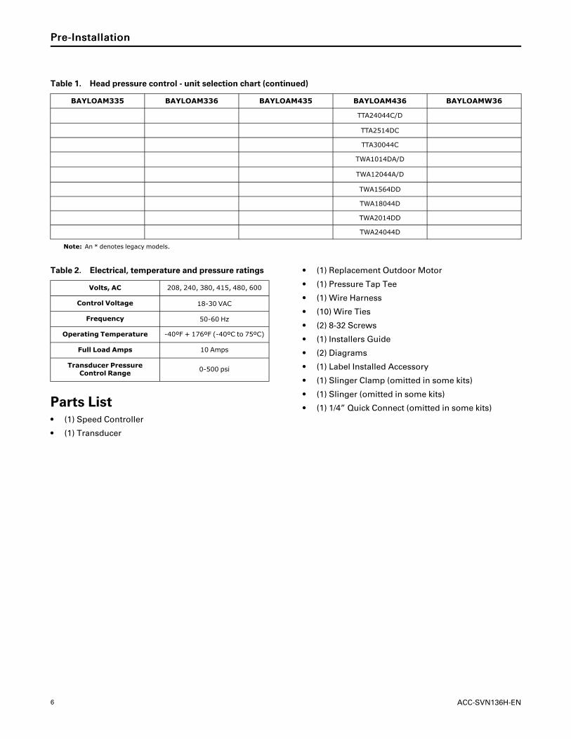
Pre-InstallationGeneral InformationSee Table 1, p. 5 for match-up of Head PressureControl with unit model and voltage. Then refer to thecorresponding instructions.
Table 1. Head pressure control - unit selection chart
BAYLOAM335 BAYLOAM336 BAYLOAM435 BAYLOAM436 BAYLOAMW36
TTA073D3* TTA120D3/E3/F3* TTA061DD* TTA101DD*/ED*/FD* TTA120DW*/EW*/FW*
TTA073G3* TTA120G3/H3/J3* TTA061GD* TTA101GD*/HD*/JD* TTA120GW*/HW*/JW*
TTA090D3* TTA150E3* TTA073D4* TTA120D4*/E4*/F4* TTA150EW*
TTA090G3* TTA150H3* TTA073G4* TTA120G4*/H4*/J4* TTA150HW*
TTA180J3* TTA180E3/F3* TTA076DD* TTA126ED* TTA180EW*/FW*
TWA073D3*/E3* TTA180H3* TTA076GD* TTA126HD* TTA180HW*
TWA090D3*/E3* TTA240E3*/F3* TTA090D4* TTA150E4* TTA240EW*/FW*
TTA07243A TTA240H3*/J3* TTA090G4* TTA150H4* TTA240HW*/JW*
TTA09043A TTA300F3* TTA180J4* TTA156ED*/FD* TTA300FW*
TWA07243A/D TTA300J3* TWA061DD*/ED* TTA156HD*/JD* TTA300JW*
TWA09043A/D TWA120D3*/E3* TWA073D4*/E4* TTA180E4*/F4* TWA120DW*/EW*
TWA180E3* TWA076DD*/ED* TTA180H4* TWA180EW*
TWA240E3* TWA090D4*/E4* TTA201ED*/FD* TWA240EW*
TTA12043A/C/D TTA0604DA TTA201HD*/JD* TTA1204WA/C/D
TTA15043D TTA07244A TTA240E4*/F4* TTA1504WD
TTA18043C/D TTA0764DA TTA240H4*/J4* TTA1804WC/D
TTA24043C/D TTA09044A TTA251FD* TTA2404WC/D
TTA30043C TWA0604DA/D TTA300F4* TTA3004WC
TWA12043A/D TWA07244A/D TTA251JD* TWA1204WA/D
TWA18043D TWA0764DA/D TTA300J4* TWA1804WD
TWA24043D TWA09044A/D TWA101DD*/ED* TWA2404WD
TWA120D4*/E4*
TWA156ED*
TWA180E4*
TWA201ED*
TWA240E4*
TTA1014DA/C/D
TTA12044A/C/D
TTA1264DD
TTA15044D
TTA1564DC/D
TTA18044C/D
TTA2014DC/D
6 ACC-SVN136H-EN
Table 1. Head pressure control - unit selection chart (continued)
BAYLOAM335 BAYLOAM336 BAYLOAM435 BAYLOAM436 BAYLOAMW36
TTA24044C/D
TTA2514DC
TTA30044C
TWA1014DA/D
TWA12044A/D
TWA1564DD
TWA18044D
TWA2014DD
TWA24044D
Note: An * denotes legacy models.
Table 2. Electrical, temperature and pressure ratings
Volts, AC 208, 240, 380, 415, 480, 600
Control Voltage 18-30 VAC
Frequency 50-60 Hz
Operating Temperature -40ºF + 176ºF (-40ºC to 75ºC)
Full Load Amps 10 Amps
Transducer PressureControl Range 0-500 psi
Parts List• (1) Speed Controller
• (1) Transducer
• (1) Replacement Outdoor Motor
• (1) Pressure Tap Tee
• (1) Wire Harness
• (10) Wire Ties
• (2) 8-32 Screws
• (1) Installers Guide
• (2) Diagrams
• (1) Label Installed Accessory
• (1) Slinger Clamp (omitted in some kits)
• (1) Slinger (omitted in some kits)
• (1) 1/4” Quick Connect (omitted in some kits)
PPrree--IInnssttaallllaattiioonn
ACC-SVN136H-EN 7
InstallationController
WWAARRNNIINNGGHHaazzaarrddoouuss VVoollttaaggee ww//CCaappaacciittoorrss!!FFaaiilluurree ttoo ddiissccoonnnneecctt ppoowweerr aanndd ddiisscchhaarrggeeccaappaacciittoorrss bbeeffoorree sseerrvviicciinngg ccoouulldd rreessuulltt iinn ddeeaatthh oorrsseerriioouuss iinnjjuurryy..DDiissccoonnnneecctt aallll eelleeccttrriicc ppoowweerr,, iinncclluuddiinngg rreemmootteeddiissccoonnnneeccttss aanndd ddiisscchhaarrggee aallll mmoottoorr ssttaarrtt//rruunnccaappaacciittoorrss bbeeffoorree sseerrvviicciinngg.. FFoollllooww pprrooppeerrlloocckkoouutt//ttaaggoouutt pprroocceedduurreess ttoo eennssuurree tthhee ppoowweerrccaannnnoott bbee iinnaaddvveerrtteennttllyy eenneerrggiizzeedd.. FFoorr vvaarriiaabblleeffrreeqquueennccyy ddrriivveess oorr ootthheerr eenneerrggyy ssttoorriinnggccoommppoonneennttss pprroovviiddeedd bbyy TTrraannee oorr ootthheerrss,, rreeffeerr ttootthhee aapppprroopprriiaattee mmaannuuffaaccttuurreerr’’ss lliitteerraattuurree ffoorraalllloowwaabbllee wwaaiittiinngg ppeerriiooddss ffoorr ddiisscchhaarrggee ooffccaappaacciittoorrss.. VVeerriiffyy wwiitthh aa CCAATT IIIIII oorr IIVV vvoollttmmeetteerrrraatteedd ppeerr NNFFPPAA 7700EE tthhaatt aallll ccaappaacciittoorrss hhaavveeddiisscchhaarrggeedd..FFoorr aaddddiittiioonnaall iinnffoorrmmaattiioonn rreeggaarrddiinngg tthhee ssaaffeeddiisscchhaarrggee ooff ccaappaacciittoorrss,, sseeee PPRROODD--SSVVBB0066**--EENN..
WWAARRNNIINNGGPPrrooppeerr FFiieelldd WWiirriinngg aanndd GGrroouunnddiinnggRReeqquuiirreedd!!FFaaiilluurree ttoo ffoollllooww ccooddee ccoouulldd rreessuulltt iinn ddeeaatthh oorrsseerriioouuss iinnjjuurryy..AAllll ffiieelldd wwiirriinngg MMUUSSTT bbee ppeerrffoorrmmeedd bbyy qquuaalliiffiieeddppeerrssoonnnneell.. IImmpprrooppeerrllyy iinnssttaalllleedd aanndd ggrroouunnddeeddffiieelldd wwiirriinngg ppoosseess FFIIRREE aanndd EELLEECCTTRROOCCUUTTIIOONNhhaazzaarrddss.. TToo aavvooiidd tthheessee hhaazzaarrddss,, yyoouu MMUUSSTT ffoolllloowwrreeqquuiirreemmeennttss ffoorr ffiieelldd wwiirriinngg iinnssttaallllaattiioonn aannddggrroouunnddiinngg aass ddeessccrriibbeedd iinn NNEECC aanndd yyoouurr llooccaall//ssttaattee//nnaattiioonnaall eelleeccttrriiccaall ccooddeess..
1. Prepare the unit for installation.
a. Disconnect all power from the unit.
b. Remove the compressor and control box accesspanel(s).
c. Ensure that the capacitor has discharged storedvoltage.
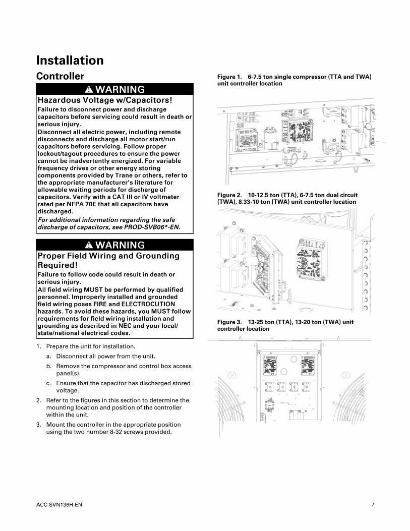
2. Refer to the figures in this section to determine themounting location and position of the controllerwithin the unit.
3. Mount the controller in the appropriate positionusing the two number 8-32 screws provided.
Figure 1. 6-7.5 ton single compressor (TTA and TWA)unit controller location
Figure 2. 10-12.5 ton (TTA), 6-7.5 ton dual circuit(TWA), 8.33-10 ton (TWA) unit controller location
Figure 3. 13-25 ton (TTA), 13-20 ton (TWA) unitcontroller location
8 ACC-SVN136H-EN
Transducer and TeeWWAARRNNIINNGG
RR--441100AA RReeffrriiggeerraanntt uunnddeerr HHiigghheerrPPrreessssuurree tthhaann RR--2222!!FFaaiilluurree ttoo uussee pprrooppeerr eeqquuiippmmeenntt oorr ccoommppoonneennttss aassddeessccrriibbeedd bbeellooww,, ccoouulldd rreessuulltt iinn eeqquuiippmmeenntt ffaaiilliinnggaanndd ppoossssiibbllyy eexxppllooddiinngg,, wwhhiicchh ccoouulldd rreessuulltt iinnddeeaatthh,, sseerriioouuss iinnjjuurryy,, oorr eeqquuiippmmeenntt ddaammaaggee..TThhee uunniittss ddeessccrriibbeedd iinn tthhiiss mmaannuuaall uussee RR--441100AArreeffrriiggeerraanntt wwhhiicchh ooppeerraatteess aatt hhiigghheerr pprreessssuurreesstthhaann RR--2222.. UUssee OONNLLYY RR--441100AA rraatteedd sseerrvviicceeeeqquuiippmmeenntt oorr ccoommppoonneennttss wwiitthh tthheessee uunniittss.. FFoorrssppeecciiffiicc hhaannddlliinngg ccoonncceerrnnss wwiitthh RR--441100AA,, pplleeaasseeccoonnttaacctt yyoouurr llooccaall TTrraannee rreepprreesseennttaattiivvee..
NNOOTTIICCEEWWiirree DDaammaaggee!!FFaaiilluurree ttoo ffoollllooww iinnssttrruuccttiioonnss bbeellooww ccoouulldd rreessuulltt iinnddaammaaggeedd wwiirreess..UUssee pprroovviiddeedd wwiirree ttiieess ttoo mmaakkee ssuurree wwiirree aarreesseeccuurreedd aanndd pprrootteecctteedd ffrroomm sshhaarrpp eeddggeess aanndd hhoottssuurrffaacceess..
1. Remove cap nut from the unit's high pressureservice port on the discharge line that runs from thecompressor.
Figure 4. High pressure service port
High pressure service port
2. Install the transducer onto the Tee port without thevalve core.
Figure 5. Transducer to tee
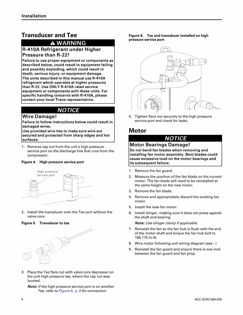
3. Place the Tee flare nut with valve core depressor onthe unit high pressure tap, where the cap nut waslocated.
NNoottee:: If the high pressure service port is on anotherTee, refer to Figure 6, p. 8 for connection.
Figure 6. Tee and transducer installed on highpressure service port
4. Tighten flare nut securely to the high pressureservice port and check for leaks.
MotorNNOOTTIICCEE
MMoottoorr BBeeaarriinnggss DDaammaaggee!!DDoo nnoott bbeenndd ffaann bbllaaddeess wwhheenn rreemmoovviinngg aannddiinnssttaalllliinngg ffaann mmoottoorr aasssseemmbbllyy.. BBeenntt bbllaaddeess ccoouullddccaauussee eexxcceessssiivvee llooaadd oonn tthhee mmoottoorr bbeeaarriinnggss aannddiittss ssuubbsseeqquueenntt ffaaiilluurree..
1. Remove the fan guard.
2. Measure the position of the fan blade on the currentmotor. The fan blade will need to be reinstalled atthe same height on the new motor.
3. Remove the fan blade.
4. Remove and appropriately discard the existing fanmotor.
5. Install the new fan motor.
6. Install slinger, making sure it does not press againstthe shaft end bearing.
NNoottee:: Use slinger clamp if applicable.
7. Reinstall the fan so the fan hub is flush with the endof the motor shaft and torque the fan hub bolt to165-175 in-lb.
8. Wire motor following unit wiring diagram (see - )
9. Reinstall the fan guard and ensure there is one inchbetween the fan guard and fan prop.
IInnssttaallllaattiioonn
ACC-SVN136H-EN 9
WiringNNOOTTIICCEE
WWiirree DDaammaaggee!!FFaaiilluurree ttoo ffoollllooww iinnssttrruuccttiioonnss bbeellooww ccoouulldd rreessuulltt iinnddaammaaggeedd wwiirreess..UUssee pprroovviiddeedd wwiirree ttiieess ttoo mmaakkee ssuurree wwiirree aarreesseeccuurreedd aanndd pprrootteecctteedd ffrroomm sshhaarrpp eeddggeess aanndd hhoottssuurrffaacceess..
ReliaTel Evaporator Defrost ControlFunction Disable (EDC)1. Disable ReliaTel™ on-board low ambient function.
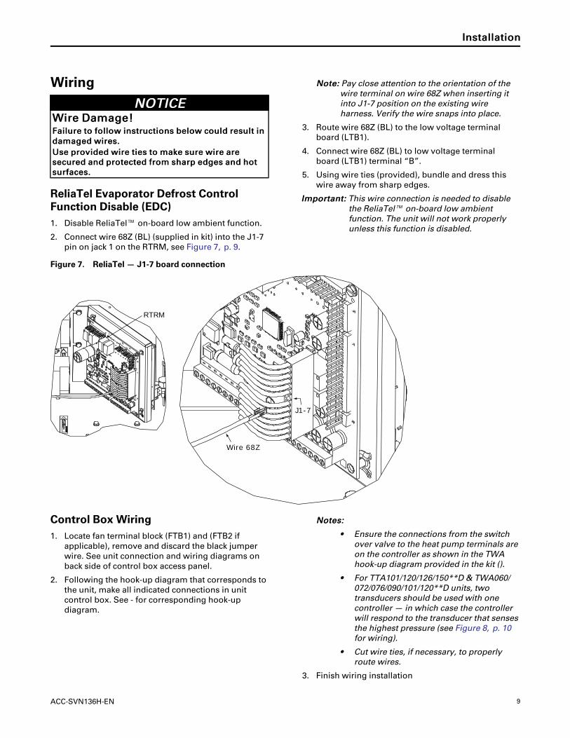
2. Connect wire 68Z (BL) (supplied in kit) into the J1-7pin on jack 1 on the RTRM, see Figure 7, p. 9.
NNoottee:: Pay close attention to the orientation of thewire terminal on wire 68Z when inserting itinto J1-7 position on the existing wireharness. Verify the wire snaps into place.
3. Route wire 68Z (BL) to the low voltage terminalboard (LTB1).
4. Connect wire 68Z (BL) to low voltage terminalboard (LTB1) terminal “B”.
5. Using wire ties (provided), bundle and dress thiswire away from sharp edges.
IImmppoorrttaanntt:: This wire connection is needed to disablethe ReliaTel™ on-board low ambientfunction. The unit will not work properlyunless this function is disabled.
Figure 7. ReliaTel — J1-7 board connection
J1-7
RTRM
Wire 68Z
Control Box Wiring1. Locate fan terminal block (FTB1) and (FTB2 if
applicable), remove and discard the black jumperwire. See unit connection and wiring diagrams onback side of control box access panel.
2. Following the hook-up diagram that corresponds tothe unit, make all indicated connections in unitcontrol box. See - for corresponding hook-updiagram.
NNootteess::
• Ensure the connections from the switchover valve to the heat pump terminals areon the controller as shown in the TWAhook-up diagram provided in the kit ().
• For TTA101/120/126/150**D & TWA060/072/076/090/101/120**D units, twotransducers should be used with onecontroller — in which case the controllerwill respond to the transducer that sensesthe highest pressure (see Figure 8, p. 10for wiring).
• Cut wire ties, if necessary, to properlyroute wires.
3. Finish wiring installation
IInnssttaallllaattiioonn
10 ACC-SVN136H-EN
a. Using wire ties, bundle and dress any excesswires away from sharp edges, moving parts, orhot tubes.
b. Apply the correct hook-up diagram (supplied inkit) which corresponds to the unit to an openarea on the back side of the control box accesspanel for future reference. See - forcorresponding diagrams.
c. After the settings have been properly adjusted(see “Controller Settings,” p. 10), reinstall thecompressor and control box access panels andsecure with screws that were removed.
d. Re-connect all power to the unit. Refer totroubleshooting guide, if needed.
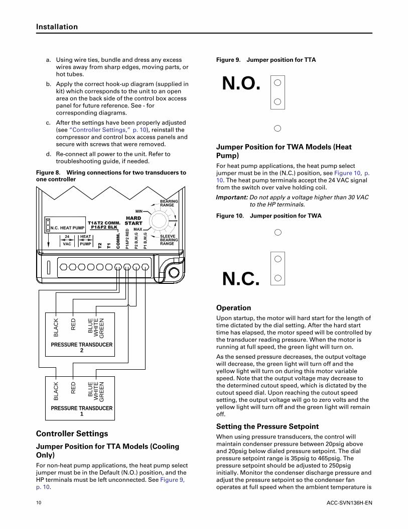
Figure 8. Wiring connections for two transducers toone controller
BLUE
WHITE
GREEN
RED
BLACK
PRESSURE TRANSDUCER2
BLUE
WHITE
GREEN
RED
BLACK
PRESSURE TRANSDUCER1
Controller Settings
Jumper Position for TTA Models (CoolingOnly)For non-heat pump applications, the heat pump selectjumper must be in the Default (N.O.) position, and theHP terminals must be left unconnected. See Figure 9,p. 10.
Figure 9. Jumper position for TTA
N.O.
Jumper Position for TWA Models (HeatPump)For heat pump applications, the heat pump selectjumper must be in the (N.C.) position, see Figure 10, p.10. The heat pump terminals accept the 24 VAC signalfrom the switch over valve holding coil.
IImmppoorrttaanntt:: Do not apply a voltage higher than 30 VACto the HP terminals.
Figure 10. Jumper position for TWA
N.C.OperationUpon startup, the motor will hard start for the length oftime dictated by the dial setting. After the hard starttime has elapsed, the motor speed will be controlled bythe transducer reading pressure. When the motor isrunning at full speed, the green light will turn on.
As the sensed pressure decreases, the output voltagewill decrease, the green light will turn off and theyellow light will turn on during this motor variablespeed. Note that the output voltage may decrease tothe determined cutout speed, which is dictated by thecutout speed dial. Upon reaching the cutout speedsetting, the output voltage will go to zero volts and theyellow light will turn off and the green light will remainoff.
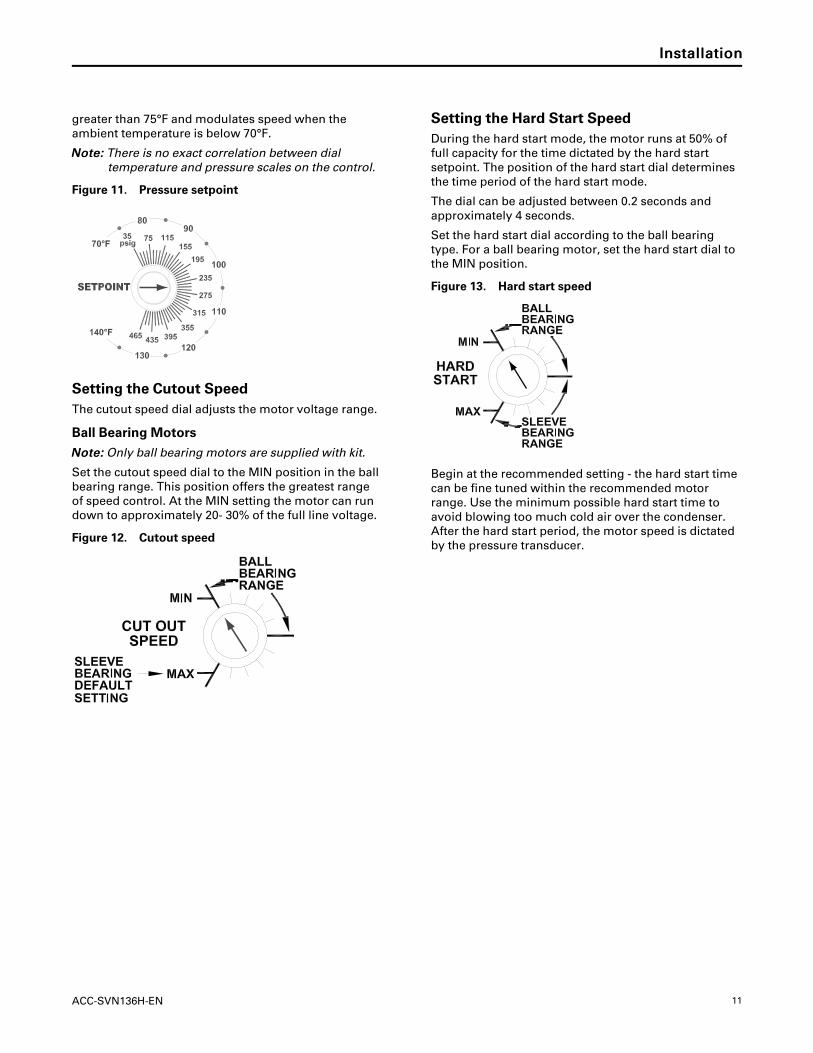
Setting the Pressure SetpointWhen using pressure transducers, the control willmaintain condenser pressure between 20psig aboveand 20psig below dialed pressure setpoint. The dialpressure setpoint range is 35psig to 465psig. Thepressure setpoint should be adjusted to 250psiginitially. Monitor the condenser discharge pressure andadjust the pressure setpoint so the condenser fanoperates at full speed when the ambient temperature is
IInnssttaallllaattiioonn
ACC-SVN136H-EN 11
greater than 75°F and modulates speed when theambient temperature is below 70°F.
NNoottee:: There is no exact correlation between dialtemperature and pressure scales on the control.
Figure 11. Pressure setpoint
Setting the Cutout SpeedThe cutout speed dial adjusts the motor voltage range.
Ball Bearing MotorsNNoottee:: Only ball bearing motors are supplied with kit.
Set the cutout speed dial to the MIN position in the ballbearing range. This position offers the greatest rangeof speed control. At the MIN setting the motor can rundown to approximately 20- 30% of the full line voltage.
Figure 12. Cutout speed
Setting the Hard Start SpeedDuring the hard start mode, the motor runs at 50% offull capacity for the time dictated by the hard startsetpoint. The position of the hard start dial determinesthe time period of the hard start mode.
The dial can be adjusted between 0.2 seconds andapproximately 4 seconds.
Set the hard start dial according to the ball bearingtype. For a ball bearing motor, set the hard start dial tothe MIN position.
Figure 13. Hard start speed
Begin at the recommended setting - the hard start timecan be fine tuned within the recommended motorrange. Use the minimum possible hard start time toavoid blowing too much cold air over the condenser.After the hard start period, the motor speed is dictatedby the pressure transducer.
IInnssttaallllaattiioonn
12 ACC-SVN136H-EN
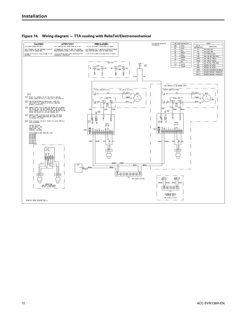
Figure 14. Wiring diagram— TTA cooling with ReliaTel/Electromechanical
IInnssttaallllaattiioonn
ACC-SVN136H-EN 13
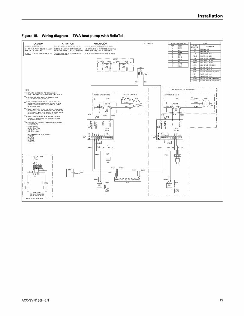
Figure 15. Wiring diagram—TWA heat pump with ReliaTel
IInnssttaallllaattiioonn
14 ACC-SVN136H-EN
Operation & TroubleshootingCheckout Procedure
WWAARRNNIINNGGHHaazzaarrddoouuss SSeerrvviiccee PPrroocceedduurreess!!FFaaiilluurree ttoo ffoollllooww aallll pprreeccaauuttiioonnss iinn tthhiiss mmaannuuaall aannddoonn tthhee ttaaggss,, ssttiicckkeerrss,, aanndd llaabbeellss ccoouulldd rreessuulltt iinnddeeaatthh oorr sseerriioouuss iinnjjuurryy..TTeecchhnniicciiaannss,, iinn oorrddeerr ttoo pprrootteecctt tthheemmsseellvveess ffrroommppootteennttiiaall eelleeccttrriiccaall,, mmeecchhaanniiccaall,, aanndd cchheemmiiccaallhhaazzaarrddss,, MMUUSSTT ffoollllooww pprreeccaauuttiioonnss iinn tthhiiss mmaannuuaallaanndd oonn tthhee ttaaggss,, ssttiicckkeerrss,, aanndd llaabbeellss,, aass wweellll aass tthheeffoolllloowwiinngg iinnssttrruuccttiioonnss:: UUnnlleessss ssppeecciiffiieedd ootthheerrwwiissee,,ddiissccoonnnneecctt aallll eelleeccttrriiccaall ppoowweerr iinncclluuddiinngg rreemmootteeddiissccoonnnneecctt aanndd ddiisscchhaarrggee aallll eenneerrggyy ssttoorriinnggddeevviicceess ssuucchh aass ccaappaacciittoorrss bbeeffoorree sseerrvviicciinngg..FFoollllooww pprrooppeerr lloocckkoouutt//ttaaggoouutt pprroocceedduurreess ttooeennssuurree tthhee ppoowweerr ccaann nnoott bbee iinnaaddvveerrtteennttllyyeenneerrggiizzeedd.. WWhheenn nneecceessssaarryy ttoo wwoorrkk wwiitthh lliivveeeelleeccttrriiccaall ccoommppoonneennttss,, hhaavvee aa qquuaalliiffiieedd lliicceennsseeddeelleeccttrriicciiaann oorr ootthheerr iinnddiivviidduuaall wwhhoo hhaass bbeeeennttrraaiinneedd iinn hhaannddlliinngg lliivvee eelleeccttrriiccaall ccoommppoonneennttssppeerrffoorrmm tthheessee ttaasskkss..
Before leaving the installation, observe for correctoperation through the desired pressure range (seeTable 4, p. 15).
Table 3. Troubleshooting guide
Problem Possible Cause Possible Solution
No fan operation
No 24 volt control voltage Check for 24 VAC at control and verify correct wiring. If wired correctly,check voltage across the transformer.
No line voltage Check voltage across the FTB pins D and C. If no line voltage is present,verify all wiring is correct.
Bad fan motor or controller
Disconnect power. Place the jumper removed during installation backonto FTB-1/FTB-2 across terminals (C) and (D). Restore power to theunit and check for fan operation. If fan does not start, motor is bad andshould be replaced. If motor does start, check controller settings. Ifmotor still fails to start, replace controller.
Improper fan operation
Heat pump jumper notconfigured correctly
Refer to the IOM or correct hook-up diagram and verify the heat pumpjumper is configured correctly.
Control is not wired correctly See wiring diagrams. Ensure that the 24 VAC power supply isconnected in-phase with the motor power supply.
No fan modulation
No need to modulate the fanIf pressure is equal to or greater than the head pressure controlsetpoint, the fan will be operating at full speed.
No input pressure to controlCheck for proper transducer and Tee installation. Schrader valvedepressor must depress Schrader valve enough to allow refrigerantinto pressure transducer.
Heat pump inputs wiredincorrectly into the controller
Check hook-up diagram and verify heat pump inputs are properly wiredinto the controller.
Miswired
Verify jumper on FTB is removed
Check that the 24VAC signal and the transducer are wired up correctlyinto the controller.
ACC-SVN136H-EN 15
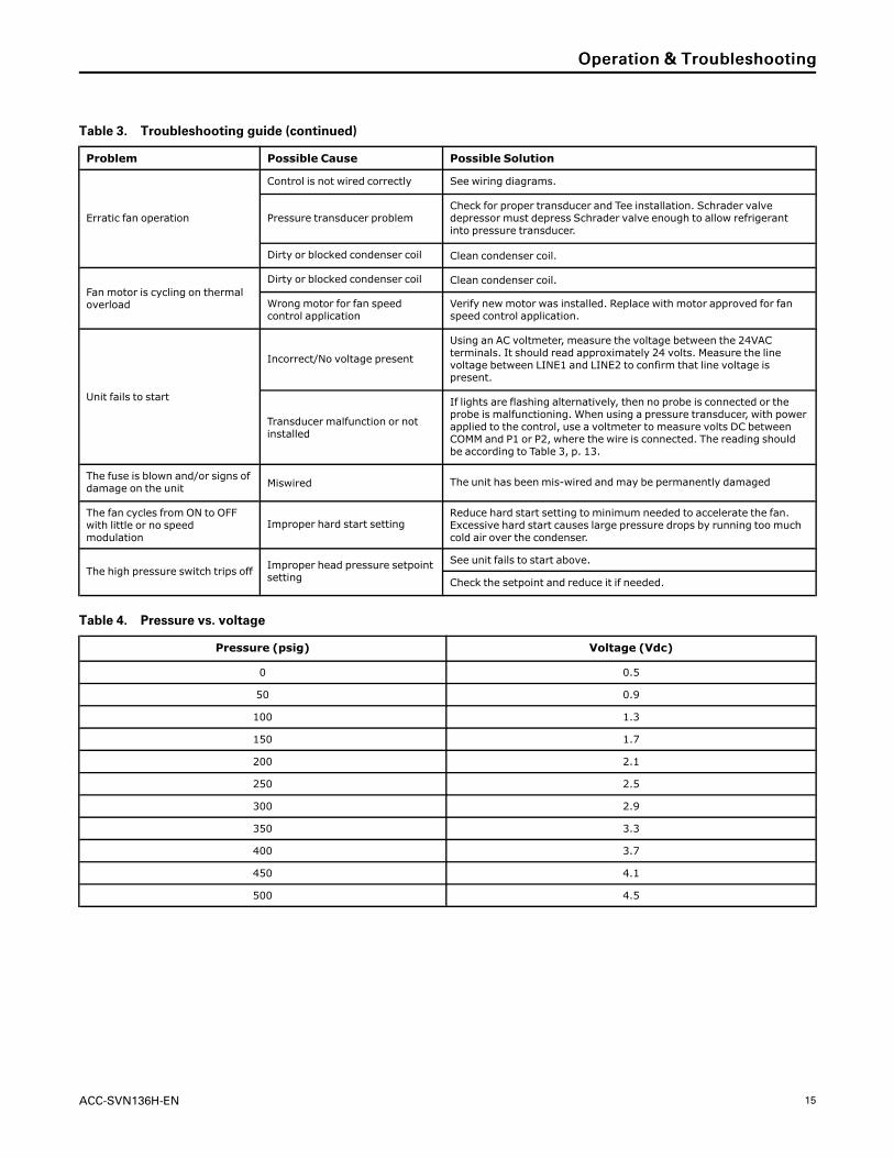
Table 3. Troubleshooting guide (continued)
Problem Possible Cause Possible Solution
Erratic fan operation
Control is not wired correctly See wiring diagrams.
Pressure transducer problemCheck for proper transducer and Tee installation. Schrader valvedepressor must depress Schrader valve enough to allow refrigerantinto pressure transducer.
Dirty or blocked condenser coil Clean condenser coil.
Fan motor is cycling on thermaloverload
Dirty or blocked condenser coil Clean condenser coil.
Wrong motor for fan speedcontrol application
Verify new motor was installed. Replace with motor approved for fanspeed control application.
Unit fails to start
Incorrect/No voltage present
Using an AC voltmeter, measure the voltage between the 24VACterminals. It should read approximately 24 volts. Measure the linevoltage between LINE1 and LINE2 to confirm that line voltage ispresent.
Transducer malfunction or notinstalled
If lights are flashing alternatively, then no probe is connected or theprobe is malfunctioning. When using a pressure transducer, with powerapplied to the control, use a voltmeter to measure volts DC betweenCOMM and P1 or P2, where the wire is connected. The reading shouldbe according to Table 3, p. 13.
The fuse is blown and/or signs ofdamage on the unit Miswired The unit has been mis-wired and may be permanently damaged
The fan cycles from ON to OFFwith little or no speedmodulation
Improper hard start settingReduce hard start setting to minimum needed to accelerate the fan.Excessive hard start causes large pressure drops by running too muchcold air over the condenser.
The high pressure switch trips off Improper head pressure setpointsetting
See unit fails to start above.
Check the setpoint and reduce it if needed.
Table 4. Pressure vs. voltage
Pressure (psig) Voltage (Vdc)
0 0.5
50 0.9
100 1.3
150 1.7
200 2.1
250 2.5
300 2.9
350 3.3
400 3.7
450 4.1
500 4.5
OOppeerraattiioonn && TTrroouubblleesshhoooottiinngg

Trane and American Standard create comfortable, energy efficient indoor environments for residentialapplications. For more information, please visit trane.com or americanstandardair.com.
Trane and American Standard have a policy of continuous product and product data improvement and reserve the right to change design andspecifications without notice. We are committed to using environmentally conscious print practices.
ACC-SVN136H-EN 28 Apr 2020
Supersedes ACC-SVN136G-EN (November 2018) ©2020