HDF Specification and Developer's Guide
226
HDF Specification and Developer’s Guide HDF4 Release 2.9 • February 2013
-
Upload
khangminh22 -
Category
Documents
-
view
1 -
download
0
Transcript of HDF Specification and Developer's Guide
HDF Specification and Developer’s GuideHDF4 Release 2.9 • February 2013
ii of ii February 2013
The HDF Group
Copyright Notice and License Terms for Hierarchical Data Format (HDF) Software Library and UtilitiesHierarchical Data Format (HDF) Software Library and Utilities Copyright 2006-2013 by The HDF Group (THG)
NCSA Hierarchical Data Format (HDF) Software Library and UtilitiesCopyright 1988-2006 by the Board of Trustees of the University of Illinois.
All rights reserved.
Contributors: National Center for Supercomputing Applications (NCSA) at the University of Illinois, Fortner Software, Unidata Program Center (netCDF), The Independent JPEG Group (JPEG), Jean-loup Gailly and Mark Adler (gzip), and Digital Equipment Corporation (DEC).
Redistribution and use in source and binary forms, with or without modification, are permitted for any purpose (including commer-cial purposes) provided that the following conditions are met:
1. Redistributions of source code must retain the above copyright notice, this list of conditions, and the following disclaimer.
2. Redistributions in binary form must reproduce the above copyright notice, this list of conditions, and the following dis-claimer in the documentation and/or materials provided with the distribution.
3. In addition, redistributions of modified forms of the source or binary code must carry prominent notices stating that the original code was changed and the date of the change.
4. All publications or advertising materials mentioning features or use of this software are asked, but not required, to acknowledge that it was developed by The HDF Group and by the National Center for Supercomputing Applications at the University of Illinois at Urbana-Champaign and credit the contributors.
5. Neither the name of The HDF Group, the name of the University, nor the name of any Contributor may be used to endorse or promote products derived from this software without specific prior written permission from THG, the University, or the Contributor, respectively.
DisclaimerTHIS SOFTWARE IS PROVIDED BY THE HDF GROUP (THG) AND THE CONTRIBUTORS "AS IS" WITH NO WAR-RANTY OF ANY KIND, EITHER EXPRESSED OR IMPLIED. In no event shall THG or the Contributors be liable for any dam-ages suffered by the users arising out of the use of this software, even if advised of the possibility of such damage.
TrademarksSun is a registered trademark, and Sun Workstation, Sun/OS and Solaris are trademarks of Sun Microsystems Inc.UNIX is a registered trademark of X/OpenVAX and VMS are trademarks of Digital Equipment CorporationMacintosh is a trademark of Apple Computer, Inc.CRAY and UNICOS are registered trademarks of Silicon Graphics , Inc.IBM PC is a registered trademark of International Business Machines CorporationMS-DOS is a registered trademark of Microsoft Corporation.The SZIP Science Data Lossless Compression Program is Copyright (C) 2001 Science & Technology Corporation @ UNM. All rights released. Copyright (C) 2003 Lowell H. Miles and Jack A. Venbrux. Licensed to ICs Corp. for distribution by the University of Illinois' National Center for Supercomputing Applications as a part of the HDF data storage and retrieval file format and soft-ware libraryproducts package. All rights reserved. Do not modify or use for other purposes. See for further information regarding terms of use.
The HDF Group and HDF Information and ContactsInformation regarding The HDF Group and HDF products is available from The HDF Group’s website: http://www.hdfgroup.org
HDF Help Desk assistance is available via email: [email protected]
Business queries and contacts can be made through the website or by mail:
http://www.hdfgroup.org/about/contact.html
The HDF Group
1800 South Oak Street
Suite 203
Champaign, IL 61820 USA
February 14, 2013 TOC-3
1Introduction
1.1 Overview. . . . . . . . . . . . . . . . . . . . . . . . . . . . . . . . . . . . . . . . . . . . . . . . . . . . . . . . . . . . . . . . . . . . . . . . . . . 11.2 Why HDF? . . . . . . . . . . . . . . . . . . . . . . . . . . . . . . . . . . . . . . . . . . . . . . . . . . . . . . . . . . . . . . . . . . . . . . . . . 11.3 What is HDF? . . . . . . . . . . . . . . . . . . . . . . . . . . . . . . . . . . . . . . . . . . . . . . . . . . . . . . . . . . . . . . . . . . . . . . . 21.4 Some History. . . . . . . . . . . . . . . . . . . . . . . . . . . . . . . . . . . . . . . . . . . . . . . . . . . . . . . . . . . . . . . . . . . . . . . . 41.5 About This Document . . . . . . . . . . . . . . . . . . . . . . . . . . . . . . . . . . . . . . . . . . . . . . . . . . . . . . . . . . . . . . . . . 51.6 Document Contents. . . . . . . . . . . . . . . . . . . . . . . . . . . . . . . . . . . . . . . . . . . . . . . . . . . . . . . . . . . . . . . . . . . 61.7 Conventions Used in This Document . . . . . . . . . . . . . . . . . . . . . . . . . . . . . . . . . . . . . . . . . . . . . . . . . . . . . 7
2Basic Structure of HDF Files
2.1 Chapter Overview . . . . . . . . . . . . . . . . . . . . . . . . . . . . . . . . . . . . . . . . . . . . . . . . . . . . . . . . . . . . . . . . . . . . 12.2 File Header . . . . . . . . . . . . . . . . . . . . . . . . . . . . . . . . . . . . . . . . . . . . . . . . . . . . . . . . . . . . . . . . . . . . . . . . . 12.3 Data Objects . . . . . . . . . . . . . . . . . . . . . . . . . . . . . . . . . . . . . . . . . . . . . . . . . . . . . . . . . . . . . . . . . . . . . . . . 12.4 Physical Organization of HDF Files . . . . . . . . . . . . . . . . . . . . . . . . . . . . . . . . . . . . . . . . . . . . . . . . . . . . . . 42.5 Sample HDF File . . . . . . . . . . . . . . . . . . . . . . . . . . . . . . . . . . . . . . . . . . . . . . . . . . . . . . . . . . . . . . . . . . . . 5
3Software Overview
3.1 Chapter Overview . . . . . . . . . . . . . . . . . . . . . . . . . . . . . . . . . . . . . . . . . . . . . . . . . . . . . . . . . . . . . . . . . . . . 13.2 HDF Software Layers . . . . . . . . . . . . . . . . . . . . . . . . . . . . . . . . . . . . . . . . . . . . . . . . . . . . . . . . . . . . . . . . . 13.3 Software Organization . . . . . . . . . . . . . . . . . . . . . . . . . . . . . . . . . . . . . . . . . . . . . . . . . . . . . . . . . . . . . . . . 2
3.3.1 Versions and Release Numbers . . . . . . . . . . . . . . . . . . . . . . . . . . . . . . . . . . . . . . . . . . . . . . . . . . . . 23.3.2 ANSI C and Portability. . . . . . . . . . . . . . . . . . . . . . . . . . . . . . . . . . . . . . . . . . . . . . . . . . . . . . . . . . . 33.3.3 Modules and Interfaces . . . . . . . . . . . . . . . . . . . . . . . . . . . . . . . . . . . . . . . . . . . . . . . . . . . . . . . . . . . 33.3.4 Header Files . . . . . . . . . . . . . . . . . . . . . . . . . . . . . . . . . . . . . . . . . . . . . . . . . . . . . . . . . . . . . . . . . . . 53.3.5 The HDF Test Suite . . . . . . . . . . . . . . . . . . . . . . . . . . . . . . . . . . . . . . . . . . . . . . . . . . . . . . . . . . . . . 103.3.6 Sample HDF Programs . . . . . . . . . . . . . . . . . . . . . . . . . . . . . . . . . . . . . . . . . . . . . . . . . . . . . . . . . . . 10
3.4 Some HDF Conventions . . . . . . . . . . . . . . . . . . . . . . . . . . . . . . . . . . . . . . . . . . . . . . . . . . . . . . . . . . . . . . . 10
4Low-level Interface
4.1 Chapter Overview . . . . . . . . . . . . . . . . . . . . . . . . . . . . . . . . . . . . . . . . . . . . . . . . . . . . . . . . . . . . . . . . . . . . 14.2 Introduction. . . . . . . . . . . . . . . . . . . . . . . . . . . . . . . . . . . . . . . . . . . . . . . . . . . . . . . . . . . . . . . . . . . . . . . . . 14.3 New Low-level Routines with Version 3.2 and Higher . . . . . . . . . . . . . . . . . . . . . . . . . . . . . . . . . . . . . . . 24.4 Overview of the Low-level Interface . . . . . . . . . . . . . . . . . . . . . . . . . . . . . . . . . . . . . . . . . . . . . . . . . . . . . 3
5Sets and Groups
5.1 Chapter Overview . . . . . . . . . . . . . . . . . . . . . . . . . . . . . . . . . . . . . . . . . . . . . . . . . . . . . . . . . . . . . . . . . . . . 15.2 Data Sets . . . . . . . . . . . . . . . . . . . . . . . . . . . . . . . . . . . . . . . . . . . . . . . . . . . . . . . . . . . . . . . . . . . . . . . . . . . 1
5.2.1 Types of Sets. . . . . . . . . . . . . . . . . . . . . . . . . . . . . . . . . . . . . . . . . . . . . . . . . . . . . . . . . . . . . . . . . . . 15.2.2 Calling Interfaces for Sets. . . . . . . . . . . . . . . . . . . . . . . . . . . . . . . . . . . . . . . . . . . . . . . . . . . . . . . . . 2
5.3 Groups . . . . . . . . . . . . . . . . . . . . . . . . . . . . . . . . . . . . . . . . . . . . . . . . . . . . . . . . . . . . . . . . . . . . . . . . . . . . . 25.3.1 General Features of Groups . . . . . . . . . . . . . . . . . . . . . . . . . . . . . . . . . . . . . . . . . . . . . . . . . . . . . . . 3
5.4 Raster Image Sets (RIS) . . . . . . . . . . . . . . . . . . . . . . . . . . . . . . . . . . . . . . . . . . . . . . . . . . . . . . . . . . . . . . . 45.4.1 Raster Image Groups (RIG) . . . . . . . . . . . . . . . . . . . . . . . . . . . . . . . . . . . . . . . . . . . . . . . . . . . . . . . 4
TOC-4 February 14, 2013
The HDF Group
5.4.2 RIS Tags. . . . . . . . . . . . . . . . . . . . . . . . . . . . . . . . . . . . . . . . . . . . . . . . . . . . . . . . . . . . . . . . . . . . . . 45.4.3 Raster Image Compression . . . . . . . . . . . . . . . . . . . . . . . . . . . . . . . . . . . . . . . . . . . . . . . . . . . . . . . 6
5.5 Scientific Data Sets . . . . . . . . . . . . . . . . . . . . . . . . . . . . . . . . . . . . . . . . . . . . . . . . . . . . . . . . . . . . . . . . . . 65.5.1 Backward and Forward Compatibility . . . . . . . . . . . . . . . . . . . . . . . . . . . . . . . . . . . . . . . . . . . . . . . 75.5.2 Internal Structures . . . . . . . . . . . . . . . . . . . . . . . . . . . . . . . . . . . . . . . . . . . . . . . . . . . . . . . . . . . . . . 75.5.3 SDG Structures . . . . . . . . . . . . . . . . . . . . . . . . . . . . . . . . . . . . . . . . . . . . . . . . . . . . . . . . . . . . . . . . 85.5.4 NDG Structures . . . . . . . . . . . . . . . . . . . . . . . . . . . . . . . . . . . . . . . . . . . . . . . . . . . . . . . . . . . . . . . . 95.5.5 SDG-like NDG Structures . . . . . . . . . . . . . . . . . . . . . . . . . . . . . . . . . . . . . . . . . . . . . . . . . . . . . . . . 105.5.6 Compatibility with Future NDG Structures . . . . . . . . . . . . . . . . . . . . . . . . . . . . . . . . . . . . . . . . . . . 11
5.6 Vsets, Vdatas, and Vgroups . . . . . . . . . . . . . . . . . . . . . . . . . . . . . . . . . . . . . . . . . . . . . . . . . . . . . . . . . . . . 125.7 The Raster-8 Set (Obsolete) . . . . . . . . . . . . . . . . . . . . . . . . . . . . . . . . . . . . . . . . . . . . . . . . . . . . . . . . . . . 13
5.7.1 Raster-8 Sets . . . . . . . . . . . . . . . . . . . . . . . . . . . . . . . . . . . . . . . . . . . . . . . . . . . . . . . . . . . . . . . . . . 135.7.2 Compatibility Between Raster-8 and Raster Image Sets . . . . . . . . . . . . . . . . . . . . . . . . . . . . . . . . . 13
5.8 Deleted information from "Vsets, Vdatas, and Vgroups:". . . . . . . . . . . . . . . . . . . . . . . . . . . . . . . . . . . . . 14
6Annotations
6.1 Chapter Overview . . . . . . . . . . . . . . . . . . . . . . . . . . . . . . . . . . . . . . . . . . . . . . . . . . . . . . . . . . . . . . . . . . . 16.2 General Description . . . . . . . . . . . . . . . . . . . . . . . . . . . . . . . . . . . . . . . . . . . . . . . . . . . . . . . . . . . . . . . . . . 16.3 File Annotations . . . . . . . . . . . . . . . . . . . . . . . . . . . . . . . . . . . . . . . . . . . . . . . . . . . . . . . . . . . . . . . . . . . . . 26.4 Object Annotations. . . . . . . . . . . . . . . . . . . . . . . . . . . . . . . . . . . . . . . . . . . . . . . . . . . . . . . . . . . . . . . . . . . 2
7Scientific Data Sets:The SD Model
7.1 Chapter Overview . . . . . . . . . . . . . . . . . . . . . . . . . . . . . . . . . . . . . . . . . . . . . . . . . . . . . . . . . . . . . . . . . . . 17.2 UML Notation and Object Symbols in HDF Data Model Descriptions . . . . . . . . . . . . . . . . . . . . . . . . . . 17.3 Introduction to the SD Model. . . . . . . . . . . . . . . . . . . . . . . . . . . . . . . . . . . . . . . . . . . . . . . . . . . . . . . . . . . 37.4 The SD User’s Model. . . . . . . . . . . . . . . . . . . . . . . . . . . . . . . . . . . . . . . . . . . . . . . . . . . . . . . . . . . . . . . . . 47.5 The SD Developer’s Model . . . . . . . . . . . . . . . . . . . . . . . . . . . . . . . . . . . . . . . . . . . . . . . . . . . . . . . . . . . . 67.6 Mapping between SD Developer's Model and HDF File Structures . . . . . . . . . . . . . . . . . . . . . . . . . . . . . 8
7.6.1 SD Collection. . . . . . . . . . . . . . . . . . . . . . . . . . . . . . . . . . . . . . . . . . . . . . . . . . . . . . . . . . . . . . . . . . 87.6.2 Attribute . . . . . . . . . . . . . . . . . . . . . . . . . . . . . . . . . . . . . . . . . . . . . . . . . . . . . . . . . . . . . . . . . . . . . . 97.6.3 Variable . . . . . . . . . . . . . . . . . . . . . . . . . . . . . . . . . . . . . . . . . . . . . . . . . . . . . . . . . . . . . . . . . . . . . . 97.6.4 Dimension . . . . . . . . . . . . . . . . . . . . . . . . . . . . . . . . . . . . . . . . . . . . . . . . . . . . . . . . . . . . . . . . . . . . 107.6.5 Overall Correspondence of SDS Elements and the HDF File Structure . . . . . . . . . . . . . . . . . . . . . 117.6.6 Accessing SD Objects via non-SD Interfaces . . . . . . . . . . . . . . . . . . . . . . . . . . . . . . . . . . . . . . . . . 12
7.7 SDS Memory Structures and Storage Layout . . . . . . . . . . . . . . . . . . . . . . . . . . . . . . . . . . . . . . . . . . . . . . 137.8 Library Implementation Details with Example File and SDS . . . . . . . . . . . . . . . . . . . . . . . . . . . . . . . . . . 15
7.8.1 Creating or opening an HDF file . . . . . . . . . . . . . . . . . . . . . . . . . . . . . . . . . . . . . . . . . . . . . . . . . . . 157.8.2 Creating an empty SDS . . . . . . . . . . . . . . . . . . . . . . . . . . . . . . . . . . . . . . . . . . . . . . . . . . . . . . . . . . 157.8.3 Writing data to an SDS . . . . . . . . . . . . . . . . . . . . . . . . . . . . . . . . . . . . . . . . . . . . . . . . . . . . . . . . . . 187.8.4 Adding global and local attributes . . . . . . . . . . . . . . . . . . . . . . . . . . . . . . . . . . . . . . . . . . . . . . . . . . 197.8.5 Setting a data string . . . . . . . . . . . . . . . . . . . . . . . . . . . . . . . . . . . . . . . . . . . . . . . . . . . . . . . . . . . . . 257.8.6 Setting a dimension name . . . . . . . . . . . . . . . . . . . . . . . . . . . . . . . . . . . . . . . . . . . . . . . . . . . . . . . . 257.8.7 Setting a dimension scale . . . . . . . . . . . . . . . . . . . . . . . . . . . . . . . . . . . . . . . . . . . . . . . . . . . . . . . . . 277.8.8 Setting a dimension string . . . . . . . . . . . . . . . . . . . . . . . . . . . . . . . . . . . . . . . . . . . . . . . . . . . . . . . . 277.8.9 Terminating access to the SD collection and file. . . . . . . . . . . . . . . . . . . . . . . . . . . . . . . . . . . . . . . 27
8
February 14, 2013 TOC-5
General Raster Images:The GR Model
8.1 Chapter Overview . . . . . . . . . . . . . . . . . . . . . . . . . . . . . . . . . . . . . . . . . . . . . . . . . . . . . . . . . . . . . . . . . . . . 18.2 Images in an HDF File . . . . . . . . . . . . . . . . . . . . . . . . . . . . . . . . . . . . . . . . . . . . . . . . . . . . . . . . . . . . . . . . 2
8.2.1 GR data sets . . . . . . . . . . . . . . . . . . . . . . . . . . . . . . . . . . . . . . . . . . . . . . . . . . . . . . . . . . . . . . . . . . . 38.2.2 RIG images (RIS8 and RIS24) . . . . . . . . . . . . . . . . . . . . . . . . . . . . . . . . . . . . . . . . . . . . . . . . . . . . . 48.2.3 RI8 images . . . . . . . . . . . . . . . . . . . . . . . . . . . . . . . . . . . . . . . . . . . . . . . . . . . . . . . . . . . . . . . . . . . . 4
8.3 The GR Data Model . . . . . . . . . . . . . . . . . . . . . . . . . . . . . . . . . . . . . . . . . . . . . . . . . . . . . . . . . . . . . . . . . . 58.3.1 A Casual View . . . . . . . . . . . . . . . . . . . . . . . . . . . . . . . . . . . . . . . . . . . . . . . . . . . . . . . . . . . . . . . . . 58.3.2 The Formal GR Data Model . . . . . . . . . . . . . . . . . . . . . . . . . . . . . . . . . . . . . . . . . . . . . . . . . . . . . . . 7
8.4 Mapping between GR Data Model and HDF File Structures . . . . . . . . . . . . . . . . . . . . . . . . . . . . . . . . . . . 88.5 Modifying an RIG or RI8 Image via the GR Interface . . . . . . . . . . . . . . . . . . . . . . . . . . . . . . . . . . . . . . . . 108.6 Backwards Compatibility when Creating New Images via the GR Interface. . . . . . . . . . . . . . . . . . . . . . . 118.7 Main Data Structures and their Relationships. . . . . . . . . . . . . . . . . . . . . . . . . . . . . . . . . . . . . . . . . . . . . . . 12
8.7.1 File Information Structure (gr_info_t) . . . . . . . . . . . . . . . . . . . . . . . . . . . . . . . . . . . . . . . . . . . . . . . 148.7.2 Raster Image Information Structure (ri_info_t) . . . . . . . . . . . . . . . . . . . . . . . . . . . . . . . . . . . . . . . . 148.7.3 Attribute Information Structure (at_info_t) . . . . . . . . . . . . . . . . . . . . . . . . . . . . . . . . . . . . . . . . . . . 158.7.4 Dimension Information Structure (dim_info_t) . . . . . . . . . . . . . . . . . . . . . . . . . . . . . . . . . . . . . . . . 15
8.8 Relationships among Main Data Structures . . . . . . . . . . . . . . . . . . . . . . . . . . . . . . . . . . . . . . . . . . . . . . . . 158.9 The Evolution of an HDF File in the GR Interface. . . . . . . . . . . . . . . . . . . . . . . . . . . . . . . . . . . . . . . . . . . 19
8.9.1 Creating or Opening an HDF File. . . . . . . . . . . . . . . . . . . . . . . . . . . . . . . . . . . . . . . . . . . . . . . . . . . 198.9.2 Creating and Writing to a Raster Image . . . . . . . . . . . . . . . . . . . . . . . . . . . . . . . . . . . . . . . . . . . . . . 208.9.3 Adding Attributes . . . . . . . . . . . . . . . . . . . . . . . . . . . . . . . . . . . . . . . . . . . . . . . . . . . . . . . . . . . . . . . 228.9.4 Adding Palettes . . . . . . . . . . . . . . . . . . . . . . . . . . . . . . . . . . . . . . . . . . . . . . . . . . . . . . . . . . . . . . . . . 248.9.5 Opening an Existing File . . . . . . . . . . . . . . . . . . . . . . . . . . . . . . . . . . . . . . . . . . . . . . . . . . . . . . . . . 24
9Tag Specifications
9.1 Chapter Overview . . . . . . . . . . . . . . . . . . . . . . . . . . . . . . . . . . . . . . . . . . . . . . . . . . . . . . . . . . . . . . . . . . . . 19.2 The HDF Tag Space . . . . . . . . . . . . . . . . . . . . . . . . . . . . . . . . . . . . . . . . . . . . . . . . . . . . . . . . . . . . . . . . . . 19.3 Tag Specifications. . . . . . . . . . . . . . . . . . . . . . . . . . . . . . . . . . . . . . . . . . . . . . . . . . . . . . . . . . . . . . . . . . . . 1
9.3.1 Utility Tags . . . . . . . . . . . . . . . . . . . . . . . . . . . . . . . . . . . . . . . . . . . . . . . . . . . . . . . . . . . . . . . . . . . . 39.3.2 Annotation Tags . . . . . . . . . . . . . . . . . . . . . . . . . . . . . . . . . . . . . . . . . . . . . . . . . . . . . . . . . . . . . . . . 69.3.3 Compression Tags. . . . . . . . . . . . . . . . . . . . . . . . . . . . . . . . . . . . . . . . . . . . . . . . . . . . . . . . . . . . . . . 99.3.4 Raster Image Tags . . . . . . . . . . . . . . . . . . . . . . . . . . . . . . . . . . . . . . . . . . . . . . . . . . . . . . . . . . . . . . 129.3.5 Composite Image Tags . . . . . . . . . . . . . . . . . . . . . . . . . . . . . . . . . . . . . . . . . . . . . . . . . . . . . . . . . . . 199.3.6 Vector Image Tags . . . . . . . . . . . . . . . . . . . . . . . . . . . . . . . . . . . . . . . . . . . . . . . . . . . . . . . . . . . . . . 209.3.7 Scientific Data Set Tags . . . . . . . . . . . . . . . . . . . . . . . . . . . . . . . . . . . . . . . . . . . . . . . . . . . . . . . . . . 219.3.8 Vset Tags . . . . . . . . . . . . . . . . . . . . . . . . . . . . . . . . . . . . . . . . . . . . . . . . . . . . . . . . . . . . . . . . . . . . . 299.3.9 Obsolete Tags . . . . . . . . . . . . . . . . . . . . . . . . . . . . . . . . . . . . . . . . . . . . . . . . . . . . . . . . . . . . . . . . . . 33
10Extended Tags and Special Elements
10.1 Chapter Overview . . . . . . . . . . . . . . . . . . . . . . . . . . . . . . . . . . . . . . . . . . . . . . . . . . . . . . . . . . . . . . . . . . . 110.2 Extended Tags and Alternate Physical Storage Methods . . . . . . . . . . . . . . . . . . . . . . . . . . . . . . . . . . . . . 1
10.2.1 Extended Tag Implementation . . . . . . . . . . . . . . . . . . . . . . . . . . . . . . . . . . . . . . . . . . . . . . . . . . . . 110.3 Linked Block Elements . . . . . . . . . . . . . . . . . . . . . . . . . . . . . . . . . . . . . . . . . . . . . . . . . . . . . . . . . . . . . . . 310.4 External Elements . . . . . . . . . . . . . . . . . . . . . . . . . . . . . . . . . . . . . . . . . . . . . . . . . . . . . . . . . . . . . . . . . . . 410.5 Chunked Data Storage . . . . . . . . . . . . . . . . . . . . . . . . . . . . . . . . . . . . . . . . . . . . . . . . . . . . . . . . . . . . . . . 5
10.5.1 Chunked Element Description Record . . . . . . . . . . . . . . . . . . . . . . . . . . . . . . . . . . . . . . . . . . . . . . 5
TOC-6 February 14, 2013
The HDF Group
10.5.2 Chunk Table . . . . . . . . . . . . . . . . . . . . . . . . . . . . . . . . . . . . . . . . . . . . . . . . . . . . . . . . . . . . . . . . . . 710.6 Data Compression . . . . . . . . . . . . . . . . . . . . . . . . . . . . . . . . . . . . . . . . . . . . . . . . . . . . . . . . . . . . . . . . . . 8
10.6.1 Compression Header: The Common Elements of Compressed Element Description Records. . . 810.6.2 Compressed Element Description Record: NBIT Run-length Encoding. . . . . . . . . . . . . . . . . . . . 1010.6.3 Compressed Element Description Record: Skipping-Huffman . . . . . . . . . . . . . . . . . . . . . . . . . . . 1110.6.4 Compressed Element Description Record: GNU ZIP (Deflate) . . . . . . . . . . . . . . . . . . . . . . . . . . 1110.6.5 Compressed Element Description Record: SZIP . . . . . . . . . . . . . . . . . . . . . . . . . . . . . . . . . . . . . . 12
11Portability Issues
11.1 Chapter Overview . . . . . . . . . . . . . . . . . . . . . . . . . . . . . . . . . . . . . . . . . . . . . . . . . . . . . . . . . . . . . . . . . . 111.2 The HDF Environment. . . . . . . . . . . . . . . . . . . . . . . . . . . . . . . . . . . . . . . . . . . . . . . . . . . . . . . . . . . . . . . 1
11.2.1 Supported Platforms. . . . . . . . . . . . . . . . . . . . . . . . . . . . . . . . . . . . . . . . . . . . . . . . . . . . . . . . . . . . 111.2.2 Language Standards . . . . . . . . . . . . . . . . . . . . . . . . . . . . . . . . . . . . . . . . . . . . . . . . . . . . . . . . . . . . 211.2.3 Guidelines . . . . . . . . . . . . . . . . . . . . . . . . . . . . . . . . . . . . . . . . . . . . . . . . . . . . . . . . . . . . . . . . . . . 2
11.3 Organization of Source Files . . . . . . . . . . . . . . . . . . . . . . . . . . . . . . . . . . . . . . . . . . . . . . . . . . . . . . . . . . 211.3.1 Header Files . . . . . . . . . . . . . . . . . . . . . . . . . . . . . . . . . . . . . . . . . . . . . . . . . . . . . . . . . . . . . . . . . . 311.3.2 Source Code Files . . . . . . . . . . . . . . . . . . . . . . . . . . . . . . . . . . . . . . . . . . . . . . . . . . . . . . . . . . . . . 311.3.3 File Naming Conventions . . . . . . . . . . . . . . . . . . . . . . . . . . . . . . . . . . . . . . . . . . . . . . . . . . . . . . . 4
11.4 Passing Strings between FORTRAN and C. . . . . . . . . . . . . . . . . . . . . . . . . . . . . . . . . . . . . . . . . . . . . . . 411.4.1 Passing Strings from FORTRAN to C. . . . . . . . . . . . . . . . . . . . . . . . . . . . . . . . . . . . . . . . . . . . . . 411.4.2 Passing Strings from C to FORTRAN. . . . . . . . . . . . . . . . . . . . . . . . . . . . . . . . . . . . . . . . . . . . . . 6
11.5 Function Return Values between FORTRAN and C . . . . . . . . . . . . . . . . . . . . . . . . . . . . . . . . . . . . . . . . 611.6 Differences in Routine Names . . . . . . . . . . . . . . . . . . . . . . . . . . . . . . . . . . . . . . . . . . . . . . . . . . . . . . . . . 7
11.6.1 Case Sensitivity. . . . . . . . . . . . . . . . . . . . . . . . . . . . . . . . . . . . . . . . . . . . . . . . . . . . . . . . . . . . . . . 711.6.2 Appended Underscores . . . . . . . . . . . . . . . . . . . . . . . . . . . . . . . . . . . . . . . . . . . . . . . . . . . . . . . . . 811.6.3 Short Names vs. Long Names . . . . . . . . . . . . . . . . . . . . . . . . . . . . . . . . . . . . . . . . . . . . . . . . . . . . 9
11.7 Differences Between ANSI C and Old C. . . . . . . . . . . . . . . . . . . . . . . . . . . . . . . . . . . . . . . . . . . . . . . . . 911.8 Type Differences . . . . . . . . . . . . . . . . . . . . . . . . . . . . . . . . . . . . . . . . . . . . . . . . . . . . . . . . . . . . . . . . . . . 10
11.8.1 Size differences . . . . . . . . . . . . . . . . . . . . . . . . . . . . . . . . . . . . . . . . . . . . . . . . . . . . . . . . . . . . . . . 1011.8.2 Number Representation . . . . . . . . . . . . . . . . . . . . . . . . . . . . . . . . . . . . . . . . . . . . . . . . . . . . . . . . . 1111.8.3 Byte-order and Structure Representations . . . . . . . . . . . . . . . . . . . . . . . . . . . . . . . . . . . . . . . . . . . 11
11.9 Access to Library Functions. . . . . . . . . . . . . . . . . . . . . . . . . . . . . . . . . . . . . . . . . . . . . . . . . . . . . . . . . . . 12
ATags and Extended Tag Labels
A.1 Overview . . . . . . . . . . . . . . . . . . . . . . . . . . . . . . . . . . . . . . . . . . . . . . . . . . . . . . . . . . . . . . . . . . . . . . . . . . 1A.2 Tags . . . . . . . . . . . . . . . . . . . . . . . . . . . . . . . . . . . . . . . . . . . . . . . . . . . . . . . . . . . . . . . . . . . . . . . . . . . . . . 1A.3 Extended Tag Labels . . . . . . . . . . . . . . . . . . . . . . . . . . . . . . . . . . . . . . . . . . . . . . . . . . . . . . . . . . . . . . . . . 4
BLibrary Calling Trees
B.1 Overview . . . . . . . . . . . . . . . . . . . . . . . . . . . . . . . . . . . . . . . . . . . . . . . . . . . . . . . . . . . . . . . . . . . . . . . . . . 1B.2 Library Calling Trees: SD API . . . . . . . . . . . . . . . . . . . . . . . . . . . . . . . . . . . . . . . . . . . . . . . . . . . . . . . . . 1
CFunction Specifications
C.1 Overview . . . . . . . . . . . . . . . . . . . . . . . . . . . . . . . . . . . . . . . . . . . . . . . . . . . . . . . . . . . . . . . . . . . . . . . . . . 1C.2 Opening and Closing Files . . . . . . . . . . . . . . . . . . . . . . . . . . . . . . . . . . . . . . . . . . . . . . . . . . . . . . . . . . . . 1
February 14, 2013 TOC-7
C.3 Locating Elements for Access and Getting Information . . . . . . . . . . . . . . . . . . . . . . . . . . . . . . . . . . . . . . 3C.4 Reading and Writing Entire Data Elements . . . . . . . . . . . . . . . . . . . . . . . . . . . . . . . . . . . . . . . . . . . . . . . . 8C.5 Reading and Writing Part of a Data Element . . . . . . . . . . . . . . . . . . . . . . . . . . . . . . . . . . . . . . . . . . . . . . . 9C.6 Manipulating Data Descriptors . . . . . . . . . . . . . . . . . . . . . . . . . . . . . . . . . . . . . . . . . . . . . . . . . . . . . . . . . 11C.7 Managing Special Data Elements. . . . . . . . . . . . . . . . . . . . . . . . . . . . . . . . . . . . . . . . . . . . . . . . . . . . . . . . 13C.8 Data Set Chunking . . . . . . . . . . . . . . . . . . . . . . . . . . . . . . . . . . . . . . . . . . . . . . . . . . . . . . . . . . . . . . . . . . . 16C.9 Development Routines . . . . . . . . . . . . . . . . . . . . . . . . . . . . . . . . . . . . . . . . . . . . . . . . . . . . . . . . . . . . . . . . 24C.10 Error Reporting. . . . . . . . . . . . . . . . . . . . . . . . . . . . . . . . . . . . . . . . . . . . . . . . . . . . . . . . . . . . . . . . . . . . . 26C.11 Other . . . . . . . . . . . . . . . . . . . . . . . . . . . . . . . . . . . . . . . . . . . . . . . . . . . . . . . . . . . . . . . . . . . . . . . . . . . . . 28
TOC-8 February 14, 2013
The HDF Group
February 2013 1-1
CHAPTER 1 -- Introduction
1.1 Overview
The Hierarchical Data Format (HDF) was designed to be an easy, straight-forward, and self-describing means of sharing scientific data among people, projects, and types of computers. An extensible header and carefully crafted internal layers provide a system that can grow as scientific data-handling needs evolve.
This document, the HDF Specification and Developer's Guide, fully describes the HDF data mod-els, the corresponding file format specifications, and library implementation, and discusses crite-ria employed in the library’s development. Where appropriate, this document provides limited guidelines for developers working on HDF itself or building applications that employ HDF.
This introduction provides a brief overview of HDF capabilities and design.
1.2 Why HDF?
A fundamental requirement of scientific data management is the ability to access as much infor-mation in as many ways, as quickly and easily as possible. A data storage and retrieval system that facilitates these capabilities must provide the following features:
Support for scientific data and metadata
Scientific data is characterized by a variety of data types and representations, data sets (including images) that can be extremely large and complex, and the need to attach accompanying attributes, parameters, notebooks, and other metadata. Metadata, supple-mentary data that describes the basic data (sometimes referred to as the raw data), includes information such as the dimensions of an array, the number type of the elements of a record, or a color lookup table (LUT).
Support for a range of hardware platforms
Data can originate on one machine only to be used later on many different machines. Scientists must be able to access data and metadata on as many hardware platforms as possible.
Support for a range of software tools
Scientists need a variety of software tools and utilities for easily searching, analyzing, archiving, and transporting the data and metadata. These tools range from a library of routines for reading and writing data and metadata, to small utilities that simply display an image on a console, to full-blown database retrieval systems that provide multiple views of thousands of sets of data and metadata.
1-2 February 2013
The HDF Group
Rapid data transfer
Both the size and the dispersion of scientific data sets require that mechanisms exist to get the data from place to place rapidly.
Extendibility
As new types of information are generated and new kinds of science are done, a means must be provided to support them.
1.3 What is HDF?
The HDF Structure
HDF is a self-describing extensible file format using tagged objects that have standard meanings. The idea is to store both a known format description and the data in the same file. HDF tags describe the format of the data because each tag is assigned a specific meaning; for example, the tag DFTAG_LUT indicates a color palette, the tag DFTAG_RI indicates an 8-bit raster image, and so on . A program that has been written to understand a certain set of tag types can scan the file for those tags and process the data. This program also can ignore any data that is beyond its scope.
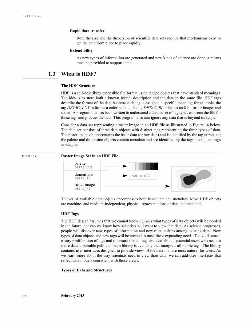
Consider a data set representing a raster image in an HDF file as illustrated in Figure 1a below. The data set consists of three data objects with distinct tags representing the three types of data. The raster image object contains the basic data (or raw data) and is identified by the tag DFTAG_RI; the palette and dimension objects contain metadata and are identified by the tags DFTAG_LUT tags DFTAG_ID.
FIGURE 1a Raster Image Set in an HDF File .
The set of available data objects encompasses both basic data and metadata. Most HDF objects are machine- and medium-independent, physical representations of data and metadata.
HDF Tags
The HDF design assumes that we cannot know a priori what types of data objects will be needed in the future, nor can we know how scientists will want to view that data. As science progresses, people will discover new types of information and new relationships among existing data. New types of data objects and new tags will be created to meet these expanding needs. To avoid unnec-essary proliferation of tags and to ensure that all tags are available to potential users who need to share data, a portable public domain library is available that interprets all public tags. The library contains user interfaces designed to provide views of the data that are most natural for users. As we learn more about the way scientists need to view their data, we can add user interfaces that reflect data models consistent with those views.
Types of Data and Structures
palette
dimensions
raster image
DFTAG_LUT
DFTAG_ID
DFTAG_RI
400 x 600
HDF Specification and Developer’s Guide
February 2013 1-3
HDF currently supports the most common types of data and metadata that scientists use, including multidimensional gridded data, 2-dimensional raster images, polygonal mesh data, multivariate data sets, finite-element data, non-Cartesian coordinate data, and text.
In the future there will almost certainly be a need to incorporate new types of data, such as voice and video, some of which might actually be stored on other media than the central file itself. Under such circumstances, it may become desirable to employ the concept of a virtual file. A vir-tual file functions like a regular file but does not fit our normal notion of a monolithic sequence of bits stored entirely on a single disk or tape.
HDF also makes it possible for the user to include annotations, titles, and specific descriptions of the data in the file. Thus, files can be archived with human-readable information about the data and its origins.
One collection of HDF tags supports a hierarchical grouping structure called a Vgroup that allows scientists to organize data objects within HDF files to fit their views of how the objects go together, much as a person in an office or laboratory organizes information in folders, drawers, journal boxes, and on their desktops.
Backward and Forward Compatibility
An important goal of HDF is to maximize backward and forward compatibility among its inter-faces, and storage and object types. This is not always achievable, because data formats must sometimes change to enhance performance, to correct errors, or for other reasons. However, whenever possible, HDF files should not become out of date. For example, suppose a site falls far behind in the HDF standard so its users can only work with the portions of the specification that are three years old. Users at this site might produce files with their old HDF software then read them with newer software designed to work with more advanced data files. The newer software should still be able to read the old files.
Conversely, if the site receives files that contain objects that its HDF software does not under-stand, it should still be able to list the types of data in the file. It should also be able to access all of the older types of data objects that it understands, despite the fact that the older types of data objects are mixed in with new kinds of data. In addition, if the more advanced site uses the text annotation facilities of HDF effectively, the files will arrive with complete human-readable descriptions of how to decipher the new tag types.
Calling Interfaces
To present a convenient user interface made up of something more usable than a list of tag types with their associated data requirements, HDF supports multiple calling interfaces, utilities, and applications.
The low-level calling interface is used to manipulate tags and raw data, to perform error handling, and to control the physical storage of data. This interface is designed to be used by developers who are providing the higher level interfaces for applications like raster image storage or scien-tific data archiving. See Chapter 4, Low-level Interface, and in Chapter 3, Software Overview, see Section 3.3, "Software Organization."
The application interfaces, at the next level, include several modules specifically designed to sim-plify the process of storing and accessing specific types of data. For example, the palette inter-faces are designed to handle color palettes and lookup tables, the general raster (GR) interface is designed to handle generalized raster images, and the scientific data (SD) interface is designed to handle arrays of scientific data. If you are primarily interested in reading data from or writing data to HDF files, you will spend most of your time working with the application interfaces. See Section 3.3, "Software Organization," for a complete list of these APIs.
1-4 February 2013
The HDF Group
The HDF utilities and NCSA applications, at the top level, are special purpose programs designed to handle specific tasks or solve specific problems. The utilities provide a command line interface for data management. The applications provide solutions for problems in specific application areas and often include a graphic user interface. Several third party applications are also available at this level.
Machine Independence
An important issue in data file design is that of machine independence or transportability. The HDF design defines standard representations for storing all data types that it supports. When data is written to a file, it is typically written in the standard HDF representation. The conversion is handled by the HDF software and need not concern the user. Users may override this convention and install their own conversion routines, or they may write data to a file in the native format of the machine on which it was generated.
1.4 Some History
In 1987 a group of users and software developers at NCSA searched for a file format that would satisfy NCSA's data needs. There were some interesting candidates, but none that were in the pub-lic domain, were targeted to scientific data, and yet were sufficiently general and extensible. In the course of several months, borrowing concepts from several existing formats, the group designed HDF.
The first version of HDF was implemented in the spring and summer of 1988. It included a gen-eral purpose interface and an 8-bit raster image interface. In the fall of 1988, a scientific data set interface was designed and implemented, enabling HDF users to store multidimensional arrays and related data. Soon thereafter interfaces were implemented for storing color palettes, 24-bit raster images, and annotations.
In 1989, it became clear that there was a need to support a general grouping structure and unstruc-tured data such as that used to represent polyhedra in graphical applications. This led to Vsets, whose interface routines were implemented as a separate HDF library.
Also in 1989 it became clear that the existing general purpose layer was not sufficiently powerful to meet anticipated future needs and that the coding could use a substantial overhaul. From this, the long process of redesigning the lower layers of HDF began. The first version incorporating extended tags and the new lower layers of HDF was released in the summer of 1992 as HDF Ver-sion 3.2.
In 1993, in response to the needs of flexibility in data ranges and sizes, HDF Version 3.3 was released. In this version of HDF, the new SD interface was introduced with multi-file access and an unlimited dimension feature for arrays. HDF Version 3.3 provided alternative physical storage methods (external and linked block data elements) through extended tags, JPEG data compres-sion, changes to some Vset interface functions, access to netCDF files through a complete netCDF interface,1 hyperslab access routines for old-style SDS objects, and various performance improvements.
In 1994, as standard ANSI C became more commonly used, HDF shifted from K&R to ANSI C to support portability. After several beta versions, HDF Version 4.0 was released in 1996 and pro-vided features such as support for n-bit integers and SDS compression, limited support for reading CDF files, a parallel I/O interface for the CM5, auto configuration, multi-file versions of the AN
1. NetCDF is a network-transparent derivative of the original CDF (Common Data Format) developed by the National Aeronautics and Space Administration (NASA). It is used widely in atmospheric sciences and other disciplines requiring very large data structures. NetCDF is in the public domain and was developed at the Unidata Program Center in Boulder, Colorado.
HDF Specification and Developer’s Guide
February 2013 1-5
and GR interfaces, and significant improvement in I/O performance and memory usage. In addi-tion, more options were added to existing HDF utilities and two new programs were added to the HDF utilities:
• hdp, to view the contents of HDF files
• hdfunpac, to unpack scientific datasets into external elements
HDF Version 4.1 was released in 1997. In this version, attributes were added to both the Vdata and Vgroup APIs to provide more ways for meaningfully storing data, data chunking was intro-duced in the SD API to improve I/O performance, and a new representation was used for storing dimensions to improve storage efficiency.
In 1998, the second release of HDF Version 4.1, called Version 4.1r2, was announced. In this release, data chunking was added for the GR API, the Java Products (the Java-based HDF Viewer, JHV, and the Java HDF interface, JHI) were incorporated into the HDF release itself, and the HDF Reference Manual and HDF User’s Guide were extensively updated. In addition, the new repre-sentation of dimensions that was introduced in the previous release became the default representa-tion.
HDF Version 4.1r3, released in May 1999, emphasized fixing problems in the SD and GR inter-faces. The HDF User's Guide accompanying the release was significantly improved and updated. The term Vset became obsolete, being replaced with the more specific terms Vgroup and Vdata.
The current release, HDF Version 4.1r4, released in October 2000, completes the enabling of all GR chunking capabilities. In addition, new options were added to the hdp utility. This document, the HDF Specification and Developer’s Guide, was largely rewritten for this release.
See the HDF website at http://hdfgroup.org/ for release information, lists of supported plat-forms, and the list of bugs fixed in the current release.
The HDF library is considered mature and complete at this time. Future work will focus on techni-cal support, maintenance, and bug fixes; there are no plans to implement new features. All new features and tools are being implemented in the HDF5 library, a new, next-generation product from the same team that built and supports HDF. HDF5 is discussed in detail on the web athttp://hdfgroup.org/HDF5/.
1.5 About This Document
This document is designed for software developers who are designing applications or routines for use with HDF files and for users who need detailed information about HDF. Users who are inter-ested in using HDF to store or manipulate their data will not normally need the kind of detail pre-sented in this manual. They should instead consult one of the user-level documents:1
Versions 4.x
HDF User's Guide
HDF Reference Manual
A tutorial is available online at the following URL:http://hdfgroup.org/training/HDFtraining/tutorial/index.html
New material appears throughout this edition of The HDF Specification and Developer’s Guide, but the following chapters bear special mention. Chapters 7 and 8 and Appendix B are entirely
1. The user-level documents for Versions 3.2 and earlier were NCSA HDF Calling Interfaces and Utilities and NCSA HDF Vset; for Version 3.3, they were Getting Started with NCSA HDF, NCSA HDF User's Guide, and NCSA HDF Reference Manual. Library versions prior to Version 4.0 and the corresponding doucuments are no longer supported or available.
1-6 February 2013
The HDF Group
new. Chapter 10 contains new compression and chunking information and some material that pre-viously appeared in Chapter 9.
Users of third-party software that uses HDF may also have to consult a manual for that software.
1.6 Document Contents
The HDF Specification and Developer's Guide contains the following chapters and appendix:
Chapter 1: Introduction
Introduces the document and provides an overview.
Chapter 2: Basic Structure of HDF Files
Introduces and describes the components and organization of HDF files.
Chapter 3: Software Overview
Describes the organization of the software layers that make up the basic HDF library and provides guidelines for writing HDF software.
Chapter 4: Low-level Interface
Describes the low-level HDF routines that make up the low-level interface (see also the H routines section of the HDF Reference Manual).
Chapter 5: Sets and Groups
Explains the roles of sets and groups in an HDF file, and describes raster image sets, sci-entific data sets, and Vgroups.
Chapter 6: Annotations
Explains the use of annotations in HDF files.
Chapter 7: Scientific Data Sets: The SD Model
Explains the role, structure, and usage of SDSs in HDF files.
Chapter 8: General Raster Images: The GR Model
Explains the role, structure, and usage of GRs in HDF files.
Chapter 9: Tag Specifications
Describes the tag identification space and the HDF-supported basic tags.
Chapter 10: Extended Tags and Special Elements
Describes the extended tag structure and the HDF-supported extended tags and special elements.
Chapter 11: Portability Issues
Describes the measures taken to maximize HDF portability across platforms and to ensure that HDF routines are available to both C and FORTRAN programs.
Appendix A: Tags and Extended Tag Labels
Presents a list of HDF-supported tags and a list of labels used with extended tags.
Appendix B: Library Calling Trees
Illustrates the calling structure of HDF library functions.
HDF Specification and Developer’s Guide
February 2013 1-7
Appendix C: Function Specifications
Provides detailed specifications for selected low-level interface functions.
1.7 Conventions Used in This Document
Most of the descriptive text in this guide is printed in 10 point Times. Other typefaces have spe-cific meanings that will help the reader understand the functionality being described.
New concepts and newly defined terms are sometimes presented in bold italics on their first occurrence to indicate that they are defined within the paragraph.
Cross references within the specification include the title of the referenced section in quotation marks or the reference chapter in italics. (E.g., See Section 3.3, "Software Organization," in Chap-ter 3, Software Overview, for a complete list of ...)
References to documents italicize the title of the document. (E.g., See the HDF User’s Guide to familiarize yourself with the basic principles of using HDF.)
Literal expressions and variables often appear in the discussion. Literal expressions are pre-sented in Courier while variables are presented in italic Courier. A literal expression is any expression that would be entered exactly as presented, e.g., commands, command options, literal strings, and data. A variable is an expression that serves as a place holder for some other text that would be entered. Consider the expression cp file1 file2 . cp is a command name and would be entered exactly as it appears, so it is printed in Courier. But file1 and file2 are variables, place holders for the names of actual files, so they are printed in italic Courier; the user would enter the actual filenames.
This guide frequently offers sample command lines. Sometimes these are examples of what might be done; other times they are specific instructions to the user. Command lines may appear within running text, as in the preceding paragraph, or on a separate line, as follows:
cp file1 file2
Command lines always include one or more literal expressions and may include one or more vari-ables, so they are printed in Courier and italic Courier as described above.
Keys that are labeled with more than one character, such as the RETURN key, are identified with all uppercase letters. Keys that are to be pressed simultaneously or in succession are linked with a hyphen. For example, "press CONTROL-A" means to press the CONTROL key then, without releasing the CONTROL key, press the A key. Similarly, "press CONTROL-SHIFT-A " means to press the CONTROL and SHIFT keys then, without releasing either of those, press the A key.
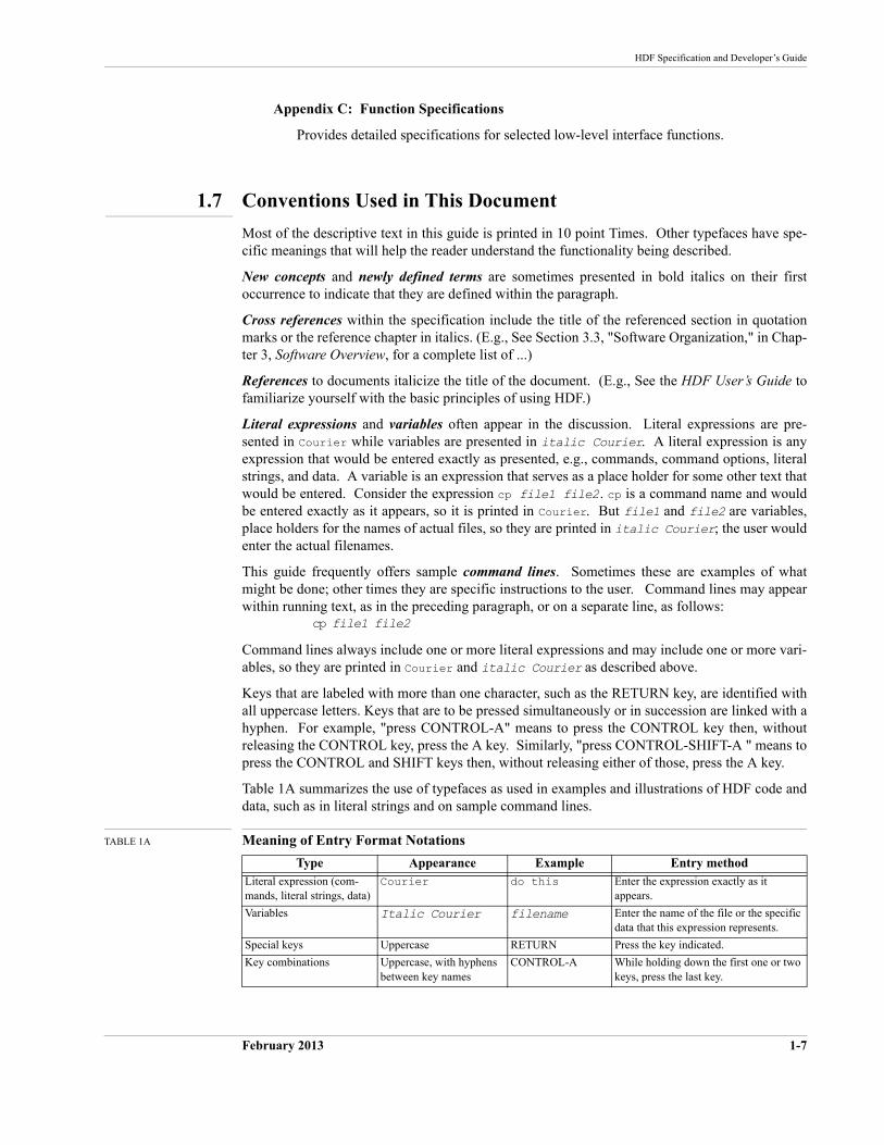
Table 1A summarizes the use of typefaces as used in examples and illustrations of HDF code and data, such as in literal strings and on sample command lines.
TABLE 1A Meaning of Entry Format Notations
Type Appearance Example Entry methodLiteral expression (com-mands, literal strings, data)
Courier do this Enter the expression exactly as it appears.
Variables Italic Courier filename Enter the name of the file or the specific data that this expression represents.
Special keys Uppercase RETURN Press the key indicated.
Key combinations Uppercase, with hyphens between key names
CONTROL-A While holding down the first one or two keys, press the last key.
1-8 February 2013
The HDF Group
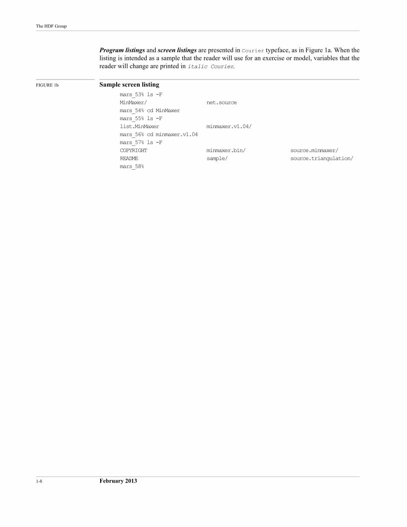
Program listings and screen listings are presented in Courier typeface, as in Figure 1a. When the listing is intended as a sample that the reader will use for an exercise or model, variables that the reader will change are printed in italic Courier.
FIGURE 1b Sample screen listing
mars_53% ls -FMinMaxer/ net.sourcemars_54% cd MinMaxermars_55% ls -Flist.MinMaxer minmaxer.v1.04/mars_56% cd minmaxer.v1.04mars_57% ls -FCOPYRIGHT minmaxer.bin/ source.minmaxer/README sample/ source.triangulation/mars_58%
February 14, 2013 2-9
CHAPTER 2 -- Basic Structure of HDF Files
2.1 Chapter Overview
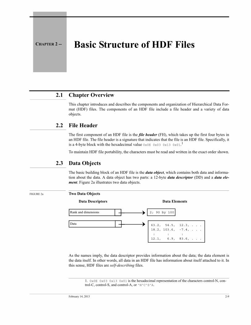
This chapter introduces and describes the components and organization of Hierarchical Data For-mat (HDF) files. The components of an HDF file include a file header and a variety of data objects.
2.2 File Header
The first component of an HDF file is the file header (FH), which takes up the first four bytes in an HDF file. The file header is a signature that indicates that the file is an HDF file. Specifically, it is a 4-byte block with the hexadecimal value 0x0E 0x03 0x13 0x01.1
To maintain HDF file portability, the characters must be read and written in the exact order shown.
2.3 Data Objects
The basic building block of an HDF file is the data object, which contains both data and informa-tion about the data. A data object has two parts: a 12-byte data descriptor (DD) and a data ele-ment. Figure 2a illustrates two data objects.
FIGURE 2a Two Data Objects
As the names imply, the data descriptor provides information about the data; the data element is the data itself. In other words, all data in an HDF file has information about itself attached to it. In this sense, HDF files are self-describing files.
1. 0x0E 0x03 0x13 0x01 is the hexadecimal representation of the characters control-N, con-trol-C, control-S, and control-A, or ^N^C^S^A.
Rank and dimensions
Data 63.2, 54.5, 12.3, . . .
18.2, 103.6, -7.4, . . .
: : :
12.1, 6.9, 83.6, . . .
2; 90 by 100
Data Descriptors Data Elements
Tag Reference number
Offset Length
Tag/ref (data identifier)
16 bits 16 bits 32 bits32 bits
2-10 February 14, 2013
The HDF Group
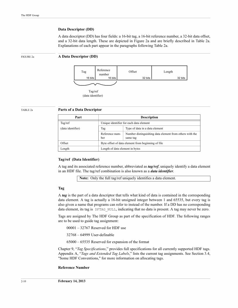
Data Descriptor (DD)
A data descriptor (DD) has four fields: a 16-bit tag, a 16-bit reference number, a 32-bit data offset, and a 32-bit data length. These are depicted in Figure 2a and are briefly described in Table 2a. Explanations of each part appear in the paragraphs following Table 2a.
FIGURE 2a A Data Descriptor (DD)
TABLE 2a Parts of a Data Descriptor
Tag/ref (Data Identifier)
A tag and its associated reference number, abbreviated as tag/ref, uniquely identify a data element in an HDF file. The tag/ref combination is also known as a data identifier.
Tag
A tag is the part of a data descriptor that tells what kind of data is contained in the corresponding data element. A tag is actually a 16-bit unsigned integer between 1 and 65535, but every tag is also given a name that programs can refer to instead of the number. If a DD has no corresponding data element, its tag is DFTAG_NULL, indicating that no data is present. A tag may never be zero.
Tags are assigned by The HDF Group as part of the specification of HDF. The following ranges are to be used to guide tag assignment:
00001 – 32767 Reserved for HDF use
32768 – 64999 User-definable
65000 – 65535 Reserved for expansion of the format
Chapter 9, “Tag Specifications,” provides full specifications for all currently supported HDF tags. Appendix A, “Tags and Extended Tag Labels,” lists the current tag assignments. See Section 3.4, "Some HDF Conventions," for more information on allocating tags.
Reference Number
Part Description
Tag/ref Unique identifier for each data element
(data identifier) Tag Type of data in a data element
Reference num-ber
Number distinguishing data element from others with the same tag
Offset Byte offset of data element from beginning of file
Length Length of data element in bytes
Note: Only the full tag/ref uniquely identifies a data element.
Blocksize
Nextblock Tag Ref Offset Length
DD Block
DDH DD DD DD
Tag Ref Offset Length Tag Ref Offset Length ....
HDF Specification and Developer’s Guide
February 14, 2013 2-11
Tags are not necessarily unique in an HDF file; there may be more than one data element of a given type. Therefore, the data descriptor includes a unique reference number.
Reference numbers are not necessarily assigned consecutively, so you cannot assume that the actual value of a reference number has any meaning beyond providing a means of distinguishing among elements with the same tag. Furthermore, reference numbers are only unique for data ele-ments with the same tag; two 8-bit raster images will never have the same reference number but an 8-bit raster image and a 24-bit raster image might.
Reference numbers are 16-bit unsigned integers.
Data Offset and Length
The data offset states the byte position of the corresponding data element from the beginning of the file. The length states the number of bytes occupied by the data element.
Offset and length are both 32-bit signed integers. This results in a file-size limit of 2 gigabytes.
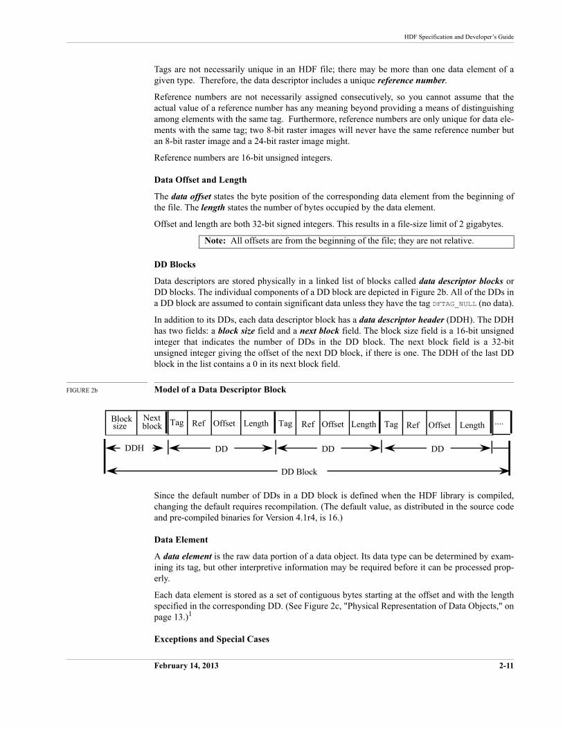
DD Blocks
Data descriptors are stored physically in a linked list of blocks called data descriptor blocks or DD blocks. The individual components of a DD block are depicted in Figure 2b. All of the DDs in a DD block are assumed to contain significant data unless they have the tag DFTAG_NULL (no data).
In addition to its DDs, each data descriptor block has a data descriptor header (DDH). The DDH has two fields: a block size field and a next block field. The block size field is a 16-bit unsigned integer that indicates the number of DDs in the DD block. The next block field is a 32-bit unsigned integer giving the offset of the next DD block, if there is one. The DDH of the last DD block in the list contains a 0 in its next block field.
FIGURE 2b Model of a Data Descriptor Block
Since the default number of DDs in a DD block is defined when the HDF library is compiled, changing the default requires recompilation. (The default value, as distributed in the source code and pre-compiled binaries for Version 4.1r4, is 16.)
Data Element
A data element is the raw data portion of a data object. Its data type can be determined by exam-ining its tag, but other interpretive information may be required before it can be processed prop-erly.
Each data element is stored as a set of contiguous bytes starting at the offset and with the length specified in the corresponding DD. (See Figure 2c, "Physical Representation of Data Objects," on page 13.)1
Exceptions and Special Cases
Note: All offsets are from the beginning of the file; they are not relative.
2-12 February 14, 2013
The HDF Group
Note that there are a few exceptions and special cases to the above standards.
• The data object identified by the tag DFTAG_MT, for machine type, consists of the tag imme-diately followed by four number types. Since there can be only one DFTAG_MT tag in an HDF file and the data can be stored in the DD with the tag, there is no need for a data ele-ment. Consequently, the reference number, offset, and length are unnecessary.
• Several tags, specifically DFTAG_NULL, DFTAG_JPEG, and DFTAG_GREYJPEG, serve as binary flags and convey all the required information by the mere fact of their presence in an HDF file. These tags therefore point to no data element and have offset and length values of 0. DFTAG_NULL indicates a data object containing no data. DFTAG_JPEG and DFTAG_GREYJPEG indicate that an associated data object, indicated by a different tag but the same reference number, contains JPEG data image. The descriptions of these tags include a sink pointer ( ) in the diagrams in Chapter 9.
• It is possible to create a tag/ref object then to end access to that object before writing any data or specifying its size. In such cases, the offset and length in the DD block will be set to the invalid offset or invalid length value of 0xFFFFFFFF.
See the related entries in Chapter 9, Tag Specifications, for complete descriptions of these tags.
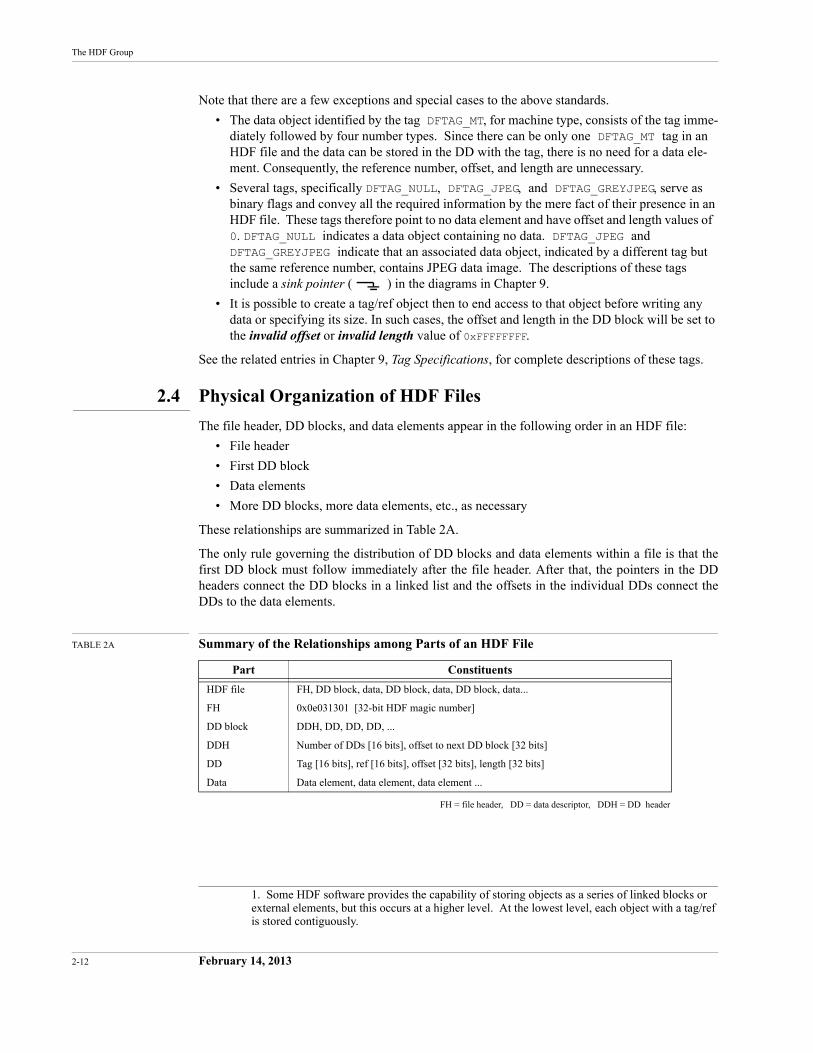
2.4 Physical Organization of HDF Files
The file header, DD blocks, and data elements appear in the following order in an HDF file:
• File header
• First DD block
• Data elements
• More DD blocks, more data elements, etc., as necessary
These relationships are summarized in Table 2A.
The only rule governing the distribution of DD blocks and data elements within a file is that the first DD block must follow immediately after the file header. After that, the pointers in the DD headers connect the DD blocks in a linked list and the offsets in the individual DDs connect the DDs to the data elements.
TABLE 2A Summary of the Relationships among Parts of an HDF File
FH = file header, DD = data descriptor, DDH = DD header
1. Some HDF software provides the capability of storing objects as a series of linked blocks or external elements, but this occurs at a higher level. At the lowest level, each object with a tag/ref is stored contiguously.
Part Constituents
HDF file FH, DD block, data, DD block, data, DD block, data...
FH 0x0e031301 [32-bit HDF magic number]
DD block DDH, DD, DD, DD, ...
DDH Number of DDs [16 bits], offset to next DD block [32 bits]
DD Tag [16 bits], ref [16 bits], offset [32 bits], length [32 bits]
Data Data element, data element, data element ...
HDF Specification and Developer’s Guide
February 14, 2013 2-13
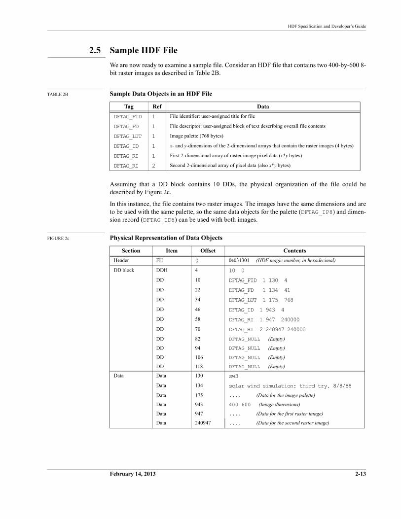
2.5 Sample HDF File
We are now ready to examine a sample file. Consider an HDF file that contains two 400-by-600 8-bit raster images as described in Table 2B.
TABLE 2B Sample Data Objects in an HDF File
Assuming that a DD block contains 10 DDs, the physical organization of the file could be described by Figure 2c.
In this instance, the file contains two raster images. The images have the same dimensions and are to be used with the same palette, so the same data objects for the palette (DFTAG_IP8) and dimen-sion record (DFTAG_ID8) can be used with both images.
FIGURE 2c Physical Representation of Data Objects
Tag Ref Data
DFTAG_FID 1 File identifier: user-assigned title for file
DFTAG_FD 1 File descriptor: user-assigned block of text describing overall file contents
DFTAG_LUT 1 Image palette (768 bytes)
DFTAG_ID 1 x- and y-dimensions of the 2-dimensional arrays that contain the raster images (4 bytes)
DFTAG_RI 1 First 2-dimensional array of raster image pixel data (x*y bytes)
DFTAG_RI 2 Second 2-dimensional array of pixel data (also x*y bytes)
Section Item Offset Contents
Header FH 0 0e031301 (HDF magic number, in hexadecimal)
DD block DDH 4 10 0
DD 10 DFTAG_FID 1 130 4
DD 22 DFTAG_FD 1 134 41
DD 34 DFTAG_LUT 1 175 768
DD 46 DFTAG_ID 1 943 4
DD 58 DFTAG_RI 1 947 240000
DD 70 DFTAG_RI 2 240947 240000
DD 82 DFTAG_NULL (Empty)
DD 94 DFTAG_NULL (Empty)
DD 106 DFTAG_NULL (Empty)
DD 118 DFTAG_NULL (Empty)
Data Data 130 sw3
Data 134 solar wind simulation: third try. 8/8/88
Data 175 .... (Data for the image palette)
Data 943 400 600 (Image dimensions)
Data 947 .... (Data for the first raster image)
Data 240947 .... (Data for the second raster image)

2-14 February 14, 2013
The HDF Group
February 2013 3-15
CHAPTER 3 -- Software Overview
3.1 Chapter Overview
This chapter describes the HDF software organization and provides guidelines for writing HDF software.
HDF is an amalgam of code and functionality from many sources. For example, the netCDF code came from the Unidata Program Center, and data compression and conversion software has been acquired from a variety of third parties. The HDF development team wrote the code for the basic HDF functionality and perfomed all of the integration work.
This document contains specifications for the HDF code and functionality. It does not include specifications for code or functionality from non-NCSA sources, though it does sometimes refer to specifications provided by other sources. Only the HDF interface to such code is specified in this document.
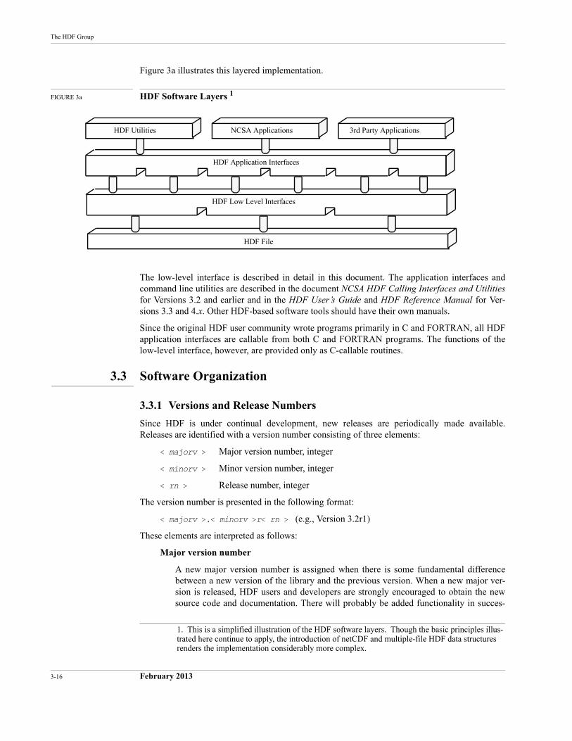
3.2 HDF Software Layers
There are three basic levels of HDF software:
• HDF low-level interface
• HDF application interfaces
• HDF applications and utilities
The lowest layer, the low-level interface, includes general purpose routines that form the basis of all higher-level HDF development. The low-level interface directly executes operations such as file I/O, error handling, memory management, and physical storage.
The application interfaces support higher level views of data and provide the interfaces for build-ing user-level applications. Routines that handle raster images, palettes, annotations, scientific data sets, vdatas, vgroups, and netCDF appear at this level.
The applications and utilities are implemented at the highest level.
The utilities perform general functions, such as listing the contents of an HDF file, and more spe-cialized functions, such as converting data from one HDF data type to another (e.g., raster images to scientific data sets). In general, the utilities have simple command line interfaces and perform data management tasks.
The applications usually perform data analysis tasks and have polished interactive user interfaces. They include the NCSA Visualization Tool Suite, commercial software packages that use HDF, and other packages created by various third party projects.
HDF Utilities NCSA Applications 3rd Party Applications
HDF Application Interfaces
HDF Low Level Interfaces
HDF File
3-16 February 2013
The HDF Group
Figure 3a illustrates this layered implementation.
FIGURE 3a HDF Software Layers 1
The low-level interface is described in detail in this document. The application interfaces and command line utilities are described in the document NCSA HDF Calling Interfaces and Utilities for Versions 3.2 and earlier and in the HDF User’s Guide and HDF Reference Manual for Ver-sions 3.3 and 4.x. Other HDF-based software tools should have their own manuals.
Since the original HDF user community wrote programs primarily in C and FORTRAN, all HDF application interfaces are callable from both C and FORTRAN programs. The functions of the low-level interface, however, are provided only as C-callable routines.
3.3 Software Organization
3.3.1 Versions and Release Numbers
Since HDF is under continual development, new releases are periodically made available. Releases are identified with a version number consisting of three elements:
< majorv > Major version number, integer
< minorv > Minor version number, integer
< rn > Release number, integer
The version number is presented in the following format:
< majorv >.< minorv >r< rn > (e.g., Version 3.2r1)
These elements are interpreted as follows:
Major version number
A new major version number is assigned when there is some fundamental difference between a new version of the library and the previous version. When a new major ver-sion is released, HDF users and developers are strongly encouraged to obtain the new source code and documentation. There will probably be added functionality in succes-
1. This is a simplified illustration of the HDF software layers. Though the basic principles illus-trated here continue to apply, the introduction of netCDF and multiple-file HDF data structures renders the implementation considerably more complex.
HDF Specification and Developer’s Guide
February 2013 3-17
sive major versions of the library and some obsolete code may be deleted. Some user code may have to be modified to use the new library.
Minor version number
A new minor version number indicates an intermediate release between one major ver-sion and the next. Changes will probably be significant. When a new minor version is released, users and developers are strongly encouraged to obtain the new source code and documentation. There may be minor interface changes.
Release number
A new release number is assigned when bug fixes or other small modifications have been made. Using a new release of the same version of the library will not usually require modifying existing user code.
3.3.2 ANSI C and Portability
To ensure that HDF can be easily ported to new platforms, all versions of the HDF source code from Version 3.2 on are written in ANSI standard C, with special provisions for non-ANSI com-pilers. For more information about porting HDF and writing portable HDF-based code, refer to Chapter 11, Portability Issues.
3.3.3 Modules and Interfaces
The HDF distribution contains many source files or modules that can be grouped into families. For example, dfp.c, dfpf.c, and dfpff.f all share the root name dfp and, therefore, all belong to the dfp family. In general, each family of source modules represents one HDF applica-tions interface; the dfp family represents the HDF Palette Interface (DFP).
For each interface, there is necessarily one file that contains the C code that provides the basic functionality of that interface. Some interfaces may have one or two additional code modules that provide FORTRAN callability for the interface, so a family may have one, two, or three files:
1 file Modules of this sort are generally not calling interfaces themselves; they provide useful support functions for actual calling interfaces. Since they are not meant to be called by any routine outside the HDF library, they do not need to be FOR-TRAN-callable. Example: hblocks.c is called only by internal HDF routines and has only the C-callable interface.
2 files Some interfaces need only one extra source module to provide FORTRAN com-patibility. In such cases, there are only two source modules for the interface. Example: mfan.c and mfanf.c make up the Multifile Annotation Interface.
3 files Most current implementations of FORTRAN-callable HDF interfaces require that character string arguments be passed to some of their functions. Due to dif-ferences in the way C and FORTRAN represent strings, passing strings requires that there be a small amount of special purpose FORTRAN code written for each function that takes a string argument.
Therefore, most FORTRAN-callable HDF interfaces consist of three source modules:
•The primary C module
•A FORTRAN-callable C module
•A FORTRAN module
3-18 February 2013
The HDF Group
Example: dfsd.c, dfsdf.c, and dfsdff.f make up the Single-file Scien-tific Data Interface. dfsd.c contains the basic functionality of the interface.dfsdf.c provides the major part of FORTRAN callability. And dfsdff.f contains the special purpose FORTRAN code that enables passing character string arguments.
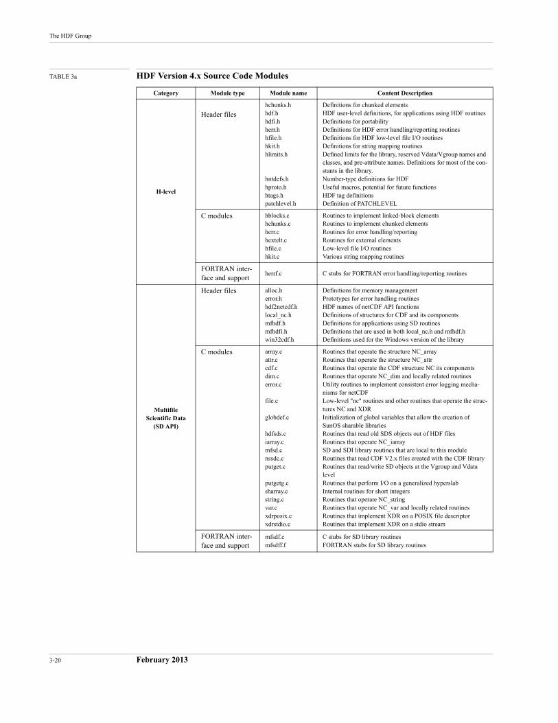
Table 3a, "HDF Version 4.x Source Code Modules," on page 20 lists the families of source code modules and header files of HDF Version 4.x. The first column of the table lists the name of the interface or the category of the modules, depending on their functionality. The modules are cate-gorized as follows:
• Low-level interface, or H-level interface, includes modules that facilitate portability and provide physical storage management, error handling mechanisms, support for simultaneous access to multiple objects within a single file, support for simultaneous access to multiple files, and an interface for key lower-level modules. Low-level routines begin with an H (e.g., Hopen/Hclose or Hread/Hwrite).
• Multifile Scientific Data interface (SD API) includes modules that provide the mechanisms for managing scientific data sets in a multifile environment. These modules reside in the directory mfhdf/, which is separate from that of the other interfaces. Library routines in this interface begin with SD. This interface replaces the Single-file Scientific Data interface (DFSD API). (A subtantial number of local or internal routine names in this code are influ-enced by netCDF. )
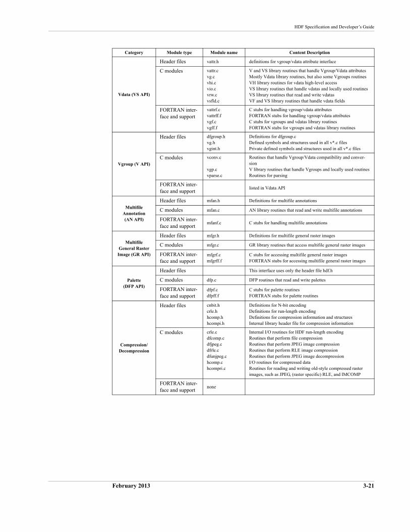
• Vdata interface (VS API) includes modules that provide mechanisms for managing Vdatas. Library routines in this interface begin with VS.
• Vgroup interface (V API) includes modules that provide mechanisms for managing Vgroups. Library routines in this interface begin with a V. Note that in the Content Descrip-tion column, the V and VS routines share some modules and header files.
• Multifile Annotation interface (AN API) includes modules that provide mechanisms for managing annotations in a multifile environment. Library routines in this interface begin with AN. This interface replaces the Single-file Annotation interface (DFAN API).
• General Raster Image interface (GR API) includes modules that provide mechanisms for managing general raster images in a multifile environment. Library routines in this interface begin with GR. This interface replaces the 8-bit Raster Image interface (DFR8 API) and the 24-bit Raster Image interface (DFR24 API), which operate in the single-file environment.
• Palette interface (DFP API) includes modules that provide mechanisms for managing the palettes that are used by the raster image interfaces. Library routines in this interface begin with DFP.
• Compression/Decompression includes modules that provide mechanisms for managing file and image compresion and decompression.
• Conversion includes modules that provide mechanisms to support conversion to and from the HDF format.
• Single-file Scientific Data interface (DFSD API) includes modules that provide mecha-nisms for managing scientific data sets in a single-file environment. Library routines in this interface begin with DFSD. This interface is replaced by the Multifile SD interface (SD API).
• Single-file General Raster Image interface (DFGR API) includes modules that provide mechanisms for managing general raster images in the single-file environment. This inter-face is an older version of the GR interface.
• 8-bit Raster Image interface (DFR8 API) includes modules that provide mechanisms for managing 8-bit raster images. This interface is replaced by the Multifile GR interface.
HDF Specification and Developer’s Guide
February 2013 3-19
• 24-bit Raster Image interface (DFR24 API) includes modules that provide mechanisms for managing 24-bit raster images. This interface is replaced by the Multifile GR interface.
• Single-file Annotation interface (DFAN API) includes modules that provide mechanisms for managing annotations in the single-file environment. This interface is replaced by the Multifile AN interface.
• Developer-level interface includes modules that are at a lower level than the H-level mod-ules, which heavily use the developer-level routines. These modules simplify the task of writing HDF applications by providing low-level routines for internal I/O handling, dynamic storage handling, memory management, and data descriptor handling.
• Mac Only interface includes modules that implement UNIX-like directory reading for the Macintosh.
The second column of Table 3a divides the modules in the interface into three groups: header files, C modules, and FORTRAN interface and support. The header files are discussed in the next section. The C modules group contains the primary C modules. The FORTRAN interface and sup-port group contains either or both the FORTRAN-callable C module and the FORTRAN module of the interface.
3.3.4 Header Files
In addition to the source code modules discussed above, some interfaces also have C header files associated with them that are meant to be included by C applications programmers with the#include preprocessor directive. They contain useful constants and data structures for interaction with the interface from C programs. The header files can be identified by the same name as the root name for the rest of the family with the .h extension. For example, dfsd.h is the header file for the Single-file Scientific Data Interface.
Of particular importance among the C header files are mfhdf.h, hdf.h and hdfi.h:
mfhdf.h Contains symbolic constants and public data structures for HDF’s SD interface.mfhdf.h must be included by any program that uses the SD API of the HDF library.
hdf.h Contains all the symbolic constants and public data structures required by HDF. hdf.h must be included by any program that uses the HDF library. (Note that this file is automatically included by the inclusion of mfhdf.h and need not be included separately.)
hdfi.h Contains specific portability information about each platform on which HDF is supported. hdfi.h is automatically included in a program when hdf.h is included, so programmers need not explicitly include it.
Refer to Chapter 11, Portability Issues, for more information on hdfi.h and other portability issues. Refer to Table 3a for the listing of the header files provided in the current version of the HDF library.
3-20 February 2013
The HDF Group
TABLE 3a HDF Version 4.x Source Code Modules
Category Module type Module name Content Description
H-level
Header fileshchunks.hhdf.hhdfi.hherr.hhfile.hhkit.hhlimits.h
hntdefs.hhproto.hhtags.hpatchlevel.h
Definitions for chunked elementsHDF user-level definitions, for applications using HDF routinesDefinitions for portabilityDefinitions for HDF error handling/reporting routinesDefinitions for HDF low-level file I/O routinesDefinitions for string mapping routinesDefined limits for the library, reserved Vdata/Vgroup names and classes, and pre-attribute names. Definitions for most of the con-stants in the library.Number-type definitions for HDFUseful macros, potential for future functionsHDF tag definitionsDefinition of PATCHLEVEL
C modules hblocks.chchunks.cherr.chextelt.chfile.chkit.c
Routines to implement linked-block elementsRoutines to implement chunked elementsRoutines for error handling/reportingRoutines for external elementsLow-level file I/O routinesVarious string mapping routines
FORTRAN inter-face and support
herrf.c C stubs for FORTRAN error handling/reporting routines
MultifileScientific Data
(SD API)
Header files alloc.herror.hhdf2netcdf.hlocal_nc.hmfhdf.hmfhdfi.hwin32cdf.h
Definitions for memory managementPrototypes for error handling routinesHDF names of netCDF API functionsDefinitions of structures for CDF and its componentsDefinitions for applications using SD routinesDefinitions that are used in both local_nc.h and mfhdf.hDefinitions used for the Windows version of the library
C modules array.cattr.ccdf.cdim.cerror.c
file.c
globdef.c
hdfsds.ciarray.cmfsd.cnssdc.cputget.c
putgetg.csharray.cstring.cvar.cxdrposix.cxdrstdio.c
Routines that operate the structure NC_arrayRoutines that operate the structure NC_attrRoutines that operate the CDF structure NC its componentsRoutines that operate NC_dim and locally related routinesUtility routines to implement consistent error logging mecha-nisms for netCDFLow-level "nc" routines and other routines that operate the struc-tures NC and XDRInitialization of global variables that allow the creation of SunOS sharable librariesRoutines that read old SDS objects out of HDF filesRoutines that operate NC_iarraySD and SDI library routines that are local to this moduleRoutines that read CDF V2.x files created with the CDF libraryRoutines that read/write SD objects at the Vgroup and Vdata levelRoutines that perform I/O on a generalized hyperslabInternal routines for short integersRoutines that operate NC_stringRoutines that operate NC_var and locally related routinesRoutines that implement XDR on a POSIX file descriptorRoutines that implement XDR on a stdio stream
FORTRAN inter-face and support
mfsdf.cmfsdff.f
C stubs for SD library routinesFORTRAN stubs for SD library routines
HDF Specification and Developer’s Guide
February 2013 3-21
Vdata (VS API)
Header files vattr.h definitions for vgroup/vdata attribute interface
C modules vattr.cvg.cvhi.cvio.cvrw.cvsfld.c
V and VS library routines that handle Vgroup/Vdata attributesMostly Vdata library routines, but also some Vgroups routinesVH library routines for vdata high-level accessVS library routines that handle vdatas and locally used routinesVS library routines that read and write vdatasVF and VS library routines that handle vdata fields
FORTRAN inter-face and support
vattrf.cvattrff.fvgf.cvgff.f
C stubs for handling vgroup/vdata attributesFORTRAN stubs for handling vgroup/vdata attributesC stubs for vgroups and vdatas library routinesFORTRAN stubs for vgroups and vdatas library routines
Vgroup (V API)
Header files dfgroup.hvg.hvgint.h
Definitions for dfgroup.cDefined symbols and structures used in all v*.c filesPrivate defined symbols and structures used in all v*.c files
C modules vconv.c
vgp.cvparse.c
Routines that handle Vgroup/Vdata compatibility and conver-sionV library routines that handle Vgroups and locally used routinesRoutines for parsing
FORTRAN inter-face and support
listed in Vdata API
Multifile Annotation(AN API)
Header files mfan.h Definitions for multifile annotations
C modules mfan.c AN library routines that read and write multifile annotations
FORTRAN inter-face and support
mfanf.c C stubs for handling multifile annotations
Multifile General Raster
Image (GR API)
Header files mfgr.h Definitions for multifile general raster images
C modules mfgr.c GR library routines that access multifile general raster images
FORTRAN inter-face and support
mfgrf.cmfgrff.f
C stubs for accessing multifile general raster imagesFORTRAN stubs for accessing multifile general raster images
Palette (DFP API)
Header files This interface uses only the header file hdf.h
C modules dfp.c DFP routines that read and write palettes
FORTRAN inter-face and support
dfpf.cdfpff.f
C stubs for palette routinesFORTRAN stubs for palette routines
Compression/Decompression
Header files cnbit.hcrle.hhcomp.hhcompi.h
Definitions for N-bit encodingDefinitions for run-length encodingDefinitions for compression information and structuresInternal library header file for compression information
C modules crle.cdfcomp.cdfjpeg.cdfrle.cdfunjpeg.chcomp.chcompri.c
Internal I/O routines for HDF run-length encodingRoutines that perform file compressionRoutines that perform JPEG image compressionRoutines that perform RLE image compressionRoutines that perform JPEG image decompressionI/O routines for compressed dataRoutines for reading and writing old-style compressed raster images, such as JPEG, (raster specific) RLE, and IMCOMP
FORTRAN inter-face and support
none
Category Module type Module name Content Description
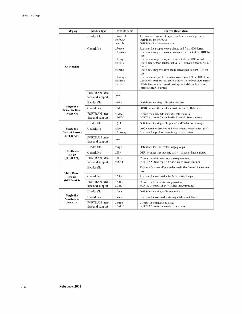
3-22 February 2013
The HDF Group
Conversion
Header files dfconvrt.hdfufp2i.hhconv.h
The macro DFconvert to speed up the conversion processDefinitions for dfufp2i.cDefinitions for data conversion
C modules dfconv.cdfkconv.c
dfkcray.cdfkfuji.c
dfknat.c
dfkswap.cdfkvms.cdfufp2i.c
Routines that support conversion to and from HDF formatRoutines to support Convex-native conversion to/from HDF for-matRoutines to support Cray conversion to/from HDF formatRoutines to support Fujitsu-native (VP) conversion to/from HDF formatRoutines to support native-mode conversion to/from HDF for-matRoutines to support little-endian conversion to/from HDF formatRoutines to support Vax-native conversion to/from HDF formatUtility functions to convert floating point data to 8-bit raster image set (RIS8) format
FORTRAN inter-face and support
none
Single-fileScientific Data
(DFSD API)
Header files dfsd.h Definitions for single-file scientific data
C modules dfsd.c DFSD routines that read and write Scientific Data Sets
FORTRAN inter-face and support
dfsdf.cdfsdff.f
C stubs for single-file scientific data routinesFORTRAN stubs for single-file Scientific Data routines
Single-fileGeneral Rasters
(DFGR API)
Header files dfgr.h Definitions for single-file general and 24-bit raster images
C modules dfgr.cdfimcomp.c
DFGR routines that read and write general raster images (old)Routines that perform color image compression
FORTRAN inter-face and support
none
8-bit Raster Images
(DFR8 API)
Header files dfrig.h Definitions for 8-bit raster image groups
C modules dfr8.c DFR8 routines that read and write 8-bit raster image groups
FORTRAN inter-face and support
dfr8f.cdfr8ff.f
C stubs for 8-bit raster image group routinesFORTRAN stubs for 8-bit raster image group routines
24-bit Raster Images
(DFR24 API)
Header files This interface uses dfgr.h in the single-file General Raster inter-face
C modules df24.c Routines that read and write 24-bit raster images
FORTRAN inter-face and support
df24f.cdf24ff.f
C stubs for 24-bit raster image routinesFORTRAN stubs for 24-bit raster image routines
Single-fileAnnotations(DFAN API)
Header files dfan.h Definitions for single-file annotations
C modules dfan.c Routines that read and write single-file annotations
FORTRAN inter-face and support
dfanf.cdfanff.f
C stubs for annotation routinesFORTRAN stubs for annotation routines
Category Module type Module name Content Description
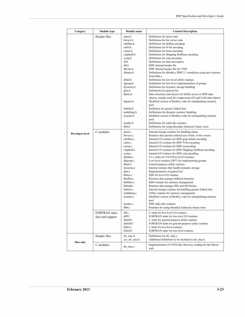
HDF Specification and Developer’s Guide
February 2013 3-23
Developer-level
Header files atom.hbitvect.hcdeflate.hcnbit.hcnone.hcskphuff.hcszip.hdf.hdfi.hdfivms.hdfstubs.h
dfutil.hdgroup.hdynarray.hglist.hhbitio.h
hqueue.h
linklist.hmaldebug.hmcache.h
mstdio.htbbt.h
Definitions for atom codeDefinitions for bit vector codeDefinitions for deflate encodingDefinitions for N-bit encodingDefinitions for none-encodingDefinitions for Skipping Huffman encodingDefinitions for szip encodingDefinitions for data descriptorsHDF internal header fileHDF internal header file for VMSDefinitions for dfstubs.c HDF 3.1 emulation using new routines from hfile.cDefinitions for low-level utility routinesDefinitions for low-level implementation of groupsDefinitions for dynamic storage handlingDefinitions for general listData structures and macros for bitfile access to HDF data objects; mainly used for compression I/O and N-bit data objectsModified version of Berkley code for manipulating memory poolDefinition for generic linked listsDefinitions for dynamic memory handlingModified version of Berkley code for manipulating memory poolDefinitions for stdio-like routinesDefinitions for using threaded, balanced, binary trees
C modules atom.cbitvect.ccdeflate.ccnbit.ccnone.ccskphuff.ccszip.cdfstubs.cdfgroup.cdfutil.cdynarray.cglist.chbitio.chbuffer.chdfalloc.chfiledd.clinklist.cmaldebug.cmcache.c
mstdio.ctbbt.c
Internal storage routines for handling atomsRoutines that operate ordered sets of bits, or bit vectorsInternal I/O routines for HDF gzip deflate encodingInternal I/O routines for HDF N-bit encodingInternal I/O routines for HDF noencodingInternal I/O routines for HDF Skipping Huffman encodingInternal I/O routines for HDF szip encodingV3.x stubs for V4.0 H-level I/O routinesLow-level routines (DF*) for implementing groupsGeneral-purpose utility routinesInternal routines that handle dynamic storageImplementation of general listHDF bit level I/O routinesRoutines that manage buffered elementsHDF routines for memory managementRoutines that manage DDs and DD blocksInternal storage routines for handling generic linked listsUtility routines for memory managementModified version of Berkley code for manipulating memory poolHDF stdio-like routinesRoutines for using threaded, balanced, binary trees
FORTRAN inter-face and support
dff.cdfff.fdfutilf.cdfutilff.fhfilef.chfileff.f
C stubs for low-level I/O routinesFORTRAN stubs for low-level I/O routinesC stubs for general-purpose utility routinesFORTRAN stubs for general-purpose utility routinesC stubs for low-level routinesFORTRAN stubs for low-level routines
Mac only
Header files dir_mac.hsys_dir_mac.h
Definitions for dir_mac.cAdditional definitions to be included in dir_mac.h
C modules dir_mac.cImplementation of UNIX-like directory reading for the Macin-tosh
Category Module type Module name Content Description
3-24 February 2013
The HDF Group
3.3.5 The HDF Test Suite
In addition to the source code for the HDF library, Versions 3.2 and higher include a test suite. There are two test modules: one for C and one for FORTRAN. Each module tests all of the rou-tines in all of the application interfaces and in the low-level interface. The exact form of these test modules may vary from one release to the next; consult the release code and online test documen-tation for details.
Every effort has been made to ensure that the test programs provide a thorough and accurate assessment of the health of the HDF library. Although the test suite will greatly improve the reli-ability of HDF code, it is almost inevitable that some parts of the code will remain untested. Therefore, no guarantees can be made on the basis of test suite performance.
3.3.6 Sample HDF Programs
Sample programs, illustrating some of the common techniques employed by HDF programmers, are available on the HDF web site at http://www.hdfgroup.org/training/HDFtraining/examples/.
To help users become familiar with HDF, each release includes several sample programs illustrat-ing common techniques employed by HDF programmers.
3.4 Some HDF Conventions
The HDF specification described in the previous chapter is not sufficient to guarantee its success. It is also important that HDF programmers and users adhere to certain conventions. Some guide-lines are implicit in the discussions in other sections of this document. Others are presented in the document NCSA HDF Calling Interfaces and Utilities for Versions 3.2 and earlier, or in the HDF User’s Guide and the HDF Reference Manual for Versions 3.3 and 4.x.
Guidelines not covered elsewhere are introduced in this section.
Naming and Assigning Tags
Tags that are to be made available to a general population of HDF users should be assigned and controlled by The HDF Group (THG). Tags of this type are given numbers in the range 1 to 32,767. If you have an application that fits this criterion, contact THG at the address listed in the front matter at the beginning of this manual and specify the tags you would like. For each tag, your specifications should include a suggested name, information about the type and structure of the data that the tag will refer to, and information about how the tag will be used. Your specifica-tions should be similar to those contained in Chapter 9, Tag Specifications. THG will assign a set of tags for your application and will include your tag descriptions in the HDF documentation.
Tags in the range 32,768 to 64,999 are user-definable. That is, you can assign them for any private application. If you use tags in this range, be aware that they may conflict with other people's pri-vate tags.
Using Reference Numbers to Organize Data Objects
The HDF library itself uses reference numbers solely to distinguish among objects with the same tag. While application programmers may find it convenient to impart some meaning to reference numbers, they should be forewarned that the HDF library will be ignorant of any such meaning.
HDF Specification and Developer’s Guide
February 2013 3-25
Multiple References
Multiple references to a single data element are quite common in HDF. The low-level routineHdupdd generates a new reference to data that is already pointed to by another DD. If Hdupdd is used several times, there may be several DDs that point to the same data element.
It is important to note that when a multiply-referenced data element is deleted or moved, the vari-ous DDs that previously pointed to the data element are not automatically deleted or adjusted to point to the data element in its new location. Consequently, each DD to be deleted or moved should be checked for multiple references and handled appropriately.
Note: Users are discouraged from assigning any meaning to reference numbers beyond that imparted by the HDF library.

3-26 February 2013
The HDF Group
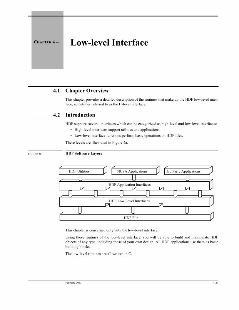
February 2013 4-27
CHAPTER 4 -- Low-level Interface
4.1 Chapter Overview
This chapter provides a detailed description of the routines that make up the HDF low-level inter-face, sometimes referred to as the H-level interface.
4.2 Introduction
HDF Utilities NCSA Applications 3rd Party Applications
HDF Application Interfaces
HDF Low Level Interfaces
HDF File
HDF supports several interfaces which can be categorized as high-level and low-level interfaces:
• High-level interfaces support utilities and applications.
• Low-level interface functions perform basic operations on HDF files.
These levels are illustrated in Figure 4a.
FIGURE 4a HDF Software Layers
This chapter is concerned only with the low-level interface.
Using these routines of the low-level interface, you will be able to build and manipulate HDF objects of any type, including those of your own design. All HDF applications use them as basic building blocks.
The low-level routines are all written in C.
4-28 February 2013
The HDF Group
4.3 New Low-level Routines with Version 3.2 and Higher
The low-level routines described in this chapter are new with HDF Version 3.2 and higher; they replace the routines provided with earlier versions. The new routines provide better performance and increased functionality and users are strongly advised to use them in new applications. The old routines are supported through emulation, but may be eliminated from the HDF library in a future release.
The new lower layer incorporates the following improvements:
• More consistent data and function types
• More meaningful and extensive error reporting
• Simplification of key lower-level functions
• Simplified techniques to facilitate portability
• Support for alternate forms of physical storage, such as linked blocks storage and storage of the data portion of an object in an external file
• A version tag to indicate which version of the HDF library last changed a file
• Support for simultaneous access to multiple files
• Support for simultaneous access to multiple objects within a single file
The previous lower layer was called the DF layer because all routines began with the letters DF(e.g., DFopen and DFclose). The new lower layer is called the H layer because all routines begin with the letter H (e.g., Hopen, Hclose, and Hwrite). The source modules containing these routines begin with the letter h (see Table 3a, "HDF Version 4.x Source Code Modules"):
hfile.c Basic I/0 routines
herr.c Error-handling routines
hkit.c General purpose routines
hblocks.c Routines to support linked block storage
hextelt.c Routines to support external storage of HDF data elements
hchunks.c Routines to support chunked elements
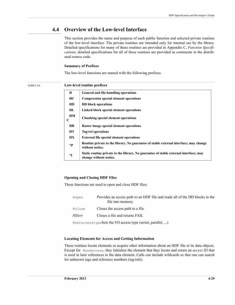
HDF Specification and Developer’s Guide
February 2013 4-29
4.4 Overview of the Low-level Interface
This section provides the name and purpose of each public function and selected private routines of the low-level interface. The private routines are intended only for internal use by the library. Detailed specifications for many of these routines are provided in Appendix C, Function Specifi-cations; detailed specifications for all of these routines are provided as comments in the distrib-uted source code.
Summary of Prefixes
The low-level functions are named with the following prefixes.
TABLE 4A Low-level routine prefixes
Opening and Closing HDF Files
These functions are used to open and close HDF files:
Hopen Provides an access path to an HDF file and reads all of the DD blocks in the file into memory
Hclose Closes the access path to a file
HDerr Closes a file and returns FAIL
HsetaccesstypeSets the I/O access type (serial, parallel, ...)
Locating Elements for Access and Getting Information
These routines locate elements or acquire other information about an HDF file or its data objects. Except for Hendaccess, they initialize the element that they locate and return an access ID that is used in later references to the data element. Calls can include wildcards so that one can search for unknown tags and reference numbers (tag/refs).
H General and file-handling operations
HC Compression special element operations
HD DD block operations
HL Linked block special element operations
HMC
Chunking special element operations
HR Raster image special element operations
HT Tag/ref operations
HX External file special element operations
*PRoutine private to the library. No guarantee of stable external interface; may change without notice.
*IStatic routine private to the library. No guarantee of stable external interface; may change without notice.
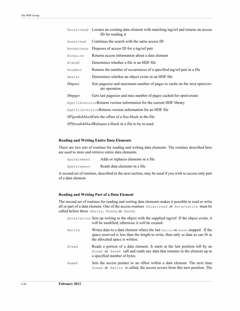
4-30 February 2013
The HDF Group
Hstartread Locates an existing data element with matching tag/ref and returns an access ID for reading it
Hnextread Continues the search with the same access ID
Hendaccess Disposes of access ID for a tag/ref pair
Hinquire Returns access information about a data element
Hishdf Determines whether a file is an HDF file
Hnumber Returns the number of occurrences of a specified tag/ref pair in a file
Hexist Determines whether an object exists in an HDF file
Hmpset Sets pagesize and maximum number of pages to cache on the next open/cre-ate operation
Hmpget Gets last pagesize and max number of pages cached for open/create
HgetlibversionReturns version information for the current HDF library
HgetfileversionReturns version information for an HDF file
HPgetdiskblockGets the offset of a free block in the file
HPfreediskblockReleases a block in a file to be re-used
Reading and Writing Entire Data Elements
There are two sets of routines for reading and writing data elements. The routines described here are used to store and retrieve entire data elements.
Hputelement Adds or replaces elements in a file
Hgetelement Reads data elements in a file
A second set of routines, described in the next section, may be used if you wish to access only part of a data element.
Reading and Writing Part of a Data Element
The second set of routines for reading and writing data elements makes it possible to read or write all or part of a data element. One of the access routines Hstartread or Hstartwrite must be called before these Hwrite, Hread, or Hseek:
Hstartwrite Sets up writing to the object with the supplied tag/ref. If the object exists, it will be modified; otherwise it will be created.
Hwrite Writes data to a data element where the last Hwrite or Hseek stopped. If the space reserved is less than the length to write, then only as data as can fit in the allocated space is written.
Hread Reads a portion of a data element. It starts at the last position left by anHread or Hseek call and reads any data that remains in the element up to a specified number of bytes.
Hseek Sets the access pointer to an offset within a data element. The next timeHread or Hwrite is called, the access occurs from this new position. The
HDF Specification and Developer’s Guide
February 2013 4-31
location to seek can be specified as an offset from the current location, from the start of the element, or from the end of the element.
Htrunc Truncates a data set to a specified length.
Manipulating Data Descriptors (DDs)
The routines listed here perform operations on DDs without modifying the data to which the DDs refer. The first list indicates public routines that are available to users and applications; the second list indicates private routines that are used internally by the library.
Public user routines
Hdupdd Generates new references to a data element that is already referenced from somewhere else
Hdeldd Deletes a tag/ref pair from the list of DDs
HDcheck_tagrefChecks to see whether a tag/ref pair is in the DD list
HDreuse_tagrefReuses a data descriptor of a tag/ref pair in a DD list of an HDF file
Hnewref Returns a reference number that is unique in the file
Htagnewref Returns a reference number that is unique in the file for a given tag
Hfind Locates the next object of a search in an HDF file
Private library routines (internal)
HTPcreate Creates (and attaches to) a tag/ref pair and inserts it into the DD list
HTPselect Attaches to an existing DD in the DD list
HTPendaccess Ends access to an attached DD in the DD list
HTPdelete Marks a tag/ref pair as free and ends access to it
HTPupdate Changes the offset and/or length of a data object
HTPinquire Gets the DD information for a DD (i.e. tag/ref/offset/length)
HTPis_special Checks whether a DD identifier is associated with a special tag
HTPstart Initializes the DD list from disk, i.e., creates the DD list in memory
HTPinit Creates a new DD list in memory
HTPsync Flushes the DD list to disk
HTPend Closes the DD list to disk
Creating Special Data Elements
Prior to release 3.2, any data element had to be stored contiguously and all of the objects in an HDF file had to be in the same physical file. The contiguous requirement caused many problems, especially with regard to appending to existing objects. If you wanted to append data to an object, the entire data element had to be deleted and rewritten to the end of the file. Later HDF versions introduced alternate methods of storing HDF objects: linked blocks and external elements at the
4-32 February 2013
The HDF Group
release of HDF Version 3.2 and chunking at HDF Version 4.1. These special elements, plus com-pression, are discussed in detail in Chapter 10, Extended Tags and Special Elements.
Linked blocks improve storage management by allowing elements in a single HDF file to be non-contiguous. The routines listed here operate on linked blocks The first list indicates the public rou-tines that are available to users and applications; the second list indicates the private routines that are used internally by the library.
Public user routines
HLcreate Creates a new linked-block special data element
HLconvert Converts an AID into a linked-block element
HDinqblockinfoReturns information about linked blocks
Private library routines (internal)
HLPread Reads some data out of a linked-block element
HLPwrite Writes out some data to a linked-block element
HLPinquire Returns information about a linked-block element
HLPendacess Closes a linked-block AID
HLPinfo Returns information about a linked-block element
HLPstread Opens an access record for reading
HLPstwrite Opens an access record for writing
HLPseek Sets position for the next access
External elements allow a single HDF object to be stored in an external file. The following rou-tines operate on external elements:
HXcreate Creates a new external file special data element
HXsetcreatedir Sets the directory variable for creating external file
HXsetdir Sets the directory variable for locating external file
It is not currently possible to store a single object (such as a very large data set) in multiple files. Nor can multiple objects be stored in one external file.
Once they are created with the routines HLcreate and HXcreate, these special data elements can be accessed with the routines used for normal data elements. These routines have two modes of operation. Calling HLcreate with a tag/ref that does not exist in a file will create a new element with the given tag/ref pair which will be stored as linked blocks. On the other hand, if the tag/ref pair already exists in the file, the referenced object will be promoted to linked block status. All data which had been stored in the object before the promotion will be retained. HXcreate behaves similarly.
Chunking allows elements in large arrays to be stored as chunks in such a way that I/O perfor-mance can be significantly improved. The routines listed here perform operations on chunking elements. The first list indicates the public routines that are available to users and applications; the second list indicates the private routines that are used internally by the library.
Public user routines
HDF Specification and Developer’s Guide
February 2013 4-33
HMCcreate Creates a chunked element.
HMCwriteChunkWrites out the specified chunk to a chunked element.
HMCreadChunk Reads the specified chunk from a chunked element.
HMCsetMaxcacheSets the maximum number of chunks to cache.
HMCPcloseAID Closes the file but keeps AID active (for Hnextread()).
Private library routines (internal)
HMCPstread Opens an access record for reading.
HMCPstwrite Opens an access record for writing.
HMCPseek Sets the seek position.
HMCPchunkreadReads a single chunk from a chunked element.
HMCPread Reads a more arbitrarily sized piece of data from a chunked element.
HMCPchunkwriteWrites out a single chunk of data to a chunked element.
HMCPwrite Writes out a more arbitrarily sized piece of data to a chunked element.
HMCPinquire Implements Hinquire for a chunked element.
HMCPendacess Closes a chunked element AID
HMCPinfo Returns information about a chunked element.
Compression provides for the compression of data sets. The routines listed here perform those compression operations. The first list indicates the public routines that are available to users and applications; the second list indicates the private routines that are used internally by the library.1
Public user routines
HCcreate Create a compressed data element
Private library routines (internal)
1. These are the general compression functions. Additional compression functions, specific to each compression style, can be found in the compression style-specific modules in the source code distribution. As of HDF Version 1.4r4, those modules included the files c*.c (e.g., cde-flate.c., crle.c) in the directory ./hdf/src/.
4-34 February 2013
The HDF Group
HCIinit_coderSet the coder function pointers
HCIinit_modelSet the model function pointers
HCIread_headerRead the compression header info from a file
HCIstaccess Start accessing a compressed data element.
HCIwrite_headerWrite the compression header info to a file
HCPcloseAID Get rid of the compressed data element data structures
HCPdecode_headerDecode the compression header info from a memory buffer
HCPencode_headerEncode the compression header info to a memory buffer
HCPendaccess Close the compressed data element and free the AID
HCPinfo return info about a compressed element
HCPinquire Inquire information about the access record and data element.
HCPmstdio_endaccessClose the compressed data element
HCPmstdio_inquire Inquire information about the access record and data element
HCPmstdio_readRead in a portion of data from a compressed data element
HCPmstdio_seekSeek to offset within the data element
HCPmstdio_streadstart read access for compressed file
HCPmstdio_stwritestart write access for compressed file
HCPmstdio_writeWrite out a portion of data from a compressed data element
HCPquery_encode_headerQuery the length of compression header for a memory buffer
HCPread Read in a portion of data from a compressed data element.
HCPseek Seek to offset within the data element
HCPstread Start read access on a compressed data element.
HCPstwrite Start write access on a compressed data element.
HCPwrite Write out a portion of data from a compressed data element.
HRPcloseAID Free memory but keep AID active
HRPconvert Wrap an existing raster image with the special element routines.
HRPendacess Free AID
HRPinfo Return info about a compressed raster element
HRPinquire Retreive information about a compressed raster element
HRPread Read some data out of compressed raster element
HRPseek Set the seek posn
HRPstread Open an access record for reading
HRPstwrite Open an access record for reading
HRPwrite Write data out to a compressed raster image
HDF Specification and Developer’s Guide
February 2013 4-35
General special element routines: In addition to the routines specific to a particular type of spe-cial element, the library provides general routines for use on any special element:
HDget_special_infoGets information about a special element
HDset_special_infoResets information about a special element
Development Routines
The HDF library provides the following developer-level routines that simplify the task of writing HDF applications. Many of these routines mirror basic C library functions which are, unfortu-nately, not always completely portable in their library form:
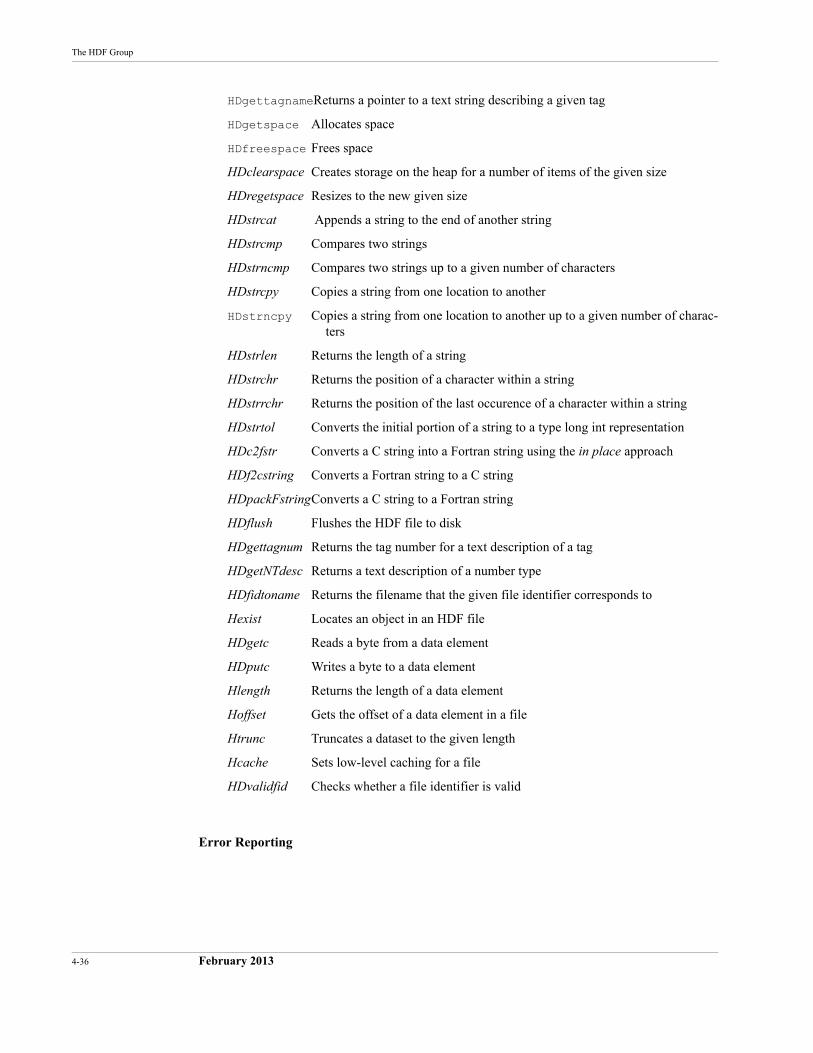
4-36 February 2013
The HDF Group
HDgettagnameReturns a pointer to a text string describing a given tag
HDgetspace Allocates space
HDfreespace Frees space
HDclearspace Creates storage on the heap for a number of items of the given size
HDregetspace Resizes to the new given size
HDstrcat Appends a string to the end of another string
HDstrcmp Compares two strings
HDstrncmp Compares two strings up to a given number of characters
HDstrcpy Copies a string from one location to another
HDstrncpy Copies a string from one location to another up to a given number of charac-ters
HDstrlen Returns the length of a string
HDstrchr Returns the position of a character within a string
HDstrrchr Returns the position of the last occurence of a character within a string
HDstrtol Converts the initial portion of a string to a type long int representation
HDc2fstr Converts a C string into a Fortran string using the in place approach
HDf2cstring Converts a Fortran string to a C string
HDpackFstringConverts a C string to a Fortran string
HDflush Flushes the HDF file to disk
HDgettagnum Returns the tag number for a text description of a tag
HDgetNTdesc Returns a text description of a number type
HDfidtoname Returns the filename that the given file identifier corresponds to
Hexist Locates an object in an HDF file
HDgetc Reads a byte from a data element
HDputc Writes a byte to a data element
Hlength Returns the length of a data element
Hoffset Gets the offset of a data element in a file
Htrunc Truncates a dataset to the given length
Hcache Sets low-level caching for a file
HDvalidfid Checks whether a file identifier is valid
Error Reporting
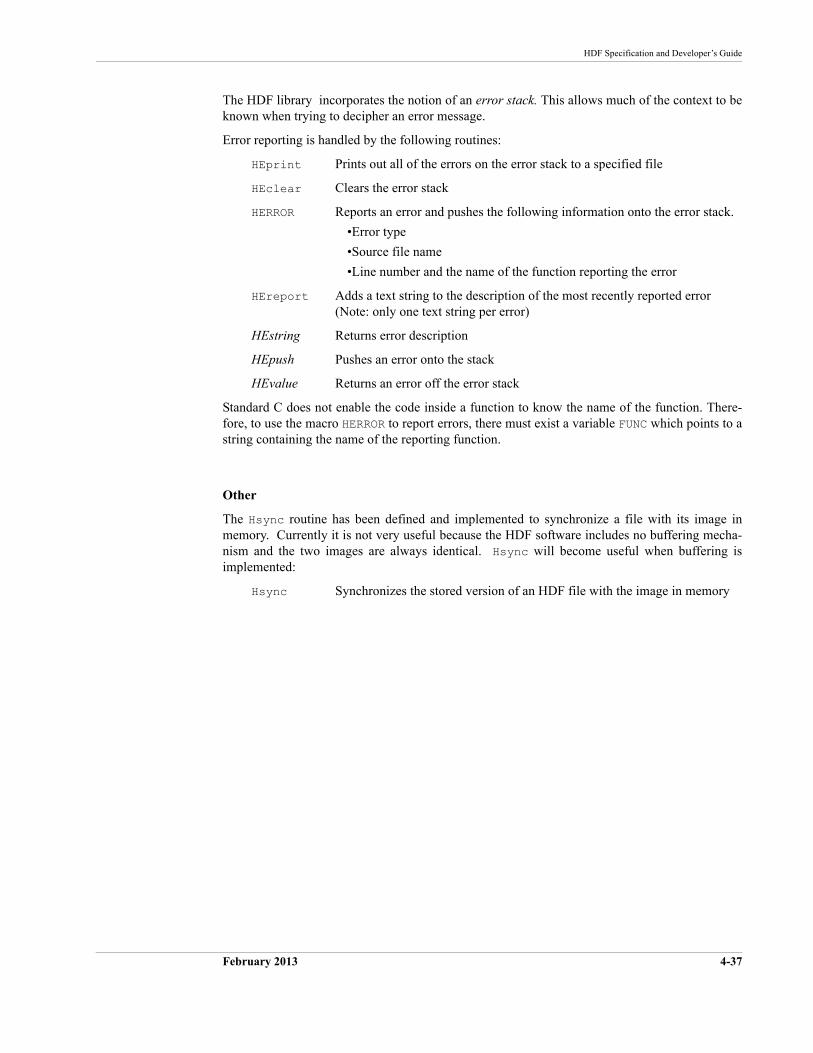
HDF Specification and Developer’s Guide
February 2013 4-37
The HDF library incorporates the notion of an error stack. This allows much of the context to be known when trying to decipher an error message.
Error reporting is handled by the following routines:
HEprint Prints out all of the errors on the error stack to a specified file
HEclear Clears the error stack
HERROR Reports an error and pushes the following information onto the error stack.
•Error type
•Source file name
•Line number and the name of the function reporting the error
HEreport Adds a text string to the description of the most recently reported error(Note: only one text string per error)
HEstring Returns error description
HEpush Pushes an error onto the stack
HEvalue Returns an error off the error stack
Standard C does not enable the code inside a function to know the name of the function. There-fore, to use the macro HERROR to report errors, there must exist a variable FUNC which points to a string containing the name of the reporting function.
Other
The Hsync routine has been defined and implemented to synchronize a file with its image in memory. Currently it is not very useful because the HDF software includes no buffering mecha-nism and the two images are always identical. Hsync will become useful when buffering is implemented:
Hsync Synchronizes the stored version of an HDF file with the image in memory

4-38 February 2013
The HDF Group
February 2013 5-37
CHAPTER 5 -- Sets and Groups
5.1 Chapter Overview
This chapter discusses the roles of the following sets and groups in organizing data stored in an HDF file:
Raster image sets (RIS)Raster image groups (RIG)
Scientific data sets (SDS)Scientific data groups (SDG)Numeric data groups (NDG)SDG-like NDGs
Vsets Vgroups and Vdatas
Raster-8 sets (obsolete)
This chapter introduces several tags used in support of sets and groups. All of these tags are fully described in Chapter 9, Tag Specifications, and are listed in the table in Appendix A, Tags and Extended Tag Labels.
5.2 Data Sets
HDF files frequently contain several closely related data objects. Taken together, these objects form a data set which serves a particular user requirement. For example, five or six data objects might be used to describe a raster image; eight or more data objects might be used to describe the results of a scientific experiment.
The HDF mechanism for specifying and controlling data sets is the group. The data element of a group consists of a single record listing the tag/refs for all the objects contained in the data set. For example, the raster image groups described in the following sections each contain three tag/refs that point to three data objects that, taken as a set, fully describe an 8-bit raster image.
5.2.1 Types of Sets
The current HDF implementation supports three kinds of sets:
Raster image setA set containing a raster image and descriptive information such as the image dimensions and an optional color lookup table
Scientific data setA set containing a multidimensional array and information describing the data in the array
Vset A general grouping structure containing any kinds of HDF objects that a user wishes to include
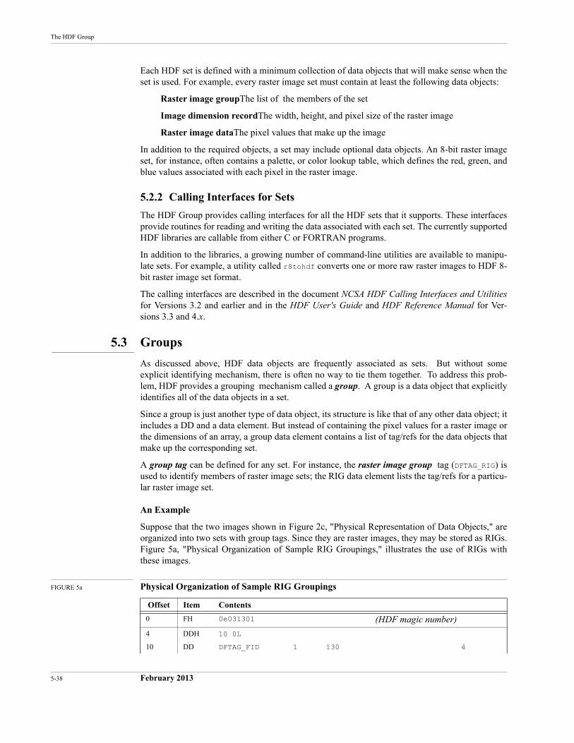
5-38 February 2013
The HDF Group
Each HDF set is defined with a minimum collection of data objects that will make sense when the set is used. For example, every raster image set must contain at least the following data objects:
Raster image groupThe list of the members of the set
Image dimension recordThe width, height, and pixel size of the raster image
Raster image dataThe pixel values that make up the image
In addition to the required objects, a set may include optional data objects. An 8-bit raster image set, for instance, often contains a palette, or color lookup table, which defines the red, green, and blue values associated with each pixel in the raster image.
5.2.2 Calling Interfaces for Sets
The HDF Group provides calling interfaces for all the HDF sets that it supports. These interfaces provide routines for reading and writing the data associated with each set. The currently supported HDF libraries are callable from either C or FORTRAN programs.
In addition to the libraries, a growing number of command-line utilities are available to manipu-late sets. For example, a utility called r8tohdf converts one or more raw raster images to HDF 8-bit raster image set format.
The calling interfaces are described in the document NCSA HDF Calling Interfaces and Utilitiesfor Versions 3.2 and earlier and in the HDF User's Guide and HDF Reference Manual for Ver-sions 3.3 and 4.x.
5.3 Groups
As discussed above, HDF data objects are frequently associated as sets. But without some explicit identifying mechanism, there is often no way to tie them together. To address this prob-lem, HDF provides a grouping mechanism called a group. A group is a data object that explicitly identifies all of the data objects in a set.
Since a group is just another type of data object, its structure is like that of any other data object; it includes a DD and a data element. But instead of containing the pixel values for a raster image or the dimensions of an array, a group data element contains a list of tag/refs for the data objects that make up the corresponding set.
A group tag can be defined for any set. For instance, the raster image group tag (DFTAG_RIG) is used to identify members of raster image sets; the RIG data element lists the tag/refs for a particu-lar raster image set.
An Example
Suppose that the two images shown in Figure 2c, "Physical Representation of Data Objects," are organized into two sets with group tags. Since they are raster images, they may be stored as RIGs. Figure 5a, "Physical Organization of Sample RIG Groupings," illustrates the use of RIGs with these images.
FIGURE 5a Physical Organization of Sample RIG Groupings
Offset Item Contents
0 FH 0e031301 (HDF magic number)
4 DDH 10 0L
10 DD DFTAG_FID 1 130 4
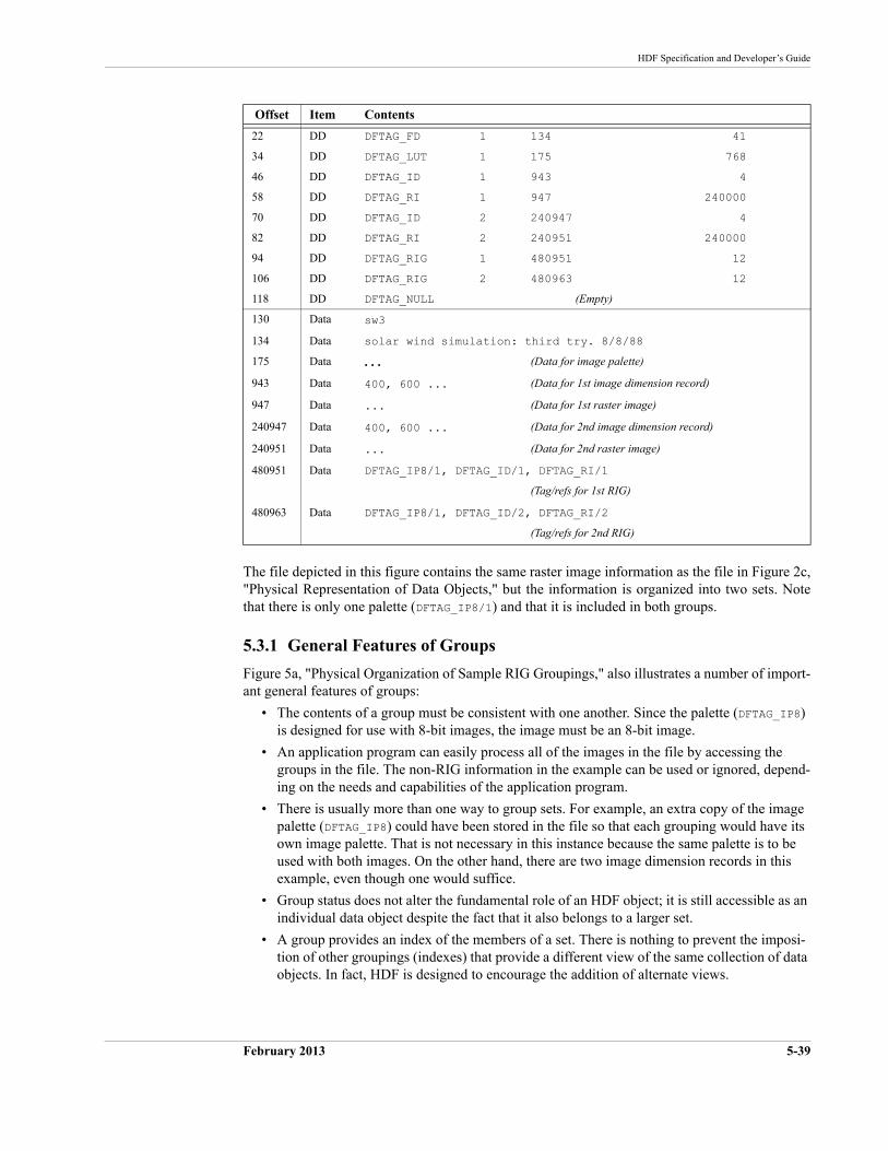
HDF Specification and Developer’s Guide
February 2013 5-39
The file depicted in this figure contains the same raster image information as the file in Figure 2c, "Physical Representation of Data Objects," but the information is organized into two sets. Note that there is only one palette (DFTAG_IP8/1) and that it is included in both groups.
5.3.1 General Features of Groups
Figure 5a, "Physical Organization of Sample RIG Groupings," also illustrates a number of import-ant general features of groups:
• The contents of a group must be consistent with one another. Since the palette (DFTAG_IP8) is designed for use with 8-bit images, the image must be an 8-bit image.
• An application program can easily process all of the images in the file by accessing the groups in the file. The non-RIG information in the example can be used or ignored, depend-ing on the needs and capabilities of the application program.
• There is usually more than one way to group sets. For example, an extra copy of the image palette (DFTAG_IP8) could have been stored in the file so that each grouping would have its own image palette. That is not necessary in this instance because the same palette is to be used with both images. On the other hand, there are two image dimension records in this example, even though one would suffice.
• Group status does not alter the fundamental role of an HDF object; it is still accessible as an individual data object despite the fact that it also belongs to a larger set.
• A group provides an index of the members of a set. There is nothing to prevent the imposi-tion of other groupings (indexes) that provide a different view of the same collection of data objects. In fact, HDF is designed to encourage the addition of alternate views.
22 DD DFTAG_FD 1 134 41
34 DD DFTAG_LUT 1 175 768
46 DD DFTAG_ID 1 943 4
58 DD DFTAG_RI 1 947 240000
70 DD DFTAG_ID 2 240947 4
82 DD DFTAG_RI 2 240951 240000
94 DD DFTAG_RIG 1 480951 12
106 DD DFTAG_RIG 2 480963 12
118 DD DFTAG_NULL (Empty)
130 Data sw3
134 Data solar wind simulation: third try. 8/8/88
175 Data . . . (Data for image palette)
943 Data 400, 600 ... (Data for 1st image dimension record)
947 Data ... (Data for 1st raster image)
240947 Data 400, 600 ... (Data for 2nd image dimension record)
240951 Data ... (Data for 2nd raster image)
480951 Data DFTAG_IP8/1, DFTAG_ID/1, DFTAG_RI/1
(Tag/refs for 1st RIG)
480963 Data DFTAG_IP8/1, DFTAG_ID/2, DFTAG_RI/2
(Tag/refs for 2nd RIG)
Offset Item Contents
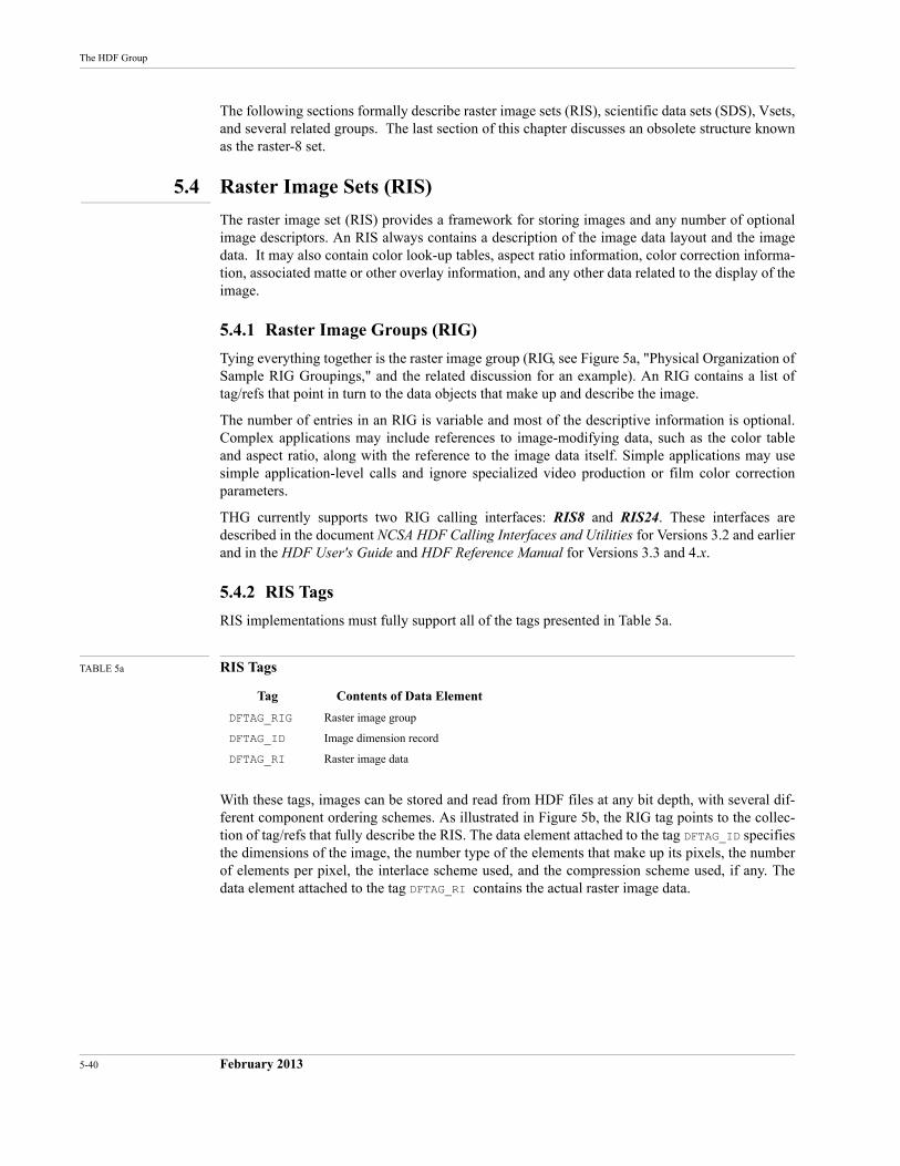
5-40 February 2013
The HDF Group
The following sections formally describe raster image sets (RIS), scientific data sets (SDS), Vsets, and several related groups. The last section of this chapter discusses an obsolete structure known as the raster-8 set.
5.4 Raster Image Sets (RIS)
The raster image set (RIS) provides a framework for storing images and any number of optional image descriptors. An RIS always contains a description of the image data layout and the image data. It may also contain color look-up tables, aspect ratio information, color correction informa-tion, associated matte or other overlay information, and any other data related to the display of the image.
5.4.1 Raster Image Groups (RIG)
Tying everything together is the raster image group (RIG, see Figure 5a, "Physical Organization of Sample RIG Groupings," and the related discussion for an example). An RIG contains a list of tag/refs that point in turn to the data objects that make up and describe the image.
The number of entries in an RIG is variable and most of the descriptive information is optional. Complex applications may include references to image-modifying data, such as the color table and aspect ratio, along with the reference to the image data itself. Simple applications may use simple application-level calls and ignore specialized video production or film color correction parameters.
THG currently supports two RIG calling interfaces: RIS8 and RIS24. These interfaces are described in the document NCSA HDF Calling Interfaces and Utilities for Versions 3.2 and earlier and in the HDF User's Guide and HDF Reference Manual for Versions 3.3 and 4.x.
5.4.2 RIS Tags
RIS implementations must fully support all of the tags presented in Table 5a.
TABLE 5a RIS Tags
With these tags, images can be stored and read from HDF files at any bit depth, with several dif-ferent component ordering schemes. As illustrated in Figure 5b, the RIG tag points to the collec-tion of tag/refs that fully describe the RIS. The data element attached to the tag DFTAG_ID specifies the dimensions of the image, the number type of the elements that make up its pixels, the number of elements per pixel, the interlace scheme used, and the compression scheme used, if any. The data element attached to the tag DFTAG_RI contains the actual raster image data.
Tag Contents of Data Element
DFTAG_RIG Raster image group
DFTAG_ID Image dimension record
DFTAG_RI Raster image data
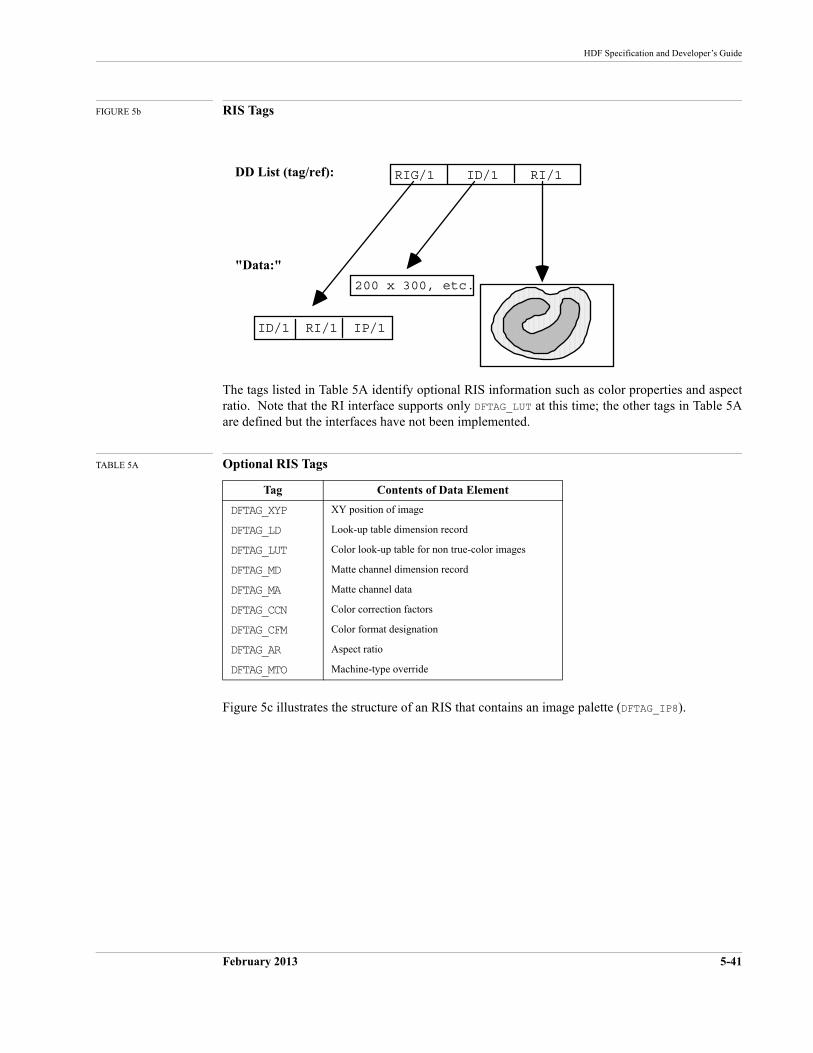
HDF Specification and Developer’s Guide
February 2013 5-41
FIGURE 5b RIS Tags
The tags listed in Table 5A identify optional RIS information such as color properties and aspect ratio. Note that the RI interface supports only DFTAG_LUT at this time; the other tags in Table 5A are defined but the interfaces have not been implemented.
TABLE 5A Optional RIS Tags
Figure 5c illustrates the structure of an RIS that contains an image palette (DFTAG_IP8).
Tag Contents of Data Element
DFTAG_XYP XY position of image
DFTAG_LD Look-up table dimension record
DFTAG_LUT Color look-up table for non true-color images
DFTAG_MD Matte channel dimension record
DFTAG_MA Matte channel data
DFTAG_CCN Color correction factors
DFTAG_CFM Color format designation
DFTAG_AR Aspect ratio
DFTAG_MTO Machine-type override
DD List (tag/ref):
"Data:"
RIG/1 ID/1 RI/1
ID/1 RI/1 IP/1
200 x 300, etc.
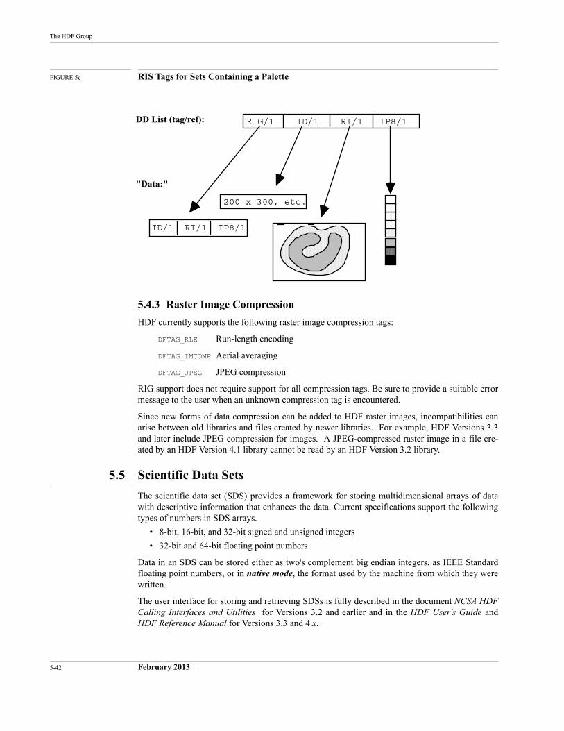
5-42 February 2013
The HDF Group
FIGURE 5c RIS Tags for Sets Containing a Palette
5.4.3 Raster Image Compression
HDF currently supports the following raster image compression tags:
DFTAG_RLE Run-length encoding
DFTAG_IMCOMP Aerial averaging
DFTAG_JPEG JPEG compression
RIG support does not require support for all compression tags. Be sure to provide a suitable error message to the user when an unknown compression tag is encountered.
Since new forms of data compression can be added to HDF raster images, incompatibilities can arise between old libraries and files created by newer libraries. For example, HDF Versions 3.3 and later include JPEG compression for images. A JPEG-compressed raster image in a file cre-ated by an HDF Version 4.1 library cannot be read by an HDF Version 3.2 library.
5.5 Scientific Data Sets
The scientific data set (SDS) provides a framework for storing multidimensional arrays of data with descriptive information that enhances the data. Current specifications support the following types of numbers in SDS arrays.
• 8-bit, 16-bit, and 32-bit signed and unsigned integers
• 32-bit and 64-bit floating point numbers
Data in an SDS can be stored either as two's complement big endian integers, as IEEE Standard floating point numbers, or in native mode, the format used by the machine from which they were written.
The user interface for storing and retrieving SDSs is fully described in the document NCSA HDF Calling Interfaces and Utilities for Versions 3.2 and earlier and in the HDF User's Guide and HDF Reference Manual for Versions 3.3 and 4.x.
DD List (tag/ref):
"Data:"
RIG/1 ID/1 RI/1 IP8/1
ID/1 RI/1 IP8/1
200 x 300, etc.
HDF Specification and Developer’s Guide
February 2013 5-43
5.5.1 Backward and Forward Compatibility
One concerns in HDF development is always to maximize backward and forward compatibility; as much as possible, any application written to use HDF should be able to read data files written with an older or a newer version of the libraries. To maximize this compatibility, the HDF devel-opement team had to consider the following factors in upgrading the SDS capabilities:
• Support for future variations (e.g., new number types, data compression, and new physical arrangements for SDS storage)
• Older versions of the library should be able to read new data files if the data itself can be interpreted by the older version. To do so, the older version must be able to determine whether the data in a given data object will be comprehensible to it. For example, if a newly created file contains 32-bit IEEE floating point or Cray floating point data objects, older versions of the library should be able determine that fact then read and interpret the data.
• New libraries must be able to read and interpret files created by older versions.
Unfortunately, such compatibility concerns yield an SDS structure somewhat more complex than would otherwise be the case. Two examples illustrate the problem:
• HDF 3.2 development had to accommodate the fact that HDF Version 3.1 and previous ver-sions only supported 32-bit IEEE floating-point numbers and Cray floating point numbers in SDSs. SDSs in HDF versions since Version 3.2 support 8-bit, 16-bit, and 32-bit signed and unsigned integers, 32-bit and 64-bit floating-point numbers, and the local machine format (native mode) for all supported architectures.
• HDF 3.3 includes support for the netCDF data model, which involved the creation of an entire new structure for supporting netCDF objects, based on Vgroups and Vdatas. At the same time, a goal of HDF 3.3 was to harmonize the SDS and the netCDF data model, which was best accomplished by storing SDS objects in the same way that netCDF objects are stored. In order to maintain backward compatibility, two structures had to be created for every SDS or netCDF object: one that could be recognized by older HDF libraries, and the new structure.
In the following sections we describe how the first problem was solved. A later issue of this man-ual will describe how the second problem was addressed.
5.5.2 Internal Structures
The SDS capability was substantially enhanced for HDF Version 3.2. Previous versions employed a structure known as a scientific data group (SDG); Version 3.2 and subsequent ver-sions use the numeric data group (NDG). To accommodate the enhanced structure and to remain compatible with previous releases, the current HDF library supports the following scientific and numerical data groups:
SDGs Created by old libraries and containing 32-bit IEEE and Cray floating-point data.
NDGs Created by the newer libraries (Version 3.2 and later) and containing any acceptable floating-point or non-floating-point data. This data group will not be recognized by old libraries.
The NDG structure supports 8-bit, 16-bit, and 32-bit signed and unsigned integers, and 32-bit and 64-bit floating-point numbers. It also supports native mode, data sets written to HDF files in the local machine format.
SDG-like NDGs
Created by the new library and containing IEEE 32-bit floating-point data only. The old libraries will recognize and interpret these numerical data groups correctly.
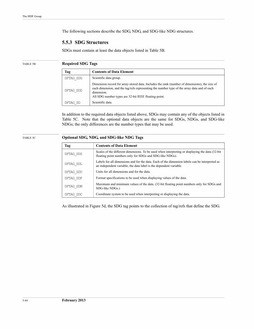
5-44 February 2013
The HDF Group
The following sections describe the SDG, NDG, and SDG-like NDG structures.
5.5.3 SDG Structures
SDGs must contain at least the data objects listed in Table 5B.
TABLE 5B Required SDG Tags
In addition to the required data objects listed above, SDGs may contain any of the objects listed in Table 5C. Note that the optional data objects are the same for SDGs, NDGs, and SDG-like NDGs; the only differences are the number types that may be used.
TABLE 5C Optional SDG, NDG, and SDG-like NDG Tags
As illustrated in Figure 5d, the SDG tag points to the collection of tag/refs that define the SDG.
Tag Contents of Data Element
DFTAG_SDG Scientific data group.
DFTAG_SDD
Dimension record for array-stored data. Includes the rank (number of dimensions), the size of each dimension, and the tag/refs representing the number type of the array data and of each dimension. All SDG number types are 32-bit IEEE floating-point.
DFTAG_SD Scientific data.
Tag Contents of Data Element
DFTAG_SDSScales of the different dimensions. To be used when interpreting or displaying the data (32-bit floating point numbers only for SDGs and SDG-like NDGs).
DFTAG_SDLLabels for all dimensions and for the data. Each of the dimension labels can be interpreted as an independent variable; the data label is the dependent variable.
DFTAG_SDU Units for all dimensions and for the data.
DFTAG_SDF Format specifications to be used when displaying values of the data.
DFTAG_SDMMaximum and minimum values of the data. (32-bit floating point numbers only for SDGs and SDG-like NDGs.)
DFTAG_SDC Coordinate system to be used when interpreting or displaying the data.
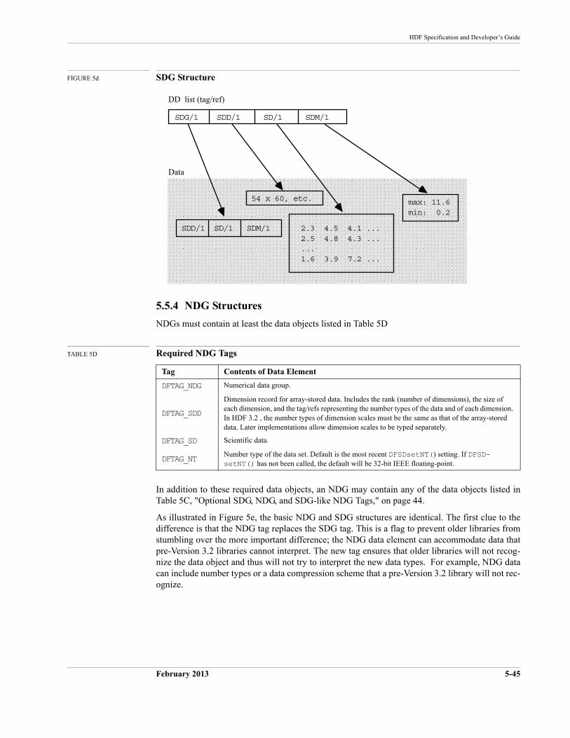
HDF Specification and Developer’s Guide
February 2013 5-45
FIGURE 5d SDG Structure
5.5.4 NDG Structures
NDGs must contain at least the data objects listed in Table 5D
TABLE 5D Required NDG Tags
In addition to these required data objects, an NDG may contain any of the data objects listed in Table 5C, "Optional SDG, NDG, and SDG-like NDG Tags," on page 44.
As illustrated in Figure 5e, the basic NDG and SDG structures are identical. The first clue to the difference is that the NDG tag replaces the SDG tag. This is a flag to prevent older libraries from stumbling over the more important difference; the NDG data element can accommodate data that pre-Version 3.2 libraries cannot interpret. The new tag ensures that older libraries will not recog-nize the data object and thus will not try to interpret the new data types. For example, NDG data can include number types or a data compression scheme that a pre-Version 3.2 library will not rec-ognize.
Tag Contents of Data Element
DFTAG_NDG Numerical data group.
DFTAG_SDD
Dimension record for array-stored data. Includes the rank (number of dimensions), the size of each dimension, and the tag/refs representing the number types of the data and of each dimension. In HDF 3.2 , the number types of dimension scales must be the same as that of the array-stored data. Later implementations allow dimension scales to be typed separately.
DFTAG_SD Scientific data.
DFTAG_NTNumber type of the data set. Default is the most recent DFSDsetNT() setting. If DFSD-setNT() has not been called, the default will be 32-bit IEEE floating-point.
DD list (tag/ref)
Data
SDG/1 SDD/1 SD/1 SDM/1
SDD/1 SD/1 SDM/1 2.3 4.5 4.1 ... 2.5 4.8 4.3 ... ... 1.6 3.9 7.2 ...
max: 11.6 min: 0.2
54 x 60, etc.
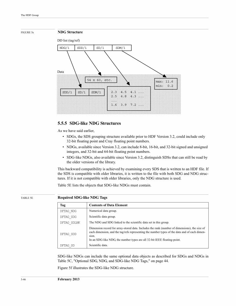
5-46 February 2013
The HDF Group
FIGURE 5e NDG Structure
5.5.5 SDG-like NDG Structures
As we have said earlier,
• SDGs, the SDS grouping structure available prior to HDF Version 3.2, could include only 32-bit floating point and Cray floating point numbers.
• NDGs, available since Version 3.2, can include 8-bit, 16-bit, and 32-bit signed and unsigned integers, and 32-bit and 64-bit floating point numbers.
• SDG-like NDGs, also available since Version 3.2, distinguish SDSs that can still be read by the older versions of the library.
This backward compatibility is achieved by examining every SDS that is written to an HDF file. If the SDS is compatible with older libraries, it is written to the file with both SDG and NDG struc-tures. If it is not compatible with older libraries, only the NDG structure is used.
Table 5E lists the objects that SDG-like NDGs must contain.
TABLE 5E Required SDG-like NDG Tags
SDG-like NDGs can include the same optional data objects as described for SDGs and NDGs in Table 5C, "Optional SDG, NDG, and SDG-like NDG Tags," on page 44.
Figure 5f illustrates the SDG-like NDG structure.
Tag Contents of Data Element
DFTAG_NDG Numerical data group.
DFTAG_SDG Scientific data group.
DFTAG_SDLNK The NDG and SDG linked to the scientific data set in this group.
DFTAG_SDD
Dimension record for array-stored data. Includes the rank (number of dimensions), the size of each dimension, and the tag/refs representing the number types of the data and of each dimen-sion.In an SDG-like NDG, the number types are all 32-bit IEEE floating-point.
DFTAG_SD Scientific data.
DD list (tag/ref)
Data
NDG/1 SDD/1 SD/1 SDM/1
SDD/1 SD/1 SDM/1 2.3 4.5 4.1 ... 2.5 4.8 4.3 ... ... 1.6 3.9 7.2 ...
max: 11.6 min: 0.2
54 x 60, etc.
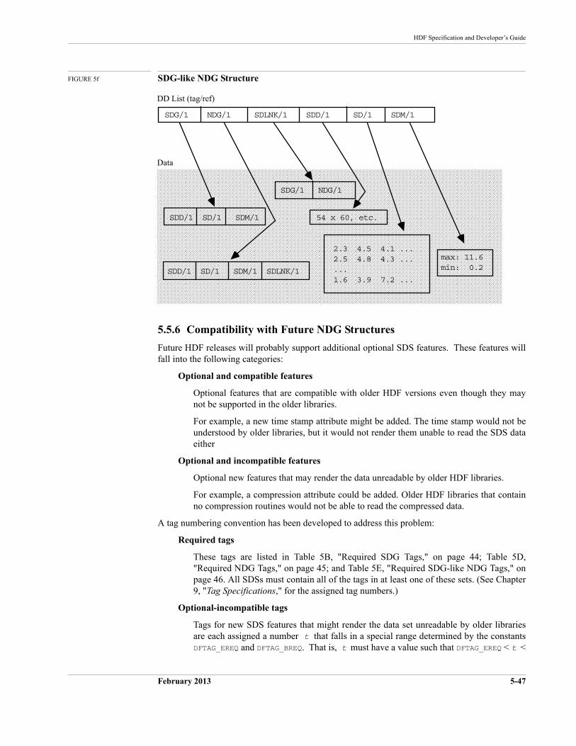
HDF Specification and Developer’s Guide
February 2013 5-47
FIGURE 5f SDG-like NDG Structure
5.5.6 Compatibility with Future NDG Structures
Future HDF releases will probably support additional optional SDS features. These features will fall into the following categories:
Optional and compatible features
Optional features that are compatible with older HDF versions even though they may not be supported in the older libraries.
For example, a new time stamp attribute might be added. The time stamp would not be understood by older libraries, but it would not render them unable to read the SDS data either
Optional and incompatible features
Optional new features that may render the data unreadable by older HDF libraries.
For example, a compression attribute could be added. Older HDF libraries that contain no compression routines would not be able to read the compressed data.
A tag numbering convention has been developed to address this problem:
Required tags
These tags are listed in Table 5B, "Required SDG Tags," on page 44; Table 5D, "Required NDG Tags," on page 45; and Table 5E, "Required SDG-like NDG Tags," on page 46. All SDSs must contain all of the tags in at least one of these sets. (See Chapter 9, "Tag Specifications," for the assigned tag numbers.)
Optional-incompatible tags
Tags for new SDS features that might render the data set unreadable by older libraries are each assigned a number t that falls in a special range determined by the constants DFTAG_EREQ and DFTAG_BREQ. That is, t must have a value such that DFTAG_EREQ < t <
DD List (tag/ref)
Data
SDG/1 NDG/1 SDLNK/1 SDD/1 SD/1 SDM/1
SDD/1 SD/1 SDM/1
2.3 4.5 4.1 ... 2.5 4.8 4.3 ... ... 1.6 3.9 7.2 ...
max: 11.6 min: 0.2
54 x 60, etc.
SDD/1 SD/1 SDM/1 SDLNK/1
SDG/1 NDG/1
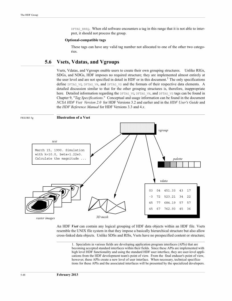
5-48 February 2013
The HDF Group
DFTAG_BREQ. When old software encounters a tag in this range that it is not able to inter-pret, it should not process the group.
Optional-compatible tags
These tags can have any valid tag number not allocated to one of the other two catego-ries.
5.6 Vsets, Vdatas, and Vgroups
Vsets, Vdatas, and Vgroups enable users to create their own grouping structures. Unlike RIGs, SDGs, and NDGs, HDF imposes no required structure; they are implemented almost entirely at the user level and are not specified in detail in HDF or in this document.1 The only specifications define DFTAG_VG, DFTAG_VH, and DFTAG_VS and the formats of their respective data elements. A detailed discussion similar to that for the other grouping structures is, therefore, inappropriate here. Detailed information regarding the DFTAG_VG, DFTAG_VH, and DFTAG_VS tags can be found in Chapter 9, "Tag Specifications." Conceptual and usage information can be found in the document NCSA HDF Vset Version 2.0 for HDF Versions 3.2 and earlier and in the HDF User's Guide and the HDF Reference Manual for HDF Versions 3.3 and 4.x.
FIGURE 5g Illustration of a Vset
An HDF Vset can contain any logical grouping of HDF data objects within an HDF file. Vsets resemble the UNIX file system in that they impose a basically hierarchical structure but also allow cross-linked data objects. Unlike SDSs and RISs, Vsets have no prespecified content or structure;
1. Specialists in various fields are developing application program interfaces (APIs) that are becoming accepted standard interfaces within their fields. Since these APIs are implemented with high level HDF functionality and using the standard HDF user interface, they are user-level appli-cations from the HDF development team's point of view. From the final enduser's point of view, however, these APIs create a new level of user interface. When necessary, technical specifica-tions for these APIs and the associated interfaces will be presented by the specialized developers.
03 04 451.33 43 17
-3 72 523.21 34 22
45 77 684.19 57 57
45 67 762.93 45 36
March 15, 1990. Simulation with k=10.0, beta=1.22e3. Calculate the magnitude ...
vgroup
text
raster images
palette
vdata
3D mesh
HDF Specification and Developer’s Guide
February 2013 5-49
users can use them to create structural relationships among HDF objects according to their needs. Figure 5g illustrates a Vset.
A Vset is identified by a Vgroup, an HDF object that contains information about the members of the Vset. The tag DFTAG_VG identifies the Vgroup which contains the tag/refs of its members, an optional user-specified name, an optional user-specified class, and fields that enable the Vgroup to be extended to contain more information.
The only required Vgroup tag is the tag that defines the Vgroup itself.
TABLE 5F The Vgroup Tag
Vgroups are fully described in the document NCSA HDF Vset, Version 2.0 for Versions 3.2 and earlier and in the HDF User's Guide and HDF Reference Manual for Versions 3.3 and 4.x.
5.7 The Raster-8 Set (Obsolete)
Current HDF versions use the raster image set (RIS) to manage raster images. But before the RIS was implemented, a simpler, less flexible set called the raster-8 set was used for storing 8-bit ras-ter images. This set is no longer supported in the HDF software, although it may turn up in some older HDF files.1
5.7.1 Raster-8 Sets
The raster-8 set is defined by a set of tags that provide the basic information necessary to store 8-bit raster images and display them accurately without requiring the user to supply dimensions or color information. The raster-8 set tags are listed in Table 5G.
TABLE 5G Raster-8 Set Tags
Software that does not support DFTAG_CI8 or DFTAG_II8 must provide appropriate error indicators to higher layers that might expect to find these tags.
5.7.2 Compatibility Between Raster-8 and Raster Image Sets
To maintain backward compatibility with raster-8 sets, the RIS interface stores tag/refs for both types of sets. For example, if an image is stored as part of a raster image set, there is one copy each of the image dimension data, the image data, and the palette data. But there were two sets of
Tag Contents of Data Element
DFTAG_VG Vgroup
1. In fact, during the first three years that RIS was used, the HDF software stored raster images in both RIS and raster-8 sets.
Tag Contents of Data Element
DFTAG_RI8 8-bit raster image data
DFTAG_CI8 8-bit raster image data compressed with run-length encoding
DFTAG_II8 IMCOMP compressed image data
DFTAG_ID8 Image dimension record
DFTAG_IP8 Image palette data
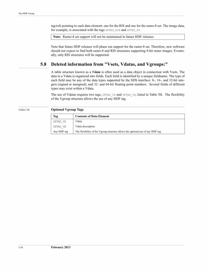
5-50 February 2013
The HDF Group
tag/refs pointing to each data element: one for the RIS and one for the raster-8 set. The image data, for example, is associated with the tags DFTAG_RI8 and DFTAG_RI.
Note that future HDF releases will phase out support for the raster-8 set. Therefore, new software should not expect to find both raster-8 and RIS structures supporting 8-bit raster images. Eventu-ally, only RIS structures will be supported.
5.8 Deleted information from "Vsets, Vdatas, and Vgroups:"
A table structure known as a Vdata is often used as a data object in connection with Vsets. The data in a Vdata is organized into fields. Each field is identified by a unique fieldname. The type of each field may be any of the data types supported by the SDS interface: 8-, 16-, and 32-bit inte-gers (signed or unsigned), and 32- and 64-bit floating point numbers. Several fields of different types may exist within a Vdata.
The use of Vdatas requires two tags, DFTAG_VS and DFTAG_VH, listed in Table 5H. The flexibility of the Vgroup structure allows the use of any HDF tag.
TABLE 5H Optional Vgroup Tags
Note: Raster-8 set support will not be maintained in future HDF releases.
Tag Contents of Data Element
DFTAG_VS Vdata.
DFTAG_VH Vdata description.
Any HDF tag The flexibility of the Vgroup structure allows the optional use of any HDF tag.
February 2013 6-51
CHAPTER 6 -- Annotations
6.1 Chapter Overview
This chapter introduces annotations, HDF data objects used to annotate HDF files and objects.
The tags introduced in this chapter are fully described in Chapter 9, "Tag Specifications," and are listed in the table in Appendix A, "Tags and Extended Tag Labels."
6.2 General Description
It is often useful to attach a text annotation to an HDF file or its contents and to store that annota-tion in the same HDF file. HDF provides this capability in two ways: through the annotation data object and by the assignment of attributes. This chapter discusses annotations.
The data element of an annotation is a sequence of ASCII characters that can be associated with any of three types of objects:
• The file itself
• An individual HDF data object in the file
• A tag that identifies a data element
The current annotation interface supports only the first two.
Annotations come in two forms:
Label A short, NULL-terminated string. Labels may include no embedded NULLs.
Description A longer and more complex body of text of a pre-defined length. Descrip-tions may contain embedded NULLs.
Annotations are never required; they are used strictly at the discretion of the creator or user of an HDF file.
Table 6A shows the currently defined annotation types and their assigned tags.
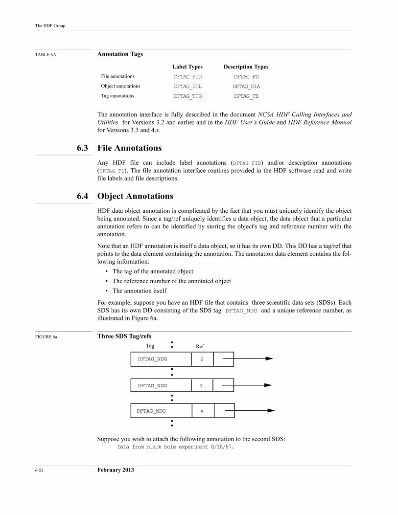
6-52 February 2013
The HDF Group
TABLE 6A Annotation Tags
The annotation interface is fully described in the document NCSA HDF Calling Interfaces and Utilities for Versions 3.2 and earlier and in the HDF User’s Guide and HDF Reference Manualfor Versions 3.3 and 4.x.
6.3 File Annotations
Any HDF file can include label annotations (DFTAG_FID) and/or description annotations (DFTAG_FD). The file annotation interface routines provided in the HDF software read and write file labels and file descriptions.
6.4 Object Annotations
DFTAG_NDG
DFTAG_NDG
DFTAG_NDG
2
4
9
Tag Ref
HDF data object annotation is complicated by the fact that you must uniquely identify the object being annotated. Since a tag/ref uniquely identifies a data object, the data object that a particular annotation refers to can be identified by storing the object's tag and reference number with the annotation.
Note that an HDF annotation is itself a data object, so it has its own DD. This DD has a tag/ref that points to the data element containing the annotation. The annotation data element contains the fol-lowing information:
• The tag of the annotated object
• The reference number of the annotated object
• The annotation itself
For example, suppose you have an HDF file that contains three scientific data sets (SDSs). Each SDS has its own DD consisting of the SDS tag DFTAG_NDG and a unique reference number, as illustrated in Figure 6a.
FIGURE 6a Three SDS Tag/refs
Suppose you wish to attach the following annotation to the second SDS: Data from black hole experiment 8/18/87.
Label Types Description Types
File annotations DFTAG_FID DFTAG_FD
Object annotations DFTAG_DIL DFTAG_DIA
Tag annotations DFTAG_TID DFTAG_TD
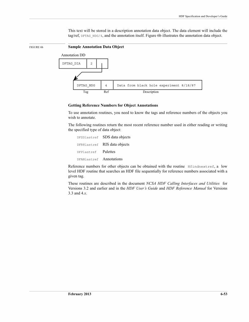
DFTAG_NDG 4 Data from black hole experiment 8/18/87
DFTAG_DIA 2
Annotation DD
Tag Ref Description
HDF Specification and Developer’s Guide
February 2013 6-53
This text will be stored in a description annotation data object. The data element will include the tag/ref, DFTAG_NDG/4, and the annotation itself. Figure 6b illustrates the annotation data object.
FIGURE 6b Sample Annotation Data Object
Getting Reference Numbers for Object Annotations
To use annotation routines, you need to know the tags and reference numbers of the objects you wish to annotate.
The following routines return the most recent reference number used in either reading or writing the specified type of data object:
DFSDlastref SDS data objects
DFR8lastref RIS data objects
DFPlastref Palettes
DFANlastref Annotations
Reference numbers for other objects can be obtained with the routine Hfindnextref, a low level HDF routine that searches an HDF file sequentially for reference numbers associated with a given tag.
These routines are described in the document NCSA HDF Calling Interfaces and Utilities for Versions 3.2 and earlier and in the HDF User’s Guide and HDF Reference Manual for Versions 3.3 and 4.x.

6-54 February 2013
The HDF Group
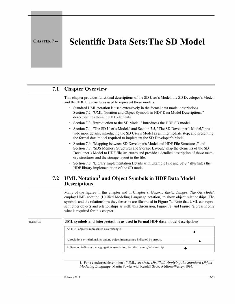
February 2013 7-55
CHAPTER 7 -- Scientific Data Sets:The SD Model
7.1 Chapter Overview
This chapter provides functional descriptions of the SD User’s Model, the SD Developer’s Model, and the HDF file structures used to represent these models.
• Standard UML notation is used extensively in the formal data model descriptions. Section 7.2, "UML Notation and Object Symbols in HDF Data Model Descriptions," describes the relevant UML elements.
• Section 7.3, "Introduction to the SD Model," introduces the HDF SD model.
• Section 7.4, "The SD User’s Model," and Section 7.5, "The SD Developer’s Model," pro-vide more details, introducing the SD User’s Model as an intermediate step, and presenting the formal data model required to implement the SD Developer’s Model.
• Section 7.6, "Mapping between SD Developer's Model and HDF File Structures," and Section 7.7, "SDS Memory Structures and Storage Layout," map the elements of the SD Developer’s Model to HDF file structures and provide a detailed description of those mem-ory structures and the storage layout in the file.
• Section 7.8, "Library Implementation Details with Example File and SDS," illustrates the HDF library implementation of the SD model.
7.2 UML Notation1 and Object Symbols in HDF Data Model Descriptions
Many of the figures in this chapter and in Chapter 8, General Raster Images: The GR Model, employ UML notation (Unified Modeling Language notation) to show object relationships. The symbols and the relationships they describe are illustrated in Figure 7a. Note that UML can repre-sent other objects and relationships as well; this discussion, Figure 7a, and Figure 7a present only what is required for this chapter.
FIGURE 7a UML symbols and interpretations as used in formal HDF data model descriptions
1. For a condensed description of UML, see UML Distilled: Applying the Standard Object Modeling Language, Martin Fowler with Kendall Scott, Addison-Wesley, 1997.
An HDF object is represented as a rectangle.
Associations or relationships among object instances are indicated by arrows.
A diamond indicates the aggregation association, i.e., the a part of relationship.
A
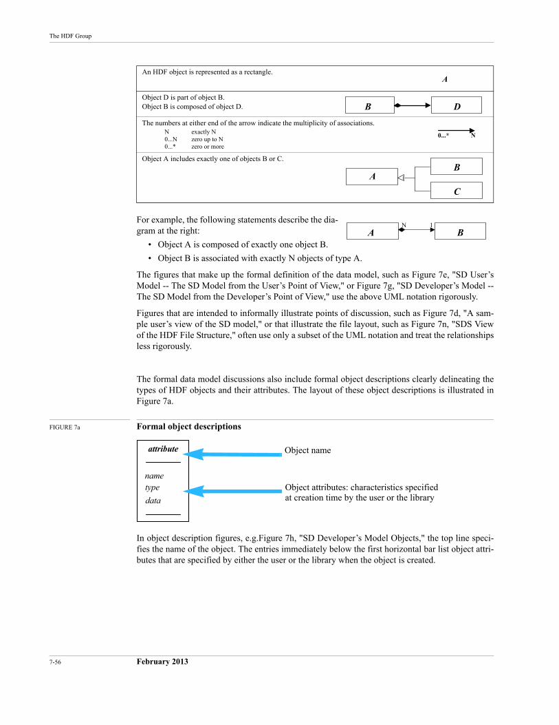
7-56 February 2013
The HDF Group
For example, the following statements describe the dia-gram at the right:
• Object A is composed of exactly one object B.
• Object B is associated with exactly N objects of type A.
The figures that make up the formal definition of the data model, such as Figure 7e, "SD User’s Model -- The SD Model from the User’s Point of View," or Figure 7g, "SD Developer’s Model -- The SD Model from the Developer’s Point of View," use the above UML notation rigorously.
Figures that are intended to informally illustrate points of discussion, such as Figure 7d, "A sam-ple user’s view of the SD model," or that illustrate the file layout, such as Figure 7n, "SDS View of the HDF File Structure," often use only a subset of the UML notation and treat the relationships less rigorously.
The formal data model discussions also include formal object descriptions clearly delineating the types of HDF objects and their attributes. The layout of these object descriptions is illustrated in Figure 7a.
FIGURE 7a Formal object descriptions
In object description figures, e.g.Figure 7h, "SD Developer’s Model Objects," the top line speci-fies the name of the object. The entries immediately below the first horizontal bar list object attri-butes that are specified by either the user or the library when the object is created.
Object D is part of object B. Object B is composed of object D.
The numbers at either end of the arrow indicate the multiplicity of associations. N exactly N0...N zero up to N0...* zero or more
Object A includes exactly one of objects B or C.
An HDF object is represented as a rectangle.A
B D
0...* N
BA
C
A BN 1
attribute
nametype
data
Object name
Object attributes: characteristics specifiedat creation time by the user or the library
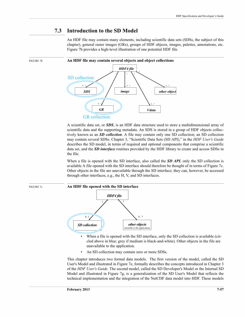
HDF Specification and Developer’s Guide
February 2013 7-57
7.3 Introduction to the SD Model
An HDF file may contain many elements, including scientific data sets (SDSs, the subject of this chapter), general raster images (GRs), groups of HDF objects, images, palettes, annotations, etc. Figure 7b provides a high-level illustration of one potential HDF file.
FIGURE 7b An HDF file may contain several objects and object collections
A scientific data set, or SDS, is an HDF data structure used to store a multidimensional array of scientific data and the supporting metadata. An SDS is stored in a group of HDF objects collec-tively known as an SD collection. A file may contain only one SD collection; an SD collection may contain several SDSs. Chapter 3, “Scientific Data Sets (SD API),” in the HDF User's Guidedescribes the SD model, in terms of required and optional components that comprise a scientific data set, and the SD interface routines provided by the HDF library to create and access SDSs in the file.
When a file is opened with the SD interface, also called the SD API, only the SD collection is available A file opened with the SD interface should therefore be thought of in terms of Figure 7c. Other objects in the file are unavailable through the SD interface; they can, however, be accessed through other interfaces, e.g., the H, V, and SD interfaces.
FIGURE 7c An HDF file opened with the SD interface
• When a file is opened with the SD interface, only the SD collection is available (cir-cled above in blue; grey if medium is black-and-white). Other objects in the file are unavailable to the application.
• An SD collection may contain zero or more SDSs.
This chapter introduces two formal data models. The first version of the model, called the SD User's Model and illustrated in Figure 7e, formally describes the concepts introduced in Chapter 3 of the HDF User's Guide. The second model, called the SD Developer's Model or the Internal SD Model and illustrated in Figure 7g, is a generalization of the SD User's Model that reflects the technical implementation and the integration of the NetCDF data model into HDF. These models
HDF4 file
imageSDS
Vdata
0…*
1
0…*
11
GR
0…*
1
other object
0…*
1
0…*
SD collection
GR collection
HDF4 file
SD collection other objects(invisible to the application)
0...1 0…*
11
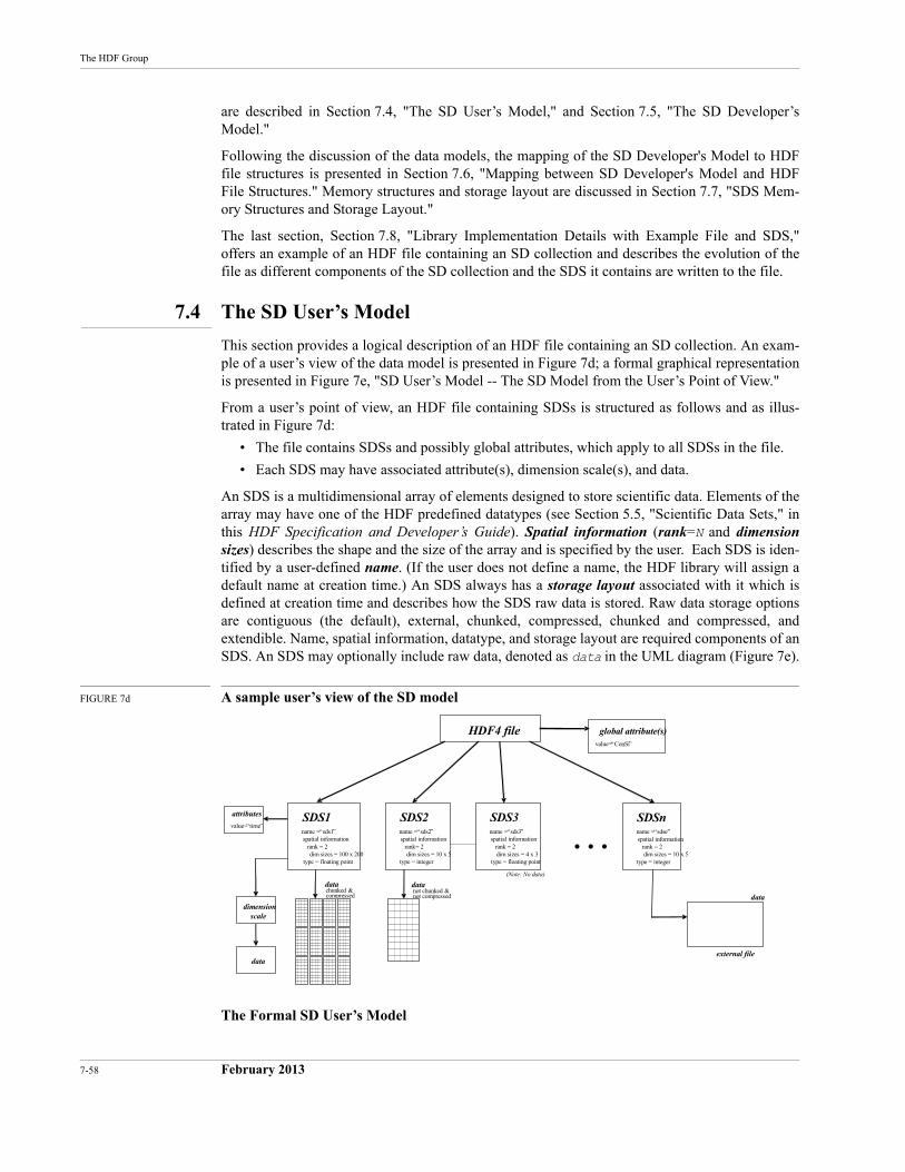
7-58 February 2013
The HDF Group
are described in Section 7.4, "The SD User’s Model," and Section 7.5, "The SD Developer’s Model."
Following the discussion of the data models, the mapping of the SD Developer's Model to HDF file structures is presented in Section 7.6, "Mapping between SD Developer's Model and HDF File Structures." Memory structures and storage layout are discussed in Section 7.7, "SDS Mem-ory Structures and Storage Layout."
The last section, Section 7.8, "Library Implementation Details with Example File and SDS," offers an example of an HDF file containing an SD collection and describes the evolution of the file as different components of the SD collection and the SDS it contains are written to the file.
7.4 The SD User’s Model
This section provides a logical description of an HDF file containing an SD collection. An exam-ple of a user’s view of the data model is presented in Figure 7d; a formal graphical representation is presented in Figure 7e, "SD User’s Model -- The SD Model from the User’s Point of View."
From a user’s point of view, an HDF file containing SDSs is structured as follows and as illus-trated in Figure 7d:
• The file contains SDSs and possibly global attributes, which apply to all SDSs in the file.
• Each SDS may have associated attribute(s), dimension scale(s), and data.
An SDS is a multidimensional array of elements designed to store scientific data. Elements of the array may have one of the HDF predefined datatypes (see Section 5.5, "Scientific Data Sets," in this HDF Specification and Developer’s Guide). Spatial information (rank=N and dimensionsizes) describes the shape and the size of the array and is specified by the user. Each SDS is iden-tified by a user-defined name. (If the user does not define a name, the HDF library will assign a default name at creation time.) An SDS always has a storage layout associated with it which is defined at creation time and describes how the SDS raw data is stored. Raw data storage options are contiguous (the default), external, chunked, compressed, chunked and compressed, and extendible. Name, spatial information, datatype, and storage layout are required components of an SDS. An SDS may optionally include raw data, denoted as data in the UML diagram (Figure 7e).
FIGURE 7d A sample user’s view of the SD model
The Formal SD User’s Model
HDF4 file
SDS1name = “sds1”spatial information
rank = 2dim sizes = 100 x 200
type = floating point
global attribute(s)value=“ConSi”
. . .attributes
value=“time”
dimensionscale
datachunked &compressed
data
SDS2name = “sds2”spatial information
rank= 2dim sizes = 10 x 5
type = integer
datanot chunked ¬ compressed
SDS3name = “sds3”spatial information
rank = 2dim sizes = 4 x 3
type = floating point
(Note: No data)
SDSnname = “sdsn”spatial information
rank = 2dim sizes = 10 x 5
type = integer
data
external file
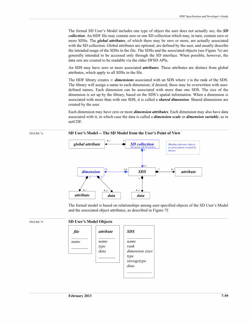
HDF Specification and Developer’s Guide
February 2013 7-59
The formal SD User’s Model includes one type of object the user does not actually see, the SD collection. An HDF file may contain zero or one SD collection which may, in turn, contain zero or more SDSs. The global attributes, of which there may be zero or more, are actually associated with the SD collection. Global attributes are optional, are defined by the user, and usually describe the intended usage of the SDSs in the file. The SDSs and the associated objects (see Figure 7e) are generally intended to be accessed only through the SD interface. When possible, however, the data sets are created to be readable via the older DFSD APIs.
An SDS may have zero or more associated attributes. These attributes are distinct from global attributes, which apply to all SDSs in the file.
The HDF library creates N dimensions associated with an SDS where N is the rank of the SDS. The library will assign a name to each dimension; if desired, these may be overwritten with user-defined names. Each dimension can be associated with more than one SDS. The size of the dimension is set up by the library, based on the SDS’s spatial information. When a dimension is associated with more than with one SDS, it is called a shared dimension. Shared dimensions are created by the user.
Each dimension may have zero or more dimension attributes. Each dimension may also have data associated with it, in which case the data is called a dimension scale or dimension variable, as in netCDF.
FIGURE 7e SD User’s Model -- The SD Model from the User’s Point of View
The formal model is based on relationships among user-specified objects of the SD User’s Model and the associated object attributes, as described in Figure 7f.
FIGURE 7f SD User’s Model Objects
dimension SDS
SD collection
attribute
global attribute
data
1
0...1
1
attribute data
1
0...1
1
(file opened with SD interface)Shading indicates objects or associations created by library
1
1..LN
0...*
0...*
1 0...*
0...*
file ________name________
SDS____________namerankdimension sizestypestoragetypedata____________
attribute________nametypedata________
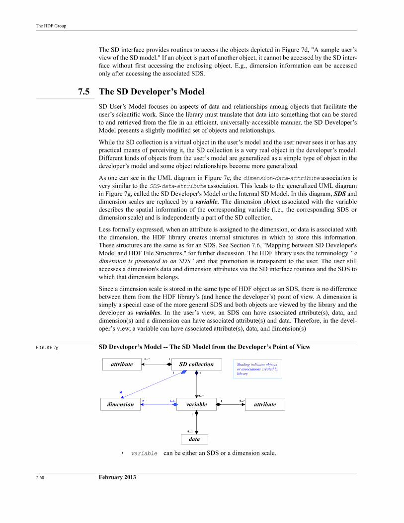
7-60 February 2013
The HDF Group
The SD interface provides routines to access the objects depicted in Figure 7d, "A sample user’s view of the SD model." If an object is part of another object, it cannot be accessed by the SD inter-face without first accessing the enclosing object. E.g., dimension information can be accessed only after accessing the associated SDS.
7.5 The SD Developer’s Model
SD User’s Model focuses on aspects of data and relationships among objects that facilitate the user’s scientific work. Since the library must translate that data into something that can be stored to and retrieved from the file in an efficient, universally-accessible manner, the SD Developer’s Model presents a slightly modified set of objects and relationships.
While the SD collection is a virtual object in the user’s model and the user never sees it or has any practical means of perceiving it, the SD collection is a very real object in the developer’s model. Different kinds of objects from the user’s model are generalized as a simple type of object in the developer’s model and some object relationships become more generalized.
As one can see in the UML diagram in Figure 7e, the dimension-data-attribute association is very similar to the SDS-data-attribute association. This leads to the generalized UML diagram in Figure 7g, called the SD Developer's Model or the Internal SD Model. In this diagram, SDS and dimension scales are replaced by a variable. The dimension object associated with the variable describes the spatial information of the corresponding variable (i.e., the corresponding SDS or dimension scale) and is independently a part of the SD collection.
Less formally expressed, when an attribute is assigned to the dimension, or data is associated with the dimension, the HDF library creates internal structures in which to store this information. These structures are the same as for an SDS. See Section 7.6, "Mapping between SD Developer's Model and HDF File Structures," for further discussion. The HDF library uses the terminology “a dimension is promoted to an SDS” and that promotion is transparent to the user. The user still accesses a dimension's data and dimension attributes via the SD interface routines and the SDS to which that dimension belongs.
Since a dimension scale is stored in the same type of HDF object as an SDS, there is no difference between them from the HDF library’s (and hence the developer’s) point of view. A dimension is simply a special case of the more general SDS and both objects are viewed by the library and the developer as variables. In the user’s view, an SDS can have associated attribute(s), data, and dimension(s) and a dimension can have associated attribute(s) and data. Therefore, in the devel-oper’s view, a variable can have associated attribute(s), data, and dimension(s)
FIGURE 7g SD Developer’s Model -- The SD Model from the Developer’s Point of View
• variable can be either an SDS or a dimension scale.
dimension variable
SD collection
attribute
attribute
data
1
0...1
1
Shading indicates objects or associations created by library
1
1..LN
0...*
0...*
1 0...*
1
M
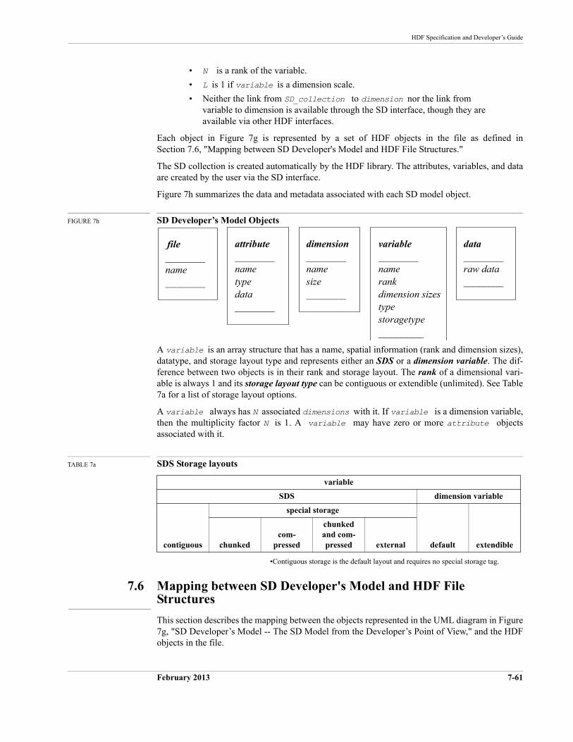
HDF Specification and Developer’s Guide
February 2013 7-61
• N is a rank of the variable.
• L is 1 if variable is a dimension scale.
• Neither the link from SD_collection to dimension nor the link from variable to dimension is available through the SD interface, though they are available via other HDF interfaces.
Each object in Figure 7g is represented by a set of HDF objects in the file as defined in Section 7.6, "Mapping between SD Developer's Model and HDF File Structures."
The SD collection is created automatically by the HDF library. The attributes, variables, and data are created by the user via the SD interface.
Figure 7h summarizes the data and metadata associated with each SD model object.
FIGURE 7h SD Developer’s Model Objects
A variable is an array structure that has a name, spatial information (rank and dimension sizes), datatype, and storage layout type and represents either an SDS or a dimension variable. The dif-ference between two objects is in their rank and storage layout. The rank of a dimensional vari-able is always 1 and its storage layout type can be contiguous or extendible (unlimited). See Table 7a for a list of storage layout options.
A variable always has N associated dimensions with it. If variable is a dimension variable, then the multiplicity factor N is 1. A variable may have zero or more attribute objects associated with it.
TABLE 7a SDS Storage layouts
•Contiguous storage is the default layout and requires no special storage tag.
7.6 Mapping between SD Developer's Model and HDF File Structures
This section describes the mapping between the objects represented in the UML diagram in Figure 7g, "SD Developer’s Model -- The SD Model from the Developer’s Point of View," and the HDF objects in the file.
variable
SDS dimension variable
contiguous
special storage
default extendiblechunkedcom-
pressed
chunked and com-pressed external
file ________name________
variable________namerankdimension sizestypestoragetype________
attribute________nametypedata________
dimension________namesize________
data________raw data ________
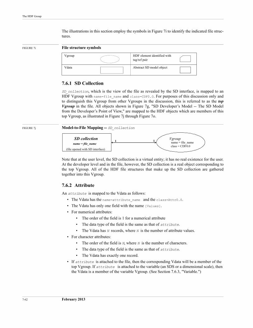
7-62 February 2013
The HDF Group
The illustrations in this section employ the symbols in Figure 7i to identify the indicated file struc-tures.
FIGURE 7i File structure symbols
7.6.1 SD Collection
SD_collection, which is the view of the file as revealed by the SD interface, is mapped to an HDF Vgroup with name=file_name and class=CDF0.0. For purposes of this discussion only and to distinguish this Vgroup from other Vgroups in the discussion, this is referred to as the top Vgroup in the file. All objects shown in Figure 7g, "SD Developer’s Model -- The SD Model from the Developer’s Point of View," are mapped to the HDF objects which are members of this top Vgroup, as illustrated in Figure 7j through Figure 7o.
FIGURE 7j Model-to-File Mapping -- SD_collection
Note that at the user level, the SD collection is a virtual entity; it has no real existence for the user. At the developer level and in the file, however, the SD collection is a real object corresponding to the top Vgroup. All of the HDF file structures that make up the SD collection are gathered together into this Vgroup.
7.6.2 Attribute
An attribute is mapped to the Vdata as follows:
• The Vdata has the name=attribute_name and the class=Attr0.0.
• The Vdata has only one field with the name [Values].
• For numerical attributes:
• The order of the field is 1 for a numerical attribute
• The data type of the field is the same as that of attribute.
• The Vdata has N records, where N is the number of attribute values.
• For character attributes:
• The order of the field is N, where N is the number of characters.
• The data type of the field is the same as that of attribute.
• The Vdata has exactly one record.
• If attribute is attached to the file, then the corresponding Vdata will be a member of the top Vgroup. If attribute is attached to the variable (an SDS or a dimensional scale), then the Vdata is a member of the variable Vgroup. (See Section 7.6.3, "Variable.")
Vgroup HDF element identified with tag/ref pair
Vdata Abstract SD model object
Vgroupname = file_nameclass = CDF0.0
SD collectionname = file_name
1 1
(file opened with SD interface)
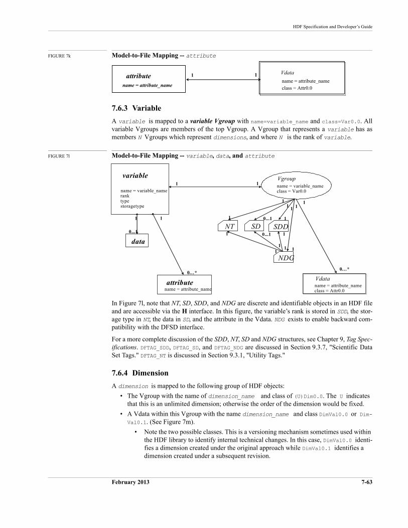
HDF Specification and Developer’s Guide
February 2013 7-63
FIGURE 7k Model-to-File Mapping -- attribute
7.6.3 Variable
A variable is mapped to a variable Vgroup with name=variable_name and class=Var0.0. All variable Vgroups are members of the top Vgroup. A Vgroup that represents a variable has as members N Vgroups which represent dimensions, and where N is the rank of variable.
FIGURE 7l Model-to-File Mapping -- variable, data, and attribute
In Figure 7l, note that NT, SD, SDD, and NDG are discrete and identifiable objects in an HDF file and are accessible via the H interface. In this figure, the variable’s rank is stored in SDD, the stor-age type in NT, the data in SD, and the attribute in the Vdata. NDG exists to enable backward com-patibility with the DFSD interface.
For a more complete discussion of the SDD, NT, SD and NDG structures, see Chapter 9, Tag Spec-ifications. DFTAG_SDD, DFTAG_SD, and DFTAG_NDG are discussed in Section 9.3.7, "Scientific Data Set Tags." DFTAG_NT is discussed in Section 9.3.1, "Utility Tags."
7.6.4 Dimension
A dimension is mapped to the following group of HDF objects:
• The Vgroup with the name of dimension_name and class of (U)Dim0.0. The U indicates that this is an unlimited dimension; otherwise the order of the dimension would be fixed.
• A Vdata within this Vgroup with the name dimension_name and class DimVal0.0 or Dim-Val0.1. (See Figure 7m).
• Note the two possible classes. This is a versioning mechanism sometimes used within the HDF library to identify internal technical changes. In this case, DimVal0.0 identi-fies a dimension created under the original approach while DimVal0.1 identifies a dimension created under a subsequent revision.
Vdata
name = attribute_nameclass = Attr0.0
attributename = attribute_name
1 1
Vgroupname = variable_nameclass = Var0.0
NDG
SDDSDNT
variable
name = variable_nameranktypestoragetype
data
Vdataname = attribute_nameclass = Attr0.0
1 1
0…* 0…*
1
1
attributename = attribute_name
1 1
1 1
1 1
1 1 1 1
1 1 0...1
0...1
0...1
1
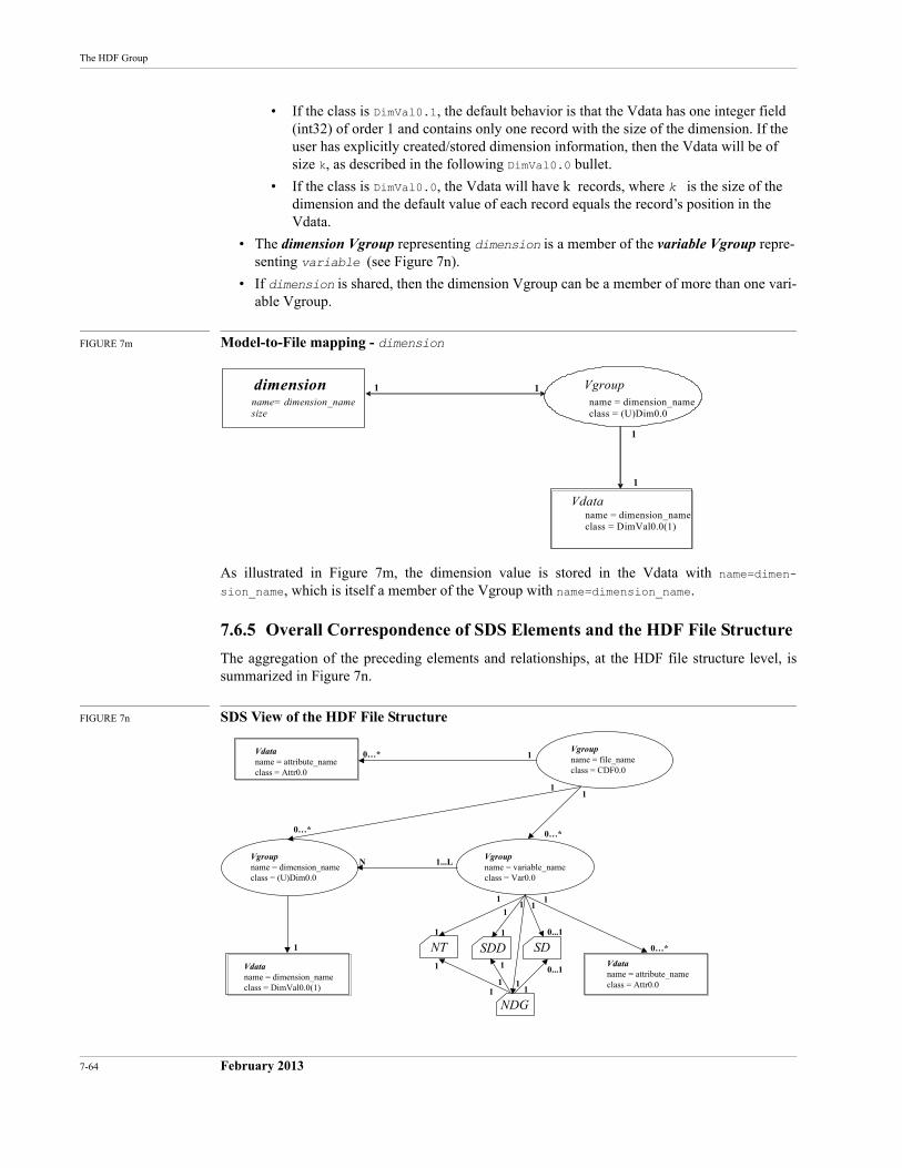
7-64 February 2013
The HDF Group
• If the class is DimVal0.1, the default behavior is that the Vdata has one integer field (int32) of order 1 and contains only one record with the size of the dimension. If the user has explicitly created/stored dimension information, then the Vdata will be of size k, as described in the following DimVal0.0 bullet.
• If the class is DimVal0.0, the Vdata will have k records, where k is the size of the dimension and the default value of each record equals the record’s position in the Vdata.
• The dimension Vgroup representing dimension is a member of the variable Vgroup repre-senting variable (see Figure 7n).
• If dimension is shared, then the dimension Vgroup can be a member of more than one vari-able Vgroup.
FIGURE 7m Model-to-File mapping - dimension
As illustrated in Figure 7m, the dimension value is stored in the Vdata with name=dimen-sion_name, which is itself a member of the Vgroup with name=dimension_name.
7.6.5 Overall Correspondence of SDS Elements and the HDF File Structure
The aggregation of the preceding elements and relationships, at the HDF file structure level, is summarized in Figure 7n.
FIGURE 7n SDS View of the HDF File Structure
Vdataname = dimension_nameclass = DimVal0.0(1)
Vgroupname = dimension_nameclass = (U)Dim0.0
dimensionname= dimension_namesize
1 1
1
1
Vdataname = dimension_nameclass = DimVal0.0(1)
Vdataname = attribute_nameclass = Attr0.0
Vdataname = attribute_nameclass = Attr0.0
Vgroupname = dimension_nameclass = (U)Dim0.0
Vgroupname = file_nameclass = CDF0.0
Vgroupname = variable_nameclass = Var0.0
NDG
SDSDDNT
0…* 1
1
1 11
1
1
1
0...1
0...11
11
1
0…*
111
1
1...LN
0…*
1
0…*
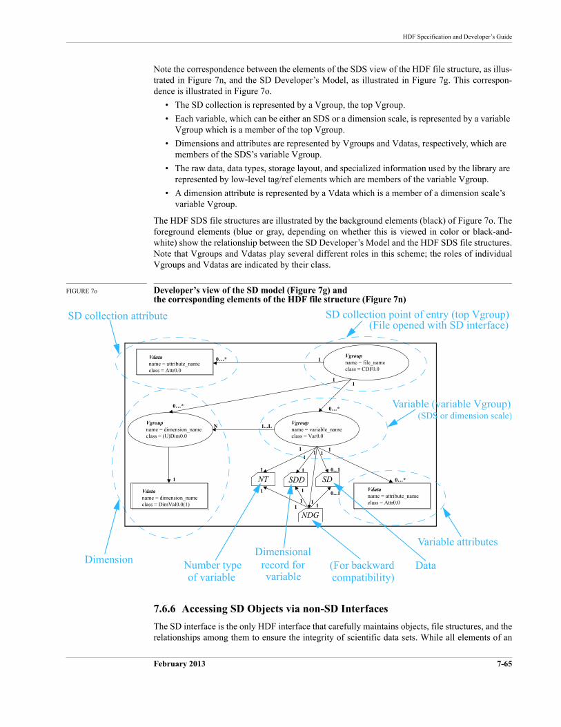
HDF Specification and Developer’s Guide
February 2013 7-65
Note the correspondence between the elements of the SDS view of the HDF file structure, as illus-trated in Figure 7n, and the SD Developer’s Model, as illustrated in Figure 7g. This correspon-dence is illustrated in Figure 7o.
• The SD collection is represented by a Vgroup, the top Vgroup.
• Each variable, which can be either an SDS or a dimension scale, is represented by a variable Vgroup which is a member of the top Vgroup.
• Dimensions and attributes are represented by Vgroups and Vdatas, respectively, which are members of the SDS’s variable Vgroup.
• The raw data, data types, storage layout, and specialized information used by the library are represented by low-level tag/ref elements which are members of the variable Vgroup.
• A dimension attribute is represented by a Vdata which is a member of a dimension scale’s variable Vgroup.
The HDF SDS file structures are illustrated by the background elements (black) of Figure 7o. The foreground elements (blue or gray, depending on whether this is viewed in color or black-and-white) show the relationship between the SD Developer’s Model and the HDF SDS file structures. Note that Vgroups and Vdatas play several different roles in this scheme; the roles of individual Vgroups and Vdatas are indicated by their class.
FIGURE 7o Developer’s view of the SD model (Figure 7g) and the corresponding elements of the HDF file structure (Figure 7n)
7.6.6 Accessing SD Objects via non-SD Interfaces
The SD interface is the only HDF interface that carefully maintains objects, file structures, and the relationships among them to ensure the integrity of scientific data sets. While all elements of an
Vdataname = dimension_nameclass = DimVal0.0(1)
Vdataname = attribute_nameclass = Attr0.0
Vdataname = attribute_nameclass = Attr0.0
Vgroupname = dimension_nameclass = (U)Dim0.0
Vgroupname = file_nameclass = CDF0.0
Vgroupname = variable_nameclass = Var0.0
NDG
SDSDDNT
0…* 1
1
1 11
1
1
1
0...1
0...11
11
1
0…*
111
1
1...LN
0…*
1
0…*
Dimension
SD collection point of entry (top Vgroup)(File opened with SD interface)
Number typeDimensional
Data(For backward
Variable attributes
Variable (variable Vgroup)
compatibility)record forvariableof variable
SD collection attribute
(SDS or dimension scale)
7-66 February 2013
The HDF Group
SD collection are individually accessible and manipulatable via the more general HDF interfaces, such as the H interface, to do so introduces a significant risk of corrupting relationships and/or data within the SD collection and is not recommended.
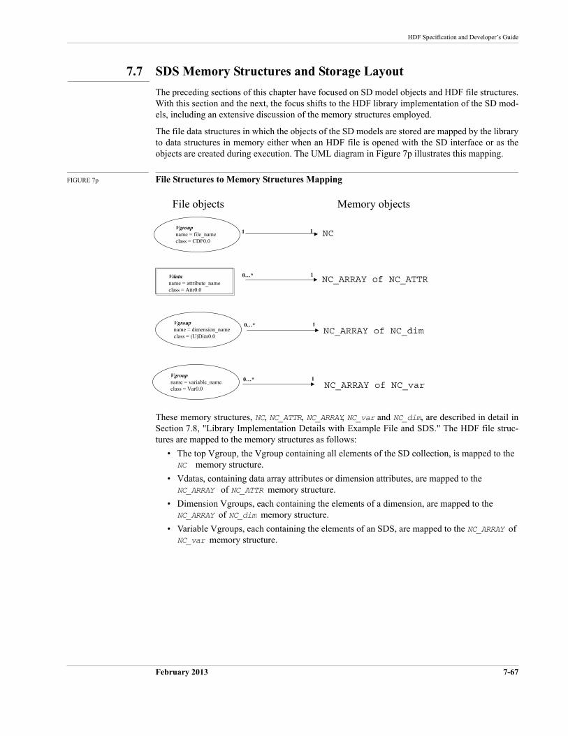
HDF Specification and Developer’s Guide
February 2013 7-67
7.7 SDS Memory Structures and Storage Layout
The preceding sections of this chapter have focused on SD model objects and HDF file structures. With this section and the next, the focus shifts to the HDF library implementation of the SD mod-els, including an extensive discussion of the memory structures employed.
The file data structures in which the objects of the SD models are stored are mapped by the library to data structures in memory either when an HDF file is opened with the SD interface or as the objects are created during execution. The UML diagram in Figure 7p illustrates this mapping.
FIGURE 7p File Structures to Memory Structures Mapping
These memory structures, NC, NC_ATTR, NC_ARRAY, NC_var and NC_dim, are described in detail in Section 7.8, "Library Implementation Details with Example File and SDS." The HDF file struc-tures are mapped to the memory structures as follows:
• The top Vgroup, the Vgroup containing all elements of the SD collection, is mapped to the NC memory structure.
• Vdatas, containing data array attributes or dimension attributes, are mapped to the NC_ARRAY of NC_ATTR memory structure.
• Dimension Vgroups, each containing the elements of a dimension, are mapped to the NC_ARRAY of NC_dim memory structure.
• Variable Vgroups, each containing the elements of an SDS, are mapped to the NC_ARRAY of NC_var memory structure.
Vdataname = attribute_nameclass = Attr0.0
Vgroupname = dimension_nameclass = (U)Dim0.0
Vgroupname = variable_nameclass = Var0.0
NC_ARRAY of NC_ATTR
NC_ARRAY of NC_dim
NC_ARRAY of NC_var
NCVgroupname = file_nameclass = CDF0.0
1 1
0…* 1
0…* 1
0…* 1
File objects Memory objects
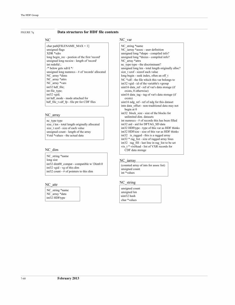
7-68 February 2013
The HDF Group
FIGURE 7q Data structures for HDF file contents
nc_type typesize_t len - total length originally allocatedsize_t szof - size of each valueunsigned count - length of the arrayVoid *values - the actual data
NC_array
unsigned countunsigned lenuint32 hashchar *values
NC_string
(counted array of ints for assoc list)unsigned countint *values
NC_iarrayNC_string *namelong sizeint32 dim00_compat - compatible w/ Dim0.0int32 vgid - vg of this dimint32 count - # of pointers to this dim
NC_dim
NC_string *nameNC_array *dataint32 HDFtype
NC_attr
char path[FILENAME_MAX + 1]unsigned flagsXDR *xdrslong begin_rec - postion of the first 'record'unsigned long recsize - length of 'record'int redefid ;/* below gets xdr'd */unsigned long numrecs - # of 'records' allocatedNC_array *dimsNC_array *attrsNC_array *varsint32 hdf_file;int file_type;int32 vgid;int hdf_mode - mode attached forhdf_file_t cdf_fp - file ptr for CDF files
NC
NC_string *nameNC_iarray *assoc - user definitionunsigned long *shape - compiled info?unsigned long *dsizes - compiled info?NC_array *attrsnc_type type - the discriminant?unsigned long len - total length originally alloc?size_t szof - sizeof each valuelong begin - seek index, often an off_tNC *cdf - the file which this var belongs toint32 vgid - id of the variable's vgroupuint16 data_ref - ref of var's data storage (if
exists, 0 otherwise)uint16 data_tag - tag of var's data storage (if
exists)uint16 ndg_ref - ref of ndg for this datasetintn data_offset - non-traditional data may not
begin at 0int32 block_size - size of the blocks for
unlimited dim. datasetsint numrecs - # of records this has been filledint32 aid - aid for DFTAG_SD dataint32 HDFtype - type of this var as HDF thinksint32 HDFsize - size of this var as HDF thinksint32 is_ragged - this is a ragged arrayint32 * rag_list - size of ragged array linesint32 rag_fill - last line in rag_list to be setvix_t * vixHead - list of VXR records for
CDF data storage
NC_var
HDF Specification and Developer’s Guide
February 2013 7-69
7.8 Library Implementation Details with Example File and SDS
This section describes the interface routines that are used to create, open, and modify an SDS and its components in the file. In particular, the following evolutionary stages of accessing and manip-ulating the SDS are discussed:
• The file is created or open.
• An SDS is created.
• Data is written to the SDS.
• Global attributes are set for the file.
• Local attributes are set for the SDS (data string and attribute name) and the dimension (dimension scale and dimension string).
• Access to the file is terminated.
At each stage, the correspondence between storing the contents in memory and representing the data in the file is discussed.
Illustrations in this section adhere to the conventions used previously in this chapter, with the fol-lowing additional elements:
• New items introduced for the next step are lightly shaded.
• Items being removed are heavily shaded and/or labeled in white text.
7.8.1 Creating or opening an HDF file
The routine SDstart creates a new HDF file or opens an existing one.
• When SDstart creates a file, a structure NC is created with the pointers dims, attrs, and vars set to NULL.
• When SDstart opens a file, a structure NC is created and the structures NC_array, NC_var, NC_dim, and NC_attr are created and attached to the pointers vars, dims, and attrs cor-responding to the contents of the file.
The objects are stored in these internal data structures (except for writing values) until the com-pletion of SDend, which writes the contents in these data structures to the file in the form of Vgroups, Vdatas, and other objects, as described below in each stage of the file evolution.
7.8.2 Creating an empty SDS
The routine SDcreate creates an SDS by the following steps:
• Creates an NC_dim for each dimension then inserts it into NC_array pointed to by dims. If dims is NULL, a structure of NC_array is created for it.
• For each NC_dim, creates a structure of NC_string to hold the name of the dimension.
• Creates an NC_var then inserts it into NC_array pointed to by vars. If vars is NULL, a structure of NC_array is created for it.
• Creates a structure of NC_string to hold the name of the SDS.
• Creates a structure of NC_iarray to hold the indices of the SDS dimensions.
Figure 7r illustrates the contents of the SD collection in the HDF file in memory at this point, when the collection contains an empty two-dimensional SDS.
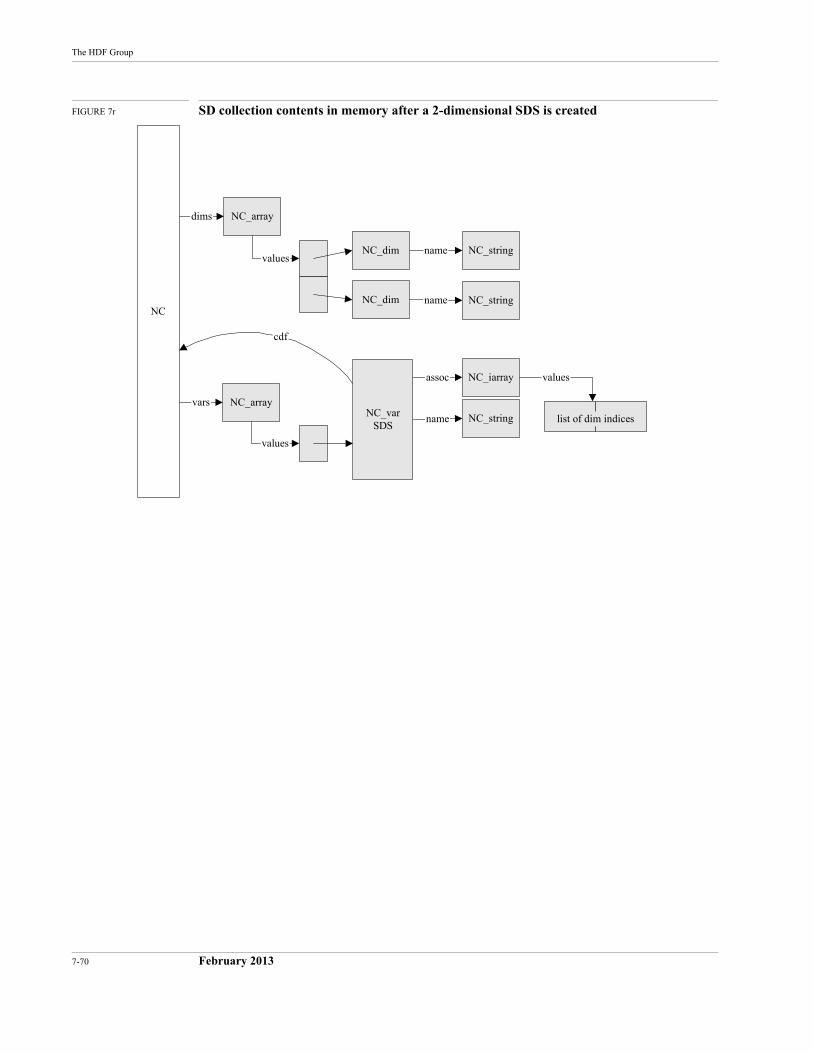
7-70 February 2013
The HDF Group
FIGURE 7r SD collection contents in memory after a 2-dimensional SDS is created
dims
vars
name
name
assoc
name
cdf
NC_array
NC_array
NC_string
NC_string
NC_string
NC_dim
NC_dim
NC_iarray
NC
values
values
NC_varSDS
values
list of dim indices
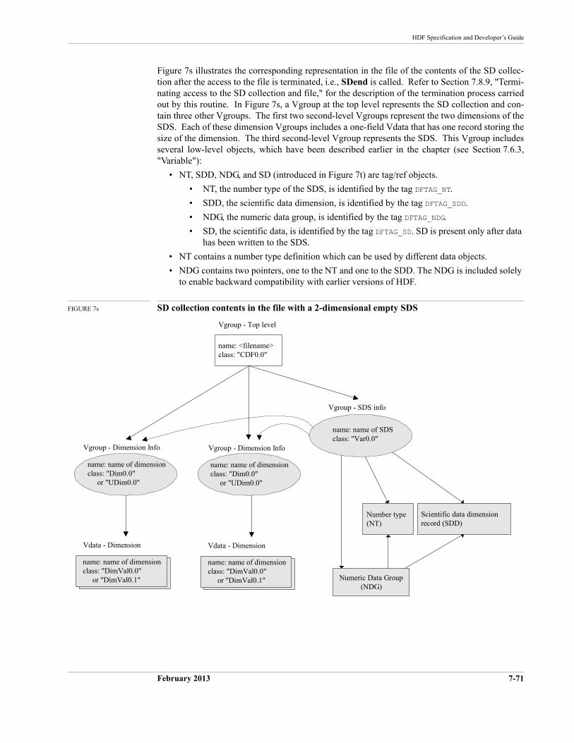
HDF Specification and Developer’s Guide
February 2013 7-71
Figure 7s illustrates the corresponding representation in the file of the contents of the SD collec-tion after the access to the file is terminated, i.e., SDend is called. Refer to Section 7.8.9, "Termi-nating access to the SD collection and file," for the description of the termination process carried out by this routine. In Figure 7s, a Vgroup at the top level represents the SD collection and con-tain three other Vgroups. The first two second-level Vgroups represent the two dimensions of the SDS. Each of these dimension Vgroups includes a one-field Vdata that has one record storing the size of the dimension. The third second-level Vgroup represents the SDS. This Vgroup includes several low-level objects, which have been described earlier in the chapter (see Section 7.6.3, "Variable"):
• NT, SDD, NDG, and SD (introduced in Figure 7t) are tag/ref objects.
• NT, the number type of the SDS, is identified by the tag DFTAG_NT.
• SDD, the scientific data dimension, is identified by the tag DFTAG_SDD.
• NDG, the numeric data group, is identified by the tag DFTAG_NDG.
• SD, the scientific data, is identified by the tag DFTAG_SD. SD is present only after data has been written to the SDS.
• NT contains a number type definition which can be used by different data objects.
• NDG contains two pointers, one to the NT and one to the SDD. The NDG is included solely to enable backward compatibility with earlier versions of HDF.
FIGURE 7s SD collection contents in the file with a 2-dimensional empty SDS
name: <filename>class: "CDF0.0"
Vgroup - Top level
Numeric Data Group(NDG)
name: name of SDSclass: "Var0.0"
Vgroup - SDS info
Number type(NT)
Scientific data dimensionrecord (SDD)
name: name of dimensionclass: "DimVal0.0" or "DimVal0.1"
Vdata - Dimension
name: name of dimensionclass: "Dim0.0" or "UDim0.0"
Vgroup - Dimension Info
name: name of dimensionclass: "DimVal0.0" or "DimVal0.1"
Vdata - Dimension
name: name of dimensionclass: "Dim0.0" or "UDim0.0"
Vgroup - Dimension Info
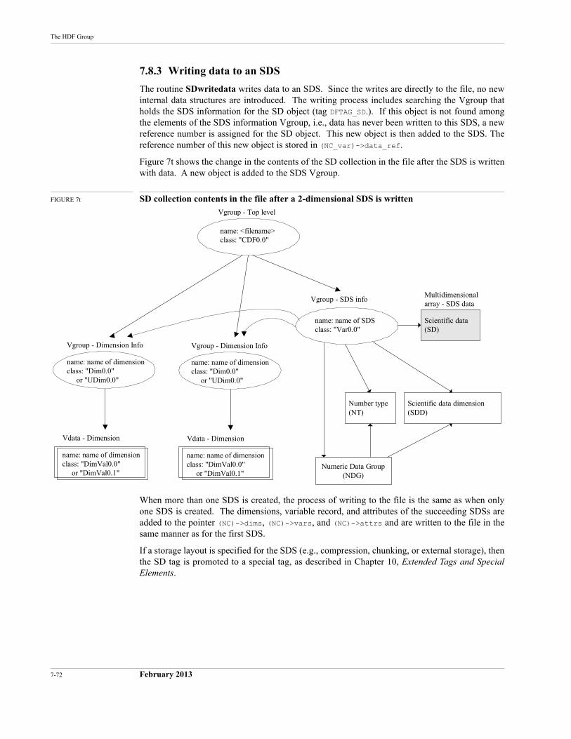
7-72 February 2013
The HDF Group
7.8.3 Writing data to an SDS
The routine SDwritedata writes data to an SDS. Since the writes are directly to the file, no new internal data structures are introduced. The writing process includes searching the Vgroup that holds the SDS information for the SD object (tag DFTAG_SD.). If this object is not found among the elements of the SDS information Vgroup, i.e., data has never been written to this SDS, a new reference number is assigned for the SD object. This new object is then added to the SDS. The reference number of this new object is stored in (NC_var)->data_ref.
Figure 7t shows the change in the contents of the SD collection in the file after the SDS is written with data. A new object is added to the SDS Vgroup.
FIGURE 7t SD collection contents in the file after a 2-dimensional SDS is written
When more than one SDS is created, the process of writing to the file is the same as when only one SDS is created. The dimensions, variable record, and attributes of the succeeding SDSs are added to the pointer (NC)->dims, (NC)->vars, and (NC)->attrs and are written to the file in the same manner as for the first SDS.
If a storage layout is specified for the SDS (e.g., compression, chunking, or external storage), then the SD tag is promoted to a special tag, as described in Chapter 10, Extended Tags and Special Elements.
name: <filename>class: "CDF0.0"
Vgroup - Top level
Numeric Data Group(NDG)
name: name of SDSclass: "Var0.0"
Vgroup - SDS info
Number type(NT)
Scientific data dimension(SDD)
name: name of dimensionclass: "DimVal0.0" or "DimVal0.1"
Vdata - Dimension
name: name of dimensionclass: "Dim0.0" or "UDim0.0"
Vgroup - Dimension Info
name: name of dimensionclass: "DimVal0.0" or "DimVal0.1"
Vdata - Dimension
name: name of dimensionclass: "Dim0.0" or "UDim0.0"
Vgroup - Dimension Info
Scientific data(SD)
Multidimensionalarray - SDS data
HDF Specification and Developer’s Guide
February 2013 7-73
7.8.4 Adding global and local attributes
The routine SDsetattr adds an attribute to
A: the SD collection by the following steps:
Creates an NC_attr for the attribute.
Attaches the new attribute record to the pointer values of NC_array pointed to by attrs. If attrs is NULL, a structure of NC_array is created for it first.
B: an SDS by the following steps:
Creates an NC_attr for the attribute.
If this object has not yet had any attribute created, i.e., attrs is NULL, starts the attribute list by creating a structure of NC_array, then attaches the new attribute record to the pointer values of NC_array.
If this object already has an attribute list, searches the attribute list for an attribute with the same name as the one to be added.
• If one is found, replaces the found attribute structure with the new one.
• If none is found, adds the new attribute structure to the attribute list. Note: the number of attributes must not exceed the maximum number of attributes allowed (MAX_NC_ATTRS.)
C: a dimension by the following steps:
• Creates an NC_attr for the attribute
• If the SD collection contains no variable record (from the list (NC)->vars) that rep-resents this dimension, promotes the dimension to a variable record, i.e. creates an NC_var for this dimension and attaches it to the variable list of the SD collection, (NC)->vars. At this point, the dimension has a variable record and, therefore, the rest of the attribute-setting process is identical to the process for an SDS.
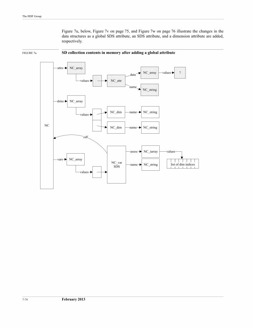
7-74 February 2013
The HDF Group
Figure 7u, below, Figure 7v on page 75, and Figure 7w on page 76 illustrate the changes in the data structures as a global SDS attribute, an SDS attribute, and a dimension attribute are added, respectively.
FIGURE 7u SD collection contents in memory after adding a global attribute
NC_arrayattrs
name
datavalues ?
NC_attr
NC_array
NC_string
values
dims
vars
name
name
assoc
name
cdf
NC_array
NC_array
NC_string
NC_string
NC_string
NC_dim
NC_dim
NC_iarray
NC
values
values
NC_varSDS
values
list of dim indices
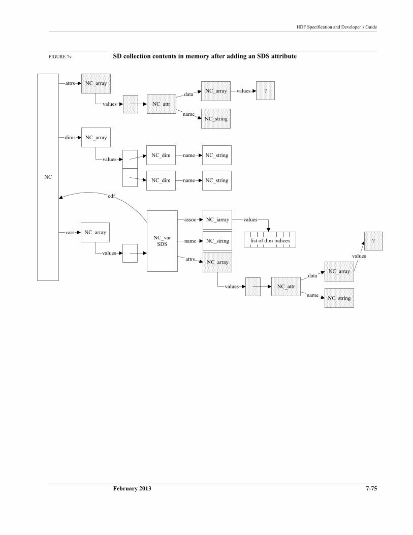
HDF Specification and Developer’s Guide
February 2013 7-75
FIGURE 7v SD collection contents in memory after adding an SDS attribute
NC_arrayattrs
name
datavalues ?
NC_attr
NC_array
NC_string
values
dims
vars
name
name
assoc
name
cdf
NC_array
NC_array
NC_string
NC_string
NC_string
NC_dim
NC_dim
NC_iarray
NC
values
values
NC_varSDS
values
list of dim indices
attrs NC_array
name
data
values
?
NC_array
NC_string
values NC_attr
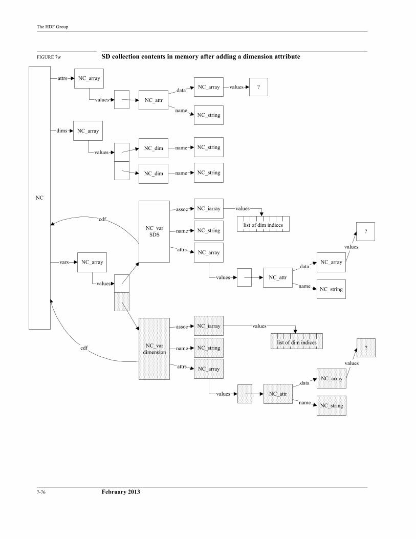
7-76 February 2013
The HDF Group
FIGURE 7w SD collection contents in memory after adding a dimension attribute
NC_array
dims
vars
attrs
name
datavalues
cdf
?
name
name
assoc
name
cdf
attrs
NC_attr
NC_array
NC_array
NC_array
NC_array
NC_string
NC_string
NC_string
NC_string
NC_dim
NC_dim
NC_iarray
NC
values
values
values
NC_varSDS
values
list of dim indices
name
data
values
?
NC_array
NC_string
values
NC_vardimension
attrs NC_array
assoc
name NC_string
NC_iarray values
list of dim indices
NC_attr
name
data
values
?
NC_array
NC_string
values NC_attr
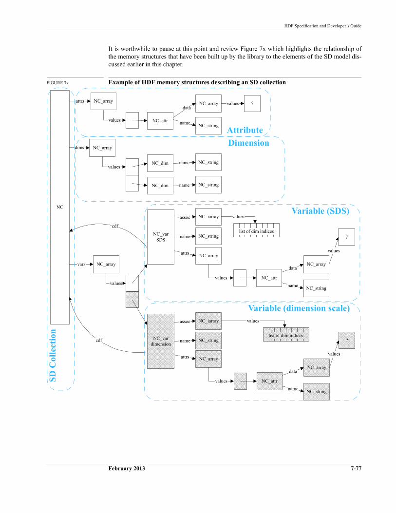
HDF Specification and Developer’s Guide
February 2013 7-77
It is worthwhile to pause at this point and review Figure 7x which highlights the relationship of the memory structures that have been built up by the library to the elements of the SD model dis-cussed earlier in this chapter.
FIGURE 7x Example of HDF memory structures describing an SD collection
NC_array
dims
vars
attrs
name
datavalues
cdf
?
name
name
assoc
name
cdf
attrs
NC_attr
NC_array
NC_array
NC_array
NC_array
NC_string
NC_string
NC_string
NC_string
NC_dim
NC_dim
NC_iarray
NC
values
values
values
NC_varSDS
values
list of dim indices
name
data
values
?
NC_array
NC_string
values
NC_vardimension
attrs NC_array
assoc
name NC_string
NC_iarray values
list of dim indices
NC_attr
name
data
values
?
NC_array
NC_string
values NC_attrSD
Col
lect
ion
Attribute
Dimension
Variable (SDS)
Variable (dimension scale)
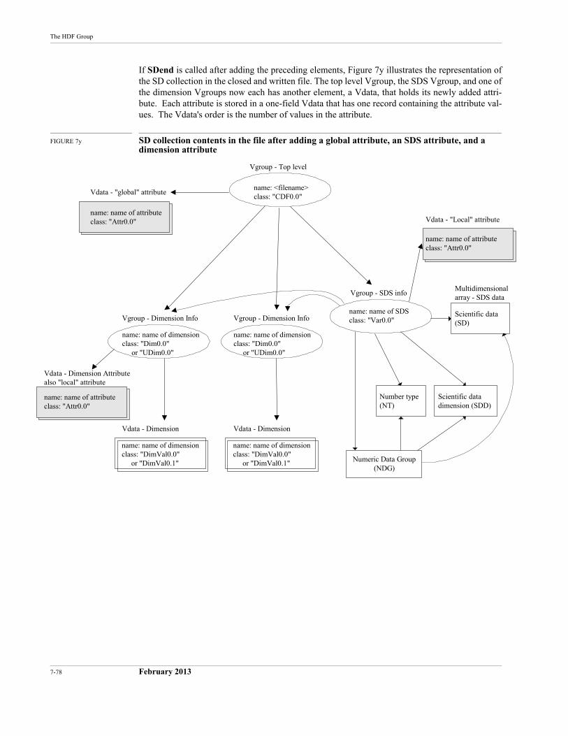
7-78 February 2013
The HDF Group
If SDend is called after adding the preceding elements, Figure 7y illustrates the representation of the SD collection in the closed and written file. The top level Vgroup, the SDS Vgroup, and one of the dimension Vgroups now each has another element, a Vdata, that holds its newly added attri-bute. Each attribute is stored in a one-field Vdata that has one record containing the attribute val-ues. The Vdata's order is the number of values in the attribute.
FIGURE 7y SD collection contents in the file after adding a global attribute, an SDS attribute, and a dimension attribute
name: name of attributeclass: "Attr0.0"
Vdata - Dimension Attributealso "local" attribute
name: name of attributeclass: "Attr0.0"
Vdata - "Local" attributename: name of attributeclass: "Attr0.0"
Vdata - "global" attributename: <filename>class: "CDF0.0"
Vgroup - Top level
Numeric Data Group(NDG)
name: name of SDSclass: "Var0.0"
Vgroup - SDS info
Number type(NT)
Scientific datadimension (SDD)
name: name of dimensionclass: "DimVal0.0" or "DimVal0.1"
Vdata - Dimension
name: name of dimensionclass: "Dim0.0" or "UDim0.0"
Vgroup - Dimension Info
name: name of dimensionclass: "DimVal0.0" or "DimVal0.1"
Vdata - Dimension
name: name of dimensionclass: "Dim0.0" or "UDim0.0"
Vgroup - Dimension InfoScientific data(SD)
Multidimensionalarray - SDS data
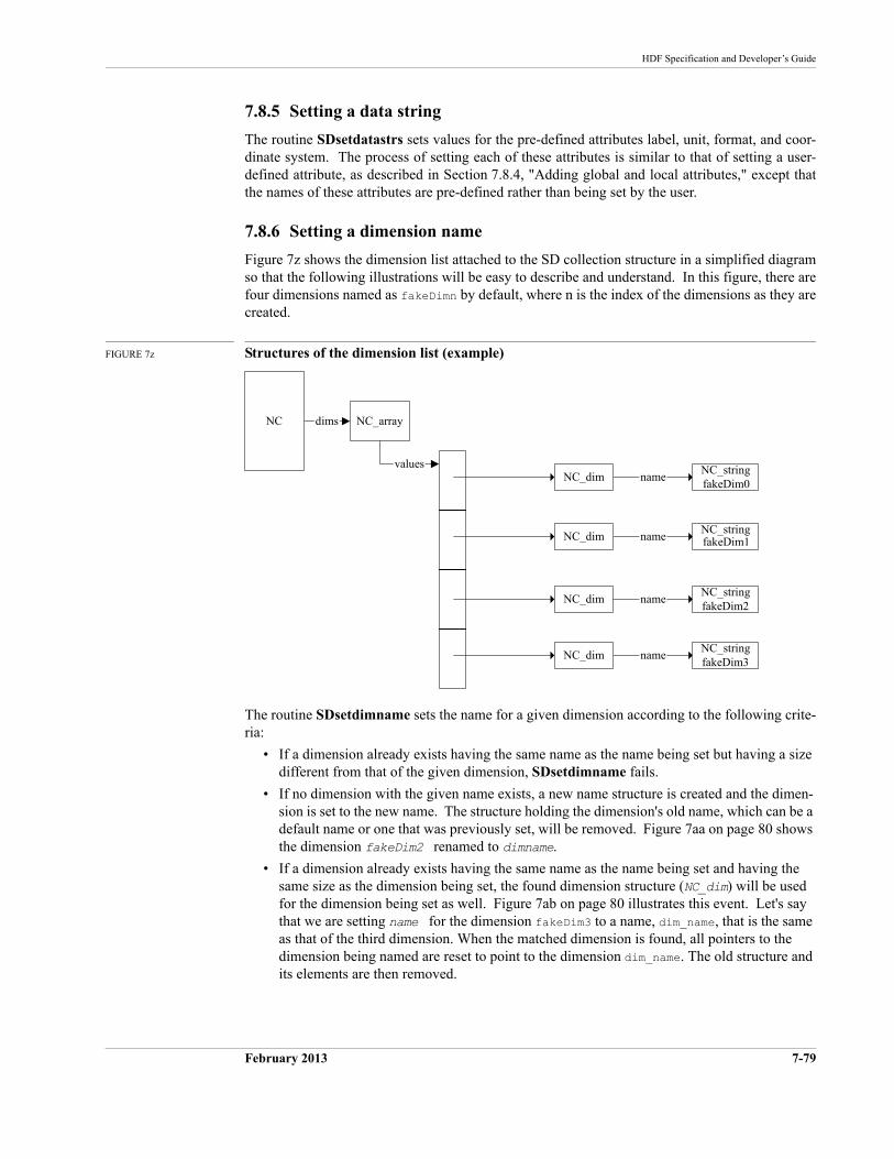
HDF Specification and Developer’s Guide
February 2013 7-79
7.8.5 Setting a data string
The routine SDsetdatastrs sets values for the pre-defined attributes label, unit, format, and coor-dinate system. The process of setting each of these attributes is similar to that of setting a user-defined attribute, as described in Section 7.8.4, "Adding global and local attributes," except that the names of these attributes are pre-defined rather than being set by the user.
7.8.6 Setting a dimension name
Figure 7z shows the dimension list attached to the SD collection structure in a simplified diagram so that the following illustrations will be easy to describe and understand. In this figure, there are four dimensions named as fakeDimn by default, where n is the index of the dimensions as they are created.
FIGURE 7z Structures of the dimension list (example)
The routine SDsetdimname sets the name for a given dimension according to the following crite-ria:
• If a dimension already exists having the same name as the name being set but having a size different from that of the given dimension, SDsetdimname fails.
• If no dimension with the given name exists, a new name structure is created and the dimen-sion is set to the new name. The structure holding the dimension's old name, which can be a default name or one that was previously set, will be removed. Figure 7aa on page 80 shows the dimension fakeDim2 renamed to dimname.
• If a dimension already exists having the same name as the name being set and having the same size as the dimension being set, the found dimension structure (NC_dim) will be used for the dimension being set as well. Figure 7ab on page 80 illustrates this event. Let's say that we are setting name for the dimension fakeDim3 to a name, dim_name, that is the same as that of the third dimension. When the matched dimension is found, all pointers to the dimension being named are reset to point to the dimension dim_name. The old structure and its elements are then removed.
name
name
name
NC_stringfakeDim0
NC_stringfakeDim3
NC_stringfakeDim1
NC_array
NC_dim
dimsNC
NC_dim
NC_dim
NC_dim
values
nameNC_stringfakeDim2
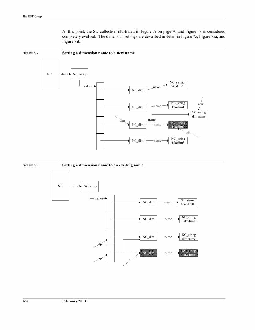
7-80 February 2013
The HDF Group
At this point, the SD collection illustrated in Figure 7r on page 70 and Figure 7s is considered completely evolved. The dimension settings are described in detail in Figure 7z, Figure 7aa, and Figure 7ab.
FIGURE 7aa Setting a dimension name to a new name
FIGURE 7ab Setting a dimension name to an existing name
NC_stringfakedim2
NC_stringdim name
new
dim
name
name
name
NC_stringfakedim0
NC_stringfakedim3
NC_stringfakedim1
NC_array
NC_dim
dimsNC
NC_dim
NC_dim
NC_dim
name
values
name
old
NC_stringdim name
dim
name
name
name
NC_stringfakedim0
NC_stringfakedim3
NC_stringfakedim1
NC_array
NC_dim
dimsNC
NC_dim
NC_dim
NC_dim
values
name
ap
dp
HDF Specification and Developer’s Guide
February 2013 7-81
7.8.7 Setting a dimension scale
The routine SDsetdimscale sets values to a given dimension as follows.
• If the SD collection contains no variable record (from the list (NC)->vars) that represents this dimension, promote the dimension to a variable record as described in the case of set-ting dimension attribute in Section 7.6.4, "Dimension." and illustrated in Figure 7w, "SD collection contents in memory after adding a dimension attribute." At this point, the dimen-sion has a variable record and the scale values are written to the variable record.
• If this dimension already has a variable record, the record is updated with the scale values.
In both cases, the number type of the dimension is set via a call to SDsetdimscale.
7.8.8 Setting a dimension string
The routine SDsetdimstrs sets values to the pre-defined attributes label, unit, and format for a dimension. The process of setting each of these attributes is similar to that of setting a user-defined attribute described in Section 7.6.4, "Dimension," except that the names of these attri-butes are pre-defined rather than being set by the user. Before setting values for any of these attri-butes, a variable record is created for this dimension if the record does not already exist. The creation of the variable record for a dimension is illustrated in Figure 7.6.4, "Dimension."
If SDsetdimstrs is called before SDsetdimscale, then the number type of this dimension will be set to DFNT_FLOAT32 (5).
7.8.9 Terminating access to the SD collection and file
The routine SDend terminates access to the SD collection and the HDF file and, if the contents of the structures have changed, writes all the structures to the file. The following steps will be car-ried out:
• For each dimension
• a Vdata is created containing the size of the corresponding dimension.
• a Vgroup for this dimension is created. Its reference number is stored in (NC_dim)->vgid, a Vgroup containing the above Vdata.
• For each SDS
• the record SD that stores the SDS data is written if data has been written to this SDS.
• the record NT that stores the number type is written.
• the record SDD that stores the dimension values is written.
• the NDG record that is formed by the records SD, NT, and SDD is written.
• a Vgroup for this variable is created. Its reference number is stored in (NC_var)->vgid, a Vgroup containing all of the dimensions' Vgroups, the attributes' Vgroups if there are any, and the SD, NT, SDD and NDG records.
• For the SD collection and the HDF file
• global attributes are written.
• a Vgroup for the top level is created. Its reference number is stored in (NC)->vgid, a Vgroup containing all of the global attributes' Vgroups, the dimensions' Vgroups, and the SDS Vgroups.

7-82 February 2013
The HDF Group
February 2013 8-81
CHAPTER 8 -- General Raster Images:
The GR Model
8.1 Chapter Overview
This chapter provides functional descriptions of the GR Data Model, the GR implementation in the HDF library, and the HDF file structures employed.
• Section 8.2, "Images in an HDF File," describes the types of images that may be found in an HDF file.
• Section 8.3, "The GR Data Model," and Section 8.4, "Mapping between GR Data Model and HDF File Structures," describe the GR data model, including a rigorous UML represen-tation, and the mapping of the model’s elements to HDF data structures.
• Section 8.5, "Modifying an RIG or RI8 Image via the GR Interface," discusses the interac-tion of the GR interface with older-style RIG and RI8 images.
• Section 8.6, "Backwards Compatibility when Creating New Images via the GR Interface," through Section 8.8, "Relationships among Main Data Structures," describe the GR imple-mentation in the HDF library and the data structures employed.
• Section 8.9, "The Evolution of an HDF File in the GR Interface," then illustrates several steps in the evolution of the contents in an HDF file under the GR interface. At each step, the correspondence between the information as stored in memory and as represented in the file is described.
Many of the figures in this chapter employ UML notation (Unified Modeling Language notation) to show object relationships. See Section 7.2, "UML Notation and Object Symbols in HDF Data Model Descriptions."
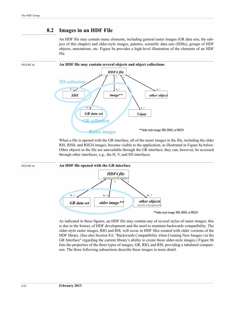
8-82 February 2013
The HDF Group
8.2 Images in an HDF File
An HDF file may contain many elements, including general raster images (GR data sets, the sub-ject of this chapter) and older-style images, palettes, scientific data sets (SDSs), groups of HDF objects, annotations, etc. Figure 8a provides a high-level illustration of the elements of an HDF file.
FIGURE 8a An HDF file may contain several objects and object collections
When a file is opened with the GR interface, all of the raster images in the file, including the older RI8, RIS8, and RIS24 images, become visible to the application, as illustrated in Figure 8a below. Other objects in the file are unavailable through the GR interface; they can, however, be accessed through other interfaces, e.g., the H, V, and SD interfaces.
FIGURE 8a An HDF file opened with the GR interface
As indicated in these figures, an HDF file may contain any of several styles of raster images; this is due to the history of HDF development and the need to maintain backwards compatibility. The older-style raster images, RIG and RI8, will occur in HDF files created with older versions of the HDF library. (See also Section 8.6, "Backwards Compatibility when Creating New Images via the GR Interface" regarding the current library’s ability to create these older-style images.) Figure 8b lists the properties of the three types of images, GR, RIG, and RI8, providing a tabulated compari-son. The three following subsections describe these images in more detail.
HDF4 file
image**SDS
Vdata
0…*
1
0…*
11
GR data set
0…*
1
other object
0…*
1
0…*
SD collection
Raster images
GR collection
**older style image: RI8, RIS8, or RIS24
HDF4 file
other objects(invisible to the application)
GR data set
0…*
1
0…*
1
older image**
0…*
1
(opened with GR interface)
**older style image: RI8, RIS8, or RIS24
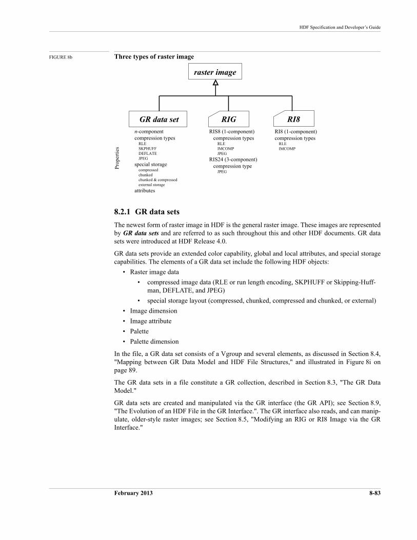
HDF Specification and Developer’s Guide
February 2013 8-83
FIGURE 8b Three types of raster image
8.2.1 GR data sets
The newest form of raster image in HDF is the general raster image. These images are represented by GR data sets and are referred to as such throughout this and other HDF documents. GR data sets were introduced at HDF Release 4.0.
GR data sets provide an extended color capability, global and local attributes, and special storage capabilities. The elements of a GR data set include the following HDF objects:
• Raster image data
• compressed image data (RLE or run length encoding, SKPHUFF or Skipping-Huff-man, DEFLATE, and JPEG)
• special storage layout (compressed, chunked, compressed and chunked, or external)
• Image dimension
• Image attribute
• Palette
• Palette dimension
In the file, a GR data set consists of a Vgroup and several elements, as discussed in Section 8.4, "Mapping between GR Data Model and HDF File Structures," and illustrated in Figure 8i on page 89.
The GR data sets in a file constitute a GR collection, described in Section 8.3, "The GR Data Model."
GR data sets are created and manipulated via the GR interface (the GR API); see Section 8.9, "The Evolution of an HDF File in the GR Interface.". The GR interface also reads, and can manip-ulate, older-style raster images; see Section 8.5, "Modifying an RIG or RI8 Image via the GR Interface."
raster image
GR data set RIGn-componentcompression types RLE SKPHUFF DEFLATE JPEG
special storage compressed chunked chunked & compressed external storage
attributes
RIS8 (1-component) compression types RLE IMCOMP JPEG
RIS24 (3-component) compression type JPEG
RI8 (1-component)compression types RLE IMCOMP
Pro
pert
ies
RI8
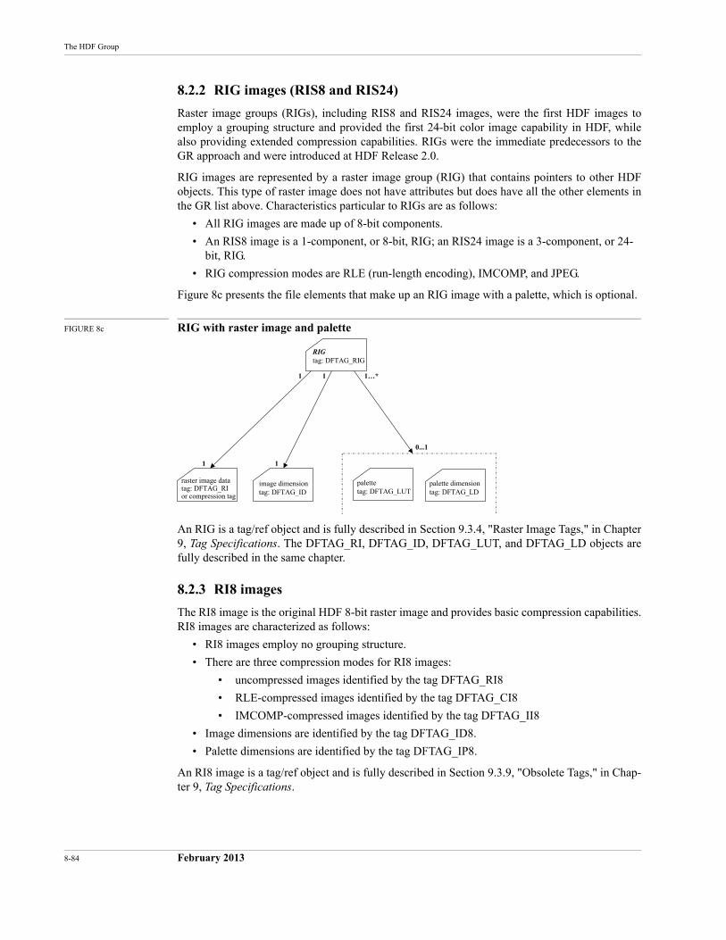
8-84 February 2013
The HDF Group
8.2.2 RIG images (RIS8 and RIS24)
Raster image groups (RIGs), including RIS8 and RIS24 images, were the first HDF images to employ a grouping structure and provided the first 24-bit color image capability in HDF, while also providing extended compression capabilities. RIGs were the immediate predecessors to the GR approach and were introduced at HDF Release 2.0.
RIG images are represented by a raster image group (RIG) that contains pointers to other HDF objects. This type of raster image does not have attributes but does have all the other elements in the GR list above. Characteristics particular to RIGs are as follows:
• All RIG images are made up of 8-bit components.
• An RIS8 image is a 1-component, or 8-bit, RIG; an RIS24 image is a 3-component, or 24-bit, RIG.
• RIG compression modes are RLE (run-length encoding), IMCOMP, and JPEG.
Figure 8c presents the file elements that make up an RIG image with a palette, which is optional.
FIGURE 8c RIG with raster image and palette
An RIG is a tag/ref object and is fully described in Section 9.3.4, "Raster Image Tags," in Chapter 9, Tag Specifications. The DFTAG_RI, DFTAG_ID, DFTAG_LUT, and DFTAG_LD objects are fully described in the same chapter.
8.2.3 RI8 images
The RI8 image is the original HDF 8-bit raster image and provides basic compression capabilities. RI8 images are characterized as follows:
• RI8 images employ no grouping structure.
• There are three compression modes for RI8 images:
• uncompressed images identified by the tag DFTAG_RI8
• RLE-compressed images identified by the tag DFTAG_CI8
• IMCOMP-compressed images identified by the tag DFTAG_II8
• Image dimensions are identified by the tag DFTAG_ID8.
• Palette dimensions are identified by the tag DFTAG_IP8.
An RI8 image is a tag/ref object and is fully described in Section 9.3.9, "Obsolete Tags," in Chap-ter 9, Tag Specifications.
0...1
1…*
RIGtag: DFTAG_RIG
palettetag: DFTAG_LUT
1
palette dimensiontag: DFTAG_LD
image dimensiontag: DFTAG_ID
11
raster image datatag: DFTAG_RIor compression tag
1
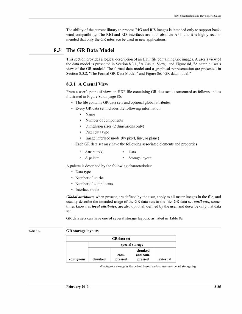
HDF Specification and Developer’s Guide
February 2013 8-85
The ability of the current library to process RIG and RI8 images is intended only to support back-ward compatibility. The RIG and RI8 interfaces are both obsolete APIs and it is highly recom-mended that only the GR interface be used in new applications.
8.3 The GR Data Model
This section provides a logical description of an HDF file containing GR images. A user’s view of the data model is presented in Section 8.3.1, "A Casual View," and Figure 8d, "A sample user’s view of the GR model." The formal data model and a graphical representation are presented in Section 8.3.2, "The Formal GR Data Model," and Figure 8e, "GR data model."
8.3.1 A Casual View
From a user’s point of view, an HDF file containing GR data sets is structured as follows and as illustrated in Figure 8d on page 86:
• The file contains GR data sets and optional global attributes.
• Every GR data set includes the following information:
• Name
• Number of components
• Dimension sizes (2 dimensions only)
• Pixel data type
• Image interlace mode (by pixel, line, or plane)
• Each GR data set may have the following associated elements and properties
A palette is described by the following characteristics:
• Data type
• Number of entries
• Number of components
• Interlace mode
Global attributes, when present, are defined by the user, apply to all raster images in the file, and usually describe the intended usage of the GR data sets in the file. GR data set attributes, some-times known as local attributes, are also optional, defined by the user, and describe only that data set.
GR data sets can have one of several storage layouts, as listed in Table 8a.
TABLE 8a GR storage layouts
•Contiguous storage is the default layout and requires no special storage tag.
• Attribute(s)
• A palette
• Data
• Storage layout
GR data set
contiguous
special storage
chunkedcom-
pressed
chunked and com-pressed external
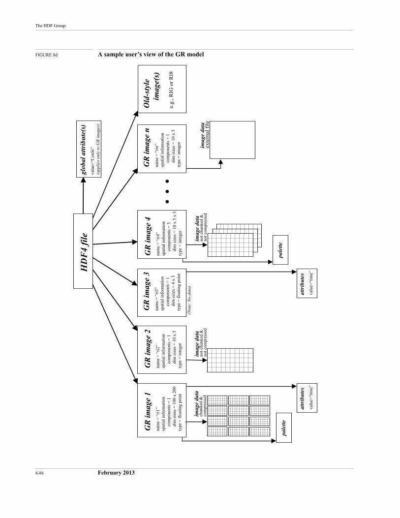
8-86 February 2013
The HDF Group
FIGURE 8d A sample user’s view of the GR model
HD
F4
file
GR
imag
e 1
nam
e =
“ri
1”sp
atia
l inf
orm
atio
n
com
pone
nts
= 1
d
im s
izes
= 1
00 x
200
type
= f
loat
ing
poin
t
glob
al a
ttri
bute
(s)
valu
e=“C
onS
i”(a
ppli
es o
nly
to G
R im
ages
)
. . .
attr
ibu
tes
valu
e=“t
ime”
imag
e da
tach
unke
d &
com
pres
sed
GR
imag
e 2
nam
e =
“ri
2”sp
atia
l inf
orm
atio
n
com
pone
nts
= 1
d
im s
izes
= 1
0 x
5ty
pe =
inte
ger
imag
e da
tano
t chu
nked
&no
t com
pres
sed
GR
imag
e 3
nam
e =
“ri
3”sp
atia
l inf
orm
atio
n
com
pone
nts
= 1
d
im s
izes
= 4
x 3
type
= f
loat
ing
poin
t
(Not
e: N
o da
ta)
GR
imag
e n
nam
e =
“ri
n”sp
atia
l inf
orm
atio
n
com
pone
nts
= 1
d
im s
izes
= 1
0 x
5ty
pe =
inte
ger
imag
e da
taex
tern
al f
ile
GR
imag
e 4
nam
e =
“ri
4”sp
atia
l inf
orm
atio
n
com
pone
nts
= 3
d
im s
izes
= 1
0 x
5 x
3ty
pe =
inte
ger
imag
e da
tano
t chu
nked
&no
t com
pres
sed
pale
ttepa
lett
e
Old
-sty
le
imag
e(s)
e.g.
, RIG
or
RI8
attr
ibut
es
valu
e=“t
ime”
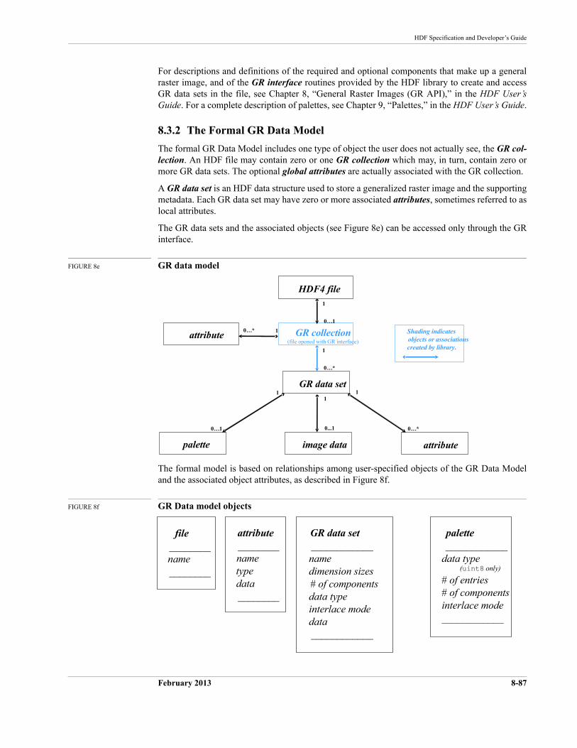
HDF Specification and Developer’s Guide
February 2013 8-87
For descriptions and definitions of the required and optional components that make up a general raster image, and of the GR interface routines provided by the HDF library to create and access GR data sets in the file, see Chapter 8, “General Raster Images (GR API),” in the HDF User’s Guide. For a complete description of palettes, see Chapter 9, “Palettes,” in the HDF User’s Guide.
8.3.2 The Formal GR Data Model
The formal GR Data Model includes one type of object the user does not actually see, the GR col-lection. An HDF file may contain zero or one GR collection which may, in turn, contain zero or more GR data sets. The optional global attributes are actually associated with the GR collection.
A GR data set is an HDF data structure used to store a generalized raster image and the supporting metadata. Each GR data set may have zero or more associated attributes, sometimes referred to as local attributes.
The GR data sets and the associated objects (see Figure 8e) can be accessed only through the GR interface.
FIGURE 8e GR data model
The formal model is based on relationships among user-specified objects of the GR Data Model and the associated object attributes, as described in Figure 8f.
FIGURE 8f GR Data model objects
GR collectionattribute
GR data set
palette attribute
0…*
0…*
0…*
1
1
11
image data
0...1
1
(file opened with GR interface)
Shading indicates objects or associations created by library.
0…1
HDF4 file
0…1
1
file ________name________
GR data set____________namedimension sizes# of componentsdata typeinterlace modedata____________
attribute________nametypedata________
palette ____________
data type (uint8 only)
# of entries# of componentsinterlace mode____________
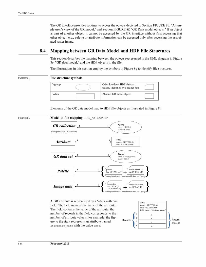
8-88 February 2013
The HDF Group
The GR interface provides routines to access the objects depicted in Section FIGURE 8d, "A sam-ple user’s view of the GR model," and Section FIGURE 8f, "GR Data model objects." If an object is part of another object, it cannot be accessed by the GR interface without first accessing that other object; e.g., palette or attribute information can be accessed only after accessing the associ-ated raster image.
8.4 Mapping between GR Data Model and HDF File Structures
This section describes the mapping between the objects represented in the UML diagram in Figure 8e, "GR data model," and the HDF objects in the file.
The illustrations in this section employ the symbols in Figure 8g to identify file structures.
FIGURE 8g File structure symbols
Elements of the GR data model map to HDF file objects as illustrated in Figure 8h
FIGURE 8h Model-to-file mapping -- GR_collection
A GR attribute is represented by a Vdata with one field. The field name is the name of the attribute. The field contains the value of the attribute; the number of records in the field corresponds to the number of attribute values. For example, the fig-ure to the right represents an attribute named attribute_name with the value abcd.
Vgroup Other low-level HDF objects, usually identified by a tag/ref pair
Vdata Abstract GR model object
{ + }{ + }
Vgroupname = RIG0.0class = RIG0.0
GR collection
GR data set
1 1
11
(file opened with GR interface)
Vdataname = RIATTR0.0Nclass = RIATTR0.0C
Attribute 11
Vgroupname = image_nameclass = RI0.0
Palette 11 palettetag: DFTAG_LUT
palette dimensiontag: DFTAG_LD
Two tag/ref elements added to GR data set Vgroup
Image data 11 image datatag: DFTAG_RI or extended tag
image dimensiontag: DFTAG_ID
Two tag/ref elements added to GR data set Vgroup
Vdataname = RIATTR0.0Nclass = RIATTR0.0Cfield_name = “attribute_name”
Records
a
b
c
d
1
2
3
4
Recordcontent
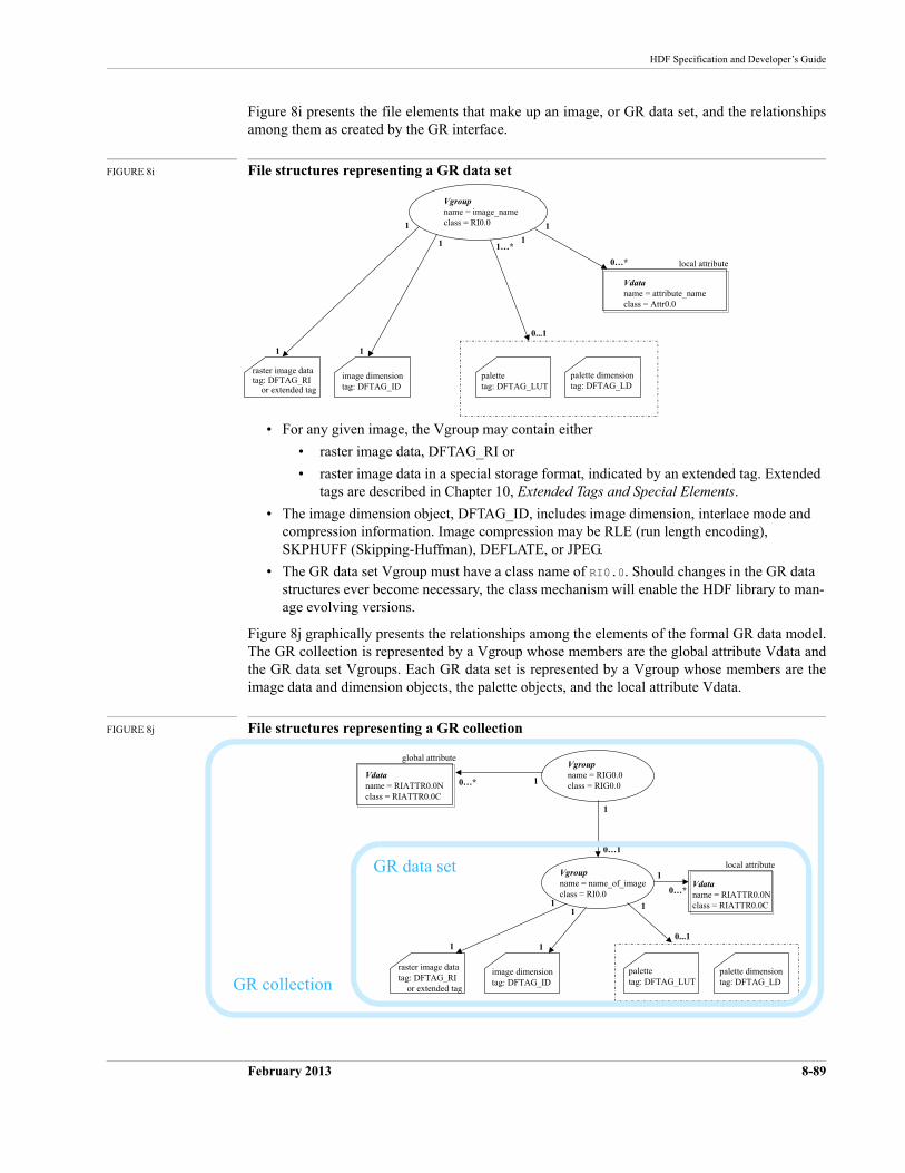
HDF Specification and Developer’s Guide
February 2013 8-89
Figure 8i presents the file elements that make up an image, or GR data set, and the relationships among them as created by the GR interface.
FIGURE 8i File structures representing a GR data set
• For any given image, the Vgroup may contain either
• raster image data, DFTAG_RI or
• raster image data in a special storage format, indicated by an extended tag. Extended tags are described in Chapter 10, Extended Tags and Special Elements.
• The image dimension object, DFTAG_ID, includes image dimension, interlace mode and compression information. Image compression may be RLE (run length encoding), SKPHUFF (Skipping-Huffman), DEFLATE, or JPEG.
• The GR data set Vgroup must have a class name of RI0.0. Should changes in the GR data structures ever become necessary, the class mechanism will enable the HDF library to man-age evolving versions.
Figure 8j graphically presents the relationships among the elements of the formal GR data model. The GR collection is represented by a Vgroup whose members are the global attribute Vdata and the GR data set Vgroups. Each GR data set is represented by a Vgroup whose members are the image data and dimension objects, the palette objects, and the local attribute Vdata.
FIGURE 8j File structures representing a GR collection
Vdataname = attribute_nameclass = Attr0.0
Vgroupname = image_nameclass = RI0.0
palettetag: DFTAG_LUT
0…*
1 1
local attribute
palette dimensiontag: DFTAG_LD
0...1
1…*
image dimensiontag: DFTAG_ID
1
1
1
raster image datatag: DFTAG_RI or extended tag
1
Vdataname = RIATTR0.0Nclass = RIATTR0.0C
Vgroupname = RIG0.0class = RIG0.0
0…*
1
1local attribute
Vgroupname = name_of_imageclass = RI0.0
1
0…1
1
0…*
global attribute
Vdataname = RIATTR0.0Nclass = RIATTR0.0C
palettetag: DFTAG_LUT
palette dimensiontag: DFTAG_LD
image dimensiontag: DFTAG_ID
11
raster image datatag: DFTAG_RI or extended tag
11
0...1
GR data set
GR collection
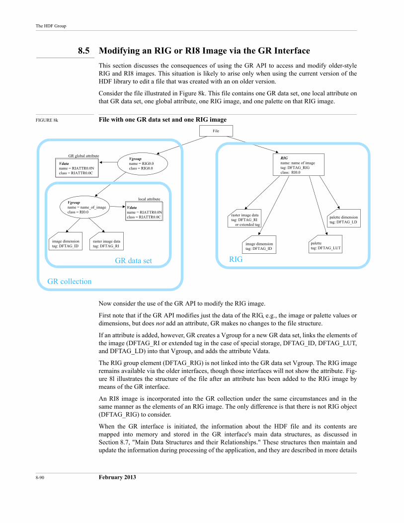
8-90 February 2013
The HDF Group
8.5 Modifying an RIG or RI8 Image via the GR Interface
This section discusses the consequences of using the GR API to access and modify older-style RIG and RI8 images. This situation is likely to arise only when using the current version of the HDF library to edit a file that was created with an on older version.
Consider the file illustrated in Figure 8k. This file contains one GR data set, one local attribute on that GR data set, one global attribute, one RIG image, and one palette on that RIG image.
FIGURE 8k File with one GR data set and one RIG image
Now consider the use of the GR API to modify the RIG image.
First note that if the GR API modifies just the data of the RIG, e.g., the image or palette values or dimensions, but does not add an attribute, GR makes no changes to the file structure.
If an attribute is added, however, GR creates a Vgroup for a new GR data set, links the elements of the image (DFTAG_RI or extended tag in the case of special storage, DFTAG_ID, DFTAG_LUT, and DFTAG_LD) into that Vgroup, and adds the attribute Vdata.
The RIG group element (DFTAG_RIG) is not linked into the GR data set Vgroup. The RIG image remains available via the older interfaces, though those interfaces will not show the attribute. Fig-ure 8l illustrates the structure of the file after an attribute has been added to the RIG image by means of the GR interface.
An RI8 image is incorporated into the GR collection under the same circumstances and in the same manner as the elements of an RIG image. The only difference is that there is not RIG object (DFTAG_RIG) to consider.
When the GR interface is initiated, the information about the HDF file and its contents are mapped into memory and stored in the GR interface's main data structures, as discussed in Section 8.7, "Main Data Structures and their Relationships." These structures then maintain and update the information during processing of the application, and they are described in more details
Vdataname = RIATTR0.0Nclass = RIATTR0.0C
Vgroupname = RIG0.0class = RIG0.0
image dimensiontag: DFTAG_ID
local attributeVgroupname = name_of_imageclass = RI0.0
raster image datatag: DFTAG_RI
GR global attribute
Vdataname = RIATTR0.0Nclass = RIATTR0.0C
File
RIG
GR collection
GR data set
RIGname: name of imagetag: DFTAG_RIGclass: RI0.0
palettetag: DFTAG_LUT
palette dimensiontag: DFTAG_LD
image dimensiontag: DFTAG_ID
raster image datatag: DFTAG_RI or extended tag
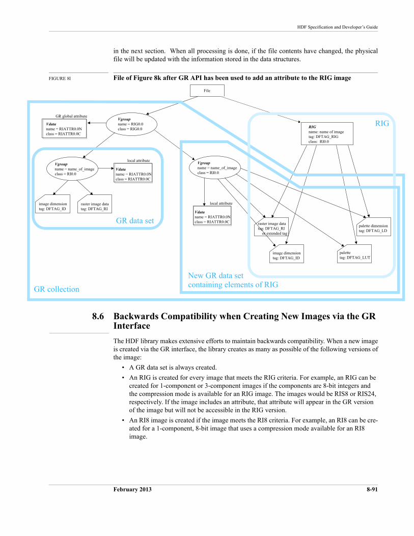
HDF Specification and Developer’s Guide
February 2013 8-91
in the next section. When all processing is done, if the file contents have changed, the physical file will be updated with the information stored in the data structures.
FIGURE 8l File of Figure 8k after GR API has been used to add an attribute to the RIG image
8.6 Backwards Compatibility when Creating New Images via the GR Interface
The HDF library makes extensive efforts to maintain backwards compatibility. When a new image is created via the GR interface, the library creates as many as possible of the following versions of the image:
• A GR data set is always created.
• An RIG is created for every image that meets the RIG criteria. For example, an RIG can be created for 1-component or 3-component images if the components are 8-bit integers and the compression mode is available for an RIG image. The images would be RIS8 or RIS24, respectively. If the image includes an attribute, that attribute will appear in the GR version of the image but will not be accessible in the RIG version.
• An RI8 image is created if the image meets the RI8 criteria. For example, an RI8 can be cre-ated for a 1-component, 8-bit image that uses a compression mode available for an RI8 image.
Vdataname = RIATTR0.0Nclass = RIATTR0.0C
Vgroupname = RIG0.0class = RIG0.0
image dimensiontag: DFTAG_ID
local attributeVgroupname = name_of_imageclass = RI0.0
raster image datatag: DFTAG_RI
GR global attribute
Vdataname = RIATTR0.0Nclass = RIATTR0.0C
File
Vdataname = RIATTR0.0Nclass = RIATTR0.0C
local attribute
Vgroupname = name_of_imageclass = RI0.0
RIGname: name of imagetag: DFTAG_RIGclass: RI0.0
palettetag: DFTAG_LUT
palette dimensiontag: DFTAG_LD
image dimensiontag: DFTAG_ID
raster image datatag: DFTAG_RI or extended tag
GR collection
GR data set
New GR data set containing elements of RIG
RIG
8-92 February 2013
The HDF Group
8.7 Main Data Structures and their Relationships
This section provides the description of the main data structures used in the GR interface to store a GR data set's contents in memory. Figure 8m lists these data structures and all their elements.
gr_info_t File information structure storing information about the HDF file.
ri_info_t Raster image information structure storing information about a raster image.
at_info_t Attribute information structure storing local and global attribute information.
dim_info_t Dimension information structure storing both image and palette dimension information.
These structures are somewhat self-described in Figure 8m, except for some details too complex to present in the figure. The following subsections provide additional details about these struc-tures. The last subsection in this section describes the relationships among the data structures.
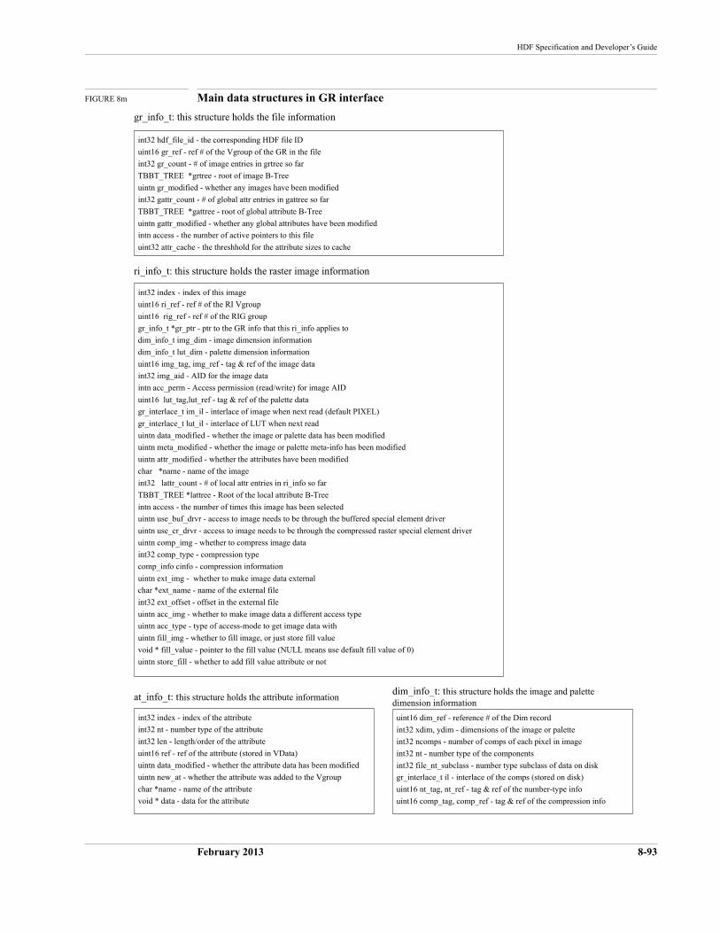
HDF Specification and Developer’s Guide
February 2013 8-93
FIGURE 8m Main data structures in GR interface
int32 index - index of the attribute
int32 nt - number type of the attribute
int32 len - length/order of the attribute
uint16 ref - ref of the attribute (stored in VData)
uintn data_modified - whether the attribute data has been modified
uintn new_at - whether the attribute was added to the Vgroup
char *name - name of the attribute
void * data - data for the attribute
at_info_t: this structure holds the attribute information
int32 hdf_file_id - the corresponding HDF file ID
uint16 gr_ref - ref # of the Vgroup of the GR in the file
int32 gr_count - # of image entries in grtree so far
TBBT_TREE *grtree - root of image B-Tree
uintn gr_modified - whether any images have been modified
int32 gattr_count - # of global attr entries in gattree so far
TBBT_TREE *gattree - root of global attribute B-Tree
uintn gattr_modified - whether any global attributes have been modified
intn access - the number of active pointers to this file
uint32 attr_cache - the threshhold for the attribute sizes to cache
gr_info_t: this structure holds the file information
int32 index - index of this image
uint16 ri_ref - ref # of the RI Vgroup
uint16 rig_ref - ref # of the RIG group
gr_info_t *gr_ptr - ptr to the GR info that this ri_info applies to
dim_info_t img_dim - image dimension information
dim_info_t lut_dim - palette dimension information
uint16 img_tag, img_ref - tag & ref of the image data
int32 img_aid - AID for the image data
intn acc_perm - Access permission (read/write) for image AID
uint16 lut_tag,lut_ref - tag & ref of the palette data
gr_interlace_t im_il - interlace of image when next read (default PIXEL)
gr_interlace_t lut_il - interlace of LUT when next read
uintn data_modified - whether the image or palette data has been modified
uintn meta_modified - whether the image or palette meta-info has been modified
uintn attr_modified - whether the attributes have been modified
char *name - name of the image
int32 lattr_count - # of local attr entries in ri_info so far
TBBT_TREE *lattree - Root of the local attribute B-Tree
intn access - the number of times this image has been selected
uintn use_buf_drvr - access to image needs to be through the buffered special element driver
uintn use_cr_drvr - access to image needs to be through the compressed raster special element driver
uintn comp_img - whether to compress image data
int32 comp_type - compression type
comp_info cinfo - compression information
uintn ext_img - whether to make image data external
char *ext_name - name of the external file
int32 ext_offset - offset in the external file
uintn acc_img - whether to make image data a different access type
uintn acc_type - type of access-mode to get image data with
uintn fill_img - whether to fill image, or just store fill value
void * fill_value - pointer to the fill value (NULL means use default fill value of 0)
uintn store_fill - whether to add fill value attribute or not
ri_info_t: this structure holds the raster image information
uint16 dim_ref - reference # of the Dim record
int32 xdim, ydim - dimensions of the image or palette
int32 ncomps - number of comps of each pixel in image
int32 nt - number type of the components
int32 file_nt_subclass - number type subclass of data on disk
gr_interlace_t il - interlace of the comps (stored on disk)
uint16 nt_tag, nt_ref - tag & ref of the number-type info
uint16 comp_tag, comp_ref - tag & ref of the compression info
dim_info_t: this structure holds the image and palettedimension information
8-94 February 2013
The HDF Group
8.7.1 File Information Structure (gr_info_t)
The gr_info_t structure contains the information describing the HDF file whose identifier is stored in hdf_file_id (refer to Figure 8m).
Additional details are as follows:
• gr_ref is the reference number of the top level Vgroup in Figure 8j.
• grtree points to the tree whose nodes link to the raster image information structure describ-ing an image in the file (see Figure 8p). Note that the images stored in this tree may include images read in from an existing file and images created in the application.
• gr_count indicates the number of nodes in the tree grtree, i.e., the number of images cur-rently stored in the file information structure.
• gr_modified and gattr_modified ensure that the file will be updated during GRend pro-cessing.
• gattree points to the tree whose nodes link to the attribute information structure which describes a global attribute in the file (see Figure 8p). Note that the attributes stored in this tree may include attributes read in from an existing file and attributes created in the applica-tion.
• gattr_count indicates the number of nodes in the global attribute tree gattree, i.e., the number of global attributes currently stored in the file information structure.
8.7.2 Raster Image Information Structure (ri_info_t)
The ri_info_t structure contains information describing a raster image.
When an existing file is opened, its contents are retrieved and stored in the data structures. The contents may include raster images, which may be of any type described in Section 8.2, "Images in an HDF File." The following table illustrates how different reference numbers in this structure are used to store the in-file representation of the three types of raster images. Notice that dim_refin the table belongs to the dimension information structure; however, because the dimension information structure is used by this image for both the image dimension and the image's palette dimension, it makes more sense to describe the dimensions' reference number here.
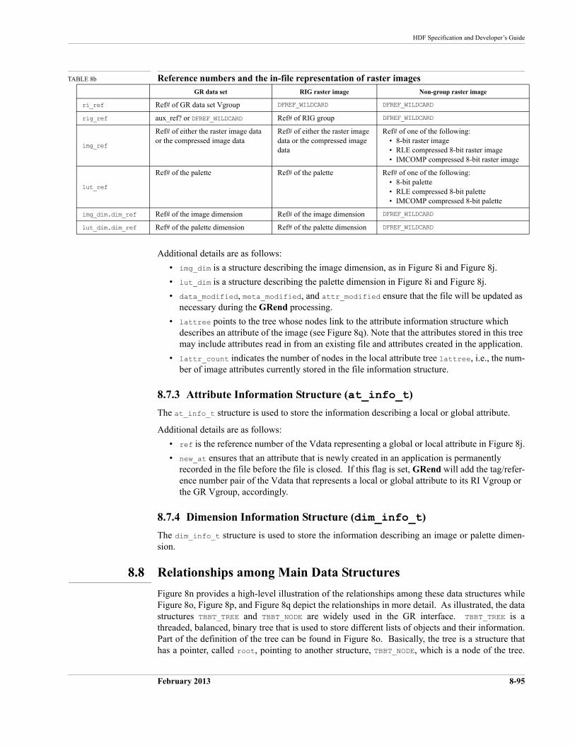
HDF Specification and Developer’s Guide
February 2013 8-95
TABLE 8b Reference numbers and the in-file representation of raster images
Additional details are as follows:
• img_dim is a structure describing the image dimension, as in Figure 8i and Figure 8j.
• lut_dim is a structure describing the palette dimension in Figure 8i and Figure 8j.
• data_modified, meta_modified, and attr_modified ensure that the file will be updated as necessary during the GRend processing.
• lattree points to the tree whose nodes link to the attribute information structure which describes an attribute of the image (see Figure 8q). Note that the attributes stored in this tree may include attributes read in from an existing file and attributes created in the application.
• lattr_count indicates the number of nodes in the local attribute tree lattree, i.e., the num-ber of image attributes currently stored in the file information structure.
8.7.3 Attribute Information Structure (at_info_t)
The at_info_t structure is used to store the information describing a local or global attribute.
Additional details are as follows:
• ref is the reference number of the Vdata representing a global or local attribute in Figure 8j.
• new_at ensures that an attribute that is newly created in an application is permanently recorded in the file before the file is closed. If this flag is set, GRend will add the tag/refer-ence number pair of the Vdata that represents a local or global attribute to its RI Vgroup or the GR Vgroup, accordingly.
8.7.4 Dimension Information Structure (dim_info_t)
The dim_info_t structure is used to store the information describing an image or palette dimen-sion.
8.8 Relationships among Main Data Structures
Figure 8n provides a high-level illustration of the relationships among these data structures while Figure 8o, Figure 8p, and Figure 8q depict the relationships in more detail. As illustrated, the data structures TBBT_TREE and TBBT_NODE are widely used in the GR interface. TBBT_TREE is a threaded, balanced, binary tree that is used to store different lists of objects and their information. Part of the definition of the tree can be found in Figure 8o. Basically, the tree is a structure that has a pointer, called root, pointing to another structure, TBBT_NODE, which is a node of the tree.
GR data set RIG raster image Non-group raster image
ri_ref Ref# of GR data set Vgroup DFREF_WILDCARD DFREF_WILDCARD
rig_ref aux_ref? or DFREF_WILDCARD Ref# of RIG group DFREF_WILDCARD
img_ref
Ref# of either the raster image data or the compressed image data
Ref# of either the raster image data or the compressed image data
Ref# of one of the following:• 8-bit raster image• RLE compressed 8-bit raster image• IMCOMP compressed 8-bit raster image
lut_ref
Ref# of the palette Ref# of the palette Ref# of one of the following:• 8-bit palette• RLE compressed 8-bit palette• IMCOMP compressed 8-bit palette
img_dim.dim_ref Ref# of the image dimension Ref# of the image dimension DFREF_WILDCARD
lut_dim.dim_ref Ref# of the palette dimension Ref# of the palette dimension DFREF_WILDCARD
8-96 February 2013
The HDF Group
The main elements of TBBT_NODE include two void pointers, data and key, and an array of three pointers that point to the parent, the left child, and the right child of the current node. The pointer data points to the data structure that is stored in this tree. The pointer key points to the value that is used to search for the data in the tree.
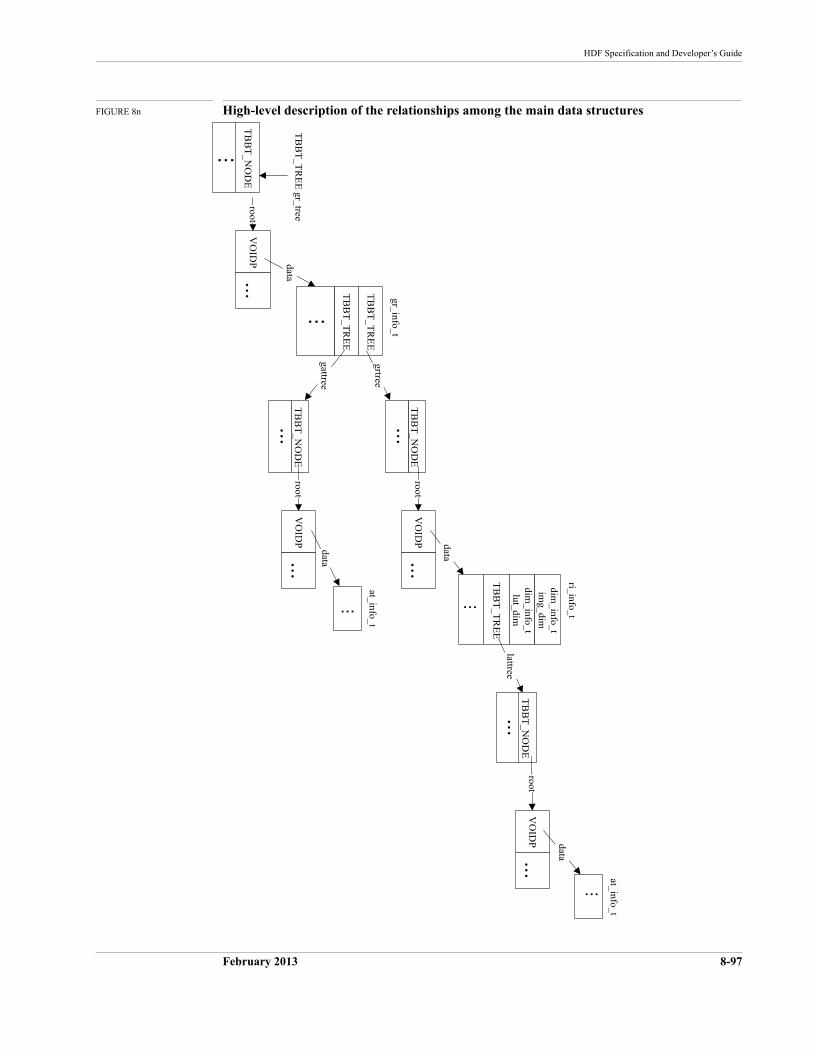
HDF Specification and Developer’s Guide
February 2013 8-97
FIGURE 8n High-level description of the relationships among the main data structures
VO
IDP
...
TB
BT
_TR
EE
gr_treedata
TB
BT
_NO
DE
root
gr_info_t
ri_info_t
at_info_t
at_info_t...
...
VO
IDP
...
TB
BT
_TR
EE
TB
BT
_TR
EE
...
TB
BT
_NO
DE
...
TB
BT
_NO
DE
...
grtree
gattree
root
root
TB
BT
_TR
EE
...
dim_info_t
lut_dim
dim_info_t
img_dim
lattree
TB
BT
_NO
DE
...root
VO
IDP
...
data
data
VO
IDP
...
data
...
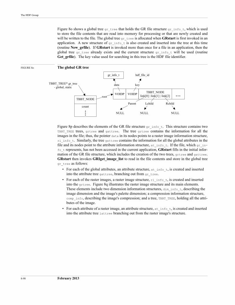
8-98 February 2013
The HDF Group
Figure 8o shows a global tree gr_tree that holds the GR file structure gr_info_t, which is used to store the file contents that are read into memory for processing or that are newly created and will be written to the file. The global tree gr_tree is allocated when GRstart is first invoked in an application. A new structure of gr_info_t is also created and inserted into the tree at this time (routine New_grfile). If GRstart is invoked more than once for a file in an application, then the global tree gr_tree already exists and the current structure gr_info_t will be used (routine Get_grfile). The key value used for searching in this tree is the HDF file identifier.
FIGURE 8o The global GR tree
Figure 8p describes the elements of the GR file structure gr_info_t. This structure contains two TBBT_TREE trees, grtree and gattree. The tree grtree contains the information for all the images in the file; thus, the pointer data in its nodes points to a raster image information structure, ri_info_t. Similarly, the tree gattree contains the information for all the global attributes in the file and its nodes point to the attribute information structure, at_info_t. If the file, which gr_in-fo_t represents, has not been accessed in the current application, GRstart fills in the initial infor-mation of the GR file structure, which includes the creation of the two trees, grtree and gattree. GRstart then invokes GRIget_image_list to read in the file contents and store in the global tree gr_tree as follows:
• For each of the global attributes, an attribute structure, at_info_t, is created and inserted into the attribute tree gattree, branching out from gr_tree.
• For each of the raster images, a raster image structure, ri_info_t, is created and inserted into the grtree. Figure 8q illustrates the raster image structure and its main elements. These elements include two dimension information structures, dim_info_t, describing the image dimension and the image's palette dimension; a compression information structure, comp_info, describing the image's compression; and a tree, TBBT_TREE, holding all the attri-butes of the image.
• For each attribute of a raster image, an attribute structure, at_info_t, is created and inserted into the attribute tree lattree branching out from the raster image's structure.
gr_info_t
VOIDP VOIDPTBBT_NODE
link[0] | link[1] | link[2] ...TBBT_NODE
count...
root
Parent Lchild Rchild
NULL NULLNULL
hdf_file_id
TBBT_TREE* gr_tree- global, static
keydata
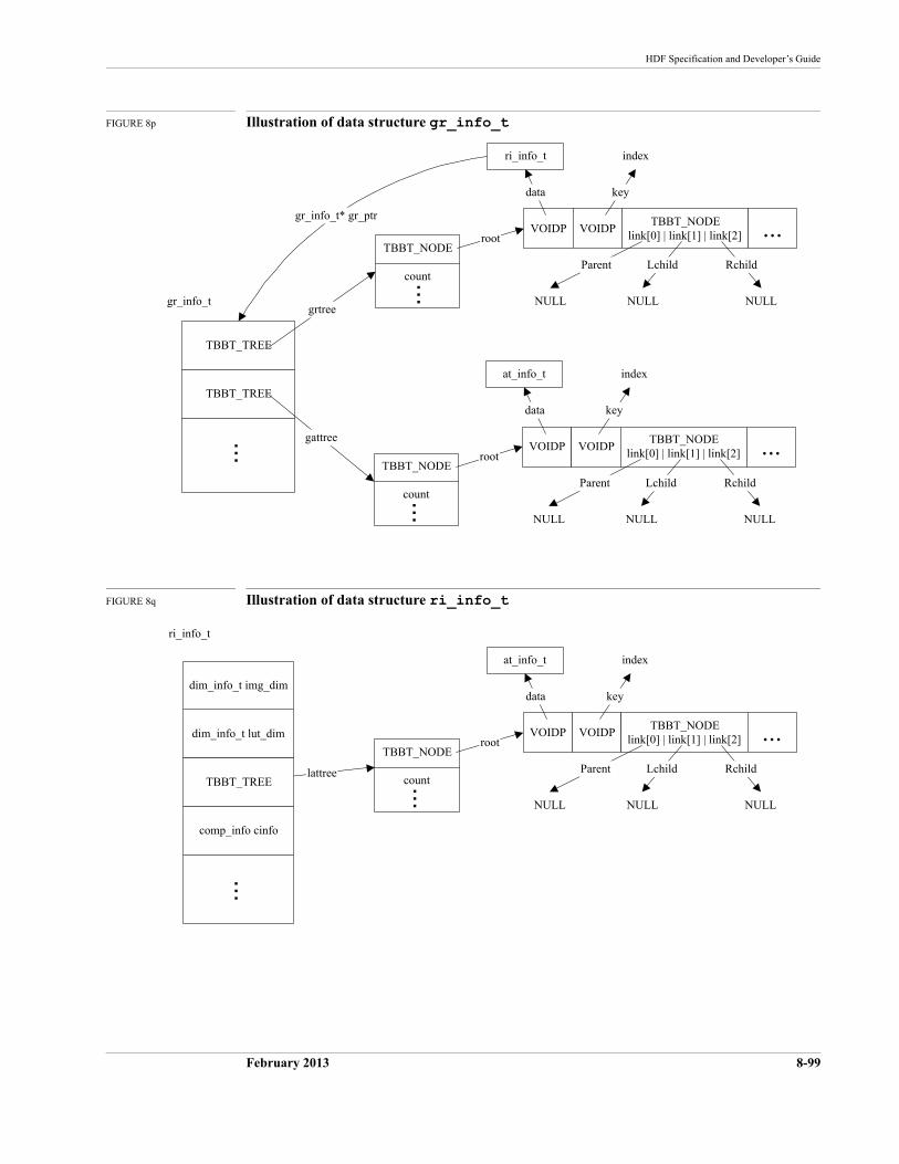
HDF Specification and Developer’s Guide
February 2013 8-99
FIGURE 8p Illustration of data structure gr_info_t
FIGURE 8q Illustration of data structure ri_info_t
ri_info_t
VOIDP VOIDPTBBT_NODE
link[0] | link[1] | link[2] ...TBBT_NODE
count...
root
Parent Lchild Rchild
NULL NULLNULL
index
at_info_t
VOIDP VOIDPTBBT_NODE
link[0] | link[1] | link[2] ...TBBT_NODE
count...root
Parent Lchild Rchild
NULL NULLNULL
index
gr_info_t
data key
keydata
gr_info_t* gr_ptr
TBBT_TREE
TBBT_TREE
...
grtree
gattree
at_info_t
VOIDP VOIDPTBBT_NODE
link[0] | link[1] | link[2] ...TBBT_NODE
count...
root
Parent Lchild Rchild
NULL NULLNULL
index
ri_info_t
lattree
keydata
dim_info_t lut_dim
TBBT_TREE
comp_info cinfo
...dim_info_t img_dim
8-100 February 2013
The HDF Group
8.9 The Evolution of an HDF File in the GR Interface
This section illustrates several steps in the evolution of the contents in an HDF file under the GR interface. At each step, the correspondence between the information as stored in memory and as represented in the file is described.
• The file is created for access from the GR interface.
• Two raster images are created and written with data.
• Attributes are added to the file and to one of the raster images.
• A palette is added for one of the raster images.
The section also illustrates how the main GR structures represent the file elements in memory. The routines involved in constructing the file are described as necessary.
8.9.1 Creating or Opening an HDF File
A typical HDF5 application calls the routine Hopen to create a new HDF file or to open an exist-ing file.
Next, the routine GRstart is called to initiate the GR interface. GRstart does the following:
• Allocates the file information tree, gr_tree. (Note that if GRstart is called more than once for the same HDF file, this tree will not be allocated again.)
• Initializes the atom groups for GR data sets (and older-style raster images).
• Retrieves the information of all contents in the file into the tree by invoking GRIget_im-age_list, which fills in gr_tree with structures such as gr_info_t, ri_info_t, at_info_t, and dim_info_t.
At the end of GRstart, a newly created HDF file is represented in memory as shown in Figure 8r. Since there are neither images nor global attributes in the file, the roots of the image tree grtreeand global attribute tree gattree point to NULL.
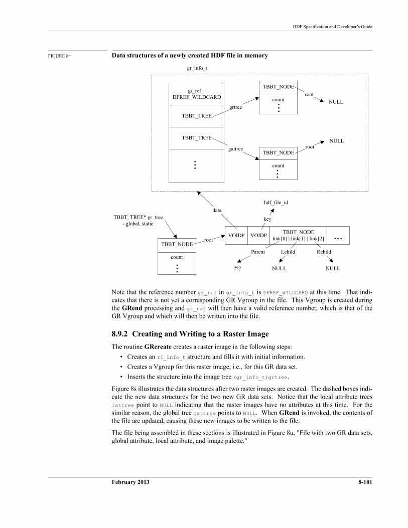
HDF Specification and Developer’s Guide
February 2013 8-101
FIGURE 8r Data structures of a newly created HDF file in memory
Note that the reference number gr_ref in gr_info_t is DFREF_WILDCARD at this time. That indi-cates that there is not yet a corresponding GR Vgroup in the file. This Vgroup is created during the GRend processing and gr_ref will then have a valid reference number, which is that of the GR Vgroup and which will then be written into the file.
8.9.2 Creating and Writing to a Raster Image
The routine GRcreate creates a raster image in the following steps:
• Creates an ri_info_t structure and fills it with initial information.
• Creates a Vgroup for this raster image, i.e., for this GR data set.
• Inserts the structure into the image tree (gr_info_t)grtree.
Figure 8s illustrates the data structures after two raster images are created. The dashed boxes indi-cate the new data structures for the two new GR data sets. Notice that the local attribute trees lattree point to NULL indicating that the raster images have no attributes at this time. For the similar reason, the global tree gattree points to NULL. When GRend is invoked, the contents of the file are updated, causing these new images to be written to the file.
The file being assembled in these sections is illustrated in Figure 8u, "File with two GR data sets, global attribute, local attribute, and image palette."
TBBT_NODE
count...
root
VOIDP VOIDPTBBT_NODE
link[0] | link[1] | link[2] ...TBBT_NODE
count...root
Parent Lchild Rchild
??? NULLNULL
hdf_file_id
TBBT_TREE* gr_tree- global, static
TBBT_NODE
count...
rootNULL
gr_info_t
key
data
NULL
TBBT_TREE
TBBT_TREE
...
gr_ref =DFREF_WILDCARD
grtree
gattree
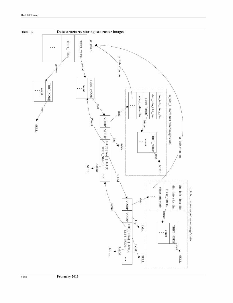
8-102 February 2013
The HDF Group
FIGURE 8s Data structures storing two raster images
VO
IDP
VO
IDP
link[0] | link[1] | link[2]T
BB
T_N
OD
E...
TB
BT
_NO
DE
count
...
root
Lchild
Lchild
index
TB
BT
_NO
DE
count
...
root
NU
LL
gr_info_t
data
key
TB
BT
_TR
EE
TB
BT
_TR
EE
...
grtree
gattree
TB
BT
_NO
DE
count
...
rootN
UL
L
NU
LL
dim_info_t lut_dim
TB
BT
_TR
EE
comp_info cinfo
dim_info_t im
g_dim
lattree
gr_info_t* gr_ptr
ri_info_t, stores first raster image's info
VO
IDP
VO
IDP
link[0] | link[1] | link[2]T
BB
T_N
OD
E...
Rchild
NU
LL
indexdata
key
Parent
Parent
...
Rchild
NU
LL
TB
BT
_NO
DE
count...
rootN
UL
L
dim_info_t lut_dim
TB
BT
_TR
EE
comp_info cinfo
dim_info_t im
g_dim
lattree
...
ri_info_t, stores second raster image's info
gr_info_t* gr_ptr
HDF Specification and Developer’s Guide
February 2013 8-103
8.9.3 Adding Attributes
The routine GRsetattr creates an attribute for a file or for a raster image in the following steps:
• If the attribute already exists in the file, then simply updates it, although, the number type cannot be changed
• If the attribute's data is small enough to be cached, keeps the data in memory where specified by (at_info_t)data.
• Otherwise, writes the data to the attribute Vdata on disk.
• If the attribute is new, the following actions are performed:
• Creates the attribute structure at_info_t and stores the attribute information.
• If the attribute's data is small enough to be cached, keeps the data in memory where specified by (at_info_t)data.
• Otherwise, writes the data to the attribute Vdata on disk.
• Adds the attribute structure to the attribute tree, which can be either the global attri-bute tree (gr_info_t)gattree or the local attribute tree (ri_info_t)lattree.
Figure 8t shows the memory data structures with two raster images, one file attribute, and one local attribute. An at_info_t structure is also added to the global attribute tree for the new file attribute. When GRend is invoked, the contents of the file are updated, causing these attributes be written to the file.
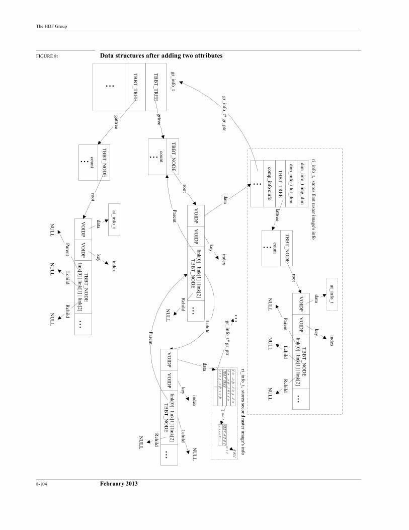
8-104 February 2013
The HDF Group
FIGURE 8t Data structures after adding two attributes
VO
IDP
VO
IDP
link[0] | link[1] | link[2]T
BB
T_N
OD
E...
TB
BT
_NO
DE
count
...
root
Lchild
Lchild
index
TB
BT
_NO
DE
count
...
root
gr_info_t
data
key
TB
BT
_TR
EE
TB
BT
_TR
EE
...
grtree
gattree
TB
BT
_NO
DE
count
...
root
NU
LL
dim_info_t lut_dim
TB
BT
_TR
EE
comp_info cinfo
dim_info_t im
g_dim
lattree
gr_info_t* gr_ptr
ri_info_t, stores first raster image's info
VO
IDP
VO
IDP
link[0] | link[1] | link[2]T
BB
T_N
OD
E...
RchildN
UL
L
index
data
key
Parent
Parent
...
Rchild
NU
LL
ri_info_t, stores second raster image's info
gr_info_t* gr_ptr
at_info_t
VO
IDP
VO
IDP
TB
BT
_NO
DE
link[0] | link[1] | link[2]...
ParentL
childR
child
NU
LL
NU
LL
NU
LL
index
keydata
TBBT_NO
DE
co
un
t...
roo
t
NU
LLd
im_in
f
lut_d
imTBBT_TR
EEc
om
p_in
fo c
info
dim
_info
_t img
_dim
...
...
at_info_t
VO
IDP
VO
IDP
TB
BT
_NO
DE
link[0] | link[1] | link[2]...
ParentL
childR
child
NU
LL
NU
LL
NU
LL
index
keydata
dim
_info
_t lut_d
im
lat t re
e
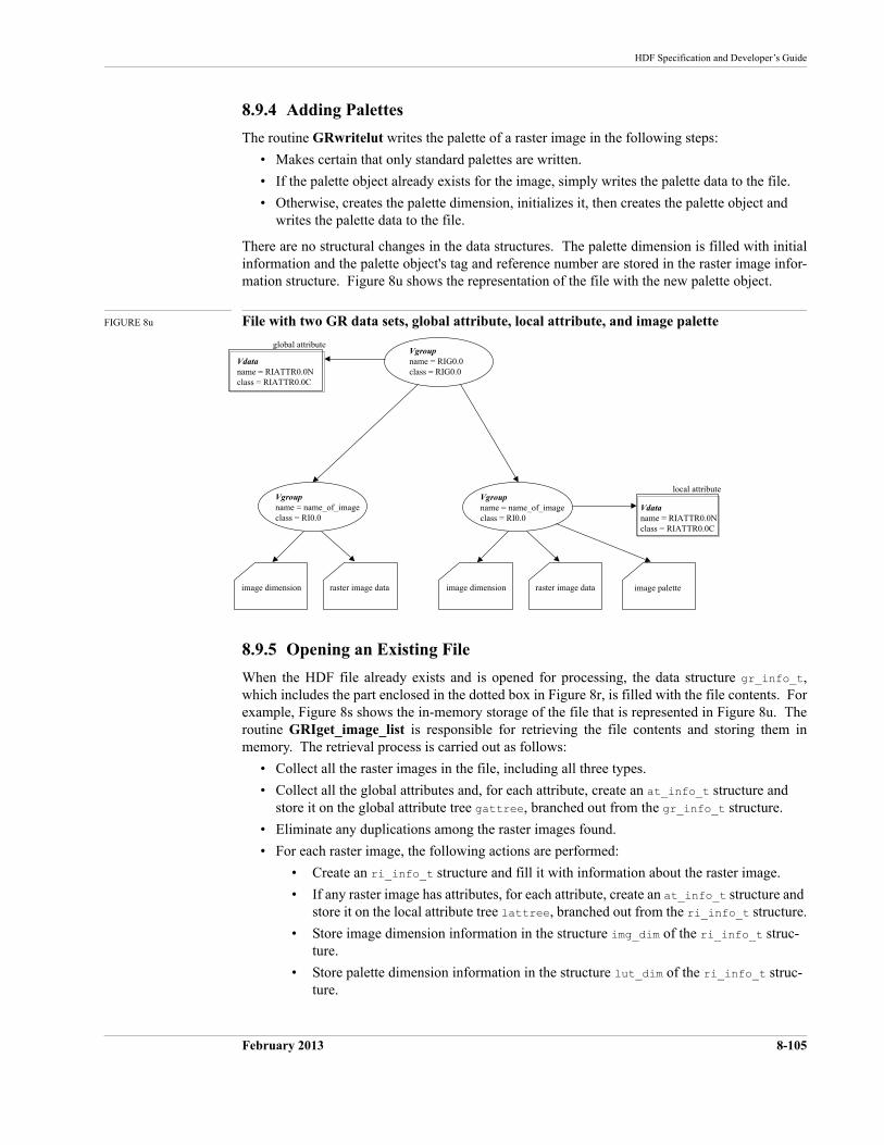
HDF Specification and Developer’s Guide
February 2013 8-105
8.9.4 Adding Palettes
The routine GRwritelut writes the palette of a raster image in the following steps:
• Makes certain that only standard palettes are written.
• If the palette object already exists for the image, simply writes the palette data to the file.
• Otherwise, creates the palette dimension, initializes it, then creates the palette object and writes the palette data to the file.
There are no structural changes in the data structures. The palette dimension is filled with initial information and the palette object's tag and reference number are stored in the raster image infor-mation structure. Figure 8u shows the representation of the file with the new palette object.
FIGURE 8u File with two GR data sets, global attribute, local attribute, and image palette
8.9.5 Opening an Existing File
When the HDF file already exists and is opened for processing, the data structure gr_info_t, which includes the part enclosed in the dotted box in Figure 8r, is filled with the file contents. For example, Figure 8s shows the in-memory storage of the file that is represented in Figure 8u. The routine GRIget_image_list is responsible for retrieving the file contents and storing them in memory. The retrieval process is carried out as follows:
• Collect all the raster images in the file, including all three types.
• Collect all the global attributes and, for each attribute, create an at_info_t structure and store it on the global attribute tree gattree, branched out from the gr_info_t structure.
• Eliminate any duplications among the raster images found.
• For each raster image, the following actions are performed:
• Create an ri_info_t structure and fill it with information about the raster image.
• If any raster image has attributes, for each attribute, create an at_info_t structure and store it on the local attribute tree lattree, branched out from the ri_info_t structure.
• Store image dimension information in the structure img_dim of the ri_info_t struc-ture.
• Store palette dimension information in the structure lut_dim of the ri_info_t struc-ture.
Vdataname = RIATTR0.0Nclass = RIATTR0.0C
Vgroupname = RIG0.0class = RIG0.0
image dimension
local attributeVgroupname = name_of_imageclass = RI0.0
raster image data
global attribute
Vdataname = RIATTR0.0Nclass = RIATTR0.0C
image dimension
Vgroupname = name_of_imageclass = RI0.0
raster image data image palette
8-106 February 2013
The HDF Group
• Finally, store the ri_info_t structure for this raster image on the image tree grtree, branched out from the gr_info_t structure.
February 14, 2013 9-107
CHAPTER 9 -- Tag Specifications
9.1 Chapter Overview
This chapter and the next address issues related to HDF tags and the data they represent. The first section of this chapter provides general information about tags and their interpretation. The remainder of the chapter contains a complete list of the HDF basic tags supported by HDF Version 4.1r3 and detailed tag specifications. The next chapter, Extended Tags and Special Elements, pro-vides detailed information regarding HDF-supported extended tags and the special elements they define.
9.2 The HDF Tag Space
As discussed in Chapter , "Basic Structure of HDF Files," 16 bits are allotted for an HDF tag num-ber. This provides for 65535 possible tags, ranging from 1 to 65535; zero (0) is not used. This tag space is divided into three ranges:
1 – 32767 Reserved for HDF-supported tags
32768 – 64999 Set aside as user-definable tags
65000 – 65535 Reserved for expansion of the format
No restrictions are placed on the user-definable tags. Note that tags from this range are not expected to be unique across user-developed HDF applications.
The rest of this chapter is devoted to the HDF-supported basic tags in the range 1 (0x0001) to 16383 (0x3FFF). The next chapter, Extended Tags and Special Elements, is devoted to HDF-sup-ported extended tags in the range 16384 (0x4000) to 32767 (0x7FFF).
9.3 Tag Specifications
The following pages contain the specifications of the HDF-supported basic tags in HDF Version 4.1r3. Each entry contains the following information:
• The tag (in capital letters in the left margin)
• The full name of the tag (on the first line to the right)
• The type and, where possible, the amount of data in the corresponding data element (on the second line to the right)When the data element is a variable-sized data structure—such as text, a string, or a vari-able-sized array—the amount of data cannot be specified exactly. Where possible, a formula is provided to estimate the amount of data. The string ? bytes appears when neither the size nor the structure of the data element can be specified.
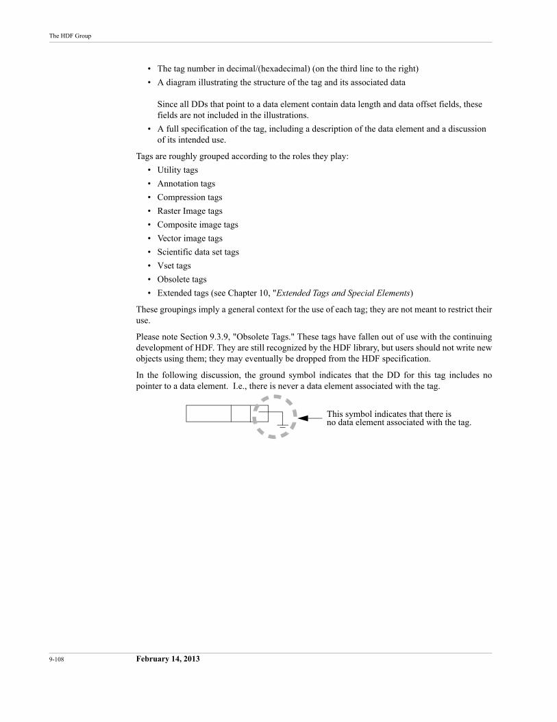
9-108 February 14, 2013
The HDF Group
• The tag number in decimal/(hexadecimal) (on the third line to the right)
• A diagram illustrating the structure of the tag and its associated dataSince all DDs that point to a data element contain data length and data offset fields, these fields are not included in the illustrations.
• A full specification of the tag, including a description of the data element and a discussion of its intended use.
Tags are roughly grouped according to the roles they play:
• Utility tags
• Annotation tags
• Compression tags
• Raster Image tags
• Composite image tags
• Vector image tags
• Scientific data set tags
• Vset tags
• Obsolete tags
• Extended tags (see Chapter 10, "Extended Tags and Special Elements)
These groupings imply a general context for the use of each tag; they are not meant to restrict their use.
Please note Section 9.3.9, "Obsolete Tags." These tags have fallen out of use with the continuing development of HDF. They are still recognized by the HDF library, but users should not write new objects using them; they may eventually be dropped from the HDF specification.
In the following discussion, the ground symbol indicates that the DD for this tag includes no pointer to a data element. I.e., there is never a data element associated with the tag.
This symbol indicates that there is no data element associated with the tag.
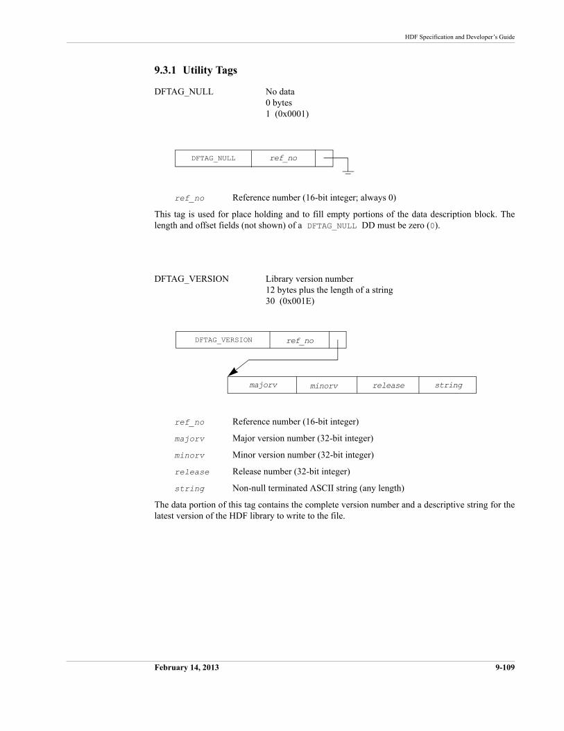
HDF Specification and Developer’s Guide
February 14, 2013 9-109
9.3.1 Utility Tags
DFTAG_NULL No data0 bytes1 (0x0001)
ref_no Reference number (16-bit integer; always 0)
This tag is used for place holding and to fill empty portions of the data description block. The length and offset fields (not shown) of a DFTAG_NULL DD must be zero (0).
DFTAG_VERSION Library version number12 bytes plus the length of a string30 (0x001E)
ref_no Reference number (16-bit integer)
majorv Major version number (32-bit integer)
minorv Minor version number (32-bit integer)
release Release number (32-bit integer)
string Non-null terminated ASCII string (any length)
The data portion of this tag contains the complete version number and a descriptive string for the latest version of the HDF library to write to the file.
ref_noDFTAG_NULL
DFTAG_VERSION
minorv
ref_no
majorv release string
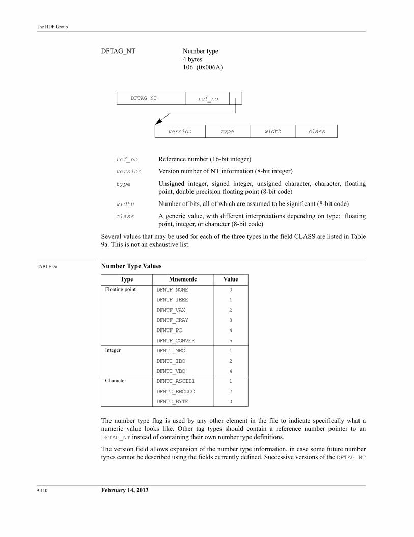
9-110 February 14, 2013
The HDF Group
DFTAG_NT Number type4 bytes106 (0x006A)
ref_no Reference number (16-bit integer)
version Version number of NT information (8-bit integer)
type Unsigned integer, signed integer, unsigned character, character, floating point, double precision floating point (8-bit code)
width Number of bits, all of which are assumed to be significant (8-bit code)
class A generic value, with different interpretations depending on type: floating point, integer, or character (8-bit code)
Several values that may be used for each of the three types in the field CLASS are listed in Table 9a. This is not an exhaustive list.
TABLE 9a Number Type Values
The number type flag is used by any other element in the file to indicate specifically what a numeric value looks like. Other tag types should contain a reference number pointer to an DFTAG_NT instead of containing their own number type definitions.
The version field allows expansion of the number type information, in case some future number types cannot be described using the fields currently defined. Successive versions of the DFTAG_NT
Type Mnemonic Value
Floating point DFNTF_NONE 0
DFNTF_IEEE 1
DFNTF_VAX 2
DFNTF_CRAY 3
DFNTF_PC 4
DFNTF_CONVEX 5
Integer DFNTI_MBO 1
DFNTI_IBO 2
DFNTI_VBO 4
Character DFNTC_ASCII1 1
DFNTC_EBCDOC 2
DFNTC_BYTE 0
DFTAG_NT
type
ref_no
version width class
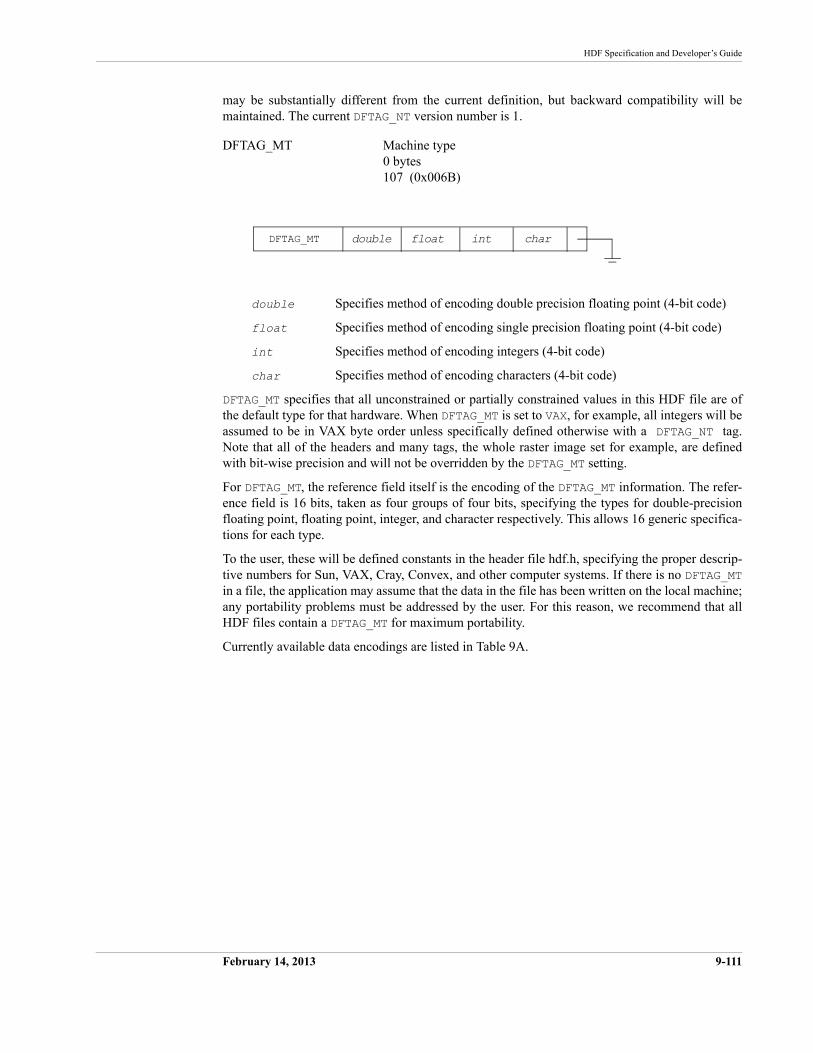
HDF Specification and Developer’s Guide
February 14, 2013 9-111
may be substantially different from the current definition, but backward compatibility will be maintained. The current DFTAG_NT version number is 1.
DFTAG_MT Machine type0 bytes107 (0x006B)
double Specifies method of encoding double precision floating point (4-bit code)
float Specifies method of encoding single precision floating point (4-bit code)
int Specifies method of encoding integers (4-bit code)
char Specifies method of encoding characters (4-bit code)
DFTAG_MT specifies that all unconstrained or partially constrained values in this HDF file are of the default type for that hardware. When DFTAG_MT is set to VAX, for example, all integers will be assumed to be in VAX byte order unless specifically defined otherwise with a DFTAG_NT tag. Note that all of the headers and many tags, the whole raster image set for example, are defined with bit-wise precision and will not be overridden by the DFTAG_MT setting.
For DFTAG_MT, the reference field itself is the encoding of the DFTAG_MT information. The refer-ence field is 16 bits, taken as four groups of four bits, specifying the types for double-precision floating point, floating point, integer, and character respectively. This allows 16 generic specifica-tions for each type.
To the user, these will be defined constants in the header file hdf.h, specifying the proper descrip-tive numbers for Sun, VAX, Cray, Convex, and other computer systems. If there is no DFTAG_MTin a file, the application may assume that the data in the file has been written on the local machine; any portability problems must be addressed by the user. For this reason, we recommend that all HDF files contain a DFTAG_MT for maximum portability.
Currently available data encodings are listed in Table 9A.
DFTAG_MT intdouble float char
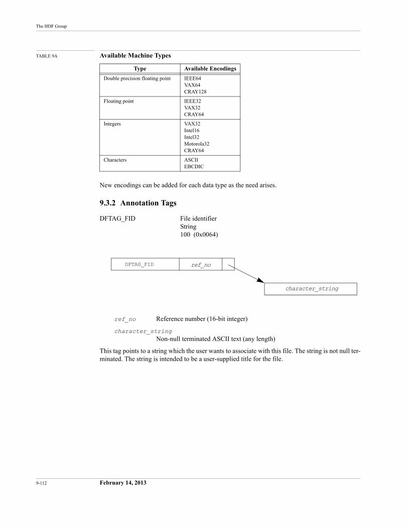
9-112 February 14, 2013
The HDF Group
TABLE 9A Available Machine Types
New encodings can be added for each data type as the need arises.
9.3.2 Annotation Tags
DFTAG_FID File identifierString100 (0x0064)
ref_no Reference number (16-bit integer)
character_stringNon-null terminated ASCII text (any length)
This tag points to a string which the user wants to associate with this file. The string is not null ter-minated. The string is intended to be a user-supplied title for the file.
Type Available Encodings
Double precision floating point IEEE64VAX64CRAY128
Floating point IEEE32VAX32CRAY64
Integers VAX32Intel16Intel32Motorola32CRAY64
Characters ASCIIEBCDIC
DFTAG_FID ref_no
character_string
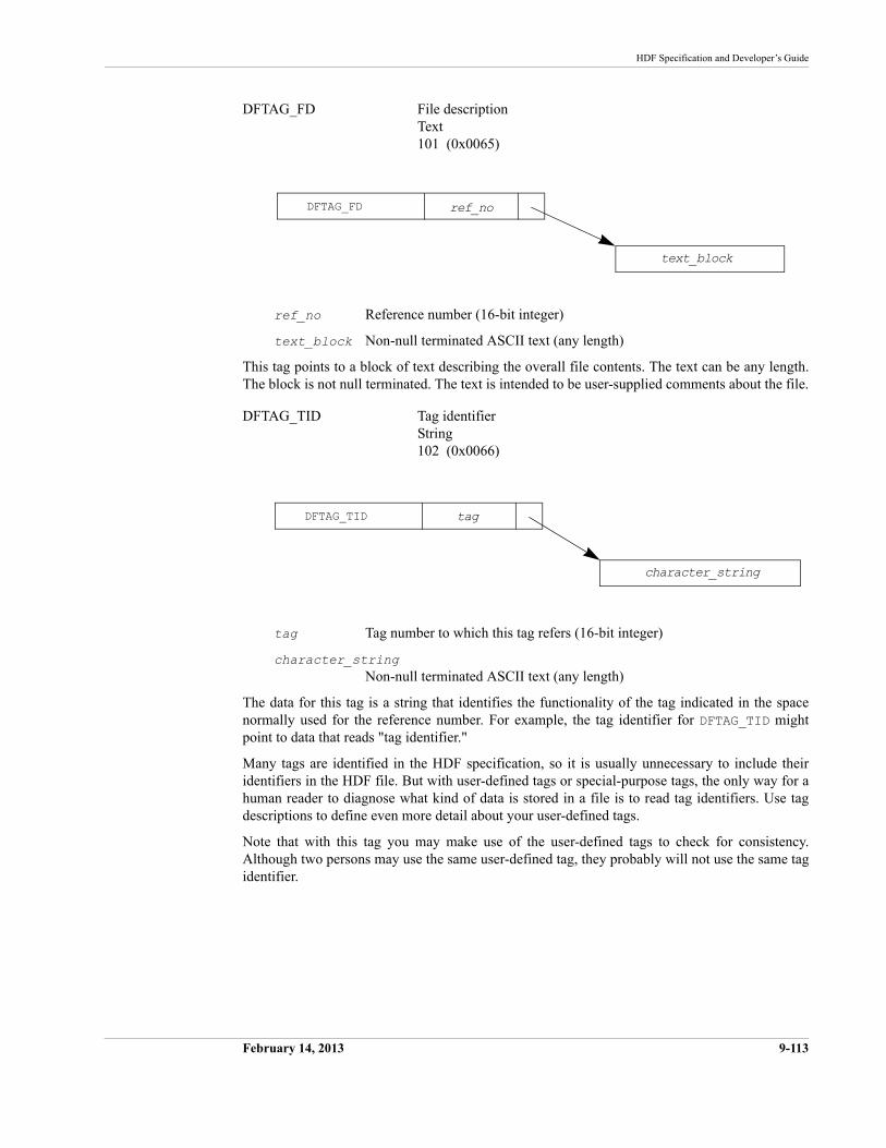
HDF Specification and Developer’s Guide
February 14, 2013 9-113
DFTAG_FD File descriptionText101 (0x0065)
ref_no Reference number (16-bit integer)
text_block Non-null terminated ASCII text (any length)
This tag points to a block of text describing the overall file contents. The text can be any length. The block is not null terminated. The text is intended to be user-supplied comments about the file.
DFTAG_TID Tag identifierString102 (0x0066)
tag Tag number to which this tag refers (16-bit integer)
character_stringNon-null terminated ASCII text (any length)
The data for this tag is a string that identifies the functionality of the tag indicated in the space normally used for the reference number. For example, the tag identifier for DFTAG_TID might point to data that reads "tag identifier."
Many tags are identified in the HDF specification, so it is usually unnecessary to include their identifiers in the HDF file. But with user-defined tags or special-purpose tags, the only way for a human reader to diagnose what kind of data is stored in a file is to read tag identifiers. Use tag descriptions to define even more detail about your user-defined tags.
Note that with this tag you may make use of the user-defined tags to check for consistency. Although two persons may use the same user-defined tag, they probably will not use the same tag identifier.
DFTAG_FD ref_no
text_block
DFTAG_TID tag
character_string
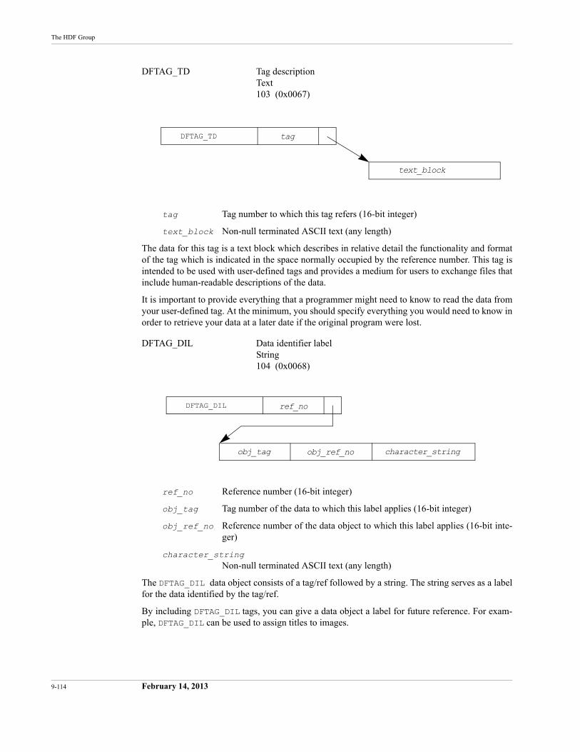
9-114 February 14, 2013
The HDF Group
DFTAG_TD Tag descriptionText103 (0x0067)
tag Tag number to which this tag refers (16-bit integer)
text_block Non-null terminated ASCII text (any length)
The data for this tag is a text block which describes in relative detail the functionality and format of the tag which is indicated in the space normally occupied by the reference number. This tag is intended to be used with user-defined tags and provides a medium for users to exchange files that include human-readable descriptions of the data.
It is important to provide everything that a programmer might need to know to read the data from your user-defined tag. At the minimum, you should specify everything you would need to know in order to retrieve your data at a later date if the original program were lost.
DFTAG_DIL Data identifier labelString104 (0x0068)
ref_no Reference number (16-bit integer)
obj_tag Tag number of the data to which this label applies (16-bit integer)
obj_ref_no Reference number of the data object to which this label applies (16-bit inte-ger)
character_stringNon-null terminated ASCII text (any length)
The DFTAG_DIL data object consists of a tag/ref followed by a string. The string serves as a label for the data identified by the tag/ref.
By including DFTAG_DIL tags, you can give a data object a label for future reference. For exam-ple, DFTAG_DIL can be used to assign titles to images.
DFTAG_TD tag
text_block
DFTAG_DIL
obj_ref_no
ref_no
obj_tag character_string
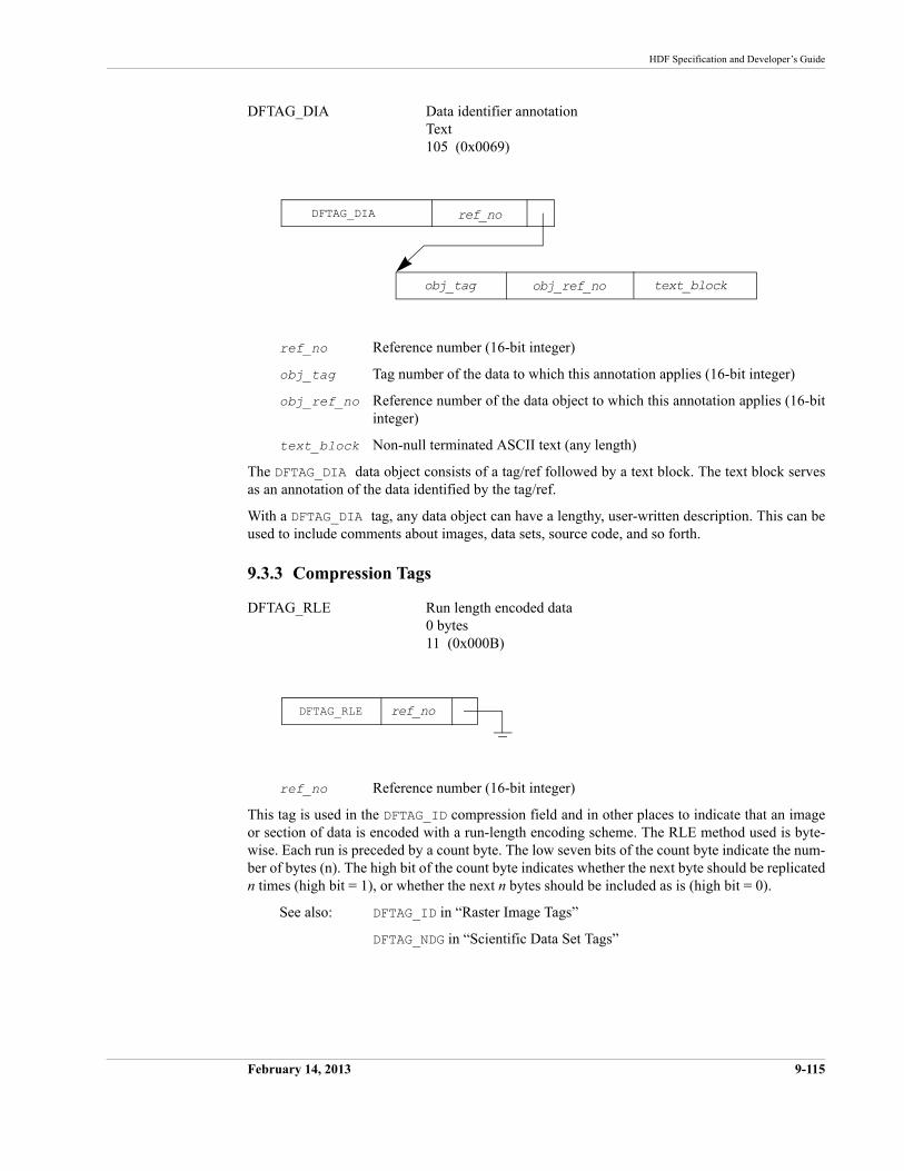
HDF Specification and Developer’s Guide
February 14, 2013 9-115
DFTAG_DIA Data identifier annotationText105 (0x0069)
ref_no Reference number (16-bit integer)
obj_tag Tag number of the data to which this annotation applies (16-bit integer)
obj_ref_no Reference number of the data object to which this annotation applies (16-bit integer)
text_block Non-null terminated ASCII text (any length)
The DFTAG_DIA data object consists of a tag/ref followed by a text block. The text block serves as an annotation of the data identified by the tag/ref.
With a DFTAG_DIA tag, any data object can have a lengthy, user-written description. This can be used to include comments about images, data sets, source code, and so forth.
9.3.3 Compression Tags
DFTAG_RLE Run length encoded data0 bytes11 (0x000B)
ref_no Reference number (16-bit integer)
This tag is used in the DFTAG_ID compression field and in other places to indicate that an image or section of data is encoded with a run-length encoding scheme. The RLE method used is byte-wise. Each run is preceded by a count byte. The low seven bits of the count byte indicate the num-ber of bytes (n). The high bit of the count byte indicates whether the next byte should be replicated n times (high bit = 1), or whether the next n bytes should be included as is (high bit = 0).
See also: DFTAG_ID in “Raster Image Tags”
DFTAG_NDG in “Scientific Data Set Tags”
DFTAG_DIA
obj_ref_no
ref_no
obj_tag text_block
DFTAG_RLE ref_no
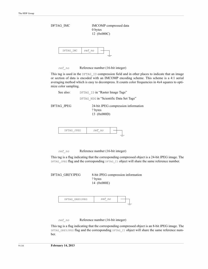
9-116 February 14, 2013
The HDF Group
DFTAG_IMC IMCOMP compressed data0 bytes12 (0x000C)
ref_no Reference number (16-bit integer)
This tag is used in the DFTAG_ID compression field and in other places to indicate that an image or section of data is encoded with an IMCOMP encoding scheme. This scheme is a 4:1 aerial averaging method which is easy to decompress. It counts color frequencies in 4x4 squares to opti-mize color sampling.
See also: DFTAG_ID in “Raster Image Tags”
DFTAG_NDG in “Scientific Data Set Tags”
DFTAG_JPEG 24-bit JPEG compression information? bytes13 (0x000D)
ref_no Reference number (16-bit integer)
This tag is a flag indicating that the corresponding compressed object is a 24-bit JPEG image. The DFTAG_JPEG flag and the corresponding DFTAG_CI object will share the same reference number.
DFTAG_GREYJPEG 8-bit JPEG compression information? bytes14 (0x000E)
ref_no Reference number (16-bit integer)
This tag is a flag indicating that the corresponding compressed object is an 8-bit JPEG image. The DFTAG_GREYJPEG flag and the corresponding DFTAG_CI object will share the same reference num-ber.
DFTAG_IMC ref_no
ref_noDFTAG_JPEG
ref_noDFTAG_GREYJPEG
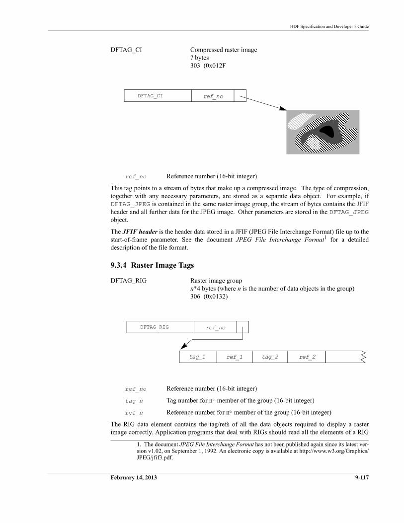
HDF Specification and Developer’s Guide
February 14, 2013 9-117
DFTAG_CI Compressed raster image? bytes 303 (0x012F
ref_no Reference number (16-bit integer)
This tag points to a stream of bytes that make up a compressed image. The type of compression, together with any necessary parameters, are stored as a separate data object. For example, if DFTAG_JPEG is contained in the same raster image group, the stream of bytes contains the JFIF header and all further data for the JPEG image. Other parameters are stored in the DFTAG_JPEGobject.
The JFIF header is the header data stored in a JFIF (JPEG File Interchange Format) file up to the start-of-frame parameter. See the document JPEG File Interchange Format1 for a detailed description of the file format.
9.3.4 Raster Image Tags
DFTAG_RIG Raster image groupn*4 bytes (where n is the number of data objects in the group)306 (0x0132)
ref_no Reference number (16-bit integer)
tag_n Tag number for nth member of the group (16-bit integer)
ref_n Reference number for nth member of the group (16-bit integer)
The RIG data element contains the tag/refs of all the data objects required to display a raster image correctly. Application programs that deal with RIGs should read all the elements of a RIG
1. The document JPEG File Interchange Format has not been published again since its latest ver-sion v1.02, on September 1, 1992. An electronic copy is available at http://www.w3.org/Graphics/JPEG/jfif3.pdf.
DFTAG_CI ref_no
DFTAG_RIG
ref_1
ref_no
tag_1 ref_2tag_2
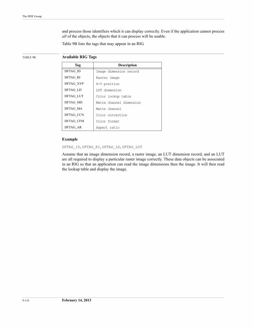
9-118 February 14, 2013
The HDF Group
and process those identifiers which it can display correctly. Even if the application cannot process all of the objects, the objects that it can process will be usable.
Table 9B lists the tags that may appear in an RIG.
TABLE 9B Available RIG Tags
Example
DFTAG_ID, DFTAG_RI, DFTAG_LD, DFTAG_LUT
Assume that an image dimension record, a raster image, an LUT dimension record, and an LUT are all required to display a particular raster image correctly. These data objects can be associated in an RIG so that an application can read the image dimensions then the image. It will then read the lookup table and display the image.
Tag Description
DFTAG_ID Image dimension record
DFTAG_RI Raster image
DFTAG_XYP X-Y position
DFTAG_LD LUT dimension
DFTAG_LUT Color lookup table
DFTAG_MD Matte channel dimension
DFTAG_MA Matte channel
DFTAG_CCN Color correction
DFTAG_CFM Color format
DFTAG_AR Aspect ratio
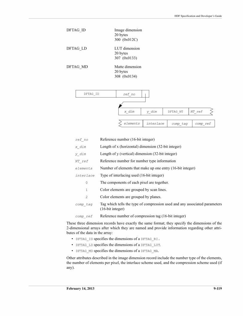
HDF Specification and Developer’s Guide
February 14, 2013 9-119
DFTAG_ID Image dimension20 bytes300 (0x012C)
DFTAG_LD LUT dimension20 bytes307 (0x0133)
DFTAG_MD Matte dimension20 bytes308 (0x0134)
ref_no Reference number (16-bit integer)
x_dim Length of x (horizontal) dimension (32-bit integer)
y_dim Length of y (vertical) dimension (32-bit integer)
NT_ref Reference number for number type information
elements Number of elements that make up one entry (16-bit integer)
interlace Type of interlacing used (16-bit integer)
0 The components of each pixel are together.
1 Color elements are grouped by scan lines.
2 Color elements are grouped by planes.
comp_tag Tag which tells the type of compression used and any associated parameters (16-bit integer)
comp_ref Reference number of compression tag (16-bit integer)
These three dimension records have exactly the same format; they specify the dimensions of the 2-dimensional arrays after which they are named and provide information regarding other attri-butes of the data in the array:
• DFTAG_ID specifies the dimensions of a DFTAG_RI.
• DFTAG_LD specifies the dimensions of a DFTAG_LUT.
• DFTAG_MD specifies the dimensions of a DFTAG_MA.
Other attributes described in the image dimension record include the number type of the elements, the number of elements per pixel, the interlace scheme used, and the compression scheme used (if any).
DFTAG_ID
y_dim
ref_no
x_dim NT_refDFTAG_NT
interlaceelements comp_refcomp_tag
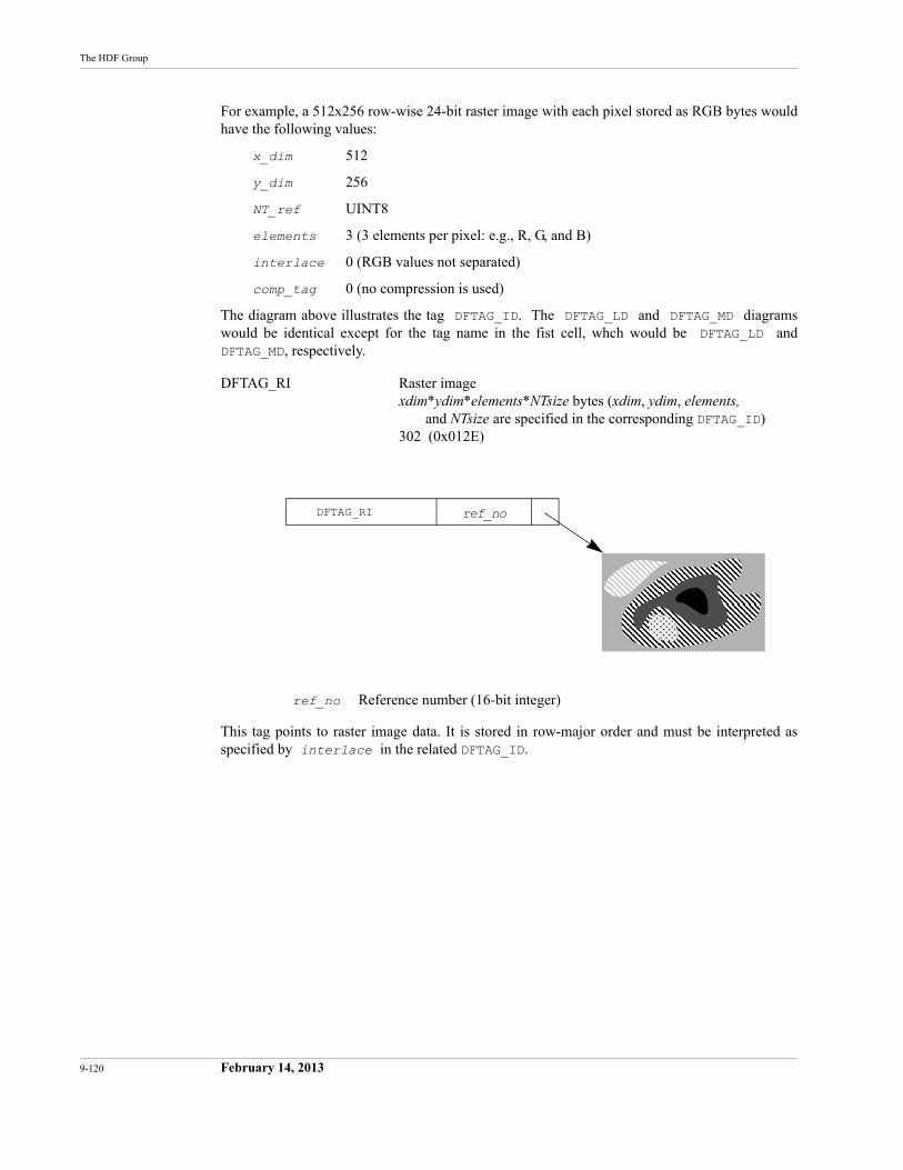
9-120 February 14, 2013
The HDF Group
For example, a 512x256 row-wise 24-bit raster image with each pixel stored as RGB bytes would have the following values:
x_dim 512
y_dim 256
NT_ref UINT8
elements 3 (3 elements per pixel: e.g., R, G, and B)
interlace 0 (RGB values not separated)
comp_tag 0 (no compression is used)
The diagram above illustrates the tag DFTAG_ID. The DFTAG_LD and DFTAG_MD diagrams would be identical except for the tag name in the fist cell, whch would be DFTAG_LD andDFTAG_MD, respectively.
DFTAG_RI Raster imagexdim*ydim*elements*NTsize bytes (xdim, ydim, elements,
and NTsize are specified in the corresponding DFTAG_ID)302 (0x012E)
ref_no Reference number (16-bit integer)
This tag points to raster image data. It is stored in row-major order and must be interpreted as specified by interlace in the related DFTAG_ID.
DFTAG_RI ref_no
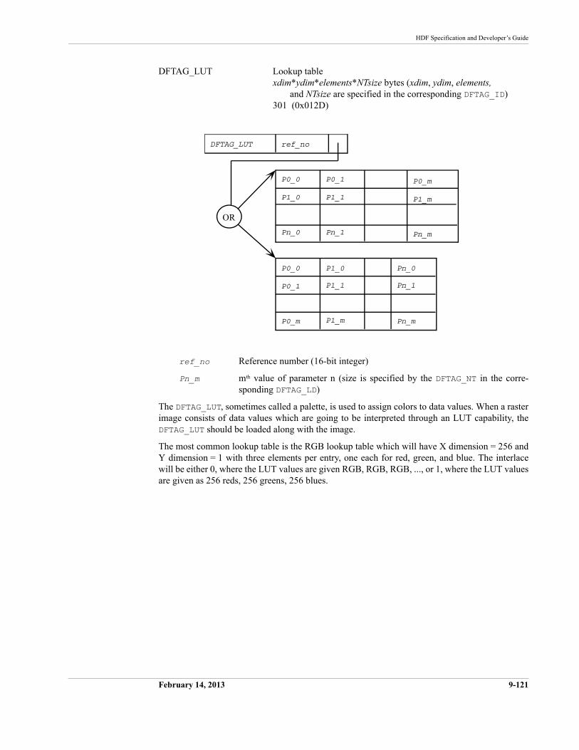
P0_0 P0_1 P0_m
Pn_m
P1_0 P1_1 P1_m
Pn_0 Pn_1
DFTAG_LUT ref_no
OR
P0_0
P0_1
P0_m Pn_m
P1_0
P1_1
P1_m
Pn_0
Pn_1
HDF Specification and Developer’s Guide
February 14, 2013 9-121
DFTAG_LUT Lookup tablexdim*ydim*elements*NTsize bytes (xdim, ydim, elements,
and NTsize are specified in the corresponding DFTAG_ID)301 (0x012D)
ref_no Reference number (16-bit integer)
Pn_m mth value of parameter n (size is specified by the DFTAG_NT in the corre-sponding DFTAG_LD)
The DFTAG_LUT, sometimes called a palette, is used to assign colors to data values. When a raster image consists of data values which are going to be interpreted through an LUT capability, the DFTAG_LUT should be loaded along with the image.
The most common lookup table is the RGB lookup table which will have X dimension = 256 and Y dimension = 1 with three elements per entry, one each for red, green, and blue. The interlace will be either 0, where the LUT values are given RGB, RGB, RGB, ..., or 1, where the LUT values are given as 256 reds, 256 greens, 256 blues.
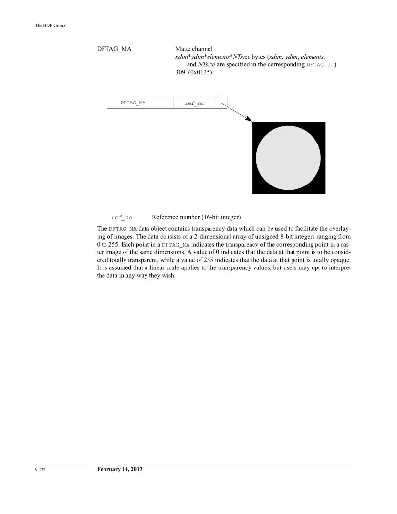
9-122 February 14, 2013
The HDF Group
DFTAG_MA Matte channelxdim*ydim*elements*NTsize bytes (xdim, ydim, elements,
and NTsize are specified in the corresponding DFTAG_ID)309 (0x0135)
ref_no Reference number (16-bit integer)
The DFTAG_MA data object contains transparency data which can be used to facilitate the overlay-ing of images. The data consists of a 2-dimensional array of unsigned 8-bit integers ranging from 0 to 255. Each point in a DFTAG_MA indicates the transparency of the corresponding point in a ras-ter image of the same dimensions. A value of 0 indicates that the data at that point is to be consid-ered totally transparent, while a value of 255 indicates that the data at that point is totally opaque. It is assumed that a linear scale applies to the transparency values, but users may opt to interpret the data in any way they wish.
DFTAG_MA ref_no
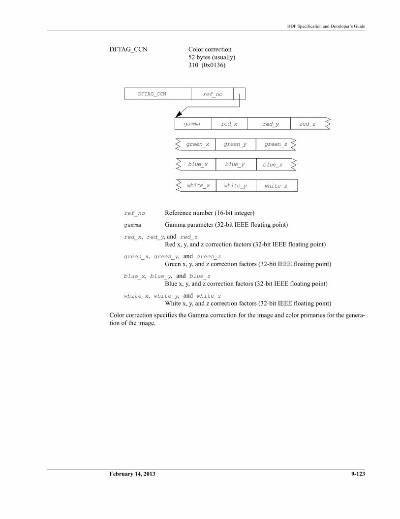
HDF Specification and Developer’s Guide
February 14, 2013 9-123
DFTAG_CCN Color correction52 bytes (usually)310 (0x0136)
ref_no Reference number (16-bit integer)
gamma Gamma parameter (32-bit IEEE floating point)
red_x, red_y, and red_zRed x, y, and z correction factors (32-bit IEEE floating point)
green_x, green_y, and green_zGreen x, y, and z correction factors (32-bit IEEE floating point)
blue_x, blue_y, and blue_zBlue x, y, and z correction factors (32-bit IEEE floating point)
white_x, white_y, and white_zWhite x, y, and z correction factors (32-bit IEEE floating point)
Color correction specifies the Gamma correction for the image and color primaries for the genera-tion of the image.
DFTAG_CCN ref_no
green_x green_y
white_ywhite_x white_z
green_z
blue_yblue_x blue_z
red_xgamma red_y red_z
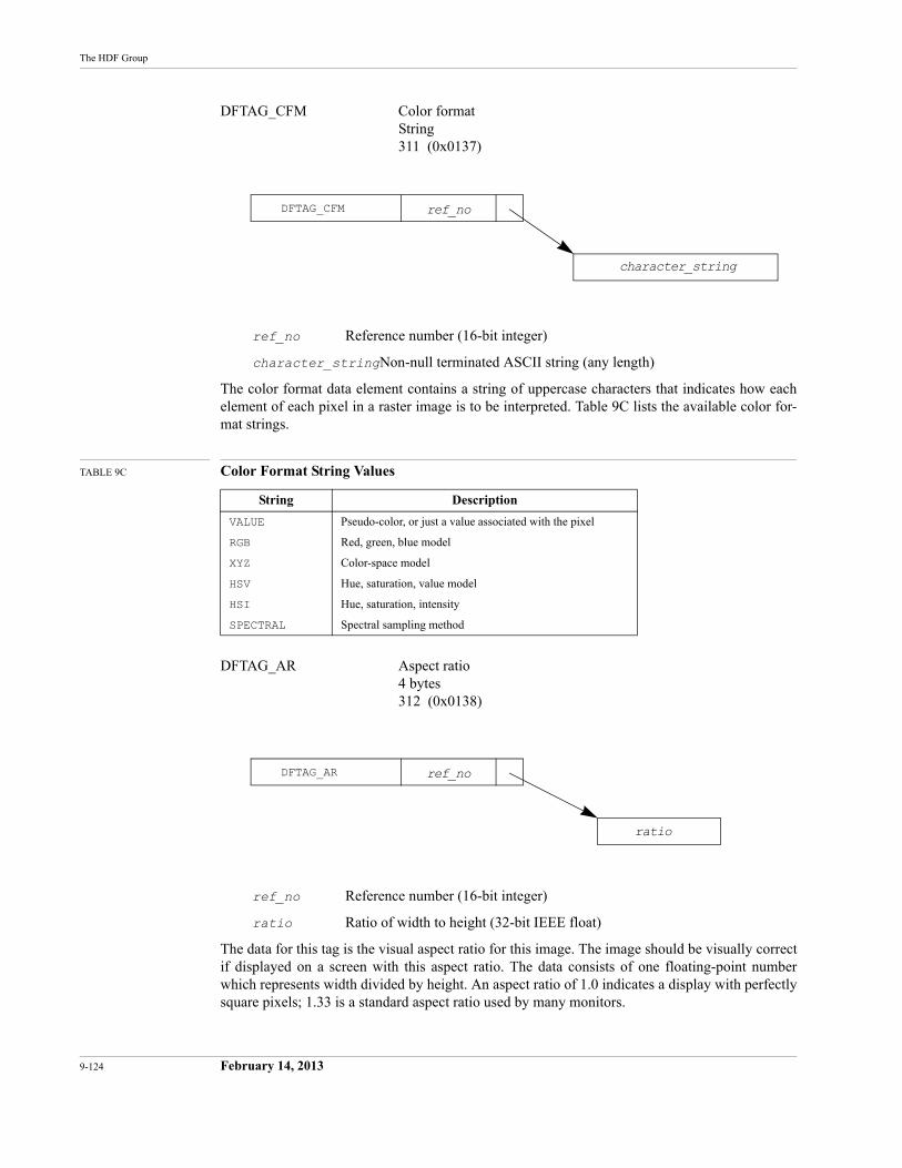
9-124 February 14, 2013
The HDF Group
DFTAG_CFM Color formatString311 (0x0137)
ref_no Reference number (16-bit integer)
character_stringNon-null terminated ASCII string (any length)
The color format data element contains a string of uppercase characters that indicates how each element of each pixel in a raster image is to be interpreted. Table 9C lists the available color for-mat strings.
TABLE 9C Color Format String Values
DFTAG_AR Aspect ratio4 bytes312 (0x0138)
ref_no Reference number (16-bit integer)
ratio Ratio of width to height (32-bit IEEE float)
The data for this tag is the visual aspect ratio for this image. The image should be visually correct if displayed on a screen with this aspect ratio. The data consists of one floating-point number which represents width divided by height. An aspect ratio of 1.0 indicates a display with perfectly square pixels; 1.33 is a standard aspect ratio used by many monitors.
String Description
VALUE Pseudo-color, or just a value associated with the pixel
RGB Red, green, blue model
XYZ Color-space model
HSV Hue, saturation, value model
HSI Hue, saturation, intensity
SPECTRAL Spectral sampling method
DFTAG_CFM ref_no
character_string
DFTAG_AR ref_no
ratio
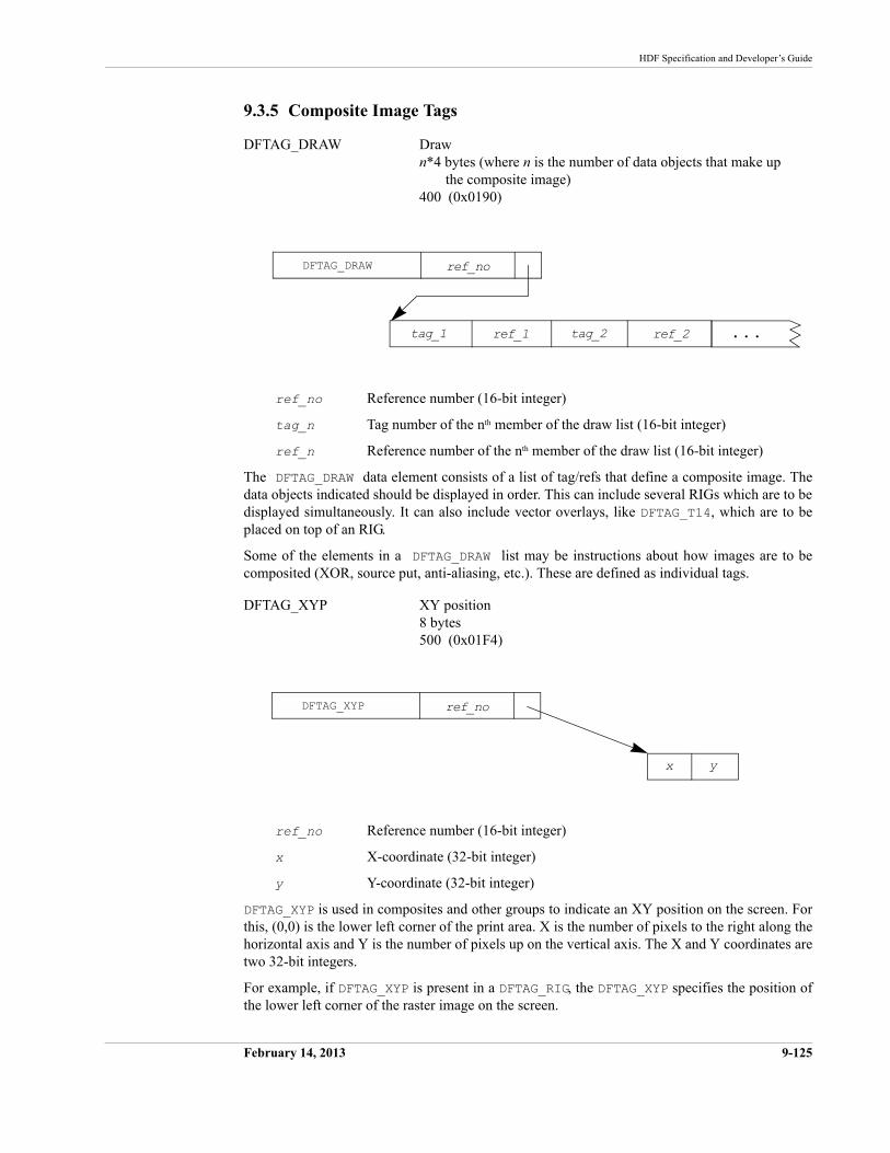
HDF Specification and Developer’s Guide
February 14, 2013 9-125
9.3.5 Composite Image Tags
DFTAG_DRAW Drawn*4 bytes (where n is the number of data objects that make up
the composite image)400 (0x0190)
ref_no Reference number (16-bit integer)
tag_n Tag number of the nth member of the draw list (16-bit integer)
ref_n Reference number of the nth member of the draw list (16-bit integer)
The DFTAG_DRAW data element consists of a list of tag/refs that define a composite image. The data objects indicated should be displayed in order. This can include several RIGs which are to be displayed simultaneously. It can also include vector overlays, like DFTAG_T14, which are to be placed on top of an RIG.
Some of the elements in a DFTAG_DRAW list may be instructions about how images are to be composited (XOR, source put, anti-aliasing, etc.). These are defined as individual tags.
DFTAG_XYP XY position8 bytes500 (0x01F4)
ref_no Reference number (16-bit integer)
x X-coordinate (32-bit integer)
y Y-coordinate (32-bit integer)
DFTAG_XYP is used in composites and other groups to indicate an XY position on the screen. For this, (0,0) is the lower left corner of the print area. X is the number of pixels to the right along the horizontal axis and Y is the number of pixels up on the vertical axis. The X and Y coordinates are two 32-bit integers.
For example, if DFTAG_XYP is present in a DFTAG_RIG, the DFTAG_XYP specifies the position of the lower left corner of the raster image on the screen.
DFTAG_DRAW
ref_1
ref_no
tag_1 ref_2tag_2 . . .
DFTAG_XYP ref_no
x y
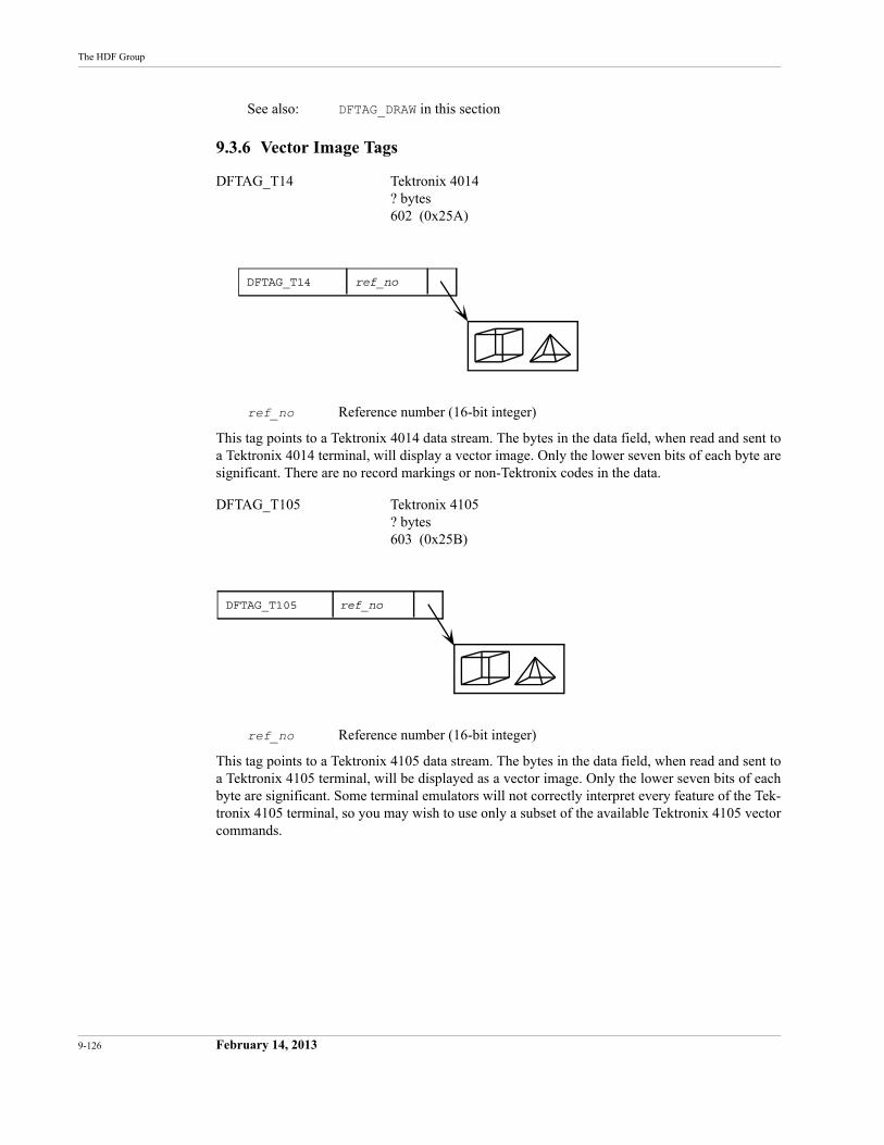
9-126 February 14, 2013
The HDF Group
See also: DFTAG_DRAW in this section
9.3.6 Vector Image Tags
DFTAG_T14 Tektronix 4014? bytes602 (0x25A)
ref_no Reference number (16-bit integer)
This tag points to a Tektronix 4014 data stream. The bytes in the data field, when read and sent to a Tektronix 4014 terminal, will display a vector image. Only the lower seven bits of each byte are significant. There are no record markings or non-Tektronix codes in the data.
DFTAG_T105 Tektronix 4105? bytes603 (0x25B)
ref_no Reference number (16-bit integer)
This tag points to a Tektronix 4105 data stream. The bytes in the data field, when read and sent to a Tektronix 4105 terminal, will be displayed as a vector image. Only the lower seven bits of each byte are significant. Some terminal emulators will not correctly interpret every feature of the Tek-tronix 4105 terminal, so you may wish to use only a subset of the available Tektronix 4105 vector commands.
DFTAG_T14 ref_no
DFTAG_T105 ref_no
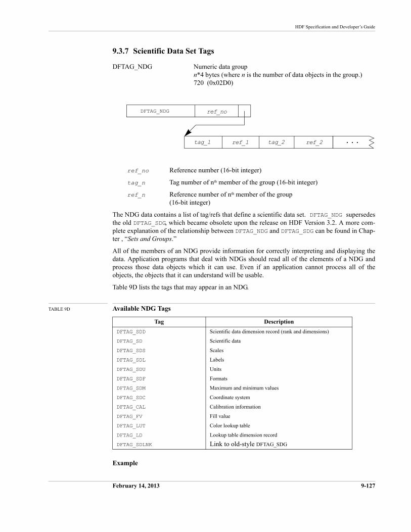
HDF Specification and Developer’s Guide
February 14, 2013 9-127
9.3.7 Scientific Data Set Tags
DFTAG_NDG Numeric data groupn*4 bytes (where n is the number of data objects in the group.)720 (0x02D0)
ref_no Reference number (16-bit integer)
tag_n Tag number of nth member of the group (16-bit integer)
ref_n Reference number of nth member of the group (16-bit integer)
The NDG data contains a list of tag/refs that define a scientific data set. DFTAG_NDG supersedes the old DFTAG_SDG, which became obsolete upon the release on HDF Version 3.2. A more com-plete explanation of the relationship between DFTAG_NDG and DFTAG_SDG can be found in Chap-ter , “Sets and Groups.”
All of the members of an NDG provide information for correctly interpreting and displaying the data. Application programs that deal with NDGs should read all of the elements of a NDG and process those data objects which it can use. Even if an application cannot process all of the objects, the objects that it can understand will be usable.
Table 9D lists the tags that may appear in an NDG.
TABLE 9D Available NDG Tags
Example
Tag Description
DFTAG_SDD Scientific data dimension record (rank and dimensions)
DFTAG_SD Scientific data
DFTAG_SDS Scales
DFTAG_SDL Labels
DFTAG_SDU Units
DFTAG_SDF Formats
DFTAG_SDM Maximum and minimum values
DFTAG_SDC Coordinate system
DFTAG_CAL Calibration information
DFTAG_FV Fill value
DFTAG_LUT Color lookup table
DFTAG_LD Lookup table dimension record
DFTAG_SDLNK Link to old-style DFTAG_SDG
DFTAG_NDG
ref_1
ref_no
tag_1 ref_2tag_2 . . .
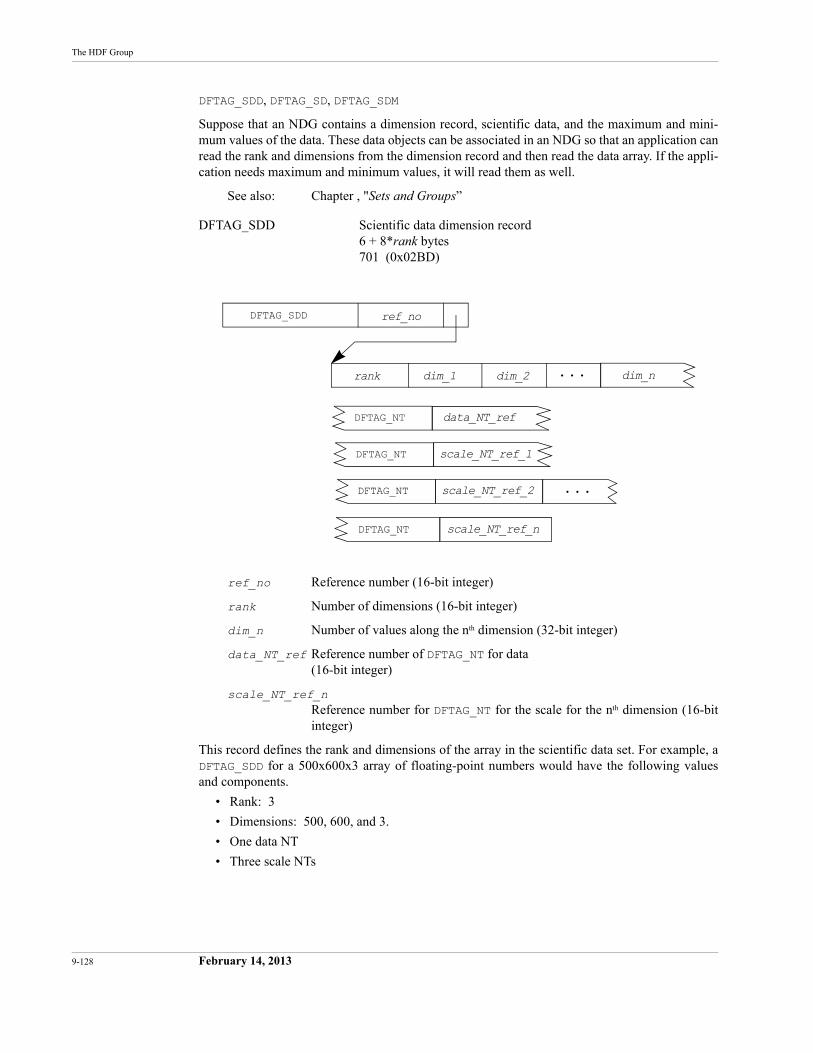
9-128 February 14, 2013
The HDF Group
DFTAG_SDD, DFTAG_SD, DFTAG_SDM
Suppose that an NDG contains a dimension record, scientific data, and the maximum and mini-mum values of the data. These data objects can be associated in an NDG so that an application can read the rank and dimensions from the dimension record and then read the data array. If the appli-cation needs maximum and minimum values, it will read them as well.
See also: Chapter , "Sets and Groups”
DFTAG_SDD Scientific data dimension record6 + 8*rank bytes 701 (0x02BD)
ref_no Reference number (16-bit integer)
rank Number of dimensions (16-bit integer)
dim_n Number of values along the nth dimension (32-bit integer)
data_NT_ref Reference number of DFTAG_NT for data (16-bit integer)
scale_NT_ref_nReference number for DFTAG_NT for the scale for the nth dimension (16-bit integer)
This record defines the rank and dimensions of the array in the scientific data set. For example, a DFTAG_SDD for a 500x600x3 array of floating-point numbers would have the following values and components.
• Rank: 3
• Dimensions: 500, 600, and 3.
• One data NT
• Three scale NTs
DFTAG_SDD ref_no
DFTAG_NT data_NT_ref
dim_1rank dim_2 dim_n. . .
DFTAG_NT scale_NT_ref_1
DFTAG_NT scale_NT_ref_2 . . .
DFTAG_NT scale_NT_ref_n
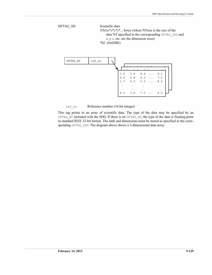
HDF Specification and Developer’s Guide
February 14, 2013 9-129
DFTAG_SD Scientific dataNTsize*x*y*z*... bytes (where NTsize is the size of the
data NT specified in the corresponding DFTAG_SDD and x, y, z, etc. are the dimension sizes)
702 (0x02BE)
ref_no Reference number (16-bit integer)
This tag points to an array of scientific data. The type of the data may be specified by an DFTAG_NT included with the SDG. If there is no DFTAG_NT, the type of the data is floating-point in standard IEEE 32-bit format. The rank and dimensions must be stored as specified in the corre-sponding DFTAG_SDD. The diagram above shows a 3-dimensional data array.
2.1 2.9 8.7 ... 6.4
7.7
8.3
6.1
1.1 2.5 9.8 ... 6.7
7.2
8.6
6.4
DFTAG_SD ref_no
1.2 3.6 8.4 ... 9.1
2.4 2.8 6.3 ... 7.5
1.7 2.0 5.3 ... 8.2
. . . .
. . . .
4.3 3.6 7.1 ... 6.2
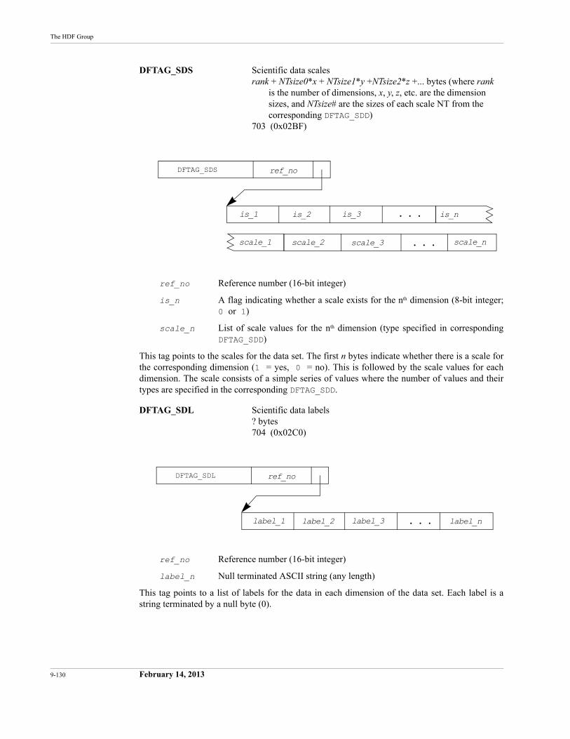
9-130 February 14, 2013
The HDF Group
DFTAG_SDS Scientific data scalesrank + NTsize0*x + NTsize1*y +NTsize2*z +... bytes (where rank
is the number of dimensions, x, y, z, etc. are the dimensionsizes, and NTsize# are the sizes of each scale NT from the corresponding DFTAG_SDD)
703 (0x02BF)
ref_no Reference number (16-bit integer)
is_n A flag indicating whether a scale exists for the nth dimension (8-bit integer;0 or 1)
scale_n List of scale values for the nth dimension (type specified in corresponding DFTAG_SDD)
This tag points to the scales for the data set. The first n bytes indicate whether there is a scale for the corresponding dimension (1 = yes, 0 = no). This is followed by the scale values for each dimension. The scale consists of a simple series of values where the number of values and their types are specified in the corresponding DFTAG_SDD.
DFTAG_SDL Scientific data labels? bytes704 (0x02C0)
ref_no Reference number (16-bit integer)
label_n Null terminated ASCII string (any length)
This tag points to a list of labels for the data in each dimension of the data set. Each label is a string terminated by a null byte (0).
DFTAG_SDS
is_2
ref_no
is_1 is_nis_3
scale_2scale_1 scale_3
. . .
scale_n. . .
DFTAG_SDL
label_2
ref_no
label_1 label_nlabel_3 . . .
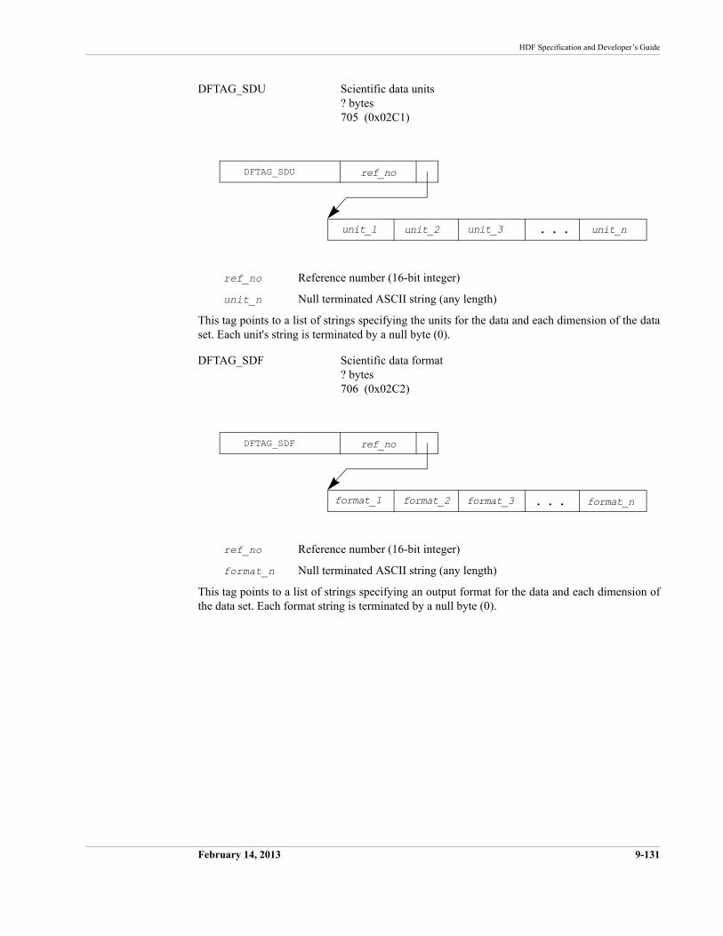
HDF Specification and Developer’s Guide
February 14, 2013 9-131
DFTAG_SDU Scientific data units? bytes705 (0x02C1)
ref_no Reference number (16-bit integer)
unit_n Null terminated ASCII string (any length)
This tag points to a list of strings specifying the units for the data and each dimension of the data set. Each unit's string is terminated by a null byte (0).
DFTAG_SDF Scientific data format? bytes706 (0x02C2)
ref_no Reference number (16-bit integer)
format_n Null terminated ASCII string (any length)
This tag points to a list of strings specifying an output format for the data and each dimension of the data set. Each format string is terminated by a null byte (0).
DFTAG_SDU
unit_2
ref_no
unit_1 unit_nunit_3 . . .
DFTAG_SDF
format_2
ref_no
format_1 format_nformat_3 . . .
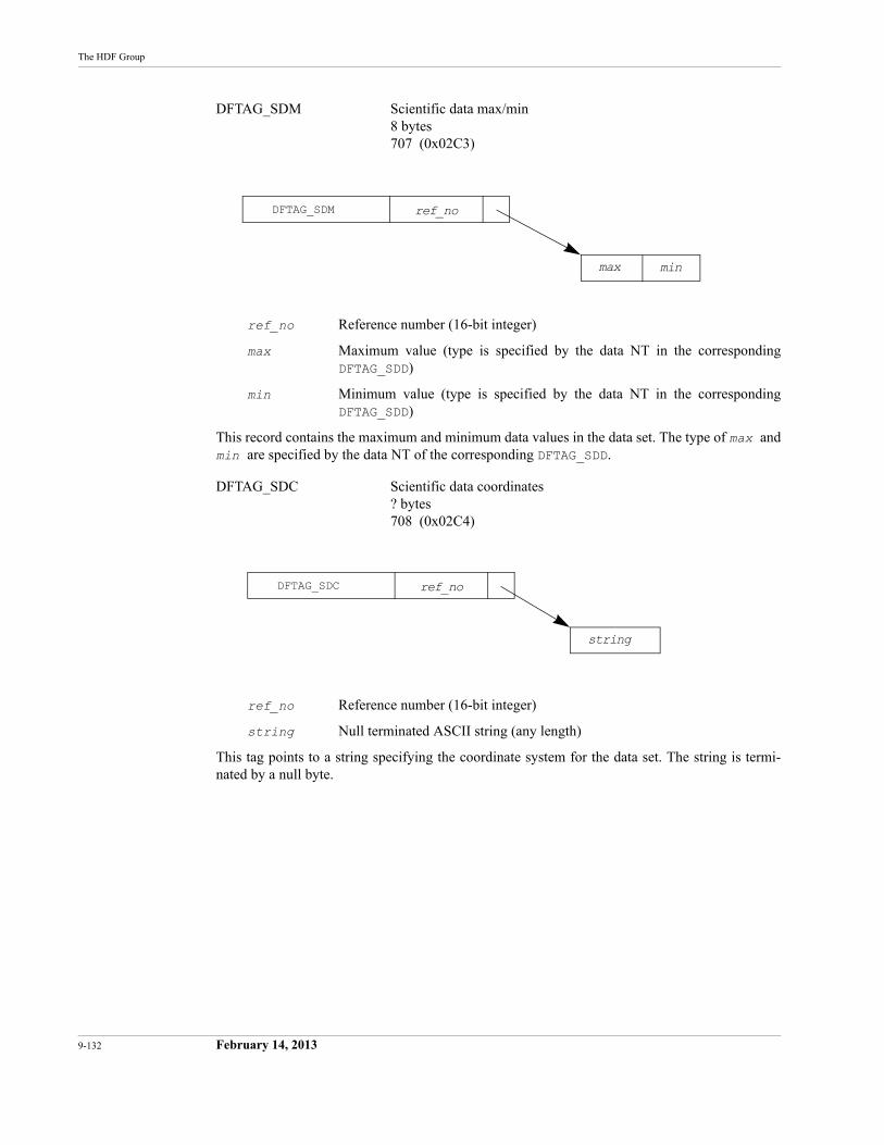
9-132 February 14, 2013
The HDF Group
DFTAG_SDM Scientific data max/min8 bytes707 (0x02C3)
ref_no Reference number (16-bit integer)
max Maximum value (type is specified by the data NT in the corresponding DFTAG_SDD)
min Minimum value (type is specified by the data NT in the corresponding DFTAG_SDD)
This record contains the maximum and minimum data values in the data set. The type of max andmin are specified by the data NT of the corresponding DFTAG_SDD.
DFTAG_SDC Scientific data coordinates? bytes708 (0x02C4)
ref_no Reference number (16-bit integer)
string Null terminated ASCII string (any length)
This tag points to a string specifying the coordinate system for the data set. The string is termi-nated by a null byte.
DFTAG_SDM ref_no
max min
DFTAG_SDC ref_no
string
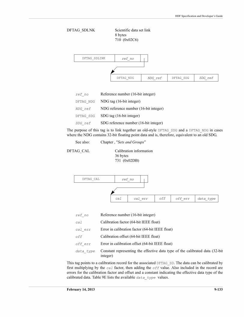
HDF Specification and Developer’s Guide
February 14, 2013 9-133
DFTAG_SDLNK Scientific data set link8 bytes710 (0x02C6)
ref_no Reference number (16-bit integer)
DFTAG_NDG NDG tag (16-bit integer)
NDG_ref NDG reference number (16-bit integer)
DFTAG_SDG SDG tag (16-bit integer)
SDG_ref SDG reference number (16-bit integer)
The purpose of this tag is to link together an old-style DFTAG_SDG and a DFTAG_NDG in cases where the NDG contains 32-bit floating point data and is, therefore, equivalent to an old SDG.
See also: Chapter , "Sets and Groups”
DFTAG_CAL Calibration information36 bytes731 (0x02DB)
ref_no Reference number (16-bit integer)
cal Calibration factor (64-bit IEEE float)
cal_err Error in calibration factor (64-bit IEEE float)
off Calibration offset (64-bit IEEE float)
off_err Error in calibration offset (64-bit IEEE float)
data_type Constant representing the effective data type of the calibrated data (32-bit integer)
This tag points to a calibration record for the associated DFTAG_SD. The data can be calibrated by first multiplying by the cal factor, then adding the off value. Also included in the record are errors for the calibration factor and offset and a constant indicating the effective data type of the calibrated data. Table 9E lists the available data_type values.
DFTAG_SDLINK
NDG_ref
ref_no
DFTAG_NDG SDG_refDFTAG_SDG
DFTAG_CAL
cal_err
ref_no
cal data_typeoff off_err
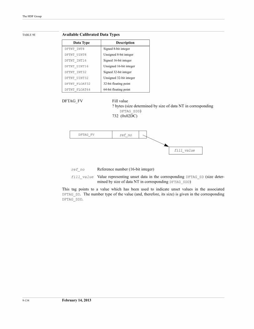
9-134 February 14, 2013
The HDF Group
TABLE 9E Available Calibrated Data Types
DFTAG_FV Fill value? bytes (size determined by size of data NT in corresponding
DFTAG_SDD)732 (0x02DC)
ref_no Reference number (16-bit integer)
fill_value Value representing unset data in the corresponding DFTAG_SD (size deter-mined by size of data NT in corresponding DFTAG_SDD)
This tag points to a value which has been used to indicate unset values in the associated DFTAG_SD. The number type of the value (and, therefore, its size) is given in the corresponding DFTAG_SDD.
Data Type Description
DFTNT_INT8 Signed 8-bit integer
DFTNT_UINT8 Unsigned 8-bit integer
DFTNT_INT16 Signed 16-bit integer
DFTNT_UINT16 Unsigned 16-bit integer
DFTNT_INT32 Signed 32-bit integer
DFTNT_UINT32 Unsigned 32-bit integer
DFTNT_FLOAT32 32-bit floating point
DFTNT_FLOAT64 64-bit floating point
DFTAG_FV ref_no
fill_value
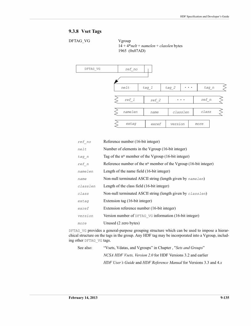
HDF Specification and Developer’s Guide
February 14, 2013 9-135
9.3.8 Vset Tags
DFTAG_VG Vgroup14 + 4*nelt + namelen + classlen bytes 1965 (0x07AD)
ref_no Reference number (16-bit integer)
nelt Number of elements in the Vgroup (16-bit integer)
tag_n Tag of the nth member of the Vgroup (16-bit integer)
ref_n Reference number of the nth member of the Vgroup (16-bit integer)
namelen Length of the name field (16-bit integer)
name Non-null terminated ASCII string (length given by namelen)
classlen Length of the class field (16-bit integer)
class Non-null terminated ASCII string (length given by classlen)
extag Extension tag (16-bit integer)
exref Extension reference number (16-bit integer)
version Version number of DFTAG_VG information (16-bit integer)
more Unused (2 zero bytes)
DFTAG_VG provides a general-purpose grouping structure which can be used to impose a hierar-chical structure on the tags in the group. Any HDF tag may be incorporated into a Vgroup, includ-ing other DFTAG_VG tags.
See also: “Vsets, Vdatas, and Vgroups” in Chapter , "Sets and Groups”
NCSA HDF Vsets, Version 2.0 for HDF Versions 3.2 and earlier
HDF User’s Guide and HDF Reference Manual for Versions 3.3 and 4.x
DFTAG_VG ref_no
tag_1nelt tag_2 tag_n. . .
namelen name
extag
classlen class
ref_1 ref_2 . . . ref_n
versionexref more
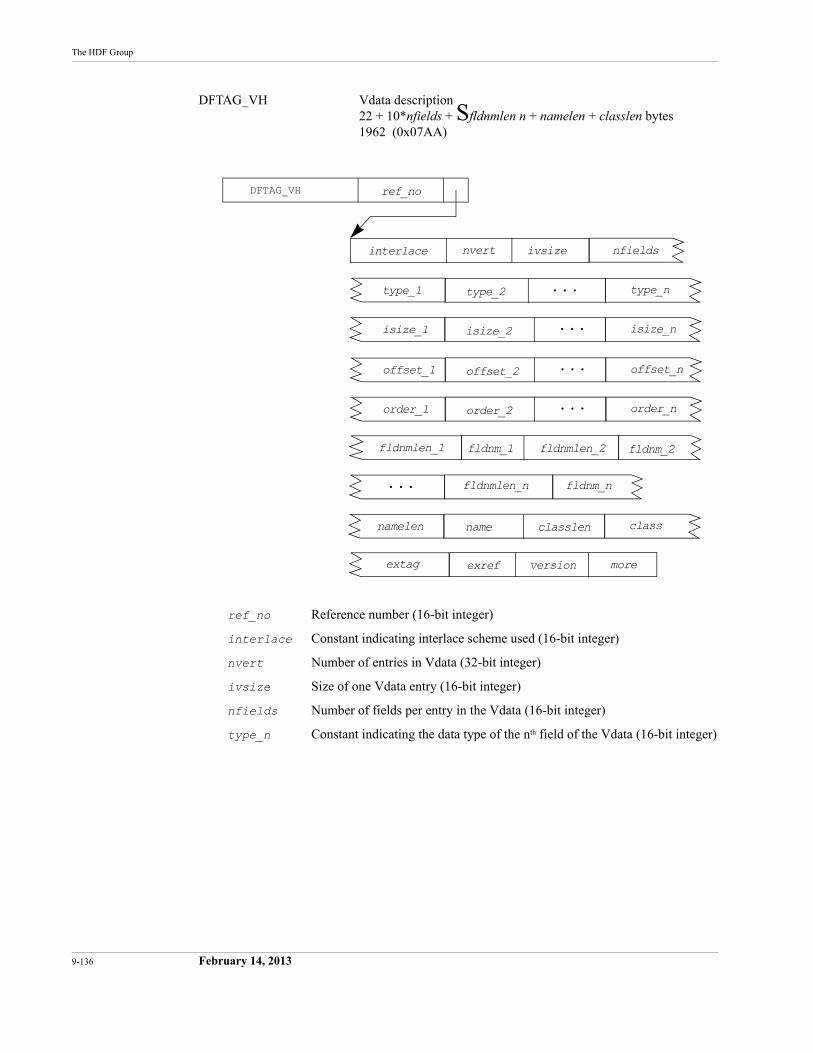
9-136 February 14, 2013
The HDF Group
DFTAG_VH Vdata description22 + 10*nfields + Sfldnmlen n + namelen + classlen bytes1962 (0x07AA)
ref_no Reference number (16-bit integer)
interlace Constant indicating interlace scheme used (16-bit integer)
nvert Number of entries in Vdata (32-bit integer)
ivsize Size of one Vdata entry (16-bit integer)
nfields Number of fields per entry in the Vdata (16-bit integer)
type_n Constant indicating the data type of the nth field of the Vdata (16-bit integer)
DFTAG_VH ref_no
nvertinterlace ivsize nfields
namelen name
extag
classlen class
. . .
versionexref more
fldnmlen_1 fldnm_1
order_1 order_2 . . . order_n
offset_1 offset_2 . . . offset_n
isize_1 isize_2 . . . isize_n
type_1 type_2 . . . type_n
fldnmlen_2 fldnm_2
fldnmlen_n fldnm_n
HDF Specification and Developer’s Guide
February 14, 2013 9-137
isize_n Size in bytes of the nth field of the Vdata (16-bit integer)
offset_n Offset of the nth field within the Vdata (16-bit integer)
order_n Order of the nth field of the Vdata (16-bit integer)
fldnmlen_n Length of the nth field name string (16-bit integer)
fldnm_n Non-null terminated ASCII string (length given by corresponding fld-nmlen_n)
namelen Length of the name field (16-bit integer)
name Non-null terminated ASCII string (length given by namelen)
classlen Length of the class field (16-bit integer)
class Non-null terminated ASCII string (length given by classlen)
extag Extension tag (16-bit integer)
exref Extension reference number (16-bit integer)
version Version number of DFTAG_VH information (16-bit integer)
more Unused (2 zero bytes)
DFTAG_VH provides all the information necessary to process a DFTAG_VS.
See also: DFTAG_VS (this section)
“Vsets, Vdatas, and Vgroups” in Chapter , "Sets and Groups”
NCSA HDF Vsets, Version 2.0 for HDF Versions 3.2 and earlier
HDF User’s Guide and HDF Reference Manual for Versions 3.3 and 4.x
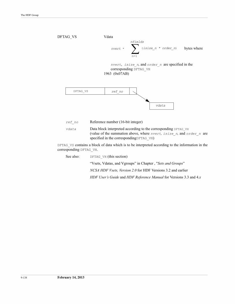
9-138 February 14, 2013
The HDF Group
DFTAG_VS Vdata
nvert, isize_n, and order_n are specified in the corresponding DFTAG_VH
1963 (0x07AB)
ref_no Reference number (16-bit integer)
vdata Data block interpreted according to the corresponding DFTAG_VH(value of the summation above, where nvert, isize_n, and order_n are specified in the correspondingDFTAG_VH)
DFTAG_VS contains a block of data which is to be interpreted according to the information in the corresponding DFTAG_VH.
See also: DFTAG_VH (this section)
“Vsets, Vdatas, and Vgroups” in Chapter , "Sets and Groups”
NCSA HDF Vsets, Version 2.0 for HDF Versions 3.2 and earlier
HDF User’s Guide and HDF Reference Manual for Versions 3.3 and 4.x
nvert * (isize_n * order_n)
n=1
nfields
bytes where
DFTAG_VS ref_no
vdata
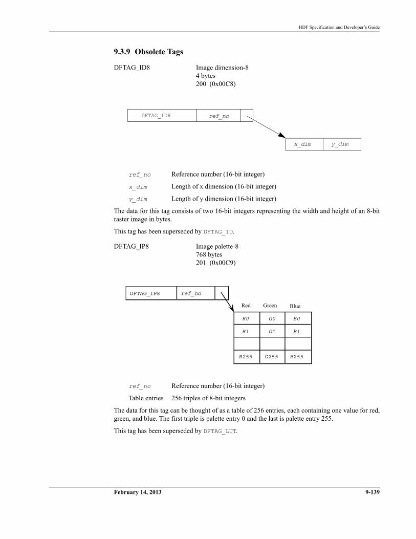
HDF Specification and Developer’s Guide
February 14, 2013 9-139
9.3.9 Obsolete Tags
DFTAG_ID8 Image dimension-84 bytes200 (0x00C8)
ref_no Reference number (16-bit integer)
x_dim Length of x dimension (16-bit integer)
y_dim Length of y dimension (16-bit integer)
The data for this tag consists of two 16-bit integers representing the width and height of an 8-bit raster image in bytes.
This tag has been superseded by DFTAG_ID.
DFTAG_IP8 Image palette-8768 bytes201 (0x00C9)
ref_no Reference number (16-bit integer)
Table entries 256 triples of 8-bit integers
The data for this tag can be thought of as a table of 256 entries, each containing one value for red, green, and blue. The first triple is palette entry 0 and the last is palette entry 255.
This tag has been superseded by DFTAG_LUT.
DFTAG_ID8 ref_no
x_dim y_dim
DFTAG_IP8 ref_no
Red Green Blue
R0
R1
R255
G0
G1
B0
B1
G255 B255
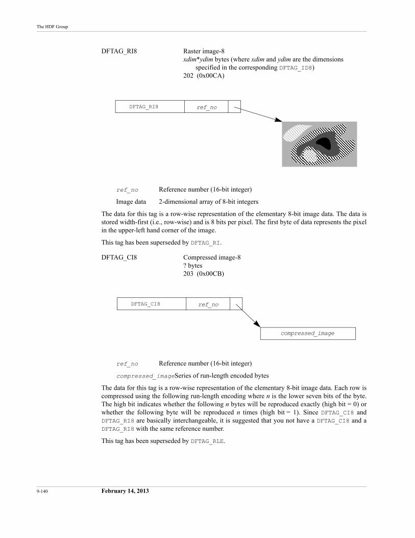
9-140 February 14, 2013
The HDF Group
DFTAG_RI8 Raster image-8xdim*ydim bytes (where xdim and ydim are the dimensions
specified in the corresponding DFTAG_ID8)202 (0x00CA)
ref_no Reference number (16-bit integer)
Image data 2-dimensional array of 8-bit integers
The data for this tag is a row-wise representation of the elementary 8-bit image data. The data is stored width-first (i.e., row-wise) and is 8 bits per pixel. The first byte of data represents the pixel in the upper-left hand corner of the image.
This tag has been superseded by DFTAG_RI.
DFTAG_CI8 Compressed image-8? bytes203 (0x00CB)
ref_no Reference number (16-bit integer)
compressed_imageSeries of run-length encoded bytes
The data for this tag is a row-wise representation of the elementary 8-bit image data. Each row is compressed using the following run-length encoding where n is the lower seven bits of the byte. The high bit indicates whether the following n bytes will be reproduced exactly (high bit = 0) or whether the following byte will be reproduced n times (high bit = 1). Since DFTAG_CI8 and DFTAG_RI8 are basically interchangeable, it is suggested that you not have a DFTAG_CI8 and a DFTAG_RI8 with the same reference number.
This tag has been superseded by DFTAG_RLE.
DFTAG_RI8 ref_no
DFTAG_CI8 ref_no
compressed_image
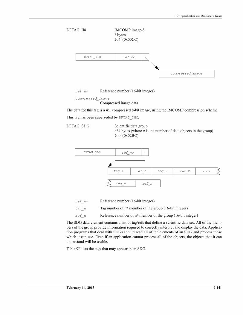
HDF Specification and Developer’s Guide
February 14, 2013 9-141
DFTAG_II8 IMCOMP image-8? bytes204 (0x00CC)
ref_no Reference number (16-bit integer)
compressed_imageCompressed image data
The data for this tag is a 4:1 compressed 8-bit image, using the IMCOMP compression scheme.
This tag has been superseded by DFTAG_IMC.
DFTAG_SDG Scientific data groupn*4 bytes (where n is the number of data objects in the group)700 (0x02BC)
ref_no Reference number (16-bit integer)
tag_n Tag number of nth member of the group (16-bit integer)
ref_n Reference number of nth member of the group (16-bit integer)
The SDG data element contains a list of tag/refs that define a scientific data set. All of the mem-bers of the group provide information required to correctly interpret and display the data. Applica-tion programs that deal with SDGs should read all of the elements of an SDG and process those which it can use. Even if an application cannot process all of the objects, the objects that it can understand will be usable.
Table 9F lists the tags that may appear in an SDG.
DFTAG_II8 ref_no
compressed_image
DFTAG_SDG
ref_1
ref_no
tag_1 ref_2tag_2
tag_n ref_n
. . .
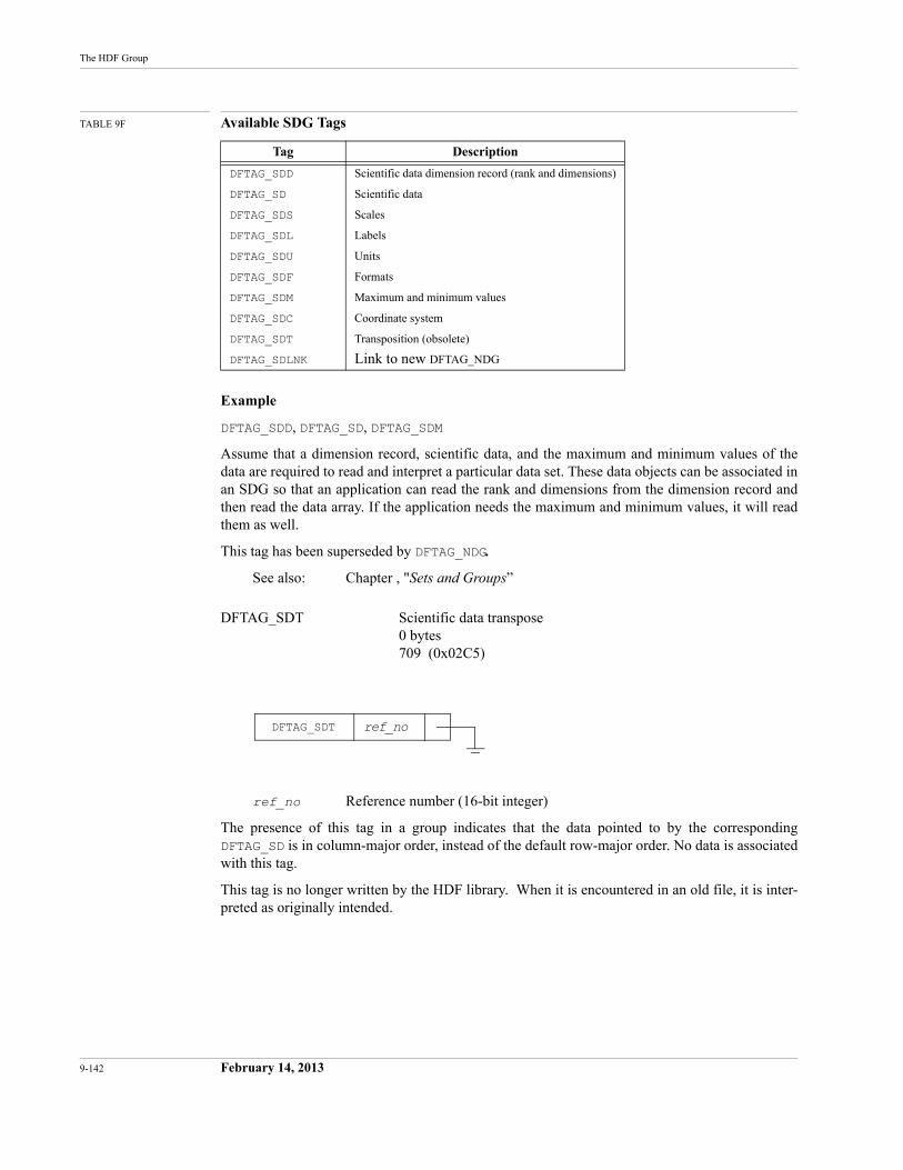
9-142 February 14, 2013
The HDF Group
TABLE 9F Available SDG Tags
Example
DFTAG_SDD, DFTAG_SD, DFTAG_SDM
Assume that a dimension record, scientific data, and the maximum and minimum values of the data are required to read and interpret a particular data set. These data objects can be associated in an SDG so that an application can read the rank and dimensions from the dimension record and then read the data array. If the application needs the maximum and minimum values, it will read them as well.
This tag has been superseded by DFTAG_NDG.
See also: Chapter , "Sets and Groups”
DFTAG_SDT Scientific data transpose0 bytes709 (0x02C5)
ref_no Reference number (16-bit integer)
The presence of this tag in a group indicates that the data pointed to by the corresponding DFTAG_SD is in column-major order, instead of the default row-major order. No data is associated with this tag.
This tag is no longer written by the HDF library. When it is encountered in an old file, it is inter-preted as originally intended.
Tag Description
DFTAG_SDD Scientific data dimension record (rank and dimensions)
DFTAG_SD Scientific data
DFTAG_SDS Scales
DFTAG_SDL Labels
DFTAG_SDU Units
DFTAG_SDF Formats
DFTAG_SDM Maximum and minimum values
DFTAG_SDC Coordinate system
DFTAG_SDT Transposition (obsolete)
DFTAG_SDLNK Link to new DFTAG_NDG
DFTAG_SDT ref_no
February 2013 10-143
CHAPTER 10 -- Extended Tags and Special Elements
10.1 Chapter Overview
This chapter provides detailed information regarding HDF-supported HDF extended tags and the special elements they define. General information about tags and detailed specifications of basic tags are presented in Chapter 9, “Tag Specifications."
10.2 Extended Tags and Alternate Physical Storage Methods
Prior to HDF Version 3.2, each data element had to be stored in one contiguous block in the basic HDF file. Version 3.2 introduced extended tags, a mechanism supporting alternate physical data element storage structures. All HDF-supported tags with variable-sized data elements can take advantage of the extended tag features.
10.2.1Extended Tag Implementation
Extended tags are automatically recognized by current versions of the HDF library and interpreted according to a description record. The description record, a complete data element, identifies the type of extended element and provides the relevant parameters for data retrieval.
Extended tags currently support four styles of alternate physical storage:
• Linked block elements are stored in several non-contiguous blocks within the basic HDF file.
• External elements are stored in a separate file, external to the basic HDF file.
• Chunked elements are stored in blocks within the basic HDF file to facilitate selective I/O.
• Compressed elements are stored in a configurable compressed mode within the basic HDF file to save storage space and to speed I/O and data transfer.
Every HDF-supported tag is represented in HDF libraries and files by a tag number. HDF-sup-ported tags that take advantage of alternative physical storage features have an alternative tag number, called an extended tag number, that appears instead of the original tag number when an alternative physical storage method is in use.
When The HDF Group determines that an extended tag should be defined for a given tag, the extended tag number is determined by performing an arithmetic OR with the original tag number and the hexadecimal number 0x4000. Since all basic tags are numbered 0x0001 through 0x3FFF, this arithmetic OR effectively adds 0x4000, or a decimal value of 16384, to derive the extended tag value.
For example, the tag DFTAG_RI points to a data element containing a raster image. If the data element is stored contiguously in the same HDF file, the DD contains the tag number 302; if the
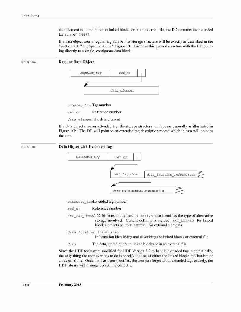
10-144 February 2013
The HDF Group
data element is stored either in linked blocks or in an external file, the DD contains the extended tag number 16686.
If a data object uses a regular tag number, its storage structure will be exactly as described in the "Section 9.3, "Tag Specifications." Figure 10a illustrates this general structure with the DD point-ing directly to a single, contiguous data block.
FIGURE 10a Regular Data Object
regular_tag Tag number
ref_no Reference number
data_elementThe data element
If a data object uses an extended tag, the storage structure will appear generally as illustrated in Figure 10b. The DD will point to an extended tag description record which in turn will point to the data.
FIGURE 10b Data Object with Extended Tag
extended_tagExtended tag number
ref_no Reference number
ext_tag_descA 32-bit constant defined in Hdfi.h that identifies the type of alternative storage involved. Current definitions include EXT_LINKED for linked block elements or EXT_EXTERN for external elements.
data_location_informationInformation identifying and describing the linked blocks or external file
data The data, stored either in linked blocks or in an external file
Since the HDF tools were modified for HDF Version 3.2 to handle extended tags automatically, the only thing the user ever has to do is specify the use of either the linked blocks mechanism or an external file. Once that has been specified, the user can forget about extended tags entirely; the HDF library will manage everything correctly.
regular_tag ref_no
data_element
extended_tag ref_no
ext_tag_desc data_location_information
data (in linked blocks or external file)
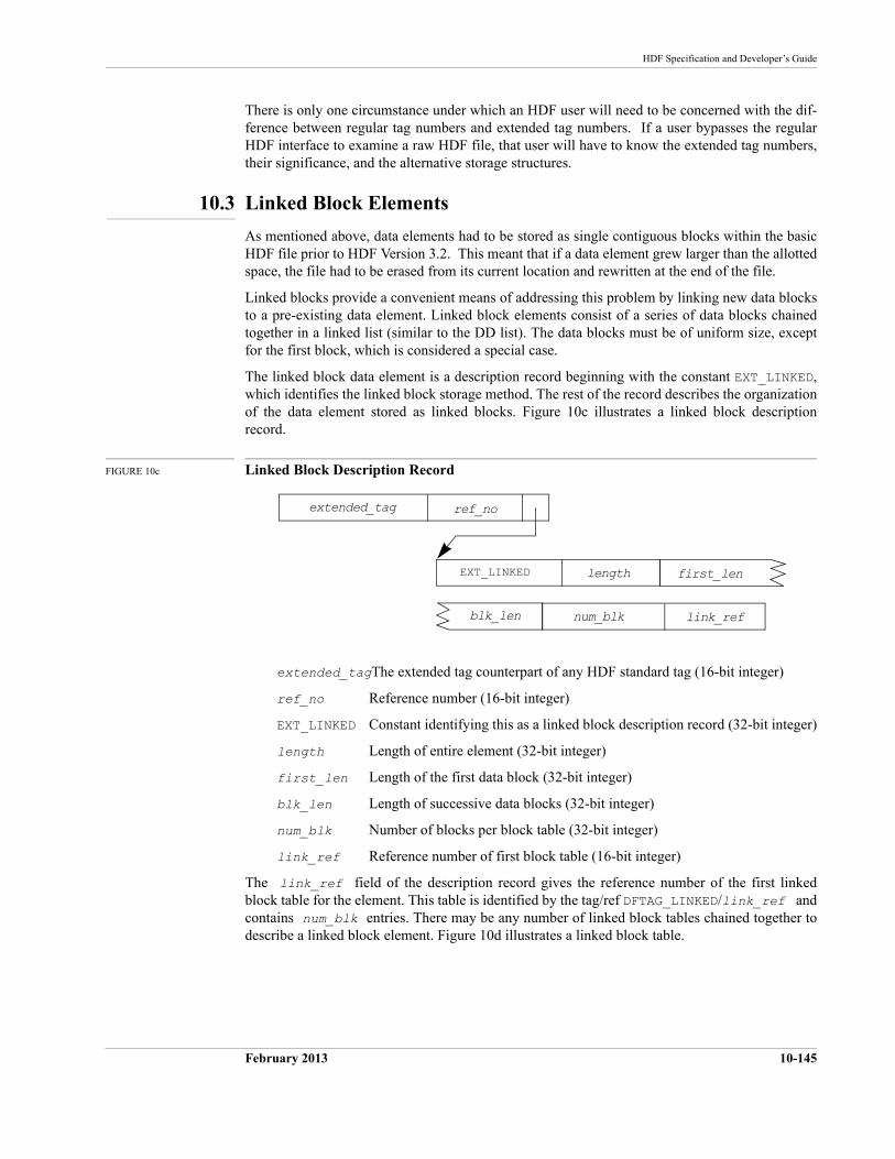
HDF Specification and Developer’s Guide
February 2013 10-145
There is only one circumstance under which an HDF user will need to be concerned with the dif-ference between regular tag numbers and extended tag numbers. If a user bypasses the regular HDF interface to examine a raw HDF file, that user will have to know the extended tag numbers, their significance, and the alternative storage structures.
10.3 Linked Block Elements
As mentioned above, data elements had to be stored as single contiguous blocks within the basic HDF file prior to HDF Version 3.2. This meant that if a data element grew larger than the allotted space, the file had to be erased from its current location and rewritten at the end of the file.
Linked blocks provide a convenient means of addressing this problem by linking new data blocks to a pre-existing data element. Linked block elements consist of a series of data blocks chained together in a linked list (similar to the DD list). The data blocks must be of uniform size, except for the first block, which is considered a special case.
The linked block data element is a description record beginning with the constant EXT_LINKED, which identifies the linked block storage method. The rest of the record describes the organization of the data element stored as linked blocks. Figure 10c illustrates a linked block description record.
FIGURE 10c Linked Block Description Record
extended_tagThe extended tag counterpart of any HDF standard tag (16-bit integer)
ref_no Reference number (16-bit integer)
EXT_LINKED Constant identifying this as a linked block description record (32-bit integer)
length Length of entire element (32-bit integer)
first_len Length of the first data block (32-bit integer)
blk_len Length of successive data blocks (32-bit integer)
num_blk Number of blocks per block table (32-bit integer)
link_ref Reference number of first block table (16-bit integer)
The link_ref field of the description record gives the reference number of the first linked block table for the element. This table is identified by the tag/ref DFTAG_LINKED/link_ref and contains num_blk entries. There may be any number of linked block tables chained together to describe a linked block element. Figure 10d illustrates a linked block table.
extended_tag ref_no
EXT_LINKED first_len
num_blkblk_len link_ref
length
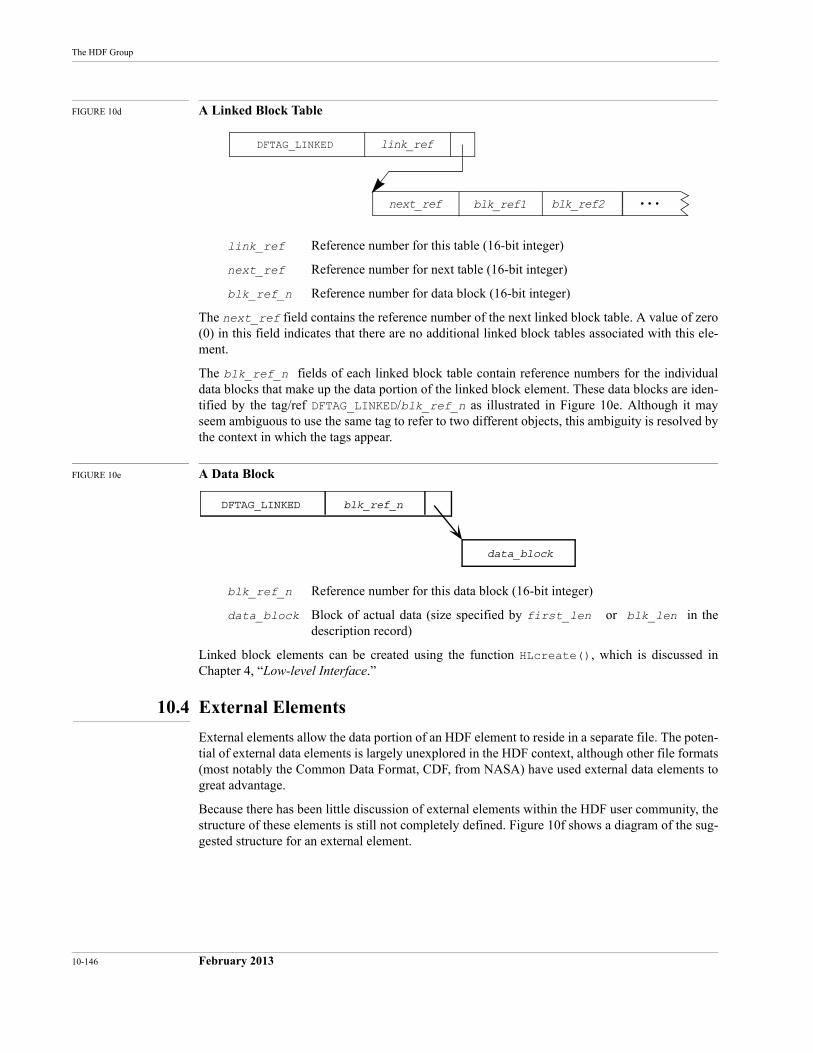
10-146 February 2013
The HDF Group
FIGURE 10d A Linked Block Table
link_ref Reference number for this table (16-bit integer)
next_ref Reference number for next table (16-bit integer)
blk_ref_n Reference number for data block (16-bit integer)
The next_ref field contains the reference number of the next linked block table. A value of zero (0) in this field indicates that there are no additional linked block tables associated with this ele-ment.
The blk_ref_n fields of each linked block table contain reference numbers for the individual data blocks that make up the data portion of the linked block element. These data blocks are iden-tified by the tag/ref DFTAG_LINKED/blk_ref_n as illustrated in Figure 10e. Although it may seem ambiguous to use the same tag to refer to two different objects, this ambiguity is resolved by the context in which the tags appear.
FIGURE 10e A Data Block
blk_ref_n Reference number for this data block (16-bit integer)
data_block Block of actual data (size specified by first_len or blk_len in the description record)
Linked block elements can be created using the function HLcreate(), which is discussed in Chapter 4, “Low-level Interface.”
10.4 External Elements
External elements allow the data portion of an HDF element to reside in a separate file. The poten-tial of external data elements is largely unexplored in the HDF context, although other file formats (most notably the Common Data Format, CDF, from NASA) have used external data elements to great advantage.
Because there has been little discussion of external elements within the HDF user community, the structure of these elements is still not completely defined. Figure 10f shows a diagram of the sug-gested structure for an external element.
DFTAG_LINKED link_ref
. . .next_ref blk_ref2blk_ref1
DFTAG_LINKED blk_ref_n
data_block
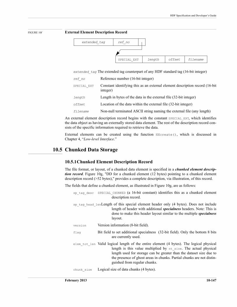
HDF Specification and Developer’s Guide
February 2013 10-147
FIGURE 10f External Element Description Record
extended_tag The extended tag counterpart of any HDF standard tag (16-bit integer)
ref_no Reference number (16-bit integer)
SPECIAL_EXT Constant identifying this as an external element description record (16-bit integer)
length Length in bytes of the data in the external file (32-bit integer)
offset Location of the data within the external file (32-bit integer)
filename Non-null terminated ASCII string naming the external file (any length)
An external element description record begins with the constant SPECIAL_EXT, which identifies the data object as having an externally stored data element. The rest of the description record con-sists of the specific information required to retrieve the data.
External elements can be created using the function HXcreate(), which is discussed in Chapter 4, “Low-level Interface.”
10.5 Chunked Data Storage
10.5.1Chunked Element Description Record
The file format, or layout, of a chunked data element is specified in a chunked element descrip-tion record. Figure 10g, "DD for a chunked element (12 bytes) pointing to a chunked element description record (>52 bytes)," provides a complete description, via illustration, of this record.
The fields that define a chunked element, as illustrated in Figure 10g, are as follows:
sp_tag_desc SPECIAL_CHUNKED (a 16-bit constant) identifies this as a chunked element description record.
sp_tag_head_lenLength of this special element header only (4 bytes). Does not include length of header with additional specialness headers. Note: This is done to make this header layout similar to the multiple specialnesslayout.
version Version information (8-bit field).
flag Bit field to set additional specialness (32-bit field). Only the bottom 8 bits are currently used.
elem_tot_len Valid logical length of the entire element (4 bytes). The logical physical length is this value multiplied by nt_size. The actual physical length used for storage can be greater than the dataset size due to the presence of ghost areas in chunks. Partial chunks are not distin-guished from regular chunks.
chunk_size Logical size of data chunks (4 bytes).
extended_tag ref_no
SPECIAL_EXT offsetlength filename
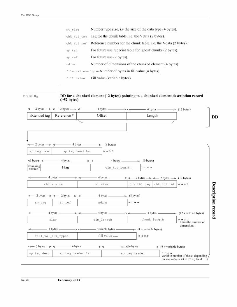
10-148 February 2013
The HDF Group
nt_size Number type size, i.e the size of the data type (4 bytes).
chk_tbl_tag Tag for the chunk table, i.e. the Vdata (2 bytes).
chk_tbl_ref Reference number for the chunk table, i.e. the Vdata (2 bytes).
sp_tag For future use. Special table for 'ghost' chunks (2 bytes).
sp_ref For future use (2 bytes).
ndims Number of dimensions of the chunked element.(4 bytes).
file_val_num_bytesNumber of bytes in fill value (4 bytes).
fill value Fill value (variable bytes).
.
FIGURE 10g DD for a chunked element (12 bytes) pointing to a chunked element description record (>52 bytes)
Extended tag Reference # Offset Length
2 bytes 2 bytes 4 bytes 4 bytes
Chunking Flag elm_tot_length
1 byte 4 bytes 4 bytes
nt_size
4 bytes 4 bytes
chunk_size
2 bytes 2 bytes
chk_tbl_tag chk_tbl_ref
sp_tag_desc sp_tag_head_len
4 bytes2 bytes
sp_ref ndims
4 bytes2 bytes
sp_tag
2 bytes
dim_length
4 bytes 4 bytes
flag chunk_length
4 bytes
times the number of
fill value .....
variable bytes
fill_val_num_types
4 bytesdimensions
variable bytes
sp_tag_header_len
4 bytes2 bytes
sp_tag_headersp_tag_descvariable number of these, dependingon specialness set in flag field
(12 x ndims bytes)
(6 + variable bytes)
(4 + variable bytes)
(8 bytes)
(12 bytes)
(9 bytes)
(6 bytes)
(12 bytes)
DD
Descrip
tion record
version
HDF Specification and Developer’s Guide
February 2013 10-149
In addition to the above fields, each chunked element dimension requires a set of the following fields:
flag (32-bit field) This field is divided as follows:| High, 8 bits | Medium High, 8 bits | Medium Low, 8 bits | Low, 8 bits |
•distrib_type (Low 8 bits, bits 0-7)Type of data distribution along this dimension 0x00 -> None0x01 -> BlockCurrently only block distribution is supported but this is not currently checked or verified.
•Other (Medium Low 8 bits, bits 7-15) 0x00 -> Regular dimension0x01 -> UNLIMITED dimension
dim_length Current length of this dimension (4 bytes).
chunk_length Length of the chunk along this dimension (4 bytes).
Further, additional specialnesses may be used. Each additional specialness requires a set of the following fields:
sp_tag_desc SPECIAL_xxx (16-bit constant) identifies this as an xxx element description record (16-bit field).
sp_tag_header_lenLength of special element header (4 bytes).
sp_tag_header Special header (variable bytes).
10.5.2Chunk Table
Information regarding a chunked data set is stored in the chunk table, described in Figure 10h on page 150.
The chunk table fields are defined as follows:
origin Specifies the coordinates of the chunk in the overall chunk array. This is a variable-size field, depending on the number of dimensions of the chunked element.
chunk_tag Currently DFTAG_CHUNK. Could be another chunked element to allow recur-sive chunked elements (DFTAG_CHUNKED). (16-bit field)
chunk_ref Reference number of the chunk itself. (16-bit field)
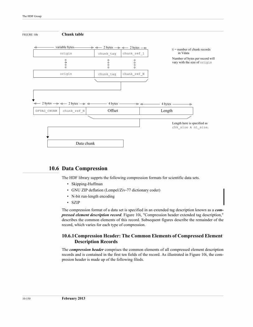
10-150 February 2013
The HDF Group
FIGURE 10h Chunk table
10.6 Data Compression
The HDF library supprts the following compression formats for scientific data sets.
• Skipping-Huffman
• GNU ZIP deflation (Lempel/Ziv-77 dictionary coder)
• N-bit run-length encoding
• SZIP
The compression format of a data set is specified in an extended tag description known as a com-pressed element description record. Figure 10i, "Compression header extended tag description," describes the common elements of this record. Subsequent figures describe the remainder of the record, which varies for each type of compression.
10.6.1Compression Header: The Common Elements of Compressed Element Description Records
The compression header comprises the common elements of all compressed element description records and is contained in the first ten fields of the record. As illustrated in Figure 10i, the com-presion header is made up of the following fileds.
2 bytes 2 bytesvariable bytes
Data chunk
origin chunk_ref_1chunk_tag
origin chunk_ref_Nchunk_tag
N = number of chunk records in Vdata
Number of bytes per record willvary with the size of origin
2 bytes 2 bytes 4 bytes 4 bytes
chunk_ref_NDFTAG_CHUNK Offset Length
Length here is specified as chk_size x nt_size.
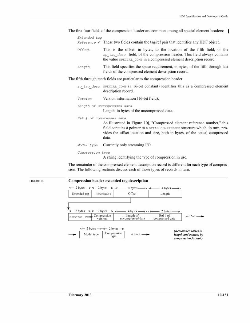
HDF Specification and Developer’s Guide
February 2013 10-151
The first four fields of the compression header are common among all special element headers:
Extended tagReference # These two fields contain the tag/ref pair that identifies any HDF object.
Offset This is the offset, in bytes, to the location of the fifth field, or the sp_tag_desc field, of the compression header. This field always contains the value SPECIAL_COMP in a compressed element description record.
Length This field specifies the space requirement, in bytes, of the fifth through last fields of the compressed element description record.
The fifth through tenth fields are particular to the compression header:
sp_tag_desc SPECIAL_COMP (a 16-bit constant) identifies this as a compressed element description record.
Version Version information (16-bit field).
Length of uncompressed dataLength, in bytes of the uncompressed data.
Ref # of compressed dataAs illustrated in Figure 10j, "Compressed element reference number," this field contains a pointer to a DFTAG_COMPRESSED structure which, in turn, pro-vides the offset location and size, both in bytes, of the actual compressed data.
Model type Currently only streaming I/O.
Compression typeA string identifying the type of compression in use.
The remainder of the compressed element description record is different for each type of compres-sion. The following sections discuss each of those types of records in turn.
FIGURE 10i Compression header extended tag description
4 bytes2 bytes
(Remainder varies in length and content bycompression format.)
Offset LengthExtended tag Reference #
2 bytes 4 bytes
2 bytes2 bytes
Length ofSPECIAL_COMP Compression
2 bytes 4 bytes
version uncompressed dataRef # of
compressed data
2 bytes
Compression
2 bytes
typeModel type
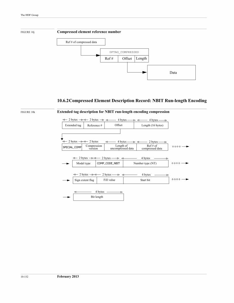
10-152 February 2013
The HDF Group
FIGURE 10j Compressed element reference number
10.6.2Compressed Element Description Record: NBIT Run-length Encoding
FIGURE 10k Extended tag description for NBIT run-length encoding compression
DFTAG_COMPRESSED
Ref # Offset Length
Data
Ref # of compressed data
4 bytes2 bytes
Offset Length (16 bytes)Extended tag Reference #
2 bytes 4 bytes
2 bytes2 bytes
Length ofSPECIAL_COMP Compression
2 bytes 4 bytes
version uncompressed dataRef # of
compressed data
2 bytes2 bytes
Model type COMP_CODE_NBIT Number type (NT)
Sign extent flag Start bitFill value
4 bytes
2 bytes2 bytes 4 bytes
Bit length
4 bytes
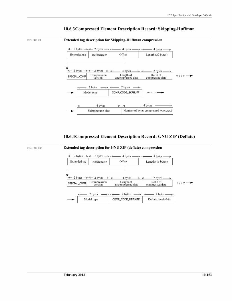
HDF Specification and Developer’s Guide
February 2013 10-153
10.6.3Compressed Element Description Record: Skipping-Huffman
FIGURE 10l Extended tag description for Skipping-Huffman compression
10.6.4Compressed Element Description Record: GNU ZIP (Deflate)
FIGURE 10m Extended tag description for GNU ZIP (deflate) compression
4 bytes2 bytes
Offset Length (22 bytes)Extended tag Reference #
2 bytes 4 bytes
2 bytes2 bytes
Length ofSPECIAL_COMP Compression
2 bytes 4 bytes
version uncompressed dataRef # of
compressed data
2 bytes
Model type COMP_CODE_SKPHUFF
2 bytes
4 bytes
Skipping unit size
4 bytes
Number of bytes compressed (not used)
4 bytes2 bytes
Offset Length (16 bytes)Extended tag Reference #
2 bytes 4 bytes
2 bytes2 bytes
Length ofSPECIAL_COMP Compression
2 bytes 4 bytes
version uncompressed dataRef # of
compressed data
2 bytes
Model type COMP_CODE_DEFLATE Deflate level (0-9)
2 bytes2 bytes
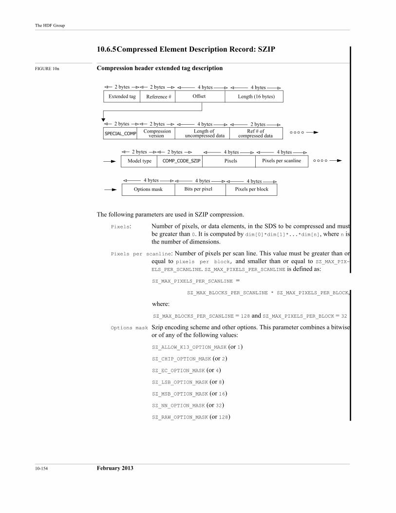
10-154 February 2013
The HDF Group
10.6.5Compressed Element Description Record: SZIP
FIGURE 10n Compression header extended tag description
The following parameters are used in SZIP compression.
Pixels: Number of pixels, or data elements, in the SDS to be compressed and must be greater than 0. It is computed by dim[0]*dim[1]*...*dim[n], where n is the number of dimensions.
Pixels per scanline: Number of pixels per scan line. This value must be greater than or equal to pixels per block, and smaller than or equal to SZ_MAX_PIX-ELS_PER_SCANLINE. SZ_MAX_PIXELS_PER_SCANLINE is defined as:
SZ_MAX_PIXELS_PER_SCANLINE =
SZ_MAX_BLOCKS_PER_SCANLINE * SZ_MAX_PIXELS_PER_BLOCK,
where:
SZ_MAX_BLOCKS_PER_SCANLINE = 128 and SZ_MAX_PIXELS_PER_BLOCK = 32
Options mask Szip encoding scheme and other options. This parameter combines a bitwise or of any of the following values:
SZ_ALLOW_K13_OPTION_MASK (or 1)
SZ_CHIP_OPTION_MASK (or 2)
SZ_EC_OPTION_MASK (or 4)
SZ_LSB_OPTION_MASK (or 8)
SZ_MSB_OPTION_MASK (or 16)
SZ_NN_OPTION_MASK (or 32)
SZ_RAW_OPTION_MASK (or 128)
4 bytes2 bytes
Offset Length (16 bytes)Extended tag Reference #
2 bytes 4 bytes
2 bytes2 bytes
Length ofSPECIAL_COMP Compression
2 bytes 4 bytes
version uncompressed dataRef # of
compressed data
2 bytes2 bytes
Model type COMP_CODE_SZIP Pixels Pixels per scanline
Options mask Pixels per blockBits per pixel
4 bytes 4 bytes
4 bytes 4 bytes 4 bytes
HDF Specification and Developer’s Guide
February 2013 10-155
Bits per pixel: The number of bits in the SDS number type, e.g., if the SDS’ number type is DFNT_FLOAT, the bits per pixel of this SDS will be 32. This parameter must be either 8, 16, 32, or 64.
Pixels per block: Number of data elements in an szip block. Must be even and smaller than or equal to pixels per scanline and smaller than and equal to SZ_-MAX_PIXELS_PER_BLOCK (32.)
The two parameters Options mask and Pixels per block are required when setting compression for SZIP. If any of the other parameters are not provided, they will be computed by HCPset-up_szip_parms.
The SZIP source code can be found at ftp://ftp.hdfgroup.org/lib-external/szip for fur-ther reference.

10-156 February 2013
The HDF Group
February 2013 11-155
CHAPTER 11 -- Portability Issues
11.1 Chapter Overview
The NCSA implementation of HDF is accessible to both C and FORTRAN programs and is implemented on many different machines and several operating systems. There are important dif-ferences between C and FORTRAN, and among implementations of each language, especially FORTRAN. There are also important differences among the machines and operating systems that HDF supports.
If HDF is to be a portable tool, these differences must be constructively addressed. This chapter describes many of these differences, discusses the problems and issues associated with them, and presents the methods employed in the HDF implementation to reduce their impact.
11.2 The HDF Environment
The list of machines and operating systems on which HDF is implemented is steadily growing. For reasons that this chapter will make clear, the number of NCSA-supported HDF platforms is growing slowly. Every time a platform is added, additional code must be written to address con-cerns of memory management, operating system and file system differences, number representa-tions, and differences in FORTRAN and C implementations on that system.
11.2.1Supported Platforms
As of this writing, NCSA supports the platforms listed in Table 11a.
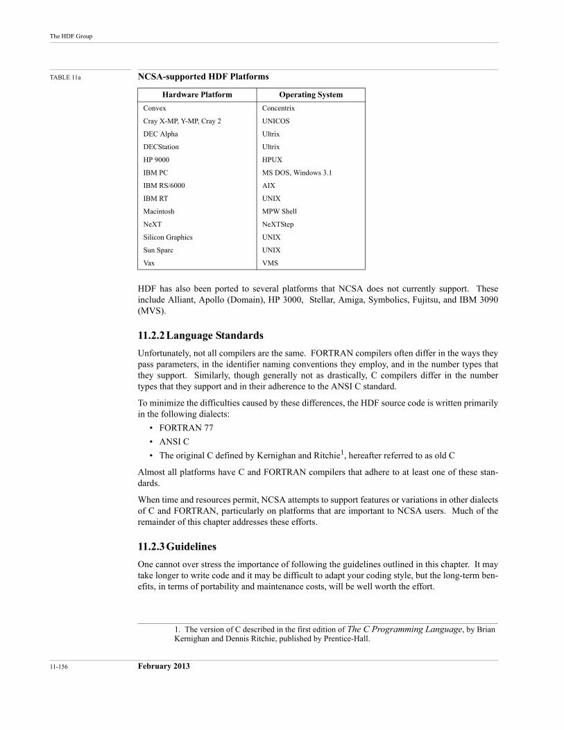
11-156 February 2013
The HDF Group
TABLE 11a NCSA-supported HDF Platforms
HDF has also been ported to several platforms that NCSA does not currently support. These include Alliant, Apollo (Domain), HP 3000, Stellar, Amiga, Symbolics, Fujitsu, and IBM 3090 (MVS).
11.2.2Language Standards
Unfortunately, not all compilers are the same. FORTRAN compilers often differ in the ways they pass parameters, in the identifier naming conventions they employ, and in the number types that they support. Similarly, though generally not as drastically, C compilers differ in the number types that they support and in their adherence to the ANSI C standard.
To minimize the difficulties caused by these differences, the HDF source code is written primarily in the following dialects:
• FORTRAN 77
• ANSI C
• The original C defined by Kernighan and Ritchie1, hereafter referred to as old C
Almost all platforms have C and FORTRAN compilers that adhere to at least one of these stan-dards.
When time and resources permit, NCSA attempts to support features or variations in other dialects of C and FORTRAN, particularly on platforms that are important to NCSA users. Much of the remainder of this chapter addresses these efforts.
11.2.3Guidelines
One cannot over stress the importance of following the guidelines outlined in this chapter. It may take longer to write code and it may be difficult to adapt your coding style, but the long-term ben-efits, in terms of portability and maintenance costs, will be well worth the effort.
Hardware Platform Operating System
Convex Concentrix
Cray X-MP, Y-MP, Cray 2 UNICOS
DEC Alpha Ultrix
DECStation Ultrix
HP 9000 HPUX
IBM PC MS DOS, Windows 3.1
IBM RS/6000 AIX
IBM RT UNIX
Macintosh MPW Shell
NeXT NeXTStep
Silicon Graphics UNIX
Sun Sparc UNIX
Vax VMS
1. The version of C described in the first edition of The C Programming Language, by Brian Kernighan and Dennis Ritchie, published by Prentice-Hall.
HDF Specification and Developer’s Guide
February 2013 11-157
11.3 Organization of Source Files
Three types of files appear in the HDF source code directory:
• Header files
• Source code files
• Configuration files
Header files and source code files are organized by application area. All of the functions that apply to a particular application area are stored in three source files, and all the definitions and declarations that apply to that application are stored in a corresponding header file. The makefile describes the dependencies among the source and header files and provides the commands required to compile the corresponding libraries and utilities.
11.3.1Header Files
Certain application modules require header files. The header file dfan.h, for example, contains definitions and declarations that are unique to the annotation interface.
There are also several general header files that are used in compiling the libraries for all applica-tion areas:
hdf.h and hdfi.h1hdf.h contains declarations and definitions for the common data structures used throughout HDF, definitions of the HDF tags, definitions of error num-bers, and definitions and declarations specific to the low level interface. Since hdf.h depends on hdfi.h, it includes hdfi.h via #include.
hdfi.h contains information specific to the various NCSA-supported HDF computing environments, environmental parameters that need to be set to particular values when compiling the HDF libraries, and machine dependent definitions of such things as number types and macros for reading and writ-ing numbers.
When porting HDF to a new system, only hdfi.h and the makefile should need to be modified, though there may be exceptions.
It is normally a good idea to include hdf.h (and therefore indirectlyhdfi.h) in user programs, though users usually need not be aware of its con-tents.
hproto.h This file contains ANSI C prototypes for all HDF C routines. It must be included in ANSI C programs that call HDF routines.
constants.i This file is for use in FORTRAN programs. It contains important constants, such as tag values, that are defined in hdf.h. Systems with FORTRAN pre-processors might be able to include this file via #include statements or their equivalent.
dffunc.i This file is for use in FORTRAN programs. It contains declarations of all HDF FORTRAN-callable functions. Systems with FORTRAN preproces-
1. Prior to Version 3.2 of HDF, these files were called df.h and dfi.h. At the time of HDF Version 3.2, the low level interfaces, the general purpose layer of HDF, was completely rewritten and all routine names were changed from df* to hdf*.
11-158 February 2013
The HDF Group
sors might be able to include this file via #include statements or their equivalent.
11.3.2Source Code Files
All HDF operations are performed by routines written in C. Hence, even FORTRAN calls to HDF result in calls to the corresponding C routines. Because of the problems described below the relationships between the C routines and the corresponding FORTRAN routines can be confusing. This section discusses the C and FORTRAN source file organization. It is followed by discus-sions of problems users will face in the FORTRAN–C interface.
HDF interfaces typically have three or four associated files. For example, the scientific data set (SDS) interface is associated with the following files: dfsd.h, dfsd.c, dfsdf.c, and dfsdff.f.
These files fill the following roles:
Header filesThe *.h files are header files.
Normal C routinesThese routines do the actual HDF work. The others are used to transfer control and data from a FORTRAN environment to a C environment.
These routines are in the *.c files, as in dfsd.c. Every call to HDF, whether from C or FORTRAN, ultimately results in a call to one of these routines.
C routines that are directly callable from FORTRANThese routines provide recognizable function names to the linker. They may also per-form operations on data they receive from the FORTRAN routines that call them, such as transferring a FORTRAN string to a local C data area. Examples are provided below.
These routines are in the *f.c files, such as dfsdf.c. The f means that the routines can be called from FORTRAN; the .c means that they are C source code.
FORTRAN routines that perform some operation on the parameters that C would be unable to perform, before and/or after calling the corresponding C routineThese routines are required, for example, when one of the parameters is a string. The corresponding C routine has no way of knowing the length of the string unless it is explicitly given the length by the FORTRAN routine.
These routines are in the *ff.f files, such as dfsdff.f. The ff means that the rou-tines perform some FORTRAN operation that C cannot perform and that they are to be called from FORTRAN; the .f means that they are FORTRAN source code.
The roles of these different types of source file types will become clearer as we look at some of the problems that arise in interfacing C and many different implementations of FORTRAN.
11.3.3File Naming Conventions
The naming conventions for HDF library source code files are complicated by several factors. Because HDF must accommodate a wide variety of platforms, all files that will compile to object modules must have names that are unique in the first 8 characters, ignoring case. The difficulties involved in maintaining a FORTRAN-callable interface to a library that is primarily written in C further complicate the naming of source code files.
HDF Specification and Developer’s Guide
February 2013 11-159
11.4 Passing Strings between FORTRAN and C
One of the most important differences between FORTRAN and C compilers is in the way strings are represented. Different compilers use different data structures for strings, and supply string length information in different ways.
11.4.1Passing Strings from FORTRAN to C
When strings are passed between FORTRAN and C routines, they may need to be converted from one representation to the other. C compilers store strings in an array of type char, terminated by a null byte (\0). The name of a string variable is equivalent to a pointer the first character in the string. FORTRAN compilers are not consistent in the ways that they store strings.
Two pieces of information must be acquired before FORTRAN can pass a string to C:
• The string’s length
• The string’s address
The string’s length is determined by invoking the standard FORTRAN function len(), which returns the length of a string. Since C expects a null byte at the end of a string, care must be taken that this null byte does not overwrite useful information in the FORTRAN string.
Determining the string’s address is more difficult because of the different ways that different FORTRAN implementations store strings. The macro _fcdtocp (FORTRAN character descrip-tor to C pointer) is used to acquire this information. _fcdtocp is one of the elements that must be customized for each platform. The following paragraphs discuss several existing customized implementations:
• UNICOS FORTRAN stores strings in a structure called _fcd (FORTRAN character descriptor). _fcdtocp is a built-in UNICOS function that returns the string’s address. (Since UNICOS provides this function, HDF omits the corresponding macro definition on UNICOS systems.
• VMS FORTRAN uses a string descriptor structure that provides the string’s address and length. When compiled under VMS, _fcdtocp extracts the string's address from that struc-ture.
• Most other FORTRAN compilers supported by HDF store strings just as C does, in charac-ter arrays with the array name identifying the array's address. In such situations, nothing special needs to be done to pass a string from FORTRAN to C, except to add a NULL byte.
An HDF FORTRAN call that involves passing a string results in the following sequence of actions:
1 A FORTRAN filter routine determines the length and address in memory of the string. Since this filter is a FORTRAN routine, it can be found in the appropriate *ff.f file.
2 The FORTRAN filter then calls a C routine, to which it passes all parameters from the initial call the string's length.
3 The C routine converts the FORTRAN string to a C string by copying it to a C array of type char and appending a null byte. Since this C routine serves as a link between a FORTRAN filter and the corresponding C interface call, it can be found in the appropriate *f.c file.
4 This C routine then calls the HDF C routine that performs the actual work.
This process is illustrated in Figure 11a, "Sequence of Events when a FORTRAN Call Includes a String as a Parameter."
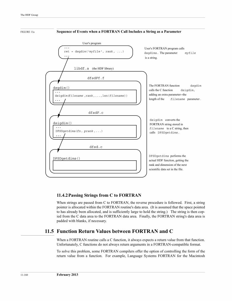
...
ret = dsgdim(' ', , ...)
...
User's program
dfsdFf.f
dfsdF.c
dfsd.c
libdf.a (the HDF library)
User's FORTRAN program calls
dsgdims. The parameter
is a string.
dsgdim()
...
dsigdim( , ,...,len( ))
...
The FORTRAN function dsgdim
calls the C function dsigdim,
adding an extra parameter--the
length of the filename parameter .
...
DFSDgetdims( , ,...)
...
dsigdim()
DFSDgetdims() DFSDgetdims performs the
actual HDF function, getting the
rank and dimension of the next
scientific data set in the file.
dsigdim converts the
FORTRAN string stored in filename to a C string, then calls DFSDgetdims.
myfilemyfile
filenamefilename rank
fn prank
rank
11-160 February 2013
The HDF Group
FIGURE 11a Sequence of Events when a FORTRAN Call Includes a String as a Parameter
11.4.2Passing Strings from C to FORTRAN
When strings are passed from C to FORTRAN, the reverse procedure is followed. First, a string pointer is allocated within the FORTRAN routine's data area. (It is assumed that the space pointed to has already been allocated, and is sufficiently large to hold the string.) The string is then cop-ied from the C data area to the FORTRAN data area. Finally, the FORTRAN string's data area is padded with blanks, if necessary.
11.5 Function Return Values between FORTRAN and C
When a FORTRAN routine calls a C function, it always expects a return value from that function. Unfortunately, C functions do not always return arguments in a FORTRAN-compatible format.
To solve this problem, some FORTRAN compilers offer the option of controlling the form of the return value from a function. For example, Language Systems FORTRAN for the Macintosh
HDF Specification and Developer’s Guide
February 2013 11-161
requires that all C function declarations be prepended by the word pascal so that the return value can be recognized by a FORTRAN routine that calls it, as in:
pascal int dsgrang(void *pmax, void *pmin)
Since C always expects return values to be passed by value rather than, say, by reference, it is important to coerce FORTRAN functions to do the same. This is accomplished by defining a macro FRETVAL that is prepended to the declaration of every FORTRAN-callable C function. For example:
FRETVAL(int)dsgrang(void *pmax, void *pmin)
If Language Systems FORTRAN is to be used, FRETVAL is defined in hdfi.h as follows:
#if defined(MAC) /* with LS FORTRAN */# define FRETVAL(x) pascal x#endif
11.6 Differences in Routine Names
HDF generally employs standard C conventions in naming routines. But many FORTRAN com-pilers impose varying restrictions on the length, character set, and form of identifiers, some of which are considerable more restrictive than the C conventions. Therefore, an extra effort must be made to accommodate those FORTRAN compilers.
To address this issue, HDF defines a set of preprocessor flags in hdfi.h. Then conditional com-pilation, with #ifdef statements in the source code, produces routine names that the target sys-tem’s FORTRAN will understand.
11.6.1Case Sensitivity
C compilers are case sensitive; uppercase and lowercase letters are recognized as different charac-ters. Many FORTRAN compilers are not case sensitive; they allow users to use uppercase and lowercase letters while naming routines in the source code, but the names are converted to all uppercase or all lowercase in the object module symbol tables. Routine name recognition prob-lems are common when routines compiled by a case sensitive compiler are to be linked with rou-tines compiled by a non-case sensitive compiler.
For example, the UNICOS FORTRAN compiler allows you to name routines without regard to case, but produces object module symbol tables with the routine names in all uppercase. UNI-COS C, on the other hand, performs no such conversion.
Consider the HDF routine Hopen. Hopen is written in C, so the HDF library symbol table con-tains the name Hopen. Suppose you make the following call in your UNICOS FORTRAN pro-gram:
file_id = Hopen('myfile', ...)
The FORTRAN compiler will create an object module symbol table with the routine name HOPEN. When you link it to the HDF library, it will find Hopen but not HOPEN, and will generate an unsat-isfied external reference error.
HDF supports the following non-case sensitive compilers:
• VMS FORTRAN
• UNICOS FORTRAN
• Language Systems FORTRAN.
11-162 February 2013
The HDF Group
All of these compilers convert identifiers to all uppercase when building an object module symbol table. In the following discussion, they are referred to as all-uppercase compilers.
The HDF Solution
HDF addresses the all-uppercase compiler problem in the platform-specific section of hdfi.h where the DF_CAPFNAMES flag is defined. With conditional compilation, HDF generates all-uppercase routine names and symbol table entries.
Once again, consider UNICOS. The UNICOS section of hdfi.h contains the following line:
#define DF_CAPFNAMES
The *f.c files contain corresponding conditional sections that produce all-uppercase routine names. For example, the function name Fun can be redefined as FUN:
#ifdef DF_CAPFNAMESdefine Fun FUN
#endif /* DF_CAPFNAMES */
11.6.2Appended Underscores
Differing compiler conventions create a similar problem in their use of the underscore ( _ ) char-acter. Many compilers, including most C compilers, prepend an underscore to all external sym-bols in the object module symbol table. The linker then looks for external symbols in other symbol tables with the prefixed underscore.
Many FORTRAN compilers also append an underscore to identify external symbols. Since C compilers do not generally do this, external references in FORTRAN-generated object modules will not recognize externals with the same names in C-generated modules.
For example, the FORTRAN compiler on the CONVEX system places an underscore both at the beginning and at the end of routine names, while the C compiler places an underscore only at the beginning.
Since FUN is a C function, it appears under the name _FUN in the object module containing it. Now suppose you make the following call in a FORTRAN program:
x = FUN(y)
The FORTRAN compiler will create an object module symbol table with the routine name _FUN_. When you link it to the C module, the linker will be unable to link _FUN and _FUN_ and will gen-erate an unsatisfied external reference error.
The HDF Solution
Like the all-uppercase compiler problem, this issue is resolved in the platform-specific sections ofhdfi.h and with conditional sections of code that append an underscore to C routine names on platforms where the FORTRAN compiler expects it.
This is implemented as follows: The FNAME_POST_UNDERSCORE flag is defined in the platform-specific section of hdfi.h for every platform whose FORTRAN compiler requires appended underscores. Similarly, the FNAME_PRE_UNDERSCORE flag is defined on platforms where the FOR-TRAN compiler expects prepended underscores. The macro FNAME is then defined to append and/or prepend underscores as required.
The FNAME macro is then applied to each routine in the module in which it is actually defined (including in hptroto.h), adding the appropriate underscores.
HDF Specification and Developer’s Guide
February 2013 11-163
Consider the above example in which Fun was renamed FUN. The actual definition appears as follows:
#ifdef DF_CAPFNAMESdefine Fun FNAME(FUN)
#endif /* DF_CAPFNAMES */
11.6.3Short Names vs. Long Names
In the C implementations supported by HDF, identifiers may be any length with at least the first 31 characters being significant. FORTRAN compilers differ in the maximum lengths of identifi-ers that they allow, but all of those supported by HDF allow identifiers to be at least seven charac-ters long.
To deal with the discrepancies between identifier lengths allowed by C and those allowed by the various FORTRAN compilers, a set of equivalent short names has been created for use when pro-gramming in FORTRAN. For every HDF routine with a name more than seven characters long, there is an identical routine whose name is seven or fewer characters long.
For example, the routines DFSDgetdims (in dfsd.c) and dsgdims (in dfsdff.f) are function-ally identical.
11.7 Differences Between ANSI C and Old C
The current HDF release supports both ANSI C and old C compilers. ANSI C is preferred because it has many features that help ensure portability; unfortunately, many important platforms do not support full ANSI C. The HDF code determines whether ANSI C is available from the flag__STDC__. If ANSI C is available on a platform, then __STDC__ is defined by the compiler.1
The most noticeable difference between ANSI C and old C is in the way functions are declared. For example, in ANSI C the function DFSDsetdims() is declared with a single line:
int DFSDsetdims(intn rank, int32 dimsizes[])
In old C the same function is declared as follows:
int DFSDsetdims(rank, dimsizes)intn rank;int32 dimsizes[];
HDF accommodates these differences by defining the flag PROTOTYPE in hdfi.h. PROTOTYPE is used for every function declaration in a manner similar to the following example:
#ifdef PROTOTYPEint DFSDsetdims(intn rank, int32 dimsizes[])#elseint DFSDsetdims(rank, dimsizes)intn rank;int32 dimsizes[];#endif /* PROTOTYPE */
Note that prototypes are supported by some C compilers that are not otherwise ANSI-conformant. In such situations, PROTOTYPE is defined even though __STDC__ is not.
1. __STD__ is generally defined by ANSI-conforming C compilers. Some C compilers are not entirely ANSI-conforming, yet they conform well enough that the HDF implementation can treat them as if they were. In such cases, it is permissible to define __STDC__ by adding the option -D__STDC__ to the cc line in the makefile.
11-164 February 2013
The HDF Group
Another difference between old C and ANSI C is that ANSI C supports function prototypes with arguments. (Old C also supports function prototypes, but without the argument list.) This feature helps in detecting errors in the number and types of arguments. This difference is handled by means of a macro PROTO, which is defined as follows:
#ifdef PROTOTYPE#define PROTO(x) x#else#define PROTO(x) ()#endif
This macro is applied as in the following example:
extern int32 HopenPROTO((char *path, intn access, int16 ndds));
When PROTOTYPE is defined, PROTO causes the argument list to stay as it is. When PROTOTYPE is not defined, PROTO causes the argument list to disappear.
11.8 Type Differences
Platforms and compilers also differ in the sizes of numbers that they assign to different data types, in their representations of different number types, and in the way they organize aggregates of numbers (especially structures).
11.8.1Size differences
The same number type can be different sizes on different platforms. The type int, for example, is 16 bits to many IBM PC compilers, 48 bits to some supercomputer compilers, and 32 bits on most others. This can cause problems that are difficult to diagnose in code like the HDF code, which depends in many places on numbers being the right size.
HDF handles this problem by fully defining all variable types and function data types viatypedef, including the number of bits occupied. All parameters, members of structures, and static, automatic, and external variables are so defined .
The HDF data types include the following (types with the prefix u are unsigned).
int8uint8int16uint16int32uint32float32float64intnuintn
For each machine, typedefs are declared that map all of the data types used into the best available types. For example, int32 is defined as follows for Sun's C compiler:
typedef long int int32;
HDF Specification and Developer’s Guide
February 2013 11-165
Unfortunately, the HDF data types do not always map exactly to one of the native data types. For example, the Cray UNICOS C compiler does not support a 16-bit data type. In such instances, HDF uses the best available match and care is taken to minimize potential problems.
The data types intn and uintn are for situations where it can be determined that number type size is unimportant and that a 16-bit integer is large enough to hold any value the number can have. In such cases, the native integer type (or unsigned integer type) of the host machine is used. Experience indicates that substantial performance gains can be achieved by using intn or uintn in certain circumstances.
11.8.2Number Representation
One of the keys to producing a portable file format is to ensure that numbers that are represented differently on different machines are converted correctly when moved from machine to machine. HDF provides conversion routines to convert between native representations and a standard repre-sentation that is actually used in the HDF file. This ensures that HDF data will always be inter-preted correctly, regardless of the platform on which it is read or written. Details of this process will be included in a later edition of this manual.
11.8.3Byte-order and Structure Representations
Even when the basic bit-representation of constants or aggregates like structures is the same across platforms, the ways that the bits are packed into a word and the order in which the bits are laid out can differ. For example, DEC and Intel-based machines generally order bytes differently from most others. And the C compiler on a Cray, with a 64-bit word, packs structures differently from those on 32-bit word machines.
Differences in byte order among machines are handled in either of two ways. When the data to be written (or read) includes non-integer data and/or a large array of any type of data, conversion routines mentioned in the previous section, “Number Representation,” are invoked. When an individual integer is to be written (or read), an ENCODE or DECODE macro is used.
The following ENCODE and DECODE macros are available for 16-bit and 32-bit integers:
INT16ENCODEUINT16ENCODEINT32ENCODEUINT32ENCODEINT16DECODEUINT16DECODEINT32DECODEUINT32DECODE
The ENCODE macros write integers to an HDF file in a standard format regardless of the word-size and byte order of the host machine.
Likewise, the DECODE macros read integers from a standard format in an HDF file and provide the integers in the required byte order and word size to the host machine.
Since the ENCODE and DECODE macros deal with both byte order and word size, they are also used in reading and writing record-like structures. For example, an HDF data descriptor consists of two 16-bit fields followed by two 32-bit fields, as implied by the following C declaration:
struct {uint16 tag;uint16 ref;uint32 offset;
11-166 February 2013
The HDF Group
uint32 length;}
Even though this structure might occupy 12 bytes on one platform or 32 bytes on another (e.g., a Cray), it must occupy exactly 12 bytes in an HDF file. Furthermore, some machines represent the numbers internally in different byte orders than others, but the byte order must always be big-endian in an HDF file. The ENCODE and DECODE macros ensure that these values are always rep-resented correctly in HDF files and as presented to any host machine.
11.9 Access to Library Functions
Despite standardization efforts, function libraries often differ in significant ways. At least three types of functions require special treatment in the HDF implementation:
File I/OSome platforms use 16-bit values for the element size and the number of elements to write or read, while others use 32-bit values. This must be considered when working with either stream or system level I/O functions (i.e., the functions associated with thefopen() and open() calls).
Memory allocation and releaseFirst, 16-bit machines use a 16-bit value to indicate the number of bytes to allocate or release at one time. Second, certain operating systems (notably MS Windows and MAC/OS) don't have malloc() and free() calls. These operating systems use handles for allocating memory and require different function calls.
Memory and string manipulationThese functions (e.g., memcpy(), memcmp(), strcpy(), and strlen()) require slightly different function names under different memory models in MS DOS and under MS Windows than on most other systems.
HDF accommodates these special situations by defining appropriate macros in the machine-spe-cific sections of hdfi.h.
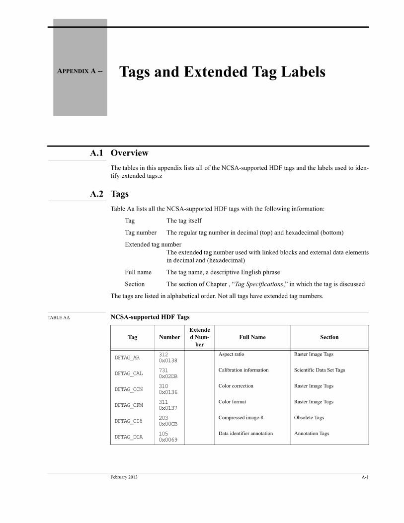
February 2013 A-1
APPENDIX A -- Tags and Extended Tag Labels
A.1 Overview
The tables in this appendix lists all of the NCSA-supported HDF tags and the labels used to iden-tify extended tags.z
A.2 Tags
Table Aa lists all the NCSA-supported HDF tags with the following information:
Tag The tag itself
Tag number The regular tag number in decimal (top) and hexadecimal (bottom)
Extended tag numberThe extended tag number used with linked blocks and external data elements in decimal and (hexadecimal)
Full name The tag name, a descriptive English phrase
Section The section of Chapter , “Tag Specifications,” in which the tag is discussed
The tags are listed in alphabetical order. Not all tags have extended tag numbers.
TABLE AA NCSA-supported HDF Tags
Tag NumberExtended Num-
berFull Name Section
DFTAG_AR 312 0x0138
Aspect ratio Raster Image Tags
DFTAG_CAL 731 0x02DB
Calibration information Scientific Data Set Tags
DFTAG_CCN 310 0x0136
Color correction Raster Image Tags
DFTAG_CFM 311 0x0137
Color format Raster Image Tags
DFTAG_CI8 203 0x00CB
Compressed image-8 Obsolete Tags
DFTAG_DIA 105 0x0069
Data identifier annotation Annotation Tags
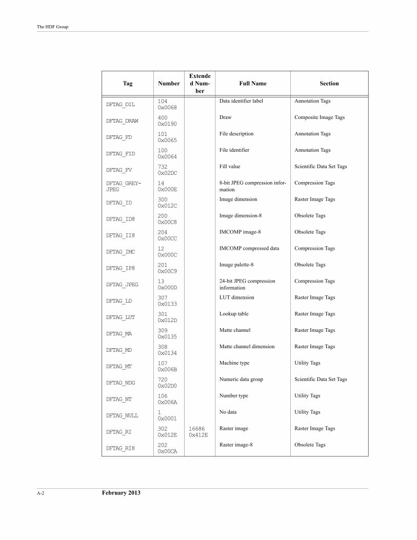
A-2 February 2013
The HDF Group
Tag NumberExtended Num-
berFull Name Section
DFTAG_DIL 104 0x0068
Data identifier label Annotation Tags
DFTAG_DRAW 400 0x0190
Draw Composite Image Tags
DFTAG_FD 101 0x0065
File description Annotation Tags
DFTAG_FID 100 0x0064
File identifier Annotation Tags
DFTAG_FV 732 0x02DC
Fill value Scientific Data Set Tags
DFTAG_GREY-JPEG
14 0x000E
8-bit JPEG compression infor-mation
Compression Tags
DFTAG_ID 300 0x012C
Image dimension Raster Image Tags
DFTAG_ID8 200 0x00C8
Image dimension-8 Obsolete Tags
DFTAG_II8 204 0x00CC
IMCOMP image-8 Obsolete Tags
DFTAG_IMC 12 0x000C
IMCOMP compressed data Compression Tags
DFTAG_IP8 201 0x00C9
Image palette-8 Obsolete Tags
DFTAG_JPEG 13 0x000D
24-bit JPEG compression information
Compression Tags
DFTAG_LD 307 0x0133
LUT dimension Raster Image Tags
DFTAG_LUT 301 0x012D
Lookup table Raster Image Tags
DFTAG_MA 309 0x0135
Matte channel Raster Image Tags
DFTAG_MD 308 0x0134
Matte channel dimension Raster Image Tags
DFTAG_MT 107 0x006B
Machine type Utility Tags
DFTAG_NDG 720 0x02D0
Numeric data group Scientific Data Set Tags
DFTAG_NT 106 0x006A
Number type Utility Tags
DFTAG_NULL 1 0x0001
No data Utility Tags
DFTAG_RI 302 0x012E
16686 0x412E
Raster image Raster Image Tags
DFTAG_RI8 202 0x00CA
Raster image-8 Obsolete Tags
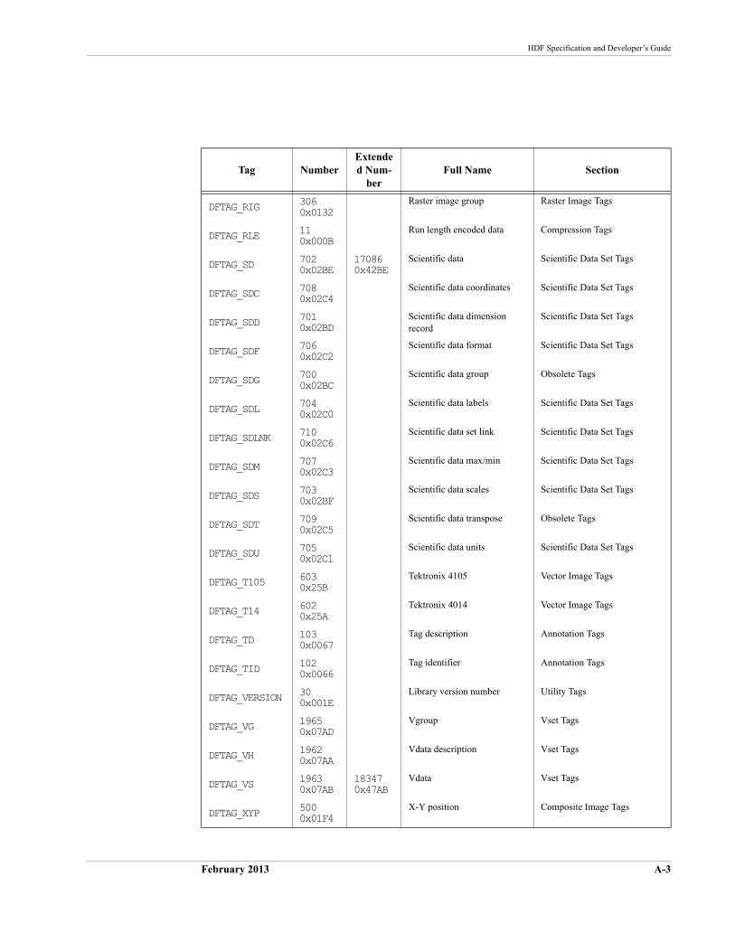
HDF Specification and Developer’s Guide
February 2013 A-3
Tag NumberExtended Num-
berFull Name Section
DFTAG_RIG 306 0x0132
Raster image group Raster Image Tags
DFTAG_RLE 11 0x000B
Run length encoded data Compression Tags
DFTAG_SD 702 0x02BE
17086 0x42BE
Scientific data Scientific Data Set Tags
DFTAG_SDC 708 0x02C4
Scientific data coordinates Scientific Data Set Tags
DFTAG_SDD 701 0x02BD
Scientific data dimension record
Scientific Data Set Tags
DFTAG_SDF 706 0x02C2
Scientific data format Scientific Data Set Tags
DFTAG_SDG 700 0x02BC
Scientific data group Obsolete Tags
DFTAG_SDL 704 0x02C0
Scientific data labels Scientific Data Set Tags
DFTAG_SDLNK 710 0x02C6
Scientific data set link Scientific Data Set Tags
DFTAG_SDM 707 0x02C3
Scientific data max/min Scientific Data Set Tags
DFTAG_SDS 703 0x02BF
Scientific data scales Scientific Data Set Tags
DFTAG_SDT 709 0x02C5
Scientific data transpose Obsolete Tags
DFTAG_SDU 705 0x02C1
Scientific data units Scientific Data Set Tags
DFTAG_T105 603 0x25B
Tektronix 4105 Vector Image Tags
DFTAG_T14 602 0x25A
Tektronix 4014 Vector Image Tags
DFTAG_TD 103 0x0067
Tag description Annotation Tags
DFTAG_TID 102 0x0066
Tag identifier Annotation Tags
DFTAG_VERSION 30 0x001E
Library version number Utility Tags
DFTAG_VG 1965 0x07AD
Vgroup Vset Tags
DFTAG_VH 1962 0x07AA
Vdata description Vset Tags
DFTAG_VS 1963 0x07AB
18347 0x47AB
Vdata Vset Tags
DFTAG_XYP 500 0x01F4
X-Y position Composite Image Tags
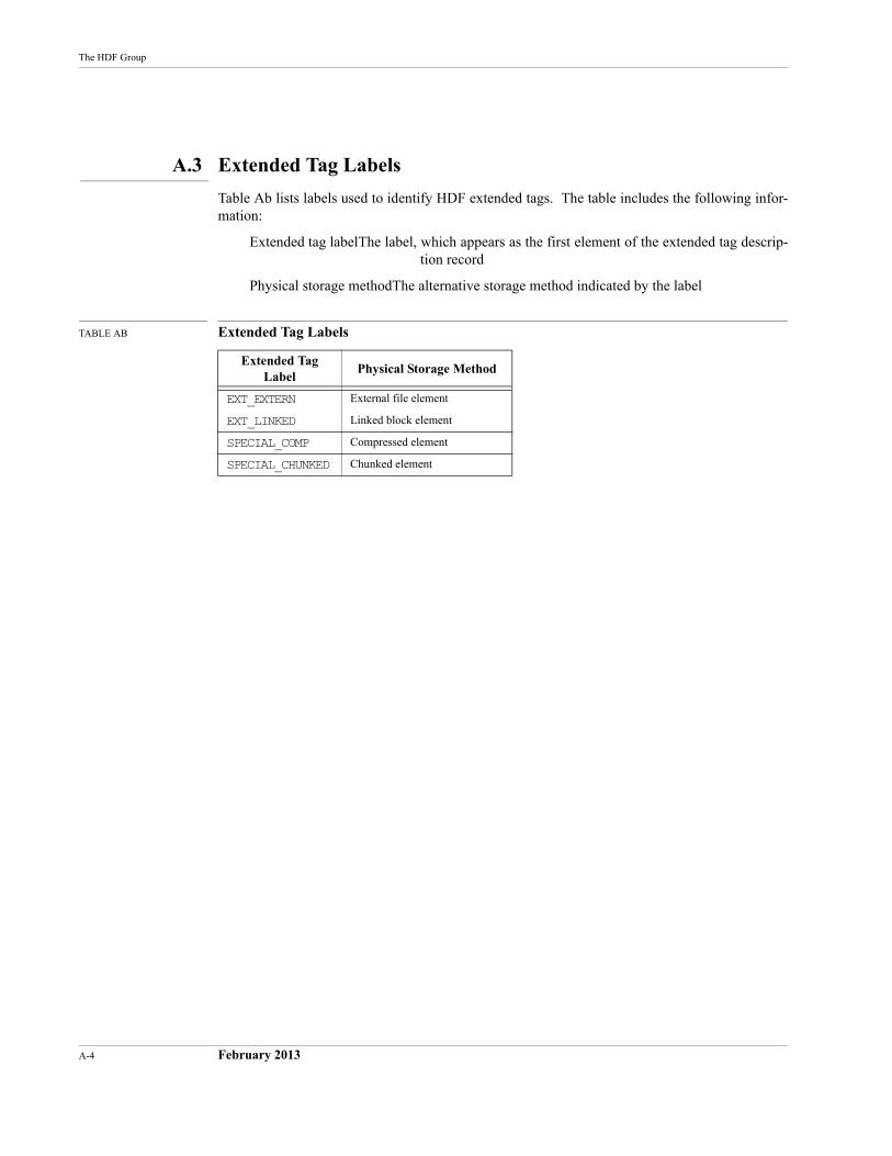
A-4 February 2013
The HDF Group
A.3 Extended Tag Labels
Table Ab lists labels used to identify HDF extended tags. The table includes the following infor-mation:
Extended tag labelThe label, which appears as the first element of the extended tag descrip-tion record
Physical storage methodThe alternative storage method indicated by the label
TABLE AB Extended Tag Labels
Extended Tag Label
Physical Storage Method
EXT_EXTERN External file element
EXT_LINKED Linked block element
SPECIAL_COMP Compressed element
SPECIAL_CHUNKED Chunked element
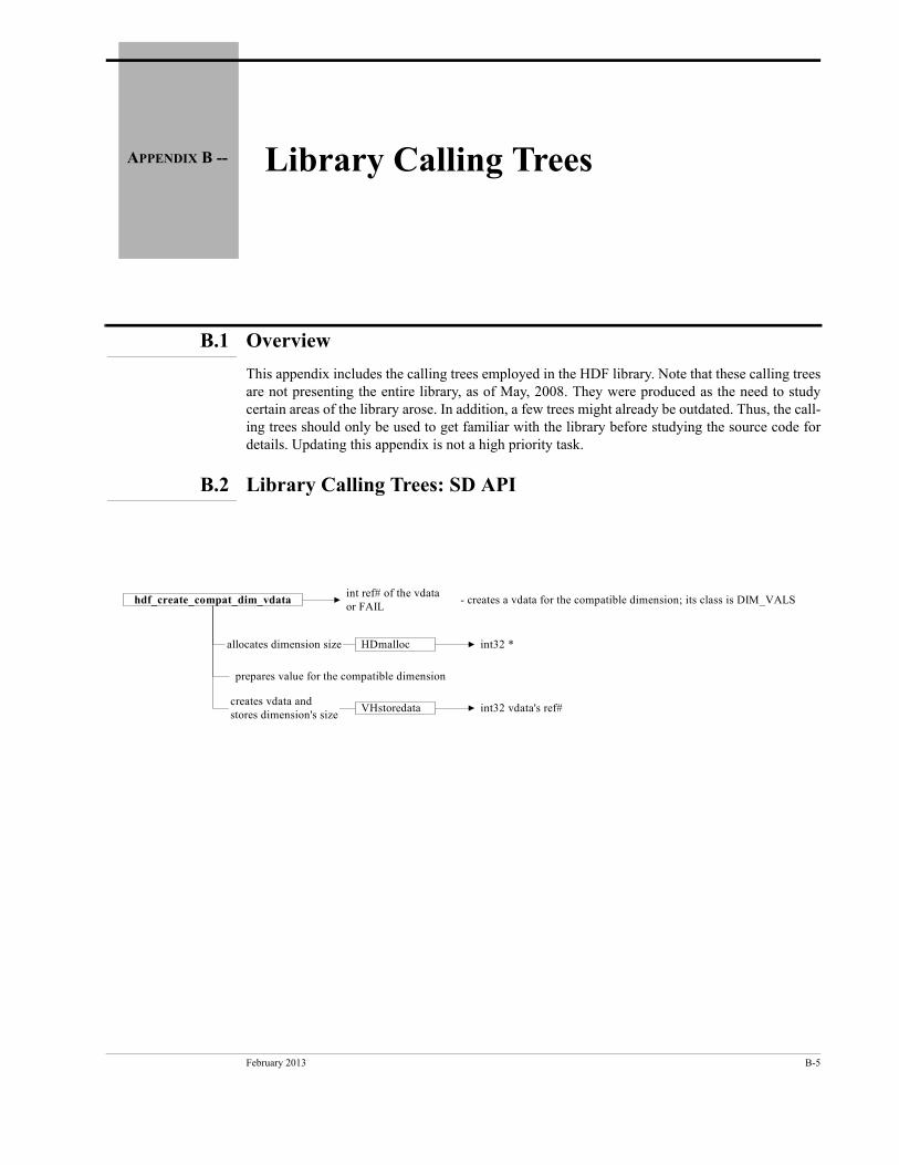
February 2013 B-5
APPENDIX B -- Library Calling Trees
B.1 Overview
This appendix includes the calling trees employed in the HDF library. Note that these calling trees are not presenting the entire library, as of May, 2008. They were produced as the need to study certain areas of the library arose. In addition, a few trees might already be outdated. Thus, the call-ing trees should only be used to get familiar with the library before studying the source code for details. Updating this appendix is not a high priority task.
B.2 Library Calling Trees: SD API
hdf_create_compat_dim_vdataint ref# of the vdataor FAIL
- creates a vdata for the compatible dimension; its class is DIM_VALS
VHstoredata int32 vdata's ref#creates vdata andstores dimension's size
allocates dimension size HDmalloc int32 *
prepares value for the compatible dimension
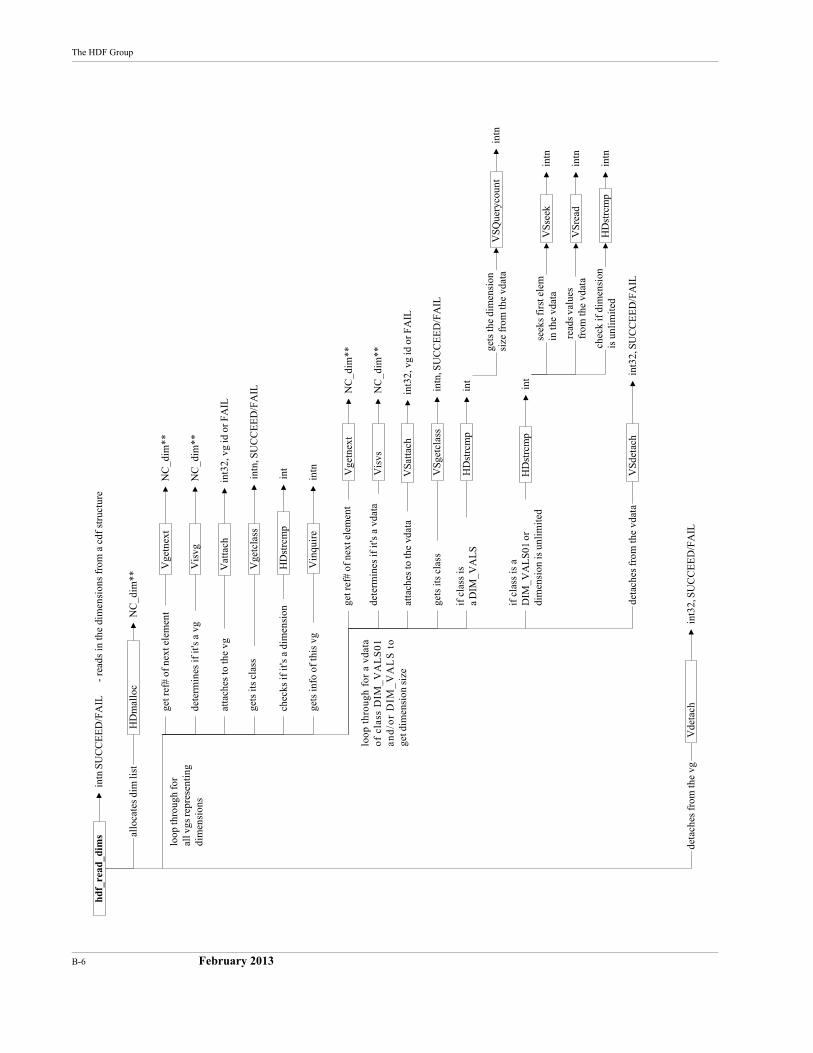
B-6 February 2013
The HDF Group
hdf
_rea
d_di
ms
HD
mal
loc
NC
_dim
**
intn
SU
CC
EE
D/F
AIL
- re
ads
in th
e di
men
sion
s fr
om a
cdf
str
uctu
re
Vge
tcla
ss
HD
strc
mp
int
intn
, SU
CC
EE
D/F
AIL
Vat
tach
int3
2, v
g id
or
FAIL
Vin
quir
e
deta
ches
fro
m th
e vg
intn
Vde
tach
int3
2, S
UC
CE
ED
/FA
IL
Vge
tnex
tN
C_d
im**
Vis
vgN
C_d
im**
get r
ef#
of n
ext e
lem
ent
dete
rmin
es if
it's
a v
g
atta
ches
to th
e vg
gets
its
clas
s
chec
ks if
it's
a d
imen
sion
gets
info
of
this
vg
allo
cate
s di
m li
st
loop
thro
ugh
for
all v
gs re
pres
enti
ngdi
men
sion
s
loop
thr
ough
for
a v
data
of
clas
s D
IM_V
AL
S01
and
/or
DIM
_V
AL
S t
oge
t dim
ensi
on s
ize
VSg
etcl
ass
HD
strc
mp
int
intn
, SU
CC
EE
D/F
AIL
VSa
ttac
hin
t32,
vg
id o
r FA
IL
Vge
tnex
tN
C_d
im**
Vis
vsN
C_d
im**
get r
ef#
of n
ext e
lem
ent
dete
rmin
es if
it's
a v
data
atta
ches
to th
e vd
ata
gets
its
clas
s
if c
lass
isa
DIM
_VA
LS
gets
the
dim
ensi
onsi
ze fr
om th
e vd
ata
HD
strc
mp
int
if c
lass
is a
DIM
_VA
LS0
1 or
dim
ensi
on is
unl
imit
edV
Ssee
kin
tnse
eks
firs
t ele
min
the
vdat
a
HD
strc
mp
intn
chec
k if
dim
ensi
onis
unl
imit
ed
VSr
ead
intn
read
s va
lues
from
the
vdat
a
VSd
etac
hin
t32,
SU
CC
EE
D/F
AIL
deta
ches
fro
m th
e vd
ata
VSQ
uery
coun
tin
tn
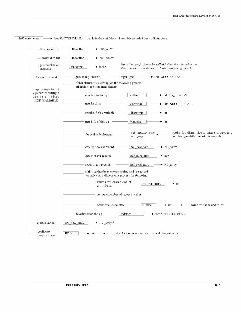
HDF Specification and Developer’s Guide
February 2013 B-7
hdf_read_vars
HDmalloc NC_var**
intn SUCCEED/FAIL - reads in the variables and variable records from a cdf structure
Vgetclass
HDstrcmp int
intn, SUCCEED/FAIL
Vattach int32, vg id or FAIL
Vinquire intn
NC_new_array NC_array *
Vgettagref intn, SUCCEED/FAILfor each element gets its tag and ref#
if this element is a vgroup, do the following process,otherwise, go to the next element
attaches to the vg
gets its class
checks if it's a variable
allocates var list
loop through for allvgs representing av a r i a b l e - c l a s s_HDF_VARIABLE
HDmalloc NC_dim**allocates dim list
Vntagrefs int32gets number ofelements
Note: Vntagrefs should be called before the allocations sothey can use its result too; variable used wrong type: int
if this var has been written w/data and is a recordvariable (i.e, a dimension), process the following
sub diagram is onnext page
for each sub-element
gets info of this vg
NC_new_var NC_var *creates new var record
hdf_num_attrs intn
hdf_read_attrs NC_array *reads in attr records
gets # of attr records
NC_var_shape intreturns var->assoc->countor -1 if error
detaches from the vg
twice for shape and dsizesdeallocate shape info
compute number of records written
HDfree int
Vdetach int32, SUCCEED/FAIL
twice for temporary variable list and dimension listHDfree int
looks for dimensions, data storage, andnumber type definition of this variable
deallocatetemp. storage
creates var list
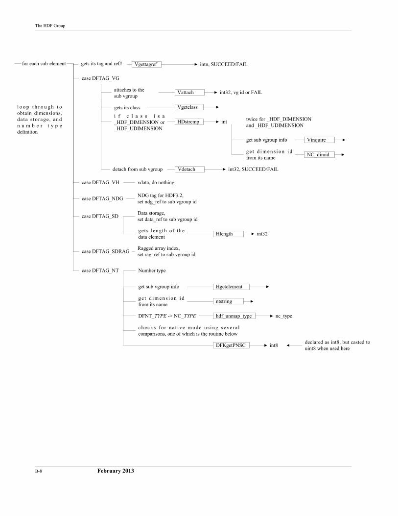
B-8 February 2013
The HDF Group
Vinquire
Vgettagref intn, SUCCEED/FAILfor each sub-element
l o o p t h r o u g h t oobtain dimensions,da ta s torage, andn u m b e r t y p edefinition
gets its tag and ref#
case DFTAG_VG
case DFTAG_VH
case DFTAG_NDG
case DFTAG_SD
case DFTAG_SDRAG
Vgetclass
HDstrcmp int
Vattach int32, vg id or FAILattaches to thesub vgroup
i f c l a s s i s a_HDF_DIMENSION or_HDF_UDIMENSION
twice for _HDF_DIMENSIONand _HDF_UDIMENSION
get sub vgroup info
NC_dimidg e t d i m en s i o n i dfrom its name
Vdetach int32, SUCCEED/FAILdetach from sub vgroup
vdata, do nothing
NDG tag for HDF3.2,set ndg_ref to sub vgroup id
Data storage,set data_ref to sub vgroup id
Hlength int32gets length of thedata element
Ragged array index,set rag_ref to sub vgroup id
case DFTAG_NT
c h eck s for n a t i ve mod e u s i n g severa lcomparisons, one of which is the routine below
Number type
gets its class
Hgetelementget sub vgroup info
ntstringg e t d i m en s i o n i dfrom its name
hdf_unmap_type
DFKgetPNSC int8
nc_typeDFNT_TYPE -> NC_TYPE
declared as int8, but casted touint8 when used here
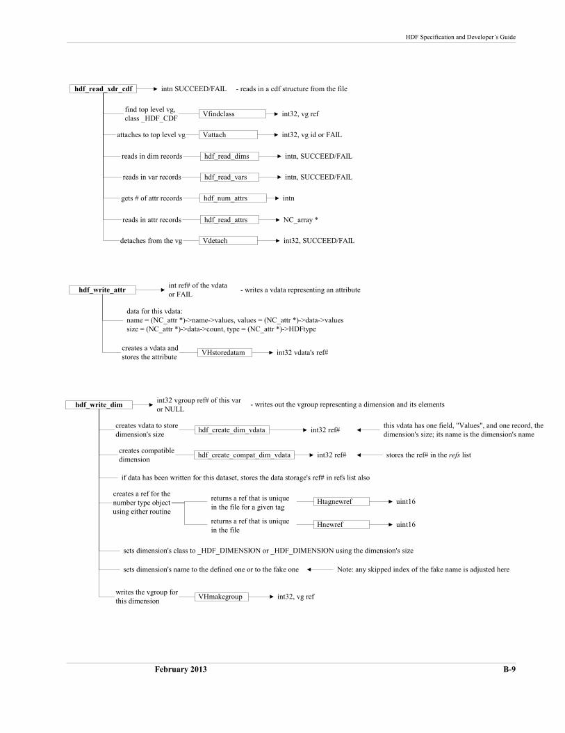
HDF Specification and Developer’s Guide
February 2013 B-9
hdf_read_xdr_cdf
Vfindclassfind top level vg,class _HDF_CDF
int32, vg ref
intn SUCCEED/FAIL - reads in a cdf structure from the file
hdf_read_dims
hdf_read_varsreads in var records intn, SUCCEED/FAIL
intn, SUCCEED/FAIL
attaches to top level vg Vattach int32, vg id or FAIL
reads in dim records
hdf_num_attrs
detaches from the vg
gets # of attr records intn
Vdetach int32, SUCCEED/FAIL
reads in attr records hdf_read_attrs NC_array *
hdf_write_attrint ref# of the vdataor FAIL
- writes a vdata representing an attribute
VHstoredatam int32 vdata's ref#creates a vdata andstores the attribute
data for this vdata:name = (NC_attr *)->name->values, values = (NC_attr *)->data->valuessize = (NC_attr *)->data->count, type = (NC_attr *)->HDFtype
hdf_write_dim
hdf_create_dim_vdata int32 ref#
int32 vgroup ref# of this varor NULL
- writes out the vgroup representing a dimension and its elements
creates vdata to storedimension's size
hdf_create_compat_dim_vdata int32 ref#creates compatibledimension
if data has been written for this dataset, stores the data storage's ref# in refs list also
this vdata has one field, "Values", and one record, thedimension's size; its name is the dimension's name
stores the ref# in the refs list
Htagnewref uint16
Hnewref uint16
creates a ref for thenumber type objectusing either routine
returns a ref that is uniquein the file
returns a ref that is uniquein the file for a given tag
sets dimension's class to _HDF_DIMENSION or _HDF_DIMENSION using the dimension's size
VHmakegroupwrites the vgroup forthis dimension
int32, vg ref
sets dimension's name to the defined one or to the fake one Note: any skipped index of the fake name is adjusted here
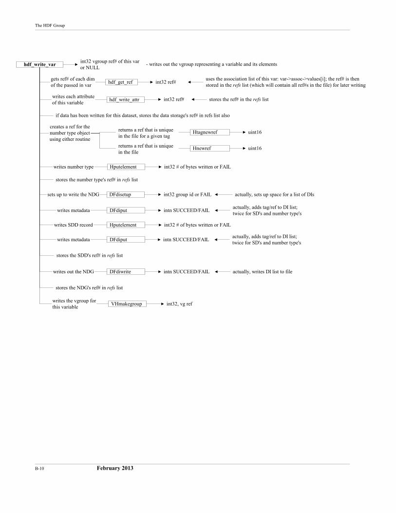
B-10 February 2013
The HDF Group
hdf_write_var
hdf_get_ref int32 ref#
int32 vgroup ref# of this varor NULL
- writes out the vgroup representing a variable and its elements
gets ref# of each dimof the passed in var
hdf_write_attr int32 ref#writes each attributeof this variable
if data has been written for this dataset, stores the data storage's ref# in refs list also
uses the association list of this var: var->assoc->values[i]; the ref# is thenstored in the refs list (which will contain all ref#s in the file) for later writing
stores the ref# in the refs list
Htagnewref uint16
Hnewref uint16
creates a ref for thenumber type objectusing either routine
returns a ref that is uniquein the file
returns a ref that is uniquein the file for a given tag
Hputelement int32 # of bytes written or FAILwrites number type
stores the number type's ref# in refs list
DFdisetup int32 group id or FAILsets up to write the NDG
writes metadata
writes SDD record
writes out the NDG
DFdiput intn SUCCEED/FAILactually, adds tag/ref to DI list;twice for SD's and number type's
Hputelement
writes metadata DFdiput
stores the SDD's ref# in refs list
DFdiwrite
stores the NDG's ref# in refs list
VHmakegroupwrites the vgroup forthis variable
int32, vg ref
int32 # of bytes written or FAIL
intn SUCCEED/FAILactually, adds tag/ref to DI list;twice for SD's and number type's
actually, writes DI list to fileintn SUCCEED/FAIL
actually, sets up space for a list of DIs
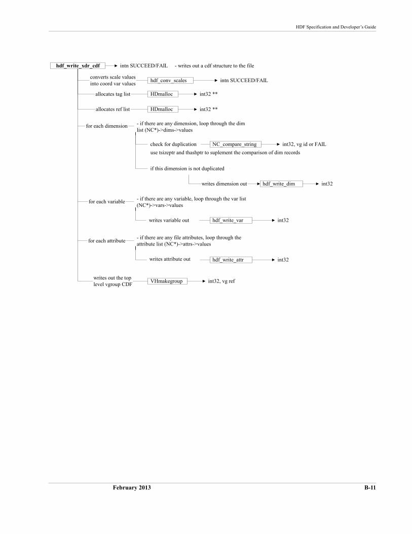
HDF Specification and Developer’s Guide
February 2013 B-11
hdf_write_xdr_cdf
VHmakegroupwrites out the toplevel vgroup CDF
int32, vg ref
intn SUCCEED/FAIL - writes out a cdf structure to the file
hdf_write_dim int32writes dimension out
hdf_conv_scales intn SUCCEED/FAILconverts scale valuesinto coord var values
HDmalloc int32 **allocates tag list
HDmalloc int32 **allocates ref list
for each dimension - if there are any dimension, loop through the dimlist (NC*)->dims->values
NC_compare_string int32, vg id or FAILcheck for duplication
use tsizeptr and thashptr to suplement the comparison of dim records
if this dimension is not duplicated
hdf_write_var int32
for each variable - if there are any variable, loop through the var list(NC*)->vars->values
writes variable out
hdf_write_attr int32
for each attribute- if there are any file attributes, loop through theattribute list (NC*)->attrs->values
writes attribute out
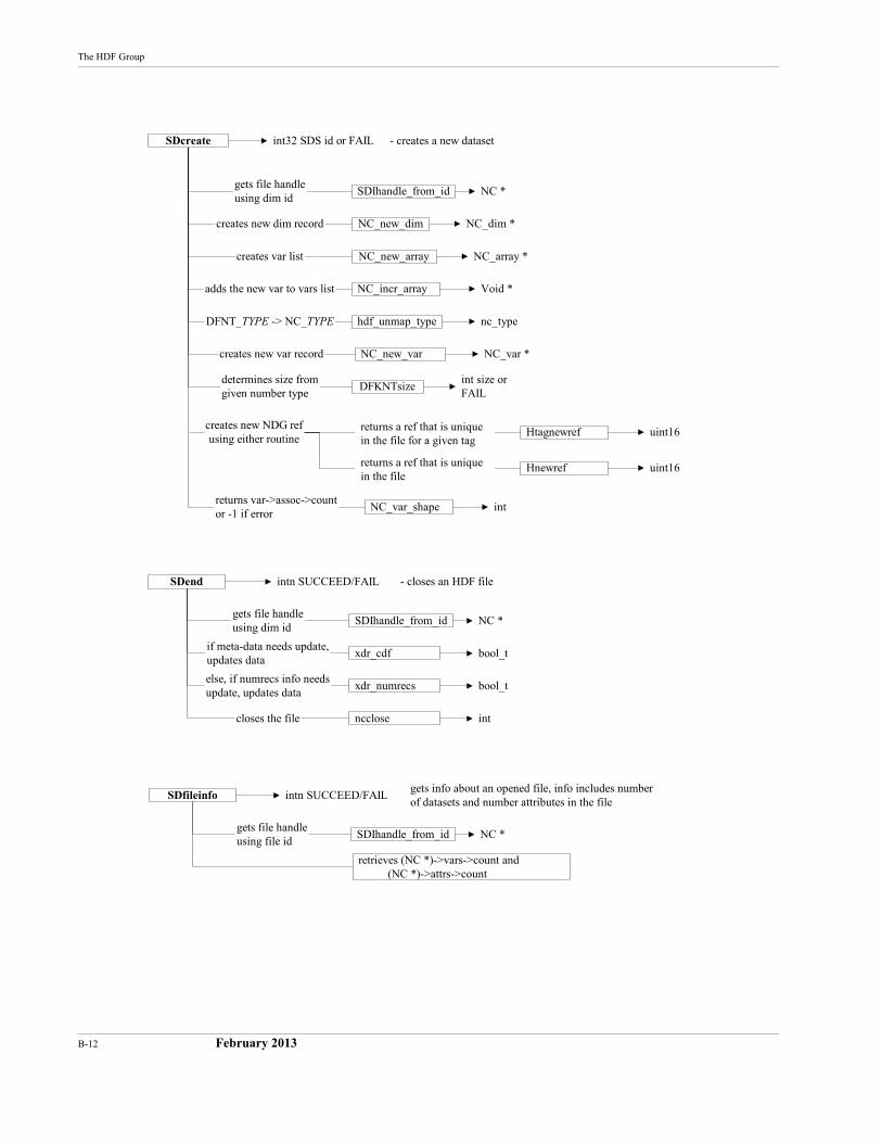
B-12 February 2013
The HDF Group
NC_new_array
NC_new_dim
DFKNTsize
SDIhandle_from_idgets file handleusing dim id
NC *
NC_array *creates var list
adds the new var to vars list NC_incr_array Void *
hdf_unmap_type nc_typeDFNT_TYPE -> NC_TYPE
NC_new_var NC_var *creates new var record
NC_var_shape int
Htagnewref uint16
Hnewref uint16
creates new NDG refusing either routine
returns a ref that is uniquein the file
returns a ref that is uniquein the file for a given tag
returns var->assoc->countor -1 if error
NC_dim *creates new dim record
determines size fromgiven number type
int size orFAIL
SDcreate int32 SDS id or FAIL - creates a new dataset
xdr_cdf
SDend
SDIhandle_from_id
xdr_numrecs
ncclosecloses the file
else, if numrecs info needsupdate, updates data
if meta-data needs update,updates data
gets file handleusing dim id
NC *
int
bool_t
bool_t
intn SUCCEED/FAIL - closes an HDF file
SDfileinfo
retrieves (NC *)->vars->count and (NC *)->attrs->count
SDIhandle_from_idgets file handleusing file id
NC *
gets info about an opened file, info includes numberof datasets and number attributes in the file
intn SUCCEED/FAIL
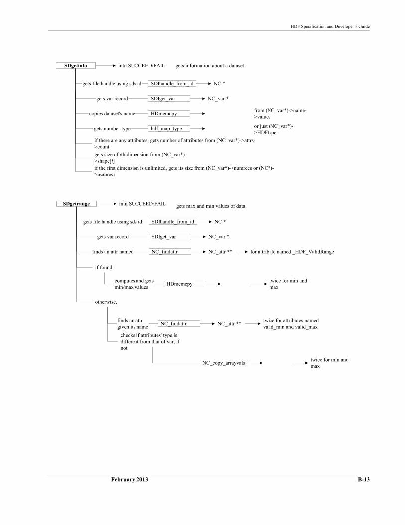
HDF Specification and Developer’s Guide
February 2013 B-13
SDgetinfo
SDIhandle_from_idgets file handle using sds id NC *
gets information about a datasetintn SUCCEED/FAIL
gets var record SDIget_var NC_var *
copies dataset's name HDmemcpyfrom (NC_var*)->name->values
hdf_map_typegets number type or just (NC_var*)->HDFtype
if there are any attributes, gets number of attributes from (NC_var*)->attrs->count
gets size of ith dimension from (NC_var*)->shape[i]if the first dimension is unlimited, gets its size from (NC_var*)->numrecs or (NC*)->numrecs
gets file handle using sds id
NC_findattr NC_attr **finds an attr named
if found
SDgetrange
SDIhandle_from_id NC *
gets max and min values of dataintn SUCCEED/FAIL
gets var record SDIget_var NC_var *
computes and getsmin/max values
HDmemcpytwice for min andmax
otherwise,
NC_findattr NC_attr **finds an attrgiven its name
twice for attributes namedvalid_min and valid_max
for attribute named _HDF_ValidRange
checks if attributes' type isdifferent from that of var, ifnot
NC_copy_arrayvalstwice for min andmax
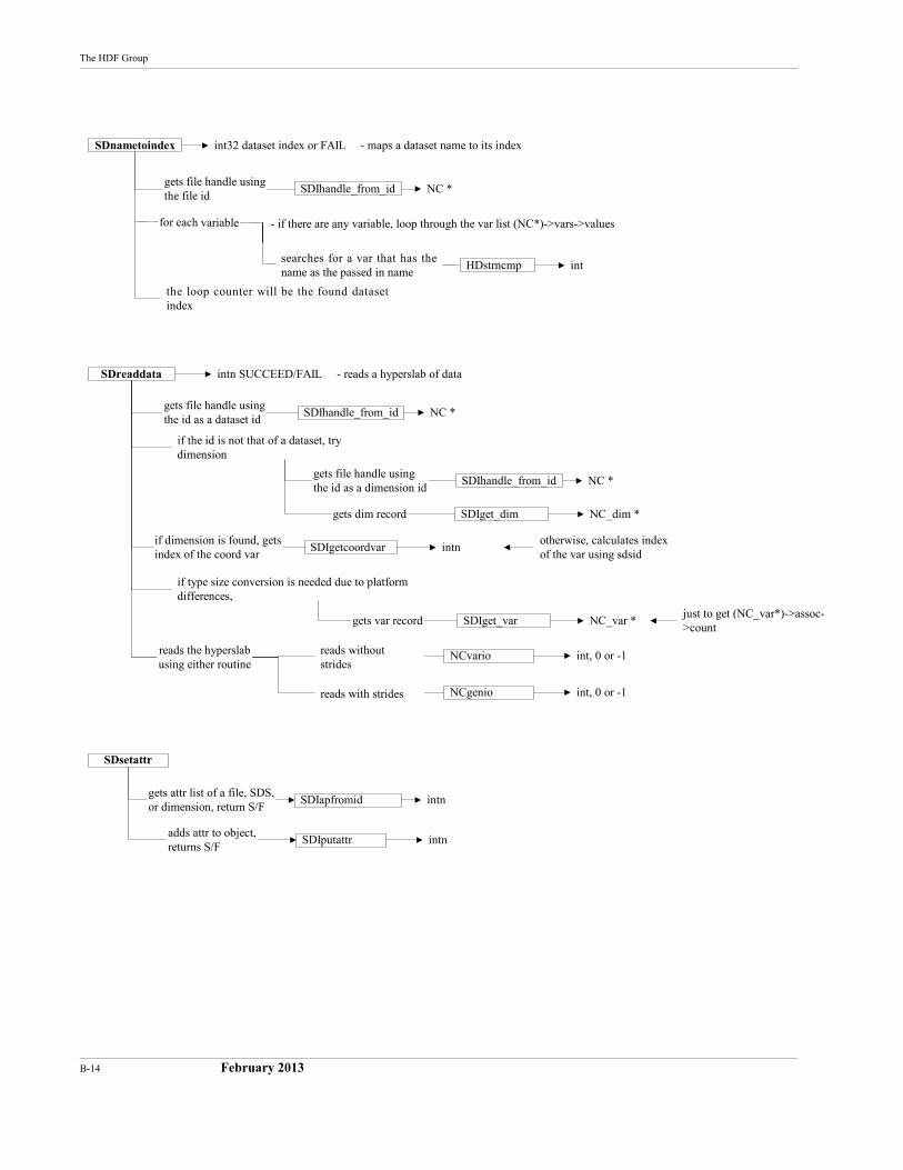
B-14 February 2013
The HDF Group
SDnametoindex
SDIhandle_from_idgets file handle usingthe file id
NC *
int32 dataset index or FAIL - maps a dataset name to its index
for each variable - if there are any variable, loop through the var list (NC*)->vars->values
HDstrncmp intsearches for a var that has thename as the passed in name
the loop counter will be the found datasetindex
SDreaddata
SDIhandle_from_id
gets dim record
gets file handle usingthe id as a dataset id
NC *
intn SUCCEED/FAIL - reads a hyperslab of data
SDIget_dim NC_dim *
gets var record SDIget_var NC_var *
SDIhandle_from_idgets file handle usingthe id as a dimension id
NC *
if the id is not that of a dataset, trydimension
SDIgetcoordvar intnif dimension is found, getsindex of the coord var
otherwise, calculates indexof the var using sdsid
if type size conversion is needed due to platformdifferences,
just to get (NC_var*)->assoc->count
NCvario int, 0 or -1
NCgenio int, 0 or -1
reads the hyperslabusing either routine
reads with strides
reads withoutstrides
SDsetattr
SDIputattr
SDIapfromid
adds attr to object,returns S/F
gets attr list of a file, SDS,or dimension, return S/F
intn
intn
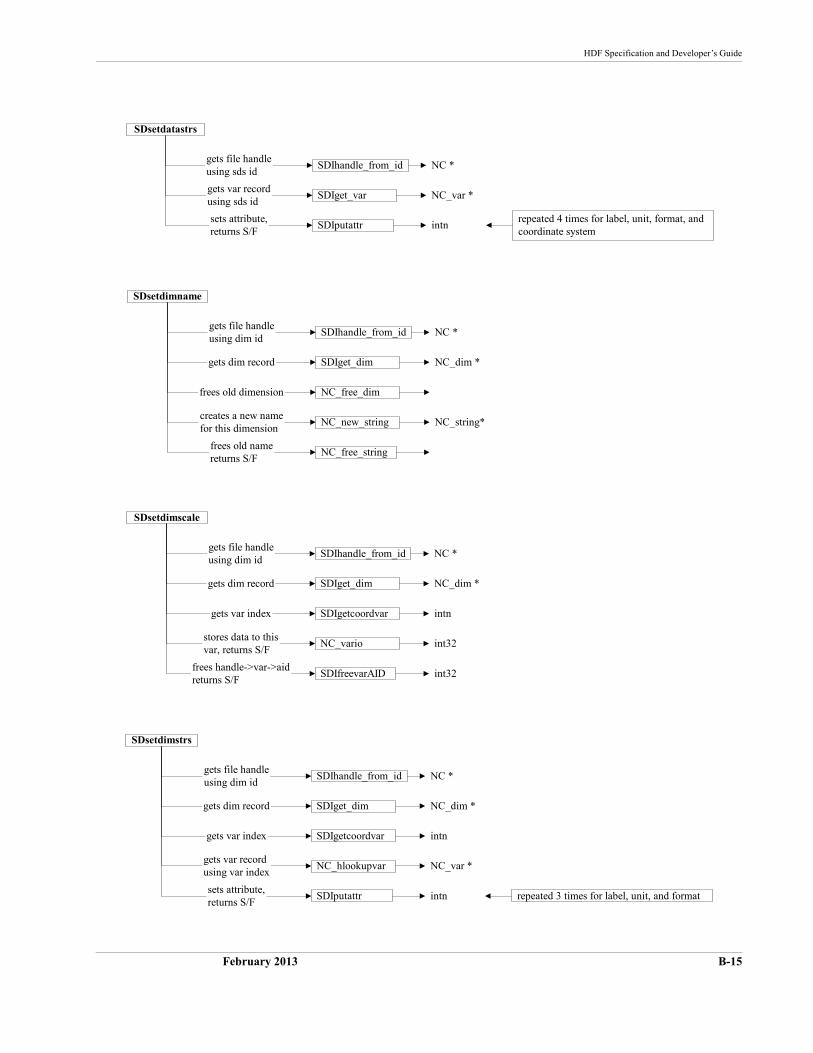
HDF Specification and Developer’s Guide
February 2013 B-15
SDIputattr
SDIget_var
SDsetdatastrs
SDIhandle_from_id
sets attribute,returns S/F
gets var recordusing sds id
gets file handleusing sds id
NC *
intn
NC_var *
repeated 4 times for label, unit, format, andcoordinate system
NC_free_string
SDIget_dim
SDsetdimname
SDIhandle_from_id
NC_free_dim
NC_new_string
frees old namereturns S/F
creates a new namefor this dimension
frees old dimension
gets dim record
gets file handleusing dim id
NC *
NC_string*
NC_dim *
SDIfreevarAID
SDIget_dim
SDsetdimscale
SDIhandle_from_id
SDIgetcoordvar
NC_vario
frees handle->var->aidreturns S/F
stores data to thisvar, returns S/F
gets var index
gets dim record
gets file handleusing dim id
NC *
int32
int32
intn
NC_dim *
SDIputattr
SDIget_dim
SDsetdimstrs
SDIhandle_from_id
SDIgetcoordvar
NC_hlookupvar
sets attribute,returns S/F
gets var recordusing var index
gets var index
gets dim record
gets file handleusing dim id
NC *
intn
NC_var *
intn
NC_dim *
repeated 3 times for label, unit, and format
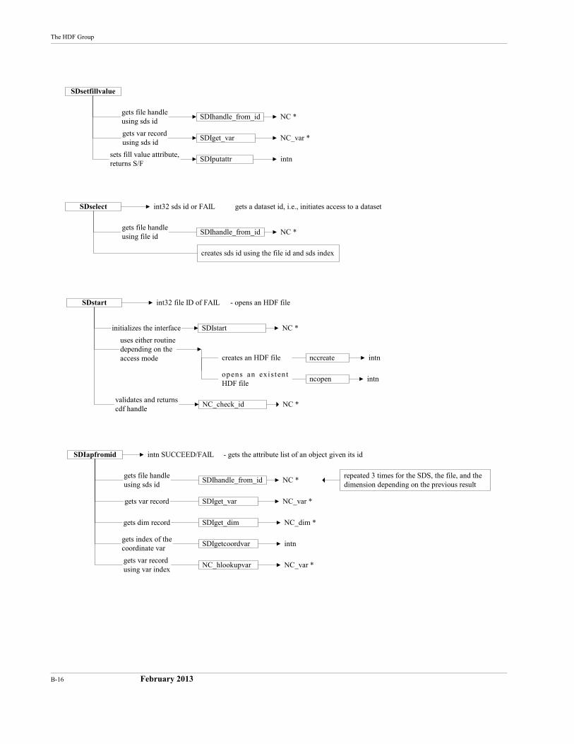
B-16 February 2013
The HDF Group
SDsetfillvalue
SDIputattr
SDIget_var
SDIhandle_from_id
sets fill value attribute,returns S/F
gets var recordusing sds id
gets file handleusing sds id
NC *
intn
NC_var *
SDselect
creates sds id using the file id and sds index
SDIhandle_from_idgets file handleusing file id
NC *
gets a dataset id, i.e., initiates access to a datasetint32 sds id or FAIL
SDstart
SDIstart
uses either routinedepending on theaccess mode
initializes the interface NC *
nccreate intncreates an HDF file
ncopen intnopens an exi s ten tHDF file
NC_check_idvalidates and returnscdf handle
NC *
int32 file ID of FAIL - opens an HDF file
SDIapfromid
SDIhandle_from_id
gets dim record
gets file handleusing sds id
NC *repeated 3 times for the SDS, the file, and thedimension depending on the previous result
intn SUCCEED/FAIL - gets the attribute list of an object given its id
SDIget_dim
SDIgetcoordvar
NC_hlookupvargets var recordusing var index
NC_var *
intn
NC_dim *
gets var record SDIget_var NC_var *
gets index of thecoordinate var
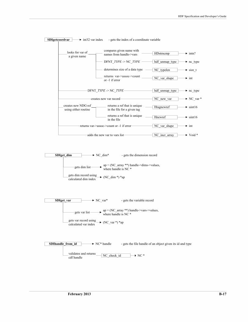
HDF Specification and Developer’s Guide
February 2013 B-17
Htagnewref
NC_new_var
SDIgetcoordvar
creates new var record
uint16
NC_var *
NC_typelen
hdf_unmap_type
size_t
nc_type
NC_var_shape
HDstrncmp
int
intn?looks for var ofa given name
compares given name withnames from handle->vars
DFNT_TYPE -> NC_TYPE
determines size of a data type
returns var->assoc->countor -1 if error
hdf_unmap_type nc_typeDFNT_TYPE -> NC_TYPE
Hnewref uint16
creates new NDG refusing either routine
returns a ref that is uniquein the file
returns a ref that is uniquein the file for a given tag
returns var->assoc->count or -1 if error NC_var_shape int
adds the new var to vars list NC_incr_array Void *
int32 var index - gets the index of a coordinate variable
SDIget_dim
gets dim list
NC_dim* - gets the dimension record
gets dim record usingcalculated dim index
ap = (NC_array **) handle->dims->values,where handle is NC *
(NC_dim *) *ap
SDIget_var
gets var list
NC_var* - gets the variable record
gets var record usingcalculated var index
ap = (NC_array **) handle->vars->values,where handle is NC *
(NC_var *) *ap
SDIhandle_from_id
NC_check_idvalidates and returnscdf handle
NC *
NC* handle - gets the file handle of an object given its id and type

B-18 February 2013
The HDF Group
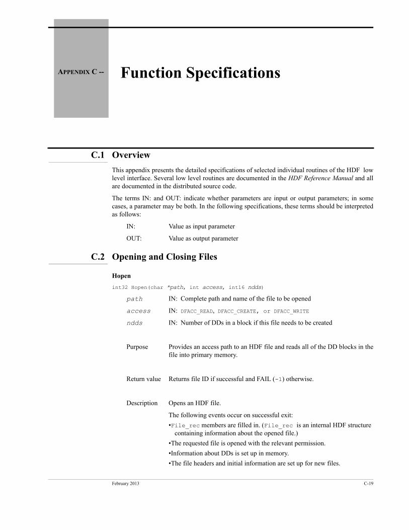
February 2013 C-19
APPENDIX C -- Function Specifications
C.1 Overview
This appendix presents the detailed specifications of selected individual routines of the HDF low level interface. Several low level routines are documented in the HDF Reference Manual and all are documented in the distributed source code.
The terms IN: and OUT: indicate whether parameters are input or output parameters; in some cases, a parameter may be both. In the following specifications, these terms should be interpreted as follows:
IN: Value as input parameter
OUT: Value as output parameter
C.2 Opening and Closing Files
Hopen
int32 Hopen(char *path, int access, int16 ndds)
path IN: Complete path and name of the file to be opened
access IN: DFACC_READ, DFACC_CREATE, or DFACC_WRITE
ndds IN: Number of DDs in a block if this file needs to be created
Purpose Provides an access path to an HDF file and reads all of the DD blocks in the file into primary memory.
Return value Returns file ID if successful and FAIL (-1) otherwise.
Description Opens an HDF file.
The following events occur on successful exit:
•File_rec members are filled in. (File_rec is an internal HDF structure containing information about the opened file.)
•The requested file is opened with the relevant permission.
•Information about DDs is set up in memory.
•The file headers and initial information are set up for new files.
C-20 February 2013
The HDF Group
Access privilege codesHDF provides several constants for use as access privilege codes as listed below. Note that these constants are not bit-flags and should not be ORed together to combine access modes. Doing so may cause odd behavior and, in some cases, loss of data:
Recommended tags:
DFACC_READOpen for read only. If file does not exist, error.
DFACC_WRITEOpen for read/write. If file does not exist, create it.
DFACC_CREATEForce creation. If file exists, delete it, then open a new file for read/write (in the spirit of the UNIX system command clobber).
Obsolete tags:
DFACC_ALLSame as DFACC_WRITE (obsolete but still supported).
DFACC_RDWRSame as DFACC_WRITE (obsolete but still supported).
Hclose
intn Hclose(int32 id)
id IN: The identifier of the file to be closed
Purpose Closes the access path to the file.
Return value Returns SUCCEED (0) if successful and FAIL (-1) otherwise.
Description id is first validated. If valid, the function closes the access path to the file.
If there are still access elements attached to the file, the error DFE_OPENAID is pushed onto the error stack and the file is not closed. This is a fairly com-mon error when developing new interfaces. See the discussion of Hendac-cess below for debugging hints.
HDF Specification and Developer’s Guide
February 2013 C-21
C.3 Locating Elements for Access and Getting Information
Hstartread
int32 Hstartread(int32 file_id, uint16 tag, uint16 ref)
file_id IN: ID of file to attach access element to
tag IN: Tag to search for
ref IN: Reference number to search for
Purpose Locates an existing data element with matching tag/ref and returns an access ID for reading it.
Return value Returns access element ID if successful and FAIL (-1) otherwise.
Description Searches the DDs for a particular tag/ref combination. If the search is suc-cessful, an access element is created, attached to the file, and positioned at the start of that data element; otherwise an error is returned. Searching on wildcards begins from the beginning of the DD list. Wildcards can be used for the tag or reference number (DFTAG_WILDCARD and DFREF_WILDCARD) and they match any values.
Hnextread
intn Hnextread(int32 access_id, uint16 tag, uint16 ref, int origin)
access_id IN: ID of a READ access element
tag IN: Tag to search for
ref IN: Reference number to search for
origin IN: Position at which to start searching
Purpose Locates and positions a read access ID on next occurrence of tag/ref.
Return value Returns SUCCEED (0) if successful and FAIL (-1) otherwise.
Description Searches for the next DD that fits the tag/ref. Wildcards apply. If origin is DF_START, searches from start of DD list; if origin is DF_CURRENT, searches from current position. Searching from the end of the file via DF_END is not yet implemented.
If the search is successful, then the access element is positioned at the start of that tag/ref; otherwise, the access ID is not modified.
C-22 February 2013
The HDF Group
Hstartwrite
int32 Hstartwrite(int32 file_id, uint16 tag, uint16 ref, int32 length)
file_id IN: ID of file to write to
tag IN: Tag to write to
ref IN: Reference number to write to
length IN: Length of the data element
Purpose Creates or replaces data element with matching tag/ref.
Return value Returns access element ID if successful and FAIL (-1) otherwise.
Description Sets up an access element to write a data element. The DD list of the file is searched first; if the tag/ref is found, the data element can be modified. If an object with the corresponding tag/ref is not found, a new one is created.
Hstartaccess
int32 Hstartaccess(int32 file_id, int16 tag, int16 ref, int32 flags)
file_id IN:ID of file to read/write to
tag IN:Tag to read/write to
ref IN:Reference number to read/write to
flags IN:Access flags for the data element
Purpose Sets up an access element for either reading or writing.
Return value Returns an access element identifier if successful and FAIL (-1) otherwise.
Description Starts up an access element for either read or write access. The data descrip-tor list for the file is searched first. If the tag/ref is found, it is not replaced; the seek position is presumed to be at zero (0). If the tag/ref is not found, it is created.
Only a finite number of access elements can be active at a given time, so it is important to call Hendaccess whenever you are done using an element.
HDF Specification and Developer’s Guide
February 2013 C-23
Hendaccess
int32 Hendaccess(int access_id)
access_id IN: ID of access element to dispose of
Purpose Disposes of access element for tag/ref.
Return value Returns SUCCEED (0) if successful and FAIL (-1) otherwise.
Description Disposes of an access element. Only a finite number of access elements can be active at a given time, so it is important to call Hendaccess whenever you are done using an element.
When developing new interfaces, a common mistake is to fail to call Hend-access for all of the elements accessed. When this happens, Hclose will return FAIL and the dump of the error stack (see HEprint below) will tell how many access elements are still active.
This can be difficult problem to debug, as the low levels of the HDF library have no idea who or what opened an access element and forgot to release it. A tedious but effective means of debugging this problem is to annotate with comments the locations where the attached count of a file record is changed. This occurs in the files hfile.c, hblocks.c, and hextelt.c.
Hinquire
intn Hinquire(int32 access_id, int32 *pfile_id, uint16 *ptag, uint16 *pref,int32 *plength, int32 *poffset, int32 *pposn, int *paccess,int16 *pspecial)
access_id IN:Access element ID
pfile_id OUT:File ID
ptag OUT:Tag of the element pointed to
pref OUT:Reference number of the element pointed to
plength OUT:Length of the element pointed to
poffset OUT:Offset of element in the file
pposn OUT:Position pointed to within the data element
paccess OUT:Access type of this access element
pspecial OUT:Special code
Purpose Returns access information for a data element.
Return value Returns SUCCEED (0) if the access element points to some data element and FAIL (-1) otherwise.
C-24 February 2013
The HDF Group
Description Inquires for the statistics of the data element pointed to by the access ele-ment. If a piece of information is not needed, a NULL can be sent in for that value. Convenience macros for calls to Hinquire (HQuerypositon, HQuerylength, etc.) are defined in hdf.h.
Hishdf
int32 Hishdf(char *path)
path IN: Complete path and name of file
Purpose Determines whether a file is an HDF file.
Return value Returns TRUE (non-zero) if file is an HDF file and FALSE (0) otherwise.
Description The decision as to whether a file is an HDF file is based solely on the magic number stored in the first four bytes of an HDF file. Hishdf may some-times identify a file as an HDF file that Hopen is unable to open (e.g., an HDF file with a corrupted DD list).
Hnumber
int Hnumber(int32 file_id, uint16 tag)
file_id IN: File ID
tag IN: Tag to be counted
Purpose Counts the number of occurrences of a tag in a file.
Return value The number of occurrences of a tag in a file.
Note: Hishdf only determines whether a file is an HDF file. It does not verify that the file is readable.
HDF Specification and Developer’s Guide
February 2013 C-25
Hgetlibversion
Hgetlibversion(uint32 *majorv, uint32 *minorv, uint32 *release, char string[])
majorv OUT:Major version number
minorv OUT:Minor version number
release OUT:Release number
string OUT:Informational text string
Purpose Gets version information for current HDF library.
Return value Returns SUCCEED (0).
Description Returns the version of the HDF library. The version information is compiled into the HDF library, so it is not necessary to have any open files for this function to execute.
Hgetfileversion
Hgetfileversion(uint32 file_id, uint32 *majorv, uint32 *minorv, uint32 *release, char *string)
file_id IN: File ID
majorv OUT:Major version number
minorv OUT:Minor version number
release OUT:Release number
string OUT:Informational text string
Purpose Gets version information for an HDF file.
Return value Returns SUCCEED (0) if successful and FAIL (-1) otherwise.
Description Returns the HDF version information stored in the given file.
C-26 February 2013
The HDF Group
C.4 Reading and Writing Entire Data Elements
Hputelement
int Hputelement(int32 file_id, uint16 tag, uint16 ref, uint8 *data, int32 length)
file_id IN: File ID
tag IN: Tag of data element to put
ref IN: Reference number of data element to put
data IN: Pointer to buffer
length IN: Length of data
Purpose Adds or replaces an element in a file.
Return value Returns SUCCEED (0) if successful and FAIL (-1) otherwise.
Description Writes a new data element or replaces an existing data element in a HDF file. Uses Hwrite and its associated routines.
Hgetelement
int Hgetelement(int32 file_id, uint16 tag, uint16 ref, uint8 *data)
file_id IN: ID of the file to read from
tag IN: Tag of data element to read
ref IN: Reference number of data element to read
data OUT:Buffer to read into
Purpose Obtains the data referred to by the passed tag/ref.
Return value Returns SUCCEED (0) if successful and FAIL (-1) otherwise.
Description Reads a data element from an HDF file and puts it into the buffer pointed to by data. The space allocated for the buffer is assumed to be large enough.
Note: Hgetelement assumes that the buffer is large enough to hold the data being read. It is the user’s responsibility to prevent data loss by ensuring that this is the case.
HDF Specification and Developer’s Guide
February 2013 C-27
C.5 Reading and Writing Part of a Data Element
Hread
int32 Hread(int32 access_id, int32 length, uint8 *data)
access_id IN: Read access element ID
length IN: Length of segment to read in
data OUT:Pointer to data array to read to
Purpose Reads a portion of a data element.
Return value Returns length of segment actually read if successful and FAIL (-1) other-wise.
Description Reads in the next segment in the data element pointed to by the access ele-ment. Hread starts at the last position left by an Hread or Hseek call and reads any data that remains in the element up to length bytes. If the data element is too short (less than length bytes long), Hread reads to the end of the data element.
Hwrite
int32 Hwrite(int32 access_id, int32 length, uint8 *data)
access_id IN: Write access element ID
length IN: Length of segment to write
data IN: Pointer to data to write
Purpose Writes next data segment to data element.
Return value Returns length of segment successfully written and FAIL (-1) otherwise.
Description Writes the data to the data element where the last Hwrite or Hseek stopped.
Hwrite starts at the last position left by an Hwrite or Hseek call, writes up to a specified number of bytes, and leaves the write pointer at the end of the data written. If the space reserved is less than the length to write, then only as much as can fit is written.
It is the user’s responsibility to ensure that no two access elements are writ-ing to the same data element. Note that a user can interlace writes to multiple data elements in the same file.
C-28 February 2013
The HDF Group
Hseek
intn Hseek(int32 access_id, int32 offset, int origin)
access_id IN: Access element ID
offset IN: Offset to seek to
origin IN: Position to seek from:
DF_START (0)offset from beginning of data elementDF_CURRENT (1)offset from current positionDF_END (2)offset from end of data element
Purpose Sets the access pointer to an offset within a data element. The next timeHread or Hwrite is called, the read or write occurs from the new position.
Return value Returns SUCCEED (0) if successful and FAIL (-1) otherwise.
Description Sets the position of an access element in a data element so that the nextHread or Hwrite will start from that position. origin determines the position from which offset should be counted.
This routine fails if the access element is not associated with a data element or if the position sought is outside of the data element.
Seeking from the end of a data element is not currently supported.
HDF Specification and Developer’s Guide
February 2013 C-29
C.6 Manipulating Data Descriptors
Hdupdd
int Hdupdd(int32 file_id, uint16 tag, uint16 ref, uint16 old_tag, uint16 old_ref)
file_id IN: File ID
tag IN: Tag of new data descriptor
ref IN: Reference number of new data descriptor
old_tag IN: Tag of data descriptor to duplicate
old_ref IN: Reference number of data descriptor to duplicate
Purpose Generates new references to data that is already referenced from somewhere else.
Return value Returns SUCCEED (0) if successful and FAIL (-1) otherwise.
Description Duplicates a data descriptor so that the new tag/ref points to the same data element pointed to by the old tag/ref.
Hdeldd
int Hdeldd(int32 file_id, uint16 tag, uint16 ref)
file_id IN: File ID
tag IN: Tag of data descriptor to delete
ref IN: Reference number of data descriptor to delete
Purpose Deletes a tag/ref from the list of DDs.
Return value Returns SUCCEED (0) if successful and FAIL (-1) otherwise.
Description Deletes the data descriptor of tag/ref from the DD list of the file. This routine is unsafe and may leave a file in a condition that is not usable by some rou-tines. Use with care.
C-30 February 2013
The HDF Group
Hnewref
uint16 Hnewref(int32 file_id)
file_id IN: File ID
Purpose Returns the next available reference number.
Return value Returns the reference number if successful and 0 otherwise.
Description Returns a reference number that can be used with any tag to produce a unique tag/ref. Successive calls to Hnewref will generate a strictly increas-ing sequence until the highest possible reference number has been returned; then Hnewref will return unused reference numbers starting from 1.
HDF Specification and Developer’s Guide
February 2013 C-31
C.7 Managing Special Data Elements
HLcreate
int32 HLcreate(int32 file_id, uint16 tag, uint16 ref, int32 block_length, int32 number_blocks)
file_id IN: File ID
tag IN: Tag of new data element (or object)
ref IN: Reference number of new data element (or object)
block_lengthIN: Length of blocks to be used
number_blocksIN: Number of blocks to use per linked block record
Purpose: Creates a new linked block special data element.
Return value Returns access ID for special data element if successful and FAIL (-1) other-wise.
Description Appending to existing HDF elements was a problem prior to HDF Version 3.2 because HDF objects had to be stored contiguously. When appending, the HDF library forced the user to delete the existing element and rewrite it at the end of the file. HDF Version 3.2 introduced the concept of linked blocks, which allow unlimited appending to existing elements without copy-ing over existing data.
This routine can be used to create an object with the given tag/ref as a linked block element or to promote an existing element to be stored in linked blocks.
Initially, a table is set up to accommodate number_blocks linked blocks for the specified data object. Each block has block_length bytes. If an existing object is being promoted, block_length does not have to be the same size as the original element.
HLcreate returns an active access ID with write permission to the linked block element.
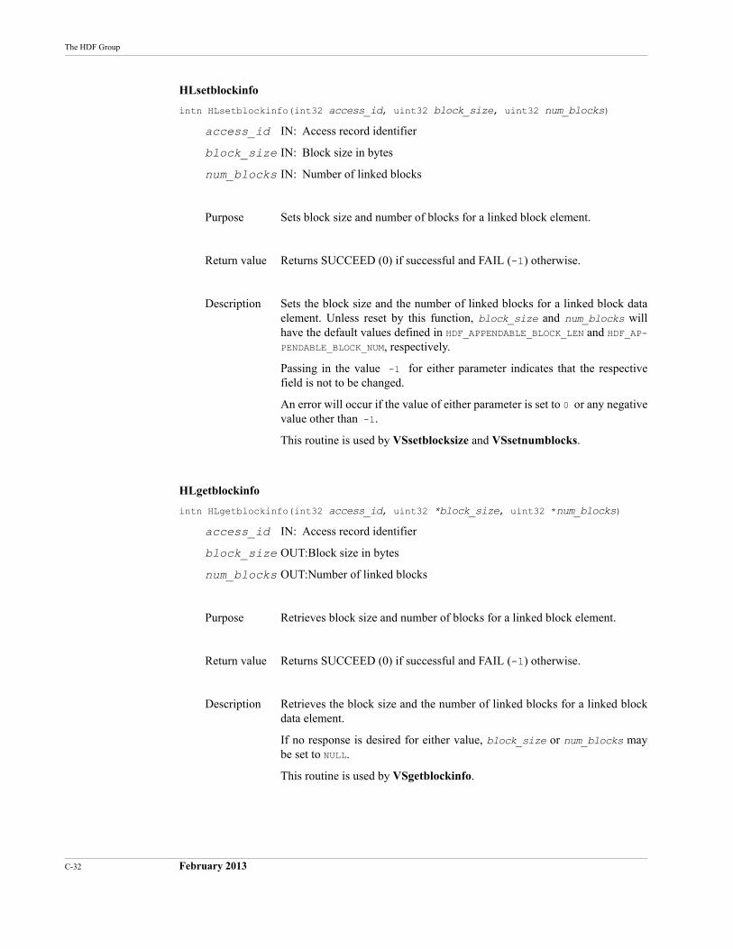
C-32 February 2013
The HDF Group
HLsetblockinfo
intn HLsetblockinfo(int32 access_id, uint32 block_size, uint32 num_blocks)
access_id IN: Access record identifier
block_size IN: Block size in bytes
num_blocks IN: Number of linked blocks
Purpose Sets block size and number of blocks for a linked block element.
Return value Returns SUCCEED (0) if successful and FAIL (-1) otherwise.
Description Sets the block size and the number of linked blocks for a linked block data element. Unless reset by this function, block_size and num_blocks will have the default values defined in HDF_APPENDABLE_BLOCK_LEN and HDF_AP-PENDABLE_BLOCK_NUM, respectively.
Passing in the value -1 for either parameter indicates that the respective field is not to be changed.
An error will occur if the value of either parameter is set to 0 or any negative value other than -1.
This routine is used by VSsetblocksize and VSsetnumblocks.
HLgetblockinfo
intn HLgetblockinfo(int32 access_id, uint32 *block_size, uint32 *num_blocks)
access_id IN: Access record identifier
block_size OUT:Block size in bytes
num_blocks OUT:Number of linked blocks
Purpose Retrieves block size and number of blocks for a linked block element.
Return value Returns SUCCEED (0) if successful and FAIL (-1) otherwise.
Description Retrieves the block size and the number of linked blocks for a linked block data element.
If no response is desired for either value, block_size or num_blocks may be set to NULL.
This routine is used by VSgetblockinfo.
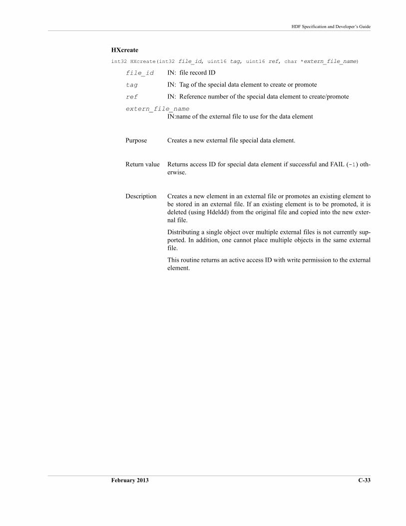
HDF Specification and Developer’s Guide
February 2013 C-33
HXcreate
int32 HXcreate(int32 file_id, uint16 tag, uint16 ref, char *extern_file_name)
file_id IN: file record ID
tag IN: Tag of the special data element to create or promote
ref IN: Reference number of the special data element to create/promote
extern_file_nameIN:name of the external file to use for the data element
Purpose Creates a new external file special data element.
Return value Returns access ID for special data element if successful and FAIL (-1) oth-erwise.
Description Creates a new element in an external file or promotes an existing element to be stored in an external file. If an existing element is to be promoted, it is deleted (using Hdeldd) from the original file and copied into the new exter-nal file.
Distributing a single object over multiple external files is not currently sup-ported. In addition, one cannot place multiple objects in the same external file.
This routine returns an active access ID with write permission to the external element.
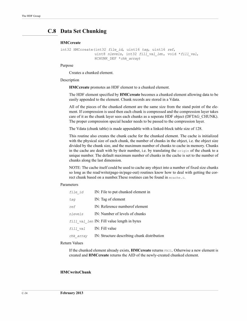
C-34 February 2013
The HDF Group
C.8 Data Set Chunking
HMCcreate
int32 HMCcreate(int32 file_id, uint16 tag, uint16 ref, uint8 nlevels, int32 fill_val_len, void *fill_val, HCHUNK_DEF *chk_array)
Purpose
Creates a chunked element.
Description
HMCcreate promotes an HDF element to a chunked element.
The HDF element specified by HMCcreate becomes a chunked element allowing data to be easily appended to the element. Chunk records are stored in a Vdata.
All of the pieces of the chunked element are the same size from the stand point of the ele-ment. If compression is used then each chunk is compressed and the compression layer takes care of it as the chunk layer sees each chunks as a seperate HDF object (DFTAG_CHUNK). The proper compression special header needs to be passed to the compression layer.
The Vdata (chunk table) is made appendable with a linked-block table size of 128.
This routine also creates the chunk cache for the chunked element. The cache is initialized with the physical size of each chunk, the number of chunks in the object, i.e. the object size divided by the chunk size, and the maximum number of chunks to cache in memory. Chunks in the cache are dealt with by their number, i.e. by translating the origin of the chunk to a unique number. The default maximum number of chunks in the cache is set to the number of chunks along the last dimension.
NOTE: The cache itself could be used to cache any object into a number of fixed size chunks so long as the read/write(page-in/page-out) routines know how to deal with getting the cor-rect chunk based on a number.These routines can be found in mcache.c.
Parameters
file_id IN: File to put chunked element in
tag IN: Tag of element
ref IN: Reference numberof element
nlevels IN: Number of levels of chunks
fill_val_len IN: Fill value length in bytes
fill_val IN: Fill value
chk_array IN: Structure describing chunk distribution
Return Values
If the chunked element already exists, HMCcreate returns FAIL. Otherwise a new element is created and HMCcreate returns the AID of the newly-created chunked element.
HMCwriteChunk
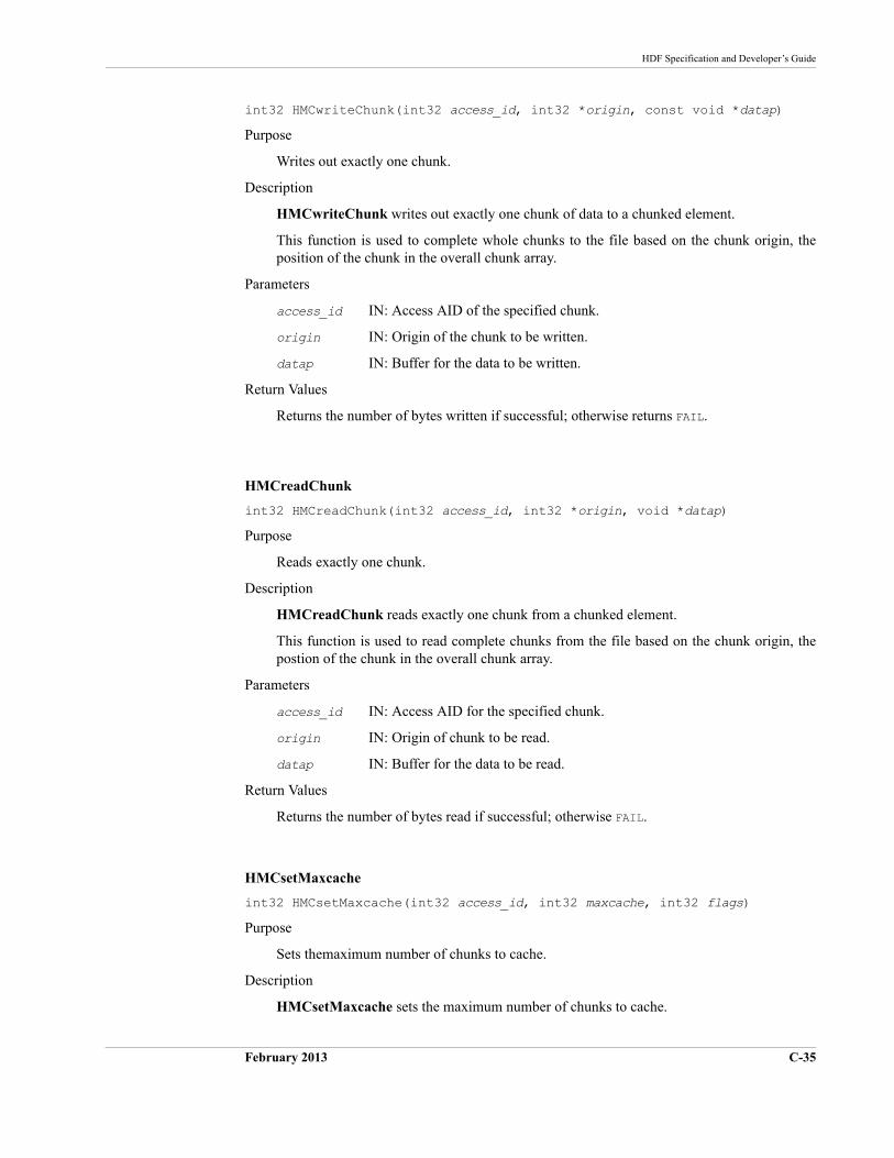
HDF Specification and Developer’s Guide
February 2013 C-35
int32 HMCwriteChunk(int32 access_id, int32 *origin, const void *datap)
Purpose
Writes out exactly one chunk.
Description
HMCwriteChunk writes out exactly one chunk of data to a chunked element.
This function is used to complete whole chunks to the file based on the chunk origin, the position of the chunk in the overall chunk array.
Parameters
access_id IN: Access AID of the specified chunk.
origin IN: Origin of the chunk to be written.
datap IN: Buffer for the data to be written.
Return Values
Returns the number of bytes written if successful; otherwise returns FAIL.
HMCreadChunk
int32 HMCreadChunk(int32 access_id, int32 *origin, void *datap)
Purpose
Reads exactly one chunk.
Description
HMCreadChunk reads exactly one chunk from a chunked element.
This function is used to read complete chunks from the file based on the chunk origin, the postion of the chunk in the overall chunk array.
Parameters
access_id IN: Access AID for the specified chunk.
origin IN: Origin of chunk to be read.
datap IN: Buffer for the data to be read.
Return Values
Returns the number of bytes read if successful; otherwise FAIL.
HMCsetMaxcache
int32 HMCsetMaxcache(int32 access_id, int32 maxcache, int32 flags)
Purpose
Sets themaximum number of chunks to cache.
Description
HMCsetMaxcache sets the maximum number of chunks to cache.
C-36 February 2013
The HDF Group
The values set here affects the current object's caching behaviour.
If the chunk cache is full and maxcache is greater then the current maxcache value, then the chunk cache is reset to the new maxcache value, else the chunk cache remains at the current maxcache value.
If the chunk cache is not full, then the chunk cache is set to the new maxcache value only if the new maxcache value is greater than the current number of chunks in the cache.
Use flags arguement of HMC_PAGEALL if the whole object is to be cached in memory; other-wise pass in zero.
NOTES: This function calls the routine mcache_set_maxcache(). The value of maxcachemust be greater than 1.
Parameters
access_id IN: Access AID for the specified chunked element.
maxcache IN: Maximum number of chunks to cache.
flags IN: Valid flags are 0 (zero) and HMC_PAGEALL.
Returns
Returns the new value of maxcache if successful; otherwise returns FAIL.
HMCPstwrite
int32 HMCPstwrite(accrec_t *access_rec)
Purpose
Opens an access record of a chunked elemnent for writing.
Description
HMCPstwrite calls HMCIstaccess() to fill in the access record for writing.
Parameter
access_rec IN: Access record to fill in.
Return Values
Returns the AID of the access record if successful; otherwise returns FAIL.
HMCPseek
int32 HMCPseek(accrec_t *access_rec, int32 offset, int origin)
Purpose
Sets the seek position in the chunked element.
Description
HMCPseek sets the seek position in the specified chunked element.
Parameters
access_rec IN: Access record for the specified chunk.
HDF Specification and Developer’s Guide
February 2013 C-37
offset IN: Seek offset.
origin IN: Location from which the offset should be calculated.
Return Values
Returns a positive value if successful; otherwise returns FAIL.
HMCPchunkread
int32 HMCPchunkread(void *cookie, int32 chunk_num, void *datap)
Purpose
Reads a chunk.
Description
Given the chunk number, HMCPchunkread reads in a complete chunk from a chunked ele-ment.
This is used as the page-in-chunk routine for the cache.
Only the cache should call this routine.
Parameters
cookie IN: Access record for the desired chunk.
chunk_num IN: Chunk to be read.
datap OUT: Buffer for data to be read.
Return Values
Returns the number of bytes read if successful; otherwise returns FAIL.
HMCPread
int32 HMCPread(accrec_t *access_rec, int32 length, void *datap)
Purpose
Reads data from a chunked element.
Description
HMCPread reads in data from a chunked element.
Data is obtained from the cache, which takes care of reading in the proper chunks to satisfy the request.
Parameters
access_rec IN: Access record for the desired chunk.
length IN: Number of bytes to read.
datap OUT: Buffer for data to be read.
Return Values
Returns the number of bytes read if successful; otherwise returns FAIL.
C-38 February 2013
The HDF Group
HMCPchunkwrite
int32 HMCPchunkwrite(void *cookie, int32 chunk_num, const void *datap)
Purpose
Writes out exactly one chunk.
Description
Given the chunk number, HMCPchunkwrite writes a complete chunk to a chunked ele-ment.
This is used as the page-out-chunk routine for the cache.
Only the cache should call this routine.
Parameters
cookie IN: Access record for the chunk to be written.
chunk_num IN: Chunk number.
datap IN: Buffer for the data to be written.
Return Values
Returns the number of bytes written if successful; otherwise returns FAIL.
HMCPwrite
int32 HMCPwrite(accrec_t *access_rec, int32 length, const void *datap)
Purpose
Writes data to a chunked element.
Description
HMCPwrite writes data to a chunked element.
Data is obtained from the cache, which takes care of obtaining the proper chunks to write to satisfy the request.
The chunks are marked as dirty before being returned to the cache.
Parameters
access_rec IN: Access record for the chunked element.
length IN: Number of bytes to be written.
datap IN: Buffer for the data to be written.
Return Values
Returns the number of bytes written if successful; otherwise returns FAIL.
HMCPcloseAID
int32 HMCPcloseAID(accrec_t *access_rec)
HDF Specification and Developer’s Guide
February 2013 C-39
Purpose
Closes file but keeps AID active.
Description
HMCPcloseAID closes the file currently pointed to by this AID but does not free the AID.
This will flush the chunk cache and free up the special information struct.
This function is called by Hnextread(), which reuses an AID to point to the next object, as requested. If the current object was a chunked object, the chunked information needs to be closed before all reference to it is lost.
NOTE: Direct use of Hnextread() is not recommened since it relies on previous state infor-mation.
Parameter
access_rec IN: Access record of file to close.
Return Values
Returns a positive value if successful; otherwise returns FAIL.
HMCPendaccess
intn HMCPendaccess(accrec_t *access_rec)
Purpose
Closes a chunk element AID.
Description
HMCPendaccess closes the specied AID, freeing up all of the space used to store informa-tion about a chunked element and updating the proper records, access_rec, file_rec, etc. All relevant information is flushed.
Parameter
access_rec IN: Access record to close.
Return Values
Returns a positive value if successful; otherwise returns FAIL.
HMCPinfo
int32 HMCPinfo(accrec_t *access_rec, sp_info_block_t *info_chunk)
Purpose
Returns information about a chunked element.
Description
HMCPinfo returns information about the given chunked element.
info_chunk is assumed to be non-NULL.
C-40 February 2013
The HDF Group
Parameters
access_rec IN: access record of access elemement
info_chunk OUT: Information about the special element.
Return Values
Returns a positive value if successful; otherwise returns FAIL.
HMCPinquire
int32 HMCPinquire(accrec_t *access_rec, int32 *pfile_id, uint16 *ptag,uint16 *pref, int32 *plength, int32 *poffset, int32 *pposn, int16 *paccess, int16 *pspecial)
Purpose
Inquires for chunked elements.
Description
HMCPinquire returns interesting information about a chunked element.
NULL can be passed for any OUT parameter if the value is not needed.
Parameters
access_rec IN: Access record of the chunked element for which information is sought.
pfile_id OUT: File identifier.
ptag OUT: Tag of information record.
pref OUT: Reference number of information record.
plength OUT: Length of element.
poffset OUT: Offset of element -- meaningless.
pposn OUT: Current position in element.
paccess OUT: Access mode.
pspecial OUT: Special code.
Return Values
Returns a positive value if successful; otherwise returns FAIL.
HDF Specification and Developer’s Guide
February 2013 C-41
C.9 Development Routines
HDgettagname
char *HDgettagname(uint16 tag)
tag IN: Tag to look up
Purpose Gets a meaningful description of a tag.
Return value Returns a pointer to a string describing this tag or NULL if the tag is unknown.
Description To reduce the amount of duplicated code, this routine can be used to map a tag to a character string containing the name of the tag.
The string returned by this routine is guaranteed to be 30 characters or less.
HDgetspace
void *HDgetspace(uint32 qty)
qty IN: Number of bytes to allocate
Purpose Allocates space.
Return value If successful, returns a pointer to space that was allocated; otherwise returns NULL .
Description Uses an appropriate allocation routine on the local machine to get space.
HDfreespace
void *HDfreespace(void *ptr)
ptr IN: Pointer to previously-allocated space that is to be freed
Purpose Frees space.
Return value Returns NULL.
Description Uses an appropriate routine on the local machine to free space. This routine is platform dependent.
C-42 February 2013
The HDF Group
HDstrncpy
char *HDstrncpy(register char *dest, register char *source, int32 length)
dest OUT:Pointer to area to copy string to
source IN: Pointer to area to copy string from
length IN: Maximum number of bytes to copy
Purpose Copies a string with maximum length length.
Return value Returns address of dest.
Description Creates a string in dest that is at most length characters long. The num-ber of characters must include the NULL terminator for historical reasons. Hence, if you are working with the string Foo, you must call this copy function with the value 4 (three characters plus the NULL terminator) in length.
HDF Specification and Developer’s Guide
February 2013 C-43
C.10 Error Reporting
HEprint
void HEprint(FILE *stream, int32 level)
stream IN: Stream to print error messages on
level IN: Level of the error stack to print
Purpose Prints information on the error stack.
Return value Has no return value.
Description Prints information on reported errors. If level is zero, all of the errors cur-rently on the error stack are printed. Output from this function is sent to the file pointed to by stream.
The following information is printed:
•An ASCII description of the error
•The reporting routine
•The reporting routine’s source file name
•The line at which the error was reported
If the programmer has supplied extra information by means of HEreport, this information is printed as well.
HEclear
void HEclear(void)
Purpose Clears all information on reported errors off of the error stack.
Return value Has no return value.
Description Clears all of the information off of the error stack.
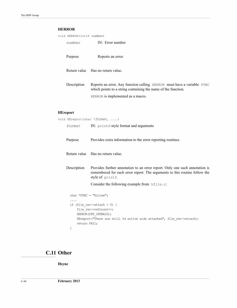
C-44 February 2013
The HDF Group
HERROR
void HERROR(int16 number)
number IN: Error number
Purpose Reports an error.
Return value Has no return value.
Description Reports an error. Any function calling HERROR must have a variable FUNC which points to a string containing the name of the function.
HERROR is implemented as a macro.
HEreport
void HEreport(char *format, ....)
format IN: printf-style format and arguments
Purpose Provides extra information to the error reporting routines.
Return value Has no return value.
Description Provides further annotation to an error report. Only one such annotation is remembered for each error report. The arguments to this routine follow the style of printf.
Consider the following example from hfile.c:
char *FUNC = "Hclose";....if (file_rec->attach > 0) {
file_rec->refcount++;HERROR(DFE_OPENAID);HEreport("There are still %d active aids attached", file_rec->attach);return FAIL;
}
C.11 Other
Hsync
HDF Specification and Developer’s Guide
February 2013 C-45
int Hsync(int32 file_id)
file_id IN: ID of the file to synchronize
Purpose Synchronizes on-disk HDF file with image in memory.
Return value Returns SUCCEED.
Description Hsync is not included in the current HDF library release because the on-disk representation of an HDF file is always the same as its in-memory rep-resentation. Hsync will be provided when future releases implement buffer-ing schemes.

C-46 February 2013
The HDF Group