split spoon penetration testing in gravels - Open Collections
Upload
khangminh22Category
view
5download
0
P a g e | ii
HARMONOGRAPH
SIDDHARTHA BALASUBRAMANIAN
MOHAMED NABIL LATHIFF
PROJECT SPONSOR: ANDRES WANNER
TEAM #1172 APPLIED SCIENCE 479
ENGINEERING PHYSICS PROJECT LABORATORY THE UNIVERSITY OF BRITISH COLUMBIA
JANUARY 15, 2012

P a g e | iii
Executive Summary
The objective of the project was to design and build an electro-mechanical harmonograph for the
project sponsor, Mr. Andres Wanner. The sponsor is a lecturer at the School of Arts and Technology at
the Simon Fraser University.
A harmonograph is an artistic drawing device capable of plotting a specific set of mathematical figures
known as Lissajous curves on a two dimensional drawing surface. The following set of requirements for
the device was requested by the sponsor at the start of the project:
I. The device should be capable of drawing Lissajous curves of 40 cm in size on a sheet of paper
with a variety of pens/pencils.
II. Has custom tunable x-y ratio that can be set during operation of the device so that various types
of drawings may be produced.
III. Produces drawings through simple harmonic motion only (as opposed to computer-controlled
plotting).
IV. Is precise enough that lines drawn from multiple passes of the device trace right over each
other.
V. Is capable of producing drawings with some imperfections through mechanical noise for artistic
effect.
The final version of the harmonograph was designed and built to the above specifications.
The completed device uses a dual stage hypo-cycloid drive to produce simple harmonic motion in two
orthogonal axes with amplitudes of 10 cm. This drive is then coupled to a 4:1 pantograph mechanism to
magnify the drawings to 40 cm. The pantograph drives a universal pen holder to produce the required
drawings over a sheet of paper placed at the side of the device.
The hypo-cycloid motion is produced using two bipolar stepper motors, each driven at a specific speed
by a “Geckodrive” stepper motor controller. The stepping pulses required by the motor controllers are
provided by an Arduino Mega microcontroller. The x-y ratio of the device is controlled through a user
interface via push buttons on an Arduino LCD shield. The mechanical imperfections inherent to the
machining processes deliver a slightly noisy drawing as initially requested by the sponsor.
The following components were handed over to the sponsor at the end of the project:
I. Two-stage hypocycloid drive
II. Pantograph mechanism
III. Control electronics

P a g e | iv
Table of Contents
Executive Summary ...................................................................................................................................... iii
Table of Contents ......................................................................................................................................... iv
List of Figures .............................................................................................................................................. vii
List of Tables ................................................................................................................................................ ix
1. Introduction .......................................................................................................................................... 1
2. Discussion .............................................................................................................................................. 4
2.1 Theory ........................................................................................................................................... 4
2.1.1 Rotary to Linear mechanism ................................................................................................. 4
2.1.2 Linear Bearings ...................................................................................................................... 7
2.1.3 Pantograph Linkage .............................................................................................................. 7
2.1.4 Pen Holder Mechanism ......................................................................................................... 8
2.2 Mechanical Design ........................................................................................................................ 9
2.2.1 Stage I .................................................................................................................................... 9
2.2.2 Stage II ................................................................................................................................. 11
2.2.3 Pantograph .......................................................................................................................... 13
2.2.4 Pen holder ........................................................................................................................... 14
2.2.5 Full Assembly ...................................................................................................................... 15
2.3 Controller Design ........................................................................................................................ 16
2.3.1 Stepper Motor Control ........................................................................................................ 16
2.3.2 Power Supply ...................................................................................................................... 17
2.3.3 User Interface...................................................................................................................... 18
2.3.4 Software .............................................................................................................................. 19
2.3.4.1 Keypad Interface ............................................................................................................. 19

P a g e | v
2.3.4.2 Pulse Period .................................................................................................................... 20
2.3.4.3 State Machine Control .................................................................................................... 21
2.3.4.4 Software PWM ................................................................................................................ 23
2.4 Performance Analysis.................................................................................................................. 24
2.4.1 Drift Rate ............................................................................................................................. 24
2.4.2 Mechanical Oscillation ........................................................................................................ 24
2.4.3 Manufacturing imperfections ............................................................................................. 24
3. Results ................................................................................................................................................. 25
3.1 Maximum Deviation Error........................................................................................................... 26
3.2 Underdamped Oscillation ........................................................................................................... 28
3.3 Manufacturing Imperfections ..................................................................................................... 31
4. Conclusions ......................................................................................................................................... 32
5. Project Deliverables ............................................................................................................................ 33
5.1 List of Deliverables ...................................................................................................................... 33
5.1.1 Harmonograph .................................................................................................................... 33
5.1.2 Controller System ................................................................................................................ 33
5.1.3 Noise Analysis ..................................................................................................................... 33
5.2 Financial Summary ...................................................................................................................... 33
6. Recommendations .............................................................................................................................. 34
6.1 General operating recommendations ......................................................................................... 34
6.2 Future Improvements ................................................................................................................. 34
Appendix A: Lissajous Curves ...................................................................................................................... 35
Appendix B: Bill of Materials ....................................................................................................................... 36
Appendix C: Stepper Motor Controller Connections .................................................................................. 37
Appendix D: Software Code ........................................................................................................................ 38

P a g e | vi
Bibliography ................................................................................................................................................ 42

P a g e | vii
List of Figures
Figure 1: A Drawing Produced By A Simple harmonograph ......................................................................... 1
Figure 2: Drawing Produced By a harmonograph with 4 Coupled Oscillations ............................................ 1
Figure 3: Crank Slider Mechanism (Ryan, 2009) ........................................................................................... 4
Figure 4: Scotch Yoke Mechanism (Sawyer) ................................................................................................. 5
Figure 5: Crank and Scotch Yoke Compared (Klingener, 2011) .................................................................... 5
Figure 6: Hypocycloid Gear Drive (Malar, 2009) ........................................................................................... 6
Figure 7: Pantograph Mechanism (Lewis, 2007) ........................................................................................... 8
Figure 8: Hypocycloid mechanism - Stage I ................................................................................................ 10
Figure 9: Hypocycloid Mechanism: Stage II Exploded View ....................................................................... 11
Figure 10: Two views of the Full Assembly ................................................................................................. 12
Figure 11: Pantograph ................................................................................................................................. 13
Figure 12: Pen Holder ................................................................................................................................. 14
Figure 13: Complete Device Assembly. Paper placement shown ............................................................... 15
Figure 14: Fixed Output Regulator (Fairchild Semiconductor, 2011) ......................................................... 17
Figure 15: Completed Power Supply Circuit ............................................................................................... 17
Figure 16: Layout of the LCD Keypad .......................................................................................................... 18
Figure 17: User Interface of the Harmonograph Application ..................................................................... 19
Figure 18: Error Prone Drawing with ratio 1:3.03 ....................................................................................... 21
Figure 19: Drawing with ratio 1:3 ............................................................................................................... 21
Figure 20: State Machine Control Loop ...................................................................................................... 22
Figure 21: PWM Control Loop ..................................................................................................................... 23
Figure 22: Photo of drawing showing significant deviation error .............................................................. 26

P a g e | viii
Figure 23: Plot of maximum deviation as a function of average speed. .................................................... 27
Figure 24: Photo of drawing showing significant Oscillatory behavior ...................................................... 28
Figure 25: Measurement of oscillation amplitude and wavelength ........................................................... 28
Figure 26: Graph showing oscillation amplitude as a function of the average speed ................................ 29
Figure 27: Graph showing oscillation wavelength as a function of the average speed ............................. 29
Figure 28: Drawing with 3mm wide marker pen ........................................................................................ 30
Figure 29: Drawing anomaly caused by imperfect gearing......................................................................... 31
Figure 30: Measurement of anomaly size ................................................................................................... 31
Figure 31: Lissajous Figures ......................................................................................................................... 35
Figure 32: Stepper Motor Wire Identification (Lin Engineering) ................................................................ 37

P a g e | ix
List of Tables
Table 1: Keypad Functionality ..................................................................................................................... 18
Table 2: Range of Analog Pin0 Readings Corresponding to each Key Press ............................................... 20
Table 3: Performance figures for 2:3 ratio at various speeds ..................................................................... 25

P a g e | 1
1. Introduction
The first mechanical harmonograph is believed to have been originally invented in 1844 by the Scottish
mathematician Hugh Blackburn. The device was built using two coupled pendulums oscillating at right
angles to each other, which were used to control the movement of a pen relative to a drawing surface. A
resulting drawing from this setup is shown in Figure 1.
FIGURE 1: A DRAWING PRODUCED BY A SIMPLE HARMONOGRAPH
There are many different designs for mechanical harmonographs and some manage to incorporate up to
4 different independent oscillations by attaching pendulums to the drawing surface as well as to the pen
itself to produce drawings as in Figure 2.
FIGURE 2: DRAWING PRODUCED BY A HARMONOGRAPH WITH 4 COUPLED OSCILLATIONS

P a g e | 2
The curves resulting from mechanical harmonographs eventually terminate at a point as the motion of
the pendulums would typically be damped by friction. Conversely, in the absence of friction and for
small displacements the general pendulum equations of motion become simple harmonic, which can
then be coupled to produce Lissajous curves (see Appendix A).
In contrast, an electro-mechanical harmonograph is a device capable of producing continuous
customizable Lissajous-figures onto a sheet of paper. The objective of this project is to build such a
dynamic system which can be controlled to produce different Lissajous curves.
The harmonograph was built using a dual stage hypo-cycloid drive mechanism with a drawing extent of
10 cm. This was then coupled through a pantograph mechanism to magnify the drawings to 40 cm. The
hypo-cycloid motion was produced through two bipolar stepper motors which were controlled through
two Geckodrive motor controllers. And the stepping pulses required by the motor controllers were
provided through an Arduino Mega microcontroller. Moreover, the frequency of the pulses was
controlled through a user interface via push buttons on the Arduino LCD shield. Hence, by varying the
relative frequency of the sinusoidal motion across the two orthogonal axes, various customizable
Lissajous curves can be drawn onto a 2 dimensional surface.
Since the project is intended to be used in an artistic setting, the aesthetics of the device was a major
design consideration. The multiple stages of the device were made of transparent acrylic glass. This
allowed the inner workings of the hypocycloid mechanism to be displayed for artistic value. All pieces
were cut using the water jet cutter to high precision. The acrylic glass hypocycloid mechanism was
complemented by an all-aluminum pantograph, creating a dual tone accented styling.
The final phase of the project was focused on the study of the harmonograph’s performance. The study
included an analysis of the inherent imperfections of the system and its effect on the final drawings. Due
to the inclusion of a pantograph design, the sum of all mechanical perturbations present in the hypo-
cycloid device was magnified in the drawings. This was most apparent when running the device at high
speeds. The deviations of the lines traced out by the harmonograph from their true mathematical
positions were recorded and analysed at different speeds. The drawn figures were measured for
imprecision errors. By measuring the deviations from multiple passes of the drawing with calipers, we
were able to determine the drift error.

P a g e | 3
With respect to the administration, the project was executed in phases. The main phases were: design,
construction, demo and testing. At the end of each phase, the sponsor was provided with a video
detailing the progress. At the end of the construction phase, the sponsor was invited to a demo of the
device. Subsequent to the demo, the feedback from the sponsor was used to make improvements to the
device. Testing was done after the said improvements to measure the performance of the device.
This report discusses the theoretical considerations made at the start of the project, the steps that were
taken to construct the harmonograph, the analysis of the final results, the interpretations of the results
and finally a set of recommendations for future continuation of the project.

P a g e | 4
2. Discussion
The theory, including the methods and considerations behind the physical mechanisms, the drive system
and the control algorithm are discussed in this section.
2.1 Theory
This section will describe the fundamental physics and mathematics involved in the linkages and
mechanisms that were used to build the harmonograph.
2.1.1 Rotary to Linear mechanism
A mechanism that generates smooth sinusoidal motion independently in two dimensions is required to
create the Lissajous figures. There are several mechanisms that provide this kind of movement. A very
common mechanism is the crank slider shown in Figure 3.
FIGURE 3: CRANK SLIDER MECHANISM (RYAN, 2009)
While this mechanism provides motion very close to a sine wave, it does not match it exactly. Velocity of
the motion also needs to be sinusoidal, which this mechanism cannot achieve.

P a g e | 5
We need a mechanism that provides perfectly sinusoidal motion. One mechanism that does is this is
called the Scotch Yoke mechanism. This mechanism, shown in Figure 4, produces purely sinusoidal
motion and will be suitable for the purpose of drawing Lissajous figures. It does require that the disk be
spun at a constant angular velocity.
FIGURE 4: SCOTCH YOKE MECHANISM (SAWYER)
The motion of the scotch yoke and the crank slider are compared in Figure 5. As can be seen, the
velocity curve for the crank mechanism is not a sine wave. Hence it is unsuitable for this task.
FIGURE 5: CRANK AND SCOTCH YOKE COMPARED (KLINGENER, 2011)

P a g e | 6
Another device that produces the same motion is the hypo-cycloid gear drive. Hypocycloids are a class
of curves that are produced by rolling a circle on the inner surface of a larger circle. The curves traced
out by a point on the edge of the smaller circle are the hypocycloids. By varying the ratio of the radii of
two circles, the various modes of hypocycloids can be produced.
A ratio of 1:2 produces a straight line. The motion along this line is simple harmonic. Hence this
mechanism can also be used to produce the required motion. Practically, the mechanism needs to be
constructed with gears in place of circles to minimize slippage. Such a mechanism is shown in Figure 6.
FIGURE 6: HYPOCYCLOID GEAR DRIVE (MALAR, 2009)
In the mechanism, the smaller gear is known as the planet. The larger one is the ring gear. There is also a
third gear (not shown in the figure) which drives the planet within the ring. This is known as the planet
carrier or the base gear.
Each dimension of motion requires one of the above mechanisms. To draw in two dimensions, the
movements of two mechanisms need to be combined to produce the composite motion. One way this
can be done is to stack up the mechanisms one on top of the other. This will mean that motion
produced by the top stage will include its own motion and the motion of all the stages below it.
The hypocycloid mechanism was chosen over the scotch-yoke mechanism. The scotch-yoke requires a
sliding slot that may experience a considerable amount of friction. The hypocycloid drive only has rolling
elements. Additionally, using gears automatically introduces the required gearing ratio into the
mechanism. In contrast, using the scotch-yoke, this gearing would have be done separately.

P a g e | 7
2.1.2 Linear Bearings
To achieve motion in 2 dimensions, at least one linear sliding joint is needed. The joint will need to be
high-precision and low-friction. There are linear ball bearings would be the ideal choice. Another
alternative is to use a large diameter hardened steel and a bronze sleeve bearing that slides over it. The
latter mechanism definitely is prone to problems of friction and stiction (caused by the jamming of the
shaft inside the sleeve). However, the former is very expensive. With adequate lubrication and lots of
torque from the stepper motors, the sleeve bearing solution is feasible.
2.1.3 Pantograph Linkage
To produce the drawings to the required size of 40cm directly through the motions of the above
mechanisms would require that the mechanisms themselves be 40cm in size. Mechanisms of this size
are difficult to fabricate and require large, expensive motors to drive.
One way this can be mitigated is to keep the mechanisms small and then subsequently enlarge the
motions to the required size using a simple mechanical linkage called a pantograph.
The pantograph is shown in Figure 7. It has three significant points. The anchor point remains fixed to a
stationary pivot. It is able to freely rotate around this point, but not translate. The output of the rotary
mechanisms is provided into the tracing point. The linkage then moves the pencil point with the
required enlargement factor set by the lengths of the arms.
The ratio of the length of arm D to the length of arm A determines the enlargement factor.

P a g e | 8
FIGURE 7: PANTOGRAPH MECHANISM (LEWIS, 2007)
2.1.4 Pen Holder Mechanism
The mechanism that attaches to the end of the pantograph arm must be able to accommodate a range
of pen shapes and sizes. Generally, the pen cross-sections are circular or of a regular polygon (commonly
hexagonal). However, there are pens which have cross-sections that are elliptical (some markers) or
rounded-rectangular (highlighters).
A universal mechanism is required to hold all these pen types. The mechanism also needs to be light so
that it can be freely moved along with the pantograph linkage. Additionally, it should keep the pen
always in contact with the paper by means of a spring or a flexing joint.

P a g e | 9
2.2 Mechanical Design
Since we need simple harmonic motion in two dimensions, we can stack one hypocycloid stage on
another to achieve the required composite motion. The two stage design will require the second stage
to be supported by a linear bearing.
The hypocycloid mechanisms are constructed from layers of ½” clear acrylic plastic. Using the waterjet
cutter, the mechanisms can be cut to tolerances of up to 0.5 mm. The various gears, base platforms and
spacer blocks are all cut from acrylic. Precision mechanics such as bearings, pins and sliding rods were
ordered from McMaster Carr. These parts require very high tolerances that water jet cutting cannot
achieve. Hence they were ordered from suppliers.
The entire pantograph mechanism is constructed from water jetted sections of ¼“ and ½“ aluminum.
The bearings used in the pivots are Super-OilLite iron/brass bushings ordered from McMaster Carr.
0.325” dowel pins form the rods on which the aluminum arms pivot. The bearings and pins are press
fitted into the aluminum.
2.2.1 Stage I
The first stage of the device was constructed with a fairly large base since it has to support itself and the
stage above it. The assembly of this stage can be seen in Figure 8. As can be seen from the diagram,
there are two rod supports made of aluminum that hold the rod used in the linear slide bearing for the
next stage. The rod itself is a case hardened stainless steel shaft ½” in diameter. The large shaft
diameter reduces the possibility of jamming between the bushing and the rod itself. However, it is still
required to be lubricated with grease regularly to be friction free.
The torque from the stepper motor is passed to the base gear through an idler. The idler is required so
as keep the motor body from interfering with the slide bearing mechanism.
The motor and base gears form a gear reduction of 3:20. This reduction produces plenty of torque to
overcome any friction present in the manufacturing of the gears and the linear slide bearings. The size of
the idler gear has no effect on the overall gear ratios.
The planet and ring gears form a 1:2 gear ratio. The ring itself is 100mm in diameter. This mechanism
causes the control point (labeled in Figure 8) to exhibit simple harmonic motion with an amplitude of
100mm in a direction parallel to the slider rod.

P a g e | 10
A dowel pin pushed into this control point links this stage with the stage above it.
FIGURE 8: HYPOCYCLOID MECHANISM - STAGE I

P a g e | 11
2.2.2 Stage II
Stage II is very similar to stage I. However, the entire platform slides on two linear bush bearings. This
stage is shown in Figure 9. The linear bushings connect with the slider rod on Stage I, allowing this stage
to move freely along it. The combined assembly is shown in Figure 10.
FIGURE 9: HYPOCYCLOID MECHANISM: STAGE II EXPLODED VIEW

P a g e | 12
FIGURE 10: TWO VIEWS OF THE FULL ASSEMBLY

P a g e | 13
2.2.3 Pantograph
The pantograph is built from linkages cut from interleaved ½“ and ¼“ thick aluminum sheets.
FIGURE 11: PANTOGRAPH
¼“Dowel pins and matching brass bushings were used to couple the different sections of the linkages
together. Driving the control point with the hypocycloid drive moves the pen with a 4x enlargement.

P a g e | 14
2.2.4 Pen holder
The pen holder is constructed of Plexiglas material cut on the laser cutter. The holder contains a
universal slot in the shape of a tear drop. This allows the holder to accommodate any pen size and
shape. Commonly used pens have a circular cross section, ranging in diameter from 3mm to 15 mm.
Pencils, on the other hand have a hexagonal cross section and are 7 mm on each side. Using the
thumbscrews, all pens and pencils can be tightly secured onto the pantograph.
Additionally, the pen holder requires a suspension mechanism to keep constant contact with the paper.
This is especially important for pencils as they shorten in length while they draw. A spring mechanism in
the pen holder keeps the pen in contact with a constant pressure. Figure 12 shows the pen holder.
FIGURE 12: PEN HOLDER

P a g e | 15
2.2.5 Full Assembly
The various parts and mechanisms were individually designed and built in phases. The coupling pieces
for each stage were finalized beforehand. This way, any modifications to one mechanism system did not
require redesigning any other part.
The fully assembled device is shown in Figure 13. The paper is placed on the side of the device as shown.
The paper may be moved or rotated if the drawings need to be rotated. The entire device is one piece
and can be picked up easily and relocated. This is significant, as it allows drawing even on very large
paper. The device simply needs to be moved over the paper to the required location.
FIGURE 13: COMPLETE DEVICE ASSEMBLY. PAPER PLACEMENT SHOWN
Moving the device for transport is easy. The hypocycloid mechanism can be separated from the
pantograph with a single thumb screw. The pantograph can then be folded similar to an umbrella.
Including all the mechanical parts, the entire device weighs around 4Kg.
The performance characteristics of the harmonograph -Drawing speed, accuracy, precision, RMS noise,
steady state error and drive – are all quantified in a separate addendum to this report.

P a g e | 16
2.3 Controller Design
The two orthogonal hypo-cycloid motions were produced through two bipolar stepper motors which
were controlled through two “Geckodrive” stepper motor controllers. The stepping pulses required by
the motor controllers were provided by an Arduino Mega microcontroller. The frequency of the pulses
was controlled through a user interface via push buttons on the Arduino LCD shield. Hence, by varying
the relative frequency of the sinusoidal motion across the two orthogonal axes, various customizable
Lissajous curves were drawn onto a 2 dimensional drawing surface. An additional option of pausing the
drawing and to dynamically change the ratio and speed of the two sinusoidal motions were added
through the user interface. Hence the harmonograph was made capable of producing a plethora of
complex yet highly controllable drawings.
2.3.1 Stepper Motor Control
Since the drive mechanism is required to compensate for all inherent friction of the overall system, two
precision - high torque “Lin Engineering” 4209M-03P bipolar stepper motors were used to build the
control system. After extensive testing it was observed that the motors required a current supply of ≈
0.7 Amperes to overcome the friction present in the system. Yet since this exceeded the rated current
draw of the stepper motors of 0.56 Amperes, further testing was done to study the stability of the
motors. After close to 30 minutes of continuous usage the stepper motor’s temperatures reached close
to 47 ⁰C which was still within the maximum limit of 80 ⁰C and no noticeable performance degradation
was noticed during this time. Yet in spite of that, it is still highly recommended that the harmonograph
should not be used for more than 30 minutes continuously as further increases in temperature could
possible damage the motors.
The two “Geckodrive” G201 stepper motor controllers provided an additional 10 micro-step resolution
on top of the 0.9 ⁰ step size of the stepper motors. Each step was controlled by providing a square pulse
at different frequencies as determined by the user through the micro-controller. Hence the relative
frequency of each sinusoidal motion was controlled accurately through an open loop configuration, as a
feedback mechanism to get the exact position of the stepper motor through encoders or sensors was
not included in the hypo-cycloid drive device.

P a g e | 17
Both stepper motor controllers require a power of +24VDC along with a +5VDC common connection
between the stepper motor controllers to the pulse generator (i.e. the microcontroller). A full list of the
required stepper motor controller connectors are listed in Appendix C.
2.3.2 Power Supply
Two different DC voltage supplies of +24VDC and +5VDC were required by the overall system. Both
+24VDC and +5VDC supply was required by the “Geckodrive” stepper motor controller and the +5VDC
supply was required by the Arduino Mega microcontroller.
A “Mean Well” S-150-24 single output switching power supply with an output voltage of 24V was used
to supply the +24VDC. Moreover, a “Dimension Engineering” DE-SWADJ adjustable switching voltage
regulator was used to step down the power supply voltage of 24V to 5V. The following circuit diagram in
Figure 10 was used to build the circuitry required to get the output voltage of 5VDC.
FIGURE 14: FIXED OUTPUT REGULATOR (FAIRCHILD SEMICONDUCTOR, 2011)
The input and the output voltages were 24V and 5V respectively. The capacitor Ci is used to filter the
power supply voltage and the capacitor Co is added to improve stability of the circuit. Figure 15 shows
the completed circuit.
FIGURE 15: COMPLETED POWER SUPPLY CIRCUIT

P a g e | 18
2.3.3 User Interface
A DFRobot LCD keypad shield was used along with the Arduino mega microcontroller to interface with
user inputs. The keypad shield includes a 2×16 LCD display and six momentary push buttons. Figure 16
shows the layout of the individual keys on the keypad.
FIGURE 16: LAYOUT OF THE LCD KEYPAD
The functionality of each key is described in Table 1 below:
TABLE 1: KEYPAD FUNCTIONALITY
Select Start the Harmonograph Application
Submit Period Values
Pause Drawing and Return to Set Period Menu
Left Decrease Period Values by 1 Unit to a Minimum of 0
Right Increase Period Values by 1 Unit to a Maximum of 100
Down Decrease Period Values by 10 Units to a Minimum of 0
Up Increase Period Values by 10 Units a Maximum of 100
Reset Resets the Micro-Controller
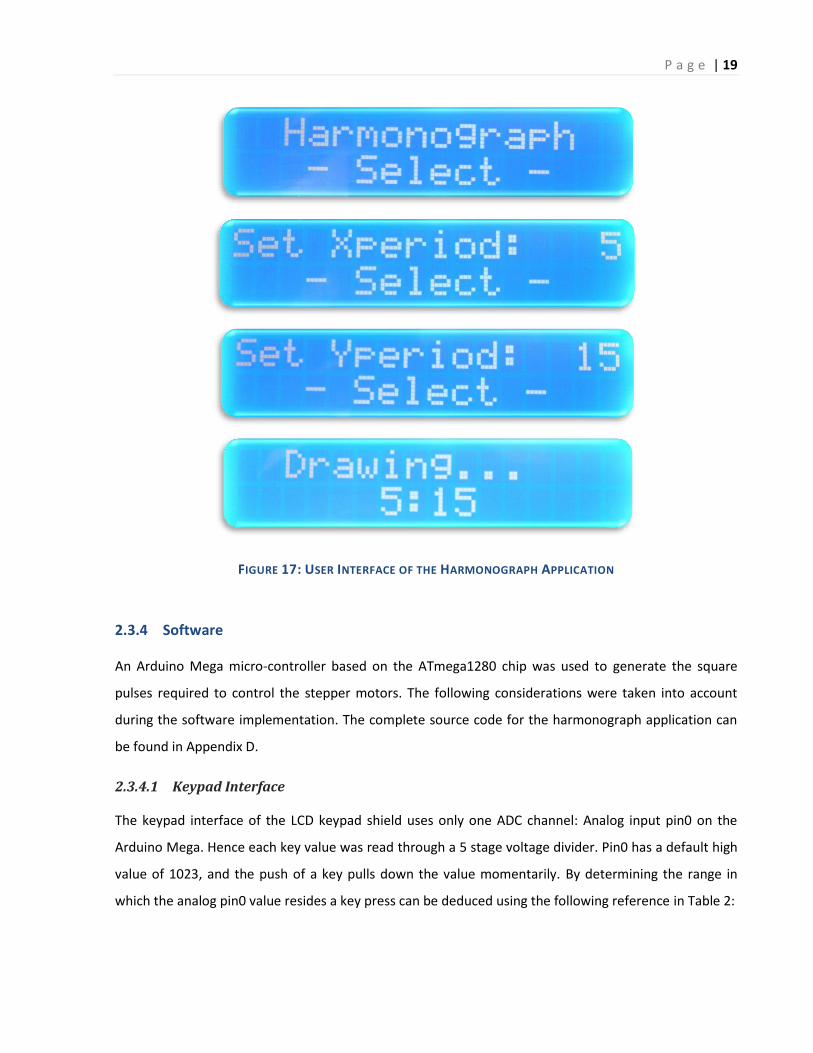
Screen shots of all menus available through the harmonograph application are shown below in Figure
17:
P a g e | 19
FIGURE 17: USER INTERFACE OF THE HARMONOGRAPH APPLICATION
2.3.4 Software
An Arduino Mega micro-controller based on the ATmega1280 chip was used to generate the square
pulses required to control the stepper motors. The following considerations were taken into account
during the software implementation. The complete source code for the harmonograph application can
be found in Appendix D.
2.3.4.1 Keypad Interface
The keypad interface of the LCD keypad shield uses only one ADC channel: Analog input pin0 on the
Arduino Mega. Hence each key value was read through a 5 stage voltage divider. Pin0 has a default high
value of 1023, and the push of a key pulls down the value momentarily. By determining the range in
which the analog pin0 value resides a key press can be deduced using the following reference in Table 2:

P a g e | 20
TABLE 2: RANGE OF ANALOG PIN0 READINGS CORRESPONDING TO EACH KEY PRESS
RIGHT 0-29
UP 30-149
DOWN 150-359
LEFT 360-534
SELECT 535-759
NO KEY PRESS 760-1023
2.3.4.2 Pulse Period
Since the period of the square pulses were used internally to generate the pulse width modulated
(PWM) outputs from the Arduino, determining the exact ratio of frequencies on each sinusoidal axis was
highly dependent on the accuracy of the period values. Hence if the speed was used as inputs instead,
the precision lost due to inverting the inputs produced oscillation periods with non-integer ratios thus
preventing the harmonograph from drawing accurate Lissajous curves.
For instance Figure 18 shows a failed attempt to create a 1:3 ratio drawing by inputting speeds of ratio
1:3. A simple conversion of the speeds to the oscillation period can be achieved through the following
equation:
⌊
⌋
Hence the resulting oscillation periods are 33 and 100 micro-seconds (μs) respectively with a ratio of
1:303, which in turn introduces a steady state error into the drawing forcing it to deviate from the
expected drawing of ratio 1:3.
Therefore in order to avoid this issue the period of oscillation was taken in as input directly from the
user interface and the values were mapped to a range from 20 μs to 500 μs (i.e. 50kHz to 2kHz) by the
following equation:
( )
where the user inputs starts from 4 to 100, and as a special case an input of 0 sets the oscillation period
to 0. Figure 19 shows a precise drawing for inputs 20 and 60 (i.e. 100 μs and 300 μs) with a ratio of 1:3
and a phase slightly different from the above scenario.

P a g e | 21
FIGURE 18: ERROR PRONE DRAWING WITH RATIO 1:3.03
FIGURE 19: DRAWING WITH RATIO 1:3
2.3.4.3 State Machine Control
The harmonograph application was implemented using a state machine as illustrated in Figure 20.

P a g e | 22
FIGURE 20: STATE MACHINE CONTROL LOOP

P a g e | 23
2.3.4.4 Software PWM
The software pwm was implemented using a 16 bit timer on the Arduino microcontroller. The timer was
initialized right before the transition to the “Drawing” state to call an interrupt service routine (ISR)
every 1 micro-second. The ISR would then keep track of the period of oscillation as set by the user and
also the duty cycle of 10% and appropriately send pulses to switch the stepper motors on and off. The
ISR control loop is illustrated in Figure 21.
FIGURE 21: PWM CONTROL LOOP

P a g e | 24
2.4 Performance Analysis
The performance of the harmonograph device was assessed by quantitatively measuring the drawings
created. A few measures of performance were used:
2.4.1 Drift Rate
As the harmonograph draws a complete curve, there is some expected amount of drift between two
consecutive passes. This may be caused due to mechanical reasons or due to timing errors in the
electronics and software.
Mechanical drift can be introduced if the motors face high friction, causing them to skip steps. Since the
stepper system is an open loop control system, the electronics cannot account for these skipped steps. If
the skipping happens at a specific point on the curve every iteration, there will be a steady rate of drift.
Software drift can be caused if the motors are not exactly running at the required speeds. This may be
caused by rounding errors in floating point computation. To avoid such errors, the software was
designed to use only integers at all times. This bypasses the problem entirely.
2.4.2 Mechanical Oscillation
The entire device is a complex mechanical system. It does behave like a complex spring-mass-damper
system. The pantograph arm is especially vulnerable to mechanical oscillation as it is not dampened
except by the pen making contact with the paper.
Furthermore, any oscillations in the hypocyloid drives will be amplified by the pantograph further
exacerbating the problem. However, since the sponsor would like some mechanical errors for an artistic
effect, this is not a major concern. Running the device at lower speeds greatly attenuates the amplitude
of these oscillations.
The amplitude and the period of these oscillations were recorded for further analysis.
2.4.3 Manufacturing imperfections
Since the gears were cut from the waterjet, there is a level of inherent imprecision associated with
them. These imprecisions manifest themselves as very reproducible errors in the drawings. These errors
always occur at the same point in the drawing as a specific part of the gear starts to mesh. These errors
were recorded and photographed for analysis.

P a g e | 25
3. Results
The device was successfully constructed. Friction on the linear bearings was minimal and allowed the
two stages of the hypocycloid to move freely. The pen holder mechanism worked better than expected,
always keeping constant pressure on the paper. The device able to draw the required shapes at various
ratios and speeds on paper with a variety of pens. Figure 19: Drawing with ratio 1:3 shows a sample
drawing.
After a few test images, data collection was done on a specific set of ratios. The device was set to a
constant ratio of 2:3 and run on several different speeds. 2:3 was chosen as a good representative ratio
as it is the lowest ratio that requires multiple cycles of each axis of the device to complete one curve.
Since most common ratios will be a multiple cycles on each axis, this ratio is a good representative one.
The pen chosen was a Bic Round Stic 0.7 mm black ball point pen. This draws very thin lines, allowing
measurement of errors to be easily done.
The maximum drift error was recorded with calipers. The oscillatory amplitude and wavelengths were
also recorded. The specific imperfections in the image were photographed and measured. The
numerical data collected is presented in Table 3.
TABLE 3: PERFORMANCE FIGURES FOR 2:3 RATIO AT VARIOUS SPEEDS
Period X (ticks per
step)
Period Y (ticks per
step)
Average Speed (steps
per tick)
Maximum Deviation (mm)
±0.05 mm
Oscillation Amplitude (mm)
±0.05 mm
Oscillation Wavelength (mm)
±0.05 mm
8 12 0.400 1.88 4.60 13.80
16 24 0.200 1.25 1.23 10.83
24 36 0.133 1.11 0.77 6.05
32 48 0.100 1.03 0.70 4.09
64 96 0.050 0.89 0.65 3.03
160 240 0.020 0.56 0.61 2.95
240 360 0.013 Did not Finish Did not Finish Did not Finish
400 600 0.008 Did not Finish Did not Finish Did not Finish

P a g e | 26
As can be seen from the data, running the device at higher speeds causes higher deviation from the
actual curve. There are large oscillations at high speeds due to the long pantograph arm serving as an
underdamped spring mass oscillator. The oscillation period and errors can be minimized by running the
device at low speeds.
However, below a certain speed (under 0.015 steps per tick), the device is unable to produce closed
curves. This is due to overwhelming stiction present in the linear bearings. Below the threshold speed,
the high static coefficient of friction is the dominant component (as opposed to the lower kinetic
coefficient). This causes the bearing to jam and the motors skip steps. The skipping of steps produces
unclosed curves. Hence no meaningful data can be measured from these runs. The only alleviation
would be to grease the bearings and try running at higher speeds.
3.1 Maximum Deviation Error
This is the error measured as the distance between lines drawn in two consecutive iterations of the
drawing. This type of error is clearly shown in Figure 24. The two lines were drawn on separate passes.
The error was measured by aligning the two arms of the calipers to the center of each line.
FIGURE 22: PHOTO OF DRAWING SHOWING SIGNIFICANT DEVIATION ERROR

P a g e | 27
The data collected for this measurement has been plotted in Figure 23.
FIGURE 23: PLOT OF MAXIMUM DEVIATION AS A FUNCTION OF AVERAGE SPEED.
At high speeds, there is a significant error in multiple passes of the drawings. The pen traces do not fall
right on top of each other. However, at low speeds, particularly under 0.05 steps per tick, there is a
sharp drop in this error (under 0.7mm). This is a significant point as the error at this speed is less than
the pen point’s diameter. Hence at this point, the two traces are just touching with no white space
between them.
The pen thickness would be deciding factor in choosing a speed. The thicker the pen, the faster the
device can be driven. A sample drawing with a much thicker 3mm marker is shown in Figure 28.
Although there is a deviation from previously drawn traces, there is no measurable drift error. This is
significant as it allows drawing of fully closed curves over multiple iterations of drawing. Hence, by using
wider markers it is very easy to produce fully closed curves even after long periods of drawing.
0
0.2
0.4
0.6
0.8
1
1.2
1.4
1.6
1.8
2
0 0.05 0.1 0.15 0.2 0.25 0.3 0.35 0.4 0.45
Mag
nit
ud
e (
mm
)
Average Speed (Steps per Tick)
Maximum Deviation (mm)

P a g e | 28
3.2 Underdamped Oscillation
Underdamped oscillations are produced by the large pantograph mechanism acting as a spring mass
system. Examples of these oscillations are shown in Figure 24. This error was measured using calipers as
shown in Figure 25. The oscillations are fairly large and only occur in long straight sections of the
drawing, implying a sort of resonant behavior.
FIGURE 24: PHOTO OF DRAWING SHOWING SIGNIFICANT OSCILLATORY BEHAVIOR
FIGURE 25: MEASUREMENT OF OSCILLATION AMPLITUDE AND WAVELENGTH

P a g e | 29
FIGURE 26: GRAPH SHOWING OSCILLATION AMPLITUDE AS A FUNCTION OF THE AVERAGE SPEED
FIGURE 27: GRAPH SHOWING OSCILLATION WAVELENGTH AS A FUNCTION OF THE AVERAGE SPEED
0
0.5
1
1.5
2
2.5
3
3.5
4
4.5
5
0 0.05 0.1 0.15 0.2 0.25 0.3 0.35 0.4 0.45
Mag
nit
ud
e (
mm
)
Average Speed (Steps per Tick)
Oscillation Amplitude (mm)
0
2
4
6
8
10
12
14
16
0 0.05 0.1 0.15 0.2 0.25 0.3 0.35 0.4 0.45
Mag
nit
ud
e (
mm
)
Average Speed (Steps per Tick)
Oscillation Wavelength (mm)

P a g e | 30
As can be seen from the plotted data in Figure 26 and Figure 27, there exist large oscillations above
speeds of 0.150 steps per tick. The oscillation amplitude asymptotes to around 0.6 mm below this
speed. Again, this is significant, as the error is smaller than the diameter of the pen (0.7mm). Hence,
over multiple runs, the pen traces over itself and the oscillations seem like a wider steady line. Hence, if
these oscillations are not desired in the final drawing, the device should be run below 0.150 steps per
tick.
However, due to the steady periodic nature of these oscillations, they can be used to enhance the
artistic effect of the drawings. If this is the desired effect, the wavelength and amplitude can be tweaked
by setting the appropriate speeds by referencing the graphs in Figure 26 and Figure 27.
As expected, the wavelength is roughly proportional to the driving speed. One point to note is that the
wavelength settles to a minimum of around 3 mm. An explanation for this behavior is that this is the
smallest motion produced by the pantograph corresponding to one step of the stepper motor. Hence, as
the stepper motors steps, the movement from that step is enlarged and produces this oscillation.
Once again, using a thicker pen reduces the visible error produced. Figure 28 shows a part of a drawing
produced with a much thicker 3mm marker pen. There are two overlapping lines in this photo, but
appear as one.
FIGURE 28: DRAWING WITH 3MM WIDE MARKER PEN

P a g e | 31
3.3 Manufacturing Imperfections
One anomaly was found in the drawing caused by the imperfect waterjet cutting of the acrylic gearing.
This manifests itself as a sharp turn in what is supposed to be a smooth curve (seen in Figure 29 and
Figure 30). This is quite small with a height of 4.26 mm ± 0.05 mm and a width of 1.47 mm ± 0.05 mm. It
is only seen on the extreme right corners of the drawings. Again, using a large diameter pen (3mm),
these anomalies are not apparent in the drawing.
FIGURE 29: DRAWING ANOMALY CAUSED BY IMPERFECT GEARING
FIGURE 30: MEASUREMENT OF ANOMALY SIZE

P a g e | 32
4. Conclusions
The device was built to all the sponsor’s requirements. It successfully draws any ratio of Lissajous-curves
of the required size (40 cm x 40 cm) to the sponsor’s satisfaction.
The device is precise enough at low speeds (below 0.05 steps per tick) to draw over its own lines using a
0.7mm pen. Using a larger 3mm marker pen, the device produces fully closed curves with no apparent
error at any speed allowed on the user interface.
The device is also sufficiently noisy at high speeds and produces oscillations with amplitudes ranging
from 0.5 mm to 4.5mm and wavelengths ranging from 3 mm to 13 mm. This introduces an artistic
element into the drawings.
There is one manufacturing defect that produces a drawing anomaly at the extreme right hand corners
of the drawing. The defect causes the curve to have sharp turns in the corners. The effect is less visible if
the drawn curve is never close to the top right or bottom right corners. Again, using a large 3mm marker
pen, the effect is not readily apparent. Furthermore, due to the symmetry of the drawing anomaly
across the horizontal axis, it appears artistic rather than a defect in the drawing.
The device is also aesthetically intriguing, especially because of dense arrangement of the openly visible
gears, linkages and other mechanisms.
Overall, the device has fulfilled all the intended requirements.

P a g e | 33
5. Project Deliverables
5.1 List of Deliverables
The following items are the project deliverables submitted to the sponsor.
5.1.1 Harmonograph
The completed harmonograph device along with the pantograph mechanism and a wooden drawing
board would be handed over to the sponsor.
5.1.2 Controller System
All control electronics along with the stepper motor controllers, power supply, Arduino Mega
microcontroller and the LCD keypad shield were mounted on a wooden board and handed over to the
sponsor as a single control unit for the harmonograph.
5.1.3 Noise Analysis
A final study of the inherent mechanical noise found within the system is presented in section 2.4.
Additionally a final set of recommendations based on this analysis along with recommendation on
utilizing this feature of the harmonograph to produce noisy drawings is presented in section 6.
5.2 Financial Summary
A complete bill of materials is presented in Appendix B. The source of funds is also indicated at the end
of the Appendix.

P a g e | 34
6. Recommendations
This section presents a set of recommendation for the general operation of the device and the possible
future improvements that can be done.
6.1 General operating recommendations
Before operation, always ensure that the device is properly placed on a flat surface and that the paper is
secured with tape. The device can be moved and placed over any part of the paper. This allows the
device to be used with any size of paper. However, when doing this, care must be taken to ensure that
the device and the pantograph mechanism are not subjected to too much stress while moving.
The motors produce high torques. The hypocycloid mechanism can easily injure fingers that get caught
in the gearing. It is recommended, that the device be turned off before any inspections of maintenance
is done.
Regular greasing of the linear bearing mechanism is highly recommended. This will reduce wear and tear
and keep the device functioning smoothly with minimal error.
Any pen size can be used with the device. However, the recommended one for minimal error is a 3mm
wide marker. If thinner lines are required, the device must be run at lower speeds. As a general rule of
thumb, running the device at higher speeds produces noisier drawings. Using a smaller diameter pen
makes the noise readily apparent.
Finally, the device should not be run for extended periods of time without monitoring. The stepper
motors do dissipate heat. If they overheat, the device could be damaged.
6.2 Future Improvements
One main improvement that was suggested was adding a flat drawing board where the device could be
anchored along with a clip to hold paper. However, this was not implemented as this would limit the size
of paper to be used. Presently, the device can be moved over any size of paper. If only a specific size of
paper is used, it may be worthwhile to build this drawing platform.
Extra fan cooling on the stepper motors will allow the device to operate for extended periods of time.
The size of the fan required and the flow rate need to be investigated. Operating the device for
extended periods of time will allow drawing of very intricate and complex curves.

P a g e | 35
Appendix A: Lissajous Curves
A Lissajous curve, also known as Bowditch curve, can be described by the following set of parametric
equations:
( ), ( )
which is a combination of two simple harmonic motions that produces a complex harmonic motion.
Many variations of the curves can be obtained by making the frequency of the horizontal and the
vertical oscillations a, b to be either equal or multiples of the same base frequency.
Lissajous curves are also a special case of the curves produced by a two pendulum harmonograph with
damping constants β1 = β2 = 0. The damping constants here are the factors that define periodic
sinusoidal oscillations of a simple harmonic motion which obeys the following differential equation:
where ω0 is the angular frequency of oscillation.
A few examples of Lissajous figures with
are shown below in Figure 31:
FIGURE 31: LISSAJOUS FIGURES

P a g e | 36
Appendix B: Bill of Materials
Description Quantity Vendor(s) Cost/Item Total Cost Purchased
By
Arduino Mega ( ATmega1280 ) 1 EP Lab $44.00 $44.00 Nabil
DFRobot LCD Keypad Shield 1 EP Lab $18.56 $18.56 Nabil
Geckodrive Stepper Motor Controller 2 EP Lab $100.00 $200.00 Nabil
Mean Well S-150-24 Power Supply 1 EP Lab $63.91 $63.91 Nabil
Dimension Engineering DE-SWADJ 1 EP Lab $16.08 $16.08 Nabil
Hardened Precision Steel Shaft 1/2"
Diameter, 12" 1 McMaster Carr $5.01 $5.01 Sid
SAE 863 Bronze Flanged-Sleeve Bearing
for 1/2" Shaft Diameter 2 McMaster Carr $0.94 $1.88 Sid
SAE 863 Bronze Sleeve Bearing for 3/8"
Shaft Diameter 12 McMaster Carr $0.62 $7.44 Sid
Clear Acrylic Sheeting 1/2" 12"x24" 1 McMaster Carr $51.02 $51.02 Sid
Water-jet cost 38 EP Lab $1.00 $38.00 Sid
Drawing Supplies 1 Staples $25.00 $25.00 Sid
Total Supply Cost $470.90
EP Lab Project Fund $295.90
Cost for the Sponsor $175.00

P a g e | 37
Appendix C: Stepper Motor Controller Connections
The “Geckodrive” G201 stepper motor controller requires the following connections to operate
(Geckodrive Inc, 2009):
TERMINAL 1 Power Ground
TERMINAL 2 Power +24VDC supply
TERMINAL 3 Motor Phase A
TERMINAL 4 Motor Phase /A
TERMINAL 5 Motor Phase B
TERMINAL 6 Motor Phase /B
TERMINAL 9 Step (Port 49 or 53 on the Arduino Mega)
TERMINAL 10 Common +5VDC supply
TERMINAL 11 Current Set Resistor Terminal 1
TERMINAL 12 Current Set Resistor Terminal 2
The phase of each motor coil corresponding to each of the four color-coded wires of the stepper motor
can be identified from the reference diagram in Figure 32.
FIGURE 32: STEPPER MOTOR WIRE IDENTIFICATION (LIN ENGINEERING)

P a g e | 38
Appendix D: Software Code
#include <stdio.h> #include <LCD4Bit_mod.h> #include <TimerThree.h> #define STANDBY 0 #define SET_X_SPEED 1 #define SET_Y_SPEED 2 #define DRAWING 3 #define RIGHT 0 #define UP 1 #define DOWN 2 #define LEFT 3 #define SELECT 4 #define SMALL_INCR 1 #define LARGE_INCR 10 #define ZERO_SPEED 0 #define MIN_SPEED 4 #define MAX_SPEED 100 #define PERIOD_MULTIPLE 5 #define DUTY_CYCLE 10 int pwmPinX = 53; int pwmPinY = 49; LCD4Bit_mod lcd = LCD4Bit_mod(2); int NUM_KEYS = 5; int adc_key_val[5] = { 30, 150, 360, 535, 760 }; int adc_key_in; int key = -1; int oldkey=-1; char charBuffer[32]; int xSpeed = 5; int ySpeed = 5; volatile int xCount = 0; volatile int yCount = 0; volatile int periodX; volatile int periodY; volatile int pwmPeriodX; volatile int pwmPeriodY; volatile int currentState = STANDBY; void setup() { pinMode( pwmPinX, OUTPUT ); pinMode( pwmPinY, OUTPUT ); lcd.init(); lcd.clear(); lcd.cursorTo(1, 2); lcd.printIn("Harmonograph"); lcd.cursorTo(2, 3); lcd.printIn("- Select -"); Timer3.initialize(1); Timer3.attachInterrupt( IncrementCounters ); Timer3.stop(); }

P a g e | 39
void loop() { adc_key_in = analogRead(0); key = get_key(adc_key_in); if (key != oldkey ) { delay(50); adc_key_in = analogRead(0); key = get_key(adc_key_in); if (key != oldkey) { oldkey = key; switch ( key ) { case RIGHT: { if ( currentState == SET_X_SPEED ) { xSpeed += SMALL_INCR; if ( xSpeed > MAX_SPEED ) xSpeed = MAX_SPEED; } else if ( currentState == SET_Y_SPEED ) { ySpeed += SMALL_INCR; if ( ySpeed > MAX_SPEED ) ySpeed = MAX_SPEED; } break; } case LEFT: { if ( currentState == SET_X_SPEED ) { xSpeed -= SMALL_INCR; if ( xSpeed < MIN_SPEED ) xSpeed = ZERO_SPEED; } else if ( currentState == SET_Y_SPEED ) { ySpeed -= SMALL_INCR; if ( ySpeed < MIN_SPEED ) ySpeed = ZERO_SPEED; } break; } case UP: { if ( currentState == SET_X_SPEED ) { xSpeed += LARGE_INCR; if ( xSpeed > MAX_SPEED ) xSpeed = MAX_SPEED; } else if ( currentState == SET_Y_SPEED ) { ySpeed += LARGE_INCR; if ( ySpeed > MAX_SPEED ) ySpeed = MAX_SPEED; } break; } case DOWN: { if ( currentState == SET_X_SPEED ) { xSpeed -= LARGE_INCR; if ( xSpeed < MIN_SPEED ) xSpeed = ZERO_SPEED; } else if ( currentState == SET_Y_SPEED )

P a g e | 40
{ ySpeed -= LARGE_INCR; if ( ySpeed < MIN_SPEED ) ySpeed = ZERO_SPEED; } break; } case SELECT: { switch ( currentState ) { case STANDBY: { lcd.clear(); lcd.cursorTo(1, 0); lcd.printIn("Set Xperiod: "); sprintf( charBuffer, "%3d", xSpeed ); lcd.printIn( charBuffer ); lcd.cursorTo(2, 3); lcd.printIn("- Select -"); currentState++; break; } case SET_X_SPEED: { lcd.clear(); lcd.cursorTo(1, 0); lcd.printIn("Set Yperiod: "); sprintf( charBuffer, "%3d", ySpeed ); lcd.printIn( charBuffer ); lcd.cursorTo(2, 3); lcd.printIn("- Select -"); currentState++; break; } case SET_Y_SPEED: { lcd.clear(); lcd.cursorTo(1, 2); lcd.printIn("Drawing..."); if ( xSpeed == ZERO_SPEED ) periodX = 1; else periodX = xSpeed * PERIOD_MULTIPLE; if ( ySpeed == ZERO_SPEED ) periodY = 1; else periodY = ySpeed * PERIOD_MULTIPLE; pwmPeriodX = periodX * DUTY_CYCLE / 100; pwmPeriodY = periodY * DUTY_CYCLE / 100; lcd.cursorTo(2, 5); sprintf( charBuffer, "%2d:%2d", xSpeed, ySpeed ); lcd.printIn( charBuffer ); Timer3.restart(); Timer3.start(); currentState++; break; } case DRAWING: { Timer3.stop(); lcd.clear(); lcd.cursorTo(1, 0); lcd.printIn("Set Xperiod: "); sprintf( charBuffer, "%3d", xSpeed ); lcd.printIn( charBuffer ); lcd.cursorTo(2, 3); lcd.printIn("- Select -");

P a g e | 41
currentState = SET_X_SPEED; break; } } } } } } switch ( currentState ) { case STANDBY: { delay(1); break; } case SET_X_SPEED: { lcd.cursorTo(1, 13); sprintf( charBuffer, "%3d", xSpeed ); lcd.printIn( charBuffer ); break; } case SET_Y_SPEED: { lcd.cursorTo(1, 13); sprintf( charBuffer, "%3d", ySpeed ); lcd.printIn( charBuffer ); break; } } } int get_key(unsigned int input) { int k; for (k = 0; k < NUM_KEYS; k++) if (input < adc_key_val[k]) return k; if (k >= NUM_KEYS) return -1; } void IncrementCounters() { xCount++; if ( xCount == pwmPeriodX ) digitalWrite( pwmPinX, LOW ); else if ( xCount == periodX ) { digitalWrite( pwmPinX, HIGH ); xCount = 0; } yCount++; if ( yCount == pwmPeriodY ) digitalWrite( pwmPinY, LOW ); else if ( yCount == periodY ) { digitalWrite( pwmPinY, HIGH ); yCount = 0; } }

P a g e | 42
Bibliography
Fairchild Semiconductor. (2011, September). Retrieved from LM78XX Voltage Regulator:
http://www.fairchildsemi.com/ds/LM/LM7805.pdf
Geckodrive Inc. (2009, August 6). G201 Step Motor Drive - User Manual. Retrieved from
http://www.geckodrive.com/images/fck_uploads/G201%20REV-16%20MANUAL.pdf
Klingener, F. (2011). Comparing Simple Crank/Slider and Scotch Yoke Mechanisms. Retrieved September
21, 2011, from Wolfram Demonstrations Project:
http://demonstrations.wolfram.com/ComparingSimpleCrankSliderAndScotchYokeMechanisms/
Lewis, P. N. (2007). How to Build a Pantograph. Retrieved January 8, 2012, from Peter's Articles:
http://www.peter.com.au/articles/pantograph.html
Lin Engineering. (n.d.). Retrieved from 4209 Stepper Motor User Guide:
http://www.linengineering.com/LinE/contents/stepmotors/pdf/Step_Motor_Start-
up_Guide.pdf
Malar, M. (2009). Hypocycloid Straight-Line Mechanism. Retrieved 2012, from
http://www.mekanizmalar.com/s16.html
Ryan, V. (2009). Crank And Slider Mechanism. Retrieved September 21, 2011, from Technology Student:
http://www.technologystudent.com/cams/crkslid1.htm
Sawyer, W. G. (n.d.). Wearing Mechanisms. Retrieved September 21, 2011, from
http://grove.ufl.edu/~wgsawyer/Laboratory/Wear/Mechanisms.HTML
Copyright © 2022 FDOKUMEN