Hardware Trojan Horses in Cryptographic IP Cores - Archive ...
16
HAL Id: hal-00855146 https://hal.archives-ouvertes.fr/hal-00855146v1 Submitted on 29 Aug 2013 (v1), last revised 8 Oct 2014 (v2) HAL is a multi-disciplinary open access archive for the deposit and dissemination of sci- entific research documents, whether they are pub- lished or not. The documents may come from teaching and research institutions in France or abroad, or from public or private research centers. L’archive ouverte pluridisciplinaire HAL, est destinée au dépôt et à la diffusion de documents scientifiques de niveau recherche, publiés ou non, émanant des établissements d’enseignement et de recherche français ou étrangers, des laboratoires publics ou privés. Hardware Trojan Horses in Cryptographic IP Cores Shivam Bhasin, Jean-Luc Danger, Sylvain Guilley, Thuy Ngo, Laurent Sauvage To cite this version: Shivam Bhasin, Jean-Luc Danger, Sylvain Guilley, Thuy Ngo, Laurent Sauvage. Hardware Trojan Horses in Cryptographic IP Cores. FDTC, Aug 2013, Santa Barbara, United States. pp.15-29, 10.1109/FDTC.2013.15. hal-00855146v1
-
Upload
khangminh22 -
Category
Documents
-
view
0 -
download
0
Transcript of Hardware Trojan Horses in Cryptographic IP Cores - Archive ...

HAL Id: hal-00855146https://hal.archives-ouvertes.fr/hal-00855146v1
Submitted on 29 Aug 2013 (v1), last revised 8 Oct 2014 (v2)
HAL is a multi-disciplinary open accessarchive for the deposit and dissemination of sci-entific research documents, whether they are pub-lished or not. The documents may come fromteaching and research institutions in France orabroad, or from public or private research centers.
L’archive ouverte pluridisciplinaire HAL, estdestinée au dépôt et à la diffusion de documentsscientifiques de niveau recherche, publiés ou non,émanant des établissements d’enseignement et derecherche français ou étrangers, des laboratoirespublics ou privés.
Hardware Trojan Horses in Cryptographic IP CoresShivam Bhasin, Jean-Luc Danger, Sylvain Guilley, Thuy Ngo, Laurent
Sauvage
To cite this version:Shivam Bhasin, Jean-Luc Danger, Sylvain Guilley, Thuy Ngo, Laurent Sauvage. Hardware TrojanHorses in Cryptographic IP Cores. FDTC, Aug 2013, Santa Barbara, United States. pp.15-29,�10.1109/FDTC.2013.15�. �hal-00855146v1�

Hardware Trojan Horses in Cryptographic IP Cores
Shivam BHASIN1, Jean-Luc DANGER1,2, Sylvain GUILLEY1,2, Xuan Thuy NGO1,† and Laurent SAUVAGE1,2
1Institut MINES-TELECOM, TELECOM-ParisTech
CNRS LTCI (UMR 5141),
46 rue Barrault, 75 634 Paris Cedex 13, France.
Email: [email protected]
2Secure-IC S.A.S.
80 avenue des Buttes de Coesmes, 35 700 Rennes, France.
Email: [email protected]
†Corresponding author.
Abstract—Detecting hardware trojans is a difficult task ingeneral. In this article we study hardware trojan horses insertionand detection in cryptographic intellectual property (IP) blocks.The context is that of a fabless design house that sells IPblocks as GDSII hard macros, and wants to check that finalproducts have not been infected by trojans during the foundrystage. First, we show the efficiency of a medium cost hardwaretrojans detection method if the placement or the routing havebeen redone by the foundry. It consists in the comparisonbetween optical microscopic pictures of the silicon product andthe original view from a GDSII layout database reader. Second,we analyze the ability of an attacker to introduce a hardwaretrojan horse without changing neither the placement nor therouting of the cryptographic IP logic. On the example of anAES engine, we show that if the placement density is beyond80%, the insertion is basically impossible. Therefore, this settlesa simple design guidance to avoid trojan horses insertion incryptographic IP blocks: have the design be compact enough,so that any functionally discreet trojan necessarily requires acomplete re-place and re-route, which is detected by mere opticalimaging (and not complete chip reverse-engineering).
Index Terms—Hardware trojan horses (HTH), HTH detectionand insertion, optical pictures versus GDSII comparison tech-nique, ECO place-and-route, core utilization rate (CUR).
I. Introduction
The semiconductor industry has spread across borders in
the time of globalization. Different design phases of an In-
tegrated Circuit (IC) may be performed at geographically
dispersed locations. This coupled with the outsourcing design
and fabrication to increase profitability has become a common
trend in the semiconductors industry. However, this business
model comes with an ample scope of introducing malicious
behavior to a part of the IC. The adversary has enough scope to
tamper the supply chain by maliciously implanting extra logic
as Hardware Trojan Horse (HTH) circuitry into an IC [40].
This raises serious concerns about security and trustworthiness
of imported products employed in critical applications like
military, health, transportation, etc. HTH can be introduced
in an IC at several points right from the Register Transfer
Level (RTL) source code to lithographic masks fabrication. An
C CmodifiedAB
Trojan active
PayloadTrigger
Figure 1. Minimalist Hardware Trojan Horse example
attacker can change a design netlist or subvert the fabrication
process by manipulating design masks, without affecting the
main functionality of the design [2].
Any HTH is composed of two main components [36]:
• Trigger: is the part of HTH used to activate the malicious
activity,
• Payload: is the part of HTH used to realize/execute the
malicious activity.
Fig. 1 gives an example of one simplistic HTH. In this
archetype HTH, the trigger is a simple AND gate: it tests the
equality of the inputs A and B to 1; the payload is an XOR
gate: it inverts the intermediate net C if the trigger is active.
An adversary can introduce a HTH which might be designed
to disable or destroy a system at some future time, or to leak
confidential information such as secret keys covertly to an
adversary [35] by putting them to output channels. In [34],
the author demonstrates an attack on a (purported military-
grade) chip using a malicious backdoor. The backdoor allows
the attacker to disable all the security of the chip, reprogram
cryptographic part, access secret keys, modify low-level sil-
icon features, access unencrypted configuration bitstream or
permanently damage the device. Thus protection against HTH
is an open problem and an active research topic.
HTH detection is an extremely challenging problem; tradi-
tional structural and functional tests do not seem to be effective

in targeting and detecting HTHs. Since HTH can be introduced
during different design phases, the nature of HTH differs from
one design phase to the others. Therefore it is difficult to
find a unique detection technique for all HTH. For instance
Automatic Test Pattern Generation (ATPG) methods which
are used in manufacturing test for detecting defects, generally
operate on the netlist of the HTH-free circuit. Existing ATPG
algorithms cannot target HTH activation/detection directly [41]
because HTH are designed such that they are silent most
of their lifetime and have very small size relative to their
host design, with featuring limited contribution into design
characteristics. Such HTHs are most likely connected to nets
with low controllability and/or observability [41], [5].
The state of the art principle in detection strategies of HTH
can be widely classified in two categories, viz. invasive and
non-invasive [25].
Invasive methods try to (prophylactically) modify the design
of IC to prevent the HTH or to assist another detection
technique. Chakraborty et al. have proposed a design that
aims to expose the presence of a HTH in a multi-module
design [11]. Salmani et al. propose a procedure to insert
dummy flip-flops into logic to increase HTH activity, making
the detection easier using side-channel techniques [32]. Other
researchers also suggest logic additions that will make it easier
to detect a HTH utilising side-channel analysis, e.g., [24] add
extra logic for characterising delay times within an IC.
Non-invasive HTH detection is done by comparing the
performance characteristics of an IC with a known good copy
also known as the “golden circuit”. Detecting HTH in a non-
invasive manner can be done either at runtime or in the testing
phase. The runtime detection mechanisms is combined with
the countermeasures, as once a HTH is detected at runtime,
attempts are made to try and continue operating by bypassing
the HTH. For runtime, Bloom et al. detail a HTH detection
approach that uses both hardware and software to detect
two types of HTH which are DoS (Denial of Service) and
combined hardware and software HTH [8]. Abramovici and
Bradley added reconfigurable DEsign-For-ENabling-SEcurity
(DEFENSE) logic to the functional design to implement real-
time security monitors [1]. McIntyre et al. detect the presence
of HTHs by executing functionally equivalent processes on
multiple hardware processing elements [26]. The testing phase
detection methods attempt to enhance traditional IC testing,
or use side-channel analysis. For logic testing, Jha and Jha
present a randomisation-based technique which probabilisti-
cally compares the functionality of the design of the circuit
with the implemented circuit [18]. Chakraborty et al. suggest
to test rare occurrences on an IC rather than testing for cor-
rectness [12]. The tester determines rare states that can occur
within a circuit module. For side-channel analysis, Agrawal et
al. present a type of detection mechanism [3]. Some known
good copies of the IC are obtained and fingerprinted using
one or more side-channel parameters. Other chips can then be
tested against these fingerprints like path delay in [19]. Power
supply transient signal analysis is used as the side channel by
Rad et al. [31]. They aim at determining the smallest HTH
that they can find using this technique, which can be as low
as three additional gates. Banga and Hsiao [5] propose the
“sustained vector technique” that is able to magnify the side-
channel differences (based on power draw) between circuits
infected with HTHs and those that are not.
Most of the abovementioned techniques are indirect de-
tection methods (e.g. reviewed in Chapter 15 of [36]). Such
methods observe the effect of the HTH on the timing, the
side-channel emissions, etc. The presented indirect detection
methods are, under ideal circumstances, able to detect a
HTH even of small size. However, countermeasures protecting
cryptographic implementations often rely on perturbing the
power consumption by methods like random clock jitter or
masking of sensitive data, etc. Therefore, the indirect method,
though still feasible, will loose efficiency in such applications.
Another requirement for the indirect method is the golden
reference, which can be sometimes expensive to obtain. Also
side-channel based techniques are often becoming less efficient
because of factors like environmental/measurement noise, pro-
cess variation, or algorithmic noise. Thus HTH detection may
require a huge amount of traces. On the contrary, our direct
observation technique is not affected by the randomization or
variations brought by countermeasures.
In this paper, we develop a new HTH detection method
at the layout level of integrated circuits by using a low-cost
direct visual detection. We address the scenario where the
HTH is inserted by an untrusted off-shore foundry just before
the fabrication of a unit. We place ourselves in the role of a
designer who sends a HTH-free layout (e.g. in GDSII format
– Graphic Database System version II, format of Cadence
Design Systems) to a third-party foundry for fabrication but
is threatened by introduction of a HTH in the GDSII by the
untrusted fab. Of course an untrusted founder introducing a
HTH will not share the HTH-infected GDSII with the designer.
To address this issue we propose a detection technique based
on image processing/comparison techniques. These techniques
are used to compare the final HTH-free layout with the high-
quality optical snapshots of the IC. We illustrate our technique
on secret key block ciphers (modified to allow for a distant
fault injection); but actually it can also allow to detect the mod-
ification made in the netlist of arithmetic operations, which can
lead to “bug attacks” [6] in asymmetric cryptography. Several
works on insertion of HTH in cryptographic applications have
been previously studied [16], [4].
This paper describes a HTH based on a backdoor that can
activate a bitflip compliant with a (remote) differential fault
attack. It also discusses a visual or correlation based technique
capable of detecting modifications in the layout (that can
somehow be considered permanent faults).
The rest of this paper is organized as follows. Section II
gives a general background on AES and how fault attacks
can reveal its secret key. Also in this section, a small gate
count HTH is given whose principle is to trigger an artificial
fault injection. Section III presents the central contribution of
the paper: it explains how a visual comparison between the
chip and the original GDSII can reveal HTH insertions. An

automated method for the HTH detection based on a similarity
tool (namely the cross-correlation) is then presented. Based
on this detection method, a case study of HTH and results
are shown in Section IV; it is applied successfully to real
images and layouts. Section V gives some recommendations
for the designer to implement a cryptographic IP module that
would resist to HTH insertion; that is either the HTH fails to
be inserted by lack of resources, or it will be detected after
fabrication with our low-cost visual detection based on lay-
out/picture comparison. Finally conclusions and perspectives
are drawn in Section VI. In the appendix A, the setup to test
the proposed fault-based HTH is presented.
II. Proposal for a Low Gate Count Hardware Trojan Horse
in AES
A. General Background on Differential Fault Analysis and
AES
Physical attacks which target the implementation of crypto-
graphic circuits (in smartcards, pay-TV and SIM cards, etc.)
have been known for some years now. They are widely classi-
fied as “observation” and “perturbation” attacks. Observation
or side channel attacks (SCA) consist in observing physical
emanations of the system, like power (Differential Power
analysis, or DPA [22]) or E/H field (ElectroMagnetic Analysis,
or EMA [30]). Thereafter statistical tools are deployed to
find dependency between the predicted and observed behavior.
Perturbation or fault attacks consist in the injection of faults
during the execution of a cryptographic algorithm [7]. From
the knowledge of one or multiple couples {correct ciphertext,
faulted ciphertext}, some hypotheses on the secret key can be
discarded. This generic attack strategy is referred to as DFA
(Differential Fault Analysis). DFA is very effective against
some cryptographic algorithms. For example in AES, the
number of faulty ciphertext required to break the key can be
as low as two1. There are several techniques known for fault
injection in a system [20]. The variations of the supply voltage,
overclocking, temperature increase, or the irradiation by a laser
beam will most probably lead to a wrong computation result
that can be exploited to realize a DFA. This kind of attack
represents a real threat for the implementation of cryptographic
algorithms such as the AES.
In the sequel, and without loss of generality, we focus on
the 128-bit version of AES. AES is a substitution permuta-
tion network (SPN) product block cipher. It has an iterative
structure, consisting in the repetition of ten rounds which are
applied to the 16 bytes data block to be encrypted. The 16
bytes are laid out as a matrix of four columns of four bytes
si, j, where 0 ≤ i ≤ 3 and 0 ≤ j ≤ 3. A round consists
of a fixed sequence of transformations. Apart from the first
and the last rounds, the other eight rounds are identical and
consist of four transformations each. The first and last rounds
1Recently, some even stronger attacks have been presented [39]; the idea isto exploit further relationships from the key scheduling logic to end up with aBoolean equation system that solves the key with one fault, albeit at the costof more computation. For the need of our HTH design, both types of DFAwould be equally adequate.
are incomplete, so as to ease the decryption. The four round
transformations are called SubBytes, ShiftRows, MixColumns
and AddRoundKey.
Piret’s DFA [28] assumes only a random “byte-flip” in
the last or penultimate encryption round. It is an attack that
consists in solving a system of non-linear equations with
Boolean variables: the 128+ 8 unknown variables are the key
and the fault, whereas the 128 + 128 known variables are the
correct and the faulted ciphertexts. In fact due to the linearity
of the MixColumns transformation there are 255 × 4 possible
differences at the output of the MixColumns. If we suppose a
fault on one input byte of the last MixColumns it will affect
4 bytes of the output as shown in Fig. 2 and if we use a pair
of correct ciphertext C and a faulty ciphertext F, we can make
a guess about 4 bytes in the key using Piret’s algorithm [28].
Eight single faults, located by pairs in the four columns before
the MixColumns stage of the ninth round (further referred
to as “Round 9”) permits the unveiling of the whole key.
Alternatively, for this attack, only two single faults located
before the MixColumns of the eighth round (further denoted
as “Round 8”) allows the attacker to find the 16 bytes of the
key.
B. DFA-based AES Hardware Trojan Horse
Fig. 3 shows an example of a HTH introduced in an AES
coprocessor. The inserted HTH aids the attacker to perform
faults compliant with Piret’s DFA. It has three activation
conditions:
1) First of all, an external switch (optional) should be
activated; it allowed us to validate the design without
and with the HTH, simply by moving a sliding lever
of a DIP switch on a SASEBO-GII board (for details,
please refer to appendix A).
2) Second, the HTH tests that the round counter is equal
to 8. As already mentioned, in this round, the fault is
scattered to all of the 128 bits of the ciphertext, and these
faulted bits allow to retrieve the complete last round key.
3) The third activation condition is a pattern detected in the
plaintext. Concretely, our HTH is generic: depending
on a parameter N, N bits of the plaintext are tested
for equality to one. Such genericity makes it possible
for a trade-off: the larger N, the smaller the activation
probability (1/2N) – by functional test for instance –
but the larger the HTH (its size grows roughly speaking
proportionally with N). A working example of this HTH
on FPGA is shown in Appendix A for N = 16.
The HTH payload is a single XOR gate which faults one
bit of the AES in the inner eighth round. As a consequence,
this HTH is more compact than other HTH that would (for
instance) output one round key instead of the ciphertext; such
strategy requires at least 128 multiplexers.
In our setup, the attacker needs to activate the HTH for
2 encryptions to retrieve the whole key. The power of the
attacker will be determined by the HTH activation circuit. The
smaller the activation circuit (Trigger) is applied, the more
difficult it is to detect HTH, thus the more dangerous it is.

����������
����������
����������
����������
����������
����������
����������
����������
��������
��������
��������
��������
����������
����������
��������
��������
����������
����������
����������
����������
��������
��������
����������
����������
����������
����������
����������
����������
��������
��������
����������
����������
���������������
���������������
��������
��������
S00
S03
S02S
01
S12S
11S
13
S21
S20
S22
S23
S30
S31 S
33S
32
S10
K9 K10
S00
S03
S02S
01
S12S
11S
13
S21
S20
S22
S23
S30
S31 S
33S
32
S10
S00
S03
S02S
01
S12S
11S
13
S21
S20
S22
S23
S30
S31 S
33S
32
S10
ShiftR
ow
s
Mix
Colu
mns
ShiftR
ow
s
S00
S03
S02S
01
S12S
11S
13
S21
S20
S22
S23
S30
S31 S
33S
32
S10
SubB
yte
s
SubB
yte
s
S00
S03
S02S
01
S12S
11S
13
S21
S20
S22
S23
S30
S31 S
33S
32
S10
S03
S02
S12S
11S
13
S21
S20
S22
S30
S31 S
33
S01
S00
S03
S02
S12S
11S
13
S21
S20
S22
S30
S31 S
33
S01
S00
Round 9
Cipher Text
Round 10
Figure 2. Effect of a fault in last but one round of AES-128.
We stress that some interpretation (in other words, little
reverse-engineering) of a GDSII file is needed to identify
the resources where to plug the HTH. However, we assume
that the localization of the state register (128 flip-flops) is
fairly easy, and thus understanding roughly speaking the
organization of the layout should be feasible without too much
pain.
To some extent, the principle of this fault-based HTH is the
equivalent to the “intentionally leaky” blocks discussed in [21]
for side-channel analyses, but in the domain of fault injection
attacks. Indeed, the side-channel (resp. fault injections) attacks
are used for a constructive feature (although our HTH actually
implements a malicious functionality!).
Finally, let us mention that, to our best knowledge, the first
HTH that relies on the insertion of a distant fault injection
mechanism is the “bug attack” [6]. It consists in slightly
altering a hardware integer multiplier, in such a way it delivers
always the correct answer but for at least one configuration
of the inputs. It has been shown by Biham, Carmeli and
Shamir that this permits a remote Bellcore [9] attack that
allows, for the insider who inserted the HTH and under
some circumstances (e.g. depending on the padding scheme),
a retrieval of the private key. The HTH presented in this
section is based on a similar idea that allows a remote DFA
on symmetric block ciphers.
III. Low-Cost Hardware Trojan Horse Detection by GDSII /
Picture Comparison
A. Reverse Engineering
Reverse engineering is often used in the semiconductor
industry to extract technical or patent related information
from a competitor’s chip [17]. The chip can be reverse en-
gineered at different levels like: product components, system-
level, process-level and circuit-level [38]. In our case we are
interested with the circuit-level reverse engineering. Modern
devices are fabricated in technology like 45 nm or lower
which can have up to 12 layers of metal and several millions
of transistors. The detail of the circuit are extracted in the
following sequential steps:
• package removal;
• delayering;
• imaging.
In the state of the art, “destructive reverse-engineering” can
be used to detect HTH for our scenario. Reverse-engineering
is generally performed by Chemical Metal Polishing (CMP)
followed by Scanning Electron Microscope (SEM) image
reconstruction and analysis [37]. It helps to reconstruct exactly
all via, metal and silicon layers. After, the determination of
the “correctness” of a chip is performed through visual com-
parison with a known good example or “golden reference”.
But this technique is very expensive since it takes a lot of
time (hence costs a lot) to realize properly: the mere error in
a picture (because the delayering left pieces of material on the
chip surface or because the recognition software [33] failed)
makes the reverse engineering fail. In addition, modern devices
are extremely small and densely packed, which makes the cost
(in money and time) of reverse engineering even higher.
B. Medium Cost Hardware Trojan Horse Detection
In this paper, we demonstrate that HTH inserted at GDSII
level can be spotted with a visual detection technique. The
main argument is that the full reverse-engineering is overkill
to detect a change in a layout. Mesoscopic imaging (obtained
with a ×150 optical microscope) is enough to conduct a
coarse imaging comparison between the GDSII file submitted
for fabrication and the returned circuit. High-end visible-light
microscope and camera are termed specialized equipments in
the attacks quotation application note [15, §3.7] (for Common
Criteria [14]), which means that they considered medium
cost laboratory tools. Indeed, the low-level (masks drawing)
“bitmap” comparison of two images is a more elementary task
than a full-fledged reverse engineering (that in addition aims

AddRoundKey
MixColumns
ShiftRows
SubBytes
AddRoundKey
AND
Grid
ShiftRows
SubBytes
Cipher Key
Round Key
Round Key 10
Initial Round
9 Rounds
Final Round
AddRoundKey
acti
vat
ion
_co
nd
[0]
(sw
itch
)
acti
vat
ion
_co
nd
[2]
Output Cipher (128 bits)
Input Cipher (128 bits)
127
Trojan_active
127
acti
vat
ion
_co
nd
[1]
(8th
ro
un
d)
128
128
[126:0]1271
Payload
N
Trigger
Figure 3. Differential Fault Analysis (DFA) based HTH in AES — Illustration of a remote DFA enabled by the HTH
at interpreting the layout, i.e. reconstruct the netlist, by giving
sense to the picture). Still said differently, reverse engineering
is well suited to perform an “image versus netlist” comparison,
whereas we research in this paper to make a sheer “image
versus layout” comparison.
By optical observation, the M6 shape (topmost layer) can
be recovered. For example, Fig. 4 shows the layout and
the picture of the fabricated chip side-by-side. The layout is
opened in Mentor Graphics Calibre Litho View tool (r2102-
4.25), because it allows to set the color and the transparency
level for each layer. Specifically, we decided to represent the
topmost metal layer with a solid color, as this corresponds to
the non-transparency of this layer by optical microscopy. The
pictures were taken by a confocal microscope with a ×150
lens, and are presented in real colors (i.e. no image edition has
been performed: the image is raw). In the picture view, the L
shapes (that appear “white”) are aluminium dummy fillings2.
added to meet the density constraints of design rules. These
(innocuous) shapes cannot be seen in the layout view because
they are added by the silicon founder at masks preparation
steps. The technological node is 130 nm, where the metal lines
are in copper (that appear in “orange” color). The M6 lines are
rather routed vertical (but for the ring). Their smallest width is
460 nm. To a lesser extent, the M5 lines can be seen: those are
thiner lines (100 nm large). The L shapes slightly mask M6 /
M5 layers, but still the lines can be seen. In the “side of the
module” area of Fig. 4, various power and ground rings are
visible. In the “middle of the module” area of Fig. 4, power
strips and some signals of the AES core are visible. Some
of them are very noticeable, as they are making turns or even
zigzags (i.e. multiple jogs). If the chip has a shield layer (refer
to [10]), then the image recognition might be harder.
2Given the orientation of the picture, each L shape appears like a Γ symbol.

Table IUsage of routing resources per layer for the AES case-study with 95%
core utilization rate
Density
LayerM1 M2 M3 M4 M5 M6
N = 0 44% 22% 20% 17% 10% 5%
N = 1 44% 22% 20% 17% 10% 5%
N = 2 44% 22% 20% 17% 10% 5%
N = 4 44% 22% 20% 17% 10% 5%
N = 8 44% 22% 20% 17% 10% 5%
N = 16 44% 22% 20% 17% 10% 5%
N = 32 44% 22% 20% 17% 10% 5%
N = 64 44% 22% 20% 17% 10% 6%
N = 128 44% 22% 20% 18% 11% 6%
Our experiments are low cost, insofar as the circuits are
not depassivated (hence images are slightly blurred). Notwith-
standing we see that the pictures and the GDSII remarkably
match. Therefore, any single modification of the M6 (or M5)
routing could be easily detected visually.
In addition, the analyzed circuit remains functional, and so
it can be trusted alone. Indeed, in the case where both circuits
with and without HTH are produced, then the absence of HTH
on one circuit cannot prove the absence of HTH on all the
circuits.
Now, if we extrapolate to technologies where the feature
size is smaller (i.e. < 130 nm), a visual inspection might be
more delicate, and probably more error-prone. This is why in
the next section IV we use a statistical tool (viz. the cross-
correlation) instead of the exact shape recognition.
It can be argued that it is possible for the designer of a
HTH to route it using the inner metal layers (<M6). For
small HTHs, this is certainly true. However, when the HTH
becomes larger and larger, then low-level metal layers (M1,
M2, etc.) are already very crowded, and thus will feature a
faster congestion. For instance, in our AES module, the routing
density per layer for a core utilization rate of 95% is given in
Tab. I. For reasonable size hardware HTHs, the higher metal
layers are more likely to be used for routing the HTHs. Tab. I
also shows for AES infected with HTHs of size N = 1 to
N = 128. Obviously, some parts of the lower metal layers
are also used for routing. For the success of our method of
visual detection, it is sufficient that the higher layers are used
for routing some part of the HTHs. The higher the layer used
for routing the HTHs the simpler is it detection. Therefore if
only a small part of the HTHs uses the M6 tracks for routing,
our method can detect the presence. We do not need to go
down the other layers. But if the HTH is routed in lower level
metals, then circuit must be delayered. This operation is more
costly, however, since the passivation has been removed, the
layout stands out more clearly.
As a consequence, the strategy of an attacker is to make
the HTH as furtive as possible. Typically, she cannot change
the dimension of the IP block, because this will be the first
check made by the designer. So, the attacker must meet the
challenge to interleave the HTH gates and interconnections
signals inside the existing layout. Moreover, to be as discreet
as possible, low-level metal layers should be preferred.
However, as will be argued in the next section (and quanti-
fied with similarity metrics), it is extremely difficult to insert
logic (even some a couple of tens) in a design that is already
compact (density over 80%) without changing the appearance
of the layout.
IV. AES Hardware Trojan Horse Layout Study
A. Experiment Setup
In this experiment, we evaluate the feasibility and impacts of
HTH insertion at layout level. First, we create a circuit layout
without HTHs and then we insert a HTH with different sizes in
this layout while maintaining the IC placement and the routing.
After, we calculate the cross-correlation between these layouts
(layout without HTHs and layout with HTHs inserted) to see
the impacts of HTH insertion. The Cross-Correlation CC is
defined as the measure of similarity between two waveforms
or processes f1 and f2. It can be expressed as:
CC = Σx,y f1(x, y) · f2(x, y)
However, for image processing, cross-correlation may not be
an optimal metric. The problem arises from factors like light-
ning and exposure conditions. In such cases, the Normalized
Cross-Correlation (NCC) is recommended, which normalizes
the images before applying correlation. It is expressed as:
NCC =1
nx · ny
·Σx,y
(
f1(x, y) − f1)
·(
f2(x, y) − f2)
σ f1 · σ f2
,
where nx (resp. ny) is the number of x (resp. y) values. NCC
is relevant to compare two heterogeneous objects (e.g. image
versus GDSII), unlike the “difference” that applies only to
two homogeneous objects (e.g. GDSII versus GDSII). We also
introduce another notion i.e. Reverse NCC or RNCC expressed
as:
RNCC = 1 − |NCC| ∈ [0, 1] .
The sole purpose of defining RNCC is for better visibility of
results. If the NCC between the image and the layout is low
then RNCC will be high and it will be easy to distinguish the
error.
An AES 128-bit algorithm, as shown in Fig. 3, is imple-
mented to perform this experiment. Different AES layouts
with different core utilization rates are generated thanks to
Cadence Encounter (product SOC version 2012/8.1) software.
Core utilization rate is the area occupied by the standard cells
of the AES circuit relative to the total area of silicon. For
each core utilization, 8 HTHs with different sizes are inserted.
The structure of the HTH “trigger” consists in a series of
AND gates, as depicted in Fig. 5. The size of HTH is the
number of AND gates which varies from 1 gate to 128 gates.
These HTHs will observe the N inputs of the AES circuit and
inject a fault to the 8th AES round when the corresponding
inputs are in the high state. Of course we are aware that
less than (N − 1) AND gates might be needed to observe N

Side of the module
M5
M6
Middle of the module
Figure 4. Picture (left hand side) and GDSII layout (right hand side – M6 in orange for Middle and Side of the module, M5 in yellow for Side of themodule) of an AES-128 cryptographic accelerator (area size: 67 µm × 60 µm)
inputs (because of optimization with complex gates and use
of inverted NAND gates instead of AND gates), but we use
a 2 input AND tree to have a regular structure. It has the
advantage of growing linearly with the number of input bits
observed, which allows for a simple law to quantify the impact
of HTH size on the AES layout. The next section shows the
result of this experiment.
To maintain the placement and the routing of AES circuit,
we use the “ECO Placement” function of Encounter software.
The “ECO” option (short for “Engineering Change Order”)
is a local modification, customarily used to fine-tune a design
before tape-out. It allows to modify a couple of gates / nets,
without affecting the rest of the circuit, considered acceptable.
First, this function verifies the layout (with Design Rule
Checking, aka DRC). Second it inserts standard cells of
Figure 5. HTH with N − 1 AND gates (AND tree) inserted in AES circuit

HTHs in unused places in the circuit. At the end, it routes
all HTH nets while minimizing the modification created to
original layout. The core utilization rates used are 50%, 60%,
70%, 80%, 90%, 95% and 99%. Eight different HTHs used
are 1, 2, 4, 8, 16, 32, 64, 128 AND gates HTHs. In total, 63
different AES layouts were generated thanks to this software
(7 original layouts for each core utilization rate and 56, 8 for
each core utilization rate (CUR), modified layouts).
B. Experiment Results
In reality, we can see only the last metal and isolation
layers in the pictures taken by microscopy. Because of this,
for the first experiment, all AES layouts generated show
only the 6th metal layer (the last metal layer in our case)
and hide others layer. Fig. 6(a), 6(b) and 6(c) show the
original AES, and two modified AES layouts (with 1 AND
gate and 128 AND gates HTHs) for 50% CUR. Visually,
there is very little difference between these layouts. By using
cross-correlation calculations, we can extract their differences.
The Tab. II indicates all NCC between these layouts. Each
line shows NCC between AES with HTH and original layouts
for the corresponding core utilization rate. Note that these
coefficients are the comparisons between GDSII files so they
are calculated in the best cases. This result shows that NCC
decreases when core utilization rate and HTH size increases.
We realize that for CUR more than 80% and for HTHs more
than 64 gates, NCC decreases by about 10% or more. So
these HTHs can be detected. In this experiment, 64 gates are
equivalent to about 0.5% of AES circuit which is composed of
12, 267 standard cells . The values in bold correspond to the
cases when “ECO placement” function cannot place and route
HTHs without making errors in the layout. In these cases, we
must replace and reroute of all standard cells (AES and HTH
standard cells). This causes a big difference compared to the
original layout (NCC equal to 0.4010 & 0.3798) and so the
resulting HTH insertion is easy to detect. Values “X” mean that
even with replace and reroute of all standard cells, Encounter
cannot achieve the layout without errors.
The fact that “ECO placement” is able to place an HTH of
128 gates when CUR is 95% but fails for 90%, is a property
specific to our design and not at all generic. Probably this
would not hold for another design; actually, we expect that the
NCC decreases with the CUR (provided we could estimate the
NCC over a large number of circuits).
In addition, at the cost of depassivation and of the disso-
lution of the oxide layers3, it becomes possible to observe
from the top the superimposition of all the metal layers [29].
With such a preparation, the HTH will obviously be spotted
more accurately. We recomputed the cross-correlation under
this assumption. This time, all AES layouts (GDSII files) show
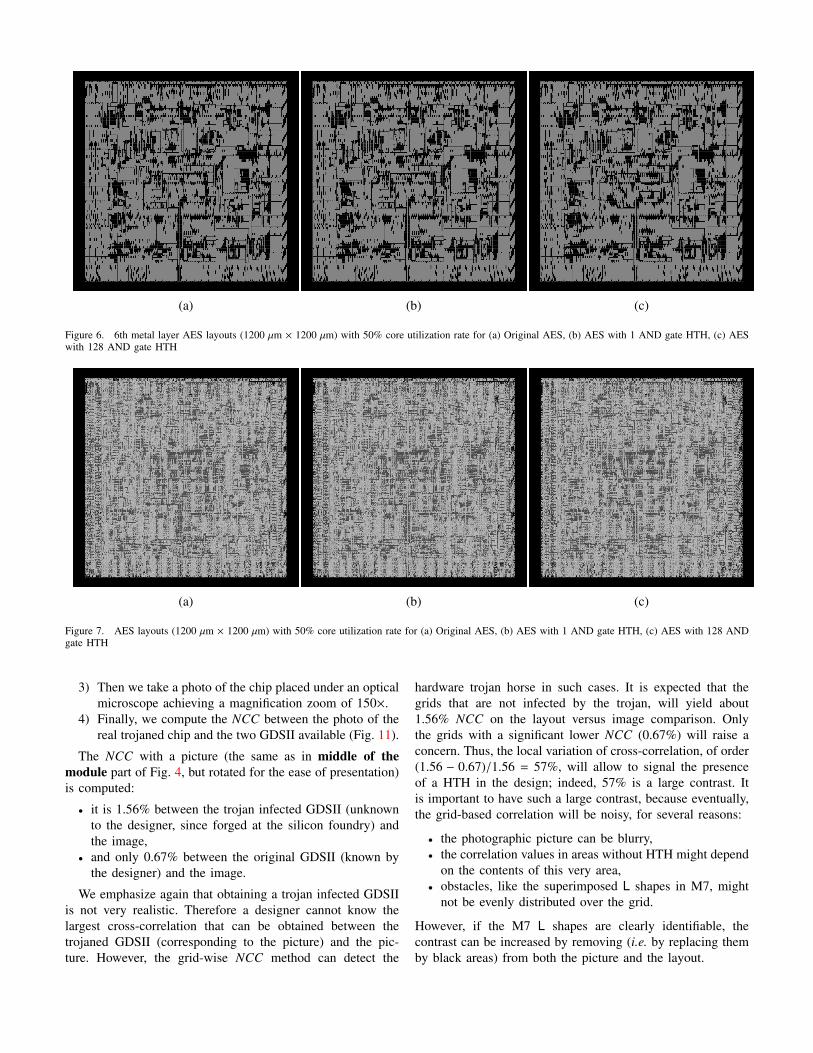
all metal layers. Fig. 7(a), 7(b) and 7(c) show the original AES,
3Those oxide layers are also known as “inter-level dielectric” (ILD) orsimply “passivation layers”.
and two modified AES layouts (with 1 AND gate and 128
AND gates HTHs) for 50% CUR. The Tab. III indicates all
NCC coefficients between these layouts. By observing Tab. II
and Tab. III, we notice that NCC coefficients for 6th metal
layer AES layouts are better. This is expected because adding
all metal layer into NCC computation is equivalent to adding
noise to the computation. For a strong attacker who can restrict
the HTH to lower metal levels, the computations for all metal
layers layout can be applied for detection.
We also compute the pixel-wise difference between the two
images. The Fig. 8(a) and 8(b) show the differences of all
metal layers AES layout with 1 and 128 AND gates HTHs
compared with original AES layout for 50% core utilization
rate. So Fig. 8(a) is the difference between Fig. 6(a) and
Fig. 6(b), and Fig. 8(b) is the difference between Fig. 6(a)
and Fig. 6(c). We notice that these differences are small but
they are concentrated in areas where the HTH standard cells
are actually placed. Following this observation, we realize a
grid-wise RNCC calculations for these layouts. The principle
is to split into several pictures of same size using a grid.
Each sub-picture of a given layout is then correlated with the
corresponding sub-picture of the reference layout. Grid-wise
RNCC permits not only to detect the trojan but also localise
it visually. The Fig. 9(a), 9(b), 10(a) and 10(b) show the
grid-wise RNCC of the AES HTH layout (1 and 128 AND
gates) for 50% and 95% core utilization rates. For these
calculations, layouts are cut in 32 parts horizontally and in
31 parts vertically. So there are in total 32 × 31 = 992 pieces
and also 992 correlation coefficients without overlap for each
comparison. Note that these coefficients are reverse correlation
coefficients (i.e. 1 − cross-correlation coefficients) for being
seen better in the figures. We notice that the cross-correlation
coefficients were improved. HTH standard cells can be also
localized with this technique and also be detected easier (see
in [23] how to prepare a circuit accordingly with HF).
C. Validation on a Real Trojan Horse Insertion
In order to validate the relevance of NCC as a tool to
measure the similarity between an observed image and a
reference layout, we actually tested this metric in the real
context of HTH recognition. Figure 11 shows two GDSII
layouts, one infected and the other genuine.
Obtaining an infected GDSII is not a practical assumption.
Fabricating a golden reference circuit in an trusted fab is
neither a practical assumption. Thus, the detection shall be
based only of the comparison between the genuine GDSII and
the fabricated chip, that may (or not) contain a HTH.
If the untrusted chip contains a HTH, the NCC value will
indicate its presence to the designer. To validate our concept,
we perform the following operations.
1) We fabricated a chip which contains a very tiny HTH
(whose impact at the M6 topmost metal level is only to
add two routing wires) and thus we have its GDSII.
2) Since we also know the HTH, we can obtain the genuine
GDSII from the trojaned GDSII.
(a) (b) (c)
Figure 6. 6th metal layer AES layouts (1200 µm × 1200 µm) with 50% core utilization rate for (a) Original AES, (b) AES with 1 AND gate HTH, (c) AESwith 128 AND gate HTH
(a) (b) (c)
Figure 7. AES layouts (1200 µm × 1200 µm) with 50% core utilization rate for (a) Original AES, (b) AES with 1 AND gate HTH, (c) AES with 128 ANDgate HTH
3) Then we take a photo of the chip placed under an optical
microscope achieving a magnification zoom of 150×.
4) Finally, we compute the NCC between the photo of the
real trojaned chip and the two GDSII available (Fig. 11).
The NCC with a picture (the same as in middle of the
module part of Fig. 4, but rotated for the ease of presentation)
is computed:
• it is 1.56% between the trojan infected GDSII (unknown
to the designer, since forged at the silicon foundry) and
the image,
• and only 0.67% between the original GDSII (known by
the designer) and the image.
We emphasize again that obtaining a trojan infected GDSII
is not very realistic. Therefore a designer cannot know the
largest cross-correlation that can be obtained between the
trojaned GDSII (corresponding to the picture) and the pic-
ture. However, the grid-wise NCC method can detect the
hardware trojan horse in such cases. It is expected that the
grids that are not infected by the trojan, will yield about
1.56% NCC on the layout versus image comparison. Only
the grids with a significant lower NCC (0.67%) will raise a
concern. Thus, the local variation of cross-correlation, of order
(1.56 − 0.67)/1.56 = 57%, will allow to signal the presence
of a HTH in the design; indeed, 57% is a large contrast. It
is important to have such a large contrast, because eventually,
the grid-based correlation will be noisy, for several reasons:
• the photographic picture can be blurry,
• the correlation values in areas without HTH might depend
on the contents of this very area,
• obstacles, like the superimposed L shapes in M7, might
not be evenly distributed over the grid.
However, if the M7 L shapes are clearly identifiable, the
contrast can be increased by removing (i.e. by replacing them
by black areas) from both the picture and the layout.

Table IINCC Coefficients between 6th metal layer of Original and Infected AES layouts
HTH size (Nb of AND gates)
1 2 4 8 16 32 64 128
CUR (Core Utilization Rate)
50% 0.9991 0.9972 0.9981 0.9950 0.9933 0.9918 0.9815 0.9668
60% 0.9987 0.9968 0.9959 0.9955 0.9944 0.9893 0.9788 0.9670
70% 0.9989 0.9981 0.9918 0.9941 0.9881 0.9850 0.9594 0.9067
80% 0.9999 0.9965 0.9898 0.9957 0.9780 0.9711 0.8970 0.8509
90% 0.9988 0.9990 0.9983 0.9962 0.9832 0.9572 0.8858 0.4010
95% 0.9997 0.9984 0.9980 0.9889 0.9589 0.9115 0.8824 0.8202
99% 0.9917 0.938 0.9714 0.9527 0.3798 X X X
Table IIINCC Coefficients between all metal layers of Original and Infected AES layouts
HTH size (Nb of AND gates)
1 2 4 8 16 32 64 128
CUR (Core Utilization Rate)
50% 0.9996 0.9788 0.9794 0.9770 0.9766 0.9760 0.9719 0.9708
60% 0.9993 0.9975 0.9973 0.9970 0.9964 0.9923 0.9843 0.9783
70% 0.9991 0.9987 0.9947 0.9952 0.9924 0.9889 0.9655 0.9272
80% 0.9997 0.9976 0.9942 0.9969 0.9868 0.9790 0.9291 0.8915
90% 0.9990 0.9988 0.9981 0.9964 0.9878 0.9709 0.9255 0.5162
95% 0.9995 0.9978 0.9974 0.9927 0.9742 0.9387 0.9159 0.8661
99% 0.994 0.9965 0.9803 0.962 0.4905 X X X
To further investigate, the designer can then focus on
the infected area by repeating the same detection technique
with magnified pictures (of local SEM imaging) to attest the
presence of the HTH.
V. Recommendations
During this experiment, we realize that HTHs insertion
at layout level is not easy for the attacker. Firstly, he must
understand the functionality of the circuit from the GDSII file.
Secondly, he must keep the original layout mainly unchanged,
otherwise a “forensic” visual inspection is very likely to
detect the HTH. Thus the HTH must be placed-and-routed
inbetween the (unaltered) existing circuit. Results, given in
Section IV, show that HTHs insertion become more and more
difficult when core utilization rate increases. We recommend
the designer to use more than 80% core utilization rate (CUR)
for his design. From this CUR, the insertion of HTH is very
unlikely because of HTH size. If the HTH size is small, this
HTH can be accidentally activated and hence can be easily
detected at test time. If the HTH has a reasonable size (for
example superior to 64 gates in our study case), it is visually
detected (NCC decreases by about 10% or less for a CUR
superior to 80%). A similar observation was proposed in [41],
where the authors recommended to avoid dead space in an
IC in order to prevent HTH insertion. We reconfirm the same
observation and take it a bit further in order to quantify it
in terms of core utilization rate. With this, either the HTH
insertion fails (because it is too large w.r.t. the available place-
and-route resources4), or its insertion can be detected with a
medium cost visual technique. Further, our criteria based on
the CUR is “global” to a design, and can easily be set as a
constraint in all P&R tools.
VI. Conclusion and Perspectives
In this paper, we have presented the feasibility and impacts
of HTHs insertion to the circuit layout (especially for AES
circuit). Additionally, we have demonstrated the possibility
to detect HTHs with a medium cost visual technique; this
technique can be automated thanks to a cross-correlation. In
particular, the observation of the sole top-level metal layer
suffices (for large enough HTHs); thus the method avoids
mechanical or chemical preparation, known to produce dust
of material that would cause many false positive detections.
As a corollary, if no HTH is detected in the observed circuit,
then this circuit can be trusted and used safely in an appli-
cation, even if other circuits from a different batch happen
to be infected by a HTH. The results show that the insertion
complexity and the visibility of HTH increases with the core
utilization rate of circuits. With a high CUR, HTH can be
detected by comparing layout images and GDSII file. This
technique cannot detect HTH inserted in specification or RTL
level but it can be combined with others detection techniques
to ensure the security of the full fabrication process.
4In particular, our experiments with the Cadence Encounter place-and-routetool show that even if there is “physically” some room for the insertion of theHTH, the routing-aware placer and the router itself can fail. This is becausespace on the die is not the limitating factor for the HTH, but rather theavailability of free routing tracks.

Checking for the genuineness of an observed picture (such
as the lefthand side of Fig. 4) against a known template (such
as the layout at the righthand side of Fig. 4) can benefit
from better decision strategies than a simple correlation.
Indeed, the layout is rich of particular features. Thus, for
instance, minutæ analyses for fingerprint recognition can be
used advantageously (using routing zigzags for instance); those
techniques are also interesting insofar as they allow to tune
the false acceptance/rejection rate(s). However, application of
minutæ-like features in context of HTH is an open research
topic. In our case, as we do not want to accept as genuine
a trojaned circuit, we intend to configure the technique to
minimize its false acceptance rate.
Besides, we could also profit of advanced techniques such
as those used in steganalysis to detect a piece of information
(the HTH) hidden in noise (the genuine layout).
Acknowledgments
This project has been funded by the French Government,
under grant FUI #14 HOMERE (Hardware trOjans : Menaces
et robustEsse des ciRcuits intEgres). We acknowledge in-
teresting inputs from the other members of the consortium,
in particular Julien Francq (Cassidan Cyber Security) and
Denis Real (DGA). Also, while preparing the camera-ready
version of the paper, we appreciated the positive inputs from
Nicolas Bruneau, Guillaume Duc, Zakaria Najm, Pablo Rauzy
and Youssef Souissi (crypto group of TELECOM-ParisTech).
Besides, we are grateful to Yves Mathieu for the setup of the
Calibre LITHO view tool, to Antoine Khy and Fabien Thomas-
Brans for pictures, and to the CMP [13] staff (Kholdoun
Torki and Jean-Francois Paillotin) for an excellent support in
the fabrication of the SecMat-v2 ASIC in STMicroelectronics
HCMOS9GP technology.
References
[1] Miron Abramovici and Paul Bradley. Integrated circuit security: newthreats and solutions. In Frederick T. Sheldon, Greg Peterson, Axel W.Krings, Robert K. Abercrombie, and Ali Mili, editors, CSIIRW, page 55.ACM, 2009.
[2] Sally Adee. The Hunt For The Kill Switch. IEEE Spectr., 45(5):34–39,May 2008.
[3] Dakshi Agrawal, Selcuk Baktir, Deniz Karakoyunlu, Pankaj Rohatgi, andBerk Sunar. Trojan Detection using IC Fingerprinting. In Proceedings
of the 2007 IEEE Symposium on Security and Privacy, SP ’07, pages296–310, Washington, DC, USA, 2007. IEEE Computer Society.
[4] Subidh S. Ali, Rajat Subhra Chakraborty, Debdeep Mukhopadhyay, andSwarup Bhunia. Multi-level attacks: An emerging security concernfor cryptographic hardware. In Design, Automation Test in Europe
Conference Exhibition (DATE), 2011, pages 1–4, march 2011.
[5] Mainak Banga and Michael S. Hsiao. A Novel Sustained VectorTechnique for the Detection of Hardware Trojans. In Proceedings of
the 2009 22nd International Conference on VLSI Design, VLSID ’09,pages 327–332, Washington, DC, USA, 2009. IEEE Computer Society.
[6] Eli Biham, Yaniv Carmeli, and Adi Shamir. Bug attacks. In CRYPTO,volume 5157 of LNCS, pages 221–240. Springer, 2008. Santa Barbara,CA, USA.
[7] Johannes Blomer and Jean-Pierre Seifert. Fault Based Cryptanalysisof the Advanced Encryption Standard (AES) Financial Cryptography.In Rebecca Wright, editor, Financial Cryptography, volume 2742 ofLecture Notes in Computer Science, pages 162–181. Springer Berlin /Heidelberg, 2003.
[8] Gedare Bloom, Bhagirath Narahari, and Rahul Simha. OS Support forDetecting Trojan Circuit Attacks. In Mohammad Tehranipoor and JimPlusquellic, editors, HOST, pages 100–103. IEEE Computer Society,2009.
[9] Dan Boneh, Richard A. DeMillo, and Richard J. Lipton. On the Impor-tance of Checking Cryptographic Protocols for Faults. In Proceedings
of Eurocrypt’97, volume 1233 of LNCS, pages 37–51. Springer, May11-15 1997. Konstanz, Germany. DOI: 10.1007/3-540-69053-0 4.
[10] Sebastien Briais, Jean-Michel Cioranesco, Jean-Luc Danger, SylvainGuilley, David Naccache, and Thibault Porteboeuf. Random activeshield. In Guido Bertoni and Benedikt Gierlichs, editors, FDTC, pages103–113. IEEE, 2012.
[11] Rajat Subhra Chakraborty, Somnath Paul, and Swarup Bhunia. On-demand transparency for improving hardware trojan detectability. InMohammad Tehranipoor and Jim Plusquellic, editors, HOST, pages 48–50. IEEE Computer Society, 2008.
[12] Rajat Subhra Chakraborty, Francis G. Wolff, Somnath Paul, Christos A.Papachristou, and Swarup Bhunia. Mero: A statistical approach forhardware trojan detection. In Christophe Clavier and Kris Gaj, editors,CHES, volume 5747 of Lecture Notes in Computer Science, pages 396–410. Springer, 2009.
[13] Circuits Multi-Projets (CMP). Website: http://cmp.imag.fr.
[14] Common Criteria Consortium. Common Criteria (aka CC) for Informa-tion Technology Security Evaluation (ISO/IEC 15408), 2013.Website: http://www.commoncriteriaportal.org/.
[15] Common Criteria. Application of Attack Potential to Smartcards,Mandatory Technical Document, Version 2.7, Revision 1, CCDB-2009-03-001, March 2009. http://www.commoncriteriaportal.org/files/supdocs/CCDB-2009-03-001.pdf.
[16] Jean-Francois Gallais, Johann Großschadl, Neil Hanley, Markus Kasper,Marcel Medwed, Francesco Regazzoni, Jorn-Marc Schmidt, StefanTillich, and Marcin Wojcik. Hardware trojans for inducing or amplifyingside-channel leakage of cryptographic software. In Liqun Chen and MotiYung, editors, INTRUST, volume 6802 of Lecture Notes in Computer
Science, pages 253–270. Springer, 2010.
[17] Silicon Investigations. Company website: http://www.siliconinvestigations.com/.
[18] Susmit Jha and Sumit Kumar Jha. Randomization Based ProbabilisticApproach to Detect Trojan Circuits. In Proceedings of the 2008 11th
IEEE High Assurance Systems Engineering Symposium, HASE ’08,pages 117–124, Washington, DC, USA, 2008. IEEE Computer Society.
[19] Yier Jin and Y Makris. Hardware trojan detection using path delayfingerprint. In Hardware-Oriented Security and Trust, 2008. HOST 2008.
IEEE International Workshop on, pages 51–57, 2008.
[20] Marc Joye and Michael Tunstall. Fault Analysis in Cryptography.Springer LNCS, March 2011. http://joye.site88.net/FAbook.html. DOI:10.1007/978-3-642-29656-7 ; ISBN 978-3-642-29655-0.
[21] Markus Kasper, Amir Moradi, Georg T. Becker, Oliver Mischke, TimGuneysu, Christof Paar, and Wayne Burleson. Side channels as buildingblocks. J. Cryptographic Engineering, 2(3):143–159, 2012.
[22] Paul C. Kocher, Joshua Jaffe, and Benjamin Jun. Differential PowerAnalysis. In Proceedings of CRYPTO’99, volume 1666 of LNCS, pages388–397. Springer-Verlag, 1999.
[23] Oliver Kommerling and Markus G. Kuhn. Design Principles for Tamper-Resistant Smartcard Processors. In WOST ’99 (USENIX Workshop on
Smartcard Technology), pages 9–20, Berkeley, CA, USA, May 10-111999. USENIX Association. Chicago, Illinois, USA (On-line paper).ISBN: 1-880446-34-0.
[24] Jie Li and John Lach. At-speed delay characterization for IC authen-tication and Trojan Horse detection. In Proceedings of the 2008 IEEE
International Workshop on Hardware-Oriented Security and Trust, HST’08, pages 8–14, Washington, DC, USA, 2008. IEEE Computer Society.
[25] Bradley Hopkins Mark Beaumont and Tristan Newby. Hardware Trojans- Prevention, Detection, Countermeasures. http://www.dtic.mil/cgi-bin/GetTRDoc?AD=ADA547668.
[26] David R. McIntyre, Francis G. Wolff, Christos A. Papachristou, andSwarup Bhunia. Dynamic evaluation of hardware trust. In Proceedings
of the 2009 IEEE International Workshop on Hardware-Oriented Secu-
rity and Trust, HST ’09, pages 108–111, Washington, DC, USA, 2009.IEEE Computer Society.
[27] NIST/ITL/CSD. Advanced Encryption Standard (AES). FIPS PUB 197,Nov 2001. http://csrc.nist.gov/publications/fips/fips197/fips-197.pdf.
[28] Gilles Piret and Jean-Jacques Quisquater. A Differential Fault AttackTechnique against SPN Structures, with Application to the AES and

Khazad. In CHES, volume 2779 of LNCS, pages 77–88. Springer,September 2003. Cologne, Germany.
[29] SEMATECH Surface Preparation and Cleaning Conference (SPCC).Conference website: http://www.sematech.org/meetings/spcc/past.htm.
[30] Jean-Jacques Quisquater and David Samyde. ElectroMagnetic Analysis(EMA): Measures and Counter-Measures for Smard Cards. In I. Attaliand T. P. Jensen, editors, Smart Card Programming and Security (E-
smart 2001), volume 2140 of LNCS, pages 200–210. Springer-Verlag,September 2001. Nice, France. ISSN 0302-9743.
[31] Reza Rad, Jim Plusquellic, and Mohammad Tehranipoor. Sensitivityanalysis to hardware Trojans using power supply transient signals. InProceedings of the 2008 IEEE International Workshop on Hardware-
Oriented Security and Trust, HST ’08, pages 3–7, Washington, DC,USA, 2008. IEEE Computer Society.
[32] Hassan Salmani, Mohammad Tehranipoor, and Jim Plusquellic. Newdesign strategy for improving hardware Trojan detection and reducingTrojan activation time. In Hardware-Oriented Security and Trust, 2009.
HOST ’09. IEEE International Workshop on, pages 66–73, 2009.[33] Martin Schobert. GNU software degate. Webpage: http://www.degate.
org/.[34] Sergei Skorobogatov and Christopher Woods. Breakthrough silicon
scanning discovers backdoor in military chip. In Proceedings of the 14th
international conference on Cryptographic Hardware and Embedded
Systems, CHES’12, pages 23–40, Berlin, Heidelberg, 2012. Springer-Verlag.
[35] Mohammad Tehranipoor and Farinaz Koushanfar. A Survey of HardwareTrojan Taxonomy and Detection. IEEE Des. Test, 27(1):10–25, January2010.
[36] Mohammad Tehranipoor and Cliff Wang, editors. Introduction to
Hardware Security and Trust. Springer, 2012. ISBN 978-1-4419-8079-3.[37] Randy Torrance and Dick James. The State-of-the-Art in IC Reverse
Engineering. In CHES, volume 5747 of Lecture Notes in Computer
Science, pages 363–381. Springer, September 6-9 2009. Lausanne,Switzerland.
[38] Randy Torrance and Dick James. The state-of-the-art in semiconductorreverse engineering. In Design Automation Conference (DAC), 2011
48th ACM/EDAC/IEEE, pages 333–338, 2011.[39] Michael Tunstall, Debdeep Mukhopadhyay, and Subidh Ali. Differential
Fault Analysis of the Advanced Encryption Standard Using a SingleFault. In Claudio Agostino Ardagna and Jianying Zhou, editors, WISTP,volume 6633 of Lecture Notes in Computer Science, pages 224–233.Springer, 2011.
[40] U.S. Department Of Defense. Defense science board task force onhigh performance microchip supply. http://www.acq.osd.mil/dsb/reports/2005-02-HPMS Report Final.pdf.
[41] Xiaoxiao Wang, Mohammad Tehranipoor, and Jim Plusquellic. Detect-ing malicious inclusions in secure hardware: Challenges and solutions.In Proceedings of the 2008 IEEE International Workshop on Hardware-
Oriented Security and Trust, HST ’08, pages 15–19, Washington, DC,USA, 2008. IEEE Computer Society.
Appendix A
Example of DFA on AES Infected Hardware Trojan Horse
on SASEBO-GII
We implemented a HTH in an AES coprocessor to facilitate
Piret’s DFA. The HTH gets activated when the switch is on
and the first two bytes of the plaintext are equal to 0xff; it
is thus an instantiation of the generic HTH depicted in Fig. 3
with parameter N set to 16. This configuration leads us to a
unique key in a total of 4 encryptions. The key used in our
example is same as in Appendix B of the AES standard [27].
The design is tested on a SASEBO-GII board running on the
Virtex-5 FPGA.
Table IVCost and Performance Overhead of the Inserted HTH of Size N = 16
Design LUT BRAM Frequency
HTH Free AES 1851 0 222.477 MHz
HTH Infected AES 1861 0 218.722 MHz
Overhead 0.5% 0 1.6%
Tab IV compares the cost and performance of a HTH as
described before which gets activated when the first two bytes
of the plaintext are equal to 0xff i.e. N = 16. The HTH is
very small i.e. only 10 LUTs and causes speed degradation
of 1.6% (indeed, our HTH adds one XOR gate on the critical
path). This configuration helps us to easily implement Piret’s
Attack. Recall that the signal activation cond[0] is an
input of the trigger part of the HTH; thus both a faulted and a
fault-free ciphertext can be obtained (which is required for the
DFA of Piret and Quisquater). In Tab V, we give the transcript
of an example of the Piret’s Attack on an AES implementation
with our inserted HTH.

Table VPiret’s attack on the trojaned AES, revealing the last round key
--Encryption 1--
--Input Plaintext Message--
fffff6a8885a308d313198a2e0370734
--Wrong Ciphered Message--
dabb96f24f04b523a11bbf02cc4828d5
--Correct Ciphered Message--
0316ca805c0797b5cd6a2341eec89aae
--Encryption 2--
--Input Plaintext Message--
ffff03a8885a308d313198a2e0370734
--Faulty Ciphered Message--
73f9bfae29c49f1d0256ed3ef0e470da
--Correct Ciphered Message--
acd6874cf0f73af0fab66d2a21d6fc96
--Launching Piret’s DFA--
+++++++++++++++++++++++++
operating on column :0
+++++++++++++++++++++++++
MATCHED 2 Bytes
MATCHED 3 Bytes
MATCHED Column 0
+++++++++++++++++++++++++
operating on column :1
+++++++++++++++++++++++++
MATCHED 2 Bytes
MATCHED 3 Bytes
MATCHED Column 1
+++++++++++++++++++++++++
operating on column :2
+++++++++++++++++++++++++
MATCHED 2 Bytes
MATCHED 3 Bytes
MATCHED Column 2
+++++++++++++++++++++++++
operating on column :3
+++++++++++++++++++++++++
MATCHED 2 Bytes
MATCHED 3 Bytes
MATCHED Column 3
List of possible key 10:columns0(1)
d0630c89
List of possible key 10:columns1(1)
c9140cc8
List of possible key 10:columns2(1)
e1eef9a6
List of possible key 10:columns3(1)
b63f25a8
Retrieved Round 10 key:
d0|c9|e1|b6|
14|ee|3f|63|
f9|25|0c|0c|
a8|89|c8|a6|

(a) (b)
Figure 8. Pixelwise difference of AES layouts with 50% core utilization rate for Original layout and Infected Layout with (a) 1 AND gate, (b) 128 ANDgate.
(a) (b)
Figure 9. Grid-wise RNCC of AES layouts for with 50% core utilization rate for Original layout and Infected Layout with (a) 1 AND gate, (b) 128 ANDgate.
(a) (b)
Figure 10. Grid-wise RNCC of AES layouts for with 95% core utilization rate for Original layout and Infected Layout with (a) 1 AND gate, (b) 128 ANDgate.

Trojaned GDSII Picture Genuine GDSII
Added by
the Trojan
≈ 6≈
>|NCC| = 1.56% |NCC| = 0.67%
Figure 11. Cross-correlation based comparison between trojaned (lefthand side) / genuine (righthand side) GDSII and an actual picture, a microscope imageof an AES area where the inserted HTH shows up (center). The designer checking for the presence of a purported HTH only knows the genuine GDSII andthe picture.