Telerehabilitation: controlling haptic virtual environments through handheld interfaces
Upload
independentCategory
view
1download
0
Handheld histology-equivalent sectioning laser-scanningconfocal optical microscope for interventional imaging
Karthik Kumar & Rony Avritscher & Youmin Wang &
Nancy Lane & David C. Madoff & Tse-Kuan Yu &
Jonathan W. Uhr & Xiaojing Zhang
Published online: 10 December 2009# Springer Science+Business Media, LLC 2009
Abstract A handheld, forward-imaging, laser-scanningconfocal microscope (LSCM) demonstrating optical sec-tioning comparable with microtome slice thicknesses inconventional histology, targeted towards interventionalimaging, is reported. Fast raster scanning (~2.5 kHz linescan rate, 3.0–5.0 frames per second) was provided by a2-axis microelectromechanical system (MEMS) scanningmirror fabricated by a method compatible with comple-mentary metal-oxide-semiconductor (CMOS) processing.
Cost-effective rapid-prototyped packaging combined theMEMS mirror with micro-optical components into a probewith 18 mm outer diameter and 54 mm rigid length.ZEMAX optical design simulations indicate the ability ofthe handheld optical system to obtain lateral resolutionof 0.31 and axial resolution of 2.85µm. Lateral and axialresolutions are experimentally measured at 0.5µm and4.2µm respectively, with field of view of 200×125µm.Results of reflectance imaging of ex vivo swine liver, andfluorescence imaging of the expression of cytokeratin andmammaglobin tumor biomarkers in epithelial human breasttissue from metastatic breast cancer patients are presented.The results indicate that inexpensive, portable handheldoptical microscopy tools based on silicon micromirrortechnologies could be important in interventional imaging,complementing existing coarse-resolution techniques toimprove the efficacy of disease diagnosis, image-guidedexcisional microsurgery, and monitored photodynamictherapy.
Keywords Handheld instrumentation . Laser scanningconfocal microscope (LSCM) . CMOS-compatible scanningmicromirror .Microelectromechanical systems (MEMS) .
Interventional imaging
1 Introduction
Miniaturized depth-resolved optical imaging can enablehighly sensitive biopsy-free characterization of diseasesin situ and precision guided microsurgery and photody-namic therapy at improved spatial resolution, augmentingexisting image-guided intervention methods such as mag-netic resonance or ultrasound imaging (Yaqoob et al. 2006).Laser-scanning confocal microscopy (LSCM) allows high-
K. Kumar :Y. WangDepartment of Electrical and Computer Engineering,University of Texas at Austin,1 University Station C0803,Austin, TX 78712, USA
R. Avritscher :D. C. MadoffSection of Interventional Radiology,University of Texas M. D. Anderson Cancer Center,1515 Holcombe Boulevard,Houston, TX 77030, USA
N. Lane : J. W. UhrCancer Immunobiology Center,University of Texas Southwestern Medical Center at Dallas,5323 Harry Hines Boulevard,Dallas, TX 75390, USA
T.-K. YuRadiation Treatment Center,University of Texas M. D. Anderson Cancer Center,1515 Holcombe Boulevard,Houston, TX 77030, USA
X. Zhang (*)Department of Biomedical Engineering,University of Texas at Austin,1 University Station C0800,Austin, TX 78712, USAe-mail: [email protected]
Biomed Microdevices (2010) 12:223–233DOI 10.1007/s10544-009-9377-6

resolution imaging of an “optical section” situated a fewhundred micrometers beneath the tissue surface, enablingvisual tumor assessment in the epithelium by mappingspatial variations in refractive index of native tissue ordetecting fluorescent markers preferentially bound to tumorsites. Axial resolution of 5µm or less, comparable to thethickness of microtome slices in conventional histology andless than that of a single layer of cells, is required to ensurehigh contrast while imaging in highly scattering media suchas biological tissue (Rajadhyaksha et al. 1999). Achievingthe cellular-scale optical sectioning in a compact andversatile forward-imaging miniature probe, which has notbeen achieved in previous literature, would facilitate itsapplication in surgical operating theaters and in vivo clinicalstudies. Microelectromechanical system (MEMS) tech-nologies are uniquely suited to combining actuators forguiding light in very small volumes with micro-opticalelements for in vivo beam scanning and imaging. Thescaling laws in optics enable miniaturized imaging probeswith functionality that cannot practically be achieved withtraditional technologies (Solgaard 2008). Micromirrorspowered by electrostatic vertical comb drives (Dooyounget al. 2004; Hyuck et al. 2007; Krishnamoorthy et al. 2003)provide the favorable optical characteristics, large deflec-tion angles and fast response times required for real-timeimaging, and have been employed in optical coherencetomography (Aguirre et al. 2007; Woonggyu et al. 2005;Kumar et al. 2008a), confocal (Maitland et al. 2006; Raet al. 2008; Kumar et al. 2008b) and multi-photon (Hoyet al. 2008; Piyawattanametha et al. 2006; Fu et al. 2006)microscopies. Unfortunately, the micromirrors used in thesestudies have been fabricated by complicated micromachin-ing processes, resulting in low wafer yield, non-lineartransformation between input voltage and mechanicalscan angle and unstable scanning characteristics due to asignificant tendency to exhibit the pull-in phenomenonand cease scanning operation. MEMS design processesthat integrate complementary metal-oxide-semiconductor(CMOS) circuitry on the same chip as the MEMS deviceare widely seen as the solution to this problem, and havegained significant attention in recent years (Cheng et al.2005; Ching-Liang et al. 2005; Dai et al. 2005; Fedder et al.2008). We have addressed these drawbacks by introducinga simple 3-mask comb self-aligned micromirror fabricationprocess compatible with traditional CMOS processing inthe semiconductor industry (Kumar et al. 2009a). Ourprocess only utilizes conventional silicon processing toolswhich operate at temperatures low enough to allow pre-fabrication of CMOS circuitry on the wafer prior tocommencing micromirror fabrication. For microendoscopes,this can enable CMOS-MEMS integration of control elec-tronics and sensors to adaptively correct for aberrations inbeam scanning along with power amplifier drive electronics,
while significantly reducing fabrication costs and loweringthe barriers towards clinical applications and market accep-tance. Based on this fast-scanning two-axis MEMS micro-mirror, we report in this paper, for the first time, a handheldforward-imaging confocal microscope capable of sub-micrometer lateral resolution and optical sectioning compa-rable to histology, and demonstrate its application toreflectance and fluorescence imaging of the native spatialvariation of refractive index contrast of biological tissues andexpression of molecular tumor biomarkers respectively.
2 Methods
2.1 LSCM instrumentation
We have developed a handheld forward-imaging single-fiber laser-scanning confocal microscope incorporating ourfast high-reflectivity two-axis micromirror in the distalscanning mechanism. The single-fiber approach provideshigh-quality pixilation-free imaging and a simple approachto aligning the confocal pinhole to the image of the point onthe sample created by the objective system (Kimura andWilson 1991). The schematic of the optical layout of oursystem is provided in Fig. 1. The semiconductor diode
Fig. 1 Schematic of the optical layout of the single-fiber laser-scanningconfocal microscope. LM: laser module; PM: polarization-maintainingsingle-mode fiber; CL: collimating lens; QWP: quarter-wave plate; FM:folding mirror; MS: micromirror scanner; DL1: doublet beam expanderlens 1; DL2: doublet beam expander lens 2; OBJ: objective lens;SMP: sample being imaged; POL: walk-off polarizer; MR:miniature reflector; EF: emission filter; PD: photo-detector; CPU:central processing unit; FG: function generator; HVA: high-voltageamplifier
224 Biomed Microdevices (2010) 12:223–233
laser module LM (Blue Sky Research, Inc., FMXL-635-017-PA-0B), operating at a wavelength of 635 nm andmaximum power of 17 mW, launches linearly polarizedlight into a polarization maintaining single-mode fiber PM,with the electric field of the coherent laser light orientedalong the slow axis of the PM fiber. The PM fiberterminates at an optical bench (OFR, Inc., FT-38x100-3 W) housing the components to extract light reflected fromthe sample. Light exiting the fiber is coupled into a secondPM fiber (Oz Optics, Inc., LPC-01-635-4/125-P, 0.11 NA)through two identical collimating lenses CL (OFR, Inc.,PAF-X-5-VIS) and a calcite walk-off polarizer POL (OFR,Inc., PB-5x7-16-VIS). The polarizer ensures that only lightof polarization aligned to the slow axis the PM fibers entersthe second fiber. The core of the second PM fiber is 4.0µmin diameter; therefore the exit aperture of the second PMfiber serves as the confocal pinhole in our system by virtueof its small size. This light diverges out of the exit apertureof the second fiber into the distal-end optical system. Thestill linearly-polarized light diverging from the fiber iscollimated into a quarter-wave plate QWP by a miniature5 mm effective focal length (EFL) aspheric lens mounted atthe collimator end of the second PM fiber, which has thediameter of 1 mm, matching the size of the micromirrorscanner in our system. The QWP (Red Optronics, Inc.,0.1”×0.1” Zero-Order MicroWaveplate) converts the lightlinearly polarized along the slow axis of the PM fiber intocircularly polarized light, as shown in the inset in Fig. 1.The circularly polarized light is deflected by the foldingmirror onto the micromirror scanner in a folded opticalpath, for compactness. The micromirror scanner is posi-tioned at the back focal plane of a doublet lens DL1(Thorlabs, Inc., AC050-008-A1) and deflects the beamacross its entrance aperture in raster fashion. The doubletlens DL1 is part of an afocal Keplerian beam expandersystem, acting in conjunction with doublet lens DL2(Thorlabs, Inc., AC127-025-A1-ML). The doublet lensDL1 converts the angular deflection created by the micro-mirror scanner into linear deflection of the focused spot inthe intermediate focal plane. The position of the back focalplane of doublet lens DL2 is adjusted to match thisintermediate focal plane. Doublet lens DL2 reconverts thelinear scan into angular scan about a pivot point located atthe point on the optical axis intersecting with the front focalplane of DL2. In effect, the beam expander increases thefull-width half maximum (FWHM) diameter of the laserbeam by a factor of about 3× in order to almost fill the backaperture of the objective lens OBJ, thereby maximizing theobject-space numerical aperture (NA) of the distal opticalsystem. In addition to increasing the object-space NA, thebeam expander also translates the real pivot point, i.e.,the micromirror scanner, to a virtual pivot point located atthe back focal plane of the objective lens OBJ. This action
results in the objective lens OBJ (Thorlabs, Inc., 350390-B,Ø4 mm, 2.75 mm EFL, 0.68 NA) converting the angularscan about the virtual pivot point into a linear scan acrossthe sample.
The focused and scanned spot on the sample inducesdirect backscatter due to native spatially-varying refractiveindex contrast present in the sample, or induces emission(enhanced reflective backscatter) from fluorophores (reflec-tive contrast agents) selectively tagged to tumor biomarkersat the imaging site. The reflective backscatter is known tomaintain its original circularly polarized state while thefluorescence emission has components of all polarizationstates. The polarization-maintaining property of reflectivebackscatter is exploited to improve the signal-to-noise ratioin reflection confocal imaging mode (Gan et al. 1999;Schmitt et al. 1992). The backscattered light retraces itspath through the distal optical system and the QWP. At thispoint, the circularly polarized reflective backscatter isconverted linearly polarized light, this time however,aligned along the fast axis of the PM fibers. Any spuriousreflection from a part of the optical system prior to theQWP is therefore easily distinguished from the signal wewish to detect from the sample by analyzing its polariza-tion. The QWP has no significant effect on fluorescentemission from the sample. The reconverted light is coupledinto the PM fiber through the CL lens that acts as a focuser.Only light backscattered (or created, in the case of fluores-cence) from the sample plane that was confocal with theaperture of the PM fiber enters into the fiber, and out-of-focuslight is rejected at the PM fiber entrance, yielding confocalaction. The spatially filtered light propagates through the PMfiber and into the proximal end of the system, where it iscollimated by the lens CL on fiber table, and into the polarizerPOL. The polarizer separates the polarization aligned alongthe fast and slow axes of the fiber. The slow axis polarizationis rejected, while the fast axis light is reflected off a miniaturereflector into an emission filter. For reflectance imaging, theemission filter is removed, while in fluorescence imaging, theemission filter eliminates the laser line and allows anyfluorescence to enter into the photodetector (New Focus,Inc., Model 2051-FS).
The circuitry that drives the micromirror scanner andsynchronized data collection is controlled by a centralprocessing unit (CPU). The CPU controls the amplitude andphase of the 2-channel function generator FG (Tektronix,Inc., AFG3022B), which outputs two drive signals corre-sponding to two-axis scanning and their associated triggerpulses in synchrony. The voltages of the drive signals outputby the FG are amplified by a factor of 50× by a high-voltageamplifier HVA (TEGAM, Inc., Model 2350) before beingsupplied to the micromirror scanner. The first drive signaloperates at the resonant frequency of the inner axis of themicromirror scanner to create fast line scans, while the second
Biomed Microdevices (2010) 12:223–233 225
signal varies slowly at the frame rate required for imaging.The pulses trigger the recording of samples from thephotodetector by the data acquisition board (National Instru-ments, Inc., NI PCI-6111). Data samples are acquired onlyduring the forward line and frame traces of the micromirror,while image processing is performed in real time during theacquisition idle time in the retrace scanning segment. All dataacquisition, signal processing, and image rendering isperformed in a Matlab® graphical user interface (GUI)program loaded in the CPU.
2.2 Scanning micromirror
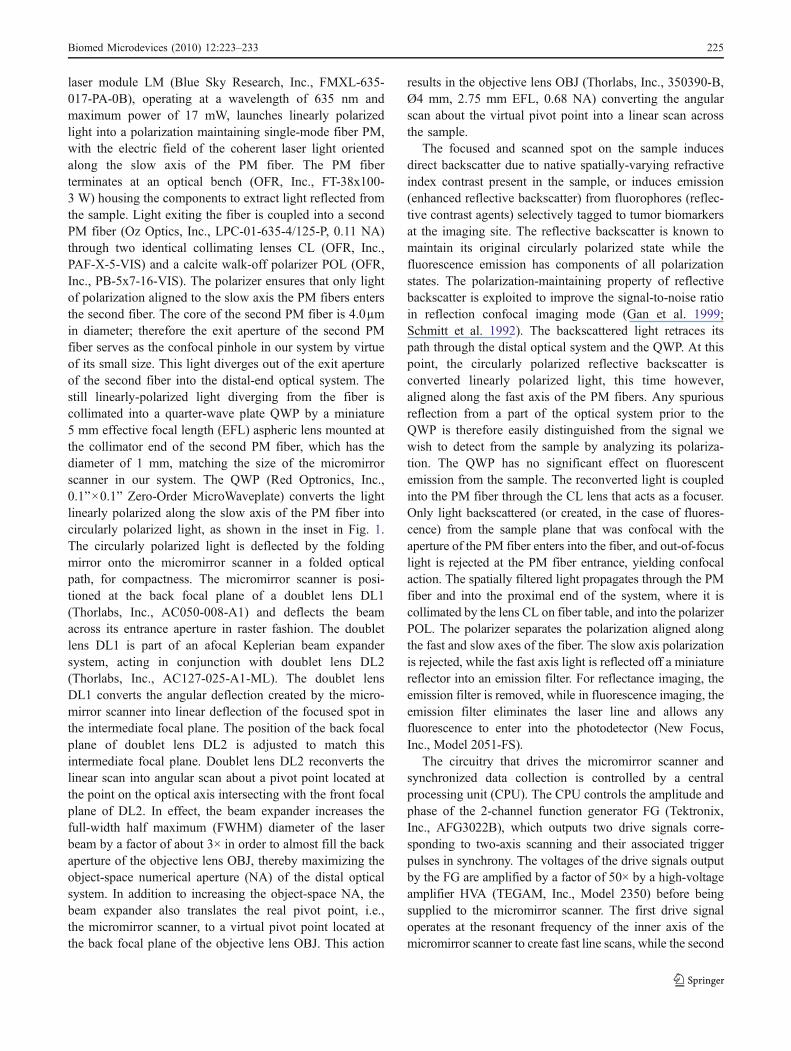
Our scanning micromirror was the core component (labeledMS in Fig. 1 enabling the probe, and was fabricated by asimple method (Kumar et al. 2009a) that is compatible withthe complementary metal-oxide-semiconductor (CMOS)processes employed in the electronics industry. CMOS-compatible processing can allow on-chip integration ofsensors and electronics to improve scanning precision,wafer yield and device lifetimes, while reducing fabricationcosts and barriers to commercial market acceptance (Ching-Liang et al. 2005; Fedder et al. 2008). The mirrors (Fig. 2)measured 1,024 μm in diameter and were fabricated on
chips of size 2.8 mm2. Out-of-plane rotation about twoorthogonal axes intersecting at the mirror center, based on agimbal design, was generated by two pairs of electrostaticstaggered vertical comb drives on each axis. Primaryresonances for the mechanical structure were observed ataround 2.8 kHz and 670 Hz for the two rotation axes.Mechanical deflection angles of 11° and 6° at these resonantpeaks were observed on the fast and slow axes respectively.When applying static or low-frequency voltages, maximumdouble-sided deflection angles of 5° and 4.5°, respectively,were obtained. Raster scanning was achieved by operating thefast axis at resonance to perform line scans, and applying alow-frequency sinusoidal voltage to the slow axis, creatingframe scans. Image data was acquired only during forwardtraces of line and frame scans, with frame retrace beingutilized for real-time image processing prior to display.Trigger waveforms from the signal generators synchronizedthe Matlab® image acquisition code with micromirrorposition.
2.3 Handheld forward-imaging probe
Forward imaging was achieved in the probe by aimingcoherent illumination out of the single-mode polarization-
Fig. 2 Scanning electron micro-graph (SEM) images of thefabricated devices. (a) Topview of micromirror showingelectrical bond pads, combdrives on both axes, andmicromirror surface. (b) Close-in view of layers forming thecombdrive actuator on the inneraxis. (c) Close-in view of thequality of alignment between thestator and rotor comb fingers.(d) Backside view of thesubstrate DRIE through-etch,bottom face of the micromirror
226 Biomed Microdevices (2010) 12:223–233
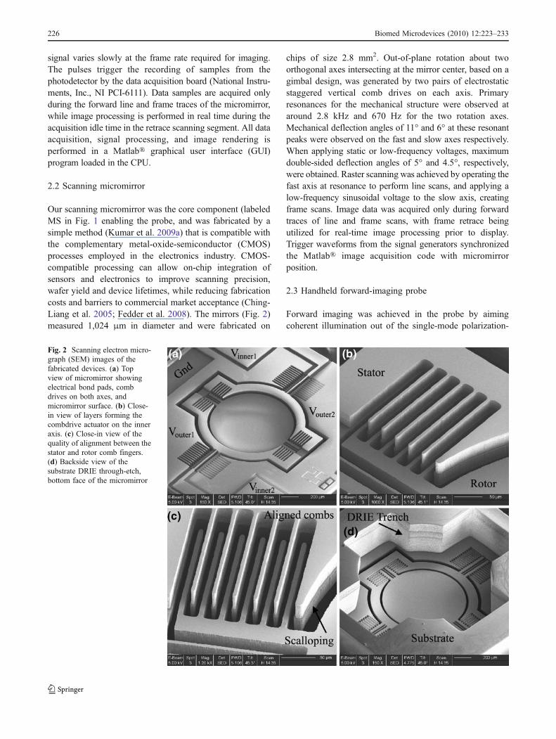
maintaining fiber with pigtailed collimator at a stationarymirror, which deflected it onto the micromirror in a foldedoptical path (Kumar et al. 2009b). We developed a cost-effective MEMS probe package fabricated by laser stereo-lithography rapid prototyping to combine the micromirrorwith the other optical components. The use of inexpensivebatch-fabricated components in the distal system wasmotivated by the clinical considerations for a probe thatcan eventually be made disposable after one-time use. Thepackage (Fig. 3(a–b)) included a hollow tube 4 mm innerdiameter to secure the collimator, mounted stationarymirror, inclined surface to mount the micromirror chip,vias for five electrical pins to power the micromirror,threading to attach the objective system and position themicromirror at its back focal plane, and a slot to introduce a
miniature QWP into the beam path with appropriateorientation. The QWP could alternatively be incorporatedfurther ahead in the optical path within the objective systemfor improved noise rejection.
Our objective system was assembled using standard 1/2”tube lens optics (Thorlabs, Inc.). Attaching the module tothe MEMS package with compatible threading completedassembly of the final system (Fig. 3(c–d)). The objectiveconsisted of a Keplerian beam expander providing 3×magnification of spot size followed by a high numericalaperture (NA) aspheric lens serving as the focusingelement. The focusing lens had 0.65 NA when its 3.6 mmclear aperture was filled by the entering beam. The micro-mirror diameter determined the maximum size of the beamentering the objective, and was designed such that the back
Fig. 3 Design and assembly ofthe handheld forward-imagingprobe. (a) Mechanical drawingsof the MEMS mount with top,bottom, and oblique views ofmain component depicted alongwith the folding mirror. (b)Photograph of the fabricatedmount with a micromirror pack-aged in it. (c) Photograph of thefully assembled handheld probe.(d) Photograph of the portablesystem instrumentation
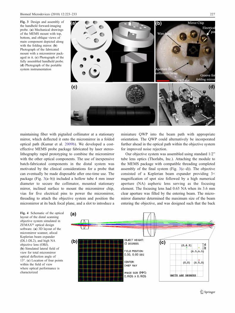
Fig. 4 Schematic of the opticallayout of the distal scanningobjective system simulated inZEMAX® optical designsoftware. (a) 3D layout of themicromirror scanner, afocalKeplerian beam expander(DL1-DL2), and high NAobjective lens (OBJ).(b) Simulated lateral field ofview for total micromirroroptical deflection angle of13°. (c) Location of four pointswithin the field of viewwhere optical performance ischaracterized
Biomed Microdevices (2010) 12:223–233 227
aperture of the focusing element was slightly under-filled toallow for beam scanning across the objective.
3 System characterization
3.1 Optical design simulations
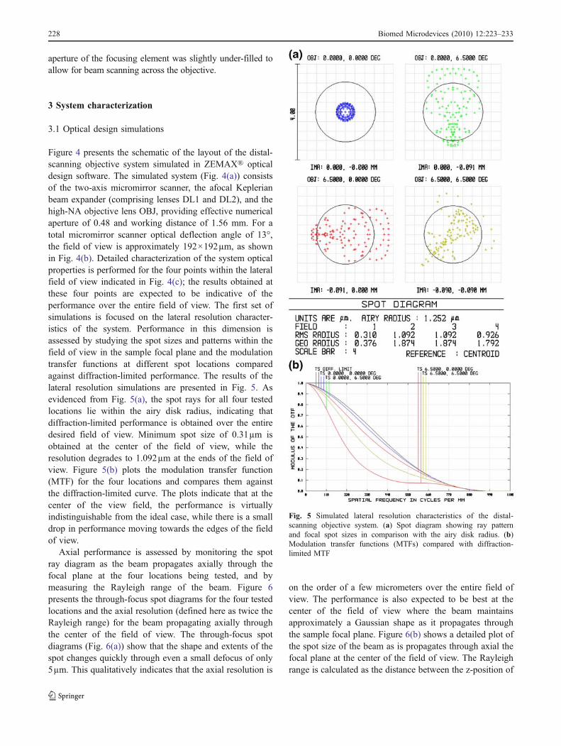
Figure 4 presents the schematic of the layout of the distal-scanning objective system simulated in ZEMAX® opticaldesign software. The simulated system (Fig. 4(a)) consistsof the two-axis micromirror scanner, the afocal Keplerianbeam expander (comprising lenses DL1 and DL2), and thehigh-NA objective lens OBJ, providing effective numericalaperture of 0.48 and working distance of 1.56 mm. For atotal micromirror scanner optical deflection angle of 13°,the field of view is approximately 192×192µm, as shownin Fig. 4(b). Detailed characterization of the system opticalproperties is performed for the four points within the lateralfield of view indicated in Fig. 4(c); the results obtained atthese four points are expected to be indicative of theperformance over the entire field of view. The first set ofsimulations is focused on the lateral resolution character-istics of the system. Performance in this dimension isassessed by studying the spot sizes and patterns within thefield of view in the sample focal plane and the modulationtransfer functions at different spot locations comparedagainst diffraction-limited performance. The results of thelateral resolution simulations are presented in Fig. 5. Asevidenced from Fig. 5(a), the spot rays for all four testedlocations lie within the airy disk radius, indicating thatdiffraction-limited performance is obtained over the entiredesired field of view. Minimum spot size of 0.31µm isobtained at the center of the field of view, while theresolution degrades to 1.092µm at the ends of the field ofview. Figure 5(b) plots the modulation transfer function(MTF) for the four locations and compares them againstthe diffraction-limited curve. The plots indicate that at thecenter of the view field, the performance is virtuallyindistinguishable from the ideal case, while there is a smalldrop in performance moving towards the edges of the fieldof view.
Axial performance is assessed by monitoring the spotray diagram as the beam propagates axially through thefocal plane at the four locations being tested, and bymeasuring the Rayleigh range of the beam. Figure 6presents the through-focus spot diagrams for the four testedlocations and the axial resolution (defined here as twice theRayleigh range) for the beam propagating axially throughthe center of the field of view. The through-focus spotdiagrams (Fig. 6(a)) show that the shape and extents of thespot changes quickly through even a small defocus of only5µm. This qualitatively indicates that the axial resolution is
on the order of a few micrometers over the entire field ofview. The performance is also expected to be best at thecenter of the field of view where the beam maintainsapproximately a Gaussian shape as it propagates throughthe sample focal plane. Figure 6(b) shows a detailed plot ofthe spot size of the beam as is propagates through axial thefocal plane at the center of the field of view. The Rayleighrange is calculated as the distance between the z-position of
Fig. 5 Simulated lateral resolution characteristics of the distal-scanning objective system. (a) Spot diagram showing ray patternand focal spot sizes in comparison with the airy disk radius. (b)Modulation transfer functions (MTFs) compared with diffraction-limited MTF
228 Biomed Microdevices (2010) 12:223–233
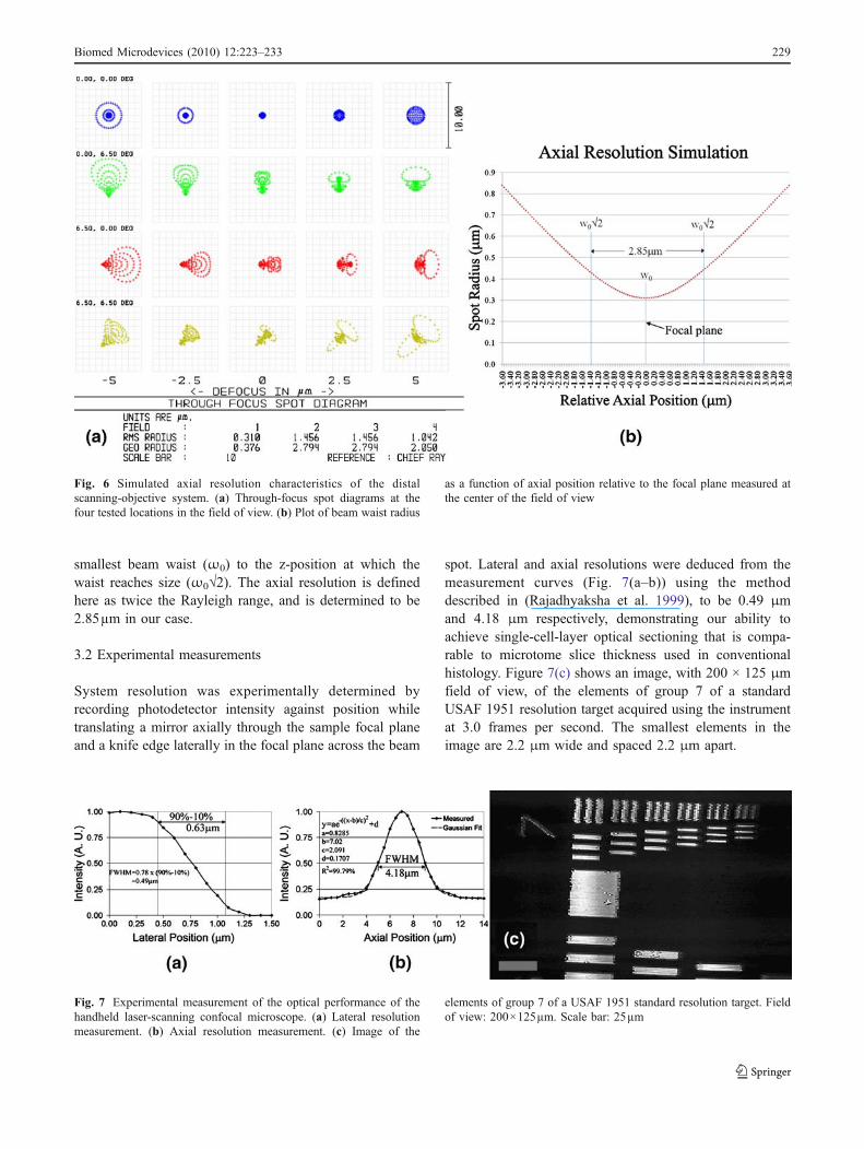
smallest beam waist (ω0) to the z-position at which thewaist reaches size (ω0√2). The axial resolution is definedhere as twice the Rayleigh range, and is determined to be2.85µm in our case.
3.2 Experimental measurements
System resolution was experimentally determined byrecording photodetector intensity against position whiletranslating a mirror axially through the sample focal planeand a knife edge laterally in the focal plane across the beam
spot. Lateral and axial resolutions were deduced from themeasurement curves (Fig. 7(a–b)) using the methoddescribed in (Rajadhyaksha et al. 1999), to be 0.49 μmand 4.18 μm respectively, demonstrating our ability toachieve single-cell-layer optical sectioning that is compa-rable to microtome slice thickness used in conventionalhistology. Figure 7(c) shows an image, with 200 × 125 μmfield of view, of the elements of group 7 of a standardUSAF 1951 resolution target acquired using the instrumentat 3.0 frames per second. The smallest elements in theimage are 2.2 μm wide and spaced 2.2 μm apart.
Fig. 6 Simulated axial resolution characteristics of the distalscanning-objective system. (a) Through-focus spot diagrams at thefour tested locations in the field of view. (b) Plot of beam waist radius
as a function of axial position relative to the focal plane measured atthe center of the field of view
Fig. 7 Experimental measurement of the optical performance of thehandheld laser-scanning confocal microscope. (a) Lateral resolutionmeasurement. (b) Axial resolution measurement. (c) Image of the
elements of group 7 of a USAF 1951 standard resolution target. Fieldof view: 200×125µm. Scale bar: 25µm
Biomed Microdevices (2010) 12:223–233 229

4 Imaging results and discussion
4.1 Reflectance confocal microscopy
We conducted experiments on ex vivo samples of swineliver to explore the applicability of our system to interven-tional imaging without the aid of contrast enhancing agents.Reflectance confocal microscopy can be extremely usefulin situations where agents are not available for contrastenhancement in in-vivo imaging environments, and insituations where cytomorphological information can besufficient for diagnostic purposes. All animal experimentswere approved by the institutional animal care and usecommittee at the University of Texas M. D. AndersonCancer Center before the start of the study. Figure 8presents images of normal ex vivo swine liver obtained atdifferent imaging depths without the use of fixing orcontrast agents. Each image consists of four adjacent fieldsof view stitched together to form a composite image. Theoutermost capsular layer is depicted in Fig. 8(b). The depthof this layer is usually 1–5 cells, its structure is completelydifferent from the underlying functional section of theorgan, and serves only as a protective layer. Beneath thecapsular layer, the liver consists mainly of hepatocytes,depicted in Fig. 8(c). The liver sinusoids (blood vessels) areclearly visible as white lines outlining the hepatocyte cells,and are equivalent to the white lines in Fig. 8(d), which is abright-field image of a fixed and stained sample of the sametissue. The nuclei of the hepatocytes in Fig. 8(c), however,seem not to exhibit sufficient contrast for imaging withoutthe aid of contrast agents.
4.2 Fluorescence confocal microscopy
The study of tumor biomarker expression via fluorescenceimaging, in addition to providing useful information oncytomorphology, can provide far more powerful detail onthe tumor progression and insight into treatment strategies.We chose to study the expression of cytokeratin andmammaglobin in fluorescently labeled samples of breasttissue from metastatic breast cancer patients. All patientswere enrolled using protocols (IRB #092004-010) approvedby the Institutional Review Board at the University ofTexas Southwestern Medical Center at Dallas, and providedinformed consent. On receipt, the samples were fixed inice-cold acetone for 10 minutes, and rinsed in a mixture ofphosphate buffer saline (PBS) and 0.1% Tween-20. Thesamples were then immersed in blocking buffer [PBS+0.1% Tween-20+1% Bovine Serum Albumin (BSA)] andincubated for 30 minutes at 37°C. After incubation, thesamples were rinsed in PBS, blotted dry. The sampleswere stained with the fluorescent contrast agents conju-gated to appropriate antibodies and incubated for 40minutes at 37°C. After rinsing with PBS+0.1% Tween-20, the samples were dried, and mounting medium wasadded. The samples were covered with a 100 μm thicklayer of polydimethylsiloxane (PDMS) infused withtitanium dioxide (TiO2) that approximates the opticalscattering properties of tissue (Parthasarathy et al. 2008).The final prepared samples mimic the staining of a sub-surface (100 μm depth) layer of breast tissue withfluorescent contrast agents for imaging with the handheldmicroscope.
Fig. 8 Results of experiments on ex vivo swine liver imagingusing our MEMS handheld reflectance confocal microscope. (a)Photomicrograph of liver sample depicting the capsular layer inrelation to the rest of the organ tissue. (b) Image of the protectivecapsular layer (four fields stitched) using the MEMS instrument. (c)
Image of hepatocyte nuclei obtained by reflectance confocal micros-copy using our handheld instrument. (d) Bright-field image using anOlympus BX51 20× microscope of a stained swine liver tissuemicrotome slice. Scale bars: 50 μm
230 Biomed Microdevices (2010) 12:223–233
The prepared samples were first imaged under a bench-top Leica SP2 AOBS confocal microscope using a dry0.7NA, 20× objective using 632.8 nm He-Ne laser excitationwavelength and emission filter spectra matched to thefluorophore emissions. Expression maps of the entire tissuesample were obtained from the bench-top instrument ascontrols for imaging with our handheld instrument. Imageprocessing for image histogram equalization and encoding thefluorophores into color channels of the 8-bit images wasperformed during the imaging procedure in the proprietarysoftware bundled with the Leica instrument. The sampleswere next imaged with our handheld instrument. Four fieldsof view were stitched together to form an image of sizeapproximately 400×250 μm with the two fluorophoresencoded into the green and red channels of the 8-bit compositecolor images. Image processing, including high-frequencynoise removal, image histogram equalization, image rotationand resampling to match the orientation of the control images,was performed in a Matlab® programming environment.
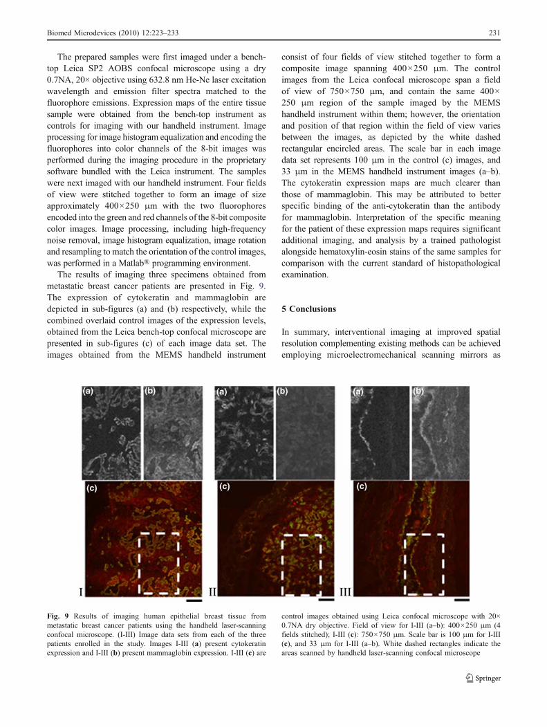
The results of imaging three specimens obtained frommetastatic breast cancer patients are presented in Fig. 9.The expression of cytokeratin and mammaglobin aredepicted in sub-figures (a) and (b) respectively, while thecombined overlaid control images of the expression levels,obtained from the Leica bench-top confocal microscope arepresented in sub-figures (c) of each image data set. Theimages obtained from the MEMS handheld instrument
consist of four fields of view stitched together to form acomposite image spanning 400×250 μm. The controlimages from the Leica confocal microscope span a fieldof view of 750×750 μm, and contain the same 400×250 μm region of the sample imaged by the MEMShandheld instrument within them; however, the orientationand position of that region within the field of view variesbetween the images, as depicted by the white dashedrectangular encircled areas. The scale bar in each imagedata set represents 100 μm in the control (c) images, and33 μm in the MEMS handheld instrument images (a–b).The cytokeratin expression maps are much clearer thanthose of mammaglobin. This may be attributed to betterspecific binding of the anti-cytokeratin than the antibodyfor mammaglobin. Interpretation of the specific meaningfor the patient of these expression maps requires significantadditional imaging, and analysis by a trained pathologistalongside hematoxylin-eosin stains of the same samples forcomparison with the current standard of histopathologicalexamination.
5 Conclusions
In summary, interventional imaging at improved spatialresolution complementing existing methods can be achievedemploying microelectromechanical scanning mirrors as
Fig. 9 Results of imaging human epithelial breast tissue frommetastatic breast cancer patients using the handheld laser-scanningconfocal microscope. (I-III) Image data sets from each of the threepatients enrolled in the study. Images I-III (a) present cytokeratinexpression and I-III (b) present mammaglobin expression. I-III (c) are
control images obtained using Leica confocal microscope with 20×0.7NA dry objective. Field of view for I-III (a–b): 400×250 μm (4fields stitched); I-III (c): 750×750 μm. Scale bar is 100 μm for I-III(c), and 33 μm for I-III (a–b). White dashed rectangles indicate theareas scanned by handheld laser-scanning confocal microscope
Biomed Microdevices (2010) 12:223–233 231
the core technology component driving miniaturization.MEMS-based endoscope technology brings unique strengthof miniaturization, batch fabrication, and integration ofactuators, sensors and electronics. The combination ofthese features enable large array of optical devices that canbe accurately positioned and assembled for compact biomed-ical imaging applications. The use of CMOS-compatiblebatch-processed microfabrication and cost-effective rapid-prototyped packaging techniques promises to enable dis-posable handheld probes that provide optical sectioningcomparable with conventional histology. The ability todetect histologically relevant features in biological tissueby high resolution optical microscopy can prove to be adisruptive innovation that can significantly alter thetechnological and procedural landscape in image-guidedintervention. Such tools can complement more conven-tional large-volume scanning systems to provide thephysician with a comprehensive and detailed understand-ing of the physiology of the tissue to accurately assess thecondition of the patient and make timely confidentdecisions on the basis of these diagnoses.
Acknowledgments Financial support of this research by Wallace HCoulter Foundation Early Career Award is gratefully acknowledged.The scanning micromirrors were fabricated at Stanford NanofabricationFacility and the Microelectronics Research Center at the University ofTexas at Austin, both supported by the National Science FoundationNational Nanofabrication Infrastructure Network under grants 9731293and 0335765, respectively. The University of Texas M. D. AndersonCancer Center and University of Texas Southwestern Tissue Repositoryat UTSW provided the swine liver and human specimens used for thisresearch respectively. Control images for the fluorescence microscopyexperiments were obtained using equipment at the Core facilities withinthe Institute for Cellular andMolecular Biology at the University of Texasat Austin.
References
A.D. Aguirre, P.R. Hertz, Y. Chen, J.G. Fujimoto, W. Piyawattanametha,L. Fan, M.C.Wu, "Two-axis MEMS scanning catheter for ultrahighresolution three-dimensional and En face imaging. Opt Express 15,2445–2453 (2007)
Y.-C. Cheng, C.-L. Dai, C.-Y. Lee, P.-H. Chen, P.-Z. Chang, A MEMSmicromirror fabricated using CMOS post-process. Sensors andActuators A: Physical 120, 573–581 (2005)
D. Ching-Liang, X. Fu-Yuan, J. Ying-Zong, C. Chin-Fon, Anapproach to fabricating microstructures that incorporate circuitsusing a post-CMOS process. Journal of Micromechanics andMicroengineering 15, 98 (2005)
C.-L. Dai, F.-Y. Xiao, Y.-Z. Juang, C.-F. Chiu, An approach tofabricating microstructures that incorporate circuits using a post-CMOS process. Journal of Micromechanics and Microengineering15, 98–103 (2005)
H. Dooyoung, P.R. Patterson, H.D. Nguyen, H. Toshiyoshi, M.C. Wu,Theory and experiments of angular vertical comb-drive actuatorsfor scanning micromirrors. IEEE Journal of Selected Topics inQuantum Electronics 10, 505–513 (2004)
G.K. Fedder, R.T. Howe, L. Tsu-Jae King, E.P. Quevy, Technologiesfor cofabricating MEMS and electronics. Proceedings of theIEEE 96, 306–322 (2008)
L. Fu, A. Jain, H. Xie, C. Cranfield, M. Gu, Nonlinear opticalendoscopy based on a double-clad photonic crystal fiber and aMEMS mirror. Opt Express 14, 1027–1032 (2006)
X. Gan, S.P. Schilders, M. Gu, Image enhancement through turbidmedia under a microscope by use of polarization gating methods.Journal of the Optical Society of America A 16, 2177–2184(1999)
C.L. Hoy, N.J. Durr, P. Chen, W. Piyawattanametha, H. Ra, O.Solgaard, A. Ben-Yakar, Miniaturized probe for femtosecondlaser microsurgery and two-photon imaging. Opt Express 16,9996–10005 (2008)
C. Hyuck, D. Garmire, J. Demmel, R.S. Muller, Simple fabricationprocess for self-aligned, high-performance microscanners—Demonstrated use to generate a 2-D ablation pattern. Journal ofMicroelectromechanical Systems 16, 260–268 (2007)
S. Kimura, T. Wilson, Confocal scanning optical microscope usingsingle-mode fiber for signal detection. Applied Optics 30, 2143–2150 (1991)
U. Krishnamoorthy, L. Daesung, O. Solgaard, Self-aligned verticalelectrostatic combdrives for micromirror actuation. Journal ofMicroelectromechanical Systems 12, 458–464 (2003)
K. Kumar, J.C. Condit, A. McElroy, N.J. Kemp, K. Hoshino, T.E.Milner, X. Zhang, Fast 3D in vivo swept-source opticalcoherence tomography using a two-axis MEMS scanning micro-mirror. Journal of Optics A: Pure and Applied Optics 10, 044013(2008a)
K. Kumar, K. Hoshino, X. Zhang, Handheld subcellular-resolutionsingle-fiber confocal microscope using high-reflectivity two-axisvertical combdrive silicon microscanner. Biomedical Microdevices10, 653–660 (2008b)
K. Kumar, X. Zhang, CMOS-compatible 2-axis self-aligned verticalcomb-driven micromirror for large field-of-view microendo-scopes, Proceedings of the 22nd IEEE International Conferenceon MicroElectroMechanical Systems (MEMS 2009), pp. 1015,2009a
K. Kumar, Rony Avritscher, D.C. Madoff, X.J. Zhang, HandheldSingle-Cell-Layer Optical Sectioning Reflectance ConfocalMicroscope for Interventional Imaging, The 29th Conference onLasers and Electro Optics(CLEO), Baltimore, Maryland, 1–5Jun, 2009b
K.C. Maitland, H.J. Shin, H. Ra, D. Lee, O. Solgaard, R. Richards-Kortum, Single fiber confocal microscope with a two-axisgimbaled MEMS scanner for cellular imaging. Opt Express 14,8604–8612 (2006)
A.B. Parthasarathy, W.J. Tom, A. Gopal, X.J. Zhang, A.K. Dunn,Robust flow measurement with multi-exposure speckle imaging.Optics Express 16, 1975–1989 (2008)
W. Piyawattanametha, R.P.J. Barretto, T.H. Ko, B.A. Flusberg, E.D.Cocker, H. Ra, D. Lee, O. Solgaard, M.J. Schnitzer, Fast-scanning two-photon fluorescence imaging based on a micro-electromechanical systems two- dimensional scanning mirror.Opt Lett. 31, 2018–2020 (2006)
H. Ra, W. Piyawattanametha, M.J. Mandella, P.-L. Hsiung, J. Hardy,T.D. Wang, C.H. Contag, G.S. Kino, O. Solgaard, Three-dimensional in vivo imaging by a handheld dual-axes confocalmicroscope. Opt Express 16, 7224–7232 (2008)
M. Rajadhyaksha, R.R. Anderson, R.H. Webb, Video-rate confocalscanning laser microscope for imaging human tissues in vivo.Appl Opt 38, 2105–2115 (1999)
J.M. Schmitt, A.H. Gandjbakhche, R.F. Bonner, Use of polarized lightto discriminate short-path photons in a multiply scatteringmedium. Applied Optics 31, 6535–6546 (1992)
232 Biomed Microdevices (2010) 12:223–233

O. Solgaard, Photonic microsystems: Micro and nanotechnologyapplied to optical devices and systems, 1st edn. (Springer, NewYork, 2008)
J. Woonggyu, Z. Jun, W. Lei, P. Wilder-Smith, C. Zhongping, D.T.McCormick, N.C. Tien, Three-dimensional optical coherencetomography employing a 2-axis microelectromechanical scan-
ning mirror. IEEE Journal of Selected Topics in QuantumElectronics 11, 806–810 (2005)
Z. Yaqoob, J. Wu, E.J. McDowell, X. Heng, C. Yang, Methodsand application areas of endoscopic optical coherencetomography. Journal of Biomedical Optics 11, 063001–19(2006)
Biomed Microdevices (2010) 12:223–233 233
Copyright © 2022 FDOKUMEN