Agilent U1270 Series Handheld Digital Multimeters - Farnell
26
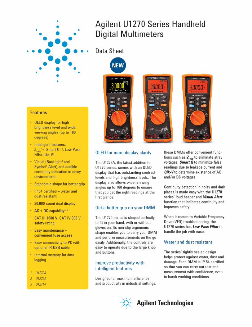
Agilent U1270 Series Handheld Digital Multimeters Data Sheet Features • OLED display for high brightness level and wider viewing angles (up to 160 degrees) 1 • Intelligent features: Z LOW 1, 2 , Smart Ω 1, 2 , Low Pass Filter, Qik-V 3 • Visual (Backlight 3 and Symbol 1 Alert) and audible continuity indication in noisy environments • Ergonomic shape for better grip • IP 54 certified – water and dust resistant • 30,000-count dual display • AC + DC capability 1, 2 • CAT III 1000 V, CAT IV 600 V safety rating • Easy maintenance – convenient fuse access • Easy connectivity to PC with optional IR-USB cable • Internal memory for data logging 1. U1273A 2. U1272A 3. U1271A OLED for more display clarity The U1273A, the latest addition to U1270 series, comes with an OLED display that has outstanding contrast levels and high brightness levels. The display also allows wider viewing angles up to 160 degrees to ensure that you get the right readings at the first glance. Get a better grip on your DMM The U1270 series is shaped perfectly to fit in your hand, with or without gloves on. Its non-slip ergonomic shape enables you to carry your DMM and perform measurements on the go easily. Additionally, the controls are easy to operate due to the large knob and buttons. Improve productivity with intelligent features Designed for maximum efficiency and productivity in industrial settings, these DMMs offer convenient func- tions such as Z LOW to eliminate stray voltages, Smart Ω to minimize false readings due to leakage current and Qik-V to determine existence of AC and/or DC voltages. Continuity detection in noisy and dark places is made easy with the U1270 series’ loud beeper and Visual Alert function that indicates continuity and improves safety. When it comes to Variable Frequency Drive (VFD) troubleshooting, the U1270 series has Low Pass Filter to handle the job with ease. Water and dust resistant The series’ tightly sealed design helps protect against water, dust and damage. Each DMM is IP 54 certified so that you can carry out test and measurement with confidence, even in harsh working conditions. NEW
-
Upload
khangminh22 -
Category
Documents
-
view
0 -
download
0
Transcript of Agilent U1270 Series Handheld Digital Multimeters - Farnell
Agilent U1270 Series Handheld Digital Multimeters
Data Sheet
Features
• OLED display for high brightness level and wider viewing angles (up to 160 degrees)1
• Intelligent features: ZLOW
1, 2, Smart Ω1, 2, Low Pass Filter, Qik-V3
• Visual (Backlight3 and Symbol1 Alert) and audible continuity indication in noisy environments
• Ergonomic shape for better grip
• IP 54 certified – water and dust resistant
• 30,000-count dual display
• AC + DC capability1, 2
• CAT III 1000 V, CAT IV 600 V safety rating
• Easy maintenance – convenient fuse access
• Easy connectivity to PC with optional IR-USB cable
• Internal memory for data logging
1. U1273A2. U1272A3. U1271A
OLED for more display clarity
The U1273A, the latest addition to U1270 series, comes with an OLED display that has outstanding contrast levels and high brightness levels. The display also allows wider viewing angles up to 160 degrees to ensure that you get the right readings at the first glance.
Get a better grip on your DMM
The U1270 series is shaped perfectly to fit in your hand, with or without gloves on. Its non-slip ergonomic shape enables you to carry your DMM and perform measurements on the go easily. Additionally, the controls are easy to operate due to the large knob and buttons.
Improve productivity with intelligent features
Designed for maximum efficiency and productivity in industrial settings,
these DMMs offer convenient func-tions such as ZLOW to eliminate stray voltages, Smart Ω to minimize false readings due to leakage current and Qik-V to determine existence of AC and/or DC voltages.
Continuity detection in noisy and dark places is made easy with the U1270 series’ loud beeper and Visual Alert function that indicates continuity and improves safety.
When it comes to Variable Frequency Drive (VFD) troubleshooting, the U1270 series has Low Pass Filter to handle the job with ease.
Water and dust resistant
The series’ tightly sealed design helps protect against water, dust and damage. Each DMM is IP 54 certified so that you can carry out test and measurement with confidence, even in harsh working conditions.
NEW

2
Key Functions
Low Impedance (ZLOW)
The U1272A and U1273A are dual input impedance digital multimeters. The DMM’s high input impedance is preferred in most electrical measurements because it would not load the circuit under test. However, to obtain accurate measurements on circuits that may contain stray voltages, the U1272A and U1273A’s 2 kΩ low impedance function comes
in handy. Stray voltages are usually found in non-energized electrical wiring adjacent to powered wires due to capacitive or inductive coupling between these wires. When a pair of test leads is placed between the open circuit and neutral conductor, the circuit is then complete and forms a voltage divider in conjunction with the input impedance of the multimeter.
High input impedance multimeter is sensitive enough to measure volt-age coupled into the disconnected conductor, thus giving an inaccurate indication of a live conductor. The low impedance function serves to elimi-nate false readings by dissipating the stray voltages, thus improves safety and measurement efficiency during voltage.
Figure 1. U1272A helps you identify the presence of stray voltage on a disconnected wire running parallel with the wire powering up the VFD to an industrial motor. The image on the right shows the U1272A in low impedance mode.
3
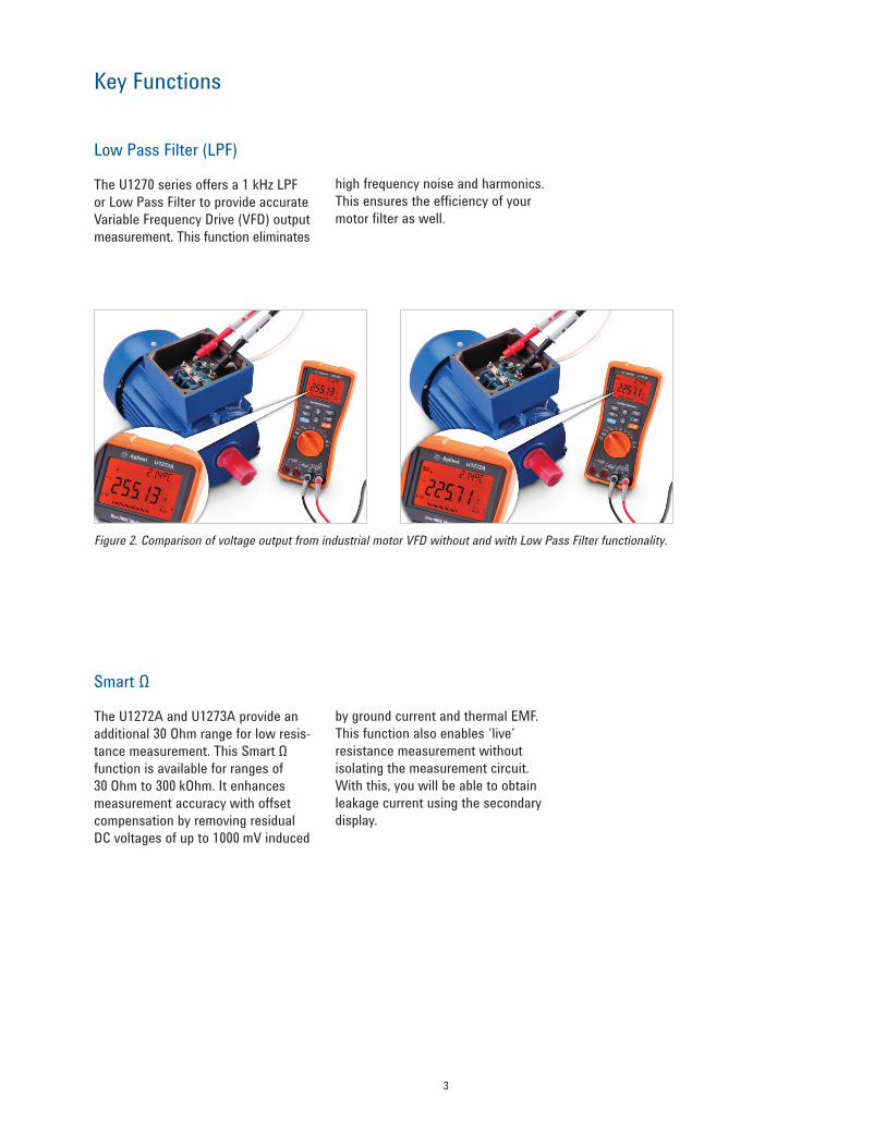
Low Pass Filter (LPF)
The U1270 series offers a 1 kHz LPF or Low Pass Filter to provide accurate Variable Frequency Drive (VFD) output measurement. This function eliminates
high frequency noise and harmonics. This ensures the efficiency of your motor filter as well.
Key Functions
Figure 2. Comparison of voltage output from industrial motor VFD without and with Low Pass Filter functionality.
Smart Ω
The U1272A and U1273A provide an additional 30 Ohm range for low resis-tance measurement. This Smart Ω function is available for ranges of 30 Ohm to 300 kOhm. It enhances measurement accuracy with offset compensation by removing residual DC voltages of up to 1000 mV induced
by ground current and thermal EMF. This function also enables ‘live’ resistance measurement without isolating the measurement circuit. With this, you will be able to obtain leakage current using the secondary display.
4
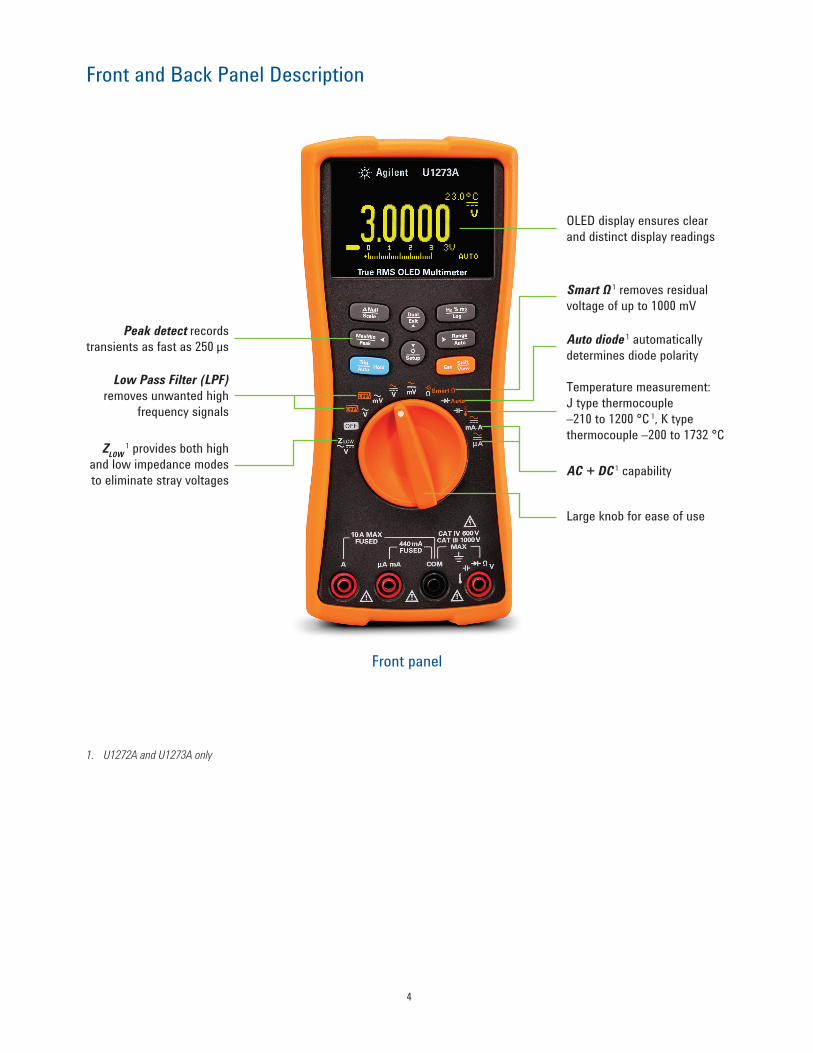
Front and Back Panel Description
OLED display ensures clear and distinct display readings
Smart Ω 1 removes residual voltage of up to 1000 mV
Auto diode 1 automatically determines diode polarity
Large knob for ease of use
Temperature measurement: J type thermocouple –210 to 1200 °C 1, K type thermocouple –200 to 1732 °C
ZLOW 1 provides both high
and low impedance modes to eliminate stray voltages
Peak detect records transients as fast as 250 μs
Low Pass Filter (LPF) removes unwanted high
frequency signals
AC + DC 1 capability
Front panel
1. U1272A and U1273A only
5
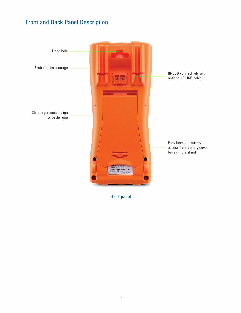
Front and Back Panel Description
Back panel
Probe holder/storageIR-USB connectivity with optional IR-USB cable
Hang hole
Slim, ergonomic design for better grip
Easy fuse and battery access from battery cover beneath the stand

6
Choose Among These Three Models
Di U1271A U1272A U1273ABasic FeaturesDisplay resolution 30,000 30,000 30,000Auto/manual ranging Yes Yes YesAnalog bar graph Yes Yes YesBacklight Yes Yes —AC bandwidth 20 kHz 100 kHz 100 kHzTrue RMS AC AC + DC AC + DCMeasurements
Voltage DC Range Accuracy
300 mV to 1000 V0.05% + 2 cnts
30 mV to 1000 V0.05% + 2 cnts
30 mV to 1000 V0.05% + 2 cnts
Voltage ACRange
Accuracy Bandwidth
300 mV to 1000 V0.7% + 20 cnts45 Hz to 20 kHz
30 mV to 1000 V0.6% + 20 cnts
45 Hz to 100 kHz
30 mV to 1000 V0.6% + 20 cnts
45 Hz to 100 kHz
Current DC Range Accuracy
300 µA to 10 A 0.2% + 5 cnts
300 µA to 10 A 0.2% + 5 cnts
300 µA to 10 A 0.2% + 5 cnts
Current ACRange
Accuracy Bandwidth
300 µA to 10 A 0.9% + 25 cnts 45 Hz to 2 kHz
300 µA to 10 A 0.6% + 25 cnts 45 Hz to 2 kHz
300 µA to 10 A 0.6% + 25 cnts 45 Hz to 2 kHz
Resistance Range Accuracy
300 Ω to 100 MΩ 0.2 % + 5 cnts
30 Ω to 300 MΩ 0.2% + 5 cnts
30 Ω to 300 MΩ 0.2% + 5 cnts
Frequency Range Accuracy
99.999 Hz to 999.99 kHz0.005% + 5 cnts
99.999 Hz to 999.99 kHz 0.005% + 5 cnts
99.999 Hz to 999.99 kHz 0.005% + 5 cnts
Capacitance Range Accuracy
10 nF to 10 mF 1% + 2 cnts
10 nF to 10 mF 1% + 2 cnts
10 nF to 10 mF 1% + 2 cnts
TemperatureRange
Accuracy
K: –200 to 1372 °C
1% + 1°C
K: –200 to 1372 °C J: –210 to 1200 °C
1% + 1 °C
K: –200 to 1372 °C J: –210 to 1200 °C
1% + 1 °CContinuity with beeper Yes Yes YesDiode test Yes Yes YesData ManagementMin/Max Recording Yes Yes YesDisplay Hold Yes Yes YesPeak Hold Yes Yes Yes
Datalogging Manual: 100 pointsInterval: 200 points
Manual: 100 pointsInterval: 10,000 points
Manual: 100 pointsInterval: 10,000 points
Null Yes Yes YesPC Connectivity IR-USB IR-USB IR-USB% scale of 4-20 mA Yes Yes Yes

7
Di U1271A U1272A U1273ASpecial FeaturesOLED display — — YesAlert in continuity test Beep + Backlight Alert Beep + Backlight Alert Beep + Symbol AlertLow Pass Filter (LPF) Yes Yes YesZLOW - Low impedance mode — Yes YesSmart Ω — Yes YesQik-V Yes — —Safety and Regulatory
Over-voltage safety protection CAT III 1000 V, CAT IV 600 V
CAT III 1000 V, CAT IV 600 V
CAT III 1000 V, CAT IV 600 V
EN/IEC 61010-1:2001 compliance Yes Yes YesGeneralBattery 4x AAA 4x AAA 4x AAA
Operating temperature –20 °C to 55 °C, 0 to 80% RH
–20 °C to 55 °C, 0 to 80% RH
–20 °C to 55 °C, 0 to 80% RH
Standard accessories
Standard test leads, test probes with 4-mm tips,
K-type thermocouple and adapter, 4x AAA batteries, Certificate of Calibration, UK 6 (test report), Quick
Start Guide
Standard test leads, test probes with 4-mm tips,
K-type thermocouple and adapter, 4x AAA batteries, Certificate of Calibration, UK 6 (test report), Quick
Start Guide
Standard test leads, test probes with 4-mm tips,
K-type thermocouple and adapter, 4x AAA batteries, Certificate of Calibration, UK 6 (test report), Quick
Start Guide
Choose Among These Three Models

8
General Specifications
Display • U1271A and U1272A: Liquid crystal display (LCD) (with maximum reading of 33,000 counts)
• U1273A: Organic LED (OLED) display (with maximum reading of 33,000 counts)Power consumption • U1271A/U1272A: 460 mVA maximum (with backlight enabled)
• U1273A: 180 mVA maximum (with maximum brightness)Battery type • 4 × 1.5 V Alkaline battery (ANSI/NEDA 24A or IEC LR03), or
• 4 × 1.5 V Zinc Chloride battery (ANSI/NEDA 24D or IEC R03)Battery life • U1271A and U1272A: 300 hours typical (based on new Alkaline batteries for DC
voltage measurement)• U1273A: 30/45/60 hours typical (based on new Alkaline batteries for DC voltage
measurement at High/Medium/Low brightness, respectively)• Low battery indicator will flash when the battery voltage drops below 4.4 V
(approximately) Fuse • 10 × 35 mm 440 mA/1000 V 30 kA fast-acting fuse
• 10 × 38 mm 11 A/1000 V 30 kA fast-acting fuseOperating environment • Operating temperature from –20 to 55 °C, 0 to 80% RH
• Full accuracy up to 80% RH for temperatures up to 30 °C, decreasing linearly to 50% RH at 55 °C
• Altitude up to 2000 meters• Pollution degree II
Storage compliance –40 to 70 °C, 0 to 80% RHSafety compliance • CAN/CSA-C22.2 No. 61010-1-04
• EN/IEC 61010-1:2001• ANSI/UL 61010-1:2004
Measurement category CAT III 1000 V/CAT IV 600 VElectromagnetic compatibility (EMC) Commercial limits compliance with EN61326-1Ingress protection rating IP-54Temperature coefficient 0.05 × (specified accuracy) / °C (from –20 to 18 °C, or 28 to 55 °C)Common Mode Rejection Ratio (CMRR) > 120 dB at DC, 50/60 Hz ± 0.1% (1 kΩ unbalanced)Normal Mode Rejection Ration (NMRR) > 60 dB at 50/60 Hz ± 0.1%Dimensions (W x H x D) 92 × 207 × 59 mmWeight • U1271A: 518 grams (with batteries)
• U1272A: 520 grams (with batteries)• U1273A: 500 grams (with batteries)
Warranty • Three years for product• Three months for product’s accessories
Calibration cycle One year
Specification Assumptions• Accuracy is given as ±(% of reading + counts of least significant digit) at 23 °C ± 5 °C, with relative humidity less than
80% RH.
• AC V and AC μA/mA/A specifications are AC coupled, true RMS and are valid from 5% of range to 100% of range.
• The crest factor may be up to 3.0 at full scale except for the 1000 V range where it is 1.5 at full scale.
• For non-sinusoidal waveforms, add (2% reading + 2% full scale) typical, for crest factors up to 3.
• After ZLOW voltage measurements, wait at least 20 minutes for thermal impact to cool before proceeding with any other measurement.

9
Electrical Specifications
DC specifications for U1271A, U1272A, and U1273A
Function Range ResolutionAccuracy ± (% of reading +
counts of least significant digit) Test current/Burden voltageU1271A U1272A U1273A
Voltage1
30 mV 0.001 mV — 0.05 + 20 0.05 + 20 —300 mV 0.01 mV 0.05 + 5 0.05 + 5 0.05 + 5 —
3 V 0.0001 V 0.05 + 5 0.05 + 5 0.05 + 5 —30 V 0.001 V 0.05 + 2 0.05 + 2 0.05 + 2 —300 V 0.01 V 0.05 + 2 0.05 + 2 0.05 + 2 —1000 V 0.1 V 0.05 + 2 0.05 + 2 0.05 + 2 —
ZLOW (low input
impedance) enabled,
applicable for 1000 V range and resolution
only
0.1 V — 1 + 20 1 + 20 —
Resistance2
30 Ω 0.001 Ω — 0.2 + 10 0.2 + 10 0.65 mA300 Ω 0.01 Ω 0.2 + 5 0.2 + 5 0.2 + 5 0.65 mA3 kΩ 0.0001 kΩ 0.2 + 5 0.2 + 5 0.2 + 5 65 µA30 kΩ 0.001 kΩ 0.2 + 5 0.2 + 5 0.2 + 5 6.5 µA300 kΩ 0.01 kΩ 0.5 + 5 0.5 + 5 0.5 + 5 0.65 µA3 MΩ 0.0001 MΩ 0.6 + 5 0.6 + 5 0.6 + 5 93 nA/10 MΩ30 MΩ 0.001 MΩ 1.2 + 5 1.2 + 5 1.2 + 5 93 nA/10 MΩ100 MΩ 0.01 MΩ 2.0 +10 — — 93 nA/10 MΩ
300 MΩ 0.01 MΩ — 2.0 + 10 @ < 100 MΩ 8.0 + 10 @ > 100 MΩ
2.0 + 10 @ < 100 MΩ 8.0 + 10 @ > 100 MΩ 93 nA/10 MΩ
300 nS 0.01 nS 1 + 10 1 + 10 1 + 10 93 nA/10 MΩ
Current3
300 µA 0.01 µA 0.2 + 5 0.2 + 3 0.2 + 5 < 0.04 V/100 Ω3000 µA 0.1 µA 0.2 + 5 0.2 + 3 0.2 + 5 < 0.4 V/100 Ω30 mA 0.001 mA 0.2 + 5 0.2 + 3 0.2 + 5 < 0.08 V/1 Ω300 mA 0.01 mA 0.2 + 5 0.2 + 3 0.2 + 5 < 1.00 V/1 Ω
3 A 0.0001 A 0.3 +10 0.3 +10 0.3 +10 < 0.1 V/0.01 Ω10 A 0.001 A 0.3 +10 0.3 +10 0.3 +10 < 0.3 V/0.01 Ω
Diode Test4
3 V 0.0001 V 0.5 + 5 0.5 + 5 0.5 + 5 Approximately 1 to 2 mA
Auto 0.0001 V — 0.5 + 5 0.5 + 5 Approximately 0.1 to 0.3 mA
See notes on next page.

10
Electrical Specifications
Notes for DC specifications (previous page)
1. Notes for voltage specifications: • The accuracy of the 30 to 300 mV range is specified after the Null function is used to subtract the thermal effect (by shorting the test leads).• For ZLOW measurements, autoranging is disabled and the multimeter’s range is set to 1000 volts in the manual ranging mode.
2. Notes for resistance specifications:• Overload protection: 1000 Vrms for short circuits with < 0.3 A current. • Maximum open voltage is < +3.3 V. • Built-in buzzer beeps when the resistance measured is less than 25 Ω ± 10 Ω. The multimeter can capture intermittent measurements longer than
1 ms. • The accuracy of the 300 Ω to 3 kΩ range is specified after the Null function is used to subtract the test lead resistance and thermal effect (by
shorting the test leads). • For the ranges of 30 MΩ and 100 MΩ, the RH is specified for < 60%. • The accuracy for ranges < 50 nS is specified after the Null function is used on an open test lead.• The temperature coefficient of the 100 MΩ and 300 MΩ range is 0.1 × (specified accuracy)/°C (from –20 °C to 18 °C or 28 °C to 55 °C).
3. Notes for current specifications: • Overload protection for 300 μA to 300 mA range: 0.44 A/1000 V; 10 × 35 mm 30 kA fast-acting fuse. • Overload protection for 3 A to 10 A range: 11 A/1000 V; 10 × 38 mm 30 kA fast-acting fuse. • Specification for 300 mA range: 440 mA continuous. • Specification for 10 A range: 10 A continuous. Add 0.3% to the specified accuracy when measuring signals > 10 to 20 A for 30 seconds
maximum. After measuring currents > 10 A, cool down the multimeter for twice the duration of the measured time before proceeding with low current measurements.
4. Notes for diode specifications:• Overload protection: 1000 Vrms for short circuits with < 0.3 A current. • Built-in buzzer beeps continuously when the voltage measured is less than 50 mV and beeps once for forward-biased diode or semiconductor
junctions measured between 0.3 V and 0.8 V (0.3 V ≤ reading ≤ 0.8 V). • Open voltage for diode: < +3.3 V DC. • Open voltage for Auto diode: < +2.5 V DC and > –1.0 V DC.

11
Electrical Specifications
AC specifications for U1271A
Function Range ResolutionAccuracy ± (% of reading + counts of least significant digit)
45 Hz to 65 Hz
30 Hz to 1 kHz
1 kHz to 5 kHz
5 kHz to 20 kHz
True RMS AC Voltage1
300 mV 0.01 mV 0.7 + 20 1.0 + 25 2.0 + 25 2.0 + 403 V 0.0001 V 0.7 + 20 1.0 + 25 2.0 + 25 2.0 + 4030 V 0.001 V 0.7 + 20 1.0 + 25 2.0 + 25 2.0 + 40300 V 0.01 V 0.7 + 20 1.0 + 25 2.0 + 25 —1000 V 0.1 V 0.7 + 20 1.0 + 25 — —
LPF (low pass filter) enabled, applicable for all voltage
ranges and resolution0.7 + 20 1.0 + 25 @ < 200 Hz
5.0 + 25 @ < 440 Hz — —
Function Range ResolutionAccuracy ± (% of reading +
counts of least significant digit) Burden voltage/Shunt45 Hz to 2 kHz
True RMS AC Current2
300 µA 0.01 µA 0.9 + 25 < 0.04 V/100 Ω3000 µA 0.1 µA 0.9 + 25 < 0.4 V/100 Ω30 mA 0.001 mA 0.9 + 25 < 0.08 V/1 Ω300 mA 0.01 mA 0.9 + 25 < 1.00 V/1 Ω
3 A 0.0001 A 1.0 + 25 < 0.1 V/0.01 Ω10 A 0.001 A 1.0 + 25 < 0.3 V/0.01 Ω
1. Notes for voltage specifications: • Overload protection: 1000 Vrms. For millivolt measurements, 1000 Vrms for short circuits with < 0.3 A current.• Input impedance: 10 MΩ (nominal) in parallel with < 100 pF.
2. Notes for current specifications:• Overload protection for 300 μA to 300 mA range: 0.44 A/1000 V; 10 × 35 mm 30 kA fast-acting fuse. • Overload protection for 3 A to 10 A range: 11 A/1000 V; 10 × 38 mm 30 kA fast-acting fuse. • Specification for 300 mA range: 440 mA continuous. • Specification for 10 A range: 10 A continuous. Add 0.3% to the specified accuracy when measuring signals > 10 to 20 A for 30 seconds
maximum. After measuring currents > 10 A, cool down the multimeter for twice the duration of the measured time before proceeding with low current measurements.

12
Electrical Specifications
AC specifications for U1272A and U1273A
Function Range ResolutionAccuracy ± (% of reading + counts of least significant digit)45 Hz to
65 Hz20 Hz to
1 kHz1 kHz to
5 kHz5 kHz to 20 kHz
20 kHz to 100 kHz
True RMS AC Voltage1
30 mV 0.001 mV 0.6 + 20 0.7 + 25 1.0 + 25 1.0 + 40 3.5 + 40300 mV 0.01 mV 0.6 + 20 0.7 + 25 1.0 + 25 1.0 + 40 3.5 + 40
3 V 0.0001 V 0.6 + 20 1.0 + 25 1.5 + 25 2.0 + 40 3.5 + 4030 V 0.001 V 0.6 + 20 1.0 + 25 1.5 + 25 2.0 + 40 3.5 + 40300 V 0.01 V 0.6 + 20 1.0 + 25 1.5 + 25 2.0 + 40 —1000 V 0.1 V 0.6 + 20 1.0 + 25 1.5 + 25 — —
LPF (low pass filter) enabled, applicable for all voltage
ranges and resolution0.6 + 20 1.0 + 25 @ < 200 Hz
5.0 + 25 @ < 440 Hz — — —
ZLOW 1000 V 2.0 + 40 2 + 40 @ < 440 Hz — — —
Function Range ResolutionAccuracy ± (% of reading +
counts of least significant digit) Burden voltage/Shunt45 Hz to 65 Hz 20 Hz to 2 kHz
True RMS AC Current2
300 µA 0.01 µA 0.6 + 25 0.9 + 25 < 0.04 V/100 Ω3000 µA 0.1 µA 0.6 + 25 0.9 + 25 < 0.4 V/100 Ω30 mA 0.001 mA 0.6 + 25 0.9 + 25 < 0.08 V/1 Ω300 mA 0.01 mA 0.6 + 25 0.9 + 25 < 1.00 V/1 Ω
3 A 0.0001 A 0.8 + 25 1.0 + 25 < 0.1 V/0.01 Ω10 A 0.001 A 0.8 + 25 1.0 + 25 < 0.3 V/0.01 Ω
1. Notes for voltage specifications: • Overload protection: 1000 Vrms. For millivolt measurements, 1000 Vrms for short circuits with < 0.3 A current.• Input impedance: 10 MΩ (nominal) in parallel with < 100 pF.• ZLOW impedance: 2 kΩ (nominal).• The input signal is lower than the product of 20,000,000 V×Hz.• For 20 to 100 kHz accuracy: Three counts of the LSD per kHz of additional error is to be added for frequencies > 20 kHz and signal inputs < 10%
of range.2. Notes for current specifications:• Overload protection for 300 μA to 300 mA range: 0.44 A/1000 V; 10 × 35 mm 30 kA fast-acting fuse. • Overload protection for 3 A to 10 A range: 11 A/1000 V; 10 × 38 mm 30 kA fast-acting fuse. • Specification for 300 mA range: 440 mA continuous. • Specification for 10 A range: 10 A continuous. Add 0.3% to the specified accuracy when measuring signals > 10 to 20 A for 30 seconds
maximum. After measuring currents > 10 A, cool down the multimeter for twice the duration of the measured time before proceeding with low current measurements.
13
Electrical Specifications
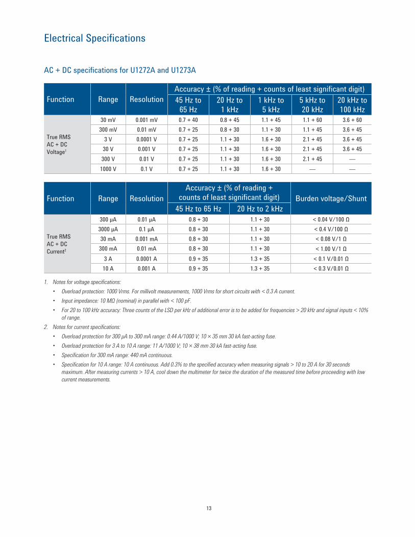
AC + DC specifications for U1272A and U1273A
Function Range ResolutionAccuracy ± (% of reading + counts of least significant digit)45 Hz to
65 Hz20 Hz to
1 kHz1 kHz to
5 kHz5 kHz to 20 kHz
20 kHz to 100 kHz
True RMS AC + DC Voltage1
30 mV 0.001 mV 0.7 + 40 0.8 + 45 1.1 + 45 1.1 + 60 3.6 + 60300 mV 0.01 mV 0.7 + 25 0.8 + 30 1.1 + 30 1.1 + 45 3.6 + 45
3 V 0.0001 V 0.7 + 25 1.1 + 30 1.6 + 30 2.1 + 45 3.6 + 4530 V 0.001 V 0.7 + 25 1.1 + 30 1.6 + 30 2.1 + 45 3.6 + 45300 V 0.01 V 0.7 + 25 1.1 + 30 1.6 + 30 2.1 + 45 —1000 V 0.1 V 0.7 + 25 1.1 + 30 1.6 + 30 — —
Function Range ResolutionAccuracy ± (% of reading +
counts of least significant digit) Burden voltage/Shunt45 Hz to 65 Hz 20 Hz to 2 kHz
True RMS AC + DC Current2
300 µA 0.01 µA 0.8 + 30 1.1 + 30 < 0.04 V/100 Ω3000 µA 0.1 µA 0.8 + 30 1.1 + 30 < 0.4 V/100 Ω30 mA 0.001 mA 0.8 + 30 1.1 + 30 < 0.08 V/1 Ω300 mA 0.01 mA 0.8 + 30 1.1 + 30 < 1.00 V/1 Ω
3 A 0.0001 A 0.9 + 35 1.3 + 35 < 0.1 V/0.01 Ω10 A 0.001 A 0.9 + 35 1.3 + 35 < 0.3 V/0.01 Ω
1. Notes for voltage specifications: • Overload protection: 1000 Vrms. For millivolt measurements, 1000 Vrms for short circuits with < 0.3 A current.• Input impedance: 10 MΩ (nominal) in parallel with < 100 pF.• For 20 to 100 kHz accuracy: Three counts of the LSD per kHz of additional error is to be added for frequencies > 20 kHz and signal inputs < 10%
of range.2. Notes for current specifications:• Overload protection for 300 μA to 300 mA range: 0.44 A/1000 V; 10 × 35 mm 30 kA fast-acting fuse. • Overload protection for 3 A to 10 A range: 11 A/1000 V; 10 × 38 mm 30 kA fast-acting fuse. • Specification for 300 mA range: 440 mA continuous. • Specification for 10 A range: 10 A continuous. Add 0.3% to the specified accuracy when measuring signals > 10 to 20 A for 30 seconds
maximum. After measuring currents > 10 A, cool down the multimeter for twice the duration of the measured time before proceeding with low current measurements.

14
Electrical Specifications
Temperature specifications1 - 6
Thermocouple type Range ResolutionAccuracy ± (% of reading +
counts of least significant digit)U1271A U1272A U1273A
K–200 to 1372 °C 0.1 °C 1% + 1 °C 1% + 1 °C 1% + 1 °C–328 to 2502 °F 0.1 °F 1% + 1.8 °F 1% + 1.8 °F 1% + 1.8 °F
J–210 to 1200 °C 0.1 °C — 1% + 1 °C 1% + 1 °C–346 to 2192 °F 0.1 °F — 1% + 1.8 °F 1% + 1.8 °F
1. The specifications above is specified after 60 minutes of warm-up time.2. The accuracy does not include the tolerance of the thermocouple probe.3. Do not allow the temperature sensor to contact a surface that is energized above 30 Vrms or 60 V DC. Such voltages pose a shock hazard.4. Ensure that the ambient temperature is stable within ±1 ºC and that the Null function is used to reduce the test lead’s thermal effect and temperature
offset. Before using Null function, set the multimeter to measure temperature without ambient compensation (°C) and keep the thermocouple probe as close to the multimeter as possible (avoid contact with any surface that has a different temperature from the ambient temperature).
5. When measuring temperature with respect to any temperature calibrator, try to set both the calibrator and multimeter with an external reference (without internal ambient compensation). If both the calibrator and multimeter are set with internal reference (with internal ambient compensation), some deviations may show between the readings of the calibrator and multimeter, due to differences in ambient compensation between the calibrator and multimeter. Keeping the multimeter close to the output terminal of calibrator will help reduce the deviation.
6. The temperature calculation is specified according to the safety standards of EN/IEC-60548-1 and NIST175.
Capacitance specifications7, 8
Range ResolutionAccuracy ± (% of reading +
counts of least significant digit)U1271A U1272A U1273A
10 nF 0.001 nF 1 + 5 1 + 5 1 + 5100 nF 0.01 nF 1 + 2 1 + 2 1 + 21000 nF 0.1 nF 1 + 2 1 + 2 1 + 210 μF 0.001 μF 1 + 2 1 + 2 1 + 2100 μF 0.01 μF 1 + 2 1 + 2 1 + 21000 μF 0.1 μF 1 + 2 1 + 2 1 + 210 mF 0.001 mF 1 + 2 1 + 2 1 + 2
7. Overload protection: 1000 Vrms for short circuits with < 0.3 A current.8. The accuracy for all ranges is specified based on a film capacitor or better, and after the Null function is used to subtract the test lead resistance and
thermal effect (by shorting the test leads).
15
Electrical Specifications
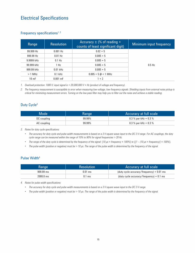
Frequency specifications1, 2
Range Resolution Accuracy ± (% of reading + counts of least significant digit) Minimum input frequency
99.999 Hz 0.001 Hz 0.02 + 5
0.5 Hz
999.99 Hz 0.01 Hz 0.005 + 59.9999 kHz 0.1 Hz 0.005 + 599.999 kHz 1 Hz 0.005 + 5999.99 kHz 0.01 kHz 0.005 + 5> 1 MHz 0.1 kHz 0.005 + 5 @ < 1 MHz10 mF 0.001 mF 1 + 2
1. Overload protection: 1000 V; input signal is < 20,000,000 V × Hz (product of voltage and frequency).2. The frequency measurement is susceptible to error when measuring low-voltage, low-frequency signals. Shielding inputs from external noise pickup is
critical for minimizing measurement errors. Turning on the low pass filter may help you to filter out the noise and achieve a stable reading.
Duty Cycle3
Mode Range Accuracy at full scaleDC coupling 99.99% 0.3 % per kHz + 0.3 %AC coupling 99.99% 0.3 % per kHz + 0.3 %
3. Notes for duty cycle specifications:• The accuracy for duty cycle and pulse width measurements is based on a 3 V square wave input to the DC 3 V range. For AC couplings, the duty
cycle range can be measured within the range of 10% to 90% for signal frequencies > 20 Hz.• The range of the duty cycle is determined by the frequency of the signal: 10 μs × frequency × 100% to [1 – (10 μs × frequency)] × 100%.• The pulse width (positive or negative) must be > 10 μs. The range of the pulse width is determined by the frequency of the signal.
Pulse Width4
Range Resolution Accuracy at full scale999.99 ms 0.01 ms (duty cycle accuracy/frequency) + 0.01 ms2000.0 ms 0.1 ms (duty cycle accuracy/frequency) + 0.1 ms
4. Notes for pulse width specifications:• The accuracy for duty cycle and pulse width measurements is based on a 3 V square wave input to the DC 3 V range.• The pulse width (positive or negative) must be > 10 μs. The range of the pulse width is determined by the frequency of the signal.

16
Electrical Specifications
U1271A and U1272A frequency sensitivity for voltage measurements1, 2, 3
Input rangeMinimum sensitivity (RMS sine wave) Trigger level for DC coupling
15 Hz to 100 kHz
0.5 Hz to 200 kHz
Up to 1 MHz
0.5 Hz to 200 kHzU1271A U1272A
30 mV 3 mV 3 mV — — 5 mV300 mV 6 mV 8 mV 40 mV 10 mV 15 mV
3 V 0.12 V 0.2 V 0.4 V 0.15 V 0.15 V30 V 0.6 V 0.8 V 2.6 V 1.5 V 1.5 V300 V 6 V 8 V @ < 100 kHz — 9 V @ < 100 kHz 9 V @ < 100 kHz1000 V 50 V 50 V @ < 100 kHz — 90 V @ < 100 kHz 90 V @ < 100 kHz
1. Maximum input for specified accuracy, refer to “AC specifications” on page 11.2. 30 mV range applicable for U1272A only. 3. 200 kHz to 1 MHz range applicable for U1272A only.
U1273A sensitivity for voltage measurements4
Input range Frequency sensitivity and trigger levelMinimum sensitivity (RMS sine wave) Trigger level for DC coupling
Maximum input for specified accuracy, refer to AC voltage
15 Hz to 100 kHz
0.5 Hz to 200 kHz
Up to 1 MHz 0.5 Hz to 200 kHz
30 mV 3 mV 3 mV — 5 mV300 mV 7 mV 8 mV 38 mV 15 mV
3 V 0.12 V 0.12 V 0.48 V 0.15 V30 V 0.8 V 0.8 V 3.5 V 1.5 V300 V 6.7 V 8 V < 100 kHz — 11 V < 100 kHz1000 V 67 V 67 V < 100 kHz — 110 V < 100 kHz
4. Maximum input for specified accuracy, refer to “AC specifications” on page 11.
Frequency sensitivity for current measurements5
Input rangeMinimum sensitivity (RMS sine wave)
2 Hz to 30 kHzU1271A/U1272A U1273A
300 µA 100 µA 70 μA3000 µA 70 µA 120 μA30 mA 1.2 mA 1.2 mA300 mA 12 mA 12 mA
3 A 0.12 A 0.12 A10 A 1.2 A 1.2 A
5. Maximum input for specified accuracy, refer to “AC specifications” on page 11.
Peak hold
Signal width Accuracy for DC Voltage and CurrentSingle event >1 ms Specified accuracy + 400Repetitive >250 µs Specified accuracy + 1000
17
Electrical Specifications
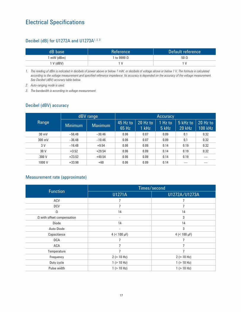
Decibel (dB) for U1272A and U1273A1, 2, 3
dB base Reference Default reference1 mW (dBm) 1 to 9999 Ω 50 Ω
1 V (dBV) 1 V 1 V
1. The reading of dBm is indicated in decibels of power above or below 1 mW, or decibels of voltage above or below 1 V. The formula is calculated according to the voltage measurement and specified reference impedance. Its accuracy is depended on the accuracy of the voltage measurement. See Decibel (dBV) accuracy table below.
2. Auto-ranging mode is used.3. The bandwidth is according to voltage measurement.
Decibel (dBV) accuracy
RangedBV range Accuracy
Minimum Maximum 45 Hz to 65 Hz
20 Hz to 1 kHz
1 Hz to 5 kHz
5 kHz to 20 kHz
20 Hz to 100 kHz
30 mV –56.48 –30.46 0.06 0.07 0.09 0.1 0.32300 mV –36.48 –10.46 0.06 0.07 0.09 0.1 0.32
3 V –16.48 +9.54 0.06 0.09 0.14 0.19 0.3230 V +3.52 +29.54 0.06 0.09 0.14 0.19 0.32300 V +23.52 +49.54 0.06 0.09 0.14 0.19 —1000 V +33.98 +60 0.06 0.09 0.14 — —
Measurement rate (approximate)
Function Times/secondU1271A U1272A/U1273A
ACV 7 7DCV 7 7
Ω 14 14Ω with offset compensation - 3
Diode 14 14Auto Diode - 3Capacitance 4 (< 100 µF) 4 (< 100 µF)
DCA 7 7ACA 7 7
Temperature 7 7Frequency 2 (> 10 Hz) 2 (> 10 Hz)Duty cycle 1 (> 10 Hz) 1 (> 10 Hz)
Pulse width 1 (> 10 Hz) 1 (> 10 Hz)

18
Ordering Information
Standard shipped accessoriesStandard test leads, test probes with 4-mm tips, K-type thermocouple and adapter, 4x AAA batteries, Certificate of Calibration, UK 6 (test report), Quick Start Guide
Optional accessoriesMeasuring accessories (non-temperature)U1161A Extended test lead kit
Includes two test leads (red and black), two test probes, medium-sized alligator clips and 4-mm banana plugs.• Test leads: CAT II 1000 V, 15 A• Test probes: CAT III 1000 V, 15 A• Medium-sized alligator clips: CAT III 1000 V/CAT IV 600 V, 10 A• 4-mm banana plugs: CAT II 600 V, 10 A
U1162AAlligator clips
• One pair of insulated alligator clips (red and black). Recommended for use with Agilent standard test leads.
• Rated CAT III 1000 V, 10 A
U1163A SMT grabbers
• One pair of SMT grabbers (red and black). Recommended for use with Agilent standard test leads.
• Rated CAT II 300 V, 3 A
U1164A Fine-tip test probes
• One pair of fine-tip test probes (red and black). Recommended for use with Agilent standard test leads.
• Rated CAT II 300 V, 3 A
U1168A Standard test lead kit
Includes two test leads (red and black), 4-mm test probes, alligator clips, fine-tip test probes, SMT grabbers and mini grabber (black).• Test leads: CAT III 1000 V, CAT IV 600 V, 15 A• Test probe (19-mm tips): CAT II 1000 V, 15 A• Test probes (4-mm tip): CAT III 1000 V, CAT IV 600 V, 15 A
(highly recommended for CAT IV environment)• Alligator clips: CAT III 1000 V, 10 A, CAT IV 600 V, 10 A• Fine-tip test probes: CAT II 300 V, 3 A• SMT grabber: CAT II 300 V, 3 A• Mini grabber: CAT II 300 V, 3 A
U1583B AC current clamp
• Dual range: 40 A and 400 A• Rated CAT III 600 V• BNC-to-banana-plug adapter provided for use with DMMs
U1271A U1272A U1273A

19
Ordering Information
Optional accessoriesMeasuring accessories (temperature)U1180A Thermocouple adapter+lead kit, J and K types
Includes thermocouple adapter, thermocouple bead J-type and thermocouple bead K-type.• T/C adapter J/K-type• T/C bead J-type: –20 °C to 200 °C• T/C bead K-type: –20 °C to 200 °C
U1181A Immersion temperature probe
• Type-K T/C for use in oil and other liquids• Measurement range: –50 °C to 700 ºC• Includes adapter U1184A for connection to DMM
U1182A Industrial surface temperature probe
• Type-K T/C for use on still surfaces• Measurement range: –50 ºC to 400 ºC• Includes adapter U1184A for connection to DMM
U1183A Air temperature probe
• Type-K T/C for use in air and non-caustic gas• Measurement range: –50 ºC to 800 ºC• Includes adapter U1184A for connection to DMM
U1184A Temperature probe adapter
• Mini-connector-to-banana-plug adapter for use with DMM
U1185A J-type thermocouple and adapter
• T/C adapter J/K-type• T/C bead J-type: –20 °C to 200 °C
U1186A K-type thermocouple and adapter
• T/C adapter J/K-type• T/C bead J-type: –20 °C to 200 °C
20
Ordering Information
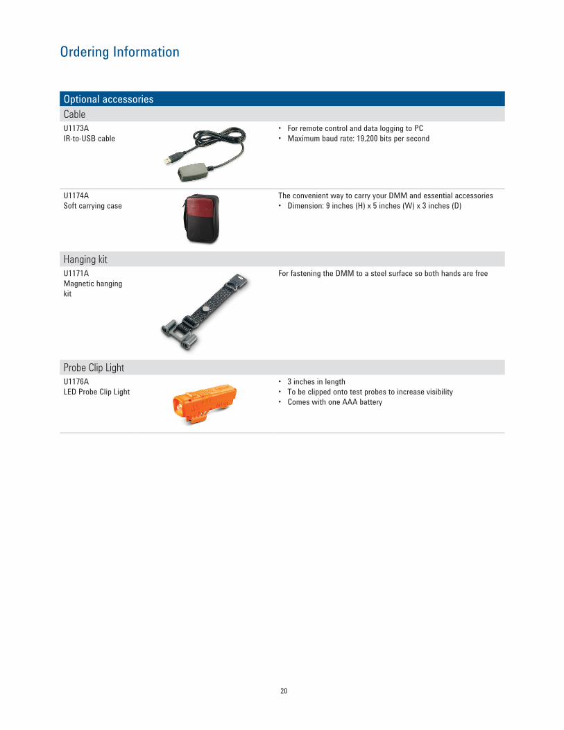
Optional accessoriesCableU1173A IR-to-USB cable
• For remote control and data logging to PC• Maximum baud rate: 19,200 bits per second
U1174A Soft carrying case
The convenient way to carry your DMM and essential accessories• Dimension: 9 inches (H) x 5 inches (W) x 3 inches (D)
Hanging kitU1171A Magnetic hanging kit
For fastening the DMM to a steel surface so both hands are free
Probe Clip LightU1176A LED Probe Clip Light
• 3 inches in length• To be clipped onto test probes to increase visibility• Comes with one AAA battery
Agilent Email Updates
www.agilent.com/find/emailupdatesGet the latest information on the products and applications you select.
www.lxistandard.orgLAN eXtensions for Instruments puts the power of Ethernet and the Webinside your test systems. Agilent is a founding member of the LXI consortium.
Agilent Channel Partnerswww.agilent.com/find/channelpartnersGet the best of both worlds: Agilent’s measurement expertise and product breadth, combined with channel partner convenience.
For more information on Agilent Technologies’ products, applications or services, please contact your local Agilent office. The complete list is available at:www.agilent.com/find/contactus
AmericasCanada (877) 894 4414 Brazil (11) 4197 3500Mexico 01800 5064 800 United States (800) 829 4444
Asia PacificAustralia 1 800 629 485China 800 810 0189Hong Kong 800 938 693India 1 800 112 929Japan 0120 (421) 345Korea 080 769 0800Malaysia 1 800 888 848Singapore 1 800 375 8100Taiwan 0800 047 866Other AP Countries (65) 375 8100
Europe & Middle EastBelgium 32 (0) 2 404 93 40 Denmark 45 70 13 15 15Finland 358 (0) 10 855 2100France 0825 010 700* *0.125 €/minuteGermany 49 (0) 7031 464 6333 Ireland 1890 924 204Israel 972-3-9288-504/544Italy 39 02 92 60 8484Netherlands 31 (0) 20 547 2111Spain 34 (91) 631 3300Sweden 0200-88 22 55United Kingdom 44 (0) 131 452 0200For other unlisted countries: www.agilent.com/find/contactusRevised: June 8, 2011
Product specifications and descriptions in this document subject to change without notice.
© Agilent Technologies, Inc. 2010, 2011Published in USA, September 2, 20115990-6425EN
www.agilent.comwww.agilent.com/find/handhelddmm
Agilent Advantage Services is committed to your success throughout your equip-ment’s lifetime. To keep you competitive, we continually invest in tools and processes that speed up calibration and repair and reduce your cost of ownership. You can also use Infoline Web Services to manage equipment and services more effectively. By sharing our measurement and service expertise, we help you create the products that change our world.
www.agilent.com/quality
www.agilent.com/find/advantageservices
www.axiestandard.org AdvancedTCA® Extensions for Instrumentation and Test (AXIe) is an open standard that extends the AdvancedTCA for general purpose and semiconductor test. Agilent is a founding member of the AXIe consortium.
www.pxisa.org PCI eXtensions for Instrumentation (PXI) modular instrumentationdelivers a rugged, PC-based high-performance measurement and automation system.
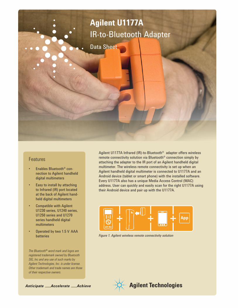
Agilent U1177A IR-to-Bluetooth AdapterData Sheet
Agilent U1177A Infrared (IR)-to-Bluetooth® adapter offers wireless remote connectivity solution via Bluetooth® connection simply by attaching the adapter to the IR port of an Agilent handheld digital multimeter. The wireless remote connectivity is set up when an Agilent handheld digital multimeter is connected to U1177A and an Android device (tablet or smart phone) with the installed software. Every U1177A also has a unique Media Access Control (MAC) address. User can quickly and easily scan for the right U1177A using their Android device and pair up with the U1177A.
Features• Enables Bluetooth® con-
nection to Agilent handheld digital multimeters
• Easy to install by attaching to Infrared (IR) port located at the back of Agilent hand-held digital multimeters
• Compatible with Agilent U1230 series, U1240 series, U1250 series and U1270 series handheld digital multimeters
• Operated by two 1.5 V AAA batteries
The Bluetooth® word mark and logos are registered trademark owned by Bluetooth SIG, Inc and any use of such marks by Agilent Technologies, Inc. is under license. Other trademark and trade names are those of their respective owners.
Figure 1. Agilent wireless remote connectivity solution

2
Low battery indication: Red LED flashing
Bluetooth® disconnected: Green LED flashing
Bluetooth® connected: Green solid LED
Bluetooth® power off: LED off
ON/OFF/Setup slide switch
Figure 2. The U1177A as illustrated
Take a closer look
3
Agilent Mobile Meter is a free Android application software that allows an Android device to connect, control and perform up to 3 multimeter measure-ments. Without the need to be physically present at various points, users can now extend their reach to two or three places. This solution allows you to make measurements from a safe distance, eliminates the need to walk back-and-forth between measure target and control points, and monitors multiple measure-ments simultaneously. Achieve higher work productivity when you use the U1177A with your Agilent handheld digital multimeters.
Perform up to three multimeter measurements at the same time with Agilent Mobile Meter
Figure 4. Up to three multimeters measurements with the Agilent Mobile Meter
Figure 5. Make measurements with the Agilent Mobile Meter via an Android smart phone
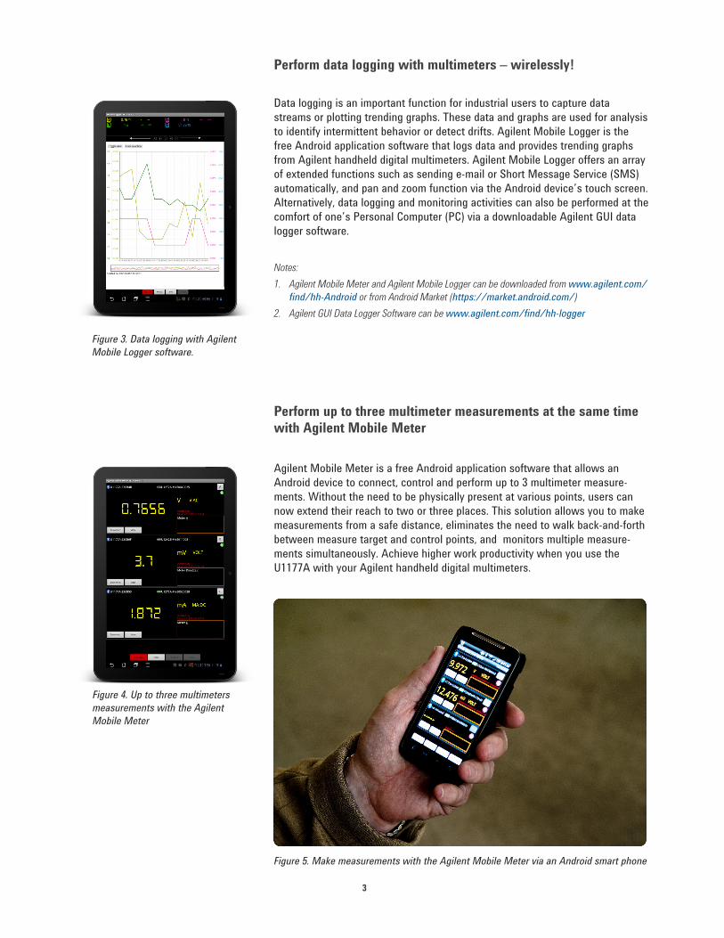
Data logging is an important function for industrial users to capture data streams or plotting trending graphs. These data and graphs are used for analysis to identify intermittent behavior or detect drifts. Agilent Mobile Logger is the free Android application software that logs data and provides trending graphs from Agilent handheld digital multimeters. Agilent Mobile Logger offers an array of extended functions such as sending e-mail or Short Message Service (SMS) automatically, and pan and zoom function via the Android device’s touch screen. Alternatively, data logging and monitoring activities can also be performed at the comfort of one’s Personal Computer (PC) via a downloadable Agilent GUI data logger software.
Perform data logging with multimeters – wirelessly!
Notes: 1. Agilent Mobile Meter and Agilent Mobile Logger can be downloaded from www.agilent.com/
find/hh-Android or from Android Market (https://market.android.com/)2. Agilent GUI Data Logger Software can be www.agilent.com/find/hh-logger
Figure 3. Data logging with Agilent Mobile Logger software.

4
Product characteristics DescriptionRadio specification • Frequency: 2402 MHz ~ 2480 MHz
• Antenna Power: 1 mW or less• Number of Channels: 79• Modulation: GFSK / PSK
Operating environment Operating temperature from –20 to 55 °C
Storage environment Storage temperature from –40 to 70 °C
Relative humidity (R.H.) Relative humidity up to 95% at 40 °C (non-condensing)
Power consumption Maximum 130 mVA for two 1.5 V AAA batteries
Battery life 30 hours typical (based on continuous data transfer)
Battery type Alkaline 24 A (ANSI/NEDA) and LR03 (IEC), or Zinc Chloride 24 D (ANSI/NEDA) and R03 (IEC)
Dimension (W x H x L) 39.0 × 71.0 × 37.0 mm
Weight 60 g with batteries
Warranty Three months
Bluetooth "Bluetooth" Version 2.1 + EDR compliant, SPP profile, Class 2 device (with 10 metres connection range)
Safety The U1177A complies with the requirements of the following safety and regulation standards:• FCC Part15C (Certification) (15.209, 15.247) FCC ID: ZKMAGILENT-U1177A• FCC Part15B (DoC) (15.109)• RSS–210 Issue 8:2010 IC: 6310A–U1177A• ICES–003 Issue 4:2004• EN 300 328 V1.7.1:2008• EN 301 489–1V1.8.1:2008/–17 V2.11:2009• EN 55022:2006+A1:2007/EN55024:1998+A1:2001+A2:2003• EN 50371:2002• EN 60950–1:2006/A11:2009/A1:2010• Complies with IDA Standards (DB 102425)• India Equipment Type Approval (ETA) Certificate No: 1424/2011/WRLO• COFETEL Certificate No: RCPAGU111-1066, registered under Agilent Technologies
Mexico S de RL de CV
"This telecommunication equipment conforms NTC technical requirement"
Specifications
Standard shipped items:
• Two 1.5 V AAA batteries• Operating instructions
For more information on Agilent Technologies’ products, applications or services, please contact your local Agilent office. The complete list is available at:www.agilent.com/find/contactus
AmericasCanada (877) 894 4414 Brazil (11) 4197 3600Mexico 01800 5064 800 United States (800) 829 4444
Asia PacificAustralia 1 800 629 485China 800 810 0189Hong Kong 800 938 693India 1 800 112 929Japan 0120 (421) 345Korea 080 769 0800Malaysia 1 800 888 848Singapore 1 800 375 8100Taiwan 0800 047 866Other AP Countries (65) 375 8100
Europe & Middle EastBelgium 32 (0) 2 404 93 40 Denmark 45 45 80 12 15Finland 358 (0) 10 855 2100France 0825 010 700* *0.125 €/minuteGermany 49 (0) 7031 464 6333 Ireland 1890 924 204Israel 972-3-9288-504/544Italy 39 02 92 60 8484Netherlands 31 (0) 20 547 2111Spain 34 (91) 631 3300Sweden 0200-88 22 55United Kingdom 44 (0) 118 927 6201For other unlisted countries: www.agilent.com/find/contactusRevised: January 6, 2012
Product specifications and descriptions in this document subject to change without notice.
© Agilent Technologies, Inc. 2012Published in USA, February 2, 20125990-9531EN
www.agilent.comwww.agilent.com/find/U1177A
Agilent Advantage Services is committed to your success throughout your equip-ment’s lifetime. To keep you competitive, we continually invest in tools and processes that speed up calibration and repair and reduce your cost of ownership. You can also use Infoline Web Services to manage equipment and services more effectively. By sharing our measurement and service expertise, we help you create the products that change our world.
www.agilent.com/quality
www.agilent.com/find/advantageservices
Agilent Email Updates
www.agilent.com/find/emailupdatesGet the latest information on the products and applications you select.
www.lxistandard.orgLAN eXtensions for Instruments puts the power of Ethernet and the Webinside your test systems. Agilent is a founding member of the LXI consortium.
Agilent Channel Partnerswww.agilent.com/find/channelpartnersGet the best of both worlds: Agilent’s measurement expertise and product breadth, combined with channel partner convenience.
www.axiestandard.org AdvancedTCA® Extensions for Instrumentation and Test (AXIe) is an open standard that extends the AdvancedTCA for general purpose and semiconductor test. Agilent is a founding member of the AXIe consortium.
www.pxisa.org PCI eXtensions for Instrumentation (PXI) modular instrumentationdelivers a rugged, PC-based high-performance measurement and automation system.