
HAMPSTEAD/SCOTT'S HILL WELL PROJECT - Pender ...
743
PENDER COUNTY North Carolina Project Manual for: HAMPSTEAD/SCOTT’S HILL WELL PROJECT ISSUED FOR BID NOT FOR CONSTRUCTION Prepared By: McKim & Creed, Inc. 243 N. Front Street Wilmington, NC 28401 910-343-1048 M&C Project Number 00542-0079 McKim & Creed NC License No. F-1222 APRIL 2020
-
Upload
khangminh22 -
Category
Documents
-
view
0 -
download
0
Transcript of HAMPSTEAD/SCOTT'S HILL WELL PROJECT - Pender ...

PENDER COUNTY
North Carolina
Project Manual for:
HAMPSTEAD/SCOTT’S HILL
WELL PROJECT
ISSUED FOR BID
NOT FOR CONSTRUCTION
Prepared By:
McKim & Creed, Inc.
243 N. Front Street
Wilmington, NC 28401
910-343-1048
M&C Project Number 00542-0079
McKim & Creed NC License No. F-1222
APRIL 2020
TABLE OF CONTENTS
HAMPSTEAD/SCOTT’S HILL WELL PROJECT i 00542-0079 APRIL 2020
DIVISION 0 – FRONT END 00 01 00 Advertisement for Bids 00 01 00:1-2 00 10 00 Instruction to Bidders 00 10 00:1-10 00 20 00 Bid Form 00 20 00:1-6 00 22 00 Bid Bond 00 22 00:1-2 00 24 00 DBE 00 24 00:1-8 00 30 00 Notice of Award 00 30 00:1-2 00 50 00 Agreement 00 50 00:1-6 00 51 00 Insurance Certificate 00 51 00:1-2 00 52 00 Performance Bond 00 52 00:1-4 00 53 00 Payment Bond 00 53 00:1-4 00 60 00 Notice to Proceed 00 60 00:1-2 00 62 50 Certificate of Substantial Completion 00 62 50:1-2 00 70 00 Standard General Conditions 00 70 00:1-62 00 80 00 Supplementary Conditions 00 80 00:1-13 00 90 00 Special Project Conditions 00 90 00:1-6 00 94 00 Work Change Directive 00 94 00:1-2 00 94 10 Change Order 00 94 10:1-2 00 94 20 Field Order 00 94 20.:1-2 DIVISION 1 – GENERAL REQUIREMENTS 01 10 00 - Summary 01 10 00:1-5 01 25 00 – Contract Modification Procedures 01 25 00:1-4 01 27 00 – Measurement and Payment 01 27 00:1-5 01 29 00 - Price and Payment Procedures 01 29 00:1-6 01 31 00 - Project Management and Coordination 01 31 00:1-10 01 32 00 - Construction Progress Documentation 01 32 00:1-8 01 33 00 - Submittal Procedures 01 33 00: 1-13 01 34 00 - Submittals 01 34 00:1-4 01 40 00 - Quality Requirements 01 40 00:1-10 01 42 00 - References 01 42 00:1-18 01 50 00 - Temporary Facilities and Controls 01 50 00:1-10 01 60 00 - Product Requirements 01 60 00:1-6 01 70 00 - Execution Requirements 01 70 00:1-12 01 77 00 - Closeout Procedures 01 77 00:1-6 01 78 10 – Project Record Documents 01 78 10:1-5 01 78 20 - Operation and Maintenance Data 01 78 20:1-9 01 82 00 - Demonstration and Training 01 82 00:1-6 DIVISION 2 – SITEWORK 02 05 10 - Piping Materials and Methods 02 05 10:1-23 02 06 00 - Hangers and Support 02 06 00:1-5 02 08 00 - Piped Utilities – Basic Materials and Methods 02 08 00:1-16 02 10 20 - Air Release and Air Relief Valves 02 10 20:1-5 02 10 70 - Gate Valves 02 10 70:1-8 02 22 00 - Excavating, Grading, Trenching, and Backfilling 02 22 00:1-9 02 24 00 - Dewatering 02 24 00:1-6
TABLE OF CONTENTS
HAMPSTEAD/SCOTT’S HILL WELL PROJECT ii 00542-0079 APRIL 2020
02 26 00 - Excavation Support and Protection 02 26 00:1-6 02 47 60 - Control of Erosion, Siltation, and Pollution 02 47 60:1-3 02 48 00 - Seeding and Mulching 02 48 00:1-4 02 73 10 - Gravity Sewer Systems 02 73 10:1-10 02 82 10 - Fencing 02 82 10:1-9 DIVISION 3 – CONCRETE 03 30 00 - Cast-In-Place Concrete 03 30 00: 1-13 DIVISION 4 – MASONRY 04 22 00 - Concrete Masonry 04 22 00: 1-9 DIVISION 9 – FINISHES 09 90 00 - Protective Coatings 09 90 00:1-6 DIVISION 11 – EQUIPMENT 11 93 00 - Polyethylene Chemical Storage Tanks 11 93 00:1-15 DIVISION 13 – SPECIAL CONSTRUCTION 13 45 00 – Precast Concrete Field Erected Building 13 45 00:1-6 DIVISION 26 – ELECTRICAL 26 00 00 - Electrical Basic Requirements 26 00 00:1-15 26 00 10 – Testing and Commissioning of Electrical Systems 26 00 10:1-5 26 00 15 - Identification for Electrical Systems 26 00 15:1-18 26 05 01 – Excavation and Concrete Work for Electrical Systems 26 05 01:1-5 26 05 19 - Wire and Cable - 600V 26 05 19:1-9 26 05 26 - Grounding and Bonding 26 05 26:1-5 26 05 29 - Electrical Hangers and Supports 26 05 29:1-5 26 05 30 - Electrical Raceway Systems 26 05 30:1-15 26 05 33 – Boxes Cabinets and Enclosures for Electrical Systems 26 05 33:1-8 26 05 43 - Underground Duct-Bank Systems 26 05 43:1-15 26 24 16 – Panelboards 26 24 16:1-6 26 28 16 - Disconnect Switches 26 28 16:1-7 26 29 23 - Variable Frequency Drives - 600V 26 29 23:1-20 26 32 13 - Engine-Driven Generator 26 32 13:1-15 26 33 53 - Packaged Power Supplies 26 33 53:1-7 26 36 23 - Automatic Transfer Switches 26 36 23:1-11 DIVISION 33 – UTILITIES 33 11 13 – Potable Water Supply Wells 33 11 13:1-13
TABLE OF CONTENTS
HAMPSTEAD/SCOTT’S HILL WELL PROJECT iii 00542-0079 APRIL 2020
DIVISION 40 – PROCESS INTERCONNECTIONS 40 61 00 – ICS General Req 40 61 00:1-23 40 61 93 – IO Schedule 40 61 93:1-2 40 63 00 - ICS SCADA Hardware 40 63 00:1-7 40 66 33 - ICS Pump Station RTU 40 66 33:1-4 40 67 00 - ICS Control Enclosures 40 67 00:1-12 40 70 00 - ICS Field Equipment 40 70 00:1-8 40 70 00A – Inst Schedule 40 70 00A:1-1 40 75 21 - Chlorine Residual Analyzer 40 75 21:1-10 40 80 00 - ICS Functional Control Descriptions 40 80 00:1-4
DIVISION 44 – POLLUTION AND WASTE CONTAINMENT 44 41 33 – Chemical Containment Pallet 44 41 33:1-2 DIVISION 46 – WATER AND WASTEWATER EQUIPMENT 46 33 00 - Liquid Chemical Feed Equipment 46 33 00:1-13 APPENDICES Appendix A Project Geotechnical Report

HAMPSTEAD\SCOTT’S HILL WELL PROJECT 00 01 00-1 00542-0079 APRIL 2020
Pender County Burgaw, NC
Pender County Utilities Hampstead/Scott’s Hill Well Project
ADVERTISEMENT FOR BIDS
PUBLIC BID OPENING
Sealed Bids for the construction of the Hampstead/Scott’s Hill Well Project will be received, by Pender County on May 12, 2020 until 2:00 p.m. local time, at which time the Bids received will be “publicly” opened and read via a web-based meeting utilizing Microsoft Teams. Interested parties wishing to join the web-based public reading of the bids received may do so by sending an email request to the following email address no later than May 11, 2020, 5:00 p.m. local time. Note that a physical meeting will not be held for the bid opening and only the web-based meeting will be conducted.
A Microsoft Teams link will be sent to all parties who provide an email address for the bid opening no later than 10:00 a.m. local time on May 12, 2020. Parties may utilize this link to join the web-based Microsoft Teams meeting. Interested parties are advised that only audio may be available due to limitations with Microsoft Teams video capability. Consequently, the public bid opening will be conducted via audio and interested parties may only hear the reading of the bids as video may not be available.
PRE-BID CONFERENCE
A pre-bid conference will be held at 10:00 AM local time on April 28, 2020. The pre-bid conference will be conducted via a web-based meeting utilizing Microsoft Teams. Interested parties wishing to join the web-based pre-bid conference may do so by sending an email to the following email address no later than April 27, 2020 2:00 p.m. local time. Note that a physical meeting will not be held for the pre-bid conference and only the web-based meeting will be available to interested parties.
A Microsoft Teams link will be sent to all parties who provide an email address for the pre-bid conference no later than 8:30 a.m. local time on April 28, 2020. Parties will utilize this link to join the web-based Microsoft Teams meeting. Interested parties are advised that only audio may be available due to limitations with Microsoft Teams video capability. Consequently, the pre-bid conference will be conducted via audio and interested parties may only hear the pre-bid conference as video may not be available. Attendance at the pre-bid conference is not mandatory.
The Project consists of the construction of:
• Two (2) finished water production supply wells and associated appurtenances
• Pre-fabricated well house buildings
• Chemical Feed Systems
• Electrical and control systems for well system operation
• Approximately 600 linear feet of Water Main Distribution Piping

HAMPSTEAD\SCOTT’S HILL WELL PROJECT 00 01 00-2 00542-0079 APRIL 2020
Bids will be received for a single prime Contract. Bids shall be as indicated in the Bid Form. Bidders are not required to be pre-qualified in order to submit a bid for the Hampstead/Scott’s Hill Well Project. Contractor is advised and shall meet the following project schedule for execution and completion of the project:
• Pre-Bid Conference April 28, 2020 10:00 a.m. local time
• Public Bid Opening May 12, 2020 2:00 p.m. local time
• Notice of Award June 2, 2020
• Notice to Proceed June 15, 2020
Prospective bidders may obtain copies of the Bidding Documents by contacting the Issuing Office for the Bidding Documents at: McKim & Creed, Inc., 243 N. Front Street, Wilmington, NC 28401, Jamie Mabe Fitzsimmons, 910-343-1048, [email protected]. Physical copies of the Bidding Documents will not be available for review at the Issuing Office.
Bidding Documents may also be examined on the Pender County website at the following link. Physical copies of the Bidding Documents will not be available for review at the offices of Pender County:
http://www.pendercountync.gov/utl/
Bidding Documents will be provided no later than April 20, 2020, at Carolinas Plan Room, 2527 S. 17th Street, Wilmington, NC 28401; online at Carolinas AGC www.cagc.org; Prospective Bidders should contact these entities to determine availability for obtaining or viewing the documents.
Bidding Documents are available on compact disc (as portable document format (PDF) files for a non-refundable charge of $100.00, including shipping via overnight express service. Alternatively, printed Bidding Documents may be obtained from the Issuing Office via mail, upon Issuing Office’s receipt of payment for the Bidding Documents. The non-refundable cost of printed Bidding Documents is $200.00 per set, payable to “McKim & Creed, Inc.”, plus a non-refundable shipping charge. Upon Issuing Office’s receipt of payment, printed Bidding Documents will be sent via the prospective Bidder’s delivery method of choice; the shipping charge will depend on the shipping method chosen. The date that the Bidding Documents are transmitted by the Issuing Office will be considered the prospective Bidder’s date of receipt of the Bidding Documents. Partial sets of Bidding Documents will not be available from the Issuing Office. Neither Owner nor Engineer will be responsible for full or partial sets of Bidding Documents, including Addenda if any, obtained from sources other than the Issuing Office.
Owner: Pender County Utilities
By: Kenny P. Keel PE
Title: Director
+ + END OF ADVERTISEMENT FOR BIDS + +
HAMPSTEAD\SCOTT’S HILL WELL PROJECT 00 10 00 – 1 00542-0079 APRIL 2020
INSTRUCTIONS TO BIDDERS
TABLE OF CONTENTS
Page
Article 1 – Defined Terms ............................................................................................................................ 2
Article 2 – Copies of Bidding Documents .................................................................................................... 2
Article 3 – Qualifications of Bidders ............................................................................................................ 2
Article 4 – Site and Other Areas; Existing Site Conditions; Examination of Site; Owner’s Safety Program;
Other Work at the Site .................................................................................................................................. 2
Article 5 – Bidder’s Representations ............................................................................................................ 3
Article 6 – Pre-Bid Conference ..................................................................................................................... 4
Article 7 – Interpretations and Addenda ....................................................................................................... 5
Article 8 – Bid Security ................................................................................................................................ 5
Article 9 – Contract Times ............................................................................................................................ 5
Article 10 – Liquidated Damages ................................................................................................................. 5
Article 11 – Substitute and “Or-Equal” Items .............................................................................................. 5
Article 12 – Subcontractors, Suppliers, and Others ...................................................................................... 6
Article 13 – Preparation of Bid ..................................................................................................................... 6
Article 14 – Basis of Bid ............................................................................................................................... 7
Article 15 – Submittal of Bid ........................................................................................................................ 7
Article 16 – Modification and Withdrawal of Bid ........................................................................................ 8
Article 17 – Opening of Bids ........................................................................................................................ 8
Article 18 – Bids to Remain Subject to Acceptance ..................................................................................... 8
Article 19 – Evaluation of Bids and Award of Contract ............................................................................... 8
Article 20 – Bonds and Insurance ................................................................................................................. 9
Article 21 – Signing of Agreement ............................................................................................................... 9
Article 22 – Sales and Use Taxes.................................................................................................................. 9
HAMPSTEAD\SCOTT’S HILL WELL PROJECT 00 10 00 - 2 00542-0079 APRIL 2020
ARTICLE 1 – DEFINED TERMS
1.01 Terms used in these Instructions to Bidders have the meanings indicated in the General Conditions and Supplementary Conditions. Additional terms used in these Instructions to Bidders have the meanings indicated below:
A. Issuing Office – The office from which the Bidding Documents are to be issued.
ARTICLE 2 – COPIES OF BIDDING DOCUMENTS
2.01 Complete sets of the Bidding Documents may be obtained from the Issuing Office in the number and format stated in the advertisement or invitation to bid.
2.02 Complete sets of Bidding Documents shall be used in preparing Bids; neither Owner nor Engineer assumes any responsibility for errors or misinterpretations resulting from the use of incomplete sets of Bidding Documents.
2.03 Owner and Engineer, in making copies of Bidding Documents available on the above terms, do so only for the purpose of obtaining Bids for the Work and do not authorize or confer a license for any other use.
ARTICLE 3 – QUALIFICATIONS OF BIDDERS
3.01 To demonstrate Bidder’s qualifications to perform the Work, Bidder shall submit with its Bid the following information:
A. Evidence of Bidder’s authority to do business in the state where the Project is located.
B. Bidder’s state or other contractor license number, if applicable.
3.02 A Bidder’s failure to submit required qualification information within the times indicated may disqualify Bidder from receiving an award of the Contract.
3.03 No requirement in this Article 3 to submit information will prejudice the right of Owner to seek additional pertinent information regarding Bidder’s qualifications.
3.04 Bidder is advised to carefully review those portions of the Bid Form requiring Bidder’s representations and certifications.
ARTICLE 4 – SITE AND OTHER AREAS; EXISTING SITE CONDITIONS; EXAMINATION OF SITE; OWNER’S SAFETY PROGRAM; OTHER WORK AT THE SITE
4.01 Site and Other Areas
A. The Site is identified in the Bidding Documents. By definition, the Site includes rights-of-way, easements, and other lands furnished by Owner for the use of the Contractor. Any additional lands required for temporary construction facilities, construction equipment, or storage of materials and equipment, and any access needed for such additional lands, are to be obtained and paid for by Contractor.
4.02 Existing Site Conditions
A. Subsurface and Physical Conditions; Hazardous Environmental Conditions
1. The Supplementary Conditions identify:
a. Those drawings known to Owner of physical conditions relating to existing surface or subsurface structures at the Site (except Underground Facilities).
HAMPSTEAD\SCOTT’S HILL WELL PROJECT 00 10 00 - 3 00542-0079 APRIL 2020
B. Adequacy of Data: Provisions concerning responsibilities for the adequacy of data furnished to prospective Bidders with respect to subsurface conditions, other physical conditions, and Underground Facilities, and possible changes in the Bidding Documents due to differing or unanticipated subsurface or physical conditions appear in Paragraphs 4.03, 4.04, and 4.05 of the General Conditions. Provisions concerning responsibilities for the adequacy of data furnished to prospective Bidders with respect to a Hazardous Environmental Condition at the Site, if any, and possible changes in the Contract Documents due to any Hazardous Environmental Condition uncovered or revealed at the Site which was not shown or indicated in the Drawings or Specifications or identified in the Contract Documents to be within the scope of the Work, appear in Paragraph 4.06 of the General Conditions.
4.03 Site Visit and Testing by Bidders
A. Bidder shall conduct the required Site visit during normal working hours, and shall not disturb any ongoing operations at the Site. (Site access gate will be secured but not locked)
B. Bidder is not required to conduct any subsurface testing, or exhaustive investigations of Site conditions.
C. On request, and to the extent Owner has control over the Site, and schedule permitting, the Owner will provide Bidder access to the Site to conduct such additional examinations, investigations, explorations, tests, and studies as Bidder deems necessary for preparing and submitting a successful Bid. Owner will not have any obligation to grant such access if doing so is not practical because of existing operations, security or safety concerns, or restraints on Owner’s authority regarding the Site.
D. Bidder shall comply with all applicable Laws and Regulations regarding excavation and location of utilities, obtain all permits, and comply with all terms and conditions established by Owner or by property owners or other entities controlling the Site with respect to schedule, access, existing operations, security, liability insurance, and applicable safety programs.
E. Bidder shall fill all holes and clean up and restore the Site to its former condition upon completion of such explorations, investigations, tests, and studies.
4.04 Owner’s Safety Program
A. Site visits and work at the Site may be governed by an Owner safety program. As the General Conditions indicate, if an Owner safety program exists, it will be noted in the Supplementary Conditions.
4.05 Other Work at the Site
A. Reference is made to Article 7 of the Supplementary Conditions for the identification of the general nature of other work of which Owner is aware (if any) that is to be performed at the Site by Owner or others (such as utilities and other prime contractors) and relates to the Work contemplated by these Bidding Documents. If Owner is party to a written contract for such other work, then on request, Owner will provide to each Bidder access to examine such contracts (other than portions thereof related to price and other confidential matters), if any.
ARTICLE 5 – BIDDER’S REPRESENTATIONS
5.01 It is the responsibility of each Bidder before submitting a Bid to:
HAMPSTEAD\SCOTT’S HILL WELL PROJECT 00 10 00 - 4 00542-0079 APRIL 2020
A. examine and carefully study the Bidding Documents, and any data and reference items identified in the Bidding Documents;
B. visit the Site, conduct a thorough, alert visual examination of the Site and adjacent areas, and become familiar with and satisfy itself as to the general, local, and Site conditions that may affect cost, progress, and performance of the Work;
C. become familiar with and satisfy itself as to all Laws and Regulations that may affect cost, progress, and performance of the Work;
D. carefully study all: (1) reports of explorations and tests of subsurface conditions at or adjacent to the Site and all drawings of physical conditions relating to existing surface or subsurface structures at the Site.
E. consider the information known to Bidder itself; information commonly known to contractors doing business in the locality of the Site; information and observations obtained from visits to the Site; the Bidding Documents; and the Site-related reports and drawings identified in the Bidding Documents, with respect to the effect of such information, observations, and documents on (1) the cost, progress, and performance of the Work; (2) the means, methods, techniques, sequences, and procedures of construction to be employed by Bidder; and (3) Bidder’s safety precautions and programs;
F. agree, based on the information and observations referred to in the preceding paragraph, that at the time of submitting its Bid no further examinations, investigations, explorations, tests, studies, or data are necessary for the determination of its Bid for performance of the Work at the price bid and within the times required, and in accordance with the other terms and conditions of the Bidding Documents;
G. become aware of the general nature of the work to be performed by Owner and others at the Site that relates to the Work as indicated in the Bidding Documents;
H. promptly give Engineer written notice of all conflicts, errors, ambiguities, or discrepancies that Bidder discovers in the Bidding Documents and confirm that the written resolution thereof by Engineer is acceptable to Bidder;
I. determine that the Bidding Documents are generally sufficient to indicate and convey understanding of all terms and conditions for the performance and furnishing of the Work; and
J. agree that the submission of a Bid will constitute an incontrovertible representation by Bidder that Bidder has complied with every requirement of this Article, that without exception the Bid and all prices in the Bid are premised upon performing and furnishing the Work required by the Bidding Documents.
ARTICLE 6 – PRE-BID CONFERENCE
6.01 A pre-Bid conference will be held at the time and location stated in the invitation or advertisement to bid. Representatives of Owner and Engineer will be present to discuss the Project. Bidders are encouraged to attend and participate in the conference. Engineer will transmit to all prospective Bidders of record such Addenda as Engineer considers necessary in response to questions arising at the conference. Oral statements may not be relied upon and will not be binding or legally effective.
HAMPSTEAD\SCOTT’S HILL WELL PROJECT 00 10 00 - 5 00542-0079 APRIL 2020
ARTICLE 7 – INTERPRETATIONS AND ADDENDA
7.01 All questions about the meaning or intent of the Bidding Documents are to be submitted to Engineer in writing. Interpretations or clarifications considered necessary by Engineer in response to such questions will be issued by Addenda delivered to all parties recorded as having received the Bidding Documents. Questions received less than three days prior to the date for opening of Bids may not be answered. Only questions answered by Addenda will be binding. Oral and other interpretations or clarifications will be without legal effect.
7.02 Addenda may be issued to clarify, correct, supplement, or change the Bidding Documents.
ARTICLE 8 – BID SECURITY
8.01 A Bid must be accompanied by Bid security made payable to Owner in an amount of 5% percent of Bidder’s maximum Bid price (determined by adding the base bid and all alternates) and in the form of a certified check, bank money order, or a Bid bond (on the form included in the Bidding Documents) issued by a surety meeting the requirements of Paragraphs 5.01 and 5.02 of the General Conditions.
8.02 The Bid security of the apparent Successful Bidder will be retained until Owner awards the contract to such Bidder, and such Bidder has executed the Contract Documents, furnished the required contract security, and met the other conditions of the Notice of Award, whereupon the Bid security will be released. If the Successful Bidder fails to execute and deliver the Contract Documents and furnish the required contract security within 15 days after the Notice of Award, Owner may consider Bidder to be in default, annul the Notice of Award, and the Bid security of that Bidder will be forfeited. Such forfeiture shall be Owner’s exclusive remedy if Bidder defaults.
8.03 The Bid security of other Bidders that Owner believes to have a reasonable chance of receiving the award may be retained by Owner until the earlier of seven days after the Effective Date of the Contract or 61 days after the Bid opening, whereupon Bid security furnished by such Bidders will be released.
8.04 Bid security of other Bidders that Owner believes do not have a reasonable chance of receiving the award will be released within seven days after the Bid opening.
ARTICLE 9 – CONTRACT TIMES
9.01 The Contract Times are set forth in the agreement. The Contract Times are 210 days to substantial completion and 240 days to final completion from the date of the agreement.
ARTICLE 10 – LIQUIDATED DAMAGES
10.01 Provisions for liquidated damages, if any, for failure to timely attain a Milestone, Substantial Completion, or completion of the Work in readiness for final payment, are set forth in the Agreement.
ARTICLE 11 – SUBSTITUTE AND “OR-EQUAL” ITEMS
11.01 The Contract for the Work, as awarded, will be on the basis of materials and equipment specified or described in the Bidding Documents without consideration during the bidding and Contract award process of possible substitute or “or-equal” items. In cases in which the Contract allows the Contractor to request that Engineer authorize the use of a substitute or “or-equal” item of material or equipment, application for such acceptance
HAMPSTEAD\SCOTT’S HILL WELL PROJECT 00 10 00 - 6 00542-0079 APRIL 2020
may not be made to and will not be considered by Engineer until after the Effective Date of the Contract.
11.02 All prices that Bidder sets forth in its Bid shall be based on the presumption that the Contractor will furnish the materials and equipment specified or described in the Bidding Documents, as supplemented by Addenda. Any assumptions regarding the possibility of post-Bid approvals of “or-equal” or substitution requests are made at Bidder’s sole risk.
ARTICLE 12 – SUBCONTRACTORS, SUPPLIERS, AND OTHERS
12.01 A Bidder shall be prepared to retain specific Subcontractors, Suppliers, or other individuals or entities for the performance of the Work if required by the Bidding Documents (most commonly in the Specifications) to do so. If a prospective Bidder objects to retaining any such Subcontractor, Supplier, or other individual or entity, and the concern is not relieved by an Addendum, then the prospective Bidder should refrain from submitting a Bid.
12.02 Subsequent to the submittal of the Bid, Owner may not require the Successful Bidder or Contractor to retain any Subcontractor, Supplier, or other individual or entity against which Contractor has reasonable objection.
12.03 The apparent Successful Bidder, and any other Bidder so requested, shall within five days after Bid opening, submit to Owner a list of the Subcontractors or Suppliers proposed for the following portions of the Work: Earthwork, Utilities, and Roadways.
12.04 The Owner will pay for construction materials testing and is not to be included in the contractors pricing. Contractor shall include in his bid coordination and scheduling for the Owner’s construction materials testing representative.
ARTICLE 13 – PREPARATION OF BID
13.01 The Bid Form is included with the Bidding Documents.
A. All blanks on the Bid Form shall be completed in ink and the Bid Form signed in ink. Erasures or alterations shall be initialed in ink by the person signing the Bid Form. A Bid price shall be indicated for each section, Bid item, alternate, adjustment unit price item, and unit price item listed therein.
B. If the Bid Form expressly indicates that submitting pricing on a specific alternate item is optional, and Bidder elects to not furnish pricing for such optional alternate item, then Bidder may enter the words “No Bid” or “Not Applicable.”
13.02 A Bid by a corporation shall be executed in the corporate name by a corporate officer (whose title must appear under the signature), accompanied by evidence of authority to sign. The corporate address and state of incorporation shall be shown.
13.03 A Bid by a limited liability company shall be executed in the name of the firm by a member or other authorized person and accompanied by evidence of authority to sign. The state of formation of the firm and the official address of the firm shall be shown.
13.04 A Bid by an individual shall show the Bidder’s name and official address.
13.05 A Bid by a joint venture shall be executed by an authorized representative of each joint venturer in the manner indicated on the Bid Form. The official address of the joint venture shall be shown.
13.06 All names shall be printed in ink below the signatures.
13.07 The Bid shall contain an acknowledgment of receipt of all Addenda, the numbers of which shall be filled in on the Bid Form.
HAMPSTEAD\SCOTT’S HILL WELL PROJECT 00 10 00 - 7 00542-0079 APRIL 2020
13.08 Postal and e-mail addresses and telephone number for communications regarding the Bid shall be shown.
13.09 The Bid shall contain evidence of Bidder’s authority and qualification to do business in the state where the Project is located, or Bidder shall covenant in writing to obtain such authority and qualification prior to award of the Contract and attach such covenant to the Bid. Bidder’s state contractor license number, if any, shall also be shown on the Bid Form.
ARTICLE 14 – BASIS OF BID
14.01 Lump Sum
A. Bidders shall submit a Bid on a lump sum basis as set forth in the Bid Form.
14.02 Unit Price Information
A. Bidders shall submit unit price information in support of the lump sum total.
B. The “Bid Price” (sometimes referred to as the extended price) for each unit price Bid item will be the product of the “Estimated Quantity” (which Owner or its representative has set forth in the Bid Form) for the item and the corresponding “Bid Unit Price” offered by the Bidder. The total of all unit price Bid items will be the sum of these “Bid Prices”; such total will be used by Owner for Bid comparison purposes. The final quantities and Contract Price will be determined in accordance with Paragraph 13.03 of the General Conditions.
C. Discrepancies between the multiplication of units of Work and unit prices will be resolved in favor of the unit prices. Discrepancies between the indicated sum of any column of figures and the correct sum thereof will be resolved in favor of the correct sum.
14.03 Allowances
A. For cash allowances the Bid price shall include such amounts as the Bidder deems proper for Contractor's overhead, costs, profit, and other expenses on account of cash allowances, if any, named in the Contract Documents, in accordance with Paragraph 11.02.B of the General Conditions.
ARTICLE 15 – SUBMITTAL OF BID
15.01 With each copy of the Bidding Documents, a Bidder is furnished one separate unbound copy of the Bid Form, and, if required, the Bid Bond Form. The unbound copy of the Bid Form is to be completed and submitted with the Bid security and the other documents required to be submitted under the terms of Article 7 of the Bid Form.
15.02 A Bid shall be received no later than the date and time prescribed and at the place indicated in the advertisement or invitation to bid and shall be enclosed in a plainly marked package with the Project title (and, if applicable, the designated portion of the Project for which the Bid is submitted), the name and address of Bidder, and shall be accompanied by the Bid security and other required documents. If a Bid is sent by mail or other delivery system, the sealed envelope containing the Bid shall be enclosed in a separate package plainly marked on the outside with the notation “BID ENCLOSED.” A mailed Bid shall be addressed to 605 East Fremont Street, Burgaw, NC 28425.
15.03 Bids received after the date and time prescribed for the opening of bids, or not submitted at the correct location or in the designated manner, will not be accepted and will be returned to the Bidder unopened.
HAMPSTEAD\SCOTT’S HILL WELL PROJECT 00 10 00 - 8 00542-0079 APRIL 2020
ARTICLE 16 – MODIFICATION AND WITHDRAWAL OF BID
16.01 A Bid may be withdrawn by an appropriate document duly executed in the same manner that a Bid must be executed and delivered to the place where Bids are to be submitted prior to the date and time for the opening of Bids. Upon receipt of such notice, the unopened Bid will be returned to the Bidder.
16.02 If a Bidder wishes to modify its Bid prior to Bid opening, Bidder must withdraw its initial Bid in the manner specified in Paragraph 16.01 and submit a new Bid prior to the date and time for the opening of Bids.
16.03 If within 24 hours after Bids are opened any Bidder files a duly signed written notice with Owner and promptly thereafter demonstrates to the reasonable satisfaction of Owner that there was a material and substantial mistake in the preparation of its Bid, that Bidder may withdraw its Bid, and the Bid security will be returned. Thereafter, if the Work is rebid, that Bidder will be disqualified from further bidding on the Work.
ARTICLE 17 – OPENING OF BIDS
17.01 Bids will be opened at the time and place indicated in the advertisement or invitation to bid and, unless obviously non-responsive, read aloud publicly. An abstract of the amounts of the base Bids and major alternates, if any, will be made available to Bidders after the opening of Bids.
ARTICLE 18 – BIDS TO REMAIN SUBJECT TO ACCEPTANCE
18.01 All Bids will remain subject to acceptance for the period of time stated in the Bid Form, but Owner may, in its sole discretion, release any Bid and return the Bid security prior to the end of this period.
ARTICLE 19 – EVALUATION OF BIDS AND AWARD OF CONTRACT
19.01 Owner reserves the right to reject any or all Bids, including without limitation, nonconforming, nonresponsive, unbalanced, or conditional Bids. Owner will reject the Bid of any Bidder that Owner finds, after reasonable inquiry and evaluation, to not be responsible. If Bidder purports to add terms or conditions to its Bid, takes exception to any provision of the Bidding Documents, or attempts to alter the contents of the Contract Documents for purposes of the Bid, then the Owner will reject the Bid as nonresponsive; provided that Owner also reserves the right to waive all minor informalities not involving price, time, or changes in the Work.
19.02 If Owner awards the contract for the Work, such award shall be to the responsible Bidder submitting the lowest responsive Bid.
19.03 Evaluation of Bids
A. In evaluating Bids, Owner will consider whether or not the Bids comply with the prescribed requirements, and such alternates, unit prices, and other data, as may be requested in the Bid Form or prior to the Notice of Award.
B. For determination of the apparent low Bidder(s) when sectional bids are submitted, Bids will be compared on the basis of the aggregate of the Bids for separate sections and the Bids for combined sections that result in the lowest total amount for all of the Work.
C. Bid prices will be compared after adjusting for differences in time of Substantial Completion (total number of calendar days to substantially complete the Work)
HAMPSTEAD\SCOTT’S HILL WELL PROJECT 00 10 00 - 9 00542-0079 APRIL 2020
designated by Bidders. The adjusting amount will be determined at the rate set forth in the Agreement for liquidated damages for failing to achieve Substantial Completion, or such other amount that Owner has designated in the Bid Form.
1. The method for calculating the lowest bid for comparison will be the summation of the Bid price shown in the Bid Form plus the product of the Bidder-specified time of Substantial Completion (in calendar days) times the rate for liquidated damages (in dollars per day).
2. This procedure is only used to determine the lowest bid for comparison and contractor selection purposes. The Contract Price for compensation and payment purposes remains the Bid price shown in the Bid Form.
19.04 In evaluating whether a Bidder is responsible, Owner will consider the qualifications of the Bidder and may consider the qualifications and experience of Subcontractors and Suppliers proposed for those portions of the Work for which the identity of Subcontractors and Suppliers must be submitted as provided in the Bidding Documents.
19.05 Owner may conduct such investigations as Owner deems necessary to establish the responsibility, qualifications, and financial ability of Bidders and any proposed Subcontractors or Suppliers.
ARTICLE 20 – BONDS AND INSURANCE
20.01 Article 5 of the General Conditions, as may be modified by the Supplementary Conditions, sets forth Owner’s requirements as to performance and payment bonds and insurance. When the Successful Bidder delivers the Agreement (executed by Successful Bidder) to Owner, it shall be accompanied by required bonds and insurance documentation.
ARTICLE 21 – SIGNING OF AGREEMENT
21.01 When Owner issues a Notice of Award to the Successful Bidder, it shall be accompanied by the unexecuted counterparts of the Agreement along with the other Contract Documents as identified in the Agreement. Within 10 days thereafter, Successful Bidder shall execute and deliver the required number of counterparts of the Agreement (and any bonds and insurance documentation required to be delivered by the Contract Documents) to Owner. Within ten days thereafter, Owner shall deliver one fully executed counterpart of the Agreement to Successful Bidder, together with printed and electronic copies of the Contract Documents as stated in Paragraph 2.02 of the General Conditions.
ARTICLE 22 – SALES AND USE TAXES
22.01 Owner is exempt from NC state sales and use taxes on materials and equipment to be incorporated in the Work. Said taxes shall not be included in the Bid. Refer to Paragraph SC- 6.10 of the Supplementary Conditions for additional information.

HAMPSTEAD\SCOTT’S HILL WELL PROJECT 00 10 00 - 10 00542-0079 APRIL 2020
This page intentionally left blank

HAMPSTEAD/SCOTT’S HILL WELL PROJECT 00 20 00 – 1 BID FORM 00542-0079 APRIL 2020
BID FORM
Pender County
Burgaw, NC
Pender County Utilities
Hampstead/Scott’s Hill Well Project
April, 2020
HAMPSTEAD\SCOTT’S HILL WELL PROJECT 00 20 00 - 2
BID FORM
00542-0079 APRIL 2020
TABLE OF CONTENTS
Page
Article 1 – Bid Recipient .............................................................................................................................. 4
Article 2 – Bidder’s Acknowledgements ...................................................................................................... 4
Article 3 – Bidder’s Representations ............................................................................................................ 4
Article 4 - Bidder's Certification ................................................................................................................... 4
Article 5 - Basis of Bid ................................................................................................................................. 5
Article 6 - Time of Completion .................................................................................................................... 7
Article 7 - Attachments to this Bid ............................................................................................................... 7
Article 8 - Defined Terms ............................................................................................................................. 8
Article 9 - Bid Submittal ............................................................................................................................... 8
HAMPSTEAD/SCOTT’S HILL WELL PROJECT 00 20 00 - 3 BID FORM 00542-0079 APRIL 2020
ARTICLE 1 – BID RECIPIENT
1.01 This Bid is submitted to:
Pender County Utilities
c/o Kenneth Keel PE
605 East Fremont Street
Burgaw, NC 28425
1.02 The undersigned Bidder proposes and agrees, if this Bid is accepted, to enter into an Agreement
with Owner in the form included in the Bidding Documents to perform all Work as specified or
indicated in the Bidding Documents for the prices and within the times indicated in this Bid and
in accordance with the other terms and conditions of the Bidding Documents.
ARTICLE 2 – BIDDER’S ACKNOWLEDGEMENTS
2.01 Bidder accepts all of the terms and conditions of the Instructions to Bidders, including without
limitation those dealing with the disposition of Bid security. This Bid will remain subject to
acceptance for 60 days after the Bid opening, or for such longer period of time that Bidder may
agree to in writing upon request of Owner.
ARTICLE 3 – BIDDER’S REPRESENTATIONS
3.01 In submitting this Bid, Bidder represents that:
A. Bidder has examined and carefully studied the Bidding Documents, and any data and
reference items identified in the Bidding Documents, and hereby acknowledges receipt of
the following Addenda:
Addendum No. Addendum, Date
B. Bidder has visited the Site, conducted a thorough, alert visual examination of the Site and
adjacent areas, and become familiar with and satisfied itself as to the general, local, and Site
conditions that may affect cost, progress, and performance of the Work.
C. Bidder is familiar with and has satisfied itself as to all Laws and Regulations that may affect
cost, progress, and performance of the Work.
D. Bidder has carefully studied all reports of explorations and tests of subsurface conditions at
or adjacent to the Site and all drawings of physical conditions relating to existing surface or
subsurface structures at the Site.
E. Bidder has considered the information known to Bidder itself; information commonly known
to contractors doing business in the locality of the Site; information and observations
obtained from visits to the Site; the Bidding Documents; and any Site-related reports and
drawings identified in the Bidding Documents, with respect to the effect of such information,
observations, and documents on (1) the cost, progress, and performance of the Work; (2) the
means, methods, techniques, sequences, and procedures of construction to be employed by
Bidder; and (3) Bidder’s safety precautions and programs.

HAMPSTEAD/SCOTT’S HILL WELL PROJECT 00 20 00 - 4 BID FORM 00542-0079 APRIL 2020
F. Bidder agrees, based on the information and observations referred to in the preceding
paragraph, that no further examinations, investigations, explorations, tests, studies, or data
are necessary for the determination of this Bid for performance of the Work at the price bid
and within the times required, and in accordance with the other terms and conditions of the
Bidding Documents.
G. Bidder is aware of the general nature of work to be performed by Owner and others at the
Site that relates to the Work as indicated in the Bidding Documents.
H. Bidder has given Engineer written notice of all conflicts, errors, ambiguities, or
discrepancies that Bidder has discovered in the Bidding Documents, and confirms that the
written resolution thereof by Engineer is acceptable to Bidder.
I. The Bidding Documents are generally sufficient to indicate and convey understanding of all
terms and conditions for the performance and furnishing of the Work.
J. The submission of this Bid constitutes an incontrovertible representation by Bidder that
Bidder has complied with every requirement of this Article, and that without exception the
Bid and all prices in the Bid are premised upon performing and furnishing the Work required
by the Bidding Documents.
ARTICLE 4 – BIDDER’S CERTIFICATION
4.01 Bidder certifies that:
A. This Bid is genuine and not made in the interest of or on behalf of any undisclosed
individual or entity and is not submitted in conformity with any collusive agreement or rules
of any group, association, organization, or corporation;
B. Bidder has not directly or indirectly induced or solicited any other Bidder to submit a false
or sham Bid;
C. Bidder has not solicited or induced any individual or entity to refrain from bidding; and
D. Bidder has not engaged in corrupt, fraudulent, collusive, or coercive practices in competing
for the Contract. For the purposes of this Paragraph 4.01.D:
1. “corrupt practice” means the offering, giving, receiving, or soliciting of any thing of
value likely to influence the action of a public official in the bidding process;
2. “fraudulent practice” means an intentional misrepresentation of facts made (a) to
influence the bidding process to the detriment of Owner, (b) to establish bid prices at
artificial non-competitive levels, or (c) to deprive Owner of the benefits of free and
open competition;
3. “collusive practice” means a scheme or arrangement between two or more Bidders,
with or without the knowledge of Owner, a purpose of which is to establish bid prices at
artificial, non-competitive levels; and
4. “coercive practice” means harming or threatening to harm, directly or indirectly,
persons or their property to influence their participation in the bidding process or affect
the e execution of the Contract.
HAMPSTEAD/SCOTT’S HILL WELL PROJECT 00 20 00 - 5 BID FORM 00542-0079 APRIL 2020
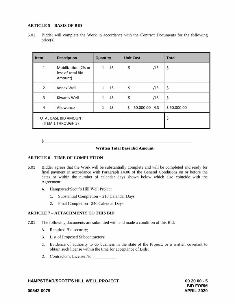
ARTICLE 5 – BASIS OF BID
5.01 Bidder will complete the Work in accordance with the Contract Documents for the following
price(s):
Item Description Quantity Unit Cost Total
1 Mobilization (2% or less of total Bid Amount)
1 LS $ /LS $
2 Annex Well 1 LS $ /LS $
3 Kiwanis Well 1 LS $ /LS $
4 Allowance 1 LS $ 50,000.00 /LS $ 50,000.00
TOTAL BASE BID AMOUNT (ITEM 1 THROUGH 5)
$
$______________________________________________________________________
Written Total Base Bid Amount
ARTICLE 6 – TIME OF COMPLETION
6.01 Bidder agrees that the Work will be substantially complete and will be completed and ready for
final payment in accordance with Paragraph 14.06 of the General Conditions on or before the
dates or within the number of calendar days shown below which also coincide with the
Agreement:
A. Hampstead/Scott’s Hill Well Project
1. Substantial Completion – 210 Calendar Days
2. Final Completion –240 Calendar Days
ARTICLE 7 – ATTACHMENTS TO THIS BID
7.01 The following documents are submitted with and made a condition of this Bid:
A. Required Bid security;
B. List of Proposed Subcontractors;
C. Evidence of authority to do business in the state of the Project; or a written covenant to
obtain such license within the time for acceptance of Bids;
D. Contractor’s License No.: __________

HAMPSTEAD/SCOTT’S HILL WELL PROJECT 00 20 00 - 6 BID FORM 00542-0079 APRIL 2020
ARTICLE 8 – DEFINED TERMS
8.01 The terms used in this Bid with initial capital letters have the meanings stated in the Instructions
to Bidders, the General Conditions, and the Supplementary Conditions.
ARTICLE 9 – BID SUBMITTAL
BIDDER: [Indicate correct name of bidding entity]
By:
[Signature]
[Printed name]
(If Bidder is a corporation, a limited liability company, a partnership, or a joint venture, attach
evidence of authority to sign.)
Attest:
[Signature]
[Printed name]
Title:
Submittal Date:
Address for giving notices:
Telephone Number:
Fax Number:
Contact Name and e-mail address:
Bidder’s License No.:
END OF SECTION 00 20 00
PENAL SUM FORM
HAMPSTEAD\SCOTT’S HILL WELL PROJECT 00 22 00 - 1
00542-0079 APRIL 2020
BID BOND
Any singular reference to Bidder, Surety, Owner or other party shall be considered plural where applicable.
BIDDER (Name and Address):
SURETY (Name, and Address of Principal Place of Business):
OWNER: Pender County Utilities 605 East Fremont Street Burgaw, NC 28425
BID
Bid Due Date: MAY 5, 2020
Description: HAMPSTEAD/SCOTT’S HILL WELL PROJECT
BOND
Bond Number:
Date:
Penal sum $
(Words) (Figures) Surety and Bidder, intending to be legally bound hereby, subject to the terms set forth below, do each cause this Bid Bond to be duly executed by an authorized officer, agent, or representative. BIDDER SURETY
(Seal) (Seal)
Bidder’s Name and Corporate Seal Surety’s Name and Corporate Seal
By: By:
Signature Signature (Attach Power of Attorney)
Print Name Print Name
Title Title
Attest: Attest:
Signature Signature
Title Title
Note: Addresses are to be used for giving any required notice. Provide execution by any additional parties, such as joint venturers, if necessary.
PENAL SUM FORM
HAMPSTEAD\SCOTT’S HILL WELL PROJECT 00 22 00 - 2
00542-0079 APRIL 2020
1. Bidder and Surety, jointly and severally, bind themselves, their heirs, executors, administrators, successors, and assigns to pay to Owner upon default of Bidder the penal sum set forth on the face of this Bond. Payment of the penal sum is the extent of Bidder’s and Surety’s liability. Recovery of such penal sum under the terms of this Bond shall be Owner’s sole and exclusive remedy upon default of Bidder.
2. Default of Bidder shall occur upon the failure of Bidder to deliver within the time required by the Bidding Documents (or any extension thereof agreed to in writing by Owner) the executed Agreement required by the Bidding Documents and any performance and payment bonds required by the Bidding Documents.
3. This obligation shall be null and void if:
3.1 Owner accepts Bidder’s Bid and Bidder delivers within the time required by the Bidding Documents (or any extension thereof agreed to in writing by Owner) the executed Agreement required by the Bidding Documents and any performance and payment bonds required by the Bidding Documents, or
3.2 All Bids are rejected by Owner, or
3.3 Owner fails to issue a Notice of Award to Bidder within the time specified in the Bidding Documents (or any extension thereof agreed to in writing by Bidder and, if applicable, consented to by Surety when required by Paragraph 5 hereof).
4. Payment under this Bond will be due and payable upon default of Bidder and within 30 calendar days after receipt by Bidder and Surety of written notice of default from Owner, which notice will be given with reasonable promptness, identifying this Bond and the Project and including a statement of the amount due.
5. Surety waives notice of any and all defenses based on or arising out of any time extension to issue Notice of Award agreed to in writing by Owner and Bidder, provided that the total time for issuing Notice of Award including extensions shall not in the aggregate exceed 120 days from the Bid due date without Surety’s written consent.
6. No suit or action shall be commenced under this Bond prior to 30 calendar days after the notice of default required in Paragraph 4 above is received by Bidder and Surety and in no case later than one year after the Bid due date.
7. Any suit or action under this Bond shall be commenced only in a court of competent jurisdiction located in the state in which the Project is located.
8. Notices required hereunder shall be in writing and sent to Bidder and Surety at their respective addresses shown on the face of this Bond. Such notices may be sent by personal delivery, commercial courier, or by United States Registered or Certified Mail, return receipt requested, postage pre-paid, and shall be deemed to be effective upon receipt by the party concerned.
9. Surety shall cause to be attached to this Bond a current and effective Power of Attorney evidencing the authority of the officer, agent, or representative who executed this Bond on behalf of Surety to execute, seal, and deliver such Bond and bind the Surety thereby.
10. This Bond is intended to conform to all applicable statutory requirements. Any applicable requirement of any applicable statute that has been omitted from this Bond shall be deemed to be included herein as if set forth at length. If any provision of this Bond conflicts with any applicable statute, then the provision of said statute shall govern and the remainder of this Bond that is not in conflict therewith shall continue in full force and effect.
11. The term “Bid” as used herein includes a Bid, offer, or proposal as applicable.

HAMPSTEAD\SCOTT’S HILL WELL PROJECT 00 24 00 - 1 00542-0079 APRIL 2020
COMMUNICATION OF PENDER COUNTY, NORTH CAROLINA
TOWARD USE OF MINORITY AND WOMEN-OWNED BUSINESS/CONTRACTORS
Pender County prohibits discrimination in any manner on the basis of race, color, creed, national origin,
sex, age, handicap or sexual orientation and will pursue an affirmative policy of fostering, promoting and
conducting business with women and minority-owned business enterprises. Pender County had adopted a
goal of 10% for participation by minority businesses where the project cost is one hundred thousand
dollars ($100,000) or more.
Definition of Minority Business:
(a) The term “minority business” means a business:
i. In which at least fifty-one percent (51%) is owned by one or more minority persons or
socially and economically disadvantaged individuals, or in the case of a corporation, in
which at least fifty-one percent (51%) of the stock is owned by one or more minority
persons or socially and economically disadvantaged individuals; and
ii. Of which the management and daily business operations are controlled by one or more of
the minority persons socially and economically disadvantaged individuals who own it.
(b) The term “minority person” means a person who is a citizen or lawful permanent resident of the
United Stated and who is:
i. Black, that is, a person having origins in any of the black racial groups in Africa;
ii. Hispanic, that is, a person of Spanish or Portuguese culture with origins in Mexico, South or
Central America, or the Caribbean Islands, regardless of race;
iii. Asian American, that is, a person having origins in any of the original peoples of the Far
East, Southeast Asia and Asia, the Indian subcontinent, or the Pacific Islands;
iv. American Indian, that is, a person having origins in any of the original Indian peoples of
North America; or
v. Female
(c) The term “socially and economically disadvantaged individual” means the same as defined in 15
U.S.C. 637.
The Recipient and Bidders shall make a good faith effort to assure that MBE’s and WBE’s are utilized,
when possible, as sources of goods and services. The good faith effort must include the following
affirmative steps: (a) including small, minority, and women’s businesses on solicitation lists; (b) assuring
that small, minority, and women’s businesses are solicited whenever they are potential sources; (c)
dividing total requirements, when economically feasible, into small tasks or quantities to permit
maximum participation by small, minority, and women’s businesses; (d) establishing delivery schedules,
and (e) using the services of the Small Business Administration and the Minority Business Development
Agency of the U.S. Department of Commerce. Please note that the solicitation efforts should include
documentable follow up phone calls.

HAMPSTEAD\SCOTT’S HILL WELL PROJECT 00 24 00 - 2 00542-0079 APRIL 2020
A listing of the minority and women-owned businesses/contractors can be obtained from the following:
Minority Business Development Agency
Department of Economic and Community Development
114 W. Parish St.
Durham, NC 27701
Phone: (919) 287-3198
and/or
The North Carolina Institute of Minority Economic Development
114 W. Parish St.
Durham, NC 27701
Phone: (919) 956-8889
and/or
Pender County
Post Office Box 5
Burgaw, NC 28425

HAMPSTEAD\SCOTT’S HILL WELL PROJECT 00 24 00 - 3 00542-0079 APRIL 2020
PENDER COUNTY, NORTH CAROLINA
BIDDER'S REPORT OF
SUBCONTRACTOR SELECTION AND EFFORTS
TO OBTAIN WOMEN AND MINORITY SUBCONTRACTORS
One form must be completed for each subcontractor trade.
Project Name:
Project Reference Number:
General Contractor:
Subcontractor Trade:
If no subcontractors used indicate why:
Selected Subcontractor Subcontract Amount $
Address and Telephone No.:
Is the selected contractor(s) women or minority owned: Yes ( ) No ( )
If No, list M/WBE firms you contacted:
Name, Address and Telephone No.
How did you learn or
Become familiar with Firm
1.
2.
3.
4.
If women and minority-owned firm(s) contacted and not selected explain reason(s):
If women and minority-owned firm(s) not contacted explain reason(s):
Completed By:
Name: Position:
Signature: Date:
Multiple forms to be attached to bid proposal forms and must be completed and signed in order for bid to
be complete.
HAMPSTEAD\SCOTT’S HILL WELL PROJECT 00 24 00 - 4 00542-0079 APRIL 2020
SUBCONTRACTORS AND MATERIAL SUPPLIERS LIST
Bidder shall provide the following information concerning minorities and women-owned subcontractors.
All information shall be complete for acceptable award.
A. List of Subcontractors to be used
Subcontractor
(M/F*)
Work
Dollar
Amt.
% of
Total
( )
( )
( )
( )
( )
( )
B. Material Suppliers List
Supplier
Material
( )
( )
( )
( )
( )
( )
*(M) Denotes Minority
(F) Denotes Female
(M/F) Denotes Minority & Female
HAMPSTEAD\SCOTT’S HILL WELL PROJECT 00 24 00 - 5 00542-0079 APRIL 2020
AFFIDAVIT A – Listing of the Good Faith Effort
SUBMIT WITH BID
County of Pender
Affidavit of ___________________________________________________________________________
(Name of Bidder)
I have made a good faith effort to comply under the following areas checked:
(A minimum of five (5) areas must be checked in order to have achieved a “good faith effort”)
______ 1. Contacting minority businesses that reasonably could have been expected to submit a quote and that were
known to the contractor or available on State or local government maintained lists at least ten (10) days before
the bid or proposal date and notifying them of the nature and scope of the work to be performed;
______ 2. Making the construction plans, specification, and requirements available for review by prospective minority
businesses, or providing these documents to them at least ten (10) days before the bid or proposals are due;
______ 3. Breaking down or combining elements of work into economically feasible units to facilitate minority
participation;
______ 4. Working with minority trade, community, or contractor organizations identified by the Office of Historically
Underutilized Businesses and included in the bid documents that provide assistance in recruitment of minority
businesses.
______ 5. Attending any pre-bid meetings scheduled by the public owner;
______ 6. Providing assistance in getting required bonding or insurance, or providing alternatives to bonding or
insurance for subcontractors;
______ 7. Negotiating in good faith with interested minority businesses and not rejecting them as unqualified without
sound reasons based on their capabilities. Any rejection of a minority business, based on lack of qualification,
should have the reasons documented in writing;
______ 8. Providing assistance to an otherwise qualified minority business in need of equipment, loan capital, lines of
credit, or joint pay agreements to secure loans, supplies, or letters of credit, including waiving credit that is
ordinarily required. Assisting minority businesses in obtaining the same unit pricing with the bidder’s
suppliers in order to help minority businesses in establishing credit;
______ 9. Negotiating joint venture and partnership arrangements with minority businesses in order to increase
opportunities for minority business participation in a public construction or repair project when possible;
______ 10. Providing quick pay agreements and policies to enable minority contractors and suppliers to meet cash-flow
demands.
In accordance with GS143-128.2 (d) the undersigned will enter into a formal agreement with the firms listed
in the Bidder’s Report of Subcontractor Selection and Efforts to Obtain Women and Minority
Subcontractors upon execution of a contract with the Owner. Failure to abide by this statutory provision will
constitute a breach of the Contract.
The undersigned herby certifies that he or she has read the terms of the minority business commitment and is
authorized to bind the bidder to the commitment herein set forth.
Date: _________ Name if Authorized Officer: _______________________________
Signature: _______________________________
Title: _______________________________
SEAL State of North Carolina, County of_______________________
Subscribed and sworn to before me this____ day of _________ 20__
Notary Public__________________________________
My commission expires__________________________
HAMPSTEAD\SCOTT’S HILL WELL PROJECT 00 24 00 - 6 00542-0079 APRIL 2020
AFFIDAVIT B – Intent to Perform Contract with Own Workforce
SUBMIT WITH BID
County of Pender
Affidavit of
____________________________________________________________________________
(Name of Bidder)
I hereby certify that it is our intent to perform 100% of the work required for the _____________
_____________________________________________________________________contract.
(Name of project)
In making this certification, the Bidder stated that the Bidder does not customarily subcontract elements
of this type project, and normally performs and has the capability to perform and will perform all
elements of the work on this project with his/her own current work forces; and
The Bidder agrees to provide any additional information or documentation requested by the owner in
support of the above statement.
The undersigned hereby certifies that he or she has read this certificate and is authorized to bind the
Bidder to the commitments herein contained.
Date: _________ Name if Authorized Officer: _______________________________
Signature: _______________________________
Title: _______________________________
SEAL State of North Carolina, County of_______________________
Subscribed and sworn to before me this____ day of _________ 20__
Notary Public__________________________________
My commission expires__________________________
HAMPSTEAD\SCOTT’S HILL WELL PROJECT 00 24 00 - 7 00542-0079 APRIL 2020
AFFIDAVIT C – Portion of the Work to be performed by Minority Firms
County of Pender
Affidavit of ____________________________________________________________________
(Name of Bidder)
If the portion of the work to be executed by minority businesses as defined inn GS143-128.2 (g) is equal to or
greater than 10% of the bidders total contract price, then the bidder must complete this affidavit. The apparent
lowest responsible, responsive bidder shall provide this affidavit within 72 hours after notification of being low
bidder.
Affidavit of __________________________________________________________________ I do certify
(Name of Bidder)
that on ______________________________________________________________________________
(Project Name)
Amount of Bid $________________________________________
I will expend a minimum of ____% of the total dollar amount of the contract with minority business enterprises.
Minority businesses will be employed as construction subcontractors, vendors, suppliers, or providers of
professional services. Such work will be subcontracted to the following firms listed below.
Name and Phone Number *Minority
Category
Work Description Dollar Value
*Minority categories: Black (B), Hispanic (H), Asian American (A), American Indian (I), Female (F) Socially and Economically Disadvantaged
(D)
Pursuant to GS 143-128.3(d), the undersigned will enter into a formal agreement with Minority Forms for work
listed in this schedule conditional upon execution of a contract with the Owner. Failure to fulfill this commitment
may constitute a breach of contract.
The undersigned hereby certifies that he or she has read the terms of this commitment and is authorized to bind the
bidder to the commitment herein set forth.
Date: _________ Name if Authorized Officer: _______________________________
Signature: _______________________________
Title: _______________________________
SEAL State of North Carolina, County of_______________________
Subscribed and sworn to before me this____ day of _________ 20__
Notary Public__________________________________
My commission expires__________________________
HAMPSTEAD\SCOTT’S HILL WELL PROJECT 00 24 00 - 8 00542-0079 APRIL 2020
AFFIDAVIT D – Good Faith Efforts
If the goal of 10% participation by minority business is not achieved, the Bidder shall provide the following
documentation to the Owner of hid good faith efforts.
County of Pender
Affidavit of ____________________________________________________________________
(Name of Bidder)
I do certify the attached documentation as true and accurate representation of my good faith efforts.
Name and Phone Number *Minority
Category
Work Description Dollar Value
*Minority categories: Black (B), Hispanic (H), Asian American (A), American Indian (I), Female (F) Socially and Economically Disadvantaged (D)
1. Documentation of the Bidder’s good faith efforts to meet the goals set forth in these provisions. Examples of documentation
include, but are not limited to, the following evidence:
2. Copies of solicitations for quotes to at least three (3) minority business firms from the source list provided by the
County/State for each subcontract to be let under this contract (if 3 or more firms are shown on the source list). Each
solicitation shall contain a specific description of the work to be subcontracted, location where the bid documents can be
reviewed, representative of the Prime Bidder to contact, and location, date and time when quotes must be received.
3. Copies of quotes or responses received from each firm responding to the solicitation.
4. A telephone log of follow-up calls to each firm sent a solicitation.
5. For subcontracts where a minority business firm is not considered the lowest responsible sub-bidder, copies of quotes
received from all firms submitting quotes for that particular subcontract.
6. Documentation of any contacts or correspondence to minority business, community, or contractor organizations in an
attempt to meet the goal.
7. Copy of pre-bid roster.
8. Letter documenting efforts to provide assistance in obtaining required bonding or insurance for minority business.
9. Letter detailing reasons for rejection of minority business due to lack of qualification.
10. Letter documenting proposed assistance offered to minority business in need of equipment, loan capital, lines of credit, or
joint pay agreements to secure loans, supplies, or letter of credit, including waving credit that is ordinarily required.
Failure to provide the documentation as listed in these provisions may result in rejection of the bid and award to the
next lowest responsible and responsive bidder.
Date: _________ Name if Authorized Officer: _______________________________
Signature: _______________________________
Title: _______________________________
SEAL State of North Carolina, County of_______________________
Subscribed and sworn to before me this____ day of _________ 20__
Notary Public__________________________________
My commission expires__________________________

HAMPSTEAD\SCOTT’S HILL WELL PROJECT 00 30 00 - 1
00542-0079 APRIL 2020
NOTICE OF AWARD
Date of Issuance:
Owner: Pender County Owner's Contract No.:
Engineer: McKim & Creed, Inc. Engineer's Project No.:
Project: Hampstead/Scott’s Hill Well Project Contract Name: Hampstead/Scott’s Hill Well
Project
Bidder:
Bidder’s
Address:
TO BIDDER:
You are notified that Owner has accepted your Bid dated ______________for the above Contract, and that you
are the Successful Bidder and are awarded a Contract for:
Hampstead/Scott’s Hill Well Project ________________________ .
The Contract Price of the awarded Contract is: $ _____________
a set of the Drawings will be delivered separately from the other Contract Documents.
You must comply with the following conditions precedent within 10 days of the date of receipt of this Notice
of Award:
1. Deliver to Owner two counterparts of the Agreement, fully executed by Bidder.
2. Deliver with the executed Agreement(s) the Contract security [e.g., performance and payment bonds]
and insurance documentation as specified in the Instructions to Bidders and General Conditions,
Articles 2 and 6.
3. Other conditions precedent (if any):
Failure to comply with these conditions within the time specified will entitle Owner to consider you in default,
annul this Notice of Award, and declare your Bid security forfeited.
Within ten days after you comply with the above conditions, Owner will return to you one fully executed
counterpart of the Agreement, together with any additional copies of the Contract Documents as indicated in
Paragraph 2.02 of the General Conditions.
Owner:
Authorized Signature
By:
Title:
Copy:

HAMPSTEAD\SCOTT’S HILL WELL PROJECT 00 30 00 - 2
00542-0079 APRIL 2020
This page intentionally left blank
HAMPSTEAD\SCOTT’S HILL WELL PROJECT 00 50 00 - 1 00542-0079 APRIL 2020
AGREEMENT
BETWEEN OWNER AND CONTRACTOR
FOR CONSTRUCTION CONTRACT (STIPULATED PRICE)
THIS AGREEMENT is by and between Pender County (“Owner”) and
(“Contractor”).
Owner and Contractor hereby agree as follows:
ARTICLE 1 – WORK
1.01 Contractor shall complete all Work as specified or indicated in the Contract Documents. The
Work is generally described as follows:
ARTICLE 2 – THE PROJECT
2.01 The Project, of which the Work under the Contract Documents is a part, is generally described as
follows: Hampstead/Scott’s Hill Well Project
ARTICLE 3 – ENGINEER
3.01 The Project has been designed by McKim & Creed, Inc.
3.02 The Owner has retained McKim & Creed, Inc (“Engineer”) to act as Owner’s representative,
assume all duties and responsibilities, and have the rights and authority assigned to Engineer in
the Contract Documents in connection with the completion of the Work in accordance with the
Contract Documents.
ARTICLE 4 – CONTRACT TIMES
4.01 Time of the Essence
A. All time limits for Milestones, if any, Substantial Completion, and completion and readiness
for final payment as stated in the Contract Documents are of the essence of the Contract.
4.02 Contract Times: Dates
A. The Work will be completed and ready for final payment in accordance with the General
Conditions from the date when the Contract Time commences to run according to the
following schedule:
1. Substantial Completion – 210 Calendar Days
2. Final Completion – 240 Calendar Days
4.03 Liquidated Damages
A. Contractor and Owner recognize that time is of the essence as stated in Paragraph 4.01 above
and that Owner will suffer financial and other losses if the Work is not completed and
Milestones not achieved within the times specified in Paragraph 4.02 above, plus any
extensions thereof allowed in accordance with the Contract. The parties also recognize the
delays, expense, and difficulties involved in proving in a legal or arbitration proceeding the
actual loss suffered by Owner if the Work is not completed on time. Accordingly, instead of
requiring any such proof, Owner and Contractor agree that as liquidated damages for delay
(but not as a penalty):
HAMPSTEAD\SCOTT’S HILL WELL PROJECT 00 50 00 - 2 00542-0079 APRIL 2020
1. Substantial Completion: Contractor shall pay Owner $500.00 for each day that expires
after the time (as duly adjusted pursuant to the Contract) specified in Paragraph 4.02.A
above for Substantial Completion until the Work is substantially complete.
ARTICLE 5 – CONTRACT PRICE
5.01 Owner shall pay CONTRACTOR for completion of the Work in accordance with the Contract
Documents in current funds at the Lump Sum or Unit Prices included in the Bid Forms of these
Contract Documents, the sum of:
________________________________________________________ Dollars
($_______________ , ______________ , ______________ . ____ )
See Contractor’s Bid, Attachment 1.
5.02 The parties expressly agree that the Contract Price is subject to adjustment by Change Order
based upon the final Contract quantities performed by the Contractor, measured at the completion
of the Work.
ARTICLE 6 – PAYMENT PROCEDURES
6.01 Submittal and Processing of Payments
A. Contractor shall submit Applications for Payment in accordance with Article 14 of the
General Conditions. Applications for Payment will be processed by Engineer as provided in
the General Conditions.
6.02 Progress Payments; Retainage
A. Owner shall make progress payments on account of the Contract Price on the basis of
Contractor’s Applications for Payment on or about the __ day of each month during
performance of the Work as provided in Paragraph 6.02.A.1 below, provided that such
Applications for Payment have been submitted in a timely manner and otherwise meet the
requirements of the Contract. All such payments will be measured by the Schedule of Values
established as provided in the General Conditions (and in the case of Unit Price Work based
on the number of units completed) or, in the event there is no Schedule of Values, as
provided elsewhere in the Contract.
1. Prior to Substantial Completion, progress payments will be made in an amount equal to
the percentage indicated below but, in each case, less the aggregate of payments
previously made and less such amounts as Owner may withhold, including but not
limited to liquidated damages, in accordance with the Contract
a. 95 percent of Work completed (with the balance being retainage). If the Work has
been 50 percent completed as determined by Engineer, and if the character and
progress of the Work have been satisfactory to Owner and Engineer, then as long
as the character and progress of the Work remain satisfactory to Owner and
Engineer, there will be no additional retainage; and
b. 95 percent of cost of materials and equipment not incorporated in the Work (with
the balance being retainage).
B. Upon Substantial Completion, Owner shall pay an amount sufficient to increase total
payments to Contractor to 100 percent of the Work completed, less such amounts set off by
Owner pursuant to Paragraph 15.01.E of the General Conditions, and less 200 percent of
Engineer’s estimate of the value of Work to be completed or corrected as shown on the
punch list of items to be completed or corrected prior to final payment.
HAMPSTEAD\SCOTT’S HILL WELL PROJECT 00 50 00 - 3 00542-0079 APRIL 2020
6.03 Final Payment
A. Upon final completion and acceptance of the Work in accordance with Paragraph 14.06 of
the General Conditions, Owner shall pay the remainder of the Contract Price as
recommended by Engineer as provided in said Paragraph 14.06.
ARTICLE 7 – INTEREST
7.01 All amounts not paid when due shall bear interest at the rate of 0.00 percent per annum.
ARTICLE 8 – CONTRACTOR’S REPRESENTATIONS
8.01 In order to induce Owner to enter into this Contract, Contractor makes the following
representations:
A. Contractor has examined and carefully studied the Contract Documents, and any data and
reference items identified in the Contract Documents.
B. Contractor has visited the Site, conducted a thorough, alert visual examination of the Site
and adjacent areas, and become familiar with and is satisfied as to the general, local, and Site
conditions that may affect cost, progress, and performance of the Work.
C. Contractor is familiar with and is satisfied as to all Laws and Regulations that may affect
cost, progress, and performance of the Work.
D. Contractor has carefully studied all: (1) reports of explorations and tests of subsurface
conditions at or adjacent to the Site and all drawings of physical conditions relating to
existing surface or subsurface structures at the Site that have been identified in the
Supplementary Conditions.
E. Contractor has considered the information known to Contractor itself; information
commonly known to contractors doing business in the locality of the Site; information and
observations obtained from visits to the Site; the Contract Documents; and the Site-related
reports and drawings identified in the Contract Documents, with respect to the effect of such
information, observations, and documents on (1) the cost, progress, and performance of the
Work; (2) the means, methods, techniques, sequences, and procedures of construction to be
employed by Contractor; and (3) Contractor’s safety precautions and programs.
F. Based on the information and observations referred to in the preceding paragraph, Contractor
agrees that no further examinations, investigations, explorations, tests, studies, or data are
necessary for the performance of the Work at the Contract Price, within the Contract Times,
and in accordance with the other terms and conditions of the Contract.
G. Contractor is aware of the general nature of work to be performed by Owner and others at
the Site that relates to the Work as indicated in the Contract Documents.
H. Contractor has given Engineer written notice of all conflicts, errors, ambiguities, or
discrepancies that Contractor has discovered in the Contract Documents, and the written
resolution thereof by Engineer is acceptable to Contractor.
I. The Contract Documents are generally sufficient to indicate and convey understanding of all
terms and conditions for performance and furnishing of the Work.
J. Contractor’s entry into this Contract constitutes an incontrovertible representation by
Contractor that without exception all prices in the Agreement are premised upon performing
and furnishing the Work required by the Contract Documents.
HAMPSTEAD\SCOTT’S HILL WELL PROJECT 00 50 00 - 4 00542-0079 APRIL 2020
ARTICLE 9 – CONTRACT DOCUMENTS
9.01 Contents
A. The Contract Documents consist of the following:
1. This Agreement (00500 – 1 to 00500 – 6, inclusive).
2. Performance bond (00520 – 1 to 00520 – 3, inclusive).
3. Payment bond (00530 – 1 to 00530 – 3, inclusive).
4. General Conditions (00700 – 1 to 00700 – 62, inclusive).
5. Supplementary Conditions (00800 – 1 to 00800 – 13, inclusive).
6. Specifications as listed in the table of contents of the Project Manual.
7. Drawings (not attached but incorporated by reference) consisting of __ sheets with each
sheet bearing the following general title: Hampstead/Scott’s Hill Well Project.
8. Addenda (numbers _ to _, inclusive).
9. Exhibits to this Agreement (enumerated as follows):
a. Contractor’s Bid (pages _ to _, inclusive).
10. The following which may be delivered or issued on or after the Effective Date of the
Contract and are not attached hereto:
a. Notice to Proceed.
b. Work Change Directives.
c. Change Orders.
d. Field Orders.
B. The documents listed in Paragraph 9.01.A are attached to this Agreement (except as
expressly noted otherwise above).
C. There are no Contract Documents other than those listed above in this Article 9.
D. The Contract Documents may only be amended, modified, or supplemented as provided in
the General Conditions.
ARTICLE 10 – MISCELLANEOUS
10.01 Terms
A. Terms used in this Agreement will have the meanings stated in the General Conditions and
the Supplementary Conditions.
10.02 Assignment of Contract
A. Unless expressly agreed to elsewhere in the Contract, no assignment by a party hereto of any
rights under or interests in the Contract will be binding on another party hereto without the
written consent of the party sought to be bound; and, specifically but without limitation,
money that may become due and money that is due may not be assigned without such
consent (except to the extent that the effect of this restriction may be limited by law), and
unless specifically stated to the contrary in any written consent to an assignment, no
assignment will release or discharge the assignor from any duty or responsibility under the
Contract Documents.
HAMPSTEAD\SCOTT’S HILL WELL PROJECT 00 50 00 - 5 00542-0079 APRIL 2020
10.03 Successors and Assigns
A. Owner and Contractor each binds itself, its successors, assigns, and legal representatives to
the other party hereto, its successors, assigns, and legal representatives in respect to all
covenants, agreements, and obligations contained in the Contract Documents.
10.04 Severability
A. Any provision or part of the Contract Documents held to be void or unenforceable under any
Law or Regulation shall be deemed stricken, and all remaining provisions shall continue to
be valid and binding upon Owner and Contractor, who agree that the Contract Documents
shall be reformed to replace such stricken provision or part thereof with a valid and
enforceable provision that comes as close as possible to expressing the intention of the
stricken provision.
10.05 Contractor’s Certifications
A. Contractor certifies that it has not engaged in corrupt, fraudulent, collusive, or coercive
practices in competing for or in executing the Contract. For the purposes of this Paragraph
10.05:
1. “corrupt practice” means the offering, giving, receiving, or soliciting of any thing of
value likely to influence the action of a public official in the bidding process or in the
Contract execution;
2. “fraudulent practice” means an intentional misrepresentation of facts made (a) to
influence the bidding process or the execution of the Contract to the detriment of
Owner, (b) to establish Bid or Contract prices at artificial non-competitive levels, or (c)
to deprive Owner of the benefits of free and open competition;
3. “collusive practice” means a scheme or arrangement between two or more Bidders,
with or without the knowledge of Owner, a purpose of which is to establish Bid prices
at artificial, non-competitive levels; and
4. “coercive practice” means harming or threatening to harm, directly or indirectly,
persons or their property to influence their participation in the bidding process or affect
the execution of the Contract.
10.06 Other Provisions
A. Owner stipulates that if the General Conditions that are made a part of this Contract are
based on EJCDC® C-700, Standard General Conditions for the Construction Contract,
published by the Engineers Joint Contract Documents Committee®, and if Owner is the
party that has furnished said General Conditions, then Owner has plainly shown all
modifications to the standard wording of such published document to the Contractor in the
Supplementary Conditions.
HAMPSTEAD\SCOTT’S HILL WELL PROJECT 00 50 00 - 6 00542-0079 APRIL 2020
IN WITNESS WHEREOF, Owner and Contractor have signed this Agreement.
This Agreement will be effective on _______________ (which is the Effective Date of the Contract).
OWNER: Pender County CONTRACTOR:
By: Mr. Chad McEwen By:
Title: Pender County Manager Title:
(If Contractor is a corporation, a partnership, or a
joint venture, attach evidence of authority to sign.)
Attest: Attest:
Title: Title:
Address for giving notices: Address for giving notices:
License No.:

HAMPSTEAD\SCOTT’S HILL WELL PROJECT 00 51 00 - 1
00542-0079 APRIL 2020
SECTION 00510 – INSURANCE CERTIFICATE
ATTACH INSURANCE CERTIFICATE HERE
END OF SECTION 00510

HAMPSTEAD\SCOTT’S HILL WELL PROJECT 00 51 00 - 2
00542-0079 APRIL 2020
This page intentionally left blank
HAMPSTEAD\SCOTT’S HILL WELL PROJECT 00 52 00 - 1 00542-0079 APRIL 2020
PERFORMANCE BOND
CONTRACTOR:
SURETY (name and address of principal place of business):
OWNER:
Pender County
805 S. Walker Street
Burgaw, NC 28425
CONSTRUCTION CONTRACT
Effective Date of the Agreement:
Amount:
Description:
BOND
Bond Number:
Date:
Amount:
Modifications to this Bond Form: None See Paragraph 16
Surety and Contractor, intending to be legally bound hereby, subject to the terms set forth below, do each cause
this Performance Bond to be duly executed by an authorized officer, agent, or representative.
CONTRACTOR AS PRINCIPAL SURETY
(seal) (seal)
Contractor’s Name and Corporate Seal Surety’s Name and Corporate Seal
By: By:
Signature Signature (attach power of attorney)
Print Name Print Name
Title Title
Attest: Attest:
Signature Signature
Title Title
Notes: (1) Provide supplemental execution by any additional parties, such as joint venturers. (2) Any singular reference to
Contractor, Surety, Owner, or other party shall be considered plural where applicable.
HAMPSTEAD\SCOTT’S HILL WELL PROJECT 00 52 00 - 2 00542-0079 APRIL 2020
1. The Contractor and Surety, jointly and severally, bind
themselves, their heirs, executors, administrators, successors, and
assigns to the Owner for the performance of the Construction Contract,
which is incorporated herein by reference.
2. If the Contractor performs the Construction Contract, the Surety
and the Contractor shall have no obligation under this Bond, except
when applicable to participate in a conference as provided in
Paragraph 3.
3. If there is no Owner Default under the Construction Contract, the
Surety’s obligation under this Bond shall arise after:
3.1 The Owner first provides notice to the Contractor and
the Surety that the Owner is considering declaring a Contractor
Default. Such notice shall indicate whether the Owner is
requesting a conference among the Owner, Contractor, and Surety
to discuss the Contractor’s performance. If the Owner does not
request a conference, the Surety may, within five (5) business
days after receipt of the Owner’s notice, request such a
conference. If the Surety timely requests a conference, the Owner
shall attend. Unless the Owner agrees otherwise, any conference
requested under this Paragraph 3.1 shall be held within ten (10)
business days of the Surety’s receipt of the Owner’s notice. If the
Owner, the Contractor, and the Surety agree, the Contractor shall
be allowed a reasonable time to perform the Construction
Contract, but such an agreement shall not waive the Owner’s
right, if any, subsequently to declare a Contractor Default;
3.2 The Owner declares a Contractor Default, terminates
the Construction Contract and notifies the Surety; and
3.3 The Owner has agreed to pay the Balance of the
Contract Price in accordance with the terms of the Construction
Contract to the Surety or to a contractor selected to perform the
Construction Contract.
4. Failure on the part of the Owner to comply with the notice
requirement in Paragraph 3.1 shall not constitute a failure to comply
with a condition precedent to the Surety’s obligations, or release the
Surety from its obligations, except to the extent the Surety
demonstrates actual prejudice.
5. When the Owner has satisfied the conditions of Paragraph 3, the
Surety shall promptly and at the Surety’s expense take one of the
following actions:
5.1 Arrange for the Contractor, with the consent of the
Owner, to perform and complete the Construction Contract;
5.2 Undertake to perform and complete the Construction
Contract itself, through its agents or independent contractors;
5.3 Obtain bids or negotiated proposals from qualified
contractors acceptable to the Owner for a contract for
performance and completion of the Construction Contract,
arrange for a contract to be prepared for execution by the Owner
and a contractor selected with the Owners concurrence, to be
secured with performance and payment bonds executed by a
qualified surety equivalent to the bonds issued on the
Construction Contract, and pay to the Owner the amount of
damages as described in Paragraph 7 in excess of the Balance of
the Contract Price incurred by the Owner as a result of the
Contractor Default; or
5.4 Waive its right to perform and complete, arrange for
completion, or obtain a new contractor, and with reasonable
promptness under the circumstances:
5.4.1 After investigation, determine the amount for
which it may be liable to the Owner and, as soon as
practicable after the amount is determined, make payment to
the Owner; or
5.4.2 Deny liability in whole or in part and notify the
Owner, citing the reasons for denial.
6. If the Surety does not proceed as provided in Paragraph 5 with
reasonable promptness, the Surety shall be deemed to be in default on
this Bond seven days after receipt of an additional written notice from
the Owner to the Surety demanding that the Surety perform its
obligations under this Bond, and the Owner shall be entitled to enforce
any remedy available to the Owner. If the Surety proceeds as provided
in Paragraph 5.4, and the Owner refuses the payment or the Surety has
denied liability, in whole or in part, without further notice the Owner
shall be entitled to enforce any remedy available to the Owner.
7. If the Surety elects to act under Paragraph 5.1, 5.2, or 5.3, then
the responsibilities of the Surety to the Owner shall not be greater than
those of the Contractor under the Construction Contract, and the
responsibilities of the Owner to the Surety shall not be greater than
those of the Owner under the Construction Contract. Subject to the
commitment by the Owner to pay the Balance of the Contract Price,
the Surety is obligated, without duplication for:
7.1 the responsibilities of the Contractor for correction of
defective work and completion of the Construction Contract;
7.2 additional legal, design professional, and delay costs
resulting from the Contractor’s Default, and resulting from the
actions or failure to act of the Surety under Paragraph 5; and
7.3 liquidated damages, or if no liquidated damages are
specified in the Construction Contract, actual damages caused by
delayed performance or non-performance of the Contractor.
8. If the Surety elects to act under Paragraph 5.1, 5.3, or 5.4, the
Surety’s liability is limited to the amount of this Bond.
9. The Surety shall not be liable to the Owner or others for
obligations of the Contractor that are unrelated to the Construction
Contract, and the Balance of the Contract Price shall not be reduced or
set off on account of any such unrelated obligations. No right of
action shall accrue on this Bond to any person or entity other than the
Owner or its heirs, executors, administrators, successors, and assigns.
10. The Surety hereby waives notice of any change, including
changes of time, to the Construction Contract or to related
subcontracts, purchase orders, and other obligations.
11. Any proceeding, legal or equitable, under this Bond may be
instituted in any court of competent jurisdiction in the location in
which the work or part of the work is located and shall be instituted
within two years after a declaration of Contractor Default or within
two years after the Contractor ceased working or within two years
after the Surety refuses or fails to perform its obligations under this
Bond, whichever occurs first. If the provisions of this paragraph are
void or prohibited by law, the minimum periods of limitations
HAMPSTEAD\SCOTT’S HILL WELL PROJECT 00 52 00 - 3 00542-0079 APRIL 2020
available to sureties as a defense in the jurisdiction of the suit shall be
applicable.
12. Notice to the Surety, the Owner, or the Contractor shall be mailed
or delivered to the address shown on the page on which their signature
appears.
13. When this Bond has been furnished to comply with a statutory or
other legal requirement in the location where the construction was to
be performed, any provision in this Bond conflicting with said
statutory or legal requirement shall be deemed deleted herefrom and
provisions conforming to such statutory or other legal requirement
shall be deemed incorporated herein. When so furnished, the intent is
that this Bond shall be construed as a statutory bond and not as a
common law bond.
14. Definitions
14.1 Balance of the Contract Price: The total amount payable
by the Owner to the Contractor under the Construction Contract
after all proper adjustments have been made including allowance
for the Contractor for any amounts received or to be received by
the Owner in settlement of insurance or other claims for damages
to which the Contractor is entitled, reduced by all valid and
proper payments made to or on behalf of the Contractor under the
Construction Contract.
14.2 Construction Contract: The agreement between the
Owner and Contractor identified on the cover page, including all
Contract Documents and changes made to the agreement and the
Contract Documents.
14.3 Contractor Default: Failure of the Contractor, which has
not been remedied or waived, to perform or otherwise to comply
with a material term of the Construction Contract.
14.4 Owner Default: Failure of the Owner, which has not
been remedied or waived, to pay the Contractor as required under
the Construction Contract or to perform and complete or comply
with the other material terms of the Construction Contract.
14.5 Contract Documents: All the documents that comprise
the agreement between the Owner and Contractor.
15. If this Bond is issued for an agreement between a contractor and
subcontractor, the term Contractor in this Bond shall be deemed to be
Subcontractor and the term Owner shall be deemed to be Contractor.
16. Modifications to this Bond are as follows:

HAMPSTEAD\SCOTT’S HILL WELL PROJECT 00 52 00 - 4 00542-0079 APRIL 2020
This page intentionally left blank
HAMPSTEAD\SCOTT’S HILL WELL PROJECT 00 53 00 - 1 00542-0079 APRIL 2020
PAYMENT BOND
CONTRACTOR (name and address): SURETY (name and address of principal place of business):
OWNER Pender County, 805 S. Walker St., Burgaw, NC 28425
CONSTRUCTION CONTRACT
Effective Date of the Agreement:
Amount:
Description:
BOND
Bond Number:
Date:
Amount:
Modifications to this Bond Form: None See Paragraph 18
Surety and Contractor, intending to be legally bound hereby, subject to the terms set forth below, do each cause
this Payment Bond to be duly executed by an authorized officer, agent, or representative.
CONTRACTOR AS PRINCIPAL SURETY
(seal) (seal)
Contractor’s Name and Corporate Seal Surety’s Name and Corporate Seal
By: By:
Signature Signature (attach power of attorney)
Print Name Print Name
Title Title
Attest: Attest:
Signature Signature
Title Title
Notes: (1) Provide supplemental execution by any additional parties, such as joint venturers. (2) Any singular reference
to Contractor, Surety, Owner, or other party shall be considered plural where applicable.
HAMPSTEAD\SCOTT’S HILL WELL PROJECT 00 53 00 - 2 00542-0079 APRIL 2020
1. The Contractor and Surety, jointly and severally, bind
themselves, their heirs, executors, administrators,
successors, and assigns to the Owner to pay for labor,
materials, and equipment furnished for use in the
performance of the Construction Contract, which is
incorporated herein by reference, subject to the following
terms.
2. If the Contractor promptly makes payment of all sums due
to Claimants, and defends, indemnifies, and holds harmless
the Owner from claims, demands, liens, or suits by any
person or entity seeking payment for labor, materials, or
equipment furnished for use in the performance of the
Construction Contract, then the Surety and the Contractor
shall have no obligation under this Bond.
3. If there is no Owner Default under the Construction
Contract, the Surety’s obligation to the Owner under this
Bond shall arise after the Owner has promptly notified the
Contractor and the Surety (at the address described in
Paragraph 13) of claims, demands, liens, or suits against the
Owner or the Owner’s property by any person or entity
seeking payment for labor, materials, or equipment
furnished for use in the performance of the Construction
Contract, and tendered defense of such claims, demands,
liens, or suits to the Contractor and the Surety.
4. When the Owner has satisfied the conditions in Paragraph
3, the Surety shall promptly and at the Surety’s expense
defend, indemnify, and hold harmless the Owner against a
duly tendered claim, demand, lien, or suit.
5. The Surety’s obligations to a Claimant under this Bond
shall arise after the following:
5.1 Claimants who do not have a direct contract with
the Contractor,
5.1.1 have furnished a written notice of non-
payment to the Contractor, stating with
substantial accuracy the amount claimed
and the name of the party to whom the
materials were, or equipment was,
furnished or supplied or for whom the
labor was done or performed, within ninety
(90) days after having last performed labor
or last furnished materials or equipment
included in the Claim; and
5.1.2 have sent a Claim to the Surety (at the
address described in Paragraph 13).
5.2 Claimants who are employed by or have a direct
contract with the Contractor have sent a Claim to
the Surety (at the address described in Paragraph
13).
6. If a notice of non-payment required by Paragraph 5.1.1 is
given by the Owner to the Contractor, that is sufficient to
satisfy a Claimant’s obligation to furnish a written notice of
non-payment under Paragraph 5.1.1.
7. When a Claimant has satisfied the conditions of Paragraph
5.1 or 5.2, whichever is applicable, the Surety shall
promptly and at the Surety’s expense take the following
actions:
7.1 Send an answer to the Claimant, with a copy to the
Owner, within sixty (60) days after receipt of the
Claim, stating the amounts that are undisputed and
the basis for challenging any amounts that are
disputed; and
7.2 Pay or arrange for payment of any undisputed
amounts.
7.3 The Surety’s failure to discharge its obligations
under Paragraph 7.1 or 7.2 shall not be deemed to
constitute a waiver of defenses the Surety or
Contractor may have or acquire as to a Claim,
except as to undisputed amounts for which the
Surety and Claimant have reached agreement. If,
however, the Surety fails to discharge its
obligations under Paragraph 7.1 or 7.2, the Surety
shall indemnify the Claimant for the reasonable
attorney’s fees the Claimant incurs thereafter to
recover any sums found to be due and owing to the
Claimant.
8. The Surety’s total obligation shall not exceed the amount of
this Bond, plus the amount of reasonable attorney’s fees
provided under Paragraph 7.3, and the amount of this Bond
shall be credited for any payments made in good faith by
the Surety.
9. Amounts owed by the Owner to the Contractor under the
Construction Contract shall be used for the performance of
the Construction Contract and to satisfy claims, if any,
under any construction performance bond. By the
Contractor furnishing and the Owner accepting this Bond,
they agree that all funds earned by the Contractor in the
performance of the Construction Contract are dedicated to
satisfy obligations of the Contractor and Surety under this
Bond, subject to the Owner’s priority to use the funds for
the completion of the work.
10. The Surety shall not be liable to the Owner, Claimants, or
others for obligations of the Contractor that are unrelated to
the Construction Contract. The Owner shall not be liable
for the payment of any costs or expenses of any Claimant
under this Bond, and shall have under this Bond no
obligation to make payments to or give notice on behalf of
Claimants, or otherwise have any obligations to Claimants
under this Bond.
11. The Surety hereby waives notice of any change, including
changes of time, to the Construction Contract or to related
subcontracts, purchase orders, and other obligations.
12. No suit or action shall be commenced by a Claimant under
this Bond other than in a court of competent jurisdiction in
the state in which the project that is the subject of the
Construction Contract is located or after the expiration of
one year from the date (1) on which the Claimant sent a
Claim to the Surety pursuant to Paragraph 5.1.2 or 5.2, or
(2) on which the last labor or service was performed by
anyone or the last materials or equipment were furnished
by anyone under the Construction Contract, whichever of
(1) or (2) first occurs. If the provisions of this paragraph
HAMPSTEAD\SCOTT’S HILL WELL PROJECT 00 53 00 - 3 00542-0079 APRIL 2020
are void or prohibited by law, the minimum period of
limitation available to sureties as a defense in the
jurisdiction of the suit shall be applicable.
13. Notice and Claims to the Surety, the Owner, or the
Contractor shall be mailed or delivered to the address
shown on the page on which their signature appears.
Actual receipt of notice or Claims, however accomplished,
shall be sufficient compliance as of the date received.
14. When this Bond has been furnished to comply with a
statutory or other legal requirement in the location where
the construction was to be performed, any provision in this
Bond conflicting with said statutory or legal requirement
shall be deemed deleted herefrom and provisions
conforming to such statutory or other legal requirement
shall be deemed incorporated herein. When so furnished,
the intent is that this Bond shall be construed as a statutory
bond and not as a common law bond.
15. Upon requests by any person or entity appearing to be a
potential beneficiary of this Bond, the Contractor and
Owner shall promptly furnish a copy of this Bond or shall
permit a copy to be made.
16. Definitions
16.1 Claim: A written statement by the Claimant
including at a minimum:
1. The name of the Claimant;
2. The name of the person for whom the labor
was done, or materials or equipment furnished;
3. A copy of the agreement or purchase order
pursuant to which labor, materials, or
equipment was furnished for use in the
performance of the Construction Contract;
4. A brief description of the labor, materials, or
equipment furnished;
5. The date on which the Claimant last performed
labor or last furnished materials or equipment
for use in the performance of the Construction
Contract;
6. The total amount earned by the Claimant for
labor, materials, or equipment furnished as of
the date of the Claim;
7. The total amount of previous payments
received by the Claimant; and
8. The total amount due and unpaid to the
Claimant for labor, materials, or equipment
furnished as of the date of the Claim.
16.2 Claimant: An individual or entity having a direct
contract with the Contractor or with a subcontractor
of the Contractor to furnish labor, materials, or
equipment for use in the performance of the
Construction Contract. The term Claimant also
includes any individual or entity that has rightfully
asserted a claim under an applicable mechanic’s
lien or similar statute against the real property upon
which the Project is located. The intent of this Bond
shall be to include without limitation in the terms of
“labor, materials, or equipment” that part of the
water, gas, power, light, heat, oil, gasoline,
telephone service, or rental equipment used in the
Construction Contract, architectural and
engineering services required for performance of
the work of the Contractor and the Contractor’s
subcontractors, and all other items for which a
mechanic’s lien may be asserted in the jurisdiction
where the labor, materials, or equipment were
furnished.
16.3 Construction Contract: The agreement between
the Owner and Contractor identified on the cover
page, including all Contract Documents and all
changes made to the agreement and the Contract
Documents.
16.4 Owner Default: Failure of the Owner, which has
not been remedied or waived, to pay the Contractor
as required under the Construction Contract or to
perform and complete or comply with the other
material terms of the Construction Contract.
16.5 Contract Documents: All the documents that
comprise the agreement between the Owner and
Contractor.
17. If this Bond is issued for an agreement between a
contractor and subcontractor, the term Contractor in this
Bond shall be deemed to be Subcontractor and the term
Owner shall be deemed to be Contractor.
18. Modifications to this Bond are as follows:

HAMPSTEAD\SCOTT’S HILL WELL PROJECT 00 53 00 - 4 00542-0079 APRIL 2020
This page intentionally left blank
HAMPSTEAD\SCOTT’S HILL WELL PROJECT 00 60 00 - 1
00542-0079 APRIL 2020
NOTICE TO PROCEED
Owner: Pender County Utilities Owner's Contract No.:
Contractor: Contractor’s Project No.:
Engineer: McKim & Creed, Inc. Engineer's Project No.:
Project: Hampstead/Scott’s Hill Well Project Contract Name:
Effective Date of
Contract:
TO CONTRACTOR:
Owner hereby notifies Contractor that the Contract Times under the above Contract will commence to run on
[_____________________, 2020].
On that date, Contractor shall start performing its obligations under the Contract Documents. No Work shall be
done at the Site prior to such date. In accordance with the Agreement, the number of days to achieve Substantial
Completion is ____, and the number of days to achieve readiness for final payment is _____.
Owner: Pender County Utilities
By: Kenneth Keel PE
Title: Director
Date Issued:
Copy: Engineer

HAMPSTEAD\SCOTT’S HILL WELL PROJECT 00 60 00 - 2
00542-0079 APRIL 2020
This page intentionally left blank
HAMPSTEAD\SCOTT’S HILL WELL PROJECT 00 62 50 - 1
00542-0079 APRIL 2020
CERTIFICATE OF SUBSTANTIAL COMPLETION Owner: Pender County Utilities Owner's Contract No.:
Contractor: Contractor’s Project No.:
Engineer: McKim & Creed, Inc. Engineer's Project No.:
Project: Hampstead/Scott’s Hill Well Project Contract Name:
This [preliminary] [final] Certificate of Substantial Completion applies to:
All Work The following specified portions of the Work:
Date of Substantial Completion
The Work to which this Certificate applies has been inspected by authorized representatives of Owner, Contractor, and
Engineer, and found to be substantially complete. The Date of Substantial Completion of the Work or portion thereof
designated above is hereby established, subject to the provisions of the Contract pertaining to Substantial Completion.
The date of Substantial Completion in the final Certificate of Substantial Completion marks the commencement of the
contractual correction period and applicable warranties required by the Contract.
A punch list of items to be completed or corrected is attached to this Certificate. This list may not be all-inclusive, and
the failure to include any items on such list does not alter the responsibility of the Contractor to complete all Work in
accordance with the Contract.
The responsibilities between Owner and Contractor for security, operation, safety, maintenance, heat, utilities, insurance,
and warranties upon Owner's use or occupancy of the Work shall be as provided in the Contract, except as amended as
follows: [Note: Amendments of contractual responsibilities recorded in this Certificate should be the product of mutual
agreement of Owner and Contractor; see Paragraph 15.03.D of the General Conditions.]
Amendments to Owner's
responsibilities: None
As follows
Amendments to Contractor's
responsibilities: None
As follows:
The following documents are attached to and made a part of this Certificate: [punch list; others]
This Certificate does not constitute an acceptance of Work not in accordance with the Contract Documents, nor is it a
release of Contractor's obligation to complete the Work in accordance with the Contract.
EXECUTED BY ENGINEER: RECEIVED: RECEIVED:
By: By: By:
(Authorized signature) Owner (Authorized Signature) Contractor (Authorized Signature)
Title: Title: Title:
Date: Date: Date:

HAMPSTEAD\SCOTT’S HILL WELL PROJECT 00 62 50 - 2
00542-0079 APRIL 2020
This page intentionally left blank
EJCDC C-700 Standard General Conditions of the Construction Contract
Copyright © 2007 National Society of Professional Engineers for EJCDC. All rights reserved.
This document has important legal consequences; consultation with an attorney is encouraged with respect to its
use or modification. This document should be adapted to the particular circumstances of the contemplated
Project and the controlling Laws and Regulations.
STANDARD GENERAL CONDITIONS
OF THE CONSTRUCTION CONTRACT
Prepared by
ENGINEERS JOINT CONTRACT DOCUMENTS COMMITTEE
and
Issued and Published Jointly by
AMERICAN COUNCIL OF ENGINEERING COMPANIES
______________________
ASSOCIATED GENERAL CONTRACTORS OF AMERICA
______________________
AMERICAN SOCIETY OF CIVIL ENGINEERS
_______________________
PROFESSIONAL ENGINEERS IN PRIVATE PRACTICE
A Practice Division of the
NATIONAL SOCIETY OF PROFESSIONAL ENGINEERS
Endorsed by
CONSTRUCTION SPECIFICATIONS INSTITUTE
EJCDC C-700 Standard General Conditions of the Construction Contract
Copyright © 2007 National Society of Professional Engineers for EJCDC. All rights reserved.
These General Conditions have been prepared for use with the Suggested Forms of Agreement Between
Owner and Contractor (EJCDC C-520 or C-525, 2007 Editions). Their provisions are interrelated and a
change in one may necessitate a change in the other. Comments concerning their usage are contained in the
Narrative Guide to the EJCDC Construction Documents (EJCDC C-001, 2007 Edition). For guidance in
the preparation of Supplementary Conditions, see Guide to the Preparation of Supplementary Conditions
(EJCDC C-800, 2007 Edition).
Copyright © 2007 National Society of Professional Engineers
1420 King Street, Alexandria, VA 22314-2794
(703) 684-2882
www.nspe.org
American Council of Engineering Companies
1015 15th Street N.W., Washington, DC 20005
(202) 347-7474
www.acec.org
American Society of Civil Engineers
1801 Alexander Bell Drive, Reston, VA 20191-4400
(800) 548-2723
www.asce.org
Associated General Contractors of America
2300 Wilson Boulevard, Suite 400, Arlington, VA 22201-3308
(703) 548-3118
www.agc.org
The copyright for this EJCDC document is owned jointly by the four
EJCDC sponsoring organizations and held in trust for their benefit by NSPE.
EJCDC C-700 Standard General Conditions of the Construction Contract
Copyright © 2007 National Society of Professional Engineers for EJCDC. All rights reserved.
Page i
STANDARD GENERAL CONDITIONS OF THE
CONSTRUCTION CONTRACT
TABLE OF CONTENTS
Page
Article 1 – Definitions and Terminology .......................................................................................................... 1
1.01 Defined Terms ............................................................................................................................... 1
1.02 Terminology .................................................................................................................................. 5
Article 2 – Preliminary Matters ......................................................................................................................... 6
2.01 Delivery of Bonds and Evidence of Insurance ............................................................................. 6
2.02 Copies of Documents .................................................................................................................... 6
2.03 Commencement of Contract Times; Notice to Proceed ............................................................... 6
2.04 Starting the Work .......................................................................................................................... 7
2.05 Before Starting Construction ........................................................................................................ 7
2.06 Preconstruction Conference; Designation of Authorized Representatives .................................. 7
2.07 Initial Acceptance of Schedules .................................................................................................... 7
Article 3 – Contract Documents: Intent, Amending, Reuse ............................................................................ 8
3.01 Intent .............................................................................................................................................. 8
3.02 Reference Standards ...................................................................................................................... 8
3.03 Reporting and Resolving Discrepancies ....................................................................................... 9
3.04 Amending and Supplementing Contract Documents ................................................................... 9
3.05 Reuse of Documents ................................................................................................................... 10
3.06 Electronic Data ............................................................................................................................ 10
Article 4 – Availability of Lands; Subsurface and Physical Conditions; Hazardous Environmental
Conditions; Reference Points ........................................................................................................... 11
4.01 Availability of Lands ................................................................................................................... 11
4.02 Subsurface and Physical Conditions ........................................................................................... 11
4.03 Differing Subsurface or Physical Conditions ............................................................................. 12
4.04 Underground Facilities ................................................................................................................ 13
4.05 Reference Points .......................................................................................................................... 14
4.06 Hazardous Environmental Condition at Site .............................................................................. 14
Article 5 – Bonds and Insurance ...................................................................................................................... 16
5.01 Performance, Payment, and Other Bonds ................................................................................... 16
5.02 Licensed Sureties and Insurers .................................................................................................... 16
5.03 Certificates of Insurance ............................................................................................................. 17
5.04 Contractor’s Insurance ................................................................................................................ 17
5.05 Owner’s Liability Insurance ........................................................................................................ 19
5.06 Property Insurance ....................................................................................................................... 19
5.07 Waiver of Rights ......................................................................................................................... 20
5.08 Receipt and Application of Insurance Proceeds ......................................................................... 21
EJCDC C-700 Standard General Conditions of the Construction Contract
Copyright © 2007 National Society of Professional Engineers for EJCDC. All rights reserved.
Page ii
5.09 Acceptance of Bonds and Insurance; Option to Replace ........................................................... 21
5.10 Partial Utilization, Acknowledgment of Property Insurer .......................................................... 22
Article 6 – Contractor’s Responsibilities ........................................................................................................ 22
6.01 Supervision and Superintendence ............................................................................................... 22
6.02 Labor; Working Hours ................................................................................................................ 22
6.03 Services, Materials, and Equipment ........................................................................................... 22
6.04 Progress Schedule ....................................................................................................................... 23
6.05 Substitutes and “Or-Equals” ....................................................................................................... 23
6.06 Concerning Subcontractors, Suppliers, and Others .................................................................... 25
6.07 Patent Fees and Royalties ........................................................................................................... 27
6.08 Permits ......................................................................................................................................... 27
6.09 Laws and Regulations ................................................................................................................. 28
6.10 Taxes ........................................................................................................................................... 28
6.11 Use of Site and Other Areas ........................................................................................................ 28
6.12 Record Documents ...................................................................................................................... 29
6.13 Safety and Protection .................................................................................................................. 29
6.14 Safety Representative .................................................................................................................. 30
6.15 Hazard Communication Programs.............................................................................................. 30
6.16 Emergencies ................................................................................................................................ 30
6.17 Shop Drawings and Samples ...................................................................................................... 31
6.18 Continuing the Work ................................................................................................................... 32
6.19 Contractor’s General Warranty and Guarantee .......................................................................... 33
6.20 Indemnification ........................................................................................................................... 33
6.21 Delegation of Professional Design Services ............................................................................... 34
Article 7 – Other Work at the Site ................................................................................................................... 35
7.01 Related Work at Site ................................................................................................................... 35
7.02 Coordination ................................................................................................................................ 35
7.03 Legal Relationships ..................................................................................................................... 36
Article 8 – Owner’s Responsibilities ............................................................................................................... 36
8.01 Communications to Contractor ................................................................................................... 36
8.02 Replacement of Engineer ............................................................................................................ 36
8.03 Furnish Data ................................................................................................................................ 36
8.04 Pay When Due ............................................................................................................................. 36
8.05 Lands and Easements; Reports and Tests ................................................................................... 36
8.06 Insurance...................................................................................................................................... 36
8.07 Change Orders ............................................................................................................................. 37
8.08 Inspections, Tests, and Approvals .............................................................................................. 37
8.09 Limitations on Owner’s Responsibilities ................................................................................... 37
8.10 Undisclosed Hazardous Environmental Condition .................................................................... 37
8.11 Evidence of Financial Arrangements .......................................................................................... 37
8.12 Compliance with Safety Program ............................................................................................... 37
Article 9 – Engineer’s Status During Construction ......................................................................................... 37
9.01 Owner’s Representative .............................................................................................................. 37
EJCDC C-700 Standard General Conditions of the Construction Contract
Copyright © 2007 National Society of Professional Engineers for EJCDC. All rights reserved.
Page iii
9.02 Visits to Site ................................................................................................................................ 37
9.03 Project Representative ................................................................................................................. 38
9.04 Authorized Variations in Work .................................................................................................. 38
9.05 Rejecting Defective Work ........................................................................................................... 38
9.06 Shop Drawings, Change Orders and Payments .......................................................................... 39
9.07 Determinations for Unit Price Work .......................................................................................... 39
9.08 Decisions on Requirements of Contract Documents and Acceptability of Work ..................... 39
9.09 Limitations on Engineer’s Authority and Responsibilities ........................................................ 39
9.10 Compliance with Safety Program ............................................................................................... 40
Article 10 – Changes in the Work; Claims ..................................................................................................... 40
10.01 Authorized Changes in the Work ............................................................................................... 40
10.02 Unauthorized Changes in the Work ............................................................................................ 41
10.03 Execution of Change Orders ....................................................................................................... 41
10.04 Notification to Surety .................................................................................................................. 41
10.05 Claims .......................................................................................................................................... 41
Article 11 – Cost of the Work; Allowances; Unit Price Work ....................................................................... 42
11.01 Cost of the Work ......................................................................................................................... 42
11.02 Allowances .................................................................................................................................. 45
11.03 Unit Price Work .......................................................................................................................... 45
Article 12 – Change of Contract Price; Change of Contract Times ............................................................... 46
12.01 Change of Contract Price ............................................................................................................ 46
12.02 Change of Contract Times .......................................................................................................... 47
12.03 Delays .......................................................................................................................................... 47
Article 13 – Tests and Inspections; Correction, Removal or Acceptance of Defective Work ....................... 48
13.01 Notice of Defects ......................................................................................................................... 48
13.02 Access to Work ........................................................................................................................... 48
13.03 Tests and Inspections .................................................................................................................. 49
13.04 Uncovering Work ........................................................................................................................ 49
13.05 Owner May Stop the Work ......................................................................................................... 50
13.06 Correction or Removal of Defective Work ................................................................................ 50
13.07 Correction Period ........................................................................................................................ 50
13.08 Acceptance of Defective Work ................................................................................................... 51
13.09 Owner May Correct Defective Work ......................................................................................... 52
Article 14 – Payments to Contractor and Completion .................................................................................... 52
14.01 Schedule of Values ...................................................................................................................... 52
14.02 Progress Payments ...................................................................................................................... 52
14.03 Contractor’s Warranty of Title .................................................................................................... 55
14.04 Substantial Completion ............................................................................................................... 55
14.05 Partial Utilization ........................................................................................................................ 56
14.06 Final Inspection ........................................................................................................................... 57
14.07 Final Payment .............................................................................................................................. 57
14.08 Final Completion Delayed .......................................................................................................... 58
EJCDC C-700 Standard General Conditions of the Construction Contract
Copyright © 2007 National Society of Professional Engineers for EJCDC. All rights reserved.
Page iv
14.09 Waiver of Claims ........................................................................................................................ 58
Article 15 – Suspension of Work and Termination ........................................................................................ 59
15.01 Owner May Suspend Work ......................................................................................................... 59
15.02 Owner May Terminate for Cause ............................................................................................... 59
15.03 Owner May Terminate For Convenience ................................................................................... 60
15.04 Contractor May Stop Work or Terminate................................................................................... 60
Article 16 – Dispute Resolution ...................................................................................................................... 61
16.01 Methods and Procedures ............................................................................................................. 61
Article 17 – Miscellaneous .............................................................................................................................. 61
17.01 Giving Notice .............................................................................................................................. 61
17.02 Computation of Times ................................................................................................................ 62
17.03 Cumulative Remedies ................................................................................................................. 62
17.04 Survival of Obligations ............................................................................................................... 62
17.05 Controlling Law .......................................................................................................................... 62
17.06 Headings ...................................................................................................................................... 62
EJCDC C-700 Standard General Conditions of the Construction Contract
Copyright © 2007 National Society of Professional Engineers for EJCDC. All rights reserved.
Page 1 of 62
ARTICLE 1 – DEFINITIONS AND TERMINOLOGY
1.01 Defined Terms
A. Wherever used in the Bidding Requirements or Contract Documents and printed with initial
capital letters, the terms listed below will have the meanings indicated which are applicable to
both the singular and plural thereof. In addition to terms specifically defined, terms with initial
capital letters in the Contract Documents include references to identified articles and paragraphs,
and the titles of other documents or forms.
1. Addenda—Written or graphic instruments issued prior to the opening of Bids which clarify,
correct, or change the Bidding Requirements or the proposed Contract Documents.
2. Agreement—The written instrument which is evidence of the agreement between Owner and
Contractor covering the Work.
3. Application for Payment—The form acceptable to Engineer which is to be used by Contractor
during the course of the Work in requesting progress or final payments and which is to be
accompanied by such supporting documentation as is required by the Contract Documents.
4. Asbestos—Any material that contains more than one percent asbestos and is friable or is
releasing asbestos fibers into the air above current action levels established by the United
States Occupational Safety and Health Administration.
5. Bid—The offer or proposal of a Bidder submitted on the prescribed form setting forth the
prices for the Work to be performed.
6. Bidder—The individual or entity who submits a Bid directly to Owner.
7. Bidding Documents—The Bidding Requirements and the proposed Contract Documents
(including all Addenda).
8. Bidding Requirements—The advertisement or invitation to bid, Instructions to Bidders, Bid
security of acceptable form, if any, and the Bid Form with any supplements.
9. Change Order—A document recommended by Engineer which is signed by Contractor and
Owner and authorizes an addition, deletion, or revision in the Work or an adjustment in the
Contract Price or the Contract Times, issued on or after the Effective Date of the Agreement.
10. Claim—A demand or assertion by Owner or Contractor seeking an adjustment of Contract
Price or Contract Times, or both, or other relief with respect to the terms of the Contract. A
demand for money or services by a third party is not a Claim.
11. Contract—The entire and integrated written agreement between the Owner and Contractor
concerning the Work. The Contract supersedes prior negotiations, representations, or
agreements, whether written or oral.
EJCDC C-700 Standard General Conditions of the Construction Contract
Copyright © 2007 National Society of Professional Engineers for EJCDC. All rights reserved.
Page 2 of 62
12. Contract Documents—Those items so designated in the Agreement. Only printed or hard
copies of the items listed in the Agreement are Contract Documents. Approved Shop
Drawings, other Contractor submittals, and the reports and drawings of subsurface and
physical conditions are not Contract Documents.
13. Contract Price—The moneys payable by Owner to Contractor for completion of the Work in
accordance with the Contract Documents as stated in the Agreement (subject to the
provisions of Paragraph 11.03 in the case of Unit Price Work).
14. Contract Times—The number of days or the dates stated in the Agreement to: (i) achieve
Milestones, if any; (ii) achieve Substantial Completion; and (iii) complete the Work so that it
is ready for final payment as evidenced by Engineer’s written recommendation of final
payment.
15. Contractor—The individual or entity with whom Owner has entered into the Agreement.
16. Cost of the Work—See Paragraph 11.01 for definition.
17. Drawings—That part of the Contract Documents prepared or approved by Engineer which
graphically shows the scope, extent, and character of the Work to be performed by
Contractor. Shop Drawings and other Contractor submittals are not Drawings as so defined.
18. Effective Date of the Agreement—The date indicated in the Agreement on which it becomes
effective, but if no such date is indicated, it means the date on which the Agreement is signed
and delivered by the last of the two parties to sign and deliver.
19. Engineer—The individual or entity named as such in the Agreement.
20. Field Order—A written order issued by Engineer which requires minor changes in the Work
but which does not involve a change in the Contract Price or the Contract Times.
21. General Requirements—Sections of Division 1 of the Specifications.
22. Hazardous Environmental Condition—The presence at the Site of Asbestos, PCBs,
Petroleum, Hazardous Waste, or Radioactive Material in such quantities or circumstances
that may present a substantial danger to persons or property exposed thereto.
23. Hazardous Waste—The term Hazardous Waste shall have the meaning provided in Section
1004 of the Solid Waste Disposal Act (42 USC Section 6903) as amended from time to time.
24. Laws and Regulations; Laws or Regulations—Any and all applicable laws, rules, regulations,
ordinances, codes, and orders of any and all governmental bodies, agencies, authorities, and
courts having jurisdiction.
25. Liens—Charges, security interests, or encumbrances upon Project funds, real property, or
personal property.
26. Milestone—A principal event specified in the Contract Documents relating to an intermediate
completion date or time prior to Substantial Completion of all the Work.

EJCDC C-700 Standard General Conditions of the Construction Contract
Copyright © 2007 National Society of Professional Engineers for EJCDC. All rights reserved.
Page 3 of 62
27. Notice of Award—The written notice by Owner to the Successful Bidder stating that upon
timely compliance by the Successful Bidder with the conditions precedent listed therein,
Owner will sign and deliver the Agreement.
28. Notice to Proceed—A written notice given by Owner to Contractor fixing the date on which
the Contract Times will commence to run and on which Contractor shall start to perform the
Work under the Contract Documents.
29. Owner—The individual or entity with whom Contractor has entered into the Agreement and
for whom the Work is to be performed.
30. PCBs—Polychlorinated biphenyls.
31. Petroleum—Petroleum, including crude oil or any fraction thereof which is liquid at standard
conditions of temperature and pressure (60 degrees Fahrenheit and 14.7 pounds per square
inch absolute), such as oil, petroleum, fuel oil, oil sludge, oil refuse, gasoline, kerosene, and
oil mixed with other non-Hazardous Waste and crude oils.
32. Progress Schedule—A schedule, prepared and maintained by Contractor, describing the
sequence and duration of the activities comprising the Contractor’s plan to accomplish the
Work within the Contract Times.
33. Project—The total construction of which the Work to be performed under the Contract
Documents may be the whole, or a part.
34. Project Manual—The bound documentary information prepared for bidding and constructing
the Work. A listing of the contents of the Project Manual, which may be bound in one or
more volumes, is contained in the table(s) of contents.
35. Radioactive Material—Source, special nuclear, or byproduct material as defined by the
Atomic Energy Act of 1954 (42 USC Section 2011 et seq.) as amended from time to time.
36. Resident Project Representative—The authorized representative of Engineer who may be
assigned to the Site or any part thereof.
37. Samples—Physical examples of materials, equipment, or workmanship that are representative
of some portion of the Work and which establish the standards by which such portion of the
Work will be judged.
38. Schedule of Submittals—A schedule, prepared and maintained by Contractor, of required
submittals and the time requirements to support scheduled performance of related
construction activities.
39. Schedule of Values—A schedule, prepared and maintained by Contractor, allocating portions
of the Contract Price to various portions of the Work and used as the basis for reviewing
Contractor’s Applications for Payment.
EJCDC C-700 Standard General Conditions of the Construction Contract
Copyright © 2007 National Society of Professional Engineers for EJCDC. All rights reserved.
Page 4 of 62
40. Shop Drawings—All drawings, diagrams, illustrations, schedules, and other data or
information which are specifically prepared or assembled by or for Contractor and submitted
by Contractor to illustrate some portion of the Work.
41. Site—Lands or areas indicated in the Contract Documents as being furnished by Owner upon
which the Work is to be performed, including rights-of-way and easements for access thereto,
and such other lands furnished by Owner which are designated for the use of Contractor.
42. Specifications—That part of the Contract Documents consisting of written requirements for
materials, equipment, systems, standards and workmanship as applied to the Work, and
certain administrative requirements and procedural matters applicable thereto.
43. Subcontractor—An individual or entity having a direct contract with Contractor or with any
other Subcontractor for the performance of a part of the Work at the Site.
44. Substantial Completion—The time at which the Work (or a specified part thereof) has
progressed to the point where, in the opinion of Engineer, the Work (or a specified part
thereof) is sufficiently complete, in accordance with the Contract Documents, so that the
Work (or a specified part thereof) can be utilized for the purposes for which it is intended.
The terms “substantially complete” and “substantially completed” as applied to all or part of
the Work refer to Substantial Completion thereof.
45. Successful Bidder—The Bidder submitting a responsive Bid to whom Owner makes an
award.
46. Supplementary Conditions—That part of the Contract Documents which amends or
supplements these General Conditions.
47. Supplier—A manufacturer, fabricator, supplier, distributor, materialman, or vendor having a
direct contract with Contractor or with any Subcontractor to furnish materials or equipment to
be incorporated in the Work by Contractor or Subcontractor.
48. Underground Facilities—All underground pipelines, conduits, ducts, cables, wires,
manholes, vaults, tanks, tunnels, or other such facilities or attachments, and any encasements
containing such facilities, including those that convey electricity, gases, steam, liquid
petroleum products, telephone or other communications, cable television, water, wastewater,
storm water, other liquids or chemicals, or traffic or other control systems.
49. Unit Price Work—Work to be paid for on the basis of unit prices.
50. Work—The entire construction or the various separately identifiable parts thereof required to
be provided under the Contract Documents. Work includes and is the result of performing or
providing all labor, services, and documentation necessary to produce such construction, and
furnishing, installing, and incorporating all materials and equipment into such construction,
all as required by the Contract Documents.
51. Work Change Directive—A written statement to Contractor issued on or after the Effective
Date of the Agreement and signed by Owner and recommended by Engineer ordering an
EJCDC C-700 Standard General Conditions of the Construction Contract
Copyright © 2007 National Society of Professional Engineers for EJCDC. All rights reserved.
Page 5 of 62
addition, deletion, or revision in the Work, or responding to differing or unforeseen
subsurface or physical conditions under which the Work is to be performed or to
emergencies. A Work Change Directive will not change the Contract Price or the Contract
Times but is evidence that the parties expect that the change ordered or documented by a
Work Change Directive will be incorporated in a subsequently issued Change Order
following negotiations by the parties as to its effect, if any, on the Contract Price or Contract
Times.
1.02 Terminology
A. The words and terms discussed in Paragraph 1.02.B through F are not defined but, when used in
the Bidding Requirements or Contract Documents, have the indicated meaning.
B. Intent of Certain Terms or Adjectives:
1. The Contract Documents include the terms “as allowed,” “as approved,” “as ordered,” “as
directed” or terms of like effect or import to authorize an exercise of professional judgment
by Engineer. In addition, the adjectives “reasonable,” “suitable,” “acceptable,” “proper,”
“satisfactory,” or adjectives of like effect or import are used to describe an action or
determination of Engineer as to the Work. It is intended that such exercise of professional
judgment, action, or determination will be solely to evaluate, in general, the Work for
compliance with the information in the Contract Documents and with the design concept of
the Project as a functioning whole as shown or indicated in the Contract Documents (unless
there is a specific statement indicating otherwise). The use of any such term or adjective is
not intended to and shall not be effective to assign to Engineer any duty or authority to
supervise or direct the performance of the Work, or any duty or authority to undertake
responsibility contrary to the provisions of Paragraph 9.09 or any other provision of the
Contract Documents.
C. Day:
1. The word “day” means a calendar day of 24 hours measured from midnight to the next
midnight.
D. Defective:
1. The word “defective,” when modifying the word “Work,” refers to Work that is
unsatisfactory, faulty, or deficient in that it:
a. does not conform to the Contract Documents; or
b. does not meet the requirements of any applicable inspection, reference standard, test, or
approval referred to in the Contract Documents; or
c. has been damaged prior to Engineer’s recommendation of final payment (unless
responsibility for the protection thereof has been assumed by Owner at Substantial
Completion in accordance with Paragraph 14.04 or 14.05).
EJCDC C-700 Standard General Conditions of the Construction Contract
Copyright © 2007 National Society of Professional Engineers for EJCDC. All rights reserved.
Page 6 of 62
E. Furnish, Install, Perform, Provide:
1. The word “furnish,” when used in connection with services, materials, or equipment, shall
mean to supply and deliver said services, materials, or equipment to the Site (or some other
specified location) ready for use or installation and in usable or operable condition.
2. The word “install,” when used in connection with services, materials, or equipment, shall
mean to put into use or place in final position said services, materials, or equipment complete
and ready for intended use.
3. The words “perform” or “provide,” when used in connection with services, materials, or
equipment, shall mean to furnish and install said services, materials, or equipment complete
and ready for intended use.
4. When “furnish,” “install,” “perform,” or “provide” is not used in connection with services,
materials, or equipment in a context clearly requiring an obligation of Contractor, “provide”
is implied.
F. Unless stated otherwise in the Contract Documents, words or phrases that have a well-known
technical or construction industry or trade meaning are used in the Contract Documents in
accordance with such recognized meaning.
ARTICLE 2 – PRELIMINARY MATTERS
2.01 Delivery of Bonds and Evidence of Insurance
A. When Contractor delivers the executed counterparts of the Agreement to Owner, Contractor shall
also deliver to Owner such bonds as Contractor may be required to furnish.
B. Evidence of Insurance: Before any Work at the Site is started, Contractor and Owner shall each
deliver to the other, with copies to each additional insured identified in the Supplementary
Conditions, certificates of insurance (and other evidence of insurance which either of them or any
additional insured may reasonably request) which Contractor and Owner respectively are
required to purchase and maintain in accordance with Article 5.
2.02 Copies of Documents
A. Owner shall furnish to Contractor up to ten printed or hard copies of the Drawings and Project
Manual. Additional copies will be furnished upon request at the cost of reproduction.
2.03 Commencement of Contract Times; Notice to Proceed
A. The Contract Times will commence to run on the thirtieth day after the Effective Date of the
Agreement or, if a Notice to Proceed is given, on the day indicated in the Notice to Proceed. A
Notice to Proceed may be given at any time within 30 days after the Effective Date of the
Agreement. In no event will the Contract Times commence to run later than the sixtieth day after
the day of Bid opening or the thirtieth day after the Effective Date of the Agreement, whichever
date is earlier.
EJCDC C-700 Standard General Conditions of the Construction Contract
Copyright © 2007 National Society of Professional Engineers for EJCDC. All rights reserved.
Page 7 of 62
2.04 Starting the Work
A. Contractor shall start to perform the Work on the date when the Contract Times commence to
run. No Work shall be done at the Site prior to the date on which the Contract Times commence
to run.
2.05 Before Starting Construction
A. Preliminary Schedules: Within 10 days after the Effective Date of the Agreement (unless
otherwise specified in the General Requirements), Contractor shall submit to Engineer for timely
review:
1. a preliminary Progress Schedule indicating the times (numbers of days or dates) for starting
and completing the various stages of the Work, including any Milestones specified in the
Contract Documents;
2. a preliminary Schedule of Submittals; and
3. a preliminary Schedule of Values for all of the Work which includes quantities and prices of
items which when added together equal the Contract Price and subdivides the Work into
component parts in sufficient detail to serve as the basis for progress payments during
performance of the Work. Such prices will include an appropriate amount of overhead and
profit applicable to each item of Work.
2.06 Preconstruction Conference; Designation of Authorized Representatives
A. Before any Work at the Site is started, a conference attended by Owner, Contractor, Engineer,
and others as appropriate will be held to establish a working understanding among the parties as
to the Work and to discuss the schedules referred to in Paragraph 2.05.A, procedures for handling
Shop Drawings and other submittals, processing Applications for Payment, and maintaining
required records.
B. At this conference Owner and Contractor each shall designate, in writing, a specific individual to
act as its authorized representative with respect to the services and responsibilities under the
Contract. Such individuals shall have the authority to transmit instructions, receive information,
render decisions relative to the Contract, and otherwise act on behalf of each respective party.
2.07 Initial Acceptance of Schedules
A. At least 10 days before submission of the first Application for Payment a conference attended by
Contractor, Engineer, and others as appropriate will be held to review for acceptability to
Engineer as provided below the schedules submitted in accordance with Paragraph 2.05.A.
Contractor shall have an additional 10 days to make corrections and adjustments and to complete
and resubmit the schedules. No progress payment shall be made to Contractor until acceptable
schedules are submitted to Engineer.
1. The Progress Schedule will be acceptable to Engineer if it provides an orderly progression of
the Work to completion within the Contract Times. Such acceptance will not impose on
EJCDC C-700 Standard General Conditions of the Construction Contract
Copyright © 2007 National Society of Professional Engineers for EJCDC. All rights reserved.
Page 8 of 62
Engineer responsibility for the Progress Schedule, for sequencing, scheduling, or progress of
the Work, nor interfere with or relieve Contractor from Contractor’s full responsibility
therefor.
2. Contractor’s Schedule of Submittals will be acceptable to Engineer if it provides a workable
arrangement for reviewing and processing the required submittals.
3. Contractor’s Schedule of Values will be acceptable to Engineer as to form and substance if it
provides a reasonable allocation of the Contract Price to component parts of the Work.
ARTICLE 3 – CONTRACT DOCUMENTS: INTENT, AMENDING, REUSE
3.01 Intent
A. The Contract Documents are complementary; what is required by one is as binding as if required
by all.
B. It is the intent of the Contract Documents to describe a functionally complete project (or part
thereof) to be constructed in accordance with the Contract Documents. Any labor,
documentation, services, materials, or equipment that reasonably may be inferred from the
Contract Documents or from prevailing custom or trade usage as being required to produce the
indicated result will be provided whether or not specifically called for, at no additional cost to
Owner.
C. Clarifications and interpretations of the Contract Documents shall be issued by Engineer as
provided in Article 9.
3.02 Reference Standards
A. Standards, Specifications, Codes, Laws, and Regulations
1. Reference to standards, specifications, manuals, or codes of any technical society,
organization, or association, or to Laws or Regulations, whether such reference be specific or
by implication, shall mean the standard, specification, manual, code, or Laws or Regulations
in effect at the time of opening of Bids (or on the Effective Date of the Agreement if there
were no Bids), except as may be otherwise specifically stated in the Contract Documents.
2. No provision of any such standard, specification, manual, or code, or any instruction of a
Supplier, shall be effective to change the duties or responsibilities of Owner, Contractor, or
Engineer, or any of their subcontractors, consultants, agents, or employees, from those set
forth in the Contract Documents. No such provision or instruction shall be effective to assign
to Owner, Engineer, or any of their officers, directors, members, partners, employees, agents,
consultants, or subcontractors, any duty or authority to supervise or direct the performance of
the Work or any duty or authority to undertake responsibility inconsistent with the provisions
of the Contract Documents.

EJCDC C-700 Standard General Conditions of the Construction Contract
Copyright © 2007 National Society of Professional Engineers for EJCDC. All rights reserved.
Page 9 of 62
3.03 Reporting and Resolving Discrepancies
A. Reporting Discrepancies:
1. Contractor’s Review of Contract Documents Before Starting Work: Before undertaking each
part of the Work, Contractor shall carefully study and compare the Contract Documents and
check and verify pertinent figures therein and all applicable field measurements. Contractor
shall promptly report in writing to Engineer any conflict, error, ambiguity, or discrepancy
which Contractor discovers, or has actual knowledge of, and shall obtain a written
interpretation or clarification from Engineer before proceeding with any Work affected
thereby.
2. Contractor’s Review of Contract Documents During Performance of Work: If, during the
performance of the Work, Contractor discovers any conflict, error, ambiguity, or discrepancy
within the Contract Documents, or between the Contract Documents and (a) any applicable
Law or Regulation , (b) any standard, specification, manual, or code, or (c) any instruction of
any Supplier, then Contractor shall promptly report it to Engineer in writing. Contractor shall
not proceed with the Work affected thereby (except in an emergency as required by Paragraph
6.16.A) until an amendment or supplement to the Contract Documents has been issued by
one of the methods indicated in Paragraph 3.04.
3. Contractor shall not be liable to Owner or Engineer for failure to report any conflict, error,
ambiguity, or discrepancy in the Contract Documents unless Contractor had actual
knowledge thereof.
B. Resolving Discrepancies:
1. Except as may be otherwise specifically stated in the Contract Documents, the provisions of
the Contract Documents shall take precedence in resolving any conflict, error, ambiguity, or
discrepancy between the provisions of the Contract Documents and:
a. the provisions of any standard, specification, manual, or code, or the instruction of any
Supplier (whether or not specifically incorporated by reference in the Contract
Documents); or
b. the provisions of any Laws or Regulations applicable to the performance of the Work
(unless such an interpretation of the provisions of the Contract Documents would result in
violation of such Law or Regulation).
3.04 Amending and Supplementing Contract Documents
A. The Contract Documents may be amended to provide for additions, deletions, and revisions in
the Work or to modify the terms and conditions thereof by either a Change Order or a Work
Change Directive.
B. The requirements of the Contract Documents may be supplemented, and minor variations and
deviations in the Work may be authorized, by one or more of the following ways:
EJCDC C-700 Standard General Conditions of the Construction Contract
Copyright © 2007 National Society of Professional Engineers for EJCDC. All rights reserved.
Page 10 of 62
1. A Field Order;
2. Engineer’s approval of a Shop Drawing or Sample (subject to the provisions of Paragraph
6.17.D.3); or
3. Engineer’s written interpretation or clarification.
3.05 Reuse of Documents
A. Contractor and any Subcontractor or Supplier shall not:
1. have or acquire any title to or ownership rights in any of the Drawings, Specifications, or
other documents (or copies of any thereof) prepared by or bearing the seal of Engineer or its
consultants, including electronic media editions; or
2. reuse any such Drawings, Specifications, other documents, or copies thereof on extensions of
the Project or any other project without written consent of Owner and Engineer and specific
written verification or adaptation by Engineer.
B. The prohibitions of this Paragraph 3.05 will survive final payment, or termination of the
Contract. Nothing herein shall preclude Contractor from retaining copies of the Contract
Documents for record purposes.
3.06 Electronic Data
A. Unless otherwise stated in the Supplementary Conditions, the data furnished by Owner or
Engineer to Contractor, or by Contractor to Owner or Engineer, that may be relied upon are
limited to the printed copies (also known as hard copies). Files in electronic media format of text,
data, graphics, or other types are furnished only for the convenience of the receiving party. Any
conclusion or information obtained or derived from such electronic files will be at the user’s sole
risk. If there is a discrepancy between the electronic files and the hard copies, the hard copies
govern.
B. Because data stored in electronic media format can deteriorate or be modified inadvertently or
otherwise without authorization of the data’s creator, the party receiving electronic files agrees
that it will perform acceptance tests or procedures within 60 days, after which the receiving party
shall be deemed to have accepted the data thus transferred. Any errors detected within the 60-day
acceptance period will be corrected by the transferring party.
C. When transferring documents in electronic media format, the transferring party makes no
representations as to long term compatibility, usability, or readability of documents resulting
from the use of software application packages, operating systems, or computer hardware differing
from those used by the data’s creator.
EJCDC C-700 Standard General Conditions of the Construction Contract
Copyright © 2007 National Society of Professional Engineers for EJCDC. All rights reserved.
Page 11 of 62
ARTICLE 4 – AVAILABILITY OF LANDS; SUBSURFACE AND PHYSICAL CONDITIONS;
HAZARDOUS ENVIRONMENTAL CONDITIONS; REFERENCE POINTS
4.01 Availability of Lands
A. Owner shall furnish the Site. Owner shall notify Contractor of any encumbrances or restrictions
not of general application but specifically related to use of the Site with which Contractor must
comply in performing the Work. Owner will obtain in a timely manner and pay for easements for
permanent structures or permanent changes in existing facilities. If Contractor and Owner are
unable to agree on entitlement to or on the amount or extent, if any, of any adjustment in the
Contract Price or Contract Times, or both, as a result of any delay in Owner’s furnishing the Site
or a part thereof, Contractor may make a Claim therefor as provided in Paragraph 10.05.
B. Upon reasonable written request, Owner shall furnish Contractor with a current statement of
record legal title and legal description of the lands upon which the Work is to be performed and
Owner’s interest therein as necessary for giving notice of or filing a mechanic’s or construction
lien against such lands in accordance with applicable Laws and Regulations.
C. Contractor shall provide for all additional lands and access thereto that may be required for
temporary construction facilities or storage of materials and equipment.
4.02 Subsurface and Physical Conditions
A. Reports and Drawings: The Supplementary Conditions identify:
1. those reports known to Owner of explorations and tests of subsurface conditions at or
contiguous to the Site; and
2. those drawings known to Owner of physical conditions relating to existing surface or
subsurface structures at the Site (except Underground Facilities).
B. Limited Reliance by Contractor on Technical Data Authorized: Contractor may rely upon the
accuracy of the “technical data” contained in such reports and drawings, but such reports and
drawings are not Contract Documents. Such “technical data” is identified in the Supplementary
Conditions. Except for such reliance on such “technical data,” Contractor may not rely upon or
make any claim against Owner or Engineer, or any of their officers, directors, members, partners,
employees, agents, consultants, or subcontractors with respect to:
1. the completeness of such reports and drawings for Contractor’s purposes, including, but not
limited to, any aspects of the means, methods, techniques, sequences, and procedures of
construction to be employed by Contractor, and safety precautions and programs incident
thereto; or
2. other data, interpretations, opinions, and information contained in such reports or shown or
indicated in such drawings; or
3. any Contractor interpretation of or conclusion drawn from any “technical data” or any such
other data, interpretations, opinions, or information.
EJCDC C-700 Standard General Conditions of the Construction Contract
Copyright © 2007 National Society of Professional Engineers for EJCDC. All rights reserved.
Page 12 of 62
4.03 Differing Subsurface or Physical Conditions
A. Notice: If Contractor believes that any subsurface or physical condition that is uncovered or
revealed either:
1. is of such a nature as to establish that any “technical data” on which Contractor is entitled to
rely as provided in Paragraph 4.02 is materially inaccurate; or
2. is of such a nature as to require a change in the Contract Documents; or
3. differs materially from that shown or indicated in the Contract Documents; or
4. is of an unusual nature, and differs materially from conditions ordinarily encountered and
generally recognized as inherent in work of the character provided for in the Contract
Documents;
then Contractor shall, promptly after becoming aware thereof and before further disturbing the
subsurface or physical conditions or performing any Work in connection therewith (except in an
emergency as required by Paragraph 6.16.A), notify Owner and Engineer in writing about such
condition. Contractor shall not further disturb such condition or perform any Work in connection
therewith (except as aforesaid) until receipt of written order to do so.
B. Engineer’s Review: After receipt of written notice as required by Paragraph 4.03.A, Engineer will
promptly review the pertinent condition, determine the necessity of Owner’s obtaining additional
exploration or tests with respect thereto, and advise Owner in writing (with a copy to Contractor)
of Engineer’s findings and conclusions.
C. Possible Price and Times Adjustments:
1. The Contract Price or the Contract Times, or both, will be equitably adjusted to the extent
that the existence of such differing subsurface or physical condition causes an increase or
decrease in Contractor’s cost of, or time required for, performance of the Work; subject,
however, to the following:
a. such condition must meet any one or more of the categories described in Paragraph
4.03.A; and
b. with respect to Work that is paid for on a unit price basis, any adjustment in Contract
Price will be subject to the provisions of Paragraphs 9.07 and 11.03.
2. Contractor shall not be entitled to any adjustment in the Contract Price or Contract Times if:
a. Contractor knew of the existence of such conditions at the time Contractor made a final
commitment to Owner with respect to Contract Price and Contract Times by the
submission of a Bid or becoming bound under a negotiated contract; or
b. the existence of such condition could reasonably have been discovered or revealed as a
result of any examination, investigation, exploration, test, or study of the Site and
EJCDC C-700 Standard General Conditions of the Construction Contract
Copyright © 2007 National Society of Professional Engineers for EJCDC. All rights reserved.
Page 13 of 62
contiguous areas required by the Bidding Requirements or Contract Documents to be
conducted by or for Contractor prior to Contractor’s making such final commitment; or
c. Contractor failed to give the written notice as required by Paragraph 4.03.A.
3. If Owner and Contractor are unable to agree on entitlement to or on the amount or extent, if
any, of any adjustment in the Contract Price or Contract Times, or both, a Claim may be
made therefor as provided in Paragraph 10.05. However, neither Owner or Engineer, or any
of their officers, directors, members, partners, employees, agents, consultants, or
subcontractors shall be liable to Contractor for any claims, costs, losses, or damages
(including but not limited to all fees and charges of engineers, architects, attorneys, and other
professionals and all court or arbitration or other dispute resolution costs) sustained by
Contractor on or in connection with any other project or anticipated project.
4.04 Underground Facilities
A. Shown or Indicated: The information and data shown or indicated in the Contract Documents
with respect to existing Underground Facilities at or contiguous to the Site is based on
information and data furnished to Owner or Engineer by the owners of such Underground
Facilities, including Owner, or by others. Unless it is otherwise expressly provided in the
Supplementary Conditions:
1. Owner and Engineer shall not be responsible for the accuracy or completeness of any such
information or data provided by others; and
2. the cost of all of the following will be included in the Contract Price, and Contractor shall
have full responsibility for:
a. reviewing and checking all such information and data;
b. locating all Underground Facilities shown or indicated in the Contract Documents;
c. coordination of the Work with the owners of such Underground Facilities, including
Owner, during construction; and
d. the safety and protection of all such Underground Facilities and repairing any damage
thereto resulting from the Work.
B. Not Shown or Indicated:
1. If an Underground Facility is uncovered or revealed at or contiguous to the Site which was
not shown or indicated, or not shown or indicated with reasonable accuracy in the Contract
Documents, Contractor shall, promptly after becoming aware thereof and before further
disturbing conditions affected thereby or performing any Work in connection therewith
(except in an emergency as required by Paragraph 6.16.A), identify the owner of such
Underground Facility and give written notice to that owner and to Owner and Engineer.
Engineer will promptly review the Underground Facility and determine the extent, if any, to
which a change is required in the Contract Documents to reflect and document the
EJCDC C-700 Standard General Conditions of the Construction Contract
Copyright © 2007 National Society of Professional Engineers for EJCDC. All rights reserved.
Page 14 of 62
consequences of the existence or location of the Underground Facility. During such time,
Contractor shall be responsible for the safety and protection of such Underground Facility.
2. If Engineer concludes that a change in the Contract Documents is required, a Work Change
Directive or a Change Order will be issued to reflect and document such consequences. An
equitable adjustment shall be made in the Contract Price or Contract Times, or both, to the
extent that they are attributable to the existence or location of any Underground Facility that
was not shown or indicated or not shown or indicated with reasonable accuracy in the
Contract Documents and that Contractor did not know of and could not reasonably have been
expected to be aware of or to have anticipated. If Owner and Contractor are unable to agree
on entitlement to or on the amount or extent, if any, of any such adjustment in Contract Price
or Contract Times, Owner or Contractor may make a Claim therefor as provided in Paragraph
10.05.
4.05 Reference Points
A. Owner shall provide engineering surveys to establish reference points for construction which in
Engineer’s judgment are necessary to enable Contractor to proceed with the Work. Contractor
shall be responsible for laying out the Work, shall protect and preserve the established reference
points and property monuments, and shall make no changes or relocations without the prior
written approval of Owner. Contractor shall report to Engineer whenever any reference point or
property monument is lost or destroyed or requires relocation because of necessary changes in
grades or locations, and shall be responsible for the accurate replacement or relocation of such
reference points or property monuments by professionally qualified personnel.
4.06 Hazardous Environmental Condition at Site
A. Reports and Drawings: The Supplementary Conditions identify those reports and drawings
known to Owner relating to Hazardous Environmental Conditions that have been identified at the
Site.
B. Limited Reliance by Contractor on Technical Data Authorized: Contractor may rely upon the
accuracy of the “technical data” contained in such reports and drawings, but such reports and
drawings are not Contract Documents. Such “technical data” is identified in the Supplementary
Conditions. Except for such reliance on such “technical data,” Contractor may not rely upon or
make any claim against Owner or Engineer, or any of their officers, directors, members, partners,
employees, agents, consultants, or subcontractors with respect to:
1. the completeness of such reports and drawings for Contractor’s purposes, including, but not
limited to, any aspects of the means, methods, techniques, sequences and procedures of
construction to be employed by Contractor and safety precautions and programs incident
thereto; or
2. other data, interpretations, opinions and information contained in such reports or shown or
indicated in such drawings; or
3. any Contractor interpretation of or conclusion drawn from any “technical data” or any such
other data, interpretations, opinions or information.
EJCDC C-700 Standard General Conditions of the Construction Contract
Copyright © 2007 National Society of Professional Engineers for EJCDC. All rights reserved.
Page 15 of 62
C. Contractor shall not be responsible for any Hazardous Environmental Condition uncovered or
revealed at the Site which was not shown or indicated in Drawings or Specifications or identified
in the Contract Documents to be within the scope of the Work. Contractor shall be responsible
for a Hazardous Environmental Condition created with any materials brought to the Site by
Contractor, Subcontractors, Suppliers, or anyone else for whom Contractor is responsible.
D. If Contractor encounters a Hazardous Environmental Condition or if Contractor or anyone for
whom Contractor is responsible creates a Hazardous Environmental Condition, Contractor shall
immediately: (i) secure or otherwise isolate such condition; (ii) stop all Work in connection with
such condition and in any area affected thereby (except in an emergency as required by Paragraph
6.16.A); and (iii) notify Owner and Engineer (and promptly thereafter confirm such notice in
writing). Owner shall promptly consult with Engineer concerning the necessity for Owner to
retain a qualified expert to evaluate such condition or take corrective action, if any. Promptly
after consulting with Engineer, Owner shall take such actions as are necessary to permit Owner to
timely obtain required permits and provide Contractor the written notice required by Paragraph
4.06.E.
E. Contractor shall not be required to resume Work in connection with such condition or in any
affected area until after Owner has obtained any required permits related thereto and delivered
written notice to Contractor: (i) specifying that such condition and any affected area is or has
been rendered safe for the resumption of Work; or (ii) specifying any special conditions under
which such Work may be resumed safely. If Owner and Contractor cannot agree as to entitlement
to or on the amount or extent, if any, of any adjustment in Contract Price or Contract Times, or
both, as a result of such Work stoppage or such special conditions under which Work is agreed to
be resumed by Contractor, either party may make a Claim therefor as provided in Paragraph
10.05.
F. If after receipt of such written notice Contractor does not agree to resume such Work based on a
reasonable belief it is unsafe, or does not agree to resume such Work under such special
conditions, then Owner may order the portion of the Work that is in the area affected by such
condition to be deleted from the Work. If Owner and Contractor cannot agree as to entitlement to
or on the amount or extent, if any, of an adjustment in Contract Price or Contract Times as a
result of deleting such portion of the Work, then either party may make a Claim therefor as
provided in Paragraph 10.05. Owner may have such deleted portion of the Work performed by
Owner’s own forces or others in accordance with Article 7.
G. To the fullest extent permitted by Laws and Regulations, Owner shall indemnify and hold
harmless Contractor, Subcontractors, and Engineer, and the officers, directors, members,
partners, employees, agents, consultants, and subcontractors of each and any of them from and
against all claims, costs, losses, and damages (including but not limited to all fees and charges of
engineers, architects, attorneys, and other professionals and all court or arbitration or other
dispute resolution costs) arising out of or relating to a Hazardous Environmental Condition,
provided that such Hazardous Environmental Condition: (i) was not shown or indicated in the
Drawings or Specifications or identified in the Contract Documents to be included within the
scope of the Work, and (ii) was not created by Contractor or by anyone for whom Contractor is
responsible. Nothing in this Paragraph 4.06.G shall obligate Owner to indemnify any individual
or entity from and against the consequences of that individual’s or entity’s own negligence.
EJCDC C-700 Standard General Conditions of the Construction Contract
Copyright © 2007 National Society of Professional Engineers for EJCDC. All rights reserved.
Page 16 of 62
H. To the fullest extent permitted by Laws and Regulations, Contractor shall indemnify and hold
harmless Owner and Engineer, and the officers, directors, members, partners, employees, agents,
consultants, and subcontractors of each and any of them from and against all claims, costs, losses,
and damages (including but not limited to all fees and charges of engineers, architects, attorneys,
and other professionals and all court or arbitration or other dispute resolution costs) arising out of
or relating to a Hazardous Environmental Condition created by Contractor or by anyone for
whom Contractor is responsible. Nothing in this Paragraph 4.06.H shall obligate Contractor to
indemnify any individual or entity from and against the consequences of that individual’s or
entity’s own negligence.
I. The provisions of Paragraphs 4.02, 4.03, and 4.04 do not apply to a Hazardous Environmental
Condition uncovered or revealed at the Site.
ARTICLE 5 – BONDS AND INSURANCE
5.01 Performance, Payment, and Other Bonds
A. Contractor shall furnish performance and payment bonds, each in an amount at least equal to the
Contract Price as security for the faithful performance and payment of all of Contractor’s
obligations under the Contract Documents. These bonds shall remain in effect until one year after
the date when final payment becomes due or until completion of the correction period specified
in Paragraph 13.07, whichever is later, except as provided otherwise by Laws or Regulations or
by the Contract Documents. Contractor shall also furnish such other bonds as are required by the
Contract Documents.
B. All bonds shall be in the form prescribed by the Contract Documents except as provided
otherwise by Laws or Regulations, and shall be executed by such sureties as are named in the list
of “Companies Holding Certificates of Authority as Acceptable Sureties on Federal Bonds and as
Acceptable Reinsuring Companies” as published in Circular 570 (amended) by the Financial
Management Service, Surety Bond Branch, U.S. Department of the Treasury. All bonds signed
by an agent or attorney-in-fact must be accompanied by a certified copy of that individual’s
authority to bind the surety. The evidence of authority shall show that it is effective on the date
the agent or attorney-in-fact signed each bond.
C. If the surety on any bond furnished by Contractor is declared bankrupt or becomes insolvent or its
right to do business is terminated in any state where any part of the Project is located or it ceases
to meet the requirements of Paragraph 5.01.B, Contractor shall promptly notify Owner and
Engineer and shall, within 20 days after the event giving rise to such notification, provide another
bond and surety, both of which shall comply with the requirements of Paragraphs 5.01.B and
5.02.
5.02 Licensed Sureties and Insurers
A. All bonds and insurance required by the Contract Documents to be purchased and maintained by
Owner or Contractor shall be obtained from surety or insurance companies that are duly licensed
or authorized in the jurisdiction in which the Project is located to issue bonds or insurance
policies for the limits and coverages so required. Such surety and insurance companies shall also
EJCDC C-700 Standard General Conditions of the Construction Contract
Copyright © 2007 National Society of Professional Engineers for EJCDC. All rights reserved.
Page 17 of 62
meet such additional requirements and qualifications as may be provided in the Supplementary
Conditions.
5.03 Certificates of Insurance
A. Contractor shall deliver to Owner, with copies to each additional insured and loss payee
identified in the Supplementary Conditions, certificates of insurance (and other evidence of
insurance requested by Owner or any other additional insured) which Contractor is required to
purchase and maintain.
B. Owner shall deliver to Contractor, with copies to each additional insured and loss payee
identified in the Supplementary Conditions, certificates of insurance (and other evidence of
insurance requested by Contractor or any other additional insured) which Owner is required to
purchase and maintain.
C. Failure of Owner to demand such certificates or other evidence of Contractor's full compliance
with these insurance requirements or failure of Owner to identify a deficiency in compliance from
the evidence provided shall not be construed as a waiver of Contractor’s obligation to maintain
such insurance.
D. Owner does not represent that insurance coverage and limits established in this Contract
necessarily will be adequate to protect Contractor.
E. The insurance and insurance limits required herein shall not be deemed as a limitation on
Contractor’s liability under the indemnities granted to Owner in the Contract Documents.
5.04 Contractor’s Insurance
A. Contractor shall purchase and maintain such insurance as is appropriate for the Work being
performed and as will provide protection from claims set forth below which may arise out of or
result from Contractor’s performance of the Work and Contractor’s other obligations under the
Contract Documents, whether it is to be performed by Contractor, any Subcontractor or Supplier,
or by anyone directly or indirectly employed by any of them to perform any of the Work, or by
anyone for whose acts any of them may be liable:
1. claims under workers’ compensation, disability benefits, and other similar employee benefit
acts;
2. claims for damages because of bodily injury, occupational sickness or disease, or death of
Contractor’s employees;
3. claims for damages because of bodily injury, sickness or disease, or death of any person other
than Contractor’s employees;
4. claims for damages insured by reasonably available personal injury liability coverage which
are sustained:
EJCDC C-700 Standard General Conditions of the Construction Contract
Copyright © 2007 National Society of Professional Engineers for EJCDC. All rights reserved.
Page 18 of 62
a. by any person as a result of an offense directly or indirectly related to the employment of
such person by Contractor, or
b. by any other person for any other reason;
5. claims for damages, other than to the Work itself, because of injury to or destruction of
tangible property wherever located, including loss of use resulting therefrom; and
6. claims for damages because of bodily injury or death of any person or property damage
arising out of the ownership, maintenance or use of any motor vehicle.
B. The policies of insurance required by this Paragraph 5.04 shall:
1. with respect to insurance required by Paragraphs 5.04.A.3 through 5.04.A.6 inclusive, be
written on an occurrence basis, include as additional insureds (subject to any customary
exclusion regarding professional liability) Owner and Engineer, and any other individuals or
entities identified in the Supplementary Conditions, all of whom shall be listed as additional
insureds, and include coverage for the respective officers, directors, members, partners,
employees, agents, consultants, and subcontractors of each and any of all such additional
insureds, and the insurance afforded to these additional insureds shall provide primary
coverage for all claims covered thereby;
2. include at least the specific coverages and be written for not less than the limits of liability
provided in the Supplementary Conditions or required by Laws or Regulations, whichever is
greater;
3. include contractual liability insurance covering Contractor’s indemnity obligations under
Paragraphs 6.11 and 6.20;
4. contain a provision or endorsement that the coverage afforded will not be canceled, materially
changed or renewal refused until at least 30 days prior written notice has been given to Owner
and Contractor and to each other additional insured identified in the Supplementary
Conditions to whom a certificate of insurance has been issued (and the certificates of
insurance furnished by the Contractor pursuant to Paragraph 5.03 will so provide);
5. remain in effect at least until final payment and at all times thereafter when Contractor may
be correcting, removing, or replacing defective Work in accordance with Paragraph 13.07;
and
6. include completed operations coverage:
a. Such insurance shall remain in effect for two years after final payment.
b. Contractor shall furnish Owner and each other additional insured identified in the
Supplementary Conditions, to whom a certificate of insurance has been issued, evidence
satisfactory to Owner and any such additional insured of continuation of such insurance at
final payment and one year thereafter.
EJCDC C-700 Standard General Conditions of the Construction Contract
Copyright © 2007 National Society of Professional Engineers for EJCDC. All rights reserved.
Page 19 of 62
5.05 Owner’s Liability Insurance
A. In addition to the insurance required to be provided by Contractor under Paragraph 5.04, Owner,
at Owner’s option, may purchase and maintain at Owner’s expense Owner’s own liability
insurance as will protect Owner against claims which may arise from operations under the
Contract Documents.
5.06 Property Insurance
A. Unless otherwise provided in the Supplementary Conditions, Owner shall purchase and maintain
property insurance upon the Work at the Site in the amount of the full replacement cost thereof
(subject to such deductible amounts as may be provided in the Supplementary Conditions or
required by Laws and Regulations). This insurance shall:
1. include the interests of Owner, Contractor, Subcontractors, and Engineer, and any other
individuals or entities identified in the Supplementary Conditions, and the officers, directors,
members, partners, employees, agents, consultants, and subcontractors of each and any of
them, each of whom is deemed to have an insurable interest and shall be listed as a loss
payee;
2. be written on a Builder’s Risk “all-risk” policy form that shall at least include insurance for
physical loss or damage to the Work, temporary buildings, falsework, and materials and
equipment in transit, and shall insure against at least the following perils or causes of loss:
fire, lightning, extended coverage, theft, vandalism and malicious mischief, earthquake,
collapse, debris removal, demolition occasioned by enforcement of Laws and Regulations,
water damage (other than that caused by flood), and such other perils or causes of loss as may
be specifically required by the Supplementary Conditions.
3. include expenses incurred in the repair or replacement of any insured property (including but
not limited to fees and charges of engineers and architects);
4. cover materials and equipment stored at the Site or at another location that was agreed to in
writing by Owner prior to being incorporated in the Work, provided that such materials and
equipment have been included in an Application for Payment recommended by Engineer;
5. allow for partial utilization of the Work by Owner;
6. include testing and startup; and
7. be maintained in effect until final payment is made unless otherwise agreed to in writing by
Owner, Contractor, and Engineer with 30 days written notice to each other loss payee to
whom a certificate of insurance has been issued.
B. Owner shall purchase and maintain such equipment breakdown insurance or additional property
insurance as may be required by the Supplementary Conditions or Laws and Regulations which
will include the interests of Owner, Contractor, Subcontractors, and Engineer, and any other
individuals or entities identified in the Supplementary Conditions, and the officers, directors,

EJCDC C-700 Standard General Conditions of the Construction Contract
Copyright © 2007 National Society of Professional Engineers for EJCDC. All rights reserved.
Page 20 of 62
members, partners, employees, agents, consultants and subcontractors of each and any of them,
each of whom is deemed to have an insurable interest and shall be listed as a loss payee.
C. All the policies of insurance (and the certificates or other evidence thereof) required to be
purchased and maintained in accordance with this Paragraph 5.06 will contain a provision or
endorsement that the coverage afforded will not be canceled or materially changed or renewal
refused until at least 30 days prior written notice has been given to Owner and Contractor and to
each other loss payee to whom a certificate of insurance has been issued and will contain waiver
provisions in accordance with Paragraph 5.07.
D. Owner shall not be responsible for purchasing and maintaining any property insurance specified
in this Paragraph 5.06 to protect the interests of Contractor, Subcontractors, or others in the Work
to the extent of any deductible amounts that are identified in the Supplementary Conditions. The
risk of loss within such identified deductible amount will be borne by Contractor, Subcontractors,
or others suffering any such loss, and if any of them wishes property insurance coverage within
the limits of such amounts, each may purchase and maintain it at the purchaser’s own expense.
E. If Contractor requests in writing that other special insurance be included in the property insurance
policies provided under this Paragraph 5.06, Owner shall, if possible, include such insurance, and
the cost thereof will be charged to Contractor by appropriate Change Order. Prior to
commencement of the Work at the Site, Owner shall in writing advise Contractor whether or not
such other insurance has been procured by Owner.
5.07 Waiver of Rights
A. Owner and Contractor intend that all policies purchased in accordance with Paragraph 5.06 will
protect Owner, Contractor, Subcontractors, and Engineer, and all other individuals or entities
identified in the Supplementary Conditions as loss payees (and the officers, directors, members,
partners, employees, agents, consultants, and subcontractors of each and any of them) in such
policies and will provide primary coverage for all losses and damages caused by the perils or
causes of loss covered thereby. All such policies shall contain provisions to the effect that in the
event of payment of any loss or damage the insurers will have no rights of recovery against any of
the insureds or loss payees thereunder. Owner and Contractor waive all rights against each other
and their respective officers, directors, members, partners, employees, agents, consultants and
subcontractors of each and any of them for all losses and damages caused by, arising out of or
resulting from any of the perils or causes of loss covered by such policies and any other property
insurance applicable to the Work; and, in addition, waive all such rights against Subcontractors
and Engineer, and all other individuals or entities identified in the Supplementary Conditions as
loss payees (and the officers, directors, members, partners, employees, agents, consultants, and
subcontractors of each and any of them) under such policies for losses and damages so caused.
None of the above waivers shall extend to the rights that any party making such waiver may have
to the proceeds of insurance held by Owner as trustee or otherwise payable under any policy so
issued.
B. Owner waives all rights against Contractor, Subcontractors, and Engineer, and the officers,
directors, members, partners, employees, agents, consultants and subcontractors of each and any
of them for:
EJCDC C-700 Standard General Conditions of the Construction Contract
Copyright © 2007 National Society of Professional Engineers for EJCDC. All rights reserved.
Page 21 of 62
1. loss due to business interruption, loss of use, or other consequential loss extending beyond
direct physical loss or damage to Owner’s property or the Work caused by, arising out of, or
resulting from fire or other perils whether or not insured by Owner; and
2. loss or damage to the completed Project or part thereof caused by, arising out of, or resulting
from fire or other insured peril or cause of loss covered by any property insurance maintained
on the completed Project or part thereof by Owner during partial utilization pursuant to
Paragraph 14.05, after Substantial Completion pursuant to Paragraph 14.04, or after final
payment pursuant to Paragraph 14.07.
C. Any insurance policy maintained by Owner covering any loss, damage or consequential loss
referred to in Paragraph 5.07.B shall contain provisions to the effect that in the event of payment
of any such loss, damage, or consequential loss, the insurers will have no rights of recovery
against Contractor, Subcontractors, or Engineer, and the officers, directors, members, partners,
employees, agents, consultants and subcontractors of each and any of them.
5.08 Receipt and Application of Insurance Proceeds
A. Any insured loss under the policies of insurance required by Paragraph 5.06 will be adjusted with
Owner and made payable to Owner as fiduciary for the loss payees, as their interests may appear,
subject to the requirements of any applicable mortgage clause and of Paragraph 5.08.B. Owner
shall deposit in a separate account any money so received and shall distribute it in accordance
with such agreement as the parties in interest may reach. If no other special agreement is reached,
the damaged Work shall be repaired or replaced, the moneys so received applied on account
thereof, and the Work and the cost thereof covered by an appropriate Change Order.
B. Owner as fiduciary shall have power to adjust and settle any loss with the insurers unless one of
the parties in interest shall object in writing within 15 days after the occurrence of loss to
Owner’s exercise of this power. If such objection be made, Owner as fiduciary shall make
settlement with the insurers in accordance with such agreement as the parties in interest may
reach. If no such agreement among the parties in interest is reached, Owner as fiduciary shall
adjust and settle the loss with the insurers and, if required in writing by any party in interest,
Owner as fiduciary shall give bond for the proper performance of such duties.
5.09 Acceptance of Bonds and Insurance; Option to Replace
A. If either Owner or Contractor has any objection to the coverage afforded by or other provisions of
the bonds or insurance required to be purchased and maintained by the other party in accordance
with Article 5 on the basis of non-conformance with the Contract Documents, the objecting party
shall so notify the other party in writing within 10 days after receipt of the certificates (or other
evidence requested) required by Paragraph 2.01.B. Owner and Contractor shall each provide to
the other such additional information in respect of insurance provided as the other may
reasonably request. If either party does not purchase or maintain all of the bonds and insurance
required of such party by the Contract Documents, such party shall notify the other party in
writing of such failure to purchase prior to the start of the Work, or of such failure to maintain
prior to any change in the required coverage. Without prejudice to any other right or remedy, the
other party may elect to obtain equivalent bonds or insurance to protect such other party’s
EJCDC C-700 Standard General Conditions of the Construction Contract
Copyright © 2007 National Society of Professional Engineers for EJCDC. All rights reserved.
Page 22 of 62
interests at the expense of the party who was required to provide such coverage, and a Change
Order shall be issued to adjust the Contract Price accordingly.
5.10 Partial Utilization, Acknowledgment of Property Insurer
A. If Owner finds it necessary to occupy or use a portion or portions of the Work prior to Substantial
Completion of all the Work as provided in Paragraph 14.05, no such use or occupancy shall
commence before the insurers providing the property insurance pursuant to Paragraph 5.06 have
acknowledged notice thereof and in writing effected any changes in coverage necessitated
thereby. The insurers providing the property insurance shall consent by endorsement on the
policy or policies, but the property insurance shall not be canceled or permitted to lapse on
account of any such partial use or occupancy.
ARTICLE 6 – CONTRACTOR’S RESPONSIBILITIES
6.01 Supervision and Superintendence
A. Contractor shall supervise, inspect, and direct the Work competently and efficiently, devoting
such attention thereto and applying such skills and expertise as may be necessary to perform the
Work in accordance with the Contract Documents. Contractor shall be solely responsible for the
means, methods, techniques, sequences, and procedures of construction. Contractor shall not be
responsible for the negligence of Owner or Engineer in the design or specification of a specific
means, method, technique, sequence, or procedure of construction which is shown or indicated in
and expressly required by the Contract Documents.
B. At all times during the progress of the Work, Contractor shall assign a competent resident
superintendent who shall not be replaced without written notice to Owner and Engineer except
under extraordinary circumstances.
6.02 Labor; Working Hours
A. Contractor shall provide competent, suitably qualified personnel to survey and lay out the Work
and perform construction as required by the Contract Documents. Contractor shall at all times
maintain good discipline and order at the Site.
B. Except as otherwise required for the safety or protection of persons or the Work or property at the
Site or adjacent thereto, and except as otherwise stated in the Contract Documents, all Work at
the Site shall be performed during regular working hours. Contractor will not permit the
performance of Work on a Saturday, Sunday, or any legal holiday without Owner’s written
consent (which will not be unreasonably withheld) given after prior written notice to Engineer.
6.03 Services, Materials, and Equipment
A. Unless otherwise specified in the Contract Documents, Contractor shall provide and assume full
responsibility for all services, materials, equipment, labor, transportation, construction equipment
and machinery, tools, appliances, fuel, power, light, heat, telephone, water, sanitary facilities,
temporary facilities, and all other facilities and incidentals necessary for the performance, testing,
start-up, and completion of the Work.
EJCDC C-700 Standard General Conditions of the Construction Contract
Copyright © 2007 National Society of Professional Engineers for EJCDC. All rights reserved.
Page 23 of 62
B. All materials and equipment incorporated into the Work shall be as specified or, if not specified,
shall be of good quality and new, except as otherwise provided in the Contract Documents. All
special warranties and guarantees required by the Specifications shall expressly run to the benefit
of Owner. If required by Engineer, Contractor shall furnish satisfactory evidence (including
reports of required tests) as to the source, kind, and quality of materials and equipment.
C. All materials and equipment shall be stored, applied, installed, connected, erected, protected,
used, cleaned, and conditioned in accordance with instructions of the applicable Supplier, except
as otherwise may be provided in the Contract Documents.
6.04 Progress Schedule
A. Contractor shall adhere to the Progress Schedule established in accordance with Paragraph 2.07
as it may be adjusted from time to time as provided below.
1. Contractor shall submit to Engineer for acceptance (to the extent indicated in Paragraph 2.07)
proposed adjustments in the Progress Schedule that will not result in changing the Contract
Times. Such adjustments will comply with any provisions of the General Requirements
applicable thereto.
2. Proposed adjustments in the Progress Schedule that will change the Contract Times shall be
submitted in accordance with the requirements of Article 12. Adjustments in Contract Times
may only be made by a Change Order.
6.05 Substitutes and “Or-Equals”
A. Whenever an item of material or equipment is specified or described in the Contract Documents
by using the name of a proprietary item or the name of a particular Supplier, the specification or
description is intended to establish the type, function, appearance, and quality required. Unless
the specification or description contains or is followed by words reading that no like, equivalent,
or “or-equal” item or no substitution is permitted, other items of material or equipment or
material or equipment of other Suppliers may be submitted to Engineer for review under the
circumstances described below.
1. “Or-Equal” Items: If in Engineer’s sole discretion an item of material or equipment proposed
by Contractor is functionally equal to that named and sufficiently similar so that no change in
related Work will be required, it may be considered by Engineer as an “or-equal” item, in
which case review and approval of the proposed item may, in Engineer’s sole discretion, be
accomplished without compliance with some or all of the requirements for approval of
proposed substitute items. For the purposes of this Paragraph 6.05.A.1, a proposed item of
material or equipment will be considered functionally equal to an item so named if:
a. in the exercise of reasonable judgment Engineer determines that:
1) it is at least equal in materials of construction, quality, durability, appearance,
strength, and design characteristics;
EJCDC C-700 Standard General Conditions of the Construction Contract
Copyright © 2007 National Society of Professional Engineers for EJCDC. All rights reserved.
Page 24 of 62
2) it will reliably perform at least equally well the function and achieve the results
imposed by the design concept of the completed Project as a functioning whole; and
3) it has a proven record of performance and availability of responsive service.
b. Contractor certifies that, if approved and incorporated into the Work:
1) there will be no increase in cost to the Owner or increase in Contract Times; and
2) it will conform substantially to the detailed requirements of the item named in the
Contract Documents.
2. Substitute Items:
a. If in Engineer’s sole discretion an item of material or equipment proposed by Contractor
does not qualify as an “or-equal” item under Paragraph 6.05.A.1, it will be considered a
proposed substitute item.
b. Contractor shall submit sufficient information as provided below to allow Engineer to
determine if the item of material or equipment proposed is essentially equivalent to that
named and an acceptable substitute therefor. Requests for review of proposed substitute
items of material or equipment will not be accepted by Engineer from anyone other than
Contractor.
c. The requirements for review by Engineer will be as set forth in Paragraph 6.05.A.2.d, as
supplemented by the General Requirements, and as Engineer may decide is appropriate
under the circumstances.
d. Contractor shall make written application to Engineer for review of a proposed substitute
item of material or equipment that Contractor seeks to furnish or use. The application:
1) shall certify that the proposed substitute item will:
a) perform adequately the functions and achieve the results called for by the general
design,
b) be similar in substance to that specified, and
c) be suited to the same use as that specified;
2) will state:
a) the extent, if any, to which the use of the proposed substitute item will prejudice
Contractor’s achievement of Substantial Completion on time,
b) whether use of the proposed substitute item in the Work will require a change in
any of the Contract Documents (or in the provisions of any other direct contract
with Owner for other work on the Project) to adapt the design to the proposed
substitute item, and
EJCDC C-700 Standard General Conditions of the Construction Contract
Copyright © 2007 National Society of Professional Engineers for EJCDC. All rights reserved.
Page 25 of 62
c) whether incorporation or use of the proposed substitute item in connection with
the Work is subject to payment of any license fee or royalty;
3) will identify:
a) all variations of the proposed substitute item from that specified, and
b) available engineering, sales, maintenance, repair, and replacement services; and
4) shall contain an itemized estimate of all costs or credits that will result directly or
indirectly from use of such substitute item, including costs of redesign and claims of
other contractors affected by any resulting change.
B. Substitute Construction Methods or Procedures: If a specific means, method, technique,
sequence, or procedure of construction is expressly required by the Contract Documents,
Contractor may furnish or utilize a substitute means, method, technique, sequence, or procedure
of construction approved by Engineer. Contractor shall submit sufficient information to allow
Engineer, in Engineer’s sole discretion, to determine that the substitute proposed is equivalent to
that expressly called for by the Contract Documents. The requirements for review by Engineer
will be similar to those provided in Paragraph 6.05.A.2.
C. Engineer’s Evaluation: Engineer will be allowed a reasonable time within which to evaluate
each proposal or submittal made pursuant to Paragraphs 6.05.A and 6.05.B. Engineer may require
Contractor to furnish additional data about the proposed substitute item. Engineer will be the sole
judge of acceptability. No “or equal” or substitute will be ordered, installed or utilized until
Engineer’s review is complete, which will be evidenced by a Change Order in the case of a
substitute and an approved Shop Drawing for an “or equal.” Engineer will advise Contractor in
writing of any negative determination.
D. Special Guarantee: Owner may require Contractor to furnish at Contractor’s expense a special
performance guarantee or other surety with respect to any substitute.
E. Engineer’s Cost Reimbursement: Engineer will record Engineer’s costs in evaluating a substitute
proposed or submitted by Contractor pursuant to Paragraphs 6.05.A.2 and 6.05.B. Whether or not
Engineer approves a substitute so proposed or submitted by Contractor, Contractor shall
reimburse Owner for the reasonable charges of Engineer for evaluating each such proposed
substitute. Contractor shall also reimburse Owner for the reasonable charges of Engineer for
making changes in the Contract Documents (or in the provisions of any other direct contract with
Owner) resulting from the acceptance of each proposed substitute.
F. Contractor’s Expense: Contractor shall provide all data in support of any proposed substitute or
“or-equal” at Contractor’s expense.
6.06 Concerning Subcontractors, Suppliers, and Others
A. Contractor shall not employ any Subcontractor, Supplier, or other individual or entity (including
those acceptable to Owner as indicated in Paragraph 6.06.B), whether initially or as a
replacement, against whom Owner may have reasonable objection. Contractor shall not be

EJCDC C-700 Standard General Conditions of the Construction Contract
Copyright © 2007 National Society of Professional Engineers for EJCDC. All rights reserved.
Page 26 of 62
required to employ any Subcontractor, Supplier, or other individual or entity to furnish or
perform any of the Work against whom Contractor has reasonable objection.
B. If the Supplementary Conditions require the identity of certain Subcontractors, Suppliers, or other
individuals or entities to be submitted to Owner in advance for acceptance by Owner by a
specified date prior to the Effective Date of the Agreement, and if Contractor has submitted a list
thereof in accordance with the Supplementary Conditions, Owner’s acceptance (either in writing
or by failing to make written objection thereto by the date indicated for acceptance or objection in
the Bidding Documents or the Contract Documents) of any such Subcontractor, Supplier, or other
individual or entity so identified may be revoked on the basis of reasonable objection after due
investigation. Contractor shall submit an acceptable replacement for the rejected Subcontractor,
Supplier, or other individual or entity, and the Contract Price will be adjusted by the difference in
the cost occasioned by such replacement, and an appropriate Change Order will be issued. No
acceptance by Owner of any such Subcontractor, Supplier, or other individual or entity, whether
initially or as a replacement, shall constitute a waiver of any right of Owner or Engineer to reject
defective Work.
C. Contractor shall be fully responsible to Owner and Engineer for all acts and omissions of the
Subcontractors, Suppliers, and other individuals or entities performing or furnishing any of the
Work just as Contractor is responsible for Contractor’s own acts and omissions. Nothing in the
Contract Documents:
1. shall create for the benefit of any such Subcontractor, Supplier, or other individual or entity
any contractual relationship between Owner or Engineer and any such Subcontractor,
Supplier or other individual or entity; nor
2. shall create any obligation on the part of Owner or Engineer to pay or to see to the payment of
any moneys due any such Subcontractor, Supplier, or other individual or entity except as may
otherwise be required by Laws and Regulations.
D. Contractor shall be solely responsible for scheduling and coordinating the Work of
Subcontractors, Suppliers, and other individuals or entities performing or furnishing any of the
Work under a direct or indirect contract with Contractor.
E. Contractor shall require all Subcontractors, Suppliers, and such other individuals or entities
performing or furnishing any of the Work to communicate with Engineer through Contractor.
F. The divisions and sections of the Specifications and the identifications of any Drawings shall not
control Contractor in dividing the Work among Subcontractors or Suppliers or delineating the
Work to be performed by any specific trade.
G. All Work performed for Contractor by a Subcontractor or Supplier will be pursuant to an
appropriate agreement between Contractor and the Subcontractor or Supplier which specifically
binds the Subcontractor or Supplier to the applicable terms and conditions of the Contract
Documents for the benefit of Owner and Engineer. Whenever any such agreement is with a
Subcontractor or Supplier who is listed as a loss payee on the property insurance provided in
Paragraph 5.06, the agreement between the Contractor and the Subcontractor or Supplier will
contain provisions whereby the Subcontractor or Supplier waives all rights against Owner,
EJCDC C-700 Standard General Conditions of the Construction Contract
Copyright © 2007 National Society of Professional Engineers for EJCDC. All rights reserved.
Page 27 of 62
Contractor, Engineer, and all other individuals or entities identified in the Supplementary
Conditions to be listed as insureds or loss payees (and the officers, directors, members, partners,
employees, agents, consultants, and subcontractors of each and any of them) for all losses and
damages caused by, arising out of, relating to, or resulting from any of the perils or causes of loss
covered by such policies and any other property insurance applicable to the Work. If the insurers
on any such policies require separate waiver forms to be signed by any Subcontractor or Supplier,
Contractor will obtain the same.
6.07 Patent Fees and Royalties
A. Contractor shall pay all license fees and royalties and assume all costs incident to the use in the
performance of the Work or the incorporation in the Work of any invention, design, process,
product, or device which is the subject of patent rights or copyrights held by others. If a particular
invention, design, process, product, or device is specified in the Contract Documents for use in
the performance of the Work and if, to the actual knowledge of Owner or Engineer, its use is
subject to patent rights or copyrights calling for the payment of any license fee or royalty to
others, the existence of such rights shall be disclosed by Owner in the Contract Documents.
B. To the fullest extent permitted by Laws and Regulations, Owner shall indemnify and hold
harmless Contractor, and its officers, directors, members, partners, employees, agents,
consultants, and subcontractors from and against all claims, costs, losses, and damages (including
but not limited to all fees and charges of engineers, architects, attorneys, and other professionals,
and all court or arbitration or other dispute resolution costs) arising out of or relating to any
infringement of patent rights or copyrights incident to the use in the performance of the Work or
resulting from the incorporation in the Work of any invention, design, process, product, or device
specified in the Contract Documents, but not identified as being subject to payment of any license
fee or royalty to others required by patent rights or copyrights.
C. To the fullest extent permitted by Laws and Regulations, Contractor shall indemnify and hold
harmless Owner and Engineer, and the officers, directors, members, partners, employees, agents,
consultants and subcontractors of each and any of them from and against all claims, costs, losses,
and damages (including but not limited to all fees and charges of engineers, architects, attorneys,
and other professionals and all court or arbitration or other dispute resolution costs) arising out of
or relating to any infringement of patent rights or copyrights incident to the use in the
performance of the Work or resulting from the incorporation in the Work of any invention,
design, process, product, or device not specified in the Contract Documents.
6.08 Permits
A. Unless otherwise provided in the Supplementary Conditions, Contractor shall obtain and pay for
all construction permits and licenses. Owner shall assist Contractor, when necessary, in obtaining
such permits and licenses. Contractor shall pay all governmental charges and inspection fees
necessary for the prosecution of the Work which are applicable at the time of opening of Bids, or,
if there are no Bids, on the Effective Date of the Agreement. Owner shall pay all charges of utility
owners for connections for providing permanent service to the Work.
EJCDC C-700 Standard General Conditions of the Construction Contract
Copyright © 2007 National Society of Professional Engineers for EJCDC. All rights reserved.
Page 28 of 62
6.09 Laws and Regulations
A. Contractor shall give all notices required by and shall comply with all Laws and Regulations
applicable to the performance of the Work. Except where otherwise expressly required by
applicable Laws and Regulations, neither Owner nor Engineer shall be responsible for
monitoring Contractor’s compliance with any Laws or Regulations.
B. If Contractor performs any Work knowing or having reason to know that it is contrary to Laws or
Regulations, Contractor shall bear all claims, costs, losses, and damages (including but not
limited to all fees and charges of engineers, architects, attorneys, and other professionals and all
court or arbitration or other dispute resolution costs) arising out of or relating to such Work.
However, it shall not be Contractor’s responsibility to make certain that the Specifications and
Drawings are in accordance with Laws and Regulations, but this shall not relieve Contractor of
Contractor’s obligations under Paragraph 3.03.
C. Changes in Laws or Regulations not known at the time of opening of Bids (or, on the Effective
Date of the Agreement if there were no Bids) having an effect on the cost or time of performance
of the Work shall be the subject of an adjustment in Contract Price or Contract Times. If Owner
and Contractor are unable to agree on entitlement to or on the amount or extent, if any, of any
such adjustment, a Claim may be made therefor as provided in Paragraph 10.05.
6.10 Taxes
A. Contractor shall pay all sales, consumer, use, and other similar taxes required to be paid by
Contractor in accordance with the Laws and Regulations of the place of the Project which are
applicable during the performance of the Work.
6.11 Use of Site and Other Areas
A. Limitation on Use of Site and Other Areas:
1. Contractor shall confine construction equipment, the storage of materials and equipment, and
the operations of workers to the Site and other areas permitted by Laws and Regulations, and
shall not unreasonably encumber the Site and other areas with construction equipment or
other materials or equipment. Contractor shall assume full responsibility for any damage to
any such land or area, or to the owner or occupant thereof, or of any adjacent land or areas
resulting from the performance of the Work.
2. Should any claim be made by any such owner or occupant because of the performance of the
Work, Contractor shall promptly settle with such other party by negotiation or otherwise
resolve the claim by arbitration or other dispute resolution proceeding or at law.
3. To the fullest extent permitted by Laws and Regulations, Contractor shall indemnify and hold
harmless Owner and Engineer, and the officers, directors, members, partners, employees,
agents, consultants and subcontractors of each and any of them from and against all claims,
costs, losses, and damages (including but not limited to all fees and charges of engineers,
architects, attorneys, and other professionals and all court or arbitration or other dispute
resolution costs) arising out of or relating to any claim or action, legal or equitable, brought
EJCDC C-700 Standard General Conditions of the Construction Contract
Copyright © 2007 National Society of Professional Engineers for EJCDC. All rights reserved.
Page 29 of 62
by any such owner or occupant against Owner, Engineer, or any other party indemnified
hereunder to the extent caused by or based upon Contractor’s performance of the Work.
B. Removal of Debris During Performance of the Work: During the progress of the Work
Contractor shall keep the Site and other areas free from accumulations of waste materials,
rubbish, and other debris. Removal and disposal of such waste materials, rubbish, and other
debris shall conform to applicable Laws and Regulations.
C. Cleaning: Prior to Substantial Completion of the Work Contractor shall clean the Site and the
Work and make it ready for utilization by Owner. At the completion of the Work Contractor shall
remove from the Site all tools, appliances, construction equipment and machinery, and surplus
materials and shall restore to original condition all property not designated for alteration by the
Contract Documents.
D. Loading Structures: Contractor shall not load nor permit any part of any structure to be loaded in
any manner that will endanger the structure, nor shall Contractor subject any part of the Work or
adjacent property to stresses or pressures that will endanger it.
6.12 Record Documents
A. Contractor shall maintain in a safe place at the Site one record copy of all Drawings,
Specifications, Addenda, Change Orders, Work Change Directives, Field Orders, and written
interpretations and clarifications in good order and annotated to show changes made during
construction. These record documents together with all approved Samples and a counterpart of
all approved Shop Drawings will be available to Engineer for reference. Upon completion of the
Work, these record documents, Samples, and Shop Drawings will be delivered to Engineer for
Owner.
6.13 Safety and Protection
A. Contractor shall be solely responsible for initiating, maintaining and supervising all safety
precautions and programs in connection with the Work. Such responsibility does not relieve
Subcontractors of their responsibility for the safety of persons or property in the performance of
their work, nor for compliance with applicable safety Laws and Regulations. Contractor shall
take all necessary precautions for the safety of, and shall provide the necessary protection to
prevent damage, injury or loss to:
1. all persons on the Site or who may be affected by the Work;
2. all the Work and materials and equipment to be incorporated therein, whether in storage on or
off the Site; and
3. other property at the Site or adjacent thereto, including trees, shrubs, lawns, walks,
pavements, roadways, structures, utilities, and Underground Facilities not designated for
removal, relocation, or replacement in the course of construction.
B. Contractor shall comply with all applicable Laws and Regulations relating to the safety of
persons or property, or to the protection of persons or property from damage, injury, or loss; and

EJCDC C-700 Standard General Conditions of the Construction Contract
Copyright © 2007 National Society of Professional Engineers for EJCDC. All rights reserved.
Page 30 of 62
shall erect and maintain all necessary safeguards for such safety and protection. Contractor shall
notify owners of adjacent property and of Underground Facilities and other utility owners when
prosecution of the Work may affect them, and shall cooperate with them in the protection,
removal, relocation, and replacement of their property.
C. Contractor shall comply with the applicable requirements of Owner’s safety programs, if any.
The Supplementary Conditions identify any Owner’s safety programs that are applicable to the
Work.
D. Contractor shall inform Owner and Engineer of the specific requirements of Contractor’s safety
program with which Owner’s and Engineer’s employees and representatives must comply while
at the Site.
E. All damage, injury, or loss to any property referred to in Paragraph 6.13.A.2 or 6.13.A.3 caused,
directly or indirectly, in whole or in part, by Contractor, any Subcontractor, Supplier, or any other
individual or entity directly or indirectly employed by any of them to perform any of the Work, or
anyone for whose acts any of them may be liable, shall be remedied by Contractor (except
damage or loss attributable to the fault of Drawings or Specifications or to the acts or omissions
of Owner or Engineer or anyone employed by any of them, or anyone for whose acts any of them
may be liable, and not attributable, directly or indirectly, in whole or in part, to the fault or
negligence of Contractor or any Subcontractor, Supplier, or other individual or entity directly or
indirectly employed by any of them).
F. Contractor’s duties and responsibilities for safety and for protection of the Work shall continue
until such time as all the Work is completed and Engineer has issued a notice to Owner and
Contractor in accordance with Paragraph 14.07.B that the Work is acceptable (except as
otherwise expressly provided in connection with Substantial Completion).
6.14 Safety Representative
A. Contractor shall designate a qualified and experienced safety representative at the Site whose
duties and responsibilities shall be the prevention of accidents and the maintaining and
supervising of safety precautions and programs.
6.15 Hazard Communication Programs
A. Contractor shall be responsible for coordinating any exchange of material safety data sheets or
other hazard communication information required to be made available to or exchanged between
or among employers at the Site in accordance with Laws or Regulations.
6.16 Emergencies
A. In emergencies affecting the safety or protection of persons or the Work or property at the Site or
adjacent thereto, Contractor is obligated to act to prevent threatened damage, injury, or loss.
Contractor shall give Engineer prompt written notice if Contractor believes that any significant
changes in the Work or variations from the Contract Documents have been caused thereby or are
required as a result thereof. If Engineer determines that a change in the Contract Documents is

EJCDC C-700 Standard General Conditions of the Construction Contract
Copyright © 2007 National Society of Professional Engineers for EJCDC. All rights reserved.
Page 31 of 62
required because of the action taken by Contractor in response to such an emergency, a Work
Change Directive or Change Order will be issued.
6.17 Shop Drawings and Samples
A. Contractor shall submit Shop Drawings and Samples to Engineer for review and approval in
accordance with the accepted Schedule of Submittals (as required by Paragraph 2.07). Each
submittal will be identified as Engineer may require.
1. Shop Drawings:
a. Submit number of copies specified in the General Requirements.
b. Data shown on the Shop Drawings will be complete with respect to quantities,
dimensions, specified performance and design criteria, materials, and similar data to show
Engineer the services, materials, and equipment Contractor proposes to provide and to
enable Engineer to review the information for the limited purposes required by Paragraph
6.17.D.
2. Samples:
a. Submit number of Samples specified in the Specifications.
b. Clearly identify each Sample as to material, Supplier, pertinent data such as catalog
numbers, the use for which intended and other data as Engineer may require to enable
Engineer to review the submittal for the limited purposes required by Paragraph 6.17.D.
B. Where a Shop Drawing or Sample is required by the Contract Documents or the Schedule of
Submittals, any related Work performed prior to Engineer’s review and approval of the pertinent
submittal will be at the sole expense and responsibility of Contractor.
C. Submittal Procedures:
1. Before submitting each Shop Drawing or Sample, Contractor shall have:
a. reviewed and coordinated each Shop Drawing or Sample with other Shop Drawings and
Samples and with the requirements of the Work and the Contract Documents;
b. determined and verified all field measurements, quantities, dimensions, specified
performance and design criteria, installation requirements, materials, catalog numbers,
and similar information with respect thereto;
c. determined and verified the suitability of all materials offered with respect to the
indicated application, fabrication, shipping, handling, storage, assembly, and installation
pertaining to the performance of the Work; and
d. determined and verified all information relative to Contractor’s responsibilities for
means, methods, techniques, sequences, and procedures of construction, and safety
precautions and programs incident thereto.
EJCDC C-700 Standard General Conditions of the Construction Contract
Copyright © 2007 National Society of Professional Engineers for EJCDC. All rights reserved.
Page 32 of 62
2. Each submittal shall bear a stamp or specific written certification that Contractor has satisfied
Contractor’s obligations under the Contract Documents with respect to Contractor’s review
and approval of that submittal.
3. With each submittal, Contractor shall give Engineer specific written notice of any variations
that the Shop Drawing or Sample may have from the requirements of the Contract
Documents. This notice shall be both a written communication separate from the Shop
Drawings or Sample submittal; and, in addition, by a specific notation made on each Shop
Drawing or Sample submitted to Engineer for review and approval of each such variation.
D. Engineer’s Review:
1. Engineer will provide timely review of Shop Drawings and Samples in accordance with the
Schedule of Submittals acceptable to Engineer. Engineer’s review and approval will be only
to determine if the items covered by the submittals will, after installation or incorporation in
the Work, conform to the information given in the Contract Documents and be compatible
with the design concept of the completed Project as a functioning whole as indicated by the
Contract Documents.
2. Engineer’s review and approval will not extend to means, methods, techniques, sequences, or
procedures of construction (except where a particular means, method, technique, sequence, or
procedure of construction is specifically and expressly called for by the Contract Documents)
or to safety precautions or programs incident thereto. The review and approval of a separate
item as such will not indicate approval of the assembly in which the item functions.
3. Engineer’s review and approval shall not relieve Contractor from responsibility for any
variation from the requirements of the Contract Documents unless Contractor has complied
with the requirements of Paragraph 6.17.C.3 and Engineer has given written approval of each
such variation by specific written notation thereof incorporated in or accompanying the Shop
Drawing or Sample. Engineer’s review and approval shall not relieve Contractor from
responsibility for complying with the requirements of Paragraph 6.17.C.1.
E. Resubmittal Procedures:
1. Contractor shall make corrections required by Engineer and shall return the required number
of corrected copies of Shop Drawings and submit, as required, new Samples for review and
approval. Contractor shall direct specific attention in writing to revisions other than the
corrections called for by Engineer on previous submittals.
6.18 Continuing the Work
A. Contractor shall carry on the Work and adhere to the Progress Schedule during all disputes or
disagreements with Owner. No Work shall be delayed or postponed pending resolution of any
disputes or disagreements, except as permitted by Paragraph 15.04 or as Owner and Contractor
may otherwise agree in writing.
EJCDC C-700 Standard General Conditions of the Construction Contract
Copyright © 2007 National Society of Professional Engineers for EJCDC. All rights reserved.
Page 33 of 62
6.19 Contractor’s General Warranty and Guarantee
A. Contractor warrants and guarantees to Owner that all Work will be in accordance with the
Contract Documents and will not be defective. Engineer and its officers, directors, members,
partners, employees, agents, consultants, and subcontractors shall be entitled to rely on
representation of Contractor’s warranty and guarantee.
B. Contractor’s warranty and guarantee hereunder excludes defects or damage caused by:
1. abuse, modification, or improper maintenance or operation by persons other than Contractor,
Subcontractors, Suppliers, or any other individual or entity for whom Contractor is
responsible; or
2. normal wear and tear under normal usage.
C. Contractor’s obligation to perform and complete the Work in accordance with the Contract
Documents shall be absolute. None of the following will constitute an acceptance of Work that is
not in accordance with the Contract Documents or a release of Contractor’s obligation to perform
the Work in accordance with the Contract Documents:
1. observations by Engineer;
2. recommendation by Engineer or payment by Owner of any progress or final payment;
3. the issuance of a certificate of Substantial Completion by Engineer or any payment related
thereto by Owner;
4. use or occupancy of the Work or any part thereof by Owner;
5. any review and approval of a Shop Drawing or Sample submittal or the issuance of a notice
of acceptability by Engineer;
6. any inspection, test, or approval by others; or
7. any correction of defective Work by Owner.
6.20 Indemnification
A. To the fullest extent permitted by Laws and Regulations, Contractor shall indemnify and hold
harmless Owner and Engineer, and the officers, directors, members, partners, employees, agents,
consultants and subcontractors of each and any of them from and against all claims, costs, losses,
and damages (including but not limited to all fees and charges of engineers, architects, attorneys,
and other professionals and all court or arbitration or other dispute resolution costs) arising out of
or relating to the performance of the Work, provided that any such claim, cost, loss, or damage is
attributable to bodily injury, sickness, disease, or death, or to injury to or destruction of tangible
property (other than the Work itself), including the loss of use resulting therefrom but only to the
extent caused by any negligent act or omission of Contractor, any Subcontractor, any Supplier, or
any individual or entity directly or indirectly employed by any of them to perform any of the
Work or anyone for whose acts any of them may be liable .
EJCDC C-700 Standard General Conditions of the Construction Contract
Copyright © 2007 National Society of Professional Engineers for EJCDC. All rights reserved.
Page 34 of 62
B. In any and all claims against Owner or Engineer or any of their officers, directors, members,
partners, employees, agents, consultants, or subcontractors by any employee (or the survivor or
personal representative of such employee) of Contractor, any Subcontractor, any Supplier, or any
individual or entity directly or indirectly employed by any of them to perform any of the Work, or
anyone for whose acts any of them may be liable, the indemnification obligation under Paragraph
6.20.A shall not be limited in any way by any limitation on the amount or type of damages,
compensation, or benefits payable by or for Contractor or any such Subcontractor, Supplier, or
other individual or entity under workers’ compensation acts, disability benefit acts, or other
employee benefit acts.
C. The indemnification obligations of Contractor under Paragraph 6.20.A shall not extend to the
liability of Engineer and Engineer’s officers, directors, members, partners, employees, agents,
consultants and subcontractors arising out of:
1. the preparation or approval of, or the failure to prepare or approve maps, Drawings, opinions,
reports, surveys, Change Orders, designs, or Specifications; or
2. giving directions or instructions, or failing to give them, if that is the primary cause of the
injury or damage.
6.21 Delegation of Professional Design Services
A. Contractor will not be required to provide professional design services unless such services are
specifically required by the Contract Documents for a portion of the Work or unless such services
are required to carry out Contractor’s responsibilities for construction means, methods,
techniques, sequences and procedures. Contractor shall not be required to provide professional
services in violation of applicable law.
B. If professional design services or certifications by a design professional related to systems,
materials or equipment are specifically required of Contractor by the Contract Documents, Owner
and Engineer will specify all performance and design criteria that such services must satisfy.
Contractor shall cause such services or certifications to be provided by a properly licensed
professional, whose signature and seal shall appear on all drawings, calculations, specifications,
certifications, Shop Drawings and other submittals prepared by such professional. Shop
Drawings and other submittals related to the Work designed or certified by such professional, if
prepared by others, shall bear such professional’s written approval when submitted to Engineer.
C. Owner and Engineer shall be entitled to rely upon the adequacy, accuracy and completeness of
the services, certifications or approvals performed by such design professionals, provided Owner
and Engineer have specified to Contractor all performance and design criteria that such services
must satisfy.
D. Pursuant to this Paragraph 6.21, Engineer’s review and approval of design calculations and
design drawings will be only for the limited purpose of checking for conformance with
performance and design criteria given and the design concept expressed in the Contract
Documents. Engineer’s review and approval of Shop Drawings and other submittals (except
design calculations and design drawings) will be only for the purpose stated in Paragraph
6.17.D.1.
EJCDC C-700 Standard General Conditions of the Construction Contract
Copyright © 2007 National Society of Professional Engineers for EJCDC. All rights reserved.
Page 35 of 62
E. Contractor shall not be responsible for the adequacy of the performance or design criteria
required by the Contract Documents.
ARTICLE 7 – OTHER WORK AT THE SITE
7.01 Related Work at Site
A. Owner may perform other work related to the Project at the Site with Owner’s employees, or
through other direct contracts therefor, or have other work performed by utility owners. If such
other work is not noted in the Contract Documents, then:
1. written notice thereof will be given to Contractor prior to starting any such other work; and
2. if Owner and Contractor are unable to agree on entitlement to or on the amount or extent, if
any, of any adjustment in the Contract Price or Contract Times that should be allowed as a
result of such other work, a Claim may be made therefor as provided in Paragraph 10.05.
B. Contractor shall afford each other contractor who is a party to such a direct contract, each utility
owner, and Owner, if Owner is performing other work with Owner’s employees, proper and safe
access to the Site, provide a reasonable opportunity for the introduction and storage of materials
and equipment and the execution of such other work, and properly coordinate the Work with
theirs. Contractor shall do all cutting, fitting, and patching of the Work that may be required to
properly connect or otherwise make its several parts come together and properly integrate with
such other work. Contractor shall not endanger any work of others by cutting, excavating, or
otherwise altering such work; provided, however, that Contractor may cut or alter others' work
with the written consent of Engineer and the others whose work will be affected. The duties and
responsibilities of Contractor under this Paragraph are for the benefit of such utility owners and
other contractors to the extent that there are comparable provisions for the benefit of Contractor
in said direct contracts between Owner and such utility owners and other contractors.
C. If the proper execution or results of any part of Contractor’s Work depends upon work performed
by others under this Article 7, Contractor shall inspect such other work and promptly report to
Engineer in writing any delays, defects, or deficiencies in such other work that render it
unavailable or unsuitable for the proper execution and results of Contractor’s Work. Contractor’s
failure to so report will constitute an acceptance of such other work as fit and proper for
integration with Contractor’s Work except for latent defects and deficiencies in such other work.
7.02 Coordination
A. If Owner intends to contract with others for the performance of other work on the Project at the
Site, the following will be set forth in Supplementary Conditions:
1. the individual or entity who will have authority and responsibility for coordination of the
activities among the various contractors will be identified;
2. the specific matters to be covered by such authority and responsibility will be itemized; and
3. the extent of such authority and responsibilities will be provided.
EJCDC C-700 Standard General Conditions of the Construction Contract
Copyright © 2007 National Society of Professional Engineers for EJCDC. All rights reserved.
Page 36 of 62
B. Unless otherwise provided in the Supplementary Conditions, Owner shall have sole authority and
responsibility for such coordination.
7.03 Legal Relationships
A. Paragraphs 7.01.A and 7.02 are not applicable for utilities not under the control of Owner.
B. Each other direct contract of Owner under Paragraph 7.01.A shall provide that the other
contractor is liable to Owner and Contractor for the reasonable direct delay and disruption costs
incurred by Contractor as a result of the other contractor’s wrongful actions or inactions.
C. Contractor shall be liable to Owner and any other contractor under direct contract to Owner for
the reasonable direct delay and disruption costs incurred by such other contractor as a result of
Contractor’s wrongful action or inactions.
ARTICLE 8 – OWNER’S RESPONSIBILITIES
8.01 Communications to Contractor
A. Except as otherwise provided in these General Conditions, Owner shall issue all communications
to Contractor through Engineer.
8.02 Replacement of Engineer
A. In case of termination of the employment of Engineer, Owner shall appoint an engineer to whom
Contractor makes no reasonable objection, whose status under the Contract Documents shall be
that of the former Engineer.
8.03 Furnish Data
A. Owner shall promptly furnish the data required of Owner under the Contract Documents.
8.04 Pay When Due
A. Owner shall make payments to Contractor when they are due as provided in Paragraphs 14.02.C
and 14.07.C.
8.05 Lands and Easements; Reports and Tests
A. Owner’s duties with respect to providing lands and easements and providing engineering surveys
to establish reference points are set forth in Paragraphs 4.01 and 4.05. Paragraph 4.02 refers to
Owner’s identifying and making available to Contractor copies of reports of explorations and
tests of subsurface conditions and drawings of physical conditions relating to existing surface or
subsurface structures at the Site.
8.06 Insurance
A. Owner’s responsibilities, if any, with respect to purchasing and maintaining liability and property
insurance are set forth in Article 5.
EJCDC C-700 Standard General Conditions of the Construction Contract
Copyright © 2007 National Society of Professional Engineers for EJCDC. All rights reserved.
Page 37 of 62
8.07 Change Orders
A. Owner is obligated to execute Change Orders as indicated in Paragraph 10.03.
8.08 Inspections, Tests, and Approvals
A. Owner’s responsibility with respect to certain inspections, tests, and approvals is set forth in
Paragraph 13.03.B.
8.09 Limitations on Owner’s Responsibilities
A. The Owner shall not supervise, direct, or have control or authority over, nor be responsible for,
Contractor’s means, methods, techniques, sequences, or procedures of construction, or the safety
precautions and programs incident thereto, or for any failure of Contractor to comply with Laws
and Regulations applicable to the performance of the Work. Owner will not be responsible for
Contractor’s failure to perform the Work in accordance with the Contract Documents.
8.10 Undisclosed Hazardous Environmental Condition
A. Owner’s responsibility in respect to an undisclosed Hazardous Environmental Condition is set
forth in Paragraph 4.06.
8.11 Evidence of Financial Arrangements
A. Upon request of Contractor, Owner shall furnish Contractor reasonable evidence that financial
arrangements have been made to satisfy Owner’s obligations under the Contract Documents.
8.12 Compliance with Safety Program
A. While at the Site, Owner’s employees and representatives shall comply with the specific
applicable requirements of Contractor’s safety programs of which Owner has been informed
pursuant to Paragraph 6.13.D.
ARTICLE 9 – ENGINEER’S STATUS DURING CONSTRUCTION
9.01 Owner’s Representative
A. Engineer will be Owner’s representative during the construction period. The duties and
responsibilities and the limitations of authority of Engineer as Owner’s representative during
construction are set forth in the Contract Documents.
9.02 Visits to Site
A. Engineer will make visits to the Site at intervals appropriate to the various stages of construction
as Engineer deems necessary in order to observe as an experienced and qualified design
professional the progress that has been made and the quality of the various aspects of
Contractor’s executed Work. Based on information obtained during such visits and observations,
Engineer, for the benefit of Owner, will determine, in general, if the Work is proceeding in
accordance with the Contract Documents. Engineer will not be required to make exhaustive or
EJCDC C-700 Standard General Conditions of the Construction Contract
Copyright © 2007 National Society of Professional Engineers for EJCDC. All rights reserved.
Page 38 of 62
continuous inspections on the Site to check the quality or quantity of the Work. Engineer’s efforts
will be directed toward providing for Owner a greater degree of confidence that the completed
Work will conform generally to the Contract Documents. On the basis of such visits and
observations, Engineer will keep Owner informed of the progress of the Work and will endeavor
to guard Owner against defective Work.
B. Engineer’s visits and observations are subject to all the limitations on Engineer’s authority and
responsibility set forth in Paragraph 9.09. Particularly, but without limitation, during or as a result
of Engineer’s visits or observations of Contractor’s Work, Engineer will not supervise, direct,
control, or have authority over or be responsible for Contractor’s means, methods, techniques,
sequences, or procedures of construction, or the safety precautions and programs incident thereto,
or for any failure of Contractor to comply with Laws and Regulations applicable to the
performance of the Work.
9.03 Project Representative
A. If Owner and Engineer agree, Engineer will furnish a Resident Project Representative to assist
Engineer in providing more extensive observation of the Work. The authority and responsibilities
of any such Resident Project Representative and assistants will be as provided in the
Supplementary Conditions, and limitations on the responsibilities thereof will be as provided in
Paragraph 9.09. If Owner designates another representative or agent to represent Owner at the
Site who is not Engineer’s consultant, agent or employee, the responsibilities and authority and
limitations thereon of such other individual or entity will be as provided in the Supplementary
Conditions.
9.04 Authorized Variations in Work
A. Engineer may authorize minor variations in the Work from the requirements of the Contract
Documents which do not involve an adjustment in the Contract Price or the Contract Times and
are compatible with the design concept of the completed Project as a functioning whole as
indicated by the Contract Documents. These may be accomplished by a Field Order and will be
binding on Owner and also on Contractor, who shall perform the Work involved promptly. If
Owner or Contractor believes that a Field Order justifies an adjustment in the Contract Price or
Contract Times, or both, and the parties are unable to agree on entitlement to or on the amount or
extent, if any, of any such adjustment, a Claim may be made therefor as provided in
Paragraph 10.05.
9.05 Rejecting Defective Work
A. Engineer will have authority to reject Work which Engineer believes to be defective, or that
Engineer believes will not produce a completed Project that conforms to the Contract Documents
or that will prejudice the integrity of the design concept of the completed Project as a functioning
whole as indicated by the Contract Documents. Engineer will also have authority to require
special inspection or testing of the Work as provided in Paragraph 13.04, whether or not the
Work is fabricated, installed, or completed.
EJCDC C-700 Standard General Conditions of the Construction Contract
Copyright © 2007 National Society of Professional Engineers for EJCDC. All rights reserved.
Page 39 of 62
9.06 Shop Drawings, Change Orders and Payments
A. In connection with Engineer’s authority, and limitations thereof, as to Shop Drawings and
Samples, see Paragraph 6.17.
B. In connection with Engineer’s authority, and limitations thereof, as to design calculations and
design drawings submitted in response to a delegation of professional design services, if any, see
Paragraph 6.21.
C. In connection with Engineer’s authority as to Change Orders, see Articles 10, 11, and 12.
D. In connection with Engineer’s authority as to Applications for Payment, see Article 14.
9.07 Determinations for Unit Price Work
A. Engineer will determine the actual quantities and classifications of Unit Price Work performed by
Contractor. Engineer will review with Contractor the Engineer’s preliminary determinations on
such matters before rendering a written decision thereon (by recommendation of an Application
for Payment or otherwise). Engineer’s written decision thereon will be final and binding (except
as modified by Engineer to reflect changed factual conditions or more accurate data) upon Owner
and Contractor, subject to the provisions of Paragraph 10.05.
9.08 Decisions on Requirements of Contract Documents and Acceptability of Work
A. Engineer will be the initial interpreter of the requirements of the Contract Documents and judge
of the acceptability of the Work thereunder. All matters in question and other matters between
Owner and Contractor arising prior to the date final payment is due relating to the acceptability of
the Work, and the interpretation of the requirements of the Contract Documents pertaining to the
performance of the Work, will be referred initially to Engineer in writing within 30 days of the
event giving rise to the question.
B. Engineer will, with reasonable promptness, render a written decision on the issue referred. If
Owner or Contractor believes that any such decision entitles them to an adjustment in the
Contract Price or Contract Times or both, a Claim may be made under Paragraph 10.05. The date
of Engineer’s decision shall be the date of the event giving rise to the issues referenced for the
purposes of Paragraph 10.05.B.
C. Engineer’s written decision on the issue referred will be final and binding on Owner and
Contractor, subject to the provisions of Paragraph 10.05.
D. When functioning as interpreter and judge under this Paragraph 9.08, Engineer will not show
partiality to Owner or Contractor and will not be liable in connection with any interpretation or
decision rendered in good faith in such capacity.
9.09 Limitations on Engineer’s Authority and Responsibilities
A. Neither Engineer’s authority or responsibility under this Article 9 or under any other provision of
the Contract Documents nor any decision made by Engineer in good faith either to exercise or not

EJCDC C-700 Standard General Conditions of the Construction Contract
Copyright © 2007 National Society of Professional Engineers for EJCDC. All rights reserved.
Page 40 of 62
exercise such authority or responsibility or the undertaking, exercise, or performance of any
authority or responsibility by Engineer shall create, impose, or give rise to any duty in contract,
tort, or otherwise owed by Engineer to Contractor, any Subcontractor, any Supplier, any other
individual or entity, or to any surety for or employee or agent of any of them.
B. Engineer will not supervise, direct, control, or have authority over or be responsible for
Contractor’s means, methods, techniques, sequences, or procedures of construction, or the safety
precautions and programs incident thereto, or for any failure of Contractor to comply with Laws
and Regulations applicable to the performance of the Work. Engineer will not be responsible for
Contractor’s failure to perform the Work in accordance with the Contract Documents.
C. Engineer will not be responsible for the acts or omissions of Contractor or of any Subcontractor,
any Supplier, or of any other individual or entity performing any of the Work.
D. Engineer’s review of the final Application for Payment and accompanying documentation and all
maintenance and operating instructions, schedules, guarantees, bonds, certificates of inspection,
tests and approvals, and other documentation required to be delivered by Paragraph 14.07.A will
only be to determine generally that their content complies with the requirements of, and in the
case of certificates of inspections, tests, and approvals that the results certified indicate
compliance with, the Contract Documents.
E. The limitations upon authority and responsibility set forth in this Paragraph 9.09 shall also apply
to the Resident Project Representative, if any, and assistants, if any.
9.10 Compliance with Safety Program
A. While at the Site, Engineer’s employees and representatives shall comply with the specific
applicable requirements of Contractor’s safety programs of which Engineer has been informed
pursuant to Paragraph 6.13.D.
ARTICLE 10 – CHANGES IN THE WORK; CLAIMS
10.01 Authorized Changes in the Work
A. Without invalidating the Contract and without notice to any surety, Owner may, at any time or
from time to time, order additions, deletions, or revisions in the Work by a Change Order, or a
Work Change Directive. Upon receipt of any such document, Contractor shall promptly proceed
with the Work involved which will be performed under the applicable conditions of the Contract
Documents (except as otherwise specifically provided).
B. If Owner and Contractor are unable to agree on entitlement to, or on the amount or extent, if any,
of an adjustment in the Contract Price or Contract Times, or both, that should be allowed as a
result of a Work Change Directive, a Claim may be made therefor as provided in Paragraph
10.05.
EJCDC C-700 Standard General Conditions of the Construction Contract
Copyright © 2007 National Society of Professional Engineers for EJCDC. All rights reserved.
Page 41 of 62
10.02 Unauthorized Changes in the Work
A. Contractor shall not be entitled to an increase in the Contract Price or an extension of the
Contract Times with respect to any work performed that is not required by the Contract
Documents as amended, modified, or supplemented as provided in Paragraph 3.04, except in the
case of an emergency as provided in Paragraph 6.16 or in the case of uncovering Work as
provided in Paragraph 13.04.D.
10.03 Execution of Change Orders
A. Owner and Contractor shall execute appropriate Change Orders recommended by Engineer
covering:
1. changes in the Work which are: (i) ordered by Owner pursuant to Paragraph 10.01.A, (ii)
required because of acceptance of defective Work under Paragraph 13.08.A or Owner’s
correction of defective Work under Paragraph 13.09, or (iii) agreed to by the parties;
2. changes in the Contract Price or Contract Times which are agreed to by the parties, including
any undisputed sum or amount of time for Work actually performed in accordance with a
Work Change Directive; and
3. changes in the Contract Price or Contract Times which embody the substance of any written
decision rendered by Engineer pursuant to Paragraph 10.05; provided that, in lieu of
executing any such Change Order, an appeal may be taken from any such decision in
accordance with the provisions of the Contract Documents and applicable Laws and
Regulations, but during any such appeal, Contractor shall carry on the Work and adhere to the
Progress Schedule as provided in Paragraph 6.18.A.
10.04 Notification to Surety
A. If the provisions of any bond require notice to be given to a surety of any change affecting the
general scope of the Work or the provisions of the Contract Documents (including, but not
limited to, Contract Price or Contract Times), the giving of any such notice will be Contractor’s
responsibility. The amount of each applicable bond will be adjusted to reflect the effect of any
such change.
10.05 Claims
A. Engineer’s Decision Required: All Claims, except those waived pursuant to Paragraph 14.09,
shall be referred to the Engineer for decision. A decision by Engineer shall be required as a
condition precedent to any exercise by Owner or Contractor of any rights or remedies either may
otherwise have under the Contract Documents or by Laws and Regulations in respect of such
Claims.
B. Notice: Written notice stating the general nature of each Claim shall be delivered by the claimant
to Engineer and the other party to the Contract promptly (but in no event later than 30 days) after
the start of the event giving rise thereto. The responsibility to substantiate a Claim shall rest with
the party making the Claim. Notice of the amount or extent of the Claim, with supporting data
EJCDC C-700 Standard General Conditions of the Construction Contract
Copyright © 2007 National Society of Professional Engineers for EJCDC. All rights reserved.
Page 42 of 62
shall be delivered to the Engineer and the other party to the Contract within 60 days after the start
of such event (unless Engineer allows additional time for claimant to submit additional or more
accurate data in support of such Claim). A Claim for an adjustment in Contract Price shall be
prepared in accordance with the provisions of Paragraph 12.01.B. A Claim for an adjustment in
Contract Times shall be prepared in accordance with the provisions of Paragraph 12.02.B. Each
Claim shall be accompanied by claimant’s written statement that the adjustment claimed is the
entire adjustment to which the claimant believes it is entitled as a result of said event. The
opposing party shall submit any response to Engineer and the claimant within 30 days after
receipt of the claimant’s last submittal (unless Engineer allows additional time).
C. Engineer’s Action: Engineer will review each Claim and, within 30 days after receipt of the last
submittal of the claimant or the last submittal of the opposing party, if any, take one of the
following actions in writing:
1. deny the Claim in whole or in part;
2. approve the Claim; or
3. notify the parties that the Engineer is unable to resolve the Claim if, in the Engineer’s sole
discretion, it would be inappropriate for the Engineer to do so. For purposes of further
resolution of the Claim, such notice shall be deemed a denial.
D. In the event that Engineer does not take action on a Claim within said 30 days, the Claim shall be
deemed denied.
E. Engineer’s written action under Paragraph 10.05.C or denial pursuant to Paragraphs 10.05.C.3 or
10.05.D will be final and binding upon Owner and Contractor, unless Owner or Contractor
invoke the dispute resolution procedure set forth in Article 16 within 30 days of such action or
denial.
F. No Claim for an adjustment in Contract Price or Contract Times will be valid if not submitted in
accordance with this Paragraph 10.05.
ARTICLE 11 – COST OF THE WORK; ALLOWANCES; UNIT PRICE WORK
11.01 Cost of the Work
A. Costs Included: The term Cost of the Work means the sum of all costs, except those excluded in
Paragraph 11.01.B, necessarily incurred and paid by Contractor in the proper performance of the
Work. When the value of any Work covered by a Change Order or when a Claim for an
adjustment in Contract Price is determined on the basis of Cost of the Work, the costs to be
reimbursed to Contractor will be only those additional or incremental costs required because of
the change in the Work or because of the event giving rise to the Claim. Except as otherwise may
be agreed to in writing by Owner, such costs shall be in amounts no higher than those prevailing
in the locality of the Project, shall not include any of the costs itemized in Paragraph 11.01.B, and
shall include only the following items:
EJCDC C-700 Standard General Conditions of the Construction Contract
Copyright © 2007 National Society of Professional Engineers for EJCDC. All rights reserved.
Page 43 of 62
1. Payroll costs for employees in the direct employ of Contractor in the performance of the
Work under schedules of job classifications agreed upon by Owner and Contractor. Such
employees shall include, without limitation, superintendents, foremen, and other personnel
employed full time on the Work. Payroll costs for employees not employed full time on the
Work shall be apportioned on the basis of their time spent on the Work. Payroll costs shall
include, but not be limited to, salaries and wages plus the cost of fringe benefits, which shall
include social security contributions, unemployment, excise, and payroll taxes, workers’
compensation, health and retirement benefits, bonuses, sick leave, vacation and holiday pay
applicable thereto. The expenses of performing Work outside of regular working hours, on
Saturday, Sunday, or legal holidays, shall be included in the above to the extent authorized by
Owner.
2. Cost of all materials and equipment furnished and incorporated in the Work, including costs
of transportation and storage thereof, and Suppliers’ field services required in connection
therewith. All cash discounts shall accrue to Contractor unless Owner deposits funds with
Contractor with which to make payments, in which case the cash discounts shall accrue to
Owner. All trade discounts, rebates and refunds and returns from sale of surplus materials and
equipment shall accrue to Owner, and Contractor shall make provisions so that they may be
obtained.
3. Payments made by Contractor to Subcontractors for Work performed by Subcontractors. If
required by Owner, Contractor shall obtain competitive bids from subcontractors acceptable
to Owner and Contractor and shall deliver such bids to Owner, who will then determine, with
the advice of Engineer, which bids, if any, will be acceptable. If any subcontract provides that
the Subcontractor is to be paid on the basis of Cost of the Work plus a fee, the
Subcontractor’s Cost of the Work and fee shall be determined in the same manner as
Contractor’s Cost of the Work and fee as provided in this Paragraph 11.01.
4. Costs of special consultants (including but not limited to engineers, architects, testing
laboratories, surveyors, attorneys, and accountants) employed for services specifically related
to the Work.
5. Supplemental costs including the following:
a. The proportion of necessary transportation, travel, and subsistence expenses of
Contractor’s employees incurred in discharge of duties connected with the Work.
b. Cost, including transportation and maintenance, of all materials, supplies, equipment,
machinery, appliances, office, and temporary facilities at the Site, and hand tools not
owned by the workers, which are consumed in the performance of the Work, and cost,
less market value, of such items used but not consumed which remain the property of
Contractor.
c. Rentals of all construction equipment and machinery, and the parts thereof whether rented
from Contractor or others in accordance with rental agreements approved by Owner with
the advice of Engineer, and the costs of transportation, loading, unloading, assembly,
dismantling, and removal thereof. All such costs shall be in accordance with the terms of
EJCDC C-700 Standard General Conditions of the Construction Contract
Copyright © 2007 National Society of Professional Engineers for EJCDC. All rights reserved.
Page 44 of 62
said rental agreements. The rental of any such equipment, machinery, or parts shall cease
when the use thereof is no longer necessary for the Work.
d. Sales, consumer, use, and other similar taxes related to the Work, and for which
Contractor is liable, as imposed by Laws and Regulations.
e. Deposits lost for causes other than negligence of Contractor, any Subcontractor, or
anyone directly or indirectly employed by any of them or for whose acts any of them may
be liable, and royalty payments and fees for permits and licenses.
f. Losses and damages (and related expenses) caused by damage to the Work, not
compensated by insurance or otherwise, sustained by Contractor in connection with the
performance of the Work (except losses and damages within the deductible amounts of
property insurance established in accordance with Paragraph 5.06.D), provided such
losses and damages have resulted from causes other than the negligence of Contractor,
any Subcontractor, or anyone directly or indirectly employed by any of them or for whose
acts any of them may be liable. Such losses shall include settlements made with the
written consent and approval of Owner. No such losses, damages, and expenses shall be
included in the Cost of the Work for the purpose of determining Contractor’s fee.
g. The cost of utilities, fuel, and sanitary facilities at the Site.
h. Minor expenses such as telegrams, long distance telephone calls, telephone service at the
Site, express and courier services, and similar petty cash items in connection with the
Work.
i. The costs of premiums for all bonds and insurance Contractor is required by the Contract
Documents to purchase and maintain.
B. Costs Excluded: The term Cost of the Work shall not include any of the following items:
1. Payroll costs and other compensation of Contractor’s officers, executives, principals (of
partnerships and sole proprietorships), general managers, safety managers, engineers,
architects, estimators, attorneys, auditors, accountants, purchasing and contracting agents,
expediters, timekeepers, clerks, and other personnel employed by Contractor, whether at the
Site or in Contractor’s principal or branch office for general administration of the Work and
not specifically included in the agreed upon schedule of job classifications referred to in
Paragraph 11.01.A.1 or specifically covered by Paragraph 11.01.A.4, all of which are to be
considered administrative costs covered by the Contractor’s fee.
2. Expenses of Contractor’s principal and branch offices other than Contractor’s office at the
Site.
3. Any part of Contractor’s capital expenses, including interest on Contractor’s capital
employed for the Work and charges against Contractor for delinquent payments.
4. Costs due to the negligence of Contractor, any Subcontractor, or anyone directly or indirectly
employed by any of them or for whose acts any of them may be liable, including but not
EJCDC C-700 Standard General Conditions of the Construction Contract
Copyright © 2007 National Society of Professional Engineers for EJCDC. All rights reserved.
Page 45 of 62
limited to, the correction of defective Work, disposal of materials or equipment wrongly
supplied, and making good any damage to property.
5. Other overhead or general expense costs of any kind and the costs of any item not specifically
and expressly included in Paragraphs 11.01.A.
C. Contractor’s Fee: When all the Work is performed on the basis of cost-plus, Contractor’s fee
shall be determined as set forth in the Agreement. When the value of any Work covered by a
Change Order or when a Claim for an adjustment in Contract Price is determined on the basis of
Cost of the Work, Contractor’s fee shall be determined as set forth in Paragraph 12.01.C.
D. Documentation: Whenever the Cost of the Work for any purpose is to be determined pursuant to
Paragraphs 11.01.A and 11.01.B, Contractor will establish and maintain records thereof in
accordance with generally accepted accounting practices and submit in a form acceptable to
Engineer an itemized cost breakdown together with supporting data.
11.02 Allowances
A. It is understood that Contractor has included in the Contract Price all allowances so named in the
Contract Documents and shall cause the Work so covered to be performed for such sums and by
such persons or entities as may be acceptable to Owner and Engineer.
B. Cash Allowances:
1. Contractor agrees that:
a. the cash allowances include the cost to Contractor (less any applicable trade discounts) of
materials and equipment required by the allowances to be delivered at the Site, and all
applicable taxes; and
b. Contractor’s costs for unloading and handling on the Site, labor, installation, overhead,
profit, and other expenses contemplated for the cash allowances have been included in the
Contract Price and not in the allowances, and no demand for additional payment on
account of any of the foregoing will be valid.
C. Contingency Allowance:
1. Contractor agrees that a contingency allowance, if any, is for the sole use of Owner to cover
unanticipated costs.
D. Prior to final payment, an appropriate Change Order will be issued as recommended by Engineer
to reflect actual amounts due Contractor on account of Work covered by allowances, and the
Contract Price shall be correspondingly adjusted.
11.03 Unit Price Work
A. Where the Contract Documents provide that all or part of the Work is to be Unit Price Work,
initially the Contract Price will be deemed to include for all Unit Price Work an amount equal to
EJCDC C-700 Standard General Conditions of the Construction Contract
Copyright © 2007 National Society of Professional Engineers for EJCDC. All rights reserved.
Page 46 of 62
the sum of the unit price for each separately identified item of Unit Price Work times the
estimated quantity of each item as indicated in the Agreement.
B. The estimated quantities of items of Unit Price Work are not guaranteed and are solely for the
purpose of comparison of Bids and determining an initial Contract Price. Determinations of the
actual quantities and classifications of Unit Price Work performed by Contractor will be made by
Engineer subject to the provisions of Paragraph 9.07.
C. Each unit price will be deemed to include an amount considered by Contractor to be adequate to
cover Contractor’s overhead and profit for each separately identified item.
D. Owner or Contractor may make a Claim for an adjustment in the Contract Price in accordance
with Paragraph 10.05 if:
1. the quantity of any item of Unit Price Work performed by Contractor differs materially and
significantly from the estimated quantity of such item indicated in the Agreement; and
2. there is no corresponding adjustment with respect to any other item of Work; and
3. Contractor believes that Contractor is entitled to an increase in Contract Price as a result of
having incurred additional expense or Owner believes that Owner is entitled to a decrease in
Contract Price and the parties are unable to agree as to the amount of any such increase or
decrease.
ARTICLE 12 – CHANGE OF CONTRACT PRICE; CHANGE OF CONTRACT TIMES
12.01 Change of Contract Price
A. The Contract Price may only be changed by a Change Order. Any Claim for an adjustment in the
Contract Price shall be based on written notice submitted by the party making the Claim to the
Engineer and the other party to the Contract in accordance with the provisions of Paragraph
10.05.
B. The value of any Work covered by a Change Order or of any Claim for an adjustment in the
Contract Price will be determined as follows:
1. where the Work involved is covered by unit prices contained in the Contract Documents, by
application of such unit prices to the quantities of the items involved (subject to the
provisions of Paragraph 11.03); or
2. where the Work involved is not covered by unit prices contained in the Contract Documents,
by a mutually agreed lump sum (which may include an allowance for overhead and profit not
necessarily in accordance with Paragraph 12.01.C.2); or
3. where the Work involved is not covered by unit prices contained in the Contract Documents
and agreement to a lump sum is not reached under Paragraph 12.01.B.2, on the basis of the
Cost of the Work (determined as provided in Paragraph 11.01) plus a Contractor’s fee for
overhead and profit (determined as provided in Paragraph 12.01.C).
EJCDC C-700 Standard General Conditions of the Construction Contract
Copyright © 2007 National Society of Professional Engineers for EJCDC. All rights reserved.
Page 47 of 62
C. Contractor’s Fee: The Contractor’s fee for overhead and profit shall be determined as follows:
1. a mutually acceptable fixed fee; or
2. if a fixed fee is not agreed upon, then a fee based on the following percentages of the various
portions of the Cost of the Work:
a. for costs incurred under Paragraphs 11.01.A.1 and 11.01.A.2, the Contractor’s fee shall
be 15 percent;
b. for costs incurred under Paragraph 11.01.A.3, the Contractor’s fee shall be five percent;
c. where one or more tiers of subcontracts are on the basis of Cost of the Work plus a fee
and no fixed fee is agreed upon, the intent of Paragraphs 12.01.C.2.a and 12.01.C.2.b is
that the Subcontractor who actually performs the Work, at whatever tier, will be paid a
fee of 15 percent of the costs incurred by such Subcontractor under Paragraphs 11.01.A.1
and 11.01.A.2 and that any higher tier Subcontractor and Contractor will each be paid a
fee of five percent of the amount paid to the next lower tier Subcontractor;
d. no fee shall be payable on the basis of costs itemized under Paragraphs 11.01.A.4,
11.01.A.5, and 11.01.B;
e. the amount of credit to be allowed by Contractor to Owner for any change which results
in a net decrease in cost will be the amount of the actual net decrease in cost plus a
deduction in Contractor’s fee by an amount equal to five percent of such net decrease;
and
f. when both additions and credits are involved in any one change, the adjustment in
Contractor’s fee shall be computed on the basis of the net change in accordance with
Paragraphs 12.01.C.2.a through 12.01.C.2.e, inclusive.
12.02 Change of Contract Times
A. The Contract Times may only be changed by a Change Order. Any Claim for an adjustment in
the Contract Times shall be based on written notice submitted by the party making the Claim to
the Engineer and the other party to the Contract in accordance with the provisions of Paragraph
10.05.
B. Any adjustment of the Contract Times covered by a Change Order or any Claim for an
adjustment in the Contract Times will be determined in accordance with the provisions of this
Article 12.
12.03 Delays
A. Where Contractor is prevented from completing any part of the Work within the Contract Times
due to delay beyond the control of Contractor, the Contract Times will be extended in an amount
equal to the time lost due to such delay if a Claim is made therefor as provided in Paragraph
12.02.A. Delays beyond the control of Contractor shall include, but not be limited to, acts or
EJCDC C-700 Standard General Conditions of the Construction Contract
Copyright © 2007 National Society of Professional Engineers for EJCDC. All rights reserved.
Page 48 of 62
neglect by Owner, acts or neglect of utility owners or other contractors performing other work as
contemplated by Article 7, fires, floods, epidemics, abnormal weather conditions, or acts of God.
B. If Owner, Engineer, or other contractors or utility owners performing other work for Owner as
contemplated by Article 7, or anyone for whom Owner is responsible, delays, disrupts, or
interferes with the performance or progress of the Work, then Contractor shall be entitled to an
equitable adjustment in the Contract Price or the Contract Times, or both. Contractor’s
entitlement to an adjustment of the Contract Times is conditioned on such adjustment being
essential to Contractor’s ability to complete the Work within the Contract Times.
C. If Contractor is delayed in the performance or progress of the Work by fire, flood, epidemic,
abnormal weather conditions, acts of God, acts or failures to act of utility owners not under the
control of Owner, or other causes not the fault of and beyond control of Owner and Contractor,
then Contractor shall be entitled to an equitable adjustment in Contract Times, if such adjustment
is essential to Contractor’s ability to complete the Work within the Contract Times. Such an
adjustment shall be Contractor’s sole and exclusive remedy for the delays described in this
Paragraph 12.03.C.
D. Owner, Engineer, and their officers, directors, members, partners, employees, agents, consultants,
or subcontractors shall not be liable to Contractor for any claims, costs, losses, or damages
(including but not limited to all fees and charges of engineers, architects, attorneys, and other
professionals and all court or arbitration or other dispute resolution costs) sustained by Contractor
on or in connection with any other project or anticipated project.
E. Contractor shall not be entitled to an adjustment in Contract Price or Contract Times for delays
within the control of Contractor. Delays attributable to and within the control of a Subcontractor
or Supplier shall be deemed to be delays within the control of Contractor.
ARTICLE 13 – TESTS AND INSPECTIONS; CORRECTION, REMOVAL OR ACCEPTANCE OF
DEFECTIVE WORK
13.01 Notice of Defects
A. Prompt notice of all defective Work of which Owner or Engineer has actual knowledge will be
given to Contractor. Defective Work may be rejected, corrected, or accepted as provided in this
Article 13.
13.02 Access to Work
A. Owner, Engineer, their consultants and other representatives and personnel of Owner,
independent testing laboratories, and governmental agencies with jurisdictional interests will
have access to the Site and the Work at reasonable times for their observation, inspection, and
testing. Contractor shall provide them proper and safe conditions for such access and advise them
of Contractor’s safety procedures and programs so that they may comply therewith as applicable.
EJCDC C-700 Standard General Conditions of the Construction Contract
Copyright © 2007 National Society of Professional Engineers for EJCDC. All rights reserved.
Page 49 of 62
13.03 Tests and Inspections
A. Contractor shall give Engineer timely notice of readiness of the Work for all required inspections,
tests, or approvals and shall cooperate with inspection and testing personnel to facilitate required
inspections or tests.
B. Owner shall employ and pay for the services of an independent testing laboratory to perform all
inspections, tests, or approvals required by the Contract Documents except:
1. for inspections, tests, or approvals covered by Paragraphs 13.03.C and 13.03.D below;
2. that costs incurred in connection with tests or inspections conducted pursuant to Paragraph
13.04.B shall be paid as provided in Paragraph 13.04.C; and
3. as otherwise specifically provided in the Contract Documents.
C. If Laws or Regulations of any public body having jurisdiction require any Work (or part thereof)
specifically to be inspected, tested, or approved by an employee or other representative of such
public body, Contractor shall assume full responsibility for arranging and obtaining such
inspections, tests, or approvals, pay all costs in connection therewith, and furnish Engineer the
required certificates of inspection or approval.
D. Contractor shall be responsible for arranging and obtaining and shall pay all costs in connection
with any inspections, tests, or approvals required for Owner’s and Engineer’s acceptance of
materials or equipment to be incorporated in the Work; or acceptance of materials, mix designs,
or equipment submitted for approval prior to Contractor’s purchase thereof for incorporation in
the Work. Such inspections, tests, or approvals shall be performed by organizations acceptable to
Owner and Engineer.
E. If any Work (or the work of others) that is to be inspected, tested, or approved is covered by
Contractor without written concurrence of Engineer, Contractor shall, if requested by Engineer,
uncover such Work for observation.
F. Uncovering Work as provided in Paragraph 13.03.E shall be at Contractor’s expense unless
Contractor has given Engineer timely notice of Contractor’s intention to cover the same and
Engineer has not acted with reasonable promptness in response to such notice.
13.04 Uncovering Work
A. If any Work is covered contrary to the written request of Engineer, it must, if requested by
Engineer, be uncovered for Engineer’s observation and replaced at Contractor’s expense.
B. If Engineer considers it necessary or advisable that covered Work be observed by Engineer or
inspected or tested by others, Contractor, at Engineer’s request, shall uncover, expose, or
otherwise make available for observation, inspection, or testing as Engineer may require, that
portion of the Work in question, furnishing all necessary labor, material, and equipment.
EJCDC C-700 Standard General Conditions of the Construction Contract
Copyright © 2007 National Society of Professional Engineers for EJCDC. All rights reserved.
Page 50 of 62
C. If it is found that the uncovered Work is defective, Contractor shall pay all claims, costs, losses,
and damages (including but not limited to all fees and charges of engineers, architects, attorneys,
and other professionals and all court or arbitration or other dispute resolution costs) arising out of
or relating to such uncovering, exposure, observation, inspection, and testing, and of satisfactory
replacement or reconstruction (including but not limited to all costs of repair or replacement of
work of others); and Owner shall be entitled to an appropriate decrease in the Contract Price. If
the parties are unable to agree as to the amount thereof, Owner may make a Claim therefor as
provided in Paragraph 10.05.
D. If the uncovered Work is not found to be defective, Contractor shall be allowed an increase in the
Contract Price or an extension of the Contract Times, or both, directly attributable to such
uncovering, exposure, observation, inspection, testing, replacement, and reconstruction. If the
parties are unable to agree as to the amount or extent thereof, Contractor may make a Claim
therefor as provided in Paragraph 10.05.
13.05 Owner May Stop the Work
A. If the Work is defective, or Contractor fails to supply sufficient skilled workers or suitable
materials or equipment, or fails to perform the Work in such a way that the completed Work will
conform to the Contract Documents, Owner may order Contractor to stop the Work, or any
portion thereof, until the cause for such order has been eliminated; however, this right of Owner
to stop the Work shall not give rise to any duty on the part of Owner to exercise this right for the
benefit of Contractor, any Subcontractor, any Supplier, any other individual or entity, or any
surety for, or employee or agent of any of them.
13.06 Correction or Removal of Defective Work
A. Promptly after receipt of written notice, Contractor shall correct all defective Work, whether or
not fabricated, installed, or completed, or, if the Work has been rejected by Engineer, remove it
from the Project and replace it with Work that is not defective. Contractor shall pay all claims,
costs, losses, and damages (including but not limited to all fees and charges of engineers,
architects, attorneys, and other professionals and all court or arbitration or other dispute
resolution costs) arising out of or relating to such correction or removal (including but not limited
to all costs of repair or replacement of work of others).
B. When correcting defective Work under the terms of this Paragraph 13.06 or Paragraph 13.07,
Contractor shall take no action that would void or otherwise impair Owner’s special warranty and
guarantee, if any, on said Work.
13.07 Correction Period
A. If within one year after the date of Substantial Completion (or such longer period of time as may
be prescribed by the terms of any applicable special guarantee required by the Contract
Documents) or by any specific provision of the Contract Documents, any Work is found to be
defective, or if the repair of any damages to the land or areas made available for Contractor’s use
by Owner or permitted by Laws and Regulations as contemplated in Paragraph 6.11.A is found to
be defective, Contractor shall promptly, without cost to Owner and in accordance with Owner’s
written instructions:
EJCDC C-700 Standard General Conditions of the Construction Contract
Copyright © 2007 National Society of Professional Engineers for EJCDC. All rights reserved.
Page 51 of 62
1. repair such defective land or areas; or
2. correct such defective Work; or
3. if the defective Work has been rejected by Owner, remove it from the Project and replace it
with Work that is not defective, and
4. satisfactorily correct or repair or remove and replace any damage to other Work, to the work
of others or other land or areas resulting therefrom.
B. If Contractor does not promptly comply with the terms of Owner’s written instructions, or in an
emergency where delay would cause serious risk of loss or damage, Owner may have the
defective Work corrected or repaired or may have the rejected Work removed and replaced. All
claims, costs, losses, and damages (including but not limited to all fees and charges of engineers,
architects, attorneys, and other professionals and all court or arbitration or other dispute
resolution costs) arising out of or relating to such correction or repair or such removal and
replacement (including but not limited to all costs of repair or replacement of work of others) will
be paid by Contractor.
C. In special circumstances where a particular item of equipment is placed in continuous service
before Substantial Completion of all the Work, the correction period for that item may start to run
from an earlier date if so provided in the Specifications.
D. Where defective Work (and damage to other Work resulting therefrom) has been corrected or
removed and replaced under this Paragraph 13.07, the correction period hereunder with respect to
such Work will be extended for an additional period of one year after such correction or removal
and replacement has been satisfactorily completed.
E. Contractor’s obligations under this Paragraph 13.07 are in addition to any other obligation or
warranty. The provisions of this Paragraph 13.07 shall not be construed as a substitute for, or a
waiver of, the provisions of any applicable statute of limitation or repose.
13.08 Acceptance of Defective Work
A. If, instead of requiring correction or removal and replacement of defective Work, Owner (and,
prior to Engineer’s recommendation of final payment, Engineer) prefers to accept it, Owner may
do so. Contractor shall pay all claims, costs, losses, and damages (including but not limited to all
fees and charges of engineers, architects, attorneys, and other professionals and all court or
arbitration or other dispute resolution costs) attributable to Owner’s evaluation of and
determination to accept such defective Work (such costs to be approved by Engineer as to
reasonableness) and for the diminished value of the Work to the extent not otherwise paid by
Contractor pursuant to this sentence. If any such acceptance occurs prior to Engineer’s
recommendation of final payment, a Change Order will be issued incorporating the necessary
revisions in the Contract Documents with respect to the Work, and Owner shall be entitled to an
appropriate decrease in the Contract Price, reflecting the diminished value of Work so accepted.
If the parties are unable to agree as to the amount thereof, Owner may make a Claim therefor as
provided in Paragraph 10.05. If the acceptance occurs after such recommendation, an appropriate
amount will be paid by Contractor to Owner.

EJCDC C-700 Standard General Conditions of the Construction Contract
Copyright © 2007 National Society of Professional Engineers for EJCDC. All rights reserved.
Page 52 of 62
13.09 Owner May Correct Defective Work
A. If Contractor fails within a reasonable time after written notice from Engineer to correct defective
Work, or to remove and replace rejected Work as required by Engineer in accordance with
Paragraph 13.06.A, or if Contractor fails to perform the Work in accordance with the Contract
Documents, or if Contractor fails to comply with any other provision of the Contract Documents,
Owner may, after seven days written notice to Contractor, correct, or remedy any such deficiency.
B. In exercising the rights and remedies under this Paragraph 13.09, Owner shall proceed
expeditiously. In connection with such corrective or remedial action, Owner may exclude
Contractor from all or part of the Site, take possession of all or part of the Work and suspend
Contractor’s services related thereto, take possession of Contractor’s tools, appliances,
construction equipment and machinery at the Site, and incorporate in the Work all materials and
equipment stored at the Site or for which Owner has paid Contractor but which are stored
elsewhere. Contractor shall allow Owner, Owner’s representatives, agents and employees,
Owner’s other contractors, and Engineer and Engineer’s consultants access to the Site to enable
Owner to exercise the rights and remedies under this Paragraph.
C. All claims, costs, losses, and damages (including but not limited to all fees and charges of
engineers, architects, attorneys, and other professionals and all court or arbitration or other
dispute resolution costs) incurred or sustained by Owner in exercising the rights and remedies
under this Paragraph 13.09 will be charged against Contractor, and a Change Order will be issued
incorporating the necessary revisions in the Contract Documents with respect to the Work; and
Owner shall be entitled to an appropriate decrease in the Contract Price. If the parties are unable
to agree as to the amount of the adjustment, Owner may make a Claim therefor as provided in
Paragraph 10.05. Such claims, costs, losses and damages will include but not be limited to all
costs of repair, or replacement of work of others destroyed or damaged by correction, removal, or
replacement of Contractor’s defective Work.
D. Contractor shall not be allowed an extension of the Contract Times because of any delay in the
performance of the Work attributable to the exercise by Owner of Owner’s rights and remedies
under this Paragraph 13.09.
ARTICLE 14 – PAYMENTS TO CONTRACTOR AND COMPLETION
14.01 Schedule of Values
A. The Schedule of Values established as provided in Paragraph 2.07.A will serve as the basis for
progress payments and will be incorporated into a form of Application for Payment acceptable to
Engineer. Progress payments on account of Unit Price Work will be based on the number of units
completed.
14.02 Progress Payments
A. Applications for Payments:
1. At least 20 days before the date established in the Agreement for each progress payment (but
not more often than once a month), Contractor shall submit to Engineer for review an

EJCDC C-700 Standard General Conditions of the Construction Contract
Copyright © 2007 National Society of Professional Engineers for EJCDC. All rights reserved.
Page 53 of 62
Application for Payment filled out and signed by Contractor covering the Work completed as
of the date of the Application and accompanied by such supporting documentation as is
required by the Contract Documents. If payment is requested on the basis of materials and
equipment not incorporated in the Work but delivered and suitably stored at the Site or at
another location agreed to in writing, the Application for Payment shall also be accompanied
by a bill of sale, invoice, or other documentation warranting that Owner has received the
materials and equipment free and clear of all Liens and evidence that the materials and
equipment are covered by appropriate property insurance or other arrangements to protect
Owner’s interest therein, all of which must be satisfactory to Owner.
2. Beginning with the second Application for Payment, each Application shall include an
affidavit of Contractor stating that all previous progress payments received on account of the
Work have been applied on account to discharge Contractor’s legitimate obligations
associated with prior Applications for Payment.
3. The amount of retainage with respect to progress payments will be as stipulated in the
Agreement.
B. Review of Applications:
1. Engineer will, within 10 days after receipt of each Application for Payment, either indicate in
writing a recommendation of payment and present the Application to Owner or return the
Application to Contractor indicating in writing Engineer’s reasons for refusing to recommend
payment. In the latter case, Contractor may make the necessary corrections and resubmit the
Application.
2. Engineer’s recommendation of any payment requested in an Application for Payment will
constitute a representation by Engineer to Owner, based on Engineer’s observations of the
executed Work as an experienced and qualified design professional, and on Engineer’s
review of the Application for Payment and the accompanying data and schedules, that to the
best of Engineer’s knowledge, information and belief:
a. the Work has progressed to the point indicated;
b. the quality of the Work is generally in accordance with the Contract Documents (subject
to an evaluation of the Work as a functioning whole prior to or upon Substantial
Completion, the results of any subsequent tests called for in the Contract Documents, a
final determination of quantities and classifications for Unit Price Work under Paragraph
9.07, and any other qualifications stated in the recommendation); and
c. the conditions precedent to Contractor’s being entitled to such payment appear to have
been fulfilled in so far as it is Engineer’s responsibility to observe the Work.
3. By recommending any such payment Engineer will not thereby be deemed to have
represented that:
a. inspections made to check the quality or the quantity of the Work as it has been
performed have been exhaustive, extended to every aspect of the Work in progress, or
EJCDC C-700 Standard General Conditions of the Construction Contract
Copyright © 2007 National Society of Professional Engineers for EJCDC. All rights reserved.
Page 54 of 62
involved detailed inspections of the Work beyond the responsibilities specifically
assigned to Engineer in the Contract Documents; or
b. there may not be other matters or issues between the parties that might entitle Contractor
to be paid additionally by Owner or entitle Owner to withhold payment to Contractor.
4. Neither Engineer’s review of Contractor’s Work for the purposes of recommending payments
nor Engineer’s recommendation of any payment, including final payment, will impose
responsibility on Engineer:
a. to supervise, direct, or control the Work, or
b. for the means, methods, techniques, sequences, or procedures of construction, or the
safety precautions and programs incident thereto, or
c. for Contractor’s failure to comply with Laws and Regulations applicable to Contractor’s
performance of the Work, or
d. to make any examination to ascertain how or for what purposes Contractor has used the
moneys paid on account of the Contract Price, or
e. to determine that title to any of the Work, materials, or equipment has passed to Owner
free and clear of any Liens.
5. Engineer may refuse to recommend the whole or any part of any payment if, in Engineer’s
opinion, it would be incorrect to make the representations to Owner stated in
Paragraph 14.02.B.2. Engineer may also refuse to recommend any such payment or, because
of subsequently discovered evidence or the results of subsequent inspections or tests, revise
or revoke any such payment recommendation previously made, to such extent as may be
necessary in Engineer’s opinion to protect Owner from loss because:
a. the Work is defective, or completed Work has been damaged, requiring correction or
replacement;
b. the Contract Price has been reduced by Change Orders;
c. Owner has been required to correct defective Work or complete Work in accordance with
Paragraph 13.09; or
d. Engineer has actual knowledge of the occurrence of any of the events enumerated in
Paragraph 15.02.A.
C. Payment Becomes Due:
1. Ten days after presentation of the Application for Payment to Owner with Engineer’s
recommendation, the amount recommended will (subject to the provisions of Paragraph
14.02.D) become due, and when due will be paid by Owner to Contractor.
EJCDC C-700 Standard General Conditions of the Construction Contract
Copyright © 2007 National Society of Professional Engineers for EJCDC. All rights reserved.
Page 55 of 62
D. Reduction in Payment:
1. Owner may refuse to make payment of the full amount recommended by Engineer because:
a. claims have been made against Owner on account of Contractor’s performance or
furnishing of the Work;
b. Liens have been filed in connection with the Work, except where Contractor has
delivered a specific bond satisfactory to Owner to secure the satisfaction and discharge of
such Liens;
c. there are other items entitling Owner to a set-off against the amount recommended; or
d. Owner has actual knowledge of the occurrence of any of the events enumerated in
Paragraphs 14.02.B.5.a through 14.02.B.5.c or Paragraph 15.02.A.
2. If Owner refuses to make payment of the full amount recommended by Engineer, Owner will
give Contractor immediate written notice (with a copy to Engineer) stating the reasons for
such action and promptly pay Contractor any amount remaining after deduction of the
amount so withheld. Owner shall promptly pay Contractor the amount so withheld, or any
adjustment thereto agreed to by Owner and Contractor, when Contractor remedies the reasons
for such action.
3. Upon a subsequent determination that Owner’s refusal of payment was not justified, the
amount wrongfully withheld shall be treated as an amount due as determined by Paragraph
14.02.C.1 and subject to interest as provided in the Agreement.
14.03 Contractor’s Warranty of Title
A. Contractor warrants and guarantees that title to all Work, materials, and equipment covered by
any Application for Payment, whether incorporated in the Project or not, will pass to Owner no
later than the time of payment free and clear of all Liens.
14.04 Substantial Completion
A. When Contractor considers the entire Work ready for its intended use Contractor shall notify
Owner and Engineer in writing that the entire Work is substantially complete (except for items
specifically listed by Contractor as incomplete) and request that Engineer issue a certificate of
Substantial Completion.
B. Promptly after Contractor’s notification, Owner, Contractor, and Engineer shall make an
inspection of the Work to determine the status of completion. If Engineer does not consider the
Work substantially complete, Engineer will notify Contractor in writing giving the reasons
therefor.
C. If Engineer considers the Work substantially complete, Engineer will deliver to Owner a tentative
certificate of Substantial Completion which shall fix the date of Substantial Completion. There
shall be attached to the certificate a tentative list of items to be completed or corrected before
EJCDC C-700 Standard General Conditions of the Construction Contract
Copyright © 2007 National Society of Professional Engineers for EJCDC. All rights reserved.
Page 56 of 62
final payment. Owner shall have seven days after receipt of the tentative certificate during which
to make written objection to Engineer as to any provisions of the certificate or attached list. If,
after considering such objections, Engineer concludes that the Work is not substantially
complete, Engineer will, within 14 days after submission of the tentative certificate to Owner,
notify Contractor in writing, stating the reasons therefor. If, after consideration of Owner’s
objections, Engineer considers the Work substantially complete, Engineer will, within said 14
days, execute and deliver to Owner and Contractor a definitive certificate of Substantial
Completion (with a revised tentative list of items to be completed or corrected) reflecting such
changes from the tentative certificate as Engineer believes justified after consideration of any
objections from Owner.
D. At the time of delivery of the tentative certificate of Substantial Completion, Engineer will
deliver to Owner and Contractor a written recommendation as to division of responsibilities
pending final payment between Owner and Contractor with respect to security, operation, safety,
and protection of the Work, maintenance, heat, utilities, insurance, and warranties and
guarantees. Unless Owner and Contractor agree otherwise in writing and so inform Engineer in
writing prior to Engineer’s issuing the definitive certificate of Substantial Completion, Engineer’s
aforesaid recommendation will be binding on Owner and Contractor until final payment.
E. Owner shall have the right to exclude Contractor from the Site after the date of Substantial
Completion subject to allowing Contractor reasonable access to remove its property and
complete or correct items on the tentative list.
14.05 Partial Utilization
A. Prior to Substantial Completion of all the Work, Owner may use or occupy any substantially
completed part of the Work which has specifically been identified in the Contract Documents, or
which Owner, Engineer, and Contractor agree constitutes a separately functioning and usable part
of the Work that can be used by Owner for its intended purpose without significant interference
with Contractor’s performance of the remainder of the Work, subject to the following conditions:
1. Owner at any time may request Contractor in writing to permit Owner to use or occupy any
such part of the Work which Owner believes to be ready for its intended use and substantially
complete. If and when Contractor agrees that such part of the Work is substantially complete,
Contractor, Owner, and Engineer will follow the procedures of Paragraph 14.04.A through D
for that part of the Work.
2. Contractor at any time may notify Owner and Engineer in writing that Contractor considers
any such part of the Work ready for its intended use and substantially complete and request
Engineer to issue a certificate of Substantial Completion for that part of the Work.
3. Within a reasonable time after either such request, Owner, Contractor, and Engineer shall
make an inspection of that part of the Work to determine its status of completion. If Engineer
does not consider that part of the Work to be substantially complete, Engineer will notify
Owner and Contractor in writing giving the reasons therefor. If Engineer considers that part
of the Work to be substantially complete, the provisions of Paragraph 14.04 will apply with
respect to certification of Substantial Completion of that part of the Work and the division of
responsibility in respect thereof and access thereto.
EJCDC C-700 Standard General Conditions of the Construction Contract
Copyright © 2007 National Society of Professional Engineers for EJCDC. All rights reserved.
Page 57 of 62
4. No use or occupancy or separate operation of part of the Work may occur prior to compliance
with the requirements of Paragraph 5.10 regarding property insurance.
14.06 Final Inspection
A. Upon written notice from Contractor that the entire Work or an agreed portion thereof is
complete, Engineer will promptly make a final inspection with Owner and Contractor and will
notify Contractor in writing of all particulars in which this inspection reveals that the Work is
incomplete or defective. Contractor shall immediately take such measures as are necessary to
complete such Work or remedy such deficiencies.
14.07 Final Payment
A. Application for Payment:
1. After Contractor has, in the opinion of Engineer, satisfactorily completed all corrections
identified during the final inspection and has delivered, in accordance with the Contract
Documents, all maintenance and operating instructions, schedules, guarantees, bonds,
certificates or other evidence of insurance, certificates of inspection, marked-up record
documents (as provided in Paragraph 6.12), and other documents, Contractor may make
application for final payment following the procedure for progress payments.
2. The final Application for Payment shall be accompanied (except as previously delivered) by:
a. all documentation called for in the Contract Documents, including but not limited to the
evidence of insurance required by Paragraph 5.04.B.6;
b. consent of the surety, if any, to final payment;
c. a list of all Claims against Owner that Contractor believes are unsettled; and
d. complete and legally effective releases or waivers (satisfactory to Owner) of all Lien
rights arising out of or Liens filed in connection with the Work.
3. In lieu of the releases or waivers of Liens specified in Paragraph 14.07.A.2 and as approved
by Owner, Contractor may furnish receipts or releases in full and an affidavit of Contractor
that: (i) the releases and receipts include all labor, services, material, and equipment for
which a Lien could be filed; and (ii) all payrolls, material and equipment bills, and other
indebtedness connected with the Work for which Owner might in any way be responsible, or
which might in any way result in liens or other burdens on Owner's property, have been paid
or otherwise satisfied. If any Subcontractor or Supplier fails to furnish such a release or
receipt in full, Contractor may furnish a bond or other collateral satisfactory to Owner to
indemnify Owner against any Lien.
B. Engineer’s Review of Application and Acceptance:
1. If, on the basis of Engineer’s observation of the Work during construction and final
inspection, and Engineer’s review of the final Application for Payment and accompanying
EJCDC C-700 Standard General Conditions of the Construction Contract
Copyright © 2007 National Society of Professional Engineers for EJCDC. All rights reserved.
Page 58 of 62
documentation as required by the Contract Documents, Engineer is satisfied that the Work
has been completed and Contractor’s other obligations under the Contract Documents have
been fulfilled, Engineer will, within ten days after receipt of the final Application for
Payment, indicate in writing Engineer’s recommendation of payment and present the
Application for Payment to Owner for payment. At the same time Engineer will also give
written notice to Owner and Contractor that the Work is acceptable subject to the provisions
of Paragraph 14.09. Otherwise, Engineer will return the Application for Payment to
Contractor, indicating in writing the reasons for refusing to recommend final payment, in
which case Contractor shall make the necessary corrections and resubmit the Application for
Payment.
C. Payment Becomes Due:
1. Thirty days after the presentation to Owner of the Application for Payment and
accompanying documentation, the amount recommended by Engineer, less any sum Owner is
entitled to set off against Engineer’s recommendation, including but not limited to liquidated
damages, will become due and will be paid by Owner to Contractor.
14.08 Final Completion Delayed
A. If, through no fault of Contractor, final completion of the Work is significantly delayed, and if
Engineer so confirms, Owner shall, upon receipt of Contractor’s final Application for Payment
(for Work fully completed and accepted) and recommendation of Engineer, and without
terminating the Contract, make payment of the balance due for that portion of the Work fully
completed and accepted. If the remaining balance to be held by Owner for Work not fully
completed or corrected is less than the retainage stipulated in the Agreement, and if bonds have
been furnished as required in Paragraph 5.01, the written consent of the surety to the payment of
the balance due for that portion of the Work fully completed and accepted shall be submitted by
Contractor to Engineer with the Application for such payment. Such payment shall be made
under the terms and conditions governing final payment, except that it shall not constitute a
waiver of Claims.
14.09 Waiver of Claims
A. The making and acceptance of final payment will constitute:
1. a waiver of all Claims by Owner against Contractor, except Claims arising from unsettled
Liens, from defective Work appearing after final inspection pursuant to Paragraph 14.06,
from failure to comply with the Contract Documents or the terms of any special guarantees
specified therein, or from Contractor’s continuing obligations under the Contract Documents;
and
2. a waiver of all Claims by Contractor against Owner other than those previously made in
accordance with the requirements herein and expressly acknowledged by Owner in writing as
still unsettled.
EJCDC C-700 Standard General Conditions of the Construction Contract
Copyright © 2007 National Society of Professional Engineers for EJCDC. All rights reserved.
Page 59 of 62
ARTICLE 15 – SUSPENSION OF WORK AND TERMINATION
15.01 Owner May Suspend Work
A. At any time and without cause, Owner may suspend the Work or any portion thereof for a period
of not more than 90 consecutive days by notice in writing to Contractor and Engineer which will
fix the date on which Work will be resumed. Contractor shall resume the Work on the date so
fixed. Contractor shall be granted an adjustment in the Contract Price or an extension of the
Contract Times, or both, directly attributable to any such suspension if Contractor makes a Claim
therefor as provided in Paragraph 10.05.
15.02 Owner May Terminate for Cause
A. The occurrence of any one or more of the following events will justify termination for cause:
1. Contractor’s persistent failure to perform the Work in accordance with the Contract
Documents (including, but not limited to, failure to supply sufficient skilled workers or
suitable materials or equipment or failure to adhere to the Progress Schedule established
under Paragraph 2.07 as adjusted from time to time pursuant to Paragraph 6.04);
2. Contractor’s disregard of Laws or Regulations of any public body having jurisdiction;
3. Contractor’s repeated disregard of the authority of Engineer; or
4. Contractor’s violation in any substantial way of any provisions of the Contract Documents.
B. If one or more of the events identified in Paragraph 15.02.A occur, Owner may, after giving
Contractor (and surety) seven days written notice of its intent to terminate the services of
Contractor:
1. exclude Contractor from the Site, and take possession of the Work and of all Contractor’s
tools, appliances, construction equipment, and machinery at the Site, and use the same to the
full extent they could be used by Contractor (without liability to Contractor for trespass or
conversion);
2. incorporate in the Work all materials and equipment stored at the Site or for which Owner
has paid Contractor but which are stored elsewhere; and
3. complete the Work as Owner may deem expedient.
C. If Owner proceeds as provided in Paragraph 15.02.B, Contractor shall not be entitled to receive
any further payment until the Work is completed. If the unpaid balance of the Contract Price
exceeds all claims, costs, losses, and damages (including but not limited to all fees and charges of
engineers, architects, attorneys, and other professionals and all court or arbitration or other
dispute resolution costs) sustained by Owner arising out of or relating to completing the Work,
such excess will be paid to Contractor. If such claims, costs, losses, and damages exceed such
unpaid balance, Contractor shall pay the difference to Owner. Such claims, costs, losses, and
damages incurred by Owner will be reviewed by Engineer as to their reasonableness and, when
EJCDC C-700 Standard General Conditions of the Construction Contract
Copyright © 2007 National Society of Professional Engineers for EJCDC. All rights reserved.
Page 60 of 62
so approved by Engineer, incorporated in a Change Order. When exercising any rights or
remedies under this Paragraph, Owner shall not be required to obtain the lowest price for the
Work performed.
D. Notwithstanding Paragraphs 15.02.B and 15.02.C, Contractor’s services will not be terminated if
Contractor begins within seven days of receipt of notice of intent to terminate to correct its failure
to perform and proceeds diligently to cure such failure within no more than 30 days of receipt of
said notice.
E. Where Contractor’s services have been so terminated by Owner, the termination will not affect
any rights or remedies of Owner against Contractor then existing or which may thereafter accrue.
Any retention or payment of moneys due Contractor by Owner will not release Contractor from
liability.
F. If and to the extent that Contractor has provided a performance bond under the provisions of
Paragraph 5.01.A, the termination procedures of that bond shall supersede the provisions of
Paragraphs 15.02.B and 15.02.C.
15.03 Owner May Terminate For Convenience
A. Upon seven days written notice to Contractor and Engineer, Owner may, without cause and
without prejudice to any other right or remedy of Owner, terminate the Contract. In such case,
Contractor shall be paid for (without duplication of any items):
1. completed and acceptable Work executed in accordance with the Contract Documents prior
to the effective date of termination, including fair and reasonable sums for overhead and
profit on such Work;
2. expenses sustained prior to the effective date of termination in performing services and
furnishing labor, materials, or equipment as required by the Contract Documents in
connection with uncompleted Work, plus fair and reasonable sums for overhead and profit on
such expenses;
3. all claims, costs, losses, and damages (including but not limited to all fees and charges of
engineers, architects, attorneys, and other professionals and all court or arbitration or other
dispute resolution costs) incurred in settlement of terminated contracts with Subcontractors,
Suppliers, and others; and
4. reasonable expenses directly attributable to termination.
B. Contractor shall not be paid on account of loss of anticipated profits or revenue or other
economic loss arising out of or resulting from such termination.
15.04 Contractor May Stop Work or Terminate
A. If, through no act or fault of Contractor, (i) the Work is suspended for more than 90 consecutive
days by Owner or under an order of court or other public authority, or (ii) Engineer fails to act on
any Application for Payment within 30 days after it is submitted, or (iii) Owner fails for 30 days
EJCDC C-700 Standard General Conditions of the Construction Contract
Copyright © 2007 National Society of Professional Engineers for EJCDC. All rights reserved.
Page 61 of 62
to pay Contractor any sum finally determined to be due, then Contractor may, upon seven days
written notice to Owner and Engineer, and provided Owner or Engineer do not remedy such
suspension or failure within that time, terminate the Contract and recover from Owner payment
on the same terms as provided in Paragraph 15.03.
B. In lieu of terminating the Contract and without prejudice to any other right or remedy, if Engineer
has failed to act on an Application for Payment within 30 days after it is submitted, or Owner has
failed for 30 days to pay Contractor any sum finally determined to be due, Contractor may, seven
days after written notice to Owner and Engineer, stop the Work until payment is made of all such
amounts due Contractor, including interest thereon. The provisions of this Paragraph 15.04 are
not intended to preclude Contractor from making a Claim under Paragraph 10.05 for an
adjustment in Contract Price or Contract Times or otherwise for expenses or damage directly
attributable to Contractor’s stopping the Work as permitted by this Paragraph.
ARTICLE 16 – DISPUTE RESOLUTION
16.01 Methods and Procedures
A. Either Owner or Contractor may request mediation of any Claim submitted to Engineer for a
decision under Paragraph 10.05 before such decision becomes final and binding. The mediation
will be governed by the Construction Industry Mediation Rules of the American Arbitration
Association in effect as of the Effective Date of the Agreement. The request for mediation shall
be submitted in writing to the American Arbitration Association and the other party to the
Contract. Timely submission of the request shall stay the effect of Paragraph 10.05.E.
B. Owner and Contractor shall participate in the mediation process in good faith. The process shall
be concluded within 60 days of filing of the request. The date of termination of the mediation
shall be determined by application of the mediation rules referenced above.
C. If the Claim is not resolved by mediation, Engineer’s action under Paragraph 10.05.C or a denial
pursuant to Paragraphs 10.05.C.3 or 10.05.D shall become final and binding 30 days after
termination of the mediation unless, within that time period, Owner or Contractor:
1. elects in writing to invoke any dispute resolution process provided for in the Supplementary
Conditions; or
2. agrees with the other party to submit the Claim to another dispute resolution process; or
3. gives written notice to the other party of the intent to submit the Claim to a court of
competent jurisdiction.
ARTICLE 17 – MISCELLANEOUS
17.01 Giving Notice
A. Whenever any provision of the Contract Documents requires the giving of written notice, it will
be deemed to have been validly given if:
EJCDC C-700 Standard General Conditions of the Construction Contract
Copyright © 2007 National Society of Professional Engineers for EJCDC. All rights reserved.
Page 62 of 62
1. delivered in person to the individual or to a member of the firm or to an officer of the
corporation for whom it is intended; or
2. delivered at or sent by registered or certified mail, postage prepaid, to the last business
address known to the giver of the notice.
17.02 Computation of Times
A. When any period of time is referred to in the Contract Documents by days, it will be computed to
exclude the first and include the last day of such period. If the last day of any such period falls on
a Saturday or Sunday or on a day made a legal holiday by the law of the applicable jurisdiction,
such day will be omitted from the computation.
17.03 Cumulative Remedies
A. The duties and obligations imposed by these General Conditions and the rights and remedies
available hereunder to the parties hereto are in addition to, and are not to be construed in any way
as a limitation of, any rights and remedies available to any or all of them which are otherwise
imposed or available by Laws or Regulations, by special warranty or guarantee, or by other
provisions of the Contract Documents. The provisions of this Paragraph will be as effective as if
repeated specifically in the Contract Documents in connection with each particular duty,
obligation, right, and remedy to which they apply.
17.04 Survival of Obligations
A. All representations, indemnifications, warranties, and guarantees made in, required by, or given
in accordance with the Contract Documents, as well as all continuing obligations indicated in the
Contract Documents, will survive final payment, completion, and acceptance of the Work or
termination or completion of the Contract or termination of the services of Contractor.
17.05 Controlling Law
A. This Contract is to be governed by the law of the state in which the Project is located.
17.06 Headings
A. Article and paragraph headings are inserted for convenience only and do not constitute parts of
these General Conditions.
HAMPSTEAD\SCOTT’S HILL WELL PROJECT 00 80 00 - 1
00542-0079 APRIL 2020
SECTION 00 80 00 - SUPPLEMENTARY CONDITIONS
These Supplementary Conditions amend or supplement the Standard General Conditions of the Construction Contract Edition (No. 1910-8, 1996 ed.) and other provisions of the Contract Documents as indicated below. All provisions, which are not so amended or supplemented, remain in full force and effect. Paragraph numbers correspond to paragraphs in the Standard General Conditions being amended or supplemented.
SC-1.01.A Amend by adding the following:
The terms used in these Supplementary Conditions that are defined in the Standard General Conditions of the Construction Contract Edition (No. 1910-8, 1996 ed.) have the meanings assigned to them in the General Conditions.
SC-1.01.A14 Amend by adding the following: The Contract Time shall be consecutive calendar days.
SC-2.02.A Amend as follows: Owner shall furnish to the Contractor five (2) sets of the Contract Documents.
SC-2.03.A Delete Article 2.03.A in its entirety and add the following: The Notice to Proceed shall be issued within the time indicated in the Information
for Bidders and the Contract time shall commence on the day indicated in the executed Notice to Proceed.
SC-4.01 Amend by adding the following: The project will be available to the Contractor immediately upon issuance of
“Notice to Proceed”.
SC-4.04.A Amend by adding the following: Extreme care shall be exercised when excavating with heavy equipment near
existing utility lines, drainage structures, building structures, cables, railroad, and streets. The Owner will not assume nor accept any responsibility for charges assessed by private or public utility companies for damages sustained to their property by virtue of action on the part of the Contractor, or for such charges as may be imposed by the utility for personnel to furnish field location of the facility. All such costs are to be borne by the Contractor within the unit prices and/or lump sum prices stated in the Bid.
SC-4.04.B2 Paragraph 4.04.B2 of the General Conditions is hereby deleted in its entirety and the following is substituted in its place:
SUPPLEMENTARY CONDITIONS
HAMPSTEAD\SCOTT’S HILL WELL PROJECT 00 80 00 - 2
00542-0079 APRIL 2020
The underground utilities indicated on the plans have been taken from information made available from the various utility owners. This information is not inclusive of all existing underground utilities and cables. The Contractor is advised that additional underground utilities and cables may exist which are not shown on the plans. Please be advised that the underground utilities and cables could conflict with the project as shown. The Owner will not consider any requests for additional compensation due to the presence of conflicting utilities and cables that are (or are not) shown on the plans.
SC-5.01.A Amend by adding to the end of this paragraph the following sentence: The performance bond and the payment bond shall be executed by a surety
company legally authorized to do business in the State of North Carolina and shall become effective upon the awarding of the construction contract. A bid bond is required and shall be in an amount of five percent (5%) of the bid amount as required by GS 143-129.
SC-5.04 The limits of liability for the insurance required by paragraph 5.04 of the General Conditions shall provide coverage for not less than the following amounts or greater where required by Laws and Regulations:
5.04.A.1/5.04.A2 Workers’ Compensation, etc. under paragraphs 5.4.1
and 5.4.2 of the General Conditions: (1) State Statutory (2) Applicable Federal (e.g., Longshoreman’s) Statutory 5.04.A3/5.04.A4/5.04.A5 Comprehensive General Liability (under paragraphs
5.04.A3 through 5.04.A5 of the General Conditions):
(1) Bodily Injury (including completed operations and products liability):
$500,000.00 for each person $1,000,000.00 for each occurrence Property Damage: $1,000,000 for each occurrence $1,000,000 - aggregate
(2) Property Damage Liability Insurance will provide Explosion, Collapse and Underground coverages where applicable. Equal to Contract Amount.
(3) Personal Injury, with employment exclusion
deleted.
$500,000 - annual aggregate
SUPPLEMENTARY CONDITIONS
HAMPSTEAD\SCOTT’S HILL WELL PROJECT 00 80 00 - 3
00542-0079 APRIL 2020
5.04.A6 Comprehensive Automobile Liability: Bodily Injury: $300,000 for each person $500,000 for each occurrence Property Damage: Combined single limit of $200,000 5.04.B.2 Umbrella Coverage for This Contract - $2,000,000 This coverage shall be continuous in excess of the self-insured
retention.
SC-5.04.B8 Add the following to Article 5.04 as a new paragraph 5.04.B8: 5.04.B.8 The insurance required under the above paragraphs shall provide
adequate protection for the Contractor and his subcontractors, respectively, as well as the Owner and Engineer, against damage claims which may arise from operations under this contract, whether such operations be by the insured or by anyone directly or indirectly employed by him and, also, against any special hazards which may be encountered in the performance of this contract.
SC-5.04.B9 Add the following to Article 5.04 as a new paragraph 5.04.B9: 5.04.B.9 The Contractor shall either (a) require each of his subcontractors to
procure and to maintain during the life of his subcontract, Subcontractor’s Public Liability and Property Damage, and Vehicular Liability of the type and in the same amounts as specified in the preceding paragraph, or (b) insure the activities of his subcontractors in his own policy
SC-5.04.B10 Add the following to Article 5.04 as a new paragraph 5.04.B10: 5.04.B.10 Prior to beginning construction, the Contractor shall furnish to the
Owner and Engineer certificates of insurance by companies acceptable to the Owner and Engineer covering the above specified items and including an endorsement incorporating the Save Harmless Agreement assumed by the Contractor. The Contractor shall be solely responsible for securing certificates of insurance coverage as therefore specified from all subcontractors engaged in the work.
SC-5.06 Delete paragraph 5.06 of the General Conditions in its entirety.
SC-6.01.A Amend by adding the following: At no time during the course of construction shall any of the Contractor’s
personnel behave in any ungentlemanly or abusive manner on the job site or in
SUPPLEMENTARY CONDITIONS
HAMPSTEAD\SCOTT’S HILL WELL PROJECT 00 80 00 - 4
00542-0079 APRIL 2020
any meetings or conference involving the Owner or Engineer. Ungentlemanly, abusive, uncooperative behavior shall be grounds for dismissal of the Contractor’s personnel from the project.
No alcoholic beverages or narcotics of any description will be allowed on the job
site at any time. Furthermore, anyone under the influence of alcohol or narcotics shall be removed from the job site immediately. A second offense involving Contractor’s personnel under the influence of alcohol or narcotics on the job site shall constitute grounds for automatic, permanent dismissal from any further work on the project. Contractor shall maintain a drug free workplace.
SC-6.01.B Amend by adding the following: The Owner and Engineer shall have authority of approval of the project
superintendent and all subcontractors employed on the project. Within five (5) days from receipt of the Notice of Award, the name and written summary of qualifications of the project superintendent and the name and address, and scope of work proposed for all subcontractors shall be submitted for approval by the Owner and the Engineer. The decision for approval or disapproval shall be final and binding.
SC-6.06 Amend by adding the following: WITHIN FIVE (5) DAYS of the bid opening and before the Notice of Award, the
apparent Successful Bidder is required to identify all Subcontractors to be employed in the project. The apparent Successful Bidder shall also identify the Amount of Work that each Subcontractor is employed to perform.
SC-6.06.A Amend by adding the following: Prime Contractors shall not sublet the contract, or any portion thereof, without
the written consent of the Owner. If such consent is given, the Contractor will be permitted to sublet a portion
thereof, but shall perform with his own organization work amount to not less than 75% of the total contract amount and 75% of the total labor. Upon request by the Owner, the Contractor shall furnish sufficient documentation, satisfactory to the Owner, to demonstrate compliance herewith.
A subcontractor shall not sublet, sell, transfer, assign, or otherwise dispose of his
contract with the Contractor, nor any portion thereof, or of his right, title, or interest therein.
The Contractor shall not assign the whole or any of this contract or any moneys
due or to become due hereunder without written consent of the Owner. In case the Contractor assigns all or any part of any moneys due or to become due under this contract, the instrument of assignment shall contain a clause substantially to the effect that it is agreed that the right of the assignee in and to any moneys due or to become due to the Contractor shall be subject to prior
SUPPLEMENTARY CONDITIONS
HAMPSTEAD\SCOTT’S HILL WELL PROJECT 00 80 00 - 5
00542-0079 APRIL 2020
liens of all persons, firms, and corporations for services rendered or materials supplied for the performance of the work called for in this contract.
SC-6.10.A Amend by adding the following: “Contractors are required to pay North Carolina Sales and/or Use Taxes and
County Sales Taxes where applicable on all equipment and materials incorporated into the project. The Owner is qualified to receive rebate of the amount of such Sales Taxes as are paid on Materials and/or Equipment incorporated into the project.
Pursuant to North Carolina General Statutes, Section 105-164, 14, the Owner is
eligible for Sales and Use Tax refunds on all materials that become a permanent part of the construction. The Contractor agrees to provide the Owner documentation that meets the requirements of Sales and Use Tax Regulation 42 regarding requests for refund of sales and use taxes. Those requirements are outlined below:
(g) All refund claims must be substantiated by proper documentary proof and
only those taxes actually paid by the claimant during the fiscal year covered by the refund claim may be included in the claim.
Any local sales or use taxes included in the claim must be separately
stated in the claim for refund. In cases where more than one county’s sales and use tax has been paid, a breakdown must be attached to the claim for refund showing the amount of each county’s local tax separately.
To substantiate a refund claim for sales and use taxes paid on purchases
of building materials, supplies, fixtures, and equipment by its contractor, the claimant must secure from such contractor certified statements setting forth the cost of the property purchased from each vendor and the amount of state and local sales and/or use taxes paid thereon. Such statement must also include the cost of any tangible personal property withdrawn from the contractor’s warehouse stock and the amount of state and local sales or use tax paid therein by the Contractor. Similar certified statements by his subcontractors must be obtained by the general Contractor and furnished to the claimant (Owner). Any local sales or use taxes included in the Contractor’s statement must be shown separately from the State sales or use taxes. The Contractor’s statements must not contain sales or use taxes paid on purchases of tangible personal property purchased by such contractors for use in performing the contract which does not annex to, affix to or in some manner become a part of the building or structure being erected, altered or repaired for the governmental entities as defined by NCGS 105-164(c). Examples of property on which sales and use tax has been paid by the Contractor and which should not be included in the Contractor’s statement are scaffolding, forms of concrete, fuel for the operation of machinery and equipment, tools, equipment repair, parts and equipment rentals, blueprints, etc.
SUPPLEMENTARY CONDITIONS
HAMPSTEAD\SCOTT’S HILL WELL PROJECT 00 80 00 - 6
00542-0079 APRIL 2020
The Contractor shall submit notarized sales tax certificates that meet the
requirements detailed above with each monthly payment request. Payment will not be made until the sales tax certificate(s) has been submitted to the Owner.
SC-6.11.B Amend by adding the following: The Contractor shall be responsible for disposal of all other waste/spoil
materials. Means of disposal shall be subject to the Engineer’s approval.
SC-6.13.A3 Amend by adding the following: The Contractor shall be responsible for removing and disposing of any
obstructions or obstacles at the site of the work to the satisfaction of the Engineer. Minor obstructions shall be removed and properly disposed of or protected and re-erected to as good a condition as found, at the same or adjacent locations, as directed by the Engineer.
1. The Contractor shall maintain fences at the site, which interfere with the
construction operations, until completion of the work unless written permission is obtained from the Owner thereof to leave the fence dismantled until construction is completed. He shall remove, rebuild, and extend fences as necessary to keep stock away from the construction area or from straying away.
2. Upon completion of work, all fences are to be restored to their original
location and condition, unless shown differently on the Plans. The Contractor shall purchase new material, if necessary, to replace all materials damaged, lost, or destroyed.
SC-6.13.A4 Add the following to Article 6.13 as a new paragraph 6.13.A4: 6.13.A4 During progress of the work, the convenience and protection of the
public must be provided for, and interferences held to a minimum.
1. The Contractor shall, at all times, conduct the work in such a manner as to insure the least practicable obstruction to public travel. The convenience of the general public and of the residents along and adjacent to the area of the work shall be provided for in a satisfactory manner, consistent with the operation and local conditions. Roads and streets must be kept open at all times.
2. When necessary, the Contractor shall provide watchmen and
lights to burn between twilight and sunrise, and shall erect and maintain barriers and all other necessary protection about the work at his own expense. He shall also take other precautions as may be necessary to protect life, limb, and property. The Owner reserves the right to remedy and neglect on the part of the Contractor as regards to the protection of the work after 24 hours notice in writing; and in cases of emergency, the Owner shall have
SUPPLEMENTARY CONDITIONS
HAMPSTEAD\SCOTT’S HILL WELL PROJECT 00 80 00 - 7
00542-0079 APRIL 2020
the right to remedy and neglect without previous notice and in either case deduct the cost of such remedy from money due the Contractor.
SC-6.13.A5 Add the following to Article 6.13 as a new paragraph 6.13.A5: 6.13.A5 The Contractor shall comply with the Department of Labor Safety and
Health Regulations for construction promulgated under the Occupational Safety and Health Act of 1970 (PL-91-596) and under Section 107 of the Contract Work Hours and Safety Standards Act (PL-91-054).
All chemicals used during project construction and furnished for project
operation, whether herbicide, pesticide, disinfectant, polymer, reactant or of other classification, must show approval of either EPA or USDA. Use of all such chemicals and disposal or residues shall be in strict conformance with instructions.
The Contractor shall contact the local Plant Protection and Quarantine
Office of the US Department of Agriculture to determine if any part of this project or any area of his operations in connection therewith is within any quarantine. If so, the Contractor shall thoroughly clean and wash all equipment that moves out of the quarantine area at any time during or after construction of the project and he shall comply with all restrictions and regulations of the US Department of Agriculture and the NC Department of Agriculture.
SC-7.02 Delete Article 7.02 in its entirety and insert the following: 7.02.A If OWNER contracts with others for the performance of other work on
the project at the site, the following will be set forth: 7.02.A1 The Prime General Contractor shall be responsible for overall project
coordination and scheduling of work items. He shall deliver a revised construction schedule to the Engineer, Owner, and all other sub Contractors in sufficient detail to estimate the completion date of major units. Upon request by the Engineer, all Contractors shall make themselves available for project schedules, coordination of work and resolution of conflicts, provided however that such meetings would not be required more often than monthly on the average.
7.02.A2 Not in Contract
SC-7.03 Add the following to Article 7 as a new paragraph 7.03.A: 7.03.A Should Contractor cause damage to the work or property of any
separate Contractor at the site, or should any claim arising out of the Contractor’s performance of the work at the site be made by any separate Contractor against Contractor, Owner, Engineer, the Construction Coordinator or any other person, Contractor shall promptly
SUPPLEMENTARY CONDITIONS
HAMPSTEAD\SCOTT’S HILL WELL PROJECT 00 80 00 - 8
00542-0079 APRIL 2020
attempt to settle with such other Contractor by agreement, or to otherwise resolve the dispute. Contractor shall, to the fullest extent permitted by Laws and Regulations, indemnify and hold Owner, Engineer, and the Construction Coordinator harmless from and against all claims, damages, losses and expenses (including, but not limited to, fees of engineers architects, attorneys and other professionals and court and arbitration costs) arising directly, indirectly or consequentially out of any action, legal or equitable, brought by any separate Contractor against Owner, Engineer, or the Construction Coordinator to the extent based on a claim arising out of Contractor’s performance of the Work.
Should a separate Contractor cause damage to the Work or property of
the Contractor or should the performance of Work by any separate Contractor at the site give rise to any other claim, Contractor shall not institute any action, legal or equitable, against Owner, Engineer, or the Construction Coordinator or permit any action against any of them to be maintained and continued in its name or for the benefit on any action which seeks to impose liability on or to recover damages from Owner, Engineer or the Construction Coordinator on account of any such damage or claim. If Contractor is delayed at any time in performing or furnishing Work by any act or neglect of a separate Contractor and Owner and Contractor are unable to agree as to the extent of any adjustment on Contract Time attributable thereto, Contractor may make a claim for an extension of time in accordance with Article 12. An extension of the Contract Time shall be Contractor’s exclusive remedy with respect to Owner, Engineer, and Construction Coordinator for any delay, disruption, interference or hindrance caused by a separate Contractor. This paragraph does not prevent recovery from Owner, Engineer, or Construction Coordinator for activities that are their respective responsibilities.
SC-8.12.A Add the following to Article 8 as a new paragraph 8.12.A: 8.12.A No official of the Owner, who is authorized in such capacity and on
behalf of the Owner to negotiate, make, accept, or approve or to take part in negotiating, making, accepting, or approving any architectural, engineering, inspection, construction, or material supply contract or any subcontract in connection with construction of the project, shall become directly or indirectly interested personally in this contract or in any part thereof. No officer, employee, architect, attorney, engineer, or inspector of or for the Owner, who is authorized in such capacity and on behalf of the Owner to exercise any legislative, executive, supervisory, or other similar functions in connection with the construction of the project, shall become directly or indirectly interested personally in this contract or in any part thereof, any material supply contract, subcontract, insurance contract, or any other contract pertaining to the project.
SUPPLEMENTARY CONDITIONS
HAMPSTEAD\SCOTT’S HILL WELL PROJECT 00 80 00 - 9
00542-0079 APRIL 2020
SC-11.01.A Amend by adding the following: The work to be done by the Contractor, specified and enumerated under this
contract, shall include any minor details of the work not specifically mentioned in the specifications or shown on the plans, but obviously necessary for the proper completion of the work, which shall be considered incidental and as being a part of and included with the work for which prices are given in the Bid Form. The Contractor will not be entitled to any additional compensation therefor.
SC-11.03.C Paragraph 11.03.C of the General Conditions is hereby deleted in its entirety and the following is substituted in its place:
“The unit price of an item of Unit Price Work shall be subject to re-evaluation and
adjustment under the following conditions: 11.03.C1 if the total cost of a particular item of Unit Price Work amounts to 10%
or more of the Contract Price and the variation in the quantity of that particular item of Unit Price Work performed by Contractor differs by more than 25% from the estimated quantity of such item indicated in the Agreement; and
11.03.C2 if there is no corresponding adjustment with respect to any other item
of Work; and 11.03.C3 if CONTRACTOR believes that CONTRACTOR has incurred additional
expense as a result thereof or if OWNER believes that the quantity variation entitles OWNER to an adjustment in the unit price, either OWNER or CONTRACTOR may make a claim for an adjustment in the Contract Price in accordance with the Article 11 if the parties are unable to agree as to the effect of any such variation in the quantity of Unit Price Work performed.”
SC-12.02.A Amend by adding the following: It is hereby understood and mutually agreed by and between the Contractor and
the Owner, that the date of beginning, rate of progress, and the time for completion of the work to be done hereunder are ESSENTIAL CONDITIONS of this contract; and it is further mutually understood and agreed that the work embraced in this contract shall be commenced on a date to be specified in the Notice to Proceed with the work.
The Contractor agrees that said work shall be prosecuted regularly, diligently,
and uninterruptedly at such rate of progress as will insure full completion thereof within the time specified. It is expressly understood and agreed, by and between the Contractor and the Owner, that the time for the completion of the work described herein is a reasonable time for the completion of the same, taking into consideration the average climatic range and usual industrial conditions prevailing in this locality. It is further agreed that in the event construction is not completed, or equipment not delivered, within the time specified for completion that the Owner may retain from compensation due the Contractor the stipulated amounts per day for each day thereafter, Sundays and holidays included, that the contract remains uncompleted.
SUPPLEMENTARY CONDITIONS
HAMPSTEAD\SCOTT’S HILL WELL PROJECT 00 80 00 - 10
00542-0079 APRIL 2020
Contract Time extensions for adverse weather delays shall be granted according
to the number of days when precipitation exceeds the historical average number of rain events of 0.1 inches rainfall or greater, as established by the US Army Corps of Engineers. The evaluation of weather will be based on the total number of such days over the entire Contract Time.
In addition, time extensions for “impact” days may also be granted if the
Contractor can demonstrate that his work plans or production were materially impacted by precipitation that occurred on a previous day. To be considered, the Contractor shall submit detailed documentation relative to each individual “impact” day.
SC-13.02.A Amend by adding the following: The Contractor will provide proper facilities for such access and inspection.
Access facilities shall include ladders, walks, footbridges, dewatering, illumination, etc.
SC-14.02.A3 Delete the paragraph in its entirety and add the following: The retainage shall be an amount equal to 10% of said estimate until 50% of the
work has been completed. At 50% completion, further partial payments shall be made in full to the CONTRACTOR and no additional amounts maybe retained unless the ENGINEER certifies that the job is not proceeding satisfactorily, but amounts previously retained shall not be paid to the CONTRACTOR. At 50% completion or any time thereafter when the progress of the WORK is not satisfactory, additional amounts may be retained but in no event shall the total retainage be more than 10% of the value of the work completed. Upon substantial completion of the work, any amount retained may be paid to the CONTRACTOR. When the WORK has been substantially completed except for WORK which cannot be completed because of weather conditions, lack of materials or other reasons which in the judgment of the OWNER are valid reasons for non-completion, the OWNER may make additional payments, retaining at all times an amount sufficient to cover the estimated cost of the WORK still to be completed.
Amend by adding the following: The Engineer may allow payment of the estimated value of materials and
equipment not incorporated into the Work, pursuant to the following conditions:
1. Major equipment items (as defined by the Engineer) stored off site shall be stored in a bonded warehouse and maintained with insurance in the name of the Owner for the full value of the equipment.
2. Equipment or materials stored on the site shall be properly stored,
protected, and maintained.
SUPPLEMENTARY CONDITIONS
HAMPSTEAD\SCOTT’S HILL WELL PROJECT 00 80 00 - 11
00542-0079 APRIL 2020
3. For any partial payment, the Contractor shall submit, with his monthly progress payment a certified receipt bill from each material or equipment manufacturer.
4. Partial payments on materials or equipment will not be made when the
total of such payments would exceed the Contract retainage amount.
SC-14.02.B1 Not in this Contract
SC-14.02.B2 Amend by adding the following: Final inspection and acceptance of the work is to take place at the completion of
the entire work under the Agreement, and any inspection or acceptance of materials and workmanship at the mills, shops, or elsewhere to facilitate the progress of the work, or payment of monthly payment applications of work done, shall not preclude rejection of such materials or workmanship thereafter if same be found unsuitable or not in complete accord with the plans, specifications, and contract documents.
SC-14.02.B5.d Amend this paragraph by adding to the end the word “or” and inserting thereafter the following:
Contractor has failed to make payment to subcontractors or suppliers or for
labor, or Contractor has failed to make acceptable submittals in accordance with
accepted schedules, or Liability for liquidated damages has been incurred by Contractor.
SC-15.01.B Add the following to Article 15.01 as a new paragraph 15.01.B: 15.01.B No work shall be done under these specifications except by permission
of the Engineer and Owner when the weather is unfit for good and careful work to be performed. Should the severity of the weather continue, the Contractor, upon the direction of the Owner, shall suspend all work until instructed to resume operations by the Owner, and the Contract Time shall be extended to cover the duration of the order. Work damaged during periods of suspension due to inclement weather shall be repaired and/or replaced by the Contractor at his own expense.
SC-16 Amend Article 16.01.A by adding the following: This contract shall not provide in any way for arbitration. This applies to any
reference throughout the contract document in the context of dispute resolution. All parties agree that only the North Carolina Courts shall have jurisdiction over
the contract and any controversies arising out of this contract and this agreement
SUPPLEMENTARY CONDITIONS
HAMPSTEAD\SCOTT’S HILL WELL PROJECT 00 80 00 - 12
00542-0079 APRIL 2020
shall be governed by and construed in accordance with the law of the State of North Carolina.
SC-17.06 Add the following to Article 17 as a new paragraph 17.06: 17.06A Liquidated Damages: Work on the project shall be commenced with adequate forces within
the time stipulated in the Bid and Agreement and fully completed within the stated Contract Time of consecutive calendar days, which shall include Sundays and holidays. No work shall be performed on Saturdays, Sundays, and legal holidays without the prior approval of the Engineer. When the Contractor desires to work on one of the above days, he shall request in writing approval at least one week in advance of the day or days on which he desires to work. Legal holidays shall be the following days: New Year’s Day, Good Friday, Memorial Day, Independence Day, Labor Day, Thanksgiving Day, and Christmas Day and one other day at Christmas. When a holiday falls on a Saturday, the holiday shall be observed on the preceding Friday, and when a holiday falls on a Sunday, the holiday shall be observed on the following Monday.
Liquidated damages sustained by the Owner, as a result of the work not
being completed within the Contract Time, shall be as stated in the Agreement for each Contract or Division of Work.
Liquidated damages for this contract shall be assessed for each and
every calendar day that the work remains incomplete beyond the Contract Time.
It is further agreed that time is of the essence of each and every portion
of this contract and of the specifications wherein a definite and certain length of time is fixed for the performance of any act whatsoever; and where under the contract is allowed an additional time for the completion of any work, the new time limit fixed by such extension shall be of the essence of this contract. Provided, that the Contractor shall not be charged with liquidated damages or any excess cost when the delay in completion of the work is due:
1. To any preference, priority, or allocation or order duly issued by
the Government; 2. To unforeseeable cause beyond the control and without the fault
or negligence of the Contractor, including, but not restricted to, acts of God or of the public enemy, acts of the Owner, acts of another Contractor in the performance of a contract with the Owner, fires, floods, epidemics, quarantine, restrictions, strikes, freight embargoes, and unusually severe weather; and
SUPPLEMENTARY CONDITIONS
HAMPSTEAD\SCOTT’S HILL WELL PROJECT 00 80 00 - 13
00542-0079 APRIL 2020
3. To any delays of subcontractors occasioned by any of the causes specified in subsections (1) and (2) of this article.
SC-17.07 Add the following to Article 17 as a new paragraph 17.07: 17.07.A Where conflicts exist between these General Conditions, Supplemental
Conditions, and the Division I Sections of the Specifications, the most stringent requirements shall govern.
END OF SUPPLEMENTARY CONDITIONS
HAMPSTEAD\SCOTT’S HILL WELL PROJECT 00 90 00 - 1
00542-0079 APRIL 2020
SECTION 00 90 00 – SPECIAL PROJECT CONDITIONS
SPC - 1 The following general sequence of construction shall be followed by the contractor:
1. The Contractor shall employ sufficient number of construction crews such that each phase of construction shall be complete including all clean-up, complaints, seeding, and operational before construction is allowed to start in the next phase. The Contractor must provide a construction schedule that indicates sufficient crews to provide for an orderly progression of starting and completing work from one phase to the next throughout the entire project. This construction schedule shall identify the phase and shall indicate the number of calendar days to complete each phase of the project.
2. Clean up, fine grading, seeding and mulching of disturbed areas shall
be completed immediately following installation of piping or other
work.
3. After final clean-up work is completed and once grassing has been established, erosion control measures shall be removed by the Contractor, if directed by the Engineer.
SPC - 2 A North Carolina registered surveyor shall replace property corners or right-of-way markers disturbed by the Contractor during construction at Contractor’s expense.
SPC - 3 Contractor shall coordinate with the Owner’s O&M staff and the Engineer a minimum of seven (7) days prior to the start of this project. The Contractor shall maintain access to the project site to Owner at all times during construction.
SPC - 4 All work shall be performed in accordance with approved permits and encroachments. Contractor is responsible for permit fees.
SPC - 5 Pre-Construction Conference
After award of the project, but before beginning work, a preconstruction conference shall be held which the Engineer, Contractors, and Contractors’ project superintendents, and the Owner’s representatives shall attend. Work schedules, estimate and payment procedures, etc. will be discussed.
SPC - 6 OSHA
The Contractor shall comply with the Department of Labor Safety and Health Regulations for construction promulgated under the Occupational Safety and Health Act of 1970 (PL 91-596) and under Section 107 of the Contract Work Hours and Safety Standards Act (PL 91-054).
SPC - 7 The Contractor shall satisfy himself as to the nature of the work, shall investigate all other matters, which can in any way affect the work under this Contract, and shall determine the character of equipment and facilities needed preliminary to
SPECIAL PROJECT CONDITIONS
HAMPSTEAD\SCOTT’S HILL WELL PROJECT 00 90 00 - 2
00542-0079 APRIL 2020
and during the prosecution of the work. No verbal agreement or conversation with any officer, agent or employee of the Owner or the Engineer, either before or after the execution of this Contract, shall affect or modify any of the terms or obligations herein contained.
SPC - 8 Care of Existing Facilities
In executing the work, the Contractor shall exert every effort not to injure existing facilities or to break into them. The Contractor at his own expense shall promptly repair any damage that is done thereto.
He shall not interrupt or interfere with operation of the existing facilities during construction except when absolutely necessary. When this is the case, he shall consult with the Engineer and the Owner as to procedure, and shall be governed by their decision.
THE INFORMATION ON THE DRAWINGS IS SHOWN FOR THE
CONVENIENCE OF THE CONTRACTOR, BUT IS NOT GUARANTEED TO BE
CORRECT OR COMPLETE. UNDERGROUND STRUCTURES NOT SHOWN
MAY BE ENCOUNTERED. THE CONTRACTOR SHALL HEREBY DISTINCTLY
UNDERSTAND THAT THE OWNER IS NOT RESPONSIBLE FOR THE
CORRECTNESS OR SUFFICIENCY OF THE INFORMATION GIVEN; THAT HE
SHALL HAVE NO CLAIM FOR DELAY OR EXTRA COMPENSATION ON
ACCOUNT OF INCORRECTNESS, INSUFFICIENCY, OR ABSENCE OF
INFORMATION REGARDING OBSTRUCTIONS REVEALED OR NOT
REVEALED BY THE DRAWINGS; AND THAT HE SHALL NOT HAVE CLAIM
FOR RELIEF FROM ANY OBLIGATION OR RESPONSIBILITY UNDER THE
CONTRACT BECAUSE THE EXTENT, LOCATION, SIZE OR CHARACTER OF
ANY PIPE OR OTHER UNDERGROUND STRUCTURE IS INCORRECTLY
SHOWN OR HAS BEEN OMITTED FROM THE DRAWINGS.
a. The Engineer does not guarantee that all existing facilities such as buildings, fences, pipelines, electrical lines, conduit, telephone cable, service connections, or other facilities are shown on the Plans. It shall be the Contractor's responsibility to locate and protect all such existing facilities prior to submitting a bid and prior to beginning construction.
b. Any existing surface or subsurface improvements, such as pavement, curbs, sidewalks, pipes or utilities, footings or structures (including portions thereof), trees and shrubbery, not indicated on the drawings or noted in the specifications as being removed or altered shall be protected from damage during construction of the project.
c. Any such improvements damaged during construction of the project shall be restored to a condition equal to the existing at time of award of contract.
SPC - 9 Shop Drawings
All shop drawings for material and equipment shall be submitted to the Engineer for approval before final orders for materials or equipment are placed. It shall be

HAMPSTEAD\SCOTT’S HILL WELL PROJECT 00 90 00 - 3
00542-0079 APRIL 2020
the Contractor's responsibility to check these drawings for accuracy and conformity with the Specifications before submission to the Engineer. Each drawing shall be clearly marked "Approved" or "Approved Subject to Noted Corrections," dated and signed by the Contractor before it is submitted to the Engineer. Any drawings not so marked will be returned to the Contractor without the Engineer's approval. The Contractor shall make additional changes or corrections, required by the Engineer, and resubmit such drawings for approval. Engineer's approval of such drawings or schedules shall not relieve the Contractor from responsibility for deviations from plans or specifications, nor shall it relieve him from responsibility for errors of any sort on shop drawings or schedules.
a. The Contractor shall furnish outline and principal dimension drawings of all manufactured articles furnished under this Contract, reinforcement setting drawings, schedules and catalog cuts and illustrations as called for in the specifications or required by the Engineer. Where specific materials, finished, etc., are specified, they shall be shown on shop drawings. Materials and items required to be shown on shop drawings shall not be fabricated or delivered to job site until shop drawings covering such materials or items have been approved.
b. Shop drawings and/or catalog cuts of all fabricated parts and items shall be submitted for the approval of the Engineer. All such data shall be submitted through the prime Contractor with such promptness as to cause no delay to any of the work. When catalog cuts are submitted, the specific item to be considered shall be identified by the same nomenclature and/or item number used on the drawings or in the specifications. The same identifications shall be used on shop drawings. Submission of catalog pages containing no such indications will be returned to the Contractor without action.
Original submission shall be in quadruplicate. The Engineer shall check, with reasonable promptness, such drawings, schedules and data only for conformance with the design concept of the project and compliance with the information given in the Contract Documents. The Contractor shall make any corrections required by the Engineer and shall submit the corrected copies for final approval. Upon approval, the Engineer shall retain three copies of each approved submission. The Contractor shall furnish such additional copies as may be required for the use of other contractors; the Engineer will distribute these.
c. Submissions at variance with the requirements of the specifications or contract drawings shall be accompanied with a letter settling forth such variations and the credit to be allowed where such variations are less expensive than contract requirements. If, in the opinion of the Engineer, such variations are of a minor nature, and comply with the intent of the Contract Documents, approval will be given in writing. When variations are such as to involve a credit to the Owner, approval will be given only upon receipt of a reasonable and proper credit. In the absence of such approvals, the Contractor shall comply with all specification and drawing requirements.
d. Submission of shop drawings shall be scheduled sufficiently far in advance of job requirements to allow time for checking, correcting and resubmitting
HAMPSTEAD\SCOTT’S HILL WELL PROJECT 00 90 00 - 4
00542-0079 APRIL 2020
and recheck, as necessary. Delay to the job or to the work of other contractors caused by submission of shop drawings shall be the responsibility of the prime Contractor making such late submission. Repairs, modifications, and corrections to other work due to lack of shop drawings data shall be the responsibility of the prime Contractor who failed to supply such data in sufficient time.
e. Where equipment or materials proposed in shop drawings differ from those as shown on the contract drawings as to orientation, alignment, etc., the Contractor shall be held liable for providing incidental changes for access, usability, or functionality of such equipment of materials.
f. Shop drawings will be approved only to the extent of the information clearly shown and identified. Approval of an item of equipment or material shall not be construed to mean approval for components or materials of that time for which the Contractor has provided none or insufficient information.
g. Operation, maintenance and service manuals: Equipment manufacturers shall furnish six (6) copies on an operating and maintenance manual covering their equipment. The manual shall contain complete descriptions on operation of each item of equipment, a complete parts list with factory numbers, recommended spare parts list, and name, address, and phone numbers of nearest service center(s). It shall be bound, contain complete operating and service instructions and shall be tabbed and indexed for easy reference. Manuals shall be submitted within 60 days of final shop drawing approval.
h. The Engineer's check of shop drawings cover general design only and will not include a quantity check or dimensional verification. The Engineer will not undertake the determination of dimensions that, by their nature, must be established from field measurements. The determination of such dimensions shall be a part of the Contractor's checking and coordination of shop drawings. The approval of shop drawings shall not relieve the Contractor from the responsibility for conforming with drawings and specifications unless there is an accompanying letter from him which explicitly states that a deviation is to be made and written approval is obtained for such deviation, nor shall approval of shop drawing relieve him of the responsibility for errors in or coordination of his work.
i. Shop drawing submittals shall clearly indicate the source of equipment or material giving the vendors' and/or manufacturers' address and telephone number on each copy of the shop drawings.
SPC - 10 Site Visits
Contractor shall make site visits as necessary to ascertain existing conditions of project area and facilities prior to submitting a bid. Site visits shall be coordinated through the office of the Engineer.
SPC - 11 Contractor is advised that well point and dewatering activities are the sole responsibility of the contractor. Contractor shall control discharge of all groundwater resulting from such activities and is advised that erosion control measures shown on the plan are not intended to control such discharges from
HAMPSTEAD\SCOTT’S HILL WELL PROJECT 00 90 00 - 5
00542-0079 APRIL 2020
groundwater Contractor will be responsible for damages to owner as a result of failure to comply with applicable erosion control requirements while de-watering excavation.
SPC - 12 Verification of Dimensions and Elevations
Dimensions and elevations indicated on the drawings in reference to existing structures, location of utilities, or other information on existing facilities, are the best available data obtainable but are not guaranteed by the Engineer. The Engineer will not be responsible for their accuracy. Before proceeding with any work dependent upon the data involved, the Contractor shall field check and verify all dimensions, grades, inverts, lines, elevations, or other conditions or limitations at the site of the work to avoid construction errors or damage to existing facilities If any work is performed by the Contractor, or any subcontractors, prior to adequate verification of applicable data, any resultant extra cost for adjustment of work necessary to conform to existing conditions, or damage to existing facilities, shall be assumed by the Contractor without reimbursement or compensation by the Owner.
If the Contractor in the course of the work finds any discrepancy between the drawings and the physical conditions of the locality or any errors or omissions in drawings or in the layout as given by survey points and instructions, he shall immediately inform the Engineer, in writing. The Engineer will promptly investigate the reported conditions and issue such instructions as may be necessary for the proper execution of the work. Any work done after such discovery and prior to receipt of such instructions shall be at the risk of the Contractor
SPC - 13 Contractor shall be required to video tape entire project prior to start of construction and provide 2 copies of the video to the Engineer Either - digital video format will be acceptable.
SPC - 14 Pipe Fittings:
Contractor is advised that fittings for pipe have been depicted on the contract drawings and that the quantity and degree of fitting bend required to fit field conditions may be different than noted on the construction plans. Contractor shall plan his work accordingly to furnish and install the proper fittings required to complete the work
SPC-16 Contractor shall remove and replace any existing fence at site as required to facilitate construction.
SPC-17 Inspection and Testing will be paid for by the Contractor. The Contractor shall provide incidental labor required to assist the testing agency or costs for retesting if previous tests and inspections result in failure. The cost for incidental labor to assist the testing agency shall be included in the Contract Sum.
END OF SPECIAL PROJECT CONDITIONS

HAMPSTEAD\SCOTT’S HILL WELL PROJECT 00 90 00 - 6
00542-0079 APRIL 2020
This Page Intentionally Left Blank
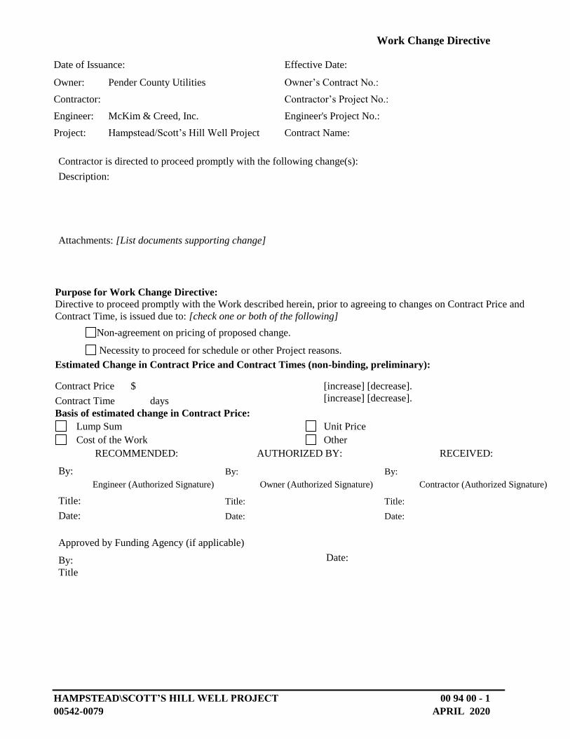
HAMPSTEAD\SCOTT’S HILL WELL PROJECT 00 94 00 - 1
00542-0079 APRIL 2020
Work Change Directive
No.
Date of Issuance: Effective Date:
Owner: Pender County Utilities Owner’s Contract No.:
Contractor: Contractor’s Project No.:
Engineer: McKim & Creed, Inc. Engineer's Project No.:
Project: Hampstead/Scott’s Hill Well Project Contract Name:
Contractor is directed to proceed promptly with the following change(s):
Description:
Attachments: [List documents supporting change]
Purpose for Work Change Directive:
Directive to proceed promptly with the Work described herein, prior to agreeing to changes on Contract Price and
Contract Time, is issued due to: [check one or both of the following]
Non-agreement on pricing of proposed change.
Necessity to proceed for schedule or other Project reasons.
Estimated Change in Contract Price and Contract Times (non-binding, preliminary):
Contract Price $ [increase] [decrease].
Contract Time days [increase] [decrease].
Basis of estimated change in Contract Price:
Lump Sum Unit Price
Cost of the Work Other
RECOMMENDED: AUTHORIZED BY: RECEIVED:
By: By: By:
Engineer (Authorized Signature) Owner (Authorized Signature) Contractor (Authorized Signature)
Title: Title: Title:
Date: Date: Date:
Approved by Funding Agency (if applicable)
By: Date:
Title
:

HAMPSTEAD\SCOTT’S HILL WELL PROJECT 00 94 00 - 2
00542-0079 APRIL 2020
This page intentionally left blank
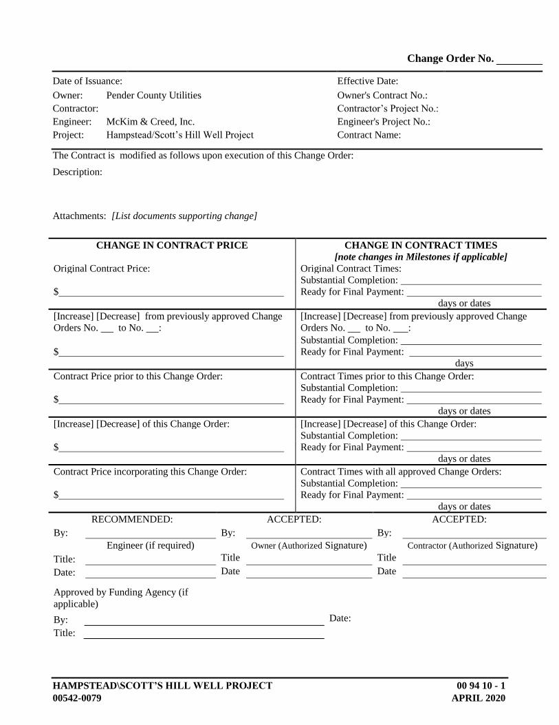
HAMPSTEAD\SCOTT’S HILL WELL PROJECT 00 94 10 - 1
00542-0079 APRIL 2020
Change Order No.
Date of Issuance: Effective Date:
Owner: Pender County Utilities Owner's Contract No.:
Contractor: Contractor’s Project No.:
Engineer: McKim & Creed, Inc. Engineer's Project No.:
Project: Hampstead/Scott’s Hill Well Project Contract Name:
The Contract is modified as follows upon execution of this Change Order:
Description:
Attachments: [List documents supporting change]
CHANGE IN CONTRACT PRICE CHANGE IN CONTRACT TIMES
[note changes in Milestones if applicable]
Original Contract Price: Original Contract Times:
Substantial Completion:
$ Ready for Final Payment:
days or dates
[Increase] [Decrease] from previously approved Change
Orders No. to No. :
[Increase] [Decrease] from previously approved Change
Orders No. to No. :
Substantial Completion:
$ Ready for Final Payment:
days
Contract Price prior to this Change Order: Contract Times prior to this Change Order:
Substantial Completion:
$ Ready for Final Payment:
days or dates
[Increase] [Decrease] of this Change Order: [Increase] [Decrease] of this Change Order:
Substantial Completion:
$ Ready for Final Payment:
days or dates
Contract Price incorporating this Change Order: Contract Times with all approved Change Orders:
Substantial Completion:
$ Ready for Final Payment:
days or dates
RECOMMENDED: ACCEPTED: ACCEPTED:
By: By: By:
Engineer (if required) Owner (Authorized Signature) Contractor (Authorized Signature)
Title: Title
: Title
:
Date: Date
: Date
:
Approved by Funding Agency (if
applicable)
By: Date:
Title:

HAMPSTEAD\SCOTT’S HILL WELL PROJECT 00 94 10 - 2
00542-0079 APRIL 2020
This page intentionally left blank
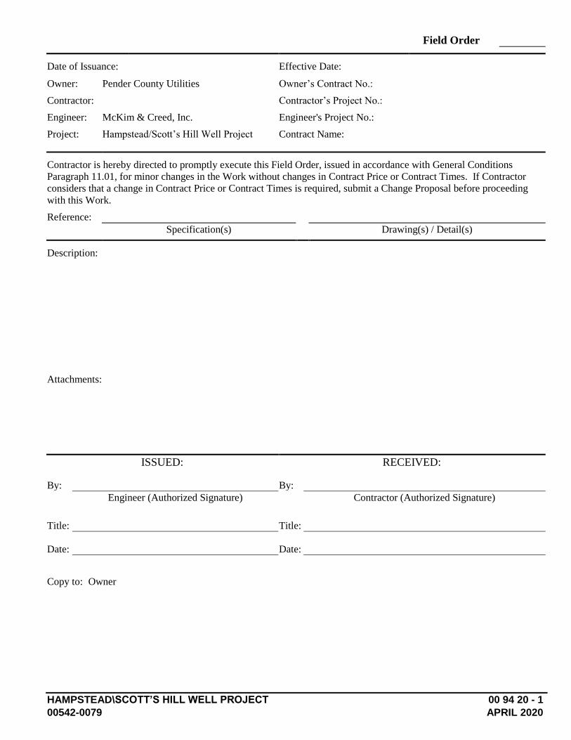
HAMPSTEAD\SCOTT’S HILL WELL PROJECT 00 94 20 - 1
00542-0079 APRIL 2020
Field Order
No.
Date of Issuance: Effective Date:
Owner: Pender County Utilities Owner’s Contract No.:
Contractor: Contractor’s Project No.:
Engineer: McKim & Creed, Inc. Engineer's Project No.:
Project: Hampstead/Scott’s Hill Well Project Contract Name:
Contractor is hereby directed to promptly execute this Field Order, issued in accordance with General Conditions
Paragraph 11.01, for minor changes in the Work without changes in Contract Price or Contract Times. If Contractor
considers that a change in Contract Price or Contract Times is required, submit a Change Proposal before proceeding
with this Work.
Reference:
Specification(s) Drawing(s) / Detail(s)
Description:
Attachments:
ISSUED: RECEIVED:
By: By:
Engineer (Authorized Signature) Contractor (Authorized Signature)
Title: Title:
Date: Date:
Copy to: Owner

HAMPSTEAD\SCOTT’S HILL WELL PROJECT 00 94 20 - 2
00542-0079 APRIL 2020
This page intentionally left blank
HAMPSTEAD/SCOTT’S HILL WELL PROJECT 01 10 00 - 1
00542-0079 APRIL 2020
SECTION 01 10 00 – SUMMARY
PART 1 - GENERAL
1.1 RELATED DOCUMENTS
A. Drawings and general provisions of the Contract, including General and Supplementary Conditions and other Division 1 Specification Sections, apply to this Section.
1.2 SUMMARY
A. Section includes:
1. Project information. 2. Work covered by Contract Documents. 3. Phased construction. 4. Work by Owner. 5. Work under separate contracts. 6. Future work. 7. Purchase contracts. 8. Owner-furnished products. 9. Contractor-furnished, Owner-installed products. 10. Access to site. 11. Coordination with occupants. 12. Work restrictions. 13. Specification and drawing conventions.
B. Related Section:
1. Division 1 Section "Temporary Facilities and Controls" for limitations and procedures governing temporary use of Owner's facilities.
1.3 PROJECT INFORMATION
A. Project Identification: Hampstead/Scott’s Hill Well Project.
1. Project Locations: Pender County Hampstead Annex and Kiwanis Park.
B. Owner: Pender County Utilities
C. Consultant: The Owner has retained the following design professionals who have prepared designated portions of the Contract Documents:
1. McKim & Creed Inc., 243 N. Front Street, Wilmington, NC 28401
SUMMARY
HAMPSTEAD/SCOTT’S HILL WELL PROJECT 01 10 00 - 2
00542-0079 APRIL 2020
1.4 WORK COVERED BY CONTRACT DOCUMENTS
A. The Work of the Project is defined by the Contract Documents and consists of the following:
1. The project consists of the construction of two (2) finished water production supply wells, well houses, and associated appurtenances. As shown on the contract drawings, both wells along with their associated pumps will be installed by Owner prior to Contractor mobilizing on the project. In addition, Owner will be providing the equipment listed below. Contractor shall be responsible for installing equipment provided by Owner and for providing and installing all other equipment and piping as necessary for a complete and operable system as shown and detailed within the Contract Documents.
B. With regards to specified/required equipment, Owner will pre-purchase the following items:
1. Two (2) prefabricated precast concrete structures (well houses) – See Spec 13
45 00** 2. Two (2) Deep Well Control Valves - See Spec 33 11 13 3. Two (2) Hydraulic Check Valves - See Spec 33 11 13 4. Two (2) Surge Control Valves - See Spec 33 11 13 5. One (1) 80 Kw generator set – See Spec 28 32 13 6. One (1) 100 Kw generator set – See Spec 28 32 13 7. Six (6) Liquid Chemical Feed Pump (Skids) (Various Capacities) – See Spec 46
33 00 8. Six (6) Chemical Tanks- See Spec 11 93 00 9. Six (6) Chemical Spill Containment Systems -See Spec 44 41 33 10. Two (2) Control Panel Packages*
*Packages include but are limited to: Control Panel, RTU, PLC, control wiring,
instruments including: Two (2) Chlorine Analyzers Two (2) Flow Element/Transmitters Two (2) Submersible Level (Pressure) Sensors Two (2) Pressure Transmitters (Gage)
** Prefabricated precast concrete structures shall be shipped directly from the supplier to the well house locations and assembled by the precast vendor. Contractor shall provide man power and equipment support to the vendor and coordinate delivery and installation through Owner.
Pre-Purchase Item Storage: Items shall be stored on Owner’s property within Pender County. Contractor shall include the pickup and delivery costs to relocate the materials from the County laydown to the various sites.
SUMMARY
HAMPSTEAD/SCOTT’S HILL WELL PROJECT 01 10 00 - 3
00542-0079 APRIL 2020
1. 5 CONTRACT TYPE
A. Type of Contract
1. Project will be constructed under a single prime contract.
1.6 WORK BY OWNER
A. General: Cooperate fully with Owner so work may be carried out smoothly, without interfering with or delaying work under this Contract or work by Owner. Coordinate the Work of this Contract with work performed by Owner.
1.7 ACCESS TO SITE
A. General: Contractor shall have full use of Project site for construction operations during construction period. Contractor's use of Project site is limited only by Owner's right to perform work or to retain other contractors on portions of Project.
B. Use of Site: Limit use of Project site to construction limits indicated. Do not disturb portions of Project site beyond areas in which the Work is indicated.
1. Limits: Confine construction operations to within construction limits unless approved by the Engineer.
2. Driveways, Walkways and Entrances: Keep driveways and entrances serving premises clear and available to Owner, Owner's employees, and emergency vehicles at all times. Do not use these areas for parking or storage of materials.
a. Schedule deliveries to minimize use of driveways and entrances by construction operations.
b. Schedule deliveries to minimize space and time requirements for storage of materials and equipment on-site.
C. Any damage by Contractor to the access road must be repaired and/or replaced by Contractor to original grade and condition.
1.8 COORDINATION WITH OCCUPANTS
A. Full Owner Occupancy: Owner will occupy adjacent sites during entire construction period. Cooperate with Owner during construction operations to minimize conflicts and facilitate Owner usage. Perform the Work so as not to interfere with Owner's day-to-day operations.
1. Maintain access to existing facilities. Do not close or obstruct occupied or used facilities without written permission from Owner and approval of authorities having jurisdiction.
2. Notify the Owner not less than 48 hours in advance of activities that will affect Owner's operations.
B. Owner Limited Occupancy of Completed Areas of Construction: Owner reserves the right to occupy and to place and install equipment in completed portions of the Work,
SUMMARY
HAMPSTEAD/SCOTT’S HILL WELL PROJECT 01 10 00 - 4
00542-0079 APRIL 2020
prior to Substantial Completion of the Work, provided such occupancy does not interfere with completion of the Work. Such placement of equipment and limited occupancy shall not constitute acceptance of the total Work.
1. Engineer will prepare a Certificate of Substantial Completion for each specific portion of the Work to be occupied prior to Owner acceptance of the completed Work.
2. Obtain a Certificate of Occupancy from authorities having jurisdiction before limited Owner occupancy.
3. Before limited Owner occupancy, mechanical and electrical systems shall be fully operational, and required tests and inspections shall be successfully completed. On occupancy, Owner will operate and maintain mechanical and electrical systems serving occupied portions of Work.
4. On occupancy, Owner will assume responsibility for maintenance and custodial service for occupied portions of Work with no obligation to occupy.
1.9 WORK RESTRICTIONS
A. Work Restrictions, General: Comply with restrictions on construction operations.
1. Comply with limitations on use of public streets and other requirements of authorities having jurisdiction.
B. On-Site Work Hours: Limit work to normal business working hours Monday through Friday or as approved by the Owner.
C. Existing Utility Interruptions: Do not interrupt utilities serving facilities occupied by Owner or others unless permitted under the following conditions and then only after providing temporary utility services according to requirements indicated:
1. Notify Owner not less than two days in advance of proposed utility interruptions. 2. Obtain Owner’s written permission before proceeding with utility interruptions.
D. Noise, Vibration, and Odors: Coordinate operations that may result in high levels of noise and vibration, odors, or other disruption to Owner occupancy with Owner.
1. Notify Owner not less than two days in advance of proposed disruptive operations.
2. Obtain Owner’s written permission before proceeding with disruptive operations.
E. Controlled Substances: Smoking is prohibited indoors in existing or temporary structures on site or other habitable structures on site.
2.0 SPECIFICATION AND DRAWING CONVENTIONS
A. Specification Content: The Specifications use certain conventions for the style of language and the intended meaning of certain terms, words, and phrases when used in particular situations. These conventions are as follows:
SUMMARY
HAMPSTEAD/SCOTT’S HILL WELL PROJECT 01 10 00 - 5
00542-0079 APRIL 2020
1. Imperative mood and streamlined language are generally used in the Specifications. The words "shall," "shall be," or "shall comply with," depending on the context, are implied where used within a sentence or phrase.
2. Specification requirements are to be performed by Contractor unless specifically stated otherwise.
B. Division 1 General Requirements: Requirements of Sections in Division 1 apply to the Work of all Sections in the Specifications.
1. Drawing Coordination: Requirements for materials and products identified on the
Drawings and not further specified in the specifications are intended to describe a performance standard for function or materials of construction.
PART 2 - PRODUCTS (Not Used)
PART 3 - EXECUTION
3.1 Precedence
A. In resolving inconsistencies precedence shall be given in the following order; Agreement, Supplementary Conditions, General Conditions, Specifications – Division 01, Specifications – Divisions 02-46, and the construction drawings.
END OF SECTION 01 10 00

HAMPSTEAD\SCOTT’S HILL WELL PROJECT 01 25 00 - 1
00542-0079 APRIL 2020
SECTION 01 25 00 - CONTRACT MODIFICATION PROCEDURES
PART 1 - GENERAL
1.1 RELATED DOCUMENTS
A. Drawings and general provisions of the Contract, including General and Supplementary Conditions and other Division 1 Specification Sections, apply to this Section.
1.2 SUMMARY
A. Section includes administrative and procedural requirements for handling and processing Contract modifications.
B. Related Sections:
1. Division 1 Section "Product Requirements" for administrative procedures for handling requests for substitutions made after Contract award.
1.3 MINOR CHANGES IN THE WORK
A. Engineer will issue supplemental instructions authorizing minor changes in the Work, not involving adjustment to the Contract Sum or the Contract Time, on applicable EJCDC forms.
1.4 PROPOSAL REQUESTS
A. Owner-Initiated Proposal Requests: Engineer will issue a detailed description of proposed changes in the Work that may require adjustment to the Contract Sum or the Contract Time. If necessary, the description will include supplemental or revised Drawings and Specifications.
1. Proposal Requests issued by Engineer are not instructions either to stop work in progress or to execute the proposed change.
2. Within 20 days after receipt of Proposal Request, submit a quotation estimating cost adjustments to the Contract Sum and the Contract Time necessary to execute the change.
a. Include a list of quantities of products required or eliminated and unit costs, with total amount of purchases and credits to be made. If requested, furnish survey data to substantiate quantities.
b. Indicate applicable taxes, delivery charges, equipment rental, and amounts of trade discounts.
c. Include costs of labor and supervision directly attributable to the change.

CONTRACT MODIFICATION PROCEDURES
HAMPSTEAD\SCOTT’S HILL WELL PROJECT 01 25 00 - 2
00542-0079 APRIL 2020
d. Include an updated Contractor's construction schedule that indicates the effect of the change, including, but not limited to, changes in activity duration, start and finish times, and activity relationship. Use available total float before requesting an extension of the Contract Time.
e. Quotation Form: Use applicable EJCDC forms or other forms acceptable to the Engineer.
B. Contractor-Initiated Proposals: If latent or changed conditions require modifications to the Contract, Contractor may initiate a claim by submitting a request for a change to the Engineer.
1. Include a statement outlining reasons for the change and the effect of the change on the Work. Provide a complete description of the proposed change. Indicate the effect of the proposed change on the Contract Sum and the Contract Time.
2. Include a list of quantities of products required or eliminated and unit costs, with total amount of purchases and credits to be made. If requested, furnish survey data to substantiate quantities.
3. Indicate applicable taxes, delivery charges, equipment rental, and amounts of trade discounts.
4. Include costs of all labor (engineer, laborer, foreman, supervisor, etc.) directly attributed to the successful design approval and construction efforts to implement the change.
5. Include an updated Contractor's construction schedule that indicates the effect of the change, including, but not limited to, changes in activity duration, start and finish times, and activity relationship. Use available total float before requesting an extension of the Contract Time.
6. Comply with requirements in Division 1 Section "Substitution Procedures" if the proposed change requires substitution of one product or system for product or system specified.
7. Proposal Request Form: Use applicable EJCDC or other forms acceptable to the Engineer.
1.5 ADMINISTRATIVE CHANGE ORDERS
A. Allowance Adjustment: Refer to Division 1 Section "Allowances" for administrative procedures for preparation of Change Order Proposal for adjusting the Contract Sum to reflect actual costs of allowances.
B. Unit Price Adjustment: Refer to Division 1 Section "Unit Prices" for administrative procedures for preparation of Change Order Proposal for adjusting the Contract Sum to reflect measured scope of unit price work.
1.6 CHANGE ORDER PROCEDURES
A. On Owner's approval of a Proposal Request, Engineer will issue a Change Order for signatures of Owner and Contractor on applicable EJCDC form.

CONTRACT MODIFICATION PROCEDURES
HAMPSTEAD\SCOTT’S HILL WELL PROJECT 01 25 00 - 3
00542-0079 APRIL 2020
1.7 CONSTRUCTION CHANGE DIRECTIVE
A. Change Directive: Engineer may issue a Change Directive on applicable EJCDC form. Change Directive instructs Contractor to proceed with a change in the Work, for subsequent inclusion in a Change Order.
1. Change Directive contains a complete description of change in the Work. It also designates method to be followed to determine change in the Contract Sum or the Contract Time.
B. Documentation: Maintain detailed records on a time and material basis of work required by the Change Directive.
1. After completion of change, submit an itemized account and supporting data necessary to substantiate cost and time adjustments to the Contract.
PART 2 - PRODUCTS (Not Used)
PART 3 - EXECUTION (Not Used)
END OF SECTION 01 25 00

CONTRACT MODIFICATION PROCEDURES
HAMPSTEAD\SCOTT’S HILL WELL PROJECT 01 25 00 - 4
00542-0079 APRIL 2020
This page intentionally left blank
HAMPSTEAD/SCOTT’S HILL WELL PROJECT 01 27 00 - 1
00542-0079 APRIL 2020
SECTION 01 27 00 –MEASUREMENT AND PAYMENT
PART 1 - GENERAL
1.1 RELATED DOCUMENTS
A. Drawings and general provisions of the Contract, including General and Supplementary Conditions and other Division 1 Specification Sections, apply to this Section.
1.2 SUMMARY
A. This Section includes administrative and procedural requirements for unit and lump sum prices as well as alternates. The scope of this section of the Contract Documents is to further define the items included in each Bid Item in the Bid Proposal section of these specifications. Payment will be made based on the specified items supplied and delivered in the description in this section for each bid item.
B. No payment will be made for work constructed outside the authorized limits of work.
C. Related Sections: The following Sections contain requirements that relate to this Section:
1. Section 01 20 00 “Price and Payment Procedures” for procedures for requesting payment.
2. Section 01 40 00 Section "Quality Requirements” for general inspection requirements.
3. All Divisions 02 through 46.
1.3 DEFINITIONS
A. Unit price is an amount proposed by bidders, stated on the Bid Form, as a price per unit of measurement for materials or services added to or deducted from the Contract Sum by appropriate modification, if the estimated quantities of Work required by the Contract Documents are increased or decreased.
B. Lump Sum Bid for all work shown, indicated, and specified in the contract documents: Amount shall reflect the Contractor’s labor, equipment, materials, overhead, profit, etc. for all work shown, indicated, and specified in the contract documents excluding the cost for work included in other bid items
1.4 PROCEDURES
A. The total Bid Price shall cover all Work required by the Contract Documents. All costs in connection with the proper and successful completion of the Work,
MEASUREMENT AND PAYMENT
HAMPSTEAD/SCOTT’S HILL WELL PROJECT 01 27 00 - 2
00542-0079 APRIL 2020
including furnishing all materials, equipment, supplies, and appurtenances; providing all construction equipment and tools; and performing all necessary labor and supervision to fully complete the Work, including system startup and commissioning and performance testing, shall be included in the unit and lump sum prices bid. All Work not specifically set forth as a pay item in the Bid Form shall be considered a subsidiary obligation of the Contractor and all costs in connection therewith shall be included in the prices bid.
B. Measurement and Payment: All estimated quantities stipulated in the Bid Form or other Contract Documents are approximate and are to be used only (a) as a basis for estimating the probable cost of the Work and (b) for the purpose of comparing the bids submitted for the Work. The actual amounts of work done and materials furnished under unit price items may differ from the estimated quantities. The basis of payment for work and materials will be the actual amount of work done and materials furnished. Contractor agrees that he will make no claim for damages, anticipated profits, or otherwise on account of any difference between the amounts of work actually performed and materials actually furnished and the estimated amounts thereof.
C. The Owner reserves the right to reject the Contractor's measurement of work-in-place that involves use of established unit prices, and to have this work measured, at the Owner's expense, by the Engineer.
D. Retainage: Refer to General Conditions.
1.5 COSTS INCLUDED IN PAYMENT ITEMS:
A. No separate payment will be made for the following items and the cost of such work shall be included in the applicable pay items for work:
1. Clearing and grubbing
2. Trench excavation, including necessary pavement removal, except as otherwise specified
3. Dewatering and disposal of surplus water
4. Demolition and removal
5. Concrete formwork and reinforcement
6. Sealants and caulking
7. Unit masonry
8. Hatch doors
9. Metal fabrications
10. Rough carpentry
11. Structural steel
MEASUREMENT AND PAYMENT
HAMPSTEAD/SCOTT’S HILL WELL PROJECT 01 27 00 - 3
00542-0079 APRIL 2020
12. Building insulation
13. Custom sheet metal roofing
14. Siding
15. Finishing work
16. Standard steel doors
17. Standard steel frames
18. Overhead coiling doors
19. Finish hardware
20. Glazing
21. Priming, painting, and labeling, except as otherwise specified
22. Handrails and railings
23. Structural fill, backfill, grading, and related transport costs, except as otherwise specified
24. Replacement of unpaved roadways, grass (sod), and shrubbery plots
25. Repairing damaged utilities
26. Cleanup, except as otherwise specified
27. Foundation and borrow materials, except as otherwise specified
28. Pipeline pressure testing, hydrostatic testing, leak testing, etc. excepted as otherwise specified.
29. Removing, replacing and bracing light poles, power poles, mail boxes, fences, walls, shrubbery, plantings, and other ornamental items
30. Equipment and system start-up
31. Process performance testing
32. Any required pipeline pigging, flushing, etc.
33. Transition couplings and labor
34. Any material and equipment required to be installed and utilized for tests
35. Pipe, structures, pavement replacement, restoration, and/or appurtenances included within the limits of lump sum work, except as otherwise specified
MEASUREMENT AND PAYMENT
HAMPSTEAD/SCOTT’S HILL WELL PROJECT 01 27 00 - 4
00542-0079 APRIL 2020
36. Maintaining the existing quality of service during construction, including required by-pass pumping
37. Appurtenant work as required for a complete and operable system
B. Contractor’s attention is called to the fact that cleanup is considered a part of the work of construction. No final payment will be made until cleanup is essentially complete and as-built drawings have been provided by the Contractor.
PART 2 - PRODUCTS (NOT USED)
PART 3 - EXECUTION
3.1 METHOD OF MEASUREMENT AND PAYMENT
A. The method of measurement and basis of payment for each item as listed in the Bid Form shall be as stipulated in the following subparagraphs.
Line Item 1 - Contractor Mobilization: Mobilization shall be bid as a single lump sum item. Payment will be made in three equal payments (each 1/3 of the amount listed on the bid form) during the first three regular monthly pay requests. Mobilization may not be in excess of 2% of the total bid amount. Mobilization shall include all costs for bonds, insurance, field offices, toilets, signs, equipment mobilization, and other similar items. No payment for Mobilization will be made prior to receipt of detailed color video with descriptive audio of project area. No additional payment will be made for any mobilization or de-mobilization costs incurred in excess of the amount indicated on the Bid Form.
Line Item 2 – Annex Well: Work shall include providing and installing a well house complete and operational with piping, electrical, HVAC, instrumentation, fencing, grading, communication, and chemical storage and feed equipment/ work as shown on the drawings and as detailed in the specifications.
Line Item 3 – Kiwanis Well: Work shall include providing and installing a well house complete and operational with piping, electrical, HVAC, instrumentation, fencing, grading, communication, and chemical storage and feed equipment/ work as shown on the drawings and as detailed in the specifications.
Line Item 4 – Owner Allowance: Contract price includes an allowance for Owner’s use only for administering changes to the work through the change order process. Amounts remaining in the allowance at the end of the contract shall be credited back to Owner through a “Final Adjusting Change Order”.
3.2 ITEMS NOT PAID FOR:
A. No payment will be made for any item not specifically listed in the Bid Form. All ancillary items required for a complete, functioning, treatment system installation will be the responsibility of the contractor to include in the cost of line
MEASUREMENT AND PAYMENT
HAMPSTEAD/SCOTT’S HILL WELL PROJECT 01 27 00 - 5
00542-0079 APRIL 2020
items listed on the Bid Form. Specific items which will NOT be paid for include, but are not limited to the following:
1. All excavation is unclassified. Neither the Owner nor the Engineer assumes responsibility for subsurface conditions, including unyielding material, ground water, and existing utilities not indicated or shown on the plans.
2. All Clearing, Grubbing, Grading, and Excavation shall be included in the total cost of work and no separate payment shall be made. This shall include storing of topsoil and disposal of debris. No additional payment will be made for any clearing or excavation outside areas indicated on plan sheets which may be required for installation pipeline and apertures.
3. No additional payment for backfill or trench stabilization stone shall be made except where specifically noted above. Contractor shall be required to furnish acceptable bedding, fill, and stabilization materials as part of the total cost of work and no separate payment for these items will be made.
4. Repairing damaged utilities will be at the Contractor’s expense and no compensation therefore will be allowed.
5. Repairing of damaged facility roads will be at the Contractor’s expense and no compensation therefore will be allowed.
6. Shoring, bracing, sheeting, etc., installed where required for trench stabilization and protection of adjacent roads, utilities, and properties shall be included in the Base Bid and no separate payment will be made thereof.
7. Tree protection fencing shall be included in the cost of work; therefore, no separate payment shall be made.
8. Penetrations of pipe through walls and retaining walls shall be included in the cost of the work and no separate payment shall be made.
9. Replacement of pavement markings and striping shall be included in the cost of the work and no separate payment shall be made.
10. No payment will be made for restocking fees incurred by the Contractor due to excess materials. Contractor is advised to include anticipated restocking fees for excess materials, including those due to unforeseen site conditions, in the total cost of work.
END OF SECTION 01 27 00
HAMPSTEAD\SCOTT’S HILL WELL PROJECT 01 29 00 - 1
00542-0079 APRIL 2020
SECTION 01 29 00 - PAYMENT PROCEDURES
PART 1 - GENERAL
1.1 RELATED DOCUMENTS
A. Drawings and general provisions of the Contract, including General and Supplementary Conditions and other Division 1 Specification Sections, apply to this Section.
1.2 SUMMARY
A. This Section specifies administrative and procedural requirements necessary to prepare and process Applications for Payment.
B. Related Sections: 1. Division 1 Section "Contract Modification Procedures" for administrative
procedures for handling changes to the Contract. 2. Division 1 Section "Construction Progress Documentation" for administrative
requirements governing the preparation and submittal of Contractor's construction schedule.
3. Division 1 Section "Submittal Procedures" for administrative requirements governing the preparation and submittal of submittal schedule.
1.3 DEFINITIONS
A. Schedule of Values: A statement furnished by Contractor allocating portions of the Contract Sum to various portions of the Work and used as the basis for reviewing Contractor's Applications for Payment.
1.4 SCHEDULE OF VALUES
A. Coordination: Coordinate preparation of the schedule of values with preparation of Contractor's construction schedule
1. Correlate line items in the schedule of values with other required administrative forms and schedules, including the following:
a. Application for Payment forms with continuation sheets. b. Submittal schedule. c. Items required to be indicated as separate activities in Contractor's
construction schedule.
2. Submit the schedule of values to Engineer at earliest possible date but no later than seven days before the date scheduled for submittal of initial Applications for Payment.
PAYMENT PROCEDURES
HAMPSTEAD\SCOTT’S HILL WELL PROJECT 01 29 00 - 2
00542-0079 APRIL 2020
3. Subschedules for Phased Work: Where the Work is separated into phases requiring separately phased payments, provide subschedules showing values correlated with each phase of payment.
4. Subschedules for Separate Elements of Work: Where the Contractor's construction schedule defines separate elements of the Work, provide subschedules showing values correlated with each element.
5. Separate Schedule of Values for each equipment item with a value greater than $1000.
B. Format and Content: Use the Project Manual table of contents as a guide to establish line items for the schedule of values. Provide at least one line item for each Specification Section.
1. Identification: Include the following Project identification on the schedule of values:
a. Project name and location. b. Name of Engineer. c. Engineer's project number. d. Contractor's name and address. e. Date of submittal.
2. Arrange schedule of values consistent with format of EJCDC Document C-620. 3. Arrange the schedule of values in tabular form with separate columns to indicate
the following for each item listed:
a. Related Specification Section or Division. b. Description of the Work. c. Name of subcontractor. d. Name of manufacturer or fabricator. e. Name of supplier. f. Change Orders (numbers) that affect value. g. Dollar value of the following, as a percentage of the Contract Sum to
nearest one-hundredth percent, adjusted to total 100 percent.
1) Labor. 2) Materials. 3) Equipment.
4. Provide a breakdown of the Contract Sum in enough detail to facilitate continued evaluation of Applications for Payment and progress reports. Coordinate with the Project Manual table of contents. Provide multiple line items for principal subcontract amounts in excess of five percent of Contract Sum.
5. Round amounts to nearest whole dollar; total shall equal the Contract Sum. 6. Provide a separate line item in the schedule of values for each part of the Work
where Applications for Payment may include materials or equipment purchased or fabricated and stored, but not yet installed.
a. Differentiate between items stored on-site and items stored off-site. If required, include evidence of insurance.
PAYMENT PROCEDURES
HAMPSTEAD\SCOTT’S HILL WELL PROJECT 01 29 00 - 3
00542-0079 APRIL 2020
7. Provide separate line items in the schedule of values for initial cost of materials, for each subsequent stage of completion, and for total installed value of that part of the Work.
8. Allowances: Provide a separate line item in the schedule of values for each allowance. Show line-item value of unit-cost allowances, as a product of the unit cost, multiplied by measured quantity. Use information indicated in the Contract Documents to determine quantities.
9. Purchase Contracts: Provide a separate line item in the schedule of values for each purchase contract. Show line-item value of purchase contract. Indicate owner payments or deposits, if any, and balance to be paid by Contractor.
10. Each item in the schedule of values and Applications for Payment shall be complete. Include total cost and proportionate share of general overhead and profit for each item.
a. Temporary facilities and other major cost items that are not direct cost of actual work-in-place may be shown either as separate line items in the schedule of values or distributed as general overhead expense, at Contractor's option.
11. Schedule Updating: Update and resubmit the schedule of values before the next Applications for Payment when Change Orders or Construction Change Directives result in a change in the Contract Sum.
1.5 APPLICATIONS FOR PAYMENT
A. Each Application for Payment shall be consistent with previous applications and payments as certified by Engineer and paid for by Owner.
1. Initial Application for Payment, Application for Payment at time of Substantial Completion, and final Application for Payment involve additional requirements.
B. Payment Application Times: The date for each progress payment is indicated in the Agreement between Owner and Contractor. The period of construction work covered by each Application for Payment is the period indicated in the Agreement.
C. Payment Application Times: Progress payments shall be submitted to Engineer by agreed upon day of the month. The period covered by each Application for Payment is one month, ending on the last day of the month.
1. Submit draft copy of Application for Payment seven days prior to due date for review by Engineer.
D. Application for Payment Forms: Use EJCDC Document C-620 as form for Applications for Payment, or applicable forms as required by funding source.
E. Attachments required with Payment Applications: 1. Updated Schedule 2. Sales Tax Forms
F. Coordination Item:

PAYMENT PROCEDURES
HAMPSTEAD\SCOTT’S HILL WELL PROJECT 01 29 00 - 4
00542-0079 APRIL 2020
1. RPR to review record drawings each month prior to approving pay application.
G. Application Preparation: Complete every entry on form. Notarize and execute by a person authorized to sign legal documents on behalf of Contractor. Engineer will return incomplete applications without action.
1. Entries shall match data on the schedule of values and Contractor's construction schedule. Use updated schedules if revisions were made.
2. Include amounts for work completed following previous Application for Payment, whether or not payment has been received. Include only amounts for work completed at time of Application for Payment.
3. Include amounts of Change Orders and Construction Change Directives issued before last day of construction period covered by application.
4. Indicate separate amounts for work being carried out under Owner-requested project acceleration.
H. Stored Materials: Include in Application for Payment amounts applied for materials or equipment purchased or fabricated and stored, but not yet installed. Differentiate between items stored on-site and items stored off-site.
1. Provide certificate of insurance, evidence of transfer of title to Owner, and consent of surety to payment, for stored materials.
2. Provide supporting documentation that verifies amount requested, such as paid invoices. Match amount requested with amounts indicated on documentation; do not include overhead and profit on stored materials.
3. Provide summary documentation for stored materials indicating the following:
a. Materials previously stored and included in previous Applications for Payment.
b. Work completed for this Application utilizing previously stored materials. c. Additional materials stored with this Application. d. Total materials remaining stored, including materials with this Application.
I. Transmittal: Submit 5 signed and notarized original copies of each Application for Payment to Engineer by a method ensuring receipt within 24 hours. One copy shall include waivers of lien and similar attachments if required.
1. Transmit each copy with a transmittal form listing attachments and recording appropriate information about application.
J. Waivers of Mechanic's Lien: With each Application for Payment, submit waivers of mechanic's lien from entities lawfully entitled to file a mechanic's lien arising out of the Contract and related to the Work covered by the payment.
1. Submit partial waivers on each item for amount requested in previous application, after deduction for retainage, on each item.
2. When an application shows completion of an item, submit conditional final or full waivers.
3. Owner reserves the right to designate which entities involved in the Work must submit waivers.
PAYMENT PROCEDURES
HAMPSTEAD\SCOTT’S HILL WELL PROJECT 01 29 00 - 5
00542-0079 APRIL 2020
4. Waiver Forms: Submit waivers of lien on forms, executed in a manner acceptable to Owner.
K. Waivers of Mechanic's Lien: With each Application for Payment, submit waivers of mechanic's liens from subcontractors, sub-subcontractors, and suppliers for construction period covered by the previous application.
1. Submit partial waivers on each item for amount requested in previous application, after deduction for retainage, on each item.
2. When an application shows completion of an item, submit conditional final or full waivers.
3. Owner reserves the right to designate which entities involved in the Work must submit waivers.
4. Submit final Application for Payment with or preceded by conditional final waivers from every entity involved with performance of the Work covered by the application who is lawfully entitled to a lien.
5. Waiver Forms: Submit waivers of lien on forms, executed in a manner acceptable to Owner.
L. Initial Application for Payment: Administrative actions and submittals that must precede or coincide with submittal of first Application for Payment include the following:
1. List of subcontractors. 2. Detailed Schedule of values. 3. Contractor's construction schedule (preliminary if not final). 4. Combined Contractor's construction schedule (preliminary if not final)
incorporating Work of multiple contracts, with indication of acceptance of schedule by each Contractor.
5. Products list (preliminary if not final). 6. Schedule of unit prices. 7. Submittal schedule (preliminary if not final). 8. List of Contractor's staff assignments. 9. List of Contractor's principal consultants. 10. Copies of building permits. 11. Copies of authorizations and licenses from authorities having jurisdiction for
performance of the Work. 12. Initial progress report. 13. Report of preconstruction conference. 14. Certificates of insurance and insurance policies. 15. Performance and payment bonds. 16. Data needed to acquire Owner's insurance.
M. Application for Payment at Substantial Completion: After issuing the Certificate of Substantial Completion, submit an Application for Payment showing 100 percent completion for portion of the Work claimed as substantially complete.
1. Include documentation supporting claim that the Work is substantially complete and a statement showing an accounting of changes to the Contract Sum.
2. This application shall reflect Certificates of Partial Substantial Completion issued previously for Owner occupancy of designated portions of the Work.
PAYMENT PROCEDURES
HAMPSTEAD\SCOTT’S HILL WELL PROJECT 01 29 00 - 6
00542-0079 APRIL 2020
N. Final Payment Application: Submit final Application for Payment with releases and supporting documentation not previously submitted and accepted, including, but not limited, to the following:
1. Evidence of completion of Project closeout requirements. 2. Insurance certificates for products and completed operations where required and
proof that taxes, fees, and similar obligations were paid. 3. Updated final statement, accounting for final changes to the Contract Sum. 4. AIA Document G706, "Contractor's Affidavit of Payment of Debts and Claims." 5. AIA Document G706A, "Contractor's Affidavit of Release of Liens." 6. AIA Document G707, "Consent of Surety to Final Payment." 7. Evidence that claims have been settled. 8. Final meter readings for utilities, a measured record of stored fuel, and similar
data as of date of Substantial Completion or when Owner took possession of and assumed responsibility for corresponding elements of the Work.
9. Final liquidated damages settlement statement. 10. Schedule of Values for each equipment item with a value over $1000.
PART 2 - PRODUCTS (Not Used)
PART 3 - EXECUTION (Not Used)
END OF SECTION 01 29 00
HAMPSTEAD\SCOTT’S HILL WELL PROJECT 01 31 00 - 1
00542-0079 APRIL 2020
SECTION 01 31 00 - PROJECT MANAGEMENT AND COORDINATION
PART 1 - GENERAL
1.1 RELATED DOCUMENTS
A. Drawings and general provisions of the Contract, including General and Supplementary Conditions and other Division 1 Specification Sections, apply to this Section.
1.2 SUMMARY
A. Section includes administrative provisions for coordinating construction operations on Project including, but not limited to, the following:
1. General project coordination procedures. 2. Administrative and supervisory personnel. 3. Coordination drawings. 4. Requests for Information (RFIs). 5. Project meetings.
B. Each contractor shall participate in coordination requirements.
C. Related Sections: 1. Division 1 Section "Project Meetings". 2. Division 1 Section "Project Schedule". 3. Division 1 Section "Contract Closeout".
1.3 DEFINITIONS
A. RFI: Request from Owner, Engineer, or Contractor seeking information from each other during construction.
1.4 COORDINATION
A. Coordination: Coordinate construction operations included in different Sections of the Specifications to ensure efficient and orderly installation of each part of the Work. Coordinate construction operations, included in different sections, which depend on each other for proper installation, connection, and operation.
1. Schedule construction operations in sequence required to obtain the best results where installation of one part of the Work depends on installation of other components, before or after its own installation.
2. Coordinate installation of different components to ensure maximum performance and accessibility for required maintenance, service, and repair.
3. Make adequate provisions to accommodate items scheduled for later installation.
PROJECT MANAGEMENT AND COORDINATION
HAMPSTEAD\SCOTT’S HILL WELL PROJECT 01 31 00 - 2
00542-0079 APRIL 2020
B. Prepare memoranda for distribution to each party involved, outlining special procedures required for coordination. Include such items as required notices, reports, and list of attendees at meetings.
1. Prepare similar memoranda for Owner and separate contractors if coordination of their Work is required.
C. Administrative Procedures: Coordinate scheduling and timing of required administrative procedures with other construction activities to avoid conflicts and to ensure orderly progress of the Work. Such administrative activities include, but are not limited to, the following:
1. Preparation of Contractor's construction schedule. 2. Preparation of the schedule of values. 3. Installation and removal of temporary facilities and controls. 4. Delivery and processing of submittals. 5. Progress meetings. 6. Pre-installation conferences with all sub-contractors prior to installation. 7. Project closeout activities. 8. Startup and adjustment of systems. 9. Project closeout activities.
D. Conservation: Coordinate construction activities to ensure that operations are carried out with consideration given to conservation of energy, water, and materials. Coordinate use of temporary utilities to minimize waste.
1. Salvage materials and equipment involved in performance of, but not actually incorporated into, the Work. Refer to other Sections for disposition of salvaged materials that are designated as Owner's property.
1.5 COORDINATION DRAWINGS
A. Coordination Drawings, General: Prepare coordination drawings in accordance with requirements in individual Sections, where installation is not completely shown on Shop Drawings, where limited space availability necessitates coordination, or if coordination is required to facilitate integration of products and materials fabricated or installed by more than one entity.
1. Content: Project-specific information, drawn accurately to a scale large enough to indicate and resolve conflicts. Do not base coordination drawings on standard printed data. Include the following information, as applicable:
a. Use applicable Drawings as a basis for preparation of coordination drawings. Prepare sections, elevations, and details as needed to describe relationship of various systems and components.
b. Coordinate the addition of trade-specific information to the coordination drawings by multiple contractors in a sequence that best provides for coordination of the information and resolution of conflicts between installed components before submitting for review.
PROJECT MANAGEMENT AND COORDINATION
HAMPSTEAD\SCOTT’S HILL WELL PROJECT 01 31 00 - 3
00542-0079 APRIL 2020
c. Indicate functional and spatial relationships of components of architectural, structural, civil, mechanical, and electrical systems.
d. Indicate space requirements for routine maintenance and for anticipated replacement of components during the life of the installation.
e. Show location and size of access doors required for access to concealed dampers, valves, and other controls.
f. Indicate required installation sequences. g. Indicate dimensions shown on the Drawings. Specifically note dimensions
that appear to be in conflict with submitted equipment and minimum clearance requirements. Provide alternate sketches to Engineer indicating proposed resolution of such conflicts. Minor dimension changes and difficult installations will not be considered changes to the Contract.
B. Coordination Drawing Organization: Organize coordination drawings as follows: 1. Mechanical Rooms: Provide coordination drawings for mechanical rooms
showing plans and elevations of mechanical, plumbing, fire protection, fire alarm, and electrical equipment.
2. Structural Penetrations: Indicate penetrations and openings required for all disciplines.
3. Slab Edge and Embedded Items: Indicate slab edge locations and sizes and locations of embedded items for metal fabrications, sleeves, anchor bolts, bearing plates, angles, door floor closers, slab depressions for floor finishes, curbs and housekeeping pads, and similar items.
4. Mechanical and Plumbing Work: Show the following:
a. Sizes and bottom elevations of ductwork, piping, and conduit runs, including insulation, bracing, flanges, and support systems.
b. Dimensions of major components, such as dampers, valves, diffusers, access doors, cleanouts and electrical distribution equipment.
c. Fire-rated enclosures around ductwork.
5. Electrical Work: Show the following:
a. Runs of vertical and horizontal conduit 1-1/4 inch diameter and larger. b. Light fixture, exit light, emergency battery pack, smoke detector, and other
fire alarm locations. c. Panel board, switch board, switchgear, transformer, busway, generator,
and motor control center locations. d. Location of pull boxes and junction boxes, dimensioned from column center
lines.
6. Review: Engineer will review coordination drawings to confirm that the Work is being coordinated, but not for the details of the coordination, which are the Contractor's responsibility. If the Engineer determines that the coordination drawings are not being prepared in sufficient scope or detail, or are otherwise deficient, the Engineer will so inform the Contractor, who shall make changes as directed and resubmit.
7. Coordination Drawing Prints: Prepare coordination drawing prints in accordance with requirements of Division 1 Section "Submittal Procedures."

PROJECT MANAGEMENT AND COORDINATION
HAMPSTEAD\SCOTT’S HILL WELL PROJECT 01 31 00 - 4
00542-0079 APRIL 2020
C. Coordination Digital Data Files: Prepare coordination digital data files in accordance with the following requirements:
1. File Preparation Format: Same digital data software program, version, and operating system as the original Drawings.
2. File Preparation Format: DWG, Version 2008, operating in Microsoft Windows operating system.
3. File Submittal Format: Submit or post coordination drawing files using format same as file preparation format.
4. Engineer will furnish Contractor one set of digital data files of the Drawings for use in preparing coordination digital data files.
a. Engineer makes no representations as to the accuracy or completeness of digital data files as they relate to the Drawings.
b. Contractor shall execute a data licensing agreement in the form acceptable to the Owner and Engineer.
1.6 KEY PERSONNEL
A. Key Personnel Names: Within 15 days of starting construction operations, submit a list of key personnel assignments, including superintendent and other personnel in attendance at Project site. Identify individuals and their duties and responsibilities; list addresses and telephone numbers, including home, office, and cellular telephone numbers and email addresses. Provide names, addresses, and telephone numbers of individuals assigned as standbys in the absence of individuals assigned to Project.
1. Post copies of list in project meeting room, in temporary field office, and by each temporary telephone. Keep list current at all times.
1.7 REQUESTS FOR INFORMATION (RFIs)
A. General: Immediately on discovery of the need for additional information or interpretation of the Contract Documents, Contractor shall prepare and submit an RFI in the form specified.
1. Engineer will return RFIs submitted to Engineer by other entities controlled by Contractor with no response.
2. Coordinate and submit RFIs in a prompt manner so as to prevent delays in Contractor's work or work of subcontractors.
B. Content of the RFI: Include a detailed, legible description of item needing information or interpretation and the following:
1. Project name. 2. Project number. 3. Date. 4. Name of Contractor. 5. Name of Engineer. 6. RFI number, numbered sequentially.
PROJECT MANAGEMENT AND COORDINATION
HAMPSTEAD\SCOTT’S HILL WELL PROJECT 01 31 00 - 5
00542-0079 APRIL 2020
7. RFI subject. 8. Specification Section number and title and related paragraphs, as appropriate. 9. Drawing number and detail references, as appropriate. 10. Field dimensions and conditions, as appropriate. 11. Contractor's suggested resolution. If Contractor's solution(s) impacts the
Contract Time or the Contract Sum, Contractor shall state impact in the RFI. 12. Contractor's signature. 13. Attachments: Include sketches, descriptions, measurements, photos, Product
Data, Shop Drawings, coordination drawings, and other information necessary to fully describe items needing interpretation.
a. Include dimensions, thicknesses, structural grid references, and details of affected materials, assemblies, and attachments on attached sketches.
C. RFI Forms: EJCDC Forms acceptable to the Engineer.
D. Engineer’s Action: Engineer will review each RFI, determine action required, and respond. Allow fifteen working days for Engineer’s response for each RFI. RFIs received by Engineer after 1:00 p.m. will be considered as received the following working day.
1. The following RFIs will be returned without action:
a. Requests for approval of submittals. b. Requests for approval of substitutions. c. Requests for coordination information already indicated in the Contract
Documents. d. Requests for adjustments in the Contract Time or the Contract Sum. e. Requests for interpretation of Engineer's actions on submittals. f. Incomplete RFIs or inaccurately prepared RFIs.
2. Engineer's action may include a request for additional information, in which case Engineer's time for response will date from time of receipt of additional information.
3. Engineer's action on RFIs that may result in a change to the Contract Time or the Contract Sum may be eligible for Contractor to submit Change Proposal according to Division 1 Section "Contract Modification Procedures."
a. If Contractor believes the RFI response warrants change in the Contract Time or the Contract Sum, notify Engineer in writing within 10 days of receipt of the RFI response.
E. On receipt of Engineer’s action, update the RFI log and immediately distribute the RFI response to affected parties. Review response and notify Engineer within 7 days if Contractor disagrees with response.
F. RFI Log: Prepare, maintain, and submit a tabular log of RFIs organized by the RFI number. Submit log weekly with the following information:
1. Project name. 2. Name and address of Contractor.

PROJECT MANAGEMENT AND COORDINATION
HAMPSTEAD\SCOTT’S HILL WELL PROJECT 01 31 00 - 6
00542-0079 APRIL 2020
3. Name and address of Engineer. 4. RFI number including RFIs that were dropped and not submitted. 5. RFI description. 6. Date the RFI was submitted. 7. Date Engineer’s response was received. 8. Identification of related Minor Change in the Work, Construction Change
Directive, and Proposal Request, as appropriate. 9. Identification of related Field Order, Work Change Directive, and Proposal
Request, as appropriate.
1.8 PROJECT MEETINGS
A. General: Engineer will schedule and conduct meetings and conferences at Project site, unless otherwise indicated.
1. Attendees: Inform participants and others involved, and individuals whose presence is required, of date and time of each meeting. Notify Owner and Engineer of scheduled meeting dates and times.
2. Agenda: Prepare the meeting agenda. Distribute the agenda to all invited attendees.
3. Minutes: Entity responsible for conducting meeting will record significant discussions and agreements achieved. Distribute the meeting minutes to everyone concerned, including Owner, Engineer, within 5 days of the meeting.
B. Preconstruction Conference: Engineer will schedule and conduct a preconstruction conference before starting construction, at a time convenient to Owner and Engineer, but no later than 15 days after execution of the Agreement.
1. Conduct the conference to review responsibilities and personnel assignments. 2. Attendees: Authorized representatives of Owner, Engineer, and their
consultants; Contractor and its superintendent; major subcontractors; suppliers; and other concerned parties shall attend the conference. Participants at the conference shall be familiar with Project and authorized to conclude matters relating to the Work.
3. Agenda: Discuss items of significance that could affect progress, including the following:
a. Tentative construction schedule. b. Phasing. c. Critical work sequencing and long-lead items. d. Designation of key personnel and their duties. e. Lines of communications. f. Procedures for processing field decisions and Change Orders. g. Procedures for RFIs. h. Procedures for testing and inspecting. i. Procedures for processing Applications for Payment. j. Distribution of the Contract Documents. k. Submittal procedures. l. Sustainable design requirements. m. Preparation of record documents.
PROJECT MANAGEMENT AND COORDINATION
HAMPSTEAD\SCOTT’S HILL WELL PROJECT 01 31 00 - 7
00542-0079 APRIL 2020
n. Use of the premises. o. Work restrictions. p. Working hours. q. Owner's occupancy requirements. r. Responsibility for temporary facilities and controls. s. Procedures for moisture and mold control. t. Procedures for disruptions and shutdowns. u. Construction waste management and recycling. v. Parking availability. w. Office, work, and storage areas. x. Equipment deliveries and priorities. y. First aid. z. Security. aa. Progress cleaning.
4. Minutes: Entity responsible for conducting meeting will record and distribute meeting minutes.
C. Preinstallation Conferences: Conduct a preinstallation conference at Project site before each construction activity that requires coordination with other construction.
1. Attendees: Installer and representatives of manufacturers and fabricators involved in or affected by the installation and its coordination or integration with other materials and installations that have preceded or will follow, shall attend the meeting. Advise Engineer and Owner’s representative of scheduled meeting dates.
2. Agenda: Review progress of other construction activities and preparations for the particular activity under consideration, including requirements for the following:
a. Contract Documents. b. Options. c. Related RFIs. d. Related Change Orders. e. Purchases. f. Deliveries. g. Submittals. h. Review of mockups. i. Possible conflicts. j. Compatibility problems. k. Time schedules. l. Weather limitations. m. Manufacturer's written recommendations. n. Warranty requirements. o. Compatibility of materials. p. Acceptability of substrates. q. Temporary facilities and controls. r. Space and access limitations. s. Regulations of authorities having jurisdiction. t. Testing and inspecting requirements. u. Installation procedures.
PROJECT MANAGEMENT AND COORDINATION
HAMPSTEAD\SCOTT’S HILL WELL PROJECT 01 31 00 - 8
00542-0079 APRIL 2020
v. Coordination with other work. w. Required performance results. x. Protection of adjacent work. y. Protection of construction and personnel.
3. Record significant conference discussions, agreements, and disagreements, including required corrective measures and actions.
4. Reporting: Distribute minutes of the meeting to each party present and to other parties requiring information.
5. Do not proceed with installation if the conference cannot be successfully concluded. Initiate whatever actions are necessary to resolve impediments to performance of the Work and reconvene the conference at earliest feasible date.
D. Project Closeout Conference: Engineer will schedule and conduct a Project closeout conference, at a time convenient to Owner and Engineer, but no later than 90 days prior to the scheduled date of Substantial Completion.
1. Conduct the conference to review requirements and responsibilities related to Project closeout.
2. Attendees: Authorized representatives of Owner, Engineer, and their consultants; Contractor and its superintendent; major subcontractors; suppliers; and other concerned parties shall attend the meeting. Participants at the meeting shall be familiar with Project and authorized to conclude matters relating to the Work.
3. Agenda: Discuss items of significance that could affect or delay Project closeout, including the following:
a. Preparation of record documents. b. Procedures required prior to inspection for Substantial Completion and for
final inspection for acceptance. c. Submittal of written warranties. d. Requirements for preparing sustainable design documentation. e. Requirements for preparing operations and maintenance data. f. Requirements for demonstration and training. g. Preparation of Contractor's punch list. h. Procedures for processing Applications for Payment at Substantial
Completion and for final payment. i. Submittal procedures. j. Coordination of separate contracts. k. Owner's partial occupancy requirements. l. Installation of Owner's furniture, fixtures, and equipment. m. Responsibility for removing temporary facilities and controls.
4. Minutes: Entity conducting meeting will record and distribute meeting minutes.
E. Progress Meetings: Engineer will conduct progress meetings at monthly intervals.
1. Coordinate dates of meetings with preparation of payment requests. 2. Attendees: In addition to representatives of Owner, Engineer, and each
contractor, subcontractor, supplier, and other entity concerned with current progress or involved in planning, coordination, or performance of future activities
PROJECT MANAGEMENT AND COORDINATION
HAMPSTEAD\SCOTT’S HILL WELL PROJECT 01 31 00 - 9
00542-0079 APRIL 2020
shall be represented at these meetings. All participants at the meeting shall be familiar with Project and authorized to conclude matters relating to the Work.
3. Agenda: Review and correct or approve minutes of previous progress meeting. Review other items of significance that could affect progress. Include topics for discussion as appropriate to status of Project.
a. Contractor's Construction Schedule: Review progress since the last meeting. Determine whether each activity is on time, ahead of schedule, or behind schedule, in relation to Contractor's construction schedule. Determine how construction behind schedule will be expedited; secure commitments from parties involved to do so. Discuss whether schedule revisions are required to ensure that current and subsequent activities will be completed within the Contract Time.
1) Review schedule for next period.
b. Review present and future needs of each entity present, including the following:
1) Interface requirements. 2) Sequence of operations. 3) Status of submittals. 4) Deliveries. 5) Off-site fabrication. 6) Access. 7) Site utilization. 8) Temporary facilities and controls. 9) Progress cleaning. 10) Quality and work standards. 11) Status of correction of deficient items. 12) Field observations. 13) Status of RFIs. 14) Status of proposal requests. 15) Pending changes. 16) Status of Change Orders. 17) Pending claims and disputes. 18) Documentation of information for payment requests.
4. Minutes: Entity responsible for conducting the meeting will record and distribute the meeting minutes to each party present and to parties requiring information.
a. Schedule Updating: Revise Contractor's construction schedule after each progress meeting where revisions to the schedule have been made or recognized. Issue revised schedule concurrently with the report of each meeting.
F. Coordination Meetings: Engineer will conduct project coordination meetings as required. Project coordination meetings are in addition to specific meetings held for other purposes, such as progress meetings and preinstallation conferences.
PROJECT MANAGEMENT AND COORDINATION
HAMPSTEAD\SCOTT’S HILL WELL PROJECT 01 31 00 - 10
00542-0079 APRIL 2020
1. Attendees: In addition to representatives of Owner, Engineer, each contractor, subcontractor, supplier, and other entity concerned with current progress or involved in planning, coordination, or performance of future activities shall be represented at these meetings. All participants at the meetings shall be familiar with Project and authorized to conclude matters relating to the Work.
2. Agenda: Review and correct or approve minutes of the previous coordination meeting. Review other items of significance that could affect progress. Include topics for discussion as appropriate to status of Project.
a. Combined Contractor's Construction Schedule: Review progress since the last coordination meeting. Determine whether each contract is on time, ahead of schedule, or behind schedule, in relation to combined Contractor's construction schedule. Determine how construction behind schedule will be expedited; secure commitments from parties involved to do so. Discuss whether schedule revisions are required to ensure that current and subsequent activities will be completed within the Contract Time.
b. Schedule Updating: Revise combined Contractor's construction schedule after each coordination meeting where revisions to the schedule have been made or recognized. Issue revised schedule concurrently with report of each meeting.
c. Review present and future needs of each contractor present, including the following:
1) Interface requirements. 2) Sequence of operations. 3) Status of submittals. 4) Deliveries. 5) Off-site fabrication. 6) Access. 7) Site utilization. 8) Temporary facilities and controls. 9) Work hours. 10) Hazards and risks. 11) Progress cleaning. 12) Quality and work standards. 13) Change Orders.
3. Reporting: Record meeting results and distribute copies to everyone in attendance and to others affected by decisions or actions resulting from each meeting.
PART 2 - PRODUCTS (Not Used)
PART 3 - EXECUTION (Not Used)
END OF SECTION 01 31 00
HAMPSTEAD\SCOTT’S HILL WELL PROJECT 01 32 00 - 1
00542-0079 APRIL 2020
SECTION 01 32 00 - CONSTRUCTION PROGRESS DOCUMENTATION
PART 1 - GENERAL
1.1 RELATED DOCUMENTS
A. Drawings and general provisions of the Contract, including General and Supplementary Conditions and other Division 1 Specification Sections, apply to this Section.
1.2 SUMMARY
A. Section includes administrative and procedural requirements for documenting the progress of construction during performance of the Work, including the following:
1. Start-up construction schedule. 2. Contractor's construction schedule. 3. Daily construction reports. 4. Material location reports. 5. Field condition reports. 6. Special reports. 7. Erosion control and NPDES reports
B. Related Sections:
1. Division 1 Section "Submittal Procedures" for submitting schedules and reports. 2. Division 1 Section "Quality Requirements" for submitting a schedule of tests and
inspections.
1.3 DEFINITIONS
A. Activity: A discrete part of a project that can be identified for planning, scheduling, monitoring, and controlling the construction project. Activities included in a construction schedule consume time and resources.
1. Critical Activity: An activity on the critical path that must start and finish on the planned early start and finish times.
2. Predecessor Activity: An activity that precedes another activity in the network. 3. Successor Activity: An activity that follows another activity in the network.
B. Cost Loading: The allocation of the schedule of values for the completion of an activity as scheduled. The sum of costs for all activities must equal the total Contract Sum, unless otherwise approved by Engineer.
CONSTRUCTION PROGRESS DOCUMENTATION
HAMPSTEAD\SCOTT’S HILL WELL PROJECT 01 32 00 - 2
00542-0079 APRIL 2020
C. CPM: Critical path method, which is a method of planning and scheduling a construction project where activities are arranged based on activity relationships. Network calculations determine when activities can be performed and the critical path of the Project.
D. Critical Path: The longest connected chain of interdependent activities through the network schedule that establishes the minimum overall Project duration and contains no float.
E. Event: The starting or ending point of an activity.
F. Float: The measure of leeway in starting and completing an activity.
1. Float time is not for the exclusive use or benefit of either Owner or Contractor, but is a jointly owned, expiring Project resource available to both parties as needed to meet schedule milestones and Contract completion date.
2. Free float is the amount of time an activity can be delayed without adversely affecting the early start of the successor activity.
3. Total float is the measure of leeway in starting or completing an activity without adversely affecting the planned Project completion date.
G. Resource Loading: The allocation of manpower and equipment necessary for the completion of an activity as scheduled.
1.4 INFORMATIONAL SUBMITTALS
A. Format for Submittals: Submit required submittals in the following format:
1. PDF electronic file. 2. Two paper copies.
B. Start-up construction schedule.
1. Approval of cost-loaded start-up construction schedule will not constitute approval of schedule of values for cost-loaded activities.
C. Start-up Network Diagram: Of size required to display entire network for entire construction period. Show logic ties for activities.
D. Contractor's Construction Schedule: Initial schedule, of size required to display entire schedule for entire construction period.
1. Submit a working electronic copy of schedule, using software indicated, and labeled to comply with requirements for submittals. Include type of schedule (initial or updated) and date on label.
E. CPM Reports: Concurrent with CPM schedule, submit each of the following reports. Format for each activity in reports shall contain activity number, activity description, cost and resource loading, original duration, remaining duration, early start date, early finish date, late start date, late finish date, and total float in calendar days.
CONSTRUCTION PROGRESS DOCUMENTATION
HAMPSTEAD\SCOTT’S HILL WELL PROJECT 01 32 00 - 3
00542-0079 APRIL 2020
1. Activity Report: List of all activities sorted by activity number and then early start date, or actual start date if known.
2. Logic Report: List of preceding and succeeding activities for all activities, sorted in ascending order by activity number and then early start date, or actual start date if known.
3. Total Float Report: List of all activities sorted in ascending order of total float. 4. Earnings Report: Compilation of Contractor's total earnings from the Notice to
Proceed until most recent Application for Payment.
F. Daily Construction Reports: Submit at weekly intervals.
G. Material Location Reports: Submit at monthly intervals.
H. Field Condition Reports: Submit at time of discovery of differing conditions.
I. Special Reports: Submit at time of unusual event.
J. Qualification Data: For scheduling consultant.
1.5 QUALITY ASSURANCE
A. Scheduling Consultant Qualifications: An experienced specialist in CPM scheduling and reporting, with capability of producing CPM reports and diagrams within 24 hours of Engineer’s request.
B. Prescheduling Conference: Conduct conference at Project site to comply with requirements in Division 1 Section "Project Management and Coordination." Review methods and procedures related to the preliminary construction schedule and Contractor's construction schedule, including, but not limited to, the following:
1. Review software limitations and content and format for reports. 2. Verify availability of qualified personnel needed to develop and update schedule. 3. Discuss any constraints. 4. Review delivery dates for Owner-furnished products. 5. Review schedule for work of Owner's separate contracts. 6. Review time required for review of submittals and resubmittals. 7. Review requirements for tests and inspections by independent testing and
inspecting agencies. 8. Review time required for completion and startup procedures. 9. Review and finalize list of construction activities to be included in schedule. 10. Review submittal requirements and procedures. 11. Review procedures for updating schedule.
1.6 COORDINATION
A. Coordinate preparation and processing of schedules and reports with performance of construction activities and with scheduling and reporting of separate contractors.
CONSTRUCTION PROGRESS DOCUMENTATION
HAMPSTEAD\SCOTT’S HILL WELL PROJECT 01 32 00 - 4
00542-0079 APRIL 2020
B. Coordinate Contractor's construction schedule with the schedule of values, submittal schedule, progress reports, payment requests, and other required schedules and reports.
1. Secure time commitments for performing critical elements of the Work from entities involved.
2. Coordinate each construction activity in the network with other activities and schedule them in proper sequence.
PART 2 - PRODUCTS
2.1 CONTRACTOR'S CONSTRUCTION SCHEDULE, GENERAL
A. Time Frame: Extend schedule from date established the Notice to Proceed to date of final completion.
1. Contract completion date shall not be changed by submission of a schedule that shows an early completion date, unless specifically authorized by Change Order.
B. Activities: Treat each separate area as a separate numbered activity for each principal element of the Work. Comply with the following: 1. Procurement Activities: Include procurement process activities for the long lead
items and major items, requiring a cycle of more than 60 days, as separate activities in schedule. Procurement cycle activities include, but are not limited to, submittals, approvals, purchasing, fabrication, and delivery.
2. Submittal Review Time: Include review and resubmittal times indicated in Division 1 Section "Submittal Procedures" in schedule. Coordinate submittal review times in Contractor's construction schedule with submittal schedule.
3. Startup and Testing Time: Include not less than 15 days for startup and testing. 4. Substantial Completion: Indicate completion in advance of date established for
Substantial Completion, and allow time for Engineer’s administrative procedures necessary for certification of Substantial Completion.
5. Punch List and Final Completion: Include not more than 30 days for punch list and final completion.
C. Constraints: Include constraints and work restrictions indicated in the Contract Documents and as follows in schedule, and show how the sequence of the Work is affected.
1. Phasing: Arrange list of activities on schedule by phase. 2. Work under More Than One Contract: Include a separate activity for each
contract. 3. Work by Owner: Include a separate activity for each portion of the Work
performed by Owner. 4. Products Ordered in Advance: Include a separate activity for each product.
Include delivery date indicated in Division 1 Section "Summary." Delivery dates indicated stipulate the earliest possible delivery date.
CONSTRUCTION PROGRESS DOCUMENTATION
HAMPSTEAD\SCOTT’S HILL WELL PROJECT 01 32 00 - 5
00542-0079 APRIL 2020
5. Owner-Furnished Products: Include a separate activity for each product. Include delivery date indicated in Division 1 Section "Summary." Delivery dates indicated stipulate the earliest possible delivery date.
6. Work Restrictions: Show the effect of the following items on the schedule:
a. Coordination with existing construction. b. Limitations of continued occupancies. c. Uninterruptible services. d. Partial occupancy before Substantial Completion. e. Use of premises restrictions. f. Provisions for future construction. g. Seasonal variations. h. Environmental control.
7. Work Stages: Indicate important stages of construction for each major portion of the Work, including, but not limited to, the following:
a. Subcontract awards. b. Submittals. c. Purchases. d. Mockups. e. Fabrication. f. Sample testing. g. Deliveries. h. Installation. i. Tests and inspections. j. Adjusting. k. Curing. l. Startup and placement into final use and operation.
8. Construction Areas: Identify each major area of construction for each major portion of the Work. Indicate where each construction activity within a major area must be sequenced or integrated with other construction activities to provide for the following:
a. Structural completion. b. Permanent space enclosure. c. Completion of mechanical installation. d. Completion of electrical installation. e. Substantial Completion.
9. Milestones: Include milestones indicated in the Contract Documents in schedule, including, but not limited to, the Notice to Proceed, Substantial Completion, and final completion.
D. Cost Correlation: At the head of schedule, provide a cost correlation line, indicating planned and actual costs. On the line, show dollar volume of the Work performed as of dates used for preparation of payment requests.
1. Refer to Division 1 Section "Payment Procedures" for cost reporting and payment procedures.
CONSTRUCTION PROGRESS DOCUMENTATION
HAMPSTEAD\SCOTT’S HILL WELL PROJECT 01 32 00 - 6
00542-0079 APRIL 2020
E. Upcoming Work Summary: Prepare summary report indicating activities scheduled to occur or commence prior to submittal of next schedule update. Summarize the following issues:
1. Unresolved issues. 2. Unanswered RFIs. 3. Rejected or unreturned submittals. 4. Notations on returned submittals.
F. Recovery Schedule: When periodic update indicates the Work is 14 or more calendar days behind the current approved schedule, submit a separate recovery schedule indicating means by which Contractor intends to regain compliance with the schedule. Indicate changes to working hours, working days, crew sizes, and equipment required to achieve compliance, and date by which recovery will be accomplished.
G. Computer Scheduling Software: Prepare schedules using current version of a program that has been developed specifically to manage construction schedules as approved by the Engineer.
2.2 START-UP CONSTRUCTION SCHEDULE
A. Bar-Chart Schedule: Submit start-up horizontal bar-chart-type construction schedule within 7 days of date established for the Notice to Proceed.
B. Preparation: Indicate each significant construction activity separately. Identify first workday of each week with a continuous vertical line. Outline significant construction activities for first 30 days of construction. Include skeleton diagram for the remainder of the Work and a cash requirement prediction based on indicated activities.
2.3 CONTRACTOR'S CONSTRUCTION SCHEDULE (GANTT CHART)
A. Gantt-Chart Schedule: Submit a comprehensive, fully developed, horizontal Gantt-chart-type, Contractor's construction schedule within 30 days of date established for the Notice to Proceed. Base schedule on the start-up construction schedule and additional information received since the start of Project.
B. Preparation: Indicate each significant construction activity separately. Identify first workday of each week with a continuous vertical line.
1. For construction activities that require three months or longer to complete, indicate an estimated completion percentage in 10 percent increments within time bar.
2.4 REPORTS
A. Daily Construction Reports: Prepare a daily construction report recording the following information concerning events at Project site:
1. List of subcontractors at Project site.
CONSTRUCTION PROGRESS DOCUMENTATION
HAMPSTEAD\SCOTT’S HILL WELL PROJECT 01 32 00 - 7
00542-0079 APRIL 2020
2. List of separate contractors at Project site. 3. Approximate count of personnel at Project site. 4. Equipment at Project site. 5. Material deliveries. 6. High and low temperatures and general weather conditions, including presence
of rain or snow. 7. Accidents. 8. Meetings and significant decisions. 9. Unusual events (refer to special reports). 10. Stoppages, delays, shortages, and losses. 11. Meter readings and similar recordings. 12. Emergency procedures. 13. Orders and requests of authorities having jurisdiction. 14. Change Orders received and implemented. 15. Change Directives received and implemented. 16. Services connected and disconnected. 17. Equipment or system tests and startups. 18. Partial completions and occupancies. 19. Substantial Completions authorized.
B. Material Location Reports: At monthly intervals, prepare and submit a comprehensive list of materials delivered to and stored at Project site. List shall be cumulative, showing materials previously reported plus items recently delivered. Include with list a statement of progress on and delivery dates for materials or items of equipment fabricated or stored away from Project site.
C. Field Condition Reports: Immediately on discovery of a difference between field conditions and the Contract Documents, prepare and submit a detailed report. Submit with a Request for Information. Include a detailed description of the differing conditions, together with recommendations for changing the Contract Documents.
2.5 SPECIAL REPORTS
A. General: Submit special reports directly to Owner within one day of an occurrence. Distribute copies of report to parties affected by the occurrence.
B. Reporting Unusual Events: When an event of an unusual and significant nature occurs at Project site, whether or not related directly to the Work, prepare and submit a special report. List chain of events, persons participating, response by Contractor's personnel, evaluation of results or effects, and similar pertinent information. Advise Owner in advance when these events are known or predictable.
CONSTRUCTION PROGRESS DOCUMENTATION
HAMPSTEAD\SCOTT’S HILL WELL PROJECT 01 32 00 - 8
00542-0079 APRIL 2020
PART 3 - EXECUTION
3.1 CONTRACTOR'S CONSTRUCTION SCHEDULE
A. Contractor's Construction Schedule Updating: At monthly intervals, update schedule to reflect actual construction progress and activities. Issue schedule one week before each regularly scheduled progress meeting.
1. Revise schedule immediately after each meeting or other activity where revisions have been recognized or made. Issue updated schedule concurrently with the report of each such meeting.
2. Include a report with updated schedule that indicates every change, including, but not limited to, changes in logic, durations, actual starts and finishes, and activity durations. If an updated schedule is not received by the Engineer the pay application request will be placed on hold.
3. As the Work progresses, indicate final completion percentage for each activity.
B. Distribution: Distribute copies of approved schedule to Engineer, Owner, separate contractors, testing and inspecting agencies, and other parties identified by Contractor with a need-to-know schedule responsibility.
1. Post copies in Project meeting rooms and temporary field offices. 2. When revisions are made, distribute updated schedules to the same parties and
post in the same locations. Delete parties from distribution when they have completed their assigned portion of the Work and are no longer involved in performance of construction activities.
END OF SECTION 01 32 00
HAMPSTEAD\SCOTT’S HILL WELL PROJECT 01 33 00 - 1
00542-0079 APRIL 2020
SECTION 01 33 00 - SUBMITTAL PROCEDURES
PART 1 - GENERAL
1.1 RELATED DOCUMENTS
A. Drawings and general provisions of the Contract, including General and Supplementary Conditions and other Division 1 Specification Sections, apply to this Section.
1.2 SUMMARY
A. Section includes requirements for the submittal schedule and administrative and procedural requirements for submitting Shop Drawings, Product Data, Samples, and other submittals.
B. Related Sections:
1. Division 1 Section "Payment Procedures" for submitting Applications for Payment and the schedule of values.
2. Division 1 Section "Progress Documentation" for submitting schedules and reports, including Contractor's construction schedule.
3. Division 1 Section "Project Record Documents" for submitting record Drawings, record Specifications, and record Product Data.
4. Division 1 Section "Operation and Maintenance Data" for submitting operation and maintenance manuals.
5. Division 1 Section "Demonstration and Training" for submitting video recordings of demonstration of equipment and training of Owner's personnel.
1.3 DEFINITIONS
A. Action Submittals: Written and graphic information and physical samples that require Engineer’s responsive action. Action submittals are those submittals indicated in individual Specification Sections as action submittals.
B. Informational Submittals: Written and graphic information and physical samples that do not require Engineer’s responsive action. Submittals may be rejected for not complying with requirements. Informational submittals are those submittals indicated in individual Specification Sections as informational submittals.
C. File Transfer Protocol (FTP): Communications protocol that enables transfer of files to and from another computer over a network and that serves as the basis for standard Internet protocols. An FTP site is a portion of a network located outside of network firewalls within which internal and external users are able to access files.
SUBMITTAL PROCEDURES
HAMPSTEAD\SCOTT’S HILL WELL PROJECT 01 33 00 - 2
00542-0079 APRIL 2020
D. Portable Document Format (PDF): An open standard file format licensed by Adobe Systems used for representing documents in a device-independent and display resolution-independent fixed-layout document format.
1.4 ACTION SUBMITTALS
A. Submittal Schedule: Submit a schedule of submittals, arranged in chronological order by dates required by construction schedule. Include time required for review, ordering, manufacturing, fabrication, and delivery when establishing dates. Include additional time required for making corrections or modifications to submittals noted by the Engineer and additional time for handling and reviewing submittals required by those corrections.
1. Coordinate submittal schedule with list of subcontracts, the schedule of values, and Contractor's construction schedule.
2. Initial Submittal: Submit concurrently with start-up construction schedule. Include submittals required during the first 60 days of construction. List those submittals required to maintain orderly progress of the Work and those required early because of long lead time for manufacture or fabrication.
3. Final Submittal: Submit concurrently with the first complete submittal of Contractor's construction schedule.
a. Submit revised submittal schedule to reflect changes in current status and timing for submittals.
4. Format: Arrange the following information in a tabular format:
a. Scheduled date for first submittal. b. Specification Section number and title. c. Submittal category: Action, informational. d. Name of subcontractor. e. Narrative Description of the Work covered. f. Scheduled date Engineer’s final release or approval. g. Scheduled dates for purchasing. h. Scheduled dates for installation. i. Activity or event number.
1.5 SUBMITTAL ADMINISTRATIVE REQUIREMENTS
A. Engineer's Digital Data Files: Electronic copies of CAD Drawings of the Contract Drawings will be provided by Engineer to the Contractor's use in preparing submittals.
1. Engineer will furnish Contractor one set of digital data drawing files of the Contract Drawings for use in preparing Shop Drawings and Project record drawings.
a. Engineer makes no representations as to the accuracy or completeness of digital data drawing files as they relate to the Contract Drawings.
SUBMITTAL PROCEDURES
HAMPSTEAD\SCOTT’S HILL WELL PROJECT 01 33 00 - 3
00542-0079 APRIL 2020
b. Digital Drawing Software Program: The Contract Drawings are available in MEP 2010.
c. Contractor shall execute a data licensing agreement in the form of an Agreement form acceptable to the Owner and Engineer.
B. Coordination: Coordinate preparation and processing of submittals with performance of construction activities.
1. Coordinate each submittal with fabrication, purchasing, testing, delivery, other submittals, and related activities that require sequential activity.
2. Submit all submittal items required for each Specification Section concurrently unless partial submittals for portions of the Work are indicated on approved submittal schedule.
3. Submit action submittals and informational submittals required by the same Specification Section as separate packages under separate transmittals.
4. Coordinate transmittal of different types of submittals for related parts of the Work so processing will not be delayed because of need to review submittals concurrently for coordination.
a. Engineer reserves the right to withhold action on a submittal requiring coordination with other submittals until related submittals are received.
C. Processing Time: Allow time for submittal review, including time for resubmittals, as follows. Time for review shall commence on Engineers receipt of submittal. No extension of the Contract Time will be authorized because of failure to transmit submittals enough in advance of the Work to permit processing, including resubmittals.
1. Initial Review: Allow fifteen (15) days for initial review of each submittal. Allow additional time if coordination with subsequent submittals is required. Engineer will advise Contractor when a submittal being processed must be delayed for coordination.
2. Intermediate Review: If intermediate submittal is necessary, process it in same manner as initial submittal.
3. Resubmittal Review: Allow 7 days for review of each resubmittal. 4. Sequential Review: Where sequential review of submittals by Engineer's
consultants, Owner, or other parties is indicated, allow 14 days for initial review of each submittal.
5. Insert list of submittals requiring sequential review in first subparagraph below, or delete and identify submittals in Sections where they are specified. Structural, HVAC, plumbing, and electrical components are examples of the Work that often require sequential review.
6. Allowing procedure in subparagraph below may cause tracking problems for Engineer and Construction Manager, if any. Delete if not allowed. See Evaluations.
7. Concurrent Consultant Review: Where the Contract Documents indicate that submittals may be transmitted simultaneously to Engineer and subconsultant, allow 15 days for review of each submittal. Submittal will be returned to Engineer before being returned to Contractor.
SUBMITTAL PROCEDURES
HAMPSTEAD\SCOTT’S HILL WELL PROJECT 01 33 00 - 4
00542-0079 APRIL 2020
D. Identification and Information: Place a permanent label or title block on each paper copy submittal item for identification.
1. Indicate name of firm or entity that prepared each submittal on label or title block. 2. Provide a space approximately 6 by 8 inches on label or beside title block to
record Contractor's review and approval markings and action taken by Engineer. 3. Include the following information for processing and recording action taken:
a. Project name. b. Date. c. Name of Engineer d. Name of Construction Manager. e. Name of Contractor. f. Name of subcontractor. g. Name of supplier. h. Name of manufacturer. i. Submittal number or other unique identifier, including revision identifier.
1) Submittal number shall use Specification Section number followed by a decimal point and then a sequential number (e.g., 06100.01). Resubmittals shall include an alphabetic suffix after another decimal point (e.g., 06100.01.A).
j. Number and title of appropriate Specification Section. k. Drawing number and detail references, as appropriate. l. Location(s) where product is to be installed, as appropriate. m. Brief narrative description of item or equipment.
E. Identification and Information: Identify and incorporate information in each electronic submittal file as follows:
1. Assemble complete submittal package into a single indexed file with links enabling navigation to each item.
2. Name file with submittal number or other unique identifier, including revision identifier.
a. File name shall use project identifier and Specification Section number followed by a decimal point and then a sequential number (e.g., LNHS-06100.01). Resubmittals shall include an alphabetic suffix after another decimal point (e.g., LNHS-06100.01.A).
3. Provide means for insertion to permanently record Contractor's review and approval markings and action taken by Engineer.
4. Include the following information on an inserted cover sheet:
a. Project name. b. Date. c. Name and address of Engineer. d. Name of Construction Manager. e. Name of Contractor. f. Name of firm or entity that prepared submittal.
SUBMITTAL PROCEDURES
HAMPSTEAD\SCOTT’S HILL WELL PROJECT 01 33 00 - 5
00542-0079 APRIL 2020
g. Name of subcontractor. h. Name of supplier. i. Name of manufacturer. j. Number and title of appropriate Specification Section. k. Drawing number and detail references, as appropriate. l. Location(s) where product is to be installed, as appropriate. m. Related physical samples submitted directly. n. Brief narrative description of item or equipment.
5. Include the following information as keywords in the electronic file metadata:
a. Project name. b. Number and title of appropriate Specification Section. c. Manufacturer name. d. Product name.
F. Options: Identify options requiring selection by the Engineer.
G. Deviations: Identify deviations from the Contract Documents on submittals.
H. Additional Paper Copies: Unless additional copies are required for final submittal, and unless Engineer observes noncompliance with provisions in the Contract Documents, initial submittal may serve as final submittal.
1. Submit one copy of submittal to concurrent reviewer in addition to specified number of copies to Engineer..
I. Transmittal: Assemble each submittal individually and appropriately for transmittal and handling. Transmit each submittal using a transmittal form. Engineer will return submittals, without review received from sources other than Contractor.
1. Transmittal Form: Use CSI Form 12.1A
2. Retain subparagraph above or first subparagraph below. Retain below if transmittal forms typically used by contractors are acceptable; otherwise, retain above. Above is more common.
3. Transmittal Form: Provide locations on form for the following information:
a. Project name. b. Date. c. Destination (To:). d. Source (From:). e. Names of subcontractor, manufacturer, and supplier. f. Category and type of submittal. g. Submittal purpose and description. h. Specification Section number and title. i. Indication of full or partial submittal. j. Drawing number and detail references, as appropriate. k. Transmittal number. l. Submittal and transmittal distribution record. m. Remarks.
SUBMITTAL PROCEDURES
HAMPSTEAD\SCOTT’S HILL WELL PROJECT 01 33 00 - 6
00542-0079 APRIL 2020
n. Signature of transmitter.
4. On an attached separate sheet, prepared on Contractor's letterhead, record relevant information, requests for data, revisions other than those requested by Engineer on previous submittals, and deviations from requirements in the Contract Documents, including minor variations and limitations. Include same identification information as related submittal.
J. Resubmittals: Make resubmittals in same form and number of copies as initial submittal.
1. Note date and content of previous submittal. 2. Note date and content of revision in label or title block and clearly indicate extent
of revision. 3. Resubmit submittals until they are marked with “no exceptions taken” notation
from Engineer’s action stamp.
K. Distribution: Furnish copies of final submittals to manufacturers, subcontractors, suppliers, fabricators, installers, authorities having jurisdiction, and others as necessary for performance of construction activities. Show distribution on transmittal forms.
L. Use for Construction: Use only final submittals that are marked with “no exceptions taken” notation from Engineer's action stamp.
PART 2 - PRODUCTS
2.1 SUBMITTAL PROCEDURES
A. General Submittal Procedure Requirements: Prepare and submit submittals required by individual Specification Sections. Types of submittals are indicated in individual Specification Sections.
1. Post electronic submittals as PDF electronic files directly to Engineer’s Project FTP site specifically established for Project.
a. Engineer will return annotated file. Annotate and retain one copy of file as an electronic Project record document file.
2. Submit electronic submittals via email as PDF electronic files.
a. Engineer will return annotated file. Annotate and retain one copy of file as an electronic Project record document file.
3. Action Submittals: Submit 5 paper copies of each submittal, unless otherwise indicated. Engineer will return 4 copies.
4. Informational Submittals: Submit 2 paper copies of each submittal, unless otherwise indicated. Engineer will not return copies.
5. Closeout Submittals and Maintenance Material Submittals: Comply with requirements specified in Division 1 Section "Closeout Procedures."
SUBMITTAL PROCEDURES
HAMPSTEAD\SCOTT’S HILL WELL PROJECT 01 33 00 - 7
00542-0079 APRIL 2020
6. Certificates and Certifications Submittals: Provide a statement that includes signature of entity responsible for preparing certification. Certificates and certifications shall be signed by an officer or other individual authorized to sign documents on behalf of that entity.
a. Provide a digital signature with digital certificate on electronically-submitted certificates and certifications where indicated.
b. Provide a notarized statement on original paper copy certificates and certifications where indicated.
7. Test and Inspection Reports Submittals: Comply with requirements specified in Division 1 Section "Quality Requirements."
B. Product Data: Collect information into a single submittal for each element of construction and type of product or equipment.
1. If information must be specially prepared for submittal because standard published data are not suitable for use, submit as Shop Drawings, not as Product Data.
2. Mark each copy of each submittal to show which products and options are applicable.
3. Include the following information, as applicable:
a. Manufacturer's catalog cuts. b. Manufacturer's product specifications. c. Standard color charts. d. Statement of compliance with specified referenced standards. e. Testing by recognized testing agency. f. Application of testing agency labels and seals. g. Notation of coordination requirements. h. Availability and delivery time information.
4. For equipment, include the following in addition to the above, as applicable:
a. Wiring diagrams showing factory-installed wiring. b. Printed performance curves. c. Operational range diagrams. d. Clearances required to other construction, if not indicated on
accompanying Shop Drawings. e. Draft Operation and Maintenance Manual with submittal.
5. Submit Product Data before or concurrent with Samples. 6. Submit Product Data in the following format:
a. PDF electronic file. b. Three paper copies of Product Data, unless otherwise indicated. Engineer
will return two copies.
C. Shop Drawings: Prepare Project-specific information, drawn accurately to scale. Do not base Shop Drawings on reproductions of the Contract Documents or standard
SUBMITTAL PROCEDURES
HAMPSTEAD\SCOTT’S HILL WELL PROJECT 01 33 00 - 8
00542-0079 APRIL 2020
printed data unless submittal based upon Engineer’s digital data drawing files is otherwise permitted.
1. Preparation: Fully illustrate requirements in the Contract Documents. Include the following information, as applicable:
a. Identification of products. b. Schedules. c. Compliance with specified standards. d. Notation of coordination requirements. e. Notation of dimensions established by field measurement. f. Relationship and attachment to adjoining construction clearly indicated. g. Seal and signature of professional engineer if specified.
2. Sheet Size: Except for templates, patterns, and similar full-size drawings, submit Shop Drawings on sheets at least 8-1/2 by 11 inches but no larger than 24 x 36 inches.
3. Retain subparagraph below unless default submittal format specified elsewhere in this article applies.
4. Submit Shop Drawings in the following format:
a. PDF electronic file. b. Two opaque (bond) copies of each submittal. Engineer will return one
copy. c. Three opaque copies of each submittal. Engineer will retain two copies;
remainder will be returned.
D. Samples: Submit Samples for review of kind, color, pattern, and texture for a check of these characteristics with other elements and for a comparison of these characteristics between submittal and actual component as delivered and installed.
1. Transmit Samples that contain multiple, related components such as accessories together in one submittal package.
2. Identification: Attach label on unexposed side of Samples that includes the following:
a. Generic description of Sample. b. Product name and name of manufacturer. c. Sample source. d. Number and title of applicable Specification Section.
3. Disposition: Maintain sets of approved Samples at Project site, available for quality-control comparisons throughout the course of construction activity. Sample sets may be used to determine final acceptance of construction associated with each set.
a. Samples that may be incorporated into the Work are indicated in individual Specification Sections. Such Samples must be in an undamaged condition at time of use.
SUBMITTAL PROCEDURES
HAMPSTEAD\SCOTT’S HILL WELL PROJECT 01 33 00 - 9
00542-0079 APRIL 2020
b. Samples not incorporated into the Work, or otherwise designated as Owner's property, are the property of Contractor.
4. Samples for Initial Selection: Submit manufacturer's color charts consisting of units or sections of units showing the full range of colors, textures, and patterns available.
a. Number of Samples: Submit one full set(s) of available choices where color, pattern, texture, or similar characteristics are required to be selected from manufacturer's product line. Engineer will return submittal with options selected.
5. Samples for Verification: Submit full-size units or Samples of size indicated, prepared from same material to be used for the Work, cured and finished in manner specified, and physically identical with material or product proposed for use, and that show full range of color and texture variations expected. Samples include, but are not limited to, the following: partial sections of manufactured or fabricated components; small cuts or containers of materials; complete units of repetitively used materials; swatches showing color, texture, and pattern; color range sets; and components used for independent testing and inspection.
a. Number of Samples: Submit three sets of Samples. Engineer will retain two Sample sets; remainder will be returned
1) Submit a single Sample where assembly details, workmanship, fabrication techniques, connections, operation, and other similar characteristics are to be demonstrated.
2) If variation in color, pattern, texture, or other characteristic is inherent in material or product represented by a Sample, submit at least three sets of paired units that show approximate limits of variations.
E. Product Schedule: As required in individual Specification Sections, prepare a written summary indicating types of products required for the Work and their intended location. Include the following information in tabular form:
1. Type of product. Include unique identifier for each product indicated in the Contract Documents.
2. Manufacturer and product name, and model number if applicable. 3. Number and name of room or space. 4. Location within room or space. 5. Submit product schedule in the following format:
a. PDF electronic file. b. Three paper copies of product schedule or list, unless otherwise indicated.
Engineer will return two copies.
F. Contractor's Construction Schedule: Comply with requirements specified in Division 1 Section "Construction Progress Documentation."
G. Application for Payment: Comply with requirements specified in Division 1 Section "Payment Procedures."
SUBMITTAL PROCEDURES
HAMPSTEAD\SCOTT’S HILL WELL PROJECT 01 33 00 - 10
00542-0079 APRIL 2020
H. Schedule of Values: Comply with requirements specified in Division 1 Section "Payment Procedures."
I. Subcontract List: Prepare a written summary identifying individuals or firms proposed for each portion of the Work, including those who are to furnish products or equipment fabricated to a special design. Use CSI Form 1.5A. Include the following information in tabular form:
1. Name, address, and telephone number of entity performing subcontract or supplying products.
2. Number and title of related Specification Section(s) covered by subcontract. 3. Drawing number and detail references, as appropriate, covered by subcontract. 4. Submit subcontract list in the following format:
a. PDF electronic file. b. Number of Copies: Three paper copies of subcontractor list, unless
otherwise indicated. Engineer will return two copies.
J. Coordination Drawings: Comply with requirements specified in Division 1 Section "Project Management and Coordination."
K. Qualification Data: Prepare written information that demonstrates capabilities and experience of firm or person. Include lists of completed projects with project names and addresses, contact information of architects and owners, and other information specified.
L. Welding Certificates: Prepare written certification that welding procedures and personnel comply with requirements in the Contract Documents. Submit record of Welding Procedure Specification and Procedure Qualification Record on American Welding Society (AWS) forms. Include names of firms and personnel certified.
M. Installer Certificates: Submit written statements on manufacturer's letterhead certifying that Installer complies with requirements in the Contract Documents and, where required, is authorized by manufacturer for this specific Project.
N. Manufacturer Certificates: Submit written statements on manufacturer's letterhead certifying that manufacturer complies with requirements in the Contract Documents. Include evidence of manufacturing experience where required.
O. Product Certificates: Submit written statements on manufacturer's letterhead certifying that product complies with requirements in the Contract Documents.
P. Material Certificates: Submit written statements on manufacturer's letterhead certifying that material complies with requirements in the Contract Documents.
Q. Material Test Reports: Submit reports written by a qualified testing agency, on testing agency's standard form, indicating and interpreting test results of material for compliance with requirements in the Contract Documents.
R. Product Test Reports: Submit written reports indicating current product produced by manufacturer complies with requirements in the Contract Documents. Base reports on

SUBMITTAL PROCEDURES
HAMPSTEAD\SCOTT’S HILL WELL PROJECT 01 33 00 - 11
00542-0079 APRIL 2020
evaluation of tests performed by manufacturer and witnessed by a qualified testing agency, or on comprehensive tests performed by a qualified testing agency.
S. Research Reports: Submit written evidence, from a model code organization acceptable to authorities having jurisdiction, that product complies with building code in effect for Project. Include the following information:
1. Name of evaluation organization. 2. Date of evaluation. 3. Time period when report is in effect. 4. Product and manufacturers' names. 5. Description of product. 6. Test procedures and results. 7. Limitations of use.
T. Schedule of Tests and Inspections: Comply with requirements specified in Division 1 Section "Quality Requirements."
U. Preconstruction Test Reports: Submit reports written by a qualified testing agency, on testing agency's standard form, indicating and interpreting results of tests performed before installation of product, for compliance with performance requirements in the Contract Documents.
V. Compatibility Test Reports: Submit reports written by a qualified testing agency, on testing agency's standard form, indicating and interpreting results of compatibility tests performed before installation of product. Include written recommendations for primers and substrate preparation needed for adhesion.
W. Field Test Reports: Submit reports indicating and interpreting results of field tests performed either during installation of product or after product is installed in its final location, for compliance with requirements in the Contract Documents.
X. Maintenance Data: Submit draft O7M Manuals with initial product submittal.
Y. Design Data: Prepare and submit written and graphic information, including, but not limited to, performance and design criteria, list of applicable codes and regulations, and calculations. Include list of assumptions and other performance and design criteria and a summary of loads. Include load diagrams if applicable. Provide name and version of software, if any, used for calculations. Include page numbers.
2.2 DELEGATED-DESIGN SERVICES
A. Performance and Design Criteria: Where professional design services or certifications by a design professional are specifically required of Contractor by the Contract Documents, provide products and systems complying with specific performance and design criteria indicated.
1. If criteria indicated are not sufficient to perform services or certification required, submit a written request for additional information to Engineer.
SUBMITTAL PROCEDURES
HAMPSTEAD\SCOTT’S HILL WELL PROJECT 01 33 00 - 12
00542-0079 APRIL 2020
B. Delegated-Design Services Certification: In addition to Shop Drawings, Product Data, and other required submittals, submit digitally-signed PDF electronic file and three paper copies of certificate, signed and sealed by the responsible design professional licensed in the State of NC, for each product and system specifically assigned to Contractor to be designed or certified by a design professional.
1. Indicate that products and systems comply with performance and design criteria in the Contract Documents. Include list of codes, loads, and other factors used in performing these services.
PART 3 - EXECUTION
3.1 CONTRACTOR'S REVIEW
A. Action and Informational Submittals: Review each submittal and check for coordination with other Work of the Contract and for compliance with the Contract Documents. Note corrections and field dimensions. Mark with approval stamp before submitting to Engineer. If Contractor stamps submittal indicating it meets the project specifications and the submittal does not meet project specifications, the Engineer will charge the Contractor the cost to review the submittal.
B. Project Closeout and Maintenance/Material Submittals: Refer to requirements in Division 1 Section "Closeout Procedures."
C. Approval Stamp: Stamp each submittal with a uniform, approval stamp. Include Project name and location, submittal number, Specification Section title and number, name of reviewer, date of Contractor's approval, and statement certifying that submittal has been reviewed, checked, and approved for compliance with the Contract Documents.
3.2 ENGINEER’S ACTION
A. General: Engineer will not review submittals that do not bear Contractor's approval stamp and will return them without action.
B. Action Submittals: Engineer will review each submittal, make marks to indicate corrections or modifications required, and return it. Engineer will stamp each submittal with an action stamp and will mark stamp appropriately to indicate action required.
C. Informational Submittals: Engineer will review each submittal and will not return it, or will return it if it does not comply with requirements. Engineer will forward each submittal to appropriate party.
D. Partial submittals prepared for a portion of the Work will be reviewed when use of partial submittals has received prior approval from Engineer.
E. Incomplete submittals are not acceptable, will be considered nonresponsive, and will be returned without review.
SUBMITTAL PROCEDURES
HAMPSTEAD\SCOTT’S HILL WELL PROJECT 01 33 00 - 13
00542-0079 APRIL 2020
F. Submittals not required by the Contract Documents may not be reviewed and may be discarded.
END OF SECTION 01 33 00
HAMPSTEAD\SCOTT’S HILL WELL PROJECT 01 34 00 - 1
00542-0079 APRIL 2020
SECTION 01 34 00 – SUBMITTALS
PART 1 - GENERAL
1.1 Before any work is started at the job site, the Contractor shall make submittals to the Engineer in accordance with the requirements of this section. The Contractor shall be responsible for preparing a progress or work schedule for the project awarded. The Contractor shall process the shop drawings for all materials required by his work to the Engineer and he shall be responsible for their timely submission in accordance with the shop drawing schedule which is included in the overall progress or work schedule as described in this section.
1.2 SUBMITTALS
A. Submittals are defined as shop drawings, diagrams, illustrations, schedules, performance charts, brochures and other data prepared by each contractor which illustrate how specific portions of the work shall be fabricated and/or installed.
B. Shop drawings are not part of the Contract Documents, but are a supplementary means of communications to assist in understanding what each Contractor proposes to provide and to establish whether or not what he intends to install conforms to the drawing and specifications.
C. In the instance of a substituted item, the Contractor shall verify that it will fit into the space allocated to the originally required item giving due regard to all other trades' requirements. Where modifications to the Plans and Specifications are proposed, the Contractor must indicate such deviation in writing in his submittal.
1.3 SUBMITTAL PROCEDURES
A. All shop drawings shall be delivered to the Engineer. The Engineer will screen shop drawing submittals to insure that the shop drawings have been properly certified and identified. If they are submitted properly, he will review the items.
1.4 CATALOG SHEETS
A. For standard manufactured items considered by the Engineer as not requiring special shop drawings, each Contractor shall submit 5 copies of manufacturer's catalog sheets showing illustrated cuts of the items to be furnished, scale details, sizes, dimensions, performance characteristics, capacities, wiring and control diagrams, and all other pertinent information. Engineer will retain one (1)) copy and return remainder to the Contractor submitting the catalog sheets.
SUBMITTALS
HAMPSTEAD\SCOTT’S HILL WELL PROJECT 01 34 00 - 2
00542-0079 APRIL 2020
1.5 SHOP DRAWINGS
A. Each contractor will submit for review five (5) white prints of shop and working drawings of materials fabricated especially for his contract, and of equipment and materials for which such drawings are specifically requested.
B. Prior to submitting drawings to the Engineer, the Contractor shall check thoroughly all such drawings to satisfy himself that the subject matter conforms to the Plans and Specifications in all respects. Drawings which are correct shall be marked with the date, checker's name and certification of the Contractor's approval, and then shall be submitted to the Engineer. Any shop drawings submitted without the Contractor's certification will be returned without review.
C. Engineer will retain one (1) copy and return remainder to the respective Contractor.
D. Shop drawings shall show the principal dimensions, weight and structural and operating features, performance characteristics and wiring diagrams, space required, clearances, type and/or brand of finish or shop coat, grease fittings, etc., depending on the subject of the drawing. When it is customary to do so, when the dimensions are of particular importance or when so specified, the drawings shall be certified by the manufacturer or fabricator as correct.
E. When so specified or if considered by the Engineer to be acceptable, manufacturer's specifications, catalog data, descriptive matter, illustrations, etc., may be submitted for review in place of shop and working drawings. In such case, the requirements shall be as specified for shop and working drawings, insofar as possible.
F. The Contractor shall be responsible for the prompt submission of all shop and working drawings in accordance with the shop drawing schedule so that there shall be no delay to the work due to the absence of such drawings.
G. No material shall be purchased or fabricated until the required shop and working drawings have been submitted and reviewed. All materials and work involved in the construction shall then be as represented by said drawings.
H. Only drawings which have been checked or corrected by the fabricator should be submitted to the Contractor by his subcontractors and vendors. Prior to submitting drawings to the Engineer, the Contractor shall check thoroughly all such drawings to satisfy himself that the subject matter thereof conforms to the drawings and specifications in all respects. Drawings which are correct shall be marked with the date, checker's name and indication of the Contractor's approval, and then shall be submitted to the Engineer; other drawings shall be returned for correction.
I. The Engineer's review of shop and working drawings will follow a general check made to ascertain conformance with the design concept and functional result of the project and compliance with the information given in the Plans and Specifications. The Contractor is responsible for details and accuracy, for conforming and correlating all quantities and dimensions at the job site; for information that pertains to the fabrication
SUBMITTALS
HAMPSTEAD\SCOTT’S HILL WELL PROJECT 01 34 00 - 3
00542-0079 APRIL 2020
processes or to techniques of construction; for coordination of the work of all trades; and for timely delivery of all materials so that the project will not be delayed.
1.6 FIELD DISTRIBUTION
A. The Contractor shall be responsible for the required number of processed drawings or catalog cuts for field distribution. The Contractor shall be responsible for the prompt distribution of processed shop drawings. The Contractor shall have the overall responsibility for coordinating the necessary information to properly coordinate the work.
1.7 SAMPLES
A. Unless otherwise specified, the Contractor shall provide samples in duplicate and identify each sample by an appropriate tag or label listing the names of the project, the Contractor and/or Subcontractor, as well as the exact identification of the sample.
B. Tag or label shall be large enough to provide a blank space for review stamps.
C. Samples of items submitted for destruction tests or for use in testing mixture which other materials will not be returned. Review of these items will be given by letter.
D. When reviewed, one sample of each item, not submitted for destruction, will be returned to the respective Contractor and shall be kept and maintained in good condition in the submitting Contractor's office at the project site for later use in comparison with material actually delivered for the work. When samples of large fabricated items or of costly items are required, reviewed samples may be installed in the work if the exact location of such samples is recorded on the Engineer's record drawings.
1.8 CERTIFICATION AND TESTS
A. Two (2) copies of certifications and reports of tests, when required under the various sections of the Specifications, shall be submitted to the Engineer.
B. The Contractor shall furnish the Engineer a certified daily statement of unit price work performed for which payments will be requested.
1.9 PAYMENT FOR SUBMITTALS
A. Submittals are considered subsidiary to the contract and, therefore shall be performed at no extra cost.

SUBMITTALS
HAMPSTEAD\SCOTT’S HILL WELL PROJECT 01 34 00 - 4
00542-0079 APRIL 2020
PART 2 - PRODUCTS (Not Applicable)
PART 3 - EXECUTION (Not Applicable)
END OF SECTION 01 34 00
HAMPSTEAD\SCOTT’S HILL WELL PROJECT 01 40 00 - 1
00542-0079 APRIL 2020
SECTION 01 40 00 - QUALITY REQUIREMENTS
PART 1 - GENERAL
1.1 RELATED DOCUMENTS
A. Drawings and general provisions of the Contract, including General and Supplementary Conditions and other Division 1 Specification Sections, apply to this Section.
1.2 SUMMARY
A. Section includes administrative and procedural requirements for quality assurance and quality control.
B. Testing and inspecting services are required to verify compliance with requirements specified or indicated. These services do not relieve Contractor of responsibility for compliance with the Contract Document requirements.
1. Specific quality-assurance and -control requirements for individual construction activities are specified in the Sections that specify those activities. Requirements in those Sections may also cover production of standard products.
2. Specified tests, inspections, and related actions do not limit Contractor's other quality-assurance and -control procedures that facilitate compliance with the Contract Document requirements.
3. Requirements for Contractor to provide quality-assurance and -control services required by Engineer or authorities having jurisdiction are not limited by provisions of this Section.
C. Related Sections: 1. Division 1 Section "Construction Progress Documentation" for developing a
schedule of required tests and inspections. 2. Divisions 2 through 46 Sections for specific test and inspection requirements.
1.3 DEFINITIONS
A. Quality-Assurance Services: Activities, actions, and procedures performed before and during execution of the Work to guard against defects and deficiencies and substantiate that proposed construction will comply with requirements.
B. Quality-Control Services: Tests, inspections, procedures, and related actions during and after execution of the Work to evaluate that actual products incorporated into the Work and completed construction comply with requirements. Services do not include contract enforcement activities performed by Engineer.
QUALITY REQUIREMENTS
HAMPSTEAD\SCOTT’S HILL WELL PROJECT 01 40 00 - 2
00542-0079 APRIL 2020
C. Preconstruction Testing: Tests and inspections performed specifically for the Project before products and materials are incorporated into the Work to verify performance or compliance with specified criteria.
D. Product Testing: Tests and inspections that are performed by an NRTL, an NVLAP, or a testing agency qualified to conduct product testing and acceptable to authorities having jurisdiction, to establish product performance and compliance with specified requirements.
E. Source Quality-Control Testing: Tests and inspections that are performed at the source, i.e., plant, mill, factory, or shop.
F. Field Quality-Control Testing: Tests and inspections that are performed on-site for installation of the Work and for completed Work.
G. Testing Agency: An entity engaged to perform specific tests, inspections, or both. Testing laboratory shall mean the same as testing agency.
H. Installer/Applicator/Erector: Contractor or another entity engaged by Contractor as an employee, Subcontractor, or Sub-subcontractor, to perform a particular construction operation, including installation, erection, application, and similar operations.
1. Use of trade-specific terminology in referring to a trade or entity does not require that certain construction activities be performed by accredited or unionized individuals, or that requirements specified apply exclusively to specific trade or trades.
I. Experienced: When used with an entity or individual, "experienced" means having successfully completed a minimum of 5 previous projects similar in nature, size, and extent to this Project; being familiar with special requirements indicated; and having complied with requirements of authorities having jurisdiction.
1.4 CONFLICTING REQUIREMENTS
A. Referenced Standards: If compliance with two or more standards is specified and the standards establish different or conflicting requirements for minimum quantities or quality levels, comply with the most stringent requirement. Refer conflicting requirements that are different, but apparently equal, to Engineer for a decision before proceeding.
B. Minimum Quantity or Quality Levels: The quantity or quality level shown or specified shall be the minimum provided or performed. The actual installation may comply exactly with the minimum quantity or quality specified, or it may exceed the minimum within reasonable limits. To comply with these requirements, indicated numeric values are minimum or maximum, as appropriate, for the context of requirements. Insert an article on special compliance with a governing code only if necessary. Such provisions typically belong in the Supplementary Conditions.

QUALITY REQUIREMENTS
HAMPSTEAD\SCOTT’S HILL WELL PROJECT 01 40 00 - 3
00542-0079 APRIL 2020
1.5 ACTION SUBMITTALS
A. Shop Drawings: For laboratory layout, provide plans, sections, and elevations, indicating materials and size.
1. Indicate manufacturer and model number of individual components. 2. Provide axonometric drawings for conditions difficult to illustrate in two
dimensions.
1.6 INFORMATIONAL SUBMITTALS
A. Contractor's Quality-Control Plan: For quality-assurance and quality-control activities and responsibilities.
B. Contractor's Quality-Control Manager Qualifications: For supervisory personnel.
C. Contractor's Statement of Responsibility: When required by authorities having jurisdiction, submit copy of written statement of responsibility sent to authorities having jurisdiction before starting work on the following systems.
1. Seismic-force resisting system, designated seismic system, or component listed in the designated seismic system quality assurance plan prepared by the Engineer.
2. Main wind-force resisting system or a wind-resisting component listed in the wind-force-resisting system quality assurance plan prepared by the Engineer.
D. Testing Agency Qualifications: For testing agencies specified in "Quality Assurance" Article to demonstrate their capabilities and experience. Include proof of qualifications in the form of a recent report on the inspection of the testing agency by a recognized authority.
E. Schedule of Tests and Inspections: Prepare in tabular form and include the following:
1. Specification Section number and title. 2. Entity responsible for performing tests and inspections. 3. Description of test and inspection. 4. Identification of applicable standards. 5. Identification of test and inspection methods. 6. Number of tests and inspections required. 7. Time schedule or time span for tests and inspections. 8. Requirements for obtaining samples. 9. Unique characteristics of each quality-control service.
1.7 CONTRACTOR'S QUALITY-CONTROL PLAN
A. Quality-Control Plan, General: Submit quality-control plan within 10 days of Notice to Proceed, and not less than 5 days prior to preconstruction conference. Submit in format acceptable to Engineer. Identify personnel, procedures, controls, instructions,
QUALITY REQUIREMENTS
HAMPSTEAD\SCOTT’S HILL WELL PROJECT 01 40 00 - 4
00542-0079 APRIL 2020
tests, records, and forms to be used to carry out Contractor's quality-assurance and quality-control responsibilities. Coordinate with Contractor's construction schedule.
B. Quality-Control Personnel Qualifications: Engage qualified full-time personnel trained and experienced in managing and executing quality-assurance and quality-control procedures similar in nature and extent to those required for Project.
1. Project quality-control manager may not serve as Project superintendent.
C. Submittal Procedure: Describe procedures for ensuring compliance with requirements through review and management of submittal process. Indicate qualifications of personnel responsible for submittal review.
D. Testing and Inspection: Include in quality-control plan a comprehensive schedule of Work requiring testing or inspection, including the following:
1. Contractor-performed tests and inspections including subcontractor-performed tests and inspections. Include required tests and inspections and Contractor-elected tests and inspections.
2. Special inspections required by authorities having jurisdiction and indicated on the "Statement of Special Inspections."
3. Owner-performed tests and inspections indicated in the Contract Documents.
E. Continuous Inspection of Workmanship: Describe process for continuous inspection during construction to identify and correct deficiencies in workmanship in addition to testing and inspection specified. Indicate types of corrective actions to be required to bring work into compliance with standards of workmanship established by Contract requirements and approved mockups.
F. Monitoring and Documentation: Maintain testing and inspection reports including log of approved and rejected results. Include work Engineer has indicated as nonconforming or defective. Indicate corrective actions taken to bring nonconforming work into compliance with requirements. Comply with requirements of authorities having jurisdiction.
1.8 REPORTS AND DOCUMENTS
A. Test and Inspection Reports: Prepare and submit certified written reports specified in other Sections. Include the following:
1. Date of issue. 2. Project title and number. 3. Name, address, and telephone number of testing agency. 4. Dates and locations of samples and tests or inspections. 5. Names of individuals making tests and inspections. 6. Description of the Work and test and inspection method. 7. Identification of product and Specification Section. 8. Complete test or inspection data. 9. Test and inspection results and an interpretation of test results.
QUALITY REQUIREMENTS
HAMPSTEAD\SCOTT’S HILL WELL PROJECT 01 40 00 - 5
00542-0079 APRIL 2020
10. Record of temperature and weather conditions at time of sample taking and testing and inspecting.
11. Comments or professional opinion on whether tested or inspected Work complies with the Contract Document requirements.
12. Name and signature of laboratory inspector. 13. Recommendations on retesting and reinspecting.
B. Manufacturer's Technical Representative's Field Reports: Prepare written information documenting manufacturer's technical representative's tests and inspections specified in other Sections. Include the following:
1. Name, address, and telephone number of technical representative making report. 2. Statement on condition of substrates and their acceptability for installation of
product. 3. Statement that products at Project site comply with requirements. 4. Summary of installation procedures being followed, whether they comply with
requirements and, if not, what corrective action was taken. 5. Results of operational and other tests and a statement of whether observed
performance complies with requirements. 6. Statement whether conditions, products, and installation will affect warranty. 7. Other required items indicated in individual Specification Sections.
C. Factory-Authorized Service Representative's Reports: Prepare written information documenting manufacturer's factory-authorized service representative's tests and inspections specified in other Sections. Include the following:
1. Name, address, and telephone number of factory-authorized service representative making report.
2. Statement that equipment complies with requirements. 3. Results of operational and other tests and a statement of whether observed
performance complies with requirements. 4. Statement whether conditions, products, and installation will affect warranty. 5. Other required items indicated in individual Specification Sections. 6. Service representative reports to be given to RPR the same day, before the
Factory Representative leaves the job site.
D. Permits, Licenses, and Certificates: For Owner's records, submit copies of permits, licenses, certifications, inspection reports, releases, jurisdictional settlements, notices, receipts for fee payments, judgments, correspondence, records, and similar documents, established for compliance with standards and regulations bearing on performance of the Work.
1.9 QUALITY ASSURANCE
A. General: Qualifications paragraphs in this article establish the minimum qualification levels required; individual Specification Sections specify additional requirements.
B. Manufacturer Qualifications: A firm experienced in manufacturing products or systems similar to those indicated for this Project and with a record of successful in-service performance, as well as sufficient production capacity to produce required units.

QUALITY REQUIREMENTS
HAMPSTEAD\SCOTT’S HILL WELL PROJECT 01 40 00 - 6
00542-0079 APRIL 2020
C. Fabricator Qualifications: A firm experienced in producing products similar to those indicated for this Project and with a record of successful in-service performance, as well as sufficient production capacity to produce required units.
D. Installer Qualifications: A firm or individual experienced in installing, erecting, or assembling work similar in material, design, and extent to that indicated for this Project, whose work has resulted in construction with a record of successful in-service performance.
E. Professional Engineer Qualifications: A professional engineer who is legally qualified to practice in jurisdiction where Project is located and who is experienced in providing engineering services of the kind indicated. Engineering services are defined as those performed for installations of the system, assembly, or product that are similar to those indicated for this Project in material, design, and extent.
F. Specialists: Certain Specification Sections require that specific construction activities shall be performed by entities who are recognized experts in those operations. Specialists shall satisfy qualification requirements indicated and shall be engaged for the activities indicated.
1. Requirements of authorities having jurisdiction shall supersede requirements for specialists.
G. Testing Agency Qualifications: An NRTL, an NVLAP, or an independent agency with the experience and capability to conduct testing and inspecting indicated, as documented according to ASTM E 329; and with additional qualifications specified in individual Sections; and where required by authorities having jurisdiction, that is acceptable to authorities.
1. NRTL: A nationally recognized testing laboratory according to 29 CFR 1910.7. 2. NVLAP: A testing agency accredited according to NIST's National Voluntary
Laboratory Accreditation Program.
H. Manufacturer's Technical Representative Qualifications: An authorized representative of manufacturer who is trained and approved by manufacturer to observe and inspect installation of manufacturer's products that are similar in material, design, and extent to those indicated for this Project.
I. Factory-Authorized Service Representative Qualifications: An authorized representative of manufacturer who is trained and approved by manufacturer to inspect installation of manufacturer's products that are similar in material, design, and extent to those indicated for this Project.
J. Preconstruction Testing: Where testing agency is indicated to perform preconstruction testing for compliance with specified requirements for performance and test methods, comply with the following:
1. Contractor responsibilities include the following:
a. Provide test specimens representative of proposed products and construction.
QUALITY REQUIREMENTS
HAMPSTEAD\SCOTT’S HILL WELL PROJECT 01 40 00 - 7
00542-0079 APRIL 2020
b. Submit specimens in a timely manner with sufficient time for testing and analyzing results to prevent delaying the Work.
c. Provide sizes and configurations of test assemblies, mockups, and laboratory mockups to adequately demonstrate capability of products to comply with performance requirements.
d. Build site-assembled test assemblies and mockups using installers who will perform same tasks for Project.
e. Build laboratory mockups at testing facility using personnel, products, and methods of construction indicated for the completed Work.
f. When testing is complete, remove test specimens, assemblies; do not reuse products on Project.
2. Testing Agency Responsibilities: Submit a certified written report of each test, inspection, and similar quality-assurance service to Engineer with copy to Contractor. Interpret tests and inspections and state in each report whether tested and inspected work complies with or deviates from the Contract Documents.
1.10 QUALITY CONTROL
A. Owner Responsibilities: Where quality-control services are indicated as Owner's responsibility, Owner will engage a qualified testing agency to perform these services.
1. Owner will furnish Contractor with names, addresses, and telephone numbers of testing agencies engaged and a description of types of testing and inspecting they are engaged to perform.
2. Payment for these services will be made from testing and inspecting allowances, as authorized by Change Orders.
3. Costs for retesting and reinspecting construction that replaces or is necessitated by work that failed to comply with the Contract Documents will be charged to Contractor.
B. Contractor Responsibilities: Tests and inspections not explicitly assigned to Owner are Contractor's responsibility. Perform additional quality-control activities required to verify that the Work complies with requirements, whether specified or not.
1. Unless otherwise indicated, provide quality-control services specified and those required by authorities having jurisdiction. Perform quality-control services required of Contractor by authorities having jurisdiction, whether specified or not.
2. Where services are indicated as Contractor's responsibility, engage a qualified testing agency to perform these quality-control services.
a. Contractor shall not employ same entity engaged by Owner, unless agreed to in writing by Owner.
3. Notify testing agencies at least 24 hours in advance of time when Work that requires testing or inspecting will be performed.
4. Where quality-control services are indicated as Contractor's responsibility, submit a certified written report, in duplicate, of each quality-control service.
QUALITY REQUIREMENTS
HAMPSTEAD\SCOTT’S HILL WELL PROJECT 01 40 00 - 8
00542-0079 APRIL 2020
5. Testing and inspecting requested by Contractor and not required by the Contract Documents are Contractor's responsibility.
6. Submit additional copies of each written report directly to authorities having jurisdiction, when they so direct.
C. Manufacturer's Field Services: Where indicated, engage a factory-authorized service representative to inspect field-assembled components and equipment installation, including service connections. Report results in writing as specified in Division 1 Section "Submittal Procedures."
D. Manufacturer's Technical Services: Where indicated, engage a manufacturer's technical representative to observe and inspect the Work. Manufacturer's technical representative's services include participation in preinstallation conferences, examination of substrates and conditions, verification of materials, observation of Installer activities, inspection of completed portions of the Work, and submittal of written reports.
E. Retesting/Reinspecting: Regardless of whether original tests or inspections were Contractor's responsibility, provide quality-control services, including retesting and reinspecting, for construction that replaced Work that failed to comply with the Contract Documents.
F. Testing Agency Responsibilities: Cooperate with Engineer and Contractor in performance of duties. Provide qualified personnel to perform required tests and inspections.
1. Notify Engineer and Contractor promptly of irregularities or deficiencies observed in the Work during performance of its services.
2. Determine the location from which test samples will be taken and in which in-situ tests are conducted.
3. Conduct and interpret tests and inspections and state in each report whether tested and inspected work complies with or deviates from requirements.
4. Submit a certified written report, in duplicate, of each test, inspection, and similar quality-control service through Contractor.
5. Do not release, revoke, alter, or increase the Contract Document requirements or approve or accept any portion of the Work.
6. Do not perform any duties of Contractor.
G. Associated Services: Cooperate with agencies performing required tests, inspections, and similar quality-control services, and provide reasonable auxiliary services as requested. Notify agency sufficiently in advance of operations to permit assignment of personnel. Provide the following:
1. Access to the Work. 2. Incidental labor and facilities necessary to facilitate tests and inspections. 3. Adequate quantities of representative samples of materials that require testing
and inspecting. Assist agency in obtaining samples. 4. Facilities for storage and field curing of test samples. 5. Delivery of samples to testing agencies. 6. Preliminary design mix proposed for use for material mixes that require control by
testing agency.
QUALITY REQUIREMENTS
HAMPSTEAD\SCOTT’S HILL WELL PROJECT 01 40 00 - 9
00542-0079 APRIL 2020
7. Security and protection for samples and for testing and inspecting equipment at Project site.
H. Coordination: Coordinate sequence of activities to accommodate required quality-assurance and -control services with a minimum of delay and to avoid necessity of removing and replacing construction to accommodate testing and inspecting.
1. Schedule times for tests, inspections, obtaining samples, and similar activities.
I. Schedule of Tests and Inspections: Prepare a schedule of tests, inspections, and similar quality-control services required by the Contract Documents as a component of the Contractor's quality-control plan. Coordinate and submit concurrently with Contractor's construction schedule. Update as the Work progresses. .
1. Distribution: Distribute schedule to Owner, Engineer, testing agencies, and each party involved in performance of portions of the Work where tests and inspections are required.
1.11 SPECIAL TESTS AND INSPECTIONS
A. Special Tests and Inspections: Conducted by a qualified testing agency as required by authorities having jurisdiction, as indicated in individual Specification Sections, and as follows:
1. Verifying that manufacturer maintains detailed fabrication and quality-control procedures and reviewing the completeness and adequacy of those procedures to perform the Work.
2. Notifying Engineer, and Contractor promptly of irregularities and deficiencies observed in the Work during performance of its services.
3. Submitting a certified written report of each test, inspection, and similar quality-control service to Engineer with copy to Contractor and to authorities having jurisdiction.
4. Submitting a final report of special tests and inspections at Substantial Completion, which includes a list of unresolved deficiencies.
5. Interpreting tests and inspections and stating in each report whether tested and inspected work complies with or deviates from the Contract Documents.
6. Retesting and reinspecting corrected work.
PART 2 - PRODUCTS (Not Used)
PART 3 - EXECUTION
3.1 ACCEPTABLE TESTING AGENCIES
A. As approved by Owner and Engineer.
QUALITY REQUIREMENTS
HAMPSTEAD\SCOTT’S HILL WELL PROJECT 01 40 00 - 10
00542-0079 APRIL 2020
3.2 TEST AND INSPECTION LOG
A. Prepare a record of tests and inspections. Include the following:
1. Date test or inspection was conducted. 2. Description of the Work tested or inspected. 3. Date test or inspection results were transmitted to Architect. 4. Identification of testing agency or special inspector conducting test or inspection.
B. Maintain log at Project site. Post changes and modifications as they occur. Provide access to test and inspection log for Engineer’s reference during normal working hours.
3.3 REPAIR AND PROTECTION
A. General: On completion of testing, inspecting, sample taking, and similar services, repair damaged construction and restore substrates and finishes.
1. Provide materials and comply with installation requirements specified in other Specification Sections or matching existing substrates and finishes. Restore patched areas and extend restoration into adjoining areas with durable seams that are as invisible as possible. Comply with the Contract Document requirements for cutting and patching in Division 1 Section "Execution Requirements."
B. Protect construction exposed by or for quality-control service activities.
C. Repair and protection are Contractor's responsibility, regardless of the assignment of responsibility for quality-control services.
END OF SECTION 01 40 00
HAMPSTEAD\SCOTT’S HILL WELL PROJECT 01 42 00 - 1
00542-0079 APRIL 2020
SECTION 01 42 00 - REFERENCES
PART 1 - GENERAL
1.1 RELATED DOCUMENTS
A. Drawings and general provisions of the Contract, including General and Supplementary Conditions and other Division 1 Specification Sections, apply to this Section.
1.2 DEFINITIONS
A. General: Basic Contract definitions are included in the Conditions of the Contract.
B. "Approved": When used to convey Architect's action on Contractor's submittals, applications, and requests, "approved" is limited to Architect's duties and responsibilities as stated in the Conditions of the Contract.
C. "Directed": A command or instruction by Engineer. Other terms including "requested," "authorized," "selected," "required," and "permitted" have the same meaning as "directed."
D. "Indicated": Requirements expressed by graphic representations or in written form on Drawings, in Specifications, and in other Contract Documents. Other terms including "shown," "noted," "scheduled," and "specified" have the same meaning as "indicated."
E. "Regulations": Laws, ordinances, statutes, and lawful orders issued by authorities having jurisdiction, and rules, conventions, and agreements within the construction industry that control performance of the Work.
F. "Furnish": Supply and deliver to Project site, ready for unloading, unpacking, assembly, installation, and similar operations.
G. "Install": Operations at Project site including unloading, temporarily storing, unpacking, assembling, erecting, placing, anchoring, applying, working to dimension, finishing, curing, protecting, cleaning, and similar operations.
H. "Provide": Furnish and install, complete and ready for the intended use.
I. "Project Site": Space available for performing construction activities. The extent of Project site is shown on Drawings and may or may not be identical with the description of the land on which Project is to be built.
1.3 INDUSTRY STANDARDS
A. Applicability of Standards: Unless the Contract Documents include more stringent requirements, applicable construction industry standards have the same force and
REFERENCES
HAMPSTEAD\SCOTT’S HILL WELL PROJECT 01 42 00 - 2
00542-0079 APRIL 2020
effect as if bound or copied directly into the Contract Documents to the extent referenced. Such standards are made a part of the Contract Documents by reference.
B. Publication Dates: Comply with standards in effect as of date of the Contract Documents unless otherwise indicated.
C. Copies of Standards: Each entity engaged in construction on Project should be familiar with industry standards applicable to its construction activity. Copies of applicable standards are not bound with the Contract Documents.
1. Where copies of standards are needed to perform a required construction activity, obtain copies directly from publication source.
1.4 ABBREVIATIONS AND ACRONYMS
A. Industry Organizations: Where abbreviations and acronyms are used in Specifications or other Contract Documents, they shall mean the recognized name of the entities indicated in Thomson Gale's "Encyclopedia of Associations" or in Columbia Books' "National Trade & Professional Associations of the U.S."
B. Industry Organizations: Where abbreviations and acronyms are used in Specifications or other Contract Documents, they shall mean the recognized name of the entities in the following list. Names, telephone numbers, and Web sites are subject to change and are believed to be accurate and up-to-date as of the date of the Contract Documents.
AA Aluminum Association, Inc. (The) (703) 358-2960 www.aluminum.org AAADM American Association of Automatic Door Manufacturers (216) 241-7333 www.aaadm.com AABC Associated Air Balance Council (202) 737-0202 www.aabchq.com AAMA American Architectural Manufacturers Association (847) 303-5664 www.aamanet.org AASHTO American Association of State Highway and Transportation
Officials (202) 624-5800
www.transportation.org AATCC American Association of Textile Chemists and Colorists (919) 549-8141 www.aatcc.org ABAA Air Barrier Association of America (866) 956-5888 www.airbarrier.org ABMA American Bearing Manufacturers Association (202) 367-1155
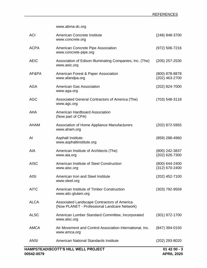
REFERENCES
HAMPSTEAD\SCOTT’S HILL WELL PROJECT 01 42 00 - 3
00542-0079 APRIL 2020
www.abma-dc.org ACI American Concrete Institute (248) 848-3700 www.concrete.org ACPA American Concrete Pipe Association (972) 506-7216 www.concrete-pipe.org AEIC Association of Edison Illuminating Companies, Inc. (The) (205) 257-2530 www.aeic.org AF&PA American Forest & Paper Association (800) 878-8878 www.afandpa.org (202) 463-2700 AGA American Gas Association (202) 824-7000 www.aga.org AGC Associated General Contractors of America (The) (703) 548-3118 www.agc.org AHA American Hardboard Association (Now part of CPA) AHAM Association of Home Appliance Manufacturers (202) 872-5955 www.aham.org AI Asphalt Institute (859) 288-4960 www.asphaltinstitute.org AIA American Institute of Architects (The) (800) 242-3837 www.aia.org (202) 626-7300 AISC American Institute of Steel Construction (800) 644-2400 www.aisc.org (312) 670-2400 AISI American Iron and Steel Institute (202) 452-7100 www.steel.org AITC American Institute of Timber Construction (303) 792-9559 www.aitc-glulam.org ALCA Associated Landscape Contractors of America (Now PLANET - Professional Landcare Network) ALSC American Lumber Standard Committee, Incorporated (301) 972-1700 www.alsc.org AMCA Air Movement and Control Association International, Inc. (847) 394-0150 www.amca.org ANSI American National Standards Institute (202) 293-8020
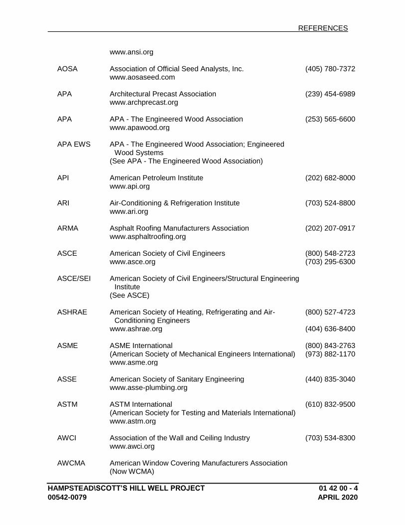
REFERENCES
HAMPSTEAD\SCOTT’S HILL WELL PROJECT 01 42 00 - 4
00542-0079 APRIL 2020
www.ansi.org AOSA Association of Official Seed Analysts, Inc. (405) 780-7372 www.aosaseed.com APA Architectural Precast Association (239) 454-6989 www.archprecast.org APA APA - The Engineered Wood Association (253) 565-6600 www.apawood.org APA EWS APA - The Engineered Wood Association; Engineered
Wood Systems
(See APA - The Engineered Wood Association) API American Petroleum Institute (202) 682-8000 www.api.org ARI Air-Conditioning & Refrigeration Institute (703) 524-8800 www.ari.org ARMA Asphalt Roofing Manufacturers Association (202) 207-0917 www.asphaltroofing.org ASCE American Society of Civil Engineers (800) 548-2723 www.asce.org (703) 295-6300 ASCE/SEI American Society of Civil Engineers/Structural Engineering
Institute
(See ASCE) ASHRAE American Society of Heating, Refrigerating and Air-
Conditioning Engineers (800) 527-4723
www.ashrae.org (404) 636-8400 ASME ASME International (800) 843-2763 (American Society of Mechanical Engineers International) (973) 882-1170 www.asme.org ASSE American Society of Sanitary Engineering (440) 835-3040 www.asse-plumbing.org ASTM ASTM International (610) 832-9500 (American Society for Testing and Materials International) www.astm.org AWCI Association of the Wall and Ceiling Industry (703) 534-8300 www.awci.org AWCMA American Window Covering Manufacturers Association (Now WCMA)
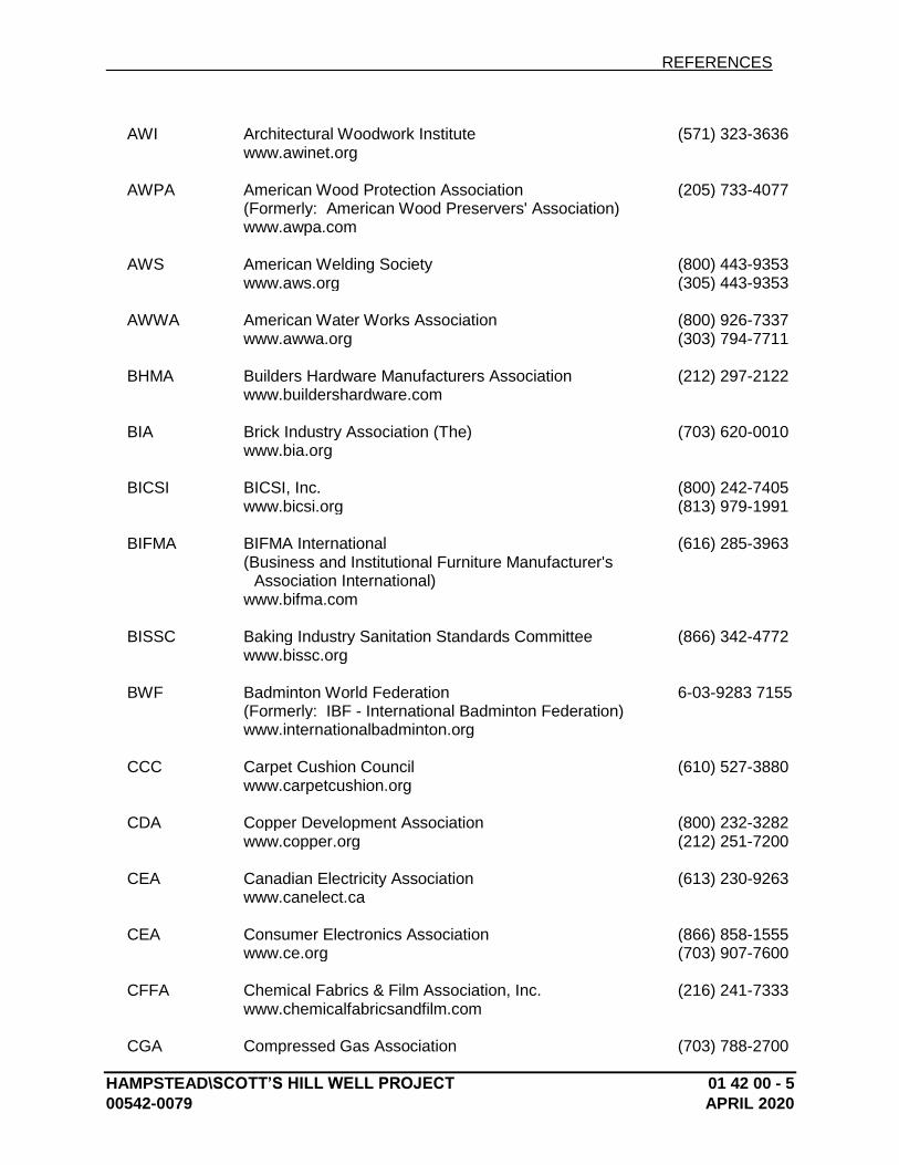
REFERENCES
HAMPSTEAD\SCOTT’S HILL WELL PROJECT 01 42 00 - 5
00542-0079 APRIL 2020
AWI Architectural Woodwork Institute (571) 323-3636 www.awinet.org AWPA American Wood Protection Association (205) 733-4077 (Formerly: American Wood Preservers' Association) www.awpa.com AWS American Welding Society (800) 443-9353 www.aws.org (305) 443-9353 AWWA American Water Works Association (800) 926-7337 www.awwa.org (303) 794-7711 BHMA Builders Hardware Manufacturers Association (212) 297-2122 www.buildershardware.com BIA Brick Industry Association (The) (703) 620-0010 www.bia.org BICSI BICSI, Inc. (800) 242-7405 www.bicsi.org (813) 979-1991 BIFMA BIFMA International (616) 285-3963 (Business and Institutional Furniture Manufacturer's
Association International)
www.bifma.com BISSC Baking Industry Sanitation Standards Committee (866) 342-4772 www.bissc.org BWF Badminton World Federation 6-03-9283 7155 (Formerly: IBF - International Badminton Federation) www.internationalbadminton.org CCC Carpet Cushion Council (610) 527-3880 www.carpetcushion.org CDA Copper Development Association (800) 232-3282 www.copper.org (212) 251-7200 CEA Canadian Electricity Association (613) 230-9263 www.canelect.ca CEA Consumer Electronics Association (866) 858-1555 www.ce.org (703) 907-7600 CFFA Chemical Fabrics & Film Association, Inc. (216) 241-7333 www.chemicalfabricsandfilm.com CGA Compressed Gas Association (703) 788-2700
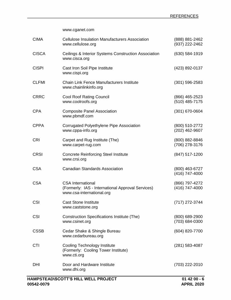
REFERENCES
HAMPSTEAD\SCOTT’S HILL WELL PROJECT 01 42 00 - 6
00542-0079 APRIL 2020
www.cganet.com CIMA Cellulose Insulation Manufacturers Association (888) 881-2462 www.cellulose.org (937) 222-2462 CISCA Ceilings & Interior Systems Construction Association (630) 584-1919 www.cisca.org CISPI Cast Iron Soil Pipe Institute (423) 892-0137 www.cispi.org CLFMI Chain Link Fence Manufacturers Institute (301) 596-2583 www.chainlinkinfo.org CRRC Cool Roof Rating Council (866) 465-2523 www.coolroofs.org (510) 485-7175 CPA Composite Panel Association (301) 670-0604 www.pbmdf.com CPPA Corrugated Polyethylene Pipe Association (800) 510-2772 www.cppa-info.org (202) 462-9607 CRI Carpet and Rug Institute (The) (800) 882-8846 www.carpet-rug.com (706) 278-3176 CRSI Concrete Reinforcing Steel Institute (847) 517-1200 www.crsi.org CSA Canadian Standards Association (800) 463-6727 (416) 747-4000 CSA CSA International (866) 797-4272 (Formerly: IAS - International Approval Services) (416) 747-4000 www.csa-international.org CSI Cast Stone Institute (717) 272-3744 www.caststone.org CSI Construction Specifications Institute (The) (800) 689-2900 www.csinet.org (703) 684-0300 CSSB Cedar Shake & Shingle Bureau (604) 820-7700 www.cedarbureau.org CTI Cooling Technology Institute (281) 583-4087 (Formerly: Cooling Tower Institute) www.cti.org DHI Door and Hardware Institute (703) 222-2010 www.dhi.org
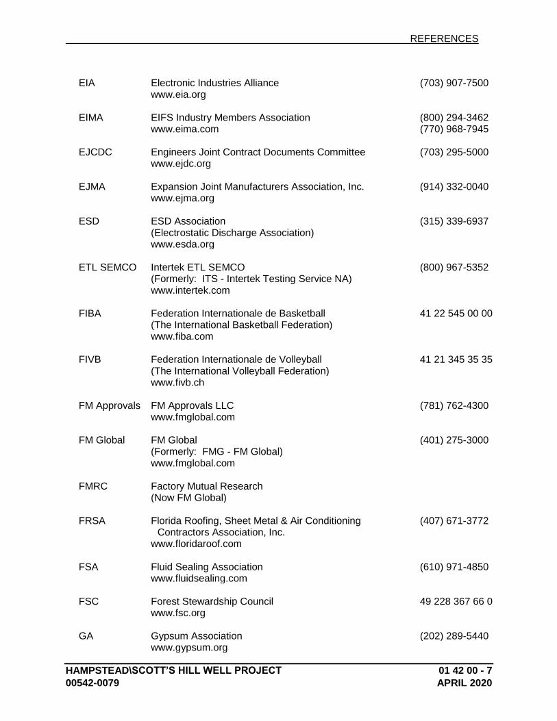
REFERENCES
HAMPSTEAD\SCOTT’S HILL WELL PROJECT 01 42 00 - 7
00542-0079 APRIL 2020
EIA Electronic Industries Alliance (703) 907-7500 www.eia.org EIMA EIFS Industry Members Association (800) 294-3462 www.eima.com (770) 968-7945 EJCDC Engineers Joint Contract Documents Committee (703) 295-5000 www.ejdc.org EJMA Expansion Joint Manufacturers Association, Inc. (914) 332-0040 www.ejma.org ESD ESD Association (315) 339-6937 (Electrostatic Discharge Association) www.esda.org ETL SEMCO Intertek ETL SEMCO (800) 967-5352 (Formerly: ITS - Intertek Testing Service NA) www.intertek.com FIBA Federation Internationale de Basketball 41 22 545 00 00 (The International Basketball Federation) www.fiba.com FIVB Federation Internationale de Volleyball 41 21 345 35 35 (The International Volleyball Federation) www.fivb.ch FM Approvals FM Approvals LLC (781) 762-4300 www.fmglobal.com FM Global FM Global (401) 275-3000 (Formerly: FMG - FM Global) www.fmglobal.com FMRC Factory Mutual Research (Now FM Global) FRSA Florida Roofing, Sheet Metal & Air Conditioning
Contractors Association, Inc. (407) 671-3772
www.floridaroof.com FSA Fluid Sealing Association (610) 971-4850 www.fluidsealing.com FSC Forest Stewardship Council 49 228 367 66 0 www.fsc.org GA Gypsum Association (202) 289-5440 www.gypsum.org
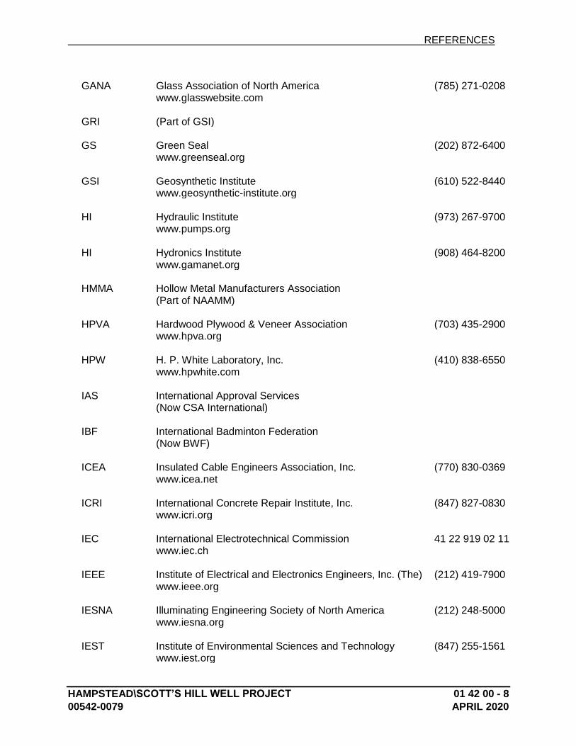
REFERENCES
HAMPSTEAD\SCOTT’S HILL WELL PROJECT 01 42 00 - 8
00542-0079 APRIL 2020
GANA Glass Association of North America (785) 271-0208 www.glasswebsite.com GRI (Part of GSI) GS Green Seal (202) 872-6400 www.greenseal.org GSI Geosynthetic Institute (610) 522-8440 www.geosynthetic-institute.org HI Hydraulic Institute (973) 267-9700 www.pumps.org HI Hydronics Institute (908) 464-8200 www.gamanet.org HMMA Hollow Metal Manufacturers Association (Part of NAAMM) HPVA Hardwood Plywood & Veneer Association (703) 435-2900 www.hpva.org HPW H. P. White Laboratory, Inc. (410) 838-6550 www.hpwhite.com IAS International Approval Services (Now CSA International) IBF International Badminton Federation (Now BWF) ICEA Insulated Cable Engineers Association, Inc. (770) 830-0369 www.icea.net ICRI International Concrete Repair Institute, Inc. (847) 827-0830 www.icri.org IEC International Electrotechnical Commission 41 22 919 02 11 www.iec.ch IEEE Institute of Electrical and Electronics Engineers, Inc. (The) (212) 419-7900 www.ieee.org IESNA Illuminating Engineering Society of North America (212) 248-5000 www.iesna.org IEST Institute of Environmental Sciences and Technology (847) 255-1561 www.iest.org
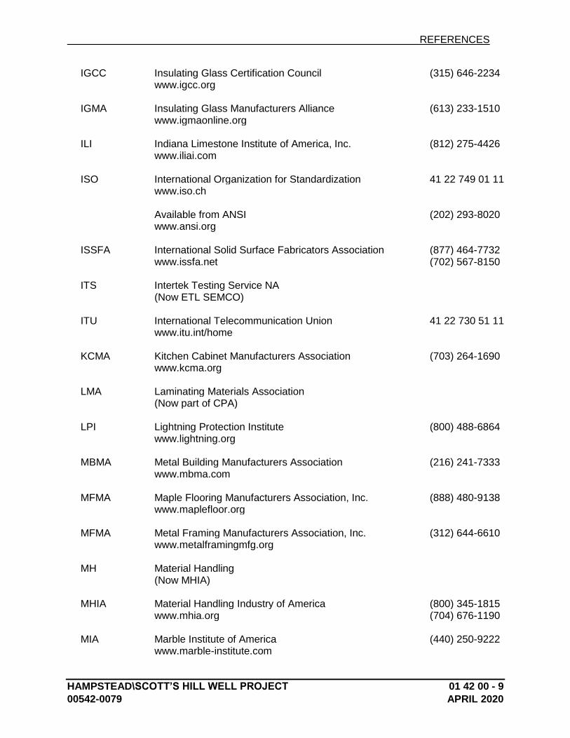
REFERENCES
HAMPSTEAD\SCOTT’S HILL WELL PROJECT 01 42 00 - 9
00542-0079 APRIL 2020
IGCC Insulating Glass Certification Council (315) 646-2234 www.igcc.org IGMA Insulating Glass Manufacturers Alliance (613) 233-1510 www.igmaonline.org ILI Indiana Limestone Institute of America, Inc. (812) 275-4426 www.iliai.com ISO International Organization for Standardization 41 22 749 01 11 www.iso.ch Available from ANSI (202) 293-8020 www.ansi.org ISSFA International Solid Surface Fabricators Association (877) 464-7732 www.issfa.net (702) 567-8150 ITS Intertek Testing Service NA (Now ETL SEMCO) ITU International Telecommunication Union 41 22 730 51 11 www.itu.int/home KCMA Kitchen Cabinet Manufacturers Association (703) 264-1690 www.kcma.org LMA Laminating Materials Association (Now part of CPA) LPI Lightning Protection Institute (800) 488-6864 www.lightning.org MBMA Metal Building Manufacturers Association (216) 241-7333 www.mbma.com MFMA Maple Flooring Manufacturers Association, Inc. (888) 480-9138 www.maplefloor.org MFMA Metal Framing Manufacturers Association, Inc. (312) 644-6610 www.metalframingmfg.org MH Material Handling (Now MHIA) MHIA Material Handling Industry of America (800) 345-1815 www.mhia.org (704) 676-1190 MIA Marble Institute of America (440) 250-9222 www.marble-institute.com
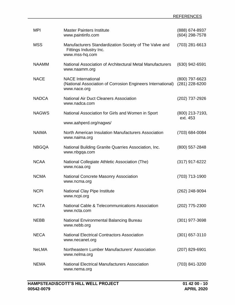
REFERENCES
HAMPSTEAD\SCOTT’S HILL WELL PROJECT 01 42 00 - 10
00542-0079 APRIL 2020
MPI Master Painters Institute (888) 674-8937 www.paintinfo.com (604) 298-7578 MSS Manufacturers Standardization Society of The Valve and
Fittings Industry Inc. (703) 281-6613
www.mss-hq.com NAAMM National Association of Architectural Metal Manufacturers (630) 942-6591 www.naamm.org NACE NACE International (800) 797-6623 (National Association of Corrosion Engineers International) (281) 228-6200 www.nace.org NADCA National Air Duct Cleaners Association (202) 737-2926 www.nadca.com NAGWS National Association for Girls and Women in Sport (800) 213-7193,
ext. 453 www.aahperd.org/nagws/ NAIMA North American Insulation Manufacturers Association (703) 684-0084 www.naima.org NBGQA National Building Granite Quarries Association, Inc. (800) 557-2848 www.nbgqa.com NCAA National Collegiate Athletic Association (The) (317) 917-6222 www.ncaa.org NCMA National Concrete Masonry Association (703) 713-1900 www.ncma.org NCPI National Clay Pipe Institute (262) 248-9094 www.ncpi.org NCTA National Cable & Telecommunications Association (202) 775-2300 www.ncta.com NEBB National Environmental Balancing Bureau (301) 977-3698 www.nebb.org NECA National Electrical Contractors Association (301) 657-3110 www.necanet.org NeLMA Northeastern Lumber Manufacturers' Association (207) 829-6901 www.nelma.org NEMA National Electrical Manufacturers Association (703) 841-3200 www.nema.org
REFERENCES
HAMPSTEAD\SCOTT’S HILL WELL PROJECT 01 42 00 - 11
00542-0079 APRIL 2020
NETA InterNational Electrical Testing Association (888) 300-6382 www.netaworld.org (269) 488-6382 NFHS National Federation of State High School Associations (317) 972-6900 www.nfhs.org NFPA NFPA (800) 344-3555 (National Fire Protection Association) (617) 770-3000 www.nfpa.org NFRC National Fenestration Rating Council (301) 589-1776 www.nfrc.org NGA National Glass Association (866) 342-5642 www.glass.org (703) 442-4890 NHLA National Hardwood Lumber Association (800) 933-0318 www.natlhardwood.org (901) 377-1818 NLGA National Lumber Grades Authority (604) 524-2393 www.nlga.org NOFMA NOFMA: The Wood Flooring Manufacturers Association (901) 526-5016 (Formerly: National Oak Flooring Manufacturers
Association)
www.nofma.com NOMMA National Ornamental & Miscellaneous Metals Association (888) 516-8585 www.nomma.org NRCA National Roofing Contractors Association (800) 323-9545 www.nrca.net (847) 299-9070 NRMCA National Ready Mixed Concrete Association (888) 846-7622 www.nrmca.org (301) 587-1400 NSF NSF International (800) 673-6275 (National Sanitation Foundation International) (734) 769-8010 www.nsf.org NSSGA National Stone, Sand & Gravel Association (800) 342-1415 www.nssga.org (703) 525-8788 NTMA National Terrazzo & Mosaic Association, Inc. (The) (800) 323-9736 www.ntma.com (540) 751-0930 NTRMA National Tile Roofing Manufacturers Association (Now TRI) NWWDA National Wood Window and Door Association (Now WDMA)
REFERENCES
HAMPSTEAD\SCOTT’S HILL WELL PROJECT 01 42 00 - 12
00542-0079 APRIL 2020
OPL Omega Point Laboratories, Inc. (Now ITS) PCI Precast/Prestressed Concrete Institute (312) 786-0300 www.pci.org PDCA Painting & Decorating Contractors of America (800) 332-7322 www.pdca.com (314) 514-7322 PDI Plumbing & Drainage Institute (800) 589-8956 www.pdionline.org (978) 557-0720 PGI PVC Geomembrane Institute (217) 333-3929 http://pgi-tp.ce.uiuc.edu PLANET Professional Landcare Network (800) 395-2522 (Formerly: ACLA - Associated Landscape Contractors of
America) (703) 736-9666
www.landcarenetwork.org PTI Post-Tensioning Institute (602) 870-7540 www.post-tensioning.org RCSC Research Council on Structural Connections www.boltcouncil.org RFCI Resilient Floor Covering Institute (301) 340-8580 www.rfci.com RIS Redwood Inspection Service (888) 225-7339 www.redwoodinspection.com (415) 382-0662 SAE SAE International (877) 606-7323 www.sae.org (724) 776-4841 SDI Steel Deck Institute (847) 458-4647 www.sdi.org SDI Steel Door Institute (440) 899-0010 www.steeldoor.org SEFA Scientific Equipment and Furniture Association (877) 294-5424 www.sefalabs.com (516) 294-5424 SEI/ASCE Structural Engineering Institute/American Society of Civil
Engineers
(See ASCE) SGCC Safety Glazing Certification Council (315) 646-2234 www.sgcc.org
REFERENCES
HAMPSTEAD\SCOTT’S HILL WELL PROJECT 01 42 00 - 13
00542-0079 APRIL 2020
SIA Security Industry Association (866) 817-8888 www.siaonline.org (703) 683-2075 SIGMA Sealed Insulating Glass Manufacturers Association (Now IGMA) SJI Steel Joist Institute (843) 626-1995 www.steeljoist.org SMA Screen Manufacturers Association (561) 533-0991 www.smacentral.org SMACNA Sheet Metal and Air Conditioning Contractors' (703) 803-2980 National Association www.smacna.org SMPTE Society of Motion Picture and Television Engineers (914) 761-1100 www.smpte.org SPFA Spray Polyurethane Foam Alliance (800) 523-6154 (Formerly: SPI/SPFD - The Society of the Plastics
Industry, Inc.; Spray Polyurethane Foam Division)
www.sprayfoam.org SPIB Southern Pine Inspection Bureau (The) (850) 434-2611 www.spib.org SPRI Single Ply Roofing Industry (781) 647-7026 www.spri.org SSINA Specialty Steel Industry of North America (800) 982-0355 www.ssina.com (202) 342-8630 SSPC SSPC: The Society for Protective Coatings (877) 281-7772 www.sspc.org (412) 281-2331 STI Steel Tank Institute (847) 438-8265 www.steeltank.com SWI Steel Window Institute (216) 241-7333 www.steelwindows.com SWRI Sealant, Waterproofing, & Restoration Institute (816) 472-7974 www.swrionline.org TCA Tile Council of America, Inc. (Now TCNA) TCNA Tile Council of North America, Inc. (864) 646-8453 www.tileusa.com
REFERENCES
HAMPSTEAD\SCOTT’S HILL WELL PROJECT 01 42 00 - 14
00542-0079 APRIL 2020
TIA/EIA Telecommunications Industry Association/Electronic
Industries Alliance (703) 907-7700
www.tiaonline.org TMS The Masonry Society (303) 939-9700 www.masonrysociety.org TPI Truss Plate Institute, Inc. (703) 683-1010 www.tpinst.org TPI Turfgrass Producers International (800) 405-8873 www.turfgrasssod.org (847) 649-5555 TRI Tile Roofing Institute (312) 670-4177 www.tileroofing.org UL Underwriters Laboratories Inc. (877) 854-3577 www.ul.com (847) 272-8800 UNI Uni-Bell PVC Pipe Association (972) 243-3902 www.uni-bell.org USAV USA Volleyball (888) 786-5539 www.usavolleyball.org (719) 228-6800 USGBC U.S. Green Building Council (800) 795-1747 www.usgbc.org USITT United States Institute for Theatre Technology, Inc. (800) 938-7488 www.usitt.org (315) 463-6463 WASTEC Waste Equipment Technology Association (800) 424-2869 www.wastec.org (202) 244-4700 WCLIB West Coast Lumber Inspection Bureau (800) 283-1486 www.wclib.org (503) 639-0651 WCMA Window Covering Manufacturers Association (212) 297-2122 www.wcmanet.org WCSC Window Covering Safety Council (800) 506-4636 (Formerly: WCMA - Window Covering Manufacturers
Association) (212) 297-2109
www.windowcoverings.org WDMA Window & Door Manufacturers Association (800) 223-2301 (Formerly: NWWDA - National Wood Window and Door
Association) (847) 299-5200
www.wdma.com
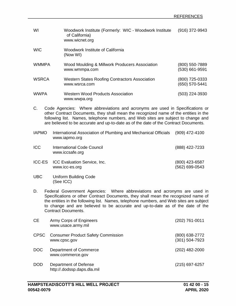
REFERENCES
HAMPSTEAD\SCOTT’S HILL WELL PROJECT 01 42 00 - 15
00542-0079 APRIL 2020
WI Woodwork Institute (Formerly: WIC - Woodwork Institute of California)
(916) 372-9943
www.wicnet.org WIC Woodwork Institute of California (Now WI) WMMPA Wood Moulding & Millwork Producers Association (800) 550-7889 www.wmmpa.com (530) 661-9591 WSRCA Western States Roofing Contractors Association (800) 725-0333 www.wsrca.com (650) 570-5441 WWPA Western Wood Products Association (503) 224-3930 www.wwpa.org
C. Code Agencies: Where abbreviations and acronyms are used in Specifications or other Contract Documents, they shall mean the recognized name of the entities in the following list. Names, telephone numbers, and Web sites are subject to change and are believed to be accurate and up-to-date as of the date of the Contract Documents.
IAPMO International Association of Plumbing and Mechanical Officials (909) 472-4100 www.iapmo.org ICC International Code Council (888) 422-7233 www.iccsafe.org ICC-ES ICC Evaluation Service, Inc. (800) 423-6587 www.icc-es.org (562) 699-0543 UBC Uniform Building Code (See ICC)
D. Federal Government Agencies: Where abbreviations and acronyms are used in Specifications or other Contract Documents, they shall mean the recognized name of the entities in the following list. Names, telephone numbers, and Web sites are subject to change and are believed to be accurate and up-to-date as of the date of the Contract Documents.
CE Army Corps of Engineers (202) 761-0011 www.usace.army.mil CPSC Consumer Product Safety Commission (800) 638-2772 www.cpsc.gov (301) 504-7923 DOC Department of Commerce (202) 482-2000 www.commerce.gov DOD Department of Defense (215) 697-6257 http://.dodssp.daps.dla.mil
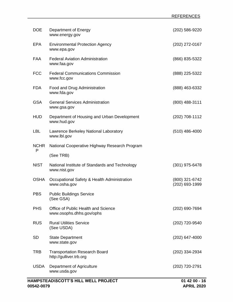
REFERENCES
HAMPSTEAD\SCOTT’S HILL WELL PROJECT 01 42 00 - 16
00542-0079 APRIL 2020
DOE Department of Energy (202) 586-9220 www.energy.gov EPA Environmental Protection Agency (202) 272-0167 www.epa.gov FAA Federal Aviation Administration (866) 835-5322 www.faa.gov FCC Federal Communications Commission (888) 225-5322 www.fcc.gov FDA Food and Drug Administration (888) 463-6332 www.fda.gov GSA General Services Administration (800) 488-3111 www.gsa.gov HUD Department of Housing and Urban Development (202) 708-1112 www.hud.gov LBL Lawrence Berkeley National Laboratory (510) 486-4000 www.lbl.gov NCHR
P National Cooperative Highway Research Program
(See TRB) NIST National Institute of Standards and Technology (301) 975-6478 www.nist.gov OSHA Occupational Safety & Health Administration (800) 321-6742 www.osha.gov (202) 693-1999 PBS Public Buildings Service (See GSA) PHS Office of Public Health and Science (202) 690-7694 www.osophs.dhhs.gov/ophs RUS Rural Utilities Service (202) 720-9540 (See USDA) SD State Department (202) 647-4000 www.state.gov TRB Transportation Research Board (202) 334-2934 http://gulliver.trb.org USDA Department of Agriculture (202) 720-2791 www.usda.gov
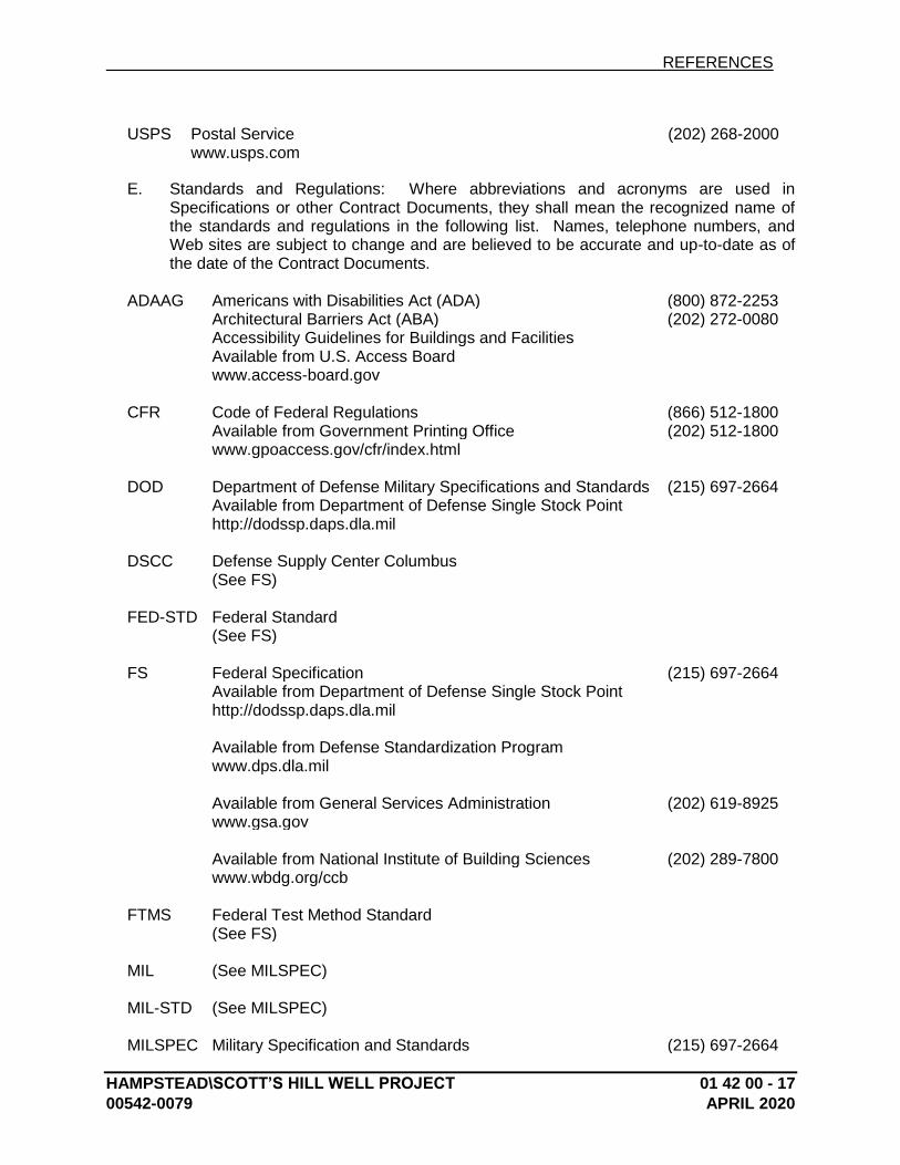
REFERENCES
HAMPSTEAD\SCOTT’S HILL WELL PROJECT 01 42 00 - 17
00542-0079 APRIL 2020
USPS Postal Service (202) 268-2000 www.usps.com
E. Standards and Regulations: Where abbreviations and acronyms are used in Specifications or other Contract Documents, they shall mean the recognized name of the standards and regulations in the following list. Names, telephone numbers, and Web sites are subject to change and are believed to be accurate and up-to-date as of the date of the Contract Documents.
ADAAG Americans with Disabilities Act (ADA) (800) 872-2253 Architectural Barriers Act (ABA) (202) 272-0080 Accessibility Guidelines for Buildings and Facilities Available from U.S. Access Board www.access-board.gov CFR Code of Federal Regulations (866) 512-1800 Available from Government Printing Office (202) 512-1800 www.gpoaccess.gov/cfr/index.html DOD Department of Defense Military Specifications and Standards (215) 697-2664 Available from Department of Defense Single Stock Point http://dodssp.daps.dla.mil DSCC Defense Supply Center Columbus (See FS) FED-STD Federal Standard (See FS) FS Federal Specification (215) 697-2664 Available from Department of Defense Single Stock Point http://dodssp.daps.dla.mil Available from Defense Standardization Program www.dps.dla.mil Available from General Services Administration (202) 619-8925 www.gsa.gov Available from National Institute of Building Sciences (202) 289-7800 www.wbdg.org/ccb FTMS Federal Test Method Standard (See FS) MIL (See MILSPEC) MIL-STD (See MILSPEC) MILSPEC Military Specification and Standards (215) 697-2664
REFERENCES
HAMPSTEAD\SCOTT’S HILL WELL PROJECT 01 42 00 - 18
00542-0079 APRIL 2020
Available from Department of Defense Single Stock Point http://dodssp.daps.dla.mil UFAS Uniform Federal Accessibility Standards (800) 872-2253 Available from Access Board (202) 272-0080 www.access-board.gov
PART 2 - PRODUCTS (Not Used)
PART 3 - EXECUTION (Not Used)
END OF SECTION 01 42 00

HAMPSTEAD\SCOTT’S HILL WELL PROJECT 01 50 00 - 1
00542-0079 APRIL 2020
SECTION 01 50 00 - TEMPORARY FACILITIES AND CONTROLS
PART 1 - GENERAL
1.1 RELATED DOCUMENTS
A. Drawings and general provisions of the Contract, including General and Supplementary Conditions and other Division 1 Specification Sections, apply to this Section.
1.2 SUMMARY
A. Section includes requirements for temporary utilities, support facilities, and security and protection facilities.
B. Related Sections:
1. Division 1 Section "Summary" for limitations on work restrictions and utility interruptions.
2. Division 2 Section "Dewatering" for disposal of ground water at Project site. 3. Division 3 Section "Cast in Place Concrete" for construction and maintenance of
cement concrete pavement for temporary roads and paved areas.
1.3 USE CHARGES
A. General: Installation and removal of and use charges for temporary facilities shall be included in the Contract Sum unless otherwise indicated. Allow other entities to use temporary services and facilities without cost, including, but not limited to Owner, Engineer, testing agencies, and authorities having jurisdiction.
B. Sewer Service: Pay sewer service use charges for sewer usage by all entities for construction operations.
C. Water Service: Pay water service use charges for water used by all entities for construction operations.
D. Electric Power Service: Pay electric power service use charges for electricity used by all entities for construction operations.
1.4 INFORMATIONAL SUBMITTALS
A. Site Plan: Show temporary facilities, utility hookups, staging areas, and parking areas for construction personnel.
TEMPORARY FACILITIES AND CONTROLS
HAMPSTEAD\SCOTT’S HILL WELL PROJECT 01 50 00 - 2
00542-0079 APRIL 2020
B. Erosion- and Sedimentation-Control Plan: Show compliance with requirements of EPA Construction General Permit or authorities having jurisdiction, whichever is more stringent.
C. Moisture-Protection Plan: Describe procedures and controls for protecting materials and construction from water absorption and damage, including delivery, handling, and storage provisions for materials subject to water absorption or water damage, discarding water-damaged materials, protocols for mitigating water intrusion into completed Work, and replacing water damaged Work.
1. Indicate sequencing of all work that requires water. Show procedures for verifying that wet construction has dried sufficiently to permit installation of finish materials.
1.5 QUALITY ASSURANCE
A. Electric Service: Comply with NECA, NEMA, and UL standards and regulations for temporary electric service. Install service to comply with NFPA 70.
B. Tests and Inspections: Arrange for authorities having jurisdiction to test and inspect each temporary utility before use. Obtain required certifications and permits.
1.6 PROJECT CONDITIONS
A. Temporary Use of Permanent Facilities: Engage installer of each permanent service to assume responsibility for operation, maintenance, and protection of each permanent service during its use as a construction facility before Owner's acceptance, regardless of previously assigned responsibilities.
PART 2 - PRODUCTS
2.1 MATERIALS
A. Temporary Chain-Link Fencing: Minimum 2-inch, 0.148-inch thick, galvanized steel, chain-link fabric fencing; minimum 6 feet high with galvanized steel pipe posts; minimum 2-3/8-inch- OD line posts and 2-7/8-inch OD corner and pull posts, with 1-5/8-inch OD top and bottom rails. Provide concrete bases for supporting posts. Provide access gates as required for movement of personnel, vehicles, and equipment.
B. Insulation: Unfaced mineral-fiber blanket, manufactured from glass, slag wool, or rock wool; with maximum flame-spread and smoke-developed indexes of 25 and 50, respectively.
TEMPORARY FACILITIES AND CONTROLS
HAMPSTEAD\SCOTT’S HILL WELL PROJECT 01 50 00 - 3
00542-0079 APRIL 2020
2.2 TEMPORARY FACILITIES
A. Field Offices, General: Prefabricated or mobile units with serviceable finishes, temperature controls, and foundations adequate for normal loading and meeting the requirements of the building inspector.
B. Common-Use Field Office: Of sufficient size to accommodate needs of Owner/Engineer and to accommodate project meetings specified in other Division 1 Sections. Keep office clean and orderly. Furnish and equip offices as follows:
1. Furniture required for Project-site documents including file cabinets, plan tables, plan racks, and bookcases.
2. Conference room of sufficient size to accommodate meetings of 10 individuals. Provide electrical power service and 120-V ac duplex receptacles, with not less than 1 receptacle on each wall. Furnish room with conference table, chairs, and 4 ft. square tack and marker boards.
3. Drinking water and private toilet. 4. Coffee machine and supplies. 5. Heating and cooling equipment necessary to maintain a uniform indoor
temperature of 68 to 72 deg. 6. Lighting fixtures capable of maintaining acceptable illumination. 7. Coordinate paragraph below with Owner for use of existing building for storage
and protection of materials to be incorporated into Project.
C. Storage and Fabrication Sheds: Provide sheds sized, furnished, and equipped to accommodate materials and equipment for construction operations.
1. Store combustible materials apart from building.
2.3 EQUIPMENT
A. Fire Extinguishers: Portable, UL rated; with class and extinguishing agent as required by locations and classes of fire exposures.
B. HVAC Equipment: Unless Owner authorizes use of permanent HVAC system, provide vented, self-contained, liquid-propane-gas or fuel-oil heaters with individual space thermostatic control.
1. Use of gasoline-burning space heaters, open-flame heaters, or salamander-type heating units is prohibited.
2. Heating Units: Listed and labeled for type of fuel being consumed, by a testing agency acceptable to authorities having jurisdiction, and marked for intended use.
TEMPORARY FACILITIES AND CONTROLS
HAMPSTEAD\SCOTT’S HILL WELL PROJECT 01 50 00 - 4
00542-0079 APRIL 2020
PART 3 - EXECUTION
3.1 INSTALLATION, GENERAL
A. Locate facilities where they will serve Project adequately and result in minimum interference with performance of the Work. Relocate and modify facilities as required by progress of the Work.
1. Locate facilities to limit site disturbance as specified in Division 1 Section "Summary."
B. Provide each facility ready for use when needed to avoid delay. Do not remove until facilities are no longer needed or are replaced by authorized use of completed permanent facilities.
3.2 TEMPORARY UTILITY INSTALLATION
A. General: Install temporary service.
B. Sewers and Drainage: Provide temporary utilities to remove effluent lawfully.
C. Water Service: Install temporary water service and distribution piping in sizes and pressures adequate for construction.
D. Sanitary Facilities: Provide temporary toilets, wash facilities, and drinking water for use of construction personnel. Comply with requirements of authorities having jurisdiction for type, number, location, operation, and maintenance of fixtures and facilities.
E. Heating and Cooling: Provide temporary heating and cooling required by construction activities for curing or drying of completed installations or for protecting installed construction from adverse effects of low temperatures or high humidity. Select equipment that will not have a harmful effect on completed installations or elements being installed.
F. Ventilation and Humidity Control: Provide temporary ventilation required by construction activities for curing or drying of completed installations or for protecting installed construction from adverse effects of high humidity. Select equipment that will not have a harmful effect on completed installations or elements being installed. Coordinate ventilation requirements to produce ambient condition required and minimize energy consumption.
1. Provide dehumidification systems when required to reduce substrate moisture levels to level required to allow installation or application of finishes.
G. Electric Power Service: Provide electric power service and distribution system of sufficient size, capacity, and power characteristics required for construction operations.
1. Install electric power service overhead or underground as required.
TEMPORARY FACILITIES AND CONTROLS
HAMPSTEAD\SCOTT’S HILL WELL PROJECT 01 50 00 - 5
00542-0079 APRIL 2020
H. Lighting: Provide temporary lighting with local switching that provides adequate illumination for construction operations, observations, inspections, and traffic conditions.
1. Install and operate temporary lighting that fulfills security and protection requirements without operating entire system.
2. Install lighting for Project identification sign.
I. Telephone Service: Provide temporary telephone service in common-use facilities for use by all construction personnel. Install one telephone line(s) for each field office.
1. Provide additional telephone lines for the following:
a. Provide a dedicated telephone line for each facsimile machine in each field office.
2. At each telephone, post a list of important telephone numbers.
a. Police and fire departments. b. Ambulance service. c. Contractor's home office. d. Engineers' offices. e. Owner's office. f. Principal subcontractors' field and home offices.
3. Provide superintendent with cellular telephone or portable two-way radio for use when away from field office.
J. Electronic Communication Service: Provide a desktop computer in the primary field office adequate for use by Engineer and Owner to access project electronic documents and maintain electronic communications. Equip computer with not less than the following:
1. Processor: Intel Pentium D or Intel CoreDuo, 1.8 GHz processing speed. 2. Memory: 2 gigabyte. 3. Disk storage: 80 gigabyte hard disk drive and combination DVD-RW/CD-RW
drive. 4. Display: 19-inch LCD monitor with 128 Mb dedicated video RAM. 5. Full-size keyboard and mouse. 6. Network Connectivity: 10/100BaseT Ethernet. 7. Operating System: Microsoft Windows XP Professional 8. Productivity Software:
a. Microsoft Office Professional, XP or higher, including Word, Excel, and Outlook.
b. Adobe Reader 7.0 or higher. c. WinZip 7.0 or higher.
9. Printer: "All-in-one" unit equipped with printer server, combining color printing, photocopying, scanning, and faxing, or separate units for each of these 3 functions.
TEMPORARY FACILITIES AND CONTROLS
HAMPSTEAD\SCOTT’S HILL WELL PROJECT 01 50 00 - 6
00542-0079 APRIL 2020
10. Internet Service: Broadband modem, router and ISP, equipped with hardware firewall, providing minimum 384 Kbps upload and 1 Mbps download speeds at each computer.
11. Internet Security: Integrated software, providing software firewall, virus, spyware, phishing and spam protection in a combined application.
12. Backup: External hard drive, minimum 40 gigabyte, with automated backup software providing daily backups.
3.3 SUPPORT FACILITIES INSTALLATION
A. General: Comply with the following:
1. Provide construction for temporary offices, shops, and sheds located within construction area or within 30 ft. of building lines that is noncombustible according to ASTM E 136. Comply with NFPA 241.
2. Maintain support facilities until Engineer schedules Substantial Completion inspection. Remove before Substantial Completion. Personnel remaining after Substantial Completion will be permitted to use permanent facilities, under conditions acceptable to Owner.
B. Temporary Roads and Paved Areas: Construct and maintain temporary roads and paved areas adequate for construction operations. Locate temporary roads and paved areas as indicated on Drawings.
1. Provide dust-control treatment that is nonpolluting and nontracking. Reapply treatment as required to minimize dust.
C. Temporary Use of Permanent Roads and Paved Areas: Locate temporary roads and paved areas in same location as permanent roads and paved areas. Construct and maintain temporary roads and paved areas adequate for construction operations. Extend temporary roads and paved areas, within construction limits indicated, as necessary for construction operations.
1. Coordinate elevations of temporary roads and paved areas with permanent roads and paved areas.
2. Prepare subgrade and install subbase and base for temporary roads and paved areas according to Division 2 Section "Earthwork."
3. Recondition base after temporary use, including removing contaminated material, regrading, proofrolling, compacting, and testing.
4. Delay installation of final course of permanent hot-mix asphalt pavement until immediately before Substantial Completion. Repair hot-mix asphalt base-course pavement before installation of final course according to Division 2 Section "Asphalt Paving."
D. Traffic Controls: Comply with requirements of authorities having jurisdiction.
1. Protect existing site improvements to remain including curbs, pavement, and utilities.
2. Maintain access for fire-fighting equipment and access to fire hydrants.
TEMPORARY FACILITIES AND CONTROLS
HAMPSTEAD\SCOTT’S HILL WELL PROJECT 01 50 00 - 7
00542-0079 APRIL 2020
E. Parking: Provide parking areas for construction personnel.
F. Dewatering Facilities and Drains: Comply with requirements of authorities having jurisdiction. Maintain Project site, excavations, and construction free of water.
1. Dispose of rainwater in a lawful manner that will not result in flooding Project or adjoining properties nor endanger permanent Work or temporary facilities.
2. Remove snow and ice as required to minimize accumulations.
G. Project Signs: Provide Project signs as indicated. Unauthorized signs are not permitted.
1. Identification Signs: Provide Project identification signs as indicated on Drawings.
2. Temporary Signs: Provide other signs as indicated and as required to inform public and individuals seeking entrance to Project.
a. Provide temporary, directional signs for construction personnel and visitors.
3. Maintain and touchup signs so they are legible at all times.
H. Waste Disposal Facilities: Provide waste-collection containers in sizes adequate to handle waste from construction operations. Comply with requirements of authorities having jurisdiction. Comply with Division 1 Section "Execution Requirements" for progress cleaning requirements.
I. Lifts and Hoists: Provide facilities necessary for hoisting materials and personnel.
1. Truck cranes and similar devices used for hoisting materials are considered "tools and equipment" and not temporary facilities.
J. Temporary Stairs: Until permanent stairs are available, provide temporary stairs where ladders are not adequate.
K. Temporary Use of Permanent Stairs: Use of new stairs for construction traffic will be permitted, provided stairs are protected and finishes restored to new condition at time of Substantial Completion.
3.4 SECURITY AND PROTECTION FACILITIES INSTALLATION
A. Environmental Protection: Provide protection, operate temporary facilities, and conduct construction as required to comply with environmental regulations and that minimize possible air, waterway, and subsoil contamination or pollution or other undesirable effects.
1. Comply with work restrictions specified in Division 1 Section "Summary."
B. Temporary Erosion and Sedimentation Control: Comply with requirements of 2003 EPA Construction General Permit or authorities having jurisdiction, whichever is more stringent and requirements specified in Division 2 Section "Site Clearing."
TEMPORARY FACILITIES AND CONTROLS
HAMPSTEAD\SCOTT’S HILL WELL PROJECT 01 50 00 - 8
00542-0079 APRIL 2020
C. Temporary Erosion and Sedimentation Control: Provide measures to prevent soil erosion and discharge of soil-bearing water runoff and airborne dust to undisturbed areas and to adjacent properties and walkways, according to erosion- and sedimentation-control Drawings and requirements of 2003 EPA Construction General Permit or authorities having jurisdiction, whichever is more stringent.
1. Verify that flows of water redirected from construction areas or generated by construction activity do not enter or cross tree- or plant- protection zones.
2. Inspect, repair, and maintain erosion- and sedimentation-control measures during construction until permanent vegetation has been established.
3. Clean, repair, and restore adjoining properties and roads affected by erosion and sedimentation from the project site during the course of the project.
4. Remove erosion and sedimentation controls and restore and stabilize areas disturbed during removal.
D. Stormwater Control: Comply with requirements of authorities having jurisdiction. Provide barriers in and around excavations and subgrade construction to prevent flooding by runoff of stormwater from heavy rains.
E. Tree and Plant Protection: Install temporary fencing located as indicated or outside the drip line of trees to protect vegetation from damage from construction operations. Protect tree root systems from damage, flooding, and erosion.
F. Pest Control: Engage pest-control service to recommend practices to minimize attraction and harboring of rodents, roaches, and other pests and to perform extermination and control procedures at regular intervals so Project will be free of pests and their residues at Substantial Completion. Obtain extended warranty for Owner. Perform control operations lawfully, using environmentally safe materials.
G. Site Enclosure Fence: Before construction operations begin, furnish and install site enclosure fence in a manner that will prevent people and animals from easily entering site except by entrance gates.
1. Extent of Fence: As required to enclose entire Project site or portion determined sufficient to accommodate construction operations.
2. Maintain security by limiting number of keys and restricting distribution to authorized personnel. Furnish one set of keys to Owner.
H. Security Enclosure and Lockup: Install temporary enclosure around partially completed areas of construction. Provide lockable entrances to prevent unauthorized entrance, vandalism, theft, and similar violations of security. Lock entrances at end of each work day.
I. Barricades, Warning Signs, and Lights: Comply with requirements of authorities having jurisdiction for erecting structurally adequate barricades, including warning signs and lighting.
J. Temporary Egress: Maintain temporary egress from existing occupied facilities as indicated and as required by authorities having jurisdiction.
TEMPORARY FACILITIES AND CONTROLS
HAMPSTEAD\SCOTT’S HILL WELL PROJECT 01 50 00 - 9
00542-0079 APRIL 2020
K. Temporary Fire Protection: Install and maintain temporary fire-protection facilities of types needed to protect against reasonably predictable and controllable fire losses. Comply with NFPA 241.
1. Restrict smoking to designated smoking areas only. 2. Supervise welding operations, combustion-type temporary heating units, and
similar sources of fire ignition according to requirements of authorities having jurisdiction.
3. Develop and supervise an overall fire-prevention and -protection program for personnel at Project site. Review needs with local fire department and establish procedures to be followed. Instruct personnel in methods and procedures. Post warnings and information.
3.5 MOISTURE AND MOLD CONTROL
A. Contractor's Moisture-Protection Plan: Avoid trapping water in finished work. Document visible signs of mold that may appear during construction.
B. Exposed Construction Phase: Before installation of weather barriers, when materials are subject to wetting and exposure and to airborne mold spores, protect as follows:
1. Protect porous materials from water damage. 2. Protect stored and installed material from flowing or standing water. 3. Keep porous and organic materials from coming into prolonged contact with
concrete. 4. Remove standing water from decks. 5. Keep deck openings covered or dammed.
C. Partially Enclosed Construction Phase: After installation of weather barriers but before full enclosure and conditioning of building, when installed materials are still subject to infiltration of moisture and ambient mold spores, protect as follows:
1. Do not load or install drywall or other porous materials or components, or items with high organic content, into partially enclosed building.
2. Keep interior spaces reasonably clean and protected from water damage. 3. Periodically collect and remove waste containing cellulose or other organic
matter. 4. Discard or replace water-damaged material. 5. Do not install material that is wet. 6. Discard, replace or clean stored or installed material that begins to grow mold. 7. Perform work in a sequence that allows any wet materials adequate time to dry
before enclosing the material in drywall or other interior finishes.
D. Controlled Construction Phase of Construction: After completing and sealing of the building enclosure but prior to the full operation of permanent HVAC systems, maintain as follows:
1. Control moisture and humidity inside building by maintaining effective dry-in conditions.
2. Use permanent HVAC system to control humidity.
TEMPORARY FACILITIES AND CONTROLS
HAMPSTEAD\SCOTT’S HILL WELL PROJECT 01 50 00 - 10
00542-0079 APRIL 2020
3. Comply with manufacturer's written instructions for temperature, relative humidity, and exposure to water limits.
a. Hygroscopic materials that may support mold growth, including wood and gypsum-based products, that become wet during the course of construction and remain wet for 24 hours are considered defective.
b. Measure moisture content of materials that have been exposed to moisture during construction operations or after installation. Record daily readings over a forty-eight hour period. Identify materials containing moisture levels higher than allowed. Report findings in writing to Engineer.
c. Remove materials that can not be completely restored to their manufactured moisture level within 24 hours.
3.6 OPERATION, TERMINATION, AND REMOVAL
A. Supervision: Enforce strict discipline in use of temporary facilities. To minimize waste and abuse, limit availability of temporary facilities to essential and intended uses.
B. Maintenance: Maintain facilities in good operating condition until removal.
1. Maintain operation of temporary enclosures, heating, cooling, humidity control, ventilation, and similar facilities on a 24-hour basis where required to achieve indicated results and to avoid possibility of damage.
C. Temporary Facility Changeover: Do not change over from using temporary security and protection facilities to permanent facilities until Substantial Completion.
D. Termination and Removal: Remove each temporary facility when need for its service has ended, when it has been replaced by authorized use of a permanent facility, or no later than Substantial Completion. Complete or, if necessary, restore permanent construction that may have been delayed because of interference with temporary facility. Repair damaged Work, clean exposed surfaces, and replace construction that cannot be satisfactorily repaired.
1. Materials and facilities that constitute temporary facilities are property of Contractor. Owner reserves right to take possession of Project identification signs.
2. Remove temporary roads and paved areas not intended for or acceptable for integration into permanent construction. Where area is intended for landscape development, remove soil and aggregate fill that do not comply with requirements for fill or subsoil. Remove materials contaminated with road oil, asphalt and other petrochemical compounds, and other substances that might impair growth of plant materials or lawns. Repair or replace street paving, curbs, and sidewalks at temporary entrances, as required by authorities having jurisdiction.
3. At Substantial Completion, repair, renovate, and clean permanent facilities used during construction period. Comply with final cleaning requirements specified in Division 1 Section "Closeout Procedures."
END OF SECTION 01 50 00
HAMPSTEAD\SCOTT’S HILL WELL PROJECT 01 60 00 - 1
00542-0079 APRIL 2020
SECTION 01 60 00 - PRODUCT REQUIREMENTS
PART 1 - GENERAL
1.1 RELATED DOCUMENTS
A. Drawings and general provisions of the Contract, including General and Supplementary Conditions and other Division 1 Specification Sections, apply to this Section.
1.2 SUMMARY
A. Section includes administrative and procedural requirements for selection of products for use in Project; product delivery, storage, and handling; manufacturers' standard warranties on products; special warranties; and comparable products.
B. Related Sections:
1. Division 1 Section "Allowances" for products selected under an allowance. 2. Division 1 Section "Alternates" for products selected under an alternate. 3. Division 1 Section "References" for applicable industry standards for products
specified.
1.3 DEFINITIONS
A. Products: Items obtained for incorporating into the Work, whether purchased for Project or taken from previously purchased stock. The term "product" includes the terms "material," "equipment," "system," and terms of similar intent.
1. Named Products: Items identified by manufacturer's product name, including make or model number or other designation shown or listed in manufacturer's published product literature, that is current as of date of the Contract Documents.
2. New Products: Items that have not previously been incorporated into another project or facility. Products salvaged or recycled from other projects are not considered new products.
3. Comparable Product: Product that is demonstrated and approved through submittal process to have the indicated qualities related to type, function, dimension, in-service performance, physical properties, appearance, and other characteristics that equal or exceed those of specified product.
B. Basis-of-Design Product Specification: A specification in which a specific manufacturer's product is named and accompanied by the words "basis-of-design product," including make or model number or other designation, to establish the significant qualities related to type, function, dimension, in-service performance, physical properties, appearance, and other characteristics for purposes of evaluating comparable products of additional manufacturers named in the specification.
PRODUCT REQUIREMENTS
HAMPSTEAD\SCOTT’S HILL WELL PROJECT 01 60 00 - 2
00542-0079 APRIL 2020
1.4 ACTION SUBMITTALS
A. Comparable Product Requests: Submit request for consideration of each comparable product. Identify product or fabrication or installation method to be replaced. Include Specification Section number and title and Drawing numbers and titles.
1. Include data to indicate compliance with the requirements specified in "Comparable Products" Article.
2. Engineer’s Action: If necessary, Engineer will request additional information or documentation for evaluation within one week of receipt of a comparable product request. Engineer will notify Contractor of approval or rejection of proposed comparable product request within 15 days of receipt of request, or 7 days of receipt of additional information or documentation, whichever is later.
a. Form of Approval: As specified in Division 1 Section "Submittal Procedures."
b. Use product specified if Engineer does not issue a decision on use of a comparable product request within time allocated.
B. Basis-of-Design Product Specification Submittal: Comply with requirements in Division 1 Section "Submittal Procedures." Show compliance with requirements.
1.5 QUALITY ASSURANCE
A. Compatibility of Options: If Contractor is given option of selecting between two or more products for use on Project, select product compatible with products previously selected, even if previously selected products were also options.
1. Each contractor is responsible for providing products and construction methods compatible with products and construction methods of other contractors.
2. If a dispute arises between contractors over concurrently selectable but incompatible products, Engineer will determine which products shall be used.
1.6 PRODUCT DELIVERY, STORAGE, AND HANDLING
A. Deliver, store, and handle products using means and methods that will prevent damage, deterioration, and loss, including theft and vandalism. Comply with manufacturer's written instructions.
B. Delivery and Handling:
1. Schedule delivery to minimize long-term storage at Project site and to prevent overcrowding of construction spaces.
2. Coordinate delivery with installation time to ensure minimum holding time for items that are flammable, hazardous, easily damaged, or sensitive to deterioration, theft, and other losses.

PRODUCT REQUIREMENTS
HAMPSTEAD\SCOTT’S HILL WELL PROJECT 01 60 00 - 3
00542-0079 APRIL 2020
3. Deliver products to Project site in an undamaged condition in manufacturer's original sealed container or other packaging system, complete with labels and instructions for handling, storing, unpacking, protecting, and installing.
4. Inspect products on delivery to determine compliance with the Contract Documents and to determine that products are undamaged and properly protected.
C. Storage:
1. Store products to allow for inspection and measurement of quantity or counting of units.
2. Store materials in a manner that will not endanger Project structure. 3. Store products that are subject to damage by the elements, under cover in a
weathertight enclosure above ground, with ventilation adequate to prevent condensation.
4. Store foam plastic from exposure to sunlight, except to extent necessary for period of installation and concealment.
5. Comply with product manufacturer's written instructions for temperature, humidity, ventilation, and weather-protection requirements for storage.
6. Protect stored products from damage and liquids from freezing. 7. Provide a secure location and enclosure at Project site for storage of materials
and equipment by Owner's construction forces. Coordinate location with Owner.
1.7 PRODUCT WARRANTIES
A. Warranties specified in other Sections shall be in addition to, and run concurrent with, other warranties required by the Contract Documents. Manufacturer's disclaimers and limitations on product warranties do not relieve Contractor of obligations under requirements of the Contract Documents.
1. Manufacturer's Warranty: Written warranty furnished by individual manufacturer for a particular product and specifically endorsed by manufacturer to Owner.
2. Special Warranty: Written warranty required by the Contract Documents to provide specific rights for Owner.
B. Special Warranties: Prepare a written document that contains appropriate terms and identification, ready for execution.
1. Manufacturer's Standard Form: Modified to include Project-specific information and properly executed.
2. Specified Form: When specified forms are included with the Specifications, prepare a written document using indicated form properly executed.
3. Refer to Divisions 2 through 16. Sections for specific content requirements and particular requirements for submitting special warranties.
C. Submittal Time: Comply with requirements in Division 1 Section "Closeout Procedures."
PRODUCT REQUIREMENTS
HAMPSTEAD\SCOTT’S HILL WELL PROJECT 01 60 00 - 4
00542-0079 APRIL 2020
PART 2 - PRODUCTS
2.1 PRODUCT SELECTION PROCEDURES
A. General Product Requirements: Provide products that comply with the Contract Documents, are undamaged and, unless otherwise indicated, are new at time of installation.
1. Provide products complete with accessories, trim, finish, fasteners, and other items needed for a complete installation and indicated use and effect.
2. Standard Products: If available, and unless custom products or nonstandard options are specified, provide standard products of types that have been produced and used successfully in similar situations on other projects.
3. Owner reserves the right to limit selection to products with warranties not in conflict with requirements of the Contract Documents.
4. Where products are accompanied by the term "as selected," Engineer will make selection.
5. Descriptive, performance, and reference standard requirements in the Specifications establish salient characteristics of products.
6. Or Equal: For products specified by name and accompanied by the term "or equal," or "or approved equal," or "or approved," comply with requirements in "Comparable Products" Article to obtain approval for use of an unnamed product.
B. Product Selection Procedures:
1. Product: Where Specifications name a single manufacturer and product, provide the named product that complies with requirements. Comparable products or substitutions for Contractor's convenience will not be considered.
2. Manufacturer/Source: Where Specifications name a single manufacturer or source, provide a product by the named manufacturer or source that complies with requirements. Comparable products or substitutions for Contractor's convenience will not be considered.
3. Products:
a. Restricted List: Where Specifications include a list of names of both manufacturers and products, provide one of the products listed that complies with requirements. Comparable products or substitutions for Contractor's convenience will not be considered.
b. Nonrestricted List: Where Specifications include a list of names of both available manufacturers and products, provide one of the products listed, or an unnamed product, that complies with requirements. Comply with requirements in "Comparable Products" Article for consideration of an unnamed product.
4. Manufacturers:
a. Restricted List: Where Specifications include a list of manufacturers' names, provide a product by one of the manufacturers listed that complies with requirements. Comparable products or substitutions for Contractor's convenience will not be considered.
PRODUCT REQUIREMENTS
HAMPSTEAD\SCOTT’S HILL WELL PROJECT 01 60 00 - 5
00542-0079 APRIL 2020
b. Nonrestricted List: Where Specifications include a list of available manufacturers, provide a product by one of the manufacturers listed, or a product by an unnamed manufacturer, that complies with requirements. Comply with requirements in "Comparable Products" Article for consideration of an unnamed manufacturer's product.
5. Basis-of-Design Product: Where Specifications name a product, or refer to a product indicated on Drawings, and include a list of manufacturers, provide the specified or indicated product or a comparable product by one of the other named manufacturers. Drawings and Specifications indicate sizes, profiles, dimensions, and other characteristics that are based on the product named. Comply with requirements in "Comparable Products" Article for consideration of an unnamed product by one of the other named manufacturers.
C. Visual Matching Specification: Where Specifications require "match Engineer's sample", provide a product that complies with requirements and matches Engineer's sample. Engineer's decision will be final on whether a proposed product matches.
D. Visual Selection Specification: Where Specifications include the phrase "as selected by Engineer from manufacturer’s full range”, Engineer will select color, gloss, pattern, density, or texture from manufacturer's product line that includes both standard and premium items.
2.2 COMPARABLE PRODUCTS
A. Conditions for Consideration: Engineer will consider Contractor's request for comparable product when the following conditions are satisfied. If the following conditions are not satisfied, Engineer may return requests without action, except to record noncompliance with these requirements:
1. Evidence that the proposed product does not require revisions to the Contract Documents, that it is consistent with the Contract Documents and will produce the indicated results, and that it is compatible with other portions of the Work.
2. Detailed comparison of significant qualities of proposed product with those named in the Specifications. Significant qualities include attributes such as performance, weight, size, durability, visual effect, and specific features and requirements indicated.
3. Evidence that proposed product provides specified warranty. 4. List of similar installations for completed projects with project names and
addresses and names and addresses of architects and owners, if requested. 5. Samples, if requested.
PART 3 - EXECUTION (Not Used)
END OF SECTION 01 60 00

PRODUCT REQUIREMENTS
HAMPSTEAD\SCOTT’S HILL WELL PROJECT 01 60 00 - 6
00542-0079 APRIL 2020
This page intentionally left blank

HAMPSTEAD\SCOTT’S HILL WELL PROJECT 01 70 00 - 1
00542-0079 APRIL 2020
SECTION 01 70 00 - EXECUTION REQUIREMENTS
PART 1 - GENERAL
1.1 RELATED DOCUMENTS
A. Drawings and general provisions of the Contract, including General and Supplementary Conditions and other Division 1 Specification Sections, apply to this Section.
1.2 SUMMARY
A. Section includes general administrative and procedural requirements governing execution of the Work including, but not limited to, the following:
1. Construction layout. 2. Field engineering and surveying. 3. Installation of the Work. 4. Cutting and patching. 5. Coordination of Owner-installed products. 6. Progress cleaning. 7. Starting and adjusting. 8. Protection of installed construction. 9. Correction of the Work.
B. Related Sections:
1. Division 1 Section "Submittal Procedures" for submitting surveys. 2. Division 1 Section "Closeout Procedures" for submitting final property survey with
Project Record Documents, recording of Owner-accepted deviations from indicated lines and levels, and final cleaning.
1.3 DEFINITIONS
A. Cutting: Removal of in-place construction necessary to permit installation or performance of other work.
B. Patching: Fitting and repair work required to restore construction to original conditions after installation of other work.
1.4 INFORMATIONAL SUBMITTALS
A. Qualification Data: For surveyor.
B. Certificates: Submit certificate signed by land surveyor certifying that location and elevation of improvements comply with requirements.

EXECUTION REQUIREMENTS
HAMPSTEAD\SCOTT’S HILL WELL PROJECT 01 70 00 - 2
00542-0079 APRIL 2020
C. Cutting and Patching Plan: Submit plan describing procedures at least 10 days prior to the time cutting and patching will be performed. Include the following information:
1. Extent: Describe reason for and extent of each occurrence of cutting and patching.
2. Changes to In-Place Construction: Describe anticipated results. Include changes to structural elements and operating components as well as changes in building appearance and other significant visual elements.
3. Products: List products to be used for patching and firms or entities that will perform patching work.
4. Dates: Indicate when cutting and patching will be performed. 5. Utilities and Mechanical and Electrical Systems: List services and systems that
cutting and patching procedures will disturb or affect. List services and systems that will be relocated and those that will be temporarily out of service. Indicate how long services and systems will be disrupted.
D. Certified Surveys: Submit two copies signed by land surveyor.
E. Final Property Survey: Submit 5 copies showing the Work performed and record survey data.
1.5 QUALITY ASSURANCE
A. Land Surveyor Qualifications: A professional land surveyor who is legally qualified to practice in jurisdiction where Project is located and who is experienced in providing land-surveying services of the kind indicated.
B. Cutting and Patching: Comply with requirements for and limitations on cutting and patching of construction elements.
1. Structural Elements: When cutting and patching structural elements, notify Engineer of locations and details of cutting and await directions from the Engineer before proceeding. Shore, brace, and support structural element during cutting and patching. Do not cut and patch structural elements in a manner that could change their load-carrying capacity or increase deflection
2. Operational Elements: Do not cut and patch operating elements and related components in a manner that results in reducing their capacity to perform as intended or that results in increased maintenance or decreased operational life or safety. Operational elements include the following:
a. Primary operational systems and equipment. b. Fire separation assemblies. c. Fire-suppression systems. d. Mechanical systems piping and ducts. e. Control systems. f. Communication systems. g. Conveying systems. h. Electrical wiring systems.
EXECUTION REQUIREMENTS
HAMPSTEAD\SCOTT’S HILL WELL PROJECT 01 70 00 - 3
00542-0079 APRIL 2020
i. Operating systems of special construction.
3. Other Construction Elements: Do not cut and patch other construction elements or components in a manner that could change their load-carrying capacity, that results in reducing their capacity to perform as intended, or that results in increased maintenance or decreased operational life or safety. Other construction elements include but are not limited to the following:
a. Water, moisture, or vapor barriers. b. Membranes and flashings. c. Exterior curtain-wall construction. d. Equipment supports. e. Piping, ductwork, vessels, and equipment. f. Noise- and vibration-control elements and systems.
4. Visual Elements: Do not cut and patch construction in a manner that results in visual evidence of cutting and patching. Do not cut and patch exposed construction in a manner that would, in Architect's opinion, reduce the building's aesthetic qualities. Remove and replace construction that has been cut and patched in a visually unsatisfactory manner.
C. Cutting and Patching Conference: Before proceeding, meet at Project site with parties involved in cutting and patching, including mechanical and electrical trades. Review areas of potential interference and conflict. Coordinate procedures and resolve potential conflicts before proceeding.
D. Manufacturer's Installation Instructions: Obtain and maintain on-site manufacturer's written recommendations and instructions for installation of products and equipment.
1.6 WARRANTY
A. Existing Warranties: Remove, replace, patch, and repair materials and surfaces cut or damaged during installation or cutting and patching operations, by methods and with materials so as not to void existing warranties.
PART 2 - PRODUCTS
2.1 MATERIALS
A. General: Comply with requirements specified in other Sections.
B. In-Place Materials: Use materials for patching identical to in-place materials. For exposed surfaces, use materials that visually match in-place adjacent surfaces to the fullest extent possible.
1. If identical materials are unavailable or cannot be used, use materials that, when installed, will provide a match acceptable to the Engineer for the visual and functional performance of in-place materials.

EXECUTION REQUIREMENTS
HAMPSTEAD\SCOTT’S HILL WELL PROJECT 01 70 00 - 4
00542-0079 APRIL 2020
PART 3 - EXECUTION
3.1 EXAMINATION
A. Existing Conditions: The existence and location of underground and other utilities and construction indicated as existing are not guaranteed. Before beginning sitework, investigate and verify the existence and location of underground utilities, and other construction affecting the Work.
1. Before construction, verify the location and invert elevation at points of connection of sanitary sewer, storm sewer, and water-service piping; underground electrical services, and other utilities.
2. Furnish location data for work related to Project that must be performed by public utilities serving Project site.
B. Examination and Acceptance of Conditions: Before proceeding with each component of the Work, examine substrates, areas, and conditions, with Installer or Applicator present where indicated, for compliance with requirements for installation tolerances and other conditions affecting performance. Record observations.
1. Written Report: Where a written report listing conditions detrimental to performance of the Work is required by other Sections, include the following:
a. Description of the Work. b. List of detrimental conditions, including substrates. c. List of unacceptable installation tolerances. d. Recommended corrections.
2. Verify compatibility with and suitability of substrates, including compatibility with existing finishes or primers.
3. Examine roughing-in for mechanical and electrical systems to verify actual locations of connections before equipment and fixture installation.
4. Examine walls, floors, and roofs for suitable conditions where products and systems are to be installed.
5. Proceed with installation only after unsatisfactory conditions have been corrected. Proceeding with the Work indicates acceptance of surfaces and conditions.
3.2 PREPARATION
A. Existing Utility Information: Furnish information to Owner that is necessary to adjust, move, or relocate existing utility structures, utility poles, lines, services, or other utility appurtenances located in or affected by construction. Coordinate with authorities having jurisdiction.
B. Field Measurements: Take field measurements as required to fit the Work properly. Recheck measurements before installing each product. Where portions of the Work are indicated to fit to other construction, verify dimensions of other construction by field
EXECUTION REQUIREMENTS
HAMPSTEAD\SCOTT’S HILL WELL PROJECT 01 70 00 - 5
00542-0079 APRIL 2020
measurements before fabrication. Coordinate fabrication schedule with construction progress to avoid delaying the Work.
C. Space Requirements: Verify space requirements and dimensions of items shown diagrammatically on Drawings.
D. Review of Contract Documents and Field Conditions: Immediately on discovery of the need for clarification of the Contract Documents caused by differing field conditions outside the control of the Contractor, submit a request for information to Engineer according to requirements in Division 1 Section "Project Management and Coordination."
E. Surface and Substrate Preparation: Comply with manufacturer's recommendations for preparation of substrates to receive subsequent work.
3.3 CONSTRUCTION LAYOUT
A. Verification: Before proceeding to lay out the Work, verify layout information shown on Drawings, in relation to the property survey and existing benchmarks. If discrepancies are discovered, notify Engineer promptly.
B. General: Engage a land surveyor licensed in the State of North Carolina to lay out the Work using accepted surveying practices.
1. Establish benchmarks and control points to set lines and levels at each story of construction and elsewhere as needed to locate each element of Project.
2. Establish dimensions within tolerances indicated. Do not scale Drawings to obtain required dimensions.
3. Inform installers of lines and levels to which they must comply. 4. Check the location, level and plumb, of every major element as the Work
progresses. 5. Notify Engineer when deviations from required lines and levels exceed allowable
tolerances. 6. Close site surveys with an error of closure equal to or less than the standard
established by authorities having jurisdiction.
C. Site Improvements: Locate and lay out site improvements, including pavements, grading, fill and topsoil placement, utility slopes, and rim and invert elevations.
D. Building Lines and Levels: Locate and lay out control lines and levels for structures, building foundations, column grids, and floor levels, including those required for mechanical and electrical work. Transfer survey markings and elevations for use with control lines and levels. Level foundations and piers from two or more locations.
E. Record Log: Maintain a log of layout control work. Record deviations from required lines and levels. Include beginning and ending dates and times of surveys, weather conditions, name and duty of each survey party member, and types of instruments and tapes used. Make the log available for reference by Engineer.
EXECUTION REQUIREMENTS
HAMPSTEAD\SCOTT’S HILL WELL PROJECT 01 70 00 - 6
00542-0079 APRIL 2020
3.4 FIELD ENGINEERING
A. Identification: Owner will identify existing benchmarks, control points, and property corners.
B. Reference Points: Locate existing permanent benchmarks, control points, and similar reference points before beginning the Work. Preserve and protect permanent benchmarks and control points during construction operations.
1. Do not change or relocate existing benchmarks or control points without prior written approval of Engineer. Report lost or destroyed permanent benchmarks or control points promptly. Report the need to relocate permanent benchmarks or control points to Engineer before proceeding.
2. Replace lost or destroyed permanent benchmarks and control points promptly. Base replacements on the original survey control points.
C. Benchmarks: Establish and maintain a minimum of two permanent benchmarks on Project site, referenced to data established by survey control points. Comply with authorities having jurisdiction for type and size of benchmark.
1. Record benchmark locations, with horizontal and vertical data, on Project Record Documents.
2. Where the actual location or elevation of layout points cannot be marked, provide temporary reference points sufficient to locate the Work.
3. Remove temporary reference points when no longer needed. Restore marked construction to its original condition.
D. Certified Survey: On completion of foundation walls, major site improvements, and other work requiring field-engineering services, prepare a certified survey showing dimensions, locations, angles, and elevations of construction and sitework.
E. Final Property Survey: Engage a land surveyor licensed in the State of North Carolina to prepare a final property survey showing significant features (real property) for Project. Include on the survey a certification, signed by surveyor, that principal metes, bounds, lines, and levels of Project are accurately positioned as shown on the survey.
1. Show boundary lines, monuments, streets, site improvements and utilities, existing improvements and significant vegetation, adjoining properties, acreage, grade contours, and the distance and bearing from a site corner to a legal point.
2. Recording: At Substantial Completion, have the final property survey recorded by or with authorities having jurisdiction as the official "property survey."
3.5 INSTALLATION
A. General: Locate the Work and components of the Work accurately, in correct alignment and elevation, as indicated.
1. Make vertical work plumb and make horizontal work level. 2. Where space is limited, install components to maximize space available for
maintenance and ease of removal for replacement.
EXECUTION REQUIREMENTS
HAMPSTEAD\SCOTT’S HILL WELL PROJECT 01 70 00 - 7
00542-0079 APRIL 2020
3. Conceal pipes, ducts, and wiring in finished areas, unless otherwise indicated. 4. Maintain minimum headroom clearance of 90 inches in occupied spaces and 90
inches in unoccupied spaces.
B. Comply with manufacturer's written instructions and recommendations for installing products in applications indicated.
C. Install products at the time and under conditions that will ensure the best possible results. Maintain conditions required for product performance until Substantial Completion.
D. Conduct construction operations so no part of the Work is subjected to damaging operations or loading in excess of that expected during normal conditions of occupancy.
E. Tools and Equipment: Do not use tools or equipment that produce harmful noise levels.
F. Templates: Obtain and distribute to the parties involved templates for work specified to be factory prepared and field installed. Check Shop Drawings of other work to confirm that adequate provisions are made for locating and installing products to comply with indicated requirements.
G. Attachment: Provide blocking and attachment plates and anchors and fasteners of adequate size and number to securely anchor each component in place, accurately located and aligned with other portions of the Work. Where size and type of attachments are not indicated, verify size and type required for load conditions.
1. Mounting Heights: Where mounting heights are not indicated, mount components at heights directed by Engineer.
2. Allow for building movement, including thermal expansion and contraction. 3. Coordinate installation of anchorages. Furnish setting drawings, templates, and
directions for installing anchorages, including sleeves, concrete inserts, anchor bolts, and items with integral anchors, that are to be embedded in concrete or masonry. Deliver such items to Project site in time for installation.
H. Joints: Make joints of uniform width. Where joint locations in exposed work are not indicated, arrange joints for the best visual effect. Fit exposed connections together to form hairline joints.
I. Hazardous Materials: Use products, cleaners, and installation materials that are not considered hazardous.
3.6 CUTTING AND PATCHING
A. Cutting and Patching, General: Employ skilled workers to perform cutting and patching. Proceed with cutting and patching at the earliest feasible time, and complete without delay.
EXECUTION REQUIREMENTS
HAMPSTEAD\SCOTT’S HILL WELL PROJECT 01 70 00 - 8
00542-0079 APRIL 2020
1. Cut in-place construction to provide for installation of other components or performance of other construction, and subsequently patch as required to restore surfaces to their original condition.
B. Temporary Support: Provide temporary support of work to be cut.
C. Protection: Protect in-place construction during cutting and patching to prevent damage. Provide protection from adverse weather conditions for portions of Project that might be exposed during cutting and patching operations.
D. Adjacent Occupied Areas: Where interference with use of adjoining areas or interruption of free passage to adjoining areas is unavoidable, coordinate cutting and patching in accordance with requirements of Division 1 Section "Summary."
E. Existing Utility Services and Mechanical/Electrical Systems: Where existing services/systems are required to be removed, relocated, or abandoned, bypass such services/systems before cutting to prevent interruption to occupied areas.
F. Cutting: Cut in-place construction by sawing, drilling, breaking, chipping, grinding, and similar operations, including excavation, using methods least likely to damage elements retained or adjoining construction. If possible, review proposed procedures with original Installer; comply with original Installer's written recommendations.
1. In general, use hand or small power tools designed for sawing and grinding, not hammering and chopping. Cut holes and slots neatly to minimum size required, and with minimum disturbance of adjacent surfaces. Temporarily cover openings when not in use.
2. Finished Surfaces: Cut or drill from the exposed or finished side into concealed surfaces.
3. Concrete and masonry: Cut using a cutting machine, such as an abrasive saw or a diamond-core drill.
4. Excavating and Backfilling: Comply with requirements in applicable Division 2 Sections where required by cutting and patching operations.
5. Mechanical and Electrical Services: Cut off pipe or conduit in walls or partitions to be removed. Cap, valve, or plug and seal remaining portion of pipe or conduit to prevent entrance of moisture or other foreign matter after cutting.
6. Proceed with patching after construction operations requiring cutting are complete.
G. Patching: Patch construction by filling, repairing, refinishing, closing up, and similar operations following performance of other work. Patch with durable seams that are as invisible as practicable. Provide materials and comply with installation requirements specified in other Sections, where applicable.
1. Inspection: Where feasible, test and inspect patched areas after completion to demonstrate physical integrity of installation.
2. Exposed Finishes: Restore exposed finishes of patched areas and extend finish restoration into retained adjoining construction in a manner that will minimize evidence of patching and refinishing.

EXECUTION REQUIREMENTS
HAMPSTEAD\SCOTT’S HILL WELL PROJECT 01 70 00 - 9
00542-0079 APRIL 2020
a. Clean piping, conduit, and similar features before applying paint or other finishing materials.
b. Restore damaged pipe covering to its original condition.
3. Floors and Walls: Where walls or partitions that are removed extend one finished area into another, patch and repair floor and wall surfaces in the new space. Provide an even surface of uniform finish, color, texture, and appearance. Remove in-place floor and wall coverings and replace with new materials, if necessary, to achieve uniform color and appearance.
a. Where patching occurs in a painted surface, prepare substrate and apply primer and intermediate paint coats appropriate for substrate over the patch, and apply final paint coat over entire unbroken surface containing the patch. Provide additional coats until patch blends with adjacent surfaces.
4. Ceilings: Patch, repair, or rehang in-place ceilings as necessary to provide an even-plane surface of uniform appearance.
5. Exterior Building Enclosure: Patch components in a manner that restores enclosure to a weathertight condition.
H. Cleaning: Clean areas and spaces where cutting and patching are performed. Remove paint, mortar, oils, putty, and similar materials from adjacent finished surfaces.
3.7 OWNER-INSTALLED PRODUCTS
A. Site Access: Provide access to Project site for Owner's construction personnel.
B. Coordination: Coordinate construction and operations of the Work with work performed by Owner's construction personnel.
1. Construction Schedule: Inform Owner of Contractor's preferred construction schedule for Owner's portion of the Work. Adjust construction schedule based on a mutually agreeable timetable. Notify Owner if changes to schedule are required due to differences in actual construction progress.
2. Preinstallation Conferences: Include Owner's construction personnel at preinstallation conferences covering portions of the Work that are to receive Owner's work. Attend preinstallation conferences conducted by Owner's construction personnel if portions of the Work depend on Owner's construction.
3.8 PROGRESS CLEANING
A. General: Clean Project site and work areas daily, including common areas. Enforce requirements strictly. Dispose of materials lawfully.
1. Comply with requirements in NFPA 241 for removal of combustible waste materials and debris.
2. Do not hold waste materials more than seven days during normal weather or three days if the temperature is expected to rise above 80 deg F.
EXECUTION REQUIREMENTS
HAMPSTEAD\SCOTT’S HILL WELL PROJECT 01 70 00 - 10
00542-0079 APRIL 2020
3. Containerize hazardous and unsanitary waste materials separately from other waste. Mark containers appropriately and dispose of legally, according to regulations.
a. Utilize containers intended for holding waste materials of type to be stored.
4. Coordinate progress cleaning for joint-use areas where more than one installer has worked.
B. Site: Maintain Project site free of waste materials and debris.
C. Work Areas: Clean areas where work is in progress to the level of cleanliness necessary for proper execution of the Work.
1. Remove liquid spills promptly. 2. Where dust would impair proper execution of the Work, broom-clean or vacuum
the entire work area, as appropriate.
D. Installed Work: Keep installed work clean. Clean installed surfaces according to written instructions of manufacturer or fabricator of product installed, using only cleaning materials specifically recommended. If specific cleaning materials are not recommended, use cleaning materials that are not hazardous to health or property and that will not damage exposed surfaces.
E. Concealed Spaces: Remove debris from concealed spaces before enclosing the space.
F. Exposed Surfaces in Finished Areas: Clean exposed surfaces and protect as necessary to ensure freedom from damage and deterioration at time of Substantial Completion.
G. Waste Disposal: Do not bury or burn waste materials on-site. Do not wash waste materials down sewers or into waterways. Comply with waste disposal requirements in Division 1 Section "Temporary Facilities and Controls."
H. During handling and installation, clean and protect construction in progress and adjoining materials already in place. Apply protective covering where required to ensure protection from damage or deterioration at Substantial Completion.
I. Clean and provide maintenance on completed construction as frequently as necessary through the remainder of the construction period. Adjust and lubricate operable components to ensure operability without damaging effects.
J. Limiting Exposures: Supervise construction operations to assure that no part of the construction, completed or in progress, is subject to harmful, dangerous, damaging, or otherwise deleterious exposure during the construction period.
EXECUTION REQUIREMENTS
HAMPSTEAD\SCOTT’S HILL WELL PROJECT 01 70 00 - 11
00542-0079 APRIL 2020
3.9 STARTING AND ADJUSTING
A. Coordinate startup and adjusting of equipment and operating components with requirements in Division 1 Section "General Commissioning Requirements."
B. Start equipment and operating components to confirm proper operation. Remove malfunctioning units, replace with new units, and retest.
C. Adjust equipment for proper operation. Adjust operating components for proper operation without binding.
D. Test each piece of equipment to verify proper operation. Test and adjust controls and safeties. Replace damaged and malfunctioning controls and equipment.
E. Manufacturer's Field Service: Comply with qualification requirements in Division 1 Section "Quality Requirements."
3.10 PROTECTION OF INSTALLED CONSTRUCTION
A. Provide final protection and maintain conditions that ensure installed Work is without damage or deterioration at time of Substantial Completion.
B. Comply with manufacturer's written instructions for temperature and relative humidity.
3.11 CORRECTION OF THE WORK
A. Repair or remove and replace defective construction. Restore damaged substrates and finishes.
1. Repairing includes replacing defective parts, refinishing damaged surfaces, touching up with matching materials, and properly adjusting operating equipment.
B. Restore permanent facilities used during construction to their specified condition.
C. Remove and replace damaged surfaces that are exposed to view if surfaces cannot be repaired without visible evidence of repair.
D. Repair components that do not operate properly. Remove and replace operating components that cannot be repaired.
E. Remove and replace chipped, scratched, and broken glass or reflective surfaces.
END OF SECTION 01 70 00

EXECUTION REQUIREMENTS
HAMPSTEAD\SCOTT’S HILL WELL PROJECT 01 70 00 - 12
00542-0079 APRIL 2020
This page intentionally left blank
HAMPSTEAD\SCOTT’S HILL WELL PROJECT 01 77 00 - 1
00542-0079 APRIL 2020
SECTION 01 77 00 - CLOSEOUT PROCEDURES
PART 1 - GENERAL
1.1 RELATED DOCUMENTS
A. Drawings and general provisions of the Contract, including General and Supplementary Conditions and other Division 1 Specification Sections, apply to this Section.
1.2 SUMMARY
A. Section includes administrative and procedural requirements for contract closeout, including, but not limited to, the following:
1. Substantial Completion procedures. 2. Final completion procedures. 3. Warranties. 4. Final cleaning. 5. Follow-up service and repairs during warranty period.
B. Related Sections: 1. Division 1 Section "Execution Requirements" for progress cleaning of Project
site. 2. Division 1 Section "Project Record Documents" for submitting Record Drawings,
Record Specifications, and Record Product Data. 3. Division 1 Section "Operation and Maintenance Data" for operation and
maintenance manual requirements. 4. Division 1 Section "Demonstration and Training" for requirements for instructing
Owner's personnel. 5. Divisions 2 through 16 Sections for specific closeout and special cleaning
requirements for the Work in those Sections.
1.3 SUBSTANTIAL COMPLETION
A. Preliminary Procedures: Before requesting inspection for determining date of Substantial Completion, complete the following. List items below that are incomplete with request.
1. Prepare a list of items to be completed and corrected (punch list), the value of items on the list, and reasons why the Work is not complete.
2. Advise Owner of pending insurance changeover requirements. 3. Submit specific warranties, workmanship bonds, maintenance service
agreements, final certifications, and similar documents.
CLOSEOUT PROCEDURES
HAMPSTEAD\SCOTT’S HILL WELL PROJECT 01 77 00 - 2
00542-0079 APRIL 2020
4. Obtain and submit releases permitting Owner unrestricted use of the Work and access to services and utilities. Include occupancy permits, operating certificates, and similar releases.
5. Prepare and submit Project Record Documents, operation and maintenance manuals, damage or settlement surveys, property surveys, and similar final record information.
6. Deliver tools, spare parts, extra materials, and similar items to location designated by Owner. Label with manufacturer's name and model number where applicable.
7. Make final changeover of permanent locks and deliver keys to Owner. Advise Owner's personnel of changeover in security provisions.
8. Complete startup testing and functional testing of all equipment, systems, and instrumentation and controls.
9. Submit test/adjust/balance records. 10. Terminate and remove temporary facilities from Project site, along with mockups,
construction tools, and similar elements. 11. Advise Owner of changeover in heat and other utilities. 12. Submit changeover information related to Owner's occupancy, use, operation,
and maintenance. 13. Complete final cleaning requirements, including touchup painting. 14. Touch up and otherwise repair and restore marred exposed finishes to eliminate
visual defects.
B. Inspection: Submit a written request for inspection for Substantial Completion. On receipt of request, Engineer will either proceed with inspection or notify Contractor of unfulfilled requirements. Engineer will prepare the Certificate of Substantial Completion after inspection or will notify Contractor of items, either on Contractor's list or additional items identified by Engineer, that must be completed or corrected before certificate will be issued.
1. Reinspection: Request reinspection when the Work identified in previous inspections as incomplete is completed or corrected.
2. Results of completed inspection will form the basis of requirements for final completion.
1.4 FINAL COMPLETION
A. Preliminary Procedures: Before requesting final inspection for determining final completion, complete the following:
1. Submit a final Application for Payment according to Division 1 Section "Payment Procedures."
2. Complete one month (30 days) of successful operation of all equipment, instrumentation and controls with effluent testing conducted by the Owner that indicates that the plant is successfully meeting all effluent requirements.
3. Submit certified copy of Engineer's Substantial Completion inspection list of items to be completed or corrected (punch list), endorsed and dated by Engineer. The certified copy of the list shall state that each item has been completed or otherwise resolved for acceptance.
CLOSEOUT PROCEDURES
HAMPSTEAD\SCOTT’S HILL WELL PROJECT 01 77 00 - 3
00542-0079 APRIL 2020
4. Submit evidence of final, continuing insurance coverage complying with insurance requirements.
5. Submit pest-control final inspection report and warranty. 6. Instruct Owner's personnel in operation, adjustment, and maintenance of
products, equipment, and systems.
B. Inspection: Submit a written request for final inspection for acceptance. On receipt of request, Engineer will either proceed with inspection or notify Contractor of unfulfilled requirements. Engineer will prepare a final Certificate for Payment after inspection or will notify Contractor of construction that must be completed or corrected before certificate will be issued.
1. Reinspection: Request reinspection when the Work identified in previous inspections as incomplete is completed or corrected.
1.5 LIST OF INCOMPLETE ITEMS (PUNCH LIST)
A. Organization of List: Include name and identification of each space and area affected by construction operations for incomplete items and items needing correction including, if necessary, areas disturbed by Contractor that are outside the limits of construction
1. Organize list of structures, pump stations, unit operations and processes, buildings, pumps, blowers, etc..
2. Organize items applying to each space by major elements, equipment items, etc..
3. Include the following information at the top of each page:
a. Project name. b. Date. c. Name of Engineer. d. Name of Contractor. e. Page number.
4. Submit list of incomplete items in the following format:
a. PDF electronic file. b. Three paper copies of product schedule or list, unless otherwise indicated.
Engineer will return 2 copies.
1.6 WARRANTIES
A. Submittal Time: Submit written warranties on request of Engineer for designated portions of the Work where commencement of warranties other than date of Substantial Completion is indicated.
B. Partial Occupancy: Submit properly executed warranties within 15 days of completion of designated portions of the Work that are completed and occupied or used by Owner during construction period by separate agreement with Contractor.
CLOSEOUT PROCEDURES
HAMPSTEAD\SCOTT’S HILL WELL PROJECT 01 77 00 - 4
00542-0079 APRIL 2020
C. Organize warranty documents into an orderly sequence based on the table of contents of the Project Manual.
1. Bind warranties and bonds in heavy-duty, three-ring, vinyl-covered, loose-leaf binders, thickness as necessary to accommodate contents, and sized to receive 8-1/2-by-11-inch paper.
2. Provide heavy paper dividers with plastic-covered tabs for each separate warranty. Mark tab to identify the product or installation. Provide a typed description of the product or installation, including the name of the product and the name, address, and telephone number of Installer.
3. Identify each binder on the front and spine with the typed or printed title "WARRANTIES," Project name, and name of Contractor.
4. Scan warranties and bonds and assemble complete warranty and bond submittal package into a single indexed electronic PDF file with links enabling navigation to each item. Provide table of contents at beginning of document.
D. During the one month performance testing period, the contractor and SBR equipment manufacturer shall immediately make any necessary repairs, adjustments, etc. to any equipment to correct any deficiencies in the operation and performance at no additional expense to the Owner.
E. After the one month performance testing period and during the warranty period, the contractor and the SBR equipment supplier shall respond immediately to correct equipment operational and performance issues at no cost to the owner.
PART 2 - PRODUCTS
2.1 MATERIALS
A. Cleaning Agents: Use cleaning materials and agents recommended by manufacturer or fabricator of the surface to be cleaned. Do not use cleaning agents that are potentially hazardous to health or property or that might damage finished surfaces.
1. Use cleaning products that meet Green Seal GS-37, or if GS-37 is not applicable, use products that comply with the California Code of Regulations maximum allowable VOC levels.
PART 3 - EXECUTION
3.1 FINAL CLEANING
A. General: Perform final cleaning. Conduct cleaning and waste-removal operations to comply with local laws and ordinances and Federal and local environmental and antipollution regulations.
CLOSEOUT PROCEDURES
HAMPSTEAD\SCOTT’S HILL WELL PROJECT 01 77 00 - 5
00542-0079 APRIL 2020
B. Cleaning: Employ experienced workers or professional cleaners for final cleaning. Clean each surface or unit to condition expected in an average commercial building cleaning and maintenance program. Comply with manufacturer's written instructions.
1. Complete the following cleaning operations before requesting inspection for certification of Substantial Completion for entire Project or for a portion of Project:
a. Clean Project site, yard, and grounds, in areas disturbed by construction activities, including landscape development areas, of rubbish, waste material, litter, and other foreign substances.
b. Sweep paved areas broom clean. Remove petrochemical spills, stains, and other foreign deposits.
c. Rake grounds that are neither planted nor paved to a smooth, even-textured surface.
d. Remove tools, construction equipment, machinery, and surplus material from Project site.
e. Remove snow and ice to provide safe access to building. f. Clean exposed exterior and interior hard-surfaced finishes to a dirt-free
condition, free of stains, films, and similar foreign substances. Avoid disturbing natural weathering of exterior surfaces. Restore reflective surfaces to their original condition.
g. Remove debris and surface dust from limited access spaces, including roofs, plenums, shafts, trenches, equipment vaults, manholes, attics, and similar spaces.
h. Sweep concrete floors broom clean in unoccupied spaces. i. Vacuum carpet and similar soft surfaces, removing debris and excess nap;
shampoo if visible soil or stains remain. j. Clean transparent materials, including mirrors and glass in doors and
windows. Remove glazing compounds and other noticeable, vision-obscuring materials. Replace chipped or broken glass and other damaged transparent materials. Polish mirrors and glass, taking care not to scratch surfaces.
k. Remove labels that are not permanent. l. Touch up and otherwise repair and restore marred, exposed finishes and
surfaces. Replace finishes and surfaces that cannot be satisfactorily repaired or restored or that already show evidence of repair or restoration.
1) Do not paint over "UL" and other required labels and identification, including mechanical and electrical nameplates.
m. Wipe surfaces of mechanical and electrical equipment and similar equipment. Remove excess lubrication, paint and mortar droppings, and other foreign substances.
n. Replace parts subject to operating conditions during construction that may impede operation or reduce longevity.
o. Clean plumbing fixtures to a sanitary condition, free of stains, including stains resulting from water exposure.
p. Replace disposable air filters and clean permanent air filters. Clean exposed surfaces of diffusers, registers, and grills.
CLOSEOUT PROCEDURES
HAMPSTEAD\SCOTT’S HILL WELL PROJECT 01 77 00 - 6
00542-0079 APRIL 2020
q. Clean ducts, blowers, and coils if units were operated without filters during construction or that display contamination with particulate matter upon inspection.
1) Clean HVAC system in compliance with NADCA Standard 1992-01. Provide written report upon completion of cleaning.
r. Clean light fixtures, lamps, globes, and reflectors to function with full efficiency. Replace burned-out bulbs, and those noticeably dimmed by hours of use, and defective and noisy starters in fluorescent and mercury vapor fixtures to comply with requirements for new fixtures.
s. Leave Project clean and ready for occupancy.
C. Pest Control: Engage an experienced, licensed exterminator to make a final inspection and rid Project of rodents, insects, and other pests. Prepare a report.
D. Construction Waste Disposal: Comply with waste disposal requirements in Division 1 Section "Temporary Facilities and Controls".
END OF SECTION 01 77 00

HAMPSTEAD\SCOTT’S HILL WELL PROJECT 01 78 10 - 1
00542-0079 APRIL 2020
SECTION 01 78 10 - PROJECT RECORD DOCUMENTS
PART 1 - GENERAL
1.1 RELATED DOCUMENTS
A. Drawings and general provisions of the Contract, including General and Supplementary Conditions and other Division 1 Specification Sections, apply to this Section.
1.2 SUMMARY
A. Section includes administrative and procedural requirements for project record documents, including the following:
1. Submit marked-up Progress Record Drawings and Newly Prepared Record Drawings including the following contract document drawing sheets:
a. General Drawing Sheets.
b. Civil Drawing Sheets.
c. Mechanical Drawing Sheets.
d. Structural Drawing Sheets
e. Electrical Drawing Sheets
f. Instrumentation and Control Sheets
B. Related Sections: 1. Division 1 Section "Execution Requirements" for final property survey. 2. Division 1 Section "Closeout Procedures" for general closeout procedures. 3. Division 1 Section "Operation and Maintenance Data" for operation and
maintenance manual requirements. 4. Divisions 2 through 16 Sections for specific requirements for project record
documents of the Work in those Sections.
1.3 CLOSEOUT SUBMITTALS
A. Record Drawings: Comply with the following:
1. Number of Copies: Submit one set of Newly Prepared Record Drawings which illustrate the clouded plan revisions cross referenced to change orders and/or RFI implemented design revisions.
2. Number of Copies: Submit copies of record Drawings as follows:
PROJECT RECORD DOCUMENTS
HAMPSTEAD\SCOTT’S HILL WELL PROJECT 01 78 10 - 2
00542-0079 APRIL 2020
a. Initial Submittal: Submit one paper copy set and one PDF electronic file of marked-up record prints and one set(s) of plots from corrected record digital data files. Engineer will indicate whether general scope of changes, additional information recorded, and quality of drafting are acceptable.
b. Final Submittal: Submit one set of Newly Prepared Record Drawings which illustrate the clouded plan revisions cross referenced to change orders and/or RFI implemented design revisions. Provide one full paper copy set and one pdf electronic file. Print each drawing whether or not changes and additional information were recorded.
B. RFI Catalog: Comply with the following: 1. Catalog project RFI’s in binder in chronological form. 2. Provide RFI TOC and reference RFI subject. 3. Provide tabs for each RFI item and include all supporting RFI documents and
attachments. a. Initial Submittal: Submit two binders for review. b. Final Submittal: Submit two binders and one PDF electronic file of the
same.
PART 2 - PRODUCTS
2.1 RECORD DRAWINGS
A. Progress Record Prints: Maintain one set of marked-up paper copies of the Contract Drawings and Shop Drawings.
1. Preparation: Mark progress record prints to show the actual installation where installation varies from that shown originally. Require individual or entity who obtained record data, whether individual or entity is Installer, subcontractor, or similar entity, to provide information for preparation of corresponding marked-up record prints.
a. Give particular attention to information on concealed elements that would be difficult to identify or measure and record later.
b. Accurately record information in an acceptable drawing technique. c. Record data as soon as possible after obtaining it. d. Record and check the markup before enclosing concealed installations. e. Cross-reference record prints to corresponding archive photographic
documentation.
2. Content: Types of items requiring marking include, but are not limited to, the following:
a. Dimensional changes in Drawings. b. Revisions to details shown on Drawings. c. Depths of foundations below first floor. d. Locations and depths of underground utilities. e. Revisions to routing of piping and conduits.
PROJECT RECORD DOCUMENTS
HAMPSTEAD\SCOTT’S HILL WELL PROJECT 01 78 10 - 3
00542-0079 APRIL 2020
f. Revisions to electrical circuitry. g. Actual equipment locations. h. Duct size and routing. i. Locations of concealed internal utilities. j. Changes made by Change Order or Work Change Directive. k. Changes made following Engineer’s written orders. l. Details not on the original Contract Drawings. m. Field records for variable and concealed conditions. n. Record information on the Work that is shown only schematically.
3. Mark the Contract Drawings and Shop Drawings completely and accurately. Utilize personnel proficient at recording graphic information in production of marked-up record prints.
4. Mark record sets with erasable, red-colored pencil. Use other colors to distinguish between changes for different categories of the Work at same location.
5. Mark important additional information that was either shown schematically or omitted from original Drawings.
6. Note Construction Change Directive numbers, alternate numbers, Change Order numbers, and similar identification, where applicable.
B. Record Digital Data Files: Immediately before inspection for Certificate of Substantial Completion, review marked-up record prints with Engineer. When authorized, prepare a full set of corrected digital data files of the Contract Drawings, as follows:
1. Format: Same digital data software program, version, and operating system as the original Contract Drawings.
2. Format: DWG, Version 2010, operating in Microsoft Windows operating system. 3. Format: Annotated PDF electronic file. 4. Incorporate changes and additional information previously marked on record
prints. Delete, redraw, and add details and notations where applicable. 5. Refer instances of uncertainty to Engineer for resolution. 6. Engineer will furnish Contractor one set of digital data files of the Contract
Drawings for use in recording information.
a. Refer to Division 1 Section "Submittal Procedures" for requirements related to use of Engineer's digital data files.
b. Engineer will provide data file layer information. Record markups in separate layers.
C. Newly Prepared Record Drawings: Prepare new drawings which illustrate the clouded plan revisions cross referenced to change orders and/or RFI implemented design revisions. 1. Consult Engineer for proper scale and scope of detailing and notations required
to record the actual physical installation and its relation to other construction. Integrate newly prepared record Drawings into record Drawing sets; comply with procedures for formatting, organizing, copying, binding, and submitting.
D. Format: Identify and date each record Drawing; include the designation "PROJECT RECORD DRAWING" in a prominent location.

PROJECT RECORD DOCUMENTS
HAMPSTEAD\SCOTT’S HILL WELL PROJECT 01 78 10 - 4
00542-0079 APRIL 2020
1. Record Prints: Organize record prints and newly prepared record Drawings into manageable sets. Bind each set with durable paper cover sheets. Include identification on cover sheets.
2. Format: Annotated PDF electronic (signed and sealed) 3. Record Digital Data Files: Organize digital data information into separate
electronic files that correspond to each sheet of the Contract Drawings. Name each file with the sheet identification. Include identification in each digital data file.
4. Identification: As follows:
a. Project name. b. Date. c. Designation "PROJECT RECORD DRAWINGS." d. Name of Engineer. e. Name of Contractor.
2.2 MISCELLANEOUS RECORD SUBMITTALS
A. Assemble miscellaneous records required by other Specification Sections for miscellaneous record keeping and submittal in connection with actual performance of the Work. Bind or file miscellaneous records and identify each, ready for continued use and reference.
B. Format: Submit miscellaneous record submittals as PDF electronic file of marked up miscellaneous record submittals.
1. Include miscellaneous record submittals directory organized by specification section number and title, electronically linked to each item of miscellaneous record submittals.
PART 3 - EXECUTION
3.1 RECORDING AND MAINTENANCE
A. Recording: Maintain one copy of each submittal during the construction period for project record document purposes. Post changes and modifications to project record documents as they occur; do not wait until the end of Project.
B. Maintenance of Record Documents and Samples: Store record documents and Samples in the field office apart from the Contract Documents used for construction. Do not use project record documents for construction purposes. Maintain record documents in good order and in a clean, dry, legible condition, protected from deterioration and loss. Provide access to project record documents for Engineer’s reference during normal working hours.
C. Review: RPR to review record drawings each month prior to approving pay application request.

PROJECT RECORD DOCUMENTS
HAMPSTEAD\SCOTT’S HILL WELL PROJECT 01 78 10 - 5
00542-0079 APRIL 2020
END OF SECTION 01 78 10
HAMPSTEAD\SCOTT’S HILL WELL PROJECT 01 78 20 - 1
00542-0079 APRIL 2020
SECTION 01 78 20 - OPERATION AND MAINTENANCE DATA
PART 1 - GENERAL
1.1 RELATED DOCUMENTS
A. Drawings and general provisions of the Contract, including General and Supplementary Conditions and other Division 1 Specification Sections, apply to this Section.
1.2 SUMMARY
A. Section includes administrative and procedural requirements for preparing operation and maintenance manuals, including the following:
1. Operation and maintenance documentation directory. 2. Emergency manuals. 3. Operation manuals for systems, subsystems, and equipment. 4. Product maintenance manuals. 5. Systems and equipment maintenance manuals.
B. Related Sections: 1. Division 1 Section "Submittal Procedures" for submitting copies of submittals for
operation and maintenance manuals. 2. Division 1 Section "General Commissioning Requirements" for verification and
compilation of data into operation and maintenance manuals. 3. Divisions 2 through 16 Sections for specific operation and maintenance manual
requirements for the Work in those Sections.
1.3 DEFINITIONS
A. System: An organized collection of parts, equipment, or subsystems united by regular interaction.
B. Subsystem: A portion of a system with characteristics similar to a system.
1.4 CLOSEOUT SUBMITTALS
A. Manual Content: Operations and maintenance manual content is specified in individual specification sections to be reviewed at the time of Section submittals. Submit reviewed manual content formatted and organized as required by this Section.
1. Where applicable, clarify and update reviewed manual content to correspond to modifications and field conditions.
B. Format: Submit operations and maintenance manuals in the following format:

OPERATION AND MAINTENANCE DATA
HAMPSTEAD\SCOTT’S HILL WELL PROJECT 01 78 20 - 2
00542-0079 APRIL 2020
1. PDF electronic file. Assemble each manual into a composite electronically-indexed file. Submit on digital media acceptable to Engineer.
a. Name each indexed document file in composite electronic index with applicable item name. Include a complete electronically-linked operation and maintenance directory.
b. Enable inserted reviewer comments on draft submittals.
2. Three paper copies. Include a complete operation and maintenance directory. Enclose title pages and directories in clear plastic sleeves. Engineer will return 2 copies.
C. Initial Manual Submittal: Submit draft copy of each O&M manual with the initial equipment submittal. Engineer will comment on whether general scope and content of manual are acceptable.
D. Final Manual Submittal: Submit each manual in final form prior to requesting inspection for Substantial Completion and at least 15 days before commencing demonstration and training. Engineer will return copy with comments.
1. Correct or modify each manual to comply with Engineer’s comments. Submit copies of each corrected manual within 15 days of receipt of Engineers comments and prior to commencing demonstration and training.
PART 2 - PRODUCTS
2.1 OPERATION AND MAINTENANCE DOCUMENTATION DIRECTORY
A. Organization: Include a section in the directory for each of the following:
1. List of documents. 2. List of systems. 3. List of equipment. 4. Table of contents.
B. List of Systems and Subsystems: List systems alphabetically. Include references to operation and maintenance manuals that contain information about each system.
C. List of Equipment: List equipment for each system, organized alphabetically by system. For pieces of equipment not part of system, list alphabetically in separate list.
D. Tables of Contents: Include a table of contents for each emergency, operation, and maintenance manual.
E. Identification: In the documentation directory and in each operation and maintenance manual, identify each system, subsystem, and piece of equipment with same designation used in the Contract Documents.
OPERATION AND MAINTENANCE DATA
HAMPSTEAD\SCOTT’S HILL WELL PROJECT 01 78 20 - 3
00542-0079 APRIL 2020
2.2 REQUIREMENTS FOR EMERGENCY, OPERATION, AND MAINTENANCE MANUALS
A. Organization: Unless otherwise indicated, organize each manual into a separate section for each system and subsystem, and a separate section for each piece of equipment not part of a system. Each manual shall contain the following materials, in the order listed:
1. Title page. 2. Table of contents. 3. Manual contents.
B. Title Page: Include the following information:
1. Subject matter included in manual. 2. Name and address of Project. 3. Name and address of Owner. 4. Date of submittal. 5. Name and contact information for Contractor. 6. Name and contact information for Construction Manager. 7. Name and contact information for Engineer. 8. Name and contact information for Commissioning Agent. 9. Names and contact information for major consultants to the Engineer that
designed the systems contained in the manuals. 10. Cross-reference to related systems in other operation and maintenance manuals.
C. Table of Contents: List each product included in manual, identified by product name, indexed to the content of the volume, and cross-referenced to Specification Section number in Project Manual.
1. If operation or maintenance documentation requires more than one volume to accommodate data, include comprehensive table of contents for all volumes in each volume of the set.
D. Manual Contents: Organize into sets of manageable size. Arrange contents alphabetically by system, subsystem, and equipment. If possible, assemble instructions for subsystems, equipment, and components of one system into a single binder.
E. Manuals, Electronic Files: Submit manuals in the form of a multiple file composite electronic PDF file for each manual type required.
1. Electronic Files: Use electronic files prepared by manufacturer where available. Where scanning of paper documents is required, configure scanned file for minimum readable file size.
2. File Names and Bookmarks: Enable bookmarking of individual documents based upon file names. Name document files to correspond to system, subsystem, and equipment names used in manual directory and table of contents. Group documents for each system and subsystem into individual composite bookmarked files, then create composite manual, so that resulting bookmarks
OPERATION AND MAINTENANCE DATA
HAMPSTEAD\SCOTT’S HILL WELL PROJECT 01 78 20 - 4
00542-0079 APRIL 2020
reflect the system, subsystem, and equipment names in a readily navigated file tree. Configure electronic manual to display bookmark panel upon opening file.
F. Manuals, Paper Copy: Submit manuals in the form of hard copy, bound and labeled volumes.
1. Binders: Heavy-duty, three-ring, vinyl-covered, loose-leaf, post-type binders, in thickness necessary to accommodate contents, sized to hold 8-1/2-by-11-inch paper; with clear plastic sleeve on spine to hold label describing contents and with pockets inside covers to hold folded oversize sheets.
a. If two or more binders are necessary to accommodate data of a system, organize data in each binder into groupings by subsystem and related components. Cross-reference other binders if necessary to provide essential information for proper operation or maintenance of equipment or system.
b. Identify each binder on front and spine, with printed title "OPERATION AND MAINTENANCE MANUAL," Project title or name, and subject matter of contents, and indicate Specification Section number on bottom of spine. Indicate volume number for multiple-volume sets.
2. Dividers: Heavy-paper dividers with plastic-covered tabs for each section of the manual. Mark each tab to indicate contents. Include typed list of products and major components of equipment included in the section on each divider, cross-referenced to Specification Section number and title of Project Manual.
3. Protective Plastic Sleeves: Transparent plastic sleeves designed to enclose diagnostic software storage media for computerized electronic equipment.
4. Supplementary Text: Prepared on 8-1/2-by-11-inch white bond paper. 5. Drawings: Attach reinforced, punched binder tabs on drawings and bind with
text.
a. If oversize drawings are necessary, fold drawings to same size as text pages and use as foldouts.
b. If drawings are too large to be used as foldouts, fold and place drawings in labeled envelopes and bind envelopes in rear of manual. At appropriate locations in manual, insert typewritten pages indicating drawing titles, descriptions of contents, and drawing locations.
2.3 EMERGENCY MANUALS
A. Content: Organize manual into a separate section for each of the following:
1. Type of emergency. 2. Emergency instructions. 3. Emergency procedures.
B. Type of Emergency: Where applicable for each type of emergency indicated below, include instructions and procedures for each system, subsystem, piece of equipment, and component:
OPERATION AND MAINTENANCE DATA
HAMPSTEAD\SCOTT’S HILL WELL PROJECT 01 78 20 - 5
00542-0079 APRIL 2020
1. Fire. 2. Flood. 3. Gas leak. 4. Water leak. 5. Power failure. 6. Water outage. 7. System, subsystem, or equipment failure. 8. Chemical release or spill.
C. Emergency Instructions: Describe and explain warnings, trouble indications, error messages, and similar codes and signals. Include responsibilities of Owner's operating personnel for notification of Installer, supplier, and manufacturer to maintain warranties.
D. Emergency Procedures: Include the following, as applicable:
1. Instructions on stopping. 2. Shutdown instructions for each type of emergency. 3. Operating instructions for conditions outside normal operating limits. 4. Required sequences for electric or electronic systems. 5. Special operating instructions and procedures.
2.4 OPERATION MANUALS
A. Content: In addition to requirements in this Section, include operation data required in individual Specification Sections and the following information:
1. System, subsystem, and equipment descriptions. Use designations for systems and equipment indicated on Contract Documents.
2. Performance and design criteria if Contractor is delegated design responsibility. 3. Operating standards. 4. Operating procedures. 5. Operating logs. 6. Wiring diagrams – showing complete terminal to terminal wiring routing. 7. Control diagrams – showing complete controls logic and sequencing 8. Piped system diagrams. 9. Precautions against improper use. 10. License requirements including inspection and renewal dates.
B. Descriptions: Include the following:
1. Product name and model number. Use designations for products indicated on Contract Documents.
2. Manufacturer's name. 3. Equipment identification with serial number of each component. 4. Equipment function. 5. Operating characteristics. 6. Limiting conditions. 7. Performance curves. 8. Engineering data and tests. 9. Complete nomenclature and number of replacement parts.
OPERATION AND MAINTENANCE DATA
HAMPSTEAD\SCOTT’S HILL WELL PROJECT 01 78 20 - 6
00542-0079 APRIL 2020
C. Operating Procedures: Include the following, as applicable:
1. Startup procedures. 2. Equipment or system break-in procedures. 3. Routine and normal operating instructions. 4. Regulation and control procedures. 5. Instructions on stopping. 6. Normal shutdown instructions. 7. Seasonal and weekend operating instructions. 8. Required sequences for electric or electronic systems. 9. Special operating instructions and procedures.
D. Systems and Equipment Controls: Describe the sequence of operation, and diagram controls as installed.
E. Piped Systems: Diagram piping as installed, and identify color-coding where required for identification.
2.5 PRODUCT MAINTENANCE MANUALS
A. Content: Organize manual into a separate section for each product, material, and finish. Include source information, product information, maintenance procedures, repair materials and sources, and warranties and bonds, as described below.
B. Source Information: List each product included in manual, identified by product name and arranged to match manual's table of contents. For each product, list name, address, and telephone number of Installer or supplier and maintenance service agent, and cross-reference Specification Section number and title in Project Manual and drawing or schedule designation or identifier where applicable.
C. Product Information: Include the following, as applicable:
1. Product name and model number. 2. Manufacturer's name. 3. Color, pattern, and texture. 4. Material and chemical composition. 5. Reordering information for specially manufactured products.
D. Maintenance Procedures: Include manufacturer's written recommendations and the following:
1. Inspection procedures. 2. Types of cleaning agents to be used and methods of cleaning. 3. List of cleaning agents and methods of cleaning detrimental to product. 4. Schedule for routine cleaning and maintenance. 5. Repair instructions with complete disassembly, repair, and reassembly
instructions and illustrations.
E. Repair Materials and Sources: Include lists of materials and local sources of materials and related services.
OPERATION AND MAINTENANCE DATA
HAMPSTEAD\SCOTT’S HILL WELL PROJECT 01 78 20 - 7
00542-0079 APRIL 2020
F. Warranties and Bonds: Include copies of warranties and bonds and lists of circumstances and conditions that would affect validity of warranties or bonds.
1. Include procedures to follow and required notifications for warranty claims.
2.6 SYSTEMS AND EQUIPMENT MAINTENANCE MANUALS
A. Content: For each system, subsystem, and piece of equipment not part of a system, include source information, manufacturers' maintenance documentation, maintenance procedures, maintenance and service schedules, spare parts list and source information, maintenance service contracts, and warranty and bond information, as described below.
B. Source Information: List each system, subsystem, and piece of equipment included in manual, identified by product name and arranged to match manual's table of contents. For each product, list name, address, and telephone number of Installer or supplier and maintenance service agent, and cross-reference Specification Section number and title in Project Manual and drawing or schedule designation or identifier where applicable.
C. Manufacturers' Maintenance Documentation: Manufacturers' maintenance documentation including the following information for each component part or piece of equipment:
1. Standard maintenance instructions and bulletins. 2. Drawings, diagrams, and instructions required for maintenance, including
disassembly and component removal, replacement, and assembly. 3. Identification and nomenclature of parts and components. 4. List of items recommended to be stocked as spare parts.
D. Maintenance Procedures: Include the following information and items that detail essential maintenance procedures:
1. Test and inspection instructions. 2. Troubleshooting guide. 3. Precautions against improper maintenance. 4. Disassembly; component removal, repair, and replacement; and reassembly
instructions. 5. Aligning, adjusting, and checking instructions. 6. Demonstration and training video recording, if available.
E. Maintenance and Service Schedules: Include service and lubrication requirements, list of required lubricants for equipment, and separate schedules for preventive and routine maintenance and service with standard time allotment.
1. Scheduled Maintenance and Service: Tabulate actions for daily, weekly, monthly, quarterly, semiannual, and annual frequencies.
2. Maintenance and Service Record: Include manufacturers' forms for recording maintenance.

OPERATION AND MAINTENANCE DATA
HAMPSTEAD\SCOTT’S HILL WELL PROJECT 01 78 20 - 8
00542-0079 APRIL 2020
F. Spare Parts List and Source Information: Include lists of replacement and repair parts, with parts identified and cross-referenced to manufacturers' maintenance documentation and local sources of maintenance materials and related services.
G. Maintenance Service Contracts: Include copies of maintenance agreements with name and telephone number of service agent.
H. Warranties and Bonds: Include copies of warranties and bonds and lists of circumstances and conditions that would affect validity of warranties or bonds.
1. Include procedures to follow and required notifications for warranty claims.
PART 3 - EXECUTION
3.1 MANUAL PREPARATION
A. Operation and Maintenance Documentation Directory: Prepare a separate manual that provides an organized reference to emergency, operation, and maintenance manuals.
B. Emergency Manual: Assemble a complete set of emergency information indicating procedures for use by emergency personnel and by Owner's operating personnel for types of emergencies indicated.
C. Product Maintenance Manual: Assemble a complete set of maintenance data indicating care and maintenance of each product, material, and finish incorporated into the Work.
D. Operation and Maintenance Manuals: Assemble a complete set of operation and maintenance data indicating operation and maintenance of each system, subsystem, and piece of equipment not part of a system.
1. Engage a factory-authorized service representative to assemble and prepare information for each system, subsystem, and piece of equipment not part of a system.
2. Prepare a separate manual for each system and subsystem, in the form of an instructional manual for use by Owner's operating personnel.
E. Manufacturers' Data: Where manuals contain manufacturers' standard printed data, include only sheets pertinent to product or component installed. Mark each sheet to identify each product or component incorporated into the Work. If data include more than one item in a tabular format, identify each item using appropriate references from the Contract Documents. Identify data applicable to the Work and delete references to information not applicable.
1. Prepare supplementary text if manufacturers' standard printed data are not available and where the information is necessary for proper operation and maintenance of equipment or systems.
OPERATION AND MAINTENANCE DATA
HAMPSTEAD\SCOTT’S HILL WELL PROJECT 01 78 20 - 9
00542-0079 APRIL 2020
F. Drawings: Prepare drawings supplementing manufacturers' printed data to illustrate the relationship of component parts of equipment and systems and to illustrate control sequence and flow diagrams. Coordinate these drawings with information contained in record Drawings to ensure correct illustration of completed installation.
1. Do not use original project record documents as part of operation and maintenance manuals.
2. Comply with requirements of newly prepared record Drawings in Division 1 Section "Project Record Documents."
G. Comply with Division 1 Section "Closeout Procedures" for schedule for submitting operation and maintenance documentation.
END OF SECTION 01 78 20
HAMPSTEAD\SCOTT’S HILL WELL PROJECT 01 82 00 - 1
00542-0079 APRIL 2020
SECTION 01 82 00 - DEMONSTRATION AND TRAINING
PART 1 - GENERAL
1.1 RELATED DOCUMENTS
A. Drawings and general provisions of the Contract, including General and Supplementary Conditions and other Division 1 Specification Sections, apply to this Section.
1.2 SUMMARY
A. Section includes administrative and procedural requirements for instructing Owner's personnel, including the following:
1. Demonstration of operation of systems, subsystems, and equipment. 2. Training in operation and maintenance of systems, subsystems, and equipment. 3. Demonstration and training video recordings.
B. Related Sections:
1. Divisions 2 through 16 Sections for specific requirements for demonstration and training for products in those Sections.
1.3 INFORMATIONAL SUBMITTALS
A. Instruction Program: Submit outline of instructional program for demonstration and training, including a list of training modules and a schedule of proposed dates, times, length of instruction time, and instructors' names for each training module. Include learning objective and outline for each training module.
1. Indicate proposed training modules utilizing manufacturer-produced demonstration and training video recordings for systems, equipment, and products in lieu of video recording of live instructional module.
B. Qualification Data: For facilitator.
C. Attendance Record: For each training module, submit list of participants and length of instruction time.
D. Evaluations: For each participant and for each training module, submit results and documentation of performance-based test.

DEMONSTRATION AND TRAINING
HAMPSTEAD\SCOTT’S HILL WELL PROJECT 01 82 00 - 2
00542-0079 APRIL 2020
1.4 CLOSEOUT SUBMITTALS
A. Demonstration and Training Video Recordings: Submit 2 copies within 7 days of end of each training module.
1. Identification: On each copy, provide an applied label with the following information:
a. Name of Project. b. Name and address of videographer. c. Name of Engineer d. Name of Contractor. e. Date of video recording.
2. Transcript: Prepared on 8-1/2-by-11-inch paper, punched and bound in heavy-duty, three-ring, vinyl-covered binders. Mark appropriate identification on front and spine of each binder. Include a cover sheet with same label information as the corresponding video recording. Include name of Project and date of video recording on each page.
3. At completion of training, submit complete training manual(s) for Owner's use.
1.5 QUALITY ASSURANCE
A. Facilitator Qualifications: A firm or individual experienced in training or educating maintenance personnel in a training program similar in content and extent to that indicated for this Project, and whose work has resulted in training or education with a record of successful learning performance.
B. Instructor Qualifications: A factory-authorized service representative, complying with requirements in Division 1 Section "Quality Requirements," experienced in operation and maintenance procedures and training.
C. Videographer Qualifications: A professional videographer who is experienced photographing demonstration and training events similar to those required.
D. Preinstruction Conference: Conduct conference at Project site to comply with requirements in Division 1 Section "Project Management and Coordination." Review methods and procedures related to demonstration and training including, but not limited to, the following:
1. Inspect and discuss locations and other facilities required for instruction. 2. Review and finalize instruction schedule and verify availability of educational
materials, instructors' personnel, audiovisual equipment, and facilities needed to avoid delays.
3. Review required content of instruction. 4. For instruction that must occur outside, review weather and forecasted weather
conditions and procedures to follow if conditions are unfavorable.
DEMONSTRATION AND TRAINING
HAMPSTEAD\SCOTT’S HILL WELL PROJECT 01 82 00 - 3
00542-0079 APRIL 2020
1.6 COORDINATION
A. Coordinate instruction schedule with Owner's operations. Adjust schedule as required to minimize disrupting Owner's operations.
B. Coordinate instructors, including providing notification of dates, times, length of instruction time, and course content.
C. Coordinate content of training modules with content of approved emergency, operation, and maintenance manuals. Do not submit instruction program until operation and maintenance data has been reviewed and approved by Engineer.
PART 2 - PRODUCTS
2.1 INSTRUCTION PROGRAM
A. Program Structure: Develop an instruction program that includes individual training modules for each system and for equipment not part of a system, as required by individual Specification Sections.
B. Training Modules: Develop a learning objective and teaching outline for each module. Include a description of specific skills and knowledge that participant is expected to master. For each module, include instruction for the following as applicable to the system, equipment, or component:
1. Basis of System Design, Operational Requirements, and Criteria: Include the following:
a. System, subsystem, and equipment descriptions. b. Performance and design criteria if Contractor is delegated design
responsibility. c. Operating standards. d. Regulatory requirements. e. Equipment function. f. Operating characteristics. g. Limiting conditions. h. Performance curves.
2. Documentation: Review the following items in detail:
a. Emergency manuals. b. Operations manuals. c. Maintenance manuals. d. Project record documents. e. Identification systems. f. Warranties and bonds. g. Maintenance service agreements and similar continuing commitments.
3. Emergencies: Include the following, as applicable:
DEMONSTRATION AND TRAINING
HAMPSTEAD\SCOTT’S HILL WELL PROJECT 01 82 00 - 4
00542-0079 APRIL 2020
a. Instructions on meaning of warnings, trouble indications, and error messages.
b. Instructions on stopping. c. Shutdown instructions for each type of emergency. d. Operating instructions for conditions outside of normal operating limits. e. Sequences for electric or electronic systems. f. Special operating instructions and procedures.
4. Operations: Include the following, as applicable:
a. Startup procedures. b. Equipment or system break-in procedures. c. Routine and normal operating instructions. d. Regulation and control procedures. e. Control sequences. f. Safety procedures. g. Instructions on stopping. h. Normal shutdown instructions. i. Operating procedures for emergencies. j. Operating procedures for system, subsystem, or equipment failure. k. Seasonal and weekend operating instructions. l. Required sequences for electric or electronic systems. m. Special operating instructions and procedures.
5. Adjustments: Include the following:
a. Alignments. b. Checking adjustments. c. Noise and vibration adjustments. d. Economy and efficiency adjustments.
6. Troubleshooting: Include the following:
a. Diagnostic instructions. b. Test and inspection procedures.
7. Maintenance: Include the following:
a. Inspection procedures. b. Types of cleaning agents to be used and methods of cleaning. c. List of cleaning agents and methods of cleaning detrimental to product. d. Procedures for routine cleaning e. Procedures for preventive maintenance. f. Procedures for routine maintenance. g. Instruction on use of special tools.
8. Repairs: Include the following:
a. Diagnosis instructions. b. Repair instructions.
DEMONSTRATION AND TRAINING
HAMPSTEAD\SCOTT’S HILL WELL PROJECT 01 82 00 - 5
00542-0079 APRIL 2020
c. Disassembly; component removal, repair, and replacement; and reassembly instructions.
d. Instructions for identifying parts and components. e. Review of spare parts needed for operation and maintenance.
PART 3 - EXECUTION
3.1 PREPARATION
A. Assemble educational materials necessary for instruction, including documentation and training module. Assemble training modules into a training manual organized in coordination with requirements in Division 1 Section "Operations and Maintenance Data."
B. Set up instructional equipment at instruction location.
3.2 INSTRUCTION
A. Facilitator: Engage a qualified facilitator to prepare instruction program and training modules, to coordinate instructors, and to coordinate between Contractor and Owner for number of participants, instruction times, and location.
B. Engage qualified instructors to instruct Owner's personnel to adjust, operate, and maintain systems, subsystems, and equipment not part of a system.
1. Engineer will furnish an instructor to describe basis of system design, operational requirements, criteria, and regulatory requirements.
2. Owner will furnish an instructor to describe Owner's operational philosophy. 3. Owner will furnish Contractor with names and positions of participants.
C. Scheduling: Provide instruction at mutually agreed on times. For equipment that requires seasonal operation, provide similar instruction at start of each season.
1. Schedule training with Owner and Engineer with at least 7 days' advance notice.
D. Evaluation: At conclusion of each training module, assess and document each participant's mastery of module by use of demonstration performance-based test.
E. Cleanup: Collect used and leftover educational materials and give to the Owner. Remove instructional equipment. Restore systems and equipment to condition existing before initial training use.
3.3 DEMONSTRATION AND TRAINING VIDEO RECORDINGS
A. General: Engage a qualified commercial videographer to record demonstration and training video recordings. Record each training module separately. Include classroom instructions and demonstrations, board diagrams, and other visual aids, but not student practice.
DEMONSTRATION AND TRAINING
HAMPSTEAD\SCOTT’S HILL WELL PROJECT 01 82 00 - 6
00542-0079 APRIL 2020
1. At beginning of each training module, record each chart containing learning objective and lesson outline.
B. Video Recording Format: Provide high-quality color video recordings with menu navigation in format acceptable to Engineer.
C. Recording: Mount camera on tripod before starting recording, unless otherwise necessary to show area of demonstration and training. Display continuous running time.
D. Narration: Describe scenes on video recording by audio narration. Include description of items being viewed.
E. Transcript: Provide a transcript of the narration. Display images and running time captured from videotape opposite the corresponding narration segment.
F. Pre-Produced Video Recordings: Provide video recordings used as a component of training modules in same format as recordings of live training.
END OF SECTION 01 82 00
HAMPSTEAD\SCOTTS HILL WELL PROJECT 02 05 10 - 1
00542-0079 APRIL 2020
SECTION 02 05 10 –PIPING MATERIALS AND METHODS
PART 1 - GENERAL
1.1 SECTION INCLUDES
A. Piping systems shown on the Civil and Mechanical Drawings and specified in this Section.
1.2 PRODUCTS INSTALLED BUT NOT FURNISHED UNDER THIS SECTION
A. Water piping systems pipe, fittings and accessories.
B. Wastewater piping systems pipe, fittings and accessories.
C. Chemical piping systems pipe, fittings and accessories.
D. Drain piping systems pipe, fittings and accessories.
E. Valves and accessories.
1.3 RELATED SECTIONS
A. Division 01 - General Requirements
B. Division 02 - Sitework
C. Division 11 – Equipment
D. Division 26 - Electrical
1.4 REFERENCES
A. General: As specified in Section 01420.
B. ANSI Standards 1. ANSI B2.1 Pipe Threads (Except Dryseal) 2. ANSI B16.1 Cast Iron Pipe Flanges and Flanged Fittings, Class 125
C. ANSI/AWWA Standards 1. ANSI/AWWA C110/A21.10 Ductile-Iron and Gray-Iron Fittings 3-in. Through 48-
in. for Water and Other Liquids 2. ANSI/AWWA C111/A21.11 Rubber-Gasket Joints for Ductile-Iron and Gray-Iron
Pressure Pipe and Fittings 3. ANSI/AWWA C600 Installation of Ductile-Iron Water Mains and Their
Appurtenances
D. ASTM Standards 1. ASTM A193 Specification for Alloy-Steel and Stainless Steel Bolting Materials for
PIPING MATERIALS AND METHODS
HAMPSTEAD\SCOTTS HILL WELL PROJECT 02 05 10 - 2
00542-0079 APRIL 2020
High-Temperature Service 2. ASTM D2855 Standard Practice for Making Solvent-Cemented Joints with Poly
(Vinyl Chloride) (PVC) Pipe and Fittings 3. ASTM F402 Standard Practice for Safe Handling of Solvent Cements, Primers,
and Cleaners Used for Joining Thermoplastic Pipe and Fittings
E. AWWA Standards 1. AWWA C205 Cement-Mortar Protective Lining and Coating for Steel Water Pipe
- 4 in. and Larger - Shop Applied 2. AWWA C206 Field Welding of Steel Water Pipe 3. AWWA C207 Steel Pipe Flanges for Waterworks Service - Sizes 4 In. Through
144 - in. 4. AWWA C602 Cement Mortar Lining of Water Pipelines - 4 In. (100 mm) and
Larger - In Place
F. MSS Standards 1. MSS SP-60 Connecting Flange Joint Between Tapping Sleeves and Tapping
Valves
1.5 SYSTEM DESCRIPTION
A. Piping systems required for a complete and functioning wastewater facility including the following: 1. Water Piping Systems 2. Wastewater Piping Systems 3. Chemical Piping Systems 4. Drain Piping Systems 5. Low Pressure Air Piping Systems
B. Pipe, fittings, valves, hydrants, expansion joints, flexible connectors, joint accessories, piping appurtenances, lining and coating, hangers, supports, anchors, testing, disinfection, excavation and backfill, to provide a functional installation.
1.6 SUBMITTALS
A. General: As specified in: 1. General Conditions 2. Section 01340, Submittals
B. Shop Drawings 1. Shop Drawings for Pipe, Fittings, Valves, Hydrants and Piping Appurtenances,
such as Valve Operators, Valve Boxes, Valve Stands, Valve Accessories, Couplings, Adapters, Sleeves, Saddles, Modular Casing Seals, Floor Drains, Strainers, Hose, Nozzles and Piping Tools: Include the following in each submittal: a. Specification Section number; b. Catalog data including the following:
1) Specifications 2) Intended Service 3) Maximum working pressure 4) Illustrations in sufficient detail to serve as a guide for assembly and
PIPING MATERIALS AND METHODS
HAMPSTEAD\SCOTTS HILL WELL PROJECT 02 05 10 - 3
00542-0079 APRIL 2020
disassembly 5) Parts schedule identifying materials to be used for various piping
components and accessories 6) Materials of construction 7) Dimensions 8) Coatings 9) Additional information required to evaluate the proposed piping
appurtenance product's compliance with the Contract Documents. 2. Shop Drawings for Piping Systems Layout and Installation: Include the following
in each piping system layout and installation submittal: a. Dimensions and elevations b. Piece numbers coordinated with the tabulated pipe layout schedule c. Pipe supports and anchors including the following:
1) Location 2) Support type 3) Anchor type 4) Support and anchor dimensions 5) Hanger rod size 6) Loads on supports and anchors
d. Weight of all component parts e. Design calculations
3. Tabulated piping layout schedule including the following: a. Piece number b. Service c. Pipe, fitting, adapter and valves sizes d. Valve types, operators and accessories e. Piping system working pressure f. Pipe and fitting wall thickness.
C. Certifications 1. Prior to delivery at project site, furnish an Affidavit of Compliance certified by the
piping product manufacturer that the pipe, fittings, valves, joint accessories and other piping appurtenances furnished under this Contract comply with all applicable provisions of applicable referenced standards and these Specifications.
2. Do not deliver pipe product to job site until Affidavit of Compliance has been submitted and accepted by the Engineer.
D. Valve Labeling: Include the following in the valve labeling submittal: 1. Valve service 2. Valve type 3. Valve location 4. Valve number 5. Proposed wording for valve label.
E. Pressure Recording Charts for Hydrostatic Test: Submit pressure-recording charts to Engineer not more than three (3) days following pressure test.
PIPING MATERIALS AND METHODS
HAMPSTEAD\SCOTTS HILL WELL PROJECT 02 05 10 - 4
00542-0079 APRIL 2020
1.7 QUALITY ASSURANCE
A. Marking 1. Mark pipe, fittings and valves. 2. Markings shall meet the requirements of applicable Standards.
B. Factory Tests 1. Test materials used in the manufacture of the pipe, fittings, sleeves, couplings,
valves, valve operators, sleeves, couplings. 2. Tests shall meet the requirements of applicable Specifications and Standards.
C. Welder Qualifications 1. Piping systems welding shall be by welders qualified under provisions of AWS
D10.9. 2. Welders shall be qualified by an independent local, acceptable testing agency
not more than twelve (12) months prior to commencing work. 3. Perform qualification tests with machines and electrodes similar to those to be
used in the Work. 4. Qualify welders at no additional cost to the Owner.
D. Hydrostatic Tests: Field test installed piping as specified in this Section.
1.8 DELIVERY, STORAGE AND HANDLING
A. Contractor shall be responsible for the delivery, storage and handling of products. Load and unload plant piping materials, and appurtenances by hoists or skidding. Do not drop products. Do not skid or roll products on or against other products. Pad slings and hooks in a manner that prevents damage to products.
B. Deliver pipe, fittings, valves and accessories in a clean and undamaged condition. Stored pipe, fittings, valves and accessories off the ground.
C. Keep stored products safe from damage or deterioration. Keep the interior of pipe, fittings, valves and appurtenances free from dirt or foreign matter. Drain and store valves in a manner that will protect valves from damage. Store gaskets, plastic pipe and fittings, and other products that will be deteriorated by sunlight in a cool location out of direct sunlight. Gaskets shall not come in contact with petroleum products.
D. Store valves and appurtenances in accordance with manufacturer's recommendations.
E. Do not stack ductile iron pipe higher than the limits shown in ANSI/AWWA C600. Stacking of pipe shall meet the requirements of the pipe manufacturer. Do not stack fittings, valves, valve boxes or valve stands.
F. Promptly remove damaged products from the job site. Replace damaged products with undamaged products.
PART 2 - PRODUCTS
PIPING MATERIALS AND METHODS
HAMPSTEAD\SCOTTS HILL WELL PROJECT 02 05 10 - 5
00542-0079 APRIL 2020
2.1 GENERAL
A. Pipe, fittings, valves and appurtenances furnished and installed as part of Work shall be new and unused.
2.2 SLEEVE-TYPE COUPLINGS
A. Manufacturers 1. Straight Couplings:
a. Rockwell (Smith-Blair), Style 411; b. Dresser, Style 38; c. Ford Meter Box Co., Inc., Style FC1 or FC3; d. Or equal straight sleeve type couplings by US manufacturer.
2. Reducing Couplings: a. Rockwell (Smith-Blair), Style 415; b. Dresser, Style 62; c. Ford Meter Box Co., Inc., Style FC1 or FC3; d. Or equal sleeve type reducing couplings by US manufacturer.
3. Transition Couplings: a. Rockwell (Smith-Blair), Style 413; b. Dresser, Style 162; c. Ford Meter Box Co., Inc., Style FC1 or FC3; d. Or equal sleeve type transition couplings by US manufacturer.
B. Coupling Description: One (1) steel middle ring, two (2) steel follower flanges, two (2) molded rubber gaskets, and sufficient bolts and nuts to properly compress the gaskets.
C. Coupling Size: Fit outside diameter of pipe and fittings to be coupled.
D. Middle Rings 1. Interior of Rings: Smooth without pipe stop. 2. Minimum Thickness: Not less than 1/4" 3. Length
a. Standard Couplings: 5" or 7” b. Long Sleeve Couplings: 16"
4. Tests: Cold-expansion, a minimum of one percent (1%) beyond the yield point and air test for porosity.
E. Followers 1. Type: Single-piece contoured mill section welded and cold expanded as
required for the middle rings. 2. Strength: As required to accommodate the number of bolts necessary to obtain
adequate gasket pressures without excessive rolling. 3. Shape: As required provide positive confinement of the gasket.
F. Gaskets 1. Gaskets for Water Service: Buna-N. 2. Gaskets for Air Service: EPDM
G. Bolts and Nuts
PIPING MATERIALS AND METHODS
HAMPSTEAD\SCOTTS HILL WELL PROJECT 02 05 10 - 6
00542-0079 APRIL 2020
1. Bolts for Sleeve-type Couplings: a. Type: Track headed. b. Material: AISI 316 stainless steel. c. Standard: ASTM A193, Grade B8M d. Threads: Rolled thread.
2. Nuts for Sleeve-type Couplings: a. Type: Hexagon head b. Material: AISI 316 stainless steel c. Standard: ASTM A194, Grade 8M. d. Threads: To match bolts.
H. Restrained Joint Sleeve-Type Couplings 1. Restraint Type: Harness. 2. Standard: Meet the requirements of the appropriate reference standard, or as
shown.
I. Insulating Sleeve-Type Couplings 1. Requirement: Insulate coupling metal parts from the pipe. 2. Configuration, Both Ends of Coupling: Wedge-shaped gasket that assembles
over a rubber sleeve of an insulating compound.
J. Pipe Preparation for Sleeve-Type Couplings 1. Pipe End Configuration: Plane ends. 2. Pipe End Surfaces: Smooth 3. Length of End Preparation: 12" from the ends of the pipe. 4. Pipe OD Tolerance: Not more than 1/64" smaller than the standard outside
diameter of the pipe.
2.3 REINFORCED FLEXIBLE PIPE COUPLING
A. Manufacturers 1. General Rubber Co.; 2. Mercer Rubber Company; 3. Metraflex; 4. Or equal reinforced flexible pipe couplings by US manufacturer.
B. Rated Working Pressure: 150 psig.
C. Reinforced Flexible Couplings for Water and Wastewater Service 1. Material: Buna-N elastomer with 1/8" hypalon cover. 2. Maximum Temperature Rating: 180 oF.
D. Reinforced Flexible Couplings for Air Service 1. Material: Butyl elastomer with 1/8" hypalon cover. 2. Maximum Temperature Rating: 250 oF.
E. Coupling Flanges 1. Type: Integrally molded.
F. Retaining Rings 1. Type: Split and beveled
PIPING MATERIALS AND METHODS
HAMPSTEAD\SCOTTS HILL WELL PROJECT 02 05 10 - 7
00542-0079 APRIL 2020
2. Material: AISI 316 stainless steel. 3. Accessories: AISI 316 stainless steel washers at point where retaining rings are
split. 4. Flange Bolt Holes and Bolt Circle: Conform to mating flange patterns of
connecting piping.
G. Control Units 1. Manufacturer: Same as coupling manufacturer. 2. Requirement: Provide with all flexible pipe couplings. 3. Material: AISI 316 stainless steel.
2.4 FLANGE-MECHANICAL JOINT ADAPTERS
A. Manufacturers and Type 1. Dresser Style 127; 2. Smith-Blair Type 912; 3. Or equal flange-mechanical joint adapters by US manufacturer.
2.5 FLANGE-PLAIN END ADAPTERS
A. Product 1. Uni-Flange 2. Or equal product by US manufacturer.
2.6 TAPPING SLEEVES
A. Type: Split sleeve full body
B. Material: SST
C. Branch Connection 1. End Type: Flange. 2. Inside Diameter: Oversized to permit entry and exit of tapping machine cutters. 3. Flange Recess Standard: MSS SP-60. 4. Flange Dimension Standard: ANSI B16.1.
D. Flange Accessories 1. Gaskets for Flange Joint
a. Type: Flat face b. Material: 1/8” neoprene or red rubber. c. Bolts for Flange Joint d. Type: Semi-finished regular hexagon head cap screws. e. Material: AISI 316 stainless steel. f. Standard: ASTM A 193, Grade B8. g. Threads: NC threads.
2. Nuts for Flange Joint a. Type: Semi-finished regular hexagon nuts. b. Material: AISI 316 stainless steel. c. Standard: ASTM A 194, Grade 3F. d. Threads: NC threads.

PIPING MATERIALS AND METHODS
HAMPSTEAD\SCOTTS HILL WELL PROJECT 02 05 10 - 8
00542-0079 APRIL 2020
E. Sleeve Dimensions: Sleeve shall not leak when installed on cast iron, ductile iron, or polyvinyl chloride pipe with outside diameters shown in AWWA standards.
F. Sleeve to Pipe Joints 1. Type: Mechanical. 2. Joint Standard: ANSI/AWWA C110/A21.10.
G. Working Pressure: 200 psi.
2.7 TAPPING SADDLES
A. Body Material: stainless steel.
B. Strap Material: stainless steel.
C. Saddle Gasket: 1. Type: Positively confined 0-ring gasket. 2. Cross Section: Circular. 3. Material: Natural or synthetic rubber with a Durometer Hardness of 65 to 75.
D. Branch Connection 1. End Type
a. Branch End Type for Wet Connections: Flange or threaded. b. Branch End Type for Dry Connections: Flange, threaded or mechanical
joint. 2. Inside Diameter: Oversized to permit entry and exit of tapping machine cutters. 3. Branch Joints 4. Flange
a. Flange Recess Standard: MSS SP-60. b. Flange Dimension Standard: ANSI B16.1. c. Flange Accessories
1) Gaskets for Flange Joint 2) Type: Flat face 3) Material: 1/8” neoprene or red rubber. 4) Bolts for Flange Joint 5) Type: Semi-finished regular hexagon head cap screws. 6) Material: AISI 316 stainless steel. 7) Standard: ASTM A193, Grade B8. 8) Threads: NC threads. 9) Nuts for Flange Joint 10) Type: Semi-finished regular hexagon nuts. 11) Material: AISI 316 stainless steel. 12) Standard: ASTM A 194, Grade 3F. 13) Threads: NC threads.
5. Mechanical Joints a. Joint Standard: ANSI/AWWA C111/A21.11
E. Sleeve Dimensions: Sleeve shall not leak when installed on cast iron, ductile iron or polyvinyl chloride pipe with outside diameters shown in AWWA standards.
F. Working Pressure: 250 psi.
PIPING MATERIALS AND METHODS
HAMPSTEAD\SCOTTS HILL WELL PROJECT 02 05 10 - 9
00542-0079 APRIL 2020
2.8 WALL PIPE
A. Material: Cast iron or ductile iron.
B. Type: Cast or fabricated.
C. Joints: As shown on the Drawings.
D. Water Stop 1. Water Stops for Cast Wall Pipe: Cast integral with wall pipe. 2. Water Stops for Fabricated Wall Pipe: Ductile iron, welded to wall pipe.
2.9 WALL SLEEVES
A. Mechanical Joint Wall Sleeves 1. Material: Cast iron or ductile iron. 2. Type: Cast or fabricated. 3. Joint Standard: ANSI/AWWA C111/A21.11. 4. Water Stop
a. Water Stops for Cast Wall Sleeves: Cast integral with wall sleeve. b. Water Stops for Fabricated Wall Sleeves: Ductile iron. Welded to wall
sleeve.
B. Wall Sleeves for Modular Casing Seals 1. Material: AISI 304 stainless steel, or fiberglass. 2. Type: Plain end with water stop.
2.10 MODULAR CASING SEALS
A. Manufacturer 1. Thunderline Corporation Link-Seal; 2. Or equal modular casing seals by US manufacturer.
B. Type: Modular mechanical.
C. Seal Description: Continuous belt of interlocking synthetic rubber links shaped to fill annular space between pipe and wall sleeve, or cored opening, and bolted together with pressure plate under each bolt and nut.
D. Link Assembly 1. Assemble seal with bolts loose. 2. Position seal between pipe and wall sleeve, or between pipe and cored opening. 3. Tighten bolts. When bolts are tightened rubber sealing elements shall expand
and provide watertight seal between pipe and wall sleeve, or cored opening.
E. Seal Element Material: Ethylene-propylene diene terpolymer (EPDM) rubber.
F. Pressure Plate Material: Glass reinforced nylon plastic.
G. Bolts and Nuts: AISI 304 stainless steel.
PIPING MATERIALS AND METHODS
HAMPSTEAD\SCOTTS HILL WELL PROJECT 02 05 10 - 10
00542-0079 APRIL 2020
2.11 PIPE INSULATION
A. Provide insulation on hot liquid (120 °F and greater) pipe, fittings and valves, flues, and engine exhaust piping.
B. No unprotected hot piping shall be within reach of persons standing on floors or walkways.
C. On all water piping above grade, 6” and smaller.
2.12 PIPING TOOLS
A. Special Tools: As required to operate and maintain valves.
PART 3 - EXECUTION
3.1 GENERAL
A. Install pipe, fittings, valves and piping appurtenances in accordance with the requirements of the applicable Sections of Division 2 and as specified in this Section.
B. Install piping to lines, grades, elevations or lines, grades and elevations shown on Drawings. Install piping with continuous grade between elevations shown on Drawings. Provide additional grade changes as required to avoid interferences and as required to provide separation distances specified in this Section. Make changes in directions or elevations with fittings, by deflecting pipe joints, or with fittings and deflecting pipe joints. Do not exceed deflections specified in this Section or recommended by the joint manufacturer, whichever is more stringent.
C. Clean pipe, fittings, valves and piping appurtenances before installation. Keep pipe, fittings, valves and piping appurtenances clean during installation.
D. Before setting wall sleeves, pipes, castings and pipes to be cast in place, check the Drawings and equipment manufacturer's drawings, which may have a direct bearing on pipe locations. Properly locate pipe, fittings, valves and appurtenances during construction of and renovation of tanks and structures.
E. Attach piping to pumps and other equipment in accordance with respective manufacturers' recommendations. Use flexible connectors where required to prevent excess load, vibration, or load and vibration on pumps and other equipment.
F. Provide and locate unions for piping assembled with threaded, solvent-cement, welded or solder joints, so that piping can be disassembled and disconnected from pumps and equipment without cutting pipe.
G. Support pipe, fittings, valves and piping appurtenances in accordance with requirements as shown.
H. Do not damage pipe, fittings, valves, hydrants and piping appurtenances, including linings, coatings and encasement, during installation. Remove and replace damaged pipe, fitting, valves, hydrants or piping appurtenances. Remove damaged products
PIPING MATERIALS AND METHODS
HAMPSTEAD\SCOTTS HILL WELL PROJECT 02 05 10 - 11
00542-0079 APRIL 2020
from job site. Remove and replace damaged products at no additional cost to Owner.
3.2 INSPECTION
A. Quality of materials, process of manufacture and finished products shall be subject to inspection and approval by Engineer. Such inspection may be made at place of manufacture or at project site after delivery, or at both places. Products shall be subject to rejection at any time on account of failure to meet any of the specified requirements even though sample products have been accepted as satisfactory at place of manufacture.
B. Inspect pipe, fittings, valves, hydrants and piping appurtenances prior to installation. Reject and promptly remove pipe, fittings, valves, hydrants and piping appurtenances that do not meet the Specifications. Remove rejected products from the job site.
3.3 CUTTING PIPE
A. Do not cut pipe by burning.
B. Cut pipe with a saw, cutter or abrasion. Use the proper tool, machine or tool and machine for each pipe material.
C. Examine cut ends for damage caused by cutting.
D. Finish cut ends of pipe. 1. Plain End Pipe: Bevel cut ends of pipe. 2. Threaded Pipe: Square pipe ends and remove burrs. 3. Butt Welded Pipe: Bevel cut ends of pipe. 4. Solvent Socket Weld Pipe: square and smooth pipe ends.
3.4 INSTALLATION OF BURIED PIPE
A. Laying Piping 1. Provide proper implements, tools and facilities for safe and expeditious
prosecution of Work. 2. Clean pipe, fittings and valves of debris, dirt and other foreign material before
installation. Keep pipe, fittings and valves clean until accepted in completed Work.
3. Lay and maintain pipe to lines shown on the Drawings, except as specified in this Section. Lay and maintain pipe to grade shown on Drawings or to minimum depth specified in this Section. Install fittings and valves, in locations shown on the Drawings.
4. Where piping is to be constructed parallel to and close to existing buried utilities, the exact location of which is unknown, adjust alignment of piping to least interfere with existing buried utilities, unless otherwise shown or specified.
5. Install potable water piping at least 10 feet horizontally from any sanitary sewer, storm sewer or sewage force main. Install potable water piping at least 5 feet horizontally from any reclaimed water main. Measure distance from edge of pipe to edge of pipe. Install potable water piping crossing sanitary sewers, storm sewers, or sewage force mains to provide minimum vertical distance of 18 inches between outside of potable water piping and outside of sewer or force
PIPING MATERIALS AND METHODS
HAMPSTEAD\SCOTTS HILL WELL PROJECT 02 05 10 - 12
00542-0079 APRIL 2020
main. Lay potable water piping at crossings of sewers and force mains so a full length of pipe is centered on sewer or force main whenever possible. No potable water piping shall pass through or come in contact with any part of a sanitary sewer manhole or any part of a drain structure.
6. Lay pressure piping to a depth so that not less than 2'-6" of cover is provided, unless otherwise shown. Cover shall be vertical distance from top of the pipe to finish grade elevation.
7. Do not lay pipe in water or when trench or weather conditions are unsuitable for proper installation.
8. Lower pipe, fittings and valves into trench by hand, by means of hoists or ropes, or by other suitable tools or equipment that will not damage products, coatings or linings. Do not drop or dump pipe, fittings or valves into the trench.
9. Use laser beam equipment, surveying instruments or other proven techniques to maintain accurate alignment and grade.
10. Deflection of pressure pipe from a straight line or grade shall not exceed limits specified in this Section or individual pipe Sections, as applicable. If alignment requires joint deflections in excess of allowable deflection per joint, furnish and install fittings or a sufficient number of shorter lengths of pipe.
11. Provide piping, 3" and larger, with two (2) short lengths of pipe, not to exceed 4 feet, for first two (2) joints outside a building or tank wall unless a greater number of joints is shown on the Drawings.
12. Provide thrust restraint at horizontal and vertical deflection fittings and at tees, plugs, tapping sleeves and tapping saddles as specified in this Section.
13. Properly protect open excavations at all times. At the end of each day's work, protect the open ends of all pipes against entrance of animals, children, earth or debris by bulkheads or stoppers. Perforate bulkheads or stoppers to allow passage of water into installed pipeline so that flotation of pipeline is prevented. Remove any earth or other material that gets into piping.
B. Pipe Bedding and Haunching 1. General 2. Lay each pipe section in a firm foundation of bedding material. 3. Haunch and backfill pipe so that:
a. Piping is properly supported b. Line and grade of piping is not changed c. Piping is not damaged d. Coating and encasement is not damaged.
4. Use material from excavation for bedding when excavated material meets gradation requirements specified in Section 02220 for pipe bedding material.
5. Prior to pipe installation, bring bedding material to grade along entire length of pipe to be installed. Provide support for pipe by the following procedures: a. Provide uniformly compacted bedding. Excavate bedding material or place
the bedding material above pipe bottom so that bedding grade is correct following compaction of bedding. Use hand or mechanical tamping to compact bedding material to a minimum of ninety-five percent (95%) of bedding material's Modified Proctor Maximum Dry Density.
b. Control moisture content of bedding so that specified compaction is achieved. Dewater trenches as required to maintain dry trench or trenches, and control moisture content of pipe bedding. Add water to bedding if moisture in bedding is deficient. If additional water is required to
PIPING MATERIALS AND METHODS
HAMPSTEAD\SCOTTS HILL WELL PROJECT 02 05 10 - 13
00542-0079 APRIL 2020
achieve specified compaction, control addition of water so that specified compaction is achieved.
c. Check grade of bedding after compaction. 6. Provide bedding as detailed on Drawings or as specified. 7. Bell Holes: Excavate bell holes in advance of pipe laying so that entire barrel will
bear uniformly on bedding. 8. Ductile Iron Pipe: Laying of ductile iron pipe shall meet the requirements of
ANSI/AWWA C600, unless otherwise specified in this Section 9. Concrete Pipe
a. Backfill between bedding material and a plane 12 inches over top of pipe shall be finely divided earth, or granular backfill, free of debris and stone.
b. Hand place backfill. 10. Stainless Steel Pipe
a. Backfill between bedding material and a plane 12 inches over top of pipe shall be finely divided earth, or granular backfill, free of debris and stone.
11. Hand place backfill. 12. PVC Pipe
a. Place bedding, haunching and initial backfill material around pipe so that pipe is not deflected beyond specified limits or scratched.
b. Hand place backfill material. If fine sand, silt or clayey gravels are used for initial backfill over pipe, hand place initial backfill in 6" to 8" layers.
c. Hand compact backfill material to 12 inches above top of pipe. If initial backfill is placed in layers, hand compact each layer.
13. Do not compact directly over PVC pipe. 14. Yielding Subsoil
a. In yielding subsoil, undercut trench bottom to the depth necessary to achieve stable bedding.
b. Backfill trench bottom with foundation material as specified in Section 02220 and as follows: 1) Screened gravel for pipe smaller than 24". 2) Crushed stone for pipe 24" and larger.
c. Stabilize yielding subsoil at no additional cost to Owner.
C. Jointing 1. Clean ends of pipe before laying pipe, and make each joint in a satisfactory
manner in accordance with the recommendations of the manufacturer of each particular type of joint and as specified in this Section. Experienced workmen shall do joint work.
2. Joints shall be as specified in this Section. 3. Push, pull or push and pull each length of pipe "home" into bell of previously
installed pipe. 4. Push pipe by means of block and push bar. 5. Do not use backhoe bucket, or other mechanically, electrically or hydraulically
powered excavating equipment, to join pipe or move pipe to grade. 6. Do not push pipe if pushing will damage pipe being installed or pipe previously
installed. 7. Do not push pipe if joint gaskets are "rolled", cut, or otherwise damaged by
pushing. 8. Where pushing will damage pipe or joint, use mechanical means consisting of
cable placed inside pipe with winch, jack or come-along to pull pipe "home".
PIPING MATERIALS AND METHODS
HAMPSTEAD\SCOTTS HILL WELL PROJECT 02 05 10 - 14
00542-0079 APRIL 2020
9. Hold each length of pipe in place until trench and bedding are prepared for next pipe section.
D. Setting Valves and Valve Boxes 1. Clean interiors of valves of foreign matter before installation. Tighten stuffing
boxes. Inspect valves in opened and closed positions to ensure parts are in working condition.
2. Set buried valves and valve boxes plumb. Center valve boxes on valves, or valve operators. Tamp backfill around each valve box to a distance of 4 feet on all sides of box, or to undisturbed trench face if less than 4 feet.
3. Valve stem extensions shall be 2’ below finish grade.
3.5 INSTALLATION OF EXPOSED PIPING
A. Alignment 1. Install pipe to accurate lines and grades with fittings, valves and appurtenances
at locations shown on Drawings and specified. 2. Wherever possible, install piping parallel to walls and floors.
B. Installation 1. Clean debris, dirt and other deleterious substances out of piping before installing
piping. Keep piping clean until accepted at completion of work. Do not place debris, tools, clothing, lumber or other materials in pipe during installation.
2. Inspect pipe, fittings, valves and appurtenances for defects prior to installation. 3. Use proper implements, tools and facilities. Do not damage piping. Do not
damage linings and coating. 4. Install piping so no undue strain is placed upon piping joints, equipment or
structures.
C. Supports 1. Provide supports necessary to hold pipe and appurtenances at lines and grades
shown on Drawings 2. Support piping so that there is no undue strain on piping joints, equipment or
structures. 3. Provide hangers and supports as shown or required.
D. Wall Pipe and Sleeves 1. Set each wall pipe and each sleeve cast in concrete to line and elevation shown
on Drawings, ± 0.01 foot. 2. Align sleeves so that piping passes through sleeves without contacting sleeves. 3. Align wall pipe and sleeves so that joints between pipes and wall pipes and
between pipes and sleeves are watertight.
3.6 SETTING APPURTENANCES
A. Install fittings, valves, hydrants, couplings, adapters, sleeves, saddles and other piping appurtenances, in piping as indicated on the Drawings.
3.7 CONNECTING TO EXISTING PIPE
A. General
PIPING MATERIALS AND METHODS
HAMPSTEAD\SCOTTS HILL WELL PROJECT 02 05 10 - 15
00542-0079 APRIL 2020
1. Locate existing pipe horizontally and vertically and verify exact size of existing pipe.
2. Locate existing pipe sufficiently in advance of making connections to allow ample time for making changes in connection location and size.
B. Wet Connections 1. Make each wet connection with a tapping valve and tapping sleeve. 2. Install tapping sleeves and valves in accordance with manufacturer’s written
instructions. 3. Hydrostatically test each tapping valve and tapping sleeve assembly prior to
tapping existing pipe. 4. Open and close tapping valves. 5. Inspect tapping valves in opened and closed positions. Make certain valves are
in working condition. 6. Inspect each tapping valve immediately before connection tapping machine, and
verify that tapping valve is open. 7. Install watertight plug on tapping valve outlet and backfill excavation if existing
pipe is not tapped within forty-eight (48) hours after installing tapping valve and tapping sleeve or tapping saddle assembly.
8. Install watertight plug on valve outlet and backfill excavation if new piping is not connected to tapping valve within forty-eight (48) hours after making tap in existing pipe.
C. Dry Connections 1. Make each dry connection with fittings and valves indicated on Drawings. 2. Provide sleeves required to complete connections. 3. Required pipe, fittings, valves, tools and equipment shall be at connection site
prior to starting connection. 4. Make connections at night and on weekends when existing piping can only be
removed from service during minimum flow periods. 5. Owner will operate existing valves. 6. Install sufficient pipe, restrained joints, so that existing pipe can be put in service
immediately after connection is completed. 7. Inspect joints and eliminate leaks immediately after connection is completed and
existing pipe is put in service. 8. Install watertight plugs on open ends of pipe and valves and backfill excavation if
new piping is not connected to dry connection within forty-eight (48) hours after completing dry connection.
3.8 JOINTS
A. Push-on Joints 1. Cleaning Joint Surfaces 2. General: Clean joining surfaces of pipe, fittings and valves. 3. Cleaning Spigots
a. Spigot Ends of Ductile Iron Pipe and Fittings: Remove lumps, blisters and excess bituminous coating from spigot end of each pipe and fitting, and wire brush outside of each ductile iron pipe spigot
b. Spigot Ends of PVC Pipe: Remove dirt, debris and other deleterious substances from spigot end of pipe, and wipe spigot end of pipe dry.
PIPING MATERIALS AND METHODS
HAMPSTEAD\SCOTTS HILL WELL PROJECT 02 05 10 - 16
00542-0079 APRIL 2020
c. Spigot Ends of Prestressed Concrete Cylinder Pipe: Remove dirt, debris and other deleterious substances from spigot end of pipe, and wipe spigot end of pipe dry.
4. Cleaning Bells a. Bell End of Ductile Iron Pipe and Fittings
1) Wire brush inside of each ductile iron pipe and fitting bell. 2) Wipe bell clean of dirt, oil, grease and other foreign matter. 3) Wipe each bell dry. 4) Wipe each gasket clean of dirt, dust and other foreign matter.
b. Bell End of PVC Pipe 1) Wash and wipe bell clean of dirt, oil, grease and other foreign matter. 2) Wipe each bell dry. 3) Wipe each gasket clean of dirt, dust and other foreign matter.
c. Bell End of Prestressed Concrete Cylinder Pipe 1) Wash and wipe bell clean of dirt, oil, grease and other foreign matter. 2) Wipe each bell dry. 3) Wipe each gasket clean of dirt, dust and other foreign matter.
5. Making Joints a. Seat gasket in bell of receiving pipe or fitting. b. Lubricate spigot end of pipe being installed, using lubricant furnished by
pipe manufacturer. c. Center end of pipe, fitting or valve. d. Support pipe, fitting or valve being installed so that pipe, fitting or valve
being installed is jointed along the centerline of receiving pipe, fitting or valve.
e. Push, pull or push and pull pipe or fitting "home" as specified in this Section.
6. Checking Joints a. After jointing, check gasket and verify that gasket has not pushed out of
gasket seat and that gasket is uniformly compressed around pipe spigot. b. If gasket is not fully seated, uniformly compressed or fully seated and
uniformly compressed, replace joint. 1) Pull piping apart. 2) Remove gasket. 3) Replace gasket. 4) Make joint with new gasket.
c. When pulling piping apart, secure previously installed piping so that previously installed piping is not damaged and previously completed joints are not disturbed.
7. Deflection a. Deflect pipe, fittings or valves after jointing, if deflection is required.
B. Mechanical Joints 1. Cleaning Joint Surfaces 2. Clean joining surfaces of pipe, fittings and valves. 3. Cleaning Spigots
a. Plain Ends of Ductile Iron Pipe and Fittings: Remove lumps, blisters and excess bituminous coating from spigot end of each pipe and fitting, and wire brush outside of each ductile iron pipe spigot
b. Plain Ends of PVC Pipe: Remove dirt, debris and other deleterious
PIPING MATERIALS AND METHODS
HAMPSTEAD\SCOTTS HILL WELL PROJECT 02 05 10 - 17
00542-0079 APRIL 2020
substances from spigot end of pipe, and wipe spigot end of pipe dry. 4. Cleaning Bells
a. Bell End of Mechanical Joints 1) Wire brush inside of each ductile iron pipe and fitting bell. 2) Wipe bell and ring gland clean of all dirt, oil, grease and other foreign
matter. 3) Wipe each bell and ring gland dry. 4) Wipe each gasket clean of all dirt, dust and other foreign matter.
5. Making Joints a. Brush each spigot and gasket with soapy water. b. Slip ring gland, followed by gasket, over spigot. c. Center end of pipe, fitting or valve. d. Support pipe, fitting or valve being installed so pipe, fitting or valve being
installed is jointed along the centerline of the receiving pipe, fitting or valve. e. Push, pull or push and pull pipe, fitting or valve being installed "home" as
specified in this Section. f. Push gasket into position. g. Move gland into position against face of gasket. h. Loosely assemble joint bolts and nuts. i. Evenly tighten nuts using a torque wrench. j. Torque shall be within the range listed in the following table: k. Deflection
1) Deflect pipe, fittings or valves after jointing, if deflection is required.
C. Threaded Joints 1. Thread pipe after cutting, bending, forging, heat-treating or welding operations. 2. Threads shall be concentric with the outside of pipe and shall conform to ANSI
B2.1. 3. If threaded joints are not to be seal welded, make joints leak-tight by use of
Teflon tape. Do not apply Teflon tape to the first two (2) threads on the pipe. 4. When threading chemically cleaned pipe, use trichloroethane (menthyl
chloroform), inhibited, as the cutting fluid. 5. Do not over-tighten threaded joints. Do not damage pipe exterior with pipe
wrench or other tools.
D. Flanged Joints 1. Cleaning Joint Surfaces
a. Remove anti-rust coating from machined surfaces. b. Clean joint surfaces of the pipe, fittings and valves being joined. c. Wipe surfaces clean of dirt, oil, grease and other foreign matter. d. Wipe surfaces dry. e. Wipe each gasket clean of dirt, dust and other foreign matter.
2. Making Joints a. Align flange of pipe, fitting or valve being installed with flange of receiving
pipe, fitting or valve. b. Support pipe, fittings and valves being joined so that flanges are properly
aligned. c. Lubricate bolts and nuts with a graphite and oil mixture prior to installation
of bolts and nuts. d. Check gasket and verify gasket is in proper position.
PIPING MATERIALS AND METHODS
HAMPSTEAD\SCOTTS HILL WELL PROJECT 02 05 10 - 18
00542-0079 APRIL 2020
e. Evenly tighten bolts and nuts. f. Tighten bolts and nuts so that joint will not leak. g. Do not over-torque bolts and nuts.
E. Welded Joints for Stainless Steel Pipe 1. Welding procedures for stainless steel pipe shall meet requirements of
ANSI/AWS D10.4. 2. Factory assemble stainless steel pipe in sections as large as practicable and
field assemble sections using flange or coupled joints. Field welding will be permitted for stainless steel pipe where the Contractor can demonstrate that pipe can be welded to meet requirements of referenced standards. Welding in field shall be performed only when requested on shop drawings and accepted by Owner and Engineer in writing as specified in this Section.
3. Prepare pipe edges by machine shaping or cutting. Bevel ends of pipe and fittings with wall thickness of 3/16-inch and larger. Bevel ends of stainless steel pipe to meet requirements of ANSI/AWS D10.12. Separate abutting pipe ends before welding, and completely fuse inside walls of pipe without overlapping. Welding shall be continuous around the joint and shall be completed without interruption. Welds shall be single vee butt type, of sound weld metal thoroughly fused into the ends of pipe and into bottom of vee. Welds shall be free from cold spots, pinholes, oxide inclusions, burrs, snags, rough projections or other defects.
4. Protect and finish stainless steel pipe as follows: a. Factory Welded Joint Stainless Steel Pipe, Fittings and Pipe Assemblies
1) Wire brush outside welded areas. Remove weld splatter. Wire brushes shall be stainless steel, and shall only be used on stainless steel.
2) Following wire brushing, completely immerse stainless steel assemblies and parts in pickling solution of an ambient nitric-hydrofluoric acid solution made from Oakite Deoxidizer SS, or equal, and monitored to generally maintain a twenty-five percent (25%) or higher solution by volume of water. Duration of immersion shall be fifteen to twenty (15 – 20) minutes. Immersion in pickling solution shall remove iron particles and other foreign substances from stainless steel assemblies and parts.
3) Following removal from pickling solution, neutralize stainless steel assemblies and parts by immersion in a rinse water tank. Immersion in rinse water tank shall be followed by a spray rinse if necessary to completely clean pickling solution from stainless steel assemblies and parts.
4) Following rinse, stainless steel assemblies and parts shall be allowed to air dry.
b. Field Welded Joint Stainless Steel Pipe, Fittings and Pipe Assemblies 1) Wire brush outside weld area. Remove weld splatter. Brushes shall
be stainless steel and used only on stainless steel. 2) Remove surface oxidation by brushing, or grinding and brushing.
F. Solvent Cemented Joints 1. Joint Standard: ASTM D2855. 2. Standard for Handling Solvent Cement: ASTM F402.
PIPING MATERIALS AND METHODS
HAMPSTEAD\SCOTTS HILL WELL PROJECT 02 05 10 - 19
00542-0079 APRIL 2020
3.9 THRUST RESTRAINT FOR BURIED PIPING
A. Restraint for Pipe and Fittings 1. Provide restrained joints at changes in direction of pipelines. 2. Restrain pipe joints in all directions from change of direction. Restrain joints
within distance of change of direction shown on the restraint joint table in the contract drawings.
3. Where piping enters structures within distances specified in tables above, provide restrained joint wall pipe at structure. Terminate restraint at restrained joint wall pipe.
B. Restraint for Valves, Couplings, Adapters and Other Piping Appurtenances 1. General
a. Restrain valves, couplings, adapters and other piping appurtenances located near changes in direction and within distances specified in tables below.
b. Restrain valves so that unbalanced force developed during opening and closing of valves is supported independently of the piping system.
c. Sleeve Type Couplings and Flange Adapters 1) Restrain sleeve type couplings with harness of tie rods that span
across coupling between restrained pipe or fitting joints.
C. Pipe Anchors 1. Pipe anchors may be used in lieu of restrained joints where Contractor can
demonstrate that pipe anchors will provide restraint equivalent to restraint specified in tables below.
2. Space pipe anchors so that pipe is divided into equal, plus or minus ten percent (±10%), sections. Locate anchors at valves, changes in direction of piping, and major branch connections.
3. Anchors shall be of type recommended by pipe manufacturer and accepted by the Engineer.
3.10 THRUST RESTRAINT FOR EXPOSED SLEEVES AND COUPLINGS
A. General 1. Restrain sleeves and couplings in exposed piping if anchors or structures do not
secure piping. 2. Restraint of sleeves and couplings in exposed piping is not required if piping is
secured by anchors, structures or anchors and structures.
B. Restraint for Sleeve Type Couplings and Flange Adapters 1. Restrain sleeve type couplings with harness of tie rods that span across
coupling, as shown on Drawings. 2. Where distance between adjacent flanges is in excess of 10 feet or where
harness cannot be used due to obstructions or other conditions, provide pipe supports adjacent to coupling. Provide supports adjacent to couplings that prevent linear or angular movement that results in pipe separating from the coupling or misalignment in coupling joints.
3. Tie rods and nuts shall be AISI Type 316 stainless steel.
C. Restraint for Flexible Pipe Couplings
PIPING MATERIALS AND METHODS
HAMPSTEAD\SCOTTS HILL WELL PROJECT 02 05 10 - 20
00542-0079 APRIL 2020
1. Provide control units for flexible pipe couplings. 2. Install tie rods and control in accordance with the manufacturer's
recommendations.
3.11 MANUFACTURER'S REPRESENTATIVE
A. Provide assistance of manufacturers' representatives as follows: 1. Check piping installation to verify installation procedures comply with
manufacturer's recommendations. 2. Advise Contractor on proper installation of piping, joints, supports and special
connections.
B. Provide services of manufacturers' representative at no additional cost to Owner.
3.12 HYDROSTATIC TEST
A. General 1. Test completed piping sections. 2. Test Procedures Standard: ANSI/AWWA C600.
B. Preparation for Test 1. Closed-end Piping Systems
a. Expel air from piping prior to application of test pressure. b. Tap piping at high points in piping section to be tested, if necessary to
release air from piping. 2. Open-end Piping Systems
a. Test Plugs and Test Caps for Open Pipe Ends 1) Install test plugs in ends of piping section to be tested or test caps on
ends of piping section to be tested. 2) Provide tap in each test plug and test cap. 3) Provide taps of adequate size to fill and pressurize piping section to
be tested. 4) Test plugs, test caps or test plugs and test caps shall be capable of
holding one and one-half (1.5) times the test pressure applied to the piping section to be tested.
5) Installation of Test Plugs and Test Caps 6) Install test plugs so that test plugs do not blow out of line being
tested. 7) Install test caps so that test caps do not blow off of line being tested.
3. Taps a. If lower end of piping section to be tested is closed, provide tap at lower
end of piping. b. Provide taps of adequate size to fill and pressurize piping section to be
tested. c. Tap piping at high points in piping section to be tested, if necessary to
release air from piping. 4. Filling Line to be Tested
a. Place water into line at lower end of line. b. Provide orifice at top of pipe in plug or cap at upper end of line. c. Provide orifice of adequate size to remove air from line.
PIPING MATERIALS AND METHODS
HAMPSTEAD\SCOTTS HILL WELL PROJECT 02 05 10 - 21
00542-0079 APRIL 2020
d. Expel air from line.
C. Test Pressure: As specified in individual piping system Sections, or at 150 psi if not otherwise specified.
D. Test Period: Not less than eight (8) consecutive hours.
E. Pressure Recording 1. Record test pressure. 2. Use recording pressure gauge. 3. Submit recording charts to Engineer. 4. Test Requirement 5. Test will be considered successful when pressure drop over test period is 5 psi
or less. 6. If pressure drop exceeds 5 psi, repair leaks and repeat test. 7. Repair leaks and repeat test until pressure drop over test period is 5 psi or less.
F. Test Clean-up 1. Remove testing equipment, piping, water storage vessels and appurtenances. 2. Remove test plugs and test caps after test is successfully completed. 3. Plug taps watertight after test is successfully completed.
3.13 FLUSHING AND CLEANING INTERIOR OF PIPING
A. General 1. Flush, clean or flush and clean interior of piping. 2. Coordinate flushing time and duration with Owner. Coordinate flushing duration
and time for each piping section prior to flushing.
B. Water Piping Systems, Wastewater Piping Systems, Grit Piping Systems, Drain Piping Systems, and Low Pressure Air Piping Systems, 20" and Smaller 1. General: Flush interior of water piping systems, wastewater piping systems, grit
piping systems, drain piping systems and low pressure air piping systems, 20" and smaller.
2. Minimum Flushing Velocity for 20" and smaller piping: 4 feet per second. 3. Flow Rate for Flushing: Flow rates required for flushing piping are presented in
table titled “Flow Rate for Flushing Pipe” at end of this Section. (Table is to be used only as a guide and is not guaranteed.)
C. Water Piping Systems, Wastewater Piping Systems, and Low Pressure Air Piping Systems, 24" and Larger 1. General: Clean interior of water piping systems, wastewater piping systems and
low-pressure air piping systems, 24" and larger, by flushing or hand cleaning. 2. Minimum Flushing Velocity
a. Minimum Flushing Velocity for 24" through 36” piping: 3 feet per second. b. Minimum Flushing Velocity for 42" and larger piping: 2.5 feet per second.
3. Flow Rate for Flushing: Flow rates required for flushing piping are presented in table titled Flow Rate for Flushing Pipe at end of this Section. (Table is to be used only as a guide and is not guaranteed.)
D. Chemical Piping Systems
PIPING MATERIALS AND METHODS
HAMPSTEAD\SCOTTS HILL WELL PROJECT 02 05 10 - 22
00542-0079 APRIL 2020
1. General: Clean interior of chemical piping systems by purging with air or gas. 2. Use air or gas as specified in individual piping system Sections. 3. Purge piping until dew point specified in individual piping system Sections is
reached and held for thirty (30) minutes.
3.14 DISINFECTION
A. Clean and disinfect water-distribution piping as follows:
1. Purge new water-distribution piping systems and parts of existing systems that have been altered, extended, or repaired before use.
2. Use purging and disinfecting procedure prescribed by authorities having jurisdiction or, if method is not prescribed by authorities having jurisdiction, use procedure described in NFPA 24 for flushing of piping. Flush piping system with clean, potable water until dirty water does not appear at points of outlet.
3. Use purging and disinfecting procedure prescribed by authorities having jurisdiction or, if method is not prescribed by authorities having jurisdiction, use procedure described in AWWA C651 or do as follows:
4. Fill system or part of system with water/chlorine solution containing at least 50 ppm of chlorine; isolate and allow to stand for 24 hours.
6. Drain system or part of system of previous solution and refill with water/chlorine solution containing at least 200 ppm of chlorine; isolate and allow to stand for 3 hours.
7. After standing time, flush system with clean, potable water until no chlorine remains in water coming from system.
8. Submit water samples in sterile bottles to authorities having jurisdiction. Repeat procedure if biological examination shows evidence of contamination.
9. Prepare reports of purging and disinfecting activities. PART 4 – TABLES
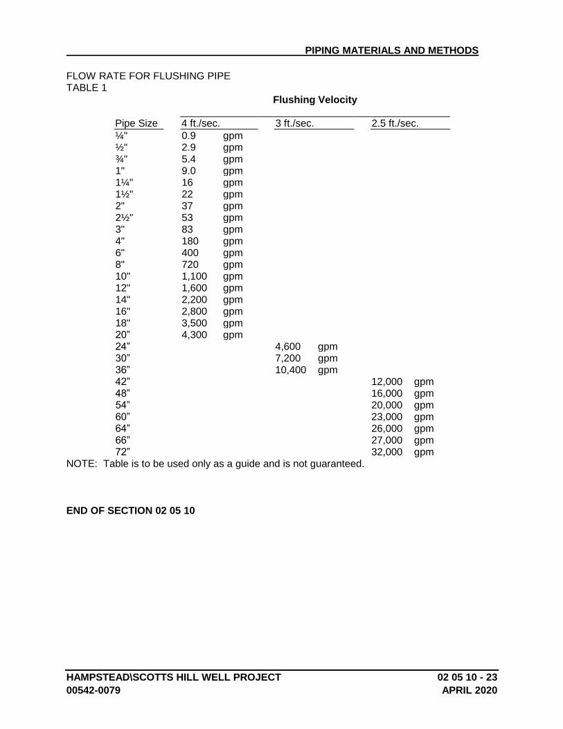
PIPING MATERIALS AND METHODS
HAMPSTEAD\SCOTTS HILL WELL PROJECT 02 05 10 - 23
00542-0079 APRIL 2020
FLOW RATE FOR FLUSHING PIPE TABLE 1
Flushing Velocity
Pipe Size 4 ft./sec. 3 ft./sec. 2.5 ft./sec.
¼" 0.9 gpm ½" 2.9 gpm ¾" 5.4 gpm 1" 9.0 gpm 1¼" 16 gpm 1½" 22 gpm 2" 37 gpm 2½" 53 gpm 3" 83 gpm 4" 180 gpm 6" 400 gpm 8" 720 gpm 10" 1,100 gpm 12" 1,600 gpm 14" 2,200 gpm 16" 2,800 gpm 18" 3,500 gpm 20” 4,300 gpm 24” 4,600 gpm 30” 7,200 gpm 36” 10,400 gpm 42” 12,000 gpm 48” 16,000 gpm 54” 20,000 gpm 60” 23,000 gpm 64” 26,000 gpm 66” 27,000 gpm 72” 32,000 gpm
NOTE: Table is to be used only as a guide and is not guaranteed.
END OF SECTION 02 05 10
HAMPSTEAD\SCOTTS HILL WELL PROJECT 02 06 00-1
00542-0079 APRIL 2020
SECTION 02 06 00 - HANGERS AND SUPPORTS
PART 1 - GENERAL
1.1 SUMMARY
A. This section includes providing all the necessary hangers and supports for the plant piping.
1.2 SUMITTALS
A. Contractor shall submit detailed shop drawings of proposed hanger and support systems for all piping per Section 01340 – Submittals for the Engineer’s approval.
PART 2 - PRODUCTS
2.1 HANGERS AND SUPPORTS
A. All piping shall be properly supported and restrained by means of adequate hangers, concrete piers, pipe supports, brackets or otherwise as may be required by the location. Support and anchor system shall prevent undue deflection, vibration, and stresses on piping, equipment, and structures.
B. Generally, concrete supports shall be used where pipe centerline is less than 3 feet above floor, and hangers above 6 feet unless specified or shown otherwise. Supports shall be not more than 10 feet on center for steel and DI piping, 5 feet on center for plastic, and at changes in direction, unless otherwise shown on the drawings or required by the specific manufacturer. All necessary inserts or appurtenances shall be furnished and installed in the concrete or structures for adequately securing hangers and supports to the structure.
C. Hangers and supports shall conform to the following requirements: 1. All hangers and supports shall be capable of adjustment after installation. Types of
hangers and supports shall be kept to a minimum. 2. Hanger rods shall be straight and vertical. Chain, wire, strap or perforated bar
hangers shall not be used. Hangers shall not be suspended from other piping. 3. Vertical piping shall be supported at each floor and between floors by stays or
braces to prevent rattling and vibration. 4. Supports and hangers for plastic piping shall include wire saddles or bands as
recommended by the manufacturer and approved by the Engineer to distribute load and thus avoid localized deformation of the pipe.
5. Hanger and supports shall prevent contact between dissimilar metals by use of copper plated, rubber, vinyl coated or stainless steel hangers.
6. Ferrous pipes to be painted shall be painted in accordance with Section 09900, PAINTING. Galvanized hangers and supports shall support ferrous pipes that do not require painting.
7. Plastic coated or copper plated steel hangers and supports shall support copper piping.
8. Plastic coated steel hangers and supports shall support plastic piping.
HANGERS AND SUPPORTS
HAMPSTEAD\SCOTTS HILL WELL PROJECT 02 06 00-2
00542-0079 APRIL 2020
9. Hangers and supports shall provide for thermal expansion throughout the full operating temperature range.
10. Expansion type anchors used for pipe hangers and supports shall be Type 304 stainless steel.
11. Hangers and rods shall be stainless steel Type 304 and pipe supports shall be cradle type.
D. All metallic hangers and supports shall be standard make “Anvil” by Anvil International, “Witch” by Carpenter & Patterson, Inc., B-Line Systems, Inc., or equal; and data on the types and sizes to be used shall be furnished to the Engineer for approval. Metallic support welded system brackets, rods, support clips, clevis hangers, hardware, etc. shall be stainless steel construction.
E. Non-metallic support system shall be a heavy-duty channel framing system. Channel frames shall be manufactured by the pultrusion process using corrosion grade polyester or exposure and shall have a flame spread rating of 25 or less per ASTM E84. Piping accessories, pipe clamps, clevis hangers, support posts, support racks, fasteners, etc., shall be constructed of vinylester or polyurethane resin. Non-metallic support systems shall be standard make Aickinstrut by Aickinstrut, Inc., Uninstrut Fiberglass by Unistrut, Inc., Enduro Fiberglass Systems, or equal. The Contractor shall submit data on the types and sizes of approval. Unless otherwise shown or specified the Contractor shall provide support spacing in conformance with the pipe and support system manufacturer’s requirements.
2.2 PROCESS AIR PIPE SUPPORTS
A. Process air piping shall be supported by slide bearings as manufactured by Fluorocarbon Company, Anaheim, California, ITT Grinnell Corp., Providence, Rhode Island, or equal.
B. The slide bearing material shall be 3/32 inch thick, twenty-five percent (25%) glass-fiber reinforced structural grade Teflon. The bearing material shall withstand at least 1000 psi (compression) at 210 °F with a coefficient of friction between 0.05 and 0.08. The performance of bearing and bonding materials shall be unaffected by continual immersion in wastewater containing domestic and industrial waste at a temperature of 210 °F.
C. Non-submerged slide bearing type supports shall be provided with a bearing material covering a 120 degree arc centered at the bottom of the pipe. The Teflon shall be at least 4 inches wide at the underside of the pipe and 8 inches wide at the top of the support. The Teflon material shall be hot press bonded to 10 gauge stainless steel plates for welding to the bottom of the pipe and securing to the top of the support.
D. Submerged slide-bearing type supports shall be provided with Teflon bonded to the underside of the hold down strap and the top of the pipe such that the sliding surface is formed between two (2) sheets of Teflon. Each surface shall cover a 120 degree arc centered at the top of the pipe. On the underside of the strap, the Teflon bearing shall be hot press bonded directly to the stainless steel strap or to a 10 gauge stainless steel plate for welding to the strap. At the top of the pipe, the Teflon shall be bonded to a 10 gauge stainless steel plate for welding to the pipe.
HANGERS AND SUPPORTS
HAMPSTEAD\SCOTTS HILL WELL PROJECT 02 06 00-3
00542-0079 APRIL 2020
E. Pipe straps shall not tightly bind the pipe, but shall provide 3/32 inch clearance over the top 180 degrees of the pipe surface.
F. Wall bracket supports shall be used where shown for pipe to be installed adjacent to a wall. Where it is not feasible to install hanger supports, adjustable pipe saddle supports may be used with the permission of the Engineer. Concrete pier supports shall be spaced at a maximum distance of 10 feet and shall be at least 1 foot square unless otherwise shown on the drawings.
G. Small diameter piping (6 inches in diameter or less) shall not be strapped or otherwise secured directly to walls. Suitable wall offset brackets of an approved type shall be used. Anchors shall not be attached using percussion fasteners.
H. Sliding surfaces shall be protected from accumulation of dirt, grit or other foreign matter.
I. Slide bearings shall be capable of adequately supporting the design loads and shall be attached to pipe and supports as specified and recommended by the manufacturer.
J. The slide bearings shall be installed in the locations shown or indicated on the drawings, at required elevations, true to orientation and level, assuring that the correct half of each bearing is in its proper position. The Contractor shall store the bearings to protect them from mechanical damage prior to installation, and shall protect the same during and after installation from contamination and damage due to placing of concrete and other materials. The Contractor shall clean the operating surfaces of bearings thoroughly before final assembly.
K. The Contractor shall note that all pipe support locations are not shown on the drawings, and shall follow the specifications herein in locating supports. Where deviations and modifications are required, they shall be made only with the permission of the Engineer. A detailed layout of pipe supports and hangers shall be submitted for approval.
2.3 HANGERS AND SUPPORTS
A. General
1. Hangers shall be capable of supporting piping in all conditions of intended operation. Hanger shall allow for free expansion and contraction of the piping system. Hangers shall prevent excess stress on equipment.
2. Provide hangers with 1-1/2 inch minimum vertical adjustment.
3. Hangers shall be designed so that they cannot become disengaged by movement of the supported piping.
4. Hangers subject to shock or thrust imposed by the action of safety valves, shall include hydraulic shock suppressers.
5. Hanger rods shall be subject to tensile loading only.
HANGERS AND SUPPORTS
HAMPSTEAD\SCOTTS HILL WELL PROJECT 02 06 00-4
00542-0079 APRIL 2020
6. At hanger locations where lateral or axial movement is anticipated, provide linkage that permits lateral and axial movement. Where horizontal pipe movement is greater than 1/2”, or where hanger rod deflection from the vertical is greater than 4 degrees from the cold to the hot position of the pipe, offset hanger rod and structural attachment so that the rod is vertical in the hot position.
7. Provide spring-type hangers for piping subject to vibration or vertical expansion and contraction, such as engine exhausts and similar piping. Spring-type hangers shall be sized to the manufacturers written recommendations and the loading conditions encountered. Provide variable spring supports with means to limit misalignment, buckling, and eccentric loading. Provide variable spring supports with means to prevent overstressing of the spring. Provide variable spring supports with means to indicate spring compression. Spring-type hangers shall be designed for a maximum variation in supporting effort of 25% of total travel resulting from thermal movement.
8. Wherever expansion and contraction of piping is expected, provide a sufficient number of expansion loops or joints, together with necessary rolling or sliding supports, anchors, guides, pivots, and restraints, that allow expansion and contraction without damaging piping, equipment, or structures. Provisions for expansion and contraction shall permit piping to expand and contract freely in directions away from anchored points for total travel resulting from thermal movement.
9. Supports, hangers, anchors, and guides shall be designed and insulated so that excess heat will not be transmitted to the structure or other equipment.
B. Materials for Hangers, Fasteners, Supports, and Rods
1. Hangers, Fasteners, Supports, and Hanger Rods for SS and DI Piping: AISI Type 304 stainless steel.
2. Anchor Bolts and Assembly Bolts, Nuts, and Washers for All Hangers and Supports: AISI Type 304 stainless steel.
C. Stainless Steel Bracket Support Systems
1. Stainless steel channel and bracket supports shall be fabricated from AISI Type 304 stainless steel.
2. Stainless steel supports shall be appropriately designed and manufactured for the specific pipe support application.
3. Systems shall be welded or assembled with 304 SS nuts, bolts, and washers.
PART 3 – EXECUTION
A. Install all hangers and support devices and systems per the manufacturer’s recommendations and instructions.
B. Whenever possible, support pipes from structural members. Provide piping support framing between structural members as required to support piping as specified in this

HANGERS AND SUPPORTS
HAMPSTEAD\SCOTTS HILL WELL PROJECT 02 06 00-5
00542-0079 APRIL 2020
Section and as required to meet requirements of applicable building code and the American Institute of Steel Construction.
C. Arrange piping supports systems so that piping is neat and orderly. Adjust height of hangers and supports to align pipes to the proper grade for drainage and venting.
D. Support piping independent of connected equipment. Space supports for piping to prevent sag, bending, and shear stresses in the piping. Reduce support spacing where components, such as flanges and valves, impose concentrated loads. Provide supports on both sides of meters, valves, strainers, and other items that impose heavy point loads on piping system.
END OF SECTION 02 06 00
HAMPSTEAD\SCOTT’S HILL WELL PROJECT 02 08 00 - 1
00542-0079 APRIL 2020
SECTION 02 08 00 - PIPED UTILITIES, BASIC MATERIALS AND METHODS
PART 1 - GENERAL
1.1 RELATED DOCUMENTS
A. Drawings and general provisions of the Contract, including General and Supplementary Conditions and Division 1 Specification Sections, apply to this Section.
1.2 SUMMARY
A. This Section includes the following:
1. Piping joining materials. 2. Transition fittings. 3. Dielectric fittings. 4. Sleeves. 5. Identification devices. 6. Grout. 7. Flowable fill. 8. Piped utility demolition. 9. Piping system common requirements. 10. Equipment installation common requirements. 11. Painting. 12. Concrete bases. 13. Metal supports and anchorages.
1.3 DEFINITIONS
A. Exposed Installations: Exposed to view outdoors or subject to outdoor ambient temperatures and weather conditions.
B. Concealed Installations: Concealed from view and protected from weather conditions and physical contact by building occupants but subject to outdoor ambient temperatures. Examples include installations within unheated shelters.
C. ABS: Acrylonitrile-butadiene-styrene plastic.
D. CPVC: Chlorinated polyvinyl chloride plastic.
E. PE: Polyethylene plastic.
F. PVC: Polyvinyl chloride plastic.

PIPED UTILITIES, BASIC MATERIALS AND METHODS
HAMPSTEAD\SCOTT’S HILL WELL PROJECT 02 08 00 - 2
00542-0079 APRIL 2020
1.4 SUBMITTALS
1. Product Data: Submit product data for approval in accordance with Section 01340.
B. Welding certificates.
1.5 QUALITY ASSURANCE
A. Steel Support Welding: Qualify procedures and personnel according to AWS D1.1/D1.1M, "Structural Welding Code - Steel."
B. Steel Piping Welding: Qualify processes and operators according to ASME Boiler and Pressure Vessel Code: Section IX, "Welding and Brazing Qualifications."
1. Comply with provisions in ASME B31 Series, "Code for Pressure Piping." 2. Certify that each welder has passed AWS qualification tests for welding
processes involved and that certification is current.
C. Comply with ASME A13.1 for lettering size, length of color field, colors, and viewing angles of identification devices.
1.6 DELIVERY, STORAGE, AND HANDLING
A. Deliver pipes and tubes with factory-applied end caps. Maintain end caps through shipping, storage, and handling to prevent pipe end damage and to prevent entrance of dirt, debris, and moisture.
B. Store plastic pipes protected from direct sunlight. Support to prevent sagging and bending.
1.7 COORDINATION
A. Coordinate installation of required supporting devices and set sleeves in poured-in-place concrete and other structural components as they are constructed.
B. Coordinate installation of identifying devices after completing covering and painting if devices are applied to surfaces.
C. Coordinate size and location of concrete bases. Formwork, reinforcement, and concrete requirements are specified in Division 3.
PIPED UTILITIES, BASIC MATERIALS AND METHODS
HAMPSTEAD\SCOTT’S HILL WELL PROJECT 02 08 00 - 3
00542-0079 APRIL 2020
PART 2 - PRODUCTS
2.1 PIPING JOINING MATERIALS
A. Pipe-Flange Gasket Materials: Suitable for chemical and thermal conditions of piping system contents. DI piping for process air piping from the blowers shall utilize EPDM gasket materials for flanged and mechanical joints. Buried piping shall be installed with protective PE wrap.
1. ASME B16.21, nonmetallic, flat, asbestos free, 1/8-inch maximum thickness, unless otherwise indicated.
a. Full-Face Type: For flat-face, Class 125, cast-iron and cast-bronze flanges.
b. Narrow-Face Type: For raised-face, Class 250, cast-iron and steel flanges.
2. AWWA C110, rubber, flat face, 1/8 inch thick, unless otherwise indicated; and full-face or ring type, unless otherwise indicated.
B. Flange Bolts and Nuts: Stainless steel, unless otherwise indicated.
C. Plastic, Pipe-Flange Gasket, Bolts, and Nuts: Type recommended by piping system manufacturer, unless otherwise indicated. Hardware shall be 304 stainless steel.
D. Solder Filler Metals: ASTM B 32, lead-free alloys. Include water-flushable flux according to ASTM B 813.
E. Brazing Filler Metals: AWS A5.8, BCuP Series, copper-phosphorus alloys for general-duty brazing, unless otherwise indicated; and AWS A5.8, BAg1, silver alloy for refrigerant piping, unless otherwise indicated.
F. Welding Filler Metals: Comply with AWS D10.12/D10.12M for welding materials appropriate for wall thickness and chemical analysis of steel pipe being welded.
G. Solvent Cements for Joining Plastic Piping:
1. ABS Piping: ASTM D 2235. 2. CPVC Piping: ASTM F 493. 3. PVC Piping: ASTM D 2564. Include primer according to ASTM F 656. 4. PVC to ABS Piping Transition: ASTM D 3138.
H. Fiberglass Pipe Adhesive: As furnished or recommended by pipe manufacturer.
2.2 TRANSITION FITTINGS
A. Transition Fittings, General: Same size as, and with pressure rating at least equal to and with ends compatible with, piping to be joined.
B. Transition Couplings NPS 1-1/2 (DN 40) and Smaller:
PIPED UTILITIES, BASIC MATERIALS AND METHODS
HAMPSTEAD\SCOTT’S HILL WELL PROJECT 02 08 00 - 4
00542-0079 APRIL 2020
1. Underground Piping: Manufactured piping coupling or specified piping system fitting.
2. Aboveground Piping: Specified piping system fitting.
C. AWWA Transition Couplings NPS 2 (DN 50) and Larger:
1. Available Manufacturers: Subject to compliance with requirements, manufacturers offering products that may be incorporated into the Work include, but are not limited to, the following:
2. Manufacturers: Subject to compliance with requirements, provide products by one of the following:
a. Cascade Waterworks Mfg. Co. b. Dresser, Inc.; DMD Div. c. Ford Meter Box Company, Inc. (The); Pipe Products Div. d. JCM Industries. e. Smith-Blair, Inc. f. Viking Johnson.
3. Description: AWWA C219, metal sleeve-type coupling for underground pressure piping.
D. Plastic-to-Metal Transition Fittings:
1. Available Manufacturers: Subject to compliance with requirements, manufacturers offering products that may be incorporated into the Work include, but are not limited to, the following:
2. Manufacturers: Subject to compliance with requirements, provide products by one of the following:
a. Spears Manufacturing Co.
3. Description: CPVC and PVC one-piece fitting with manufacturer's Schedule 80 equivalent dimensions; one end with threaded brass insert, and one solvent-cement-joint or threaded end.
E. Plastic-to-Metal Transition Unions:
1. Available Manufacturers: Subject to compliance with requirements, manufacturers offering products that may be incorporated into the Work include, but are not limited to, the following:
2. Manufacturers: Subject to compliance with requirements, provide products by one of the following:
a. Colonial Engineering, Inc. b. NIBCO INC. c. Spears Manufacturing Co.
3. Description: MSS SP-107, CPVC and PVC four-part union. Include stainless-steel threaded end, solvent-cement-joint or threaded plastic end, rubber O-ring, and union nut.
PIPED UTILITIES, BASIC MATERIALS AND METHODS
HAMPSTEAD\SCOTT’S HILL WELL PROJECT 02 08 00 - 5
00542-0079 APRIL 2020
F. Flexible Transition Couplings for Underground Nonpressure Drainage Piping:
1. Available Manufacturers: Subject to compliance with requirements, manufacturers offering products that may be incorporated into the Work include, but are not limited to, the following:
2. Manufacturers: Subject to compliance with requirements, provide products by one of the following:
a. Cascade Waterworks Mfg. Co. b. Fernco, Inc. c. Mission Rubber Company. d. Plastic Oddities.
3. Description: ASTM C 1173 with elastomeric sleeve, ends same size as piping to be joined, and corrosion-resistant metal band on each end.
2.3 DIELECTRIC FITTINGS
A. Dielectric Fittings, General: Assembly of copper alloy and ferrous materials or ferrous material body with separating nonconductive insulating material suitable for system fluid, pressure, and temperature.
B. Dielectric Unions:
1. Available Manufacturers: Subject to compliance with requirements, manufacturers offering products that may be incorporated into the Work include, but are not limited to, the following:
2. Manufacturers: Subject to compliance with requirements, provide products by one of the following:
a. Capitol Manufacturing Co. b. Central Plastics Company. c. Epco Sales, Inc. d. Hart Industries, International, Inc. e. Watts Water Technologies, Inc. f. Zurn Plumbing Products Group; Wilkins Div.
3. Description: Factory fabricated, union, NPS 2 (DN 50) and smaller.
a. Pressure Rating: 150 psig (1035 kPa) at 180 deg F (82 deg C). b. End Connections: Solder-joint copper alloy and threaded ferrous; threaded
ferrous.
C. Dielectric Flanges:
1. Available Manufacturers: Subject to compliance with requirements, manufacturers offering products that may be incorporated into the Work include, but are not limited to, the following:
2. Manufacturers: Subject to compliance with requirements, provide products by one of the following:
PIPED UTILITIES, BASIC MATERIALS AND METHODS
HAMPSTEAD\SCOTT’S HILL WELL PROJECT 02 08 00 - 6
00542-0079 APRIL 2020
a. Capitol Manufacturing Co. b. Central Plastics Company. c. Epco Sales, Inc. d. Watts Water Technologies, Inc.
3. Description: Factory-fabricated, bolted, companion-flange assembly, NPS 2-1/2 to NPS 4 (DN 65 to DN 100) and larger.
a. Pressure Rating: 150 psig (1035 kPa) minimum. b. End Connections: Solder-joint copper alloy and threaded ferrous; threaded
solder-joint copper alloy and threaded ferrous.
D. Dielectric-Flange Kits:
1. Available Manufacturers: Subject to compliance with requirements, manufacturers offering products that may be incorporated into the Work include, but are not limited to, the following:
2. Manufacturers: Subject to compliance with requirements, provide products by one of the following:
a. Advance Products & Systems, Inc. b. Calpico, Inc. c. Central Plastics Company. d. Pipeline Seal and Insulator, Inc.
3. Description: Nonconducting materials for field assembly of companion flanges, NPS 2-1/2 (DN 65) and larger.
a. Pressure Rating: 150 psig (1035 kPa) minimum. b. Gasket: Neoprene or phenolic. c. Bolt Sleeves: Phenolic or polyethylene. d. Washers: Phenolic with steel backing washers.
E. Dielectric Couplings:
1. Available Manufacturers: Subject to compliance with requirements, manufacturers offering products that may be incorporated into the Work include, but are not limited to, the following:
2. Manufacturers: Subject to compliance with requirements, provide products by one of the following:
a. Calpico, Inc. b. Lochinvar Corporation.
3. Description: Galvanized-steel coupling with inert and noncorrosive, thermoplastic lining, NPS 3 (DN 80) and smaller.
a. Pressure Rating: 300 psig (2070 kPa) at 225 deg F (107 deg C). b. End Connections: Threaded.
F. Dielectric Nipples:
PIPED UTILITIES, BASIC MATERIALS AND METHODS
HAMPSTEAD\SCOTT’S HILL WELL PROJECT 02 08 00 - 7
00542-0079 APRIL 2020
1. Available Manufacturers: Subject to compliance with requirements, manufacturers offering products that may be incorporated into the Work include, but are not limited to, the following:
2. Manufacturers: Subject to compliance with requirements, provide products by one of the following:
a. Perfection Corporation. b. Precision Plumbing Products, Inc. c. Victaulic Company.
3. Description: Electroplated steel nipple with inert and noncorrosive, thermoplastic lining.
a. Pressure Rating: 300 psig (2070 kPa) at 225 deg F (107 deg C) b. End Connections: Threaded or grooved.
2.4 SLEEVES
A. Mechanical sleeve seals for pipe penetrations below water level shall be link-seal type.
B. Galvanized-Steel Sheet Sleeves: 0.0239-inch (0.6-mm) minimum thickness; round tube closed with welded longitudinal joint.
C. Steel Pipe Sleeves: Schedule 40, stainless steel plain ends.
D. Cast-Iron Sleeves: Cast or fabricated "wall pipe" equivalent to ductile-iron pressure pipe, with plain ends and integral waterstop, unless otherwise indicated.
E. Molded PVC Sleeves: Permanent, with nailing flange for attaching to wooden forms.
F. PVC Pipe Sleeves: ASTM D 1785, Schedule 40.
G. Molded PE Sleeves: Reusable, PE, tapered-cup shaped, and smooth outer surface with nailing flange for attaching to wooden forms.
2.5 IDENTIFICATION DEVICES
A. General: Products specified are for applications referenced in other Division 2 Sections.
B. Equipment Nameplates: Metal permanently fastened to equipment with data engraved or stamped.
1. Data: Manufacturer, product name, model number, serial number, capacity, operating and power characteristics, labels of tested compliances, and essential data.
2. Location: Accessible and visible.
PIPED UTILITIES, BASIC MATERIALS AND METHODS
HAMPSTEAD\SCOTT’S HILL WELL PROJECT 02 08 00 - 8
00542-0079 APRIL 2020
C. Stencils: Standard stencils prepared with letter sizes complying with recommendations in ASME A13.1. Minimum letter height is 1-1/4 inches (30 mm) for ducts, and 3/4 inch (20 mm) for access door signs and similar operational instructions.
1. Material: Fiberboard or Brass. 2. Stencil Paint: Exterior, oil-based, alkyd-gloss black enamel, unless otherwise
indicated. Paint may be in pressurized spray-can form. 3. Identification Paint: Exterior, oil-based, alkyd enamel in colors according to
ASME A13.1, unless otherwise indicated.
D. Snap-on Plastic Pipe Markers: Manufacturer's standard preprinted, semirigid, snap-on type. Include color-coding according to ASME A13.1, unless otherwise indicated.
E. Pressure-Sensitive Pipe Markers: Manufacturer's standard preprinted, color-coded, pressure-sensitive-vinyl type with permanent adhesive.
F. Pipes with OD, Including Insulation, Less Than 6 Inches (150 mm): Full-band pipe markers, extending 360 degrees around pipe at each location.
G. Pipes with OD, Including Insulation, 6 Inches (150 mm) and Larger: Either full-band or strip-type pipe markers, at least three times letter height and of length required for label.
H. Lettering: Manufacturer's standard preprinted captions as selected by Engineer.
I. Lettering: Use piping system terms indicated and abbreviate only as necessary for each application length.
1. Arrows: Either integrally with piping system service lettering to accommodate both identification and direction of flow, or as separate unit on each pipe marker to indicate direction of flow. Stencil on pipe at appropriate intervals.
J. Plastic Tape: Manufacturer's standard color-coded, pressure-sensitive, self-adhesive vinyl tape, at least 3 mils (0.08 mm) thick.
1. Width: 1-1/2 inches (40 mm) on pipes with OD, including insulation, less than 6 inches (150 mm); 2-1/2 inches (65 mm) for larger pipes.
2. Color: Comply with ASME A13.1, unless otherwise indicated.
K. Valve Tags: Stamped or engraved with 1/4-inch (6.4-mm) letters for piping system abbreviation and 1/2-inch (13-mm) sequenced numbers. Include 5/32-inch (4-mm) hole for fastener.
1. Material: 0.032-inch- (0.8-mm-) thick, polished brass or aluminum. 2. Material: 0.0375-inch- (1-mm-) thick stainless steel. 3. Material: 3/32-inch- (2.4-mm-) thick plastic laminate with 2 black surfaces and a
white inner layer. 4. Material: Valve manufacturer's standard solid plastic. 5. Size: 1-1/2 inches (40 mm) in diameter, unless otherwise indicated. 6. Shape: As indicated for each piping system.
PIPED UTILITIES, BASIC MATERIALS AND METHODS
HAMPSTEAD\SCOTT’S HILL WELL PROJECT 02 08 00 - 9
00542-0079 APRIL 2020
L. Valve Tag Fasteners: Brass, wire-link or beaded chain; or brass S-hooks.
M. Engraved Plastic-Laminate Signs: ASTM D 709, Type I, cellulose, paper-base, phenolic-resin-laminate engraving stock; Grade ES-2, black surface, black phenolic core, with white melamine subcore, unless otherwise indicated. Fabricate in sizes required for message. Provide holes for mechanical fastening.
1. Engraving: Engraver's standard letter style, of sizes and with terms to match equipment identification.
2. Thickness: 1/16 inch (1.6 mm), unless otherwise indicated. 3. Thickness: 1/16 inch (1.6 mm), for units up to 20 sq. in. (130 sq. cm) or 8 inches
(200 mm) in length, and 1/8 inch (3 mm) for larger units. 4. Fasteners: Self-tapping, stainless-steel screws or contact-type permanent
adhesive.
N. Plastic Equipment Markers: Manufacturer's standard laminated plastic, in the following color codes:
1. Green: Cooling equipment and components. 2. Yellow: Heating equipment and components. 3. Brown: Energy reclamation equipment and components. 4. Blue: Equipment and components that do not meet criteria above. 5. Hazardous Equipment: Use colors and designs recommended by ASME A13.1. 6. Terminology: Match schedules as closely as possible. Include the following:
a. Name and plan number. b. Equipment service. c. Design capacity. d. Other design parameters such as pressure drop, entering and leaving
conditions, and speed.
7. Size: 2-1/2 by 4 inches (65 by 100 mm) for control devices, dampers, and valves; 4-1/2 by 6 inches (115 by 150 mm) for equipment.
O. Plasticized Tags: Preprinted or partially preprinted, accident-prevention tags, of plasticized card stock with mat finish suitable for writing.
1. Size: 3-1/4 by 5-5/8 inches (83 by 143 mm). 2. Fasteners: Brass grommets and wire. 3. Nomenclature: Large-size primary caption such as DANGER, CAUTION, or DO
NOT OPERATE.
P. Lettering and Graphics: Coordinate names, abbreviations, and other designations used in piped utility identification with corresponding designations indicated. Use numbers, letters, and terms indicated for proper identification, operation, and maintenance of piped utility systems and equipment.
1. Multiple Systems: Identify individual system number and service if multiple systems of same name are indicated.

PIPED UTILITIES, BASIC MATERIALS AND METHODS
HAMPSTEAD\SCOTT’S HILL WELL PROJECT 02 08 00 - 10
00542-0079 APRIL 2020
2.6 GROUT
A. Description: ASTM C 1107, Grade B, nonshrink and nonmetallic, dry hydraulic-cement grout.
1. Characteristics: Post hardening, volume adjusting, nonstaining, noncorrosive, nongaseous, and recommended for interior and exterior applications.
2. Design Mix: 5000-psi (34.5-MPa), 28-day compressive strength. 3. Packaging: Premixed and factory packaged.
2.7 FLOWABLE FILL
A. Description: Low-strength-concrete, flowable-slurry mix.
1. Cement: ASTM C 150, Type I, portland. 2. Density: 115- to 145-lb/cu. ft. (1840- to 2325-kg/cu. m). 3. Aggregates: ASTM C 33, natural sand, fine and crushed gravel or stone, coarse. 4. Aggregates: ASTM C 33, natural sand, fine. 5. Admixture: ASTM C 618, fly-ash mineral. 6. Water: Comply with ASTM C 94/C 94M. 7. Strength: 100 to 200 psig (690 to 1380 kPa) at 28 days.
PART 3 - EXECUTION
3.1 PIPED UTILITY DEMOLITION
A. Refer to Division 1 Sections "Cutting and Patching" for general demolition requirements and procedures.
B. Disconnect, demolish, and remove piped utility systems, equipment, and components indicated to be removed.
1. Piping to Be Removed: Remove portion of piping indicated to be removed and cap or plug remaining piping with same or compatible piping material.
2. Piping to Be Abandoned in Place: Drain piping. Fill abandoned piping with flowable fill, and cap or plug piping with same or compatible piping material.
3. Equipment to Be Removed: Disconnect and cap services and remove equipment.
4. Equipment to Be Removed and Reinstalled: Disconnect and cap services and remove, clean, and store equipment; when appropriate, reinstall, reconnect, and make operational.
5. Equipment to Be Removed and Salvaged: Disconnect and cap services and remove equipment and deliver to Owner.
C. If pipe, insulation, or equipment to remain is damaged in appearance or is unserviceable, remove damaged or unserviceable portions and replace with new products of equal capacity and quality.
PIPED UTILITIES, BASIC MATERIALS AND METHODS
HAMPSTEAD\SCOTT’S HILL WELL PROJECT 02 08 00 - 11
00542-0079 APRIL 2020
3.2 DIELECTRIC FITTING APPLICATIONS
A. Dry Piping Systems: Connect piping of dissimilar metals with the following:
1. NPS 2 (DN 50) and Smaller: Dielectric unions. 2. NPS 2-1/2 to NPS 12 (DN 65 to DN 300): Dielectric flanges or dielectric flange
kits.
B. Wet Piping Systems: Connect piping of dissimilar metals with the following:
1. NPS 2 (DN 50) and Smaller: Dielectric couplings or dielectric nipples. 2. NPS 2-1/2 to NPS 4 (DN 65 to DN 100): Dielectric nipples. 3. NPS 2-1/2 to NPS 8 (DN 65 to DN 200): Dielectric nipples or dielectric flange
kits. 4. NPS 10 and NPS 12 (DN 250 and DN 300): Dielectric flange kits.
3.3 PIPING INSTALLATION
A. Install piping according to the following requirements and Division 2 Sections specifying piping systems.
B. Drawing plans, schematics, and diagrams indicate general location and arrangement of piping systems. Indicated locations and arrangements were used to size pipe and calculate friction loss, expansion, pump sizing, and other design considerations. Install piping as indicated unless deviations to layout are approved on the Coordination Drawings by the Engineer.
C. Install piping indicated to be exposed and piping in equipment rooms and service areas at right angles or parallel to building walls. Diagonal runs are prohibited unless specifically indicated otherwise.
D. Install piping to permit valve servicing.
E. Install piping at indicated slopes.
F. Install piping free of sags and bends.
G. Install fittings for changes in direction and branch connections.
H. Select system components with pressure rating equal to or greater than system operating pressure.
I. Sleeves are not required for core-drilled holes.
J. Permanent sleeves are not required for holes formed by removable PE sleeves.
K. Install sleeves for pipes passing through concrete and masonry walls and concrete floor and roof slabs.
1. Cut sleeves to length for mounting flush with both surfaces.
PIPED UTILITIES, BASIC MATERIALS AND METHODS
HAMPSTEAD\SCOTT’S HILL WELL PROJECT 02 08 00 - 12
00542-0079 APRIL 2020
a. Exception: Extend sleeves installed in floors of equipment areas or other wet areas 2 inches (50 mm) above finished floor level.
2. Install sleeves in new walls and slabs as new walls and slabs are constructed.
a. Steel Pipe Sleeves: For pipes smaller than NPS 6 (DN 150). b. Steel Sheet Sleeves: For pipes NPS 6 (DN 150) and larger, penetrating
gypsum-board partitions.
L. Verify final equipment locations for roughing-in.
M. Refer to equipment specifications in other Sections for roughing-in requirements.
3.4 PIPING JOINT CONSTRUCTION
A. Join pipe and fittings according to the following requirements and Division 2 Sections specifying piping systems.
B. Ream ends of pipes and tubes and remove burrs. Bevel plain ends of steel pipe.
C. Remove scale, slag, dirt, and debris from inside and outside of pipe and fittings before assembly.
D. Threaded Joints: Thread pipe with tapered pipe threads according to ASME B1.20.1. Cut threads full and clean using sharp dies. Ream threaded pipe ends to remove burrs and restore full ID. Join pipe fittings and valves as follows:
1. Apply appropriate tape or thread compound to external pipe threads unless dry seal threading is specified.
2. Damaged Threads: Do not use pipe or pipe fittings with threads that are corroded or damaged. Do not use pipe sections that have cracked or open welds.
E. Welded Joints: Construct joints according to AWS D10.12/D10.12M, using qualified processes and welding operators according to Part 1 "Quality Assurance" Article.
F. Flanged Joints: Select appropriate gasket material, size, type, and thickness for service application. Install gasket concentrically positioned. Use suitable lubricants on bolt threads.
G. Grooved Joints: Assemble joints with grooved-end pipe coupling with coupling housing, gasket, lubricant, and bolts according to coupling and fitting manufacturer's written instructions.
H. Soldered Joints: Apply ASTM B 813 water-flushable flux, unless otherwise indicated, to tube end. Construct joints according to ASTM B 828 or CDA's "Copper Tube Handbook," using lead-free solder alloy (0.20 percent maximum lead content) complying with ASTM B 32.
PIPED UTILITIES, BASIC MATERIALS AND METHODS
HAMPSTEAD\SCOTT’S HILL WELL PROJECT 02 08 00 - 13
00542-0079 APRIL 2020
I. Brazed Joints: Construct joints according to AWS's "Brazing Handbook," "Pipe and Tube" Chapter, using copper-phosphorus brazing filler metal complying with AWS A5.8.
J. Pressure-Sealed Joints: Assemble joints for plain-end copper tube and mechanical pressure seal fitting with proprietary crimping tool to according to fitting manufacturer's written instructions.
K. Plastic Piping Solvent-Cemented Joints: Clean and dry joining surfaces. Join pipe and fittings according to the following:
1. Comply with ASTM F 402 for safe-handling practice of cleaners, primers, and solvent cements.
2. ABS Piping: Join according to ASTM D 2235 and ASTM D 2661 appendixes. 3. CPVC Piping: Join according to ASTM D 2846/D 2846M Appendix. 4. PVC Pressure Piping: Join schedule number ASTM D 1785, PVC pipe and PVC
socket fittings according to ASTM D 2672. Join other-than-schedule-number PVC pipe and socket fittings according to ASTM D 2855.
5. Solvent cement used in PVC piping for chemical piping shall be compatible and approved for use with the chemical in the pipe.
6. PVC Nonpressure Piping: Join according to ASTM D 2855. 7. PVC to ABS Nonpressure Transition Fittings: Join according to ASTM D 3138
Appendix.
L. Plastic Pressure Piping Gasketed Joints: Join according to ASTM D 3139.
M. Plastic Nonpressure Piping Gasketed Joints: Join according to ASTM D 3212.
N. Plastic Piping Heat-Fusion Joints: Clean and dry joining surfaces by wiping with clean cloth or paper towels. Join according to ASTM D 2657.
1. Plain-End PE Pipe and Fittings: Use butt fusion. 2. Plain-End PE Pipe and Socket Fittings: Use socket fusion.
O. Bonded Joints: Prepare pipe ends and fittings, apply adhesive, and join according to pipe manufacturer's written instructions.
3.5 PIPING CONNECTIONS
A. Make connections according to the following, unless otherwise indicated:
1. Install unions, in piping NPS 2 (DN 50) and smaller, adjacent to each valve and at final connection to each piece of equipment.
2. Install flanges, in piping NPS 2-1/2 (DN 65) and larger, adjacent to flanged valves and at final connection to each piece of equipment.
3. Install dielectric fittings at connections of dissimilar metal pipes.
PIPED UTILITIES, BASIC MATERIALS AND METHODS
HAMPSTEAD\SCOTT’S HILL WELL PROJECT 02 08 00 - 14
00542-0079 APRIL 2020
3.6 EQUIPMENT INSTALLATION
A. Install equipment level and plumb, unless otherwise indicated.
B. Install equipment to facilitate service, maintenance, and repair or replacement of components. Connect equipment for ease of disconnecting, with minimum interference with other installations. Extend grease fittings to an accessible location.
C. Install equipment to allow right of way to piping systems installed at required slope.
3.7 PAINTING
A. Painting of piped utility systems, equipment, and components is specified in Division 9 painting Sections.
B. Damage and Touchup: Repair marred and damaged factory-painted finishes with materials and procedures to match original factory finish.
3.8 IDENTIFICATION
A. Piping Systems: Install pipe markers on each system. Include arrows showing normal direction of flow.
1. Stenciled Markers: According to ASME A13.1. 2. Plastic markers, with application systems. Install on insulation segment if
required for hot noninsulated piping. 3. Locate pipe markers on exposed piping according to the following:
a. Near each valve and control device. b. Near each branch, excluding short takeoffs for equipment and terminal
units. Mark each pipe at branch if flow pattern is not obvious. c. Near locations where pipes pass through walls or floors or enter
inaccessible enclosures. d. At manholes and similar access points that permit view of concealed
piping. e. Near major equipment items and other points of origination and
termination.
B. Equipment: Install engraved plastic-laminate sign or equipment marker on or near each major item of equipment.
1. Lettering Size: Minimum 1/4 inch (6.4 mm) high for name of unit if viewing distance is less than 24 inches (610 mm), 1/2 inch (13 mm) high for distances up to 72 inches (1800 mm), and proportionately larger lettering for greater distances. Provide secondary lettering two-thirds to three-fourths of size of principal lettering.
2. Text of Signs: Provide name of identified unit. Include text to distinguish among multiple units, inform user of operational requirements, indicate safety and emergency precautions, and warn of hazards and improper operations.
PIPED UTILITIES, BASIC MATERIALS AND METHODS
HAMPSTEAD\SCOTT’S HILL WELL PROJECT 02 08 00 - 15
00542-0079 APRIL 2020
C. Adjusting: Relocate identifying devices that become visually blocked by work of this or other Divisions.
3.9 CONCRETE BASES
A. Concrete Bases: Anchor equipment to concrete base according to equipment manufacturer's written instructions and according to seismic codes at Project.
1. Construct concrete bases of dimensions indicated, but not less than 4 inches (100 mm) larger in both directions than supported unit.
2. Install dowel rods to connect concrete base to concrete floor. Unless otherwise indicated, install dowel rods on 18-inch (450-mm) centers around the full perimeter of base.
3. Install epoxy-coated anchor bolts for supported equipment that extend through concrete base, and anchor into structural concrete floor.
4. Place and secure anchorage devices. Use supported equipment manufacturer's setting drawings, templates, diagrams, instructions, and directions furnished with items to be embedded.
5. Install anchor bolts to elevations required for proper attachment to supported equipment.
6. Install anchor bolts according to anchor-bolt manufacturer's written instructions. 7. Use 3000-psi (20.7-MPa), 28-day compressive-strength concrete and
reinforcement as specified in Division 3 Section "Cast-in-Place Concrete .
3.10 ERECTION OF METAL SUPPORTS AND ANCHORAGES
A. Refer to Division 5 Sections.
B. Cut, fit, and place miscellaneous metal supports accurately in location, alignment, and elevation to support and anchor piped utility materials and equipment.
C. Field Welding: Comply with AWS D1.1/D1.1M.
3.11 GROUTING
A. Mix and install grout for equipment base bearing surfaces, pump and other equipment base plates, and anchors.
B. Clean surfaces that will come into contact with grout.
C. Provide forms as required for placement of grout.
D. Avoid air entrapment during placement of grout.
E. Place grout, completely filling equipment bases.
F. Place grout on concrete bases and provide smooth bearing surface for equipment.
G. Place grout around anchors.

PIPED UTILITIES, BASIC MATERIALS AND METHODS
HAMPSTEAD\SCOTT’S HILL WELL PROJECT 02 08 00 - 16
00542-0079 APRIL 2020
H. Cure placed grout.
END OF SECTION 02 08 00
HAMPSTEAD\SCOTT’S HILL WELL PROJECT 02 10 20 - 1
00542-0079 APRIL 2020
SECTION 02 10 20 – AIR RELEASE AND AIR RELIEF VALVES
PART 1 - GENERAL
1.1 SECTION INCLUDES
A. Air release valves, air relief valves and appurtenances specified in this Section and as shown on the Drawings.
1.2 RELATED SECTIONS
A. Division 01 - General Requirements
B. Division 02 - Sitework 1. Section 02051, Plant Piping, Materials, and Methods
1.3 REFERENCES
A. General: As specified in Section 01340, References
B. ANSI Standards 1. ANSI B16.1 - Cast Iron Pipe Flanges and Flange Fittings, Class 125
C. ASTM Standards 1. ASTM A48 - Specification for Gray Iron Castings 2. ASTM A126 - Specification for Gray Iron Castings for Valves, Flanges, and Pipe
Fittings 3. ASTM A240 - Specification for Heat-Resisting Chromium and Chromium- Nickel
Stainless Steel Plate, Sheet, and Strip for Pressure Vessels 4. ASTM A276 - Specification for Stainless Steel and Heat-Resisting Steel Bars
and Shapes 5. ASTM A582 - Specification for Free-Machining Stainless and Heat Resisting
Steel Bars, Hot-Rolled or Cold-Finished 6. ASTM B584 - Specification for Copper Alloy Sand Castings for General
Applications
1.4 DEFINITIONS
A. References to valve sizes on the Drawings and in the Specifications are intended to be nominal size, and shall be interpreted as nominal size.
1.5 SUBMITTALS
A. General: As specified in: 1. General Conditions 2. Section 01340, Submittals
1.6 QUALITY ASSURANCE
A. Testing: Test valves as specified in this Section.
AIR RELEASE AND AIR RELIEF VALVES
HAMPSTEAD\SCOTT’S HILL WELL PROJECT 02 10 20 - 2
00542-0079 APRIL 2020
PART 2 - PRODUCTS
2.1 AIR RELEASE VALVES WATER
A. General 1. Air release valves smaller than 1 inch shall be simple lever type. 2. Air release valves 1 inch and larger shall be compound lever type. 3. Air release valve shall open under pressure when air enters air release valve.
B. Valve Inlets and Outlets for Air Release Valves: NPT.
C. Materials for Air Release Valves 1. Valve Body and Cover Material:
a. Material Type: Cast Iron. b. Material Standard: ASTM A48.
2. Valve Float Material a. Material Type: Stainless Steel. b. Material Standard: ASTM A276.
3. Float Seat Material: Buna-N rubber. 4. Float Linkage Materials
a. Material Types: Bronze and Delrin. b. Material Standard for Bronze: ASTM B584.
D. Manufacturer and Model 1. 2” Air Release Valves: APCO Model 200, Val-matic Model 45, or equal. 2. 1” Air Release Valve: APCO Model 200A, Val-matic Model 38, or equal. 3. 3/4” Air Release Valves: APCO Model 65, Val-matic Model 25, or equal. 4. 1/2” Air Release Valves: APCO Model 55, Val-matic Model 22, or equal.
2.2 AIR AND VACUUM VALVE ASSEMBLIES (COMBINATION) , 1” THROUGH 3”
A. General 1. Each air and vacuum valve assembly shall include an air and vacuum valve and
an air release valve. 2. All components of the air and vacuum valve assemblies shall be furnished by
one (1) manufacturer.
B. Air and Vacuum Valves for Air and Vacuum Valve Assemblies, 1” through 3” 1. Description
a. Air and vacuum valve shall allow large quantities of air to escape out of valve orifice when piping is filled and shall close tight when water enters the valve. Air and vacuum valve shall remain closed tight while water is in the valve.
b. Air and vacuum valve shall permit large quantities of air to enter through valve when piping is drained and shall prevent vacuum from forming in piping.
c. Air and vacuum valve shall consist of a body, cover, baffle, float, seat and throttling device. 1) Baffle shall protect float from direct contact with air and water rushing
in through air and vacuum valve inlet and shall prevent float from
AIR RELEASE AND AIR RELIEF VALVES
HAMPSTEAD\SCOTT’S HILL WELL PROJECT 02 10 20 - 3
00542-0079 APRIL 2020
closing prematurely. 2) Float shall be designed to withstand a minimum of 1000 psi. Float
shall be center guided and shall seat positively. 3) Float seat shall be fastened into air and vacuum valve cover, without
distortion. Float seat shall be easily removable. 4) Float and baffle assembly shall be shrouded with perforated water
diffuser which prevents water entering air and vacuum valve from slamming float shut and prevents water hammer.
5) Air and vacuum valve orifice shall be fitted with adjustable throttling device, which regulates flow of air escaping air and vacuum valve. Air and vacuum valve orifice shall establish pressure loading on rising water column.
2. Air and Vacuum Valve Inlet and Outlet: NPT. 3. Air and Vacuum Valve Materials
a. Air and Vacuum Valve Body, Cover and Baffle Material 1) Material Type: Cast Iron. 2) Material Standard: ASTM A48.
b. Air and Vacuum Valve Float Material 1) Material Type: Stainless steel. 2) Material Standard: ASTM A240.
c. Air and Vacuum Valve Seat Material: Buna-N rubber. d. Air and Vacuum Valve Water Diffuser Material
1) Material Type: Brass. 2) Material Standard: ASTM B584.
e. Material for Air and Vacuum Valve Throttling Device: Malleable Iron. f. Manufacturer and Model for Air and Vacuum Valves for Air and Vacuum
Valve Assemblies, 1” through 3” 1) 3” Air and Vacuum Valves: APCO Model 146 WD, Val-matic Model
103 DWS-T, or equal. 2) 2” Air and Vacuum Valves: APCO Model 144 WD, Val-matic Model
102 DWS-T, or equal. 3) 1” Air and Vacuum Valves: APCO Model 142 WD, Val-matic Model
101 DWS-T, or equal.
C. Air Release Valves for Air and Vacuum Valve Assemblies, 1” through 3” 1. Mounting
a. Air release valve shall be mounted on each air and vacuum valve for 1” through 3” air and vacuum valve assemblies.
b. Air release valve shall be side connected to air and vacuum valve near top of air and vacuum valve.
c. Bronze gate valve shall be installed in pipe connecting air and vacuum valve and air release valve.
2. Description a. Air release valve shall vent air while piping is pressurized. b. Air release valve shall be simple lever type. c. Air release valve shall open under pressure when air enters air release
valve. 3. Air Release Valve Materials
a. Air Release Valve Body and Cover Material 1) Material Type: Cast Iron.
AIR RELEASE AND AIR RELIEF VALVES
HAMPSTEAD\SCOTT’S HILL WELL PROJECT 02 10 20 - 4
00542-0079 APRIL 2020
2) Material Standard: ASTM A48. 4. Air Release Valve Float Material
a. Material Type: Stainless steel. b. Material Standard: ASTM A276.
5. Air Release Valve Seat Material: Buna-N rubber. 6. Air Release Valve Linkage Materials
a. Material Types: Bronze and Delrin. b. Material Standard for Bronze: ASTM B584.
7. Manufacturer and Model for Air Release Valve for Air and Vacuum Valve Assemblies, 1” through 3”: APCO Model 55, Val-matic Model 22, or equal.
2.3 AIR RELEASE VALVES (SEWAGE)
A. General: 1. Pressure air release valves shall permit unrestricted passage of accumulated air,
and shall be suitable for use with sewage. 2. Sewage air release valves shall be fitted with back flushing device 3. Sewage air release valve body shall be tested 300 psi. 4. Sewage air release valve shall be designed so that venting mechanism does not
come in contact with sewage.
B. Mounting 1. Valve Inlet: 2” NPT. 2. Valve shall be connected to pump discharge line or force main with Schedule 40
AISI Type 316 stainless steel nipples, and stainless ball valve.
C. Materials: Float and internal parts shall be stainless steel.
D. Sewage Air Release Valve Manufacturer and Model: Empire Model 935, short body or equal.
E.
PART 3 - EXECUTION
3.1 INSTALLATION
A. As specified in Section 02051, Plant Piping, Materials, and Methods.
3.2 HYDROSTATIC TEST
A. Test valves with piping in which valves are installed.
3.3 MANUFACTURERS' REPRESENTATIVE
A. Provide services of valve manufacturer's representative as required to obtain correct installation of valves and accessories, and to provide training to Owner.
B. Provide assistance of valve manufacturer's representatives at no additional cost to the Owner.

AIR RELEASE AND AIR RELIEF VALVES
HAMPSTEAD\SCOTT’S HILL WELL PROJECT 02 10 20 - 5
00542-0079 APRIL 2020
END OF SECTION 02 10 20
HAMPSTEAD\SCOTT’S HILL WELL PROJECT 02 10 70 - 1
00542-0079 APRIL 2020
SECTION 02 10 70 – GATE VALVES
PART 1 – GENERAL
1.1 SECTION INCLUDES
A. This section applies to gate valves used in water service and filtered effluent applications.
1.2 RELATED SECTIONS
A. Division 01 - General Requirements
B. Division 02- Sitework
1. Section 02051, Plant Piping, Materials, and Methods
1.3 REFERENCES
A. General: As specified in Section 01420, References.
B. ANSI/AWWA Standards
1. ANSI/AWWA C111/A21.11 - Rubber-Gasket Joints for Ductile-Iron and Gray-Iron Pressure Pipe and Fittings
2. ANSI/AWWA C500 - Gate Valves
3. ANSI/AWWA C509 - Resilient-Seated Gate Valves 3 through 12 NPS, for Water and Sewage Systems
C. ASTM Standards
1. ASTM A276 - Specification for Stainless Steel and Heat-Resisting Steel Bars and Shapes
2. ASTM A351 - Specification for Steel Castings, Austenitic, for High- Temperature Service
3. ASTM A743 - Specification for Castings, Iron-Chromium, Iron-Chromium- Nickel, and Nickel-Base Corrosion-Resistant for General Applications
D. MSS Standards
1. MSS SP-60 - Connecting Flange Joint Between Tapping Sleeves and Tapping Valves
1.4 DEFINITIONS
A. References to valve sizes on the Drawings and in the Specifications are intended to be nominal size, and shall be interpreted as nominal size.
GATE VALVES
HAMPSTEAD\SCOTT’S HILL WELL PROJECT 02 10 70 - 2
00542-0079 APRIL 2020
1.5 SUBMITTALS
A. General: as specified in:
1. General Conditions;
2. Section 01340, Submittals
1.6 QUALITY ASSURANCE
A. Testing: test valves as specified in this Section.
PART 2 – PRODUCTS
2.1 GATE VALVES, IRON
A. Manufactures
1. Kennedy;
2. Mueller;
3. U.S. Pipe;
4. Or equal gate valves by U.S. manufacturer.
B. Buried Iron Gate Valves
1. Buried Iron Gate Valves, 18" through 48"
a. Description: Non-rising stem gate valves with bypass valves.
b. Horizontally Mounted 18” through 48” Buried Iron Gate Valves: Provide with rollers and tracks.
c. Valve Standard for 18” through 48” Buried Iron Gate Valves: ANSI/AWWA C500.
d. Materials for 18” through 48” Buried Iron Gate Valves
1. Valve Body and Gate: Cast Iron.
2. Exposed Bolts and Nuts: Stainless steel.
3. Joints for 18” through 48” Buried Iron Gate Valves
4. Joint Type: Mechanical joint.
5. Joint Standard: ANSI/AWWA C111/A21.11.
e. Operators for 18” through 48” Buried Iron Gate Valves
1. Type: Gear operators with enclosed gear cases.
2. Gear Cases Type: Extruded type with bolted side plates to cover stem and stuffing box or totally enclosed typed.
2. Buried Iron Gate Valves, 4" through 16"
a. Description: Resilient seat, non-rising stem gate valves.
GATE VALVES
HAMPSTEAD\SCOTT’S HILL WELL PROJECT 02 10 70 - 3
00542-0079 APRIL 2020
b. Valve Standard for 4” through 6” Buried Iron Gate Valves: ANSI/AWWA C509.
c. Materials for 4” through 6” Buried Iron Gate Valves
1. Valve Body and Gate: Cast Iron.
2. Exposed Bolts and Nuts: Stainless steel.
d. Joints for 4” through 6” Buried Iron Gate Valves
1. Joint Type: Mechanical joint.
2. Joint Standard: ANSI/AWWA C111/A21.11.
3. Three-inch Buried Iron Gate Valves
a. Description: Non-rising stem gate valves.
b. Valve Standard for 3” Buried Iron Gate Valves: ANSI/AWWA C500, except ends shall be screwed.
c. Joint Dimension Standard for 3” Buried Iron Gate Valves: ANSI B16.3.
C. Exposed Iron Gate Valves
1. Exposed Iron Gate Valves, 18" through 48"
a. Description: Outside screw and yoke gate valves with bypass valves.
b. Horizontally Mounted 18” through 48” Exposed Iron Gate Valves: Provide with rollers and tracks.
c. Valve Standard for 18” through 48” Exposed Iron Gate Valves: ANSI/AWWA C500, except those parts of ANSI/AWWA C500 only applicable to non-rising stem gate valves and wrench nuts.
d. Materials for 18” through 48” Exposed Iron Gate Valves
1. Valve Body and Gate: Cast Iron.
2. Exposed Bolts and Nuts: Stainless steel.
3. Handwheels: Malleable iron.
e. Joints for 18” through 48” Exposed Iron Gate Valves
1. Joint Type: Integrally cast flange.
2. Dimension Standard: ANSI B16.1.
f. Operators for 18” through 48” Exposed Iron Gate Valves: Gear operators with handwheels or chainwheels and chains.
2. Exposed Iron Gate Valves, 3" through 16"
a. Description: Outside screw and yoke gate valves.
b. Valve Standard for 3” through 16” Exposed Iron Gate Valves: ANSI/AWWA C500, except those parts of ANSI/AWWA C500 only applicable to non-rising stem gate valves and wrench nuts.
c. Materials for 3” through 16” Exposed Iron Gate Valves
GATE VALVES
HAMPSTEAD\SCOTT’S HILL WELL PROJECT 02 10 70 - 4
00542-0079 APRIL 2020
1. Valve Body and Gate: Cast Iron.
2. Exposed Bolts and Nuts: Stainless steel.
3. Handwheels: Malleable iron.
d. Joints for 3” through 16” Exposed Iron Gate Valves
1. Joint Type: Integrally cast flange.
2. Dimension Standard: ANSI B16.1.
e. Operators for 3” through 16” Exposed Iron Gate Valves: Handwheels or chainwheels and chains.
2.2 GATE VALVES, STAINLESS STEEL
A. Manufacturers
1. Wm Powell Company;
2. Stockham;
3. Or equal stainless steel gate valves by U.S. manufacturer.
B. Stainless Steel Gate Valves, 3" through 24"
1. Description: Bolted flanged yoke-bonnet, outside screw, rising stem gate valves with solid wedges.
2. Pressure Rating: 150 pound, minimum.
3. Materials for 3” through 24” Stainless Steel Gate Valves
a. Valve Bodies, Bonnets, Yokes, and Wedges
1) Material Type: AISI Type 316 stainless steel.
2) Casting Standard: ASTM A351, Grade CF8M.
b. Valve Stems
1) Material Type: AISI Type 316 stainless steel.
2) Material Standard: ASTM A276.
c. Handwheel Material: Malleable iron.
d. Joints for 3” through 16” Exposed Iron Gate Valves
1) Joint Type: Integrally cast flange.
2) Flange Dimension Standard: ANSI B16.5.
3) Model: Powell Figure 2456, or equal.
C. Stainless Steel Gate Valves, 2" and Smaller
1. Description: Screwed-in bonnet, rising stem, inside screw gate valves with solid wedge.
2. Pressure Rating: 200 pound, minimum.
GATE VALVES
HAMPSTEAD\SCOTT’S HILL WELL PROJECT 02 10 70 - 5
00542-0079 APRIL 2020
3. Materials for 2” and Smaller Stainless Steel Gate Valves
a. Valve Bodies
1. Material Type: AISI Type 316L stainless steel.
2. Casting Standard: ASTM A743, Grade CF3M.
b. Valve Stems, Packing Glands, Packing Nuts, and Packing Collars
1. Material Type: AISI Type 316 stainless steel.
2. Material Standard: ASTM A276.
c. Packing Material: Teflon.
d. Handwheel Material: Malleable iron.
e. Joint Type for 2” and Smaller Stainless Steel Gate Valves: NPT.
f. Model
1. Powell Figure 1832
2. Stockham Figure 20-RZS.
2.3 TAPPING VALVES
A. Tapping Valves, 16" through 48"
1. Description
a. Non-rising stem, double disc gate valves with bypass valves.
b. Gates, gate rings and body-seat rings shall be oversized to permit entry and exit of tapping machine cutters.
2. Horizontally Mounted 16” through 48” Tapping Valves: Provide with rollers and tracks.
3. Valve Standard for 16” through 48” Tapping Valves: ANSI/AWWA C500.
4. Materials for 16” through 48” Tapping Valves
a. Valve Body and Gate: Cast Iron.
b. Exposed Bolts and Nuts: Stainless steel.
c. Joints for 16” through 48” Tapping Valves
1. General
a. Valve End Connecting to Tapping Sleeve: Flange for bolting to the sleeve.
b. Valve End Connecting to Branch Pipe: Mechanical Joint, unless otherwise shown on the Drawings.
2. Flange Joints
a. Type: Integrally cast flange.
b. Flange Dimension Standard: ANSI B16.1.

GATE VALVES
HAMPSTEAD\SCOTT’S HILL WELL PROJECT 02 10 70 - 6
00542-0079 APRIL 2020
3. Tongue
a. Description: Flange shall have a tongue which fits a recess in tapping sleeve.
b. Tongue Standard: of MSS SP-60.
d. Mechanical Joints
1. Type: Integrally cast.
2. Mechanical Joint Standard: ANSI/AWWA C111/A21.11.
e. Operators for 16” through 48” Tapping Valves
f. Type: Gear operators with enclosed gear cases.
g. Gear Cases Type: Extruded type with bolted side plates to cover stem and stuffing box or totally enclosed typed.
B. Tapping Gate Valves, 4" through 14"
1. Description: Resilient seat, non-rising stem gate valves.
a. Orientation of 4” through 14” Tapping Valves: Install 4" through 14" tapping valves vertically.
2. Valve Standard for 4” through 14” Tapping Valves: ANSI/AWWA C509.
3. Materials for 4” through 14” Tapping Valves
a. Valve Body and Gate: Cast Iron.
4. Exposed Bolts and Nuts: Stainless steel.
5. Joints for 4” through 14” Tapping Valves
a. General
1. Valve end connecting to tapping sleeve: Flange for bolting to the sleeve.
2. Valve end connecting to branch pipe: Mechanical Joint, unless otherwise shown on the Drawings.
b. Flange Joints
1) Type: Integrally cast flange.
2) Dimension Standard: ANSI B16.1.
c. Tongue
1) Description: Flange shall have a tongue which fits a recess in tapping sleeve.
2) Tongue Standard: of MSS SP-60.
d. Mechanical Joints
1) Type: Integrally cast.
2) Mechanical Joint Standard: ANSI/AWWA C111/A21.11.
GATE VALVES
HAMPSTEAD\SCOTT’S HILL WELL PROJECT 02 10 70 - 7
00542-0079 APRIL 2020
PART 3 – EXECUTION
3.1 INSTALLATION
A. As specified in Section 02051, Plant Piping, Materials, and Methods.
3.2 TESTS
A. Test tapping valves as specified in Section 15051, PLANT PIPING MATERIALS AND METHODS.
B. Hydrostatic test valves with piping in which valves are installed.
3.3 MANUFACTURERS' REPRESENTATIVE
A. Provide services of valve manufacturers' representative as required to obtain correct installation of valves and accessories, and to provide training to the Owner.
B. Provide assistance of valve manufacturers' representatives at no additional cost to the Owner.
END OF SECTION 02 10 70

GATE VALVES
HAMPSTEAD\SCOTT’S HILL WELL PROJECT 02 10 70 - 8
00542-0079 APRIL 2020
This page intentionally left blank
HAMPSTEAD/SCOTT’S HILL WELL PROJECT 02 22 00 - 1 00542-0079 APRIL 2020
SECTION 02 22 00 – EXCAVATING, GRADING, TRENCHING AND BACKFILLING
PART 1 - GENERAL
1.1 DESCRIPTION OF WORK
A. The contractor shall furnish all labor, equipment, supplies and materials, and perform all operation in connection with the excavations, grading and backfilling, including borrow for drainage structures, curb and gutter, sidewalks, driveways, pavements, slopes, storm drains, water, and sanitary sewer lines, including all hauling, wetting, compacting and other operations pertaining thereto within the clearing limits, complete, in strict accordance with this section of the specifications and the applicable project documents.
1.2 EXISTING CONDITIONS
A. Every reasonable effort has been made to provide accurate information on existing site conditions. The Contractor should become familiar with the site and satisfy himself as to the scope of the work involved and the materials to be encountered. Any significant change in conditions should be immediately brought to the attention of the Owner's representative.
1.3 REFERENCES
A. ASTM D698 - Tests for moisture-density relations of soils and soil-aggregate mixture using 5.5 lb rammer and 12 inch drop
B. ASTM D1556 - Density of soil in place by sand-cone method
C. ASTM D 6938 – Standard Test Method for In-Place Density and Water Content of Soil and Soil-Aggregate by Nuclear Methods (shallow depth)
D. ASTM C33 - Standard specification for concrete aggregates
B. ASTM C136 - Sieve analysis of fine and coarse aggregates
E. ASTM D2487 - Classification of soils for engineering purposes
F. ASTM C127 – Standard Test Method for Density, Relative Density (specific gravity) and Absorption of Coarse Aggregate.
G. ASTM C33 - Standard specification for concrete aggregates
H. ASTM C136 - Sieve analysis of fine and coarse aggregates
EXCAVATING, GRADING, TRENCHING AND BACKFILLING
HAMPSTEAD/SCOTT’S HILL WELL PROJECT 02 22 00 - 2 00542-0079 APRIL 2020
PART 2 - PRODUCTS
2.1 SOILS
A. General: Use soils free of organic matter, refuse, rocks and lumps greater than 4 inches in diameter and other deleterious matter.
B. Backfilling Materials: Suitable material, when used as backfill in paved areas, shall
be capable of being compacted as specified in paragraph 3.6 FILL AND COMPACTION of this section of these specifications.
1. Type 1 Material: Excavated material from the trench or materials from other
sources that are free from large clods, roots or stones larger than 1 inch may be used as initial backfill in trenches.
2. Type 2 Material: Excavated material from the trench or materials from other sources that are free from large clods, roots or stones larger than 8 inches may be used as final backfill in trenches.
C. Classification: For the purpose of this specification, soils to be used as fill material are grouped into five classes according to soil properties and characteristics.
1. Class I - Angular, 1/4 to 1-1/2 in., graded stone, including a number of fill
materials that have regional significance such as coral, slag, cinders, crushed stone, crushed gravel, and crushed shells.
2. Class II - Coarse sands and gravels with maximum practical size of 1-1/2 in., including variously graded sands and gravels containing small percentages of fines, generally granular and non-cohesive, either wet or dry. Soil Types GW, GP, SW, and SP are included in this class.
3. Class III - Fine sand and clayey gravels, including fine sands, sand-clay
mixtures, and gravel-clay mixtures. Soil Types GM, GC, SM, and SC are included in this class.
4. Class IV - Silt, silty clays, and clays, including inorganic clays and silts of
medium to high plasticity and liquid limits. Soil Types MH, ML, CH, and CL are included in this class. These materials are not recommended for bedding, haunching, or initial backfill.
5. Class V - This class includes the organic soil, OL, OH, PT as well as soils
containing frozen earth, debris, rocks, larger than 1-1/2 in. in diameter, and other foreign materials. These materials are not recommended for bedding haunching or initial backfill.
EXCAVATING, GRADING, TRENCHING AND BACKFILLING
HAMPSTEAD/SCOTT’S HILL WELL PROJECT 02 22 00 - 3 00542-0079 APRIL 2020
D. Topsoil: Natural, friable soil free of subsoil, stumps, rocks larger than 2 inches in diameter, weeds and other material detrimental to plant growth.
E. Granular Fill: Granular fill under floor slabs shall be Class I material.
F. Structural Fill: Fill material placed inside the line of the structure foundation or slab shall be Class I or II as directed by Engineer.
G. Fill Beneath Pavement: Fill material used beneath pavement and for road shoulders shall be Class I, II or III as directed by Engineer.
H. General Fill: General fill material not otherwise specified shall be Class II or III.
I. Trench Backfill: Material used for bedding, haunching and initial backfill shall be as specified herein and as specified in paragraph 3.8 TRENCHING, BACKFILLING AND COMPACTION FOR UTILITY SYSTEMS.
2.2 CRUSHED STONE
A. Crushed stone shall be size no. 57, with fines present to stabilize it in the trench. If fines are insufficient, stone screenings shall be added to extent required to stabilize it in the trench.
2.3 CONCRETE
A. Concrete placed for cradles, thrust blocks, or encasement shall be Class B concrete as specified in Section 03300 Cast in Place Concrete
PART 3 - EXECUTION
3.1 GENERAL
A. Familiarization: Prior to commencement of the earthwork, become thoroughly familiar with the site, the site conditions, and all portions of the work specified in this Section.
B. Approvals: Backfilling and grading operations near foundations, walls, pipes and other portions of the work to be covered shall not commence until the Owner's Representative has completed all required inspections, tests and approvals. Work covered prior to inspection shall be uncovered for inspection purposes and backfilled.
EXCAVATING, GRADING, TRENCHING AND BACKFILLING
HAMPSTEAD/SCOTT’S HILL WELL PROJECT 02 22 00 - 4 00542-0079 APRIL 2020
3.2 SURFACE PREPARATION
A. Clearing: Areas designated for clearing and required for construction operations shall be cleared of trees, brush, structures and other materials. Trees, which are to remain, shall be protected during clearing operations and subsequent work. (see plan details)
B. Grubbing: Roots, stumps and other materials shall be grubbed from the cleared areas. Tree stumps shall be grubbed in their entirety, including taproots where applicable.
C. Topsoil: Strip existing topsoil to a minimum depth of 4 inches or as directed by Geotechnical Report from areas to be excavated or graded. Stockpile the topsoil in a suitable area for use during final grading operations. Protect the topsoil from excessive erosion.
D. Unsuitable Material: Remove sod, muck or other unsuitable material to firm subsoil in areas designated for filling or grading operations per Geotechnical Report or as directed.
3.3 EXCESS WATER CONTROL
A. General: Grade and maintain areas of the site to preclude surface runoff into excavations and prevent ponding of water.
B. Dewatering: Where groundwater is encountered, the contractor shall dewater the trench sufficiently to meet the bedding and backfill specifications.
C. Softened Subgrade: Remove all soil softened or eroded by the presence of water and replace with suitable backfill material.
3.4 EXCAVATION
A. Excavation shall be accomplished in accordance with the grades and lines as established by the Engineer and as required by the work to be performed. Excavation shall include the removal and replacement of all asphalt, concrete, curb, rock, earth, fences, trees (as directed by the Engineer), shrubs, and other materials as applicable. The contractor will exercise care to prevent undercutting lower than the required subgrades. All materials from excavation, if considered as suitable, shall be used as fill wherever required, and the Contractor shall arrange his work so that this usage of excavated materials will be possible. Unsuitable and surplus materials from excavation, if any, shall be disposed of by the Contractor at his expense. All areas of the site shall be graded and maintained at all times to prevent surface runoff from draining into the excavations, and to prevent ponding of water therein.
Excavated materials not required for topsoil, fill or backfill shall be removed from the site of the work by the Contractor.
EXCAVATING, GRADING, TRENCHING AND BACKFILLING
HAMPSTEAD/SCOTT’S HILL WELL PROJECT 02 22 00 - 5 00542-0079 APRIL 2020
B. Unsuitable Materials: Unsuitable materials encountered in an excavation shall be removed as directed by the Engineer, backfilled with suitable material and compacted. Unsuitable materials include existing fills, organic soils, muck, unstable and compressible silts and clays, and running sands.
C. Undercutting: Undercutting, unless authorized by the Engineer, shall be replaced and compacted, as specified in paragraph 3.6 FILL AND COMPACTION, at the Contractor's expense. If the material, after excavation to subgrade, is found to be unstable, spongy or unfit for use as subgrade, such unsuitable material shall be removed to a depth as directed by the Engineer and the subgrade shall be brought to proper elevation by filling with suitable material from excavation or from an approved borrow site.
D. Borrow: The Contractor will supply all borrow necessary and the Contractor will provide all labor and equipment necessary to dig and haul such borrow.
3.5 PREPARATION OF SUBGRADE
A. General: After completion of site preparation and excavation. Areas to receive fill shall be scarified to a depth of eight (8) inches, moisture conditioned, and compacted as specified prior to placing the fill.
3.6 FILL AND COMPACTION
A. When and where existing plans and grades require the use of fill to reach the required elevation, the Contractor shall deposit suitable material from previously excavated areas. Such material shall be free from debris, roots, trash, stones, or other harmful substances, and shall be spread in successive layers of loose material not more than 8 inches in depth. Each layer shall be spread uniformly by an approved device and compacted with an approved tamping or wheeled compactor until thoroughly compacted. Subsequent compaction requirements are described in the following section.
B. When any portion of the fill is constructed on an old roadbed, the existing surfaces shall be scarified and manipulated as directed by the Geotechnical Engineer in order that, when compacted, it shall have a uniform density, as specified above. Fills shall be shaped and maintained at all times during their construction to prevent an accumulation of standing water in the event of rain.
C. Moisture Conditioning: Moisten condition the subgrade and fill material as required to obtain proper compaction generally within +/-2% of optimum moisture as determined by ASTM D698.
D. Structural Fill: Compact the subgrade and fill to a minimum of 98 percent ASTM D698 (Standard Proctor) maximum dry density at optimum moisture.
EXCAVATING, GRADING, TRENCHING AND BACKFILLING
HAMPSTEAD/SCOTT’S HILL WELL PROJECT 02 22 00 - 6 00542-0079 APRIL 2020
E. Granular Fill: Place granular fill on compacted, unscarified fill or subgrade and compact to a minimum 100 percent ASTM D698, maximum density at optimum moisture content.
F. Pavement Areas: Compact subgrade and fill material below paved areas and shoulders to 100 percent of ASTM D698 maximum dry density at optimum moisture content.
G. Landscaped Areas: Compact the subgrade and fill to a minimum 90 percent ASTM D698 maximum density near optimum moisture content. Compact topsoil to 85 percent ASTM D698 maximum density near optimum moisture content as directed by geotechnical report.
3.7 FINISH GRADING
A. General: Perform finish grading to the lines and grades shown on the drawings. Finished grades should be smooth and uniform and provide positive drainage.
B. Tolerances: 1. Rough Grade Plus or minus 0.1 foot 2. Finish Grade Plus or minus 0.1 foot
C. Topsoil: The top 4 inches of soil in landscaped areas shall be topsoil.
D. Protection: Protect areas that have been graded from equipment traffic.
3.8 TRENCHING, BACKFILLING AND COMPACTION FOR UTILITY SYSTEMS
A. General: Refer to specific utility sections in these specifications for installation requirements. Trench, backfill, and compact as specified except as modified herein.
B. Trenching: Trench widths at and below the top of the pipe shall be the minimum necessary for proper installation. Trench banks above the top of the pipe shall be as vertical as practicable. Over depth excavation shall be backfilled with concrete or Class I material and compacted. The Contractor shall provide, at his expense and as directed by the Engineer, special bedding material or concrete encasement as may be necessary due to over-width excavation.
C. Depth: Trench to the lines and grades shown on the drawings. Where elevations are not shown, trench to a depth sufficient to provide at least 36 inches of cover above the top of pipe, unless otherwise specified. Grade trenches to provide a constant, uniform slope free of sags and high spots.
D. Trench Bracing: Properly brace, sheet, and support trench walls as soil conditions indicate and in strict conformance with all pertinent laws and OSHA regulations. Provide adequate bracing and shoring to protect adjacent improvements.
EXCAVATING, GRADING, TRENCHING AND BACKFILLING
HAMPSTEAD/SCOTT’S HILL WELL PROJECT 02 22 00 - 7 00542-0079 APRIL 2020
E. Bedding, Haunching and Initial Backfill: Tamp to provide firm, even bedding. Excavate bedding material to match the shape of the bottom of the pipe and bell, as detailed in the drawings. Place haunching material to provide full bearing around the bottom of the pipe. Place bedding haunching and initial backfill as specified below.
F. Pipe Bedding:
1. SDR 35 P.V.C. - Provide six (6) inches of Class I bedding material compacted
firm for line and grade of the pipe. Haunching material shall be Class I, II, or III material compacted to 85-90 percent ASTM C127 Relative Density. Haunching of pipe from invert to spring line shall be by hand placement to ensure material is worked under haunch. Initial backfill shall be Class I, II, or III.
2. Pressure Main DIP - Provide six (6) inches of Class I or II bedding material compacted firm for line and grade of the pipe. Haunching material shall be Class I material compacted to 98 percent per ASTM D698 density. Haunching of pipe from invert to spring line shall be by hand placement to ensure material is worked under haunch. Initial backfill shall be Class I to spring line of pipe and Class I, II, or III material to top of pipe.
3. Service Pipe (Schedule 40) - Provide six (6) inches of Class I or II bedding
material compacted firm for line and grade of the pipe. Haunching material shall be Class I, II, or II material compacted to 85-90 percent ASTM C127 Relative Density. Haunching of pipe from invert to spring line shall be by hand placement to ensure material is worked under haunch. Initial backfill shall be Class I, II, or III.
4. Storm Drainage Pipe (RCP) - Provide six (6) inches of Class I bedding material
compacted firm for line and grade of the pipe where the middle bedding is loosely placed for joints. Haunching material shall be Class I, II, or III material compacted to 90-95 percent ASTM C127 Relative Density. Haunching of pipe from invert to spring line shall be by hand placement to ensure material is worked under haunch. Initial backfill shall be Class I, II or III.
5. Storm Drainage Pipe (HDPE) - Provide four (4) inches of Class I, II, or III
material for bedding for pipe diameters less than twenty four (24) inches. Provide six (6) inches of Class I, II, or III material for bedding for pipe diameters greater than twenty four (24) inches. Haunching material shall be Class I, II, or III material compacted to 90-95 percent ASTM C127 Relative Density. Haunching of pipe from invert to spring line shall be by hand placement to ensure material is worked under haunch. Initial backfill shall be Class I, II or III.
G. Backfill: Backfill the remainder of the trench with Type I or Type II material. Backfill from embedment zone to surface grade may be by hand or mechanical placement. Mechanical placement shall only be used when at least 24” of cover material is hand compacted over the pipe. Trench backfill shall be compacted in 8-inch loose lifts.
EXCAVATING, GRADING, TRENCHING AND BACKFILLING
HAMPSTEAD/SCOTT’S HILL WELL PROJECT 02 22 00 - 8 00542-0079 APRIL 2020
H. Foundation: Foundation shall be required in wet, yielding and mucky locations. Foundation shall be constructed by removal of wet, yielding or mucky material and its replacement with sufficient Class I material or concrete to correct the instability. In areas where foundation is required, bedding shall be Class I only.
I. Backfilling in Traffic Areas (Highways, shoulders)
1. Initial Backfilling of Pipe (Ordinary bedding for DIP Pipe)
a. After preparing trench for ordinary bedding as described under paragraph 3.08G of this section, this portion of the pipe trench shall be backfilled with suitable material (Type 1) under and around the pipe, carefully deposited in uniform layers on both sides of the pipe and compacted by hand or pneumatic tampers until backfill reaches one foot above the top of pipe. The depth of the backfill layers shall be six (6) inches maximum. Each layer of material shall be compacted to 98 percent ASTM D698.
b. When crushed stone or concrete encasement is used, the initial backfill of suitable materials will not be required.
c. The tampers shall be properly sized to operate between trench wall and pipe without damaging the pipe.
2. Initial Backfilling of Pipe (crushed stone encasement for PVC pipe, DIP in unstable or wet conditions, or crushed stone encasement)
a. This portion of the pipe trench shall be backfilled with crushed stone to
provide crushed stone encasement. b. When concrete cradle is used, the initial backfill will start at the top of the
concrete and then continue as specified above. c. When concrete encasement is used, the initial backfill of crushed stone will
not be required.
3. Backfilling Trench to Subgrade after Initial Backfilling (Suitable Materials)
a. After initial backfilling has been compacted as specified above, backfill the remainder of the trench in compacted layers not to exceed six (6) inches using mechanical tamper up to the bottom elevation of the pavement structure with suitable materials (Type 2) to be 98 percent ASTM D698.
3.9 FIELD QUALITY CONTROL
A. Field inspection, sampling and testing will be performed per Engineer’s instructions.
B. An independent soils engineering and testing laboratory shall perform sufficient test and inspection procedures, to the satisfaction of the Engineer, both in the field and lab to ensure that the provisions of this specification are met. The testing shall be paid by the Contractor. The testing lab shall be approved by the Engineer.
EXCAVATING, GRADING, TRENCHING AND BACKFILLING
HAMPSTEAD/SCOTT’S HILL WELL PROJECT 02 22 00 - 9 00542-0079 APRIL 2020
After testing is completed and reports are provided, all subgrades below the paving will be examined by the Engineer and NCDOT before any paving is authorized.
C. Density testing shall be performed by either of the following tests: 1. ASTM D1556 – standard test method for density and unit weight of soil in place
by the sand cone method. 2. ASTM D6938 – standard test method for in-place density and water content of
A soil and soil-aggregate by nuclear methods (shallow depth).
D. Compaction Testing Frequency
1. At a minimum, compaction testing in the DOT ROW will occur on each fill layer a maximum 30 ft intervals along the pipe trench.
2. At a minimum, compaction testing outside DOT ROW will occur on each fill layer at 100 ft intervals unless otherwise approved by Engineer along the pipe trench.
END OF SECTION 02 22 00
HAMPSTEAD\SCOTT’S HILL WELL PROJECT 02 24 00 - 1
00542-0079 APRIL 2020
SECTION 02 24 00 - DEWATERING
PART 1 - GENERAL
1.1 RELATED DOCUMENTS
A. Drawings and general provisions of the Contract, including General and Supplementary Conditions and Division 1 Specification Sections, apply to this Section.
1.2 SUMMARY
A. Section includes construction dewatering.
B. Related Sections:
1. Division 1 Section “Construction Progress Documentation” 2. Division 2 Section "Earthwork" for excavating, backfilling, site grading, and for
site utilities. 3. Division 2 Section "Subdrainage"
1.3 PERFORMANCE REQUIREMENTS
A. Dewatering Performance: Design, furnish, install, test, operate, monitor, and maintain dewatering system of sufficient scope, size, and capacity to control hydrostatic pressures and to lower, control, remove, and dispose of ground water and permit excavation and construction to proceed on dry, stable subgrades.
1. Delegated Design: Design dewatering system, including comprehensive engineering analysis by a qualified professional engineer, using performance requirements and design criteria indicated.
2. Continuously monitor and maintain dewatering operations to ensure erosion control, stability of excavations and constructed slopes, that excavation does not flood, and that damage to subgrades and permanent structures is prevented.
3. Prevent surface water from entering excavations by grading, dikes, or other means.
4. Accomplish dewatering without damaging existing buildings, structures, and site improvements adjacent to excavation.
5. Remove dewatering system when no longer required for construction.
1.4 SUBMITTALS
A. Shop Drawings: For dewatering system. Show arrangement, locations, and details of wells and well points; locations of risers, headers, filters, pumps, power units, and discharge lines; and means of discharge, control of sediment, and disposal of water.

DEWATERING
HAMPSTEAD\SCOTT’S HILL WELL PROJECT 02 24 00 - 2
00542-0079 APRIL 2020
1. Include layouts of piezometers and flow-measuring devices for monitoring performance of dewatering system.
2. Include a written plan for dewatering operations including control procedures to be adopted if dewatering problems arise.
B. Delegated-Design Submittal: For dewatering system indicated to comply with performance requirements and design criteria, including analysis data signed and sealed by the qualified professional engineer responsible for their preparation.
C. Qualification Data: For qualified installer, surveyor, and engineer.
D. Field quality-control reports.
E. Other Informational Submittals:
1. Photographic or Video Documentation: Show existing conditions of adjoining construction and site improvements that might be misconstrued as damage caused by dewatering operations.
1.5 QUALITY ASSURANCE
A. Installer Qualifications: An experienced installer that has specialized in dewatering work.
B. Regulatory Requirements: Comply with governing EPA notification regulations before beginning dewatering. Comply with hauling and disposal regulations of authorities having jurisdiction.
C. Preinstallation Conference:
1. Review methods and procedures related to dewatering including, but not limited to, the following:
a. Inspection and discussion of condition of site to be dewatered including coordination with temporary erosion control measures and temporary controls and protections.
b. Geotechnical report. c. Proposed site clearing and excavations. d. Existing utilities and subsurface conditions. e. Coordination for interruption, shutoff, capping, and continuation of utility
services. f. Construction schedule. Verify availability of Installer's personnel,
equipment, and facilities needed to make progress and avoid delays. g. Testing and monitoring of dewatering system.
DEWATERING
HAMPSTEAD\SCOTT’S HILL WELL PROJECT 02 24 00 - 3
00542-0079 APRIL 2020
1.6 PROJECT CONDITIONS
A. Interruption of Existing Utilities: Do not interrupt any utility serving facilities occupied by Owner or others unless permitted under the following conditions and then only after arranging to provide temporary utility according to requirements indicated:
1. Notify Engineer no fewer than 2 days in advance of proposed interruption of utility.
2. Do not proceed with interruption of utility without Engineer’s written permission.
B. Project-Site Information: A geotechnical report has been prepared for this Project and is available for information only. The opinions expressed in this report are those of geotechnical engineer and represent interpretations of subsoil conditions, tests, and results of analyses conducted by geotechnical engineer. Owner will not be responsible for interpretations or conclusions drawn from this data.
1. Make additional test borings and conduct other exploratory operations necessary for dewatering.
2. The geotechnical report referenced elsewhere in the Project Manual.
C. Survey Work: Engage a qualified land surveyor or professional engineer to survey adjacent existing buildings, structures, and site improvements, establishing exact elevations at fixed points to act as benchmarks. Clearly identify benchmarks and record existing elevations.
1. During dewatering, regularly resurvey benchmarks, maintaining an accurate log of surveyed elevations for comparison with original elevations. Promptly notify Architect if changes in elevations occur or if cracks, sags, or other damage is evident in adjacent construction.
PART 2 - PRODUCTS (Not Used)
PART 3 - EXECUTION
3.1 PREPARATION
A. Protect structures, utilities, sidewalks, pavements, and other facilities from damage caused by settlement, lateral movement, undermining, washout, and other hazards created by dewatering operations.
1. Prevent surface water and subsurface or ground water from entering excavations, from ponding on prepared subgrades, and from flooding site and surrounding area.
2. Protect subgrades and foundation soils from softening and damage by rain or water accumulation.
B. Install dewatering system to ensure minimum interference with roads, streets, walks, and other adjacent occupied and used facilities.
DEWATERING
HAMPSTEAD\SCOTT’S HILL WELL PROJECT 02 24 00 - 4
00542-0079 APRIL 2020
1. Do not close or obstruct streets, walks, or other adjacent occupied or used facilities without permission from Owner and authorities having jurisdiction. Provide alternate routes around closed or obstructed traffic ways if required by authorities having jurisdiction.
C. Provide temporary grading to facilitate dewatering and control of surface water.
D. Monitor dewatering systems continuously.
E. Promptly repair damages to adjacent facilities caused by dewatering.
F. Protect and maintain specified temporary erosion and sedimentation controls during dewatering operations.
3.2 INSTALLATION
A. Install dewatering system utilizing wells, well points, or similar methods complete with pump equipment, standby power and pumps, filter material gradation, valves, appurtenances, water disposal, and surface-water controls.
1. Space well points or wells at intervals required to provide sufficient dewatering. 2. Use filters or other means to prevent pumping of fine sands or silts from the
subsurface.
B. Before excavating below ground-water level, place system into operation to lower water to specified levels. Operate system continuously until drains, sewers, and structures have been constructed and fill materials have been placed or until dewatering is no longer required.
C. Provide an adequate system to lower and control ground water to permit excavation, construction of structures, and placement of fill materials on dry subgrades. Install sufficient dewatering equipment to drain water-bearing strata above and below bottom of foundations, drains, sewers, and other excavations.
1. Do not permit open-sump pumping that leads to loss of fines, soil piping, subgrade softening, and slope instability.
D. Reduce hydrostatic head in water-bearing strata below subgrade elevations of foundations, drains, sewers, and other excavations.
1. Maintain piezometric water level a minimum of 24 inches below surface of excavation.
E. Dispose of water removed by dewatering in a manner that avoids endangering public health, property, and portions of work under construction or completed. Dispose of water and sediment in a manner that avoids inconvenience to others. Provide sumps, sedimentation tanks, and other flow-control devices as required by authorities having jurisdiction.
DEWATERING
HAMPSTEAD\SCOTT’S HILL WELL PROJECT 02 24 00 - 5
00542-0079 APRIL 2020
F. Provide standby equipment on site, installed and available for immediate operation, to maintain dewatering on continuous basis if any part of system becomes inadequate or fails. If dewatering requirements are not satisfied due to inadequacy or failure of dewatering system, restore damaged structures and foundation soils at no additional expense to Owner.
1. Remove dewatering system from Project site on completion of dewatering. Plug or fill well holes with sand or cut off and cap wells a minimum of 36 inches below overlying construction.
G. Damages: Promptly repair damages to adjacent facilities caused by dewatering operations.
3.3 FIELD QUALITY CONTROL
A. Observation Wells: Provide, take measurements, and maintain at least the minimum number of observation wells or piezometers indicated; additional observation wells may be required by authorities having jurisdiction.
1. Observe and record daily elevation of ground water and piezometric water levels in observation wells.
2. Repair or replace, within 24 hours, observation wells that become inactive, damaged, or destroyed. In areas where observation wells are not functioning properly, suspend construction activities until reliable observations can be made. Add or remove water from observation-well risers to demonstrate that observation wells are functioning properly.
3. Fill observation wells, remove piezometers, and fill holes when dewatering is completed. Abandon per State of North Carolina regulations and requirements.
B. Provide continual observation to ensure that subsurface soils are not being removed by the dewatering operation.
END OF SECTION 02 24 00

DEWATERING
HAMPSTEAD\SCOTT’S HILL WELL PROJECT 02 24 00 - 6
00542-0079 APRIL 2020
This page intentionally left blank
HAMPSTEAD\SCOTT’S HILL WELL PROJECT 02 26 00 - 1
00542-0079 APRIL 2020
SECTION 02 26 00 - EXCAVATION SUPPORT AND PROTECTION
PART 1 - GENERAL
1.1 RELATED DOCUMENTS
A. Drawings and general provisions of the Contract, including General and Supplementary Conditions and Division 1 Specification Sections, apply to this Section.
1.2 SUMMARY
A. Section includes temporary excavation support and protection systems.
B. Related Sections:
1. Division 1 Section "Construction Progress Documentation”. 2. Division 1 Section "Temporary Facilities and Controls" for temporary utilities and
support facilities. 3. Division 2 Section "Dewatering" for dewatering system for excavations.
1.3 PERFORMANCE REQUIREMENTS
A. Design, furnish, install, monitor, and maintain excavation support and protection system capable of supporting excavation sidewalls and of resisting soil and hydrostatic pressure and superimposed and construction loads.
1. Delegated Design: Design excavation support and protection system, including comprehensive engineering analysis by a qualified professional engineer, using performance requirements and design criteria indicated.
2. Prevent surface water from entering excavations by grading, dikes, or other means.
3. Install excavation support and protection systems without damaging existing buildings, structures, and site improvements adjacent to excavation.
4. Monitor vibrations, settlements, and movements.
1.4 SUBMITTALS
A. Shop Drawings: For excavation support and protection system.
B. Delegated-Design Submittal: For excavation support and protection system indicated to comply with performance requirements and design criteria, including analysis data signed and sealed by the qualified professional engineer responsible for their preparation.
C. Qualification Data: For qualified professional engineer
EXCAVATION SUPPORT AND PROTECTION
HAMPSTEAD\SCOTT’S HILL WELL PROJECT 02 26 00 - 2
00542-0079 APRIL 2020
D. Other Informational Submittals:
1. Photographic or Video: Show existing conditions of adjacent construction and site improvements that might be misconstrued as damage caused by the absence of, the installation of, or the performance of excavation support and protection systems. Submit before Work begins.
2. Record Drawings: Identifying and locating capped utilities and other subsurface structural, electrical, or mechanical conditions.
a. Note locations and capping depth of wells and well points.
1.5 QUALITY ASSURANCE
A. Preinstallation Conference:
1. Review methods and procedures related to excavation support and protection system including, but not limited to, the following:
a. Geotechnical report. b. Existing utilities and subsurface conditions. c. Proposed excavations. d. Proposed equipment. e. Monitoring of excavation support and protection system. f. Working area location and stability. g. Coordination with waterproofing. h. Abandonment or removal of excavation support and protection system.
1.6 PROJECT CONDITIONS
A. Interruption of Existing Utilities: Do not interrupt any utility serving facilities occupied by Owner or others unless permitted under the following conditions and then only after arranging to provide temporary utility according to requirements indicated:
1. Notify Engineer no fewer than 2 days in advance of proposed interruption of utility.
2. Do not proceed with interruption of utility without Engineer’s written permission.
B. Project-Site Information: A geotechnical report has been prepared for this Project and is available for information only. The opinions expressed in this report are those of geotechnical engineer and represent interpretations of subsoil conditions, tests, and results of analyses conducted by geotechnical engineer. Owner will not be responsible for interpretations or conclusions drawn from the data.
1. Make additional test borings and conduct other exploratory operations necessary for excavation support and protection.
2. The geotechnical report is referenced elsewhere in the Project Manual.
EXCAVATION SUPPORT AND PROTECTION
HAMPSTEAD\SCOTT’S HILL WELL PROJECT 02 26 00 - 3
00542-0079 APRIL 2020
C. Survey Work: Engage a qualified land surveyor licensed in the State of North Carolina to survey adjacent existing buildings, structures, and site improvements; establish exact elevations at fixed points to act as benchmarks. Clearly identify benchmarks and record existing elevations.
1. During installation of excavation support and protection systems, regularly resurvey benchmarks, maintaining an accurate log of surveyed elevations and positions for comparison with original elevations and positions. Promptly notify Architect if changes in elevations or positions occur or if cracks, sags, or other damage is evident in adjacent construction.
PART 2 - PRODUCTS
2.1 MATERIALS
A. General: Provide materials that are either new or in serviceable condition.
B. Structural Steel: ASTM A 36/A 36M, ASTM A 690/A 690M, or ASTM A 992/A 992M.
C. Steel Sheet Piling: ASTM A 328/A 328M, ASTM A 572/A 572M, or ASTM A 690/A 690M; with continuous interlocks.
1. Corners: Site-fabricated mechanical interlock or Roll-formed corner shape with continuous interlock.
D. Wood Lagging: Lumber, mixed hardwood, nominal rough thickness of size and strength required for the application.
E. Shotcrete: Comply with Division 3 Section "Shotcrete" for shotcrete materials and mixes, reinforcement, and shotcrete application.
F. Cast-in-Place Concrete: ACI 301, of compressive strength required for application.
G. Reinforcing Bars: ASTM A 615/A 615M, Grade 60 deformed.
H. Tiebacks: Steel bars, ASTM A 722/A 722M.
I. Tiebacks: Steel strand, ASTM A 416/A 416M.
PART 3 - EXECUTION
3.1 PREPARATION
A. Protect structures, utilities, sidewalks, pavements, and other facilities from damage caused by settlement, lateral movement, undermining, washout, and other hazards that could develop during excavation support and protection system operations.
1. Shore, support, and protect utilities encountered.
EXCAVATION SUPPORT AND PROTECTION
HAMPSTEAD\SCOTT’S HILL WELL PROJECT 02 26 00 - 4
00542-0079 APRIL 2020
B. Install excavation support and protection systems to ensure minimum interference with roads, streets, walks, and other adjacent occupied and used facilities.
1. Do not close or obstruct streets, walks, or other adjacent occupied or used facilities without permission from Owner and authorities having jurisdiction. Provide alternate routes around closed or obstructed traffic ways if required by authorities having jurisdiction.
C. Locate excavation support and protection systems clear of permanent construction so that forming and finishing of concrete surfaces are not impeded.
D. Monitor excavation support and protection systems daily during excavation progress and for as long as excavation remains open. Promptly correct bulges, breakage, or other evidence of movement to ensure that excavation support and protection systems remain stable.
E. Promptly repair damages to adjacent facilities caused by installing excavation support and protection systems.
3.2 SOLDIER PILES AND LAGGING
A. Install steel soldier piles before starting excavation. Extend soldier piles below excavation grade level to depths adequate to prevent lateral movement. Space soldier piles at regular intervals not to exceed allowable flexural strength of wood lagging. Accurately align exposed faces of flanges to vary not more 2 inches from a horizontal line and not more than 1:120 out of vertical alignment.
B. Install wood lagging within flanges of soldier piles as excavation proceeds. Trim excavation as required to install lagging. Fill voids behind lagging with soil, and compact.
C. Install wales horizontally at locations indicated on Drawings and secure to soldier piles.
3.3 SHEET PILING
A. Before starting excavation, install one-piece sheet piling lengths and tightly interlock to form a continuous barrier. Accurately place the piling, using templates and guide frames unless otherwise recommended in writing by the sheet piling manufacturer. Limit vertical offset of adjacent sheet piling to 60 inches (1500 mm). Accurately align exposed faces of sheet piling to vary not more than 2 inches (50 mm) from a horizontal line and not more than 1:120 out of vertical alignment. Cut tops of sheet piling to uniform elevation at top of excavation.
3.4 TIEBACKS
A. Tiebacks: Drill, install, grout, and tension tiebacks. Test load-carrying capacity of each tieback and replace and retest deficient tiebacks.
EXCAVATION SUPPORT AND PROTECTION
HAMPSTEAD\SCOTT’S HILL WELL PROJECT 02 26 00 - 5
00542-0079 APRIL 2020
1. Test loading shall be observed by a qualified professional engineer responsible for design of excavation support and protection system.
2. Maintain tiebacks in place until permanent construction is able to withstand lateral soil and hydrostatic pressures.
3.5 BRACING
A. Bracing: Locate bracing to clear columns, floor framing construction, and other permanent work. If necessary to move brace, install new bracing before removing original brace.
1. Do not place bracing where it will be cast into or included in permanent concrete work unless otherwise approved by Architect.
2. Install internal bracing, if required, to prevent spreading or distortion of braced frames.
3. Maintain bracing until structural elements are supported by other bracing or until permanent construction is able to withstand lateral earth and hydrostatic pressures.
3.6 REMOVAL AND REPAIRS
A. Remove excavation support and protection systems when construction has progressed sufficiently to support excavation and bear soil and hydrostatic pressures. Remove in stages to avoid disturbing underlying soils or damaging structures, pavements, facilities, and utilities.
1. Remove excavation support and protection systems to a minimum depth of 48 inches (1200 mm) below overlaying construction and abandon remainder.
2. Fill voids immediately with approved backfill compacted to density specified in Division 2 Section "Earthwork."
3. Repair or replace, as approved by Architect, adjacent work damaged or displaced by removing excavation support and protection systems.
B. Leave excavation support and protection systems permanently in place.
END OF SECTION 02 26 00

EXCAVATION SUPPORT AND PROTECTION
HAMPSTEAD\SCOTT’S HILL WELL PROJECT 02 26 00 - 6
00542-0079 APRIL 2020
This page intentionally left blank
HAMPSTEAD\SCOTT’S HILL WELL PROJECT 02 47 60-1 00542-0079 APRIL 2020
SECTION 02 47 60 – CONTROL OF EROSION, SILTATION AND POLLUTION
PART 1 - GENERAL
1.1 WORK INCLUDED
A. Contractor shall take every reasonable precaution throughout construction to prevent the erosion of soil and the sedimentation of streams, lakes, reservoirs, other water impoundments, ground surfaces, or other property as required by State and Local regulations.
1.2 RELATED WORK
A. Contractor shall, upon suspension or completion of land-disturbing activities, provide protection covering for disturbed areas. Permanent vegetation shall be established at the earliest practicable time. Temporary and permanent erosion control measures shall be coordinated to assure economical, effective, and continuous erosion and siltation control throughout the construction and post construction period.
1.3 REGULATORY REQUIREMENTS
A. Contractor shall be responsible for prevention of damage to properties outside the construction limits from siltation due to construction of the project. The Contractor will assume all responsibilities to the affected property owners for correction of damages that may occur. Erosion control measures shall be performed by the Contractor, conforming to the requirements of, and in accordance with plans approved by applicable state and local agencies and as per the erosion control portion of the construction drawings and these specifications. The Contractor shall not allow mud and debris to accumulate in the streets. Should the Contractor pump water from trenches during construction, appropriate siltation preventative measures shall be taken prior to discharge of pumped water into any storm drain or stream.
B. Contractor shall be responsible for all required regulatory reporting including but not limited to; Division Land Quality and NPDES.
PART 2 - PRODUCTS
A. Open mesh biodegradable mulching cloth.
B. Fertilizer shall be 10-10-10 grade or equivalent.
C. Lime shall be dolomitic agricultural ground 1 limestone containing not less than 10 percent magnesium oxide.
D. Phosphate shall be 20 percent super phosphate or equivalent.
E. Provide grass seed mixture as shown on the plans.
F. Silt fence shall consist of non-biodegradable filter fabric (Trevira, Mirafi, etc.) wired to galvanized wire mesh fencing and supported by metal posts.
G. Stone for erosion control as called out in the Construction Documents.
PART 3 - EXECUTION
3.1 CLEARING
A. Plan required. No person shall initiate any land disturbing activity which uncovers more than one acre without having an erosion control plan approved by NCDENR. No land

CONTROL OF EROSION,SILTATION AND POLLUTION
HAMPSTEAD\SCOTT’S HILL WELL PROJECT 02 47 60-1 00542-0079 APRIL 2020
disturbing activity may be initiated until the county is notified of the date that the land disturbing activity will begin.
B. Protection of property. Persons conducting land disturbing activity shall take all reasonable measures to protect all public and private property from damage caused by such activity.
C. More restrictive rules shall apply. Whenever conflicts exist between federal, state, or local laws, ordinances, or rules, the more restrictive provision shall apply.
3.2 STABILIZING
A. The angle for graded slopes and fills shall be no greater than the angle, from zero to nineteen degrees, which can be retained by vegetative cover or other adequate erosion control devices or structures. Only when approved by NCDENR may slopes be steeper than two foot of run to one foot of rise. Slopes shall be stabilized in accordance with the ground stabilization criteria schedule below:
Site Area Description Stabilization Timeframe
Stabilization Timeframe Exceptions
Perimeter dikes, swales, ditches and slopes
7 days None
High Quality Water (HQW) Zones
7 days None
Slopes steeper than 3:1 7 days If slopes are 10’ or less in length and are not steeper than 2:1, 14 days are allowed
Slopes 3:1 or flatter 14 days 7-days for slopes greater than 50 feet in length
All other areas with slopes flatter than 4:1
14 days None (except for perimeters and HQW Zones)
3.3 REGULATORY REQUIREMENTS
A. Whenever land disturbing activity is undertaken on a tract comprising more than one acre, if more than one acre is uncovered, the person conducting the land disturbing activity shall install such sedimentation and erosion control devices and practices as are sufficient to retain the sediment generated by the land disturbing activity within the boundaries of the tract during construction upon and development of said tract, and shall plant or otherwise provide a permanent ground cover sufficient to restrain erosion after completion of construction or development.
B. No person shall initiate any land disturbing activity on a tract if more than one acre is to be uncovered unless, 30 or more days prior to initiating the activity, an erosion and sedimentation control plan for such activity must be both filed with and approved by NCDENR.
C. NCG 010000 Miscellaneous
1. Outlet structures shall be utilized that withdraw water from the surface. For basins or traps that have a drainage area of less than 1 acre, the existing standard requirements apply.
2. The NCG 010000 permittee must locate areas dedicated for management of land clearing and demolition debris, construction and domestic waste, and hazardous or toxic waste. This location shall be at least 50 feet away from storm drain inlets
CONTROL OF EROSION,SILTATION AND POLLUTION
HAMPSTEAD\SCOTT’S HILL WELL PROJECT 02 47 60-2 00542-0079 APRIL 2020
and surface waters unless it can be shown that no other alternatives are reasonably available.
3. The NCG 010000 permittee must locate earthen-material stock pile areas at least 50 feet away from storm drain inlets and surface waters unless it can be shown that no other alternatives are reasonably available.
PART 4 - CONSTRUCTION PHASE
4.1 PRACTICES
A. Avoid dumping soil or sediment into any streambed or watercourse. Backfill for stream crossings shall be placed dry and compacted to minimize siltation of the watercourse, where applicable.
B. Maintain an undisturbed vegetative buffer where possible between a natural watercourse and trenching and grading operations.
C. Avoid equipment crossings of streams, creeks, and ditches where practicable.
PART 5 - SEDIMENT CONTROL FEATURES
5.1 GENERAL
A. All devices (silt fences, retention areas, etc.), for sediment control shall be constructed at the locations indicated prior to beginning excavation on the site. All devices shall be properly maintained in place until a structure or paving makes the device unnecessary or until directed to permanently remove the device.
5.2 DESIGN APPLICATIONS
A. Mulch shall be used for temporary stabilization of areas subject to excessive erosion, and for protection of seed beds after planting where required.
1. Jute, Excelsior matting, etc. should be installed as per manufacturer's instructions.
B. Silt fences shall be used at the base of slopes and in drainage swales to restrict movement of sediment from the site.
C. Riprap shall be used at the proposed outfall pipes as indicated on plans.
D. Establish vegetative cover on all unpaved areas disturbed by the work.
1. Preparation of Seedbed. Areas to be seeded shall be scarified a depth of 6 inches until a firm, well-pulverized, uniform seedbed is prepared. Lime, phosphorous, and fertilizer shall be applied during the scarification process in accordance with the following rates.
a. Lime - 1 ton per acre
b. Phosphorous - 500 pounds per acre
c. Fertilizer - 500 pounds per acre
2. Seeding. Refer to seeding schedule within construction plans.
3. Mulch all areas immediately after seeding. Mulch shall be applied and anchored as specified herein before.
E. Temporary Diversion Ditches shall be lined with grass.
5.3 MAINTENANCE
CONTROL OF EROSION,SILTATION AND POLLUTION
HAMPSTEAD\SCOTT’S HILL WELL PROJECT 02 47 60-3 00542-0079 APRIL 2020
A. The Permittee shall be responsible for maintaining all temporary and permanent erosion control measures in functioning order. Temporary structures shall be maintained until such time as vegetation is firmly established and grassed areas shall be maintained until completion of the project. Areas which fail to show a suitable stand of grass or which are damaged by erosion shall be immediately repaired.
5.4 REMOVAL OF SEDIMENT CONTROL DEVICES
A. Near completion of the project, when directed by the Owner's agent, the Contractor shall dismantle and remove the temporary devices used for sediment control during construction. All erosion control devices in seeded areas shall be left in place until the grass is established. Seed areas around devices and mulch after removing or filling temporary control devices.
END OF SECTION 02 47 60
HAMPSTEAD\SCOTT’S HILL WELL PROJECT 02 48 00 - 1
00542-0079 APRIL 2020
SECTION 02 48 00 – SEEDING AND MULCHING
PART 1 - GENERAL
A. Description of Work: The work of seeding and mulching shall be performed immediately upon completion of grading. The Contractor shall adapt his operations to variations in weather or soil conditions as necessary for the establishment and growth of the grasses or legumes. In all operations, care shall be taken to preserve the required line, grade, and cross-section of the area.
PART 2 - PRODUCTS
A. Seed shall be certified by and comply with the rules and regulations of the NC Department of Agriculture. Only high quality seed shall be used. Wet, moldy, or otherwise damaged seed or seed containing an excess of noxious weeds will not be acceptable. Each variety of seed shall be furnished and delivered in separate bags. If seed is to be mixed before sowing, it shall be mixed by methods that will mix the seed thoroughly and uniformly without causing damage to the seed. During handling and storage, seed shall be protected from damage from any cause.
B. Fertilizer shall comply with the rules and regulations of the NC Department of Agriculture. It shall be manufactured from cured stock and have the required analysis per the project seeding schedule. During handling and storage, the fertilizer shall be protected against hardening, caking, or loss of plant food values. Any hardened or caked fertilizer shall be pulverized to its original condition before being used.
C. Lime shall comply with the rules and regulations of the NC Department of Agriculture. It shall be agricultural grade ground dolomitic limestone containing not less than 85 percent of combined calcium and magnesium carbonates. It shall be so graded that 100 percent will pass a No. 10 sieve and 40 percent will pass a No. 100 sieve. During handling and storage, lime shall be protected against hardening and caking. Any hardened or caked lime shall be pulverized to its original condition before being used.
D. Mulch shall consist of clean grain straw reasonably free from mature seed bearing stalks, roots, or bulblets of Johnson Grass, Nutgrass, Sanbur, Wild Garlic, Wild Onion, Bermuda Grass, Crotalaria, Witchweed, and restricted noxious weeds as defined by the NC Department of Agriculture at the time of use. Mulch that is matted or lumpy shall be loosened and separated before being used.
PART 3 - EXECUTION
A. The Seedbed shall be properly prepared and true to line and grade with lime and fertilizer worked into the soil four to six inches deep. All weeds and other unacceptable growth shall be cut and disposed of properly. Uneven and rough areas shall be smoothed to provide a uniform surface. The soil shall be loosened to a minimum depth of five inches and all clods shall be broken up. The top two or three inches of soil shall
SEEDING AND MULCHING
HAMPSTEAD\SCOTT’S HILL WELL PROJECT 02 48 00 - 2
00542-0079 APRIL 2020
be worked into an acceptable seedbed by the use of approved methods. On cut slopes greater the 2:1, the Engineer may permit the depth of preparation to be reduced, but in all cases, the slope surface shall be scarified, grooved, trenched, or punctured to provide places in which the seeding materials can lodge.
B. Lime and fertilizer shall be distributed uniformly over the prepared seedbed at the specified rates and then harrowed, raked, or otherwise thoroughly worked or mixed into seedbed. Seed shall be distributed uniformly over the prepared seedbed at the specified rate and immediately harrowed, dragged, raked, or otherwise worked to cover the seed with a layer of soil. Immediately after seed has been properly covered, the seedbed shall be compacted by means approved by the Engineer.
C. Within 24 hours after the completion of seeding, all areas shall be mulched. Mulch shall be spread uniformly by hand or by approved mechanical spreaders that will provide an acceptable application. An acceptable application will be that which will allow some sunlight to penetrate and air to circulate but also partially shade the ground, reduce erosion, and conserve soil moisture.
D. Mulch shall be held in place by applying a sufficient amount of asphalt emulsion or other approved binding material. The rate and method of application shall meet the approval of the Engineer. When the binding material is not applied directly with the mulch, it shall be applied immediately following the mulch application. During the application of the binding material, adequate precautions shall be taken to prevent damage to traffic, structures, traffic control devices, and other appurtenances. When any damage does occur, the Contractor shall repair it, including any necessary cleaning. The Contractor shall take precautions to prevent mulch from entering drainage structures and shall promptly remove any blockages that may occur.
E. The type of seed and the rates for seed, fertilizer, lime, and mulch shall be as noted on the projects seeding schedule.
PART 4 - SEEDBED PREPARATION
A. Chisel compacted areas and spread topsoil four (4) inches deep over adverse soil conditions, if available.
B. Rip the entire area to 6 inches depth.
C. Remove all loose rock, roots, and other obstructions leaving surface reasonably smooth and uniform.
D. Apply agricultural lime, fertilizer, and super phosphate uniformly and mix with soil.
E. Continue tillage unit a well-pulverized, firm, reasonably uniform seedbed is prepared 4 to 6 inches deep.
F. Seed on a freshly prepared seedbed and cover seed lightly with seeding equipment or culti-pack after seeding.
SEEDING AND MULCHING
HAMPSTEAD\SCOTT’S HILL WELL PROJECT 02 48 00 - 3
00542-0079 APRIL 2020
G. Mulch immediately after seeding and anchor mulch.
H. Inspect all seeded areas and make necessary repairs or reseeding within the planting season, if possible. If stand should be over 60% damaged reestablish following original lime, fertilizer and seeding rates.
I. The Contractor shall maintain seeded areas in a satisfactory condition until final acceptance of the project. Areas of damage or failure due to any cause shall be corrected by being repaired or by being completely redone as may be directed by the Engineer. Damage or failure resulting from poor seed, the Contractor's operation, or his failure to provide erosion control shall be repaired or replaced at the Contractor's expense.
J. The Contractor shall maintain adequate drainage on the project at all times. In the event water pockets are formed, they shall be drained by the Contractor and all wet and unstable material shall be removed and disposed of and the area backfilled and compacted with suitable material. Such remedial work caused by the failure of the Contractor to keep the area adequately drained shall be performed at his expense.
END OF SECTION 02 48 00

SEEDING AND MULCHING
HAMPSTEAD\SCOTT’S HILL WELL PROJECT 02 48 00 - 4
00542-0079 APRIL 2020
This page intentionally left blank
HAMPSTEAD\SCOTT’S HILL WELL PROJECT 02 73 10 - 1
00542-0079 APRIL 2020
SECTION 02 73 10 – GRAVITY SEWER SYSTEM
PART 1 - GENERAL
1.1 DESCRIPTION
A. This section gives the requirements for installation of gravity sewer pipe, service laterals and manholes. Service laterals shall be installed where shown on the approved drawings. Excavation, trenching and back filling is „covered in Section 02220: “Excavating, Grading, Trenching, and Backfilling”.
1.2 SUBMITTALS
A. Record Drawings: Shall be submitted in accordance with Section 01781.
B. Shop Drawings: Contractor shall submit shop drawings and material specification sheets of all material and items to be installed or delivered as specified in Section 01340: Submittals.
1.3 REFERENCES
A. ASTM D1784 - Rigid Poly Vinyl Chloride (PVC) Compounds and Chlorinated Poly Vinyl Chloride (CPVC) Compounds.
B. ASTM D1785 - Poly Vinyl Chloride (PVC) Plastic Pipe, Schedules 40, 80, and 120.
C. ASTM D2241 - Poly Vinyl Chloride (PVC) Pressure-rated pipe (SDRSERIES).
D. ASTM D2152 - Test Method for Degree of Fusion of Extruded Poly Vinyl Chloride (PVC) Pipe and Molded Fittings by Acetone Immersion.
E. ASTM D2321 - Underground Installation of Flexible Thermoplastic Sewer Pipe.
F. ASTM D2412 - External Loading Properties of Plastic Pipe by Parallel-Plate Loading.
G. ASTM D2444 - Impact Resistance of Thermoplastic Pipe and Fittings by Means of a Tup (Falling Weight)
H. ASTM D3034 - Type PSM Poly Vinyl Chloride (PVC) Sewer Pipe and Fittings.
I. ASTM D-3212 - Elastomeric push-on joints for plastic pipe.
J. AWWA C600 - Installation of Ductile Iron water mains and appurtenances.
K. AWWA C900 - PVC Pressure Pipe 4 inch through 12 inch.
L. AWWA C905 - PVC Pressure Pipe 14 inch through 36 inch.
GRAVITY SEWER SYSTEM
HAMPSTEAD\SCOTT’S HILL WELL PROJECT 02 73 10 - 2
00542-0079 APRIL 2020
M. ASTM D2672 - Bell-End Poly Vinyl Chloride (PVC) Pipe.
N. ASTM F477 - Elastomeric Seals (Gaskets) for Joining Plastic Pipe.
O. ASTM F478 - Precast Concrete Manhole Risers and Tops.
P. ASTM C497 - Concrete Pipe, Manhole Sections, or Tile
Q. ASTM F679 - Poly Vinyl Chloride (PVC) Large-Diameter Plastic Gravity Sewer Pipe and Fittings
R. ASTM A746 - Ductile Iron Gravity Sewer Pipe
S. ASTM F794 - Poly Vinyl Chloride (PVC) Ribbed Gravity Sewer Pipe and Fittings Based on Controlled Inside Diameter.
PART 2 - PRODUCTS
2.1 POLYVINYL CHLORIDE (PVC) PIPE
A. Sewer mains with depth of earth cover greater than 3 feet. 1. For pipe sizes 4" and 6" pipe shall be SCH 40 conforming to the requirements of
ASTM D1785 with solvent weld joints conforming to ASTM D2672. 2. For pipe sizes 8" through 12", pipe shall be Class 150, DR18 conforming to the
requirements of AWWA C900 with elastomeric push-on joints conforming to ASTM D3212 or ASTM D3139.
3. For pipe sizes 14" through 24", pipe shall be Class 235, DR18 conforming to the requirements of AWWA C905 with elastomeric push-on joints conforming to ASTM D3212 or ASTM D3139.
B. Couplings shall be mechanical joint ductile iron.
C. Pipe and fittings used for sewer service laterals shall be 4" or 6" schedule 40 conforming to ASTM D1785 with solvent welded joints.
D. Fasteners shall be 316 stainless steel or better where exposed to sewer or sewer gases.
2.2 DUCTILE IRON PIPE Ductile Iron Pipe: Conforming to ASTM A746, ANSI/AWWA CI51/A21.51, Class 350, lined with Protecto 401 ceramic epoxy, “Sewpercoat” or approved equal unless otherwise shown or specified.
A. Joints shall be rubber gasket push-on, conforming to ANSI/AWWA C111/A21.11, or mechanical joint conforming to ANSI/AWWA C110/A21.10, as modified by ANSI/AWWA C151/A21.51.
GRAVITY SEWER SYSTEM
HAMPSTEAD\SCOTT’S HILL WELL PROJECT 02 73 10 - 3
00542-0079 APRIL 2020
B. Fittings and specials shall be suitable for 150 pounds per square inch pressure rating, unless otherwise specified. Fittings and specials for mechanical joint pipe shall conform to ANSI/AWWA C110/A21.10. Fittings and specials for use with push-on joint pipe shall conform to ANSI/AWWA C111/A21.11 lined with protecto 401 ceramic epoxy, “Sewpercoat” or approved equal unless otherwise shown or specified.
2.3 PIPE COUPLINGS
A. Couplings between dissimilar pipe materials (PVC to ductile iron) shall be mechanical joint ductile iron only or adapter conforming to ASTM 3139 lined with Protecto 401 ceramic epoxy, “Sewpercoat” or approved equal unless otherwise shown or specified. For pipes 8” and larger, manholes are also acceptable. Fernco couplings are NOT permitted.
2.4 MANHOLES
A. Manholes shall be precast concrete only conforming to ASTM C478. 1. Joint surfaces between bases, risers and cones shall be manufactured to the
joint surface design and tolerance requirements of ASTM C76. 2. Flexible joint sealants shall be butyl rubber based conforming to Federal
Specification SS-S-210A, AASHTO M-198, Type B - Butyl Rubber and as follows: maximum of 1% volatile matter and suitable for application temperatures between 10 and 100 degrees F.
3. Joints between precast components shall be sealed between the tongue and the groove and additionally around the internal and external perimeter as follows: a. Tongue and groove seals shall consist of a plastic or paper-backed butyl
rubber rope no less than 14 feet long and having a cross-sectional area no less than the annular space times the height of the joint. Provide additional external joint seal meeting ASTM C-877, MacWrap or equal.
b. Internal seals shall consist of Type S mortar grout. c. External seals shall consist of Type S mortar grout or plastic or paper-
backed butyl rubber rope no less than 14 feet long and having a cross-sectional area no less than the annular space times the height of the joint. Provide additional external joint seal meeting ASTM C-877, MacWrap or equal.
4. Pipe to manhole connectors shall conform to ASTM C923. The location of the pipe connectors shall vary from the location shown on the project plans no more than ½ inch vertically and 5 degrees horizontally. Provide for control of the pipe OD to within the tolerances of the connector on flexible pipes larger than 12 inches.
5. Concrete shall conform to ASTM C478 and as follows: a. Compressive strength: 4000 psi minimum at 28 days. b. Air Content: 4 percent minimum. c. Cementitious Materials: Minimum of 564 pounds per CY d. Coarse Aggregates: ASTM C33. e. Fine Aggregates: ASTM C33. Free from organic impurities. f. Chemical Admixtures: ASTM C494. Calcium Chloride or admixtures
containing calcium shall not be used. g. Air Entraining Admixtures: ASTM C260.
GRAVITY SEWER SYSTEM
HAMPSTEAD\SCOTT’S HILL WELL PROJECT 02 73 10 - 4
00542-0079 APRIL 2020
6. Mortar: ASTM C270, Type S. 7. Grout: Grout for sealing openings and joints in manholes shall be Type S mortar.
No Preco or Hydraulic Cement shall be permitted. 8. Brick: Brick shall be used to bring manhole rings to grade or filler for forming
manhole inverts only and shall conform to ASTM C62 Grade SW or ASTM C32 Grade MS.
9. Manholes 4' deep or less shall have an eccentric cone or a flat top. 10. Manholes over 4 feet deep shall have an eccentric cone. 11. Manholes shall have a minimum inside diameter of 4 feet for sewer mains 18
inches diameter and smaller, and shall be 5 feet inside diameter for sewer mains larger than 18 inches. Larger inside diameters may be required for larger pipe sizes, more than two pipes, or when entrance/exit angle requires.
12. Drop manholes shall be inside drop with a minimum inside diameter of 5 feet. 13. 5 foot diameter manholes shall have a 8 inch extended base. For 4 foot diameter
manholes shall have a 6 inch extended base. All extended bases shall have a minimum thickness of 6-inches.
14. Manhole steps shall be provided in bases, risers, cones, transition cones and transition top sections aligned vertically on 16" centers. Steps shall be secured to the wall with a compression fit in tapered holes or cast in place. Steps shall not be vibrated or driven into freshly cast concrete or grouted in place. The steps shall be Copolymer Polypropylene Plastic reinforced with a ½" diameter grade 60 bar and have serrated tread and tall end lugs. Step pullout strength shall be tested according to ASTM C497.
15. Sewer Guard Manhole Inserts: Each manhole shall be equipped with an insert of high density copolymer meeting the requirements of ASTM 124 with gas and vacuum relief valves matching manhole covers and rings. The insert shall be similar or equal to Sewer Guards manufactured by Southwestern Packing and Seals. Manholes located in traffic areas shall have stainless steel sewer guards by Southwestern Packing and Seals or approved equal.
16. Manhole interiors shall be coated with Zebron 386, Duramar 1030 as manufactured by Sewerkote, or approved equal. Coal tar epoxy coating shall be applied to outside of the manhole before backfilling.
17. All in place penetrations into manholes must be by core drilling methods including main line and service drops. Properly sized elastomeric boots shall be set in penetrations. The boot and the pipe must be fully mortared on the inside and the outside of the manhole.
B. Grey Iron Castings: 1. Manhole Castings: All iron casting for manhole frames and covers, inlet frame
and traps and other sewer appurtenances, unless other specified, shall conform to ASTM A48 "Grey Iron Castings: Class 30B” and shall be marked "Sanitary Sewers". Standard and watertight frames shall have a 24 inch clear opening. Standard covers shall have up to four 1" diameter vent holes. All covers shall have lifting bars in lieu of pickholes. All manhole castings shall be American made or machined to insure proper fit. a. Approved manufacturers of standard frames and vented covers ae as
follows: 1) U.S. Foundry 725 ring and LJ cover 2) East Jordan Iron Works 7 ½" Frame (in traffic areas) Product
#202711, 4" Frame Product #202611 - Cover Product #202746 3) U.S. Foundry 710 ring and LJ cover (in traffic areas)
GRAVITY SEWER SYSTEM
HAMPSTEAD\SCOTT’S HILL WELL PROJECT 02 73 10 - 5
00542-0079 APRIL 2020
4) Capitol Foundry of Virginia, Item MH-3000 ring & cover. 5) General Foundries, Inc., Item GFI-7126, frame & cover (in traffic
areas). 6) General Foundries, Inc., Item GFI-4126, frame & cover.
b. Approved manufacturers of watertight frames and non-vented covers are as follows: 1) U.S. Foundry 725 ring and LJ-SSG cover 2) East Jordan Iron Works 7 ½" Frame and Cover Assembly (in traffic
areas) Product #202701, 4" Frame Product #202611 - Cover Product #202722
3) U.S. Foundry 710 ring and LJ-SSG cover (in traffic areas) 4) Capital Foundry of Virginia, Item MH-3000-WT ring & cover.
2. Cleanouts: A nominal 6" diameter by 12" cast-iron box and cover shall be furnished and installed flush with the final grade. “C.O.” shall be stamped on lid.
3. Adjusting Rings: a. Concrete adjusting rings shall be pre-cast and conform to ASTM C478.
PART 3 - EXECUTION
3.1 PIPE INSTALLATION
A. Install PVC pipe in strict accordance with ASTM D2321. Install manholes as indicated on the plans. Excavation and backfill shall be accomplished as specified under Section 02220 - “Excavating, Grading, Trenching & Backfilling”.
B. Pipe shall be kept clean at all times, and no pipe shall be used in the work that does not conform to the appropriate ASTM Specifications. The laying of pipe in finished trenches shall commence at the lowest point, with the spigot ends pointing in the direction of the flow. All pipe shall be laid with the ends abutting accurately to the lines and grades as shown on the plans. Preparatory to making pipe joints, all surfaces of the portion of the pipe to be jointed or of the factory made jointing material shall be clean and dry. Lubricants, primer, adhesives, etc., shall be used as recommended by the pipe or joint manufacturer's specifications. The jointing material or factory fabricated joints shall then be placed, fitted, and adjusted in a workmanlike manner as to obtain the degrees of water tightness required. Trenches shall be kept dry during bedding, laying and jointing and for as long a period as required. As soon as possible after the joint is made, sufficient backfill material shall be placed along each side of the pipe to offset conditions that might tend to move the pipe off line and grade.
C. No superficial loads shall be placed on the exposed surface of the trench, unless the backfill is of non-cohesive material, is vibrated or is tamped in layers not exceeding 6-inches in depth. Any defects due to settlement shall be corrected by the Contractor. Bell holes shall be dug sufficiently large to insure the making of proper joints. Water shall not be allowed to rise in the excavation until the joint material has received its set. Great care shall be used to secure water tightness, and to prevent damage to or disturbing of the joints during the backfilling process, or at any other time. Special precautions shall be exercised to prevent any pipe from resting on rock or any other hard projection which might cause breakage of pipe. During construction, the mouth of the completed pipe shall always be kept properly closed with a suitable plug to prevent
GRAVITY SEWER SYSTEM
HAMPSTEAD\SCOTT’S HILL WELL PROJECT 02 73 10 - 6
00542-0079 APRIL 2020
the entrance therein of any water, earth, stones or other debris. The Contractor shall also take any and all measures to keep the pipe clean and free from deposits and protect the pipe from damage.
D. Cleaning Pipe: The pipes shall be thoroughly cleaned before they are laid and shall be kept clean until acceptance of the completed work. The upper end of all pipe lines shall be provided with a header carefully fitted, so as to keep dirt and other substances from entering. This header shall be kept in the end of the pipe line at all times when pipe laying is not in actual progress.
E. Shoring, Sheeting and Well-Pointing: The Contractor shall include in his price bid for pipe the placing of all necessary shoring, sheeting and well-pointing, gravel bedding, and any other dewatering devices to prevent damage to other installations and where required by the Engineer.
F. Service piping shall be perpendicular with the main unless otherwise approved by the Engineer. Where new mains are being laid, the house service shall be connected to the main by means of a wye set in the main with the branch turned up in such manner that a good square connection will be made with the grade of the house service. Service pipe shall connect to the main at manholes when noted on the drawings or when requested by the Engineer by core boring the manhole and field installation of the proper size elastomeric boot mortared inside and outside of the manhole. Service lines that enter manholes shall enter on the shelf or at a minimum of crown to crown for the receiving pipe.
3.2 MANHOLE INSTALLATION
A. General: Manholes shall be constructed of pre-cast concrete rings in accordance with the Drawings. The pre-cast concrete base shall be placed on a six inch (minimum) stone bedding foundation which shall extend up around the pipes to at least 3 inches above the top line of the pipes. Pipes entering the pre-cast sections of the manhole shall be inserted into the adaptor couplings provided. All pre-cast manhole components shall be lifted and moved by use of suitable lifting slings and plugs that will not damage the pre-cast manhole lip. All damage to pre-cast sections shall be thoroughly repaired in the presence of the Engineer. Repair and patching of minor breaks shall be done by chipping and scarifying the defective area before application of grout. Pre-cast sections shall be subject to rejection on account of failure to conform to any of the specification requirements. In addition, individual sections of manhole sections may be rejected because of fractures or cracks passing through the wall, except for a single end crack that does not exceed the depth of the joint; defects that indicate imperfect proportioning, mixing, and molding; surface defects indicating honey-combed or open texture; damaged or cracked end, where such damage would prevent making a satisfactory joint; and/or any continuous crack having a surface which width of 0.01 inches or more and extending for a length of 12 inches or more, regardless of position in the section wall.
GRAVITY SEWER SYSTEM
HAMPSTEAD\SCOTT’S HILL WELL PROJECT 02 73 10 - 7
00542-0079 APRIL 2020
B. The Contractor is responsible for getting the manhole tops to proper grade. The top of the pre-cast manhole may be brought to proper grade for receiving manhole frames by using brick with a maximum adjustment of 12 inches from pre-cast cone to the cast iron ring. Masonry construction shall be preformed by experienced and qualified workmen. All work shall be laid plumb, straight, level, square, and true. The Contractor shall set and bond the manhole frame in a full bed of mortar. All manhole steps and miscellaneous items shall be properly bedded.
C. Invert Channels: The invert channels shall be 3/4 the depth of the largest pipe and shall be smooth and semicircular in shape conforming to the inside of the adjacent sewer section. Changes in direction of flow shall be made with a smooth curve of as large a radius as the size of the manhole will permit. Changes in size and grade of channels shall be made gradually and evenly. The invert channels shall be formed directly in the concrete of the manhole base or shall be built up with solid brick and Type S mortar. All upstream pipes (including services) shall have sloped invert channel slides that provide smooth transitions to the downstream invert channel. Invert channel slides shall be the diameter of the entering pipe and be formed as a channel that is at least 3/4 pipe deep. Upstream pipes that enter at the shelf shall have their invert channel slides smoothly cast into the shelf with a sloping transition to the downstream pipe invert. The floor of the manhole outside the channels, or slides, shall be smooth and shall slope toward the channels not less than 1 inch per foot nor more than 2 inches per foot. No laser bowl invert manholes shall be permitted.
D. Grade Rings: Manhole castings shall be installed to grade using 24 inch inside diameter pre-cast concrete grade rings, or brick grouted in place, for a maximum adjustment of 12 inches. Manhole sections shall be used for greater adjustment, unless approved otherwise. Flat top manholes shall not be adjusted by more than one course of brick.
3.3 CUTTING OF PIPE Cut pipe in a neat manner without damage to the pipe or any fittings or specials.
3.4 ADJACENT FACILITIES
A. Water Mains 1. Horizontal and Vertical Separation
a. Minimum horizontal separation between gravity sanitary sewer lines and existing or proposed water mains (measured edge of pipe to edge of pipe) shall be 10 feet for PVC pipe. Any deviation from the minimum separation shall involve the water main in a separate trench or on an undisturbed earth shelf located on one side of the sewer at an elevation so the bottom of the water main is at least 18 inches above the top of sewer.
b. If it is impossible to obtain proper horizontal and vertical separation as described above or anytime sewer must be laid above a water main, both
GRAVITY SEWER SYSTEM
HAMPSTEAD\SCOTT’S HILL WELL PROJECT 02 73 10 - 8
00542-0079 APRIL 2020
the water main and sewer main must be constructed of class 350 ductile iron pipe and prepared for pressure testing to 150 psi to assure water-tightness before backfilling.
2. Crossings a. Sewers crossing water mains shall be laid to provide a minimum vertical
separation of 18 inches between the bottom of the water main pipe and the top of the sewer pipe. The crossing shall be arranged perpendicularly so that the sewer joints will be equidistant and at least 10 feet from the crossing in each direction.
b. When it is impossible to obtain proper horizontal and vertical separation as stipulated above, the following methods must be specified: 1) The sewer shall be designed and constructed of class 350 ductile
iron pipe and prepared for pressure testing to 150 psi to assure water-tightness prior to backfilling.
2)
B. Wells 1. No manhole shall be placed within 100 feet of a well utilized for potable water. 2. No sewer piping shall be placed within 25 feet of a well utilized for potable water. 3. Minimum specifications for sewer piping placed between 25 feet and 50 feet of a
well utilized for potable water shall meet or exceed the requirements Class 350, ductile iron with push on joints conforming to ANSI A21.50/A21.51 lined with Protecto 401 ceramic epoxy or approved equal.
C. Roads and Ditches: Provide 36 inch minimum cover for PVC beneath the roads and ditches. When a roadside ditch is perpendicular to the sewer service, a minimum cover of 24 inch will be allowed. Otherwise construct the sewer of ductile iron pipe or encase the pipe in concrete.
3.5 MINIMUM GRADE (Unless otherwise directed or shown on the plans)
A. 4 INCH PIPE: One foot per 100 feet (1.0 percent).
B. 6 INCH PIPE: 0.6 feet per 100 feet (0.6 percent).
C. 8 INCH PIPE: 0.4 feet per 100 feet (0.4 percent).
D. 10 INCH PIPE: 0.28 feet per 100 feet (0.28 percent).
E. 12 INCH PIPE: 0.22 feet per 100 feet (0.22 percent)
GRAVITY SEWER SYSTEM
HAMPSTEAD\SCOTT’S HILL WELL PROJECT 02 73 10 - 9
00542-0079 APRIL 2020
3.6 BACKFILL Materials and installation of pipe bedding haunching and backfill shall be in accordance with Section 02220, “Excavating, Grading, Trenching and Backfilling”.
3.7 TESTING
A. General: The Contractor shall be responsible for providing all equipment necessary for tests of displacement, deflection, and leakage. Tests for deflection and leakage shall be performed by the Contractor and observed by the Engineer’s resident observer. Each segment of line shall be tested: 1. After gravel has been installed on all roadways. 2. After forty-eight (48) hour notice is given.
The camera inspection must be performed upon completing of cleaning and potable water introduced into the system to be tested. All defects in the pipeline and appurtenances shall be remedied by the Contractor at no additional expense to the Owner and will be reinspected as outlined above.
B. Test for Deflection: Deflection tests may be performed on all sections of flexible pipe. 1. Maximum allowable deflection shall be 5 percent at any point. 2. Deflection shall be measured with a pin-type mandrel "Go/No Go" gauge. The
gauge shall be pulled through the pipe by means of a strong cord or cable. 3. Any section of pipe not meeting the 5 percent maximum deflective requirement
shall be excavated, backfilled, re-compacted and retested.
C. Test for Leakage: All segments of completed line may be tested for leakage by low pressure air test, except that the infiltration test may be used as approved by the Engineer. 1. The Contractor shall remedy all visible leaks in pipes, manholes, and
appurtenances. 2. Maximum allowable leakage for the system shall be 0 gallons per inch pipe
diameter per linear mile of pipe per 24 hours, including manhole infiltration. No single segment of line (manhole to manhole) shall exceed this requirement.
3. Air Testing: Air testing shall be required by the Engineer if conditions are such that infiltration measurements may be inconclusive. The test shall be conducted in the presence of the Engineer’s representative and shall conform to the following requirements: a. Test pressure shall be 3.5 psi increased by the ground water pressure
above the top of the sewer. b. Pressure loss from 3.5 psi shall not exceed 0.5 psi during the required
testing time. c. Testing time in minutes shall be calculated as 0.625 x nominal pipe size
(inches).
D. Testing Manholes: 1. Each manhole may be tested immediately after assembly and prior to backfilling. 2. All lift holes shall be plugged with an approved Type “S” grout. 3. All pipes entering the manhole shall be plugged, taking care to securely brace
the plug from being drawn into the manhole. Unless plugs are mechanically
GRAVITY SEWER SYSTEM
HAMPSTEAD\SCOTT’S HILL WELL PROJECT 02 73 10 - 10
00542-0079 APRIL 2020
restrained, it is recommended that the plugs are used with a minimum of 2 times safety factor above the test pressure.
4. The test head shall be placed at the inside of the top of the cone section and the seal inflated in accordance with the manufacturers' recommendations.
5. A vacuum of 10 inches (5 psig) of mercury shall be drawn and the vacuum pump shut off. With the valves closed, the time shall be measured for the vacuum to drop to 9 inches. The manhole shall pass if the time is greater than 60 seconds for 48 inch diameter, 75 seconds for 60 inch.
6. If the manhole fails the initial test, necessary repairs shall be made with a non-shrink grout while the vacuum is still being drawn. You shall retest until a satisfactory test is obtained.
7. After the gravity sewers and manholes have been installed and backfilled, the manholes shall be inspected for leakage. No visible leaks will be permitted.
E. Test Results: Certified copies of all test results shall be furnished to the Engineer within 1 week after the test.
END OF SECTION 02 73 10
HAMPSTEAD/SCOTT’S HILL WELL PROJECT 02 82 10 - 1
00542-0079 APRIL 2020
SECTION 02 82 10 - CHAIN-LINK FENCES AND GATES
PART 1 - GENERAL
1.1 RELATED DOCUMENTS
A. Drawings and general provisions of the Contract, including General and Supplementary Conditions and Division 01 Specification Sections, apply to this Section.
1.2 SUMMARY
A. Section Includes:
1. Chain-link fences. 2. Gates.
B. Related Sections:
1. Section 03 30 00 – Cast in Place Concrete
1.3 PERFORMANCE REQUIREMENTS
A. Delegated Design: Design chain-link fences and gates, including comprehensive engineering analysis by a qualified professional engineer, using performance requirements and design criteria indicated.
B. Structural Performance: Chain-link fence and gate framework shall withstand the effects of gravity loads and the following loads and stresses within limits and under conditions indicated according to ASCE/SEI 7:
1. Minimum Post Size: Determine according to ASTM F 1043 for framework up to 12 feet (3.66 m) high, and post spacing not to exceed 10 feet
2. Minimum Post Size and Maximum Spacing: Determine according to CLFMI WLG 2445, based on mesh size and pattern specified and on the following:
a. Wind Loads: 140 mph b. Exposure Category: C c. Fence Height: 8 feet d. Material Group: IA, ASTM F 1043, Schedule 40 steel pipe or IC, electric-
resistance-welded round steel pipe.
C. Lightning Protection System: Maximum grounding-resistance value of 25 ohms under normal dry conditions.
CHAIN-LINK FENCES AND GATES
HAMPSTEAD/SCOTT’S HILL WELL PROJECT 02 82 10 - 2
00542-0079 APRIL 2020
1.4 ACTION SUBMITTALS
A. Product Data: For each type of product indicated. Include construction details, material descriptions, dimensions of individual components and profiles, and finishes for chain-link fences and gates.
1. Fence and gate posts, rails, and fittings. 2. Chain-link fabric, reinforcements, and attachments. 3. Accessories: stranded barbed wire. 4. Gates and hardware. 5. Gate operators, including operating instructions.
B. Shop Drawings: Include plans, elevations, sections, details, and attachments to other work. Show accessories, hardware, gate operation, and operational clearances.
C. Delegated-Design Submittal: For chain-link fences and gate framework indicated to comply with performance requirements and design criteria, including analysis data signed and sealed by the qualified professional engineer responsible for their preparation.
1.5 INFORMATIONAL SUBMITTALS
A. Product Certificates: For each type of chain-link fence, operator, and gate, from manufacturer.
B. Product Test Reports: For framing strength according to ASTM F 1043.
C. Field quality-control reports.
D. Warranty: Sample of special warranty.
1.6 CLOSEOUT SUBMITTALS
A. Operation and Maintenance Data: For the following to include in emergency, operation, and maintenance manuals: 1. Gate hardware.
1.7 QUALITY ASSURANCE
A. Testing Agency Qualifications: For testing fence grounding. Member company of NETA or an NRTL.
1. Testing Agency's Field Supervisor: Currently certified by NETA to supervise on-site testing.
CHAIN-LINK FENCES AND GATES
HAMPSTEAD/SCOTT’S HILL WELL PROJECT 02 82 10 - 3
00542-0079 APRIL 2020
1.8 PROJECT CONDITIONS
A. Field Measurements: Verify layout information for chain-link fences and gates shown on Drawings in relation to property survey and existing structures. Verify dimensions by field measurements.
1.9 WARRANTY
A. Special Warranty: Manufacturer's standard form in which manufacturer and installer agrees to repair or replace components of chain-link fences and gates that fail in materials or workmanship within specified warranty period.
1. Failures include, but are not limited to, the following: a. Deterioration of metals, metal finishes, and other materials beyond normal
weathering.
2. Warranty Period: Five years from date of Substantial Completion.
PART 2 - PRODUCTS
2.1 CHAIN-LINK FENCE FABRIC
A. General: Provide fabric in one-piece heights measured between top and bottom of outer edge of selvage knuckle or twist. Comply with CLFMI Product Manual and with requirements indicated below:
1. Fabric Height: as shown on drawings. 2. Steel Wire Fabric: 0.148 inches.
a. Mesh Size: 2 inches b. Aluminum-Coated Fabric: 0.35 oz./sq. ft. c. Retain first subparagraph below for fabrics that are metallic (zinc) coated
before weaving, especially for fence projects located in corrosive atmospheres. Verify suitability with manufacturer and availability with supplier. Delete if fabric is zinc coated after weaving.
d. Coat selvage ends of fabric that is metallic coated before the weaving process with manufacturer's standard clear protective coating.
3. Selvage: Knuckled at both selvages
2.2 FENCE FRAMING
A. Posts and Rails: Comply with ASTM F 1043 for framing, including rails, braces, and line; terminal; and corner posts. Provide members with minimum dimensions and wall thickness according to ASTM F 1043based on the following:
1. Fence Height: as indicated on drawings
CHAIN-LINK FENCES AND GATES
HAMPSTEAD/SCOTT’S HILL WELL PROJECT 02 82 10 - 4
00542-0079 APRIL 2020
2. Heavy Industrial Strength: Material Group IA, round steel pipe, Schedule 40 or Group IC, round steel pipe, electric-resistance-welded pipe.
a. Line Post: 1.9 inches in diameter. b. End, Corner and Pull Post: 2.875 inches (73 mm) in diameter.
3. Horizontal Framework Members: Intermediate and top rails complying with ASTM F 1043.
a. Top Rail: 1.66 inches in diameter.
4. Brace Rails: Comply with ASTM F 1043. 5. Metallic Coating for Steel Framing:
a. Type A, consisting of not less than minimum 2.0-oz./sq. ft. (0.61-kg/sq. m) average zinc coating per ASTM A 123/A 123M or 4.0-oz./sq. ft. (1.22-kg/sq. m) zinc coating per ASTM A 653/A 653M.
2.3 TENSION WIRE
A. Metallic-Coated Steel Wire: 0.177-inch- diameter, marcelled tension wire complying with ASTM A 817 and ASTM A 824, with the following metallic coating:
1. Type I, aluminum coated (aluminized).
2.4 SWING GATES
A. General: Comply with ASTM F 900 for gate posts and double swing gate types.
1. Gate Leaf Width: As indicated on the drawings 2. Gate Fabric Height: as shown on the drawings.
B. Pipe and Tubing:
1. Zinc-Coated Steel: Comply with ASTM F 1043 and ASTM F 1083; protective coating and finish to match fence framing.
2. Gate Posts: Round tubular steel 3. Gate Frames and Bracing: Round tubular steel
C. Frame Corner Construction: Welded or assembled with corner fittings.
D. Extended Gate Posts and Frame Members: Extend gate posts and frame end members above top of chain-link fabric at both ends of gate frame 12 inches to attach barbed wire assemblies.
E. Hardware:
1. Hinges: 180 degrees swing. 2. Latches permitting operation from both sides of gate with provision for padlocking
accessible from both sides of gate.
CHAIN-LINK FENCES AND GATES
HAMPSTEAD/SCOTT’S HILL WELL PROJECT 02 82 10 - 5
00542-0079 APRIL 2020
3. Padlock: Furnished by Owner. 4. Closer: Manufacturer’s standard
2.5 FITTINGS
A. General: Comply with ASTM F 626.
B. Post Caps: Provide for each post.
1. Provide line post caps with loop to receive tension wire or top rail.
C. Rail and Brace Ends: For each gate, corner, pull, and end post.
D. Rail Fittings: Provide the following:
1. Top Rail Sleeves: Pressed-steel or round-steel tubing not less than 6 inches long.
2. Rail Clamps: Line and corner boulevard clamps for connecting intermediate and bottom rails in the fence line-to-line posts.
E. Tension and Brace Bands: Pressed steel.
F. Tension Bars: Steel length not less than 2 inches shorter than full height of chain-link fabric. Provide one bar for each gate and end post, and two for each corner and pull post, unless fabric is integrally woven into post.
G. Truss Rod Assemblies: Steel, hot-dip galvanized after threading rod and turnbuckle or other means of adjustment.
H. Barbed Wire Arms: Presses steel or aluminum, with clips, slots, or other means for attaching strands of barbed wire, and means for attaching to posts or integral with post cap; for each post.
I. Tie Wires, Clips, and Fasteners: According to ASTM F 626.
1. Standard Round Wire Ties: For attaching chain-link fabric to posts, rails, and frames, complying with the following: a. Aluminum: ASTM B 211 Alloy 1350-H19; 0.148 inch diameter, mill-finished
wire.
J. Finish:
1. Metallic Coating for Pressed Steel or Cast Iron: Not less than 1.2 oz. /sq. ft. zinc.
2.6 FENCE GROUNDING
A. Conductors: Bare, solid wire for No. 6 AWG and smaller; stranded wire for No. 4 AWG and larger.
1. Material above Finished Grade: aluminum.
CHAIN-LINK FENCES AND GATES
HAMPSTEAD/SCOTT’S HILL WELL PROJECT 02 82 10 - 6
00542-0079 APRIL 2020
2. Material on or below Finished Grade: Copper. 3. Bonding Jumpers: Braided copper tape, 1 inch wide, woven of No. 30 AWG bare
copper wire, terminated with copper ferrules.
B. Connectors and Grounding Rods: Comply with UL 467.
1. Connectors for Below-Grade Use: Exothermic welded type. 2. Grounding Rods: Copper-clad steel, 5/8 by 96 inches
PART 3 - EXECUTION
3.1 EXAMINATION
A. Examine areas and conditions, with Installer present, for compliance with requirements for a verified survey of property lines and legal boundaries, site clearing, earthwork, pavement work, and other conditions affecting performance of the Work.
1. Do not begin installation before final grading is completed unless otherwise permitted by Architect.
B. Proceed with installation only after unsatisfactory conditions have been corrected.
3.2 PREPARATION
A. Stake locations of fence lines, gates, and terminal posts. Do not exceed intervals of 500 feet (or line of sight between stakes. Indicate locations of utilities, lawn sprinkler system, underground structures, benchmarks, and property monuments.
3.3 INSTALLATION, GENERAL
A. Install chain-link fencing to comply with ASTM F 567 and more stringent requirements indicated.
1. Install fencing on established boundary lines inside property line.
3.4 CHAIN-LINK FENCE INSTALLATION
A. Post Excavation: Drill or hand-excavate holes for posts to diameters and spacings indicated, in firm, undisturbed soil.
B. Post Setting: Set posts in concrete at indicated spacing into firm, undisturbed soil.
1. Verify that posts are set plumb, aligned, and at correct height and spacing, and hold in position during setting with concrete or mechanical devices.
2. Concrete Fill: Place concrete around posts to dimensions indicated and vibrate or tamp for consolidation. Protect aboveground portion of posts from concrete splatter.
CHAIN-LINK FENCES AND GATES
HAMPSTEAD/SCOTT’S HILL WELL PROJECT 02 82 10 - 7
00542-0079 APRIL 2020
a. Exposed Concrete: Extend 2 inches above grade; shape and smooth to shed water.
C. Post Bracing and Intermediate Rails: Install according to ASTM F 567, maintaining plumb position and alignment of fencing. Diagonally brace terminal posts to adjacent line posts with truss rods and turnbuckles. Install braces at end and gate posts and at both sides of corner and pull posts.
D. Tension Wire: Install according to ASTM F 567, maintaining plumb position and alignment of fencing. Pull wire taut, without sags. Fasten fabric to tension wire with 0.120-inch- diameter hog rings of same material and finish as fabric wire, spaced a maximum of 24 inches o.c. Install tension wire in locations indicated before stretching fabric.
E. Top Rail: Install according to ASTM F 567, maintaining plumb position and alignment of fencing. Run rail continuously through line post caps, bending to radius for curved runs and terminating into rail end attached to posts or post caps fabricated to receive rail at terminal posts. Provide expansion couplings as recommended in writing by fencing manufacturer.
F. Intermediate and Bottom Rails: Install and secure to posts with fittings.
G. Chain-Link Fabric: Apply fabric to outside of enclosing framework. Leave 1 inch between finish grade or surface and bottom selvage unless otherwise indicated. Pull fabric taut and tie to posts, rails, and tension wires. Anchor to framework so fabric remains under tension after pulling force is released.
H. Tension or Stretcher Bars: Thread through fabric and secure to end, corner, pull, and gate posts with tension bands spaced not more than 15 inches o.c.
I. Tie Wires: Use wire of proper length to firmly secure fabric to line posts and rails. Attach wire at one end to chain-link fabric, wrap wire around post a minimum of 180 degrees, and attach other end to chain-link fabric per ASTM F 626. Bend ends of wire to minimize hazard to individuals and clothing.
1. Maximum Spacing: Tie fabric to line posts at 12 inches o.c. and to braces at 24 inches o.c.
J. Fasteners: Install nuts for tension bands and carriage bolts on the side of the fence opposite the fabric side. Peen ends of bolts or score threads to prevent removal of nuts.
K. Barbed Wire: Install barbed wire uniformly spaced as indicated on the dreawings. Pull wire taut, install securely to extension arms, and secure to end post or terminal arms.
3.5 GATE INSTALLATION
A. Install gates according to manufacturer's written instructions, level, plumb, and secure for full opening without interference. Attach fabric as for fencing. Attach hardware
CHAIN-LINK FENCES AND GATES
HAMPSTEAD/SCOTT’S HILL WELL PROJECT 02 82 10 - 8
00542-0079 APRIL 2020
using tamper-resistant or concealed means. Install ground-set items in concrete for anchorage. Adjust hardware for smooth operation and lubricate where necessary.
3.6 GATE OPERATOR INSTALLATION
A. General: Install gate operators according to manufacturer's written instructions, aligned and true to fence line and grade.
B. Excavation for Equipment Bases/Pads: Hand-excavate holes for bases/pads, in firm, undisturbed soil to dimensions and depths and at locations as required by gate-operator component manufacturer's written instructions and as indicated.
C. Comply with NFPA 70 and manufacturer's written instructions for grounding of electric-powered motors, controls, and other devices.
3.7 GROUNDING AND BONDING
A. Fence Grounding: Install at maximum intervals of 1500 feet except as follows:
1. Fences within 100 Feet of Buildings, Structures, Walkways, and Roadways: Ground at maximum intervals of 750 feet.
a. Gates and Other Fence Openings: Ground fence on each side of opening.
1) Bond metal gates to gate posts. 2) Bond across openings, with and without gates, except openings
indicated as intentional fence discontinuities. Use No. 2 AWG wire and bury it at least 18 inches below finished grade.
B. Fences Enclosing Electrical Power Distribution Equipment: Ground as required by IEEE C2 unless otherwise indicated.
C. Grounding Method: At each grounding location, drive a grounding rod vertically until the top is 6 inches below finished grade. Connect rod to fence with No. 6 AWG conductor. Connect conductor to each fence component at the grounding location, including the following:
1. Make grounding connections to each barbed wire strand with wire-to-wire connectors designed for this purpose.
2. Make grounding connections to each barbed tape coil with connectors designed for this purpose.
D. Bonding Method for Gates: Connect bonding jumper between gate post and gate frame.
E. Connections: Make connections to minimize possibility of galvanic action or electrolysis. Select connectors, connection hardware, conductors, and connection methods so metals in direct contact will be galvanically compatible.
CHAIN-LINK FENCES AND GATES
HAMPSTEAD/SCOTT’S HILL WELL PROJECT 02 82 10 - 9
00542-0079 APRIL 2020
1. Use electroplated or hot-tin-coated materials to ensure high conductivity and to make contact points closer in order of galvanic series.
2. Make connections with clean, bare metal at points of contact. 3. Make aluminum-to-steel connections with stainless-steel separators and
mechanical clamps. 4. Make aluminum-to-galvanized-steel connections with tin-plated copper jumpers
and mechanical clamps. 5. Coat and seal connections having dissimilar metals with inert material to prevent
future penetration of moisture to contact surfaces.
F. Bonding to Lightning Protection System: If fence terminates at lightning-protected building or structure, ground the fence and bond the fence grounding conductor to lightning protection down conductor or lightning protection grounding conductor complying with NFPA 780.
3.8 ADJUSTING
A. Gates: Adjust gates to operate smoothly, easily, and quietly, free of binding, warp, excessive deflection, distortion, nonalignment, misplacement, disruption, or malfunction, throughout entire operational range. Confirm that latches and locks engage accurately and securely without forcing or binding.
B. Lubricate hardware and other moving parts.
3.9 DEMONSTRATION
A. Engage a factory-authorized service representative to train Owner's personnel to adjust, operate, and maintain chain-link fences and gates.
END OF SECTION 02 82 10
HAMPSTEAD/SCOTT’S HILL WELL PROJECT 03 30 00 - 1 00542-0079 APRIL 2020
SECTION 03 30 00 - CAST-IN-PLACE CONCRETE
PART 1 - GENERAL
1.1 SUMMARY
A. Section includes cast-in-place concrete, including formwork, reinforcement, concrete materials, mixture design, placement procedures, and finishes.
1.2 ACTION SUBMITTALS
A. Product Data: For each type of product.
B. Design Mixtures: For each concrete mixture.
C. Steel Reinforcement Shop Drawings: Placing Drawings that detail fabrication, bending, and placement.
1.3 INFORMATIONAL SUBMITTALS
A. Material certificates.
B. Material test reports.
C. Formwork Shop Drawings: Prepared by or under the supervision of a qualified professional engineer, detailing fabrication, assembly, and support of formwork.
D. Floor surface flatness and levelness measurements indicating compliance with specified tolerances.
1.4 QUALITY ASSURANCE
A. Manufacturer Qualifications: A firm experienced in manufacturing ready-mixed concrete products and that complies with ASTM C 94/C 94M requirements for production facilities and equipment.
1. Manufacturer certified according to NRMCA's "Certification of Ready Mixed Concrete Production Facilities."
B. Testing Agency Qualifications: An independent agency qualified according to ASTM C 1077 and ASTM E 329 for testing indicated.
C. Special Inspections Coordination: Review special inspection, testing and inspecting agency procedures for field quality control, concrete finishes and finishing, cold- and hot-weather concreting procedures, curing procedures, construction contraction and isolation joints, and joint-filler strips, semi-rigid joint fillers, forms and form removal limitations, shoring and reshoring procedures, vapor-retarder installation, anchor rod and anchorage device installation tolerances, steel reinforcement installation, floor and slab flatness and levelness measurement, concrete repair procedures, and concrete protection.

CAST-IN-PLACE CONCRETE
HAMPSTEAD/SCOTT’S HILL WELL PROJECT 03 30 00 - 2 00542-0079 APRIL 2020
1.5 PRECONSTRUCTION TESTING (Not Applicable this Project)
A. Preconstruction Testing Service: Engage a qualified testing agency to perform preconstruction testing on concrete mixtures.
1.6 FIELD CONDITIONS
A. Cold-Weather Placement: Comply with ACI 306.1.
1. Do not use calcium chloride, salt, or other materials containing antifreeze agents or chemical accelerators unless otherwise specified and approved in mixture designs.
B. Hot-Weather Placement: Comply with ACI 301.
PART 2 - PRODUCTS
2.1 CONCRETE, GENERAL
A. ACI Publications: Comply with the following unless modified by requirements in the Contract Documents:
1. ACI 301.
2. ACI 117.
2.2 FORM-FACING MATERIALS
A. Smooth-Formed Finished Concrete: Form-facing panels that provide continuous, true, and smooth concrete surfaces. Furnish in largest practicable sizes to minimize number of joints.
B. Rough-Formed Finished Concrete: Plywood, lumber, metal, or another approved material. Provide lumber dressed on at least two edges and one side for tight fit.
2.3 STEEL REINFORCEMENT
A. Reinforcing Bars: ASTM A 615/A 615M, Grade 60, deformed.
B. Plain-Steel Welded-Wire Reinforcement: ASTM A 1064/A 1064M, plain, fabricated from as-drawn steel wire into flat sheets.
C. Bar Supports: Bolsters, chairs, spacers, and other devices for spacing, supporting, and fastening reinforcing bars and welded-wire reinforcement in place. Manufacture bar supports from steel wire, plastic, or precast concrete according to CRSI's "Manual of Standard Practice."
2.4 CONCRETE MATERIALS
A. Cementitious Materials:
1. Portland Cement: ASTM C 150/C 150M, Type I/II gray.
CAST-IN-PLACE CONCRETE
HAMPSTEAD/SCOTT’S HILL WELL PROJECT 03 30 00 - 3 00542-0079 APRIL 2020
2. Fly Ash: ASTM C 618, Class F or C.
a. Use one brand/source of cement and fly ash throughout the project.
b. Fly ash shall be used as partial cement replacement and not exceed 25% of the total cementitious content
3. Slag Cement: ASTM C 989/C 989M, Grade 100 or 120.
B. Normal-Weight Aggregates: ASTM C 33/C 33M, graded.
1. Maximum Coarse-Aggregate Size: 3/4 inch nominal to 1 ½” nominal.
2. Fine Aggregate: Free of materials with deleterious reactivity to alkali in cement.
C. Air-Entraining Admixture: ASTM C 260/C 260M.
D. Chemical Admixtures: Certified by manufacturer to be compatible with other admixtures and that do not contribute water-soluble chloride ions exceeding those permitted in hardened concrete. Do not use calcium chloride or admixtures containing calcium chloride.
1. Water-Reducing Admixture: ASTM C 494/C 494M, Type A.
2. Retarding Admixture: ASTM C 494/C 494M, Type B.
3. Water-Reducing and Retarding Admixture: ASTM C 494/C 494M, Type D.
4. High-Range, Water-Reducing Admixture: ASTM C 494/C 494M, Type F.
5. High-Range, Water-Reducing and Retarding Admixture: ASTM C 494/C 494M, Type G.
6. Plasticizing and Retarding Admixture: ASTM C 1017/C 1017M, Type II.
E. Water: ASTM C 94/C 94M and potable.
2.5 VAPOR RETARDERS
A. Sheet Vapor Retarder: ASTM E 1745, Class A. Include manufacturer's recommended adhesive or pressure-sensitive tape.
B. Sheet Vapor Retarder: Polyethylene sheet, ASTM D 4397, not less than 10 mils thick.
2.6 CURING MATERIALS
A. Evaporation Retarder: Waterborne, monomolecular film forming, manufactured for application to fresh concrete.
CAST-IN-PLACE CONCRETE
HAMPSTEAD/SCOTT’S HILL WELL PROJECT 03 30 00 - 4 00542-0079 APRIL 2020
B. Absorptive Cover: AASHTO M 182, Class 2, burlap cloth made from jute or kenaf, weighing approximately 9 oz./sq. yd. (305 g/sq. m) when dry.
C. Moisture-Retaining Cover: ASTM C 171, polyethylene film or white burlap-polyethylene sheet.
D. Water: Potable.
E. Clear, Waterborne, Membrane-Forming Curing Compound: ASTM C 309, Type 1, Class B, dissipating.
2.7 RELATED MATERIALS
A. Non-Liquid Containment Structures Expansion and Isolation Joint-Filler Strips: ASTM D 1751, asphalt-saturated cellulosic fiber.
2.8 CONCRETE MIXTURES, GENERAL
A. Prepare design mixtures for each type and strength of concrete, proportioned on the basis of laboratory trial mixture or field test data, or both, according to ACI 301.
B. Admixtures: Use admixtures according to manufacturer's written instructions.
1. Use water-reducing admixture in concrete, as required, for placement and workability.
2. Use water-reducing and -retarding admixture when required by high temperatures, low humidity, or other adverse placement conditions.
3. Use water-reducing admixture in pumped concrete, concrete for heavy-use industrial slabs and parking structure slabs, concrete required to be watertight, and concrete with a w/c ratio below 0.50.
2.9 CONCRETE MIXTURES
A. Non-Structural Concrete:
1. Minimum Compressive Strength: 3000 psi at 28 days.
2. Maximum W/C Ratio: 0.50.
3. Slump Limit: 4 inches plus or minus 1”.
4. Air Content: 5.5 percent, plus or minus 1.5 percent at point of delivery for 1 ½”.
5. Air Content: Do not allow air content of trowel-finished floors to exceed 3 percent.
B. Structural Concrete: Proportion normal weight concrete mix as follows:
CAST-IN-PLACE CONCRETE
HAMPSTEAD/SCOTT’S HILL WELL PROJECT 03 30 00 - 5 00542-0079 APRIL 2020
1. Minimum Compressive Strength: 4000 psi at 28 days.
2. Maximum W/C Ratio: 0.45.
3. Slump Limit: 4 inches before adding high-range water-reducing admixture or plasticizing admixture and 6” to 8” after addition of high-range water-reducing or plasticizing admixture.
4. Air Content: 5.5 percent, plus or minus 1.5 percent at point of delivery for 1 ½”.
5. Air Content: Do not allow air content of trowel-finished floors to exceed 3 percent.
2.10 FABRICATING REINFORCEMENT
A. Fabricate steel reinforcement according to CRSI's "Manual of Standard Practice."
2.11 CONCRETE MIXING
A. Ready-Mixed Concrete: Measure, batch, mix, and deliver concrete according to ASTM C 94/C 94M and furnish batch ticket information.
1. When air temperature is between 85 and 90 deg F, reduce mixing and delivery time from 1-1/2 hours to 75 minutes; when air temperature is above 90 deg F, reduce mixing and delivery time to 60 minutes.
PART 3 - EXECUTION
3.1 FORMWORK INSTALLATION
A. Design, erect, shore, brace, and maintain formwork, according to ACI 301 (ACI 301M), to support vertical, lateral, static, and dynamic loads, and construction loads that might be applied, until structure can support such loads.
B. Construct formwork so concrete members and structures are of size, shape, alignment, elevation, and position indicated, within tolerance limits of ACI 117 (ACI 117M).
C. Chamfer exterior corners and edges of permanently exposed concrete.
3.2 EMBEDDED ITEM INSTALLATION
A. Place and secure anchorage devices and other embedded items required for adjoining work that is attached to or supported by cast-in-place concrete. Use setting drawings, templates, diagrams, instructions, and directions furnished with items to be embedded.
3.3 VAPOR-RETARDER INSTALLATION
A. Sheet Vapor Retarders: Place, protect, and repair sheet vapor retarder according to ASTM E 1643 and manufacturer's written instructions.
CAST-IN-PLACE CONCRETE
HAMPSTEAD/SCOTT’S HILL WELL PROJECT 03 30 00 - 6 00542-0079 APRIL 2020
1. Lap joints 6 inches and seal with manufacturer's recommended tape.
3.4 STEEL REINFORCEMENT INSTALLATION
A. General: Comply with CRSI's "Manual of Standard Practice" for fabricating, placing, and supporting reinforcement.
1. Do not cut or puncture vapor retarder. Repair damage and reseal vapor retarder before placing concrete.
2. Clean reinforcement of loose rust and mill scale, earth, ice, and other foreign materials that would reduce bond to concrete.
3. Accurately position, support, and secure reinforcement against displacement. Locate and support reinforcement with bar supports to maintain minimum concrete cover. Do not tack weld crossing reinforcing bars.
4. Set wire ties with ends directed into concrete, not toward exposed concrete surfaces.
3.5 JOINTS
A. General: Construct joints true to line with faces perpendicular to surface plane of concrete.
B. Construction Joints: Install so strength and appearance of concrete are not impaired, at locations indicated or as approved by Engineer.
C. Contraction Joints in Slabs-on-Grade: Form weakened-plane contraction joints, sectioning concrete into areas as indicated. Construct contraction joints for a depth equal to at least one-fourth of concrete thickness as follows:
1. Grooved Joints: Form contraction joints after initial floating by grooving and finishing each edge of joint to a radius of 1/8 inch. Repeat grooving of contraction joints after applying surface finishes. Eliminate groover tool marks on concrete surfaces.
2. Sawed Joints: Form contraction joints with power saws equipped with shatterproof abrasive or diamond-rimmed blades. Cut 1/8-inch- wide joints into concrete when cutting action does not tear, abrade, or otherwise damage surface and before concrete develops random contraction cracks.
D. Isolation Joints in Slabs-on-Grade: After removing formwork, install joint-filler strips at slab junctions with vertical surfaces, such as column pedestals, foundation walls, grade beams, and other locations, as indicated.
E. Doweled Joints: Install dowel bars and support assemblies at joints where indicated. Lubricate or asphalt coat one-half of dowel length to prevent concrete bonding to one side of joint.
CAST-IN-PLACE CONCRETE
HAMPSTEAD/SCOTT’S HILL WELL PROJECT 03 30 00 - 7 00542-0079 APRIL 2020
3.6 CONCRETE PLACEMENT
A. Before placing concrete, verify that installation of formwork, reinforcement, and embedded items is complete and that required inspections are completed.
B. Deposit concrete continuously in one layer or in horizontal layers of such thickness that no new concrete is placed on concrete that has hardened enough to cause seams or planes of weakness. If a section cannot be placed continuously, provide construction joints as indicated. Deposit concrete to avoid segregation.
C. Deposit concrete continuously in one layer or in horizontal layers of such thickness that no new concrete is placed on concrete that has hardened enough to cause seams or planes of weakness. If a section cannot be placed continuously, provide construction joints as indicated. Deposit concrete to avoid segregation.
1. Consolidate placed concrete with mechanical vibrating equipment according to ACI 301.
D. Cold-Weather Placement: Comply with ACI 306.1 and as follows. Protect concrete work from physical damage or reduced strength that could be caused by frost, freezing actions, or low temperatures.
1. When average high and low temperature is expected to fall below 40 deg F (4.4 deg C) for three successive days, maintain delivered concrete mixture temperature within the temperature range required by ACI 301.
2. Do not use frozen materials or materials containing ice or snow. Do not place concrete on frozen subgrade or on subgrade containing frozen materials.
3. Do not use calcium chloride, salt, or other materials containing antifreeze agents or chemical accelerators.
E. Hot-Weather Placement: Comply with ACI 301 and as follows:
1. Maintain concrete temperature below 90 deg F (32 deg C) at time of placement. Chilled mixing water or chopped ice may be used to control temperature, provided water equivalent of ice is calculated to total amount of mixing water. Using liquid nitrogen to cool concrete is Contractor's option.
2. Fog-spray forms, steel reinforcement, and subgrade just before placing concrete. Keep subgrade uniformly moist without standing water, soft spots, or dry areas.
CAST-IN-PLACE CONCRETE
HAMPSTEAD/SCOTT’S HILL WELL PROJECT 03 30 00 - 8 00542-0079 APRIL 2020
3.7 FINISHING FORMED SURFACES
A. Rough-Formed Finish: As-cast concrete texture imparted by form-facing material with tie holes and defects repaired and patched. Remove fins and other projections that exceed specified limits on formed-surface irregularities.
1. Apply to concrete surfaces not exposed to public view or process water.
B. Smooth-Formed Finish: As-cast concrete texture imparted by form-facing material, arranged in an orderly and symmetrical manner with a minimum of seams. Repair and patch tie holes and defects. Remove fins and other projections that exceed specified limits on formed-surface irregularities.
1. Apply to concrete surfaces exposed to public view and tanks.
C. Rubbed Finish: Apply the following to smooth-formed-finished as-cast concrete where indicated:
1. Smooth-Rubbed Finish: Not later than one day after form removal, moisten concrete surfaces and rub with carborundum brick or another abrasive until producing a uniform color and texture. Do not apply cement grout other than that created by the rubbing process.
2. Grout-Cleaned Finish: Wet concrete surfaces and apply grout of a consistency of thick paint to coat surfaces and fill small holes. Mix 1 part portland cement to 1-1/2 parts fine sand with a 1:1 mixture of bonding admixture and water. Add white portland cement in amounts determined by trial patches, so color of dry grout matches adjacent surfaces. Scrub grout into voids and remove excess grout. When grout whitens, rub surface with clean burlap and keep surface damp by fog spray for at least 36 hours.
3. Cork-Floated Finish: Wet concrete surfaces and apply a stiff grout. Mix 1 part portland cement and 1 part fine sand with a 1:1 mixture of bonding agent and water. Add white portland cement in amounts determined by trial patches, so color of dry grout matches adjacent surfaces. Compress grout into voids by grinding surface. In a swirling motion, finish surface with a cork float.
D. Related Unformed Surfaces: At tops of walls, horizontal offsets, and similar unformed surfaces adjacent to formed surfaces, strike off smooth and finish with a texture matching adjacent formed surfaces. Continue final surface treatment of formed surfaces uniformly across adjacent unformed surfaces unless otherwise indicated.
3.8 FINISHING FLOORS AND SLABS
A. General: Comply with ACI 302.1R recommendations for screeding, restraightening, and finishing operations for concrete surfaces. Do not wet concrete surfaces.
CAST-IN-PLACE CONCRETE
HAMPSTEAD/SCOTT’S HILL WELL PROJECT 03 30 00 - 9 00542-0079 APRIL 2020
B. Float Finish: Consolidate surface with power-driven floats or by hand floating if area is small or inaccessible to power-driven floats. Restraighten, cut down high spots, and fill low spots. Repeat float passes and restraightening until surface is left with a uniform, smooth, granular texture.
1. Apply float finish to surfaces to receive trowel finish, built-up or membrane roofing, or as indicated.
C. Trowel Finish: After applying float finish, apply first troweling and consolidate concrete by hand or power-driven trowel. Continue troweling passes and restraighten until surface is free of trowel marks and uniform in texture and appearance. Grind smooth any surface defects that would telegraph through applied coatings or floor coverings.
1. Apply a trowel finish to surfaces exposed to view and tank bottom surfaces.
2. Finish and measure surface, so gap at any point between concrete surface and an unleveled, freestanding, 10-ft. long straightedge resting on two high spots and placed anywhere on the surface does not exceed 1/4 inch.
D. Broom Finish: Apply a broom finish to all concrete platforms, steps, ramps, and elsewhere as indicated.
1. Immediately after float finishing, slightly roughen trafficked surface by brooming with fiber-bristle broom perpendicular to main traffic route.
3.9 CONCRETE PROTECTING AND CURING
A. General: Protect freshly placed concrete from premature drying and excessive cold or hot temperatures. Comply with ACI 306.1 for cold-weather protection and ACI 301 for hot-weather protection during curing.
B. Evaporation Retarder: Apply evaporation retarder to unformed concrete surfaces if hot, dry, or windy conditions cause moisture loss approaching 0.2 lb/sq. ft. x h before and during finishing operations. Apply according to manufacturer's written instructions after placing, screeding, and bull floating or darbying concrete, but before float finishing.
C. Formed Surfaces: Cure formed concrete surfaces, including underside of beams, supported slabs, and other similar surfaces. If forms remain during curing period, moist cure after loosening forms. If removing forms before end of curing period, continue curing for remainder of curing period.
D. Cure concrete according to ACI 308.1, by one or a combination of the following methods:
1. Moisture Curing: Keep surfaces continuously moist for not less than seven days.
CAST-IN-PLACE CONCRETE
HAMPSTEAD/SCOTT’S HILL WELL PROJECT 03 30 00 - 10 00542-0079 APRIL 2020
2. Moisture-Retaining-Cover Curing: Cover concrete surfaces with moisture-retaining cover for curing concrete, placed in widest practicable width, with sides and ends lapped at least 12 inches, and sealed by waterproof tape or adhesive. Cure for not less than seven days. Immediately repair any holes or tears during curing period, using cover material and waterproof tape.
3. Curing Compound: Apply uniformly in continuous operation by power spray or roller according to manufacturer's written instructions. Recoat areas subjected to heavy rainfall within three hours after initial application. Maintain continuity of coating and repair damage during curing period.
4. Curing and Sealing Compound: Apply uniformly to floors and slabs indicated in a continuous operation by power spray or roller according to manufacturer's written instructions. Recoat areas subjected to heavy rainfall within three hours after initial application. Repeat process 24 hours later and apply a second coat. Maintain continuity of coating and repair damage during curing period.
3.10 JOINT FILLING
A. Prepare, clean, and install joint filler according to manufacturer's written instructions.
1. Defer joint filling until concrete has aged at least one month. Do not fill joints until construction traffic has permanently ceased.
B. Remove dirt, debris, saw cuttings, curing compounds, and sealers from joints; leave contact faces of joint clean and dry.
C. Install semi-rigid joint filler full depth in saw-cut joints and at least 2 inches deep in formed joints. Overfill joint and trim joint filler flush with top of joint after hardening.
3.11 CONCRETE SURFACE REPAIRS
A. Defective Concrete: Repair and patch defective areas when approved by Engineer. Remove and replace concrete that cannot be repaired and patched to Engineer's approval.
B. Patching Mortar: Mix dry-pack patching mortar, consisting of one part portland cement to two and one-half parts fine aggregate passing a No. 16 (1.18-mm) sieve, using only enough water for handling and placing.
C. Repairing Formed Surfaces: Surface defects include color and texture irregularities, cracks, spalls, air bubbles, honeycombs, rock pockets, fins and other projections on the surface, and stains and other discolorations that cannot be removed by cleaning.
D. Repairing Unformed Surfaces: Test unformed surfaces, such as floors and slabs, for finish and verify surface tolerances specified for each surface. Correct
CAST-IN-PLACE CONCRETE
HAMPSTEAD/SCOTT’S HILL WELL PROJECT 03 30 00 - 11 00542-0079 APRIL 2020
low and high areas. Test surfaces sloped to drain for trueness of slope and smoothness; use a sloped template.
E. Perform structural repairs of concrete, subject to Engineer’s approval, using epoxy adhesive and patching mortar.
3.12 FIELD QUALITY CONTROL
A. Testing and Inspecting: Engage a qualified testing and inspecting agency to perform tests and inspections and to submit reports.
B. Inspections:
1. Steel reinforcement placement.
2. Headed bolts and studs.
3. Verification of use of required design mixture.
4. Concrete placement, including conveying and depositing.
5. Curing procedures and maintenance of curing temperature.
6. Verification of concrete strength before removal of shores and forms from beams, columns walls and slabs.
C. Defective Concrete: Repair and patch defective areas when approved by Engineer. Remove and replace concrete that cannot be repaired and patched to Engineer's approval.
D. Concrete Tests: Testing of composite samples of fresh concrete obtained according to ASTM C 172 shall be performed according to the following requirements:
1. Testing Frequency: Obtain one composite sample for each day's pour of each concrete mixture exceeding 5 cu. yd. but less than 25 cu. yd., plus one set for each additional 50 cu. yd. or fraction thereof.
a. When frequency of testing will provide fewer than five compressive-strength tests for each concrete mixture, testing shall be conducted from at least five randomly selected batches or from each batch if fewer than five are used.
2. Slump: ASTM C 143/C 143M; one test at point of placement for each composite sample, but not less than one test for each day's pour of each concrete mixture. Perform additional tests when concrete consistency appears to change.
3. Air Content: ASTM C 231, pressure method, for normal-weight concrete; one test for each composite sample, but not less than one test for each day's pour of each concrete mixture.
CAST-IN-PLACE CONCRETE
HAMPSTEAD/SCOTT’S HILL WELL PROJECT 03 30 00 - 12 00542-0079 APRIL 2020
4. Concrete Temperature: ASTM C 1064/C 1064M; one test hourly when air temperature is 40 deg F (4.4 deg C) and below and when 80 deg F (27 deg C) and above, and one test for each composite sample.
5. Unit Weight: ASTM C 567, fresh unit weight of structural lightweight concrete; one test for each composite sample, but not less than one test for each day's pour of each concrete mixture.
6. Compression Test Specimens: ASTM C 31/C 31M.
a. Cast and laboratory cure five standard cylinder specimens for each composite sample.
b. Cast and field cure five standard cylinder specimens for each composite sample.
7. Compressive-Strength Tests: ASTM C 39/C 39M; test one set of two laboratory-cured specimens at 7 days and one set of two specimens at 28 days.
a. Test one set of two field-cured specimens at 7 days, one set of two specimens at 28 days and reserve one specimen for 56 days.
b. A compressive-strength test shall be the average compressive strength from a set of two specimens obtained from same composite sample and tested at age indicated.
8. When strength of field-cured cylinders is less than 85 percent of companion laboratory-cured cylinders, Contractor shall evaluate operations and provide corrective procedures for protecting and curing in-place concrete.
9. Strength of each concrete mixture will be satisfactory if every average of any three consecutive compressive-strength tests equals or exceeds specified compressive strength and no compressive-strength test value falls below specified compressive strength by more than 500 psi (3.4 MPa).
10. Test results shall be reported in writing to Engineer, concrete manufacturer, and Contractor within 48 hours of testing. Reports of compressive-strength tests shall contain Project identification name and number, date of concrete placement, name of concrete testing and inspecting agency, location of concrete batch in Work, design compressive strength at 28 days, concrete mixture proportions and materials, compressive breaking strength, and type of break for both 7- and 28-day tests.
11. Nondestructive Testing: Impact hammer, sonoscope, or other nondestructive device may be permitted by Engineer but will not be used as sole basis for approval or rejection of concrete.
CAST-IN-PLACE CONCRETE
HAMPSTEAD/SCOTT’S HILL WELL PROJECT 03 30 00 - 13 00542-0079 APRIL 2020
12. Additional Tests: Testing and inspecting agency shall make additional tests of concrete when test results indicate that slump, air entrainment, compressive strengths, or other requirements have not been met, as directed by Engineer. Testing and inspecting agency may conduct tests to determine adequacy of concrete by cored cylinders complying with ASTM C 42/C 42M or by other methods as directed by Engineer.
13. Additional testing and inspecting, at Contractor's expense, will be performed to determine compliance of replaced or additional work with specified requirements.
E. Measure floor and slab flatness and levelness according to ASTM E 1155 (ASTM E 1155M) within 48 hours of finishing.
END OF SECTION 03 30 00
HAMPSTEAD/SCOTT’S HILL WELL PROJECT 04 22 00 - 1 00542-0079 APRIL 2020
SECTION 04 22 00 - CONCRETE UNIT MASONRY
PART 1 - GENERAL
1.1 SUMMARY
A. Section Includes:
1. Concrete masonry units.
2. Steel reinforcing bars.
1.2 DEFINITIONS
A. CMU(s): Concrete masonry unit(s).
B. Reinforced Masonry: Masonry containing reinforcing steel in grouted cells.
1.3 ACTION SUBMITTALS
A. Product Data: For each type of product.
B. Shop Drawings: For reinforcing steel. Detail bending, lap lengths, and placement of unit masonry reinforcing bars. Comply with ACI 315.
1.4 INFORMATIONAL SUBMITTALS
A. Material Certificates: For each type and size of product. For masonry units, include data on material properties, material test reports substantiating compliance with requirements.
B. Mix Designs: For each type of mortar and grout. Include description of type and proportions of ingredients.
1. Include test reports for mortar mixes required to comply with property specification. Test according to ASTM C 109/C 109M for compressive strength, ASTM C 1506 for water retention, and ASTM C 91/C 91M for air content.
2. Include test reports, according to ASTM C 1019, for grout mixes required to comply with compressive strength requirement.
1.5 FIELD CONDITIONS
A. Cold-Weather Requirements: Do not use frozen materials or materials mixed or coated with ice or frost. Do not build on frozen substrates. Remove and replace unit masonry damaged by frost or by freezing conditions. Comply with cold-weather construction requirements contained in TMS 602/ACI 530.1/ASCE 6.
B. Hot-Weather Requirements: Comply with hot-weather construction requirements contained in TMS 602/ACI 530.1/ASCE 6.
CONCRETE UNIT MASONRY
HAMPSTEAD/SCOTT’S HILL WELL PROJECT 04 22 00 - 2 00542-0079 APRIL 2020
PART 2 - PRODUCTS
2.1 UNIT MASONRY, GENERAL
A. Masonry Standard: Comply with TMS 602/ACI 530.1/ASCE 6, except as modified by requirements in the Contract Documents.
B. Defective Units: Referenced masonry unit standards may allow a certain percentage of units to contain chips, cracks, or other defects exceeding limits stated. Do not use units where such defects are exposed in the completed Work.
C. Fire-Resistance Ratings: Comply with requirements for fire-resistance-rated assembly designs indicated.
1. All masonry unit construction shall provide 2 hour fire-resistance. Units shall be listed and labeled by a qualified testing agency acceptable to authorities having jurisdiction.
2.2 CONCRETE MASONRY UNITS
A. Shapes: Provide shapes indicated and as follows, with exposed surfaces matching exposed faces of adjacent units unless otherwise indicated.
1. Provide special shapes for lintels, corners, jambs, sashes, movement joints, headers, bonding, and other special conditions.
B. CMUs: ASTM C 90.
1. Unit Compressive Strength: Provide units with minimum average net-area compressive strength of 2150 psi.
2. Density Classification: Normal weight.
2.3 MORTAR AND GROUT MATERIALS
A. Portland Cement: ASTM C 150/C 150M, Type I or II, except Type III may be used for cold-weather construction. Provide natural color or white cement as required to produce mortar color indicated.
B. Hydrated Lime: ASTM C 207, Type S.
C. Portland Cement-Lime Mix: Packaged blend of portland cement and hydrated lime containing no other ingredients.
D. Masonry Cement: ASTM C 91/C 91M.
E. Aggregate for Mortar: ASTM C 144.
1. White-Mortar Aggregates: Natural white sand or crushed white stone.
2. Colored-Mortar Aggregates: Natural sand or crushed stone of color necessary to produce required mortar color.
CONCRETE UNIT MASONRY
HAMPSTEAD/SCOTT’S HILL WELL PROJECT 04 22 00 - 3 00542-0079 APRIL 2020
F. Aggregate for Grout: ASTM C 404.
G. Cold-Weather Admixture: Nonchloride, noncorrosive, accelerating admixture complying with ASTM C 494/C 494M, Type C, and recommended by manufacturer for use in masonry mortar of composition indicated.
H. Water: Potable.
2.4 REINFORCEMENT
A. Uncoated-Steel Reinforcing Bars: ASTM A 615/A 615M, Grade 60.
B. Reinforcing Bar Positioners: Wire units designed to fit into mortar bed joints spanning masonry unit cells and to hold reinforcing bars in center of cells. Units are formed from 0.148-inch steel wire, hot-dip galvanized after fabrication. Provide units designed for number of bars indicated.
1. Interior Walls: Carbon steel.
2. Exterior Walls: Hot-dip galvanized carbon steel.
3. Wire Size for Side Rods: 0.148-inch diameter.
4. Wire Size for Cross Rods: 0.148-inch diameter.
5. Spacing of Cross Rods: Not more than 16 inches o.c.
6. Provide in lengths of not less than 10 feet.
2.5 TIES AND ANCHORS
A. Materials: Provide ties and anchors specified in this article that are made from materials that comply with the following unless otherwise indicated:
1. Hot-Dip Galvanized, Carbon-Steel Wire: ASTM A 82/A 82M, with ASTM A 153/A 153M, Class B-2 coating.
2. Steel Sheet, Galvanized after Fabrication: ASTM A 1008/A 1008M, Commercial Steel, with ASTM A 153/A 153M, Class B coating.
3. Steel Plates, Shapes, and Bars: ASTM A 36/A 36M.
B. Adjustable Anchors for Connecting to Concrete: Provide anchors that allow vertical or horizontal adjustment but resist tension and compression forces perpendicular to plane of wall.
1. Connector Section: Dovetail tabs for inserting into dovetail slots in concrete and attached to tie section; formed from 0.060-inch thick steel sheet, galvanized after fabrication].
2. Tie Section: Triangular-shaped wire tie made from 0.187-inch diameter, hot-dip galvanized-steel wire.
CONCRETE UNIT MASONRY
HAMPSTEAD/SCOTT’S HILL WELL PROJECT 04 22 00 - 4 00542-0079 APRIL 2020
3. Corrugated-Metal Ties: Metal strips not less than 7/8 inch wide with corrugations having a wavelength of 0.3 to 0.5 inch and an amplitude of 0.06 to 0.10 inch made from 0.060-inch, galvanized after fabrication with dovetail tabs for inserting into dovetail slots in concrete.
C. Partition Top Anchors: 0.105-inch thick metal plate with a 3/8-inch diameter metal rod 6 inches long welded to plate and with closed-end plastic tube fitted over rod that allows rod to move in and out of tube. Fabricate from steel, hot-dip galvanized after fabrication.
D. Rigid Anchors: Fabricate from steel bars 1-1/2 inches wide by 1/4 inch thick by 24 inches long, with ends turned up 2 inches or with cross pins unless otherwise indicated.
2.6 MISCELLANEOUS MASONRY ACCESSORIES
A. Compressible Filler: Premolded filler strips complying with ASTM D 1056, Grade 2A1; compressible up to 35 percent; of width and thickness indicated; formulated from neoprene or PVC.
B. Preformed Control-Joint Gaskets: Made from styrene-butadiene-rubber compound, complying with ASTM D 2000, Designation M2AA-805 and designed to fit standard sash block and to maintain lateral stability in masonry wall; size and configuration as indicated.
C. Bond-Breaker Strips: Asphalt-saturated felt complying with ASTM D 226/D 226M, Type I (No. 15 asphalt felt).
2.7 MASONRY-CELL FILL
A. As Noted on Drawings.
2.8 MORTAR AND GROUT MIXES
A. General: Do not use admixtures, including pigments, air-entraining agents, accelerators, retarders, water-repellent agents, antifreeze compounds, or other admixtures unless otherwise indicated.
1. Do not use calcium chloride in mortar or grout.
2. Use portland cement-lime or masonry cement mortar unless otherwise indicated.
3. Add cold-weather admixture (if used) at same rate for all mortar that will be exposed to view, regardless of weather conditions, to ensure that mortar color is consistent.
B. Preblended, Dry Mortar Mix: Furnish dry mortar ingredients in form of a preblended mix. Measure quantities by weight to ensure accurate proportions, and thoroughly blend ingredients before delivering to Project site.
CONCRETE UNIT MASONRY
HAMPSTEAD/SCOTT’S HILL WELL PROJECT 04 22 00 - 5 00542-0079 APRIL 2020
C. Mortar for Unit Masonry: Comply with ASTM C 270, Proportion Specification. Provide the following types of mortar for applications stated unless another type is indicated.
1. For masonry below grade or in contact with earth, use Type M
2. For reinforced masonry, use Type N.
3. For exterior, above-grade, load-bearing and nonload-bearing walls and parapet walls; for interior load-bearing walls; for interior nonload-bearing partitions; and for other applications where another type is not indicated, use Type N.
4. For interior nonload-bearing partitions, Type O may be used instead of Type N.
D. Grout for Unit Masonry: Comply with ASTM C 476.
1. Use grout of type indicated or, if not otherwise indicated, of type (fine or coarse) that will comply with TMS 602/ACI 530.1/ASCE 6 for dimensions of grout spaces and pour height.
2. Proportion grout in accordance with ASTM C 476, paragraph 4.2.2 for specified 28-day compressive strength indicated, but not less than 2000 psi.
3. Provide grout with a slump of 8 to 11 inches as measured according to ASTM C 143/C 143M.
PART 3 - EXECUTION
3.1 INSTALLATION, GENERAL
A. Use full-size units without cutting if possible. If cutting is required to provide a continuous pattern or to fit adjoining construction, cut units with motor-driven saws; provide clean, sharp, unchipped edges. Allow units to dry before laying unless wetting of units is specified. Install cut units with cut surfaces and, where possible, cut edges concealed.
3.2 TOLERANCES
A. Dimensions and Locations of Elements:
1. For dimensions in cross section or elevation, do not vary by more than plus 1/2 inch or minus 1/4 inch.
2. For location of elements in plan, do not vary from that indicated by more than plus or minus 1/2 inch.
3. For location of elements in elevation, do not vary from that indicated by more than plus or minus 1/4 inch in a story height or 1/2 inch total.
CONCRETE UNIT MASONRY
HAMPSTEAD/SCOTT’S HILL WELL PROJECT 04 22 00 - 6 00542-0079 APRIL 2020
B. Lines and Levels:
1. For bed joints and top surfaces of bearing walls, do not vary from level by more than 1/4 inch in 10 feet, or 1/2-inch maximum.
2. For conspicuous horizontal lines, such as lintels, sills, parapets, and reveals, do not vary from level by more than 1/8 inch in 10 feet, 1/4 inch in 20 feet, or 1/2-inch maximum.
3. For vertical lines and surfaces, do not vary from plumb by more than 1/4 inch in 10 feet, 3/8 inch in 20 feet, or 1/2-inch maximum.
4. For conspicuous vertical lines, such as external corners, door jambs, reveals, and expansion and control joints, do not vary from plumb by more than 1/8 inch in 10 feet, 1/4 inch in 20 feet, or 1/2-inch maximum.
5. For lines and surfaces, do not vary from straight by more than 1/4 inch in 10 feet, 3/8 inch in 20 feet, or 1/2-inch maximum.
C. Joints:
1. For bed joints, do not vary from thickness indicated by more than plus or minus 1/8 inch, with a maximum thickness limited to 1/2 inch.
2. For head and collar joints, do not vary from thickness indicated by more than plus 3/8 inch or minus 1/4 inch.
3. For exposed head joints, do not vary from thickness indicated by more than plus or minus 1/8 inch.
3.3 LAYING MASONRY WALLS
A. Lay out walls in advance for accurate spacing of surface bond patterns with uniform joint thicknesses and for accurate location of openings, movement-type joints, returns, and offsets. Avoid using less-than-half-size units, particularly at corners, jambs, and, where possible, at other locations.
B. Bond Pattern for Exposed Masonry: Unless otherwise indicated, lay exposed masonry in running bond; do not use units with less-than-nominal 4-inch horizontal face dimensions at corners or jambs.
C. Built-in Work: As construction progresses, build in items specified in this and other Sections. Fill in solidly with masonry around built-in items.
D. Fill space between steel frames and masonry solidly with mortar unless otherwise indicated.
E. Where built-in items are to be embedded in cores of hollow masonry units, place a layer of metal lath, wire mesh, or plastic mesh in the joint below, and rod mortar or grout into core.
CONCRETE UNIT MASONRY
HAMPSTEAD/SCOTT’S HILL WELL PROJECT 04 22 00 - 7 00542-0079 APRIL 2020
F. Fill cores in hollow CMUs with grout 24 inches under bearing plates, beams, lintels, posts, and similar items unless otherwise indicated.
3.4 MORTAR BEDDING AND JOINTING
A. Lay hollow CMUs as follows:
1. Bed face shells in mortar and make head joints of depth equal to bed joints.
2. Bed webs in mortar in all courses of piers, columns, and pilasters.
3. Bed webs in mortar in grouted masonry, including starting course on footings.
4. Fully bed entire units, including areas under cells, at starting course on footings where cells are not grouted.
B. Lay solid CMUs with completely filled bed and head joints; butter ends with sufficient mortar to fill head joints and shove into place. Do not deeply furrow bed joints or slush head joints.
C. Tool exposed joints slightly concave when thumbprint hard, using a jointer larger than joint thickness unless otherwise indicated.
D. Cut joints flush for masonry walls to receive plaster or other direct-applied finishes (other than paint) unless otherwise indicated.
3.5 MASONRY-JOINT REINFORCEMENT
A. General: Install entire length of longitudinal side rods in mortar with a minimum cover of 5/8 inch on exterior side of walls, 1/2 inch elsewhere. Lap reinforcement a minimum of 6 inches.
1. Space reinforcement not more than 16 inches o.c.
2. Space reinforcement not more than 8 inches o.c. in foundation walls and parapet walls.
3. Provide reinforcement not more than 8 inches above and below wall openings and extending 12 inches beyond openings in addition to continuous reinforcement.
B. Interrupt joint reinforcement at control and expansion joints unless otherwise indicated.
C. Provide continuity at corners by using prefabricated L-shaped units.
3.6 ANCHORING MASONRY TO STRUCTURAL STEEL AND CONCRETE
A. Anchor masonry to structural steel and concrete, where masonry abuts or faces structural steel or concrete, to comply with the following:
CONCRETE UNIT MASONRY
HAMPSTEAD/SCOTT’S HILL WELL PROJECT 04 22 00 - 8 00542-0079 APRIL 2020
1. Provide an open space not less than 1/2 inch wide between masonry and structural steel or concrete unless otherwise indicated. Keep open space free of mortar and other rigid materials.
2. Anchor masonry with anchors embedded in masonry joints and attached to structure.
3. Space anchors as indicated, but not more than 24 inches o.c. vertically and 36 inches o.c. horizontally.
3.7 REINFORCED UNIT MASONRY INSTALLATION
A. Temporary Formwork and Shores: Construct formwork and shores as needed to support reinforced masonry elements during construction.
1. Construct formwork to provide shape, line, and dimensions of completed masonry as indicated. Make forms sufficiently tight to prevent leakage of mortar and grout. Brace, tie, and support forms to maintain position and shape during construction and curing of reinforced masonry.
2. Do not remove forms and shores until reinforced masonry members have hardened sufficiently to carry their own weight and that of other loads that may be placed on them during construction.
B. Placing Reinforcement: Comply with requirements in TMS 602/ACI 530.1/ASCE 6.
C. Grouting: Do not place grout until entire height of masonry to be grouted has attained enough strength to resist grout pressure.
1. Comply with requirements in TMS 602/ACI 530.1/ASCE 6 for cleanouts and for grout placement, including minimum grout space and maximum pour height.
2. Limit height of vertical grout pours to not more than 60 inches.
3.8 FIELD QUALITY CONTROL
A. Testing Prior to Construction: One set of tests.
B. Testing Frequency: One set of tests for each 5000 sq. ft. of wall area or portion thereof.
C. Concrete Masonry Unit Test: For each type of unit provided, according to ASTM C 140 for compressive strength.
D. Mortar Aggregate Ratio Test (Proportion Specification): For each mix provided, according to ASTM C 780.
E. Grout Test (Compressive Strength): For each mix provided, according to ASTM C 1019.

CONCRETE UNIT MASONRY
HAMPSTEAD/SCOTT’S HILL WELL PROJECT 04 22 00 - 9 00542-0079 APRIL 2020
3.9 REPAIRING, POINTING, AND CLEANING
A. In-Progress Cleaning: Clean unit masonry as work progresses by dry brushing to remove mortar fins and smears before tooling joints.
B. Final Cleaning: After mortar is thoroughly set and cured, clean exposed masonry as follows:
1. Test cleaning methods on sample wall panel; leave one-half of panel uncleaned for comparison purposes.
2. Clean concrete masonry by applicable cleaning methods indicated in NCMA TEK 8-4A.
END OF SECTION 04 22 00
HAMPSTEAD/SCOTT’S HILL WELL PROJECT 09 90 00 - 1
00542-0079 APRIL 2020
SECTION 09 90 00 – PROTECTIVE COATINGS
PART 1 - GENERAL
1.1 DESCRIPTION
A. The Work required under this section consists of all painting and finishing work and related items necessary to complete the Work indicated on Contract Drawings, described in the Specifications and listed in the Painting Schedule.
1.2 WORK TO BE PERFORMED UNDER THIS SECTION
A. Painting of all exposed surfaces of all ferrous metal work (including galvanized) of the building exterior and interior, in whatever location found, not covered by other sections of the specifications. This specifically includes miscellaneous metal, ornamental metal, metal doors and frames, metal windows, mechanical trade work and electrical trade work.
B. Painting of exposed surfaces of masonry on the interior and exterior as indicated in the Finish Schedule.
C. Painting of all bare and covered pipes (excluding stainless steel), anchors and hangers; exposed steel and iron work; and copper metal surfaces and equipment installed under Divisions 33, 40, 41, 43, 44 and 46 and under the electrical work Division 26.
D. Painting of all bare and primed only valves and mechanical equipment installed under Divisions 33, 40, 41, 43, 44 and 46 and under the electrical work Division 26.
1.3 RELATED WORK SPECIFIED IN OTHER SECTIONS
A. Drawings and general provisions of the Contract, including General and Supplementary Conditions and Division 1 Specification Sections, apply to this Section.
B. Shop priming and shop coat on machinery and equipment. Refer to the sections under which various items of manufactured equipment with factory applied shop prime coat are furnished as referenced in paragraphs 1.2.D and E. All items of equipment furnished with prime coat finish shall be finish painted under this section.
1.4 MANUFACTURER
A. A single manufacturer to the greatest extent possible will supply paint materials. Proprietary designations of colors and materials are not intended to exclude equivalent products of other manufacturers. Manufacturer's numbers specified refer to products manufactured by the Tnemec Company, Inc. to establish quality standards to be equaled or surpassed as equals subject to compliance with specifications. Painting materials and colors may be selected from the following or equal:
PROTECTIVE COATINGS
HAMPSTEAD/SCOTT’S HILL WELL PROJECT 09 90 00 - 2
00542-0079 APRIL 2020
1. Sherwin Williams.
2. Pittsburgh Paint Division of PPG Industries, Inc.
3. Tnemec Company, Inc.
4. Or Equal.
1.5 SUBMITTALS
A. In addition to manufacturer's data, application instructions and label analysis for each coating material, submit samples for Engineer's review of color and texture only. Resubmit samples if requested until required sheen, color and texture are achieved.
B. For all paint finishes in occupied spaces supply manufacturers VOC content information.
1.6 STORAGE OF MATERIALS
A. Store all materials used on the job in a single place designated by the Contractor and Approved by the Owner. Such storage place shall be kept neat and clean and all damage thereto or its surroundings shall be restored. Soiled or used rags, waste and trash must be removed from the facilities every night and every precaution taken to avoid the danger of fire.
1.7 INSPECTION OF SURFACES
A. Before starting any work, surfaces to receive paint finishes shall be examined carefully for defects, which cannot be corrected by the procedures, specified herein under "PREPARATION OF SURFACES" and which might prevent satisfactory painting results. Work shall not proceed until such damages are corrected. The commencing of work in a specific area shall be construed as acceptance of the surfaces, and thereafter the Contractor shall be fully responsible for satisfactory work as required herein.
B. High-Voltage Holiday (Spark) Testing: Upon full cure, the installed lining system shall be checked by high voltage spark detection in accordance with NACE SP0188 and the Manufacturer’s printed application guide to verify a pinhole-free surface. Areas which do not pass the spark detection test shall be corrected at no cost to the Owner. For coating systems less than 20 mils, a low-voltage holiday testing equipment shall be used.
1.8 JOB, WEATHER AND TEMPERATURE CONDITIONS
A. Maintain temperature in facilities at constant 65 °F or above during drying masonry and providing adequate ventilation for escape of moisture from building in order to prevent mildew, damage to other work and improper drying of paint. Once painting
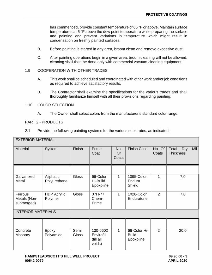
PROTECTIVE COATINGS
HAMPSTEAD/SCOTT’S HILL WELL PROJECT 09 90 00 - 3
00542-0079 APRIL 2020
has commenced, provide constant temperature of 65 °F or above. Maintain surface temperatures at 5 °F above the dew point temperature while preparing the surface and painting and prevent variations in temperature which might result in condensation on freshly painted surfaces.
B. Before painting is started in any area, broom clean and remove excessive dust.
C. After painting operations begin in a given area, broom cleaning will not be allowed; cleaning shall then be done only with commercial vacuum cleaning equipment.
1.9 COOPERATION WITH OTHER TRADES
A. This work shall be scheduled and coordinated with other work and/or job conditions as required to achieve satisfactory results.
B. The Contractor shall examine the specifications for the various trades and shall thoroughly familiarize himself with all their provisions regarding painting.
1.10 COLOR SELECTION
A. The Owner shall select colors from the manufacturer’s standard color range.
PART 2 - PRODUCTS
2.1 Provide the following painting systems for the various substrates, as indicated:
EXTERIOR MATERIAL
Material System Finish Prime Coat
No. Of
Coats
Finish Coat No. Of Coats
Total Dry Mil Thickness
Galvanized Metal
Aliphatic Polyurethane
Gloss 66-Color Hi-Build Epoxoline
1 1095-Color Endura Shield
1 7.0
Ferrous Metals (Non-submerged)
HDP Acrylic Polymer
Gloss 37H-77 Chem-Prime
1 1028-Color Enduratone
2 7.0
INTERIOR MATERIALS
Concrete Masonry
Epoxy Polyamide
Semi Gloss
130-6602 Envirofill (fill all voids)
1 66-Color Hi-Build Epoxoline
2 20.0
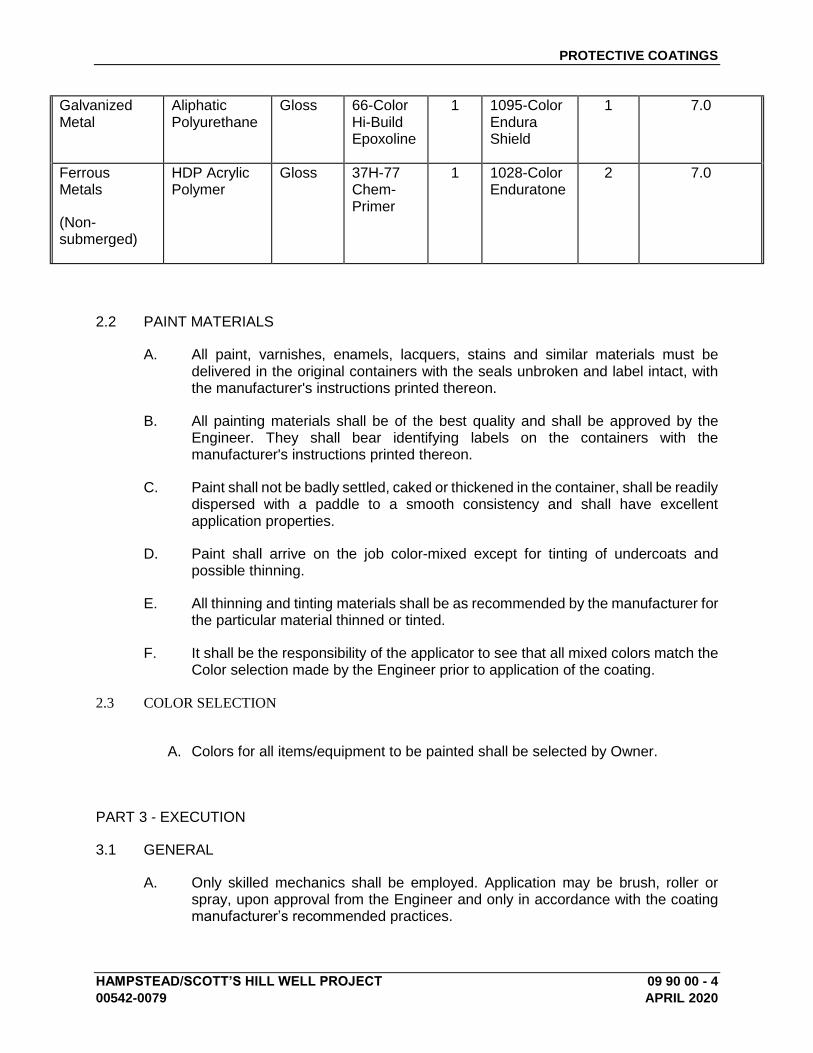
PROTECTIVE COATINGS
HAMPSTEAD/SCOTT’S HILL WELL PROJECT 09 90 00 - 4
00542-0079 APRIL 2020
Galvanized Metal
Aliphatic Polyurethane
Gloss 66-Color Hi-Build Epoxoline
1 1095-Color Endura Shield
1 7.0
Ferrous Metals
(Non-submerged)
HDP Acrylic Polymer
Gloss 37H-77 Chem-Primer
1 1028-Color Enduratone
2 7.0
2.2 PAINT MATERIALS
A. All paint, varnishes, enamels, lacquers, stains and similar materials must be delivered in the original containers with the seals unbroken and label intact, with the manufacturer's instructions printed thereon.
B. All painting materials shall be of the best quality and shall be approved by the Engineer. They shall bear identifying labels on the containers with the manufacturer's instructions printed thereon.
C. Paint shall not be badly settled, caked or thickened in the container, shall be readily dispersed with a paddle to a smooth consistency and shall have excellent application properties.
D. Paint shall arrive on the job color-mixed except for tinting of undercoats and possible thinning.
E. All thinning and tinting materials shall be as recommended by the manufacturer for the particular material thinned or tinted.
F. It shall be the responsibility of the applicator to see that all mixed colors match the Color selection made by the Engineer prior to application of the coating.
2.3 COLOR SELECTION
A. Colors for all items/equipment to be painted shall be selected by Owner.
PART 3 - EXECUTION
3.1 GENERAL
A. Only skilled mechanics shall be employed. Application may be brush, roller or spray, upon approval from the Engineer and only in accordance with the coating manufacturer’s recommended practices.
PROTECTIVE COATINGS
HAMPSTEAD/SCOTT’S HILL WELL PROJECT 09 90 00 - 5
00542-0079 APRIL 2020
B. The Contractor shall protect his work at all times and shall protect all adjacent work and materials by suitable covering or other method during progress of his work. Upon completion of the work, he shall remove all paint and varnish spots from floors, glass and other surfaces. He shall remove from the premises all rubbish and accumulated materials of whatever nature not caused by others and shall leave his part of the work in clean, orderly and acceptable condition.
C. Remove and protect hardware, accessories, device plates, lighting fixtures, factory finished work and similar items, provide ample in-place protection. Upon completion of each space, carefully replace all removed items.
D. Remove electrical panel box covers and doors before painting walls. Paint separately and reinstall after all paint is dry.
E. All materials shall be applied under adequate illumination, evenly spread and flowed-on smoothly to avoid runs, sags, holidays, brush marks, air bubbles and excessive roller stipple.
F. Coverage and hide shall be complete. When color, stain, dirt or undercoats show through final coat of paint, the surface shall be covered by additional coats until the paint film is of uniform finish, color, appearance and coverage, at no additional cost to the Owner.
G. All coats shall be dry to manufacturer's recommendations before applying succeeding coats.
H. Where spray paint is specified, the Contractor shall finish 100 square feet by spraying a sample of the finish upon the request of the Engineer. This shall be finished with materials specified or approved.
I. Surfaces to be stained shall appear uniform in shading with color variations caused only by the natural wood grain.
3.2 PREPARATION OF SURFACES
A. General:
1. Surfaces shall be clean, dry and adequately protected from dampness.
2. Surfaces shall be free of any foreign materials that will adversely affect adhesion or appearance of applied coating.
3. Mildew shall be removed and the surface neutralized per the coating manufacturer's recommendations.
4. Efflorescence on any area will be corrected before painting.
B. Ferrous Metal Surfaces:
1. Remove dirt and grease with mineral spirits and wipe dry with clean cloths.
PROTECTIVE COATINGS
HAMPSTEAD/SCOTT’S HILL WELL PROJECT 09 90 00 - 6
00542-0079 APRIL 2020
2. Remove rust, mill scale and defective paint down to sound surfaces or bare metal using scraper, sandpaper, wire brush or, if necessary, sandblasting. Grind, disc sand, sand blast, etc., if necessary to remove shoulders at edge of sound paint to prevent them from photographing through finish coats. Preparation shall meet or exceed an SSPC-SP 6 specification for non-submerged surfaces and an SSPC-SP10 specification for submerged surfaces or surface subject to high humidity.
3. Touch up all bare metal and damaged shop coats with specified shop coat primer.
4. For ferrous surfaces with shop coats touched up, as above required, the first coat as listed in the following schedule will be applied to the dry mil film thickness specified.
C. Galvanized Metal Surfaces:
1. All Galvanized Surfaces shall be cleaned in accord with SSPC-SP 16 Brush-Off Blast Cleaning of Coated and Uncoated Galvanized, Steel.
D. Concrete
1. Patch large openings and holes and finish flush with Tnemec Series 218 MortarClad. After priming, fill any remaining small holes with prepared patching material.
2. Check pH; if not neutral, then correct by using a 3% solution of T.S.P. or ammonium hydroxide. The etched surface should appear uniform in sheen and feel like 100 grit abrasive paper.
3. Remove form oil from poured-in-place concrete by washing concrete with xylol or exempt-type form oil solvent, or as required for complete removal.
4. All surfaces shall be dry. No painting shall be done until surfaces have cured for 28 days and are dry.
5. All concrete in immersion shall be cleaned in accordance with SSPC-SP13/NACE6 Surface Preparation of Concrete, ICRI CSP 5.
3.3 WORKMANSHIP FOR PAINTING
A. Exterior painting shall not be done when the surface temperature is below 50 °F, while the surface is damp, or during cold, rainy or frosty weather. The substrate temperature must be 5 °F or more above the dew point temperature while painting and during the coating cure. Avoid painting surfaces while they are exposed to hot sun.
B. Exterior doors shall have tops; bottoms and side edges finished the same as the exterior faces of these doors.
END OF SECTION 09 90 00
HAMPSTEAD\SCOTT’S HILL WELL PROJECT 11 93 00 - 1
00542-0079 APRIL 2020
SECTION 11 93 00 – POLYETHYLENE SINGLE WALL STORAGE TANK
PART 1 – GENERAL 1.1 Scope
A. This specification covers upright, cylindrical, flat bottom, single wall tanks molded in a one-piece seamless construction by the rotational molding process (laminated or fabricated tanks will not be accepted). The tanks are designed for above-ground, vertical installation and are capable of containing chemicals at atmospheric pressure. Included in this specification are requirements for materials, properties, design, construction, dimensions, tolerances, workmanship, and appearance. Tank capacities are from 500 gallon (1,816 L) up to 16,500 gallon (62,453 L).
B. This specification does not cover the design of vessels intended for use at pressures above or below atmospheric conditions. It is also not for vessels intended for use with liquids heated above their flash points, temperatures above 140 degrees Fahrenheit for Type I materials, or temperatures above 130 degrees Fahrenheit for Type II materials. (Note: See 1.08 A.2. for chemicals being stored above 100 degrees F)
C. Contractor shall supply and install all materials, equipment, appurtenances, specialty items, and services required to provide an upright, single wall, flat bottom, closed top, polyethylene storage tank for storage of the chemical application(s) described in Table I. Each tank is to be molded in one-piece seamless construction according to ASTM D 1998 (laminated or fabricated tanks will not be accepted) and will be capable of storing the chemical application at atmospheric pressure.
1.2 Manufacturer
A. Tanks shall be manufactured by Snyder Industries Inc. or approved equal
1.3 Applicable Documents
A. ASTM (American Society for Testing and Materials) Standards:
1. D618 Conditioning Plastics and Electrical Insulating Materials for Testing 2. D638 Tensile Properties of Plastics 3. D790 Flexural Properties of Unreinforced and Reinforced Plastics and Electrical
Insulating Materials 4. D883 Definitions of Terms Relating to Plastics 5. D1505 Density of Plastics by the Density-Gradient Technique 6 D1525 Test Method for Vicat Softening Temperature of Plastics 7. D1693 Test Method for Environmental Stress-Cracking of Ethylene Plastics 8. D1998 Standard Specification for Polyethylene Upright Storage Tanks
9. D2765 Degree of Crosslinking in Crosslinked Ethylene Plastics as Determined by Solvent Extraction
10. D2837 Method for Obtaining Hydrostatic Design Basis for Thermoplastic Pipe Materials 11. D3892 Practice for Packaging/Packing of Plastics 12. F412 Definitions of Terms Relating to Plastic Piping Systems
B. ARM (Association of Rotational Molders) Standards: Low Temperature Impact Resistance
(Falling Dart Test Procedure)
C. ANSI Standards: B-16.5 Pipe Flanges and Flanged Fitting
POLYETHYLENE SINGLE WALL STORAGE TANK
HAMPSTEAD\SCOTT’S HILL WELL PROJECT 11 93 00 - 2
00542-0079 APRIL 2020
D. OSHA Standards: 29 CFR 1910.106 Occupational Safety and Health Administration, Flammable and Combustible Liquids
E. UBC CODE: Uniform Building Code 2006 Edition
F. IBC CODE: International Building Code 2015 Edition
G. CBC Code: California Building Code 2016 Edition
H. NSF/ANSI Standard 61 – Drinking Water System Components (Type II resin)
1.4 Submittals
A. Drawings and Data: The manufacturer’s shop drawings shall be approved by the engineer or contractor prior to the manufacturing of the tank(s). Data and specifications for the equipment shall include, but shall not be limited to the following submittals.
B. Contractor shall submit for review sufficient literature, detailed specifications, and
drawings to show dimensions, materials used, design features, internal construction, weights and any other information required by the ENGINEER for review of storage tanks and accessories.
C. Information to be included with submittals are specified below:
1. Shop drawings for the tanks shall include as a minimum the following:
a. Service Conditions: Chemical environment and temperature. b. Statement that fabrication shall be in accordance with ASTM D 1998, where
applicable. c. Sizing and description of the fittings and accessories for each tank that are to
be supplied by the tank manufacturer. d. Layouts and assembly schedules for each tank identifying the location and
elevation from the bottom of the tank for all inlet, outlet and other integrally molded connections and appurtenances supplied by the tank manufacturer.
2. Resin - A copy of the resin data sheet from the resin manufacturer for the tank is to be
supplied and the tank manufacturer is to certify that it will be the resin used in the manufacture of the tank. Verification may be required if the resin is to be FDA or NSF 61 listed.
3. Wall thickness - Prior to the manufacture of the tank the designed wall thickness audit
is to be supplied based upon ASTM D1998 @ 100 degrees F. (Note: See 1.08 A.2 for chemicals being stored above 100 degrees F)
4. Tank restraint – If supplied, the drawings and calculations for the system are to be supplied. Note: Wet stamped or site specific drawings and calculations may be required.
5. Supporting information on fittings and accessories to be supplied; heat system,
insulation, mastic coating, etc.
POLYETHYLENE SINGLE WALL STORAGE TANK
HAMPSTEAD\SCOTT’S HILL WELL PROJECT 11 93 00 - 3
00542-0079 APRIL 2020
6 Technical Manuals: The tank manufacturers Guideline for Use & Installation is to be submitted for review.
7. Manufacturer’s warranty 8. Manufacturer Qualifications: The manufacturer is to have rotationally molded tanks
based upon ASTM D 1998 utilizing Type I and Type II resins for the last 10 years. 9. Installation certificate: Once installed the installer is to certify that the tank system has
been installed according to the tank manufacturer’s Guidelines for Use & Installation.
10. Factory Test Report: Upon completion of the tank the manufacturer’s inspection report is to be supplied for each tank.
a. Verification of wall thickness (See 1.09 E.) b. Impact test (See 1.09 C.) c. Gel test – (Type I resin only) (See 1.09 D.) d. Hydrostatic test (See 1.09 F.) e. Verification of fitting placement (See 1.09 B.) f. Visual inspection (See 1.09 G.) g. Verification of materials
1.5 Service Conditions
Note: The tank color will be based upon the chemical application and UV exposure of the installation. Tank color is to be natural, black or opaque white.
Table I – Service Conditions
Tank #
Chemical Stored
Concentration / Specific Gravity
Tank Location Inside / Outside
Operating Temperature
Fitting Material
Gasket Material
Bolt / SUMO Material
1.6 Chemical Compatibility
A. Chemical compatibility shall be according to the following chemical resistance guides:
Compass Publications - Pruett, Kenneth M., “Chemical Resistance Guide for Plastics” Pruett, Kenneth M., “Chemical Resistance Guide for Metals and Alloys” Pruett, Kenneth M., “Chemical Resistance Guide for Elastomers III”
B. These references shall be considered as general guidelines only. In many cases,
combinations of these chemicals are used in such a way that only the customer (by testing molded product samples) can make a determination in regards to acceptability.
Note: Contact the manufacturer for applications that are not listed below.
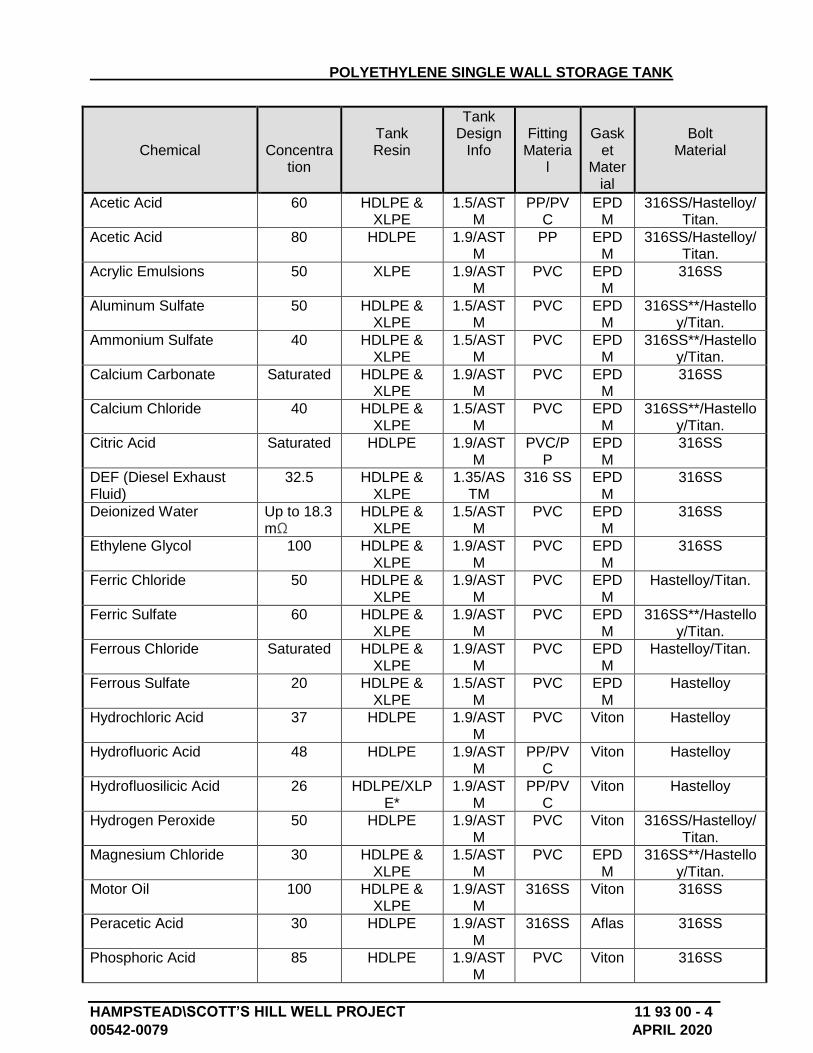
POLYETHYLENE SINGLE WALL STORAGE TANK
HAMPSTEAD\SCOTT’S HILL WELL PROJECT 11 93 00 - 4
00542-0079 APRIL 2020
Chemical
Concentration
Tank Resin
Tank Design
Info
Fitting
Material
Gask
et Mater
ial
Bolt
Material
Acetic Acid 60 HDLPE & XLPE
1.5/ASTM
PP/PVC
EPDM
316SS/Hastelloy/Titan.
Acetic Acid 80 HDLPE 1.9/ASTM
PP EPDM
316SS/Hastelloy/Titan.
Acrylic Emulsions 50 XLPE 1.9/ASTM
PVC EPDM
316SS
Aluminum Sulfate 50 HDLPE & XLPE
1.5/ASTM
PVC EPDM
316SS**/Hastelloy/Titan.
Ammonium Sulfate 40 HDLPE & XLPE
1.5/ASTM
PVC EPDM
316SS**/Hastelloy/Titan.
Calcium Carbonate Saturated HDLPE & XLPE
1.9/ASTM
PVC EPDM
316SS
Calcium Chloride 40 HDLPE & XLPE
1.5/ASTM
PVC EPDM
316SS**/Hastelloy/Titan.
Citric Acid Saturated HDLPE 1.9/ASTM
PVC/PP
EPDM
316SS
DEF (Diesel Exhaust Fluid)
32.5 HDLPE & XLPE
1.35/ASTM
316 SS EPDM
316SS
Deionized Water Up to 18.3 mΩ
HDLPE & XLPE
1.5/ASTM
PVC EPDM
316SS
Ethylene Glycol 100 HDLPE & XLPE
1.9/ASTM
PVC EPDM
316SS
Ferric Chloride 50 HDLPE & XLPE
1.9/ASTM
PVC EPDM
Hastelloy/Titan.
Ferric Sulfate 60 HDLPE & XLPE
1.9/ASTM
PVC EPDM
316SS**/Hastelloy/Titan.
Ferrous Chloride Saturated HDLPE & XLPE
1.9/ASTM
PVC EPDM
Hastelloy/Titan.
Ferrous Sulfate 20 HDLPE & XLPE
1.5/ASTM
PVC EPDM
Hastelloy
Hydrochloric Acid 37 HDLPE 1.9/ASTM
PVC Viton Hastelloy
Hydrofluoric Acid 48 HDLPE 1.9/ASTM
PP/PVC
Viton Hastelloy
Hydrofluosilicic Acid 26 HDLPE/XLPE*
1.9/ASTM
PP/PVC
Viton Hastelloy
Hydrogen Peroxide 50 HDLPE 1.9/ASTM
PVC Viton 316SS/Hastelloy/Titan.
Magnesium Chloride 30 HDLPE & XLPE
1.5/ASTM
PVC EPDM
316SS**/Hastelloy/Titan.
Motor Oil 100 HDLPE & XLPE
1.9/ASTM
316SS Viton 316SS
Peracetic Acid 30 HDLPE 1.9/ASTM
316SS Aflas 316SS
Phosphoric Acid 85 HDLPE 1.9/ASTM
PVC Viton 316SS
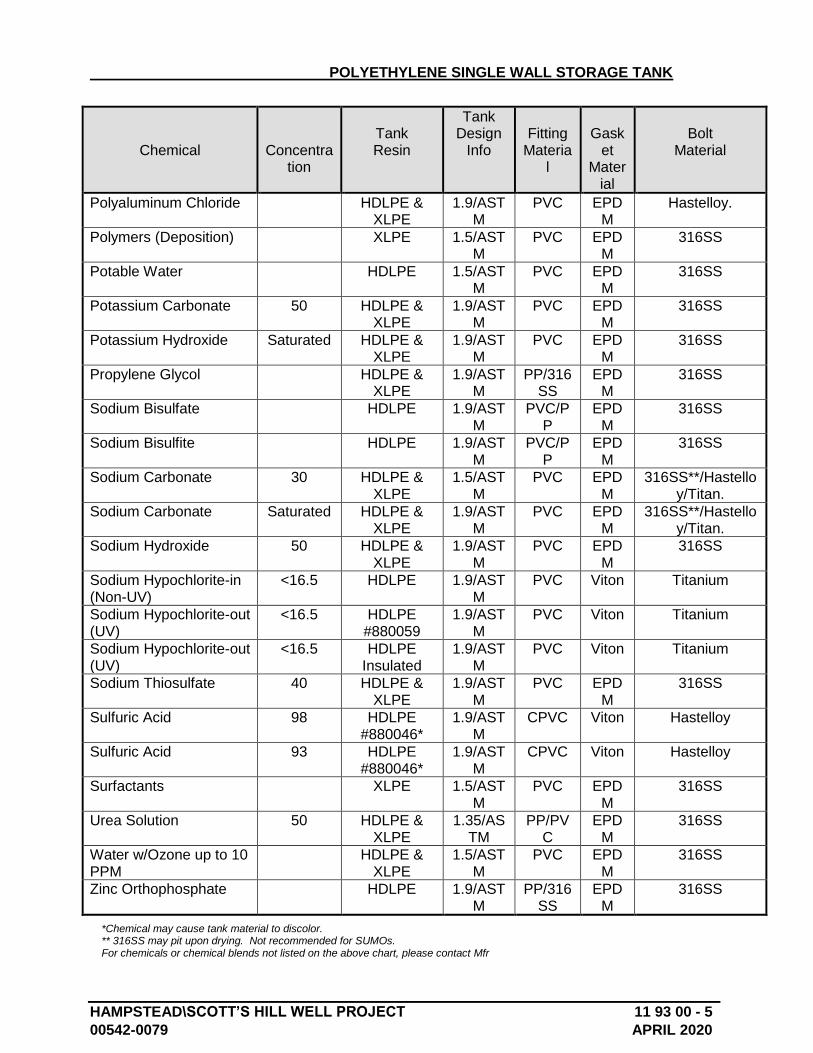
POLYETHYLENE SINGLE WALL STORAGE TANK
HAMPSTEAD\SCOTT’S HILL WELL PROJECT 11 93 00 - 5
00542-0079 APRIL 2020
Chemical
Concentration
Tank Resin
Tank Design
Info
Fitting
Material
Gask
et Mater
ial
Bolt
Material
Polyaluminum Chloride HDLPE & XLPE
1.9/ASTM
PVC EPDM
Hastelloy.
Polymers (Deposition) XLPE 1.5/ASTM
PVC EPDM
316SS
Potable Water HDLPE 1.5/ASTM
PVC EPDM
316SS
Potassium Carbonate 50 HDLPE & XLPE
1.9/ASTM
PVC EPDM
316SS
Potassium Hydroxide Saturated HDLPE & XLPE
1.9/ASTM
PVC EPDM
316SS
Propylene Glycol HDLPE & XLPE
1.9/ASTM
PP/316SS
EPDM
316SS
Sodium Bisulfate HDLPE 1.9/ASTM
PVC/PP
EPDM
316SS
Sodium Bisulfite HDLPE 1.9/ASTM
PVC/PP
EPDM
316SS
Sodium Carbonate 30 HDLPE & XLPE
1.5/ASTM
PVC EPDM
316SS**/Hastelloy/Titan.
Sodium Carbonate Saturated HDLPE & XLPE
1.9/ASTM
PVC EPDM
316SS**/Hastelloy/Titan.
Sodium Hydroxide 50 HDLPE & XLPE
1.9/ASTM
PVC EPDM
316SS
Sodium Hypochlorite-in (Non-UV)
<16.5 HDLPE 1.9/ASTM
PVC Viton Titanium
Sodium Hypochlorite-out (UV)
<16.5 HDLPE #880059
1.9/ASTM
PVC Viton Titanium
Sodium Hypochlorite-out (UV)
<16.5 HDLPE Insulated
1.9/ASTM
PVC Viton Titanium
Sodium Thiosulfate 40 HDLPE & XLPE
1.9/ASTM
PVC EPDM
316SS
Sulfuric Acid 98 HDLPE #880046*
1.9/ASTM
CPVC Viton Hastelloy
Sulfuric Acid 93 HDLPE #880046*
1.9/ASTM
CPVC Viton Hastelloy
Surfactants XLPE 1.5/ASTM
PVC EPDM
316SS
Urea Solution 50 HDLPE & XLPE
1.35/ASTM
PP/PVC
EPDM
316SS
Water w/Ozone up to 10 PPM
HDLPE & XLPE
1.5/ASTM
PVC EPDM
316SS
Zinc Orthophosphate HDLPE 1.9/ASTM
PP/316SS
EPDM
316SS
*Chemical may cause tank material to discolor. ** 316SS may pit upon drying. Not recommended for SUMOs. For chemicals or chemical blends not listed on the above chart, please contact Mfr
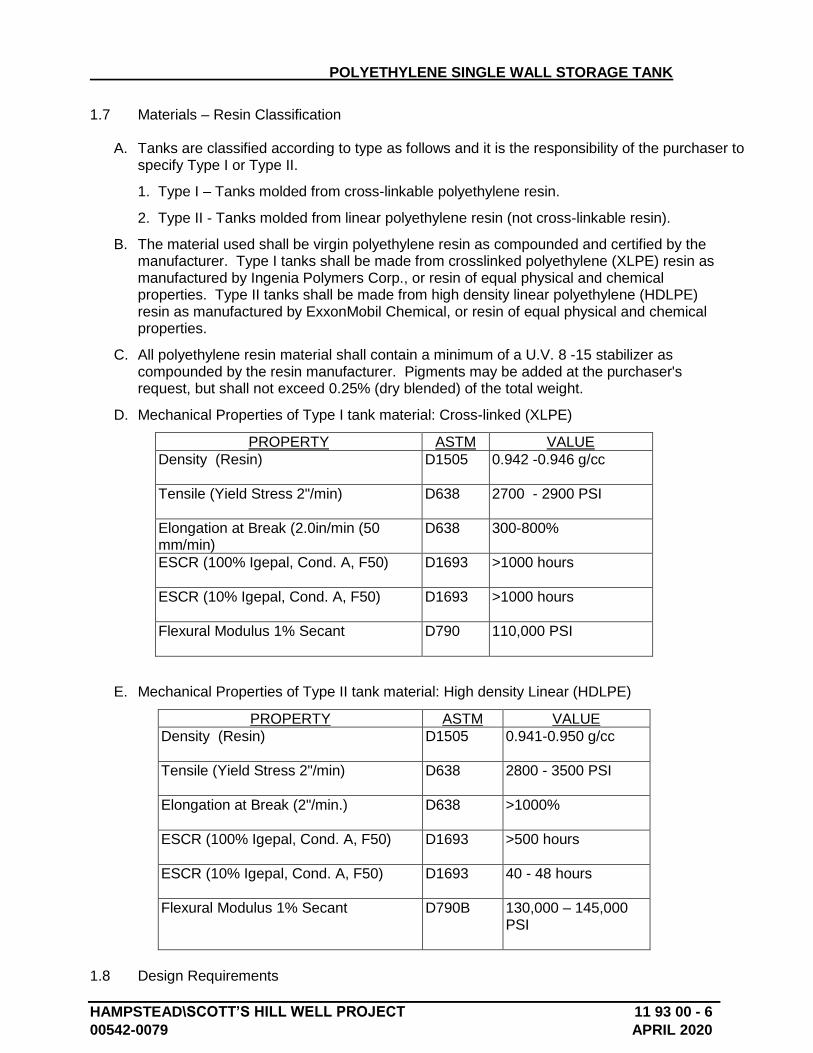
POLYETHYLENE SINGLE WALL STORAGE TANK
HAMPSTEAD\SCOTT’S HILL WELL PROJECT 11 93 00 - 6
00542-0079 APRIL 2020
1.7 Materials – Resin Classification
A. Tanks are classified according to type as follows and it is the responsibility of the purchaser to specify Type I or Type II.
1. Type I – Tanks molded from cross-linkable polyethylene resin.
2. Type II - Tanks molded from linear polyethylene resin (not cross-linkable resin).
B. The material used shall be virgin polyethylene resin as compounded and certified by the manufacturer. Type I tanks shall be made from crosslinked polyethylene (XLPE) resin as manufactured by Ingenia Polymers Corp., or resin of equal physical and chemical properties. Type II tanks shall be made from high density linear polyethylene (HDLPE) resin as manufactured by ExxonMobil Chemical, or resin of equal physical and chemical properties.
C. All polyethylene resin material shall contain a minimum of a U.V. 8 -15 stabilizer as compounded by the resin manufacturer. Pigments may be added at the purchaser's request, but shall not exceed 0.25% (dry blended) of the total weight.
D. Mechanical Properties of Type I tank material: Cross-linked (XLPE)
PROPERTY ASTM VALUE
Density (Resin) D1505 0.942 -0.946 g/cc
Tensile (Yield Stress 2"/min)
D638
2700 - 2900 PSI
Elongation at Break (2.0in/min (50 mm/min)
D638
300-800%
ESCR (100% Igepal, Cond. A, F50)
D1693
>1000 hours
ESCR (10% Igepal, Cond. A, F50)
D1693
>1000 hours
Flexural Modulus 1% Secant
D790
110,000 PSI
E. Mechanical Properties of Type II tank material: High density Linear (HDLPE)
PROPERTY ASTM VALUE
Density (Resin) D1505 0.941-0.950 g/cc
Tensile (Yield Stress 2"/min)
D638
2800 - 3500 PSI
Elongation at Break (2"/min.)
D638
>1000%
ESCR (100% Igepal, Cond. A, F50)
D1693
>500 hours
ESCR (10% Igepal, Cond. A, F50)
D1693
40 - 48 hours
Flexural Modulus 1% Secant
D790B
130,000 – 145,000 PSI
1.8 Design Requirements
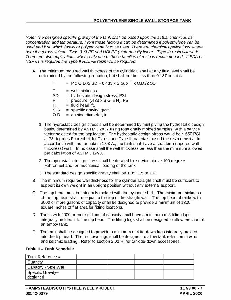
POLYETHYLENE SINGLE WALL STORAGE TANK
HAMPSTEAD\SCOTT’S HILL WELL PROJECT 11 93 00 - 7
00542-0079 APRIL 2020
Note: The designed specific gravity of the tank shall be based upon the actual chemical, its’ concentration and temperature. From these factors it can be determined if polyethylene can be used and if so which family of polyethylene is to be used. There are chemical applications where both the (cross-linked - Type I) XLPE and HDLPE (high-density linear - Type II) resin will work. There are also applications where only one of these families of resin is recommended. If FDA or NSF 61 is required the Type II HDLPE resin will be required.
A. The minimum required wall thickness of the cylindrical shell at any fluid level shall be determined by the following equation, but shall not be less than 0.187 in. thick.
T = P x O.D./2 SD = 0.433 x S.G. x H x O.D./2 SD
T = wall thickness SD = hydrostatic design stress, PSI P = pressure (.433 x S.G. x H), PSI H = fluid head, ft. S.G. = specific gravity, g/cm3 O.D. = outside diameter, in.
1. The hydrostatic design stress shall be determined by multiplying the hydrostatic design basis, determined by ASTM D2837 using rotationally molded samples, with a service factor selected for the application. The hydrostatic design stress would be ≤ 660 PSI at 73 degrees Fahrenheit for Type I and Type II materials based the resin density. In accordance with the formula in 1.08 A., the tank shall have a stratiform (tapered wall thickness) wall. In no case shall the wall thickness be less than the minimum allowed per calculation of ASTM D1998.
2. The hydrostatic design stress shall be derated for service above 100 degrees Fahrenheit and for mechanical loading of the tank.
3. The standard design specific gravity shall be 1.35, 1.5 or 1.9.
B. The minimum required wall thickness for the cylinder straight shell must be sufficient to support its own weight in an upright position without any external support.
C. The top head must be integrally molded with the cylinder shell. The minimum thickness of the top head shall be equal to the top of the straight wall. The top head of tanks with 2000 or more gallons of capacity shall be designed to provide a minimum of 1300 square inches of flat area for fitting locations.
D. Tanks with 2000 or more gallons of capacity shall have a minimum of 3 lifting lugs integrally molded into the top head. The lifting lugs shall be designed to allow erection of an empty tank.
E. The tank shall be designed to provide a minimum of 4 tie-down lugs integrally molded into the top head. The tie-down lugs shall be designed to allow tank retention in wind and seismic loading. Refer to section 2.02 H. for tank tie-down accessories.
Table II – Tank Schedule
Tank Reference #
Quantity
Capacity - Side Wall
Specific Gravity– designed
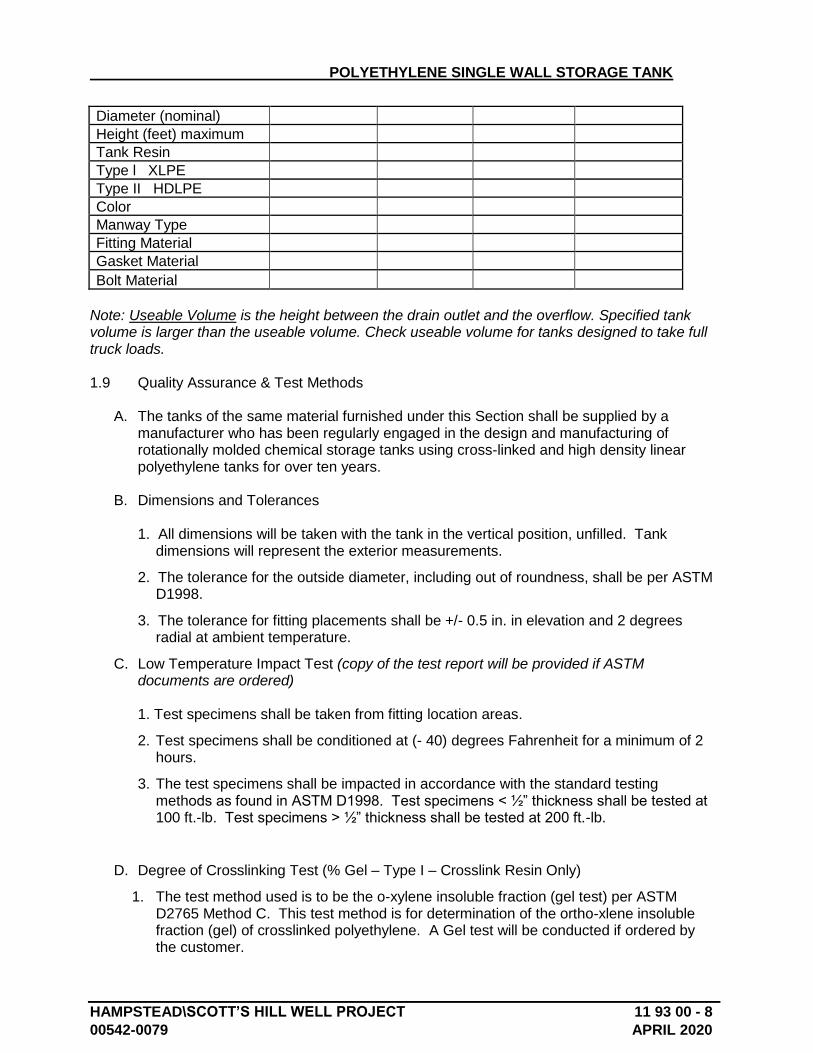
POLYETHYLENE SINGLE WALL STORAGE TANK
HAMPSTEAD\SCOTT’S HILL WELL PROJECT 11 93 00 - 8
00542-0079 APRIL 2020
Diameter (nominal)
Height (feet) maximum
Tank Resin
Type l XLPE
Type II HDLPE
Color
Manway Type
Fitting Material
Gasket Material
Bolt Material
Note: Useable Volume is the height between the drain outlet and the overflow. Specified tank volume is larger than the useable volume. Check useable volume for tanks designed to take full truck loads. 1.9 Quality Assurance & Test Methods
A. The tanks of the same material furnished under this Section shall be supplied by a manufacturer who has been regularly engaged in the design and manufacturing of rotationally molded chemical storage tanks using cross-linked and high density linear polyethylene tanks for over ten years.
B. Dimensions and Tolerances
1. All dimensions will be taken with the tank in the vertical position, unfilled. Tank dimensions will represent the exterior measurements.
2. The tolerance for the outside diameter, including out of roundness, shall be per ASTM D1998.
3. The tolerance for fitting placements shall be +/- 0.5 in. in elevation and 2 degrees radial at ambient temperature.
C. Low Temperature Impact Test (copy of the test report will be provided if ASTM documents are ordered) 1. Test specimens shall be taken from fitting location areas.
2. Test specimens shall be conditioned at (- 40) degrees Fahrenheit for a minimum of 2 hours.
3. The test specimens shall be impacted in accordance with the standard testing methods as found in ASTM D1998. Test specimens < ½” thickness shall be tested at 100 ft.-lb. Test specimens > ½” thickness shall be tested at 200 ft.-lb.
D. Degree of Crosslinking Test (% Gel – Type I – Crosslink Resin Only)
1. The test method used is to be the o-xylene insoluble fraction (gel test) per ASTM D2765 Method C. This test method is for determination of the ortho-xlene insoluble fraction (gel) of crosslinked polyethylene. A Gel test will be conducted if ordered by the customer.
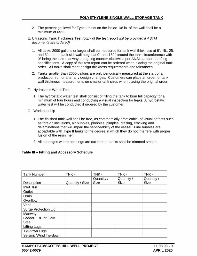
POLYETHYLENE SINGLE WALL STORAGE TANK
HAMPSTEAD\SCOTT’S HILL WELL PROJECT 11 93 00 - 9
00542-0079 APRIL 2020
2. The percent gel level for Type I tanks on the inside 1/8 in. of the wall shall be a minimum of 65%.
E. Ultrasonic Tank Thickness Test (copy of the test report will be provided if ASTM documents are ordered)
1. All tanks 2000 gallons or larger shall be measured for tank wall thickness at 6”, 1ft., 2ft.
and 3ft. on the tank sidewall height at 0° and 180° around the tank circumference with 0° being the tank manway and going counter-clockwise per ANSI standard drafting specifications. A copy of this test report can be ordered when placing the original tank order. All tanks shall meet design thickness requirements and tolerances.
2. Tanks smaller than 2000 gallons are only periodically measured at the start of a production run or after any design changes. Customers can place an order for tank wall thickness measurements on smaller tank sizes when placing the original order.
F. Hydrostatic Water Test
1. The hydrostatic water test shall consist of filling the tank to brim full capacity for a minimum of four hours and conducting a visual inspection for leaks. A hydrostatic water test will be conducted if ordered by the customer.
G. Workmanship
1. The finished tank wall shall be free, as commercially practicable, of visual defects such as foreign inclusions, air bubbles, pinholes, pimples, crazing, cracking and delaminations that will impair the serviceability of the vessel. Fine bubbles are acceptable with Type II tanks to the degree in which they do not interfere with proper fusion of the resin melt.
2. All cut edges where openings are cut into the tanks shall be trimmed smooth.
Table III – Fitting and Accessory Schedule
Tank Number TNK - TNK - TNK - TNK -
Description Quantity / Size Quantity / Size
Quantity / Size
Quantity / Size
Inlet /Fill
Outlet
Drain
Overflow
Vent
Surge Protection Lid
Manway
Ladder FRP or Galv. Steel
Lifting Lugs
Tie-down Lugs
Seismic/Wind Tie-down
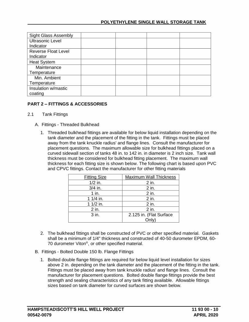
POLYETHYLENE SINGLE WALL STORAGE TANK
HAMPSTEAD\SCOTT’S HILL WELL PROJECT 11 93 00 - 10
00542-0079 APRIL 2020
Sight Glass Assembly
Ultrasonic Level Indicator
Reverse Float Level Indicator
Heat System
Maintenance Temperature
Min. Ambient Temperature
Insulation w/mastic coating
PART 2 – FITTINGS & ACCESSORIES 2.1 Tank Fittings
A. Fittings - Threaded Bulkhead
1. Threaded bulkhead fittings are available for below liquid installation depending on the tank diameter and the placement of the fitting in the tank. Fittings must be placed away from the tank knuckle radius' and flange lines. Consult the manufacturer for placement questions. The maximum allowable size for bulkhead fittings placed on a curved sidewall section of tanks 48 in. to 142 in. in diameter is 2 inch size. Tank wall thickness must be considered for bulkhead fitting placement. The maximum wall thickness for each fitting size is shown below. The following chart is based upon PVC and CPVC fittings. Contact the manufacturer for other fitting materials
Fitting Size Maximum Wall Thickness
1/2 in. 2 in.
3/4 in. 2 in.
1 in. 2 in.
1 1/4 in. 2 in.
1 1/2 in. 2 in.
2 in. 2 in.
3 in. 2.125 in. (Flat Surface Only)
2. The bulkhead fittings shall be constructed of PVC or other specified material. Gaskets shall be a minimum of 1/4" thickness and constructed of 40-50 durometer EPDM, 60-70 durometer Viton®, or other specified material.
B. Fittings - Bolted Double 150 lb. Flange Fittings
1. Bolted double flange fittings are required for below liquid level installation for sizes above 2 in. depending on the tank diameter and the placement of the fitting in the tank. Fittings must be placed away from tank knuckle radius' and flange lines. Consult the manufacturer for placement questions. Bolted double flange fittings provide the best strength and sealing characteristics of any tank fitting available. Allowable fittings sizes based on tank diameter for curved surfaces are shown below.
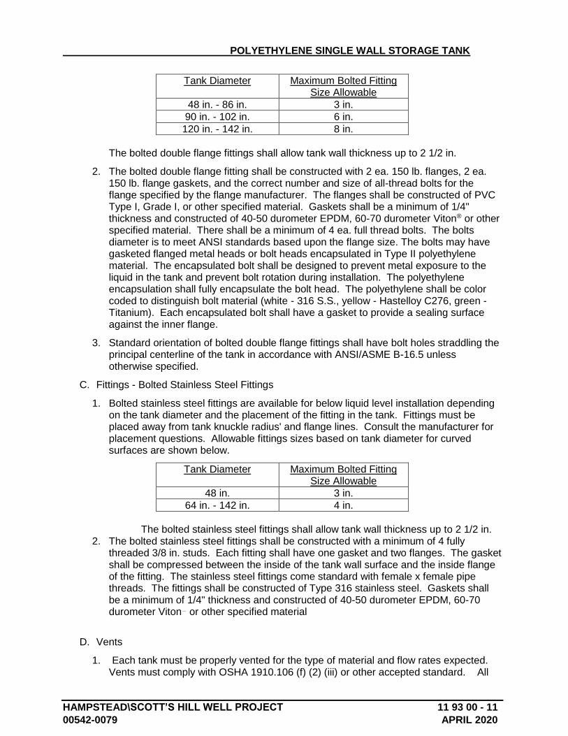
POLYETHYLENE SINGLE WALL STORAGE TANK
HAMPSTEAD\SCOTT’S HILL WELL PROJECT 11 93 00 - 11
00542-0079 APRIL 2020
Tank Diameter Maximum Bolted Fitting Size Allowable
48 in. - 86 in. 3 in.
90 in. - 102 in. 6 in.
120 in. - 142 in. 8 in.
The bolted double flange fittings shall allow tank wall thickness up to 2 1/2 in.
2. The bolted double flange fitting shall be constructed with 2 ea. 150 lb. flanges, 2 ea. 150 lb. flange gaskets, and the correct number and size of all-thread bolts for the flange specified by the flange manufacturer. The flanges shall be constructed of PVC Type I, Grade I, or other specified material. Gaskets shall be a minimum of 1/4" thickness and constructed of 40-50 durometer EPDM, 60-70 durometer Viton® or other specified material. There shall be a minimum of 4 ea. full thread bolts. The bolts diameter is to meet ANSI standards based upon the flange size. The bolts may have gasketed flanged metal heads or bolt heads encapsulated in Type II polyethylene material. The encapsulated bolt shall be designed to prevent metal exposure to the liquid in the tank and prevent bolt rotation during installation. The polyethylene encapsulation shall fully encapsulate the bolt head. The polyethylene shall be color coded to distinguish bolt material (white - 316 S.S., yellow - Hastelloy C276, green - Titanium). Each encapsulated bolt shall have a gasket to provide a sealing surface against the inner flange.
3. Standard orientation of bolted double flange fittings shall have bolt holes straddling the principal centerline of the tank in accordance with ANSI/ASME B-16.5 unless otherwise specified.
C. Fittings - Bolted Stainless Steel Fittings
1. Bolted stainless steel fittings are available for below liquid level installation depending on the tank diameter and the placement of the fitting in the tank. Fittings must be placed away from tank knuckle radius' and flange lines. Consult the manufacturer for placement questions. Allowable fittings sizes based on tank diameter for curved surfaces are shown below.
Tank Diameter Maximum Bolted Fitting Size Allowable
48 in. 3 in.
64 in. - 142 in. 4 in.
The bolted stainless steel fittings shall allow tank wall thickness up to 2 1/2 in.
2. The bolted stainless steel fittings shall be constructed with a minimum of 4 fully threaded 3/8 in. studs. Each fitting shall have one gasket and two flanges. The gasket shall be compressed between the inside of the tank wall surface and the inside flange of the fitting. The stainless steel fittings come standard with female x female pipe threads. The fittings shall be constructed of Type 316 stainless steel. Gaskets shall be a minimum of 1/4" thickness and constructed of 40-50 durometer EPDM, 60-70 durometer Viton or other specified material
D. Vents
1. Each tank must be properly vented for the type of material and flow rates expected. Vents must comply with OSHA 1910.106 (f) (2) (iii) or other accepted standard. All
POLYETHYLENE SINGLE WALL STORAGE TANK
HAMPSTEAD\SCOTT’S HILL WELL PROJECT 11 93 00 - 12
00542-0079 APRIL 2020
tanks must be vented for atmospheric pressure as well as any pressure created by filling and emptying the tank. Some applications may require a sealed tank with a vent line going to a scrubber system for proper chemical safety. Venting equipment should be sized to limit pressure or vacuum in the tank to a maximum of 1/2" of water column (0.02 psi). U-Vents are offered in sizes from 1 in. to 6 in. with or without mesh insect screening. U-Vents with mesh screening may require additional sizing due to reduced air-flow rates. Consult the manufacturer for necessary venting and placement information.
2. All u-vents shall be constructed of PVC or other specified materials.
3. When a tank is being filled from a pressurized tanker truck or rail car steps need to be taken to avoid pressurizing the tank. The tank may require a secondary surge protection lid to avoid any pressure build up. The surge protection lid is to be a 14” or 18” hinged and be design that it is self-closing.
4. To avoid the air surge and over-pressurization from a tank being filled from a pressurized tanker truck or rail car, the 18” (26” x 11.7”) polyethylene mushroom vent could be used. The mushroom vent is rotationally molded with Type II, HDLPE. The vent is to be attached to the tank with (8) screws and a bead of silicone sealant. The underside of the vent has 1/8” poly mesh insect screen. The mushroom vent requires a 19” diameter flat surface on the tank for installation.
E. Flange Adapters
1. Flange adapters may be purchased as optional equipment to adapt threaded or socket fitting outlets to 150 lb. flange connections for connection to piping system components. Flange adapters are available in PVC, CPVC or other specified materials. Flange adapter construction shall utilize schedule 80 components in sizes ranging from ¾” to 8” depending on material required.
F. Flexible Connections
1. All tank fitting attachments shall be equipped with flexible couplers or other movement provisions provided by the tank customer. The tank will deflect based upon tank loading, chemical temperature and storage time duration. Tank piping flexible couplers shall be designed to allow 4% tank design movement. Movement shall be considered to occur both outward in tank radius and downward in fitting elevation from the neutral tank fitting placement.
2. The flexible connection is to be manufactured of the same material as the tank or a compatible material approved by the project engineer. If an elastomer flexible connection is used control bolts are required if recommended by the manufacturer. The flexible connection is to be designed for a minimum of 4% tank movement. The flexible connection is to be designed with 150# flange connections to allow for attachment to the tank and the piping system. The flexible connection is to be attached as close as possible to the tank to reduce stress.
2.2 Tank Accessories
A. Level Indication
1. Sight Level Gage
POLYETHYLENE SINGLE WALL STORAGE TANK
HAMPSTEAD\SCOTT’S HILL WELL PROJECT 11 93 00 - 13
00542-0079 APRIL 2020
a. The sight level gage shall be constructed of flexible PE or PVC tubing to allow for tank contraction and expansion due to loading and temperature changes. The level gage shall be connected to the tank with 2 Ea. appropriate 3/4" fittings as described in section 2.01 A or B. Each fitting can have valves installed for isolation or drainage purposes.
B. Manway and Fill Cap (Non-sealed)
1. Fill caps are available in a 10 in. vented-threaded style on various tank sizes with a minimum opening diameter of 7.125 in. Cap attachment shall be provided with all standard 10 in. cap placements with a polyurethane cap tie. Check the manufacturer’s specification drawing for availability and position.
2. Manways are available in an 18 in. vented or non-vented threaded design or hinged style (minimum opening diameter of 15 in.) and a 24 in. vented or non-vented threaded or hinged style (minimum opening diameter of 22 in.) on various tank sizes. Check the manufacture’s specification drawing for availability and position.
3. All caps and manways shall be constructed of polyethylene material.
C. Down Pipes and Fill Pipes
1. Down pipes and fill pipes shall be prepared per the customer approved drawings and specifications. All down pipes and fill pipes shall be supported at 5 ft. maximum intervals with support structures. Standard support structure design shall utilize bulkhead fitting tank attachments or welded attachments on Type II tanks. All designs shall be done according to the specific needs of the customer.
2. All down pipes and fill pipes shall be constructed of PVC or other specified materials.
F. External Fill Pipes
1. External fill pipes shall be prepared per the customer approved drawings and specifications. All external fill pipes shall be supported at 3 ft. maximum intervals with a support structure independent of the tank (ground supported). All designs shall be done according to the specific needs of the customer.
2. All external fill pipes shall be constructed of PVC or other specified materials.
G. Tie Down Systems
1. The tie down system shall be designed to withstand 150 MPH wind loads. Tie down systems are based on requirements for nonbuilding structures and must meet seismic requirements per IBC 2015 / CBC 2016 code with seismic loads ≤ .445g (Seismic Design Category "D" - Fa=1.0, Fv=1.5, Ss=1.4, S1=0.5). Anchor bolts shall be provided by the contractor per the calculations and the base plates for the system. A registered engineer’s wet stamped calculations and or drawings may be required.
2. The tie down system shall be offered in either galvanized steel, 304 or 316 stainless
steel.
3. Mild steel parts shall be deburred and galvanized.
2.3 Warranty
POLYETHYLENE SINGLE WALL STORAGE TANK
HAMPSTEAD\SCOTT’S HILL WELL PROJECT 11 93 00 - 14
00542-0079 APRIL 2020
A. The tank shall be warranted for three years in regards to defects in materials and workmanship. The warranty on fittings and accessories supplied by the tank manufacturer will be for one year. The warranty will begin at time of shipment.
2.4 Marking, Packing and Packaging
A. The tanks shall be marked to identify the product, date (month and year) of manufacture, capacity, and serial number. The tank shall be shipped with a 3 of 9, HRI bar code label containing tank description, manufacturing order number, part number, serial number, manufacturer, and date.
B. The proper caution or warning signs as prescribed by OSHA standard 29 CFR 1910.106 shall be customer determined and supplied.
C. All packing, packaging, and marking provisions of ASTM Practice D3892 shall apply to this standard.
D. Customer specified labeling is available.
E. Tank shrink wrapping and bagging is available upon customer request.
F. All fittings that do not interfere with tank shipment shall be installed unless otherwise specified. Fittings and accessories that interfere with tank shipment or could be broken during shipment are shipped separately.
G. Permanent Labels:
1. Engraved stainless steel identification plate. Must be ordered by customer. 2. National Fire Protection Association label specifically coded for the tank contents in
accordance with NFPA 30. (to be supplied by the contractor). 3. Stencil the chemical label on to the tank wall to be clearly visible from outside the tank
enclosure. Must be ordered by customer.
PART 3 – EXECUTION
3.1 Shipping, Delivery & Storage
A. Since there are variations in methods of shipping, SII's instructions shall be followed in all cases.
B. Transportation, handling, storage of the tanks, and installation shall be in accordance with the manufacturer's printed instructions.
C. Consult the manufacturer’s “Guideline for Use and Installation” booklet included with your tank for unloading instructions on specific tanks. This booklet can be found attached to the cap or manway area on the inside of the tank. Tanks with capacities of 2000 gallons or more have molded-in lifting lugs provided to assist with handling the empty tank.
D. Upon receipt of the tank and accessories the purchaser and/or his agent shall be responsible for inspection for damage and to verify that the system is complete. If damage has occurred, a claim should be filed with the carrier by the purchaser, and the manufacturer should be notified prior to the tank being put into service. All fittings and accessories need to be installed and adjusted in the field according to the manufacturer’s Guidelines for Use & Installation.
POLYETHYLENE SINGLE WALL STORAGE TANK
HAMPSTEAD\SCOTT’S HILL WELL PROJECT 11 93 00 - 15
00542-0079 APRIL 2020
E. If tank shall be stored for over one month before being put into service, it should be stored in an upright vertical position. If outdoors it shall be secured to prevent movement or overturn during high wind situations.
3.2 Installation & Field Testing
A. Install the tanks in strict accordance with Manufacturer’s Guidelines for Use and Installation and shop drawings.
B. Hydro test (water test) for 24 hours before introduction of chemical. Once completed, if necessary, remove all test water to prevent any possible reaction with chemical to be stored.
C. All tank fitting attachments shall be equipped with flexible couplers or other movement provisions provided by the tank customer. The tank will deflect based upon tank loading, chemical temperature and storage time duration. Tank piping flexible couplers shall be designed to allow 4 percent tank design movement. Movement shall be considered to occur both outward in tank radius and downward in fitting elevation from the neutral tank fitting placement.
D. The installer is to certify in writing that the tank system has been installed according to the tank manufacturer’s Guidelines for Use & Installation.
End of Section 11 93 00
HAMPSTEAD/SCOTT’S HILL WELL PROJECT 13 45 00 - 1 00542-0079 APRIL 2020
SECTION 13 45 00 – PRECAST CONCRETE FIELD ERECTED BUILDINGS PACKAGE
PART 1 - GENERAL
1.1 SUMMARY
A. Contractor shall furnish precast concrete buildings as shown on the drawings. Buildings shall be field assembled by the manufacturer on contractor’s poured-in-place foundations as indicated on contract drawings. Precast buildings shall be equivalent to EASI-SET brand as manufactured by SMITH-MIDLAND Corporation (SMC), Midland, Virginia, or SMITH-CAROLINA Corporation, Reidsville, North Carolina. Precast concrete buildings shall be provided by manufacturer with all necessary openings as coordinated and specified on the drawings in conformance with manufacturer’s structural requirements.
1.2 QUALITY ASSURANCE
A. ACI-315, “Building Code Requirements for Reinforced Concrete”. Concrete Reinforcing Institute, “Manual of Standard Practice”.
B. ANSI/ASCE-7-10 “Building Code Requirement for Minimum Design Loads in Buildings and Other Structures”.
C. Local Codes and Standards for Project Location IBC 2015 / 2018 NC State Building Code
D. Concrete Reinforcing Institute, “Manual of Standard Practice”.
E. UL-752 test method level 4 for bullet resistance certified by an independent structural engineer.
F. Building fabricator must have a minimum of 5 years of experience manufacturing and setting transportable precast concrete buildings.
1.3 DESIGN REQUIREMENTS
A. Dimensions: The dimensions of the precast concrete buildings shall be as shown on the contract drawings and shall be coordinated with the manufacturer’s design requirements.
B. Design Loads
1. Dead Load of the building walls and roof.
2. Live Roof Load – 40 PSF
3. Snow Loading – 10 PSF Ground Load.
4. Wind Loading – 155 MPH, Category III, Exposure C criteria.
PRECAST CONCRETE FIELD ERECTED BUILDINGS PACKAGE
HAMPSTEAD/SCOTT’S HILL WELL PROJECT 13 45 00 - 2 00542-0079 APRIL 2020
5. Seismic Loading – Seismic Design Category ‘C’ with Seismic Occupancy Category III, Short Period Spectral Response Acceleration (SDs) = 22.0% and the 1 Second Spectral Response Acceleration (SD1) = 12.9%
C. Design requirements shall be in compliance with the load requirements and load cases of the North Carolina State Building Code and ASCE 7.
D. Roof: Roof panel shall have a slope from peak to edge as indicated on the drawings. The roof shall extend 3” beyond the wall panel and have a turndown design which extends ½” below the top edge of the wall panels to prevent water migration into the building along top of wall panels. Roof shall also have an integral architectural ribbed edge or smooth form finished edge.
1. Roof panel assembly shall include 48” x 48” roof equipment access hatch at location indicated on the drawings. The roof equipment access hatch shall be provided by a reputable vendor experienced in manufacturing roof equipment access hatches and include the following:
a. Double leaf door assembly with hinge sides as indicated on the drawings.
b. The roof hatch assembly shall be pre-assembled from the manufacturer.
c. Covers shall be reinforced to support a minimum live load of 40 psf with a maximum deflection of 1/150th of the span.
d. Operation of the covers shall be smooth and easy with controlled operation throughout the entire arc of opening and closing.
e. Operation of the covers shall not be affected by temperature.
f. Entire hatch shall be weather tight with fully welded corner joints on covers and curb.
g. Covers shall be 11 gauge aluminum with a 3” beaded flange with formed reinforcing members, and shall have a heavy extruded EPDM rubber gasket that is bonded to the cover interior to assure a continuous seal when compressed to the top surface of the curb.
h. Cover insulation shall be fiberglass of 1” thickness, fully covered and protected by a metal liner 18 gauge aluminum.
i. Curb shall be 12” in height and of 11 gauge aluminum. The curb shall be formed with a 3-1/2” flange with 7/16” holes provided for securing to the roof deck/panels concrete curb. The curb shall be equipped with an integral metal cap flashing of the same gauge and material as the curb, fully welded at the corners, that features the manufacturers flashing system, including stamped tabs, 6” on
PRECAST CONCRETE FIELD ERECTED BUILDINGS PACKAGE
HAMPSTEAD/SCOTT’S HILL WELL PROJECT 13 45 00 - 3 00542-0079 APRIL 2020
center, to be bent inward to hold single ply roofing membrane securely in place.
j. Curb insulation shall be rigid, high-density fiberboard of 1” thickness on outside of curb.
k. Lifting mechanisms: Manufacturer shall provide compression spring operators enclosed in telescopic tubes to provide, smooth, easy, and controlled cover operation throughout the entire arc of opening and closing. The upper tube shall be the outer tube to prevent accumulation of moisture, grit, and debris inside the lower tube assembly. The lower tube shall interlock with a flanged support shoe welded to the curb assembly.
l. Hardware
1) Heavy pintle hinges shall be provided.
2) Covers shall be equipped with an enclosed two point spring latch with interior and exterior turn handles.
3) Roof hatch shall be equipped with interior and exterior padlock hasps.
4) The latch strike shall be a stamped component bolted to the curb assembly.
m. Covers shall automatically lock in the open position with a rigid hold open arm equipped with a 1” diameter red vinyl grip handle to permit easy release for closing.
n. Compression spring tubes shall be an anti-corrosive composite material and all other hardware shall be zinc plated and chromate sealed.
o. Finishes: Factory finish shall be mill finish aluminum.
p. Manufacturer’s Warranty: Provide manufacturer’s standard warranty. Materials shall be free of defects in material and workmanship for a period of five years from the date of purchase. Should a part fail to function in normal use within this period, manufacturer shall furnish a new part at no charge.
2. The equipment access hatch shall be mounted on 4” high (min.) x 4” wide concrete curb poured monolithic with the roof panel assembly.
E. Keyway Roof Joints: Grout in keyways shall be polymer concrete placed after coating keyways with a methyl methacrylate resin and isocyanate resin. Top of keyway must be coated with primer followed by one coat of a polymeric joint
PRECAST CONCRETE FIELD ERECTED BUILDINGS PACKAGE
HAMPSTEAD/SCOTT’S HILL WELL PROJECT 13 45 00 - 4 00542-0079 APRIL 2020
sealant followed by a fiberglass resin fabric followed by a second coat of polymeric joint sealant.
F. Contractor shall coordinate all required building openings with the pre-cast building manufacturer.
1.4 SUBMITTALS
A. Manufacturer shall submit for approval engineering calculations that are designed and sealed by a registered professional engineer licensed by the State of North Carolina.
B. Manufacturer shall submit for approval detailed engineering drawing for each building including all structural details of construction. The final approved drawing package shall be sealed by a registered professional engineer licensed by the State of North Carolina.
C. Contractor shall submit shop drawings on all building accessories, including doors, windows and louvers to the precast building manufacturer for incorporation into their shop drawings. Only after this coordination has taken place shall pre-cast shop drawing submittal be made to the Engineer. Contractor to verify precast building manufacturers roof, wall and slab connection plates do not conflict with building accessories installation requirements.
PART 2 - PRODUCTS
2.1 MATERIALS
A. Concrete: Steel-reinforced, 5000 PSI minimum 28-day compressive strength, air-entrained (ASTM C260)..
B. Reinforcing Steel: ASTM A615, grade 60 unless otherwise specified.
C. Post-tensioning Strand: Roof and floor (if required) shall be post-tensioned in field after grout keyway is filled and has cured to required PSI strength. Post-tensioning cable shall be 41K Polystrand CP50, .50”, 270 KSI, 7-wire strand, enclosed within a greased plastic sheath (ASTM A416). There will be a minimum of three post-tensioning cables connecting roofs and floors together to provide a watertight joint.
D. Caulking: All joints between panels shall be caulked on the exterior and interior surface of the joints. Caulking shall be Sonneborn “Sonolastic” NP-1 Limestone sealant or equal. Exterior caulk joint to be 1/2” x 1/2” square so that sides of joint are parallel for correct caulk adhesion.
E. Panel Connections: All panels shall be securely fastened together with stainless steel brackets. All fasteners to be ½” diameter SS bolts. Cast-in anchors used for panel connections to be Dayton-Superior #F-63 or equal. All inserts for corner connections must be bolted directly to form before casting panels. No floating-in of connection inserts shall be allowed. Wall panels shall be connected to floor slab with 4” expansion anchors by manufacturer.

PRECAST CONCRETE FIELD ERECTED BUILDINGS PACKAGE
HAMPSTEAD/SCOTT’S HILL WELL PROJECT 13 45 00 - 5 00542-0079 APRIL 2020
2.2 ACCESSORIES
A. Doors and frames shall be as shown on the contract drawings and shall comply with Steel Door Institute “Recommended Specifications for Standard Steel Doors and Frames” (SDI-100), and as herein specified. The buildings shall be equipped with standard steel insulated doors with steel frames as shown on the drawings.
B. Coiling doors shall be as specified in Section 08331 – Not required.
C. Door Hardware shall be as follows:
1. Hinges: Stanley, F179-USP-NPR, Five Knuckle Full Mortise, ANSI A8133, primed with a non-removable pin (3 per door or equal)
2. Lock Set: Falcon cylinder lever, B511D626SC, ANSI A 156.2 Dane design, 626 finish.
3. Flush Bolt: Rockwood 555-12, US26-Dm ANSI L14251, 11
4. Astragal: National Guard 158NA, Clear Anodized Aluminum, Vinyl seal, UL #10B, on active leaf and a factory applied astragal to inactive leaf.
5. Panic Threshold: National Guard 892VA, x 72” Mill Finished Aluminum, Vinyl seal, UL #10B.
6. Door Stop: Ives #445 or #446, Stop/Hold open, US 26D.dinate
7. Drip Cap: National Guard 16AD x 76”, Clear Anodized Aluminum, UL #10B.
8. Coordinate lockset with Owner
2.3 FINISHES
A. Interior of Building: Smooth steel form finish on all interior panel surfaces.
B. Building exterior architectural finish shall be provided as shown on the drawings and shall be approved by Owner, prior to fabrication.
C. Doors and frames shall be primed at the factory. Contractor shall finish paint doors and frames in accordance with spec 09 90 00.
PART 3 - EXECUTION
3.1 SITE PREPARATION REQUIREMENTS
A. Cast in place concrete slabs shall be as specified and as shown in the contract drawings. Slabs shall be level within 1/8” in both directions and capable of supporting loads imposed by the structure.
B. Manufacturer’s building panels shall be installed on the cast-in-place foundation/floor slabs constructed by the contractor per the contract drawings
PRECAST CONCRETE FIELD ERECTED BUILDINGS PACKAGE
HAMPSTEAD/SCOTT’S HILL WELL PROJECT 13 45 00 - 6 00542-0079 APRIL 2020
and specifications and as coordinated with the manufacturer. The cast-in-place foundation/floor slabs shall be at least 2” longer and 2” wider than each side of the buildings footprint, square and level to within 1/8” over the entire surface area. Contractor shall coordinate delivery of the building panels with completion of construction of the foundation / floor slabs.
3.2 ACCESS
A. Contractor must provide a level unobstructed area large enough for a crane and a tractor-trailer to park adjacent to the pad. Crane must be able to place outriggers within 5’-0” of edge of pad, and truck and crane must be able to get side by side under their own power. No overhead lines may be within 75’ radius of center of pad. Firm roadbed with turns that allow 65’ lowboy tractor-trailer must be provided directly to site prior to delivery of the building panels.
END OF SECTION 13 45 00
HAMPSTEAD/SCOTT’S HILL WELL PROJECT 26 00 00 - 1 00542-0079 APRIL 2020
SECTION 26 00 00 – ELECTRICAL BASIC REQUIREMENTS
PART 1 - GENERAL
1.1 REQUIREMENT SUMMARY
A. Contractor shall furnish all labor, materials, equipment and incidentals required for a complete electrical installation for the following New Well Houses required under this Contract as hereinafter specified and/or shown in the Contract Documents:
1. Kiwanis – Well No.4
2. Annex – Well No.6
B. Contractor shall read and examine all Contract Documents thoroughly to gain a complete understanding of the Electrical Scope Of Work (SOW).
C. Electrical Scope Of Work includes but not limited to the following:
1. Temporary Electrical Power Systems and Equipment as required during construction.
2. Duct-Bank Systems and required conductors, cabling and wires for power, control and data circuitries.
a. Reference Specification Sections:
1) 26 05 19 – WIRE AND CABLE – 600V
2) 26 05 26 – GROUNDING AND BONDING
3) 26 05 30 – ELECTRICAL RACEWAY SYSTEMS
4) 26 05 43 – UNDERGROUND DUCTBANK SYSTEMS
b. New Utility Low-Voltage duct-bank systems, routed from existing overhead pole-line, underground to new site Service Entrance Equipment.
c. New Site low-voltage (less than 1kV) duct-bank system routed between new Generator Assembly and Electrical and/or Control equipment located in Well House
d. New Area Lighting duct-bank systems.
3. Provide and install Standby Diesel Generator Assemblies. Engine Driven Generator Assemblies to include required structural foundations, acceptance testing, fueling/re-fueling, power and control conductors, cabling and wiring to include all ancillary equipment.
a. Reference Specification Sections:
1) 26 32 13 – ENGINE-DRIVEN GENERATOR
ELECTRICAL BASIC REQUIREMENTS
HAMPSTEAD/SCOTT’S HILL WELL PROJECT 26 00 00 - 2 00542-0079 APRIL 2020
4. Provide and install 480/277V, 3-Phase Variable Frequency Drives (VFDs) to include required conductors, cabling and wires for power, control, data and grounding.
a. Reference Specification Sections:
1) 26 29 23 – VARIABLE FREQUENCY DRIVES – 600V
5. Provide and install Power Distribution Panelboard to feed 480/277V loads
a. Reference Specification Sections:
1) 26 24 16 - PANELBOARDS
6. Provide and install Packaged Power Supplies to feed 208/120V branch circuit loads.
a. Reference Specification Sections:
1) 26 33 53 – PACKAGED POWER SUPPLIES
7. Interior and Exterior Lighting System to include fixtures, control devices mountings, structural foundations and all required appurtenances.
8. Feeders and Branch Circuits to include all required disconnects, pull-boxes, junction-boxes, terminal-boxes, conduit bodies, raceways, conductors, cabling and wires for power, control and data.
a. Reference Specification Sections:
1) 26 05 19 – WIRE AND CABLE – 600V
2) 26 05 26 – GROUNDING AND BONDING
3) 26 05 30 – ELECTRICAL RACEWAY SYSTEMS
4) 26 28 16 – DISCONNECT SWITCHES
9. HVAC Systems shall consist of one (1) duct-less air conditioning unit for heating and cooling, (1) unit heater and one (1) exhaust fan for each New Well House as shown on Contract Documents. Electrical for HVAC Systems to include power and control wiring, raceways and devices components as required to provide complete and fully operable HVAC Systems.
10. Electrical for Process Controls and Equipment, SCADA, Data and Network Systems to include power and control wiring, raceways and devices components (as provided under Division 40 for installation) as required to provide complete and fully operable Process Control Systems.
a. Reference Specification Sections:
ELECTRICAL BASIC REQUIREMENTS
HAMPSTEAD/SCOTT’S HILL WELL PROJECT 26 00 00 - 3 00542-0079 APRIL 2020
1) 40 61 00 – INSTRUMENTATION AND CONTROL, GENERAL REQUIREMENTS
11. Concrete foundations and/or structural elements to include but not limited to house-keeping pads, equipment rack anchorage, light-pole bases, etc. to securely mount and install Electrical Equipment and Systems. These concrete foundation and/or structural element designs shall be prepared by a North Carolina licensed professional engineer for Engineer review prior to installation.
a. Reference Specification Sections:
1) DIVISION 3 – CONCRETE
D. Provide complete and functioning systems in compliance with manufacturer's instructions, performance requirements specified or shown on the Contract Documents and modifications resulting from reviewed and approved submittals and field coordinated drawings.
E. Contractor shall immediately notify the Engineer, if there are discrepancies between the Contract Documents and any related Specification Sections.
F. Electrical Scope Of Work, apparatus and materials which shall be furnished under these Specifications and accompanying Contract Documents shall include all items listed hereinafter and/or shown on the Contract Documents. Certain equipment will be furnished as specified in other sections of these Specifications which will require wiring thereto and/or complete installation as indicated. All materials necessary for the complete installation shall be furnished and installed by the Contractor to provide complete power, control instrumentation, wiring, and ancillary systems as indicated on the Contract Documents and/or as specified herein.
G. It is the intent of these Specifications and Contract Documents that the electrical and control system(s) be suitable in every way for the service and functionality design intent. All material and all work which may be reasonably implied as being incidental to the work of this Section shall be furnished at no extra cost to the Owner.
1.2 RELATED WORK SPECIFIED ELSEWHERE
A. In addition to the requirements specified in this section, the requirements of Division 26 and those Project Documents referenced herein shall be applied.
B. Related Specification Sections include but not limited to:
1. Division 0 – PROCUREMENT AND CONTRACTING REQUIREMENTS
2. Division 1 – GENERAL CONDITIONS
3. Division 2 – SITE CONTRUCTION

ELECTRICAL BASIC REQUIREMENTS
HAMPSTEAD/SCOTT’S HILL WELL PROJECT 26 00 00 - 4 00542-0079 APRIL 2020
1.3 REFERENCES
A. Codes and Standards:
1. American Iron and Steel Institute (AISI):
2. American National Standards Institute (ANSI):
a. C2, National Electrical Safety Code.
3. American Society for Testing and Materials (ASTM):
4. Factory Mutual System (FM):
a. A Guide to Equipment, Materials and Services.
5. Institute of Electrical and Electronics Engineers (IEEE):
a. 141, Recommended Practice for Electrical Power Distribution for Industrial Plants
b. 142, Recommended Practice for Grounding of Industrial and Commercial Power Systems
c. 242, Recommended Practice for Protection and Coordination of Industrial and Commercial Power Systems
6. National Electrical Contractors Association (NECA):
a. NECA 1, Good Workmanship in Electrical Construction
b. NECA 200, Recommended Practice for Installing and Maintaining Temporary Electrical Power at Construction Sites
c. All Project applicable NECA standards and recommendations
7. National Electrical Installation Standards (NEiS):
a. Project applicable standards and recommendations
8. National Electrical Manufacturers Association (NEMA):
a. 250, Enclosures for Electrical Equipment (1000V Maximum)
b. ICS 6, Enclosures for Industrial Control and Systems
9. National Fire Protection Association (NFPA):
a. 70, National Electrical Code (NEC)
b. 70E, Standard for Electric Safety in the Workplace
ELECTRICAL BASIC REQUIREMENTS
HAMPSTEAD/SCOTT’S HILL WELL PROJECT 26 00 00 - 5 00542-0079 APRIL 2020
c. 79, Electrical Standard for Industrial Machinery
d. 820, Standard for Fire Protection in Wastewater Treatment and Collection Facilities
10. Underwriters Laboratories, Inc (UL):
a. 96A, Installation Requirements for Lightning Protection Systems
b. 508, Industrial Control Equipment
c. 508A, Industrial Control
d. 698, Industrial Control Equipment for Use in Hazardous Locations
B. When a specific code or standard has not been cited, the applicable codes and standards of the following code making authorities and standards organizations shall apply:
1. American Association of State Highway and Transportation Officials (AASHTO).
2. American Iron and Steel Institute (AISI)
3. American National Standard Institute (ANSI)
4. American Society for Testing and Materials (ASTM)
5. ETL Testing Laboratories, Inc (ETL)
6. Insulated Cable Engineers Association (ICEA)
7. Institute of Electrical and Electronic Engineers (IEEE)
8. Illuminating Engineering Society of North America (IES)
9. Instrument Society of America (ISA)
10. Lightning Protection Institute (LPI)
11. National Electrical Manufacturers Association (NEMA)
12. National Fire Protection Association (NFPA)
13. Occupational, Health and Safety Administration (OSHA)
14. Underwriters Laboratories Inc (UL)
C. In case of conflict or disagreement between codes, standards, laws, ordinances, rules, regulations, drawings and specifications, or within either document itself, the more stringent condition shall govern.
ELECTRICAL BASIC REQUIREMENTS
HAMPSTEAD/SCOTT’S HILL WELL PROJECT 26 00 00 - 6 00542-0079 APRIL 2020
D. ENVIRONMENTAL CONDITIONS
1. Outdoor locations may contain wet and corrosive areas:
a. Corrosive areas are identified on the Contract Documents. Areas not identified as such shall be considered wet.
2. Indoor locations may contain unclassified, damp, wet and corrosive areas:
a. Damp, wet and corrosive areas are identified on the Contract Documents. Areas not identified as such, but provided with heating shall be considered unclassified. Areas not identified as such, but provided without heating shall be considered damp.
E. DEFINITIONS
1. Outdoor Areas:
a. Those locations on the Project site where the equipment is normally exposed to wind, dust, rain, snow, etc. Outdoor areas include areas protected by a roof or rain/sun shields but not enclosed within a structure.
2. Indoor Areas:
a. Those locations on the Project site where the equipment is normally protected from wind, dust, rain, snow, etc.
1.4 SUBMITTALS
A. Contractor shall reference and provide all documentation for all Division 26 Sections as required per Specification Sections:
1. 01 33 00 – SUBMITTAL PROCEDURES
B. Shop Drawings:
1. Shop drawings shall be arranged and labeled according to specification section and Contract Drawing.
2. Submit shop drawings prior to purchase or fabrication of equipment. See individual Division 26 Sections for additional specific requirements.
3. Prior to submittals of shop drawings, coordinate electrical equipment, particularly motor control equipment, control panels, and instrumentation, with all applicable equipment and systems interfacing with that equipment.
4. Submittals shall be made in the following combinations:
a. Low Voltage Electrical Equipment (less than 1kV)
ELECTRICAL BASIC REQUIREMENTS
HAMPSTEAD/SCOTT’S HILL WELL PROJECT 26 00 00 - 7 00542-0079 APRIL 2020
1) Panelboards, Load Centers, (lighting panels), Disconnect Switches, Transformers.
b. Raceways
1) Conduits, Cable Trays, Duct-Bank details, Manholes, Handholes, Pull-Boxes, Junction Boxes, Conduit Bodies and Fittings.
2) Raceway layout drawings for major and/or complex raceway routings
c. Wire and Cables
1) Feeder Circuitry power cables and conductors
2) Branch Circuitry cables and conductors
3) Control/Signal Circuitry
4) Low Voltage Systems: Tele/Com, Data, Security, Video
d. Wiring Devices
1) Receptacles, Switches
e. Lighting
1) Interior/Exterior Lighting Fixtures, Site Lighting Fixtures
f. Supports and Hardware
1) Strut-Channel, Equipment Racks and Stanchions, Fasteners, Concrete Bases, Anchorage, etc.
a) Installation Detail Sketches, Layouts, BOM
g. Electrical Systems Raceway Schedule
1) Provide a Electrical Systems Raceway Schedule for Engineer review; reference:
a) Specification Section 26 00 15 1.4B.4, 54
5. For each product, clearly identify manufacturer by name. When general data sheets are provided as part of the submittal, specifically identify the products to be used on this Project. Provide manufacturer's technical information on products to be used, including:
a. Product descriptive bulletin.
ELECTRICAL BASIC REQUIREMENTS
HAMPSTEAD/SCOTT’S HILL WELL PROJECT 26 00 00 - 8 00542-0079 APRIL 2020
b. Electrical data pertinent to the Project and necessary to assure compliance with Specifications and Contract Documents.
c. Equipment dimensions, where applicable.
d. Evidence that the products submitted meet the requirements of the standards referenced.
e. Specify part number with explanation of options selected.
6. Ensure that all submittals clearly indicate the equipment is UL or ETL listed.
7. For all equipment, provide manufacturer's installation instructions.
C. When a quality standard has been established by identification of a specific manufacturer or catalog number, submittals for proposed alternates and substitutions shall include:
1. Alternate and substitute equipment cross referenced to the equipment it is replacing. Submittal shall be marked to show how differences will be accommodated.
2. Calculations and other detail data to allow determination of alternate and substitute equipment equivalency to the equipment it is replacing. Data supplied shall allow detailed comparison of all significant characteristics upon which the design equipment is based.
3. Dimensioned drawings, of the same or larger scale as the Contract Documents, for all alternate and substitute equipment, which differs in size, configuration, service accessibility or in any significant way from the equipment it is replacing.
a. Complete system layout, except that portion which is identical to the Contract Documents.
b. Redesign and modifications to all work required by the alternate or substitute equipment.
D. Operation and Maintenance Manuals.
1.5 DELIVERY, STORAGE, AND HANDLING
A. Contractor shall unload and handle materials using methods, rigging, and equipment that will prevent damage to the materials. Care shall be used to prevent damage to painted and galvanized surfaces.
1. Bare wire rope slings shall not be used for unloading and handling materials and equipment, except with the specific written permission of the Engineer.
B. Equipment and materials, in accordance with the manufacturer’s recommendations, shall be stored, supported and protected to prevent damage.
ELECTRICAL BASIC REQUIREMENTS
HAMPSTEAD/SCOTT’S HILL WELL PROJECT 26 00 00 - 9 00542-0079 APRIL 2020
1. Stored materials and equipment shall not be allowed to contact the ground.
2. Equipment and materials which incorporate electrical equipment or which have finished painted surfaces, and other items which would be damaged by outdoor exposure, shall be stored indoors.
a. Provide covering and shielding for all equipment to protect from damage.
b. When such storage would present an unreasonable building space or volume requirement, the equipment or materials may, when acceptable to the Engineer, be stored under weatherproof coverings on shoring or platforms.
3. All small loose items that could be easily lost, stolen, broken, or misused shall not be stored on open platforms or shoring.
4. All storage methods and schedules shall be acceptable to the Engineer.
C. Ensure that equipment is not used as steps, ladders, scaffolds, platforms, or for storage either inside or on top of enclosures.
D. Protect nameplates on electrical equipment to prevent defacing.
E. Repair, restore or replace damaged, corroded and rejected items at no additional cost to the Owner.
F. Record Drawings:
1. Contractor shall maintain a marked up set of Document Drawings showing actual installed circuit numbers, conduit sizes, cable tray routing, number of conductors, conductor sizes (other than 12AWG) and all other deviations from the design drawings.
2. All underground conduit and concealed items shall be dimensioned on the Document Drawings from permanent, visible, building features.
3. Provide actual motor size, starter size, and heater size, along with all other protective equipment for all motor circuits as part of the one-line record drawings.
4. Revise all wire/cable identification schedules to indicate as installed conditions.
5. Revise all panelboard schedules to indicate as installed conditions.
ELECTRICAL BASIC REQUIREMENTS
HAMPSTEAD/SCOTT’S HILL WELL PROJECT 26 00 00 - 10 00542-0079 APRIL 2020
1.6 OPERATION AND MAINTENANCE MANUALS NOT USED
1.7 WARRANTY NOT USED
1.8 IDENTIFICATION
A. Contractor shall reference and provide all identification, tagging and labeling for electrical and control systems as required per Specification Section:
1. 26 00 15 – INDENTIFICATION FOR ELECTRICAL SYSTEMS
PART 2 - PRODUCTS
2.1 MANUFACTURERS
A. Refer to related Division 26 Sections. All equipment of a similar type shall be by one manufacturer unless otherwise noted in the Specifications.
B. Subject to compliance with the Contract Documents all electrical equipment and materials shall be acceptable as specified in the Owner’s Approved Products List
2.2 MATERIALS
A. Trade names and catalog numbers may be used in the Contract Documents or Specifications to establish quality standards and basics of design.
1. Other listed manufacturers in the applicable specification sections with equal equipment may be acceptable.
2. If no other manufacturer is listed then any manufacturer of equal equipment may be acceptable.
B. Listed: Where UL test procedures have been established for the product type, electrical equipment shall be approved by UL or ETL and shall be provided with the UL or ETL label.
2.3 FABRICATION
A. When equipment is shop fabricated for the Project, the electrical devices and enclosures utilized shall be UL or ETL listed and labeled or shall be UL recognized.
1. Contractor shall submit for Engineer review all fabricated electrical and control equipment assemblies, enclosures including but not limited to: equipment racks or support systems.
B. Shop or Factory Finishes: Interiors of other painted equipment shall be white.
PART 3 - EXECUTION
3.1 INSTALLATION
A. Equipment shall be installed in accordance with the requirements of the NEC.
ELECTRICAL BASIC REQUIREMENTS
HAMPSTEAD/SCOTT’S HILL WELL PROJECT 26 00 00 - 11 00542-0079 APRIL 2020
B. Enclosures for use with electrical equipment unless specifically shown or specified elsewhere in the Contract Documents:
1. NEMA 1G/12:
a. Acceptable for use in the Electrical Building or those interior spaces that are provided with temperature and humidity controlled conditioned air.
2. NEMA 4X:
a. Acceptable for use in all exterior and interior areas or spaces.
b. Enclosures shall be 304-Stainless-Steel minimum.
c. Nonmetallic enclosures are not acceptable.
3. Exceptions:
a. As required in other Division 26 Sections.
b. As otherwise indicated in the Contract Documents.
C. Coordinate the installation of electrical equipment with other trades.
1. Arrange for the building in of equipment during structure construction.
2. Where equipment cannot be built in during construction, arrange for sleeves, box outs, openings, etc., as required to allow installation of equipment after structure construction is complete.
D. Verify that equipment will fit support layouts indicated.
E. Equipment Dimensions and Clearances:
1. Equipment shall fit in the locations shown in the Contract Documents.
2. Do not use equipment or arrangements of equipment that reduce required clearances or exceed the space allocation.
F. Install equipment in accordance with the manufacturer’s instructions.
G. Equipment Access:
1. Install equipment so it is readily accessible for operation and maintenance.
2. Equipment shall not be blocked or concealed.
3. Do not install electrical equipment such that it interferes with normal maintenance requirements of other equipment.
ELECTRICAL BASIC REQUIREMENTS
HAMPSTEAD/SCOTT’S HILL WELL PROJECT 26 00 00 - 12 00542-0079 APRIL 2020
H. Equipment shall be installed plumbed, square and true with the building construction and shall be securely fastened.
I. Outdoor wall mounted equipment and indoor equipment mounted on earth or water bearing walls shall be provided with corrosion resistant spacers to maintain 1/4IN separation between the equipment and the wall.
J. Screen or seal all openings into outdoor equipment to prevent the entrance of rodents and insects.
K. Equipment fabricated from aluminum shall not be placed in direct contact with earth or concrete.
L. Provide all necessary anchoring devices and supports.
1. Reference Specification Section 26 05 29 – HANGERS AND SUPPORTS
2. Use supports as detailed in the Contract Documents and as specified.
3. Where not detailed on the Contract Documents or specified, use supports and anchoring devices rated for the equipment load and as recommended by the manufacturer.
M. Contractor shall verify exact rough in locations and dimensions for connection to electrical items to be installed under this Contract.
1. Shop drawings shall be secured from those furnishing the equipment.
2. Proceeding without proper information may require the Contractor to remove and replace work that does not meet the conditions imposed by the equipment supplied.
3. Provide sleeves wherever openings are required through new concrete or masonry members. Place sleeves accurately and coordinate locations with the Engineer.
4. Should any cutting and patching be required on account of failure of the Contractor to coordinate penetrations, such cutting and patching shall be done at the expense of the Contractor.
a. Contractor shall not endanger the stability of any structural member by cutting, digging, chasing, or drilling and shall not, at any time, cut or alter the work without the Engineer's written consent.
1) Provide additional reinforcing if required.
2) Cutting shall be done neatly using proper tools and methods.
b. Subsequent patching to restore walls, ceilings, or floors to their original condition shall be done by workmen skilled in their particular field.
ELECTRICAL BASIC REQUIREMENTS
HAMPSTEAD/SCOTT’S HILL WELL PROJECT 26 00 00 - 13 00542-0079 APRIL 2020
N. Provide concrete foundations or pads required for electrical equipment as indicated or specified.
1. Floor mounted equipment shall be mounted on a 4IN high concrete housekeeping pad. Pad shall be poured on top of the finished floor or slab.
O. Material that may cause rusting or streaking on a building surface shall not be used.
P. Contractor shall coordinate the installation of the conduit and wire associated with the HVAC equipment supplied under this Contract.
3.2 FIELD QUALITY CONTROL
A. Contractor shall reference and provide all testing procedures, reports and data for Engineer review and approval for electrical systems as required per Specification Section:
1. 26 00 10 – TESTING AND COMMISSIONING OF ELECTRICAL SYSTEMS
B. Verify all components are operational.
C. Perform ground fault performance testing as required by NEC Article 230 95(c).
D. Test Equipment Interface:
E. Verify systems coordination and operation.
1. Set all adjustable trip protective devices as required for system protection and coordination.
F. Verify all system and equipment ground continuity.
G. Adjust installed equipment for proper operation of all electrical and mechanical components.
H. Replace equipment and systems found inoperative or defective and re test.
1. If equipment or system fails re test, replace it with products that conform to Contract Documents.
2. Continue remedial measures and re tests until satisfactory results are obtained.
3. Remedial measures and re tests will be done at no cost to the Owner.
I. The Engineer shall be notified of tests and Engineer may witness individual tests at their discretion.
J. Required certificates of testing and test reports shall be presented to the Engineer upon completion of the tests.
ELECTRICAL BASIC REQUIREMENTS
HAMPSTEAD/SCOTT’S HILL WELL PROJECT 26 00 00 - 14 00542-0079 APRIL 2020
K. At Completion of Installation:
1. Test to ensure all equipment is free of short circuits and improper grounds.
2. Test to ensure all equipment is operational.
L. After installation, all equipment shall be tested as recommended by the manufacturer.
3.3 STRUCTURAL COORDINATION
A. Contractor shall reference all structural and building requirements prior to installing work and shall not interfere with any structural foundation component such as footings, bearing walls, etc. Contractor shall identify any structural interference and notify the Engineer immediately prior to continuation of work.
B. Do not remove or damage fireproofing materials.
1. Install hangers, inserts, supports, and anchors prior to installation of fireproofing.
2. Repair or replace fireproofing removed or damaged.
C. Make all penetrations through roofs prior to installation of roofing.
D. All penetrations required after installation of roofing, shall be completed by an authorized roofer to maintain the roof warranty.
E. Make all penetrations of electrical work through walls water and weather tight.
F. Equipment furnished under this Contract for use on future work and all concealed equipment, including conduits, shall be dimensioned, on the Record Drawings, from visible and permanent building features.
3.4 PROJECT CLOSEOUT
A. Cleaning
1. Clean dirt and debris from all interior and exterior surfaces.
2. Exterior surfaces shall be cleaned with manufacturer approved cleaning agents.
3. Apply touch up paint as required to repair scratches, etc.
4. Replace nameplates or wire and cable markers damaged during installation.
5. Thoroughly vacuum the interior of all enclosures to remove dirt and debris. Do not use pressurized air systems to blow out dirt and debris.
B. Demonstration
ELECTRICAL BASIC REQUIREMENTS
HAMPSTEAD/SCOTT’S HILL WELL PROJECT 26 00 00 - 15 00542-0079 APRIL 2020
1. Demonstrate equipment has been installed and operational in accordance with Contract Requirements and Project Specifications.
END OF SECTION 26 00 00
HAMPSTEAD/SCOTT’S HILL WELL PROJECT 26 00 10 - 1 00542-0079 APRIL 2020
SECTION 26 00 10 – TESTING AND COMMISSIONING OF ELECTRICAL SYSTEMS
PART 1 - GENERAL
1.1 REQUIREMENT SUMMARY
A. Contractor shall furnish all labor, materials, equipment and incidentals required to providing standard electrical inspections, testing and commissioning services and required reports required under this Contract as hereinafter specified and/or in the Contract Documents.
B. Requirements include but not limited to:
1. Contractor responsibilities that are a part of, or are related to the testing and commissioning process for the all the electrical systems under this scope of work and as related in the Contract Documents.
2. Engineer will review and approve, prior to use, all test procedures and forms used and will witness, at their discretion initial checks and testing performed by the Contractor. Engineer will review the completed check and test documentation of the Contractor.
3. It is not the intent of the Specifications to duplicate Contractor efforts or to require the Contractor to perform any check or test more than twice. Electrical checks and testing by the Contractor are expected to occur once in the normal sequence of installation, testing and placing equipment into service, if appropriate coordination has occurred allowing the Engineer and/or Owner to witness Contractor efforts.
4. The test requirements listed in this section do not release the Contractor from the obligation to perform all other appropriate, industry standard, manufacturer-recommended or code-required checks and tests.
1.2 RELATED WORK SPECIFIED ELSEWHERE
A. In addition to the requirements specified in this section, the requirements of Division 26 and those Project Specification Sections referenced therein shall be applied.
B. Related Specification Sections include:
1. Division 2 – SITE CONTRUCTION
1.3 REFERENCES
A. Abbreviations and Acronyms:
1. American Society for Testing & Materials (ASTM)
2. American National Standards Institute (ANSI)
TESTING AND COMMISSIONING OF ELECTRICAL SYSTEMS
HAMPSTEAD/SCOTT’S HILL WELL PROJECT 26 00 10 - 2 00542-0079 APRIL 2020
3. Institute of Electrical and Electronic Engineers (IEEE)
4. International Electrical Testing Association (NETA)
5. National Electrical Manufacturers Association (NEMA)
6. North American Electric Reliability Corporation (NERC)
7. National Fire Protection Association (NFPA)
8. Uninterruptible Power Supply (UPS)
9. Variable Speed Drive/Controller (VFD)
B. Codes and Standards:
1. ANSI/NETA ATS – Acceptance Testing Specifications for Electric Power Distribution Equipment and Systems
2. ANSI/NETA ETT – Standard for Certification of Electrical Testing Technicians
3. ANSI/NEMA AB4 – Guidelines for Inspection and Preventive Maintenance of Molded-Case Circuit Breakers Used in Commercial and Industrial Applications
4. IEEE C37.233 – Guide for Power System Protection Testing
5. IEEE C57.13.1 – Guide for Field Testing of Relaying Current Transformers
6. IEEE C57.13.3 – Guide for Grounding of Instrument Transformer Secondary Circuits and Cases
7. IEEE C57.104 – Guide for the Interpretation of Gases Generated in Oil-Immersed Transformers
8. IEEE 43 – Recommended Practice for Testing Insulation Resistance of Rotating Machinery
9. IEEE 450 – Recommended Practice for Maintenance, Testing, and Replacement of Vented Lead-Acid Batteries for Stationary Applications
10. IEEE 519 – Recommended Practices and Requirements for Harmonics Control in Electrical Power Systems
11. NEMA MG1 – Motors and Generators
12. NERC PRC-005-2 – Protection System Maintenance
13. NFPA 70 – National Electrical Code
14. NFPA 72 – National Fire Alarm and Signaling Code

TESTING AND COMMISSIONING OF ELECTRICAL SYSTEMS
HAMPSTEAD/SCOTT’S HILL WELL PROJECT 26 00 10 - 3 00542-0079 APRIL 2020
15. NFPA 110 – Emergency and Standby Power Systems
1.4 SUBMITTALS
A. Contractor shall reference and provide all documentation for all Division 26 Sections as required per Specification Sections:
1. 01 33 00 – SUBMITTAL PROCEDURES
B. Contractor shall submit written copies of all inspection and test reports to the Engineer for review and acceptance.
C. Sixty days (60DY) before any testing is conducted, submit an overall testing plan and schedule for electrical systems that lists the equipment, modes to be tested, dates of testing and parties conducting the tests. Contractor shall place these tests into the master construction schedule and update as needed.
1.5 DELIVERY, STORAGE AND HANDLING NOT USED
1.6 OPERATION AND MAINTENANCE MANUALS NOT USED
1.7 WARRANTY NOT USED
1.8 IDENTIFICATION NOT USED
PART 2 - PRODUCTS NOT USED
PART 3 - EXECUTION
3.1 QUALITY ASSURANCE
A. Qualifications:
1. Contractor shall provide a listing of testing personnel stating their experience in testing of low-voltage (600V) equipment for Engineer approval. All personnel involved in testing major electrical equipment, protective relays and meters shall be certified per ANSI/NETA ETT and have a minimum of five years (5YR) experience in testing of this type of equipment; each electrical testing crew leader shall have a current certification of Level III or higher.
2. Contractor shall provide a listing of testing equipment that will be used and provide verification of calibration as applicable within the last year, prior to use and shall have dated calibration labels visible on all test equipment. Test equipment and calibration shall be in accordance with ANSI/NETA ATS Sections 5.2 and 5.3.
B. Test Equipment:
1. Contractor shall provide all test equipment necessary to fulfill the checks and testing requirements. Test equipment shall have been calibrated within one year (1YR) of its use on the Project.

TESTING AND COMMISSIONING OF ELECTRICAL SYSTEMS
HAMPSTEAD/SCOTT’S HILL WELL PROJECT 26 00 10 - 4 00542-0079 APRIL 2020
3.2 EXAMINATION
A. Engineer reserves the right to inspect the Contractor’s work at any time during the contract period. Contractor shall make all work available to the Owner and/or the Engineer, upon request.
B. Contractor shall request Engineer review and approval at least twenty-four-hours (24HR) prior to covering of any concealed work; pulling of wires and cables; or placing covers over outlets, cabinets, panel boards, switchboards, or switchgear.
C. Perform additional tests required under other Specification Sections required under Division 26. Written reports of all test results shall be submitted to Engineer for review.
D. Notify Engineer of any deficiencies that are found during the tests; after deficiencies are corrected, repeat tests until the system is approved. When applicable, electrical work shall not be covered or concealed until satisfactory tests are made and approved.
E. Upon request from the Owner and/or Engineer, place the entire electrical installation or any portion thereof, in operation to demonstrate satisfactory operation.
F. Contractor shall inspect and test all materials and equipment, including all furnished major equipment under this Contract, using the latest edition of the ANSI/NETA ATS – Acceptance Testing Specifications for Electric Power Distribution Equipment and Systems as a guide. The ANSI/NETA ATS specifications apply to testing of all electrical equipment and cabling installed and/or modified under this Project prior to placing into service.
3.3 INSPECTION AND TESTING
A. Cables, Low-Voltage 600V Maximum:
1. In accordance with ANSI/NETA ATS Section 7.3.2
B. Engine Driven Generator:
1. In accordance with ANSI/NETA ATS Section 7.22.1
C. Test Reports: All testing results, evaluations and operational/functionality reports for all equipment and cabling installed and/or modified under this Contract shall be recorded in a formal report and submitted to the Engineer for review.
3.4 COMMISSIONING
A. The following are Contractor responsibilities applicable to all electrical systems being commissioned and/or placed into service.
1. Document all electrical testing and commissioning forms submitted to and approved by the Engineer prior to placing equipment into service.
TESTING AND COMMISSIONING OF ELECTRICAL SYSTEMS
HAMPSTEAD/SCOTT’S HILL WELL PROJECT 26 00 10 - 5 00542-0079 APRIL 2020
2. Notify the Engineer immediately when commissioning activities not yet performed or not yet scheduled will delay construction.
3. Respond to deficiencies identified during the commissioning process, making required corrections or clarifications and returning prompt notification to the Engineer.
4. When completion of a task or other issue has been identified as holding up any commissioning process, particularly functional testing, the Contractor shall, within two days (2DY) notify the Engineer in writing providing an expected date of completion.
5. Develop check and testing procedures with start-up and/or commissioning plan for Engineer review.
6. Review design documents, shop drawings and O&M manuals along with manufacturer recommended installation and testing procedures.
7. Develop test procedures and forms and execute and document testing.
8. Tests of energized equipment shall be conducted when the equipment is operating at its normal capacity. This may require some tests to be conducted after occupancy.
3.5 TRAINING AND ORIENTATION
A. Contractor shall provide orientation and training to facility personnel as required in Division 26 and those Project Specification Sections.
3.6 PROJECT CLOSE-OUT
A. Contractor shall provide Operation and Maintenance (O&M) Manuals as required in Division 26 and those Project Specification Sections.
END OF SECTION 26 00 10
HAMPSTEAD/SCOTT’S HILL WELL PROJECT 26 00 15 - 1 00542-0079 APRIL 2020
SECTION 26 00 15 – IDENTIFICATION FOR ELECTRICAL SYSTEMS
PART 1 - GENERAL
1.1 REQUIREMENT SUMMARY
A. Contractor shall furnish and install but not limited to the following equipment and warning labels:
1. Equipment Identification Nameplates
2. Conduit/Raceway:
a. Identification Tags
b. Voltage System Warning Labels
3. Wire/Cable Bundles Identification Tags
4. Wire Markers and Cable Color Coding
5. Electrical Hazards Information
a. Electrical Signage
b. Shock Hazard Warning Labels
c. Arc-Flash Warning Labels
6. Working Space Markings
7. Duct-Bank Systems Warning Tape
1.2 RELATED WORK SPECIFIED ELSEWHERE
A. In addition to the requirements specified in this section, the requirements of Division 26 and those Project Specification Sections referenced therein shall be applied.
B. Related Specification Sections include but not limited to:
1. Section 26 05 19 – WIRE AND CABLE – 600V
2. Section 26 05 30 – ELECTRICAL RACEWAY SYSYTEMS
3. Section 40 61 00 – ICS GENERAL REQUIREMENTS
4. Division 46 – WASTEWATER EQUIPMENT
IDENTIFICATION FOR ELECTRICAL SYSTEMS
HAMPSTEAD/SCOTT’S HILL WELL PROJECT 26 00 15 - 2 00542-0079 MARCH 2020
1.3 REFERENCES
A. Conform to requirements of the National Electrical Code (NEC), NFPA 70E, and OSHA.
B. Codes and Standards
1. Conform to applicable requirements of the following ANSI Standards:
a. Z535.1 Safety Color Codes
b. Z535.2 Environmental and Facility Safety Signs
c. Z535.3 Criteria for Safety Symbols and Labels
d. Z535.4 Product Safety Signs and Labels
e. Z535.5 Safety Tags and Barricade Tapes (for Temporary Hazards)
1.4 SUBMITTALS
A. Contractor shall reference and provide all documentation for all Division 26 Sections as required per Specification Sections:
1. 01 33 00 – SUBMITTAL PROCEDURES
B. Contractor shall submit the following:
1. Catalog Data: Submit manufacturer’s catalog literature for each product.
2. Submit electrical identification schedule including list of wording, symbols, letter size, color coding, tag number, location, and function.
3. Samples:
a. Submit two (2) samples of each type of printed identification products applicable to the Project.
b. Submit two (2) nameplates illustrating materials and engraving quality.
4. Submit an Electrical Systems Raceway Schedule for all power, control, signal, process tele/comm/data raceway systems that aligns with the Electrical Wire Schedule. The Electrical Systems Raceway Schedule shall be submitted for Engineer review in an electronic spreadsheet type Excel compatible file format. The Electrical Systems Raceway Schedule shall include but not limited to the following data:
a. Raceway ID Tag
b. Raceway size, type and quantity
IDENTIFICATION FOR ELECTRICAL SYSTEMS
HAMPSTEAD/SCOTT’S HILL WELL PROJECT 26 00 15 - 3 00542-0079 MARCH 2020
c. Routing
1) duct-bank sections, pull-boxes, hand-holes, marshalling and termination cabinets, etc.
d. Spare Raceway ID Tag
e. Spare Raceway type, size and quantity
f. Contractor additional notes
5. Submit an Electrical Wire Schedule for all power, control, signal, process tele/comm/data, protective circuitry, wiring, conductors, etc. that aligns with the Electrical Systems Raceway Schedule. The Electrical Wire Schedule shall be submitted for Engineer review in an electronic spreadsheet type Excel compatible file format. The Electrical Wire Schedule shall include but not limited to the following data:
a. Raceway ID Tag
b. Cable/Conductor/Wire ID Tag
c. Cable/Conductor/Wire type, size, quantity and rated voltage
d. Terminations
1) terminal block numbers
2) supply, origin, source, etc.
3) intermediate terminations and/or splices, e.g. marshalling and termination cabinets
4) utilization and/or field device, spares, etc.
5) line, load, lug, terminal block or connection identification
e. Contractor additional notes
6. Engineer Note: Electrical Systems Raceway Schedule and Electrical Wire Schedule can be combined into one (1) submittal document.
7. The Schedule shall be submitted for Engineer review in an electronic spreadsheet type Excel compatible file format. The marker schedule shall incorporate the following alpha-numeric scheme:
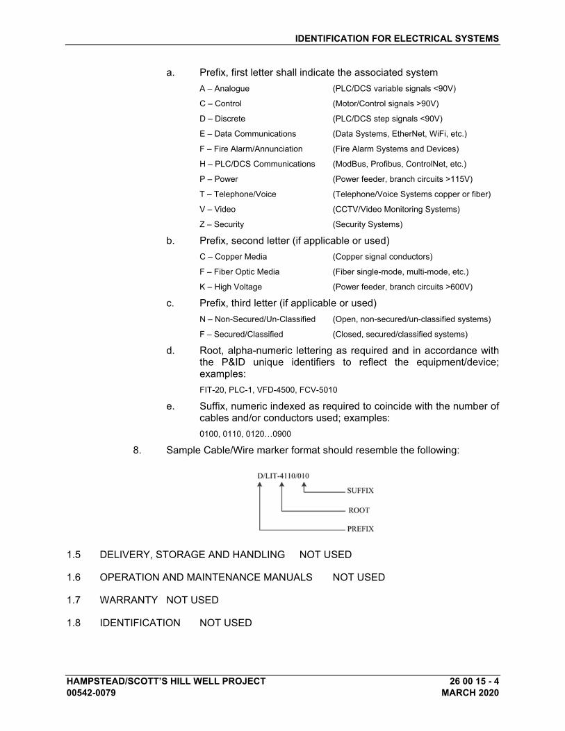
IDENTIFICATION FOR ELECTRICAL SYSTEMS
HAMPSTEAD/SCOTT’S HILL WELL PROJECT 26 00 15 - 4 00542-0079 MARCH 2020
a. Prefix, first letter shall indicate the associated system
A – Analogue (PLC/DCS variable signals <90V)
C – Control (Motor/Control signals >90V)
D – Discrete (PLC/DCS step signals <90V)
E – Data Communications (Data Systems, EtherNet, WiFi, etc.)
F – Fire Alarm/Annunciation (Fire Alarm Systems and Devices)
H – PLC/DCS Communications (ModBus, Profibus, ControlNet, etc.)
P – Power (Power feeder, branch circuits >115V)
T – Telephone/Voice (Telephone/Voice Systems copper or fiber)
V – Video (CCTV/Video Monitoring Systems)
Z – Security (Security Systems)
b. Prefix, second letter (if applicable or used)
C – Copper Media (Copper signal conductors)
F – Fiber Optic Media (Fiber single-mode, multi-mode, etc.)
K – High Voltage (Power feeder, branch circuits >600V)
c. Prefix, third letter (if applicable or used)
N – Non-Secured/Un-Classified (Open, non-secured/un-classified systems)
F – Secured/Classified (Closed, secured/classified systems)
d. Root, alpha-numeric lettering as required and in accordance with the P&ID unique identifiers to reflect the equipment/device; examples:
FIT-20, PLC-1, VFD-4500, FCV-5010
e. Suffix, numeric indexed as required to coincide with the number of cables and/or conductors used; examples:
0100, 0110, 0120…0900
8. Sample Cable/Wire marker format should resemble the following:
1.5 DELIVERY, STORAGE AND HANDLING NOT USED
1.6 OPERATION AND MAINTENANCE MANUALS NOT USED
1.7 WARRANTY NOT USED
1.8 IDENTIFICATION NOT USED
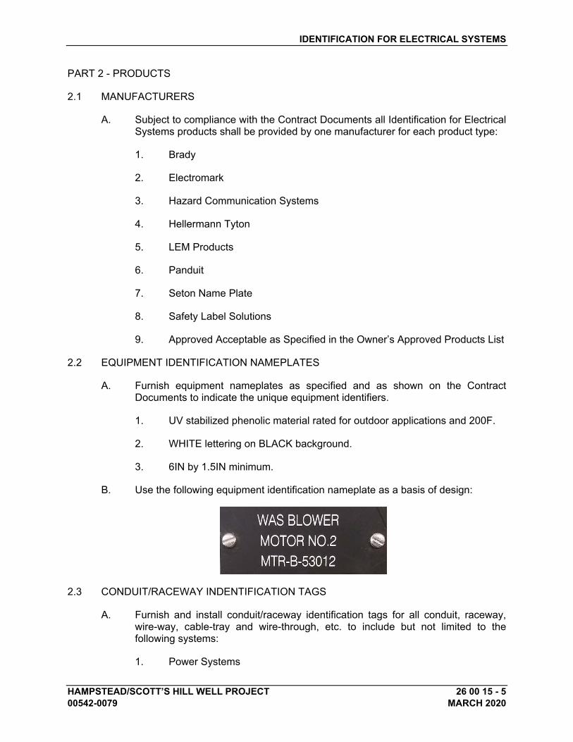
IDENTIFICATION FOR ELECTRICAL SYSTEMS
HAMPSTEAD/SCOTT’S HILL WELL PROJECT 26 00 15 - 5 00542-0079 MARCH 2020
PART 2 - PRODUCTS
2.1 MANUFACTURERS
A. Subject to compliance with the Contract Documents all Identification for Electrical Systems products shall be provided by one manufacturer for each product type:
1. Brady
2. Electromark
3. Hazard Communication Systems
4. Hellermann Tyton
5. LEM Products
6. Panduit
7. Seton Name Plate
8. Safety Label Solutions
9. Approved Acceptable as Specified in the Owner’s Approved Products List
2.2 EQUIPMENT IDENTIFICATION NAMEPLATES
A. Furnish equipment nameplates as specified and as shown on the Contract Documents to indicate the unique equipment identifiers.
1. UV stabilized phenolic material rated for outdoor applications and 200F.
2. WHITE lettering on BLACK background.
3. 6IN by 1.5IN minimum.
B. Use the following equipment identification nameplate as a basis of design:
2.3 CONDUIT/RACEWAY INDENTIFICATION TAGS
A. Furnish and install conduit/raceway identification tags for all conduit, raceway, wire-way, cable-tray and wire-through, etc. to include but not limited to the following systems:
1. Power Systems

IDENTIFICATION FOR ELECTRICAL SYSTEMS
HAMPSTEAD/SCOTT’S HILL WELL PROJECT 26 00 15 - 6 00542-0079 MARCH 2020
2. PLC/DCS Control Systems
3. Telephone/Voice/Data Systems
4. Fire Alarm and Security Systems
5. Video/CCTV Systems
B. All conduit/raceway identification tags shall conform to the following unless otherwise noted on the Contract Documents.
1. Indoor areas: UV stabilized phenolic
2. Indoor wet/corrosive areas: stainless steel 316L
3. Outdoor areas: aluminum 6063-T6 or stainless steel 304L
4. Outdoor corrosive areas: stainless steel 316L
C. Use the following conduit/raceway identification tags as a basis of design:
D. Reference previous Section 1.4B.4.
2.4 VOLTAGE SYSTEM WARNING LABELS
A. Furnish and install voltage system warning labels for transformers, switchgear, panelboards, starters, motor control centers, safety switches, pull boxes, cabinets, and raceways.
B. Provide flexible pressure sensitive vinyl markers with minimum 1IN by 4IN ORANGE or RED or background with BLACK lettering.
C. Use the following warning label as a basis of design:
D. Provide voltage markers with lettering indicating the highest voltage present:
1. 120V system: 120 VOLTS
2. 208/120V system: 208 VOLTS
3. 120/240V and 240V systems: 240 VOLTS
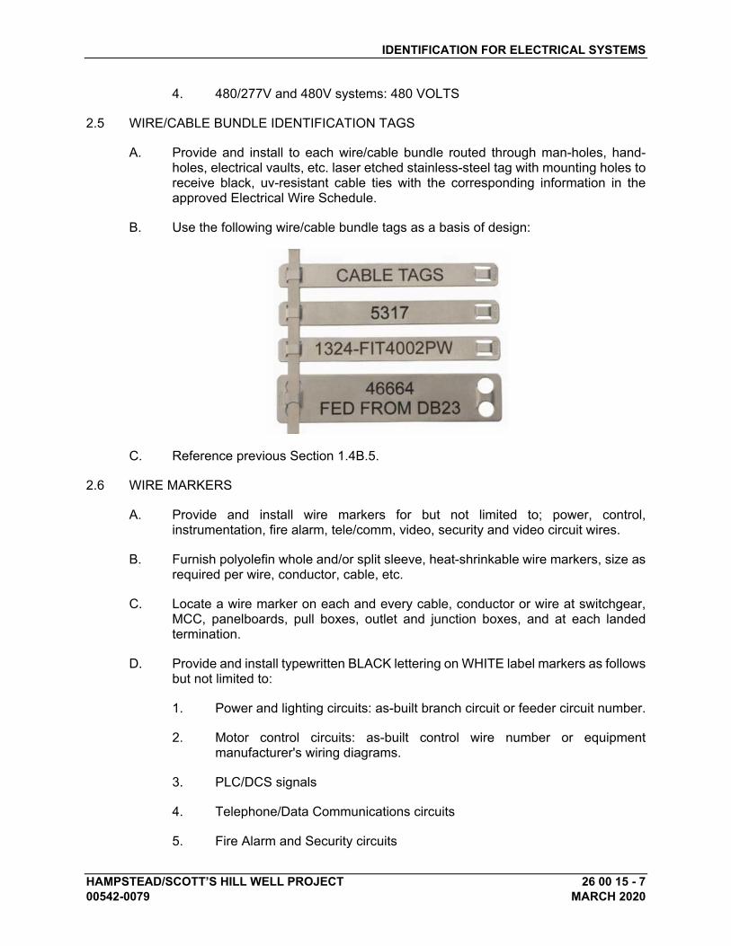
IDENTIFICATION FOR ELECTRICAL SYSTEMS
HAMPSTEAD/SCOTT’S HILL WELL PROJECT 26 00 15 - 7 00542-0079 MARCH 2020
4. 480/277V and 480V systems: 480 VOLTS
2.5 WIRE/CABLE BUNDLE IDENTIFICATION TAGS
A. Provide and install to each wire/cable bundle routed through man-holes, hand-holes, electrical vaults, etc. laser etched stainless-steel tag with mounting holes to receive black, uv-resistant cable ties with the corresponding information in the approved Electrical Wire Schedule.
B. Use the following wire/cable bundle tags as a basis of design:
C. Reference previous Section 1.4B.5.
2.6 WIRE MARKERS
A. Provide and install wire markers for but not limited to; power, control, instrumentation, fire alarm, tele/comm, video, security and video circuit wires.
B. Furnish polyolefin whole and/or split sleeve, heat-shrinkable wire markers, size as required per wire, conductor, cable, etc.
C. Locate a wire marker on each and every cable, conductor or wire at switchgear, MCC, panelboards, pull boxes, outlet and junction boxes, and at each landed termination.
D. Provide and install typewritten BLACK lettering on WHITE label markers as follows but not limited to:
1. Power and lighting circuits: as-built branch circuit or feeder circuit number.
2. Motor control circuits: as-built control wire number or equipment manufacturer's wiring diagrams.
3. PLC/DCS signals
4. Telephone/Data Communications circuits
5. Fire Alarm and Security circuits
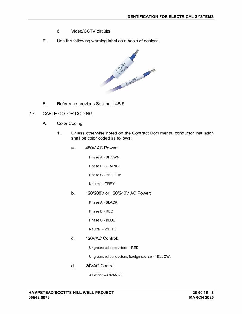
IDENTIFICATION FOR ELECTRICAL SYSTEMS
HAMPSTEAD/SCOTT’S HILL WELL PROJECT 26 00 15 - 8 00542-0079 MARCH 2020
6. Video/CCTV circuits
E. Use the following warning label as a basis of design:
F. Reference previous Section 1.4B.5.
2.7 CABLE COLOR CODING
A. Color Coding
1. Unless otherwise noted on the Contract Documents, conductor insulation shall be color coded as follows:
a. 480V AC Power:
Phase A - BROWN
Phase B - ORANGE
Phase C - YELLOW
Neutral – GREY
b. 120/208V or 120/240V AC Power:
Phase A - BLACK
Phase B - RED
Phase C - BLUE
Neutral – WHITE
c. 120VAC Control:
Ungrounded conductors – RED
Ungrounded conductors, foreign source - YELLOW.
d. 24VAC Control:
All wiring – ORANGE
IDENTIFICATION FOR ELECTRICAL SYSTEMS
HAMPSTEAD/SCOTT’S HILL WELL PROJECT 26 00 15 - 9 00542-0079 MARCH 2020
e. 24VDC Power:
Positive Lead – RED
Negative Lead – BLACK
f. 24VDC Control:
Ungrounded conductors – BLUE
Grounded conductors – BLUE w/ WHITE stripe
g. Equipment Grounding Conductor:
All wiring – GREEN
2. Conductors #4AWG and smaller shall be factory color coded with a separate color for each phase and neutral, which shall be used consistently throughout the system. Larger cables shall be coded by the use of colored heat-shrinkable tubing.
2.8 WARNING SIGNS
A. Furnish warning signs for low-voltage and medium-voltage transformers, switchgear, switchboards, panelboards, motor starters, motor control centers, safety switches, pull boxes, and cabinets.
B. Use warning signs that conform to ANSI Z535.4 and OSHA Danger and Caution specifications.
C. Provide minimum 2IN by 4IN warning signs.
D. Provide warning signs with format and lettering as follows:
1. Signal word: DANGER
2. Signal word panel color: RED with safety alert symbol.
3. Word message: HAZARDOUS VOLTAGE SHOCK, BURN OR DEATH
4. Safety symbol: ISO 3864 “lightning bolt” in YELLOW triangle.
E. Materials:
1. For indoor applications use flexible, pressure sensitive, polyester base with polyester overlaminate.
2. For outdoor applications use aluminum signs.
2.9 ARC FLASH AND SHOCK HAZARD WARNING LABELS
A. Furnish and install arc flash and shock hazard warning labels for switchgear, transformers, panelboards, industrial control panels, motor controllers (including
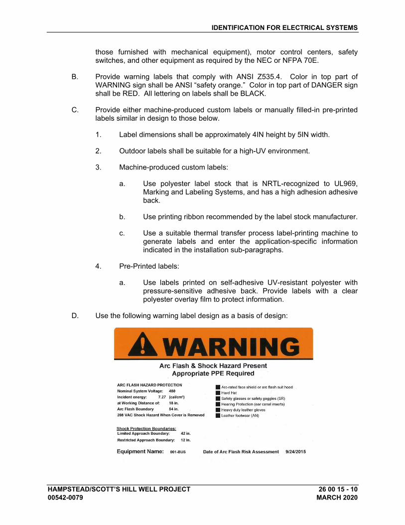
IDENTIFICATION FOR ELECTRICAL SYSTEMS
HAMPSTEAD/SCOTT’S HILL WELL PROJECT 26 00 15 - 10 00542-0079 MARCH 2020
those furnished with mechanical equipment), motor control centers, safety switches, and other equipment as required by the NEC or NFPA 70E.
B. Provide warning labels that comply with ANSI Z535.4. Color in top part of WARNING sign shall be ANSI “safety orange.” Color in top part of DANGER sign shall be RED. All lettering on labels shall be BLACK.
C. Provide either machine-produced custom labels or manually filled-in pre-printed labels similar in design to those below.
1. Label dimensions shall be approximately 4IN height by 5IN width.
2. Outdoor labels shall be suitable for a high-UV environment.
3. Machine-produced custom labels:
a. Use polyester label stock that is NRTL-recognized to UL969, Marking and Labeling Systems, and has a high adhesion adhesive back.
b. Use printing ribbon recommended by the label stock manufacturer.
c. Use a suitable thermal transfer process label-printing machine to generate labels and enter the application-specific information indicated in the installation sub-paragraphs.
4. Pre-Printed labels:
a. Use labels printed on self-adhesive UV-resistant polyester with pressure-sensitive adhesive back. Provide labels with a clear polyester overlay film to protect information.
D. Use the following warning label design as a basis of design:
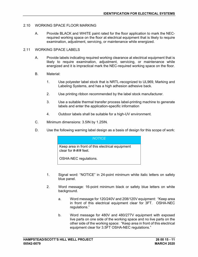
IDENTIFICATION FOR ELECTRICAL SYSTEMS
HAMPSTEAD/SCOTT’S HILL WELL PROJECT 26 00 15 - 11 00542-0079 MARCH 2020
2.10 WORKING SPACE FLOOR MARKING
A. Provide BLACK and WHITE paint rated for the floor application to mark the NEC-required working space on the floor at electrical equipment that is likely to require examination, adjustment, servicing, or maintenance while energized.
2.11 WORKING SPACE LABELS
A. Provide labels indicating required working clearance at electrical equipment that is likely to require examination, adjustment, servicing, or maintenance while energized and it is impractical mark the NEC-required working space on the floor.
B. Material:
1. Use polyester label stock that is NRTL-recognized to UL969, Marking and Labeling Systems, and has a high adhesion adhesive back.
2. Use printing ribbon recommended by the label stock manufacturer.
3. Use a suitable thermal transfer process label-printing machine to generate labels and enter the application-specific information
4. Outdoor labels shall be suitable for a high-UV environment.
C. Minimum dimensions: 3.5IN by 1.25IN.
D. Use the following warning label design as a basis of design for this scope of work:
NOTICE
Keep area in front of this electrical equipment clear for #-#/# feet.
OSHA-NEC regulations.
1. Signal word: “NOTICE” in 24-point minimum white italic letters on safety blue panel.
2. Word message: 16-point minimum black or safety blue letters on white background.
a. Word message for 120/240V and 208/120V equipment: “Keep area in front of this electrical equipment clear for 3FT. OSHA-NEC regulations.”
b. Word message for 480V and 480/277V equipment with exposed live parts on one side of the working space and no live parts on the other side of the working space: “Keep area in front of this electrical equipment clear for 3.5FT OSHA-NEC regulations.”
IDENTIFICATION FOR ELECTRICAL SYSTEMS
HAMPSTEAD/SCOTT’S HILL WELL PROJECT 26 00 15 - 12 00542-0079 MARCH 2020
c. Word message for 480V and 480/277V equipment with exposed live parts on both sides of the working space: “Keep area in front of this electrical equipment clear for 4FT OSHA-NEC regulations.”
2.12 DUCT-BANK SYSTEMS WARNING TAPE
A. Provide detectable underground warning tape for underground electrical systems as required and in accordance with the NEC and the Contract Documents.
1. Reference Specification Section: 26 05 43 – UNDERGROUND DUCTBANK SYSTEMS, MANHOLES AND HANDHOLES
B. Material:
1. 5-MIL tape thickness with aluminum backing and 2-MIL clear laminated finished over lettering
2. Warning tape shall comply with APWA approved colors
C. Dimensions: 6IN by 1000FT
PART 3 - EXECUTION
3.1 COORDINATION
A. Coordinate identification names, abbreviations, colors, and other features with requirements in the Contract Documents, Shop Drawings, and manufacturer's wiring diagrams, with those required by codes, standards, and 29 CFR 1910.145. Use consistent designations throughout Project.
B. Verify electrical equipment designations and unique equipment identifiers with Engineer, Engineer’s Representative and/or Owner.
3.2 EXAMINATION
A. Examine surfaces to receive identification products for compliance with installation tolerances and other conditions affecting performance of the identification products. Do not proceed with installation until unsatisfactory conditions have been corrected.
3.3 INSTALLATION - GENERAL
A. Where identification is to be applied to surfaces that require finish, install identification after completion of finish work.
B. Install labels at locations for best convenience of viewing without interference with operation and maintenance of equipment.
1. Coordinate installation of identifying devices with location of access panels and doors.
IDENTIFICATION FOR ELECTRICAL SYSTEMS
HAMPSTEAD/SCOTT’S HILL WELL PROJECT 26 00 15 - 13 00542-0079 MARCH 2020
2. Install identifying devices before installing acoustical ceilings and similar concealment.
C. Install electrical identification products only when ambient temperature and humidity conditions for adhesive are within range recommended by manufacturer.
D. Prepare, clean and/or de-grease surfaces where electrical identification product is to be placed.
E. Place electrical identification products centered and parallel to equipment lines.
3.4 EQUIPMENT NAMEPLATES
A. Install equipment nameplates on the front of each piece of new electrical equipment to include but not limited to switchgear, switchboards, motor control centers, control equipment, transformers, panelboards, lighting panelboards, safety switches, enclosed circuit breakers, etc.
B. Position equipment nameplates so they can be read from the front of the enclosure, cabinet, etc.
C. Use manufacturer's recommended adhesive for engraved tags and nameplates.
1. Additionally, equipment nameplates shall be fastened with stainless-steel machine screws; self-tapping fasteners are not acceptable and will be rejected to include re-placement of enclosure.
3.5 CONDUIT/RACEWAYS
A. Identification Tags
1. Install identification tags in accordance with the approved Electrical Systems Raceway Schedule on all but not limited to; power, control, data, fire, tele/comm, video and security system conduit and raceways.
2. Permanently attach laser-etched stainless-steel conduit/raceway tags with stainless steel wire and permanent crimp seal to each exposed terminal end of all conduit runs entering all electrical equipment such as switchgear, switchboards, motor control centers, control panels, pull/junction boxes, utilization equipment, and at each point leaving or entering a structure or building.
3. Position identification tags so they can be read from finished floor/grade visible and vertically or horizontally.
a. Engineer reserves the right during project close-out procedures that Contractor re-position and/or supplement conduit and raceway identification as Engineer and/or Owner requires at no additional cost.
IDENTIFICATION FOR ELECTRICAL SYSTEMS
HAMPSTEAD/SCOTT’S HILL WELL PROJECT 26 00 15 - 14 00542-0079 MARCH 2020
4. Furnish identification tags for all conduit, raceway, wire-way, cable-tray and wire-through, etc. at each enclosure, equipment, junction/pull box, termination cabinet, etc. at terminal ends.
3.6 VOLTAGE SYSTEM WARNING LABELS
A. Install voltage system warning labels to all transformers, switchgear, panelboards, starters, motor control centers, safety switches, pull boxes, cabinets, and conduit/raceway systems.
1. Labels shall indicate the maximum voltage present with enclosures, equipment and conduit/raceway.
B. Electrical Equipment
1. Front and rear of each free-standing switchgear, switchboard and motor-control-center section.
2. Front of each transformer, panelboard, industrial control panel, enclosed circuit breaker, safety switch, and motor controller enclosure, including those furnished with mechanical equipment.
3. Front cover of each pull/junction box containing low-voltage or medium-voltage conductors.
C. Conduit/Raceways
1. Install voltage system warning labels to each exposed terminal end of all conduit runs entering all electrical equipment such as switchgear, switchboards, motor control centers, control panels, pull/junction boxes, utilization equipment, and at each point leaving or entering a structure or building.
a. Labels shall be applied to conduit/raceway systems at intervals no greater than twenty feet (20FT) along entire conduit/raceway run.
b. Position labels so they can be read from finished floor/grade and vertically or horizontally.
3.7 WIRE/CABLE BUNDLES IDENTIFICATION TAGS
A. Install in electrical vaults, man-holes, hand-holes, and underground pull/junction boxes. Vaults only in substitution of stainless-steel conduit/raceway tag identification system.
B. Provide laser-etched stainless-steel tag with uv-resistant cable ties attached to a minimum of one (1) wire/cable bundle associated with each raceway.
IDENTIFICATION FOR ELECTRICAL SYSTEMS
HAMPSTEAD/SCOTT’S HILL WELL PROJECT 26 00 15 - 15 00542-0079 MARCH 2020
C. All wire/cable bundles shall be tagged with its approved tag number per the approved Electrical Wire Schedule immediately after it has been pulled.
3.8 WIRE MARKERS AND CABLE COLOR CODING
A. Install wire markers on all but not limited to; power, control, data, fire, tele/comm, video and security system conductors within all termination, splicing, marshalling, junction-box, devices, cabinets and enclosures.
B. Install wire markers within all switchgear, switchboards, motor control centers, panelboards, lighting panelboards, safety switches, etc.
1. Wire markers shall be installed on all terminated/spliced wire, cable and conductor ends regardless of the number of enclosures that they are routed through.
2. Contractor shall inspect and ensure that all wire markers match on all terminated/spliced ends and correspond with the approved Cable/Wire marker schedule.
3. Engineer reserves the right during project close-out procedures that Contractor re-install wire markers as Engineer and/or Owner requires at no additional cost.
C. Position wire markers so they can be read when opening the enclosure door and without rotating the wire/conductor when landed on terminal strips.
D. Contractor shall re-install wire markers that are blurred, smudged, ill-legible, mis-printed, damaged or soiled at no additional cost.
3.9 WARNING SIGNS
A. Install warning signs at the following locations and position signs so they can be read from floor or ground:
1. Front and rear of each low-voltage switchgear or switchboard section.
2. Front of each low-voltage transformer, switchboard, panelboard, industrial control panel, motor control center, enclosed circuit breaker, safety switch, and motor starter enclosure including those furnished with mechanical equipment.
3.10 ARC FLASH AND SHOCK HAZARD WARNING LABELS
A. Install arc flash and shock hazard warning labels at the following locations and position signs so they can be read from floor or ground:
1. Front and rear of each freestanding low-voltage switchgear or switchboard section.
IDENTIFICATION FOR ELECTRICAL SYSTEMS
HAMPSTEAD/SCOTT’S HILL WELL PROJECT 26 00 15 - 16 00542-0079 MARCH 2020
2. Front of each low-voltage transformer, panelboard, industrial control panel, motor control center, enclosed circuit breaker, safety switch, and motor controller enclosure, including those furnished with mechanical equipment.
3. Cover of each pull box containing exposed low conductors.
B. Enter the following application-specific information in arc-flash and shock hazard warning labels as required under Specification Section 26 05 05:
1. Arc-Flash Protection Boundary (inches) calculated in accordance with IEEE Std 1584 or NFPA 70E.
2. Arc-flash incident energy (cal/cm2) calculated in accordance with IEEE Std 1584 or NFPA 70E.
3. Working distance (inches) selected from IEEE Std 1584 or NFPA 70E (Annex D) based on equipment type.
4. Hazard/risk category number from NFPA 70E Table 130.7(C)(9) for operations with doors closed and covers on.
5. System phase-to-phase voltage.
6. Condition that exposes worker to an electrical shock hazard.
7. Limited Approach Boundary from NFPA 70E Table 130.2(C) based on nominal system phase-to-phase voltage.
8. Restricted Approach Boundary from NFPA 70E Table 130.2(C) based on nominal system phase-to-phase voltage.
9. Prohibited Approach Boundary from NFPA 70E Table 130.2(C) based on nominal system phase-to-phase voltage.
10. Class for insulating gloves based on system voltage (e.g. Class 00 for up to 500 volts).
11. Voltage rating for insulated or insulating tools based on system voltage (e.g. 1000 volts).
12. Equipment ID code based on Drawings and including TA number, building number, and system identifier.
13. Date that hazard analysis was performed.
14. “Served from” circuit directory information including the serving equipment ID code, location (e.g. room number), circuit number, and circuit voltage/phases/wires.
15. If applicable, “serves” circuit directory information including the served equipment ID code, location (e.g. room number), circuit number, and circuit voltage/phases/wires.
IDENTIFICATION FOR ELECTRICAL SYSTEMS
HAMPSTEAD/SCOTT’S HILL WELL PROJECT 26 00 15 - 17 00542-0079 MARCH 2020
3.11 WORKING SPACE FLOOR MARKERS
A. Install floor marking paint on the floor at the locations listed below to indicate the working space required by the NEC.
1. Front and rear of each free-standing low-voltage switchgear or switchboard section.
2. Front of each low-voltage transformer, switchboard, panelboard, industrial control panel, motor control center, enclosed circuit breaker, safety switch, and motor controller enclosure including those furnished with mechanical equipment.
3. Any other equipment likely to require examination, adjustment, servicing, or maintenance while energized.
B. Dimensions of working space area shall be as follows:
1. Width: the greater of the width of the equipment or 30IN.
2. Depth:
a. 120/240V and 208/120V equipment: 3FT
b. 480V and 480/277V equipment with exposed live parts on one side of the working space and no live parts on the other side of the working space: 3.5FT.
c. 480V and 480/277V equipment with exposed live parts on both sides of the working space: 4FT.
C. Thoroughly prepare floor surface to receive paint.
D. Paint the NEC-required working space area with alternating 3 to 6IN wide black and white diagonal stripes.
3.12 WORKING SPACE LABELS
A. Install working space labels at the following locations only in cases where it is impractical to mark the NEC-required working space on the floor (e.g. carpeted areas).
1. Front of each low-voltage switchgear or switchboard section and rear of each freestanding low-voltage switchgear or switchboard section.
2. Front of each meter enclosure, low-voltage transformer, panelboard, industrial control panel, motor control center, enclosed circuit breaker, safety switch, and motor controller enclosure, including those furnished with mechanical equipment.
3. Any other equipment likely to require examination, adjustment, servicing, or maintenance while energized.
IDENTIFICATION FOR ELECTRICAL SYSTEMS
HAMPSTEAD/SCOTT’S HILL WELL PROJECT 26 00 15 - 18 00542-0079 MARCH 2020
B. Position labels so they can be read from floor or ground.
3.13 DUCT-BANK SYSTEMS WARNING TAPE
A. Provide warning tape(s) as follows:
1. Electrical duct-bank systems, trenches and raceways:
a. Legend: “CAUTION CAUTION CAUTION” (1st line), “BURIED ELECTRIC LINE” (2nd line).
b. Letters: 1 1/4IN minimum.
c. Interval: Continuous.
d. Color: BLACK lettering on RED background.
2. Tele-Communication duct-bank systems, trenches and raceways:
a. Legend: “CAUTION CAUTION CAUTION” (1st line), “BURIED TELEPHONE LINE” (2nd line).
b. Letters: 1 1/4IN minimum.
c. Interval: Continuous.
d. Color: BLACK lettering on ORANGE background.
3. SCADA duct-bank systems, trenches and raceways:
a. Legend: “CAUTION CAUTION CAUTION” (1st line), “BURIED COMPUTER LINE” (2nd line).
b. Letters: 1 1/4IN minimum.
c. Interval: Continuous.
d. Color: BLACK lettering on ORANGE background.
END OF SECTION 26 00 15
HAMPSTEAD/SCOTT’S HILL WELL PROJECT 26 05 01 - 1 00542-0079 APRIL 2020
SECTION 26 05 01 – EXCAVATION AND CONCRETE WORK FOR ELECTRICAL SYSTEMS
PART 1 - GENERAL
1.1 REQUIREMENT SUMMARY
A. Contractor shall furnish all labor, materials, equipment and incidentals required to complete electrical systems that require excavation and/or concrete work as required under this Contract as hereinafter specified and/or shown in the Contract Documents.
1.2 RELATED WORK SPECIFIED ELSEWHERE
A. In addition to the requirements specified in this section, the requirements of Division 26 and those Project Specification Sections referenced therein shall be applied.
1.3 REFERENCES NOT USED
1.4 SUBMITTALS
A. Contractor shall reference and provide all documentation for all Division 26 Sections as required per Specification Sections:
1. 01 33 00 – SUBMITTAL PROCEDURES
B. Contractor shall obtain from the equipment manufacturer and submit shop drawings. Each submittal shall be identified by the applicable Specification Section.
C. Shop drawings shall include but not be limited to:
1. Equipment specifications and product data sheets identifying all materials used and methods of fabrication.
2. Complete assembly, layout, installation, and foundation drawings with clearly marked dimensions.
1.5 QUALITY ASSURANCE
A. Manufacturers: Firms regularly engaged in manufacture of products for electrical related work of sizes, types, ratings, and materials required, whose products have been in satisfactory use in similar service for not less than three (3) years.
1.6 PROJECT CONDITIONS
A. Protect property from any and all damage that might result from excavating and backfilling.
B. Protect persons from injury at excavations, by barricades, warnings and illumination.
EXCAVATION AND CONCRETE WORK FOR ELECTRICAL SYSTEMS
HAMPSTEAD/SCOTT’S HILL WELL PROJECT 26 05 01 - 2 00542-0079 APRIL 2020
C. Coordinate excavations with weather conditions, to minimize possibility of washouts, settlements and other damages and hazards.
PART 2 - PRODUCTS - NOT USED
PART 3 - EXECUTION
3.1 EXCAVATIONS
A. General: Do not excavate for electrical work until the work is ready to proceed without delay, so that total time lapse from excavation to completion of backfilling will be minimized.
B. Excavate with vertical-sided excavations to greatest extent possible, except where otherwise indicated. Where necessary, provide sheeting and cross-bracing to sustain sides of excavations. Remove sheeting and cross-bracing during backfilling wherever such removal would not endanger the work or other property. Where not removed, cut sheeting off at sufficient distance below finished grade to not interfere with other work.
C. Excavations shall not interfere or adversely compromise structural foundations, elements or features. Excavations that encroach structural foundations, elements or features shall be coordinated with structural Engineer of Record prior to commencing work.
D. Depth for sub-base Support: Unless otherwise noted, provide installation of sub-base material(s). Excavate for installation of sub-base material in depth indicated or, if not otherwise indicated, 6IN below bottom of work to be supported.
E. Shoring and Bracing: Provide materials for shoring and bracing, such as sheet piling, uprights, stringers and cross-braces, in good serviceable condition.
1. Establish requirements for trench shoring and bracing to comply with local codes and authorities having jurisdiction.
2. Maintain shoring and bracing in excavations regardless of time period excavations will be open. Carry down shoring and bracing as excavation progresses.
F. Excavate trenches to the uniform dimensions required for the particular item(s) to be installed and provide sufficient working clearances. Dig trenches to approximate depth and hand grade bottom to accurate elevation as required.
G. Where rock is encountered, carry excavation 6IN below required elevation and backfill with a 6IN layer of sand prior to installation of conduit.
H. Where soil conditions at bottom of indicated excavation are unsatisfactory, excavate additional depth as directed to reach satisfactory soil-bearing condition. Backfill with sub-base material compacted as directed, to indicated excavation depth.
EXCAVATION AND CONCRETE WORK FOR ELECTRICAL SYSTEMS
HAMPSTEAD/SCOTT’S HILL WELL PROJECT 26 05 01 - 3 00542-0079 APRIL 2020
I. Unless otherwise noted in the Contract Documents, store excavated material (temporarily) near excavation, in manner that will not interfere with or damage excavation or other work. Do not store under trees (within drip-line).
J. Retain excavated material that complies with requirements for backfill material.
K. Dispose of excess or unsatisfactory excavated material(s) as directed by the Contract requirements and site conditions.
L. Refer to the Contract requirements and site conditions for removal of large subsurface materials.
3.2 DEWATERING
A. Prevent surface water and subsurface or ground water from flowing into excavations and from flooding project site and surrounding area.
B. Establish and maintain temporary drainage ditches and other diversions outside excavation limits to convey rain water and water removed from excavations to collecting or run-off areas. Do not use trench excavations as temporary drainage ditches.
C. Maintain dry excavations for electrical work, by removing water. Protect excavations from inflow of surface water. Pump minor inflow of ground water from excavations; protect excavations from major inflow of ground water, by installing temporary sheeting and waterproofing. Provide adequate barriers that will protect other excavations and below-grade property from being damaged by water, sediment or erosion from or through electrical work excavations.
3.3 BASE PREPARATION
A. Install sub-base material to receive electrical work, and compact by tamping to form a firm base for the work.
B. Provide finely-graded sub-base material for equipment to be buried.
C. Tamp fill to uniform compacted density.
D. Where conduit crosses over areas which have been previously excavated to depths greater than required for conduit installation, provide suitable support that comply with details shown and Contract requirements.
3.4 BACKFILLING
A. Backfill with approved backfill materials.
B. Backfill with finely-graded subbase material to 6IN above equipment to be buried. Backfill materials shall be soil materials free of clay, rock or gravel larger than 3/4IN, debris, waste, frozen materials, vegetation and other deleterious matter.
EXCAVATION AND CONCRETE WORK FOR ELECTRICAL SYSTEMS
HAMPSTEAD/SCOTT’S HILL WELL PROJECT 26 05 01 - 4 00542-0079 APRIL 2020
C. Condition backfill material by either drying or adding water uniformly, to whatever extent may be necessary to facilitate compaction to required densities. Do not backfill with frozen soil materials.
D. Backfill simultaneously on opposite sides of electrical work, and compact simultaneously; do not dislocate the work from installed positions.
E. Backfill excavations in 8IN high courses of backfill material, uniformly compacted to the following densities (% of maximum density, ASTM D 1557), using power-driven hand-operated compaction equipment.
F. When backfilling excavations for electrical work, backfill to elevations matching finished grades.
G. Backfill trenches with concrete where trench excavations pass within 18IN of column or wall footings and which are carried below bottom of such footings, or which pass under wall footings. Place concrete to level of bottom of adjacent footing.
H. Do not backfill trenches until tests and inspections have been made and backfilling authorized by the Engineer. Use care in backfilling to avoid damage or displacement of conduit systems.
3.5 INSTALLATION OF CONCRETE
A. Refer to Specification Section 03 30 00 – CAST – IN – PLACE CONCRETE
B. Miscellaneous Concrete Work
1. Concrete Grouting: Grout openings and recesses as indicated on the Contract Documents and around all electrical work and other work that penetrates or adjoins all concrete work. Provide formwork where required, and tamp, screed and trowel surfaces. Cure grout as specified for concrete work.
2. Refer to Specification Sections for grouting of equipment base plates on foundations (with high-strength, non-shrinking grout), and similar grouting requirements not defined herein.
C. Clean-Up: Upon completion of work, clean excess concrete and grout from adjacent areas and surfaces. Remove excess concrete and grout by proper methods of removal, using care not to scratch or otherwise damage finished surfaces.
3.6 SUPPORT AND FASTENERS
A. Contractor shall reference and provide all hangers, supports, equipment racks, etc. for all electrical equipment components and devices as required per Specification Section:
1. 26 05 29 – ELECTRICAL HANGERS AND SUPPORTS
EXCAVATION AND CONCRETE WORK FOR ELECTRICAL SYSTEMS
HAMPSTEAD/SCOTT’S HILL WELL PROJECT 26 05 01 - 5 00542-0079 APRIL 2020
B. Concrete or Masonry Inserts
1. Contractor shall be responsible for the furnishing and installation of all conduit sleeves, anchor bolts, masonry inserts, and similar devices required for installation of equipment furnished under this Contract.
2. Aluminum support members shall not be installed in direct contact with concrete. Stainless steel or non-metallic ABS plastic spacers shall be used to prevent contact of aluminum with concrete.
3. Contractor is responsible for the design of supporting structures and shall submit design details to the Engineer for acceptance before proceeding with the fabrication and installation.
4. Wherever dissimilar metals come into contact, the Contractor shall isolate these metals as required with UV resistant nylon washers or 9MIL polyethylene tape or gaskets.
END OF SECTION 26 05 01
HAMPSTEAD/SCOTT’S HILL WELL PROJECT 26 05 19 - 1 00542-0079 APRIL 2020
SECTION 26 05 19 – WIRE AND CABLE – 600V
PART 1 - GENERAL
1.1 REQUIREMENT SUMMARY
A. Contractor shall furnish, install, connect, test, and place in satisfactory operating condition, ready for service, all cables and wires indicated on the Contract Documents and as specified herein or required for proper operation of the installation, with the exception of internal wiring provided by electrical equipment manufacturers. The work of connecting cables to equipment, machinery, and devices shall be considered a part of this Section. All hardware, junction boxes, bolts, clamps, insulators, and fittings required for the installation of cable and wires system shall be furnished and installed by the Contractor
B. The wire and cable to be furnished and installed for this Project shall be the product of manufacturers who have been in the business of manufacturing wire and cable for a minimum of ten years (10YR).
1.2 RELATED WORK SPECIFIED ELSEWHERE
A. In addition to the requirements specified in this section, the requirements of Division 26 and those Project Specification Sections referenced therein shall be applied.
B. Related Specification Sections include but not limited to:
1. 26 00 15 – TESTING AND COMMISSIONING OF ELECTRICAL SYSYTEMS
2. 26 05 30 – ELECTRICAL RACEWAY SYSTEMS
3. 40 61 00 – INSTRUMENTATION AND CONTROL, GENERAL REQUIREMENTS
1.3 REFERENCES NOT USED
1.4 SUBMITTALS
A. Contractor shall reference and provide all documentation for all Division 26 Sections as required per Specification Sections:
1. 01 33 00 – SUBMITTAL PROCEDURES
B. Contractor shall obtain from the wire and cable manufacturer and submit the following:
1. Shop Drawings
a. Drawings shall include, but not limited to, detailed specifications and product data sheets for all cabling required for this Project.
WIRE AND CABLE – 600V
HAMPSTEAD/SCOTT’S HILL WELL PROJECT 26 05 19 - 2 00542-0079 APRIL 2020
b. Material specifications and product data sheets identifying all materials used and methods of fabrication.
c. Cable and wire identification methods and materials.
d. Reports of Certified Shop and Field Tests
2. Electrical Raceway and Cable Schedule
a. Submit an Electrical Raceway and Cable Schedule that aligns with the requirements in Section 26 00 15 – IDENTIFICATION FOR ELECTRICAL SYSTEMS for all power, control, signal, process, data and protective circuits. The schedule shall be submitted for Engineer review in an electronic spreadsheet type Excel compatible file format. The schedule shall include but not limited to the following data:
1) Raceway ID Tag
2) From Description and ID Tag
3) To Description and ID Tag
4) Cable/Conductor/Wire type, size and number
5) Raceway type and size
6) Service, e.g. voltage, data, communications
7) Ductbank Call-Outs, if installed and/or routed
8) Contractor additional notes
C. Submittals shall be identified by the applicable Specification Section.
1.5 DELIVERY, STORAGE AND HANDLING NOT USED
1.6 OPERATION AND MAINTENANCE MANUALS NOT USED
1.7 WARRANTY NOT USED
1.8 IDENTIFICATION
A. All cable, wires and conductors shall be identified as specified in Section PART 3, EXECUTION.
PART 2 - PRODUCTS
2.1 POWER WIRE
A. All 600V rated power wire shall consist of stranded, copper conductor with insulation type XHHW-2, 90C
WIRE AND CABLE – 600V
HAMPSTEAD/SCOTT’S HILL WELL PROJECT 26 05 19 - 3 00542-0079 APRIL 2020
B. Circuits within the interior spaces of buildings may utilize 600V rated insulation, type THHN/THWN, 75C.
C. Conductors shall be stranded copper per ASTM-B8, B-33 and B-189, Class B or C stranding contingent on the size unless otherwise specified. Minimum size wire shall be 12AWG.
D. 600V rated individual or multi-conductor power wire and cable shall be manufactured by the Okonite Company, BICC Industrial Cable Company or Approved.
2.2 CONTROL WIRE
A. All 600V rated control wire shall consist of stranded, copper conductor with insulation type THHN/THWN, 75C .
B. Conductors shall be stranded copper per ASTM B-8, B 33 and B-189, Class B or C stranding contingent on the size unless otherwise specified. Minimum wire size shall be 14AWG.
C. 600V rated individual or multi-conductor control wire shall be manufactured by the Okonite Company, BICC Industrial Cable Company or Approved.
2.3 LIGHTING AND RECEPTACLE WIRE
A. All exterior lighting and receptacle branch circuit wire shall consist of stranded, copper conductors with 600V rated insulation, type XHHW-2, 90C.
B. Interior lighting and receptacle branch circuit wire may utilize stranded, copper conductors with 600V rated insulation, type THHN/THWN 75C.
C. Conductors shall be stranded copper per ASTM-B8, B-33 and B-189, Class B or C stranding contingent on the size unless otherwise specified. Minimum size wire shall be 12AWG.
D. Lighting and receptacle wire shall be manufactured by the General Cable Company, Southwire Cable Company or Approved.
2.4 CONTROL SIGNAL CABLE (F/UT)
A. Control cable for discrete signals shall be unshielded twisted individual conductors (F/UT) or twisted multi-paired conductors with an overall foil shield (F/UTP), unless otherwise noted on the Contract Documents. Conductors shall be tin or alloy coated, soft, annealed stranded 14AWG copper with 600V rated insulation for 75C. All twisted pairs shall have an overall foil shield with a 18AWG tinned copper drain wire. Outer jackets shall be lead-free, cross-linked chlorinated polyethylene.
B. Typical notation as shown on the Contract Documents:
1. 1[9C#14F/UT] denotes one (1) cable of nine (9) twisted 14AWG conductors wrapped within an overall foil shielded outer jacket
WIRE AND CABLE – 600V
HAMPSTEAD/SCOTT’S HILL WELL PROJECT 26 05 19 - 4 00542-0079 APRIL 2020
C. The individual conductors of the multi-conductor control cable shall be color coded for proper identification. Color coding shall be equal to ICEA S-68-514, Table K-1. Cables shall meet requirements of IEEE-383.
D. Control cable shall be
1. Southwire Product Series: 367120 or Approved.
2.5 INSTRUMENTATION SIGNAL CABLE (F/FTP)
A. Instrumentation cable for analog signals shall be individually shielded twisted paired conductors (F/FTP) or individually shielded twisted multi-pair conductors within an overall foil shield (F/FTP), unless otherwise shown on the Contract Documents. Conductors shall be tin or alloy coated, soft, annealed stranded 16AWG copper with 600V rated insulation for 75C. All cable assemblies shall have a 18AWG tinned copper drain wire. Outer jackets shall be lead-free, cross-linked chlorinated polyethylene.
B. Typical notation as shown on the Contract Documents:
1. 2[2C#16F/FTP] denotes two (2) cables of two (2) twisted 16AWG paired conductors within individual foil shield and wrapped with an overall foil shielded outer jacket
C. Instrumentation cable shall be
1. Southwire Product Series: 337630 or Approved.
2.6 CABLE FITTINGS AND CONNECTORS
A. Where shown in the Contract Documents, Contractor shall provide and install all required cable glands, fittings and connectors with those manufacturer approvals, UL listing and/or NEMA rating to match enclosures and/or devices to which the cable is terminated.
B. Where cables are subject to vibration and/or tension, Contractor shall provide and install cable glands, fittings and connectors with strain-relief assembly to include supplemental cable strain-reliefs were required.
PART 3 - EXECUTION
3.1 GENERAL
A. Power Feeder and Branch Circuitry
1. All power feeder and branch circuit cables, wires and/or conductors shall be terminated in accordance with the applicable Specification Sections throughout all power distribution equipment to include all utilization equipment and/or devices.
WIRE AND CABLE – 600V
HAMPSTEAD/SCOTT’S HILL WELL PROJECT 26 05 19 - 5 00542-0079 APRIL 2020
a. Splices within pull-boxes and junction boxes for all power feeder circuits rated 100A or more are not acceptable unless approved by Engineer.
B. Control, Signal and Data Circuitries
1. All control, signal and data cables, wires and/or conductors shall be terminated in accordance with the applicable Project Specification Sections throughout all terminal, marshalling cabinets to include all control and/or utilization devices.
a. Splices within pull-boxes and junction boxes are not acceptable unless approved by Engineer
2. All control and data cabling routed to Programmable Logic Controllers (PLC) and/or SCADA equipment shall be identified and neatly bound in coils, secured with white nylon cable ties
a. Sufficient cable and/or wire slack shall be provided such that no splicing is required within PLC and SCADA cabinets.
C. Contractor shall ensure all power, control, signal and data cables, wires and/or conductors are terminated correctly throughout the entire circuit and shall provide labor and materials as required to make all corrections necessary without any additional cost to Owner.
D. Engineer and/or Owner Representative reserves the right to witness and inspect all power, control, signal and data terminations.
3.2 600V CABLE INSTALLATION
A. Cable and wires shall be installed as specified herein and shown on the Contract Documents.
B. Cables shall be terminated in accordance with the cable and/or termination product manufacturer's instructions for the particular type of cable.
C. To minimize oxidation and corrosion, wire and cable shall be terminated using an oxide-inhibiting joint compound recommended for "copper-to-copper" connections. The compound shall be Penetrox-E as manufactured by Burndy Electrical, or approved equal.
D. Splices are normally not permitted in the underground duct, manhole and handhole systems. If splices are required, Contractor shall obtain approval in writing from the Engineer prior to splicing.
1. Splicing material shall be a two-part insulating and encapsulating resin.
E. Sizing
WIRE AND CABLE – 600V
HAMPSTEAD/SCOTT’S HILL WELL PROJECT 26 05 19 - 6 00542-0079 APRIL 2020
1. Sizes of cable and wire shall be as shown in the Contract Documents, or if not shown, as approved by the Engineer. If required due to field routing, the size of conductors and respective conduit shall be shall be coordinated with and approved by the Engineer.
2. Minimum wire size within control panels, motor control centers, switchboards and similar equipment shall be 12AWG for power and 14AWG for control.
F. Quantity
1. The number of wires indicated in the Contract Documents for the various control, indication, and metering circuits were determined for general schemes of control and for particular indication and metering systems.
2. The actual number of wires installed for each circuit shall, in no case, be less than the number required; however, the Contractor shall add as many wires as may be required for control and indication of the actual equipment selected for installation at no additional cost to the Owner. The addition of conductors shall be coordinated with and approved by the Engineer.
G. Identification
1. Provide and install cable, conductor and wiring identification in accordance with the procedures and requirements Specification Section(s):
a. 26 00 15 – INDENTIFICATION FOR ELECTRICAL SYSTEMS
H. Installation
1. All interior cable not protected by a compartment enclosure shall be run in conduit.
I. Training
1. Furnish all labor and material required to train wire, conductors and cables in all electrical and control enclosures to include but not limited to cable vaults within buildings, manholes, hand-holes and pull-boxes.
a. Sufficient length of cable shall be provided in each cable vault, manhole, handhole or underground pull-box such that the wire, conductors or cable can be trained and racked in an approved manner. In training or racking, the radius of bend of any wire, conductors or cable shall be not less than the manufacturer's recommendation. The training shall be done in such a manner as to minimize chaffing.
b. Slack coils of wire, conductors or cables shall be provided in all pull-boxes, junction boxes, etc. and secured with approved UV resistant cable ties.
WIRE AND CABLE – 600V
HAMPSTEAD/SCOTT’S HILL WELL PROJECT 26 05 19 - 7 00542-0079 APRIL 2020
c. Power and control wire, conductors or cables shall be neatly routed, trained and secured with approved UV resistant cable ties within all electrical enclosures to include but not limited to switchboards, transformers, transfer switches, power panels, lighting panels, disconnects, control cabinets such as PLCs.
J. Terminations and Connections
1. Where stranded wires are terminated at panels, and/or devices, connections shall be made by solderless lug, crimp type ferrule or solder dipped.
2. Where enclosure sizes and sizes of terminals at limit switches, solenoid valves, float switches, pressure switches, temperature switches, and other devices make seven-strand, 12AWG, wire terminations impractical, the Contractor shall terminate external circuits in an adjacent junction box of proper size and shall install 14AWG stranded wires from the device to the junction box in a conduit. The 12 AWG field wiring shall also be terminated in the same junction box to complete the circuit.
K. Temperature
1. Cable shall not be flexed or pulled when the temperature of the insulation or of the jacket is such that damage will occur due to low temperature embrittlement. When cable will be pulled with an ambient temperature within a three-day period prior to pulling of 40F or lower, cable reels shall be stored during the three-day period prior to pulling in a protected storage area with an ambient temperature not lower than 55F and pulling shall be completed during the work day for which the cable is removed from the protected storage.
L. Color Coding
1. Unless otherwise noted in the Contract Documents, conductor insulation shall be color coded as follows:
a. 480V AC Power:
1) Phase A - BROWN
2) Phase B - ORANGE
3) Phase C - YELLOW
4) Neutral – GREY
b. 120/208V or 120/240V AC Power:
1) Phase A - BLACK
2) Phase B - RED
WIRE AND CABLE – 600V
HAMPSTEAD/SCOTT’S HILL WELL PROJECT 26 05 19 - 8 00542-0079 APRIL 2020
3) Phase C - BLUE
4) Neutral – WHITE
c. 120VAC Control:
1) Ungrounded conductors – RED
2) Ungrounded conductors, foreign source - YELLOW.
d. 24VAC Control:
1) All wiring – ORANGE
e. 24VDC Power:
1) Positive Lead – RED
2) Negative Lead – BLACK
f. 24VDC Control:
1) Ungrounded conductors – BLUE
2) Grounded conductors – BLUE w/ WHITE stripe
g. Equipment Grounding Conductor:
1) All wiring – GREEN
2. Conductors 4AWG and smaller shall be factory color coded with a separate color for each phase and neutral, which shall be used consistently throughout the system. Larger cables shall be coded by the use of colored tape.
3.3 INSTRUMENTATION / TELEPHONE / DATA CABLE INSTALLATION
A. Grounding of cable shield shall be accomplished at one end point only.
B. Raceways exceeding 5FT and containing instrumentation / telephone / data cable shall be installed to provide the following clearances:
1. Raceway installed parallel to raceway conductors energized at 480 through 208V shall be 18IN and 208/120V shall be 12IN.
2. Raceway installed at right angles to conductors energized at 480V or 120/208V shall be 6IN.
C. Where practical, raceways containing instrumentation / telephone / data cable shall cross raceway containing conductors of other systems at right angles.
WIRE AND CABLE – 600V
HAMPSTEAD/SCOTT’S HILL WELL PROJECT 26 05 19 - 9 00542-0079 APRIL 2020
D. Where instrumentation / telephone / data cables are installed in panels, etc., the Contractor shall arrange wiring to provide maximum clearance between cables and other conductors. Instrumentation / telephone / data cables shall not be installed in same bundle with conductors of other circuits.
E. Additional pullboxes shall be furnished and installed for ease of cable pulling and the cable manufacturer's recommended conduit fill factor shall be followed.
F. All cable, insulation and jacket shall have adequate strength to allow for it to be pulled through the conduit systems. Sufficient conductors shall be installed to provide space and serve future equipment where shown and specified. All conductors shall be color coded and all wires shall be suitably tagged with permanent markers at each end.
3.4 TESTING
A. All wire and cable testing shall be performed in accordance with the requirements of Specification Section(s):
1. 26 00 10 – TESTING AND COMMISSIONING OF ELECTRICAL SYSTEMS
B. If tests reveal defects or deficiencies, the Contractor shall make the necessary repairs or shall replace the cable as directed by the Engineer, without additional cost to the Owner.
C. All tests shall be made by and at the expense of the Contractor who shall supply all testing equipment.
END OF SECTION 26 05 19
HAMPSTEAD/SCOTT’S HILL WELL PROJECT 26 05 26 - 1 00542-0079 APRIL 2020
SECTION 26 05 26 – GROUNDING AND BONDING
PART 1 - GENERAL
1.1 REQUIREMENT SUMMARY
A. Contractor shall furnish and install grounding systems complete in accordance with the minimum requirements established by Article 250 of the NEC. Article 250 of the NEC shall be considered as a minimum requirement for compliance with this Specification Section.
B. Grounding of all instrumentation and control systems shall be furnished and installed in accordance with the manufacturer/system requirements and IEEE 1100-92, Powering and Grounding of Sensitive Electronic Equipment. Conflicts shall be promptly brought to the attention of the Engineer.
C. In addition to the NEC requirements, building structural steel columns shall be permanently and effectively grounded:
D. Additional requirements for grounding and bonding as shown on the Contract Documents.
1.2 RELATED WORK SPECIFIED ELSEWHERE
A. In addition to the requirements specified in this section, the requirements of Division 26 and those Project Specification Sections referenced therein shall be applied.
1.3 REFERENCES
A. All grounding components and the completed system shall comply with the following codes and standards as well as within the Specifications or as shown in the Contract Documents:
B. Codes and Standards:
1. American National Standards Institute (ANSI/IEEE):
a. C2, National Electrical Safety Code (NESC)
2. Institute of Electrical and Electronic Engineers (IEEE):
a. IEEE 81, Guide for Measuring Earth Resistivity.
b. IEEE 142, Recommended Practice for Grounding of Industrial and Commercial Power Systems.
3. National Fire Protection Association (NFPA):
a. NFPA 70, National Electric Code (NEC)
4. Underwriters Laboratories Inc (UL):

GROUNDING AND BONDING
HAMPSTEAD/SCOTT’S HILL WELL PROJECT 26 05 26 - 2 00542-0079 APRIL 2020
a. 588, Grounding Equipment
1.4 SUBMITTALS
A. Contractor shall reference and provide all documentation for all Division 26 Sections as required per Specification Sections:
1. 01 33 00 – SUBMITTAL PROCEDURES
B. Contractor shall obtain from the equipment manufacturer and submit the following:
1. Shop Drawings
2. Reports of certified field tests. Each submittal shall be identified by the applicable Specification Section.
3. Equipment specifications and product data sheets identifying all materials used and methods of fabrication.
C. Contractor shall provide drawings and written description(s) of how the grounding/bonding system will be installed for Engineer review prior to commencing work.
1.5 DELIVERY, STORAGE AND HANDLING NOT USED
1.6 OPERATION AND MAINTENANCE MANUALS NOT USED
1.7 WARRANTY NOT USED
1.8 IDENTIFICATION NOT USED
PART 2 - PRODUCTS
2.1 MANUFACTURERS
A. The equipment covered by these specifications shall be standard equipment of proven performance as manufactured by reputable concerns. Equipment shall be designed, constructed, and installed in accordance with the best practices of the trade, and shall operate satisfactorily when installed as shown on the Contract Documents.
2.2 GROUNDING CONDUCTOR
A. A green, insulated equipment grounding conductor, which shall be separate from the electrical system neutral conductor, shall be furnished and installed for all circuits. Equipment grounding conductors shall be furnished and installed in all conduits. Use of conduits as the NEC required equipment grounding conductor is not acceptable.
B. Where specified or shown a 3IN strap shall be furnished and installed as the grounding conductor.
GROUNDING AND BONDING
HAMPSTEAD/SCOTT’S HILL WELL PROJECT 26 05 26 - 3 00542-0079 APRIL 2020
2.3 EQUIPMENT GROUND CONDUCTOR
A. Equipment ground conductors shall be solid and continuous from a connection at earth to all distribution panelboards. Ground connections at panelboards, outlets, equipment, and apparatus shall be made in an approved and permanent manner.
2.4 BONDING FITTINGS
A. Grounding connections to equipment shall be bolted. Cable end connections may be made by use of the crucible weld process or bolted type connectors. Bolted type connectors for this application shall consist of corrosion resistant copper alloy with silicone bronze bolts, nuts and lock-washers which are designed for this purpose.
2.5 GROUND RODS
A. Ground rods shall be rolled to a commercially round shape from copper clad steel manufactured by the molten welding process or by the electro formed process (molecularly bonded). They shall have an ultimate tensile strength of 75kPSI and an elastic limit of 49kPSI. The rods shall be not less than 3/4IN diameter by 10FT in length; and the proportion of copper shall be uniform throughout the length of the rod. The copper shall have a minimum wall thickness of 0.013IN at any point on the rod.
B. The maximum resistance to ground of a driven ground rod shall not exceed 25OHM under normally dry conditions. Where the resistance obtained with one (1) ground rod exceeds 25OHM, additional ground rods shall be coupled, by exothermic welds. Except where specifically indicated otherwise, all exposed non-current carrying metallic parts of electrical equipment, metallic raceway systems, grounding conductors in non-metallic raceways and neutral conductors of wiring systems shall be grounded.
C. The ground connection shall be made at the main service equipment and shall be extended to the point of entrance of the metallic water service. Connection to the water pipe shall be made by a suitable ground clamp or lug connection to a plugged tee. If flanged pipes are encountered, connection shall be made with the lug bolted to the street side of the flanged connection. If there is not suitable metallic water service to the facility, the ground connection shall be made to the driven ground rods on the exterior of the building.
D. Where ground fault protection is employed, care shall be taken so that the connection of the ground and neutral does not interfere with the correct operation of the ground fault protection system.
2.6 GROUNDING GRID
A. A grounding grid shall be provided for each structure and interconnected between structures. The grounding grid shall be installed such that the ground resistance does not exceed 5OHM. The grounding grid shall be interconnected by bare copper conductors sized to the largest service entrance ground, spliced and connected to ground rods by exothermic welds. The grounding conductors shall
GROUNDING AND BONDING
HAMPSTEAD/SCOTT’S HILL WELL PROJECT 26 05 26 - 4 00542-0079 APRIL 2020
be installed after the excavations for the building have been completed and prior to the pouring of concrete for the footings, mats, etc. Copper "pigtails" shall be connected to the grounding grid system and shall enter the buildings and structure from the outside and shall be connected to steel structures, and equipment as described in this Section and as shown in the Contract Documents.
PART 3 - EXECUTION
3.1 INSTALLATION
A. Metal surfaces where grounding connections are to be made shall be clean and dry. Steel surfaces shall be ground or filed to remove all scale, rust, grease, and dirt. Copper and galvanized steel shall be cleaned with emery cloth to remove oxide before making connections.
B. Grounding conductors shall be continuous between points of connection; splices shall not be permitted.
C. Where conductors are exposed and subject to damage from personnel, traffic, etc., conductors shall be installed in PVC SCH-80 raceway.
D. Mechanical connections shall be permitted to ground rods in “Ground Test Wells” and shall be exposed to permit maintenance and inspection for continuity and effectiveness of grounding system.
E. Where subsurface conditions do not permit use of driven ground rods to obtain proper ground resistance, rods shall be installed in a trench or plate electrodes shall be provided, as applicable and necessary to obtain proper values of resistance.
F. Conduit:
1. Conduit that enters equipment such as motor control centers, switchboards, switchgear, variable frequency drives, instrument and control panels, and similar equipment shall be bonded to the ground bus, where provided, and as otherwise required by the NEC.
3.2 TESTING
A. All testing shall be performed in accordance with the requirements of Specification Section(s):
1. 26 00 10 – TESTING AND COMMISSIONING OF ELECTRICAL SYSTEMS
B. If tests reveal defects or deficiencies, the Contractor shall make the necessary repairs or shall replace the cable as directed by the Engineer, without additional cost to the Owner.
C. All tests shall be made by and at the expense of the Contractor who shall supply all testing equipment.
GROUNDING AND BONDING
HAMPSTEAD/SCOTT’S HILL WELL PROJECT 26 05 26 - 5 00542-0079 APRIL 2020
D. Field Tests:
1. Ground resistance shall be measured with a three-point, fall of potential instrument.
2. All ground rods shall be tested after being driven and prior to connection to the grounding system. Where test results show resistance-to-ground is greater-than 25OHM, additional ground rods shall be driven by coupling with exothermic welds. The compliance shall be demonstrated by retesting ground rod.
3. Upon completion of installation of the grounding and bonding system, the entire system shall be tested at the ground test well(s), as indicated in the Contract Documents. The completed system shall have less-than 5OHM of ground resistance.
END OF SECTION 26 05 26
HAMPSTEAD/SCOTT’S HILL WELL PROJECT 26 05 29 - 1 00542-0079 APRIL 2020
SECTION 26 05 29 – ELECTRICAL HANGERS AND SUPPORTS
PART 1 - GENERAL
1.1 REQUIREMENT SUMMARY
A. Contractor shall furnish, install and place in satisfactory condition all conduit, cable-tray, raceway and equipment hangers and/or supports as required for proper installation of those systems per equipment manufacturer installation instructions and applicable codes and standards. All hardware and fasteners required for the installation shall be furnished and installed by the Contractor.
1.2 RELATED WORK SPECIFIED ELSEWHERE
A. In addition to the requirements specified in this section, the requirements of Division 26 and those Project Specification Sections referenced therein shall be applied.
B. Related Specification Sections include but not limited to:
1. 40 61 00 – INSTRUMENTATION AND CONTROL, GENERAL REQUIREMENTS
1.3 REFERENCES
A. Abbreviations and Acronyms:
1. American Society for Testing and Materials (ASTM)
2. National Electric Code (NEC)
3. National Electric Manufacturers Association (NEMA)
4. National Fire Protection Agency (NFPA)
5. Nationally Recognized Testing Laboratories (NRTL)
6. Polyvinyl Chloride (PVC)
7. Underwriters Laboratories, Inc. (UL)
B. Codes and Standards:
1. ASTM A1011 – Standard Specification for Steel, Sheet and Strip, Hot-Rolled, Carbon, Structural, High-Strength Low-Alloy, High-Strength Low-Alloy with Improved Formability, and Ultra-High Strength
2. ASTM E84 – Standard Test Method for Surface Burning Characteristics of Building Materials
3. ASTM F1136 – Standard Specification for Zinc/Aluminum Corrosion Protective Coatings for Fasteners
ELECTRICAL HANGERS AND SUPPORTS
HAMPSTEAD/SCOTT’S HILL WELL PROJECT 26 05 29 - 2 00542-0079 APRIL 2020
4. ASTM A1018 – Standard Specification for Steel, Sheet and Strip, Heavy-Thickness Coils, Hot-Rolled, Carbon, Commercial, Drawing, Structural, High-Strength Low-Alloy, High-Strength Low-Alloy with Improved Formability, and Ultra-High Strength
5. ASTM B633 – Specification for Electrodeposited Coatings of Zinc on Iron and Steel
6. NEMA Standards Publication VE-2 – Cable Tray Installation Guidelines
7. NFPA 70 – National Electrical Code
C. Qualifications:
1. Electrical components shall be listed and labeled by UL, CSA or other NRTL testing and listing agencies that provide third-party certification follow-up services.
D. Strut-Channel and fittings shall have a unique identifying number that trace the product back to material test reports. Stainless steel items shall have a part number that contains a material designator or a separate stamp that includes a reference to the type of material used.
1.4 SUBMITTALS
A. Contractor shall reference and provide all documentation for all Division 26 Sections as required per Specification Sections:
1. 01 33 00 – SUBMITTAL PROCEDURES
B. Product data shall be submitted for each support system component and accessory; including clamps, brackets, hanger rods and fittings. The information shall include, but not be limited to, types, materials, finishes, gauge thickness and mounting-hole patterns.
1.5 DELIVERY, STORAGE AND HANDLING NOT USED
1.6 OPERATION AND MAINTENANCE MAUNALS NOT USED
1.7 WARRANTY NOT USED
1.8 IDENTIFICATION NOT USED
PART 2 - PRODUCTS
2.1 GENERAL REQUIREMENTS
A. Acceptable manufacturers:
1. Allied Power-Strut Products
2. B Line Systems
ELECTRICAL HANGERS AND SUPPORTS
HAMPSTEAD/SCOTT’S HILL WELL PROJECT 26 05 29 - 3 00542-0079 APRIL 2020
3. Rob-Roy Industries
4. Thomas & Betts
5. Unistrut Building Systems
B. All strut, clamps, fittings and fastener materials shall conform to the following unless otherwise noted on the Contract Documents.
1. Indoor/Wet Areas: Aluminum 6063-T6
2. Indoor/Corrosive Areas: Fiberglass (ASTM D-4385)
3. Outdoor/Wet Areas:
a. Stainless Steel Type-304 (ASTM A240)
b. Aluminum 6063-T6
4. Outdoor/Corrosive Areas:
a. Stainless Steel Type-316 (ASTM A240)
C. Strut-Channel shall not be bent, drilled, cut or otherwise modified to produce fittings, braces or brackets for conduit and equipment supports.
D. Manufactured strut-channel braces, brackets, fittings and post-bases shall be provided and installed with associated hardware and fasteners as a complete system for conduit and equipment supports.
2.2 COMPONENTS
A. Materials:
1. Strut-Channel systems shall be furnished with fittings and accessories designed for use with the manufacturers strut system and made by the same manufacturer.
2. Contractor shall furnish all necessary locknuts, bushings, pipe clamps, ground clamps, supports, pull boxes, mounting bolts, inserts, lugs and any other materials necessary and proper in the execution of the work.
3. All fasteners and hardware materials shall be:
a. Stainless-Steel Type 316 (ASTM A276).
4. Anti-Vibratory type fasteners and hardware shall be utilized on all equipment subject to movement and/or vibration or as indicated on the Contract Documents.

ELECTRICAL HANGERS AND SUPPORTS
HAMPSTEAD/SCOTT’S HILL WELL PROJECT 26 05 29 - 4 00542-0079 APRIL 2020
5. Hanger rods shall be that as listed in Section 2.2A.3 or as noted in the Contract Documents and 3/8IN minimum diameter for conduit supports and 1/2IN minimum for cable tray supports.
6. Material types other than those listed in Section 2.2A.3, are not acceptable and considered rejected work by the Engineer.
PART 3 - EXECUTION
3.1 INSTALLATION
A. Systems Integration
1. Contractor shall coordinate with other trades and craft to ensure electrical, plumbing and HVAC systems utilize common support and hanger systems to minimize individual support systems for each trade.
a. Hanger and support installed for multiple systems shall be designed and installed in accordance with the loading requirements.
b. Multiple individual support and hanger systems installed within common areas and spaces for electrical, plumbing and HVAC systems are not acceptable and considered rejected work by Engineer.
B. General
1. Boxes, wall brackets, cabinets and hangers shall be secured by means of toggle bolts in hollow masonry and gyp-board, preset inserts or expansion bolts in solid masonry and concrete, machine screws or bolts on metal surfaces and wood or sheet metal screws in wood construction. Brackets and hangers may also be welded to metal surfaces. Boxes and cabinets shall not be welded to metal surfaces.
2. Electrical cabinets, panelboards, transformers, boxes, disconnect switches, etc., and their supporting hardware, shall be fastened securely to the building structure, bolted strut or fabricated structure.
3. Metal strut shall be installed for surface-mounted cabinets, panelboards, disconnects, control enclosures, pull boxes, junction boxes, transformers and any other electrical devices.
a. Fiberglass materials where indicated in the Contract Documents
4. In open overhead spaces, cast boxes threaded to raceways need not be supported separately, except where used for fixture support. Sheet metal boxes shall be supported directly from the building structure.
5. Hanger rods shall be fastened to structural steel members with heavy duty beam clamps. Under concrete floors, rods shall be fastened to concrete inserts set flush to the surface. When a hanger is required with no
ELECTRICAL HANGERS AND SUPPORTS
HAMPSTEAD/SCOTT’S HILL WELL PROJECT 26 05 29 - 5 00542-0079 APRIL 2020
structural steel member directly above, the Contractor shall span between steel members with strut-channel and attach the rod to the strut.
6. Raceway supports shall be selected and installed in accordance with the manufacturer’s recommendations. Raceways shall be supported within 1FT of an unsupported box or fitting. Individual horizontal raceways shall be supported with separate conduit hangers. Horizontal conduit racks shall be trapeze-type hangers utilizing strut and all-thread hanger rods. Each conduit on the rack shall be clamped with conduit clamps designed for use with strut. Trapeze hangers shall be used for all RAC, PVC-RAC and PVC conduits. In vertical applications, raceways shall be supported so the load produced by the weight of the raceway and the enclosed conductors is carried entirely by the raceway supports, with no load on the raceway fittings. Vertical conduit racks shall utilize strut attached to walls with conduits attached with pipe clamps.
7. Vertical conductor supports and conductors shall be installed simultaneously.
8. Conduits, fittings, enclosures, conduit straps and clamps shall not be welded.
9. Supporting devices and raceways shall be installed plumb, horizontal, or parallel to building lines, finished floors and each other.
10. Cable tray supports shall conform to NEMA Standards Publication VE-2, and the cable tray support detail drawings.
11. All electrical equipment shall not be mounted or supported in any manner to hand-rails, stair-wells, ladder-wells, or safety railing systems unless approved by structural Engineer of record
12. Residential and/or Commercial supports and hanger methods and materials are not acceptable and considered rejected work by Engineer. Example: plumber’s perforated strap, “caddy” clips, “push-in” conduit fittings, etc.
END OF SECTION 26 05 29
HAMPSTEAD/SCOTT’S HILL WELL PROJECT 26 05 30 - 1 00542-0079 APRIL 2020
SECTION 26 05 30 – ELECTRICAL RACEWAY SYSTEMS
PART 1 - GENERAL
1.1 REQUIREMENT SUMMARY
A. Contractor shall furnish all labor, materials, tools and equipment necessary for furnishing, installing, connecting, testing and placing into service all raceway systems to include all conduits, conduit fittings, wireway, supports, etc. as required for a complete electric installation as specified herein and indicated on the Contract Documents.
B. Conduit home runs for lighting, receptacle and other misc. circuits are not necessarily depicted on the Contract Documents; however, the circuit numbers are shown. Conduit shall be furnished and installed for these circuits.
C. Additional conduit and raceway from what is shown on the Contract Documents may be required. Contractor shall coordinate with the requirements of equipment provided under other Divisions.
1.2 RELATED WORK SPECIFIED ELSEWHERE
A. In addition to the requirements specified in this section, the requirements of Division 26 and those Project Documents referenced herein shall be applied.
B. Related Specification Sections include but not limited to:
1. Division 2 – SITE CONTRUCTION
2. 26 05 19 – WIRE AND CABLE – 600V
3. 26 05 29 – ELECTRICAL HANGERS AND SUPPORTS
4. 26 05 33 – BOXES, CABINETS AND ENCLOSURES FOR ELECTRICAL SYSYTEMS
1.3 REFERENCES
A. Raceways shall comply with the following applicable codes and standards as well as any others within the specifications and Contract Documents. In the event of any conflict between these codes, regulations, standards, and Contract Documents, the most restrictive shall apply.
B. Codes and Standards
1. American National Standards Institute (ANSI)
a. C80.1, Rigid Steel Conduit Zinc Coated.
b. C80.3, Electrical Metallic Tubing Zinc Coated.
ELECTRICAL RACEWAY SYSTEMS
HAMPSTEAD/SCOTT’S HILL WELL PROJECT 26 05 30 - 2 00542-0079 APRIL 2020
c. C80.4 Fittings for Rigid Metal Conduit and Electrical Metallic Tubing.
d. C80.5 Electrical Rigid Aluminum Conduit.
e. C80.6 Electrical Intermediate Metal Conduit.
2. American Society for Testing and Materials (ASTM)
a. A36, Standard Specification for Structural Steel.
b. A153, Zinc Coating (Hot Dip) on Iron and Steel Hardware.
c. A307, Carbon Steel Externally Threaded Standard Fasteners.
d. A563, Standard Specification for Carbon Steel Nuts.
e. A569, Steel Carbon, Hot Rolled Sheet and Strip, Commercial Quality.
f. A570, Hot Rolled Sheet and Strip, Structural Quality.
g. A575, Merchant Quality Hot Rolled Carbon Steel Bars.
h. A635, Standard Specification for Steel, Sheet and Strip, Heavy Thickness Coils, Carbon, Hot Rolled.
i. D1784, Standard Specification for Rigid Poly (Vinyl Chloride) (PVC) Compounds and Chlorinated Poly (Vinyl Chloride) (CPVC) Compounds.
j. D1788, Standard Specification for Rigid Acrylonitrile Butadiene Styrene (ABS) Plastics.
k. D2564, Solvent Cements for (PVC) Plastic Pipe, Tubing, and Fittings.
l. F512, Standard Specification for Smooth Wall Poly (Vinyl Chloride) (PVC) Conduit and Fittings for Underground Installation.
3. ETL Testing Laboratories, Inc (ETL)
4. National Electric Manufacturers Association (NEMA)
a. RN 1, Polyvinyl Chloride (PVC) Externally Coated Galvanized Rigid Steel Conduit and Intermediate Metal Conduit.
b. TC 2, Electrical Plastic Tubing (EPT) and Conduit (EPC 40 and EPC 80).
c. TC 6, PVC and ABS Plastic Utilities Duct for Underground Installation.
ELECTRICAL RACEWAY SYSTEMS
HAMPSTEAD/SCOTT’S HILL WELL PROJECT 26 05 30 - 3 00542-0079 APRIL 2020
5. National Electric Contractors Association (NECA)
a. NECA 1: Standard Practices for Good Workmanship in Electrical Construction.
b. Project applicable standards and recommendations
6. National Electric Installation Standards (NEiS)
a. Project applicable standards and recommendations
7. National Fire Protection Association (NFPA)
a. 70, National Electric Code (NEC).
b. 79, Electrical Standard for Industrial Machinery
8. Underwriters Laboratories Inc (UL)
a. 1, Flexible Metal Conduit.
b. 6, Rigid Metal Conduit.
c. 6A, Electrical Rigid Metal Conduit – Aluminum.
d. 209, Cellular Metal Floor Raceways and Fittings.
e. 360, Liquid Tight Flexible Steel Conduit.
f. 467, Grounding and Bonding Equipment.
g. 514, Nonmetallic Outlet Boxes, Flush Device Boxes, and Covers.
h. 514B, Conduit, Tubing and Cable Fittings.
i. 651, Schedule 40 and 80 Rigid PVC Conduit.
j. 797, Electrical Metallic Tubing.
k. 870, Wireways, Auxiliary Gutters, and Associated Fittings.
l. 886, Outlet Boxes and Fittings for Use in Hazardous (Classified) Locations.
m. 1242, Intermediate Metal Conduit.
n. 1660, Liquid-Tight Flexible Non-Metallic Conduit.
1.4 SUBMITTALS
A. Contractor shall reference and provide all documentation for all Division 26 Sections as required per Specification Sections:
ELECTRICAL RACEWAY SYSTEMS
HAMPSTEAD/SCOTT’S HILL WELL PROJECT 26 05 30 - 4 00542-0079 APRIL 2020
1. 01 33 00 – SUBMITTAL PROCEDURES
B. Construction Drawings
1. Proposed routing of all site conduits including direct buried, concrete encased, and long run above ground conduits.
2. Proposed routing of conduits buried under floor slabs.
3. Proposed routing and details of construction, including conduit and rebar, of conduits embedded in floor slabs, columns, etc.
1.5 DELIVERY, STORAGE AND HANDLING
A. All raceways, fittings and associated components shall be handled and stored in accordance with manufacturer’s instructions and recommendations.
B. Inspect and report concealed damage to carrier within their required time period. Owner is not responsible for damages incurred during shipping, handling and storage.
C. Store in a clean, dry space. an additional heavy canvas or heavy plastic cover to protect structure from dirt, water, construction debris, and traffic. Where applicable, provide adequate heating within enclosures to prevent condensation.
1.6 OPERATION AND MAINTENANCE NOT USED
1.7 WARRANTY NOT USED
1.8 IDENTIFICATION
A. All electrical raceway systems shall be identified with the equipment tag number indicated on the Contract Documents and the accepted shop drawings. Nameplates shall be furnished and installed as required Specification Section(s):
B. 26 00 15 – IDENTIFICATION FOR ELECTRICAL SYSTEMS
PART 2 - PRODUCTS
2.1 GENERAL
A. Materials covered by under this Section is intended to be standard material of proven performance as manufactured by reputable firms. Raceways and appurtenances shall be designed, constructed and installed in accordance with the best practices of the trade, and shall operate satisfactorily when installed as shown on the Contract Documents.
B. All equipment shall be UL listed and labeled for its intended service.
C. Subject to compliance with the Contract Documents, the listed manufacturers are acceptable.
ELECTRICAL RACEWAY SYSTEMS
HAMPSTEAD/SCOTT’S HILL WELL PROJECT 26 05 30 - 5 00542-0079 APRIL 2020
2.2 RIGID ALUMINUM CONDUIT (RAC)
A. Acceptable Manufacturers
1. Allied Tube and Conduit Corporation
2. Western Tube and Conduit Corporation
3. Wheatland Tube Company
B. RAC and associated fittings shall be manufactured from 6063 aluminum alloy in temper designation T-1.
C. Standards
1. ANSI C80.5
2.3 PVC COATED RIGID ALUMINUM CONDUIT (PVC-RAC)
A. Acceptable Manufacturers:
1. Thomas & Betts
2. Perma-Cote
3. Rob Roy Ind.
B. PVC-RAC shall have a minimum 40MIL polyvinyl chloride exterior coating. The coating shall be bonded to rigid aluminum conduit conforming to ANSI C80.1. The bond between the polyvinyl chloride coating and the conduit surface shall be greater than the tensile strength of the coating. PVC-RAC shall have a nominal 2MIL, minimum, urethane interior coating and a urethane coating on threads. RAC conduit: shall have an epoxy prime coating prior to application of polyvinyl chloride and urethane coatings.
C. Female ends shall have a plastic sleeve extending a minimum of 1 pipe diameter or 2IN, whichever is less beyond the opening. The inside diameter of the sleeve shall be the same as the outside diameter of the conduit to be used with it.
D. Standards:
1. ANSI C80.1
2. NEMA RN 1
2.4 RIGID POLYVINYL CHLORIDE CONDUIT (PVC)
A. Acceptable Manufacturers:
1. Allied Tube and Conduit Corporation
2. Carlon
ELECTRICAL RACEWAY SYSTEMS
HAMPSTEAD/SCOTT’S HILL WELL PROJECT 26 05 30 - 6 00542-0079 APRIL 2020
3. Cantex
B. PVC shall be either Schedule-40 or Schedule-80. The polyvinyl chloride plastic compound shall meet, as a minimum, ASTM D1784 cell classification PVC 12233 A, B, or C. PVC shall be rated for direct sunlight exposure, 90C wire, and fire retardant with low smoke emission.
C. Standards:
1. ANSI C33.91
2. NEMA TC 2
3. UL 651
2.5 LIQUID-TIGHT FLEXIBLE METAL CONDUIT (LFMC)
A. Acceptable Manufacturers:
1. Anamet, Inc.
2. Electri Flex Company
3. International Metal Hose Company
B. LFMC shall have a core formed of continuous, spiral wound, aluminum strip with successive convolutions securely interlocked, contain an interwoven copper strip suitable as a grounding means, and have an extruded vapor and liquid tight polyvinyl chloride outer jacket positively locked to the steel core.
C. Standard:
1. UL 360
2.6 WIREWAY
A. Acceptable Manufacturers:
1. E.M. Wiegmann and Company, Inc.
2. Hoffman Engineering Company
3. Stahlin
4. Square D
B. Wireway shall have a minimum wall thickness of 0.040IN, be furnished without knockouts, be designed for continuous grounding, and suitable for lay in conductors. Provide Solid and non-removable covers when passing through partitions and solid hinged covers with captive screw fasteners when accessible.
ELECTRICAL RACEWAY SYSTEMS
HAMPSTEAD/SCOTT’S HILL WELL PROJECT 26 05 30 - 7 00542-0079 APRIL 2020
C. Wireway shall not be smaller than 4 x 4IN unless otherwise indicated on the Contract Documents.
D. Types
1. NEMA-3/3R/12: Wireway shall be steel, finished with rust inhibiting phosphatizing coating and gray baked enamel finish on interior and exterior surfaces. Cover shall be fully gasketed and provided with captive clamp type latches.
2. NEMA- 4/4X: Wireway shall be type 304 stainless steel for interior or exterior corrosive areas. Cover shall be fully gasketed and provided with captive external screw type clamps.
E. Standards
1. NFPA 79
2. UL 870
2.7 CONDUIT FITTINGS AND ACCESSORIES
A. Acceptable Manufacturers:
1. Appleton
2. Carlon
3. Crouse Hinds
4. Killark
5. OZ Gedney Company
6. Perma Cote
7. RACO
8. Rob Roy Ind.
9. Steel City
10. Thomas and Betts
11. Western Plastics Company
B. Fittings for Use with RAC
1. Materials: Following minimum requirements unless otherwise noted.
a. Body: Copper-free aluminum with aluminum lacquer or aluminum enamel finish
ELECTRICAL RACEWAY SYSTEMS
HAMPSTEAD/SCOTT’S HILL WELL PROJECT 26 05 30 - 8 00542-0079 APRIL 2020
b. Covers: Copper-free aluminum and gasketed
c. Gaskets: Neoprene or PVC
d. Insulators phenolic, thermosetting: minimum 105C UL rating
e. Grounding saddles tin plated copper or bronze suitable for use with copper and aluminum conductors
f. Bonding jumpers: Tinned copper flexible braid
g. Locknuts: Malleable iron, zinc plated
2. All fittings: Threaded unless otherwise noted
3. Conduit Hubs shall be cast aluminum with insulated throat or grounding type with insulated throat
4. Straight couplings: Same material and finish as the conduit with which they are used
5. Mogul pulling elbows and tees:
a. Die cast copper free aluminum
b. Rain tight
6. Conduit seals
a. Drain and breather: Stainless steel or brass
b. Fiber and sealing compound: UL listed for use with the sealing fitting
7. Standards
a. UL 467
b. UL 514B
C. Fittings for Use with PVC-RAC
1. The same material and construction as those fittings listed under paragraph "Fittings for Use with RAC"; and coated as defined under paragraph "PVC-RAC."
D. Fittings for Use with PVC
1. Fittings shall be of the same material, thickness, and construction as the conduits with which they are used.
a. Standards:
ELECTRICAL RACEWAY SYSTEMS
HAMPSTEAD/SCOTT’S HILL WELL PROJECT 26 05 30 - 9 00542-0079 APRIL 2020
1) UL 651
2) NEMA TC 2 1978
2. Solvent cement for welding fittings shall be supplied by the same manufacturer as the conduit and fittings.
a. Shall be heavy-body, grey
b. Shall not be more than one (1) year past date of manufacture.
c. Standard: ASTM D2564
E. Conduit Bodies
1. Conduit Bodies shall be of the same material as the conduits with which they are used and sized in accordance with the conductors installed and in compliance with applicable NEC Articles.
a. Standards:
1) UL 514B
F. Fittings for Use with LFMC
1. Fittings shall meet the following minimum requirements unless otherwise noted:
a. Body: Copper-Free Aluminum
b. Ferrule: Aluminum
c. Locknuts and compression nuts: Malleable iron, zinc plated
d. Sealing ring: Neoprene
2. Fittings shall be compression type
3. Standard: UL 514
4. Where LFMC is subject to vibration and/or tension, Contractor shall provide and install LFMC fittings strain-relief with stainless-steel wire mesh assembly as required.
2.8 HANGERS AND SUPPORTS
A. See Specification Section 26 05 29 – HANGERS AND SUPPORTS

ELECTRICAL RACEWAY SYSTEMS
HAMPSTEAD/SCOTT’S HILL WELL PROJECT 26 05 30 - 10 00542-0079 APRIL 2020
PART 3 - EXECUTION
3.1 DELIVERY, STORAGE, AND HANDLING
A. All conduit, raceway, wireway and associated fittings shall be stored in accordance with the manufacturer recommendations and shall not be stored exposed to sunlight or other UV radiation.
3.2 INSTALLATION
A. Contractor shall plan the layout of conduit and raceway systems so that when the work is complete it will exhibit good workmanship practices in accordance with NECA-1.
1. Exposed raceway groupings three (3) or more shall use a common support/hanger systems with standard radius bends and be arranged such that no cross-overs and saddle bending is required.
2. Exposed raceway groupings twenty (20) or more shall use a common support/hanger systems with concentric radii bends and be arranged such that no cross-overs and saddle bending is required.
3. Exposed raceways and raceway systems that are not organized and grouped in a logical manner are consider rejected work by the Engineer.
B. Exposed Work
1. Wherever practical all conduit and raceway for power and control circuitry designated for process related equipment shall be installed exposed.
C. Concealed Work
1. All conduit and raceway for power and control circuitry designated for non-process related equipment shall be installed concealed within structures and/or buildings.
2. All conduit and raceway for branch, receptacle, lighting and/or ancillary systems shall be installed concealed within structures and/or buildings.
D. Installation of Conduit and Raceway
1. Conduit and Raceway embedded in concrete slabs shall be installed in the middle third of the slab thickness with at least 2IN concrete cover. Raceways shall be secured to reinforcing steel to prevent sagging or shifting during concrete placement. Raceways shall be spaced laterally to prevent voids in the concrete. Reference installation details as shown in the Contract Documents.
2. Conduit and Raceway runs, where shown in the Contract Documents, indicate the preferred location. Site conditions may affect actual routing.
ELECTRICAL RACEWAY SYSTEMS
HAMPSTEAD/SCOTT’S HILL WELL PROJECT 26 05 30 - 11 00542-0079 APRIL 2020
Contractor shall coordinate routing and measurement with other trades and with equipment suppliers.
3. Shall not interfere with, or prevent access to, piping, valves, ductwork, or other equipment for operation, maintenance and repair.
4. Wherever possible avoid routing conduits and raceways through areas of high ambient temperature or radiant heat.
E. Size of Conduits and Raceways
1. The size of conduit and raceway are normally shown on the Contract Documents. If a size is not shown on the Contract Documents, or if a minimum size is not stated in the Specifications, then the size of conduits and raceways shall be in accordance with the NEC.
2. Conduits shall not be smaller than 1IN for underground installations and 3/4IN elsewhere, unless otherwise shown on the Contract Documents.
F. Types of Conduits and Raceways
1. Shall be installed as defined in the Contract Documents.
2. As required by NFPA.
3. Flexible Conduit:
a. Install as the final conduit to motors, electrically operated valves, primary elements (instrumentation), and electrical equipment that is liable to vibrate.
b. Shall not be used as a conduit run:
c. Maximum length shall not exceed:
1) 60IN to motors.
2) 48IN to all other equipment.
4. PVC-RAC
a. Contractor shall use tools, clamps, dies, equipment, etc. designed specifically for the cutting, bending and threading of PVC-RAC.
b. Contractor shall follow the recommendations and methods of the manufacturer for installing PVC-RAC.
c. Contractor shall repair small (less than 1IN) nicks and cuts to the outer PVC coating per the manufacturer’s instructions. If the damaged area is larger (greater than 1IN), the conduit section shall be replaced.
ELECTRICAL RACEWAY SYSTEMS
HAMPSTEAD/SCOTT’S HILL WELL PROJECT 26 05 30 - 12 00542-0079 APRIL 2020
G. Provide openings in walls, floors, and ceilings for all required raceway penetrations.
1. Sleeves and block outs: Set in masonry walls during erection.
2. Sleeves and block outs: Set in concrete during forming.
a. Material: Not harmful to the concrete.
b. Not considered to replace structurally the displaced concrete.
H. Conduit Runs
1. All conduits within a structure shall be installed concealed unless otherwise noted on the Contract Documents.
2. Total of Bends in a Conduit Run:
a. Less than 270 degrees.
b. Provide pull boxes, conduit bodies, condulets, or pulling elbows or tees as needed.
3. Run in straight lines parallel to or at right angles to structural members or building lines.
4. Maintain minimum 2IN separation between all conduits.
5. Maintain minimum 6IN separation between instrumentation and power conduits.
6. Maintain minimum 12IN separation from process, gas, air and water pipes.
7. Conduits and accessories embedded in concrete:
a. Shall not be larger in outside diameter than one third the thickness of the slab, column or beam.
b. Place conduit and accessories after reinforcing steel has been laid.
c. Shall not displace the reinforcement steel.
d. Provide a minimum of 1-1/2IN of concrete cover around conduit.
e. Do not run against reinforcing steel.
f. Provide 2IN minimum of spacing between conduits.
g. Install expansion/deflection fittings wherever conduit spans structural or expansion joint.
I. Field Bending of Conduits
ELECTRICAL RACEWAY SYSTEMS
HAMPSTEAD/SCOTT’S HILL WELL PROJECT 26 05 30 - 13 00542-0079 APRIL 2020
1. Utilize tools, equipment, methods and recommendations by the manufacturer to make all field bends.
2. The internal diameter of conduit shall not be reduced or distorted.
J. Field Cutting and Threading Conduits
1. Utilize tools, equipment, methods and recommendations by the manufacturer to field cut and thread conduit.
2. All field cut conduit shall be cut perpendicular, smooth and evenly chamfered on the inside.
3. All field threaded conduit shall be wire-brushed, cleaned and degreased before applying a zinc rich paint.
K. Terminating Conduits
1. NEMA 2/12/12K enclosures:
a. Top: Double sealing locknuts and insulated or grounding bushings.
b. Side: Double locknuts and insulated or grounding bushings.
c. Bottom: Double locknuts and insulated or grounding bushings.
2. NEMA 3/3R/3S/13 enclosures:
a. Top: Not allowable on new work and considered rejected work by Engineer.
b. Side: Threaded conduit hubs with insulated throats, threaded grounding conduit hubs with insulated throats or approved cable gland fittings Double sealing locknuts and insulated or grounding bushings.
c. Bottom: Double locknuts and insulated or grounding bushings.
3. NEMA 4/4X enclosures
a. Top: Not allowable on new work and considered rejected work by Engineer.
b. Side: Not allowable on new work and considered rejected work by Engineer.
c. Bottom: Threaded conduit hubs with insulated throats, threaded grounding conduit hubs with insulated throats or approved cable gland fittings.
L. Conduit Bodies
ELECTRICAL RACEWAY SYSTEMS
HAMPSTEAD/SCOTT’S HILL WELL PROJECT 26 05 30 - 14 00542-0079 APRIL 2020
1. Conduit bodies shall be installed such that access to covers are maximized and exceed the intent of “Readily Accessible” as described in NEC Article 100. Contractor shall provide and install those conduit body types/models as required to facilitate this requirement in the installation of the completed raceway system(s).
2. Conduit bodies containing conductors #4/0AWG and larger shall be “Mogul” type with domed covers and integral rollers.
M. Conduit Moisture Sealing
1. All exposed enclosures located outdoors with conduits routed underground or conduits routed from interior to exterior locations shall have:
a. Conduit sealing foam filled within each conduit opening.
1) Polywater P/N FST-205KIT1 or approved equal
N. Conduit Coatings
1. The protective coating of metallic conduits, fittings, and accessories shall be maintained.
a. Repair PVC-RAC utilizing a patching compound, of the same material as the coating, provided by the manufacturer of the conduit.
1) The total nominal thickness: 40MIL.
b. Repair surfaces that will be inaccessible after installation prior to installation.
2. All metallic raceways installed in direct contact with concrete, masonry or soils shall be:
a. PVC-RAC
b. Installed with heavy-wall heat-shrink polyolefin tubing.
c. Two (2) spiral half-lapped layers of 3M (or approved equal) Type-50 all-weather corrosion protection tape.
d. Installed with 40MIL minimum coating of cured coal-tar bitumastic paint.
3. All metallic raceway transitions through concrete, masonry or soils shall be:
a. PVC-RAC
b. Installed with heavy-wall heat-shrink polyolefin tubing extending 6IN minimum on each side of transition.
ELECTRICAL RACEWAY SYSTEMS
HAMPSTEAD/SCOTT’S HILL WELL PROJECT 26 05 30 - 15 00542-0079 APRIL 2020
c. Two (2) spiral half-lapped layers of 3M (or approved equal) Type-50 all-weather corrosion protection tape extending 6IN above finished concrete and below.
d. Installed with 40MIL minimum coating of cured coal-tar bitumastic paint.
O. Power Feeder Cable Pulling Preparation
1. The following preparation procedures are required for but not limited to service-entrance, critical systems, emergency power, legally required and process critical equipment raceways larger than 3IN.
a. Pull conduit wire brush sized for raceway and draw within to remove larger debris.
b. Swab raceway by pulling a clean, tight fitting rag through the raceway as many times as required to remove smaller debris, dirt, sand, mud, etc.
c. Pull mandrel with diameter nominally 1/4IN smaller than the internal diameter of the raceway, to ensure circular cross-section and removal of any obstructions.
d. Remove water debris from raceway prior to installation of power cables.
e. Tightly plug ends of conduit with manufactured pipe plugs or plastic conduit inserts until power cables are pulled.
f. Only nylon or polyethylene rope shall be used to pull power cables in rigid nonmetallic conduit systems.
END OF SECTION 26 05 30
HAMPSTEAD/SCOTT’S HILL WELL PROJECT 26 05 33.16 - 1
00542-0079 APRIL 2020
SECTION 26 05 33.16 - BOXES, CABINETS AND ENCLOSURES FOR ELECTRICAL SYSTEMS
PART 1 - GENERAL
1.1 REQUIREMENT SUMMARY
A. Contractor shall furnish and install all required boxes, cabinets and enclosures used in electrical systems. Types of boxes, cabinets and enclosures specified in this section include but not limited to the following:
1. Terminal, Junction and Pull Boxes
2. Device Boxes
3. Cabinets and Enclosures
1.2 RELATED WORK SPECIFIED ELSEWHERE
A. In addition to the requirements specified in this section, the requirements of Division 26 and those Project Specification Sections referenced therein shall be applied.
B. Related Specification Sections include but not limited to:
1. Section 26 00 15 – INDENTIFICATION FOR ELECTRICAL SYSTEMS
2. Section 26 05 29 – ELECTRICAL HANGERS AND SUPPORTS
3. Section 26 05 30 – ELECTRICAL RACEWAY SYSTEMS
1.3 REFERENCES
A. Abbreviations and Acronyms:
1. American Society of Testing and Materials (ASTM)
2. National Electrical Manufacturers Association (NEMA)
3. National Fire Protection Agency (NFPA)
4. Polyvinyl Chloride (PVC)
5. Underwriters Laboratories, Inc. (UL)
B. Definitions:
1. Cabinet – An enclosure designed for surface mounting or flush mounting with a frame, mat or trim in which a swinging door or doors may be hung.
BOXES, CABINETS AND ENCLOSURES FOR ELECTRICAL SYSTEMS
HAMPSTEAD/SCOTT’S HILL WELL PROJECT 26 05 33.16 - 2 00542-0079 MARCH 2020
2. Device Box – A box designed to house a unit that carries or controls electric energy as its principal function; such as a receptacle or light switch.
3. Enclosure – A case or housing for electrical wiring and/or components which is utilized to either prevent personnel from accidently contacting energized parts or to protect the equipment from physical damage.
4. Floor Box – A device box designed to be installed in a poured concrete floor.
5. Terminal Box – An enclosure with a screw-fastened cover utilized for splicing or terminating wires.
6. Pull Box – An enclosure with a screw-fastened cover utilized in facilitating the pulling of cable.
C. Reference Standards:
1. ASTM A167 – Standard Specification for Stainless and Heat Resisting Chromium-Nickel Steel Plate, Sheet, and Strip
2. NEMA 250 – Enclosures for Electrical Equipment (1000 Volts Maximum)
3. NEMA ICS6 – Enclosures for Industrial Controls and Systems
4. NEMA OS 1 – Sheet-Steel Outlet Boxes, Device Boxes, Covers, and Box Supports
5. NEMA OS 2 – Nonmetallic Outlet Boxes, Device Boxes, Covers, and Box Supports
6. NFPA 70 – National Electrical Code
7. UL 50 & 50E – Enclosures for Electrical Equipment
8. UL 508A – Industrial Control Panels
9. UL 514A – Metallic Outlet Boxes
10. UL 514B – Conduit, Tubing, and Cable Fittings
11. UL 514C – Nonmetallic Outlet Boxes, Flush Device Boxes and Covers
12. UL 886 – Outlet Boxes and Fittings for Use in Hazardous (Classified) Locations
13. UL 1203 – Explosion Proof and Dust Ignition Proof Electrical Equipment for Use in Hazardous (Classified) Locations
14. UL 1773 – Termination Boxes
BOXES, CABINETS AND ENCLOSURES FOR ELECTRICAL SYSTEMS
HAMPSTEAD/SCOTT’S HILL WELL PROJECT 26 05 33.16 - 3 00542-0079 MARCH 2020
15. NFPA 496 – Purged and Pressurized Enclosures for Electrical Equipment
D. Qualifications:
1. Each box, cabinet and enclosure shall be listed and labeled by UL, ETL or other recognized testing agency that provides third-party certification follow-up services.
2. Each metallic box, cabinet and enclosure shall have a unique identifying number that traces the product back to material mill test reports. Stainless steel items shall have a part number that contains a material designator or a separate stamp that includes a reference to the type of material used.
1.4 SUBMITTALS
Product data shall be submitted in accordance with Section 01 33 00 – SUBMITTAL PROCEDURES for each type of box, cabinet or enclosure with a classification greater than NEMA 1. Shop drawings for NEMA 1 boxes, cabinets and enclosures that are non-stock items shall also be submitted.
1.5 DELIVERY, STORAGE AND HANDLING NOT USED
1.6 OPERATION AND MAINTENANCE MANUALS NOT USED
1.7 WARRANTY NOT USED
1.8 IDENTIFICATION
A. All required boxes, cabinets and enclosures used in electrical systems shall be identified with the equipment tag number indicated on the Contract Documents and the accepted shop drawings. Nameplates shall be furnished and installed as required Specification Section(s):
3. 26 00 15 – IDENTIFICATION FOR ELECTRICAL SYSTEMS
PART 2 - PRODUCTS
2.1 BOXES, CABINETS AND ENCLOSURES
A. Boxes, cabinets and enclosures shall be of the NEMA Class and of the types and sizes shown on the Contract Documents.
B. Those sizes not indicated on the Contract Documents shall be sized and applied in accordance with the requirements of NFPA 70 (National Electrical Code).
C. Unless specified on the Contract Documents, minimum classifications shall be either NEMA 1 or NEMA 12 for dry indoor applications and either NEMA
BOXES, CABINETS AND ENCLOSURES FOR ELECTRICAL SYSTEMS
HAMPSTEAD/SCOTT’S HILL WELL PROJECT 26 05 33.16 - 4 00542-0079 MARCH 2020
3R, NEMA 4 or NEMA 4X/SS for outdoor locations, depending on the surrounding environment.
D. Unless indicated otherwise, metallic boxes, cabinets and enclosures shall be cast-aluminum. Corrosion-resistant screws and hardware, including cadmium and zinc plated items, shall be utilized for dry indoor locations.
E. Stainless-steel screws and hardware shall be utilized for exterior or wet locations. Boxes, cabinets and enclosures shall be complete with covers, gaskets and any other accessories required for the intended use. Fittings for boxes, cabinets and enclosures shall conform to UL 514B. Malleable iron or zinc plated steel shall be used for conduit hubs, bushings and box connectors.
2.2 PRODUCT TYPES
A. Performance Criteria:
1. Terminal Boxes and Pull Boxes:
Terminal boxes and pull boxes shall be manufactured and applied in accordance with UL 50. Boxes shall have bolted-on, screwed or hinged covers manufactured from the same material as the boxes. Covers shall be of the size and shape to suit the application.
2. Device Boxes:
Device Boxes shall be complete with features and accessories suitable for each location; including mounting brackets, cable clamps, closure plugs, exterior rings and threaded screw holes for devices and covers.
a. Metallic:
Metallic device boxes shall be manufactured from sheet-steel in accordance with NEMA OS 1 and UL 514A. Metallic boxes shall be galvanized, enameled or otherwise corrosion resistant.
b. Nonmetallic:
Nonmetallic device boxes shall be manufactured and applied in accordance with NEMA OS 2 and UL 514C.
3. Cabinets and Enclosures:
Cabinets and enclosures shall be selected, manufactured and applied in accordance with UL 50. Cabinets and enclosures shall consist of a one-piece frame box and front with hinged door or doors. Cabinets and enclosures greater than 36 inches wide shall have double doors. Door(s) shall be constructed to close against a rabbet placed around
BOXES, CABINETS AND ENCLOSURES FOR ELECTRICAL SYSTEMS
HAMPSTEAD/SCOTT’S HILL WELL PROJECT 26 05 33.16 - 5 00542-0079 MARCH 2020
the inside edge of the frame, with a uniformly close fit between door and frame. Solid neoprene gaskets shall be utilized if required for the application. Door hinges may be flush or concealed and shall be bolted and installed less than 24 inches apart and less than 6 inches from either the top or the bottom of the door.
Flush mounted cabinets and enclosures shall have a front that is 3/4-inch larger than the box all around. Surface mounted cabinets and enclosures shall have a front that is the same height and width as the box.
Cabinets and enclosures not installed in dedicated wiring closets or mechanical/electrical rooms shall have key locks. Cabinets and enclosures for the same system shall be keyed alike and have spare keys. Locks shall allow doors to latch closed without locking.
If required, cabinets and enclosures shall have adequate ventilation, filtration, fans and ducting to compensate for internal heat generation. Cabinets and enclosures shall also have a mounting panel constructed of the same material.
B. Materials:
1. Sheet Steel:
Sheet steel boxes, cabinets and enclosures shall be constructed of flat-rolled, code-gauge, galvanized steel with stamped knockouts for raceway entries.
2. Hot-Dipped Galvanized Steel:
Hot-dipped galvanized steel junction boxes and pull boxes shall be constructed of sheet steel with welded seams. Internal stiffeners shall be provided when necessary to ensure a rigid assembly. Boxes shall be hot-dip galvanized after fabrication.
3. Stainless-Steel:
Stainless-steel junction boxes, pull boxes, cabinets and enclosures shall be fabricated of stainless-steel conforming to Type 304 of ASTM A167. Internal stiffeners shall be provided when necessary to ensure a rigid and structurally sound assembly.
4. Cast-Aluminum:
Cast-aluminum boxes, cabinets and enclosures shall be molded of copper-free aluminum with integral threaded raceway entries.
5. Cast-Iron:
BOXES, CABINETS AND ENCLOSURES FOR ELECTRICAL SYSTEMS
HAMPSTEAD/SCOTT’S HILL WELL PROJECT 26 05 33.16 - 6 00542-0079 MARCH 2020
Cast-iron boxes shall be waterproof and molded of an iron alloy with integral threaded raceway entries.
6. Nonmetallic (PVC):
Nonmetallic boxes, cabinets and enclosures shall be molded from gray, nonconductive, glass fiber-reinforced, ultra-violet stabilized, high impact-resistance strength polyvinyl chloride (PVC) with integral mounting flanges and raceway entries.
C. Finishes:
Metallic boxes, cabinets and enclosures shall have an exterior finish of gray baked enamel and an interior finish of white baked enamel. Mounting panels shall be primed and painted white.
PART 3 EXECUTION
3.1 INSTALLATION
Installation of boxes, cabinets and enclosures shall be in accordance with the electrical plans and details and Article 314 of NFPA 70 (National Electrical Code). Boxes, cabinets and enclosures shall be installed such that the box is supported independently of raceways and cable trays and does not interfere with any other equipment or equipment access. Caps and plugs shall be installed in any raceway entry not utilized. Knockouts on boxes, cabinets and enclosures shall only be removed if required for raceway installation. All burs and sharp edges shall be removed from knockouts prior to the connection of raceways. Isolation barriers shall be installed between adjacent devices or cables of dissimilar voltage. Boxes, cabinets and enclosures installed in concrete walls shall be deep enough to avoid interference with reinforcing steel, with a maximum depth of six inches.
A. Systems Integration:
1. Terminal Boxes and Pull Boxes:
Terminal boxes shall be installed as required to terminate or tap multiple circuits. Pull boxes or conduit bodies shall be installed on any field routed conduit installation that exceeds 360 degrees of bending and as required to eliminate jamming, excessive sidewall pressures and excessive pulling tensions during cable installation.
2. Device Boxes:
Unless shown otherwise on the lighting and power plans, device boxes shall be installed at the following heights (inches):
Outdoor Receptacle 24
Indoor Receptacle 18
BOXES, CABINETS AND ENCLOSURES FOR ELECTRICAL SYSTEMS
HAMPSTEAD/SCOTT’S HILL WELL PROJECT 26 05 33.16 - 7 00542-0079 MARCH 2020
Mechanical Room Receptacle 24
Light Switch 48
Outdoor Telephone Device 48
Indoor Telephone Device 18
Computer/Data Devices 18
Fire Alarm Pull Switches 48
Welding Receptacles 48
Device boxes for light switches and receptacles shall be installed with the long axis of the box in the vertical position. Device boxes for light switches shall be installed at doors on the side opposite the hinges.
Through wall boxes shall not be installed. Device boxes installed back-to-back on common walls shall be installed on opposite sides of a stud to minimize sound transmission. Device boxes installed on columns or pilasters shall be located such that the centers are clear for the future installation of partitions.
Device boxes installed in fire-rated walls or partitions shall have a maximum of 16 square inches of surface area exposed through the wall at one location, unless additional fireproofing material is added. Metallic device boxes installed in fire-rated walls or partitions shall have a minimum of 24 inches of separation.
Device boxes for fixtures installed in finished areas with concealed wiring shall be a minimum of 4 inches square by 1-1/2 inches deep.
Extension rings installed on existing device boxes shall have mounting holes drilled to align the extension ring with the existing device box.
3. Cabinets and Enclosures:
Unless otherwise shown on the electrical details, cabinets and enclosures shall be installed such that the tops of the boxes are 78 inches above the finished floor. Cabinets and enclosures installed in finished locations shall be plumb and flush with the finished wall. Pad mounted cabinets and enclosures shall be mounted on concrete surfaces as indicated on either the electrical details or foundation plans. As a minimum, clearances around cabinets and enclosures shall be in accordance with Article 110 of NFPA 70 (National Electrical Code).

BOXES, CABINETS AND ENCLOSURES FOR ELECTRICAL SYSTEMS
HAMPSTEAD/SCOTT’S HILL WELL PROJECT 26 05 33.16 - 8 00542-0079 MARCH 2020
3.2 GROUNDING AND BONDING
Metallic boxes, cabinets and enclosures shall be electrically grounded in accordance with Article 250 of NFPA 70 (National Electrical Code) and Section 26 05 26 – GROUNDING & BONDING.
3.3 PROJECT CLOSE OUT
Upon completion of installation, interiors of boxes, cabinets and enclosures shall be inspected, all blockages cleared, and burrs, dirt and construction debris removed. Damaged finishes, including chips, scratches and abrasions, shall be repaired. Damaged galvanized finishes shall be repaired with zinc-rich paint recommended by the manufacturer. Precautions shall be taken to prevent the future entrance of plaster, dirt and debris.
END OF SECTION 26 05 33.16
HAMPSTEAD/SCOTT’S HILL WELL PROJECT 26 05 19 - 1 00542-0079 APRIL 2020
SECTION 26 05 43 – UNDERGROUND DUCT-BANK SYSTEMS
PART 1 - GENERAL
1.1 REQUIREMENT SUMMARY
A. Specification Section includes requirements for providing and installing underground raceways, raceway systems, duct-bank systems manholes, handholes and pull-boxes for power, control, instrumentation, data and communications circuitries.
1.2 RELATED WORK SPECIFIED ELSEWHERE
A. In addition to the requirements specified in this Section, the requirements of Division 26 and those Project Specification Sections referenced therein shall be applied.
B. Related Specification Sections include but not limited to:
1. Division 2 – SITE CONTRUCTION
2. 03 30 00 – CAST – IN – PLACE CONCRETE
1.3 REFERENCES
A. Definitions:
1. Direct buried conduit refers to an individual (single) underground conduits without concrete encasement.
2. Direct buried duct-bank refers to multiple three (3) or more underground conduits, in a common trench, without concrete encasement.
3. Concrete encased duct-bank refers to multiple three (3) or more underground conduits or combination of underground raceways encased in a common concrete envelope.
4. Interpretations of duct-bank and/or duct-bank systems and what constitutes these definitions as they relate to the Project Scope Of Work are at the discretion of the Engineer.
B. Codes and Standards:
1. American Association of State Highway & Transportation Officials (AASHTO).
2. American Society for Testing Materials (ASTM):
a. A536, Standard Specification for Ductile Iron Castings.
3. National Fire Protection Association (NFPA):
UNDERGROUND DUCT – BANK SYSTEMS
HAMPSTEAD/SCOTT’S HILL WELL PROJECT 26 05 43 - 2 00542-0079 MARCH 2020
a. NFPA 70, National Electrical Code (NEC), 2008 Edition.
C. Additional:
1. Contract Documents indicate the minimum size of manholes, hand-holes and pull-boxes. Field conditions and/or Contractor raceway groupings may affect NEC cable, conductor or wire minimum fill. Contractor shall notify Engineer of any condition that may require upsized or additional manholes, hand-holes and pull-boxes.
2. Contract Documents indicate the intended location of manholes, hand-holes and pull-boxes; and routing of duct-banks and direct buried conduit. Field conditions may affect actual routing.
1.4 SUBMITTALS
A. Contractor shall reference and provide all documentation for all Division 26 Sections as required per Specification Sections:
1. 01 33 00 – SUBMITTAL PROCEDURES
B. Contractor shall provide duct-bank fabrication and layout drawings for Engineer review prior to commencing, pre-fabrication and/or placing work.
1. Cross sectioned sketch of each duct-bank.
a. Dimension spacing between conduits
b. Dimension concrete envelope and reinforcing, where applicable
c. Identify all raceways with approved ID scheme and nomenclatures
2. Duct-bank and direct buried conduit profile.
a. Dimension from grade to duct-bank and direct buried conduit
b. Dimension from duct-bank and direct buried conduit to other utilities in the route
3. Raceways within duct-bank sections shall be arranged and grouped in a logical manner in accordance with voltage and/or signal type circuitries to minimize induced electro-motive force (EMF) from current-carrying conductors and to include the requirements as shown in the Contract Documents.
a. 24V analogue, discrete and control circuits along with fiber optic cabling shall be located nearest the top of the duct-bank section and arranged in horizontal layers
b. 90V and less limited-power signal and control circuits shall be located the top-middle of the duct-bank section and arranged in horizontal layers
UNDERGROUND DUCT – BANK SYSTEMS
HAMPSTEAD/SCOTT’S HILL WELL PROJECT 26 05 43 - 3 00542-0079 MARCH 2020
c. 120V up to 240V single and three-phase power circuits shall be located the lower-middle of the duct-bank section and arranged in horizontal layers
d. 480V up to 600V single and three-phase power circuits shall be located the lower-bottom of the duct-bank section and arranged in horizontal layers.
e. Spare and future raceways for all voltage and/or signal type circuitries all shall located towards the center of the duct-bank section
1.5 DELIVERY, STORAGE AND HANDLING NOT USED
1.6 OPERATION AND MAINTENANCE MANUALS NOT USED
1.7 WARRANTY NOT USED
1.8 IDENTIFICATION NOT USED
PART 2 - PRODUCTS
2.1 MANUFACTURERS
A. Subject to compliance with the Contract Documents, the following manufacturers are acceptable:
1. Precast manholes, handholes and pull-boxes:
a. Carolina Precast Concrete, Inc.
b. Oldcastle Precast
c. Utility Vault Co
2. Manhole and handhole covers:
a. Neenah
b. Utility Vault Co.
3. Cable racks:
a. Unistrut
b. B Line
c. Condux International, Inc.
d. Underground Devices, Inc.
4. Cable pulling irons:
UNDERGROUND DUCT – BANK SYSTEMS
HAMPSTEAD/SCOTT’S HILL WELL PROJECT 26 05 43 - 4 00542-0079 MARCH 2020
a. Condux International, Inc.
5. Ground wire, rods and grounding equipment:
a. Reference Specification Section: 26 05 10 – GROUNDING AND BONDING.
6. Duct terminators:
a. Carlon
b. Condux International, Inc.
7. Raceways:
a. Reference Specification Section: 26 05 33 – ELECTRICAL RACEWAYS AND BOXES
8. Duct spacers:
a. Underground Devices, Inc.
b. Condux International, Inc.
9. Precast cable trench:
a. Concast
b. Trenwa
2.2 MATERIALS
A. Hand-holes and Pull-Boxes:
1. Fiberglass reinforced polymer concrete:
a. Boxes and covers are required to conform to all test provisions of ANSI/SCTE 77 “Specification For Underground Enclosure Integrity” for Tier 15 applications at a minimum unless otherwise noted in the Contract Documents.
b. In no assembly can the cover design load exceed the design load of the box.
c. All components in an assembly (box and cover) are manufactured using matched surface tooling.
d. All covers are required to have a minimum 0.50 coefficient of friction in accordance with ASTM C 1028.
2. Precast steel-reinforced concrete:
UNDERGROUND DUCT – BANK SYSTEMS
HAMPSTEAD/SCOTT’S HILL WELL PROJECT 26 05 43 - 5 00542-0079 MARCH 2020
a. Boxes are required to meet ASTM C 858 with 4000PSI minimum compressive strength concrete and designed for AASHTO H-20 loading unless otherwise noted in the Contract Documents.
b. Tongue-and-grove double sealed joints on mating edges of pre-cast components. The joints shall firmly interlock adjoining components and provide waterproof junctions and adequate shear transfer. Joints shall be sealed with approved watertight joint sealant as prescribed in the manufacturer’s installation specifications and conforming to AASHTO M198, Type B. Sealing material shall be installed in strict accordance with manufacturer’s printed instructions.
c. Knockout panels or pre-cast individual conduit openings may be used. Block-out panels are not acceptable and considered rejected work by the Engineer.
d. Cover:
1) Heavy-duty type frames and covers made of cast iron, suitable for AASHTO H-20 loading, and having machined bearing surfaces shall be used.
2) Covers shall be of indented type with solid top design.
3) Upper side of each cover shall have the letters “Electrical”, “Control”, or “Communication” cast in integral letters no less than 2IN high as indicated in the Contract Documents.
3. Cast-In-Place concrete:
a. Reference Specification Section: 03 30 00 – CAST – IN – PLACE CONCRETE.
b. Constructed as detailed on the Contract Documents.
c. Cover:
1) Heavy-duty type frames and covers made of cast iron, suitable for AASHTO H-20 loading, and having machined bearing surfaces shall be used.
2) Covers shall be of indented type with solid top design.
3) Upper side of each cover shall have the letters “Electrical”, “Control”, or “Communication” cast in integral letters no less than 2IN high as indicated in the Contract Documents.
d. Shall have an AASHTO live load rating of H-20, unless otherwise noted in the Contract Documents.
UNDERGROUND DUCT – BANK SYSTEMS
HAMPSTEAD/SCOTT’S HILL WELL PROJECT 26 05 43 - 6 00542-0079 MARCH 2020
PART 3 - EXECUTION
3.1 GENERAL
A. Installation shall comply with manufacturer's instructions and Contract Documents.
B. Excavation, trenching, backfilling and compacting shall comply Specification Sections:
1. Division 2 – SITE CONTRUCTION
2. 26 05 01 – EXCAVATION AND CONCRETE WORK FOR ELECTRICAL SYSTEMS
3.2 INSTALLATION
A. General:
1. Underground ducts and raceway systems shall be applied in accordance with NFPA 70. Electrical raceways, ducts, components, manholes, handholes and pull boxes shall be installed in accordance with the manufacturer’s instructions. Ducts and raceways shall be installed to prevent the accumulation of debris and moisture and shall provide the highest degree of reliability.
B. Excavation:
1. Prior to excavation, Contractor shall verify the routing and termination locations of underground duct-bank systems, verify the intended locations of manholes and locate existing underground utilities.
a. Reference Specification Section: 26 00 00 1. 6B.4.g – ELECTRICAL BASIC REQUIREMENTS
2. Installer shall exercise caution to prevent the interruption of existing services and utilities.
3. Trenches shall be excavated to the appropriate depth, width and slope required for the installation of underground duct-bank systems, pull boxes and manholes as indicated in the Contract Documents.
4. Trench walls shall be less than 6IN from the edge of duct-bank systems. Trench walls shall be sloped, terraced, shored and/or braced in accordance with any applicable OSHA Standards and guidelines, Owner Safety Standards and Specification Sections:
a. 26 05 01 – EXCAVATION AND CONCRETE WORK FOR ELECTRICAL SYSTEMS
5. Trench bottoms shall be undisturbed earth, crushed rock or compacted sand. Trench bottoms shall be evenly graded, level and free of loose or
UNDERGROUND DUCT – BANK SYSTEMS
HAMPSTEAD/SCOTT’S HILL WELL PROJECT 26 05 43 - 7 00542-0079 MARCH 2020
sharp materials larger than 3/4IN. Trench bottoms shall have a minimum slope of 3IN per 100FT.
C. Reinforced Concrete Encased Underground Duct-Bank:
1. Reinforced, concrete encased, underground duct-bank assemblies shall be installed as indicated in the Contract Documents.
2. Unless indicated otherwise shown in the Contract Documents, the minimum depth of duct-banks shall not be less than 24IN as measured from the top of the concrete encasement to final grade.
3. Electrical Duct Spacers:
a. Spacers shall be utilized in the fabrication of duct-bank systems.
b. Spacers shall be installed no more than 6FT intervals. Spacers may be staggered to accommodate sweeping bends with a large radius. Additional, non-metallic banding shall be utilized as required to prevent shifting or floating during concrete placement.
c. Spacers shall rest on concrete blocks or bricks to reduce sinking and allow for proper, bottom concrete coverage.
d. Duct-bank systems shall be securely anchored through reinforcing steel; to prevent floating during concrete placement.
4. Reinforcing Steel:
a. Reinforcing steel shall be utilized as indicated in the Contract Documents.
b. Reinforcing steel of the duct-bank shall be securely bonded to the reinforcing steel of the attached manhole, building or equipment foundation to protect against vertical shearing. When terminating to an existing structure, dowel reinforcements shall be drilled into the existing wall and secured with epoxy adhesive, providing a permanent connection. Dowels shall then be tied into the reinforcing steel of the duct-bank.
c. When a continuous pour is impractical, additional #4 steel reinforcing bars shall be utilized at the corners of the duct-bank, extending at least 6FT through the first and second pour.
5. Concrete:
a. Loose dirt and debris shall be completely removed from the trench and electrical ducts and raceways prior to the installation of concrete.
UNDERGROUND DUCT – BANK SYSTEMS
HAMPSTEAD/SCOTT’S HILL WELL PROJECT 26 05 43 - 8 00542-0079 MARCH 2020
b. In general, concrete placement shall utilize one monolithic pour. Sequential depth pours may be allowed to minimize hydraulic pressure on duct-banks of extreme depths or with a large number of rows.
c. Raceways shall be protected against heavy masses of concrete by directing the concrete flow down the sides of the duct-bank assembly and through the tiers to the center of the assembly. Open spaces shall be filled uniformly. Concrete shall be thoroughly vibrated and spaded to ensure complete coverage and the absence of voids.
d. Concrete coverage shall be a minimum of 3IN over the top and sides of the duct-bank.
e. Top of the duct-bank shall be troweled to a slight crown to prevent the accumulation and pooling of water.
f. Application of powered red dye shall be applied to the troweled finish, un-cured surface of the duct-bank concrete.
D. Concrete Encased Underground Duct-Bank:
1. Non-reinforced, concrete encased, underground duct-bank assemblies shall be installed as indicated in the Contract Documents.
2. Unless indicated otherwise shown in the Contract Documents, the minimum depth of duct-banks shall not be less than 24IN as measured from the top of the concrete encasement to final grade.
3. Electrical Duct Spacers:
a. Spacers shall be utilized in the fabrication of duct-bank systems.
b. Spacers shall be installed no more than 6FT apart. Spacers may be staggered to accommodate sweeping bends with a large radius. Additional, non-metallic banding shall be utilized as required to prevent shifting or floating during concrete placement.
c. Spacers shall rest on concrete blocks or bricks to reduce sinking and allow for proper, bottom concrete coverage.
d. Duct-bank systems shall be securely anchored to prevent floating during concrete placement.
4. Concrete:
a. Loose dirt and debris shall be completely removed from the trench and electrical ducts and raceways prior to the installation of concrete.
UNDERGROUND DUCT – BANK SYSTEMS
HAMPSTEAD/SCOTT’S HILL WELL PROJECT 26 05 43 - 9 00542-0079 MARCH 2020
b. In general, concrete placement shall utilize one monolithic pour. Sequential depth pours may be allowed to minimize hydraulic pressure on duct-banks of extreme depths or with a large number of rows.
c. Raceways shall be protected against heavy masses of concrete by directing the concrete flow down the sides of the duct-bank assembly and through the tiers to the center of the assembly. Open spaces shall be filled uniformly. Concrete shall be thoroughly vibrated and spaded to ensure complete coverage and the absence of voids.
d. Concrete coverage shall be a minimum of 3IN over the top and sides of the duct-bank.
e. Top of the duct-bank shall be troweled to a slight crown to prevent the accumulation and pooling of water.
f. Application of powered red dye shall be applied to the troweled finish, un-cured surface of the duct-bank concrete.
E. Direct-Buried Underground Duct-Bank:
1. Direct-Buried, underground duct-bank assemblies shall be installed as indicated in the Contract Documents.
2. Install duct-bank system consisting of raceways directly buried in earth.
a. Lay conduits on minimum 2IN sand base completely encased by 2IN of selected backfill containing no stones or other hard material larger than 1/2IN diameter.
3. Circuits 600V and below, install so that the top selected backfill at any point, is not less than the minimum depths established by the NEC (Table 300 5 and exceptions).
a. PVC SCH-80 conduit: 24IN.
b. Under areas subject to vehicular traffic:
c. All applications: 24IN.
d. Unless a greater depth is detailed in the Contract Documents.
4. Unless indicated otherwise shown in the Contract Documents, the minimum depth of duct-banks shall not be less than 24IN as measured from the top of the concrete encasement to final grade.
5. Electrical Duct Spacers:
a. Spacers shall be utilized in the fabrication of duct-bank systems.
UNDERGROUND DUCT – BANK SYSTEMS
HAMPSTEAD/SCOTT’S HILL WELL PROJECT 26 05 43 - 10 00542-0079 MARCH 2020
b. Spacers shall be installed no more than 6FT apart. Spacers may be staggered to accommodate sweeping bends with a large radius.
F. Precast Electrical Manholes:
1. Precast electrical manholes shall be installed in accordance with ASTM C891.
2. Precast electrical manholes shall be installed plumb and level on over a 12IN minimum layer of #57 stone. Concrete leveling pads may be required for large manholes.
3. Set frames and covers:
4. Manholes, handholes and pull-boxes located in roadways, paint with two coats asphaltic paint before setting and set top of covers flush with finished surface of paving.
a. Manholes, handholes and pull-boxes not located in roadways, set top of covers 2IN above finished grade. Slope surrounding grade away from edge to insure water drains away from opening.
b. Install sufficient number of concrete extensions between top of manhole, handhole or pull-box frame as required to elevate cover to existing grade level.
5. Grout or seal all joints:
a. For precast construction, comply with the manufacturer's instructions.
b. For cast in place construction, comply with Section 03 30 00 – CAST – IN – PLACE CONCRETE.
6. Cable trays, support racks, cable insulators, saddles, strut and other accessories shall be installed as required and as indicated in the Contract Documents. Cable supports shall be installed no less than 3FT apart and within 2FT of each corner and cable entrance. Accessory attachments shall utilize stainless steel hardware.
7. Support cables on walls by cable racks:
a. Install cable racks with adjustable arms/hooks:
1) Quantity of arms/hooks as required by the number of conductors.
2) Minimum of (2) cable arms/hooks per rack.
b. Install a minimum of (2) racks on each wall in each manhole, handhole and pull-box.

UNDERGROUND DUCT – BANK SYSTEMS
HAMPSTEAD/SCOTT’S HILL WELL PROJECT 26 05 43 - 11 00542-0079 MARCH 2020
c. Space cable racks so that both ends of cable splices will be supported horizontally.
d. In manholes, install (1) spare arm/hook on each rack.
e. Install a cable pulling iron in each wall opposite each duct-bank entrance.
8. Grounding:
a. In each manhole, drive copper ground rod into the earth and extend ground rod approximately 6IN above finished floor.
b. In precast structures, drill openings in floor to install ground rod.
c. Connect all metallic conduits, racks, and other metallic components to ground rod by means of 2AWG tinned copper wire and approved grounding clamps.
d. 4/0AWG grounding conductors shall terminate into the manhole on those walls that duct-bank is routed. The grounding ring shall be electrically bonded to the incoming duct-bank grounding conductor, insulated grounding bushings on metal conduits, steel cable racks, steel ladders and other exposed metal hardware. Bonding conductors shall be a minimum of 2AWG tinned copper.
G. Backfilling and Compacting:
1. Prior to backfilling, grounding conductors shall be installed as indicated on the Contract Documents.
2. Prior to backfilling, warning tape shall be installed as indicated in the Contract Documents and in accordance with Specification Sections:
a. 26 00 15 – IDENTIFICATION FOR ELECTRICAL SYSTEMS
3. Excavated trenches shall be backfilled and compacted to 95% of the maximum density. Additional backfilling and compacting shall be performed as required to compensate for further settlement.
H. Raceways:
1. Preparation
a. Raceways shall be cut-off square with a hacksaw or power saw designed for the purpose. All field cut ends shall be properly reamed and filed to remove sharp edges. Pipe cutters shall not be used for cutting raceways and considered rejected work by Engineer. All field threaded raceways shall have National Standard Pipe threads. Threads shall be clean cut and pipe ends shall butt inside couplings when turned up with a wrench, but shall not butt

UNDERGROUND DUCT – BANK SYSTEMS
HAMPSTEAD/SCOTT’S HILL WELL PROJECT 26 05 43 - 12 00542-0079 MARCH 2020
when turned hand tight. After cleaning all cutting oil and filings, threads shall be coated with a suitable thread compound before installing any couplings or fittings.
2. Materials
a. Raceway materials shall be PVC or PVC-RAC. Bends, elbows and conduits rising above-ground shall be PVC-RAC.
3. Installation
a. Raceways shall be installed in duct-bank section(s) in those arrangements as submitted by Contractor for Engineer review in accordance with Section 1.4B.
b. Raceways shall be installed such that the curved portion of the bend is not visible above the finished slab or final grade. PVC threaded caps shall be installed prior to pouring concrete to prevent the entrance of concrete and other debris. Raceways stubbed up beneath motor control centers, switchgear, etc., shall extend above the finished concrete a minimum of 2IN; if PVC-RAC is used the installation of an insulated throat grounding bushings shall be installed and bonded as required by NFPA 70.
c. Contractor shall route/locate new duct-bank systems to avoid underground utilities and piping to include structural features such as foundations, footings, piles, etc.
d. Prior to installation of field-routed raceways and duct-bank systems that may contain numerous changes in direction, Contractor shall provide cable pulling and side-wall tension calculations for Engineer review to ensure that no damage will occur during the cable installation. Difficult raceway and duct-bank routing shall be brought to the Engineer’s attention.
1) Continuous raceways, ducts and/or conduit shall have no more than 270-degrees of bend
e. Field bends and offsets shall be with equipment designed for such use such that the inside diameter of the raceway is not effectively reduced.
f. Raceways shall be joined with fittings and couplings designed for the purpose. Suitable fittings shall be utilized to accommodate expansion and deflection. Couplings shall be staggered horizontally and vertically such that no two couplings are side by side. Joints and terminations shall be properly tightened.
1) PVC raceways shall be joined using heavy-bodied grey cement
UNDERGROUND DUCT – BANK SYSTEMS
HAMPSTEAD/SCOTT’S HILL WELL PROJECT 26 05 43 - 13 00542-0079 MARCH 2020
g. PVC caps shall be installed on all exposed raceway ends to prevent the entry of debris.
h. Electrical ducts and raceways shall enter manholes perpendicular.
i. Furnish and install manufactured bends at end of runs.
1) Minimum radius of 18IN for conduits less than 3IN trade size and 36IN for conduits 3IN trade size and larger.
j. Transition from PVC to PVC-RAC conduit with a minimum of 3FT prior to entering a structure or going above ground.
1) Unless otherwise indicated on the Contract Documents.
2) PVC conduit may be extended directly to pull, junction and transformer boxes; manholes and hand-holes.
k. Where conduits enter transformer boxes; manholes and hand-holes:
1) Terminate PVC conduits in end bells.
2) Terminate PVC-RAC conduits in insulated bushings.
I. Wire/Cable Installation
1. Preparation
a. Upon completion of installation, interiors of electrical ducts and raceways shall be inspected, all blockages cleared, and burrs, dirt and construction debris removed.
b. After raceways have been installed complete, pull a standard flexible mandrel having a length of not less than 12IN and a diameter approximately 1/4IN less than the inside diameter of the raceway through each. Afterward, pull a brush with stiff bristles through each raceway to remove any foreign material left in conduit.
c. Pull-cords shall be installed in all raceways. Pull-cords for 6IN trade size raceway shall be NEPTCO P/N RP6000N or approved. Pull-cords for 4IN trade size raceway and smaller shall be NEPTCO P/N WP2500P or approved. Leave a minimum of 24IN of slack at each end of raceways.
1) Pneumatic rodding may be used to draw in pull-cords.
2. Installation
a. Installation of drawing wiring, cabling and conductors into duct-bank systems shall be in accordance with manufacturer’s installation instructions and recommendations, best industry practices using
UNDERGROUND DUCT – BANK SYSTEMS
HAMPSTEAD/SCOTT’S HILL WELL PROJECT 26 05 43 - 14 00542-0079 MARCH 2020
equipment designed for this purpose to include Engineer directives to ensure wiring, cabling and conductors are not damaged.
b. Damaged wiring, cabling and conductors drawn into duct-bank systems shall be removed and placed with new without no additional cost to Owner.
c. Reference Specification Sections:
1) 26 00 10 – TESTING AND COMMISSIONING OF ELECTRICAL SYSTEMS
2) 26 05 30 – ELECTRICAL RACEWAY SYSTEMS
3. Training / Management
a. Wiring, cabling and conductors shall be organized, arranged and grouped by voltage and/or signal type circuitries within manholes, handholes, pull-boxes etc. and as required in the Contract Documents.
b. Groups shall be bundled and secured to rack arms/hooks within all manholes, handholes, pull-boxes, etc.
1) Use heavy-duty, black, ultra violet-resistant cable ty-wraps
c. Wiring, cabling and conductors shall be installed within manholes, handholes, pull-boxes, etc. with sufficient slack to prevent mechanical stress and facilitate removal or splicing.
d. Straight-through, multiple cross-over, un-managed/un-trained and/or “birds nest” wire and cable training is considered rejected work by Engineer.
J. Warning Tape:
1. Warning Tape(s) shall be installed for all duct-bank systems as indicated in the Contract Documents to include those critical underground utilities and in accordance with Specification Sections:
a. 26 00 15 – IDENTIFICATION FOR ELECTRICAL SYSTEMS
2. Place warning tape(s) in trench directly over all duct-bank systems, direct buried raceways and direct buried wire and cable.
a. 6IN below finished grade where conduit or duct-bank is 12IN or more below finished grade.
b. 3IN below finished grade where conduit or duct-bank is less than 12IN below finished grade.
UNDERGROUND DUCT – BANK SYSTEMS
HAMPSTEAD/SCOTT’S HILL WELL PROJECT 26 05 43 - 15 00542-0079 MARCH 2020
3.3 PROJECT CLOSE OUT
A. All manholes, handholes, pull-boxes shall be pumped dry and all debris removed to include using vacuum equipment to provide clean interior surfaces. The use of compressed air systems are not acceptable.
B. Provide Owner with (2) sets of manhole cover, underground pull-box cover or precast cable trench cover removal tools.
END OF SECTION 26 05 43
HAMPSTEAD/SCOTT’S HILL WELL PROJECT 26 24 16 - 1 00542-0079 APRIL 2020
SECTION 26 24 16 – PANELBOARDS
PART 1 - GENERAL
1.1 REQUIREMENT SUMMARY
A. Contractor shall furnish and install panelboards of voltage and current ratings as shown in the Contract Documents. Panelboards shall be furnished with circuit breaker ratings, number of breakers, number of poles and locations conforming to the panelboard schedules in the Contract Documents.
1.2 RELATED WORK SPECIFIED ELSEWHERE
A. In addition to the requirements specified in this Section, the requirements of Division 26 and those Project Specification Sections referenced therein shall be applied.
B. Related Specification Sections include but not limited to:
1.3 REFERENCES
A. Panelboards shall conform to all applicable Federal, UL, and NEMA standards. Materials and components shall be new and conform to grades, qualities and standards as specified herein and shown in the Contract Documents.
B. Codes and Standards:
1. UL Listing/ Approval
2. UL 50 – Cabinets and Boxes
3. UL 67 – Panelboards
4. NEMA – PB1
5. NFPA 70 – National Electrical Code
1.4 SUBMITTALS
A. Contractor shall reference and provide all documentation for all Division 26 Sections as required per Specification Sections:
1. 01 33 00 – SUBMITTAL PROCEDURES
B. Qualifications
1. For approval, manufacturer shall have specialized in the manufacturing and assembly of Panelboards for at least fifty (50) years.
2. Furnish products listed by Underwriters Laboratories Incorporated and in accordance with standards listed in Section 1.3.

PANELBOARDS
HAMPSTEAD/SCOTT’S HILL WELL PROJECT 26 28 16 - 2 00542-0079 MARCH 2020
3. Manufacturer of the assembly shall be the manufacturer of the major components within the assembly.
4. Equipment specified herein, the manufacturer shall be ISO 9001 or 9002 certified.
5. Switchboards shall bear a UL 891 label.
1.5 DELIVERY, STORAGE AND HANDLING
A. Panelboards and all components shipped loose shall be handled and stored in accordance with manufacturer’s instructions and recommendations as outlined in applicable Installation and Maintenance Manuals. Three (3) copies of these instructions shall be included with the equipment at time of shipment.
B. Inspect and report concealed damage to carrier within their required time period. Owner is not responsible for damages incurred during shipping, handling and storage.
C. Store in a clean, dry space. Maintain factory protection and/or provide an additional heavy canvas or heavy plastic cover to protect structure from dirt, water, construction debris, and traffic. Where applicable, provide adequate heating within enclosures to prevent condensation.
1.6 OPERATION AND MAINTENANCE MANUALS
A. Panelboards operation and maintenance manuals shall be provided with each assembly shipped, and shall include instruction leaflets and instruction bulletins for the complete assembly and each major component.
1.7 WARRANTY
A. Manufacturer shall warrant Panelboards to be free from defects in materials and workmanship for the lesser of one (1) year from date of installation or eighteen (18) months from date of purchase.
1.8 IDENTIFICATION
A. Panelboards shall be identified with the equipment tag number indicated on the Contract Documents and the accepted shop drawings. Nameplates shall be furnished and installed as required Specification Section(s):
1. 26 00 15 – IDENTIFICATION FOR ELECTRICAL SYSTEMS
PART 2 - PRODUCTS
2.1 MANUFACTURERS
A. Panelboards shall be designed, constructed and installed in accordance with the best practices of the trade, and shall operate satisfactorily when installed as shown in the Contract Documents.
PANELBOARDS
HAMPSTEAD/SCOTT’S HILL WELL PROJECT 26 28 16 - 3 00542-0079 MARCH 2020
B. Subject to compliance with the Contract Documents all Panelboards shall be of the same manufacturer and provided by:
1. Eaton Power and Industrial
2. General Electric Company
3. Siemens Power USA
4. Square D / Schneider Electric USA
5. Approved Equal
2.2 MAIN BUS AND BRANCH CONNECTORS
A. All main bus shall be copper sized in accordance with UL standards to limit the temperature rise on any current carrying part to a maximum of 50C above a maximum ambient temperature of 40C.
2.3 PANELBOARDS - POWER DISTRIBUTION
A. General
1. Power Distribution Panelboards, as defined by NEC or noted in Contract Documents, shall be of the configuration and rated as shown in the Contract Documents. Panelboards shall be dead front type with automatic trip-free, non-adjustable, thermal overload branch circuit breakers. Circuit breakers shall be bolt-on molded case type conforming to NEMA Standard AB1. Trip elements of the circuit breakers shall be rated 20A unless otherwise shown in the Contract Documents. Bus ratings shall be as shown in the Contract Documents. Panelboards shall be listed and labeled by Underwriter's Laboratories, Inc.
2. Power distribution panelboards shall be fully rated and shall have a short circuit rating of 35kA symmetrical, minimum. In the event the results of the Contractor's short circuit fault analysis, as accepted by the Engineer, indicate that a higher short circuit rating of the panelboards is required, furnish complete panelboards with that higher rating.
3. Power Distribution Panelboards shall be furnished with Surge Protective Device(s) (SPD) integral to the Panelboard provided by the Panelboard Manufacturer.
B. Enclosures
1. Power Distribution Panelboard enclosure rating shall be NEMA Type-12 or as indicated in the Contract Documents. The door shall be fastened to the enclosure with concealed brass hinges and shall be equipped with flush-type catches and locks; all locks shall be keyed alike. Enclosures shall have wiring gutters on sides and shall be at least 20IN wide and 5-3/4IN
PANELBOARDS
HAMPSTEAD/SCOTT’S HILL WELL PROJECT 26 28 16 - 4 00542-0079 MARCH 2020
deep. Contractor shall provide an engraved nameplate for the panelboard in accordance with Section 1.8
2. All metal surfaces of the enclosures shall be thoroughly cleaned and given one prime of zinc chromate primer. All interior surfaces shall then be given one shop finishing coat of a lacquer of the nitro cellulose enamel variety. All exterior surfaces shall be given three coats of the same lacquer. The color of finishing coats shall be light gray ANSI #61.
3. An Underwriter's Laboratories, Inc. inspection label shall appear on the interior of the cabinet.
C. Bus Work
1. Main bus bars shall be of ample size so that a current density of not more than 1kA per square inch of cross section will be attained. This current density shall be based on the application of the full load connected to the panel plus approximately 25% of the full load for spare capacity. The main bus shall be full capacity as based on the preceding for the entire length of the panel so as to provide full flexibility of circuit arrangement.
2. Solid neutral bus bars, where required, shall be provided. Ratings shall be in accordance with applicable standards.
3. A separate ground bus shall be provided with lugs for termination of equipment grounding conductors.
4. Branch bus work shall be rated to match the maximum branch circuit breaker which may be installed in the standard space.
5. All bus shall be plated copper.
D. Circuit Breakers
1. Circuit breakers shall be bolt-on, molded-case type conforming to NEMA Standard AB 1. Trip elements of circuit breakers shall be 20A unless otherwise shown in the Contract Documents. Minimum branch circuit breaker shall be 100A frame for 30A and above except where shown otherwise in the Contract Documents or where a larger frame size is standard for the continuous current rating required. Breakers shall have an interrupting rating of 25kA symmetrical at 480VAC, minimum. All breakers shall have quick-make, quick-break, toggle mechanism for manual as well as automatic operation. Tandem or half-size breakers are not acceptable.
E. Directories
1. Approved directories with glass or noncombustible plastic cover, and with typewritten designations of each branch circuit, shall be provided in each panel. Contractor shall maintain in each panel, during the duration of the Contract, a handwritten directory clearly indicating the circuit breakers in
PANELBOARDS
HAMPSTEAD/SCOTT’S HILL WELL PROJECT 26 28 16 - 5 00542-0079 MARCH 2020
service. This directory shall be updated as work progresses, and final, typewritten directories, as specified above, shall be installed at the end of the project and required for project close-out. Designations and circuit locations shall conform to the Panelboard schedules in the Contract Documents, except as otherwise authorized by the Engineer.
2. Contractor shall provide directories identifying Panelboards and indicating the size of the feeder (cable and conduit) serving the panel, circuit numbers, and a description of associated branch circuits including branch circuit trip and connected load for each circuit.
PART 3 - EXECUTION
3.1 INSTALLATION
A. Panelboards shall be furnished and installed as shown in the Contract Documents and as recommended by the equipment manufacturer.
B. Panelboards shall be set true and plumb in all locations as shown in the Contract Documents. Top of Panelboard enclosure shall not exceed 6FT above finished floor elevation.
C. Panelboards installed outdoors shall not be mounted to hand-rail or safety rail.
D. Panelboard enclosures shall not be fastened to concrete or masonry surfaces with wooden plugs, conical plastic anchors. Appropriate cadmium plated or galvanized steel bolts shall be used with expansion shields or other metallic type concrete insert for mounting on concrete or solid masonry walls. Cadmium plated or galvanized steel toggle bolts shall be used for mounting on concrete block or other hollow masonry walls. Bolt diameter shall be as required considering the size and weight of the completed panelboard and enclosure to provide adequate structural support.
E. Contractor shall not use factory furnished knockouts with surface back boxes. The Contractor shall punch or drill required openings during installation and shall equip flush back boxes with manufacturer's standard pattern of knockouts. The Contractor shall equip enclosure doors exceeding 40IN height with vertical bolt three-point locking mechanism.
F. Contractor shall install cabinets (and other enclosure products) in plumb with the building construction. Flush enclosures shall be installed so that the trim will rest against the surrounding surface material and around the entire perimeter of the enclosure.
3.2 PROJECT CLOSE OUT
A. All exterior and interior surfaces of the Panelboards shall be cleaned thoroughly, and all scratches and abrasions shall be retouched with the same paint coating as approved by the manufacturer for touch-up work.

PANELBOARDS
HAMPSTEAD/SCOTT’S HILL WELL PROJECT 26 28 16 - 6 00542-0079 MARCH 2020
B. Interiors of Panelboards shall be free of debris to include cleaning of wire/cable pulling compounds. The use of compressed air systems is not acceptable.
END OF SECTION 26 24 16
HAMPSTEAD/SCOTT’S HILL WELL PROJECT 26 28 16 - 1 00542-0079 APRIL 2020
SECTION 26 28 16 – DISCONNECT SWITCHES
PART 1 - GENERAL
1.1 REQUIREMENT SUMMARY
A. Contractor shall provide and install all Disconnect Switches of voltage and current ratings as shown in the Contract Documents of the type approved and as indicated herein.
1.2 RELATED WORK SPECIFIED ELSEWHERE
A. In addition to the requirements specified in this Section, the requirements of Division 26 and those Project Specification Sections referenced therein shall be applied.
B. Related Specification Sections include but not limited to:
1. 26 05 19 – WIRE AND CABLE – 600V
2. 26 05 30 – ELECTRICAL RACEWAY SYSTEMS
1.3 REFERENCES
A. Disconnect Switches shall conform to all applicable Federal, UL, and NEMA standards. Materials and components shall be new and conform to grades, qualities and standards as specified herein and shown in the Contract Documents.
B. Codes and Standards:
1. UL Listing/ Approval
2. UL 98 - Enclosed and Dead Front Switches
3. NEMA KS 1 - Enclosed Switches
4. NEMA 250 - Enclosures for Electrical Equipment
1.4 SUBMITTALS
A. Contractor shall reference and provide all documentation for all Division 26 Sections as required per Specification Sections:
1. 01 33 00 – SUBMITTAL PROCEDURES
B. Shop Drawings
1. Submittal shall be complete in all respects, incorporating all information and data listed herein and all additional information required for evaluation of the proposed equipment's compliance with the Contract Documents.
DISCONNECT SWITCHES
HAMPSTEAD/SCOTT’S HILL WELL PROJECT 26 28 16 - 2 00542-0079 APRIL 2020
2. Partial, incomplete or illegible submittals will be returned to the Contractor without review for resubmittal.
3. Shop drawings shall include but not be limited to:
a. Equipment specifications and product data sheets identifying all materials used and methods of fabrication.
b. Complete layout drawing(s) with clearly marked dimensions for each type/size/rating of Disconnect Switch.
c. Assembled weight of each unit.
4. Shop drawing information shall be complete and organized in such a way that Engineer can determine if the requirements of these Specifications are being met. Copies of technical bulletins, technical data sheets from "soft-cover" catalogs, and similar information which is "highlighted" or somehow identifies the specific equipment items that the Contractor intends to provide are acceptable and shall be submitted.
C. Qualifications
1. For approval, manufacturer shall have specialized in the manufacturing and assembly of Disconnect Switches for at least fifty (50) years.
2. Furnish products listed by Underwriters Laboratories Incorporated and in accordance with standards listed in Section 1.3.
3. Manufacturer of the assembly shall be the manufacturer of the major components within the assembly.
1.5 DELIVERY, STORAGE AND HANDLING
A. Disconnect Switches and all components shipped loose shall be handled and stored in accordance with manufacturer’s instructions and recommendations.
B. Inspect and report concealed damage to carrier within their required time period. Owner is not responsible for damages incurred during shipping, handling and storage.
C. Store in a clean, dry space.
1.6 OPERATION AND MAINTENANCE MANUALS
A. Disconnect Switches operation and maintenance manuals shall be provided with each lot shipped, and shall include instruction leaflets and instruction bulletins for the assembly.
DISCONNECT SWITCHES
HAMPSTEAD/SCOTT’S HILL WELL PROJECT 26 28 16 - 3 00542-0079 APRIL 2020
1.7 WARRANTY
A. Manufacturer shall warrant Disconnect Switches to be free from defects in materials and workmanship for the lesser of one year (1YR) from date of installation or eighteen months (18MTH) from date of purchase.
1.8 IDENTIFICATION
A. Disconnect Switches shall be identified with the equipment tag number indicated on the Contract Documents and the accepted shop drawings. Nameplates shall be furnished and installed as required Specification Section(s):
1. 26 00 15 – IDENTIFICATION FOR ELECTRICAL SYSTEMS
PART 2 - PRODUCTS
2.1 MANUFACTURERS
A. The equipment covered by this Section is intended to be standard equipment of proven performance as manufactured by reputable concerns. Equipment shall be designed, constructed and installed in accordance with the best practices of the trade, and shall operate satisfactorily when installed as shown in the Contract Documents.
B. Subject to compliance with the Contract Documents all Disconnect Switches shall be of the same manufacturer and provided by:
1. Eaton Power and Industrial
2. General Electric Company
3. Siemens Power USA
4. Square D / Schneider Electric USA
5. Approved Equal
2.2 GENERAL-DUTY SAFETY DISCONNECT SWITCHES
A. Provide Disconnect Switch as shown in the Contract Documents with the following ratings:
1. 30A
2. 240VAC maximum
3. 2- and 3-pole plus Solid Neutral (S/N)
4. Fusible and Non-Fusible
5. Mechanical lugs suitable for aluminum or copper conductors
DISCONNECT SWITCHES
HAMPSTEAD/SCOTT’S HILL WELL PROJECT 26 28 16 - 4 00542-0079 APRIL 2020
B. Construction:
1. Switch blades and jaws shall be visible and plated copper
2. Disconnect Switches shall have a black handle through 100A (except on plug-fuse type) that is easily pad-lockable with two 3/8IN shank locks in the OFF position. Higher rating shall have a RED handle that is easily pad-lockable with three 3/8IN shank locks in the OFF position
3. Disconnect Switches shall have non-defeatable door interlock that prevent the door from opening when the handle is in the ON position
a. Switch assembly and operating handle shall be an integral part of the enclosure
b. Disconnect Switches rated 200A to 600A shall have reinforced fuse clips
c. Switch blades shall be readily visible in the “ON” and “OFF” position
4. Switch operating mechanism shall be non-teasable, positive quick-make/quick-break type (except 30A plug-fuse type and compact design general-duty double-throw)
5. Fusible Disconnect Switches shall be suitable for service entrance equipment and be equipped with factory installed neutrals, as noted on drawings
6. All Disconnect Switches (except 30A plug-fuse type) shall have hinged doors. Door padlocking capability shall be provided
7. Disconnect Switches shall be suitable for systems capable of 100kA with Class R Fuses (except 30A plug-fuse type)
8. Double-Make, Double-Break switch blade feature shall be provided (except 30A plug-fuse type and compact design general-duty double throw)
9. 30A to 100A shall have Class R fuse rejection capability (not applicable to plug-fuse type)
10. Viewing Window, lower contacts
11. Voltage Indicators, line-side and load-side
C. Enclosures
1. Outdoor enclosure shall be NEMA-3R rainproof general purpose unless otherwise noted in the Contract Documents.
2. Paint color shall be ANSI 61 gray
3. Other types, where noted in the Contract Documents shall be:
DISCONNECT SWITCHES
HAMPSTEAD/SCOTT’S HILL WELL PROJECT 26 28 16 - 5 00542-0079 APRIL 2020
a. NEMA-1G plug fuse indoor:
1) 30A to 60A NEMA 1 enclosures shall have tangential knockouts on the top, bottom and sides of the enclosure.
2.3 HEAVY-DUTY SAFETY DISONNECT SWITCHES
A. Provide Disconnect Switches as shown in the Contract Documents with the following ratings:
1. 150A to 200A
2. 250VAC/DC, 600VAC (30A to 200A 600VDC)
3. 2 and 3 pole plus Solid Neutral (S/N)
4. Fusible and Non-Fusible
5. Mechanical lugs suitable for aluminum or copper conductors.
B. Switch Interior
1. All Switches shall have switch blades which are visible when the switch is OFF and the cover is open.
2. Switches for use in the exterior areas shall be NEMA Type 4X stainless steel.
3. Lugs shall be front removable and UL Listed for 75C aluminum or copper conductors.
4. Switches shall have all copper current carrying parts.
5. All current carrying parts shall be plated to resist corrosion.
6. Switches shall have removable arc suppressors to facilitate easy access to line side lugs.
7. Switches shall have provisions for a field installable electrical interlock.
C. Switch Mechanism
1. Switch operating mechanism shall be quick-make, quick-break such that, during normal operation of the Switch, the operation of the contacts shall not be capable of being restrained by the operating handle after the closing or opening action of the contacts has started.
2. The operating handle shall be an integral part of the box and not the cover.
3. Provisions for padlocking the switch in the OFF position with at least three padlocks shall be provided.
DISCONNECT SWITCHES
HAMPSTEAD/SCOTT’S HILL WELL PROJECT 26 28 16 - 6 00542-0079 APRIL 2020
4. The handle position shall travel at least 90-degrees between OFF and ON positions to clearly distinguish and indicate handle position.
5. All Switches shall have a dual cover interlock mechanism to prevent unintentional opening of the Switch cover when the Switch is ON and prevent turning the Switch ON when the cover is open. The cover interlock mechanism shall have an externally operated override but the override shall not permanently disable the interlock mechanism. The tool used to override the cover interlock mechanism shall not be required to enter the enclosure in order to override the interlock.
D. Switch Rating
1. Switches shall be horsepower rated for AC/DC as indicated on the Contract Drawings.
2. The UL Listed short circuit current rating of the Switches shall be: 10,000 RMS symmetrical amperes minimum.
E. Enclosures:
1. All enclosures shall be NEMA-4X 304/316 Grade Stainless Steel unless otherwise shown in the Contract Documents.
a. NEMA-4X watertight corrosion-resistant:
1) 30A to 200A – 304/316 stainless steel
b. Paint color shall be ANSI 61 gray
2. NEMA-4X enclosures shall be provided with draw-pull latches.
PART 3 - EXECUTION
3.1 INSTALLATION
A. Disconnect Switches to be mounted 60IN to top of enclosure above the finished floor, finished concrete or finished grade at the equipment height where appropriate, or as shown in the Contract Documents.
B. Disconnect Switches shall not be mounted to any hand-rail, safety rail stair-well, ladder-well or like structure that is designed for life-safety use. A minimum of 4IN shall be maintained from all life-safety structures and any edge of Disconnect Switches.
C. Contractor shall provide and install supports and/or support structures such as equipment racks to mount all Disconnect Switches.
D. Contractor shall furnish and install fuses or circuit breakers as required or shown in the Contract Documents.
DISCONNECT SWITCHES
HAMPSTEAD/SCOTT’S HILL WELL PROJECT 26 28 16 - 7 00542-0079 APRIL 2020
3.2 PROJECT CLOSE OUT
A. All exterior and interior surfaces of the Disconnect Switches shall be cleaned thoroughly, and all scratches and abrasions shall be retouched with the same paint coating as approved by the manufacturer for touch-up work.
B. Interiors of Disconnect Switches shall be free of debris to include cleaning of wire/cable pulling compounds. The use of compressed air systems is not acceptable.
END OF SECTION 26 28 16
HAMPSTEAD/SCOTT’S HILL WELL PROJECT 26 29 23 - 1 00542-0079 APRIL 2020
SECTION 26 29 23 - VARIABLE FREQUENCY DRIVES – 600V
PART 1 - GENERAL
1.1 REQUIREMENT SUMMARY
A. Contractor shall provide and install Variable Frequency Drives or herein identified as AC DRIVES for use with AC motors in accordance with the Contract Documents and specified herein.
B. Contractor shall provide and install the AC DRIVES and all associated appurtenances for the equipment as referenced in the Contract Documents.
C. AC DRIVES shall fit in those existing locations as shown in the Contract Documents and not exceed the base dimensions for the equipment listed:
D. All power and control wiring shall enter the bottom of the AC DRIVES.
1. AC DRIVES shall operate with motor power conductors as shown on the Contract Documents.
E. Any exceptions/deviations to this Specification Section shall be indicated in writing to the Engineer and submitted with the quotation.
F. AC DRIVES shall operate auxiliary equipment such as seal water valves, motor space heaters, and include safety and equipment protection interlocks as shown in the Contract Documents.
G. AC DRIVES manufacturer shall be responsible for providing all equipment specified under this section, and furnishing the equipment to the Contractor for installation.
H. AC DRIVES manufacturer shall furnish, field test, adjust and certify all installed AC DRIVES for satisfactory operation.
1.2 RELATED WORK SPECIFIED ELSEWHERE
A. In addition to the requirements specified in this Section, the requirements of Division 26 and those Project Specification Sections referenced therein shall be applied.
1.3 REFERENCES
A. Codes and Standards:
1. NFPA-70 National Electric Code (NEC®)
2. ANSI C84.1 Electric Power Systems and Equipment - Voltage Ratings (60Hz)
3. CSA® C22.2 No.14-95 Industrial Control Equipment
VARIABLE FREQUENCY DRIVES – 600V
HAMPSTEAD/SCOTT’S HILL WELL PROJECT 26 29 23 - 2 00542-0079 MARCH 2020
4. UL508A Standard for Safety for Industrial Control Panels
5. UL508C Standard for Safety for Power Conversion Equipment
6. NFPA 79 Electrical Equipment of Industrial Machines/Industrial Machinery
7. NEMA ICS7 Industrial Control and Systems: Adjustable Speed Drives
8. NEMA ICS7.1 Safety Standards for Construction and Guide for Selection, Installation, and Operation of Adjustable Speed Drive Systems
9. NEMA 250 Enclosures for Electrical Equipment (1000V maximum)
10. IEC 61800-2 Adjustable speed electrical power drive systems - Part 2: General requirements - rating specifications for low voltage adjustable frequency AC power drive systems
11. IEC 61800-3 Adjustable speed electrical power drive systems - Part 3: EMC product standard including specific test methods
12. IEC 61800-5-1 Adjustable speed electrical power drive systems - Part 5-1: Safety requirements - Electrical, thermal and energy
13. IEC 61800-6 Adjustable speed electrical power drive systems - Part 6: Guide for determination of types of load duty and corresponding current ratings.
14. EGSA 101P Engine Driven Generator Sets - Performance Standard
15. IEEE 519 Recommended Practices and Requirements for Harmonic Control in Electrical Power Systems
1.4 SUBMITTALS
A. Contractor shall reference and provide all documentation for all Division 26 Sections as required per Specification Sections:
1. 01 33 00 – SUBMITTAL PROCEDURES
B. Shop drawings shall be furnished for Engineer review prior to factory assembly of the AC DRIVES. These drawings shall consist of elementary power and control wiring diagrams and enclosure outline drawings. The enclosure drawings shall include front and side views of the enclosures with overall dimensions and weights shown, conduit entrance locations and nameplate legend details.
C. Standard catalog sheets showing voltage, horsepower, maximum current ratings and recommended replacement parts with part numbers shall be furnished for each different horsepower rated AC DRIVES provided.
D. Qualifications
1. Manufacturer of the AC DRIVES shall be a certified ISO 9001 facility.
VARIABLE FREQUENCY DRIVES – 600V
HAMPSTEAD/SCOTT’S HILL WELL PROJECT 26 29 23 - 3 00542-0079 MARCH 2020
2. AC DRIVES and all associated optional equipment shall be UL LISTED according to UL508C Power Conversion Equipment. A UL label shall be attached inside each enclosure as verification.
3. AC DRIVES shall be designed constructed and tested in accordance with NEMA, NEC, VDE, IEC standards.
4. All AC DRIVES shall be tested with an actual AC induction motor, 100% load and temperature cycled within an environmental chamber at 104F. Documentation shall be furnished to verify successful completion at the request of the Engineer.
5. AC DRIVES door mounted pilot devices shall be tested to verify successful operation. Documentation shall be furnished upon written request of the Engineer.
6. AC DRIVES shall undergo QA test procedures and be submitted to a hi-pot test with all enclosed devices mounted and wired, prior to shipment.
1.5 DELIVERY, STORAGE AND HANDLING
A. AC DRIVES and all components shipped loose shall be handled and stored in accordance with manufacturer’s instructions and recommendations as outlined in applicable Installation and Maintenance Manuals. Three (3) copies of these instructions shall be included with the equipment at time of shipment.
B. Inspect and report concealed damage to carrier within their required time period. Owner is not responsible for damages incurred during shipping, handling and storage.
C. Store in a clean, dry space. Maintain factory protection and/or provide an additional heavy canvas or heavy plastic cover to protect structure from dirt, water, construction debris, and traffic. Where applicable, provide adequate heating within enclosures to prevent condensation.
1.6 OPERATION AND MAINTENANCE MANUALS
A. AC DRIVES operation and maintenance manuals shall be provided with each assembly shipped, and shall include instruction leaflets and instruction bulletins for the complete assembly and each major component.
1.7 WARRANTY
A. Manufacturer shall warrant AC DRIVES to be free from defects in materials and workmanship for the lesser of one year (1YR) from date of installation or eighteen months (18MTH) from date of purchase.
VARIABLE FREQUENCY DRIVES – 600V
HAMPSTEAD/SCOTT’S HILL WELL PROJECT 26 29 23 - 4 00542-0079 MARCH 2020
1.8 IDENTIFICATION
A. AC DRIVES shall be identified with the equipment tag number indicated on the Contract Documents and the accepted shop drawings. Nameplates shall be furnished and installed as required Specification Section(s):
1. 26 00 15 – IDENTIFICATION FOR ELECTRICAL SYSTEMS
PART 2 - PRODUCTS
2.1 MANUFACTURERS
A. AC DRIVES shall be designed, constructed and installed in accordance with the best practices of the trade, and shall operate satisfactorily when installed as shown in the Contract Documents.
B. Subject to compliance with the Contract Documents all AC DRIVES shall be of the same manufacturer and provided by:
1. Allen-Bradley / Rockwell Automation
2. Siemens Power USA
3. Square D / Schneider Electric USA
4. Yaskawa America
5. Approved Equal
C. Alternate control techniques other than Pulse Width Modulated (PWM) are not acceptable.
2.2 FEATURES
A. Certifications
1. Listed to UL508C and CAN/CSA-C22.2 No. 14-05
2. In conformity with EMC Directive (2004/108/EC) and Low Voltage Directive (2006/95/EC). Standards applied; EN 61800-3:2004, EN 61800-5-1:2007
3. Electric Power Research Institute. Certified compliant with standards SEMI F47 and IEC 61000-4-34
B. Hardware
1. Utilize latest SCR or IGBT technology on the input rectifier.
2. Utilize switching logic power supply operating from the DC bus.
VARIABLE FREQUENCY DRIVES – 600V
HAMPSTEAD/SCOTT’S HILL WELL PROJECT 26 29 23 - 5 00542-0079 MARCH 2020
3. Incorporate phase-to-phase and phase-to-ground MOV protection on the AC input line.
4. Microprocessor based inverter logic shall be isolated from power circuits.
5. Utilize latest generation IGBT technology on the inverter section.
6. Battery receptacle for Lithium battery power to the Real Time Clock.
7. Additional DPI port for handheld and remote Human Interface Module (HIM) options.
8. Dedicated Digital Input for hardware enable.
9. Conformal coated printed circuit boards.
10. Optional onboard 24VDC Auxiliary Control Power Supply.
C. Standard Control Functions
1. Ability to operate with motor disconnected “No Load Test”.
2. Provide a controlled shut down, when properly protected, with no component failure in the event of an output phase to phase or phase to ground short circuit. Provide annunciation of the fault condition.
3. Provide multiple programmable stop modes including Ramp, Coast, DC-Brake, Ramp-to-Hold, Fast Braking, and Current Limit Stop.
4. Provide multiple acceleration and deceleration rates.
5. Adjustable output frequency up to 65Hz.
D. EtherNet/IP Control
1. Ability to provide ON-OFF control of the AC DRIVE.
2. Ability to control outputs and manage status information locally within the AC DRIVES.
3. Ability to function stand-alone or complimentary to supervisory control.
4. Ability to speed reaction time by processing in the AC DRIVES.
5. Ability to provide scaling, selector switches, or other data manipulations not already built into the AC DRIVES.
6. Ability to read inputs/write outputs and exclusively control the AC DRIVES.
7. Ability to provide an option for decision making if communication is lost with main controller.
VARIABLE FREQUENCY DRIVES – 600V
HAMPSTEAD/SCOTT’S HILL WELL PROJECT 26 29 23 - 6 00542-0079 MARCH 2020
8. Ability to control other AC DRIVES via a peer-to-peer EtherNet/IP network.
9. Ability to write programs off-line.
E. Motor Control
1. Selectable Sensorless Vector, Flux Vector, V/Hz, and Adjustable Voltage Control modes selectable through programming.
2. AC DRIVES shall be supplied with a Start-Up and Auto-Tune mode.
3. The V/Hz mode shall be programmable for fan curve or full custom patterns.
4. Capable of Open Loop V/Hz.
F. Current Limit
1. Programmable current limit from 20-160% of rated output current.
2. Current limit shall be active for all drive states: accelerating, constant speed and decelerating.
3. AC DRIVES shall employ PI regulation with an adjustable gain for smooth transition in and out of current limit.
G. Acceleration / Deceleration
1. Accel/Decel settings shall provide separate adjustments to allow either setting to be adjusted from 0-3600SEC.
2. A second set of remotely selectable accel/decel settings shall be accessible through digital inputs.
H. Speed Profiles
1. Programming capability shall allow the user to produce speed profiles with linear acceleration/deceleration or "S-Curve" profiles that provide changing accel/decel rates.
2. S-Curve profiles shall be adjustable.
I. PID Control
1. AC DRIVES shall incorporate an internal process PI regulator with proportional and integral gain adjustments as well as error inversion and output clamping functions.
2. The feedback shall be configurable for normal or square root functions. If the feedback indicates that the process is moving away from the set-
VARIABLE FREQUENCY DRIVES – 600V
HAMPSTEAD/SCOTT’S HILL WELL PROJECT 26 29 23 - 7 00542-0079 MARCH 2020
point, the regulator shall adjust the drive output until the feedback equals the reference.
3. Process control shall be capable of being enabled or disabled with a hardwire input. Transitioning in and out of process control shall be capable of being tuned for faster response by preloading the integrator.
4. Protection shall be provided for a loss of feedback or reference signal.
J. Skip Frequencies
1. Three adjustable set points that lock out continuous operation at frequencies which may produce mechanical resonance shall be provided.
2. The set points shall have a bandwidth adjustable from Maximum Reverse Speed to Maximum Forward Speed.
K. Fault Reset / Run
1. AC DRIVES provide up to nine (9) automatic fault reset and restarts following a fault condition before locking out and requiring manual restart.
2. The automatic mode shall not be applicable to a ground fault, shorted output faults and other internal microprocessor faults.
3. The time between restarts shall be adjustable from 0.5-30SEC.
L. Run on Power Up
1. A user programmable restart function shall be provided to allow restart of the equipment after restoration of power after long duration power outages. Restart time dependent on presence of incoming signal.
M. Fault Memory
1. The last thirty-two (32) fault codes shall be stored and time stamped in a fault buffer.
2. Information about the AC DRIVES condition at the time of the last fault such as operating frequency, output current, dc bus voltage and twenty-seven (27) other status conditions shall be stored.
3. A power-up marker shall be provided at each power-up time to aid in analyzing fault data.
4. The last thirty-two (32) alarm codes shall be stored and time stamped for additional troubleshooting reference.
N. Overload Protection
1. AC DRIVES shall provide internal overload protection.
VARIABLE FREQUENCY DRIVES – 600V
HAMPSTEAD/SCOTT’S HILL WELL PROJECT 26 29 23 - 8 00542-0079 MARCH 2020
2. Overload protection shall be speed sensitive and adjustable.
3. A viewable parameter shall store the overload usage.
O. Flying Start
1. AC DRIVES shall be capable of determining the speed and direction of a spinning motor and adjust its output to "pick-up" the motor at the rotating speed. This feature is disabled by default.
P. Input and Output
1. Input / Output modules shall consist of both analog and digital I/O.
a. No jumpers or switches shall be required to configure digital inputs and outputs.
b. All digital input and output functions shall be fully programmable.
c. The control terminal blocks shall be rated for 115VAC.
d. Inputs shall be optically isolated from the drive control logic.
e. The control interface card shall provide input terminals for access to fixed AC DRIVES functions that include start, stop, external fault, speed, and enable.
f. AC DRIVES shall be capable of supporting up to eight (8) analog inputs, eight (8) analog outputs, sixteen (16) digital inputs, eight (8) relay outputs, eight (8) transistor outputs, and three (3) Positive Temperature Coefficient (PTC) inputs.
2. Analog Inputs:
a. Minimum quantity of two (2) differentially isolated, ±10V (bi-polar) / 11 bit plus sign, 88kOHM input impedance, 4-20mA or 1-5V.
b. Analog inputs shall be user programmable for a variety of uses including frequency command and process loop input. Analog inputs shall be user programmable for function scaling (including invert), offset, signal loss detect and square root.
3. Analog Outputs:
a. Minimum quantity of two (2) ±10V (bi-polar) / 11 bit & sign, 2kOHM minimum load, 4-20mA, 11 bit plus sign, 400kOHM maximum load.
b. The analog output shall be user programmable to be proportional to one of fourteen (14) process parameters including output frequency, output current, encoder feedback, output power.
VARIABLE FREQUENCY DRIVES – 600V
HAMPSTEAD/SCOTT’S HILL WELL PROJECT 26 29 23 - 9 00542-0079 MARCH 2020
c. Programming shall be available to select either absolute or signed values of these parameters.
4. Digital Inputs:
a. Minimum quantity of four (4) digital inputs rated 24VDC/115VAC.
b. All inputs shall be individually programmable for multiple functions including: Start, Run, Stop, Auxiliary Fault, Speed Select, Jog and Process PI functions.
5. Digital Outputs:
a. Minimum two (2) relay output (N.O. or N.C.).
b. For 240VAC or 24VDC, N.O. contact output ratings shall be 2A max., general purpose (inductive)/resistive. N.C. contact output ratings shall be 2A max., resistive only.
c. Relays shall be programmable to multiple conditions including: Fault, Alarm, At Speed, Drive Ready and PI Excess Error.
d. Timers shall be available for each output to control the amount of time, after the occurring event, that the output relay actually changes state.
e. Minimum one (1) transistor output.
f. For 24VDC, transistor output rating shall be 1A max, Resistive.
6. Reference Signals:
a. AC DRIVES shall be capable of using the following input reference signals:
1) Analog inputs
2) Preset speeds
3) Remote potentiometer
4) Digital MOP
5) Human Interface Module
6) Communication modules
b. Loss of Reference
1) AC DRIVES shall be capable of sensing reference loss conditions.
VARIABLE FREQUENCY DRIVES – 600V
HAMPSTEAD/SCOTT’S HILL WELL PROJECT 26 29 23 - 10 00542-0079 MARCH 2020
2) In the event of loss of the reference signal, the AC DRIVE shall be user programmable to the following:
3) Fault AC DRIVES and coast to stop.
4) Issue a minor fault - allows the AC DRIVES to continue running while some types of faults are present.
5) Alarm and maintain last reference.
6) When using a communications network to control the AC DRIVES, the communications adapter shall have these configurable responses to network disruptions and controller idle (fault or program) conditions:
a) Fault
b) Stop
c) Zero Data
d) Hold Last State
e) Send Fault Configuration
Q. Metering
1. At a minimum, the following parameters shall be accessible through the Human Interface Module (HIM):
a. Output Current in Amps
b. Output Voltage in Volts
c. Output Power in kW
d. Elapsed MWh
e. DC Bus Voltage
f. Frequency
g. Heatsink Temperature
h. Last eight (32) faults
i. Elapsed Run Time
j. IGBT Temperature
R. Faults
VARIABLE FREQUENCY DRIVES – 600V
HAMPSTEAD/SCOTT’S HILL WELL PROJECT 26 29 23 - 11 00542-0079 MARCH 2020
1. At a minimum, the following faults shall be accessible through the HIM:
a. Power Loss
b. Undervoltage
c. Overvoltage
d. Motor Overload
e. Heat Sink Over-Temperature
f. Maximum Retries
g. Phase to Phase and Phase to Ground Faults
S. Predictive Diagnostics
1. At a minimum, the following predictive diagnostic features shall be provided:
a. Relay Output Life Cycles based on load type and amps.
b. Hours of Fan Life based on load and ambient temperature.
c. Motor Bearing life based on expected hours of use.
d. Motor Lubrication schedule based on hours of use.
e. Machine Bearing life based on expected hours of use.
T. Real-Time Clock
1. Shall be capable of providing time stamped events.
2. Shall have the ability to be set locally or via a remote controller.
3. Shall provide the ability to be programmable for date, MM:DD:YYYY and local time zones HH:MM:SS.
U. Terminal Blocks
1. Separate screw-cage terminal blocks shall be provided for control and power wiring.
2. I/O screw-cage terminal blocks shall be removable with wiring in place.
V. Adjustments
1. A digital interface can be used for all set-up, operation and adjustment settings.
VARIABLE FREQUENCY DRIVES – 600V
HAMPSTEAD/SCOTT’S HILL WELL PROJECT 26 29 23 - 12 00542-0079 MARCH 2020
2. All adjustments shall be stored in nonvolatile memory (EEPROM).
3. No potentiometer adjustments shall be required.
4. EEPROM memory for factory default values shall be provided.
5. Software must be available for trending and diagnostics, as well as online and offline programming functionality.
2.3 AC DRIVES SYSTEM
A. Voltage
1. Capable of accepting the nominal existing electrical power system of 480VAC 3PH @ 60Hz.
2. The supply input voltage tolerance shall be ± 10% of nominal line voltage.
B. Displacement Power Factor
1. AC DRIVES shall be capable of maintaining a minimum true Power Factor (Displacement P.F. X Distortion P.F.) of 0.97 lagging or better at rated load and nominal line voltage, over the entire speed range.
2. AC DRIVES shall operate with the existing electrical power system to include the facility back-up generator. AC DRIVE shall not produce a leading power factor during any point in operation.
C. Efficiency
1. A minimum of 96.5% (+/- 1%) at 100% speed and 100% motor load at nominal line voltage.
2. Control power supplies, control circuits, and cooling fans shall be included in all loss calculations.
3. Operating ambient temperature range without derating: 0°C-40°C (32°F-104°F)
4. Operating relative humidity range shall be 5-95% non-condensing.
5. Operating elevation shall be up to 1000M (3,300FT) without derating.
D. Sizing
1. AC DRIVES shall be rated based on continuous output amps, and matched to meet or exceed the nameplate-rated Motor Full Load Amps (FLA) of those motors as shown in the Contract Documents.
2. Overload current rating of each AC DRIVES System shall be rated appropriately for the application.
VARIABLE FREQUENCY DRIVES – 600V
HAMPSTEAD/SCOTT’S HILL WELL PROJECT 26 29 23 - 13 00542-0079 MARCH 2020
E. Auto Reset/Run
1. For faults other than those caused by a loss of power or any other non-critical fault, AC DRIVES shall provide a means to automatically clear the fault and resume operation.
F. Ride-Through
1. AC DRIVES System shall attempt to ride through power dips up to 20% of nominal. The duration of ride-through shall be inversely proportional to load. For outages greater than 20%, AC DRIVES shall stop the motor and issue a power loss alarm signal to a process controller, which may be forwarded to an external alarm signaling device.
G. Run on Power Up
1. AC DRIVES shall provide circuitry to allow for remote restart of equipment after a power outage. Unless indicated in the Contact Documents, faults due to power outages shall be remotely resettable. AC DRIVES shall indicate a loss of power to a process controller, which may be forwarded to an external alarm signaling device. Upon indication of power restoration, the process controller will attempt to clear any faults and issue a run command, if desired.
H. Network Communications
1. AC DRIVES shall provide at a minimum one (1) Modbus and one (1) Ethernet Modbus TCP communications ports. In addition, the following communications options shall be provided as necessary for communications. Reference network communication requirements as specified elsewhere in the Project Specification Sections.
a. Ethernet IP and/or Modbus TCP, RJ45 dual port for daisy chain
2. Ethernet ports shall be IPv6 compliant, allow for web server access and provide network management via SNMP and clock synchronization.
3. AC DRIVES shall provide an embedded web server for enhanced diagnostic, configuration, parameter access, and energy management. There shall be the capability to create a user-defined custom dashboard for viewing drive and process status through tables, charts, and graphical views. It shall be possible to export data in standard table format using the webserver, for information around energy consumption as well as error and warning history.
4. AC DRIVES communications modules shall be capable of being remotely powered by a separate external 24VDC to allow for continued communications when AC DRIVES power supply is off.
5. AC DRIVES shall provide integration connectivity via
VARIABLE FREQUENCY DRIVES – 600V
HAMPSTEAD/SCOTT’S HILL WELL PROJECT 26 29 23 - 14 00542-0079 MARCH 2020
a. DHCP protocol for Fast Device Replacement
b. DTM library in compliance with standard FDT technology
6. Diagnostics and Configuration
a. AC DRIVES shall allow Windows based PC software for configuring and diagnosing the AC DRIVES. It shall be possible to set and modify parameters, control the AC DRIVES, read actual values and make trend analysis using the software. The PC-tools may be connected to the AC DRIVES by wired or wireless connection.
b. AC DRIVES shall display all faults in plain text and help screens shall be available to guide the user in the troubleshooting. Codes are not acceptable.
c. AC DRIVES shall provide a Real Time Clock management for time stamping of detected errors.
d. AC DRIVES shall display detected errors with QR codes to guide the user in the troubleshooting.
e. AC DRIVES must have the ability to dynamically display I/O status.
I. Human Interface Module (HIM)
1. AC DRIVES shall provide a HIM with integral LCD display, operating keys and programming keys.
2. An enclosure door-mounted HIM, rated NEMA/UL Type 4/12, shall be provided.
3. The HIM shall have the following features:
a. An eight (8) line by (240 x 160) pixel backlit LCD display with graphics capability.
b. Shall indicate AC DRIVES operating conditions, adjustments and fault indications.
c. Shall be configured to display in the following three (3) distinct zones:
1) The top zone shall display the status of direction, AC DRIVES condition, fault / alarm conditions and Auto/Manual mode.
2) The middle zone shall display AC DRIVES output frequency.
VARIABLE FREQUENCY DRIVES – 600V
HAMPSTEAD/SCOTT’S HILL WELL PROJECT 26 29 23 - 15 00542-0079 MARCH 2020
3) The bottom zone shall be configurable as a display for either programming menus / information or as a two (2) line user display for two additional values utilizing scaled units.
d. Shall provide digital speed control.
e. The keypad shall include programming keys, AC DRIVES operating keys (Start, Stop, Direction, Jog and Speed Control), and numeric keys for direct entry.
J. Enclosure
1. AC DRIVES and all associated motor control devices and circuitry shall be provided in a NEMA rated enclosure as shown on the Contract Documents
2. Input Disconnect
a. Provide an enclosure door interlocked disconnect with power-rated fuses.
b. AC DRIVES shall match the Available Interrupting Current (AIC) and Short Circuit Current Rating (SCCR) of the existing equipment as referenced in the Contract Documents.
c. Operator Handles
1) Provide externally operated main disconnect handle.
2) Handles shall be lockable with up to three (3) lockout/tagout padlock positions.
K. Control Power Transformer
1. Provide a control power transformer mounted and wired inside of the AC DRIVES enclosure.
2. The control power transformer shall be rated for the all AC DRIVES power requirements and control circuitry to include ancillary devices.
L. Harmonics
1. Mitigation
a. AC DRIVES shall be compliant with IEEE519-1992 standards at the input AC DRIVES terminals based upon the input power phase imbalance within 0.5% of nominal line voltage and under full AC DRIVES output current ratings.
2. Equipment
VARIABLE FREQUENCY DRIVES – 600V
HAMPSTEAD/SCOTT’S HILL WELL PROJECT 26 29 23 - 16 00542-0079 MARCH 2020
a. AC DRIVES shall include 3% effective impedance. If integral to the AC DRIVE, a DC choke shall be used.
b. Passive Harmonic Filter with Capacitor Cutout Contactor:
1) AC DRIVES shall utilize a Passive Harmonic Filter that is designed to limit harmonic distortion (current and voltage) to levels that allow the overall system to meet IEEE519-1992. The Passive Harmonic Filter shall include a capacitor cut-out contactor to disconnect the capacitor assembly under no-load, low-load and/or generator power conditions.
M. Auxiliary Relays
1. Provide relays for Drive Alarm, Drive Fault, Drive Run, and System Status Faults (as required).
2. The relays shall be (2 N.O. & 2 N.C.). The relay contacts shall be rated for 115VAC/30VDC, 5A resistive, 2.5A inductive.
N. Control Interface
1. The control terminals shall be rated for 115VAC.
2. The control interface shall provide input terminals for access to AC DRIVES functions that include start, stop, external fault, speed-select, and enable, as required.
O. Switch Operators and Pilot Lights
1. E-Stop / Disable Mushroom Push Button
a. Provide and install a maintained mushroom style push button, mounted on the enclosure door that when pushed, will disable the AC DRIVE and immediately stop operation.
2. Hand/Off/Auto Mode Selector Switch
a. Provide a HAND-OFF-AUTO selector switch, mounted on the enclosure door.
b. HAND-OFF-AUTO selector switch shall start the AC DRIVES in the HAND mode and stop the AC DRIVES in the OFF mode.
c. In the AUTO mode the AC DRIVES shall be started and stopped from a remote RUN contact.
d. In all modes, Auxiliary and Enable inputs to the AC DRIVES control interface board must be present before the AC DRIVES will start.
VARIABLE FREQUENCY DRIVES – 600V
HAMPSTEAD/SCOTT’S HILL WELL PROJECT 26 29 23 - 17 00542-0079 MARCH 2020
e. When a HIM is present, the stop function shall always be available to stop the AC DRIVES regardless of the selected mode (HAND or AUTO). The HIM will be non-functional (except for the display and programming) when the switch is in OFF mode. The HIM shall stop the AC DRIVES if the switch is in the AUTO mode with the remote start contact initiated.
f. AC DRIVES speed reference shall be controlled from the HIM, unless a separate door-mounted potentiometer is provided, when in HAND mode (factory default setting).
g. AC DRIVES speed reference shall be controlled by a remote 4-20mA input when in AUTO mode.
3. AFD/Off/Bypass Selector Switch
a. Where required in the Project Specifications and/or shown in the Contract Documents, provide and install an AFD-OFF-BYPASS selector switch, mounted on the enclosure door.
b. In the AFD mode, the AC DRIVE shall operate the AFD controller and stop the AC DRIVE in the OFF mode.
c. In BYPASS mode, the AC DRIVE shall operate the Full-Voltage Non-Reserving Starter or the Reduced Voltage Solid-State Starter (as required) motor controller in the BYPASS mode and stop the AC DRIVE in the OFF mode.
d. The operator shall have full control of the bypass starter by operation of the door-mounted selector switch.
e. When the AC DRIVES are supplied with a HAND-OFF-AUTO selector switch, the auto mode shall also control the RUN / STOP of the bypass operation.
4. Pilot Lights
a. Provide LED pilot lights, mounted on the enclosure door, for indication of the following status:
a. Power ON / Controller READY pilot light, LED, BLUE
b. RUNNING pilot light, LED, GREEN, push-to-test
c. STOPPED pilot light, LED, RED, push-to-test.
d. HAND / AUTO pilot lights, LED, AMBER, push-to-test
e. FAULT(S) pilot light, LED, AMBER, push-to-test
f. Additional pilot lights shall be installed as required in accordance with the Contract Documents.
VARIABLE FREQUENCY DRIVES – 600V
HAMPSTEAD/SCOTT’S HILL WELL PROJECT 26 29 23 - 18 00542-0079 MARCH 2020
5. All operators and pilot lights shall be (30mm), NEMA Type 4/13, mounted on the enclosure door.
Q. Motor Run Time Meter
1. Provide a digital, non-resettable, door-mounted elapsed time meter.
2. The meter shall be electrically interlocked with the Drive Run relay to indicate actual motor operating hours.
PART 3 - EXECUTION
3.1 FACTORY ACCEPTANCE TESTING
A. AC DRIVES shall go through a non-witnessed, Factory Acceptance Test (FAT) prior to shipment. FAT shall include, but not limited to, the following:
1. Physical Inspection of the following:
a. Structure
b. Electrical conductors, including, but not limited to, the following:
1) Power and Control wiring
2. Electrical Tests:
a. General electrical tests shall include, but shall not be limited to, the following:
1) Power circuit phasing
2) Control circuit wiring
3) Device electrical operation
4) No-load motor testing
5) Forced faults
b. AC dielectric tests shall be performed on the power circuits.
3. Markings/labels include, but shall not be limited to, the following:
a. Instructional type
b. UL/CSA
c. Inspector's stamps
4. Each device shall be configured and addressed to correspond with software setting.
VARIABLE FREQUENCY DRIVES – 600V
HAMPSTEAD/SCOTT’S HILL WELL PROJECT 26 29 23 - 19 00542-0079 MARCH 2020
5. A read/write test shall be performed prior to shipment on network devices.
6. Testing shall be designed to verify system operation and shall include, but shall not be limited to, these verifications as a minimum:
a. Drawings and bill of materials
b. I/O addressing, hard-wired and digital
c. Correct device operation by I/O address
d. Host communications
e. Control network interface
B. Manufacturer shall use integral quality control checks throughout the manufacturing process to ensure that AC DRIVES meet operating Specifications.
C. A certified test report of all standard FAT procedures, tests, results and corrective actions shall be shipped with AC DRIVES.
D. Manufacturer shall notify Engineer two (2) weeks prior to the date the tests are to be performed
3.2 EXAMINATION
A. Examine concrete flooring and/or concrete equipment pad(s) to receive AC DRIVES for compliance with installation tolerances and other conditions affecting performance of the product as required by the manufacturers installation instructions and recommendations to include Engineer installation details. Do not proceed with installation until unsatisfactory conditions have been met or corrective action has been taken.
3.3 INSTALLATION
A. Contractor shall install AC DRIVES per the manufacturer’s recommendations and the Contract Documents.
B. All necessary hardware to secure the assembly in place shall be provided by the Contractor.
C. AC DRIVES shall be installed and checked in accordance with the manufacturer’s recommendations. This shall include but not limited to:
1. Checking to ensure that concrete flooring and/or concrete equipment pad(s) are level to within 0.125IN per 3FT feet of distance in any direction; reference Section 2.3B
2. Checking to ensure that all bus bars are torqued to the manufacturer’s recommendations
VARIABLE FREQUENCY DRIVES – 600V
HAMPSTEAD/SCOTT’S HILL WELL PROJECT 26 29 23 - 20 00542-0079 MARCH 2020
3. Assembling all shipping sections, removing all shipping braces and connecting all shipping split mechanical and electrical connections
4. Securing AC DRIVES to concrete flooring and/or concrete equipment pad(s).
5. Inspecting and installing all circuit breakers in their proper compartments
3.4 FIELD QUALITY CONTROL
A. Clean, inspect, test, and energize AC DRIVES in accordance with applicable NECA / NEiS standards and recommendations.
B. Field testing shall be done in accordance with the requirements specified in Specification Sections:
1. Division 2 – SITE CONTRUCTION
2. 26 00 10 – TESTING AND COMMISSIONING OF ELECTRICAL SYSTEMS
3. Coordinate inspections and tests as required
C. After completing installation, cleaning, and testing, touch up scratches and mars on finish to match original finish.
D. Provide the services of a qualified factory-trained manufacturer’s representative to provide start-up of the equipment specified under this Section for a period of one (1) working days.
E. Contractor shall provide three (3) copies of the manufacturer’s field startup report.
3.5 TRAINING
A. Contractor shall provide a training session for up to five (5) Owner’s representatives for one (1) normal workday at a job site location determined by the Owner.
B. Training sessions shall be conducted by a manufacturer’s qualified representative. The training program shall consist of the instruction on the operation of the assembly, circuit breakers, and major components within the assembly.
END OF SECTION 26 29 23
HAMPSTEAD/SCOTT’S HILL WELL PROJECT 26 32 13 - 1 00542-0079 APRIL 2020
SECTION 26 32 13 – ENGINE DRIVEN GENERATOR
PART 1 - GENERAL
1.1 REQUIREMENT SUMMARY
A. Contractor shall furnish and install a completed and fully functional standby electrical power system sourced by an Engine Driven Generator that has been tested during design verification, production and at the Project site. All finished equipment shall be of the latest industrial design and will be complete with all of the necessary accessories for complete installation as shown in the Contract Documents and Specifications herein. Engine Driven Generator and associated equipment supplied and installed shall meet the requirements of the National Electrical Code, along with all applicable local codes and regulations. All Engine Driven Generator equipment shall be new and of current production of a national firm that manufactures generator sets and controls, switchgear, paralleling switchgear and assembles these as a complete and coordinated systems. There will be one (1) source responsibility for warranty, parts, and service through a local representative with factory-trained service personnel.
B. Section consists of providing a complete packaged electrical system and associated controls with all required accessories as specified and shown in the Contract Documents. The equipment supplier must be the authorized distributor for each component of the products specified herein. The Work includes the furnishing of all labor, materials, equipment, test, and training to provide a complete and workable power system, including the generator set and generator set controls, transfer switch controls, fuel tank system, and installation as shown in the Contract Documents and Specifications herein. It is the intent of this Specification to have a single source responsibility for the Engine Driven Generator.
C. Any and all exceptions to the published Specifications shall be subject to the approval of the Engineer.
D. Engine Driven Generator and associated standby power system shall be finished by a single manufacturer who shall be responsible for the design, coordination, and testing of the complete system. The entire system shall be installed as shown in the Contract Documents and Specifications herein.
E. Equipment shall be produced by a manufacturer who has produced this type of equipment for a period of at least twenty-five years (25YR) and who maintains a service organization available twenty-four hours (24HR) a day throughout the year.
F. Equipment shall be produced by a manufacturer who is ISO 9001 certified for the design, development, production, installation, and service of their complete product line.
G. Specifications contained herein represent minimum requirements. Actual sizing of the generator shall be coordinated with the loads of the equipment supplied.
H. Reference Contract Documents for additional requirements.
ENGINE DRIVEN GENERATOR
HAMPSTEAD/SCOTT’S HILL WELL PROJECT 26 32 13 - 2 00542-0079 APRIL 2020
1.2 RELATED WORK SPECIFIED ELSEWHERE
A. In addition to the requirements specified in this Section, the requirements of Division 26 and those Project Specification Sections referenced therein shall be applied.
B. Related Specification Sections include but not limited to:
1. 26 36 23 – AUTOMATIC TRANSFER SWITCHESS
1.3 REFERENCES
A. Engine Driven Generator system shall conform to the requirements of the following codes, standards and regulations.
B. Codes and Standards:
1. US Environmental Protection Agency
a) Clean Air Act (CAA)
b) National Emission Standards for Hazardous Air Pollutants for Reciprocating Internal Combustion Engines (RICE NESHAP)
c) New Source Performance Standards (NSPS)
2. CSA C22.2, No. 14 – M91 Industrial Control Equipment.
3. EN 50082-2, Electromagnetic Compatibility – Generic Immunity Requirements, Part 2: Industrial.
4. EN 55011, Limits and Methods of Measurement of Radio Interference Characteristics of Industrial, Scientific and Medical Equipment.
5. IEC 8528 part 4. Control Systems for Generator Sets
6. IEC Std 801.2, 801.3, and 801.5 for susceptibility, conducted, and radiated electromagnetic emissions.
7. IEEE 446 – Recommended Practice for Emergency and Standby Power Systems for Commercial and Industrial Applications
8. Mil Std 461D –1993. Military Standard, Electromagnetic Interference Characteristics.
9. Mil Std 462D - 1993. Military Standard, Measurement of Electromagnetic Interference Characteristics.
10. NFPA 70 – National Electrical Code. Equipment shall be suitable for use in systems in compliance to Article 700, 701, and 702.
11. NFPA 99 – Essential Electrical Systems for Health Care Facilities
ENGINE DRIVEN GENERATOR
HAMPSTEAD/SCOTT’S HILL WELL PROJECT 26 32 13 - 3 00542-0079 APRIL 2020
12. NFPA 110 – Emergency and Standby Power Systems. The generator set shall meet all requirements for Level 1 systems. Level 1 prototype tests required by this standard shall have been performed on a complete and functional unit, component level type tests will not substitute for this requirement.
13. UL 2200 The generator set shall be listed to UL 2200 or submit to an independent 3rd party certification process to verify compliance as installed
1.4 SUBMITTALS
A. Contractor shall reference and provide all documentation for all Division 26 Sections as required per Specification Sections:
1. 01 33 00 – SUBMITTAL PROCEDURES
B. Submittals shall include prototype test certification and specification sheets showing all standard and optional accessories to be supplied, schematic wiring diagrams, dimensional drawings, and interconnection diagrams identifying by terminal number, each required interconnection between the generator set, the transfer switch, and the remote monitoring/control devices if included elsewhere in these Contract Documents.
C. Engine Driven Generator submittal shall include contact information for the 24-hour parts and service organization. Submittals without this information will be rejected.
D. Submit sizing calculations for Engine Driven Generator with respect to the actual equipment loads supplied as part of this Contract.
1.5 DELIVERY, STORAGE AND HANDLING
A. Engine Driven Generator and all components shipped loose shall be handled and stored (if required) in accordance with manufacturer’s instructions and recommendations as outlined in applicable Installation and Maintenance Manuals. Three (3) copies of these instructions shall be included with the equipment at time of shipment.
B. Inspect and report concealed damage to carrier within their required time period. Owner shall not be held responsible for damages incurred during shipping, handling and storage.
1.6 OPERATION AND MAINTENANCE MANUALS
A. Engine Driven Generator Operation and Maintenance manuals shall be provided and shall include additional instruction leaflets and instruction bulletins for the complete assembly and each major component.
B. Operation and Maintenance manuals, drawings etc. to be provided within the assemblies shall be water-proof and fire-resistant utilizing tear-resistant paper.
ENGINE DRIVEN GENERATOR
HAMPSTEAD/SCOTT’S HILL WELL PROJECT 26 32 13 - 4 00542-0079 APRIL 2020
1.7 WARRANTY
A. Manufacturer shall warrant Engine Driven Generator to be free from defects in materials and workmanship for the lesser of one year (1YR) from date of installation or eighteen months (18MTH) from date of purchase.
1.8 MAINTAINENCE
A. Engine Driven Generator manufacturer and its distributor shall maintain a twenty-four-hour (24HR) parts and service organization within one-hundred miles (100MILE) of the Project site. This organization shall be regularly engaged in a maintenance contract program to perform preventive maintenance and service on equipment provided.
1.9 IDENTIFICATION
A. Engine Driven Generator shall be identified with the equipment tag number indicated on the Contract Documents and the accepted shop drawings. Nameplate(s) shall be securely affixed in a conspicuous place(s). Nameplates shall be furnished and installed as required Specification Section(s):
1. 26 00 15 – IDENTIFICATION FOR ELECTRICAL SYSTEMS
PART 2 – PRODUCTS
2.1 MANUFACTURERS
A. Engine Driven Generator and associated equipment shall be provided by one of the manufacturers listed:
1. Caterpillar Power Generation
2. Cummins Power Systems
3. Kohler Power
4. MTU Onsite Energy
5. Approved Equal
B. Listing of specific manufacturers above does not imply acceptance of their products that do not meet the specified ratings, features and functions. Manufacturers listed above are not relieved from meeting the Specifications in their entirety.
2.2 RATINGS
A. Engine Driven Generator Assembly shall be defined for the purpose of this Project as Stationary Emergency Standby Power Diesel Driven Generator.
ENGINE DRIVEN GENERATOR
HAMPSTEAD/SCOTT’S HILL WELL PROJECT 26 32 13 - 5 00542-0079 APRIL 2020
B. Engine Driven Generator shall have those electrical ratings as shown on the Contract Documents and rated for operation in an ambient condition of 40C at 150M above sea level (minimum).
C. Engine Driven Generator shall be rated for continuous standby duty usage.
2.3 DIESEL ENGINE
A. Turbocharged and accept No.2 diesel fuel (2-D)
B. Operate at a governed speed of 1800RPM
C. Liquid-Cooled by a unit-mounted radiator, blower fan, water pump, and thermostats. This system shall properly cool the Diesel Engine with up to 0.5IN H20 static pressure on the fan in an ambient temperature up to 50C.
D. EPA Tier-II factory certified
E. Shall be equipped with the following:
1. Electronic isochronous governor capable of +0.25% steady-state frequency regulation.
2. 24V positive engagement solenoid shift-starting motor.
3. Automatic battery charging alternator with solid-state voltage regulation.
4. Positive displacement, full pressure lubrication oil pump, cartridge oil filters, dipstick, and oil drain.
5. Dry-type replaceable air cleaner elements for heavy-duty applications.
6. Engine-Driven or electric fuel transfer pump capable of lifting fuel 300.0mm, fuel filters, and electric solenoid fuel shut-off valve.
F. Vibration isolators shall be provided between the engine-alternator and heavy-duty steel base.
2.4 ALTERNATOR
A. Permanent Magnet brushless design.
B. Salient-Pole, brushless, 12-lead reconnectable, self-ventilated of drip-proof construction with amortisseur rotor windings and skewed stator for smooth voltage waveform. The insulation shall meet the NEMA standard (MG1-33.40) for Class H and be insulated with epoxy varnish to be fungus resistant per MIL 1-24092. The excitation system shall be of brushless construction controlled by a solid- state voltage regulator capable of maintaining voltage within +/- 2% at any constant load from 0% to 100% of rating. The regulator must be isolated to prevent tracking when connected to SCR loads, and provide individual adjustments for voltage range, stability and volts-per-hertz operations; and be protected from the environment by conformal coating.
ENGINE DRIVEN GENERATOR
HAMPSTEAD/SCOTT’S HILL WELL PROJECT 26 32 13 - 6 00542-0079 APRIL 2020
C. The generator set shall meet the transient performance requirements of ISO 8528-5, level G-3.
D. The alternator excitation shall be of a permanent magnet exciter design.
E. Engine Driven Generator shall be inherently capable of sustaining at least 250% of rated current for at least 10SEC under a three-phase symmetrical short circuit without the addition of separate current support devices.
F. Alternator having a single maintenance-free bearing, shall be directly connected to the flywheel housing with a semi-flexible coupling between the rotor and the flywheel.
2.5 CONTROLS
A. Engine Driven Generator shall be controlled and monitored by a fully solid-state, microprocessor based electronic controller and shall be designed, tested and built by the engine manufacturer. Controller shall provide all operating, monitoring, and control functions for the generator set. Controller shall provide real time digital communications to all engine and regulator controls via SAE J1939.
B. Controller and its enclosure shall be tested and certified to the following environmental conditions:
1. –40C to +70C Operating Range
2. 100% condensing humidity, 30C to 60C
3. IP22 protection for rear of controller; IP55 when installed in controller enclosure
4. 5% salt spray, 48HR, +38C, 36.8V system voltage
5. Sinusoidal Vibration: 4.3G RMS, 24-1000Hz
6. Shock Withstand: 15G
7. Electromagnetic Capability (89/336/EEC, 91/368/EEC, 93/44/EEC, 93/68/EEC, BS EN 50081-2, 50082-2)
C. Controller shall have but not limited to the following functional requirements:
1. Standard ISO labels
2. Display: 33 x 132 pixel, 24mm x 95mm, positive image, transflective LCD display with minimum three-line data display for text-based alarm/event descriptions
3. Audible horn for alarm and shutdown with horn silence switch
4. Remote start/stop control
ENGINE DRIVEN GENERATOR
HAMPSTEAD/SCOTT’S HILL WELL PROJECT 26 32 13 - 7 00542-0079 APRIL 2020
5. Local AUTO/OFF/RUN control integral to system microprocessor
6. Cooldown timer
7. Speed Adjustment
8. Push-To-Test Lamps
9. Emergency E-STOP mushroom push-button
10. Voltage Adjustment
11. Voltage regulator V/Hz slope - adjustable
12. Password protected system programming
D. Controller shall provide the following digital readouts for the engine and alternator. All readings shall be indicated in either SI or Imperial units
1. Engine
a) oil pressure
b) oil temperature
c) coolant temperature
d) RPM
e) battery volts
f) run-hours
g) crank attempt counter
h) successful start counter
i) maintenance interval(s)
j) real-time clock
k) exhaust stack temperature
l) main bearing temperature
2. Alternator
a) AC voltage (line-to-line, line-to-neutral and average)
b) AC current (average and per phase)
c) AC frequency
ENGINE DRIVEN GENERATOR
HAMPSTEAD/SCOTT’S HILL WELL PROJECT 26 32 13 - 8 00542-0079 APRIL 2020
d) kW (total and per phase)
e) kVA (total and per phase)
f) kVAR (total and per phase)
g) power factor (average and per phase)
h) total kW-Hr
i) total kVAR-Hr
j) % kW
k) % kVA
l) % kVAR
m) bearing temperature
n) stator winding temperature
3. Voltage Regulator
a) excitation voltage
b) excitation current
E. Controller shall monitor and provide alarm indication and subsequent shutdown for the following conditions. All alarms and shutdowns are accompanied by a time, date, and engine hour stamp that are stored in memory for first and last occurrence:
1. Engine Alarm/Shutdown
a) low oil pressure alarm/shutdown
b) high coolant temperature alarm/shutdown
c) loss of coolant shutdown
d) overspeed shutdown
e) overcrank shutdown
f) emergency stop shutdown
g) low coolant temperature alarm
h) low battery voltage alarm
i) high battery voltage alarm
ENGINE DRIVEN GENERATOR
HAMPSTEAD/SCOTT’S HILL WELL PROJECT 26 32 13 - 9 00542-0079 APRIL 2020
j) not in AUTO alarm
k) battery charger failure alarm
2. Alternator Alarm/Shutdown
a) phase sequence
b) over voltage
c) under voltage
d) over frequency
e) under frequency
f) reverse power (real and reactive)
g) overcurrent
3. Voltage Regulator Alarm/Shutdown
a) loss of excitation alarm/shutdown
b) instantaneous over excitation alarm/shutdown
c) time over excitation alarm/shutdown
d) rotating diode failure
F. Controller I/O
1. Programmable Digital Inputs: Controller shall include the ability to accept programmable digital input signals. Signals may be programmed for either high or low activation using programmable Normally Open or Normally Closed contacts.
2. Programmable Relay Outputs: Controller shall include the ability to operate programmable relay output signals, integral to the controller. Output relays shall be rated for 2A @ 30VDC and consist of six (6) Form A (Normally Open) contacts and two (2) Form C (Normally Open & Normally Closed) contacts.
3. Programmable Discrete Outputs: Controller shall include the ability to operate two (2) discrete outputs, integral to the controller, which are capable of sinking up to 300mA.
G. Maintenance
1. All engine, voltage regulator, control panel and accessory units shall be accessible through a single electronic service tool. The following maintenance functionality shall be integral to the Controller.
ENGINE DRIVEN GENERATOR
HAMPSTEAD/SCOTT’S HILL WELL PROJECT 26 32 13 - 10 00542-0079 APRIL 2020
(1) engine running hours display
(2) service maintenance interval (running hours or calendar days)
(3) engine crank attempt counter
(4) engine successful starts counter
(5) forty (40) events are stored in memory
2. Programmable cycle timer that starts and runs the Engine Driven Generator for a predetermined time. Timer shall use seven (7) user-programmable sequences that are repeated in a seven-day (7DY) cycle. Each sequence shall have the following programmable set points:
a) day of week
b) time of day to start
c) duration of cycle
H. Local Annunciator
1. Shall be provided and installed in the same enclosure with the along with Engine Driven Generator controller to meet the requirements of CSA 282, NFPA 99 and NFPA 110, Level 1.
2. Include a lamp test pushbutton, alarm horn and alarm acknowledge pushbutton
3. Provide but not limited to the following individual LED light indications for protection and diagnostics
a) overcrank
b) low coolant temperature
c) high coolant temperature warning
d) high coolant temperature shutdown
e) low oil pressure warning
f) low oil pressure shutdown
g) overspeed
h) low coolant level
i) not in AUTO
ENGINE DRIVEN GENERATOR
HAMPSTEAD/SCOTT’S HILL WELL PROJECT 26 32 13 - 11 00542-0079 APRIL 2020
j) high battery voltage
k) low battery voltage
l) battery charger AC failure
m) emergency stop
2.6 FUEL SYSTEM
A. The fuel system shall be integral with the engine. In addition to the standard fuel filters provided by the engine manufacturer, there shall also be installed a primary fuel filter/water separator in the fuel inlet line to the engine. All fuel piping shall be black iron or flexible fuel hose rated for this service. No galvanized piping will be permitted. Flexible fuel lines shall be minimally rated for 300F and 100psi.
B. Fuel Sub Base Tank: Provide a double wall sub-base tank constructed to meet all local codes and requirements to include UL 142. A fuel tank base of thirty-six-hour (36HR) capacity shall be provided as an integral part of the enclosure. It shall be contained in a rupture basin with 110% capacity. A locking fill cap, a mechanical reading fuel level gauge, low fuel level alarm contact, normal and emergency vent extensions to 12FT and fuel tank rupture alarm contact shall be provided.
1. Provide five-gallon (5GAL) Fuel Fill spill containment with OFPV (without exception)
2. Steps and Platforms on both sides of the weather/sound enclosure as required for re-fueling operations
2.7 STARTING SYSTEM
A. Starting Motor(s) shall be direct-current type with positive engagement and as recommended by the engine manufacturer.
B. Engine block and water jacket heater shall be thermostatically controlled and sized to maintain manufacturers recommended engine coolant temperature to meet the start-up requirements of NFPA 99 and NFPA 110, Level 1 in accordance with the ambient conditions of the site.
C. Batteries shall be 12V lead-antimony capable of delivering the manufacturer's recommended minimum cold-cranking amps required at -20C, per SAE Standard J-537.
D. Battery Charging System shall be automatic float and equalize with +/- 1% constant voltage regulation from no load to full load over +/-10% AC input line variation, current limited during engine cranking and short circuit conditions, temperature compensated for ambient temperatures from -40C to +60C, 5% accurate voltmeter and ammeter, fused, reverse polarity and transient protected. Battery Charging System shall be mounted within the inside weather/sound enclosure.
ENGINE DRIVEN GENERATOR
HAMPSTEAD/SCOTT’S HILL WELL PROJECT 26 32 13 - 12 00542-0079 APRIL 2020
2.8 COOLING SYSTEM
A. Engine Driven Generator shall be equipped with a rail-mounted, engine-driven radiator with blower fan and all accessories. Cooling system shall be sized to operate at full load conditions and 110F ambient air entering the weather/sound enclosure. Engine Driven Generator supplier is responsible for providing a properly sized cooling system based on the enclosure static pressure restriction.
2.9 EXHAUST SYSTEM
A. Muffler / Silencer shall be a super critical grade silencer, companion flanges, and flexible stainless-steel exhaust fitting properly sized shall be furnished and installed inside weather/sound enclosure. Muffler / Silencer shall be mounted so that its weight is not supported by the engine nor will exhaust system growth due to thermal expansion be imposed on the engine. Exhaust pipe size shall be sufficient to ensure that exhaust backpressure does not exceed the maximum limitations specified by the engine manufacturer.
2.10 WEATHER / SOUND ENCLOSURE
A. Weather/Sound enclosure with sub-base fuel tank shall include the following features:
1. Enclosure shall be constructed of aluminum (min. 2.5MM thickness), cleaned and painted inside and out with rust inhibiting primer and exterior coat of the manufacturer's standard color.
2. Enclosure shall be braced for wind loading of 160MILES per hour (71.5 meters per second) in accordance with the Project Site Conditions and/or as outlined in the Contract Documents.
3. Enclosures must be equipped with sufficient side and end doors to allow access for operation, inspection, and service of the unit and all options. Minimum requirements are two doors per side. When the generator set controller faces the rear of the generator set, an additional rear facing door is required. Access to the controller and main line circuit breaker must meet the requirements of the National Electric Code. Doors must be hinged with stainless steel hinges and hardware and be removable. Doors must be equipped with lockable latches. Locks must be keyed alike.
4. Enclosure roof must be pitched to prevent accumulation of water
5. A duct between the radiator and air outlet must be provided to prevent re-circulation of hot air.
6. A radiator duct flange to provide a convenient connection to duct work for the radiator discharge air.
7. Generator heater to prevent the accumulation of moisture for dampness in the generator windings.
ENGINE DRIVEN GENERATOR
HAMPSTEAD/SCOTT’S HILL WELL PROJECT 26 32 13 - 13 00542-0079 APRIL 2020
8. Engine exhaust silencer shall be stainless steel and be temperature and rust resistance, rated for residential application. The silencer will reduce total engine exhaust noise by 25-35 dB(A).
9. Gas-proof, seamless, stainless steel, flexible exhaust bellows with threaded NPT connection.
10. Generator rodent guards.
11. Generator skid end caps.
2.5 ACCESSORIES
A. Battery rack, and battery cables, capable of holding the manufacturer's recommended batteries, shall be supplied.
B. Two flexible fuel lines rated at a minimum of 125C and 690kPA ending in pipe thread.
C. Air cleaner restriction indicator to indicate the need for maintenance of the air cleaners.
2.6 TOOLS, SUPPLIES, AND SPARE PARTS
A. Tools, supplies, and spare parts shall be provided per manufacturer requirements and as specified for each equipment item. In addition, the following items shall be provided.
1. Provide one set of tools required for preventative maintenance of the Engine Driven Generator system. Package tools in an industrial grade metal tool box with minimum of 30% spare space.
2. Two (2) of each type of fuel, oil, and air filters
3. Two (2) of each type of accessories belt(s)
4. One (1) can of touch up paint
PART 3 – EXECUTION
3.1 TESTING
A. To assure that the equipment has been designed and built to the highest reliability and quality standards, the manufacturer and/or local representative shall be responsible for three separate tests: design prototype tests, final production tests, and site tests.
B. Design Prototype Tests: Components of the stand-by emergency system such as the Engine Driven Generator, transfer switch, and accessories shall not be subjected to prototype tests since the tests are potentially damaging. Rather, similar design prototypes and preproduction models shall be subject to the following tests.
ENGINE DRIVEN GENERATOR
HAMPSTEAD/SCOTT’S HILL WELL PROJECT 26 32 13 - 14 00542-0079 APRIL 2020
1. Maximum power (kW).
2. Maximum motor starting (kVA) at 35% instantaneous voltage dip.
3. Alternator temperature rise by embedded thermocouple and/or by resistance method per NEMA MG1-32.40.
4. Governor speed regulation under steady-state and transient conditions.
5. Voltage regulation and generator transient response.
6. Harmonic Analysis, voltage waveform deviation, and telephone influence factor.
7. Three-Phase short circuit tests.
8. Alternator cooling air flow.
9. Torsional analysis to verify that the generator set is free of harmful torsional stresses.
10. Endurance testing.
C. Production Tests: Each Engine Driven Generator shall be tested under varying loads with guards and exhaust system in place. Tests shall include:
1. Single-Step loading pickup
2. Transient and steady—state governing
3. Safety shutdown device testing
4. Voltage regulation
5. Rated Power @ 0.8 PF
6. Maximum Power
7. Upon Owner or Engineer request, arrangements to either witness this test will be made, or a certified test record will be sent prior to shipment.
D. Site Tests: An installation check, start-up, and load bank test shall be performed by the manufacturer's local representative. Contractor shall notify Owner and Engineer at least two weeks (2WK) prior of the time and date of the site test. The tests shall include but not limited to the following:
1. Fuel, lubricating oil, and antifreeze shall be checked for conformity to the manufacturer's recommendations, under the environmental conditions present and expected.
ENGINE DRIVEN GENERATOR
HAMPSTEAD/SCOTT’S HILL WELL PROJECT 26 32 13 - 15 00542-0079 APRIL 2020
2. Accessories that normally function while the set is standing by shall be checked prior to cranking the engine. These shall include: block heaters, battery charger, alternator strip heaters, remote annunciator, etc.
3. Start-up under test mode to check for exhaust leaks, path of exhaust gases outside the building, cooling air flow, movement during starting and stopping, vibration during running, normal and emergency line-to-line voltage and frequency, and phase rotation.
4. Automatic start-up by means of simulated power outage to test remote-automatic starting, transfer of the load, and automatic shutdown. Prior to this test, all transfer switch timing shall be adjusted for proper system coordination. Engine coolant temperature, oil pressure, and battery charge level along with Engine Driven Generator voltage, amperes, and frequency shall be monitored throughout the test. An external load bank shall be connected to the system if sufficient load is unavailable to load the generator set to the nameplate kW rating.
5. Contractor shall provide all fuel, lubricants, and engine fluids required and consumed for start-up, testing or commissioning at no additional cost to Owner.
6. Contractor shall replenish fuel to maximum filled level after successful completion of testing at no additional cost to Owner.
END OF SECTION 26 32 13
HAMPSTEAD/SCOTT’S HILL WELL PROJECT 26 33 53-1 00542-0079 APRIL 2020
SECTION 26 33 53 – PACKAGED POWER SUPPLIES
PART 1 - GENERAL
1.1 REQUIREMENT SUMMARY
A. Contractor shall furnish and install Packaged Power Supplies of voltage and current ratings as shown in the Contract Documents. Packaged Power Supplies shall be furnished with transformer ratings, circuit breaker ratings, number of circuit breakers, number of poles and locations conforming to the Contract Documents.
B. Reference Section 26 00 00 – Electrical Basic Requirements.
1.2 RELATED WORK SPECIFIED ELSEWHERE
A. In addition to the requirements specified in this Section, the requirements of Division 26 and those Project Specification Sections referenced therein shall be applied.
B. Related Specification Sections include but not limited to:
1. 26 05 19 – WIRE AND CABLE – 600V
2. 26 05 30 - ELECTRICAL RACEWAY SYSTEMS
1.3 REFERENCES
A. Packaged Power Supplies shall conform to all applicable Federal, UL, and NEMA standards. Materials and components shall be new and conform to grades, qualities and standards as specified herein and shown on the Contract Documents.
B. Panelboard within the Packaged Power Supply shall comply with the following industry standards:
1. UL Listing/Approval
2. UL Standards
a) Panelboards - UL 67
b) Cabinets and Boxes - UL 50
3. NEMA Standard - PB1
4. National Electrical Code
C. Transformer within the Packaged Power Supply shall comply with the following industry standards:
1. UL Listing/Approval
PACKAGED POWER SUPPLIES
HAMPSTEAD/SCOTT’S HILL WELL PROJECT 26 33 53 - 2 00542-0079 JANUARY 2020
2. ANSI C89.2
3. NEMA ST20
4. National Electrical Code
D. Packaged Power Supply assembly shall be UL listed and labeled as service equipment.
E. Quality Assurance
1. Manufacturer of the assembly shall be the manufacturer of the secondary distribution equipment.
2. For the equipment specified herein, the manufacturer shall be ISO 9001 or 9002 certified.
3. Manufacturer of this equipment shall have produced similar electrical equipment for a minimum period of five (5) years.
1.4 SUBMITTALS
A. Contractor shall reference and provide all documentation for all Division 26 Sections as required per Specification Sections:
1. 01 33 00 – SUBMITTAL PROCEDURES
B. Shop drawings shall be furnished for Engineer review prior to factory assembly of the Packaged Power Supplies. These drawings shall include but not limited to:
1. Material specifications and product data sheets identifying all materials used and methods of fabrication.
2. Complete assembly, layout, and installation drawings with clearly marked dimensions for each packaged power supply.
3. Complete panelboard schedules indicating circuit designations and connected loads as shown on the Contract Documents for each packaged power supply.
C. In accordance with the procedures and requirements set forth in the General Conditions and Section 01300, SUBMITTALS, the Contractor shall obtain from the equipment manufacturer and submit the following:
1. Shop Drawings.
2. Reports of Certified Shop Tests.
3. Spare Parts List.
4. Operation and Maintenance Manuals.
PACKAGED POWER SUPPLIES
HAMPSTEAD/SCOTT’S HILL WELL PROJECT 26 33 53 - 3 00542-0079 JANUARY 2020
D. Each submittal shall be identified by the applicable specification section.
E. Each submittal shall be complete in all respects, incorporating all information and data listed herein and all additional information required for evaluation of the proposed equipment's compliance with the Contract Documents.
F. Partial, incomplete, or illegible submittals will be returned to the Contractor without review for resubmittal.
G. Shop drawings shall include but not be limited to:
1. Material specifications and product data sheets identifying all materials used and methods of fabrication.
2. Complete assembly, layout, and installation drawings with clearly marked dimensions for each packaged power supply.
3. Complete panelboard schedules indicating circuit designations and connected loads as shown on the Contract Documents for each packaged power supply.
H. The submittal information shall reflect the specific equipment identification as indicated on the Contract Documents.
1.5 DELIVERY, STORAGE AND HANDLING
A. Deliver materials to site in unopened cartons or bundles as appropriate, clearly identified with manufacturer's name, Underwriter's or other approved label, grade or identifying number.
B. Store in a clean, dry space. Maintain factory wrapping or provide an additional heavy canvas or heavy plastic cover to equipment and material from dirt, water, construction debris, and traffic.
C. Handle in accordance with manufacturer's written instructions. One (1) copy of these instructions shall be included with the equipment at time of shipment.
1.6 OPERATION AND MAINTENANCE MANUALS
A. Equipment operation and maintenance manuals shall be provided with each assembly shipped, and shall include instruction leaflets and instruction bulletins for the complete assembly and each major component
1.7 WARRANTY
A. Manufacturer shall warrant Packaged Power Supplies to be free from defects in materials and workmanship for the lesser of one year (1YR) from date of installation or eighteen months (18MTH) from date of purchase.
1.8 IDENTIFICATION

PACKAGED POWER SUPPLIES
HAMPSTEAD/SCOTT’S HILL WELL PROJECT 26 33 53 - 4 00542-0079 JANUARY 2020
A. Packaged Power Supplies shall be identified with the equipment tag number indicated on the Contract Documents and the accepted shop drawings. Nameplates shall be furnished and installed as required Specification Section(s):
1. 26 00 15 – IDENTIFICATION FOR ELECTRICAL SYSTEMS
A. All Packaged Power Supplies shall be identified with the identification tag number as indicated on the Contract Documents and the accepted shop drawings. A nameplate shall be securely affixed in a conspicuous place on each packaged power supply.
PART 2 - PRODUCTS
2.1 MANUFACTURERS
A. Equipment covered by this Specification is intended to be standard equipment of proven performance as manufactured by reputable concerns. Equipment shall be designed, constructed and installed in accordance with the best practices of the trade, and shall operate satisfactorily when installed as shown on the Contract Documents.
B. Subject to compliance with these specifications all Packaged Power Supplies shall be of the same manufacturer and provided by:
2. Eaton Power and Industrial
3. General Electric Company
4. Siemens Power USA
5. Square D / Schneider Electric USA
6. Approved Equal
2.2 FEATURES
A. General
1. The Packaged Power Supply panelboard and transformer shall be constructed with separate enclosures capable of being assembled or disassembled as independent units.
2. Panelboard shall be furnished with Surge Protective Device(s) (SPD) integral to the packaged unit provided by the package unit manufacturer.
3. Packaged Power Supply enclosure(s) shall be NEMA rated and as shown on the Contract Documents.
4. Packaged Power Supplies shall be UL listed and labeled for use as service equipment where indicated on the Contract Documents.
B. Panelboard
PACKAGED POWER SUPPLIES
HAMPSTEAD/SCOTT’S HILL WELL PROJECT 26 33 53 - 5 00542-0079 JANUARY 2020
1. General:
a) Panelboard shall be dead-front type with automatic trip-free, non-adjustable, thermal-overload, branch circuit breakers. Panelboard shall be of the configuration and rating as specified herein and indicated on the Contract Drawings.
b) Panelboard shall be equipped with a main breaker or main lugs complete with branch circuit breakers, as shown on the Contract Documents.
c) Panelboard shall be fully rated and shall have a short circuit rating of 35kA symmetrical, minimum.
2. Circuit Breakers:
a) All circuit breakers shall be bolt-on, molded-case type conforming to NEMA Standard AB 1. Trip elements of circuit breakers shall be 20A unless otherwise shown on the Contract Drawings. Circuit breakers shall have an interrupting rating of 22kA symmetrical at 240VAC, minimum. All breakers shall have quick-make, quick-break, toggle-mechanism for manual as well as automatic operation. Tandem or half-size breakers are not acceptable.
3. Bus Work:
a) All bus shall be plated copper.
b) Branch bus work shall be rated to match the maximum branch circuit breaker which may be installed in the standard space.
c) Solid neutral bus bars are required. Ratings shall be in accordance with applicable standards.
d) A separate ground bus shall be provided with lugs for termination of equipment grounding conductors.
4. Directory:
a) An approved panelboard directory with typewritten designations of each branch circuit shall be furnished and installed for each packaged power supply panelboard.
C. Transformer
1. All transformers shall have copper windings.
2. Transformers shall have a minimum of (2-5%) full capacity primary taps below normal and shall be rated 115DEG C temperature rise above 40DEG C maximum ambient.
PACKAGED POWER SUPPLIES
HAMPSTEAD/SCOTT’S HILL WELL PROJECT 26 33 53 - 6 00542-0079 JANUARY 2020
3. All insulating materials are to be in accordance with current ANSI C89.2 and NEMA ST20 standards for an 185DEG C UL component recognized insulation system.
4. All transformers shall be encapsulated using a sand-epoxy resin mixture
5. All three-phase transformers shall be 480VAC primary and 208/120VAC secondary.
D. Enclosure
1. Packaged Power Supplies enclosure rating shall be NEMA-12 or as shown on the Contract Documents.
2.3 TOOLS, SUPPLIES AND SPARE PARTS
A. Contractor shall furnish to the Owner all spare parts as recommended by the equipment manufacturer including two (2) molded case circuit breakers of each type, size, and rating used.
B. Spare parts lists, included with the shop drawing submittal, shall indicate specific sizes, quantities, and part numbers of the items to be furnished. Terms such as "1 lot of packing material" are not acceptable.
C. Parts shall be completely identified with a numerical system to facilitate parts inventory control and stocking. Each part shall be properly identified by a separate number. Those parts which are identical for more than one size shall have the same parts number.
2.4 PAINTING
A. Factory: Surfaces shall be thoroughly cleaned, phosphatized and electrostatically power coated.
B. Field: After delivery and installation, but before packaged power supplies are placed in service, all factory-painted surfaces shall be carefully cleaned and all abrasions shall be repaired.
PART 3 - EXECUTION
3.1 INSTALLATION
A. Packaged Power Supplies shall be furnished and installed as shown on the Contract Documents and as recommended by the equipment manufacturer.
B. Packaged Power Supplies shall be set true and plumb in all locations as shown on the Contract Documents. The main breaker and/or disconnect of Packaged Power Supplies shall not exceed 6FT above finished floor elevation.
C. Packaged Power Supplies shall not be fastened to concrete or masonry surfaces with wooden plugs, conical plastic anchors. Contractor shall use approved cadmium plated, galvanized steel or stainless-steel bolts with expansion shields or
PACKAGED POWER SUPPLIES
HAMPSTEAD/SCOTT’S HILL WELL PROJECT 26 33 53 - 7 00542-0079 JANUARY 2020
other metallic type concrete insert for mounting on concrete or solid masonry walls. Approved cadmium plated, galvanized steel or stainless-steel toggle bolts shall be used for mounting on concrete block or other hollow masonry walls. Bolt diameter shall be as required considering the size and weight of the packaged power supply to provide adequate structural support.
3.2 FIELD QUALITY CONTROL
A. All tests shall be performed in accordance with the requirements of the General Conditions and Division 1. The following tests are required:
B. Witnessed Shop Tests
1. None required
C. Field Tests
1. Field testing shall be done in accordance with the requirements specified in the General Conditions, Division 1, and Section 26 00 00 – Electrical Basic Requirements.
END OF SECTION 26 33 53

HAMPSTEAD/SCOTT’S HILL WELL PROJECT 26 36 23 - 1 00542-0079 APRIL 2020
SECTION 26 36 23 – AUTOMATIC TRANSFER SWITCHES
PART 1 - GENERAL
1.1 REQUIREMENT SUMMARY
A. Contractor shall furnish and install complete and fully functional Automatic Transfer Switches that have been tested during design verification, production to include performance testing at the Project site. All finished equipment shall be of the latest industrial design and will be complete with all of the necessary accessories for complete installation as shown in the Contract Documents and Specifications herein. Automatic Transfer Switches and associated equipment supplied and installed shall meet the requirements of the National Electrical Code, along with all applicable local codes and regulations. All Automatic Transfer Switches and ancillary equipment shall be new and of current production of a national firm that manufactures Automatic Transfer Switches, switchgear, paralleling switchgear, generator controls and assembles these as complete and coordinated systems. There will be one (1) source responsibility for warranty, parts, and service through a local representative with factory-trained service personnel.
B. Scope of work shall include furnishing all labor, materials, equipment, testing, and training to provide a complete and fully functional standby back -up power system, including but no t l im i ted to the generator set, generator set controls, Automatic Transfer Switch(es), switching controls and installations as shown on the Contract Documents. It is the intent of this Specification to have a single source responsibility for the generator set, and automatic transfer switch.
C. Automatic Transfer Switches shall be produced by a manufacturer who has produced this type of equipment for a period of at least twenty-five years (25YR) and who maintains a service organization available twenty-four hours (24HR) a day throughout the year.
D. Automatic Transfer Switches shall be produced by a manufacturer who is ISO 9001 certified for the design, development, production, installation, and service of their complete product line.
1.2 RELATED WORK SPECIFIED ELSEWHERE
A. In addition to the requirements specified in this section, the requirements of specification Section 26 00 00 – Electrical, Basic Requirements and the sections referenced therein shall be applied.
B. Section 26 32 13 – ENGINE DRIVEN GENERATOR
1.3 REFERENCES
A. Automatic Transfer Switches shall conform to all applicable Federal, UL and NEMA standards. Materials shall be new and conform to grades, qualities and standards as specified herein and shown in the Contract Documents.
B. Codes and Standards:
AUTOMATIC TRANSFER SWITCHES
HAMPSTEAD/SCOTT’S HILL WELL PROJECT 26 36 23 - 2 00542-0079 MARCH 2020
1. EN 50082-2 Generic immunity standard
2. EN 50140 Radiated Electro-Magnetic field immunity
3. EN 55011 Emission standard - Group 1, Class A
4. EN 61000-4-2 Electrostatic discharge (ESD) immunity
5. EN 61000-4-4 Fast Transient Immunity Severity Level 4
6. EN 61000-4-5 Surge Immunity Class 4 (voltage sensing and programmable inputs only)
7. IEC Specifications for EMI/EMC Immunity as follows:
a) CISPR 1 Radiated Emissions
b) IEC 947-6-1, Low-Voltage Switchgear and Controlgear; Multifunction equipment; Automatic Transfer Switching Equipment
c) IEC 1000-4-2, Electrostatic Discharge
d) IEC 1000-4-3, Radiated Electromagnetic Fields
e) IEC 1000-4-4, Electrical Fast Transient (Bursts)
f) IEC 1000-4-5, Surge Voltage
g) IEC 1000-4-6, Conducted RF Disturbances
h) IEC 1000-4-8, Magnetic Fields
i) IEC 1000-4-11, Voltage Variations and Interruptions
8. IEEE Standard 241--Recommended Practice for Electric Power Systems in Commercial Buildings (Gray Book)
9. IEEE Standard 446--Recommended Practice for Emergency and Standby Power Systems (Orange Book)
10. IEEE472 (ANSI C37.90A) Ring Wave Test
11. NEMA Standard IC10 (formerly ICS 2-447) Automatic Transfer Switches.
12. NFPA 70--National Electrical Code, including use in emergency and standby systems in accordance with Articles 517, 700
13. NFPA 99--Essential Electrical Systems for Health Care Facilities
14. NFPA 110--Standard for Emergency and Standby Power Systems
15. UL 508 – Standard for industrial Control Equipment
AUTOMATIC TRANSFER SWITCHES
HAMPSTEAD/SCOTT’S HILL WELL PROJECT 26 36 23 - 3 00542-0079 MARCH 2020
16. UL 1008--Standard for Automatic Transfer Switches
1.4 SUBMITTALS
A. Contractor shall reference and provide all documentation for all Division 26 Sections as required per Specification Sections:
1. 01 33 00 – SUBMITTAL PROCEDURES
B. Shop Drawings
1. Submittal shall be complete in all respects, incorporating all information and data listed herein and all additional information required for evaluation of the proposed equipment's compliance with the Contract Documents.
2. Partial, incomplete or illegible submittals will be returned to the Contractor without review for resubmittal.
3. Shop drawings shall include but not be limited to:
a) Equipment specifications and product data sheets identifying all materials used and methods of fabrication.
b) Complete layout drawing(s) with clearly marked dimensions for each type/size/rating of each Automatic Transfer Switch utilized in the Project scope of work.
c) Automatic Transfer Switches identified for use as Service-Entrance (SE) equipment are to be labeled for this application.
d) Assembled weight of each unit.
4. Shop drawing information shall be complete and organized in such a way that Engineer can determine if the requirements of these Specifications are being met. Copies of technical bulletins, technical data sheets from "soft-cover" catalogs, and similar information which is "highlighted" or somehow identifies the specific equipment items that the Contractor intends to provide are acceptable and shall be submitted.
C. The submittal shall include prototype test certification and specification sheets showing all standard and optional accessories to be supplied, schematic wiring diagrams, dimension drawings, and interconnection diagrams identifying by terminal number, each required interconnection between the generator set and the Automatic Transfer Switch if it is included elsewhere in these Specifications.
D. Qualifications
1. For approval, manufacturer shall have specialized in the manufacturing and assembly of Automatic Transfer Switches for at least twenty-five years (25YR).

AUTOMATIC TRANSFER SWITCHES
HAMPSTEAD/SCOTT’S HILL WELL PROJECT 26 36 23 - 4 00542-0079 MARCH 2020
2. Furnish products listed by Underwriters Laboratories Incorporated and in accordance with standards listed in Section 1.3.
3. Manufacturer of the assembly shall be the manufacturer of the major components within the assembly.
1.5 DELIVERY, STORAGE AND HANDLING
A. Automatic Transfer Switches and all components shipped loose shall be handled and stored in accordance with manufacturer’s instructions and recommendations.
1. Inspect and report concealed damage to carrier within their required time period. Owner is not responsible for damages incurred during shipping, handling and storage.
2. Store in a clean, dry space.
1.6 OPERATION AND MAINTENANCE MANUALS
A. Automatic Transfer Switches operation and maintenance manuals shall be provided with each lot shipped, and shall include instruction leaflets and instruction bulletins for the assembly.
1.7 WARRANTY
A. A one- y e a r (1YR) service agreement and warranty shall be provided and shall include complete corrective and preventative maintenance for one year from the date of substantial completion. The service agreement shall include adjustment to the Automatic Transfer Switch, generator set and switchgear controls as required, and certification in the Owner's maintenance log of repairs made and proper functioning of all systems. All required materials and labor shall be provided.
B. Automatic Transfer Switch manufacturer and its distributor shall maintain a 24-hour (24HR) parts and service organization within one-hundred miles (100MILE) of the project site. The organization shall be regularly engaged in a maintenance contract program to perform preventive maintenance and service on equipment provided.
1.8 IDENTIFICATION
A. Automatic Transfer Switches shall be identified with the equipment tag number indicated on the Contract Documents and the accepted shop drawings. Nameplates shall be furnished and installed as required Specification Section(s):
1. 26 00 15 – IDENTIFICATION FOR ELECTRICAL SYSTEMS
PART 2 – PRODUCTS
2.1 MANUFACTURERS
AUTOMATIC TRANSFER SWITCHES
HAMPSTEAD/SCOTT’S HILL WELL PROJECT 26 36 23 - 5 00542-0079 MARCH 2020
A. Automatic Transfer Switches and associated equipment shall be provided by one of the manufacturers listed:
1. ASCO Power technologies
2. Eaton Power and Industrial
3. General Electric Company
4. Russelectric / Siemens
5. Square D / Schneider Electric USA
6. Approved Equal
B. Listing of specific manufacturers above does not imply acceptance of their products that do not meet the specified ratings, features and functions. Manufacturers listed above are not relieved from meeting the Specifications in their entirety.
2.2 RATINGS
A. Switch assembly shall be rated for power system operating voltage as shown on the Contract Documents
B. Switch enclosure shall be NEMA rated with those enclosure ratings as shown on the Contract Documents
C. Switch shall be a 600V class equipment
2.3 ELECTRICAL REQUIREMENTS
A. Automatic Transfer Switches not intended for continuous duty or repetitive load transfer switching are not acceptable.
B. Automatic Transfer Switches shall be rated in amperes for total system transfer including control of motors, electric-discharge lamps, electric heating, and tungsten-filament lamp load.
C. Automatic Transfer Switches rated less than or equal to 400A shall be suitable for 100% tungsten-filament lamp load.
D. Automatic Transfer Switches rated greater than or equal to 600A shall have segmented, blow-on construction for high withstand and close-on capability and be protected by separate arcing contacts.
E. Automatic Transfer Switches rated greater than 800A shall have front removable and replaceable contacts. All stationary and moveable contacts shall be replaceable without removing power conductors and/or bus bars.
F. Inspection of all contacts shall be possible from the front of the switch without disassembly of operating linkages and without disconnection of power conductors.
AUTOMATIC TRANSFER SWITCHES
HAMPSTEAD/SCOTT’S HILL WELL PROJECT 26 36 23 - 6 00542-0079 MARCH 2020
G. Automatic Transfer Switches shall be rated to withstand the RMS symmetrical short circuit current 35kA minimum at the switch terminals, with the type of overcurrent protection shown on the Contract Documents.
2.4 MECHANICAL REQUIREMENTS
A. All main contacts shall be of silver composition.
B. All contacts, coils, springs, and control elements shall be conveniently removable from the front of the Automatic Transfer Switch without major disassembly or disconnection of power conductors.
C. Contact transfer time shall not exceed (0.150SEC)
D. All moveable parts of the operating mechanism shall remain in positive mechanical contact with the main contacts during the transfer operation without the use of sepa ra te mechanical interlocks.
E. All contacts, coils, springs, and control elements shall be conveniently removable from the front of the Automatic Transfer Switch without major disassembly or disconnection of power conductors.
F. The neutral conductor shall be solidly connected o r as o the rw ise shown on the Con t rac t Documen ts . A neutral conductor terminal plate with fully rated AL-CU pressure connectors shall be provided.
2.5 CONTROL SYSTEM
A. A control module shall direct the operation and status of the switch. The sensing and logic shall be a built-in microprocessor-based system for maximum reliability, minimum maintenance, and inherent digital communications capability. The control settings shall be stored in nonvolatile EEPROM. The module shall contain an integral battery-backed programmable clock and calendar. C ontrol module shall have a keyed disconnect plug to enable the control module to be disconnected from the switch mechanism for routine maintenance.
B. Control module shall be mounted separately from the switch mechanism unit for safety and ease of maintenance. Interfacing relays shall be industrial control grade plug-in type with dust cover.
C. Control module shall be capable of storing the following records in memory for access either locally (at the control module) or remotely (at a computer):
1. Number of hours transfer switch is in the emergency position (total and since record reset)
2. Number of hours the emergency is available (total and since record reset)
3. Total days that control has been energized (total and since record reset)
4. Total transfers in either direction (total and since record reset)
AUTOMATIC TRANSFER SWITCHES
HAMPSTEAD/SCOTT’S HILL WELL PROJECT 26 36 23 - 7 00542-0079 MARCH 2020
5. Date of record reset
6. Date of last exercise period
7. Date, time, and description of the last four source failures
8. Elapsed time during the most recent source outage
2.6 OPERATION
A. Source Voltages
1. The voltage of each phase of the normal source and a single phase of the emergency source shall be monitored with pickup adjustable from 75% to 100% and dropout adjustable from 70% to 95% of nominal. Adjustment must be digital.
2. An automatic minimum differential of 2% shall be maintained between pickup and dropout settings.
3. Repetitive accuracy of the setting shall be ±2% or better over an operating temperature range of -20°F to 150°F (-29°C to 65.5°C).
4. Settings shall be fully field-adjustable by keypad or keyboard (local or remote) in increments of 1V without opening the enclosure door and without the use of special tools or separate meters.
5. Factory settings shall be pickup at 95% and dropout at 85%.
6. A light-emitting diode shall indicate that normal and/or emergency voltage is within the set point parameter. The indication shall be viewable when the enclosure door is closed.
B. Time Delays
1. Control module shall include four-time delays that are fully field-adjustable by keypad or keyboard in increments of 1SEC over the entire range.
2. Adjustments and viewing of the time delay values shall be accessible when the enclosure door is closed.
3. Light emitting diodes shall indicate when the timing feature is running and when the time delay has ended.
4. Required Time Delays
a) Time delay for engine start to delay initiation of transfer for momentary source outages: Range 0-6SEC. Factory set at 5SEC.
b) Time delay for transfer to standby power: Range 0-5MIN. Factory set at 10SEC.
AUTOMATIC TRANSFER SWITCHES
HAMPSTEAD/SCOTT’S HILL WELL PROJECT 26 36 23 - 8 00542-0079 MARCH 2020
c) Time delay for transfer back to normal power: Range 0-30MIN. Factory set at 5MIN.
d) Time delay for engine cooldown: Range 0-60MIN. Factory set at 10MIN.
5. Input values outside the allowable parameters shall cause a "range error" message to be displayed.
C. User shall have the ability to manually program an engine start and run for a period of up to twenty-four hours (24HR) in the loaded or unloaded mode of operation. The time delay transfer to standby and/or normal power may be bypassed during the run period. A numeric indication shall be displayed of the run time remaining in hours and minutes. The run period may be stopped at any time with a single keystroke. After the run period has stopped, the engine shall run unloaded for the cooldown time.
D. User terminals shall be available to connect a normally closed contact that, when opened, signals the control module to start and transfer load to the engine-generator. Closing these contacts shall initiate a re-transfer and engine cooldown sequence. The load shall be transferred to an available utility source immediately if the generator source should fail.
E. The following features shall be built into the control module logic. These features shall be enabled at the factory or in the field by installing an insulated program jumper provided by the vendor as standard.
1. Factory installed anti-single phasing protection shall detect regenerative voltage as a failed source condition.
2. In-phase monitoring shall continuously monitor the contactor transfer times, source voltage, frequency and phase angle to provide a self-adjusting, zero crossing contactor transfer signal.
3. Manual operation override shall function to bypass any manual switch accessories if the source to which the transfer switch is positioned fails. This program jumper shall be factory installed.
4. Plant Exerciser: Programmable seven-day, fourteen-day or calendar exerciser. Each exerciser mode shall be capable of performing up to two exercise runs in up to five exercise event periods. The exerciser period shall be programmed with the enclosure door closed. The exercise time may be reset at any time with a single keystroke. The engine shall be allowed to run when the exercise period is terminated.
F. Status Indicators
1. Light-emitting diodes shall indicate the status of the following:
2. Contactor Position
AUTOMATIC TRANSFER SWITCHES
HAMPSTEAD/SCOTT’S HILL WELL PROJECT 26 36 23 - 9 00542-0079 MARCH 2020
3. System Status
a) Switch Position Sensing Fault
b) Switch Fail to Transfer
c) Internal Control Module Fault
d) Manual Transfer Operation
e) External Fault Condition (two inputs)
f) Not In Automatic
g) Programming Switch Not In Off
h) System status messages shall also be shown on the alphanumeric display.
4. Accessory Active
a) Plant Exerciser
b) In-Phase Monitor
c) Load Shed
d) Area Protection
5. A lamp test push button shall light all light-emitting diodes.
G. Control module shall have a three-position, key-operated, programming control switch. The key shall be removable in any position. The positions shall be:
1. OFF - Allows all enabled accessories to be monitored only. Settings cannot be changed while in this position.
2. LOCAL - Allows all enabled accessory settings to be changed by local keypad entry.
3. REMOTE - Allows all enabled accessories to be altered via the remote communications port.
H. A momentary-type test switch shall be provided to simulate a normal source failure.
I. Automatic Transfer Switch (ATS) shall be able to control up to twelve (12) isolated Form-C auxiliary contacts. Signals to be monitored include the following:
1. ATS connected to utility.
2. ATS connected to standby power.
AUTOMATIC TRANSFER SWITCHES
HAMPSTEAD/SCOTT’S HILL WELL PROJECT 26 36 23 - 10 00542-0079 MARCH 2020
3. ATS connected to standby power for pump control panel interlock.
4. ATS failure.
J. A set of gold-flashed contacts rated 10A/28VDC shall be provided for a low-voltage engine start signal when the normal source fails.
PART 3 – EXECUTION
3.1 TESTING
A. Assure that the equipment has been designed and built to the highest reliability and quality standards, the manufacturer and/or local representative shall be responsible for three separate tests: design prototype tests, final production tests, and site tests.
B. Design Prototype Tests: Components of the emergency system such as the Automatic Transfer Switch, engine/generator set and accessories shall not be subjected to prototype tests since the tests are potentially damaging. Rather, similar design prototypes and preproduction models, which will not be sold, shall have been used for the following tests.
C. Production Tests
1. Final Production Tests: Each Automatic Transfer Switch shall be tested under load with all guards in place. Tests shall include:
a) The complete Automatic Transfer Switch shall be tested to ensure proper operation of the individual components and correct overall sequence of operation and to ensure that the operating transfer time, voltage, frequency, and time delay settings are in compliance with the Specification requirements.
b) The complete Automatic Transfer Switch shall be subjected to a dielectric strength test per NEMA Standard ICS 1-109.05.
c) The control panel shall meet or exceed the voltage surge withstand capability in accordance with ANSI C37.90a-2978 and the impulse withstand voltage test in accordance with NEMA Standard ICS 1-109.
2. Upon request, arrangements to either witness this test will be made, or a certified test record will be sent prior to shipment.
D. Site Tests
1. Site Tests: The manufacturer’s local representative shall perform an installation check, start-up, and building load test. The Owner and Engineer shall be notified a minimum of two weeks (2WK) prior to the time and date of the site test.

AUTOMATIC TRANSFER SWITCHES
HAMPSTEAD/SCOTT’S HILL WELL PROJECT 26 36 23 - 11 00542-0079 MARCH 2020
END OF SECTION 26 36 23
HAMPSTEAD/SCOTT’S HILL WELL PROJECT 33 11 13-1
00542-0079 APRIL 2020
SECTION 33 11 13 – POTABLE WATER SUPPLY WELLS
PART 1 – GENERAL
1.1 DESCRIPTION OF WORK
A. The Contractor shall furnish all labor, tools, equipment, materials, supplies and other requirements necessary for the installation and construction of well houses, piping, and electrical as described herein and as shown on the plans.
B. Work under this section consists of installing wellhouses with appurtenances. The wellhouses shall be located and constructed as shown on the plans. All labor, material, equipment, testing, logs, sampling, analysis of water samples, chlorination, and all other items required for an acceptable installation shall be provided, including obtaining all necessary trade permits and licenses.
C. It is not the intention of these specifications to specify in detail all of the procedures and methods of production well construction, but rather to establish certain minimum standards, procedures, and construction practices.
1.2 RELATED WORK IN OTHER SECTIONS
A. Technical Specifications for Water System
B. Cast-In-Place Concrete Section 03 30 00
C. Precast Concrete Field Erected Buildings Package Section 13 45 00
D. Electrical Division 26
1.3 QUALITY ASSURANCE
A. Standards:
1. American Petroleum Institute
a. API RP 13B – Recommended Practice Standard Procedure for Field Testing Drilling Fluids.
b. API Spec. 5L – Specification for Line Pipe.
c. API Spec. 10 – Specification for Materials and Testing for Well Cements.
POTABLE WATER SUPPLY WELLS
HAMPSTEAD/SCOTT’S HILL WELL PROJECT 33 11 13-2
00542-0079 APRIL 2020
2. American Society for Testing and Materials
a. ASTM A53 – Standard Specification for Pipe, Steel, Black and Hot Dipped, Zinc-Coated Welded and Seamless.
b. ASTM A139 – Standard Specification for Electric-Fusion (ABC)-Welded Steel Pipe (NPS 4 and Over).
c. ASTM C33 – Standard Specification for Concrete Aggregates
d. ASTM C136 – Standard Method for Sieve Analysis of Fine and Coarse Aggregates.
e. ASTM C150 – Standard Specification for Portland Cement.
f. ASTM D75 – Standard Practice for Sampling Aggregates.
g. ASTM F480 – Standard Specification for Thermoplastic Water Well Casing Pipe and Couplings Made in Standard Dimension Ratios (SDR), SCH 40 and SCH 80.
h. ASTM D1784 – Standard Specification for Rigid PVC Compounds and Chlorinated PVC Compounds
i. ASTM D837 – Standard Test Method for Obtaining Hydrostatic Design Basis for Thermoplastic Pipe Materials
j. ASTM F480 – Standard Specification for Thermoplastic Well Casing Pipe and Couplings Made in Standard Dimension Ratios (SDR), SCH 40 and SCH 80
3. American Water Work Association
a. AWWA E100 - Pumps
b. AWWA A100 – Standard for Water Wells
c. AWWA C200 – Standard for Steel Water Pipe 6” In. and Larger
d. AWWA C206 – Standard for Field Welding of Steel Water Pipe
e. AWWA C654 – Standard for Disinfection of Well
4. National Electrical Motors and Generators
a. NEMA 1CS2 – Industrial Control Devices, Controllers and Assemblies
b. NEMA MG1 – Motors and Generators
5. NSF International
POTABLE WATER SUPPLY WELLS
HAMPSTEAD/SCOTT’S HILL WELL PROJECT 33 11 13-3
00542-0079 APRIL 2020
a) NSF14 – Plastic Piping System Components and Related Materials
b) NSF61 – Drinking Water System Components – Health Effects
B. Permits
1. The Contractor shall obtain all permits and meet all North Carolina requirements as listed in 15A NCAC 2C “Well Construction Standards” and 15A NCAC 18C “Rules Governing Public Water Systems” including submission of all well construction and testing records to the Engineer.
C. Standards and Regulations:
1. All work and materials shall conform to the Well Construction Regulations and Standards of the NCDEQ, Division of Environmental Health - Public Water Supply Section (PWSS) and NCDEQ, Division of Water Quality – Aquifer Protection Section.
2. Well construction shall meet the minimum requirements of 15A NCAC 2C Section .0100 “Well Construction Standards.” However, in any dispute over project requirements, the more stringent stipulation of 15A NCAC 2C or these well construction specifications will be used.
3. All work and materials shall conform to the latest addition of AWWA Specification for Water Wells, A100 Type 2
4. Where these standards are in conflict, the more stringent requirements shall be met.
D. Registrations:
1. All well pumps shall be installed by persons, firms or companies properly registered with NCDEQ, as set forth in 15A NCAC 2C.
2. All welding shall be performed by certified welders.
1.4 SUBMITTALS
A. The Contractor shall submit for review and approval shop drawings for all items (not provided by Owner) necessary for construction and completion of the well houses.
B. Six (6) copies of all material and equipment submittals shall be furnished to the Engineer. None of the following equipment or materials shall be used on the project unless the approval for that particular item has been given by the Engineer.
1. Instruments:
1) Installation Details
2) Complete component data sheets

POTABLE WATER SUPPLY WELLS
HAMPSTEAD/SCOTT’S HILL WELL PROJECT 33 11 13-4
00542-0079 APRIL 2020
3) ISA Specification Sheet for each calibrated process measurement instrument
C. Groundwater Protection
1. The Contractor shall take all necessary precautions during construction to ensure that no contaminants enter the subsurface environment. The Contractor shall also take any and all precautions necessary, including but not limited to properly place sanitary seals and pads, to permanently prevent contaminants from entering the subsurface environment. If well becomes contaminated or water having undesirable physical or chemical characteristics enters well due to neglect, provide casings, seals, sterilizing agents or other materials to eliminate contamination or shut off undesirable water. Provide remedial work at no cost to the OWNER. Exercise care in performance of work to prevent breakdown or caving in of strata overlaying that from which water is to be drawn. Protect work to prevent either tampering with well or entrance of foreign matter. Upon completion, provide temporary well cap. Store well casing and screens off the ground to prevent contamination and keep site clean.
D. Erosion Control
1. Siltation, sedimentation, and erosion shall be kept to a minimum at all times during construction. Sedimentation and erosion control methods shall be employed by the Contractor during construction in order to comply with the requirements of the N.C. Sedimentation Pollution Control Act of 1973, and to plan and specification requirements.
1.5 WARRANTY
A. The Contractor shall warrant all Contractor provided equipment and other accessories and appurtenances required for construction of the wells for the warranty period. The warranty period for each well shall begin on the date that the well is placed into continuous use by the Owner. The warranty period shall extend for one (1) year.
PART 2 - PRODUCTS
2.1 GENERAL
A. Where material and product specifications are shown on the drawings, the Owner's standard details shall be met. Where materials and specifications are not shown on the drawings, the requirements of this section shall govern.
B. All materials and appurtenances shall meet the following minimum standard requirements. It shall be each manufacturer's responsibility to check the proposed application and to furnish material that will be fully capable of performing its intended function.
POTABLE WATER SUPPLY WELLS
HAMPSTEAD/SCOTT’S HILL WELL PROJECT 33 11 13-5
00542-0079 APRIL 2020
2.2 WATER TAP
A. The Contractor shall provide a water sampling tap on the discharge piping as shown on the plans. The tap discharge shall be threaded and with an anti-siphon device.
2.3 GATE VALVES
A. Gate valves shall be as specified in Section 02 80 00 Piped Utilities
2.4 SOLENOID OPERATED WELL PUMP CONTROL VALVE (PROVIDED BY OWNER)
A. The valve shall be a normally open pilot operated pump control valve installed in a tee between the discharge side of the well pump and a downstream check valve to dis-charge air and pump debris within the pump column and prevent surges associated with the normal starting and stopping of the pump. The pump control valve functions as a non-modulating, two position valve, either fully open or fully closed. The booster pump shall start and stop against an open pump control valve with pump discharge to atmosphere. On pump start, with the control valve in an open position, the pilot sole-noid is energized to close the control valve at a controlled and adjustable rate, until fully closed, gradually diverting pump output into the main line. Upon command to stop the pump, the control valve pilot solenoid is de-energized, allowing the valve to open at a controlled and adjustable rate. When the valve is sufficiently open, a valve mounted position limit switch shall be actuated, signalling the pump to shut down. The control valve has two control chambers, separated by a common diaphragm, to allow for inde-pendent and adjustable opening and closing speeds.
B. The control valve pilot system consists of a 4-way solenoid pilot that when de-energized shall use the available system pressure to hydraulically maintain the valve in an open position by pressurizing the bonnet chamber below the diaphragm, while also venting the bonnet chamber from above the diaphragm to atmosphere. When the 4-way solenoid pilot is energized, the system pressure shall hydraulically close the valve by pressurizing the bonnet chamber above the diaphragm, while also venting the bon-net chamber from below the diaphragm to atmosphere. Separate opening and closing flow control pilot valves shall allow the opening and closing speeds of the control valve to be adjusted to eliminate surges on pump start and stop cycles.
C. Valve Supplier shall have been manufacturing rate of flow control valves for a period of at least ten (10) years and shall, at the Engineer's request, provide a list of installations involving equipment of similar size and application.
D. Valve Body
1. The main valve, bonnet and removable stem cap shall be constructed of ASTM A536 (Grade 65/45/12) ductile iron.
2. The main valve bonnet shall be located using two or more locating guide pins to maintain the inner valve assembly alignment and for ease of maintenance.
POTABLE WATER SUPPLY WELLS
HAMPSTEAD/SCOTT’S HILL WELL PROJECT 33 11 13-6
00542-0079 APRIL 2020
3. The main valve trim, consisting of seat ring and stem shall be constructed of AISI 316 stainless steel. The valve stem shall have wrench flats for ease of mainte-nance.
4. The main valve shall provide a drip-tight seal using a mechanically retained resil-
ient disc, having a rectangular cross section, against the stationary AISI 316 stainless steel seat ring.
5. The stationary AISI 316 stainless steel seat ring of main valves 2.5” (65mm) and
larger shall be held in place using self-locking screws and seat ring retainers.
6. All internal and external ferrous components, including all mating surfaces, shall be coated with an NSF-61 approved fusion bonded epoxy to a minimum of 10 mils DFT-Dry Film Thickness.
7. The main valve elastomers: diaphragm, resilient disc and seals, shall be of
EPDM or Buna-N.
8. All main valve fasteners (bolts, nuts, studs, cap screws) shall be supplied as 304 stainless steel. All bonnet bolts shall be fitted with stainless steel washers to pre-vent damage to the bonnet coating.
9. Valve shall have flanged, threaded or grooved end connections. Flanged connections shall be ANSI/ASME B16.42 Class 150# flange drilled, faced and rated.
10. The valve shall consist of four components: the body with seat installed, the power unit body with center bearing, the cover with bearings installed, and the diaphragm assembly. The valve shall be hydraulically operated, single diaphragm-actuated, angle pattern. The diaphragm assembly shall be the only moving part and shall form a sealed chamber in the upper portion of the valve, separating operating pressure from line pressure. Packing glands and/or stuffing boxes are not permitted and there shall be no pistons operating the main valve or pilot controls. No separate chamber shall be allowed between the main valve cover and body. No fabrication or welding shall be used in the manufacturing process.
11. The valve shall contain a resilient, synthetic rubber disc, with a rectangular cross-section contained on three and one-half sides by a disc retainer and forming a tight seal against a single removable seat insert. No O-ring type discs shall be permitted as the seating surface. The disc guide shall be of the contoured type to permit smooth transition of flow and shall hold the disc firmly in place. The disc retainer shall be of a sturdy one-piece design capable of withstanding opening and closing shocks. It must have straight edge sides and a radius at the top edge to prevent excessive diaphragm wear as the diaphragm flexes across this surface. No hourglass-shaped disc retainers shall be permitted and no V-type or slotted type disc guides shall be used.
POTABLE WATER SUPPLY WELLS
HAMPSTEAD/SCOTT’S HILL WELL PROJECT 33 11 13-7
00542-0079 APRIL 2020
E. Valve Design
1. Valve Size 3 Inch
2. Main Valve Body and Cover: Ductile Iron
3. Main Valve Trim: Bronze
4. End Detail: 150 lb. Flat Face Flange
5. Pressure Rating: 250 MWWP
6. Coating: Fusion Bonded NSF 61 Blue Epoxy
F. Pilot Controls
1. The 4-way solenoid pilot shall be specify manufacturer and model, with specify voltage and frequency, coil, having a maximum specify psi working pressure. The solenoid pilot body shall be specify material brass or stainless steel.
2. The opening and closing speed controls shall be micrometer flow control valves, supplied as specifiy material brass or stainless steel construction.
3. The pilot fittings shall be supplied as specific material ASTM B16 brass or AISI
316 stainless steel.
4. The pilot tubing shall be supplied as specify material ASTM B280 seamless cop-per or AISI 316 stainless steel or PTFE lined flexible braided stainless steel.
5. A pilot supply isolation ball valve shall be supplied as standard. Pilot isolation ball valves shall be constructed of specify material B16 brass or 316 stainless steel with stainless steel handle operator.
6. A pilot strainer shall be supplied as standard. Strainer material shall be ASTM
A351 CF8M stainless steel with a 40-mesh or 80-mesh 316 stainless steel screen. The external pilot strainer shall have a removable plug for easy mainte-nance access to the pilot screen and have provision for installation of a ball valve for pilot screen flushing.
7. A Singer Model X129 Limit Switch Indicator shall be supplied as standard. The
valve position indicator switch is actuated by the opening and closing of the main valve. The actuating position shall be fully adjustable over the entire valve stroke. The limit switch assembly shall be supplied with (1) SPDT-Single Pole Double Throw, Honeywell OP-AR switch having a NEMA 4 rating. The limit switch actua-tion stem rod shall be AISI 316 stainless steel, threaded or pinned to the main valve stem. The indicator rod shall move within an adapter bushing of specify material as brass or stainless steel having Buna-N seals. A vent screw shall be provided to purge any air that may become trapped within the main valve bonnet and stem cap. The limit switch shall be actuated with the main valve in a 75% open position.
POTABLE WATER SUPPLY WELLS
HAMPSTEAD/SCOTT’S HILL WELL PROJECT 33 11 13-8
00542-0079 APRIL 2020
G. The control valve shall be tested prior to shipment. The standard test shall include a functional stroke, pressure and leak test of valve body, seat, fitted pilots and accessories.
H. The control valve shall be covered by a minimum three (3) year warranty against defects in materials and workmanship. The 316 stainless steel seat ring shall be covered by a lifetime guarantee.
I. All control valve maintenance and repairs shall be possible without removing the main valve body from the line, when installed in accordance with manufacturer’s recommendations.
J. The well pump control valve shall be Singer Model 106-DW double chamber, bypass
pump control valve, Mueller Company or approved equal.
2.5 HYDRAULICALLY OPERATED NO-SLAM CHECK VALVE (PROVIDED BY OWNER)
A. Hydraulic Check Valve
1. Valve shall be a 3” Singer Model 106– HC Hydraulic Check Valve or equal. 2. Function: The valve shall be a pilot operated hydraulic check valve which will per-
mit normal forward flow and close when pressure is reversed so as to prevent re-verse flow through the valve. The control valve functions as a non-modulating, two position valve, either fully open or fully closed.
3. Operation: The pilot system shall allow the valve to open under normal forward
flow at a controlled rate through a swing check valve and manually adjustable opening speed control, by venting the bonnet pressure to the lower downstream pressure. Upon pressure reversal the higher downstream pressure is applied to the bonnet chamber through a swing check valve and manually adjustable clos-ing speed control to permit controlled ‘non-slam’ valve closure to prevent surges.
B. Quality Assurance
1. The control valve shall be tested prior to shipment. The standard test shall include
a functional stroke, pressure and leak test of valve body, seat, fitted pilots and ac-cessories.
2. The control valve shall be covered by a minimum three (3) year warranty against
defects in materials and workmanship. The AISI 316 stainless steel seat ring shall be covered by a lifetime guarantee.
POTABLE WATER SUPPLY WELLS
HAMPSTEAD/SCOTT’S HILL WELL PROJECT 33 11 13-9
00542-0079 APRIL 2020
3. All control valve maintenance and repairs shall be possible without removing the main valve body from the line, when installed in accordance with manufacturer’s recommendations.
C. Main Valve
2 The main valve shall be a Singer 106-PG single chamber, diaphragm actuated full port
model. Main valve shall be installed in a flow direction with forward flow over the valve seat.
3 The main valve, bonnet and removable stem cap shall be constructed of ASTM A536
(Grade 65/45/12) ductile iron. 4 Main valves of 2.5” (65mm) and larger shall have a removable stem cap for access to the
main valve stem for alignment check, spring installation and ease of service and as-sembly.
5 The main valve bonnet shall be located using two or more locating guide pins to maintain
the inner valve assembly alignment and for ease of maintenance. 6 The main valve trim, consisting of seat ring and stem shall be constructed of AISI 316
stainless steel. The valve stem shall have wrench flats for ease of maintenance. 7 The main valve shall provide a drip-tight seal using a mechanically retained resilient disc,
having a rectangular cross section, against the stationary AISI 316 stainless steel seat ring.
8 The stationary AISI 316 stainless steel seat ring of main valves 2.5” (65mm) and larger
shall be held in place using self-locking screws and seat ring retainers. 9 All internal and external ferrous components, including all mating surfaces, shall be coated
with an NSF-61 approved fusion bonded epoxy to a minimum of 10 mils DFT-Dry Film Thickness.
10 The main valve elastomers: diaphragm, resilient disc and seals, shall be of EPDM or Buna-
N. 11 All main valve fasteners (bolts, nuts, studs, cap screws) shall be supplied as AISI 18-8 or
304 stainless steel. All bonnet bolts shall be fitted with stainless steel washers to prevent damage to the bonnet coating.
12 Valve shall have flanged end connections. Flanged connections shall be ANSI/ASME
B16.42 Class 150# flange drilled, faced and rated. Due to the potential for noise, vibration and erosion damage from cavitation, the valve manufacturer shall provide, upon request, a computerized sizing and cavitation analysis, using independent third party software. Cavi-tation analysis shall provide the status of cavitation based on customer supplied parame-ters as to valve size, flow rate requirements and pressure conditions. The cavitation anal-ysis shall also provide information as to Cv factor, percent of valve lift, cavitation index and noise level.
13 The valve manufacturer shall be able to supply cavitation control trim which shall be engi-
neered to be optimized to the actual operating parameters of the control valve application and warranted to perform correctly and prevent main valve cavitation damage under the stated conditions. Orifice plates or other non-engineered cavitation control devices shall not be used to prevent or minimize valve cavitation.
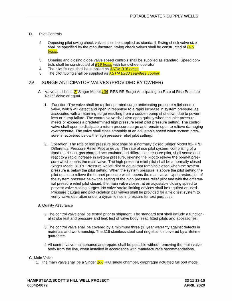
POTABLE WATER SUPPLY WELLS
HAMPSTEAD/SCOTT’S HILL WELL PROJECT 33 11 13-10
00542-0079 APRIL 2020
D. Pilot Controls
2 Opposing pilot swing check valves shall be supplied as standard. Swing check valve size
shall be specified by the manufacturer. Swing check valves shall be constructed of B16 brass.
3 Opening and closing globe valve speed controls shall be supplied as standard. Speed con-
trols shall be constructed of B16 brass with handwheel operator. 4 The pilot fittings shall be supplied as ASTM B16 brass. 5 The pilot tubing shall be supplied as ASTM B280 seamless copper.
2.6 . SURGE ANTICIPATOR VALVES (PROVIDED BY OWNER)
A. Valve shall be a 2” Singer Model 106–RPS-RR Surge Anticipating on Rate of Rise Pressure Relief Valve or equal.
1. Function: The valve shall be a pilot operated surge anticipating pressure relief control
valve, which will detect and open in response to a rapid increase in system pressure, as associated with a returning surge resulting from a sudden pump shut down due to power loss or pump failure. The control valve shall also open quickly when the inlet pressure meets or exceeds a predetermined high pressure relief pilot pressure setting. The control valve shall open to dissipate a return pressure surge and remain open to relieve damaging overpressure. The valve shall close smoothly at an adjustable speed when system pres-sure is recovered below the high pressure relief pilot setting.
2. . Operation: The rate of rise pressure pilot shall be a normally closed Singer Model 81-RPD
Differential Pressure Relief Pilot or equal. The rate of rise pilot system, comprising of a fixed restriction, gas charged accumulator and differential pressure pilot, shall sense and react to a rapid increase in system pressure, opening the pilot to relieve the bonnet pres-sure which opens the main valve. The high pressure relief pilot shall be a normally closed Singer Model 81-RP Pressure Relief Pilot or equal that remains closed when the system pressure is below the pilot setting. When the system pressure is above the pilot setting the pilot opens to relieve the bonnet pressure which opens the main valve. Upon restoration of the system pressure below the setting of the high pressure relief pilot and with the differen-tial pressure relief pilot closed, the main valve closes, at an adjustable closing speed to prevent valve closing surges. No valve stroke limiting devices shall be required or used. Pressure gauges and pilot isolation ball valves shall be provided for a field test system to verify valve operation under a dynamic rise in pressure for test purposes.
B. Quality Assurance
2 The control valve shall be tested prior to shipment. The standard test shall include a function-al stroke test and pressure and leak test of valve body, seat, fitted pilots and accessories.
3 The control valve shall be covered by a minimum three (3) year warranty against defects in
materials and workmanship. The 316 stainless steel seat ring shall be covered by a lifetime guarantee.
4 All control valve maintenance and repairs shall be possible without removing the main valve
body from the line, when installed in accordance with manufacturer’s recommendations.
C. Main Valve 1. The main valve shall be a Singer 106 -PG single chamber, diaphragm actuated full port model.

POTABLE WATER SUPPLY WELLS
HAMPSTEAD/SCOTT’S HILL WELL PROJECT 33 11 13-11
00542-0079 APRIL 2020
2. The main valve, bonnet and removable stem cap shall be constructed of ASTM A536 (Grade 65/45/12) ductile iron.
3. Main valves of 2.5” (65mm) and larger shall have a removable stem cap for access to the main
valve stem for alignment check, spring installation and ease of service and assembly.
4. The main valve bonnet shall be located using two or more locating guide pins to maintain the in-ner valve assembly alignment and for ease of maintenance.
5. The main valve trim, consisting of seat ring and stem shall be constructed of AISI 316 stainless
steel. The valve stem shall have wrench flats for ease of maintenance.
6. The main valve shall provide a drip-tight seal using a mechanically retained resilient disc, having a rectangular cross section, against the stationary AISI 316 stainless steel seat ring.
7. The stationary AISI 316 stainless steel seat ring of main valves 2.5” (65mm) and larger shall be
held in place using self-locking screws and seat ring retainers.
8. All internal and external ferrous components, including all mating surfaces, shall be coated with an NSF-61 approved fusion bonded epoxy to a minimum of 10 mils DFT-Dry Film Thickness.
9. The main valve elastomers: diaphragm, resilient disc and seals, shall be of EPDM or Buna-N.
10. All main valve fasteners (bolts, nuts, studs, cap screws) shall be supplied as AISI 18-8 or 304
stainless steel. All bonnet bolts shall be fitted with stainless steel washers to prevent damage to the bonnet coating.
11. Valve shall have flanged end connections. Flanged connections shall be ANSI/ASME B16.42
Class 150# flange drilled, faced and rated.
12. Due to the potential for noise, vibration and erosion damage from cavitation, the valve manufac-turer shall provide, upon request, a computerized sizing and cavitation analysis, using independ-ent third party software. Cavitation analysis shall provide the status of cavitation based on cus-tomer supplied parameters as to valve size, flow rate requirements and pressure conditions. The cavitation analysis shall also provide information as to Cv factor, percent of valve lift, cavitation index and noise level.
13. The valve manufacturer shall be able to supply cavitation control trim which shall be engineered
to be optimized to the actual operating parameters of the control valve application and warranted to perform correctly and prevent main valve cavitation damage under the stated conditions. Ori-fice plates or other non-engineered cavitation control devices shall not be used to prevent or min-imize valve cavitation.
D. Pilot Controls
1. The differential pressure relief pilot shall be a Singer Model 81-RPD normally closed pilot or equal with a spring to adjust the differential pressure setting.
2. The pilot trim, consisting of a seat ring, stem and inner valve, shall be constructed of AISI 316
stainless steel. 3. The adjustable pilot spring range shall be supplied with a spring range of 5-25psi (0.35-1.72 bar).
The pilot shall be factory preset at 10psid (0.7 bar). 4. The pilot body and spring casing shall be constructed of ASTM B62 bronze.
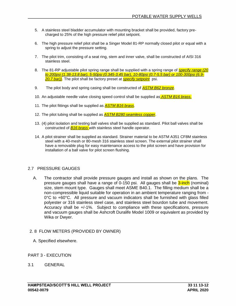
POTABLE WATER SUPPLY WELLS
HAMPSTEAD/SCOTT’S HILL WELL PROJECT 33 11 13-12
00542-0079 APRIL 2020
5. A stainless steel bladder accumulator with mounting bracket shall be provided, factory pre-charged to 25% of the high pressure relief pilot setpoint.
6. The high pressure relief pilot shall be a Singer Model 81-RP normally closed pilot or equal with a
spring to adjust the pressure setting. 7. The pilot trim, consisting of a seat ring, stem and inner valve, shall be constructed of AISI 316
stainless steel. 8. The 81-RP adjustable pilot spring range shall be supplied with a spring range of specify range (20
to 200psi (1.38-13.8 bar), 5-50psi (0.345-3.45 bar), 10-80psi (0.7-5.5 bar) or 100-300psi (6.9-20.7 bar)). The pilot shall be factory preset at specify setpoint psi.
9. The pilot body and spring casing shall be constructed of ASTM B62 bronze. 10. An adjustable needle valve closing speed control shall be supplied as ASTM B16 brass. 11. The pilot fittings shall be supplied as ASTM B16 brass. 12. The pilot tubing shall be supplied as ASTM B280 seamless copper. 13. (4) pilot isolation and testing ball valves shall be supplied as standard. Pilot ball valves shall be
constructed of B16 brass with stainless steel handle operator. 14. A pilot strainer shall be supplied as standard. Strainer material to be ASTM A351 CF8M stainless
steel with a 40-mesh or 80-mesh 316 stainless steel screen. The external pilot strainer shall have a removable plug for easy maintenance access to the pilot screen and have provision for installation of a ball valve for pilot screen flushing.
2.7 PRESSURE GAUGES
A. The contractor shall provide pressure gauges and install as shown on the plans. The pressure gauges shall have a range of 0-150 psi. All gauges shall be 3-inch (nominal) size, stem mount type. Gauges shall meet ASME B40.1. The filling medium shall be a non-compressible liquid suitable for operation in an ambient temperature ranging from -0°C to +60°C. All pressure and vacuum indicators shall be furnished with glass filled polyester or 316 stainless steel case, and stainless steel bourdon tube and movement. Accuracy shall be +/-1%. Subject to compliance with these specifications, pressure and vacuum gauges shall be Ashcroft Duralife Model 1009 or equivalent as provided by Wika or Dwyer.
2. 8 FLOW METERS (PROVIDED BY OWNER)
A. Specified elsewhere.
PART 3 - EXECUTION
3.1 GENERAL
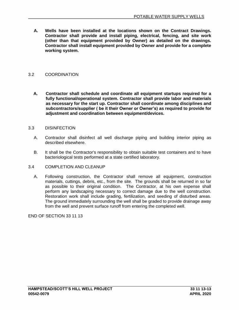
POTABLE WATER SUPPLY WELLS
HAMPSTEAD/SCOTT’S HILL WELL PROJECT 33 11 13-13
00542-0079 APRIL 2020
A. Wells have been installed at the locations shown on the Contract Drawings. Contractor shall provide and install piping, electrical, fencing, and site work (other than that equipment provided by Owner) as detailed on the drawings. Contractor shall install equipment provided by Owner and provide for a complete working system.
3.2 COORDINATION
A. Contractor shall schedule and coordinate all equipment startups required for a fully functional/operational system. Contractor shall provide labor and materials as necessary for the start up. Contractor shall coordinate among disciplines and subcontractors/supplier ( be it their Owner or Owner’s) as required to provide for adjustment and coordination between equipment/devices.
3.3 DISINFECTION
A. Contractor shall disinfect all well discharge piping and building interior piping as described elsewhere.
B. It shall be the Contractor's responsibility to obtain suitable test containers and to have bacteriological tests performed at a state certified laboratory.
3.4 COMPLETION AND CLEANUP
A. Following construction, the Contractor shall remove all equipment, construction materials, cuttings, debris, etc., from the site. The grounds shall be returned in so far as possible to their original condition. The Contractor, at his own expense shall perform any landscaping necessary to correct damage due to the well construction. Restoration work shall include grading, fertilization, and seeding of disturbed areas. The ground immediately surrounding the well shall be graded to provide drainage away from the well and prevent surface runoff from entering the completed well.
END OF SECTION 33 11 13
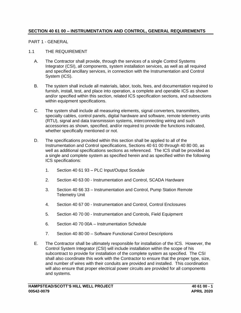
HAMPSTEAD/SCOTT’S HILL WELL PROJECT 40 61 00 - 1
00542-0079 APRIL 2020
SECTION 40 61 00 – INSTRUMENTATION AND CONTROL, GENERAL REQUIREMENTS
PART 1 - GENERAL
1.1 THE REQUIREMENT
A. The Contractor shall provide, through the services of a single Control Systems Integrator (CSI), all components, system installation services, as well as all required and specified ancillary services, in connection with the Instrumentation and Control System (ICS).
B. The system shall include all materials, labor, tools, fees, and documentation required to furnish, install, test, and place into operation, a complete and operable ICS as shown and/or specified within this section, related ICS specification sections, and subsections within equipment specifications.
C. The system shall include all measuring elements, signal converters, transmitters, specialty cables, control panels, digital hardware and software, remote telemetry units (RTU), signal and data transmission systems, interconnecting wiring and such accessories as shown, specified, and/or required to provide the functions indicated, whether specifically mentioned or not.
D. The specifications provided within this section shall be applied to all of the Instrumentation and Control specifications, Sections 40 61 00 through 40 80 00, as well as additional specifications sections as referenced. The ICS shall be provided as a single and complete system as specified herein and as specified within the following ICS specifications:
1. Section 40 61 93 – PLC Input/Output Scedule
2. Section 40 63 00 - Instrumentation and Control, SCADA Hardware
3. Section 40 66 33 – Instrumentation and Control, Pump Station Remote Telemetry Unit
4. Section 40 67 00 - Instrumentation and Control, Control Enclosures
5. Section 40 70 00 - Instrumentation and Controls, Field Equipment
6. Section 40 70 00A – Instrumentation Schedule
7. Section 40 80 00 – Software Functional Control Descriptions
E. The Contractor shall be ultimately responsible for installation of the ICS. However, the Control System Integrator (CSI) will include installation within the scope of his subcontract to provide for installation of the complete system as specified. The CSI shall also coordinate this work with the Contractor to ensure that the proper type, size, and number of wires with their conduits are provided and installed. This coordination will also ensure that proper electrical power circuits are provided for all components and systems.
INSTRUMENTATION AND CONTROL, GENERAL REQUIREMENTS
HAMPSTEAD/SCOTT’S HILL WELL PROJECT 40 61 00 - 1
00542-0079 APRIL 2020
F. The Contractor’s responsibilities, as distinct from the CSI’s responsibilities, shall be to provide all additional materials and work necessary to supplement the materials and work provided by the CSI; thereby satisfying all requirements that are within ICS specification sections.
G. The Contractor shall coordinate structural work, penetrations, painting, etc., as required for installation of a complete ICS. In-line or integrally mounted items (such as flow elements, level sensors, etc.) shall be installed under the supervision of the CSI.
H. The Contractor shall be responsible for coordinating interfaces between ICS equipment provided under the ICS specification sections and the equipment provided under other sections of the specifications. The Contractor shall verify and coordinate space requirements, process equipment power supply and voltage, process equipment control power supply and voltage, compatibility of control signals, details of equipment installation and interconnection. Coordination shall include distribution of approved shop drawings to all vendors, subcontractors, etc., involved in the control interface. Likewise, the Contractor shall ensure that instrumentation and control devices provided under other sections of the specifications are compatible and of the same quality and characteristics as similar devices specified under the ICS specification sections.
1.2 SCOPE
A. The scope listed within this subsection pertains to major items of supply. Refer to the complete Contract Documents for all requirements.
B. Monitoring and control of each process shall be accomplished through PLC control panels, provided by the CSI as well as other equipment suppliers. The panels shall communicate via cellular communication to the existing cloud-hosted Mission Controls SCADA system HMI application.
C. This project will provide for the following components, systems:
1. Furnish various local process monitoring instrumentation complete with surge protection and signal transmission as specified for the following new well sites:
a. Kiwanis – Well No. 4
b. Annex – Well No. 6
2. Furnish, install and test a new PLC control panel at each of the two well sites to accommodate the input/output (I/O) and functional requirements for the equipment and instruments within the respective well site building and surrounding area.
3. Modify the existing cloud hosted SCADA system HMI application for monitoring and control of all well sites.
4. Furnish TVSS for instrumentation and control panels as specified.
5. Furnish, install and test RTU communication modules at each site that shall communicate with the existing hosted SCADA system HMI application via cellular

INSTRUMENTATION AND CONTROL, GENERAL REQUIREMENTS
HAMPSTEAD/SCOTT’S HILL WELL PROJECT 40 61 00 - 2
00542-0079 APRIL 2020
communication. RTU communication modules shall reside within the PLC panels.
6. Provide, install and configure all SCADA telemetry units and software packages specified and as needed to complete the requirements herein.
7. Furnish spare parts as described herein.
8. Provide implementation and testing of the complete system.
9. Furnish training of Owner personnel.
10. Provide Operations and Maintenance Manuals.
D. The CSI shall provide control panels complete with all hardware, wiring, relay logic, pilot devices, backup power systems, power and signal line surge protection, and appropriate interfaces to all station equipment. The CSI shall also provide PLC programming of control logic functions including control applications for the monitoring and control of the process equipment as specified.
E. The Contractor, working in conjunction with the CSI, shall be responsible to provide a complete and operational system in full compliance with the specifications and contract drawings. The CSI shall be responsible for the detailed design, field verification, installation, technical oversight, testing, quality assurance and documentation of all technical details involving instrumentation and control for this project. The CSI shall furnish trained personnel on site during any activities requiring installation, calibration, testing or startup of any controls or communications.
1.3 RELATED WORK SPECIFIED ELSEWHERE
A. Division 26 – Electrical
1. Where electrical subcomponents are to be provided as part of ICS equipment, but for which there is no specification, provide in accordance with Division 26 - Electrical. These subcomponents shall be compatible and of the same quality and characteristics as similar devices specified under Division 26 - Electrical. If possible the same make and/or model supplied under Division 26 shall be provided.
2. The following work shall be provided under Division 26 – Electrical:
a. Conduit, raceways, and installation of wire and cable for all instrumentation and control system signal wiring, grounding systems, special cables and network cables except as noted.
b. Instrumentation and control system signal field wire.
c. Grounding systems for all ICS equipment.
d. Mounting of ICS electrical enclosures (i.e. control panels, TVSS boxes, electronic instrumentation, etc.) with exclusion of final measuring elements
INSTRUMENTATION AND CONTROL, GENERAL REQUIREMENTS
HAMPSTEAD/SCOTT’S HILL WELL PROJECT 40 61 00 - 3
00542-0079 APRIL 2020
of instrumentation (i.e. flow tubes, sensors in process piping, etc.) which shall be as coordinated by the Contractor.
1.4 CODES AND STANDARDS
A. The ICS shall comply with the National Electric Code, National Electric Safety Code, OSHA, and with all applicable federal, state, county, municipal, and electrical utility codes and regulations, as well as the Contract Documents. In the event of any conflict between these codes, regulations, and Contract Documents, the most restrictive shall apply.
B. The Instrumentation and Control System shall comply with the following codes and standards as well as any others within the specifications and drawings. In the event of any conflict between these codes, regulations, standards and Contract Documents, the most restrictive shall apply.
1. Applicable state, county, and municipal code requirements.
2. Applicable standards of the National Fire Protection Association (NFPA)
a. National Electrical Code (NEC).
3. Applicable standards of the Underwriter's Laboratories, Inc. (U.L.)
a. UL 508 Industrial Control Equipment
b. UL 508A Industrial Control Panels
4. Applicable standards of the Institute of Electrical and Electronics Engineers (IEEE)
5. Applicable standards of the National Electrical Manufacturers Association (NEMA)
a. NEMA 250 Enclosures for Electrical Equipment (1000 V Maximum)
b. NEMA ICS 1 Industrial Control and Systems: General Requirements
c. NEMA ICS 6 Enclosures for Industrial Control and Systems
6. Applicable standards of the International Society of Automation (ISA)
a. S5.1 Instrumentation Symbols and Identification
b. S5.4 Instrument Loop Diagrams
c. S20 Specification Forms for Process Measurement and Control Instruments, Primary Elements, and Control Valves
d. TR20.00.01 Specification Forms for Process Measurement and Control Instruments

INSTRUMENTATION AND CONTROL, GENERAL REQUIREMENTS
HAMPSTEAD/SCOTT’S HILL WELL PROJECT 40 61 00 - 4
00542-0079 APRIL 2020
1.5 SUBMITTALS
A. Submittals shall be provided in accordance with the requirements set forth in Division 0 – Procurement and Contracting Requirements, and as specified herein.
B. Every submittal shall have a separate section entitled "Requested Deviations from ICS Specifications" which shall clearly define and clearly explain all requested deviations and exceptions of the Instrumentation and Control System to this Specification. Only those deviations requests listed in this section will be reviewed.
C. After all changes or corrections resulting from the review of the system supplier's drawings have been made, panels may be built and instrumentation devices may be supplied in accordance with the approved drawings. One set of "as shipped" prints shall be included in the panels when shipped from the system supplier's wiring and assembly shop.
D. The following major list of submittals shall be provided as a minimum. Major submittals are generally listed in the order they are to be provided. Refer to related ICS specification sections and equipment subsections for additional submittals and submittal requirements.
1. Process Instrumentation Submittal
2. SCADA System Hardware and Control Panel Submittal
3. Training Submittal
4. Testing Submittal
5. Tools, Supplies, and Spare Parts Lists Submittal
6. Preliminary and Final Operation and Maintenance Manuals
E. Process Instrumentation Submittal
1. This submittal shall provide complete documentation of all field devices and other instrument and control equipment not specified to be submitted elsewhere.
a. Provide data sheets for each component listing all model numbers, optional, and ancillary devices that are being provided. The data sheets shall be provided with an index and proper identification and cross referencing. They shall include but not be limited to the following information.
(i) Plant Equipment Number and ISA tag number per the Loop Diagrams.
(ii) Product (item) name used herein and on the Contract Drawings.
(iii) Manufacturers complete model number.
INSTRUMENTATION AND CONTROL, GENERAL REQUIREMENTS
HAMPSTEAD/SCOTT’S HILL WELL PROJECT 40 61 00 - 5
00542-0079 APRIL 2020
(iv) Location of the device.
(v) Input - output characteristics.
(vi) Range, size, and graduations.
(vii) Physical size with dimensions, enclosure NEMA classification and mounting details.
(viii) Materials of construction of all components.
(ix) Instrument or control device sizing calculations where applicable.
(x) Certified calibration data on all flow metering devices.
b. Provide equipment specification sheets which shall fully describe the device, the intended function, how it operates and its physical environmental and performance characteristics. Each data sheet shall have appropriate cross references to loop or equipment identification tags. As a minimum the specification sheets shall include the following:
(i) Dimension, rigid-clearances.
(ii) Mounting or installation details.
(iii) Connection.
(iv) Electrical power or air requirements.
(v) Materials of construction.
(vi) Environmental characteristics.
(vii) Performance characteristics.
c. The submittal shall also contain all planning information, site preparation instructions, grounding and bonding procedures, cabling diagrams, plug identifications, safety precautions or guards, and equipment layouts in order to enable the Contractor to proceed with the detailed site preparation for all equipment.
F. SCADA System Hardware and Control Panel Submittal
1. Provide detailed drawings covering control panels, consoles and/or enclosures which shall include:
a. Cabinet assembly and layout drawings to scale. These shall include both front and interior layouts.
b. Material, fabrication and painting specifications.
INSTRUMENTATION AND CONTROL, GENERAL REQUIREMENTS
HAMPSTEAD/SCOTT’S HILL WELL PROJECT 40 61 00 - 6
00542-0079 APRIL 2020
c. Color selection samples for selection by the Engineer.
d. Where graphic display panels are required, submit detailed layout to scale, including symbols and line widths as well as color selection samples and details of fabrication. Half-scale layout will be acceptable.
e. Heat calculations for control panels consisting of a PLC control system.
f. Power supply device sizing calculations which includes UPS systems (where applicable).
g. Panel wiring diagrams showing all power connections to equipment within and on the panel, combined panel power draw requirements (volts, amps), breaker sizes, fuse sizes, and grounding. This wiring diagram shall be in ladder logic format and shall reference the appropriate drawing for continuations or details where required. Show all wire numbers and terminal block designations
2. Provide detailed PLC input/output wiring diagrams for each monitoring or control loop. The diagrams shall show all components of the loop both analog, digital, and discrete including all relays, switches, dropping resistors, etc. which are being provided for proper operation. Loop numbers used shall correspond to the loop numbers indicated in the Contract Documents.
a. The diagrams shall show all components and panel terminal board identification numbers and all wire numbers. This diagram shall include all intermediate terminations between field elements and panels (e.g. terminal junction boxes). The diagrams shall be coordinated with the electrical contractor and shall bear his mark showing this has been done.
b. Show location of all devices.
c. Show instrument description showing type, manufacturer, model number, range, set points, and operation (e.g. fail open, open on energize, normally closed, etc.) as applicable.
d. Show all instrument loop power or instrument air requirements back to termination on terminal block or bulkhead, fuse block (including fuse size), etc., as applicable.
3. This submittal shall provide complete documentation of the proposed hardware (PLCs, communications equipment, peripherals, etc.) including:
a. A system block diagram(s) showing in schematic form, the interconnections between major hardware components such as: control centers, panels, consoles, computer and peripheral devices, telemetry equipment, local digital processors and like equipment. The block diagram shall reflect the total integration of all digital devices in the system and shall reflect any man/machine interface locations. All components shall be clearly identified with appropriate cross references to the location of each.

INSTRUMENTATION AND CONTROL, GENERAL REQUIREMENTS
HAMPSTEAD/SCOTT’S HILL WELL PROJECT 40 61 00 - 7
00542-0079 APRIL 2020
The diagram shall reference all interconnecting cabling requirements for digital components of the system including any data communication links.
b. Data sheet for each hardware component, listing all model numbers, optional, auxiliary, and ancillary devices that are being provided. The data sheets shall be provided with an index and proper identification and cross referencing. They shall include but not be limited to the following information.
(i) Equipment Number and ISA tag number per the Loop Diagrams (as applicable).
(ii) Product (item) name used herein and on the Contract Drawings.
(iii) Manufacturers complete model number.
(iv) Location of the device.
(v) Input - output characteristics.
(vi) Range, size, and graduations.
(vii) Physical size with dimensions, enclosure NEMA classification and mounting details.
(viii) Materials of construction of all components.
(ix) Power supply device sizing calculations where applicable.
c. Equipment specification sheets which shall fully describe the device, the intended function, how it operates and its physical environmental and performance characteristics. Each data sheet shall have appropriate cross references to loop or equipment identification tags. As a minimum the specification sheets shall include the following:
(i) Dimensions and working clearances.
(ii) Mounting or installation details.
(iii) Connection diagrams.
(iv) Electrical power requirements (volts, amps).
(v) Materials of construction.
(vi) Environmental characteristics.
(vii) Performance characteristics.
d. The submittal shall also contain all planning information, site preparation instructions, grounding and bonding procedures, cabling diagrams, plug
INSTRUMENTATION AND CONTROL, GENERAL REQUIREMENTS
HAMPSTEAD/SCOTT’S HILL WELL PROJECT 40 61 00 - 8
00542-0079 APRIL 2020
identifications, safety precautions or guards, and equipment layouts in order to enable the Contractor to proceed with the detailed site preparation for all equipment.
4. This submittal shall contain a complete system Input/Output (I/O) and termination list for the local control PLC panel. The list shall be sorted first by ISA tag name and second by I/O type (i.e. AI, AO, D1, DO, PI, PO. etc.). The list shall contain as a minimum the following for each active point and spare point:
a. Full ISA instrument tag (or "SPARE").
b. Type of I/O (i.e., DI, DO, AI or AO).
c. I/O terminal point physical location (panel name, rack, slot, point, etc.).
d. I/O point address.
e. Point name.
f. Terminal Strip and Number
G. Training Submittals
1. Training Plan Submittal: The training plan shall include:
a. Definitions of each course.
b. Specific course attendance.
c. Schedule of training courses including dates, duration, and locations of each class.
d. Resumes of the instructors who will actually conduct the training.
H. Testing Submittals
1. The test plan shall be submitted after all equipment submittals have been approved by the Owner and/or Engineer.
2. The test plan shall demonstrate that the CSI has designed and configured a system that meets the design specifications. The documents for the test plan shall be structured so that it is easily understood what the inputs are, what the predicted outputs should be, and what the actual outputs are. The test plan should have sign-off and date block for the CSI, the Contractor, and the Owner.
3. The complete test plan should include but not be limited to the following:
a. Test assumptions and methods
b. Test Equipment List
INSTRUMENTATION AND CONTROL, GENERAL REQUIREMENTS
HAMPSTEAD/SCOTT’S HILL WELL PROJECT 40 61 00 - 9
00542-0079 APRIL 2020
c. Test Personnel Staffing and Qualifications
d. Test Schedule with time allotted for each task
e. System hardware and software summary.
f. Communications test to the various PLCs for Discrete and Analog I/O data transfer.
g. 100 percent I/O point test including all spare points based upon the previously submitted System I/O list.
4. Test Procedures: Submit the procedures proposed to be followed during the test. Procedures shall include test descriptions, forms, and checklists to be used to control and document the required tests. Testing may not be started until all Testing Submittals have been approved.
5. Test Documentation: Submit a copy of the signed off test procedures upon completion of each required test.
I. Tools, Supplies and Spare Parts Lists Submittal
1. This submittal shall include a list of all required and recommended spares. The following information shall be provided in table format:
a. Specification Section
b. Tagname
c. Description
d. Quantity
e. Manufacturer
f. Model, part, order number
g. Local distributor and manufacturer contact information. Contact information shall include address, phone number, and website.
J. Operational and Maintenance Manuals
1. Prior to installation of any equipment onsite, preliminary O&M manuals shall have been submitted and approved. No installation of equipment shall be permitted without the Contractor maintaining an updated version of these preliminary O&M manuals onsite for the Owner’s and Engineer’s use.
2. After all field changes or corrections made during installation and field check out have been completed, then all system supplier documentation, including drawings, shall be revised to reflect the “as installed, corrected and accepted" condition of the system and final record copies of O&M manuals for the system
INSTRUMENTATION AND CONTROL, GENERAL REQUIREMENTS
HAMPSTEAD/SCOTT’S HILL WELL PROJECT 40 61 00 - 10
00542-0079 APRIL 2020
shall be provided to the Owner and Engineer for approval.
3. Final system documentation shall be provided in 3-hole type binders of archival quality (e.g. slant D or elliptical binding, vinyl with metal hinge or extra heavy weight vinyl, etc.) with a binding no larger than three (3) inches. Materials shall be printed on 8.5” x 11” or 11” x 17” tear resistant paper or ring reinforced paper where tear resistant is not available. Drawings shall be either folded to fit within an 8.5” x 11” binder or in an 11” x 17” 3-hole binder. Each binder shall include fifteen percent (15%) spare space for the addition of future material. Tear resistant paper shall be Xerox Never Tear or equal.
4. Final documentation shall also be provided in an electronic format. Electronic documentation shall be organized and provided on CD which shall include all CAD drawings, manuals and word processing documents. Electronic documentation format shall be primarily Adobe .pdf with additional documents provided in AutoCAD, Microsoft Office, HTML or as approved by the Engineer or Owner. Organization of the electronic documentation shall be such as to allow point and click navigation from a table of contents to the particular documents with the ability to return to the table of contents from any location with one mouse click.
5. AutoCAD drawings files shall include all supporting files, symbol libraries and print configurations needed to support future modifications and properly print additional drawing copies.
6. All electronic media (i.e. software, electronic documentation, configuration files/reports, device backups, etc.) shall be provided with two (2) backup copies, each organized into a separate binder. Media storage binders shall include but not be limited to the following:
a. Table of contents
b. Archival media holders (e.g. CD, DVD, floppy, tape disk, etc.)
c. Support contacts (i.e. company, phone, internet link, etc.)
d. Software system requirements and installation instructions
7. Laminated or water/tear resistant copies of all applicable instrumentation and control system drawings shall be supplied in drawing pocket of each control enclosure after “as installed, corrected, and accepted" revisions have been made to the enclosure.
8. Operation and Maintenance manuals shall include but not be limited to the following:
a. Manufacturer standard O&M manuals for all equipment and software furnished.
b. Custom O&M information describing the specific configuration of equipment and software, and the operation and maintenance requirements
INSTRUMENTATION AND CONTROL, GENERAL REQUIREMENTS
HAMPSTEAD/SCOTT’S HILL WELL PROJECT 40 61 00 - 11
00542-0079 APRIL 2020
for this particular project.
c. The manuals shall contain all illustrations, detailed drawings, wiring diagrams and instructions necessary for installing, operating and maintaining the equipment.
d. All modifications to manufacturer standard equipment and/or components shall be clearly identified and shown on the drawings and schematics. All information contained therein shall apply specifically to the equipment furnished and shall only include instructions that are applicable.
e. A functional description of the entire system, with references to drawings and instructions.
f. A complete "as built" set of all approved shop drawings, which shall reflect all work required to achieve final system acceptance.
g. A complete list of the equipment supplied, including serial numbers, ranges, configuration parameters and other pertinent data.
h. Full specifications on each item.
i. Detailed service, maintenance and operation instructions for each item supplied.
j. Special maintenance requirements particular to this system shall be clearly defined, along with special calibration and test procedures.
k. Complete parts lists with stock numbers and name, address and telephone number of the local supplier.
l. References to manufacturers' standard literature where applicable.
m. Warning notes shall be located throughout the manual where such notes are required to prevent accidents or inadvertent misuse of equipment.
n. The operating instructions shall clearly describe the step by step procedures that must be followed to implement all phases of all operating modes. The instructions shall be in terms understandable and usable by operating personnel and maintenance crews and shall be useful in the training of such personnel.
o. The maintenance instructions shall describe the detailed preventive and corrective procedures required, including environmental requirements during equipment storage and system operation, to keep the System in good operating condition. All hardware maintenance documentation shall make reference to appropriate diagnostics, where applicable, and all necessary wiring diagrams, component drawings and PCB schematic drawings shall be included.
1.6 MEETINGS
INSTRUMENTATION AND CONTROL, GENERAL REQUIREMENTS
HAMPSTEAD/SCOTT’S HILL WELL PROJECT 40 61 00 - 12
00542-0079 APRIL 2020
A. The Contractor shall be required to give the Owner and their representatives, at least two weeks’ notice prior to any scheduled meetings. The notice may be shortened by consent.
1.7 CONTROL SYSTEM INTEGRATOR
A. The Control System Integrator shall be regularly engaged in the detailed design, fabrication, installation and startup of instrumentation and control systems for water and wastewater treatment facilities in the state of North Carolina. Any CSI that has been subject to litigation or the assessment of liquidated damages for nonperformance on any project within the last five calendar years shall not be acceptable.
B. Where specific manufacturers and/or models of major hardware or software products (PLC, Software, Network Equipment, Wireless Equipment, etc.) are specified to be used on this project, the CSI shall have completed at least one project using that specified hardware or software. As used herein, the term “completed” shall mean that a project has been brought to final completion and final payment has been made.
C. Control System Integrators shall meet the following minimum qualifications:
1. A minimum of 7 years experience with at least 5 years in water / wastewater projects
2. References for 3 completed projects of like size and application to the project specified herein
3. Project bonding capacity of $2 million
4. UL 508 certified panel shop
5. Electrical contractors license in the project site’s state.
6. On staff licensed professional engineer capable of being registered in the state of the project and registered in that state, if required to perform engineering services as specified to implement this project.
D. The listing of acceptable Control System Integrators in this specification in no way relieves the Control System Integrator from meeting the qualifications specified herein. Acceptable Control System Integrators shall be Coastline Controls and Electric Inc.; Revere Control Systems; CITI, LLC; M/R Systems, Inc.; or Custom Controls Unlimited, Inc.
E. The Owner shall have the right of access to the CSI’s facilities and the facilities of their equipment suppliers to inspect materials and parts, witness inspections, tests and work in progress, and examine applicable design documents, records and certifications during any stage of design, fabrication and tests. The CSI and their equipment suppliers shall furnish office space, supplies and services required for these inspection activities.
1.8 QUALITY ASSURANCE
INSTRUMENTATION AND CONTROL, GENERAL REQUIREMENTS
HAMPSTEAD/SCOTT’S HILL WELL PROJECT 40 61 00 - 13
00542-0079 APRIL 2020
A. The listing of specific products in this specification in no way relieves the Contractor of furnishing equipment which shall meet the performance and quality criteria specified herein.
B. All equipment and materials shall be new and the products of reputable recognized suppliers having adequate experience in the manufacture of these particular items.
C. For uniformity, only one manufacturer will be accepted for each type of product.
D. All equipment shall be designed for the service intended and shall be of rugged construction, of ample strength for all stresses that may occur during fabrication, transportation, and erection as well as during continuous or intermittent operation. They shall be adequately stayed, braced and anchored and shall be installed in a neat and workmanlike manner. Appearance and safety, as well as utility, shall be given consideration in the design of details.
E. All components and devices installed shall be standard items of industrial grade, unless otherwise noted, which shall be of sturdy and durable construction and be suitable for long, trouble free service.
F. Electronic equipment shall be suitable for the specified environmental conditions.
G. Optional or substituted equipment or both requiring changes in details or dimensions required to maintain all structural, mechanical, electrical, control, operating, maintenance or design features incorporated in these specifications and drawings, shall be made at no additional cost to the Owner. In the event that the changes are necessary, calculations and drawings showing the proposed revisions shall be submitted for approval. The Contractor shall coordinate all changes with other affected trades and contracts and pay all additional charges incurred.
1.9 DEFINITIONS AND ABREVIATIONS
A. The following definitions and abbreviations are used throughout the specifications and drawings when referring to instrumentation and control equipment, functions, and service. Definitions and abbreviations are not listed for those used in common industry practice except where to provide explicit meaning. Refer to ISA, IEEE, and other industry standard references for those not listed herein.
CSI………………………………………….Control System Integrator MS………………………………………….Membrane System Supplier CF…………………………………………..Calcite Filter System Supplier ICS………………………………………….Instrumentation and Control System OIT………………………………………....Operator Interface Terminal OWS………………………………………..Operator WorkStation PID…………………………………………Proportional-Integral-Derivative Control SCADA…………………………………….Supervisory Control and Data Acquisition SSP…………………………………………SCADA System Programmer TVSS……………………………………….Transient Voltage Surge Suppression RTU………………………………………...Remote Telemetry Unit PLC…………………………………………Programmable Logic Controller
INSTRUMENTATION AND CONTROL, GENERAL REQUIREMENTS
HAMPSTEAD/SCOTT’S HILL WELL PROJECT 40 61 00 - 14
00542-0079 APRIL 2020
PART 2 - PRODUCTS
2.1 GENERAL REQUIREMENTS
A. All materials, equipment, and devices shall, as a minimum, meet the requirements of UL, where UL Standards are established for those items, and the requirements of NFPA-70. All control panels shall comply with the requirements of UL 508A for Industrial Control Panels. All items shall be new and unused unless specified or indicated otherwise.
B. Properly store, adequately protect, and carefully handle equipment and materials to prevent damage before and during installation. Handle, store, and protect equipment and materials in accordance with the manufacturer's recommendations. Replace damaged or defective items.
C. All equipment shall be the latest and proven design. Specifications and drawings call attention to certain features, but do not purport to cover all details entering into design of the instrumentation system. The completed system shall be compatible with functions required and the equipment furnished by the Contractor.
D. All electrical components of the system shall operate on 120 volt, single phase, 60 Hz power source, except as otherwise noted in the Specifications. Drawings and specifications indicate the energy sources that will be provided. Any other devices necessary to obtain proper operation of the instrumentation and control system from these energy sources shall be furnished with the system.
E. All necessary fuses or switches required by the instrumentation manufacturer for equipment shall be provided with the equipment. All instruments requiring internal power supply shall have internal on-off switches.
F. The mechanical, process, and electrical drawings indicate the approximate locations of field instruments, control panels, systems and equipment as well as field mounted equipment provided by others. The instrumentation subcontractor shall examine the mechanical, process and electrical drawings to determine actual size and locations of process connections and wiring requirements for instrumentation and controls furnished under this Contract. The CSI shall inspect all equipment, panels, instrumentation, controls and appurtenances either existing or furnished under other Divisions of the Specifications to determine all requirements to interface same with the ICS. The Contractor shall coordinate the completion of any required modifications with the associated supplier of the item furnished.
G. Instrumentation equipment and enclosures shall be suitable for ambient conditions specified. All system elements shall operate properly in the presence of telephone lines, power lines, and electrical equipment.
H. Inside control rooms and climate-controlled electrical rooms, the temperature will normally be 20 to 25 degrees C; relative humidity 40 to 80 percent without condensation and the air will be essentially free of corrosive contaminants and moisture. Appropriate air filtering shall be provided to meet environmental conditions (i.e., for dust).
INSTRUMENTATION AND CONTROL, GENERAL REQUIREMENTS
HAMPSTEAD/SCOTT’S HILL WELL PROJECT 40 61 00 - 15
00542-0079 APRIL 2020
I. Other indoor areas may not be air conditioned/heated; temperatures may range between 0 and 40 degrees C with relative humidity between 40 and 95 percent.
J. Field equipment, including instrumentation and panels, may be subjected to wind, rain, lightning, and corrosives in the environment, with ambient temperatures from -20 to 40 degrees C and relative humidity from 10 to 100 percent. All supports, brackets and interconnecting hardware shall be aluminum, 316 stainless steel, or as shown on the installation detail drawings.
2.2 TOOLS, SUPPLIES, AND SPARE PARTS
A. Provide special tools, other than those normally found in an electronic technician's tool box, required to test, diagnose, calibrate, install, wire, connect, disconnect, assemble and disassemble any digital equipment, instrument, panel, rack, cabinet or console mounted equipment for service and maintenance (i.e., connector pin insertion and removal tools, wire crimping tool, special wrenches, special instrument calibrators, indicator lamp insertion and removal tools, etc.).
B. Provide tools and test equipment together with items such as instruction manuals, carrying/storage cases, unit battery charger where applicable, special tools, calibration fixtures, cord extenders, patch cords and test leads, which are not specified but are necessary for checking field operation of equipment supplied under this Section.
C. The CSI shall provide supplies as needed or as required by the Owner during the specified warranty period. All fuses consumed during installation, testing, start-up, the system availability demonstration, and the warranty period shall be replaced by the Contractor.
D. Provide spare parts for items of ICS equipment as recommended by the manufacturer and in accordance with the Contract Documents.
E. Furnish all spares in moisture-proof boxes designed to provide ample protection for their contents. Label all boxes to clearly identify contents and purpose.
F. Refer to individual product specifications for additional requirements specific to those devices.
2.3 SIGNAL TRANSMISSION
A. The Contractor shall be responsible for providing a signal transmission system free from electrical interference that would be detrimental to the proper functioning of the ICS equipment.
B. The Contractor shall be responsible for coordinating signal types and transmission requirements between the various parties providing equipment under this Contract. This shall include, but not be limited to, distribution of appropriate shop drawings among the equipment suppliers and subcontractors.
C. The CSI shall provide 24 VDC power supplies for signals and instruments where applicable and as required inside panels, controls, etc. Where two-wire instruments transmit directly to the instrumentation and control system, the CSI shall provide power
INSTRUMENTATION AND CONTROL, GENERAL REQUIREMENTS
HAMPSTEAD/SCOTT’S HILL WELL PROJECT 40 61 00 - 16
00542-0079 APRIL 2020
supplies at the PLC-equipped control panels for those instruments. Where four-wire instruments with on-board loop power supplies transmit directly to the instrumentation and control system, the CSI shall provide necessary signal isolators or shall otherwise isolate the input from the ICS loop power supply. Similar provisions shall be made when a third element such as a recorder, indicator or single loop controller with integral loop power supply is included in the loop.
D. Analog signal transmission between electric or electronic instruments, controllers, and all equipment and control devices shall be individually isolated, linear 4-20 mA and shall operate at 24 VDC. Signal output from all transmitters and controllers shall be current regulated and shall not be affected by changes in load resistance within the unit's rating. All cable shields shall be grounded at one end only, at the control panel, with terminals bonded to the panel ground bus. Analog signal isolation and/or conversion shall be provided where necessary to interface with instrumentation, equipment controls, panels and appurtenances.
E. Non-standard analog transmission systems such as pulse duration, pulse rate, and voltage regulated shall not be permitted except where specifically noted in the Contract Documents. Where transmitters with nonstandard outputs do occur, their outputs shall be converted to an isolated, linear, 4-20 mA signal.
F. All discrete inputs to equipment and PLC's, from field devices, starters, panels, etc., shall be dry contacts in the field device or equipment, powered from the PLCs, unless specified otherwise. Sensing power (wetting voltage) supplied by the PLC shall be 24 VDC.
G. All discrete outputs from local control panels and Control and Information System PLCs, to field devices, starters, panels, etc., shall be 120 VAC / 28 VDC 5A dry contacts. Output contacts may be powered from the field equipment, or powered from 24 VDC / 120 VAC sourced from PLCs cabinet power system, as required to interface with field equipment. Outputs to solenoid valves, horns, and strobe lights shall be 120 VAC, powered from the PLC or control panel unless specified or shown otherwise.
H. Discrete signals between starters, panels, etc. where 120 VAC is utilized shall be clearly identified in the starter, panel, etc. as being powered from a different power supply, than other starter/panel components. Where applicable, warning signs shall be affixed inside the starter, panel, etc., stating that the panel is energized from multiple sources. Output contacts in the starter, panel, etc. which are powered from other locations shall be provided with special tags and/or color coding. Disconnecting terminal strips shall be provided for such contacts. The above requirements shall apply to all starters and panels, regardless of supplier.
2.4 NAMEPLATES
A. All items of equipment listed in the instrument schedule, control panels, and all items of digital hardware shall be identified with nameplates. Each nameplate shall be located so that it is readable from the normal observation position and is clearly associated with the device or devices it identifies. Nameplates shall be positioned so that removal of the device for maintenance and repair shall not disturb the nameplate. Nameplates shall include the equipment identification number and description. Abbreviations of the description shall be subject to the Engineer's approval.
INSTRUMENTATION AND CONTROL, GENERAL REQUIREMENTS
HAMPSTEAD/SCOTT’S HILL WELL PROJECT 40 61 00 - 17
00542-0079 APRIL 2020
B. Nameplates shall be made of 1/16 inch thick machine engraved laminated phenolic plastic having white numbers and letters not less than 3/16 inch high on a black background.
C. Nameplates shall be attached to metal equipment by stainless steel screws. In cases where the label cannot be attached by the above methods, it shall be drilled and attached to the associated device by means of stainless steel wire.
D. Nameplates for field instrumentation shall be 316 Stainless Steel, minimum 1 inch x 4 inch and attached with stainless steel wire.
PART 3 - EXECUTION
3.1 INSTALLATION
A. The CSI shall provide the Contractor a periodic written report detailing progress of start-up. This report shall include specific tabulations of devices on which start-up has been completed.
B. Equipment shall be located so that it is accessible for operation and maintenance. The CSI shall examine the Contract Drawings and Shop Drawings for various items of equipment in order to determine the best arrangement for the work as a whole, and shall supervise the installation of ICS equipment.
C. Instrumentation and Control System equipment shall be installed in accordance with the manufacturer's instructions. The locations of equipment, transmitters, alarms and similar devices shown on the Drawings are approximate only. Exact locations shall be as approved by the Engineer during construction. Obtain in the field, all information relevant to the placing of process control work and in case of any interference with other work, proceed as directed by the Engineer and furnish all labor and materials necessary to complete the work in an approved manner.
D. The CSI shall investigate each space in the building through which equipment must pass to reach its final location. If necessary, the CSI shall be required to ship his material in sections sized to permit passing through restricted areas in the building. The CSI shall also investigate, and make any field modifications to the allocated space for each cabinet, enclosure and panel, to assure proper space and access (front, rear, side).
E. Two complete sets of approved shop drawings shall be kept at the job site during all on-site construction. Both sets shall be identically marked up to reflect any modifications made during field installation or start-up. All markings shall be verified and initialed by the Engineer or his designated representative. Following completion of installation and the operational readiness test, one set of the marked up drawings shall be provided to the Engineer, the other retained by the CSI for incorporation of the mark-ups into final as-built documentation.
F. All work shall be in strict accordance with codes and local rulings, should any work be performed contrary to said rulings, ordinances and regulations, the Contractor shall bear full responsibility for such violations and assume all costs arising there from.
INSTRUMENTATION AND CONTROL, GENERAL REQUIREMENTS
HAMPSTEAD/SCOTT’S HILL WELL PROJECT 40 61 00 - 18
00542-0079 APRIL 2020
G. Brackets and hangers required for mounting of equipment shall be provided. They shall be installed in a workmanlike manner and not interfere with any other equipment.
H. The Contractor shall take steps to keep electrical and control enclosures clean and free of contaminants throughout installation. Cleaning after installation is not acceptable. Under no circumstances are electrical and control enclosures to be cleaned using compressed air to blow out dust, causing contaminants to be forced into sensitive electronics.
I. Provisions shall be made to completely capture filings (metal, etc.) when drilling into enclosures, to prevent contamination of electrical equipment.
J. Upon completion of the instrumentation and control work, the Contractor shall thoroughly clean all soiled surfaces of installed equipment and materials and remove all surplus materials, rubbish, and debris that has accumulated during the construction work. The entire area shall be left neat, clean, and acceptable to the Owner.
3.2 WIRING AND GROUNDING
A. The following wiring practice guidelines shall be used in order to minimize ground loops, to minimize electromagnetic interference/radio frequency interference (EMI/RFI) to this equipment, and to provide maximum practical immunity from damage resulting from lightning-induced transients.
B. Common wires or conductors shall not be utilized (either within panels or external to panels or for grounding of field devices) for both signal shield or signal grounding and for safety grounds.
C. Exposed wire lengths extending from within shielded signal cables shall be minimized to reduce pick-up of EMI/RFI by signal circuits. Exposed lengths of less than one inch are preferred, and a maximum exposed length of two inches may be permitted where necessary. No splicing of signal wires is permitted.
D. All signal wiring shall be shielded, both within panels and external to panels. Unless otherwise specified, all signal wiring shall be No. 16 AWG stranded tinned two-conductor twisted pair, with 100 percent coverage aluminized Mylar or aluminized polyester shield and tinned copper drain wire.
E. Signal wiring within outdoor or indoor field device enclosures shall conform to the same requirements as panel wiring.
F. The shield on each process instrumentation cable shall be continuous from source to destination, and grounded at one end only. In general, grounding of signal cable shields shall be done at the control panel end. The signal cable for no signal shall share a common cable shield grounding wire with the signal cable shield for any other signal, and shall not share a common grounding wire with any other circuit. The length of no signal cable shield grounding wire shall not exceed two inches, with less than one-inch maximum length preferred.
G. All outdoor instruments and all outdoor enclosures shall be grounded using the practice defined in Section 800.40 of the National Electric Code.

INSTRUMENTATION AND CONTROL, GENERAL REQUIREMENTS
HAMPSTEAD/SCOTT’S HILL WELL PROJECT 40 61 00 - 19
00542-0079 APRIL 2020
3.3 TESTING, GENERAL REQUIREMENTS
A. The CSI shall test all equipment hardware and software at the factory prior to shipment. As a minimum, testing shall include the following:
1. Operational Readiness Testing (ORT).
2. System Acceptance Testing (SAT).
B. Each test shall be in the cause and effect format. The person conducting the test shall initiate an input (cause) and, upon the system's or subsystem's producing the correct result (effect), the specific test requirement will have been satisfied.
C. All tests shall be conducted in accordance with prior Engineer approved procedures, forms, and check lists. Each specific test to be performed shall be described and a space provided after it for sign off by the appropriate party after its satisfactory completion.
D. Copies of these sign off test procedures, forms, and check lists will constitute the required test documentation.
E. Provide all special testing materials and equipment. Wherever possible, perform tests using actual process variables, equipment, and data. Where it is not practical to test with real process variables, equipment, and data; provide suitable means of simulation. Define these simulation techniques in the test procedures.
F. The Contractor shall require the CSI to coordinate all of his testing with him, all affected Subcontractors, and the Owner Representative.
G. The Owner Representative reserves the right to test or retest all specified functions whether or not explicitly stated in the prior approved test procedures.
H. The Owner Representative's decision shall be final regarding the acceptability and completeness of all testing.
I. The CSI shall furnish the services of technicians, all special calibration, and test equipment, and labor to perform the field tests.
3.4 OPERATIONAL READINESS TESTING (ORT)
A. The entire system shall be certified (inspected, calibrated, tested, and documented) that it is ready for operation. Each specified function shall be verified on a paragraph-by-paragraph, loop-by-loop and site-by-site basis.
B. The Owner and/or Engineer reserves the right to witness any test, inspection, calibration, or start-up activity. Acceptance by the Engineer of any plan, report, or documentation relating to any testing or commissioning activity specified herein, shall not relieve the Contractor of his responsibility for meeting all specified requirements.
C. The CSI shall provide the services of factory trained technicians, tools and equipment to field calibrate, test, inspect and adjust each instrument to its specified performance
INSTRUMENTATION AND CONTROL, GENERAL REQUIREMENTS
HAMPSTEAD/SCOTT’S HILL WELL PROJECT 40 61 00 - 20
00542-0079 APRIL 2020
requirement in accordance with manufacturer's specifications and instructions. Any instrument which fails to meet any contract requirements, or any published manufacturer performance specification for functional and operational parameters, shall be repaired or replaced, at the discretion of the Engineer, at no cost to the Owner. The Contractor shall bear all costs and provide all personnel, equipment and materials necessary to implement all installation tests and inspection activities for equipment specified herein.
D. Each instrument shall be calibrated at 0, 25, 50, 75 and 100 percent of span using test instruments to simulate inputs and read outputs. Test instruments shall be rated to an accuracy of at least five (5) times greater than the specified accuracy of the instrument being calibrated. Where applicable, such test instruments shall have accuracies as set forth by the National Institute for Standards and Technology (NIST).
E. The CSI shall provide a written calibration sheet to the Engineer for each instrument, certifying that it has been calibrated to its published specified accuracy. The Contractor shall submit proposed calibration sheets for various types of instruments for Engineer approval prior to the start of calibration. This sheet shall include but not be limited to date, instrument tag numbers, calibration data for the various procedures described herein, name of person performing the calibration, a listing of the published specified accuracy, permissible tolerance at each point of calibration, calibration reading as finally adjusted within tolerance, defect noted, corrective action required and corrections made.
F. If doubt exists as to the correct method for calibrating or checking the calibration of an instrument, the manufacturer's printed recommendations shall be used as an acceptable standard, subject to the approval of the Engineer.
G. Upon completion of calibration, devices calibrated hereunder shall not be subjected to sudden movements, accelerations, or shocks, and shall be installed in permanent protected positions not subject to moisture, dirt, and excessive temperature variations. Caution shall be exercised to prevent such devices from being subjected to over-voltage, incorrect voltages, overpressure or incorrect air. Damaged equipment shall be replaced and recalibrated at no cost to the Owner.
H. After completion of instrumentation installation and calibration, the CSI shall perform a loop check. The Contractor shall submit final loop test results with all instruments listed in the loop. Loop test results shall be signed by all representatives involved for each loop test.
I. Loop/Component Inspections and Tests: The entire system shall be checked for proper installation, calibrated, and adjusted on a loop-by-loop and component-by-component basis to ensure that it is in conformance with related submittals and the Contract Documents.
1. The Loop/Component Inspections and Tests shall be implemented using Engineer approved forms and check lists.
2. The Contractor shall require the CSI to maintain the Loop Status Reports and Components Calibration sheets at the job-site and make them available to the Engineer/Owner at any time.
INSTRUMENTATION AND CONTROL, GENERAL REQUIREMENTS
HAMPSTEAD/SCOTT’S HILL WELL PROJECT 40 61 00 - 21
00542-0079 APRIL 2020
3. These inspections and tests do not require witnessing. However, the Engineer will review and initial all Loop Status Sheets and Component Calibration Sheets and spot-check their entries periodically and upon completion of the Operational Readiness Tests. Any deficiencies found shall be corrected.
3.5 SYSTEM ACCEPTANCE TEST (SAT)
A. Successful completion of the operational readiness test, as determined by the Owner and/or Engineer, shall be the basis for starting the witnessed system acceptance test. The Engineer shall approve the ORT test results and the Engineer and Owner shall be given two weeks notice prior to the start of the System Acceptance Test.
B. The system acceptance test shall repeat loop and functional testing done during the operational readiness test in order to demonstrate to the Owner and Engineer that the system has been started up, is operating, and is in compliance with these Specifications. Each specified function shall be demonstrated on a paragraph-by-paragraph, loop-by-loop and site-by-site basis.
C. The following documentation shall be made available to the Engineer during the test:
1. All Contract Drawings and Specifications, addenda, and change orders.
2. Master copy of the test procedure.
3. One copy of all O&M Manuals shall be made available to the Engineer at the job-site both before and during testing.
D. Any malfunction during the tests shall be analyzed, and corrections made by the CSI. At any time during the tests, the Owner and/or Engineer reserves the right to halt the test if there are an excessive number of malfunctions until all signals are corrected by the CSI. The Owner and/or Engineer will determine whether any such malfunctions are sufficiently serious to warrant a repeat of this test.
E. After all functions have been tested and all corrections made, the system shall operate continuously for 15 days without failure before this test will be considered successful.
F. The total availability of the system shall be greater than 99.5 percent during this test period. Availability shall be defined as "Avail. = (Total Time-Down Time,) / (Total Time) x 100%". Down times due to power outages or other factors outside the normal protection devices or back-up power supplies provided, shall not contribute to the availability test times above.
3.6 TRAINING
A. The CSI shall provide project specific classroom training at the Owners site or designated location. Training shall be provided for the operation and maintenance of all equipment provided, as well as site specific installation configuration training for the system as a whole.
B. Each student shall be provided with training materials. All training materials shall be provided in hardcopy as well as on a training CD, with all materials in Microsoft Office

INSTRUMENTATION AND CONTROL, GENERAL REQUIREMENTS
HAMPSTEAD/SCOTT’S HILL WELL PROJECT 40 61 00 - 22
00542-0079 APRIL 2020
or Adobe pdf file format. All training CD’s shall be updated with final configuration information and resubmitted for approval. Final CD media shall be archival quality.
C. The owner reserves the right to video tape any and all training sessions for the purposes of future or refresher training.
D. To facilitate the Owner’s operations staff scheduling, training shall be conducted in two (2) four-hour sessions, a morning session and an afternoon session. Morning and afternoon sessions will cover the same material on a given day. The training shall consist of four (4) days minimum with (2) sessions per day.
E. Maintenance training shall be provided to designated maintenance personnel, so that each component may be maintained without the assistance of outside organizations. The training shall be extensive so that after training, personnel shall be able to identify component malfunctions and repair components to the board/module replacement level. Training shall cover the entire system including controls and field equipment.
F. Maintenance training shall be conducted in one (1) session, with a minimum of 8 hours of instruction.
G. Under the scope of this project, the System Integrator will not be responsible for providing PLC and HMI control programming and logic. Specific training should therefore include, but not be limited to: system architecture and interconnection, wiring, field instrumentation and PLC hardware including maintenance and trouble-shooting.
H. Refer to related specification sections for additional training requirements.
I. Training sessions shall be carried out to the satisfaction of the Owner before final acceptance will be provided.
J. Training schedules shall be coordinated with the Owner and conducted at his convenience.
3.7 WARRANTY
A. The warranty for the ICS shall be provided as specified in Section 1740 – Warranties, and as specified herein. The warranty period for this system shall be for one year and shall begin upon acceptance of the complete system by the Owner. During this warranty period, the CSI shall provide, at no additional cost to the Owner, the services of a trained, competent, field service engineer who shall arrive on site within 36 hours of notification by the Owner or Engineer, to repair and/or replace any faulty device or equipment supplied by the system supplier as part of this Instrumentation and Control System. All preventive and corrective activities shall be documented with service reports, which shall identify the equipment being serviced, state the condition of the equipment, describe all work performed, and list materials used. A copy of all service reports shall be delivered to the Owner on or before the next business day.
B. The CSI shall be capable of providing, after the warranty period for this system expires, a 1-year renewable service contract whereby a trained, competent field service engineer shall arrive on site within 36 hours of notification by the Owner. Information relative to charges for such service and availability of such service shall be submitted
INSTRUMENTATION AND CONTROL, GENERAL REQUIREMENTS
HAMPSTEAD/SCOTT’S HILL WELL PROJECT 40 61 00 - 23
00542-0079 APRIL 2020
to the Owner and the Engineer.
C. Components shall be furnished to the manufacturer's standard for service intended, unless otherwise indicated in the Specifications or on the Contract Drawings.
END OF SECTION
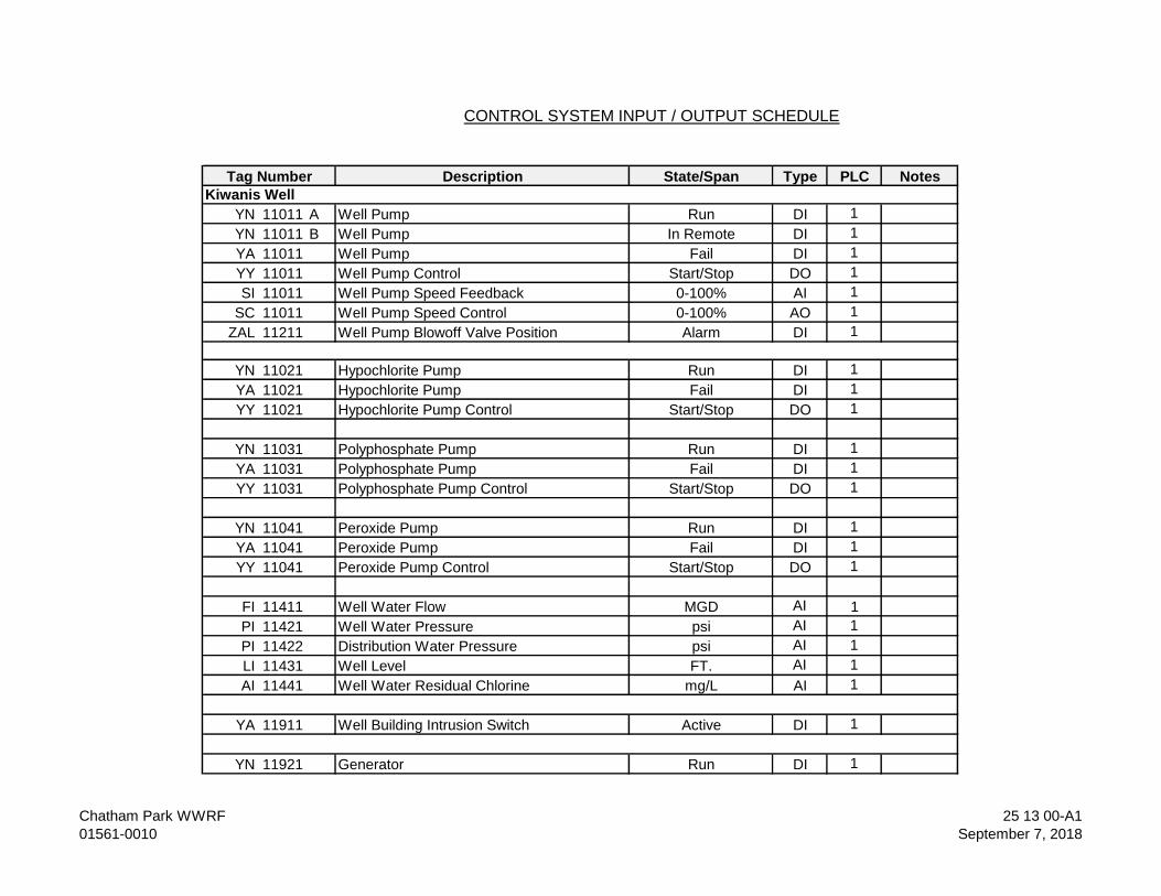
Description State/Span Type PLC Notes
YN 11011 A Well Pump Run DI 1
YN 11011 B Well Pump In Remote DI 1
YA 11011 Well Pump Fail DI 1
YY 11011 Well Pump Control Start/Stop DO 1
SI 11011 Well Pump Speed Feedback 0-100% AI 1
SC 11011 Well Pump Speed Control 0-100% AO 1
ZAL 11211 Well Pump Blowoff Valve Position Alarm DI 1
YN 11021 Hypochlorite Pump Run DI 1
YA 11021 Hypochlorite Pump Fail DI 1
YY 11021 Hypochlorite Pump Control Start/Stop DO 1
YN 11031 Polyphosphate Pump Run DI 1
YA 11031 Polyphosphate Pump Fail DI 1
YY 11031 Polyphosphate Pump Control Start/Stop DO 1
YN 11041 Peroxide Pump Run DI 1
YA 11041 Peroxide Pump Fail DI 1
YY 11041 Peroxide Pump Control Start/Stop DO 1
FI 11411 Well Water Flow MGD AI 1
PI 11421 Well Water Pressure psi AI 1
PI 11422 Distribution Water Pressure psi AI 1
LI 11431 Well Level FT. AI 1
AI 11441 Well Water Residual Chlorine mg/L AI 1
YA 11911 Well Building Intrusion Switch Active DI 1
YN 11921 Generator Run DI 1
CONTROL SYSTEM INPUT / OUTPUT SCHEDULE
Tag Number
Kiwanis Well
Chatham Park WWRF
01561-0010
25 13 00-A1
September 7, 2018
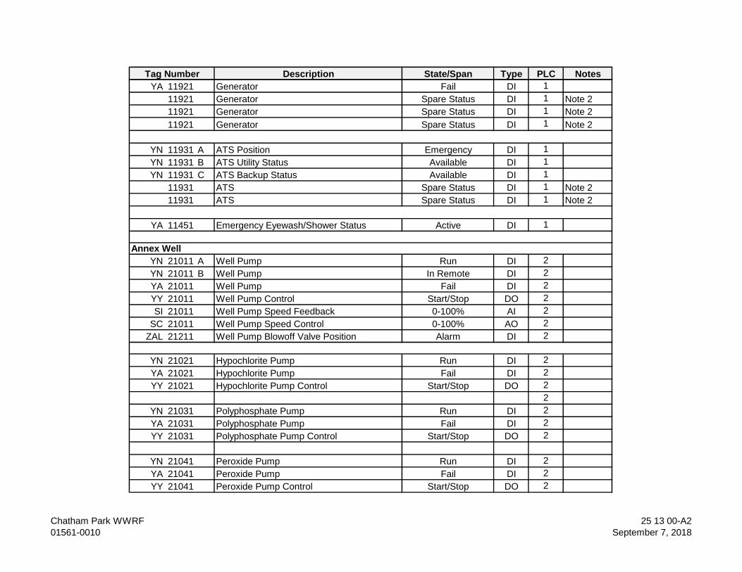
Description State/Span Type PLC NotesTag Number
YA 11921 Generator Fail DI 1
11921 Generator Spare Status DI 1 Note 2
11921 Generator Spare Status DI 1 Note 2
11921 Generator Spare Status DI 1 Note 2
YN 11931 A ATS Position Emergency DI 1
YN 11931 B ATS Utility Status Available DI 1
YN 11931 C ATS Backup Status Available DI 1
11931 ATS Spare Status DI 1 Note 2
11931 ATS Spare Status DI 1 Note 2
YA 11451 Emergency Eyewash/Shower Status Active DI 1
YN 21011 A Well Pump Run DI 2
YN 21011 B Well Pump In Remote DI 2
YA 21011 Well Pump Fail DI 2
YY 21011 Well Pump Control Start/Stop DO 2
SI 21011 Well Pump Speed Feedback 0-100% AI 2
SC 21011 Well Pump Speed Control 0-100% AO 2
ZAL 21211 Well Pump Blowoff Valve Position Alarm DI 2
YN 21021 Hypochlorite Pump Run DI 2
YA 21021 Hypochlorite Pump Fail DI 2
YY 21021 Hypochlorite Pump Control Start/Stop DO 2
2
YN 21031 Polyphosphate Pump Run DI 2
YA 21031 Polyphosphate Pump Fail DI 2
YY 21031 Polyphosphate Pump Control Start/Stop DO 2
YN 21041 Peroxide Pump Run DI 2
YA 21041 Peroxide Pump Fail DI 2
YY 21041 Peroxide Pump Control Start/Stop DO 2
Annex Well
Chatham Park WWRF
01561-0010
25 13 00-A2
September 7, 2018
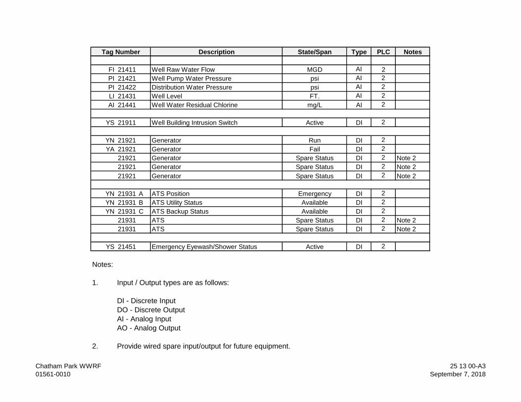
Description State/Span Type PLC NotesTag Number
FI 21411 Well Raw Water Flow MGD AI 2
PI 21421 Well Pump Water Pressure psi AI 2
PI 21422 Distribution Water Pressure psi AI 2
LI 21431 Well Level FT. AI 2
AI 21441 Well Water Residual Chlorine mg/L AI 2
YS 21911 Well Building Intrusion Switch Active DI 2
YN 21921 Generator Run DI 2
YA 21921 Generator Fail DI 2
21921 Generator Spare Status DI 2 Note 2
21921 Generator Spare Status DI 2 Note 2
21921 Generator Spare Status DI 2 Note 2
YN 21931 A ATS Position Emergency DI 2
YN 21931 B ATS Utility Status Available DI 2
YN 21931 C ATS Backup Status Available DI 2
21931 ATS Spare Status DI 2 Note 2
21931 ATS Spare Status DI 2 Note 2
YS 21451 Emergency Eyewash/Shower Status Active DI 2
Notes:
1. Input / Output types are as follows:
DI - Discrete Input
DO - Discrete Output
AI - Analog Input
AO - Analog Output
2. Provide wired spare input/output for future equipment.
Chatham Park WWRF
01561-0010
25 13 00-A3
September 7, 2018
Description State/Span Type PLC NotesTag Number
- END OF SECTION -
Chatham Park WWRF
01561-0010
25 13 00-A4
September 7, 2018
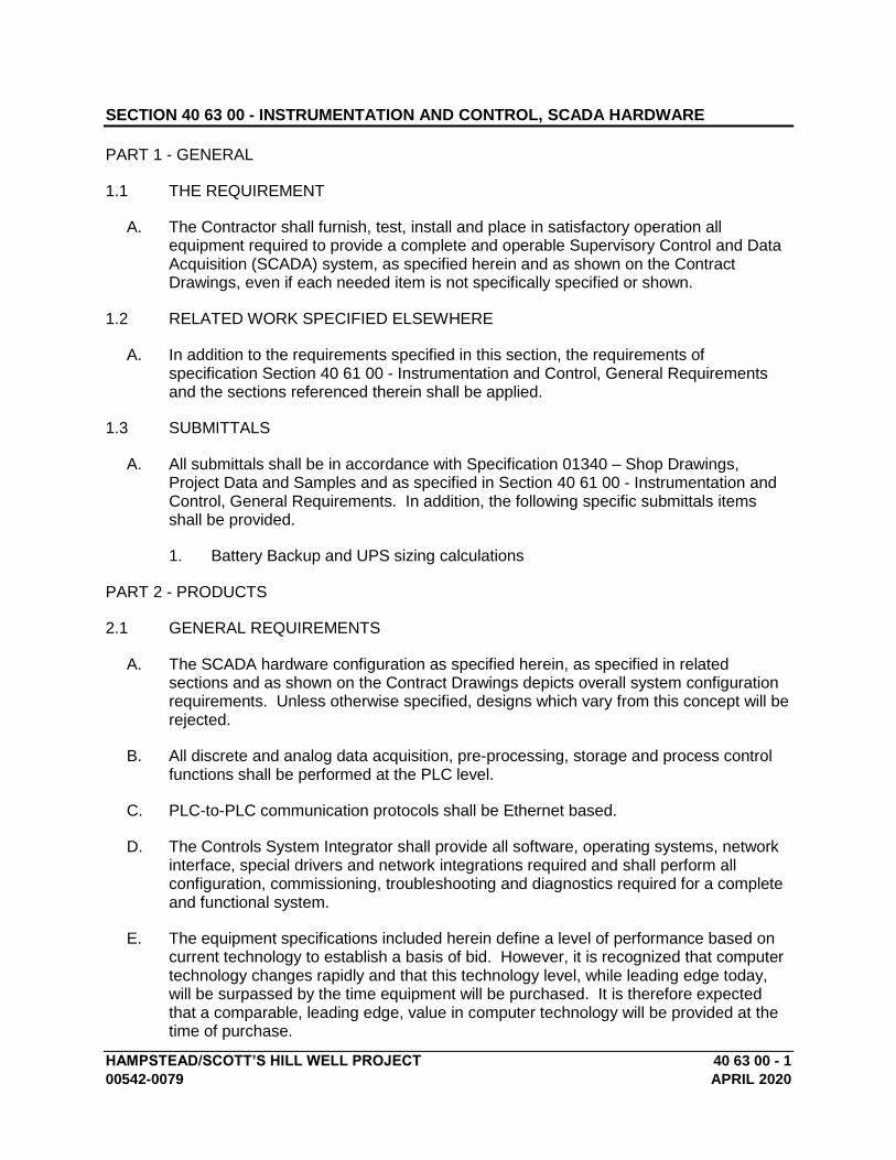
HAMPSTEAD/SCOTT’S HILL WELL PROJECT 40 63 00 - 1
00542-0079 APRIL 2020
SECTION 40 63 00 - INSTRUMENTATION AND CONTROL, SCADA HARDWARE
PART 1 - GENERAL
1.1 THE REQUIREMENT
A. The Contractor shall furnish, test, install and place in satisfactory operation all equipment required to provide a complete and operable Supervisory Control and Data Acquisition (SCADA) system, as specified herein and as shown on the Contract Drawings, even if each needed item is not specifically specified or shown.
1.2 RELATED WORK SPECIFIED ELSEWHERE
A. In addition to the requirements specified in this section, the requirements of specification Section 40 61 00 - Instrumentation and Control, General Requirements and the sections referenced therein shall be applied.
1.3 SUBMITTALS
A. All submittals shall be in accordance with Specification 01340 – Shop Drawings, Project Data and Samples and as specified in Section 40 61 00 - Instrumentation and Control, General Requirements. In addition, the following specific submittals items shall be provided.
1. Battery Backup and UPS sizing calculations
PART 2 - PRODUCTS
2.1 GENERAL REQUIREMENTS
A. The SCADA hardware configuration as specified herein, as specified in related sections and as shown on the Contract Drawings depicts overall system configuration requirements. Unless otherwise specified, designs which vary from this concept will be rejected.
B. All discrete and analog data acquisition, pre-processing, storage and process control functions shall be performed at the PLC level.
C. PLC-to-PLC communication protocols shall be Ethernet based.
D. The Controls System Integrator shall provide all software, operating systems, network interface, special drivers and network integrations required and shall perform all configuration, commissioning, troubleshooting and diagnostics required for a complete and functional system.
E. The equipment specifications included herein define a level of performance based on current technology to establish a basis of bid. However, it is recognized that computer technology changes rapidly and that this technology level, while leading edge today, will be surpassed by the time equipment will be purchased. It is therefore expected that a comparable, leading edge, value in computer technology will be provided at the time of purchase.
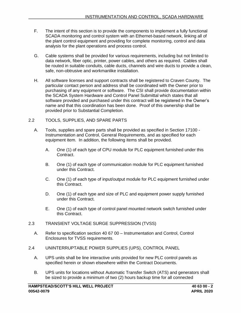
INSTRUMENTATION AND CONTROL, SCADA HARDWARE
HAMPSTEAD/SCOTT’S HILL WELL PROJECT 40 63 00 - 2
00542-0079 APRIL 2020
F. The intent of this section is to provide the components to implement a fully functional SCADA monitoring and control system with an Ethernet-based network, linking all of the plant control equipment and providing for complete monitoring, control and data analysis for the plant operations and process control.
G. Cable systems shall be provided for various requirements, including but not limited to data network, fiber optic, printer, power cables, and others as required. Cables shall be routed in suitable conduits, cable ducts, channels and wire ducts to provide a clean, safe, non-obtrusive and workmanlike installation.
H. All software licenses and support contracts shall be registered to Craven County. The particular contact person and address shall be coordinated with the Owner prior to purchasing of any equipment or software. The CSI shall provide documentation within the SCADA System Hardware and Control Panel Submittal which states that all software provided and purchased under this contract will be registered in the Owner’s name and that this coordination has been done. Proof of this ownership shall be provided prior to Substantial Completion.
2.2 TOOLS, SUPPLIES, AND SPARE PARTS
A. Tools, supplies and spare parts shall be provided as specified in Section 17100 - Instrumentation and Control, General Requirements, and as specified for each equipment item. In addition, the following items shall be provided.
A. One (1) of each type of CPU module for PLC equipment furnished under this Contract.
B. One (1) of each type of communication module for PLC equipment furnished under this Contract.
C. One (1) of each type of input/output module for PLC equipment furnished under this Contract.
D. One (1) of each type and size of PLC and equipment power supply furnished under this Contract.
E. One (1) of each type of control panel mounted network switch furnished under this Contract.
2.3 TRANSIENT VOLTAGE SURGE SUPPRESSION (TVSS)
A. Refer to specification section 40 67 00 – Instrumentation and Control, Control Enclosures for TVSS requirements.
2.4 UNINTERRUPTABLE POWER SUPPLIES (UPS), CONTROL PANEL
A. UPS units shall be line interactive units provided for new PLC control panels as specified herein or shown elsewhere within the Contract Documents.
B. UPS units for locations without Automatic Transfer Switch (ATS) and generators shall be sized to provide a minimum of two (2) hours backup time for all connected
INSTRUMENTATION AND CONTROL, SCADA HARDWARE
HAMPSTEAD/SCOTT’S HILL WELL PROJECT 40 63 00 - 3
00542-0079 APRIL 2020
equipment. At sites with ATS and generators, UPS units shall be sized for a minimum of twenty (20) minute backup for all connected equipment. Each UPS shall consist of a UPS module and battery modules as required to meet backup run time requirements.
C. UPS units provided for PLC cabinets shall be provided with a dry contact output to alarm on UPS trouble or failure. This fail output shall be wired into the PLC I/O to represent UPS status.
D. Where located in a control or PLC enclosure, the UPS shall be located at the bottom of the enclosure but mounted on a raised shelf or platform.
E. Provide network interface for network management support and power management.
F. Each UPS shall be sized to match the maximum power requirements of the associated digital equipment, control panel power supplies and accessories plus twenty (20) percent spare capacity. Upon loss of the AC supply, the inverter shall continue to supply normal power to the device, drawing DC from the batteries.
G. Each UPS shall meet the following requirements:
A. Input voltage shall be 120 VAC, single phase, 60 Hz.
B. Operating temperature range shall be 0 to 40 degree C.
C. Voltage regulation shall be plus or minus five percent (+/-5%) for line and load changes.
D. The output frequency shall be phase-locked to the input AC line on AC operation and shall be 60 hertz (+/-0.5%) when on battery operation.
E. The batteries shall be of the sealed, lead acid or lead calcium gelled electrolyte type, suitable for high temperatures.
F. Sound absorbing enclosure.
G. EMI/RF noise filtering.
H. Surge protection shall be provided on the AC input circuit, which shall have a UL TVSS clamping voltage rating of 400 V with a <5 ns response time.
I. Adjustment allowed to prevent UPS from going offline when on a standby generator supplied power source.
H. UPS systems shall be equal to Tripp Lite OMNI Series, APC, Eaton or approved equal.
2.5 PROGRAMMABLE LOGIC CONTROLLERS (PLC), GENERAL
A. The Control System Integrator shall furnish programmable controllers (PLCs) as specified herein and as shown on the Drawings. PLCs shall be provided complete with rack, power supply, Input/Output (I/O) modules, special function cards, instructions, memory, input/output capacity and appurtenances to provide all features and functions

INSTRUMENTATION AND CONTROL, SCADA HARDWARE
HAMPSTEAD/SCOTT’S HILL WELL PROJECT 40 63 00 - 4
00542-0079 APRIL 2020
as described herein. PLC I/O cards may be supplied by third party vendors if approved by the PLC manufacturer and the Owner. No substitutions will be permitted.
B. All components of the PLC system shall be of the same manufacturer; who shall have fully tested units similar to those being furnished, in an industrial environment with associated electrical noise. The PLC system shall have been tested to meet the requirements of NEMA Standard ICS 2-230 (Arc Test) and IEEE C37.90.1 (SWC). The processing unit shall perform the operations functionally described herein, based on the program stored in memory and the status of the inputs and outputs.
C. The programmable controller shall be designed to operate in an industrial environment. The PLC shall operate in an ambient temperature range of 0°-60°C and a relative humidity of five to ninety-five percent (5% - 95%), non-condensing. The PLC shall operate on supply voltages of 90-132 VAC at 47-63 Hz, or 24 VDC if provided with a battery backup system. Overcurrent and undervoltage protection shall be provided on the power supply.
D. System configuration shall be as shown on the Contract Drawings. PLC types shall be designated on the system block diagram and correspond to the specifications herein. Only a single type of processor shall be supplied for all PLCs of a designated type. Memory, processor and PLC type shall be adequate for all control functions specified. Memory backup shall be provided during loss of power for the configuration, logic program and current operating parameters/addresses.
E. The processor and its associated memory shall be enclosed in a modular enclosure. A multiple-position selector switch or equivalent shall be used to select processor operating mode. LED-type indicating lights shall be provided to indicate processor, memory and battery status. Errors in memory shall be recognized, and shall activate the memory error indicating lights. Memory shall consist of battery-backed RAM or EEPROM, which shall retain the control program for at least one (1) year, in the event of power loss. Visual indication shall be provided if battery charge is insufficient to maintain the program in RAM memory for at least two (2) weeks.
F. All PLC processors shall be provided with the latest manufactured firmware revision level installed.
G. The instruction set for the PLC shall include the following, as a minimum.
A. Relay type instructions
B. Counter and timer instructions
C. Comparison instructions (equal, greater than, limit tests, etc.)
D. Integer, long integer and floating point mathematical instructions
E. Advanced math and trigonometric functions
F. Matrix and array instructions
G. Logical instructions (and, not, or, etc.)
INSTRUMENTATION AND CONTROL, SCADA HARDWARE
HAMPSTEAD/SCOTT’S HILL WELL PROJECT 40 63 00 - 5
00542-0079 APRIL 2020
H. Bit modification, moving and shift instructions
I. Diagnostic instructions
J. Sequencer instructions
K. Program control instructions (jump, goto, subroutine, etc.)
L. PID control loops
M. Block read and write capability
N. Master and slave communications capabilities
O. Immediate I/O and communications update instructions
P. Real-time clock and date
H. In addition to a port for communications as shown on the Contract Documents, additional communication ports shall be provided for any other devices as required (i.e., operator interface unit, connection to a notebook computer for programming and configuration.)
I. PLC shall be Wago PFC200.
2.6 PLC INPUT/OUTPUTS
A. PLC input/output hardware shall be a modular system. Modules shall be placed in the PLC chassis slot where the backplane of the chassis provides a high-speed communication path between modules. The chassis power supply, located to the left of the modules, shall distribute power to each of the modules within the chassis.
B. The PLC and Remote I/O within an enclosure shall handle the required number of process inputs and outputs, plus a minimum of ten percent (10%) pre-wired spares for each I/O type furnished except discrete inputs which shall have a minimum of twenty percent (20%) pre-wired spares. Spare slots shall include slot modules cover plates.
C. PLC input/output systems and processing modules shall be of the same model series. No third party manufacturer models will be accepted.
D. Discrete inputs (DI) shall be 16-point, 24VDC modules, developed from dry field contacts.
E. Discrete outputs (DO) shall be 16-point, 24VDC, 2A dry contacts relay modules. Output contacts may be powered from the field equipment or powered from 24VDC sourced from PLC control panel’s power system, as required to interface with field equipment. Outputs to solenoid valves shall be 120 VAC, powered from the PLC or control panel unless specified or shown otherwise. Provide interposing relays only if the current draw exceeds the module contact rating. Refer to Section 17420 for interposing relay specifications.
INSTRUMENTATION AND CONTROL, SCADA HARDWARE
HAMPSTEAD/SCOTT’S HILL WELL PROJECT 40 63 00 - 6
00542-0079 APRIL 2020
F. Analog input (AI) circuits shall be individually isolated, 16-bit (minimum) resolution type. Analog input hardware shall be provided as required for all types of analog inputs being transmitted to the PLC. In general, analog input modules shall be capable of receiving 4-20 mA signals. Each input circuit shall have optical isolation to protect the equipment against high voltage transients.
G. Analog outputs (AO) shall be coordinated with the receivers but shall generally be individually isolated 24 VDC, 4-20mA outputs powered from the PLC. Each output circuit shall have optical isolation to protect the equipment against high voltage transients.
H. Input/output modules shall be configured for ease of wiring and maintenance. The modules shall be connected to wiring arms which can be disconnected to permit removal of a module without disturbing field wiring. Covers shall be provided to prevent operator personnel from inadvertently touching the terminals. The process interface modules shall be provided with screw-type terminal blocks with barriers between adjacent terminals for connection of field inputs. Terminals shall be suitable for accepting up to and including No. #22...#12 AWG (0.2...4 mm2) wire.
I. Output failure mode shall be selectable so that upon station or communication system failure, all outputs shall be placed in the non-conducting mode or remain as they were prior to failure. Light-emitting diodes shall be provided for status indication for each input and output point.
J. Power supplies shall be provided with the PLC as required to meet specified installed I/O power requirements, plus spares. Power supplies shall be modular units, shall be fully redundant and shall alarm to the PLC upon failure. Power supplies shall have a line regulation of 0.05% and meet the environmental and power requirements specified herein.
K. Control circuits and signals entering hazardous areas shall be provided with intrinsically safe barriers meeting the requirements of the NEC and UL698.
2.7 PLC PROGRAMMING SOFTWARE
A. The PLC programming and configuration software shall be the manufacturer's latest version. The software package shall consist of all programming, configuration, and documentation software needed to place the control and information system in satisfactory operation. The software shall allow on-line and off-line program development and documentation. Programming shall be accomplished through the use of ladder logic. PLC programming software shall include CD-ROM documentation.
B. One copy of the PLC programming software shall be purchased and licensed to the Owner and turned over to the Owner.
PART 3 - EXECUTION
3.1 REQUIREMENTS:
A. In addition to the requirements specified in this section, refer to Section 40 61 00 - Instrumentation and Controls, General Requirements.

INSTRUMENTATION AND CONTROL, SCADA HARDWARE
HAMPSTEAD/SCOTT’S HILL WELL PROJECT 40 63 00 - 7
00542-0079 APRIL 2020
END OF SECTION

HAMPSTEAD/SCOTT’S HILL WELL PROJECT 40 66 33 - 1
00542-0079 APRIL 2020
SECTION 40 66 33 – INSTRUMENTATION AND CONTROL, PUMP STATION REMOTE TELEMETRY UNIT
PART 1 - GENERAL
1.1 THE REQUIREMENT
A. The Contractor shall furnish, test, install, and place in satisfactory operation all equipment required to provide a complete and operable cellular based lift station remote telemetry unit (RTU), as part of the Instrumentation and Control System as specified herein and as shown on the Contract Drawings, even if each needed item is not specifically specified or shown.
B. Specialty cables shall be furnished by the Control System Integrator. Specialty cables include any type of cable not specified in Division 26 – Electrical.
1.2 RELATED WORK SPECIFIED ELSEWHERE
A. In addition to the requirements specified in this section, the requirements of specification Section 40 61 00 – Instrumentation and Control, General Requirements and the sections referenced therein shall be applied.
1.3 SUBMITTALS
A. The Contractor shall provide submittals as specified in Section 40 61 00 – Instrumentation and Control, General Requirements.
PART 2 - PRODUCTS
2.1 GENERAL REQUIREMENTS
A. The remote telemetry system configuration as specified herein and as specified in related sections, depicts overall system configuration requirements. Unless otherwise specified, designs which vary from this concept will be rejected.
B. The intent of this project is to provide a cellular based, remote hosted RTU monitoring system for each of the two well sites. Communications for each RTU will be provided through a cellular data plan provided as part of the RTU package. The Contractor shall provide the first year annual monitoring fee related to this system, not to take effect until the unit is placed in operation.
2.2 TOOLS, SUPPLIES, AND SPARE PARTS
A. Tools, supplies and spare parts shall be provided as specified in Section 40 61 00 – Instrumentation and Control, General Requirements and as specified for each equipment item.
2.3 REMOTE TELEMETRY UNIT HARDWARE
A. Microprocessor Based Field RTU
INSTRUMENTATION AND CONTROL, PUMP STATION REMOTE TELEMETRY UNIT
HAMPSTEAD/SCOTT’S HILL WELL PROJECT 40 66 33 - 2
00542-0079 MARCH 2020
1. Data Cellular Radio - The RTU shall incorporate a radio that utilizes the data side of the cellular system to transmit the data and alarms monitored.
2. Microprocessor Feature Updates - data transmission rates shall be adjustable through the cellular system without site visits.
3. RTU Inputs and Outputs - RTU shall have sufficient input and output points to support the requirements noted herein.
4. Digital inputs shall be user selectable as normally open (NO) or normally closed (NC).
5. Digital inputs on the main board must be capable of being programmed to record and report pump run times in one minute increments or less as indicated by a relay opening and closing.
6. RTU shall have built-in alarms for input wiring fault, AC failure, communication failure and low battery detection.
7. RTU shall include analog inputs measuring 4-20mA at 10 bit resolution with four (4) alarm thresholds per input.
8. RTU shall have digital normally open or closed output relays rated at 0.5 A at 120VAC.
9. Status LED’s on Motherboard
a. LED’s above each digital input shall visually display the status of the digital input
b. Radio signal strength shall be displayed by 8 LEDs in 5db increments between -75db and -110db to facilitate accurate antenna placement
c. Operational and diagnostic status shall be displayed by individual LED’s.
10. Power Requirements
a. The RTU shall be powered by 120 volts AC and have a built in battery backup capable of keeping the RTU powered for 30 hours in case of primary AC failure.
b. All terminations inside the RTU enclosure shall be low voltage DC (28 volts or less).
B. Communication Links
1. Communication System
a. Wireless communication links shall be through the data side of the cellular system.
2. Cellular Carriers
INSTRUMENTATION AND CONTROL, PUMP STATION REMOTE TELEMETRY UNIT
HAMPSTEAD/SCOTT’S HILL WELL PROJECT 40 66 33 - 3
00542-0079 MARCH 2020
a. The manufacturer shall have a direct relationship with the cellular company and shall not use third parties to affect data transport through the cellular company.
b. The Owner will not purchase cellular data contracts direct with the carrier.
3. Security Protocols
a. The cellular radio shall make continuous, secure socket connections (SSL) from the radio, through the cellular system, to the manufacturer’s servers and web pages.
b. The RTU shall utilize a transmission scheme that encrypts the transmitted data utilizing a 128 bit encryption method that meets the advanced encryption standard (AES). The 128 bit AES encryption shall be at all stages of data transfer and storage
c. The manufacturer shall have established private gateways through the cellular system, completely behind firewalls.
C. System Software
1. The Contractor shall not be responsible for RTU or master station software implementation. The software functionality shall be provided by the RTU manufacturer. Functionality and data exchange shall be fully coordinated by the Contractor.
2. The Contractor shall provide startup services for connection of the RTU through the cellular carrier to the manufacturer’s hosted server facilities. Startup documentation shall be provided establishing the data rate, signal strength.
D. Manufacturer
1. RTU shall be Mission Communications Model M-110 Series with accessories and expansion modules as needed to meet the functional requirements.
PART 3 - EXECUTION
3.1 REQUIREMENTS
A. In addition to the requirements specified in this section, refer to Section 40 61 00 - Instrumentation and Controls, General Requirements.
B. The Contractor shall provide all labor, materials, equipment, and expertise required to carry out the installation, termination, testing and start-up of all cables, connectors and related equipment, in a manner in keeping with the best standard practices available and in accordance with the manufacturer's recommendations.
C. Careful attention should be paid to provide installations at each location which are both functional and aesthetically acceptable.
INSTRUMENTATION AND CONTROL, PUMP STATION REMOTE TELEMETRY UNIT
HAMPSTEAD/SCOTT’S HILL WELL PROJECT 40 66 33 - 4
00542-0079 MARCH 2020
D. Accurate and appropriate test equipment and industry standard test procedures shall be used to demonstrate that the equipment operates within the expected tolerance of accuracy at various points throughout the operating range.
E. The Contractor shall provide the services of the manufacturer’s representative for startup and initial configuration of the RTU. Startup services shall include the communications link connection from the RTU, through the cellular carrier, to the manufacturer’s server. The technician shall be fully familiar, trained and qualified to service and support the items which are being serviced.
F. Documentation shall be provided establishing the completion of the startup process including input/output testing, radio signal strength, link data rate and link reliability. All reports shall be distributed to the Engineer, the Contractor and copied to the plant staff, and a copy shall be kept in a permanent file on site for future reference.
3.2 INSTALLATION
A. All outdoor radio transmission cable connections shall be water-proofed using the appropriate UV resistant cable water-proofing kit as manufactured by 3M or approved equal.
B. All cable straps and cable mounting hardware shall be stainless steel as manufactured by Andrew, Wireless Solutions or approved equal.
C. Antenna cables shall enter a building through a grounded copper bulkhead panel. The panel shall provide for water-proof cable entry as well as grounding prior to entry into the building. Cable lightning protectors shall be mounted immediately inside the building, attached to a ground plate below the bulkhead panel. Bulkhead panels shall provide for future cable entries as specified or shown elsewhere.
END OF SECTION 40 66 33
HAMPSTEAD/SCOTT’S HILL WELL PROJECT 40 67 00 - 1
00542-0079 APRIL 2020
SECTION 40 67 00 – INSTRUMENTATION AND CONTROL, CONTROL ENCLOSURES
PART 1 - GENERAL
1.1 THE REQUIREMENT
A. The Contractor shall furnish, modify, test, install and place into satisfactory operation all control enclosures (i.e. field panels, control panels, cabinets, consoles, boxes, etc.) required to provide a complete and operable Instrumentation and Control System (ICS) as specified herein and as shown on the Contract Drawings, even if each needed item is not specifically specified or shown.
B. The Contractor shall also be responsible to provide modifications to existing control panels as described herein or as indicated in the PLC Input/Output Schedule Attachment. Modifications to existing control panels shall also conform to the requirements of these specifications.
C. New control enclosures and/or subpanels shall be assembled, wired and tested in the CSI’s own facilities, unless specified otherwise.
1.2 RELATED WORK SPECIFIED ELSEWHERE
A. In addition to the requirements specified in this section, the requirements of specification Section 40 61 00 - Instrumentation and Control, General Requirements and the sections referenced therein shall be applied.
B. Instrumentation and Controls Schedules. Refer to Instrumentation Schedule and PLC Input/Output Schedule Attachments for a listing of major equipment, enclosure construction and signal monitoring requirements.
1.3 SUBMITTALS
A. All submittals shall be in accordance with Specification 01340 – Shop Drawings, Project Data and Samples and as specified in Section 40 61 00 - Instrumentation and Control, General Requirements. In addition, the following specific submittal items shall be provided.
1. Cabinet sizing in relation to heat dissipation and cooling/heating system sizing calculations shall be submitted for all cabinets containing PLCs, UPSs, VFDs, SCRs and, at the request of the Engineer, for all cabinets containing sensitive electronic equipment or chemicals.
PART 2 - PRODUCTS
2.1 GENERAL REQUIREMENTS
A. All enclosures shall fit within the allocated space shown on the Drawings. The Contractor shall examine plans and/or field inspect new and existing structures as required to determine installation requirements and shall coordinate the installation of all enclosures with the Owner and all affected contractors. The Contractor shall be responsible for all costs associated with installation of enclosures, including repair of
INSTRUMENTATION AND CONTROL, CONTROL ENCLOSURES
HAMPSTEAD/SCOTT’S HILL WELL PROJECT 40 67 00 - 2
00542-0079 APRIL 2020
damage to structures (incidental, accidental or unavoidable).
B. A minimum estimated size is shown on the Drawings. The Contractor shall furnish enclosures of the size and quantity required to house the manufacturers' equipment supplied and all other electrical components installed in the enclosure. In addition, provide useful space and power supply capacity as spare for future expandability to a minimum of one (1) item per item type installed or twenty percent (20%) of quantity of each type item installed, whichever yields the greater spare space.
C. Enclosures (cabinets, panels, boxes, etc.) shall be formed or welded construction, reinforced with Unistrut, Powerstrut or equal to facilitate mounting of internal components or equipment. Sufficient access plates and doors shall be provided to facilitate maintenance and testing of the supplier's equipment. Doors shall be removable. Enclosures with any dimension thirty-six (36) inches or greater shall be provided with removable lifting lugs designed to facilitate safe moving and lifting of the panel during installation. No screws or bolts shall protrude through from the interior enclosure.
D. All steel enclosures shall be free from dirt, grease and burrs, and shall be treated with a phosphatizing metal conditioner (phosphate conversion coating) before painting. All surfaces shall be filled, sanded, and finish coated by spraying a 1-2 mil epoxy prime coat and smooth, level, high grade textured finish between flat and semi-gloss shine. The colors shall be selected by the Owner from a minimum of six (6) color samples provided. All stainless steel enclosures shall be polished to a No. 4 finish
E. Enclosures shall be prefabricated cabinets and panels equal to Hoffman, Rittal or Vynckier. The Contractor may optionally provide enclosures custom fabricated by a reputable panel fabrication shop acceptable to the Engineer.
F. Each panel shall incorporate a removable back panel on which control components shall be mounted. Back panels shall be secured to the enclosures with collar studs. All components shall be of the highest industrial quality and securely mounted to the removable back panels with screw and lock washers. Back panels shall be tapped to accept all mounting screws. Self-tapping screws shall not be used to mount any component.
G. All enclosures with any dimension twenty-four (24) inches or larger shall be provided with drawing pockets for as-built panel drawings. One (1) laminated copy of the appropriate panel as-built drawings shall be furnished and left in the pocket of each panel.
H. All enclosures shall be protected from internal corrosion-inhibiting vapor capsules as manufactured by Northern Instruments Model Zerust VC, Hoffman Engineering Model A-HCL, or equal.
I. All metallic enclosures with door mounted equipment shall have the door grounded by means of flexible ground strap.
J. The enclosure and all interior and exterior equipment shall be identified with nameplates. The equipment shall be mounted such that service can occur without removal of other equipment. Panel mounted equipment shall be flush or semi-flush
INSTRUMENTATION AND CONTROL, CONTROL ENCLOSURES
HAMPSTEAD/SCOTT’S HILL WELL PROJECT 40 67 00 - 3
00542-0079 APRIL 2020
mounted with flat black escutcheons. All equipment shall be accessible such that adjustments can be made while the equipment is in service and operating. All enclosures shall fit within the allocated space as shown on the Contract Drawings.
K. Enclosures shall provide mounting for UPS, power supplies, control equipment, input / output subsystems, panel mounted equipment and appurtenances. Ample space shall be provided between equipment to facilitate servicing and cooling. Enclosures shall be sized to adequately dissipate heat generated by equipment mounted inside the panel. Louvered openings fitted with dust filters near the bottom and top of the cabinet shall be provided for NEMA 12 enclosures. If required, cabinets shall be provided with filtered fans, heat exchangers or air conditioners. Only closed loop cooling systems shall be provided for NEMA 4X cabinets. Cooling systems shall be by the cabinet fabricator or equal to McLean Midwest, Noren Products, or approved equal.
L. Enclosures shall be provided with 120 volt duplex receptacles, for service equipment and fluorescent service lights, and convenience GFCI receptacles for programming. Simplex receptacles shall be provided for enclosures with an uninterruptable power supply (UPS). Main breaker and branch breaker sizes shall be coordinated such that an overload in a branch circuit will trip only the branch breaker but not the main breaker. Circuit breakers shall be provided for the following internal branch circuits distributed within the panel:
1. Receptacles and power strips
2. Lighting
3. UPS
4. HVAC equipment
M. Enclosures shall be provided with 120 volt duplex receptacles for service equipment and fluorescent service lights. Loads not requiring transient voltage surge suppression (i.e. receptacles, lighting, HVAC, branch circuits to remote equipment, etc.) shall be connected ahead of the enclosure TVSS device.
N. Locate equipment, devices, hardware, power supplies, instrumentation and controls, electrical equipment and wiring to be installed inside the enclosures and/or as facial features on the enclosures, so that connections can be easily made and so that there is ample room for servicing each item. Every component in and on the enclosures shall be able to be removed individually without affecting the other components and without the need to move other components. Support and restrain all internally, as well as panel mounted components to prevent any movement.
O. All cabinets and/or enclosures shall be NEMA rated for the environment in which it is to be installed and as noted in the Drawings.
P. Materials and equipment used shall be U.L. approved wherever such approved equipment and materials are available.
Q. Control panel enclosures containing PLCs shall be provided with a security door switch mounted at the top of the enclosure as shown on the drawings. The door switch shall

INSTRUMENTATION AND CONTROL, CONTROL ENCLOSURES
HAMPSTEAD/SCOTT’S HILL WELL PROJECT 40 67 00 - 4
00542-0079 APRIL 2020
be general duty, Reed switch type operation with a straight plunger. Maximum voltage rating shall be 240 VAC and 125/VDC with 1pole, double throw, one position momentary signal switch unit. Door switch shall be Square D, XA7506E or approved equal.
R. Control panels shall be built in accordance with UL508A Industrial Control Panels and NEC Article 409 Industrial Control Panels. Control panels for areas classified as Hazardous shall be built in accordance with UL698 Industrial Control Equipment for Use in Hazardous Locations. Control panels shall be UL508A and/or UL698 labeled and marked as defined in NEC 409.110 with the following:
1. Manufacturer’s name and contact information (i.e. address, phone, website, email, etc.).
2. Supply voltage, phase, frequency and full-load current.
3. Short-circuit current rating of the industrial panel based on one of the following:
a. Short-circuit current rating of a listed and labeled assembly
b. Short-circuit current rating established utilizing an approved method
c. Electrical wiring diagram numbers or the index sheet to the electrical wiring diagrams.
d. The enclosure type number (i.e. NEMA 1A, 3R, 12, 4X, 7, 9, etc.)
4. If the industrial control panel is intended as service equipment, it shall be marked to identify it as being suitable for use as service equipment.
S. All work shall be performed in a professional manner and in consideration of allowing ease of future troubleshooting and maintenance. All equipment should be mounted so as to minimize crowding within the panel. All devices shall be mounted and wired in a neat and workmanlike manner. Each component shall be prominently identified with the use of permanent engraved legend plates.
T. Grounding: All suppressors shall be grounded per the suppressor manufacturer's recommendations. Furnish control panels with an integral copper grounding bus for connection of suppressors and other required instrumentation. Provide single-point connection of all grounds to grounding bus using the shortest possible path. Each grounded object shall have a separate connection to the ground bus. Do not connect cable shields to suppressor ground terminal or daisy-chain ground connections. Provide 1-inch wide by 1/8-inch thick copper ground bus as a minimum.
2.2 TOOLS, SUPPLIES, AND SPARE PARTS
A. Tools, supplies, and spare parts shall be provided as specified in Section 17100 - Instrumentation and Control, General Requirements and as specified for each equipment item. In addition, the following items shall be provided.
1. One (1) of each type of panel mounted equipment (i.e., indicators, signal
INSTRUMENTATION AND CONTROL, CONTROL ENCLOSURES
HAMPSTEAD/SCOTT’S HILL WELL PROJECT 40 67 00 - 5
00542-0079 APRIL 2020
converters, etc.) provided under this Contract.
2. One (1) 24VDC power supply and redundancy module.
3. Three (3) of each type of interposing relay provided under this Contract.
4. One (1) of each type of power TVSS device used
5. Three (3) of each type of signal TVSS device used
6. Two (2) of each type of communication TVSS device used.
B. OUTDOOR ENCLOSURES
1. All outdoor enclosures shall be rated NEMA 4X, constructed of 316 stainless steel with a white powder epoxy coating finish unless specified otherwise. Outdoor enclosures shall have a hinged and gasketed door. Door latches shall be all stainless steel, fast operating clamp assemblies (quick release), which do not require bolts or screws to secure. Gaskets shall be polyurethane.
2. Outdoor panels shall be fitted with pad-lockable latch kits.
3. Outdoor enclosures with internal digital electronics, exterior indicators, or exterior indicator lights shall have external sun shields or sun shades, constructed of the same materials as the associated enclosure, unless otherwise specified.
4. Outdoor enclosures shall be designed for ambient conditions of -15 to 50°C and twenty to ninety-five percent (20% - 95%) relative humidity, unless otherwise specified. Outdoor enclosures shall be provided with thermostatically controlled space heaters to provide condensation protection.
C. INDOOR ENCLOSURES
1. Indoor enclosures located in the same area (i.e. room, etc.) as open process tanks, open process channels, closed process piping or process equipment containing wet liquids or possible airborne powders, shall be rated NEMA 4X, constructed of 316 stainless steel, fiberglass, fiberglass reinforced polyester, or polycarbonate, unless specified otherwise. Enclosures shall have a hinged and gasketed door. Door latches shall be all stainless steel, fast operating clamp assemblies (quick release) which do not require bolts or screws to secure. Gaskets shall be polyurethane.
2. Indoor enclosures located in a dry or environmentally controlled area (i.e. electrical room, etc.) shall be NEMA 12 steel, unless specified otherwise. Enclosures shall have a hinged and gasketed door. Door latches shall be 3 point door latch with handle for all enclosures with a dimension of 24 inches or larger, or otherwise shall be fast operating clamp assemblies which do not require bolts or screws to secure. Gaskets shall be polyurethane.
3. Indoor enclosures in a non-air conditioned space shall be designed for ambient conditions of 0 to 40°C and twenty to ninety-five percent (20% - 95%) relative
INSTRUMENTATION AND CONTROL, CONTROL ENCLOSURES
HAMPSTEAD/SCOTT’S HILL WELL PROJECT 40 67 00 - 6
00542-0079 APRIL 2020
humidity, unless otherwise specified. Indoor enclosures in an air conditioned space shall be designed for ambient conditions of 20 to 30°C and twenty to eighty-five percent (20% - 85%) relative humidity, unless otherwise specified.
D. TERMINALS
1. Terminal blocks shall be assembled on non-current carrying galvanized steel DIN mounting rails, securely bolted to the cabinet sub-panel. Terminals shall be of the screw down pressure plate type equal to that manufactured by Allen Bradley, Phoenix Contact, Wieland, Square D, or equal. Power terminal blocks shall be single tier with a minimum rating of 600 volts, 30 amps. Signal terminal blocks shall be single tier with a minimum rating of 600 volts, 20 amps.
2. Fused terminal blocks or miniature thermal circuit breaker terminal blocks shall be supplied for protection and isolation of enclosed equipment, or as specified in the Contract documents. Blown fuse indicators shall be provided and/or tripped breaker status shall be clearly visible. Fused or miniature thermal circuit breaker terminal blocks shall be provided for, but not limited to each of the following:
a. Each PLC module requiring external power
b. Each piece of equipment provided with a power supply (integral, internal or external) with the exception of devices with internal fusing plugged into a receptacle.
c. Terminals shall be marked with a black waterproof, permanent, continuous marking strip. One side of each terminal shall be reserved exclusively for field incoming conductors. Common connections and jumpers required for internal wiring shall not be made on the field side of the terminal.
E. WIRING
1. All wiring shall be bundled and run open or enclosed in vented plastic wireway, as required. All conductors run open shall be bundled and bound with nylon cable ties, at regular intervals, with intervals not to exceed 12 inches. Adequately support and restrain all wiring runs to prevent sagging or other movement. Care shall be taken to separate communication, network, electronic signal, AC discrete signal, DC discrete signal and power wiring. Wiring to equipment mounted on doors or where movement of the equipment will take place, shall be installed in nylon spiral wrapping sheaths.
2. Wires shall be color coded as follows:
a. Equipment Ground – GREEN
b. 120 VAC Power Distribution – BLACK
c. 120 VAC Power Neutral – WHITE
d. 120 VAC Control (Internally Powered) – RED
INSTRUMENTATION AND CONTROL, CONTROL ENCLOSURES
HAMPSTEAD/SCOTT’S HILL WELL PROJECT 40 67 00 - 7
00542-0079 APRIL 2020
e. 120 VAC Control (Externally Powered) – YELLOW
f. 24 VAC Control – ORANGE
g. DC Power (+) – BLUE
h. DC Power (-) – BLUE/WHITE
i. DC Control – BLUE
j. Analog Signal (+) – BLACK
k. Analog Signal (-) – WHITE
3. All wiring shall comply with accepted standard instrumentation and electrical practices. Field wiring for power, control and signal wires shall comply with Division 16 of the specifications. For each pair of parallel terminal blocks, the field wiring shall be between the blocks.
4. Internal panel wiring shall be as follows:
a. AC power wiring: 14 AWG minimum, stranded copper conductors, THHN/THHW wire rated for 600 volts and 90 °C. For wiring carrying more than 15 amps, use sizes required by NEC.
b. AC control and dc power and control wiring: 16 AWG minimum, stranded copper conductors, THHN/THHW wire rated for 600 volts and 90 °C.
c. Instrument signal wiring: 18 AWG stranded conductors, tinned copper, twisted pair or triad, overall one hundred percent (100%) aluminum foil shield with 20 AWG stranded drain wire, plenum rated 300V 60°C FEP insulated wire with FEP jacket, equal to Belden 88760.
d. All stranded wire shall have a minimum of sixteen (16) strands, except for drain wires.
F. IDENTIFICATION:
1. Provide a laminated black nameplate with beveled edges and ½ inch white letters to identify each console, panel or cabinet on the front of the enclosure.
2. Provide laminated, beveled edge, plastic legend plates and nameplates, with 1/4 inch letters, for each front panel mounted device as shown on the Drawings. Legend plates and nameplates shall be the size as shown on the Drawings. Color shall be black lettering on white background except caution/warning nameplates which shall be white lettering on a red background. Attach front panel nameplates with both a permanent adhesive and stainless steel machine screws into tapped holes.
3. Tag all interior instruments and other components with engraved, laminated plastic nameplates with 1/8 inch, minimum, lettering. Legends shall be consistent with wiring and layout drawings. Nameplates shall be attached with
INSTRUMENTATION AND CONTROL, CONTROL ENCLOSURES
HAMPSTEAD/SCOTT’S HILL WELL PROJECT 40 67 00 - 8
00542-0079 APRIL 2020
permanent adhesive to the panel, near the device or on the device itself or as otherwise approved by the Engineer.
4. Number and label each wire in the systems. Every unique wiring node shall have its own individual unique number. Numbers shall be shown on all submitted drawings. All wires shall be labeled at each termination and junction of the wire and at 30 inch intervals along the wire. All multi-conductor cables shall be labeled at each end and at 30-inch intervals with CBL-XXX and also label each conductor at both ends. Labeling shall be self-laminating white/transparent self-extinguishing vinyl strips (equal to Brady DAT 7 292) with clear heat shrink tubing over the markers. Length shall be sufficient to provide at least two and one-half (2 ½) wraps. All labels shall be machine-printed with wire and/or cable numbers.
G. ACCESSORIES
1. Control operators such as pushbuttons (PB), selector switches (SS), and pilot lights (PL) shall be equal to Allen Bradley 800H, Square D Company Type SK or equal. Control operators shall be 30.5 mm, round, heavy-duty, oil tight NEMA 4X corrosion resistant.
2. Pushbuttons and selector switches shall be non-illuminated, spring release type. Pushbuttons shall include a full guard. Panic stop/alarm pushbuttons shall be red mushroom type with manual-pull release. Pilot lights shall be of the proper control voltage, LED type (indoor) and lamp type (outdoor).
3. Control operators shall have legend plates as specified herein, indicated on the Contract Drawings, or otherwise directed by the Engineer. Legend plates shall be plastic, white field (background) with black lettering. Engraved nameplates shall be securely fastened above each control operator. If adequate space is not available, the nameplate shall be mounted below the operator.
4. Control operators for all equipment shall be as specified herein and of the same type and manufacturer unless otherwise specified or indicated on the Contract Drawings. Modifications to existing panels using control operators and indicators of the same type and manufacturer shall be allowed with Engineer’s approval.
5. Where required to interface between motor control centers, equipment controls, and control panels, interposing relays and associated control wiring circuitry shall be furnished and installed to provide the monitoring and/or control functions specified herein. Interposing relays shall be miniature type with DPDT contacts rated a minimum 10 amp @ 120 VAC, push-to-test button, and status indicator. Relay coils shall be 120/240 VAC or 24 VDC as required. Relays shall be equal to Idec, Square D, Omron, Allen-Bradley or approved equal.
6. Digital Indicators shall be provided to indicate rates and readings in digital format and true engineering units. Indicators shall accept a 4-20 mA input signal and shall be programmable through the front panel to provide scaling, calibration, options and accessories. Units shall be 4 digit minimum with red LED indication, 120 VAC power. Digital Indicators shall be equal to Precision Digital, Red Lion or approved equal.
INSTRUMENTATION AND CONTROL, CONTROL ENCLOSURES
HAMPSTEAD/SCOTT’S HILL WELL PROJECT 40 67 00 - 9
00542-0079 APRIL 2020
7. Signal isolators/boosters/converters shall be solid state electronic type with RFI protection. Signal isolators/boosters/converters shall accept a current, voltage, frequency, temperature, or resistance and provide current or voltage dual outputs as shown on the drawings and specified herein. Signal isolators/boosters/converters shall have complete isolation between input circuitry, output circuitry, and power supply, and with provisions for din-rail mount inside the control panel enclosure. Signal isolators/boosters/converters shall be Phoenix Contact, Acromag, or approved equal.
H. POWER SUPPLIES
1. Each control panel shall be provided with a minimum of one 24 VDC power supply. Power supplies shall be enclosed and sized per the guidelines of UL508 and UL508A. Redundant power supplies with redundancy modules shall be provided in locations as specified and shown on the drawings. Power supplies shall be equal to Phoenix Contact, Model Quint-PS-X, Allen Bradley 1606, or approved equal.
2. External PLC power supplies provided for loop and/or PLC power shall be redundant and alarm to the PLC upon failure.
I. TRANSIENT VOLTAGE SURGE SUPPRESSION (TVSS)
1. Transient voltage surge suppressors shall be provided at the following minimum locations:
a. At any connections between AC power and electrical and electronic equipment, including panels, assemblies and field mounted instruments.
b. At both ends of all analog signal circuits that have any portion of the circuit extending outside of a protecting building.
c. At the control panel of all discrete signal circuits that have any portion of the circuit extending outside of a protecting building.
d. At both ends of all copper-based communications cables that extend outside of a building.
e. At all specified spare analog inputs and outputs in PLCs and RTUs.
2. These protective devices shall be external to and installed in addition to any protective devices built into the equipment. Power and signal protection shall be installed in either in a NEMA 4X enclosure or in the enclosure that houses the equipment to be protected.
3. All surge arrestors shall be mounted and wired per the manufacturer’s recommendations including local grounding for surge energy dissipation. For surge suppressors use No. 8 cable for ground connection or install suppressor directly on ground bus using grounding screw. Provide 1-inch wide by 1/8-inch thick copper ground bus as a minimum.
INSTRUMENTATION AND CONTROL, CONTROL ENCLOSURES
HAMPSTEAD/SCOTT’S HILL WELL PROJECT 40 67 00 - 10
00542-0079 APRIL 2020
4. Panel-mounted power circuit protectors shall be provided in all enclosures powered by 120 VAC. The protector shall be a 3-stage hybrid, solid-state power line protector with noise filtering, common mode and normal mode suppression and nanosecond reaction time. The unit shall include a replaceable fuse to remove the load (protected equipment) from the line if the unit is either overloaded or the internal protection fails. TVSS devices shall be equal to EDCO HSP121BT.
5. Panel-mounted signal circuit protectors shall be made for mounting on a terminal block rail. Each TVSS shall include a moveable grounding link to allow each signal cable shield to be individually grounded to the panel via the mounting rail through the TVSS for that cable without the use of any additional grounding wire or to be isolated from ground at the TVSS. Each mounting rail shall be grounded to the panel by the use of rail mounting screws at approximately one-foot intervals. Protection shall be from line to line and from each line to ground. Protection shall also be from shield to ground where the shield is not grounded at the protector. Each TVSS shall have the ability to protect against surge currents greater than 10,000 amperes. Each TVSS shall add no more than 22 ohms per signal wire to the total signal loop resistance of the analog signal loop in which it is installed. TVSSs shall not introduce error-producing ground loop currents into the instrumentation signal circuits. TVSS devices shall be equal to EDCO DRS-036, Phoenix Contract, or approved equal.
6. Signal circuit TVSS for 2-wire field instruments shall be a conduit connected/pipe nipple type and shall have characteristics equal to the panel mounted devices. Units shall be mounted to a transmitter conduit entry point where available. When not available or practical, then these devices shall be mounted in NEMA 4X enclosures located at the field devices. TVSS devices shall be equal to EDCO SS64-36, Phoenix Contact S-PT1, or approved equal.
7. Signal circuit TVSS for 4-wire field instruments shall be a separate enclosure unit capable of providing protection on both the power and signal side. The unit shall contain the characteristics of the line power protector and signal circuit protectors discussed above. Units shall be enclosed in a manufacturer assembled NEMA 4X polycarbonate enclosure with a clear polycarbonate cover. TVSS devices shall be equal to EDCO SLAC-12036, Phoenix Contact or approved equal.
8. TVSS devices antenna cable signal protection shall be an in-line panel mount type unit rated for 50 Ohms and with dc blocking. Unit shall be rated for the appropriate frequency range and have an insertion loss of 0.1 dB. TVSS device shall be equal to Polyphaser EDCO or approved equal.
9. TVSS device specifications and ratings for signal or communications types not defined herein shall be as specified elsewhere or of a type recommended by the manufacturer of the device being protected. TVSS devices shall be equal to EDCO, Inc.
PART 3 - EXECUTION
3.1 REQUIREMENTS:
INSTRUMENTATION AND CONTROL, CONTROL ENCLOSURES
HAMPSTEAD/SCOTT’S HILL WELL PROJECT 40 67 00 - 11
00542-0079 APRIL 2020
A. In addition to the requirements specified in this section, refer to Section 17100 - Instrumentation and Control, General Requirements.
B. Floor mounted enclosures shall be installed on 1/4 inch thick rubber type pads. These pads shall completely cover the area of the base that is against the floor.
C. Keep enclosures clean at all times. Keep enclosures doors closed except when actually working in the enclosure. Protect all equipment during installation, including hole punching for conduit connection. Remove all filings and thread cuttings from enclosures. Careful attention must be paid to provide installations which are both functional and esthetically acceptable.
D. All conduits used in conjunction with control panels or instrumentation of any kind shall be sealed using a suitable duct-sealing compound to minimize the possible damage caused by vapors or wetness. It shall be the responsibility of the CSI to verify that this is accomplished early in the project, so that corrosion damage does not occur during the time of construction.
E. The Contractor shall provide the Engineer a periodic written report detailing construction progress. This report shall include specific tabulations of equipment on which construction/installation has been completed.
F. Equipment shall be located so that it is accessible for operation and maintenance. The CSI shall examine the Contract Drawings and Shop Drawings for various items of equipment in order to determine the best arrangement for the work as a whole and shall supervise the installation of all equipment.
3.2 WIRING AND GROUNDING
A. The following wiring practice guidelines shall be used in order to minimize ground loops, minimize the effects of electromagnetic interference/radio frequency interference (EMI/RFI) and to provide maximum practical immunity from damage resulting from lightning-induced transients.
B. Common wires or conductors shall not be utilized (either within panels or external to panels, or for grounding of field devices) for signal shielding, signal grounding, or safety grounds.
C. Exposed wire lengths extending from within shielded signal cables shall be minimized to reduce pick-up of EMI/RFI by signal circuits. Exposed lengths of less than one inch is preferred with a maximum exposed length of two inches only permitted where necessary. No splicing of signal wires shall be permitted.
D. All signal wiring shall be shielded, both within panels and external to panels. Unless otherwise specified, all signal wiring shall be No. 16 AWG stranded tinned two-conductor twisted pair with 100 percent coverage of aluminized Mylar or aluminized polyester shield and tinned copper drain wire.
E. The shield on each process instrumentation cable shall be continuous from source to destination, and grounded at one end only. In general, grounding of signal cable shields shall be done at the control panel end. No signal cable shall share a common
INSTRUMENTATION AND CONTROL, CONTROL ENCLOSURES
HAMPSTEAD/SCOTT’S HILL WELL PROJECT 40 67 00 - 12
00542-0079 APRIL 2020
cable shield grounding wire with any other signal cable or other circuit. The exposed length of cable shield grounding wires shall not exceed two inches prior to termination with less than one-inch maximum length preferred.
F. All outdoor instruments and all outdoor enclosures shall be grounded using the practice defined in Section 800.40 of the National Electric Code.
END OF SECTION
HAMPSTEAD/SCOTT’S HILL WELL PROJECT 40 70 00 - 1
00542-0079 APRIL 2020
SECTION 40 70 00 - INSTRUMENTATION AND CONTROL, FIELD EQUIPMENT
PART 1 - GENERAL
1.1 THE REQUIREMENT
A. The Contractor shall furnish, test, install and place in satisfactory operation all equipment required to provide a complete and operable Instrumentation and Control System (ICS) as specified herein and as shown on the Contract Drawings, even if each needed item is not specifically specified or shown.
B. The Control System Integrator (CSI) shall provide full onsite supervision of all equipment provided under this section, where installation is provided by others.
C. Field equipment (i.e. primary elements, measuring devices, transmitters, field controllers, chart recorders, indicators, and other instrumentation and accessories) shall be provided with all components necessary for a fully functional device whether specifically mentioned in these specifications or not. This shall include, as applicable or recommended by the manufacturer: sample conditioning, sensors, sensor holder and mounting brackets, transmitter, all required cables, calibration equipment, chemicals, reagents and spare parts.
D. Specialty cables between sensors/probes and their electronics/transmitters shall be furnished with each instrument. Cables shall be coordinated with the conduit installation and be of sufficient length to not require any splicing. Special cables include any type of cable not specified in Division 26 – Electrical.
E. Panels will be designed with consideration given to routing of cables and piping, maintenance and calibration. The panel designs will be submitted with the field measurement equipment for approval.
1.2 RELATED WORK SPECIFIED ELSEWHERE
A. In addition to the requirements specified in this section, the requirements of specification Section 40 61 00 – Instrumentation and Control, General Requirements and sections referenced therein shall be applied.
1.3 SUBMITTALS
A. All submittals shall be in accordance with Section 40 61 00 – Instrumentation and Control, General Requirements. In addition, the following specific submittals items shall be provided:
1. An ISA specification sheet for each instrument furnished and/or calibrated shall be submitted with the field equipment submittals. The ISA data sheet shall be in accordance with ISA Standards ISA S20 “Specification Forms for Process Measurement and Control Instruments, Primary Elements, and Control Valves” and ISA TR20.00.01 “Specification Forms for Process Measurement and Control Instruments”.
INSTRUMENTATION AND CONTROL FIELD EQUIPMENT
HAMPSTEAD/SCOTT’S HILL WELL PROJECT 40 70 00 - 2
00542-0079 APRIL 2020
2. The CSI and the field equipment manufacturer shall review the proposed installation and configuration of all field equipment, prior to submittal for approval, and shall identify any condition which shall require corrective measures. The following as a minimum shall be reviewed for the installation configuration of each instrument:
a. Listed features
b. Material of construction
c. Consideration of process fluid
d. Environmental conditions
e. Installation location
f. Process connections
g. Ability to perform maintenance
3. Submit in writing in the field equipment submittal, that each piece of equipment is suitable for the proposed installation. Any proposed deviations shall be reviewed by the Engineer prior to execution.
PART 2 - PRODUCTS
2.1 GENERAL REQUIREMENTS
A. Unless otherwise specified, instruments shall be provided with enclosures to suit the specified environmental conditions. Field-mounted devices shall be rugged and mounted on walls, equipment racks, or pipe stanchions. Where the field equipment’s integral enclosure for a specified instrument is not available with the specified environmental rating, the field equipment shall be provided in a control enclosure as specified in Specification Section 40 67 00 - Instrumentation and Controls, Control Enclosures.
B. Where separate elements and transmitters are required, they shall be fully matched, and unless otherwise noted or shown on the Contract Drawings, installed adjacent or near to the sensor, in a readily accessible location. Special cables that are required for interconnection between sensors or probes and transmitters shall be furnished with the instrumentation devices by the associated equipment manufacturer. Special cables shall be of the required length for the equipment locations and conduit routing paths shown on the Contract Drawings. No splicing of cables will be accepted.
C. Electronic equipment shall utilize printed circuitry and shall be coated (tropicalized) to prevent contamination by dust, moisture and fungus. Ambient conditions shall be -15 to 50° C and twenty to ninety-five percent (20% - 95%) relative humidity, unless otherwise specified. Field mounted equipment and system components shall be designed for installation in dusty, humid and corrosive service conditions.
D. All non-loop-powered instruments and equipment shall be designed to operate on a 60 Hz alternating current power source at a nominal 120 VAC, except where specifically noted.
INSTRUMENTATION AND CONTROL FIELD EQUIPMENT
HAMPSTEAD/SCOTT’S HILL WELL PROJECT 40 70 00 - 3
00542-0079 APRIL 2020
All regulators and power supplies required for compliance with the above shall be provided. Where equipment requires voltage regulation, constant voltage transformers shall be supplied.
E. All analog transmitter and controller outputs shall be isolated, 4-20 mA into a load of 0-750 ohms minimum, unless specifically noted otherwise.
F. Process taps for primary sensors shall be sized to suit each individual installation and the requirements of the instrument served. It is the Contractor's responsibility to ensure that the location, supports, orientation and dimensions of the connections and taps for instrumentation furnished under this Division are such as to provide the proper bracing, the required accuracy of measurement, protection of the sensor from accidental damage, and accessibility for maintenance while the plant is in operation. Isolation valves shall be provided at all process taps.
G. All instrumentation exposed to sunlight shall be provided with sunshields constructed from 316 stainless steel. Sunshields shall be designed to withstand regional wind and ice loads. Sunshield design shall be submitted for approval.
H. All outdoor external sample/process piping, including valves and appurtenances, shall be insulated with weather-proof insulation, and heat-taped to prevent freezing. Heat taping shall be thermostatically controlled and self-regulating, and shall adjust its heat output to the temperature of the lines.
I. Each instrument shall include a stainless steel tag, with tag number and calibration data from the contract drawings, attached to the instrument. Where not physically connected to the instrument, the tag shall be attached with stainless steel wire.
J. Instruments shall meet NSF/ANSI Standard 61 (NSF-61) for drinking water approval applications.
2.2 TOOLS, SUPPLIES AND SPARE PARTS
A. Tools, supplies and spare parts shall be provided as specified in Section 40 61 00 – ICS General Req, and as specified for each equipment item. In addition, the following items shall be provided:
1. All applicable instruments shall be supplied with one (1) years’ worth of supplies, including chemicals and reagents, for the calibration, operation and maintenance of the device.
2.3 ACCESSORIES
A. Instrument tubing shall be 1/4 x 0.065-inch seamless, annealed, ASTM A-269 Type 316L stainless steel with Type 316 - 37° stainless steel flared fittings, or equal to Swagelock or Parker-CPI flareless fittings.
B. Diaphragm seals shall be provided to systems as shown on the Contract Drawings, as specified herein and/or for isolation of pressure gauges, switches and transmitters attached to systems containing chemical solutions or corrosive fluids. As a minimum, seals shall be of all 316 stainless steel construction. Diaphragms shall be 316L stainless
INSTRUMENTATION AND CONTROL FIELD EQUIPMENT
HAMPSTEAD/SCOTT’S HILL WELL PROJECT 40 70 00 - 4
00542-0079 APRIL 2020
steel for operating pressures at or above 15 psi, and elastomers for operating pressures below 15 psi. Diaphragm material shall be non-reactive with the process fluid. Refer to the Instrument Schedules for specific materials requirements. Seal shall have fill connection, 1/4-inch NPT valve flush port and capable of disassembly without loss of filler fluid. Where specified, diaphragm seals shall comply with the above requirements, and shall be provided with 316 stainless steel factory filled capillaries. Seals shall be equal to Helicoid Type 100 HA, Mansfield & Green, Ashcroft or approved equal.
C. Isolation valves shall be 1/2-inch diameter ball valves with 316 stainless steel body, 316 stainless steel ball.
2.4 TRANSIENT VOLTAGE SURGE SUPPRESSION (TVSS)
A. TVSS shall be supplied for all field equipment power, signal, and communications wires that have any portion extending outside of a building. Refer to Specification Section 40 67 00 - Instrumentation and Controls, Control Enclosures for requirements.
2.5 LEVEL TRANSMITTER, SUBMERSIBLE PRESSURE TYPE
A. Submersible level transmitters shall be submerged pressure transmitters with a vent tube to reference atmospheric pressure.
B. Submersible level transmitters shall meet the following specifications as a minimum:
1. Welded 316 Stainless Steel Construction (Titanium construction where process compatibility dictates)
2. Integral cable containing electrical wires (min. 22 gauge) and vent tube. Cable shall have Polyurethane jacket (Tefzel jacket where process compatibility dictates), Kevlar support members and be self-sealing in event of accidental cable cut.
3. Accuracy: ≤± 0.25% of full span
4. Output shall be linear isolated 4-20ma 24VDC. Power supply shall be 24 VDC, two wire design.
5. Temperature Range: 0-50°C
C. The transmitter shall be provided with a suitable vent filter or bellows depending on application at the end of the transmitter’s integral cable. Coordinate with the electrical contractor to insure the junction box being supplied for connection to integral cable has room for this device.
D. The sensor shall be mounted within a stilling well to minimize incorrect responses to wave action in the liquid. The stilling well shall be a four (4) inch PVC pipe which shall extend the entire depth of the measured range and to below the normal low liquid level. The stilling well shall have holes drilled periodically along the length sufficient to allow adequate response to changes in liquid level. The stilling well shall be supported in a manner which produces a rigid installation minimizing the movement due to the turbulent liquid.
INSTRUMENTATION AND CONTROL FIELD EQUIPMENT
HAMPSTEAD/SCOTT’S HILL WELL PROJECT 40 70 00 - 5
00542-0079 APRIL 2020
E. Submersible level transmitters shall be sized to measure the level span as shown on the Contract Documents. Level sensor dimensions shall be fully coordinated and shall fit within the well casing provided by the Contractor.
F. Where the transmitter is suspended by the cable, manufacturer approved cable hangers shall be used.
G. Subject to compliance with the Contract Documents, submersible level transmitters shall be equal to Pressure Systems Inc. (PSI) Model KPSI Series 720-14O-0 or Model 750-14D-40 for non-clog service, Druck PTX1290 or equal as manufactured by Siemens or approved equal.
2.6 PRESSURE TRANSMITTER, GAGE
A. Gage pressure transmitters shall be of the capacitance type, with a process isolated diaphragm with silicone oil fill, microprocessor based "smart" electronics, and a field adjustable 30:1 input range.
B. Span and zero shall be continuously adjustable externally over the entire range. Span and zero adjustments shall be capable of being disabled internally.
C. Transmitters shall be NEMA 4X weatherproof and corrosion resistant construction with low copper aluminum body and 316 stainless steel process wetted parts.
D. Accuracy, including nonlinearity, hysteresis, and repeatability errors shall be plus or minus 0.10 percent of calibrated span, zero based. The maximum zero elevation and maximum zero suppression shall be adjustable to anywhere within sensor limits.
E. Output shall be linear isolated 4-20mA 24 VDC. Power supply shall be 24 VDC, two wire design.
F. Each transmitter shall be furnished with a 4 digit LCD indicator capable of displaying engineering units and/or milliamps, and mounting hardware as required.
G. Overload capacity shall be rated at a minimum of 25 MPa. Environmental limits shall be 40 to 85 °C at zero to one hundred percent (0-100%) relative humidity.
H. Each transmitter shall have a stainless steel tag with calibration data, attached to body.
I. The capacitance pressure sensor shall be mechanically, electrically and thermally isolated from the process and the environment, shall include an integral temperature compensation sensor, and shall provide a digital signal to the transmitter's electronics for further processing.
J. Factory set correction coefficients shall be stored in the sensor's non-volatile memory for correction and linearization of the sensor output in the electronics section.
K. The electronics section shall correct the digital signal from the sensor, and convert it into a 4-20 mA analog signal for transmission to receiving devices.
INSTRUMENTATION AND CONTROL FIELD EQUIPMENT
HAMPSTEAD/SCOTT’S HILL WELL PROJECT 40 70 00 - 6
00542-0079 APRIL 2020
L. The electronics section shall contain configuration parameters and diagnostic data in non-volatile EEPROM memory, and shall be capable of communicating, via a digital signal superimposed on the 4-20 mA output signal, with a remote interface device. Output signal damping shall be provided, with an adjustable time constant of 0-36 seconds.
M. Where scheduled, gage pressure indicating transmitters shall be calibrated in feet of liquid for liquid level service. Refer to the Contract Drawings for installations and applications.
N. Gage pressure indicating transmitters shall be equal to, Rosemount Model 3051CG, Siemens P DSIII, or approved equal.
2.7 FLOW TRANSMITTER, MAGNETIC
A. Magnetic flow meters shall consist of a flow tube with integral or remote-mounted signal converter/transmitter that is capable of converting and transmitting a signal from the flow tube. The flow tube shall utilize the characterized principle of electromagnetic induction and shall produce DC signals directly proportional to the flow rate
B. The flow meter accuracy shall be ≤±0.5% of reading from 2-100% meter capacity.
C. The flow meter shall include but not be limited to the following:
1. Meter body shall be powder coated aluminum or carbon steel with an epoxy finish
2. Electrical Housing shall be epoxy painted aluminum
3. ANSI Class 150 flanges (minimum)
4. EPDM, polyurethane or hard rubber liner to suit process requirements
5. Flush type electrodes compatible with process fluid
6. Empty pipe detection
7. SST bolts/nuts, centering device, Teflon gaskets
8. Grounding rings when installed in non-metallic piping. Grounding rings shall be chemically resistant to process, 316SST minimum.
9. The cables for interconnecting the flow tube to the transmitter shall be furnished by the manufacturer and of sufficient length as to not require splicing.
10. All flow meters shall have an integral mounted flow transmitter/converter.
D. The transmitter shall include but not be limited to the following:
1. NEMA 4X enclosure
2. 120VAC, 60Hz input power

INSTRUMENTATION AND CONTROL FIELD EQUIPMENT
HAMPSTEAD/SCOTT’S HILL WELL PROJECT 40 70 00 - 7
00542-0079 APRIL 2020
3. Process display with keypad for menu driven configuration
4. One (1) 4-20ma output
5. HART protocol
6. One (1) alarm relay output
7. Empty pipe detection
8. Low-flow cutoff
9. Damping
10. Flow Totalizer
11. Non-volatile memory
E. Magnetic Flowmeters shall be equal to Rosemount 8750, Sitrans F M Mag 5100W flow tube with Sitrans F M Mag 6000 signal converter/transmitter as provided by Siemens, Endress + Hauser, or approved equal.
2.8 FLOW SWITCH, VANE TYPE
A. Vane operated flow switches shall consist of a paddle or vane, a magnet that moves with the paddle or piston and a reed switch. Motion from the vane shall be passed through a sealed, magnetically coupled mechanism to actuate the switch.
B. Vane operated flow switches shall have the following specifications:
C. 1. Temperature Limit: 275°F
D. 2. Max. Operating Pressure: 1,000 psig
E. 3. Switch Type: SPDT snap action micro switch
F. 4. Switch Rating: 10 A, 125 VAC; 106 cycle contact life
G. 5. Body Type/Material: Single piece milled, bored brass
H. 6. Vane Type/Material: Layered, 316 stainless steel
I. Manufacturer/Model: Model V4-2-U Flotect by W.E. Anderson, or equal.
2.9 PRESSURE GAUGE
A. General: Pressure and vacuum gauges shall conform to the following:
B. Mounting Type: Gauges shall be of the stem-mount type unless noted otherwise.
C. Construction: Gauges shall be of the bourdon tube or bellows type with 270 degrees clockwise pointer travel. Dials shall be white face with black numerals. Dial size shall
INSTRUMENTATION AND CONTROL FIELD EQUIPMENT
HAMPSTEAD/SCOTT’S HILL WELL PROJECT 40 70 00 - 8
00542-0079 APRIL 2020
be 4-1/2 inches. Connections for all gauges shall be male 1/2 NPT with square wrench flats. Wetted parts shall be corrosion-resistant to the process fluid shown and unless otherwise specified shall be the manufacturer's best quality standard. The case shall be filled with glycerin and shall be black phenolic. Accuracy shall be ±0.5 percent of span.
D. Chemical Seal: Where specified or shown in the drawings, the gauge, with optional locking device, shall be furnished with a diaphragm seal. The diaphragm seal shall have a 316 stainless steel (minimum) top and bottom housing and a 316 stainless steel diaphragm welded to the top housing. When the process fluid or pressure is not compatible with 316 stainless steel, the manufacturer shall provide a diaphragm seal compatible with the process fluid. The process connection shall be a 3/4-inch threaded connection with a flushing connection. The fill fluid shall be glycerin. A locking device shall be included from the factory on all fluid-filled instruments to prevent inadvertent loosening or removal from the seal.
E. Where no seal is specified the gauge will be supplied with a pressure limiting snubber to protect against surges and pulsations.
F. Manufacturers: The gauges shall be equal to Ashcroft, McDaniels, U.S. Gauge or approved equal.
G. The diaphragm seals shall be field serviceable for oil filling and equal to Ashcroft, Mansfield and Green, FIT, Ametek or equal.
PART 1 - EXECUTION
3.1 REQUIREMENTS:
A. In addition to the requirements specified in this section, refer to Section 40 61 00 - Instrumentation and Controls, General Requirements.
END OF SECTION
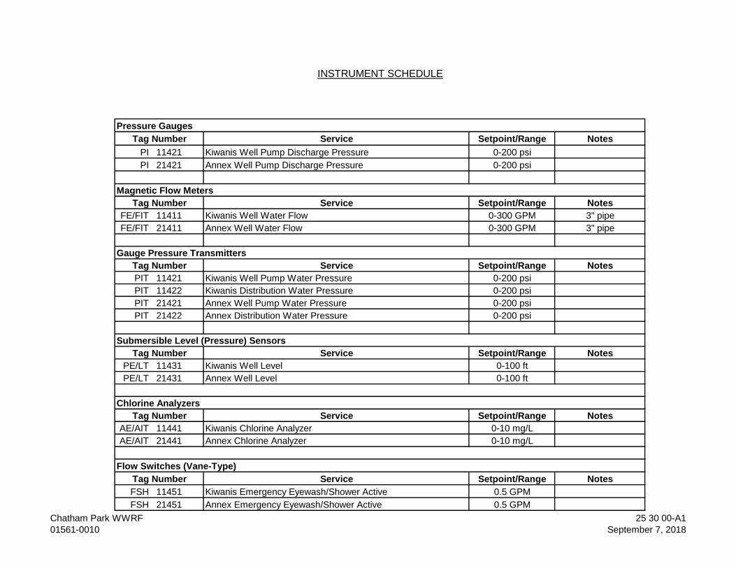
Service Setpoint/Range Notes
PI 11421 Kiwanis Well Pump Discharge Pressure 0-200 psi
PI 21421 Annex Well Pump Discharge Pressure 0-200 psi
Service Setpoint/Range Notes
FE/FIT 11411 Kiwanis Well Water Flow 0-300 GPM 3" pipe
FE/FIT 21411 Annex Well Water Flow 0-300 GPM 3" pipe
Service Setpoint/Range Notes
PIT 11421 Kiwanis Well Pump Water Pressure 0-200 psi
PIT 11422 Kiwanis Distribution Water Pressure 0-200 psi
PIT 21421 Annex Well Pump Water Pressure 0-200 psi
PIT 21422 Annex Distribution Water Pressure 0-200 psi
Service Setpoint/Range Notes
PE/LT 11431 Kiwanis Well Level 0-100 ft
PE/LT 21431 Annex Well Level 0-100 ft
Service Setpoint/Range Notes
AE/AIT 11441 Kiwanis Chlorine Analyzer 0-10 mg/L
AE/AIT 21441 Annex Chlorine Analyzer 0-10 mg/L
Service Setpoint/Range Notes
FSH 11451 Kiwanis Emergency Eyewash/Shower Active 0.5 GPM
FSH 21451 Annex Emergency Eyewash/Shower Active 0.5 GPM
INSTRUMENT SCHEDULE
Gauge Pressure Transmitters
Tag Number
Chlorine Analyzers
Tag Number
Pressure Gauges
Tag Number
Tag Number
Submersible Level (Pressure) Sensors
Flow Switches (Vane-Type)
Tag Number
Magnetic Flow Meters
Tag Number
Chatham Park WWRF
01561-0010
25 30 00-A1
September 7, 2018

- END OF SECTION -
Chatham Park WWRF
01561-0010
25 30 00-A2
September 7, 2018
HAMPSTEAD/SCOTT’S HILL WELL PROJECT 40 75 21 - 1
00542-0079 APRIL 2020
SECTION 40 75 21 – CHLORINE RESIDUAL ANALYZER
PART 1 - GENERAL
1.1 SCOPE OF WORK
A. This section covers the furnishing of all labor, materials, equipment, related components and accessories for the construction and installation of the NaOCl residual analyzer system as specified under this section and as shown on the Contract Drawings. The work includes placing all equipment into service, including interface, coordination, start-up, calibration, operating, training, troubleshooting and warranty repair.
B. Work includes furnishing and installing two (2) chlorine residual analyzer systems each consisting of a sampler/analyzer, controller, reagents, tubing, piping, valves, appurtenances, control interface, and all associated work to make complete and fully operational the chemical analyzer system.
C. This specification provides a general description of the requirements of the chlorine residual analyzer system. The system shall be provided as a complete system, and shall include all of the necessary components and accessories required for a system which is practical and functional in its operation, appropriate from the point of view of generally accepted safety standards, correctly designed for the type of chemical used, well ordered and complete in every way.
D. Related Work specified elsewhere:
1. Division 01 – GENERAL PROVISIONS
2. Division 26 – ELECTRICAL
3. Division 40 – INSTRUMENTATION AND CONTROLS
4. Division 46 – WATER EQUIPMENT
1.2 QUALITY ASSURANCE
A. The Contractor and a designated Qualified Supplier or subcontractor shall have system responsibility for the chlorine residual analyzer system. The Qualified Supplier shall be experienced in the special design considerations and safety requirements associated with the handling and feeding of the specified chemicals, and shall be responsible for the proper design, installation and operation of the specified chlorine residual analyzer system.
B. The items of equipment covered by this Specification are intended to be standard equipment of proven ability as manufactured by a reputable, qualified manufacturer, having long experience in the production of such equipment. The equipment shall be designed, constructed and installed with the best methods, materials and practice, and shall operate satisfactorily when installed. All equipment shall be new and un-used, and shall be the standard product of
CHLORINE RESIDUAL ANALYZER
HAMPSTEAD/SCOTT’S HILL WELL PROJECT 40 75 21 - 2
00542-0079 APRIL 2020
manufacturers having a successful record of manufacturing and servicing such equipment and systems as specified herein for a minimum of five (5) years.
C. The Qualified Supplier shall be responsible to the Contractor to assure that the chlorine residual analyzer system is supplied and installed in keeping with the best available practices and using the most appropriate materials and equipment available.
1.3 SUBMITTALS
A. Complete submittal drawings and information shall be submitted in accordance with Section 01 33 00 – SUBMITTAL PROCEDURES.
B. Submittal package shall include a complete copy of this Specification section. Contractor shall review submittal and indicate all items within the submittal as compliant with the specifications by indicating a check mark by each paragraph of this Specification. For any items which do not meet the requirements of this Specification, the Contractor shall indicate by marking the corresponding paragraph with an “X”. For each item which is not in compliance with this Specification, a written clarification shall be provided by the Contractor detailing how the submitted equipment differs from the requirements outlined in this Specification section and detail why it is not possible to meet the requirements of this Specification. All exceptions shall be listed on a separate document which is included at the front of the submittal provided for review. Any submittal package received without a marked up Specification section, description of exceptions or a Contractor’s review stamp shall be rejected and returned by the Engineer without further review.
C. Submittal shall contain the following at a minimum
1. Equipment drawings showing all important details of construction and dimensions.
2. Descriptive literature, bulletins, and/or catalogs of the equipment.
3. Data on the characteristics, features, and performance of the equipment.
4. Controls description
5. Control and Wiring diagrams
6. Operations and Maintenance (O&M) Manual
1.4 TOOLS AND SPARE PARTS
A. All special tools required for normal operation, adjustment or maintenance of the equipment shall be furnished with the equipment by the manufacturer.
B. As a minimum the following spare parts shall be furnished for the chemical feed system:
CHLORINE RESIDUAL ANALYZER
HAMPSTEAD/SCOTT’S HILL WELL PROJECT 40 75 21 - 3
00542-0079 APRIL 2020
1. One (1) extra set of all gaskets, seals, tubes, etc. for each analyzer.
2. Electrolyte, CLF 10sc
3. Membrane replacement kit, CLF10sc Plastic Tip.
4. Standard Cell Solution for pHD sc and pHD, packaged in resealable 500 mL bottle
5. Singlets (20 pack) for pH 4.01, 7.0 and 10.01 buffer solutions
C. The manufacturer shall provide a recommendation and supply all parts and accessories expected to be required for normal operation for the first year of operation.
D. All tools and spare parts shall be furnished in containers clearly marked with indelible markings as to their contents. This inventory shall be provided in a manner that is well ordered and complete.
1.5 LAYOUT COORDINATION AND REVIEW
A. The Contractor shall review design and layout drawings to ensure that installation arrangements are suitable for the specified equipment. Any potential conflicts or recommended modifications shall be coordinated with the Engineer and noted on the shop drawings or by a pre-submittal Request for Information (RFI), if appropriate.
1.6 OPERATING INSTRUCTIONS
A. The Manufacturer shall furnish operation and maintenance manuals. The manuals shall be prepared specifically for this installation and shall include all required catalog cuts, drawings, equipment lists, descriptions and other information that is required to instruct operation and maintenance personnel unfamiliar with such equipment.
1.7 PRODUCT STORAGE AND PROTECTION
A. The Contractor shall be responsible for protection and storage in accordance with the Manufacturer’s recommendations of all items shipped to the site from the time of delivery until installation is completed and the units and equipment are ready for operation.
1.8 WARRANTY
A. The chlorine residual analyzer system equipment furnished under this Section shall be warranted by the Manufacturer to be free of defects in material and workmanship, including damages that may be incurred during shipping for a period of 12 months from date of substantial completion.
CHLORINE RESIDUAL ANALYZER
HAMPSTEAD/SCOTT’S HILL WELL PROJECT 40 75 21 - 4
00542-0079 APRIL 2020
B. The Contractor shall warrant the complete final chlorine residual analyzer system installation for a period of 12 months from the date of issuance of Substantial Completion to be free of defects in materials and workmanships.
PART 2 - PRODUCTS
2.1 MANUFACTURER
A. Hach Company, Loveland, CO
2.2 CHLORINE RESIDUAL ANALYZER
A. The CLF10SC analyzer consisting of:
1. Three-electrode Amperometric Chlorine sensor
2. Chlorine sensor flow cell with integrated flow sensor
3. pHD Differential Sensor
4. pH flow cell with grab sample port
5. Digital gateway for communication between probes and controller
6. Stainless steel panel
2.3 EQUIPMENT
A. The CL10 sc works with Hach sc model controllers only.
B. The amperometric cell of the sensor consists of:
1. Gold cathode
2. Stainless steel counter electrode
3. Silver/silver chloride reference electrode
4. pH buffered electrolyte
5. Sensor membrane to filter chlorine species selectively and to provide interface between the electrochemical cell and the sample
C. Wetted materials as follows:
1. Chlorine Measuring Cell: PVC
2. Chlorine Sensor Body: PVC
3. Chlorine Sensor Flow Cell: Acrylic
4. pH Sensor Flow Cell: PVC
D. The sensor interface to the controller is through a digital gateway.
CHLORINE RESIDUAL ANALYZER
HAMPSTEAD/SCOTT’S HILL WELL PROJECT 40 75 21 - 5
00542-0079 APRIL 2020
E. The chlorine sensor automatically compensates for temperature utilizing an embedded temperature sensor.
F. The electrolyte provides internal, buffered pH compensation in the range of 4-9 pH units.
G. The sensor includes proprietary Cal Watch self-diagnostic technology.
H. The panel assembly includes a flow cell that integrates a flow meter and control valve.
2.4 COMPONENTS
A. Standard equipment:
1. Stainless Steel Mounting Panel
2. Chlorine Sensor with Membrane and Electrolyte
3. Chlorine Sensor flow cell
4. Flow meter with control valve
5. Digital gateway to sc controller with cable
6. User Manual
B. Dimensions
1. Sensor
a. Length: 7.68 in. (195 mm)
b. Diameter: 0.98 in. (25 mm)
2. Panel
a. Length: 19.0 in. (482.6 mm)
b. Width: 19.5 in. (495.3 mm)
c. Depth: 5.95 in. (151.2 mm)
3. Gateway to Controller cable: 3 ft. (1 m)
C. Weight
1. Panel and empty panel-mounted components: approximately 12 lbs. (5.5 kg)
2. Complete panel with pH sensor: approximately 20 lbs. (9.1 kg)
D. Standard Controller Equipment
1. Provide a Hach SC200 controller for online chlorine analyzer operation.
CHLORINE RESIDUAL ANALYZER
HAMPSTEAD/SCOTT’S HILL WELL PROJECT 40 75 21 - 6
00542-0079 APRIL 2020
2. Controller shall provide:
a. Full functionality of CL10sc menu structure
b. Communication outputs
c. Relays
d. Guided routine maintenance
e. Calibration verification
f. Access to analyzer data logs
3. Communication outputs for the controller shall include:
a. 4-20 mA
E. Chlorine Sensor
1. Measurement Range: 0 to 20 ppm
2. Lower Limit of Detection: 0.03 ppm or lower
3. Limit of Quantitation: 0.09 ppm or lower
4. Resolution: 0.001 ppm
5. Accuracy:
a. Free Chlorine +/- 3% of the reference test (DPD) at constant pH less than 7.2 (+/- 0.2 pH units)
b. Free Chlorine +/- 10% of the reference test (DPD) at stable pH less than 8.5 (+/- 0.5 pH unit from the pH at calibration)
c. Total Chlorine +/10 of the reference test (DPD) at pH less than 8.5 (+/- 0.5 pH unit from the pH at calibration)
d. Total Chlorine +/- 20% of the reference test (DPD) at stable pH greater than 8.5
6. Repeatability: 30 ppb or 3%, whichever is greater
7. Response Time:
a. Free chlorine: 140 seconds or less for 90% change at a stable temperature and pH
b. Total Chlorine: 100 seconds or less for 90% change at a stable temperature and pH
8. Sampling Time: Continuous
9. Interference:
a. Free chlorine: monochloramine, chlorine dioxide, ozone and chalk deposits
b. Total Chlorine: Chlorine dioxide, ozone and chalk deposits
10. Pressure Limit: 0.5 bar, no pressure impulses and/or vibrations
11. Sample Flow Rate: 7.9 to 12.2 gal/hour
CHLORINE RESIDUAL ANALYZER
HAMPSTEAD/SCOTT’S HILL WELL PROJECT 40 75 21 - 7
00542-0079 APRIL 2020
12. Sample pH: 4 to 9
13. Sample Temperature: 41 to 113 oF
14. Temperature Compensation: Internal temperature sensor
15. Storage Temperature:
a. Sensor: 32 to 122 oF
b. Electrolyte: 59 to 77 oF
16. Power Requirements: 12Vdc, 30 mA maximum (Supplied by controller)
17. Cable Length: 1 m
18. Cable Connection: 5 pin, M12 connector
19. Measurement Method: Reagentless, electrochemical, three-electrode amperometric system
20. Calibration Method: 1-point or 2-point calibration
21. Material: Corrosion-resistant materials (stainless steel, PVC, Silicon rubber and polycarbonate)
F. Panel (includes SS Panel, Gateway, Chlorine Sensor Flow Cell, pH Sensor Flow Cell)
1. Operating Temperature: 32 to 113 oF
2. Storage Temperature: -4 to 149 oF
3. Power Requirements: 12 Vdc +/- 10% at 100 mA maximum (supplied by sc controller)
4. Mounting: Flat, vertical surface
5. Connections:
a. Sample Line: 1/4 inch OD
b. Drain Line (pH flow Cell Outlet): 1/2 inch OD
G. Complete Analyzer (Panel + Sensor)
1. Waterproof Rating: IP65 (NEMA 4X)
2. Certification: CE/ETL, EMC
H. Components
1. CL10sc Online Chlorine Analyzer with pHD Differential Sensor
2. Sensor, free chlorine CLF10 sc Stainless Tip
3. Installation kit
4. Tubing kit
5. User manual
6. Cell cleaning kit

CHLORINE RESIDUAL ANALYZER
HAMPSTEAD/SCOTT’S HILL WELL PROJECT 40 75 21 - 8
00542-0079 APRIL 2020
7. Calibration verification kit
PART 3 - EXECUTION
3.1 INSTALLATION
A. Prior to assembly, all stainless steel bolts and nut threads shall be coated with a non – seizing compound.
B. The chlorine residual analyzer equipment shall be handled and installed in strict accordance with the Manufacturer’s instruction and recommendations, as detailed on the Contract Drawings and specified in the Contract Documents.
C. All equipment, components, piping and appurtenances shall be installed true to alignment and rigidly supported.
3.2 EQUIPMENT CALIBRATION
A. Every analog instrument, control or related device shall be properly calibrated, tuned, adjusted and commissioned so that the accuracy and operation of the device equals the highest level of performance which that device can achieve.
B. Accurate and appropriate test equipment and industry standard test procedures shall be used to demonstrate that the equipment operates within its expected tolerance of accuracy at various points throughout its operating range.
C. Whenever calibration adjustments are being made, the technician shall notify the members of the operating staff, so that they may witness the procedure as an educational process. The technicians shall assist the operator in any way possible in becoming well-versed in the start-up, operation, maintenance and calibration of the equipment provided.
D. The technician shall be fully familiar, trained and qualified to service and support the items which are being serviced.
3.3 CALIBRATION AND SERVICE REPORTS
A. A dated written report shall be prepared by the Qualified Supplier technician for each start-up, calibration, troubleshooting or maintenance event which identifies the equipment serviced, defines procedures, describes the results of the testing, and verifies the proper operation of the system. The report shall also document every wiring modification, warranty repair and problem analysis.
B. All reports shall be distributed to the Engineer, the Contractor and copied to the operating staff, and a copy shall be kept in a permanent file on site for future reference.
CHLORINE RESIDUAL ANALYZER
HAMPSTEAD/SCOTT’S HILL WELL PROJECT 40 75 21 - 9
00542-0079 APRIL 2020
3.4 FIELD TESTS, ADJUSTMENT AND STARTUP
A. A qualified representative of the manufacturer shall provide checkout of the chlorine residual analyzer equipment following installation. Sufficient checks shall be conducted to demonstrate that all system components are fully operational, that control and instrumentation components have been calibrated and properly adjusted and that the entire liquid chemical feed system is ready for continuous safe operation. The purpose of the checkout shall be to ensure that each individual system component has been correctly installed, shall operate fully in the manner intended, and is ready to perform its function as part of an integrated system when placed in continuous operation.
B. The manufacturer shall schedule one (1) trip to comprise at least one (1) 8 – hour day to each project site for equipment start – up assistance for the Contractor. Time does not include travel.
C. After completion of the installation, the equipment shall be inspected and certified by an authorized representative of the manufacturer as being in compliance with the manufacturer’s recommendations and requirements. At such time as the manufacturer has deemed the installation to be acceptable, the manufacturer’s authorized service representative shall make any required adjustments and shall start the equipment to assure proper operation.
D. After the equipment has been placed into operation, the manufacturer’s representative shall make all final adjustments for proper operation and issue a complete written report to the Engineer specifying all deficiencies noted and corrective measures required.
E. Sufficient checks shall be conducted to demonstrate that all system components are fully operational, that control and instrumentation components have been calibrated and properly adjusted and that the entire liquid chemical feed system is ready for continuous safe operation. The purpose of the checkout shall be to ensure that each individual system component has been correctly installed, shall operate fully in the manner intended, and is ready to perform its function as part of an integrated system when placed in continuous operation.
F. Start-up shall include furnishing the required oil and grease for initial operation. The grades of oil and grease shall be in accordance with the manufacturer's recommendations
G. Should the system fail the manufacturer’s requirements or performance requirements, the manufacturer shall at its own expense make all necessary modifications to the equipment until such tests can be passed.
3.5 OPERATOR TRAINING
A. The equipment supplier shall provide operator training for Owner’s personnel after system is operational. Training will take place while manufacturer’s representative is at the job site for inspection and shall include one (1) additional trip of at least one (1) 8 – hour day to make the operator’s staff thoroughly familiar with the system operation.

CHLORINE RESIDUAL ANALYZER
HAMPSTEAD/SCOTT’S HILL WELL PROJECT 40 75 21 - 10
00542-0079 APRIL 2020
END OF SECTION 40 75 21
HAMPSTEAD/SCOTT’S HILL WELL PROJECT 40 80 00 - 1
00542-0079 APRIL 2020
SECTION 40 80 00– SOFTWARE FUNCTIONAL CONTROL DESCRIPTIONS
PART 1 - GENERAL
1.1 OPERATIONAL OVERVIEW
A. The system consists of two well sites (Annex and Kiwanis), with one pump at each site.
B. The wells will operate to fill up the elevated water storage tank when the level reaches a low level setpoint. The sites will alternate in a lead/lag sequence.
C. The existing Mission SCADA system will be modified to facilitate communication between the tank and the two wells.
1.2 RELATED WORK SPECIFIED ELSEWHERE
A. In addition to the requirements specified in this section, the requirements of specification Section 40 61 00 - Instrumentation and Control, General Requirements and the sections referenced therein shall be applied.
B. There are ICS hardware and functional requirements contained herein that the Contractor shall provide that may not be described elsewhere in the Contract. Examples of such requirements are RTU-mounted pilot operators (e.g., selector switches, pushbuttons, indicating lights) and the associated functionality described herein.
1.3 SEQUENCE OF OPERATION – REMOTE TELEMETRY UNIT (RTU)
A. GENERAL
1. Where set points, operating limits, and other control settings are provided by the functional control descriptions, these settings shall be initial settings only and shall be used for assistance in the initial startup of the well. All settings shall be fully adjustable and based on actual operating conditions. The CSI shall make all necessary adjustments to provide smooth, stable operation at no additional cost to the Owner.
2. All set point control shall be by PID control algorithms unless specifically stated otherwise. Where only proportional control is specified, tuning constants shall be used to reduce the Integral and Derivative functions to zero.
3. Provision shall be made in PLC logic to suppress nuisance alarms and control actions by the use of adjustable time delays and hysteresis deadbands where needed. Initial settings for time delays shall be 10 seconds (range 0-900 seconds). Initial settings for deadbands shall be 5% of span (range 0-100%). In addition, process logic shall be used to suppress any alarms that are not applicable due to associated process or equipment status.
SOFTWARE FUNCTIONAL CONTROL DESCRIPTIONS
HAMPSTEAD/SCOTT’S HILL WELL PROJECT 40 80 00 - 2
00542-0079 APRIL 2020
4. All flow measurements shall be totalized over the current day, yesterday and cumulative.
B. ALARM ANNUNCIATION 1. All of the equipment status and alarms for the various analog signals shall
be monitored by the PLC. Upon trigger of any alarm condition, the PLC shall activate corresponding panel-mounted alarm lights and notification shall be sent through the RTU.
C. RTU-MOUNTED PILOT OPERATORS
1. The following pilot lights shall be provided on the RTU panel door:
• Well Pump Required
D. PUMP STATION SITE INPUTS/OUTPUTS
1. Each analog and discrete point required shall be properly wired, terminated, integrated, and programmed to provide the intended functions as specified herein.
2. The CSI shall coordinate the detailed wiring requirements with the electrical contractor and the suppliers of other equipment to assure that the interfaces are well ordered and complete.
E. CONTROL SEQUENCING
1. The PLC shall be programmed with logic to provide appropriate automatic control of process systems as described herein. In all cases, the local PLC shall provide the sequence logic and data accumulation. The control logic shall be structured to provide monitoring of timers, set points, sequences, current conditions, and alarms.
2. Each control algorithm shall be designed to operate appropriately in case of equipment failures of various types. Upon failure of various analog measurements or communications, the control will revert to a “safe” operation.
3. Control logic and operational sequences shall be versatile and shall respond safely and appropriately to equipment which fails to start, units which are out of service and instrument failure. Suitable time delays shall be included so that rapid starting or sequencing of pump motors is not possible.
F. PLC MODE OF OPERATION – WELL PUMPS
1. When the HAND-OFF-AUTO selector switch located on the VFD panel is in HAND position, the pump shall start until stopped by switching back to the OFF position. When the HAND-OFF-AUTO selector switch is in OFF position, the pump shall not operate under any conditions.
SOFTWARE FUNCTIONAL CONTROL DESCRIPTIONS
HAMPSTEAD/SCOTT’S HILL WELL PROJECT 40 80 00 - 3
00542-0079 APRIL 2020
2. When the HAND-OFF-AUTO selector switch is in AUTO position, the well pumps (Annex and Kiwanis) shall be controlled in a lead/lag sequence via tank level-based control strategy as follows:
3. The following elevated tank level (ft.) setpoints shall be utilized for level control, and shall be operator adjustable:
a) Start Lead Pump
b) Start Lag Pump
c) Stop Lag Pump
d) Stop Lead Pump
4. Lead/lag well (Annex or Kiwanis) designation shall alternate under each of the following conditions:
a) Both pumps are stopped
b) Lead pump has run for more than twelve (12) hours in one day
c) Both pumps have run for six (6) hours simultaneously
5. The well pump shall run at an adjustable Blowoff Speed during blow off upon each pump start. When the blow off valve closes (i.e., the blow off cycle completes) the pump speed shall ramp up to maintain an operator adjustable flow setpoint. The VFD ramp time shall be operator adjustable.
6. Alternation logic shall be present in both well site PLCs, with the operator having the ability to select the alternation master PLC from the cloud hosted SCADA system. The selected master PLC shall control the well pump alternation sequence, and the hosted SCADA system shall be responsible for distributing the alternation sequence between the well PLCs.
7. When the PLC calls the pump to stop, the PLC shall ramp the pump speed, at the operator-entered rate, down to minimum speed and shall remain there for an adjustable time period (initial: 30 seconds, range: 0-120 seconds) before actually stopping.
8. A low well level alarm shall be configured and shall stop the pump if breached. The setpoint shall be adjustable via the cloud host SCADA system.
9. The pump shall shut down upon high or low chlorine alarms.
G. PLC MODE OF OPERATION – CHEMICAL PUMPS
1. The PLC shall start all chemical pumps when the well pump is running and either of the following conditions are true:
SOFTWARE FUNCTIONAL CONTROL DESCRIPTIONS
HAMPSTEAD/SCOTT’S HILL WELL PROJECT 40 80 00 - 4
00542-0079 APRIL 2020
a) Well flow measurement is greater than 50 gpm
b) The well pump pressure and distribution pressure measurements are within 10 psi of each other
2. Deadbands and time delays shall be used to prevent nuisance operation.
PART 2 – PRODUCTS – NOT USED
PART 3 - EXECUTION
3.1 REQUIREMENTS:
A. In addition to the requirements specified in this section, refer to Section 40 61 00 - Instrumentation and Control, General Requirements.
END OF SECTION 40 80 00
HAMPSTEAD\SCOTT’S HILL WELL PROJECT 44 41 33 - 1
00542-0079 APRIL 2020
SECTION 44 41 33 – CHEMICAL CONTAINMENT PALLET
PART 1 - GENERAL
1.1 SUMMARY
A. Section Includes:
1. Chemical Containment Pallet
1.2 ACTION SUBMITTALS
A. Shop Drawings: Detailed drawings showing exact dimensions, chemical compatibility, support rating.
1.3 INFORMATIONAL SUBMITTALS
A. Material Certificates: For pallet containment system include data on material properties, material test reports substantiating compliance with requirements.
1.4 MANUFACTURER
A. Provide Chemical Containment Pallet by Ultratech International, Inc. Part # 1157 IBC Spill Pallet w/o drain or equal.
1.5 WARRANTY
A. Term of warranty shall be for 5 years after substantial completion and shall cover any material or workmanship defects.
PART 2 - PRODUCTS
A. CHEMICAL CONTAINMENT PALLET
1. Description: Molded 365 gallon (1382L) sump designed to hold one IBCs.
2. Unit shall support IBCs side by side for easy access to each unit, while maintaining compliance with EPA spill containment regulations for two IBC tanks.
a. Unit shall comply with EPA 40 CFR 264.175 and SPCC regulations.
b. Unit shall have molded sump catches leaks, drips and spills.
c. All-polyethylene construction resists UV rays, rust, corrosion and most chemicals for long trouble-free life of the product.
CHEMICAL CONTAINMENT PALLET
HAMPSTEAD\SCOTT’S HILL WELL PROJECT 44 41 33 - 2
00542-0079 APRIL 2020
d. Grates are easily removed for quick clean up
e. One continuous sump holds 365 gallons – meets EPA Spill Containment and SPCC Regulations for IBC tanks.
3. Materials of Construction
a. 100% polyethylene with UV inhibitors.
4. Performance
a. Load Capacity UDL: 8,000 lbs. / side (3629 kg)
b. Sump Capacity: 365 Gallons (1328L)
5. Physical Properties
a. Color: Black (Grating) /Yellow (Containment)
b. Misc. Features: No Drain
c. Dimensions:
1) Single Spill Pallet
i. Length: 61.625 inches
ii. Width: 61.625 inches
iii. Height: 28 inches
iv. Weight: 324 lbs
4. Accessories
a. Provide containment with removable grates for easy cleanup (each containment area shall be provided with (2) sections of 24”x48”x4” grating.)
END OF SECTION 44 41 33
HAMPSTEAD/SCOTT’S HILL WELL PROJECT 46 33 00 - 1
00542-0079 APRIL 2020
SECTION 46 33 00 – LIQUID CHEMICAL FEED EQUIPMENT
PART 1 - GENERAL
1.1 SCOPE OF WORK
A. This section covers the furnishing of all labor, materials, equipment, related components and accessories for the construction and installation of the NaOCl chemical feed systems and polyphosphate chemical feed systems as specified under this section and as shown on the drawings. The work includes placing all equipment into service, including interface, coordination, start-up, calibration, operating, training, troubleshooting and warranty repair.
B. Work includes furnishing and installing four (4) chemical metering systems each consisting of a chemical metering pump skid with one (1) pump, chemical piping, valves, appurtenances, control interface, chemicals and all associated work to make complete and fully operational the chemical feed system. Two (2) systems shall serve for feeding liquid sodium hypochlorite and two (2) system shall serve for feeding liquid polyphosphate. A common shelf spare chemical feed pump shall be provided.
C. This specification provides a general description of the requirements of the chemical feed system. The system shall be provided as a complete system, and shall include all of the necessary components and accessories required for a system which is practical and functional in its operation, appropriate from the point of view of generally accepted safety standards, correctly designed for the type of chemical used, well ordered and complete in every way.
D. Related Work specified elsewhere:
1. Division 01 – GENERAL PROVISIONS
2. Division 03 – CONCRETE
3. Division 26 – ELECTRICAL
4. Division 40 – INSTRUMENTATION AND CONTROLS
1.2 CHEMICALS
A. Provide initial filling of chemical storage tanks on site for initial operation of the well pump station consisting of 12% sodium hypochlorite and Aquapure 3655 NSF (Polyphosphate).
1.3 QUALITY ASSURANCE
A. The Contractor and a designated Qualified Supplier or subcontractor shall have system responsibility for the chemical feed system. The Qualified Supplier shall be experienced in the special design considerations and safety requirements associated with the handling and feeding of the specified chemicals, and shall be
LIQUID CHEMICAL FEED EQUIPMENT
HAMPSTEAD/SCOTT’S HILL WELL PROJECT 46 33 00 - 2
00542-0079 APRIL 2020
responsible for the proper design, installation and operation of the specified chemical feed system.
B. The items of equipment covered by this Specification are intended to be standard equipment of proven ability as manufactured by a reputable, qualified manufacturer, having long experience in the production of such equipment. The equipment shall be designed, constructed and installed with the best methods, materials and practice, and shall operate satisfactorily when installed. All equipment shall be new and un-used, and shall be the standard product of manufacturers having a successful record of manufacturing and servicing such equipment and systems as specified herein for a minimum of five (5) years.
C. The Qualified Supplier shall be responsible to the Contractor to assure that the chemical feed system is supplied and installed in keeping with the best available practices and using the most appropriate materials and equipment available.
1.4 SUBMITTALS
A. Complete submittal drawings and information shall be submitted in accordance with Section 01 33 00 – SUBMITTAL PROCEDURES.
B. Submittal package shall include a complete copy of this Specification section. Contractor shall review submittal and indicate all items within the submittal as compliant with the specifications by indicating a check mark by each paragraph of this Specification. For any items which do not meet the requirements of this Specification, the Contractor shall indicate by marking the corresponding paragraph with an “X”. For each item which is not in compliance with this Specification, a written clarification shall be provided by the Contractor detailing how the submitted equipment differs from the requirements outlined in this Specification section and detail why it is not possible to meet the requirements of this Specification. All exceptions shall be listed on a separate document which is included at the front of the submittal provided for review. Any submittal package received without a marked up Specification section, description of exceptions or a Contractor’s review stamp shall be rejected and returned by the Engineer without further review.
C. Submittal shall contain the following at a minimum
1. Equipment drawings showing all important details of construction and dimensions.
2. Descriptive literature, bulletins, and/or catalogs of the equipment.
3. Data on the characteristics, features, and performance of the equipment.
4. Controls description.
5. Control and Wiring diagrams.
6. Motor drive data.
LIQUID CHEMICAL FEED EQUIPMENT
HAMPSTEAD/SCOTT’S HILL WELL PROJECT 46 33 00 - 3
00542-0079 APRIL 2020
7. Operations and Maintenance (O&M) Manual.
1.5 TOOLS AND SPARE PARTS
A. All special tools required for normal operation, adjustment or maintenance of the equipment shall be furnished with the equipment by the manufacturer.
B. As a minimum the following spare parts shall be furnished for the chemical feed system:
1. One (1) extra set of all gaskets, seals, tubes, etc. for each pump.
2. Sufficient inventory of lubricants as required for one (1) year of operation as specified by the manufacturer.
C. The manufacturer shall provide a recommendation and supply all parts and accessories expected to be required for normal operation for the first year of operation.
D. All tools and spare parts shall be furnished in containers clearly marked with indelible markings as to their contents. This inventory shall be provided in a manner that is well ordered and complete.
1.6 LAYOUT COORDINATION AND REVIEW
A. The Contractor shall review design and layout drawings to ensure that installation arrangements are suitable for the specified equipment. Any potential conflicts or recommended modifications shall be coordinated with the Engineer and noted on the shop drawings or by a pre-submittal Request for Information (RFI), if appropriate.
1.7 OPERATING INSTRUCTIONS
A. The Manufacturer shall furnish operation and maintenance manuals. The manuals shall include all required catalog cuts, drawings, equipment lists, descriptions and other information that is required to instruct operation and maintenance personnel unfamiliar with such equipment.
1.8 PRODUCT STORAGE AND PROTECTION
A. The Contractor shall be responsible for protection and storage in accordance with the Manufacturer’s recommendations of all items shipped to the site from the time of delivery until installation is completed and the units and equipment are ready for operation.
1.9 WARRANTY
A. The Manufacturer shall warrant the complete pump skid system for a period of 12 months from the date of issuance of Substantial Completion to be free of defects in materials and workmanship.
LIQUID CHEMICAL FEED EQUIPMENT
HAMPSTEAD/SCOTT’S HILL WELL PROJECT 46 33 00 - 4
00542-0079 APRIL 2020
B. Pump shall be warranted by the manufacturer for a period of five (5) years. Warranty shall include chemical damage to the pump head and roller assembly for a period of two (2) years.
C. The Contractor shall warrant the complete final chemical feed pump system installation for a period of 12 months from the date of issuance of Substantial Completion to be free of defects in materials and workmanships.
PART 2 - PRODUCTS
2.1 CHEMICAL FEED PUMPS
A. Basis of Design
1. Chemical Skids: Four (4) skids
2. Quantity: One (1) Pump per skid with one (1) common shelf spare. Total of 5.
3. Chemical Service: 12.5% Sodium Hypochlorite Solution and Aqua Pure 3655 NSF (Polyphosphate/Orthophosphate)
4. Chlorine Pump Capacity: 0.6 GPH (Average) 1.5 GPH (Max)
5. Polyphosphate Capacity: 0.2 GPH (Average) 0.4 GPH (Max)
6. Backpressure: 80 psi (max.)
B. Acceptable Manufacturers
1. Blue-White Industries ProSeries Metering Pump Model M-3
2. Approved Equal
C. Shall be a positive displacement, peristaltic type tubing pump with a brushless variable speed motor, non-spring-loaded roller assembly located in the pump head, integral tube failure detection system, tube life roller revolution counter with user alarm set-point and flexible tubing with attached connection fittings. Shall be capable of output volumes from 0.0002 to 33.3 gallons per hour.
1. There shall be no valves, diaphragms, springs, or dynamic seals in the fluid path. Process fluid shall contact the pump tubing assembly and connection fittings only.
2. Pump shall be capable of 24-hour continuous duty, self-priming and operating in either direction of flow at the rated maximum pressure of up to 125 PSI (8.6 bar).
3. Pump shall be capable of running dry without damage.
4. Pump shall be capable of operating in either direction without output variation.
5. Suction lift shall be 30 feet of water.
LIQUID CHEMICAL FEED EQUIPMENT
HAMPSTEAD/SCOTT’S HILL WELL PROJECT 46 33 00 - 5
00542-0079 APRIL 2020
D. PUMPHEAD – Shall be a single, unbroken track with a clear removable cover
1. Tube failure detection sensors shall be wholly located in the pump head. Tube failure detection system shall not trigger with water contact. Float type switches shall not be used. Process fluid waste ports or leak drains shall not be provided.
2. Squeeze rollers with encapsulated ball bearings shall be directly coupled to a one-piece thermoplastic rotor. Four Kynar (PVDF) or Nylon rollers shall be provided; two squeeze rollers for tubing compression shall be located 180 degrees apart and two guide rollers that do not compress the tubing shall be located 180 degrees apart. The roller diameters and occlusion gap shall be factory set to provide the optimum tubing compression; field adjustment shall not be required. Spring-loaded or hinged rollers shall not be used.
3. Rotor assembly shall be installed on a D-shaped, chrome plated motor shaft and removable without tools.
4. For tubing installation and removal, rotor assembly shall be rotated by the motor drive at 6 RPM maximum when the pump head cover is removed. Hand cranking of the rotor assembly shall not be required.
5. Pump head and tubing compression surface shall be corrosion resistant Valox thermoplastic.
6. The pump head cover shall be clear, polycarbonate thermoplastic with an integral ball bearing fitted to support the overhung load on the motor shaft. Cover shall include an imbedded magnetic safety interlock which will limit the motor rotation speed to 6 RPM when removed.
7. Cover shall be positively secured to the pump head using a minimum of four thumb screws. Tools shall not be required to remove the pump head cover.
E. PUMP TUBE ASSEMBLY
1. To ensure pump performance and accuracy, only tubing provided by the manufacturer is acceptable.
2. Pump tube shall be assembled to connection fittings of PVDF material.
3. Connection fittings shall be permanently clamped to the tubing with stainless steel clamps or over molded directly to the tubing. To prevent tubing misalignment and ensure accuracy, fittings shall insert into keyed slots located in the pump head and secured in place by the pump head cover.
4. Connection fittings shall be 1/2” M/NPT. (Engineer to specify)
5. Tube sizes and connections shall be measured in inches.
F. DRIVE SYSTEM – Shall be factory installed and totally enclosed in a NEMA 4X, (IP66)
wash-down enclosure. Capable of operating on any input power from 110VAC to
240VAC, 50/60 Hz single phase supply without user configuration or selection switches.
1. Motor
LIQUID CHEMICAL FEED EQUIPMENT
HAMPSTEAD/SCOTT’S HILL WELL PROJECT 46 33 00 - 6
00542-0079 APRIL 2020
a. Reversible, brushless DC gear motor rated for continuous duty.
b. Motor shall include overload protection.
c. The maximum gear motor RPM shall be 125 RPM.
2. Enclosure
a. Pressure cast aluminum with acidic liquid iron phosphate three-stage clean and coat pretreatment and exterior grade corrosion resistant polyester polyurethane powder coat.
b. Rated NEMA 4X (IP66).
c. Provided with 316SS floor/shelf level mounting brackets and hardware.
d. A wiring compartment shall be provided for connection of input/output signal wires and alarm output loads to un-pluggable type terminal block connectors. Terminal board shall be positively secured to the rear of the pump housing by two polymeric screws and fully enclosed by the wiring compartment cover. The terminal board shall not be disturbed by the removal of the wiring compartment cover. Ribbon cables shall not be used in the wiring compartment. Conduit hubs, liquid-tight connectors, connector through holes and tapped holes shall be sized in U.S. inches.
3. Control Circuitry. All control circuitry shall be integral to the pump.
a. All control circuitry shall be integral to the pump and capable of adjusting the pump motor speed from 0.001% to 100.0% in 0.001% increments less than 1% motor speed, in 0.01% increments between 1% and 10% motor speed, and in 0.1% increments greater than 10% motor speed (10,000:1 turndown ratio).
b. The pump output shall be capable of being manually controlled via front panel user touchpad controls. The pump motor speed shall be adjustable from 0.001% to 100.0% in 0.001% increments less than 1% motor speed, in 0.01% increments between 1% and 10% motor speed, and in 0.1% increments greater than 10% motor speed.
c. The pump output shall be capable of being remotely control via 4-20mA analog input. The input resolution shall be 0.01 of input value and capable of adjusting the pump motor speed from 0% to 100.0% motor speed in 0.1% increments. Four values shall be user configurable to define the low and high points on the output slope; a low input value, the required pump percentage of motor speed at the low input value, a high input value, the required pump percentage of motor speed at the high input value.
d. The pump output shall be capable of being remotely control via 0-10 VDC input. The input resolution shall be 0.01 of input value and capable of adjusting the pump motor speed from 0% to 100.0% motor speed in 0.1% increments. Four values shall be user configurable to define the low and high points on the output slope;
LIQUID CHEMICAL FEED EQUIPMENT
HAMPSTEAD/SCOTT’S HILL WELL PROJECT 46 33 00 - 7
00542-0079 APRIL 2020
a low input value, the required pump percentage of motor speed at the low input value, a high input value, the required pump percentage of motor speed at the high input value.
e. The pump output shall be capable of being remotely control via TTL/Cmos digital high-speed pulse type input and an AC sine wave type pulse input in the range of 0 to 1,000 Hz. The frequency resolution shall be 1 Hz and capable of adjusting the pump motor speed from 0% to 100.0% motor speed in 0.1% increments. Four values shall be user configurable to define the low and high points on the output slope; a low input value, the required pump percentage of motor speed at the low input value, a high input value, the required pump percentage of motor speed at the high input value.
f. The pump output shall be capable of being remotely control via pulse triggered batching. The pump shall accept a TTL/Cmos digital pulse type input and a contact closure type pulse input in the range of 1 to 9999 pulses per batch. The batch time shall be adjustable from 1 to 999999.9 seconds. The pump motor speed during the batch shall be adjustable from 0% to 100.0% motor speed in 0.1% increments.
g. The pump shall include an internal cycle timer capable of automatically cycling the pump on and off. The pumping total cycle time shall be adjustable from 1 to 999999.9 seconds. The pumping on time during the cycle shall be adjustable from 1 to 999999.9 seconds. The pump motor speed during the cycle shall be adjustable from 0% to 100.0% motor speed in 0.1% increments.
h. The pump shall be capable of dispensing upon demand. The dispensing shall be manually triggered by pressing the front panel start button or by inputting a contact closure. The dispensing volume shall be adjustable from 1 to 999999.9 milliliters. The pump motor speed during the dispensing cycle shall be adjustable from 0% to 100.0% motor speed in 0.1% increments.
i. The pump shall be capable of automatically calculating the pump motor speed required to achieve a part per million dosing output that is proportional to a fixed system flow rate. The pump shall permit the user to input the dispensing chemical percentage concentration from 0% to 100.0% in 0.1% increments. The pump shall permit the user to input the dispensing chemical specific gravity from 0.1 to 9.9 in 0.1 increments. The pump shall permit the user to input the fixed system flow rate from 1.0 to 9999.9 liters per minute in 0.1 liters per minute increments. The pump shall permit the user to input the required dosing parts per million (PPM) from 0.1 to 100.0 in 0.1 increments.
j. The pump shall be capable of automatically calculating the pump motor speed required to achieve a part per million dosing output that is proportional to a variable system flow rate. The pump shall permit the user to input the dispensing chemical percentage concentration from 0% to 100.0% in 0.1% increments. The pump
LIQUID CHEMICAL FEED EQUIPMENT
HAMPSTEAD/SCOTT’S HILL WELL PROJECT 46 33 00 - 8
00542-0079 APRIL 2020
shall permit the user to input the dispensing chemical specific gravity from 0.1 to 9.9 in 0.1 increments. The pump shall permit the user to input a K-factor in pulses per liter from a sensor in the water system that outputs a high-speed digital pulse from 0 to 1000 Hz that is proportional to the system water flow velocity. The pump shall permit the user to input the required dosing parts per million (PPM) from 0.1 to 100.0 in 0.1 increments.
k. Provide an 11-button front panel user touchpad control for stop/start, configuration menu access and navigation, operating mode selection, auto priming, display options selection, tube life data, and reverse direction.
l. Provide a multi-color VGA graphic LCD display for menu driven configuration settings, pump output value, service alerts, tube failure detection (TFD) system and flow verification system (FVS) alarms status, remote input signal values, tubing life timer value. Display color shall be green when indicating normal operation, blue when in stand-by, and red to indicate an alarm condition exists.
m. Provide for remote stop/start pump via 6-30 VDC powered loop or non-powered contact closure loop.
n. Provide a user selectable 4-20mA and 0-1000Hz output signal which are scalable and proportional to pump output volume.
o. Provide four contact closure alarm outputs. Three rated at 1A-115VAC, 0.8A-30VDC and one rated at 6A-250VAC, 5A-30VDC. Each alarm output shall be assignable to monitor any of the following pump functions: TFD system, FVS system, motor run/stop, motor failed to respond to commands, motor is running in reverse, general alarm (TFD, FVS, and/or motor over current), input signal failure, output signal failure, remote/local control status, revolution counter (tube life) set-point, or monitor which of the nine different pump operating modes is currently active.
p. Provide a four-digit password protected configuration menu.
q. Provide a flow verification system with programmable alarm delay time from 1-255 seconds. FVS system shall monitor the FVS flow sensor while pump is running only. System shall not monitor pump while not running.
r. Provide a roller revolution counter display (tube life indicator) with user programmable alarm set-point value from 1 to 999,999,999 revolutions which can be assigned to any one of the 4 contact closure alarm outputs.
s. Provide a user programmable maximum RPM (revolutions per minute) set-point value from 0.1 to 100.0 RPM in 0.1 increments.
t. Provide a user adjustable response delay time from 0 to 999.9 seconds for the remote start/stop input and the four contact closure alarm outputs to facilitate closed-loop applications.
LIQUID CHEMICAL FEED EQUIPMENT
HAMPSTEAD/SCOTT’S HILL WELL PROJECT 46 33 00 - 9
00542-0079 APRIL 2020
u. Provide a power interruption pump restart option which is user programmable to either automatically restart or require a user re-start if AC mains power is interrupted.
G. SAFETY
1. The pump shall be certified to NSF Standard 61 Drinking Water System Components, UL standard 778 motor operated pump and CSA standard C22.2 process control equipment.
2. Manufactured to ISO 9001:2015 Quality Management System requirements.
3. Tube Failure Detection (TFD) system sensors shall be wholly located in the pump head. TFD system will stop the pump within three seconds of leak detection. To prevent false alarms due to rain, wash-down, condensation, etc., tube failure detection system shall not trigger with water contact. Process fluid waste ports or leak drains shall not be provided.
4. Pump head cover shall include an imbedded magnetic safety interlock which will stop the pump when removed. Pump rotor speed shall be limited to 6 RPM when cover is removed.
5. Secondary user confirmation input required for motor reversal, tube life revolution count reset, and factory default configuration reset.
H. SKID – Single pump systems and dual pump systems shall be constructed using a Polyethylene structure. The skid shall permit the installation of any Blue-White Industries Chem-Pro series diaphragm metering pumps or Flex-Pro Proseries-M peristaltic metering pumps.
1. There shall be two side walls for support and a pump mounting base.
2. There shall be a chemical spill containment area located at the base of the frame.
3. There shall be a drain port to drain fluid from containment area.
4. Four 316 stainless steel skid mounting pads shall be provided which can be positioned to enable either floor mounting or wall mounting the skid. Each mounting pad shall be secured to two mounting holes in the skid structure by 18-8 stainless steel hardware.
5. Two 316 stainless steel pump mounting brackets with four mounting slots shall be provided. Pump mounting brackets shall be secured to a HDPE plate. The HDPE plate shall be mounted to the skid structure by 18-8 stainless steel hardware.
6. Custom engineered universal mounting brackets shall secure each of the ball valves to the skid structure. Valve mounting brackets shall be PA12. Valve mounting brackets shall be secured by threaded inserts in the skid structure by 18-8 stainless steel hardware.
7. Single skid piping shall be ½” diameter schedule 80 PVC or CPVC. Dual skid piping shall be 1 ½” PVC or CPVC on the inlet side and ½” PVC or CPVC on the outlet side.

LIQUID CHEMICAL FEED EQUIPMENT
HAMPSTEAD/SCOTT’S HILL WELL PROJECT 46 33 00 - 10
00542-0079 APRIL 2020
8. Vented ball valves shall be PVC or CPVC with PTFE shaft bearings and seals.
9. Unions shall be schedule 80 PVC or CPVC.
10. Seals may be specified as either FKM or EPDM.
11. Two chemical inlet ports shall be provided.
12. System shall have a two-year manufacturer’s warranty.
I. FLOW INDICATOR – Shall be located in the discharge side of the piping system to provide a visual indication of fluid movement through the system.
1. The flow indicator body shall be machined from clear cast acrylic with a ceramic ball indicator and PVDF ball stop.
2. The flow indicator shall be secured to the piping system with PVC or CPVC connectors and Polypropylene half unions.
J. CHECK VALVE – Shall be located on the discharge side of the piping system at the pump injection point to prevent the back flow of fluid through the system.
1. The check valve shall be PVC with a 1.0 – 1.5 PSI cracking pressure.
2. The maximum inlet working pressure shall be 150 PSI.
3. Seals shall be EPDM
K. PRESSURE RELIEF VALVE - be located in the discharge side of the piping system to prevent excessive pressure in the system. Fluid shall be returned to the inlet side of the system if the pre-set maximum system pressure is exceeded.
1. The valve shall be PVC with a PTFE diaphragm seal manufactured by Griffco Valve Inc.
2. The pressure adjustment screw and lock nut shall be polypropylene.
3. Infinite adjustment increments from 10 to 150 psi shall be possible.
4. An outlet safety vent port shall be provided with 1/8” F/NPT connection.
L. PUMP CONNECTIONS – Shall be flexible, reinforced braided PVC tubing rated for 200 psi maximum continuous duty and terminated to half unions with stainless steel hose clamps. The tubing shall meet NSF listed.
1. Single pump systems shall include two chemical injection inlet ports; one for the primary chemical injection and one for use as a secondary chemical inlet port or as a flushing port.
M. INLET STRAINER – Shall be located in the suction side of the piping system.
1. The Y-type dampener shall be PVC with removable screen.
2. Seals shall be EPDM.
N. CALIBRATION CYLINDER – Shall be located in the inlet side of the system to permit metering pump output volume calibration.
LIQUID CHEMICAL FEED EQUIPMENT
HAMPSTEAD/SCOTT’S HILL WELL PROJECT 46 33 00 - 11
00542-0079 APRIL 2020
1. Valves shall permit the cylinder to be filled by gravity or by by-passing the chemical metering pump output into the cylinder.
2. The cylinder shall PVC with PVC end caps.
3. An outlet vent shall be provided with ¼” ID tubing barb connection.
O. PULSATION DAMPENER – Shall be located in the discharge side of the system to reduce pulsation.
1. A ball valve shall be provided to permit the dampener to be removed for service.
2. The dampener shall CPVC with 10 cubic inches of volume.
3. Seals shall be EPDM.
P. PRESSURE GAUGE with GUARD – Shall be located in the discharge side of the system to indicate system pressure.
1. The liquid filled gauge shall be stainless steel and include a blow-out plug.
2. The gauge shall be bottom mounted to the guard with ¼” NPT stainless steel threads.
3. The temperature compensated oil filled gauge guard shall be PVC.
4. Range shall be 0 – 200 PSI.
PART 3 - EXECUTION
3.1 FIELD PREPARATION AND PAINTING
A. The Contractor shall touch – up all shipping damage to the paint and stainless steel as soon as the equipment arrives on the job site.
3.2 INSTALLATION
A. Prior to assembly, all stainless steel bolts and nut threads shall be coated with a non – seizing compound.
B. The liquid chemical feed equipment shall be handled and installed in strict accordance with the Manufacturer’s instruction and recommendations, as detailed on the Contract Drawings and specified in the Contract Documents.
C. All equipment, components, piping and appurtenances shall be installed true to alignment and rigidly supported.
LIQUID CHEMICAL FEED EQUIPMENT
HAMPSTEAD/SCOTT’S HILL WELL PROJECT 46 33 00 - 12
00542-0079 APRIL 2020
3.3 EQUIPMENT CALIBRATION
A. Every analog instrument, control or related device shall be properly calibrated, tuned, adjusted and commissioned so that the accuracy and operation of the device equals the highest level of performance which that device can achieve.
B. Accurate and appropriate test equipment and industry standard test procedures shall be used to demonstrate that the equipment operates within its expected tolerance of accuracy at various points throughout its operating range.
C. Whenever calibration adjustments are being made, the technician shall notify the members of the operating staff, so that they may witness the procedure as an educational process. The technicians shall assist the operator in becoming well-versed in the start-up, operation, maintenance and calibration of the equipment provided.
D. The technician shall be fully familiar, trained and qualified to service and support the items which are being serviced.
3.4 CALIBRATION AND SERVICE REPORTS
A. A dated written report shall be prepared by the Qualified Supplier technician for each start-up, calibration, troubleshooting or maintenance event which identifies the equipment serviced, defines procedures, describes the results of the testing, and verifies the proper operation of the system. The report shall also document every wiring modification, warranty repair and problem analysis.
B. All reports shall be distributed to the Engineer, the Contractor and copied to the operating staff, and a copy shall be kept in a permanent file on site for future reference.
3.5 FIELD TESTS, ADJUSTMENT AND STARTUP
A. A qualified representative of the manufacturer shall provide checkout of the liquid chemical feed equipment following installation. Sufficient checks shall be conducted to demonstrate that all system components are fully operational, that control and instrumentation components have been calibrated and properly adjusted and that the entire liquid chemical feed system is ready for continuous safe operation. The purpose of the checkout shall be to ensure that each individual system component has been correctly installed, shall operate fully in the manner intended, and is ready to perform its function as part of an integrated system when placed in continuous operation.
B. The manufacturer shall schedule one (1) trip to comprise at least one (1) 8 – hour day to each project site for equipment start – up assistance for the Contractor. Time does not include travel.
C. After completion of the installation, the equipment shall be inspected and certified by an authorized representative of the manufacturer as being in compliance with the manufacturer’s recommendations and requirements. At such time as the
LIQUID CHEMICAL FEED EQUIPMENT
HAMPSTEAD/SCOTT’S HILL WELL PROJECT 46 33 00 - 13
00542-0079 APRIL 2020
manufacturer has deemed the installation to be acceptable, the manufacturer’s authorized service representative shall make any required adjustments and shall start the equipment to assure proper operation.
D. After the equipment has been placed into operation, the manufacturer’s representative shall make all final adjustments for proper operation and issue a complete written report to the Engineer specifying all deficiencies noted and corrective measures required.
E. Sufficient checks shall be conducted to demonstrate that all system components are fully operational, that control and instrumentation components have been calibrated and properly adjusted and that the entire liquid chemical feed system is ready for continuous safe operation. The purpose of the checkout shall be to ensure that each individual system component has been correctly installed, shall operate fully in the manner intended, and is ready to perform its function as part of an integrated system when placed in continuous operation.
F. Start-up shall include furnishing the required oil and grease for initial operation. The grades of oil and grease shall be in accordance with the manufacturer's recommendations
G. Should the system fail the manufacturer’s requirements or performance requirements, the manufacturer shall at its own expense make all necessary modifications to the equipment until such tests can be passed.
3.6 OPERATOR TRAINING
A. The equipment supplier shall provide operator training for Owner’s personnel after system is operational. Training will take place while manufacturer’s representative is at the job site for inspection.
END OF SECTION 46 33 00

APPENDIX A
Soils Report

ECS Southeast, LLP Geotechnical Engineering Report
Pender Well Sites
Hampstead, Pender County, North Carolina ECS Project Number # 22:28643 December 18, 2019
December 18, 2019
Mr. Tony Boahn McKim & Creed 243 North Front Street Wilmington, North Carolina 28401
ECS Project No. 22:28643 Reference: Geotechnical Engineering Report
Pender Well Sites Hampstead, Pender County, North Carolina
Dear Mr. Boahn: ECS Southeast, LLP (ECS) has completed the subsurface exploration, and geotechnical engineering analyses for the above-referenced project. Our services were performed in general accordance with our Proposal No. 22:23658.Rev1, dated December 3, 2019. This report presents our understanding of the geotechnical aspects of the project along, the results of the field exploration conducted, and our design and construction. It has been our pleasure to be of service to McKim & Creed during the design phase of this project. We would appreciate the opportunity to remain involved during the continuation of the design phase, and we would like to provide our services during construction phase operations as well to verify the assumptions of subsurface conditions made for this report. Should you have any questions concerning the information contained in this report, or if we can be of further assistance to you, please contact us. Respectfully submitted, ECS Southeast, LLP
Annemarie Crumrine, E.I. Winslow Goins, PE Project Manager Principal Engineer [email protected] [email protected]
12/18/19
Pender Well Sites December 18, 2019 ECS Project No. 22:28643 Page i
TABLE OF CONTENTS
EXECUTIVE SUMMARY ............................................................................................................. 1 1.0 INTRODUCTION .................................................................................................................. 2
1.1 General ................................................................................................................................... 2 1.2 Scope of Services .................................................................................................................... 2 1.3 Authorization .......................................................................................................................... 2
2.0 PROJECT INFORMATION ..................................................................................................... 3 2.1 Project Location...................................................................................................................... 3 2.2 Current Site Conditions .......................................................................................................... 4 2.3 Proposed Construction ........................................................................................................... 4
3.0 FIELD EXPLORATION ........................................................................................................... 5 3.1 Field Exploration Program ...................................................................................................... 5
3.1.1 Cone Penetrometer Soundings ..................................................................................... 5 3.2 Regional/Site Geology ............................................................................................................ 5 3.3 Subsurface Characterization .................................................................................................. 7 3.4 Groundwater Observations .................................................................................................... 7
4.0 DESIGN RECOMMENDATIONS ............................................................................................. 8 4.1 Building Design ....................................................................................................................... 8
4.1.1 Foundations .................................................................................................................. 8 4.1.2 Floor Slabs ..................................................................................................................... 9 4.1.3 Seismic Design Considerations ..................................................................................... 9
4.2 Site Design Considerations ................................................................................................... 11 4.2.1 Pavement Sections ..................................................................................................... 11
5.0 SITE CONSTRUCTION RECOMMENDATIONS ....................................................................... 13 5.1 Subgrade Preparation .......................................................................................................... 13
5.1.1 Stripping and Grubbing ............................................................................................... 13 5.1.2 Proofrolling ................................................................................................................. 13
5.2 Earthwork Operations .......................................................................................................... 13 5.2.1 Structural Fill Materials............................................................................................... 13 5.2.2 Compaction ................................................................................................................. 14
5.3 Foundation observations ..................................................................................................... 16 5.4 Utility Installations ............................................................................................................... 16 5.5 General Construction Considerations .................................................................................. 17
6.0 CLOSING ........................................................................................................................... 19 APPENDICES Appendix A – Drawings & Reports
Site Location Diagrams
Exploration Location Diagrams Appendix B – Field Operations
Reference Notes for Sounding Logs
CPT Sounding Logs (RW4 and RW6) Appendix C – Supplemental Report Documents
GBA Document
Pender Well Sites December 18, 2019 ECS Project No. 22:28643 Page 1
EXECUTIVE SUMMARY
The following summarizes the main findings of the exploration, particularly those that may have a cost impact on the planned development. Further, our principal foundation recommendations are summarized. Information gleaned from the executive summary should not be utilized in lieu of reading the entire geotechnical report.
The geotechnical exploration performed for the sites (RW4 and RW6) included two (2) electronic cone penetration test (CPT) soundings drilled to refusal and termination depths of approximately 28 to 40 feet.
The soundings generally encountered coastal plain soils consisting of very loose to very dense, Silty, Clean, and Cemented SAND (SM, SP) and Very Soft to Stiff, Sandy and Clayey SILT (ML) and Silty, Lean, and Fat CLAYS (CL-ML, CL, CH).
The proposed structures at both of the sites can be supported by conventional shallow foundations consisting of column or strip footings bearing on firm natural soil and/or approved structural fill. We recommend a maximum net allowable bearing pressure of 3,000 psf be used for design. Details of the assumed foundation subgrade elevations and loads are contained in the body of the report.
Groundwater was encountered in the soundings RW4 and RW6 at depths of about 3.33 and 14.5 feet, respectively, below existing grades.
Please note this Executive Summary is an important part of this report and should be considered a “summary” only. The subsequent sections of this report constitute our findings, conclusions, and recommendations in their entirety.
Pender Well Sites December 18, 2019 ECS Project No. 22:28643 Page 2
1.0 INTRODUCTION
1.1 GENERAL
The purpose of this study was to provide geotechnical information for the preliminary design of the proposed two well sites located off of Country Club Drive and off of US Highway 17 in Hampstead, New Pender County, North Carolina. The recommendations developed for this report are based on project information supplied by McKim & Creed. This report contains the results of our subsurface explorations, site characterization, engineering analyses, and recommendations for the design and construction of the proposed development. 1.2 SCOPE OF SERVICES To obtain the necessary geotechnical information required for design of the proposed project, two (2) CPT soundings were performed. The soundings were advanced to termination and refusal depths of approximately 28 to 40 feet beneath the ground surface. This report discusses our exploratory and testing procedures, presents our findings and evaluations and includes the following.
A brief review and description of our field test procedures and the results of testing conducted;
A review of surface topographical features and site conditions;
A review of area and site geologic conditions;
A review of subsurface soil stratigraphy with pertinent available physical properties;
Preliminary foundation recommendations; o Allowable bearing pressure; o Settlement estimates (total and differential);
Site development recommendations;
Suitability of soils for use as fill material;
Pavement design recommendations;
Seismic site class and liquefaction recommendations;
Discussion of groundwater impact;
Compaction recommendations;
Special conditions encountered;
Site vicinity maps;
Exploration location plans; and
CPT sounding logs.
1.3 AUTHORIZATION
Our services were provided in accordance with our Proposal No. 22.23658.Rev1, dated December 3, 2019, as authorized by Mr. Tony Boahn on December 3, 2019, and include the Terms and Conditions of Service outlined with our Proposal.
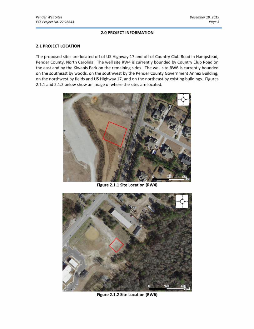
Pender Well Sites December 18, 2019 ECS Project No. 22:28643 Page 3
2.0 PROJECT INFORMATION
2.1 PROJECT LOCATION
The proposed sites are located off of US Highway 17 and off of Country Club Road in Hampstead, Pender County, North Carolina. The well site RW4 is currently bounded by Country Club Road on the east and by the Kiwanis Park on the remaining sides. The well site RW6 is currently bounded on the southeast by woods, on the southwest by the Pender County Government Annex Building, on the northwest by fields and US Highway 17, and on the northeast by existing buildings. Figures 2.1.1 and 2.1.2 below show an image of where the sites are located.
Figure 2.1.1 Site Location (RW4)
Figure 2.1.2 Site Location (RW6)
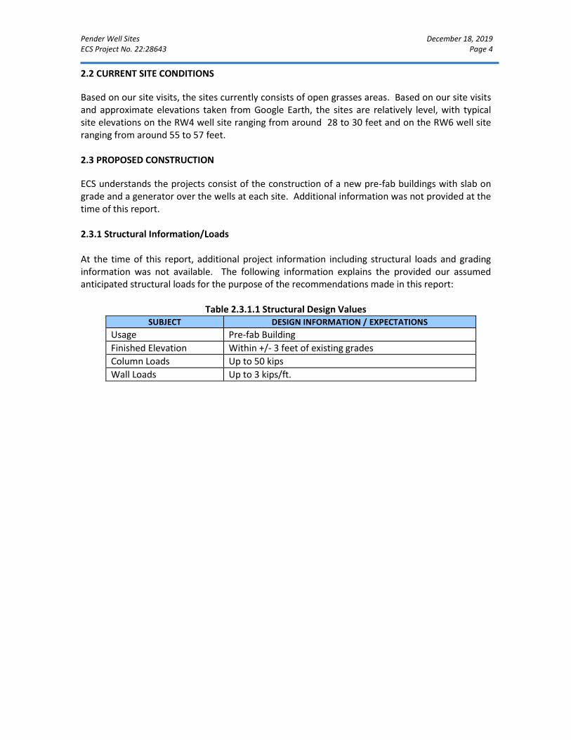
Pender Well Sites December 18, 2019 ECS Project No. 22:28643 Page 4
2.2 CURRENT SITE CONDITIONS
Based on our site visits, the sites currently consists of open grasses areas. Based on our site visits and approximate elevations taken from Google Earth, the sites are relatively level, with typical site elevations on the RW4 well site ranging from around 28 to 30 feet and on the RW6 well site ranging from around 55 to 57 feet. 2.3 PROPOSED CONSTRUCTION
ECS understands the projects consist of the construction of a new pre-fab buildings with slab on grade and a generator over the wells at each site. Additional information was not provided at the time of this report. 2.3.1 Structural Information/Loads At the time of this report, additional project information including structural loads and grading information was not available. The following information explains the provided our assumed anticipated structural loads for the purpose of the recommendations made in this report:
Table 2.3.1.1 Structural Design Values
SUBJECT DESIGN INFORMATION / EXPECTATIONS
Usage Pre-fab Building
Finished Elevation Within +/- 3 feet of existing grades
Column Loads Up to 50 kips
Wall Loads Up to 3 kips/ft.
Pender Well Sites December 18, 2019 ECS Project No. 22:28643 Page 5
3.0 FIELD EXPLORATION
3.1 FIELD EXPLORATION PROGRAM
The field exploration was planned with the objective of characterizing the project sites in general geotechnical and geological terms and to evaluate subsequent field data to assist in the determination of geotechnical recommendations. 3.1.1 Cone Penetrometer Soundings The subsurface conditions were explored by drilling two (2) electronic cone penetration test (CPT) soundings on the proposed sites. The soundings were advanced to termination and refusal depths of approximately 28 to 40 feet. Sounding locations were located in the field by an ECS representative using a hand held GPS unit and referencing existing site features. The approximate as-drilled sounding location is shown on the Exploration Location Diagrams in Appendix A. The CPT soundings were conducted in general accordance with ASTM D 5778. The cone used in the soundings has a tip area of 10 cm2 and a sleeve area of 150 cm2. The CPT soundings recorded tip resistance and sleeve friction measurements to assist in determining pertinent index and engineering properties of the site soils. The ratio of the sleeve friction to tip resistance is then used to aid in assessing the soil types through which the tip is advanced. The results of the CPT soundings are presented in Appendix B.
3.2 REGIONAL/SITE GEOLOGY
The natural geology of the sites has been modified in the past; therefore potential unsuitable material might be present throughout the sites. The sites are located in the Coastal Plain Physiographic Province of North Carolina. The Coastal Plain is composed of seven terraces, each representing a former level of the Atlantic Ocean. Soils in this area generally consist of sedimentary materials transported from other areas by the ocean or rivers. These deposits vary in thickness from a thin veneer along the western edge of the region to more than 10,000 feet near the coast. The sedimentary deposits of the Coastal Plain rest upon consolidated rocks similar to those underlying the Piedmont and Mountain Physiographic Provinces. In general, shallow unconfined groundwater movement within the overlying soils is largely controlled by topographic gradients. Recharge occurs primarily by infiltration along higher elevations and typically discharges into streams or other surface water bodies. The elevation of the shallow water table is transient and can vary greatly with seasonal fluctuations in precipitation.
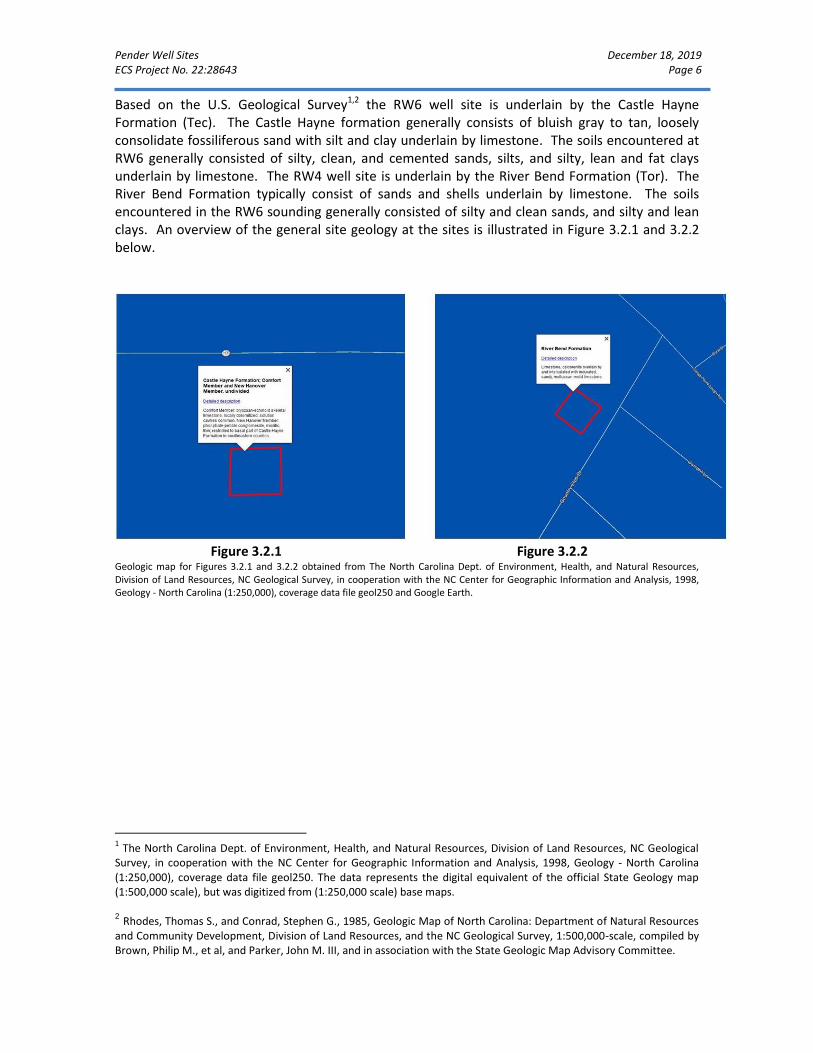
Pender Well Sites December 18, 2019 ECS Project No. 22:28643 Page 6
Based on the U.S. Geological Survey1,2 the RW6 well site is underlain by the Castle Hayne Formation (Tec). The Castle Hayne formation generally consists of bluish gray to tan, loosely consolidate fossiliferous sand with silt and clay underlain by limestone. The soils encountered at RW6 generally consisted of silty, clean, and cemented sands, silts, and silty, lean and fat clays underlain by limestone. The RW4 well site is underlain by the River Bend Formation (Tor). The River Bend Formation typically consist of sands and shells underlain by limestone. The soils encountered in the RW6 sounding generally consisted of silty and clean sands, and silty and lean clays. An overview of the general site geology at the sites is illustrated in Figure 3.2.1 and 3.2.2 below.
Figure 3.2.1 Figure 3.2.2
Geologic map for Figures 3.2.1 and 3.2.2 obtained from The North Carolina Dept. of Environment, Health, and Natural Resources, Division of Land Resources, NC Geological Survey, in cooperation with the NC Center for Geographic Information and Analysis, 1998, Geology - North Carolina (1:250,000), coverage data file geol250 and Google Earth.
1 The North Carolina Dept. of Environment, Health, and Natural Resources, Division of Land Resources, NC Geological
Survey, in cooperation with the NC Center for Geographic Information and Analysis, 1998, Geology - North Carolina (1:250,000), coverage data file geol250. The data represents the digital equivalent of the official State Geology map (1:500,000 scale), but was digitized from (1:250,000 scale) base maps. 2 Rhodes, Thomas S., and Conrad, Stephen G., 1985, Geologic Map of North Carolina: Department of Natural Resources
and Community Development, Division of Land Resources, and the NC Geological Survey, 1:500,000-scale, compiled by Brown, Philip M., et al, and Parker, John M. III, and in association with the State Geologic Map Advisory Committee.

Pender Well Sites December 18, 2019 ECS Project No. 22:28643 Page 7
3.3 SUBSURFACE CHARACTERIZATION
The subsurface conditions encountered were generally consistent with published geological mapping. The following sections provide generalized characterizations of the soil encountered during our subsurface exploration. For subsurface information at a specific location, refer to the CPT Sounding Logs in Appendix B.
Table 3.3.1 Subsurface Stratigraphy - RW4 Approximate Depth Range
Stratum Description Ranges of N*-Values(1) blows per foot (bpf)
0 to 20 I Very Loose to Medium Dense, Silty and Clean SAND (SM, SP)
3 to 25
20 to 24 II Very Soft to Stiff, Sandy and Clayey SILT (ML) and Silty, Lean, and Fat CLAY (CL-ML, CL, CH) with interbedded layers of loose to medium dense, Silty SAND (SM)
2 to 11
24 to 28.2 III Medium Dense to Very Dense, Silty, Clean, and Cemented SAND (SM, SP). Sounding RW4 encountered refusal on limestone at 28.2 feet.
13 to 33
Notes: (1) Equivalent Corrected Standard Penetration Test Resistances
Table 3.3.2 Subsurface Stratigraphy - RW6
Approximate Depth Range
Stratum Description Ranges of N*-Values(1) blows per foot (bpf)
0 to 17 I Very Loose to Medium Dense, Silty and Clean SAND (SM, SP)
4 to 30
17 to 22 II Medium Dense to Dense, Silty and Clean SAND (SM, SP) 26 to 46
22 to 40 III Soft to Stiff, Silty and Lean CLAY (CL-ML, CL) with occasional interbedded layers of medium dense, Silty SAND (SM)
4 to 20
Notes: (1) Equivalent Corrected Standard Penetration Test Resistances
3.4 GROUNDWATER OBSERVATIONS
Porewater pressure measurements were made at the sounding locations during exploration as noted on the CPT sounding logs in Appendix B. The apparent groundwater depths at soundings RW4 and RW6 were observed at the time of drilling and during field exploration to approximately be 3.33 and 14.5 feet, respectively, below ground surface. The highest groundwater observations are normally encountered in the late winter and early spring. Variations in the long-term water table may occur as a result of changes in precipitation, evaporation, surface water runoff, construction activities, and other factors not immediately apparent at the time of this exploration. If long term water levels are crucial to the development of these sites, it would be prudent to verify water levels with the use of perforated pipes or piezometers.
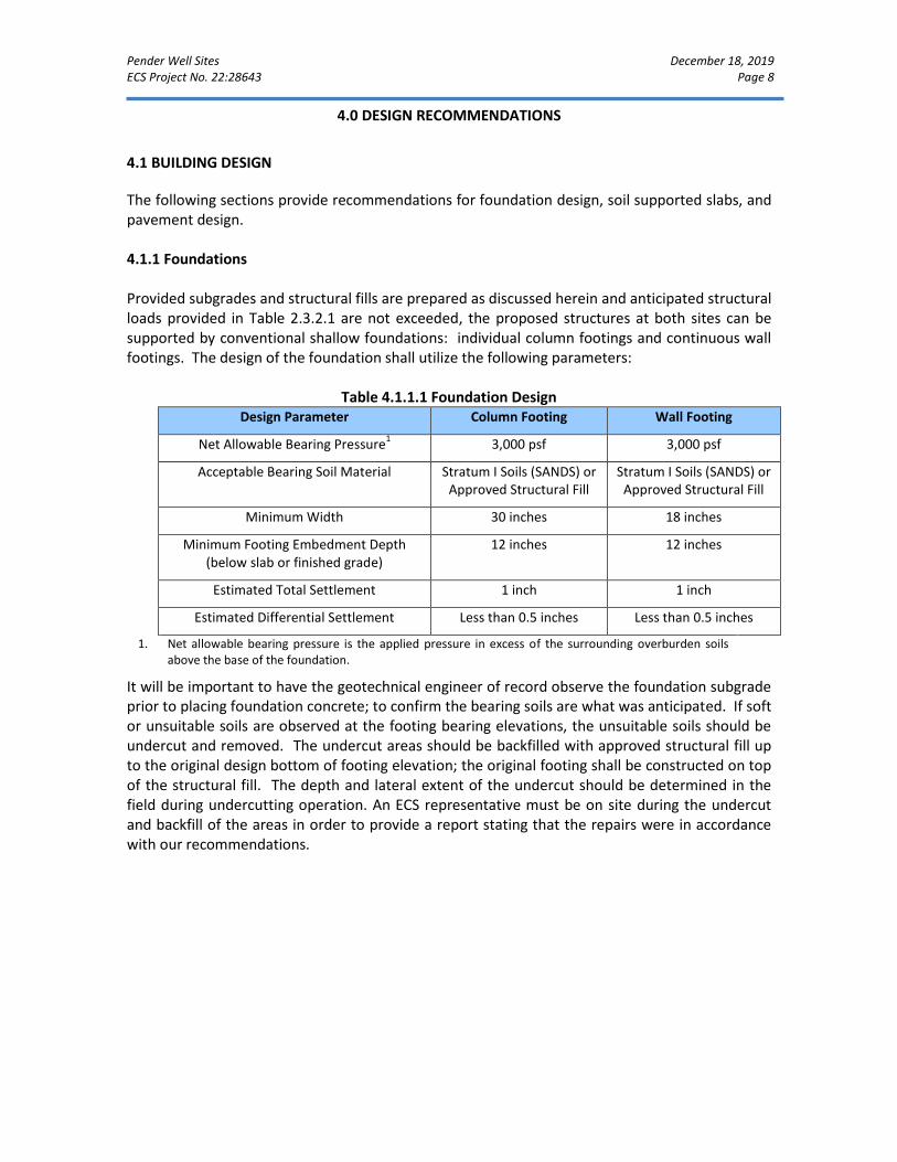
Pender Well Sites December 18, 2019 ECS Project No. 22:28643 Page 8
4.0 DESIGN RECOMMENDATIONS
4.1 BUILDING DESIGN
The following sections provide recommendations for foundation design, soil supported slabs, and pavement design. 4.1.1 Foundations Provided subgrades and structural fills are prepared as discussed herein and anticipated structural loads provided in Table 2.3.2.1 are not exceeded, the proposed structures at both sites can be supported by conventional shallow foundations: individual column footings and continuous wall footings. The design of the foundation shall utilize the following parameters:
Table 4.1.1.1 Foundation Design
Design Parameter Column Footing Wall Footing
Net Allowable Bearing Pressure1 3,000 psf 3,000 psf
Acceptable Bearing Soil Material Stratum I Soils (SANDS) or Approved Structural Fill
Stratum I Soils (SANDS) or Approved Structural Fill
Minimum Width 30 inches 18 inches
Minimum Footing Embedment Depth (below slab or finished grade)
12 inches 12 inches
Estimated Total Settlement 1 inch 1 inch
Estimated Differential Settlement Less than 0.5 inches Less than 0.5 inches
1. Net allowable bearing pressure is the applied pressure in excess of the surrounding overburden soils above the base of the foundation.
It will be important to have the geotechnical engineer of record observe the foundation subgrade prior to placing foundation concrete; to confirm the bearing soils are what was anticipated. If soft or unsuitable soils are observed at the footing bearing elevations, the unsuitable soils should be undercut and removed. The undercut areas should be backfilled with approved structural fill up to the original design bottom of footing elevation; the original footing shall be constructed on top of the structural fill. The depth and lateral extent of the undercut should be determined in the field during undercutting operation. An ECS representative must be on site during the undercut and backfill of the areas in order to provide a report stating that the repairs were in accordance with our recommendations.
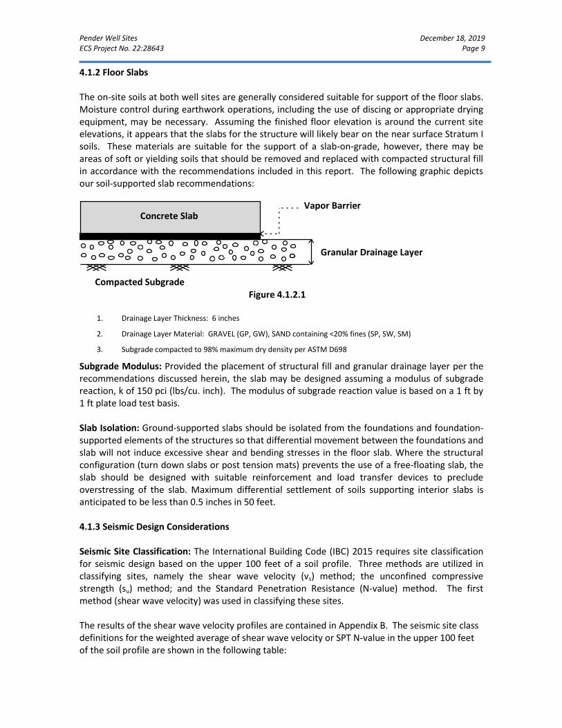
Pender Well Sites December 18, 2019 ECS Project No. 22:28643 Page 9
4.1.2 Floor Slabs The on-site soils at both well sites are generally considered suitable for support of the floor slabs. Moisture control during earthwork operations, including the use of discing or appropriate drying equipment, may be necessary. Assuming the finished floor elevation is around the current site elevations, it appears that the slabs for the structure will likely bear on the near surface Stratum I soils. These materials are suitable for the support of a slab-on-grade, however, there may be areas of soft or yielding soils that should be removed and replaced with compacted structural fill in accordance with the recommendations included in this report. The following graphic depicts our soil-supported slab recommendations:
Figure 4.1.2.1
1. Drainage Layer Thickness: 6 inches
2. Drainage Layer Material: GRAVEL (GP, GW), SAND containing <20% fines (SP, SW, SM)
3. Subgrade compacted to 98% maximum dry density per ASTM D698
Subgrade Modulus: Provided the placement of structural fill and granular drainage layer per the recommendations discussed herein, the slab may be designed assuming a modulus of subgrade reaction, k of 150 pci (lbs/cu. inch). The modulus of subgrade reaction value is based on a 1 ft by 1 ft plate load test basis. Slab Isolation: Ground-supported slabs should be isolated from the foundations and foundation-supported elements of the structures so that differential movement between the foundations and slab will not induce excessive shear and bending stresses in the floor slab. Where the structural configuration (turn down slabs or post tension mats) prevents the use of a free-floating slab, the slab should be designed with suitable reinforcement and load transfer devices to preclude overstressing of the slab. Maximum differential settlement of soils supporting interior slabs is anticipated to be less than 0.5 inches in 50 feet. 4.1.3 Seismic Design Considerations Seismic Site Classification: The International Building Code (IBC) 2015 requires site classification for seismic design based on the upper 100 feet of a soil profile. Three methods are utilized in classifying sites, namely the shear wave velocity (vs) method; the unconfined compressive strength (su) method; and the Standard Penetration Resistance (N-value) method. The first method (shear wave velocity) was used in classifying these sites. The results of the shear wave velocity profiles are contained in Appendix B. The seismic site class definitions for the weighted average of shear wave velocity or SPT N-value in the upper 100 feet of the soil profile are shown in the following table:
Concrete Slab Vapor Barrier
Granular Drainage Layer
Compacted Subgrade
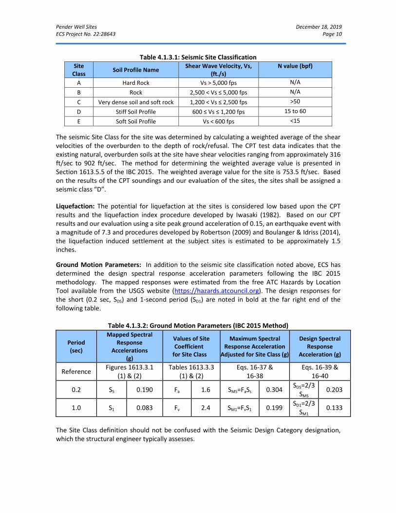
Pender Well Sites December 18, 2019 ECS Project No. 22:28643 Page 10
Table 4.1.3.1: Seismic Site Classification Site
Class Soil Profile Name
Shear Wave Velocity, Vs, (ft./s)
N value (bpf)
A Hard Rock Vs > 5,000 fps N/A
B Rock 2,500 < Vs ≤ 5,000 fps N/A
C Very dense soil and soft rock 1,200 < Vs ≤ 2,500 fps >50
D Stiff Soil Profile 600 ≤ Vs ≤ 1,200 fps 15 to 60
E Soft Soil Profile Vs < 600 fps <15
The seismic Site Class for the site was determined by calculating a weighted average of the shear velocities of the overburden to the depth of rock/refusal. The CPT test data indicates that the existing natural, overburden soils at the site have shear velocities ranging from approximately 316 ft/sec to 902 ft/sec. The method for determining the weighted average value is presented in Section 1613.5.5 of the IBC 2015. The weighted average value for the site is 753.5 ft/sec. Based on the results of the CPT soundings and our evaluation of the sites, the sites shall be assigned a seismic class “D”.
Liquefaction: The potential for liquefaction at the sites is considered low based upon the CPT results and the liquefaction index procedure developed by Iwasaki (1982). Based on our CPT results and our evaluation using a site peak ground acceleration of 0.15, an earthquake event with a magnitude of 7.3 and procedures developed by Robertson (2009) and Boulanger & Idriss (2014), the liquefaction induced settlement at the subject sites is estimated to be approximately 1.5 inches.
Ground Motion Parameters: In addition to the seismic site classification noted above, ECS has determined the design spectral response acceleration parameters following the IBC 2015 methodology. The mapped responses were estimated from the free ATC Hazards by Location Tool available from the USGS website (https://hazards.atcouncil.org). The design responses for the short (0.2 sec, SDS) and 1-second period (SD1) are noted in bold at the far right end of the following table.
Table 4.1.3.2: Ground Motion Parameters (IBC 2015 Method)
Period (sec)
Mapped Spectral Response
Accelerations (g)
Values of Site Coefficient
for Site Class
Maximum Spectral Response Acceleration
Adjusted for Site Class (g)
Design Spectral Response
Acceleration (g)
Reference Figures 1613.3.1
(1) & (2) Tables 1613.3.3
(1) & (2) Eqs. 16-37 &
16-38 Eqs. 16-39 &
16-40
0.2 SS 0.190 Fa 1.6 SMS=FaSs 0.304 SDS=2/3
SMS 0.203
1.0 S1 0.083 Fv 2.4 SM1=FvS1 0.199 SD1=2/3
SM1 0.133
The Site Class definition should not be confused with the Seismic Design Category designation, which the structural engineer typically assesses.

Pender Well Sites December 18, 2019 ECS Project No. 22:28643 Page 11
4.2 SITE DESIGN CONSIDERATIONS
4.2.1 Pavement Sections Subgrade Characteristics: Based on the results of our soundings, it appears that the soils that will likely be exposed as pavement subgrades consisting of approved structural fill. Based on the results of the soundings, a CBR value of 10 has been selected to model the in place subgrade soils. The pavement design assumes subgrades consist of suitable materials evaluated by ECS and placed and compacted to at least 98 percent of the maximum dry density as determined by the Standard Proctor test (ASTM D 698) in accordance with the project specifications. Design Considerations: For the design and construction of exterior pavements, the subgrades should be prepared in strict accordance with the recommendations in the “Subgrade Preparation” and “Engineered Fill Placement” sections of this report. An important consideration with the design and construction of pavements is surface and subsurface drainage. Where standing water develops, either on the pavement surface or within the base course layer, softening of the subgrade and other problems related to the deterioration of the pavement can be expected. Furthermore, good drainage should reduce the possibility of the subgrade materials becoming saturated during the normal service period of the pavement. Anticipated traffic conditions were not provided to ECS. However, based on our experience on similar projects, the following flexible pavement sections may be utilized: Light Duty: 2” surface mix asphalt overlying 6” of compacted stone base. Heavy Duty: 3” surface mix asphalt overlying 6” compacted stone base. The following rigid pavement sections may be utilized: Light Duty: 5” 4,000 psi compressive strength concrete overlying 4” of compacted stone base. Heavy Duty: 6” 4,000 psi compressive strength concrete overlying 4” of compacted stone base. Aggregate base course materials beneath pavements should be compacted to at least 98 percent of their Modified Proctor maximum dry density (ASTM D 1557). Regardless of the section and type of construction utilized, saturation of the subgrade materials and asphalt pavement areas results in a softening of the subgrade material and shortened life span for the pavement. Therefore, we recommend that both the surface and subsurface materials for the pavement be properly graded to enhance surface and subgrade drainage. By quickly removing surface and subsurface water, softening of the subgrade can be reduced and the performance of the parking area can be improved. Site preparation for the pavement areas should be similar to that for the building areas including stripping, proofrolling, and the placement of compacted structural fill.

Pender Well Sites December 18, 2019 ECS Project No. 22:28643 Page 12
Please note that large, front-loading trash dumpsters frequently impose concentrated front-wheel loads on pavements during loading. This type of loading typically results in rutting of bituminous pavements and ultimately pavement failures and costly repairs. Concrete pavements should be properly jointed and reinforced as needed to help reduce the potential for cracking and to permit proper load transfer. Weather Restrictions: In this region, asphalt plants may close during the months of December, January, and/or February if particularly cold weather conditions prevail. However, this can change based on year to year temperature fluctuations. Daily temperatures from December to February will often stay below 40°F, limiting the days that asphalt placement can occur.
Pender Well Sites December 18, 2019 ECS Project No. 22:28643 Page 13
5.0 SITE CONSTRUCTION RECOMMENDATIONS
5.1 SUBGRADE PREPARATION
5.1.1 Stripping and Grubbing The subgrade preparation should consist of stripping vegetation, rootmat, topsoil, existing fill, foundations, and utilities, and any other soft or unsuitable materials from the 10-foot expanded building and 5-foot expanded pavement limits. The sounding on the RW4 site encountered minimal amounts of topsoil. ECS should be called to verify that topsoil, roots, and unsuitable surficial materials have been removed prior to the placement of structural fill or construction of structures. 5.1.2 Proofrolling The natural geology of the sites has been modified in the past; therefore potential unsuitable material might be present throughout the sites. After removing unsuitable surface materials, cutting to the proposed grade, and prior to the placement of any structural fill or other construction materials, the exposed subgrade should be examined by the geotechnical engineer or authorized representative. The exposed subgrade should be proofrolled with previously approved construction equipment having a minimum axle load of 10 tons (e.g. fully loaded tandem-axle dump truck). The areas subject to proofrolling should be traversed by the equipment in two perpendicular (orthogonal) directions with overlapping passes of the vehicle under the observation of the geotechnical engineer or authorized representative. This procedure is intended to assist in identifying any localized yielding materials. In the event that unstable or “pumping” subgrade is identified by the proofrolling, those areas should be marked for repair prior to the placement of any subsequent structural fill or other construction materials. Methods of repair of unstable subgrade, such as undercutting or moisture conditioning, should be discussed with the geotechnical engineer to determine the appropriate procedure with regard to the existing conditions causing the instability. A test pit(s) may be excavated to explore the shallow subsurface materials in the area of the instability to help in determined the cause of the observed unstable materials and to assist in the evaluation of the appropriate remedial action to stabilize the subgrade.
5.2 EARTHWORK OPERATIONS
5.2.1 Structural Fill Materials Product Submittals: Prior to placement of structural fill, representative bulk samples (about 50 pounds) of on-site and off-site borrow should be submitted to ECS for laboratory testing, which will include Atterberg limits, natural moisture content, grain-size distribution, and moisture-density relationships for compaction. Import materials should be tested prior to being hauled to the site to determine if they meet project specifications.
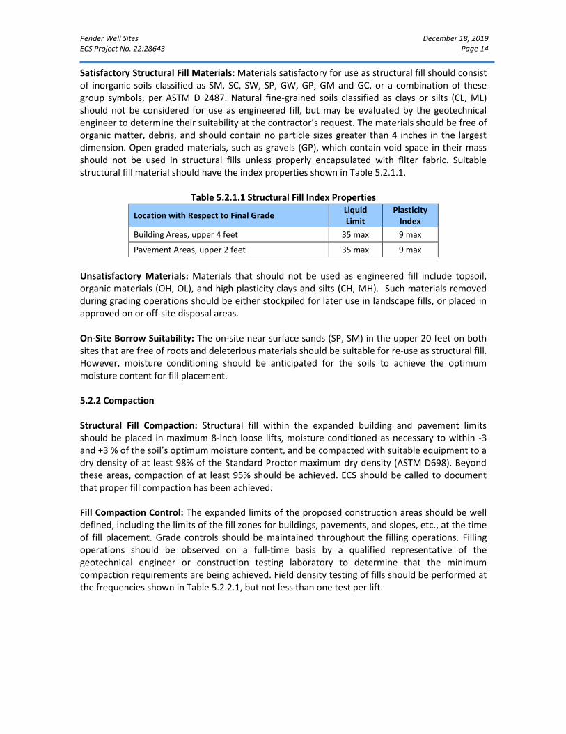
Pender Well Sites December 18, 2019 ECS Project No. 22:28643 Page 14
Satisfactory Structural Fill Materials: Materials satisfactory for use as structural fill should consist of inorganic soils classified as SM, SC, SW, SP, GW, GP, GM and GC, or a combination of these group symbols, per ASTM D 2487. Natural fine-grained soils classified as clays or silts (CL, ML) should not be considered for use as engineered fill, but may be evaluated by the geotechnical engineer to determine their suitability at the contractor’s request. The materials should be free of organic matter, debris, and should contain no particle sizes greater than 4 inches in the largest dimension. Open graded materials, such as gravels (GP), which contain void space in their mass should not be used in structural fills unless properly encapsulated with filter fabric. Suitable structural fill material should have the index properties shown in Table 5.2.1.1.
Table 5.2.1.1 Structural Fill Index Properties
Location with Respect to Final Grade Liquid Limit
Plasticity Index
Building Areas, upper 4 feet 35 max 9 max
Pavement Areas, upper 2 feet 35 max 9 max
Unsatisfactory Materials: Materials that should not be used as engineered fill include topsoil, organic materials (OH, OL), and high plasticity clays and silts (CH, MH). Such materials removed during grading operations should be either stockpiled for later use in landscape fills, or placed in approved on or off-site disposal areas. On-Site Borrow Suitability: The on-site near surface sands (SP, SM) in the upper 20 feet on both sites that are free of roots and deleterious materials should be suitable for re-use as structural fill. However, moisture conditioning should be anticipated for the soils to achieve the optimum moisture content for fill placement. 5.2.2 Compaction Structural Fill Compaction: Structural fill within the expanded building and pavement limits should be placed in maximum 8-inch loose lifts, moisture conditioned as necessary to within -3 and +3 % of the soil’s optimum moisture content, and be compacted with suitable equipment to a dry density of at least 98% of the Standard Proctor maximum dry density (ASTM D698). Beyond these areas, compaction of at least 95% should be achieved. ECS should be called to document that proper fill compaction has been achieved. Fill Compaction Control: The expanded limits of the proposed construction areas should be well defined, including the limits of the fill zones for buildings, pavements, and slopes, etc., at the time of fill placement. Grade controls should be maintained throughout the filling operations. Filling operations should be observed on a full-time basis by a qualified representative of the geotechnical engineer or construction testing laboratory to determine that the minimum compaction requirements are being achieved. Field density testing of fills should be performed at the frequencies shown in Table 5.2.2.1, but not less than one test per lift.
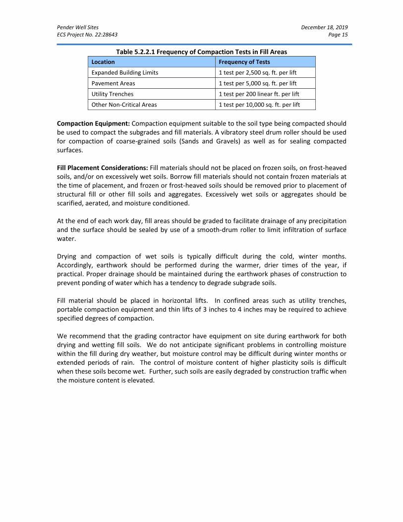
Pender Well Sites December 18, 2019 ECS Project No. 22:28643 Page 15
Table 5.2.2.1 Frequency of Compaction Tests in Fill Areas
Location Frequency of Tests
Expanded Building Limits 1 test per 2,500 sq. ft. per lift
Pavement Areas 1 test per 5,000 sq. ft. per lift
Utility Trenches 1 test per 200 linear ft. per lift
Other Non-Critical Areas 1 test per 10,000 sq. ft. per lift
Compaction Equipment: Compaction equipment suitable to the soil type being compacted should be used to compact the subgrades and fill materials. A vibratory steel drum roller should be used for compaction of coarse-grained soils (Sands and Gravels) as well as for sealing compacted surfaces. Fill Placement Considerations: Fill materials should not be placed on frozen soils, on frost-heaved soils, and/or on excessively wet soils. Borrow fill materials should not contain frozen materials at the time of placement, and frozen or frost-heaved soils should be removed prior to placement of structural fill or other fill soils and aggregates. Excessively wet soils or aggregates should be scarified, aerated, and moisture conditioned.
At the end of each work day, fill areas should be graded to facilitate drainage of any precipitation and the surface should be sealed by use of a smooth-drum roller to limit infiltration of surface water. Drying and compaction of wet soils is typically difficult during the cold, winter months. Accordingly, earthwork should be performed during the warmer, drier times of the year, if practical. Proper drainage should be maintained during the earthwork phases of construction to prevent ponding of water which has a tendency to degrade subgrade soils. Fill material should be placed in horizontal lifts. In confined areas such as utility trenches, portable compaction equipment and thin lifts of 3 inches to 4 inches may be required to achieve specified degrees of compaction. We recommend that the grading contractor have equipment on site during earthwork for both drying and wetting fill soils. We do not anticipate significant problems in controlling moisture within the fill during dry weather, but moisture control may be difficult during winter months or extended periods of rain. The control of moisture content of higher plasticity soils is difficult when these soils become wet. Further, such soils are easily degraded by construction traffic when the moisture content is elevated.
Pender Well Sites December 18, 2019 ECS Project No. 22:28643 Page 16
5.3 FOUNDATION OBSERVATIONS
Protection of Foundation Excavations: Exposure to the environment may weaken the soils at the footing bearing level if the foundation excavations remain open for too long a time. Therefore, foundation concrete should be placed the same day that excavations are made. If the bearing soils are softened by surface water intrusion or exposure, the softened soils must be removed from the foundation excavation bottom immediately prior to placement of concrete. If the excavation must remain open overnight, or if rainfall becomes imminent while the bearing soils are exposed, a 1 to 3-inch thick “mud mat” of “lean” concrete should be placed on the bearing soils before the placement of reinforcing steel. Footing Subgrade Observations: It will be important to have the geotechnical engineer of record observe the foundation subgrade prior to placing foundation concrete, to confirm the bearing soils are what was anticipated. Soft or unsuitable soils observed at the footing bearing elevations should be undercut and removed. Any undercut should be backfilled with approved structural fill or DOT size No. 57 stone up to the original design bottom of footing elevation; the original footing shall be constructed on top of the approved fill. The depth and lateral extent of the undercut should be determined in the field during undercutting operation. An ECS representative must be on site during the undercut and backfill of the areas in order to provide a report stating that the repairs were in accordance with our recommendations. Slab Subgrade Verification: A representative of ECS should be called to observe exposed subgrades within the expanded building limits prior to structural fill placement to confirm that adequate subgrade preparation has been achieved. Proofrolling using a drum roller or loaded dump truck should be performed in their presence at that time. Once subgrades have been prepared to the satisfaction of ECS, subgrades should be properly compacted and new structural fill can be placed. Structural fill should be moisture conditioned to within -3/+3 percentage points of optimum moisture content then be compacted to the required density. If there will be a significant time lag between the site grading work and final grading of concrete slab areas prior to the placement of the subbase stone and concrete, a representative of ECS should be called to verify the condition of the prepared subgrade. Prior to final slab construction, the subgrade may require scarification, moisture conditioning, and re-compaction to restore stable conditions.
5.4 UTILITY INSTALLATIONS
Utility Subgrades: The soils encountered in our exploration are expected to be generally suitable for support of utility pipes. The pipe subgrade should be observed and probed for stability by ECS to evaluate the suitability of the materials encountered. Any loose or unsuitable materials encountered at the utility pipe subgrade elevation should be removed and replaced with suitable compacted structural fill or pipe bedding material.
Pender Well Sites December 18, 2019 ECS Project No. 22:28643 Page 17
Utility Backfilling: Granular bedding material, if required, should be at least 4 inches thick, but not less than that specified by the project drawings and specifications. Fill placed for support of the utilities, as well as backfill over the utilities, should satisfy the requirements for structural fill given in this report. Compacted backfill should be free of topsoil, roots, ice, or any other material designated by ECS as unsuitable. The backfill should be moisture conditioned, placed, and compacted in accordance with the recommendations of this report. Utility Excavation Dewatering: It is likely that groundwater will be encountered by utility excavations which extend more than 3 feet below existing grades on well site RW4. It is expected that removal of water which seeps into excavations could be accomplished by pumping from sumps excavated in the trench bottom and which are backfilled with DOT size No. 57 stone or open graded bedding material. Should water conditions beyond the capability of sump pumping be encountered, the contractor should submit a Dewatering Plan in accordance with project specifications.
5.5 GENERAL CONSTRUCTION CONSIDERATIONS
Moisture Conditioning: During the cooler and wetter periods of the year, delays and additional costs should be anticipated. At these times, reduction of soil moisture may need to be accomplished by mechanical manipulation in order to lower moisture contents to levels appropriate for compaction. Alternatively, during the drier times of the year, such as the summer months, moisture may need to be added to the soil to provide adequate moisture for successful compaction according to the project requirements. Subgrade Protection: Measures should also be taken to limit site disturbance, especially from rubber-tired heavy construction equipment, and to control and remove surface water from development areas, including structural and pavement areas. Surface Drainage: Surface drainage conditions should be properly maintained. Surface water should be directed away from the construction area, and the work area should be sloped away from the construction area at a gradient of 1 percent or greater to reduce the potential of ponding water and the subsequent saturation of the surface soils. At the end of each work day, the subgrade soils should be sealed by rolling the surface with a smooth drum roller to minimize infiltration of surface water.
Pender Well Sites December 18, 2019 ECS Project No. 22:28643 Page 18
Excavation Safety: Cuts or excavations associated with utility excavations may require forming or bracing, slope flattening, or other physical measures to control sloughing and/or prevent slope failures. Contractors should comply with applicable OSHA regulations to confirm that adequate protection of the excavations and trench walls is provided. The contractor is solely responsible for designing and constructing stable, temporary excavations and slopes and should shore, slope, or bench the sides of the excavations and slopes as required to maintain stability of both the excavation sides and bottom. The contractor’s responsible person, as defined in 29 CFR Part 1926, should evaluate the soil exposed in the excavations as part of the contractor’s safety procedures. In no case should slope height, slope inclination, or excavation depth, including utility trench excavation depth, exceed those specified in local, state, and federal safety regulations. ECS is providing this information solely as a service to our client. ECS is not assuming responsibility for construction site safety or the contractor’s activities; such responsibility is not being implied and should not be inferred. Excavation Considerations: Based on the results of the borings, we expect that the natural Coastal Plain soils encountered on these sites can be excavated with conventional earth moving equipment such as loaders, bulldozers, rubber tired backhoes, etc. The site soils are OSHA Type C soils for the purpose of temporary excavation support. Excavations should be constructed in compliance with current OSHA standards for excavation and trenching safety. Excavations should be observed by a “competent person,” as defined by OSHA, who should evaluate the specific soil type and other conditions, which may control the excavation side slopes or the need for shoring or bracing. Regardless, site safety shall be the sole responsibility of the contractor and their subcontractors. Exposed earth slopes shall be protected during periods of inclement weather. Erosion Control: The surface soils may be erodible. Therefore, the contractor should provide and maintain good site drainage during earthwork operations to maintain the integrity of the surface soils. Erosion and sedimentation controls should be in accordance with sound engineering practices and local requirements.

Pender Well Sites December 18, 2019 ECS Project No. 22:28643 Page 19
6.0 CLOSING
ECS has prepared this report of findings, evaluations, and recommendations to guide geotechnical-related design and construction aspects of the project. The description of the proposed project is based on information provided to ECS by Mr. Tony Boahn of McKim & Creed. If any of this information is inaccurate, either due to our interpretation of the documents provided or site or design changes that may occur later, ECS should be contacted immediately so that we can review the report in light of the changes and provide additional or alternate recommendations as may be required to reflect the proposed construction. We recommend that ECS review the project’s plans and specifications pertaining to our work so that we may ascertain consistency of those plans/specifications with the intent of the geotechnical report. Field observations, monitoring, and quality assurance testing during earthwork and foundation installation are an extension of and integral to the geotechnical design recommendation. We recommend that the owner retain these quality assurance services and that ECS be allowed to continue our involvement throughout these critical phases of construction to provide general consultation as issues arise. ECS is not responsible for the conclusions, opinions, or recommendations of others based on the data in this report.

APPENDIX A – Drawings & Reports
Site Location Diagrams Exploration Location Diagrams
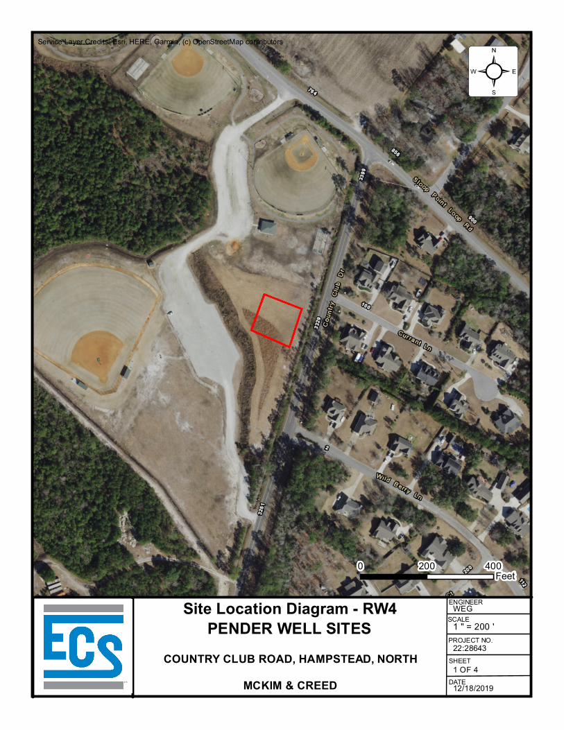
Service Layer Credits: Esri, HERE, Garmin, (c) OpenStreetMap contributors
²
MCKIM & CREED
PENDER WELL SITESCOUNTRY CLUB ROAD, HAMPSTEAD, NORTH
Site Location Diagram - RW4
0 400200Feet
12/18/2019
ENGINEER
SCALE
22:28643
1 OF 4
PROJECT NO.
SHEET
DATE
WEG1 " = 200 '
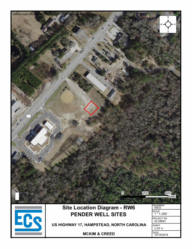
Service Layer Credits: Esri, HERE, Garmin, (c) OpenStreetMap contributors
²
MCKIM & CREED
PENDER WELL SITESUS HIGHWAY 17, HAMPSTEAD, NORTH CAROLINA
Site Location Diagram - RW6
0 400200Feet
12/18/2019
ENGINEER
SCALE
22:28643
2 OF 4
PROJECT NO.
SHEET
DATE
WEG1 " = 200 '
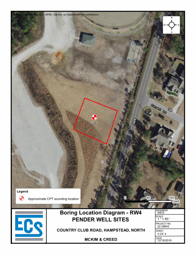
Service Layer Credits: Esri, HERE, Garmin, (c) OpenStreetMap contributors
²
LegendApproximate CPT sounding location
MCKIM & CREED
PENDER WELL SITESCOUNTRY CLUB ROAD, HAMPSTEAD, NORTH
Boring Location Diagram - RW4
0 16080Feet
12/18/2019
ENGINEER
SCALE
22:28643
3 OF 4
PROJECT NO.
SHEET
DATE
WEG1 " = 80 '
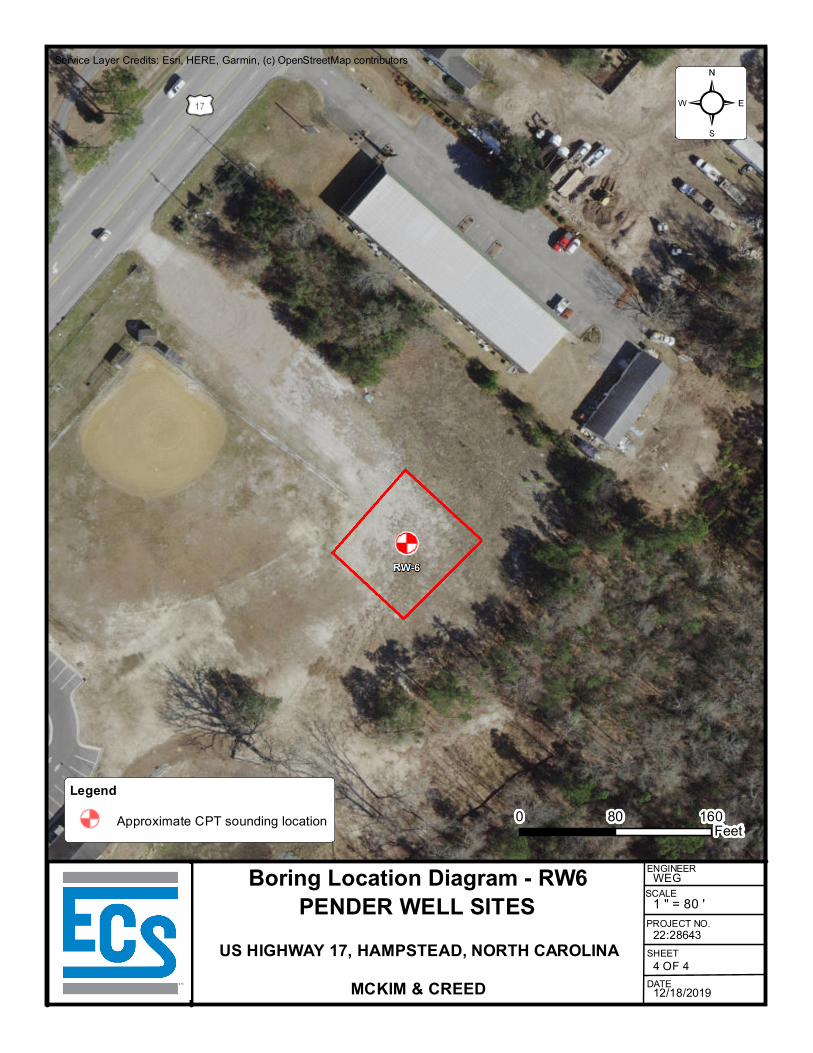
Service Layer Credits: Esri, HERE, Garmin, (c) OpenStreetMap contributors
²
LegendApproximate CPT sounding location
MCKIM & CREED
PENDER WELL SITESUS HIGHWAY 17, HAMPSTEAD, NORTH CAROLINA
Boring Location Diagram - RW6
0 16080Feet
12/18/2019
ENGINEER
SCALE
22:28643
4 OF 4
PROJECT NO.
SHEET
DATE
WEG1 " = 80 '

APPENDIX B – Field Operations
Reference Notes for Sounding Logs CPT Sounding Logs (RW4 and RW6)
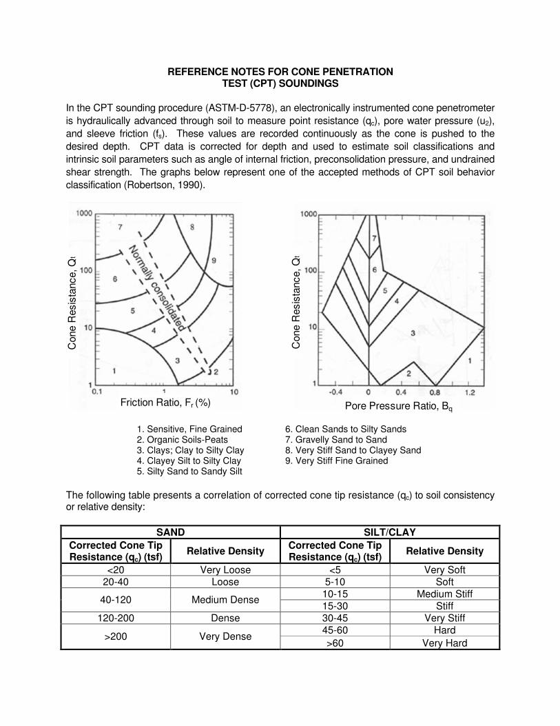
REFERENCE NOTES FOR CONE PENETRATION TEST (CPT) SOUNDINGS
In the CPT sounding procedure (ASTM-D-5778), an electronically instrumented cone penetrometer
is hydraulically advanced through soil to measure point resistance (qc), pore water pressure (u2),
and sleeve friction (fs). These values are recorded continuously as the cone is pushed to the
desired depth. CPT data is corrected for depth and used to estimate soil classifications and
intrinsic soil parameters such as angle of internal friction, preconsolidation pressure, and undrained
shear strength. The graphs below represent one of the accepted methods of CPT soil behavior
classification (Robertson, 1990).
1. Sensitive, Fine Grained 6. Clean Sands to Silty Sands 2. Organic Soils-Peats 7. Gravelly Sand to Sand 3. Clays; Clay to Silty Clay 8. Very Stiff Sand to Clayey Sand 4. Clayey Silt to Silty Clay 9. Very Stiff Fine Grained 5. Silty Sand to Sandy Silt
The following table presents a correlation of corrected cone tip resistance (qc) to soil consistency or relative density:
SAND SILT/CLAY
Corrected Cone Tip Resistance (qc) (tsf)
Relative Density Corrected Cone Tip Resistance (qc) (tsf)
Relative Density
<20 Very Loose <5 Very Soft 20-40 Loose 5-10 Soft
10-15 Medium Stiff 40-120 Medium Dense
15-30 Stiff 120-200 Dense 30-45 Very Stiff
45-60 Hard >200 Very Dense
>60 Very Hard
Pore Pressure Ratio, Bq
Cone R
esis
tance, Q
t
Cone R
esis
tance, Q
t
Friction Ratio, Fr (%)
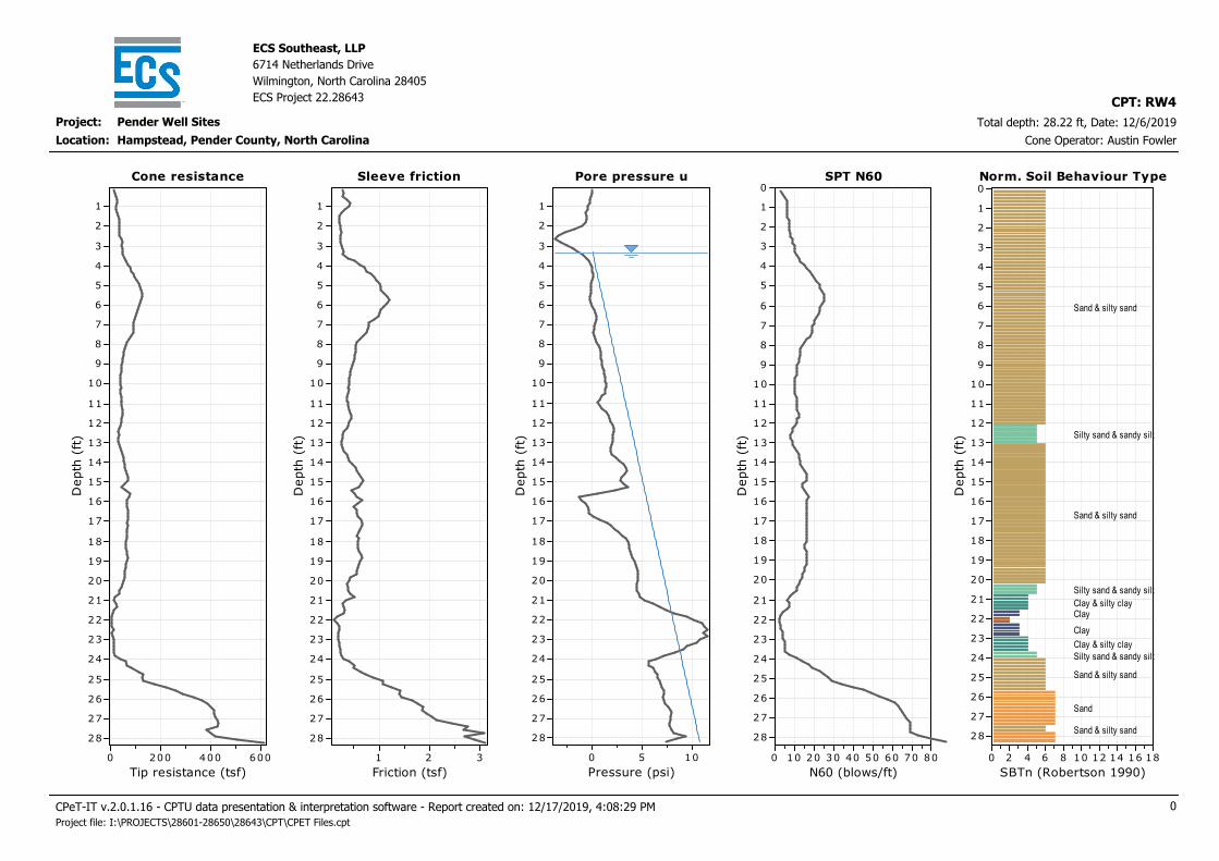
Project: Pender Well Sites
ECS Southeast, LLP
6714 Netherlands Drive
Wilmington, North Carolina 28405
ECS Project 22.28643
Total depth: 28.22 ft, Date: 12/6/2019
Hampstead, Pender County, North Carolina Cone Operator: Austin Fowler
CPT: RW4
Location:
Cone resistance
Tip resistance (tsf)
6004002000
Depth (ft)
28
27
26
25
24
23
22
21
20
19
18
17
16
15
14
13
12
11
10
9
8
7
6
5
4
3
2
1
Cone resistance Sleeve friction
Friction (tsf)
321
Depth (ft)
28
27
26
25
24
23
22
21
20
19
18
17
16
15
14
13
12
11
10
9
8
7
6
5
4
3
2
1
Sleeve friction Pore pressure u
Pressure (psi)
1050
Depth (ft)
28
27
26
25
24
23
22
21
20
19
18
17
16
15
14
13
12
11
10
9
8
7
6
5
4
3
2
1
Pore pressure u SPT N60
N60 (blows/ft)
80706050403020100
Depth (ft)
28
27
26
25
24
23
22
21
20
19
18
17
16
15
14
13
12
11
10
9
8
7
6
5
4
3
2
1
0SPT N60 Norm. Soil Behaviour Type
SBTn (Robertson 1990)
181614121086420
Depth (ft)
28
27
26
25
24
23
22
21
20
19
18
17
16
15
14
13
12
11
10
9
8
7
6
5
4
3
2
1
0Norm. Soil Behaviour Type
Sand & silty sand
Silty sand & sandy silt
Sand & silty sand
Silty sand & sandy silt
Clay & silty clayClay
Clay
Clay & silty clay
Silty sand & sandy silt
Sand & silty sand
Sand
Sand & silty sand
CPeT-IT v.2.0.1.16 - CPTU data presentation & interpretation software - Report created on: 12/17/2019, 4:08:29 PM 0
Project file: I:\PROJECTS\28601-28650\28643\CPT\CPET Files.cpt
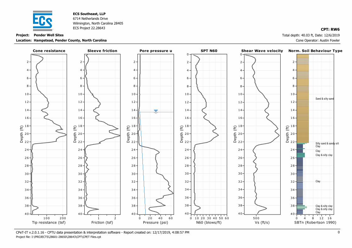
Project: Pender Well Sites
ECS Southeast, LLP
6714 Netherlands Drive
Wilmington, North Carolina 28405
ECS Project 22.28643
Total depth: 40.03 ft, Date: 12/6/2019
Hampstead, Pender County, North Carolina Cone Operator: Austin Fowler
CPT: RW6
Location:
Cone resistance
Tip resistance (tsf)
200100
Depth
(ft)
40
38
36
34
32
30
28
26
24
22
20
18
16
14
12
10
8
6
4
2
Cone resistance Sleeve friction
Friction (tsf)
21
Depth
(ft)
40
38
36
34
32
30
28
26
24
22
20
18
16
14
12
10
8
6
4
2
Sleeve friction Pore pressure u
Pressure (psi)
6040200
Depth
(ft)
40
38
36
34
32
30
28
26
24
22
20
18
16
14
12
10
8
6
4
2
Pore pressure u SPT N60
N60 (blows/ft)
6050403020100
Depth
(ft)
40
38
36
34
32
30
28
26
24
22
20
18
16
14
12
10
8
6
4
2
0SPT N60 Shear Wave velocity
Vs (ft/s)
500
Depth
(ft)
40
38
36
34
32
30
28
26
24
22
20
18
16
14
12
10
8
6
4
2
0Shear Wave velocity Norm. Soil Behaviour Type
SBTn (Robertson 1990)
1612840
Depth
(ft)
40
38
36
34
32
30
28
26
24
22
20
18
16
14
12
10
8
6
4
2
Norm. Soil Behaviour Type
Sand & silty sand
Silty sand & sandy siltClay
Clay
Clay & silty clay
Clay
Clay & silty clayClay & silty clayClay
CPeT-IT v.2.0.1.16 - CPTU data presentation & interpretation software - Report created on: 12/17/2019, 4:08:57 PM 0
Project file: I:\PROJECTS\28601-28650\28643\CPT\CPET Files.cpt

APPENDIX C – Supplemental Report Documents
GBA Document

Geotechnical-Engineering ReportImportant Information about This
Subsurface problems are a principal cause of construction delays, cost overruns, claims, and disputes.
While you cannot eliminate all such risks, you can manage them. The following information is provided to help.
The Geoprofessional Business Association (GBA) has prepared this advisory to help you – assumedly a client representative – interpret and apply this geotechnical-engineering report as effectively as possible. In that way, clients can benefit from a lowered exposure to the subsurface problems that, for decades, have been a principal cause of construction delays, cost overruns, claims, and disputes. If you have questions or want more information about any of the issues discussed below, contact your GBA-member geotechnical engineer. Active involvement in the Geoprofessional Business Association exposes geotechnical engineers to a wide array of risk-confrontation techniques that can be of genuine benefit for everyone involved with a construction project.
Geotechnical-Engineering Services Are Performed for Specific Purposes, Persons, and ProjectsGeotechnical engineers structure their services to meet the specific needs of their clients. A geotechnical-engineering study conducted for a given civil engineer will not likely meet the needs of a civil-works constructor or even a different civil engineer. Because each geotechnical-engineering study is unique, each geotechnical-engineering report is unique, prepared solely for the client. Those who rely on a geotechnical-engineering report prepared for a different client can be seriously misled. No one except authorized client representatives should rely on this geotechnical-engineering report without first conferring with the geotechnical engineer who prepared it. And no one – not even you – should apply this report for any purpose or project except the one originally contemplated.
Read this Report in FullCostly problems have occurred because those relying on a geotechnical-engineering report did not read it in its entirety. Do not rely on an executive summary. Do not read selected elements only. Read this report in full.
You Need to Inform Your Geotechnical Engineer about ChangeYour geotechnical engineer considered unique, project-specific factors when designing the study behind this report and developing the confirmation-dependent recommendations the report conveys. A few typical factors include: • the client’s goals, objectives, budget, schedule, and risk-management preferences; • the general nature of the structure involved, its size, configuration, and performance criteria; • the structure’s location and orientation on the site; and • other planned or existing site improvements, such as retaining walls, access roads, parking lots, and underground utilities.
Typical changes that could erode the reliability of this report include those that affect:• the site’s size or shape;• the function of the proposed structure, as when it’s changed from a parking garage to an office building, or from a light-industrial plant to a refrigerated warehouse;• the elevation, configuration, location, orientation, or weight of the proposed structure;• the composition of the design team; or• project ownership.
As a general rule, always inform your geotechnical engineer of project changes – even minor ones – and request an assessment of their impact. The geotechnical engineer who prepared this report cannot accept responsibility or liability for problems that arise because the geotechnical engineer was not informed about developments the engineer otherwise would have considered.
This Report May Not Be ReliableDo not rely on this report if your geotechnical engineer prepared it:• for a different client;• for a different project;• for a different site (that may or may not include all or a portion of the original site); or • before important events occurred at the site or adjacent to it; e.g., man-made events like construction or environmental remediation, or natural events like floods, droughts, earthquakes, or groundwater fluctuations.
Note, too, that it could be unwise to rely on a geotechnical-engineering report whose reliability may have been affected by the passage of time, because of factors like changed subsurface conditions; new or modified codes, standards, or regulations; or new techniques or tools. If your geotechnical engineer has not indicated an “apply-by” date on the report, ask what it should be, and, in general, if you are the least bit uncertain about the continued reliability of this report, contact your geotechnical engineer before applying it. A minor amount of additional testing or analysis – if any is required at all – could prevent major problems.
Most of the “Findings” Related in This Report Are Professional OpinionsBefore construction begins, geotechnical engineers explore a site’s subsurface through various sampling and testing procedures. Geotechnical engineers can observe actual subsurface conditions only at those specific locations where sampling and testing were performed. The data derived from that sampling and testing were reviewed by your geotechnical engineer, who then applied professional judgment to form opinions about subsurface conditions throughout the site. Actual sitewide-subsurface conditions may differ – maybe significantly – from those indicated in this report. Confront that risk by retaining your geotechnical engineer to serve on the design team from project start to project finish, so the individual can provide informed guidance quickly, whenever needed.
This Report’s Recommendations Are Confirmation-DependentThe recommendations included in this report – including any options or alternatives – are confirmation-dependent. In other words, they are not final, because the geotechnical engineer who developed them relied heavily on judgment and opinion to do so. Your geotechnical engineer can finalize the recommendations only after observing actual subsurface conditions revealed during construction. If through observation your geotechnical engineer confirms that the conditions assumed to exist actually do exist, the recommendations can be relied upon, assuming no other changes have occurred. The geotechnical engineer who prepared this report cannot assume responsibility or liability for confirmation-dependent recommendations if you fail to retain that engineer to perform construction observation.
This Report Could Be MisinterpretedOther design professionals’ misinterpretation of geotechnical-engineering reports has resulted in costly problems. Confront that risk by having your geotechnical engineer serve as a full-time member of the design team, to: • confer with other design-team members, • help develop specifications, • review pertinent elements of other design professionals’ plans and specifications, and • be on hand quickly whenever geotechnical-engineering guidance is needed. You should also confront the risk of constructors misinterpreting this report. Do so by retaining your geotechnical engineer to participate in prebid and preconstruction conferences and to perform construction observation.
Give Constructors a Complete Report and GuidanceSome owners and design professionals mistakenly believe they can shift unanticipated-subsurface-conditions liability to constructors by limiting the information they provide for bid preparation. To help prevent the costly, contentious problems this practice has caused, include the complete geotechnical-engineering report, along with any attachments or appendices, with your contract documents, but be certain to note conspicuously that you’ve included the material for informational purposes only. To avoid misunderstanding, you may also want to note that “informational purposes” means constructors have no right to rely on the interpretations, opinions, conclusions, or recommendations in the report, but they may rely on the factual data relative to the specific times, locations, and depths/elevations referenced. Be certain that constructors know they may learn about specific project requirements, including options selected from the report, only from the design drawings and specifications. Remind constructors that they may
perform their own studies if they want to, and be sure to allow enough time to permit them to do so. Only then might you be in a position to give constructors the information available to you, while requiring them to at least share some of the financial responsibilities stemming from unanticipated conditions. Conducting prebid and preconstruction conferences can also be valuable in this respect.
Read Responsibility Provisions CloselySome client representatives, design professionals, and constructors do not realize that geotechnical engineering is far less exact than other engineering disciplines. That lack of understanding has nurtured unrealistic expectations that have resulted in disappointments, delays, cost overruns, claims, and disputes. To confront that risk, geotechnical engineers commonly include explanatory provisions in their reports. Sometimes labeled “limitations,” many of these provisions indicate where geotechnical engineers’ responsibilities begin and end, to help others recognize their own responsibilities and risks. Read these provisions closely. Ask questions. Your geotechnical engineer should respond fully and frankly.
Geoenvironmental Concerns Are Not CoveredThe personnel, equipment, and techniques used to perform an environmental study – e.g., a “phase-one” or “phase-two” environmental site assessment – differ significantly from those used to perform a geotechnical-engineering study. For that reason, a geotechnical-engineering report does not usually relate any environmental findings, conclusions, or recommendations; e.g., about the likelihood of encountering underground storage tanks or regulated contaminants. Unanticipated subsurface environmental problems have led to project failures. If you have not yet obtained your own environmental information, ask your geotechnical consultant for risk-management guidance. As a general rule, do not rely on an environmental report prepared for a different client, site, or project, or that is more than six months old.
Obtain Professional Assistance to Deal with Moisture Infiltration and MoldWhile your geotechnical engineer may have addressed groundwater, water infiltration, or similar issues in this report, none of the engineer’s services were designed, conducted, or intended to prevent uncontrolled migration of moisture – including water vapor – from the soil through building slabs and walls and into the building interior, where it can cause mold growth and material-performance deficiencies. Accordingly, proper implementation of the geotechnical engineer’s recommendations will not of itself be sufficient to prevent moisture infiltration. Confront the risk of moisture infiltration by including building-envelope or mold specialists on the design team. Geotechnical engineers are not building-envelope or mold specialists.
Copyright 2016 by Geoprofessional Business Association (GBA). Duplication, reproduction, or copying of this document, in whole or in part, by any means whatsoever, is strictly prohibited, except with GBA’s specific written permission. Excerpting, quoting, or otherwise extracting wording from this document is permitted only with the express written permission of GBA, and only for purposes of scholarly research or book review. Only members of GBA may use this document or its wording as a complement to or as an element of a report of any
kind. Any other firm, individual, or other entity that so uses this document without being a GBA member could be committing negligent
Telephone: 301/565-2733e-mail: [email protected] www.geoprofessional.org