guidelines on safe use of press machines i - DOSH
56
-
Upload
khangminh22 -
Category
Documents
-
view
2 -
download
0
Transcript of guidelines on safe use of press machines i - DOSH


GUIDELINES ON SAFE USE OF PRESS MACHINES I
FOREWORD
Statistics have shown that many accidents occurred due to the use of press machine. Serious upper limb injuries like loss of fingers, hands and even loss of life are among the consequences usually results from accidents caused by trapping between the tools of a power press.
In many accident cases investigated by the Department of Occupational Safety and Health (DOSH), it have found that most of the accident occurred due to the failure of the employer in establishing and providing a safe work system for the use of press machine. These include lack of understanding on how the machine works, not understanding the risk taken and also lack of control measure to minimize the risk.
Thus, in order to overcome these problems, DOSH in collaboration with the industry and MyJICA (The JICA Alumni Society of Malaysia) have developed a guideline on safe use of power press to provide practical guidance and advice to ensure safe use of power press. This guideline will guide the user on basic principle of machine safety, risk assessment and important of safety features that must be installed to ensure high level of protection of user and other exposed persons against the risk.
I would like to request to all employers who have responsibility, directly or indirectly, for power presses and their provision and use, to adapt this guideline as a source of reference in operating and maintaining power presses and also to fulfill one of their general duties under the Occupational Safety and Health Act 1994 and regulations made under this Act. Industries are welcome to give any comment and recommendation to DOSH at any time so that improvements can be made to this guideline.
Director GeneralDepartment of Occupational Safety and HealthMalaysia
2015

II
ACKNOWLEDGEMENTS
The Department of Occupational Safety and Health Malaysia wishes to thank and acknowledge the following organizations and individuals for their most valuable contributions during drafting the guidelines:
REpRESENTATivE ORGANiSATiONS1. En. Shairul Baki bin Mohamad Saleh Leading Platform Sdn Bhd2. En. Mohd Fadglullah bin Ibrahim Leading Platform Sdn Bhd3. En. Adnan bin Abdul Kadir PHN Industry Sdn Bhd4. En. Mustafa Kamal bin Yaakub Perodua Manufacturing Sdn Bhd5. Pn. Hasni binti Hashim Perodua Manufacturing Sdn Bhd6. En. Mazlan bin Mohamad Perusahaan Otomobil Nasional SB7. En. Leon Lai Malaysia Automotive Institute8. En. Lee Kin Fen Li Chin (S.E.A) Sdn Bhd9. En. Soo Woon Fah Li Chin (S.E.A) Sdn Bhd10. En. Fong Kin Choong Li Chin (S.E.A) Sdn Bhd11. Ir. Haji Saiful Azhar bin Mohd Said DOSH12. Pn. Sarimah binti Awang DOSH13. En. Abdul Rahim bin Sabri DOSH14. En. Jason Liew Ee Lung DOSH15. Pn. Jinurah Sintian DOSH16. En. Ramlan bin Kashah DOSH17. En. Zulkifli bin Mohamad DOSH18. Tn. Haji Ismail bin Jalil DOSH

GUIDELINES ON SAFE USE OF PRESS MACHINES III
TABLE OF CONTENTS pAGE
Foreword i
Acknowledgements ii
Table Of Contents iii
part 1 introduction 1
part 2 Objective 1
part 3 Legal provisions 1
part 4 press Machine introduction 2
A. Type Of Press Machine 2
I. Mechanical Press 2
a. Mechanical Press Machine (Clutch & Brake) 3
b. Full Revolution Clutches 3
c. Part Revolution Clutches 4
II. Servo Press 5
III. Hydraulic Press 6
IV. Pneumatic Press 7
B. Press Work Area 7
- Hazards Area 7
- Type Of Accidents 8
C. Electrical Control Systems 9
part 5 press Machines Hazards And Risk Management 10
part 6 Basic Machine Safety 10
- ISO 12100 11
part 7 Safety Features Of press Machines 12
A. Full Revolution Clutch And Brake for Mechanical Press 17
- Restraint Device With Hand Feeding Tool. 17
- Pullback Device 18
B. Part Revolution Clutch And Brake for Mechanical Press, Servo, Pneumatic and Hydraulic Press
18
Feature 1: Operation Selector Switch. 15
Feature 2: Double Push Start Button. 16
Foot Switch Pedal 18
Feature 3: Safety Light Curtain Sensor 20
Feature 4: Safety Movable / Fixed Fence 21

IV
TABLE OF CONTENTS pAGE
Feature 5: Gate Safety Plug (For Robotic Operation) 22
Feature 6: Safety Block 23
Feature 7: Emergency Stop Button. 25
part 8 Safe Operating procedures 26
A. Before Start Working 26
- Importance Of Machine Operation Manual 26
- Function Of Emergency Stop 27
- Importance Of PPE 27
B. Operating Machine 28
C. Maintenance Of Machine 29
part 9 press Machine inspection 31
The Need For Press Machine Inspection 31
- Establishing A Safety Inspection Plan 32
- Providing A Power Press Supervisor 32
- Providing The Content And Method Of Inspection 32
- Setting The Inspection Time Frame 32
- Corrections Based On The Result Of Inspection 33
- Preserving The Result Of Inspection 33
- Matters To Consider Before An Inspection 33
part 10 Checklist For inspection, Operation, Maintenance. 34
A. Safety Inspection & Operation Checklist 34
B. Maintenance Checklist 36
C. Critical Parts Replacement Timing 37
part 11 Safety information’s 38
- Safety Signage 38
- Bolster ‘In and Out’ Area Identification 39
- Safety Board Information (Do’s And Don’ts). 39
part 12 Training On Safe Use Of press Machine 47
- Safety Training Matrix On Press Machine 47
- Training Methods 48
- When Retraining Is Needed 48
part 13. References 48
Appendix A – press Machine Hazards and Risks Management 49

GUIDELINES ON SAFE USE OF PRESS MACHINES 1
Part 1 - INTRODUCTION The transformation of the country’s economic sector from an agriculture-based economy to an industrial-based economy has increased the use of machinery in the manufacturing sector. This has positive and negative impact on workers. Although it can improve productivity, the increased use of machinery also raised the issue of safety of workers. Many reports on industrial accidents attributed the cause of accident to the use of machinery, including the press machine, which is widely used in the steel and automotive industries. This scenario is observed from cases reported to SOCSO and DOSH. Analysis of the report found that the most common type of accidents involved upper limb injuries which include hands and fingers.
Press machines are usually used in the manufacturing sector to produce automotive parts and components, metal furniture, electrical goods such as pots and microwave oven, air conditioning system, brackets for communication systems, gas stove, canned drinks or food, and many others. Amputation or serious injury usually results from accidents caused by trapping between the pinch points (point-of-operation) of a power press. The varied work demands on power presses and the wear to which the guarding mechanisms are subject means that the integrity of the guarding is constantly ‘under threat’. The operation of the press itself pushes main parts such as the clutch and brake to wear and damage over quite short periods of time. This guideline gives advice on precautions that can be taken to ensure the safe use of power presses.
Part 2 - OBJECTIVEThis Guidelines on Safe Use of Press Machines will enable all parties who have the responsibility, directly or indirectly, on power presses and their provision and use which include understanding of hazards and risk managements, safety features, procedures, safety information’s and trainings related to press machines and thus eventually will reduce upper limb injuries.
Part 3 - LEGAL PROVISIONSEvery employer is required under Section 15(2) OSHA 1994 to ensure as far as practicable, the safety, health and welfare at work of his employees. The employers shall ensure that the press machines are properly maintained, have good system of works, safe to be operated and the operators are well trained and supervised.
Similarly, employees are required under Section 24(1) to take reasonable care in terms of the safety of themselves and other persons who may be affected by their actions or omissions in operating the power press. As well as the designers, manufacturers and suppliers also have responsibilities under Section 20(1) to carry out their duty to eliminate or minimizing of any risk to safety or health related to press machine.

2
Part 4 - PRESS MACHINE (INTRODUCTION)
A. TYPE OF PRESS MACHINE.Press machine is a machine tool that changes the shape of a work piece by the application of pressure. Press machine can be classified into 4 types according to the source of energy that create the pressure.
i. Mechanical Press – energy sourced from flywheel rotation energy.ii. Servo Press – energy sourced from geared servo motor.iii. Hydraulic Press – energy sourced from hydraulic power pac.iv. Pneumatic Press –energy sourced from compress air.
I - MECHANICAL PRESSMechanical press or power press is the most commonly used for sheet metal stamping process. Electrical motor with belting is used to spin the flywheel to create rotational energy as shown in figure 1 below. A clutch & brake is used to couple the spinning flywheel to the crankshaft. The crankshaft converts the rotary motion of the flywheel to the downward and upward reciprocating motions of the press ram. The force that creates the pressure to the ram (slide) comes from the flywheel rotational energy.
Figure. 1 Mechanical Press

GUIDELINES ON SAFE USE OF PRESS MACHINES 3
Mechanical press has 3 main assembly units.
• Crown or crankshaft assembly: consist of main motor, flywheel, clutch & brake and crankshaft.
• Slide assembly: consist of ram plate, overload unit and slide adjustment.• Bed assembly: consist of bed plate and cushion unit (optional).
Mechanical press commonly has 2 basic frame shapes.
• C-Frame for small tonnage press machine, below 250 tons. Structure is made from thick plate cut into C shape. Structure is simple and cost cheaper.
• H-Frame for medium and large tonnage, above 300 tons. Crown unit at the top and bed unit at the bottom connected together with 4 units of poles (Upright). Fixed bolster for 500 tons below and moving bolster above 500 tons. Structure is complicated and expensive.
a. MECHANICAL PRESS MACHINE (CLUTCH & BRAKE)
Clutch and Brake is a component in mechanical press machine that make slide move and stop by coupling and decoupling with the rotated flywheel. The basic knowledge on this clutch and brake is necessary to understand the safety system of press machine.
Two different types of clutches are used on mechanical presses, full-revolution clutches and part-revolution clutches.
b. FULL-REVOLUTION CLUTCHES
Mechanism of full-revolution clutch is simpler and cheaper. Full-revolution clutch is design for small tonnage presses for simple and smaller part. Normally small scale industry acquired this kind of press for their operation.
Once the clutch is engaged, it remains engaged until the crankshaft has completed a full cycle. Since the full-revolution clutch makes a complete revolution before it disengages, presses equipped with this type of clutch generally expose a greater hazard after a stroke is initiated. See Figure 2.
Figure 2 Full-Revolution Clutches

4
Figure 3 Show the basic simplified cross section use to explain the operation of full-revolution clutch and brake. Flywheel mounted to the clutch housing and rotates together. The rotation of the clutch housing will move the roller in the cam slot from free condition to pinned condition which rotates the cam together with crank shaft. A trip lug on the roller cage releases the clutch and stopping the shaft. The clutch remains free until the pawl is moved away from the trip lug. The driven shaft is always disengaged at Top Dead Center (TDC) crankshaft position. The trip may be activated manually, mechanically, or electromagnetically.
Figure 3 Simplified Cross Section of Full-revolution clutches
c. PART-REVOLUTION CLUTCHES.
The part-revolution clutch can be disengaged and engaged at any point in the downward and upward slide movement. This type of clutch is for all range of press tonnage from small to large press.
Figure 4 show picture of press using part-revolution clutch and brake. Cross section drawing in the middle shows the location of the clutch and brake unit inside the machine. Drawing on the right shows the clutch and brake unit.
Figure 4 part-Revolution Clutches

GUIDELINES ON SAFE USE OF PRESS MACHINES 5
The basic operation of part-revolution clutches and brake is similar with car engine and it transmission. It is work base on friction force from friction disc to move and stop the slide. The drive motor and flywheel of the press machine is keep rotating regardless clutch and brake engage and disengage. In default condition the press machine is always in brake condition.
Figure 5 show the basic simplified cross section use to explain the operation of part-revolution clutch and brake. The red colour is the rotational part consist of flywheel with it friction disc. Main motor and belt is use to rotate the mass of the flywheel to create rotational energy. The green colour is the static part consist of brake casing and it friction disc. The grey colour is the drive unit consists of drive shaft and drive plate lock together with key way. Press the double push button will trigger the solenoid valve which will allow hydraulic/ pneumatic force to activate the piston. The piston pushes the drive plate coupling together with flywheel and rotates the drive shaft. The drive shaft rotates the crankshaft and moves the slide up and down.
Figure 5. Simplified Cross Section of Part-revolution clutches
II. SERVO PRESS
The physical shape of servo press and mechanical press is almost the same. The major different is mechanical press having big flywheel where else a servo press do not have flywheel. The pressure energy for servo press comes from servo motor and its transmission gear ratio. The servo press used electrical servo controller to stop and rotate the servo motor in different speed. Servo controller acts like a clutch and brake for mechanical press.
Servo press is a new technology and the price is higher than common mechanical press. For maintenance purposes, it requires technician with special skill in electrical servo system. Servo press has better advantage compare to mechanical press, it;
• Could control slide movement throughout the stroke and dwell for a certain period at bottom dead center (BDC), thus eventually controlling sheet metal flow inside dies is much easier.
• Could set different height of slide stroke which significantly increase the output. It ideal for progressive dies.

6
Figure 6 : The Drive System for C-Frame Servo Press.
III. HYDRAULIC PRESS
A hydraulic press is a machine using a hydraulic power unit and hydraulic cylinder to generate a compressive force as shown in figure 7 Hydraulic Power Units consist of a motor, a reservoir and a hydraulic pump. Based on law of physics, one part of the system is a piston acting as a pump, with modest mechanical force acting on a small cross-sectional area; the other part is a piston with a larger area which generates a correspondingly large mechanical force to drive most any kind of hydraulic ram (slide).
Figure . 7 Hydraulic power Unit

GUIDELINES ON SAFE USE OF PRESS MACHINES 7
IV. PNEUMATIC PRESSA pneumatic press is a machine using a pneumatic cylinder to generate a compressive pressure. Compress air supply from compressor unit to pneumatic cylinder by piping or hoses. The system of hydraulic and pneumatic press is almost the same however hydraulic can deliver higher tonnage and higher energy efficiency. Pneumatic press normally use for small metal part or non- metal material for bigger part.
Figure. 8 pneumatic press
B. PRESS WORK AREA
HAZARDS AREAPress machine make very simple movement, downward and upward of the ram (slide). Every each cycle stroke, the machine operator will load the work piece into the lower dies and unload formed work piece after complete the cycle. The space between upper slide and bolster is called ‘press work area’ or ‘point of operation’ as shown in figure.9. This press work area is also known as hazardous area on which an accident might happen.

8
Figure. 9 Hazard area (point of Operation)
TYPE OF ACCIDENTThe slide movement of mechanical, servo and pneumatic press is faster than the hydraulic press. Faster movement creates higher possibility of accident. Accident in press machine is when the slide movement downward interferes with human movement inside press work area. Figure 10 below show the main type of accident recorded;
1) Pinch – many cases occurred at small press.
2) Hit – a few cases occurred at large press.
3) Crush - a few cases occurred at large press
Figure 10 - Type of Accident

GUIDELINES ON SAFE USE OF PRESS MACHINES 9
C. ELECTRICAL CONTROL SYSTEMS
Electrical control unit is a device regulates the sequence and interlocking of all systems in press machine using logic control such as relays circuit, programmable logic controllers or microcontrollers. The logic control has input lines where sensors are connected to notify upon events (e.g. temperature above/below a certain level, lubrication level reached, etc.), and output lines to signal any reaction to the incoming events (e.g. start main motor, open/close a valve, etc.).
Figure 11 Electrical Control
Purpose of electrical control system in Press Machine.
Machine safe:
Example:
• Oil level sensor: Lubrication level at lubrication tank enough before start lubrication pump.
• Oil pressure sensor: Lubrication pressure is enough to ensure lubrication oil reach all rotating and sliding mechanism lubricated inside crown.
• Air pressure sensor: Air pressure is enough for slide counter balancer to operate as per setting.
• Sequence sensor: Machine component movement follow sequence to avoid interference such as dies change process.
Human safe:
Example:
• Safety Feature Sensor: Sensor to ensure machine turn to OFF Mode or STOP mode immediately if detected human enter the machine movement area (hazard zone) or operate in as per safety procedure

10
Part 5 - PRESS MACHINE HAZARDS AND RISK MANAGEMENTWorking with Power presses creates multiple hazards to operators, technicians and contractors. Those hazards should be identified, analysis on risk should be performed and control measure (or risk control) should be developed. Control measure need to be communicated to all related parties. In so doing, arrangement on improvement of work procedure, training and retraining or engineering modification can be implemented to remove or reduce the risk.
Appendix A shows the proposed matrix that describes the activities, hazard identified, risk involved and finally the control measure. Industry may refer to the matrix prior to developing own risk control.
Part 6 - BASIC MACHINE SAFETY Safety must be taken into account in the design phase and also throughout all stages of a machine’s life cycle; transportation, installation, adjustment, operation, production maintenance, repair and dismantling. Designer and manufacturer should consider inherently safe design measures: protective measure which either eliminates hazards or reduces the risks associated with hazards by changing the design or operating characteristics of the machine without the use of guards or protective devices.
DESIGN Persons engaged in designing and manufacturing of press machine should conduct a risk assessment of machinery and measures based on the findings of thereof, carry out the following items:
a. specification of the limits of the machine such as :
• Use limits: the intended use of machinery, reasonably foreseeable misuses, workers’ experiences, and abilities, etc.
• Space limits: range, etc. required for machine action, installation, maintenance and inspection, etc.
• Time limits: the foreseeable “life limit” etc. of machinery and their components and parts
a. Identification of hazard (which refers to the action of finding and determining identical instances indicated as examples as hazards caused by machinery) in tasks, etc. where workers interact with machinery.
b. Estimation of risk for the hazards identified in (b) and consideration whether adequate risk reductions have been achieved.
c. Reduction of risk by considering and carrying out protective measures

GUIDELINES ON SAFE USE OF PRESS MACHINES 11
MACHINE SAFETY ACCORDING TO ISO 12100
Figure 12 Machine Safety
[1] Constructing safer machine by reducing risk by design.
Other than inherently safe design measures, designer and manufacturer should consider designing a press machine will not let the operator and hazard exist in the same area or time (distance separation). Automatic or continuous feeding is one good example reducing risk by design.
[2]a. Safe guarding by isolation
Simple and effective machinery and equipment risk control on which isolating a hazard and a person by space
• Distance separation : a person cannot reach the hazard due to distance.• Barrier separation :
an effective barrier or guard denies access and controls ejection of parts, products or waste (fixed guard).
• Time separation : at the time of access, the machinery or equipment is disabled
[2]b. Safe guarding by shutdown
This is design as such that the machine will stop when the safeguard is intervened. Using the principle of stop, when the interlock system of the gate is opened, it will off the

12
whole electronic and electric system and thus will stop the machine.
[3] Additional Preventive Measure
This is done by adding preventive measure for allowable risk. This is introduced when other protective measure failed to function. Such items are Emergency Stop Button (ESB), operation selector switch, remote enabler switches of remote controller on Hoisting machine and lockout/tagout switches
[4] Risk reduction by Information in use
Residual Risk should be noticeable to user. All information on hazardous state should be communicated and displayed. Such information includes alarm (such as sound or light) or warning label or hazard identification.
Part 7 - SAFETY FEATURE OF PRESS MACHINES. A. FULL-REVOLUTION CLUTCH AND BRAKE PRESS MACHINE There are 2 safety features that can be implemented to operator that operate the machine.
i) Restraint device with hand feeding tool.
ii) Pullback device with or without hand feeding tool.
RESTRAINT DEVICE WITH HAND FEEDING TOOL.
The restraint (hold out) device utilizes cables or straps that are attached to the operator’s hands at a fixes point. The cables or straps must be adjusted to let the operator’s hand travel within a predetermined safe area. There is no extending or retracting action involved. Consequently, hand-feeding tools are often necessary if the operation involves placing and removing work piece in the press work area (hazard area).

GUIDELINES ON SAFE USE OF PRESS MACHINES 13
Figure 13 Restraint Device With Hand Feeding Tool
PULLBACK DEVICE
Pullback devices utilise a series of cables attached to the operator’s hands, wrists, and/or arms. This type of device is primarily used on machines with stroking action. When the slide/ram is up between cycles, the operator is allowed access to the press work area (hazard zone) . Pullback device not required to use hand feeding tool for placing and removing work piece however if use, it is additional safety.
Figure 14 pullback Devices
B. PART-REVOLUTION CLUTCH AND BRAKE PRESS MACHINE.
Safety feature that guard the press work area (hazard zone) is one of the system that connected to electrical control unit. As shown in figure 15, six out of seven safety features connected to electrical control unit.

14
Pressing double push start button will send a command to electrical control unit to energise the solenoid valve and immediately slide move up and down inside press work area. The command will only be processed in condition all safety devices are as per designed of the safety ladder logic. If anyone of the safety feature failed the solenoid valve will not energise and the slide remains static.
This basic understanding is fully required to the management of Press Shop to educate technician and engineer not to “bypass” the safety ladder logic either with hard wiring or PLC programming.
Figure 6. 2a – pLC and safety features
Figure 15 Seven Safety Features Connected To Electrical Control Unit.
Figure 16 show the location of the 7 types of the safety feature at the H-Frame and C-Frame. The C-Frame safety feature is at the same location the only different is it has only one side of curtain sensor where loading/unloading at the same side compares to H-Frame loading from the front and unloading from the back

GUIDELINES ON SAFE USE OF PRESS MACHINES 15
Figure 16 Location Of The 7 Safety Feature
FEATURE 1: OPERATION SELECTOR SWITCH.
All mechanical press machines have this mode of operation selector switch. The selector switch mounted at the press machine operation panel located at right hand side of the press machine. There are two type of selector switch commonly use as shown in figure 17. The left hand side use key itself to turn for selection and the right hand side use knob for selection and key to lock.
Figure 17 Operation Selector SwitchStandard modes of operation that can be selected are as follow:
b) INCHING mode: slide can be jogged slightly downward movement and upward movement. This Inching operation mode is use for dies setting and on-line dies repair.
c) CYCLE/SINGLE mode: a complete cycle of slide movement start from top position move to bottom position and back to top position and stop. This 1 cycle/single operation mode is use for production purpose.

16
d) OFF mode: the operator selects this mode when there is dies change operation. In this mode, main motor still spinning the flywheel but initiation with push start button cannot be done. At this mode all switches on the operation panel are active such as switches to move bolster out and in, slide adjustment up down and cushion adjustment.
e) CONTINUE mode: it is continuous repeated cycle of slide movement. Depress one time double push start button to initiate this repeated cycle movement and another depress will stop the cycle. This continues operation mode is use for coil feeding stamping production for blanking or progressive part.
f) ADJUST mode: only applicable for moving bolster press machine. Switch to this mode for adjustment of slide shut height and cushion stroke height. An electrical motor is use to turn the slide adjustment screw and cushion adjustment screw. This mode is use during Dies change operation where different part has different setting of shut height and cushion stroke height.
The safety part of this operation selector switch is the key. This key must always be kept with competent certified staff such as Line Leader or Supervisor or Die Setter, not left at the selector switch. The safety purpose of the key are as follow:
1. To prevent non competent staff or unauthorize staff to switch to adjustment mode and change slide shut height and cushion stroke height that can cause accident and quality issue.
2. To prevent non competent staff or unauthorize staff to switch to inching and off mode to perform dies change without leader supervision.
3. If press machine cycle interrupted due to unsafe action from the wrong use of double push button or trigger curtain sensor or trigger emergency stop button, leader will be called to verified the unsafe action before he use the key switch the selector to inching mode for reset purpose.
4. Selector switch lock at off mode during rest time and shift change, leader with the key to ensure everything in safe condition before switch to production mode ( 1 Cycle mode or Cont mode) and handover the machine to operator.
FEATURE 2: DOUBLE PUSH START BUTTON.
Double push start button is an electrical switch to energise the press safety valve to engage the clutch for press machine cycle initiation. It is not just a normal electrical switch, it has been design to ensure safe action which make it as one of press machine safety feature.
The standard safety design requirements for double push start button are as follow;
1. Double Push Start Button requires both hands to be away from the hazard area when the 1 cycle is initiated. Once a work piece is manually positioned on the lower dies, both hands must be removed from the hazard area to depress the push buttons.

GUIDELINES ON SAFE USE OF PRESS MACHINES 17
Figure 18 Double push Start Button
2. Double push start button shall incorporate an anti-tie-down feature. This feature allows the buttons to be wired so that they must both be simultaneously depressed and released for each cycle of the press. This eliminates the possibility that operators will “tie-down” one of the buttons, permitting the use of one hand to push only one button to cycle the press and make the other hand possibility enter danger zone.
3. Both push buttons shall have ring guard or cover guard to prevent inadvertently depressed. The guard is also to separate between buttons to prevent “bridging” of both buttons by operators—i.e., activating the press without using both hands.
Figure 19 Ring Guard Or Cover Guard

18
4. Mechanical power presses shall incorporate a single-stroke (or anti-repeat) feature that allows the clutch to engage and the press to cycle only once each time when the buttons are depressed.
5. The height of double push button should be adjusted/installed same level with operator elbow and the button is in horizontal orientation for the purpose to reduce undue operator fatigue.
6. The double push button are arranged so that the only probable means of operation is by both hands of a single operator, or by both hands of each operator where more than one operator is being protected by double push buttons.
7. On presses with part-revolution clutches, the removal of a worker’s hand from any double push button during the down stroke of the slide quickly deactivates the clutch and applies the brake to stop slide motion.
8. The double push buttons are fixed in a position so that only a set-up person, supervisor, or safety engineer can move them.
9. The position of the double push buttons is arranged to prevent any part of the body from entering the hazard area of the press during the down stroke.
10. The operation of the press is monitored frequently to ensure that operators are not bypassing or defeating the safety features of the double push buttons.
FOOT SWITCH PEDAL.
Since the availability of Double Push Start Button, Foot Switch is not recommended for press machine. With foot switch controls, the press is activated by pressing down on a foot switch or pedal, leaving the hands free during the cycling of the press. Foot controls do not intrinsically separate the operator’s hands from the machine’s hazard area during the operating cycle.
However if operation of press machine insist to use foot switch, it can only be used in 1 Cycle mode or Safety Once mode in which the safety of the operator is rely on the 2nd layer of safety feature such as Safety Guards (physical barrier), Hand Tools, Curtain Sensor (wherever applicable). Operator productivity may be greater with foot switch operation than with double switch button operation since the hands are free during the entire period of the press cycle. However, this freedom of hand movement also places operators using foot switches at greater potential risk of sustaining a press work area injury.

GUIDELINES ON SAFE USE OF PRESS MACHINES 19
Figure 20 Location Of Foot pedal Switch
Safety Standards for Foot Switch
1. Manually-fed mechanical power presses shall incorporate a single-stroke (or anti-repeat) feature that allows the clutch to engage and the press to cycle only once each time the foot control is depressed.
2. A guard shall be used to protect the foot pedal against accidental operation from failing or moving objects or from another person accidentally stepping on the control.
Figure 20 Guard for Foot pedal Switch
3. A pad with a nonslip contact area shall be firmly attached to the foot pedal.
4. The pedal return spring(s) shall be of the compression type, operating on a rod or guided within a hole or tube, or designed to prevent interleaving of spring coils in the event of breakage. A double compression spring (one spring inside another with each spring wound in the opposite direction) is one way to meet this requirement.

20
FEATURE 3: SAFETY LIGHT CURTAIN SENSOR
Safety Light Curtain sensor are one of the most common safeguards for press machine press work area (hazard zone). The location of this safety feature is at area loading and unloading entrance. The function of this curtain sensor is control by the cam switch. It will automatically brake and stop the machine stroke if the sensing field is interrupted during the downward movement to avoid accident. Upward movement the sensor is not active.
Figure 21 Safety Light Curtain sensor
Safety Standards for Light Curtain Sensor.
There are many requirements that must be met before light curtain sensor can be installed as press work area safeguards.
1. Light curtain sensor devices cannot be used on machines using full revolution clutches.
2. A light curtain sensor must protect the operator by preventing or stopping normal stroking of the press if the operator’s hands are inadvertently placed in the press work area. It must also be interlocked into the control circuit so that the slide motion will stop the down stroke from continuing if any part of the operator’s body is within the sensing field at that time.
3. Should a failure occur within the system, the light curtain sensor must be constructed so that the normal stopping action is still applied when required, but prevents the start of the next stroke until the failure are corrected. The failure must be indicated by the system.
4. The operation mode selector at the controller must always at the active mode and the key must kept by the press maintenance. This operation mode selector use for press maintenance to overwrite for repair purpose.

GUIDELINES ON SAFE USE OF PRESS MACHINES 21
5. The indicator light to indicate on and off must be in good condition to notify sensor is working.
FEATURE 4: SAFETY MOVABLE / FIXED FENCE
Safety fence are the most appropriate safeguards for press work area (hazard zone) and use at location where no loading and unloading work piece. There are 2 type of safety fence, movable with interlock sensor and fixed type. The movable with interlock sensor sometime call safety movable fence, use at press machine with moving bolster in and out. Fix bolster or bed press machine use fix fence. (Figure 22)
1. Safety fence design must prevent the entry of body or hands into the press work area by reaching through, over, under or around the fence.
2. The safety fence itself must not create pinch points between the fence and moving machine parts.
3. The fix safety fence must not be easily removable.
4. The safety fence must not interfere with machine inspection.
5. The safety fence must offer maximum visibility of the press work area.
6. Fixed safety fence must be attached securely to the frame and bed of the press.
7. Movable safety fence must be in closed position to trigger the interlock sensor for the machine to be in ready mode for cycle initiation.
Figure 22 Movable And Fixed Fence

22
FEATURE 5: GATE SAFETY PLUG (FOR ROBOTIC OPERATION)
Press operation with robot automation for work piece handling must be fenced around to prevent entry into robot envelop (hazard zone) during operation. Entry to robot envelop required during production when there is work piece drop from robot arm or miss loading on the dies. The operator enters the robot zone through gate with interlock sensor call Gate Safety Plug. Safety plug socket mounted to the fence and the receptacle tie to the gate with wire rope or chain. Open the gate will pull off the receptacle from the socket which will halt the robot and brake the press machine. Robot and press machine will be in ready mode when close the gate, insert the receptacle into socket and press reset button.
Figure 23 Gate Safety plug (For Robotic Operation)

GUIDELINES ON SAFE USE OF PRESS MACHINES 23
Item needs to be monitored and controlled for Gate Safety Plug are as follow:
1. No entry is permitted in the fenced area during operation. If entry is required the Gate Safety Plug must be pulled-off before opening the gate to shut down all machines movement. Entry without pulling off the Gate Safety Plug can posed great danger that possibly will lead to deadly accident.
2. The wire rope or chain use to tie the Gate Safety Plug must in good condition and cannot be detached or dismantle, It must be crimp or welded.
3. The length x, of the wire rope or chain must be as short as posibble to avoid operator slip through between gate and fence.
4. Do not allow bypassing the interlock using bypass wire at gate safety plug socket.
FEATURE 6: SAFETY BLOCK
The employer shall provide and enforce the use of safety blocks for use whenever dies are being adjusted or repaired in the press work area (hazard zone). They are not required during die setting unless safety blocks are included in die setting procedure. Safety blocks painted in red color are placed on the lower dies at dedicated area painted in red. The size and the quantity of the safety block are designed by the machine manufacturer to support a static load. The static load represents the combined weight of the press machine slide unit and upper dies. Small press equipped with 1 unit of safety block and large press equipped with 2 units of safety block.
Flywheel rotation energy for large press is strong enough to crush the safety block therefore for large press machine the safety block is tie together with safety plug for interlocking with machine control unit. Pull off the safety block safety plug will cut off the main motor and flywheel brake stop the flywheel from spinning. Small press safety block not necessary required interlocking due to the flywheel rotation energy not enough to crush the safety block, however interlocking is additional safety.

24
Figure 24 Safety Block
Item needs to be monitored and controlled for Safety Block are as follow:
1. Always place this safety block into the dies or tooling when adjusting or repairing dies in the machine.
2. Do not use this safety blocks for large press unless it has been electrically interlocked with the machine control unit to off main motor and brake the flywheel.
3. Never place this safety block on an edge where it is partially unsupported.

GUIDELINES ON SAFE USE OF PRESS MACHINES 25
4. The wire rope or chain use to tie the safety block safety plug must in good condition and cannot be detached or dismantle, It must be crimp or welded.
5. Do not allow bypassing the interlock using bypass wire at safety plug socket.
6. Always remove this static block before starting the machine.
FEATURE 7: EMERGENCY STOP BUTTON.
An emergency stop button is a button that is used only when the functions of a machine need to be halted immediately. These buttons can be pressed when anything regarding the machine’s functions or the operator’s surroundings poses a threat to production or safety. As a safety measure, emergency stop buttons are a critical part of potentially dangerous machines that contain electrical circuits. These buttons typically work by cutting off power to the circuit that provides electricity to the machine.
The button is wired into the machine’s main and normal circuitry. Once it is pressed, it breaks and opens the circuitry, which in turn, cuts off the electrical supply and shuts down the machine. The electrical power supply is interrupted and causes the machine to halt its functions immediately.
A standard stop button shouldn’t be confused with an emergency one. Stop buttons are usually located next to start buttons and are generally of comparable size to the start button. An emergency button is usually much larger and more obvious, and it’s often red. It can be made of metal or plastic and can also come in different forms to suit a particular machine. For example, they can vary in position and release styles; some can require key, push-pull or twist releases. Depending on the size of machine, multiple emergency stop buttons could be found on a single machine.
Figure 25 Emergency Stop Button
Operators should be aware that using an emergency stop button can result in the complete shutdown of the machine. Should an operator decide to restart the machine’s functions, he or she might have to reset the machine and the stop button manually. After this occurs, the electricity circuit that powers the machine can be closed and restored to full operation.

26
Summary of seven safety features.
Safety Feature Safety purposeFeature 1 :Selector Switch Key
To ensure only trained people verify the safety at each mode of operation.
Feature 2 : Double Push Start Button.
To ensure both hand push the start button to initiate the press and safe away from press work area.
Feature 3 :Curtain Sensor
Immediately brake the slide if human entering press work area from loading/unloading side when slide moving downward.
Feature 4 :Safety Fence.
Fencing both side of the press machine press work area to avoid people entering from the side.
Feature 5 :Gate Safety Plug
To shut off robot and press machine when entering robot envelop area through gate.
Feature 6 :Safety Block
To shut off the main motor and stop flywheel. To support slide and upper dies static load.
Feature 7 :Emergency Stop Button
Shutdown the main motor when found any abnormal sound or in emergency situation.
Part 8 - SAFETY OPERATING PROCEDURESIN OPERATIONS
A. BEFORE START WORKING
IMPORTANCE OF MACHINE OPERATION MANUAL
1. Understand operation manual contents
• Read the manual before turning on the power or touching switches. Operate the machine by following the instructions in the manual. Avoid from doing anything that is not mentioned in the manual.
• Know potentially hazardous sections of the machine and how they could be hazardous. Understand how to avoid these hazards and then how to treat an injured person in case of emergency.
• Never operate the machine based on your own judgment or assumption.
• If instructions in the manual are not understandable or machine operation methods are not clear, immediately contact your supervisor or your local distributor for any doubt.
• Choose personnel to be in charge of keeping the manual safely. This manual must always be kept in the designated place.

GUIDELINES ON SAFE USE OF PRESS MACHINES 27
• If the manual is damaged or lost, relay the machine model name and the serial number to your local distributor.
• Only qualified personnel trained for the machine’s correct operation with sufficient knowledge for the safety as well as authorized by user’s safety supervisor can operate the machine. Ignoring this instruction could result in death or serious injury.
• Especially for electric devices, only electrical experts with official qualification can service them. Ignoring this instruction will result in lethal accidents.
FUNCTION OF EMERGENCY STOP
2. Know how to emergency stop the machine
Figure 26 Location Of Emergency Stop At Control panel
1. Exactly know the location of the Emergency Stop buttons and its operation method in case of emergency before operating the machine.
2. If a hazard is predicted or caused actually:
a) Press the Emergency Stop button immediately.
b) Cry out to ask people for help.
c) If there is an injured person, administer first aid to him/her as necessary.
d) Contact your supervisor immediately.
IMPORTANCE OF PPE
1. ppE for operation and maintenance activity
1. Wear a hard helmet, safety glass (goggle), safety shoe, ear plug, mask or glove when operating or servicing the machine.

28
2. Bundle a long hair neatly and cover it with a helmet to avoid being entangled in the machine.
3. Never wear clothes with loose bottoms or sleeves to avoid being caught in the machine.
Figure 27 Use of ppE
B. OPERATING MACHINE
1. When starting operation
• With the selector switch in operation mode remove the key and kept by an authorized person.
• Never use the INCH mode for production. INCH has no safety feature and must be used only for die changing and maintenance.
• Use a double push button for production.
• Be sure to execute a daily check every day before operations in order to recognize sudden malfunction.
• Never operate the press with the control panel door open.

GUIDELINES ON SAFE USE OF PRESS MACHINES 29
• Never start the press if a WARNiNG TAG has been attached to the display panel.
• Never use the press with a load that exceeds its capacity or the upper die weight as stated in the manual.
2. During operation
1. Follow all the instruction in the SOP
2. Make sure all safety features are functioning accordingly
3. Do not remove, bypass or modified any safety features.
4. Never damage, remove or relocate any part of protective components or interlocks of this machine. Never operate the machine with any high-voltage terminal exposed.
5. Before operation, check that there is no obstruction on/in the machine and its moving area.
6. Never make access to the machine moving area during operation.
7. Never open any cover or door during operation.
8. If the machine stops abruptly during operation, never restart operation until the cause of trouble is removed and restarting procedure is understood.
3. Finishing Operation
1 Check that the machine and optional devices are at a complete standstill and shut off the power following the designated procedure.
2 Always wear a helmet, safety glasses and leather gloves when involving scattering metal chips or cleaning the machine with compressed air.
3 Remove the keys from the switches and keep them with an authorized person.
C. MAINTENANCE OF MACHINE
Maintenance and servicing on machine must be done to ensure that the clutch and brake operates as intended or designed. This clutch and brake system includes the following;
• Maintenance of clutch and brake unit
• Press safety valve (hydraulic or pneumatic)
• Electrical control unit
• Cam switch is functioning precisely
• Air receiver tank and system is free from water
• Hydraulic power unit and system is functioning and free from any contaminant

30
When conducting maintenance works
1. Maintenance and servicing schedule must be formulated according to manufacturer operation manual or to any best practice.
2. Only qualified and competent personnel can do the maintenance works.
3. Machine should be isolated from source of energy during maintenance and servicing.
4. Put up “WARNING TAG” or placard saying “SERVICING” or apply LOTO system when needed.
5. It is highly recommended to have buddy system to carry out the task.
6. Always wear a helmet, safety shoe, safety glass (goggle), mask and glove.
Turning ON/OFF power of machine
1. Cables and wires with damaged film will cause electric leakage or shock. Double-check that there is no damage on cables and wires. If any, ask qualified electric experts for correct actions.
2. Always close and lock control cabinet doors completely before turning on the power.
3. Always obey the Turning On/Off Power instructions described in the Operation Manual.
4. Check that protective components and interlocks work correctly. For any trouble, ask the qualified maintenance personnel for correct actions or contact your local distributor immediately.
5. All covers must be in place without damage.
6. Check the following after turning on the power.
a. Pneumatic pressure level is appropriate.
b. No abnormal sound is heard from motors or gear sections.
c. Cooling fans in the control cabinet are rotating.
7. Undertake the daily checkup listed in the Operation Manual.
8. When the machine is to be operated after a long interval, check that the motions, sound and lubrication condition on slide ways have no trouble. If you suspect any trouble, turn off the power and ask qualified maintenance personnel for correct actions.

GUIDELINES ON SAFE USE OF PRESS MACHINES 31
precaution for maintenance and operator
1 Always wear gloves when touching the die during operation.
2 Never leave any tool or measuring instrument inside the machine during operation.
3 Throw away metal chips regularly. Never leave chips piled inside the machine.
4 Never remove metal chips with bare hands. When removing them, wear gloves and use brushes.
5 Stop operating the machine immediately and contact your supervisor if you suspect malfunction.
Others - Changing Die
1. Only qualified personnel can carry out hoisting or use cranes or forklifts.
2. Never load the upper die exceeding the rated weight.
3. Press the EMG. STOP button, turn the selector key to the OFF mode and be sure to carry the key with you before making an access to the die area.
4. Never put your hands or any other part of your body into the die area while the motor remains ON or either the slide or the die is not securely blocked.
5. Be sure to securely lock the slide (where available) and double check that the SLIDE LOCK lamp is lit when having to enter the die area.
6. Always put up a WARNING TAG on the control panel to alert others that you are working on the press. Arrange some more tags around the machine as necessary.
7. Make sure that the chain slings or ropes are adequate for the die’s weight.
8. Remove all remaining materials and tools out of the die area, clean the die set, the slide and the bolster surface to assure correct alignment of the die set.
9. Use adequate tools for the job and always make sure all fixing bolts or clamps are securely fastened.
Part 9 - PRESS MACHINE INSPECTIONTHE NEED FOR PRESS MACHINE INSPECTIONa) Dust and extreme heat generated during press machine operation, the machine
begins to corrode, wear-out and fracture.

32
b) A decrease in its functionality and increase the possibility of malfunction and/or breakdown.
Therefore, to be able to use the machinery safely by maintaining its condition, it is necessary to inspect the machinery periodically to detect and recover any damage/abrasion at an early stage.
ESTABLISHING A SAFETY INSPECTION PLAN
The purpose is:-
• To maintain the safety and functionality of the machinery.
• To enforce the safety inspection plan continuously year-round as part of standard practice.
For this to become standard policy, it is necessary for management to recognize the importance of the inspection. In the following section, let examine various concerns when establishing and systemizing a successful safety inspection plan.
PROVIDING A POWER PRESS SUPERVISOR
The in-house designated power press supervisor would begin to overlook the potential dangers due to the effect of the pressures of business and the daily inspection becoming routine. Therefore to get an objective inspection, the desirable solution is to call for an established safety personnel or an outside specialist whenever the demand arises to estimate the validity of the in-house inspection and to give advises towards future inspections.
PROVIDING THE CONTENT AND METHOD OF INSPECTION
An inspection checklist consisting of all necessary focal points of the machine must be provided and make known to all operators.
• Continuous education is still needed to detect new dangers within the work place even though the checklist is a good guideline.
• A method of inspection must be established to ensure a complete and thorough inspection and also to secure the safety of the worker and inspector.
• To avoid potential hazards during safety inspection, it is necessary to establish an efficient safety inspection method with taking into consideration the structure and material of the machine.
SETTING THE INSPECTION TIME FRAME
Safety inspections should be executed periodically within a set range of time dependent

GUIDELINES ON SAFE USE OF PRESS MACHINES 33
on the object being inspected. The objective and date or time of the inspection should be planned in advance.
Daily inspection takes place before the use of general machinery. If the machinery poses any danger to the operator, they are inspected monthly. A demo inspection takes place once a month. An inspection that attempts to cover the entire premise takes place once a year.
CORRECTIONS BASED ON THE RESULT OF INSPECTION
The goal of safety inspection is to implement methods of accident prevention and to maintain the condition of the machinery by discovering the safety hazards and repairing its condition immediately. To efficiently maintain and repair the machinery, a systemized procedure and confirmation method of the result is developed.
• Establishing a Confirmation Method.
The accident recurrence prevention-measure is divided into two groups, the “symptomatic-therapy” and “cause-removal”. An optimum prevention-measure finds a balance between the two measures. The symptomatic-therapy measure removes the unsafe condition temporarily, while the cause-removal measure attempts to radically remove the cause of the problem.
• Confirmation of the Improvements.
Confirmation of the improvements should occur at the line by the workers. The designated supervisor should report the results to management, so the management can confirm the results.
PRESERVING THE RESULT OF INSPECTION
After eliminating the safety-hazards and problems, it is important to organize and collect the resulting data for future reference. The collected data can help to show which parts are frequently replaced, specifics of the machine etc, thus making future inspection more efficient.
MATTERS TO CONSIDER BEFORE AN INSPECTION
The following should be considered before an inspection.
a. The power press supervisor should communicate with the workers, educate them about the purpose of the inspection and ask for their cooperation.
b. When re-inspecting areas with history of defects, the power press supervisor should confirm the elimination of the defects.
c. If a defect is found on one machine, inspect the others for the same defect.
d. When a defect is found, do not simply fix the situation. The power press supervisor

34
should investigate the cause of the result and implement the radical improvements. Then use fundamental-measures (change of layout, improving work methods, etc.) to eliminate the possibility of similar defects.
e. Do not overlook the small parts. Many major accidents were caused by small and seem to be unimportant parts
Part 10 - CHECKLIST FOR INSPECTION, OPERATION, MAINTENANCE.A. Safety inspection & Operation checklistIt is important for the safety operation of the press machine is working accordingly. Therefore be sure to carry out the following inspection with the other inspections. User (operator and/or power press supervisor) should do the inspection by own or consult with the maker/manufacturer (if necessary) especially involving major maintenance activities. Frequency of inspection will be based on the framework suggested in Part 5 Press Machine Inspection and please refer to “Do and Don’t” of Part 10 Safety Information for detail. Suggested format is shown below.
SAFETy iTEMS FREQ piC11a1b
OPERATION SELECTOR SWITCHCondition and function as per designed.Only competent staff keep the key
22a
DOUBLE PUSH START BUTTON (PSB)All machine must equipped with PSB (2 push button) and only function in simultaneous mode.
2b All PSB are according to standard specification- Ring cover must be higher than Push Start Button
2c PSB location is fixed33a
EMERGENCY STOP BUTTON (ESB)All machine must equipped with ESB
3b All ESB are according to standard specification- Ring cover must be lower than Emergency Start Button
3c ESB are function properly- Main motor will not ON when Emergency Stop Button is pushed
3d ESB location is fixed and easy to reach (no interference)

GUIDELINES ON SAFE USE OF PRESS MACHINES 35
SAFETy iTEMS FREQ piC44a
SAFETY LIGHT CURTAIN SENSOR (CS)All machine must be equipped with Safety Light Curtain Sensor(Large/Medium : 4 sensor/machine Small : 2 sensors/machine
4b Safety Light Curtain Sensor are function properly- Clutch & Brake STOP when sensor is activated
5
5a
DIES SAFETY BLOCKLarge/Medium PressAll machine must equipped with Safety Block
5b Safety Block is connected with Safety Plug- Main motor STOP when Safety Block/Plug pulled out
5c Safety Block location near machine and easy to reach; no interference
5dSmall PressSafety Block requirement minimum 1 block (sharing)
5e Safety Block must be kept by Maintenance5f SOP and Rules are available6
6a
SAFETY MOVABLE / FIXED FENCELarge/Medium PressAll machine must equipped with Safety Movable Fence (2 movable fence/machine)
6b All Safety Movable Fence are function properly- Clutch & Brake not activate when Safety Movable Fence not close/down
6cSmall PressAll machine must equipped with Safety fencing (side & back)
6d Safety Movable Fence /Fixed Fence must be lock during operation
7 GATE SAFETY PLUG (FOR ROBOTIC OPERATION)Interlocking system available and functioning as per designed.
88a
SCRAP FLOWEach process must have scrap chute
8b Scrap flow is properly managed (scrap not scatter on the platform or near working area)
8c For Large & Medium Press, scrap must smoothly get into scrap conveyer.
8d For Small Press, each machine must have scrap bin and properly manage

36
SAFETy iTEMS FREQ piC99a
WORKING PLATFORMWorking platform must suitable with operator height (prevent unbalance during part handling)
FREQ – Frequency PIC – Person in Charge
B. Maintenance Checklist
SAFETy iTEMS FREQ piC1 Maintenance on clutch and brake unit
a. Wear and tear on Clutch and Brake Friction Disk and other components should be not beyond manufacturer allowable limit.
b. No sign of distortion and other defects on spring stiffness and length.
c. Internally, it is clean and no sign of abrasion of friction disk or any other foreign material
2 Press (solenoid) safety valve (hydraulic or pneumatic)a. Spring in good condition (return to original length)b. Solenoid activated and move smoothly with no
sign of wear and tear c. No sign of fatigue on rubber componentd. Internally, no trace of water regardless it is
hydraulic or pneumatic3. Electrical control unit
b. Relay and other PLC should be connected properly for smooth notification upon even.
4. Cam switch is functioning preciselya. All related holding screws, gear and bracket of
switch should be tightened adequately.b. Check the limit switches for stoppage at top
dead center (cycle stop) and for restarting prevention (anti-repeat)
5. Air receiver tank and system is free from water a. There should be no sign of water trap in the
systemb. Trapped water should be drained manually or
automatically. c. If dyer is provided, check that dryer is functioning.
6 Hydraulic power unit and system is functioning and free from any contaminant a. Pressure on filter should be maintained at
designated pressure. Abnormal pressure indicate clogged filter.
b. Oil change must be performed at manufacturer recommendation.

GUIDELINES ON SAFE USE OF PRESS MACHINES 37
C. Critical parts Replacement TimingThere are parts from press machine are required to be inspected regularly and need to be replaced accordingly due to safety reasons. Failed to conduct the maintenance activity may expose the users to accident if some of the parts broken during the operation or doing maintenance activity.
Example of Typical Mechanical press
(Please refer to manufacturer recommendation for detail)
NO iTEM TypE OF iNSpECTiONLiFETiME / REpLACEMENT CyCLE
1 Clutch and brake
Inspection and repair of diaphragm and lining. 5 years
2 Clutch Renewal of clutch drive parts 15 years3 Brake Renewal of brake drive parts 15 years4 Press drive gear
and axesInspection and repair of crown drive parts 5 yearsRenewal of crown drive parts 20 yearsRenewal of crown main gear and drum 25 years
5 Inching device Inspection and repair of crown drive parts 5 yearsRenewal inching drive parts 15 years
6 Main motor Overhaul of main motor 5 yearsRenewal of main motor 15 years
7 Balancer Inspection and repair of balancer units 5 yearsRenewal of Rod, piston and cylinder 15 years
8 Electric parts Replacement of electrical parts 10 years9 PLC Replacement of PLC 10~12 years

38
Part 11 - SAFETY INFORMATION’SSafety awareness of press machine can easily be communicated to employee through safety information. Safety signage and safety area identification is effective visual safety information. Effective visual safety information contain of photo and graphic explained by a simple word. There are 3 type of safety information on use of press machine:
- Safety signage- Bolster ‘in and out’ area identification - Safety board Information (Do’s and Don’ts)
Employers must compile written safety information on power press before conducting any press work. The compilation of written safety information will help the employer and the employees involved in operating the power press to identify and understand the hazards posed by the machine. Safety information must include information on the hazards of the press machine.
SAFETY SIGNAGE
Safety signages give a specific message to those who may be exposed to hazards in the workplace and must be followed. Sizes and information on the signage must be easily understood by all operators. Examples of this safety signage are as follow:
• Examples of press machines safety feature signages :
• Example press shop PPE signage :

GUIDELINES ON SAFE USE OF PRESS MACHINES 39
• Example hazard area signage in the press shop :
Figure 28 Examples of Safety Signages
BOLSTER ‘IN AND OUT’ AREA IDENTIFICATION Press machine with moving bolster in and out is identified as accident prone area. The hazard on this area is the possibility hit by the bolster while moving in and out and the floor surface of this area is oily and slippery. This area must be clearly marked with black/yellow line to indicate that the present physical or health risk to operators and extra caution must be exercised.
Figure 28 Marked Area For Moving in And Out Of Bolster
SAFETY BOARD INFORMATION (DO’S AND DON’T).Safety awareness for Press Machine Safety Feature can be communicated to all Press Line employees through safety board information near the press line. The safety feature information must be simple word with graphic or photo. The best practice is ‘DO and DON’T’. There are few formats available but industry may use the following format:
40
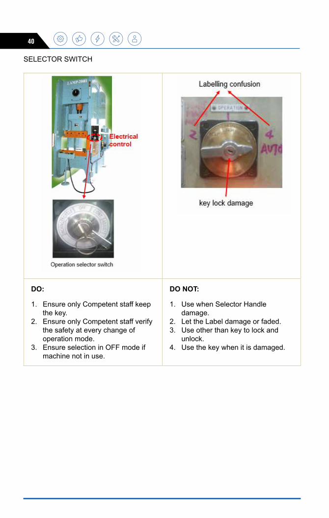
SELECTOR SWITCH
DO:
1. Ensure only Competent staff keep the key.
2. Ensure only Competent staff verify the safety at every change of operation mode.
3. Ensure selection in OFF mode if machine not in use.
DO NOT:
1. Use when Selector Handle damage.
2. Let the Label damage or faded.3. Use other than key to lock and
unlock.4. Use the key when it is damaged.

GUIDELINES ON SAFE USE OF PRESS MACHINES 41
DOUBLE PUSH START BUTTON
DO :
1. Ensure simultaneous function 2. Ensure Anti – repeat function3. Ensure functioning of Emergency
Stop Button
DO NOT :
1. Use when Green Button higher than ring or no cover.
2. Bridge the operation with single hand
3. Use when Height and position wrong setting.
4. Use Stand which is not stable and easily topple.

42
SAFETY LIGHT CURTAIN
DO : 1. Ensure the slide (ram) immediately
stop downward movement when the safety curtain is blocked.
2. Distance from the slide must protect shoulder and head.
5. The height of the safety curtain must protect any normal access to danger zone.
6. Must not function while slide moving upward.
7. Clean the light beam sensors and other peripheral device
DO NOT : 1. Let the controller label not clear or
missing. 2. Let the Controller Indicator lamp
blown3. Allow the Leader or responsible
person to leave the selector/setting key at controller.
4. Let the Device Controller unprotected and expose to damage.
5. Install controller in hidden position (operator/inspector may not be able to see indicator for function confirmation).

GUIDELINES ON SAFE USE OF PRESS MACHINES 43
SAFETY MOVABLE / FIXED FENCE
Fix bed/bolster Fix bed/bolster
Movable bolster Movable bolster
DO : 1. Fixed bed machine for manual fed
or coil fed must have fixed side safety fence.
2. Moveable bolster must use electrical interlock safety gate of safety movable fence.
DO NOT : 1. By pass the limit switch and leave
interlock safety gate of movable fence open.
2. Remove/dismantle fixed safety fence.
3. Wrong grid dimension resulted hand can reach danger zone.

44
GATE SAFETY PLUG
For robot automation handling
DO :
1. Ensure every safety fence hinges door have safety plug.
2. Ensure robot off when un-plug the safety plug.
3. Ensure enter robot area from the safety fence door.
DO NOT : 1. Let the chain or wire rope too long
to avoid people slip through the fence to the robot area without unplug the safety plug.
2. Let the chain or wire rope detach or broken.
3. Climb the safety fence to enter the robot area.

GUIDELINES ON SAFE USE OF PRESS MACHINES 45
SAFETY BLOCK
DO : 1. Ensure Safety Block complete with
Safety Plug.2. Use Safety Block when performing
any task other than normal production (eg. Repair/clean/check die) in the Hazard Area
3. Ensure operator get permission from Authorized Staff to use this safety block.
4. Ensure operation selector switch at OFF mode.
5. Put the safety block on the lower dies at designated area to ensure not topple.
6. Ensure once unplug the safety block the main motor indicator off and RPM at Zero reading.
DO NOT : 1. Work inside press work area
(hazard area) without Safety Block.2. Use safety block without safety
plug attached with it.3. Use safety block without
permission from competent staff

46
EMERGENCY STOP BUTTON (ESB)
DO : 1. Press this button when anything
regarding people or machine poses threat or safety (abnormality).
2. Ensure ESB must be in RED and twist release or latch type.
3. Ensure the colour and label is clear for all ESB on all machines.
4. Ensure ESB is easily reachable and normally located at operator operation area such as push start button and operation panel.
DO NOT : 1. Use ESB except for emergency
case.2. Use broken/damaged ESB.

GUIDELINES ON SAFE USE OF PRESS MACHINES 47
Part 12 - TRAINING ON SAFE USE OF PRESS MACHINEIt is the employer’s legal responsibility to educate employees on all workplace safety standards and the hazards that their employees may face while on job. Training is important to ensure that personnel are provided with the knowledge and skills to work competently and in a safe manner.
An effective training program can reduce the number of injuries and deaths, property damage, legal liability, illnesses, workers’ compensation claims, and missed time from work. The requirement from OSHA’s belief that training is an essential part of every employer’s safety and health program for protecting workers from injuries and illnesses.
The training on press machine given to workers will be based on the existing competency of workers and other competency needed to operate, supervise or manage the use of press machine.
SAFETY TRAINING MATRIX ON PRESS MACHINETraining matrix is a very effective planning and communication tool used by an organization to manage and monitor their safety and other training needs. It can also be used for quickly determine who has been trained, when they were trained, what gaps there are in their training, scheduling training and allocating resources. A safety training matrix can also be used for employee development and performance evaluation.
Type Of Training
personnel
project Engineers, production Managers
Tool Makers, Tooling
Engineers, Specialist, Supervisor
Tool setters, Die setters,
Machine setters,
production supervisors
Maintenance personnel Operator
Legislation Proficient Proficient Proficient Familiar FamiliarPress machine introduction
Proficient Proficient Proficient Proficient Proficient
Press machine hazard and risk
Proficient Proficient Proficient Proficient Proficient
Safety features Proficient Proficient Proficient Proficient Proficient
Safe Operating Procedure
Proficient Proficient Proficient Proficient Proficient
Maintenance and Inspection
Proficient Proficient Proficient Proficient Familiar

48
TRAINING METHODS This ensures that personnel become productive as quickly as possible. It can avoid costly mistakes by recruits not knowing the procedures or techniques of their new jobs. The methods of the training includes:-
• Job rotation arrangement by supervisors or management representatives to gain experience of operational machine
• Training by machine supplier
• Daily safety briefing
• Practical demonstrations by supervisor and competent personnel
• In-house training, using an internal and external competent personnel
• Periodic refresher training
• Delegation of specific tasks
• Sharing information among operators and supervisors regarding press machine safety
WHEN RETRAINING IS NEEDED?
Retraining is needed when there is a changed in:-
• the risks to which people are exposed
• technology or installation of new equipment
• system of work
Part 13 – REFERENCES- Factories and Machinery Act, 1967 (Act 139)
- Occupational Safety and Health Acts 1994 (Act 514)
- SOCSO Accident Statistics
- The Power Press Machine, Specific Voluntary Inspection Manual
- Safety Distance for Guard and Beam Type Press Machine
- Malaysia Automotive Institute Press Shop Training Modules

GUIDELINES ON SAFE USE OF PRESS MACHINES 49A
ppEN
DiX
Apa
rt 5
pre
ss M
achi
ne H
azar
ds a
nd R
isk
Man
agem
ent
AC
Tivi
TyD
UTy
HA
zAR
DR
iSK
CO
NTR
OL
MEA
SUR
E•
Des
crib
e th
e a
ctiv
ities
at
wor
ksta
tion
• S
peci
fic a
rea
to fo
cus
Des
crib
e th
e
pers
onne
l’s
that
doi
ng t
he
activ
ities
• Id
entif
y th
e po
tent
ial h
azar
d or
inci
dent
.•
Prio
ritiz
es t
he h
azar
d
• D
escr
ibe
the
risk
an
d
• D
escr
ibe
the
co
nseq
uenc
e
• D
escr
ibe
the
mos
t pra
ctic
al w
ay to
m
anag
e an
d co
ntro
l the
risk
s.•
Man
agem
ent
to a
ppro
ve t
he c
ontro
l m
easu
re a
nd re
view
by
saf
ety
co
mm
ittee
mem
bers
SELE
CTE
D E
XAM
pLE
OF
pRES
S M
AC
HiN
E H
AzA
RD
S A
ND
CO
NTR
OL
MEA
SUR
ES (O
pER
ATiO
N)
NO
AC
Tivi
TyD
UTy
HA
zAR
DR
iSK
CO
NTR
OL
MEA
SUR
EC
Die
s op
erat
ion
1.7
Pro
cess
1:
Man
ual
feed
mat
eria
l /
Eje
ct m
ater
ial
to n
ext
stag
e /
Tran
sfer
mat
eria
l by
co
nvey
or t
o O
p20
• O
pera
tors
• L
eade
r s•
Han
d c
augh
t be
twee
n d
ies
• H
and
caug
ht in
co
nvey
or b
elt
• S
ever
e in
jury
•
Trai
ned
ope
rato
r to
do P
roce
ss 1
• Fo
llow
SO
P &
PP
E•
Use
d ki
cker
/lift
er
• U
sed
phy
sica
l gua
rd
1.8
Op2
0:M
anua
l pi
ck &
pla
ce
mat
eria
l /
Tran
sfer
mat
eria
l by
conv
eyor
• O
pera
tors
• L
eade
r s•
Han
d c
augh
t be
twee
n d
ies
• H
and
caug
ht in
co
nvey
or b
elt
• S
ever
e in
jury
•
Trai
ned
ope
rato
r to
do O
p20
• Fo
llow
SO
P &
PP
E•
Use
d ki
cker
/ lif
ter
• U
sed
phys
ical
gua
rd
1.9
Op3
0:M
anua
l pi
ck &
pla
ce
mat
eria
l /
Tran
sfer
mat
eria
l by
co
nvey
or
• O
pera
tors
• L
eade
r s•
Han
d c
augh
t be
twee
n d
ies
• H
and
caug
ht in
co
nvey
or b
elt
• S
ever
e in
jury
•
Trai
ned
ope
rato
r to
do O
p30
•
Follo
w S
OP
& P
PE
•
Use
d ki
cker
/lift
er•
Use
d ph
ysic
al g
uard
1.10
Op4
0:M
anua
l pi
ck &
pla
ce
mat
eria
l /
Tran
sfer
mat
eria
l by
co
nvey
or
• O
pera
tors
• L
eade
r s•
Han
d c
augh
t be
twee
n d
ies
• H
and
caug
ht in
co
nvey
or b
elt
• S
ever
e in
jury
•
Trai
ned
ope
rato
r to
do O
p40
• Fo
llow
SO
P &
PP
E•
Use
d ki
cker
/ lif
ter
• U
sed
phys
ical
gua
rd

50
SELE
CTE
D E
XAM
pLE
OF
pRES
S M
AC
HiN
E H
AzA
RD
S A
ND
CO
NTR
OL
MEA
SUR
ES (M
AiN
TEN
AN
CE)
NO
AC
Tivi
TyD
UTy
HA
zAR
DR
iSK
CO
NTR
OL
MEA
SUR
EA
Rep
air
Mai
nten
ance
( E
lect
rical
)1
Rep
air M
aint
enan
ce o
n liv
e eq
uipm
ent
1.
Prim
ary
& s
econ
dary
pow
er a
t op
erat
ion
pane
l2.
E
lect
rical
ite
ms
in th
e m
ain
oper
atio
n p
anel
and
sub
ope
ratio
n pa
nel
3.
Che
ckin
g an
d te
stin
g sw
itche
s,
rela
ys, s
enso
rs, l
imit
switc
hes
and
sole
noid
val
ves.
• Te
chni
cian
s•
Eng
inee
rs•
Con
tract
ors
• H
igh
volta
ge
• Lo
w v
olta
ge
• W
ork
at h
eigh
t •
Slip
pery
• Li
mite
d sp
ace
&
unba
lanc
e•
Exp
ose
live
wire
s
• S
ever
e bu
rns
• S
hock
• Fa
ll -
seve
re
inju
ry
• Tr
aine
d te
chni
cian
s an
d us
ed
of c
orre
ct P
PE
and
tool
s.•
Stu
dy th
e m
anua
l•
Shu
t of p
ower
sup
ply
•
App
ly b
uddy
sys
tem
•
Dis
play
pla
card
war
ning
sig
n.•
Avoi
d un
auth
oriz
ed
mod
ifica
tion
on w
iring
/ P
LC
Rep
air M
aint
enan
ce (
mec
hani
cal )
1.1
Flyw
heel
& B
eltin
g •
Tech
nici
an•
Eng
inee
r•
Con
tract
ors
• W
ork
at h
eigh
t•
Rot
atin
g ob
ject
• Li
mite
d w
ork
spac
e &
un
bala
nce
• S
lippe
ry
• E
ntan
gled
–
seve
re i
njur
y•
Fall
– se
vere
in
jury
• Tr
aine
d te
chni
cian
s•
Stu
dy th
e m
aint
enan
ce
man
ual
• Fo
llow
SO
P &
use
PP
E•
App
ly b
uddy
sys
tem
• P
erfo
rm T
ake-
21.
2C
lutc
h &
Bra
ke: i
nspe
ctio
n ,
mon
itorin
g a
nd te
stin
g•
Tech
nici
an•
Eng
inee
r•
Con
tract
ors
•W
ork
at h
eigh
t•
Rot
atin
g ob
ject
•A
ctua
ted
obje
ct•
Lim
ited
wor
k sp
ace
&
unba
lanc
e•
Slip
pery
•
Hig
h pr
essu
re h
ose
•E
ntan
gled
–
seve
re i
njur
y•
Pin
ched
- se
vere
inj
ury
•Fa
ll –
seve
re
inju
ry•
Pre
ssur
ize
– se
ver i
njur
y
•Tr
aine
d te
chni
cian
s•
Stu
dy th
e m
aint
enan
ce
man
ual
•Fo
llow
SO
P &
use
of P
PE
•A
pply
bud
dy s
yste
m•
Per
form
Tak
e-2
1.3
Lubr
icat
ing
syst
em a
nd fi
tting
•
Tech
nici
an•
Eng
inee
r•
Con
tract
ors
•W
ork
at h
eigh
t•
Rot
atin
g ob
ject
•A
ctua
ted
obje
ct•
Lim
ited
wor
k sp
ace
&
unba
lanc
e•
Slip
pery
•E
ntan
gled
–
seve
re i
njur
y•
Pin
ched
- se
vere
inj
ury
•Fa
ll –
seve
re
inju
ry
•Tr
aine
d te
chni
cian
s•
Stu
dy t
he m
aint
enan
ce
man
ual
•Fo
llow
SO
P &
use
of P
PE
•A
pply
bud
dy s
yste
m•
Per
form
Tak
e-2