Guide d'exploitation ATV66
50
Altivar 66 Telemecanique variateurs de vitesse pour moteurs asynchrones couple constant / variable : 2,2 à 250 kW, 400 V couple constant / variable : 3 à 400 HP, 460 V couple constant / variable : 2,2/3 à 30/37 kW, 230 V couple constant / variable : 3/5 à 40/50 HP, 230 V réception, installation et mise en service Guide d'exploitation ■ Merlin Gerin ■ Square D ■ Telemecanique
-
Upload
khangminh22 -
Category
Documents
-
view
0 -
download
0
Transcript of Guide d'exploitation ATV66
Altivar 66Telemecanique
variateurs de vitessepour moteurs asynchrones
couple constant / variable :2,2 à 250 kW, 400 V
couple constant / variable :3 à 400 HP, 460 V
couple constant / variable :2,2/3 à 30/37 kW, 230 V
couple constant / variable :3/5 à 40/50 HP, 230 V
réception, installation et mise en service
Guide d'exploitation
Merlin Gerin Square D Telemecanique

i
The Altivar 66 must be considered as a component. It is neither a machine nor a device ready foruse in accordance with European standards (EN 60204-1 on the safety of machines, EN 50081 and82 on electromagnetic compatibility). It is the responsiblity of the end user to ensure that hismachine conforms to these standards.
This speed controllers must be installed and implemented in compliance with the international andnational standards in force in the premises where it is to be used. Conformity is under theresponsibility of the integrator who will comply with the EMC directive, among others, for whatconcerns the European Community.
Compliance with the essential requirements specified in the EMC directive is namely conditioned byapplication of the prescriptions provided in our catalogue which indicates the accessories to beassociated with variators, for instance when radio disturbance filtering is needed .
For any information about these documents, please contact our SCHNEIDERcommercial agency.
Warning

i i
1
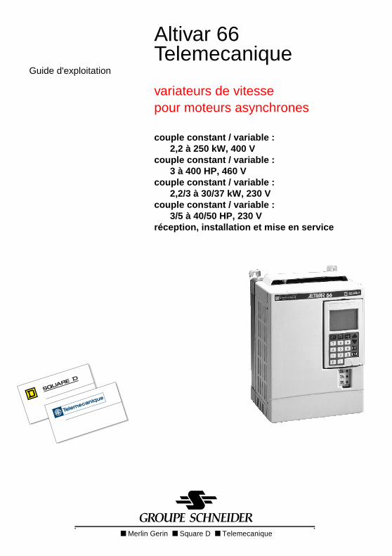
Contents
Preliminary checks 2
Motor-speed controller combination 3 to 12
Available torque 13
Characteristics 14 and 15
Dimensions 16 and 18
Mounting recommendations (sizes 1 to 6) 19 and 21
Mounting in a wall-fixing or floor-standing enclosure 22 to 24
Connection
Access to terminal blocks (sizes 1 to 5) 25
Power terminal blocks (sizes 1 to 5) 26
Access to terminal blocks (size 6) 27
Power terminal blocks (size 6) 28
Access to terminal blocks (size 7) 29
Power terminal blocks (size 7) 30
Control terminal blocks 31
Connection diagrams 32
Ferrite core installation and recommendations 33 and 34
Command type 35
Cable cross-sections 36
Cable entry points 37 to 39
Start-up 40
Operating assistance 41
Maintenance assistance 42 and 43
Spare parts 44 to 47
P4P1
P5
P3
P6P6
2
Preliminary checks
Receipt
Check that the speed controller reference code printed on the label is that same as that onthe delivery note corresponding to the purchase order.
Open the packaging and check that the Altivar 66 has not been damaged during transport.
Handling and storage
To ensure that the speed controller is protected prior to installation, handle and store it inits packaging.
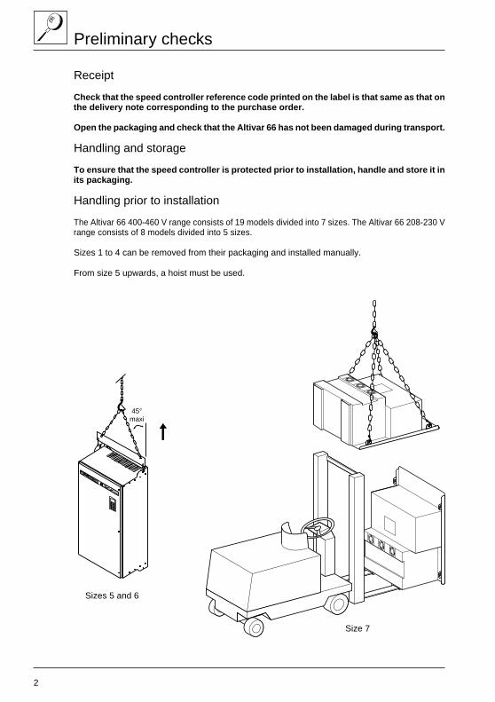
Handling prior to installation
The Altivar 66 400-460 V range consists of 19 models divided into 7 sizes. The Altivar 66 208-230 Vrange consists of 8 models divided into 5 sizes.
Sizes 1 to 4 can be removed from their packaging and installed manually.
From size 5 upwards, a hoist must be used.
45°maxi
Size 7
Sizes 5 and 6
3
Motor-speed controller combination
Preliminary comments
Motor power rating
In the tables on pages 4 to 12, the values given are the standard power ratings.
At 460 V - 60 Hz, the HP ratings conform to NEC (National Electrical Code).
There is no HP equivalent on a 460 V supply for a motor rated at 3 kW on a 400 V AC supply, whilethe ATV-66U54N4 speed controller can be supplied at 460 V - 60 Hz.
Line current
The line current corresponds to the current consumed by the speed controller at nominal operatingpower on an AC supply with an impedance to limit the presumed short-circuit current to :
– 12000 A for a 208 V - 50/60 Hz supply voltage,– 22000 A for a 230 V - 50/60 Hz supply voltage,– 22000 A for a 400 V - 50 Hz supply voltage,– 65000 A for a 460 V - 60 Hz supply voltage.
Providing the supply via a power transformer suitable for the speed controller, or adding a linechoke from the catalogue, reduces current consumption to a value close to the speed controllernominal current.
Example : ATV-66D23N4 with 15 kW motor on a 400 V AC supply.
Constant torque application : Inv = 33 A.
Line current with no choke : 45 A.Line current with choke from catalogue : 28 A.
Variable torque applications
For variable torque applications not involving high switching frequency (see tables on pages 6, 7and 11), limiting overtorque makes it possible to use a speed controller with a motor with a higherpower rating.
ATV-66U41N4 speed controller
When a speed controller is used with a motor whose power rating is below 2.2 kW (or 3 kW forvariable torque), the speed controller should be reconfigured via the graphic terminal to adapt itsintegral thermal protection (see the Programming Manual).
4
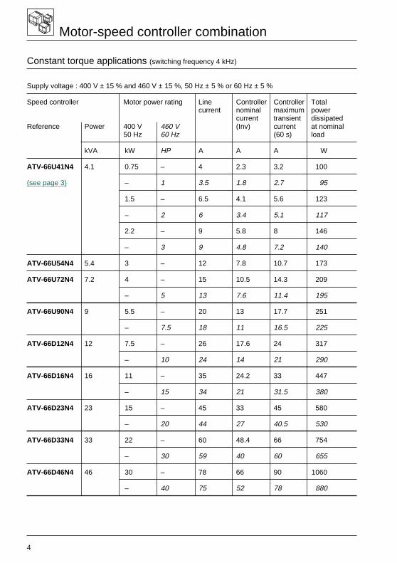
Motor-speed controller combination
Constant torque applications (switching frequency 4 kHz)
Supply voltage : 400 V ± 15 % and 460 V ± 15 %, 50 Hz ± 5 % or 60 Hz ± 5 %
Speed controller Motor power rating Line Controller Controller Totalcurrent nominal maximum power
current transient dissipatedReference Power 400 V 460 V (Inv) current at nominal
50 Hz 60 Hz (60 s) load
kVA kW HP A A A W
ATV-66U41N4 4.1 0.75 – 4 2.3 3.2 100
(see page 3) – 1 3.5 1.8 2.7 95
1.5 – 6.5 4.1 5.6 123
– 2 6 3.4 5.1 117
2.2 – 9 5.8 8 146
– 3 9 4.8 7.2 140
ATV-66U54N4 5.4 3 – 12 7.8 10.7 173
ATV-66U72N4 7.2 4 – 15 10.5 14.3 209
– 5 13 7.6 11.4 195
ATV-66U90N4 9 5.5 – 20 13 17.7 251
– 7.5 18 11 16.5 225
ATV-66D12N4 12 7.5 – 26 17.6 24 317
– 10 24 14 21 290
ATV-66D16N4 16 11 – 35 24.2 33 447
– 15 34 21 31.5 380
ATV-66D23N4 23 15 – 45 33 45 580
– 20 44 27 40.5 530
ATV-66D33N4 33 22 – 60 48.4 66 754
– 30 59 40 60 655
ATV-66D46N4 46 30 – 78 66 90 1060
– 40 75 52 78 880
5
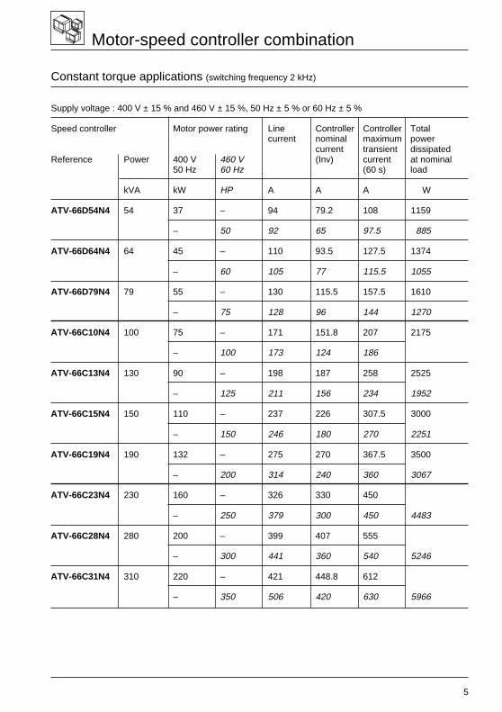
Motor-speed controller combination
Constant torque applications (switching frequency 2 kHz)
Supply voltage : 400 V ± 15 % and 460 V ± 15 %, 50 Hz ± 5 % or 60 Hz ± 5 %
Speed controller Motor power rating Line Controller Controller Totalcurrent nominal maximum power
current transient dissipatedReference Power 400 V 460 V (Inv) current at nominal
50 Hz 60 Hz (60 s) load
kVA kW HP A A A W
ATV-66D54N4 54 37 – 94 79.2 108 1159
– 50 92 65 97.5 885
ATV-66D64N4 64 45 – 110 93.5 127.5 1374
– 60 105 77 115.5 1055
ATV-66D79N4 79 55 – 130 115.5 157.5 1610
– 75 128 96 144 1270
ATV-66C10N4 100 75 – 171 151.8 207 2175
– 100 173 124 186
ATV-66C13N4 130 90 – 198 187 258 2525
– 125 211 156 234 1952
ATV-66C15N4 150 110 – 237 226 307.5 3000
– 150 246 180 270 2251
ATV-66C19N4 190 132 – 275 270 367.5 3500
– 200 314 240 360 3067
ATV-66C23N4 230 160 – 326 330 450
– 250 379 300 450 4483
ATV-66C28N4 280 200 – 399 407 555
– 300 441 360 540 5246
ATV-66C31N4 310 220 – 421 448.8 612
– 350 506 420 630 5966
6
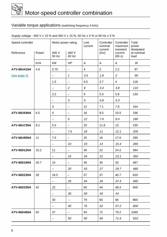
Motor-speed controller combination
Variable torque applications (switching frequency 4 kHz)
Supply voltage : 400 V ± 15 % and 460 V ± 15 %, 50 Hz ± 5 % or 60 Hz ± 5 %
Speed controller Motor power rating Line Controller Controller Totalcurrent nominal maximum power
current transient dissipatedReference Power 400 V 460 V (Inv) current at nominal
50 Hz 60 Hz (60 s) load
kVA kW HP A A A W
ATV-66U41N4 4.9 0.75 – 4 2 2.2 97
(see page 3) – 1 3.5 1.8 2 90
1.5 – 6.5 3.7 4 118
– 2 6 3.4 3.8 110
2.2 – 9 5.3 5.8 130
– 3 9 4.8 5.3
3 – 12 7.1 7.8 164
ATV-66U54N4 6.5 4 – 16 9.5 10.5 196
– 5 12 7.6 8.4 180
ATV-66U72N4 8.2 5.5 – 20 11.8 13 230
– 7.5 18 11 12.1 205
ATV-66U90N4 11 7.5 – 25 16 17.6 295
– 10 23 14 15.4 265
ATV-66D12N4 15.2 11 – 36 22 24.2 384
– 15 34 21 23.1 350
ATV-66D16N4 20.7 15 – 45 30 33 487
– 20 43 27 29.7 480
ATV-66D23N4 28 18.5 – 57 37 40.7 620
– 25 54 34 37.4 560
ATV-66D33N4 42 22 – 60 44 48.4 600
– 30 59 40 44
30 – 79 60 66 860
– 40 75 52 57.2 800
ATV-66D46N4 50 37 – 94 72 79.2 1069
– 50 90 65 71.5 910
7
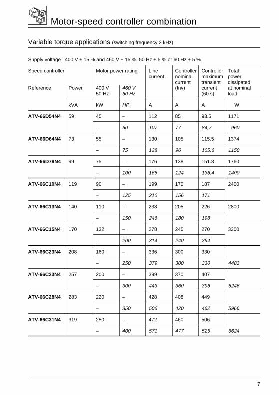
Motor-speed controller combination
Variable torque applications (switching frequency 2 kHz)
Supply voltage : 400 V ± 15 % and 460 V ± 15 %, 50 Hz ± 5 % or 60 Hz ± 5 %
Speed controller Motor power rating Line Controller Controller Totalcurrent nominal maximum power
current transient dissipatedReference Power 400 V 460 V (Inv) current at nominal
50 Hz 60 Hz (60 s) load
kVA kW HP A A A W
ATV-66D54N4 59 45 – 112 85 93.5 1171
– 60 107 77 84,7 960
ATV-66D64N4 73 55 – 130 105 115.5 1374
– 75 128 96 105.6 1150
ATV-66D79N4 99 75 – 176 138 151.8 1760
– 100 166 124 136.4 1400
ATV-66C10N4 119 90 – 199 170 187 2400
– 125 210 156 171
ATV-66C13N4 140 110 – 238 205 226 2800
– 150 246 180 198
ATV-66C15N4 170 132 – 278 245 270 3300
– 200 314 240 264
ATV-66C23N4 208 160 – 336 300 330
– 250 379 300 330 4483
ATV-66C23N4 257 200 – 399 370 407
– 300 443 360 396 5246
ATV-66C28N4 283 220 – 428 408 449
– 350 506 420 462 5966
ATV-66C31N4 319 250 – 472 460 506
– 400 571 477 525 6624
8
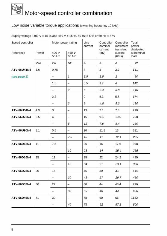
Motor-speed controller combination
Low noise variable torque applications (switching frequency 10 kHz)
Supply voltage : 400 V ± 15 % and 460 V ± 15 %, 50 Hz ± 5 % or 60 Hz ± 5 %
Speed controller Motor power rating Line Controller Controller Totalcurrent nominal maximum power
current transient dissipatedReference Power 400 V 460 V (Inv) current at nominal
50 Hz 60 Hz (60 s) load
kVA kW HP A A A W
ATV-66U41N4 3.6 0.75 – 4 2 2.2 111
(see page 3) – 1 3.5 1.8 2 90
1.5 – 6.5 3.7 4 142
– 2 6 3.4 3.8 110
2.2 – 9 5.3 5.8 174
– 3 9 4.8 5.3 130
ATV-66U54N4 4.9 3 – 13 7.1 7.8 210
ATV-66U72N4 6.5 4 – 15 9.5 10.5 258
– 5 12 7.6 8.4 180
ATV-66U90N4 8.1 5.5 – 20 11.8 13 311
– 7.5 18 11 12.1 205
ATV-66D12N4 11 7.5 – 26 16 17.6 398
– 10 23 14 15.4 265
ATV-66D16N4 15 11 – 35 22 24.2 490
– 15 34 21 23.1 350
ATV-66D23N4 20 15 – 45 30 33 614
– 20 43 27 29.7 480
ATV-66D33N4 30 22 – 60 44 48.4 796
– 30 59 40 44 600
ATV-66D46N4 41 30 – 78 60 66 1182
– 40 75 52 57.2 800
9
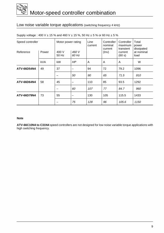
Motor-speed controller combination
Low noise variable torque applications (switching frequency 4 kHz)
Supply voltage : 400 V ± 15 % and 460 V ± 15 %, 50 Hz ± 5 % or 60 Hz ± 5 %
Speed controller Motor power rating Line Controller Controller Totalcurrent nominal maximum power
current transient dissipatedReference Power 400 V 460 V (Inv) current at nominal
50 Hz 60 Hz (60 s) load
kVA kW HP A A A W
ATV-66D54N4 49 37 – 94 72 79.2 1096
– 50 90 65 71.5 910
ATV-66D64N4 58 45 – 110 85 93.5 1292
– 60 107 77 84.7 960
ATV-66D79N4 73 55 – 130 105 115.5 1433
– 75 128 96 105.6 1150
Note
ATV-66C10N4 to C31N4 speed controllers are not designed for low noise variable torque applications withhigh switching frequency.
10
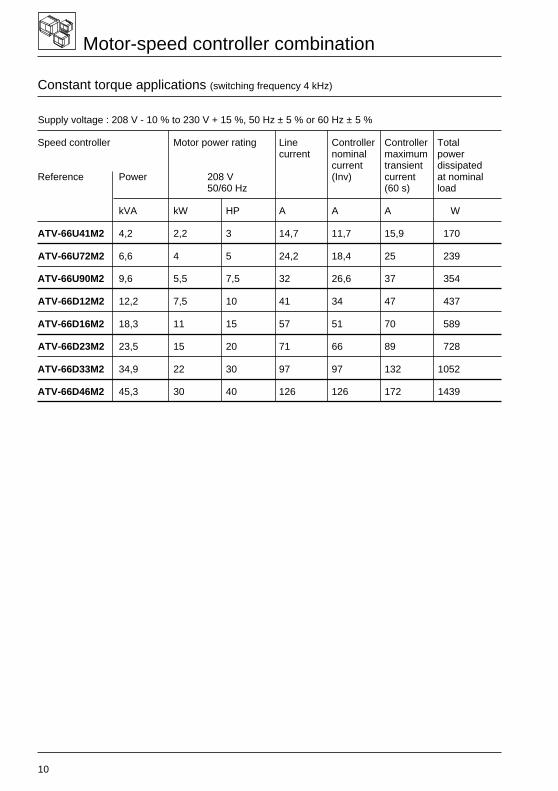
Motor-speed controller combination
Constant torque applications (switching frequency 4 kHz)
Supply voltage : 208 V - 10 % to 230 V + 15 %, 50 Hz ± 5 % or 60 Hz ± 5 %
Speed controller Motor power rating Line Controller Controller Totalcurrent nominal maximum power
current transient dissipatedReference Power 208 V (Inv) current at nominal
50/60 Hz (60 s) load
kVA kW HP A A A W
ATV-66U41M2 4,2 2,2 3 14,7 11,7 15,9 170
ATV-66U72M2 6,6 4 5 24,2 18,4 25 239
ATV-66U90M2 9,6 5,5 7,5 32 26,6 37 354
ATV-66D12M2 12,2 7,5 10 41 34 47 437
ATV-66D16M2 18,3 11 15 57 51 70 589
ATV-66D23M2 23,5 15 20 71 66 89 728
ATV-66D33M2 34,9 22 30 97 97 132 1052
ATV-66D46M2 45,3 30 40 126 126 172 1439
11
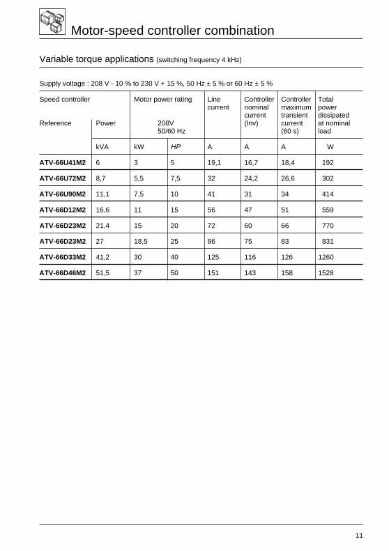
Motor-speed controller combination
Variable torque applications (switching frequency 4 kHz)
Supply voltage : 208 V - 10 % to 230 V + 15 %, 50 Hz ± 5 % or 60 Hz ± 5 %
Speed controller Motor power rating Line Controller Controller Totalcurrent nominal maximum power
current transient dissipatedReference Power 208V (Inv) current at nominal
50/60 Hz (60 s) load
kVA kW HP A A A W
ATV-66U41M2 6 3 5 19,1 16,7 18,4 192
ATV-66U72M2 8,7 5,5 7,5 32 24,2 26,6 302
ATV-66U90M2 11,1 7,5 10 41 31 34 414
ATV-66D12M2 16,6 11 15 56 47 51 559
ATV-66D23M2 21,4 15 20 72 60 66 770
ATV-66D23M2 27 18,5 25 86 75 83 831
ATV-66D33M2 41,2 30 40 125 116 126 1260
ATV-66D46M2 51,5 37 50 151 143 158 1528
12
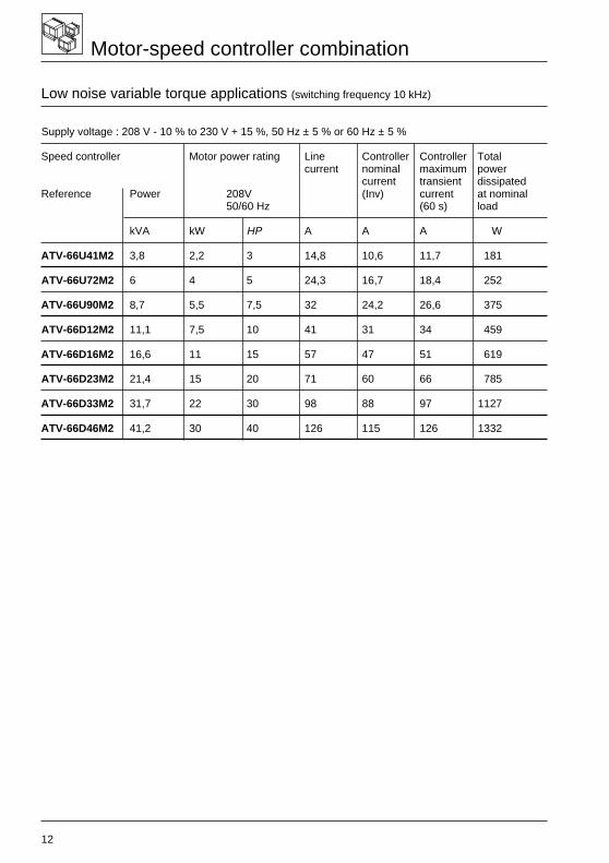
Motor-speed controller combination
Low noise variable torque applications (switching frequency 10 kHz)
Supply voltage : 208 V - 10 % to 230 V + 15 %, 50 Hz ± 5 % or 60 Hz ± 5 %
Speed controller Motor power rating Line Controller Controller Totalcurrent nominal maximum power
current transient dissipatedReference Power 208V (Inv) current at nominal
50/60 Hz (60 s) load
kVA kW HP A A A W
ATV-66U41M2 3,8 2,2 3 14,8 10,6 11,7 181
ATV-66U72M2 6 4 5 24,3 16,7 18,4 252
ATV-66U90M2 8,7 5,5 7,5 32 24,2 26,6 375
ATV-66D12M2 11,1 7,5 10 41 31 34 459
ATV-66D16M2 16,6 11 15 57 47 51 619
ATV-66D23M2 21,4 15 20 71 60 66 785
ATV-66D33M2 31,7 22 30 98 88 97 1127
ATV-66D46M2 41,2 30 40 126 115 126 1332
13
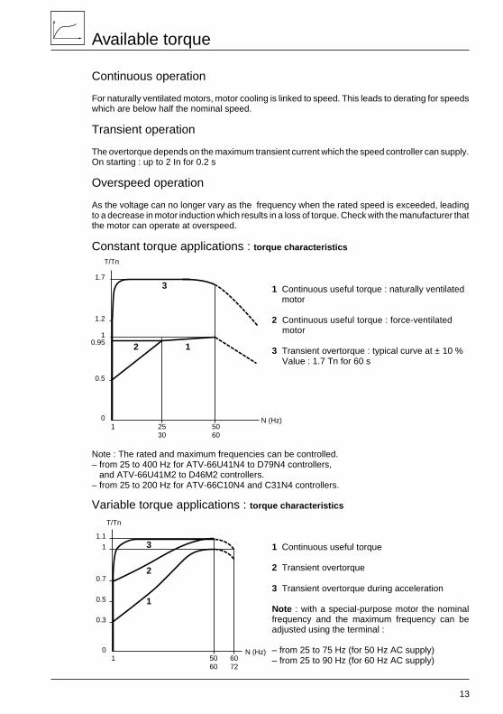
Available torque
Continuous operation
For naturally ventilated motors, motor cooling is linked to speed. This leads to derating for speedswhich are below half the nominal speed.
Transient operation
The overtorque depends on the maximum transient current which the speed controller can supply.On starting : up to 2 In for 0.2 s
Overspeed operation
As the voltage can no longer vary as the frequency when the rated speed is exceeded, leadingto a decrease in motor induction which results in a loss of torque. Check with the manufacturer thatthe motor can operate at overspeed.
Constant torque applications : torque characteristics
1 Continuous useful torque : naturally ventilated motor
2 Continuous useful torque : force-ventilated motor
3 Transient overtorque : typical curve at ± 10 %Value : 1.7 Tn for 60 s
Note : The rated and maximum frequencies can be controlled.– from 25 to 400 Hz for ATV-66U41N4 to D79N4 controllers, and ATV-66U41M2 to D46M2 controllers.– from 25 to 200 Hz for ATV-66C10N4 and C31N4 controllers.
Variable torque applications : torque characteristics
1 Continuous useful torque
2 Transient overtorque
3 Transient overtorque during acceleration
Note : with a special-purpose motor the nominalfrequency and the maximum frequency can beadjusted using the terminal :
– from 25 to 75 Hz (for 50 Hz AC supply)– from 25 to 90 Hz (for 60 Hz AC supply)
1.1
1
0.7
0.5
0.3
05060
T/Tn
N (Hz)1
3
2
1
6072
1.7
1.2
1
0.5
02530
5060
N (Hz)
T/Tn
12
3
1
0.95
14
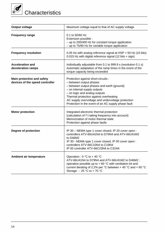
Characteristics
Output voltage Maximum voltage equal to that of AC supply voltage
Frequency range 0.1 to 50/60 HzExtension possible :– up to 200/400 Hz for constant torque application– up to 75/90 Hz for variable torque application
Frequency resolution 0.05 Hz with analog reference signal at HSP = 50 Hz (10 bits)0.015 Hz with digital reference signal (12 bits + sign)
Acceleration and Individually adjustable from 0.1 to 999.9 s (resolution 0.1 s)deceleration ramps Automatic adaptation of the ramp times in the event of the
torque capacity being exceeded
Main protective and safety Protection against short-circuits :devices of the speed controller – between output phases
– between output phases and earth (ground)– on internal supply outputs– on logic and analog outputsThermal protection against overheatingAC supply overvoltage and undervoltage protectionProtection in the event of an AC supply phase fault
Motor protection Integrated electronic thermal protection(calculation of I2 t taking frequency into account)Memorization of motor thermal stateProtection against phase faults
Degree of protection IP 30 – NEMA type 1 cover closed, IP 20 cover open :controllers ATV-66U41N4 to D79N4 and ATV-66U41M2to D46M2IP 30 - NEMA type 1 cover closed, IP 00 cover open :controllers ATV-66C10N4 to C19N4IP 00 controller ATV-66C23N4 to C31N4
Ambient air temperature Operation : 0 °C to + 40 °CATV-66U41N4 to D79N4 and ATV-66U41M2 to D46M2 :operation possible up to + 60 °C with ventilation kit andcurrent derating of 2,2% per °C between + 40 °C and + 60 °CStorage : - 25 °C to + 70 °C

15
Maximum operating altitude 1000 m without derating(above this, derate the current by 1 % for each additional100 m)
Maximum relative humidity 93 % without condensation or dripping water, conforming toIEC 68-2-3
Degree of pollution Degree 3 conforming to IEC 664-1
Vibration resistance Conforming to IEC 68-2-6 :– 1,5 mm peak to peak from 3 to 13 Hz– 1mm from 13 to22.3 Hz and 2 gn from 22.3 to 150 Hz : ATV-66U41N4 to D23N4 and ATV-66U41M2 to D16M2– 1.5 mm peak to peak from 3 to 13 Hz and 1 gn from 13 to
150 Hz : ATV-66D33N4 to D79N4 and ATV-66D23M2 toD46M2 speed controllers– 0.15 mm from 10 to 58 Hz and 1 gn from 58 to 150 Hz :ATV-66C10N4 to C31N4
Shock resistance Conforming to IEC 68-2-27 : 15 g, 11 ms
Characteristics
16
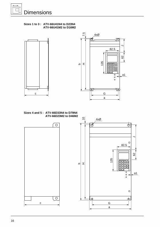
Dimensions
Sizes 1 to 3 : ATV-66U41N4 to D23N4ATV-66U41M2 to D16M2
Sizes 4 and 5 : ATV-66D33N4 to D79N4ATV-66D23M2 to D46M2
F 1 F 2 F 3
7 8 9
4 5 6
1 2 3
0 .
ESC
ENT
c G
a
a1
62
82.5
J
7.5
Hb
4xØ
135
F 1 F 2 F 3
7 8 9
4 5 6
1 2 3
0 .
ESC
ENT
c
b H10 4xØ
J62
82.5
135
a1
Ga
17
Dimensions
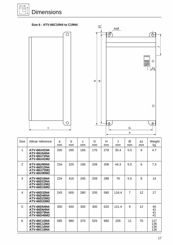
Size 6 : ATV-66C10N4 to C19N4
Size Altivar reference a b c G H J Ø a1 Weightmm mm mm mm mm mm mm mm kg
1 ATV-66U41N4 200 295 165 175 278 35.4 5.5 6 4.7ATV-66U54N4ATV-66U72N4ATV-66U41M2
2 ATV-66U90N4 234 325 195 209 308 44.3 5.5 6 7.3ATV-66D12N4ATV-66U72M2ATV-66U90M2
3 ATV-66D16N4 234 416 245 209 398 79 5.5 6 14ATV-66D23N4ATV-66D12M2ATV-66D16M2
4 ATV-66D33N4 243 600 280 205 580 116.4 7 12 27ATV-66D46N4ATV-66D23M2ATV-66D33M2
5 ATV-66D54N4 350 650 300 300 620 121.4 9 12 40ATV-66D64N4 41ATV-66D79N4 41ATV-66D46M2 41
6 ATV-66C10N4 585 980 370 525 960 205 11 70 127ATV-66C13N4 136ATV-66C15N4 136ATV-66C19N4 136
10
J
a1
F 1 F 2 F 3
7 8 9
4 5 6
1 2 3
0 .
ESC
ENT
4xØ
b H
G
a
c
18
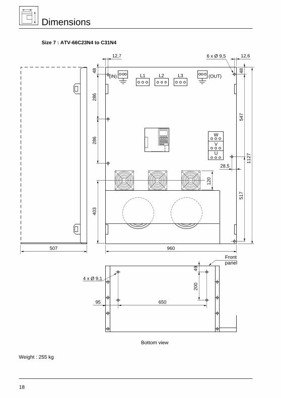
Dimensions
Size 7 : ATV-66C23N4 to C31N4
Weight : 255 kg
F 1 F 2 F 3
7 8 9
4 5 6
1 2 3
0 .
ESC
ENT
517
4920
0
286
286
4840
3
120
960
28,5
12,612,7
65095
547
48
6 x Ø 9,5
4 x Ø 9,1
1127
507
L1 L2 L3
W
U
V
(OUT)(IN)
Bottom view
Frontpanel
19
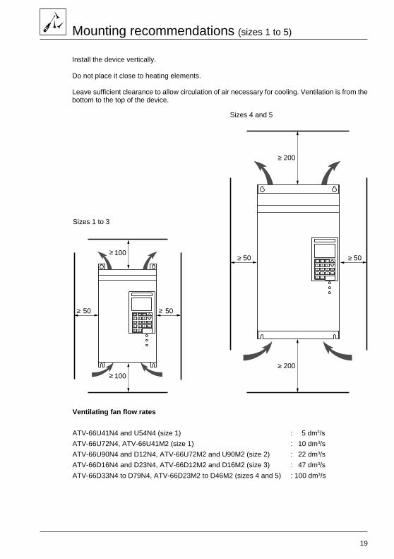
Mounting recommendations (sizes 1 to 5)
Install the device vertically.
Do not place it close to heating elements.
Leave sufficient clearance to allow circulation of air necessary for cooling. Ventilation is from thebottom to the top of the device.
Sizes 1 to 3
Sizes 4 and 5
Ventilating fan flow rates
ATV-66U41N4 and U54N4 (size 1) : 5 dm3/s
ATV-66U72N4, ATV-66U41M2 (size 1) : 10 dm3/s
ATV-66U90N4 and D12N4, ATV-66U72M2 and U90M2 (size 2) : 22 dm3/s
ATV-66D16N4 and D23N4, ATV-66D12M2 and D16M2 (size 3) : 47 dm3/s
ATV-66D33N4 to D79N4, ATV-66D23M2 to D46M2 (sizes 4 and 5) : 100 dm3/s
F 1 F 2 F 3
7 8 9
4 5 6
1 2 3
0 .
ESC
ENT
50 50
100
100≥
≥ ≥
≥ F 1 F 2 F 3
7 8 9
4 5 6
1 2 3
0 .
ESC
ENT
≥ 200
≥ 200
≥ 50 ≥ 50

20
Mounting recommendations (sizes 6 and 7)
Install the device vertically.
Do not place it close to heating elements.
Maintain enough clearance for the cooling air flow that a fan provides from bottom to top for Size 6unit and from the bottom of the front panel to the top for Size 7 unit.
Ventilating fan flow rates
ATV-66C10N4 to C19N4 (size 6) : 250 dm3/sATV-66C23N4 to C31N4 (size 7) : 470 dm3/s
Recommendation for installing a Size 7 unit in a cabinet : A clearance greater than 250 mm shouldbe provided between the VSC and the cabinet walls for easier routing of cables and easier accessto the unit.
Sizes 6
Sizes 7
200
50 50
≥
350
≥ ≥
≥
250
50 50
≥
200
≥ ≥
≥
F 1 F 2 F 3
7 8 9
4 5 6
1 2 3
0 .
ESC
ENT

21
Mounting recommendations (size 7)
Principle of forced-air cooling in IP 00
Recommendation : Hot air must be exhausted to the outside.
The IP00 version of the Altivar 66 Size 7 unit must be equipped with a protective barrier toensure personnel safety against electric shocks.
403
3 x 50 dm3/s
470 dm3/s
470 dm3/s
78621 21
107
11
15
F 1 F 2 F 3
7 8 9
4 5 6
1 2 3
0 .
ESC
ENT
686
9111
Air outlet opening, power section
Air outlet, power section
Air inlet opening, power section
Air inlet,power section
Board coolingfan
22
Mounting in a wall-fixing or floor-standing enclosure
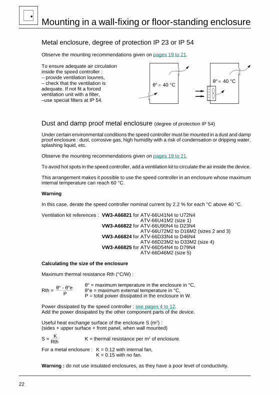
Metal enclosure, degree of protection IP 23 or IP 54
Observe the mounting recommendations given on pages 19 to 21.
To ensure adequate air circulationinside the speed controller :– provide ventilation louvres,– check that the ventilation isadequate. If not fit a forcedventilation unit with a filter,–use special filters at IP 54.
Dust and damp proof metal enclosure (degree of protection IP 54)
Under certain environmental conditions the speed controller must be mounted in a dust and dampproof enclosure : dust, corrosive gas, high humidity with a risk of condensation or dripping water,splashing liquid, etc.
Observe the mounting recommendations given on pages 19 to 21.
To avoid hot spots in the speed controller, add a ventilation kit to circulate the air inside the device.
This arrangement makes it possible to use the speed controller in an enclosure whose maximuminternal temperature can reach 60 °C.
Warning
In this case, derate the speed controller nominal current by 2.2 % for each °C above 40 °C.
Ventilation kit references : VW3-A66821 for ATV-66U41N4 to U72N4ATV-66U41M2 (size 1)
VW3-A66822 for ATV-66U90N4 to D23N4ATV-66U72M2 to D16M2 (sizes 2 and 3)
VW3-A66824 for ATV-66D33N4 to D46N4ATV-66D23M2 to D33M2 (size 4)
VW3-A66825 for ATV-66D54N4 to D79N4ATV-66D46M2 (size 5)
Calculating the size of the enclosure
Maximum thermal resistance Rth (°C/W) :
θ° = maximum temperature in the enclosure in °C,Rth = θ°e = maximum external temperature in °C,
P = total power dissipated in the enclosure in W.
Power dissipated by the speed controller : see pages 4 to 12.Add the power dissipated by the other component parts of the device.
Useful heat exchange surface of the enclosure S (m2) :(sides + upper surface + front panel, when wall mounted)
S = K = thermal resistance per m2 of enclosure.
For a metal enclosure : K = 0.12 with internal fan,K = 0.15 with no fan.
Warning : do not use insulated enclosures, as they have a poor level of conductivity.
θ° 40 °Cθ° 40 °C
θ° - θ°e P
KRth
23
Mounting in a wall-fixing or floor-standing enclosure
Flush mounting (sizes 1 to 3)
To reduce the power dissipated in the enclosure, the speed controller can be flush mounted, withthe heatsink on the outside. This necessitates making a cut-out in the rear of the enclosure andusing a mounting kit which comprises : dust and damp proof gaskets, leaflet and a cut-out drawing.
IP 54 kit references : VW3-A66801 for ATV-66U41N4 to U72N4ATV-66U41M2 (size 1)
VW3-A66802 for ATV-66U90N4 and D12N4ATV-66U72M2 to U90M2 (size 2)
VW3-A66803 for ATV-66D16N4 and D23N4ATV-66D12M2 to D16M2 (size 3)
Mounting as an air heat exchanger with the exterior (sizes 1 to 5)
To reduce the power dissipated in the enclosure, the speed controller can be fitted with adaptorswhich enable the ventilation fan to draw in cool air at the bottom of the controller and evacuatehot air at the top.
This necessitates making a two cut-outs in the rear of the enclosure and using a mounting kitwhich comprises : adaptors, dust and damp proof gaskets, leaflet and a cut-out drawing.
Kit references : VW3-A66811 for ATV-66U41N4 to U72N4ATV-66U41M2 (size 1)
VW3-A66812 for ATV-66U90N4 and D12N4ATV-66U72M2 and U90M2 (size 2)
VW3-A66813 for ATV-66D16N4 and D23N4ATV-66D12M2 and D16M2 (size 3)
VW3-A66814 for ATV-66D33N4 and D46N4ATV-66D23M2 and D33M2 (size 4)
VW3-A66814 for ATV-66D54N4 to D79N4ATV-66D46M2 (size 5)
With each of these mounting methods, the maximum internal temperature in the enclosure canreach 60 °C without having to derate the speed controller current. To avoid hot spots, use theventilation kit to circulate the air inside the speed controller.
Note : with each of these mounting methods, the heatsink and ventilation fan outside the enclosureremains protected to IP 30.
24
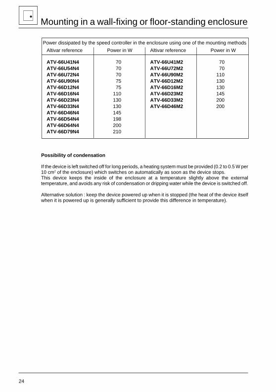
Power dissipated by the speed controller in the enclosure using one of the mounting methods
Altivar reference Power in W Altivar reference Power in W
ATV-66U41N4 70 ATV-66U41M2 70ATV-66U54N4 70 ATV-66U72M2 70ATV-66U72N4 70 ATV-66U90M2 110ATV-66U90N4 75 ATV-66D12M2 130ATV-66D12N4 75 ATV-66D16M2 130ATV-66D16N4 110 ATV-66D23M2 145ATV-66D23N4 130 ATV-66D33M2 200ATV-66D33N4 130 ATV-66D46M2 200ATV-66D46N4 145ATV-66D54N4 198ATV-66D64N4 200ATV-66D79N4 210
Possibility of condensation
If the device is left switched off for long periods, a heating system must be provided (0.2 to 0.5 W per10 cm2 of the enclosure) which switches on automatically as soon as the device stops.This device keeps the inside of the enclosure at a temperature slightly above the externaltemperature, and avoids any risk of condensation or dripping water while the device is switched off.
Alternative solution : keep the device powered up when it is stopped (the heat of the device itselfwhen it is powered up is generally sufficient to provide this difference in temperature).
Mounting in a wall-fixing or floor-standing enclosure
25
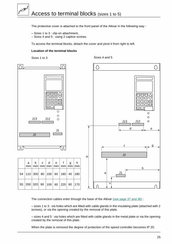
Access to terminal blocks (sizes 1 to 5)
The protective cover is attached to the front panel of the Altivar in the following way :
– Sizes 1 to 3 : clip-on attachment,– Sizes 4 and 5 : using 2 captive screws.
To access the terminal blocks, detach the cover and pivot it from right to left.
Location of the terminal blocks
The connection cables enter through the base of the Altivar (see page 37 and 38) :
– sizes 1 to 3 : via holes which are fitted with cable glands in the insulating plate (attached with 2screws), or via the opening created by the removal of this plate.
– sizes 4 and 5 : via holes which are fitted with cable glands in the metal plate or via the openingcreated by the removal of this plate.
When the plate is removed the degree of protection of the speed controller becomes IP 20.
Sizes 4 and 5Sizes 1 to 3
F 1 F 2 F 3
7 8 9
4 5 6
1 2 3
0 .
ESC
ENT
J13 J12
J1
J2
d e
h
g
c
a
b
f
F 1 F 2 F 3
7 8 9
4 5 6
1 2 3
0 .
ESC
ENT
J13 J12
J1J2
S4
S5
amm
bmm
cmm
dmm
emm
fmm
gmm
hmm
110 300 80 100 60 180 40 180
200 320 90 100 60 220 60 170
26
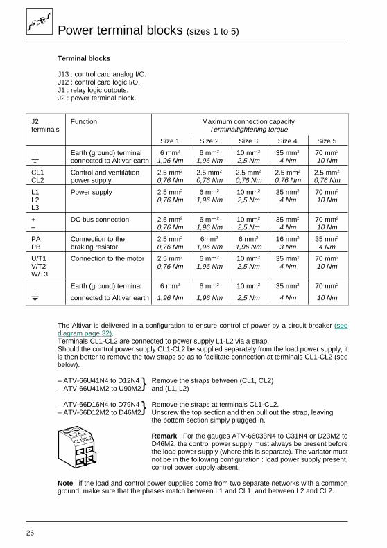
Power terminal blocks (sizes 1 to 5)
Terminal blocks
J13 : control card analog I/O.J12 : control card logic I/O.J1 : relay logic outputs.J2 : power terminal block.
J2 Function Maximum connection capacityterminals Terminaltightening torque
Size 1 Size 2 Size 3 Size 4 Size 5
S Earth (ground) terminal 6 mm2 6 mm2 10 mm2 35 mm2 70 mm2
s connected to Altivar earth 1,96 Nm 1,96 Nm 2,5 Nm 4 Nm 10 Nm
CL1 Control and ventilation 2.5 mm2 2.5 mm2 2.5 mm2 2.5 mm2 2.5 mm2
CL2 power supply 0,76 Nm 0,76 Nm 0,76 Nm 0,76 Nm 0,76 Nm
L1 Power supply 2.5 mm2 6 mm2 10 mm2 35 mm2 70 mm2
L2 0,76 Nm 1,96 Nm 2,5 Nm 4 Nm 10 NmL3
+ DC bus connection 2.5 mm2 6 mm2 10 mm2 35 mm2 70 mm2
– 0,76 Nm 1,96 Nm 2,5 Nm 4 Nm 10 Nm
PA Connection to the 2.5 mm2 6mm2 6 mm2 16 mm2 35 mm2
PB braking resistor 0,76 Nm 1,96 Nm 1,96 Nm 3 Nm 4 Nm
U/T1 Connection to the motor 2.5 mm2 6 mm2 10 mm2 35 mm2 70 mm2
V/T2 0,76 Nm 1,96 Nm 2,5 Nm 4 Nm 10 NmW/T3
Earth (ground) terminal 6 mm2 6 mm2 10 mm2 35 mm2 70 mm2
s connected to Altivar earth 1,96 Nm 1,96 Nm 2,5 Nm 4 Nm 10 Nm
The Altivar is delivered in a configuration to ensure control of power by a circuit-breaker (seediagram page 32).Terminals CL1-CL2 are connected to power supply L1-L2 via a strap.Should the control power supply CL1-CL2 be supplied separately from the load power supply, itis then better to remove the tow straps so as to facilitate connection at terminals CL1-CL2 (seebelow).
– ATV-66U41N4 to D12N4 Remove the straps between (CL1, CL2)– ATV-66U41M2 to U90M2 and (L1, L2)
– ATV-66D16N4 to D79N4 Remove the straps at terminals CL1-CL2.– ATV-66D12M2 to D46M2 Unscrew the top section and then pull out the strap, leaving
the bottom section simply plugged in.
Remark : For the gauges ATV-66033N4 to C31N4 or D23M2 toD46M2, the control power supply must always be present beforethe load power supply (where this is separate). The variator mustnot be in the following configuration : load power supply present,control power supply absent.
Note : if the load and control power supplies come from two separate networks with a commonground, make sure that the phases match between L1 and CL1, and between L2 and CL2.
27
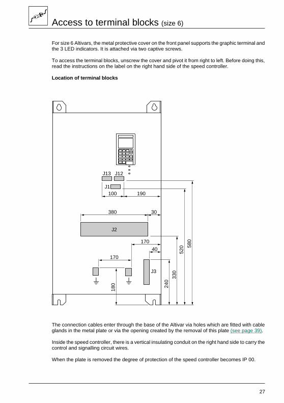
Access to terminal blocks (size 6)
For size 6 Altivars, the metal protective cover on the front panel supports the graphic terminal andthe 3 LED indicators. It is attached via two captive screws.
To access the terminal blocks, unscrew the cover and pivot it from right to left. Before doing this,read the instructions on the label on the right hand side of the speed controller.
Location of terminal blocks
The connection cables enter through the base of the Altivar via holes which are fitted with cableglands in the metal plate or via the opening created by the removal of this plate (see page 39).
Inside the speed controller, there is a vertical insulating conduit on the right hand side to carry thecontrol and signalling circuit wires.
When the plate is removed the degree of protection of the speed controller becomes IP 00.
J3
J1
J13 J12
s
J2
F 1 F 2 F 3
7 8 9
4 5 6
1 2 3
0 .
ESC
ENT
100 190
380 30
170
170
40
180 24
0
330
520 58
0
s
28
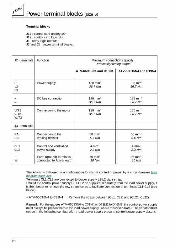
Power terminal blocks (size 6)
Terminal blocks
J13 : control card analog I/O.J12 : control card logic I/O.J1 : relay logic outputs.J2 and J3 : power terminal blocks.
J2 - terminals Function Maximum connection capacityTerminaltightening torque
ATV-66C10N4 and C13N4 ATV-66C15N4 and C19N4
L1 Power supply 120 mm2 185 mm2
L2 36,7 Nm 36,7 NmL3
+ DC bus connection 120 mm2 185 mm2
– 36,7 Nm 36,7 Nm
U/T1 Connection to the motor 120 mm2 185 mm2
V/T2 36,7 Nm 36,7 NmW/T3
J3 - terminals
PA Connection to the 50 mm2 50 mm2
PB braking resistor 5,6 Nm 5,6 Nm
CL1 Control and ventilation 4 mm2 4 mm2
CL2 power supply 2,3 Nm 2,3 Nm
Earth (ground) terminals 70 mm2 95 mm2
s connected to Altivar earth 10 Nm 10 Nm
The Altivar is delivered in a configuration to ensure control of power by a circuit-breaker (seediagram page 32).Terminals CL1-CL2 are connected to power supply L1-L2 via a strap.Should the control power supply CL1-CL2 be supplied separately from the load power supply, itis then better to remove the tow straps so as to facilitate connection at terminals CL1-CL2 (seebelow).
– ATV-66C10N4 to C31N4 Remove the straps between (CL1, CL2) and (CL21, CL22)
Remark : For the gauges ATV-66033N4 to C31N4 or D23M2 to D46M2, the control power supplymust always be present before the load power supply (where this is separate). The variator mustnot be in the following configuration : load power supply present, control power supply absent.
29
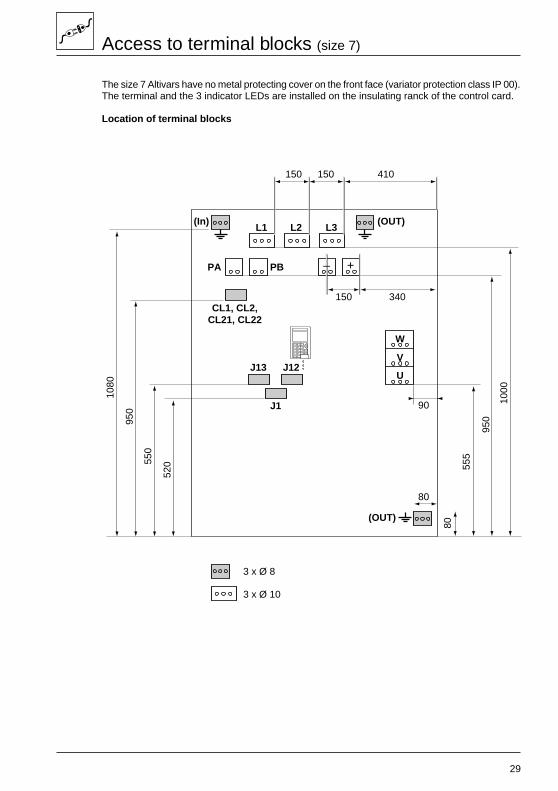
Access to terminal blocks (size 7)
The size 7 Altivars have no metal protecting cover on the front face (variator protection class IP 00).The terminal and the 3 indicator LEDs are installed on the insulating ranck of the control card.
Location of terminal blocks
F 1 F 2 F 3
7 8 9
4 5 6
1 2 3
0 .
ESC
ENT
+–
150 410
150 340
90
3 x Ø 10
3 x Ø 8
80
520 55
5
950
1000
80
550
950
1080
150
J13
PA PB
L1(In) (OUT)
(OUT)
L2 L3
J12
J1
CL1, CL2,CL21, CL22
W
V
U
30
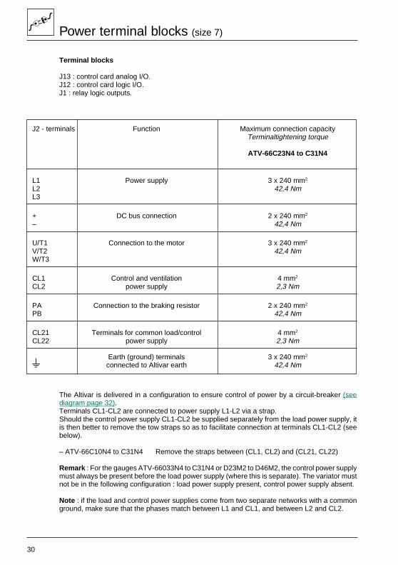
Power terminal blocks (size 7)
Terminal blocks
J13 : control card analog I/O.J12 : control card logic I/O.J1 : relay logic outputs.
J2 - terminals Function Maximum connection capacityTerminaltightening torque
ATV-66C23N4 to C31N4
L1 Power supply 3 x 240 mm2
L2 42,4 NmL3
+ DC bus connection 2 x 240 mm2
– 42,4 Nm
U/T1 Connection to the motor 3 x 240 mm2
V/T2 42,4 NmW/T3
CL1 Control and ventilation 4 mm2
CL2 power supply 2,3 Nm
PA Connection to the braking resistor 2 x 240 mm2
PB 42,4 Nm
CL21 Terminals for common load/control 4 mm2
CL22 power supply 2,3 Nm
Earth (ground) terminals 3 x 240 mm2
s connected to Altivar earth 42,4 Nm
The Altivar is delivered in a configuration to ensure control of power by a circuit-breaker (seediagram page 32).Terminals CL1-CL2 are connected to power supply L1-L2 via a strap.Should the control power supply CL1-CL2 be supplied separately from the load power supply, itis then better to remove the tow straps so as to facilitate connection at terminals CL1-CL2 (seebelow).
– ATV-66C10N4 to C31N4 Remove the straps between (CL1, CL2) and (CL21, CL22)
Remark : For the gauges ATV-66033N4 to C31N4 or D23M2 to D46M2, the control power supplymust always be present before the load power supply (where this is separate). The variator mustnot be in the following configuration : load power supply present, control power supply absent.
Note : if the load and control power supplies come from two separate networks with a commonground, make sure that the phases match between L1 and CL1, and between L2 and CL2.
31
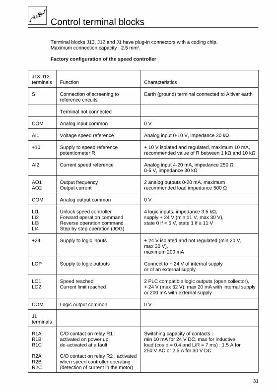
Control terminal blocks
Terminal blocks J13, J12 and J1 have plug-in connectors with a coding chip.Maximum connection capacity : 2.5 mm2.
Factory configuration of the speed controller
J13-J12terminals Function Characteristics
S Connection of screening to Earth (ground) terminal connected to Altivar earthreference circuits
Terminal not connected
COM Analog input common 0 V
AI1 Voltage speed reference Analog input 0-10 V, impedance 30 kΩ
+10 Supply to speed reference + 10 V isolated and regulated, maximum 10 mA,potentiometer R recommended value of R between 1 kΩ and 10 kΩ
AI2 Current speed reference Analog input 4-20 mA, impedance 250 Ω0-5 V, impedance 30 kΩ
AO1 Output frequency 2 analog outputs 0-20 mA, maximumAO2 Output current recommended load impedance 500 Ω
COM Analog output common 0 V
LI1 Unlock speed controller 4 logic inputs, impedance 3.5 kΩ,LI2 Forward operation command supply + 24 V (min 11 V, max 30 V),LI3 Reverse operation command state 0 if < 5 V, state 1 if ≥ 11 VLI4 Step by step operation (JOG)
+24 Supply to logic inputs + 24 V isolated and not regulated (min 20 V,max 30 V),maximum 200 mA
LOP Supply to logic outputs Connect to + 24 V of internal supplyor of an external supply
LO1 Speed reached 2 PLC compatible logic outputs (open collector),LO2 Current limit reached + 24 V (max 32 V), max 20 mA with internal supply
or 200 mA with external supply
COM Logic output common 0 V
J1terminals
R1A C/O contact on relay R1 : Switching capacity of contacts :R1B activated on power up, min 10 mA for 24 V DC, max for inductiveR1C de-activated at a fault load (cos ϕ = 0.4 and L/R = 7 ms) : 1.5 A for
250 V AC or 2.5 A for 30 V DCR2A C/O contact on relay R2 : activatedR2B when speed controller operatingR2C (detection of current in the motor)
32
Q1U1
W1
V1
L1
L2
L3
CL1
CL2
COM
AI1
+10
AI2
LI1
LI2
LI3
LI4
+24
R4-20 mA
–
+
Hz
A
M13 c
PA
PB
U/T1
V/T2
W/T3
R1A
R1B
R1C
R2A
R2B
R2C
COM
AO1
AO2
COM
LO1
LO2
LOP
+ –
U1
W1
V1 M13 c
F2 F1
L1
L2
L3
CL1
CL2
U/T1
V/T2
W/T3
Q1 KM1
–+
24 V
JOG
S
LI1
LI2
LI3
LI4
COM
LO1
LO2
LOP
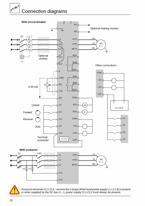
Connection diagrams
With circuit-breaker
Other connections
Optionalchokes
Unlock
Reverse
Forward
Optional braking resistor
Terminalconnector
With contactor
Access to terminals CL1-CL2 : remove the 2 straps.When load power supply L1-L2-L3) is presentor when supplied by the DC bus (+, -), power supply CL1-CL2 must always be present.

33
Ferrite core installation and recommendations
Wiring precautions
Power
Respect the cable cross-sections recommended by the standards (see page 36).Speed controller-motor connection cables :– minimum length : 0.5 m,– maximum length 100 m with non-screened cables, or 50 m with screened cables.Above this, install an L or LC filter between the speed controller and the motor (refer to thecatalogue).
The speed controller must be connected to earth (ground), in order to conform with the regulationscovering high leakage currents (above 3.5 mA). Use of a differential circuit-breaker upstream is notrecommended since DC components could be generated by leakage currents from the speedcontroller. If the installation comprises several speed controllers on the same line, connect eachcontroller to earth separately. If necessary, install a line choke (refer to the catalogue).
Keep the power cables separate from the low level signal circuits in the installation (detectors,PLCs, measuring apparatus, video, telephone).
Control
Keep the control circuits separate from the power cables. For the speed reference circuits, it isrecommended that twisted cable with a pitch of between 25 and 50 mm is used, or screened cablewith the screening connected to terminal S.
Ferrite core installation
The options to enable compliance with the EMC directive are thoseindicated in our documentation (EMC Catalogue No. 75011). Theseitems need to be ordered separately.The only items delivered with the product are :– The control cable ferrite (blue) : "control ferrite core“.– The motor cable ferrite (red) : "motor ferrite core“.
(1) motor cable(2) control cable
The ferrites must be installed on the unscreened cable as close aspossible to the terminals on the Altivar.
Please note : Schneider organisation is at your disposal to provide any assistance required in termsof Documentation, Practical Advice, Technical Assistance, EMC Traning Courses.
Selection of associated components
Circuit-breaker or isolator Q1 (with gl type fuses) : determine according to the line current, plusthe consumption of the other parts of the device.
Contactor KM1 : select for category AC-1, according to the line current.
Fuses F1-F2 : determine according to the AC supply voltage and the rating of the control andventilation power supply transformer (terminals CL1-CL2) :– ATV-66U41N4 to D23N4 (sizes 1 to 3) : 40 VA, and ATV-66U41M2 to D16M2– ATV-66D33N4 to D79N4 (sizes 4 and 5) : 110 VA, and ATV-66D23M2 to D46M2– ATV-66C10N4 to C19N4 (size 6) : 630 VA,– ATV-66C23N4 to C31N4 (size 7) : 1000 VA.
F 1 F 2 F 3
7 8 9
4 5 6
1 2 3
0 .
ESC
ENT
J13 J12
J1J2
(1)
(2)
34
Recommendations
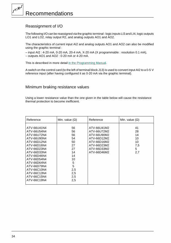
Reassignment of I/O
The following I/O can be reassigned via the graphic terminal : logic inputs LI3 and LI4, logic outputsLO1 and LO2, relay output R2, and analog outputs AO1 and AO2.
The characteristics of current input AI2 and analog outputs AO1 and AO2 can also be modifiedusing the graphic terminal :
– input AI2 : 4-20 mA, 0-20 mA, 20-4 mA, X-20 mA (X programmable : resolution 0.1 mA),– outputs AO1 and AO2 : 0-20 mA or 4-20 mA.
This is described in more detail in the Programming Manual.
A switch on the control card (to the left of terminal block J13) is used to convert input AI2 to a 0-5 Vreference input (after having configured it as 0-20 mA via the graphic terminal).
Reference Min. value (Ω) Reference Min. value (Ω)
ATV-66U41N4 56 ATV-66U41M2 41ATV-66U54N4 56 ATV-66U72M2 28ATV-66U72N4 56 ATV-66U90M2 14ATV-66U90N4 54 ATV-66D12M2 10ATV-66D12N4 50 ATV-66D16M2 10ATV-66D16N4 27 ATV-66D23M2 7,5ATV-66D23N4 27 ATV-66D33M2 5ATV-66D33N4 14 ATV-66D46M2 2,7ATV-66D46N4 14ATV-66D54N4 10ATV-66D64N4 5ATV-66D79N4 5ATV-66C10N4 2,5ATV-66C13N4 2,5ATV-66C15N4 2,5ATV-66C19N4 2,5
Minimum braking resistance values
Using a lower resistance value than the one given in the table below will cause the resistancethermal protection to become inefficient.
35
Command type
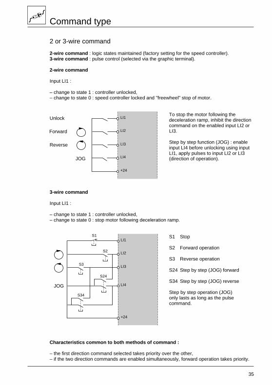
2 or 3-wire command
2-wire command : logic states maintained (factory setting for the speed controller).3-wire command : pulse control (selected via the graphic terminal).
2-wire command
Input LI1 :
– change to state 1 : controller unlocked,– change to state 0 : speed controller locked and "freewheel" stop of motor.
To stop the motor following thedeceleration ramp, inhibit the directioncommand on the enabled input LI2 orLI3.
Step by step function (JOG) : enableinput LI4 before unlocking using inputLI1, apply pulses to input LI2 or LI3(direction of operation).
3-wire command
Input LI1 :
– change to state 1 : controller unlocked,– change to state 0 : stop motor following deceleration ramp.
S1 Stop
S2 Forward operation
S3 Reverse operation
S24 Step by step (JOG) forward
S34 Step by step (JOG) reverse
Step by step operation (JOG)only lasts as long as the pulsecommand.
Characteristics common to both methods of command :
– the first direction command selected takes priority over the other,– if the two direction commands are enabled simultaneously, forward operation takes priority.
LI1
LI2
LI3
LI4
+24
JOG
Unlock
LI1
LI2
LI3
LI4
+24
S2
S3
S24
S34
S1
JOG
Reverse
Forward
36
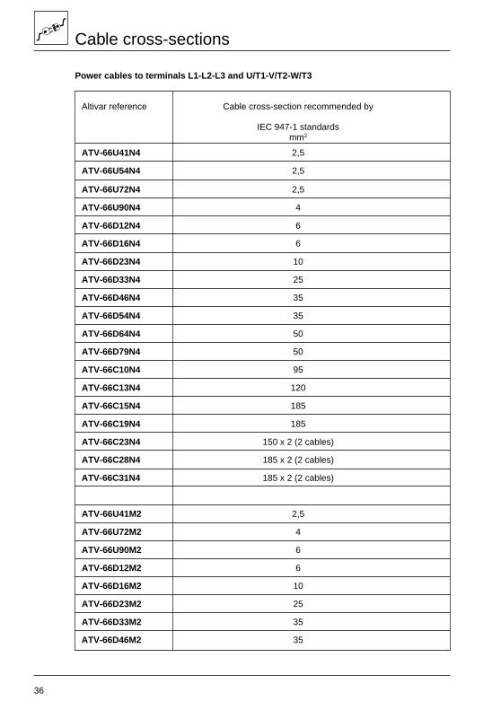
Cable cross-sections
Power cables to terminals L1-L2-L3 and U/T1-V/T2-W/T3
Altivar reference Cable cross-section recommended by
IEC 947-1 standardsmm2
ATV-66U41N4 2,5
ATV-66U54N4 2,5
ATV-66U72N4 2,5
ATV-66U90N4 4
ATV-66D12N4 6
ATV-66D16N4 6
ATV-66D23N4 10
ATV-66D33N4 25
ATV-66D46N4 35
ATV-66D54N4 35
ATV-66D64N4 50
ATV-66D79N4 50
ATV-66C10N4 95
ATV-66C13N4 120
ATV-66C15N4 185
ATV-66C19N4 185
ATV-66C23N4 150 x 2 (2 cables)
ATV-66C28N4 185 x 2 (2 cables)
ATV-66C31N4 185 x 2 (2 cables)
ATV-66U41M2 2,5
ATV-66U72M2 4
ATV-66U90M2 6
ATV-66D12M2 6
ATV-66D16M2 10
ATV-66D23M2 25
ATV-66D33M2 35
ATV-66D46M2 35
37
f
g
f
d
e
= h =
d1
d2
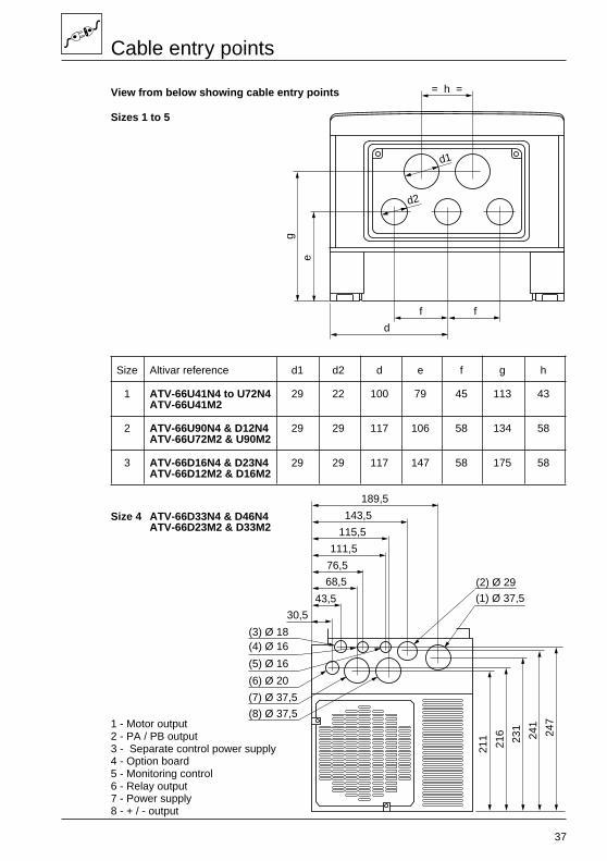
Cable entry points
View from below showing cable entry points
Sizes 1 to 5
Size Altivar reference d1 d2 d e f g h
1 ATV-66U41N4 to U72N4 29 22 100 79 45 113 43ATV-66U41M2
2 ATV-66U90N4 & D12N4 29 29 117 106 58 134 58ATV-66U72M2 & U90M2
3 ATV-66D16N4 & D23N4 29 29 117 147 58 175 58ATV-66D12M2 & D16M2
Size 4 ATV-66D33N4 & D46N4ATV-66D23M2 & D33M2
1 - Motor output2 - PA / PB output3 - Separate control power supply4 - Option board5 - Monitoring control6 - Relay output7 - Power supply8 - + / - output
(1) Ø 37,5
(2) Ø 29
(3) Ø 18(4) Ø 16
(5) Ø 16
(6) Ø 20
(7) Ø 37,5
(8) Ø 37,5
111,5
76,5
143,5
115,5
189,5
68,5
43,5
30,5
241
247
216
231
211
38
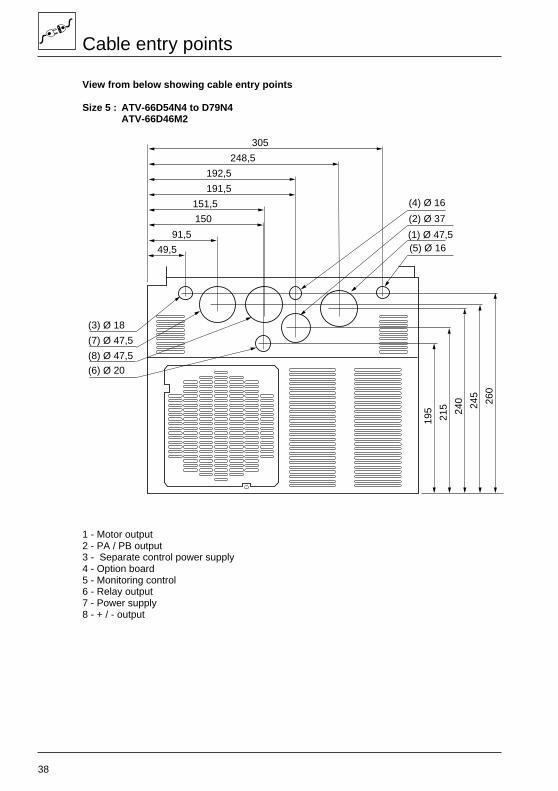
Cable entry points
View from below showing cable entry points
Size 5 : ATV-66D54N4 to D79N4ATV-66D46M2
1 - Motor output2 - PA / PB output3 - Separate control power supply4 - Option board5 - Monitoring control6 - Relay output7 - Power supply8 - + / - output
(1) Ø 47,5
(2) Ø 37
(3) Ø 18
(4) Ø 16
(5) Ø 16
(6) Ø 20
(7) Ø 47,5
(8) Ø 47,5
191,5
151,5
248,5
192,5
305
150
91,5
49,5
245
260
215 24
0
195
39
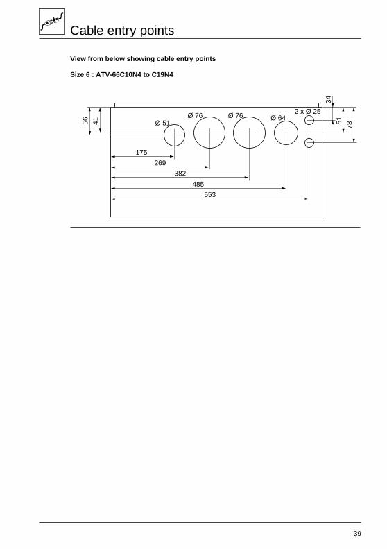
Cable entry points
View from below showing cable entry points
Size 6 : ATV-66C10N4 to C19N4
175
56
269
382
485
41 51
78
34
Ø 51Ø 76 Ø 76 Ø 64
2 x Ø 25
553
40
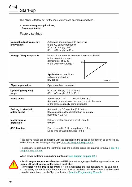
Start-up
The Altivar is factory-set for the most widely used operating conditions :
– constant torque applications,– 2-wire command.
Factory settings
Nominal output frequency Automatic adaptation on 1st power-upand voltage to the AC supply frequency
50 Hz AC supply : 400 V60 Hz AC supply : 460 V
Voltage / frequency ratio Normal linear ratio, IR compensation set at 100 %of the correction range,damping set at 20 %of the adjustment range
Applications : machineswith average load atlow speed
Slip compensation Operational and automatic
Operating frequency 50 Hz AC supply : 0.1 to 75 Hzrange 60 Hz AC supply : 0.1 to 90 Hz
Ramp times Acceleration : 3 s Deceleration : 3 sAutomatic adaptation of the ramp times in the eventof the torque capacity being exceeded
Braking to standstill Automatic by DC injection (0.7 Inv) forat low speed 0.5 s as soon as the deceleration frequency
becomes < 0.1 Hz
Motor thermal Set for a motor nominal current equal toprotection 0.9 Inv
JOG function Speed limited to 5 Hz, ramp times : 0.1 sDead time between 2 pulses : 0.5 s
If the above values are compatible with the application, the speed controller can be powered up.To understand the messages displayed, see the Programming Manual.
If necessary, reconfigure the controller and the settings using the graphic terminal : see theProgramming Manual.
When power switching using a line contactor (see diagram on page 32) :
– Avoid frequent operation of contactor KM1 (premature ageing of the filtering capacitors), useinputs LI1 to LI4 to control the speed controller .– For cycles < 60 s, this is essential . If it is not respected the load resistors will be damaged.– If the safety standards state that the motor must be insulated, install a contactor at the speedcontroller output and use the “bypass” function (see the Programming Manual).
U
Un
f50/60 Hz
41
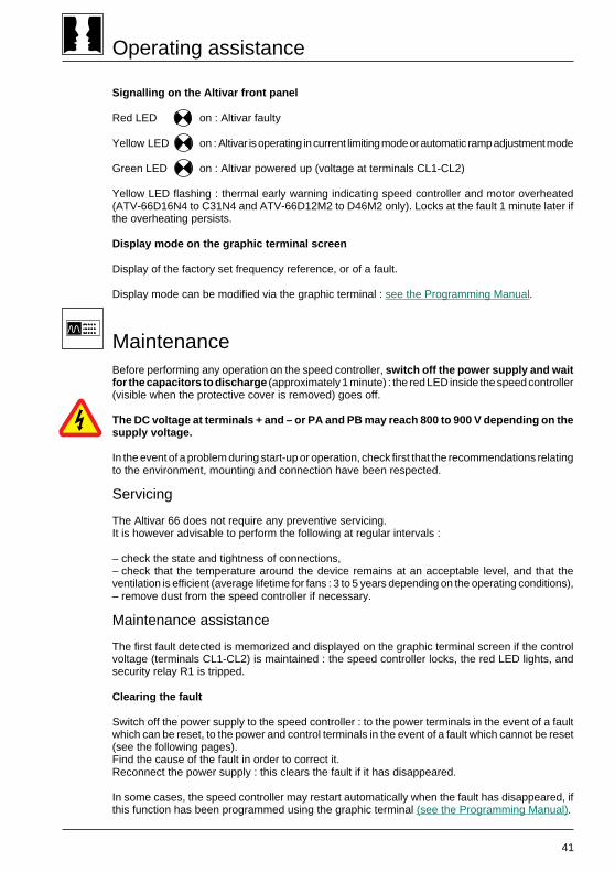
Operating assistance
Signalling on the Altivar front panel
Red LED on : Altivar faulty
Yellow LED on : Altivar is operating in current limiting mode or automatic ramp adjustment mode
Green LED on : Altivar powered up (voltage at terminals CL1-CL2)
Yellow LED flashing : thermal early warning indicating speed controller and motor overheated(ATV-66D16N4 to C31N4 and ATV-66D12M2 to D46M2 only). Locks at the fault 1 minute later ifthe overheating persists.
Display mode on the graphic terminal screen
Display of the factory set frequency reference, or of a fault.
Display mode can be modified via the graphic terminal : see the Programming Manual.
MaintenanceBefore performing any operation on the speed controller, switch off the power supply and waitfor the capacitors to discharge (approximately 1 minute) : the red LED inside the speed controller(visible when the protective cover is removed) goes off.
The DC voltage at terminals + and – or PA and PB may reach 800 to 900 V depending on thesupply voltage.
In the event of a problem during start-up or operation, check first that the recommendations relatingto the environment, mounting and connection have been respected.
Servicing
The Altivar 66 does not require any preventive servicing.It is however advisable to perform the following at regular intervals :
– check the state and tightness of connections,– check that the temperature around the device remains at an acceptable level, and that theventilation is efficient (average lifetime for fans : 3 to 5 years depending on the operating conditions),– remove dust from the speed controller if necessary.
Maintenance assistance
The first fault detected is memorized and displayed on the graphic terminal screen if the controlvoltage (terminals CL1-CL2) is maintained : the speed controller locks, the red LED lights, andsecurity relay R1 is tripped.
Clearing the fault
Switch off the power supply to the speed controller : to the power terminals in the event of a faultwhich can be reset, to the power and control terminals in the event of a fault which cannot be reset(see the following pages).Find the cause of the fault in order to correct it.Reconnect the power supply : this clears the fault if it has disappeared.
In some cases, the speed controller may restart automatically when the fault has disappeared, ifthis function has been programmed using the graphic terminal (see the Programming Manual).
42
Maintenance assistance
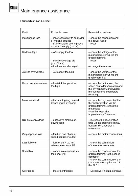
Faults which can be reset
Fault Probable cause Remedial procedure
Input phase loss – incorrect supply to controller – check the connection andor melting of fuses the power fuses– transient fault of one phase – resetof the AC supply (t ≥ 1 s)
Undervoltage – AC supply too low – check the voltage or themotor parameter Un via thegraphic terminal
– transient voltage dip – reset(t ≥ 200 ms)– load resistor damaged – change the resistor
AC-line overvoltage – AC supply too high – check the voltage or themotor parameter Un via thegraphic terminal
Drive overtemperature – heatsink temperature – check the motor load, thetoo high speed controller ventilation and
the environment, and wait forthe controller to cool beforeresetting
Motor overload – thermal tripping caused – check the adjustment of theby prolonged overload thermal protection via the
graphic terminal, check themotor load– can be reset afterapproximately 7 minutes
DC-bus overvoltage – excessive braking or – increase the decelerationdriving load time via the graphic terminal,
add a braking resistor ifnecessary
Output phase loss – fault on one phase at – check the motor connectionsspeed controller output
Loss follower – loss of the 4-20 mA – check the connectionreference on input AI2 of the reference circuits
Serial link – communication fault via – check the connection of thethe serial link graphic terminal to the speed
controller– check the connection of thecommunication option and ofthe PLC
Overspeed – Motor control loss – Excessively high motor load
43
Maintenance assistance
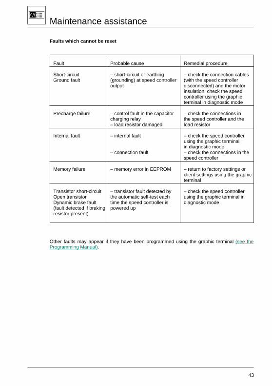
Faults which cannot be reset
Fault Probable cause Remedial procedure
Short-circuit – short-circuit or earthing – check the connection cablesGround fault (grounding) at speed controller (with the speed controller
output disconnected) and the motorinsulation, check the speedcontroller using the graphicterminal in diagnostic mode
Precharge failure – control fault in the capacitor – check the connections incharging relay the speed controller and the– load resistor damaged load resistor
Internal fault – internal fault – check the speed controllerusing the graphic terminalin diagnostic mode
– connection fault – check the connections in thespeed controller
Memory failure – memory error in EEPROM – return to factory settings orclient settings using the graphicterminal
Transistor short-circuit – transistor fault detected by – check the speed controllerOpen transistor the automatic self-test each using the graphic terminal inDynamic brake fault time the speed controller is diagnostic mode(fault detected if braking powered upresistor present)
Other faults may appear if they have been programmed using the graphic terminal (see theProgramming Manual).

44
Spare parts
Description For speed controllers Reference
Programming graphic terminal ATV-66 all sizes VW3-A66206
Control terminal blocks (plug-in parts ATV-66 all sizes VZ3-N006of terminal blocks J1 - J12 - J13)
Set of two-ferrite cores ATV-66U41N4 to D46N4 VW3-A66470ATV-66U41M2 to D33M2 VW3-A66470ATV-66D54N4 to D79N4 VW3-A66471ATV-66D46M2 VW3-A66471
“Controle” card (with isolating basket) ATV-66U41N4 to D79N4 VX4-A661
ATV-66U41M2 to D46M2 VX4-A661
ATV-66C10N4 to C19N4 VX4-A661S238ATV-66C23N4 to C31N4 VX4-A661S238
"Power" assemblies ATV-66U41N4 VX5-A66U41N4ATV-66U54N4 VX5-A66U54N4ATV-66U72N4 VX5-A66U72N4
ATV-66U41M2 VX5-A66U41M2
ATV-66U90N4 VX5-A66U90N4ATV-66D12N4 VX5-A66D12N4
ATV-66U72M2 VX5-A66U72M2ATV-66U90M2 VX5-A66U90M2
"Power" cards TV-66D16N4 VX5-A66D16N4ATV-66D23N4 VX5-A66D23N4
ATV-66D12M2 VX5-A66D12M2ATV-66D16M2 VX5-A66D16M2
Tool for removing and inserting ATV-66U41N4 to D23N4 VY1-ADV608the power card
ATV-66U41M2 to D16M2 VY1-ADV608
"Power" cards ATV-66D33N4 VX5-A66D33N4ATV-66D46N4 VX5-A66D46N4
ATV-66D23M2 VX5-A66D23M2ATV-66D33M2 VX5-A66D33M2
ATV-66D54N4 VX5-A66D54N4ATV-66D64N4 VX5-A66D64N4ATV-66D79N4 VX5-A66D79N4
ATV-66D46M2 VX5-A66D46M2
ATV-66C10N4 VX5-A66C10N4ATV-66C13N4 VX5-A66C13N4ATV-66C15N4 VX5-A66C15N4ATV-66C19N4 VX5-A66C19N4
ATV-66C23N4 VX5-A66C23N4ATV-66C28N4 VX5-A66C28N4ATV-66C31N4 VX5-A66C31N4
45
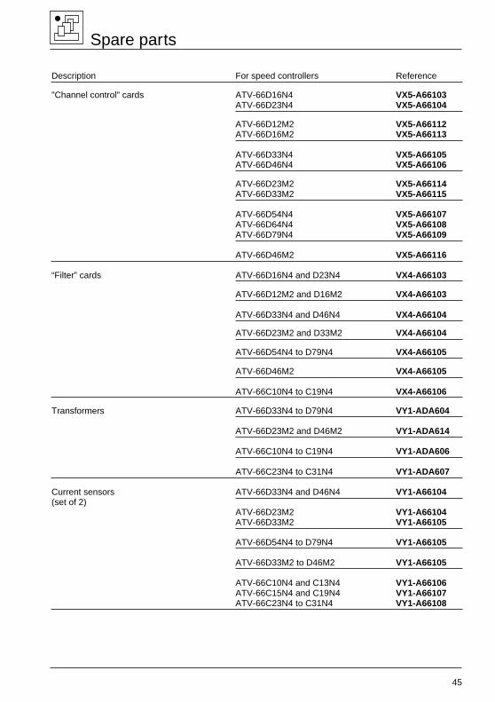
Description For speed controllers Reference
"Channel control" cards ATV-66D16N4 VX5-A66103ATV-66D23N4 VX5-A66104
ATV-66D12M2 VX5-A66112ATV-66D16M2 VX5-A66113
ATV-66D33N4 VX5-A66105ATV-66D46N4 VX5-A66106
ATV-66D23M2 VX5-A66114ATV-66D33M2 VX5-A66115
ATV-66D54N4 VX5-A66107ATV-66D64N4 VX5-A66108ATV-66D79N4 VX5-A66109
ATV-66D46M2 VX5-A66116
“Filter” cards ATV-66D16N4 and D23N4 VX4-A66103
ATV-66D12M2 and D16M2 VX4-A66103
ATV-66D33N4 and D46N4 VX4-A66104
ATV-66D23M2 and D33M2 VX4-A66104
ATV-66D54N4 to D79N4 VX4-A66105
ATV-66D46M2 VX4-A66105
ATV-66C10N4 to C19N4 VX4-A66106
Transformers ATV-66D33N4 to D79N4 VY1-ADA604
ATV-66D23M2 and D46M2 VY1-ADA614
ATV-66C10N4 to C19N4 VY1-ADA606
ATV-66C23N4 to C31N4 VY1-ADA607
Current sensors ATV-66D33N4 and D46N4 VY1-A66104(set of 2)
ATV-66D23M2 VY1-A66104ATV-66D33M2 VY1-A66105
ATV-66D54N4 to D79N4 VY1-A66105
ATV-66D33M2 to D46M2 VY1-A66105
ATV-66C10N4 and C13N4 VY1-A66106ATV-66C15N4 and C19N4 VY1-A66107ATV-66C23N4 to C31N4 VY1-A66108
Spare parts
46
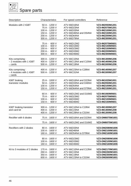
Description Characteristics For speed controllers Reference
Modules with 2 IGBT 50 A - 1200 V ATV-66D16N4 VZ3-IM2050M120175 A - 1200 V ATV-66D23N4 VZ3-IM2075M1201
100 A - 1200 V ATV-66D33N4 VZ3-IM2100M1201150 A - 1200 V ATV-66D46N4 and D54N4 VZ3-IM2150M1201200 A - 1200 V ATV-66D64N4 VZ3-IM2200M1201300 A - 1200 V ATV-66D79N4 VZ3-IM2300M1201
75 A - 600 V ATV-66D12M2 VZ3-IM2075M0601100 A - 600 V ATV-66D16M2 VZ3-IM2100M0601150 A - 600 V ATV-66D23M2 VZ3-IM2150M0601200 A - 600 V ATV-66D33M2 VZ3-IM2200M0601300 A - 600 V ATV-66D46M2 VZ3-IM2300M0601
Kits comprising : 300 A - 1200 V ATV-66C10N4 VZ3-IM1300M1206– 2 modules with 1 IGBT 400 A - 1200 V ATV-66C13N4 and C15N4 VZ3-IM1400M1206– cards 500 A - 1200 V ATV-66C19N4 VZ3-IM1500M1206
Kits comprising : 400 A - 1200 V ATV-66C23N4 to C28N4 VZ3-IM1400M1207– 4 modules with 1 IGBT 500 A - 1200 V ATV-66C31N4 VZ3-IM1500M1207– cards
IGBT braking 25 A - 1000 V ATV-66D16N4 and D23N4 VZ3-IM1025M1001transistor modules 50 A - 1200 V ATV-66D33N4 and D46N4 VZ3-IM2050M1201
100 A - 1200 V ATV-66D54N4 VZ3-IM2100M1201150 A - 1200 V ATV-66D64N4 and D79N4 VZ3-IM2150M1201
60 A - 600 V ATV-66D12M2 and D16M2 VZ3-IM1060M0601 75 A - 600 V ATV-66D23M2 VZ3-IM2075M0601100 A - 600 V ATV-66D33M2 VZ3-IM2100M0601150 A - 600 V ATV-66D46M2 VZ3-IM2150M0601
IGBT braking transistor 300 A - 1200 V ATV-66C10N4 to C19N4 VZ3-IM1300M1207and card kit 400 A - 1200 V ATV-66C23N4 VZ3-IM1400M1208
400 A - 1200 V ATV-66C28N4 to C31N4 VZ3-IM1300M1208
Rectifier with 6 diodes 75 A - 1600 V ATV-66D16N4 and D23N4 VZ3-DM6075M1601
75 A - 1600 V ATV-66D12M2 and D16M2 VZ3-DM6075M1601
Rectifiers with 2 diodes 80 A - 1600 V ATV-66D33N4 VZ3-DM2080M1606100 A - 1600 V ATV-66D46N4 VZ3-DM2100M1601160 A - 1600 V ATV-66D54N4 to D79N4 VZ3-DM2160M1606
80 A - 1600 V ATV-66D23M2 VZ3-DM2080M1606100 A - 1600 V ATV-66D33M2 VZ3-DM2100M1601160 A - 1600 V ATV-66D46M2 VZ3-DM2160M1606
Kit to 3 modules of 2 diodes 170 A - 1600 V ATV-66C10N4 and C13N4 VZ3-DM2170M1601260 A - 1600 V ATV-66C15N4 VZ3-DM2260M1601350 A - 1600 V ATV-66C19N4 VZ3-DM2350M1601600 A - 1600 V ATV-66C23N4 to C31N4 VZ3-DM2600M1601
Spare parts
47
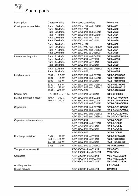
Spare parts
Description Characteristics For speed controllers Reference
Cooling sub-assemblies Rate 5 dm3/s ATV-66U41N4 and U54N4 VZ3-V661Rate 10 dm3/s ATV-66U72N4 VZ3-V662Rate 22 dm3/s ATV-66U90N4 and D12N4 VZ3-V663Rate 47 dm3/s ATV-66D16N4 and D23N4 VZ3-V664Rate 100 dm3/s ATV-66D33N4 to D79N4 VZ3-V665Rate 250 dm3/s ATV-66C10N4 to C31N4 VZ3-V666
Rate 10 dm3/s ATV-66U41M2 VZ3-V662Rate 22 dm3/s ATV-66U72M2 and U90M2 VZ3-V663Rate 47 dm3/s ATV-66D12M2 and D16M2 VZ3-V664Rate 100 dm3/s ATV-66D23M2 to D46M2 VZ3-V665
Internal cooling units Rate 11 dm3/s ATV-66D33N4 and D46N4 VZ3-V6654Rate 14 dm3/s ATV-66D54N4 to D79N4 VZ3-V6655Rate 14 dm3/s ATV-66C10N4 to C19N4 VZ3-V667Rate 18 dm3/s ATV-66C23N4 to C31N4 VZ3-V669
Rate 11 dm3/s ATV-66D23M2 and D33M2 VZ3-V6654Rate 14 dm3/s ATV-66D46M2 VZ3-V6655
Load resistors 33 Ω - 8,5 W ATV-66D16N4 and D23N4 VZ3-R033W00910 Ω - 25 W ATV-66D33N4 and D46N4 VZ3-R010W02510 Ω - 480 W ATV-66D54N4 to C31N4 VZ3-R010W481
33 Ω - 8,5 W ATV-66D12M2 and D16M2 VZ3-R033W00910 Ω - 25 W ATV-66D23M2 and D33M2 VZ3-R010W02510 Ω - 480 W ATV-66D46M2 VZ3-R010W481
Control fuse 5 A- 600(8,5 x 31,5) ATV-66C10N4 to C31N4 DF3-CF00501
DC bus protection fuses 400 A - 700 V ATV-66C10N4 and C13N4 VY1-ADF400V700450 A - 700 V ATV-66C15N4 and C19N4 VY1-ADF450V700
ATV-66C23N4 and C31N4 VY1-ADF400V700
Capacitors ATV-66D16N4 and D23N4 VY1-ADC152V450ATV-66D33N4 and D46N4 VY1-ADC472V450
ATV-66D12M2 and D16M2 VY1-ADC152V450ATV-66D23M2 and D33M2 VY1-ADC472V450
Capacitor sub-assemblies ATV-66D54N4 VY1-ADC605ATV-66D64N4 and D79N4 VY1-ADC606ATV-66C10N4 to C19N4 VY1-ADC607ATV-66C23N4 to C31N4 VY1-ADC608
ATV-66D46M2 VY1-ADC605
Discharge resistors 5 kΩ - 40 W ATV-66D33N4 to D79N4 VZ3-R5K0W040640 Ω - 135 W ATV-66D10N4 to D19N4 VZ3-R640W1351,2 kΩ - 480 W ATV-66D23N4 to D31N4 VZ3-R1K2W480
5 kΩ - 40 W ATV-66D23M2 to D46M2 VZ3R5K0W040
Temperature sensor kit ATV-66C10N4 to C19N4 VZ3-G003ATV-66C23N4 and C31N4 VZ3-G004
Contactor ATV-66C10N4 to C13N4 VY1-A661C1010ATV-66C15N4 and C19N4 VY1-A661C1510ATV-66C23N4 to C31N4 VY1-A661C2310
Auxiliary contact LA1-DN04
Circuit breaker ATV-66C10N4 to C31N4 GV2M10