GstDef2.1 Defining Tool Issue2.18.pdf
28
-
Upload
khangminh22 -
Category
Documents
-
view
3 -
download
0
Transcript of GstDef2.1 Defining Tool Issue2.18.pdf
GstDef2.1 Defining Tool User’s Manual The Intelligent Solution
CONTENTS
1 Overview ...................................................................................................................... 1
2 System Requirement .................................................................................................. 1
2.1 Hardware .................................................................................................................... 1
2.2 Software ..................................................................................................................... 1
3 Installation ................................................................................................................... 1
4 Download Card ........................................................................................................... 2
5 User’s Guide................................................................................................................ 3
5.1 Function Tools ............................................................................................................ 3
5.1.1 Com Set ............................................................................................................... 4
5.1.2 Setting Language ................................................................................................ 4
5.1.3 Com Test .............................................................................................................. 4
5.1.4 Database ............................................................................................................. 5
5.1.5 Device type .......................................................................................................... 5
5.1.6 Cancel .................................................................................................................. 5
5.1.7 About .................................................................................................................... 5
5.1.8 Exit system .......................................................................................................... 6
5.2 General Operation ...................................................................................................... 6
5.2.1 Panel Operation ................................................................................................... 6
5.2.2 Zone Operation .................................................................................................... 7
5.3 System Definition ....................................................................................................... 7
5.3.1 Define zones ........................................................................................................ 7
5.3.2 Define devices ..................................................................................................... 9
5.3.3 Define Control Keys and their LEDs ................................................................. 12
5.3.4 Define Repeater Panels .................................................................................... 15
5.3.5 Define Equations ............................................................................................... 16
6 Caution ...................................................................................................................... 23
Appendix Device Type List ............................................................................................. 24

GstDef2.1 Defining Tool User’s Manual The Intelligent Solution
Page 1
1 Overview
The newly developed GST Intelligent Fire Alarm System Defining Tool software is used for
system commissioning. It is designed with friendly user interface and powerful functions. The
fire alarm control panel (FACP) that can use this software include GST200 series (GST200
and GST200-2), GST5000 series (GST5000, GST5000W and GST5000F) and GST-IFP8
FACPs. The main features of this highly intelligent package are:
By dividing control panels into logical zones and with descriptions of each zone, the
control functions of the panels are made clearer:
Providing the network definition of up to 32 FACPs of any model of GST200 and
GST5000 series.
Communicating with FACP through RS232 interface at a rate of 2400bps.
Devices are distinguished with different icons.
Zones are easily distinguished with different colors.
Dropdown lists are used to save time. Manual input is also available with memory ability
from the software that makes it simpler for similar inputs. Definitions can be edited in
dialogue boxes.
C&E equation definition with clear relationship, easily selecting exact device or group
devices by fuzzy logic.
In addition to normal text display, the system also supports upload or download of
bi-direction text (a mixture of left-to-right and right-to-left horizontal text) for some
special languages, and the screen displays accordingly.
For GST200-2 and GST-IFP8, name of device type is user-definable and running record
can be uploaded to computer and saved as an Excel file.
Supporting multi-languages. The default language is English. The language package
can be downloaded from http://www.gst.com.cn/english/products/GST-def.html.
2 System Requirement
2.1 Hardware
CPU: Pentium III 1G or above
Free Hard disk: 2GB or above
Memory: 512MB or above
2.2 Software
Windows 2000 or Windows XP Professional
3 Installation
The software setup file is named GstDef2.1_setup.exe. Double clicking the file and following
the wizards will install the software into your computer.
To uninstall the software, you can either go to <Control Panel> -- <Add/Remove Software>
or run the GstDef2.1_setup.exe again.

GstDef2.1 Defining Tool User’s Manual The Intelligent Solution
Page 2
4 Download Card
The software can work offline for defining in the office, only connecting to the panel for
downloading the definition. The definition download needs an RS232 communication card.
P-9930 download card is for GST200. Connect the download card to the extend port on the
main board with a ribbon cable. Enter the commission password 24220011 and press the
button SK1 on the main board, as shown in Fig. 1.
Fig. 1
If the RED LED on the download card flashes, the download/upload operation can be done.
Otherwise please repeat the above operation.
For GST5000 series panels, choose any unused slot to insert the download card. Set the
card code to next of the last card. For example, there are 3 loop cards in the panel which
takes codes 01 02 & 03, then the download card should be set as 04. Make the panel work
in commission state (the panel will show “Installer” on top of the screen) and restart the
panel. Then press BROWSE button on the keypad. If <CRT INSTALLED> appears, it
succeeds. Otherwise check the card code and repeat the operation. The code setting is
shown as in Fig. 2.

GstDef2.1 Defining Tool User’s Manual The Intelligent Solution
Page 3
Communication LEDCommunication LED
Run LED
Ones Digit
232 Communication Card
To CRT
Communication LED
To Zone Indication and
Manual Intervention Panel
Run LED
Fault LED
Run LEDRun LED
485 Communication CardLoop CardMain Board
Tens DigitTo Switch Board
Fig. 2
For GST-IFP panel, choose COMMUNICATION BOARD slot to insert the download card.
There is code set switch on the communication board. Set the card code to next of the last
card. For example, there are 2 loop cards in the panel which takes codes 01 & 02, then the
download card should be set as 03. Make the panel work in commission state (the panel will
show “×” on right-top corner of the screen) and restart the panel. Then enter <USER
SETUP>--<1 BROWSE>--<1 BROWSE DEVICES> to ensure that CRT CARD is registered.
If unregistered, check the card code and repeat the operation.
There is one more setting for download if all the panels are to be connected into network. In
this case, there must be an individual address for each panel. This address should match
the address in the software.
For GST200, go to <SYSTEM> -- <COM SETTING> -- <Local ADD>, input the correct
address.
For GST5000 series, go to <SYSTEM> -- <Communication Setup> -- <CRT Setup>, input
local address.
For IFP8 panel, go to <SYSTEM SETUP>--<1 PROGRAMMING>--<3 COMMUNICATION
SETUP>--<1 MONITOR INTERFACE>, input local address.
There are 2 LED indicators on the download cards. The RED is showing communicating with
panel main processor. The GREEN is showing communicating with computer.
5 User’s Guide
5.1 Function Tools
The toolbar is shown in Fig. 3, clicking the corresponding button, you can reach the relevant
window.
Fig. 3

GstDef2.1 Defining Tool User’s Manual The Intelligent Solution
Page 4
5.1.1 Com Set
Choose the serial port communicating with fire alarm control panel, as shown in Fig. 4.
Fig. 4
5.1.2 Setting Language
Define system language, as shown in Fig. 5. The software supports multi-languages. The
default language is English. The language package can be downloaded from
http://www.gst.com.cn/english/products/GST-def.html.
Fig. 5
5.1.3 Com Test
Test the communication, as shown in Fig. 6.
Fig. 6
GstDef2.1 Defining Tool User’s Manual The Intelligent Solution
Page 5
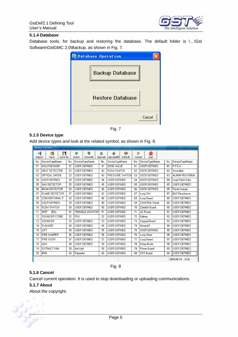
5.1.4 Database
Database tools, for backup and restoring the database. The default folder is \…\Gst
Software\GstGMC 2.0\Backup, as shown in Fig. 7.
Fig. 7
5.1.5 Device type
Add device types and look at the related symbol, as shown in Fig. 8.
Fig. 8
5.1.6 Cancel
Cancel current operation. It is used to stop downloading or uploading communications.
5.1.7 About
About the copyright.

GstDef2.1 Defining Tool User’s Manual The Intelligent Solution
Page 6
5.1.8 Exit system
5.2 General Operation
The system map provides a quick method to define FACPs, loops, devices, manual keys and
zones and etc, as shown in Fig. 9.
Fig. 9
5.2.1 Panel Operation
5.2.1.1 Add New FACP
Right-click on <FACP>, click on <Add FACP>. The dialogue box is shown in Fig. 10.
Fig. 10
FACP Name:Any description of the FACP, which can be blank.
FACP Address:The FACP Address must be unique for each control panel.
FACP Type:The FACP Type must be correct, otherwise GstDef Tools cannot
communicate with the panel. This setting cannot be changed once it is saved.
Net: If < Net> is selected, the devices in this panel can be used into equations on
other panels.
Start Zone: The Start Zone is for network use, only for GST200. When the panel is
connected to network, the information will be displayed on main panel as <Zone =
Local zone + Start Zone>. The setting can be modified later.
5.2.1.2 Delete FACP
Right-click the name of the panel, select <Delete FACP>, all configurations with this panel
will be completely deleted.
5.2.1.3 Export Devices
Right-click the name of the panel, select <Export Devices>, all the defined devices in this
panel can be exported to a text file (.txt), which can be easily converted to Excel file or other

GstDef2.1 Defining Tool User’s Manual The Intelligent Solution
Page 7
format.
5.2.1.4 Export Equations
This operation can export C&E equations to a text file by double clicking.
5.2.1.5 Upload and Download
When a panel is selected, the upload or download operation will cover all definitions relating
to that panel, including zones, devices, control switches and equations, as shown in Fig. 11.
Fig. 11
Upload means taking pre-record information from the panel.
Download means sending the definitions to the panel.
5.2.1.6 Save
The “Save” operation is for completing definition. Each time it will save all changes
comparing with previously saved data.
5.2.2 Zone Operation
Clicking <FACP Zone> will go to zone operation. Here you can add, delete or modify the
zones.
5.3 System Definition
5.3.1 Define zones
The protected area can be divided into several zones, which, in case of emergency situation
in a zone, a general location information can be shown on the FACP to give people the “First
Aid”. The zones should be divided according to building structure. A major consideration is to
make people easily access the area. By BS standard, each detection zone should be no
more than 2000m2 to 3000 m
2 for L1 or L2.
The zone definitions are shared by all devices connected to the FACP. Each zone may
contain devices from different loops, and devices from the same loop may be set to different
zones.
Click <FACP Zone> and select a panel, all zones defined in this panel will be displayed. And
click a zone number, you can check all devices in that zone, as shown in Fig. 12.

GstDef2.1 Defining Tool User’s Manual The Intelligent Solution
Page 8
Fig. 12
5.3.1.1 Add New Zone
Click <New> , there will be a new zone shown at the bottom.
There can be maximum 30 zones for GST200, 60 for GST200-2, 255 zones for GST5000
series panels, and 999 for GST-IFP8 panel.
Description of the information will be shown on panel screen, the name of the zone,
Maximum 8-characters (40 for GST-IFP8 panel) including letters, number and some
symbols.
<ForeColor> and <BackColor>: When a device is defined into a zone, the text <ForeColor>
and background <BackColor> will easily spot it. The default color is black on white, as
shown in Fig.13.
Fig. 13
Fig. 14

GstDef2.1 Defining Tool User’s Manual The Intelligent Solution
Page 9
As shown in Fig. 14, GST-IFP8 panel has additional < Zone Mode >, < Zone Sounder
Mode >, < Zone Resound Mode > and < Zone Led > options.
5.3.1.2 Delete zone
Select a zone (highlighted) and click <Delete> button.
5.3.1.3 Download & Upload
By <Upload All> or <Download All> , the operation will be done to all
zones.
Select one or several zones and press <Upload> or <Download> , the
operation is done to the selected zone(s).
5.3.1.4 Save
Press <Save> button to save all the modifications.
5.3.1.5 Reload
This operation will restore the definition from the last <Save> operation. All modifications not
saved will be lost.
5.3.2 Define devices
5.3.2.1 General
Fig. 15
The items include:
<Address>: The physical address of the device.
<Device Number>: Each device has a 6-digit number, normally arranged as zone number +
address. This number must not be repeated in the whole system (including network devices).
Although the zone number on GST5000 series can be manually modified, it’s recommended
not modifying it to avoid any incorrect display.
<Loop>: Showing the loop of the devices.
<Zone>: Dropdown list to select zone.
<Device Type>: Select device type by dropdown list. For detectors or MCP, this type should
be selected according to the real device type. For modules, the type is decided by
equipment connecting to the module. For example, there is a Fire Door connecting to a
module addressed 17, so address 17 should be defined as 28-FireDoor. To view the
complete type list, please refer to the appendix.
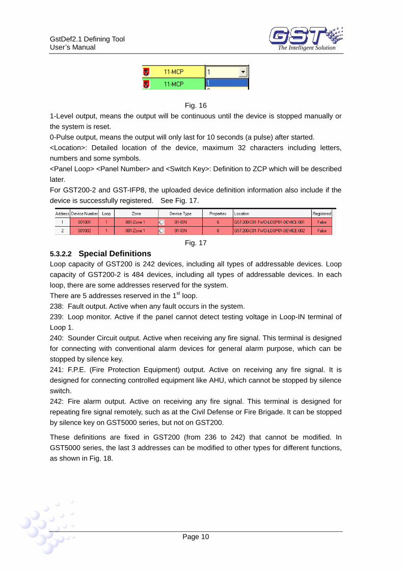
<Properties> Device properties, which is only useful for output devices like sounder or
output modules. Refer to Fig.16.
GstDef2.1 Defining Tool User’s Manual The Intelligent Solution
Page 10
Fig. 16
1-Level output, means the output will be continuous until the device is stopped manually or
the system is reset.
0-Pulse output, means the output will only last for 10 seconds (a pulse) after started.
<Location>: Detailed location of the device, maximum 32 characters including letters,
numbers and some symbols.
<Panel Loop> <Panel Number> and <Switch Key>: Definition to ZCP which will be described
later.
For GST200-2 and GST-IFP8, the uploaded device definition information also include if the
device is successfully registered. See Fig. 17.
Fig. 17
5.3.2.2 Special Definitions
Loop capacity of GST200 is 242 devices, including all types of addressable devices. Loop
capacity of GST200-2 is 484 devices, including all types of addressable devices. In each
loop, there are some addresses reserved for the system.
There are 5 addresses reserved in the 1st loop.
238: Fault output. Active when any fault occurs in the system.
239: Loop monitor. Active if the panel cannot detect testing voltage in Loop-IN terminal of
Loop 1.
240: Sounder Circuit output. Active when receiving any fire signal. This terminal is designed
for connecting with conventional alarm devices for general alarm purpose, which can be
stopped by silence key.
241: F.P.E. (Fire Protection Equipment) output. Active on receiving any fire signal. It is
designed for connecting controlled equipment like AHU, which cannot be stopped by silence
switch.
242: Fire alarm output. Active on receiving any fire signal. This terminal is designed for
repeating fire signal remotely, such as at the Civil Defense or Fire Brigade. It can be stopped
by silence key on GST5000 series, but not on GST200.
These definitions are fixed in GST200 (from 236 to 242) that cannot be modified. In
GST5000 series, the last 3 addresses can be modified to other types for different functions,
as shown in Fig. 18.

GstDef2.1 Defining Tool User’s Manual The Intelligent Solution
Page 11
Fig. 18
In multi-loop panel (GST5000 series), Loop1 and other loops have only the last address (242)
reserved, which is defined as 57-Loop SW for monitoring the corresponding loop. Refer to
Fig. 19.
Fig. 19
5.3.2.3 Loop Operation
For GST200, there is only ONE loop. When the panel is created, the loop is configured as
default.
For GST200-2, there are TWO loops. When the panel is created, two loops are configured
as default.
For GST5000 series and GST-IFP8, there is no default loop. Right-click on the panel under
<FACP Net> command and select <Add Loop>, as shown in Fig. 20.
Fig. 20

GstDef2.1 Defining Tool User’s Manual The Intelligent Solution
Page 12
Fig. 21
The <Loop Number> is default as next to the previous, which can be changed manually. But
for the system, the loop number must be continuous, as shown in Fig. 21. (Note: Loop 0 is
for repeater panel, refer to 5.3.4 Define Repeaters for details.)
The <Loop Name> can only be described in the software only, but cannot be downloaded to
the panel.
Both Loop Number and Name can be modified later. Clicking button can save the
changes. Refer to Fig. 22.
Fig. 22
5.3.2.4 Upload and Download
Same as for zones, the upload or download can be done to one or a group of or all the
devices in the current loop.
5.3.2.5 Device Check
Click on button , the software will check the definitions of the current panel. As
mentioned in <Device Number>, in the whole system, the device number cannot be
duplicated. This operation will check all devices and give out the information.
If there are the same addresses from different loops installed into the same zone, the
duplicated condition may occur. In this case, please manually modify the 4th
to 6th
digits of
<device Number>.
5.3.2.6 Reload
This operation will restore the definition from last <Save> operation. All modifications not
saved will be lost.
5.3.3 Define Control Keys
5.3.3.1 General
The panels (except for GST-IFP8) are configured with one or more Zone Indication and
Manual Intervention Panels (ZCP).
For GST200 and GST200-2, there are 32 buttons.
For GST5000 series, the default configuration is 1 (one) ZCP, which has 64 buttons. The

GstDef2.1 Defining Tool User’s Manual The Intelligent Solution
Page 13
ZCP can be expandable on order.
The key/indicators can be defined to one of the three types: Zone Indication, Start One
Device or Silence. A key/indicator can only be set with one of the three types. In GST5000
series, the keys can be used for evacuation.
Zone Indication: The indicators will show Fire (Red lit), Fault (Yellow lit) or Disable (Yellow
flash) of the related zone. Pressing the button can start all sounders in that zone. This
definition must be done to every zone.
Start One Device: This option is only available for output devices. The button will reverse
the condition of the related device. When it is started, pressing this button will stop it. This is
optional that can be defined or not.
Silence: This must be defined, normally at the right-bottom corner so that it is easy to reach.
Pressing this button will stop all started (by fire signal) sounders and the sounder output on
the panel. When the next fire signal comes, the related sounders will be started again.
All Evacuation: This function only available for GST5000 series. Pressing the button will
start all sounders and sounder outputs to evacuate the building manually. The started
sounders cannot be stopped by the SILENCE button. They can only be stopped by RESET.
5.3.3.2 Control Switches of GST200 and GST200-2
Fig. 23
Fig. 24
Choose the wanted zone or device address, the related Function line will automatically
change to Zone indication or Start One Device. To define a silence button, choose Silence in
the Function Line, as shown in Fig. 23 and Fig. 24 for GST200-2 with additional “Loop”
column.
This definition is uploaded/downloaded separately.
5.3.3.3 Control Keys for GST5000 Series
In GST5000 series panels, the ZCP(s) is (are) connected to loop(s). By default, it is
connected to loop 1. To each loop, Maximum 4 ZCPs can be connected. When creating
loops, there is one ZCP automatically added into Loop 1, shown as <Control Switch 1>. If
more control switches are needed, right-click on the loop and click <Add Control Switch>.
Refer to Fig. 25.

GstDef2.1 Defining Tool User’s Manual The Intelligent Solution
Page 14
Fig. 25
The definition is done with the loop devices. Normally the loop capacity will not be fully used.
Choose a group of unused addresses for defining the control switches, as shown in Fig. 26.
Fig. 26
(1) Define “Zone Indication”
Select the 64-Zone under <device Type>. Set the addresses into individual zones. Set a
<Switch Key> number to each zone. When a <Switch Key> is decided, the <Panel Loop>
and <Panel Number> will be automatically changed to 1 & 1. That means this ZCP is the 1st
one connecting to the 1st loop. If the panel number and connected loop are different, please
modify them to the same manually.
(2) Define “Start One Device”
Fig. 27
Set the switches to be related with corresponding devices directly, as shown in Fig. 27.
(3) Define “Silence” Switch
Select one unused address. Set <Device Type> at 56-Silence and the wanted switch.
(4) Checking
After saving the above definitions, by clicking the <Control Switch 1> on the left, the
complete definition list will be shown as in Fig. 28.
Fig. 28

GstDef2.1 Defining Tool User’s Manual The Intelligent Solution
Page 15
(5) Upload and Download
The definition will be downloaded/uploaded together with loop devices definition.
5.3.4 Define Repeater Panels
5.3.4.1 Repeater Panel of GST200 and GST200-2
Fig. 29
As shown in Fig. 29, GST200 and GST200-2 can drive up to 10 repeater panels. The
description (8 characters) can be downloaded to the fire alarm panel. In case there is fault
with the repeater panel, the description will be displayed on the FACP. But even if the
repeater panel is not defined, it will still work normally.
5.3.4.2 Define Repeater Panel of GST5000 Series
Select the FACP, and add Loop 0 ( Loop 0 is defaulted as repeater panel loop), as shown in
Fig. 30.
Fig. 30
After adding the loop, the devices of repeater panel are shown in Fig. 31. Its operation is the
same as other device definition of GST5000 series.

GstDef2.1 Defining Tool User’s Manual The Intelligent Solution
Page 16
Fig. 31
5.3.5 Define Equations
5.3.5.1 General
In case of fire, the FACPs (GST200 and GST5000 series) will act according to the
pre-programmed equation. There are TWO default actions that do not need to be defined:
(1) In case of fire in a zone, the zonal sounders will be started immediately.
(2) In case of fire in a zone, the panel outputs (Sounder circuit output, fire alarm output &
F.P.E.) will be started immediately.
Clicking <Equations> under <FACP Net> will get into equation definition, as shown in Fig. 32
and Fig. 33.
Fig. 32
<New>: Add a new equation.
<Insert Dev>: Add a device into the condition or result.
<Delete Dev>: Delete a device from the condition or result.
<Save Modify>: Save the current equation temporarily.
<Save New>: Easily add a similar equation into the temporary database.
Fig. 33
<Upload>: Upload this piece of equation from panel.
<Upload All>: Upload all equations from panel.
<Download All>: Download all equations to the panel. The equations can be only
downloaded together, rather than piece by piece.
<Delete>: Delete the selected equation.
<Save>: Save all equations to the database. Note: this operation must be done
after defining all equations.
<Reload>: Restore equation from the last <Save> operation.
The number of devices (both in condition and result) shall not exceed 10. If more than 10
devices are to be used, please split them into two equations..
5.3.5.2 Equations in GST200 and GST200-2
(1) Define a new equation
Click the device cell under the <Condition Devices>, the cell becomes editable. The device
number can be input manually. An easier way is double-clicking the cell again, a defined

GstDef2.1 Defining Tool User’s Manual The Intelligent Solution
Page 17
devices list will pop out. Choose the device and double-click or click <OK> button, the device
will be selected and input to the cell, as shown in Fig. 34.
If more than one device are required in the condition, click <Insert Dev> to add another
device. The relationship between the devices should be manually set. “+” means “OR” logic.
“X” means “AND” logic.
The operation is the same for adding multiple devices to the result.
If the current panel is in network, both condition devices and result devices can be selected
from devices under other networked panels, as long as their zone numbers are not greater
than 100.
The delay time can be set individually to each output device. The delay time is in second
multiplied by 10, Maximum 10 minutes (600 seconds). For example, 6 means delaying 1
minute (6X10=60s).
Fig. 34
After clicking , the equation will be added to the list at the bottom. Then add the
next equation.
(2) Fuzzy Device
For similar devices, we can use Fuzzy Logic to save our work. It means for these similar
devices, we use only one Fuzzy Device instead of inputting them one by one.
Tick <Fuzzy Devices> to start the function, as shown in Fig. 35.
Fig. 35
For example, <Zone>=01 & <Dev Type>=03 means any Optical detector in Zone 1. If
<Zone>=02, <Dev Type>= Any Type, means any device in zone 2. Refer to Fig. 36.
Also the quantity can be set. Between all these devices, the logic is AND.

GstDef2.1 Defining Tool User’s Manual The Intelligent Solution
Page 18
Fig. 36
If <Device QTY>=2, means this condition is only getting true if any 2 of these devices alarm
together.
(3) Rules for display
Exact device:
Led by G
Digit 2&3 for zone number
Digit 4 to 6 for address
Digit 7&8 for device type
For example, G0207503 means an optical detector in zone 2, address at 075
Fuzzy device:
Led by S
Digit 2&3 for zone number, ** means any zone.
Digit 4 to 6 for device quantity, shown under <Device QTY>
Digit 7&8 for device type, ** means any type of devices
For example, S0100203 means any two optical detectors in zone 1
The output can also be Fuzzy device. The <Device QTY>=1 will start all devices
complying with the setting.
(4) Edit equation
An existing equation can be edited by clicking the lower part of Fig. 34.
5.3.5.3 Equations in GST5000 Series
(1) Define a new equation
The operations for adding a new equation is the similar to GST200. Besides, if the current
panel is in network, both condition devices and result devices can be selected from all
devices under other networked panels, not restricted by their zone numbers, as shown in Fig.
37.
The delay time is in second multiplied by 6.

GstDef2.1 Defining Tool User’s Manual The Intelligent Solution
Page 19
Fig. 37
(2) Fuzzy Device
The Fuzzy Devices for GST5000 series is defined in a different way comparing with GST200,
as shown in Fig. 38 and Fig. 39.
Fig. 38
Fig. 39
It is using the 6-digit device number plus 2-digit device type code. Any digit replaced by * will
represent any of the numbers from 0 to 9. For example, 01***11 represents any MCP in zone
001. ******02 means any R&F heat detector of the whole system.
(3) Gas equation
The gas extinguishing control equation requires to first confirm if gas extinguishing is
permitted on the FACP, as shown in Fig. 40.

GstDef2.1 Defining Tool User’s Manual The Intelligent Solution
Page 20
Fig. 40
(4) Edit equation
Refer to (4) Edit equation in 5.3.5.2 Equations in GST200.
5.3.5.4 Equations in GST-IFP8
The definition and edition of equations for GST-IFP8 is the same as GST5000. Please refer
to the description for editing GST5000 equations.
5.3.6 Customize Device Type
Fig. 41
Choose the node of the tree structure at the left of the main screen and click <Device Type>
button, the screen in Fig. 41 will pop up. For GST200-2 and GST-IFP8, the name of device
type is user-definable. Function of tool bar buttons are as follows:
<Import>: Importing .ini file with saved device type.
<Save>: Saving the current device type into current database so that the device type doesn’t
change when running the software next time.
<Save As>: Saving the current device type as an .ini file.
<Down>: Downloading the selected device type to the FACP.
<DownAll>: Downloading all currently defined device types to the FACP.

GstDef2.1 Defining Tool User’s Manual The Intelligent Solution
Page 21
<UpLoad>: Uploading device type to the computer.
<UpLoadAll>: Uploading all device types to the computer.
<Default>: Restoring the default device type.
<Cancel>: Canceling the current operation.
<Quit>: Closing the current window.
Fig. 42
Fig. 43
The device type icon is also customer-definable. Right-clicking the device type number in Fig.
41, <Define Images> menu will pop up as in Fig. 42 and Fig. 43, and then clicking
<Browser> can choose and save an icon.
5.3.7 Upload Running Record
Right-clicking the FACP node at the left of the main screen as in Fig. 44, a menu will pop up.
Choosing <History Record >, the window as in Fig. 45 will pop up.

GstDef2.1 Defining Tool User’s Manual The Intelligent Solution
Page 22
Fig. 44
Fig. 45
For GST200-2 and GST-IFP8, the user can upload the running record in the FACP to the
computer by clicking <Upload> in the screen of Fig. 45. After uploading, clicking <Export>
will save the current records in the form of an Excel file (the user shall have the Excel
program in the computer).

GstDef2.1 Defining Tool User’s Manual The Intelligent Solution
Page 23
6 Caution
After completing all above definitions, please make a backup of the database for
future checking and modification.
The copyright of this software is reserved by the manufacturer, and protected by
law. Any copy or modification without the permission of the manufacturer is
prohibited.
This operation manual may be updated according to product upgrading without
notification.

GstDef2.1 Defining Tool User’s Manual The Intelligent Solution
Page 24
Appendix Device Type List
Device No. Abridge Description 1 ION Ionization Smoke Detector
2 R+F.Heat Rate of Rise & Fixed Temperature Detector
3 Optical Optical Smoke Detector
4 Fix Temp Fixed Temperature Detector
5 Gas Det Combustible Gas Detector
6 Beam Det Infrared Beam Detector
7 FlameDet Ultraviolet Flame Detector
8 Cable Linear Cable Heat Detector
9 A.Heat Advanced Heat Detector
10 Detector Normal Detector
11 MCP Manual Call Point
12 VA.Module Voice Alarm Module
13 Sounder Sounder (special for all types of alarming devices)
14 FTModule Fire Telephone Module
15 HR MCP Hydrant Manual Call Point
16 HR Pump Hydrant Pump
17 SPKR Pmp Sprinkler Pump
18 PS.SW Jockey Pump
19 Extract Smoke Extract
20 Presuriz Pressurize
21 FreshAir Fresh Air
22 Damper Fire Damper
23 SM Vent Smoke Vent
24 Air Inlet Air Inlet
25 Sol Valve Solenoid Valve
26 SM CURT Smoke Curtain, Middle Position
27 RSD Close Smoke Curtain, Closed
28 FireDoor Fire Door
29 PS.DIFF Pressure Switch
30 Flow SW Flow Switch
31 Elevator Elevator
32 AHU Air Handling Unit
33 GENI Generator
34 Light.DB Power DB for lighting
35 Power.DB Power DB for equipment
36 WTR.CURT Water Curtain Solenoid Valve
37 Gas Dump Gas Extinguishing Start
38 GasAbort Gas Extinguishing Abort
39 Net Unit Network Panel (for panel indication only)
40 Repeater Repeater (for panel indication only)
41 Gen I/P General Input
42 DryPower Dry-Powder Cylinder
43 FoamPump Foam Pump
44 Field PSU Power Supply Unit
45 EM Light Emergency Light
46 EscapeLT Exit Light
47 GasActiv Gas Extinguishing Warn Indicator
48 Security Security Interface module
49 ZoneValv Zonal Valve
50 Cylinder Cylinder
51 DelugePM Deluge pump

GstDef2.1 Defining Tool User’s Manual The Intelligent Solution
Page 25
52 Undefine Undefined
53 Stop Mod Device stop
54 Silence Silence Button (for definition only)
55 SounderA Sounder Circuit Output
56 SounderF Fault output
57 Loop SW Loop Monitor
58 CRT Fault CRT Fault (for panel indication only)
59 Loop Loop (for panel indication only)
60 PSU.Bat Remote PSU Battery Fault (for panel indication only)
61 PSU.AC Remote PSU AC Fault (for panel indication only)
62 Lock Function Control Lock
63 PART Part of devices (for panel indication only)
64 Zone Zone Indication (for definition only)
65 F.P.E Fire protection equipment output
66 All evac Start all sounders (for definition only)
67 Ground.f Ground fault (for panel indication only)

GST China
Gulf Security Technology Co., Ltd.
No. 80, Changjiang East Road, QETDZ, Qinhuangdao, Hebei,
P. R. China 066004
Tel: +86 (0) 335 8502528
Fax: +86 (0) 335 8508942
Email: [email protected]
www.gst.com.cn
GST UK
Global System Technology PLC
Lion Court, Staunton Harold Hall,
Melbourne Road, Ashby de la Zouch,
Leicestershire,
England LE65 1RT
Tel: +44 1283 225 478
Fax: +44 1283 220 690
Email: [email protected]
www.gst.uk.com
GST Dubai
Global System Technology PLC
P.O. Box 17998 Unit ZA04 JEBEL ALI Free Zone,
Dubai, UAE
Tel: +971 (0) 4 8833050
Fax: +971 (0) 4 8833053
Email: [email protected]
www.gst.uk.com