GstarCAD 2021 - ACE-Hellas
210
-
Upload
khangminh22 -
Category
Documents
-
view
0 -
download
0
Transcript of GstarCAD 2021 - ACE-Hellas


Table of Contents
1. GstarCAD 2021 Introduction and Installation ...................................................................................................................... 1
1.1. GstarCAD 2021 Introduction ............................................................................................................................ 1
1.2. System Requirement........................................................................................................................................ 1
1.3. GstarCAD 2021 Installation.............................................................................................................................. 4
2. Starting up GstarCAD 2021 ................................................................................................................................................ 8
2.1. The User Interface ............................................................................................................................................ 8
2.1.1. Quick Access Toolbar ............................................................................................................................. 8
2.1.2. Workspace .............................................................................................................................................. 9
2.1.3. Menu Bar .............................................................................................................................................. 10
2.1.4. The Ribbon ........................................................................................................................................... 12
2.1.5. Appearance .......................................................................................................................................... 13
2.1.6. Drawing Area ........................................................................................................................................ 13
2.1.7. Toolbars ............................................................................................................................................... 14
2.1.8. User Coordinate System (UCS) ............................................................................................................ 15
2.1.9. Model Space and Layout Space tabs .................................................................................................... 15
2.1.10. Command Window ............................................................................................................................... 16
2.1.11. Status Bar ............................................................................................................................................. 18
2.1.12. Properties Palette ................................................................................................................................. 18
2.1.13. Quick Properties ................................................................................................................................... 18
2.2. Customize the Drawing Environment ............................................................................................................. 19
2.2.1. Set Interface Options ............................................................................................................................ 19
2.2.2. Settings of Modifying Interface ............................................................................................................. 19
2.2.3. Save and Restore Profiles ..................................................................................................................... 20
2.3. Customize User Interface ............................................................................................................................... 21
2.4. Import, Export and Migrate User Custom Settings ......................................................................................... 24
2.4.1. Import and Export Settings of Current Version ...................................................................................... 24
2.4.2. Migrate from a Previous Release .......................................................................................................... 26
2.4.3. Import AutoCAD Tool Palettes ............................................................................................................... 26
2.5. Tool Palettes .................................................................................................................................................. 27
2.6. Design Center ................................................................................................................................................ 27
2.7. Clean Screen ................................................................................................................................................. 28
2.8. Lock UI .......................................................................................................................................................... 28
3. Create, Open, Save, Recover a Drawing and Manage Drawings ........................................................................................ 29
3.1. Create a Drawing ........................................................................................................................................... 29
3.1.1. Create a New Drawing Using Default Settings ....................................................................................... 29
3.1.2. Create a New Drawing Using a Setup Wizard ........................................................................................ 29
3.1.3. Create a New Drawing Using Template ................................................................................................. 30
3.2. Open a Drawing ............................................................................................................................................. 30
3.2.1. Open a Drawing .................................................................................................................................... 30
3.2.2. Multiple Open Drawings ....................................................................................................................... 31
3.3. Save a Drawing .............................................................................................................................................. 31
3.3.1. . Save a Drawing................................................................................................................................... 31
3.3.2. Save Your Drawing Automatically ......................................................................................................... 32
3.3.3. Save Part of a Drawing File ................................................................................................................... 32
3.3.4. Save to a Different Type of Drawing File ................................................................................................ 32
3.3.5. DWG Convert ....................................................................................................................................... 33
3.3.6. Batch conversion between graphical file formats .................................................................................. 33
3.3.7. Use Backup Files .................................................................................................................................. 34
3.3.8. Reduce the Time Required to Save a Drawing File ................................................................................ 34
3.4. Recover a Drawing ......................................................................................................................................... 34
3.4.1. Recover a Damaged File ....................................................................................................................... 34
3.4.2. Drawing Recovery Manager .................................................................................................................. 35
3.5. Manage Drawings .......................................................................................................................................... 36
3.5.1. Sheet Set Control ................................................................................................................................. 36
3.5.2. Sheet Set Manager Basic Information ................................................................................................... 38
4. Control the Drawing Views ............................................................................................................................................... 43
4.1. Redraw and Regenerate a Drawing ................................................................................................................. 43
4.2. Magnify a View (Zoom) ................................................................................................................................. 43
4.2.1. Zooming Methods ................................................................................................................................ 44
4.2.2. Zoom to Magnify a Specified Rectangular Area .................................................................................... 44
4.2.3. Zoom in Real Time ............................................................................................................................... 44
4.2.4. Displaying the Previous View of a Drawing ........................................................................................... 45
4.2.5. Zooming to a Specific Scale ................................................................................................................. 45
4.2.6. Displaying the Entire Drawing ............................................................................................................... 45
4.3. Pan and View ................................................................................................................................................. 46
4.4. Display Multiple Views on Model Space ........................................................................................................ 46
4.4.1. Set Model Space Viewports.................................................................................................................. 46
4.4.2. Working with Multiple Views of a Single Drawing ................................................................................. 47
4.4.3. Working with Multiple Drawings ........................................................................................................... 48
4.4.4. View Manager ....................................................................................................................................... 49
4.5. Specify a 3D View ......................................................................................................................................... 49
4.5.1. Set the Viewing Direction ..................................................................................................................... 49
4.5.2. Isometric View ...................................................................................................................................... 50
4.5.3. Draw 2D Isometric Views ...................................................................................................................... 50
4.5.4. Set Isometric Grid and Snap ................................................................................................................. 51
4.5.5. Change a 3D View Dynamically ............................................................................................................ 52
4.5.6. Hide Lines or Shade 3D Objects ........................................................................................................... 52
4.5.7. Add Simple Shading to 3D Objects ...................................................................................................... 53
4.5.8. Section Plane ....................................................................................................................................... 53
4.6. Render ........................................................................................................................................................... 53
4.6.1. Render Environment ............................................................................................................................. 54
4.6.2. Light ..................................................................................................................................................... 54
4.6.3. Materials .............................................................................................................................................. 54
5. Precision Tools and the Properties of Drawings ................................................................................................................ 55
5.1. Specify Units, Angles and Scale .................................................................................................................... 55
5.1.1. Set the Units Format ............................................................................................................................. 55

5.1.2. Set Angle Conventions ......................................................................................................................... 55
5.1.3. Setting Scale Factors ........................................................................................................................... 56
5.2. Drawing Limits .............................................................................................................................................. 56
5.3. Grid and Grid Snap ........................................................................................................................................ 57
5.3.1. Change Grid and Snap Spacing ............................................................................................................ 57
5.4. Use Object Snaps .......................................................................................................................................... 57
5.4.1. Setting Object Snaps ............................................................................................................................ 58
5.4.2. AutoSnap Tools .................................................................................................................................... 58
5.4.3. Selection Cycling ................................................................................................................................. 59
5.5. Use Polar Tracking and Object Snap Tracking................................................................................................. 60
5.5.1. Polar Tracking ....................................................................................................................................... 60
5.5.2. Object Snap Tracking ............................................................................................................................ 61
5.6. Use Orthogonal (Ortho Mode) ....................................................................................................................... 62
5.7. Working with Linetypes .................................................................................................................................. 62
5.7.1. Load Linetypes ..................................................................................................................................... 62
5.7.2. Change the Linetype of an Object ......................................................................................................... 63
5.7.3. Set the Current Linetype ....................................................................................................................... 63
5.7.4. Control Linetype Scale ......................................................................................................................... 63
5.8. Working with Layers ....................................................................................................................................... 64
5.8.1. Create and Name Layers ....................................................................................................................... 64
5.8.2. Setting the Current Layer ...................................................................................................................... 64
5.8.3. Removing Layers .................................................................................................................................. 65
5.8.4. Controlling Layer Visibility .................................................................................................................... 65
5.8.5. Locking and Unlocking Layers .............................................................................................................. 65
5.8.6. Controlling Layer Printing ..................................................................................................................... 65
5.8.7. Setting a Layer's Print Style .................................................................................................................. 66
5.8.8. Freeze or Thaw Layers .......................................................................................................................... 66
5.8.9. Setting the Layer Color ......................................................................................................................... 67
5.8.10. Setting a Layer's Linetype ..................................................................................................................... 67
5.8.11. Setting a Layer's Lineweight ................................................................................................................. 67
5.8.12. Filter List of Layers ............................................................................................................................... 68
5.9. Displaying Lineweights .................................................................................................................................. 68
5.9.1. Display Lineweights in Model Space .................................................................................................... 68
5.9.2. Display Lineweights in Layouts ............................................................................................................. 68
5.10. Spell Command ............................................................................................................................................. 69
6. Create Objects ................................................................................................................................................................. 70
6.1. Draw Linear Objects....................................................................................................................................... 70
6.1.1. Lines .................................................................................................................................................... 70
6.1.2. Multilines ............................................................................................................................................. 70
6.1.3. Rays ..................................................................................................................................................... 71
6.1.4. Construction Lines ............................................................................................................................... 71
6.1.5. Polylines .............................................................................................................................................. 71
6.1.6. Polygons .............................................................................................................................................. 73
6.1.7. Rectangles ........................................................................................................................................... 74
6.1.8. Points ................................................................................................................................................... 74
6.1.9. Freehand Sketches ............................................................................................................................... 75
6.2. Draw Curved Objects ..................................................................................................................................... 75
6.2.1. Arcs ...................................................................................................................................................... 75
6.2.2. Circles .................................................................................................................................................. 76
6.2.3. Ellipses ................................................................................................................................................ 76
6.2.4. Splines ................................................................................................................................................. 77
6.2.5. Helix ..................................................................................................................................................... 78
6.2.6. Donut ................................................................................................................................................... 78
6.3. Create 3D Objects.......................................................................................................................................... 79
6.3.1. 3D Thickness and Elevation .................................................................................................................. 79
6.3.2. 3D Faces .............................................................................................................................................. 79
6.3.3. Ruled Surfaces ..................................................................................................................................... 80
6.3.4. Tabulated Surface ................................................................................................................................. 80
6.3.5. Revolved Surface .................................................................................................................................. 80
6.3.6. Solid Box .............................................................................................................................................. 81
6.3.7. Solid Cone ........................................................................................................................................... 81
6.3.8. Solid Cylinder ...................................................................................................................................... 82
6.3.9. Sphere .................................................................................................................................................. 82
6.3.10. Torus .................................................................................................................................................... 82
6.3.11. Pyramid ................................................................................................................................................ 83
6.3.12. Wedge .................................................................................................................................................. 83
6.3.13. Solids Extrude ...................................................................................................................................... 83
6.3.14. Solids Revolve ...................................................................................................................................... 83
6.3.15. Solid .................................................................................................................................................... 84
6.3.16. Flatshot ................................................................................................................................................ 84
6.3.17. Creating Composite Solids ................................................................................................................... 85
6.3.18. PLOYSOLID........................................................................................................................................... 86
6.3.19. PLANESURF ......................................................................................................................................... 87
6.3.20. SURFOFFSET ....................................................................................................................................... 87
6.3.21. CONVTOMESH ..................................................................................................................................... 89
6.3.22. CONVTOSOLID ..................................................................................................................................... 89
6.3.23. CONVTOSURFACE ................................................................................................................................ 90
6.3.24. CONVTONURBS ................................................................................................................................... 90
6.4. Point Cloud .................................................................................................................................................... 92
6.5. Create Regions .............................................................................................................................................. 93
6.6. Create Revision Cloud ................................................................................................................................... 94
6.7. Create Break Line ........................................................................................................................................... 94
6.8. Create Wipeout .............................................................................................................................................. 94
6.9. Create table ................................................................................................................................................... 95
6.9.1. Insert Table Dialog Box ......................................................................................................................... 95
6.9.2. Table Style Dialog Box .......................................................................................................................... 97
6.9.3. Create New Table Style Dialog Box ....................................................................................................... 97
6.9.4. New and Modify Table Style Dialog Boxes ............................................................................................ 98

7. Modify Objects .............................................................................................................................................................. 100
7.1. Remove Objects .......................................................................................................................................... 100
7.2. Copy Objects ............................................................................................................................................... 100
7.3. Mirror Objects ............................................................................................................................................. 100
7.4. Offset an Object ........................................................................................................................................... 101
7.5. Create an Array of Objects ........................................................................................................................... 101
7.6. Move Objects .............................................................................................................................................. 102
7.7. Rotate Objects ............................................................................................................................................. 103
7.8. Align Objects ............................................................................................................................................... 103
7.9. Scale Objects .............................................................................................................................................. 103
7.10. Lengthen Objects ......................................................................................................................................... 104
7.11. Stretch Objects ............................................................................................................................................ 104
7.12. Trim Objects ................................................................................................................................................ 105
7.13. Extend Objects ............................................................................................................................................. 105
7.14. Create Breaks ............................................................................................................................................... 106
7.15. Create Chamfers .......................................................................................................................................... 106
7.16. Create Fillets ............................................................................................................................................... 107
7.16.1. Trim and Extend Filleted Objects ........................................................................................................ 108
7.16.2. Fillet Line and Polyline Combinations ................................................................................................ 108
7.16.3. Fillet Parallel Lines ............................................................................................................................. 108
7.16.4. Invert Fillet ......................................................................................................................................... 108
7.17. Disassociate Compound Objects ................................................................................................................. 109
7.18. Modify Polylines .......................................................................................................................................... 109
7.19. Modify Multilines ........................................................................................................................................ 110
7.20. Clip ............................................................................................................................................................. 110
7.21. Add selected ............................................................................................................................................... 110
7.22. Multiple ....................................................................................................................................................... 111
7.23. Set by layer ................................................................................................................................................. 111
7.24. MKSHAPE Command .................................................................................................................................. 111
8. Notes and Labels ........................................................................................................................................................... 112
8.1. Create Text ................................................................................................................................................... 112
8.1.1. Single-Line Text .................................................................................................................................. 112
8.1.2. Multiline Text ...................................................................................................................................... 112
8.2. Work with Text Styles ................................................................................................................................... 114
8.3. Create Leader ............................................................................................................................................... 114
8.3.1. Leaders ............................................................................................................................................... 114
8.3.2. Mleader .............................................................................................................................................. 115
8.4. Modify Text .................................................................................................................................................. 115
8.4.1. Change Text ........................................................................................................................................ 115
9. Dimensions and Tolerances ........................................................................................................................................... 117
9.1. Create Dimensions ...................................................................................................................................... 117
9.1.1. Horizontal and Vertical Dimensions .................................................................................................... 117
9.1.2. Create Aligned Dimensions ................................................................................................................ 117
9.1.3. Create Baseline and Continued Dimensions ....................................................................................... 118
9.1.4. Create Rotated Dimensions ................................................................................................................ 118
9.1.5. Create Angular Dimensions ................................................................................................................ 118
9.1.6. Create Radial Dimensions .................................................................................................................. 119
9.1.7. Jogged Dimension ............................................................................................................................. 119
9.1.8. Create Diameter Dimensions .............................................................................................................. 119
9.1.9. Create Ordinate Dimensions ............................................................................................................... 120
9.1.10. Create Quick Dimension ..................................................................................................................... 120
9.1.11. Create Arc Length Dimension ............................................................................................................. 120
9.2. Use Dimension Styles ................................................................................................................................. 120
9.2.1. Dimension Styles ............................................................................................................................... 121
9.2.2. Modify Dimension Lines .................................................................................................................... 122
9.2.3. Modify Extension Lines ...................................................................................................................... 122
9.2.4. Choose Dimension Arrowheads .......................................................................................................... 122
9.2.5. Fit Dimension Text within Extension Lines .......................................................................................... 123
9.2.6. Fit Diameter Dimension Text ............................................................................................................... 123
9.2.7. Align Dimension Text .......................................................................................................................... 124
9.2.8. Position Dimension Text Vertically ...................................................................................................... 124
9.2.9. Position Dimension Text Horizontally .................................................................................................. 124
9.2.10. Dimension Units ................................................................................................................................. 124
9.2.11. Alternate Units .................................................................................................................................... 125
9.2.12. Display Lateral Tolerances .................................................................................................................. 125
9.2.13. Set the Scale for Dimensions ............................................................................................................. 126
9.3. Modify Existing Dimensions ........................................................................................................................ 127
9.3.1. Modify Dimension Style ..................................................................................................................... 127
9.3.2. Make Dimensions Oblique ................................................................................................................. 127
9.3.3. Dimension Jogged Linear ................................................................................................................... 127
9.3.4. Dimension Inspection ......................................................................................................................... 128
9.3.5. Adjust Dimension Space .................................................................................................................... 128
9.4. Add Geometric Tolerances .......................................................................................................................... 129
9.4.1. Geometric Tolerance Dialog Box ......................................................................................................... 129
9.4.2. Geometric Tolerance Symbols ............................................................................................................ 129
9.4.3. Material Conditions ............................................................................................................................ 130
9.4.4. Datum Reference Frames.................................................................................................................... 130
9.4.5. Projected Tolerance Zones.................................................................................................................. 130
9.4.6. Composite Tolerances ........................................................................................................................ 130
10. Blocks, Attribute and reference ............................................................................................................................. 132
10.1. Create and Insert Blocks .............................................................................................................................. 132
10.1.1. Create Blocks ..................................................................................................................................... 132
10.1.2. Create Nested Blocks ......................................................................................................................... 132
10.1.3. Create Drawing Files for Use as Blocks .............................................................................................. 133
10.1.4. Change the Base Point of Drawings to Be Used as Blocks .................................................................. 133
10.1.5. Update Changes in the Original Drawing ............................................................................................ 133
10.1.6. Use Paper Space Objects in Blocks .................................................................................................... 133
10.1.7. Insert Blocks ...................................................................................................................................... 133
10.1.8. Modify a Block Definition ................................................................................................................... 134
10.1.9. Remove Block Definitions ................................................................................................................... 135
10.1.10. Define and Use Block Attributes ......................................................................................................... 135
10.1.11. Modify Block Attributes ...................................................................................................................... 136
10.1.12. Extract Block Attribute Data ................................................................................................................ 136
10.1.13. Synchronize Attributes ........................................................................................................................ 136
10.2. Reference Other Drawing Files (Xrefs) ......................................................................................................... 136
10.2.1. Attach External References ................................................................................................................. 137
10.2.2. Control the Properties of Referenced Layers ....................................................................................... 137
10.2.3. Xref Clipping Boundaries .................................................................................................................... 138
10.2.4. Nest and Overlay External References ................................................................................................. 138
10.2.5. Binding an Xref to a Drawing .............................................................................................................. 138
10.2.6. Refresh Xrefs ...................................................................................................................................... 138
10.3. DGN Underlay .............................................................................................................................................. 138
10.4. DWF Underlay ............................................................................................................................................. 139
10.5. PDF Underlay .............................................................................................................................................. 139
10.6. About Clipping Underlays ............................................................................................................................ 140
10.7. Edit Reference Tab ....................................................................................................................................... 140
10.8. PDF Import and Export................................................................................................................................. 142
10.9. IFC File Format Import and Export ............................................................................................................... 142
11. Hatches and Raster Images ................................................................................................................................... 143
11.1. Hatches ....................................................................................................................................................... 143
11.1.1. Define Hatch Boundary ....................................................................................................................... 143
11.1.2. Control the Hatching in Islands........................................................................................................... 143
11.1.3. Choose and Define Hatch Patterns ...................................................................................................... 144
11.1.4. Hatch to Back ..................................................................................................................................... 146
11.1.5. ................................................................................................................................................................... 146
11.2. Work with Raster Images.............................................................................................................................. 146
11.2.1. Attach, Scale, and Detach Raster Images............................................................................................ 146
11.2.2. Attach Raster Images .......................................................................................................................... 146
11.2.3. Scale Raster Images ........................................................................................................................... 147
11.2.4. Detach Raster Images ......................................................................................................................... 147
11.2.5. Modify and Manage Raster Images ..................................................................................................... 147
11.2.6. Change Raster Image Brightness, Contrast, and Fade ......................................................................... 148
11.2.7. Improve the Display Speed of Raster Images ...................................................................................... 148
12. Layout, Plot and Publish Drawings ........................................................................................................................ 149
12.1. Create Multiple-View Drawing Layouts ......................................................................................................... 149
12.1.1. Overview of Layout ............................................................................................................................. 149
12.1.2. Work with Model Space and Paper Space ........................................................................................... 149
12.1.3. Specify Layout Settings ...................................................................................................................... 150
12.1.4. Select a Paper Size for a Layout .......................................................................................................... 150
12.1.5. Determine the Drawing Orientation of a Layout ................................................................................... 150
12.1.6. Adjust the Plot Offset of a Layout ........................................................................................................ 150
12.1.7. Set the Plot Area of a Layout ............................................................................................................... 151
12.1.8. Set the Plot and Lineweight Scale for a Layout ................................................................................... 151
12.1.9. Move and Copy Layouts ..................................................................................................................... 151
12.1.10. Create Layout from Template .............................................................................................................. 151
12.1.11. Create and Modify Layout Viewports ................................................................................................... 152
12.2. Plot Drawings .............................................................................................................................................. 153
12.2.1. Plot Settings ....................................................................................................................................... 153
12.2.2. Set Paper Size .................................................................................................................................... 153
12.2.3. Position the Drawing on the Paper ...................................................................................................... 154
12.2.4. Set Drawing Orientation ...................................................................................................................... 154
12.2.5. Set Plot Scale ..................................................................................................................................... 154
12.2.6. Set Plot Options ................................................................................................................................. 155
12.2.7. Specify the Area to Plot ...................................................................................................................... 155
12.2.8. Preview a Plot ..................................................................................................................................... 155
12.2.9. Use Plot Styles ................................................................................................................................... 156
12.2.10. Plot Files to Other Formats ................................................................................................................. 157
12.2.11. Publish Drawings................................................................................................................................ 158
13. Create and Edit Dynamic Blocks ........................................................................................................................... 160
13.1. Dynamic Block Editor .................................................................................................................................. 160
13.1.1. Dynamic Block Editor Tool Panels ...................................................................................................... 160
13.1.2. Parameters ......................................................................................................................................... 161
13.1.3. Actions ............................................................................................................................................... 163
13.1.4. The General Steps of Creating a Dynamic Block Definition ................................................................. 163
13.2. Dynamic Blocks Creation Samples .............................................................................................................. 164
13.2.1. Base Point Parameter .......................................................................................................................... 164
13.2.2. Visibility ............................................................................................................................................. 164
13.2.3. Alignment ........................................................................................................................................... 166
13.2.4. Point Movement ................................................................................................................................. 167
13.2.5. Linear Movement ................................................................................................................................ 168
13.2.6. Number of Grips ................................................................................................................................. 169
13.2.7. Angle Offset ........................................................................................................................................ 169
13.2.8. Linear Stretch ..................................................................................................................................... 169
13.2.9. Parameter Value Set ........................................................................................................................... 170
13.2.10. Symmetrical Stretch ........................................................................................................................... 171
13.2.11. Distance Multiplier ............................................................................................................................. 171
13.2.12. Chain Action ....................................................................................................................................... 172
13.2.13. Scale Action ....................................................................................................................................... 173
13.2.14. Scale Character .................................................................................................................................. 174
13.2.15. Rotation .............................................................................................................................................. 175
13.2.16. Polar Stretch ....................................................................................................................................... 176
13.2.17. Polar Stretch Action Characteristics .................................................................................................... 178
13.2.18. Array................................................................................................................................................... 179
14. Share Date between Applications .......................................................................................................................... 181
14.1. Net Framework Support ............................................................................................................................... 181
14.2. Cloud Storage.............................................................................................................................................. 181
14.2.1. Cloud Settings .................................................................................................................................... 181
14.2.2. Upload drawings ................................................................................................................................ 182
14.2.3. Download Drawings ............................................................................................................................ 183
14.2.4. Upload Current Drawing ..................................................................................................................... 184
14.2.5. Backup or Restore Configurations ....................................................................................................... 185
14.3. Copylink Command ..................................................................................................................................... 185
15. Security ................................................................................................................................................................ 186
15.1. SECURITY .................................................................................................................................................... 186
15.2. Security Options in Save As ......................................................................................................................... 186
16. Innovative Features ............................................................................................................................................... 187
16.1. Line Enhancement ....................................................................................................................................... 187
16.2. Polyline Enhancement ................................................................................................................................. 188
16.3. Rectangle Enhancement .............................................................................................................................. 188
16.4. Circle Enhancement ..................................................................................................................................... 189
16.5. Copy Enhancement ...................................................................................................................................... 189
16.6. Rotate Enhancement .................................................................................................................................... 190
16.7. Magnifier ..................................................................................................................................................... 191
16.8. QR Code ...................................................................................................................................................... 192
16.9. Barcode ....................................................................................................................................................... 194
16.10. Symmetric Draw .......................................................................................................................................... 195
16.11. Outline Objects ............................................................................................................................................ 197
16.12. Area Table .................................................................................................................................................... 197
16.13. Automatically Layer ..................................................................................................................................... 197
16.14. Attribute Increment ...................................................................................................................................... 198
16.15. Viewport from Model ................................................................................................................................... 199
16.16. Free Scale ................................................................................................................................................... 200
17. Collaboration ........................................................................................................................................................ 201
Chapter1_GstaCAD 2021 Introduction and Installation
1
1. GstarCAD 2021 Introduction and Installation
1.1. GstarCAD 2021 Introduction
GstarCAD 2021 optimizes 3D functionalities with adding a series of new commands. Other new features like Rapid Dist,
Import/Export custom settings, and point cloud greatly improve user’s efficiency to obtain dimensional data, transfer user
settings, and view point cloud data. Plus, the significant improvements of tool palette and Mtext editor will lighten workload
tasks and design process.
1.2. System Requirement
System Requirement
Before installing GstarCAD, please confirm whether the specifications of your PC meet the following requirements:
OS (Operating System)
Windows 7(32-bit, 64-bit)
Windows 8(32-bit, 64-bit)
Windows 10(32-bit, 64-bit)
CPU
1GHZ or faster, 32-bit(x86) or 64-bit(x64) processor
RAM
For 32-bit GstarCAD - 1GB (3GB recommended or higher)
For 64-bit GstarCAD - 2GB (4GB recommended or higher)
Display
1024 * 768 VGA with True Color (minimum)
Hard Disk
1GB free hard disk available or higher (3GB recommended or higher)
Chapter 2_Starting up GstarCAD 2021
4
1.3. GstarCAD 2021 Installation
Users can visit www.gstarcad.net to download GstarCAD 2021 to your computer or server.
GstarCAD 2021 Install Wizard will guide the user to install the software in the operating system completely and successfully.
Please follow the steps below to install GstarCAD 2021:
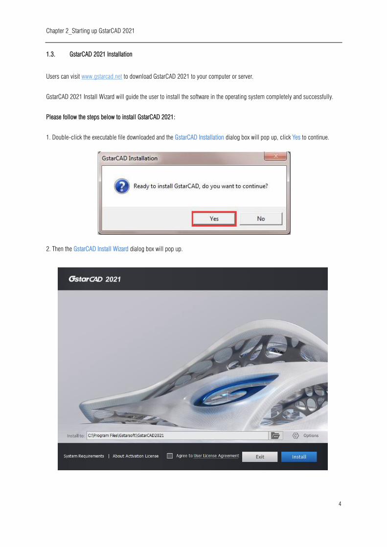
1. Double-click the executable file downloaded and the GstarCAD Installation dialog box will pop up, click Yes to continue.
2. Then the GstarCAD Install Wizard dialog box will pop up.

Chapter 2_Starting up GstarCAD 2021
5
3. Click Browse button and choose the destination path where setup will install the files and then click the Options
button.
4. In the GstarCAD Install Wizard > Options dialog box, users can select or deselect the features according to your need. If you
want to review or change any of your installation settings just click the Back button to confirm the path.
Chapter 2_Starting up GstarCAD 2021
6
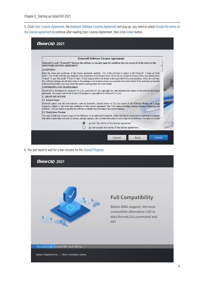
5. Click User License Agreement, the Gstarsoft Software License Agreement will pop up, you need to select Accept the terms of
the license agreement to continue after reading User License Agreement, then click Install button.
6. You just need to wait for a few minutes for the Overall Progress.

Chapter 2_Starting up GstarCAD 2021
7
7. Then you will see the workspace selection window. Select your favorite workspace and click the Finish button to exit the
wizard. The GstarCAD wizard has successfully installed GstarCAD 2021.
Chapter 2_Starting up GstarCAD 2021
8
2. Starting up GstarCAD 2021
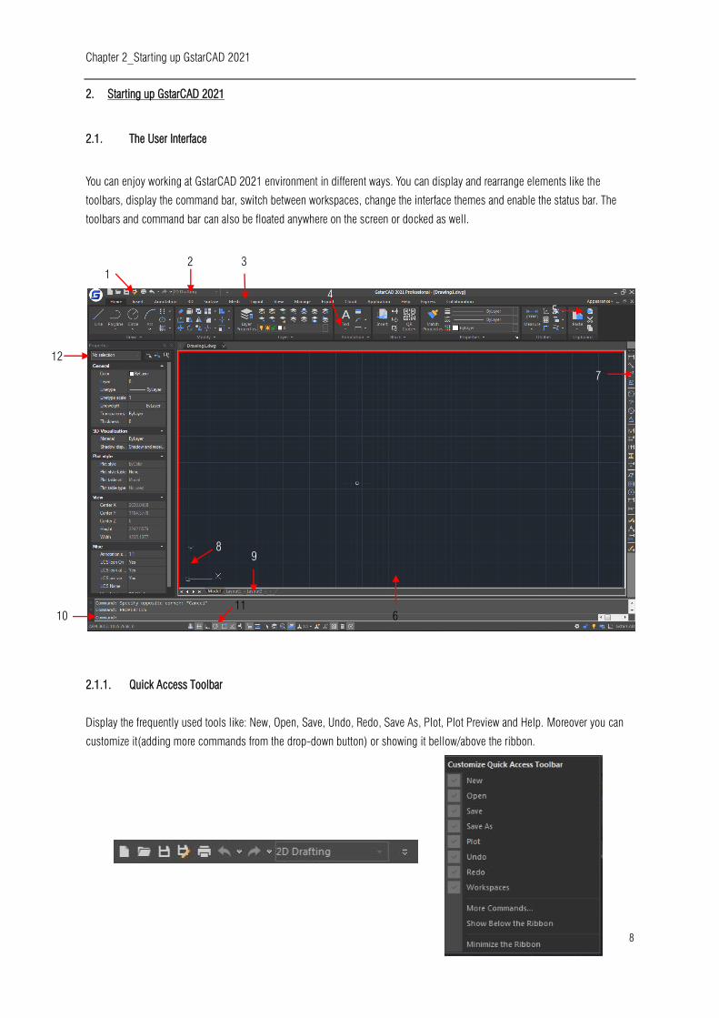
2.1. The User Interface
You can enjoy working at GstarCAD 2021 environment in different ways. You can display and rearrange elements like the
toolbars, display the command bar, switch between workspaces, change the interface themes and enable the status bar. The
toolbars and command bar can also be floated anywhere on the screen or docked as well.
2.1.1. Quick Access Toolbar
Display the frequently used tools like: New, Open, Save, Undo, Redo, Save As, Plot, Plot Preview and Help. Moreover you can
customize it(adding more commands from the drop-down button) or showing it bellow/above the ribbon.
1
2 3
4
5
6
7
8
9
10
11
12
Chapter 2_Starting up GstarCAD 2021
9
2.1.2. Workspace
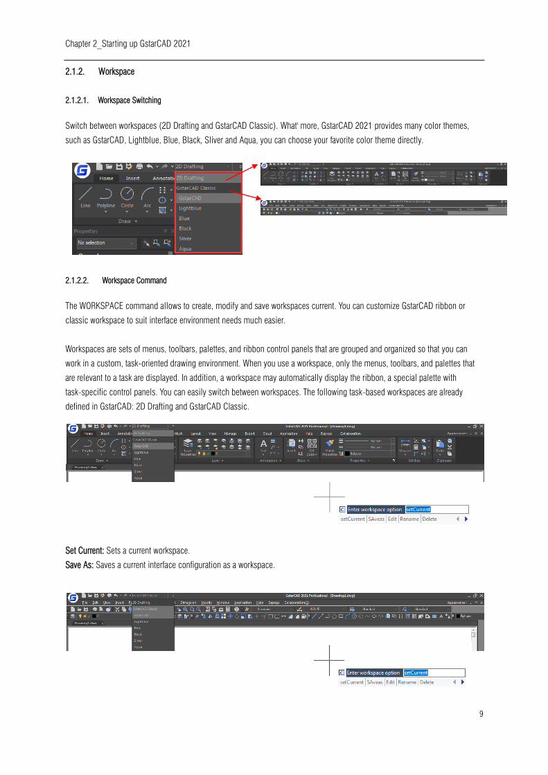
2.1.2.1. Workspace Switching
Switch between workspaces (2D Drafting and GstarCAD Classic). What' more, GstarCAD 2021 provides many color themes,
such as GstarCAD, Lightblue, Blue, Black, Sliver and Aqua, you can choose your favorite color theme directly.
2.1.2.2. Workspace Command
The WORKSPACE command allows to create, modify and save workspaces current. You can customize GstarCAD ribbon or
classic workspace to suit interface environment needs much easier.
Workspaces are sets of menus, toolbars, palettes, and ribbon control panels that are grouped and organized so that you can
work in a custom, task-oriented drawing environment. When you use a workspace, only the menus, toolbars, and palettes that
are relevant to a task are displayed. In addition, a workspace may automatically display the ribbon, a special palette with
task-specific control panels. You can easily switch between workspaces. The following task-based workspaces are already
defined in GstarCAD: 2D Drafting and GstarCAD Classic.
If you execute WORKSPACE command, the following prompts are displayed:
Set Current: Sets a current workspace.
Save As: Saves a current interface configuration as a workspace.
Chapter 2_Starting up GstarCAD 2021
10
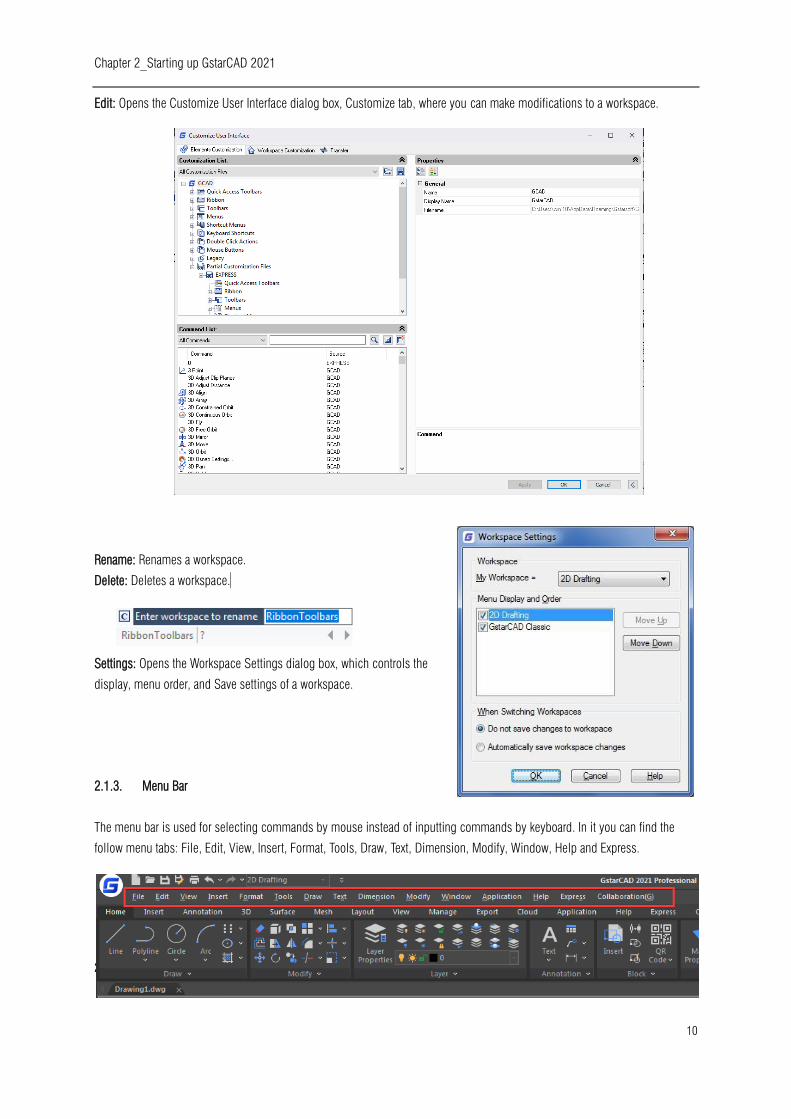
Edit: Opens the Customize User Interface dialog box, Customize tab, where you can make modifications to a workspace.
Rename: Renames a workspace.
Delete: Deletes a workspace.
Settings: Opens the Workspace Settings dialog box, which controls the
display, menu order, and Save settings of a workspace.
2.1.3. Menu Bar
The menu bar is used for selecting commands by mouse instead of inputting commands by keyboard. In it you can find the
follow menu tabs: File, Edit, View, Insert, Format, Tools, Draw, Text, Dimension, Modify, Window, Help and Express.
2.1.3.1. 2.1.3.1. Menus and Shortcut Menus
Chapter 2_Starting up GstarCAD 2021
11
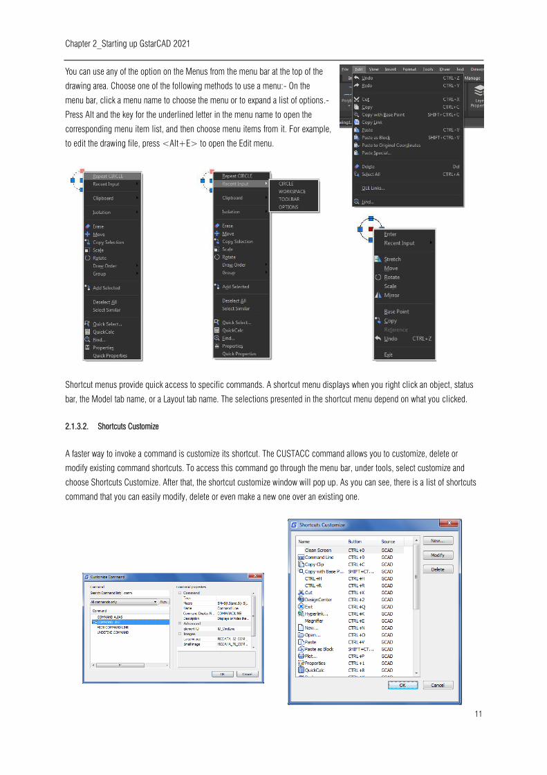
You can use any of the option on the Menus from the menu bar at the top of the
drawing area. Choose one of the following methods to use a menu:- On the
menu bar, click a menu name to choose the menu or to expand a list of options.-
Press Alt and the key for the underlined letter in the menu name to open the
corresponding menu item list, and then choose menu items from it. For example,
to edit the drawing file, press <Alt+E> to open the Edit menu.
Shortcut menus provide quick access to specific commands. A shortcut menu displays when you right click an object, status
bar, the Model tab name, or a Layout tab name. The selections presented in the shortcut menu depend on what you clicked.
2.1.3.2. Shortcuts Customize
A faster way to invoke a command is customize its shortcut. The CUSTACC command allows you to customize, delete or
modify existing command shortcuts. To access this command go through the menu bar, under tools, select customize and
choose Shortcuts Customize. After that, the shortcut customize window will pop up. As you can see, there is a list of shortcuts
command that you can easily modify, delete or even make a new one over an existing one.
Chapter 2_Starting up GstarCAD 2021
12
If you want to create a new one, just click the New button and the customize command window will pop up. Then you can
search the command or select one from the command list. For example, you can input “command line” and then select the
requested command. Notice that it will display the command properties by selecting the requested command at the right side
of the window. After selecting the command, press OK.
Then the set shortcut window will pop up. You can input the desire keyword(s).
For example, you can set the shortcuts SHIFT+D. If you want to delete a
created shortcut command, invoke the command CUSTACC and then select the
delete button from the Shortcut Customize window.
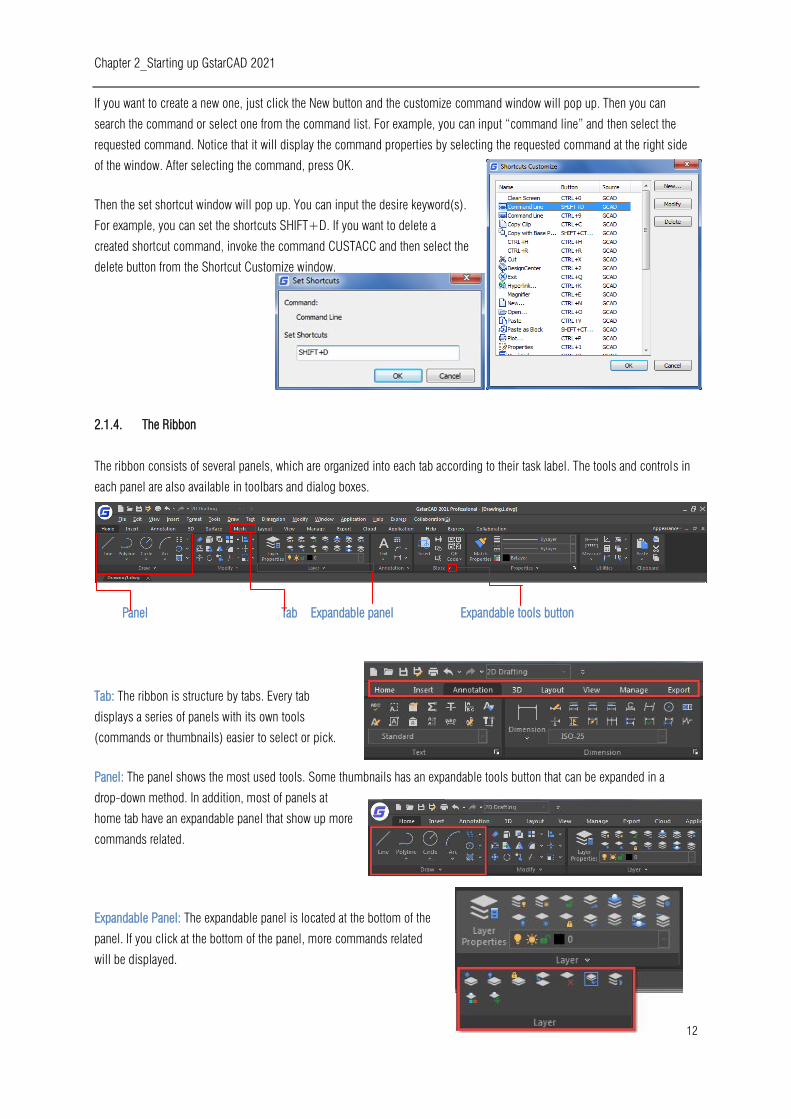
2.1.4. The Ribbon
The ribbon consists of several panels, which are organized into each tab according to their task label. The tools and controls in
each panel are also available in toolbars and dialog boxes.
Panel Tab Expandable panel Expandable tools button
Tab: The ribbon is structure by tabs. Every tab
displays a series of panels with its own tools
(commands or thumbnails) easier to select or pick.
Panel: The panel shows the most used tools. Some thumbnails has an expandable tools button that can be expanded in a
drop-down method. In addition, most of panels at
home tab have an expandable panel that show up more
commands related.
Expandable Panel: The expandable panel is located at the bottom of the
panel. If you click at the bottom of the panel, more commands related
will be displayed.
Chapter 2_Starting up GstarCAD 2021
13
Expandable Tools Button: Some thumbnails (tools or commands at the panel) have an expandable tools
button that can be expanded in a drop-down method. If you click this button, all related tools will be
displayed.
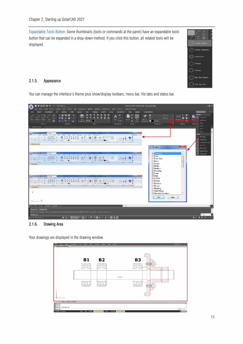
2.1.5. Appearance
You can manage the interface’s theme plus show/display toolbars, menu bar, file tabs and status bar.
2.1.6. Drawing Area
Your drawings are displayed in the drawing window.

Chapter 2_Starting up GstarCAD 2021
14
2.1.7. Toolbars
Toolbars partially contain buttons that start commands. When you move your mouse or pointing device over a toolbar button,
the tooltip displays the name of the button.
The Standard toolbar at the top of the drawing area contains commonly used commands such as Copy Pan and Zoom, as well
as Microsoft Office standard commands such as New, Open, and Save. GstarCAD 2021 classic workspace initially displays
several toolbars by default:
- Draw toolbar
- Draw order toolbar
- Modify toolbar
- Properties toolbar
- Layer toolbar
- Style toolbar
- Standard toolbar
2.1.7.1. Displaying and Hiding Toolbars
GstarCAD 2021 provides many toolbars, which you can show or hide in both classic and ribbon interfaces. You can also move
and dock toolbars. To choose which toolbars to display:
1.- Execute TOOLBAR command or select the option TOOLBARS from the drop-down list under Appearance button (at top right
of the interface) to open the Toolbar dialog box.
2.- Choose the toolbars you want to hide or display by checking/unchecking the small boxes in the dialog box, then click OK.
Chapter 2_Starting up GstarCAD 2021
15
To make floated a horizontal docked toolbar, just click and
hold the left side of it and drag around the place you need.
To make floated a vertical docked toolbar, just click and hold
the top of it and drag around. To dock any toolbar, just double-click at the left side of it.
2.1.7.2. Starting Commands Using Toolbars
To start a command from a toolbar, click a
command button and respond to the prompts.
2.1.8. User Coordinate System (UCS)
The icon indicates the orientation of the drawing in two dimensional space.
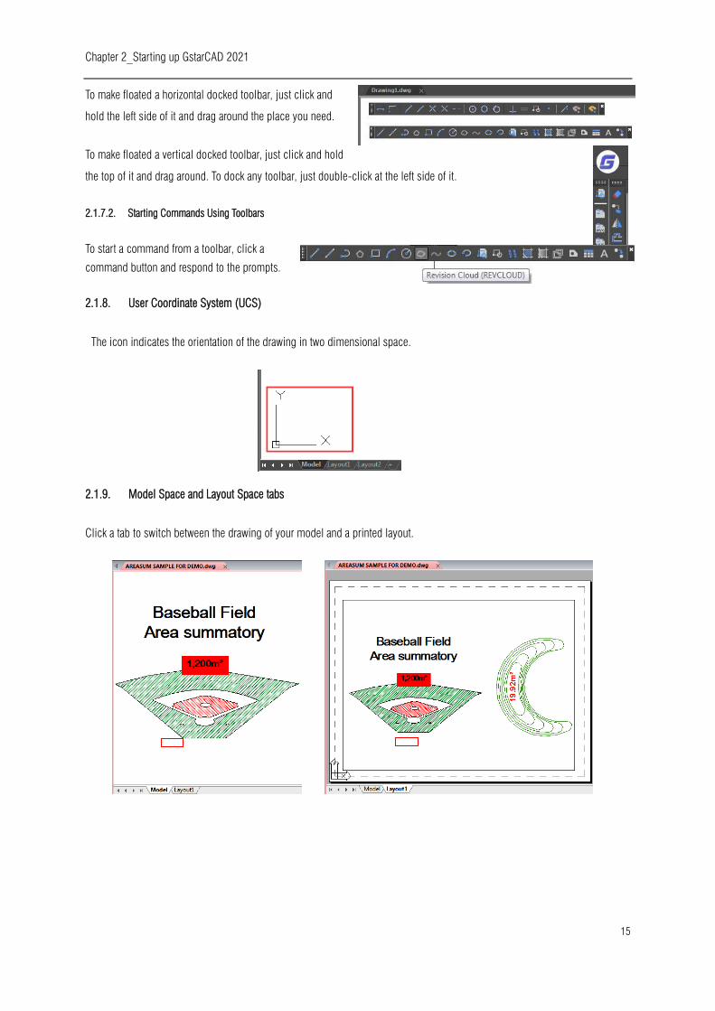
2.1.9. Model Space and Layout Space tabs
Click a tab to switch between the drawing of your model and a printed layout.
Chapter 2_Starting up GstarCAD 2021
16
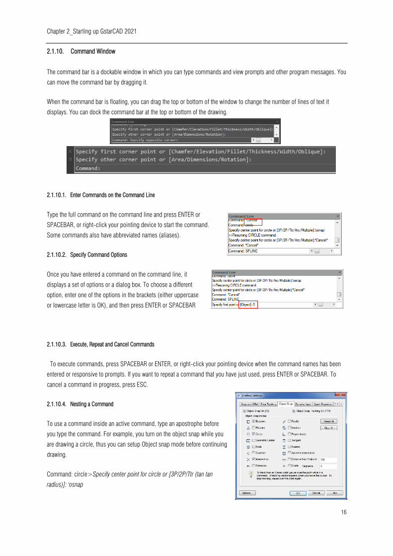
2.1.10. Command Window
The command bar is a dockable window in which you can type commands and view prompts and other program messages. You
can move the command bar by dragging it.
When the command bar is floating, you can drag the top or bottom of the window to change the number of lines of text it
displays. You can dock the command bar at the top or bottom of the drawing.
2.1.10.1. Enter Commands on the Command Line
Type the full command on the command line and press ENTER or
SPACEBAR, or right-click your pointing device to start the command.
Some commands also have abbreviated names (aliases).
2.1.10.2. Specify Command Options
Once you have entered a command on the command line, it
displays a set of options or a dialog box. To choose a different
option, enter one of the options in the brackets (either uppercase
or lowercase letter is OK), and then press ENTER or SPACEBAR
2.1.10.3. Execute, Repeat and Cancel Commands
To execute commands, press SPACEBAR or ENTER, or right-click your pointing device when the command names has been
entered or responsive to prompts. If you want to repeat a command that you have just used, press ENTER or SPACEBAR. To
cancel a command in progress, press ESC.
2.1.10.4. Nesting a Command
To use a command inside an active command, type an apostrophe before
you type the command. For example, you turn on the object snap while you
are drawing a circle, thus you can setup Object snap mode before continuing
drawing.
Command: circle>Specify center point for circle or [3P/2P/Ttr (tan tan
radius)]: 'osnap
Chapter 2_Starting up GstarCAD 2021
17
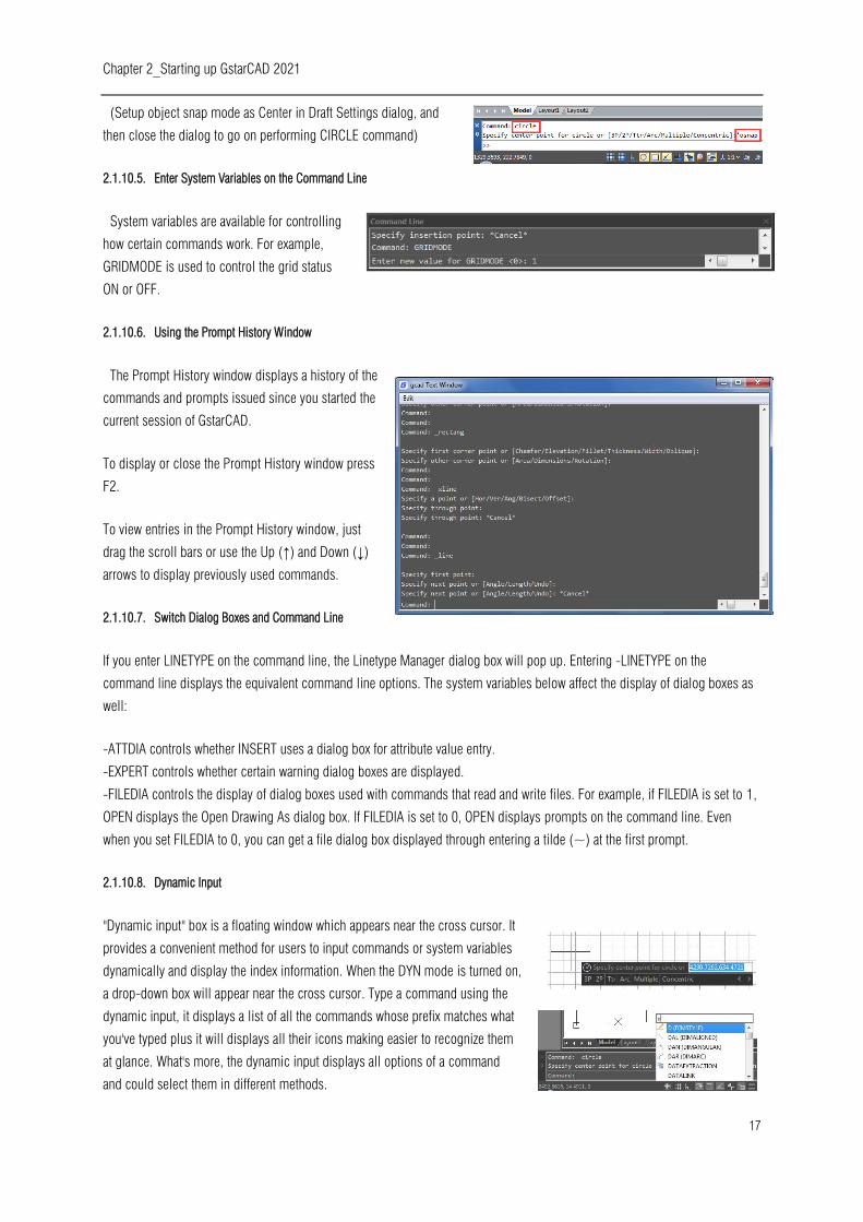
(Setup object snap mode as Center in Draft Settings dialog, and
then close the dialog to go on performing CIRCLE command)
2.1.10.5. Enter System Variables on the Command Line
System variables are available for controlling
how certain commands work. For example,
GRIDMODE is used to control the grid status
ON or OFF.
2.1.10.6. Using the Prompt History Window
The Prompt History window displays a history of the
commands and prompts issued since you started the
current session of GstarCAD.
To display or close the Prompt History window press
F2.
To view entries in the Prompt History window, just
drag the scroll bars or use the Up (↑) and Down (↓)
arrows to display previously used commands.
2.1.10.7. Switch Dialog Boxes and Command Line
If you enter LINETYPE on the command line, the Linetype Manager dialog box will pop up. Entering -LINETYPE on the
command line displays the equivalent command line options. The system variables below affect the display of dialog boxes as
well:
-ATTDIA controls whether INSERT uses a dialog box for attribute value entry.
-EXPERT controls whether certain warning dialog boxes are displayed.
-FILEDIA controls the display of dialog boxes used with commands that read and write files. For example, if FILEDIA is set to 1,
OPEN displays the Open Drawing As dialog box. If FILEDIA is set to 0, OPEN displays prompts on the command line. Even
when you set FILEDIA to 0, you can get a file dialog box displayed through entering a tilde (~) at the first prompt.
2.1.10.8. Dynamic Input
"Dynamic input" box is a floating window which appears near the cross cursor. It
provides a convenient method for users to input commands or system variables
dynamically and display the index information. When the DYN mode is turned on,
a drop-down box will appear near the cross cursor. Type a command using the
dynamic input, it displays a list of all the commands whose prefix matches what
you've typed plus it will displays all their icons making easier to recognize them
at glance. What's more, the dynamic input displays all options of a command
and could select them in different methods.
Chapter 2_Starting up GstarCAD 2021
18
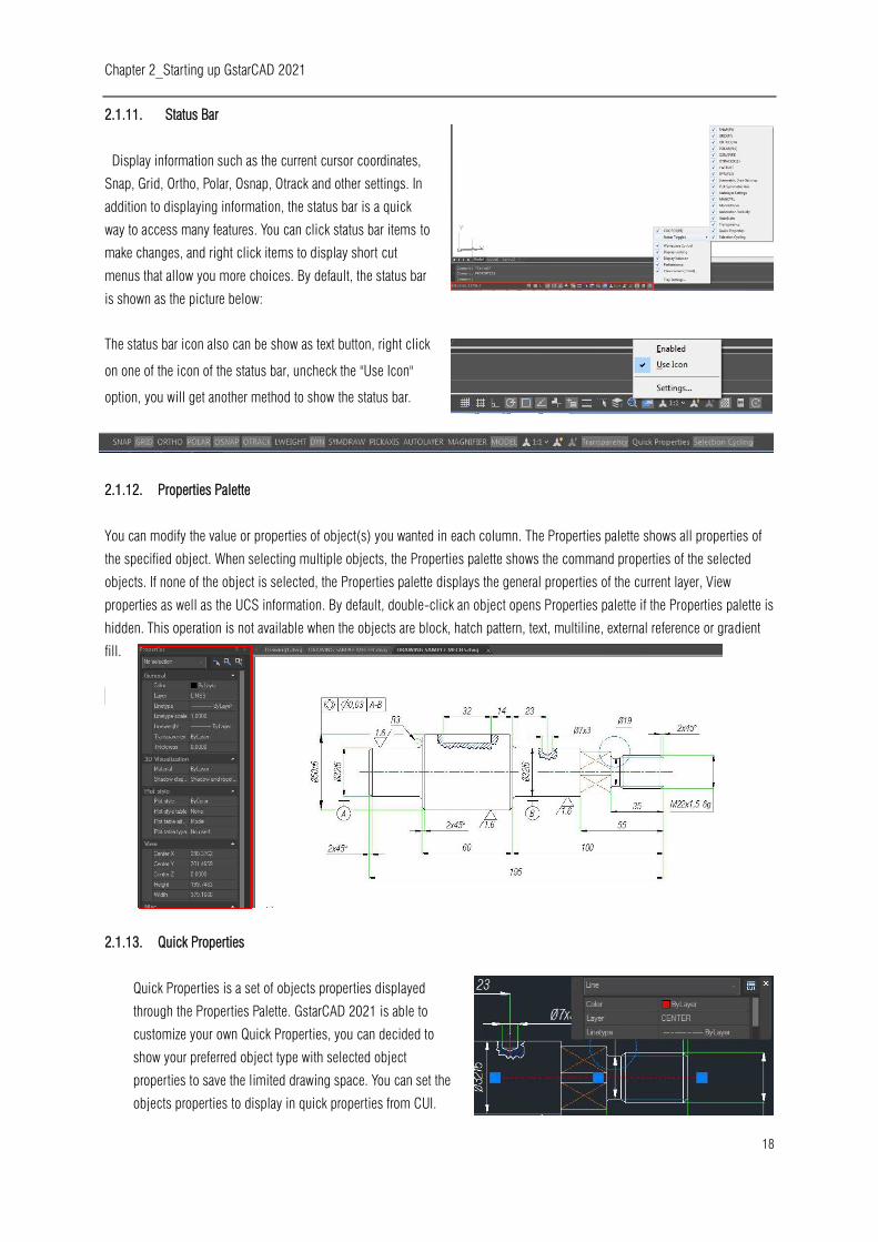
2.1.11. Status Bar
Display information such as the current cursor coordinates,
Snap, Grid, Ortho, Polar, Osnap, Otrack and other settings. In
addition to displaying information, the status bar is a quick
way to access many features. You can click status bar items to
make changes, and right click items to display short cut
menus that allow you more choices. By default, the status bar
is shown as the picture below:
The status bar icon also can be show as text button, right click
on one of the icon of the status bar, uncheck the "Use Icon"
option, you will get another method to show the status bar.
2.1.12. Properties Palette
You can modify the value or properties of object(s) you wanted in each column. The Properties palette shows all properties of
the specified object. When selecting multiple objects, the Properties palette shows the command properties of the selected
objects. If none of the object is selected, the Properties palette displays the general properties of the current layer, View
properties as well as the UCS information. By default, double-click an object opens Properties palette if the Properties palette is
hidden. This operation is not available when the objects are block, hatch pattern, text, multiline, external reference or gradient
fill.
2.1.13. Quick Properties
Quick Properties is a set of objects properties displayed
through the Properties Palette. GstarCAD 2021 is able to
customize your own Quick Properties, you can decided to
show your preferred object type with selected object
properties to save the limited drawing space. You can set the
objects properties to display in quick properties from CUI.
Chapter 2_Starting up GstarCAD 2021
19
2.2. Customize the Drawing Environment
In GstarCAD 2021 there are different elements of the working environment that can be customized to fit your needs.
2.2.1. Set Interface Options
In the Options dialog box, you can change many of the settings that affect the interface and drawing environment.
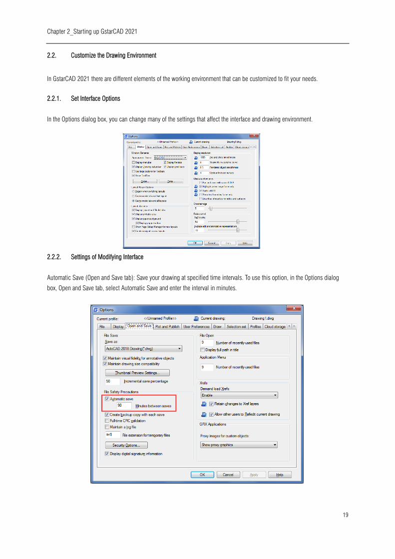
2.2.2. Settings of Modifying Interface
Automatic Save (Open and Save tab): Save your drawing at specified time intervals. To use this option, in the Options dialog
box, Open and Save tab, select Automatic Save and enter the interval in minutes.
Chapter 2_Starting up GstarCAD 2021
20
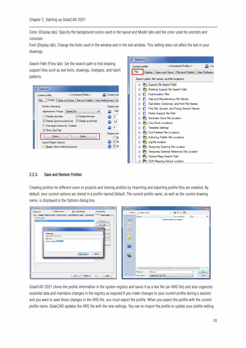
Color (Display tab): Specify the background colors used in the layout and Model tabs and the color used for prompts and
crosshair.
Font (Display tab): Change the fonts used in the window and in the text window. This setting does not affect the text in your
drawings.
Search Path (Files tab): Set the search path to find drawing
support files such as text fonts, drawings, linetypes, and hatch
patterns.
2.2.3. Save and Restore Profiles
Creating profiles for different users or projects and sharing profiles by importing and exporting profile files are enabled. By
default, your current options are stored in a profile named Default. The current profile name, as well as the current drawing
name, is displayed in the Options dialog box.
GstarCAD 2021 stores the profile information in the system registry and saves it as a text file (an ARG file) and also organizes
essential data and maintains changes in the registry as required.If you make changes to your current profile during a session
and you want to save those changes in the ARG file, you must export the profile. When you export the profile with the current
profile name, GstarCAD updates the ARG file with the new settings. You can re-import the profile to update your profile setting

Chapter 2_Starting up GstarCAD 2021
21
2.2.3.1. MOVEBAK Command
The new MOVEBAK command changes the destination folder for drawing backup (BAK) files. Once you specify a path, the
drawing’s BAK files is placed in that path after every save operation.
Enter new value for MOVEBAK, or for none <current setting>:
Enter a . (period) for none or type the folder name
If you enter ".", the MOVEBAK folder name is cleared and new BAK files will be created in the original folder.
2.3. Customize User Interface
Drag & Drop Customization: An innovative way to customize user interface must be easy and quickly according to user needs,
so this is possible by drag and drop action, that means users can drag any command from the command list and drop it into
workspaces elements like ribbon panels and toolbars that are visible at top right corner of the CUI dialog box. Users will not
have restrictions to place anywhere or even arrange a preferred command on a panel or toolbar. UI customization has never
been easier and flexible through Drag & Drop action.
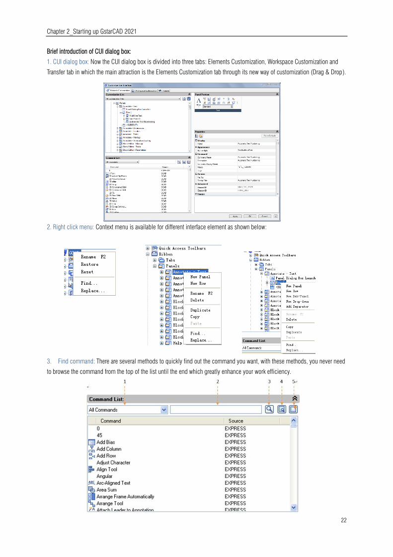
Chapter 2_Starting up GstarCAD 2021
22
Brief introduction of CUI dialog box:
1. CUI dialog box: Now the CUI dialog box is divided into three tabs: Elements Customization, Workspace Customization and
Transfer tab in which the main attraction is the Elements Customization tab through its new way of customization (Drag & Drop).
2. Right click menu: Context menu is available for different interface element as shown below:
3. Find command: There are several methods to quickly find out the command you want, with these methods, you never need
to browse the command from the top of the list until the end which greatly enhance your work efficiency.

Chapter 2_Starting up GstarCAD 2021
23
1- Filter the command by Category: Click the button right side and select the category the
command belongs which will reduce the command search scope
2-Filter a command by entry relevant keywords: For example, input “dimension” in the filter, all
the commands contains the word “dimension” will be shown, reducing the number of
commands to browse.
3- Command cleaner: If you input the keywords in the filter, the icon will automatically change to which is used
to clean the content in the filter, meanwhile, the following command list will return to the default state.
4- Find and replace: In Find tab input the command you want to find out and click Find Next, the command you searched will
be positioned accurately. In replace tab, you can replace one command with another command, but we suggest not change the
standard command name and description.
5- Create a new command: If it is necessary to add secondary development program command to the command list, you can
set the items follow the current command settings as shown below.
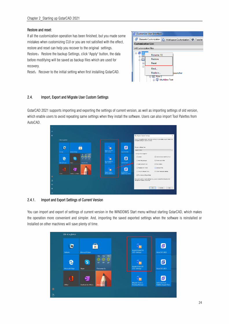
Chapter 2_Starting up GstarCAD 2021
24
Restore and reset:
If all the customization operation has been finished, but you made some
mistakes when customizing CUI or you are not satisfied with the effect,
restore and reset can help you recover to the original settings.
Restore:Restore the backup Settings, click "Apply" button, the data
before modifying will be saved as backup files which are used for
recovery.
Reset:Recover to the initial setting when first installing GstarCAD.
2.4. Import, Export and Migrate User Custom Settings
GstarCAD 2021 supports importing and exporting the settings of current version, as well as importing settings of old version,
which enable users to avoid repeating same settings when they install the software. Users can also import Tool Palettes from
AutoCAD.
2.4.1. Import and Export Settings of Current Version
You can import and export of settings of current version in the WINDOWS Start menu without starting GstarCAD, which makes
the operation more convenient and simpler. And, importing the saved exported settings when the software is reinstalled or
Installed on other machines will save plenty of time.
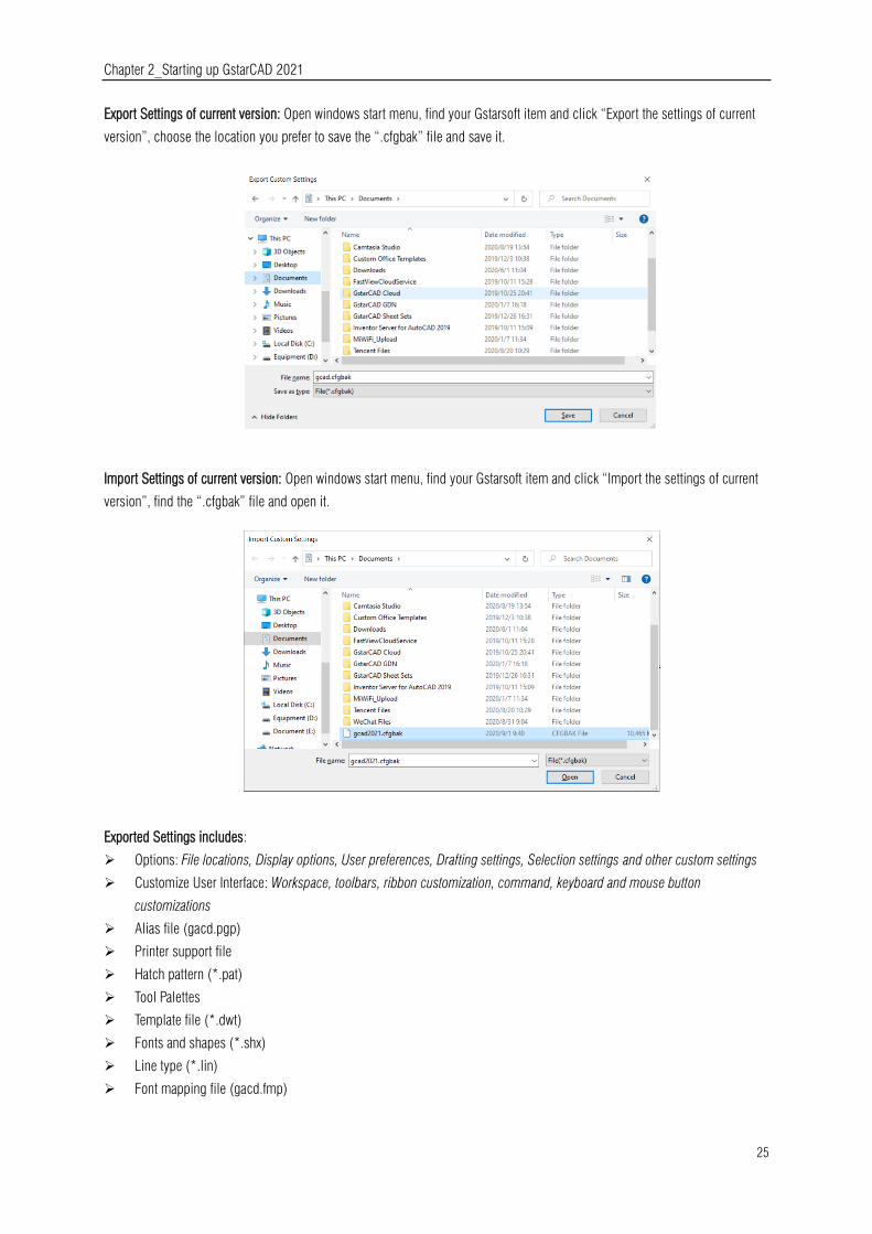
Chapter 2_Starting up GstarCAD 2021
25
Export Settings of current version: Open windows start menu, find your Gstarsoft item and click “Export the settings of current
version”, choose the location you prefer to save the “.cfgbak” file and save it.
Import Settings of current version: Open windows start menu, find your Gstarsoft item and click “Import the settings of current
version”, find the “.cfgbak” file and open it.
Exported Settings includes:
Options: File locations, Display options, User preferences, Drafting settings, Selection settings and other custom settings
Customize User Interface: Workspace, toolbars, ribbon customization, command, keyboard and mouse button
customizations
Alias file (gacd.pgp)
Printer support file
Hatch pattern (*.pat)
Tool Palettes
Template file (*.dwt)
Fonts and shapes (*.shx)
Line type (*.lin)
Font mapping file (gacd.fmp)

Chapter 2_Starting up GstarCAD 2021
26
2.4.2. Migrate from a Previous Release
GstarCAD 2021 adds a "Migrate from a previous release" feature in the WINDOWS Start menu program items, which allows
users to migrate selected settings of old versions directly to the new version after installation without copying and setup
manually under same language. The earliest version that can be migrated is GstarCAD 2016.
Migrated Settings includes:
Options: File locations, Display options, User preferences, Drafting
settings, Selection settings and other custom settings
Customize User Interface: Workspace, toolbars, ribbon
customization, command, keyboard and mouse button
customizations
Alias file (gacd.pgp)
Printer support file
Hatch pattern (*.pat)
Tool Palettes
Template file (*.dwt)
Fonts and shapes (*.shx)
Line type (*.lin)
Font mapping file (gacd.fmp)
Note:
After migration from older version, the relevant settings of current version will be overwritten, and can’t be restored.
After migration from older version, the new functionalities that only current version supports, will be reset to default.
2.4.3. Import AutoCAD Tool Palettes
You can import AutoCAD customized Tool palettes in the WINDOWS Start menu easily. If you installed AutoCAD in your PC, you
can just import the file from the path in AutoCAD options. If you need to import AutoCAD customized Tool Palettes from another
equipment, the path can be anywhere, but the folder must include AcTpCatalog.atc file.
Before importing an AutoCAD tool palettes, read carefully the following notes:
1. The default blocks of AutoCAD cannot be directly imported into GstarCAD. If you want to import default blocks of AutoCAD to
GstarCAD, you need to drag them to the drawing from the Tool Palettes, and add them back to Tool Palettes in AutoCAD, then
save the drawing and import.
2. The imported file is only block and command, hatch pattern, light source, constraint, table and other objects haven’t been
supported yet.
3. If there is a lack of grip point in the imported dynamic block, probably it’s the result of the imperfect action of the dynamic
block.

Chapter 2_Starting up GstarCAD 2021
27
4. All eligible GstarCAD paths will be detected first when you import the file into GstarCAD directly, the entire Tool Palettes in
GstarCAD will be overwritten.
5. The order of the tools list in Tool Palettes after import may be different from that of AutoCAD. The reason is that AutoCAD
supports a file recording the order of the tools in Tool Palettes, but GstarCAD does not.
6. If the source DWG drawing location is changed before you import custom AutoCAD Tool Palettes and its tools, the block(s)
imported into the palettes in GstarCAD will be unable to be used without that corresponding DWG drawing original saved path.
2.5. Tool Palettes
Tool palettes are tabbed areas within the Tool Palettes window. The items you add to a tool palette are
called tools. You can create a tool by dragging an object onto the tool palette. In GstarCAD, blocks
and external references (xrefs) can be dragged onto the tool palette. The new tool inserted will has
the same properties into your drawing. Also you can create, delete, rename and customize panels by
doing right click on it. To open the tool palettes just press CTRL+3 or Type TOOLPALETTES
command.
2.6. Design Center
With Design Center, you can organize access to drawings, blocks, text styles and other drawing contents:
-Browse for drawing content on your
computer or a networked drive.
-View definition tables for named objects
and then insert, attach, copy and paste the
definitions into the current drawing.
-Create shortcuts to drawings and folders
that you access frequently.
-Add content such as xrefs, blocks to a
drawing.
-Drag drawings, blocks to a tool palette
for convenient access
Folders Tab: The following icons are
displayed in this tab: networks and computers, computer drives, folders, drawings and related support files, Xrefs, layouts and
named objects, including blocks, layers, linetypes, text styles and dimension styles within a drawing.
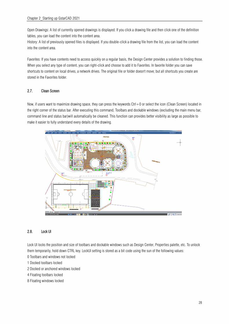
Chapter 2_Starting up GstarCAD 2021
28
Open Drawings: A list of currently opened drawings is displayed. If you click a drawing file and then click one of the definition
tables, you can load the content into the content area.
History: A list of previously opened files is displayed. If you double-click a drawing file from the list, you can load the content
into the content area.
Favorites: If you have contents need to access quickly on a regular basis, the Design Center provides a solution to finding those.
When you select any type of content, you can right-click and choose to add it to Favorites. In favorite folder you can save
shortcuts to content on local drives, a network drives. The original file or folder doesn't move; but all shortcuts you create are
stored in the Favorites folder.
2.7. Clean Screen
Now, if users want to maximize drawing space, they can press the keywords Ctrl+0 or select the icon (Clean Screen) located in
the right corner of the status bar. After executing this command, Toolbars and dockable windows (excluding the main menu bar,
command line and status bar)will automatically be cleaned. This function can provides better visibility as large as possible to
make it easier to fully understand every details of the drawing.
2.8. Lock UI
Lock UI locks the position and size of toolbars and dockable windows such as Design Center, Properties palette, etc. To unlock
them temporarily, hold down CTRL key. LockUI setting is stored as a bit code using the sun of the following values:
0 Toolbars and windows not locked
1 Docked toolbars locked
2 Docked or anchored windows locked
4 Floating toolbars locked
8 Floating windows locked
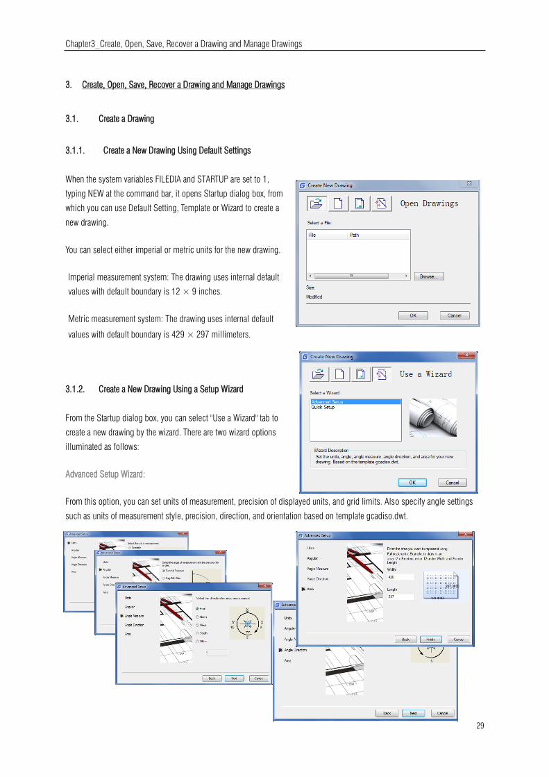
Chapter3_Create, Open, Save, Recover a Drawing and Manage Drawings
29
3. Create, Open, Save, Recover a Drawing and Manage Drawings
3.1. Create a Drawing
3.1.1. Create a New Drawing Using Default Settings
When the system variables FILEDIA and STARTUP are set to 1,
typing NEW at the command bar, it opens Startup dialog box, from
which you can use Default Setting, Template or Wizard to create a
new drawing.
You can select either imperial or metric units for the new drawing.
Imperial measurement system: The drawing uses internal default
values with default boundary is 12 × 9 inches.
Metric measurement system: The drawing uses internal default
values with default boundary is 429 × 297 millimeters.
3.1.2. Create a New Drawing Using a Setup Wizard
From the Startup dialog box, you can select "Use a Wizard" tab to
create a new drawing by the wizard. There are two wizard options
illuminated as follows:
Advanced Setup Wizard:
From this option, you can set units of measurement, precision of displayed units, and grid limits. Also specify angle settings
such as units of measurement style, precision, direction, and orientation based on template gcadiso.dwt.

Chapter3_Create, Open, Save, Recover a Drawing and Manage Drawings
30
Quick Setup Wizard: From this option, you can specify units of
measurement, precision of displayed units, and grid limits based on
template gcadiso.dwt.
3.1.3. Create a New Drawing Using Template
When you need to create several drawings with the
default settings, you can save time by creating a
template file designed to create the same drawing files
so that you does not need to specify default settings
each time you start. Conventions and settings commonly
stored in template files include: unit type and precision,
title blocks, borders, and logos, layer names, snap, grid,
and ortho settings, grid limits, dimension styles, text
styles and Linetypes.
Also when the system variables FILEDIA and STARTUP
are set to 1 and 0 separately, typing NEW opens Select Template dialog box, from which you can select the desired one or use
the default template by clicking the arrowhead button next to the Open button.
3.2. Open a Drawing
3.2.1. Open a Drawing
You can open drawing (.dwg) files, Drawing Exchange Format (.dxf) files,
drawing standard (dws) files and drawing template (.dwt) files. You can also
open and check drawings that you suspect are damaged.
To open an existing drawing: File > Open
Command line> OPEN Using shortcut>
CTRL+O
-In the dialog box, choose the type of file you
want to open.
-Choose the folder containing the desired
file.-Choose the drawing you want to open, and
then click the Open button or Double click on the drawing you want to open.
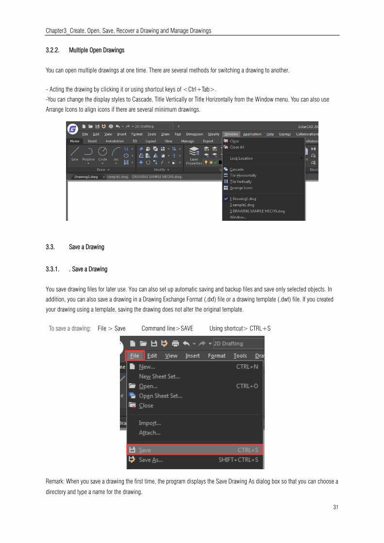
Chapter3_Create, Open, Save, Recover a Drawing and Manage Drawings
31
3.2.2. Multiple Open Drawings
You can open multiple drawings at one time. There are several methods for switching a drawing to another.
- Acting the drawing by clicking it or using shortcut keys of <Ctrl+Tab>.
-You can change the display styles to Cascade, Title Vertically or Title Horizontally from the Window menu. You can also use
Arrange Icons to align icons if there are several minimum drawings.
3.3. Save a Drawing
3.3.1. . Save a Drawing
You save drawing files for later use. You can also set up automatic saving and backup files and save only selected objects. In
addition, you can also save a drawing in a Drawing Exchange Format (.dxf) file or a drawing template (.dwt) file. If you created
your drawing using a template, saving the drawing does not alter the original template.
To save a drawing: File > Save Command line>SAVE Using shortcut> CTRL+S
Remark: When you save a drawing the first time, the program displays the Save Drawing As dialog box so that you can choose a
directory and type a name for the drawing.
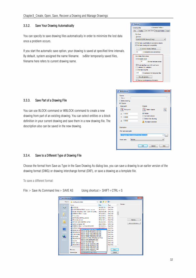
Chapter3_Create, Open, Save, Recover a Drawing and Manage Drawings
32
3.3.2. Save Your Drawing Automatically
You can specify to save drawing files automatically in order to minimize the lost data
once a problem occurs.
If you start the automatic save option, your drawing is saved at specified time intervals.
By default, system assigned the name filename. sv$for temporarily saved files,
filename here refers to current drawing name.
3.3.3. Save Part of a Drawing File
You can use BLOCK command or WBLOCK command to create a new
drawing from part of an existing drawing. You can select entities or a block
definition in your current drawing and save them in a new drawing file. The
description also can be saved in the new drawing.
3.3.4. Save to a Different Type of Drawing File
Choose the format from Save as Type in the Save Drawing As dialog box, you can save a drawing to an earlier version of the
drawing format (DWG) or drawing interchange format (DXF), or save a drawing as a template file.
To save a different format:
File > Save As Command line> SAVE AS Using shortcut> SHIFT+CTRL+S
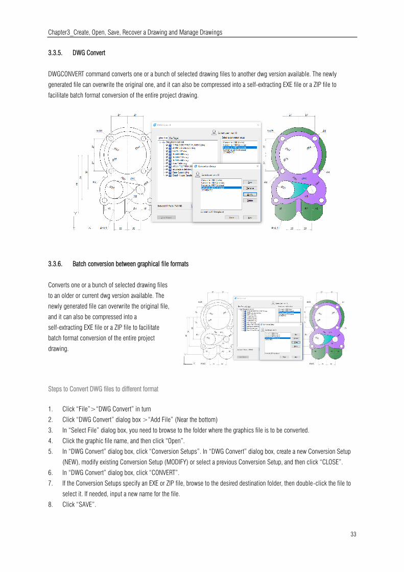
Chapter3_Create, Open, Save, Recover a Drawing and Manage Drawings
33
3.3.5. DWG Convert
DWGCONVERT command converts one or a bunch of selected drawing files to another dwg version available. The newly
generated file can overwrite the original one, and it can also be compressed into a self-extracting EXE file or a ZIP file to
facilitate batch format conversion of the entire project drawing.
3.3.6. Batch conversion between graphical file formats
Converts one or a bunch of selected drawing files
to an older or current dwg version available. The
newly generated file can overwrite the original file,
and it can also be compressed into a
self-extracting EXE file or a ZIP file to facilitate
batch format conversion of the entire project
drawing.
Steps to Convert DWG files to different format
1. Click “File”>“DWG Convert” in turn
2. Click “DWG Convert” dialog box >“Add File” (Near the bottom)
3. In “Select File” dialog box, you need to browse to the folder where the graphics file is to be converted.
4. Click the graphic file name, and then click “Open”.
5. In “DWG Convert” dialog box, click “Conversion Setups”. In “DWG Convert” dialog box, create a new Conversion Setup
(NEW), modify existing Conversion Setup (MODIFY) or select a previous Conversion Setup, and then click “CLOSE”.
6. In “DWG Convert” dialog box, click “CONVERT”.
7. If the Conversion Setups specify an EXE or ZIP file, browse to the desired destination folder, then double-click the file to
select it. If needed, input a new name for the file.
8. Click “SAVE”.

Chapter3_Create, Open, Save, Recover a Drawing and Manage Drawings
34
3.3.7. Use Backup Files
GstarCAD creates a backup file with the current drawing name and a ".bak" extension to save the previous version of the current
drawing when launching "backup automatically" option.
3.3.8. Reduce the Time Required to Save a Drawing File
In order to reduce the time of saving a drawing file, you can specify
the incremental save percentage on the Open and Save tab of Options
dialog box or from the ISAVEPERCENT system variable.
The incremental save updates only the portions of the saved drawing
file you changed. Drawing files will contain a percentage of
potentially wasted space when you use incremental saves. This
percentage increases after each incremental save until it reaches the
specified maximum value, and then a full save is perform.
3.4. Recover a Drawing
3.4.1. Recover a Damaged File
You can recover some or all of data by reverting to a backup file or using commands
to find and correct errors if a drawing file is damaged. A drawing file may be damaged
by a hardware failure, power outage and system crash. You had better create a backup
file if the drawing is important.
On the Open and Save tab of Options dialog box, you can specify the backup file are
created when you save drawings and set the proper interval time for saving. Then a
backup copy file with a ".bak" extension is created when you save the named drawing
once again. After that, a backup file is always updated while you executing the command SAVE or SAVEAS.
You can use RECOVER command to check and attempt to open a damage file. Then uses AUDIT command to find and correct
errors.
To open a damaged file: File > Drawing Utilities> Recover
Command line>RECOVER

Chapter3_Create, Open, Save, Recover a Drawing and Manage Drawings
35
-In the dialog box at Files of Type, choose the type of file you want to recover.
-Choose the directory containing the damaged file.
-Choose the damaged file you want to recover and Click the Open button or Double click on the drawing you want to open.
To check errors for a drawing file: File > Drawing Utilities> Audit Command line> Audit
1. To choose from the opened drawing, click on File > Drawing Utilities > Audit
2. Input Y or N to determine whether to recover the errors that are automatically found by GstarCAD, and then press Enter.
3.4.2. Drawing Recovery Manager
Once terminated by hardware problems, power failure or software problems, the application is capable of backup the opened
drawing file. At the next startup, the program starts "Drawing Recovery Manager" in which all of the auto-backup drawing files
that have been closed accidentally will be displayed. You can open the file of your demand by double clicking at the Backup
File list on the "Drawing Recovery", if there is any damage to the file, system attempts to recover the drawing in process of
backup.
When program or system stopped by accident, the drawing files need to recover are sorted
into the following types.
-Recovered drawing file saved when program fails (DWG)
-Temporary saved file (sv$)
-Backup file (BAK)
-Source drawing file (DWG)

Chapter3_Create, Open, Save, Recover a Drawing and Manage Drawings
36
3.5. Manage Drawings
In GstarCAD the Sheet Set Manager allows you to manage the entire project
drawing sheetsets. It can manage all the work flow from sheets creation,
printing and publishing.etc.
In Sheet Set Manager, a sheet set is an organized collection of sheets from
several drawing files and each sheet in a sheet set is a layout in a drawing
file.
Begin taking advantage of sheet set functionality for your current projects with minimal effort by importing your current drawing
layouts into a sheet set. You can easily open drawings from a central location while you continue edit them using traditional
tools.
3.5.1. Sheet Set Control
Lists menu options to create a new sheet set, open an existing sheet set, or switch between open sheet sets
Details or Preview:Displays either descriptive information or a
thumbnail preview of the currently selected item in the tree
view.
Tree View:Displays the contents of the sheet list.

Chapter3_Create, Open, Save, Recover a Drawing and Manage Drawings
37
You can use the following actions in the tree view:
Right-click to access shortcut menus of the operations that are relevant to the
currently selected item.
Double-click items to open them. This is a convenient method for opening drawing files from the Sheet List. You can also
double-click items in the tree view to expand or collapse them.
Click one or more items to select them for operations such as opening, publishing, or transmitting.
Move the cursor over a single item to display descriptive information or a thumbnail preview of a selected sheet, view, or
drawing file.
Drag items within the tree view to reorder them.

Chapter3_Create, Open, Save, Recover a Drawing and Manage Drawings
38
3.5.2. Sheet Set Manager Basic Information
Opening Sheet Set Manager
Ribbon: View tab > Palettes > Sheet Set Manager or Type: sheetset
Creating a Sheet Set
Once the Sheet Set Manager is open, select the pull down box at the
top and then click on New Sheet Set.
A new dialog box will pop up displaying the 4 steps in creating a Sheet
Set.
Begin
Under Begin there are two options for creating a sheet set.
Option one
Is using “An example sheet set” that allows the use of a standard
template to create the sheet set.
Option two
Is using Existing drawings to start a new sheet set. We are going to
select the Existing Drawings option.
Sheet Set Details
This is where basic information like sheet set name, description, and file location can be added.

Chapter3_Create, Open, Save, Recover a Drawing and Manage Drawings
39
Choose Layouts
Existing layouts can be added to the sheet
set by browsing for the proper file needed
in the drawing set. Once the layouts are
selected, click Next to confirm.
Confirm
The confirm tab will give a summary of
the layouts to be added to the set. After
selecting the Next button the new layout
will be added to the sheet set.
Import layouts to the Sheet Set Manager
To add a new sheet from an existing drawing layout, right click the title of the sheet
set and select Import Layout as Sheet. A new pop up box will appear which allows you
to browse for an existing drawing to add a layout.
Tip: If the import box is not checked, the layout is already in the sheet set or the
layout is unable to be imported into the set.
Managing Sheet Set
Moving and Removing Sheets from a set
Once the sheets have been added to the Sheet Set Manger, they can be
dragged and dropped to the order needed. To remove a sheet from the
set, right click and select Remove Sheet.

Chapter3_Create, Open, Save, Recover a Drawing and Manage Drawings
40
Rename and Renumbering Sheets
To rename and renumber a sheet or a subset, right click on the
sheet needed to be changed and select Rename & Renumber.
A pop up box will show up that will allow the number, sheet title
and layout name to be changed.
Adding project information to a sheet set
To add project information to the sheet set, like
project name, project number, and project
description, right click on the sheet set title and
scroll down to the sheet set Properties. A new pop
up box will display that allows the update of project
information.
Tips: Project information in the sheet set can be
used in object such as fields
Creating Subsets in Sheet Set Manager
Creating subsets in Sheet Set Manager is a fast way to organize and find what is
needed in a big drawing set. To create a subset, right click on the sheet set
and then to New Subset.
The Subset Properties box will pop up.
Most of the properties are basic.
Select OK.
A new subset is added to the sheet set
manager.
Tip: To move a sheet to the new subset,
simply click and drag to the desired
subset.

Chapter3_Create, Open, Save, Recover a Drawing and Manage Drawings
41
Publishing Sheet Sets
Sheet Set Manager makes it simple to publish a full set or only select sheets of the construction documents. There are two
ways to plot: Publish directly to the plotter/file or use the Publish dialog box.
Publish and Plot directly to the plotter/file
Right click on the sheet set, scroll to Publish, and then Publish to Plotter.
This method is used to plot and publish when the page setup is set per layout. The drawback to using this optio
n is if someone plots one of the sheets using the plot command and saved the setup to the layout, the layout w
ill not publish properly. Sheetset can also be packaged and shared through e-transmit.
Publishing using Publish dialog box may not be as fast as Publishing directly to the plotter/file, but there is less
of a chance the document will come out wrong.
You are also able to use Page Setups saved in the
drawing to particular sheets or the full set.
To pull up the dialog box, right click the Sheet Set
title, scroll to Publish, and then to Publish Dialog
Box. The Publish Dialog Box will display.
Now with page setups, Publish Dialog Box can chan
ge the way the document is published. Now we hav
e the options to publish to Plotter named in Page
Setup, DWF, DWFx, and PDF.
Selecting the Sheet Set Publish Options allows the
options to change information like default output location
and naming.
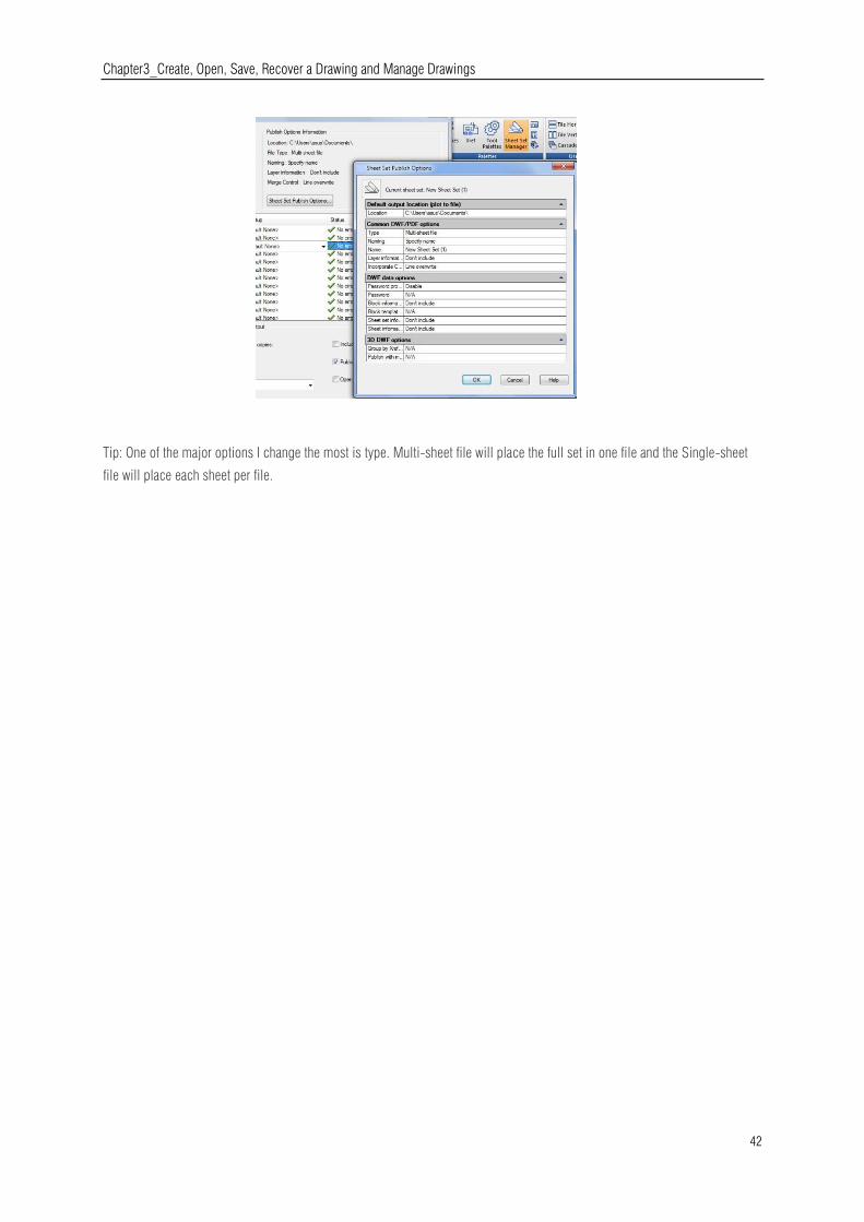
Chapter3_Create, Open, Save, Recover a Drawing and Manage Drawings
42
Tip: One of the major options I change the most is type. Multi-sheet file will place the full set in one file and the Single-sheet
file will place each sheet per file.
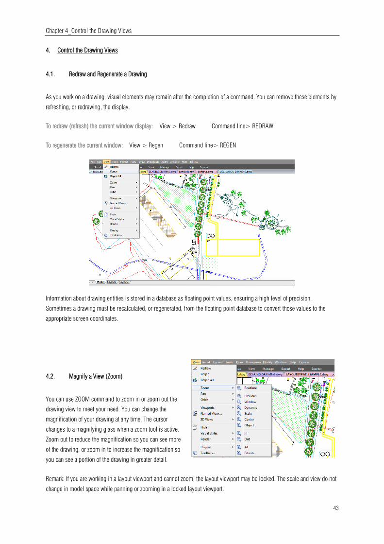
Chapter 4_Control the Drawing Views
43
4. Control the Drawing Views
4.1. Redraw and Regenerate a Drawing
As you work on a drawing, visual elements may remain after the completion of a command. You can remove these elements by
refreshing, or redrawing, the display.
To redraw (refresh) the current window display: View > Redraw Command line> REDRAW
To regenerate the current window: View > Regen Command line> REGEN
Information about drawing entities is stored in a database as floating point values, ensuring a high level of precision.
Sometimes a drawing must be recalculated, or regenerated, from the floating point database to convert those values to the
appropriate screen coordinates.
4.2. Magnify a View (Zoom)
You can use ZOOM command to zoom in or zoom out the
drawing view to meet your need. You can change the
magnification of your drawing at any time. The cursor
changes to a magnifying glass when a zoom tool is active.
Zoom out to reduce the magnification so you can see more
of the drawing, or zoom in to increase the magnification so
you can see a portion of the drawing in greater detail.
Remark: If you are working in a layout viewport and cannot zoom, the layout viewport may be locked. The scale and view do not
change in model space while panning or zooming in a locked layout viewport.

Chapter 4_Control the Drawing Views
44
4.2.1. Zooming Methods
To zoom, you can use any of the following methods:
-To define the portion of the drawing to zoom, create a window.
-To zoom in real time, use the Zoom Realtime tool on the Standard toolbar.
-If you have a mouse with a wheel, rotate the wheel to zoom in and out.
4.2.2. Zoom to Magnify a Specified Rectangular Area
You can specify a rectangular area defined by two corners to display the objects within that area as large as possibly. The
lower-left corner of the specified area becomes the lower-left corner of the new view.
To zoom in to an area using a window: View > Zoom> Window Command line> ZOOM
-Choose View > Zoom > Window
-Select one corner of the window around the area you want to magnify.
-Specify the opposite corner of the window around the area you want to magnify.
4.2.3. Zoom in Real Time
Realtime option zooms dynamically by moving your pointing device up or
down. By right-clicking, you can display a shortcut menu with additional
viewing options.
To zoom in real time: View > Zoom>Realtime
Command line> RTZOOM
-Choose View > Zoom > Realtime from the main menu.
-Hold the left mouse button, then drag the cursor forward to zoom in and move back to zoom out.
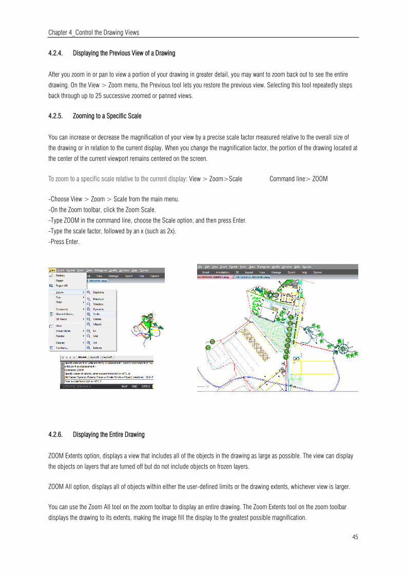
Chapter 4_Control the Drawing Views
45
4.2.4. Displaying the Previous View of a Drawing
After you zoom in or pan to view a portion of your drawing in greater detail, you may want to zoom back out to see the entire
drawing. On the View > Zoom menu, the Previous tool lets you restore the previous view. Selecting this tool repeatedly steps
back through up to 25 successive zoomed or panned views.
4.2.5. Zooming to a Specific Scale
You can increase or decrease the magnification of your view by a precise scale factor measured relative to the overall size of
the drawing or in relation to the current display. When you change the magnification factor, the portion of the drawing located at
the center of the current viewport remains centered on the screen.
To zoom to a specific scale relative to the current display: View > Zoom>Scale Command line> ZOOM
-Choose View > Zoom > Scale from the main menu.
-On the Zoom toolbar, click the Zoom Scale.
-Type ZOOM in the command line, choose the Scale option, and then press Enter.
-Type the scale factor, followed by an x (such as 2x).
-Press Enter.
4.2.6. Displaying the Entire Drawing
ZOOM Extents option, displays a view that includes all of the objects in the drawing as large as possible. The view can display
the objects on layers that are turned off but do not include objects on frozen layers.
ZOOM All option, displays all of objects within either the user-defined limits or the drawing extents, whichever view is larger.
You can use the Zoom All tool on the zoom toolbar to display an entire drawing. The Zoom Extents tool on the zoom toolbar
displays the drawing to its extents, making the image fill the display to the greatest possible magnification.

Chapter 4_Control the Drawing Views
46
4.3. Pan and View
You can move the drawing in any direction using the pan command. Panning shifts or slides the view of the drawing
horizontally, vertically, or diagonally. The magnification of the drawing remains the same, as does its orientation in space. The
only change is the portion of the drawing displayed. To pan, you can use any of the following methods:
-For precise panning, specify two points defining the magnitude and direction of the pan. The first point indicates the starting
point of the pan. The second point indicates the amount of pan displacement relative to the first point.-To pan in real time, use
the Pan Realtime tool on the Standard toolbar.
-If you have a mouse with a wheel, press and hold the wheel, and then move the mouse.
To pan in real time: View > Pan>Realtime Command line>PAN
-Choose View > Zoom > Realtime from the main menu.
-Move the cursor in the direction you want to pan.
-To stop panning, press Enter, ESC or choose Exit from the shortcut menu.
To pan using a mouse with a wheel:
-Press and hold the wheel, and then move the mouse in the direction you
want to pan (The MBUTTONPAN system variable controls this feature.)
4.4. Display Multiple Views on Model Space
When you begin a new drawing, it is displayed in a single window. You can view the drawing in a second window, or you can
divide one window into multiple windows. You can also open and display multiple drawings.
4.4.1. Set Model Space Viewports
The viewports created on the Model tab completely fill the drawing area and do not overlap. As you make changes in one
viewport, the others are updated simultaneously.
You can do the following operations at the model
space viewport:
-Set Snap, Grid, and UCS icon modes; Pan; Zoom;
and restore named views.
-Save orientations of UCS with individual viewports.
-When executing a command, you can draw from
one viewport to another.
-Name a viewport arrangement in order to you can
reuse it on the Model tab or insert it on a layout tab.
-When you work on 3D models, is helpful setting up
different UCS in individual viewports.

Chapter 4_Control the Drawing Views
47
4.4.2. Working with Multiple Views of a Single Drawing
You can open and work with several views of the same drawing simultaneously. After you divide a single window into multiple
windows, you can control each window separately. For example, you can zoom or pan in one window without affecting the
display in any of the other windows. As you draw, any changes you make in one window are immediately visible in the others.
And also you can switch from one window to another at any time.
To create multiple views: View > Viewports Command line> VPORTS
-Choose View> Viewports-In viewports menu, choose 1, 2, 3, or 4 viewports.
-Type h if you want the horizontal orientation, or type v if you want the vertical orientation.
To join two views: View > Viewports> Join Command line> VPORTS
-Choose View > Viewports > Join -Click anywhere inside the window you want to keep.
-Click anywhere inside the adjacent window you want to join to the first window.
To restore a named window configuration:
-Type -VPORTS system variable at the command line and press ENTER.
-Then type Restore.
-Then type the name of the window configuration you want to restore.

Chapter 4_Control the Drawing Views
48
4.4.2.1. VPSCALE
The VPSCALE (viewport scale) command reports the real scale of the current viewport of a selected layout viewport.
1. You can open a recent drawing with layouts or create a new viewport on layout space with a desire scale according to paper
format.
2. Type VPSCALE command on the command line, then select the edge of the viewport.
3. The command line will show the correct viewport scale according to unit measure you are working with.
4. Notice the status bar shows the right scale of the selected viewport only at layout space.
4.4.3. Working with Multiple Drawings
With the multiple document interface, you can open and work on several drawings at one time, you can copy, cut, or paste an
entity from one drawing to another. Each drawing appears in a drawing window, which has the following advantages: You can
see two or more drawings side by side, and you can easily copy entities from one drawing to another. Under the Window menu,
the following three methods that determine how drawings are arranged are provided for user's choice.
-Cascade
-Tile Horizontally
-Tile Vertically
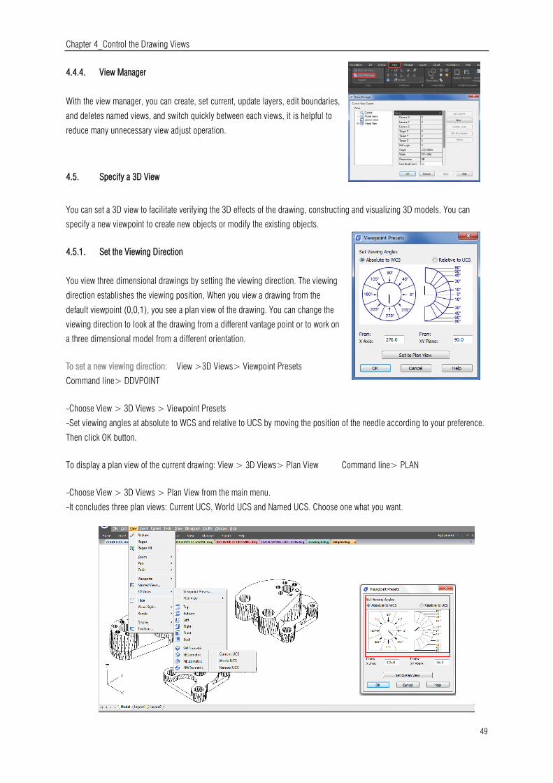
Chapter 4_Control the Drawing Views
49
4.4.4. View Manager
With the view manager, you can create, set current, update layers, edit boundaries,
and deletes named views, and switch quickly between each views, it is helpful to
reduce many unnecessary view adjust operation.
4.5. Specify a 3D View
You can set a 3D view to facilitate verifying the 3D effects of the drawing, constructing and visualizing 3D models. You can
specify a new viewpoint to create new objects or modify the existing objects.
4.5.1. Set the Viewing Direction
You view three dimensional drawings by setting the viewing direction. The viewing
direction establishes the viewing position, When you view a drawing from the
default viewpoint (0,0,1), you see a plan view of the drawing. You can change the
viewing direction to look at the drawing from a different vantage point or to work on
a three dimensional model from a different orientation.
To set a new viewing direction: View >3D Views> Viewpoint Presets
Command line> DDVPOINT
-Choose View > 3D Views > Viewpoint Presets
-Set viewing angles at absolute to WCS and relative to UCS by moving the position of the needle according to your preference.
Then click OK button.
To display a plan view of the current drawing: View > 3D Views> Plan View Command line> PLAN
-Choose View > 3D Views > Plan View from the main menu.
-It concludes three plan views: Current UCS, World UCS and Named UCS. Choose one what you want.

Chapter 4_Control the Drawing Views
50
4.5.2. Isometric View
You can define perspective views of a
model to create realistic effects. Select
predefined standard orthographic and
isometric views by name or description.
These views represent commonly used
options: Top, Bottom, Front, Left, Right,
and Back. In addition, you can set views
from isometric options: SW (southwest)
Isometric, SE (southeast) Isometric, NE
(northeast) Isometric, and NW (northwest)
Isometric.
4.5.3. Draw 2D Isometric Views
With Isometric Snap, you can create 2D objects that appear to be 3D solids.
By setting Isometric Snap on the Draft Settings dialog box and turning on Snap and Grid, you can easily align objects along
one of three isometric planes. However, although the isometric drawing looks like 3D, it is actually a 2D representation.
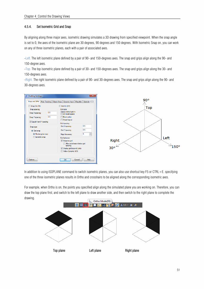
Chapter 4_Control the Drawing Views
51
4.5.4. Set Isometric Grid and Snap
By aligning along three major axes, isometric drawing simulates a 3D drawing from specified viewpoint. When the snap angle
is set to 0, the axes of the isometric plane are 30 degrees, 90 degrees and 150 degrees. With Isometric Snap on, you can work
on any of three isometric planes, each with a pair of associated axes.
-Left. The left isometric plane defined by a pair of 90- and 150-degrees axes. The snap and grips align along the 90- and
150-degree axes.
-Top. The top isometric plane defined by a pair of 30- and 150-degrees axes. The snap and grips align along the 30- and
150-degrees axes.
-Right. The right isometric plane defined by a pair of 90- and 30-degrees axes. The snap and grips align along the 90- and
30-degrees axes.
In addition to using ISOPLANE command to switch isometric planes, you can also use shortcut key F5 or CTRL+E. specifying
one of the three isometric planes results in Ortho and crosshairs to be aligned along the corresponding isometric axes.
For example, when Ortho is on, the points you specified align along the simulated plane you are working on. Therefore, you can
draw the top plane first, and switch to the left plane to draw another side, and then switch to the right plane to complete the
drawing.
Top plane Left plane Right plane

Chapter 4_Control the Drawing Views
52
4.5.5. Change a 3D View Dynamically
You can view objects from any viewing direction by holding down mouse or other pointing devices and moving dynamically.
With dynamic viewing, you can display the effects of changing viewpoint while you change the view. You can execute move or
zoom operations as the 3D Orbit is active. When the 3D Orbit is active, you are not allowed to modify objects. GstarCAD
supports more orbit options like Free Orbit, 3D Continuous Orbit, Orbit along the X-axis, Orbit along the Y-axis, Orbit along
Z-orbit and 3D Orbit Center. Additionally users can create two new meshes through DISH and DOME commands. To close 3D
Orbit, press Enter, ESC or choose Exit from the shortcut menu.
4.5.6. Hide Lines or Shade 3D Objects
Hides or shapes for 3D objects in the current drawing, suppresses the display of the objects (partly or entirely) that are located
behind other objects, or generates a simply shaded image displayed in the current view. You can use HIDE command to
remove the hidden lines to verify the current placement of these surfaces. Hiding background lines makes the display much
clearer, but you cannot modify hidden-line or render views.
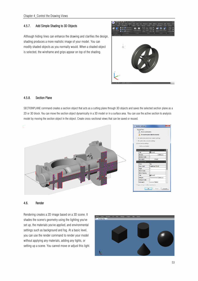
Chapter 4_Control the Drawing Views
53
4.5.7. Add Simple Shading to 3D Objects
Although hiding lines can enhance the drawing and clarifies the design,
shading produces a more realistic image of your model. You can
modify shaded objects as you normally would. When a shaded object
is selected, the wireframe and grips appear on top of the shading.
4.5.8. Section Plane
SECTIONPLANE command creates a section object that acts as a cutting plane through 3D objects and saves the selected section plane as a
2D or 3D block. You can move the section object dynamically in a 3D model or in a surface area. You can use the active section to analysis
model by moving the section object in the object. Create cross-sectional views that can be saved or reused.
4.6. Render
Rendering creates a 2D image based on a 3D scene. It
shades the scene's geometry using the lighting you've
set up, the materials you've applied, and environmental
settings such as background and fog. At a basic level,
you can use the render command to render your model
without applying any materials, adding any lights, or
setting up a scene. You cannot move or adjust this light.

Chapter 4_Control the Drawing Views
54
4.6.1. Render Environment
You can use environmental features to set up atmospheric effects or background
images. You can enhance a rendered image by means of atmospheric effects like fog
and depth cueing or by adding a bitmap image as a background. Fog and depth
cueing are actually two extremes of the same effect: a white color is fog, and a black
color is traditional depth cueing. You can use any color in between.
4.6.2. Light
Lighting adds the finishing touch to the scene. You can add point lights, spotlights, and distant lights and set the location and
photometric properties of each.
Point Light: A point light radiates light in all directions from
its location and does not target an object.
Spotlights: A spotlight can be directed towards an object.
Distant Lights: Simulates the effect of sunlight and can be
used to show how the shadows cast by a structure affect the
surrounding area.
Light List: Displays a list of type and light name used in
model. Distant lights and the sun do not appear as interface
objects in the model.
4.6.3. Materials
You can add materials to objects in your drawings to provide a realistic effect. In
the context of rendering, materials describe how an object reflects or transmits
light. Within a material, maps can simulate textures, bump effects, reflections,
or refractions.
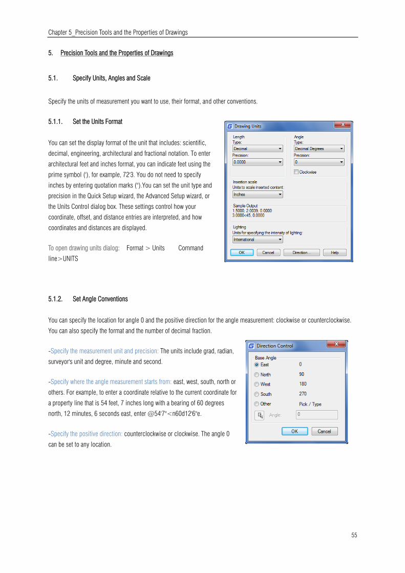
Chapter 5_Precision Tools and the Properties of Drawings
55
5. Precision Tools and the Properties of Drawings
5.1. Specify Units, Angles and Scale
Specify the units of measurement you want to use, their format, and other conventions.
5.1.1. Set the Units Format
You can set the display format of the unit that includes: scientific,
decimal, engineering, architectural and fractional notation. To enter
architectural feet and inches format, you can indicate feet using the
prime symbol ('), for example, 72'3. You do not need to specify
inches by entering quotation marks (").You can set the unit type and
precision in the Quick Setup wizard, the Advanced Setup wizard, or
the Units Control dialog box. These settings control how your
coordinate, offset, and distance entries are interpreted, and how
coordinates and distances are displayed.
To open drawing units dialog: Format > Units Command
line>UNITS
5.1.2. Set Angle Conventions
You can specify the location for angle 0 and the positive direction for the angle measurement: clockwise or counterclockwise.
You can also specify the format and the number of decimal fraction.
-Specify the measurement unit and precision: The units include grad, radian,
surveyor's unit and degree, minute and second.
-Specify where the angle measurement starts from: east, west, south, north or
others. For example, to enter a coordinate relative to the current coordinate for
a property line that is 54 feet, 7 inches long with a bearing of 60 degrees
north, 12 minutes, 6 seconds east, enter @54'7"<n60d12'6"e.
-Specify the positive direction: counterclockwise or clockwise. The angle 0
can be set to any location.

Chapter 5_ Precision Tools and the properties of Drawing
56
5.1.3. Setting Scale Factors
Instead of drawing to a particular scale, you draw everything full size in the
program. When you print your drawing, you can assign the scale at which
the drawing is to print. Scale, however, does affect the way a few elements
such as text, arrows, or linetypes print in your drawing. For example, when
you draw text, you need to determine the text size so that when you print it
later at a particular scale, the text height is correct.
After you determine the eventual scale of your finished drawing, you can
calculate the scale factor for the drawing as a ratio of one drawing unit to
the actual scale unit represented by each drawing unit.
The following table shows some standard architectural and engineering
scale ratios and equivalent text heights required to create text that measures
1/8 inch high when you print the drawing at the specified scale.
You can use these scale factors to predetermine the size of your drawing to
make sure that it fits on a specific size paper when you print it. You control
the size of your drawing by the drawing limits. To calculate the drawing
limits to match the size of your paper, multiply the dimensions of your
paper size by your scale factor.
5.2. Drawing Limits
You can specify the drawing limits that form an invisible boundary around your drawing. You can use the drawing limits to make
sure that you do not create a drawing larger than can fit on a specific sheet of paper when printed at a specific scale.
For example, if you plan to print your drawing at 1/8" = 1'-0" (in other words, using a scale factor of 96) on a sheet of paper
measuring 36 inches x 24 inches, you can set drawing limits to 3,264 units wide (that is, 34 x 96) and 2,112 units high (22 x
96), which allows a 1-inch margin around the edges of the
printed image.
To set the drawing limits: Format > Drawing limits
Command line> LIMITS
-Choose Format > Drawing Limits
-Specify the x-coordinate and y-coordinate of the upper right
drawing limit and the lower left drawing limit. You can also click
Select to specify the drawing limits by selecting points in the
drawing.
Standard scale ratios and equivalent text heights
Scale Scale factor Text height
1/16" = 1'-0" 192 24"
1/8" = 1'-0" 96 12"
3/16" = 1'-0" 64 8"
1/4" = 1'-0" 48 6"
3/8" = 1'-0" 32 4"
1/2" = 1'-0" 24 3"
3/4" = 1'-0" 16 2"
1" = 1'-0" 12 1.5"
1 1/2" = 1'-0" 8 1"
3" = 1'-0" 4 0.5"
1" = 10' 120 15"
1" = 20' 240 30"
1" = 30' 360 45"
1" = 40' 480 60"
1" = 50' 600 75"
1" = 60' 720 90"
1" = 100' 1200 150"
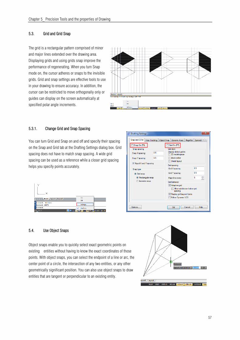
Chapter 5_ Precision Tools and the properties of Drawing
57
5.3. Grid and Grid Snap
The grid is a rectangular pattern comprised of minor
and major lines extended over the drawing area.
Displaying grids and using grids snap improve the
performance of regenerating. When you turn Snap
mode on, the cursor adheres or snaps to the invisible
grids. Grid and snap settings are effective tools to use
in your drawing to ensure accuracy. In addition, the
cursor can be restricted to move orthogonally only or
guides can display on the screen automatically at
specified polar angle increments.
5.3.1. Change Grid and Snap Spacing
You can turn Grid and Snap on and off and specify their spacing
on the Snap and Grid tab at the Drafting Settings dialog box. Grid
spacing does not have to match snap spacing. A wide grid
spacing can be used as a reference while a closer grid spacing
helps you specify points accurately.
5.4. Use Object Snaps
Object snaps enable you to quickly select exact geometric points on
existing entities without having to know the exact coordinates of those
points. With object snaps, you can select the endpoint of a line or arc, the
center point of a circle, the intersection of any two entities, or any other
geometrically significant position. You can also use object snaps to draw
entities that are tangent or perpendicular to an existing entity.

Chapter 5_ Precision Tools and the properties of Drawing
58
5.4.1. Setting Object Snaps
You can set object snaps using any of the following methods:
-Choose Tools > Drafting Settings > Object Snap, and then click
one of the object snap tools.
-On the Object Snap toolbar, click one of the object snap tools.
-On the status bar, right-click on the Object Snap button to choose
Settings.
-Press and hold down the Shift key while right clicking anywhere
within the drawing window to display the object snap shortcut menu,
and then choose the object snap you want to set.
Additionally, you can find an option called Distance from Endpoint. This option allows snap a certain distance from any
endpoint of objects like line, arc, spline, pline, ellipse arc, mline and any other lines. As long as you pass the cursor over an
object from its endpoints, you will see a green snap point at accurate distance.
Another option called Divide Segments allows snap the divided segment points of objects like line, arc, spline, pline, ellipse
arc, mline and any other lines. Before, if you want to find the divide point, first you need to generate the divided points object,
then snap those points to draw. Now as long as you pass the cursor over an object mentioned above, you will see a green snap
point at accurate distance.
5.4.2. AutoSnap Tools
The automatic snap tool is a visual aid tool for snapping that help
you see and use object snaps more efficiently. When any object
snap is on, the system displays a marker and a tooltip when you
move your cursor on over a snap point. AutoSnap turns on
automatically when an object snap is on. By default, AutoSnap
marker, tooltip and magnet are on. You can change the settings of

Chapter 5_ Precision Tools and the properties of Drawing
59
AutoSnap on the Options dialog box. AutoSnap consists of the following snap tools:
-Marker. The object snap location is displayed when the cursor moves over or near an object. Marker shape is determined by
the snap it is marking.
-Tooltip. Indicates which part of the object you are snapping to in a flag at the cursor location.
-Magnet. Attracts and locks the cursor onto the nearest detected snap points. Provides a visual that is similar to snapping to a
grid.
-Aperture box. Surrounds the crosshairs and defines an area within which, when you move the cursor, system evaluates objects
for object snaps. You can determine the aperture box is displayed or not, and the aperture box size can be changed too.
5.4.3. Selection Cycling
With the new SELECTIONCYCLING system variable you can quickly select overlapped or coincident objects in current drawing
as well as set selection cycling options.
The Selection Cycling button is located on status bar. Right-click the button to specify the selection cycling settings. These
settings control whether a badge or the Selection dialog box displays when you hover over or select an overlapping object.
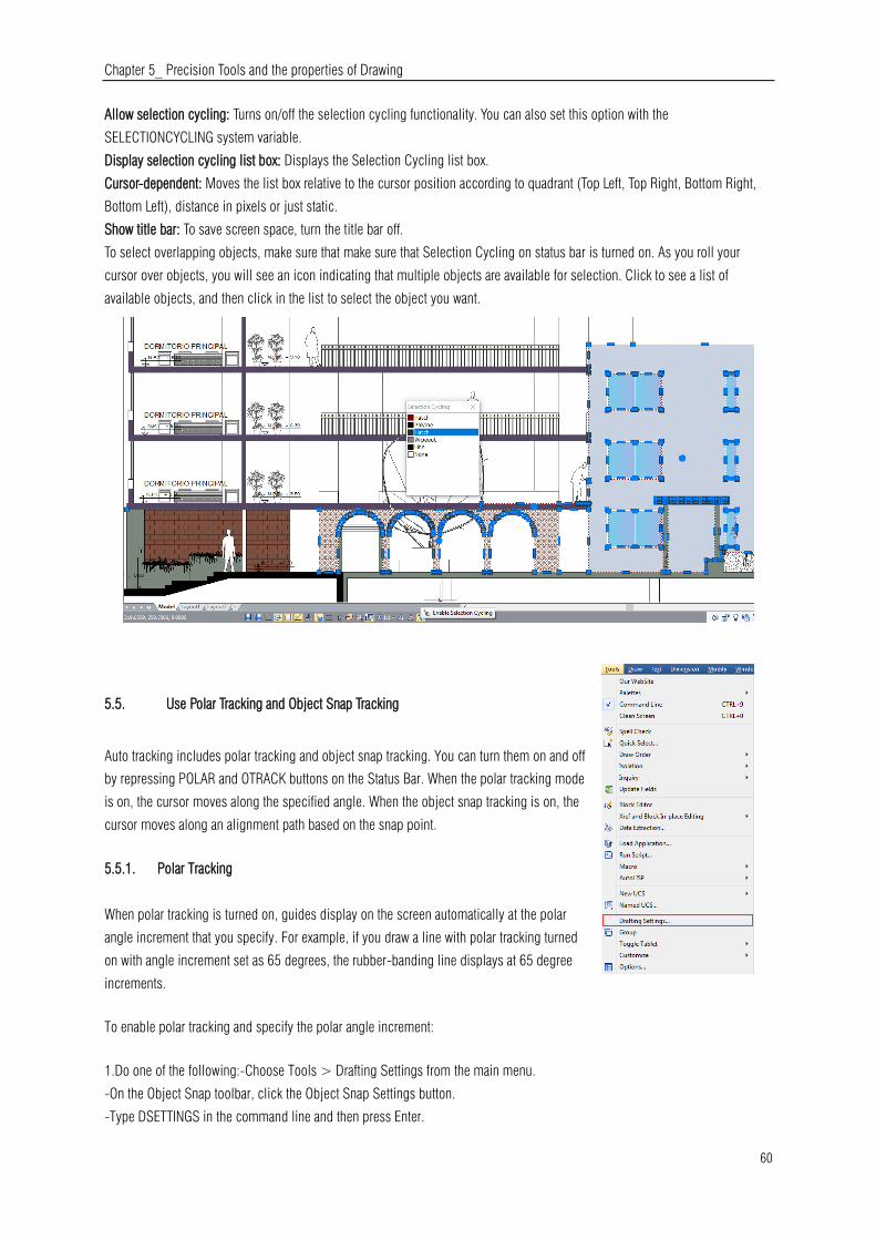
Chapter 5_ Precision Tools and the properties of Drawing
60
Allow selection cycling: Turns on/off the selection cycling functionality. You can also set this option with the
SELECTIONCYCLING system variable.
Display selection cycling list box: Displays the Selection Cycling list box.
Cursor-dependent: Moves the list box relative to the cursor position according to quadrant (Top Left, Top Right, Bottom Right,
Bottom Left), distance in pixels or just static.
Show title bar: To save screen space, turn the title bar off.
To select overlapping objects, make sure that make sure that Selection Cycling on status bar is turned on. As you roll your
cursor over objects, you will see an icon indicating that multiple objects are available for selection. Click to see a list of
available objects, and then click in the list to select the object you want.
5.5. Use Polar Tracking and Object Snap Tracking
Auto tracking includes polar tracking and object snap tracking. You can turn them on and off
by repressing POLAR and OTRACK buttons on the Status Bar. When the polar tracking mode
is on, the cursor moves along the specified angle. When the object snap tracking is on, the
cursor moves along an alignment path based on the snap point.
5.5.1. Polar Tracking
When polar tracking is turned on, guides display on the screen automatically at the polar
angle increment that you specify. For example, if you draw a line with polar tracking turned
on with angle increment set as 65 degrees, the rubber-banding line displays at 65 degree
increments.
To enable polar tracking and specify the polar angle increment:
1.Do one of the following:-Choose Tools > Drafting Settings from the main menu.
-On the Object Snap toolbar, click the Object Snap Settings button.
-Type DSETTINGS in the command line and then press Enter.
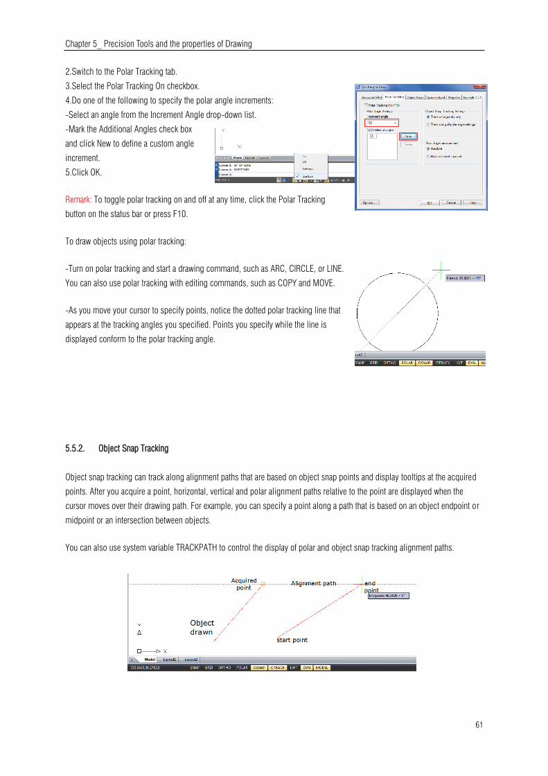
Chapter 5_ Precision Tools and the properties of Drawing
61
2.Switch to the Polar Tracking tab.
3.Select the Polar Tracking On checkbox.
4.Do one of the following to specify the polar angle increments:
-Select an angle from the Increment Angle drop-down list.
-Mark the Additional Angles check box
and click New to define a custom angle
increment.
5.Click OK.
Remark: To toggle polar tracking on and off at any time, click the Polar Tracking
button on the status bar or press F10.
To draw objects using polar tracking:
-Turn on polar tracking and start a drawing command, such as ARC, CIRCLE, or LINE.
You can also use polar tracking with editing commands, such as COPY and MOVE.
-As you move your cursor to specify points, notice the dotted polar tracking line that
appears at the tracking angles you specified. Points you specify while the line is
displayed conform to the polar tracking angle.
5.5.2. Object Snap Tracking
Object snap tracking can track along alignment paths that are based on object snap points and display tooltips at the acquired
points. After you acquire a point, horizontal, vertical and polar alignment paths relative to the point are displayed when the
cursor moves over their drawing path. For example, you can specify a point along a path that is based on an object endpoint or
midpoint or an intersection between objects.
You can also use system variable TRACKPATH to control the display of polar and object snap tracking alignment paths.

Chapter 5_ Precision Tools and the properties of Drawing
62
5.6. Use Orthogonal (Ortho Mode)
You can restrict cursor movement to the current horizontal and vertical axes so that you can draw at right angles, or
orthogonally. For example, when the Draw Orthogonal option is enabled, lines are restricted to 0 degrees, 90 degrees, 180
degrees, or 270 degrees. As you draw lines, the rubber banding line follows either the horizontal or vertical axis, depending on
which axis is farthest from the cursor. When you enable the isometric snap and grid, cursor movement is restricted to
orthogonal equivalents within the current isometric plane. Ortho mode and polar tracking cannot be on at the same time.
Turning on Ortho turns off polar tracking.
To fast enable orthogonal drawing:
-Press F8 or press the ORTO button at the status bar
5.7. Working with Linetypes
A linetype is a repeating pattern of dashes, dots, and blank spaces displayed in a line or a curve. You can assign linetypes to
objects by layer, or by specifying the linetype explicitly. And also, you can specify its scale,
load more linetypes into the program from a linetype library file, and create your own
custom linetypes.
By default, every drawing has at least three linetypes: CONTINUOUS, BYLAYER, and
BYBLOCK. You cannot rename or delete these linetypes.
Remark: You should not confuse these linetypes with the hardware linetypes provided by
some plotters. Both linetypes of dashes produce the similar effects. However, if you use
both linetypes at the same time, the results can be unpredictable.
5.7.1. Load Linetypes
GstarCAD includes the linetype definition files gcad.lin and gcadiso.lin. If you select gcadiso.lin, you can use ISO pen-width
option when you plot.If you want to know what linetypes are already available, you can display a list of linetypes that are loaded
in the drawing or stored in an LIN (linetype definition) file. Both linetype definition files contain several complex linetypes.

Chapter 5_ Precision Tools and the properties of Drawing
63
5.7.2. Change the Linetype of an Object
You can change the linetype of an object by changing the
linetype of the layer the object is on, reassigning the object to
another layer, or by specifying a linetype for the object directly.
5.7.3. Set the Current Linetype
By default, all objects are created using the current linetype,
which is displayed in the Linetype Control on the Properties
toolbar. To modify this current linetype, you can select a linetype
and make it current in the Linetype Manager dialog box. If the
current linetype is BYLAYER, objects are created using the
linetype assigned to the current layer.
If the current linetype is BYBLOCK, objects are created using CONTINOUS linetype until they are grouped into a block. When
you insert the block, it acquires the current linetype setting.
To make the linetype current:
Select a linetype from the Linetype Control pull-down list on the Properties toolbar, which is set to the current linetype.
5.7.4. Control Linetype Scale
You can set global or individual scales for objects to control the display of linetypes. The Global Scale Factor and Current
Object Scale are displayed in the Linetype Manager. The Global Scale Factor value is stored in the system variable LTSCALE,
which changes the linetype scale globally for new and existing objects.
The Current Object Scale is stored in the system
variable CELTSCALE, which specifies the
linetype scale for new objects. In a layout, you
can use system variable PSLTSCALE to adjust
the linetype scale in different viewports.
Remark: Setting the linetype scale too large or
too small may result in a line pattern looking like
a solid line, depending on what the scale view is
or at what scale the drawing is printed.
To set the current individual linetype scale:
Format > Linetype Command line> LINETYPE
-Choose Format > Linetype-Click the Show Details button.-In the Current Object Scale field, type the linetype scale that you
want to make current.-Click OK.

Chapter 5_ Precision Tools and the properties of Drawing
64
To change the global linetype scale: -Choose Format > Linetype-Click the Show Details button.-In the Global Scale Factor
field, type the global linetype scale that you want to change. Then click OK button.
5.8. Working with Layers
Layers are like the transparent overlays you use in manual
drafting. You use layers to organize different types of drawing
information. Each object in a drawing exists on a layer. When
you draw an object, it is created on the current layer.
5.8.1. Create and Name Layers
You can create an unlimited number of layers in every drawing and use those layers for organizing information. When you
create a new layer, it is initially assigned the color white (or black, depending on your system settings) and the linetype
CONTINUOUS. By default, a new layer is also visible. After you create and name a layer, you can change its color, linetype,
visibility, and other properties.
To create a new layer: Format > Layer Command line> LAYER
-Choose Format > Layer-Click the New Layer button.
-Type a name for the new layer and then click OK.
To change a layer name in the current drawing:
-Choose Format > Layer-In the Layer Properties Manager dialog box, click the name of layer you want to change.
-Type a new name and click OK button.
5.8.2. Setting the Current Layer
When you start a drawing, objects are created
in the current layer. By default, the layer 0 is
set to the current layer, but you can also create
a new one and make it current. Any subsequent
objects you create are associated with the
current layer and use its color and linetype.
To make a layer current:
-Choose Format > Layer-In the Layer Properties Manager dialog box, select a layer and then click the Set Current button to
make the layer current.-Click OK.

Chapter 5_ Precision Tools and the properties of Drawing
65
5.8.3. Removing Layers
You can remove unused layers from your drawing with PURGE or by deleting the layer from the Layer Properties Manager.
5.8.4. Controlling Layer Visibility
A layer can be visible or invisible. Objects on
invisible layers are not displayed and do not
print. By controlling layer visibility, you can turn
off unnecessary information.
To turn layers on or off: Format > Layer
Command line> LAYER
-Choose Format > Layer
-Click the icon under "On" tab in the layer list.
-Click OK button.
5.8.5. Locking and Unlocking Layers
Locking a layer prevents you from accidentally
modifying its objects. When a layer is locked
(but visible and thawed), you cannot edit them. If
you lock the current layer, you can still add new
objects to it. You can also change the linetype
and color associated with a locked layer.
Unlocking a layer restores full editing
capabilities.
To lock or unlock layers: Format > Layer
Command line> LAYER
-Choose Format > Layer from the main menu.
-Click the icon under "Lock" tab in the layer list.
-Click OK button.
5.8.6. Controlling Layer Printing
Controlling layer printing is another way you can
specify which objects print in your drawing.By
controlling layer printing, you can turn off
unnecessary information during printing. When you
turn off printing for a layer, objects drawn on that
layer are still visible, but they do not print.

Chapter 5_ Precision Tools and the properties of Drawing
66
To turn layer printing on or off: Format > Layer Command line> LAYER
-Choose Format > Layer
-Click the icon under "Plot" tab in the layer list.
-Click OK button.
5.8.7. Setting a Layer's Print Style
If your drawing uses named print style tables, you can specify a print style for each layer. Named print style tables contain print
styles that you set up to control what objects look like when they print, without actually changing the objects in the drawing. If
your drawing uses color-dependent print style tables, you cannot specify a print style for a layer. These types of print style
tables automatically determine printing requirements by the color assigned to a layer or an object.
To change the print style assigned to one or more layers (only in a drawing that uses named print style tables):
Format > Layer Command line> LAYER
-Choose Format > Layer
-Click the name of Plot Style in the layer list to open Select Plot
Style dialog box, from which, you can specify the desired plot style.
-Click OK button.
5.8.8. Freeze or Thaw Layers
You can also freeze layers to improve the performance of operations such as zooming and panning or producing hidden lines or
shaded images. When a layer is frozen, objects drawn on that layer are no longer visible.
To freeze or thaw layers: Format > Layer Command line> LAYER
-Choose Format > Layer
-Click the icon under "Freeze" tab in the layer list.
-Click OK button.
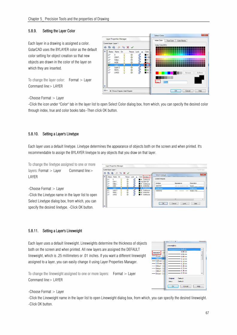
Chapter 5_ Precision Tools and the properties of Drawing
67
5.8.9. Setting the Layer Color
Each layer in a drawing is assigned a color.
GstarCAD uses the BYLAYER color as the default
color setting for object creation so that new
objects are drawn in the color of the layer on
which they are inserted.
To change the layer color: Format > Layer
Command line> LAYER
-Choose Format > Layer
-Click the icon under "Color" tab in the layer list to open Select Color dialog box, from which, you can specify the desired color
through index, true and color books tabs–Then click OK button.
5.8.10. Setting a Layer's Linetype
Each layer uses a default linetype. Linetype determines the appearance of objects both on the screen and when printed. It's
recommendable to assign the BYLAYER linetype to any objects that you draw on that layer.
To change the linetype assigned to one or more
layers: Format > Layer Command line>
LAYER
-Choose Format > Layer
-Click the Linetype name in the layer list to open
Select Linetype dialog box, from which, you can
specify the desired linetype. -Click OK button.
5.8.11. Setting a Layer's Lineweight
Each layer uses a default lineweight. Lineweights determine the thickness of objects
both on the screen and when printed. All new layers are assigned the DEFAULT
lineweight, which is .25 millimeters or .01 inches. If you want a different lineweight
assigned to a layer, you can easily change it using Layer Properties Manager.
To change the lineweight assigned to one or more layers: Format > Layer
Command line> LAYER
-Choose Format > Layer
-Click the Lineweight name in the layer list to open Lineweight dialog box, from which, you can specify the desired lineweight.
-Click OK button.
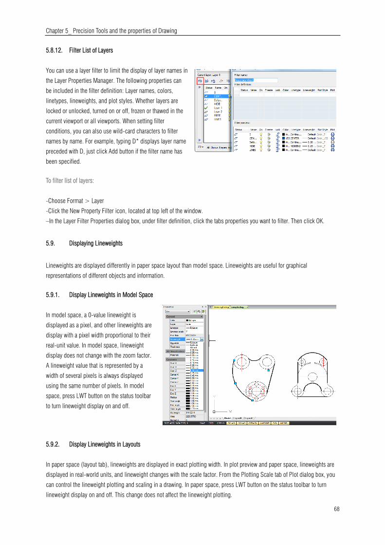
Chapter 5_ Precision Tools and the properties of Drawing
68
5.8.12. Filter List of Layers
You can use a layer filter to limit the display of layer names in
the Layer Properties Manager. The following properties can
be included in the filter definition: Layer names, colors,
linetypes, lineweights, and plot styles. Whether layers are
locked or unlocked, turned on or off, frozen or thawed in the
current viewport or all viewports. When setting filter
conditions, you can also use wild-card characters to filter
names by name. For example, typing D* displays layer name
preceded with D, just click Add button if the filter name has
been specified.
To filter list of layers:
-Choose Format > Layer
-Click the New Property Filter icon, located at top left of the window.
–In the Layer Filter Properties dialog box, under filter definition, click the tabs properties you want to filter. Then click OK.
5.9. Displaying Lineweights
Lineweights are displayed differently in paper space layout than model space. Lineweights are useful for graphical
representations of different objects and information.
5.9.1. Display Lineweights in Model Space
In model space, a 0-value lineweight is
displayed as a pixel, and other lineweights are
display with a pixel width proportional to their
real-unit value. In model space, lineweight
display does not change with the zoom factor.
A lineweight value that is represented by a
width of several pixels is always displayed
using the same number of pixels. In model
space, press LWT button on the status toolbar
to turn lineweight display on and off.
5.9.2. Display Lineweights in Layouts
In paper space (layout tab), lineweights are displayed in exact plotting width. In plot preview and paper space, lineweights are
displayed in real-world units, and lineweight changes with the scale factor. From the Plotting Scale tab of Plot dialog box, you
can control the lineweight plotting and scaling in a drawing. In paper space, press LWT button on the status toolbar to turn
lineweight display on and off. This change does not affect the lineweight plotting.
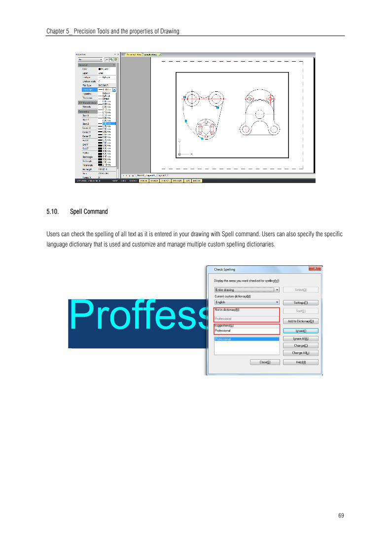
Chapter 5_ Precision Tools and the properties of Drawing
69
5.10. Spell Command
Users can check the spelling of all text as it is entered in your drawing with Spell command. Users can also specify the specific
language dictionary that is used and customize and manage multiple custom spelling dictionaries.

Chapter 6_ Create Objects
70
6. Create Objects
Drawings are made up of objects. In general, you draw objects by specifying points with the pointing device or by entering
coordinate values at the command prompt.
6.1. Draw Linear Objects
6.1.1. Lines
A line consists of two points: a start point and an endpoint. You can connect a series of lines, but each line segment is
considered a separate line object. To draw a line: Draw > Line Command line> LINE
1.Choose Draw > Line from the main menu.
2.Specify the start point.
3.Complete the first line segment by specifying the endpoint.
4.Press Enter to complete the command.
To start a new line at the endpoint of the last line drawn, start the Line
command again and press Enter directly at the "Specify first point:"
prompt.
6.1.2. Multilines
Multilines consist of several parallel lines, called elements.
You can determine the position of elements by specifying offset from the origin of each element. By default, multiline objects
contain two elements. You can create and save new multiline styles by yourself or modify existing mline styles.
To draw a multi-line: Draw > Multiline Command line> MLINE
1.Choose Draw > Multiline from the main menu.
2.Specify the start point.
3.Specify the endpoint.
4.Press Enter to complete the command.
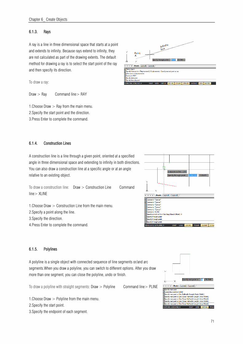
Chapter 6_ Create Objects
71
6.1.3. Rays
A ray is a line in three dimensional space that starts at a point
and extends to infinity. Because rays extend to infinity, they
are not calculated as part of the drawing extents. The default
method for drawing a ray is to select the start point of the ray
and then specify its direction.
To draw a ray:
Draw > Ray Command line> RAY
1.Choose Draw > Ray from the main menu.
2.Specify the start point and the direction.
3.Press Enter to complete the command.
6.1.4. Construction Lines
A construction line is a line through a given point, oriented at a specified
angle in three dimensional space and extending to infinity in both directions.
You can also draw a construction line at a specific angle or at an angle
relative to an existing object.
To draw a construction line: Draw > Construction Line Command
line> XLINE
1.Choose Draw > Construction Line from the main menu.
2.Specify a point along the line.
3.Specify the direction.
4.Press Enter to complete the command.
6.1.5. Polylines
A polyline is a single object with connected sequence of line segments or/and arc
segments.When you draw a polyline, you can switch to different options. After you draw
more than one segment, you can close the polyline, undo or finish.
To draw a polyline with straight segments: Draw > Polyline Command line> PLINE
1.Choose Draw > Polyline from the main menu.
2.Specify the start point.
3.Specify the endpoint of each segment.
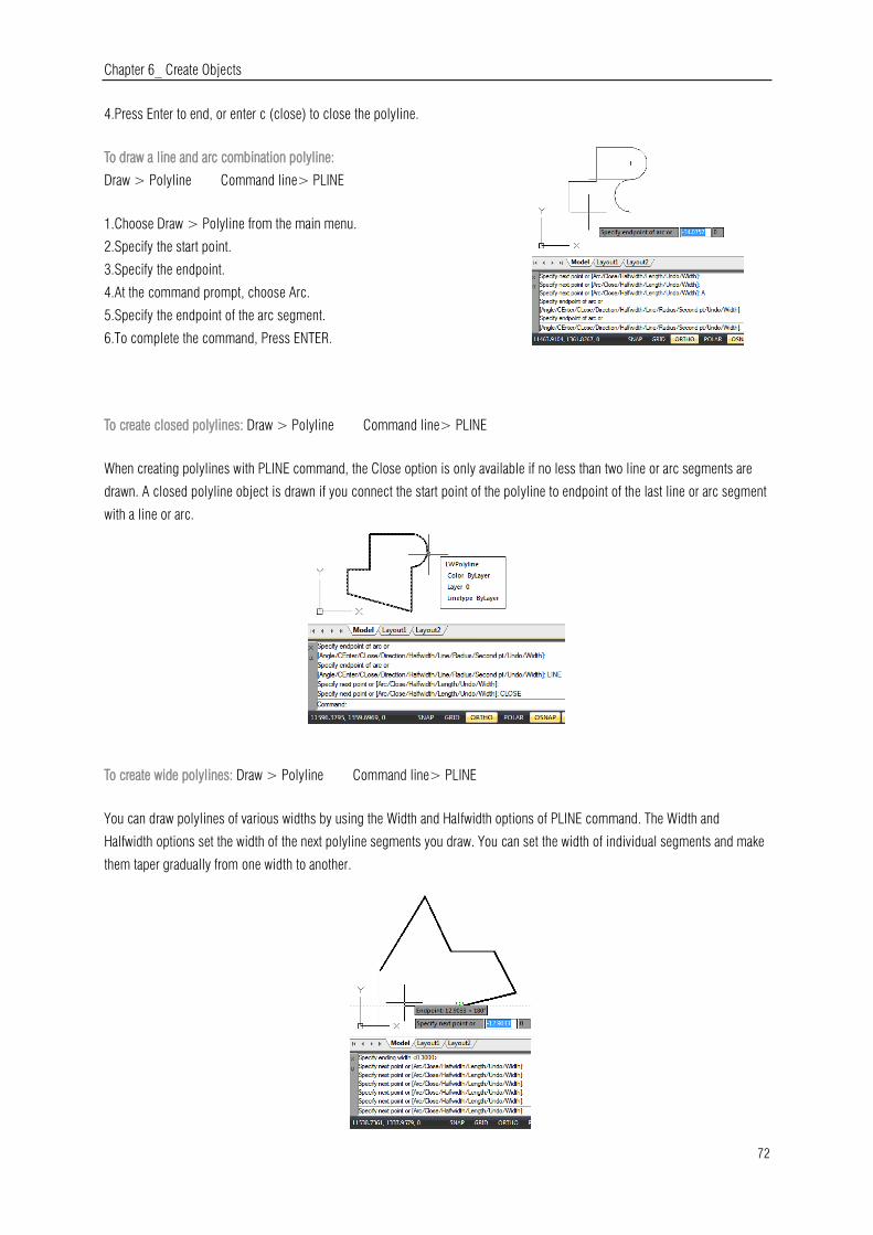
Chapter 6_ Create Objects
72
4.Press Enter to end, or enter c (close) to close the polyline.
To draw a line and arc combination polyline:
Draw > Polyline Command line> PLINE
1.Choose Draw > Polyline from the main menu.
2.Specify the start point.
3.Specify the endpoint.
4.At the command prompt, choose Arc.
5.Specify the endpoint of the arc segment.
6.To complete the command, Press ENTER.
To create closed polylines: Draw > Polyline Command line> PLINE
When creating polylines with PLINE command, the Close option is only available if no less than two line or arc segments are
drawn. A closed polyline object is drawn if you connect the start point of the polyline to endpoint of the last line or arc segment
with a line or arc.
To create wide polylines: Draw > Polyline Command line> PLINE
You can draw polylines of various widths by using the Width and Halfwidth options of PLINE command. The Width and
Halfwidth options set the width of the next polyline segments you draw. You can set the width of individual segments and make
them taper gradually from one width to another.

Chapter 6_ Create Objects
73
To draw a boundary polyline: Draw >Boundary Command line>BOUNDARY
1.Choose Draw > Boundary from the main menu.
2.Specify the objects by doing one of the following:
-Current viewport Define a boundary set with all
entities in the current viewport. if this option is
selected, any boundary set currently used will be
canceled.
-Existing set Click New button to switch to the drawing area, and prompt users to
select objects for defining boundary sets. Press Enter to return to the dialog box after selection. This option is only available
after selecting objects by using the New button.
3.Select the Island Detection option.
4.Click Pick Points.
5.In the drawing, click inside the area whose closed perimeter forms the boundary, not on the polyline itself. If desired,
continue clicking inside additional closed perimeters.
6.To complete the selection, press Enter.
7.In the Boundary Creation dialog box, click OK.
6.1.6. Polygons
Creating polygons is a simple way to draw squares, equilateral triangles,
octagons, and so on. Polygons are closed polylines with between 3 and
1,024 equal-length sides.
To draw a polygon by vertex: Draw >Polygon Command
line>POLYGON
1.Choose Draw > Polygon from the main menu.
2.Type 6 to specify six sides for the polygon.
3.Specify the center of the polygon.
4.Specify the vertex of the polygon.
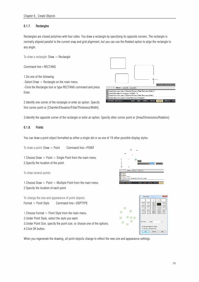
Chapter 6_ Create Objects
74
6.1.7. Rectangles
Rectangles are closed polylines with four sides. You draw a rectangle by specifying its opposite corners. The rectangle is
normally aligned parallel to the current snap and grid alignment, but you can use the Rotated option to align the rectangle to
any angle.
To draw a rectangle: Draw > Rectangle
Command line>RECTANG
1.Do one of the following:
-Select Draw > Rectangle on the main menu.
-Click the Rectangle tool or type RECTANG command and press
Enter.
2.Identify one corner of the rectangle or enter an option. Specify
first corner point or [Chamfer/Elevation/Fillet/Thickness/Width]:
3.Identify the opposite corner of the rectangle or enter an option. Specify other corner point or [Area/Dimensions/Rotation]:
6.1.8. Points
You can draw a point object formatted as either a single dot or as one of 19 other possible display styles.
To draw a point: Draw > Point Command line>POINT
1.Choose Draw > Point > Single Point from the main menu.
2.Specify the location of the point.
To draw several points:
1.Choose Draw > Point > Multiple Point from the main menu.
2.Specify the location of each point.
To change the size and appearance of point objects:
Format > Point Style Command line>DDPTYPE
1.Choose Format > Point Style from the main menu.
2.Under Point Style, select the style you want.
3.Under Point Size, specify the point size, or choose one of the options.
4.Click OK button.
When you regenerate the drawing, all point objects change to reflect the new size and appearance settings.

Chapter 6_ Create Objects
75
6.1.9. Freehand Sketches
A freehand sketch consists of many straight line segments, created either as individual line objects or as a polyline. Before you
begin creating a freehand sketch, you must set the length, or increment, of each segment. The smaller the segments, the more
accurate your sketch, but segments that are too small can greatly increase the file size.
To create a freehand sketch:
1.On the command line, enter SKETCH and press Enter.
2.At the "Record increment" prompt, enter the minimum line segment length.
3.Move the cursor to the drawing area, then click or enter p (pen) to begin sketching.
4.Click or enter p (pen) again to lift the pen up and stop drawing, so that you can move
the cursor around the drawing area without drawing.
5.Enter R (Record) at any time to write into the drawing the line you're drawing and
those already drawn.
6.Press Enter to complete the sketch and write all lines into the drawing.
To erase freehand sketch lines:
1.While running the SKETCH command, enter E. If the pen was down, it moves up.
2.Move the cursor to the end of the line you drew last and then move it back as far along
the line as you want to erase.
3.To end the erasure and return to the sketch Command prompt, enter E. If you want to
change the current viewport while sketching, make sure the pen is up and all lines were
written into the drawing.
6.2. Draw Curved Objects
6.2.1. Arcs
An arc is a portion of a circle. There are numerous ways to define an arc, the default method uses three pick points, a start point,
a second point and an end point. Using this method, the arc will start at the first pick point, pass through the second point and end
at the third point. Once you have mastered the default method try some others:
-3 points
-Start, Center, End
-Start, Center, Angle
-Start, Center, Length
-Start, End, Angle
-Start, End, Direction
-Start, End, Radius
-Center, Start, End
-Center, Start, Angle
-Center, Start, Length
-Continue
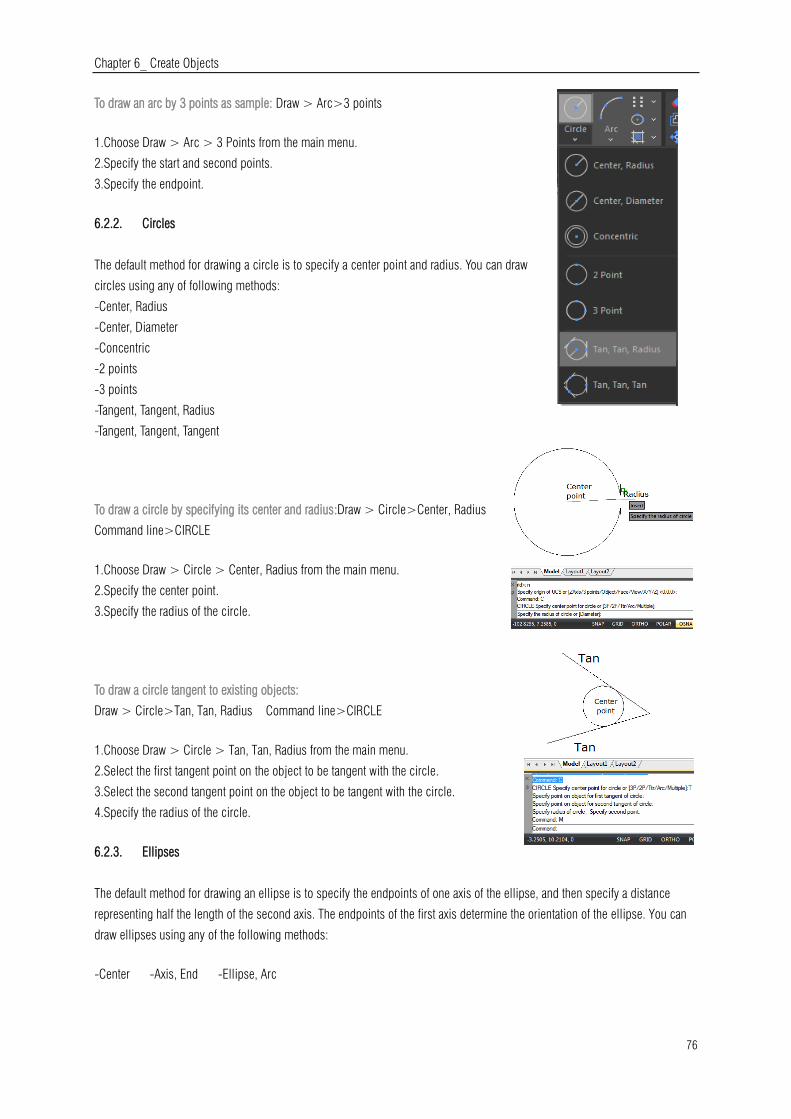
Chapter 6_ Create Objects
76
To draw an arc by 3 points as sample: Draw > Arc>3 points
1.Choose Draw > Arc > 3 Points from the main menu.
2.Specify the start and second points.
3.Specify the endpoint.
6.2.2. Circles
The default method for drawing a circle is to specify a center point and radius. You can draw
circles using any of following methods:
-Center, Radius
-Center, Diameter
-Concentric
-2 points
-3 points
-Tangent, Tangent, Radius
-Tangent, Tangent, Tangent
To draw a circle by specifying its center and radius:Draw > Circle>Center, Radius
Command line>CIRCLE
1.Choose Draw > Circle > Center, Radius from the main menu.
2.Specify the center point.
3.Specify the radius of the circle.
To draw a circle tangent to existing objects:
Draw > Circle>Tan, Tan, Radius Command line>CIRCLE
1.Choose Draw > Circle > Tan, Tan, Radius from the main menu.
2.Select the first tangent point on the object to be tangent with the circle.
3.Select the second tangent point on the object to be tangent with the circle.
4.Specify the radius of the circle.
6.2.3. Ellipses
The default method for drawing an ellipse is to specify the endpoints of one axis of the ellipse, and then specify a distance
representing half the length of the second axis. The endpoints of the first axis determine the orientation of the ellipse. You can
draw ellipses using any of the following methods:
-Center -Axis, End -Ellipse, Arc
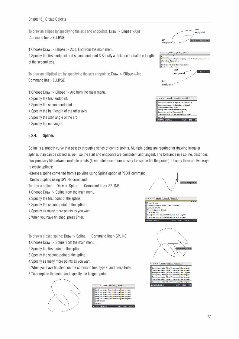
Chapter 6_ Create Objects
77
To draw an ellipse by specifying the axis and endpoints: Draw > Ellipse>Axis
Command line>ELLIPSE
1.Choose Draw > Ellipse > Axis, End from the main menu.
2.Specify the first endpoint and second endpoint.3.Specify a distance for half the length
of the second axis.
To draw an elliptical arc by specifying the axis endpoints: Draw > Ellipse>Arc
Command line>ELLIPSE
1.Choose Draw > Ellipse > Arc from the main menu.
2.Specify the first endpoint.
3.Specify the second endpoint.
4.Specify the half length of the other axis.
5.Specify the start angle of the arc.
6.Specify the end angle.
6.2.4. Splines
Spline is a smooth curve that passes through a series of control points. Multiple points are required for drawing irregular
splines than can be closed as well, so the start and endpoints are coincident and tangent. The tolerance in a spline, describes
how precisely fits between multiple points (lower tolerance, more closely the spline fits the points). Usually there are two ways
to create splines:
-Create a spline converted from a polyline using Spline option of PEDIT command.
-Create a spline using SPLINE command.
To draw a spline: Draw > Spline Command line>SPLINE
1.Choose Draw > Spline from the main menu.
2.Specify the first point of the spline.
3.Specify the second point of the spline.
4.Specify as many more points as you want.
5.When you have finished, press Enter.
To draw a closed spline: Draw > Spline Command line>SPLINE
1.Choose Draw > Spline from the main menu.
2.Specify the first point of the spline.
3.Specify the second point of the spline.
4.Specify as many more points as you want.
5.When you have finished, on the command line, type C and press Enter.
6.To complete the command, specify the tangent point.
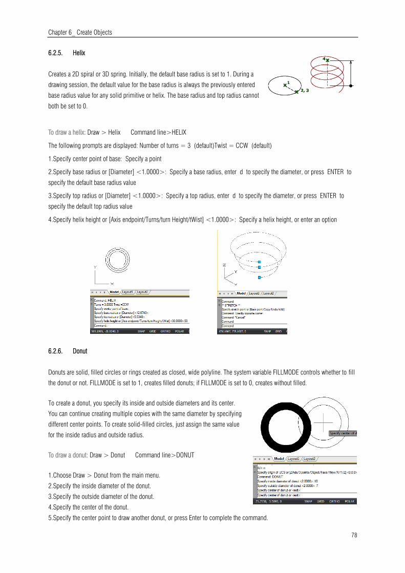
Chapter 6_ Create Objects
78
6.2.5. Helix
Creates a 2D spiral or 3D spring. Initially, the default base radius is set to 1. During a
drawing session, the default value for the base radius is always the previously entered
base radius value for any solid primitive or helix. The base radius and top radius cannot
both be set to 0.
To draw a helix: Draw > Helix Command line>HELIX
The following prompts are displayed: Number of turns = 3 (default)Twist = CCW (default)
1.Specify center point of base: Specify a point
2.Specify base radius or [Diameter] <1.0000>: Specify a base radius, enter d to specify the diameter, or press ENTER to
specify the default base radius value
3.Specify top radius or [Diameter] <1.0000>: Specify a top radius, enter d to specify the diameter, or press ENTER to
specify the default top radius value
4.Specify helix height or [Axis endpoint/Turns/turn Height/tWist] <1.0000>: Specify a helix height, or enter an option
6.2.6. Donut
Donuts are solid, filled circles or rings created as closed, wide polyline. The system variable FILLMODE controls whether to fill
the donut or not. FILLMODE is set to 1, creates filled donuts; if FILLMODE is set to 0, creates without filled.
To create a donut, you specify its inside and outside diameters and its center.
You can continue creating multiple copies with the same diameter by specifying
different center points. To create solid-filled circles, just assign the same value
for the inside radius and outside radius.
To draw a donut: Draw > Donut Command line>DONUT
1.Choose Draw > Donut from the main menu.
2.Specify the inside diameter of the donut.
3.Specify the outside diameter of the donut.
4.Specify the center of the donut.
5.Specify the center point to draw another donut, or press Enter to complete the command.
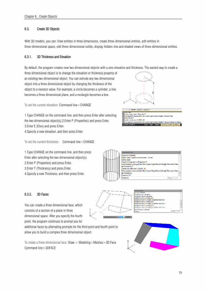
Chapter 6_ Create Objects
79
6.3. Create 3D Objects
With 3D models, you can: View entities in three dimensions, create three-dimensional entities, edit entities in
three-dimensional space, edit three-dimensional solids, display hidden-line and shaded views of three-dimensional entities.
6.3.1. 3D Thickness and Elevation
By default, the program creates new two dimensional objects with a zero elevation and thickness. The easiest way to create a
three dimensional object is to change the elevation or thickness property of
an existing two dimensional object. You can extrude any two dimensional
object into a three dimensional object by changing the thickness of the
object to a nonzero value. For example, a circle becomes a cylinder, a line
becomes a three dimensional plane, and a rectangle becomes a box.
To set the current elevation: Command line>CHANGE
1.Type CHANGE on the command line, and then press Enter after selecting
the two dimensional object(s).2.Enter P (Properties) and press Enter.
3.Enter E (Elev) and press Enter.
4.Specify a new elevation, and then press Enter.
To set the current thickness: Command line>CHANGE
1.Type CHANGE on the command line, and then press
Enter after selecting the two dimensional object(s).
2.Enter P (Properties) and press Enter.
3.Enter T (Thickness) and press Enter.
4.Specify a new Thickness, and then press Enter.
6.3.2. 3D Faces
You can create a three dimensional face, which
consists of a section of a plane in three
dimensional space. After you specify the fourth
point, the program continues to prompt you for
additional faces by alternating prompts for the third point and fourth point to
allow you to build a complex three dimensional object.
To create a three dimensional face: Draw > Modeling>Meshes>3D Face
Command line>3DFACE
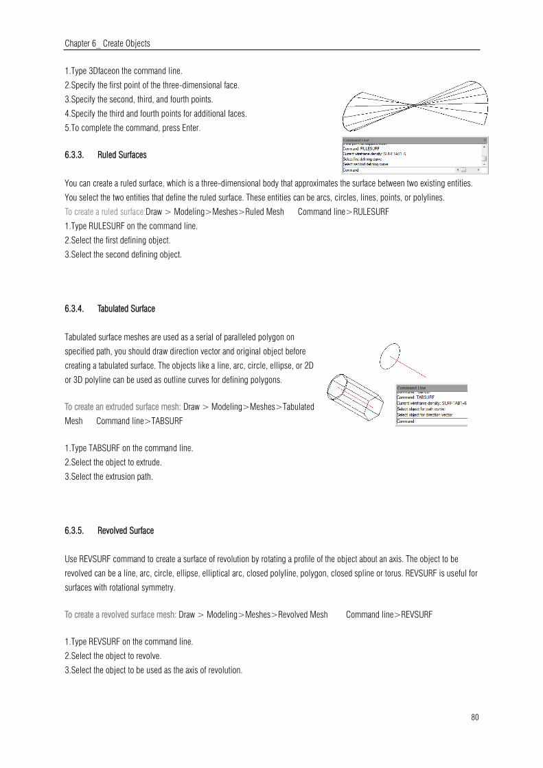
Chapter 6_ Create Objects
80
1.Type 3Dfaceon the command line.
2.Specify the first point of the three-dimensional face.
3.Specify the second, third, and fourth points.
4.Specify the third and fourth points for additional faces.
5.To complete the command, press Enter.
6.3.3. Ruled Surfaces
You can create a ruled surface, which is a three-dimensional body that approximates the surface between two existing entities.
You select the two entities that define the ruled surface. These entities can be arcs, circles, lines, points, or polylines.
To create a ruled surface:Draw > Modeling>Meshes>Ruled Mesh Command line>RULESURF
1.Type RULESURF on the command line.
2.Select the first defining object.
3.Select the second defining object.
6.3.4. Tabulated Surface
Tabulated surface meshes are used as a serial of paralleled polygon on
specified path, you should draw direction vector and original object before
creating a tabulated surface. The objects like a line, arc, circle, ellipse, or 2D
or 3D polyline can be used as outline curves for defining polygons.
To create an extruded surface mesh: Draw > Modeling>Meshes>Tabulated
Mesh Command line>TABSURF
1.Type TABSURF on the command line.
2.Select the object to extrude.
3.Select the extrusion path.
6.3.5. Revolved Surface
Use REVSURF command to create a surface of revolution by rotating a profile of the object about an axis. The object to be
revolved can be a line, arc, circle, ellipse, elliptical arc, closed polyline, polygon, closed spline or torus. REVSURF is useful for
surfaces with rotational symmetry.
To create a revolved surface mesh: Draw > Modeling>Meshes>Revolved Mesh Command line>REVSURF
1.Type REVSURF on the command line.
2.Select the object to revolve.
3.Select the object to be used as the axis of revolution.
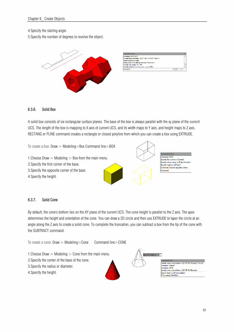
Chapter 6_ Create Objects
81
4.Specify the starting angle.
5.Specify the number of degrees to revolve the object.
6.3.6. Solid Box
A solid box consists of six rectangular surface planes. The base of the box is always parallel with the xy plane of the current
UCS. The length of the box is mapping to X axis of current UCS, and its width maps to Y axis, and height maps to Z axis.
RECTANG or PLINE command creates a rectangle or closed polyline from which you can create a box using EXTRUDE.
To create a box: Draw > Modeling>Box Command line>BOX
1.Choose Draw > Modeling > Box from the main menu.
2.Specify the first corner of the base.
3.Specify the opposite corner of the base.
4.Specify the height.
6.3.7. Solid Cone
By default, the cone's bottom lies on the XY plane of the current UCS. The cone height is parallel to the Z axis. The apex
determines the height and orientation of the cone. You can draw a 2D circle and then use EXTRUDE to taper the circle at an
angle along the Z axis to create a solid cone. To complete the truncation, you can subtract a box from the tip of the cone with
the SUBTRACT command.
To create a cone: Draw > Modeling>Cone Command line>CONE
1.Choose Draw > Modeling > Cone from the main menu.
2.Specify the center of the base of the cone.
3.Specify the radius or diameter.
4.Specify the height.

Chapter 6_ Create Objects
82
6.3.8. Solid Cylinder
You can create cylinders defined by a circular base. The base of a cylinder is always parallel with the xy plane of the current
UCS; the height of a cylinder is always parallel with the z axis. You can draw a circle and then use EXTRUDE to create a solid
cylinder.
To create a cylinder :Draw > Modeling>Cylinder Command line>CYLINDER
1.Choose Draw > Modeling> Cylinder from the main menu.
2.Specify the center of the base of the cylinder.
3.Specify the radius or diameter.
4.Specify the height.
6.3.9. Sphere
The latitude lines of a sphere are always parallel with the xy plane of the current UCS; the central axis is always parallel with the
z axis. You determine the size of a sphere by specifying either its radius or its diameter.
To create a sphere: Draw > Modeling>Sphere Command line>SPHERE
1.Choose Draw > Modeling > Sphere from the main menu.
2.Specify the center of the sphere.
3.Specify the radius or diameter.
6.3.10. Torus
A torus is constructed by revolving a circle about a line drawn in the plane of the circle and parallel with the z axis of the current
UCS. You determine the size of a torus by specifying its overall diameter or radius and the diameter or radius of the tube (the
circle being revolved).
To create a torus: Draw > Modeling>Torus Command line>TORUS
1.Choose Draw > Modeling > Torus from the main menu.
2.Specify the center of the whole torus.
3.Specify the radius or diameter of the whole torus.
4.Specify the radius or diameter of the body of the torus.
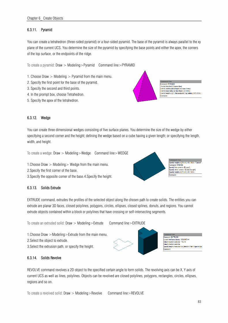
Chapter 6_ Create Objects
83
6.3.11. Pyramid
You can create a tetrahedron (three-sided pyramid) or a four-sided pyramid. The base of the pyramid is always parallel to the xy
plane of the current UCS. You determine the size of the pyramid by specifying the base points and either the apex, the corners
of the top surface, or the endpoints of the ridge.
To create a pyramid: Draw > Modeling>Pyramid Command line>PYRAMID
1. Choose Draw > Modeling > Pyramid from the main menu.
2. Specify the first point for the base of the pyramid.
3. Specify the second and third points.
4. In the prompt box, choose Tetrahedron.
5. Specify the apex of the tetrahedron.
6.3.12. Wedge
You can create three dimensional wedges consisting of five surface planes. You determine the size of the wedge by either
specifying a second corner and the height; defining the wedge based on a cube having a given length; or specifying the length,
width, and height.
To create a wedge: Draw > Modeling>Wedge Command line>WEDGE
1.Choose Draw > Modeling> Wedge from the main menu.
2.Specify the first corner of the base.
3.Specify the opposite corner of the base.4.Specify the height.
6.3.13. Solids Extrude
EXTRUDE command, extrudes the profiles of the selected object along the chosen path to create solids. The entities you can
extrude are planar 3D faces, closed polylines, polygons, circles, ellipses, closed splines, donuts, and regions. You cannot
extrude objects contained within a block or polylines that have crossing or self-intersecting segments.
To create an extruded solid: Draw > Modeling>Extrude Command line>EXTRUDE
1.Choose Draw >Modeling>Extrude from the main menu.
2.Select the object to extrude.
3.Select the extrusion path, or specify the height.
6.3.14. Solids Revolve
REVOLVE command revolves a 2D object to the specified certain angle to form solids. The revolving axis can be X, Y axis of
current UCS as well as lines, polylines. Objects can be revolved are closed polylines, polygons, rectangles, circles, ellipses,
regions and so on.
To create a revolved solid: Draw > Modeling>Revolve Command line>REVOLVE
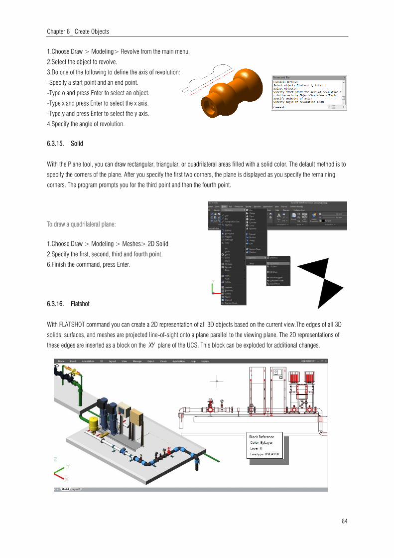
Chapter 6_ Create Objects
84
1.Choose Draw > Modeling> Revolve from the main menu.
2.Select the object to revolve.
3.Do one of the following to define the axis of revolution:
-Specify a start point and an end point.
-Type o and press Enter to select an object.
-Type x and press Enter to select the x axis.
-Type y and press Enter to select the y axis.
4.Specify the angle of revolution.
6.3.15. Solid
With the Plane tool, you can draw rectangular, triangular, or quadrilateral areas filled with a solid color. The default method is to
specify the corners of the plane. After you specify the first two corners, the plane is displayed as you specify the remaining
corners. The program prompts you for the third point and then the fourth point.
To draw a quadrilateral plane:
1.Choose Draw > Modeling > Meshes> 2D Solid
2.Specify the first, second, third and fourth point.
6.Finish the command, press Enter.
6.3.16. Flatshot
With FLATSHOT command you can create a 2D representation of all 3D objects based on the current view.The edges of all 3D
solids, surfaces, and meshes are projected line-of-sight onto a plane parallel to the viewing plane. The 2D representations of
these edges are inserted as a block on the XY plane of the UCS. This block can be exploded for additional changes.

Chapter 6_ Create Objects
85
Flatshot dialog box
Destination: Controls where the flattened representation is created.
Insert As New Block: Specifies to insert the flattened representation as a block
in the current drawing.
Replace Existing Block:Replaces an existing block in the drawing with the newly
created block.
Select Block: Closes the dialog box temporarily while you select the block you
are replacing in the drawing. When you finish selecting the block, press Enter
to re-display the
Block Selected / No Block Selected:Indicates whether a block has been
selected.
Export to a File:Saves the block to an external file.
Foreground Lines:Contains controls for setting the color and linetype of lines
that are not obscured in the flattened view.
Color: Sets the color of lines that are not obscured in the flattened view.
Linetype:Sets the linetype of lines that are not obscured in the flattened view.
Obscured Lines: Controls whether lines that are obscured in the drawing are
displayed in the flattened view, and sets the color and linetype of these
obscured lines. Show:Controls whether
obscured lines are shown in the flattened representation. When selected, the 2D flattened representation displays lines hidden
by other objects.
Color:Sets the color of lines that lie behind geometry in the flattened view.
Linetype:Sets the linetype of lines that lie behind geometry in the flattened view.
Include Tangential Lines:Creates silhouette edges for curved surfaces.
Create:Creates the flattened view.
6.3.17. Creating Composite Solids
You can create composite three-dimensional solids by combining, subtracting, and finding the intersection of two or more
solids. With UNION command, you can combine the total volume of two or more solids or two or more regions into a
composite object.
To combine solids: Modify>Solid Editing>Union Command line>UNION
1.Choose Modify>Solid Editing> Union from the main menu.
2.Select the objects to combine.
To subtract solids: Modify>Solid Editing>Subtract Command line>SUBTRACT
1.Choose Modify>Solid Editing>Subtract from the main menu.
2.Select the objects to subtract from one another.
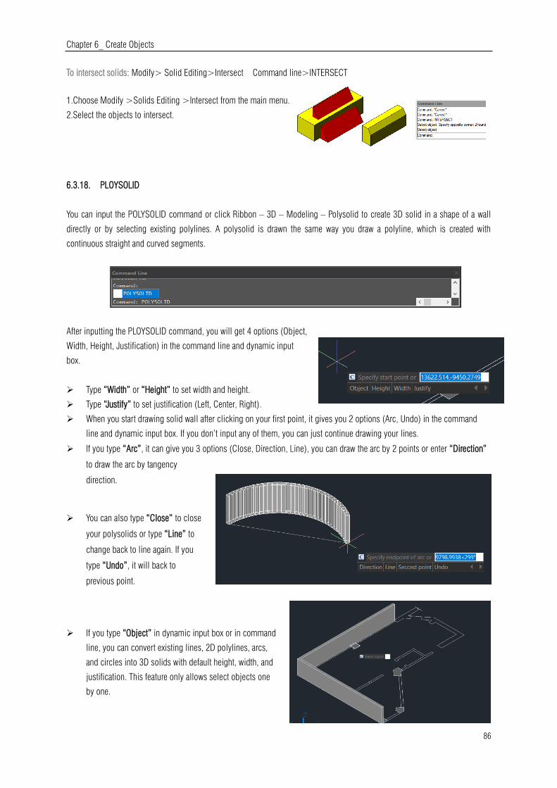
Chapter 6_ Create Objects
86
To intersect solids: Modify> Solid Editing>Intersect Command line>INTERSECT
1.Choose Modify >Solids Editing >Intersect from the main menu.
2.Select the objects to intersect.
6.3.18. PLOYSOLID
You can input the POLYSOLID command or click Ribbon – 3D – Modeling – Polysolid to create 3D solid in a shape of a wall
directly or by selecting existing polylines. A polysolid is drawn the same way you draw a polyline, which is created with
continuous straight and curved segments.
After inputting the PLOYSOLID command, you will get 4 options (Object,
Width, Height, Justification) in the command line and dynamic input
box.
Type “Width” or “Height” to set width and height.
Type “Justify” to set justification (Left, Center, Right).
When you start drawing solid wall after clicking on your first point, it gives you 2 options (Arc, Undo) in the command
line and dynamic input box. If you don’t input any of them, you can just continue drawing your lines.
If you type “Arc”, it can give you 3 options (Close, Direction, Line), you can draw the arc by 2 points or enter “Direction”
to draw the arc by tangency
direction.
You can also type “Close” to close
your polysolids or type “Line” to
change back to line again. If you
type “Undo”, it will back to
previous point.
If you type “Object” in dynamic input box or in command
line, you can convert existing lines, 2D polylines, arcs,
and circles into 3D solids with default height, width, and
justification. This feature only allows select objects one
by one.
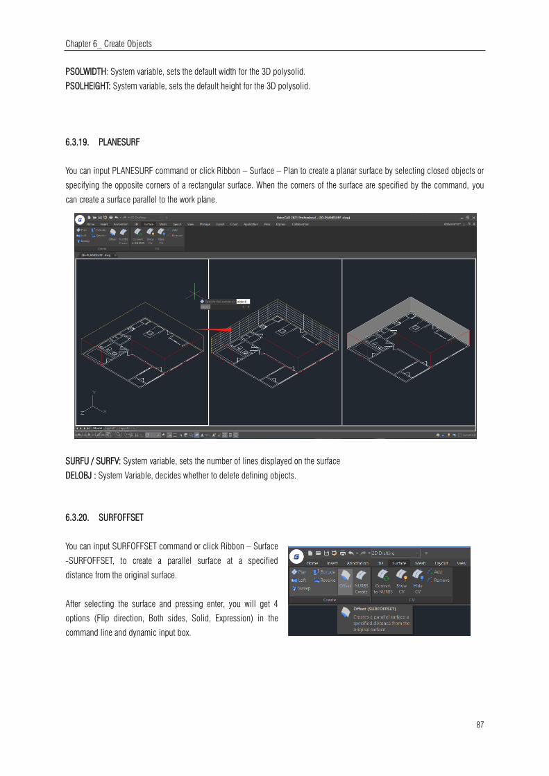
Chapter 6_ Create Objects
87
PSOLWIDTH: System variable, sets the default width for the 3D polysolid.
PSOLHEIGHT: System variable, sets the default height for the 3D polysolid.
6.3.19. PLANESURF
You can input PLANESURF command or click Ribbon – Surface – Plan to create a planar surface by selecting closed objects or
specifying the opposite corners of a rectangular surface. When the corners of the surface are specified by the command, you
can create a surface parallel to the work plane.
SURFU / SURFV: System variable, sets the number of lines displayed on the surface
DELOBJ : System Variable, decides whether to delete defining objects.
6.3.20. SURFOFFSET
You can input SURFOFFSET command or click Ribbon – Surface
-SURFOFFSET, to create a parallel surface at a specified
distance from the original surface.
After selecting the surface and pressing enter, you will get 4
options (Flip direction, Both sides, Solid, Expression) in the
command line and dynamic input box.
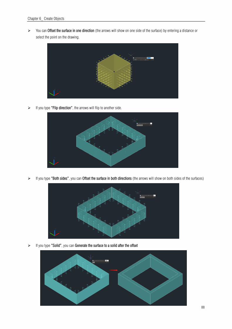
Chapter 6_ Create Objects
88
You can Offset the surface in one direction (the arrows will show on one side of the surface) by entering a distance or
select the point on the drawing.
If you type “Flip direction”, the arrows will flip to another side.
If you type “Both sides”, you can Offset the surface in both directions (the arrows will show on both sides of the surfaces)
If you type “Solid”, you can Generate the surface to a solid after the offset

Chapter 6_ Create Objects
89
If you type “Expression”, you can enter a formula or equation to specify the distance of the surface offset.
SURFACEASSOCIATICITY: System Variable, when the value is 1, Expression option will be displayed. This option does not
update the offset distance default value the next time you enter the command.
SURFACEMODELINGMODE: System Variable, when the value is 1, the surface will be a NURBS surface.
6.3.21. CONVTOMESH
You can input CONVTOMESH command or click Ribbon- Mesh – Convert to MESH to convert eligible 3D objects into meshes,
the objects will be smoothed at the same time in the conversion as well.
Eligible objects include: solids, closed polylines, regions, 3D face, 3D surfaces, polygon meshes.
When the 3D entities that are extruded, swept, lofted, and revolved with arcs are converted to meshes, and the number of faces
and vertices after conversion cannot be displayed correctly
FACETERMESHTYPE: System Variable, controls the level of smoothness upon conversion (If the mesh type is not set to be
optimized, the converted object is not smoothed).
DELOBJ : System Variable, decides whether to delete defining objects.
6.3.22. CONVTOSOLID
You can input the CONVTOSOLID command or click Ribbon-
Mesh – Convert to SOLID to convert eligible objects to 3D solids.
Eligible objects include:
3D meshes that completely enclose a volume
Surfaces that completely enclose a volume
Closed polylines and circles with a non-zero thickness property; wide polylines must have a uniform width
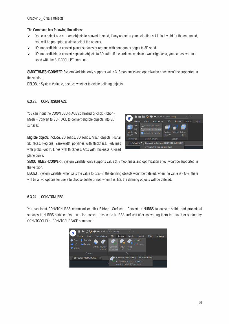
Chapter 6_ Create Objects
90
The Command has following limitations:
You can select one or more objects to convert to solid, if any object in your selection set is in invalid for the command,
you will be prompted again to select the objects.
It’s not available to convert planar surfaces or regions with contiguous edges to 3D solid.
It’s not available to convert separate objects to 3D solid. If the surfaces enclose a watertight area, you can convert to a
solid with the SURFSCULPT command.
SMOOTHMESHCONVERT: System Variable, only supports value 3. Smoothness and optimization effect won’t be supported in
the version.
DELOBJ : System Variable, decides whether to delete defining objects.
6.3.23. CONVTOSURFACE
You can input the CONVTOSURFACE command or click Ribbon-
Mesh – Convert to SURFACE to convert eligible objects into 3D
surfaces.
Eligible objects include: 2D solids, 3D solids, Mesh objects, Planar
3D faces, Regions, Zero-width polylines with thickness, Polylines
with global-width, Lines with thickness, Arcs with thickness, Closed
plane curve.
SMOOTHMESHCONVERT: System Variable, only supports value 3. Smoothness and optimization effect won’t be supported in
the version.
DEOBJ : System Variable, when sets the value to 0/3/-3, the defining objects won’t be deleted, when the value is -1/-2, there
will be a two options for users to choose delete or not, when it is 1/2, the defining objects will be deleted.
6.3.24. CONVTONURBS
You can input CONVTONURBS command or click Ribbon- Surface – Convert to NURBS to convert solids and procedural
surfaces to NURBS surfaces. You can also convert meshes to NURBS surfaces after converting them to a solid or surface by
CONVTOSOLID or CONVTOSURFACE command.

Chapter 6_ Create Objects
91
There are a series of new functionalities for NURBS control vertices editing and display, such as
SHOW CV: Shows control vertices. You can adjust the NURBS surfaces by clicking the control vertices, you will get 4
options (Base, Copy, Undo, Exit) in your command line and dynamic input box.
Base: Moves your control vertices according to the base point and second point you choose.
Copy: Copies a new NURBS surface and move it, the original surface won’t be deleted.
Undo: Cancels the previous step.
Exit: Stops adjusting control vertices.
HIDE CV: Hides control vertices.
ADD: Adds control vertices. After selecting the object, you will
get 2 options (Knots, Direction) to add control vertices and set
the position.
Knots: Turns off the display of control vertices and allows
you to place a point directly on a surface. This option only
displays if you select a surface; it does not display for
splines.
Direction: Specifies whether to add control vertices in the
U or V direction. This option only displays if you select a
surface; it does not display for splines.
REMOVE: Removes control vertices. There are at least 2 control
vertices in each direction.
DELOBJ : System Variable, decide whether to delete defining objects.

Chapter 6_ Create Objects
92
6.4. Point Cloud
GstarCAD 2021 supports point cloud file extensions (.rcp and .rcs) as attachment in a drawing. The point cloud is inserted at
the specified coordinates, based on the location of the Insertion object snap. Users can apply object color and RGB scan colors
to display point cloud data.
When users attach the Point Cloud data, the following options will be displayed in Attach Point Cloud dialog box:
Name: Identifies the point cloud file to attach.
Browse: Opens the Select Point Cloud dialog box, a standard file selection dialog box where you can find and select a
point cloud file.
Path type:
Full path: Uses the full path of the specified file, including the root
folder and all subfolders that contain the point cloud file.
Relative Path: Uses the file path relative to the current drawing file to

Chapter 6_ Create Objects
93
reference the point cloud file.
No Path: Only uses the file name of the point cloud file for referencing. The file must be located in the same folder
as the current drawing file.
Insert point: Specifies the location in the drawing where the base point of the point cloud will be attached.
Specify On-screen: Specifies the insertion point in the target drawing while you insert it.
X, Y, Z: Sets the coordinate values of the insertion point.
Scale: Specifies the scale factor for the inserted point cloud.
Specify On-screen: Specifies the relative scale of the point cloud as you attach it.
Scale: Sets the scale factor of the point cloud.
Rotation: Specifies the rotation angle for the inserted point cloud.
Specify On-Screen: Specifies the rotation angle of the point cloud by the pointing device.
Angle: Sets the rotation angle of the point cloud.
Other Options:
Use Geographic Location: Inserts the point cloud based on the geographic data in the point cloud file.
Lock Point Cloud: Controls whether an attached point cloud can be moved or rotated.
Zoom to Point Cloud: Zoom to the extents of the attached point cloud object automatically.
Show / Hide Details: Includes number of points, Point Cloud unit, and Point Cloud data.
6.5. Create Regions
You can convert a closed object into a two dimensional region. After you create a region, you can modify it using the various
three dimensional tools. You can create regions from closed objects, such as polylines, polygons, circles, ellipses, closed
splines, and donuts.
To create a region: Draw> Region Command line>REGION
1.Choose Draw > Region from the main menu.
2.Select the objects to create the region and press Enter.
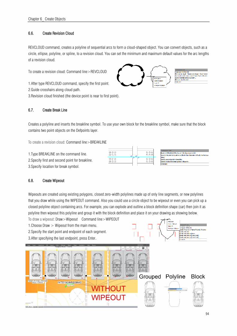
Chapter 6_ Create Objects
94
6.6. Create Revision Cloud
REVCLOUD command, creates a polyline of sequential arcs to form a cloud-shaped object. You can convert objects, such as a
circle, ellipse, polyline, or spline, to a revision cloud. You can set the minimum and maximum default values for the arc lengths
of a revision cloud.
To create a revision cloud: Command line>REVCLOUD
1.After type REVCLOUD command, specify the first point.
2.Guide crosshairs along cloud path.
3.Revision cloud finished (the device point is near to first point).
6.7. Create Break Line
Creates a polyline and inserts the breakline symbol. To use your own block for the breakline symbol, make sure that the block
contains two point objects on the Defpoints layer.
To create a revision cloud: Command line>BREAKLINE
1.Type BREAKLINE on the command line.
2.Specify first and second point for breakline.
3.Specify location for break symbol.
6.8. Create Wipeout
Wipeouts are created using existing polygons, closed zero-width polylines made up of only line segments, or new polylines
that you draw while using the WIPEOUT command. Also you could use a circle object to be wipeout or even you can pick up a
closed polyline object containing arcs. For example, you can explode and outline a block definition shape (car) then join it as
polyline then wipeout this polyline and group it with the block definition and place it on your drawing as showing below.
To draw a wipeout: Draw>Wipeout Command line>WIPEOUT
1.Choose Draw > Wipeout from the main menu.
2.Specify the start point and endpoint of each segment.
3.After specifying the last endpoint, press Enter.
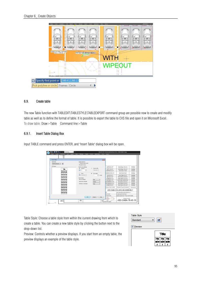
Chapter 6_ Create Objects
95
6.9. Create table
The new Table function with TABLEDIT\TABLESTYLE\TABLEEXPORT command group are possible now to create and modify
table as well as to define the format of table. It is possible to export the table to CVS file and open it on Microsoft Excel.
To draw table: Draw>Table Command line>Table
6.9.1. Insert Table Dialog Box
Input TABLE command and press ENTER, and "Insert Table" dialog box will be open.
Table Style: Choose a table style from within the current drawing from which to
create a table. You can create a new table style by clicking the button next to the
drop-down list.
Preview: Controls whether a preview displays. If you start from an empty table, the
preview displays an example of the table style.
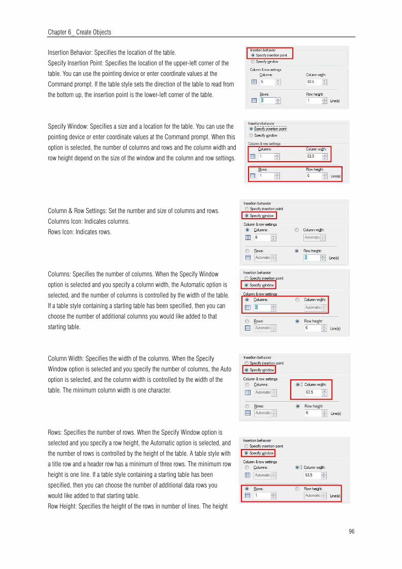
Chapter 6_ Create Objects
96
Insertion Behavior: Specifies the location of the table.
Specify Insertion Point: Specifies the location of the upper-left corner of the
table. You can use the pointing device or enter coordinate values at the
Command prompt. If the table style sets the direction of the table to read from
the bottom up, the insertion point is the lower-left corner of the table.
Specify Window: Specifies a size and a location for the table. You can use the
pointing device or enter coordinate values at the Command prompt. When this
option is selected, the number of columns and rows and the column width and
row height depend on the size of the window and the column and row settings.
Column & Row Settings: Set the number and size of columns and rows.
Columns Icon: Indicates columns.
Rows Icon: Indicates rows.
Columns: Specifies the number of columns. When the Specify Window
option is selected and you specify a column width, the Automatic option is
selected, and the number of columns is controlled by the width of the table.
If a table style containing a starting table has been specified, then you can
choose the number of additional columns you would like added to that
starting table.
Column Width: Specifies the width of the columns. When the Specify
Window option is selected and you specify the number of columns, the Auto
option is selected, and the column width is controlled by the width of the
table. The minimum column width is one character.
Rows: Specifies the number of rows. When the Specify Window option is
selected and you specify a row height, the Automatic option is selected, and
the number of rows is controlled by the height of the table. A table style with
a title row and a header row has a minimum of three rows. The minimum row
height is one line. If a table style containing a starting table has been
specified, then you can choose the number of additional data rows you
would like added to that starting table.
Row Height: Specifies the height of the rows in number of lines. The height

Chapter 6_ Create Objects
97
of a line is based on the text height and the cell margin, which are both set
in the table style. When the Specify Window option is selected and you
specify the number of rows, the Auto option is selected, and the row
height is controlled by the height of the table.
Set Cell Styles: For table styles that do not contain a starting table, specifies a cell style for rows in the new table.
First Row Cell Style: Specifies a cell style for the first row in the table. The
Title cell style is used by default.
Second Row Cell Style: Specifies a cell style for the second row in the
table. The Header cell style is used by default.
All Other Row Cell Styles: Specifies a cell style for all other rows in the
table. The Data cell style is used by default.
6.9.2. Table Style Dialog Box
Current Table Style: Displays the name of the table style that is applied
to tables you create.
Styles: Displays a list of table styles. The current style is highlighted.
List: Controls the contents of the Styles list.
Preview: Displays a preview image of the style that is selected in the Styles list.
Set Current :Sets the table style selected in the Styles list as the current style. All new tables are created using this table style.
New: Displays the Create New Table Style dialog box, in which you can define new table styles.
Modify: Displays the Modify Table Style dialog box, in which you can modify table styles.
Delete: Deletes the table style selected in the Styles list. A style that is being used in the drawing cannot be deleted.
6.9.3. Create New Table Style Dialog Box
Specifies a name for the new table style and specifies the existing table style on which the new table style will be based.
New Style Name: Names the new table style.
Start With: Specifies an existing table style whose settings are the default
for the new table style.
Continue: Displays the New Table Style dialog box, in which you define
the new table style.

Chapter 6_ Create Objects
98
6.9.4. New and Modify Table Style Dialog Boxes
Starting Table: Allows you to specify a table in your drawing to use as an example
for formatting this table style. Once you select a table, you can specify the
structure and contents you want copied from that table to the table style. With the
Remove Table icon, you can remove a table from the current specified table style.
General Table Direction: Defines a new table style or modifies an existing table
style. It sets the direction of a table.
Down: The title row and the column heads row are at the top of the table.
Up: The title row and the column heads row are at the bottom of the table.
Preview: Displays an example of the effect of the current table style settings.
Cell Styles: Defines a new cell style or modifies an existing cell style. You can
create any number of cell styles.
Create Cell Styles Button: Launches the Create New Cell Style dialog box.
Manage Cell Styles Button: Launches the Manage Cell Styles dialog box.
General Tab
Properties
Fill Color: Specifies the background color of the cell.
Alignment: Sets justification and alignment for the text in the table cell.
Format: Sets data type and formatting for the Data, Column Heading, or Title
rows in a table. Clicking this button displays the Table Cell Format dialog
box, where you can further define formatting options.
Type: Specifies the cell style as either a tag or data.
Margins
Horizontal: Sets the distance between the text or block in the cell and the left
and right cell borders.
Vertical: Sets the distance between the text or block in the cell and the top
and bottom cell borders.
Merge cells on row/column creation: Merges any new row or column created
with the current cell style into one cell. You can use this option to create a title row at the top of your table.
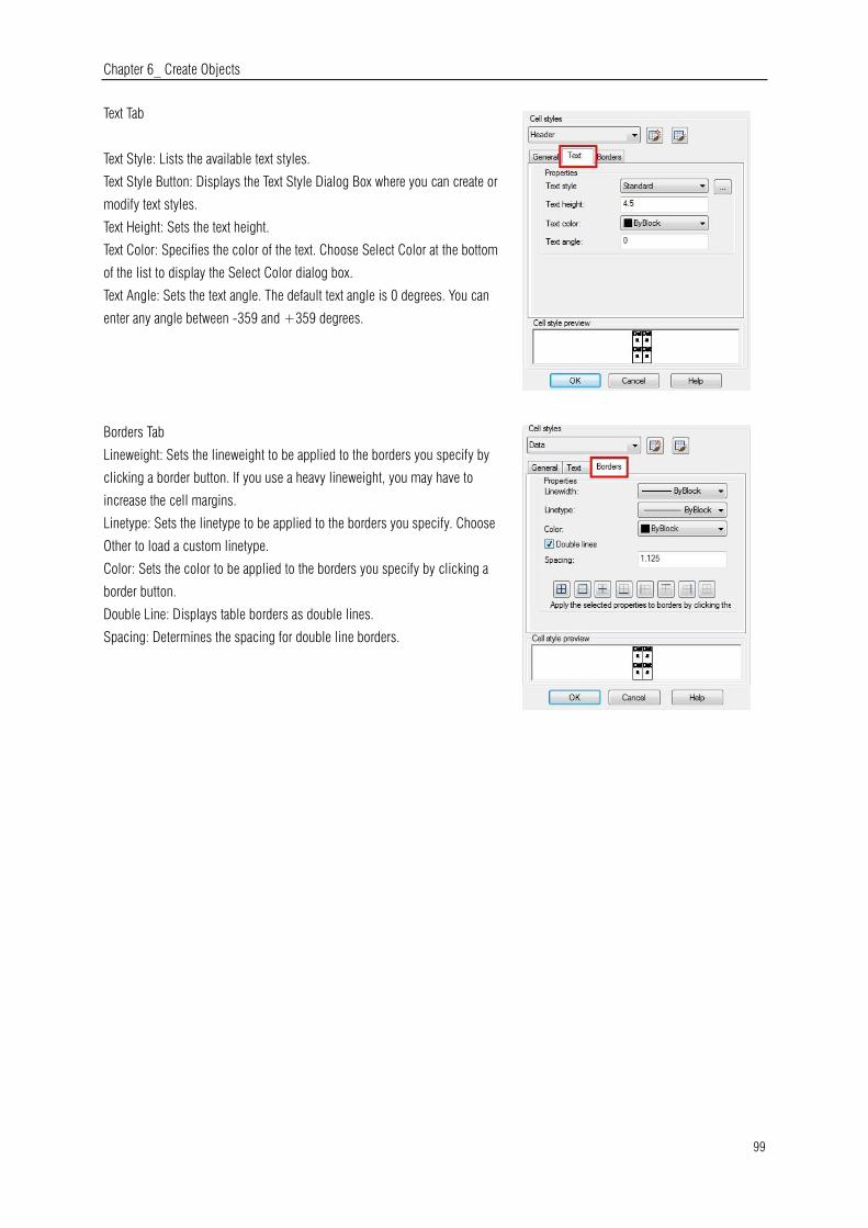
Chapter 6_ Create Objects
99
Text Tab
Text Style: Lists the available text styles.
Text Style Button: Displays the Text Style Dialog Box where you can create or
modify text styles.
Text Height: Sets the text height.
Text Color: Specifies the color of the text. Choose Select Color at the bottom
of the list to display the Select Color dialog box.
Text Angle: Sets the text angle. The default text angle is 0 degrees. You can
enter any angle between -359 and +359 degrees.
Borders Tab
Lineweight: Sets the lineweight to be applied to the borders you specify by
clicking a border button. If you use a heavy lineweight, you may have to
increase the cell margins.
Linetype: Sets the linetype to be applied to the borders you specify. Choose
Other to load a custom linetype.
Color: Sets the color to be applied to the borders you specify by clicking a
border button.
Double Line: Displays table borders as double lines.
Spacing: Determines the spacing for double line borders.
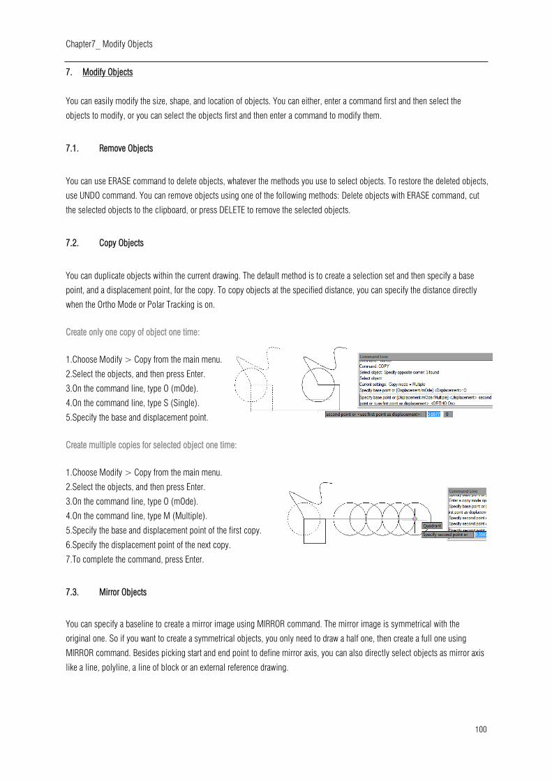
Chapter7_ Modify Objects
100
7. Modify Objects
You can easily modify the size, shape, and location of objects. You can either, enter a command first and then select the
objects to modify, or you can select the objects first and then enter a command to modify them.
7.1. Remove Objects
You can use ERASE command to delete objects, whatever the methods you use to select objects. To restore the deleted objects,
use UNDO command. You can remove objects using one of the following methods: Delete objects with ERASE command, cut
the selected objects to the clipboard, or press DELETE to remove the selected objects.
7.2. Copy Objects
You can duplicate objects within the current drawing. The default method is to create a selection set and then specify a base
point, and a displacement point, for the copy. To copy objects at the specified distance, you can specify the distance directly
when the Ortho Mode or Polar Tracking is on.
Create only one copy of object one time:
1.Choose Modify > Copy from the main menu.
2.Select the objects, and then press Enter.
3.On the command line, type O (mOde).
4.On the command line, type S (Single).
5.Specify the base and displacement point.
Create multiple copies for selected object one time:
1.Choose Modify > Copy from the main menu.
2.Select the objects, and then press Enter.
3.On the command line, type O (mOde).
4.On the command line, type M (Multiple).
5.Specify the base and displacement point of the first copy.
6.Specify the displacement point of the next copy.
7.To complete the command, press Enter.
7.3. Mirror Objects
You can specify a baseline to create a mirror image using MIRROR command. The mirror image is symmetrical with the
original one. So if you want to create a symmetrical objects, you only need to draw a half one, then create a full one using
MIRROR command. Besides picking start and end point to define mirror axis, you can also directly select objects as mirror axis
like a line, polyline, a line of block or an external reference drawing.
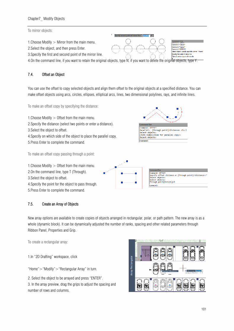
Chapter7_ Modify Objects
101
To mirror objects:
1.Choose Modify > Mirror from the main menu.
2.Select the object, and then press Enter.
3.Specify the first and second point of the mirror line.
4.On the command line, if you want to retain the original objects, type N; if you want to delete the original objects, type Y.
7.4. Offset an Object
You can use the offset to copy selected objects and align them offset to the original objects at a specified distance. You can
make offset objects using arcs, circles, ellipses, elliptical arcs, lines, two dimensional polylines, rays, and infinite lines.
To make an offset copy by specifying the distance:
1.Choose Modify > Offset from the main menu.
2.Specify the distance (select two points or enter a distance).
3.Select the object to offset.
4.Specify on which side of the object to place the parallel copy.
5.Press Enter to complete the command.
To make an offset copy passing through a point:
1.Choose Modify > Offset from the main menu.
2.On the command line, type T (Through).
3.Select the object to offset.
4.Specify the point for the object to pass through.
5.Press Enter to complete the command.
7.5. Create an Array of Objects
New array options are available to create copies of objects arranged in rectangular, polar, or path pattern. The new array is as a
whole (dynamic block). It can be dynamically adjusted the number of ranks, spacing and other related parameters through
Ribbon Panel, Properties and Grip.
To create a rectangular array:
1.In “2D Drafting” workspace, click
“Home”>“Modify”>“Rectangular Array” in turn.
2. Select the object to be arrayed and press “ENTER”.
3. In the array preview, drag the grips to adjust the spacing and
number of rows and columns.
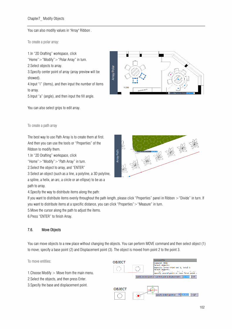
Chapter7_ Modify Objects
102
You can also modify values in "Array" Ribbon .
To create a polar array:
1.In “2D Drafting” workspace, click
“Home”>“Modify”>“Polar Array” in turn.
2.Select objects to array.
3.Specify center point of array (array preview will be
showed).
4.Input “i” (items), and then input the number of items
to array.
5.Input “a” (angle), and then input the fill angle.
You can also select grips to edit array.
To create a path array
The best way to use Path Array is to create them at first.
And then you can use the tools or “Properties” of the
Ribbon to modify them.
1.In “2D Drafting” workspace, click
“Home”>“Modify”>“Path Array” in turn.
2.Select the object to array, and “ENTER”
3 Select an object (such as a line, a polyline, a 3D polyline,
a spline, a helix, an arc, a circle or an ellipse) to be as a
path to array.
4.Specify the way to distribute items along the path:
If you want to distribute items evenly throughout the path length, please click “Properties” panel in Ribbon >“Divide” in turn. If
you want to distribute items at a specific distance, you can click “Properties”>“Measure” in turn.
5.Move the cursor along the path to adjust the items.
6.Press “ENTER” to finish Array.
7.6. Move Objects
You can move objects to a new place without changing the objects. You can perform MOVE command and then select object (1)
to move; specify a base point (2) and Displacement point (3). The object is moved from point 2 to the point 3.
To move entities:
1.Choose Modify > Move from the main menu.
2.Select the objects, and then press Enter.
3.Specify the base and displacement point.

Chapter7_ Modify Objects
103
To move an object using grips:
1.Select the object.
2.Click a grip to select it.
3.Drag the object to where you want to relocate it and press Click to release.
7.7. Rotate Objects
You can rotate the selected objects around a specified point. You can specify the rotated angle by specifying a point on the
drawing or entering the angle value directly. The direction that objects rotate depends on the value you enter is positive or
negative.
To rotate objects:
1.Choose Modify > Rotate from the main menu.
2.Select the objects, and then press Enter.
3.Specify the base point and rotation angle.
To rotate a selection set in reference to an Absolute Angle:
1.Choose Modify > Rotate from the main menu.
2.Select the objects, and then press Enter.
3.Specify the base point.
4.On the command line, type R (Reference).
5.Specify the reference and new angle.
7.8. Align Objects
You can align objects with another through move or rotation with ALIGN command.
To align and object to other as reference:
1.Choose Modify >Align from the main menu.
2.Select the object, and then press Enter.
3.Specify the first source point.
4.Specify the destination point.
5.Press Enter to finish the command.
7.9. Scale Objects
You can use SCALE command to scale the proportionality of the selected objects. You can type a scale factor or specify a base
point and distance to zoom objects. A scale factor that is greater than 1 enlarges the object; and a scale factor that is smaller
than 1 shrinks the object.
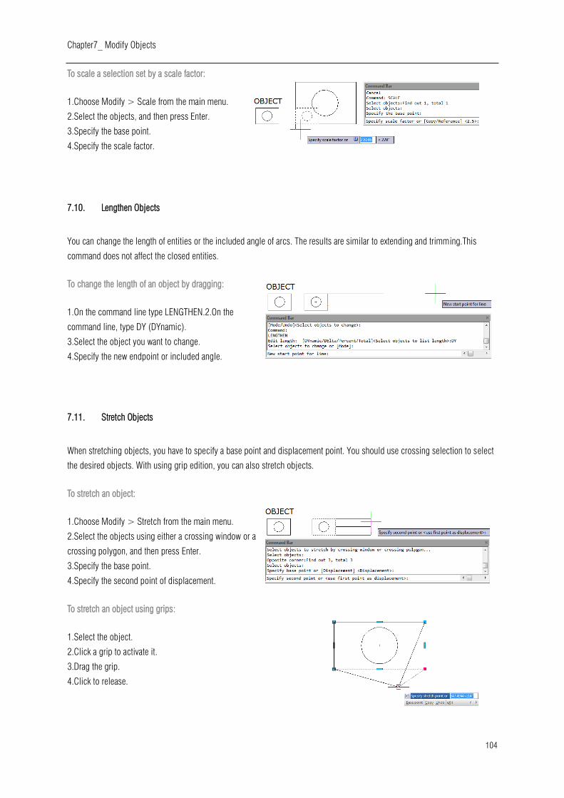
Chapter7_ Modify Objects
104
To scale a selection set by a scale factor:
1.Choose Modify > Scale from the main menu.
2.Select the objects, and then press Enter.
3.Specify the base point.
4.Specify the scale factor.
7.10. Lengthen Objects
You can change the length of entities or the included angle of arcs. The results are similar to extending and trimming.This
command does not affect the closed entities.
To change the length of an object by dragging:
1.On the command line type LENGTHEN.2.On the
command line, type DY (DYnamic).
3.Select the object you want to change.
4.Specify the new endpoint or included angle.
7.11. Stretch Objects
When stretching objects, you have to specify a base point and displacement point. You should use crossing selection to select
the desired objects. With using grip edition, you can also stretch objects.
To stretch an object:
1.Choose Modify > Stretch from the main menu.
2.Select the objects using either a crossing window or a
crossing polygon, and then press Enter.
3.Specify the base point.
4.Specify the second point of displacement.
To stretch an object using grips:
1.Select the object.
2.Click a grip to activate it.
3.Drag the grip.
4.Click to release.

Chapter7_ Modify Objects
105
7.12. Trim Objects
You can clip, or trim, objects so they end at one or
more implied cutting edges defined by other objects.
You can trim arcs, circles, lines, unclosed polylines,
and rays.
To trim an object:
1.Choose Modify > Trim from the main menu.
2.Select one or more cutting edges, and then press Enter.
3.Select the object to trim.
4.Press Enter to complete the command.
To trim several objects using the fence selection method:
1.Choose Modify > Trim from the main menu.
2.Select one or more cutting edges, and then press Enter.
3.On the command line, type F (Fence).
4.Specify the first point of the fence.
5.Specify the second point of the fence.
6.Press Enter to complete the command.
7.13. Extend Objects
You can extend objects so that they end at a boundary defined by other objects. You can extend arcs, lines, two-dimensional
polylines, and rays. Arcs, circles, ellipses, lines, splines, polylines, rays, infinite lines, and viewports on a Layout tab can act as
boundary edges.
To extend an object:
1.Choose Modify > Extend from the main menu.
2.Select one or more objects as boundary edges, and then press Enter.
3.Select the object to extend, and press Enter to finish the command.
To extend an object to an implied boundary:
1.Choose Modify > Extend from the main menu.
2.Select one or more boundary edges, and then press Enter.
3.On the command line, type E (Edge).
4.On the command line, type E (Extend).
5.Select the object to extend, and press Enter to finish.
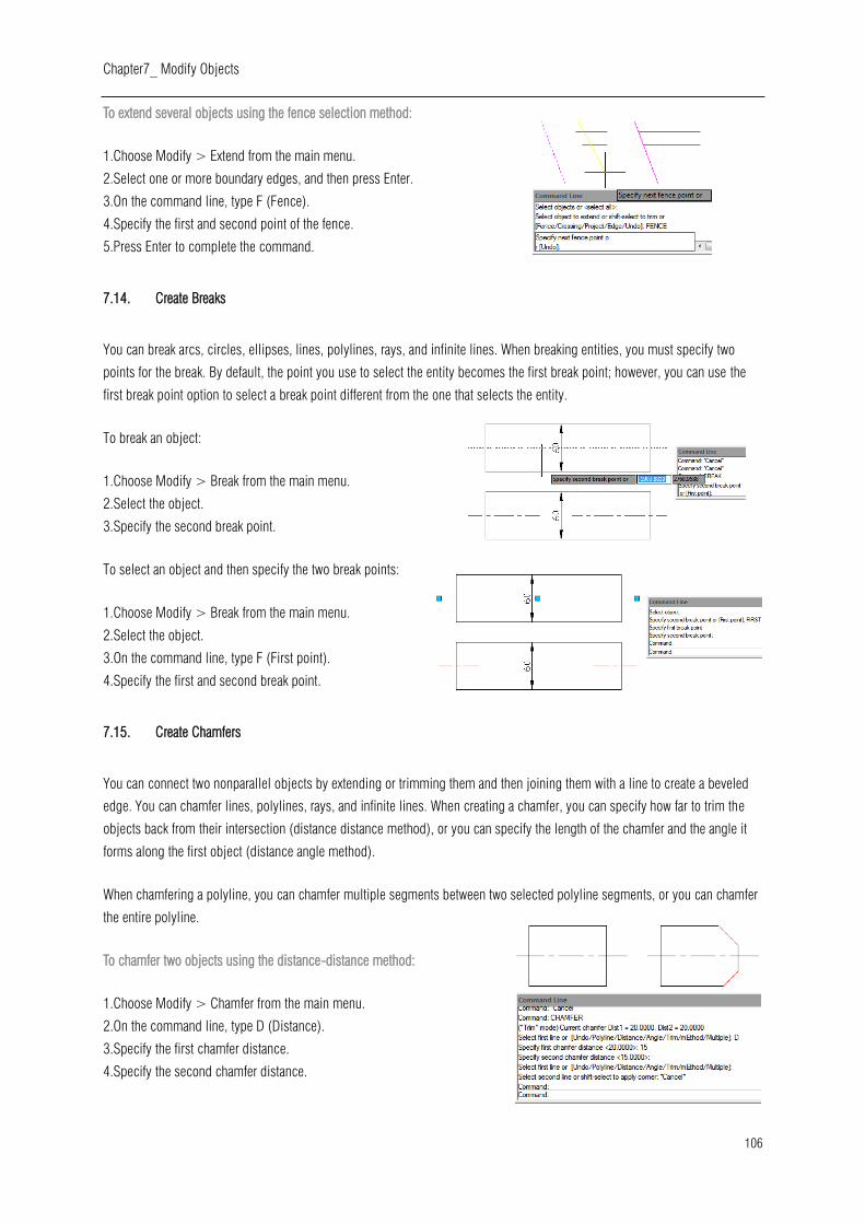
Chapter7_ Modify Objects
106
To extend several objects using the fence selection method:
1.Choose Modify > Extend from the main menu.
2.Select one or more boundary edges, and then press Enter.
3.On the command line, type F (Fence).
4.Specify the first and second point of the fence.
5.Press Enter to complete the command.
7.14. Create Breaks
You can break arcs, circles, ellipses, lines, polylines, rays, and infinite lines. When breaking entities, you must specify two
points for the break. By default, the point you use to select the entity becomes the first break point; however, you can use the
first break point option to select a break point different from the one that selects the entity.
To break an object:
1.Choose Modify > Break from the main menu.
2.Select the object.
3.Specify the second break point.
To select an object and then specify the two break points:
1.Choose Modify > Break from the main menu.
2.Select the object.
3.On the command line, type F (First point).
4.Specify the first and second break point.
7.15. Create Chamfers
You can connect two nonparallel objects by extending or trimming them and then joining them with a line to create a beveled
edge. You can chamfer lines, polylines, rays, and infinite lines. When creating a chamfer, you can specify how far to trim the
objects back from their intersection (distance distance method), or you can specify the length of the chamfer and the angle it
forms along the first object (distance angle method).
When chamfering a polyline, you can chamfer multiple segments between two selected polyline segments, or you can chamfer
the entire polyline.
To chamfer two objects using the distance-distance method:
1.Choose Modify > Chamfer from the main menu.
2.On the command line, type D (Distance).
3.Specify the first chamfer distance.
4.Specify the second chamfer distance.
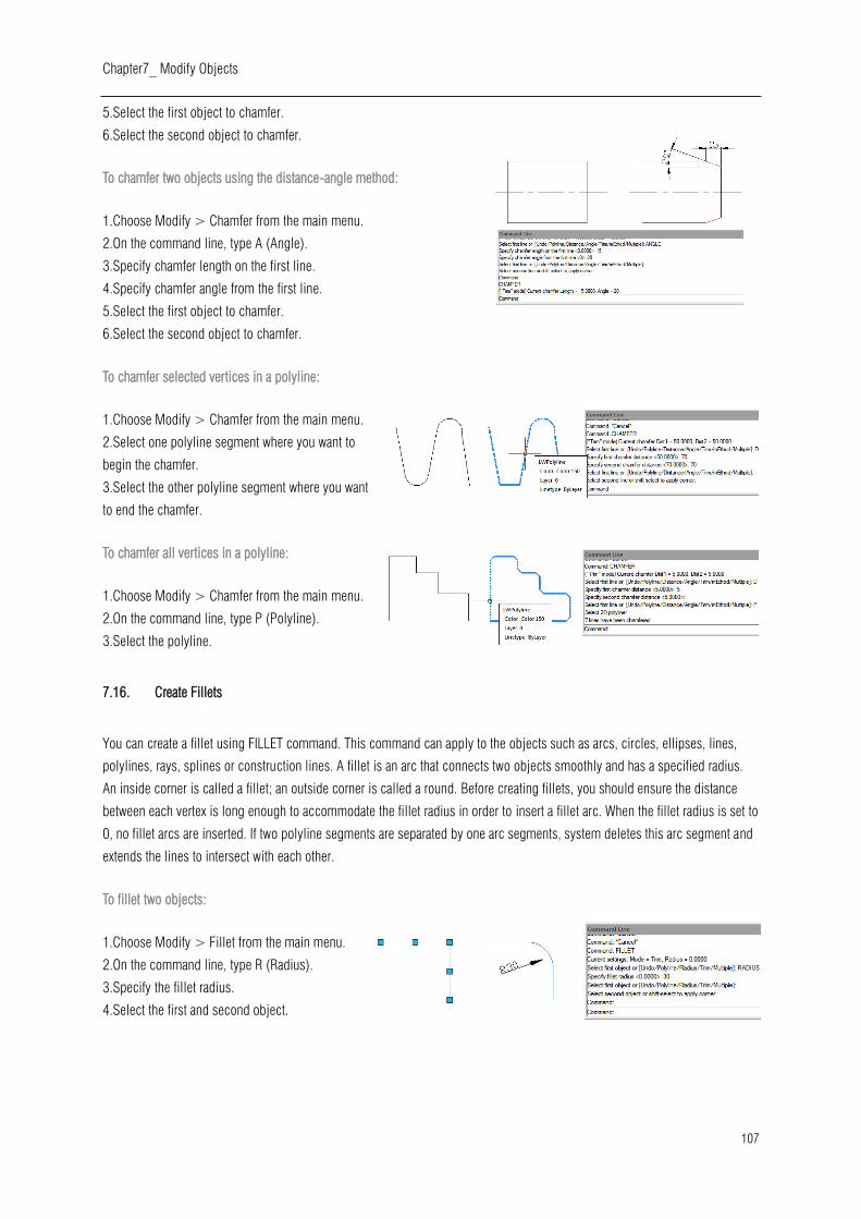
Chapter7_ Modify Objects
107
5.Select the first object to chamfer.
6.Select the second object to chamfer.
To chamfer two objects using the distance-angle method:
1.Choose Modify > Chamfer from the main menu.
2.On the command line, type A (Angle).
3.Specify chamfer length on the first line.
4.Specify chamfer angle from the first line.
5.Select the first object to chamfer.
6.Select the second object to chamfer.
To chamfer selected vertices in a polyline:
1.Choose Modify > Chamfer from the main menu.
2.Select one polyline segment where you want to
begin the chamfer.
3.Select the other polyline segment where you want
to end the chamfer.
To chamfer all vertices in a polyline:
1.Choose Modify > Chamfer from the main menu.
2.On the command line, type P (Polyline).
3.Select the polyline.
7.16. Create Fillets
You can create a fillet using FILLET command. This command can apply to the objects such as arcs, circles, ellipses, lines,
polylines, rays, splines or construction lines. A fillet is an arc that connects two objects smoothly and has a specified radius.
An inside corner is called a fillet; an outside corner is called a round. Before creating fillets, you should ensure the distance
between each vertex is long enough to accommodate the fillet radius in order to insert a fillet arc. When the fillet radius is set to
0, no fillet arcs are inserted. If two polyline segments are separated by one arc segments, system deletes this arc segment and
extends the lines to intersect with each other.
To fillet two objects:
1.Choose Modify > Fillet from the main menu.
2.On the command line, type R (Radius).
3.Specify the fillet radius.
4.Select the first and second object.

Chapter7_ Modify Objects
108
To fillet an entire polyline:
1.Choose Modify > Fillet from the main menu.
2.On the command line, type P (Polyline).
3.Select the polyline.
To fillet selected vertices in a polyline:
1.Choose Modify > Fillet from the main menu.
2.Select one polyline segment where you want to begin the fillet.
3.Select the other polyline segment where you want to end the
fillet.
7.16.1. Trim and Extend Filleted Objects
While performing fillet, you can select Trim option to decide whether the
selected edges are extended to the endpoints of fillet arcs. By default, all
objects except of circles, ellipses, closed polylines and splines are trimmed or extended when performing filleting.
7.16.2. Fillet Line and Polyline Combinations
If the objects to fillet are a line and a polyline, the line or its extension must
be intersecting with one of the polyline segments. With Trim option on, the
filleted objects join with the filleted arc to form a new polyline.
7.16.3. Fillet Parallel Lines
You can fillet parallel lines, rays, and infinite lines. The first entity must be a line or
ray, the second entity can be a line, ray, or infinite line. The diameter of the fillet arc
is always equal to the distance between the parallel entities. The current fillet radius
is ignored.
7.16.4. Invert Fillet
Invert Fillet has a very wide range of usage particularly in construction and
furniture industry. The FILLET command now offers a new option called
Invert. You can create a reverse fillet by this option.
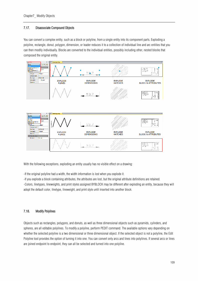
Chapter7_ Modify Objects
109
7.17. Disassociate Compound Objects
You can convert a complex entity, such as a block or polyline, from a single entity into its component parts. Exploding a
polyline, rectangle, donut, polygon, dimension, or leader reduces it to a collection of individual line and arc entities that you
can then modify individually. Blocks are converted to the individual entities, possibly including other, nested blocks that
composed the original entity.
With the following exceptions, exploding an entity usually has no visible effect on a drawing:
-If the original polyline had a width, the width information is lost when you explode it.
-If you explode a block containing attributes, the attributes are lost, but the original attribute definitions are retained.
-Colors, linetypes, lineweights, and print styles assigned BYBLOCK may be different after exploding an entity, because they will
adopt the default color, linetype, lineweight, and print style until inserted into another block.
7.18. Modify Polylines
Objects such as rectangles, polygons, and donuts, as well as three dimensional objects such as pyramids, cylinders, and
spheres, are all editable polylines. To modify a polyline, perform PEDIT command. The available options vary depending on
whether the selected polyline is a two dimensional or three dimensional object. If the selected object is not a polyline, the Edit
Polyline tool provides the option of turning it into one. You can convert only arcs and lines into polylines. If several arcs or lines
are joined endpoint to endpoint, they can all be selected and turned into one polyline.
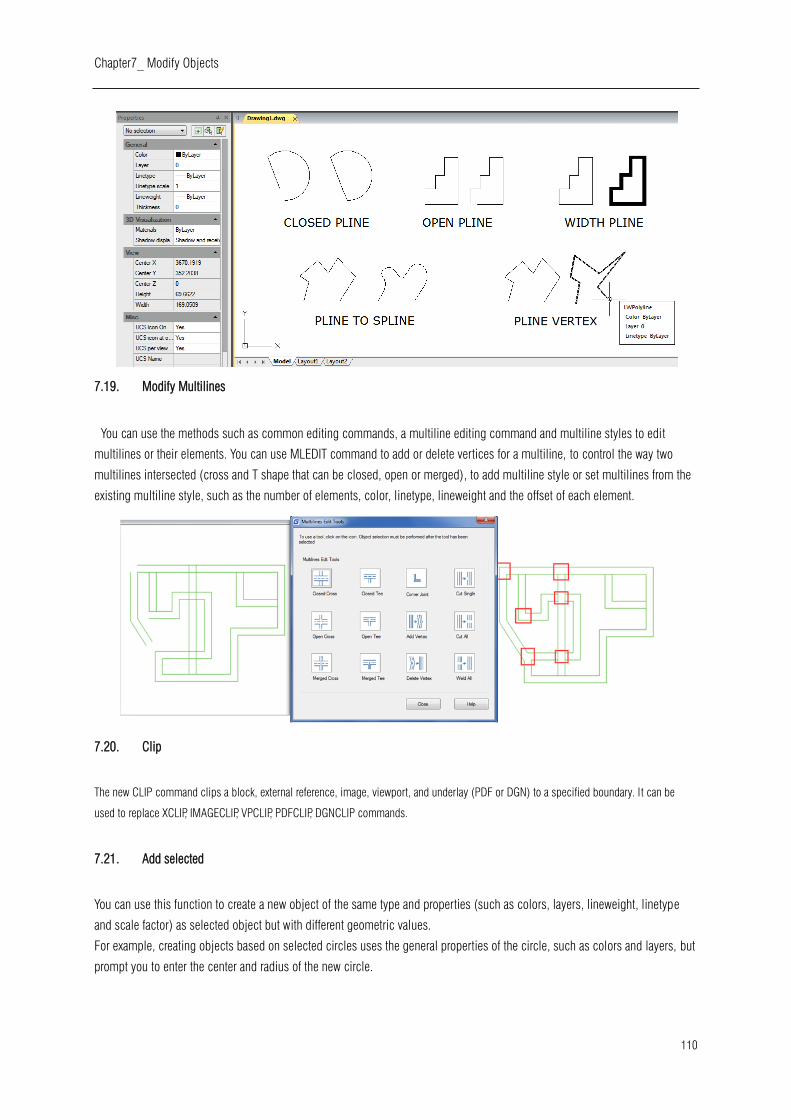
Chapter7_ Modify Objects
110
7.19. Modify Multilines
You can use the methods such as common editing commands, a multiline editing command and multiline styles to edit
multilines or their elements. You can use MLEDIT command to add or delete vertices for a multiline, to control the way two
multilines intersected (cross and T shape that can be closed, open or merged), to add multiline style or set multilines from the
existing multiline style, such as the number of elements, color, linetype, lineweight and the offset of each element.
7.20. Clip
The new CLIP command clips a block, external reference, image, viewport, and underlay (PDF or DGN) to a specified boundary. It can be
used to replace XCLIP, IMAGECLIP, VPCLIP, PDFCLIP, DGNCLIP commands.
7.21. Add selected
You can use this function to create a new object of the same type and properties (such as colors, layers, lineweight, linetype
and scale factor) as selected object but with different geometric values.
For example, creating objects based on selected circles uses the general properties of the circle, such as colors and layers, but
prompt you to enter the center and radius of the new circle.
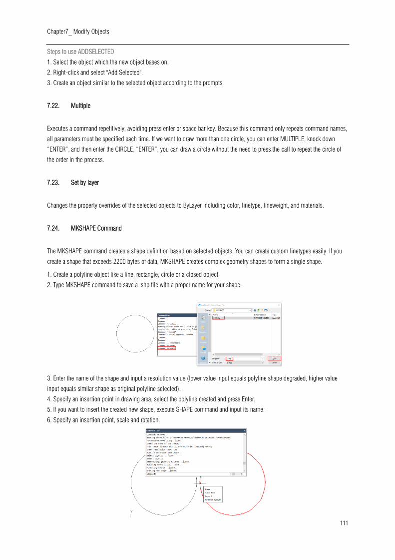
Chapter7_ Modify Objects
111
Steps to use ADDSELECTED
1. Select the object which the new object bases on.
2. Right-click and select "Add Selected".
3. Create an object similar to the selected object according to the prompts.
7.22. Multiple
Executes a command repetitively, avoiding press enter or space bar key. Because this command only repeats command names,
all parameters must be specified each time. If we want to draw more than one circle, you can enter MULTIPLE, knock down
“ENTER”, and then enter the CIRCLE, “ENTER”, you can draw a circle without the need to press the call to repeat the circle of
the order in the process.
7.23. Set by layer
Changes the property overrides of the selected objects to ByLayer including color, linetype, lineweight, and materials.
7.24. MKSHAPE Command
The MKSHAPE command creates a shape definition based on selected objects. You can create custom linetypes easily. If you
create a shape that exceeds 2200 bytes of data, MKSHAPE creates complex geometry shapes to form a single shape.
1. Create a polyline object like a line, rectangle, circle or a closed object.
2. Type MKSHAPE command to save a .shp file with a proper name for your shape.
3. Enter the name of the shape and input a resolution value (lower value input equals polyline shape degraded, higher value
input equals similar shape as original polyline selected).
4. Specify an insertion point in drawing area, select the polyline created and press Enter.
5. If you want to insert the created new shape, execute SHAPE command and input its name.
6. Specify an insertion point, scale and rotation.

Chapter 8_ Notes and Labels
112
8. Notes and Labels
8.1. Create Text
Create text, multiline text (mtext) and text that includes one or more leader lines.
8.1.1. Single-Line Text
You can use TEXT command to create a single or multiline text. Each line text is an independent object which can be modified.
Before typing text, you can specify the text style and the way to align at the prompt of creating text.
Press ENTER if you have typed some characters, and then the command line prompts to input characters for the next row of text.
While creating single line text, you are also enabled to extend or compress certain single line text object in specified space to
meet with your need by means of selecting Align or Fit option from the TEXT command line prompt.
To create text:
1.Choose Draw > Text > Single Line Text from the main menu.
2.Specify the start point for the text.
3.Specify the height of the text.
4.Specify the text rotation angle.
5.Type the text, and then press Enter at the end of each new line.
6.To complete the command, press Enter again.
To specify the line text alignment:
1.Choose Draw > Text > Single Line Text from the main menu.
2.On the command line, type J (Justify) and press ENTER.
3.Type an alignment option BR to align text at its bottom-right corner.
4.Type the text, and then press Enter at the end of each new line.
5.To complete the command, press Enter again.
8.1.2. Multiline Text
Multiline text consists of one or more lines of text or paragraphs that fit within
a boundary width that you specify. When you create multiline text, you first
determine the paragraph's boundary width by specifying the opposite corners
of a rectangle. The multiline text automatically wraps so that it fits within this
rectangle. After defining the text frame, the system opens the In-Place Text
Editor, which is comprised of a text frame and the Text Formatting toolbar.
You can type text in the text frame and change the style from the Text
Formatting toolbar.

Chapter 8_ Notes and Labels
113
To create multiline text:
1.Choose Draw > Text > Multiline Text from the main menu.
2.Select the first and second corner of the text area.
3.In the Multiline Text window, type the text you want.
4.To create paragraphs, press Enter and continue typing.
Remark: Other text features please refer to the express tool guide.
On the toolbar, make format changes as follows:
1.To change the font of the selected text, select a font
from the list.
2.To change the height of the selected text, enter a new
value in the Height box.3.To apply color to the selected
text, choose a color from the Color list.
4.Click OK on the toolbar or Press <Ctrl + Enter>
Justify Multiline Text: You can specify the attachment point at the top left, top
center, top right, middle left, middle center, middle right, bottom left, bottom
center, or bottom right. The multiline text can flow left to right, right to left, top to
bottom, or bottom to top.
Format Characters within Multiline Text: During creating multiline text, you can
assign a new value to the selected objects to overlap the default setting. You can
specify underlines, bold, color and fonts for a single or multiple characters, or
different text height.
Indent Multiline Text and Use Tabs: You can control the appearance of text objects
and create a list by specifying the tap stops and indenting text. The arrowheads
on the ruler are used to define the indent of text (first line and paragraph).
Specify the Line Spacing: The line spacing of multiline texts is the distance
between the baseline of one line of text and the baseline of the next line of text.
You can right-click in the textbox and choose Paragraph to specify the desired
line space when the cursor stays on the text frame.
Create Stacked Characters: Stacked text is text or fraction applied to mark
tolerance or measure units. Before creating stacked text, you have to use special
characters to indicate the stacked place for the selected text. The following
contents present the special characters and illustrate how to create stacked text:
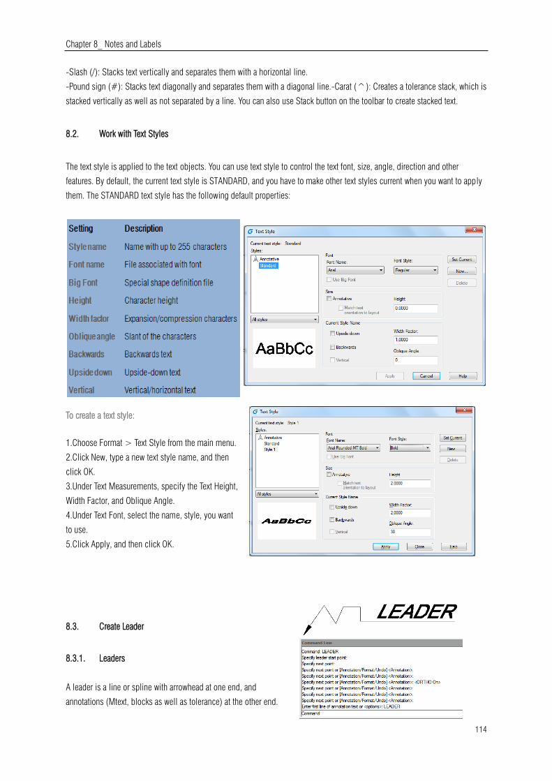
Chapter 8_ Notes and Labels
114
-Slash (/): Stacks text vertically and separates them with a horizontal line.
-Pound sign (#): Stacks text diagonally and separates them with a diagonal line.-Carat (^): Creates a tolerance stack, which is
stacked vertically as well as not separated by a line. You can also use Stack button on the toolbar to create stacked text.
8.2. Work with Text Styles
The text style is applied to the text objects. You can use text style to control the text font, size, angle, direction and other
features. By default, the current text style is STANDARD, and you have to make other text styles current when you want to apply
them. The STANDARD text style has the following default properties:
To create a text style:
1.Choose Format > Text Style from the main menu.
2.Click New, type a new text style name, and then
click OK.
3.Under Text Measurements, specify the Text Height,
Width Factor, and Oblique Angle.
4.Under Text Font, select the name, style, you want
to use.
5.Click Apply, and then click OK.
8.3. Create Leader
8.3.1. Leaders
A leader is a line or spline with arrowhead at one end, and
annotations (Mtext, blocks as well as tolerance) at the other end.

Chapter 8_ Notes and Labels
115
Generally, you place an arrowhead at the first point. An annotation, created as dimension text, is placed immediately adjacent to
the last point.
To create a leader and an annotation:
1.Choose Dimension > Leader from the main menu.
2.Specify the starting point of the leader.
3.Specify the endpoint of the leader line segment.
4.Specify additional leader line segment endpoints.
5.After you specify the last endpoint, press Enter.
6.Type the annotation, and press Enter to enter the next line of annotation text.
7.Press ENTER to complete the command.
8.3.2. Mleader
Multileader is used to attach annotation to multiple leader lines. Multileader could be used to give additional information or
special instruction in a point or specific area on your drawing .It also has more capabilities like using multiline text or blocks as
leader content in our drawing. This version supports the complete multileader set options like Add Leader, Remove Leader,
Align and Collect.
8.4. Modify Text
8.4.1. Change Text
All of text objects can be moved, rotated, deleted and copied, just as like other objects. You can change the properties at the
Properties panel. You have two methods to modify single-line text:

Chapter 8_ Notes and Labels
116
-To modify only the content of text, use DDEDIT command.
-To change text style, location, size and content, use PROPERTIES command to open Properties palette, from which, you can
make the relevant settings.
To edit single or multiline text:
1.Type DDEDIT and then press Enter.
2.Select the single line or multiline text.
3.If select the single line text, the Edit Text box will pop up, edit the text and then press Enter.
4.If select the multiline text, the In-Place Text Editor will pop, edit the text according as you need.
To change single or multiline text properties:
1.Select a single line or multiline text object.
2.Right-click the selected object and then click Properties on the shortcut menu.
3.In the Properties palette, enter any new text in the Text Contents, and then change
formatting and other properties as needed.4.You can also do double-click on the multiline
text to open the In-Place Text Editor, from which, you can modify the contents and formats of
text.

Chapter 9_ Dimensions and Tolerances
117
9. Dimensions and Tolerances
Dimensions indicate the measurement values of objects (e.g. length or width),
distance or angles among objects, or the distance between feature point and the
specified origin. You can create five basic types of dimensions: linear, angular, radial,
diametral and ordinate. Dimensions have several distinct elements: dimension text,
dimension lines, arrowheads, and extension lines.
1.Dimension text: A character string that usually indicates the measurement value,
includes prefixes, suffixes, tolerances, etc.2.Dimension line: Indicates the direction and extent of a dimension. For linear
dimensions, it displays as a line, for angular dimensions, it displays as an arc segment. 3.Arrowhead: Usually displayed at both
end of the dimension line. You can specify various sizes and shapes for arrowheads or tick marks. 4.Extension lines: Extend
from the object to the dimension line, in order to define dimension ranges.
9.1. Create Dimensions
You can create dimensions by selecting the entity to dimension and specifying the dimension line location, or by specifying the
extension line origins and the dimension line location.
9.1.1. Horizontal and Vertical Dimensions
As you create linear dimensions, the system automatically applies a horizontal or
vertical dimension depending on the specified extension line origins or the
location where you select an object. However, you can create a dimension by
specifying it be horizontal or vertical.
To create a horizontal or vertical dimension:
1.Choose Dimension > Linear from the main menu.
2.Press Enter, and then select the object to dimension. Or, you can specify the first and second extension line origins.
3.Specify the dimension line location.
9.1.2. Create Aligned Dimensions
In the aligned dimensions, the dimension line is parallel to the line passing
through the extension line origins. The aligned dimension is also parallel to the
objects you specify. The system creates the extension lines automatically.
To create an aligned dimension:
1.Choose Dimension > Aligned from the main menu.
2.Press Enter, and then select the object to dimension. Or, you can specify the first and second extension line origins.
3.Specify the dimension line location.

Chapter 9_ Dimensions and Tolerances
118
9.1.3. Create Baseline and Continued Dimensions
Both baseline and continued dimensions are multiple linear dimensions. Baseline dimensions are measured from the same
baseline and continued dimensions are placed end to end. Before creating either baseline or continued dimension, you have to
create a linear, aligned, or angular dimension.
To create a linear baseline dimension:
1.Choose Dimension > Baseline from the main menu.
2.Specify a second extension line origin3.Select the next extension line origin.
4.Continue selecting extension line origins as required.
5.To end the command, press Enter twice.
To create a linear continued dimension:
1.Choose Dimension > Continue from the main menu.
2.To select a starting dimension, press Enter.
3.Select the next extension line origin, and then press Enter. Or press Enter, and
then select an existing dimension to continue.5.To add continued dimensions,
continue selecting extension line origins.
6.To end the command, press Enter twice.
9.1.4. Create Rotated Dimensions
You can create rotated dimensions at a rotated angle you specify using DIMLINEAR
Rotated option. An example of a rotated dimension is shown in the following illustration.
In this illustration, the specified angle of the rotated dimension is equal to the angle of the slot.
9.1.5. Create Angular Dimensions
Angular dimensions are used to measure the angle between lines or three points. You can dimension objects including circles,
arcs, and lines. When you create the angular dimension, you can modify the text contend and alignment before placing the
dimension line.
To dimension an angle between two lines:
1.Choose Dimension > Angular from the main menu.
2.Select one line.
3.Select the other line.
4.Specify the dimension line location.
To dimension an angle encompassed by an arc:

Chapter 9_ Dimensions and Tolerances
119
1.Choose Dimension > Angular from the main menu.
2.Select the arc.
3.Specify the dimension arc location.
9.1.6. Create Radial Dimensions
You can create radial dimensions for circles or arcs to measure their radial. The radial
dimension is a line with an arrowhead that points to a circle or arc.
To create a radial dimension:
1.Choose Dimension > Radius from the main menu.
2.Select the arc or circle.
3.Specify the dimension line location.
9.1.7. Jogged Dimension
Jogged dimension is namely jogged radius dimension, which is also called "scaled radius dimension". User can specify center
position to place the origin of dimension for replacing center point of circle or arc within radius dimension. DIMJOGGED
command is useful for creating dimensions in case that the center of circle or arc to be dimensioned is located outside the
layout and can't be displayed in its actual position either.
To create a jogged radius dimension:
1.Choose Dimension > Jogged from the main menu.
2.Select a circle or an arc.
3.Select center position as the dimension origin.
4.Specify a point to position the jog symbol.
9.1.8. Create Diameter Dimensions
You can create diameter dimensions for circles or arcs to measure their diameters. Creating diameter dimensions resembles
creating radial dimensions. You can create various diameter dimensions based on the location and size of circles or arc, and the
settings of the dimension style.
To create a diameter dimension:
1.Choose Dimension > Diameter from the main menu.
2.Select the arc or circle.
3.Specify the dimension line location.

Chapter 9_ Dimensions and Tolerances
120
9.1.9. Create Ordinate Dimensions
Ordinate dimensions are used to measure the perpendicular distance from an origin point called the datum to a feature, such as
a hole in a part. Ordinate dimensions are comprised of a leader line with an X or Y value, and leaders are drawn along the
orthographic direction at the current UCS.
To create an ordinate dimension:
1.Choose Dimension > Ordinate from the main menu.
2.Select the point for an ordinate dimension.
3.Specify the ordinate leader endpoint.
9.1.10. Create Quick Dimension
Creates or edits a series of dimensions quickly by typing QDIM command.
To create a quick dimension:
1.Choose Dimension > Quick Dimension from the main menu.
2.Select the geometry to dimension, and then press Enter.
3.On the command line, it will display "Specify dimension line position,
or[Continuous/Staggered/Baseline/Ordinate/Radius/Diameter/datumPoint
/Edit/seTtings] <Continuous>:".You can perform the operation as
desired. The default is Continuous.
9.1.11. Create Arc Length Dimension
Arc length dimension is available for measuring the arc length of arc or polyline arc segment. GstarCAD creates arc length
dimension by specifying extension line position directly after selecting arc by default. And use an arc symbol as arc length
dimension, which is differing from linear dimension and angular dimension.
To create an arc length dimension:
1.Choose Dimension > Arc Length from the main menu.
2.Select an arc or polyline arc segment.
3.Specify a point to position the arc length dimension.
9.2. Use Dimension Styles
You can control the appearance of dimensions by changing settings to help maintain dimensioning standards, you can store
these settings in dimension styles.
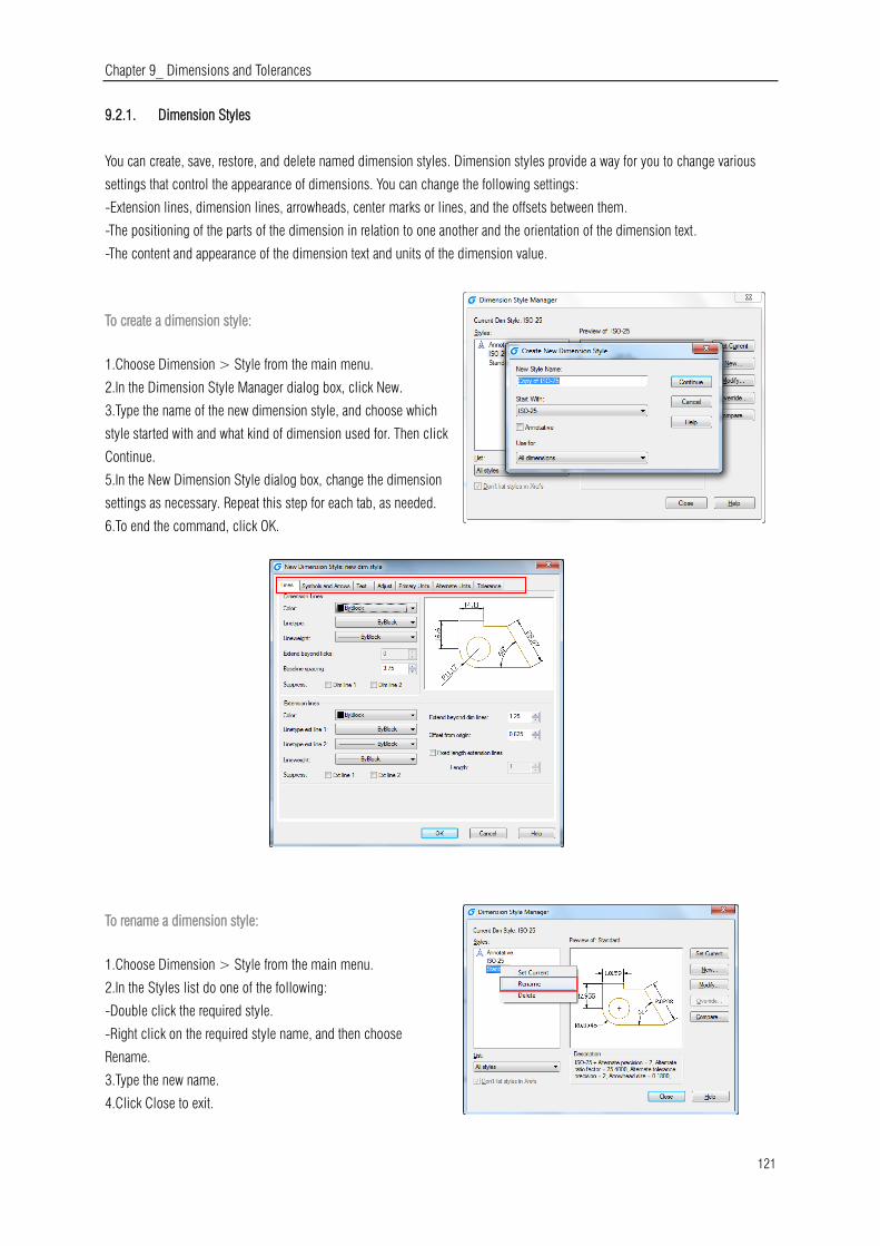
Chapter 9_ Dimensions and Tolerances
121
9.2.1. Dimension Styles
You can create, save, restore, and delete named dimension styles. Dimension styles provide a way for you to change various
settings that control the appearance of dimensions. You can change the following settings:
-Extension lines, dimension lines, arrowheads, center marks or lines, and the offsets between them.
-The positioning of the parts of the dimension in relation to one another and the orientation of the dimension text.
-The content and appearance of the dimension text and units of the dimension value.
To create a dimension style:
1.Choose Dimension > Style from the main menu.
2.In the Dimension Style Manager dialog box, click New.
3.Type the name of the new dimension style, and choose which
style started with and what kind of dimension used for. Then click
Continue.
5.In the New Dimension Style dialog box, change the dimension
settings as necessary. Repeat this step for each tab, as needed.
6.To end the command, click OK.
To rename a dimension style:
1.Choose Dimension > Style from the main menu.
2.In the Styles list do one of the following:
-Double click the required style.
-Right click on the required style name, and then choose
Rename.
3.Type the new name.
4.Click Close to exit.
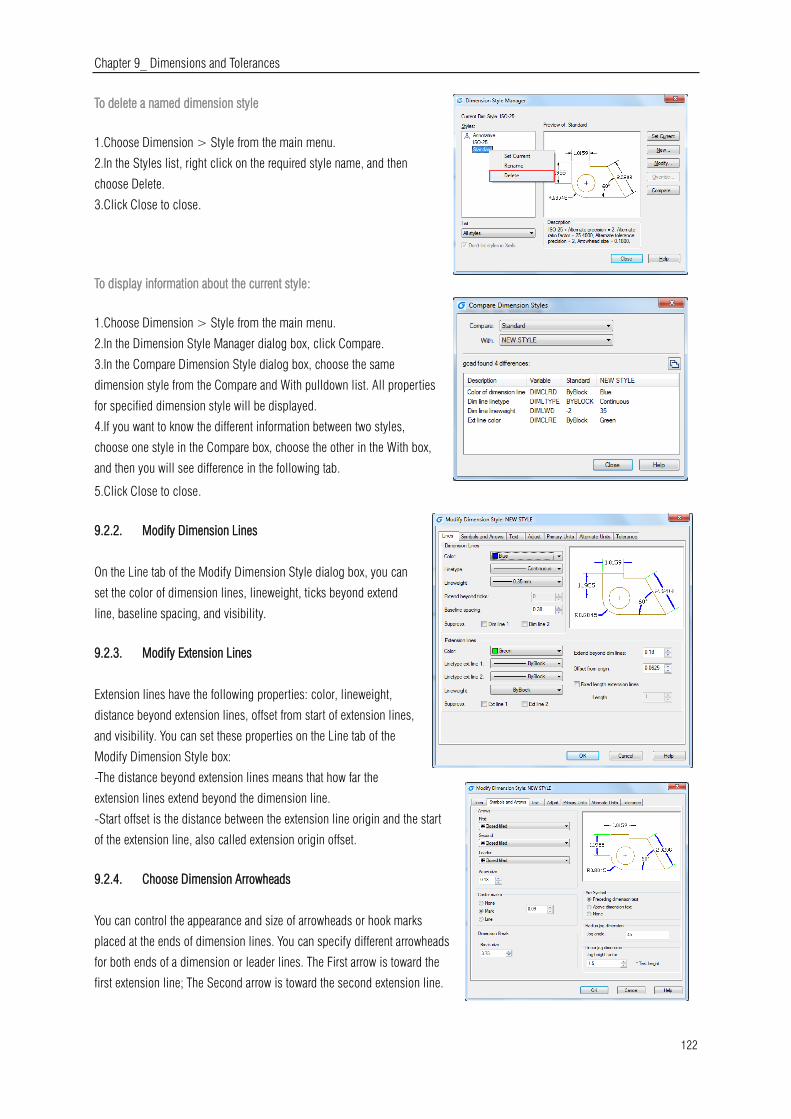
Chapter 9_ Dimensions and Tolerances
122
To delete a named dimension style
1.Choose Dimension > Style from the main menu.
2.In the Styles list, right click on the required style name, and then
choose Delete.
3.Click Close to close.
To display information about the current style:
1.Choose Dimension > Style from the main menu.
2.In the Dimension Style Manager dialog box, click Compare.
3.In the Compare Dimension Style dialog box, choose the same
dimension style from the Compare and With pulldown list. All properties
for specified dimension style will be displayed.
4.If you want to know the different information between two styles,
choose one style in the Compare box, choose the other in the With box,
and then you will see difference in the following tab.
5.Click Close to close.
9.2.2. Modify Dimension Lines
On the Line tab of the Modify Dimension Style dialog box, you can
set the color of dimension lines, lineweight, ticks beyond extend
line, baseline spacing, and visibility.
9.2.3. Modify Extension Lines
Extension lines have the following properties: color, lineweight,
distance beyond extension lines, offset from start of extension lines,
and visibility. You can set these properties on the Line tab of the
Modify Dimension Style box:
-The distance beyond extension lines means that how far the
extension lines extend beyond the dimension line.
-Start offset is the distance between the extension line origin and the start
of the extension line, also called extension origin offset.
9.2.4. Choose Dimension Arrowheads
You can control the appearance and size of arrowheads or hook marks
placed at the ends of dimension lines. You can specify different arrowheads
for both ends of a dimension or leader lines. The First arrow is toward the
first extension line; The Second arrow is toward the second extension line.
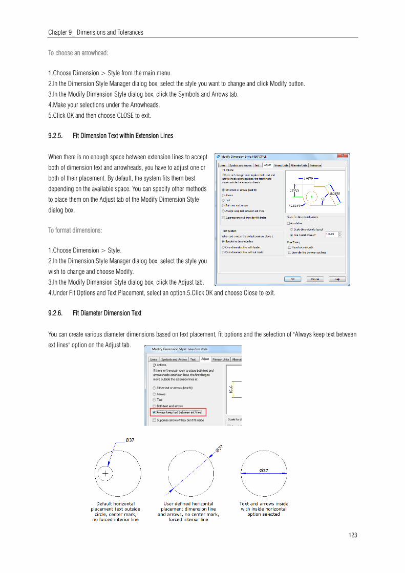
Chapter 9_ Dimensions and Tolerances
123
To choose an arrowhead:
1.Choose Dimension > Style from the main menu.
2.In the Dimension Style Manager dialog box, select the style you want to change and click Modify button.
3.In the Modify Dimension Style dialog box, click the Symbols and Arrows tab.
4.Make your selections under the Arrowheads.
5.Click OK and then choose CLOSE to exit.
9.2.5. Fit Dimension Text within Extension Lines
When there is no enough space between extension lines to accept
both of dimension text and arrowheads, you have to adjust one or
both of their placement. By default, the system fits them best
depending on the available space. You can specify other methods
to place them on the Adjust tab of the Modify Dimension Style
dialog box.
To format dimensions:
1.Choose Dimension > Style.
2.In the Dimension Style Manager dialog box, select the style you
wish to change and choose Modify.
3.In the Modify Dimension Style dialog box, click the Adjust tab.
4.Under Fit Options and Text Placement, select an option.5.Click OK and choose Close to exit.
9.2.6. Fit Diameter Dimension Text
You can create various diameter dimensions based on text placement, fit options and the selection of "Always keep text between
ext lines" option on the Adjust tab.

Chapter 9_ Dimensions and Tolerances
124
9.2.7. Align Dimension Text
Whether the text is inside or outside the extension
line, it has no effect on the justification of dimension
text. You can choose whether the text is align with the
dimension lines or remains horizontal.
To align dimension text with the dimension line:
1.Choose Dimension > Style.
2.In the Dimension Style Manager dialog box, select
the style you wish to change and choose Modify.
3.In the Modify Dimension Style dialog box, click the
Text tab.
4.Make your selections.
5.Click OK and choose Close to exit.
9.2.8. Position Dimension Text Vertically
The vertical text placement is the position of the
text relative to the dimension. You can place text
above, below, or centered within the dimension
line, or use the JIS dimensions.
9.2.9. Position Dimension Text Horizontally
The position of text along the horizon is relation
to the extension lines. The settings include
Centered, At Ext Line 1, At Ext Line 2, Over Ext Line1, and Over Ext Line2.
9.2.10. Dimension Units
You can determine the appearance and format of the
primary and alternate dimension units. You can set
the primary units for linear and angular dimensions,
including unit format, numeric precision and so on.
These settings control the display of dimension
values.
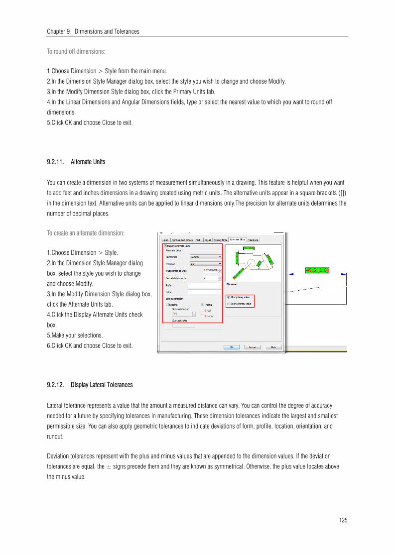
Chapter 9_ Dimensions and Tolerances
125
To round off dimensions:
1.Choose Dimension > Style from the main menu.
2.In the Dimension Style Manager dialog box, select the style you wish to change and choose Modify.
3.In the Modify Dimension Style dialog box, click the Primary Units tab.
4.In the Linear Dimensions and Angular Dimensions fields, type or select the nearest value to which you want to round off
dimensions.
5.Click OK and choose Close to exit.
9.2.11. Alternate Units
You can create a dimension in two systems of measurement simultaneously in a drawing. This feature is helpful when you want
to add feet and inches dimensions in a drawing created using metric units. The alternative units appear in a square brackets ([])
in the dimension text. Alternative units can be applied to linear dimensions only.The precision for alternate units determines the
number of decimal places.
To create an alternate dimension:
1.Choose Dimension > Style.
2.In the Dimension Style Manager dialog
box, select the style you wish to change
and choose Modify.
3.In the Modify Dimension Style dialog box,
click the Alternate Units tab.
4.Click the Display Alternate Units check
box.
5.Make your selections.
6.Click OK and choose Close to exit.
9.2.12. Display Lateral Tolerances
Lateral tolerance represents a value that the amount a measured distance can vary. You can control the degree of accuracy
needed for a future by specifying tolerances in manufacturing. These dimension tolerances indicate the largest and smallest
permissible size. You can also apply geometric tolerances to indicate deviations of form, profile, location, orientation, and
runout.
Deviation tolerances represent with the plus and minus values that are appended to the dimension values. If the deviation
tolerances are equal, the ± signs precede them and they are known as symmetrical. Otherwise, the plus value locates above
the minus value.
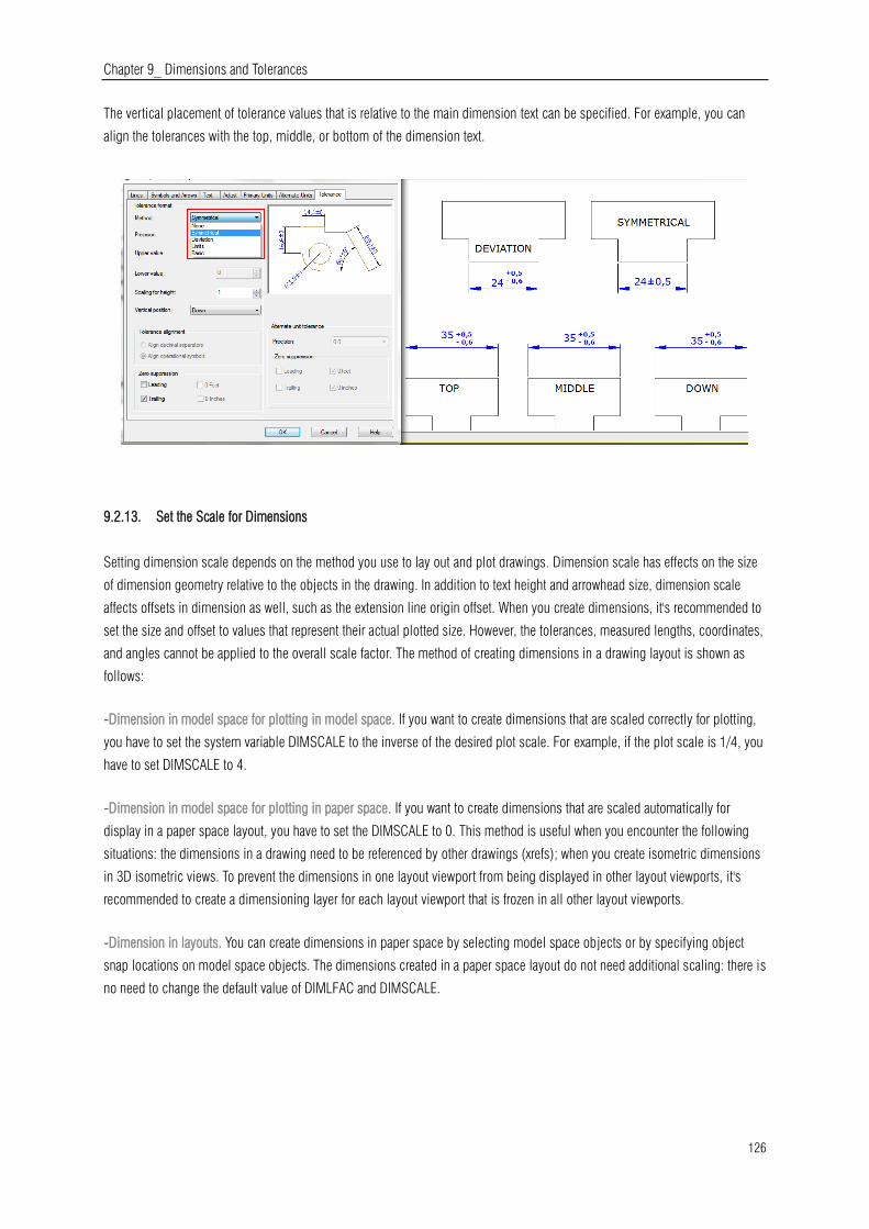
Chapter 9_ Dimensions and Tolerances
126
The vertical placement of tolerance values that is relative to the main dimension text can be specified. For example, you can
align the tolerances with the top, middle, or bottom of the dimension text.
9.2.13. Set the Scale for Dimensions
Setting dimension scale depends on the method you use to lay out and plot drawings. Dimension scale has effects on the size
of dimension geometry relative to the objects in the drawing. In addition to text height and arrowhead size, dimension scale
affects offsets in dimension as well, such as the extension line origin offset. When you create dimensions, it's recommended to
set the size and offset to values that represent their actual plotted size. However, the tolerances, measured lengths, coordinates,
and angles cannot be applied to the overall scale factor. The method of creating dimensions in a drawing layout is shown as
follows:
-Dimension in model space for plotting in model space. If you want to create dimensions that are scaled correctly for plotting,
you have to set the system variable DIMSCALE to the inverse of the desired plot scale. For example, if the plot scale is 1/4, you
have to set DIMSCALE to 4.
-Dimension in model space for plotting in paper space. If you want to create dimensions that are scaled automatically for
display in a paper space layout, you have to set the DIMSCALE to 0. This method is useful when you encounter the following
situations: the dimensions in a drawing need to be referenced by other drawings (xrefs); when you create isometric dimensions
in 3D isometric views. To prevent the dimensions in one layout viewport from being displayed in other layout viewports, it's
recommended to create a dimensioning layer for each layout viewport that is frozen in all other layout viewports.
-Dimension in layouts. You can create dimensions in paper space by selecting model space objects or by specifying object
snap locations on model space objects. The dimensions created in a paper space layout do not need additional scaling: there is
no need to change the default value of DIMLFAC and DIMSCALE.
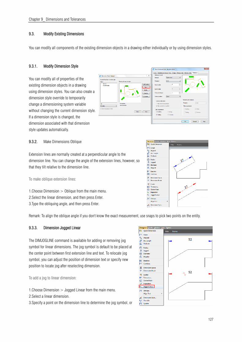
Chapter 9_ Dimensions and Tolerances
127
9.3. Modify Existing Dimensions
You can modify all components of the existing dimension objects in a drawing either individually or by using dimension styles.
9.3.1. Modify Dimension Style
You can modify all of properties of the
existing dimension objects in a drawing
using dimension styles. You can also create a
dimension style override to temporarily
change a dimensioning system variable
without changing the current dimension style.
If a dimension style is changed, the
dimension associated with that dimension
style updates automatically.
9.3.2. Make Dimensions Oblique
Extension lines are normally created at a perpendicular angle to the
dimension line. You can change the angle of the extension lines, however, so
that they tilt relative to the dimension line.
To make oblique extension lines:
1.Choose Dimension > Oblique from the main menu.
2.Select the linear dimension, and then press Enter.
3.Type the obliquing angle, and then press Enter.
Remark: To align the oblique angle if you don't know the exact measurement, use snaps to pick two points on the entity.
9.3.3. Dimension Jogged Linear
The DIMJOGLINE command is available for adding or removing jog
symbol for linear dimensions. The jog symbol is default to be placed at
the center point between first extension line and text. To relocate jog
symbol, you can adjust the position of dimension text or specify new
position to locate jog after reselecting dimension.
To add a jog to linear dimension:
1.Choose Dimension > Jogged Linear from the main menu.
2.Select a linear dimension.
3.Specify a point on the dimension line to determine the jog symbol, or

Chapter 9_ Dimensions and Tolerances
128
press ENTER directly to position the jog symbol in default place.
9.3.4. Dimension Inspection
Dimension inspection is created to transmit the frequency of inspecting the part being dimensioned, the dimension value and
parts tolerance are ensured to be within specified range. Dimension inspection is composed by a frame and internal text and
contains utmost three kinds of information field: inspection tag, dimension value and inspection rate.
Inspection tag, used for mark the text of dimension inspection is located at the left side within the inspection frame.
Dimension value is the value before adding dimension inspection, which is located at the central part of the inspection
dimension including tolerance, text and measurement value.
Inspection rate is expressed by percentage, which is located at the right side
within the inspection frame, indicates required frequency of the part being created.
To create an inspection dimension:
1.Choose Dimension > Inspect from the main menu.
2.In the Inspection Dimension dialog box, click Select Dimensions button.
3.Select dimensions to add dimension inspection, and then press ENTER to finish
selection and return to the dialog box.4.Select a shape for frame from the Shape
option.5.Click Label option to input label in the text box.6.Click Inspection Rate
option to input a value in the text box.7.Click OK.
To remove an inspection dimension:
1.Choose Dimension > Inspect from the main menu.
2.In the Inspection Dimension dialog box, click Select Dimensions button.
3.Select dimensions to remove dimension inspection, and then press ENTER to
finish selection and return to the dialog box. 4.Click Remove Inspection
button.5.Click OK.
9.3.5. Adjust Dimension Space
Once you have created multiple
paralleled linear dimensions or
angular dimensions, you can
adjust the space among these
paralleled lines with an equal
value either default or specified.
DIMSPACE command adjust the
space among paralleled linear
or angular dimensions or
overlapped dimensions
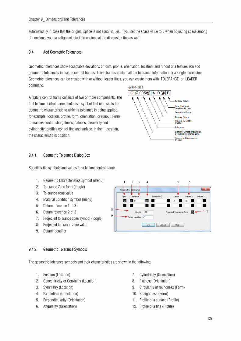
Chapter 9_ Dimensions and Tolerances
129
automatically in case that the original space is not equal values. If you set the space value to 0 when adjusting space among
dimensions, you can align selected dimensions at the dimension line as well.
9.4. Add Geometric Tolerances
Geometric tolerances show acceptable deviations of form, profile, orientation, location, and runout of a feature. You add
geometric tolerances in feature control frames. These frames contain all the tolerance information for a single dimension.
Geometric tolerances can be created with or without leader lines, you can create them with TOLERANCE or LEADER
command.
A feature control frame consists of two or more components. The
first feature control frame contains a symbol that represents the
geometric characteristic to which a tolerance is being applied,
for example, location, profile, form, orientation, or runout. Form
tolerances control straightness, flatness, circularity and
cylindricity; profiles control line and surface. In the illustration,
the characteristic is position.
9.4.1. Geometric Tolerance Dialog Box
Specifies the symbols and values for a feature control frame.
1. Geometric Characteristics symbol (menu)
2. Tolerance Zone form (toggle)
3. Tolerance zone value
4. Material condition symbol (menu)
5. Datum reference 1 of 3
6. Datum reference 2 of 3
7. Projected tolerance zone symbol (toogle)
8. Projected tolerance zone value
9. Datum identifier
9.4.2. Geometric Tolerance Symbols
The geometric tolerance symbols and their characteristics are shown in the following.
1. Position (Location)
2. Concentricity or Coaxiality (Location)
3. Symmetry (Location)
4. Parallelism (Orientation)
5. Perpendicularity (Orientation)
6. Angularity (Orientation)
7. Cylindricity (Orientation)
8. Flatness (Orientation)
9. Circularity or roundness (Form)
10. Straightness (Form)
11. Profile of a surface (Profile)
12. Profile of a line (Profile)
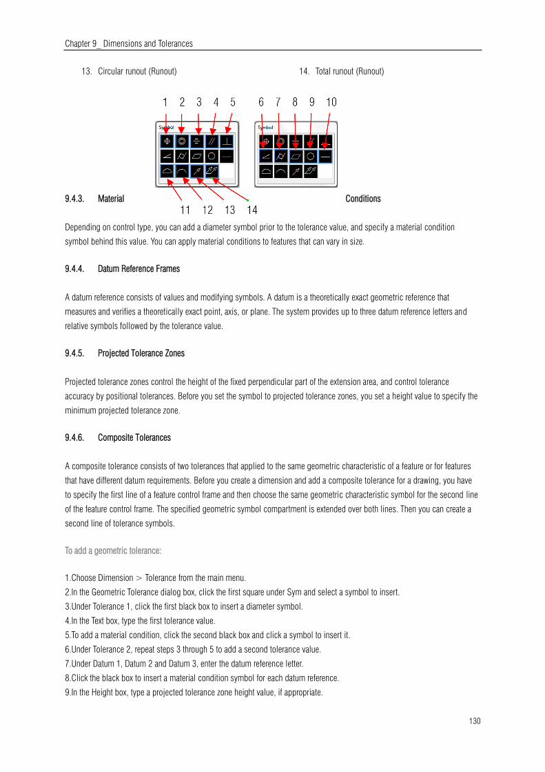
Chapter 9_ Dimensions and Tolerances
130
13. Circular runout (Runout) 14. Total runout (Runout)
9.4.3. Material Conditions
Depending on control type, you can add a diameter symbol prior to the tolerance value, and specify a material condition
symbol behind this value. You can apply material conditions to features that can vary in size.
9.4.4. Datum Reference Frames
A datum reference consists of values and modifying symbols. A datum is a theoretically exact geometric reference that
measures and verifies a theoretically exact point, axis, or plane. The system provides up to three datum reference letters and
relative symbols followed by the tolerance value.
9.4.5. Projected Tolerance Zones
Projected tolerance zones control the height of the fixed perpendicular part of the extension area, and control tolerance
accuracy by positional tolerances. Before you set the symbol to projected tolerance zones, you set a height value to specify the
minimum projected tolerance zone.
9.4.6. Composite Tolerances
A composite tolerance consists of two tolerances that applied to the same geometric characteristic of a feature or for features
that have different datum requirements. Before you create a dimension and add a composite tolerance for a drawing, you have
to specify the first line of a feature control frame and then choose the same geometric characteristic symbol for the second line
of the feature control frame. The specified geometric symbol compartment is extended over both lines. Then you can create a
second line of tolerance symbols.
To add a geometric tolerance:
1.Choose Dimension > Tolerance from the main menu.
2.In the Geometric Tolerance dialog box, click the first square under Sym and select a symbol to insert.
3.Under Tolerance 1, click the first black box to insert a diameter symbol.
4.In the Text box, type the first tolerance value.
5.To add a material condition, click the second black box and click a symbol to insert it.
6.Under Tolerance 2, repeat steps 3 through 5 to add a second tolerance value.
7.Under Datum 1, Datum 2 and Datum 3, enter the datum reference letter.
8.Click the black box to insert a material condition symbol for each datum reference.
9.In the Height box, type a projected tolerance zone height value, if appropriate.

Chapter 9_ Dimensions and Tolerances
131
10.To insert a projected tolerance zone symbol, click the Projected Tolerance Zone box.
11.In the Datum Identifier box, add a datum value and then click OK.
12.In the drawing, specify the location of the feature frame.
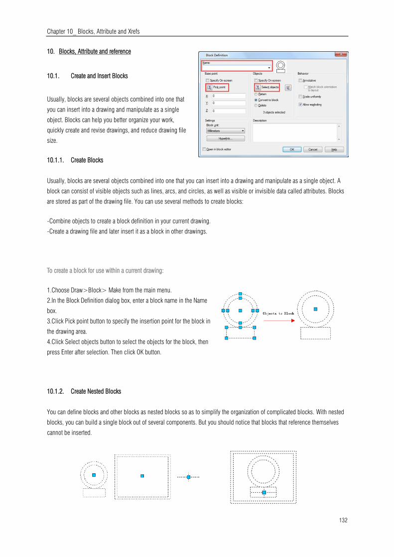
Chapter 10_ Blocks, Attribute and Xrefs
132
10. Blocks, Attribute and reference
10.1. Create and Insert Blocks
Usually, blocks are several objects combined into one that
you can insert into a drawing and manipulate as a single
object. Blocks can help you better organize your work,
quickly create and revise drawings, and reduce drawing file
size.
10.1.1. Create Blocks
Usually, blocks are several objects combined into one that you can insert into a drawing and manipulate as a single object. A
block can consist of visible objects such as lines, arcs, and circles, as well as visible or invisible data called attributes. Blocks
are stored as part of the drawing file. You can use several methods to create blocks:
-Combine objects to create a block definition in your current drawing.
-Create a drawing file and later insert it as a block in other drawings.
To create a block for use within a current drawing:
1.Choose Draw>Block> Make from the main menu.
2.In the Block Definition dialog box, enter a block name in the Name
box.
3.Click Pick point button to specify the insertion point for the block in
the drawing area.
4.Click Select objects button to select the objects for the block, then
press Enter after selection. Then click OK button.
10.1.2. Create Nested Blocks
You can define blocks and other blocks as nested blocks so as to simplify the organization of complicated blocks. With nested
blocks, you can build a single block out of several components. But you should notice that blocks that reference themselves
cannot be inserted.
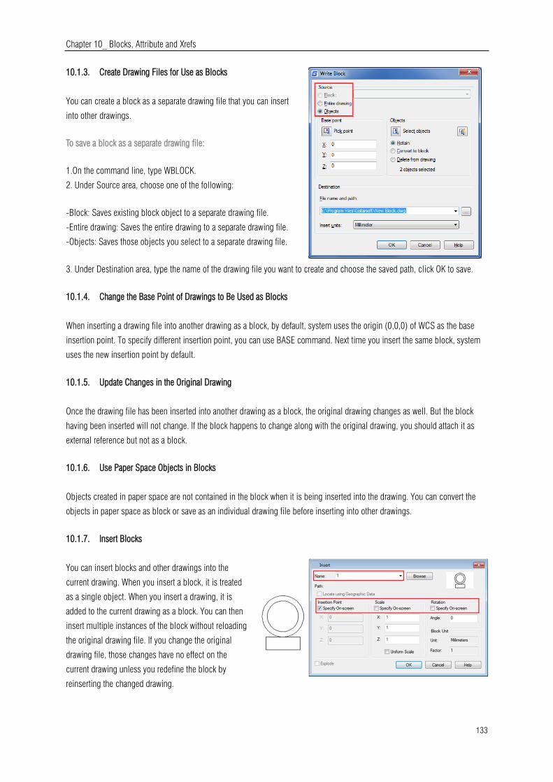
Chapter 10_ Blocks, Attribute and Xrefs
133
10.1.3. Create Drawing Files for Use as Blocks
You can create a block as a separate drawing file that you can insert
into other drawings.
To save a block as a separate drawing file:
1.On the command line, type WBLOCK.
2. Under Source area, choose one of the following:
-Block: Saves existing block object to a separate drawing file.
-Entire drawing: Saves the entire drawing to a separate drawing file.
-Objects: Saves those objects you select to a separate drawing file.
3. Under Destination area, type the name of the drawing file you want to create and choose the saved path, click OK to save.
10.1.4. Change the Base Point of Drawings to Be Used as Blocks
When inserting a drawing file into another drawing as a block, by default, system uses the origin (0,0,0) of WCS as the base
insertion point. To specify different insertion point, you can use BASE command. Next time you insert the same block, system
uses the new insertion point by default.
10.1.5. Update Changes in the Original Drawing
Once the drawing file has been inserted into another drawing as a block, the original drawing changes as well. But the block
having been inserted will not change. If the block happens to change along with the original drawing, you should attach it as
external reference but not as a block.
10.1.6. Use Paper Space Objects in Blocks
Objects created in paper space are not contained in the block when it is being inserted into the drawing. You can convert the
objects in paper space as block or save as an individual drawing file before inserting into other drawings.
10.1.7. Insert Blocks
You can insert blocks and other drawings into the
current drawing. When you insert a block, it is treated
as a single object. When you insert a drawing, it is
added to the current drawing as a block. You can then
insert multiple instances of the block without reloading
the original drawing file. If you change the original
drawing file, those changes have no effect on the
current drawing unless you redefine the block by
reinserting the changed drawing.

Chapter 10_ Blocks, Attribute and Xrefs
134
To insert a block:
1.Choose Insert > Block from the main menu.
2.In the Insert Block dialog box, under Insert, click Block Name.
3.In the Name box, select the name of the block you want to insert.
4.If you want to use the pointing device to specify the insertion point, scale, and rotation, select Specify On-Screen. Otherwise,
enter values in the Insertion Point, Scale, and Rotation boxes.
5. Click OK to insert.
To insert an entire drawing into the current drawing:
1.Choose Insert > Block from the main menu.
2.Click Browse to specify the file from the Insert Block dialog box.
3.You can use the default insertion point, scale, and rotation or
select Specify On-Screen and enter values in the Insertion Point,
Scale, and Rotation boxes.
4.If you want the objects in the block to be inserted as individual
objects instead of as a single block, select Explode. Precondition
is the block you created is allowed to explode.
5.Click OK to insert.
10.1.8. Modify a Block Definition
You can redefine all instances of a block within the current drawing. To redefine a block that was created in the current drawing,
you create a new block using the same name. You can update all the blocks in the current drawing by redefining the block. If
the block was inserted from a separate drawing file that was subsequently updated, reinsert that block to update all other
instances in the current drawing.
To redefine a block in the current drawing:
1.Choose Draw > Block > Make from the main menu.
2.In the Block Definition dialog box, type the name of the
block you want to redefine in the Name box.
3.Click Pick point button to specify a point as the insertion
point for the block in the drawing area.
4.Click Select objects button to select the objects for the
block, and then press Enter after selection.
5.Click OK.
6.Click Yes in the prompt box that displays to redefine the
block in the current drawing.
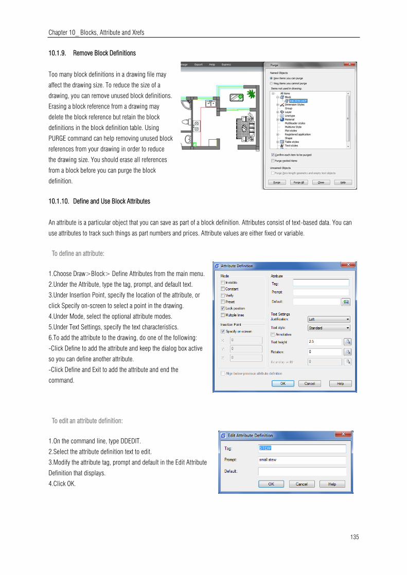
Chapter 10_ Blocks, Attribute and Xrefs
135
10.1.9. Remove Block Definitions
Too many block definitions in a drawing file may
affect the drawing size. To reduce the size of a
drawing, you can remove unused block definitions.
Erasing a block reference from a drawing may
delete the block reference but retain the block
definitions in the block definition table. Using
PURGE command can help removing unused block
references from your drawing in order to reduce
the drawing size. You should erase all references
from a block before you can purge the block
definition.
10.1.10. Define and Use Block Attributes
An attribute is a particular object that you can save as part of a block definition. Attributes consist of text-based data. You can
use attributes to track such things as part numbers and prices. Attribute values are either fixed or variable.
To define an attribute:
1.Choose Draw>Block> Define Attributes from the main menu.
2.Under the Attribute, type the tag, prompt, and default text.
3.Under Insertion Point, specify the location of the attribute, or
click Specify on-screen to select a point in the drawing.
4.Under Mode, select the optional attribute modes.
5.Under Text Settings, specify the text characteristics.
6.To add the attribute to the drawing, do one of the following:
-Click Define to add the attribute and keep the dialog box active
so you can define another attribute.
-Click Define and Exit to add the attribute and end the
command.
To edit an attribute definition:
1.On the command line, type DDEDIT.
2.Select the attribute definition text to edit.
3.Modify the attribute tag, prompt and default in the Edit Attribute
Definition that displays.
4.Click OK.

Chapter 10_ Blocks, Attribute and Xrefs
136
10.1.11. Modify Block Attributes
You can use the Block Attribute Manager to modify attributes in
block definitions. For example, you can modify the following items:
-Attributes of blocks can be displayed after modification.
-Text properties that define how attribute text is displayed in the
drawing.
-Properties that define the layer that the attribute is on and the
attribute line's color, weight, and type
To edit an attribute attached to a block:
1.On the command line, type DDATTE.
2.Select the block to edit. The Edit Attributes dialog box displays
all the attributes attached to the block you select.
3.Edit the attribute values as necessary. Then click OK.
10.1.12. Extract Block Attribute Data
Enter EATTEXT to start Attribute Extraction if the blocks
in the drawing contain attributes. You can extract block
information according to the wizard prompt and
generate list so as to overview the attributes information
of the blocks. You can get guide information from the
wizard until you accomplish selecting drawings, blocks
and block attributes.
With the extract block attribute data function, you can
easily create list using drawing data through extracting attribute information and export to external files.
10.1.13. Synchronize Attributes
The ATTSYNC command applies attribute changes in block definitions to all block references of the same name. You can use
this command to update instances of blocks containing attributes that were redefined using the BLOCK or BEDIT commands.
ATTSYNC does not change any values assigned to attributes in existing blocks. ATTSYNC removes all changes of format or
features that are made by ATTEDIT or EATTEDIT commands. And it also deletes all extended data associated with blocks and
might affect dynamic blocks and blocks created by third-party applications.
10.2. Reference Other Drawing Files (Xrefs)
External references provide additional capabilities not available when you insert a drawing as a block. When you attach an
external reference, however, any changes you make to the original drawing file are reflected in the drawings that reference it.

Chapter 10_ Blocks, Attribute and Xrefs
137
External references are useful for assembling master drawings from component drawings. Use external references to coordinate
your work with others in a group. External references help reduce the drawing file size and ensure that you are always working
with the most recent version of a drawing.
10.2.1. Attach External References
When a drawing is attached to current drawing as external reference, it will be linked to the drawing, any changes to the
referenced drawing may affect the external reference in current drawing. External references are inserted into the drawing as
block definitions and used as single objects, but you should distinguish the external references and blocks.
To attach an external reference:
1.Choose Insert>External References from the main menu.
2.Clickthe DWG icon at the top left of the window.
3.In the Select Reference File dialog box, specify the drawing file to attach and then click Open.
4.In the External Reference dialog box, under Reference Type, choose how you want to insert the drawing:
-Attachment: Inserts a copy of the drawing and includes any other drawings references.
-Overlay: Lays a copy of a drawing over your original drawing
5.Make any additional selections and then click OK.
6.If you marked Specify On-screen for any items, follow the prompts to attach the external reference
10.2.2. Control the Properties of Referenced Layers
You can control the visibility, color, linetype, and
other properties of an xref's layers and make these
changes temporary or permanent. If the VISRETAIN
variable is set to 0, these changes apply only to the
current drawing session. You can also control the
fade display through XDWGFADECTL variable. In
addition you can control Xref layer properties directly
into the Layer Manager Properties dialog box.

Chapter 10_ Blocks, Attribute and Xrefs
138
10.2.3. Xref Clipping Boundaries
You can control whether to display clipping boundary of xref
through setting system variable XCLIPFRAME. Also you can Clip
Xrefs by selecting the option on the menu bar:
Modify>Clip>Xref
10.2.4. Nest and Overlay External References
Xrefs can be nested in another xref and attached to current drawing. In the process of attaching, you can select insertion
position, scaling factor and rotation angle for xrefs.
10.2.5. Binding an Xref to a Drawing
To provide a copy of a drawing containing external references to someone else, you
must also provide all the external reference files. Binding the external references makes
them a permanent part of the drawing, which is similar to inserting a separate drawing as
a block. You can bind external references by doing right click to the
selected Xref file.
10.2.6. Refresh Xrefs
You can refresh the Xref by clicking the refresh button located at the top of the External Reference Dialog Box.
10.3. DGN Underlay
In GstarCAD 2021 version, the full DGN files are supported and
related commands such as DGNIMPORT, DGNATTACH,
DGNADJUST, DGNMAPING, etc are available. Now you can import
and attach as underlay a Microstation native format.

Chapter 10_ Blocks, Attribute and Xrefs
139
10.4. DWF Underlay
GstarCAD supports DWF Underlay, you can insert a DWF file as Underlay.
10.5. PDF Underlay
If you receive project drawings in the form of a PDF file, you can reuse that PDF data in your own GstarCAD drawing files.
After inserting the PDF file as underlay, Then you can start
drawing or placing geometry at specific point of the underlay.
What’s more, you can adjust the underlay display like contrast, fade, monochrome, and colors for background through the
properties palette.
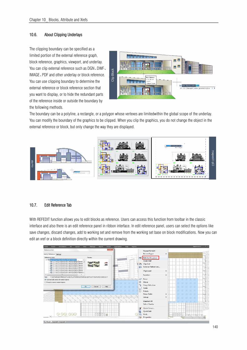
Chapter 10_ Blocks, Attribute and Xrefs
140
10.6. About Clipping Underlays
The clipping boundary can be specified as a
limited portion of the external reference graph,
block reference, graphics, viewport, and underlay.
You can clip external reference such as DGN、DWF、
IMAGE、PDF and other underlay or block reference.
You can use clipping boundary to determine the
external reference or block reference section that
you want to display, or to hide the redundant parts
of the reference inside or outside the boundary by
the following methods.
The boundary can be a polyline, a rectangle, or a polygon whose vertexes are limitedwithin the global scope of the underlay.
You can modify the boundary of the graphics to be clipped. When you clip the graphics, you do not change the object in the
external reference or block, but only change the way they are displayed.
10.7. Edit Reference Tab
With REFEDIT function allows you to edit blocks as reference. Users can access this function from toolbar in the classic
interface and also there is an edit reference panel in ribbon interface. In edit reference panel, users can select the options like
save changes, discard changes, add to working set and remove from the working set base on block modifications. Now you can
edit an xref or a block definition directly within the current drawing.
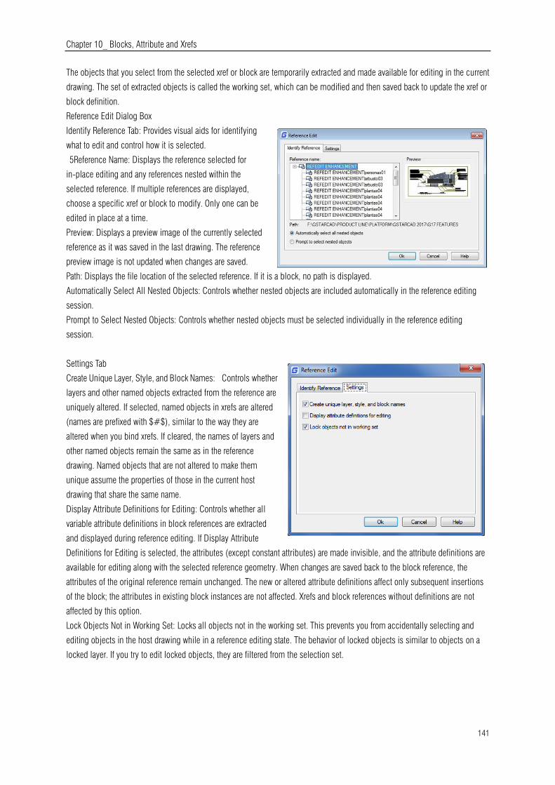
Chapter 10_ Blocks, Attribute and Xrefs
141
The objects that you select from the selected xref or block are temporarily extracted and made available for editing in the current
drawing. The set of extracted objects is called the working set, which can be modified and then saved back to update the xref or
block definition.
Reference Edit Dialog Box
Identify Reference Tab: Provides visual aids for identifying
what to edit and control how it is selected.
5Reference Name: Displays the reference selected for
in-place editing and any references nested within the
selected reference. If multiple references are displayed,
choose a specific xref or block to modify. Only one can be
edited in place at a time.
Preview: Displays a preview image of the currently selected
reference as it was saved in the last drawing. The reference
preview image is not updated when changes are saved.
Path: Displays the file location of the selected reference. If it is a block, no path is displayed.
Automatically Select All Nested Objects: Controls whether nested objects are included automatically in the reference editing
session.
Prompt to Select Nested Objects: Controls whether nested objects must be selected individually in the reference editing
session.
Settings Tab
Create Unique Layer, Style, and Block Names: Controls whether
layers and other named objects extracted from the reference are
uniquely altered. If selected, named objects in xrefs are altered
(names are prefixed with $#$), similar to the way they are
altered when you bind xrefs. If cleared, the names of layers and
other named objects remain the same as in the reference
drawing. Named objects that are not altered to make them
unique assume the properties of those in the current host
drawing that share the same name.
Display Attribute Definitions for Editing: Controls whether all
variable attribute definitions in block references are extracted
and displayed during reference editing. If Display Attribute
Definitions for Editing is selected, the attributes (except constant attributes) are made invisible, and the attribute definitions are
available for editing along with the selected reference geometry. When changes are saved back to the block reference, the
attributes of the original reference remain unchanged. The new or altered attribute definitions affect only subsequent insertions
of the block; the attributes in existing block instances are not affected. Xrefs and block references without definitions are not
affected by this option.
Lock Objects Not in Working Set: Locks all objects not in the working set. This prevents you from accidentally selecting and
editing objects in the host drawing while in a reference editing state. The behavior of locked objects is similar to objects on a
locked layer. If you try to edit locked objects, they are filtered from the selection set.
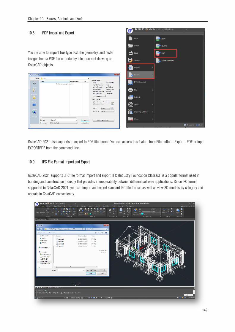
Chapter 10_ Blocks, Attribute and Xrefs
142
10.8. PDF Import and Export
You are able to import TrueType text, the geometry, and raster
images from a PDF file or underlay into a current drawing as
GstarCAD objects.
GstarCAD 2021 also supports to export to PDF file format. You can access this feature from File button - Export - PDF or input
EXPORTPDF from the command line.
10.9. IFC File Format Import and Export
GstarCAD 2021 supports .IFC file format import and export. IFC (Industry Foundation Classes) is a popular format used in
building and construction industry that provides interoperability between different software applications. Since IFC format
supported in GstarCAD 2021, you can import and export standard IFC file format, as well as view 3D models by category and
operate in GstaCAD conveniently.
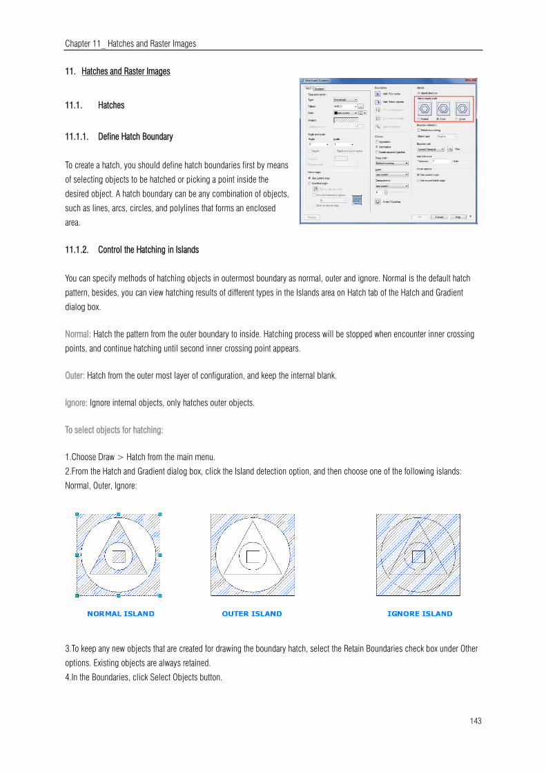
Chapter 11_ Hatches and Raster Images
143
11. Hatches and Raster Images
11.1. Hatches
11.1.1. Define Hatch Boundary
To create a hatch, you should define hatch boundaries first by means
of selecting objects to be hatched or picking a point inside the
desired object. A hatch boundary can be any combination of objects,
such as lines, arcs, circles, and polylines that forms an enclosed
area.
11.1.2. Control the Hatching in Islands
You can specify methods of hatching objects in outermost boundary as normal, outer and ignore. Normal is the default hatch
pattern, besides, you can view hatching results of different types in the Islands area on Hatch tab of the Hatch and Gradient
dialog box.
Normal: Hatch the pattern from the outer boundary to inside. Hatching process will be stopped when encounter inner crossing
points, and continue hatching until second inner crossing point appears.
Outer: Hatch from the outer most layer of configuration, and keep the internal blank.
Ignore: Ignore internal objects, only hatches outer objects.
To select objects for hatching:
1.Choose Draw > Hatch from the main menu.
2.From the Hatch and Gradient dialog box, click the Island detection option, and then choose one of the following islands:
Normal, Outer, Ignore:
3.To keep any new objects that are created for drawing the boundary hatch, select the Retain Boundaries check box under Other
options. Existing objects are always retained.
4.In the Boundaries, click Select Objects button.

Chapter 11_ Hatches and Raster Images
144
5.In the drawing, click the objects to be hatched individually, and then press Enter when done.
6.In the Hatch and Gradient dialog box, click OK.
Select an area for hatching:
1.Choose Draw > Hatch from the main menu.
2.From the Hatch and Gradient dialog box, click the Island detection option, and then choose one of the following islands:
Normal, Outer or Ignore.
3.To keep any new objects that are created for drawing the boundary hatch, select the Retain Boundaries check box under Other
options. Existing objects are always retained.
4.In the Boundaries, click Pick Points button.
5.In the drawing, click inside the closed perimeter of a boundary. If desired, continue clicking inside additional closed
perimeters.
6.To complete the selection, press Enter. Then click OK button.
11.1.3. Choose and Define Hatch Patterns
Hatch pattern consists of a repeating pattern of lines, dashes, and dots. You can
select a hatch pattern from a set of predefined patterns, or you can define a
pattern of your own. The hatch pattern you used most recently is the default
pattern the next time you add hatching. The program supplies predefined
standard hatch patterns, which are stored in the ICAD.pat and ICADISO.pat
hatch pattern library files.
To specify a predefined hatch pattern:
1.Choose Draw > Hatch from the main menu.
2.In the Hatch and Gradient dialog box, click the Hatch tab.
3.Beside Type, click Predefined to apply a scale factor to make the pattern larger or smaller than the default size.
4.Enter the scale factor as a percentage of the default.
5.Enter the angle in degrees (1-360). The default angle is clockwise, you can change the angle of any hatch pattern by entering
a numerical value.
6.Enter the ISO pen width. This option is only available if
you select existing ISO hatch pattern in the Pattern option.
7.To copy the pattern properties from an existing hatch,
choose Inherit Properties.
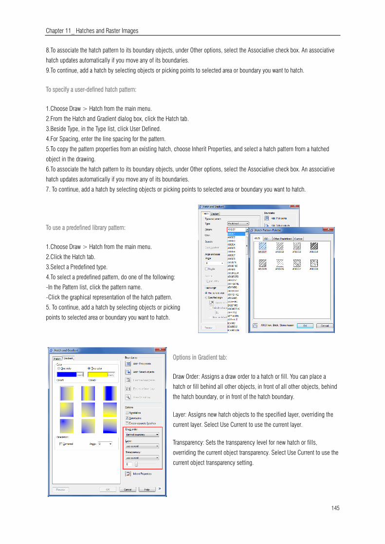
Chapter 11_ Hatches and Raster Images
145
8.To associate the hatch pattern to its boundary objects, under Other options, select the Associative check box. An associative
hatch updates automatically if you move any of its boundaries.
9.To continue, add a hatch by selecting objects or picking points to selected area or boundary you want to hatch.
To specify a user-defined hatch pattern:
1.Choose Draw > Hatch from the main menu.
2.From the Hatch and Gradient dialog box, click the Hatch tab.
3.Beside Type, in the Type list, click User Defined.
4.For Spacing, enter the line spacing for the pattern.
5.To copy the pattern properties from an existing hatch, choose Inherit Properties, and select a hatch pattern from a hatched
object in the drawing.
6.To associate the hatch pattern to its boundary objects, under Other options, select the Associative check box. An associative
hatch updates automatically if you move any of its boundaries.
7. To continue, add a hatch by selecting objects or picking points to selected area or boundary you want to hatch.
To use a predefined library pattern:
1.Choose Draw > Hatch from the main menu.
2.Click the Hatch tab.
3.Select a Predefined type.
4.To select a predefined pattern, do one of the following:
-In the Pattern list, click the pattern name.
-Click the graphical representation of the hatch pattern.
5. To continue, add a hatch by selecting objects or picking
points to selected area or boundary you want to hatch.
Options in Gradient tab:
Draw Order: Assigns a draw order to a hatch or fill. You can place a
hatch or fill behind all other objects, in front of all other objects, behind
the hatch boundary, or in front of the hatch boundary.
Layer: Assigns new hatch objects to the specified layer, overriding the
current layer. Select Use Current to use the current layer.
Transparency: Sets the transparency level for new hatch or fills,
overriding the current object transparency. Select Use Current to use the
current object transparency setting.
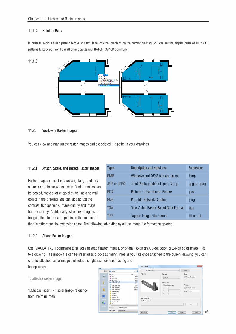
Chapter 11_ Hatches and Raster Images
146
11.1.4. Hatch to Back
In order to avoid a filling pattern blocks any text, label or other graphics on the current drawing, you can set the display order of all the fill
patterns to back position from all other objects with HATCHTOBACK command.
11.1.5.
11.2. Work with Raster Images
You can view and manipulate raster images and associated file paths in your drawings.
11.2.1. Attach, Scale, and Detach Raster Images
Raster images consist of a rectangular grid of small
squares or dots known as pixels. Raster images can
be copied, moved, or clipped as well as a normal
object in the drawing. You can also adjust the
contrast, transparency, image quality and image
frame visibility. Additionally, when inserting raster
images, the file format depends on the content of
the file rather than the extension name. The following table display all the image file formats supported:
11.2.2. Attach Raster Images
Use IMAGEATTACH command to select and attach raster images, or bitonal, 8-bit gray, 8-bit color, or 24-bit color image files
to a drawing. The image file can be inserted as blocks as many times as you like once attached to the current drawing, you can
clip the attached raster image and setup its lightness, contrast, fading and
transparency.
To attach a raster image:
1.Choose Insert > Raster Image reference
from the main menu.
Type: Description and versions: Extension:
BMP Windows and OS/2 bitmap format .bmp
JFIF or JPEG Joint Photographics Expert Group .jpg or .jpeg
PCX Picture PC Paintbrush Picture .pcx
PNG Portable Network Graphic .png
TGA True Vision Raster-Based Data Format .tga
TIFF Tagged Image File Format .tif or .tiff
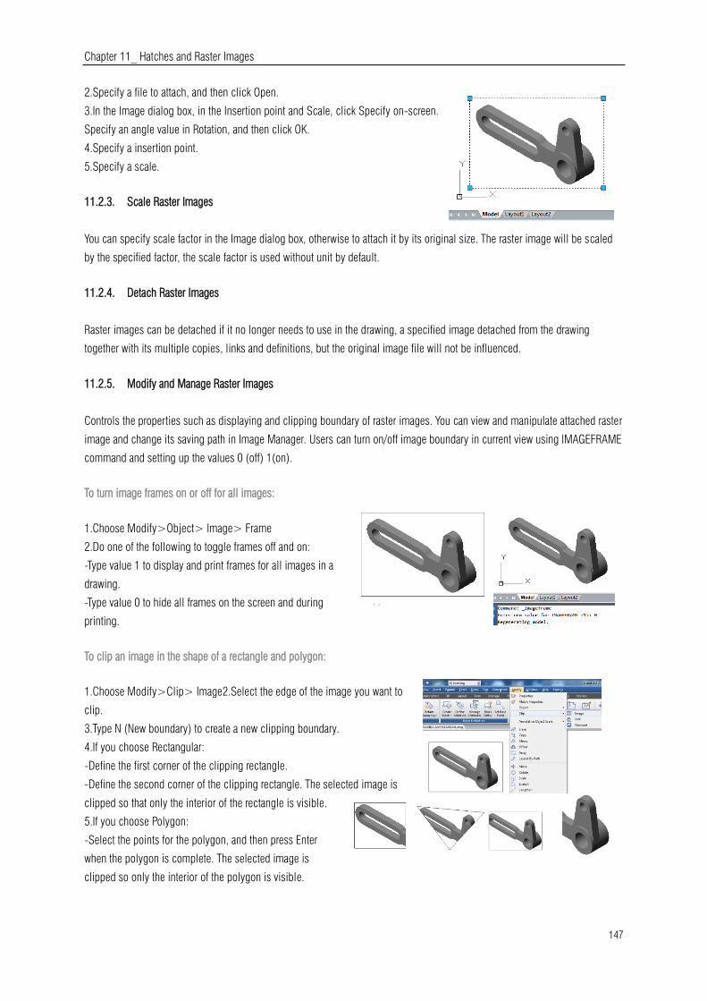
Chapter 11_ Hatches and Raster Images
147
2.Specify a file to attach, and then click Open.
3.In the Image dialog box, in the Insertion point and Scale, click Specify on-screen.
Specify an angle value in Rotation, and then click OK.
4.Specify a insertion point.
5.Specify a scale.
11.2.3. Scale Raster Images
You can specify scale factor in the Image dialog box, otherwise to attach it by its original size. The raster image will be scaled
by the specified factor, the scale factor is used without unit by default.
11.2.4. Detach Raster Images
Raster images can be detached if it no longer needs to use in the drawing, a specified image detached from the drawing
together with its multiple copies, links and definitions, but the original image file will not be influenced.
11.2.5. Modify and Manage Raster Images
Controls the properties such as displaying and clipping boundary of raster images. You can view and manipulate attached raster
image and change its saving path in Image Manager. Users can turn on/off image boundary in current view using IMAGEFRAME
command and setting up the values 0 (off) 1(on).
To turn image frames on or off for all images:
1.Choose Modify>Object> Image> Frame
2.Do one of the following to toggle frames off and on:
-Type value 1 to display and print frames for all images in a
drawing.
-Type value 0 to hide all frames on the screen and during
printing.
To clip an image in the shape of a rectangle and polygon:
1.Choose Modify>Clip> Image2.Select the edge of the image you want to
clip.
3.Type N (New boundary) to create a new clipping boundary.
4.If you choose Rectangular:
-Define the first corner of the clipping rectangle.
-Define the second corner of the clipping rectangle. The selected image is
clipped so that only the interior of the rectangle is visible.
5.If you choose Polygon:
-Select the points for the polygon, and then press Enter
when the polygon is complete. The selected image is
clipped so only the interior of the polygon is visible.
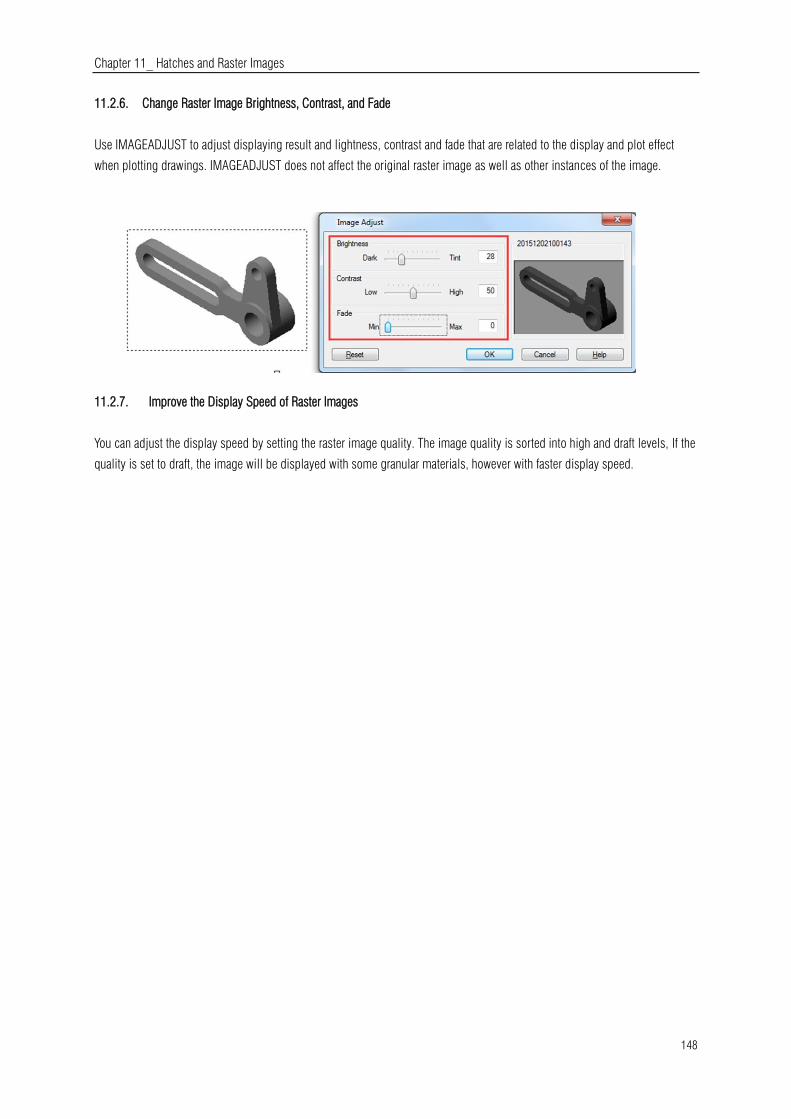
Chapter 11_ Hatches and Raster Images
148
11.2.6. Change Raster Image Brightness, Contrast, and Fade
Use IMAGEADJUST to adjust displaying result and lightness, contrast and fade that are related to the display and plot effect
when plotting drawings. IMAGEADJUST does not affect the original raster image as well as other instances of the image.
11.2.7. Improve the Display Speed of Raster Images
You can adjust the display speed by setting the raster image quality. The image quality is sorted into high and draft levels, If the
quality is set to draft, the image will be displayed with some granular materials, however with faster display speed.

Chapter 12_ Layout, Plot and Publish Drawing
149
12. Layout, Plot and Publish Drawings
12.1. Create Multiple-View Drawing Layouts
12.1.1. Overview of Layout
A layout represents a plotted page on which one or more model views are
displayed. GstarCAD provides two collateral working environments as Model
and Layout tab. You can create thematic models on Model tab. Multiple slides
of the model can be set in Layout tab. Use these general steps to prepare your
drawing for printing multiple layouts:
1. On the Model tab, create your drawing.
2. Create a new layout. You can use an existing Layout1 or Layout2 tab, or you can create
a new Layout tab.
3. Create at least one layout viewport on the Layout tab. Use each viewport to help control
which portion of the drawing prints and at what scale.
4. Specify additional settings for the layout, such as the scale of the drawing, print area, print style tables, and more.
5. Print or plot your drawing.
You can right click on Layout tab and select "New layout" to create a new layout, and also import layout from template. Options
on Shortcut menu are listed:
12.1.2. Work with Model Space and Paper Space
Model space is generally used for creating and editing drawings.
Preparations for plotting are usually working on paper space for the
drawings on layouts are close to the plotting effects.
Model space is an area in which you create two dimensional and three
dimensional objects based on either the World Coordinate System
(WCS) or a user coordinate system (UCS). The contents of paper space
represent the paper layout of your drawing. In this work area, you can
create and arrange different views of your model similar to the way you
arrange detail drawings or orthogonal views of a model on a sheet of paper.
Layout tab is enabled to make relevant plot settings. Paper space is provided
in each layout option, and you are allowed to create viewports and specify
page setup such as paper size, orientation and location that can be saved
together with the layout.
You can save and name the page setup and apply it to other layouts when setting pages. You can also create new layouts using
existing layout template file (DWT or DWG).
Click on the Model tab, you can view and edit objects in model space.
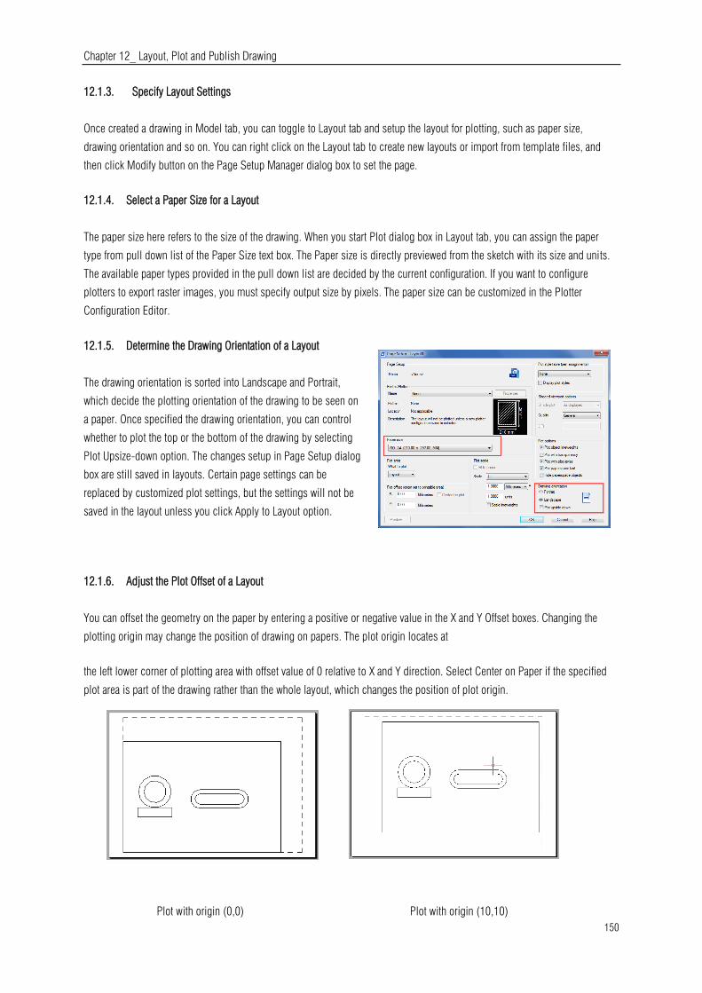
Chapter 12_ Layout, Plot and Publish Drawing
150
12.1.3. Specify Layout Settings
Once created a drawing in Model tab, you can toggle to Layout tab and setup the layout for plotting, such as paper size,
drawing orientation and so on. You can right click on the Layout tab to create new layouts or import from template files, and
then click Modify button on the Page Setup Manager dialog box to set the page.
12.1.4. Select a Paper Size for a Layout
The paper size here refers to the size of the drawing. When you start Plot dialog box in Layout tab, you can assign the paper
type from pull down list of the Paper Size text box. The Paper size is directly previewed from the sketch with its size and units.
The available paper types provided in the pull down list are decided by the current configuration. If you want to configure
plotters to export raster images, you must specify output size by pixels. The paper size can be customized in the Plotter
Configuration Editor.
12.1.5. Determine the Drawing Orientation of a Layout
The drawing orientation is sorted into Landscape and Portrait,
which decide the plotting orientation of the drawing to be seen on
a paper. Once specified the drawing orientation, you can control
whether to plot the top or the bottom of the drawing by selecting
Plot Upsize-down option. The changes setup in Page Setup dialog
box are still saved in layouts. Certain page settings can be
replaced by customized plot settings, but the settings will not be
saved in the layout unless you click Apply to Layout option.
12.1.6. Adjust the Plot Offset of a Layout
You can offset the geometry on the paper by entering a positive or negative value in the X and Y Offset boxes. Changing the
plotting origin may change the position of drawing on papers. The plot origin locates at
the left lower corner of plotting area with offset value of 0 relative to X and Y direction. Select Center on Paper if the specified
plot area is part of the drawing rather than the whole layout, which changes the position of plot origin.
Plot with origin (10,10) Plot with origin (0,0)
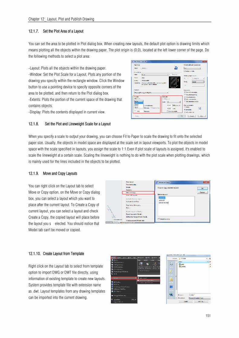
Chapter 12_ Layout, Plot and Publish Drawing
151
12.1.7. Set the Plot Area of a Layout
You can set the area to be plotted in Plot dialog box. When creating new layouts, the default plot option is drawing limits which
means plotting all the objects within the drawing paper. The plot origin is (0,0), located at the left lower corner of the page. Do
the following methods to select a plot area:
-Layout: Plots all the objects within the drawing paper.
-Window: Set the Plot Scale for a Layout, Plots any portion of the
drawing you specify within the rectangle window. Click the Window
button to use a pointing device to specify opposite corners of the
area to be plotted, and then return to the Plot dialog box.
-Extents: Plots the portion of the current space of the drawing that
contains objects.
-Display: Plots the contents displayed in current view.
12.1.8. Set the Plot and Lineweight Scale for a Layout
When you specify a scale to output your drawing, you can choose Fit to Paper to scale the drawing to fit onto the selected
paper size. Usually, the objects in model space are displayed at the scale set in layout viewports. To plot the objects in model
space with the scale specified in layouts, you assign the scale to 1:1.Even if plot scale of layouts is assigned, it's enabled to
scale the lineweight at a certain scale. Scaling the lineweight is nothing to do with the plot scale when plotting drawings, which
is mainly used for the lines included in the objects to be plotted.
12.1.9. Move and Copy Layouts
You can right click on the Layout tab to select
Move or Copy option, on the Move or Copy dialog
box, you can select a layout which you want to
place after the current layout. To Create a Copy of
current layout, you can select a layout and check
Create a Copy, the copied layout will place before
the layout you s elected. You should notice that
Model tab can't be moved or copied.
12.1.10. Create Layout from Template
Right click on the Layout tab to select from template
option to import DWG or DWT file directly, using
information of existing template to create new layouts.
System provides template file with extension name
as .dwt. Layout templates from any drawing templates
can be imported into the current drawing.

Chapter 12_ Layout, Plot and Publish Drawing
152
To create a new layout from an existing file:
1. Choose Insert>Layout>Layout from Template
2. In the dialog box, select the desired template file, and then click Open. In the Insert Layout(s) dialog box, select the layout(s)
you want to insert, and then click OK. You can choose multiple layouts by holding down Ctrl while selecting layout names.
12.1.11. Create and Modify Layout Viewports
On a Layout tab, you must create at least one layout viewport to see your model. Each layout viewport is created as a separate
entity that you can move, copy, or delete. Any changes you make in one layout viewport are immediately visible in the other
viewports (if the other layout viewports are displaying that portion of the drawing). Zooming or panning in the current viewport
affects only that viewport.
Create layout viewports:
1. On the command line, type MVIEW.
2. Type F (Fit), or create 2, 3 or 4 viewports by entering 2, 3 or
4 separately, or specify two opposing corners to create a
custom viewport.
3. Choose the viewport arrangement, typing H (Horizontal) or V
(Vertical).
4. Do one of the following:
-To arrange the viewports to fill the current graphic area, type F
(Fit)。-To fit the viewports within a bounding rectangle, specify
the corners of a rectangle.
You can create a single layout viewport, or you can divide the graphic area into many viewports arranged
[Horizontal/Vertical/Above/Below/Left/Right].
To modify layout viewport properties:
1. Click the border of the layout viewport whose
properties you want to modify.
2. Open the Properties palette through the menu
option "Tools >Palettes>Properties" or "Modify >
Properties".
3. In the Properties palette, select Standard Scale,
and then select a new scale from the list. The scale you choose is applied to the viewport.
Turn Layout Viewports On or Off:
1.Click the desired Layout tab.
2. Type MVIEW and then press Enter.
3. Type ON or OFF.

Chapter 12_ Layout, Plot and Publish Drawing
153
4. Select the edge of the layout viewport to turn on or off, then press Enter.
Create Non-rectangular layout viewports:
Use Object and Polygonal options of MVIEW to create irregular viewports,
Select Object option to convert objects created in paper space to viewports. While selecting
Polygonal option to draw irregular polylines including arcs and lines which are enabled to
either intersect or three vertexes at least, the polyline will be closed automatically.
12.2. Plot Drawings
When a drawing is completed, you can output it using several methods. You can plot the drawing on paper or create a file for
use with another application.
12.2.1. Plot Settings
When you create a drawing, you do most of your work on
the Model tab. At any time you can print your drawing to
see how it looks on paper. It's easy to startup printing,
and then later create layouts and custom print settings to
enhance your printed output.
To start printing:
1. Choose File > Plot from the main menu.
2. Set the printer and relevant parameters, and then click
OK.
12.2.2. Set Paper Size
You can assign the paper type from pull down list of the
Paper Size text box. If you want to setup paper size, you
should configure plotters first, all the available plotters are
both system plotters of Windows configured and non-system
driven.
To select a printer or plotter:
1. Choose File > Plot from the main menu.
2. From the Name list in Printer/Plotter area, select a printer or plotter you want to use, and then click OK.

Chapter 12_ Layout, Plot and Publish Drawing
154
12.2.3. Position the Drawing on the Paper
You can adjust the position of the drawing to be plotted on a paper before plotting.
To specify the print area origin:
1. If necessary, click the desired Layout tab or the Model tab.
2. Choose File > Plot from the main menu.
3. Do one of the following in the Plot Offset area:
-To center the specified print area on the printed
page, select Center the Plot check box.
-To specify an origin for the print area, type the X and Y coordinates.
4. Select OK, and then click Apply to Layout.
12.2.4. Set Drawing Orientation
The drawing orientation determines whether to plot a drawing portrait or landscape. If you
select Landscape, plots the drawing using the length edge as horizontal. While selecting
Portrait to plot the drawing using its minor edge as horizontal Changing, the drawing
orientation just like rotating the paper under the drawing. Meanwhile, selecting Plot
upsize-down to control whether to locate the drawing upsize-down on paper.
12.2.5. Set Plot Scale
Plot scale of the drawing can be specified directly from the Scale
pull-down list in Plot Scale area of Plot dialog box. You can also
choose User define to set desired plot scale, or choose Fit to Paper to
scale the drawing to fit onto the selected paper size. The plot scale
together with plot unit and drawing unit must be specified before
plotting. For example, if you select the paper size to mm, entering 1
under mm and 10 under Units blank produces a plotted drawing with
each plotted unit represents 10 actual millimeters.
To automatically scale the drawing for printing:
1. If necessary, click the desired Layout tab or the Model tab.
2. Choose File > Plot from the main menu.
3. To scale the drawing to fit on one printed page, in Plot Scale, click Fit to
Paper.
4. Select Apply to Layout and click OK.
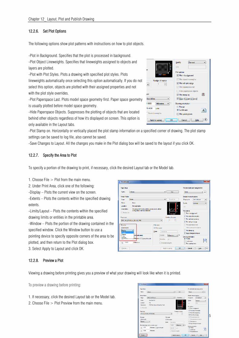
Chapter 12_ Layout, Plot and Publish Drawing
155
12.2.6. Set Plot Options
The following options show plot patterns with instructions on how to plot objects.
-Plot in Background. Specifies that the plot is processed in background.
-Plot Object Lineweights. Specifies that lineweights assigned to objects and
layers are plotted.
-Plot with Plot Styles. Plots a drawing with specified plot styles. Plots
lineweights automatically once selecting this option automatically. If you do not
select this option, objects are plotted with their assigned properties and not
with the plot style overrides.
-Plot Paperspace Last. Plots model space geometry first. Paper space geometry
is usually plotted before model space geometry.
-Hide Paperspace Objects. Suppresses the plotting of objects that are located
behind other objects regardless of how it's displayed on screen. This option is
only available in the Layout tabs.
-Plot Stamp on. Horizontally or vertically placed the plot stamp information on a specified corner of drawing. The plot stamp
settings can be saved to log file, also cannot be saved.
-Save Changes to Layout. All the changes you make in the Plot dialog box will be saved to the layout if you click OK.
12.2.7. Specify the Area to Plot
To specify a portion of the drawing to print, if necessary, click the desired Layout tab or the Model tab.
1. Choose File > Plot from the main menu.
2. Under Print Area, click one of the following:
-Display – Plots the current view on the screen.
-Extents – Plots the contents within the specified drawing
extents.
-Limits/Layout – Plots the contents within the specified
drawing limits or entities in the printable area.
-Window – Plots the portion of the drawing contained in the
specified window. Click the Window button to use a
pointing device to specify opposite corners of the area to be
plotted, and then return to the Plot dialog box.
3. Select Apply to Layout and click OK.
12.2.8. Preview a Plot
Viewing a drawing before printing gives you a preview of what your drawing will look like when it is printed.
To preview a drawing before printing:
1. If necessary, click the desired Layout tab or the Model tab.
2. Choose File > Plot Preview from the main menu.

Chapter 12_ Layout, Plot and Publish Drawing
156
3. Do one of the following:
-To print the drawing, click preview and click Plot on the top left corner of print preview.
-To return to the drawing, click the off button or press Esc.
12.2.9. Use Plot Styles
Plot styles help you control what your drawing looks like when it is printed. Because plot styles are saved in plot style tables,
which are files located on your computer, you can reuse them to help eliminate the need to reconfigure your print settings each
time you print a drawing. A drawing can use one type of plot style table at a time. There are two types of plot style tables:
-Color-dependent plot style tables (CTB) contain a collection of plot styles based on each of the
255 index colors available in a drawing.-Named plot style tables (STB) contain a collection of
plot styles that you define. They can vary regardless of color.
To assign plot style tables:1. If necessary, click the desired Layout tab, or click the Model tab.
2. Choose File > Plot from the main menu.
3. Under Plot Style Table (pen assignments), select a plot style table in the one of the following:
-None: Applies no plot style table. Objects plot according to their own properties.
-Monochrome: Plots all colors as black.
-New: Creates a new plot style table.
4. Select Save Changes to Layout, and then click Apply to Layout.
To Modify plot style tables:
1. Choose File > Plot from the main menu.
2. Under Plot Style Table (pen assignments), click the plot style table you want to
modify, and then click the button to display “Plot Style Table Editor”.
3. Click the General tab on Plot Style Table Editor, and then do any of the following:
-Enter a new plot style description.
-Select Apply global scale factor to non-ISO linetypes to apply the scale factor
-Enter a scale factor to apply to non-ISO linetypes used for any plot style in the
current plot style table.
4. Click the Form View tab, and then do any of the following:
-Make changes to a color-dependent plot style by selecting it in the Plot list, and
then make color, linetype, or lineweight changes for the plot style in Properties area.
Your changes are saved automatically for the selected plot style.
-Make changes to a named plot style by selecting it in the Plot list, and then make
color, linetype, or lineweight changes for the plot style in Properties area. Your
changes are saved automatically for the selected plot style.
-Add a new plot style by clicking Add Style. Enter a new name, and then click OK.
Select the options for the plot style. (Available for named plot styles only.)
-Delete a plot style by selecting it in the Plot list, and then click Delete Style. (Available for named plot styles only.)
5. Click OK.

Chapter 12_ Layout, Plot and Publish Drawing
157
12.2.10. Plot Files to Other Formats
Plot files have various formats. You can output drawings in any image formats with unique plotter driver.

Chapter 12_ Layout, Plot and Publish Drawing
158
12.2.11. Publish Drawings
Specifies drawing sheets that you can assemble, reorder, rename, copy, and save for publishing as a multi-sheet drawing set.
You can publish the drawing set to a DWF, DWFx, or PDF file or send it to the plotter named in the page setup for hardcopy
output or as a plot file. The following options are displayed in the Publish Dialog Box:
1. Load Sheet List Button: Displays
the Load Sheet List dialog box, in
which you can select a DSD file or a
BP3 (Batch Plot) file to load.
2. Save Sheet List Button: Displays
the Save List As dialog box, in which
you cansave the current list of
drawings as a DSD file.
3. Sheet List: Displays the current
drawing set (DSD) or batch plot (BP3)
file.
4. Publish to: Defines how to publish
the list of sheets. You can publish to
either a multi-sheet DWF, DWFx, or
PDF file.
5. Automatically load all open
drawings: When selected, the
contents of all open documents are
automatically loaded in the publish
list.
6. Add Sheets Button: Displays the
Select Drawings dialog box, in which
you can select drawings to add to the
list of drawing sheets.
7. Remove Sheets Button: Deletes the
selected drawing sheets from the list
of sheets.
8. Move Sheet Up Button: Moves the
selected drawing sheets up one
position in the list.
9. Move Sheet Down Button: Moves
the selected drawing sheets down one
position in the list.
10. Preview Button: Displays the
drawing as it will appear when plotted
on paper by executing
the PREVIEW command.

Chapter 12_ Layout, Plot and Publish Drawing
159
11. Sheet Name: Combines the
drawing name and the layout name
with a dash (-).
12. Page Setup/3D DWF:Displays the
named page setup for the sheet. You
can change the page setup by clicking
the page setup name and selecting
another page setup from the list
13. Status: Displays the status of the
sheet when it is loaded to the list of
sheets.
14/15.Show and select sheet details:
Displays and hides the Selected Sheet
Information and Selected Page Setup
Information areas.
16. Publish Options: Opens
the Publish Options dialog box, in
which you can specify options for
publishing.
17. Number of Copies: Specifies the
number of copies to publish.
18. Precision: Optimizes the dpi of
DWF, DWFx, and PDF files for your
field: manufacturing, architecture or
civil engineering.
19. Include Plot Stamp: Places a plot
stamp on a specified corner of each
drawing and logs it to a file.
20. Plot Stamp Settings: Displays
the Plot Stamp Dialog BoxPlot Stamp
Settings Dialog Box, in which you can
specify the information, such as
drawing name and plot scale that you
want applied to the plot stamp.
21. Publish in Background:Toggles
background publishing for the
selected sheets.
22. Send the Sheets to the Plotter in
Reverse Order: When selected, sends
sheets to the plotter in reverse of
default order. This option is available
only if the Plotter Named in Page
Setup option is selected.
23. Open in Viewer when Done: When
publishing completes, the DWF,
DWFx or PDF file will open in a viewer
application.
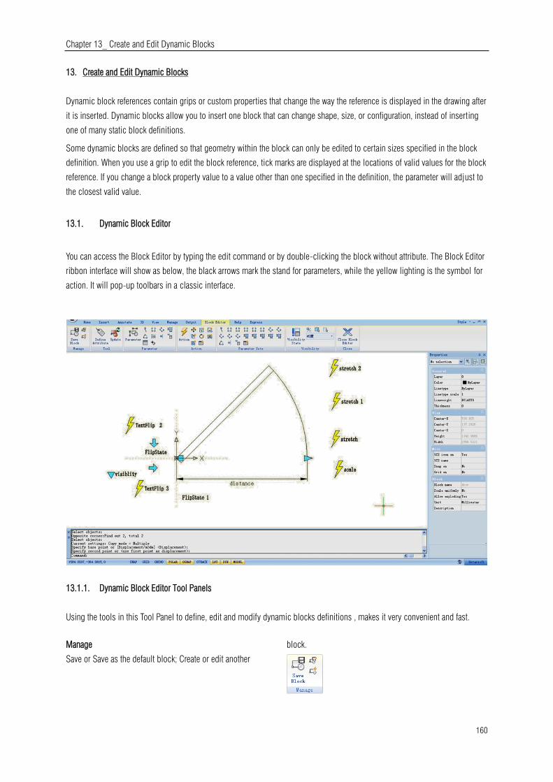
Chapter 13_ Create and Edit Dynamic Blocks
160
13. Create and Edit Dynamic Blocks
Dynamic block references contain grips or custom properties that change the way the reference is displayed in the drawing after
it is inserted. Dynamic blocks allow you to insert one block that can change shape, size, or configuration, instead of inserting
one of many static block definitions.
Some dynamic blocks are defined so that geometry within the block can only be edited to certain sizes specified in the block
definition. When you use a grip to edit the block reference, tick marks are displayed at the locations of valid values for the block
reference. If you change a block property value to a value other than one specified in the definition, the parameter will adjust to
the closest valid value.
13.1. Dynamic Block Editor
You can access the Block Editor by typing the edit command or by double-clicking the block without attribute. The Block Editor
ribbon interface will show as below, the black arrows mark the stand for parameters, while the yellow lighting is the symbol for
action. It will pop-up toolbars in a classic interface.
13.1.1. Dynamic Block Editor Tool Panels
Using the tools in this Tool Panel to define, edit and modify dynamic blocks definitions , makes it very convenient and fast.
Manage
Save or Save as the default block; Create or edit another
block.

Chapter 13_ Create and Edit Dynamic Blocks
161
Tool
Define, edit or update the block attribute.
Parameter
You can add parameters for Dynamic Blocks on this panel.
Action
You can add actions for Dynamic Blocks on this panel.
Parameter Sets
You can add the parameter set on this panel.
Visibility
This panel is specially used for Visibility editing.
Close
It is used to exit the Block Editor. Before exiting, some
commands like save or open etc. might not work.
13.1.2. Parameters
Define custom properties for the dynamic block by specifying positions, distances, and angles for geometry in the block. You
add parameters to a dynamic block definition in the Block Editor. In the Block Editor, parameters have an appearance similar to
dimensions. Parameters define custom properties for the block. Parameters also specify positions, distances, and angles for
geometry in the block reference. When you add a parameter to a dynamic block definition, the parameter defines one or more
custom properties for the block.
A dynamic block definition must contain at least one parameter. When a parameter is added to a dynamic block definition, grips
associated with key points of the parameter are automatically added. You must then add an action to the block definition and
associate the action with a parameter.
Parameters also define and constrain values that affect the dynamic block reference's behavior in a drawing. Some parameters
can have a fixed set of values, minimum and maximum values, or increment values. For example, a linear parameter used in a
window block may have the following fixed set of values: 10, 20, 30, and 40. When the block reference is inserted in a drawing,
you can only change the window to one of these values. Adding a value set to a parameter allows you to limit how the block
reference is manipulated in a drawing.
Point Parameter
Icon:
Command: BParameter→O
Defines an X and Y location in the drawing. A point
parameter can be associated with a move or stretch action.

Chapter 13_ Create and Edit Dynamic Blocks
162
Linear Parameter
Icon:
Command: BParameter→L
Shows the distance between two anchor points. Constrains
grip movement along a preset angle. A linear parameter can
be associated with a move, stretch, scale or array action.
Polar Parameter
Icon:
Command: BParameter→P
Shows the distance between two anchor points and displays
an angle value. You can use both grips and the Properties
palette to change both the distance value and the angle. A
polar parameter can be associated with a move, scale,
stretch, polar stretch, or array action.
XY Parameter
Icon:
Command: BParameter→X
Shows the X and Y distances from the base point of the
parameter. It can be associated with a move, scale, stretch,
or array action.
Rotation Parameter
Icon:
Command: BParameter→R
Defines an angle. The rotation angle can be in any value, or
be defined in a range or a specified value.
Alignment Parameter
Icon:
Command: BParameter→A
Defines an X and Y location and an angle. An alignment
parameter always applies to the entire block and needs no
action associated with it. An alignment parameter allows the
block reference to automatically rotate around a point to
align with another object in the drawing. An alignment
parameter affects the rotation property of the block.
Flip Parameter
Icon:
Command: BParameter→F
A flip parameter flips objects. You can associate a flip
parameter with a flip action.
Visibility Parameter
Icon:
Command: BParameter→V
Controls the visibility of objects in the block. A visibility
parameter always applies to the entire block and needs no
action associated with it. In a drawing, you click the grip to
display a list of visibility states available for the block
reference.
Lookup Parameter
Icon:
Command: BParameter→K
Defines a custom property that you can specify or set to
evaluate a value from a list or table you define. It can be
associated with a single lookup grip. In the block reference,
you click the grip to display a list of available values. You
can associate a lookup parameter with a lookup action.
Base Point Parameter
Icon:
Command: BParameter→B
Defines a base point for the dynamic block reference relative
to the geometry in the block. Cannot be associated with any
actions, but can belong to an action's selection set.

Chapter 13_ Create and Edit Dynamic Blocks
163
13.1.3. Actions
Actions define how the geometry of a dynamic block reference will move or change when the custom properties of the block
reference are manipulated in a drawing.
Move
ICommand:BActionTool→M
A move action causes objects to move a specified distance
and angle such as a point, a linear, a polar, an XY parameter,
etc, moves all objects in a selection set in a/any direction.
Scale
Command:BActionTool→S
A scale action such as a linear, a polar, an XY parameter, and
so on, scales the selected objects in the direction of the
parameter. Users can manipulate the grips in different way
by changing the properties and values in the Properties
palette.
Stretch
Command:BActionTool→TA stretch action causes objects to
move and stretch a specified distance in a specified location.
A stretch action associated with a point, a linear, a polar, an
XY parameter, etc.
Polar Stretch
Command:BParameter→PIn A
polar stretch action rotates, moves, and stretches objects a
specified angle and distance when the key point on the
associated polar parameter is changed through a grip or the
Properties palette.A polar stretch action can only be applied
to a polar parameter.
Rotate
Command:BActionTool→P
A rotate action is always associated with a rotate parameter.
Selected objects can be rotated freely, or the way the grips
are manipulated is different in the Properties palette.
Flip
Command:BActionTool→F
A flip action is always associated with a flip parameter.
Array
Command:BActionTool→A
An array action is associated with a linear, a polar, an XY
parameter, etc, copies and arrays selected objects in
different way.
Lookup
Command:BActionTool→L
A lookup action can only be associated with a lookup
parameter.
13.1.4. The General Steps of Creating a Dynamic Block Definition
In order to get a Dynamic Block Definition, improve block editing efficiency and avoid repeating modifications, we can create
Dynamic Block by the following steps.
Step1: Planning
Before creating Dynamic Block, it is essential to plan Dynamic Block, plan the functions, appearance, the method of drawing
and required Parameter(s) and Action(s) which are needed to achieve prospective functions.
Step2: Draw geometric figure
The included basic pixel during Dynamic drawing, of course, you can draw these pixel in Block Editor.
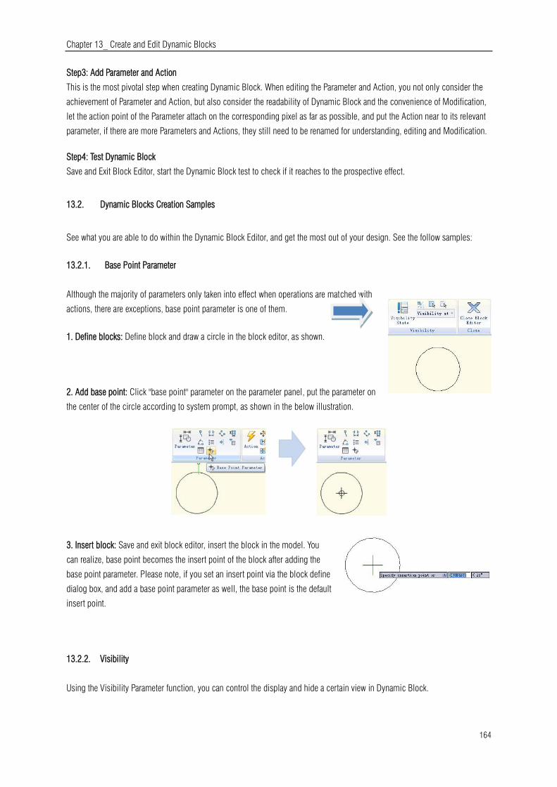
Chapter 13_ Create and Edit Dynamic Blocks
164
Step3: Add Parameter and Action
This is the most pivotal step when creating Dynamic Block. When editing the Parameter and Action, you not only consider the
achievement of Parameter and Action, but also consider the readability of Dynamic Block and the convenience of Modification,
let the action point of the Parameter attach on the corresponding pixel as far as possible, and put the Action near to its relevant
parameter, if there are more Parameters and Actions, they still need to be renamed for understanding, editing and Modification.
Step4: Test Dynamic Block
Save and Exit Block Editor, start the Dynamic Block test to check if it reaches to the prospective effect.
13.2. Dynamic Blocks Creation Samples
See what you are able to do within the Dynamic Block Editor, and get the most out of your design. See the follow samples:
13.2.1. Base Point Parameter
Although the majority of parameters only taken into effect when operations are matched with
actions, there are exceptions, base point parameter is one of them.
1. Define blocks: Define block and draw a circle in the block editor, as shown.
2. Add base point: Click "base point" parameter on the parameter panel, put the parameter on
the center of the circle according to system prompt, as shown in the below illustration.
3. Insert block: Save and exit block editor, insert the block in the model. You
can realize, base point becomes the insert point of the block after adding the
base point parameter. Please note, if you set an insert point via the block define
dialog box, and add a base point parameter as well, the base point is the default
insert point.
13.2.2. Visibility
Using the Visibility Parameter function, you can control the display and hide a certain view in Dynamic Block.

Chapter 13_ Create and Edit Dynamic Blocks
165
1. Prepare view: Prepare a three cars view and define as block.
2. Add Parameter of Visibility: Enter into Block Editor by Double-clicking the Block or right- click the menu, click the button
Visibility of Parameter in the Parameter panel, appoint the position of the Parameter according to the system prompt, as shown
below.
3. Edit the states of Visibility: Double click the button Visibility, the Visibility States dialog box will be displayed. In the dialog
box, you can rename, new and remove the Visibility States. In order to control the visibility of the three cars view in this example,
we click on new for the three Visibility States as shown in the following picture.
Click the following button as shown in the picture and choose roadster in the pull down menu.
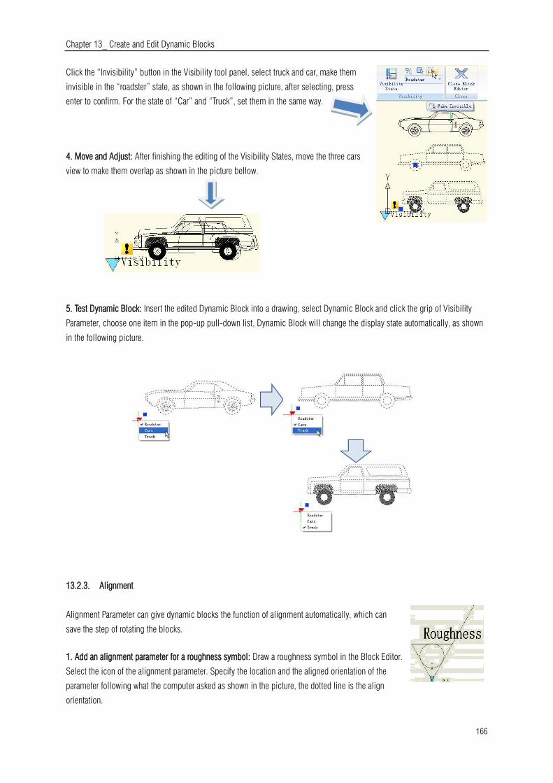
Chapter 13_ Create and Edit Dynamic Blocks
166
Click the “Invisibility” button in the Visibility tool panel, select truck and car, make them
invisible in the “roadster” state, as shown in the following picture, after selecting, press
enter to confirm. For the state of “Car” and “Truck”, set them in the same way.
4. Move and Adjust: After finishing the editing of the Visibility States, move the three cars
view to make them overlap as shown in the picture bellow.
5. Test Dynamic Block: Insert the edited Dynamic Block into a drawing, select Dynamic Block and click the grip of Visibility
Parameter, choose one item in the pop-up pull-down list, Dynamic Block will change the display state automatically, as shown
in the following picture.
13.2.3. Alignment
Alignment Parameter can give dynamic blocks the function of alignment automatically, which can
save the step of rotating the blocks.
1. Add an alignment parameter for a roughness symbol: Draw a roughness symbol in the Block Editor.
Select the icon of the alignment parameter. Specify the location and the aligned orientation of the
parameter following what the computer asked as shown in the picture, the dotted line is the align
orientation.

Chapter 13_ Create and Edit Dynamic Blocks
167
2. Test the dynamic block: Insert the roughness dynamic
blocks, move the align grips, the symbol will align with
the interface of the dimensions, as shown pin the picture
below.
Flip: When you use the "roughness symbol block" to label the spare parts, the symbol is sometimes already in the right position,
however, the characters' direction is not right. We need to add the "character flip" function to receive the correct label.
1. Add flip parameter: Click the "flip" parameter button, add the flip parameter
according to prompt, as shown in the picture.
2. Add flip action: Click the flip action button on the action panel, match
parameter and object for the action. Herein, we choose "roughness" as the object, and position the action button, as shown in
below picture.
Use the same method to add a
pair of flip parameter and action
of the vertical direction, as
shown:
13.2.4. Point Movement
1. Draw a drawing: Draw a drawing and define it as a block.
2. Add point parameter: Click point parameter on the tool bar, define the parameter
position according to prompt, as shown in the picture.
3. Add move action: Click move action button on action panel, match parameter and object for the action, and define the
position. The position of action label does not affect the effect of the dynamic block, however, for the sake of beauty&
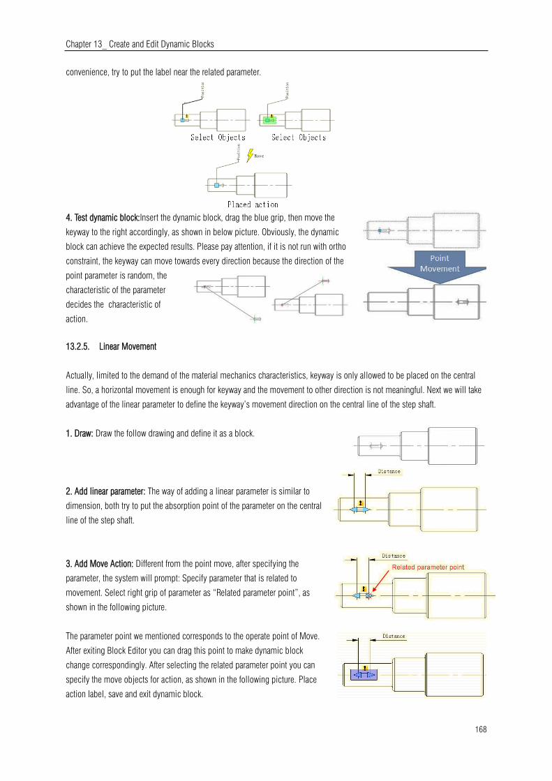
Chapter 13_ Create and Edit Dynamic Blocks
168
convenience, try to put the label near the related parameter.
4. Test dynamic block:Insert the dynamic block, drag the blue grip, then move the
keyway to the right accordingly, as shown in below picture. Obviously, the dynamic
block can achieve the expected results. Please pay attention, if it is not run with ortho
constraint, the keyway can move towards every direction because the direction of the
point parameter is random, the
characteristic of the parameter
decides the characteristic of
action.
13.2.5. Linear Movement
Actually, limited to the demand of the material mechanics characteristics, keyway is only allowed to be placed on the central
line. So, a horizontal movement is enough for keyway and the movement to other direction is not meaningful. Next we will take
advantage of the linear parameter to define the keyway’s movement direction on the central line of the step shaft.
1. Draw: Draw the follow drawing and define it as a block.
2. Add linear parameter: The way of adding a linear parameter is similar to
dimension, both try to put the absorption point of the parameter on the central
line of the step shaft.
3. Add Move Action: Different from the point move, after specifying the
parameter, the system will prompt: Specify parameter that is related to
movement. Select right grip of parameter as “Related parameter point”, as
shown in the following picture.
The parameter point we mentioned corresponds to the operate point of Move.
After exiting Block Editor you can drag this point to make dynamic block
change correspondingly. After selecting the related parameter point you can
specify the move objects for action, as shown in the following picture. Place
action label, save and exit dynamic block.

Chapter 13_ Create and Edit Dynamic Blocks
169
4 .Testing Dynamic Block: Select dynamic block and drag the right grip of the
parameter. Meanwhile, no matter how the cursor moves, the keyway is limited
to the central line of the step shaft. That is to say with the limitation of the
linear parameter, the dynamic block can only move along the direction
specified by the linear parameter.
13.2.6. Number of Grips
In the Block Editor, select the linear parameters, change
the number of grips to “1” in the properties panel.
Save and exit the Block Editor, choose the Dynamic Block, you will
find that one grip has disappeared. In fact, after changing the number
of grips from “2” to “1”, the first thing that disappeared was the basic
grip of parameters, namely the first point when adding parameters.
13.2.7. Angle Offset
Open Block Editor, choose the Angle offset from 0°to 30°in
the action property, save and exit the block editor
Select the Dynamic Block and then move the right side grip. You will find it
can only move in the direction of 30°as it is shown in the follow picture. The
direction of action can change according to the Angle Offset.
13.2.8. Linear Stretch
During a mechanical design, we often need to change the position as well as the dimension of the keyway. In this section, we
will add Linear Tensile function for the keyway on the step shaft.
1. Add linear parameter:
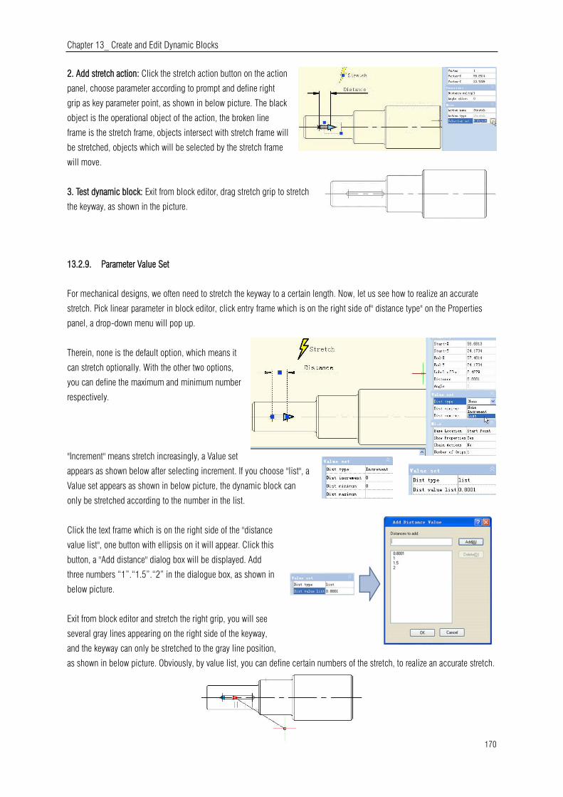
Chapter 13_ Create and Edit Dynamic Blocks
170
2. Add stretch action: Click the stretch action button on the action
panel, choose parameter according to prompt and define right
grip as key parameter point, as shown in below picture. The black
object is the operational object of the action, the broken line
frame is the stretch frame, objects intersect with stretch frame will
be stretched, objects which will be selected by the stretch frame
will move.
3. Test dynamic block: Exit from block editor, drag stretch grip to stretch
the keyway, as shown in the picture.
13.2.9. Parameter Value Set
For mechanical designs, we often need to stretch the keyway to a certain length. Now, let us see how to realize an accurate
stretch. Pick linear parameter in block editor, click entry frame which is on the right side of" distance type" on the Properties
panel, a drop-down menu will pop up.
Therein, none is the default option, which means it
can stretch optionally. With the other two options,
you can define the maximum and minimum number
respectively.
"Increment" means stretch increasingly, a Value set
appears as shown below after selecting increment. If you choose "list", a
Value set appears as shown in below picture, the dynamic block can
only be stretched according to the number in the list.
Click the text frame which is on the right side of the "distance
value list", one button with ellipsis on it will appear. Click this
button, a "Add distance" dialog box will be displayed. Add
three numbers “1”.“1.5”.“2” in the dialogue box, as shown in
below picture.
Exit from block editor and stretch the right grip, you will see
several gray lines appearing on the right side of the keyway,
and the keyway can only be stretched to the gray line position,
as shown in below picture. Obviously, by value list, you can define certain numbers of the stretch, to realize an accurate stretch.

Chapter 13_ Create and Edit Dynamic Blocks
171
13.2.10. Symmetrical Stretch
There is an easy way to realize the two-way stretch which is adding
two actions of stretch. Though it can realize a two-way stretch, the
action of stretch is independent. The parameter needs some additional
setup to realize the two-way symmetrical stretch.
-First, add two stretch actions for parameter, and select the two grips
of the two parameters as the relevant point of each action.
-Second, in the misc, modify the base location from "Start Point" to "Mid Point", like shown in the picture below. Save and exit
the block editor.
For the convenience of watching the effect, we drew a vertical center line in the middle of
the keyway, and then stretched the grip to the left side of the keyway or the right side, as
shown in the picture below. As the grips are moving, the two-way symmetrical stretch is
realized.
13.2.11. Distance Multiplier
Take the step shaft as an example, if we stretch the left part of the step shaft and the
keyway still is at the center point of the smaller diameter shaft after stretching. Then, we
use the “Distance Multiplier” property of action to achieve the aim.
1. Add linear parameter and stretch action for step shaft:
Hide the right grip of the parameter point, the action stretch
box is as in the following picture, the bolded object is the
action operation object.
2. Add Move Action for keyway: Select the left grip of the
linear parameter when moving, stretching the related
parameter points. Move the objects of action and select the
whole keyway, as in the following picture.
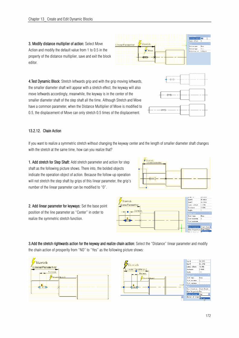
Chapter 13_ Create and Edit Dynamic Blocks
172
3. Modify distance multiplier of action: Select Move
Action and modify the default value from 1 to 0.5 in the
property of the distance multiplier, save and exit the block
editor.
4.Test Dynamic Block: Stretch leftwards grip and with the grip moving leftwards,
the smaller diameter shaft will appear with a stretch effect, the keyway will also
move leftwards accordingly, meanwhile, the keyway is in the center of the
smaller diameter shaft of the step shaft all the time. Although Stretch and Move
have a common parameter, when the Distance Multiplier of Move is modified to
0.5, the displacement of Move can only stretch 0.5 times of the displacement.
13.2.12. Chain Action
If you want to realize a symmetric stretch without changing the keyway center and the length of smaller diameter shaft changes
with the stretch at the same time, how can you realize that?
1. Add stretch for Step Shaft: Add stretch parameter and action for step
shaft as the following picture shows. There into, the bolded objects
indicate the operation object of action. Because the follow-up operation
will not stretch the step shaft by grips of this linear parameter, the grip’s
number of the linear parameter can be modified to “0”.
2. Add linear parameter for keyways: Set the base point
position of the line parameter as “Center” in order to
realize the symmetric stretch function.
3.Add the stretch rightwards action for the keyway and realize chain action: Select the “Distance” linear parameter and modify
the chain action of prosperity from “NO” to “Yes” as the following picture shows:
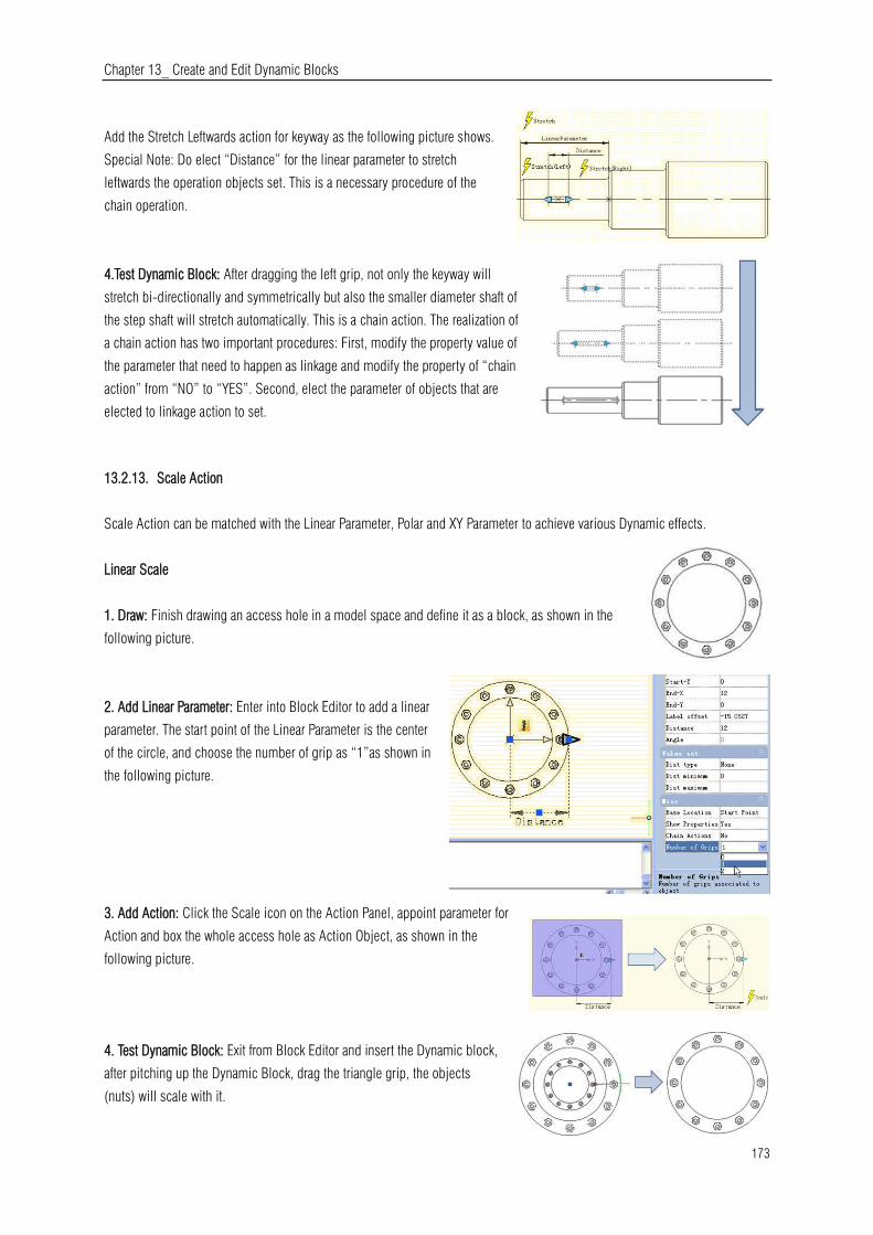
Chapter 13_ Create and Edit Dynamic Blocks
173
Add the Stretch Leftwards action for keyway as the following picture shows.
Special Note: Do elect “Distance” for the linear parameter to stretch
leftwards the operation objects set. This is a necessary procedure of the
chain operation.
4.Test Dynamic Block: After dragging the left grip, not only the keyway will
stretch bi-directionally and symmetrically but also the smaller diameter shaft of
the step shaft will stretch automatically. This is a chain action. The realization of
a chain action has two important procedures: First, modify the property value of
the parameter that need to happen as linkage and modify the property of “chain
action” from “NO” to “YES”. Second, elect the parameter of objects that are
elected to linkage action to set.
13.2.13. Scale Action
Scale Action can be matched with the Linear Parameter, Polar and XY Parameter to achieve various Dynamic effects.
Linear Scale
1. Draw: Finish drawing an access hole in a model space and define it as a block, as shown in the
following picture.
2. Add Linear Parameter: Enter into Block Editor to add a linear
parameter. The start point of the Linear Parameter is the center
of the circle, and choose the number of grip as “1”as shown in
the following picture.
3. Add Action: Click the Scale icon on the Action Panel, appoint parameter for
Action and box the whole access hole as Action Object, as shown in the
following picture.
4. Test Dynamic Block: Exit from Block Editor and insert the Dynamic block,
after pitching up the Dynamic Block, drag the triangle grip, the objects
(nuts) will scale with it.
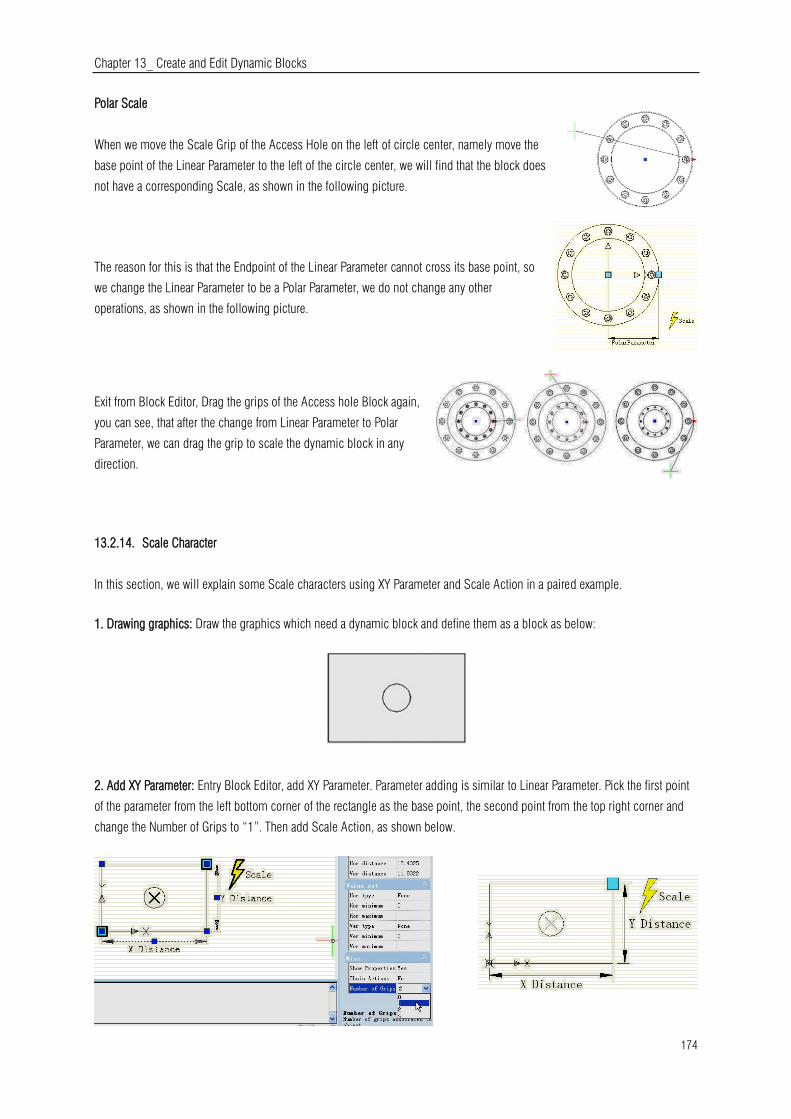
Chapter 13_ Create and Edit Dynamic Blocks
174
Polar Scale
When we move the Scale Grip of the Access Hole on the left of circle center, namely move the
base point of the Linear Parameter to the left of the circle center, we will find that the block does
not have a corresponding Scale, as shown in the following picture.
The reason for this is that the Endpoint of the Linear Parameter cannot cross its base point, so
we change the Linear Parameter to be a Polar Parameter, we do not change any other
operations, as shown in the following picture.
Exit from Block Editor, Drag the grips of the Access hole Block again,
you can see, that after the change from Linear Parameter to Polar
Parameter, we can drag the grip to scale the dynamic block in any
direction.
13.2.14. Scale Character
In this section, we will explain some Scale characters using XY Parameter and Scale Action in a paired example.
1. Drawing graphics: Draw the graphics which need a dynamic block and define them as a block as below:
2. Add XY Parameter: Entry Block Editor, add XY Parameter. Parameter adding is similar to Linear Parameter. Pick the first point
of the parameter from the left bottom corner of the rectangle as the base point, the second point from the top right corner and
change the Number of Grips to “1”. Then add Scale Action, as shown below.

Chapter 13_ Create and Edit Dynamic Blocks
175
3. Test the Dynamic Block: After exiting the Block Editor, drag the grip of the top right
corner of the rectangle, you can see the whole dynamic block is scaling as the grip is
moving. It is easy to find that both the circle and the rectangle scale by the base point
of the XY Parameter.
5. Modify Action Base: Modify Base type: go back to Editor, select Scale Action and change the default “Dependent” to
“Independent”.
Specify new base: Single click the right input box of “Base-X” and
“Base-Y”, you can manually input the coordinate value or you can
single click the small button with ellipsis dots on the right of the
input box and snap the base point, as shown:
Specify the base point by crosshair and the circle center as base point. After
exiting Block Editor, scale the dynamic block. After modifying Base type and
position, the scale center of the dynamic block changes from the XY Parameter
base point to the new specified base point (center of the circle).
6. Scale Type: There is “Scale Type” in the Scale Action
Properties. The default value is “XY Scale”. If you choose
“XY Scale”, the dynamic block scales whenever the scale
grip moves to X axis or Y axis. If you choose “X Scale”, it
scales only when the grip of the scale moves to X axis.
Same, when you choose “Y Scale”.
13.2.15. Rotation
In this section, we are going to use a rotation parameter and rotate action to add a dynamic rotate function
to view index symbols (English system) which are frequently used in architectural drawings.

Chapter 13_ Create and Edit Dynamic Blocks
176
1. Draw a drawing: Draw a view index symbol and define as a block, as shown in below picture. Please define view number and
drawing number as attribute text, so as to revise whenever you want.
2. Add rotation parameter: Pick the center of the circle as the first point of the parameter, system default it as the rotation point,
set angle type as "increment", and define its number as 15 degree, as shown below.
3. Add rotate action: Click the rotation action
button on the action panel, match parameter,
object and position for the action and select the
whole index symbol as the object of the action.
4. Test dynamic block: Exit from block editor and insert the block,
drag rotation grip to reach the effect of rotation, as shown in below
picture.
13.2.16. Polar Stretch
We use the Polar Stretch function of Dynamic Blocks to draw the section symbol in this section.
1. Draw, Mirror and Define as a Block: The follow drawing includes the attribute text which can be modified as you need. Then
mirror this drawing and define the mirrored object as a block.
2. Add action and parameter for the attribute text: Add Point
Parameter and Move Action for text and change the Chain
Action to “Yes” .It is ready for next step to create Chain
Action for Polar Stretch Action.

Chapter 13_ Create and Edit Dynamic Blocks
177
3. Add Polar Parameter and Action: Add Polar Parameter whose first point
should be the center of the section symbol. This point will be the rotation
center of the Polar Parameter. Follow the instructions below:
1. Pick the right grip of the Polar Parameter as an associated parameter point and specify the Stretch box (Fig. 3.1).
2. Select objects to stretch and the “position” Point Parameter together, which can accomplish that the text and section symbol
are moving together (Fig. 3.2).
3. Specify objects which rotate only for Polar Stretch Action (Fig 3.3).
4. Specify Action symbol location (Fig 3.4)
5. Repeat the above steps to add the same parameter and action order for the left part.
Fig 3.1 Fig 3.2
Fig 3.3 Fig 3.4
It is better if you hide the grips which are not associated with the Polar Stretch Parameter as below:
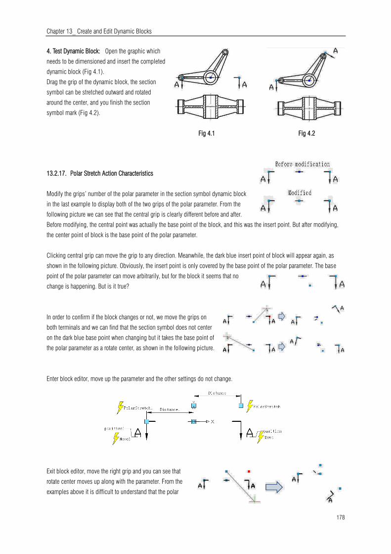
Chapter 13_ Create and Edit Dynamic Blocks
178
4. Test Dynamic Block: Open the graphic which
needs to be dimensioned and insert the completed
dynamic block (Fig 4.1).
Drag the grip of the dynamic block, the section
symbol can be stretched outward and rotated
around the center, and you finish the section
symbol mark (Fig 4.2).
Fig 4.1 Fig 4.2
13.2.17. Polar Stretch Action Characteristics
Modify the grips’ number of the polar parameter in the section symbol dynamic block
in the last example to display both of the two grips of the polar parameter. From the
following picture we can see that the central grip is clearly different before and after.
Before modifying, the central point was actually the base point of the block, and this was the insert point. But after modifying,
the center point of block is the base point of the polar parameter.
Clicking central grip can move the grip to any direction. Meanwhile, the dark blue insert point of block will appear again, as
shown in the following picture. Obviously, the insert point is only covered by the base point of the polar parameter. The base
point of the polar parameter can move arbitrarily, but for the block it seems that no
change is happening. But is it true?
In order to confirm if the block changes or not, we move the grips on
both terminals and we can find that the section symbol does not center
on the dark blue base point when changing but it takes the base point of
the polar parameter as a rotate center, as shown in the following picture.
Enter block editor, move up the parameter and the other settings do not change.
Exit block editor, move the right grip and you can see that
rotate center moves up along with the parameter. From the
examples above it is difficult to understand that the polar
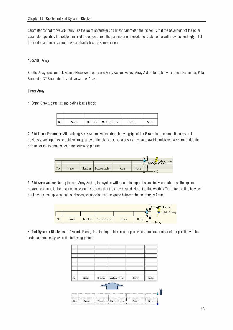
Chapter 13_ Create and Edit Dynamic Blocks
179
parameter cannot move arbitrarily like the point parameter and linear parameter, the reason is that the base point of the polar
parameter specifies the rotate center of the object, once the parameter is moved, the rotate center will move accordingly. That
the rotate parameter cannot move arbitrarily has the same reason.
13.2.18. Array
For the Array function of Dynamic Block we need to use Array Action, we use Array Action to match with Linear Parameter, Polar
Parameter, XY Parameter to achieve various Arrays.
Linear Array
1. Draw: Draw a parts list and define it as a block.
2. Add Linear Parameter: After adding Array Action, we can drag the two grips of the Parameter to make a list array, but
obviously, we hope just to achieve an up array of the blank bar, not a down array, so to avoid a mistakes, we should hide the
grip under the Parameter, as in the following picture.
3. Add Array Action: During the add Array Action, the system will require to appoint space between columns. The space
between columns is the distance between the objects that the array created. Here, the line width is 7mm, for the line between
the lines a close up array can be chosen, we appoint that the space between the columns is 7mm.
4. Test Dynamic Block: Insert Dynamic Block, drag the top right corner grip upwards, the line number of the part list will be
added automatically, as in the following picture.
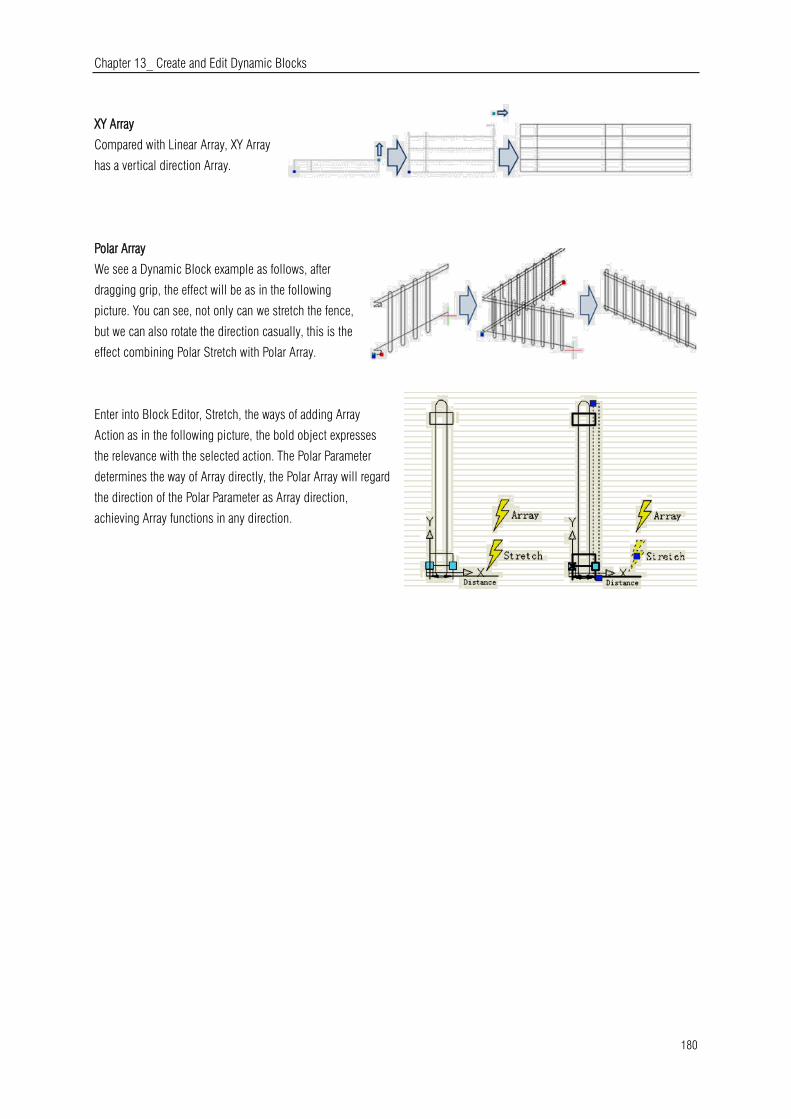
Chapter 13_ Create and Edit Dynamic Blocks
180
XY Array
Compared with Linear Array, XY Array
has a vertical direction Array.
Polar Array
We see a Dynamic Block example as follows, after
dragging grip, the effect will be as in the following
picture. You can see, not only can we stretch the fence,
but we can also rotate the direction casually, this is the
effect combining Polar Stretch with Polar Array.
Enter into Block Editor, Stretch, the ways of adding Array
Action as in the following picture, the bold object expresses
the relevance with the selected action. The Polar Parameter
determines the way of Array directly, the Polar Array will regard
the direction of the Polar Parameter as Array direction,
achieving Array functions in any direction.

Chapter 14_ Share Data between Applications
181
14. Share Date between Applications
14.1. Net Framework Support
.NET API enables you to manipulate the application and drawing files programmatically with libraries that are exposed and can
be accessed by many different programming languages such as VB.NET、C# and Managed C++.etc. Users are able to
automate tasks such as creating and modifying objects stored in the database of a drawing file or change the contents of a
customization file.
14.2. Cloud Storage
Collaborative capability between different fields like design, engineering, and project team work together efficiently thanks to
cloud storage supported in this version. With cloud storage, you can synchronize your drawing files and custom settings.
Drawing files synchronous
After register a cloud account, view and share data in the cloud is available. Users can upload or download drawings from cloud
or even create a category to implement drawing synchronous just using desktop and mobile device or tablet PC to operate.
Custom settings synchronous
There are several settings you can customize according to your need such as interface settings, usage habits, object definitions
(font, linetype, hatches and so on). The settings can be saved to local disk or cloud server, which is ease to recover drawing
settings when reinstall the software that can be shared to other members of your project team.
14.2.1. Cloud Settings
Within Options dialog box, under Cloud Storage Sync Settings tab you will see the follow options before connecting to a cloud
driver:
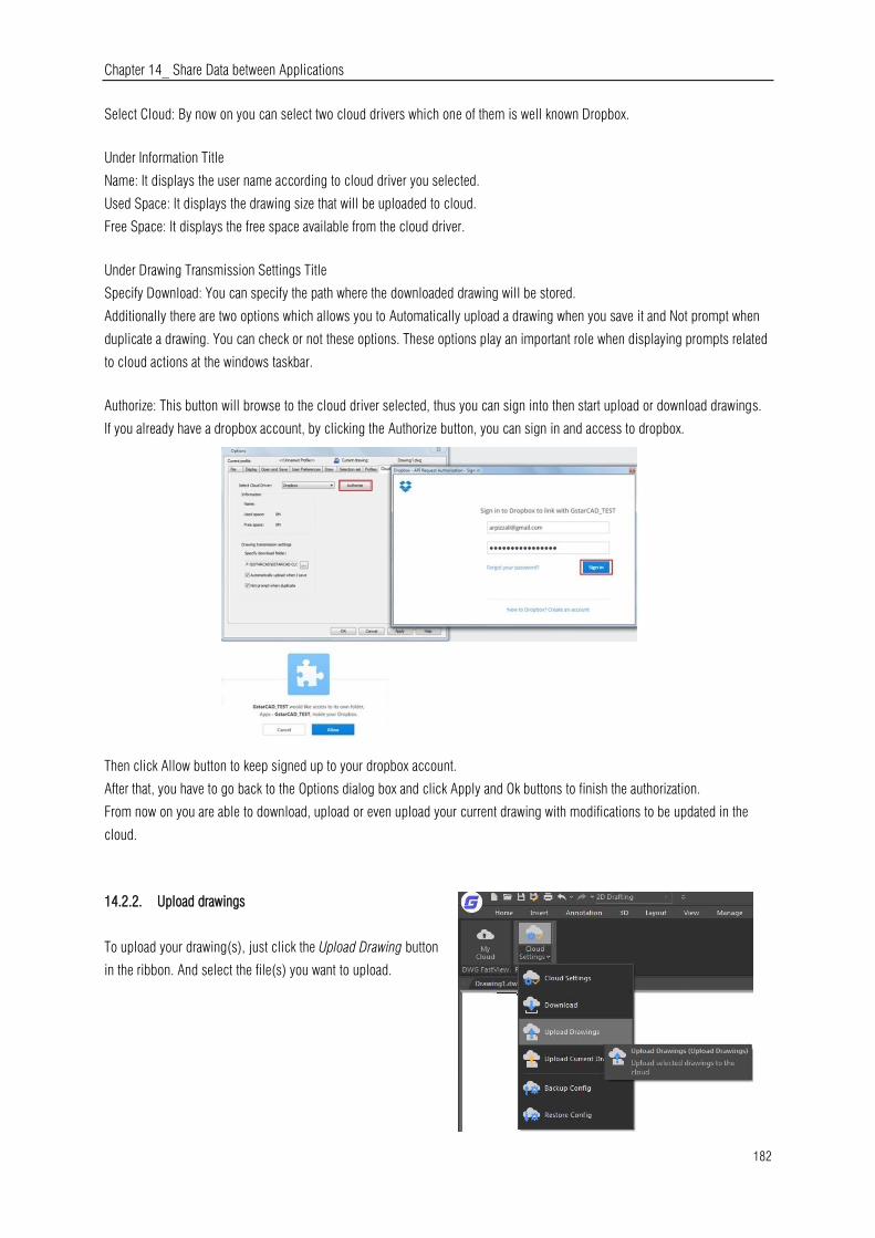
Chapter 14_ Share Data between Applications
182
Select Cloud: By now on you can select two cloud drivers which one of them is well known Dropbox.
Under Information Title
Name: It displays the user name according to cloud driver you selected.
Used Space: It displays the drawing size that will be uploaded to cloud.
Free Space: It displays the free space available from the cloud driver.
Under Drawing Transmission Settings Title
Specify Download: You can specify the path where the downloaded drawing will be stored.
Additionally there are two options which allows you to Automatically upload a drawing when you save it and Not prompt when
duplicate a drawing. You can check or not these options. These options play an important role when displaying prompts related
to cloud actions at the windows taskbar.
Authorize: This button will browse to the cloud driver selected, thus you can sign into then start upload or download drawings.
If you already have a dropbox account, by clicking the Authorize button, you can sign in and access to dropbox.
Then click Allow button to keep signed up to your dropbox account.
After that, you have to go back to the Options dialog box and click Apply and Ok buttons to finish the authorization.
From now on you are able to download, upload or even upload your current drawing with modifications to be updated in the
cloud.
14.2.2. Upload drawings
To upload your drawing(s), just click the Upload Drawing button
in the ribbon. And select the file(s) you want to upload.

Chapter 14_ Share Data between Applications
183
Then a message will pop up at the windows taskbar telling you that the upload
files has been added to the task queue.
Right away, the Select Folder dialog box will pop. You can Create Folder to
storage you drawing. This reference folder will be created in the cloud directly.
Then press Ok button.
At the windows taskbar will pop up a message telling you All tasks are finished, that means your drawing(s) was successfully
uploaded to dropbox.
14.2.3. Download Drawings
To download your drawing(s), just click the Download button in the ribbon.
The windows taskbar will prompt a message: The downloaded files has been added to the task queue.

Chapter 14_ Share Data between Applications
184
Within the Select Files dialog box you can check or uncheck the drawings you want to download. Then press Ok button to
download the file(s).
Again the windows taskbar will prompt a message: All task are finished. That means the file(s) has been downloaded
successfully at the download path you previously setup.
14.2.4. Upload Current Drawing
If you are doing current modifications to a drawing that you have
previously uploaded to cloud, it doesn’t matter… You can keep up to date
drawing modifications and override if you upload it to the cloud.
After finish drawing modifications ,if you check the option Automatically upload a
drawing when you save on Drawing transmission settings, and then Save or either
press the Upload Current Drawing button in the ribbon to upload your modified
drawing to the cloud.
You will see the follow message at the task bar: The upload files has been
added to the task queue.
And the Select Folder dialog box will pop up. You can select the same
folder you uploaded your drawing, and finally press Ok button. Your drawing
will be successfully uploaded to keep it up to date.
After finish drawing modifications, if you uncheck the option Automatically
upload a drawing when you save or Not prompt when duplicate and then
press the Upload Current Drawing button in the ribbon to upload your
modified drawing to the cloud
You will see the follow message at the task bar: The upload files has
been added to the task queue.
And the Select Folder dialog box will pop up. You can select the
same folder you uploaded your drawing, and finally press Ok button.

Chapter 14_ Share Data between Applications
185
Then you will get a message telling the drawing you want upload already
exist in the cloud, and asking if you want to overwrite it. You can click on
Yes or No button according your choice.
14.2.5. Backup or Restore Configurations
You can backup drawing and program configuration by selecting the BackupConfig button on the ribbon.
There are several settings you can customize according to your need such as interface settings, usage habits, object definitions
(font, linetype, hatches and so on). The settings can be saved to local disk or cloud server, which is ease to recover when
reinstall the software that can be shared to other members of your project team.
You can also restore settings by clicking the Restore Config button on the ribbon. Select Yes button to check and save the
current configuration before restore it.
14.3. Copylink Command
Using COPYLINK command, Users can copy the current drawing view to the Clipboard and then paste the contents of the
Clipboard into another document as a linked OLE object.

Chapter 15_ Security
186
15. Security
15.1. SECURITY
SECURITY command sets the system security monitoring level, and
display or delete the current trusted publisher certificate. Unnamed VBA
project files can be loaded without warning.
15.2. Security Options in Save As
Users could add security options for the specified drawing file, those options will have effect when saving the drawing. Anyone
who wants to open the drawing file needs to input the correct password. Do remember the password, otherwise, the drawing
can't be recovered.
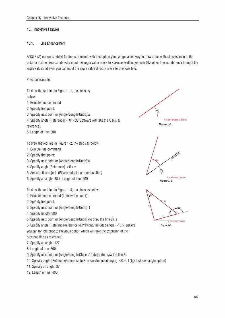
Chapter16_ Innovative Features
187
16. Innovative Features
16.1. Line Enhancement
ANGLE (A) option is added for line command, with this option you can get a fast way to draw a line without assistance of the
polar or a xline. You can directly input the angle value refers to X axis as well as you can take other line as reference to input the
angle value and even you can input the angle value directly refers to previous line.
Practice example:
To draw the red line in Figure 1-1, the steps as
below:
1. Execute line command
2. Specify first point:
3. Specify next point or [Angle/Length/Undo]:a
4. Specify angle [Reference] <0>:35(Software will take the X axis as
reference)
5. Length of line: 500
To draw the red line in Figure 1-2, the steps as below:
1. Execute line command
2. Specify first point:
3. Specify next point or [Angle/Length/Undo]:a
4. Specify angle [Reference] <0>:r
5. Select a line object: (Please select the reference line)
6. Specify an angle: 38 7. Length of line: 500
To draw the red line in Figure 1-3, the steps as below:
1. Execute line command (to draw the line 1).
2. Specify first point:
3. Specify next point or [Angle/Length/Undo]: l
4. Specify length: 300
5. Specify next point or [Angle/Length/Undo] (to draw the line 2): a
6. Specify angle [Reference/reference to Previous/Included angle] <0>: p(Here
you can try reference to Previous option which will take the extension of the
previous line as reference)
7. Specify an angle: 127
8. Length of line: 500
9. Specify next point or [Angle/Length/Closed/Undo]:a (to draw the line 3)
10. Specify angle [Reference/reference to Previous/Included angle] <0>: I (Try Included angle option)
11. Specify an angle: 37
12. Length of line: 400

Chapter16_ Innovative Features
188
16.2. Polyline Enhancement
The ANGLE (A) option in polyline command which its behavior is similar as the one in line
command is also added in Polyline. There are still three choices for angle option, you can either
input angle value which takes X Axis as reference as well as you can input “reference to Previous”
angle or “Included angle”. In CAD software, many objects are consisting of Polyline, for example:
rectangle, polygon and revision cloud, donut. Now these functions are classified under the
Polyline drop down list where you can access them quickly.
16.3. Rectangle Enhancement
OBLIQUE(O) is a new added option to draw an rotate rectangle. The behavior of oblique option is similar as the behavior in line
command. With oblique option, you can locate the angel of bottom line and the length to get a rotate rectangle, you can draw
an oblique rectangle which has specific angle with X axis and horizontal or has random angle refer to any line.
Practice example:
To draw the rotate rectangle in Figure 1-4, the steps as below:
1. Execute RECTANG command and input oblique option or click the rotate
rectangle icon in ribbon panel.
2. Specify first point:
3. Specify next point or [Angle]: a(Input Angle option)
4. Specify angle [Reference] <0>:20
5. Enter rectangle width: 800
6. Enter rectangle height: 350
To draw the rotate rectangle when there is a reference line in Figure 1-5, the steps as below:
1. Execute RECTANFG command and input oblique option or click the rotate
rectangle icon in ribbon panel.
2. Specify first point:
3. Specify next point or [Angle]a
4. Specify angle [Reference] <0>:r
5. Select a line object: (Select the reference line)
6. Specify an angle: 20
7. Enter rectangle width: 800
8. Enter rectangle height: 350

Chapter16_ Innovative Features
189
16.4. Circle Enhancement
CONCENTRIC(C) option is new added in circle command, you can input radius several times to create many concentric circle
after specify the circle center, with this new option, you can get concentric circle in a simple way.
Practice example:
To draw the concentric circle in Figure 1-6, the steps as below:
1. Execute circle command and input concentric option or click the
concentric icon in ribbon panel.
2. Specify center point for circle:
3. Specify the radius of circle or [Diameter] <400.0000>:100
4. Specify the radius of circle or [Diameter/Undo] <100.0000>:200
5. Specify the radius of circle or [Diameter/Undo] <200.0000>:300
16.5. Copy Enhancement
There are three options: measure(E), divide(I), path(P) options are added in copy command, user can easily finish the
drawing without the assistance of other operations such as divided by segment, by distance, array, or layout bypath in previous
version.
1. measure(E)when users need to copy objects with same distance and same direction, this option will be very useful.
2. Divide(I), you can copy many objects with same distance in a specified distance.

Chapter16_ Innovative Features
190
3. Path(P)After select the path option, you can select divide or measure option again to locate the count objects.
16.6. Rotate Enhancement
Multiple copy (M) option is added in rotate command, with this option, you can either copy many objects with different rotate
angles, or you can draw circles array.
When rotate, you can select multiple copy option and input several angle values; the software will rotate and copy the object
according to the value you input. You can try copy and rotate 45, 90,135 degree refers to the original object at a time such as
the following figure.
Practice example:
Rotate and copy objects in Figure1-7, the steps as below:
1. Execute the Command: ROTATE
2. Select object:
3. Specify the base point: (Select the center of the concentric)
4. Specify rotation angle or [Copy/Multiple/Reference] <135>: m
5. Specify rotation angle or [Between/Fill]: 45
6. Specify rotation angle or [Exit/Undo]: 90
7. Specify rotation angle or [Exit/Undo]: 135
If the adjacent object angle is fixed, you can select “angle between object(B)
or fill angle(F)option, then input the angle and the quantity, this option can
replace circle array.
Rotate and copy objects in Figure1-8, the steps as below:
1. Execute the command: ROTATE
2. Select object: (Select the center of the concentric)
3. Specify the base point:
4. Specify rotation angle or [Copy/Multiple/Reference] <30>: m
5. Specify rotation angle or [Between/Fill]: b
6. Specify rotation angle: 60
7. Specify total number of items: 4
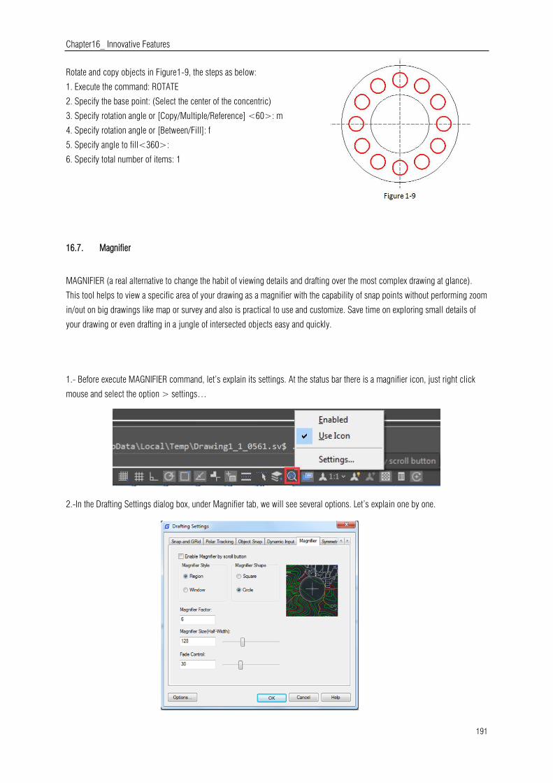
Chapter16_ Innovative Features
191
Rotate and copy objects in Figure1-9, the steps as below:
1. Execute the command: ROTATE
2. Specify the base point: (Select the center of the concentric)
3. Specify rotation angle or [Copy/Multiple/Reference] <60>: m
4. Specify rotation angle or [Between/Fill]: f
5. Specify angle to fill<360>:
6. Specify total number of items: 1
16.7. Magnifier
MAGNIFIER (a real alternative to change the habit of viewing details and drafting over the most complex drawing at glance).
This tool helps to view a specific area of your drawing as a magnifier with the capability of snap points without performing zoom
in/out on big drawings like map or survey and also is practical to use and customize. Save time on exploring small details of
your drawing or even drafting in a jungle of intersected objects easy and quickly.
1.- Before execute MAGNIFIER command, let’s explain its settings. At the status bar there is a magnifier icon, just right click
mouse and select the option > settings…
2.-In the Drafting Settings dialog box, under Magnifier tab, we will see several options. Let’s explain one by one.
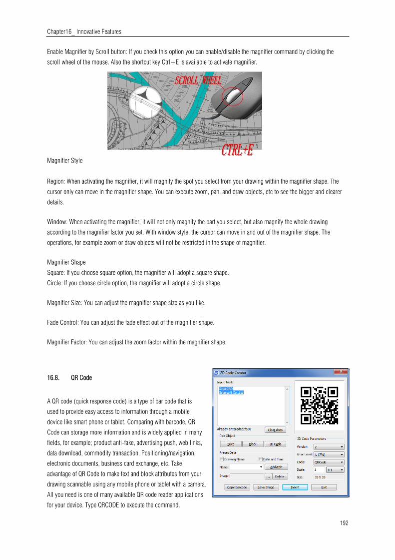
Chapter16_ Innovative Features
192
Enable Magnifier by Scroll button: If you check this option you can enable/disable the magnifier command by clicking the
scroll wheel of the mouse. Also the shortcut key Ctrl+E is available to activate magnifier.
Magnifier Style
Region: When activating the magnifier, it will magnify the spot you select from your drawing within the magnifier shape. The
cursor only can move in the magnifier shape. You can execute zoom, pan, and draw objects, etc to see the bigger and clearer
details.
Window: When activating the magnifier, it will not only magnify the part you select, but also magnify the whole drawing
according to the magnifier factor you set. With window style, the cursor can move in and out of the magnifier shape. The
operations, for example zoom or draw objects will not be restricted in the shape of magnifier.
Magnifier Shape
Square: If you choose square option, the magnifier will adopt a square shape.
Circle: If you choose circle option, the magnifier will adopt a circle shape.
Magnifier Size: You can adjust the magnifier shape size as you like.
Fade Control: You can adjust the fade effect out of the magnifier shape.
Magnifier Factor: You can adjust the zoom factor within the magnifier shape.
16.8. QR Code
A QR code (quick response code) is a type of bar code that is
used to provide easy access to information through a mobile
device like smart phone or tablet. Comparing with barcode, QR
Code can storage more information and is widely applied in many
fields, for example; product anti-fake, advertising push, web links,
data download, commodity transaction, Positioning/navigation,
electronic documents, business card exchange, etc. Take
advantage of QR Code to make text and block attributes from your
drawing scannable using any mobile phone or tablet with a camera.
All you need is one of many available QR code reader applications
for your device. Type QRCODE to execute the command.

Chapter16_ Innovative Features
193
Parameters of QR Code Creator as below:
Input:In input text area, you can input the text directly or you can pick text data from the drawing, also you can select the preset
data which can display automatically in the input text box.
Already entered:0/500:Displays the entered text number and the maximum Input text number.
Clear:Cleans all data displayed at input text area.
Pick Object: You can select three options to picking objects from your drawing.
Text:Picks text from drawing file, the text will display in input text box automatically after you picked up.
Block:Picks the attribute block from the drawing file, add the tag and value to the input text box. It is always used to pick the
information of the tab.
2D Code: Picks the QR Code from the drawing file to get the information of QR Code
Preset Data: You can preset data, when the data is needed just check the corresponding option. The information will
automatically added to the input text area.
Drawing Name: When check Drawing Name option, the drawing name will display in the input text area.
Date and Time: When check Date and Time option, the current date and time will display in the input text area.
Parameters of Costumed Field as below:
Name>Add/Edit: You can customize field that common used, when the field is needed, click the pull down list to find it out
and display it in input text box.
No: Input the field number.
Name:Input the field name.
Value: Input the field value.
Add:Add new custom field.
Delete: Delete custom field.
Image: Company logo or others marked pictures can
be added to QR Code. You can also browse pictures
from your computer, JPG\BMP\PNG\TIF\TGA.etc
formats are supported.
Delete: Delete the picture selected.
QR Code Parameters: You can set QR Code image parameters before being inserted.
Version:Creates QR Code according to the data you input. Sets the QR Code version, the version
number will adaptively according to the increase of text.
Error Level:Error level for QR Code data generated.
Size:Set the width of QR Code. H (30%)\Q(25%)\M (15%)\L (7%): the compatibility of correcting
about 15% data error.
Code:QR Code system. Currently we support Code93.
Scale:Set the QR Code printing scale, behind the scale option is the scale list. You can choose the
scale needed, meanwhile, the scale list can remind user the QR Code generating is related to the
printing scale. Finally, it will generate as a block, the scale you set can be the block scale to
ensure the QR Code can be printed correctly in different printing scales.
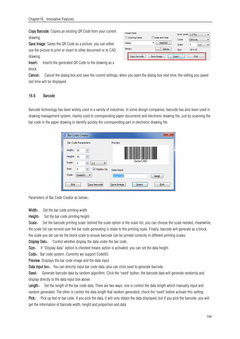
Chapter16_ Innovative Features
194
Copy Barcode: Copies an existing QR Code from your current
drawing.
Save Image: Saves the QR Code as a picture, you can either
use the picture to print or insert to other document or to CAD
drawing.
Insert: Inserts the generated QR Code to the drawing as a
block
Cancel: Cancel the dialog box and save the current settings, when you open the dialog box next time, the setting you saved
last time will be displayed.
16.9. Barcode
Barcode technology has been widely used in a variety of industries. In some design companies, barcode has also been used in
drawing management system, mainly used to corresponding paper documents and electronic drawing file, just by scanning the
bar code in the paper drawing to identify quickly the corresponding part in electronic drawing file.
Parameters of Bar Code Creator as below:
Width: Set the bar code printing width.
Height: Set the bar code printing height.
Scale: Set the barcode printing scale, behind the scale option is the scale list, you can choose the scale needed, meanwhile,
the scale list can remind user the bar code generating is relate to the printing scale. Finally, barcode will generate as a block,
the scale you set can be the block scale to ensure barcode can be printed correctly in different printing scales.
Display Data: Control whether display the data under the bar code.
Size: If “Display data” option is checked means option is activated, you can set the data height.
Code:Bar code system. Currently we support Code93.
Preview: Displays the bar code image and the data input.
Data input box:You can directly input bar code data, also can click seed to generate barcode.
Seed: Generate barcode data by random algorithm. Click the "seed" button, the barcode data will generate randomly and
display directly to the data input box above.
Length: Set the length of the bar code data. There are two ways: one is control the data length which manually input and
random generated. The other is control the data length that random generated, check the "seed" before activate this setting.
Pick: Pick up text or bar code. If you pick the data, it will only obtain the data displayed, but if you pick the barcode, you will
get the information of barcode width, height and proportion and data
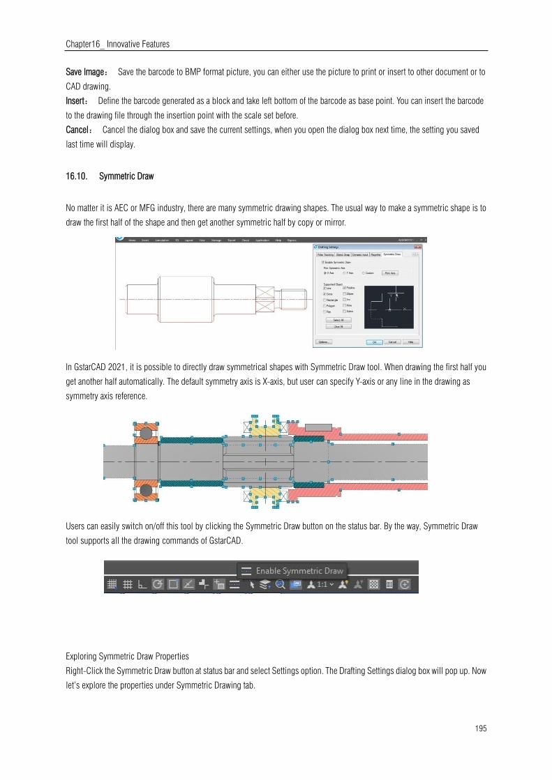
Chapter16_ Innovative Features
195
Save Image: Save the barcode to BMP format picture, you can either use the picture to print or insert to other document or to
CAD drawing.
Insert: Define the barcode generated as a block and take left bottom of the barcode as base point. You can insert the barcode
to the drawing file through the insertion point with the scale set before.
Cancel: Cancel the dialog box and save the current settings, when you open the dialog box next time, the setting you saved
last time will display.
16.10. Symmetric Draw
No matter it is AEC or MFG industry, there are many symmetric drawing shapes. The usual way to make a symmetric shape is to
draw the first half of the shape and then get another symmetric half by copy or mirror.
In GstarCAD 2021, it is possible to directly draw symmetrical shapes with Symmetric Draw tool. When drawing the first half you
get another half automatically. The default symmetry axis is X-axis, but user can specify Y-axis or any line in the drawing as
symmetry axis reference.
Users can easily switch on/off this tool by clicking the Symmetric Draw button on the status bar. By the way, Symmetric Draw
tool supports all the drawing commands of GstarCAD.
Exploring Symmetric Draw Properties
Right-Click the Symmetric Draw button at status bar and select Settings option. The Drafting Settings dialog box will pop up. Now
let’s explore the properties under Symmetric Drawing tab.

Chapter16_ Innovative Features
196
Enable Symmetric Draw: Enables the symmetric draw tool if is checked.
Pick Symmetric Axis: You can pick X, Y, or a custom axis to start working
with.
Supported Objects: Symmetric draw tool supports line, circle, rectangle,
polygon, ray, polyline, ellipse, arc, xline and spline objects to be drawn
as symmetrical shape.
Select All/ Erase All: You can select or unselect all supported objects at
once.
Symmetric Axis Effect
X Axis option: The objects drawn will take the X
coordinate system as invisible axis line. The effect of
X Axis is mirroring the drawn objects up or down
according to X coordinate system origin location.
Y Axis option: The objects drawn will take the Y coordinate system as
invisible axis line. The effect of Y Axis is mirroring the drawn objects
right or left side according to Y coordinate system origin location.
Custom/Pick Axis option: The objects drawn will take the vector
orientation of a selected object as visible axis line. The effect of
Custom/Pick Axis is mirroring the drawn objects according to a
selected object vector orientation whether inclined, vertical or
horizontal.
Pick Symmetric Axis: At status bar, besides
Symmetric Draw button is located another button
called Pick Symmetric Axis. The functionality of this
button is as same as Custom and Pick Axis options.
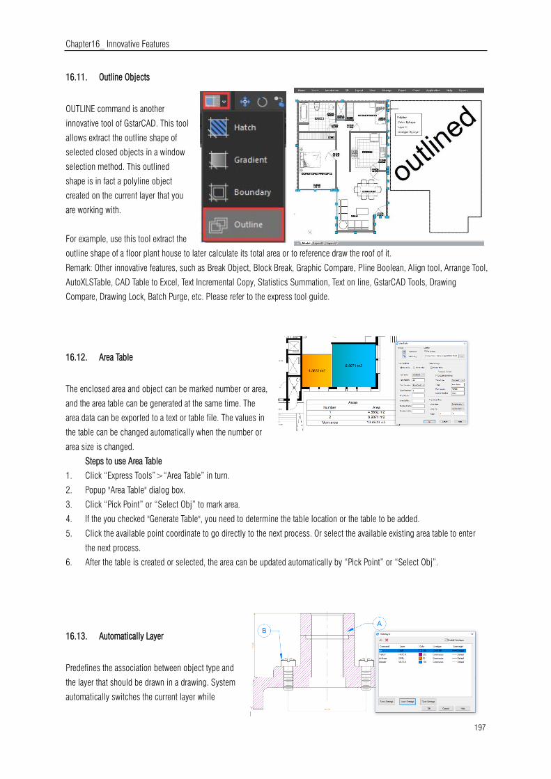
Chapter16_ Innovative Features
197
16.11. Outline Objects
OUTLINE command is another
innovative tool of GstarCAD. This tool
allows extract the outline shape of
selected closed objects in a window
selection method. This outlined
shape is in fact a polyline object
created on the current layer that you
are working with.
For example, use this tool extract the
outline shape of a floor plant house to later calculate its total area or to reference draw the roof of it.
Remark: Other innovative features, such as Break Object, Block Break, Graphic Compare, Pline Boolean, Align tool, Arrange Tool,
AutoXLSTable, CAD Table to Excel, Text Incremental Copy, Statistics Summation, Text on line, GstarCAD Tools, Drawing
Compare, Drawing Lock, Batch Purge, etc. Please refer to the express tool guide.
16.12. Area Table
The enclosed area and object can be marked number or area,
and the area table can be generated at the same time. The
area data can be exported to a text or table file. The values in
the table can be changed automatically when the number or
area size is changed.
Steps to use Area Table
1. Click “Express Tools”>“Area Table” in turn.
2. Popup "Area Table" dialog box.
3. Click “Pick Point” or “Select Obj” to mark area.
4. If the you checked "Generate Table", you need to determine the table location or the table to be added.
5. Click the available point coordinate to go directly to the next process. Or select the available existing area table to enter
the next process.
6. After the table is created or selected, the area can be updated automatically by “Pick Point” or “Select Obj”.
16.13. Automatically Layer
Predefines the association between object type and
the layer that should be drawn in a drawing. System
automatically switches the current layer while
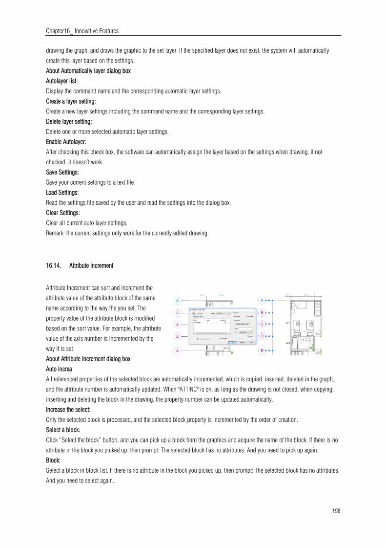
Chapter16_ Innovative Features
198
drawing the graph, and draws the graphic to the set layer. If the specified layer does not exist, the system will automatically
create this layer based on the settings.
About Automatically layer dialog box
Autolayer list:
Display the command name and the corresponding automatic layer settings.
Create a layer setting:
Create a new layer settings including the command name and the corresponding layer settings.
Delete layer setting:
Delete one or more selected automatic layer settings.
Enable Autolayer:
After checking this check box, the software can automatically assign the layer based on the settings when drawing, if not
checked, it doesn’t work.
Save Settings:
Save your current settings to a text file.
Load Settings:
Read the settings file saved by the user and read the settings into the dialog box.
Clear Settings:
Clear all current auto layer settings.
Remark: the current settings only work for the currently edited drawing.
16.14. Attribute Increment
Attribute Increment can sort and increment the
attribute value of the attribute block of the same
name according to the way the you set. The
property value of the attribute block is modified
based on the sort value. For example, the attribute
value of the axis number is incremented by the
way it is set.
About Attribute Increment dialog box
Auto Increa
All referenced properties of the selected block are automatically incremented, which is copied, inserted, deleted in the graph,
and the attribute number is automatically updated. When "ATTINC" is on, as long as the drawing is not closed, when copying,
inserting and deleting the block in the drawing, the property number can be updated automatically.
Increase the select:
Only the selected block is processed, and the selected block property is incremented by the order of creation.
Select a block:
Click “Select the block” button, and you can pick up a block from the graphics and acquire the name of the block. If there is no
attribute in the block you picked up, then prompt: The selected block has no attributes. And you need to pick up again.
Block:
Select a block in block list. If there is no attribute in the block you picked up, then prompt: The selected block has no attributes.
And you need to select again.
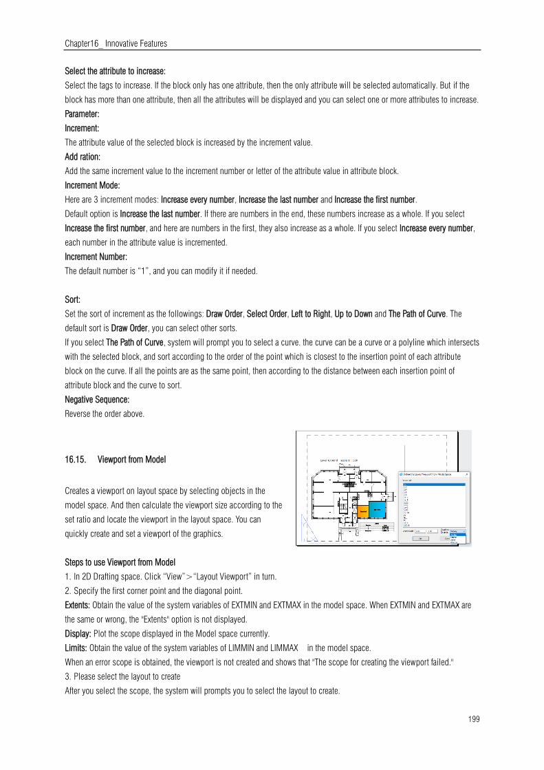
Chapter16_ Innovative Features
199
Select the attribute to increase:
Select the tags to increase. If the block only has one attribute, then the only attribute will be selected automatically. But if the
block has more than one attribute, then all the attributes will be displayed and you can select one or more attributes to increase.
Parameter:
Increment:
The attribute value of the selected block is increased by the increment value.
Add ration:
Add the same increment value to the increment number or letter of the attribute value in attribute block.
Increment Mode:
Here are 3 increment modes: Increase every number, Increase the last number and Increase the first number.
Default option is Increase the last number. If there are numbers in the end, these numbers increase as a whole. If you select
Increase the first number, and here are numbers in the first, they also increase as a whole. If you select Increase every number,
each number in the attribute value is incremented.
Increment Number:
The default number is “1”, and you can modify it if needed.
Sort:
Set the sort of increment as the followings: Draw Order, Select Order, Left to Right, Up to Down and The Path of Curve. The
default sort is Draw Order, you can select other sorts.
If you select The Path of Curve, system will prompt you to select a curve. the curve can be a curve or a polyline which intersects
with the selected block, and sort according to the order of the point which is closest to the insertion point of each attribute
block on the curve. If all the points are as the same point, then according to the distance between each insertion point of
attribute block and the curve to sort.
Negative Sequence:
Reverse the order above.
16.15. Viewport from Model
Creates a viewport on layout space by selecting objects in the
model space. And then calculate the viewport size according to the
set ratio and locate the viewport in the layout space. You can
quickly create and set a viewport of the graphics.
Steps to use Viewport from Model
1. In 2D Drafting space. Click “View”>“Layout Viewport” in turn.
2. Specify the first corner point and the diagonal point.
Extents: Obtain the value of the system variables of EXTMIN and EXTMAX in the model space. When EXTMIN and EXTMAX are
the same or wrong, the "Extents" option is not displayed.
Display: Plot the scope displayed in the Model space currently.
Limits: Obtain the value of the system variables of LIMMIN and LIMMAX in the model space.
When an error scope is obtained, the viewport is not created and shows that "The scope for creating the viewport failed."
3. Please select the layout to create
After you select the scope, the system will prompts you to select the layout to create.
Chapter16_ Innovative Features
200
-If the command is executed in the Layout space, the viewport is created directly in the layout space of the command.
-If the command is executed in the Model space, the dialog box pops up for you to select the layout.
4. Specify the insertion point to viewport
-After setting the layout, automatically switch to the selected layout and specify the insertion point of the viewport.
-You can enter coordinates or click a point to set the location of the viewport in a graphical window.
-After setting the location, the computed viewport is generated at the specified location, and the display locked of the viewport
is on.
16.16. Free Scale
FREESCALE command allows you to scales an object or a group of objects without restrictions under three methods;
Non-Uniform, Rectangle and Free.
Non-uniform scale: The scale of X and Y axis can be input separately.
Rect Scale: You can scale a graphic to match a rectangle frame. The rectangle does not need to be drawn, just specify two
diagonal points.
Free Scale: You can move or copy and scale the graphics in a closed quadrilateral frame to another closed quadrilateral frame,
which can be used to generate the pattern of tilting or perspective distortion graphics.

Chapter17_ Collaboration
201
17. Collaboration
Do you work with large or complex drawings? Is it important for your team to work together on one single referenced drawing
file at same time? You can do it now with GstarCAD Collaboration Tool.
The GstarCAD Collaboration Tool is an embedded plugin available for GstarCAD platform aimed to help CAD designers work
together among a single referenced drawing file at the same time, control drawing revisions and manage medium, big or
complex projects with ease and reliability, reducing communication barriers across different industries.
What are the general benefits of implementing GstarCAD Collaboration Tool?
Accelerates delivery of project blueprints schedule according to client or partner’s needs.
Decision making, collaboration and review are streamline shortening the design cycle.
Protection and privacy of drawing data through own user company’s network server reliability.
Improve project management life cycle keeping high organization level and data resources.
Keep a project structure safety by limiting access, permissions and assigning drawing rules for work team.
Effectiveness when tracking changes, modifications or revisions of the latest drawing file version submitted.
Better control and visualization of modifications and changes of relevant drawing data at any time.
Timely handle project’s conflicts and collisions to reduce design errors between work groups.
System flexibility to work offline and online status.

Chapter17_ Collaboration
202