Green and Rapid Preparation of Fluorosilicone Rubber Foam ...
15
Citation: Hu, W.-J.; Xia, Q.-Q.; Pan, H.-T.; Chen, H.-Y.; Qu, Y.-X.; Chen, Z.-Y.; Zhang, G.-D.; Zhao, L.; Gong, L.-X.; Xue, C.-G.; et al. Green and Rapid Preparation of Fluorosilicone Rubber Foam Materials with Tunable Chemical Resistance for Efficient Oil–Water Separation. Polymers 2022, 14, 1628. https://doi.org/10.3390/ polym14081628 Academic Editor: Boqi Xiao Received: 22 March 2022 Accepted: 15 April 2022 Published: 18 April 2022 Publisher’s Note: MDPI stays neutral with regard to jurisdictional claims in published maps and institutional affil- iations. Copyright: © 2022 by the authors. Licensee MDPI, Basel, Switzerland. This article is an open access article distributed under the terms and conditions of the Creative Commons Attribution (CC BY) license (https:// creativecommons.org/licenses/by/ 4.0/). polymers Article Green and Rapid Preparation of Fluorosilicone Rubber Foam Materials with Tunable Chemical Resistance for Efficient Oil–Water Separation Wan-Jun Hu 1,† , Qiao-Qi Xia 1,† , Hong-Tao Pan 1 , Hai-Yang Chen 1 , Yong-Xiang Qu 1 , Zuan-Yu Chen 1 , Guo-Dong Zhang 1, *, Li Zhao 1 , Li-Xiu Gong 1 , Chang-Guo Xue 2 and Long-Cheng Tang 1,3, * 1 College of Material, Chemistry and Chemical Engineering, Key Laboratory of Organosilicon Chemistry and Material Technology of Ministry of Education, Hangzhou Normal University, Hangzhou 311121, China; [email protected] (W.-J.H.); [email protected] (Q.-Q.X.); [email protected] (H.-T.P.); [email protected] (H.-Y.C.); [email protected] (Y.-X.Q.); [email protected] (Z.-Y.C.); [email protected] (L.Z.); [email protected] (L.-X.G.) 2 School of Material Science and Engineering, Anhui University of Science and Technology, Huainan 232001, China; [email protected] 3 Key Laboratory of Silicone Materials Technology of Zhejiang Province, Hangzhou Normal University, Hangzhou 311121, China * Correspondence: [email protected] (G.-D.Z.); [email protected] (L.-C.T.) † These authors contributed equally to this work. Abstract: Polydimethylsiloxane (PDMS) foam materials with lightweight, excellent oil resistance and mechanical flexibility are highly needed for various practical applications in aerospace, trans- portation, and oil/water separation. However, traditional PDMS foam materials usually present poor chemical resistance and easily swell in various solvents, which greatly limits their potential application. Herein, novel fluorosilicone rubber foam (FSiRF) materials with different contents of trifluoropropyl lateral groups were designed and fabricated by a green (no solvents used) and rapid (<10 min foaming process) foaming/crosslinking approach at ambient temperature. Typi- cally, vinyl-terminated poly(dimethyl-co-methyltrifluoropropyl) siloxanes with different fluorine contents of 0–50 mol% were obtained through ring-opening polymerization to effectively adjust the chemical resistance of the FSiRFs. Notably, the optimized FSiRF samples exhibit lightweight (~0.25 g/cm -3 ), excellent hydrophobicity/oleophilicity (WCA > 120 ◦ ), reliable mechanical flexibility (complete recovery ability after stretching of 130% strain or compressing of >60%), and improved chemical resistance and structural stability in various solvents, making them promising candidates for efficient and continuous oil–water separation. This work provides an innovative concept to design and prepare advanced fluorosilicone rubber foam materials with excellent chemical resistance for potential oil–water separation application. Keywords: fluorosilicone rubber foam; room-temperature foaming; mechanical flexibility; chemical resistance; oil–water separation 1. Introduction Silicone rubber foam (SiRF) is one of the most versatile porous polymeric foam ma- terials, which has been widely used in the fields of transportation, electronics, aerospace, and national defense because of its light weight, good mechanical flexibility, and facile processability [1–7]. The molecular structure of polydimethylsiloxane (PDMS) foam, as the most representative one of SiRF materials, is composed of a crosslinked –Si–O–Si– backbone and many -CH 3 pendant moieties. The structural features make it possess intriguing properties, such as wide temperature usage range (-60–220 ◦ C), mechanical flexibility, high thermal and chemical resistance, and thermal insulating performance [8,9]. Therefore, the PDMS foam material has drawn considerable academic and industrial attention during the Polymers 2022, 14, 1628. https://doi.org/10.3390/polym14081628 https://www.mdpi.com/journal/polymers
-
Upload
khangminh22 -
Category
Documents
-
view
1 -
download
0
Transcript of Green and Rapid Preparation of Fluorosilicone Rubber Foam ...
�����������������
Citation: Hu, W.-J.; Xia, Q.-Q.; Pan,
H.-T.; Chen, H.-Y.; Qu, Y.-X.; Chen,
Z.-Y.; Zhang, G.-D.; Zhao, L.; Gong,
L.-X.; Xue, C.-G.; et al. Green and
Rapid Preparation of Fluorosilicone
Rubber Foam Materials with Tunable
Chemical Resistance for Efficient
Oil–Water Separation. Polymers 2022,
14, 1628. https://doi.org/10.3390/
polym14081628
Academic Editor: Boqi Xiao
Received: 22 March 2022
Accepted: 15 April 2022
Published: 18 April 2022
Publisher’s Note: MDPI stays neutral
with regard to jurisdictional claims in
published maps and institutional affil-
iations.
Copyright: © 2022 by the authors.
Licensee MDPI, Basel, Switzerland.
This article is an open access article
distributed under the terms and
conditions of the Creative Commons
Attribution (CC BY) license (https://
creativecommons.org/licenses/by/
4.0/).
polymers
Article
Green and Rapid Preparation of Fluorosilicone Rubber FoamMaterials with Tunable Chemical Resistance for EfficientOil–Water SeparationWan-Jun Hu 1,†, Qiao-Qi Xia 1,†, Hong-Tao Pan 1, Hai-Yang Chen 1, Yong-Xiang Qu 1, Zuan-Yu Chen 1,Guo-Dong Zhang 1,*, Li Zhao 1, Li-Xiu Gong 1, Chang-Guo Xue 2 and Long-Cheng Tang 1,3,*
1 College of Material, Chemistry and Chemical Engineering, Key Laboratory of Organosilicon Chemistry andMaterial Technology of Ministry of Education, Hangzhou Normal University, Hangzhou 311121, China;[email protected] (W.-J.H.); [email protected] (Q.-Q.X.); [email protected] (H.-T.P.);[email protected] (H.-Y.C.); [email protected] (Y.-X.Q.); [email protected] (Z.-Y.C.);[email protected] (L.Z.); [email protected] (L.-X.G.)
2 School of Material Science and Engineering, Anhui University of Science and Technology,Huainan 232001, China; [email protected]
3 Key Laboratory of Silicone Materials Technology of Zhejiang Province, Hangzhou Normal University,Hangzhou 311121, China
* Correspondence: [email protected] (G.-D.Z.); [email protected] (L.-C.T.)† These authors contributed equally to this work.
Abstract: Polydimethylsiloxane (PDMS) foam materials with lightweight, excellent oil resistanceand mechanical flexibility are highly needed for various practical applications in aerospace, trans-portation, and oil/water separation. However, traditional PDMS foam materials usually presentpoor chemical resistance and easily swell in various solvents, which greatly limits their potentialapplication. Herein, novel fluorosilicone rubber foam (FSiRF) materials with different contentsof trifluoropropyl lateral groups were designed and fabricated by a green (no solvents used) andrapid (<10 min foaming process) foaming/crosslinking approach at ambient temperature. Typi-cally, vinyl-terminated poly(dimethyl-co-methyltrifluoropropyl) siloxanes with different fluorinecontents of 0–50 mol% were obtained through ring-opening polymerization to effectively adjustthe chemical resistance of the FSiRFs. Notably, the optimized FSiRF samples exhibit lightweight(~0.25 g/cm−3), excellent hydrophobicity/oleophilicity (WCA > 120◦), reliable mechanical flexibility(complete recovery ability after stretching of 130% strain or compressing of >60%), and improvedchemical resistance and structural stability in various solvents, making them promising candidatesfor efficient and continuous oil–water separation. This work provides an innovative concept to designand prepare advanced fluorosilicone rubber foam materials with excellent chemical resistance forpotential oil–water separation application.
Keywords: fluorosilicone rubber foam; room-temperature foaming; mechanical flexibility;chemical resistance; oil–water separation
1. Introduction
Silicone rubber foam (SiRF) is one of the most versatile porous polymeric foam ma-terials, which has been widely used in the fields of transportation, electronics, aerospace,and national defense because of its light weight, good mechanical flexibility, and facileprocessability [1–7]. The molecular structure of polydimethylsiloxane (PDMS) foam, as themost representative one of SiRF materials, is composed of a crosslinked –Si–O–Si– backboneand many −CH3 pendant moieties. The structural features make it possess intriguingproperties, such as wide temperature usage range (−60–220 ◦C), mechanical flexibility, highthermal and chemical resistance, and thermal insulating performance [8,9]. Therefore, thePDMS foam material has drawn considerable academic and industrial attention during the
Polymers 2022, 14, 1628. https://doi.org/10.3390/polym14081628 https://www.mdpi.com/journal/polymers
Polymers 2022, 14, 1628 2 of 15
past few years [10–15]. With the ever-increasing development of society, the demand forpolymer foam materials at home and abroad continues to grow [16–22] and more demandsare imposed on the production and performance of all polymeric foams, particularly forSiRFs. Unfortunately, the −CH3 pendant moiety of PDMS-based SiRF has low polarity [23]and the solubility parameter (δ) of PDMS (δ = 7.3 (cal/cm3)1/2) [24] is similar to that fornonpolar organic solvents such as hexane (δ = 7.2 (cal/cm3)1/2). It is easy to absorb solventand swell upon exposure to the most nonpolar or low-polar environment, resulting indeformation and even failure of PDMS foam structural components, which seriously limitsits application [25,26], especially in the field of oil–water separation application [27].
To overcome the above drawbacks, many strategies have been developed to enhancethe solvent resistance of the PDMS foam materials. Generally, the modifying strategies of thePDMS materials could be divided into physical and chemical methods. Physical modificationwas usually accomplished by coating some hybrid inorganic/organic polymers or addition ofvarious fillers so that the material’s swelling ratio to organic solvent could be reduced. Thechemical method usually refers to grafting some functional groups to the PDMS chains [28,29].For instance, Peng et al. used oxygen plasma and trichloro(1H,1H,2H,2H-perfluorooctyl)silane to surface-modify the PDMS foam materials that were prepared by dissolved sugarmethod [30], and the modified sample presented excellent hydrophobicity. However, theseabove strategies still show some shortages, e.g., the unchanged intrinsic chemical resistanceof the PDMS foam materials, the uncertain structure stability of filler/polymer coatingsin organic solvents, and impractical toxic solvents used. Moreover, most of the aboveapproaches still need lengthy and complex steps, e.g., centrifugation and vacuum, hightemperature drying, and complex special facilities. Therefore, it is urgent and challengingto develop an extremely simple, green, and rapid approach to prepare silicone rubber foammaterials with tunable chemical resistance.
As is well-known, the fluorine-containing groups (e.g., −CH2CH2CF3) with highpolarity could reduce the material’s surface energy, and they thus are usually used toincorporate into the polysiloxanes to improve the material’s chemical resistance in bothnonpolar solvents and oils [31]. Previous studies have demonstrated that the chemicalresistance of traditional silicone rubber could be enhanced by the partial replacement ofmethyl groups with some fluorine groups [32]; for example, fluorosilicone rubber [33–35].However, there are few reports about the preparation of fluorosilicone rubber foam ma-terials. Recently, Métivier et al. used supercritical CO2 as the foaming agent to preparepoly(methylvinyldimethyl)siloxane/fluorosilicone foam materials via physical foamingmethod [36]. Unfortunately, the density of the fluorosilicone rubber foam materials wasmore than 0.50 g/cm3, demonstrating the closed-cell structure, which cannot be used foroil–water separation. Therefore, developing an extremely simple, green, and facile method-ology for fabricating novel, lightweight, mechanically flexible, and chemical-resistantfluorosilicone rubber foam (FSiRF) materials is still of great significance.
In this work, we designed and synthesized vinyl-terminated poly(dimethyl-co-methyl-trifluoropropyl) siloxanes with different fluorine contents via anionic ring-opening polymer-ization. Water was used as an effective foaming agent to prepare the novel fluorosiliconerubber foam materials through a simple chemical dehydrogenative foaming method underambient temperature condition. The foaming process can be finished in only several min-utes and no solvents were used, showing unique features such as environment-friendliness,safety, facile, and no residual foaming agent. The prepared FSiRF samples show goodcompatibility with hydrogen dimethicone, and the fluorine content could be controlled bysimply adjusting the composition of the starting compounds. By the partial replacement ofmethyl groups with some trifluoropropyl groups, the solvent and oil resistance of FSiRFsamples are greatly improved in comparison with traditional PDMS foam materials; theporous FSiRFs feature high compressibility and stretchability, outstanding hydrophobic-ity/oleophilicity, as well as high structural stability. Discrepancies in the pore structure,mechanical properties, thermal stability, and solvent resistance of the five FSiRFs with differ-
Polymers 2022, 14, 1628 3 of 15
ent fluorine content were investigated. Moreover, the solvent-resistant mechanisms were alsodiscussed and the application of the material in oil–water separation is also demonstrated.
2. Experimental Section2.1. Materials
1,3,5-Tris(3,3,3-trifluoropropyl)-1,3,5-trimethylcyclotrisiloxane (D3F) was provided by Shan-
dong Weihai Xinyuan Chemical Co., Ltd. (Weihai, China). Octamethylcyclotetrasiloxane(D4) and hydrogen dimethicone (PDMS-H, 1.6 wt.% hydrogen group) was supplied byZhejiang Xin’an Chemical Industrial Group Co., Ltd. (Hangzhou, China). Vinyl dime-thicone with low viscosity values (MMVi) was supplied by Zhejiang Runhe Silicone NewMaterial Co., Ltd. (Ningbo, China). Tetramethylammonium hydroxide (TMAH, as catalystfor the preparation of vinyl-terminated poly(dimethyl-co-methyltrifluoropropyl) siloxane),was provided by Sinopharm Group Co., Ltd. (Shanghai, China). Karstedt’s catalyst, di-luted to a concentration of 3000 ppm, was supplied by Betely Polymer Materials Co., Ltd.(Suzhou, China). D3
F and D4 were vacuum-dried before use. Other materials were directlyused without any further purification.
2.2. Preparation of PDFS-Vi-X
PDFS-Vi-X (Vinyl-terminated poly(dimethyl-co-methyltrifluoropropyl)siloxane) withvarying fluorine content (where X represents the methyltrifluoropropylsiloxane unit ratio)is synthesized via anionic ring-opening copolymerization (AROP) of cyclic oligomers [37].The specific synthesis steps are as follows: a certain amount of D4, MMVi, and TMAH wereadded into a three-neck flask with a stir paddle and condenser under nitrogen atmosphere.The mixture was stirred at 90 ◦C and dropped D3
F into the flask with a constant pressuredropping funnel. After dropping D3
F, the solution was heated to 110 ◦C for 4 h, then to150 ◦C for 30 min to decompose the catalyst TMAH. The decomposing products of TMAH(mainly trimethylamine, methanol) unreacted D4 and D3
F, and low-molecular-weightproducts were removed at 170 ◦C in vacuum and the viscous PDFS-Vi-X were obtained.The feeding number of reactants to synthesize PDFS-Vi-X is listed in Table S2.
The molecular weight values and polymer dispersity index (PDI) of PDFS-Vi-X arelisted in Table 1.
Table 1. Molecular weight values of PDFS-VI-X with different fluorine contents.
Sample Code Fluorine Content(mol%)
Mn(g/mol)
Mw(g/mol) PDI (Mw/Mn)
PDFS-Vi-0 0.0% 116833 153094 1.36PDFS-Vi-12.5 12.5% 83139 116431 1.40PDFS-Vi-25.0 25.0% 73677 103899 1.41PDFS-Vi-37.5 37.5% 78373 105495 1.35PDFS-Vi-50.0 50.0% 87643 122486 1.39
2.3. Preparation of FSiRF Materials
According to the previous study [11], the preparation of FSiRF materials includes thefollowing steps. First, a prepolymer blend was prepared by mixing the 0.2-g inhibitor,10-g PDMS-H, and a certain content of water (0.2–1.8 wt%, as foaming agent) at a speedof ~1200 rpm for 5 min to achieve a uniform blend. Next, the PDFS-Vi-X (70 g) and 4 gKarstedt’s catalyst was dispersed in the above blend and stirred at 1200 rpm for 30 s.Afterwards, the above blend was poured into a mold and foamed at ambient temperaturefor ~8 min. Finally, the sample was cured at 100 ◦C for 2 h in an oven to obtain the FSiRF-Y(where Y means FSiRF materials prepared with different PDFS-Vi-X; for example, FSiRF-1corresponds to PDFS-Vi-12.5%, FSiRF-2 corresponds to PDFS-Vi-25.0%) materials.
Polymers 2022, 14, 1628 4 of 15
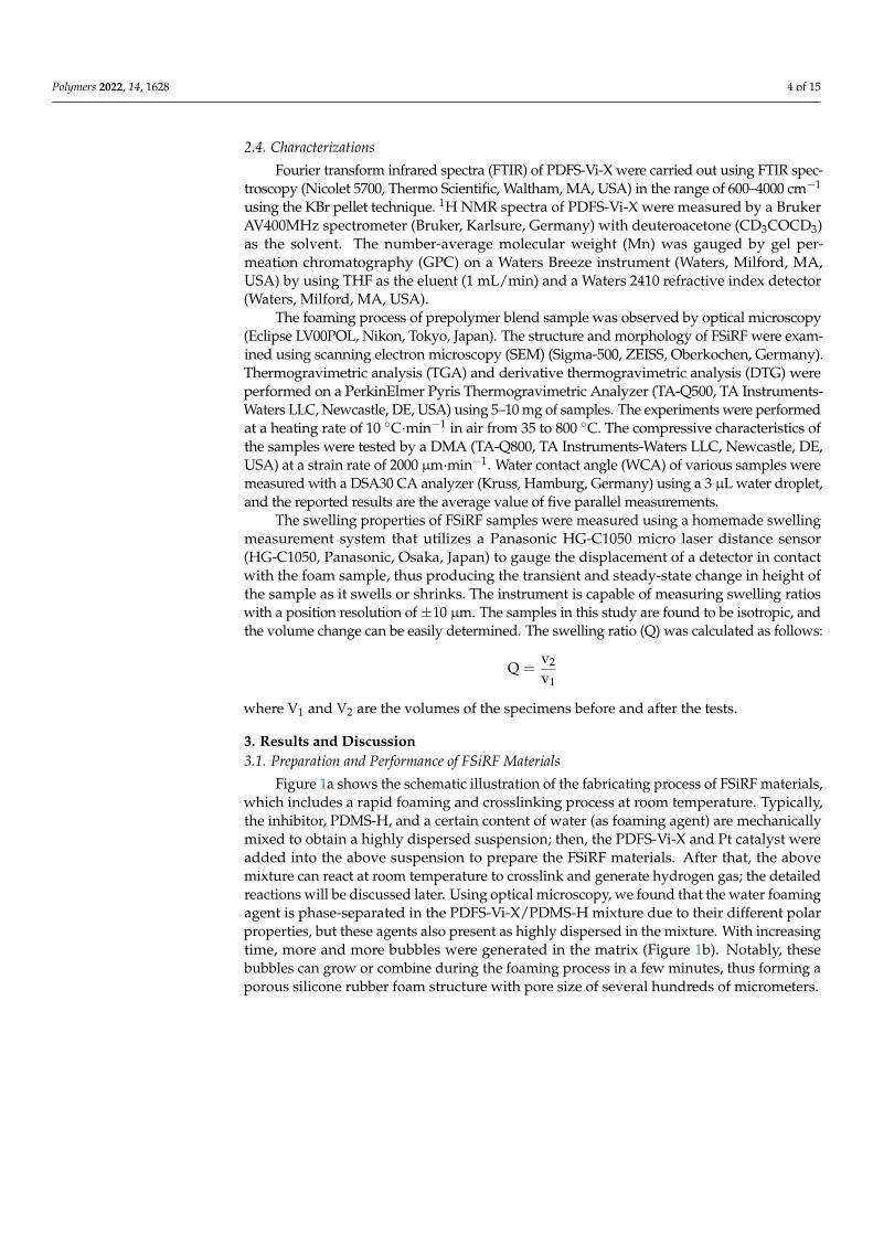
2.4. Characterizations
Fourier transform infrared spectra (FTIR) of PDFS-Vi-X were carried out using FTIR spec-troscopy (Nicolet 5700, Thermo Scientific, Waltham, MA, USA) in the range of 600–4000 cm−1
using the KBr pellet technique. 1H NMR spectra of PDFS-Vi-X were measured by a BrukerAV400MHz spectrometer (Bruker, Karlsure, Germany) with deuteroacetone (CD3COCD3)as the solvent. The number-average molecular weight (Mn) was gauged by gel per-meation chromatography (GPC) on a Waters Breeze instrument (Waters, Milford, MA,USA) by using THF as the eluent (1 mL/min) and a Waters 2410 refractive index detector(Waters, Milford, MA, USA).
The foaming process of prepolymer blend sample was observed by optical microscopy(Eclipse LV00POL, Nikon, Tokyo, Japan). The structure and morphology of FSiRF were exam-ined using scanning electron microscopy (SEM) (Sigma-500, ZEISS, Oberkochen, Germany).Thermogravimetric analysis (TGA) and derivative thermogravimetric analysis (DTG) wereperformed on a PerkinElmer Pyris Thermogravimetric Analyzer (TA-Q500, TA Instruments-Waters LLC, Newcastle, DE, USA) using 5–10 mg of samples. The experiments were performedat a heating rate of 10 ◦C·min−1 in air from 35 to 800 ◦C. The compressive characteristics ofthe samples were tested by a DMA (TA-Q800, TA Instruments-Waters LLC, Newcastle, DE,USA) at a strain rate of 2000 µm·min−1. Water contact angle (WCA) of various samples weremeasured with a DSA30 CA analyzer (Kruss, Hamburg, Germany) using a 3 µL water droplet,and the reported results are the average value of five parallel measurements.
The swelling properties of FSiRF samples were measured using a homemade swellingmeasurement system that utilizes a Panasonic HG-C1050 micro laser distance sensor(HG-C1050, Panasonic, Osaka, Japan) to gauge the displacement of a detector in contactwith the foam sample, thus producing the transient and steady-state change in height ofthe sample as it swells or shrinks. The instrument is capable of measuring swelling ratioswith a position resolution of ±10 µm. The samples in this study are found to be isotropic, andthe volume change can be easily determined. The swelling ratio (Q) was calculated as follows:
Q =v2
v1
where V1 and V2 are the volumes of the specimens before and after the tests.
3. Results and Discussion3.1. Preparation and Performance of FSiRF Materials
Figure 1a shows the schematic illustration of the fabricating process of FSiRF materials,which includes a rapid foaming and crosslinking process at room temperature. Typically,the inhibitor, PDMS-H, and a certain content of water (as foaming agent) are mechanicallymixed to obtain a highly dispersed suspension; then, the PDFS-Vi-X and Pt catalyst wereadded into the above suspension to prepare the FSiRF materials. After that, the abovemixture can react at room temperature to crosslink and generate hydrogen gas; the detailedreactions will be discussed later. Using optical microscopy, we found that the water foamingagent is phase-separated in the PDFS-Vi-X/PDMS-H mixture due to their different polarproperties, but these agents also present as highly dispersed in the mixture. With increasingtime, more and more bubbles were generated in the matrix (Figure 1b). Notably, thesebubbles can grow or combine during the foaming process in a few minutes, thus forming aporous silicone rubber foam structure with pore size of several hundreds of micrometers.
Polymers 2022, 14, 1628 5 of 15
Polymers 2022, 14, x FOR PEER REVIEW 5 of 16
It is worth noting that the prepared FSiRF sample is so light that a piece of sample with
a size of 20 mm × 20 mm × 20 mm could stand on the top of a foxtail grass without bending
any hairy branches, as shown in Figure 1c. The density values of FSiRF samples were meas-
ured and are 0.24-0.25 g/cm3, as shown in Figure S1. Meanwhile, the prepared FSiRF sample
displays excellent surface hydrophobicity and oleophilicity. When a water droplet (blue color)
is placed on the surface of the FSiRF material, the contact angle reveals high hydrophobicity
(~130°) (see Figures 1d and S2) with neither physical nor chemical surface treatment. The good
hydrophobicity could be owing to a combination of microporous morphological structures
and the low surface energy of fluorosilicone molecules. While a drop of oil (orange color) was
put on the surface of the FSiRF, and it was immediately absorbed into the foam, resulting in a
contact angle of nearly 0° (Figure 1d). The rapid absorption of the oil can be mainly owed to
the strong oleophilic nature of the FSiRF and its microporous features, which can induce ca-
pillary action [36]. More significantly, the FSiRF material possesses intriguing mechanical elas-
ticity, which can be stretched to 130% strain or compressed to about 60% strain without break-
ing apart and can completely restore to its original shape (Figure 1e,f). Such excellent stretch-
ing and compressing performance without any deformation are rarely observed in other pol-
ymer foams and aerogel materials (e.g., inherently brittle silica aerogels) with high porosity
[37,38].
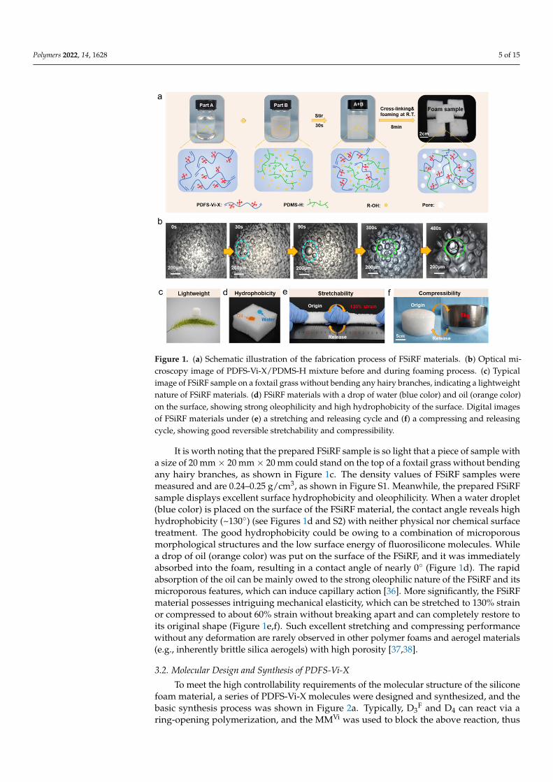
Figure 1. (a) Schematic illustration of the fabrication process of FSiRF materials. (b) Optical micros-
copy image of PDFS-Vi-X/PDMS-H mixture before and during foaming process. (c) Typical image
of FSiRF sample on a foxtail grass without bending any hairy branches, indicating a lightweight
nature of FSiRF materials. (d) FSiRF materials with a drop of water (blue color) and oil (orange color)
on the surface, showing strong oleophilicity and high hydrophobicity of the surface. Digital images
of FSiRF materials under (e) a stretching and releasing cycle and (f) a compressing and releasing
cycle, showing good reversible stretchability and compressibility.
3.2. Molecular Design and Synthesis of PDFS-Vi-X
To meet the high controllability requirements of the molecular structure of the sili-
cone foam material, a series of PDFS-Vi-X molecules were designed and synthesized, and
the basic synthesis process was shown in Figure 2a. Typically, D3F and D4 can react via a
ring-opening polymerization, and the MMVi was used to block the above reaction, thus
Figure 1. (a) Schematic illustration of the fabrication process of FSiRF materials. (b) Optical mi-croscopy image of PDFS-Vi-X/PDMS-H mixture before and during foaming process. (c) Typicalimage of FSiRF sample on a foxtail grass without bending any hairy branches, indicating a lightweightnature of FSiRF materials. (d) FSiRF materials with a drop of water (blue color) and oil (orange color)on the surface, showing strong oleophilicity and high hydrophobicity of the surface. Digital imagesof FSiRF materials under (e) a stretching and releasing cycle and (f) a compressing and releasingcycle, showing good reversible stretchability and compressibility.
It is worth noting that the prepared FSiRF sample is so light that a piece of sample witha size of 20 mm × 20 mm × 20 mm could stand on the top of a foxtail grass without bendingany hairy branches, as shown in Figure 1c. The density values of FSiRF samples weremeasured and are 0.24–0.25 g/cm3, as shown in Figure S1. Meanwhile, the prepared FSiRFsample displays excellent surface hydrophobicity and oleophilicity. When a water droplet(blue color) is placed on the surface of the FSiRF material, the contact angle reveals highhydrophobicity (~130◦) (see Figures 1d and S2) with neither physical nor chemical surfacetreatment. The good hydrophobicity could be owing to a combination of microporousmorphological structures and the low surface energy of fluorosilicone molecules. Whilea drop of oil (orange color) was put on the surface of the FSiRF, and it was immediatelyabsorbed into the foam, resulting in a contact angle of nearly 0◦ (Figure 1d). The rapidabsorption of the oil can be mainly owed to the strong oleophilic nature of the FSiRF and itsmicroporous features, which can induce capillary action [36]. More significantly, the FSiRFmaterial possesses intriguing mechanical elasticity, which can be stretched to 130% strainor compressed to about 60% strain without breaking apart and can completely restore toits original shape (Figure 1e,f). Such excellent stretching and compressing performancewithout any deformation are rarely observed in other polymer foams and aerogel materials(e.g., inherently brittle silica aerogels) with high porosity [37,38].
3.2. Molecular Design and Synthesis of PDFS-Vi-X
To meet the high controllability requirements of the molecular structure of the siliconefoam material, a series of PDFS-Vi-X molecules were designed and synthesized, and thebasic synthesis process was shown in Figure 2a. Typically, D3
F and D4 can react via aring-opening polymerization, and the MMVi was used to block the above reaction, thus
Polymers 2022, 14, 1628 6 of 15
obtaining the PDFS-Vi prepolymer. Clearly, the PDFS-Vi-X with different molar contentsof pendant trifluoropropyl groups were synthesized by simply altering the ratio of D4and D3
F and anionic polymerization time. Figure 2b illustrates that the five typical molarcontents (0, 12.5%, 25.0%, 37.5%, and 50.0%) of trifluoropropyl groups can be successfullyregulated by changing the molar ratio of D4 to D3
F [38], and the molecular weight (Mn,Mw, and PDI values) shown in Table 1 suggests a relatively good distribution of molecularweight of the synthesized PDFS-VI-X molecules, which is helpful for the preparation of theFSiRF materials.
Polymers 2022, 14, x FOR PEER REVIEW 7 of 16
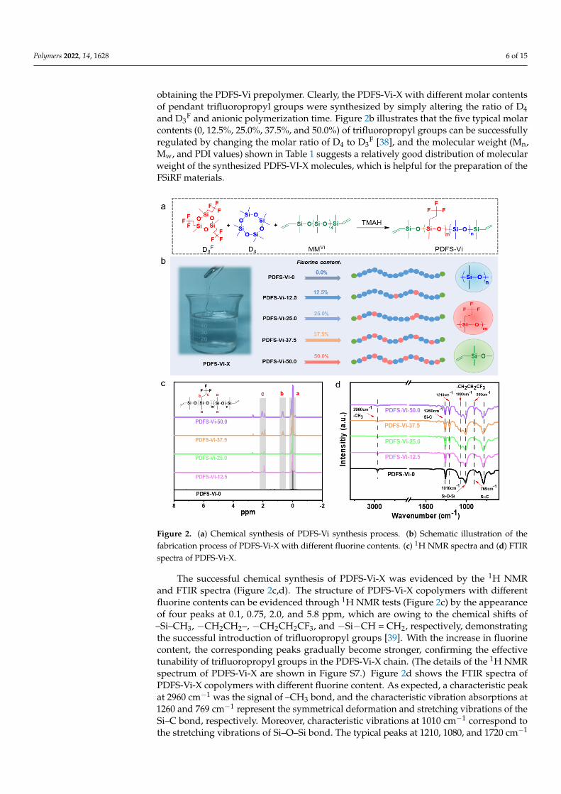
Figure 2. (a) Chemical synthesis of PDFS-Vi synthesis process. (b) Schematic illustration of the fab-
rication process of PDFS-Vi-X with different fluorine contents. (c) 1H NMR spectra and (d) FTIR
spectra of PDFS-Vi-X.
3.3. Pore Microstructures of FSiRF Materials
The pore structure of the prepared FSiRF foams is determined by the effective bal-
ance of the crosslinking and foaming reactions during the fabricating process. Typically,
the crosslinking reaction refers to the hydrosilylation reaction between hydrogen dime-
thicone molecules and vinyl-terminated poly(dimethyl-methyltrifluoropropyl)siloxane
molecules under the Pt-based catalyst to form a polymer network (see Figure 3a). The
foaming reaction means that the foaming agent (water) and hydrogen dimethicone pol-
ysiloxane react under Pt-based catalyst catalysis to release hydrogen to form a porous
structure (see Figure 3b). We do know that many factors would affect the size and uni-
formity of the pore structure of the silicone rubber foam. Besides the dispersion of the
foaming agent in the system, the most important factor is the balance of the reaction rates
of foaming and crosslinking [42]. In the initial stage, the crosslinking reaction and foaming
reaction are carried out at the same time. If the crosslinking degree of the system is not
sufficient and the viscosity is too low, the generated bubbles are easy to migrate in the
system and, thus, form some large bubbles. With the progress of the crosslinking reaction,
the crosslinking degree of the system increases, the viscosity also increases, and the gas
produced by the foaming reaction is hard to migrate in the system. After completion of
the foaming reaction and crosslinking reaction, the pore structure was finally formed.
When the fluorine content is low, the terminal vinyl of PDFS-Vi-X behaves with high re-
activity [43]. With increasing fluorine content, the activity of terminal vinyl reduces in-
tensely due to the steric hindrance of the trifluoropropyl group, which would affect the
pore morphology and structure.
Figure 2. (a) Chemical synthesis of PDFS-Vi synthesis process. (b) Schematic illustration of thefabrication process of PDFS-Vi-X with different fluorine contents. (c) 1H NMR spectra and (d) FTIRspectra of PDFS-Vi-X.
The successful chemical synthesis of PDFS-Vi-X was evidenced by the 1H NMRand FTIR spectra (Figure 2c,d). The structure of PDFS-Vi-X copolymers with differentfluorine contents can be evidenced through 1H NMR tests (Figure 2c) by the appearanceof four peaks at 0.1, 0.75, 2.0, and 5.8 ppm, which are owing to the chemical shifts of–Si–CH3, −CH2CH2–, −CH2CH2CF3, and −Si−CH = CH2, respectively, demonstratingthe successful introduction of trifluoropropyl groups [39]. With the increase in fluorinecontent, the corresponding peaks gradually become stronger, confirming the effectivetunability of trifluoropropyl groups in the PDFS-Vi-X chain. (The details of the 1H NMRspectrum of PDFS-Vi-X are shown in Figure S7.) Figure 2d shows the FTIR spectra ofPDFS-Vi-X copolymers with different fluorine content. As expected, a characteristic peakat 2960 cm−1 was the signal of –CH3 bond, and the characteristic vibration absorptions at1260 and 769 cm−1 represent the symmetrical deformation and stretching vibrations of theSi–C bond, respectively. Moreover, characteristic vibrations at 1010 cm−1 correspond tothe stretching vibrations of Si–O–Si bond. The typical peaks at 1210, 1080, and 1720 cm−1
Polymers 2022, 14, 1628 7 of 15
were associated with the asymmetrical deformation, symmetrical deformation, and stretchingvibrations of the –CH2CH2CF3, respectively. It is worth noting that the intensity of thesethree characteristic peaks become stronger with increasing fluorine content of the PDFS-Vi-Xcopolymers. The related viscosity and yield of the synthesized PDFS-Vi-X are shown inFigure S3, and the results indicate the relatively high yield (>80%) of the target molecules.The above results confirm the successful synthesis of the PDFS-Vi-X copolymers withtunable molecular structure, which agrees well with other studies [40,41].
3.3. Pore Microstructures of FSiRF Materials
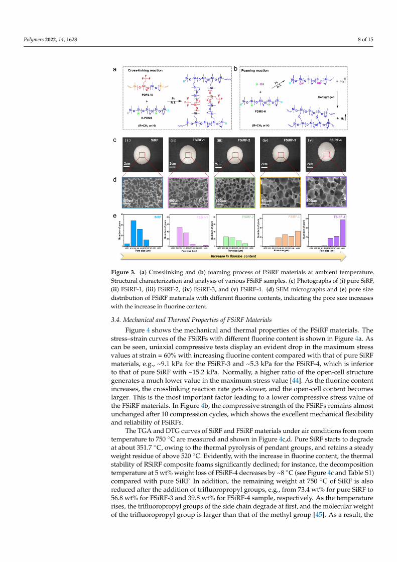
The pore structure of the prepared FSiRF foams is determined by the effective balanceof the crosslinking and foaming reactions during the fabricating process. Typically, thecrosslinking reaction refers to the hydrosilylation reaction between hydrogen dimethiconemolecules and vinyl-terminated poly(dimethyl-methyltrifluoropropyl)siloxane moleculesunder the Pt-based catalyst to form a polymer network (see Figure 3a). The foamingreaction means that the foaming agent (water) and hydrogen dimethicone polysiloxanereact under Pt-based catalyst catalysis to release hydrogen to form a porous structure (seeFigure 3b). We do know that many factors would affect the size and uniformity of thepore structure of the silicone rubber foam. Besides the dispersion of the foaming agent inthe system, the most important factor is the balance of the reaction rates of foaming andcrosslinking [42]. In the initial stage, the crosslinking reaction and foaming reaction arecarried out at the same time. If the crosslinking degree of the system is not sufficient andthe viscosity is too low, the generated bubbles are easy to migrate in the system and, thus,form some large bubbles. With the progress of the crosslinking reaction, the crosslinkingdegree of the system increases, the viscosity also increases, and the gas produced by thefoaming reaction is hard to migrate in the system. After completion of the foaming reactionand crosslinking reaction, the pore structure was finally formed. When the fluorine contentis low, the terminal vinyl of PDFS-Vi-X behaves with high reactivity [43]. With increasingfluorine content, the activity of terminal vinyl reduces intensely due to the steric hindranceof the trifluoropropyl group, which would affect the pore morphology and structure.
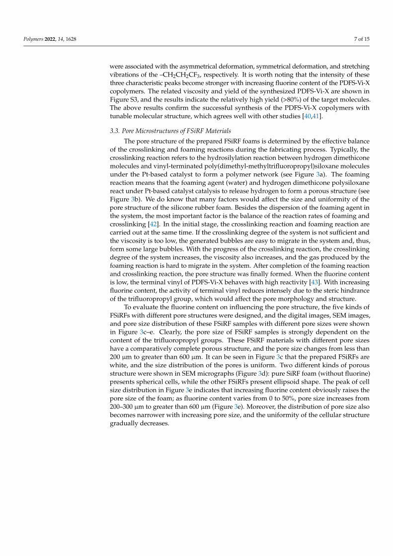
To evaluate the fluorine content on influencing the pore structure, the five kinds ofFSiRFs with different pore structures were designed, and the digital images, SEM images,and pore size distribution of these FSiRF samples with different pore sizes were shownin Figure 3c–e. Clearly, the pore size of FSiRF samples is strongly dependent on thecontent of the trifluoropropyl groups. These FSiRF materials with different pore sizeshave a comparatively complete porous structure, and the pore size changes from less than200 µm to greater than 600 µm. It can be seen in Figure 3c that the prepared FSiRFs arewhite, and the size distribution of the pores is uniform. Two different kinds of porousstructure were shown in SEM micrographs (Figure 3d): pure SiRF foam (without fluorine)presents spherical cells, while the other FSiRFs present ellipsoid shape. The peak of cellsize distribution in Figure 3e indicates that increasing fluorine content obviously raises thepore size of the foam; as fluorine content varies from 0 to 50%, pore size increases from200–300 µm to greater than 600 µm (Figure 3e). Moreover, the distribution of pore size alsobecomes narrower with increasing pore size, and the uniformity of the cellular structuregradually decreases.
Polymers 2022, 14, 1628 8 of 15
Polymers 2022, 14, x FOR PEER REVIEW 8 of 16
To evaluate the fluorine content on influencing the pore structure, the five kinds of
FSiRFs with different pore structures were designed, and the digital images, SEM images, and
pore size distribution of these FSiRF samples with different pore sizes were shown in Figure
3c–e. Clearly, the pore size of FSiRF samples is strongly dependent on the content of the tri-
fluoropropyl groups. These FSiRF materials with different pore sizes have a comparatively
complete porous structure, and the pore size changes from less than 200 μm to greater than
600 μm. It can be seen in Figure 3c that the prepared FSiRFs are white, and the size distribution
of the pores is uniform. Two different kinds of porous structure were shown in SEM micro-
graphs (Figure 3d): pure SiRF foam (without fluorine) presents spherical cells, while the other
FSiRFs present ellipsoid shape. The peak of cell size distribution in Figure 3e indicates that
increasing fluorine content obviously raises the pore size of the foam; as fluorine content varies
from 0 to 50%, pore size increases from 200–300 μm to greater than 600 μm (Figure 3e). More-
over, the distribution of pore size also becomes narrower with increasing pore size, and the
uniformity of the cellular structure gradually decreases.
Figure 3. (a) Crosslinking and (b) foaming process of FSiRF materials at ambient temperature. Struc-
tural characterization and analysis of various FSiRF samples. (c) Photographs of (ⅰ) pure SiRF, (ⅱ)
FSiRF-1, (ⅲ) FSiRF-2, (ⅳ) FSiRF-3, and (ⅴ) FSiRF-4. (d) SEM micrographs and (e) pore size distribu-
tion of FSiRF materials with different fluorine contents, indicating the pore size increases with the
increase in fluorine content.
3.4. Mechanical and Thermal Properties of FSiRF Materials
Figure 4 shows the mechanical and thermal properties of the FSiRF materials. The
stress–strain curves of the FSiRFs with different fluorine content is shown in Figure 4a. As
can be seen, uniaxial compressive tests display an evident drop in the maximum stress
values at strain = 60% with increasing fluorine content compared with that of pure SiRF
materials, e.g., ~9.1 kPa for the FSiRF-3 and ~5.3 kPa for the FSiRF-4, which is inferior to
that of pure SiRF with ~15.2 kPa. Normally, a higher ratio of the open-cell structure gen-
erates a much lower value in the maximum stress value [44]. As the fluorine content in-
creases, the crosslinking reaction rate gets slower, and the open-cell content becomes
Figure 3. (a) Crosslinking and (b) foaming process of FSiRF materials at ambient temperature.Structural characterization and analysis of various FSiRF samples. (c) Photographs of (i) pure SiRF,(ii) FSiRF-1, (iii) FSiRF-2, (iv) FSiRF-3, and (v) FSiRF-4. (d) SEM micrographs and (e) pore sizedistribution of FSiRF materials with different fluorine contents, indicating the pore size increaseswith the increase in fluorine content.
3.4. Mechanical and Thermal Properties of FSiRF Materials
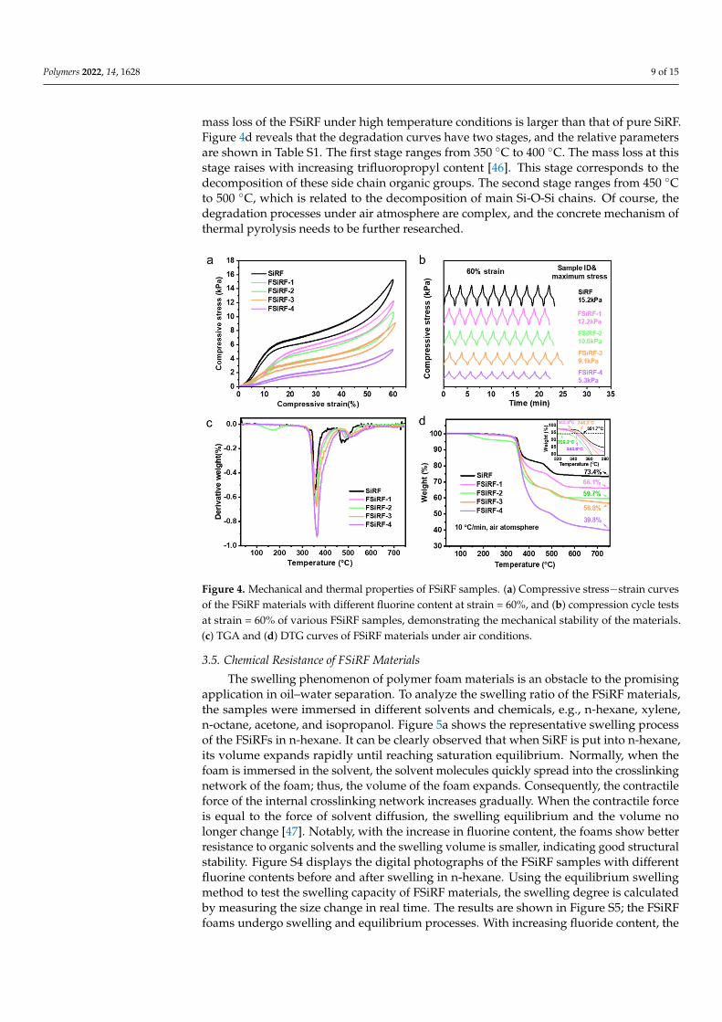
Figure 4 shows the mechanical and thermal properties of the FSiRF materials. Thestress–strain curves of the FSiRFs with different fluorine content is shown in Figure 4a. Ascan be seen, uniaxial compressive tests display an evident drop in the maximum stressvalues at strain = 60% with increasing fluorine content compared with that of pure SiRFmaterials, e.g., ~9.1 kPa for the FSiRF-3 and ~5.3 kPa for the FSiRF-4, which is inferiorto that of pure SiRF with ~15.2 kPa. Normally, a higher ratio of the open-cell structuregenerates a much lower value in the maximum stress value [44]. As the fluorine contentincreases, the crosslinking reaction rate gets slower, and the open-cell content becomeslarger. This is the most important factor leading to a lower compressive stress value ofthe FSiRF materials. In Figure 4b, the compressive strength of the FSiRFs remains almostunchanged after 10 compression cycles, which shows the excellent mechanical flexibilityand reliability of FSiRFs.
The TGA and DTG curves of SiRF and FSiRF materials under air conditions from roomtemperature to 750 ◦C are measured and shown in Figure 4c,d. Pure SiRF starts to degradeat about 351.7 ◦C, owing to the thermal pyrolysis of pendant groups, and retains a steadyweight residue of above 520 ◦C. Evidently, with the increase in fluorine content, the thermalstability of RSiRF composite foams significantly declined; for instance, the decompositiontemperature at 5 wt% weight loss of FSiRF-4 decreases by ~8 ◦C (see Figure 4c and Table S1)compared with pure SiRF. In addition, the remaining weight at 750 ◦C of SiRF is alsoreduced after the addition of trifluoropropyl groups, e.g., from 73.4 wt% for pure SiRF to56.8 wt% for FSiRF-3 and 39.8 wt% for FSiRF-4 sample, respectively. As the temperaturerises, the trifluoropropyl groups of the side chain degrade at first, and the molecular weightof the trifluoropropyl group is larger than that of the methyl group [45]. As a result, the
Polymers 2022, 14, 1628 9 of 15
mass loss of the FSiRF under high temperature conditions is larger than that of pure SiRF.Figure 4d reveals that the degradation curves have two stages, and the relative parametersare shown in Table S1. The first stage ranges from 350 ◦C to 400 ◦C. The mass loss at thisstage raises with increasing trifluoropropyl content [46]. This stage corresponds to thedecomposition of these side chain organic groups. The second stage ranges from 450 ◦Cto 500 ◦C, which is related to the decomposition of main Si-O-Si chains. Of course, thedegradation processes under air atmosphere are complex, and the concrete mechanism ofthermal pyrolysis needs to be further researched.
Polymers 2022, 14, x FOR PEER REVIEW 9 of 16
larger. This is the most important factor leading to a lower compressive stress value of the
FSiRF materials. In Figure 4b, the compressive strength of the FSiRFs remains almost un-
changed after 10 compression cycles, which shows the excellent mechanical flexibility and
reliability of FSiRFs.
The TGA and DTG curves of SiRF and FSiRF materials under air conditions from
room temperature to 750 °C are measured and shown in Figure 4c,d. Pure SiRF starts to
degrade at about 351.7 °C, owing to the thermal pyrolysis of pendant groups, and retains
a steady weight residue of above 520 °C. Evidently, with the increase in fluorine content,
the thermal stability of RSiRF composite foams significantly declined; for instance, the
decomposition temperature at 5 wt% weight loss of FSiRF-4 decreases by ~8 °C (see Figure
4c and Table S1) compared with pure SiRF. In addition, the remaining weight at 750 °C of
SiRF is also reduced after the addition of trifluoropropyl groups, e.g., from 73.4 wt% for
pure SiRF to 56.8 wt% for FSiRF-3 and 39.8 wt% for FSiRF-4 sample, respectively. As the
temperature rises, the trifluoropropyl groups of the side chain degrade at first, and the
molecular weight of the trifluoropropyl group is larger than that of the methyl group [45].
As a result, the mass loss of the FSiRF under high temperature conditions is larger than
that of pure SiRF. Figure 4d reveals that the degradation curves have two stages, and the
relative parameters are shown in Table S1. The first stage ranges from 350 °C to 400 °C.
The mass loss at this stage raises with increasing trifluoropropyl content [46]. This stage
corresponds to the decomposition of these side chain organic groups. The second stage
ranges from 450 °C to 500 °C, which is related to the decomposition of main Si-O-Si chains.
Of course, the degradation processes under air atmosphere are complex, and the concrete
mechanism of thermal pyrolysis needs to be further researched.
Figure 4. Mechanical and thermal properties of FSiRF samples. (a) Compressive stress−strain curves
of the FSiRF materials with different fluorine content at strain = 60%, and (b) compression cycle tests
at strain = 60% of various FSiRF samples, demonstrating the mechanical stability of the materials.
(c) TGA and (d) DTG curves of FSiRF materials under air conditions.
3.5. Chemical Resistance of FSiRF Materials
The swelling phenomenon of polymer foam materials is an obstacle to the promising
application in oil–water separation. To analyze the swelling ratio of the FSiRF materials,
Figure 4. Mechanical and thermal properties of FSiRF samples. (a) Compressive stress−strain curvesof the FSiRF materials with different fluorine content at strain = 60%, and (b) compression cycle testsat strain = 60% of various FSiRF samples, demonstrating the mechanical stability of the materials.(c) TGA and (d) DTG curves of FSiRF materials under air conditions.
3.5. Chemical Resistance of FSiRF Materials
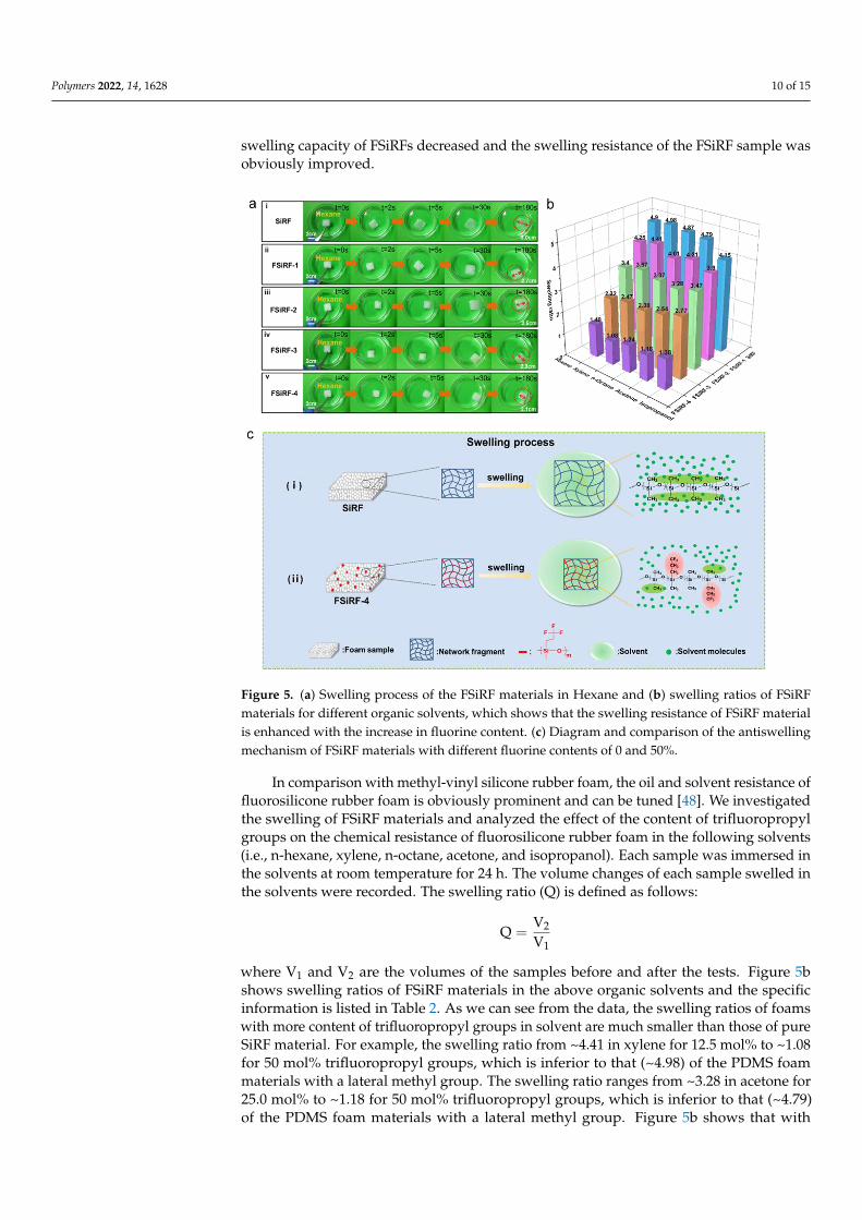
The swelling phenomenon of polymer foam materials is an obstacle to the promisingapplication in oil–water separation. To analyze the swelling ratio of the FSiRF materials,the samples were immersed in different solvents and chemicals, e.g., n-hexane, xylene,n-octane, acetone, and isopropanol. Figure 5a shows the representative swelling processof the FSiRFs in n-hexane. It can be clearly observed that when SiRF is put into n-hexane,its volume expands rapidly until reaching saturation equilibrium. Normally, when thefoam is immersed in the solvent, the solvent molecules quickly spread into the crosslinkingnetwork of the foam; thus, the volume of the foam expands. Consequently, the contractileforce of the internal crosslinking network increases gradually. When the contractile forceis equal to the force of solvent diffusion, the swelling equilibrium and the volume nolonger change [47]. Notably, with the increase in fluorine content, the foams show betterresistance to organic solvents and the swelling volume is smaller, indicating good structuralstability. Figure S4 displays the digital photographs of the FSiRF samples with differentfluorine contents before and after swelling in n-hexane. Using the equilibrium swellingmethod to test the swelling capacity of FSiRF materials, the swelling degree is calculatedby measuring the size change in real time. The results are shown in Figure S5; the FSiRFfoams undergo swelling and equilibrium processes. With increasing fluoride content, the
Polymers 2022, 14, 1628 10 of 15
swelling capacity of FSiRFs decreased and the swelling resistance of the FSiRF sample wasobviously improved.
Polymers 2022, 14, x FOR PEER REVIEW 11 of 16
The mechanisms of tunable chemical resistance were proposed and illustrated in Fig-
ure 5c. When a crosslinked polymer contacts with a solvent, the network absorbs a certain
amount of solvent, which is largely dependent on the polymer–solvent interactions
[49,50]. As shown in Figure 5c, the polarity of dimethyl silicone rubber foam molecules is
very small. According to the “Polarity nearness” rule in the polymer–solvent system,
some nonpolar or weak-polar solvent molecules can infiltrate into the crosslinking net-
work of SiRF and swell, leading to an increase in volume and a reduction of physical
properties. The chemically stable trifluoropropyl groups as substituents can “shield” the
main chain of Si-O-Si in fluorosilicon molecules and increase the polarity of the molecular
chain, which improves the chemical resistance of FSiRF materials. The feature further pro-
tects against the infiltration of solvent molecules into the crosslinking network, and obvi-
ously improves the structural stability of silicone rubber foams in various solvents.
Figure 5. (a) Swelling process of the FSiRF materials in Hexane and (b) swelling ratios of FSiRF
materials for different organic solvents, which shows that the swelling resistance of FSiRF material
is enhanced with the increase in fluorine content. (c) Diagram and comparison of the antiswelling
mechanism of FSiRF materials with different fluorine contents of 0 and 50%.
3.6. Oil–Water Separation of the FSiRF Materials
By taking advantage of oleophilic and hydrophobic properties, good mechanical flexibil-
ity and reliability, as well as excellent tunable chemical resistance, the FSiRF material can be
an ideal candidate as an efficient absorbent material that can absorb oil from oil–water mix-
tures. During the experiment, we found that the dimensional stability of the FSiRF materials
is closely related to the separation performance. In this paper, the FSiRF-4 material with the
best separation performance was selected as the demonstration for the application of oil–water
separation. As shown in Figure 6a, the porous FSiRF-4 sample with the best chemical re-
sistance is used to absorb the light organic solvent (xylene dyed by orange), which is floating
on water. The xylene was entirely absorbed by FSiRF-4, thereby, it was eliminated from the
Figure 5. (a) Swelling process of the FSiRF materials in Hexane and (b) swelling ratios of FSiRFmaterials for different organic solvents, which shows that the swelling resistance of FSiRF materialis enhanced with the increase in fluorine content. (c) Diagram and comparison of the antiswellingmechanism of FSiRF materials with different fluorine contents of 0 and 50%.
In comparison with methyl-vinyl silicone rubber foam, the oil and solvent resistance offluorosilicone rubber foam is obviously prominent and can be tuned [48]. We investigatedthe swelling of FSiRF materials and analyzed the effect of the content of trifluoropropylgroups on the chemical resistance of fluorosilicone rubber foam in the following solvents(i.e., n-hexane, xylene, n-octane, acetone, and isopropanol). Each sample was immersed inthe solvents at room temperature for 24 h. The volume changes of each sample swelled inthe solvents were recorded. The swelling ratio (Q) is defined as follows:
Q =V2
V1
where V1 and V2 are the volumes of the samples before and after the tests. Figure 5bshows swelling ratios of FSiRF materials in the above organic solvents and the specificinformation is listed in Table 2. As we can see from the data, the swelling ratios of foamswith more content of trifluoropropyl groups in solvent are much smaller than those of pureSiRF material. For example, the swelling ratio from ~4.41 in xylene for 12.5 mol% to ~1.08for 50 mol% trifluoropropyl groups, which is inferior to that (~4.98) of the PDMS foammaterials with a lateral methyl group. The swelling ratio ranges from ~3.28 in acetone for25.0 mol% to ~1.18 for 50 mol% trifluoropropyl groups, which is inferior to that (~4.79)of the PDMS foam materials with a lateral methyl group. Figure 5b shows that with
Polymers 2022, 14, 1628 11 of 15
the increase in fluorine content, the swelling ratio of foam in organic solvents decreasesgradually, which proves that the introduction of fluorine-containing groups can endowsilicone rubber foam with excellent chemical resistance and swelling resistance. The higherthe fluorine content is, the more obvious the swelling resistance is. Therefore, the chemicalresistance of fluorosilicone rubber foam materials can be tuned by controlling the amountof trifluoropropyl groups introduced.
Table 2. Swelling ratios of FSiRF materials for different organic solvents.
Sample CodeSwelling Ratio (100%)
Hexane Xylene N-Octane Acetone Isopropanol
SiRF 4.90 4.98 4.87 4.79 4.15FSiRF-1 4.25 4.41 4.01 4.21 3.90FSiRF-2 3.40 3.57 3.37 3.28 3.47FSiRF-3 2.32 2.47 2.39 2.54 2.77FSiRF-4 1.48 1.08 1.24 1.18 1.38
The mechanisms of tunable chemical resistance were proposed and illustrated inFigure 5c. When a crosslinked polymer contacts with a solvent, the network absorbs a certainamount of solvent, which is largely dependent on the polymer–solvent interactions [49,50].As shown in Figure 5c, the polarity of dimethyl silicone rubber foam molecules is verysmall. According to the “Polarity nearness” rule in the polymer–solvent system, somenonpolar or weak-polar solvent molecules can infiltrate into the crosslinking network ofSiRF and swell, leading to an increase in volume and a reduction of physical properties.The chemically stable trifluoropropyl groups as substituents can “shield” the main chain ofSi–O–Si in fluorosilicon molecules and increase the polarity of the molecular chain, whichimproves the chemical resistance of FSiRF materials. The feature further protects againstthe infiltration of solvent molecules into the crosslinking network, and obviously improvesthe structural stability of silicone rubber foams in various solvents.
3.6. Oil–Water Separation of the FSiRF Materials
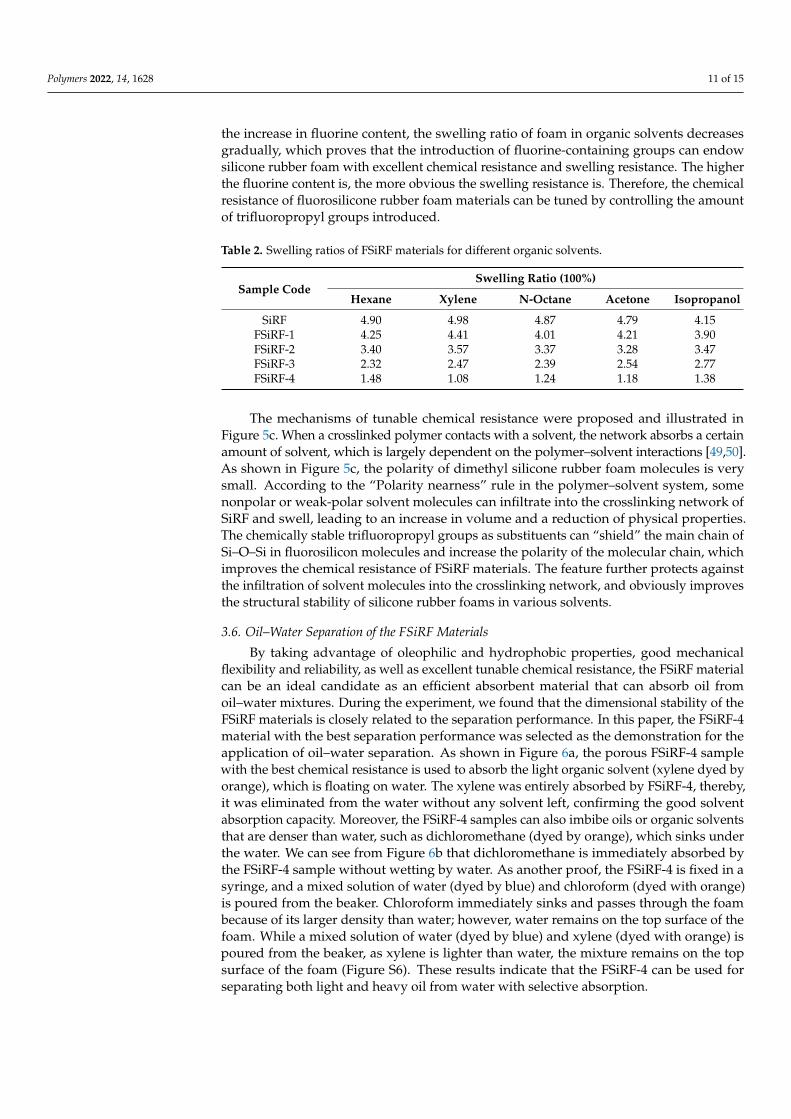
By taking advantage of oleophilic and hydrophobic properties, good mechanicalflexibility and reliability, as well as excellent tunable chemical resistance, the FSiRF materialcan be an ideal candidate as an efficient absorbent material that can absorb oil fromoil–water mixtures. During the experiment, we found that the dimensional stability of theFSiRF materials is closely related to the separation performance. In this paper, the FSiRF-4material with the best separation performance was selected as the demonstration for theapplication of oil–water separation. As shown in Figure 6a, the porous FSiRF-4 samplewith the best chemical resistance is used to absorb the light organic solvent (xylene dyed byorange), which is floating on water. The xylene was entirely absorbed by FSiRF-4, thereby,it was eliminated from the water without any solvent left, confirming the good solventabsorption capacity. Moreover, the FSiRF-4 samples can also imbibe oils or organic solventsthat are denser than water, such as dichloromethane (dyed by orange), which sinks underthe water. We can see from Figure 6b that dichloromethane is immediately absorbed bythe FSiRF-4 sample without wetting by water. As another proof, the FSiRF-4 is fixed in asyringe, and a mixed solution of water (dyed by blue) and chloroform (dyed with orange)is poured from the beaker. Chloroform immediately sinks and passes through the foambecause of its larger density than water; however, water remains on the top surface of thefoam. While a mixed solution of water (dyed by blue) and xylene (dyed with orange) ispoured from the beaker, as xylene is lighter than water, the mixture remains on the topsurface of the foam (Figure S6). These results indicate that the FSiRF-4 can be used forseparating both light and heavy oil from water with selective absorption.
Polymers 2022, 14, 1628 12 of 15
Polymers 2022, 14, x FOR PEER REVIEW 12 of 16
water without any solvent left, confirming the good solvent absorption capacity. Moreover,
the FSiRF-4 samples can also imbibe oils or organic solvents that are denser than water, such
as dichloromethane (dyed by orange), which sinks under the water. We can see from Figure
6b that dichloromethane is immediately absorbed by the FSiRF-4 sample without wetting by
water. As another proof, the FSiRF-4 is fixed in a syringe, and a mixed solution of water (dyed
by blue) and chloroform (dyed with orange) is poured from the beaker. Chloroform immedi-
ately sinks and passes through the foam because of its larger density than water; however,
water remains on the top surface of the foam. While a mixed solution of water (dyed by blue)
and xylene (dyed with orange) is poured from the beaker, as xylene is lighter than water, the
mixture remains on the top surface of the foam (Figure S6). These results indicate that the
FSiRF-4 can be used for separating both light and heavy oil from water with selective absorp-
tion.
Except uncomplicated adsorption and extruding for oil absorption and recovery, we
tried to continuously separate the oil–water blend under the assistance of a peristaltic
pump. The separation process is as follows: one port of the rubber tube is plugged with
FSiRF-4 while the other port is placed in a clean beaker, and the side containing the foam
is put in an oil–water blend. Based on a simple combination of FSiRF-4 sample with pipes
and a peristaltic pump to achieve continuous collection of oil from the oil–water mixture
[51], the oil–solvent collection process is shown in Figure 6c–d. In the pumping process
shown in Figure 6c, 50 mL heavy chloroform (dyed orange) can be immediately absorbed
by the macropores of the FSiRF-4 material and then pumped into the clean beaker in 60 s.
During the above processes, no water could pass through the FSiRF-4 due to the excellent
surface hydrophobicity [52]. In Figure 6d, the floating n-hexane (dyed orange) can be col-
lected from the water surface and pumped into the beaker in 90 s. After the above contin-
uous oil–water separation process, the dimensions of the FSiRF-4 sample remained almost
unchanged. (It shows that the structural stability of FSiRF-4 in continuous oil–water sep-
aration is better than that of PDMS foam. The comparison experiment is shown in Figure
S8.) Based on the results, it is clear that the optimized fluorosilicone foam materials with
high trifluoropropyl content prepared in this work show promising application in the
field of oil–water separation prospects.
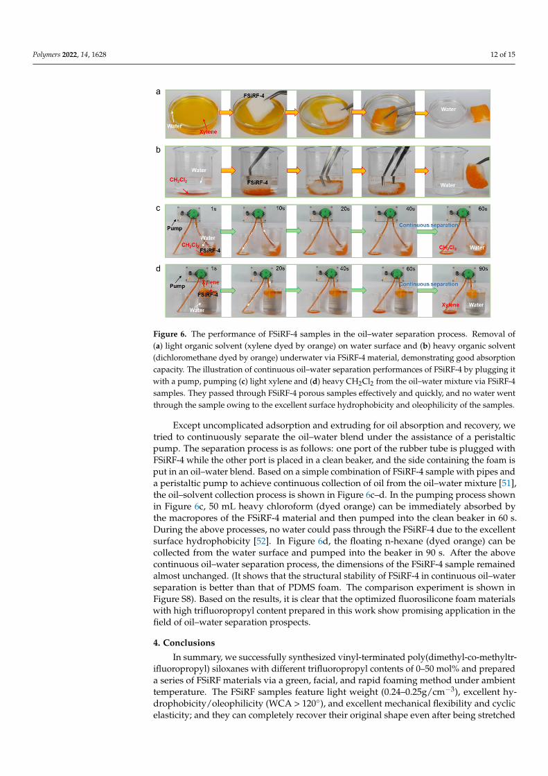
Figure 6. The performance of FSiRF-4 samples in the oil–water separation process. Removal of (a)
light organic solvent (xylene dyed by orange) on water surface and (b) heavy organic solvent (di-
chloromethane dyed by orange) underwater via FSiRF-4 material, demonstrating good absorption
Figure 6. The performance of FSiRF-4 samples in the oil–water separation process. Removal of(a) light organic solvent (xylene dyed by orange) on water surface and (b) heavy organic solvent(dichloromethane dyed by orange) underwater via FSiRF-4 material, demonstrating good absorptioncapacity. The illustration of continuous oil–water separation performances of FSiRF-4 by plugging itwith a pump, pumping (c) light xylene and (d) heavy CH2Cl2 from the oil–water mixture via FSiRF-4samples. They passed through FSiRF-4 porous samples effectively and quickly, and no water wentthrough the sample owing to the excellent surface hydrophobicity and oleophilicity of the samples.
Except uncomplicated adsorption and extruding for oil absorption and recovery, wetried to continuously separate the oil–water blend under the assistance of a peristalticpump. The separation process is as follows: one port of the rubber tube is plugged withFSiRF-4 while the other port is placed in a clean beaker, and the side containing the foam isput in an oil–water blend. Based on a simple combination of FSiRF-4 sample with pipes anda peristaltic pump to achieve continuous collection of oil from the oil–water mixture [51],the oil–solvent collection process is shown in Figure 6c–d. In the pumping process shownin Figure 6c, 50 mL heavy chloroform (dyed orange) can be immediately absorbed bythe macropores of the FSiRF-4 material and then pumped into the clean beaker in 60 s.During the above processes, no water could pass through the FSiRF-4 due to the excellentsurface hydrophobicity [52]. In Figure 6d, the floating n-hexane (dyed orange) can becollected from the water surface and pumped into the beaker in 90 s. After the abovecontinuous oil–water separation process, the dimensions of the FSiRF-4 sample remainedalmost unchanged. (It shows that the structural stability of FSiRF-4 in continuous oil–waterseparation is better than that of PDMS foam. The comparison experiment is shown inFigure S8). Based on the results, it is clear that the optimized fluorosilicone foam materialswith high trifluoropropyl content prepared in this work show promising application in thefield of oil–water separation prospects.
4. Conclusions
In summary, we successfully synthesized vinyl-terminated poly(dimethyl-co-methyltr-ifluoropropyl) siloxanes with different trifluoropropyl contents of 0–50 mol% and prepareda series of FSiRF materials via a green, facial, and rapid foaming method under ambienttemperature. The FSiRF samples feature light weight (0.24–0.25g/cm−3), excellent hy-drophobicity/oleophilicity (WCA > 120◦), and excellent mechanical flexibility and cyclicelasticity; and they can completely recover their original shape even after being stretched
Polymers 2022, 14, 1628 13 of 15
to 130% strain or compressed over 60%. Notably, with increasing fluorine content, theFSiRF materials display excellent structural stability and excellent solvent–oil resistance invarious solvents (e.g., swelling ratio from ~4.41 in xylene for 12.5 mol% to ~1.08 for 50 mol%trifluoropropyl groups, which is inferior to that (~4.98) of the PDMS foam materials with alateral methyl group. Further, the optimized FSiRF samples with 50 mol% trifluoropropylgroups demonstrated excellent adsorption potentiality for both floating or heavy solvent–oil and consecutive oil–water separating ability. Clearly, this work extends the designand development of novel high-performance fluorosilicone rubber foam materials withgood mechanical flexibility (for both stretching and compressing) and tunable chemicalresistance, showing promise for potential oil–water separation application.
Supplementary Materials: The following supporting information can be downloaded at https://www.mdpi.com/article/10.3390/polym14081628/s1, Figure S1: The density of FSiRF materialswith different fluorine contents; Figure S2: Surface water contact angles (insets are the water contactangles) of FSiRF materials; Figure S3: Viscosity and yield of PDFS-Vi-X with different fluorinecontents; Figure S4: Photographs of FSiRF materials before and after swelling; Figure S5: Swellingcapacity of FSiRF materials in hexane and xylene, respectively; Figure S6: Photographs of separatedoil (dyed orange)/water (dyed blue) mixture for the FSiRF materials; Figure S7: Details of the 1HNMR spectrum of PDFS-Vi-X; Figure S8: The performance of SiRF samples in the oil/water separationprocess; Table S1: Detailed information of TGA curves under air conditions; Table S2. The feedingnumber of reactants to synthesize PDFS-Vi-X.
Author Contributions: W.-J.H.: writing—original draft, investigation, visualization; Q.-Q.X.: investi-gation, methodology; H.-T.P., H.-Y.C., Y.-X.Q. and Z.-Y.C.: methodology; G.-D.Z.: conceptualization,methodology, data curation; L.Z.: visualization, software; L.-X.G. and C.-G.X.: validation; L.-C.T.:supervision, conceptualization, writing—review and editing. All authors have read and agreed tothe published version of the manuscript.
Funding: This research was funded by the National Natural Science Foundation of China, grantnumber 51973047, Science Foundation and Technology Project of Zhejiang Province, grant numberZ22E035302 and LGG20B040002, Natural Science Foundation of Shandong Province, grant num-ber ZR2020LFG004, Science and Technology Project of Hangzhou, grant number 20201203B136,20201203B134, and 20191203B16; Professional Development Project for Visiting Scholars in Collegesand Universities in Zhejiang Province, grant number FX2021066.
Institutional Review Board Statement: Not applicable.
Informed Consent Statement: Not applicable.
Data Availability Statement: Not applicable.
Acknowledgments: We acknowledge the funding support from the National Natural Science Foundationof China (51973047), the Science Foundation and Technology Project of Zhejiang Province (Z22E035302 andLGG20B040002), the Natural Science Foundation of Shandong Province (ZR2020LFG004), the Science andTechnology Project of Hangzhou (20201203B136, 20201203B134, and 20191203B16), and the ProfessionalDevelopment Project for Visiting Scholars in Colleges and Universities in Zhejiang Province (FX2021066).
Conflicts of Interest: The authors declare no conflict of interest.
References1. Rostami-Tapeh-Esmaeil, E.; Vahidifar, A.; Esmizadeh, E.; Rodrigue, D. Chemistry, processing, properties, and applications of
rubber foams. Polymers 2021, 13, 1565. [CrossRef] [PubMed]2. Chen, Q.; Zhao, J.; Ren, J.; Rong, L.; Cao, P.F.; Advincula, R.C. 3D printed multifunctional, hyperelastic silicone rubber foam. Adv.
Funct. Mater. 2019, 29, 1900469. [CrossRef]3. Dai, S.-W.; Gu, Y.-L.; Zhao, L.; Zhang, W.; Gao, C.-H.; Wu, Y.-X.; Shen, S.-C.; Zhang, C.; Kong, T.-T.; Li, Y.-T.; et al. Bamboo-inspired
mechanically flexible and electrically conductive polydimethylsiloxane foam materials with designed hierarchical pore structuresfor ultra-sensitive and reliable piezoresistive pressure sensor. Compos. Part. B-Eng. 2021, 225, 109243. [CrossRef]
4. Yang, J.; Liao, X.; Wang, G.; Chen, J.; Song, P.; Tang, W.; Guo, F.; Liu, F.; Li, G. Heterogeneous silicon rubber composite foam withgradient porous structure for highly absorbed ultra-efficient electromagnetic interference shielding. Compos. Sci. Technol. 2021,206, 108663. [CrossRef]
Polymers 2022, 14, 1628 14 of 15
5. Yan, H.; Wang, K.; Zhao, Y. Fabrication of silicone rubber foam with tailored porous structures by supercritical CO2. Macromol.Mater. Eng. 2017, 302, 1600377. [CrossRef]
6. Zhang, G.-D.; Wu, Z.-H.; Xia, Q.-Q.; Qu, Y.-X.; Pan, H.-T.; Hu, W.-J.; Zhao, L.; Cao, K.; Chen, E.-Y.; Yuan, Z.; et al. UltrafastFlame-Induced Pyrolysis of Poly(dimethylsiloxane) Foam Materials toward Exceptional Superhydrophobic Surfaces and ReliableMechanical Robustness. ACS Appl. Mater. Interfaces 2021, 13, 23161–23172. [CrossRef]
7. Mao, M.; Xu, H.; Guo, K.-Y.; Zhang, J.-W.; Xia, Q.-Q.; Zhang, G.-D.; Zhao, L.; Gao, J.-F.; Tang, L.-C. Mechanically flexible,super-hydrophobic and flame-retardant hybrid nano-silica/graphene oxide wide ribbon decorated sponges for efficient oil/waterseparation and fire warning response. Compos. Part. A 2021, 140, 106191. [CrossRef]
8. Zhang, C.; Qu, L.; Wang, Y.; Xu, T.; Zhang, C. Thermal insulation and stability of polysiloxane foams containing hydroxyl-terminated polydimethylsiloxanes. RSC Adv. 2018, 8, 9901–9909. [CrossRef]
9. Long, Y.; Zhao, X.; Jiang, X.; Zhang, L.; Zhang, H.; Liu, Y.; Zhu, H. A porous graphene/polydimethylsiloxane composite bychemical foaming for simultaneous tensile and compressive strain sensing. FlatChem 2018, 10, 1–7. [CrossRef]
10. Zhu, D.; Handschuh-Wang, S.; Zhou, X. Recent progress in fabrication and application of polydimethylsiloxane sponges. J. Mater.Chem. A 2017, 5, 16467–16497. [CrossRef]
11. Cao, C.-F.; Wang, P.-H.; Zhang, J.-W.; Guo, K.-Y.; Li, Y.; Xia, Q.-Q.; Zhang, G.-D.; Zhao, L.; Chen, H.; Wang, L.; et al. One-stepand green synthesis of lightweight, mechanically flexible and flame-retardant polydimethylsiloxane foam nanocomposites viasurface-assembling ultralow content of graphene derivative. Chem. Eng. J. 2020, 393, 124724. [CrossRef]
12. Xiang, B.; Jia, Y.; Lei, Y.; Zhang, F.; He, J.; Liu, T.; Luo, S. Mechanical properties of microcellular and nanocellular silicone rubberfoams obtained by supercritical carbon dioxide. Polym. J. 2019, 51, 559–568. [CrossRef]
13. Cai, J.-H.; Huang, M.-L.; Chen, X.-D.; Wang, M. Thermo-expandable microspheres strengthened polydimethylsiloxane foam withunique softening behavior and high-efficient energy absorption. Appl. Surf. Sci. 2021, 540, 148364. [CrossRef]
14. Li, Y.; Cao, C.-F.; Li, S.-N.; Huang, N.-J.; Mao, M.; Zhang, J.-W.; Wang, P.-H.; Guo, K.-Y.; Gong, L.-X.; Zhang, G.-D.; et al. In situreactive self-assembly of a graphene oxide nano-coating in polymer foam materials with synergistic fire shielding properties. J.Mater. Chem. A 2019, 7, 27032–27040. [CrossRef]
15. Turco, A.; Primiceri, E.; Frigione, M.; Maruccio, G.; Malitesta, C. An innovative, fast and facile soft-template approach for thefabrication of porous PDMS for oil–water separation. J. Mater. Chem. A 2017, 5, 23785–23793. [CrossRef]
16. Zeng, Z.; Mavrona, E.; Sacré, D.; Kummer, N.; Cao, J.; Müller, L.A.E.; Hack, E.; Zolliker, P.; Nyström, G. Terahertz BirefringentBiomimetic Aerogels Based on Cellulose Nanofibers and Conductive Nanomaterials. ACS. Nano 2021, 15, 7451–7462. [CrossRef][PubMed]
17. Zeng, Z.; Wu, T.; Han, D.; Ren, Q.; Siqueira, G.; Nyström, G. Ultralight, Flexible, and Biomimetic Nanocellulose/Silver NanowireAerogels for Electromagnetic Interference Shielding. ACS. Nano 2020, 14, 2927–2938. [CrossRef]
18. Hailan, S.M.; Ponnamma, D.; Krupa, I. The Separation of Oil/Water Mixtures by Modified Melamine and Polyurethane Foams: AReview. Polymers 2021, 13, 4142. [CrossRef]
19. Cao, C.-F.; Liu, W.-J.; Xu, H.; Yu, K.-X.; Gong, L.-X.; Guo, B.-F.; Li, Y.-T.; Feng, X.-L.; Lv, L.-Y.; Pan, H.-T.; et al. Temperature-inducedresistance transition behaviors of melamine sponge composites wrapped with different graphene oxide derivatives. J. Mater. Sci.Technol. 2021, 85, 194–204. [CrossRef]
20. Guo, K.-Y.; Wu, Q.; Mao, M.; Chen, H.; Zhang, G.-D.; Zhao, L.; Gao, J.-F.; Song, P.; Tang, L.-C. Water-based hybrid coatings towardmechanically flexible, super-hydrophobic and flame-retardant polyurethane foam nanocomposites with high-efficiency andreliable fire alarm response. Compos. Part. B-Eng. 2020, 193, 108017. [CrossRef]
21. Wu, Q.; Zhang, J.; Wang, S.; Chen, B.; Feng, Y.; Pei, Y.; Yan, Y.; Tang, L.; Qiu, H.; Wu, L. Exceptionally flame-retardant flexiblepolyurethane foam composites: Synergistic effect of the silicone resin/graphene oxide coating. Front. Chem. Sci. Eng. 2021, 15,969–983. [CrossRef]
22. Yu, Z.-R.; Mao, M.; Li, S.-N.; Xia, Q.-Q.; Cao, C.-F.; Zhao, L.; Zhang, G.-D.; Zheng, Z.-J.; Gao, J.-F.; Tang, L.-C. Facile and greensynthesis of mechanically flexible and flame-retardant clay/graphene oxide nanoribbon interconnected networks for fire safetyand prevention. Chem. Eng. J. 2021, 405, 126620. [CrossRef]
23. Kim, B.-Y.; Hong, L.-Y.; Chung, Y.-M.; Kim, D.-P.; Lee, C.-S. Solvent-Resistant PDMS Microfluidic Devices with Hybrid Inor-ganic/Organic Polymer Coatings. Adv. Funct. Mater. 2009, 19, 3796–3803. [CrossRef]
24. Lee, J.N.; Park, C.; Whitesides, G.M. Solvent compatibility of poly(dimethylsiloxane)-based microfluidic devices. Anal. Chem.2003, 75, 6544–6554. [CrossRef] [PubMed]
25. Choi, S.-J.; Kwon, T.-H.; Im, H.; Moon, D.-I.; Baek, D.J.; Seol, M.-L.; Duarte, J.P.; Choi, Y.-K. A Polydimethylsiloxane (PDMS)Sponge for the Selective Absorption of Oil from Water. ACS Appl. Mater. Interfaces 2011, 3, 4552–4556. [CrossRef]
26. Shin, J.H.; Heo, J.-H.; Jeon, S.; Park, J.H.; Kim, S.; Kang, H.-W. Bio-inspired hollow PDMS sponge for enhanced oil–waterseparation. J. Hazard. Mater. 2019, 365, 494–501. [CrossRef]
27. Guan, Y.; Cheng, F.; Pan, Z. Superwetting Polymeric Three Dimensional (3D) Porous Materials for Oil/Water Separation: AReview. Polymers 2019, 11, 806. [CrossRef]
28. Tran, T.T.V.; Nguyen, C.H.; Lin, W.-C.; Juang, R.-S. Improved stability of a supported liquid membrane process via hydrophobicmodification of PVDF support by plasma activation and chemical vapor deposition. Sep. Purif. Technol. 2021, 277, 119615.[CrossRef]
Polymers 2022, 14, 1628 15 of 15
29. Evsyukova, N.V.; Myshkovskii, A.M.; Polukhina, L.M.; Serenko, O.A.; Nikitin, L.N.; Muzafarov, A.M. Making fabrics water-repellent with fluorine-containing silane in supercritical carbon dioxide medium. Fibre Chem. 2009, 41, 46–52. [CrossRef]
30. Peng, Z.; Song, J.; Gao, Y.; Liu, J.; Lee, C.; Chen, G.; Wang, Z.; Chen, J.; Leung, M.K.H. A fluorinated polymer sponge withsuperhydrophobicity for high-performance biomechanical energy harvesting. Nano Energy 2021, 85, 106021. [CrossRef]
31. Indulekha, K.; Mathew, A.; Rajeev, R.S.; Ninan, K.N.; Gouri, C. A facile route to fluoroalkylsiloxane polymers having resistance tocorrosive acidic conditions: Synthesis and characterization. Eur. Polym. J. 2017, 97, 94–103. [CrossRef]
32. Furukawa, Y.; Kotera, M. Synthesis of fluorosilicone having highly fluorinated alkyl side chains based on the hydrosilylation offluorinated olefins with polyhydromethylsiloxane. J. Polym. Sci. Part A Polym. Chem. 2002, 40, 3120–3128. [CrossRef]
33. Cui, Y.; Jiang, W.; Li, D.; Niu, C.; Jiezhang; Feng, S. Preparation and properties of fluorosilicone and fluorosilicone elastomer withvarious contents of trifluoropropyl groups. e-Polymers 2011, 11. [CrossRef]
34. Wang, M.; Yuan, Y.; Zhao, C.; Diao, S.; Duan, B. Preparation of fluorosilicone rubber containing perfluorocyclobutyl aryl ether.Polym. Adv. Technol. 2021, 32, 538–543. [CrossRef]
35. Guan, Y.; Yang, R.; Huang, Y.; Yu, C.; Li, X.; Wei, D.; Xu, X. Multi-walled carbon nanotubes acting as antioxidant for fluorosiliconerubber. Polym. Degrad. Stab. 2018, 156, 161–169. [CrossRef]
36. Métivier, T.; Cassagnau, P. Foaming behavior of silicone/fluorosilicone blends. Polymer 2018, 146, 21–30. [CrossRef]37. Yang, Z.; Bai, Y.; Meng, L.; Wang, Y.; Pang, A.; Guo, X.; Xiao, J.; Li, W. A review of poly[(3,3,3-trifluoropropyl)methylsiloxane]:
Synthesis, properties and applications. Eur. Polym. J. 2022, 163, 110903. [CrossRef]38. Indulekha, K.; Behera, P.K.; Rajeev, R.S.; Gouri, C.; Ninan, K.N. Polyfluoroalkyl siloxanes with varying trifluoropropyl content:
Synthesis, characterization and solvent resistance studies. J. Fluor. Chem. 2017, 200, 24–32. [CrossRef]39. Kählig, H.; Zöllner, P.; Mayer-Helm, B.X. Characterization of degradation products of poly[(3,3,3-trifluoropropyl)methylsiloxane]
by nuclear magnetic resonance spectroscopy, mass spectrometry and gas chromatography. Polym. Degrad. Stab. 2009, 94,1254–1260. [CrossRef]
40. Shmeleva, O.A.; Mileshkevich, V.P. Study of the equilibrium copolymerization of dimethyl- and methyl(3,3,3-trifluoropropyl)cyclo-siloxanes. Polym. Sci. USSR. 1990, 32, 2112–2117. [CrossRef]
41. Li, B.; Chen, S.; Zhang, J. Synthesis and characterization of vinyl-terminated copolysiloxanes containing 3,3,3-trifluoropropylgroups. Polym. Chem. 2012, 3, 2366–2376. [CrossRef]
42. Xu, T.; Zhang, J.; Qu, L.; Dai, X.; Li, P.; Sui, Y.; Zhang, C. Fabrication of polysiloxane foam with a pendent phenyl group forimproved thermal insulation capacity and thermal stability. New J. Chem. 2019, 43, 6136–6145. [CrossRef]
43. Fei, H.-F.; Gao, X.; Han, X.; Wang, Q.; Hu, T.; Zhang, Z.; Xie, Z. Synthesis, characterization, and properties of vinyl-terminatedcopolysiloxanes containing trifluoropropyl and 4-trifluoromethylphenyl groups. J. Polym. Sci. Part A Polym. Chem. 2015, 53,1023–1031. [CrossRef]
44. Tang, W.; Liao, X.; Zhang, Y.; Li, J.; Wang, G.; Li, G. Mechanical–Microstructure Relationship and Cellular Failure Mechanismof Silicone Rubber Foam by the Cell Microstructure Designed in Supercritical CO2. J. Phys. Chem. C. 2019, 123, 26947–26956.[CrossRef]
45. Li, B.; Chen, S.; Zhang, J. Effects of CH2CH2CF3 on properties of RTV polysiloxane rubber: Processability, thermal stability, andoil/solvent resistance. J. Appl. Polym. Sci. 2014, 131. [CrossRef]
46. You, Y.; Chen, J.; Zheng, A.; Wei, D.; Xu, X.; Guan, Y. Effect of silanol on the thermal stability of poly[methyl(trifluoropropyl)siloxane].J. Appl. Polym. Sci. 2020, 137, 49347. [CrossRef]
47. González-Rivera, J.; Iglio, R.; Barillaro, G.; Duce, C.; Tinè, M. Structural and Thermoanalytical Characterization of 3D PorousPDMS Foam Materials: The Effect of Impurities Derived from a Sugar Templating Process. Polymers 2018, 10, 616. [CrossRef]
48. Dawir, M. Sealing in the automotive industry with liquid fluoro-silicone elastomers. Seal. Technol. 2008, 2008, 10–14. [CrossRef]49. Liao, S.; He, Y.; Chu, Y.; Liao, H.; Wang, Y. Solvent-resistant and fully recyclable perfluoropolyether-based elastomer for
microfluidic chip fabrication. J. Mater. Chem. A 2019, 7, 16249–16256. [CrossRef]50. Ma, Q.; Liao, S.; Ma, Y.; Chu, Y.; Wang, Y. An Ultra-Low-Temperature Elastomer with Excellent Mechanical Performance and
Solvent Resistance. Adv. Mater. 2021, 33, 2102096. [CrossRef]51. Ge, J.; Ye, Y.D.; Yao, H.B.; Zhu, X.; Wang, X.; Wu, L.; Wang, J.L.; Ding, H.; Yong, N.; He, L.H.; et al. Pumping through Porous
Hydrophobic/Oleophilic Materials: An Alternative Technology for Oil Spill Remediation. Angew. Chem. 2014, 53, 3612–3616.[CrossRef] [PubMed]
52. Zhang, Z.H.; Chen, Z.Y.; Tang, Y.H.; Li, Y.T.; Ma, D.; Zhang, G.D.; Rabah, B.; Cao, C.F.; Gong, L.X.; Song, P.; et al. Silicone/grapheneoxide co-cross-linked aerogels with wide-temperature mechanical flexibility, super-hydrophobicity and flame resistance forexceptional thermal insulation and oil/water separation. J. Mater. Sci. Technol. 2022, 114, 131–142. [CrossRef]