The Book of Seals & Amulets (The Shadow Tree Series, Volume 3)
Upload
khangminh22Category
view
5download
0
GOES-R Series
Data Book
Prepared for
National Aeronautics and Space Administration
GOES-R Series Program Office
Goddard Space Flight Center
Greenbelt, Maryland 20771
Pursuant to
Contract NNG09HR00C
Revision A
May 2019
CDRL PM-14

ii
This page left blank

iii
CONTENTS
Foreword___________________________________________________________________ v
Preface ___________________________________________________________________ vii
Acknowledgements ________________________________________________________ ix
1. Mission Overview _____________________________________________________ 1-1
2. GOES Spacecraft Configuration ________________________________________ 2-1
3. Advanced Baseline Imager ___________________________________________ 3-1
4. Geostationary Lightning Mapper _______________________________________ 4-1
5. Space Environment In-Situ Suite _______________________________________ 5-1
6. Magnetometer _______________________________________________________ 6-1
7. The Extreme Ultraviolet and X-ray Irradiance Sensors Instrument _________ 7-1
8. Solar Ultraviolet Imager _______________________________________________ 8-1
9. GOES-R Communications Subsystem ___________________________________ 9-1
10. Command and Data Handling Subsystem ___________________________ 10-1
11. Electrical Power Subsystem _________________________________________ 11-1
12. Guidance Navigation & Control _____________________________________ 12-1
13. Propulsion Subsystem ______________________________________________ 13-1
14. Thermal Control Subsystem _________________________________________ 14-1
15. Mechanisms _______________________________________________________ 15-1
16. Ground System Architecture ________________________________________ 16-1
17. Spacecraft Mission Phases __________________________________________ 17-1
18. On-Orbit Mission Operations ________________________________________ 18-1
19. Technical Performance Summary ___________________________________ 19-1
20. Acronyms _________________________________________________________ 20-1

iv
This page left blank

v
Foreword
The Geostationary Operational Environmental Satellite – R Series (GOES-R) is the next
generation of U.S geostationary weather satellites and is a key element in National Oceanic and
Atmospheric Administration (NOAA) operations. GOES weather imagery and advanced weather
products have been a continuous and reliable stream of environmental information used to
support weather forecasting, severe storm tracking, and meteorological research. Evolutionary
improvements in the geostationary satellite system since 1974 (i.e., since the first Synchronous
Meteorological Satellite, SMS-1) have been responsible for making the GOES system a mainstay
of weather forecasts and environmental monitoring.
The GOES-R series (GOES R, S, T, and U) represents the first major technological advancement
in geostationary observations since 1994 and will extend the availability of the GOES system
through 2036. The GOES-R series provides critical atmospheric, hydrologic, oceanic, climatic,
solar and space data, significantly improving the detection and observation of environmental
phenomena that directly affect public safety, protection of property, and our nation’s economic
health and prosperity.
Designed to operate in geosynchronous orbit, 35,786 km (22,236 statute miles) above the
equator, thereby remaining stationary relative to the Earth’s surface, the advanced GOES-R
series spacecraft continuously views the contiguous United States, neighboring environs of the
Pacific and Atlantic Oceans, and Central and South America. The GOES-R series spacecraft bus
is three-axis stabilized and designed for 10 years of on-orbit operation preceded by up to five
years of on-orbit storage. Two GOES satellites remain operational at all times while an on-orbit
spare is maintained to permit rapid recovery from a failure of either of the operational satellites.
The Advanced Baseline Imager (ABI) is the primary instrument on the GOES-R series spacecraft
for imaging Earth’s weather, oceans and environment. ABI views the Earth with 16 different
spectral bands (compared to five on the previous GOES series), including two visible channels,
four near-infrared channels, and ten infrared channels. ABI’s data enables meteorologists to
pinpoint and track developing storms in much greater detail.
The Geostationary Lightning Mapper (GLM) is the first operational lightning mapper flown in
geostationary orbit. GLM detects and maps total lightning (in-cloud and cloud-to-ground) activity
continuously over the Americas and adjacent ocean regions. Used in combination with radar, data
from the ABI instrument, and surface observations, GLM data has great potential to increase lead
time for severe thunderstorm and tornado warnings.
GOES-R series spacecraft also carry a suite of instruments to significantly improve detection of
approaching space weather hazards. The satellites provide advanced imaging of the sun and
detection of solar eruptions for earlier warning of disruption to power utilities and communication
and navigation systems. The satellites also more accurately monitor energetic particles and the
magnetic field variations that are associated with space weather for better assessment of radiation
hazards and mitigation of damage to orbiting satellites, communications, and power grids.

vi
Ground support is critical to the GOES-R series mission. To support the large increase in spatial,
spectral, and temporal resolution of the ABI and other instruments, the raw data rate increased to
75Mbps, over 30 times the previous rate. NOAA has developed a state-of-the-art ground system
to receive data from the GOES-R series spacecraft and generate real-time data products. The
ground system operates from two primary locations: the National Satellite Operations Facility
(NSOF) in Suitland, Maryland, and the Wallops Command and Data Acquisition Center (WCDAS)
at Wallops, Virginia. A third operations facility in Fairmont, West Virginia, serves as the
Consolidated Backup (CBU) in case of a systems or communications failure at either or both
NSOF and WCDAS.
Those desiring further information about the GOES system should contact the NOAA National
Environmental Satellite, Data and Information Service (NESDIS) and/or search the following
internet addresses:
https://www.goes-r.gov/
http://www.noaa.gov/
https://www.nesdis.noaa.gov/
https://www.weather.gov/
https://www.ncei.noaa.gov/
https://www.swpc.noaa.gov/

vii
Preface
To further enhance the utility of the GOES system, this reference presents a summary and
technical overview of the GOES-R series system, its satellites, subsystems, sensor suite, and
associated ground communication and data handling subsystems. The reference is intended to
serve as a convenient and comprehensive technical reference for people working on or
associated with the GOES-R series mission as well as general information suitable for public
distribution. Sufficient technical information and performance data are presented to enable the
reader to understand the importance of the GOES-R series mission, the system’s capabilities,
and how it meets the needs of the users.
Certain performance data presented herein, e.g., instrument performance, were predicted using
pre-launch analyses and ground testing. As the satellites undergo on-orbit operations and actual
data are obtained, such technical information in this reference may not necessarily reflect current
capabilities. Furthermore, this reference is not meant to be a technical specification with absolute
worst case performance numbers but rather a general document which informs the reader of
nominal and typical GOES system performance and operational capabilities.
The GOES-R series program is a collaborative development and acquisition effort between NOAA
and the National Aeronautics and Space Administration (NASA). Program activities occur at the
co-located program and project offices at Goddard Space Flight Center in Greenbelt, Maryland.
The GOES-R series program collaborates with industry partners across the United States to fulfill
the GOES-R series mission. Lockheed Martin is the principal space system contractor, with
associate contractors providing individual instruments to Lockheed for integration, and Harris is
the prime ground system contractor. Each system has numerous supporting subcontractors.

viii
This page left blank

ix
Acknowledgements
This Data Book had major contributions from the following authors at Lockheed Martin (LM):
Alexis Benz (lead), Jim Chapel, Anthony Dimercurio Jr., Bonnie Birckenstaedt, Clemens Tillier,
William Nilsson III, Jesus Colon, Robert Dence, David Hansen Jr, and Pamela Campbell. Our
special thanks for their efforts.
We would also like to thank the many instrument authors and NASA/NOAA personnel that
provided inputs and reviews of the data book content, including Dennis Chesters, Ruth Cholvibul,
Jonathan Chow, Gustave Comeyne, Lauren Gaches, Craig Keeler, Michael Kimberling, William
Lebair, Marc Rafal, Chris Rollins, Michelle Smith, and the GOES-R Algorithm Working Group
(AWG) Imagery Team. We would also like to thank Michael Ames for the front and back cover
artwork. Lastly, we would like to acknowledge Ashton Armstrong for her leadership in integrating
the first draft of this book, and Diana Schuler for taking over as book manager, providing the final
review and edits, and seeing the data book to completion and publishing.

x
This page left blank

1-1
1. Mission Overview
Mission Goals The goals for the Geostationary Operational Environmental Satellite (GOES) system are to:
Maintain continuous and reliable operational, environmental, and storm warning systems to protect life and property.
Monitor the Earth’s surface and space environmental conditions.
Introduce improved atmospheric and oceanic observations and data dissemination capabilities.
To address these goals, the National Weather Service (NWS), NESDIS, and NOAA established
mission requirements for the 21st century that are the basis for the design of the GOES-R series
system and its capabilities. The GOES-R series system functions to accomplish an environmental
mission serving the needs of operational meteorological, space environmental and research
users. Figure 1-1 illustrates the GOES-R series satellite and its instruments.
Figure 1-1. GOES-R Series Satellite
1-2
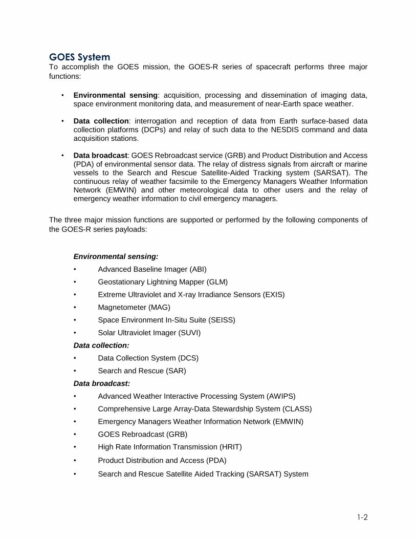
GOES System To accomplish the GOES mission, the GOES-R series of spacecraft performs three major
functions:
• Environmental sensing: acquisition, processing and dissemination of imaging data, space environment monitoring data, and measurement of near-Earth space weather.
• Data collection: interrogation and reception of data from Earth surface-based data collection platforms (DCPs) and relay of such data to the NESDIS command and data acquisition stations.
• Data broadcast: GOES Rebroadcast service (GRB) and Product Distribution and Access (PDA) of environmental sensor data. The relay of distress signals from aircraft or marine vessels to the Search and Rescue Satellite-Aided Tracking system (SARSAT). The continuous relay of weather facsimile to the Emergency Managers Weather Information Network (EMWIN) and other meteorological data to other users and the relay of emergency weather information to civil emergency managers.
The three major mission functions are supported or performed by the following components of
the GOES-R series payloads:
Environmental sensing:
• Advanced Baseline Imager (ABI)
• Geostationary Lightning Mapper (GLM)
• Extreme Ultraviolet and X-ray Irradiance Sensors (EXIS)
• Magnetometer (MAG)
• Space Environment In-Situ Suite (SEISS)
• Solar Ultraviolet Imager (SUVI)
Data collection:
• Data Collection System (DCS)
• Search and Rescue (SAR)
Data broadcast:
• Advanced Weather Interactive Processing System (AWIPS)
• Comprehensive Large Array-Data Stewardship System (CLASS)
• Emergency Managers Weather Information Network (EMWIN)
• GOES Rebroadcast (GRB)
• High Rate Information Transmission (HRIT)
• Product Distribution and Access (PDA)
• Search and Rescue Satellite Aided Tracking (SARSAT) System

1-3
A general overview of the GOES-R series system (including space and ground elements) is
shown in Figure 1-2.
Figure 1-2. GOES-R Series System and Ground System Overview
Space System The GOES-R series of spacecraft are the prime observational platforms for covering dynamic
weather events and the near-Earth space environment for the 21st century. These advanced
spacecraft enhance the capability of the GOES system to continuously observe and measure
meteorological phenomena in real time, providing the meteorological community and atmospheric
scientists of the western hemisphere with greatly improved observational and measurement data.
The key advancements realized by the GOES-R series are related to the instrument payloads
and spacecraft. The advanced instruments drive improvements in the overall system, such as the
processing, generation and distribution of data products. Advances in the spacecraft improve the
overall operations of the satellites and improvements in the instruments provide greater temporal
resolution. These enhanced operational services improve support for short-term weather
forecasting and space environment monitoring as well as atmospheric sciences research and
development for numerical weather prediction models, and environmental sensor design.

1-4
Observational Platform The GOES-R series spacecraft bus is three-axis stabilized and designed for 10 years of on-orbit
operation preceded by up to five years of on-orbit storage. Two GOES satellites remain
operational at all times while an on-orbit spare is maintained to permit rapid recovery from a failure
of either of the operational satellites. The GOES-R series spacecraft design enables the sensors
to stare at the Earth and thus more frequently image clouds and lightning, and monitor the Earth’s
surface temperature and water vapor fields. Thus, the evolution of atmospheric phenomena can
be followed, ensuring real-time coverage of short-lived, dynamic events, especially severe local
storms and tropical cyclones. These are meteorological events that directly affect public safety,
protection of property, and, ultimately, economic health and development. Various design features
of the GOES-R series spacecraft enable high volume, high quality data to be generated for the
weather community. There are two important capabilities. The first is flexible scan control—a
capability that allows small area coverage for improved short-term weather forecasts over local
areas—and simultaneous, independent imaging. The second is precision on-orbit station keeping,
coupled with three-axis stabilization, which ensures a steady observational platform for the
mission sensors.
The GOES-R series will permit a vast reduction over legacy GOES missions in instrument data
collection outages due to satellite maintenance activities. Satellite “operate-through” performance
for routine housekeeping such as momentum management and east/west station keeping
maneuvers precludes the need to schedule daily or monthly outage periods. Coupled with the
enhanced ABI capabilities of imaging through eclipse, the GOES-R series outage goal is less
than 3 hours per year compared to the hundreds of hours per year of the GOES-I/M series. Other
notable performance enhancements include: vibration isolation for the Earth-pointed optical
bench, high-speed spacecraft-to-instrument interfaces designed to maximize science data
collection, and an improved attitude control and image navigation capability.
Geographic Coverage The GOES spacecraft, on-station 35,786 km (22,236 statute miles) above the equator and
stationary relative to the Earth’s surface, can view the contiguous 48 states, Alaska, the central
and eastern Pacific Ocean, central and western Atlantic Ocean areas, and the South American
continent. Pacific coverage includes the Hawaiian Islands and the Gulf of Alaska. Because the
Atlantic and Pacific basins strongly influence the weather affecting the United States, coverage is
provided by two GOES spacecraft.
The combined footprint (radiometric coverage and communications range) of the two spacecraft
encompasses Earth’s full disk about the meridian approximately in the center of the contiguous
United States. Circles of observational limits centered at a spacecraft’s suborbital point extend to
beyond 60° north/south latitudes. The radiometric footprints are determined by the limit from the
suborbital point, beyond which interpretation of cloud data becomes unreliable. At least one
GOES spacecraft is always within line-of-sight view of Earth-based terminals and stations. The
command and data acquisition station at WCDAS has a line-of-sight to both spacecraft to uplink
commands and receive downlinked data from each simultaneously, with CBU facility ready in the
event of a systems or communications failure at WCDAS. The GOES-R series maintains the two-
satellite system implemented by the previous GOES satellites. However, the locations of the
operational GOES-R series satellites are 75.2⁰ W and 137.2⁰ W. The latter is a shift from previous

1-5
GOES at 135⁰ W in order to eliminate conflicts with other satellite systems. The GOES-R series
operational lifetime extends through December 2036. Figure 1-3 illustrates the geographic
coverage of the GOES-R series constellation.
Figure 1-3. Geographic Coverage of the GOES-R Series Constellation
Advanced Baseline Imager (ABI) The Advanced Baseline Imager, manufactured by the Harris Corporation, is the primary
instrument on the GOES-R series for imaging Earth’s weather, oceans and environment. It is a
multi-channel passive imaging radiometer designed to observe the Western Hemisphere and
provide variable area imagery and radiometric information of Earth’s surface, atmosphere and
cloud cover. ABI views the Earth with 16 different spectral bands (compared to five on the previous
GOES series), including two visible channels, four near-infrared channels, and ten infrared
channels. These different channels (wavelengths) are used by models and tools to indicate
various elements on the earth’s surface or in the atmosphere, such as trees, water, clouds,
moisture or smoke. ABI provides four times the resolution and five times faster temporal coverage
than the prior generation of GOES.
ABI has three scan modes. Scan Mode 3 concurrently takes a full disk (Western Hemisphere)
image every 15 minutes, an image of the Contiguous U.S. (CONUS) every five minutes, and two
smaller mesoscale images of areas where storm activity is present, every 60 seconds or one
mesoscale image every 30 seconds. Similarly, a second flexible mode (Scan Mode 6, also known
as “10 minute flex mode”) has been added that is the same as Scan Mode 3 in all regards except
that the full disk image is taken every 10 minutes. Scan Mode 6 is now the default scan mode.
The ABI can also operate in continuous full disk mode (known as Scan Mode 4), providing
uninterrupted scans of the full disk every 5 minutes. All ABI bands have on-orbit calibration. Figure

1-6
1-4A and Figure 1-4B illustrate the ABI spatial resolution and coverage area and default meso
locations for the GOES-East and GOES-West locations, respectively.
Figure 1-4A. ABI Spatial Resolution and Coverage Area with GOES-East Operational View and default Meso locations

1-7
Figure 1-4B. ABI Spatial Resolution and Coverage Area with GOES-West Operational View and default Meso locations
The ABI is used for a wide range of applications related to weather, oceans, land, climate and
hazards (fires, volcanoes, floods, hurricanes and storms that spawn tornadoes). It can track and
monitor cloud formation, atmospheric motion, convection, land surface temperature, ocean
dynamics, flow of water, fire, smoke, volcanic ash plumes, aerosols and air quality, and vegetative
health. ABI’s data enables meteorologists to pinpoint and track developing storms in much greater
detail. Future products will also help the aviation industry with aircraft icing threat detection and
turbulent flight condition predictions.
Benefits from the ABI include improved tropical cyclone forecasts, fewer weather-related flight
delays and airline incidents with volcanic plumes, increased efficiency in irrigated water usage in
agriculture, and higher protection rates for recreational boats in the event of a tropical storm or
hurricane.

1-8
Geostationary Lightning Mapper (GLM) The Geostationary Lightning Mapper, manufactured by Lockheed Martin, is the first operational
lightning mapper flown in geostationary orbit. GLM measures total lightning, both in-cloud and
cloud-to-ground, to aid in forecasting intensifying storms and severe weather events. GLM is
unique both in how it operates and in the information it collects. The instrument is sensitive to the
in-cloud lightning that is most dominant in severe thunderstorms and provides nearly-uniform total
lightning coverage over the region of interest.
GLM is a single-channel, near-infrared optical transient detector that can detect the momentary
changes in an optical scene, indicating the presence of lightning. GLM detects and maps total
lightning activity throughout the day and night over the Americas and adjacent ocean regions with
near-uniform spatial resolution of approximately 10 kilometers. The instrument collects
information such as the location, brightness and extent of lightning discharges to identify
intensifying storms, which are often accompanied by increased total lightning activity.
Trends in total lightning that will be available with GLM have the promise of providing critical
information to forecasters which will allow them to focus on developing severe storms much earlier
than they can currently, and before these storms produce damaging winds, hail or even
tornadoes. Such storms often exhibit a significant increase in total lightning activity, particularly
in-cloud lightning, often many minutes before radar detects the potential for severe weather. Used
in combination with radar, data from ABI, and surface observations, GLM data has great potential
to increase lead time for severe thunderstorm and tornado warnings. Data from the instrument
will also be used to produce a long-term database to track decadal changes in lightning activity.
This is important due to lightning’s role in maintaining the electrical balance between Earth and
its atmosphere and potential changes in extreme weather and severe storms under a changing
climate.
Space Weather Instruments The GOES-R series of satellites host a suite of instruments that provide significantly improved
detection of approaching space weather hazards. Changes in “space weather” can affect the
operational reliability of communication and navigation systems, disrupt power lines, damage
satellite electrical systems, and may cause radiation damage to orbiting satellites, high-altitude
aircraft and the International Space Station, as well as harming astronauts.
Two sun-pointing instruments measure solar ultraviolet light and X-rays. The Solar Ultraviolet
Imager (SUVI) observes and characterizes complex active regions of the sun, and provides six-
channel movies of solar flares and the eruptions of solar filaments which may give rise to coronal
mass ejections. The Extreme Ultraviolet and X-ray Irradiance Sensor (EXIS) detects solar flares
and monitors solar irradiance that impacts the upper atmosphere.
The satellites also carry two instruments that measure the space environment. The Space
Environment In-Situ Suite (SEISS) monitors proton, electron and heavy ion fluxes in the
magnetosphere. The Magnetometer (MAG) measures the magnetic field in the outer portion of
the magnetosphere.
The GOES-R SUVI and EXIS instruments provide improved imaging of the sun and detection of
solar eruptions, while SEISS and MAG more accurately monitor, respectively, energetic particles
and the magnetic field variations that are associated with space weather. Together, observations

1-9
from these instruments will enable NOAA’s Space Weather Prediction Center to significantly
improve space weather forecasts and provide early warning of possible impacts to Earth’s space
environment and potentially disruptive events on the ground.
Other Data Services Emergency radio beacons are carried on ships and planes to signal distress to satellites orbiting
overhead. The GOES-R series continues the legacy Geostationary Search and Rescue
(GEOSAR) function of the SARSAT system onboard NOAA’s GOES satellites which has
contributed to the rescue of thousands of individuals in distress. The SARSAT transponder was
modified slightly for the GOES-R series by operating with a lower uplink power (32 dBm), enabling
the satellites to detect weaker signal beacons. The SARSAT transponder onboard GOES-R
series satellites provides the capability to immediately detect distress signals from emergency
beacons and relay them to ground stations, called Local User Terminals. In turn, this signal is
routed to a SARSAT Mission Control Center and then sent to a Rescue Coordination Center which
dispatches a search and rescue team to the location of the distress.
Ground System The GOES-R series ground system has a much greater product distribution capability over the
legacy missions. To support the large increase in spatial, spectral, and temporal resolution of the
ABI and other instruments, the raw data rate has increased to 75Mbps, over 30 times the previous
rate. GOES-R series data volume drives a large increase in processing requirements for product
generation and for distribution of the products to users.
The ground system receives the Level 0 (L0) raw data from GOES-R series spacecraft and
generates Level 1b (L1b) and Level 2+ (L2+) products and makes these products available to
users in a timely manner. Level 0 data is the unprocessed instrument data at full resolution. L1b
data is the L0 data processed with radiometric and geometric correction applied to produce
parameters in physical units. L2+ data are derived environmental variables generated from L1b
data along with other ancillary source data, such as from the National Weather Prediction forecast
model output data. Table 1-1 shows a listing of the L1b and L2+ GOES-R series science products
by instrument.
The GOES-R ground system (GS), developed by Harris Corporation, consists of several
functional components. Mission Management (MM) provides the satellite operations (monitor and
control) function of the GS (via the Harris OS/COMET® software). Enterprise Management (EM)
is distributed over all GS components and locations and provides for the ability to monitor the
complete enterprise, as well as control the operations not directly associated with satellite
operations. Product Generation (PG) provides the L1b and L2+ product generation function.
Product Distribution (PD) functionality provides for direct distribution of product data to the GOES-
R Access Subsystem (GAS), NWS Advanced Weather Interactive Processing System (AWIPS)
and CLASS (an electronic library of NOAA environmental data). Long term archive and access
services to retrospective users of GOES-R series data will be provided by CLASS, which is
considered an external interface to the GOES-R series GS, but is part of the NOAA infrastructure.

1-10
Table 1-1. GOES-R L1b and L2+ Science Products
Instrument Level1b Products ABI Level 2+ Products
ABI Radiances Cloud and Moisture Imagery (CMI)
and Sectorized CMI (KPP)
Aerosol Detection (Smoke & Dust)
Aerosol Optical Depth (AOD)
Clear Sky Mask
Cloud Optical Depth
Cloud Particle Size Distribution
Cloud Top Height
Cloud Top Phase
Cloud Top Pressure
Cloud Top Temperature
Derived Motion Winds
Derived Stability Indices
Downward S/W Radiation: Surface
Fire/Hot Spot Characterization
Land Surface Temperature
Legacy Vertical Moisture Profile
Legacy Vertical Temperature Profile
Rainfall Rate/QPE
Reflected S/W Radiation: TOA
Sea Surface Temperature
Snow Cover
Total Precipitable Water
Volcanic Ash: Detection and Height
SEISS Energetic Heavy Ions
Magnetospheric e-/p+:
Low Energy
Magnetospheric e-/p+:
High Energy
Solar & Galactic
Protons
EXIS Solar Flux: EUV
Solar Flux: X-ray
Irradiance
SUVI Solar EUV Imagery
MAG Geomagnetic Field GLM Level 2+ Products
Lightning: Events, Groups, &
Flashes
Network Architecture The GS operates from two primary locations: NSOF in Suitland, Maryland, and WCDAS in
Wallops, Virginia. A third operations facility in Fairmont, West Virginia, serves as the CBU in case
of a systems or communications failure at either or both NSOF and WCDAS. The satellites are
commanded throughout their mission lifetime from the NSOF with the ground station radio
frequency (RF) interface located at WCDAS (or the CBU, as needed). The engineering telemetry
streams are received by both the WCDAS and CBU, then ground relayed to the NSOF for
processing and monitoring at all locations.

1-11
In addition to the redundant operational environments at each ground location, the GS includes
separate development and integration and test (I&T) environments for the purposes of ongoing
development and I&T throughout the GOES-R mission. Two on-site Development Environments
(DE) (one at NSOF and one at WCDAS) and three Integration and Test Environments (ITE) (one
at NSOF and two at WCDAS) are provided by the GS for software maintenance. Local DE and
ITE workstations are provided at WCDAS and NSOF. In addition, DE and ITE workstations are
provided at NSOF to accommodate remote use of the WCDAS DE and ITE functions. The CBU
does not provide a DE or ITE and relies on WCDAS for software maintenance.
Raw instrument data (L0) is received at WCDAS. It is then processed by the Product Generation
(PG) function at WCDAS to create Level 1b (L1b) and some Level 2+ (L2+) products. These L1b
and L2+ products are then rebroadcast through the GRB transponder. The GRB data are then
received at NSOF where the rest of the L2+ products are created. Ancillary data used in
generating the L2+ products are ingested from the Ancillary Data Relay System
(ADRS). Applicable products are directly distributed to 1) NWS AWIPS where key NWS Weather
Forecast Offices (WFO) and other AWIPS users get their data, and 2) GAS for use by the
Environmental Satellite Processing Center (ESPC) and other GOES data users.
GOES-R series data products will be available using new product distribution and access
technologies. An overview of the GOES-R series ground system architecture as well as more
information about product distribution can be found in the Ground System Architecture section of
this book.
GOES Rebroadcast (GRB) GRB provides the primary relay of full resolution, calibrated, near-real-time direct broadcast L1b
data from each instrument and L2 data from GLM. GRB replaces the GOES VARiable (GVAR)
service, and is a significant increase in capability from that service. GRB contains the ABI, GLM,
space environment, and solar data which drive data flow in the NOAA space and Earth
environment research and operational framework.
GRB uses two digital streams, each at 15.5 Mbps, compared to the GVAR standard of a single
2.11 Mbps stream. A dual polarization approach is used to accommodate the 31 Mbps data rate
within a frequency bandwidth of 9.8 or 10.9 MHz per polarization, using a standard downlink
modulation at 1686.6 MHz (L-band). GRB is able to deliver a full disk image in either five, ten, or
fifteen minutes, depending on mode, compared to GVAR’s thirty minutes.
The GRB processed instrument data is packetized compliant with Consultative Committee for
Space Data Systems (CCSDS) Standard 133.0-B-l and utilizes lossless data compression to fit
within allocated bandwidth. Data blocking and accompanying header metadata are used to
minimize the risk of data loss due to link errors and allow for user verification of data integrity.

1-12
This page left blank

2-1
2. GOES Spacecraft Configuration
The GOES-R series satellite is based on the Lockheed Martin A2100 bus. The satellite with the
magnetometer, solar array, X-band antenna, and antenna wing fully deployed (on-orbit
configuration) can be viewed in Figure 2-1. (Note that SEISS is not identified in this figure as it is
not viewable in this isometric view.) The 6,280 pound, three-axis stabilized GOES-R spacecraft
was designed for an on-orbit life of 15 years. The spacecraft bus provides mechanical support
and alignment of the various instrument payloads, communications payloads and other bus
components.
Figure 2-1: Fully Deployed GOES-R Satellite
The satellite houses three classifications of instruments: Nadir-pointing, Solar-pointing, and In-
Situ (near environment). The Nadir pointing instruments include the ABI and the GLM. These
instruments are mounted on a highly stable, precision earth-pointed platform, and are dynamically
isolated from the rest of the spacecraft. The Solar-pointing instruments, which include the EXIS,
SUVI, and the Unique Payload Services (UPS) are mounted on a Sun Pointing Platform (SPP)
housed on a solar array yoke. The SPP provides a stable platform that tracks the seasonal and
daily movement of the sun relative to the spacecraft. The In-Situ instruments include the SEISS
and the Magnetometer. The Magnetometer is mounted on a boom that deploys once the
spacecraft reaches orbit. The boom provides relative magnetic isolation for this instrument. Each
of the GOES-R Series instruments are described in detail in subsequent chapters.

2-2
A spacecraft overview system block diagram, depicting each of the spacecraft subsystems, is
shown in Figure 2-2. The following paragraphs briefly describe each subsystem. More details
can be found in subsequent chapters.
Figure 2-2: GOES-R Series Satellite System Block Diagram
Communications Subsystem The communications subsystem provides the antennas and transponders used for
communicating with the ground system and for data relay services. The spacecraft uses S-band,
L-Band, X-Band and UHF links to provide the command, telemetry, and tracking functions. It also
provides a set of communications services (Unique Payload Services) which: support the Data
Collection Platforms; relay High Rate Information Transmission (HRIT) and imaging data between
Earth terminals and relays the Emergency Managers Weather Information Network (EMWIN)
broadcast on the HRIT/EMWIN; detects and communicates Search and Rescue (SAR)
Emergency Locator Transmitter distress signals; and rebroadcasts processed GOES-R sensor
data via the GOES Re-broadcast (GRB).
Command and Data Handling Subsystem The command and data handling (C&DH) system includes the hardware needed to process,
route, and deliver commands, telemetry, and instrument data on board the spacecraft, including
the processing resources needed for the flight software to function. The C&DH system includes

2-3
6 component types, including the on-board computers, command and telemetry processors,
remote interface units, sun pointing platform interface electronics, pyro relay assemblies, and a
command decryption unit assembly.
Electrical Power Subsystem The primary function of the electrical power subsystem (EPS) is to provide power to operate the
satellite for 15 years in geostationary orbit. It consists of a Scalable Power Regulation Unit (SPRU)
to control the flow of power from the solar arrays and batteries onto the busses, two batteries for
energy storage, a solar array for power generation, 70 volt and 28 volt power busses to distribute
power to the loads, and two Fuse Board Assemblies to provide load overcurrent protection.
Guidance, Navigation and Control Subsystem The guidance, navigation and control (GN&C) subsystem provides guidance, navigation, and
attitude & articulation control for the GOES-R spacecraft. Inertial Measurement Units (IMU) and
star trackers provide attitude determination, a global positioning system (GPS) receiver provides
orbit determination, and attitude control is provided using reaction wheels and the propulsion
system. The GN&C subsystem is also responsible for controlling the spacecraft’s gimbals for the
X-Band antenna, solar panel, and sun-pointing platform.
Propulsion Subsystem The propulsion subsystem provides the impulse to perform the thrusting maneuvers required
during each mission phase, from launch and orbit raising through end of life maneuvers. It consists
of a single liquid apogee engine (LAE), sixteen monopropellant low thrust rocket engine
assemblies (REA), eight monopropellant REAs, two hydrazine bi-propellant thrusters, 4 Arcjets,
and associated tanks, valves, and regulators.
Thermal Control Subsystem The thermal control subsystem consists of all spacecraft thermal elements and coatings required
to control the onboard temperature of spacecraft elements. The subsystem uses active and
passive thermal control techniques, and includes finishes, insulators, multi-layer insulation (MLI),
heaters, thermostats and other heater controls, temperature sensors, heat transferring apparatus,
radiators, sun shields and radiation shields to accomplish its function.
Mechanical Subsystem The Mechanical subsystem provides the mechanical interface and structural support for
spacecraft components as well as the mechanisms that must be stowed and restrained for launch
and later deployment. The structure possesses sufficient strength, stiffness, and damping for
subsystems and payloads to survive the load conditions that exist within the envelope of the
mission as well as test requirements. The mechanisms include hinges, retention and release
(R&R) hardware, motors, gimbals and dampers. These are used to deploy and point the Solar
Wing Subsystem and the antennas.

2-4
Launch and Ascent Configuration During launch and ascent, the Sun Pointing Subsystem (SPS), as well as the Solar Array Wing
Assembly (SAWA), is folded against the +Y side of the spacecraft bus (as seen in a Body
Reference Frame (BRF)) and each are held in place with restraint and release (R&R)
mechanisms. The stowed configuration is shown in Figure 2-3.The SPS utilizes six R&Rs to
support the Sun Pointing Platform (SPP) and two R&Rs to support the yoke/frame assembly. The
SAWA is also supported with six R&Rs. When in the stowed configuration, instruments on the
SPP face outboard and solar cells on the outboard SAWA panel face outward.
Figure 2-3. Launch and Ascent Configuration in Body Reference Frame
SAWA
SPS

2-5
Orbit Raising Configuration During transfer orbit operations, the solar array is in the first stage deployed configuration. In the
first stage deployed configuration, the inboard SAWA panel (panel 1) and the SPS remain stowed
against the +Y side of the satellite. The solar array panels 2 through 5 are fully deployed and in
the same plane as panel 1. All panel solar cells face outward (+Y direction). The inboard panel
utilizes two R&Rs to attach to the spacecraft bus in this configuration. The solar cells on the SAWA
panels face the direction shown in Figure 2-4.
Figure 2-4. Transfer Orbit Configuration (1st Stage Deployment)

2-6
On-Orbit Configuration After Geosynchronous Earth Orbit (GEO) is achieved, the SPS is commanded to fully deploy, as
shown in Figure 2-5. The SPS articulates and maintains the SPP and the solar array in a sun
pointing orientation. Occasionally the SPP may be slewed 16 degrees off pointing from the sun
to allow for calibration of the science instrument on the SPP.
Figure 2-5. On-Orbit Solar Array Configuration (2nd/Final Stage Deployment)

3-1
3. Advanced Baseline Imager
The Advanced Baseline Imager, manufactured by Harris Corporation, is a multi-spectral imaging
radiometer for the GOES-R series of satellites. It provides nearly continuous imagery of the
Western Hemisphere from geostationary orbit for weather prediction and other Earth science
applications. ABI measures Earth’s radiance in 16 spectral channels ranging from visible (0.47µm)
to longwave infrared (13.3 µm). A view of the ABI is shown in Figure 3-1.
Figure 3-1. ABI
ABI scans the Earth via two orthogonal scan mirrors: one east-west (EW) and one north-south
(NS). The EW mirror scans the Earth at 1.4° (optical) per second; a single EW scan is called a
swath. The NS mirror is then stepped to a new location to begin another EW swath. In this
manner, ABI can scan the full Earth image in five minutes (known as Mode 4 – Continuous Full
Disk mode) or alternatively scan the full Earth in 15 minutes with interleaved 5-minute images of
the Contiguous United States (CONUS) and two 60-second (or one 30-second) 1000 x 1000 km
mesoscale images. This mode is known as Mode 3. Mesoscale images are helpful for viewing
storm activity. A third scan mode (known as Mode 6, or “10 minute flex mode”) has been added
that is the same as Mode 3 except that the full Earth scan is performed in 10 minutes instead of
15 minutes. Mode 6 is now the default for both GOES-East and GOES-West.
The scanning motion of the two scan mirrors direct Earth’s radiance into a four-mirror, off-axis
telescope that converges the energy into the aft optics. There the energy is separated into three
bands, visible and near infrared (VNIR), midwave infrared (MWIR), and longwave infrared (LWIR),
and ultimately sensed by a unique set of detectors for each of the 16 spectral bands. The nadir
spatial resolution of the collected imagery ranges from 0.5 to 1 km in the visible channels and 1
3-2
to 2 km in the infrared channels. A summary of the characteristics for each spectral channel is
shown in Table 3-1. A further description of the key performance requirements is shown in Table
3-2.
Representative ABI radiometric noise (Signal to Noise Ratio (SNR) and Noise Equivalent Delta
Temperature), and dynamic range are shown in Table 3-3, along with typical applications for each
ABI band. The nominal center wavelength is shown. The exact wavelength center can vary slightly
by flight model (FM). Each ABI FM was designed to collect radiometric data both for the earth,
and for the needed reference sources to calibrate the earth scenes. For ABI, this includes cold
space (~4 K) and a hot blackbody source flying on-board ABI. Although ABI observes cold space
to help remove its own warm telescope background, earth scenes are warmer. The brightness
temperature of the internal blackbody emitter used for calibration is warmer than that of typical
earth scenes, and can be configured. Achieved radiometric noise performance varies by detector
and FM, but is often better than these levels. The maximum range capability for each FM to
observe radiance (expressed in brightness temperature units) often exceeds the physical
brightness temperature ranges for the earth. In the case of fires though, the need to report
brightness temperature of the fire was balanced against the need to monitor cold clouds. Typical
applications of these radiance measurements are shown in Table 3-3 as well.
The Radiances product produced by the Ground Segment (GS) from the ABI observations has
units of W/(m2 sr um) in bands less than 3 um and mW/(m2 sr cm-1) in bands greater than 3 um.
The Ground Segment produces the Cloud and Moisture Imagery product that converts the
radiance output for bands greater than 3 um to Brightness temperatures in units of Kelvin, so
maximum ranges are often listed in K. The product range, configurable in the GS, was required
to cover earth scenes of interest and start at about 180 K. The products, ranges, and associated
bit depths are detailed in a separate document called the GOES-R Product Users Guide (PUG),
which can be found at https://www.goes-r.gov.

3-3
Table 3-1. ABI Channel Characteristics
Channel / Band
Center Wavelength
(µm)
EW IFOV (µrad)
NS IFOV (µrad)
EW ASD (µrad)
Pixel Size*(km)
VN
IR
1 0.47 22.9 22.9 22 1 2 0.64 12.4 10.5 11 0.5 3 0.865 22.9 22.9 22 1 4 1.378 51.5 42.0 44 2 5 1.61 22.9 22.9 22 1 6 2.25 51.5 42.0 44 2
MW
IR
7 3.90 51.5 47.7 44 2 8 6.185 51.5 47.7 44 2 9 6.95 51.5 47.7 44 2 10 7.34 51.5 47.7 44 2 11 8.5 51.5 47.7 44 2
LW
IR
12 9.61 51.5 47.7 44 2 13 10.35 34.3 38.1 44 2 14 11.2 34.3 38.1 44 2 15 12.3 34.3 38.1 44 2 16 13.3 34.3 38.1 44 2
*Pixel size refers to post-resampled image pixel spacing at nadir
Table 3-2. ABI Channel Performance Requirements Summary
Parameter Performance
Calibration Accuracy VNIR MWIR and LWIR
±3% (±4% for 1.378 μm) for 100% albedo scene ±1 K for 300 K scene
Relative Accuracy Pixel-to-Pixel Swath-to-Swath Channel-to-Channel Image-to-Image Calibration
<NEdT <NEdT <0.2 K <0.2 K <0.2 K
Navigation 21 µrad
Registration Frame-to-Frame Within-Frame Swath-to-Swath Channel-to-Channel
0.5 and 1.0 km 2.0 km 2km-to-2km/1km/0.5km 1km-to-1km/0.5km
17.6 µrad 23.0 µrad 21.0 µrad 7.8 µrad 11.2 µrad 6.0 µrad

3-4
Table 3-3. ABI Radiometric Precision and Dynamic Range Requirements
Channel / Band
Center Wavelength
(µm)
SNR / NEdT*
Dynamic Range
Typical Applications
VN
IR
1 0.47 300:1 0 – 100% Albedo
Daytime aerosol over land, coastal water mapping
2 0.64 300:1 0 – 100% Albedo
Daytime clouds, fog, solar flux, and winds
3 0.865 300:1 0 – 100% Albedo
Daytime vegetation/burn scar and aerosol over water, winds
4 1.378 300:1 0 – 100% Albedo
Daytime cirrus clouds
5 1.61 300:1 0 – 100% Albedo
Daytime cloud-top phase and particle size, snow
6 2.25 300:1 0 – 100% Albedo
Daytime land/cloud properties, particle size, vegetation, snow
MW
IR
7 3.90 0.1 K 4 – 400 K Surface and cloud, fog at night, fire, winds
8 6.185 0.1 K 4 – 300 K High-level atmospheric water vapor, winds, rainfall
9 6.95 0.1 K 4 – 300 K Mid-level atmospheric water vapor, winds, and rainfall
10 7.34 0.1 K 4 – 320 K Lower-level water vapor and winds
11 8.5 0.1 K 4 – 330 K Total water for stability, cloud phase, dust, and rainfall
LW
IR
12 9.61 0.1 K 4 – 300 K Total ozone, turbulence, and winds 13 10.35 0.1 K 4 – 330 K Surface and cloud properties
14 11.2 0.1 K 4 – 330 K Sea surface temperatures, rainfall and cloud properties
15 12.3 0.1 K 4 – 330 K Total water, ash, sea surface temp., and cloud properties
16 13.3 0.3 K 4 – 305 K Atm. temps and cloud heights *SNR @ 100% albedo; NEdT at 300 K

3-5
ABI is comprised of three units as shown in Figure 3-2. The Sensor Unit (SU) is mounted on the
spacecraft Earth Pointing Platform (EPP) and collects the scene radiance and converts it to digital
counts. The Cryocooler Control Electronics (CCE) controls the active coolers used to maintain
the infrared detectors at cryogenic temperatures. The two CCE units are mounted on the -Y
module panel. The Electronics Unit (EU) provides command and control of the SU and CCE. It is
also mounted on the -Y module panel.
Figure 3-2. ABI Units
Sensor Unit The Sensor Unit (SU) consists of a number of subsystems, as shown in Figure 3-3. The Optical
Bench is the backbone of ABI as it provides the structural support for all of the other subsystems,
establishes the mechanical alignment to the spacecraft, and controls the thermal and mechanical
loads to and from the spacecraft. The Optical Bench provides support for the Optical Port
Sunshield, the EW and NS Scanners, Telescope, Aft Optics, Solar Calibration Assembly (SCA),
Internal Calibration Target, Active Cooler, Scanner Shrouds, the Thermal Control Radiator and
Heat Pipes, and the Sensor Unit Electronics (SUE). The function of each subsystem is
summarized in Table 3-4. This section will address most of the subassemblies in the SU.
Discussion of the SUE can be found in the electronics section, and the two calibration assemblies
are described in a later section on calibration during operations.

3-6
Figure 3-3. ABI Sensor Unit Subsystems
Table 3-4. Sensor Unit (SU) Subsystems
Subsystem Function
Optical Bench Provides structural support for subsystems
Optical Port Sunshield Assembly
Reduces stray light via series of baffles, prevents contamination during storage, provides mechanical mount for solar calibration target
EW and NS scanner Provides line-of-sight pointing capability
Telescope Creates an image of the select scene on the focal plane array detectors
Focal Plane Modules (FPMs) and Aft Optics
Provides spectral separation and a controlled thermal environment for the focal plane detectors, which convert photons to electrons
Solar Calibration Assembly
Provides radiometric calibration target for visible and near-infrared channel detectors
Internal Calibration Target Provides radiometric calibration target for infrared channels
Active Cooler (Cryocoolers)
Provides cooling capability and thermal control of detectors
Thermal Control Radiator and Heat Pipes
Provides Sensor Unit thermal control
Scanner shrouds Addresses sun’s heat within scan cavity
Sensor Unit Electronics Provides video processor to read out detector arrays as well as thermal control electronics and control of other mechanisms

3-7
Optical Port Sunshield Assembly The Optical Port Sunshield Assembly (OPSA) primarily reduces the stray light entering the
system. The OPSA has a one-time deployable Optical Port Cover (OPC) that is stowed prior to
launch and secured using a non-explosive, shape memory alloy (SMA) pin-puller launch lock. The
cover protects ABI against contamination prior to launch and solar intrusion throughout the launch
and orbit-raising portions of the mission. Once the launch lock is released, spring-loaded hinges
automatically open the OPC where it is captured on a mechanical stop using a Velcro strip.
Optical System After deployment of the OPC on-orbit, the SU can begin its primary function of collecting scene
radiance and converting it to digital counts for processing by the EU. The optical collection of
radiance begins with the scan mirrors directing the line-of-sight at the desired scene. ABI has two
Scan Mirror Assemblies that consist of a scan mirror, a Scan Drive Assembly (SDA), and Support
Bearing Assembly. Each SDA mounts to the Optical Bench and supports one side of the scan
mirror. It primarily controls the mirror via the motor and monitors the position of the mirror by way
of an optical encoder. The SDA motor is controlled via the Scanner Interface & Motor Driver
(SIMD) Circuit Card Assembly (CCA) in the EU. The Support Bearing Assembly also mounts to
the Optical Bench and anchors the other side of the mirror.
As shown in Figure 3-4, the two scan mirrors are oriented orthogonally to one another to
independently scan the LOS in the NS and EW directions. The optical LOS angle is twice the
mechanical angle. The separation of EW and NS scanning allows for scans parallel to the equator
without image rotation and inherently compensates for polarization. Both mirrors can operate
simultaneously, permitting scans and slews over a wide range of angles that allows the LOS to
be pointed anywhere within the field-of-regard as well as to the Blackbody Calibration Target, an
internal calibration source for the ABI.
Figure 3-4. ABI Scanner
EW Scanner
Y(South)
Z (Earth)
X(East)
Blackbody
Calibration
Target
NS Scanner

3-8
In addition to the scan mirrors, the ABI optical system consists of a telescope and the Aft Optics
as shown in Figure 3-5. The scan mirrors direct the incoming radiance into the telescope. The
ABI telescope is comprised of four mirrors and forms the image of the scene on each of the three
Focal Plane Modules (FPMs). One of the four telescope mirrors can be driven by motor to make
minor adjustments in focus. The Telescope Assembly consists of the telescope plus the Visible–
Infrared (VIS/IR) beamsplitter and fold mirror. The VIS/IR beamsplitter (BS1) separates the
incoming radiance into VNIR and infrared spectral components. Wavelengths greater than 3 µm
are reflected toward the IR focal planes, and those less than 3 µm are transmitted to the fold
mirror and then onto the VNIR FPM.
The Aft Optics provides additional spectral separation and holds all the optical components
together to provide co-alignment of the FPMs. The separation of the infrared into MWIR and LWIR
radiance occurs via the Midwave–Longwave (MW/LW) beamsplitter (BS2). Within each spectral
band (VNIR, MWIR, LWIR), narrowband spectral selection for each channel is accomplished
using filters integrated into the FPMs. The Aft Optics also includes windows and cold stops and
provides a controlled cryogenic environment for the FPMs. The LWIR and MWIR optics and FPMs
are maintained at approximately 60K. The VNIR optics and FPM are maintained at approximately
170 K (180 K for FPM on GOES-R). Cooling of the focal planes to these cryogenic temperatures
is accomplished using the cryocooler.
Figure 3-5. Optics Block Diagram
CS
VNIR0.47, 0.64,
0.865, 1.378,
1.61, 2.25
(170 K)
BS2
MWIR3.9, 6.185,
6.95, 7.34, 8.5
(60 K)
LWIR9.61, 10.35,
11.2, 12.3, 13.3
(60 K)
SM1
(N/S)
Scan
Mirrors
SM2
(E/W)
Exit Pupil
Fold
Mirror
W1
BS1
W2
W3
60 K
170 K
300 K
CS, BS2, MWIR
& LWIR FPMs
W3, V/SWIR FPM
Remaining structure
-Y
FMA
Telescope+X
-Z
(180 K for
GOES-R)

3-9
Focal Plane Modules The FPMs filter the image produced by the telescope into select spectral channels, detect it, and
convert it into analog signals for the video processor. There are three FPMs corresponding to the
three spectral bands: VNIR, MWIR, and LWIR. Spectral selection is accomplished using
bandpass filters positioned above the linear detector arrays. The VNIR FPM provides six spectral
channels centered on wavelengths ranging from 0.47 µm to 2.25 µm. The MWIR FPM provides
five spectral channels centered on wavelengths ranging from 3.9 µm to 8.5 µm. The LWIR FPM
provides five spectral channels centered on wavelengths ranging from 9.61 µm to 13.3 µm. The
layout of the VNIR, MWIR, and LWIR Focal Plane Arrays (FPAs) are shown in Figure 3-6, Figure
3-7, and Figure 3-8, respectively. The perspective is that of an observer viewing the side of the
FPA illuminated by incident radiance.
ABI’s FPAs are the combination of a detector array and its associated Read-Out Integrated Circuit
(ROIC) for a single spectral channel. The FPA is the portion of the FPM that detects the incident
radiance and converts it to an electrical signal. Table 3-5 lists several physical properties of each
of the ABI FPAs. Each FPA provides two-fold redundancy. One redundancy consists of separate
Side 1 and Side 2 electronics. The second redundancy is the availability of multiple columns of
detectors within each electronics side. The number of redundant columns for each spectral
channel is shown in the column labeled “Columns per Side” in Table 3-5. A single detector
element from each row is downlinked during any data collection. This is accomplished using a
configurable table of the selected detector elements for each channel called the Best Detector
Select (BDS) map, as illustrated in Figure 3-9.
Figure 3-6. VNIR Focal Plane Module Layout
#4
1
.38
m
#3
0
.86
m
#1
0
.47
m
13
m
EW
× 1
1
m N
S 1
46
0 e
lem
en
ts N
S
24
m
EW
× 2
4
m N
S 6
76
ele
me
nts
NS
54
m
EW
× 4
4
m N
S 3
72
ele
me
nts
NS
0.894°
+0.89891° +0.56284° +0.25141° 0° -0.07641° -0.50270° -0.89885°
1.851°
AB
I V
NIR
W E
N
S
54
m
EW
× 4
4
m N
S 3
72
ele
me
nts
NS
24
m
EW
× 2
4
m N
S 6
76
ele
me
nts
NS
24
m
EW
× 2
4
m N
S 6
76
ele
me
nts
NS
#2
0
.64
m
#5
1
.61
m
#6
2
.26
m

3-10
Figure 3-7. MWIR Focal Plane Module Layout
Figure 3-8. LWIR Focal Plane Module Layout
#7
6
.95
m
0.906°
+0.74895° +0.37447° 0° -0.37447° -0.74895°
1.551°
AB
I M
WIR
#8
6
.19
m
#9
3
.90
m
#1
0 7
.34
m
#1
1 8
.50
m
54
m
EW
× 5
0
m N
S 3
32
ele
me
nts
NS
54
m
EW
× 5
0
m N
S 3
32
ele
me
nts
NS
54
m
EW
× 5
0
m N
S 3
32
ele
me
nts
NS
54
m
EW
× 5
0
m N
S 3
32
ele
me
nts
NS
54
m
EW
× 5
0
m N
S 3
32
ele
me
nts
NS
W E
N
S
#1
3 1
0.3
5
m
0.906°
+0.77107° +0.44596° 0° -0.35764° -0.75944°
1.548°
AB
I L
WIR
#1
2 9.6
1
m
#1
4 1
1.2
m
#1
6 1
3.3
m
#1
5 1
2.3
m
+0.04419°
36
m
EW
× 4
0
m N
S 4
08
ele
me
nts
NS
54
m
EW
× 5
0
m N
S 3
32
ele
me
nts
NS
36
m
EW
× 4
0
m N
S 4
08
ele
me
nts
NS
36
m
EW
× 4
0
m N
S 4
08
ele
me
nts
NS
36
m
EW
× 4
0
m N
S 4
08
ele
me
nts
NS
W E
N
S

3-11
Table 3-5. Focal Plane Array Properties
FPM Channel
(µm) Columns per
Side Number of NS Rows
Detector Type
VN
IR
0.47 3 676 Silicon
0.64 3 1460 Silicon
0.86 3 676 Silicon
1.378 6 372 HgCdTe
1.61 6 676 HgCdTe
2.25 6 372 HgCdTe
MW
IR
3.90 6 332
HgCdTe
6.185 6
332 HgCdTe
6.95 6
332 HgCdTe
7.34 6 332 HgCdTe
8.50 6 332 HgCdTe
LW
IR
9.61 6
332 HgCdTe
10.35 6 408 HgCdTe
11.2 6 408 HgCdTe
12.3 6 408 HgCdTe
13.3 6 408 HgCdTe

3-12
Figure 3-9. Best Detector Select Maps (Note: NS is reversed for MWIR FPAs)
1 2 3 4 5 6 6 5 4 3 2 1
1 1 N N 2 2 . .
Selected Detector 3 3 . . 4 4 . .
Unselected Detector 5 5 . . . . . . . . . . . . . . . . . . . . . . . . . . . . . . . . Detector stack . . Detector stack
N . . is output to the . . is output to the . Time Sync . Video Processor . Time Sync . Video Processor . . from North to . . from South to
S . . South for Side 1 . . North for Side 2 . . . . . . . . . . . . . . . . . . . . . . . . . . 5 5 . . 4 4 . . 3 3 . . 2 2 N N 1 1
Stack Stack Focal Plane Array
W
Side 2
Focal Plane Array
Legend
Side 1
E
Detector Stack in output
to the Video Processor
from North to South for
Side 1
Detector Stack in output
to the Video Processor
from South to North for
Side 2
Selected Detectors
Unselected
Detector

3-13
Thermal Control ABI utilizes several assemblies and subsystems to maintain thermal control: the radiator, loop heat pipes, scan shroud, cryocoolers, and heaters
Radiator/Loop Heat Pipe Assembly The radiator and Loop Heat Pipe (LHP) assembly, as shown in Figure 3-10, work in concert to reject the excess Sensor Unit thermal energy to space. The radiator is a large reflective surface that radiates energy to space. The LHPs are the interface between the instrument and the radiator; they transfer excess energy from the rest of the SU to the radiator.
Figure 3-10. Thermal Control Radiator & Heat Pipes

3-14
Scan Shroud Assembly The scan shroud assembly, as shown in Figure 3-11, consists of a series of shields that protect the internal instrument structure from direct solar loading through the optical port during the times in the orbit when solar energy enters the internal instrument cavity. The solar heat is collected within the metal shields and transported to the radiator/LHP assembly via constant conductance heat pipes.
Cryocooler The cryocooler cools the focal plane arrays to their requisite cryogenic temperatures. It is a two-stage pulse tube active cooler that pumps thermal energy from the focal plane arrays to the radiator/Loop Heat Pipe (LHP) Assembly. The crycooler is illustrated in Figure 3-12. The ABI has two redundant cryocoolers that can be operated individually or together. Each consists of a Thermal Dynamic Unit (TDU) and Cryocooler Control Electronics (CCE). The TDU consists of an integral cooler, remote cold head, and transfer line. Waste energy is pumped from the FPAs by the TDU to the loop heat pipes where it is transferred to the radiator and rejected to space.
Figure 3-11. Scan Shroud Assembly

3-15
Figure 3-12. Active Cryocooler Thermal Dynamic Unit – Aft Optics not shown for clarity
Heaters ABI has several types of heaters located within the SU to maintain temperatures: survival, operational, and outgas. All heaters are fully Side1/Side2 redundant. The survival heaters are powered directly by the spacecraft via 70V power and ensure ABI stays at safe temperatures in the absence of operational power to ABI. The outgas heaters are used during the outgas phase of the mission to increase the temperature of the SU in order to drive off contaminates from the optical surfaces prior to cooling the Aft Optics to cryogenic temperatures. The operational heaters are used to control the temperature of the SU during operation. The operational and outgas heaters can have their control points and enable/disable status controlled via ground command. Power for survival heaters is controlled by spacecraft command, and their set points are controlled by fixed thermostatic switches.
Electronics ABI’s electronics are dispersed among the three units (Sensor Unit, Electronics Unit, and Cryocooler Control Electronics). The Electronics Unit contains the bulk of the CCAs and interfaces between the spacecraft and the other ABI units. The SUE, located in the Sensor Unit, contains CCAs needed to digitize the focal plane data and control SU mechanisms. The CCE controls the cryocoolers. The ABI electronics architecture is shown in Figure 3-13.

3-16
Figure 3-13. ABI Electronics Block Diagram
Sensor Unit Electronics The SUE is comprised of the Video Processors (VPs) and the Peripheral and Thermal Control (P&TC) electronics. It is fully Side1/Side2 redundant. The VPs provide the interface between the focal plane arrays and the EU. The VPs generate timing signals and bias voltages used to read out the FPAs. They also collect the detector samples from the FPAs and format these data for transmission to the Data Processor in the EU. The P&TC CCA provides thermal and mechanism control (with the exception of the scanner) for the Sensor Unit. The P&TC controls the temperature of the Internal Calibration Target (ICT), VNIR FPM, LHP heaters, and outgas heaters. The P&TC motor driver can switch between driving the Solar Calibration Cover (SCC) and the telescope focus motor. A serial command and telemetry interface is provided for receiving control information from the Telemetry & Timing (TNT) CCA located in the EU. The SUE also controls release of the Optical Port Cover (OPC) and SCC launch locks.
Electronics Unit The Electronics Unit (EU) is the primary electrical interface between the spacecraft and the Sensor Unit. The EU contains the ABI power supplies and provides the instrument with command and control, data processing, telemetry gathering, and scan control. It consists of a chassis, parent board, and various CCAs. The parent board and CCAs are fully Side1/Side2 redundant. Functional descriptions of the EU CCAs can be found below in Table 3-6.

3-17
Table 3-6. EU Circuit Card Assemblies
CCA
Function
Power Supply Converts the +28VDC voltage provided by the spacecraft to voltages required by ABI electronics
Instrument Controller (IC) Single board computer that operates the ABI instrument
High Speed I/O (HSIO) Communicates with the spacecraft via SpaceWire
Data Processor Formats and packetizes detector data provided by the Video Processor
Telemetry and Timing (TNT) Generates system clocks and handles ABI telemetry
Scanner Interface and Motor Driver (SIMD)
Controls the motion of the scan mirrors
EW and NS Encoder Processors (EP) Power optical encoders and compute scan mirror position
Cryocooler Control Electronics The two CCEs (one per cryocooler) mount directly to the spacecraft and contain the electronics and software required to operate each cryocooler’s TDU mounted within the Sensor Unit. Waste heat from the CCE is rejected to the spacecraft. The CCE monitors the temperature of the cold head via a platinum resistance thermometer (PRT) and adjusts the duty cycle of the power amps to maintain the cold head at its set point temperature.
Operation Collection of data by ABI is driven by scenes and timelines. A scene defines the region of interest to be scanned. Each scene is comprised of one or more straight line scans called swaths. A timeline is a schedule that defines when the swaths of each selected scene are collected and the duration. The primary benefit of ABI’s swath-based timeline architecture is that the collection of swaths from multiple scenes can be interleaved. Below are a few definitions that are helpful in understanding how ABI collects data.
Scene: commanded area to be observed; constructed from a set of ordered swaths
Swath: sub-area of scene collected in a single scan defined by start and end
coordinates. The scan can be a straight line at any angle but are typically west-to-east,
parallel to equator
Scan: scan maneuver during a swath at constant velocity (nominally 1.4° west-to-east)
Stare: swath with same start and end coordinates typically used for calibration
Slew: scan maneuver between swaths
Timeline: defines what to observe when; it is a time-sequenced set of scene swaths and
durations
While ABI is flexible in its ability to handle scene definitions, scenes are typically defined in a raster scan pattern as noted in the swath and scan definitions and depicted in Figure 3-14. This manner of scanning, made possible by the advanced scanner performance, has several benefits. It allows for a constant time interval across swath boundary, which minimizes temporal distortion. Image shear is also minimized as all swaths are collected in a similar direction.

3-18
Figure 3-14. ABI Raster Scan
Fixed Grid Frame All scenes on ABI are defined using the Fixed Grid Frame (FGF) coordinate system, which parameterizes the line-of-sight into elevation and azimuth angles. The z-axis points to nadir, the y-axis points south, and the x-axis points east, with the origin of the FGF coordinate system at the ideal sub-satellite point. Figure 3-15 offers two perspectives on the definition of angles within FGF.
z-axis to center of the Earth (and ideal sub-satellite point)
x-axis to east
y-axis to south
Figure 3-15. Fixed Grid Frame (Elevation-Azimuth Coordinate System)
This coordinate system aligns naturally to the two-mirror ABI scan system as the NS angle () is
simply rotation about the x-axis and the EW angle () is rotation about the y’-axis (the rotated position of the y-axis). The roll and pitch angles are computed from the line-of-sight unit vector components using the equations:

3-19
Optical angles are twice the mechanical angles. For a perfectly aligned scanner located at the ideal satellite position with the ideal attitude, the EW and NS Fixed Grid Angles for the instrument line of sight are simply twice the EW and NS scan mirror shaft angles, respectively. The navigation algorithm accounts for the slight deviations from this ideal case using various corrections.
The FGF also defines the spacing of pixels. The nadir spatial pixel resolution of the collected imagery ranges from 0.5 to 1 km in the visible channels and 1 to 2 km in the infrared channels. The centers of the 0.5, 1, and 2-km pixels, as depicted in blue, green, and red, respectively, in Figure 3-16, are not coincident. This is done so that the nominal area corresponding to a 1-km pixel contains within it the nominal areas corresponding to four 0.5-km pixels. Similarly, the nominal area corresponding to a 2-km pixel contains within it the nominal areas corresponding to four 1-km pixels. The spacing of pixels in the FGF is uniform in fixed grid angles.
Figure 3-16. Pixel spacing in Fixed Grid Frame
Standard Earth Scenes ABI operations consist primarily of three types of Earth scenes plus additional scenes necessary for radiometric and geometric calibration. As the calibration scenes are quietly processed in the background, this section will focus on the standard Earth scenes shown below in Figure 3-17 (full disk, CONUS, and mesoscale). The operators can define custom scenes as well, which can be uploaded anytime during the mission.

3-20
Figure 3-17. Full Disk, CONUS, and Meso Scenes
Full disk: Defined as a 17.4 degree diameter circle centered at nadir. It is comprised of 22 west-
to-east swaths and is used in Scan Mode 3, 4, and 6 timelines. (Scan Modes are defined in a later
paragraph.) The flight software automatically extends the defined swaths of the Full Disk scene
off the Earth as part of a single scan motion to gather both full disk data and a look to space, or
“spacelook”, which is used for solar calibration.
CONUS (Contiguous U.S.): Defined as a 3000 km (NS) x 5000 km (EW) rectangle. It is
comprised of 6 west-to-east swaths and is used in the Scan Mode 3 and 6 timelines. The definition
of the CONUS scene is contingent upon the orbital position: GOES-East, GOES-West, or GOES-
Central as shown in Figure 3-18.
Meso: Defined as a square 1000 x 1000 km area (at the satellite sub-point), which can be located anywhere within the ABI field-of-regard. It is comprised of 2 west-to-east swaths and is used in Scan Mode 3 and 6 timelines. There are two Meso scenes available within ABI that can be adjusted on-the-fly by commanding new center locations. This allows an operator to track hurricanes and other storm events by performing rapid revisits of these “mesoscale” phenomena.
Full Disk
CONUS
MESO

3-21
Figure 3-18. CONUS Scene for Each Orbital Position
Timelines Timelines are the schedules that dictate when each swath in a selected scene is scanned. Each swath in a timeline is assigned a starting time and duration. The starting time is defined relative to the start of the timeline. The swaths of the various scenes included in the select timeline can be scanned in any order. A helpful analogy for timelines is a musical playlist as laid out in Table 3-7. The tracks of albums are akin to swaths of scenes, and just as a playlist can mix and reorder tracks of multiple albums, so too can a timeline interleave swaths from different scenes.
Table 3-7. Timeline / Playlist Analogy
ABI MP3 Player
Scene Album
Swath Track
Scan Listen
Slew Change Tracks
Timeline Playlist

3-22
To illustrate, a hypothetical timeline that includes two scenes is shown below in Figure 3-19. The figure contains depictions of two scenes: Scene A and Scene B. Scene A is comprised of three swaths and Scene B is made up of two swaths. This scanning begins 5.0 seconds after the start of the timeline to allow the scanner to slew to the starting coordinates and takes 3.0 seconds to scan. The second swath to be scanned is Swath 1 from Scene B, which will begin 10.0 seconds after the start of the timeline and requires 2.5 seconds. The 2.0 seconds between the completion of the scanning of the first swath in the timeline and the start of the second is added to allow for the scanner to complete its slew maneuver to the starting coordinates of the second swath. The remainder of the timeline continues with the interleaving of the swaths.
Figure 3-19. Hypothetical Timeline Illustration
ABI Scan Modes
ABI has three primary scan modes: Scan Mode 4 collects just the full disk while Scan Modes 3 and 6 provide more flexible storm watch capability. Table 3-8 provides information on the refresh rate for the standard Earth scenes for each scan mode. Figure 3-20, Figure 3-21, and Figure 3-22 illustrate the standard timelines graphically with time-time diagrams for the three scan modes. Each row of these diagrams depicts 30 seconds of timeline activity.
Table 3-8. Scene Refresh Rates by Scan Mode
ABI Images (Scenes)
Image Collection Revisit Intervals [Minutes]
Scan Mode 4 (Continuous
Full Disk)
Scan Mode 3 (Flex Mode)
Scan Mode 6 (10-Min Flex
Mode)
Full Disk 5 15 10
CONUS --- 5 5
Mesoscale #1 --- 0.5 1 0.5 1
Mesoscale #2 --- --- 1 --- 1
Scene A – Swath 1
Scene A – Swath 2
Scene A – Swath 3
Scene B – Swath 1
Scene B – Swath 2

3-23
Scan Mode 3: a 15-minute timeline that provides one full disk scene (every 15 minutes), three CONUS scenes (every 5 minutes), and 30 Meso scenes (one every 30 seconds or two at 1 minute intervals each). It also executes the necessary scenes for calibration (Infrared (IR) Calibration & Spacelook) and Image Navigation and Registration (INR) (star scenes).
Figure 3-20. Scan Mode 3 Time-Time Diagram
Scan Mode 4: a 5-minute timeline that provides one full disk scene every 5 minutes as well as the necessary scenes for calibration (IR Calibration & Spacelook) and INR (Star scenes).
Figure 3-21. Scan Mode 4 Time-Time Diagram

3-24
Scan Mode 6: a 10-minute timeline that provides one full disk scene (every 10 minutes), CONUS scenes every 5 minutes, and one Meso scene every 30 seconds (or two scenes at 1 minute intervals). It also executes the necessary scenes for calibration (Infrared (IR) Calibration & Spacelook) and Image Navigation and Registration (INR) (star scenes). Shown below are the Time-Time diagrams for both GOES-East (Figure 3-22A) and GOES-West (Figure 3-22B), along with a color code legend (Figure 3-22C). Note: The depiction of the timelines are only accurate to 1/10 sec. resolution.
Figure 3-22A. Scan Mode 6 Time-Time Diagram (GOES-East)
Figure 3-22B. Scan Mode 6 Time-Time Diagram (GOES-West)

3-25
Figure 3-22C. Scan Mode 6 Time-Time Diagram Legend
Line-of-Sight Pointing Compensation ABI has several functions within its Flight Software (FSW) to improve collection of its imagery.
ABI receives orbit and attitude data from the spacecraft at 1 Hz and angular rate data at 100 Hz.
It uses this information while computing scan operations to compensate for differences between
measured and ideal orbit and attitude parameters. These functions can be disabled/enabled by
ground command.
LOS Motion Compensation (LMC): corrects for scanner non-orthogonality, internal
misalignments, and instrument-to-spacecraft misalignments. It is applied in real-time.
Spacecraft Motion Compensation (SMC): corrects for non-ideal attitude using attitude and gyro
rate data. It is applied in real-time.
Orbit Motion Compensation (OMC): corrects for non-ideal orbital position. It is computed on a
per-swath basis and adjusts swath end points prior to collection to remove bias but not swath
curvature due to non-ideal orbital position.
Bright Object Avoidance While computing its scan operations as defined by the commanded scenes and timelines, ABI
will autonomously adjust its scan pattern to avoid scanning close to the center of the sun. The
exclusion zone is a region around the sun that is designed so that swath truncation restricts the
field-of-view from reaching the edge of the sun. Depending on the sun location, swaths can be
truncated on the east side, west side, or skipped altogether. The depth of the “bright object
avoidance” outage varies by band due to the East/West position offsets between ABI spectral
bands on the focal plane arrays. Each band has a different offset from the instrument line of sight
(LOS), which means that the bands are not all viewing the same spot at exactly the same time.
The offset between the extreme bands is approximately 1.5 degrees LOS. Figure 3-23 shows
depictions of east-side and west-side truncation, and Figure 3-24 shows examples of truncations
on full disk swaths.

3-26
West-Side Truncation East-Side Truncation
Figure 3-23. Bright Object Avoidance Swath Truncation
Figure 3-24. Examples of Swath Truncations on Full Disks Swaths

3-27
Radiometric Calibration ABI conducts two types of radiometric calibration during operations. Calibration of the MWIR and
LWIR channels is done with the Internal Calibration Target (ICT). The VNIR channels are
calibrated with the Solar Calibration Target (SCT). Observations of space provide the background
measurements for all channels.
Infrared Channel Calibration Infrared calibration is conducted via observations of the Internal Calibration Target (ICT), a high-
emissivity, full aperture blackbody calibration source based on a Harris-patented design. The ICT
radiance value used for calibration is determined via its temperature, which is maintained at ~302
K. Calibration occurs at the start of each operational timeline to ensure the MWIR and LWIR
channels have updated calibration coefficients for data collected during the timeline. This frequent
calibration captures the effect of the constantly changing background temperatures of ABI itself.
Each timeline begins with an observation of space to assess background radiance followed by an
observation of the ICT.
Solar Calibration Solar calibration is conducted via observations of the SCT, which is a partial-aperture, diffuse
white surface that reflects sunlight into the optical system. It is part of the SCA within the OPSA.
Solar calibration for the VNIR channels is not conducted frequently but on an as-needed basis.
The constant energy of the sun reflecting off the SCT provides a known radiance source for
calibration. Since a specific geometry with the sun must be achieved to ensure significant sunlight
falls upon the SCT, solar calibrations can only be performed during a specific 15-minute window
for any given date.
Ground Processing Algorithms Ground processing is the method of converting downlinked ABI science data packets (Level 0)
into calibrated, geo-located pixel images (Level 1B). This conversion is accomplished via the
Ground Processing Algorithms (GPAs). ABI compresses the samples from a single detector
element into a compression block via the onboard lossless Rice compression algorithm during
the creation of the CCSDS packets. The process of converting packet data to pixels consists of
four major steps (decompression, calibration, navigation, and resampling) as shown in Figure 3-
25.

3-28
Figure 3-25. Ground Processing Algorithm Flow
Decompression: undoes the onboard lossless Rice compression during the creation of the
CCSDS packets.
Calibration: converts raw instrument samples (digital counts) into calibrated radiance samples.
The detector gain and offsets determined from observations of calibration targets (ICT/SCT) and
space are applied to each detector sample. It includes a correction for scan mirror reflectivity and
emissivity.
Navigation: determines the location of individual detector samples within the FGF. This process
is a matter of applying a series of corrections to the scan encoder-reported location. It corrects
for the offset of a single detector to the ABI LOS. It also applies corrections from non-ideal
spacecraft attitude and orbit via a Kalman filter (a quadratic estimation algorithm) using data from
the spacecraft combined with ABI star observations.
Resampling: estimates the value of an FGF pixel as the weighted sum of surrounding calibrated
detector samples, where the weight assigned to each navigated detector sample is based upon
its proximity to the selected pixel.

4-1
4. Geostationary Lightning Mapper
The GOES-R series Geostationary Lightning Mapper (GLM), manufactured for the NOAA/NASA
GOES-R project by Lockheed Martin Space Systems’ Advanced Technology Center in Palo Alto,
California, is a nadir-pointed, high-speed video camera that detects the optical signature of
lightning illuminating cloud tops at 777.4 nm, a wavelength associated with the neutral atomic
oxygen emission line of the lightning spectrum. Mounted on the satellite’s EPP, GLM provides
hemispherical coverage with its 16-degree field of view, staring continuously at the cloud tops
with a near uniform resolution of 8-14 km (8 km at nadir, increasing to 14 km at the edge of the
field of view). The GOES-R flight model of GLM undergoing ground testing can be seen in Figure
4-1.
Figure 4-1. The Electronics Unit (EU) can be seen on the left, and the Sensor Unit (SU) on the right.
Remote Sensing of Lightning Lightning mapping is the process of determining when and where lightning flashes occur. By
measuring lightning, forecasters and researchers can monitor important parameters that indicate
severe thunderstorm development, and predict the formation of tornadoes or the onset of other
severe weather events. Most of the electrical energy generated by a thunderstorm is dissipated
by lightning. The lightning flash rate is quantitatively related to the electrical energy generation in

4-2
a thunderstorm, and total lightning activity (including both cloud-to-ground and intra-cloud) closely
mirrors thunderstorm development. Tracking of convective weather has important applications
not just in severe weather “now-casting” but also in traffic flow management of air and sea
transportation networks, and long-term climatological trending over decadal time scales.
A lightning discharge creates and excites atomic oxygen, which decays from its excited state by
emitting photons at characteristic wavelengths. To detect a lightning flash, optical lightning
mappers typically rely on a prominent oxygen triplet whose emission lines are near 777 nm. The
transient optical signature of a lightning pulse diffuses through the surrounding cloud and
illuminates a wide area of the cloud top, typically tens of km2. The cloud medium is optically thick
but absorbs very little at near-infrared wavelengths, so the resulting multiple scattering blurs the
source geometry, and delays and time-broadens the pulses. Observed on the cloud top, each
lightning flash consists of a series of short (less than one millisecond) strokes separated by
several milliseconds as shown below in Figure 4-2.
An optical sensor positioned above the cloud top can thus sense the diffuse 777 nm glow from
the individual optical pulses generated by the strokes without having a direct view of the lightning
plasma channel itself.
Figure 4-2. Typical Lightning Optical Pulse Profile
Detection of lightning is complicated by the presence of bright sun light reflected from the cloud
top. (It is an unfortunate feature of lightning that it usually occurs in optically-thick cumulonimbus
clouds that are particularly reflective). Using a one-nanometer-wide interference filter and a focal
plane that operates at 500 frames per second, the cloud background created by reflected solar
illumination can be subtracted and the transient lightning signal can be detected above the
residual noise even under worst-case solar illumination conditions. Even with the high frame rate
and narrow band filter, the background signal can still be orders of magnitude brighter than the
lightning signal. Taking advantage of the characteristic temporal signature of lightning, where
each flash typically consists of a series of strokes separated by several milliseconds and
400 µs
800 µs
Optical Pulse Duration
Time
Am
plit
ud
e
Peak
0.9
0.5
0.1

4-3
generating temporally distinct optical pulses, a lightning mapper system can discriminate lightning
even in the presence of various sources of noise and sensor artifacts.
A coverage map for GLM is overlaid on a worldwide flash rate map produced from Lightning
Imaging Sensor/Optical Transient Detector (LIS/OTD) data in Figure 4-3. As can readily be
observed, the majority of lightning occurs on land, and there is overlapping coverage of the
contiguous United States from GOES-East and GOES-West. Based on a mean worldwide flash
rate of approximately 45 flashes/sec, GLM is expected to see ~12 flashes/sec or ~1 million
flashes/day on average, with much higher rates during peak periods of convective weather.
Figure 4-3. GLM coverage from GOES-East position (green) and GOES-West position (cyan), overlaid on a map of flash rate.
Instrument Design GLM consists of a nadir-pointed Sensor Unit mounted on the satellite’s Earth-pointing platform,
and an Electronics Unit (EU) mounted inside the satellite bus. The two units are linked by an
instrument wiring harness, as shown below in Figure 4-4. An electronics block diagram of the
GLM is illustrated in Figure 4-5. Key instrument design parameters are listed in Table 4-1.

4-4
Figure 4-4. GLM Sensor Unit (SU), Harness and Electronics Unit (EU), with Approximate Sizes
REDUNDANT
PRIMARY
25”(63.5cm)
59”(150 cm)
19” (48cm)
14” (36cm)
11” (27cm)
REDUNDANT
PRIMARY
POWER, SPACEWIRE (2)
HEATERS, CRITICAL SENSORS)
Sensor Unit (SU)
Electronics Unit (EU)
Harness

4-5
Figure 4-5. GLM Electronics Block Diagram

4-6
Table 4-1. Key GLM Instrument Design Parameters
Design Parameter Value Unit
Lens focal length 134 mm
Lens f number 1.2 -
Lens field of view +/- 8 deg
CCD imaging area size 1372 x 1300 pixels
Pixel size (variable, up to) 30 x 30 µm
Well depth (variable) 2e6 electrons
Ground sample distance 8 – 14 km
Frame rate 503 fps
Filter center wavelength 777.4 nm
Filter band pass 1 nm
ADC resolution 14 bits
Event rate ≥1e5 sec-1
Downlink rate 7.7 Mbps
Latency
Mass (total)
Mass (Sensor Unit)
Mass (Electronics Unit)
<20
125
67
41
sec
kg
kg
kg
Operational power 290 W
Flash detection efficiency
(24 hr avg)
>80 %
False event rate
Operating life
<5
≥10
%
years
Sensor Unit The SU uses a seven-element refracting lens with a field of view of 16 degrees, extending almost
to the limb of the Earth, to form an image of the Earth disk on a Charge Coupled Device (CCD)
focal plane. The lens assembly has an entrance pupil of 110 mm diameter, needed to collect
enough lightning photons from the ~40,000 km range of geosynchronous orbit. The stray light
design of the lens assembly is particularly challenging due to the sun coming very close to the
field of view during eclipse entry and exit.
The SU lens assembly contains three interference filters of increasingly narrow spectral width: a
solar rejection filter (SRF) at ~30 nm full-width half-maximum (FWHM) that performs the task of
rejecting the bulk of out-of-band solar radiation, a solar blocking filter (SBF) at ~3 nm FWHM, and
the key narrow band filter (NBF) at ~1 nm FWHM centered on the lightning triplet. Due to their
large size and stringent spectral requirements, these filters pushed the boundaries of
manufacturing capabilities.

4-7
The SU camera electronic assembly is known as the Focal Plane Array Assembly (FPAA) and is
seen in both Figure 4-5, and Figure 4-6. It contains the CCD, associated clock drivers and biasing
circuits, and analog amplifier stages to read out the 56 parallel outputs at a pixel rate of 20 MHz.
The FPAA contains 55 separate circuit cards mounted in a cold plate chassis, to which the CCD
is bonded. The FPAA is mated to the lens assembly with three shims that set the focus of the
camera to a precision of approximately 10 microns. The FPAA is partly redundant (single-string
CCD and output amplifiers) and outputs 56-channel analog video.
Figure 4-6. The GLM Focal Plane Array Assembly (FPAA), mated to Loop Heat Pipe (LHP condenser plate at top mates to radiator). The CCD is visible at the center (blue
rectangle) with the circular thinned area onto which the Earth is imaged. Red frame is for ground handling.
Flex cables carry the analog video to the SU digitizer, known as the Sensor Electronics Box (SEB),
which processes the analog FPAA output into digital video for processing by the EU. The SEB
contains the Analog to Digital Converters (ADCs) and associated input circuits, power
conditioning circuits, digital logic to support SU command and telemetry, and electronics that
assemble the digital video stream. The SEB is fully redundant and outputs 56-channel digital
video with a resolution of 14 bits, serialized into 14 parallel SERDES (SERializer-DESerializer)
links operating at 1.6 GHz.
The SU structure, visible in Figure 4-7 consists of a titanium/carbon fiber hexapod, with struts
having a zero coefficient of thermal expansion (CTE) for pointing stability. The thermal design of
the SU isolates the lens assembly as much as possible, providing a stable thermal environment
with minimal thermo-mechanical distortion. A skirt-like carbon fiber honeycomb structure known
as the baffle support encapsulates the SU optics and electronics (not shown). The entrance optics
are fitted with a baffle and door assembly, to protect the optics during launch and orbit raising,
and to keep direct sun away from the optics to the extent possible. The door is a single-

4-8
deployment, spring-loaded mechanism released by a redundant High Output Paraffin Actuator
(HOPA) some weeks after reaching Geosynchronous Earth Orbit (GEO), following a period of
outgassing. It is the only mechanism in the GLM instrument. The digital video signal from the SU
is carried across the 4-meter instrument harness to the EU, located inside the satellite bus.
Figure 4-7. View of the interior of the GLM Sensor Unit during preparations for thermal
vacuum testing, with exterior baffle support removed, revealing lens assembly (top),
hexapod (lower half), FPAA (middle, partially hidden behind Metering Tube and
harnesses) and SEB (bottom).
Electronics Unit The EU contains image processors known as Real Time Event Processors (RTEPs), the
SpaceWire communications board, and the power supplies. The EU is a fully redundant unit with
13 electronic modules that plug into a back plane, as diagrammed in Figure 4-8. A photograph of
the EU is provided in Figure 4-9.

4-9
Figure 4-8. Electronics Unit physical block diagram. Note the Real Time Event Processor (RTEP) boards are assembled into seven modules with a primary and redundant board
each; the total number of physical modules in the EU chassis is 13.
Figure 4-9. The GLM Electronics Unit being readied for shipping. From left to right, the card modules are: 2x SU power supplies, 2x EU power supplies, 2x SpaceWire modules, and 7x redundant RTEP modules. Red unit in foreground is an environmental recorder
used for monitoring conditions during shipping.
RTEP BOARD #1(2 RTEPS+DF)
SCIENCE DATA1.6Ghz (Ea. Channel)
SENSOR UNIT ADC BOARDS
RTEP BOARD #2(2 RTEPS+DF)
RTEP BOARD #7(2 RTEPS+DF)
CHANNELS(13,14)
SPACEWIRE &HEALTH & STATUS
SU POWER BOARD
TELM & CMD
PRIMARY
Temp Sensors
SPACEWIREPORTS
SU POWER
SENSOR UNIT
OperationalHeaters
, Door Control
PO
WER
CM
D/T
LM
SC D
ATA
REDUNDANTChassisTemp
Test Connectors
ELECTRONICS UNIT
EU POWER BOARD
SPACECRAFT+28V INPUT
POWER
RTEP BOARD #6(2 RTEPS+DF)
RTEP BOARD #5(2 RTEPS+DF)
RTEP BOARD #4(2 RTEPS+DF)
RTEP BOARD #3(2 RTEPS+DF)
CHANNELS(11,12)
CHANNELS(9,10)
CHANNELS(7,8)
CHANNELS(5,6)
CHANNELS(1,2)
CHANNELS(3,4)
SENSOR UNIT
+28V
PW
R E
N
RTEP BOARD #1(2 RTEPS+DF)
RTEP BOARD #2(2 RTEPS+DF)
RTEP BOARD #7(2 RTEPS+DF)
SPACEWIRE &HEALTH & STATUS
SU POWER BOARD
EU POWER BOARD
RTEP BOARD #6(2 RTEPS+DF)
RTEP BOARD #5(2 RTEPS+DF)
RTEP BOARD #4(2 RTEPS+DF)
RTEP BOARD #3(2 RTEPS+DF)
PO
WER
SC D
ATA
CM
D/T
LM+2
8V
PW
R E
N
CHANNELS(13,14)
CHANNELS(11,12)
CHANNELS(9,10)
CHANNELS(7,8)
CHANNELS(5,6)
CHANNELS(1,2)
CHANNELS(3,4)
SCIENCE DATA1.6Ghz (Ea. Channel)
SENSOR UNIT ADC BOARDS
TELM & CMDTemp Sensors
SPACEWIREPORTS
SU POWER
OperationalHeaters
, Door Control
+28V INPUTPOWER
SENSOR UNIT
SPACECRAFT
SENSOR UNIT
Power On Detect
ChassisTemp
BA
CK
PLA
NE
BA
CK
PLA
NE
B SIDE INPUTSA SIDE INPUTS

4-10
Seven identical RTEP modules each receive two streams of 1.6 Gbps SERDES data from the
SU, for a total of eight subarrays handled by each module. The RTEP modules contain the RTEP
event detection logic, implemented in Field Programmable Gate Arrays (FPGAs) with off-chip
memory for storage of the background average. Event data are stored in one FIFO (First In, First
Out) queue per subarray, and then formatted in groups of four subarrays by the DF (Data
Formatter) logic that sends formatted event data to the SpaceWire board for downlink.
All command and telemetry into and out of GLM is controlled by the SpaceWire module. The
SpaceWire module generates CCSDS packets from the event data, and sends them along to the
spacecraft for downlink using the GOES-R Reliable Data Delivery Protocol (GRDDP). GLM does
not have a microprocessor; all of the functions related to command and telemetry, time keeping,
data formatting, thermal control, and fault management are performed by an FPGA and the
SpaceWire Application Specific Integrated Circuit (ASIC), which provides dual redundant data
links to the spacecraft clocked at 132 MHz. The SpaceWire module also performs ADC of analog
temperature sensors found throughout the instrument.
The GLM on-board software is stored in Electrically Erasable Programmable Read-Only Memory
(EEPROM) that can be updated on orbit. The EEPROM also stores configuration tables for the
numerous FPGA registers that control operation of the instrument. In operation, these tables are
copied into Random Access Memory (RAM) with Error Detection and Correction (EDAC)
protection to provide resilience against single-event effects from the radiation environment.
The EU also contains the power boards for the EU and the SU. These boards take the +28 V DC
spacecraft primary power input and generate the various secondary regulated voltages used by
the SU and EU components via DC to DC converters.
Event Detection Operation As a digital image processing system, GLM is designed to detect any positive change in the image
that exceeds a selected detection threshold. This detection process is performed on a pixel-by-
pixel basis in the RTEP by comparing each successive value of the pixel (sampled at 500 Hz in
the incoming digital video stream) to a stored background value that represents the recent history
of that pixel. The background value is computed by an exponential moving average with an
adjustable time constant. A longer time constant reduces background noise but increases lag of
the background when the pixel illumination changes, such as when the cloud scene evolves. If
the difference between the latest pixel value and its background average value exceeds the
detection threshold, an event is generated, as illustrated for just one of ~1.5 million pixels in the
example time history of Figure 4-10. The figure shows a single event occurring at frame 49.

4-11
Figure 4-10. Time history of a single pixel. A single event occurs at frame 49. Note how background reacts in frame 50. K is the value of the background time constant; higher
values of k incorporate more frames into the exponential average.
A simplified functional block diagram of the event detection logic is provided in Figure 4-11. The
detection threshold is determined on a channel-by-channel basis, among 32 different values
selected by table lookup based on the brightness of the background as reported with each event
(see table 4.2). This allows the detection threshold to be increased in accordance with the
brightness (and associated shot noise) of the cloud background signal to maintain a constant rate
of false events regardless of illumination.
Figure 4-11. Simplified Functional Block Diagram of RTEP Event Detection Logic

4-12
An event is a 64-bit data structure describing the identity of the pixel, the camera frame (i.e. time)
in which it occurred, its intensity with respect to the background, and the value of the background
itself. The data structure for one event is shown below in Table 4-2. Device status and consecutive
event status are internal status flags relating to internal details of the detection logic of the RTEP.
Events make up the bulk of the GLM science telemetry downlink, and are therefore optimized to
fit within just 64 bits.
Table 4-2. Data Structure for One Event
Normal Event
Bit Position Data # Bits
0 2 Packet ID 3
3 9 Device Status 7
10 11 Zero fill 2
12 13 Consecutive Event Status 2
14 23 Frame ID 10
24 27 Data Formatter ID (0-13) 4
28 29 RTEP ID (0-3) 2
30 44 Pixel within RTEP (0-31849) 15
45 58 Intensity 14
59 63 Background Most Significant Bits (background
bits 0 to 4) 5
Performing on-board image processing in the RTEPs and reporting changes in the Earth scene
by exception only (when an event is triggered) reduces the downlink data bandwidth of the
instrument to a reasonable level, from 14 bits/pixel * (1372 * 1300) pixels/frame * 500 frames/sec
= 12.5 Gbps of raw video data to just ~6 Mbps of processed event data. This is equivalent to a
video compression factor of greater than 2,000.
The intensity of lightning pulses, like many phenomena in nature, approximately follows a power
law. There are relatively fewer bright and easily detectable events, and a “long tail” of dim events
that eventually get drowned out by instrument noise. To achieve high detection efficiency, GLM
must reach as far into this long tail as possible by operating with the lowest-possible detection
threshold. The challenge of lightning event detection is then to lower the detection threshold so
low that it starts flirting with instrument noise, where random excursions in the value of a pixel can
trigger a so-called “false” event that does not correspond to an optical pulse. The ratio of the
detection threshold to the standard deviation of the underlying instrument noise is known as the
threshold-to-noise ratio, or TNR, and is typically set to about 4.5, meaning that a 4.5-sigma
positive deviation from the mean value of the pixel will trigger an event. While a 4.5-sigma event
has only a 1 in 3.4 million chance of happening in any given pixel and any given camera frame,
when scaled up by the frame rate and the number of pixels, there will typically be several thousand
noise false events per second.
There are numerous other sources of “false” events, such as the GEO radiation environment
(energetic particles that strike the focal plane and generate spurious streaks of light), the sun

4-13
glinting off the surface of the ocean, lakes or rivers, and various instrumental effects. The GLM
flight hardware has no way of distinguishing these from lightning; indeed, the event telemetry
stream contains only a minority of lightning events that must be sifted out by ground processing,
where much more powerful algorithms can be employed than on board the flight hardware.
In addition to the event data stream, GLM downlinks a background image every 2.5 minutes (i.e.
every ~75,000 frames), using only a small portion of the downlink. This background image (shown
in Figure 4-12) consists of the averaged value of each pixel as stored in RTEP memory, and is
not a raw camera frame from the Sensor Unit. Background images are used in the process of
event navigation, where daytime Earth scenes are analyzed for the location of coastlines. Based
on the known locations of these coastlines, the geodetic location of each GLM pixel can be derived
on the ground. In the near-infrared band where GLM operates, the contrast between vegetation
and water is strong, which facilitates this process of coastline identification. Background images
are also used in certain ground processing event filters and help to assess the quality and
reliability of GLM data products.
Figure 4-12. Background image from GLM on GOES-16. This image is displayed at fixed
pitch, which effectively stretches the edges of scene. Note the strong contrast between
land and water.
GOES-16 GLM Background Image, 2017-02-07 17:31:17
x (pixels)
y (
pix
els
)
0 200 400 600 800 1000 1200
0
200
400
600
800
1000
1200

4-14
Focal Plane The GLM focal plane, located in the Sensor Unit’s FPAA, is a purpose-built solid state CCD with
an overall size of 1372 x 2624 pixels, and an image area of 1372 x 1300 pixels. The CCD is a
frame-transfer device, where each half of the previous image frame is stored in a peripheral area
of the chip that is not sensitive to light, allowing readout of the previous image frame in parallel
with exposure of the current image frame. The frame transfer architecture enables shutter-less
operation at 500 frames per second. The CCD is backside thinned to improve quantum efficiency
(QE) over an area matching the image size of the Earth disk on the focal plane. Each pixel of the
CCD has a large charge capacity of approximately 2 million electrons (varying proportionally to
pixel area), which accommodates the background signal from sunlight reflected by clouds while
still providing enough head room to detect lightning. The deep well helps to increase the signal to
shot-noise ratio for lightning detected during daytime.
The focal plane is sub-divided into 56 physical regions, each 49 pixels tall by 650 pixels wide,
known as subarrays. Each subarray is read out in parallel and has an independent signal chain
consisting of amplifier, ADC, and RTEP event detection.
Figure 4-13. The subarrays and their numbering, overlaid with typical coast lines as might be imaged onto the focal plane from the GOES-East position (no yaw flip). Dotted
line is the periphery of the backside thinned image area.
-6 -4 -2 0 2 4 6
-6
-4
-2
0
2
4
6
Degrees from nadir
Degre
es f
rom
nadir
0
1
2
3
4
5
6
7
8
9
10
11
12
13
14
15
16
17
18
19
20
21
22
23
24
25
26
27
28
29
30
31
32
33
34
35
36
37
38
39
40
41
42
43
44
45
46
47
48
49
50
51
52
53
54
55

4-15
The subarrays near the top and bottom of Figure 4-13 appear shorter than those at the center
due to the variable pitch of the GLM pixels. The GLM CCD was designed such that the Ground
Sample Distance (GSD), the projected area of each pixel on the Earth’s surface, is approximately
constant with a target value of 8 km matched to the typical size of a storm cell. When following
the development of severe thunderstorms it is important to track the lightning flash rate of
individual storm cells; therefore, constant ground sample distance over the Earth is preferred.
Near the edge of the field of view, this design (patented under U.S. Pat. 8063968) uses reduced
pixel pitch to compensate for the foreshortening as the view shifts away from nadir. This ensures
that the cloud background signal (and its associated shot noise, associated with the particle
nature of light) is minimized while lightning signal is maximized, thus preserving a good signal-to-
noise ratio near the Earth’s limb. The resulting GSD over the contiguous United States is shown
in Figure 4-14. The largest pixels, near nadir, are sized 30 x 30 µm, with pitch reducing in steps
to the smallest size of 20 x 24 µm.
The vertical and horizontal discontinuities in the GSD reveal pixel pitch boundaries. The
overlapping coverage from GOES-East and GOES-West will ensure that every location in the
conguous United States is covered with a GSD of 11 km or better.
Figure 4-14. Ground sample distance (GSD) over CONUS. In this GOES-East visualization, CONUS is located in the top left corner of the GLM image; the full image is
1372 x 1300 pixels.
Each subarray is read out in parallel with the pixel ordering shown in Figure 4-15, which is
reflected in the raw science telemetry stream from the instrument.
CONUS Ground Sample Distance, GOES-East (km)
X (pixels)
Y (
pix
els
)
0 100 200 300 400 500 600 700 800
0
50
100
150
200
250
300
350
400
7
8
9
10
11
12
13
14
15

4-16
Figure 4-15. Pixel Numbering Convention and Readout Direction of the Focal Plane
Thermal Control The Electronics Unit is wet-mounted to a thermally controlled panel inside the satellite bus, and
is conductively cooled through its base plate.
The Sensor Unit is cooled by an external radiator dedicated to GLM, on the +Y side of the satellite.
Waste heat from the FPAA is transported to the radiator by a LHP. This dual redundant LHP is
actively controlled by the on-board software and provides variable thermal conductance as
needed to maintain a constant temperature at the focal plane. Waste heat from the SEB is
transported to the radiator by thermal straps, consisting of flexible stacks of aluminum foil layers.
Both the LHP and thermal straps were designed to impart the lowest possible disturbance forces
on the Sensor Unit, so as to minimize thermo-mechanical distortions that could cause errors in
the navigation of lightning events.
All three spectral filters (SBF, SRF and NBF) are temperature-controlled using operational
heaters, to maintain a stable center wavelength. Spectral stability becomes important when the
band pass is as narrow as 1 nm; active heater control prevents large temperature drifts that could
push the center wavelength away from the oxygen triplet and start cutting off the lightning signal.
The sensor unit is designed to thermally isolate the lens assembly to the maximum extent
possible. From the outside in, this isolation is accomplished by MLI (multi-layer insulation) thermal
blankets, the baffle support structure itself (coated on the inside with a low-emissivity surface),
and the gold plating on the lens assembly.
Survival heat when GLM is not operating is provided by thermostatically controlled survival patch
heaters located on the SU lens assembly, and prevent the lens assembly and nearby electronics
0 49
48 97 31849
0 49
48 97 31849
…
0 49
48 97 31849
48 97
0 49
31849
…
48 97
0 49
31849
48 97
0 49
31849
Line (column) transfer(“Vertical” clocking)
Subarray 0
Subarray 1
Subarray 13
Subarray 14
Subarray 26
Subarray 27
West half of CCD
……
Line (column) transfer(“Vertical” clocking)
East half of CCD
49 0
97 4831849
31849
49 0
97 48
(Subarrays 2 – 12)
(Subarrays 15 – 25)
North
South
49 0
97 4831849
97 48
49 0
31849
97 48
49 0
31849
97 48
49 0
31849
Subarray 28
Subarray 29
Subarray 41
Subarray 42
Subarray 54
Subarray 55
(Subarrays 30 – 40)
(Subarrays 43 – 53)
Line readout(“Horizontal” clocking)
Line readout(“Horizontal” clocking)

4-17
from cooling below their rated temperature range. These survival heaters are supplied by +70V
DC power from the spacecraft.
Operational Modes GLM has a very simple concept of operations, with a small set of states and modes as shown in
Figure 4-16. The bold line in the figure is the auto-boot path, which occurs during power up without
commanding and if no errors occur. Normal mode is reached within a few hours of power on, with
the timeline being driven by the slow thermal responses involved in LHP start and filter heaters.
Once in normal mode, GLM generates science telemetry (events and backgrounds) and
housekeeping telemetry.
Figure 4-16. GLM States and Modes
While power may be removed at any time, a transition to safe mode is typically used to prepare
the instrument to lose power and allows for a programmed and ordered shutdown of the
electronics.
Ground Processing GLM hardware is designed to detect events, including many events caused by various sources
of noise, and sends all these events to the ground for further processing. These raw events are
part of the Level 0 (L0) data stream. The processed data has two levels; L1b data consists of
navigated, calibrated events, and L2 data consists of the L1b events, groups, and flashes
(described later).
The first step in the processing is to remove the non-lightning events from the data stream.
Flashes are then identified by reviewing the remaining events. The ground processing algorithms
include many filters designed to remove events not caused by lightning, including radiation hits
and glint from sun on the ocean. Most of the filters are based on previous work on the Lightning
Imaging Sensor (LIS) that flew on NASA’s Tropical Rainfall Measuring Mission (TRMM). The most
important filter is the coherency filter. This filter relies on the fact that true lightning events are
SURVIVAL
RECOVERY
SAFEDIAGNOSTIC
NORMAL
Reboot/Restart
to Boot
Cold, Warm, or
Recovery reset
Launch and On-Orbit Storage
(survival power only) Operational Power Off
Detected Error
or Watchdog
Manual Boot
Load complete
Diag/Safe
Mode switch
Safe Mode switch
Ground Storage and Transportation
(no operational or survival power) OFF
Instrument power
up sequence
Exit Safe will
return to
Diagnostic
BOOT

4-18
coherent in time and space, whereas noise events are not. This is the filter that enables GLM to
operate near its noise floor, sending many noise events to the ground and detecting fainter
lightning events in the process. As viewed from space, any given lightning flash will generate
several to several tens of optical pulses. Flashes can be up to several seconds long, and contain
multiple optical pulses detected in the same pixel or adjacent pixels. A noise event will not have
this coherent behavior. Although many noise events may be triggered over the course of several
seconds, they are unlikely to occur in the same or adjacent pixels. The coherency filter calculates
the probability that any given event is a noise event, based on the event intensity, the electronics
noise, and the photon noise of the background. When another event occurs in this same pixel or
an adjacent pixel, the filter calculates the probability that both of these events are noise events,
based on the new event intensity, the instrument and photon noise, and the time elapsed between
the two events. When two events have a sufficiently low probability of both being noise, the events
are reported as lightning. This probability threshold is adjustable to allow more or less stringent
filtering of the data as desired by the user community.
The next step in ground processing is to geo-locate the lightning events, by converting their
position on the GLM focal plane (in units of pixels) into a navigated location on the cloud top (as
a geodetic longitude and latitude). Navigation takes into account the satellite’s position and
attitude, the Earth’s rotation, and must also compensate for small distortions arising from thermal,
optical and even relativistic effects. For the purpose of geo-location, lightning is assumed to
emanate from a “lightning ellipsoid,” an imaginary surface several km above the ground at the
typical altitude of cloud tops; this minimizes parallax errors at higher latitudes. The navigation
process also tags each lightning event with its origination time, which is earlier than its satellite
received time. As observed from GEO, the light travel time from the cloud top to the GLM focal
plane is ~0.12 s, during which time GLM has already acquired another 60 image frames. Events
are time-tagged to a precision of 1 millisecond.
The final step in L1b ground processing is to calibrate the events, a process that converts the
intensity of each lightning event from raw units of detector counts to physical units of energy. The
output from L1b data processing consists of all the events labeled as lightning by the ground
filters, navigated in latitude and longitude, and calibrated in units of joules.
The L2 algorithms sort the L1b events into groups and flashes. Groups are sets of events that
occur in the same frame and are contiguous on the focal plane. Groups are equivalent to the
optical pulses generated by lightning at the top of clouds. Flashes are sets of groups that are
associated with each other in time and space. The exact rules for which groups get associated
together into flashes can be adjusted by parameters in the L2 algorithm, known as the Lightning
Cluster-Filter Algorithm (LCFA).
The L2 data product from GLM is then used by downstream algorithms to convey information
about lightning to end users. The latency from occurrence of the lightning to its reporting in L2
data (including propagation time to the satellite, processing by the instrument, downlink to the
ground station, and data processing from L0 to L1b to L2) is required to be less than 20 seconds.
This short latency is what enables “now-casting” of severe weather based on lightning flash rates
tracked within individual storm cells.

5-1
5. Space Environment In-Situ Suite
The Space Environment In-Situ Suite, manufactured by Assurance Technology Corporation,
measures the energetic charged particle environment in geosynchronous orbit, providing real-
time data to the Space Weather Prediction Center (SWPC), one of NOAA’s National Centers for
Environmental Information (NCEI). SWPC receives, monitors, and interprets a wide variety of
solar terrestrial data, and issues reports, forecasts, and alerts to the community for the “space
weather” conditions.
SEISS comprises five individual sensors and a dual redundant data processing unit (DPU), as
shown in Figure 5-1. The Magnetospheric Particle Sensor – Low Energy Range (MPS-LO)
measures fluxes of ions and electrons in the 0.03 keV to 30 keV energy range in twelve angular
zones. The Magnetospheric Particle Sensor – High Energy Range (MPS-HI) measures protons
in the 0.08 MeV to 12 MeV energy range in five angular zones and electrons in the 0.05 MeV to
4 MeV energy range in five angular zones. Two identical Solar and Galactic Proton Sensors
(SGPS) measure protons and alpha particles in the 1 MeV to >500 MeV energy range. One SGPS
sensor faces east and the other faces west. The Energetic Heavy Ion Sensor (EHIS) measures
ions in the 10 MeV/nucleon to 200 MeV/nucleon energy range for hydrogen and helium with single
element resolution through nickel. The DPU provides the power, telemetry and command
interface to the spacecraft. The DPU also synchronizes the data acquisition of the five SEISS
sensors. Figure 5-2 shows the location of the sensors on the GOES-R series spacecraft, and
Figure 5-3 shows the units themselves.

5-2
Figure 5-1. Block Diagram of the SEISS Suite
Figure 5-2. Location of the SEISS Sensors on the GOES-R Series Spacecraft

5-3
Figure 5-3. The Space Environment In-Situ Suite Sensors
The GOES-R series represents a significant leap forward in technology and capability for
monitoring the energetic charged particle environment. The improvements in SEISS, over the
heritage GOES-NOP Space Environment Monitor suite, support the latest NOAA space weather
specification and prediction requirements. SEISS covers a wider range of particle types, energies
and arrival directions than with the previous GOES instruments. Meeting the latest NOAA
requirements necessitates addition of two new instruments not previously flown on GOES – the
MPS-LO suprathermal plasma analyzer and the EHIS heavy ion cosmic ray detector. The new
MPS-HI and SGPS medium and high energy electron and proton instruments have been designed
to make accurate measurements over a much wider dynamic flux range than the previous GOES
MAGPD (Magnetospheric Proton Detector), MAGED (Magnetosphere Electron Detector) and
EPEAD (Electron, Proton, Alpha Detector) instruments. Figure 5-4 below compares graphically
the measurement capabilities for protons and electrons of the SEISS sensors with the heritage
GOES-NOP sensors.
The MPS-LO, MPS-HI and SGPS sensor units do not contain microprocessors and therefore
have no software. However, they do contain firmware in the form of Field Programmable Gate
Arrays (FPGAs). The EHIS does contain a Control Processing Unit (CPU).

5-4
Figure 5-4. Graphical Comparison of the Proton and Electron Measurement Capabilities of the GOES-R SEISS Sensors and the Heritage GOES-NOP Sensors
DPU The DPU provides the electrical interface to the spacecraft for the power, command, control and
telemetry output. It controls the operation of the five SEISS sensor units and performs a power
converter function to take the prime 28-volt (V) power from the spacecraft and output regulated
voltages of ±15V and ±7.5V to each of the five sensor units. Two fully redundant power supplies
provide power to the five SEISS sensor units.
A SpaceWire interface with fully redundant cross-strap capability is used to communicate
command and telemetry data between the spacecraft and the active digital circuit card assembly
in the DPU. DPU processing includes command and telemetry data handling, but no additional
sensor unit data manipulation. The sensors each process their own data. The DPU
communicates with the sensor units over an RS-422 synchronous serial interface. Fully redundant
data buses are provided to the five sensor units. Figure 5-5 is a functional diagram for the DPU
and shows the DPU interfaces with the sensor units.

5-5
Figure 5-5. DPU Functional Block Diagram
MPS-LO Sensor MPS-LO measures ions and electrons in the 0.03 keV to 30 keV energy range. The instrument
measures and reports particle fluxes in 15 logarithmically-spaced energy channels and 12 unique
angular zones. Table 5-1 lists the MPS-LO energy band centroids for ions and electrons. The
energy band widths are 5.8% of the centroid energies. Figure 5-6 shows the configuration of the
angular zones with respect to the instrument and the spacecraft pointing. Because electrons and
protons at these energy levels generate very small signals, solid state detector (SSD) technology
is not feasible for their measurement. Therefore, the MPS-LO sensor uses an electrostatic
analyzer (ESA) and multipliers.
The ESA operates on the principle that a particle of a certain energy in a cylindrical or spherical
electric field will travel in a specific circular path. An ESA uses a pair of deflection electrodes, with
an electric field across the gap between the electrodes to guide charged particle trajectories.
Particles with just the right energy pass between the electrodes without collision. Those with
energy too high or low collide with the electrodes and are lost. The deflection electrodes operate
as a narrow band energy filter.
The MPS-LO has four sets of deflection electrodes, two for electrons and two for ions. The four
sets are mounted in two triquadrisphere assemblies. Each triquadrisphere provides a 120-degree
field-of-view and the two triquadrispheres are mounted at right angles to each other to provide a

5-6
total 180-degree field-of-view. The twelve 15 deg angular zones will enable determination of
pitch-angle distributions from the orbital data. Each triquadrisphere assembly contains both an
outer set of electron deflection electrodes and an inner set of ion deflection electrodes. The bias
voltage between the deflection electrodes is rapidly stepped to selectively filter particles from 0.03
keV to 30 keV. At a particular voltage step, only particles of a specific energy and charge will pass
through the plates to reach the MCP detectors. A complete sweep of the energy range takes one
second. Particles at the correct energy pass between the electrodes and are accelerated into an
electron multiplier, an avalanche device referred to as the Microchannel Plate (MCP), which
generates a signal large enough to measure or count. The 270 deg geometry of the MPS-LO
deflection electrodes preserves the angle of incidence information of the incident particles and
provides excellent energy resolution (E/E = 0.058). The 270 deg geometry, combined with the
deflection electrode coating, also ensures that MPS-LO is solar blind. Another unique feature of
the MPS-LO is the inclusion of detectors, shielded from the suprathermal plasma, that provide an
independent measurement of backgrounds due to penetrating radiation. Those background
measurements are utilized in the ground processing algorithms to correct the particle data during
solar particle events and major geomagnetic storms.
The MPS-LO consists of two triquadrisphere assemblies, the MCP assemblies, sensing and
counting electronics, and an RS-422 interface with the SEISS Data Processing Unit (DPU)
implemented in firmware within a single Field Programmable Gate Array (FPGA).
MPS-LO represents new capability for space weather measurement on the GOES-R series
spacecraft. MPS-LO data will reveal the level of charging by low energy electrons that the GOES-
R spacecraft is undergoing. Spacecraft charging can cause electrostatic discharge (ESD) and
arcing between two differently charged parts of the spacecraft. This discharge arc can cause
serious and permanent damage to the hardware on board a spacecraft, which affects operation,
navigation and interferes with measurements being taken. The data will also be used as inputs to
develop and validate new models of the space radiation environment.

5-7
Table 5-1. MPS-LO Energy Band Centroids for Ions and Electrons. Note that energy band
width is 5.8% of the centroid value.
Band
Energy Band Centroids
(keV)
Ions Electrons
E15 0.030 0.025
E14 0.049 0.040
E13 0.080 0.066
E12 0.130 0.115
E11 0.212 0.192
E10 0.346 0.316
E9 0.564 0.527
E8 0.926 0.888
E7 1.514 1.502
E6 2.490 2.439
E5 4.094 4.043
E4 6.588 6.732
E3 11.200 11.200
E2 18.590 18.590
E1 30.810 30.810
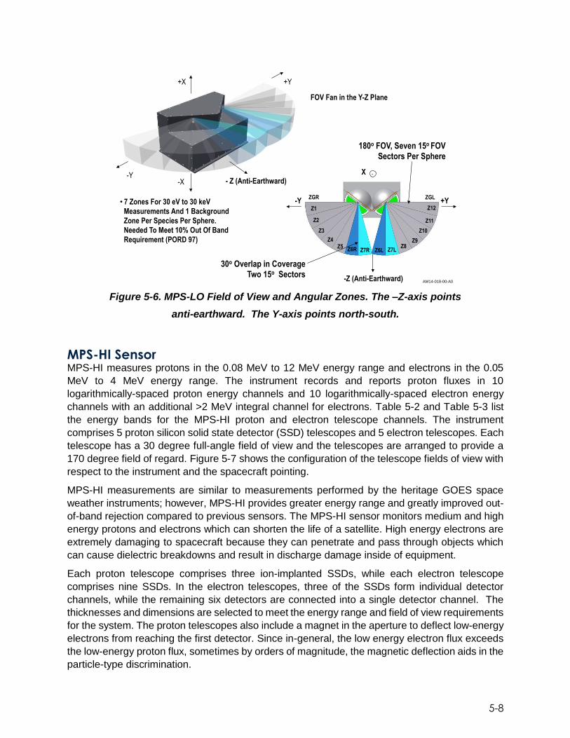
5-8
Figure 5-6. MPS-LO Field of View and Angular Zones. The –Z-axis points
anti-earthward. The Y-axis points north-south.
MPS-HI Sensor MPS-HI measures protons in the 0.08 MeV to 12 MeV energy range and electrons in the 0.05
MeV to 4 MeV energy range. The instrument records and reports proton fluxes in 10
logarithmically-spaced proton energy channels and 10 logarithmically-spaced electron energy
channels with an additional >2 MeV integral channel for electrons. Table 5-2 and Table 5-3 list
the energy bands for the MPS-HI proton and electron telescope channels. The instrument
comprises 5 proton silicon solid state detector (SSD) telescopes and 5 electron telescopes. Each
telescope has a 30 degree full-angle field of view and the telescopes are arranged to provide a
170 degree field of regard. Figure 5-7 shows the configuration of the telescope fields of view with
respect to the instrument and the spacecraft pointing.
MPS-HI measurements are similar to measurements performed by the heritage GOES space
weather instruments; however, MPS-HI provides greater energy range and greatly improved out-
of-band rejection compared to previous sensors. The MPS-HI sensor monitors medium and high
energy protons and electrons which can shorten the life of a satellite. High energy electrons are
extremely damaging to spacecraft because they can penetrate and pass through objects which
can cause dielectric breakdowns and result in discharge damage inside of equipment.
Each proton telescope comprises three ion-implanted SSDs, while each electron telescope
comprises nine SSDs. In the electron telescopes, three of the SSDs form individual detector
channels, while the remaining six detectors are connected into a single detector channel. The
thicknesses and dimensions are selected to meet the energy range and field of view requirements
for the system. The proton telescopes also include a magnet in the aperture to deflect low-energy
electrons from reaching the first detector. Since in-general, the low energy electron flux exceeds
the low-energy proton flux, sometimes by orders of magnitude, the magnetic deflection aids in the
particle-type discrimination.
-Y +Y
-Z (Anti-Earthward)
. X
ZGR ZGL
Z1
Z2
Z3
Z4 Z5 Z6R Z7R Z6L Z7L
Z8 Z9
Z10
Z11
Z12
30o Overlap in Coverage Two 15o Sectors
+X
- Z (Anti-Earthward)
+Y
FOV Fan in the Y-Z Plane
MPS-LO Field-Of-View Showing Sectors and Zones
AM14-018-00-A0
180o FOV, Seven 15o FOV Sectors Per Sphere
• 7 Zones For 30 eV to 30 keV
Measurements And 1 Background
Zone Per Species Per Sphere.
Needed To Meet 10% Out Of Band
Requirement (PORD 97)
-X -Y
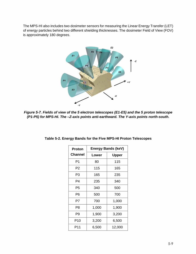
5-9
The MPS-HI also includes two dosimeter sensors for measuring the Linear Energy Transfer (LET)
of energy particles behind two different shielding thicknesses. The dosimeter Field of View (FOV)
is approximately 180 degrees.
Figure 5-7. Fields of view of the 5 electron telescopes (E1-E5) and the 5 proton telescope
(P1-P5) for MPS-HI. The –Z-axis points anti-earthward. The Y-axis points north-south.
Table 5-2. Energy Bands for the Five MPS-HI Proton Telescopes
Proton
Channel
Energy Bands (keV)
Lower Upper
P1 80 115
P2 115 165
P3 165 235
P4 235 340
P5 340 500
P6 500 700
P7 700 1,000
P8 1,000 1,900
P9 1,900 3,200
P10 3,200 6,500
P11 6,500 12,000

5-10
Table 5-3. Energy Bands for the Five MPS-HI Electron Telescopes
Channel
Energy Bands
(keV)
ETel 1, 2, 4
Energy Bands (keV)
ETel 3, 5
Lower Upper Lower Upper
E2 90 145 95 140
E3+E3A 145 230 140 275
E4 230 325 275 405
E5 325 460 405 609
E6 460 705 609 794
E7 705 1360 794 1364
E8 1360 1785 1364 1903
E9 1785 2685 1903 2842
E10 2685 4345 2842 4515
E10A 4345 5660 4515 5899
E11 2000 2000
SGPS Sensors
The SGPS instruments measure protons in the 1 MeV to >500 MeV energy range. The two
identical instruments measure and report the flux in 10 logarithmically-spaced energy channels
and 1 integral channel for protons >500 MeV. The energy range is covered using three separate
SSD telescopes. Telescope-1 measures 1 MeV to 25 MeV protons and has a 60 degree full-angle
cone field of view. Telescope-1 comprises two SSDs. Telescope-2 measures 25 MeV to 80 MeV
protons and also has a 60 degree full-angle conic field of view. Table 5-4 lists the energy bands
for the two SGPS sensors. Telescope-2 comprises three SSDs and aluminum energy degraders.
Telescope-3 measures 80 MeV to >500 MeV protons, has a 90 degree full-angle conic field of
view and comprises three SSDs and copper energy degraders. The fields of view of each of the
telescopes are co-aligned. The fields of view of one SGPS unit point east, the other points west.
Figure 5-8 shows the SGPS configuration and fields of view.
SGPS measurements are similar to measurements performed by the heritage GOES space
weather instruments; however, SGPS provides greater energy range and greatly improved out-
of-band rejection compared to previous sensors. The data provided by SGPS will assist NOAA’s
NCEI in providing solar radiation storm warnings. These particular measurements are crucial to
the health of astronauts on space missions, though passengers on certain airline routes may

5-11
experience increased radiation exposure as well. In addition, these protons can cause blackouts
of radio communication near the Earth's poles and can disrupt commercial air transportation flying
polar routes. The warning system allows airlines to reroute planes that would normally fly over
Earth’s poles.
A significant design challenge for SGPS is the differentiation of high-energy protons (>80 MeV)
that enter a telescope from the front or the back. To facilitate that differentiation, we have included
circuitry that compares the signals in the front-most SSD and the rear-most SSD. Protons entering
from the front of the sensor, will deposit slightly less energy in SSD-1 than in SSD-3. For protons
entering from the rear of the sensor, the opposite will be true. The design uses a precision
comparator to compare the signal in SSD-1 and in SSD-3. The results of that comparison aid the
on-board logic in differentiating front-entry from rear-entry particles.
Figure 5-8. Fields of view of the three SGPS telescopes. The fields of view of the three telescopes are co-aligned and point east (SGPS-1) and west (SGPS-2).

5-12
Table 5-4. Energy Bands for SGPS+X and SGSP-X (50% points)
Channel SGPS+X SGPS-X
Low (MeV) High (MeV) Low (MeV) High (MeV)
P1 1.02 1.86 1.02 1.86
P2A 1.90 2.30 1.90 2.30
P2B 2.31 3.34 2.31 3.34
P3 3.40 6.48 3.40 6.48
P4 5.84 11.0 5.84 11.0
P5 11.64 23.27 11.64 23.27
P6 25.9 39.1 24.9 38.1
P7 41.2 74.3 40.3 73.4
P8A 82.9 99.8 83.7 98.5
P8B 96.4 121 99.9 118
P8C 114 148 115 143
P9 160 242 160 242
P10 276 404 276 404
P11 540 540
EHIS Sensor The heavy ion measurements made by EHIS are a new capability for the GOES-R series space
weather instruments. The EHIS is responsible for measuring heavy ion fluxes in the
magnetosphere to provide a complete picture of the energetic particles surrounding Earth. This
includes particles trapped within Earth’s magnetosphere and particles arriving directly from the
sun and cosmic rays which have been accelerated by electromagnetic fields in space. This
information will be used to help scientists protect astronauts and high altitude aircraft from high
levels of harmful ionizing radiation.
EHIS measures fluxes of ions from protons through nickel. The energy range of measurement is
10 – 200 MeV for protons. For heavier ions it is the energy range for which that ion penetrates
the same amount of material, in areal density, as do the 10 – 200 MeV protons. The data are
binned in five logarithmically spaced intervals in this energy range for five mass bands, Hydrogen,
Helium, Carbon through Oxygen, Neon through Phosphorus, and Chlorine through Nickel. Table
5-5 lists the energy bands for representative ions that span the EHIS detection range. The
counting rate over which the instrument functions ranges from the galactic cosmic ray rate of ~0.3
events/sec through the solar particle event rate of 30,000 events/sec.

5-13
EHIS contains a single SSD telescope with a 28 degree full-angle conic field of view. The
telescope is pointed anti-earthward, with a pointing accuracy of 2 degrees. Figure 5-9 shows the
EHIS sensor, its field of view, and a cross-sectional view of the telescope.
EHIS uses commonly accepted techniques and a unique trajectory system to achieve these goals.
The technique EHIS employs is an energy loss (dE/dx) vs. residual energy (E) measurement
taken with a stack of thirteen co-axially mounted SSDs. A plastic scintillator acts as a veto for
side-entry particles.
Ions travel through detectors depositing energy in the silicon SSDs that is read out as a current
pulse. Each SSD outputs a charge (current) pulse proportional to the energy deposited. The first
three SSDs are used in the Angle Detecting Inclined Sensor (ADIS) system. Accurate incident
particle angle information allows for the individual elemental separation. In order to identify heavy
ions with good mass resolution on an event-by-event basis using a dE/dx vs. E method, it is
necessary to account for the angle of incidence of the particle. Identical ions entering an
instrument at different angles will deposit different amounts of energy in the various detectors.
ADIS takes advantage of this effect with two detectors (D2 and D3) mounted at known angles
with respect to the plane normal to the telescope axis. The polar angle is 30 deg for both D2 and
D3 but the azimuthal angles are different. The energy deposition in these tilted detectors is
compared to the energy deposition in the one mounted normal to the instrument axis. From the
different energy deposited in these inclined detectors, the on-board processing determines the
angle of incidence of each particle
With these angles and the measured energy deposits in the first six SSDs, EHIS uses an on-board processor to calculate the charge of a particle using the ZCAL method. The ZCAL method, developed originally at California Institute of Technology, is an approximation that enables the determination of the ion charge based on the energy deposited in the detectors. The on-board processor can analyze between 1,800 and 2,700 events/second. Results are stored in charge-energy histograms for telemetry to the ground on a 1-minute cadence.
Table 5-5. EHIS Energy Bands for Representative Ions.
EHIS reports abundances of all ions from H (Z=1) to Ga (Z=31)
E1
(MeV/nucl)
E2
(MeV/nucl)
E3
(MeV/nucl)
E4
(MeV/nucl)
E5
(MeV/nucl)
Atomic
Number Element Low High Low High Low High Low High Low High
1 H 13.00 31.50 31.00 44.50 43.50 56.25 54.00 92.25 109.50 179.75
2 He 10.00 31.75 31.00 43.75 44.00 52.75 54.50 91.75 110.00 194.00
6 C 18.50 59.50 57.00 82.25 81.50 98.75 101.00 171.75 210.00 335.25
7 N 19.75 65.00 61.25 89.75 87.25 107.75 108.50 184.75 229.00 367.00
8 O 22.00 70.75 67.00 97.00 96.50 117.00 119.00 200.00 249.50 400.75
12 Mg 26.25 87.00 82.75 118.00 118.25 143.00 147.00 247.50 312.25 493.75
14 Si 29.00 97.25 92.50 132.50 132.00 160.25 164.50 279.00 352.50 567.25
26 Fe 37.50 131.50 124.50 180.50 180.50 219.75 226.50 393.25 501.00 825.50

5-14
Figure 5-9. The EHIS sensor, 28 degree field of view and a cross-sectional view of the EHIS telescope showing the inclined detectors used in the Angle Detecting Inclined
Sensor.
6-1
6. Magnetometer
The GOES-R series Magnetometer assembly (MAG) consists of two magnetometer instruments
operating simultaneously to allow for gradiometry. The instruments are mounted on a deployable
boom to keep them away from the spacecraft so as to minimize the spacecraft influence on
instrument measurements. The MAG assembly is provided by ATK, while the individual
magnetometer sensors are provided by Macintyre Electronic Design Associates, Inc (MEDA).
Each Magnetometer instrument consists of a three-axis sensor and an electronics unit. Each
magnetometer instrument measures three orthogonal vector components of the magnetic field in
the vicinity of the spacecraft. The three Magnetometer axes are orthogonal to within +0.5 degrees
and calibrated to within less than 0.1 degrees. Each sensor has a linear range of +512 nanoTesla
(nT). This includes a measurement resolution of 0.016 nT and measurement bandwidth 2.5 Hz.
The determination of the ambient magnetic field within the vicinity of the spacecraft is
simultaneous and continuous.
The MAG supports the following mission objectives:
Map the space environment that controls charged particle dynamics in the outer region of the magnetosphere
Measure the magnitude and direction of the Earth’s ambient magnetic field in three orthogonal directions in the geosynchronous equatorial orbit
Determine general level of geomagnetic activity
Detect magnetopause crossings, storm sudden commencements, and sub-storms
The MAG measures and maps the space environment magnetic field that controls charged
particle dynamics in the outer region of the magnetosphere. These particular particles can be
dangerous to spacecraft and astronauts. These geomagnetic field readings are important for
providing alerts and warnings to many customers including satellite operators and power utilities.
The MAG also determines the level of geomagnetic activity as well as detects magnetopause
crossings and storm sudden commencements.
The GOES-R series MAG provides vital information to both the satellite itself, as well as to the
individuals monitoring space weather patterns on the ground. This system serves as an early
warning system for large scale magnetic storms. These measurements are used to validate large
scale space models that are used in operation. Figure 6-1 and 6-2 show notional depictions of
the MAG instrument. The two magnetometers are mounted on a deployable boom as shown with
supporting electronics mounted onboard the spacecraft. These components are thermally
controlled to maintain operational temperatures.

6-2
Figure 6-1. Magnetometer Instrument Locations
Figure 6-2. Magnetometer Stowed/Unstowed Configuration
+Z
+
-Y
+Z
+
+X
Stowed
Configuration Unstowed
Configuration

6-3
The data from the MAG is used for the estimation of the Earth’s magnetic field. A gradiometric
algorithm is used in this estimation, in conjunction with a priori knowledge of the satellite magnetic
characteristics to accurately estimate the ambient magnetic field.
The two three-axis magnetometers utilize a gradiometer effect, allowing for continuous monitoring
of the spacecraft magnetic field. The gradiometer uses a mathematical model to represent the
spacecraft’s field characteristics as a single dipole. The inboard magnetometer is deployed 6.35
meters from the spacecraft on the boom, and the outboard magnetometer is deployed 8.56 meters
away from the spacecraft. These large distances from the spacecraft significantly reduce
magnetic effects from the spacecraft’s body. The boom employs a light-weight, composite, coiled
design to permit compact stowage. Its release mechanism consists of a frangibolt with an
actuated release pin. The sensors themselves are fully blanketed with thermal blankets to protect
them from the thermal environment.
As can be seen in Figure 6-3, the electronics for the magnetometer assembly are located on the
spacecraft on the +Y panel. As shown in the block diagram in Figure 6-4, the sensor data passes
through a Remote Interface Unit (RIU) to the Command and Data Handling (C&DH) subsystem.
The flight software (FSW) passes the 10Hz magnetometer data to the ground, and the ground
processing algorithms take each magnetometer measurement and generate an estimate of the
ambient field based on the gradiometer algorithm, calibration data, and transient compensation.
Mission operations maintains system performance parameters via periodic in-flight calibrations.
The In-situ calibration takes into account the characterization of the spacecraft static magnetic
field at the magnetometer sensors, the characterization of the spacecraft AC magnetic field at the
sensors, and the characterization of the magnetic sensor alignment with respect to the attitude
reference frame.
Figure 6-3. Location of Magnetometer Electronics Units
+Zsc
+Xsc
Magnetometer
Electronics Units

6-4
Figure 6-4. Magnetometer Block Diagram
The MAG has four modes of operation. Normal mode provides 3-axis science data at 10Hz, time
stamps and status data. Maintenance Mode is used to support ground calibration and testing
along with supporting upload/download of calibration coefficients and firmware images. Health
Test Mode executes a set of step commands and reports telemetry exactly as it does in normal
mode. This generates a predefined magnetic field step sequence to confirm the health of the unit.
The last mode is Safe Mode, which is Off Mode.

7-1
7. The Extreme Ultraviolet and X-ray Irradiance
Sensors Instrument
Space Weather Monitoring: The Sun/Earth Weather Connection Measuring solar radiation variability is an important component of space weather monitoring as
huge eruptions of energy on the sun, in the form of solar flares and associated coronal mass
ejections, can have severe impacts on the Earth’s atmosphere and human endeavors. This solar
radiation variability drives the heating, ionization, chemistry and dynamics in the Earth’s
atmosphere which in turn can create hazards for astronauts in the form of an increased exposure
to radiation and for orbiting satellites where atmospheric density changes can affect orbit integrity
and tracking. Earth terrestrial level affects can include communications blackouts, disruptions to
power grids and errors in Global Positioning System (GPS) navigation. The GOES program at its
inception in 1975 had a terrestrial focus that looked to provide continuous Earth imaging and
sounding data. Monitoring solar irradiance in the soft X-rays was part of the GOES program
starting in 1986, and on the NOAA SMS series prior to that, leading to the use of the soft X-rays
measurements for the classification of flare magnitude. Starting with the GOES-N satellite series
in 2001, capability was added to monitor and study effects of solar dynamics by providing solar
imaging and extreme ultraviolet irradiance measurements.
The GOES-R satellite series development of the EXIS instrument by the University of Colorado’s
Laboratory for Atmospheric and Space Physics (LASP) continues these important space weather
measurements. EXIS focuses on measuring the brightness of the sun at several different
wavelengths of light that have been shown to affect the Earth’s atmosphere and terrestrial
environment. A detailed instrument description follows.
The Extreme Ultraviolet and X-ray Irradiance Sensors instrument resides on the Sun Pointing
Platform (SPP) which is mounted to the yoke of the spacecraft solar array. EXIS instrument
channels continuously measure the absolute brightness of the full disk of the sun looking for
changes that provide an early warning of an impending solar storm. On a quarterly basis, for a
short period of time, the SPP performs a 16° off-point in order to monitor any changes in
instrument performance by comparing to mission start baseline dark signals and performing
electronic calibrations of the instrument detector systems. Figure 7-1 below shows how EXIS
integrates into the SPP and how the SPP is integrated onto the spacecraft. Key physical
parameters for the EXIS are shown in Table 7-1.

7-2
Figure 7-1. EXIS Integrated into the SPP and the SPP Integrated onto the Spacecraft
Table 7-1. EXIS Physical Resource Summary (GOES-R EXIS FM1)

7-3
Figure 7-2. Overview of EXIS Subassemblies and Key Metrics
EXIS is divided into four subassemblies as depicted in Figure 7-2: an X-ray Sensor (XRS), an
Extreme Ultraviolet Sensor (EUVS), an EXIS Electrical Box (EXEB) and a Front Aperture
Assembly (FAA) which includes a door mechanism, a filter mechanism, and a Solar Position
Sensor (SPS). Attending flight software facilitates all intra-instrument communication and
external communication with the spacecraft. A block diagram of the EXIS is shown in Figure 7-
3, with each subassembly described in the following paragraphs.
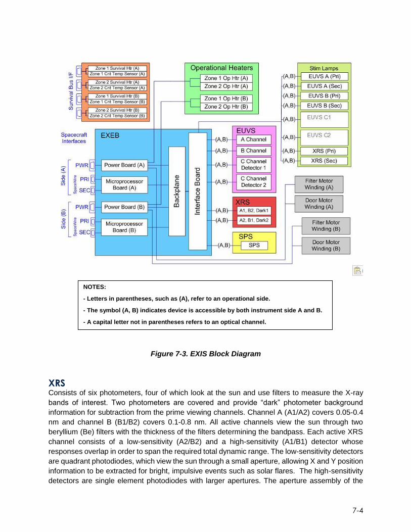
7-4
Figure 7-3. EXIS Block Diagram
XRS Consists of six photometers, four of which look at the sun and use filters to measure the X-ray
bands of interest. Two photometers are covered and provide “dark” photometer background
information for subtraction from the prime viewing channels. Channel A (A1/A2) covers 0.05-0.4
nm and channel B (B1/B2) covers 0.1-0.8 nm. All active channels view the sun through two
beryllium (Be) filters with the thickness of the filters determining the bandpass. Each active XRS
channel consists of a low-sensitivity (A2/B2) and a high-sensitivity (A1/B1) detector whose
responses overlap in order to span the required total dynamic range. The low-sensitivity detectors
are quadrant photodiodes, which view the sun through a small aperture, allowing X and Y position
information to be extracted for bright, impulsive events such as solar flares. The high-sensitivity
detectors are single element photodiodes with larger apertures. The aperture assembly of the
NOTES:
- Letters in parentheses, such as (A), refer to an operational side.
- The symbol (A, B) indicates device is accessible by both instrument side A and B.
- A capital letter not in parentheses refers to an optical channel.

7-5
XRS incorporates an in-house designed electron deflection system (Ramatron) that deflects
incoming electrons from the XRS detectors so only X-rays are measured. The Ramatron also
provides magnetic shielding to the outside environment to minimize a magnetic signature that
might affect other satellite measuring systems.
EUVS Consists of three spectrographs which measure sunlight in select wavelengths of interest. The
three spectrographs, denoted A, B and C, give coverage in the bands of 25-32 nm (0.6nm
resolution), 115-141 nm (0.6nm resolution) and 275-285nm (0.1nm resolution) respectively. From
these, a reconstruction of the full solar spectrum between 5 nm and 127 nm is generated. The
three spectrographs use gratings, filters and solid state detectors to make the measurements in
their respective wavelength bands. Post-dispersion photon detection is done via custom arrays
of discrete silicon photodiodes for the A and B spectrographs, and a linear 512-element
photodiode array for the C spectrograph which is made up of two redundant units, C1 and C2.
The A spectrograph makes measurements in the Extreme Ultraviolet (EUV), the B spectrograph
in the Far Ultraviolet (FUV), and the C in the Middle Ultraviolet (MUV) portions of the spectrum.
The C channel also provides a calibration standard for the A and B spectrographs.
EXEB Contains the instrument low voltage power supplies and a FPGA with imbedded microprocessor
and instrument internal/external interfaces that facilitate housekeeping data collection from
voltage, current and thermal monitors, instrument science data collection from XRS-A/B, EUVS
A/B, EUVS C1/C2 and SPS, control of door motor, filter wheel motor, stimulus lamps, instrument
calibration, and operational heaters. All communication to the spacecraft is via redundant
SpaceWire links using the GOES-R Reliable Data Delivery Protocol (GRDDP).
FAA and SPS Are made up of a door mechanism, a filter mechanism, a baffle assembly and a solar position
sensor as shown in Figure 7-4. There are two mechanisms on EXIS, one being the EUVS filter
mechanism which is used for selecting from redundant filters for EUVS A measurements, and the
second one being the EUVS door mechanism whose purpose is to limit the rate that contamination
can enter the EUVS optical apertures before going into on-orbit operations (not a hermetic seal).
Both mechanisms consist of an aluminum disk directly connected to the output shaft of a stepper
motor assembly. Each disk is mounted perpendicular to the axis of rotation of its shaft. The door
disk has open and closed aperture positions that are placed at the locations needed for them to
either block or open the lines of sight to the associated spectrograph. Although the door
mechanism has the capability to open/close as desired, the on orbit intent is to open and leave
open for the mission duration. The filter disk is made up of 24 redundant filters that can be cycled
as needed to support the normal solar measurements and additionally to provide degradation
checks of filters that sustain heavy usage.
The Solar Position Sensor is made up of a quadrant photodiode, aperture and control electronics
whose purpose is to accurately and at high cadence report the position of the solar disk within the
instrument field of view.
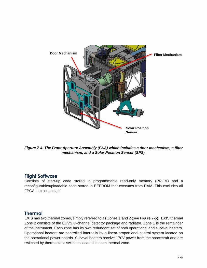
7-6
Figure 7-4. The Front Aperture Assembly (FAA) which includes a door mechanism, a filter
mechanism, and a Solar Position Sensor (SPS).
Flight Software Consists of start-up code stored in programmable read-only memory (PROM) and a
reconfigurable/uploadable code stored in EEPROM that executes from RAM. This excludes all
FPGA instruction sets.
Thermal EXIS has two thermal zones, simply referred to as Zones 1 and 2 (see Figure 7-5). EXIS thermal
Zone 2 consists of the EUVS C-channel detector package and radiator. Zone 1 is the remainder
of the instrument. Each zone has its own redundant set of both operational and survival heaters.
Operational heaters are controlled internally by a linear proportional control system located on
the operational power boards. Survival heaters receive +70V power from the spacecraft and are
switched by thermostatic switches located in each thermal zone.
Door Mechanism Filter Mechanism
Solar Position
Sensor

7-7
Thermal Zone Operational Range Survival Range
Zone 1 -5 C to +20 C -35 C to +50 C
Zone 2 -15 C to 0 C -30 C to +50 C
Figure 7-5. EXIS Thermal Zones

7-8
This page left blank

8-1
8. Solar Ultraviolet Imager
The Solar Ultraviolet Imager, manufactured by Lockheed Martin, is used to determine when to
issue forecasts and alerts of “space weather” conditions that may interfere with ground and space
systems. These conditions include ionospheric changes that affect radio communication (both
ground-to-ground and satellite-to-ground) and magnetospheric variations that induce currents in
electric power grids and long distance pipelines. These conditions can cause navigational errors
in magnetic guidance systems, introduce changes in spacecraft charging, produce high energy
particles that can cause single event upsets in satellite circuitry, and expose astronauts to
increased radiation. SUVI is designed to provide a view of the solar corona by taking full-disk
solar images at high cadence around the clock, except for brief periods during eclipse or
instrument calibration, in the extreme ultraviolet (EUV) wavelength range. Available combinations
of exposures and filters allow coverage of a range of solar features, including coronal holes, X-
class flares, and estimates of temperature and emission measurements. Images from SUVI will
be used by NOAA and U.S. Air Force forecasters to monitor solar conditions that affect space
weather conditions, including the dynamic environment of energetic particles, solar wind streams,
and coronal mass ejections emanating from the sun. These data can be used to issue forecasts
of solar phenomena.
SUVI is tailored specifically to observe solar phenomena from a geosynchronous orbit located at
either 75° or 137° west longitude. SUVI’s primary science objectives include:
Locating coronal holes for the prediction of high-speed solar wind streams causing recurrent geomagnetic storms. These weakly emitting features are good predictors of geomagnetic storms for the years near solar activity minimum when long-lived holes are present on the sun.
Locating the position of solar flares, both on the disk and beyond the west limb, to predict the magnitude of particle events.
Identifying solar activity rotating onto the disk from the east limb. Enhanced emission above the limb provides information about solar activity occulted by the solar disk at other wavelengths.
Monitoring the sun for evidence of coronal mass ejection (CME), which is associated with geomagnetic storms. Reliable indicators of the CME occurrence include separating flare ribbons, post flare loops between them (in long duration events), and large scale coronal dimming.
Observing the size, temperature, morphology, and complexity of solar active regions. Changes in these properties will be used to predict the rate of growth of solar active regions and the probability that the regions may flare.
To meet these objectives, the SUVI images the solar corona in the EUV region of the
electromagnetic spectrum. Full-disk solar images are provided with a 1280 X 1280 array with 2.5
arc-second pixels in six wavelength bands from 94 to 304 Å (9.4 to 30.4 nm). The SUVI optical

8-2
system employs a Ritchey-Chretien telescope consisting of multilayer coated optics, and a CCD
detector at its focus to record images of the solar disk and its atmosphere. Using an aperture
selector, SUVI operates at any one of the six EUV narrow spectral passbands via combination of
thin film filters and multilayer coated optics. Each optic (mirror) of the telescope has six distinct
multilayer coatings that are fine-tuned to reflect at a well-defined EUV wavelength that
corresponds to a particular temperature region of the observed solar atmosphere, as shown in
Figure 8-1. A regular sequence of exposures that are downlinked at ten-second intervals is used
to cover the full dynamic range needed to monitor solar activity. Figure 8-2 presents a sample set
of images of the sun in the six chosen wavelengths, bandpasses, representing a discrete range
of plasma temperatures of the sun’s atmosphere, from 0.3 to 3 million Kelvin. Hotter temperatures
greater than 3 million K are reached during transient events such as flares and coronal mass
ejections.
Figure 8-1. The SUVI EUV Wavelength Bands used to observe the Range of Solar Phenomena important for Space Weather Forecasting.

8-3
Figure 8-2. 60-minute averages of 1-second exposures, taken on January 23, 2017 of all six of SUVI’s EUV passbands
The SUVI instrument consists of a telescope assembly, an electronic box, and the cables that run
between the telescope assembly and the electronics box, as shown in Figure 8-3. The top level
block diagram is presented in Figure 8-4. All SUVI components are mounted on the SPP as shown
in Figure 8-5. The SUVI Electronics Box (SEB) provides the instrument control, data
management, conditioned power to the rest of the instrument, and the spacecraft interface. The
SUVI Telescope Subsystem (STS) consists of the EUV Telescope Assembly (ETA), the Guide
Telescope Assembly (GTA), and the Camera Electronics Box (CEB). The GTA includes the Guide
Telescope (GT) and the GT Pre-Amp box. The GTA is mounted on the ETA along with the CEB.
The CEB provides CCD sensor control and image processing management. The GTA provides
solar pointing data with respect to the instrument line-of-sight to the spacecraft during normal
operation. A summary of SUVI’s characteristics is given in Table 8-1.

8-4
Figure 8-3. The SUVI Instrument
Figure 8-4. The SUVI Instrument Top Level Block Diagram

8-5
Table 8-1. Solar Ultraviolet Imager Characteristics
Mirrors Multi-layer-coated Zerodur
Number of coating segments per mirror 6
Primary diameter 20 cm
Effective focal length 173.04 cm
Field of view 45 × 45 arcmin or better
Pixel size/Resolution 21 µm/2.5 arcsec
CCD detector 1280 × 1280 pixels
Detector full well 450 000 electrons
Full image frame rate 1 per 10 seconds
Typical exposure times 0.01 to 1 second
Flight computer BAe RAD750
Mass:
Telescope subsystem
Electronics box
Intra-instrument harness
39 kg
25 kg
8 kg
Instrument Power 225 W (peak)
Science telemetry
Interface to spacecraft
3.5 Mbps
Design life 10 years (after 2 years of on-orbit
storage)

8-6
Figure 8-5. Solar Ultraviolet Imager and Solar Array in Deployed Configuration
Instrument System SUVI is mounted on the SPP and co-aligned with the EXIS. The SPP assembly is mounted on
the solar array yoke to continuously face the sun. The SPP is actuated using the SPP Elevation
Gimbal Assembly (SEGA) in the north-south direction, tracking the sun in solar declination. The
Solar Array Drive Assembly (SADA) controls the east-west pointing of the yoke, tracking the
diurnal motion of the sun. Both the SPP N-S pointing and the yoke E-W pointing are controlled
during normal operations by spacecraft-provided closed-loop control systems that utilize two-axis
position error data from the SUVI Guide Telescope (GT).
The spacecraft-provided Sensor Interface Unit (SIU) (interchangeably called the Sun Pointing
Platform Interface Unit) and Fine Sun Sensor (FSS) are also mounted on the SPP, as shown in
Figure 8-6. The SIU is located between SUVI and EXIS and provides the command and telemetry
SpaceWire interface between the instruments and the spacecraft. The FSS provides two-axis
position error data when SUVI GT data is unavailable.

8-7
Figure 8-6. SUVI and EXIS Mounted on the SPP (harness and blankets not shown)
The total mass of the SUVI (telescope, electronics, harness) is 72.0 kg, of which 39 kg is the
telescope assembly. Electrical connections to the GOES spacecraft cross the SADA interface
through slip rings. Sixteen power rings have been allocated to SUVI. All SUVI spacecraft data
interfaces are carried via SpaceWire to the GOES spacecraft, and sixteen signal rings have been
allocated to SpaceWire. The SpaceWire network is capable of handling a SUVI data rate of 10
Mbps. EUV image data are transmitted from the Spacecraft at a rate of approximately 6 images
per minute via the high-rate spacecraft Raw Data Link (RDL). SUVI health and safety data is also
transmitted from the spacecraft as part of a separate low-rate observatory health data link.
Operation Operation of SUVI is controlled through the SEB. The SEB primarily consists of three parts: power
distribution, control processing, and data handling or storage. Control is performed via a RAD750
microprocessor. The SEB receives, interprets, validates, and executes both stored sequence
commands and immediate execution commands. Through these commands, the SEB
coordinates and controls the activities and operations of the SUVI instrument. In addition, the SEB
receives, collects, and multiplexes the science, engineering, and housekeeping data from the
SUVI components and provides the data stream to the spacecraft communication subsystem for
transmission to ground facilities. SUVI transmits this data as SpaceWire data packets formatted
per the GRDDP. Figure 8-7 gives a functional flow definition for the SEB command and data
handling. The SEB electronics block diagram is presented in Figure 8-8.

8-8
Figure 8-7. The SEB Command/Data Flow Block Diagram
Figure 8-8. The SUVI Electronics Functional Block Diagram
The CEB reads out the CCD at 2 Megapixel/s through either one of two ports at 14-bit resolution
with 40 electrons rms noise (including CCD contribution), stores the image data as the CCD image
is being read out, uses a high-rate IEEE 1355 SpaceWire low-voltage differential signaling (LVDS)
interface with the SEB for image and housekeeping telemetry, and conditions and converts the
28V input power.

8-9
The Bridge/SpaceWire Board contains both the SpaceWire ASIC and the Bridge FPGA. The
Bridge FPGA provides interfaces for the power system, housekeeping telemetry, mechanism
control, the Guide Telescope, and provides a lockout function to prevent conflicts if both RAD750
processors in the SEB are powered at the same time. The SpaceWire ASIC provides redundant
10Mbps SpaceWire links to the spacecraft, a 10Mbps SpaceWire command link to the CEB, and
a 50 Mbps SpaceWire data link to the CEB. The Bridge/SpaceWire board combines the CCD
image data, GT pointing data, housekeeping, and memory dump data, and passes them to the
spacecraft through the SIU on the SPP. The SIU converts the SpaceWire data into RS-422 for
transmission over the solar array drive assembly slip-ring. The spacecraft onboard computer
extracts and processes the housekeeping and GT pointing data from the combined SUVI data to
support fault management and SPP pointing functions.
SUVI data are transmitted to the ground by two paths, low-rate telemetry for housekeeping data
only, and via the Raw Data Link for all SUVI image and telemetry data. The data can be received
at SOCC in Suitland, Maryland, and the NOAA Space Weather Prediction Center (SWPC) in
Boulder, Colorado. In general, image data are downlinked as rapidly as possible after they are
acquired.
Power Electrical power is provided to SUVI from the spacecraft electrical power subsystem. The
electrical interface between SUVI and the spacecraft is at the SEB connector panel. The
spacecraft delivers both +28V and +70V dc power to SUVI, and these power inputs are protected
with fuses within the spacecraft. The spacecraft-to-SUVI electrical harnesses are routed from the
spacecraft bus via Solar Array Drive Assembly slip rings and across the SPP Elevation Gimbal
Assembly.
The spacecraft provides operational power to the SUVI instrument from the power bus that is
regulated at 28.0 ± 2.0 V dc during sunlight operation. SUVI uses two separate and redundant
sets of 28V dc input circuits. The first redundant pair serves as the main power inputs and is
converted into a number of different voltages by the SEB for the use of various SUVI instrument
components and subsystems. The second redundant pair provides power to the CCD
decontamination heaters which are used to keep the CCD sensor warmer than the rest of the
instrument while the Instrument is turned off, so as to not serve as a contamination “getter.”
During eclipse, this primary power bus is controlled by battery voltage and a voltage regulator,
which maintains the +28 volt bus. The spacecraft primary bus (70.0 ± 2.0 V dc) provides power
to the survival heater power located on the Telescope Subsystem. The input operational power
consumption by the SUVI is 90 watts maximum in sunlight and 162 watts maximum during eclipse.
Telescope Subsystem The STS consists of the ETA, the GTA, and the CEB. The GTA includes the GT and the GT Pre-
Amp box. Both the GTA and CEB are mounted on the ETA, as shown in Figure 8-3.
EUV Telescope Assembly (ETA) The ETA is a 20-cm (8-inch) Ritchey-Chretien telescope that includes a number of mechanisms
and sensor packages. The layout of the ETA is presented in Figure 8-10. The SUVI metering tube
is the ETA’s primary structure that integrates the main telescope, GTA flexure mounts, aperture
door, CEB, camera, radiators, associated housing/adapter and flexure mounts. The struts are

8-10
mounted on the metering tube located at the front and aft of the telescope carbon fiber metering
tube and interfaces with the SPP. Each of the six mounting struts is identical with adjustment
capability and provides the primary load path to the SPP. The GTA is mounted to flexures which
are themselves mounted to the ETA metering tube assembly. The Spider Assembly, Front
Aperture Housing and Aperture Door are mounted at the front end of the metering tube while the
Shutter housing, Filter Wheel Housing, Isolator tube and Detector Housing including radiator are
mounted at the aft of the metering tube. The CEB is mounted on the +Z side of the telescope next
to the Filter Wheel housing.
The Spider Assembly contains the Focus Mechanism, secondary optics, and the structure to
mount to the metering tube assembly. One spoke of the Spider Assembly houses the light emitting
diode (LED) Assembly that supports aliveness testing of the ETA focal plane array and camera
electronics while the Front Door Assembly is closed.
Figure 8-9. ETA Layout
Optics The SUVI optical design is based on the Solar Dynamics Observatory (SDO) Atmospheric
Imaging Assembly (AIA) instrument design modified to meet SUVI’s specific performance
requirements and comply with SUVI’s allocated mechanical envelope. The general optical layout
is shown in Figure 8-9.
To meet mission requirements for spectral sensitivity and response, the design combines a
normal incidence telescope with multilayer mirror coatings to achieve the required narrow
bandwidths. A system of aperture masks and internal baffles are also used to suppress out-of-
band radiation and eliminate direct paths for non-solar particle radiation that might otherwise
reach the CCD sensor. Each wavelength is accomplished by dividing the aperture into six sectors,
each with a different multilayer. As shown below in Table 8-2, the 94Å sector is made of
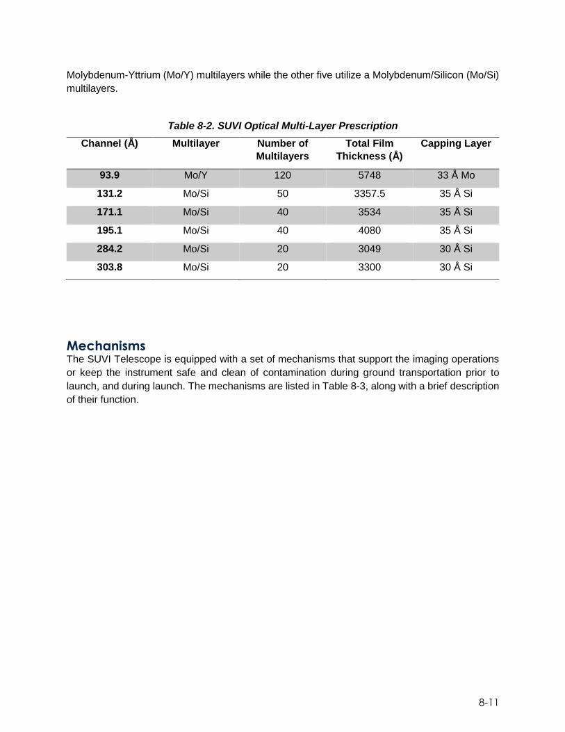
8-11
Molybdenum-Yttrium (Mo/Y) multilayers while the other five utilize a Molybdenum/Silicon (Mo/Si)
multilayers.
Table 8-2. SUVI Optical Multi-Layer Prescription
Channel (Å) Multilayer Number of
Multilayers
Total Film
Thickness (Å)
Capping Layer
93.9 Mo/Y 120 5748 33 Å Mo
131.2 Mo/Si 50 3357.5 35 Å Si
171.1 Mo/Si 40 3534 35 Å Si
195.1 Mo/Si 40 4080 35 Å Si
284.2 Mo/Si 20 3049 30 Å Si
303.8 Mo/Si 20 3300 30 Å Si
Mechanisms The SUVI Telescope is equipped with a set of mechanisms that support the imaging operations
or keep the instrument safe and clean of contamination during ground transportation prior to
launch, and during launch. The mechanisms are listed in Table 8-3, along with a brief description
of their function.

8-12
Table 8-3. SUVI Telescope Mechanisms
Mechanism Description
Front Aperture
and Door
Assembly
Consists of a door, a spring-loaded hinge, latch mechanism, and gearbox mechanism for driving the door open.
The latch is operated using redundant paraffin linear actuators.
The drive motors are fully redundant and independent.
The door is designed to sweep 245° to fully open. Aperture
Selector
Located in front of the spider assembly
Used to select the desired bandpass out of the six wavelength bands.
Focus
Mechanism
Actuated by a DC torque motor that moves the secondary mirror over a ±800 μm range in 3-μm steps
Trims the ETA’s initial focus once on orbit
Adjusts telescope focus for slow thermal drifts throughout mission
Focal Plane
Shutter
Mechanism
Consists of a circular blade turned by a brushless DC motor
Blade has two openings: a narrow slit and a wider opening to support either sweeping the solar image across the CCD or expose the entire CCD all at once
The blade can also be commanded to dwell to support long exposures.
Filterwheel
Mechanism
Two filterwheels present in the ETA.
Selects the proper filter combination to ensure that the desired channel (wavelength) reaches the detector.
Each forward/aft filterwheel contains 5 positions
The mechanism has a positional accuracy of ±30 arc minutes with a move time less than 1 second between adjacent positions.
Each filterwheel is designed to have redundant thin and thick Al and Zr filters so the telescope can continue to image properly despite the presence of pinholes.
Each wheel has one open position and the aft filter wheel has an additional clear glass filter so that the light leak performance of the entrance filter can be monitored on-orbit.
Camera System The SUVI camera system primarily consists of a focal plane detector using a CCD, CEB and the
associated flex cables and head board. The CEB receives raw image data from the CCD,
processes the data, and forwards it to the SEB, via a high speed IEEE 1355 SpaceWire low-
voltage differential signaling (LVDS) interface, as shown in Figure 8-8.
The SUVI instrument focal plane contains a 1280×1280 pixel CCD detector. The CCD is a design
similar in construction to the proven Solar-B/Hinode Focal Plane Package (FPP) and Solar
Dynamics Observatory designs. They feature low-voltage clocking of the serial output register to
minimize power dissipation in the clock driver electronics. The CCD is back thinned and back
illuminated with 21 μm pixels and operate non-inverted to ensure good full well capacity. The

8-13
SUVI thermal control system maintains the CCD operating temperature at -30C or less. The CCD
architecture and readout map is shown below in Figure 8-10.
Figure 8-10. CCD Architecture
Guide Telescope Assembly The SUVI Guide Telescope Assembly (GTA) was designed and built to support the observatory’s
sun- pointing functions. The GTA, via the SEB, provides solar pointing data to the spacecraft
during normal SUVI operation by determining the position of the solar limb relative to the GTA
centerline. The GTA is approximately 81 cm (32 inches) in length with a glint-free field of view
(FOV) of 10°. The GTA layout is shown below in Figure 8-11 along with a short description of key
components. The GTA has a linear range of approximately ±110 arcseconds, and is capable of
acquiring the sun within a cone, defined as the acquisition FOV, of approximately ±26 arcminutes.
The GTA is designed to operate between 5 °C to 35 °C.
Figure 8-11. GTA Layout

8-14
Table 8-4. GTA Components
GTA
Component
Description
Optics Design derived from Solar Dynamic Observatory (SDO) Atmospheric Imaging Assembly (AIA) and Solar Terrestrial Relations Observatory/ Solar Dynamic Observatory Atmospheric Imaging Assembly (STERO/SECCHI) ground telescope (GT)
Galilean telescope design with a bandpass entrance filter, an objective lens “semi-cemented” doublet and Barlow lens
Lenses are manufactured from radiation hardened glass
Entrance filter consists of a filter plane sandwiched between two pieces of radiation hardened glass
Sensors Four redundant pairs of photodiodes arranged in a cruciform pattern
Cruciform is located behind an occulter cone to measure the solar limb position
Pre-Amplifier Amplifies the photodiode signals
Built with redundant connectors and ¼” thick aluminum enclosure
Operation Modes SUVI has five modes which may be used over the course of the GOES mission. They are
distinguished by the telemetry generated in each mode. Each of the five modes use event flags
to signal specific events that could affect the modes or the telemetry output. SUVI modes are
illustrated below in Figure 8-12.
Figure 8-12. The SUVI Instrument Mode and Flow Diagram

8-15
SUVI OFF (Survival) Main SUVI instrument power is off. No instrument telemetry is generated. Power is provided for
thermostatically controlled survival heaters from 70V dc bus, and the CCD decontamination
heaters are drawing +28V dc power from the spacecraft if they have been turned on by the
operator and the spacecraft is power-positive. The temperatures are monitored by the spacecraft
telemetry system during this mode using SUVI-provided calibrated thermistors and spacecraft-
provided conditioning circuitry. Temperatures monitored in this mode include the mirror
assemblies (both primary and secondary mirrors), the CCD assembly, the door mechanisms, the
guide telescope (both forward and aft ends), the camera electronics box, and SUVI electronics
box.
Restricted Mode In this mode, SUVI is drawing +28V dc power. SUVI housekeeping and engineering telemetry is
generated. Diagnostic and event message telemetry may also be generated. This mode is
designed for software maintenance; i.e. debugging and updating. The instrument enters this mode
either after the initial boot-up or by a command from one of the other modes. Computer Software
Configuration (CSC) items may be loaded and unloaded in this mode. The software will not be
fully operational until all flight software CSCs are loaded. None of the SUVI functional processes
are active in this mode.
Standby (Idle) Mode In this mode, SUVI is drawing +28V dc power and all flight software CSC’s have been loaded and
activated. No updates to the software can be performed in this mode. SUVI housekeeping and
engineering telemetry is generated. Diagnostic and event message telemetry may also be
generated. One or more sub-systems may be powered off, as indicated by the sub-mode.
Thermal control may be inactive. Operational constraints on sequencing and image sizes are
disabled. The SUVI instrument can be in this mode while the telescope door is closed.
Operations (Sequencing) Mode This is the mission mode. This mode may be entered only by ground command. All subsystems
are powered on, the telescope door must be open and thermal control is enabled. Low-level
device control has been disabled. This mode minimizes the possibility of inadvertent interruption
of the mission observational program. Housekeeping, engineering telemetry and science data
telemetry are generated. Diagnostic and event message telemetry may also be generated as
needed.
The nominal imaging sequence is shown in Figure 8-13. The full sequence takes four minutes to
complete and is divided into twenty-four 10-second slots during which an image is acquired and
processed. Twenty-two images are allocated across the six wavebands to maximize science
efficacy. Two calibration images are also collected during every 4-minute sequence. During
eclipse, SUVI can be commanded to perform mechanism characterization tests.

8-16
Figure 8-13. The Nominal SUVI Image Sequence
Safe Mode SUVI enters this mode upon receiving an “Enter Safe Mode” command or upon detecting an
internal fault. The safe mode is used to prepare the instrument to lose power and allows for a
programmed and ordered shutdown of the SUVI subsystems: all EEPROM operations are
stopped; image sequencing is stopped; and the shutter is closed. Thermal control is maintained
by the instrument. Only a limited set of commands are accepted in this mode. All instrument
telemetry is generated.
Event Flags Event flags are used to signal specific events that could affect the modes or the telemetry output.
They essentially act as “sub modes” and are not mutually exclusive so SUVI may be in a particular
mode with two or more event flags.
Ground Processing
The Level 1b SUVI data product is an image of the sun in one of the six SUVI ultraviolet
wavelengths in full space-time resolution, with radiometric and geometric corrections applied. The
image has been converted to physical units, and supplemental information for further processing
is appended as metadata. The image is oriented in the same configuration as if the user was
viewing the sun from aboard the spacecraft – solar north will be in the top half of the image and
solar east will be in the left half of the image.
Ground processing of the downlinked SUVI images is carried out by the SUVI-designed Ground
Processing Algorithm (GPA). The GPA reduces and processes the information from the raw
image data received from the SUVI CCD readout onboard the S/C into usable level 1b level data
products. Reduction of raw image data follows a series of steps to manipulate the data stored in
each pixel of the image in order to produce a numerical value in each pixel that corresponds
accurately to the number of photons that were incident on that pixel during the image exposure.
Through reduction of the raw image data, by removing error sources, an accurate representation
of the field of view (FOV) at the time the image was taken can be reproduced. The SUVI raw
image data uses a number of calibration factors including fixed properties of the instrument
(primarily the CCD, camera, and electronics) measured on the ground prior to launch, and on-
orbit Instrument and Spacecraft factors that are monitored in real time because of variations
based on time, temperature and other environmental factors.

9-1
9. GOES-R Communications Subsystem
The mission of the GOES-R System is to acquire and disseminate environmental data from a
near-equatorial Earth orbit at geostationary altitude. The Communications Subsystem provides
the following functions:
Transmission of instrument data to the Command and Data Acquisition (CDA) Stations
Transmission of spacecraft telemetry to the CDA Stations
Reception of spacecraft commands from the CDA Stations
Two-way ranging and Doppler from CDA Stations and DSN Stations
Relay of Unique Payload Services signals in support of:
GOES Rebroadcast
Emergency Managers Weather Information Network broadcasts
Search and Rescue
Data Collection Platforms
Antenna reception of GPS Navigation signals
Figure 9-1 outlines the GOES-R RF interfaces between the Communications Services to
accomplish these functions. The GOES-R Communications Subsystem consists of a raw data
link and six (6) bent pipe services as depicted in Figure 9-2. A suite of transponder payloads
provide communications relay services and GOES mission data transmission. The suite consists
of the Data Collection System (DCS), the High Rate information Transmission/Emergency
Managers Weather Information Network (HRIT/EMWIN), GOES Rebroadcast (GRB), GOES Raw
Data Link (RDL) system, and the Search and Rescue Satellite-Aided Tracking (SARSAT) system.
The GRB transponders consist of dual polarized X-band uplink and dual polarized L-band earth
coverage downlink. The HRIT/EMWIN transponder is an S-band uplink to L-band earth coverage
downlink narrow bandwidth transponder. The SAR and Data Collection Platform Report (DCPR)
services are UHF uplink to L-band earth coverage downlink narrow bandwidth transponders. The
Data Collection Platform Command (DCPC) service is an S-band uplink to UHF earth coverage
downlink narrow band transponder.

9-2
Figure 9-1. Communication Links Overview
Figure 9-2. GOES Bent Pipe Transponders
The Tracking, Telemetry, and Control (TT&C) Subsystem provides telemetry, tracking, and
command functions through orbit-raising and normal on-station operations.
DCPR UHF to L
SAR UHF to L
HRIT/EMWIN S to L
DCPC S to UHF
GRB X to L
GRB X to L
KEY
UHF
L-BandS-Band GRB GRB DCPC SAR DCPR
X-band Downlinks
Up
lin
ks
Raw Data
Source
Spacecraft - Raw Data, Bent Pipe Transponders
Raw Data
HRIT/
EMRIT

9-3
The Communications service functions are:
• Provide S-band Orbit-Raising Tracking, Telemetry and Control (ORTT&C)
communications for Launch and Orbit Raising (LOR) command, telemetry and tracking
• Provide S-band ORTT&C and L-Band Command and Data Acquisition (CDA)
(housekeeping) TT&C communications for on-orbit command, telemetry and tracking
• Support terrestrial and oceanographic Data Collection Platforms (DCPs) via the Data
Collection Platform Command (DCPC) & Data Collection Platform Report (DCPR) links
• Relay High Rate Information Transmission (HRIT) and imaging data between Earth
terminals and relay the EMWIN broadcast on the HRIT/EMWIN
• Provide rapid detection of distress messages from the Search and Rescue (SAR)
Emergency Locator Transmitters (ELTs) and Emergency Position Indicating Radio
Beacons (EPIRBs)
• Rebroadcast processed GOES sensor data via the GRB data link
During LOR Mission phase, GOES-R operations will be conducted from the NOAA NSOF
supported by a global station network. This network will support all command, telemetry and
tracking requirements from post-separation acquisition through all apogee thruster firings and
deployments.
Post-Launch Checkout position at 89.5° W and post-launch test operations will be supported
primarily by the NOAA ground station. Ground support stations provide backup, tracking and
emergency support during all phases of the GOES missions for the life of the spacecraft series.
GOES Rebroadcast (GRB) GOES Rebroadcast is the primary space relay of L1b products and will replace the GVAR service.
GRB will provide full resolution, calibrated, navigated, near-real-time direct broadcast data.
The content of the data distributed via GRB service includes the full set of L1b products from all
instruments onboard the GOES-R series spacecraft. This concept for GRB is based on analysis
that a dual-pole circularly polarized L-band link of 12 MHz bandwidth may support up to a 31-
Mbps data rate – enough to include all ABI channels in a lossless compressed format as well as
data from GLM, SUVI, EXIS, SEISS, and MAG.
Data Collection System (DCS) The DCS is a satellite relay system used to collect information from Earth-based data collection
platforms that transmit in-situ environmental sensor data, such as stream or river flow, tide-levels,
weather conditions, etc. The transmissions can occur on predefined frequencies and schedules,
in response to thresholds in sensed conditions, or in response to interrogation signals. The
transponder on board the GOES-R series satellites detects this signal and then rebroadcasts it
so that it can be picked up by other ground-based equipment. Federal, state and local agencies
then monitor the environment through the transmission of observations from these surface-based
data collection platforms. The platforms can be placed in remote locations and left to operate with

9-4
minimal human intervention. The DCS thus allows for more frequent and more geographically
complete environmental monitoring. The DCS data flow is depicted in Figure 9-3.
In the GOES-R era, the number of user-platform channels were expanded from 266 to 433. There
was also a frequency change from 1696 MHz to 1679 MHz, which required the replacement of
users’ Low Noise Block (LNB) feeds. Direct Readout Ground Station (DRGS) manufacturers were
informed of this change. Data transmission rates in the GOES-R era are 300 bps and 1200 bps.
There was no change to the data access policy.
Figure 9-3. DCS Data Flows
High Rate Information Transmission (HRIT)/Emergency Managers
Weather Information Network (EMWIN) EMWIN is a direct service that provides users with weather forecasts, warnings, graphics, and
other information directly from the NWS in near real time. The GOES EMWIN relay service is one
of a suite of methods to obtain these data and display the products on the user’s personal
computer. The HRIT service provides broadcast of low-resolution GOES satellite imagery data
and selected products to remotely located user HRIT Terminals.
GOES Raw Data Link (RDL) The RDL channel broadcasts raw data coming from the GOES instruments directly down to the
Ground Stations. These stations are the NSOF in Suitland, Maryland, and the WCDAS at Wallops,
Virginia.
Search and Rescue Satellite Aided Tracking (SARSAT) As an integral part of the COSPAS-SARSAT international search and rescue satellite program,
NOAA operates the SARSAT system to detect and locate mariners, aviators, and other
recreational users in distress almost anywhere in the world at any time and in almost any
condition. This system uses a network of satellites to quickly detect and locate distress signals
from emergency beacons onboard aircraft, vessels, and from handheld personal locator beacons
(PLBs). The SARSAT transponder that will be carried onboard the GOES-R series satellites

9-5
provide the capability to immediately detect distress signals from emergency beacons and relay
them to ground stations - called local user terminals. In turn, this signal is routed to a SARSAT
mission control center and then sent to a rescue coordination center which dispatches a search
and rescue team to the location of the distress.
GOES-R continues the legacy Geostationary SAR (GEOSAR) function of the SARSAT system
onboard NOAA’s GOES satellites which has contributed to the rescue of thousands of individuals
in distress. The SARSAT transponder was modified slightly for the GOES-R era by being able to
operate with a lower uplink power (32 dBm), enabling GOES-R series satellites to detect weaker
signal beacons. An overview of the COSPAS-SARSAT System is shown below in Figure 9-4.
Figure 9-4. COSPAS-SARSAT System Overview

9-6
Tracking, Telemetry, and Command (TT&C) The TT&C subsystem provides telemetry, tracking, and commands through orbit raising, orbit-
raising contingency, normal on-station operations, and on-station contingency. The TT&C
subsystem can be configured differently depending on the particular phase of the mission.
Flexibility has been designed into the architecture in order to ensure maximum capability and
functionality throughout the GOES-R series mission. The on-board TT&C assemblies consist of
a series of antennas, as shown in Figure 9-5, and electronics boxes, which are each further
described below.
Figure 9-5. Communication Subsystem Antenna Locations
GRB Antenna The GRB antenna, which is mounted on the Antenna Wing Assembly (AWA), transmits a dual
circular-polarized global coverage beam. The antenna is composed of a multimode horn,
polarizer and waveguide to coax transition. The GRB antenna receives processed, reformatted
sensor data from WCDAS/RBU stations and rebroadcasts it to a large number of outlying ground
GRB User Terminals (GRBT). This antenna has a ±20 degree field of view cone
ANTENNA WING
ASSEMBLY (AWA)
UHF ANTENNA
L/S-BAND
ANTENNA
AFT OMNI
ANTENNAGPS-TO-GOES
ANTENNA
X-BAND
ANTENNA
SAR ANTENNAFORWARD OMNI ANTENNA
GRB ANTENNA
+X
-Y
+Z
ANTENNA WING
ASSEMBLY (AWA)
UHF ANTENNA
L/S-BAND
ANTENNA
AFT OMNI
ANTENNAGPS-TO-GOES
ANTENNA
X-BAND
ANTENNA
SAR ANTENNAFORWARD OMNI ANTENNA
GRB ANTENNA
+X
-Y
+Z
+X
-Y
+Z

9-7
L/S-Band Antenna The L/S-Band antenna is located on the AWA. This antenna transmits and receives a linearly
polarized global coverage beam. It is composed of a high efficiency horn, diplexer and waveguide-
to-coax transition. The L/S-Band antenna is used for the DCPR comm service.
UHF Antenna The UHF antenna transmits and receives a right hand circularly polarized earth coverage link
between the GOES-R spacecraft and the ground users. The design consists of a 4-Element UHF
Helix Array mounted on an aluminum ground plane that is excited by a beam forming network.
GPS to GOES-R Antenna The GPS Antenna receives a Right Hand Circularly Polarized (RHCP) L-Band signal from the
GPS satellite constellation. The antenna consists of a ground plane mounted helix radiating
element.
X-BAND ANTENNA The X-Band Antenna transmits and receives a linearly polarized communication link to and from
the primary GOES-R dedicated ground station at Wallops Command and Data Acquisition Station
(WCDAS) in Virginia as well as the remote backup (RBU) facility at Fairmount, West Virginia.
The Antenna consists of a single surface parabolic reflector illuminated by a feed network
consisting of horn, orthomode transducer, and two diplexers. The reflector is deployed and
pointed by a 2-axis gimbal allowing orbital slot flexibility.
SAR Antenna The SAR Antenna is required to transmit right hand circular polarized global coverage beams.
The Antenna is composed of a ground plane mounted dual-tapered helix radiating element.
TT&C Antenna – Forward Omni The Forward Omni Antenna provides independent hemispherical and toroidal beams. The
Forward TT&C Omni Antenna is a combined Bicone/Crossed-Dipole configuration. IT is mounted
on a mast extending from the spacecraft’s earth panel.
TT&C Antenna – Aft Omni The Aft Omni provides an independent hemispherical beam. The Aft TT&C Omni Antenna is a
Crossed-Dipole configuration. The Aft Omni Antenna is mounted on a long mast extending from
the spacecraft base panel.

9-8
TT&C Electronic Assemblies The communications subsystem electronics assemblies and their functions are as follows:
Traveling Wave Tube Amplifiers: amplify and linearize the RF input signals in the
downlink band
X-Band modulator: provides continuous phase-shift key modulation
X-Band receiver: receives and process two X-Band uplink signals and down converts the
signals as inputs to the GRB L-Band transmitter. The two independent X-Band channels,
designated CH1 and CH2 operate in fixed gain mode and are narrowband filtered.
UHF receiver: receives and processes two uplink signals at UHF. The two channels,
designated CH1 (DCPR) and CH2 (SAR), are amplified, narrowband filtered, and up
converted to L-Band.
S-Band transponder: provides command, telemetry and ranging functions during launch
and Orbit raising operations of the GOES-R satellite. It is primarily used during orbit-
raising, but is available during normal on-station operations. In addition, the S-band
Transponder is used on-station to determine the range to the satellite, to provide
secondary satellite telemetry on the S-Band downlink and to receive satellite commands
in the event the CDA command link is unavailable.
S-Band receiver: receives and processes two uplink signals at S-Band. The two
channels, designated CH1 (EMWIN-HRIT) and CH2 (DCPC), are amplified, narrowband
filtered, and down converted to L and UHF band.
CDAS transceiver: provides command (CMD) and telemetry (TLM) functions during On
Station operations of the GOES-R satellite. The CDAS transceiver is comprised of a
Command receiver and Telemetry Transmitter constructed as a single package. The
CDAS Command Receiver receives and demodulates a Binary Phase-Shift Key (BPSK)
direct-modulated RF command signal and provides the demodulated digital data and clock
for processing by C&DH. In addition, the CDAS Telemetry Transmitter receives digital
data which is sued to modulate and transmit a BPSK direct-modulated RF output.
10 Mhz reference oscillator: provide a reference signal to the communications
subsystem components that require a highly stable frequency source. The 10 MHz
Reference Oscillator is a standalone device which generates a stable 10 MHz output.

10-1
10. Command and Data Handling Subsystem
The Command and Data Handling (C&DH) Subsystem is responsible for gathering, formatting,
and delivering data throughout the spacecraft. It provides several platforms for the flight software
to execute and serves as the validator and formatter for all ground communication. The C&DH
subsystem block diagram is shown in Figure 10-1. The C&DH is comprised of the following
components:
Command and Telemetry Processor (CTP)
On Board Computer (OBC)
Remote Interface Units (RIU), quantity 4
Sun Pointing Platform Interface Unit (SIU)
Command Decryption Unit Assembly (CDUA)
Current Sensor Unit (CSU)
Transient Suppression Unit (TSU), quantity 7
SpW SpW
OB
C M
on
ito
rin
g
an
d C
on
tro
l
OB
C M
on
ito
rin
g
an
d C
on
tro
l
RS
42
2
Bile
ve
l
RS
42
2
Bile
ve
l
Relay
Drive
Cmds
CTP-A CTP-B
OBC-A OBC-B
Relay
Drive
Cmds
Remote
Interface
Unit
(RIU)
(4)
Sun
Pointing
Platform
Interface
Unit
(SIU)
LVDS
to
RDL
MIL-STD-1553B
Pyro Relay
Assembly
(PRA) (2)
On Board Computer
Command and Telemetry Processor
GN&C
I/F
GN&C
I/F
LVDS
to
RDL
HSKP
ORTT&C
I/F
Pyro
I/F
Slip
Rings
Spacecraft
Commands
and
Control
Spacecraft
and
Instrument
Telemetry
CDUA
SpW SpW SpW SpW
Sp
ace
Wire
Redundant
SpaceWire
SpW
ABI GLM
SEISS
SUVI
EXIS
HSKP
ORTT&C
I/F
Command Decryption
Unit Assembly
SpWSpW
(SpW)
SADE
(Outbard)
Current
Sensor
Unit (CSU)
Power
Telemetry
TSU
Figure 10-1. Block Diagram of the GOES-R C&DH

10-2
Command and Telemetry Processor (CTP) The CTP is the primary gateway for all uplink commanding and downlink state of health telemetry
in the GOES system. The CTP receives digital command data from the communications
subsystem via the CDAS or ORTT&C uplinks and validates the stream using CCSDS standards
before the command is allowed to be executed. The CTP is a dual sided unit and operates in a
hot-hot configuration. Each side of the CTP continually monitors all four uplink paths from the
communications subsystem and is always command receptive on all channels. The CTP also
contains discrete commanding capabilities to turn various components on or off via the Relay
Drive Card (RDC).
As well as generating C&DH State of Health telemetry packets, the CTP receives FSW telemetry
data from the On Board Computer (OBC) via SpaceWire (a spacecraft communication network
based in part on the IEEE 1355 standard of communications). The CTP formats all state of health
downlink telemetry in the proper CCSDS format and then delivers the CCSDS transfer frames to
the CDAS and ORTT&C for downlink. The CTP’s downlink is selectable at 1, 4, and 40 kilo-
symbols per second (ksps).
The CTP is also responsible for monitoring the health of the OBC and can reboot or reconfigure
the OBC if a fault is detected. This function is handled by the Redundancy Management Card
(RMC). The RMC receives two types of recurring heartbeat signals from the OBC, discrete and
critical bus heartbeats. If either of the heartbeats are not received by the RMC in a configurable
amount of time, the RMC will first attempt to reboot the ailing OBC and if this fails, the RMC will
command the standby OBC to operational and FSW will boot on the new processor.
Figure 10-2. The Command and Telemetry Processor (CTP)

10-3
On Board Computer The OBC is an internally redundant component that provides processing resources necessary for
FSW to gather and route spacecraft component and instrument commands and data. In addition,
the OBC provides direct SpaceWire interfaces to the ABI and GLM instruments and functions as
the data collection terminal for all instrument data for downlink to the ground through the Raw
Data Link (RDL).
The OBC acts as the 1553 Bus Controller for the spacecraft, communicating to all of the Remote
Interface Units (RIU), Solar Array Drive Electronics (SADE), and star trackers among other
components. There is a SpaceWire link between the OBC and CTP where FSW receives
validated uplink commands and data files as well sending spacecraft telemetry packets to the
CTP for downlink. The OBC also has direct low latency connections to the Inertial Measurement
Units (IMU) and Global Positioning System Receiver (GPSR). This data is relayed to the FSW for
constant attitude and pointing calculations to be maintained.
The SpaceWire Router Card (SWRC) within the OBC receives all of the instrument science data
and formats it for downlink through the RDL. It is also the source for the entire SpaceWire network
for all of the instruments on the spacecraft. Depending on the link, the data rates are either 132
Mbps or 10 Mbps. All instrument science data is delivered to the SWRC where it is CCSDS
formatted, Low Density Parity Check encoded and delivered to the RDL for downlink at a rate of
120 Mbps.
Figure 10-3. The On Board Computer (OBC)

10-4
Remote Interface Unit (RIU) and Sun Pointing Platform Interface Unit
(SIU) There are four RIUs (shown below in Figure 10-4) and one SIU on the spacecraft. The RIU/SIU
component provides for reception of commands over the 1553 bus data for distribution to the
other subsystems of the spacecraft. The RIU/SIU also, upon receiving a telemetry request over
the 1553 bus, collects, processes, and transmits the data via the 1553 bus to the bus controller,
the OBC. The interfaces are illustrated in Figure 10-5.
Figure 10-4. Remote Interface Unit (RIU)

10-5
Figure 10-5. RIU/SIU Block Diagram
The RIU/SIU is of modular design. Three boards provide the core circuitry necessary for each
RIU/SIU: an Electronic Power Converter (EPC) board, a Control & 1553 Board, and a Harness
Board/Backplane. The modular design is accomplished by providing a standardized Harness
Board interface which allows for the necessary combination of boards tailored for mission
requirements.
The RIU/SIU common major functions and operational features are:
MIL-STD-1553B remote terminal function
Collecting and processing satellite telemetry in response to a request received via 1553 bus
Providing requested telemetry consisting of analog, passive, digital logic level, and digital relay status back to the bus controller
Issuing relay drive commands distribution to spacecraft components
Providing heater control circuits to switch the spacecraft 70V bus to the heaters
Providing SpaceWire router functionality, interfacing to the SEISS, SUVI, and EXIS instruments

10-6
The RIU’s additional functions and operational features are:
Thruster [Rocket Engine Assembly (REA), and Liquid Apogee Engine (LAE)] control circuits to switch the spacecraft 70V bus to the thruster solenoids and thruster heaters
Motor Drive control function to drive antenna gimbals to the desired pointing direction
Provide command and telemetry interfaces to control Reaction Wheel Assemblies (RWA) for controlling spacecraft attitude and orientation
Provide command and telemetry interfaces to the Magnetometer
Provide excitation and telemetry interfaces to measure Accelerometer assemblies, used for determining spacecraft stability
Provide telemetry interfaces to monitor the Coarse Sun Sensor Assemblies, used for determining general spacecraft orientation
Provide command and telemetry interfaces to interface with the Fine Sun Sensor Assembly, used for refined spacecraft orientation
Provide AC current to Magnetometer heaters, needed to power special heater assemblies for the Magnetometer instrument
Collect lithium-ion cell bank voltage measurements and provide lithium-ion battery balancing functionality, used for power subsystem control and conditioning
Command Decryption Unit Assembly (CDUA) The CDUA is a standalone component that exclusively interfaces with the CTP. This assembly
houses the decryption ASIC that meets Committee for National Security Systems Policy (CNSSP-
12) requirements. Encrypted data is passed to the CDUA by the CTP in 128 bit CCSDS code
blocks. Upon successful decryption, the CDUA passes the 64 bit unencrypted message back to
the CTP where it is reassembled into the CCSDS transfer frame. Only after successful decryption
can any CCSDS processing be performed on uplink transactions. The GOES-R series of satellites
utilizes decryption (when enabled) only on the uplink. Downlinked telemetry is always
unencrypted. There are 16 unique keys per side of the CTP (total of 32 different keys). Each side
of the CDUA only interfaces with a single side of the CTP, therefore to send commands through
the B side CTP, a different key must be used. The reason for unique keys is twofold. First, by
having different keys interfacing with each side of the CTP ensures that both sides of the CTP will
not validate an uplink command and send two copies of the same command to FSW. Second,
per decryption requirements, keys are only valid for a certain period of time. Multiple keys are
needed to ensure the 15 year mission is satisfied.
Current Sensor Unit (CSU) The Current Sensor Unit, shown below in Figure 10-6, provides increased perceptibility into faults
during the Integration and Test phase (I&T) and Operations. The CSU measures 12 different 70V
and 28V power lines which are comprised of 12 primary and 12 secondary channels (24 total). All
primary channels are independent from the secondary channels so should a failure occur on one
channel it would not affect the redundant component. Current passes through the CSU from the

10-7
Electrical Power Subsystem (EPS) and then is connected to the individual user component. The
CSU measures the amount of current passing through the unit, converts it to an analog voltage
representation and then passes that analog value to an RIU where it is converted to a digital
representation and passed back to FSW for packaging and downlinking to the ground.
Figure 10-6. Current Sensor Unit (CSU)
Transient Suppression Unit (TSU) The TSU, shown below in Figure 10-7, interfaces directly with the harness and spacecraft
structure. The TSU is not designed to be internally redundant. The spacecraft system has the
responsibility to assign the TSU channels to meet system fault tolerance requirements. The TSU
is a passive extension to the harness. The TSU cannot be commanded, does not provide
telemetry, and does not draw nor dissipate electrical power.
There are four different spacecraft channel types that the TSU can interface with: analog/digital
telemetry, low voltage serial telemetry, 70V power, and -32V discrete relay drives. Each circuit
type is designed to protect ESD-sensitive hardware circuitry on both sides of the TSU interface.
In the event that the spacecraft harness becomes charged, potentially harmful energy will attempt
to discharge to ground through whatever electrical path it can find. Often, this is through sensitive
electronics. The TSU is designed to provide a discharge path that is safe for the spacecraft
components. Seven of these TSUs are installed on the spacecraft and are located throughout the
bus so as to provide protection to all at-risk hardware.

10-8
Figure 10-7. Transient Suppression Unit (TSU)

11-1
11. Electrical Power Subsystem
The Electrical Power Subsystem (EPS) provides tightly regulated, fault tolerant 70V and 28V
power to the spacecraft loads and instruments. The power is always on. It also provides redundant
unregulated 28V power to the deployment devices. The architecture is shown in Figure 11-1. The
major components are:
Solar Array: provides primary power to the spacecraft
Batteries: provide power when solar array power is less than the total spacecraft load and
instrument demand, e.g. during eclipses
Power Regulation Unit (PRU): regulates the flow of power from the Solar Array and batteries
to the spacecraft loads and instruments (green boxes in the figure below)
Fuse Board Assemblies (FBAs): provide over-current protection to prevent power fault
propagation
Pyro Relay Assemblies (PRAs): house, enable and fire relays to the deployment devices
Solar Array
Battery 2
Battery 1Battery
Charger/
Dischargers
Solar Array
Shunts
70V
Bu
s
28V
Bu
s
Low voltage
Power
Modules
Power
Distribution
Modules
Fuses Fuses
70V
Regulation
Electronics
28V
Regulation
Electronics
Unswitched
28V Power
Switched
28V Power
Switched
70V Power
Unswitched
70V Power
FSW Battery
Charge
Control
Deployment
Relays
Unregulated
28V Pulses to
Deployment
Devices
Items in green reside in the Power Regulation Unit
Figure 11-1. Electrical Power Subsystem Architecture

11-2
The EPS uses a direct energy transfer to distribute power efficiently. The 70V bus is regulated to
70V ± 0.6 V. Shunts in the PRU control Solar Array power. Shunts are turned on/off when
less/more power is needed to maintain the bus at 70V. When a shunt is off, power from that solar
array circuit flows directly onto the 70V bus. The Battery Charger/Dischargers (BCDs) use
buck/boost converters to regulate power to/from the batteries. When more power is needed than
the Solar Array can provide, the BCDs are commanded to discharge the batteries. The FSW
monitors battery telemetry. When the battery state-of-charge is low, the FSW commands a charge
rate to the PRU. When excess Solar Array power is available, the PRU automatically charges the
batteries up to the charge rate commanded by the FSW. Regulated 28V power is developed from
the 70V bus using buck converters. The 28V bus is regulated to 29.3V ± 0.6V. With harness
drops, the voltage at the loads is guaranteed to be 28V ±-2 V. Switched or un-switched power is
provided to the loads as needed. Unregulated 28V busses are tapped from the batteries to provide
pulses to deployment devices via relays in the PRA.
Total load power is typically a little more than 4000 W. During North South Station Keeping
(NSSK) maneuvers it peaks at 8000 W. The Solar Array provides 5000 W to 5500 W at end-of-
life with no failures. The batteries can support 4750 W for 1.2 hours using only half their capacity.
The worst case power margin throughout the mission is 17% with a Solar Array circuit failed and
a battery cell bank failed. The power budget is shown below in Figure 11-2 (instruments include
ABI, GLM, SEISS, SUVI, EXIS, and MAG; Communication Services include SAR, GRB,
HRIT/EMWIN, and DCPR, X-Band Downlink, and TTC RF; Spacecraft Support includes EPS
Electronics, Power Distribution Losses, GNC, C&DH, and heaters).
Figure 11-2. Spacecraft Power Budget
0
1000
2000
3000
4000
5000
6000
7000
8000
9000
10000
11000
Solar Array& BatteryCapability
Loads Solar ArrayCapability
Loads BatteryCapability
Loads
Po
wer
(W
)
Instruments Comm Services, Etc. Spacecraft Support
Arcjets Battery Charge Power
Summer Solstice NSSK
Vernal Equinox Sunlight
Eclipse

11-3
During pre-launch operations, power is applied to the Solar Array circuits by the Electrical Ground
Support Equipment (EGSE). A few minutes before launch, the EGSE power is removed and the
batteries provide the spacecraft power. Three-and-a-half hours after launch, the Solar Array is
deployed to provide power during orbit raising. During orbit raising and geosynchronous
operations, the Solar Array supplies the primary power while the batteries supply secondary
power during eclipses and peak power events.
Generally, the EPS components are hot redundant at the module level within the components.
For example, there are three parallel BCDs so that if one fails, the remaining two provide enough
capability to adequately charge/discharge the batteries. The battery charge control in FSW uses
redundant charge control methods to prevent over-charge. The EPS is designed to fly through
any fault without affecting the 70V or 28V bus regulation. For those faults that require timely
corrective action, the FSW monitors telemetry and takes the minimum action needed to restore
long term operability. For example, if the battery voltage telemetry circuit fails, charge control
based on battery voltage is disabled and control based on amp-hour state-of-charge and cell bank
voltages remains active.
Solar Array The Solar Array, shown in Figure 11-3, provides the primary power to the spacecraft and was
manufactured by Lockheed Martin in Sunnyvale, California. It is comprised of 6720 ultra-triple
junction (UTJ) photovoltaic cells supplied by Spectrolab. The cells are wired into 16 separate
circuits each connected separately to the 70V bus in the PRU. Each circuit has 10 parallel strings
of 42 cells wired in series. String isolation diodes prevent a string short from affecting the rest of
the circuit. Circuit isolation diodes in the PRU prevent a circuit short from pulling down the 70V
bus. At the end of the 15 year mission the Solar Array produces 4960 W at summer solstice and
5600 W at vernal equinox.
Figure 11-3. The Solar Array installed on GOES-16

11-4
The Solar Array is stowed against the spacecraft for launch. First stage deployment occurs about
four hours after the spacecraft is separated from the launch vehicle in order to provide the required
power for orbit raising. Once in geosynchronous orbit, the final deployment is performed.
Batteries Two solar array batteries, as depicted in Figure 11-5, provide power when the load demand
exceeds the solar array power, e.g. during eclipses. Each battery is comprised of 36 Saft VL48E
lithium ion cells. Three cells are connected in parallel to form a cell bank, and 12 cell banks are
connected in series to form a battery. Balancing circuits under FSW control apply current to
individual cell banks to balancer their voltages. Bypass switches are used to remove a failed cell
bank from the electrical path. The nominal capacity of each cell is 48 amp-hour and full charge
voltage is 4.1 volt. Total energy storage of each battery is 6120 watt-hour. The battery also
contains temperature sensors and heaters for thermal control. A radiator covered with optical
solar reflectors (OSRs) ejects excess heat generated during discharge.
Figure 11-5: Solar Array Battery
The FSW performs the battery charge control using redundant methods to prevent over-charge
in the face of any battery system failure. The primary method controls the maximum cell bank
voltage. When the voltage is low a constant charge current is commanded until the voltage
reaches the end of charge set point. The current is then tapered to fully charge the battery without
exceeding the set point. Finally, when the taper is done, the FSW commands the balancer circuits
to apply a small current to remaining cell banks until each is fully charged. Backup charge control
methods use battery voltage and amp-hour state of charge (integrated battery current). The
battery charge control function is depicted in Figure 11-6. The batteries were manufactured by
Saft in Cockeysville, Maryland.

11-5
Figure 11-6. Battery Charge Control
Power Regulation Unit The PRU, shown in Figure 11-7, regulates the flow of power from the Solar Array and batteries to
spacecraft loads and instruments. It was manufactured by Lockheed Martin in Littleton, Colorado.
The PRU is comprised of the following modules:
Central Distribution Assembly (CDA): 70V regulation electronics, command/telemetry interface via 1553 bus to the OBC, 70V load ports and current sensors
Solar Array Shunt (SAS) modules: shunts that control the flow of solar array power onto the 70V bus in response to a control signal from the 70V regulation electronics
BCD modules: buck/boost converters that control the flow of power to/from the batteries in response to a control signal from the 70V regulation electronics
Low voltage Control Module (LCM): 28V regulation electronics, command/telemetry interface to the CDA, 28V load ports and current sensors
Low voltage Power Modules (LPMs): buck converters that control the flow of 70V power onto the 28V bus in response to a control signal from the 28V regulation electronics
Power Distribution Modules (PDMs): power feed switches for the instruments and some spacecraft loads, instrument power feed current sensors
The PRU communicates with the OBC via a 1553 data bus. The command/telemetry interface
polls telemetry, including module temperatures, module on/off status, solar array currents, battery
currents, and load currents. Commands include battery charge rate commands, on/off commands
to each module, and on/off commands to the load switches in the PDMs.
Max C
ell
Ba
nk V
olta
ge
Charg
e C
urr
ent
Constant Current Taper Charge Balancing

11-6
Figure 11-7. The Power Regulation Unit
Fuse Board Assemblies (FBA) Two FBAs provide over-current fault protection. An FBA is depicted in Figure 11-8. The 70V
and 28V fuses are segregated to eliminate the risk that the two busses are shorted together.
Figure 11-8. A Fuse Board Assembly

11-7
Pyro Relay Assemblies (PRA) Two PRAs, shown in Figure 11-9, provide fault tolerant pulses to deployment devices in response
to commands from the Command & Telemetry Subsystem. Unregulated 28V power tapped from
the batteries is applied to the input of each PRA. For each deployment device, a latching enable
relay connects the 28V power to a non-latching fire relay that is closed by a command pulse from
the C&DH. When the fire relay is closed, the 28V power is applied to the deployment device to
actuate it.
Figure 11-9. The Pyro Relay Assembly
Energy Balance The Solar Array and battery sizes were chosen to insure that the worst case battery depth-of-
discharge is less than 50% of capacity and that the batteries are fully recharged at the end of any
24 hour period.. The scenario starts with a fully charged battery during sunlight operation. About
36 minutes before spacecraft midnight, the spacecraft enters eclipse and the batteries discharge
to support the spacecraft load (negative battery current represents discharge, positive represents
charge). At the end of the 72 minute eclipse the battery state-of-charge is at a minimum. When
the spacecraft exits eclipse, solar array power supports the spacecraft loads and battery charging.
At approximately 05:25 spacecraft local time an NSSK arcjet burn starts. The batteries discharge
to support the resulting peak load which is greater than the solar array capability. After 40 minutes
the arcjet burn ends and the batteries recharge.

11-8
This page left blank
12-1
12. Guidance Navigation & Control
The GN&C subsystem provides guidance, navigation, and attitude & articulation control for the
GOES-R spacecraft. GN&C activities include determining the attitude of the spacecraft,
determining the position of the spacecraft, determining the location of desired targets such as the
Sun and Earth nadir, providing attitude control for rate damping from the launch vehicle separation
residuals, orienting the spacecraft during cruise, communication, and science operation periods,
providing for and controlling translational delta-V maneuvers and station-keeping, and managing
momentum of the spacecraft. A block diagram of the GN&C Subsystem is shown in Figure 12-1.
Attitude determination is nominally accomplished using one Inertial Measurement Unit (IMU) and
two Star Trackers. Two IMU’s and three star trackers are included in the subsystem, which
provides redundancy. Each IMU consists of four hemispheric resonating gyros (HRGs) and two
accelerometers. The Star Tracker design is a wide field-of-view star tracker, which provides
attitude acquisition from unknown initial conditions and provides attitude updates at up to 20 Hz
in track mode. Orbit determination is provided by a global positioning system (GPS) receiver
during the operational orbit. The GN&C subsystem also contains analog sun sensor assemblies,
which are used for sun acquisition and contingency operations.
Attitude control is provided using reaction wheels and the propulsion system. There are six
reaction wheels, and all are nominally operated simultaneously. Each wheel has a momentum
storage capacity of up to 75 N-m-s. The reaction wheels serve as the primary actuators for attitude
control.
The GN&C subsystem also has responsibility for control of the spacecraft’s gimbals. The
spacecraft design includes 2-axis gimbals for the X-band antenna, a single-axis gimbal for the
solar panel, and a single-axis gimbal for the sun-pointing platform.

12-2
Figure 12-1. GN&C Subsystem Block Diagram
Sun Sensors
Coarse Sun Sensor Assembly (CSSA) : The GOES-R CSSA includes four analog sensor heads
integrated into a single pyramid shaped mounting bracket. The CSSA provides current outputs
that can be used to obtain a coarse knowledge of the sun’s position. There are six Coarse Sun
sensor Assemblies mounted on the GOES spacecraft and identified as A1, A2, B1, B2, C1, and
C2, as shown in Figure 12-2. The six Coarse Sun Sensors Assemblies support the mission
objectives of determining the position of the Sun with respect to the spacecraft and to determine
the position of the Sun at all times. Four sensors are mounted on the solar array; two on the active
side of the solar array, and two mounted on the backside. The other two sensors are located on
a bracket mounted to the spacecraft base panel. The six CSS units are configured as two
redundant systems, each system consisting of three CSS units. During eclipse, the Coarse Sun
Sensors do not converge to a solution because of the sun not being in view.

12-3
Figure 12-2. Coarse Sun Sensor Assembly Orientation
Fine Sun Sensor Assembly (FSSA): The GOES-R FSSA includes the Fine Sun Sensor Head
and the Fine Sun Sensor Electronics. The FSSA supports the mission objective of determining
the position of the sun with respect to the SPP, and determining the position of the sun with high
accuracy. The FSSA is a backup sensor to the SUVI Guide Telescope. It is mounted on the SPP,
as shown in Figure 12-3. The optical head is co-aligned with the electronics box on the side of
the SPP.
Figure 12-3. Fine Sun Sensor Assembly Mounting Location

12-4
GOES-R GN&C Performance Requirements The increased spatial, spectral and temporal resolution of the GOES-R series Earth-observing
instruments impose extremely demanding performance requirements on the spacecraft Guidance
Navigation and Control (GN&C) design, including attitude knowledge, Integrated Rate Error (IRE),
orbit knowledge, pointing, pointing stability, and jitter.
The GOES-R series attitude knowledge requirements are primarily driven by the instrument
requirements. The spacecraft GN&C subsystem is required to provide inertial attitude knowledge
to the instruments as a time-tagged attitude quaternion at 1 Hz. The spacecraft is also required
to provide low-latency 3-axis attitude rate data to the ABI at 100 Hz. The ABI uses this knowledge
to provide real-time control of its LOS. The ABI propagates its own attitude knowledge to achieve
the GOES-R INR performance. For other instruments, the attitude knowledge information is used
during the post-processing on the ground. GOES-R derives attitude and attitude rate estimates
using attitude rate data from the IMU and attitude data from the star tracker. The stringent attitude
knowledge requirements shown in Table 12-1 drive the spacecraft design to co-locate the Earth-
observing instruments with the IMUs and star trackers on the EPP.
The spacecraft GN&C is also required to provide orbit position and velocity to the instruments at
a 1 Hz rate. Position accuracy requirements are driven by pixel navigation performance, and rate
accuracy requirements are driven by the need to propagate orbit position between the 1 second
updates. GOES-R has an on-board Global Positioning System (GPS) receiver to provide orbit
data with the specified accuracy. Because GOES-R is a geostationary satellite, this involves
tracking extremely low level signals while operating above the GPS constellation.
The GOES-R series pointing and pointing stability requirements are comparable to other
precision-pointing missions. However, the GOES-R requirements apply during spacecraft
maintenance events, such as momentum unloads and station-keeping maneuvers. This “operate-
through” capability is unique to this mission. Within the control design, there are a number of feed-
forward paths to facilitate the operate-through capability. For example, the ABI instrument
provides to the spacecraft predictions of the disturbance forces and torques created by ABI mirror
motion for use in feed forward compensation.

12-5
Table 12-1: Summary of GN&C Requirements for Earth-Observing Instruments
Requirement Value
Attitude Knowledge
Static 1200 μrad 3σ per axis (prior to on-orbit calibration)
Slow Dynamic 45 μrad 3σ per axis
Dynamic 30 μrad 3σ per axis
Integrated Rate
Error
1 Sec 1 μrad 3σ X/Y axis; 1.5 μrad 3σ Z axis
30 Sec 2 μrad 3σ X/Y axis 2.5 μrad 3σ Z axis
300 Sec 7 μrad 3σ per axis
900 Sec 18.5 μrad 3σ per axis
Latency Latency requirement curve as shown in Figure 12-1
Orbit Knowledge
In-Track Position 75 m 3σ
Cross-Track
Position 75 m 3σ
Radial Position 100 m 3σ
Velocity 6 cm/sec 3σ per axis
Pointing Accuracy 270 μrad 3σ per axis
Pointing Stability, 60
sec 224 μrad 3σ per axis
Attitude Rate Error 58.7 μrad/s 3σ per axis, based upon 15 ms latency
Availability < 120 minutes per year of lost observation time
As discussed in the previous section, the stringent GOES-R series spacecraft attitude
determination requirements dictate that the IMUs and star trackers be co-located with the Earth-
observing instruments (ABI and GLM). The resulting configuration is shown in Figure 12-4, where
the placement was driven by the instruments’ field of regard, and the star tracker keep-out zones.
GLM is a static staring instrument with no capability to compensate for alignment biases or shifts.
As the GOES-R series satellites come on-orbit in the operational configuration, the GLM line-of-
sight is pointed at nadir. With its scanning mirrors, ABI has the capability to compensate for any
offset between the ABI and GLM lines-of-sight.

12-6
Figure 12-4. Earth Pointing Platform Configuration for the GOES-R Series Spacecraft
The “operate through” requirement for GOES-R drove the development of Aerojet Rocketdyne’s
miniature 0.08 N Low Thrust REA (LTR) for use during momentum adjust (MA) maneuvers and
EWSK maneuvers. The design trade for these small thrusters involved many factors, including
constant and predictable low thrust, high throughput, long life, and design simplicity (the GOES-
R design uses 16 of them). The small thrust from the LTRs can be balanced by torque from the
reaction wheels, which allows continuous firing of the LTRs with minimal spacecraft attitude
disturbance. The 0.2 Newton arcjet thrusters (also built by Aerojet Rocketdyne) are used for
NSSK because of their high Isp of ~570 sec. As with the LTRs, the small thrust from the arcjets
can be balanced with torque from the reaction wheels, and the attitude excursions during NSSK
maneuvers remain within pointing requirements.
The gimbal design used for the azimuth and elevation control of the solar array and SPP
incorporates the proven low-disturbance design first implemented on the Mars Reconnaissance
Orbiter. The design is based upon a zero-backlash harmonic drive with a relatively high gear
reduction of 200:1. The low disturbance capability is provided by a 2-phase brushless motor
driven by a sine drive commutation, which effectively eliminates motor cogging. Additionally, a
high bandwidth rate-loop is implemented on the motor rate, which essentially eliminates most of
the harmonic drive friction and nonlinear effects.
Attitude Determination Performance For attitude determination, the GOES-R series utilizes the Northrop Grumman Scalable Space
Inertial Reference Unit (SSIRU) for the IMU, and the SODERN Hydra with three optical heads for
the star tracker. The design includes 2 SSIRUs with 4 gyros each, but only one SSIRU is powered
on at a time. The SSIRU’s 4 gyros are sampled at 200 Hz, and the star tracker optical heads are

12-7
sampled at 20 Hz. Two samples of 4-gyro data are collected, filtered, bias-corrected, and
converted to 3-axis rate data before sending to the ABI at 100 Hz. Attitude estimation is performed
using a kinematic 6-state extended Kalman filter, which combines quaternion outputs from the
star tracker with angular rate measurements from the SSIRU to produce a 3-state attitude error
estimate and 3-state gyro bias error estimate.
As with previous GOES satellites, accurate attitude and rate estimates are critical to INR
requirements as they are used in the ground-based motion compensation. For the GOES-R
series, rate estimates are also used for real-time ABI mirror control to steer out jitter up to the first
instrument mode. In the GOES-R series, attitude determination implementation, star tracker
measurements and SSIRU measurements are synchronized with the spacecraft control frame to
provide the most accurate attitude estimate possible.
The SSIRU plays a key role in meeting the GOES-R series INR requirements. High bandwidth,
low-latency rate measurements are critical for accurate motion compensation and real-time mirror
control for the ABI instrument. The IRE requirements specify how much error can be accumulated
when integrating measured gyro rates. As shown in Table 12-1, IRE requirements are specified
over different time windows from 1 to 900 seconds. The 1 second window is completely driven by
gyro performance, particularly angle white noise. The other windows are driven by a combination
of gyro performance, Kalman filter bias estimation, and stability of the mounting interface. The
SSIRU was selected for the GOES-R series because of the high bandwidth and low latency of
the RS-422 gyro data output, as well as the low-noise characteristics of the four hemispherical
resonator gyros.
The three-head SODERN Hydra Star Tracker is used for attitude measurements, with two heads
operating continuously and one serving as a cold spare. The Hydra design provides the capability
to synchronize each star measurement with an externally provided 20 Hz reference signal. Star
measurements from the multiple heads are combined within the star tracker software. Each head
can track up to 15 stars at 20 Hz.
The IRE requirements are the most unique AD performance requirements for GOES-R. To
establish the performance characteristics of the gyros, 24 hours of 200 Hz data from the gyros
were collected with the GOES-R series SSIRU mounted to a granite block. Analysis of the gyro
data was performed to estimate the angle white noise, angle random walk, and rate random walk
parameters for each gyro. The SSIRU model in the AD simulation was configured with these
model parameters, and the attitude and attitude rate profiles discussed above were used as inputs
to the AD simulation. IRE performance requirements were met with considerable margin for the
GOES-R series SSIRU.
Orbit Determination Performance A key part of the GN&C component suite for the GOES-R series is the upgraded Viceroy GPS
Receiver (GPSR) from General Dynamics coupled with a GPS antenna designed by Lockheed
Martin. The Viceroy-4 was developed specifically for the GOES-R series program. The antenna
design is tailored for operations in a GEO. The new GPSR design and custom GEO antenna

12-8
design enable onboard autonomous navigation, which is a critical enabling technology for this
mission.
A GPS receiver at GEO altitude (~35,786 km) is 15,000 km farther away from Earth than the GPS
constellation. Satellites comprising the GPS constellation are designed to transmit signals
towards Earth. Therefore, a GEO spacecraft such as those in the GOES-R series must have its
GPS receive antenna nadir pointing in order to receive the GPS signals that leak around the
Earth, as shown below in Figure 12-5.
Figure 12-5. GPS Signal as Seen by a Geostationary Satellite
A GPS receiver performs optimally when it tracks 4 or more GPS satellites. Analysis shows that
this cannot be achieved at GEO when only the GPS main lobe signals are used. Because GPS
side lobe signals are inherently weak, and because free space path loss at GEO is up to 10 dB
compared with low-Earth orbit, tracking GPS side lobes is extremely challenging.
Only main-lobe signal power is specified in the GPS system specification. The antenna designers
for the various GPS vehicles (Block II, IIA, IIR, IIRM, and IIF) have chosen slightly different
methods of meeting main-lobe power requirements. As a result, the side-lobe characteristics vary
depending upon the specific GPS satellite in view, as illustrated in Figure 12-6. A GPS receiver
attempting to exploit side lobe information must have the dynamic range to distinguish a low power
signal from noise while not saturating when a high power signal is present. This characteristic of
the GPS constellation makes analysis of GEO receiver availability particularly difficult.

12-9
Figure 12-6. GPS Transmit Antenna Pattern in 3D Illustrating Side Lobe Structure Detail
The time to initialize upon power up is a good indicator of the performance capability of a GPSR.
The GOES-R GPSR acquires a position fix within eight minutes for more than 95% of the cases.
Once acquisition is attained, the Viceroy-4 outputs the spacecraft position and velocity in the
Earth-Centered Earth-Fixed (ECEF) reference frame at 1 Hz. The GPSR-provided ECEF position
and velocity are converted to the International Celestial Reference Frame (ICRF) by the GOES-
R series onboard software. The ICRF position and velocity are converted to equinoctial elements,
which are used to propagate the orbit at 20 Hz and to provide the nadir and orbit normal vectors
needed by the attitude control system.
Pointing Control and Stability Performance The disturbances affecting low frequency pointing performance include solar array articulation,
ABI scan mirror disturbances, and RWA friction, gyroscopic, and zero crossing disturbances. In
addition to these common disturbances, momentum adjust cases also include LTR thruster
disturbances (torque and thrust variation). Because many of these disturbances are deterministic
and predictable, GOES-R series FSW uses feed forward capabilities to improve pointing stability.
The gimbal articulation controller uses spacecraft body rate estimates as a feedforward term to
steer out spacecraft body motion for the sun pointed instruments.
For the Earth-observing instruments, ABI scan mirror disturbances are mitigated through
feedforward of the ABI PIFT data from the instrument. Torques produced by the LTRs and arcjets
are predicted and fed forward as compensation for those disturbances. Gyroscopic torques due
to the spinning RWAs are also fed forward through the attitude controller. Along with feedforward
prediction algorithms, RWA friction and zero crossing disturbances are mitigated by the
implementation of a wheel speed controller, which acts on the error between the commanded
speed and the actual wheel speed estimate.

12-10
This page left blank

13-1
13. Propulsion Subsystem
The GOES-R series propulsion system provides the means for reaction wheel momentum
management, attitude control, station-keeping, relocation, decommissioning, and the velocity
change at apogee required for final injection into geostationary orbit. The propulsion system
schematic is shown below in Figure 13-1.
Figure 13-1. GOES-R Series Propulsion System Schematic
It is a dual mode storable propellant propulsion system derived from the Lockheed Martin Space
Systems Company A2100 AX-class design. The delta-v at apogee is provided by a high
performance 450 N (101 lbf) hypergolic Liquid Apogee Engine (LAE) using hydrazine as a fuel
and MON-3 as an oxidizer. Two 22 N (5 lbf) hypergolic hydrazine bipropellant thrusters (HBTs)
are used for relocation, decommissioning, and as a backup to the LAE and use the same
propellants as the LAE. Eight 22 N (5 lbf) monopropellant hydrazine reaction engine assemblies
(REAs), configured in half systems, are used for settling burns prior to LAE ignition, attitude control
during LAE firings, and relocations. Sixteen 90 mN (20 mlbf) monopropellant hydrazine LTRs,
configured in half systems, are used for momentum management and station-keeping. Four
225 mN (50 mlbf) arcjets are used for station-keeping. The low thrust, highly predictable, stable
P HP
EPCU
440N Liquid Appogee Engine
22N Hydrazine Bipro-pellant Thruster22N Hydrazine REA
Low Thurst REA
Normally Closed Pyro Valve
Normally Open Pyro Valve
Parallel Check Valve
Service Valve
LLatching Valve (BackPressure Relief direc-tion shown)
Filter
Low Pressure and HighPressure transducer
Series Redundant Regulator
Orifice
Arcjet Thruster
Enhanced powerconditioning Unit
1
SV13
SV15
P2
PV1a
SV5
PV4 PV5
F3
F4
SV1 P1HP
SV2
PV7
PV6F1
R1
OR3 OR4
OR2
Pressurant tanks
Fuel
tank
SV3
SV7
-X
oxidizer
tank
SV6
OR1
SV4
F6 F7
PV1b
F2
32
14 1630
PV2a PV2bSV10
5
P3
LV7
13 1517
19
SV11P5
P
2 3
GHe GHe
EPCU
P
N2O
4
+X
oxidizer
tank
N2O
4
N2H
4
P
PV3 PV10
PV9
LV10LV9 LL
P4PPV8 a&b
SV12
SV9
LV2LV1LL
LV8
SV14
SV8
2123
2527
2931 28
2620
1824
22
7 9 11 6 8 1012

13-2
performance of the LTRs and arcjets allows the payload to operate through thruster use. Pictures
of the thrusters are shown in Figure 13-2.
Figure 13-2. GOES-R Series Spacecraft Thrusters
The propellants are stored in two cylindrical titanium alloy oxidizer tanks and one cylindrical
graphite reinforced titanium alloy fuel tank, shown in Figure 13-3.
Figure 13-3. GOES-R Series Spacecraft Propellant and Pressurant Tanks
All three propellant tanks include internal propellant management devices (PMDs) to control the
location of propellant in the zero-gravity space environment and to ensure gas-free propellants
are supplied to all thrusters over the operational life of the spacecraft. The propellant tanks are
LAE
HBT
REA
LTR
Arcjets
Fuel Tank
GHe Tank
Oxidizer Tank

13-3
pressurized by gaseous helium (GHe), supplied from two cylindrical lightweight titanium alloy
graphite over-wrapped pressurant tanks. Check valves upstream of the propellant tank prevent
migration of propellant vapors into the pressurant system. A pressure regulator maintains
constant propellant tank pressure throughout transfer orbit for consistent LAE operation. Once
the spacecraft has achieved geostationary orbit, the LAE, oxidizer tank, and GHe tank are isolated
by firing pyrovalves closed and the system operates in blowdown for the remainder of its
operational life.
One additional set of a normally open and a normally closed pyrovalves allows for a mid-life
repressurization of the fuel tank. Latch valves provide an inhibitor against propellant release on
the ground and allow for isolation of a half system of thrusters on orbit. In-line filters in both the
GHe and propellant systems protect against contamination, ensuring clean propellant to the
thrusters. Pressure transducers provide pressure telemetry at several points in the system
throughout operational life. Fill and drain service valves provide the means for loading propellants
and pressurant into the propulsion system. They are also used as test ports and can be used for
offloading propellant, if necessary. Various propulsion system components are shown in Figure
13-4.
Figure 13-4. GOES-R Propulsion System Components
Filter
Pyrovalve
Pressure Regulator

13-4
This page left blank
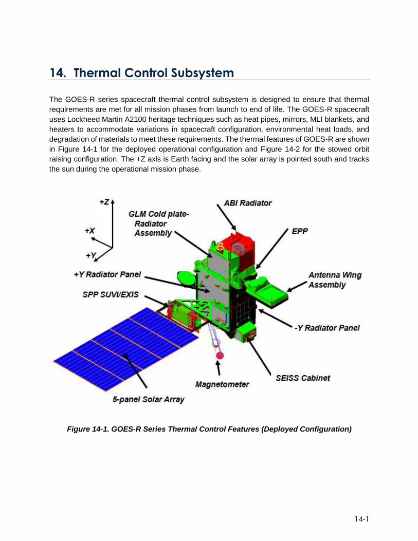
14-1
14. Thermal Control Subsystem
The GOES-R series spacecraft thermal control subsystem is designed to ensure that thermal
requirements are met for all mission phases from launch to end of life. The GOES-R spacecraft
uses Lockheed Martin A2100 heritage techniques such as heat pipes, mirrors, MLI blankets, and
heaters to accommodate variations in spacecraft configuration, environmental heat loads, and
degradation of materials to meet these requirements. The thermal features of GOES-R are shown
in Figure 14-1 for the deployed operational configuration and Figure 14-2 for the stowed orbit
raising configuration. The +Z axis is Earth facing and the solar array is pointed south and tracks
the sun during the operational mission phase.
Figure 14-1. GOES-R Series Thermal Control Features (Deployed Configuration)

14-2
Figure 14-2. GOES-R Thermal Control Features
Passive thermal control features include external and internal thermal materials and hardware.
To aid the transfer of waste heat to radiators the design uses heat pipes, wet mounting of
components, and high emissivity coatings. To reduce the flow of heat where needed, the design
uses MLI blankets, low emissivity coatings, and low conductivity stand-offs. Radiation panels are
embedded with ammonia-filled heat pipes to enhance the heat spreading throughout the panel
and serve to lower hot spots and improve heat rejection into space. Radiators are covered with
optical solar reflectors (OSRs), a high emissivity/low absorptivity material, to reject sunlight and
emit heat to space. Portions of the panels are covered in MLI to reduce heater power consumption
while maintaining internal temperatures on-orbit.
There are two types of regulated heater circuits designed for the GOES-R series: (1) mechanical-
thermostat controlled circuits; and (2) OBC-controlled circuits. Mechanical-thermostats are used
for controlling heaters intended for short durations during the early part of the mission. For
example, on deployment mechanism rate dampers for the solar array and antenna shelf. These
circuits have fixed-temperature-set-points and are usually enabled just prior to deployment. The
instruments also use mechanical-thermostats for survival heater control. OBC-controlled circuits
are used during all mission phases where heater control is required; storage, transfer orbit, and
on-orbit mission phases. These circuits have software defined control characteristics and use
feedback sensing from thermistors for control. Control algorithms include MAX/MIN logic, or the
heater can be controlled using a straight duty-cycle. All heater control parameters may be
adjusted at any point during the mission as long as a command link is available. All heaters are
fully redundant, except for the Magnetometer heaters.
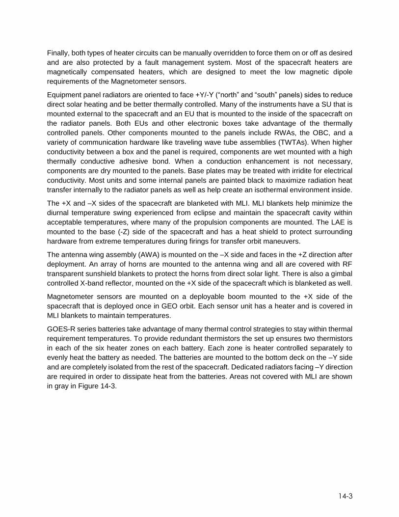
14-3
Finally, both types of heater circuits can be manually overridden to force them on or off as desired
and are also protected by a fault management system. Most of the spacecraft heaters are
magnetically compensated heaters, which are designed to meet the low magnetic dipole
requirements of the Magnetometer sensors.
Equipment panel radiators are oriented to face +Y/-Y (“north” and “south” panels) sides to reduce
direct solar heating and be better thermally controlled. Many of the instruments have a SU that is
mounted external to the spacecraft and an EU that is mounted to the inside of the spacecraft on
the radiator panels. Both EUs and other electronic boxes take advantage of the thermally
controlled panels. Other components mounted to the panels include RWAs, the OBC, and a
variety of communication hardware like traveling wave tube assemblies (TWTAs). When higher
conductivity between a box and the panel is required, components are wet mounted with a high
thermally conductive adhesive bond. When a conduction enhancement is not necessary,
components are dry mounted to the panels. Base plates may be treated with irridite for electrical
conductivity. Most units and some internal panels are painted black to maximize radiation heat
transfer internally to the radiator panels as well as help create an isothermal environment inside.
The +X and –X sides of the spacecraft are blanketed with MLI. MLI blankets help minimize the
diurnal temperature swing experienced from eclipse and maintain the spacecraft cavity within
acceptable temperatures, where many of the propulsion components are mounted. The LAE is
mounted to the base (-Z) side of the spacecraft and has a heat shield to protect surrounding
hardware from extreme temperatures during firings for transfer orbit maneuvers.
The antenna wing assembly (AWA) is mounted on the –X side and faces in the +Z direction after
deployment. An array of horns are mounted to the antenna wing and all are covered with RF
transparent sunshield blankets to protect the horns from direct solar light. There is also a gimbal
controlled X-band reflector, mounted on the +X side of the spacecraft which is blanketed as well.
Magnetometer sensors are mounted on a deployable boom mounted to the +X side of the
spacecraft that is deployed once in GEO orbit. Each sensor unit has a heater and is covered in
MLI blankets to maintain temperatures.
GOES-R series batteries take advantage of many thermal control strategies to stay within thermal
requirement temperatures. To provide redundant thermistors the set up ensures two thermistors
in each of the six heater zones on each battery. Each zone is heater controlled separately to
evenly heat the battery as needed. The batteries are mounted to the bottom deck on the –Y side
and are completely isolated from the rest of the spacecraft. Dedicated radiators facing –Y direction
are required in order to dissipate heat from the batteries. Areas not covered with MLI are shown
in gray in Figure 14-3.

14-4
Figure 14-3. Electrical Power Subsystem Architecture
SEISS Cabinet The SEISS cabinet is mounted to the –X side of the spacecraft as a stand-alone thermal-structural
assembly with embedded heat pipes. All instruments are coupled to the two radiators on the +/–
Y sides of the cabinet via a thermal wet mount. MLI is used to cover the rest of the cabinet as well
as the instruments themselves. Heaters and control thermistors are used on the cabinet heat
pipes to maintain minimum temperatures. Both MLI and radiator panels are shown below in Figure
14-4.
Figure 14-4. SEISS Cabinet and Sensors

14-5
Earth Pointing Platform The Earth Pointing Platform is mounted on top of the nadir deck. The EPP is attached to the nadir
deck via four launch lock assemblies that mechanically isolate the EPP from the rest of the
spacecraft. The EPP is the mounting location for two of the GOES-R instruments, shown in Figure
14-5.
GLM and ABI are both conductively isolated from the EPP via titanium mounting feet. Both
instrument SUs are covered with thermal blankets to insulate the instrument from the EPP, other
instruments, and space. MLI blankets are used to reduce thermal distortion in the form of diurnal
swings and temperature gradients. ABI has a dedicated radiator provided with the instrument
which it is attached via LHPs. To accommodate the GLM an isolated, free standing aluminum
honeycomb radiator panel with embedded heat pipes was designed with heater control. GLM is
attached to the radiator by both LHPs and thermal straps. Both ABI and GLM have associated
EUs that are mounted inside the spacecraft on the–Y equipment panel. To meet instrument
pointing requirements the star tracker is thermally controlled with a separate radiator, heat straps,
and heaters. To keep the scalable SSIRUs within temperature requirements they are mounted to
a dedicated heat pipe cold plate-radiator assembly.
In order to prevent excessive environmental heating due to solar entrapment, the volume of space
between ABI and GLM is closed out with a sunshield membrane.
Figure 14-5. EPP and Instruments
Solar Array Wing Assembly The SAWA is shown below in Figure 14-6. The SPP, unique to the GOES-R series, holds SUVI
and EXIS on the solar wing. Both instruments must face the sun at all times which is done via two
motor driven gimbals, the SEGA and SADA. In addition, the SEB and the SIU of the sun pointing

14-6
subsystem are mounted to the SPP. The back of the SPP is a black painted radiator to help emit
heat dissipation from the SEB and SIU. MLI blankets wrap around the individual instruments as
well as the spacecraft components mounted on the panel between them. The solar array yoke is
also blanketed on the sun-facing side with MLI. Both gimbals are also covered with MLI except at
the rotation interfaces and are equipped with heaters.
Figure 14-6. Solar Array Wing Assembly and Sun Pointing Platform

15-1
15. Mechanisms
The GOES-R series satellites have five appendages that must be stowed and restrained for
launch and later deployed at different stages of the mission. These appendages are listed below:
Solar Wing Subsystem (SWS) and Sun Pointing Platform (SPP)
Antenna Wing Assembly (AWA)
X-band Reflector Antenna (X-Band)
Magnetometer Boom (Mag Boom)
Earth Pointing Platform
Figure 15-1. GOES-R Series Deployable Structures
Various mechanisms are needed in order to restrain, deploy and position the GOES-R series
appendages. These mechanisms are discussed briefly below.
Restraint Mechanisms A shear tie is a mechanism that restraints a deployable structure while it also reacts to external
loads resulting from transportation of the spacecraft and loads resulting from the launch
environment. A shear tie assembly is composed of two main sub-assemblies; the actuator and
the retraction mechanism. The actuator secures the bolt or cable that keeps the deployable in a

15-2
preloaded and secured state. Once the actuator is commanded to release, the retraction
mechanism ensures that the cable or bolt securing the deployable is retracted out of the way to
allow the deployment. Figure 15.2 is representative of the shear ties used to secure the GOES-R
series appendages.
Figure 15-2. Example of Solar Array Shear Tie
The GOES-R series use different kind of shear tie actuators depending on the application and
preload required to secure the deployable assembly. All shear tie actuators are fully redundant
as they contain independent primary and secondary circuits for release.
The different kind of restraint and release actuators are:
Frangibolts: made by TiNi Aerospace Inc.
o Used on the SWS frame shear ties, X-band antenna and AWA shear ties
Separation Nuts (Sep Nuts): made by Eaton
o Used on the Solar Array Panel shear ties
Split Spool Release Device (SSRD): made by NEA Electronics
o Used on the SPP shear ties
Deployment and Positioning Mechanisms The deployment and movement of the GOES-R series appendages is achieved by the use of
passive hinges, gimbal actuators and stepper motor drives.
Hinges The hinges are used during one time deployments and their rotation is controlled using thermally
controlled viscous dampers. These viscous dampers can be integral to the hinge as is the case
of the Root Hinge (used in the SWS) or the HA-90 Hinge (used on the AWA), as shown in Figure
15-3
15-4. Also, the dampers can be a separate sub-assembly as is the case of the Solar Array inter-
panel hinges and the SPS frame hinges, as shown in Figure 15-3.
The hinge assemblies for the GOES-R series contain redundant springs for uniform torque
application throughout the deployment, hard stops and latches for stiff lockout of the deployable
assembly once it reaches its final position.
Figure 15-3. Solar Array Inter Panel and SPP Frame Hinge and Damper
Figure 15-4. SWS Root Hinge (left), AWA HA-90 Hinge (right)
Gimbal The gimbal (shown in Figure 15-5) is a dual axis actuator that allows the X-band reflector to be
repositioned on orbit as required. The gimbal contains two stepper motors mounted orthogonally
that provide .003°/step resolution for each axis. The gimbal contains redundant course and fine
potentiometers for reflector position telemetry.

15-4
Figure 15-5. Dual Axis Gimbal Assembly
Solar Array Drive/ Slip Ring Assembly (SADA/SRA) The SADA/SRA (shown in Figure 15-6) is composed of the Solar Array Drive Assembly the Slip
Ring Assembly. The SADA allows the Solar Array Wing (SWS) to rotate 360° (in both positive
and negative directions) while tracking the sun. The Slip Ring Assembly (SRA) allows power to
be transferred from the Solar Array back into the spacecraft thru a rotating interface. The SADA
contains redundant motors and resolver circuits. The SADA is driven via software and by the
SADE (Solar Array Drive Electronics Box).
Figure 15-6. Solar Array Drive/Slip Ring Harness Assembly
Sun-Pointing Platform Elevation Gimbal Assembly (SEGA) and Trailer
Bearing Assembly (TBA) The SEGA gimbal works in conjunction with the Trailer Bearing Assembly (TBA) to point the SPP
which contains the GOES solar instruments, as depicted in Figure 15-7. This pointing ability
provides seasonal position/offsets for the instruments on the SPP as well as the ability to perform
calibration scans which are driven by the instruments. The SEGA is a single axis motor with an
attached drive train that provides enough torque to move the SPP. The TBA which is located at
the opposite end of the SPP rotation line provides a low friction support to the SPP and allows
the SEGA to rotate the SPP with high precision.

15-5
Figure 15-7. SEGA (top & bottom left) and TBA (bottom right)
Solar Array Deployment The SWS deployment is completed in two stages. The first stage occurs autonomously within
hours after launch. At this point (reference Figure 15-8), only the solar panels are deployed by
firing the six separation nut shear ties and allowing the inter-panel hinges to deploy the solar array
portion of the wing. The remaining SPP, yoke and first stage shear ties are not fired at this time.
Once the satellite has reached final orbit, the remaining Solar Array shear ties (the two Frangibolt
Frame shear ties, the six SSRD Frame shear ties and the two (not visible as they are on the far
side of Figure 15-8) final Frangibolt shear ties) are independently commanded to fire in order to
deploy the complete wing assembly. Figure 15-9 below shows the locations of the second stage
deployment shear ties. Once these shear ties are fired the wing separates from the spacecraft.
The Root Hinge and frame hinges deploy the wing into its final position.

15-6
Figure 15-8. First Stage Solar Array Deployment
Figure 15-9. Second Stage Solar Array Deployment
After the Solar Wing is deployed, the SADA and SEGA are able to rotate the Solar Wing Assembly
and SPP via commanded instructions to the desired position (reference Figure 15-10). The
primary function of the SADA and SEGA is to precisely maintain the pointing of the solar
instruments at the sun. This action by default then also points the Solar Array cells at the sun for
spacecraft power generation.

15-7
Figure 15-10. SADA and Root Hinge Interface with Solar Wing Assembly
X-band Reflector Antenna Deployment The X-band Reflector Antenna is held in place using three Frangibolt shear ties. Once the
command is given to fire these shear ties, the X-band Gimbal is commanded to deploy the
reflector into its final position as shown in Figure 15-11.
Figure 15-11. X-band Reflector Shear Tie and Gimbal Locations
Antenna Wing Assembly (AWA) Deployment Similar to the X-band Reflector, the AWA (shown in Figure 15-12) is restrained using four
Frangibolt shear ties. The AWA is deployed into its final position via the deployment of the HA-90
hinge. The AWA final deployed position is 90 degrees from the stowed position.
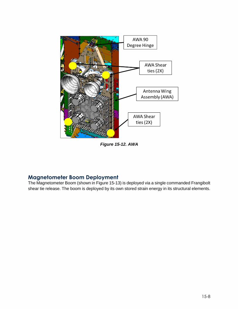
15-8
Figure 15-12. AWA
Magnetometer Boom Deployment The Magnetometer Boom (shown in Figure 15-13) is deployed via a single commanded Frangibolt
shear tie release. The boom is deployed by its own stored strain energy in its structural elements.

15-9
Figure 15-13. Magnetometer Boom Stowed and Deployed Configuration
Earth Pointing Platform Uncaging The EPP contains four identical Launch Lock Assemblies which retain the EPP during satellite
transportation and launch (see Figure 15-14). The Launch Lock assemblies are shear tie type
devices that work with a SSRD. The Launch Lock Assemblies allow the uncaging of the EPP and
allow it to become suspended via a dampened strut/isolation system. Once released, the Launch
Lock upper and lower housing separate providing the clearance required to accommodate the
EPP isolation system.
Figure 15-14. EPP and Launch Lock Assembly
Structures The GOES-R series spacecraft structure is based on the Lockheed Martin A2100.The core
structure consists of honeycomb structural panels, which form a box to support the propulsion

15-10
system (see Figures 15-15 and 15-16)The core has an integral adapter ring that provides a mating
interface to the launch vehicle. In parallel, three thermal heat-pipe embedded panels are
assembled to support the system module integration. Once these two structures are mated,
additional structures are added to support the primary instrument payloads. A honeycomb EPP
is mounted on top of the primary structure and also carries star trackers and the inertial
measurement units. A honeycomb cabinet is mounted to the base panel for instrument
accommodation. Finally, an articulating honeycomb SPP is mounted to the bus structure just
inboard of the solar array. The GOES-R series structures have a mass of 608 kgs.
Figure 15-15. Spacecraft Primary and Secondary Structures

15-11
Figure 15-16. Spacecraft Primary and Secondary Structures

15-12
This page left blank

16-1
16. Ground System Architecture The GOES-R series ground system (GS) consists of the following:
GOES-R series core GS
Antenna system
Tools and simulators hosted or integrated in the GS
GOES Rebroadcast (GRB) simulators
Product Distribution and Access (PDA) components to satisfy GOES-R Access Subsystem requirements
The GOES-R series GS operates from three sites. The NOAA Satellite Operations Facility
(NSOF) in Suitland, Maryland, houses the primary Mission Management (MM), and selected
Enterprise Management (EM), Product Generation (PG), and Product Distribution (PD) functions,
including the Environmental Satellite Processing Center (ESPC) PDA capability. The Wallops
Command and Data Acquisition Station (WCDAS), located in Wallops, Virginia, provides the
primary Radio Frequency (RF) communications services, EM and MM functions, and selected PG
and PD functions. The third site is a geographically diverse Consolidated Backup facility (CBU),
located at Fairmont, West Virginia. It functions as a completely independent backup for the MM
and selected PG and PD functions for the production of Key Performance Parameter end products
(KPPs) and GOES Rebroadcast (GRB) data, and is capable of concurrent and remote operations
from NSOF and WCDAS. The CBU has visibility to all operational and on-orbit spare satellites.
The KPPs consist of the Level 2+ (L2+) Cloud and Moisture Imagery (CONUS, full disk, and
Mesoscale) product and the associated sectorized products. Figure 16-1 provides an overview of
the GOES-R System and GS.
In addition to the operational sites, two Operational Support Locations (OSLs) have been
implemented to support GS sustainment and maintenance activities and resolve anomalies. The
first, known as OSL1, is located at the development contractor facility in Melbourne, Florida. From
OSL1, support personnel can access the system at all 3 sites. From the second site (OSL2),
located at the National Center for Weather and Climate Prediction (NCWCP) in College Park,
Maryland, support staff and government personnel are able to access the NSOF L2+ product
generation and distribution capabilities.

16-2
Figure 16-1. GOES-R System and GS Overview
The satellites are commanded throughout their mission lifetime from the NOAA Satellite
Operations Control Center (SOCC) located at NSOF with the ground station RF interface located
at WCDAS and CBU. The engineering telemetry streams are received by WCDAS and CBU, and
then ground relayed to the SOCC for processing and monitoring at all locations.
In nominal operations, the raw sensor data is received by WCDAS, processed by the PG function
at WCDAS to create Level 1b (L1b) and L2+ GLM products. These L1b and L2+ GLM products are
then rebroadcast through the spacecraft GRB transponder. Additionally, sectorized L2+ cloud and
moisture imagery products are distributed directly from WCDAS to the NWS AWIPS, and from there
onto NWS Weather Forecast Offices (WFOs) and other AWIPS users.
The GRB data is received at NSOF where the rest of the L2+ products are created. Ancillary data
used in generating the L2+ products are ingested from the Ancillary Data Relay System (ADRS).
Applicable products are directly distributed to the PDA component of ESPC, which provides the
GOES-R Access Subsystem (GAS) functionality, and provides data to NESDIS offices, NWS,
CLASS for long term archive and access supporting retrospective users of GOES data and other
GOES data users.
At the CBU, the raw sensor data, as well as GRB, is received through its RF interface and
processed by the PG function. The CBU is limited to the production of data to support L0, L1b,
and L2+ GLM generation in support of the creation and distribution of GRB, and the production
of sectorized KPPs for distribution to AWIPS. The CBU is an always-on “hot” backup in order to
allow the GS to meet its requirement for 5-minute failover in support of high availability mission
operations and KPP generation and distribution.
The GS includes separate development and integration and test (I&T) environments for the
purposes of ongoing development and I&T throughout the GOES-R series mission. Portions of
these environments are located at both NSOF and WCDAS to support local site development and
I&T activities. Figure 16-2 shows the primary data flows through the system.

16-3
Figure 16-2. GS Primary Data Flows

16-4
Overview
The GOES-R series core ground system provides the following high level functions:
Mission Management (MM), which includes
o Space-Ground Communications (SGC)
o Telemetry and Commanding
o Spacecraft Navigation
o Mission Planning and Scheduling
Data Operations (DO), including
o L0, L1b, and L2+ product generation
o Product distribution to PDA, and via the AWIPS interface
o Product monitoring
o Product performance monitoring
Enterprise Infrastructure (EI), including
o Enterprise supervision
o Configuration Management (CM)
o Data Storage, including
Mission life data storage
o 5-day (revolving temporary) data storage for CCSDS transfer frames
o 2-day (revolving temporary) data storage for other data products, intermediate products, and related data
o Life of mission storage for command and telemetry data
Network Management
Mission Management (MM) Element The Mission Management (MM) element provides the capabilities needed for satellite operations.
The MM element architecture uses both custom-developed and off-the-shelf (OTS) products,
including the OS/COMET® software product for satellite ground control systems. MM can operate
without any dependence on the other GS elements. Control and status for ground equipment is
provided through device-specific drivers that interface with the equipment and integrate the use
of those drivers into the OS/COMET toolset. Control and status for the antenna system is
integrated with OS/COMET.

16-5
Mission Management Element Functions The Mission Management element provides the following functions that are directly related to user
and operator mission operations:
Mission Operations: Handles satellite command and command verification, flight
software maintenance, ground directives, and anomaly responses. It also handles
satellite telemetry monitoring and processing and provides control and status of
ground equipment. OS/COMET is used to accomplish the mission operations
capabilities.
Spacecraft Navigation (SCN): Performs Orbit and Attitude (O&A) determination,
compares O&A solution to that generated by the spacecraft, generates orbital event
times, and plans spacecraft maneuvers. Spacecraft O&A and orbital events are used
to support instrument planning and operations. SCN is comprised of the OTS product
Focus Suite, which has been tailored and configured to support the GOES-R series
mission.
Mission Planning and Scheduling (MPS): Handles mission scheduling and planning
for all satellite activities and handles integration with ground maintenance schedule.
MPS is composed of custom-developed software that integrates with both OS/COMET
and Focus Suite.
Space-Ground Communication (SGC): Using a set of modems and front-end
processors, the SGC ingests and pre-processes satellite telemetry data used for
satellite health and status monitoring. MM also ingests the X-band raw data and
processes it to remove higher-level Consultative Committee for Space Data Systems
(CCSDS) protocols; then outputs Command and Data Acquisition (CDA) telemetry,
supplemental instrument data, and science data packets to PG.
MM Storage: Coordinates logging and storage of MM operational data, including
storage that is available for secure remote access. MM Storage makes data available
to the CASSIE (Contextual Analysis for Spectral and Spatial Information) engineering
analysis tool.
GRB Data Routing: Receives GRB data from PG and routes it to the antenna system
for RF distribution.
Antenna Monitor and Control: Provides the monitoring and controls of the GOES- R
antennas.
Data Operations Description
The core GS Data Operations (DO) functions are comprised of the PG and Product Distribution (PD
elements. These functions include:
L0, L1b, and L2+ Processing
PG Infrastructure and Service Management
Product Monitoring and Product Performance
End Product sectorization and re-projection, and formatting

16-6
Distributing end products (per current PD configuration) and non-products (e.g. ancillary data, algorithm packages)
Formatting Intermediate data files for PG and storing them in the 2-Day-Store (2DS)
Processing retransmission requests for PDA
Product Generation Element Functions The PG element generates L0, L1b and L2+ products from each GOES-R series operational
satellite on a continuous basis, meeting the applicable product latency requirements. PG
continually processes data as it is received at all three GOES-R GS sites. Although the PG
functions are fully automated, the Ground System Product Operator can monitor generated
product processing and quality. The PG element functions fully support a satellite’s ABI, GLM,
SEISS, EXIS, SUVI and Magnetometer instruments when in its operational slot, and alternately
supports a satellite’s SEISS and Magnetometer instruments when in its on-orbit storage slot. To
enable the high throughput, low latency required for DO, a solid state distributed memory cache
is utilized (referred to as the “data fabric”). This distributed memory cache provides high
throughput, low latency, flow control, fault tolerance, and linear scalability with direct access to its
contents from computer servers across the GS. All of these features are key to satisfying product
latency, operational availability, data delivery, and scalability requirements.
Product Monitoring monitors the GRB data downlink products with respect to radiometric and
geometric performance and reports status. Product performance provides for additional insight
into the performance of L1b and L2+ data operations.
Product Distribution Element Functions The PD element provides near-real-time continuous network distribution of GS products and data.
PD functionality is at all three GS locations: NSOF, WCDAS, and the CBU. The CBU and WCDAS
provide selected PD functions for the generation, formatting and distribution of sectorized
products to the NWS via the AWIPS interface and via GRB. In addition, the CBU is capable of
standalone PD operations for a limited set of products to enable generating, formatting, and
distributing products when one or both of the other two facilities (WCDAS and NSOF) are
inoperable.
PD provides configuration displays through a graphical user interface (GUI) that allows an
operator to monitor delivery status, configure message filtering, configure PD products for AWIPS,
or configure which products are being sent to PDA. Any authorized operator’s console can be
configured to show the PD displays.
PD also provides key storage for the core GS in the form of the 2DS and the mission life store
(MLS). The 2DS provides for retransmission to PDA if an error in transmission occurs. Instrument
calibration data sent to PDA comes from the PD MLS. The 2DS can also be accessed by PG to
extract, if needed, operator-selected products for use in support of analyzing anomalous
conditions. PD moves data into the PD MLS automatically as well as manually. Selected end
products are automatically stored in the PD MLS along with histories of ground directives and
security events.

16-7
Enterprise Infrastructure The Enterprise Infrastructure (EI) capabilities of the GS are comprised of the Enterprise
Management (EM) and Infrastructure (IS) elements. Together these elements provide the core
GS monitoring and control capabilities. The IS element contains the majority of the core GS
hardware. EI also provides the GS with its security monitoring, access control/authentication, and
public key infrastructure (PKI) functionality.
Inter-site Network Communication The NOAA Science Network (N-WAVE) provides inter-site communication services for GOES-R
data transfers between NSOF, WCDAS, and CBU, as well as providing communications between
WCDAS/CBU and the AWIPS Network Control Facility (ANCF) and Test Network Control Facility
(TNCF) in Silver Spring, Maryland, and the AWIPS Backup Network Control Facility (BNCF) in
Fairmont, West Virginia. In addition, N-WAVE provides communication support between the
system and the GS factory, and between the system and NCWCP. These services are provided
through a multi-protocol label switching (MPLS) wide area network (WAN). GOES-R services are
a part of the NOAA Office of Satellite and Product Operations (OSPO) MPLS WAN. Path
availability between the GS and AWIPS is specified at 99.9%. A high-level overview is shown
below in Figure 16-3.
In addition to N-WAVE, a set of optical-carrier (OC-3) (155.52 Mbps) links are in place for direct
point-to-point connectivity between sites to support mission operations. These circuits provide a
parallel path via a separate, independent network service provider to help increase reliability for
critical MM inter-site network traffic.
Figure 16-3. Inter-site GOES-R Series GS Networks

16-8
GOES-R Series GS Environments In order to support concurrent operations, integration and test, and development activities, the
core GS is segregated into three environments. Each of these environments spans sites and
security boundaries to meet GS functional requirements. In addition, the core GS edge provides
the interfaces to external systems that receive GOES-R series data, and allows for authorized
users to remotely access GS edge resources via the NOAA virtual private network (VPN)
capabilities. Figure 16-4 provides an overview of the GS environments across sites, security
zones, and functional elements.
Figure 16-4. GS Environments by Site and Element
Operational Environment The GOES-R series Operational Environment (OE) supports the operational GOES-R series
mission. OE functionality spans all sites. In the Satellite Operations Zone (SOZ) (within the NOAA
5050 security boundary), all three sites provide operational mission management functionality.
WCDAS and CBU provide data operations for L0, L1b, and selected L2+ processing for data
distribution via GRB and to the NWS via the AWIPS dedicated interface. At NSOF, the Product
Processing Zone (PPZ) OE receives L1b data via the GRB stream and processes it further into
L2+ end products, which are distributed to the user community via the ESPC PDA system. The
OE is tightly configuration managed and changes to the OE are developed, deployed, and tested
in non-operational environments before moving to the OE.
OSL1 accesses all three sites and both SOZ and PPZ security zones via the GOES-R edge.
OSL2 only has access to the PPZ in support of NSOF L2+ data operations.

16-9
Integration and Test Environment
ITE consists of capabilities to verify the element functionality prior to deployment in the operational
environment. The ITE capabilities are implemented at the NSOF and WCDAS sites. The ITE only
has one PG/PD (DO) data processing string. As a means to test the distribution of products to
the PDA ITE and the TNCF with the full operational load, the ITE includes the capability to
simulate the distribution of products from two satellites concurrently making use of the data
generated from the one available PG/PD data processing string.
The Core GS ITE supports realistic test activities by mimicking the OE. This realistic testing
extends beyond the core GS to the external interfaces (AWIPS, Level Zero Storage Service
(LZSS), and PDA) integration and test environments. Thus, GS software and hardware
modifications can be tested across the end-to-end system prior to being deployed to the
operational environments.
Development Environment The GOES-R Development Environment (DE) consists of two physically isolated sets of hardware
that do not directly communicate electronically with each other. The two DEs are separated by
site and are in different security domains. The SOZ DE resides at WCDAS with additional SOZ
workstations at NSOF. Note there is not a DE at the CBU. The PPZ DE resides at NSOF. The
PPZ DE may also be accessed by authorized users remotely through the NOAA Network
Operations Center (NOC) VPN to employ read/write/execute transactions, but not for data upload
or download.
Remote Access The GOES-R series GS provides a set of resources that are accessible to authorized users who
are not physically located at a GS site via the GOES-R Edge. This remote access capability allows
users with accounts and permissions to utilize a limited set of GS resources, while not within the
physical boundaries of the GS facilities. Using remote access, users have the ability to download
data to their own computing resources, view data and manipulate data using tools provided by
the core GS. Capabilities available via remote access include:
Access to Level 0 data via the LZSS using the secure file transfer protocol (sFTP)
Access to telemetry data and the CASSIE engineering analysis tool via Mission Management servers located in the edge at all three GS facilities
Access to other MM data such as ground directives, command procedures, schedules, and INR reports
Access to the ABI PLEIADES (Post-Launch Enhanced Image and Data Evaluation System) tool to support ABI post-launch test (PLT) and anomaly resolution activities (limited access to ABI vendor only)
Access to the PPZ DE in support of the implementation and assessment of potential
changes and upgrades to the GS L2+ DO capabilities
Remote access is accomplished via obtaining access to the NOAA NOC VPN, and by obtaining
a GOES-R system account with remote access permission. Remote access is constrained by the
available bandwidth between the GS and external partners, as well as by the number of
concurrent remote user sessions permitted by the NOAA NOC.

16-10
Level 0 Data Products GOES-R L0 data is a collection of CCSDS packets for each instrument collected over a period
of time unique for that instrument. This consists of reconstructed unprocessed instrument
science data and instrument engineering data packets at full resolution, as sent by the
instrument, with all communications artifacts (e.g. synchronization frames, communications
headers) removed. These packets are extracted from the multiplexed packets within the transfer
frame.
This data comes from Earth-looking (ABI and GLM) and space-looking instruments (SUVI,
EXIS, MAG and SEISS) at full resolution and includes science, engineering and diagnostic data
along with their instrument calibration parameters. L0 data also includes Orbit and Attitude
(O&A)/Angular Rate (OAR) telemetry data, containing orbit ephemeris and satellite position
extracted from selected telemetry packets. Each instrument receives OAR data as a part of its L0
data stream and includes this data as a part of its L0 product files.
Level 1b Data Products The L1b product is composed of GOES-R Level 0 (L0) data with radiometric and geometric
corrections applied to produce parameters in physical units. It includes calibration tables and
associated metadata as developed by the GOES-R Product Generation (PG) software. In addition
to being a standalone product, the L1b product is an input into Level 2+ (L2+) product processing.
GRB Content GRB is a 31 Mbps direct readout broadcast that replaces the 2.1 Mbps GVAR legacy format. It
contains a set of products consisting of L1b products from all instruments, L2+ GLM and
associated metadata, and GRB Information (INFO) Packets containing satellite operations
schedules, status information and orbit state vectors. GRB INFO packets also include semi-static
L1b algorithm calibration parameter tables which are transmitted after an update. GRB is sent to
the GOES-R satellites from WCDAS for rebroadcast to the GOES-R sites and GRB users. Back-
up GRB transmission capability is available CBU site.
The GRB is received at the NSOF, from which L1b, L2+ GLM and GRB INFO Packets products
(including L1b algorithm calibration parameter tables) are recovered, and the remainder of the
L2+ products are created, as well as sectorized Cloud and Moisture Imagery (CMI) products
A simplex link is used for GRB. A dual circular polarization is used to accommodate the 31 Mbps
data rate within a frequency bandwidth constraint of 12 MHz using a standard downlink
modulation at 1686.600 MHz (L-band). The GRB processed instrument data source is packetized
compliant with CCSDS Space Packet Protocol standard (CCSDS recommendation 133.0-B-1),
and utilizes lossless data compression to fit within the allocated bandwidth.
Level 2+ Data Products GOES-R L2+ products include all Level 2 and higher products. Level 2 refers to derived
environmental variables (e.g., sea surface temperature) at a comparable temporal and spatial
resolution to the Level 1 source. L2+ includes data or retrieved environmental variables which
have been spatially and/or temporally resampled (i.e. derived from Level 1 or 2). Such resampling
may include averaging and/or compositing. L2+ can also include model output or results from
analyses of lower level data (i.e., data that are not directly measured by the instruments, but are
derived from these measurements).

16-11
GOES-R L2+ products may be distributed to end users either via the ESPC PDA interface or via
the direct interface to the NWS (for sectorized cloud and moisture imagery only).
GOES-R Series Antenna System Overview The GOES-R series antenna system is part of the comprehensive GS and supports the mission
management element of the core GS. The antenna system includes all components across all
three sites required to receive or transmit RF signals to/from the satellites through the
Intermediate Frequency Distribution System (IFDS) interface demarcation point with the GS. The
ground station resources consist of three new 16.4m hurricane-rated (HR) antenna stations at
WCDAS, three new 16.4m HR antenna stations at CBU, and upgrades to four existing 9.1m
receive-only systems at NSOF. Figure 16-5 provides a notional view of a 16.4m antenna station
at site.
Figure 16-5. GOES-R Series Antenna Station
The architecture is divided into three major functional subsystems: the Antenna Subsystem, the
Monitor and Control (M&C) Subsystem and the Site Preparation and Construction Subsystem.
The Antenna Subsystem consists of the components for the 16.4m Antenna (including Antenna
Control, Tri-band feed design (X-, S-, and L-band), reflectors, trusses, drive trains, and pedestal
bases), the RF Uplink and Downlink functionality, Data Collection System (DCS), Intermediate
Frequency Distribution Switch (IFDS) and Timing and Frequency Reference System (TFRS). The
Antenna Subsystem also upgrades existing 9.1m antenna feed assemblies to support the receipt
of the circularly polarized GRB signal from GOES-R series spacecraft. The M&C Subsystem
ANT_SEIT-005-MSCSTN-R1.vsd
S-bandSSPA
X-bandSSPA
DownLink
NetMAC, BITE, Link Monitoring
IFDS
UpLink

16-12
includes the functionality for Antenna Station control, link monitoring, Built-In-Test/ Built-In-Test-
Equipment (BIT/BITE), and Antenna System Interface Simulators (ASIS). The Site Preparation
and Construction Subsystem consists of the foundation design, power interfaces, HVAC, physical
security and safety components. Figure 16-6 shows the antenna system architecture components
at each facility.
Figure 16-6. GOES-R Antenna System Architecture
WCDAS currently provides all primary space-ground communication functions and sensor data
processing for the on-orbit GOES constellation and will perform the same role for the GOES-R
series. WCDAS houses the antenna suite required for dedicated links to each operational and
stored spacecraft, the front-end equipment to acquire data and to uplink commands and data
services, and the associated network interfaces to provide data to the GOES-R series system.
WCDAS also interfaces with and provides uplinks to the Unique Payload Services for broadcast.
Unique Payload Services provides communications support to the Data Collection System (DCS),
the High Rate Information Transmission/Emergency Managers Weather Information Network
(HRIT/EMWIN), and Search-and-Rescue Satellite Aided Tracking (SARSAT). More information
on the GOES-R Unique Payload Services can be found in the Communications Subsystem
section. The 16.4m HR antennas are fully backward compatible to support both the GOES-R and
legacy GOES missions.
At NSOF, GRB data is received directly from GOES-R Series spacecraft via four 9.1m receive-
only antennas located on the roof of the NSOF facility. These antennas have been upgraded to
GOES-R GROUND SEGMENT
GOES Space Segment
GOES-R GS ANTENNA SYSTEM
Wallops Island, VA
Wallops Command and Data Acquisition Station (WCDAS)
Suitland, MD
NOAA Satellite Operations Facility (NSOF)
Fairmont, WV
Remote Backup (RBU) facility
GOES-R
Satellites
GOES-NOP
(13-15)
Satellites GPS
Satellites
GOES-N SSGS
ENTERPRISE MANAGEMENT
(EM)
GOES-R GS ANTENNA
SUBSYSTEM
GOES-R GS ANTENNA
SUBSYSTEM
Mission Management
(MM)
Mission Management
(MM)Mission Management
(MM)
Ops Building
IFDS
M&C
Ops Building
Uplink /
Downlink IF
GOES-R GS ANTENNA
SUBSYSTEM
Ops Building Roof
Ops Building
IFDS
Downlink
IF
IFDS
Monitor
&
Control
Uplink /
Downlink
IFEnterprise Management
(EM)
Monitor
&
Control
Monitor
&
Control
Enterprise Management
(EM)
Enterprise Management
(EM)
DCS
ANTENNA / RF (x 4)
TFR
(GFP)
TFR
X-Band, S-Band, and L-Band downlink
X-Band and S-Band uplink
ANTENNA / RF (x 3)
X-Band, S-Band, and L-Band downlink
DCS Pilot Signal
X-Band and S-Band uplink
ANTENNA / RF (x 3)
L-Band
Downlink
(GRB or
GVAR)
GPS
Downlink
TFR
(GFP)
M&CM&C
Signal Paths Product Data Path Test Signal Path Status and Control GPS Downlink
Domain 5
ANT_SEIT-006-ARCOVW-R1.vsd

16-13
receive GRB from GOES-R in addition to GVAR data from legacy GOES spacecraft. Also, the
NSOF has capabilities to perform remote operation of WCDAS functions.
Continuity of Operations (COOP) requirements drive the GOES-R series to include a remote site
that provides the critical functions of WCDAS and NSOF through the production and distribution
of GRB and key product data. Operation of the CBU is the primary contributor to fulfilling COOP
requirements and may also be used to enhance system availability. Although the new GOES-R
series antennas at CBU are compatible with legacy GOES, the CBU does not include the ground
processing equipment to provide backup for legacy GOES satellites.
Unless the antennas are being used for testing, training, or are in maintenance, the CBU antennas
serve as back-up antennas, positioned at the nominal satellite look angles to minimize switchover
time. The only exception to this would be the need to stow the antennas under high wind
conditions. Under high wind conditions, the 16.4m and 9.1m antennas must be driven to the stow
position (90º elevation). The 16.4m antennas are specified to operate in up to 110 MPH winds
and must be driven to stow in 135 MPH winds.
Periodic performance testing can be performed remotely on the RF uplinks and downlinks. The
antennas and control systems at CBU will be exercised remotely to verify proper tracking
performance on satellite. These steps ensure that these systems will perform as expected upon
switchover to CBU operations.
Figure 16.7 GOES-R 16.4m Antenna
Tools and Simulators Three classes of tools interact with the GOES-R series GS. Integrated tools reside in the GOES-
R GS OE, ITE, and/or DE workstations or servers. These tools are allocated GS requirements

16-14
and are necessary for system operations. Hosted tools reside in the core GS for mission
operations support, post-launch testing, or calibration/validation activities. These tools are not
allocated requirements, but they support the GOES-R series mission. Finally, a third set of offline
tools receive GS data but are not hosted within the core GS. These tools may reside at vendor
factory sites or on offline workstations at NSOF. Offline tools are not considered part of the GOES-
R series GS.
Integrated Tools Examples of integrated tools include CASSIE, the GOES-R Parameter Database (PDB) tool, the
Custom Object Dump Tool (CODT), and the Level-0 Storage Solution (LZSS). These tools fulfil
specific mission requirements for mission or data operations. CASSIE provides engineering
analysis capabilities to the Mission Operations Support Team (MOST) and accesses data directly
from the core GS mission life store. The PDB and CODT are used for spacecraft and MAG
memory management and interact directly with MM software used to uplink commands and
memory loads, and to dump memory files. The LZSS receives L0 data directly from the core GS
as netCDF (Network Common Data Form) files. These files are stored permanently for PLT data
and for two years for non-PLT data, and they are made available to LZSS users via the NOAA
remote access interface.
Hosted Tools Hosted tools have been developed by multiple parties. These tools are not necessary to meet
GOES-R requirements, but they are useful to mission and data operations teams during various
phases of the GOES-R mission. Hosted tools include the GOES-R ABI Trending and Data
Analysis Toolkit (GRATDAT) and PLEIADES. These tools are used for post-launch data
assessments as well as for long-term or infrequent calibration activities. Hosted tools reside within
the GOES-R GS on dedicated servers with operator access from both WCDAS and NSOF. (In
the case of PLEIADES, a separate set of hardware has been installed to host the tool).
Environments for hosting of external tools are shown in Figure 16-8.

16-15
Figure 16-8. System Storage and Hosting of Tools
Offline Tools Other off-line tools reside outside of the GOES-R series GS at locations such as instrument
vendor sites or NESDIS’ Center for Satellite Applications and Research (STAR). These tools are
not a part of the GOES-R GS, but they may be used by mission operations staff in support of the
GOES-R series mission. These offline tools may access L0 data via the LZSS; L1b, L2+, and
instrument calibration data via the ESPC PDA system; and long-term (greater than seven days’
worth) data via the CLASS.
Externally Provided Simulators The Spacecraft All-Software Testbed (SAST) provides an all-software simulation of the satellite
for telemetry and command functions. SAST is delivered to the flight project for use by ground
system contractor to support development of the Mission Management System and to support
mission operations rehearsals, pre-launch test activities, and post-launch updates. The SAST
simulates spacecraft command and telemetry packets associated with the L-band and S-band
links. The SAST does not model the encoding, randomization, encryption, or RF transfer
associated with spacecraft communications subsystem.
The flight-provided hardware in the loop (HWIL) test bed contains a single-sided OBC/ CTP and
can accommodate any combination of the following instrument emulators: ABI, GLM, SEISS,
SUVI and EXIS. When the instrument emulators are not present, models of the instrument are
provided in the Simulation SW Subsystem.

16-16
In its role as a Flight Software Development Environment (FSDE) or Flight Software Maintenance
Environment (FSME), the HWIL test bed supports the development teams in their integration,
test, and verification activities. When used in the SatSim capacity, the HWIL test bed supports
spacecraft integration and test (I&T), operations and maintenance (O&M) command procedure
verification, crew training, and on-orbit anomaly resolution. The test bed interfaces with the
GOES-R series GS at all three sites, and at the spacecraft factory.
GOES Rebroadcast Simulators The purpose of the GRB simulator is to allow for on-site testing of user ingest and data handling
systems at GRB field terminal sites. The unit simulates GRB downlink functionality by generating
CCSDS formatted GRB output data based on user-defined scenarios, test patterns, and proxy
data files. GRB signals in the GOES-R era will replace the current legacy GVAR signal and will
have substantially different characteristics, including a change in data rate from a single 2.1 Mbps
stream to two digital streams of 15.5 Mbps each. The GRB simulator is a portable system that
outputs a high-fidelity stream of CCSDS formatted GRB packet data equivalent to live GRB data.
The data is used for on-site testing of user ingest and data handling systems known as field
terminal sites.
The GRB simulator is a fully self-contained system that includes all the hardware and software
required for operation. The operator manages configurations to edit preferences, define individual
test scenarios, and manage event logs and reports. Simulations are controlled by test scenarios,
which are scripts that specify the test data and provide a series of actions for the GRB simulator
to perform when generating GRB output. Scenarios allow for the insertion of errors or modification
of GRB packet headers for testing purposes. The GRB simulator provides a built-in editor for
managing scenarios.
Data output by the simulator is derived from either proxy data files containing L1b or GLM L2+
data, test pattern images, or non-image test pattern generation commands specified from within
a scenario. The GRB simulator outputs packets containing both instrument and GRB Information
data. Instrument packets contain data simulated from any of the six GOES-R instruments: ABI,
SUVI, SEISS, EXIS, GLM, and the Magnetometer. The INFO packets contain information such
as satellite operations schedules, status information, orbit state vectors, static unit conversion
tables, and static calibration tables.
The GRB simulator provides GRB data as either baseband (digital) or Intermediate Frequency
(IF) output to the user ingest and data handling systems. GRB packet data is sent in the same
two output streams as used in the operational system: one for Left Hand Circular Polarization
(LHCP) and one for Right Hand Circular Polarization (RHCP). Use of circular polarization in the
operational system allows the transmitting antenna to multiplex the two digital streams into the
same signal, thereby doubling the available bandwidth. The GRB simulator is designed to be used
at any site that receives GRB downlink.
The GRB simulator produces a GRB data stream by generating CCSDS formatted GRB packets.
The operator can configure the setup and runtime parameters and create scripts for the runtime
simulations. The GRB Simulator normal operations include: configuration, scenario, test patterns,
and proxy files.

16-17
The GRB simulator operates in two modes: online and offline. The online mode is for the actual
execution of the GRB simulation whereas the offline mode is for editing and configuration activities
performed by the operator. When a simulation is started, the GRB simulator is placed in the online
mode. The actual generation and output of the CCSDS formatted GRB packets occur while in
online mode. During a simulation, GRB packets are written to a port, making them available to
the GRB simulator hardware. A new event log is generated for the currently running simulation
each time the GRB simulator is placed in online mode. In offline mode, event log reports may be
generated and tasks such as maintaining configurations and scenarios may be performed. Offline
functions are not available while the GRB simulator is in online mode. The GRB simulator is
placed into offline mode upon termination of a simulation or a user requested stop simulation.
The GRB simulator is packaged in two transit cases. The key components of the GRB simulator include:
Simulator Processor: hosts the GRB simulator software that produces GRB data and provides an interface for the users
Front End Processors (FEP): creates Channel Access Data Units (CADU) and sends the transfer frames to the modem
Modem: outputs the modulated IF signal via Digital Video Broadcasting Satellite Second Generation (DVB-S2) streaming
Time Code Generator: provides system time to the simulator
Keyboard, Video and Mouse (KVM) Switch: provides the primary operator interface
ESPC Product Distribution and Access NESDIS has moved to an enterprise-wide satellite ground processing solution for all NOAA
missions. Under the Environmental Satellite Processing and Distribution System (ESPDS)
development effort, NESDIS has developed and deployed the ESPC PDA which fulfils GOES-R
GS requirements for L1b and L2+ data distribution to authorized ad hoc and subscribed users.
PDA provides an integrated solution that includes product distribution and access capabilities for
GOES-R, Suomi National Polar-orbiting Partnership (Suomi NPP), Joint Polar Satellite System
(JPSS), and Legacy operations, as well as future NOAA and non-NOAA satellite systems. Figure
16-9 shows the GOES-R and PDA systems in the context of the broader ESPC architecture.
While the PDA system is not physically part of the GOES-R series GS, it is tightly integrated with
it to meet GOES-R series delivery requirements to users.

16-18
Figure 16-9. PDA’s Role in the ESPC Enterprise at NSOF
The new ESPC PDA system serves as a unified provider of NOAA’s satellite data and product
offerings. A single system intakes and distributes products for real-time users, receiving inbound
product files from multiple product generation systems, and enabling distribution to all registered
ESPC users. The PDA development provides a web portal to end-users of NOAA’s real-time
satellite product offerings, including GOES-R. End users are able to search for and order satellite
products, via ad hoc requests or subscriptions. The future system will also provide a single
interface for product generation system operators to subscribe to and receive ancillary data files.
PDA is estimated to make available 30 TB of daily product volume by 2020 from 10 different data
sources, including GOES-R.

17-1
17. Spacecraft Mission Phases
To reach the required on-station location in geostationary orbit (station acquisition), the GOES-R
series spacecraft undergo four distinct mission phases:
Launch/Ascent— From Atlas V 541 lift-off to satellite separation
Liquid Apogee Engine (LAE) burns: Series of 5 LAE burns to raise perigee and reduce inclination to near geosynchronous orbit
Station Acquisition: Hydrazine Bi-Propellant Thruster (HBT) drift stop maneuvers with station acquisition at PLT longitude
Post Launch Test and on station performance testing of the payloads to initial operations
Ground Stations Various ground centers and tracking stations are involved throughout the mission phases:
• Universal Space Network (USN) stations at Dongara, South Point, and Hartebeesthoek
• Diego Garcia Station (DGS), an Air Force remote tracking station
• WCDA station located at Wallops, VA
CBU in Fairmont WV
Launch/Ascent Phase The GOES-R series spacecraft are launched from Cape Canaveral Air Force Station Space
Launch Complex 41 by a United Launch Alliance (ULA) Atlas V 541 rocket.
Figure 17-1. GOES-R (now GOES-16) aboard a ULA Atlas V 541 rocket at Cape Canaveral
Air Force Station’s Space Launch Complex 41.

17-2
The Atlas V 541 ascent trajectory utilizes a three Centaur burn extended coast mission profile.
The first Centaur burn achieves a parking orbit. The second Centaur burn achieves an interim
orbit. There is then an extended coast (current baseline is 2.75 hours from Main Engine Cutoff
(MECO) 2 to Main Engine Start (MES) 3) with the third Centaur burn achieving the
Geosynchronous Transfer Orbit (GTO). Figure 17-3 provides an overview of the ascent profile.
Atlas/Centaur performance increases as the extended coast duration increases. There is a
requirement for upper stage disposal 500 km below GEO. Normally, the longer the extended coast
and the closer separation is to apogee, the harder it is for Centaur to maneuver to the disposal
orbit. For the GOES-R series trajectory design, the Atlas/Centaur is targeting satellite separation
for 500 km below GEO. This provides for the ability for the launch vehicle (LV) to maximize the
extended coast performance improvement. The satellite raises the 500 km low orbit during the
HBT station acquisition phase.
Figure 17-2. GOES-R (now GOES-16) lifted off at 6:42 p.m. EST on November 19, 2016
from Cape Canaveral Air Force Station's Space Launch Complex 41, aboard a United
Launch Alliance Atlas V 541 Rocket

17-3
Figure 17-3. Overview of the Ascent Phase Profile
LAE Burn Targeting A robust LAE burn plan has been developed for the GOES-R series that meets the constraints
and addresses the unique LV targeting on GOES-R spacecraft. Given the separated mass of the
GOES-R series spacecraft, five LAE burns are required for orbit raising. The driving constraint for
the LAE burn plan is the PLT longitude at 89.5° W. The secondary driver for the LAE burn plan is
the LV GTO. This orbit drives the target for the last LAE burn.
The LV GTO drives the drift stop maneuver plan and also the targeting of the last LAE burn. The
injection apogee altitude of 500 km below GEO stays relatively constant during orbit raising. The
post-LAE 5 perigee altitude is targeted 60 km below GEO for collision avoidance (COLA)
mitigation. The resulting post-LAE 5 drift rate is 3.6° E/rev. This is a relatively large drift rate.
Typically LAE burn plans are targeted approximately 1.5-2° W of the PLT longitude with a post-
last LAE drift rate of approximately 0.6°/rev. For the GOES-R series spacecraft, with a larger post-
last LAE drift rate of 3.6°/rev, the last LAE longitude offset is increased. The drift stop maneuver
plan was actually developed first in order to define the longitude offset required for the last LAE
burn. There is a four HBT burn drift stop maneuver plan which requires a longitude offset for the
last LAE burn of 10.3°. Therefore, the last LAE is targeted at 260.2°E/99.8°W (10.3°W of 89.5°W
PLT longitude).
With the last LAE burn determined, the first four LAE burns can be targeted. Apogee 3 is chosen
as the first LAE burn apogee to provide the necessary two revs from satellite separation for Orbit
Determination (OD) and maneuver planning. The resultant LAE 1 longitude of 99.0°E provides
good dual station coverage from Diego Garcia and Dongara. A relatively large 40.8 minute
maneuver is planned, in part to maintain LAE burns 2 and 3 below the 50 minute burn limit. Any

17-4
performance dispersions in this first LAE can be readily accommodated in planning the next four
LAE burns. The LAE 2 longitude of 61.2°E at apogee 5 provides two revs between maneuvers
and provides solid tracking station coverage from Diego Garcia, Dongara, and Hartebeethsoek.
The 47.8 minute LAE 2 burn duration is comfortably under the 50 minute burn constraint imposed
by propulsion. The resultant LAE 3 burn longitude of 331.4°E at apogee 7 again provides two revs
between maneuvers and dual tracking station coverage from Santiago and Hartebeethsoek. The
48.5 minute LAE 3 burn duration is again comfortably under the 50 minute limit. The resultant
LAE 4 longitude of 157.4° E at apogee 9 again provides two revs between maneuvers and
provides dual tracking station coverage from Dongara and South Point, Hawaii. A lower duration
maneuver time of 30.7 minutes provides a lower 206.5 m/sec ΔV which lowers the burn dispersion
magnitude which in turn provides more accuracy in targeting the final LAE 5 burn longitude. A
drift rate target of 51.4° is chosen as a divisor of 360° such that for a missed LAE 4 contingency,
the spacecraft will return to the LAE 4 burn longitude in 7 revolutions.
Finally, the final LAE 5 burn longitude of 260.2°E at apogee 11 is targeted based on the station
acquisition plan. The 24.3 minute maneuver duration imparts a ΔV of 173.7 m/sec which provides
higher maneuver accuracy for meeting the drift rate target of 3.6 °E/rev. There is a 6.8 day mission
duration from satellite separation to the last LAE 5 burn.
Additionally, the LAE burn longitudes are targeted at gaps in the GEO belt per standard practice
to mitigate potential collision avoidance conjunctions with GEO satellites. Given the 500 km below
GEO apogee, COLA at GEO is mitigated on GOES-R. Conjunction analysis will be performed by
GSFC Flight Dynamics during the LOR period. Targeting the LAE burns for gaps in the GEO belt
also minimizes Radio Frequency Interface (RFI) issues. Table 17-1 and Table 17-2 provides a
summary of the nominal LAE burn plan with information on targeting and optimization.
The complete GOES-R nominal LAE burn plan is shown below in Table 17-1 and Table 17-2.
Table 17-1 LAE Burn Plan

17-5
Table 17-2 LAE Burn Plan
HBT Station Acquisition Targeting The HBTs are used after the LAE burns to raise the orbit to GEO and stop the drift rate at the
89.5°W PLT longitude. Station acquisition is also used to describe the post-LAE drift stop
maneuver sequence. The LV GTO drives the drift stop maneuver plan based on the 500 km low
apogee altitude. A one and a half day duration between the last LAE 5 and HBT 1 is chosen for
time for a good OD and for satellite deployments. HBT maneuvers are performed in the deployed
configuration. Four HBT maneuvers provide a robust plan with good flexibility and orbit/drift
control. The LAE maneuvers take out all the inclination and therefore the HBT drift stop
maneuvers are all positive in-track maneuvers. Approximately five days are required to stop the
drift at the PLT longitude.
Satellite Separation Attitude The satellite separation attitude is optimized to provide both adequate sun angle on the outboard
panel of the stowed solar array and adequate coverage from the +Z hemispheric (hemi) antenna.
The hemi antenna is used at satellite separation. After solar array stage 1 deployment the satellite
goes into Sun Search Mode and is oriented in a sun coning attitude nominally at satellite
separation + 45 min, and the hemi antenna is still used. Subsequently, a ground command sets
the satellite to the cruise attitude where the bi-cone antenna is used. The satellite separation
attitude needs to be rotated from normal to the sun for the outboard solar array due to hemi
antenna pattern interference/nulling in the satellite XY plane.
Launch and Orbit Raising Cruise / Orbit Raising Attitude The bi-cone antenna is used for launch and orbit raising (LOR) operations after satellite
separation, Solar Array stage 1 deployment, and sun coning, all of which use the hemi antenna.
The transition from the hemi antenna to the bi-cone antenna occurs after the satellite attains sun
coning attitude nominally at satellite separation + 45 min and before commanding the satellite to
slew to the LOR cruise attitude. The LOR cruise / orbit raising attitude is optimized based on
blockage of the bi-cone antenna by both the ABI and GLM instruments and for SUVI sun angle
constraints.

17-6
LOR Tracking Station Network and Contacts For LOR activities, GOES-R has the following tracking station options:
• South Point, Hawaii (USN) 204.3°E (155.7°W)
• White Sands 253.4°E (106.6°W)
• Wallops (Ground Network) 284.5°E (75.5°W)
• Santiago, Chile (GN) 289.3°E (70.7°W)
• Hartebeesthoek, South Africa (USN) 27.7°E
• Diego Garcia (Air Force Satellite Control Network (AFSCN)) 72.4°E
• Dongara, Australia (USN) 115.3°E
• Singapore (Kongsberg (KSAT)) 103.0°E
• Hanger AE/KSC (ORTT&C 1K data will originate from here until separation)
Post Launch Test After the engineering handover is complete, post launch test begins, and the spacecraft is
checked for proper performance before entering service at either of two assigned locations. At
the 89.5 W checkout station, the orbit apogee and perigee radii will be at the geosynchronous
radius of 42,164 km. By international agreement for the GOES system, two spacecraft orbital
positions have been assigned: 75° and 137° West longitudes (the latter is a shift from previous
GOES at 135⁰ W in order to eliminate conflicts with other satellite systems). From these two
vantage points, roughly over Ecuador and the Marquesas Islands, respectively, the GOES-R
series instruments cover both the Atlantic and Pacific oceans.
The major operations performed upon station acquisition are:
• Outgas instrument contaminants
• Activate and checkout communications payload data services
• Deploy instrument cooler covers
• Activate space environment monitor equipment
• Characterize and optimize instrument radiometric performance
• Activate and evaluate image navigation and registration
• Enter storage mode or begin on-station operations

18-1
18. On-Orbit Mission Operations
Each spacecraft in the GOES-R series is designed for 10 years of on-orbit operation preceded by
up to five years of on-orbit storage. This section concerns itself only with the active science data
collection aspect of the on-orbit mission. On-orbit operations consist of daily (routine) and periodic
operations, both of which are planned in advance and executed as per the operations schedule.
Routine operations driven by the on-board schedule include instrument commanding and one
housekeeping period (for clock adjustments and momentum dumping) with the spacecraft on-
board systems controlling the spacecraft attitude, systems monitoring, and maintaining general
operations and health monitoring.
Mission Operations The GOES-R series system is a critical national resource that requires the highest level of mission
operations support, utilizing mission operations best-practices, rigorous engineering configuration
management, and extensive development and testing of normal and contingency operations
procedures.
Console operations are continuously staffed at the NSOF. Operators ensure proper execution of
all satellite commanding, monitor the performance of the satellite and ground segment, and
respond to any real time request or anomaly. Operators can also remotely monitor the status of
WCDAS elements and CBU functions, and configure those resources as required.
Spacecraft engineering ensures spacecraft health and safety and maintain a continuous flow of
high quality mission data. This support includes performance analysis and long-term trending of
all spacecraft subsystems, INR analysis and operations, anomaly investigation and resolution,
maneuver planning and execution, and engineering procedure and database development and
maintenance. Satellite and operations procedure development may utilize OTS systems for
development and configuration management.
Instrument engineering monitors instrument performance and detect, diagnose and resolve
instrument anomalies. Instrument performance analysis evaluates significant instrument
performance parameters, analyzing short and long term trends, archiving all pertinent data for
future use, and performing statistical analysis of data pertaining to instrument radiometric
calibration and performance. Activities include assistance in resolving product data anomalies,
quantitative monitoring of product data at Level 0 and Level 1, and providing information to support
data calibration activities to maintain the highest quality products on a continuous basis.
Normal Operations: Day in the Life A typical day in the life of GOES-R series satellite operations includes a maneuver, or some
combination of maneuvers, plus interactions with the on-board file system. Each day’s maneuver
plan consists of either a stand-alone MA, an MA and an EWSK maneuver, or a NSSK maneuver
immediately preceded and followed by MA maneuvers. In addition to the planned maneuver, each
operations day includes uplink and downlink of files to/from the on-board file system.

18-2
These interactions include:
• Loading and activating a new 7-Day Absolute Time Sequence (ATS) – this file is updated daily and includes all planned commands for the next seven days (in compliance with requirement of seven days of autonomous operations). The new file can be uploaded at any time of the day and is activated at the start of each day.
• Loading and dumping the 7-Day Target Star Table for ABI
• In addition, some other files are updated and uploaded on a weekly basis, including:
o the backup ephemeris file, which is used if contact is lost with the GPS constellation
o the Earth Orientation Prediction Parameters (EOPP) file, needed for the UT1 time updates used in some GN&C algorithms.
Instrument operations are integrated with spacecraft operations in the 7-Day ATS. There are a
variety of typically planned instrument operations that require commanding on a daily, weekly,
and less frequent basis. Figure 18-1 presents an example of a typical operations day in the life –
showing a day with planned MA and EWSK maneuvers, while Figure 18-2 shows activities on a
typical NSSK day.
Figure 18-1. Typical Day in the Life – Operations Activities (EWSK Day)

18-3
Figure 18-2. Typical Day in the Life – Operations Activities (NSSK Day)
Normal Operations: Week in the Life Normal Operations of the GOES-R series satellites are typically planned over a week long
timeframe and implemented via a 7-day ATS that contains all planned commanding for the next
7 days, with a new ATS uploaded and initiated every day. Spacecraft and instrument commanding
is combined into a single ATS. A constraint checker within the ground system Mission and
Planning System is used to ensure that there are no conflicts in the uploaded sequences. The 7-
day sequence is stored within the Stored Command Processing (SCP) Computer Software
Component (CSC). The SCP CSC resides in the OBC FSW that executes on the RAD750.
In addition to the typical daily operations, the station keeping and momentum adjust maneuvers
are planned via the 7-day ATS according to a 4-day repeating cycle. Figure 18-3 shows a typical
schedule for satellite maneuvers over a weekly period.
Figure 18-3. Typical Seven Day Maneuver Schedule

18-4
Normal Operations: Year in the Life In addition to the tasks that are repeated on a daily or weekly timeframe, there are also recurring
tasks that need to be performed on a less frequent basis ranging from monthly to quarterly to on
an annual basis. Spacecraft bus tasks required on this less frequent basis include a monthly
update of predicted vehicle center of gravity (CG) location and an annual repeat of the IMU to star
tracker calibration (with maneuvers about each vehicle axis) which keeps the IMU scale factor
within required limits. Flushing of the HBT thrusters is also required infrequently (~ every 239
days) via a 1-2 sec thruster burn. This flushing burn limits the build-up of ferric nitrate in the HBT
valves. Battery charging parameters are also modified on an annual basis. The End of Charge
Voltage (EOCV) is increased by 0.01V each year to account for fade and increasing depth of
discharge (due to less solar array power available to support NSSK power needs).
In addition to the needs of the spacecraft bus, there are a number of instrument calibrations that
are required on a less frequent basis. These calibrations can be grouped into those that do not
require any spacecraft bus operational changes, and those that do require bus operational
support (specifically temporary off-pointing of the SAWA and SPP from the sun).
Instrument calibrations without spacecraft bus operations include:
• ABI Scan Encoder Calibration (every 1-2 months)
• ABI Blackbody and Spacelook Calibrations (as needed)
• ABI Star Catalog Update (~ twice over mission life)
• EXIS Calibration Sequence (quarterly): EUVS: A/B/C Dark, A/B/C Flat Fields, A/B Gain Calibrations (filter comparisons)
• Magnetometer Electronic Calibrations (as needed)
SUVI and EXIS calibrations that require off-pointing of both the SAWA and the SPP from the sun
are:
• EXIS Calibration Sequence (quarterly) – includes XRS, EUVS, and SPS calibrations
• SUVI Off sun Calibrations (quarterly) – Flat-Fielding/Vignetting, Guide Telescope to Science, Telescope Cross Calibration, Light Transfer Curves
There are also a number of operations that occur very infrequently (once or twice over mission
life) such as star tracker star catalog updates, propulsion system repressurization, and EEPROM
refreshes.
Instrument Operations ABI and SUVI can operate autonomously using programmable internal schedules, or, interactively
in response to a command sequence. Autonomous operations may be enabled, disabled, or
interrupted by command. GLM, SEISS, EXIS and MAG operate autonomously without the need
for frequent uploads or calibration commands.
In addition to their Normal Operating Modes, all of the GOES-R series instruments support
“Instrument Diagnostic” and “Health and Safety” modes, including an autonomous “SAFE” mode.
The GOES-R series instruments are designed to execute transitions between modes in such a
manner as to prevent damage to the instrument, and will report the present operating mode for

18-5
each instrument in the housekeeping telemetry for that instrument. Housekeeping telemetry is
transmitted in all powered instrument modes.
Flight Software for the instruments is reprogrammable on orbit, and Computer Software Units
(object code modules) are usable immediately after upload, without restart of the internal
computer, or requiring completion of the entire software package upload. All on-board memory
may be dumped to the ground system on command without disturbing normal operations of
instrument data processing.
ABI Operations The ABI collects Earth scene data swath by swath in an east/west direction and builds the image
from successive swaths in a north/south direction. ABI is able to scan across the sun at its normal
scan rate two times within 30 seconds or less without interrupting normal imaging operations or
sustaining damage, although performance may be degraded. While in Normal Operating Mode,
the ABI concurrently acquires all secondary observations required to meet radiometric and INR
requirements within the scan period allocated for primary imaging. When star-sensing is active,
the scan pattern is autonomously adjusted to perform the necessary acquisition.
Integral parts of each scan mode are space and blackbody calibrations needed to meet
radiometric performance requirements. These calibrations are included in the allocated time for
each. It is planned that all instruments will operate concurrently and continuously with minimal
downtime for housekeeping operations. ABI exploits the “operate-through” capability of the
spacecraft bus for continuous imaging within specification during housekeeping activities and orbit
maneuvers.
No special “keep-out-zone” commanding is required for sun or moon avoidance in normal
operations. ABI is capable of scanning across the Earth limb with the sun present in the FOV at
the normal scan rate without damage, but onboard software will prevent direct sun impingement
during normal imaging operations with minimal loss of image data. Solar and lunar exclusion
zones for star looks and space-look calibrations are automatically computed by the ABI flight
software using onboard spacecraft ephemeris data.
GLM Operations During nominal operations, the GLM requires no commanding from the ground. When the
instrument is in NORMAL mode, valid science data is linked to the ground, and processed through
the ground processing algorithms. The resulting navigated lighting events are provided to higher
level processing to produce the lightning weather data products. So a typical day includes no
commands to the instrument; housekeeping and engineering telemetry are continuously
generated; and science telemetry is autonomously generated according to the lightning activity
on the earth.
For the GLM, much of the raw data processing occurs on the ground (GLM raw data downlink
rate is approximately 7.5 Mbps). On-orbit operational requirements are very limited for the GLM.
Detector navigation is performed on the ground using spacecraft bus attitude solutions. No routine
on-orbit calibrations are required. A large portion of the raw data processing involves the
discrimination of true lightning events from detector stimulation produced by charged particles,

18-6
surface glint, or electronic noise-induced events. The flash false alarm probability is less than 5%
after processing.
Some operational characteristics of the GLM are:
• Continuous operation through eclipse periods
• Withstands sun in the field-of-view indefinitely without damage
• Autonomous background imaging (intensity of every detector element) once every 5 minutes, or upon ground command
GLM data reported for each lightning event will include geolocation of the event to 5 km accuracy,
intensity of the detected event, time of the event to an accuracy of 500 microseconds, and the
identification of the imager pixel that detected the event. Lightning events can be overlaid onto
ABI imagery (via ground processing) and the GLM instrument takes background images every
150 seconds.
Space Weather and Solar Imaging Operations The SUVI, EXIS, SEISS, and MAG operate and transmit data during eclipses and stationkeeping
maneuvers. Each operates independently of the other instruments on the spacecraft bus. All
instruments observe simultaneously and do not invoke different observing modes. It is possible
that the SEISS and MAG instruments may be operational during on-orbit storage to collect space
environmental data from the storage location. This function will depend on the storage mode
attitude control mode and the downlink antenna geometry.
SEISS, SUVI, and EXIS calibrations vary by instrument. The solar-pointing instruments require
periodic (no more than 4 times per year) off-pointing from the sun by up to 15 degrees to measure
background. Sequential orthogonal slews across the solar disk (cruciform slews) are required for
the SUVI and EXIS instruments, but these activities can be combined into a unified operation for
the SPP suite and are required no more than four times per year. Initial on-orbit calibration of the
magnetometer instrument offset bias (instrument plus spacecraft) required successive large-
angle (multi-rev) spacecraft rotation maneuvers. The Magnetometer offset determination was a
one-time calibration maneuver involving large angle attitude slews performed during the
spacecraft post-launch test period in the vicinity of local noon.
Like the GLM, the SUVI, EXIS and SEISS instruments require no commanding from the ground
during nominal operations, but save for the infrequent solar off-pointing calibration maneuvers.
The instruments should require minimal operational resources.
Housekeeping Operations Housekeeping operations are activities occurring on a regular basis for maintenance of satellite
functions. Examples of routine housekeeping activities include momentum management, clock
maintenance, memory dumps or other onboard processor management, or subsystem
reconfigurations not covered by onboard autonomy. Any periodic instrument calibration, such as
SUVI/EXIS platform off-pointing or MAG calibration sequence commanding, is scheduled as a
housekeeping activity. Station keeping management requirements are met using frequent
incremental delta-v maneuvers. Any housekeeping activity not controlled autonomously onboard
is planned by the scheduling function. Daily “outage” periods to accomplish housekeeping
functions are not specified for GOES-R. Stringent total yearly outage requirements drive all

18-7
routine housekeeping activities to be accomplished without interruption in instrument data
collection or relaxation of performance specifications.
Special Operations Special operations are activities not occurring during the course of daily routine operations and
are associated with a higher level of risk than routine operations. Typically, special operations
activities are supported by engineering staff and managed using prescribed operational
procedures. Activities with a high degree of complexity and risk, such as non-routine attitude or
orbit maneuvers, also require significant preparation. This preparation includes all associated
planning and scheduling, detailed sequence of events (SOE) review, contingency planning, and
SOE validation and crew rehearsals via high-fidelity spacecraft simulation. Special operations
may include station keeping or station change maneuvers, spacecraft subsystem or instrument
configuration changes, transition to storage mode, or special instrument calibrations or
diagnostics.
Anomaly Operations Satellite anomaly operations will occur when the spacecraft bus or instruments experience a
failure or degradation in function or performance that affects normal data collection, or otherwise
compromises the health and safety of the satellite system. Anomalies could be sudden, discrete
events, such as the failure of a critical component, or could be a gradual degradation in
performance detected by engineering trending that permits action prior to the occurrence of a
mission-threatening situation. Onboard failure detection and correction will respond
autonomously to spacecraft and instrument anomalies in many cases, but it is the responsibility
of real time operators to respond to any contingency situation in accordance with pre-defined
procedures. Mission operations engineering will receive notification of any actual or suspected
satellite anomaly through either operator contact or automated ground system functionality.
Engineering support will respond in near real time when required. The remote access system will
enhance anomaly response by allowing engineers who may be off-site to acquire and analyze
satellite telemetry expediently. All anomaly investigations and corrective actions will be thoroughly
documented in reports and managed under document configuration control to ensure that the
knowledge base is maintained throughout the program lifetime.
For serious spacecraft attitude control or other subsystem anomalies, a key feature of maintaining
health and safety is the use of the Safe Hold Mode (SHM), which permits automated acquisition
and long term attitude control of the satellite in a power-positive and thermally safe condition while
maintaining ground communication. Entry into SHM may be triggered by an event or condition
detected autonomously onboard, or it may be commanded manually based on engineering
assessment of a failure or degraded condition. Recovery to normal Earth-pointing or storage
mode attitude from SHM would involve significant planning and engineering preparation.
Although flight system anomalies present the greatest threat to mission health and safety, ground
segment anomalies traditionally comprise the great majority of interruptions in product data flow.
Ground anomalies are analogous to satellite anomalies in that autonomous failure detection and
isolation is performed by the Enterprise Management function, but operators are still responsible
for ensuring proper correction of any system fault. Ground system engineers will respond similarly
to spacecraft engineers in the event of a significant problem.

18-8
Spacecraft autonomous capabilities The spacecraft bus has autonomous fault detection and correction capability, enabling it to survive
the occurrence of any credible single component failure or processor upset. Onboard autonomy
drive many aspects of the operational procedures. The spacecraft is capable of executing stored
command sequences and table loads that permit up to seven days of autonomous operation
without ground interaction. The spacecraft bus performs uninterrupted image data collection
during stationkeeping maneuvers. The spacecraft bus has sun-positive safehold mode. The
spacecraft flight software has telemetry points that are modifiable on-orbit. The flight software is
able to be uploaded without disrupting normal processor or spacecraft operations.
Image Navigation and Registration (INR) Image Navigation and Registration is a set of image quality metrics pertaining to the location
errors of Earth-referenced instrument pixels in Level-1b data. Navigation is absolute pixel location
accuracy, and the various registration requirements specify relative pixel location accuracy. Within
frame registration and line-to-line registration are relative pixel-to-pixel location errors within a
single frame. These errors result in image distortion and shear within a single image. Frame-to-
frame registration is the relative motion of a given pixel in sequential frames. This error produces
jumps when successive images are looped. Channel-to-channel registration is the offset between
spectral channels for a given pixel location. These errors affect multi-spectral products derived
from raw imagery.
INR requirements are met through a coordination of all elements of the end-to-end system; the
instruments, spacecraft, and ground processing system. INR processing will utilize precision
onboard orbit solutions, star measurements made by the instrument, and spacecraft attitude and
angular rate measurements together with ground-based resampling techniques to locate each
pixel in a fixed-grid reference. Responsibility for meeting INR requirements, from photon collection
through generation of Level 1b data, is placed on the instrument contractors (working to
spacecraft-to-instrument interface pointing requirements met by the spacecraft manufacturer).
This represents a departure from previous GOES series, in which INR was performed by the
prime contractor (GOES I–M) and the spacecraft contractor (GOES N–P).
Image navigation for the SUVI involves all the spacecraft bus pointing considerations of the ABI,
but with the additional complications of solar array platform-to-body dynamic interactions. Body-
fixed instruments such as the SEISS and MAG are navigated via simple coordinate
transformations using the spacecraft bus attitude estimate.
Yaw Flip The GOES-R series was designed to not require semi-annual yaw-flip (180 degree rotation about
the nadir axis) maneuvers, although the capability to perform such maneuvers exist. The yaw flip
maneuver may increase seasonal radiometric performance. The instrument designs are not
dependent on a semi-annual yaw flip maneuver. If the need to perform a yaw flip arises, the
GOES-R series will not perform imaging during Yaw flip maneuvers and will recover and
commence imaging within a prescribed period of time. The cumulative time that imaging is
interrupted due to all momentum management, stationkeeping, and yaw flip maneuvers will be
under 120 minutes/year. This is compared to 3650 minutes/year for momentum management
alone on the GOES-N series.

18-9
Station Relocation The longitude station of a satellite may be changed several times over the duration of the mission.
Station relocation will occur, for instance, when a satellite is “drifted” from the 89.5 W check-out
location to the 105 W storage location or when a satellite is moved from the storage location into
one of the operational stations. A satellite may also be relocated from an operational station at
the end of its operational mission for other use before it is decommissioned. Emergency station
relocation may be required to replace a failed operational satellite and meet availability
requirements. Station relocation maneuvers are initiated by applying an east/west delta-v at an
apsis to raise or lower the semi-major axis and induce a “drift” rate in geosynchronous longitude.
When the desired station is approached, a roughly equal and opposite delta-v at the same apsis
re-circularizes the orbit at the new location and stops the drift. The GOES-R series spacecraft will
be capable of up to 2 emergency station relocation maneuvers at a longitude drift rate of 3
degrees/day, and 3 drift maneuvers at a drift rate of 1 degree/day. INR specifications will be
maintained at the 1 degree/day drift rate. However, downlink of X-band frequencies during the
station drift may be restricted, so that imaging may not be possible during station relocation and
no INR specifications may be applicable.
Station relocation events include the following:
• From checkout location to an on-orbit storage location at a minimum of 1 degree/day
shift
• From the on-orbit storage location to the operational station location at a minimum of 1
degree/day shift
• Three changes of operational station location while meeting Attitude Control System
pointing performance specifications at a minimum of 1 degree/day shift
• Two emergency relocations at a minimum of 3 degrees/day shift
From the operational station location to end-of-life longitude at a minimum of 1
degree/day shift.
Eclipse Operations The GOES-R series spacecraft are designed to support full operations through the maximum
geosynchronous eclipse duration of 72 minutes. All instruments are capable of continuous
operation through eclipse. Consequently, no special operations should be required to accomplish
the daily eclipse entry and exits, with the possible exception of commanding to accomplish battery
charge management. Seasonal reconfigurations such as for the thermal and electrical power
subsystems may be required, but should not significantly affect operations.
Leap Second Adjustments In the event that the Coordinated Universal Time (UTC) is adjusted for a leap second, both GOES
spacecraft will be placed into a special housekeeping period at 0000 GMT on the day of the leap
second. A clock adjustment will be performed to compensate for this change in UTC over the
duration of the housekeeping period. Upon exit of the housekeeping period, the onboard clock
will be synchronized with UTC within specifications.
De-Orbit The deactivation phase occurs when a satellite is declared to be incapable of providing useful
mission data or other services and requires disposal to meet international guidelines for the

18-10
stewardship of geosynchronous resources. This phase includes all mission planning and
execution to boost the satellite to a supersynchronous orbit with a perigee no less than 300 km
above geosynchronous altitude. This operation is also referred to as “de-orbit”. Following orbit
boost, propellant is depleted to the greatest extent possible and all systems are deactivated so
that no spurious RF is radiated and the probability of vehicle break-up is minimized. All
deactivation activities are accomplished by NOAA operations, with planning support from the
GOES-R series program.
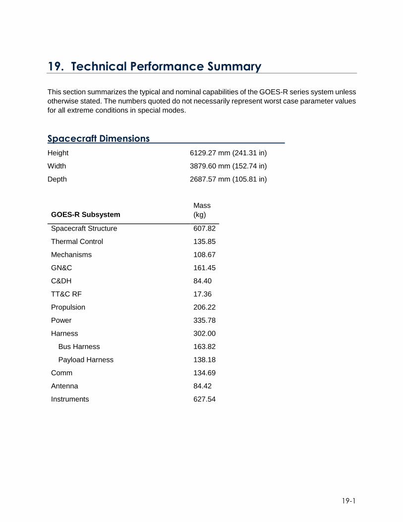
19-1
19. Technical Performance Summary
This section summarizes the typical and nominal capabilities of the GOES-R series system unless
otherwise stated. The numbers quoted do not necessarily represent worst case parameter values
for all extreme conditions in special modes.
Spacecraft Dimensions
Height 6129.27 mm (241.31 in)
Width 3879.60 mm (152.74 in)
Depth 2687.57 mm (105.81 in)
GOES-R Subsystem
Mass
(kg)
Spacecraft Structure 607.82
Thermal Control 135.85
Mechanisms 108.67
GN&C 161.45
C&DH 84.40
TT&C RF 17.36
Propulsion 206.22
Power 335.78
Harness 302.00
Bus Harness 163.82
Payload Harness 138.18
Comm 134.69
Antenna 84.42
Instruments 627.54

19-2
mm kg-M^2 kg-M^2
Mass
(kg)
X-
cg Y-cg Z-cg Ixx Iyy Izz Pxy Pxz Pyz
LIFTOFF
5191.64 -54.5 23.4 1886.9 8345.7 8557.5 3987.7 -94.4 -
26.6 120.2
Hydrazine 1627.7 0 0 1786.1 686.5 686.5 31.8 0 0 0
Oxidizer 699.7 0 0 1358.5 55.4 468.5 418 0 0 0
East Ox 349.85 768.4 0 1358.5 27.7 27.7 2.5 0 0 0
West Ox
349.85 -
768.4 0 1358.5 27.7 27.7 2.5 0 0 0
Pressurant 6.9 -0.7 0 263 1.4 0.9 0.8 0 0 0
PRELAE 5191.53 11.5 20.9 1933.4 8311.8 10604.7 6002.2 310.7 7.7 113.7
Hydrazine 1627.58 0 0 1851.9 781 781 32.9 0 0 0
Oxidizer 699.7 0 0 1549.7 103.9 516.9 419.1 0 0 0
East Ox 349.85 768.4 0 1549.7 51.9 51.9 3 0 0 0
West Ox
349.85 -
768.4 0 1549.7 51.9 51.9 3 0 0 0
Pressurant 6.9 -0.7 0 329.4 1.9 1.6 0.8 0 0 0
POSTLAE 3765.94 15.9 28.8 1994.5 7834.1 9736.9 5595.3 310.2 4 107.1
Hydrazine 865.35 0 0 1776.6 466.1 466.1 24.2 0 0 0
Oxidizer 36.35 0 0 827.5 13.5 35 21.6 0 0 0
East Ox 18.17 768.3 0 827.5 6.8 6.8 0.1 0 0 0
West Ox
18.17 -
768.3 0 827.5 6.8 6.8 0.1 0 0 0
Pressurant 6.9 -0.3 0 1024.9 4.5 5.1 1.2 0 0 0

19-3
Mass Properties at End Of:
mm kg-M^2 kg-M^2
Mass (kg) X-cg Y-cg Z-cg Ixx Iyy Izz Pxy Pxz Pyz
In Orbit
Test 3751.61 -71.6 322.3 2015.3 16585.6 8641.4 12694 58.8 -519.2 320.4
Year 1 3692.42 -72.8 327.5 2019.1 16541.1 8597.6 12681.2 60.2 -518.2 315.8
Year 2 3650.28 -73.6 331.3 2019.8 16517.3 8578.2 12675.5 61.2 -518 315
Year 3 3617.14 -74.3 334.3 2019.8 16499.6 8564 12670.9 62 -518 315
Year 4 3582.98 -75 337.5 2020 16480.8 8548.9 12666.1 62.8 -518 314.7
Year 5 3547.97 -75.7 340.8 2020.2 16461.7 8533.6 12661 63.7 -517.9 314.4
Year 6 3477.28 -77.3 347.8 2023.4 16412.6 8489.2 12647.3 65.6 -517.1 310.6
Year 7 3430.27 -78.3 352.5 2024.8 16384.5 8466.6 12640.1 66.9 -516.7 308.9
Year 8 3383.54 -79.4 357.4 2026 16357.4 8445 12632.7 68.2 -516.4 307.4
Year 9 3337.32 -80.5 362.4 2026.3 16333.4 8426.7 12625.1 69.5 -516.3 307.1
Year 10 3282.12 -81.9 368.5 2028.2 16301.3 8401.5 12615.6 71.2 -515.8 304.8
Year 11 3238.21 -83 373.4 2030.6 16273.8 8379.7 12608 72.5 -515.1 301.9
Year 12 3195.9 -84.1 378.4 2037.1 16234.3 8345.9 12600.4 73.8 -513.4 294.1
Year 13 3155.35 -85.2 383.3 2044.6 16192.2 8309.3 12593 75.1 -511.4 285
Year 14 3116.67 -86.2 388 2051.6 16152.1 8274.7 12585.8 76.4 -509.5 276.5
Year 15 3071.52 -87.5 393.7 2060 16104.5 8233.7 12577.1 77.9 -507.2 266.4
RESIDUAL 3059.9 -87.8 395.2 2063.1 16087.8 8216 12572.2 78.4 -506.4 262.6
Hydrazine 183.88 0 0 1559.8 106.9 106.9 6.3 0 0 0
Oxidizer 11.77 0 0 788.7 4.8 11.8 7 0 0 0
East Ox 5.88 768.3 0 788.7 2.4 2.4 0 0 0 0
West Ox 5.88 -
768.3 0 788.7 2.4 2.4 0 0 0 0
Pressurant 6.9 -0.2 0 1227.2 4.1 4.8 1.2 0 0 0

19-4
Electrical Power Subsystem
Solar Array Single axis sun tracking
Cell type Spectrolab Ultra triple junction (GaInP2/GaAs/Ge)
Panels 5 panels, 135.7 cm x 392.3 cm each
Redundancy 16 for 15 circuits
Power Solar Array Output Satellite Load
BOL summer solstice 5177 W 3748 W
BOL autumnal equinox 5956 W 4605 W
EOL summer solstice 4830 W 3535 W
EOL autumnal equinox 5489 W 4530 W
Batteries 2 lithium ion batteries, 36 cells each
Cell configuration 3 parallel cells per bank, 12 series banks
Redundancy 23 for 24 cell banks
Capacity 170 Wh/cell
Depth of Discharge < 60% of measured capacity
Eclipse load 4650 W BOL, 4410 W EOL, max 72 min eclipse
70V Bus Voltage 70 V ± 0.6 V at regulation point
Used for housekeeping and 70 V +0.6 V/–2.0 V at source
Auxiliary Communications
28V Bus Voltage 29.3 ± 0.6 V at source
Used for Instruments 29.3 +0.6 V/–3.0 V at load

19-5
Propulsion Design
Propellant Bipropellant
Tank volumes/ capacity
Fuel – Hydrazine 1704.7 L (60.2 ft3) / 1637 kg (3609 lbm)
Oxidizer – Nitrogen Tetroxide 657.0 L (23.2 ft3) / 900 kg (1984 lbm)
Pressurant - Helium 167.1 L (5.9 ft3)
Total Propellant Mass Loaded
Fuel (1) 1626 kg (3584 lbm)
Oxidizer (2) 700 kg (1543 lbm)
Helium (2) 7.3 kg (16.0 lbm)
Thrusters
LAE (1) 445 N (100 lbf)
HBT (2) 22 N (5 lbf)
REA (8) 22 N (5 lbf)
LTR (16) 90 mN (20 mlbf)
Arcjets (4) 225 mN (50 mlbf)

19-6
Guidance Navigation & Control – GOES-R Performance
Attitude Knowledge
Static 569.6 μrad 3σ per axis
Slow Dynamic 26 μrad 3σ per axis
Dynamic 11.8 μrad 3σ per axis
Integrated Rate Error
1 Sec 0.9 μrad 3σ X/Y axis; 0.89 μrad 3σ Z axis
30 Sec 1.16 μrad 3σ X/Y axis; 1.23 μrad 3σ Z axis
300 Sec 4.9 μrad 3σ per axis
900 Sec 12.0 μrad 3σ per axis
Orbit Knowledge
In-Track Position 10.1 m 3σ
Cross-Track Position 11.6 m 3σ
Radial Position 51.3 m 3σ
Velocity 2.4 cm/sec 3σ per axis
Pointing Accuracy 184.5 μrad 3σ per axis
Pointing Stability, 60 sec 215.3 μrad 3σ per axis
Attitude Rate Error +/-37 μrad/s 3σ per axis, based upon 15 msec
Thermal Control Subsystem
Nominal Spacecraft Internal Dissipation Thermal Load BOL
~1400 W
Nominal Spacecraft Internal Dissipation Thermal Load EOL
~1526 W
Primary heat rejection Primary heat rejection Aluminum honeycomb
panels with embedded heat pipes, covered with OSRs
Heater Control 247 Spacecraft heaters FSW controlled by OBC

19-7
Command (Command Data Acquisition (CDA))
Receive Characteristics
Uplink frequency 2034.200 MHz
Minimum G/T (On-Station) -33 dB/K
Minimum G/T (Safehold Mode) -59 dB/K over 95% spherical coverage
Dynamic range (4 ksps) -120 dBm to -50 dBm (Referenced to Command
Receiver input)
Dynamic range (64 ksps) -108 dBm to -50 dBm (Referenced to Command
Receiver input)
Modulation and Data Rate
Command modulation Direct BPSK
Command data rate (uncoded) 3.5 ksps or 56 ksps
Command data rate (coded) 4 ksps or 64 ksps
Bit error rate (after decoding) ≤ 1E-05

19-8
Command (Orbit-Raising Telemetry Tracking and Command
(ORTT&C))
Receive Characteristics
Uplink frequency 2036.000 MHz
Polarization (Orbit-Raising/On-Station using Hemis) RHCP
Polarization (Safehold Mode using Hemis) RHCP
Polarization (Orbit-Raising using Bicone) Linear
Minimum G/T (On-Station using Hemis) -42 dB/K
Minimum G/T (Safehold Mode using Hemis) -52 dB/K over 75% spherical
coverage
Minimum G/T (Orbit-Raising using Bicone) -48 dB/K
Dynamic range (1 ksps) -121 dBm to -50 dBm
(Referenced to Command Receiver input)
Dynamic range (4 ksps) -115 dBm to -50 dBm
(Referenced to Command Receiver input)
Modulation and Data Rate
Command modulation BPSK on Subcarrier
Subcarrier modulation 16 kHz subcarrier phase
modulated on carrier
Command data rate (uncoded) 875 sps or 3.5 ksps
Command data rate (coded) 1 ksps or 4 ksps
Bit error rate (after decoding) ≤ 1E-05

19-9
Telemetry (Command Data Acquisition (CDA)
Transmit Characteristics
Downlink frequency 1693.000 MHz
Polarization (On-Station using L/S-Band EC Antenna) RHCP
Polarization (On-Station using Hemis) RHCP
Polarization (Safehold Mode using Hemis) RHCP
Minimum EIRP (4 ksps) 25 dBmi
Minimum EIRP (40 ksps) 33 dBmi
Modulation and Data Rate
Telemetry modulation Direct BPSK
Telemetry data rate (uncoded) 3.4375 ksps or 34.375 ksps
Telemetry data rate (coded) 4 ksps or 40 ksps
Bit error rate (after decoding) ≤ 1E-07
Telemetry (Orbit-Raising Telemetry Tracking and Command
(ORTT&C))
Transmit Characteristics
Downlink frequency 2211.040 MHz
Polarization (Orbit-Raising/On-Station using Hemis) RHCP
Polarization (Safehold Mode using Hemis) RHCP
Polarization (Orbit-Raising using Bicone) Linear
Minimum EIRP (On-Station using Hemis) 26 dBmi
Minimum EIRP (Safehold Mode using Hemis) 24 dBmi over 75% spherical
coverage
Modulation and Data Rate
Telemetry modulation BPSK on Subcarrier
Subcarrier modulation 1.024 MHz Subcarrier Phase
Modulated on Carrier
Telemetry data rate (uncoded)
Telemetry data rate (coded) 1 ksps or 4 ksps
Bit error rate (after decoding) ≤ 1E-05
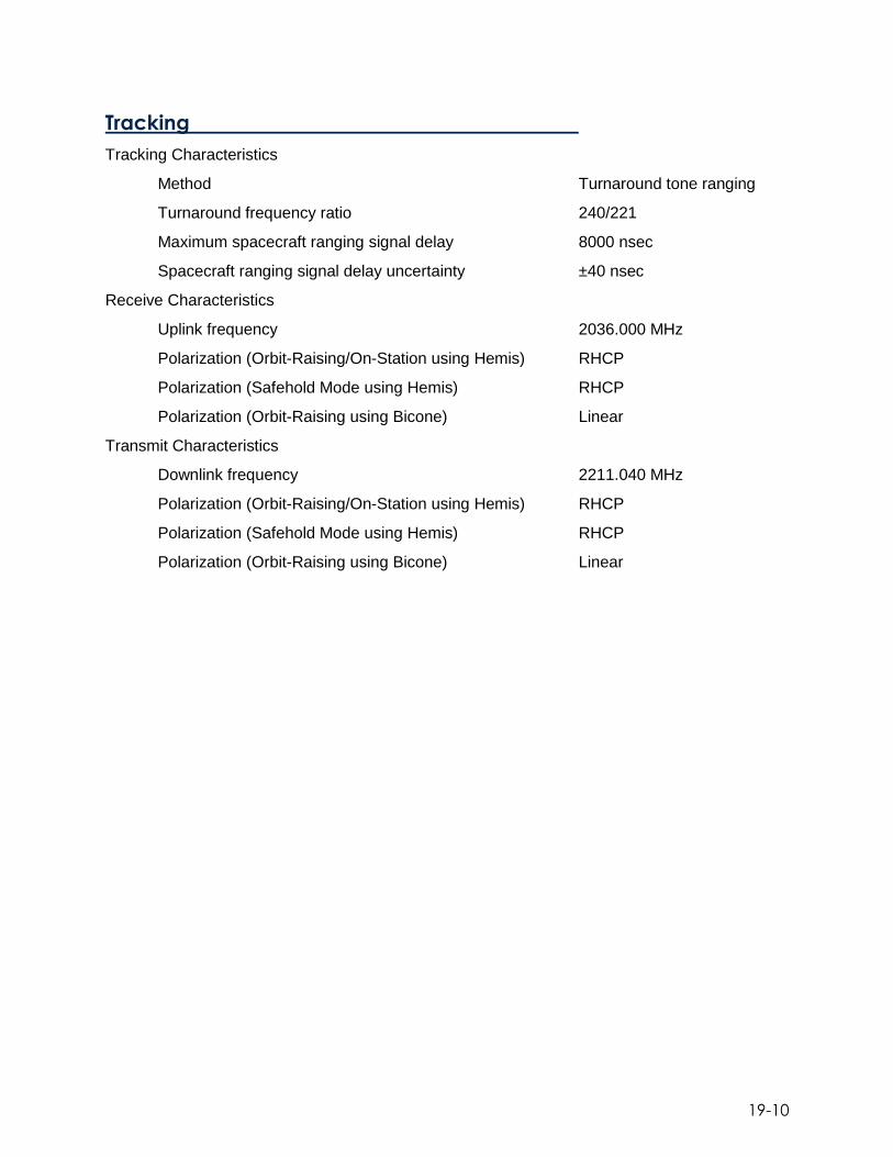
19-10
Tracking
Tracking Characteristics
Method Turnaround tone ranging
Turnaround frequency ratio 240/221
Maximum spacecraft ranging signal delay 8000 nsec
Spacecraft ranging signal delay uncertainty ±40 nsec
Receive Characteristics
Uplink frequency 2036.000 MHz
Polarization (Orbit-Raising/On-Station using Hemis) RHCP
Polarization (Safehold Mode using Hemis) RHCP
Polarization (Orbit-Raising using Bicone) Linear
Transmit Characteristics
Downlink frequency 2211.040 MHz
Polarization (Orbit-Raising/On-Station using Hemis) RHCP
Polarization (Safehold Mode using Hemis) RHCP
Polarization (Orbit-Raising using Bicone) Linear

19-11
Raw Data Link (RDL)
Transmit Characteristics
Downlink frequency 8220.000 MHz
Polarization Linear-V or Linear-H
Minimum antenna gain (includes pointing error) 33.65 dBi
Maximum antenna gain 37.0 dBi
Antenna coverage Gimbaled to provide
coverage to WCDAS and RBU
Minimum EIRP (to WCDAS/RBU from 137 deg W) 70.3 dBmi
Minimum EIRP (to WCDAS/RBU from 75 deg W) 69.6 dBmi
Modulation and Data Rate
Transmit modulation OQPSK
Transmit data rate (uncoded) 105 Mbps
Transmit data rate (coded) 120 Mbps
Transmit bandwidth ≤ 130 MHz
Bit error rate (after decoding) ≤ 1E-12

19-12
GOES Re-Broadcast (GRB)
Receive Characteristics
Uplink frequency 7216.600 MHz
Polarization Linear-V and/or Linear-H
Minimum antenna gain (includes pointing error) 33.2 dBi
Maximum antenna gain N/A
Antenna coverage Gimbaled to provide
coverage to WCDAS and RBU
Minimum G/T 3.6 dB/K
Dynamic range -103.4 dBmi to -92.1 dBmi
Transmit Characteristics
Downlink frequency 1686.600 MHz
Polarization RHCP and/or LHCP
Minimum antenna gain (includes pointing error) 14.8 dBi
Maximum antenna gain 17.7 dBi
Antenna coverage Earth coverage
Minimum EIRP 60.3 dBmi at EOC
Modulation and Data Rate
Modulation 8-PSK or QPSK
Data rate (uncoded) per polarization 15.5 Mpbs
Data rate (coded) per polarization 23.25 Mbps (8-PSK)
Channel bandwidth ≥ 11.6 MHz
Bit error rate (after decoding) ≤ 1E-10
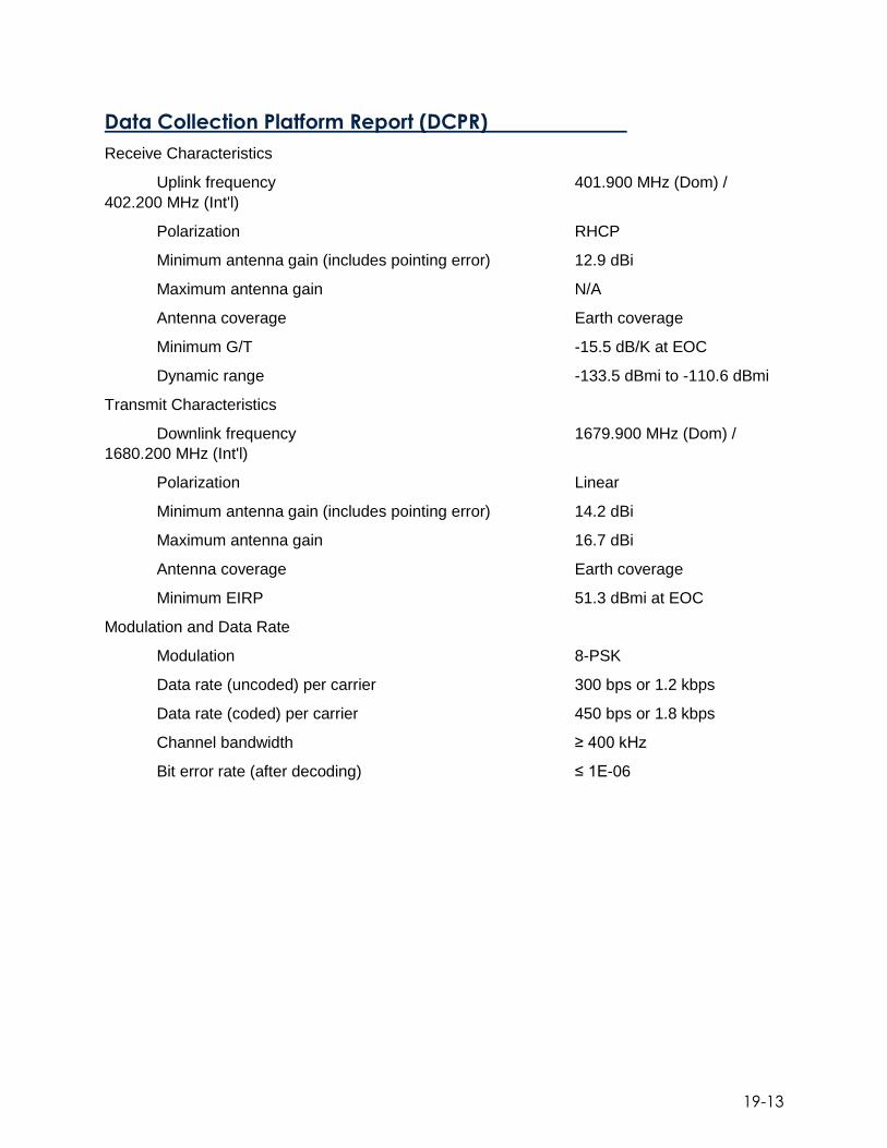
19-13
Data Collection Platform Report (DCPR)
Receive Characteristics
Uplink frequency 401.900 MHz (Dom) /
402.200 MHz (Int'l)
Polarization RHCP
Minimum antenna gain (includes pointing error) 12.9 dBi
Maximum antenna gain N/A
Antenna coverage Earth coverage
Minimum G/T -15.5 dB/K at EOC
Dynamic range -133.5 dBmi to -110.6 dBmi
Transmit Characteristics
Downlink frequency 1679.900 MHz (Dom) /
1680.200 MHz (Int'l)
Polarization Linear
Minimum antenna gain (includes pointing error) 14.2 dBi
Maximum antenna gain 16.7 dBi
Antenna coverage Earth coverage
Minimum EIRP 51.3 dBmi at EOC
Modulation and Data Rate
Modulation 8-PSK
Data rate (uncoded) per carrier 300 bps or 1.2 kbps
Data rate (coded) per carrier 450 bps or 1.8 kbps
Channel bandwidth ≥ 400 kHz
Bit error rate (after decoding) ≤ 1E-06

19-14
Data Collection Platform Command (DCPC)
Receive Characteristics
Uplink frequency 2032.775 MHz (East) /
2032.825 MHz (West)
Polarization Linear
Minimum antenna gain (includes pointing error) 14.5 dBi
Maximum antenna gain N/A
Antenna coverage Earth coverage
Minimum G/T -16.7 dB/K at EOC
Dynamic range -120.2 dBmi to -107.1 dBmi
Transmit Characteristics
Downlink frequency 468.775 MHz (East) /
468.825 MHz (West)
Polarization RHCP
Minimum antenna gain (includes pointing error) 13.0 dBi
Maximum antenna peak-to-edge gain ratio 1.7 dB
Antenna coverage Earth coverage
Minimum EIRP 47.2 dBmi at EOC
Modulation and Data Rate
Modulation BPSK with CDMA
Data rate (uncoded) 306.1 bps
Data rate (coded and chipped) 22.225 kbps
Channel bandwidth ≥ 90 kHz
Bit error rate (after decoding) ≤ 1E-05

19-15
High-Rate Information Transmission/Emergency Management
Weather Information Network (HRIT/EMWIN)
Receive Characteristics
Uplink frequency 2027.100 MHz
Polarization Linear
Minimum antenna gain (includes pointing error) 14.5 dBi
Maximum antenna gain N/A
Antenna coverage Earth coverage
Minimum G/T -16.7 dB/K at EOC
Dynamic range -91.5 dBm to -76.7 dBm
Transmit Characteristics
Downlink frequency 1694.100 MHz
Polarization Linear
Minimum antenna gain (includes pointing error) 14.2 dBi
Maximum antenna peak-to-edge gain ratio 1.4 dB
Antenna coverage Earth coverage
Minimum EIRP 56.8 dBmi at EOC
Modulation and Data Rate
Modulation BPSK
Data rate (uncoded) 400 kbps
Data rate (coded) 927 kbps
Channel bandwidth ≥ 1.2 MHz
Bit error rate (after decoding) ≤ 1E-08

19-16
Search and Rescue (SAR)
Receive Characteristics
Uplink frequency 406.050 MHz
Polarization RHCP
Minimum antenna gain (includes pointing error) 12.9 dBi
Maximum antenna gain N/A
Antenna coverage Earth coverage
Minimum G/T -15.5 dB/K at EOC
Dynamic range -149.7 dBmi to -124.7 dBmi
Transmit Characteristics
Downlink frequency 1544.550 MHz
Polarization RHCP
Minimum antenna gain (includes pointing error) 11.5 dBi
Maximum antenna gain 14.0 dBi
Antenna coverage Earth coverage
Minimum EIRP 44.5 dBmi at EOC
Modulation and Data Rate
Modulation PM/BPSK
Data rate (uncoded) 400 bps
Data rate (coded) N/A
Channel bandwidth ≥ 80 kHz
Bit error rate (uncoded) ≤ 5E-05

19-17
Advanced Baseline Imager
Field-of-View Defining Element Detector Focal Plane Module Field-of-View
Visible & Near-IR 0.88° (NS) x 1.85° (EW) Midwave IR 0.91° (NS) x 1.55° (EW) Longwave IR 0.89° (NS) x 1.57° (EW)
Field-of-Regard Ellipsoid – 20.5° (NS) x 22.7° (EW) 16-channel Imaging Simultaneously Scan Capability Scenes (Refresh Rate in Minutes)
Mode 3 Full Disk (15), CONUS (5), Mesoscale (0.5) Mode 4 Full Disk (5) Custom User-defined scenes and refresh rates
Channel (Wavelength) / Detectors Pixel Spacing
Visible & Near-IR Band 1 (0.47 um) / Silicon 1 km Band 2 (0.64 um) / Silicon 0.5 km Band 3 (0.86 um) / Silicon 1 km Band 4 (1.38 um) / HgCdTe 2 km Band 5 (0.86 um) / HgCdTe 1 km Band 6 (1.38 um) / HgCdTe 2 km
Midwave IR Band 7 (3.90 um) / HgCdTe 2 km Band 8 (6.185 um) / HgCdTe 2 km Band 9 (6.95 um) / HgCdTe 2 km Band 10 (7.34 um) / HgCdTe 2 km Band 11 (8.50 um) / HgCdTe 2 km
Longwave IR Band 12 (9.61 um) / HgCdTe 2 km Band 13 (10.35 um) / HgCdTe 2 km Band 14 (11.20 um) / HgCdTe 2 km Band 15 (12.30 um) / HgCdTe 2 km Band 16 (13.30 um) / HgCdTe 2 km
Radiometric Calibration Space, internal blackbody, solar diffuser Frequency of Calibration
Space Look ≤ 30 seconds Infrared Blackbody 15 minutes (Mode 3) / 5 minutes (Mode 4) Solar Diffuser On Demand
System Absolute Accuracy
Bands 1 – 3, 5 – 6 ± 3% @ 100 % Albedo Band 4 ± 4% @ 100% Albedo Bands 7 – 16 ± 1K @ 300 K

19-18
System Relative Accuracy Pixel-to-Pixel <NEdT Swath-to-Swath <NEdT Channel-to-Channel <0.2 K Image-to-Image <0.2 K Calibration <0.2 K
Image Navigation and Registration
Navigation 21 µrad Registration
Frame-to-Frame 0.5 and 1.0 km 17.6 µrad 2.0 km 23.0 µrad
Within-Frame 21.0 µrad Swath-to-Swath 7.8 µrad Channel-to-Channel 2km-to-0.5/1/2 km 11.2 mrad
1km-to-0.5/1km 6.0 mrad

19-19
GLM Design
Lens focal length 134 mm
Lens f number 1.2
Lens field of view +/- 8 deg
CCD imaging area size 1372 x 1300 pixels
Pixel size (variable, up to) 30 x 30 µm
Well depth (variable) 2e6 electrons
Ground sample distance 8 – 14 km
Frame rate 500 fps
Filter center wavelength 777.4 nm
Filter band pass 1 nm
ADC resolution 14 bits
Event rate ≥1e5 sec-1
Downlink rate 7.7 Mbps
Mass (Total) 125 kg
Mass (Sensor Unit) 67 kg
Mass (Electronics Unit) 41 kg
Operational power 290 W
Flash detection efficiency >80%
Operating life ≥10 years
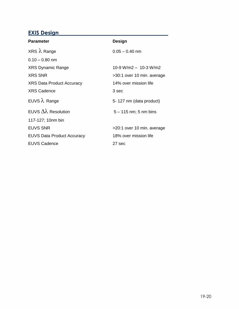
19-20
EXIS Design________________________________________
Parameter Design
XRS Range 0.05 – 0.40 nm
0.10 – 0.80 nm
XRS Dynamic Range 10-9 W/m2 – 10-3 W/m2
XRS SNR >30:1 over 10 min. average
XRS Data Product Accuracy 14% over mission life
XRS Cadence 3 sec
EUVS Range 5- 127 nm (data product)
EUVS Resolution 5 – 115 nm; 5 nm bins
117-127; 10nm bin
EUVS SNR >20:1 over 10 min. average
EUVS Data Product Accuracy 18% over mission life
EUVS Cadence 27 sec

19-21
SUVI Design
Mirrors Multi-layer-coated Zerodur
Number of coating segments per mirror 6
Primary diameter 20 cm
Effective focal length 173.04 cm
Field of view 45 × 45 arcmin or better
Pixel size/Resolution 21 µm/2.5 arcsec
CCD detector 1280 × 1280 pixels
Detector full well 450 000 electrons
Full image frame rate 1 per 10 seconds
Typical exposure times 0.01 to 1 second
Mass:
Telescope subsystem 39 kg
Electronics box 25 kg
Intra-instrument harness 8 kg
Instrument Power 225 W (peak)
Science telemetry
Interface to spacecraft 3.5 Mbps
Design life 10 years (after 5 years of on-orbit storage)

19-22
Magnetometer Performance Summary
Dynamic Range +/- 512 nT
Resolution 0.0016 nT
Accuracy <1.7 nT
Noise <0.1 nT RMS
Bandwidth 2.5 Hz
Sensor axes orthogonality Within +/- 0.1 deg post calibration
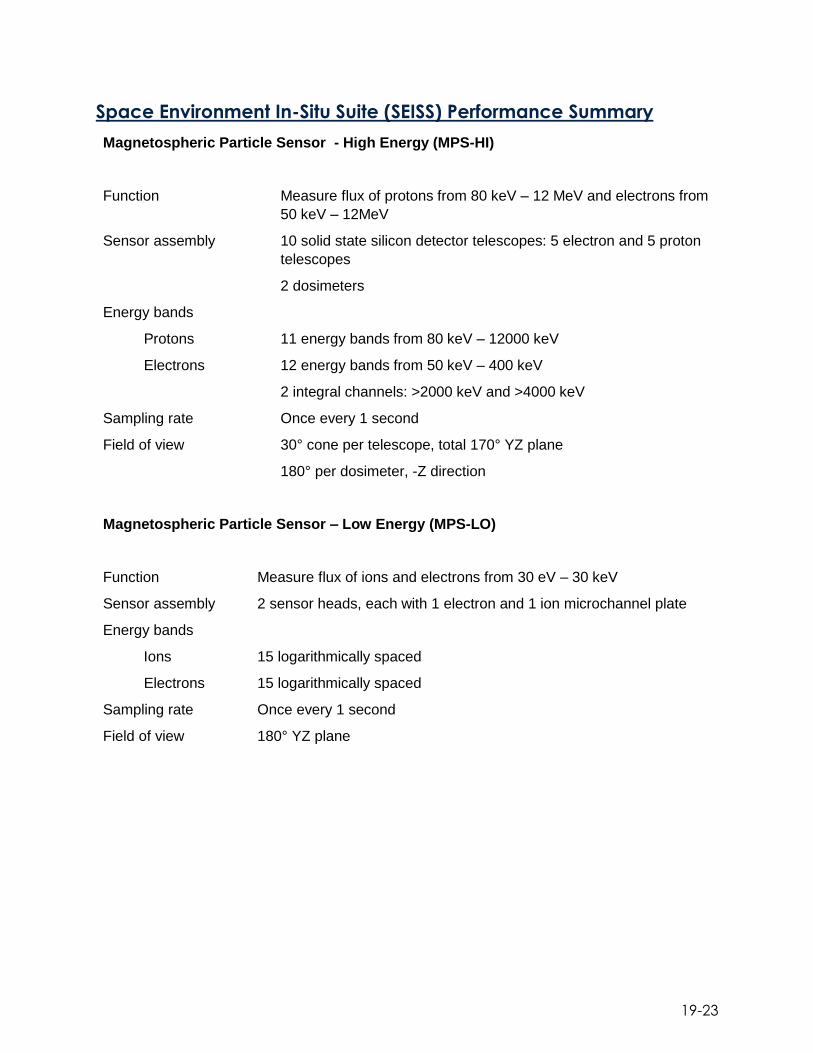
19-23
Space Environment In-Situ Suite (SEISS) Performance Summary
Magnetospheric Particle Sensor - High Energy (MPS-HI)
Function Measure flux of protons from 80 keV – 12 MeV and electrons from
50 keV – 12MeV
Sensor assembly 10 solid state silicon detector telescopes: 5 electron and 5 proton
telescopes
2 dosimeters
Energy bands
Protons 11 energy bands from 80 keV – 12000 keV
Electrons 12 energy bands from 50 keV – 400 keV
2 integral channels: >2000 keV and >4000 keV
Sampling rate Once every 1 second
Field of view 30° cone per telescope, total 170° YZ plane
180° per dosimeter, -Z direction
Magnetospheric Particle Sensor – Low Energy (MPS-LO)
Function Measure flux of ions and electrons from 30 eV – 30 keV
Sensor assembly 2 sensor heads, each with 1 electron and 1 ion microchannel plate
Energy bands
Ions 15 logarithmically spaced
Electrons 15 logarithmically spaced
Sampling rate Once every 1 second
Field of view 180° YZ plane
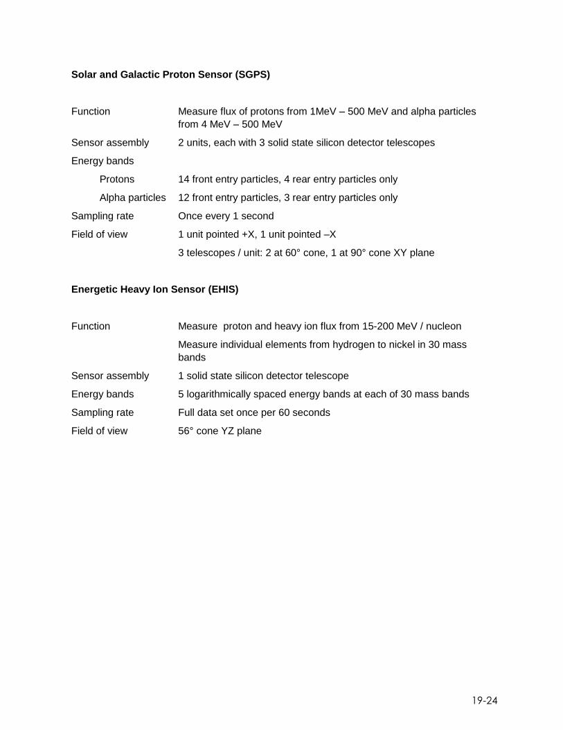
19-24
Solar and Galactic Proton Sensor (SGPS)
Function Measure flux of protons from 1MeV – 500 MeV and alpha particles
from 4 MeV – 500 MeV
Sensor assembly 2 units, each with 3 solid state silicon detector telescopes
Energy bands
Protons 14 front entry particles, 4 rear entry particles only
Alpha particles 12 front entry particles, 3 rear entry particles only
Sampling rate Once every 1 second
Field of view 1 unit pointed +X, 1 unit pointed –X
3 telescopes / unit: 2 at 60° cone, 1 at 90° cone XY plane
Energetic Heavy Ion Sensor (EHIS)
Function Measure proton and heavy ion flux from 15-200 MeV / nucleon
Measure individual elements from hydrogen to nickel in 30 mass
bands
Sensor assembly 1 solid state silicon detector telescope
Energy bands 5 logarithmically spaced energy bands at each of 30 mass bands
Sampling rate Full data set once per 60 seconds
Field of view 56° cone YZ plane

20-1
20. Acronyms 1-PPS One Pulse per Second
2DS 2-Day Store
A Angstrom
ABI Advanced Baseline Imager
ACS Antenna Controller System
ACU Antenna Control Unit
AD Attitude Determination
ADC Analog to Digital Converter
ADC Analog to Digital Conversion
ADIS Angle Detecting Inclined Sensor
ADRS Ancillary Data Relay System
AIA Atmospheric Imaging Assembly
ANCF AWIPS Network Control Facility
AS Application Server
ASD Acceleration Spectral Density
ASIC Application Specific Integrated Circuit
ASIS Antenna System Interface Simulators
ATS Absolute Time Sequence
AVD Active Vibration Damping
AWA Antenna Wing Assembly
AWIPS Advanced Weather Interactive Processing System
BCD Battery Charger/Discharger
BDS Best Detector Select
BIT/BITE Built-In-Test/ Built-In-Test-Equipment
BNCF AWIPS Backup Network Control Facility
BPSK Binary Phase-Shift Key
BRF Body Reference Frame
BS Beamsplitter
C&DH Command and Data Handling
CADU Channel Access Data Units
CASSIE Contextual Analysis for Spectral and Spatial Information
CBU Consolidated Backup
CCA Circuit Card Assembly
CCD Charge Coupled Device
CCE Cryocooler Control Electronics
CCTV Closed Circuit Television
CCSDS Consultative Committee for Space Data Systems
CDA Central Distribution Assembly
CDA Command and Data Acquisition

20-2
CDRL Contract Data Requirements List
CDUA Command Decryption Unit Assembly
CEB Camera Electronics Box
CG Center of Gravity
CI Configuration Item
CLASS Comprehensive Large Array-data Stewardship System
CM Configuration Management
CMDB Configuration Management Database
CME Coronal Mass Ejection
CMI Cloud and Moisture Imagery
CODT Custom Object Dump Tool
COLA Collision Avoidance
CONUS Contiguous United States
COOP Continuity of Operations
COSI Common Operating System Image
CPE Certified Principle Engineer
CS Consolidated Storage
CSC Computer Software Component
CSC Computer Software Configuration
CSSA Coarse Sun Sensor Assembly
CSU Current Sensor Unit
CTE Coeficient of Thermal Expansion
CTP Command and Telemetry Processor
DB Database
DC Direct Current
DCP Data Collection Platform
DCPC Data Collection Platform Command
DCPR Data Collection Platform Report
DCS Data Collection System
DE Development Environments
DF Data Formater
DGS Diego Garcia Station
DN Digital Number
DO Data Operations
DP Data Processor
DPU Data Processing Unit
DRGS Direct Readout Ground Station
DVB-S2 Digital Video Broadcasting Satellite Second Generation
ECEF Earth-Centered Earth-Fixed
EDAC Error Detection and Correction
EEPROM Electronically Erasable Programmable Read-Only Memory

20-3
EGSE Electrical Ground Support Equipment
EHIS Energetic Heavy Ion Sensor
EI Enterprise Infrastructure
ELT Emergency Locator Transmitter
EM Enterprise Management
EMWIN Emergency Managers Weather Information Network
EOCV End of Charge Voltage
EOPP Earth Orientation Prediction Parameters
EP Encoder Processor
EPEAT Electron, Proton, Alpha Detector
EPC Electronic Power Converter
EPIRB Emergency Position Indicating Radio Beacons
EPP Earth Pointing Platform
EPS Electrical Power Subsystem
ESB Enterprise Service Bus
ESD Electro-static discharge
ESPC Environmental Satellite Processing Center
ESPDS Environmental Satellite Processing and Distribution System
ETA EUV Telescope Assembly
EU Electronics Unit
EUV Extreme Ultraviolet
EUVS Extreme Ultraviolet Sensor
EW East-West
EWSK East-West Station Keeping
EXEB EXIS Electrical Box
EXIS Extreme Ultraviolet and X-ray Irradiance Sensors
FAA Front Aperture Assembly
FBA Fuse Board Assembly
FEP Front End processors
FGF Fixed Grid Frame
FIFO First In, First Out
FM Flight Model
FOV Field of View
FPA Focal Plane Arrays
FPAA Focal Plane Array Assembly
FPGA Field Programmable Gate Array
FPM Focal Plane Module
FPP Focal Plane Package
FSDE Flight Software Development Environment
FSME Flight Software Maintenance Environment
FSS Fine Sun Sensor

20-4
FSSA Fine Sun Sensor Assembly
FSW Flight Software
FUV Far Ultraviolet
FWHM Full-Width Half-Maximum
GAS GOES-R Access Subsystem
GEO Geosynchronous Earth Orbit
GEOSAR Geostationary Search and Rescue
GHe Gaseous Helium
GLM Geostationary Lightning Mapper
GN&C Guidance Navigation and Control
GOES Geostationary Operational Environmental Satellite
GPA Ground Processing Algorithm
GPS Global Positioning System
GPSR Global Positioning System Receiver
GRATDAT GOES-R ABI Trending and Data Analysis Toolkit
GRB GOES Rebroadcast service
GRBT GRB User Terminals
GRDDP GOES-R Reliable Data Delivery Protocol
GS Ground System
GSD Ground Sample Distance
GTA Guide Telescope Assembly
GTO Geosynchronous Transfer Orbit
GUI Graphical User Interface
GVAR GOES VARiable
HBT Hydrazine Bi-Propellant Thruster
HOPA High Output Paraffin Actuator
HR Hurricane-Rated
HRG Hemispheric Resonating Gyros
HRIT High Rate Information Transmission
HSIO High Speed I/O
HWIL Hardware In the Loop
Hz Hertz
I&T Integration and Test
IC Instrument Controller
ICRF International Celestial Reference Frame
ICT Internal Calibration Target
IEEE Institute of Electrical and Electronics Engineers
IETF Internet Engineering Task Force
IFDS Intermediate Frequency Distribution System
IFL Inter-Facility Link
IFL Intermediate Frequency

20-5
IMU Inertial Measurement Unit
INFO Information
INR Image Navigation and Registration
IRE Integrated Rate Error
IR Infrared
IS Infrastructure
Isp Specific Impulse
ITE Integration and Test Environment
JPSS Joint Polar Satellite System
keV Kilo Electron Volt
km Kilometer
KPP Key Performance Parameter
ksps Kilo-Symbols per Second
KVM Keyboard, Video and Mouse
LAE Liquid Apogee Engine
LAN Local Area Network
LASP Laboratory for Atmospheric and Space Physics
LCFA Lightning Cluster-Filter Algorithm
LCM Low voltage Control Module
LED Light Emitting Diode
LER Lower Equipment Room
LHCP Left Hand Circular Polarization
LHP Loop Heat Pipe
LIS Lightning Imaging Sensor
LIS/OTD Lightning Imaging Sensor / Optical Transient Detector
LMC LOS Motion Compensation
LMSSC Lockheed Martin Space Systems Company
LNA Low Noise Amplifiers
LOR Launch and Orbit Raising
LOS Line-of-Sight
LPM Low voltage Power Module
LTR Low Thrust REA
LV Launch Vehicle
LVDS Low-Voltage Differential Signal
LWIR Longwave infrared
LZSS Level Zero Storage Service
M&C Monitor & Control
MA Momentum Adjust
MAG Magnetometer
MAGED Magnetosphere Electron Detector
MAGPD Magnetospheric Proton Detector

20-6
Mbps Megabits per second
MCP Microchannel Plates
MECO Main Engine Cutoff
MEDA Macintyre Electronic Design Associates, Inc
MES Main Engine Start
MeV Mega Electron Volt
MHz MegaHertz
µrad Microradian
MLI Multi-Layer Insulation
MLS Mission Life Store
MM Mission Management
Mo/Si Molybdenum/Silicon
MOST Mission Operations Support Team
Mo/Y Molybdenum-Yttrium
MPLS Multi-Protocol Label Switching
MPS Mission Planning and Scheduling
MPS-HI Magnetospheric Particle Sensor-High energy range
MPS-LO Magnetospheric Particle Sensor-Low energy range
MSKSim Momentum and Station-Keeping Simulation
MUV Middle Ultraviolet
MUX Multiplexer
MW/LW Midwave –Longwave
MWIR Midwave infrared
MY Minus Y
NASA National Aeronautics and Space Administration
NBF Narrow Band Filter
NCEI National Centers for Environmental Information
NCWCP NOAA Center for Weather and Climate Prediction
NEdT Noise Equivalent delta Temperature
NESDIS National Environmental Satellite, Data and Information Service
NF Network Fabric
NOAA National Oceanic and Atmospheric Administration
NOC Network Operations Center
NPP National Polar-orbiting Partnership
NS North-South
NSOF NOAA Satellite Operations Facility
NSSK North South Station Keeping
nT nanoTesla
N-WAVE NOAA Science Network
NWS National Weather Service
O&A Orbit and Attitude

20-7
O&M Operations & Maintenance
OAR O&A Angular Rate
OBC On Board Computer
OCCR Operations Configuration Change Request
OD Orbit Determination
OE Operational Environment
OMC Orbit Motion Compensation
OMT Orthomode Transducer
OPC Optical Port Cover
OPSA Optical Port Sunshield Assembly
ORTT&C Orbit-Raising Tracking, Telemetry and Control
OSL Operational Support Location
OSPO Office of Satellite and Product Operations
OSR Optical Solar Reflector
OTS Off-the-Shelf
OTD Optical Transient Detector
P&TC Peripheral and Thermal Control
PD Product Distribution
PDA Product Distribution and Access
PDB Parameter Database
PDM Power Distribution Module
PDU Power Drive Unit
PG Product Generation
PIFT Predicted Interface Force and Torque
PKI Public Key Infrastructure
PLEIADES Post Launch Enhanced Image and Data Evaluation System
PLT Post-Launch Test
PMD Propellant Management Device
PMU Personal Maintenance Unit
PPS Pulse per second
PPZ Product Processing Zone
PRA Pyro Relay Assembly
PRT Platinum Resistance Thermometer
PRU Power Regulation Unit
PS Power Supplies
PSU Personal Safety Unit
PTR Program Tracking Reports
PY Plus Y
QE Quantum Efficiency
QJ Quad Junction
R&R Restraint and Release

20-8
RAM Random Access Memory
RDC Relay Drive Card
RDL Raw Data Link
REA Rocket Engine Assembly
RF Radio Frequency
RFI Radio Frequency Interface
RHCP Right Hand Circular Polarization
RIU Remote Interface Units
RMC Redundancy Management Card
RMS Root Mean Square
ROIC Read-Out Integrated Circuit
RTEP Real Time Event Processors
RWA Reaction Wheel Assembly
SADA Solar Array Drive Assembly
SADE Solar Array Drive Electronics Box
SAR Search and Rescue
SARSAT Search and Rescue Satellite-Aided Tracking
SAS Solar Array Shunt
SAST Spacecraft All-Software Testbed
SAWA Solar Array Wing Assembly
SBF Solar Blocking Filter
SCA Solar Calibration Assembly
SCC Solar Calibration Cover
SCN Spacecraft Navigation
SCP Stored Command Processing
SCT Solar Calibration Target
SDA Scan Drive Assembly
SDO Solar Dynamics Observatory
SEB Sensor Electronics Box
SEB SUVI Electronics Box
SEGA SPP Elevation Gimbal Assembly
SEISS Space Environment In-Situ Suite
Sep Nuts Separation Nuts
SERDES SERializer-DESerializer
sFTP secure File Transfer Protocol
SGC Space Ground Communications
SGPS Solar and Galactic Proton Sensors
SHM Safe Hold Mode
SIMD Scanner Interface & Motor Driver
SIU Sun Pointing Platform Interface Unit, Sensor Interface Unit
SMA Shape Memory Alloy

20-9
SMC Spacecraft Motion Compensation
SMF Single Mode Fiber
SMS-1 first Synchronous Meteorological Satellite
SNR Signal to Noise Ratio
SNMP Simple Network Management Protocol
SOCC Satellite Operations Control Center
SOZ Satellite Operations Zone
SPP Sun Pointing Platform
SPS Solar Position Sensor
SPS Sun Pointing Subsystem
SRA Slip Ring Assembly
SRAM Static Random Access Memory
SRF Solar Rejection Filter
SRS Shock Response Spectra
SSD Solid State Detector
SSIRU Scalable Space Inertial Reference Units
SSPA Solid State Power Amplifier
SSRD Split Spool Release Device
STAR Satellite Applications and Research
STS SUVI Telescope Subsystem
SU Sensor Unit
SUE Sensor Unit Electronics
SUVI Solar Ultraviolet Imager
SWA Solar Wing Assembly
SWPC Space Weather Prediction Center
SWRC SpaceWire Router Card
TBA Trailer Bearing Assembly
TCP/IP Transmission Control Protocol/Internet Protocol
TDU Thermal Dynamic Unit
TFRS Timing and Frequency Reference System
TNCF Test Network Control Facility
TNR Threshold-to-Noise Ratio
TNT Telemetry & Timing
TRMM Tropical Rainfall Measuring Mission
TSU Transient Suppression Unit
TT&C Tracking, Telemetry, and Control
TWTA Traveling Wave Tube Assembly
ULA United Launch Alliance
USN Universal Space Network
UTC Coordinated Universal Time
UTJ Ultra Triple Junction
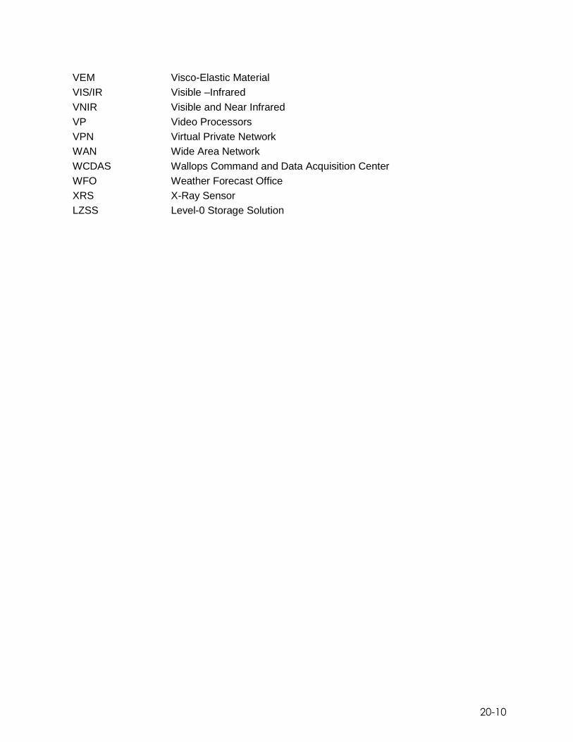
20-10
VEM Visco-Elastic Material
VIS/IR Visible –Infrared
VNIR Visible and Near Infrared
VP Video Processors
VPN Virtual Private Network
WAN Wide Area Network
WCDAS Wallops Command and Data Acquisition Center
WFO Weather Forecast Office
XRS X-Ray Sensor
LZSS Level-0 Storage Solution
Copyright © 2022 FDOKUMEN