Gocator Line Profile Sensor User Manual - LMI Technologies
607
USER MANUAL Gocator Line Confocal Sensors Gocator 5500 Series Sensors Firmware version: 0.2.x.xx Document revision: B
-
Upload
khangminh22 -
Category
Documents
-
view
7 -
download
0
Transcript of Gocator Line Profile Sensor User Manual - LMI Technologies
USER MANUAL
Gocator Line Confocal SensorsGocator 5500 Series SensorsFirmware version: 0.2.x.xx
Document revision: B

Gocator Line Confocal Sensors: User Manual 2
CopyrightCopyright © 2022 by LMI Technologies, Inc. All rights reserved.
ProprietaryThis document, submitted in confidence, contains proprietary information which shall not bereproduced or transferred to other documents or disclosed to others or used for manufacturing orany other purpose without prior written permission of LMI Technologies Inc.
No part of this publication may be copied, photocopied, reproduced, transmitted, transcribed, orreduced to any electronic medium or machine readable form without prior written consent of LMITechnologies, Inc.
Trademarks and RestrictionsGocator™ is a registered trademark of LMI Technologies, Inc. Any other company or product namesmentioned herein may be trademarks of their respective owners.
Information contained within this manual is subject to change.
Contact InformationLMI Technologies, Inc.9200 Glenlyon ParkwayBurnaby BC V5J 5J8Canada
Telephone: +1 604-636-1011Fax: +1 604-516-8368
www.lmi3D.com
Gocator Line Confocal Sensors: User Manual 3
Table of ContentsCopyright 2
Table of Contents 3
Introduction 9
Safety and Maintenance 10
Electrical Safety 10
Handling, Cleaning, and Maintenance 10
Environment and Lighting 11
Gocator 5500 Sensor Overview 12
Using the Manual 13
Getting Started 14
Hardware Overview 15
Gocator Cordsets 15
Gocator Sensor 16
System Overview 16
Standalone System 17
Installation and Network and Sensor Setup 18
Cordset Bend Radius Limits 18
Warm-up Procedure 19
Key Concepts 21
Sensors, Scanners, and Systems 21
3D Acquisition 21
Multilayer Output 21
Profile Output 22
Coordinate Systems 22
Unaligned Coordinates 22
Aligned Coordinates 22
Uniform Data and Point Cloud Data 22
Data Generation and Processing 23
Part Detection 23
Measurement and Anchoring 24
Output and Digital Tracking 24
Accelerating Sensors 25
User Interface Overview 26
Status Bar 28
System Messages 29
Metrics Area 29
Data Viewer 30
Image Mode 34
Exposure Information 35
Incorrect Exposure 35
Spots and Dropouts 39
Profile Mode 42
Surface Mode 42
Surface and Perspective Display Options 43
Using Multiple Data Viewer Windows 49
Pinning Outputs 50
File Formats 53
Working with Scan Data 54
Starting, Stopping, and Recording 55
Playing Back Recorded Data 55
Recording File Actions 56
Creating, Saving and Loading Jobs (Settings) 57
Configuring Systems 58
Sensor Management and Maintenance 59
Settings 59
Jobs 60
Maintenance 62
Software Upgrade 63
Backup and Restore 63
Support 64
Creating a Sensor System 65
Aligning Sensors 65
Transformations 67
Configuring Acquisition 70
Configuring Scanner Acquisition 71
Scan Modes 71
Uniform Spacing 72
Surface Generation 73
Fixed Length 73
Triggers 75
Trigger Settings 78
Maximum Input Trigger Rate 79
Maximum Encoder Rate 80
Layer and Advanced Settings 80
Configuring Sensor Acquisition 82
Active Area 82
Exposure and Light Intensity 84
Spot and Camera Settings 85
Configuring Inspection and Processing Tools 87
Adding a Tool 89
Removing a Tool 90
Duplicating a Tool 91

Gocator Line Confocal Sensors: User Manual 4
Renaming a Tool 92
Working with Tool Chains 92
Changing Tool Display Options 95
Reordering Tools 96
Data Types 97
Understanding the Data Flow in Tool Chains 98
Tool Configuration 104
Regions 105
Standard Regions 106
Flexible Regions 106
Working with Circular and EllipticalRegions 110
Feature Points 112
Geometric Features 115
Fit Lines 115
Decisions 115
Measurement Anchoring 116
Enabling and Disabling Outputs 119
Profile Measurement 121
Profile Area 122
Inputs 122
Parameters 123
Outputs 124
Profile Bounding Box 127
Inputs 127
Parameters 128
Outputs 128
Profile Circle 131
Inputs 131
Parameters 132
Outputs 133
Profile Circle Radii 135
Inputs 135
Parameters 136
Outputs 138
Profile Closed Area 140
Inputs 140
Parameters 140
Outputs 143
Profile Dimension 145
Inputs 145
Parameters 146
Outputs 147
Profile Edge 149
Inputs 149
Parameters 150
Outputs 154
Profile Filter 156
Inputs 156
Parameters 157
Outputs 159
Profile Groove 160
Groove Algorithm 160
Inputs 162
Parameters 163
Outputs 165
Profile Intersect 167
Inputs 167
Parameters 167
Outputs 168
Profile Line 171
Inputs 171
Parameters 172
Outputs 174
Profile Mask 177
Inputs 178
Parameters 179
Outputs 179
Profile Part Detection 181
Inputs 181
Parameters 182
Outputs 185
Profile Position 188
Inputs 188
Parameters 189
Outputs 190
Profile Round Corner 192
Inputs 192
Parameters 192
Outputs 196
Profile Strip 198
Strip Algorithm 198
Strip Start and Terminate Conditions 199
Strip Step Edge Definitions 200

Gocator Line Confocal Sensors: User Manual 5
Inputs 201
Parameters 202
Outputs 205
Profile Template Matching 207
Inputs 207
Parameters 209
Outputs 211
Raw Profile Matching 214
Inputs 214
Parameters 215
Outputs 217
Profile Thickness 219
Inputs 219
Parameters 219
Outputs 220
Profile Transform 222
Inputs 223
Parameters 224
Outputs 224
Surface Measurement 226
Surface Align Ring 227
Surface Align Wide 228
Surface Arithmetic 229
Inputs 229
Parameters 229
Outputs 231
Surface Ball Bar 232
Inputs 232
Parameters 232
Outputs 234
Surface Blob 236
Inputs 237
Parameters 237
Outputs 243
Surface Bounding Box 246
Inputs 246
Parameters 247
Outputs 251
Surface Circular Edge 254
Calipers, Extracted Paths, and Edge Points254
Inputs 255
Parameters 256
Outputs 263
Surface Countersunk Hole 267
Inputs 267
Parameters 267
Outputs 270
Surface Curvature Correction 274
Inputs 274
Parameters 275
Outputs 277
Surface Cylinder 279
Inputs 279
Parameters 279
Outputs 282
Surface Dimension 284
Inputs 284
Parameters 284
Outputs 286
Surface Direction Filter 289
Inputs 289
Parameters 290
Outputs 292
Surface Edge 293
Paths and Path Profiles 294
Inputs 295
Parameters 296
Outputs 306
Surface Ellipse 311
Inputs 311
Parameters 312
Outputs 313
Surface Extend 315
Inputs 315
Parameters 316
Outputs 317
Surface Filter 319
Inputs 319
Parameters 320
Outputs 322
Surface Flatness 324
Inputs 324
Parameters 325
Outputs 326

Gocator Line Confocal Sensors: User Manual 6
Surface Hole 329
Measurement Region 329
Hole Algorithm 330
Inputs 331
Parameters 331
Outputs 334
Surface Mask 335
Inputs 337
Parameters 338
Outputs 339
Surface Merge Wide 340
Surface Opening 341
Measurement Region 342
Opening Algorithm 342
Inputs 342
Parameters 343
Outputs 347
Surface Pattern Matching 349
Creating a Template 352
Inputs 352
Parameters 353
Outputs 357
Surface Plane 359
Inputs 359
Parameters 359
Outputs 361
Surface Position 364
Inputs 364
Parameters 364
Outputs 366
Surface Roughness 368
Inputs 368
Parameters 368
Outputs 371
Surface Section 372
Inputs 374
Parameters 374
Outputs 378
Surface Segmentation 381
Inputs 381
Parameters 382
Outputs 386
Surface Sphere 390
Inputs 390
Parameters 390
Outputs 392
Surface Stitch 396
Inputs 397
Parameters 397
Outputs 399
Surface Stud 400
Stud Algorithm 401
Inputs 401
Parameters 402
Outputs 404
Surface Track 406
Key Concepts 407
Track Location 409
Peak Detection 409
Side Detection 409
Center Point Detection 410
Configuring the Track Tool 410
Inputs 411
Parameters 412
Outputs 416
Using the Track Editor 418
Surface Transform 422
Inputs 424
Combinations of geometric feature inputsand results 425
Plane 425
Line 426
Point 427
Plane + Line 428
Plane + Point 429
Line + Point 430
Plane + Line + Point 431
Parameters 432
Outputs 433
Surface Vibration Correction 434
Inputs 434
Parameters 434
Outputs 435
Surface Volume 436

Gocator Line Confocal Sensors: User Manual 7
Inputs 436
Parameters 436
Outputs 437
Feature Measurement 440
Feature Circle Create 441
Inputs 441
Parameters 441
Output Types 441
Constant Circle 441
Circle from Points 442
Circle from point and plane 443
Outputs 443
Feature Line Create 446
Inputs 446
Parameters 446
Output Types 446
Line 446
Constant Line 447
Line from Two Points 447
Perpendicular or Parallel Line fromPoint and Line 448
Perpendicular Line from Point to Plane 450
Intersect Line of Two Planes 450
Projected Line on Plane 451
Bisect Projected Lines on Plane 451
Outputs 452
Feature Plane Create 454
Inputs 454
Parameters 454
Output Types 454
Constant Plane 454
Plane from a Point and Normal 455
Plane from a Point and Line 455
Plane from Three Points 456
Plane from Circle 456
Parallel Plane from Point and Plane 456
Perpendicular Plane from Point andPlane 457
Perpendicular Plane from Line andPlane 457
Bisect Plane from Two Planes 457
Outputs 458
Feature Point Create 460
Inputs 460
Parameters 460
Output Types 460
Point 460
Constant Point 461
Point from Offset 461
Point from Three Planes 462
Point from Line and Circle 462
Point from Line and Line 463
Point from Line and Plane 463
Projected Point on Line 464
Projected Point on Plane 464
Outputs 465
Feature Intersect 466
Inputs 466
Parameters 466
Outputs 468
Feature Dimension 470
Inputs 470
Parameters 471
Outputs 471
Array Tools 474
Array Index 476
Inputs 477
Parameters 477
Outputs 478
Array Create 479
Inputs 479
Parameters 479
Outputs 480
Configuring Control 481
Gocator Communication Protocol 481
Modbus Protocol 483
HMI 484
Reporting 486
Health 486
Measurements 489
Performance 490
Running GoPxL on a Windows PC 491
Adding a Sensor to a Scanner 493
Removing a Sensor from a PC instance of GoPxL 496
Loading Scan Data 498

Gocator Line Confocal Sensors: User Manual 8
GoHMI and GoHMI Designer 501
Enabling and Configuring GoHMI 502
Launching GoHMI Designer 505
Opening, Editing, and Saving a Project 508
Changing Outputs in GoPxL 515
Adding a Data Viewer to an HMI 516
GoPxL SDK and REST API 520
Setup and Location of GoPxL SDK and REST APIReferences 520
Generate .sln and Makefile 520
Building the SDK 520
Header Files 521
Sample Projects 521
Functional Hierarchy of Classes 521
Discover Devices 522
Configure Device Settings 523
Accessing Sensor Resources 523
Accessing Scanner Resources 525
Accessing an Array Element 526
Receive Device Data 527
Receive Health Information 528
Accelerated Devices 529
GDP Data Types 529
Value Types 529
Output Types 529
GoDataSet 530
Measurement Values and Decisions 531
Integrations 532
Protocols 532
Gocator Protocol 532
Modbus Protocol 533
Messages 533
Connections Map 534
Supported Block Types 535
Control Input 535
Control Output 536
System State 536
Scanner State 537
Stamp 537
Measurement 538
Tools 539
GoPxL Discovery Tool 539
Replay Converter Tool 540
Specifications 542
Sensors 543
Gocator 5500 Series 544
Gocator 5504 545
Gocator 5512 548
Gocator 5516 551
Sensor Connectors 554
Gocator Power/LAN Connector 554
Grounding Shield 555
Power 555
Gocator I/O Connector 556
Grounding Shield 556
Digital Outputs 557
Inverting Outputs 557
Digital Input 557
Encoder Input 558
Serial Output 559
Analog Output 559
Master Network Controllers 561
Master 100 561
Master 100 Dimensions 562
Master 400/800 563
Master 400/800 Electrical Specifications 565
Master 400/800 Dimensions 566
Master 810/2410 567
Electrical Specifications 571
Encoder 572
Input 574
Master 810 Dimensions 575
Master 2410 Dimensions 576
Master 1200/2400 578
Master 1200/2400 Electrical Specifications 580
Master 1200/2400 Dimensions 580
Accessories 582
Troubleshooting 583
Return Policy 584
Software Licenses 585
Support 606
Contact 607

Gocator Line Confocal Sensors: User Manual 9
Introduction
This documentation describes how to connect, configure, and use a Gocator 5500 series lineconfocal sensor ("G5 sensor" for short) using the GoPxL software. Although you can run the softwareon-sensor, with G5 sensors, LMI strongly recommends running sensors through a PC instance ofGoPxL.
Before using a sensor, you should familiarize yourself with sensor safety and maintenance. Formore information, see Safety and Maintenance on page 10.
The documentation applies to the following:
l Gocator 5500 series
Notational ConventionsThis documentation uses the following notational conventions:
Follow these safety guidelines to avoid potential injury or property damage.
Consider this information in order to make best use of the product.

Gocator Line Confocal Sensors: User Manual 10
Safety and Maintenance
The following sections describe the safe use and maintenance of Gocator sensors.
Electrical SafetyFailure to follow the guidelines described in this section may result in electrical shock orequipment damage.
Sensors should be connected to earth groundAll sensors should be connected to earth ground through their housing. All sensors should bemounted on an earth grounded frame using electrically conductive hardware to ensure the housingof the sensor is connected to earth ground. Use a multi-meter to check the continuity between thesensor connector and earth ground to ensure a proper connection.
Minimize voltage potential between system ground and sensor groundCare should be taken to minimize the voltage potential between system ground (ground referencefor I/O signals) and sensor ground. This voltage potential can be determined by measuring thevoltage between Analog_out- and system ground. The maximum permissible voltage potential is 12 Vbut should be kept below 10 V to avoid damage to the serial and encoder connections.
Use a suitable power supplyThe power supply used with sensors should be an isolated supply with inrush current protection orbe able to handle a high capacitive load. Verify the voltage input requirements for your sensor in thesensor's specifications; for specifications, see Sensors on page 543.
Use care when handling powered devicesWires connecting to the sensor should not be handled while the sensor is powered. Doing so maycause electrical shock to the user or damage to the equipment.
Handling, Cleaning, and MaintenanceDirty or damaged sensor windows (emitter or camera) can affect accuracy. Use caution whenhandling the sensor or cleaning the sensor's windows.
Devices are heavyDue to the weight of Gocator line confocal sensors, LMI recommends that two people mount thedevices.
Keep sensor windows cleanUse dry, clean air to remove dust or other dirt particles. If dirt remains, clean the windows carefullywith a soft, lint-free cloth and non-streaking glass cleaner or isopropyl alcohol. Ensure that noresidue is left on the windows after cleaning.

Gocator Line Confocal Sensors: User Manual Safety and Maintenance • 11
Avoid excessive modifications to files stored on the sensorSensor settings are stored in flash memory inside the sensor. Flash memory has an expected lifetimeof 100,000 writes. To maximize lifetime, avoid frequent or unnecessary file save operations.
Environment and LightingAvoid strong ambient light sourcesThe imager used in this product is highly sensitive to ambient light. Do not operate this device nearwindows or lighting fixtures that could influence measurement or data acquisition.If the unit must beinstalled in an environment with high ambient light levels, a lighting shield or similar device mayneed to be installed to prevent light from affecting measurement.
Avoid installing sensors in hazardous environmentsTo ensure reliable operation and to prevent damage to sensors, avoid installing the sensor inlocations
l that are humid, dusty, or poorly ventilated;l with a high temperature, such as places exposed to direct sunlight;l where there are flammable or corrosive gases;l where the unit may be directly subjected to harsh vibration or impact;l where water, oil, or chemicals may splash onto the unit;l where static electricity is easily generated.
Ensure that ambient conditions are within specificationsSensors are suitable for operation between 15 to 35 °C.
The sensor must be heat-sunk through the frame it is mounted to. When a sensor is properlyheat sunk, the difference between ambient temperature and the temperature reported in thesensor's health channel is less than 15° C.
Sensors are high-accuracy devices, and the temperature of all of its components must thereforebe in equilibrium. When the sensor is powered up, a warm-up time of at least one hour isrequired to reach a consistent spread of temperature in the sensor.

Gocator Line Confocal Sensors: User Manual 12
Gocator 5500 Sensor Overview
Gocator 5500 series sensors (also called G5 sensors) are 3D smart line confocal imaging (LCI)sensors. These sensors simultaneously produce 3D topography, 3D tomography, and 2D intensitydata. The sensors can scan a wide variety of material types, including multi-layered,transparent/translucent, curved edge, shiny/specular, high-contrast textured, or mixed materials. G5sensors uses a dual-axis optical system that improves noise immunity and provides higher signalquality. This makes it possible to scan difficult surfaces and very fine features.
Gocator 5500 sensors simultaneously generate 3D topography for each layer of a material, making itpossible to measure the thickness of individual layers or detect defects on secondary layers.
G5 Sensors are configured through an easy-to-use web-based interface called GoPxL, which providesbuilt-in measurement tools, I/O connectivity, and multi-layer profiling support. Although GoPxL canrun on-sensor, with G5 sensors the frequency is limited. Therefore, in most G5 applications, you willconfigure and run G5 sensors through the PC-based version. GoPxL running on a sensor and on aPC is almost identical.
Before using sensors, see Safety and Maintenance on page 10.
For information on the physical installation and mounting of sensors, as well as a general hardwareoverview, see Getting Started on page 14.
For key concepts on how sensors acquire data and perform measurements, see Key Concepts onpage 21.
For information on using the PC-based interface (and the differences between running GoPxL on-sensor and on a PC), see Running GoPxL on a Windows PC on page 491.

Gocator Line Confocal Sensors: User Manual 13
Using the ManualUse the following to decide which part of this manual you need.
Category Description
Safety and Maintenance Important safety and maintenance information (see Sensor Management andMaintenance on page 59).
Getting Started Hardware overview (see Getting Started on page 14).
Key Concepts Fundamental Gocator sensor concepts (see Key Concepts on page 21).
User Interface Overview General overview of the GoPxL user interface (see User Interface Overview onpage 26).
Data Viewer Description of the data viewer and how to use it (see See Data Viewer on page 30).
File Formats Lists the formats used in GoPxL (see File Formats on page 53).
Working with Scan Data Describes how to record scan data and how to play back recordings (seeWorkingwith Scan Data on page 54).
Creating, Saving andLoading Jobs
Describes how to work with jobs (see Creating, Saving and Loading Jobs (Settings) onpage 57).
Configuring Systems Contains subsections describing how to do the following:
l Perform general sensor maintenancel Create a sensor systeml Align sensorsl Confige scanner and sensor acquisitionl Configure inspection and processing toolsl Configure control (including protocol and GoHMI)l Configure reporting
For more information, see Configuring Systems on page 58.
Using a PC Instance ofGoPxL
Describes how to start and use a PC instance of GoPxL, as well as GoPxL Manager.You use a PC instance of GoPxL to accelerate a sensor and to examine scan dataoffline.
For more information, see Running GoPxL on a Windows PC on page 491.
Development Kits and API Coming soon. For information on the GoPxL SDK, see the SDK reference manualand the provided samples.
Integrations Describes the industrial protocols you can use in GoPxL (see See Integrations onpage 532).
Specifications Provides sensor specifications and drawings (see Specifications on page 542).
Manual breakdown

Gocator Line Confocal Sensors: User Manual 14
Getting Started
The following sections provide system and hardware overviews, in addition to installation and setupprocedures.

Gocator Line Confocal Sensors: User Manual Getting Started • 15
Hardware OverviewThe following sections describe Gocator and its associated hardware.
Gocator CordsetsGocator sensors use two types of cordsets: the Power & Ethernet cordset and the I/O cordset.
The Power & Ethernet cordset provides power and Ethernet sensor communication via 1000 Mbit/sEthernet with a standard RJ45 connector.
Note that Gocator 5500 Line Confocal Sensors use a series-specific Power & Ethernet cordset (theHigh Power & Ethernet cordset).
The I/O cordset provides digital I/O connections, an encoder interface, RS-485 serial connection, andan analog output.
The maximum cordset length is 60 m.
For information on the I/O cordset's pinout, see Gocator I/O Connector on page 556.
For information on the High Power & Ethernet cordset, see Gocator Power/LAN Connector onpage 554.

Gocator Line Confocal Sensors: User Manual Getting Started • 16
Gocator Sensor
Gocator 5512
Item Description
Light Emitter Emits light for profiling.
Camera The camera observe the light reflected from target surfaces.
I/O Connector Accepts input and output signals.
For more information on cordsets, see Gocator Cordsets on the previous page.
For information on the connector's pinout, see Gocator I/O Connector on page 556.
Power / LAN Connector Accepts power and connects to 1000 Mbit/s Ethernet network.
For more information on cordsets, see Gocator Cordsets on the previous page.
For information on the connector's pinout, see Gocator Power/LAN Connector onpage 554.
Power Indicator Illuminates when power is applied (blue).
Range Indicator Illuminates when camera detects light as the target is within the sensor'smeasurement range (green)..
Serial Number Unique sensor serial number.
System OverviewGocator 5500 series are only installed as standalone devices.

Gocator Line Confocal Sensors: User Manual Getting Started • 17
Standalone SystemStandalone systems include only a single sensor. Gocator 5500 series sensors are only used in astandalone system, mounted above a stage. The sensor is typically connected to a computer'sEthernet port for initial setup and during acquisition and inspection.
For information on physical installation, see Installation and Network and Sensor Setup on the nextpage.

Gocator Line Confocal Sensors: User Manual Getting Started • 18
Installation and Network and Sensor SetupFor installation and network and sensor setup information, see the Gocator 5500 Series Quick StartGuide.
Cordset Bend Radius LimitsWith high flex cordsets of lengths 25 meters and lower, limit bends as follows:
l In installations where a cordset does not bend continuously, limit bending to the static bendradius of 34 mm.
l In installations where a cordset bends continuously, limit bending to the dynamic bend radius of40 mm.
High flex cordset bend radius limits
Custom cordsets between 25 and 60 meters (the maximum length available) have a static bendradius limit of 45 mm and a dynamic limit of 140 mm.
Standard cordset bend radius limits
High flex cordsets are rated for a minimum of 2 million 90° Tick Tock bends and 7 million U-shapedbends, both at the dynamic bend radius limit of 40 mm. The following illustrations show the testsetups used to determine the number of bends in high flex cordsets.

Gocator Line Confocal Sensors: User Manual Getting Started • 19
Tick-tock test setup (θ = 180°)
U-shape test setup (L = 500 mm).
For cordset part numbers, see Accessories on page 582.
Standard (non high flex) cordsets, which are no longer available, have a static bendradius limit of 45 mm and a dynamic limit of 140 mm. Standard cordsets are rated fora minimum of 2 million 90° Tick Tock bends.
Warm-up ProcedureLMI recommends warming up the sensor before acquiring data to stabilize the sensor’s capability tomeasure absolute Z coordinates. During the sensor’s warm-up procedure, there is a small variationon the absolute Z height on which the sensor sees the
target surface.
The recommended sensor warm-up time is 30 minutes with a 50% duty cycle.
To perform sensor warm-up
1. Under Acquire > Scanners, expand Trigger, set Source to Time, and set Frame Rate to 500 Hz.

Gocator Line Confocal Sensors: User Manual Getting Started • 20
2. Under Acquire > Sensors, set Single Exposure to 1000 µs.
In general, it is recommended to use relative Z coordinate for measuring rather than absolute. Inrelative measuring the used Z height value is the difference to the reference, not an absolute Z value.This way the set up is less sensitive to any variation over time like vibration or ambient conditionchanges.

Gocator Line Confocal Sensors: User Manual 21
Key Concepts
The following sections provide an overview of how devices acquire and produce data, detect andmeasure parts, and control devices such as PLCs. Some of these concepts are important forunderstanding how you should mount sensors and configure settings such as active area.
Sensors, Scanners, and SystemsIn GoPxL, the term "sensor" refers to a single device. A scanner is a group that contains one or moresensors. A scanner also has an associated "scan engine." For example, when designing a sensorsystem containing one or more Gocator 5500 series sensors, the scanner's scan engine is "GocatorConfocal Profiler," with acquisition settings specific to that family of sensors.
Note that not all sensors support multi-sensor scanners: Gocator 5500 series sensors only support asingle sensor per scanner.
The term "system" refers to sensors and scanners as a whole.
Even if you are using only a single sensor in your application, it will still be "contained" in ascanner.
For acquisition, you configure both sensor-level settings and scanner-level settings (that is, settingsthat apply to all of the sensors in a scanner). Other settings apply to the system as a whole.
3D AcquisitionAfter a sensor system has been set up and is running, it is ready to start capturing 3D data.
Gocator sensors are always pre-calibrated to deliver 3D data in engineering units (mm)throughout their measurement range.
Multilayer OutputG5 sensors can produce multilayer data when scanning transparent or translucent targets such asglass or plastic. Multi-layer output is only supported if you have enabled uniform spacing (for moreinformation, see Uniform Data and Point Cloud Data on the next page). Layers can be Profileor Surface data. You can choose to generate up to eight layers. To perform measurements on thelayers, you use the Array Index tool to select which layer's profile to extract, and then use thoseextracted profiles as inputs in other measurement tools. For example, to measure the thickness oftwo layers in scan data, after extracting the layer profiles, you could use the Profile Thickness tool tomeasure the thickness that those layers represent.
For more information on Array tools, see Array Tools on page 474.
For more information on the Profile Thickness tool, see Profile Thickness on page 219.

Gocator Line Confocal Sensors: User Manual Key Concepts • 22
Profile OutputGocator sensors represent a profile as a series of ranges, with each range representing the distancefrom the origin. Each range contains a height (on the Z axis) and a position (on the X axis) in thesensor's field of view.
Coordinate SystemsData points are reported in one of two coordinate systems, which depends on the alignment state ofthe sensor.
l Unaligned (sensor) coordinates: Used on unaligned sensors.
l Aligned (system) coordinates: Used on aligned sensors.
Understanding coordinate systems is an important part of understanding measurement results.These coordinate systems are described below.
Unaligned Coordinates
Unaligned sensors use sensor coordinates, that is, the coordinate system is relative to the sensoritself. The measurement range (MR) is along the Z axis. The sensor’s field of view (FOV) is along the Xaxis. Most importantly, the origin is at the center of the measurement range and field of view, inother words, the center of the scan area.
Aligned Coordinates
Understanding aligned coordinates is important for two reasons. First, they are the direct result ofperforming the built-in alignment procedure. Second, they change how scan data is represented andhow measurement results should be interpreted. For more information on aligning sensors, seeAligning Sensors on page 65.
The adjustments resulting from alignment are called transformations (offsets along the axes androtations around the axes). Transformations are displayed in the System page, in the Alignmentpanel. Note that currently, you can ignore Scanner Transforms, which represent the transformationsbetween groups of sensors; support for this will be available in future versions of the sensorsoftware. For more information on transformations in the web interface, see Transformations onpage 67.
In aligned coordinates, the X axis is parallel to the alignment target surface. The system Z origin is setto the base of the alignment target object. In both cases, alignment determines the offsets in X andZ.
Uniform Data and Point Cloud DataThe data that a sensor produces in Profile mode is available in two formats: as uniform (resampled)data and as point cloud data (previously called "raw"). The sensor produces uniform data when theEnable uniform spacing (resampling) option is enabled. The sensor produces point cloud datawhen the option is disabled. The setting is available in Scan Mode, on the Acquire page.
When the Enable uniform spacing (resampling) option is enabled, the ranges that make up aprofile are resampled so that the spacing is uniform along the X axis. The resampling divides the X

Gocator Line Confocal Sensors: User Manual Key Concepts • 23
axis into fixed size "bins." Profile points that fall into the same bin are combined into a single rangevalue (Z).
The size of the spacing interval is set using the Uniform spacing interval parameter.
Resampling to uniform spacing reduces the complexity for downstream algorithms to process theprofile data from the sensor, but places a higher processing load on the sensor's CPU.
When uniform spacing is not enabled, no processing is required on the sensor. This frees upprocessing resources in the sensor, but usually requires more complicated processing on the clientside. Ranges in this case are reported in (X, Z) coordinate pairs.
A drawback of uniform spacing is that if sensors are angled to scan the sides of a target, data on the"verticals" is lost because points falling in the same "bin" are combined. When Uniform Spacing isdisabled, however, all points are preserved on the sides. In this case, the data can be processed bythe subset of tools that work on profiles without uniform spacing. Alternatively, the data can beprocessed externally using the SDK.
For information on enabling uniform spacing, see Scan Modes on page 71.
Data Generation and ProcessingAfter scanning a target, a sensor can process the scan data to allow the use of more sophisticatedmeasurement tools. This section describes the following concepts:
l Part detection
Part DetectionAfter a sensor has generated data by combining single exposures into larger pieces of data,GoPxL can isolate discrete parts on the generated surface into separate scans representing partsusing the Profile Part Detection tool. For more information, see Profile Part Detection on page 181.
Gocator can then perform measurements on these isolated parts.

Gocator Line Confocal Sensors: User Manual Key Concepts • 24
Part detection is useful when measurements on individual parts are needed and for robotic pick andplace applications.
Measurement and AnchoringAfter GoPxL scans a target and, optionally, further processes the data, the sensor is ready to takemeasurements on the scan data.
GoPxL provides several measurement tools, each of which provides a set of individualmeasurements, giving you dozens of measurements ideal for a wide variety of applications tochoose from. The configured measurements start returning pass/fail decisions, as well as the actualmeasured values, which are then sent over the enabled output channels to control devices such asPLCs, which can in turn control ejection or sorting mechanisms. (For more information onmeasurements and configuring measurements, see Configuring Inspection and Processing Tools onpage 87. For more information on output channels, see Output and Digital Tracking below.)
A part's position can vary on a transport system. To compensate for this variation, Gocator cananchor a measurement to the positional measurement (X, Y, or Z) or Z angle of an easily detectablefeature, such as the edge of a part. The calculated offset between the two ensures that the anchoredmeasurement will always be properly positioned on different parts. For more information, seeMeasurement Anchoring on page 116.
Output and Digital TrackingAfter the sensor has scanned and measured parts, the last step in the operation flow is to output theresults and/or measurements.
GoPxL currently supports a limited set of outputs.
One of the main functions of Gocator sensors is to produce pass/fail decisions, and then controlsomething based on that decision. Typically, this involves rejecting a part through an eject gate, but itcan also involve making decisions on good, but different, parts. This is described as “output” inGocator. Gocator supports the following output types:
l Ethernet (which provides industry-standard protocols such as Modbus, EtherNet/IP, and ASCII, inaddition to the Gocator protocol)
l Digitall Analogl Serial interfaces
An important concept is digital output tracking. Production lines can place an ejection or sortingmechanism at different distances from where the sensor scans the target. For this reason, Gocatorlets you schedule a delayed decision over the digital interfaces. Because the conveyor system on atypical production line will use an encoder or have a known, constant speed, targets can effectivelybe “tracked” or "tagged." Gocator will know when a defective part has traveled far enough andtrigger a PLC to activate an ejection/sorting mechanism at the correct moment.

Gocator Line Confocal Sensors: User Manual Accelerating Sensors • 25
Accelerating SensorsFor performance-critical applications, you can accelerate a sensor through a PC instance of GoPxL.
LMI STRONGLY recommends running G5 sensors through a PC instance of GoPxL. For moreinformation, see Running GoPxL on a Windows PC on page 491.

Gocator Line Confocal Sensors: User Manual 26
User Interface OverviewYou configure sensors using GoPxL by connecting to an IP address with a web browser.
If you are running GoPxL on-sensor, in the browser, you connect to the IP address of the sensor. Bydefault, the IP address of Gocator sensors is 192.168.1.10.
If you are running the Windows-based GoPxL application (to accelerate the sensor on a PC or viewpreviously recorded scans), in the browser, by default you connect to the localhost address(127.0.0.1). For more information on running GoPxL on a PC, see Running GoPxL on a Windows PC onpage 491.
GoPxL provides six expandable categories in a vertical area on the left of the interface that groupsimilar functions together in pages. Each page contains one or more panels that further categorizefunctionality. Generally speaking, the order of the categories and the pages reflects the workflowinvolved in configuring systems for an application for the first time, from the top down.
Element Description
1 Navigation panel The Navigation panel displays the categories and pages that contain all of

Gocator Line Confocal Sensors: User Manual User Interface Overview • 27
Element Description
GoPxL's configuration pages. Each page contains one or more panels.
By default, the sidebar is collapsed and only shows the category and page icons.When you move the mouse pointer over the sidebar, it expands temporarily toshow the category and page names. To pin the Navigation panel open, click theOpen button at the lower left of the interface:
To unpin the Navigation panel, click the Close button at the lower left of theinterface.
For information on the categories and what you can do with the pages theycontain, seeWhat you can do in the categories on the next page.
2 Job-related functions These controls let you work with jobs, for example, creating and saving jobs. Formore information on jobs, see Jobs on page 60.
3 Configuration area This area contains the configurations of the selected page and panel.
4 Scan controls These controls let you start and stop scanning, and also work with replay data.

Gocator Line Confocal Sensors: User Manual User Interface Overview • 28
Element Description
For information on starting and stopping scanning, see Starting, Stopping, andRecording on page 55. For information on working with replay data, see PlayingBack Recorded Data on page 55.
5 Data viewer The data viewer displays scan data, providing several tools in its toolbar tocontrol how data is visualized (such as top view, front view, or perspective view).The data viewer is available on all pages. You can split it horizontally andvertically, and create pop-out windows. For more information, see Data Vieweron page 30.
6 Displayed outputs pane This area lets you show, hide, and pin outputs such as measurements. You canalso control how outputs are displayed. For more information, see PinningOutputs on page 50.
7 Metrics area This area provides CPU usage and frame rate, including the calculatedmaximum frame rate. For more information, see Metrics Area on the next page.
8 System messages This area provides log messages, error alerts and warnings. For moreinformation, see System Messages on the next page.
The following table lists the categories available in GoPxL and where you can learn how to work withthem.
Category Description
Manage Lets you configure network settings, manage jobs, upgrade sensors or perform afactory restore, and so on. For more information, see Sensor Management andMaintenance on page 59.
System Lets you design and align sensor systems. For more information system design,see Creating a Sensor System on page 65.
Acquire Lets you configure a sensor's data acquisition. For more information, seeConfiguring Acquisition on page 70.
Inspect Lets you add and configure measurement and processing tools. For moreinformation on tools, see Configuring Inspection and Processing Tools on page 87.
Control Lets you enable and configure the Gocator communication protocol and industrialprotocols.
For more information, see Configuring Control on page 481.
For information on the protocols, see Integrations on page 532.
Report Lets you monitor measurements, as well as sensor health and performance. Formore information, see Reporting on page 486.
What you can do in the categories
Status BarThe status bar lets you do the following:

Gocator Line Confocal Sensors: User Manual User Interface Overview • 29
l Access sensor messages in the in the System Messages panel. For details, see System Messagesbelow.
l See important system metrics. For details, see Metrics Area below.
System MessagesThe System Messages panel displays current problems and a system log containing errors, warnings,and general information, in two tabs.
The Problems tab lists the current problems. Once you fix a problem, it is removed from theProblems tab.
Problems tab showing a current problem with the system. The number of problems is indicated in parentheses.
The System Log tab displays a complete list of problems that have been encountered in the system,even if you fix them. This gives you a way to see the history of system issues.
System Log tab showing the complete list of problems encountered, including problems you have fixed.
You can filter the log entry types using the filter drop-down to the right of the System Log tab, andclear the entries using the eraser button.
Metrics AreaThe Metrics area on the right side of the status bar displays two important performance metrics:CPU load and scanner speed (current frame rate). You can also see the maximum calculated framerate.
The CPU bar in the Metrics area displays how much of the CPU is being used.
The Speed bar displays the frame rate of the sensor.

Gocator Line Confocal Sensors: User Manual 30
Data Viewer
You use a data viewer to observe scan data (such as Profile and Surface data), as well as videoimages and intensity images. You can also use it to configure measurement tools (see ConfiguringInspection and Processing Tools on page 87) and a sensor's active area (see Active Area on page 82).GoPxL supports multiple data viewers (via both splitting and pop-out buttons).
Element Description
1 Display modes Use these to change the data viewer's display mode. One of the following:
Perspective
Perspective mode ( ) lets you view data in a 3D perspective representation.You can move and turn the data using a mouse and the pan, orbit, and zoombuttons ( ). The data viewer can display both Surface and Profile datain the Perspective display mode. For information on controlling how the dataviewer displays Surface data in Perspective mode, see Surface and PerspectiveDisplay Options on page 43.

Gocator Line Confocal Sensors: User Manual Data Viewer • 31
Element Description
Profile / Front
Profile / Front mode ( ) lets you display profiles in a 2D representation whenProfile data is available.
Surface / Top
Surface / Top mode ( ) lets you display surface data in a 2D representationwhen Surface data is available. For information on controlling how the dataviewer displays Surface data in Perspective mode, see Surface and PerspectiveDisplay Options on page 43.

Gocator Line Confocal Sensors: User Manual Data Viewer • 32
Element Description
ImageImage mode ( ) lets you view pixel data that the system has acquired in Imagemode. Useful for adjusting exposure and diagnostics.
2 Pan, zoom, and orbit Use these buttons ( ) to move scan data in the data viewer with yourmouse. (Orbit is only available in the perspective view mode; see above.)
3 Split, zoom, and pop-out
Use the split buttons ( and ) to create additional data viewers. You cancreate as many as four data viewers in the main browser window.

Gocator Line Confocal Sensors: User Manual Data Viewer • 33
Element Description
Use the Pop-out button ( ) to create a new window with a single data viewer.For more information, see Using Multiple Data Viewer Windows on page 49.
Use the Zoom to fit button ( ) to zoom the scan data so that it fits in the dataviewer window.
4 Data viewer window This is the main window in the GoPxL interface that shows scan data. When youconfigure tools or set the active area, you can graphically configure the regionsin the data viewer window.
5 Displayed Outputspane
Lets you control how scan data is displayed (such as whether Surface scan datais displayed using a color heightmap or a grayscale heightmap overlay, or thecolor of a profile). For information on changing how the data viewer displaysSurface data, see Surface and Perspective Display Options on page 43. Forinformation on how the data viewer displays Profile data, see Profile Mode onpage 42.
The Displayed Outputs pane lets you pin and hide outputs. For moreinformation, see Pinning Outputs on page 50.
Use the link icon ( ) in the lower left of the Displayed Outputs pane to copy thepath to the data viewer for use in GoHMI Designer to display a data viewer inyour HMI. For more information, see .

Gocator Line Confocal Sensors: User Manual Data Viewer • 34
Image ModeIn Image mode, the data viewer displays images and spots directly from a sensor's camera orcameras.
In this mode, depending on the model, you can use the data viewer to display exposure information(see Exposure Information on the next page) and spot and dropout information (see Spots andDropouts on page 39) that can be useful in properly setting up system exposure for scanning and fortroubleshooting stray light or ambient light problems.
To view Image data, you must first set the system to Image mode, in the Acquire > Scanners page> Scan Mode section.
Then, in the upper left corner of the data viewer, click the Image display mode button.

Gocator Line Confocal Sensors: User Manual Data Viewer • 35
Image data, zoomed out. Red dots are the "spots" found by the sensor. The grayscale dots represent camera pixels. Theyellow outline indicates the boundaries of the sensor camera.
Exposure InformationIn Image mode, you can display exposure-related information. This information can help youcorrectly adjust the exposure. (For information on setting exposure, see Exposure and Light Intensityon page 84.)
Incorrect Exposure
You can display a color exposure overlay on the video image to help set the correct exposure.Underexposed pixels are displayed in blue.

Gocator Line Confocal Sensors: User Manual Data Viewer • 36
The correct tuning of exposure depends on the reflective properties of the target material and onthe requirements of the application. You should carefully evaluate the exposure settings for eachapplication.
To display or hide the exposure information overlay
1. Make sure you have set the scan mode to Image in Acquire > Scanners page > Scan Mode section.

Gocator Line Confocal Sensors: User Manual Data Viewer • 37
2. Acquire some scan data.
3. Expand the Displayed Outputs panel below the data viewer.
Make sure the image output you want to work with is not hidden. You should see a "shown" icon ( ) nextto it. Click the "hidden" icon ( ) to toggle its visibility if necessary.
4. Next to the image for which you want to display exposure information, click the down-arrow button todisplay the menu, and click Show Exposure.
Exposure information is displayed. In the following, pixels where the profile would be expected areunderexposed (displayed in blue).

Gocator Line Confocal Sensors: User Manual Data Viewer • 38
In the following, exposure is increased, filling in the missing data points.

Gocator Line Confocal Sensors: User Manual Data Viewer • 39
5. To hide exposure information, next to the image for which you want to hide exposure information, click thedown-arrow button to display the menu, and click Show Exposure.
Spots and DropoutsVarious material settings can affect how theMaterial settings behave. In Image mode, you canexamine how theMaterial settings are affected.
In the image below, the white and gray squares represent the light as it appears on the camerasensor. Spots that GoPxL selects (which represent the center of the line of light on the camerasensor for each column) are displayed as red dots.

Gocator Line Confocal Sensors: User Manual Data Viewer • 40
Dropouts (where no spot is detected on the camera sensor in a given column) are depicted at theupper edge of the data viewer as yellow dots.
To display or hide dropouts
1. Make sure you have set the scan mode to Image in the Acquire > Scanners page > Scan Mode section.

Gocator Line Confocal Sensors: User Manual Data Viewer • 41
2. Acquire some scan data.
3. Expand the Displayed Outputs panel below the data viewer.
Make sure the spots output you want to work with is not hidden. You should see a "shown" icon ( ) next
to it. Click the "hidden" icon ( ) to toggle its visibility if necessary.
4. Next to the spots output for which you want to display dropouts, click the down-arrow button to display themenu, and click Show Dropouts.
Dropouts are displayed at the upper edge of the data viewer as yellow dots.

Gocator Line Confocal Sensors: User Manual Data Viewer • 42
5. To hide dropouts, next to the spots output for which you want to hide dropouts, click the down-arrowbutton to display the menu, and click Hide Dropouts.
Profile ModeWhen Profile data is available, either because GoPxL is in Profile scan mode or because a SurfaceSection tool is providing Profile data, the data viewer can displays profile plots.
To set the data viewer to Profile mode, click the Profile mode button above the data viewer window:
Surface ModeWhen the data viewer is in Surface / Top mode and Surface data is available, the data viewer candisplay Surface data.

Gocator Line Confocal Sensors: User Manual Data Viewer • 43
To set the data viewer to Surface / Top mode, click the mode button above the data viewer window:
In the Displayed Outputs panel below the data viewer, you can control how Surface data isdisplayed. For more information, see Surface and Perspective Display Options below.
Surface and Perspective Display OptionsYou control how Surface data displays when the data viewer is in Surface or Perspective mode usingthe display options available in the Display Outputs panel. To access the display options, open theDisplay Outputs panel and click the rightmost icon of the output you are working with.

Gocator Line Confocal Sensors: User Manual Data Viewer • 44
Modifying the display options for the "Scanner 0/Top Surface" output.
Option Description
Output shader modes The output display modes let you choose how GoPxL shades the Surface datawhen the data viewer is in Surface mode or in Perspective mode.
The following output display modes are available:
Heightmap
Heightmap mode ( ) displays a color heightmap over the Surface data. Aheightmap legend is displayed in the data viewer. You can set the range valuesthat map to the heightmap colors to make features easier to see.
Display options

Gocator Line Confocal Sensors: User Manual Data Viewer • 45
Option Description
Grayscale
Grayscale mode ( ) displays a grayscale heightmap over the Surface data. Aheightmap legend is displayed in the data viewer. You can set the range valuesthat map to the heightmap colors to make features easier to see;
UniformUniform mode ( ) displays a uniform gray color over the Surface data. This modeis mostly useful when you want to focus on shape or geometry.
Intensity

Gocator Line Confocal Sensors: User Manual Data Viewer • 46
Option Description
Intensity mode ( ) displays intensity data over the Surface data if it is available.
When intensity data is enabled, sensors produce intensity images that measurethe amount of light reflected by an object. An 8-bit intensity value is output foreach data point in the scan data, where a darker shade represents a smaller valueand lighter shade represents a larger value. The sensor applies the samecoordinate system and resampling logic as the ranges to the intensity values.
You must enable intensity data before scanning for this mode to be available. Formore information, see Scan Modes on page 71.
Heightmap + Intensity
Heightmap + Intensity mode ( ) displays a color heightmap combined withintensity data on the Surface data. You must enable intensity data before scanningfor this mode to be available. For more information, see Scan Modes on page 71.
Mesh and Points modes You can choose whether the data viewer displays Surface data as a mesh or points.

Gocator Line Confocal Sensors: User Manual Data Viewer • 47
Option Description
Points mode displays the data as discrete data points. This mode is useful in scandata that contains noise around edges, and can show hidden structure.
Mesh mode displays Surface data by connecting the data points with polygons.
Sidewall mode You can toggle the data viewer between hiding and showing polygons which arevertical or nearly vertically oriented. This can produce a more realistic-looking partfor demonstrations.

Gocator Line Confocal Sensors: User Manual Data Viewer • 48
Option Description
For example, in the following, the sidewalls are enabled, resulting in the linesshown at the edges of the PCB components.
Note that this setting only affects the appearance of scan data in the data viewer. Itdoes not change the scan data and therefore does not affect measurements.
Heightmap scaling The data viewer displays heightmap information in pseudo-color or grayscale. Theheight axis (Z) is color-coded in the legend to the right in the data viewer. Thescaling of the height map can be adjusted. To change the scaling, click the shadermode to the right of the output you are working with, and choose the option fromRange.

Gocator Line Confocal Sensors: User Manual Data Viewer • 49
Option Description
Do one of the following:
l To automatically set the scale, choose Automatic in the Range drop-down.
l To automatically set the scale based on a user-selected sub-region of theheightmap, choose Region in the Range drop-down and adjust the yellow regionbox in the data viewer to the desired location and size.
l To manually set the scale, choose theManual in the Range drop-down and enterthe minimum and maximum height to which the colors will be mapped.
Using Multiple Data Viewer WindowsYou can pop out multiple data viewers outside of the main browser. You can configure data viewersto different views, different display modes, and different sets of pinned outputs. This lets you moreeasily monitor or set up complex applications, for example placing one or more data viewer windowsin one computer monitor, and others in a different monitor.

Gocator Line Confocal Sensors: User Manual Data Viewer • 50
Main view in original browser window showing surface data and a defined section, and a second window showing a Profiletool running on the section.
External data viewer windows provide the same functions as the main data viewer via the toolbarabove the viewer (except for the ability to open a new window). External windows also include aDisplayed Outputs panel at the bottom and support the pinning of outputs; pinning in externalwindows is independent from the main view data viewer and other external windows. For moreinformation on pinning outputs, see Pinning Outputs below.
To open a new external data viewer windowl In the toolbar of the main view data viewer, click the Pop out button ( ).
A new window opens containing a separate data viewer.
Use the tool bar at the top of the new data viewer to choose and modify the view (Surface vs. section data,color heightmap vs. intensity, 2D vs. 3D, etc.). For more information, see Data Viewer on page 30.
Pin outputs to the new data viewer as in the main view data viewer. For more information, see PinningOutputs below. Any outputs pinned in the main view when you open a new data viewer window appearalready pinned in the new window, but pinning in data viewers is otherwise independent.
Pinning OutputsYou can “pin” one or more tool outputs (measurements and geometric features) to a data viewer.When these outputs are pinned, they remain visible in a data viewer at all times, even when you clickon a different tool, measurement, or feature in one of the outputs listed in either the data viewer'sDisplayed Outputs panel or in the Tools Diagram. When no tool outputs are pinned, only thecurrently selected tool output is displayed in the data viewer. Pin information is stored in job files, soparticular monitoring or configuration setups are automatically retrieved when you load a jobcontaining pinned outputs.

Gocator Line Confocal Sensors: User Manual Data Viewer • 51
Pinning outputs is useful if you want to monitor multiple, independent measurements while theGocator is running in production. Pinning is also useful when setting up tools: you can change theparameters of a tool (such as a filter) earlier in a tool chain and immediately see the impact thatmodification has on another tool later in the chain. This minimizes toggling and clicking betweentools and measurements. Pins are automatically stored as measurements in job files.
You can pin outputs in the Tools Diagram or in a data viewer's Displayed Outputs pane.
Pinning an output in the Tools Diagram. A pinned output's pin state is reflected in the Tools Diagram list.

Gocator Line Confocal Sensors: User Manual Data Viewer • 52
Pinning an output in a data viewer's Displayed Outputs panel.
You can reorder pinned outputs using the grabber on the left side of an output in the list of pinnedoutputs.
If you have created multiple data viewers, either by splitting a data viewer in the main browserwindow, or by popping out a new data viewer, you can choose which data viewer to pin an output to.

Gocator Line Confocal Sensors: User Manual File Formats • 53
File FormatsThe following formats are used with GoPxL:
Format GoPxL extensionGocator firmware6.x and earlier
Content Description
Job .gpjob .job l Scan settingsl Tool settingsl Control/output
settings
Quickly change a set of settingsby switching from one job toanother.
For more information, see Jobson page 60.
Recording .gprec .rec l Current jobsettings (seeabove)
l Recorded data
Note that sensorsettings are notnecessarily visible afterloading a recording.
Quickly save and load recordeddata for development anddiagnostic purposes.
For more information onrecording and on loadingrecorded data, seeWorking withScan Data on page 54.
Backup .gpbak .bak l All jobsl Layout and
transformationl Current recorded
datal Global settings
Allows restoring a sensor to aprevious state in case undesiredchanges were made.
For more information, seeBackup and Restore on page 63.
Support .gpsup .gs l Everything theBackup filecontains
l Additionaldiagnosticinformation
For supporting developmentand diagnosing issues.
Note that currently the supportfile must be loaded as a backupfile on theManage> Maintenance page, in theBackup and Restore panel.
For more information, seeSupport on page 64.
Recorded data operations

Gocator Line Confocal Sensors: User Manual 54
Working with Scan Data
You use the buttons in the right half of the global toolbar, at the top of the interface, to do thefollowing:
l start and stop scanningl record datal play recorded datal upload, download, and clear recorded data
When switching between scan modes, if you have previously recorded data, you must clear itbefore recording scan data of a different type.
Depending on whether Replay (2, below) is disabled or enabled, the control buttons (4,below) change. When Replay is off, the controls let you start and stop data acquisition. When Replayis on, the controls let you play back recorded data.
The global toolbar with Replay disabled (top) and enabled (bottom)
Element Description
1 Decimal places Use the decimal places buttons to control how values are displayed throughoutthe interface. The values displayed in the interface are rounded to the chosennumber of data places, but internally all decimal places are used.
Click to decrease the number of decimal places, down to zero decimalplaces.
Click to increase precision, up to six decimal places.

Gocator Line Confocal Sensors: User Manual Working with Scan Data • 55
Element Description
2 Replay toggle Lets you toggle between data acquisition (toggle is to the left) and data playback(toggle is to the right).
3 Recording file actions Clicking the Recording file actions button ( ) displays functions related touploading, downloading, and clearing recorded data. For more information, seeRecording File Actions on the next page.
4 Data controls These controls let you start and stop scanning, start recording and also workwith replay data. The controls that are available depends on whether Replay isdisabled or enabled.
For information on starting and stopping scans, see Starting, Stopping, andRecording below.
For information on data playback, see Playing Back Recorded Data below.
5 Frame count Displays the number of frames.
Starting, Stopping, and RecordingYou start and stop data acquisition using the data control buttons when Replay is disabled.
Element Description
1 Start scanning Causes the system to start scanning continually.
2 Single frame (Snapshot) Causes the sensor to acquire a single frame of data. For certain sensor models,such as laser line sensors and line confocal sensors, you can't acquire a singleframe of data if the sensor is in Surface mode.
3 Record data Causes the sensor to record scan data as it is acquired. The number of frames isdisplayed next to the Record data button.
Playing Back Recorded DataYou play back recorded data using the data control buttons when Replay is enabled.
Element Description
1 Start playback Starts playing back frames of the recorded data.
2 Go forward / back oneframe
Displays the next or previous frame of recorded data.

Gocator Line Confocal Sensors: User Manual Working with Scan Data • 56
Element Description
3 Go to first / last frame Goes to the first or last frame of data.
4 Continuous loop andplayback rate
When Continuous loop ( ) is enabled, scan data is played back in a loop.Useful for demos and when inspecting data.
5 Frame position Lets you go to a specific frame, either by entering a value, or by using a slider.
Recording File ActionsWhen you click the Recording File Actions button ( ), a menu displays operations you can performon recorded data.
Operation Description
Upload Recording Uploads previously recorded data. The file type is .gprec.
Download Recording Downloads recorded data. The file type is .gprec.
Clear Recorded Data Clears currently recorded data.
Recorded data operations

Gocator Line Confocal Sensors: User Manual 57
Creating, Saving and Loading Jobs (Settings)
Jobs contain the configurations for a particular inspection or quality control application. A sensor canstore several hundred jobs. Being able to switch between jobs is useful when a sensor is used withdifferent constraints during separate production runs. For example, width decision minimum andmaximum values might allow greater variation during one production run of a part, but might allowless variation during another production run, depending on the desired grade of the part.
Most of the settings that can be changed in the sensor's web interface are temporary until saved in ajob file. If there is a job file that is designated as the default, it will be loaded automatically when thesensor is reset.
For more information on jobs and working with them, see Jobs on page 60.

Gocator Line Confocal Sensors: User Manual 58
Configuring Systems
The following sections describe how to configure systems using the GoPxL web interface.
GoPxL can run on a sensor, or you can run the GoPxL application on a Windows PC and connect tothe sensor from the application (in order to increase performance or design an HMI). WhenGoPxL runs on a PC, we call this a local or PC instance of GoPxL.
To configure GoPxL when it is running on-sensor, you connect directly to the sensor's IP address (bydefault, 192.168.1.10.). To configure GoPxL when it is running on a PC, you connect to the IP addressof the PC instance. If you can't connect to your sensor or the PC instance of GoPxL, use theGoPxL Discovery tool to find it and launch the GoPxL interface (for more information, seeGoPxL Discovery Tool on page 539).
The interface of the sensor and the PC versions of GoPxL are nearly identical. For this reason, youcan use this section to configure sensors whether you are using GoPxL on a sensor or on a PC. If youneed to run the PC version of GoPxL, see Running GoPxL on a Windows PC on page 491 first.
For information on configuring sensors programmatically, see See GoPxL SDK and REST API onpage 520.

Gocator Line Confocal Sensors: User Manual Configuring Systems • 59
Sensor Management and MaintenanceYou use the pages in theManage category to perform networking, management, and maintenancetasks (such as software updates and sensor restores).
Manage page selected and expanded on the left in the carousel, displaying the panels available on that page. The selectedpage and panel are highlighted.
Manage Page Name Description
Settings The Settings page lets you configure the network settings of a sensor. Additionalsettings are available for certain devices. For more information, see Settings below.
Jobs The Jobs page lets you manage jobs. For more information, see Jobs on the nextpage.
Maintenance TheMaintenance page lets you upgrade a device's software, perform a backup orrestore of a device, or perform a factory restore of a device. For more information,see Maintenance on page 62.
Support The Support page provides software version information and lets you download asupport file for troubleshooting. For more information, see Support on page 64.
SettingsThe Settings page in theManage category provides network settings. Settings must be configuredto match the network to which the sensors are connected.

Gocator Line Confocal Sensors: User Manual Configuring Systems • 60
JobsThe Jobs page in theManage category lets you manage jobs.
Element Description
1 Job-related operationson global toolbar
This subset of job-related operations is available on all pages. For explanationsof all job related operations, see Job-related operations on the next page.

Gocator Line Confocal Sensors: User Manual Configuring Systems • 61
Element Description
2 Job-related operations These controls let you work with jobs, for example, creating and saving jobs.For explanations of the job related operations, see Job-related operations below.
3 Job list The list of available jobs.
4 Default job indicator Clicking on the default job indicator sets the job as the default.
5 Loaded job indicator The loaded job indicator shows which job is currently loaded. Note that "new"is the default name of a new job file.
The following table describes the job-related operations.
Operation Description
Loads the job selected in the job list.
Creates a new job.
Saves the current job. (Disabled if the job contains no changes.)
Saves the current job with a new name that you provide.
Duplicates the job selected in the job list.
Uploads a job from the client computer.
Downloads a job to the client computer.
Deletes the selected job.
Job-related operations

Gocator Line Confocal Sensors: User Manual Configuring Systems • 62
MaintenanceYou use theMaintenance page in theManage category to perform basic maintenance.
TheMaintenance panel lets you do the following:
l Upgrade the device's software.l Back up and restore all saved jobs and recorded data. For more information, see Backup andRestore on the next page.
l Restore the sensor to factory defaults. This erases all saved jobs and settings.l Restart the sensor. Note that you can't restart a sensor if you are running it through a PCinstance of GoPxL.
Note that if you are running a sensor through a PC instance of GoPxL, you can't upgrade its software.To do this, you must temporarily remove it from the scanner. For more information, see Removing aSensor from a PC instance of GoPxL on page 496.
Furthermore, when running a sensor through a PC instance of GoPxL, performing backup, restore,and factory restore operations only affects the PC instance of GoPxL: jobs and recorded saved on thesensor are left untouched.

Gocator Line Confocal Sensors: User Manual Configuring Systems • 63
Software Upgrade
LMI recommends routinely updating software to ensure that sensors always have the latest featuresand fixes.
Note that you can't upgrade a sensor's software if you are running it through a PC instance of GoPxL.For information on running a sensor through a PC instance of GoPxL, see Running GoPxL on aWindows PC on page 491
To do this, you must remove the sensor from the scanner (or delete the scanner) and connect to thescanner directly. For more information on running GoPxL on a PC, see Removing a Sensor from aPC instance of GoPxL on page 496.
Backup and Restore
You can create backups in theMaintenance page. Sensor backups let you restore a sensor to aprevious state in case you have made unwanted changes. Backup files contain the following:
l All jobsl Layout and transformationl Current recorded datal Global settings
You should create a sensor backup file in the unlikely event that a sensor fails and areplacement sensor is needed. If this happens, the new sensor can be restored with the backupfile.
Currently, you must load support files (.gpsup files) by clicking the Restore... button, makingsure to choose All Files in the File Type drop-down.

Gocator Line Confocal Sensors: User Manual Configuring Systems • 64
SupportThe Support page in theManage category lets you get software version information and downloada support file. Use support files for troubleshooting.
Support files contain everything in backup files, but contain additional diagnostic information:
l All jobsl Layout and transformationl Current recorded datal Global settingsl Additional diagnostic information
Support files are useful for supporting development and diagnosing issues. Currently, you load asupport file as a backup file, in the Sensor Backups panel (see Backup and Restore on page 63).

Gocator Line Confocal Sensors: User Manual Configuring Systems • 65
Creating a Sensor SystemYou use the Design page in the System category to create a sensor system containing one or moredevices.
With single-sensor systems, if you are running GoPxL on-sensor rather than a PC instance ofGoPxL, when you connect to the sensor, it is already added to a scanner. For information onrunning a sensor through a PC instance of GoPxL, see Running GoPxL on a Windows PC onpage 491.
The Discover page lets you see all available devices and devices that are unavailable (either becausethe on-sensor version of GoPxL doesn't match the version of GoPxL running on a PC, or because asensor is already running through another PC instance of GoPxL). For information on running asensor through a PC instance of GoPxL, see Running GoPxL on a Windows PC on page 491.
You must specify the mounting orientation of each sensor in a dual- or multi-sensor system. Thisinformation allows the alignment procedure to determine the correct system-wide coordinates forscan data and measurements. For more information on sensor and system coordinates, seeCoordinate Systems on page 22.
Dual layouts are only displayed when two or more sensors have been grouped together.
Aligning SensorsAlignment is the process you use to automatically calculate transformations (rotations andtransformations / offsets) that are applied to a sensor's scan data while it is scanning targets. If youdo not correct for these rotations, scan data may be too distorted for your application, and yourmeasurements may therefore be inaccurate. Alignment is often required for various reasons:
l To compensate for sensor mounting inaccuracies relative to the intended scanning surface.
l To set a Z (height) reference plane, using a sample target.
On G5 sensors, you should use the alignment procedure on the System > Alignment page, byclicking the Align Sensors button. The routine provides step-by-step instructions.

Gocator Line Confocal Sensors: User Manual Configuring Systems • 66
Once you click the Align Sensors button, an alignment "wizard" goes through the steps required.Note that currently, for G5 sensors, only stationary flat alignment is available. Perform the alignmentusing a sample of your intended scan target.

Gocator Line Confocal Sensors: User Manual Configuring Systems • 67
Sensors are pre-calibrated and ready to deliver data in engineering units (mm) out of the box.Alignment procedures do not affect sensor calibration.
TransformationsThe transformation values determine how data is converted from unaligned coordinates to alignedcoordinates (for an overview on coordinate systems, see Coordinate Systems on page 22). Typically,transformation values are set when you align a sensor using the alignment procedure on theSystem > Alignment page. However, you can also manually set these values.

Gocator Line Confocal Sensors: User Manual Configuring Systems • 68
Scanner transformations are not currently supported or required.
Parameter Description
X Offset Specifies the shift along the X axis.
Z Offset Specifies the shift along the Z axis. A positive value shifts the data toward the sensor.
Y Angle Specifies the tilt around the Y axis.
To configure transformation settings:
1. Go to the Scan page.
2. Choose a mode other than Image mode in the Scan Mode panel.If Image mode is selected, you will not be able to change the settings.
3. Expand the Sensor panel by clicking on the panel header.

Gocator Line Confocal Sensors: User Manual Configuring Systems • 69
4. Set the parameter values.See the table above for more information.
5. Save the job in the Toolbar by clicking the Save button .
6. Check that the transformation settings are applied correctly after the sensor is restarted.

Gocator Line Confocal Sensors: User Manual Configuring Systems • 70
Configuring AcquisitionYou configure acquisition in pages under the Acquire category. Acquisition settings are dividedbetween scanner-level settings, which apply to all sensors in a scanner, and settings that apply toindividual sensors.
Location of Settings Description
Scanners page The settings in the Scanners page include the scan mode, X spacing intervals, andtriggering. In multi-sensor systems, scanner-level acquisition settings apply to allsensors in the scanner. For more information on the scanner acquisition settings,see Configuring Sensor Acquisition on page 82.
Sensors page The settings in the Sensors page include active area, exposure, sub-sampling, andmore. For more information on the sensor acquisition settings, see ConfiguringSensor Acquisition on page 82.

Gocator Line Confocal Sensors: User Manual Configuring Systems • 71
Configuring Scanner AcquisitionYou configure settings specific to scanners, which contain one or more sensors, on the Acquire >Scanners page. The settings in the Scanners page include the scan mode (for example, Profileversus Surface), X spacing intervals, Surface generation, and triggering. In multi-sensor systems,scanner-level acquisition settings apply to all sensors in the scanner.
When configuring a scanner-specific settings, make sure to select the correct scanner in the drop-down at the top of the Scanners page.
The scanner-specific settings are described in the following sections. For information on sensor-specific settings, which you configure in the Sensors page, see Configuring Sensor Acquisition onpage 82.
Scan Modes
Sensors supports one or more data acquisition modes, in addition to an image mode. You choosethe scan mode on the Acquire > Scanners page, in Scan Mode.
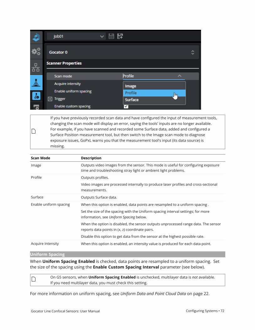
Gocator Line Confocal Sensors: User Manual Configuring Systems • 72
If you have previously recorded scan data and have configured the input of measurement tools,changing the scan mode will display an error, saying the tools' inputs are no longer available.For example, if you have scanned and recorded some Surface data, added and configured aSurface Position measurement tool, but then switch to the Image scan mode to diagnoseexposure issues, GoPxL warns you that the measurement tool's input (its data source) ismissing.
Scan Mode Description
Image Outputs video images from the sensor. This mode is useful for configuring exposuretime and troubleshooting stray light or ambient light problems.
Profile Outputs profiles.
Video images are processed internally to produce laser profiles and cross-sectionalmeasurements.
Surface Outputs Surface data.
Enable uniform spacing When this option is enabled, data points are resampled to a uniform spacing .
Set the size of the spacing with the Uniform spacing interval settings; for moreinformation, see Uniform Spacing below.
When the option is disabled, the sensor outputs unprocessed range data. The sensorreports data points in (x, z) coordinate pairs.
Disable this option to get data from the sensor at the highest possible rate.
Acquire Intensity When this option is enabled, an intensity value is produced for each data point.
Uniform Spacing
When Uniform Spacing Enabled is checked, data points are resampled to a uniform spacing. Setthe size of the spacing using the Enable Custom Spacing Interval parameter (see below).
On G5 sensors, when Uniform Spacing Enabled is unchecked, multilayer data is not available.If you need multilayer data, you must check this setting.
For more information on uniform spacing, see Uniform Data and Point Cloud Data on page 22.

Gocator Line Confocal Sensors: User Manual Configuring Systems • 73
When the option is disabled, the sensor outputs unprocessed data. The sensor reports data points in(x, z) coordinate pairs.
Disable this option to get data from the sensor at the highest possible rate.
The spacing interval is the user-configured spacing between data points in resampled data. A largerinterval also reduces the data output rate.
You can set the spacing interval to a custom value if you check Enable Custom Spacing Intervaland set the value.
Surface Generation
The sensor can generate surfaces of a user-configurable fixed length by combining a series ofprofiles gathered along the direction of travel. For more information, see Fixed Length below.
Fixed Length
The sensor generates surfaces of a user-configurable fixed length. You must set the length and thestart trigger the sensor uses to produce Surface data.

Gocator Line Confocal Sensors: User Manual Configuring Systems • 74
When you set the Surface generation type to Fixed Length, the sensor generates surfaces of a user-configurable fixed length. Like the Profile Part Detection tool, Fixed Length mode is used whenmaterial or parts continuously pass under the sensor, typically on a conveyor. Unlike the tool-basedmethod, parts and material do not have distinguishable start and stop edge.
For correct length measurement, you should ensure that motion is calibrated (that is, you have setthe encoder resolution for encoder triggers or travel speed for time triggers, in System page> Alignment panel.
To use this method of surface generation, under Acquire > Scanners, be sure to select Surfacemode and configure the following parameters.
Start Trigger
The following types of start triggers are available:
o Sequential: Continuously generates back-to-back fixed length surfaces.
o External Input: A pulse on the digital input triggers the generation of a single surface of fixedlength.
o Software Trigger: Allows starting fixed length surfaces on command from PLC or PC.
Length
The fixed length of surface to generate.

Gocator Line Confocal Sensors: User Manual Configuring Systems • 75
For more information on connecting external input to a sensor, see Digital Input on page 557.
Triggers
A trigger is an event that causes a sensor to take a single image. You configure triggers on theAcquire > Scanners page.
When a trigger is processed, the sensor's laser or LED light strobes and the camera exposes toproduce an image. The resulting image is processed inside the sensor to yield scan data. The datacan then be used for measurement.
The sensor can be triggered by one of the sources described below.

Gocator Line Confocal Sensors: User Manual Configuring Systems • 76
Trigger Source Description
Time Sensors have an internal clock that can be used to generate fixed-frequency triggers. The external
input can be used to enable or disable the time triggers.
Trigger source descriptions

Gocator Line Confocal Sensors: User Manual Configuring Systems • 77
Trigger Source Description
Encoder An encoder can be connected to provide triggers in response to motion. Three encoder triggering
behaviors are supported. These behaviors are set using the Behavior setting.
Track Backward
A scan is triggered when the target object moves forward. If the target object moves backward, it
must move forward by at least the distance that the target travelled backward (this distance
backward is "tracked"), plus one encoder spacing, to trigger the next scan.
Ignore Backward
A scan is triggered only when the target object moves forward. If the target object moves
backward, it must move forward by at least the distance of one encoder spacing to trigger the next
scan.
Bi-directional
A scan is triggered when the target object moves forward or backward.

Gocator Line Confocal Sensors: User Manual Configuring Systems • 78
Trigger Source Description
When triggers are received at a frequency higher than the maximum frame rate, some triggers
may not be accepted. Use the Trigger Drops indicator in the Health panel on the Reports page to
check for this condition; for more information, see Reporting on page 486.
The external input can be used to enable or disable the encoder triggers.
For information on the maximum encoder rate, see Maximum Encoder Rate on page 80.
To verify that the sensor is receiving encoder signals, check whether the
Encoder Value indicator is changing in the Health panel on the Reports page
(for more information, see Reporting on page 486).
External Input A digital input can provide triggers in response to external events (for example, a photocell). The
external input triggers on the rising edge of the signal.
When triggers are received at a frequency higher than the maximum frame rate, some triggers
may not be accepted. Use the Trigger Drops indicator in the Health panel on the Reports page to
check for this condition; for more information, see Reporting on page 486.
Software A network command can be used to send a software trigger. For more information, Protocols on
page 532.
Depending on the setup and measurement tools used, the CPU utilization may exceed 100%, whichreduces the overall acquisition speed.
Trigger Settings
After you choose the trigger source, the Trigger section on the Scanners panel shows theparameters that can be configured.
Parameter Trigger Source Description
Source All Selects the trigger source (Time, Encoder, External Input, orSoftware).
Max Frame Rate Time When this is enabled, the frame rate locks to the maximumframe rate.
Frame Rate Time Controls the frame rate. Fractional values are supported. Forexample, 0.1 can be entered to run at 1 frame every 10

Gocator Line Confocal Sensors: User Manual Configuring Systems • 79
Parameter Trigger Source Description
seconds.
Behavior Encoder Specifies how the sensor is triggered when the target moves.Can be Track Backward, Ignore Backward, or Bi-Directional. Formore information, see Encoder in Trigger source descriptions onpage 76.
Spacing Encoder, External Input Specifies the distance between triggers. Internally the sensorrounds the spacing to a multiple of the encoder resolution.
Reversal Distance Encoder When encoder triggering is set to Bi-Directional, use thissetting to ignore jitter or vibrations in your transport system byspecifying what distance the target must travel before adirection change is triggered. One of the following:
Auto: The distance is automatically set by multiplying the valuein Spacing by 3.
Custom: Set the distance (in millimeters). Various functions inthe sensor depend on this value to explicitly determine thepoint where direction change is triggered. Set this value largerthan the maximum vibrations you see in your transport system.
Auto Reversal Distance Encoder When encoder triggering is set to Bi-Directional, the sensorignores jitter or vibrations in the transport system.
When Auto Reversal Distance is enabled y the distance isautomatically set by multiplying the value in Spacing by 3.
When Auto Reversal Distance is disabled, set the desiredvalue in Reversal Distance in millimeters. Various functions inthe sensor depend on this value to explicitly determine thepoint where direction change is triggered. Set this value largerthan the maximum vibrations you see in your transport system.
Reversal Distance Encoder The custom value to use when Auto Reversal Distance isdisabled.
Units External Input, Software Specifies whether the trigger delay, output delay, and outputscheduled command operate in the time or the encoderdomain.
The unit is implicitly set to microseconds with Time triggersource. The unit is implicitly set to millimeters with Encodertrigger source.
Trigger Delay External Input Controls the amount of time or the distance the sensor waitsbefore producing a frame after the external input is activated.This is used to compensate for the positional differencebetween the source of the external input trigger (e.g.,photocells) and the sensor.
Maximum Input Trigger Rate
The maximum external input trigger rate in a system including Master 400 or higher is 20 kHz.

Gocator Line Confocal Sensors: User Manual Configuring Systems • 80
When using a standalone sensor or a sensor connected to a Master 100, the maximum trigger rate is32 kHz. This rate is limited by the fall time of the signal, which depends on the Vin and duty cycles. Toachieve the maximum trigger rate, the Vin and duty cycles must be adjusted as follows:
Maximum Speed Vin Maximum Duty Cycle
32 kHz 3.3 V 88%
32 kHz 5 V 56%
32 kHz 7 V 44%
32 kHz 10 V 34%
At 50% duty cycle, the maximum trigger rates are as follows:
Vin Maximum Speed
3.3 V 34 kHz
5 V 34 kHz
10 V 22 kHz
Maximum Encoder Rate
On a standalone sensor, with the encoder directly wired into the I/O port or through a Master 100,the maximum encoder rate is about 1 MHz.
For sensors connected through a Master 400 or higher, with the encoder signal supplied to theMaster, the maximum rate is about 300 kHz.
Layer and Advanced Settings
You configure layers in the Scanners page in the Acquire category.

Gocator Line Confocal Sensors: User Manual Configuring Systems • 81
The following parameters are available. Note that Enable per layer intensity is in the Advancedexpandable section.
Name Description
Layer Count Determines the maximum number of layers the sensor should detect. For eachlayer, a layerSpecificParams{n} section is displayed. For information on theparameter-specific parameters, see Layer-specific parameters below.
Layer Sorting Order The order in which layer profiles are sorted in the output. One of the following:
l By Intensity (highest intensity first), then top to bottoml Top to Bottoml Bottom to Top
Enable per layer intensity When enabled, lets you set the intensity output for each layer independently (seebelow). Enabling this parameter negatively affects performance. This setting is inthe Advanced expandable section.
Parameters
Name Description
Effective Refractive Index The effective refractive index of the material.
Intensity Filter Type The intensity filter type. One of the following:
l Average Intensityl Signal Detection
When Enable per layer intensity is disabled in the Advanced section, onlyaverage intensity is supported and this filter is applied on all layers.
Min Thickness
Max Thickness
The minimum and maximum thickness for the layer.
Layer-specific parameters

Gocator Line Confocal Sensors: User Manual Configuring Systems • 82
Configuring Sensor AcquisitionYou configure settings specific to individual sensors on the Acquire > Sensors page. The settings inthe Sensors page include active area, exposure, sub-sampling, and various advanced settings.
When configuring sensor-specific settings, make sure to select the correct sensor in the drop-downat the top of the Sensors page.
The sensor-specific settings are described in the following sections. For information on scanner-specific settings, which you configure in the Scanners page, see Configuring Scanner Acquisition onpage 71.
Active Area 82
Exposure and Light Intensity 84
Spot and Camera Settings 85
Active Area
Active area refers to the region within the sensor's maximum field of view that is used for dataacquisition.
By default, the active area covers the sensor's entire field of view. By reducing the active area, thesensor can operate at higher speeds. You can also reduce the active area to exclude areas that areaffected by ambient light.

Gocator Line Confocal Sensors: User Manual Configuring Systems • 83
Active area in an unaligned G5 sensor's scan area, set to smaller than the maximum andshifted upward.

Gocator Line Confocal Sensors: User Manual Configuring Systems • 84
You set the active area in the Sensors page in the Acquire category.
Name Description
X field of view The width of the active area along the X axis. This sets the effective field of view ofthe sensor.
Measurement range The height of the active area along the Z axis. This sets the effective measurementrange of the sensor.
X start The X position in the entire sensor field of view of the lower left corner of the activearea.
Z start The Z position in the sensor entire field of view of the lower left corner of the activearea.
Active area parameters
Exposure and Light Intensity
Exposure determines the duration of camera and light-source on-time. Longer exposures can behelpful to detect light on dark or distant surfaces, but increasing exposure time decreases themaximum speed. G5 sensors only support single exposure.
To properly set exposure, you can acquire scan data in Image mode, and examine the resultingimage use the
Additionally, G5 sensors let you set the LED light power (Light intensity setting).

Gocator Line Confocal Sensors: User Manual Configuring Systems • 85
Exposure Mode Description
Single Uses a single exposure duration for each frame.
Spot and Camera Settings
Various settings in the Acquire > Sensors page let you configure spot detection (which determineshow the sensor handles different material characteristics) and camera gain.
Data acquisition can be configured to suit different types of target materials. This helps maximize thenumber of useful profile points produced. For many targets, changing the setting is not necessary,but it can make a great difference with others.
You can select preset material types in theMaterial Type setting. The Diffusematerial option issuitable for most materials.
WhenMaterials is set to Custom, you can modify the spot detection and set digital camera gain.
Setting Description
Edge window The gradient filter size (px).
Average window The moving average filter size (px).
Intensity window The window size for spot intensity calculation (px).
Spot Threshold
Camera gain and spot settings

Gocator Line Confocal Sensors: User Manual Configuring Systems • 86
Setting Description
Camera Gain Digital camera gain can be used when the application is severely exposure limited, yetdynamic range is not a critical factor.

Gocator Line Confocal Sensors: User Manual Configuring Systems • 87
Configuring Inspection and Processing ToolsYou add and configure measurement and processing tools on the Tools page, in the Inspectcategory.
Element Description
1 Tool list Lists all of the available tools. To add a tool, double-click it or drag and drop it inthe Tools Diagram panel to the right of the list.
You can filter tools using the filter at the top of the Tool list.
You can also search for tools by typing in the search field. Tools are listed as youtype.

Gocator Line Confocal Sensors: User Manual Configuring Systems • 88
Element Description
2 Tools Diagram Lists the tools that you have added. The Tools Diagram lets you better visualizethe workflow in complex tools chains. For more information, seeWorking withTool Chains on page 92.
3 Tool configuration You configure a tool using the Inputs, Parameters, and Outputs sections inthis area.
You can select which tool you want to configure from the tool selector drop-down, in addition to selecting the tool in the Tools Diagram.
For information on parameters common to most tools, see Tool Configurationon page 104.
For information on the different types of tools, see their topics in the followingsections.
Profile tools: See Profile Measurement on page 121.
Surface tools: See Surface Measurement on page 226.
Array tools: See Array Tools on page 474.
4 Data viewer When configuring tools, you can graphically configure regions of interest.
The data viewer's toolbar lets you change the display mode (for moreinformation, see Data Viewer on page 30) and split a data viewer or pop out adata viewer in a new browser window.

Gocator Line Confocal Sensors: User Manual Configuring Systems • 89
Adding a ToolYou can add a tool from the tool list, by dragging and dropping it to a position in the Tools Diagram.
You can also click a tool's Add tool button ( ) to add a tool. In this case, the new tool is added afterthe currently selected tool in the Tools Diagram.

Gocator Line Confocal Sensors: User Manual Configuring Systems • 90
GoPxL will add the tool after the Surface Filter tool, which is currently selected. You can also drag and drop a tool to add it toa specific position in the Tools Diagram.
For information on other operations you can perform in the Tools Diagram, seeWorking with ToolChains on page 92.
Removing a ToolIf you no longer need a tool, you can remove it in the Tools Diagram. Removing an unused tool canincrease performance, as it is no longer takes up processing time.
To remove a tool, select it in the Tools Diagram and press Delete on your keyboard. You can alsoopen the tool's drop-down menu and choose Delete.

Gocator Line Confocal Sensors: User Manual Configuring Systems • 91
For information on other operations you can perform in the Tools Diagram, seeWorking with ToolChains on the next page.
Duplicating a ToolYou can quickly create a copy of a tool you have previously added in GoPxL in the Tools Diagrampanel. Tool inputs and parameter settings of the original are copied, but outputs are not. This isuseful, for example, when you need almost identical tools with only minor variations, such asdifferent maximum and minimum decision values, regions of interest shifted from one componentto another.
For information on other operations you can perform in the Tools Diagram, seeWorking with ToolChains on the next page.
In the Tools Diagram panel, you duplicate a tool using the Action menu of an individual tool.

Gocator Line Confocal Sensors: User Manual Configuring Systems • 92
Renaming a ToolIn the Tools Diagram panel, you rename a tool using the action menu of an individual tool.
For information on other operations you can perform in the Tools Diagram, seeWorking with ToolChains below.
To rename a tool in the Tools Diagram panel
1. Click the action menu icon ( ).
A context menu containing various actions appears.
2. In the context menu, choose Rename.
3. In the tool name field, rename to the tool.
4. Press Enter on the keyboard or click the check icon (see above).
Working with Tool ChainsThe Tools Diagram panel provides a visual representation of the data flow in a system (the outputfrom a scanner, and the input and output of tools). It lets you create and view complex tool chainswith drag-and-drop and other mouse operations, letting you quickly and easily implement andmaintain applications requiring multiple, interconnected tools.
All data types (if available) and their relationships between tools are displayed:
l Profile data (either directly from a scanner’s output or from tool output)l Surface data (either directly from a scanner’s output or from tool output)l Measurements (for use as anchors)

Gocator Line Confocal Sensors: User Manual Configuring Systems • 93
l Geometric featuresl Tool data (some data outputs are intended to be consumed only by SDK applications and can’t beused as part of a tool chain)
For details on how the Tools Diagram panel displays information, see Understanding the Data Flow inTool Chains on page 98.
For details on how to connect and disconnect, seeWorking with Tool Chains on the previous page andWorking with Tool Chains on the previous page.
The Tools Diagram panel is open by default. The inputs, parameters, and outputs of the tool selectedin the Tools Diagram panel are displayed to the right of the Tools Diagram panel.

Gocator Line Confocal Sensors: User Manual Configuring Systems • 94
The following illustrates the main aspects of the Tools Diagram panel.
At the top of a tool, an action menu provides functions to rename, duplicate, and delete the currenttool. For more information, see the topics below.

Gocator Line Confocal Sensors: User Manual Configuring Systems • 95
Action menu (collapsed tool)
Changing Tool Display Options
The buttons at the top of the Tools Diagram panel let you control how the panel displays scanners,tools, and the data flow (tool chain). Buttons at the top of individual tools let you organize the toolsin the list, as well as name, duplicate, and delete them.
The following describes the toolbar's functions:
1. Open All: Expands scanner and all tools in the Tools Diagram panel, displaying a list of availableinputs and enabled outputs for each one.
2. Close All: Collapses all items in the Tools Diagram panel.3. Compact View: Hides the list of small input and output icons that indicate the types of the inputs
and outputs the sensor or a tool has.

Gocator Line Confocal Sensors: User Manual Configuring Systems • 96
4. Standard View: Shows small icons that indicate the types of the inputs and outputs the scanneror a tool has. For a list of inputs and outputs, see Data Types on the next page.
Reordering Tools
You can reorder tools in the Tools Diagram to organize them more logically or to better representthe data flow. For example, you could group tools that output geometric features with the tools thatuse them, or group tools you use as anchors with the tools that use those anchors.
Note that the order of tools in the Tools Diagram panel does not affect the flow. Also, note that toolsare added after the currently selected tool in the tool list.

Gocator Line Confocal Sensors: User Manual Configuring Systems • 97
You can reorder tools you have added by dragging and dropping them to the position you want inthe list of tools, or by using the up and down arrows.
Moving the Surface Filter tool to the top of the tool chain.
If you hover the mouse pointer over a tool in the Tools Diagram panel, you can use the up / downbuttons next to the action menu to move the tool up or down in the panel.
Data Types
GoPxL represents the data types of inputs and outputs in the Tools Diagram panel with an icon.
Icon DescriptionSurface data

Gocator Line Confocal Sensors: User Manual Configuring Systems • 98
Profile data
Measurement
Geometric feature
Tool data
Understanding the Data Flow in Tool Chains
The rectangular elements displayed in the Tools Diagram represent a scanner at the top and anytools you have added below that. Scanners display output connection nodes, whereas tools displayboth input and output connection nodes.

Gocator Line Confocal Sensors: User Manual Configuring Systems • 99
The appearance of nodes changes depending on whether they are connected and whether they areselected. Connections that are used are filled. Connections that are not used are empty. When asensor or tool is expanded, you can see which specific inputs or outputs are used and part of thetool chain. For example, in the expanded Surface Hole tool below, we can see that the first threeinputs (Surface Input and the X and Y anchors, receiving their input from the scanner at the top andfrom Feature Intersect, respectively) and the Center output are involved in the chain of sensor andtools.

Gocator Line Confocal Sensors: User Manual Configuring Systems • 100
When a tool is collapsed, however, you only know that at least one input or output is used (or noneat all). For example, looking at the collapsed Feature Dimension tool at the bottom, we know that atleast one input (the connection node at the top) is used, and that none of the tool’s outputs are used.Also, we know that inputs and outputs of the three collapsed tools at the top are used, but notexactly which ones.
In both cases (collapsed or not), the data flow of the selected item is indicated by dark blueconnection lines. For more information, see below.
By default, sensors and tools are collapsed, but you can expand them individually by clicking theexpand / collapse button at the top right of a tool to display the complete list of available inputs andoutputs. Note that for an output to be listed in the Outputs section, it must be enabled in the tool’sconfiguration: in the tool’s Output list, only enabled outputs are listed.
To see a complete list of an expanded tool’s outputs (as opposed to only the enabled ones), at the topof the tool's Output section, click the menu button ( ). A pop-up list of all available outputs displays,indicating the enabled outputs with a checkmark.

Gocator Line Confocal Sensors: User Manual Configuring Systems • 101
When a tool is collapsed, you can “peek” the available inputs or the enabled outputs by clicking oneof the horizontal lists of small icons (Standard view only).

Gocator Line Confocal Sensors: User Manual Configuring Systems • 102
If you hover the mouse pointer over a blue connected node, a part of the blue connection line ishighlighted to indicate what it is connected to. In the image below, you can see that by hovering overan output (the Y measurement of the Feature Intersect tool at the top) is used as an input (the Yanchor) of the Surface Circular Edge at the bottom.

Gocator Line Confocal Sensors: User Manual Configuring Systems • 103
If a tool's input is missing, that input is displayed in red in the Tools Diagram panel to show that youmust connect it to something. You can also consult the Problems tab in the System Messages panelat the bottom of the interface to see which tools are missing inputs.
Collapsed tool with a missing input
Expanded tool with a missing input

Gocator Line Confocal Sensors: User Manual Configuring Systems • 104
Tool ConfigurationYou configure a tool's inputs, parameters, and outputs in the tool configuration area to the right ofthe Tools Diagram.
Element Description
1 Tools Diagram Lists the tools that you have added. The Tools Diagram lets you better visualizethe workflow in complex tools chains. For more information, seeWorking withTool Chains on page 92.
2 Tool configuration You configure a tool using the Inputs, Parameters, and Outputs sections in thisarea.
You can select which tool you want to configure from the tool selector drop-down, in addition to selecting the tool in the Tools Diagram.

Gocator Line Confocal Sensors: User Manual Configuring Systems • 105
Element Description
The following sections describe the parameters common to most tools.
Regions 105
Standard Regions 106
Flexible Regions 106
Working with Circular and Elliptical Regions 110
Feature Points 112
Geometric Features 115
Fit Lines 115
Decisions 115
Measurement Anchoring 116
Enabling and Disabling Outputs 119
Regions
Many tools let you disable regions entirely and force the measurement tool to use the entireactive area.
Some tools provide "flexible" regions, which in addition to rectangular regions let you create circularand elliptical regions (which can optionally be annular), and in some tools, polygon regions. Sometools also let you use Surface and Surface Intensity data as masks. For information on settingflexible regions, see Flexible Regions on the next page.
Other tools are currently limited to standard, rectangular regions. However, you can get "flexibleregions" in a tool that doesn't directly support them by adding and configuring a Surface Mask tool,and using that tool's output as the other tool's input. (For information on masks, see Surface Mask onpage 335.)
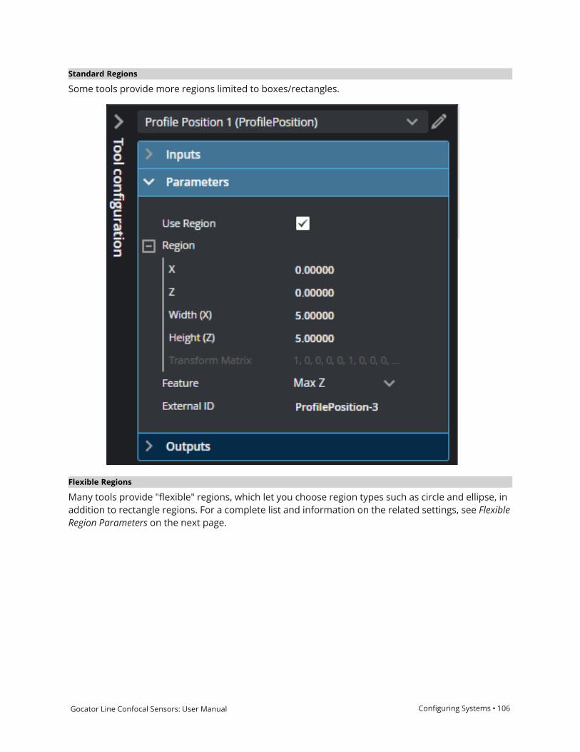
Gocator Line Confocal Sensors: User Manual Configuring Systems • 106
Standard Regions
Some tools provide more regions limited to boxes/rectangles.
Flexible Regions
Many tools provide "flexible" regions, which let you choose region types such as circle and ellipse, inaddition to rectangle regions. For a complete list and information on the related settings, see FlexibleRegion Parameters on the next page.

Gocator Line Confocal Sensors: User Manual Configuring Systems • 107
The following parameters are available in tools that support flexible regions.
Parameter Description
Mask Mode One of the following:
Include Data in Region: The tool uses only the data inside the region or regions.
Exclude Data in Region: The tool ignores the data inside the region or regions,using only the data outside.
Number of Regions The number of regions or masks the tool uses to extract surface data. You candefine up to 15 or 16 regions. This parameter is not available in some tools.
When you specify more than one region, the regions are initially stacked on top ofone another, in the same location.
Region Type {n} The type of each region. Regions can overlap.
(For more information on the settings you use with the Circle and Ellipse types, seeWorking with Circular and Elliptical Regions on page 110.)
One of the following:
Rectangle
Extracts a rectangular region from the surface data.
Flexible Region Parameters

Gocator Line Confocal Sensors: User Manual Configuring Systems • 108
Parameter Description
Circle
Extracts a circular region from the surface data, constrained by a square region.
Set the region's inner circle using the Inner Diameter parameter to extractannular data.
Use the Sector Start Angle and Sector Angle Range parameters to extract apartial circular or elliptical region.

Gocator Line Confocal Sensors: User Manual Configuring Systems • 109
Parameter Description
Ellipse
Extracts an elliptical region from the surface data, constrained by a square orrectangular region.
Set the region's inner ellipse (inner cyan ellipse below) using the Inner Major Axisand Inner Minor Axis parameters to extract annular data.
Use the Sector Start Angle and Sector Angle Range settings to extract a partialcircular or elliptical region.
Surface

Gocator Line Confocal Sensors: User Manual Configuring Systems • 110
Parameter Description
Uses the Surface data you select inMask Source {n}, in the Inputs panel, tocreate a mask.
Surface Intensity
Uses the intensity data you select inMask Source {n}, in the Inputs panel, tocreate a mask.
Set the Low Threshold and High Threshold parameters as required.
X, Y, Z
Width (X), Length (Y),Height (Z)
Z Angle
These parameters define the size, location, and orientation of the region. Notavailable when Region Type {n} is set to Surface or Surface Intensity.
The Z Angle parameter
Inner Diameter Only available when Region Type {n} is set to Circle.
Defines the diameter of the inner circle.
Set this parameter to a value greater than 0 to extract a ring of data. Set thisparameter to 0 to extract a circle of data.
Inner Major Axis
Inner Minor Axis
Only available when Region Type {n} is set to Ellipse.
These parameters define the major and minor axes of the inner ellipse,respectively
Set this parameter to a value greater than 0 to extract a ring of data. Set thisparameter to 0 to extract an elliptical disk of data.
Sector Start Angle
Sector Angle Range
Only available when Region Type {n} is set to Circle or Ellipse
Use these parameters together to extract a partial ring of data. Sector Start Anglecontrols the starting angle of the data, whereas Sector Angle Range controls thelength of the arc.
Note that the angles and ranges in these parameters are measured clockwisearound Z, where 0 degrees is along the positive X axis.
For more information on how these settings work together, seeWorking withCircular and Elliptical Regions below.
High Threshold
Low Threshold
The high and low thresholds the tool uses in combination with the intensity mask.
Only available when Region Type {n} is set to Surface Intensity.
Working with Circular and Elliptical Regions
When you set a region's type to Circle or Ellipse, the tool displays several additional settings thatwork together to define the region. Sector Start Angle and Sector Angle Range work together todefine the start and end of a partial circular/elliptical region (solid or annular). A region will beannular if Inner Circle Diameter is non-zero. Note that the "length" of the partial region extendsfrom the start angle. In the following illustration, the start angle (θ) is 135 degrees relative to the 0-degree point indicated below, and the region extends 270 degrees (δ) from that, clockwise around Z.

Gocator Line Confocal Sensors: User Manual Configuring Systems • 111
Sector Start Angle starts at the 0-degree point around Z.
Note that the angles defining a partial circular/elliptical region are relative to the region, and not thesensor's coordinate system. So a region rotated 30 degrees using its Z Angle setting rotates the startangle and angle range by 30 degrees.
When you set a region type to Ellipse, instead of the inner circle diameter, you must set the majorand minor axes of the inner ellipse.

Gocator Line Confocal Sensors: User Manual Configuring Systems • 112
Feature Points
Dimensional and positional measurements detect feature points found within the defined region(whether it's a measurement region, feature region, reference region, and so on) and then comparemeasurement values taken at the selected point with minimum and maximum thresholds toproduce a pass / fail decision. Feature points are selected in one or more Feature parameters in atool's Parameters section, and are used for all of the tool's measurements.
It is important to note that the feature points described here are distinct from the geometricfeatures generated by some tools, and which can be taken as inputs by other tools. Feature pointsare simply the location in the scan data at which a measurement tool performs a measurement. So,for example, if you set a Profile Position tool's Feature parameter to Max Z, it will return the X and Zpositions of the point that is at the highest Z value. Geometric features are a data type produced asoutput or taken as input by a tool. (For more information on geometric features, see GeometricFeatures on page 115.)
The following types of points can be identified in a measurement region. The availability of a featurepoint type is tool-dependent.
The following are represented as profiles for clarity. Many Surface tools use feature points.

Gocator Line Confocal Sensors: User Manual Configuring Systems • 113
Point Type Examples
Max Z
Finds the point with the maximum Z value in the region of interest.
Min Z
Finds the point with the minimum Z value in the region of interest.
Min X
Finds the point with the minimum X value in the region of interest.
Max X
Finds the point with the maximum X value in the region of interest.
Average
Determines the average location of points in the region of interest.
Corner
Finds a dominant corner in the region of interest, where corner is
defined as a change in profile slope.
Top Corner
Finds the top-most corner in the region of interest, where corner
is defined as a change in profile shape.

Gocator Line Confocal Sensors: User Manual Configuring Systems • 114
Point Type Examples
Bottom Corner
Finds the bottom-most corner in the region of interest, where
corner is defined as a change in profile shape.
Left Corner
Finds the left-most corner in the region of interest, where corner is
defined as a change in profile shape.
Right Corner
Finds the right-most corner in the region of interest, where corner
is defined as a change in profile shape.
Rising Edge
Finds a rising edge in the region of interest (moving from left to
right).
Falling Edge
Finds a falling edge in the region of interest (moving from left to
right).
Any Edge
Finds a rising or falling edge in the region of interest.

Gocator Line Confocal Sensors: User Manual Configuring Systems • 115
Point Type Examples
Median
Determines the median location of points in the region of interest.
Geometric Features
Most Surface tools, and many Profile tools, can output features that Feature tools can take as inputto produce measurements. These features are called geometric features. Feature tools use theseentities to produce measurements based on more complex geometry. (For more information onFeature tools, see Feature Measurement on page 440.)
The measurement tools can currently generate the following kinds of geometric features:
Points: A 2D or 3D point. Can be used for point-to-point or point-to-line measurements.
Lines: A straight line that is infinitely long. Useful for locating the orientation of an enclosure or part,or to intersect with another line to form a reference point that can be consumed by a Feature tool.
Planes: A plane extracted from a surface. Can be used for point-to-plane distance or line-planeintersection measurements.
Circles: A circle extracted from a sphere.
Fit Lines
Some measurements involve estimating lines in order to measure angles or intersection points. A fitline can be calculated using data from either one or two fit areas.
A line can be defined using one or two areas. Two areas can be used to bypass discontinuity in a linesegment.
Decisions
Results from a measurement can be compared against minimum and maximum thresholds you setin a tool's Outputs panel to generate pass / fail decisions. The decision state is pass if ameasurement value is within the minimum / maximum range; the range is inclusive. Output valuesthat pass are green in the lists of outputs. Output values that fail are red in the lists of outputs.

Gocator Line Confocal Sensors: User Manual Configuring Systems • 116
Decision maximum and minimum of Surface Position Z set in the Tool configuration panel (center). Pass values for thismeasurement displayed in green in Tools Diagram and in Displayed Outputs panels. Fail measurements are displayed in red.
Along with measurement values, decisions can be sent to external programs and devices. Inparticular, decisions are often used with digital outputs to trigger an external event in response to ameasurement. For more information on sending values and decisions as output, see ConfiguringControl on page 481.
Measurement Anchoring
When parts that a sensor is scanning move on a transport mechanism such as a conveyor, theirposition typically changes from part to part in one or both of the following ways:
l along the X, Y, and Z axesl around the Z axis (orientation angle)
When the position and angle variation between parts is minor—for example, when scanningelectronic parts in trays—you can anchor one tool to one or more measurements from another toolto compensate for these minor shifts. As a result, GoPxL can correctly place the anchored tool'smeasurement regions on each part. This increases the repeatability and accuracy of measurements.
For example, the following image shows a surface scan of a PCB. A Surface Dimension heightmeasurement returns the height of a surface-mount capacitor in the measurement region relative toa nearby reference region.

Gocator Line Confocal Sensors: User Manual Configuring Systems • 117
In the following scan, the part has shifted, but the measurement regions remain where they wereoriginally configured, in relation to the sensor or system coordinate system, so the measurementreturned is incorrect:
When you set a tool's anchor source, an offset is calculated between the anchored tool and theanchor source. This offset is used for each frame of scanned data: the anchored tool's measurementregion is placed in relation to the anchor source, at the calculated offset.

Gocator Line Confocal Sensors: User Manual Configuring Systems • 118
In the following image, after the Surface Dimension tool is anchored to the X and Y measurementsfrom a Surface Hole tool (placed over the hole to the lower left), Gocator compensates for the shift—mostly along the Y axis in this case—and returns a correct measurement, despite the shift.
You can combine the positional anchors (X, Y, or Z measurements) with an angle anchor (a Z Anglemeasurement) for optimummeasurement placement. For example, in the following scan, the parthas not only shifted on the XY plane but also rotated around the Z axis. Anchoring the SurfaceDimension tool to the Z Angle measurement of a Surface Edge tool (placed on the lower edge in thiscase) compensates for the rotation, and the anchored tool returns a correct measurement.

Gocator Line Confocal Sensors: User Manual Configuring Systems • 119
If Z Angle anchoring is used with both X and Y anchoring, the X and Y anchors should comefrom the same tool.
If Z Angle anchoring is used without X or Y anchoring, the tool's measurement region rotatesaround its center. If only one of X or Y is used, the region is rotated around its center and thenshifted by the X or Y offset.
Several anchors can be created to run in parallel. For example, you could anchor the measurementsof one tool relative to the left edge of a target, and anchor the measurements of another toolrelative to the right edge of a target.
You can combine positional anchors (X, Y, or Z) with angle anchors (Z Angle) for optimummeasurement placement.
Enabling and Disabling Outputs
All of the outputs (measurements, features, and data) available in a tool are listed in the Outputspanel in the tool's Tool configuration panel after a tool has been added. To enable an output, checkits checkbox in the tool's Outputs panel.

Gocator Line Confocal Sensors: User Manual Configuring Systems • 120
Enabling the Width measurement. Only the Height measurement is currently enabled, which is displayed in the tool's outputsection in the Tools Diagram.

Gocator Line Confocal Sensors: User Manual Configuring Systems • 121
Profile MeasurementThis section describes the profile measurement tools available in Gocator sensors.

Gocator Line Confocal Sensors: User Manual Configuring Systems • 122
Profile Area
The Area tool determines the cross-sectional area within a region.
(The following screenshot is from a G2 sensor.)
Profile Area tool with baseline set to the best-fitted line in Region 1
For information on adding, managing, and removing tools, as well as detailed descriptions of settingscommon to most tools, see Tool Configuration on page 104.
Inputs
You configure the tool's inputs in the expandable Inputs section.

Gocator Line Confocal Sensors: User Manual Configuring Systems • 123
To use a measurement as an anchor, it must be enabled and properly configured in the toolproviding the anchor. For more information on anchoring, see Measurement Anchoring onpage 116.
Name Description
Profile Input The data the tool applies measurements to or processes.
Anchor X or Anchor Z The X or Z measurement of another tool that this tool uses as a positional anchor.Positional anchors are optional.
Inputs
Parameters
You configure the tool's parameters in the expandable Parameters section.

Gocator Line Confocal Sensors: User Manual Configuring Systems • 124
Parameter Description
Type Object area type is for convex shapes above the baseline. Regions below thebaseline are ignored.
Clearance area type is for concave shapes below the baseline. Regions above thebaseline are ignored.
Baseline Baseline is the fit line that represents the line above which (Object clearance type)or below which (Clearance area type) the cross-sectional area is measured.
When this parameter is set to Line, you must define a line in the Line parameter.See Fit Lines on page 115 for more information on fit lines.
When this parameter is set to X-Axis, the baseline is set to z = 0.
Use Region When enabled, displays Region parameters (see below). When disabled, the tooluses all data.
Region The region to which the tool's measurements will apply. For more information, seeRegions on page 105.
Line When Baseline (see above) is set to Line, set this to one of the following:
1 Region or 2 Regions: Lets you set one or two regions whose data the tool willuse to fit a line.
All Data: The tool uses all of the data in the active area.
For more information on regions, see Regions on page 105).
For more information on fit lines, see Fit Lines on page 115.
External ID The external ID of the tool that appears in GoHMI Designer. For more information,see GoHMI and GoHMI Designer on page 501.
Parameters
Outputs
All tools provide measurements, geometric features, or data as outputs.

Gocator Line Confocal Sensors: User Manual Configuring Systems • 125
Outputs section with a measurement expanded to show user-configurable decision min/max fields and an external ID
You configure theMin andMax parameters by expanding the measurement in the Outputs section.In order for a measurement to return a Pass decision, the measurement must be between maximumand minimum values; the range is inclusive.
Measurement Illustration
Area
Measures the cross-sectional area within a region thatis above or below a fitted baseline.
Measurements

Gocator Line Confocal Sensors: User Manual Configuring Systems • 126
Measurement Illustration
Centroid X
Determines the X position of the centroid of the area.
Centroid Z
Determines the Z position of the centroid of the area.
Type Description
Center Point The center point of the area.
Features
For more information on geometric features, see Geometric Features on page 115.

Gocator Line Confocal Sensors: User Manual Configuring Systems • 127
Profile Bounding Box
The Bounding Box tool provides measurements related to the smallest box that contains the profile(for example, X position, Z position, width, etc.).
The bounding box provides the absolute position from which the Position centroids tools arereferenced.
(The following screenshot is from a G2 sensor.)
For information on adding, managing, and removing tools, as well as detailed descriptions of settingscommon to most tools, see Tool Configuration on page 104.
Inputs
You configure the tool's inputs in the expandable Inputs section.
To use a measurement as an anchor, it must be enabled and properly configured in the toolproviding the anchor. For more information on anchoring, see Measurement Anchoring onpage 116.

Gocator Line Confocal Sensors: User Manual Configuring Systems • 128
Name Description
Profile Input The data the tool applies measurements to or processes.
Anchor X or Anchor Z The X or Z measurement of another tool that this tool uses as a positional anchor.Positional anchors are optional.
Inputs
Parameters
You configure the tool's parameters in the expandable Parameters section.
Parameter Description
Use Region When enabled, displays Region parameters (see below). When disabled, the tooluses all data.
Region {n} The region to which the tool's measurements will apply. For more information, seeRegions on page 105.
Rotation A bounding box can be vertical or rotated. A vertical bounding box provides theabsolute position from which the part's Position centroid measurements arereferenced. When enabled, allows rotation of the bounding box.
External ID The external ID of the tool that appears in GoHMI Designer. For more information,see GoHMI and GoHMI Designer on page 501.
Parameters
Outputs
All tools provide measurements, geometric features, or data as outputs.

Gocator Line Confocal Sensors: User Manual Configuring Systems • 129
Outputs section with a measurement expanded to show user-configurable decision min/max fields and an external ID
You configure theMin andMax parameters by expanding the measurement in the Outputs section.In order for a measurement to return a Pass decision, the measurement must be between maximumand minimum values; the range is inclusive.
Measurement Illustration
X
Determines the X position of the center of thebounding box that contains the profile.
The value returned is relative to the profile.
Z
Determines the Z position of the center of thebounding box that contains the profile.
The value returned is relative to the profile.
Measurements

Gocator Line Confocal Sensors: User Manual Configuring Systems • 130
Measurement Illustration
Width
Determines the width of the bounding box thatcontains the profile. The width reports the dimensionof the box in the direction of the minor axis.
Height
Determines the height (thickness) of the bounding boxthat contains the profile.
Angle
Determines the angle of the longer side of thebounding box around the Y axis, relative to the X axis.
This measurement is only available if the Rotationparameter is enabled.
Type Description
Center Point The center point of the bounding box.
Corner Point The lower left corner of the bounding box.
Features
For more information on geometric features, see Geometric Features on page 115.

Gocator Line Confocal Sensors: User Manual Configuring Systems • 131
Profile Circle
The Circle tool provides measurements that find the best-fitted circle to a profile and measurevarious characteristics of the circle.
The tool may be unable to fit a circle to the profile when attempting the fit on a small number ofrelatively collinear data points.
(The following screenshot is from a G2 sensor.)
For information on adding, managing, and removing tools, as well as detailed descriptions of settingscommon to most tools, see Tool Configuration on page 104.
Inputs
You configure the tool's inputs in the expandable Inputs section.

Gocator Line Confocal Sensors: User Manual Configuring Systems • 132
To use a measurement as an anchor, it must be enabled and properly configured in the toolproviding the anchor. For more information on anchoring, see Measurement Anchoring onpage 116.
Name Description
Profile Input The data the tool applies measurements to or processes.
Anchor X or Anchor Z The X or Z measurement of another tool that this tool uses as a positional anchor.Positional anchors are optional.
Inputs
Parameters
You configure the tool's parameters in the expandable Parameters section.
Parameter Description
Use Region When enabled, displays Region parameters (see below). When disabled, the tooluses all data.
Parameters

Gocator Line Confocal Sensors: User Manual Configuring Systems • 133
Parameter Description
Region {n} The region to which the tool's measurements will apply. For more information, seeRegions on page 105.
External ID The external ID of the tool that appears in GoHMI Designer. For more information,see GoHMI and GoHMI Designer on page 501.
Outputs
All tools provide measurements, geometric features, or data as outputs.
Outputs section with a measurement expanded to show user-configurable decision min/max fields and an external ID
You configure theMin andMax parameters by expanding the measurement in the Outputs section.In order for a measurement to return a Pass decision, the measurement must be between maximumand minimum values; the range is inclusive.

Gocator Line Confocal Sensors: User Manual Configuring Systems • 134
Measurement Illustration
X
Finds the circle center position in the X axis.
Z
Finds the circle center position in the Z axis.
Radius
Measures the radius of the circle.
Standard Deviation
Returns the standard deviation of the data points withrespect to the fitted circle.
Min ErrorMax Error
The minimum and maximum error among the datapoints with respect to the fitted circle.
Min Error XMin Error Z
The X and Z position of the minimum error.
Max Error XMax Error Z
The X and Z position of the maximum error.
Measurements
Type Description
Center Point The center point of the fitted circle.
Features
For more information on geometric features, see Geometric Features on page 115.

Gocator Line Confocal Sensors: User Manual Configuring Systems • 135
Profile Circle Radii
The Profile Circle Radii tool lets you measure radii and diameters at specified angle steps, given aspecified center point. The tool draws rays from the center point and returns radii or diametermeasurements for each ray.
For example, in the following scan of an exhaust pipe by a four-sensor system, the tool is showing aradius measurement at 70 degrees that indicates a dent in the pipe. The tool also provides settingsto compensate for missing data and for rough surfaces or noise.
For information on adding, managing, and removing tools, as well as detailed descriptions of settingscommon to most tools, see Tool Configuration on page 104.
Inputs
You configure the tool's inputs in the expandable Inputs section.
To use a measurement as an anchor, it must be enabled and properly configured in the toolproviding the anchor. For more information on anchoring, see Measurement Anchoring onpage 116.
Name Description
Profile Input The data the tool applies measurements to or processes.
Anchor X or Anchor Z The X or Z measurement of another tool that this tool uses as a positional anchor.Positional anchors are optional.
Anchor Y Angle The Y Angle measurement of another tool to use as a rotational anchor for thistool. Rotational anchors are optional.
Center The point geometric feature coming from another tool that the Circle Radii tooluses as the center point from which rays are drawn to search for data points. Theparameter is only available when Center Selection is set to Feature Input.
Inputs

Gocator Line Confocal Sensors: User Manual Configuring Systems • 136
Parameters
You configure the tool's parameters in the expandable Parameters section.
Parameter Description
Regions When expanded, displays the region- and mask-related settings.
Enable Enables regions and displays the region- and mask-related settings (see below).
Mask Mode
Number of Regions
Region Type {n}
Region {n}
When you enable regions (see above), the tool displays additional settings relatedto the region type. For details on the regions supported by this tool and theirsettings, see Flexible Regions on page 106.
For general information on regions and the difference between standard and"flexible" regions, see Regions on page 105.
Center Selection The source for the point geometric feature the tool uses as a center point. One ofthe following:
Bounding Box – Uses the center of the bounding box that encloses the scan data.
Parameters

Gocator Line Confocal Sensors: User Manual Configuring Systems • 137
Parameter Description
If Enable is checked, the tool places a bounding box only around the data in theregion. If Enable is unchecked, the tool places a bounding box around all scandata; this will include any outliers in the bounding box, which could produce anundesired center point.
Feature Input – A point geometric feature provided by another tool, such as thecenter point from a Circle tool.
Angle Start
Angle Step
Angle Start: The angle at which ray steps start.
Angle Step: The angle step in degrees.
The following shows how these settings work together:
The tool searches for a data point at each angle step and returns the radius fromthe center point or the diameter.
Tolerance If no data point is found at the angle step, the tool searches within the specifiednumber of degrees to each side of the step to find a data point. Useful tocompensate for gaps in the data.
The graphic above shows how the tool searches to each side of the angle step untilit finds a data point (circled and in yellow).
Averaging The number of data points to each side of the point the tool uses to average. Usethis to compensate for noise or rough surfaces.

Gocator Line Confocal Sensors: User Manual Configuring Systems • 138
Parameter Description
The graphic above shows how the tool averages the data point at the angle stepwith the number of data points specified in Averaging to each side of the anglestep, replacing the original data point with the average (circled and in yellow).
Output Selects whether to output radius, diameter, or both at each step.
Selection Lets you quickly enable or disable all measurements.
External ID The external ID of the tool that appears in GoHMI Designer. For more information,see GoHMI and GoHMI Designer on page 501.
Outputs
All tools provide measurements, geometric features, or data as outputs.
Outputs section with a measurement expanded to show user-configurable decision min/max fields and an external ID
You configure theMin andMax parameters by expanding the measurement in the Outputs section.In order for a measurement to return a Pass decision, the measurement must be between maximumand minimum values; the range is inclusive.
Measurement Illustration
Radius at {angle}
Returns the radius at {angle}.
Diameter at {angle}
Returns the diameter at {angle}.
Measurements

Gocator Line Confocal Sensors: User Manual Configuring Systems • 139
Type Description
Points An array of the points at the end of the rays.
Data

Gocator Line Confocal Sensors: User Manual Configuring Systems • 140
Profile Closed Area
The Closed Area tool determines the cross-sectional area within a region using point cloud data (thatis, with Enable uniform spacing (resampling) disabled in the Acquire > Scanners page > ScanMode panel) from a dual- or multi-sensor system.
The tool is intended for use with roughly circular shaped profiles, or profiles that do not containexcessive concavity. The tool renders a polygon corresponding to the profile in the data viewer. Usethis polygon to decide whether the tool can correctly calculate an acceptable representation of theprofile. Minor gaps in the profile are permitted; the size of these gaps is configurable.
For information on adding, managing, and removing tools, as well as detailed descriptions of settingscommon to most tools, see Tool Configuration on page 104.
Inputs
You configure the tool's inputs in the expandable Inputs section.
To use a measurement as an anchor, it must be enabled and properly configured in the toolproviding the anchor. For more information on anchoring, see Measurement Anchoring onpage 116.
Name Description
Profile Input The data the tool applies measurements to or processes.
Anchor X or Anchor Z The X or Z measurement of another tool that this tool uses as a positional anchor.Positional anchors are optional.
Inputs
Parameters
You configure the tool's parameters in the expandable Parameters section.

Gocator Line Confocal Sensors: User Manual Configuring Systems • 141
Parameter Description
Use Region Indicates whether the tool uses a user-defined region.
If this option is not checked, the tool uses data from the entire active area.
Region The region to which the tool's measurements will apply. For more information, seeRegions on page 105.
Center Selection The origin of the rays used to create the polygon (which in turn is used to calculatethe area). One of the following:
Bounding Box (default)
Sets the center to the center of a bounding box that contains the tool data or thedata in the region.
Feature Input
Lets you set the center to a point geometric feature output from another tool.When you choose this option, a Center dropdown lets you choose the centerpoint. For more information on geometric features, see Geometric Features onpage 115.
Use Max Gap Indicates whether the tool uses theMax Gap setting (see below).
Max Gap The maximum gap allowed between any two profile points on the contour of thetarget, in millimeters. In the following illustration of a profile, if the gap weregreater than the value set inMax Gap, the tool would return an invalid value.
Parameters

Gocator Line Confocal Sensors: User Manual Configuring Systems • 142
Parameter Description
Sample Spacing The angle interval around the center of the profile the tool uses to calculate area.Enabling this setting and setting a value can increase the tool's performance.
In the following image, the spacing is set to 1 degree. The polygon calculated fromthe profile points, which is then used to calculate the area, is simplified, increasingperformance but reducing accuracy.
In the following image, Sampling Spacing is set to 0. Accuracy is increased, butperformance is reduced.

Gocator Line Confocal Sensors: User Manual Configuring Systems • 143
Parameter Description
If you set the value to 0, the tool uses the smallest angle permitted internally bythe sampling engine.
External ID The external ID of the tool that appears in GoHMI Designer. For more information,see GoHMI and GoHMI Designer on page 501.
Outputs
All tools provide measurements, geometric features, or data as outputs.
Outputs section with a measurement expanded to show user-configurable decision min/max fields and an external ID

Gocator Line Confocal Sensors: User Manual Configuring Systems • 144
You configure theMin andMax parameters by expanding the measurement in the Outputs section.In order for a measurement to return a Pass decision, the measurement must be between maximumand minimum values; the range is inclusive.
Measurement Illustration
Area
Measures the cross-sectional area within a regionusing data from a dual- or multi-sensor system.
Measurements

Gocator Line Confocal Sensors: User Manual Configuring Systems • 145
Profile Dimension
The Dimension tool provides Width, Height, Distance, Center X, and Center Z measurements.
(The following screenshot is from a G2 sensor.)
For information on adding, managing, and removing tools, as well as detailed descriptions of settingscommon to most tools, see Tool Configuration on page 104.
Inputs
You configure the tool's inputs in the expandable Inputs section.

Gocator Line Confocal Sensors: User Manual Configuring Systems • 146
To use a measurement as an anchor, it must be enabled and properly configured in the toolproviding the anchor. For more information on anchoring, see Measurement Anchoring onpage 116.
Name Description
Profile Input The data the tool applies measurements to or processes.
Anchor X or Anchor Z The X or Z measurement of another tool that this tool uses as a positional anchor.Positional anchors are optional.
Inputs
Parameters
You configure the tool's parameters in the expandable Parameters section.
Parameter Description
Feature {n} The Feature 1 and Feature 2 settings represent the two features the tool uses toperform measurements. For each, one of the following:
l Max Zl Min Zl Max Xl Min Xl Cornerl Averagel Rising Edgel Falling Edge
Parameters

Gocator Line Confocal Sensors: User Manual Configuring Systems • 147
Parameter Description
l Any Edgel Top Cornerl Bottom Cornerl Left Cornerl Right Cornerl Median
For more information on feature points, see Feature Points on page 112.
Use Region {n} When enabled, displays Region parameters (see below). When disabled, the tooluses all data.
Region {n} The region to which the tool's measurements will apply. For more information, seeRegions on page 105.
Absolute Width
Absolute Height
(Width and Heightmeasurements only)
Determines if the result will be expressed as an absolute or a signed value.
External ID The external ID of the tool that appears in GoHMI Designer. For more information,see GoHMI and GoHMI Designer on page 501.
Outputs
All tools provide measurements, geometric features, or data as outputs.
Outputs section with a measurement expanded to show user-configurable decision min/max fields and an external ID

Gocator Line Confocal Sensors: User Manual Configuring Systems • 148
You configure theMin andMax parameters by expanding the measurement in the Outputs section.In order for a measurement to return a Pass decision, the measurement must be between maximumand minimum values; the range is inclusive.
Measurement Illustration
Width
Determines the difference along the X axis betweentwo feature points.
The difference can be calculated as an absolute orsigned result. The difference is calculated by:
Width = Feature 2X position – Feature 1X position
Height
Determines the difference along the Z axis betweentwo feature points.
The difference can be expressed as an absolute orsigned result. The difference is calculated by:
Height = Feature 2Z position – Feature 1Z position
Distance
Determines the direct, Euclidean distance betweentwo feature points.
Center X
Finds the average location of two features andmeasures the X axis position of the average location
Center Z
Finds the average location of two features andmeasures the Z axis position of the average location.
Measurements

Gocator Line Confocal Sensors: User Manual Configuring Systems • 149
Profile Edge
The Profile Edge tool finds an edge on a profile, searching from left to right. The tool's settings helpfit the edge point when multiple potential edges are in the region of interest. You can configure thetool to locate steps or corners (that is, for cases where there is no clear step in the profile but insteada smooth slope), as well as rising or falling steps.
(The following screenshot is from a G2 sensor.)
X position of the center of a step
After the tool locates an edge, it returns the position (X and Z) of the edge. For steps, it also returnsthe step height.
The tool can also generate a point geometric feature corresponding to the center of the step thatFeature tools can take as input for measurement. For more information on Feature tools, see FeatureMeasurement on page 440.
For information on adding, managing, and removing tools, as well as detailed descriptions of settingscommon to most tools, see Tool Configuration on page 104.
Inputs
You configure the tool's inputs in the expandable Inputs section.

Gocator Line Confocal Sensors: User Manual Configuring Systems • 150
To use a measurement as an anchor, it must be enabled and properly configured in the toolproviding the anchor. For more information on anchoring, see Measurement Anchoring onpage 116.
Name Description
Profile Input The data the tool applies measurements to or processes.
Anchor X or Anchor Z The X or Z measurement of another tool that this tool uses as a positional anchor.Positional anchors are optional.
Inputs
Parameters
You configure the tool's parameters in the expandable Parameters section.

Gocator Line Confocal Sensors: User Manual Configuring Systems • 151
Parameter Description
Use Region When enabled, displays Region parameters (see below). When disabled, the tooluses all data.
Region The region to which the tool's measurements will apply. For more information, seeRegions on page 105.
Edge Detection Mode One of the following: Step or Corner.
Step: Searches for steps on each path profile.
Corner: Searches for slopes on each path profile. When you choose this mode,several of the tool's parameters are hidden.
Selection Type Determines which step the tool uses when there are multiple steps in the profile.An edge point is placed the chosen step. Steps must satisfy the tool's StepThreshold and Step Direction settings.
Best: Selects the greatest step on the profile.
First: Selects the first step on the profile.
Last: Selects the last step on the profile.
Step Direction Determines whether the expected step rises or falls, moving left to right, along theprofile. Either Rising, Falling, or Rising or Falling.
Parameters

Gocator Line Confocal Sensors: User Manual Configuring Systems • 152
Parameter Description
Step Threshold The minimum step accepted as an edge candidate. Steps on the profile are treatedas absolute values when compared to this setting.
In the following profile, with Step Threshold set to 1.7 (and Selection Type set toLast, which means the rightmost step will be selected), the tool accepts the step tothe right, with a step of -1.873 mm, because it is above the step threshold.
(The following screenshots are from a G2 sensor.)
In the following, when Step Threshold is increased to 1.9, the tool excludes thefalling step to the right, because it is no longer above the step threshold, andinstead uses the step to the left.
Step Smoothing The size of the (moving) window along the profile used to calculate an average foreach data point on the profile. The setting is useful for averaging out noise.
If Step Smoothing is set to 0, no averaging is performed.
Step Width The distance, along a path profile, separating the points the tool uses to find stepson a profile.
In the following, a step width of 5.5 mm causes the tool to consider profile pointsthat distance apart as steps. Consequently, the curved portion of the profile is not

Gocator Line Confocal Sensors: User Manual Configuring Systems • 153
Parameter Description
used to measure the step.
(The following screenshot is from a G2 sensor.)
The setting is useful when you must detect a slope as an edge, rather than asharply defined edge: setting Step Width to a value greater than the width of theedge ensures that the tool measures the height difference between the flatregions on either side of the edge. As a result, the height of the step is accuratelymeasured, and the edge is correctly located.
Setting Step Width wider than necessary can reduce the accuracyof edge location.
Max Gap Fills in regions of missing data caused by an occlusion near the desired edge. Usethis setting when continuity on the target is expected. WhenMax Gap is set to anon-zero value, the tool holds and extends the last data point on the low side nextto an edge across a gap of null points, up to the distance specified inMax Gap.

Gocator Line Confocal Sensors: User Manual Configuring Systems • 154
Parameter Description
The tool uses data points "filled in" byMax Gap before data points filled in by NullFill Value (see below).
Include Null Edges Indicates whether null points (points where no height value is available, due todropouts or regions outside of the measurement range) are filled with the value inNull Fill Value as a general “background level.”
To find an edges next null points, you must use either this optionand an appropriate value in Null Fill Value orMax Gap.Otherwise, only edges within areas of contiguous data will bedetected.
Null Fill Value The height value (in mm) used to replace null points when Include Null Edges isenabled.
If both Null Fill Value andMax Gap fill in null points at the same position, the tooluses the value extended byMax Gap, regardless of the value of Null Fill Value.
Show Detail When disabled, reduces what is indicated in the data viewer.
External ID The external ID of the tool that appears in GoHMI Designer. For more information,see GoHMI and GoHMI Designer on page 501.
Outputs
All tools provide measurements, geometric features, or data as outputs.
Outputs section with a measurement expanded to show user-configurable decision min/max fields and an external ID

Gocator Line Confocal Sensors: User Manual Configuring Systems • 155
You configure theMin andMax parameters by expanding the measurement in the Outputs section.In order for a measurement to return a Pass decision, the measurement must be between maximumand minimum values; the range is inclusive.
Measurement
X
Z
These measurements return the X and Z position of the edge point, respectively. The edge point is located half-way between the upper and lower data points of the step.
Step Height
Returns the height of the step on the profile.
Only available if Edge Detection Mode is set to Step.
Measurements
Type Description
Edge Center Point The edge point.
Features
For more information on geometric features, see Geometric Features on page 115.

Gocator Line Confocal Sensors: User Manual Configuring Systems • 156
Profile Filter
The Profile Filter tool provides processing filters that you can apply to a uniform profile, letting youprocess scan data to get more repeatable measurements. You can enable up to seven of the filtersat once, in any order. Filters in the tool are chained together. Any Profile tool can use the resultingfiltered profile as input.
(The following screenshot is from a G2 sensor.)
Profiles with no filtering (top) and with averaging filter (bottom)
For a list of the filters, see Filters on page 158.
The Filter tool provides no measurements or decisions, as its only purpose is to output processedprofile data.
For information on adding, managing, and removing tools, as well as detailed descriptions of settingscommon to most tools, see Tool Configuration on page 104.
Inputs
You configure the tool's inputs in the expandable Inputs section.

Gocator Line Confocal Sensors: User Manual Configuring Systems • 157
To use a measurement as an anchor, it must be enabled and properly configured in the toolproviding the anchor. For more information on anchoring, see Measurement Anchoring onpage 116.
Name Description
Profile Input The data the tool applies measurements to or processes.
Anchor X or Anchor Z The X or Z measurement of another tool that this tool uses as a positional anchor.Positional anchors are optional.
Inputs
Parameters
You configure the tool's parameters in the expandable Parameters section.

Gocator Line Confocal Sensors: User Manual Configuring Systems • 158
Parameter Description
Use Region When enabled, displays Region parameters (see below). When disabled, the tooluses all data.
Number of Regions
Region {n}
Lets you set the number of regions, and for each region, the position anddimensions.
For more information on regions, see Regions on page 105.
Filter Type The type of filter. For more information on the available filters, see Filters below.
Units The units the filter uses for the window or windows: points or distance (mm). Notavailable with all filters.
Filter in X
Filter in Y
When enabled, filters along X and Y, respectively, and displays X Window Size orY Window Size parameters you use to set the window size, using the unit set inUnits.
Sigma The Gaussian curve’s sigma value. (Only displayed with the Gaussian filter.)
Parameters
The following filters are available in the Profile Filter tool.
Name Description
Gap Filling Fills in missing data caused by occlusions using information from the nearestneighbors. Gap filling also fills gaps where no data is detected, which can be due tothe surface reflectivity, for example dark or specular surface areas, or to actualgaps in the surface. The value in X Window Size represents the maximum gapwidth that the sensor will fill. Gaps wider than the maximum width will not befilled.
Gap filling works by filling in missing data points using either the lowest valuesfrom the nearest neighbors or linear interpolation between neighboring values(depending on the Z difference between neighboring values), in the specifiedwindow.
Median Substitutes the value of a data point with the median calculated within the windowor windows set in X Window Size or Y Window Size around the data point. If thenumber of valid (non-null) data points in the window is even, the median value issimply the value in the center of the sorted list of values. If the number of validpoints is odd, the average of the two values in the center is used instead.
Missing data points will not be filled with the median value calculated from datapoints in the neighbourhood.
With an odd window size, the output is at the center of the window. With an evenwindow size, the output is 0.5 pixels to the right of the center (that is, usingwindow / 2-1 values from the left, and window / 2 from the right.
Averaging Substitutes a data point value with the mean value of that data point and itsnearest neighbors within the window or windows set in X Window Size orY Window Size. X smoothing works by calculating a moving average acrosssamples within the same profile. Y smoothing works by calculating a moving
Filters

Gocator Line Confocal Sensors: User Manual Configuring Systems • 159
Name Description
average in the direction of travel at each X location.
If both X and Y smoothing are enabled, the data is smoothed along X axis first,then along the Y axis.
Missing data points will not be filled with the mean value calculated from datapoints in the neighbourhood.
Decimation Decimation reduces the number of data points along the X or Y axis by choosingdata points at the end of a specified window around the data point. For example,by setting X Window Size to 0.2, only points every 0.2 millimeters will be used. Thefilter generates points starting from the leftmost edge of the scan data, stepping inequal steps away from that side.
Gaussian A Gaussian filter applied over the specified kernel using the provided sigma.Enables a Sigma parameter.
Outputs
The tool provides the following output.
Type Description
Uniform Profile The filtered uniform profile.
Data

Gocator Line Confocal Sensors: User Manual Configuring Systems • 160
Profile Groove
The Groove tool provides measurements of V-shape, U-shape, or open-shape grooves.
(The following screenshot is from a G2 sensor.)
The tool lets you optionally set an index to return the measurements of a specific groove when morethan one groove is visible in the region of interest. If you need to return multiple grooves from aprofile, add a Profile Groove tool for each groove, configure it to represent the desired groove, andset its Selection Index parameter to the desired groove (0-based index).
The Groove tool uses a complex feature-locating algorithm to find a groove and then returnmeasurements. For a detailed explanation of the algorithm the tool uses, see Groove Algorithmbelow. The behavior of the algorithm can be adjusted by changing the tool's parameters.
For information on adding, managing, and removing tools, as well as detailed descriptions of settingscommon to most tools, see Tool Configuration on page 104.
Groove Algorithm
The Groove measurement tool first locates a valley along the profile line. The bottom point of avalley, the valley point, is the first estimation of the position of the groove bottom. For each valley,the algorithm searches for the corner to the left and to the right to find the groove corners. A groovecandidate is found when the groove corners are located on the left and right before the next valley isreached. Two groove candidates may share the same corner as shown in the right image below.

Gocator Line Confocal Sensors: User Manual Configuring Systems • 161
The algorithm derives search parameters from the user settings to prevent noise from triggeringfalse detections. When detecting multiple grooves, an adaptive algorithm is used to ensure thatcandidate grooves are approximately the same scale.
The valley points of open grooves may not be visible or may fall outside of the measurement region.Voids in the data (regions with no profile data) between pairs of valid points are detected. A valleypoint is added midway between the pair of valid points. The Z position of the valley point is either theminimum groove depth below the lower of the corners or the bottom edge of the measurementregion. The algorithm then proceeds as if to find a U-shaped groove.
The actual groove bottom is calculated differently for different shapes. For a V-shaped groove, a lineis fitted to the sides of the valley points starting from the corners, up to (but not including) the valleypoint. The groove bottom is the intersection of the left and right lines. Line fitting is used such thatan accurate groove bottom can be found even when the real bottom is not visible (i.e., blocked byreflections).
For U-shaped and open groove, the distance from each point within the groove (including the addedpoint for open-shaped groove) is projected onto the width line. The groove bottom's X is at thecentroid of the projected values along the width. The groove bottom's Z is at the maximum depth ofthe groove.

Gocator Line Confocal Sensors: User Manual Configuring Systems • 162
Groove candidates that do not meet the minimum and maximum width and depth settings arerejected. The width and depth measurements are invariant to the groove rotation. The width is thedistance between the groove corners and the depth is perpendicular distance of the groove bottomfrom the groove width.
Inputs
You configure the tool's inputs in the expandable Inputs section.
To use a measurement as an anchor, it must be enabled and properly configured in the toolproviding the anchor. For more information on anchoring, see Measurement Anchoring onpage 116.
Name Description
Profile Input The data the tool applies measurements to or processes.
Inputs

Gocator Line Confocal Sensors: User Manual Configuring Systems • 163
Name Description
Anchor X or Anchor Z The X or Z measurement of another tool that this tool uses as a positional anchor.Positional anchors are optional.
Parameters
You configure the tool's parameters in the expandable Parameters section.
Parameter Description
Shape One of the following: U-Shape, V-shape, or Open.
Parameters

Gocator Line Confocal Sensors: User Manual Configuring Systems • 164
Parameter Description
Min Depth Minimum depth for a groove to be considered valid. When set to 0, any groovedepth is accepted.
Min Width Minimum width for a groove to be considered valid. The width is the distancebetween the groove corners. When set to 0, any groove width is accepted.
Max Width Maximum width of a groove to be considered valid. If set to 0, the maximum is thewidth of the region of interest, or the entire profile if Use Region is disabled.
Use Region When enabled, displays Region parameters (see below). When disabled, the tooluses all data.
Region The measurement region defines the region in which the tool searches for agroove. For a stable measurement, the measurement region should be largeenough to cover some data on the left and right sides of the groove.
For more information on regions, see Regions on page 105.
Selection Type Specifies how a groove is selected when there are multiple grooves within themeasurement area. One of the following:
Maximum Depth: The groove with the maximum depth.
Index from The Left: A 0-based groove index, counting from left to right.
Index from the Right: A 0-based groove index, counting from right to left.
When you choose either of the "Index from" selection types, a Selection Indexparameter is displayed.
Selection Index The 0-based groove index the tool uses to select a groove when multiple groovesare visible in the data. The direction depends on whether you set Selection Typeto Index from the Left or Index from the Right.

Gocator Line Confocal Sensors: User Manual Configuring Systems • 165
Parameter Description
Location
(Groove X and Groove Zmeasurements only)
Specifies the location type to return. One of the following:
Bottom: The groove bottom. For a U-shape and open-shape groove, the X positionis at the centroid of the groove. For a V-shape groove, the X position is at theintersection of lines fitted to the left and right sides of the groove. For more details,see Groove Algorithm on page 160.
Left: The groove's left corner.
Right: The groove's right corner.
External ID The external ID of the tool that appears in GoHMI Designer. For more information,see GoHMI and GoHMI Designer on page 501.
Outputs
All tools provide measurements, geometric features, or data as outputs.
Outputs section with a measurement expanded to show user-configurable decision min/max fields and an external ID
You configure theMin andMax parameters by expanding the measurement in the Outputs section.In order for a measurement to return a Pass decision, the measurement must be between maximumand minimum values; the range is inclusive.

Gocator Line Confocal Sensors: User Manual Configuring Systems • 166
Measurement Illustration
X, Z
Measures the X and Z position, respectively, ofthe bottom of a groove.
Width
Measures the width of a groove.
Depth
Measures the depth of a groove as the maximumperpendicular distance from a line connecting theedge points of the groove.
Measurements

Gocator Line Confocal Sensors: User Manual Configuring Systems • 167
Profile Intersect
The Intersect tool determines intersect points and angles.
The Intersect tool's measurements require two fit lines, one of which is a reference line set to the Xaxis (z = 0), the Z axis (x = 0), or a user-defined line.
For information on adding, managing, and removing tools, as well as detailed descriptions of settingscommon to most tools, see Tool Configuration on page 104.
Inputs
You configure the tool's inputs in the expandable Inputs section.
To use a measurement as an anchor, it must be enabled and properly configured in the toolproviding the anchor. For more information on anchoring, see Measurement Anchoring onpage 116.
Name Description
Profile Input The data the tool applies measurements to or processes.
Anchor X or Anchor Z The X or Z measurement of another tool that this tool uses as a positional anchor.Positional anchors are optional.
Inputs
Parameters
You configure the tool's parameters in the expandable Parameters section.

Gocator Line Confocal Sensors: User Manual Configuring Systems • 168
Parameter Description
Reference Type Determines the type of the reference line.
X-Axis: The reference line is set to the X axis.
Z-Axis: The reference line is set to the Z axis.
Line: The reference line is defined manually using the Ref Line parameter. One ortwo regions can be used to define the line.
Line You can use one or two fit areas for the fit line. To set the region (or regions) of thefit line, adjust it graphically in the data viewer, or expand the feature and enter thevalues in the fields. For more information on regions, see Regions on page 105.
For more information on fit lines, see Fit Lines on page 115.
Base Line Used to define the reference line when the Reference Type parameter is set toLine. For more information on regions, see Regions on page 105.
For more information on fit lines, see Fit Lines on page 115.
Angle Range Determines the range returned by the Angle measurement. One of the following:
-90 – 90
0 – 180
External ID The external ID of the tool that appears in GoHMI Designer. For more information,see GoHMI and GoHMI Designer on page 501.
Parameters
Outputs
All tools provide measurements, geometric features, or data as outputs.

Gocator Line Confocal Sensors: User Manual Configuring Systems • 169
Outputs section with a measurement expanded to show user-configurable decision min/max fields and an external ID
You configure theMin andMax parameters by expanding the measurement in the Outputs section.In order for a measurement to return a Pass decision, the measurement must be between maximumand minimum values; the range is inclusive.
Measurement Illustration
X
Finds the intersection between two fitted lines andmeasures the X axis position of the intersection point.
Z
Finds the intersection between two fitted lines andmeasures the Z axis position of the intersection point.
Measurements

Gocator Line Confocal Sensors: User Manual Configuring Systems • 170
Measurement Illustration
Angle
Finds the angle subtended by two fitted lines.
Type Description
Intersect Point The point of intersection.
Line The intersect line.
Base Line The base line.
Features
For more information on geometric features, see Geometric Features on page 115.

Gocator Line Confocal Sensors: User Manual Configuring Systems • 171
Profile Line
The Line tool fits a line to the profile and measures the deviations from the best-fitted line. The toolalso provides two “roughness parameter” measurements: Arithmetic Average and Rz. For a completelist of the measurements the tool provides, see Measurements on page 176.
(The following screenshot is from a G2 sensor.)
For information on adding, managing, and removing tools, as well as detailed descriptions of settingscommon to most tools, see Tool Configuration on page 104.
Inputs
You configure the tool's inputs in the expandable Inputs section.
To use a measurement as an anchor, it must be enabled and properly configured in the toolproviding the anchor. For more information on anchoring, see Measurement Anchoring onpage 116.

Gocator Line Confocal Sensors: User Manual Configuring Systems • 172
Name Description
Profile Input The data the tool applies measurements to or processes.
Anchor X or Anchor Z The X or Z measurement of another tool that this tool uses as a positional anchor.Positional anchors are optional.
Anchor Y Angle The Y angle measurement of another tool that this tool uses as a rotationalanchor. Rotational anchors are optional.
Inputs
Parameters
You configure the tool's parameters in the expandable Parameters section.
Name Description
Region Mode Whether fitting and measurement regions are used, and whether they arecombined or separate. One of the following:
None
The tool uses the entire profile both to fit the line and to perform measurements.
Combined
The tool uses a single, user-defined region to fit the line, in which it also performsmeasurements. In the following image, a single region.
(The following screenshots are from a G2 sensor.)
Parameters

Gocator Line Confocal Sensors: User Manual Configuring Systems • 173
Name Description
Separated
The tool uses one or two regions to fit the line (selected using the Number ofRegions parameter), and a single, separate region in which it performsmeasurements. (Offset and Angle measurements are related to the fitted line andare associated with the fitting region, rather than the measurement region.)
In the following, the tool uses a single region to the left to fit the line, and performsmeasurements in the measurement region to the right:
In the following image, the uses two regions to the left to fit the line, and performsmeasurements in the measurement region to the right:

Gocator Line Confocal Sensors: User Manual Configuring Systems • 174
Name Description
Number of Regions When Region Mode is set to Separated, lets you choose the number of regions.
Region {n}
Measurement Region
Use these expandable region parameters to define the position and size of thefitting and measurement regions precisely. (Use the mouse to position and sizethem more roughly.)
The number of region parameters displayed depends on the mode selected inRegion Mode.
Fitting Method Determines how the tool fits the line to the profile. One of the following:
Simple
Uses a less accurate but faster line-fitting method. The tool behaves like the legacyGocator Profile Line tool.
Robust
An iterative line-fitting method that removes points and attempts to fit a line untilonly one-third of the original profile data points is left. More accurate but takeslonger. When Fitting Method is set to Robust, set Outlier Fraction (see below).
Outlier Fraction The fraction of outlier points to be removed during line fitting. Adjust this valuebased on how much noise is present in the profile.
Only displayed whenMethod is set to Robust.
Measurements Percentage
(Percentile measurementonly)
The specified percentage of points around the best-fitted line that the Percentilemeasurement uses.
External ID The external ID of the tool that appears in GoHMI Designer. For more information,see GoHMI and GoHMI Designer on page 501.
Outputs
All tools provide measurements, geometric features, or data as outputs.

Gocator Line Confocal Sensors: User Manual Configuring Systems • 175
Outputs section with a measurement expanded to show user-configurable decision min/max fields and an external ID
You configure theMin andMax parameters by expanding the measurement in the Outputs section.In order for a measurement to return a Pass decision, the measurement must be between maximumand minimum values; the range is inclusive.

Gocator Line Confocal Sensors: User Manual Configuring Systems • 176
Measurement Illustration
Standard Deviation
Finds the best-fitted line and measures the standarddeviation of the data points from the line.
Min Error
Finds the best-fitted line and measures the minimumerror from the line (the maximum distance below theline).
Max Error
Finds the best-fitted line and measures the maximumerror from the line (the maximum distance above theline).
Percentile
Finds the best-fitted line and measures the range (in Z)that covers a percentage of points around the line.
Offset
Finds the best-fitted line and returns the intersectionpoint between that line and the Z axis.
Angle
Finds the best-fitted line and returns the angle relativeto the X axis.
Min Error X
Min Error Z
Finds the best-fitted line and returns the X or Zposition of the minimum error from the line (themaximum distance below the line).
Measurements

Gocator Line Confocal Sensors: User Manual Configuring Systems • 177
Measurement Illustration
Max Error X
Max Error Z
Finds the best-fitted line and returns the X or Zposition of the maximum error from the line (themaximum distance above the line).
Arithmetic Average
Returns the roughness average of the profile data.
RzReturns the average maximum height of the profiledata.
Type Description
Line The fitted line.
Error Min Point The point of minimum error.
Error Max Point The point of maximum error.
Features
For more information on geometric features, see Geometric Features on page 115.
Profile Mask
The Profile Mask tool lets you define up to 16 regions to extract data from a profile. Each region’ssize, position, and shape (circular, elliptical, and rectangular) can be individually configured, andregions can overlap. The tool can also exclude inner data of circular and elliptical regions, letting youavoid measuring noise or unwanted areas of profile data. Extracted data is output in a single profile.
The resulting profile can then be further processed or measured by other tools.
For example, given the following scan data:

Gocator Line Confocal Sensors: User Manual Configuring Systems • 178
Two mask regions defined on a profile (original profile, all data included)
The image below shows the extracted data. The extracted profile data can then be further processedby other tools, or measurements can be applied to the surface data.
For information on adding, managing, and removing tools, as well as detailed descriptions of settingscommon to most tools, see Tool Configuration on page 104.
Inputs
You configure the tool's inputs in the expandable Inputs section.
To use a measurement as an anchor, it must be enabled and properly configured in the toolproviding the anchor. For more information on anchoring, see Measurement Anchoring onpage 116.

Gocator Line Confocal Sensors: User Manual Configuring Systems • 179
Name Description
Profile Input The data the tool applies measurements to or processes.
Anchor X or Anchor Z The X or Z measurement of another tool that this tool uses as a positional anchor.Positional anchors are optional.
Anchor Y Angle The Y angle measurement of another tool that this tool uses as a rotationalanchor. Rotational anchors are optional.
Inputs
Parameters
You configure the tool's parameters in the expandable Parameters section.
Parameter Description
Flexible Region Group When expanded, displays region-related settings. For details on flexible regionsand their settings, see Flexible Regions on page 106.
External ID The external ID of the tool that appears in GoHMI Designer. For more information,see GoHMI and GoHMI Designer on page 501.
Parameters
Outputs
All tools provide measurements, geometric features, or data as outputs.

Gocator Line Confocal Sensors: User Manual Configuring Systems • 180
Type Description
Point Cloud Profile The profile containing the extracted region or regions.
Data

Gocator Line Confocal Sensors: User Manual Configuring Systems • 181
Profile Part Detection
The Profile Part Detection tool takes a series of profiles as input, analyzes the characteristics of eachprofile based on the configuration of the tool's parameters, and identifies discrete objects and thenoutputs them as Surface data. Surface measurements can then be performed on each object. Thismethod of surface generation is typically used when a transport system such as a conveyorcontinuously feeds parts or material under a sensor. The parts or material must have adistinguishable start and stop edge. The sensor continuously generates surfaces of parts that aredetected under the sensor.
Multiple parts can pass through the laser at the same time and will be individually tracked. Parts canbe separated along the laser line (X axis), in the direction of travel (Y axis), or by gated external input.
Part detection can be performed when Source on the Acquire > Scanners page in the Trigger panelis set to Time or Encoder. To use the Time trigger source, the travel speed must be calibrated. Touse the Encoder trigger source, the encoder resolution must be calibrated.
The Profile Part Detection tool is only available when Enable uniform spacing (resampling) ischecked: the tool does not support point cloud profile data.
In addition to a Part Surface output, the tool also returns the Point geometric feature of center of thedetected part, and several measurement tool that you can use as diagnostics (for example, to seethe number of parts accepted, the number of parts rejected and why, the part's length, and so on).For a complete list of the diagnostics, see below.
In order to see a detected part's Surface data when the Profile Part Detection tool is selected inthe list of added tools, the Part Surface must be selected in the list of outputs or pinned belowthe data viewer.
For information on adding, managing, and removing tools, as well as detailed descriptions of settingscommon to most tools, see Tool Configuration on page 104.
Inputs
You configure the tool's inputs in the expandable Inputs section.

Gocator Line Confocal Sensors: User Manual Configuring Systems • 182
Name Description
Profile Input The source of profiles for the tool.
Inputs
Parameters
You configure the tool's parameters in the expandable Parameters section.
Parameter Description
Frame of Reference Determines the coordinate reference for surface measurements.
Parameters

Gocator Line Confocal Sensors: User Manual Configuring Systems • 183
Parameter Description
Sensor
When Frame of Reference is set to Sensor, the sensor's frame of reference isused.
Part
When Frame of Reference is set to Part, all measurements are relative to thecenter of the bounding box of the part.
Threshold Type Determines if parts should be detected above or below the height threshold.
Threshold Determines the height threshold for part detection. The setting for ThresholdType (see above) determines if parts should be detected above or below the valuein Threshold. Above is typically used to prevent the belt surface from beingdetected as a part when scanning objects on a conveyor.
Gap Width
Gap Length
Gap Width and Gap Length determine the minimum separation between objectson the X and the Y axis, respectively. If parts are closer than the gap interval, theywill be merged into a single Surface output.
Padding Length These parameters are useful when processing part data with third-party softwaresuch as HexSight, Halcon, etc.
Padding Width and Padding Length control the amount of additional scan dataoutput in the X and Y directions, respectively. The padding can contain data pointsthat were outside the height threshold and excluded from the initial partdetection.
Min Area Determines the minimum area for a detected part. Set this value to a reasonableminimum in order to filter out small objects or noise.
Max Length Determines the maximum length of the part object. When the object exceeds themaximum length, it is automatically separated into two parts. This is useful tobreak a long object into multiple sections and perform measurements on eachsection.
Edge Filter When Edge Filter is enabled, an Edge Filter expanding section is displayed thatcontains the settings described below.
Part scans sometimes contain noise around the edges of the target. This noise isusually caused by the sensor’s light being reflected off almost vertical sides,rounded corners, etc. Edge filtering helps reduce edge noise in order to producemore accurate and repeatable volume and area measurements, as well as toimprove positioning of relative measurement regions.

Gocator Line Confocal Sensors: User Manual Configuring Systems • 184
Parameter Description
(The following screenshots are from a G2 sensor.)
Edge Filter disabled (scan shows reflection noise)
Edge Filter enabled (reflection noise eliminated or reduced)
Edge Filter enabled, Keep Interior enabled
Keep Interior The Keep Interior setting limits filtering to the outside edges of the target.
Edge Width
Edge Length
The Edge Width and Edge Length settings represent the size of the filter on the Xaxis and the Y axis, respectively.
External ID The external ID of the tool that appears in GoHMI Designer. For more information,see GoHMI and GoHMI Designer on page 501.

Gocator Line Confocal Sensors: User Manual Configuring Systems • 185
Outputs
One of the most common issues when setting up part detection is that surface data is not generatedafter scanning the target or targets. The Profile Part Detection tool's measurements provideinformation on the status of the part detection engine. You can use these measurements todiagnose why the tool is not detecting parts.
Outputs section with a measurement expanded to show user-configurable decision min/max fields and an external ID
You configure theMin andMax parameters by expanding the measurement in the Outputs section.In order for a measurement to return a Pass decision, the measurement must be between maximumand minimum values; the range is inclusive.

Gocator Line Confocal Sensors: User Manual Configuring Systems • 186
Measurement
Tracking State
Part detection state for largest currently tracking part. The possible values returned by are the following:
0: Not In Part
1: In Part, Min area not achieved
2: In Part, Min area achieved
3: In Gap, Min area not achieved
4: In Gap, Min area achieved
Parts Being Tracked
The number of parts the engine is currently tracking.
Part Center X
The center of the partial part, midway between the minimum X and maximum X detected for the part.
Part Length
The length of the part. In cases of backtracking, the number decreases.
Total Parts Accepted
The number of parts that meet the part detection criteria (based on the configuration of the tool'sparameters).
Due to Max Part Length
The number of parts accepted because they have reached the value in theMax Part Length parameter (seeabove). If too many parts are being accepted, increaseMax Part Length.
Total Parts Rejected
The number of parts that fail to meet the part detection criteria.
Rejected Due to Min Area
The number of parts rejected because they are below the value in theMin Area parameter (see above). If toomany parts are being rejected, reduceMin Area.
Rejected Due to Backtracking
The number of parts rejected due to backtracking, for example, when the user reverses the direction of thetransport mechanism while the sensor is actively scanning a part.
Area
The area of the current part.
Measurements
Type Description
Center Point The center point of the area.
Features
For more information on geometric features, see Geometric Features on page 115.

Gocator Line Confocal Sensors: User Manual Configuring Systems • 187
Type Description
Part Surface The Surface data of the detected part.
Data

Gocator Line Confocal Sensors: User Manual Configuring Systems • 188
Profile Position
The Position tool finds the X or Z axis position of a feature point. The feature type must be specified(see below).
(The following screenshot is from a G2 sensor.)
For information on adding, managing, and removing tools, as well as detailed descriptions of settingscommon to most tools, see Tool Configuration on page 104.
Inputs
You configure the tool's inputs in the expandable Inputs section.
To use a measurement as an anchor, it must be enabled and properly configured in the toolproviding the anchor. For more information on anchoring, see Measurement Anchoring onpage 116.

Gocator Line Confocal Sensors: User Manual Configuring Systems • 189
Name Description
Profile Input The data the tool applies measurements to or processes.
Anchor X or Anchor Z The X or Z measurement of another tool that this tool uses as a positional anchor.Positional anchors are optional.
Inputs
Parameters
You configure the tool's parameters in the expandable Parameters section.
Parameter Description
Use Region When enabled, displays Region parameters (see below). When disabled, the tooluses all data.
Region The region to which the tool's measurements will apply. For more information, seeRegions on page 105.
Feature The feature the tool uses for its measurements. One of the following:
l Max Zl Min Zl Max Xl Min Xl Cornerl Averagel Rising Edgel Falling Edgel Any Edgel Top Cornerl Bottom Cornerl Left Cornerl Right Cornerl Median
Parameters

Gocator Line Confocal Sensors: User Manual Configuring Systems • 190
Parameter Description
To set the region of a feature, adjust it graphically in the data viewer, or expandthe feature using the expand button ( ) and enter the values in the fields. Formore information on regions, see Regions on page 105.
External ID The external ID of the tool that appears in GoHMI Designer. For more information,see GoHMI and GoHMI Designer on page 501.
Outputs
All tools provide measurements, geometric features, or data as outputs.
Outputs section with a measurement expanded to show user-configurable decision min/max fields and an external ID
You configure theMin andMax parameters by expanding the measurement in the Outputs section.In order for a measurement to return a Pass decision, the measurement must be between maximumand minimum values; the range is inclusive.

Gocator Line Confocal Sensors: User Manual Configuring Systems • 191
Measurement Illustration
X
Finds the position of a feature on the X axis.
Z
Finds the position of a feature on the Z axis.
Measurements

Gocator Line Confocal Sensors: User Manual Configuring Systems • 192
Profile Round Corner
The Round Corner tool measures corners with a radius, returning the position of the edge of thecorner and the angle of adjacent surface with respect to the X axis.
For information on adding, managing, and removing tools, as well as detailed descriptions of settingscommon to most tools, see Tool Configuration on page 104.
You must make sure that there are enough data points to define the edge (proper exposure,etc.). If not, the algorithm will not function.
Inputs
You configure the tool's inputs in the expandable Inputs section.
To use a measurement as an anchor, it must be enabled and properly configured in the toolproviding the anchor. For more information on anchoring, see Measurement Anchoring onpage 116.
Name Description
Profile Input The data the tool applies measurements to or processes.
Anchor X or Anchor Z The X or Z measurement of another tool that this tool uses as a positional anchor.Positional anchors are optional.
Inputs
Parameters
You configure the tool's parameters in the expandable Parameters section.

Gocator Line Confocal Sensors: User Manual Configuring Systems • 193
Parameter Description
Reference Direction Defines the side used to calculate the rounded corner.
Edge When expanded, displays the tool's parameters (see below).
Max Void Width The maximum allowed width of missing data caused by occlusion or data dropout.
A larger value prevents the algorithm from registering a section of missing data asan edge.
Setting the value to 0 causes the algorithm to try to detect an edge in every missingdata section.
Min Depth Defines the minimum depth before an opening could be considered to have apotential edge. The depth is the perpendicular distance from the fitted surfaceline.
Parameters

Gocator Line Confocal Sensors: User Manual Configuring Systems • 194
Parameter Description
Surface Width The width of the surface area in which data is used to form the fitted surface line.This value should be as large as the surface allows.
Surface Offset The distance between the edge region and the surface region.
Setting a small value allows the edge within a tighter region to be detected.However, the measurement repeatability could be affected if the data from theedge are considered as part of the surface region (or vice versa). A rule of thumb isto set Surface Offset equal to Nominal Radius.
Nominal Radius The radius of the curve edge that the tool uses to locate the edge region.
The algorithm searches for a start position in which the remaining data mostresemble a circle of the specified nominal radius.
Edge Angle A point on the best fit circle to be used to calculate the feature point. The selectedpoint is on the circumference at the specified angle from the start of the edgeregion.
The angle is measured from the axis perpendicular to the fitted surface line.

Gocator Line Confocal Sensors: User Manual Configuring Systems • 195
Parameter Description
Edge Type Defines the type of feature point to use for the edge (Corner or Tangent).
A tangent edge point is the point selected based on the defined Edge Angle. Acorner edge point is the intersect point between the fitted surface line and a edgeline formed by interpolating the points at and after the tangent within the edgeregion.
Use Region When enabled, displays Region parameters (see below). When disabled, the tooluses all data.
Region The region to which the tool's measurements will apply. For more information, seeRegions on page 105.

Gocator Line Confocal Sensors: User Manual Configuring Systems • 196
Parameter Description
External ID The external ID of the tool that appears in GoHMI Designer. For more information,see GoHMI and GoHMI Designer on page 501.
Outputs
All tools provide measurements, geometric features, or data as outputs.
Outputs section with a measurement expanded to show user-configurable decision min/max fields and an external ID
You configure theMin andMax parameters by expanding the measurement in the Outputs section.In order for a measurement to return a Pass decision, the measurement must be between maximumand minimum values; the range is inclusive.

Gocator Line Confocal Sensors: User Manual Configuring Systems • 197
Measurement Illustration
X
Measures the X position of the location where thetangent touches the edge, or intersect of the tangentand the line fitted to the surface used by themeasurement (see Reference Side, below).
Z
Measures the Z position of the location where thetangent touches the edge, or intersect of the tangentand the line fitted to the surface used by themeasurement (see Reference Side, below).
Angle
Measures the angle of the line fitted to the surfacenext to the corner (see Reference Side, below), withrespect to the x-axis. Left edge angles are from -90 to90. Right edge angles are from 90 to 270.
Measurements
Type Description
Edge Point The position of the edge.
Radius Center Point The center of the radius.
Line The fitted surface line.
Features
For more information on geometric features, see Geometric Features on page 115.

Gocator Line Confocal Sensors: User Manual Configuring Systems • 198
Profile Strip
The Strip tool returns various measurements related to a strip, such as its X and Z positions, width,and height.
The tool lets you optionally set an index to return the measurements of a specific strip when morethan one is visible in the region of interest. If you need to return multiple strips from a profile, add aProfile Strip tool for each strip, configure it to represent the desired strip, and set its Selection Indexparameter to the desired strip (0-based index).
The Strip tool uses a complex feature-locating algorithm to find a strip and then returnmeasurements. For a detailed explanation of the algorithm, see Strip Algorithm below. The behaviorof the algorithm can be adjusted by changing the tool's parameters.
For information on adding, managing, and removing tools, as well as detailed descriptions of settingscommon to most tools, see Tool Configuration on page 104.
Strip Algorithm
A strip is a flat region bounded on the left and on the right by edges. The Strip tool can measure theedge positions, width, and height of a strip. The Strip tool assumes that regions outside the strip,referred to as the base regions (Region A and D below), deviate in height from the start and endparts of a strip (Region B and C).
When the target is sitting on the surface, the base is lower than the strip (as shown above).Alternatively for a groove the base is above the strip surface. The base could be missing when thetarget is hanging in the air or the surface holding the target falls outside the sensor's active area. Youcan control the base type in the measurement panel.
The Strip tool can detect multiple strips. You can select a region of interest, referred to as themeasurement region, from which the algorithm search for multiple strips.

Gocator Line Confocal Sensors: User Manual Configuring Systems • 199
Strip Start and Terminate Conditions
The Strip tool allows you to define how a strip starts and ends. The Left Edge parameter controlshow a strip starts and the Right Edge parameter controls how a strip ends.
Condition Description
Rising Rising step edge detected based on the strip edge parameters. For details on howthe step edge is detected, Strip Step Edge Definitions on the next page.
Falling Falling step edge detected based on the strip edge parameters. For details on howthe step edge is detected, Strip Step Edge Definitions on the next page.
Data end The first (for the left edge) or the last (for the right edge) valid profile data point inthe measurement region.
Void Gaps in the data that are larger than the maximum void threshold.
Gaps at the ends of the measurement region's boundary are not considered as avoid.
Start / terminate conditions
The following examples show how the parameters affect the strip detection in different scenarios.

Gocator Line Confocal Sensors: User Manual Configuring Systems • 200
Condition Example
Left: Rising, data end, void
Right: Falling, data end, void
Left: Rising, void
Right: Falling, void
Left: Rising
Right: Data end, void
Left: Data end, void
Right: Falling
Left: Falling
Right: Rising
Left and Right Edge conditions
Strip Step Edge Definitions
The Strip tool detects step edges based on the parameters Base Type, Edge Transition Width, EdgeSupport Width, and Minimum Edge Height.
When Base Type is set to Flat, the regions around the edges are visible and the edge positions arebetween the base and the strip surface.
The Minimum Edge Height parameter defines the size of the step edge. The Edge Transition Widthparameter specifies the nominal width of the transition, from the base to the strip surface.
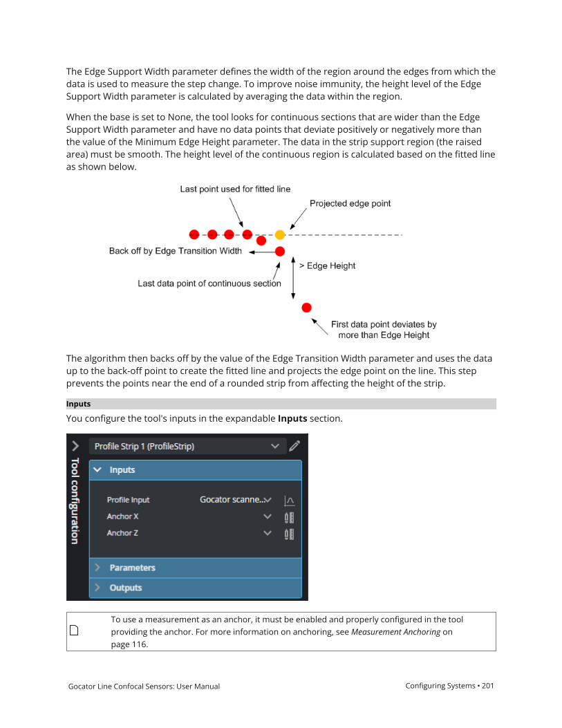
Gocator Line Confocal Sensors: User Manual Configuring Systems • 201
The Edge Support Width parameter defines the width of the region around the edges from which thedata is used to measure the step change. To improve noise immunity, the height level of the EdgeSupport Width parameter is calculated by averaging the data within the region.
When the base is set to None, the tool looks for continuous sections that are wider than the EdgeSupport Width parameter and have no data points that deviate positively or negatively more thanthe value of the Minimum Edge Height parameter. The data in the strip support region (the raisedarea) must be smooth. The height level of the continuous region is calculated based on the fitted lineas shown below.
The algorithm then backs off by the value of the Edge Transition Width parameter and uses the dataup to the back-off point to create the fitted line and projects the edge point on the line. This stepprevents the points near the end of a rounded strip from affecting the height of the strip.
Inputs
You configure the tool's inputs in the expandable Inputs section.
To use a measurement as an anchor, it must be enabled and properly configured in the toolproviding the anchor. For more information on anchoring, see Measurement Anchoring onpage 116.

Gocator Line Confocal Sensors: User Manual Configuring Systems • 202
Name Description
Profile Input The data the tool applies measurements to or processes.
Anchor X or Anchor Z The X or Z measurement of another tool that this tool uses as a positional anchor.Positional anchors are optional.
Inputs
Parameters
You configure the tool's parameters in the expandable Parameters section.
Parameter Description
Base Type Affects detection of rising and falling edges.
Parameters

Gocator Line Confocal Sensors: User Manual Configuring Systems • 203
Parameter Description
When Base Type is set to Flat, both strip (raised area) and base support regionsare needed. When set to None, only a point that deviates from a smooth stripsupport region is needed to find a rising or falling edge.
Left Edge
Right Edge
Specifies the features that will be considered as the strip's left and right edges. Youcan select more than one condition.
Rising - Rising edge detected based on the strip edge parameters.
Falling - Falling edge detected based on the strip edge parameters.
Data end - First valid profile data point in the measurement region.
Void - Gap in the data that is larger than the maximum void threshold. Gapsconnected to the measurement region's boundary are not considered as a void.
For the definitions of these conditions, see Strip Start and Terminate Conditions onpage 199.
Tilt Enabled Enables/disables tilt correction.
The strip may be tilted with respect to the sensor's coordinate X axis. This can becaused by conveyor vibration. If the Tilt option is enabled, the tool will report thewidth and height measurements, corrected by the tilt angle of the strip.
Support Width Specifies the width of the region around the edges from which the data is used tocalculate the step change. For information on how this parameter is used bydifferent base types, see Strip Step Edge Definitions on page 200.
Transition Width Specifies the nominal width needed to make the transition from the base to the

Gocator Line Confocal Sensors: User Manual Configuring Systems • 204
Parameter Description
strip. For information on how this parameter is used by different base types, seeStrip Step Edge Definitions on page 200.
Min Width Specifies the minimum width for a strip to be considered valid.
Min Height Specifies the minimum deviation from the strip base. For information on how thisparameter is used by different base types, see Strip Step Edge Definitions onpage 200.
Max Void Width The maximum width of missing data allowed for the data to be considered as partof a strip when Void is selected in the Left or Right parameter. This value must besmaller than the edge Support Width.
Use Region When enabled, displays Region parameters (see below). When disabled, the tooluses all data.
Region The measurement region defines the region in which to search for the strip. Ifpossible, the region should be made large enough to cover the base on the leftand right sides of the strip.
For more information, see Regions on page 105.
Location
(Strip Height, Strip X, andStrip Z measurements only)
Specifies the strip position from which the measurements are performed.
Left - Left edge of the strip.
Right - Right edge of the strip.
Center - Center of the strip.
Selection Type Specifies how a strip is selected when there are multiple strips within themeasurement area.
Best - The widest strip.
Index Left - 0-based strip index, counting from left to right.
Index Right - 0-based strip index, counting from right to left.
Index 0-based strip index. Only displayed when Selection Type is set to an"Index" option.
External ID The external ID of the tool that appears in GoHMI Designer. For more information,see GoHMI and GoHMI Designer on page 501.

Gocator Line Confocal Sensors: User Manual Configuring Systems • 205
Outputs
All tools provide measurements, geometric features, or data as outputs.
Outputs section with a measurement expanded to show user-configurable decision min/max fields and an external ID
You configure theMin andMax parameters by expanding the measurement in the Outputs section.In order for a measurement to return a Pass decision, the measurement must be between maximumand minimum values; the range is inclusive.
Measurement Illustration
Count
The number of strips.
Measurements

Gocator Line Confocal Sensors: User Manual Configuring Systems • 206
Measurement Illustration
X, Z
Measures the X and Z position, respectively, of a strip.
Width
Measures the width of a strip.
Height
Measures the height of a strip.
Type Description
Left Edges
Right Edges
Centers
Arrays of the left edges, right edges, and centers of all strips, from left to right.
Features

Gocator Line Confocal Sensors: User Manual Configuring Systems • 207
Profile Template Matching
The Profile Template Matching tool lets you align a profile to a "master" template profile you createin the tool (a "golden template"), compensating for movement of the target from frame to frame. Asa result, you can perform measurements on a "stabilized" profile.
The tool returns measurements that represent differences between the profile and the master,letting you perform simple defect detection and location from within the tool.
The tool also outputs an aligned profile that other Profile measurement tools can use as input.Finally, the tool produces a "difference" profile on which you can similarly perform measurements.
(The following screenshots are from a G2 sensor.)
The master profile is rendered in white. The aligned profile is rendered in blue. The current profile is rendered in red.
For information on adding, managing, and removing tools, as well as detailed descriptions of settingscommon to most tools, see Tool Configuration on page 104.
Inputs
You configure the tool's inputs in the expandable Inputs section.

Gocator Line Confocal Sensors: User Manual Configuring Systems • 208
To use a measurement as an anchor, it must be enabled and properly configured in the toolproviding the anchor. For more information on anchoring, see Measurement Anchoring onpage 116.
Name Description
Profile Input The data the tool applies measurements to or processes.
Anchor X or Anchor Z The X or Z measurement of another tool that this tool uses as a positional anchor.Positional anchors are optional.
Inputs
Note that if no profile alignment is performed (both Coarse Align and Fine Align are disabled), forexample, if the targets are sufficiently fixed from profile to profile, the following measurementsreturn 0.000:
l Transform Xl Transform Zl Transform Y Angle
Master Comparemust be enabled for the following measurements; otherwise, they return Invalidvalues:
l Max Height Differencel Max Difference Position Xl Max Difference Position Zl Standard Deviationl Difference Averagel Difference Suml Variancel Matching Score
Also, for these “master compare” measurements, if the profile has been aligned to the master (eitherCoarse Align or Fine Align is enabled), the measurement compares the aligned profile and themaster. If the profile has not been aligned (both alignment parameters are disabled), themeasurement compares the original (unaligned) profile and the master.

Gocator Line Confocal Sensors: User Manual Configuring Systems • 209
Parameters
You configure the tool's parameters in the expandable Parameters section.
Parameter Description
Template When expanded, displays File and Operation parameters.
File A list of templates available to the tool. The template containing the profile the tooluses as a master profile for alignment and comparisons. Use the Operationparameter to add and remove templates to this list.
Operation Provides operations related to profile template files (masters). One of thefollowing:
l Normal: Selected by the tool after you perform another file operation.
l Create: Creates a new template file.
l Load: Loads the template selected in File.
l Save: Saves the current profile to a template file in the local file system andadds it to the list in File. Multiple templates can be available.
l Delete:Deletes the template file selected in File.
l Refresh: Refreshes the list of files.
Parameters

Gocator Line Confocal Sensors: User Manual Configuring Systems • 210
Parameter Description
Use Region Whether the tool uses a user-defined region to performmatching. (The tool usesonly the data profile and master data in this region to perform matching.)
If this option is not checked, the tool performs matching using data from the entireactive area.
For more information on regions, see Regions on page 105.
Region The size and position of the region in which the matching (alignment) is performed.
Master comparison measurements however are applied to the entire profile(current profile and master). For example, in the following image, the tool limitsmatching to the data in the match region. But the measurement (Max HeightDifference in this case) is calculated on the data outside the region.
(The dashed lines are added to illustrate the hidden aligned profile and master.)
Coarse Align
Dependent setting
X Shift Window
When enabled, shows the X Shift Window parameter. Use this setting by itself ifyou expect targets will only move along the X and Z axes (that is, you don’t expectrotation). Otherwise, when combined with Fine Align, it provides a good initialstart position for fine alignment.
X Shift Window
The maximum distance on the X axis the tool can move the current profile in orderto align it. Should be set to the maximum amount the part is expected to shift leftor right. (Enabled using the Coarse Align parameter.)
Fine Align
Dependent settings
Max Iteration
Match Window
When enabled, lets you set theMax Iteration andMatch Window parameters forfine alignment. This alignment method is more accurate than coarse alignment buttakes more time to run.
Max Iteration
The maximum number of iterations the tool uses to perform fine alignment of theprofile to the master.
Match Window

Gocator Line Confocal Sensors: User Manual Configuring Systems • 211
Parameter Description
The region in which points are evaluated for a match. It there’s a larger differencebetween the current profile and the master than the match window size, it wouldignore the point.
Master Compare
Dependent settings
Difference Profile MedianSize
Tolerance
Causes the tool to compare the current profile to the master profile and returnresults in some of the tool’s measurements. (See list above.)
When disabled, the measurements that compare the profile to the master returninvalid values.
Difference Profile Median Size
Defines the size of the window the tool uses to smooth out noise in the DifferenceProfile data output.
Tolerance
The difference tolerance for the master comparison.
Display Master Displays the Master template (white profile).
Display Aligned Profile Displays the aligned (blue profile).
External ID The external ID of the tool that appears in GoHMI Designer. For more information,see GoHMI and GoHMI Designer on page 501.
Outputs
All tools provide measurements, geometric features, or data as outputs.

Gocator Line Confocal Sensors: User Manual Configuring Systems • 212
Outputs section with a measurement expanded to show user-configurable decision min/max fields and an external ID
You configure theMin andMax parameters by expanding the measurement in the Outputs section.In order for a measurement to return a Pass decision, the measurement must be between maximumand minimum values; the range is inclusive.
Measurement
Transform X
Transform Z
The distance the profile has shifted on the X and Z axis after alignment to the master, respectively.
Transform Y Angle
The rotation of the profile around the Y axis after alignment.
Measurements
Gocator Line Confocal Sensors: User Manual Configuring Systems • 213
Measurement
Max Height Difference
The maximum height difference between the profile and the master.
Max Difference Position X
Max Difference Position Z
The X and Z positions of the maximum height difference between the profile and the master.
Standard Deviation
The standard deviation between the profile and the master.
Difference Average
The average difference on the Z axis between the profile and the master.
Difference Sum
The sum of the differences on the Z axis between the profile and the master.
Variance
Returns the variance of a difference profile calculated by subtracting the current profile from the master.
Matching Score
Returns a value between 0 and 1 that is the is the percentile of standard deviation of a difference profile(calculated by subtracting the current profile from the master) from the tolerance.
Type Description
Aligned Profile The profile aligned to the master.
Difference Profile A profile representing the differences between the profile and the master.
Z values in the difference profile above 0 represent data points higher in theprofile than in the master.
Z values in the difference profile below 0 represent data points lower in the profilethan in the master.
Z values in the difference profile at 0 represent data points that are the same inthe profile and the master.
Data

Gocator Line Confocal Sensors: User Manual Configuring Systems • 214
Raw Profile Matching
The Raw Profile Matching tool takes unresampled profile data as input (the Enable uniformspacing setting is disabled on Acquire > Scanners).
The Raw Profile Matching tool lets you align a profile to a "master" template profile you create in thetool (a "golden template"), compensating for movement of the target from frame to frame. As aresult, you can perform measurements on a "stabilized" profile.
The tool returns measurements that represent differences between the profile and the master,letting you perform simple defect detection and location from within the tool.
The tool also outputs an aligned profile that other Profile measurement tools can use as input (viatheir Stream parameter).
In the data viewer, the profiles are rendered using different colors:
The master profile is rendered in white. The aligned profile is rendered in blue. The current profile is rendered in red.
Note that in the image above, the tool is performing only a rough alignment to ensure that thedifferent profiles are clearly visible for illustration purposes. Typically, the blue aligned profile will beon top of the white master profile.
For information on adding, managing, and removing tools, as well as detailed descriptions of settingscommon to most tools, see Tool Configuration on page 104.
Inputs
You configure the tool's inputs in the expandable Inputs section.

Gocator Line Confocal Sensors: User Manual Configuring Systems • 215
To use a measurement as an anchor, it must be enabled and properly configured in the toolproviding the anchor. For more information on anchoring, see Measurement Anchoring onpage 116.
Name Description
Profile Input The data the tool applies measurements to or processes.
Anchor X or Anchor Z The X or Z measurement of another tool that this tool uses as a positional anchor.Positional anchors are optional.
Inputs
Parameters
You configure the tool's parameters in the expandable Parameters section.

Gocator Line Confocal Sensors: User Manual Configuring Systems • 216
Parameter Description
Template When expanded, displays File and Operation parameters.
File A list of templates available to the tool to use as a master profile for alignment andcomparisons. Use the Operation parameter to add and remove templates.
Operation Provides operations related to profile template files (masters). One of thefollowing:
l Normal: Selected by the tool after you perform another file operation.
l Create: Creates a new template file.
l Load: Loads the template selected in File.
l Save: Saves the current profile to a template file in the local file system andadds it to the list in File. Multiple templates can be available.
l Delete:Deletes the template file selected in File.
l Refresh: Refreshes the list of files.
Use Region Indicates whether the tool uses a user-defined region to performmatching. (Thetool uses only the data profile and master data in this region to perform matching.)
If this option is not checked, the tool performs matching using data from the entireactive area.
For more information on regions, see Regions on page 105.
Match Region When Use Region is enabled, provides settings for the size and position of theregion in which the matching (alignment) is performed..
Master comparison measurements however are applied to the entire profile(current profile and master). For example, in the following image, the tool limitsmatching to the data in the match region. But the measurement (Max HeightDifference in this case) is calculated on the data outside the region.
(The dashed lines are added to illustrate the hidden aligned profile and master.)
Subsample Factor The sampling interval of the input profile point cloud.
Parameters

Gocator Line Confocal Sensors: User Manual Configuring Systems • 217
Parameter Description
Max Iteration The maximum number of iterations the tool uses to perform iterative closest point(ICP). The tool stops iterating once the input profile is considered within the errortolerance (see above).
Max Iteration The maximum number of iterations the tool uses to perform iterative closest point(ICP).
Inverse Transform When enabled, inverts the output transformation.
Display Master Displays the Master template (white profile).
Display Aligned Profile Displays the aligned profile (blue profile).
External ID The external ID of the tool that appears in GoHMI Designer. For more information,see GoHMI and GoHMI Designer on page 501.
Outputs
All tools provide measurements, geometric features, or data as outputs.
Outputs section with a measurement expanded to show user-configurable decision min/max fields and an external ID

Gocator Line Confocal Sensors: User Manual Configuring Systems • 218
You configure theMin andMax parameters by expanding the measurement in the Outputs section.In order for a measurement to return a Pass decision, the measurement must be between maximumand minimum values; the range is inclusive.
Measurement
Transform X
Transform Z
The distance the profile has shifted on the X and Z axis after alignment to the master, respectively.
Transform Y Angle
The rotation of the profile around the Y axis after alignment.
Root Mean Squared Error
The root mean squared error of the alignment.
Matching Score
Returns a value between 0 and 1 representing the percentile of standard deviation of a difference profile(calculated by subtracting the current profile from the master) from the tolerance.
Measurements
Type Description
Aligned Profile The profile aligned to the master.
Data

Gocator Line Confocal Sensors: User Manual Configuring Systems • 219
Profile Thickness
The Thickness tool lets you perform thickness measurements between the two profiles you specify.
The tool also lets you specify an angle measurement relative to which the tool performs thethickness measurements, up to a maximum of 20 degrees, to compensate for minor tilt of the target.To get the compensation angle, you could first fit a straight line to the top profile using the ProfileLine tool, and pass that tool's Angle measurement to Profile Thickness. (For information on ProfileLine, see Profile Line on page 171.)
For information on adding, managing, and removing tools, as well as detailed descriptions of settingscommon to most tools, see Tool Configuration on page 104.
Inputs
You configure the tool's inputs in the expandable Inputs section.
To use a measurement as an anchor, it must be enabled and properly configured in the toolproviding the anchor. For more information on anchoring, see Measurement Anchoring onpage 116.
Name Description
Top Profile Input
Bottom Profile Input
The top and bottom profiles the tool uses to perform thickness measurements.
Anchor X or Anchor Z The X or Z measurement of another tool that this tool uses as a positional anchor.Positional anchors are optional.
Thickness Angle The angle at which the tool measures thickness. If no angle is provided, thethickness measurement is perpendicular to the X axis.
Inputs
Parameters
You configure the tool's parameters in the expandable Parameters section.

Gocator Line Confocal Sensors: User Manual Configuring Systems • 220
Parameter Description
Use Region When enabled, displays Region parameters (see below). When disabled, the tooluses all data.
Region The region to which the tool's measurements will apply. For more information, seeRegions on page 105.
External ID The external ID of the tool that appears in GoHMI Designer. For more information,see GoHMI and GoHMI Designer on page 501.
Parameters
Outputs
All tools provide measurements, geometric features, or data as outputs.
Outputs section with a measurement expanded to show user-configurable decision min/max fields and an external ID
You configure theMin andMax parameters by expanding the measurement in the Outputs section.In order for a measurement to return a Pass decision, the measurement must be between maximumand minimum values; the range is inclusive.

Gocator Line Confocal Sensors: User Manual Configuring Systems • 221
Measurement
Thickness
The thickness measured in the scan data.
Thickness Min
The minimum thickness measured in the scan data.
Thickness Max
The maximum thickness measured in the scan data.
Measurements

Gocator Line Confocal Sensors: User Manual Configuring Systems • 222
Profile Transform
The Profile Transform creates a new profile based on the coordinate system of geometric featuresthe tool uses as input and/or fixed input values. The tool accepts a Line geometric feature (rotatingthe profile so that the line is parallel to the X axis) and/or a Point geometric feature (using it as the Xand Z origin).
For example, in the following, if you want to measure the characteristics of the first groove on theleft, you can use the tool to rotate the profile.
First, a Profile Line tool is added and configured on the bottom of the groove. The tool is configuredto output a line geometric feature.
A Profile Transform tool takes the line geometric feature as input, and the transformed profile fromthat tool is used as input for a Profile Groove tool, which measures the groove's characteristics:

Gocator Line Confocal Sensors: User Manual Configuring Systems • 223
For information on adding, managing, and removing tools, as well as detailed descriptions of settingscommon to most tools, see Tool Configuration on page 104.
Inputs
You configure the tool's inputs in the expandable Inputs section.
To use a measurement as an anchor, it must be enabled and properly configured in the toolproviding the anchor. For more information on anchoring, see Measurement Anchoring onpage 116.
Name Description
Profile Input The data the tool applies measurements to or processes.
Point The Point geometric feature the tool uses to offset a profile to an X and Z origin of0.
Line The Line geometric feature the tool uses to position (X and Z) and to rotate a
Inputs

Gocator Line Confocal Sensors: User Manual Configuring Systems • 224
Name Description
profile Y rotation).
Anchor X or Anchor Z The X or Z measurement of another tool that this tool uses as a positional anchor.Positional anchors are optional.
Parameters
You configure the tool's parameters in the expandable Parameters section.
Parameter Description
Use Region Whether the tool should limit the transformed profile that it outputs to a user-defined region. When enabled, the tool displays a Region parameter you use todefine the region.
If this option is not enabled, the tool transforms the entire profile.
Region The region to which the tool's measurements will apply. For more information, seeRegions on page 105.
Add Fixed Transform Enables X Offset, Y Offset, and Angle parameters you can use to manually set atransformation. Useful if you know the profiles in the scan data will always be in acertain position or orientation.
External ID The external ID of the tool that appears in GoHMI Designer. For more information,see GoHMI and GoHMI Designer on page 501.
Parameters
Outputs
All tools provide measurements, geometric features, or data as outputs.

Gocator Line Confocal Sensors: User Manual Configuring Systems • 225
Type Description
Profile Uniform
Profile Point Cloud
The transformed profile.
Only one data output will contain data, depending on whether Enable uniformspacing (resampling) on the Acquire page is enabled (in which case the Uniformoutput will contain data) or disabled (in which case the Point Cloud output willcontain data). For more information, see Scan Modes on page 71.
Data

Gocator Line Confocal Sensors: User Manual Configuring Systems • 226
Surface MeasurementSurface measurement involves capturing scan data, optionally identifying discrete objects, andmeasuring properties of the surface or the objects, such as the volume of the object or the height ata certain position of the object. All volumetric tools have the ability to operate either on the entiresurface or the full object, or within a region of interest at a certain position in relation to the surfaceor an object.
Multiple measurements can be performed on the entire surface or each discrete object, limited onlyby the available CPU resources.

Gocator Line Confocal Sensors: User Manual Configuring Systems • 227
Surface Align Ring
This tool is only intended for trouble-shooting high-accuracy alignment of multi-sensor ring andpartial ring layouts with G2 (line profile) sensors, using recorded scan data.

Gocator Line Confocal Sensors: User Manual Configuring Systems • 228
Surface Align Wide
This tool is only intended for trouble-shooting high-accuracy alignment of multi-sensor wide layoutswith G2 (line profile) sensors, using recorded scan data.

Gocator Line Confocal Sensors: User Manual Configuring Systems • 229
Surface Arithmetic
The Surface Arithmetic tool lets you perform various operations on a pair of surfaces. For example,you can use the tool to perform dynamic masking from frame to frame. The tool performs bitwiseoperations (AND or OR) on the corresponding data points in the source surfaces, and also combinesheight and intensity data with add, subtract, average, and mask operations.
Inputs
To use a measurement as an anchor, it must be enabled and properly configured in the toolproviding the anchor. For more information on anchoring, see Measurement Anchoring onpage 116.
Name Description
Surface Input The data the tool applies measurements to or processes.
Secondary Surface Input The secondary input the tool uses to perform arithmetic.
Anchor X
Anchor Y
Anchor Z
The X, Y, or Z measurement of another tool that this tool uses as a positionalanchor. Positional anchors are optional.
Anchor Z Angle The Z Angle measurement of another tool to use as a rotational anchor for thistool. Rotational anchors are optional.
Inputs
Parameters
The following parameters are in the expandable Parameters section in the tool's configuration.

Gocator Line Confocal Sensors: User Manual Configuring Systems • 230
Parameter Description
Regions When expanded, displays the region- and mask-related settings.
Enable Enables regions and displays the region- and mask-related settings (see below).
Mask Mode
Number of Regions
Region Type {n}
Region {n}
When you enable regions (see above), the tool displays additional settings relatedto the region type. For details on the regions supported by this tool and theirsettings, see Flexible Regions on page 106.
For general information on regions and the difference between standard and"flexible" regions, see Regions on page 105.
Operator One of the following:
Add – Adds the height values of the corresponding data points in the two sources.
Subtract – Subtracts the height values of the corresponding data points in the twosources.
Average – Averages the height values of the corresponding data points in the twosources.
Mask – Uses the secondary source as a mask.
Logic Performs bitwise-operations on the source and secondary source surface data.One of the following: And or Or.
External ID The external ID of the tool that appears in GoHMI Designer. For more information,see GoHMI and GoHMI Designer on page 501.
Parameters

Gocator Line Confocal Sensors: User Manual Configuring Systems • 231
Outputs
Type Description
Uniform Surface The processed surface data.
Data

Gocator Line Confocal Sensors: User Manual Configuring Systems • 232
Surface Ball Bar
The Surface Ball Bar tool returns measurements useful for calibrating systems using a ball bar,particularly systems that include a robot.
Inputs
You configure the tool's inputs in the expandable Inputs section.
Name Description
Surface Input The data the tool applies measurements to or processes.
Inputs
Parameters
You configure the tool's parameters in the expandable Parameters section.

Gocator Line Confocal Sensors: User Manual Configuring Systems • 233
Parameter Description
Use Nominal Distance When enabled, displays Nominal Distance and Distance Tolerance settings. Setthese to correspond to the distance between the balls of the ball bar (refer to thespecifications of the ball bar) and the tolerance you need. This can be useful toensure invalid results due to false or inaccurate detection are rejected.
Origin Ball Determines which ball is used as the origin. The Bottom of View option selectsthe ball at the bottom of the data viewer in the web interface.
Plane Parameters Enables advanced plane settings. For UR integration, you should leave the settingsat their default. These parameters allow ensuring the plane detection is accurateand robust to variations.
Use Nominal Radius When enabled, displays Nominal Radius {n} settings. Set these to reflect theradius of the balls of the ball bar (refer to the specifications of the ball bar) and thetolerance you need. This can be useful to ensure invalid results due to false orinaccurate detection are rejected. The tool uses these as a starting point and willnot necessarily reject targets based on these.
External ID The external ID of the tool that appears in GoHMI Designer. For more information,see GoHMI and GoHMI Designer on page 501.
Parameters

Gocator Line Confocal Sensors: User Manual Configuring Systems • 234
Outputs
Outputs section with a measurement expanded to show user-configurable decision min/max fields and an external ID
You configure theMin andMax parameters by expanding the measurement in the Outputs section.In order for a measurement to return a Pass decision, the measurement must be between maximumand minimum values; the range is inclusive.
Measurement
Normal X / Y / Z
These measurements return the X, Y, and Z components of the normal vector of the surface surrounding thecalibration target.
Radius1
Radius2
These measurements return the radius of each ball.
Center X1 / Y1 / Z1
Center X2 / Y2 / Z2
These measurements return the X, Y, and Z positions of the centers of the spheres fitted to the balls.
Ball 1 (Center X1 / Y1 / Z1) is always used as the origin. (Corresponds to the values returned in Tx / Ty / Tz.)
Distance 3D
The direct distance between the centers of the spheres fitted to the balls.
Ix / Iy / Iz
Jx / Jy / Jz
Kx / Ky / Kz
These measurements return the X, Y, and Z components of the I, J, and K unit vectors defining the coordinatesystem orientation.
Tx / Ty / Tz
Measurements

Gocator Line Confocal Sensors: User Manual Configuring Systems • 235
Measurement
These measurements return the X, Y, and Z components of the translation vector defining the coordinatesystem origin location.
Type Description
Difference Surface The difference between the scan data and the provided nominal dimensions. Usedfor diagnostics.
Data

Gocator Line Confocal Sensors: User Manual Configuring Systems • 236
Surface Blob
The Surface Blob tool lets you detect surface defects, such as uneven or excess material, gouges, orblemishes, on a relatively uniform or flat background, in either 3D height map data or intensity data.It can also extract targets from the surface. The tool optionally lets you set its height thresholdrelative to a user-defined reference region. It also lets you use a reference plane to correct for aminor tilt of the target surface (up to 10 degrees); this lets you detect low or shallow defects thatwould otherwise not be detectable due to a tilt.
The tool first filters data based on a height or intensity threshold (above or below it), and then usesconfigurable morphological operations to better isolate parts. Finally, the tool uses various size- andshape-based filters that let you exclude or include the expected defects or the targets you need(potential blobs).
The tool lets you configure the maximum number of "blobs" to output, and returns the total blobcount, and for each blob, the X and Y center, the width and length, and the area. The center point ofeach blob is available as a geometric feature.
(The following screenshot is from a G3 sensor.)
Several dents outlined by the tool on a surface. The currently selected blob is outlined in red. (Grayscale heightmap mode isused to better see the outlines.)
Note that knowing the rough size and shape of the kinds of detects you expect is important whenyou are configuring the open and close kernels and the tool's filters.
For information on adding, managing, and removing tools, as well as detailed descriptions of settingscommon to most tools, see Tool Configuration on page 104.

Gocator Line Confocal Sensors: User Manual Configuring Systems • 237
Inputs
To use a measurement as an anchor, it must be enabled and properly configured in the toolproviding the anchor. For more information on anchoring, see Measurement Anchoring onpage 116.
Name Description
Surface Input The data the tool applies measurements to or processes.
Anchor X
Anchor Y
Anchor Z
The X, Y, or Z measurement of another tool that this tool uses as a positionalanchor. Positional anchors are optional.
Anchor Z Angle The Z Angle measurement of another tool to use as a rotational anchor for thistool. Rotational anchors are optional.
Inputs
Parameters
The following parameters are in the expandable Parameters section in the tool's configuration.

Gocator Line Confocal Sensors: User Manual Configuring Systems • 238
Parameter Description
Use Intensity If enabled, the tool uses intensity data instead of heightmap data. Only available ifAcquire intensity is enabled on the Acquire page during the scan; for moreinformation, see Scan Modes on page 71.
Parameters

Gocator Line Confocal Sensors: User Manual Configuring Systems • 239
Parameter Description
Measurement Regions When expanded, displays the region- and mask-related settings.
Enable Enables regions and displays the region- and mask-related settings (see below).
Mask Mode
Number of Regions
Region Type {n}
Region {n}
When you enable regions (see above), the tool displays additional settings relatedto the region type. For details on the regions supported by this tool and theirsettings, see Flexible Regions on page 106.
For general information on regions and the difference between standard and"flexible" regions, see Regions on page 105.
Reference Type Provides three options: None, Reference Region, and Reference Plane. If thereference type is set to None, the Height Threshold setting is absolute (relative tozero). For the Reference Region and Reference Plane options, see the descriptionsof the Reference Region Type and Reference Plane parameters below.
Reference Region Type If you set Reference Type (see above) to Reference Region, the tool displays adrop-down that lets you choose the reference region type, as well as additionalsettings related to the type you select. (For details, see Flexible Regions onpage 106.) The tool calculates an average height or intensity of the data in thereference region. Height Threshold is relative to this value.
For example, in the following, blobs are detected using a relative height thresholdof -0.2 mm, relative to the average in the reference region:
(The following screenshots are from a G3 sensor.)
For general information on regions and the difference between standard and"flexible" regions, see Regions on page 105.

Gocator Line Confocal Sensors: User Manual Configuring Systems • 240
Parameter Description
Reference Plane If you set Reference Type (see above) to Reference Plane, the tool uses thespecified plane geometric feature to correct for a tilt of the target. Note howeverthat using a reference plane to correct the tilt distorts the scan data: it sheers thedata by the same angle as the tilt. The maximum tilt angle with which you can usethe tool therefore depends on how much sheer angle you can tolerate in yourapplication (which can effect the tool's ability to detect blobs). Typically, you addand configure a Surface Plane tool to generate a plane (for more information, seeSurface Plane on page 359). For information on geometric features, see GeometricFeatures on page 115.
For applications where sheer distortion can't be tolerated, use Surface Transformto correct the tilt (see Surface Transform on page 422), and use the latter tool'soutput as the input for Surface Blob.
For example, in the following, despite the overall tilt of the target, the tool detectsthe flaws on the surface. (Note the gradient of the heightmap colors, indicating aheight difference of roughly 9 millimeters between the lower and higher areasnear the dents on the target's surface.)
(The following screenshot is from a G3 sensor.)
Include Null Points Indicates whether null points (points where no height or intensity value isavailable, due to dropouts or regions outside of the measurement range) are filledwith the value in Null Fill Value as a general “background level” or to fill gaps toaid in isolating blobs.

Gocator Line Confocal Sensors: User Manual Configuring Systems • 241
Parameter Description
If Use Intensity is enabled, the value in Null Fill Value is an intensity.
Height Threshold
Intensity Threshold
The threshold above or below which data is considered for being a blob. Use theThreshold Direction setting to determine whether data above or below thethreshold is considered.
If Use Intensity is enabled, this setting is named Intensity Threshold. Otherwise,it is named Height Threshold.
Threshold Direction Determines whether data above or below the threshold is considered as being ablob.
Below: The Height Threshold value is the maximum that will be considered aspart of a blob (for example, a dent below the surrounding surface).
Above: The Height Threshold value is the minimum that will be considered aspart of a blob (so a raised feature).
Open Kernel X
Open Kernel Y
The X and Y kernel size, respectively, for morphological opening to remove smallareas of data. Use these settings, for example, to remove bridges between areas toproperly isolate them or to remove small areas entirely (perhaps caused by noise).Use different values of X and Y to use a non-rectangular filter to adapt the kernelto the kinds of unwanted data you see in the scan data.
Close Kernel X
Close Kernel Y
The X and Y kernel size, respectively, for morphological closing to fill in holessmaller than the specified kernel size. Use these settings, for example, to fill smallareas within potential blobs that may be caused by drop-outs. Use different valuesof X and Y to use a non-rectangular filter to adapt the kernel to the kinds of holesyou see in the scan data.
Hierarchy Provides options to let you find either external blobs only or both external andinternal blobs.
External Blobs
Use this option to ignore smaller blobs in larger blobs: only the outermost blob isreturned.
External + Internal Blobs
Use this option to include smaller blobs in larger blobs.
Use Area Filter
Dependent settings
Max Area
Min Area
If Use Area Filter is enabled, the tool applies an area filter to potential blobs usingthe values inMax Area andMin Area.
Use Aspect Filter
Dependent settings
Max Aspect
Min Aspect
If Use Aspect Filter is enabled, the tool applies an aspect filter (ratio of length andwidth) to the rotated bounding box that would encapsulate the area, using thevalues inMax Aspect andMin Aspect.
For example, the following dent in a surface is included as a blob if these aspectvalues are set to 1 and 0.354, respectively (the rotated bounding box encapsulating

Gocator Line Confocal Sensors: User Manual Configuring Systems • 242
Parameter Description
would be 13.059 mm x 4.704 mm).
(The following screenshots are from a G3 sensor.)
In the following, the same dent is excluded ifMin Aspect is set to a value greaterthan 0.354.
Use Circularity Filter
Dependent settings
Max Circularity
If Use Circularity Filter is enabled, the tool applies a circularity filter to potentialblobs to measure how close to a circle the blob is, using the values inMaxCircularity andMin Circularity . Circularity is determined from area within thecontour of the blob and the perimeter of its contour. With increasing perimeter forthe same area, circularity is reduced.

Gocator Line Confocal Sensors: User Manual Configuring Systems • 243
Parameter Description
Min Circularity
Use Convexity Filter
Dependent settings
Max Convexity
Min Convexity
If Use Convexity Filter is enabled, the tool applies a convexity filter to potentialblobs, using the values inMax Convexity andMin Convexity . Convexity isdefined as the (Area of the Blob / Area of its convex hull), and "convex hull" of ashape is the tightest convex shape that completely encloses the shape.
Ordering Orders the measurements, features, and surface data of the individual blobsoutput by the tool. One of the following:
l Position - X increasingl Position - X decreasingl Position - Y increasingl Position - Y decreasingl Area - Large to smalll Area - Small to large
Number of Blob Outputs Determines the number of blobs the tool outputs as measurements, features(center points of blobs), and surface data. Currently limited to 200 blobs.
External ID The external ID of the tool that appears in GoHMI Designer. For more information,see GoHMI and GoHMI Designer on page 501.
Outputs
All tools provide measurements, geometric features, or data as outputs.

Gocator Line Confocal Sensors: User Manual Configuring Systems • 244
Outputs section with a measurement expanded to show user-configurable decision min/max fields and an external ID
You configure theMin andMax parameters by expanding the measurement in the Outputs section.In order for a measurement to return a Pass decision, the measurement must be between maximumand minimum values; the range is inclusive.
Measurement
Total Count
Returns the total number of blobs identified, based on the tool's parameters.
Center X {n}
Center Y {n}
Measurements

Gocator Line Confocal Sensors: User Manual Configuring Systems • 245
Measurement
The X and Y positions of the center of mass of a blob extracted from the surface.
The Number of Blob Outputs setting determines the number of measurements listed in theMeasurementstab.
Width {n}
Length {n}
The length and width of the rotated bounding box that encapsulates the blob extracted from the surface.These are always the major and minor axis of a blob, respectively.
The Number of Blob Outputs setting determines the number of measurements listed.
Area {n}
The area of a blob.
The area is calculated using the contour of the blob and resampling. For this reason, areas calculated using theSurface Volume tool will produce different measurements; for more information, see Area on page 438.
Type Description
Center Point {n} The point representing the center of a blob.
Features
For more information on geometric features, see Geometric Features on page 115.
Type Description
Diagnostics Surface Surface data you can use to evaluate the impact of the tool's parameters, afterfilters are applied, to properly separate the areas corresponding to the defects ortargets you need to detect.
Surface {n} Surface data corresponding to each blob.
Data

Gocator Line Confocal Sensors: User Manual Configuring Systems • 246
Surface Bounding Box
The Bounding Box tool provides measurements related to the smallest box that contains the scandata from a part (for example, X position, Y position, width, length, etc.). The tool also lets you get theheight of bounding box relative to the Z origin (typically the conveyor on which the target issitting). This lets you determine, for example, the height of a box or other container on the conveyoras part of a product packaging process. Various settings let you easily filter out noise that can affectheight, width, and length measurements.
A bounding box can be vertical or rotated. A vertical bounding box provides the absolute positionfrom which the Position centroids tools are referenced.
For information on adding, managing, and removing tools, as well as detailed descriptions of settingscommon to most tools, see Tool Configuration on page 104.
Inputs
You configure the tool's inputs in the expandable Inputs section.
To use a measurement as an anchor, it must be enabled and properly configured in the toolproviding the anchor. For more information on anchoring, see Measurement Anchoring onpage 116.
Name Description
Surface Input The data the tool applies measurements to or processes.
Anchor X
Anchor Y
Anchor Z
The X, Y, or Z measurement of another tool that this tool uses as a positionalanchor. Positional anchors are optional.
Anchor Z Angle The Z Angle measurement of another tool to use as a rotational anchor for thistool. Rotational anchors are optional.
Mask Source {n} The source for the mask. (Only displayed if a region is Surface or Surface Intensitymask type.)
Inputs

Gocator Line Confocal Sensors: User Manual Configuring Systems • 247
Parameters
You configure the tool's parameters in the expandable Parameters section.
Parameter Description
Regions When expanded, displays the region- and mask-related settings.
Enable Enables regions and displays the region- and mask-related settings (see below).
Mask Mode
Region Type 1
Region 1
When you enable regions (see above), the tool displays additional settings relatedto the region type. For details on the regions supported by this tool and theirsettings, see Flexible Regions on page 106.
For general information on regions and the difference between standard and"flexible" regions, see Regions on page 105.
Rotation A bounding box can be vertical or rotated. A vertical bounding box provides theabsolute position from which the part's Position centroid measurements arereferenced. Check the Rotation setting to select rotated bounding box. When thissetting is enabled, an Asymmetry Detection setting is displayed.
Asymmetry Detection Resolves the orientation of an object over 360 degrees. The possible values are:
0 – None
1 – Along Major Axis
2 – Along Minor Axis
This setting is only visible if Rotation is checked.
Parameters

Gocator Line Confocal Sensors: User Manual Configuring Systems • 248
Parameter Description
Use Percentile Filter Limits the bounding box to data points along the Z axis between the values you setin High Percentile and Low Percentile, which are displayed when you choose thisoption. Use this setting to obtain more "robust" height measurements.
This setting is useful to exclude noise that would otherwise cause inaccurateheight measurements. For example, in the following scan of a box, withoutexcluding a small percentage of the highest data points, data points caused bynoise to the upper right produces an inaccurate height measurement of the box of406.457 mm.
(The following screenshots are from a G2 sensor.)
When High Percentile is set to 99%, the highest 1 percent of data points isexcluded from the placement of the bounding box, and an accurate height of thetarget box of 270.477 mm is returned.

Gocator Line Confocal Sensors: User Manual Configuring Systems • 249
Parameter Description
High Percentile
Low Percentile
See Use Percentile Filter above.
Use Opening Filter When enabled, this setting lets you set the value of Kernel Size for an openingmorphological operation applied to the scan data on the XY plane, letting youachieve "robust" width and length measurements.
This filter removes noise or small objects from scan data, while keeping the shapeand size of the larger objects in the scan data. For example, in the following, noisealong the edge at the top of the data viewer results in an inaccurate lengthmeasurement.
(The following screenshots are from a G2 sensor.)

Gocator Line Confocal Sensors: User Manual Configuring Systems • 250
Parameter Description
When the filter is set to an appropriately sized kernel (here, 11 points), the noise isexcluded from the calculation of the bounding box, and an accurate length isreturned.
Use the Diagnostics Surface on the Data tab to evaluate the impact of the openfilter, to avoid removing too much data.
Kernel Size See Use Opening Filter above.
External ID The external ID of the tool that appears in GoHMI Designer. For more information,see GoHMI and GoHMI Designer on page 501.

Gocator Line Confocal Sensors: User Manual Configuring Systems • 251
Outputs
All tools provide measurements, geometric features, or data as outputs.
Outputs section with a measurement expanded to show user-configurable decision min/max fields and an external ID
You configure theMin andMax parameters by expanding the measurement in the Outputs section.In order for a measurement to return a Pass decision, the measurement must be between maximumand minimum values; the range is inclusive.

Gocator Line Confocal Sensors: User Manual Configuring Systems • 252
Measurement Illustration
X
Determines the X position of the center of thebounding box that contains the part.
The value returned is relative to the part.
Y
Determines the Y position of the center of thebounding box that contains the part.
The value returned is relative to the part.
Z
Determines the Z position of the center of thebounding box that contains the part.
The value returned is relative to the part.
Width
Determines the width of the bounding box thatcontains the part.
When the Rotation setting is disabled, the boundingbox is the smallest rectangle whose sides are parallelto the X and Y axes. Width is on the X axis.
When Rotation is enabled, the width is the smallerside dimension.
Length
Determines the length of the bounding box thatcontains the part.
When the Rotation setting is disabled, the boundingbox is the smallest rectangle whose sides are parallelto the X and Y axes. Length is on the Y axis.
When Rotation is enabled, the length is the longerside dimension.
Measurements

Gocator Line Confocal Sensors: User Manual Configuring Systems • 253
Measurement Illustration
Height
Determines the height of the bounding box thatcontains the part.
Height from 0
Determines the distance from the top of the boundingbox to the Z origin (Z = 0).
Z AngleDetermines the rotation around the Z axis and theangle of the longer side of the bounding box relative tothe X axis.
If Rotation is not enabled, the measurement returns90.000 degrees.
In order to use this measurement for angle anchoring,you must enable Rotation; for more information onanchoring, see Measurement Anchoring on page 116.
Type Description
Center The center point of the bounding box.
Box Axis Line The axis of the bounding box.
Features
For more information on geometric features, see Geometric Features on page 115.

Gocator Line Confocal Sensors: User Manual Configuring Systems • 254
Surface Circular Edge
The Circular Edge tool fits a circle to a circular edge in the scan data, using either height map orintensity data. The edge can be the outer edge of a disc-like feature or the inner edge of a hole. Thetool can optionally work with partial data, as little as 1/4 of a circle, letting it work with roundedcorners.
The tool lets you measure the position and radius of the circular feature and determine itsroundness error. The feature is expected to be relatively round and not, for example, ovoid.
The tool also returns minimum and maximum error points to either side of the circle and gives theerror distance measurement of minimum/ maximum points to the circle.
The tool uses one of four standard methods to calculate roundness. The choice of method affectsthe other measurements.
l Least Square Circle (LSC)l Minimum Zone Circle (MZC)l Maximum Inscribed Circle (MIC)l Minimum Circumscribed Circle (MCC)
The tool can also generate circle and center point geometric features that Feature tools can take asinput for measurement. For more information on Feature tools, see Feature Measurement onpage 440.
Some of the tool parameters are hidden unless Show Advanced Parameters is checked.
For information on adding, managing, and removing tools, as well as detailed descriptions of settingscommon to most tools, see Tool Configuration on page 104.
Calipers, Extracted Paths, and Edge Points
To fit a circle to the scan data, the Surface Circular Edge tool starts by overlaying evenly spacedcalipers along a circular path constrained by the region of interest.
Rectangular calipers (dark blue) placed along circular path (dark blue), constrained by the region

Gocator Line Confocal Sensors: User Manual Configuring Systems • 255
The circular path can optionally be partial, and starts at a defined orientation around the Z axis. Thecircular path can be as short as 1/4 of a circle, letting it work with rounded corners. Calipers extendvertically to fill the entire region of interest.
Internally, the tool extracts profiles from the data within each caliper, running from the end of thecaliper closest to the center of the tool's region of interest to the end farthest from the center. Thetool then searches for steps in each profile that meet the criteria set by the tool’s settings, such asminimum height, direction (whether it is rising or falling), and so on.
The tool places an edge point on each selected step. The tool then uses the edge points in all thecalipers to fit a circle: the various characteristics of the fitted circle are then returned asmeasurements.
Inputs
You configure the tool's inputs in the expandable Inputs section.
To use a measurement as an anchor, it must be enabled and properly configured in the toolproviding the anchor. For more information on anchoring, see Measurement Anchoring onpage 116.
Name Description
Surface Input The data the tool applies measurements to or processes.
Anchor X
Anchor Y
Anchor Z
The X, Y, or Z measurement of another tool that this tool uses as a positionalanchor. Positional anchors are optional.
Anchor Z Angle The Z Angle measurement of another tool to use as a rotational anchor for thistool. Rotational anchors are optional.
Reference Plane Uses the feature output of a Surface Plane tool as a reference plane. Useful to
Inputs

Gocator Line Confocal Sensors: User Manual Configuring Systems • 256
Name Description
correct the scan data if the target is slightly tilted. Only displayed when ShowAdvanced Parameters is enabled.
Parameters
You configure the tool's parameters in the expandable Parameters section.

Gocator Line Confocal Sensors: User Manual Configuring Systems • 257

Gocator Line Confocal Sensors: User Manual Configuring Systems • 258
Parameter Description
Use Region When enabled, displays Region parameters (see below). When disabled, the tool uses all
data.
Region The region to which the tool's measurements will apply. For more information, see
Regions on page 105.
Caliper Count The number of calipers the tool places along the circular path. Using a higher number of
calipers increases the amount of data available to the tool, but also increases the amount
of time the tool takes to run.
Choose a balance between the runtime of the tool and the number of calipers needed to
get enough edge points to properly fit the circle to the scan data.
Caliper Length
Caliper Width
Caliper Length is the length of the calipers (extending perpendicular to a tangent on the
circular caliper path, centered on the path). The length of the calipers determines the
length of the extracted profiles the tool examines for steps. Longer calipers increase the
amount of data the tool must analyze and therefore the time the tool takes to run; longer
calipers can also include unwanted steps when the tool searches for the edge.
Caliper Width is the width of the calipers (extending parallel to a tangent on the circular
path). A wider caliper increases the time the tool takes to run. It does however increase
the number of edge points, which may help the tool fit the circle.
Edge Source Specifies the type of data the tool uses. Either Height or Intensity.
Use intensity data as the edge source when contrast differences on a flat area of a target,
which would not be detected using height map data, are distinct, letting the tool use the
detected edge to fit the circle.
Parameters

Gocator Line Confocal Sensors: User Manual Configuring Systems • 259
Parameter Description
Step Direction Determines whether the expected step in the data rises or falls, or moves from valid to
null or null to valid. Note that this setting depends on the Edge Search Direction setting
for its interpretation of what "rises" and "falls." One of the following:
Rising & Falling: Searches for edge points on rising or falling edges.
Rising: Searches for edge points only on rising edges.
Falling: Searches for edge points only on falling edges.
Edge Search Direction Specifies the search direction along the calipers. Either Inward (toward the center of the
region of interest) or Outward.
Edge Selection Type Determines which step the tool uses on each of the profiles internally extracted from the
calipers when there are multiple steps. An edge point is placed on each chosen step, and
is used to fit the circle. Steps must pass the criteria of the tool's settings, such as
threshold and outlier exclusion.
Best: Selects the greatest step in the search direction on each profile.
First: Selects the first step in the search direction on each profile.
Last: Selects the last step in the search direction on each profile.
Outlier Fraction The percentage of outlier points to exclude. Setting this to a small value can help the tool
fit the circle better to the edge.
Show Advanced Parameters When enabled, displays advanced settings. Note that most of these settings are applied
even when they are hidden. For information on these settings, see Advanced Parameters on
the next page.
Show Detail When disabled, hides the calipers and caliper path, as well as the edge points.
External ID The external ID of the tool that appears in GoHMI Designer. For more information, see
GoHMI and GoHMI Designer on page 501.

Gocator Line Confocal Sensors: User Manual Configuring Systems • 260
The following parameters are hidden when Show Advanced Parameters is unchecked. Alladvanced parameters, exceptReference Plane, are applied when they are hidden. Maskregions are not rendered, even though they are applied.
Parameter Description
Angle Start
Angle Span
These settings work together to let you set a partial path and exclude part of the data. In
the following close-up image of a circular feature, the dark blue path starts to the right of
the notch, continues counter-clockwise around the circular feature, and ends to the left of
it.
Angle Start is the starting angle, around the Z axis on the XY plane, for the circular path
along which calipers are placed. Setting this to 0 aligns the start angle with the positive
direction of the X axis.
Angle Span is the length of the circular path along which calipers are placed.
Path Spacing Sets the spacing between paths in the calipers used to extract the profiles that determine
the edge. A higher number of paths results in a higher number of edge points, which
makes the fitting of the edge line more accurate. However, a higher number of edge points
results in a greater tool execution time.
When Path Spacing is set to 0, the resolution of the scan data is used as the basis for
spacing.
Path Width The size of the windows perpendicular to the path used to calculate an average for each
data point on a path profile. Useful to average out noise along the path caused by
reflections, and so on.
If Path Width is set to 0, no averaging is performed (only the data point under the path is
used).
For averaging along the path, use Step Smoothing (see below).
Advanced Parameters

Gocator Line Confocal Sensors: User Manual Configuring Systems • 261
Parameter Description
Absolute Threshold When Use Intensity is disabled, the setting specifies the minimum height difference
between points on a path profile for that step to be considered for an edge point.
The setting can be used to exclude smaller steps on a part that should not be considered
for an edge, or to exclude height differences caused by noise. When used in conjunction
with Relative Threshold, Absolute Threshold is typically set to a small value, greater than
the general surface roughness.
When Use Intensity is enabled, the setting specifies the minimum difference in intensity.
(Acquire Intensitymust enabled in the Scan Mode panel.)
Use Relative Threshold When this option is enabled, the Relative Threshold field is displayed.
Relative Threshold The value for the relative threshold.
The tool calculates a relative threshold by scaling the greatest height or intensity difference
found on the path profiles by the percentage in Relative Threshold. This lets you
configure the tool without knowing the actual step height in advance, and is useful for
edges with varying step height.
For a height or intensity difference to be considered a valid step, both Absolute Threshold
and Relative Thresholdmust pass.
Step Smoothing The size of the windows along the path used to calculate an average for each data point on
a path profile. The setting is useful for averaging out noise.
If Step Smoothing is set to 0, no averaging is performed (only the data point under the
path is used).
For averaging perpendicular to the path, use Path Width (see above).

Gocator Line Confocal Sensors: User Manual Configuring Systems • 262
Parameter Description
Step Width The distance, along a path profile, separating the points used to find steps on a path
profile.
The setting is useful when you must detect a slope as an edge, rather than a sharply
defined edge: setting Step Width to a value greater than the width of the edge ensures
that the tool measures the height difference between the flat regions on either side of the
edge. As a result, the height of the step is accurately measured, and the edge is correctly
located.
Setting Step Width wider than necessary can reduce the precision of
edge location.
Max Gap Fills in regions of missing data caused by an occlusion near the desired edge. Use this
setting when continuity on the target is expected. WhenMax Gap is set to a non-zero
value, the tool holds and extends the last data point on the low side next to an edge across
a gap of null points, up to the distance specified inMax Gap.

Gocator Line Confocal Sensors: User Manual Configuring Systems • 263
Parameter Description
Include Null Edges Indicates whether null points (points where no height or intensity value is available, due to
dropouts or regions outside of the measurement range) are filled with the value in Null Fill
Value as a general “background level.” If Use Intensity (see above) is enabled, the intensity
value in Intensity Null Fill Value is also used.
A typical example is a discrete part produced by the part detection of an object sitting on a
flat background (for more information on part detection, see Profile Part Detection on
page 181). The background is not visible in the part, so the tool assumes that any null
region are at the background level.
To find edges along a region of null points, you must use either this
option and an appropriate value in Null Fill Value (and Intensity Null
Fill Value if Use Intensity is enabled) orMax Gap. Otherwise, only
edges within areas of contiguous data will be detected.
Null Fill Value The height value (in mm) used to replace null points not filled byMax Gap when Include
Null Edges is enabled.
Intensity Null Fill Value The intensity value (0-255) used to replace null points when Include Null Edges and Use
Intensity are enabled.
Mask Regions Lets you enable up to five regions that you can use to mask data you want the tool to
ignore.
You can resize and reposition the mask regions using the mouse in the data viewer, or by
configuring values manually in theMask Region sections the tool displays in the tool
settings for each region. You can only set the rotation of the mask regions manually by
modifying the region's Z angle parameter.
By default, when you add multiple mask regions, they are initially placed in the same
position, one on top of the other.
Reference Plane Uses the output of a Surface Plane tool as a reference plane. Useful to correct the scan
data if the target is slightly tilted.
When Show Advanced Parameters is unchecked and Reference Plane is set to a plane,
the plane is ignored.
Fit Type The method the tool uses to calculate the roundness of the feature. One of the following:
Least Square Circle (LSC)
Minimum Zone Circle (MZC): If you choose this method, set the circle the tool uses with
theWhich Circle parameter.
Maximum Inscribed Circle (MIC): Typically used to measure the inner edge of a circular
feature, such as a hole.
Minimum Circumscribed Circle (MCC): Typically used to measure the outer edge of a
circular feature.
Which Circle Tells the tool which circle (Inner or Outer) to use when Minimum Zone Circle is the fit
method in Fit Type.
Outputs
All tools provide measurements, geometric features, or data as outputs.

Gocator Line Confocal Sensors: User Manual Configuring Systems • 264
Outputs section with a measurement expanded to show user-configurable decision min/max fields and an external ID
You configure theMin andMax parameters by expanding the measurement in the Outputs section.In order for a measurement to return a Pass decision, the measurement must be between maximumand minimum values; the range is inclusive.

Gocator Line Confocal Sensors: User Manual Configuring Systems • 265
Measurement Illustration
X
Y
Returns the X and Y position of the center of the fittedcircle, respectively.
Radius
Returns the radius of the fitted circle.
Roundness
Returns the roundness or circularity of the edge pointswith respect to the reference circle of the selectedroundness error method set in Fit Type.
Measurements

Gocator Line Confocal Sensors: User Manual Configuring Systems • 266
Measurement Illustration
Min Error
Max Error
These measurements return information on the pointsfurthest inside and outside the fitted circle,respectively.
Type Description
Center The center of the fitted circle.
Circle The fitted circle.
Min Error Point The point of minimum error which is furthest inside of the circle.
Max Error Point The point of maximum error which is furthest outside of the circle.
Features
For more information on geometric features, see Geometric Features on page 115.

Gocator Line Confocal Sensors: User Manual Configuring Systems • 267
Surface Countersunk Hole
The Countersunk Hole tool locates a countersunk circular opening within a region of interest on thesurface and provides measurements to evaluate characteristics of countersunk holes, including theposition (X, Y, and Z) of the center of the hole, outside radius of the hole, hole bevel angle, and thedepth of the hole. The countersunk hole can be on a surface at an angle to the sensor. The tool alsosupports measuring holes drilled at an angle relative to the surrounding surface.
The tool does not search for or detect the feature. The tool expects that the feature,conforming reasonably well to the defined parameters, is present and that it is on a sufficientlyuniform background.
For information on adding, managing, and removing tools, as well as detailed descriptions of settingscommon to most tools, see Tool Configuration on page 104.
Inputs
You configure the tool's inputs in the expandable Inputs section.
To use a measurement as an anchor, it must be enabled and properly configured in the toolproviding the anchor. For more information on anchoring, see Measurement Anchoring onpage 116.
Name Description
Surface Input The data the tool applies measurements to or processes.
Anchor X
Anchor Y
Anchor Z
The X, Y, or Z measurement of another tool that this tool uses as a positionalanchor. Positional anchors are optional.
Inputs
Parameters
You configure the tool's parameters in the expandable Parameters section.

Gocator Line Confocal Sensors: User Manual Configuring Systems • 268
Parameter Description
Use Region When enabled, displays Region parameters (see below). When disabled, the tooluses all data.
Region The region to which the tool's measurements will apply. For more information, seeRegions on page 105.
Shape The shape of the countersunk hole. (See illustrations below.)
0 – Cone
1 – Counterbore
Nominal Bevel Angle The expected bevel angle of the countersunk hole.
Nominal Outer Radius The expected outer radius of the countersunk hole.
Nominal Inner Radius The expected inner radius of the countersunk hole.
Bevel Radius Offset The offset, relative to the surface that the countersunk hole is on, at which thebevel radius will be measured.
Partial Detection Enable if only part of the hole is within the measurement region. If disabled, thehole must be completely in the region of interest for results to be valid.
Fit Plane When enabled, excludes data beyond the distance from the plane surrounding the
Parameters

Gocator Line Confocal Sensors: User Manual Configuring Systems • 269
Parameter Description
hole, using the value you provide in the Plane Fit Range parameter. You can usethis setting to exclude surfaces close to the countersunk hole that step down fromthe plane surrounding the hole that could make measurement of the hole lessreliable.
Plane Fit Range The distance from the plane surrounding the hole beyond which data is excluded.
Curved Surface Whether the surface that the countersunk hole is on is curved.
Use Reference Region When enabled, displays settings you use to configure reference regions.
Reference Regions The tool uses the reference regions to calculate the Z position of the hole. It istypically used in cases where the surface around the hole is not flat.
When this option is set to Autoset, the algorithm automatically determines thereference region. When the option is not set to Autoset, you must manuallyspecify one or two reference regions. The location of the reference region isrelative to the detected center of the hole and positioned on the nominal surfaceplane.
When Reference Region is disabled, the tool measures the hole's Z position usingall the data in the measurement region, except for a bounding rectangular regionaround the hole.
Tilt Correction Tilt of the target with respect to the alignment plane.
Autoset: The tool automatically detects the tilt. The measurement region to covermore areas on the surface plane than other planes.
Custom: You must enter the X and Y angles manually in the X Angle and Y Angleparameters (see below).
X Angle
Y Angle
The X and Y angles you must specify when Tilt Correction is set to Custom.
You can use the Surface Plane tool's X Angle and Y Angle measurements to get theangle of the surrounding surface, and then copy those measurement's values tothe X Angle and Y Angle parameters of this tool.

Gocator Line Confocal Sensors: User Manual Configuring Systems • 270
Parameter Description
External ID The external ID of the tool that appears in GoHMI Designer. For more information,see GoHMI and GoHMI Designer on page 501.
Outputs
All tools provide measurements, geometric features, or data as outputs.
Outputs section with a measurement expanded to show user-configurable decision min/max fields and an external ID
You configure theMin andMax parameters by expanding the measurement in the Outputs section.In order for a measurement to return a Pass decision, the measurement must be between maximumand minimum values; the range is inclusive.

Gocator Line Confocal Sensors: User Manual Configuring Systems • 271
Measurement Illustration
X
Determines the X position of the center of the countersunk hole.
Y
Determines the Y position of the center of the countersunk hole.
Z
Determines the Z position of the center of the countersunk hole.
Outer Radius
Determines the outer radius of the countersunk hole.
When a hole is cut at an angle relative to the surroundingsurface, the outer radius is calculated as if the hole were not cutat an angle.
To convert the radius to a diameter, set theScale setting in the Output panel (displayedafter expanding the Filters section) to 2.
Measurements

Gocator Line Confocal Sensors: User Manual Configuring Systems • 272
Measurement Illustration
Depth
Determines the depth of the countersunk hole relative to thesurface that the countersunk hole is on.
Bevel Radius
Determines the radius at a user-defined offset (Bevel RadiusOffset setting) relative to the surface that the countersunk holeis on.
To convert the radius to a diameter, set theScale setting in the Output panel (displayedafter expanding the Filters section) to 2.
Bevel Angle
Determines the angle of the hole's bevel.
Cone
Counterbore

Gocator Line Confocal Sensors: User Manual Configuring Systems • 273
Measurement Illustration
X Angle
Determines the angle the hole relative to the X axis.
Cone
Counterbore
Y Angle
Determines the angle of the hole relative to the Y axis.
Counterbore DepthDetermines the depth of a counterbore.
Axis TiltMeasures the tilt of the axis of the hole relative to the surfacesurrounding the hole.
This measurement is not supported whenShape is set to Counterbore.

Gocator Line Confocal Sensors: User Manual Configuring Systems • 274
Measurement Illustration
Axis OrientationMeasures the angle of the axis of the hole around the normal ofthe surface surrounding the hole, relative to the X axis.
This measurement is not supported whenShape is set to Counterbore.
Type Description
Center Point The center point of the countersunk hole. The Z position of the center point is atthe Z position of the surrounding surface.
Features
For more information on geometric features, see Geometric Features on page 115.
Surface Curvature Correction
The Surface Curvature Correction tool removes curvature from curved surfaces while preservingsurface features or defects, using a configurable polynomial order (the tool performs a2D polynomial fit on X and Y to process surfaces). You can then use the tool's output as input toother measurement tools to apply measurements to the "flattened" surface.
The tool does not support rotational scans (that is, polar "unwrapping").
For information on adding, managing, and removing tools, as well as detailed descriptions of settingscommon to most tools, see Tool Configuration on page 104.
Inputs
You configure the tool's inputs in the expandable Inputs section.

Gocator Line Confocal Sensors: User Manual Configuring Systems • 275
Name Description
Surface Input The data the tool applies measurements to or processes.
Inputs
Parameters
You configure the tool's parameters in the expandable Parameters section.
Parameter Description
Show AdvancedParameters
Enables a set of advanced parameters. (See Advanced Parameters below.)
External ID The external ID of the tool that appears in GoHMI Designer. For more information,see GoHMI and GoHMI Designer on page 501.
Parameters
Parameter Description
Number of Regions Lets you specify and configure one or more regions that the tool will process. Usethis parameter to limit the tool to specific areas on the target.
Exclude Features Lets you exclude features or surface details from the polynomial fit. This can allowyou to get a better fit on the surrounding surface.
Checking this option enables the Negative area, Positive area, and IterativeSteps parameters. (See below.)
For example, in the following scan data, we would like to accurately measure thecircular divots and the small hole near the center of the data on the curvedsurface.
Advanced Parameters

Gocator Line Confocal Sensors: User Manual Configuring Systems • 276
Parameter Description
If the large feature to the left is not excluded for the polynomial fit, the fittedsurface will and therefore the measurements on the smaller features will beinaccurate. In the following "flattened" scan data, without excluding the largerfeature, the smaller features would be difficult to accurately measure:
When the larger feature is excluded from the polynomial fitting, the surroundingsurface and the smaller features are more properly "flattened."

Gocator Line Confocal Sensors: User Manual Configuring Systems • 277
Parameter Description
Polynomial Order Selects the order (or degree) of the polynomial to be fit to the surface. A higherorder results in a better fit but increases processing time.
Sampling Step The step in data points in both directions with which the surface is sampled.Choosing a higher sampling step reduces the processing time the tool requires,but reduces fit accuracy. Useful if the surface being processed has a large numberof data points.
Iterative Steps The number of times the tool repeats the feature exclusion calculation (seeExclude Features, above). Only displayed if Exclude Features is enabled.
Negative area
Positive area
These settings exclude the specified percentage of a histogram of the heightvalues of the scan data from the bottom up (Negative area) and from the topdown (Positive area), respectively. Only displayed if Exclude Features is enabled.
External ID The external ID of the tool that appears in GoHMI Designer. For more information,see GoHMI and GoHMI Designer on page 501.
Outputs
All tools provide measurements, geometric features, or data as outputs.

Gocator Line Confocal Sensors: User Manual Configuring Systems • 278
Type Description
Fit Surface The fitted polynomial the tool uses to flatten the original surface. Use this as adiagnostic to better fit the polynomial.
Difference Surface The “flattened” surface: this is the original surface with the fitted polynomialremoved.
Data

Gocator Line Confocal Sensors: User Manual Configuring Systems • 279
Surface Cylinder
The Surface Cylinder fits a cylinder to scan data and returns measurements and geometric featuresrelated to the fitted cylinder. Unlike the Surface Stud tool, the Surface Cylinder tool does not rely ona flat surface perpendicular to the cylindrical object. Examples uses of the tool include fitting to theoutside of a cylinder and fitting inside a drilled hole.
Inputs
You configure the tool's inputs in the expandable Inputs section.
Name Description
Surface Input The data the tool applies measurements to or processes.
Inputs
Parameters
You configure the tool's parameters in the expandable Parameters section.

Gocator Line Confocal Sensors: User Manual Configuring Systems • 280
Parameter Description
Use Region When enabled, displays Region parameters (see below). When disabled, the tooluses all data.
Region The region to which the tool's measurements will apply. For more information, seeRegions on page 105.
Search Mode Indicates the expected orientation of the cylindrical target’s axis around the Z axis.
One of the following:
Auto Detection – The cylindrical target can be in any orientation.
Axis in X Direction or Axis in Y Direction – The cylindrical target’s axis isexpected to be roughly parallel to the X or the Y axis, respectively. Variationtypically must be less than +/- 3 or 4 degrees.
Advanced Detection – As with Auto. Detection, the cylindrical target can be in anyorientation. This mode can handle some complex scenarios, such as when trying tofit a cylinder to the inside of a hole. Processing time is greater with this searchmode.
Resolution Mode On G3 sensors, leave this set to the default Original Resolution.
Determines whether the tool scales the X or Y resolution so that they are the same(a 1:1 ratio), or leaves the X and Y resolutions as the original. One of the following.
l Optimal (uniform)
Brings the X/Y resolution ratio to 1:1 while preserving the pixel area. Best forrandom rotation around Z. Provides a balance between the highest and lowestpossible resolutions, requiring an average amount of memory and processingtime compared to the High Oriented (uniform) or Low Oriented (uniform)options.
Parameters

Gocator Line Confocal Sensors: User Manual Configuring Systems • 281
Parameter Description
l High Oriented (uniform)
Interpolates the lower resolution to match the higher resolution (betweenX and Y) in the input. Choose this option when increased resolution ispreferred over speed and low memory usage. (This can result in a very highresolution output, creating a lot of data for subsequent tools to process. Thiscan in turn result in slower processing.)
l Low Oriented (uniform)
Decimates the higher resolution to match the lower resolution (between X andY) in the input. Choose this option when speed and low memory usage ispreferred over resolution. (It can result in significant data quality reductionwith large Z rotations if the X and Y resolutions of the input are very different.)
l Original Resolution
Keeps the original X and Y resolution of the scan. Use this option only whenyou expect little or no Z rotation. Otherwise, with X/Y resolution ratios that arenot 1:1, large rotation around Z results in severe data quality reduction.
Sampling Step The step in data points in both directions with which the surface is sampled.Choosing a higher sampling step reduces the processing time the tool requires,but reduces fit accuracy. Useful if the surface being processed has a large numberof data points.
External ID The external ID of the tool that appears in GoHMI Designer. For more information,see GoHMI and GoHMI Designer on page 501.

Gocator Line Confocal Sensors: User Manual Configuring Systems • 282
Outputs
Outputs section with a measurement expanded to show user-configurable decision min/max fields and an external ID
You configure theMin andMax parameters by expanding the measurement in the Outputs section.In order for a measurement to return a Pass decision, the measurement must be between maximumand minimum values; the range is inclusive.

Gocator Line Confocal Sensors: User Manual Configuring Systems • 283
Measurement
Radius
Returns the radius of the fitted cylinder.
Center X
Center Y
Center Z
The X, Y, and Z position of the center of a circle place in the middle of the fitted cylinder
Tilt Angle
The angle of the cylinder relative to the XY plane. A cylinder parallel to the XY plane has an angle of 90 degrees.
Direction Angle
The angle of the cylinder’s axis around the Z axis. An angle of 0 degrees is parallel to the X axis.
Normal X
Normal Y
Normal Z
These measurements return the X, Y, and Z components of the direction vector of the cylindrical target.
Measurements
Type Description
Point A point representing the center of a circle at the midpoint of the fitted cylinder
Line A line representing the axis of the fitted cylinder.
Features
For more information on geometric features, see Geometric Features on page 115.
Type Description
Fit Surface The Surface data the tool uses to fit the cylinder (for example, excluding dataoutside the defined region). Use this output, for example, to confirm that the toolis using the correct part of the target to fit the cylinder.
Difference Surface Deviations in the Surface from the fitted cylinder. Use this output, for example, toevaluate if blemishes or distortions in the Surface data are preventing the toolfrom properly fitting the cylinder.
Data

Gocator Line Confocal Sensors: User Manual Configuring Systems • 284
Surface Dimension
The Dimension tool returns various dimensional measurements of a part. You must specify twofeature types (see below).
For information on adding, managing, and removing tools, as well as detailed descriptions of settingscommon to most tools, see Tool Configuration on page 104.
Inputs
You configure the tool's inputs in the expandable Inputs section.
To use a measurement as an anchor, it must be enabled and properly configured in the toolproviding the anchor. For more information on anchoring, see Measurement Anchoring onpage 116.
Name Description
Surface Input The data the tool applies measurements to or processes.
Anchor X
Anchor Y
Anchor Z
The X, Y, or Z measurement of another tool that this tool uses as a positionalanchor. Positional anchors are optional.
Anchor Z Angle The Z Angle measurement of another tool to use as a rotational anchor for thistool. Rotational anchors are optional.
Inputs
Parameters
You configure the tool's parameters in the expandable Parameters section.

Gocator Line Confocal Sensors: User Manual Configuring Systems • 285
Parameter Description
F1, F2 When expanded, the F1 and F2 feature sections display the region- and mask-related settings associated with the two features the tool uses to performmeasurements.
The feature parameters associated with these regions are Feature 1 and Feature2, respectively; for more information, see below.
Enable When enabled, the region- and mask-related settings are displayed.
Mask Mode
Number of Regions
Region Type {n}
Region {n}
When you enable regions (see above), the tool displays additional settings relatedto the region type. For details on the regions supported by this tool and theirsettings, see Flexible Regions on page 106.
For general information on regions and the difference between standard and"flexible" regions, see Regions on page 105.
Feature 1
Feature 2
The feature point types the tool uses. For each, one of the following (for moreinformation, see Feature Points on page 112):
l Average
Parameters

Gocator Line Confocal Sensors: User Manual Configuring Systems • 286
Parameter Description
l Medianl Centroidl Max Xl Min Xl Max Yl Min Yl Max Zl Min Z
When more than one point is at minimum Y or maximum Y (and the feature is setto Min Y or Max Y, respectively), the rightmost point (the one at greater positive X)is selected by the tool.
When more than one point is at minimum X or maximum X (and the feature is setto Min X or Max X, respectively), the bottom point (the one at greater positive Y) isselected by the tool.
Absolute Width
Absolute Length
Absolute Height
Enable these parameters to return an absolute value, regardless of the relativepositions of the first and second regions of interest. (Dimensions are calculated bysubtracting the position of the feature point in region 1 from that of the featurepoint in region 2.)
External ID The external ID of the tool that appears in GoHMI Designer. For more information,see GoHMI and GoHMI Designer on page 501.
Outputs
All tools provide measurements, geometric features, or data as outputs.

Gocator Line Confocal Sensors: User Manual Configuring Systems • 287
Outputs section with a measurement expanded to show user-configurable decision min/max fields and an external ID
You configure theMin andMax parameters by expanding the measurement in the Outputs section.In order for a measurement to return a Pass decision, the measurement must be between maximumand minimum values; the range is inclusive.
Measurement Illustration
Width
Determines the distance between the selectedfeatures along the X axis.
Measurements

Gocator Line Confocal Sensors: User Manual Configuring Systems • 288
Measurement Illustration
Length
Determines the distance between the selectedfeatures along the Y axis.
Height
Determines the distance between the selectedfeatures along the Z axis.
Distance
Determines the direct, Euclidean distance between theselected features.

Gocator Line Confocal Sensors: User Manual Configuring Systems • 289
Measurement Illustration
Plane Distance
Determines the distance between the selectedfeatures. The position of the lowest feature point isprojected onto the XY plane of the highest featurepoint.
Center X
Center Y
Center Z
These measurements determine the X, Y, or Z position,respectively, of the center point between the selectedfeatures.
Surface Direction Filter
The Surface Direction Filter helps exclude unwanted data points based on their “orientation” (thepolar angle relative to surrounding data points) in 3D space, for example, data points resulting fromreflections. The tool can provide better results than median or height based filters. The tool lets youdefine up to 16 regions to which the filtering is applied.
For information on adding, managing, and removing tools, as well as detailed descriptions of settingscommon to most tools, see Tool Configuration on page 104.
Inputs
You configure the tool's inputs in the expandable Inputs section.

Gocator Line Confocal Sensors: User Manual Configuring Systems • 290
To use a measurement as an anchor, it must be enabled and properly configured in the toolproviding the anchor. For more information on anchoring, see Measurement Anchoring onpage 116.
Name Description
Surface Input The data the tool applies measurements to or processes.
Anchor X
Anchor Y
Anchor Z
The X, Y, or Z measurement of another tool that this tool uses as a positionalanchor. Positional anchors are optional.
Anchor Z Angle The Z Angle measurement of another tool to use as a rotational anchor for thistool. Rotational anchors are optional.
Inputs
Parameters
You configure the tool's parameters in the expandable Parameters section.

Gocator Line Confocal Sensors: User Manual Configuring Systems • 291
The following illustrates the angle parameters that control which data points are excluded in scandata:
The number of neighboring points shown above is for illustrative purposes only.
Parameter Description
Regions When expanded, displays the region- and mask-related settings.
Enable Enables regions and displays the region- and mask-related settings (see below).
Mask Mode
Number of Regions
Region Type {n}
Region {n}
When you enable regions (see above), the tool displays additional settings relatedto the region type. For details on the regions supported by this tool and theirsettings, see Flexible Regions on page 106.
For general information on regions and the difference between standard and"flexible" regions, see Regions on page 105.
Min Z Angle
Max Z Angle
The minimum and maximum acceptable angles around the Z axis of the XYprojection of the normal of the surface surrounding a data point, where 0 degreesis defined as positive X and positive rotation is clockwise around the Z axis.
Parameters

Gocator Line Confocal Sensors: User Manual Configuring Systems • 292
Parameter Description
Min Polar Angle
Max Polar Angle
The minimum and maximum acceptable angles of the normal of the surfacesurrounding a data point with respect to the Z axis.
Smooth Size A mean filter applied to the surface data before calculating the normals in order toavoid abrupt normal changes due to noise.
Noise Removal Eliminates noise that can be introduced by the tool's normal calculation.
Preserve Data OutsideRegion
When enabled, data outside the regions is preserved. Otherwise, only the datawithin the regions is kept.
External ID The external ID of the tool that appears in GoHMI Designer. For more information,see GoHMI and GoHMI Designer on page 501.
Outputs
All tools provide measurements, geometric features, or data as outputs.
Type Description
Filtered Surface The surface after filtering.
Data

Gocator Line Confocal Sensors: User Manual Configuring Systems • 293
Surface Edge
The Edge tool fits a line to a straight edge in the scan data, using either height map or intensity data.The tool can search for an edge using either a step (an abrupt change in the data) or a corner (acontiguous change in the shape of surface). The tool's settings help fit the line when multiplepotential edges are in the region of interest. After the tool locates an edge, it returns the position (X,Y, and Z) of the center of the edge line in the region of interest. The tool also returns its angle aroundthe Z axis, the step height between the upper and lower surfaces adjacent to the edge, minimumand maximum error points to either side of the line, and a point count.
You can use the Z Angle measurement of the edge line with some tools to perform angle anchoring,compensating for minor part rotations around the Z axis, greatly increasing repeatability betweenpart scans; for more information see Measurement Anchoring on page 116.
The tool can also generate edge line and center point geometric features that Feature tools can takeas input for measurement. For more information on Feature tools, see Feature Measurement onpage 440.
(The following screenshot is from a G2 sensor.)
For information on adding, managing, and removing tools, as well as detailed descriptions of settingscommon to most tools, see Tool Configuration on page 104.

Gocator Line Confocal Sensors: User Manual Configuring Systems • 294
Paths and Path Profiles
To fit an edge line to the scan data, the Surface Edge tool overlays evenly spaced, parallel paths (lightblue lines in the interface; see below) in the defined region of interest. (Note that the paths are onlydisplayed if Path Spacing is greater than 0.)

Gocator Line Confocal Sensors: User Manual Configuring Systems • 295
For each path, a profile is generated internally from the height map’s data points that fall under or,optionally, near the path. The tool then examines each path profile for steps (changes in height) thatmeet the criteria set by the tool’s settings, such as minimum height, direction (whether it is rising orfalling), and so on.
For the step on each path profile that matches the settings, the tool places an edge point betweenthe upper and lower area (light blue diamonds in the interface). The tool then fits a line to thoseedge points (yellow line in the interface). You can choose the orientation of the paths around theZ axis to accommodate different edge orientations.
Inputs
You configure the tool's inputs in the expandable Inputs section.
To use a measurement as an anchor, it must be enabled and properly configured in the toolproviding the anchor. For more information on anchoring, see Measurement Anchoring onpage 116.

Gocator Line Confocal Sensors: User Manual Configuring Systems • 296
Name Description
Surface Input The data the tool applies measurements to or processes.
Anchor X
Anchor Y
Anchor Z
The X, Y, or Z measurement of another tool that this tool uses as a positionalanchor. Positional anchors are optional.
Anchor Z Angle The Z Angle measurement of another tool to use as a rotational anchor for thistool. Rotational anchors are optional.
Inputs
Parameters
You configure the tool's parameters in the expandable Parameters section.
Parameter Description
Use Intensity Uses intensity data rather than height data to find an edge. Useful when colordifferences on a flat area of a target, which would not be detected using height
Parameters

Gocator Line Confocal Sensors: User Manual Configuring Systems • 297
Parameter Description
map data, are distinct, letting you use the detected "line" as an anchor source orperform geometric feature measurements.
Use Intensity enabled (intensity view): Surface Edge tool finds the edge using intensity data.
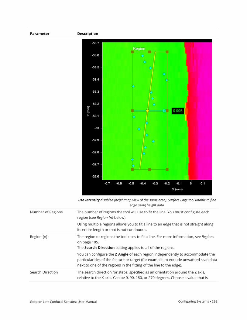
Gocator Line Confocal Sensors: User Manual Configuring Systems • 298
Parameter Description
Use Intensity disabled (heightmap view of the same area): Surface Edge tool unable to findedge using height data.
Number of Regions The number of regions the tool will use to fit the line. You must configure eachregion (see Region {n} below).
Using multiple regions allows you to fit a line to an edge that is not straight alongits entire length or that is not continuous.
Region {n} The region or regions the tool uses to fit a line. For more information, see Regionson page 105.The Search Direction setting applies to all of the regions.
You can configure the Z Angle of each region independently to accommodate theparticularities of the feature or target (for example, to exclude unwanted scan datanext to one of the regions in the fitting of the line to the edge).
Search Direction The search direction for steps, specified as an orientation around the Z axis,relative to the X axis. Can be 0, 90, 180, or 270 degrees. Choose a value that is

Gocator Line Confocal Sensors: User Manual Configuring Systems • 299
Parameter Description
roughly perpendicular to the edge on the target.
The direction is indicated by a light blue arrow in the data viewer.
Fixed Angle
Dependent settings
Fixed Angle Value
When this option is enabled, the value in Fixed Angle Value replaces the value theZ Angle measurement returns.
Useful when the angle of the feature is known and noise in the scan data couldotherwise cause the measurement to return an incorrect angle.
Path Spacing Sets the spacing between paths in the measurement region used to extract theprofiles that determine the edge. A higher number of paths results in a highernumber of edge points, which makes the fitting of the edge line more accurate.However, a higher number of edge points results in a greater tool execution time.
When Path Spacing is set to 0, the resolution of the scan data is used as the basisfor spacing. No paths are displayed in the data viewer in this case.
Path Width The size of the windows perpendicular to the path used to calculate an average foreach data point on a path profile. Useful to average out noise along the pathcaused by reflections, and so on.
If Path Width is set to 0, no averaging is performed (only the data point under thepath is used).
For averaging along the path, use Step Smoothing (see below).
Outlier Fraction The percentage of outlier points to exclude. Setting this to a small value can helpthe tool fit the line better to the edge.

Gocator Line Confocal Sensors: User Manual Configuring Systems • 300
Parameter Description
Outlier Fraction set to a low value: rejected outlier edge points are dark blue.
Edge Detection Mode One of the following: Step or Corner.
Step: Searches for steps on each path profile. For additional settings when youchoose this mode, see Step Edge Detection Mode Parameters on the next page.
Corner: Searches for slopes on each path profile. When you choose this mode,several of the tool's parameters are hidden.
Selection Type
Corner Type
Determines which step (when Edge Detection Mode is set to Step) or corner(when Edge Detection Mode is set to Corner) the tool uses on each path profilewhen there are multiple steps or corners in the profile. An edge point is placed oneach chosen step or corner. Steps must pass the criteria of the tool's AbsoluteThreshold, Step Direction, and Relative Threshold settings (see Step EdgeDetection Mode Parameters on the next page).
Best: Selects the greatest step or corner on each path profile.

Gocator Line Confocal Sensors: User Manual Configuring Systems • 301
Parameter Description
First: Selects the first step or corner on each path profile.
Last: Selects the last step or corner on each path profile.
When Edge Detection Mode is set to Corner, the following additional options areavailable in Corner Type:
Top: Selects the top-most corner on each path profile.
Bottom: Selects the bottom-most corner on each path profile.
Show Detail When disabled, hides the light blue path lines and edge points.
External ID The external ID of the tool that appears in GoHMI Designer. For more information,see GoHMI and GoHMI Designer on page 501.
The following parameters are only displayed if you set Edge Detection Mode to Step.
Step Direction Determines whether the expected step rises or falls along the path, moving fromleft to right. Either Rising, Falling, or Rising or Falling.
Absolute Threshold When Use Intensity is disabled, the setting specifies the minimum heightdifference between points on a path profile for that step to be considered for anedge point.
The setting can be used to exclude smaller steps on a part that should not beconsidered for an edge, or to exclude height differences caused by noise. Whenused in conjunction with Relative Threshold, Absolute Threshold is typically setto a small value, greater than the general surface roughness.
In the image below, when Absolute Threshold is left at the default of 0, all stepsare included as possible candidates for an edge, and will be used to fit an edgeline. The resulting edge line is angled upward to the left.
Step Edge Detection Mode Parameters

Gocator Line Confocal Sensors: User Manual Configuring Systems • 302
When Absolute Threshold is set to 3 with the same data (see image below), stepsgoing from the yellow to pink regions (roughly 1.37 mm) and from the blue toyellow regions (roughly 2 mm) are excluded. Only steps from the blue to pinkregions (roughly 3 mm) are included.

Gocator Line Confocal Sensors: User Manual Configuring Systems • 303
When Use Intensity is enabled, the setting specifies the minimum difference inintensity. (Acquire Intensitymust enabled in the Scan Mode panel.)
Use Relative Threshold When this option is enabled, the Relative Threshold field is displayed.
Relative Threshold The value for the relative threshold.
The tool calculates a relative threshold by scaling the greatest height or intensitydifference found on the path profiles by the percentage in Relative Threshold.This lets you configure the tool without knowing the actual step height in advance,and is useful for edges with varying step height.
For a height or intensity difference to be considered a valid step, both AbsoluteThreshold and Relative Thresholdmust pass.
Step Smoothing The size of the windows along the path used to calculate an average for each datapoint on a path profile. The setting is useful for averaging out noise.

Gocator Line Confocal Sensors: User Manual Configuring Systems • 304
If Step Smoothing is set to 0, no averaging is performed (only the data pointunder the path is used).
For averaging perpendicular to the path, use Path Width (see above).
Step Width The distance, along a path profile, separating the points used to find steps on apath profile.
The setting is useful when you must detect a slope as an edge, rather than asharply defined edge: setting Step Width to a value greater than the width of theedge ensures that the tool measures the height difference between the flatregions on either side of the edge. As a result, the height of the step is accuratelymeasured, and the edge is correctly located.
Setting Step Width wider than necessary can reduce the precisionof edge location.
Max Gap Fills in regions of missing data caused by an occlusion near the desired edge. Usethis setting when continuity on the target is expected. WhenMax Gap is set to anon-zero value, the tool holds and extends the last data point on the low side nextto an edge across a gap of null points, up to the distance specified inMax Gap.

Gocator Line Confocal Sensors: User Manual Configuring Systems • 305
Include Null Edges Indicates whether null points (points where no height or intensity value isavailable, due to dropouts or regions outside of the measurement range) are filledwith the value in Null Fill Value as a general “background level.” If Use Intensity(see above) is enabled, the intensity value in Intensity Null Fill Value is also used.
A typical example is a discrete part produced by the part detection of an objectsitting on a flat background (for more information on part detection, see ProfilePart Detection on page 181). The background is not visible in the part, so the toolassumes that any null region are at the background level.
To find edges along a region of null points, you must use eitherthis option and an appropriate value in Null Fill Value (andIntensity Null Fill Value if Use Intensity is enabled) orMax Gap.Otherwise, only edges within areas of contiguous data will bedetected.
Null Fill Value The height value (in mm) used to replace null points not filled byMax Gap whenInclude Null Edges is enabled.
Intensity Null Fill Value The intensity value (0-255) used to replace null points when Include Null Edgesand Use Intensity are enabled.
Edge Mode One of the following:
Projected: The line fitted to the edge is projected onto the XY plane. This mode istypically used with an edge that is parallel to the XY plane. (Shown on a slopededge to illustrate its effect.)

Gocator Line Confocal Sensors: User Manual Configuring Systems • 306
3D: The line fitted to the edge follows the slope of the edge. This mode is typicallyused with a sloped edge.
Outputs
All tools provide measurements, geometric features, or data as outputs.

Gocator Line Confocal Sensors: User Manual Configuring Systems • 307
Outputs section with a measurement expanded to show user-configurable decision min/max fields and an external ID
You configure theMin andMax parameters by expanding the measurement in the Outputs section.In order for a measurement to return a Pass decision, the measurement must be between maximumand minimum values; the range is inclusive.

Gocator Line Confocal Sensors: User Manual Configuring Systems • 308
Measurement Illustration
X
Returns the X position of the center point of the fittededge line.
Y
Returns the Y position of the center point of the fittededge line.
Z
Returns the Z position of the center point of the fittededge line.
Z Angle
Returns the rotation, around the Z axis, of the fittededge line. Rotating the measurement region has noimpact on the angle that is returned unless a differentedge is detected.
Useful for using minor variations in the rotation of anedge on target as an anchor for other measurements.For more information, see Measurement Anchoring onpage 116.
Step Height
Returns the height of the step, calculated by averagingthe step heights of all of the path profiles.
(When Use Intensity is enabled, the value returned isthe difference in intensity.)
This measurement returns Invalid when EdgeDetection Mode is set to Corner.
Point Count
The number of points used to fit the line. Useful fordetermining if the number of points is above anacceptable minimum.
Measurements

Gocator Line Confocal Sensors: User Manual Configuring Systems • 309
Measurement Illustration
Min Error
Max Error
These measurements return the distances of the pointfurthest before the line (Min Error) and the pointfurthest after the line (Max Error), based on the searchdirection specified in the tool.
The measurements ignore points excluded using the
Type Description
Edge Line The fitted edge line.
Center Point The intersection point of the fitted edge line and the line representing the searchdirection through the center of the region of interest.
Edge Plane A plane on the XZ axes at the fitted edge line.
Features
For more information on geometric features, see Geometric Features on page 115.
Type Description
Profile Point Cloud
Profile Region {n}
A point cloud profile (Profile Point Cloud) and one or more uniform spacing profiles(Profile Region {n}) representing the edge, respectively, made up of the tool's edgepoints. The XY positions of the edge points on the surface (cyan dots below) arerepresented as the XZ positions of the profile points, where X => X and Y => Z.
Given the following edge, the resulting profile is shown further below:
Data

Gocator Line Confocal Sensors: User Manual Configuring Systems • 310
Type Description
The profile is mirrored vertically when compared to the edge: Note how the singleedge point toward the top of Region 1 in the surface data above is at the bottom ofthe extracted profile (below).

Gocator Line Confocal Sensors: User Manual Configuring Systems • 311
Surface Ellipse
The Ellipse tool provides measurements for the major and minor axis lengths of an ellipse roughlyaligned to the part's shape in the XY plane, and also for the ratio of the major and minor axis lengthsand for the orientation angle of the ellipse. The tool is typically used to find the general orientation ofa part, for example, potatoes on a conveyor that are longer in one dimension than the other.
Note that the ellipse fit is not the minimum area ellipse around the data. (Technically, it is the ellipsewith matching moments as the data.) For surfaces with no holes, this results in an ellipseapproximately the same size and orientation of the part. But for surfaces with holes, the resultingellipse can be larger than the part.
(The following screenshot is from a G2 sensor.)
For information on adding, managing, and removing tools, as well as detailed descriptions of settingscommon to most tools, see Tool Configuration on page 104.
Inputs
You configure the tool's inputs in the expandable Inputs section.

Gocator Line Confocal Sensors: User Manual Configuring Systems • 312
To use a measurement as an anchor, it must be enabled and properly configured in the toolproviding the anchor. For more information on anchoring, see Measurement Anchoring onpage 116.
Name Description
Surface Input The data the tool applies measurements to or processes.
Anchor X
Anchor Y
Anchor Z
The X, Y, or Z measurement of another tool that this tool uses as a positionalanchor. Positional anchors are optional.
Anchor Z Angle The Z Angle measurement of another tool to use as a rotational anchor for thistool. Rotational anchors are optional.
Inputs
Parameters
You configure the tool's parameters in the expandable Parameters section.

Gocator Line Confocal Sensors: User Manual Configuring Systems • 313
Parameter Description
Asymmetry Resolves the orientation of an object over 360 degrees. The possible values are:
0 – None
1 – Along Major Axis
2 – Along Minor Axis
Use Region When enabled, displays Region parameters (see below). When disabled, the tooluses all data.
Region The region to which the tool's measurements will apply. For more information, seeRegions on page 105.
External ID The external ID of the tool that appears in GoHMI Designer. For more information,see GoHMI and GoHMI Designer on page 501.
Parameters
Outputs
All tools provide measurements, geometric features, or data as outputs.
Outputs section with a measurement expanded to show user-configurable decision min/max fields and an external ID
You configure theMin andMax parameters by expanding the measurement in the Outputs section.In order for a measurement to return a Pass decision, the measurement must be between maximumand minimum values; the range is inclusive.

Gocator Line Confocal Sensors: User Manual Configuring Systems • 314
Measurement Illustration
Major
Determines the major axis length of an ellipse fitted tothe part's area in the XY plane.
Minor
Determines the minor axis length of an ellipse fitted tothe part's area in the XY plane.
Ratio
Determines the minor/major axis ratio of an ellipsefitted to the part's area in the XY plane.
Z Angle
Determines the orientation angle of an ellipse fitted tothe part's area in the XY plane.
Measurements
Type Description
Center Point The center point of the fitted ellipse.
Major Axis Line A line representing the major axis of the fitted ellipse.
Minor Axis Line A line representing the minor axis of the fitted ellipse.
Features
For more information on geometric features, see Geometric Features on page 115.

Gocator Line Confocal Sensors: User Manual Configuring Systems • 315
Surface Extend
The Extend tool creates a new surface by appending part of the previous frame's data to the currentframe's data. The tool outputs the new surface data, which can be used as input by other tools.
The following shows how the tool combines data:
Data is only appended in one direction. Partial objects in the resulting surface output from the toolmust be filtered out using downstream tools, for example, excluding them based on the expectedarea.
For information on adding, managing, and removing tools, as well as detailed descriptions of settingscommon to most tools, see Tool Configuration on page 104.
Inputs
You configure the tool's inputs in the expandable Inputs section.

Gocator Line Confocal Sensors: User Manual Configuring Systems • 316
To use a measurement as an anchor, it must be enabled and properly configured in the toolproviding the anchor. For more information on anchoring, see Measurement Anchoring onpage 116.
Name Description
Surface Input The data the tool applies measurements to or processes.
Inputs
Parameters
You configure the tool's parameters in the expandable Parameters section.

Gocator Line Confocal Sensors: User Manual Configuring Systems • 317
Parameter Description
Direction Determines whether the previous frame's data is appended above or below the current frame's
data.
One of the following. Note that these settings depend on whether the trigger source has been
set to Encoder (see Triggers on page 75) and the orientation of the sensor.
l Auto: Choose this when Encoder is selected as the trigger source, in which case the tool willdetect the direction of travel relative to encoder increase / decrease.
l Forward: Choose this option when the trigger source is not set to Encoder and thedirection of motion matches the sensor's positive Y axis.
l Backward: Choose this option when the trigger source is not set to Encoder and thedirection of motion is the opposite of the sensor's positive Y axis.
Overlap Length The amount, in millimeters, of the previous frame's data to append to the current frame's data.
The combination will be output as tool data. Choose the overlap length to accommodate the
size of your scan targets.
Mode Determines the mode of the tool. One of the following:
l Normal: The tool's output is unlocked and functions normally.
l Lock: Lets you lock the current processing and outputs of the tool. Useful when you needto add another tool that will use this tool's output (for example, a Surface Section tool). Ifyou do not lock the tool, as soon as you add the other tool, the output is cleared, whichmeans you must re-execute the combined output again to configure the additional tool. Besure to unlock the tool after you have configured any other tools.
External ID The external ID of the tool that appears in GoHMI Designer. For more information, see GoHMI
and GoHMI Designer on page 501.
Parameters
Outputs
All tools provide measurements, geometric features, or data as outputs.

Gocator Line Confocal Sensors: User Manual Configuring Systems • 318
Type Description
Extended Surface Data containing an extended surface, available for use as input in the Stream drop-down in
other tools.
Data

Gocator Line Confocal Sensors: User Manual Configuring Systems • 319
Surface Filter
The Filter tool provides several common vision processing filters that you can apply to surface data,as well as a two "cropping" filters that output a subset of the surface data, letting you pre-processscan data to get more repeatable measurements. Any Surface or Feature tool can use the resultingfiltered surface data as input.
For a list of the filters, see Filters on page 321.
The Filter tool provides no measurements or decisions, as its only purpose is to output processedsurface data.
For information on adding, managing, and removing tools, as well as detailed descriptions of settingscommon to most tools, see Tool Configuration on page 104.
Inputs
You configure the tool's inputs in the expandable Inputs section.
To use a measurement as an anchor, it must be enabled and properly configured in the toolproviding the anchor. For more information on anchoring, see Measurement Anchoring onpage 116.
Name Description
Surface Input The data the tool applies measurements to or processes.
Anchor X
Anchor Y
Anchor Z
The X, Y, or Z measurement of another tool that this tool uses as a positionalanchor. Positional anchors are optional.
Anchor Z Angle The Z Angle measurement of another tool to use as a rotational anchor for thistool. Rotational anchors are optional.
Inputs

Gocator Line Confocal Sensors: User Manual Configuring Systems • 320
Parameters
You configure the tool's parameters in the expandable Parameters section.
Parameter Description
Show Advanced Filters When enabled, displays advanced filters in Filter Type (see below), in addition tothe standard filters (Gap Filling, Median, Averaging, and Decimation).
Regions When expanded, displays the region- and mask-related settings.
Enable Enables regions and displays the region- and mask-related settings (see below).
Mask Mode
Number of Regions
Region Type {n}
Region {n}
When you enable regions (see above), the tool displays additional settings relatedto the region type. For details on the regions supported by this tool and theirsettings, see Flexible Regions on page 106.
For general information on regions and the difference between standard and"flexible" regions, see Regions on page 105.
Use Intensity If enabled, the tool uses intensity data instead of Surface data. Only usable ifAcquire Intensity is enabled on the Acquire > Scanners page during scanning.Only available in the advanced filters (see above); for information on the availablefilters, see Filters on the next page.
If disabled, the tool filters using Surface data; intensity data corresponding tofiltered heightmap data will also be removed.
For more information on scan modes, see Scan Modes on page 71.
Units Specifies whether filters use data points (pts) or millimeters (mm). Not available
Parameters

Gocator Line Confocal Sensors: User Manual Configuring Systems • 321
Parameter Description
with all filters.
Filter Type The type of the filter. For information on the available filters, see Filters below.
Preserve Data OutsideRegion
Enable this setting whenMask Mode is set to Include Data in Region to includedata outside the region in the Filtered Surface data output. Otherwise, the FilteredSurface data output only includes the data in the region.
This setting is only displayed if regions are enabled.
Threshold The threshold that the filter uses. (Not available on all filters.)
Symmetry One of the following: Symmetrical, Horizontal, or Vertical. (Not available on allfilters.)
Kernel Size The kernel size that the filter uses. (Not available on all filters.)
Filter in X
Filter in Y
These parameters enable filtering along the X and the Y axis, respectively. Set thecorresponding window sizes in X Windows Size and Y Window Size.
External ID The external ID of the tool that appears in GoHMI Designer. For more information,see GoHMI and GoHMI Designer on page 501.
The following filters are available in the Filter tool. Filters described below as advanced are onlydisplayed if Show Advanced Filters is enabled.
Name Description
Gap Filling Fills in missing data caused by occlusions using information from the nearestneighbors. Gap filling also fills gaps where no data is detected, which can be due tothe surface reflectivity, for example dark or specular surface areas, or to actualgaps in the surface. The value in X Window Size represents the maximum gapwidth that the sensor will fill. Gaps wider than the maximum width will not befilled.
Gap filling works by filling in missing data points using either the lowest valuesfrom the nearest neighbors or linear interpolation between neighboring values(depending on the Z difference between neighboring values), in the specifiedwindow.
Median A median filter.
Averaging An averaging / mean / smoothing filter.
Decimation A decimation filter.
Gaussian (advanced) A Gaussian filter. Set the Sigma parameter as required.
Open (advanced) Erosion followed by dilation.
Close (advanced) Dilation followed by erosion.
Erode (advanced) Applies an erosion filter. Lets you specify the direction of the erosion; one of thefollowing:
l Horizontall Vertical
Filters

Gocator Line Confocal Sensors: User Manual Configuring Systems • 322
Name Description
l Symmetrical
Dilation (advanced) Applies a dilation filter. Lets you specify the direction of the dilation; one of thefollowing:
l Horizontall Verticall Symmetrical
Morph Gradient(advanced)
Applies a morphological gradient. The difference between dilation and erosion.
Sobel Magnitude(advanced)
Applies a Sobel magnitude filter.
Lets you specify the direction of the filter; one of the following:
l Horizontall Verticall Symmetrical
Laplacian (advanced) Applies a Laplacian filter. Useful for detecting areas of distinct edges. Uses thefollowing kernel:
Negative (advanced) Inverts the height or intensity values in the scan data. When Use Nulls is enabled,null values in the input are replaced by the highest height value.
Equalize (advanced) Normalizes the norm or value range of an array.
Binarize (advanced) Sets height values to a fixed value for each point that is present in the data. Can beused with a region Z offset to threshold points above/below a Z value.
With intensity data, sets any point over
Percentile (advanced) Limits the scan data to points between the values you set in High Percentile andLow Percentile, which are displayed when you choose this option.
Relative Threshold(advanced)
Crops scan data based on user-specified minimum and a maximum heights. UseReference Region to set the heights relative to a reference region.
Crop only (advanced) Crops the scan data to the user-defined region.
Mask With Input Uses the surface input into the tool as a mask on the data. Any points in thefiltered data will be set to null if the input surface is null at the same location.
For example, the Gaussian filter can extend data along the edges, adding data inareas that contain null values. This filter would remove data that the Gaussianfilter introduces, preserving the null values.
This filter should follow any filter that introduces this kind of unwanted data.
Outputs
All tools provide measurements, geometric features, or data as outputs.

Gocator Line Confocal Sensors: User Manual Configuring Systems • 323
Type Description
Filtered Surface The filtered data, available for use as input in the Stream drop-down in othertools.
Data

Gocator Line Confocal Sensors: User Manual Configuring Systems • 324
Surface Flatness
The Flatness tool returns various measurements related to the flatness of one or more regions onthe surface of your target. The tool is ideal for general fit and finish inspection.
The tool lets you set a grid over a specific region, or more flexibly with multiple individual regionsmanually. In each case, "local" minimum and maximum heights, as well as flatness indicators(maximum - minimum), are returned (for grid cells or individual regions, depending on the tool'ssettings). In addition, "global" minimum, maximum, and flatness measurements, which combinedata from all flatness measurement areas, can also be returned. The tool measures the maximumand minimum distances from a different best-fit plane for each local measurement, and fromanother plane fit to all data for the "global" measurements.
You can control how many data points the tool uses in its calculations to account for noise orsmooth data, or otherwise exclude unwanted data.
For information on adding, managing, and removing tools, as well as detailed descriptions of settingscommon to most tools, see Tool Configuration on page 104.
Inputs
You configure the tool's inputs in the expandable Inputs section.
To use a measurement as an anchor, it must be enabled and properly configured in the toolproviding the anchor. For more information on anchoring, see Measurement Anchoring onpage 116.
Name Description
Surface Input The data the tool applies measurements to or processes.
Anchor X
Anchor Y
The X, Y, or Z measurement of another tool that this tool uses as a positionalanchor. Positional anchors are optional.
Inputs

Gocator Line Confocal Sensors: User Manual Configuring Systems • 325
Name Description
Anchor Z
Anchor Z Angle The Z Angle measurement of another tool to use as a rotational anchor for thistool. Rotational anchors are optional.
Parameters
You configure the tool's parameters in the expandable Parameters section.
Parameter Description
Region Mode Determines how flatness measurement areas are set up on the target. One of thefollowing:
Grid Pattern: The tool determines flatness in a grid you define on the target. Thisoption enables settings that let you set the size and location of a region thatcontains the grid (Grid Region setting), as well as the width and length of the gridcells (Grid Width and Grid Length). The combination of the values of thesesettings determines the number of cells in the grid region.
Parameters

Gocator Line Confocal Sensors: User Manual Configuring Systems • 326
Parameter Description
Flexible: The tool determines flatness using one or more (up to 16) regions thatyou define individually on the target.
Grid Region
(used with Grid Patternregion mode)
Determines the size of the grid region. (See details under Grid Pattern in RegionMode above.)
Grid Width (X)
Grid Length (Y)
(used with Grid Patternregion mode)
These settings determine the size of the cells in the grid. (See details under GridPattern in Region Mode above.)
Regions When expanded, displays the region- and mask-related settings.
Enable Enables regions and displays the region- and mask-related settings (see below).
Mask Mode
Number of Regions
Region Type {n}
Region {n}
When you enable regions (see above), the tool displays additional settings relatedto the region type. For details on the regions supported by this tool and theirsettings, see Flexible Regions on page 106.
For general information on regions and the difference between standard and"flexible" regions, see Regions on page 105.
Global Flatness Mode Chooses which points the tool uses to calculate global flatness. One of thefollowing:
All Points: The tool uses all points in the measurement area (all flexible regions orthe grid pattern in the region).
Single Average Point: The tool uses an average of the points in the measurementarea. When you choose this option, the global measurements require at least fourdata points to calculate the plane and statistics. This means that if you set RegionMode to Flexible, you must choose a minimum of four regions; if you set RegionMode to Grid Pattern, the size of the grid and the cells must result in at least fourcells.
Data Filtering Lets you filter scan data before the tool performs its calculations.
Percentile - Limits the data to points between the values you set in HighPercentile and Low Percentile, which are displayed when you choose this option.
None - The tool performs no filtering.
Unit Lets you choose which units the tool uses for measurement results. One of thefollowing:
l um (micrometers)l mm (millimeters)
Enable Median Detection When enabled, median (X, Y, and Z positions) is included in the OutputMeasurement data output.
External ID The external ID of the tool that appears in GoHMI Designer. For more information,see GoHMI and GoHMI Designer on page 501.
Outputs
All tools provide measurements, geometric features, or data as outputs.

Gocator Line Confocal Sensors: User Manual Configuring Systems • 327
Outputs section with a measurement expanded to show user-configurable decision min/max fields and an external ID
You configure theMin andMax parameters by expanding the measurement in the Outputs section.In order for a measurement to return a Pass decision, the measurement must be between maximumand minimum values; the range is inclusive.
Measurement
Global Max
Global Min
Global Flatness
The maximum distance, minimum distance, and flatness (maximum - minimum) calculated using the valid datapoints from all the cells in the grid (when Region Mode is set to Grid Pattern), or all the individual regions(when Region Mode is set to Flexible).
Local Max {n}
Local Min {n}
Measurements

Gocator Line Confocal Sensors: User Manual Configuring Systems • 328
Measurement
Local Flatness {n}
The maximum distance, minimum distance, and flatness (maximum - minimum) calculated using the valid datapoints from a specific grid cell (when Region Mode is set to Grid Pattern), or an individual regions (whenRegion Mode is set to Flexible).
Clicking a local measurement in the list of measurements selects the corresponding cell or region in the dataviewer.
Type Description
Global Plane The plane fitted to the valid data points from all the cells in the grid (when RegionMode is set to Grid Pattern), or all the individual regions (when Region Mode isset to Flexible).
Local Plane {n} The plane fitted to the valid data points from grid cell {n} (when Region Mode isset to Grid Pattern), or those from region {n} (when Region Mode is set toFlexible).
Clicking a local plane in the list of features selects the corresponding cell or regionin the data viewer.
Features

Gocator Line Confocal Sensors: User Manual Configuring Systems • 329
Surface Hole
The Hole tool measures a circular opening within a region of interest on the surface and returns itsposition and radius.
The tool does not search for or detect the feature. The tool expects that the feature,conforming reasonably well to the defined parameters, is present and that it is on a sufficientlyuniform background.
The hole can be on a surface at an angle to the sensor.
The tool uses a complex feature-locating algorithm to find a hold and then return measurements.For a detailed explanation of the algorithm, see Hole Algorithm on the next page. The behavior of thealgorithm can be adjusted by changing the tool's parameters.
(The following screenshot is from a G2 sensor.)
For information on adding, managing, and removing tools, as well as detailed descriptions of settingscommon to most tools, see Tool Configuration on page 104.
Measurement Region
The center of the hole must be inside the measurement region, even if the Partial Detection option isenabled. Either of the following is acceptable.

Gocator Line Confocal Sensors: User Manual Configuring Systems • 330
Hole Algorithm
The Hole tool processes the data in three phases: Search, Measure, and Filter. The algorithm canseparate out background information that appears inside the hole. It can also detect holes that onlypartially appear in the data.
See the tool's parameters for an explanation of the options that affect the tool's algorithm.
Search phase - The tool searches for coarse data transitions (edge data) and performs a coarsefitting of the hole model (specified by the orientation angles and the nominal value) to determine themost likely candidate. If Tilt Correction is set to Autoset, the algorithm uses the data within themeasurement region to estimate the orientation of the part.
Measure phase - A more rigorous edge detection algorithm is applied to precisely determine theedges around the feature. Edge detection at this stage will reject outliers and noise. The algorithmrequires at least 25% of the data around the hole for the candidate to remain valid.
The accuracy of the algorithm improves when the points are spread more evenly along the hole'scircumference.
The set of refined edges is then used to locate and inspect the feature. If the Reference Regionsoption is enabled and set to AutoSet, the edges are also used to calculate the location of thereference regions.

Gocator Line Confocal Sensors: User Manual Configuring Systems • 331
Filter phase - The detected location and dimensions are then compared to the nominal andtolerance settings. If the refined feature falls within the measurement region and its measurementsfit within the specified tolerance, the results are reported. If not, an invalid result is returned.
Inputs
You configure the tool's inputs in the expandable Inputs section.
To use a measurement as an anchor, it must be enabled and properly configured in the toolproviding the anchor. For more information on anchoring, see Measurement Anchoring onpage 116.
Name Description
Surface Input The data the tool applies measurements to or processes.
Anchor X
Anchor Y
Anchor Z
The X, Y, or Z measurement of another tool that this tool uses as a positionalanchor. Positional anchors are optional.
Inputs
Parameters
You configure the tool's parameters in the expandable Parameters section.

Gocator Line Confocal Sensors: User Manual Configuring Systems • 332
Parameter Description
Nominal Radius Expected radius of the hole.
Radius Tolerance The maximum variation from the nominal radius (+/- from the nominal radius).
Partial Detection Enable if only part of the hole is within the measurement region; the centre of thehole must be in the measurement region to be located. If disabled, the hole mustbe completely in the region of interest for results to be valid.
Use Depth Limit Data below this limit (relative to the surface) is excluded from the hole calculations.
Parameters

Gocator Line Confocal Sensors: User Manual Configuring Systems • 333
Parameter Description
Use Region When enabled, displays Region parameters (see below). When disabled, the tooluses all data.
Region The region to which the tool's measurements will apply. For more information, seeRegions on page 105.
Use Reference Region When enabled, displays additional settings to let you set a reference region (seebelow).
Reference Region The tool uses the reference regions to calculate the Z position of the hole. It istypically used in cases where the surface around the hole is not flat.
When this option is set to Autoset, the algorithm automatically determines thereference region. When the option is set to 1 Region or 2 Regions, you mustmanually define the reference regions. The location of the reference region isrelative to the detected center of the hole and positioned on the nominal surfaceplane.
When Reference Region is disabled, the tool measures the hole's Z position usingall the data in the measurement region, except for a bounding rectangular regionaround the hole.
Tilt Correction Tilt of the target with respect to the alignment plane.
Autoset: The tool automatically detects the tilt.
Custom: You must enter the X and Y angles manually in the X Angle and Y Angleparameters (see below).
X Angle
Y Angle
The X and Y angles you must specify when Tilt Correction is set to Custom.
You can use the Surface Plane tool's X Angle and Y Angle measurements to get theangle of the surrounding surface, and then copy those measurement's values tothe X Angle and Y Angle parameters of this tool. For more information, see Plane.
External ID The external ID of the tool that appears in GoHMI Designer. For more information,see GoHMI and GoHMI Designer on page 501.

Gocator Line Confocal Sensors: User Manual Configuring Systems • 334
Outputs
All tools provide measurements, geometric features, or data as outputs.
Outputs section with a measurement expanded to show user-configurable decision min/max fields and an external ID
You configure theMin andMax parameters by expanding the measurement in the Outputs section.In order for a measurement to return a Pass decision, the measurement must be between maximumand minimum values; the range is inclusive.
Measurement Illustration
X
Determines the X position of the hole center.
Y
Determines the Y position of the hole center.
Z
Determines the Z position of the hole center.
Measurements

Gocator Line Confocal Sensors: User Manual Configuring Systems • 335
Measurement Illustration
Radius
Determines the radius of the hole.
Type Description
Center Point The center point of the hole. The Z position of the center point is at the Z positionof the surrounding surface.
Features
For more information on geometric features, see Geometric Features on page 115.
Surface Mask
The Surface Mask tool lets define up to 16 regions to extract data from a surface. Each region’s size,position, and shape (circular, elliptical, polygonal, and rectangular) can be individually configured,and regions can overlap. The tool can also exclude inner data of circular and elliptical regions, lettingyou extract rings of surface data. Extracted data is output in a single surface.
The resulting surface can then be further processed or measured by other tools.
For example, given the following scan data:

Gocator Line Confocal Sensors: User Manual Configuring Systems • 336
A circle region box containing a partial ring (cyan)
The image below shows the extracted data. The extracted surface data can then be furtherprocessed by other tools, or measurements can be applied to the surface data.

Gocator Line Confocal Sensors: User Manual Configuring Systems • 337
For information on adding, managing, and removing tools, as well as detailed descriptions of settingscommon to most tools, see Tool Configuration on page 104.
Inputs
You configure the tool's inputs in the expandable Inputs section.

Gocator Line Confocal Sensors: User Manual Configuring Systems • 338
To use a measurement as an anchor, it must be enabled and properly configured in the toolproviding the anchor. For more information on anchoring, see Measurement Anchoring onpage 116.
Name Description
Surface Input The data the tool applies measurements to or processes.
Anchor X
Anchor Y
Anchor Z
The X, Y, or Z measurement of another tool that this tool uses as a positionalanchor. Positional anchors are optional.
Anchor Z Angle The Z Angle measurement of another tool to use as a rotational anchor for thistool. Rotational anchors are optional.
Inputs
Parameters
You configure the tool's parameters in the expandable Parameters section.
Parameter Description
Regions When expanded, displays the region- and mask-related settings.
Enable Enables regions and displays the region- and mask-related settings (see below).
Mask Mode
Number of Regions
Region Type {n}
When you enable regions (see above), the tool displays additional settings relatedto the region type. For details on the regions supported by this tool and theirsettings, see Flexible Regions on page 106.
Parameters

Gocator Line Confocal Sensors: User Manual Configuring Systems • 339
Parameter Description
Region {n} For general information on regions and the difference between standard and"flexible" regions, see Regions on page 105.
External ID The external ID of the tool that appears in GoHMI Designer. For more information,see GoHMI and GoHMI Designer on page 501.
Outputs
All tools provide measurements, geometric features, or data as outputs.
Type Description
Uniform Extracted Region
Point Cloud ExtractedRegion
The surface containing the extracted region or regions. (Uniform and point clouddata, respectively.)
Only one data output will contain data, depending on whether Enable uniformspacing (resampling) on the Acquire page is enabled (in which case the Uniformoutput will contain data) or disabled (in which case the Point Cloud output willcontain data). For more information, see Scan Modes on page 71.
Data

Gocator Line Confocal Sensors: User Manual Configuring Systems • 340
Surface Merge Wide
This tool is only intended for use with a multi-sensor G2 (line profile) system.

Gocator Line Confocal Sensors: User Manual Configuring Systems • 341
Surface Opening
The Opening tool locates rounded, rectangular, and rounded corner openings. The opening can beon a surface at an angle to the sensor.
The tool does not search for or detect the feature. The tool expects that the feature,conforming reasonably well to the defined parameters, is present and that it is on a sufficientlyuniform background.
The tool uses a complex feature-locating algorithm to find a hold and then return measurements.For a detailed explanation of the algorithm the tool uses, see Opening Algorithm on the next page.The behavior of the algorithm can be adjusted by changing the tool's parameters.
The tool can separate out background information that appears inside the opening. It can also detecta slot that only partially appears in the data.
The shape of the opening is defined by its type and its nominal width, length, and radius.
The orientation defines the rotation around the normal of the alignment plane.
Measurement Panel

Gocator Line Confocal Sensors: User Manual Configuring Systems • 342
For information on adding, managing, and removing tools, as well as detailed descriptions of settingscommon to most tools, see Tool Configuration on page 104.
Measurement Region
The center and the two sides and ends of the opening must be within the measurement region, evenif Partial Detection is enabled.
Opening Algorithm
The Opening tool processes the data in three phases: Search, Measure, and Filter.
See the tool's parameters for an explanation of the options that affect the tool's algorithm.
Search phase - The tool searches for coarse data transitions (edge data) and performs a coarsefitting of the opening shape (specified by the orientation angles and the nominal dimensions) todetermine the most likely candidate. If Tilt Correction is enabled, the algorithm uses the flat surfacein the measurement region to estimate the orientation of the part.
Measure phase - A more rigorous edge detection algorithm is applied to precisely determine theedges around the feature. Edge detection at this stage will reject outliers and noise. The algorithmrequires opposite sides and ends to be associated with a comparable number of edge pixels, withthe weaker side or end having at least 25% of the stronger.
The set of refined edges is then used to locate and inspect the feature. If the Reference Regionssetting is enabled, the edges are also used to calculate the location of the reference regions.
Filter phase - The detected location and dimensions are compared to the nominal and tolerancesettings. If the refined feature falls within the measurement region and its measurements fit withinthe specified tolerance, the results are reported. If not, an invalid result is returned.
Inputs
You configure the tool's inputs in the expandable Inputs section.

Gocator Line Confocal Sensors: User Manual Configuring Systems • 343
To use a measurement as an anchor, it must be enabled and properly configured in the toolproviding the anchor. For more information on anchoring, see Measurement Anchoring onpage 116.
Name Description
Surface Input The data the tool applies measurements to or processes.
Anchor X
Anchor Y
Anchor Z
The X, Y, or Z measurement of another tool that this tool uses as a positionalanchor. Positional anchors are optional.
Inputs
Parameters
You configure the tool's parameters in the expandable Parameters section.

Gocator Line Confocal Sensors: User Manual Configuring Systems • 344
Parameter Description
Type One of the following: Rounded Slot, Rectangle.
Nominal Width Nominal width of the opening.
Nominal Length Nominal length of the opening.
Nominal Angle Nominal angle of the opening. The default orientation is the length of the openingalong the X axis.
Parameters

Gocator Line Confocal Sensors: User Manual Configuring Systems • 345
Parameter Description
Nominal Radius Nominal radius of the opening ends. If the opening type is set to rectangular, theradius setting is disabled. The opening has an oval shape if the radius is equal to ½of the width. The opening is a rounded rectangle when the radius is less than ½ ofthe width.
Width Tolerance The maximum variation from the nominal width (+/- from the nominal value).
Length Tolerance The maximum variation from the nominal length (+/- from the nominal value).
Angle Tolerance The maximum variation from the nominal orientation (+/- from the nominal value).
Partial Detection Enable if only part of the opening is within the measurement region. If disabled,the opening must be completely in the region of interest for results to be valid.
Depth Limit Data below this limit (relative to the surface) is excluded from the openingcalculations.
Region The region to which the tool's measurements will apply. For more information, seeRegions on page 105.
Reference Regions The tool uses the reference regions to calculate the Z position of the opening.Reference regions are relative to the center location of the feature. This option istypically used in cases where the surface around the opening is not flat.

Gocator Line Confocal Sensors: User Manual Configuring Systems • 346
Parameter Description
When the Reference Regions setting is disabled, the tool measures the opening's Zposition using all data in the measurement region, except for a boundingrectangular region around the opening.
With one or more reference regions, the algorithm calculates the Z positions as theaverage values of the data within the regions.
When you place the reference region manually, all of the data is used, whether thedata is inside or outside the opening. You should place the reference regioncarefully.
Tilt Correction Tilt of the target with respect to the alignment plane.
Autoset: The tool automatically detects the tilt. The measurement region to covermore areas on the surface plane than other planes.
Custom: You must enter the X and Y angles manually in the X Angle and Y Angleparameters (see below).
X Angle
Y Angle
The X and Y angles you must specify when Tilt Correction is set to Custom.
You can use the Surface Plane tool's X Angle and Y Angle measurements to get theangle of the surrounding surface, and then copy those measurement's values tothe X Angle and Y Angle parameters of this tool. For more information, see Plane.

Gocator Line Confocal Sensors: User Manual Configuring Systems • 347
Parameter Description
External ID The external ID of the tool that appears in GoHMI Designer. For more information,see GoHMI and GoHMI Designer on page 501.
Outputs
Outputs section with a measurement expanded to show user-configurable decision min/max fields and an external ID
You configure theMin andMax parameters by expanding the measurement in the Outputs section.In order for a measurement to return a Pass decision, the measurement must be between maximumand minimum values; the range is inclusive.
Measurement Illustration
X
Determines the X position of the opening's center.
Y
Determines the Y position of the opening's center.
Z
Determines the Z position of the opening's center.
Measurements

Gocator Line Confocal Sensors: User Manual Configuring Systems • 348
Measurement Illustration
Width
Determines the width of the opening.
Length
Determines the length of the opening.
Z Angle
Determines the angle (rotation) around the normal ofthe alignment plane.
Type Description
Center Point The center point of the opening. The Z position of the center point is at the Zposition of the surrounding surface.
Features
For more information on geometric features, see Geometric Features on page 115.

Gocator Line Confocal Sensors: User Manual Configuring Systems • 349
Surface Pattern Matching
The Surface Pattern Matching tool locates parts and features by comparing 2D contours (on theXY plane) found in scan data to pattern models you have defined; note that the tool does not useheight data in its algorithms. Models represent contour-based “golden parts” or “golden features.”
The tool can process multiple occurrences of a part or feature in a frame of scan data. For eachmatching part or feature (called an instance), the tool returns an X and Y position and a rotation,which can be used to anchor other measurements. The tool also returns a point and a line geometricfeature for each instance, which you can use in conjunction with Surface Transform tools to shift androtate scan data to reliably position the target; this can be used as an improved way of performingthe part matching that is available on theModel page. Finally, the tool returns a match quality thatyou can use as a general conformity measure for matching instances (for example, checking fordents in a target), as well as a count of located instances.
In order to create a template for a feature on a target, you typically need to enable the UseRegion checkbox to limit the tool to the contours related to that feature. After that, whenrunning the tool to find instances of the feature, you should either modify the region to limit itto areas of the target that might contain the feature you are looking for or disable Use Regionso that the tool can locate instances of the feature in all of the scan data. You can also use theUse Region parameter when creating a template to limit it to a unique portion of an outer edgeof a target.

Gocator Line Confocal Sensors: User Manual Configuring Systems • 350
For information on adding, managing, and removing tools, as well as detailed descriptions of settingscommon to most tools, see Tool Configuration on page 104.
Note that when you use the geometric features with a Surface Transform tool to transform the scandata from frame to frame, you can often avoid the need to anchor other measurements, becausethe transforms ensure that any features you are interested are always in the same location. This cansave considerable setup time and reduce the complexity of an application. For example, in thefollowing frames of scan data, in which a PCB shifts from frame to frame, a Surface Pattern Matchingtool successfully locates the entire PCB using its outer contours and the contours of variouscomponents on the PCB, as indicated by a dark blue outline. Note the “missing” data in the secondand fourth frames, on the lower right and left edges, respectively: the tool still locates the PCB,despite the occlusions.
Four frames of scan data. Dark blue outline represents the matching template. The first frame was used to create thetemplate.
When the tool’s Point and Line geometric features are passed to a Surface Transform tool, thetransformed scan data ensures that, for example, the set of seven mid-sized capacitors above themain IC are always in the same location and orientation.
Transformed scan data of the four frames.
Other measurement tools can then be placed over the capacitors, without needing to anchor them.In the following image (the fourth frame, which was significantly shifted and rotated), a Surface Filtertool isolates the capacitors based on height. Subsequent tools can perform measurements on theisolated data to verify that all capacitors are present, are seated properly, and so on.

Gocator Line Confocal Sensors: User Manual Configuring Systems • 351
By adding multiple Surface Pattern Matching tools to a job and defining different templates for each,you can match multiple types of features or parts, for example, matching different parts moving on aconveyor.
Two copies of the Surface Pattern Matching tool matching parts using two different templates (one for the sockets, anotherfor the capacitors). If used in conjunction with Part Detection, each part would be in an individual frame, matching templates
as necessary.
Or you can match different types of features on a single target:

Gocator Line Confocal Sensors: User Manual Configuring Systems • 352
Rectangular surface mount components (two orientations) matching one template. Circular capacitors matching anothertemplate (matched orientations are arbitrary, because a circular contour is matched). In this case, intensity was used for
template creation and matching.
Creating a Template
To create a template:
1. Scan a part that is typical (no damage, all features are present, etc.).
2. If you need to perform pattern matching on a feature on the part, enable Use Region and position theregion over the feature.
3. In the Operation drop-down, choose Create.
The tool creates a model and saves it either to the PC (if the sensor is accelerated, toC:\GoTools\SurfacePatternMatching) or to the sensor.
After creating a template, configure the tool's parameters (see below) for use during productionruns.
Inputs
You configure the tool's inputs in the expandable Inputs section.

Gocator Line Confocal Sensors: User Manual Configuring Systems • 353
To use a measurement as an anchor, it must be enabled and properly configured in the toolproviding the anchor. For more information on anchoring, see Measurement Anchoring onpage 116.
Name Description
Surface Input The data the tool applies measurements to or processes.
Anchor X
Anchor Y
Anchor Z
The X, Y, or Z measurement of another tool that this tool uses as a positionalanchor. Positional anchors are optional.
Inputs
Parameters
You configure the tool's parameters in the expandable Parameters section.

Gocator Line Confocal Sensors: User Manual Configuring Systems • 354
Parameter Description
Use Region Determines whether the tool uses a user-defined region to search for matchinginstances, or, when first creating a template, whether the tool limits establishingtemplate contours to the data in the ROI.
Region Settings related to the region. For more information, see Regions on page 105.
Use Intensity Determines whether the tool uses intensity instead of heightmap data to locateinstances or create templates.
Nominal Scale Enabled If Nominal Scale Enabled is checked, the tool displays the Nominal Scale settingand the tool uses the user-defined nominal scale. Otherwise, the tool displaysMinimum Scale andMaximum Scale settings and uses the user-defined range.
Nominal Scale The scale factor the tool requires to recognize an instance.
Displayed when Nominal Scale Enabled is enabled.
Minimum Scale
Maximum Scale
The maximum and minimum scale factors allowed for the tool to recognize aninstance, respectively.
Displayed when Nominal Scale Enabled is disabled.
Parameters

Gocator Line Confocal Sensors: User Manual Configuring Systems • 355
Parameter Description
Nominal Angle Enabled If enabled, displays the Nominal Angle setting and the tool uses the user-definednominal angle. Otherwise, the tool displaysMinimum Angle andMaximumAngle settings and uses the user-defined range.
Nominal Angle The angle the tool requires to recognize an instance.
Displayed when Nominal Angle Enabled is enabled.
Minimum Angle
Maximum Angle
The maximum and minimum angles allowed for the tool to recognize an instance,respectively.
Displayed when Nominal Angle Enabled is disabled.
Minimum Match Quality Minimum percentage of template contours that must match in the scan data forthe tool to consider the object instance as valid.
Show Detail Toggles whether to overlay a blue outline over scan data representing thecurrently loaded template’s contours.
Pattern When expanded, displays parameters related to template files.
File
A drop-down containing the currently available templates.
Operation
The operation to perform on the currently selected template in the File drop-down.One of the following:
Normal: The default value after having performed another operation.
Create: Creates a new template based on the current frame of scan data. Limitedto the region if Use Region is enabled.
Load: Loads the currently selected template.
Save: Saves contour data to the currently selected template, overwriting itscontour data.
Delete: Deletes the currently selected template.
Refresh: Refreshes the list of templates. This is useful if you have renamed atemplate (using the Pattern Editor or manually in the client PC's file system).
Advanced When enabled, the tool displays the following additional advanced parameters.
Sorting
The sort order of instances the tool uses. One of the following:
l Evidence: The instances are ordered according to their hypothesis strength.
l Quality: The instances are ordered according to their match quality. Thissetting can significantly increase the tool's search time because it can't output

Gocator Line Confocal Sensors: User Manual Configuring Systems • 356
Parameter Description
instance results until it has found and compared all instances to determinetheir order. The time required to output the first instance corresponds to thetotal time needed to search the image and analyze all the potential instances.The time for additional instances is zero since the search process is alreadycomplete.
l Position - X increasing
l Position - X decreasing
l Position - Y increasing
l Position - Y decreasing
Recognition Level
The "effort" the tool will expend on recognizing an instance in scan data. Rangesfrom Fast to Accurate (that is, there is a trade-off between accuracy and speed).Only used during pattern matching (and not during pattern template creation).
Positioning Level
How accurately the tool determines the position of the instance. Ranges from Fastto Accurate. Only used during pattern matching (and not during pattern templatecreation).
Match Tolerance Mode
The tolerance the tool uses when attempting to match contours in the scan data tothe loaded template; this is the maximum distance between the contours in thetemplate and in the scan data. Either Pattern-based (a looser tolerance, thedefault), Resolution-based (a tighter tolerance), or Manual. Typically, the Pattern-based option should produce a better match quality. However, if you are gettingtoo many false matches, try setting the mode to Resolution-based or set the valuemanually. The tolerances calculated from the pattern-based and resolution-basedmodes are displayed in the mode drop-down.
Note that the resolution-based mode results in a much tighter tolerance with highresolution scan data.
Add Border
Considers a drop to NULL, outside the region, as an edge. Use this whenperforming part detection or when there is no data around the part. If there isnothing in the region, then there will be nothing in the template either.
Instance Count The maximum number of instances the tool will locate.
External ID The external ID of the tool that appears in GoHMI Designer. For more information,see GoHMI and GoHMI Designer on page 501.

Gocator Line Confocal Sensors: User Manual Configuring Systems • 357
Outputs
All tools provide measurements, geometric features, or data as outputs.
Outputs section with a measurement expanded to show user-configurable decision min/max fields and an external ID
You configure theMin andMax parameters by expanding the measurement in the Outputs section.In order for a measurement to return a Pass decision, the measurement must be between maximumand minimum values; the range is inclusive.
Measurement
Instance Count
Returns the number of parts or features matching the loaded template up to the value set in the InstanceCount parameter.
X {n}
Y {n}
The X and Y position of the center of matched instance {n}.
Z Angle {n}
The angle of matched instance {n} relative to the sensor’s coordinate system.
Measurements

Gocator Line Confocal Sensors: User Manual Configuring Systems • 358
Measurement
Scale {n}
The scale of matched object {n} relative to the loaded template.
Match Quality {n}
Percentage of matched model contours for the selected object instance. Match quality ranges from 0 to 100,with 100 being the best quality. A value of 100 means 100% of the model contours were successfully matchedto the actual contours detected in the scan data. Use theMinimum Match Quality parameter to set theminimum acceptable value.
Type Description
Point A point representing the center of the region used when creating a template andthe template’s default reference point. (Note that the reference point of a templatecan be changed in the model editor.)
Line A line parallel to the X axis passing through the Point feature.
Features
For more information on geometric features, see Geometric Features on page 115.

Gocator Line Confocal Sensors: User Manual Configuring Systems • 359
Surface Plane
The Plane tool provides measurements that report a plane's position and orientation (X Angle, YAngle, Z Offset, Normal, Distance), as well as the maximum and average deviations from the plane.
The Z offset reported is the Z position at zero position on the X axis and the Y axis.
The results of the Angle X and Angle Y measurements can be used to manually customize the tiltangle in the Hole, Opening, and Stud tools.
For information on adding, managing, and removing tools, as well as detailed descriptions of settingscommon to most tools, see Tool Configuration on page 104.
Inputs
You configure the tool's inputs in the expandable Inputs section.
To use a measurement as an anchor, it must be enabled and properly configured in the toolproviding the anchor. For more information on anchoring, see Measurement Anchoring onpage 116.
Name Description
Surface Input The data the tool applies measurements to or processes.
Anchor X
Anchor Y
Anchor Z
The X, Y, or Z measurement of another tool that this tool uses as a positionalanchor. Positional anchors are optional.
Anchor Z Angle The Z Angle measurement of another tool to use as a rotational anchor for thistool. Rotational anchors are optional.
Inputs
Parameters
The following parameters are in the expandable Parameters section in the tool's configuration.

Gocator Line Confocal Sensors: User Manual Configuring Systems • 360
Parameter Description
Regions When expanded, displays the region- and mask-related settings.
Enable Enables regions and displays the region- and mask-related settings (see below).
Mask Mode
Number of Regions
Region Type {n}
Region {n}
When you enable regions (see above), the tool displays additional settings relatedto the region type. For details on the regions supported by this tool and theirsettings, see Flexible Regions on page 106.
For general information on regions and the difference between standard and"flexible" regions, see Regions on page 105.
External ID The external ID of the tool that appears in GoHMI Designer. For more information,see GoHMI and GoHMI Designer on page 501.
Parameters

Gocator Line Confocal Sensors: User Manual Configuring Systems • 361
Outputs
Outputs section with a measurement expanded to show user-configurable decision min/max fields and an external ID
You configure theMin andMax parameters by expanding the measurement in the Outputs section.In order for a measurement to return a Pass decision, the measurement must be between maximumand minimum values; the range is inclusive.

Gocator Line Confocal Sensors: User Manual Configuring Systems • 362
Measurement Illustration
X Angle
Determines the X angle of the surface with respect tothe alignment target.
Y Angle
Determines the Y angle of the surface with respect tothe alignment target.
Z Offset
Determines the Z value of intersection of the planeand the Z axis.
Standard Deviation
Measures the standard deviation of the points of thesurface from the detected plane within the specifiedregion or regions.
Min Error
Measures the minimum error from the detected plane(the maximum distance below the plane,perpendicular to the plane) within the specified regionor regions.
Max Error
Measures the maximum error from the detected plane(the maximum distance above the plane,perpendicular to the plane) within the specified regionor regions.
Normal X
Returns the X component of the surface normalvector.
Normal Y
Returns the Y component of the surface normalvector.
Normal Z
Returns the Z component of the surface normalvector.
Measurements

Gocator Line Confocal Sensors: User Manual Configuring Systems • 363
Measurement Illustration
Distance
Distance from the origin to the plane.
Type Description
Plane The fitted plane.
Features
For more information on geometric features, see Geometric Features on page 115.

Gocator Line Confocal Sensors: User Manual Configuring Systems • 364
Surface Position
The Position tool reports the X, Y, or Z position of a part. You must specify the feature type specifiedand is one of the following: Average (the mean X, Y, and Z of the data points), Median (median X, Y,and Z of the data points), Centroid (the centroid of the data considered as a volume with respect tothe z = 0 plane), Min X, Max X, Min Y, Max Y, Min Z, or Max Z.
For information on adding, managing, and removing tools, as well as detailed descriptions of settingscommon to most tools, see Tool Configuration on page 104.
Inputs
To use a measurement as an anchor, it must be enabled and properly configured in the toolproviding the anchor. For more information on anchoring, see Measurement Anchoring onpage 116.
Name Description
Surface Input The data the tool applies measurements to or processes.
Anchor X
Anchor Y
Anchor Z
The X, Y, or Z measurement of another tool that this tool uses as a positionalanchor. Positional anchors are optional.
Anchor Z Angle The Z Angle measurement of another tool to use as a rotational anchor for thistool. Rotational anchors are optional.
Inputs
Parameters
The following parameters are in the expandable Parameters section in the tool's configuration.

Gocator Line Confocal Sensors: User Manual Configuring Systems • 365
Parameter Description
Regions When expanded, displays the region- and mask-related settings.
Enable Enables regions and displays the region- and mask-related settings (see below).
Mask Mode
Number of Regions
Region Type {n}
Region {n}
When you enable regions (see above), the tool displays additional settings relatedto the region type. For details on the regions supported by this tool and theirsettings, see Flexible Regions on page 106.
For general information on regions and the difference between standard and"flexible" regions, see Regions on page 105.
FeatureRef
Feature
The feature point types the tool uses. For each, one of the following (for moreinformation, see Feature Points on page 112):
l Averagel Medianl Centroidl Max Xl Min Xl Max Yl Min Yl Max Zl Min Z
When more than one point is at minimum Y or maximum Y (and the feature is setto Min Y or Max Y, respectively), the rightmost point (the one at greater positive X)is selected by the tool.
Parameters

Gocator Line Confocal Sensors: User Manual Configuring Systems • 366
Parameter Description
When more than one point is at minimum X or maximum X (and the feature is setto Min X or Max X, respectively), the bottom point (the one at greater positive Y) isselected by the tool.
External ID The external ID of the tool that appears in GoHMI Designer. For more information,see GoHMI and GoHMI Designer on page 501.
Outputs
Outputs section with a measurement expanded to show user-configurable decision min/max fields and an external ID
You configure theMin andMax parameters by expanding the measurement in the Outputs section.In order for a measurement to return a Pass decision, the measurement must be between maximumand minimum values; the range is inclusive.

Gocator Line Confocal Sensors: User Manual Configuring Systems • 367
Measurement Illustration
X
Determines the X position of the selected feature type.
Y
Determines the Y position of the selected feature type.
Z
Determines the Z position of the selected feature type.
Measurements
Type Description
Point A Point geometric feature representing the returned position.
Features
For more information on geometric features, see Geometric Features on page 115.

Gocator Line Confocal Sensors: User Manual Configuring Systems • 368
Surface Roughness
The Surface Roughness tool generates measurements of surface roughness. The followingmeasurements are available:
l Sal Sql Spl Svl Szl Sskl Sku
The tool offers five filter operations that can be enabled or disabled individually as required.
For information on adding, managing, and removing tools, as well as detailed descriptions of settingscommon to most tools, see Tool Configuration on page 104.
Inputs
To use a measurement as an anchor, it must be enabled and properly configured in the toolproviding the anchor. For more information on anchoring, see Measurement Anchoring onpage 116.
Name Description
Surface Input The data the tool applies measurements to or processes.
Anchor X
Anchor Y
Anchor Z
The X, Y, or Z measurement of another tool that this tool uses as a positionalanchor. Positional anchors are optional.
Inputs
Parameters
The following parameters are in the expandable Parameters section in the tool's configuration.

Gocator Line Confocal Sensors: User Manual Configuring Systems • 369
Parameter Description
Enable Processing When enabled, the tool starts performing measurements.
Working Mode The tool's working mode. One of the following:
l Measurement
l Check Parameters: Use this to check the parameters.
l Reset Parameters: If the calibration parameters are no longer used or a newcalibration is carried out, select Reset parameters once.
l Mirror Calibration
l Roughness Calibration
Calibration The tool gives the summed up mean values and the recorded sample number aftereach measurement.
For mirror calibration, the mean values of the background noise of Sa and Sq andthe number of measurements are returned.
For roughness calibration, the nominal values of Sa and Sq must be specifiedbefore the measurement starts.
The mean scaling value and the number of measurements are returned.
Number of Regions Select the number of regions to be calculated, currently up to 18. Two regions areavailable for selection (the last 2 are reserved for calibration).
Configuration The two regions for mirror and roughness calibration targets are suspended afterthe specified number of evaluation regions, that is, after changing the number ofevaluation regions, the settings for "Mirror" and "Roughness" must be checkedagain.
Fill Gaps Check to fill any holes in the surface and on the edge while trying to keep thesurface as natural as possible.
Parameters
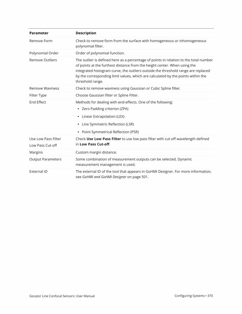
Gocator Line Confocal Sensors: User Manual Configuring Systems • 370
Parameter Description
Remove Form Check to remove form from the surface with homogeneous or inhomogeneouspolynomial filter.
Polynomial Order Order of polynomial function.
Remove Outliers The outlier is defined here as a percentage of points in relation to the total numberof points at the furthest distance from the height center. When using theintegrated histogram curve, the outliers outside the threshold range are replacedby the corresponding limit values, which are calculated by the points within thethreshold range.
Remove Waviness Check to remove waviness using Gaussian or Cubic Spline filter.
Filter Type Choose Gaussian filter or Spline Filter.
End Effect Methods for dealing with end-effects. One of the following:
l Zero Padding criterion (ZPA)
l Linear Extrapolation (LEX)
l Line Symmetric Reflection (LSR)
l Point Symmetrical Reflection (PSR)
Use Low Pass Filter
Low Pass Cut-off
Check Use Low Pass Filter to use low pass filter with cut-off wavelength definedin Low Pass Cut-off.
Margins Custom margin distance.
Output Parameters Some combination of measurement outputs can be selected. Dynamicmeasurement management is used.
External ID The external ID of the tool that appears in GoHMI Designer. For more information,see GoHMI and GoHMI Designer on page 501.

Gocator Line Confocal Sensors: User Manual Configuring Systems • 371
Outputs
Outputs section with a measurement expanded to show user-configurable decision min/max fields and an external ID
You configure theMin andMax parameters by expanding the measurement in the Outputs section.In order for a measurement to return a Pass decision, the measurement must be between maximumand minimum values; the range is inclusive.
Measurement Formula
Sa {n}
Arithmetical mean height, which is the difference inheight of each point compared to the arithmeticalmean of the surface.
Sz {n}
Maximum height, which is defined as the sum of thelargest peak height value and the largest pit depthvalue within the defined area.
Measurements

Gocator Line Confocal Sensors: User Manual Configuring Systems • 372
Measurement Formula
Sq {n}
Root mean square height, which is equivalent to thestandard deviation of heights.
Sv {n}
Maximum pit Height, which is the absolute value of theheight of the largest pit within the defined area.
Sp {n}
Height of the highest peak within the defined area.
Sku {n}
Kurtosis, which is a measure of the sharpness of theroughness profile.
Ssk {n}
Skewness, which represents the degree of bias of theroughness shape (asperity).
Type Description
Extracted Surface Surface data after filling gaps.
Form Removed Surface Surface data after subtracting the polynomial pattern.
Roughness Surface Surface data after a high pass filtering.s
Data
Surface Section
The Surface Section tool lets you define a line on a surface (a "section") from which the tool extractsa profile. You can then apply any Profile tool to the resulting profile (see Profile Measurement onpage 121). Note that a section can have any XY orientation on the surface, but its profile is parallel tothe Z axis.
(The following screenshots are from a G3 sensor.)

Gocator Line Confocal Sensors: User Manual Configuring Systems • 373
A section over a row of components
The resulting profile
Note that profiles extracted from surfaces start at the point defined as the X/Y Start of the section.Profiles are always displayed horizontally, with X increasing to the right. The origin of extractedprofiles is the beginning of the section, and not relative to the surface from which they are extracted.

Gocator Line Confocal Sensors: User Manual Configuring Systems • 374
One advantage of the Surface Section tool is that you can anchor the tool to some other easilyidentifiable feature on the scan target, which "shifts" the section in relation to that feature in casethe target moves. This increases repeatability.
For information on adding, managing, and removing tools, as well as detailed descriptions of settingscommon to most tools, see Tool Configuration on page 104.
Inputs
You configure the tool's inputs in the expandable Inputs section.
To use a measurement as an anchor, it must be enabled and properly configured in the toolproviding the anchor. For more information on anchoring, see Measurement Anchoring onpage 116.
Name Description
Surface Input The data the tool applies measurements to or processes.
Anchor X
Anchor Y
Anchor Z
The X, Y, or Z measurement of another tool that this tool uses as a positionalanchor. Positional anchors are optional.
Anchor Z Angle The Z Angle measurement of another tool to use as a rotational anchor for thistool. Rotational anchors are optional.
Inputs
Parameters
You configure the tool's parameters in the expandable Parameters section.

Gocator Line Confocal Sensors: User Manual Configuring Systems • 375
Parameter Description
Region A rectangular region to define the section to extract. The section is taken along theX axis of the region.
The length of the region is the averaging width for the section.
In the following, the region is set to a length of 5 mm and a width of 30 mm. Theresulting profile will be 20 mm long. The tool will use a 5 mm averaging window,perpendicular to the X axis (width) of the region, to calculate the data point usingits neighbor, unless Single Line is enabled (see below).
For more information, see Regions on page 105.
Single Line When Single Line is enabled, the tool performs no averaging: only data pointsunder the section are output.
Parameters

Gocator Line Confocal Sensors: User Manual Configuring Systems • 376
Parameter Description
Minimum Valid Points When Single Line is disabled, the minimum percentage of neighboring pointsacross the averaging width (perpendicular to the section) that need to be valid fora point to be output on the resulting profile.
With the following Surface scan data (zoomed in and with the data viewer set toshow individual data points),Minimum Valid Points has been set to 100%. As aresult, no data points are output to the profile in the area that lacks valid datapoints (see profile to the right).
But with the following scan data,Minimum Valid Points has been set muchlower, to 10%. As a result, the three or four data points to each side of the void areenough for an average to be calculated, and points are included in that area in theprofile.

Gocator Line Confocal Sensors: User Manual Configuring Systems • 377
Parameter Description
Show Detail Determines whether data points (in red) are displayed under the section in thedata viewer. If this setting is disabled (as shown below), only the yellow linerepresenting the defined section is displayed.

Gocator Line Confocal Sensors: User Manual Configuring Systems • 378
Parameter Description
External ID The external ID of the tool that appears in GoHMI Designer. For more information,see GoHMI and GoHMI Designer on page 501.
Outputs
All tools provide measurements, geometric features, or data as outputs.

Gocator Line Confocal Sensors: User Manual Configuring Systems • 379
Outputs section with a measurement expanded to show user-configurable decision min/max fields and an external ID
You configure theMin andMax parameters by expanding the measurement in the Outputs section.In order for a measurement to return a Pass decision, the measurement must be between maximumand minimum values; the range is inclusive.
Measurement
X StartY Start
These measurements return the X and Y position of the start of the section, respectively.
X EndY End
These measurements return the X and Y position of the end of the section, respectively.
Z Angle
Returns the rotation of the section around the Z axis.
Measurements
Type Description
Uniform Profile The profile (uniform or point cloud, respectively) that the tool extracts from the
Data

Gocator Line Confocal Sensors: User Manual Configuring Systems • 380
Type Description
Point Cloud Profile surface. Available to profile tools for profile measurement.
Only one data output will contain data, depending on whether Enable uniformspacing (resampling) on the Acquire page is enabled (in which case the Uniformoutput will contain data) or disabled (in which case the Point Cloud output willcontain data). For more information, see Scan Modes on page 71.

Gocator Line Confocal Sensors: User Manual Configuring Systems • 381
Surface Segmentation
The Segmentation tool separates surface data into "segments," based on the tool's parameters.Segments can be touching and overlapping to a certain degree. The Segmentation tool is especiallyuseful in the food industry, for example to identify food items that are too small or too big, or itemsthat are damaged.
For each segment, the tool returns the X and Y position of its center, its length and width, and itsarea, as well as several more global measurements, such as maximum / minimum width or length,and so on. For a complete list, see below.
The Segmentation tool can also be used as a second stage of processing after part detection. Forexample, part detection could be used to detect a tray (containing parts), and the Segmentation toolcould then separate the parts within the tray. For information on part detection, see Profile PartDetection on page 181.
The Segmentation tool cannot handle large overlaps.
The Segmentation tool does not perform template matching.
To reduce processing time, consider using the decimation filter. For more information on thisfilter, see Surface Filter on page 319.
For information on adding, managing, and removing tools, as well as detailed descriptions of settingscommon to most tools, see Tool Configuration on page 104.
Inputs
You configure the tool's inputs in the expandable Inputs section.
To use a measurement as an anchor, it must be enabled and properly configured in the toolproviding the anchor. For more information on anchoring, see Measurement Anchoring onpage 116.

Gocator Line Confocal Sensors: User Manual Configuring Systems • 382
Name Description
Surface Input The data the tool applies measurements to or processes.
Anchor X
Anchor Y
Anchor Z
The X, Y, or Z measurement of another tool that this tool uses as a positionalanchor. Positional anchors are optional.
Anchor Z Angle The Z Angle measurement of another tool to use as a rotational anchor for thistool. Rotational anchors are optional.
Inputs
Parameters
You configure the tool's parameters in the expandable Parameters section.

Gocator Line Confocal Sensors: User Manual Configuring Systems • 383
Parameter Description
Use Intensity Causes the tool to use intensity. The option is only displayed if intensity data isavailable.
Regions When expanded, displays the region- and mask-related settings.
Enable Enables regions and displays the region- and mask-related settings (see below).
Mask Mode
Number of Regions
Region Type {n}
Region {n}
When you enable regions (see above), the tool displays additional settings relatedto the region type. For details on the regions supported by this tool and theirsettings, see Flexible Regions on page 106.
For general information on regions and the difference between standard and"flexible" regions, see Regions on page 105.
Part Area Min
Part Area Max
The minimum and maximum areas in square millimeters for a part of the scandata to be identified as a segment.
Part Aspect Min
Part Aspect Max
The minimum and maximum aspect ratios (minimum axis length in mm) /(maximum axis length in mm) of the best fit ellipse to the segment contour pointsfor a segment to qualify to be added to the list of found segments.
Background Filter KernSize
Background FilterIterations
These settings perform background separation. The greater each of these valuesis, the more separation will be achieved. You must find a balance that removesnoise adequately without degrading the segment find quality.
Edge Filter Kernel Use this value to adjust the “granularity” of the part edge detection.
Edge Filter Threshold Controls the separation of the parts, increasing the gap between the parts so thatthey can be detected more easily.
Hierarchy Use this setting to detect segments when they are surrounded by backgrounddata. Choose one of the following: All Parts or External Parts.
All Parts
This option lets you segment parts with surrounding background data.
This is the default behavior in firmware 6.0 and later. Jobs created using firmware5.3 SR1 or earlier default to External Parts (see below).
For example, in the following image, with All Parts selected, the sphere is correctlysegmented from the surrounding background.
Parameters

Gocator Line Confocal Sensors: User Manual Configuring Systems • 384
Parameter Description
Note that this option may result in "over-segmentation": the tool may segment apart into two segments.
External Parts
In the following image, with External Parts, the sphere is not identified as asegment because of the surrounding background. It is treated as part of a largesegment that includes all of the background. (This "segment" is indicated by a redborder that shows it's currently selected. Note that to exclude this kind ofsegment, you can set a maximum acceptable part area in the tool.)
Use Margins When enabled, discards parts that are too close to the edge of the scanning areaor the region, based on the left, right, top, and bottom values.
The tool filters the parts using the center point.
In the following, a part's center point is close to the edge of the XY scan area; theright margin is set to 0, so the part is not discarded. (Total part count is 9.)

Gocator Line Confocal Sensors: User Manual Configuring Systems • 385
Parameter Description
In the following, the right margin has been set to 10 mm. Because the center pointof the part is now within the margin, the tool discards the part. (Total part count isreduced to 8.)

Gocator Line Confocal Sensors: User Manual Configuring Systems • 386
Parameter Description
Ordering Orders the measurements, features, and surface data of the individual partsoutput by the tool. Choose one of the following:
l Area - Large to smalll Area - Small to largel Position - X increasingl Position - X decreasingl Position - Y increasingl Position - Y decreasingl Position - Z increasingl Position - Z decreasing
Accurate Measurements Returns more accurate width, height, and area measurements, as well as a betterSurface output, but the trade-off is greater processing time. If you only need centerpoints or the number of parts, disable this parameter for faster processing..
Show Details Toggles whether the tool displays the index and area of each individual part.
Number of Part Outputs Determines the number of parts the tool outputs as measurements, features(center points of parts), and surface data. Currently limited to 200 parts.
External ID The external ID of the tool that appears in GoHMI Designer. For more information,see GoHMI and GoHMI Designer on page 501.
Outputs
All tools provide measurements, geometric features, or data as outputs.

Gocator Line Confocal Sensors: User Manual Configuring Systems • 387
Outputs section with a measurement expanded to show user-configurable decision min/max fields and an external ID

Gocator Line Confocal Sensors: User Manual Configuring Systems • 388
You configure theMin andMax parameters by expanding the measurement in the Outputs section.In order for a measurement to return a Pass decision, the measurement must be between maximumand minimum values; the range is inclusive.
Measurement
Part Count
Returns the total number of segments identified, based on the tool's parameters.
Min Dimension
Max Dimension
The minimum and maximum dimensions among all of the identified segments, respectively.
Mean Width
Mean Length
The mean width and length of the segments, respectively.
Min Area
Max Area
The minimum and maximum area among all of the identified segments, respectively.
Sum Area
The sum of the areas of the segments.
Mean Area
The mean area of the segments.
Min Height
Max Height
Mean Height
The minimum, maximum, and mean heights among all of the identified segments, respecitvely.
X Center {n}
Y Center {n}
The X and Y positions of the center of a part segmented from the surface.
Width {n}
Length {n}
The width and length of a part segmented from the surface. These are always the major and minor axis of apart, respectively.
Area {n}
The area of a part segmented from the surface.
The area is calculated using the contour of the part and resampling. For this reason, areas calculated using theSurface Volume tool will produce different measurements; for more information, see Area on page 438.
Measurements
Type Description
Center {n} The point representing the center of a segmented part.
Features

Gocator Line Confocal Sensors: User Manual Configuring Systems • 389
Type Description
Diagnostics Surface data you can use to evaluate the impact of the tool's kern size anditeration settings, which the tool uses to separate potential segments.
Part Surface {n} Surface data corresponding to each segmented part.
Data
Gocator Line Confocal Sensors: User Manual Configuring Systems • 390
Surface Sphere
The Sphere tool lets you compute characteristics of a scanned sphere by specifying a region toinspect. For example, you can use the tool to align a robot-mounted sensor to a ball-bar as shown inthe images below.
For the tool to work properly, the tool's region typically must be enabled and set, and properlyplaced. For more information, see the table of parameters below.
For information on adding, managing, and removing tools, as well as detailed descriptions of settingscommon to most tools, see Tool Configuration on page 104.
Inputs
You configure the tool's inputs in the expandable Inputs section.
To use a measurement as an anchor, it must be enabled and properly configured in the toolproviding the anchor. For more information on anchoring, see Measurement Anchoring onpage 116.
Name Description
Surface Input The data the tool applies measurements to or processes.
Anchor X
Anchor Y
Anchor Z
The X, Y, or Z measurement of another tool that this tool uses as a positionalanchor. Positional anchors are optional.
Anchor Z Angle The Z Angle measurement of another tool to use as a rotational anchor for thistool. Rotational anchors are optional.
Inputs
Parameters
You configure the tool's parameters in the expandable Parameters section.

Gocator Line Confocal Sensors: User Manual Configuring Systems • 391
Parameter Description
Regions When expanded, displays the region- and mask-related settings.
Enable Enables regions and displays the region- and mask-related settings (see below).
Mask Mode
Number of Regions
Region Type {n}
Region {n}
When you enable regions (see above), the tool displays additional settings relatedto the region type. For details on the regions supported by this tool and theirsettings, see Flexible Regions on page 106.
For general information on regions and the difference between standard and"flexible" regions, see Regions on page 105.
In order for the tool to correctly fit a sphere to the scan data, you must set theregion so that it only contains data from the sphere on the target.
Parameters

Gocator Line Confocal Sensors: User Manual Configuring Systems • 392
Parameter Description
Outlier Fraction The percentage of outlier points to exclude. Setting this to a small value can helpthe tool fit a better sphere when noise exist.
External ID The external ID of the tool that appears in GoHMI Designer. For more information,see GoHMI and GoHMI Designer on page 501.
Outputs
All tools provide measurements, geometric features, or data as outputs.

Gocator Line Confocal Sensors: User Manual Configuring Systems • 393
Outputs section with a measurement expanded to show user-configurable decision min/max fields and an external ID
You configure theMin andMax parameters by expanding the measurement in the Outputs section.In order for a measurement to return a Pass decision, the measurement must be between maximumand minimum values; the range is inclusive.
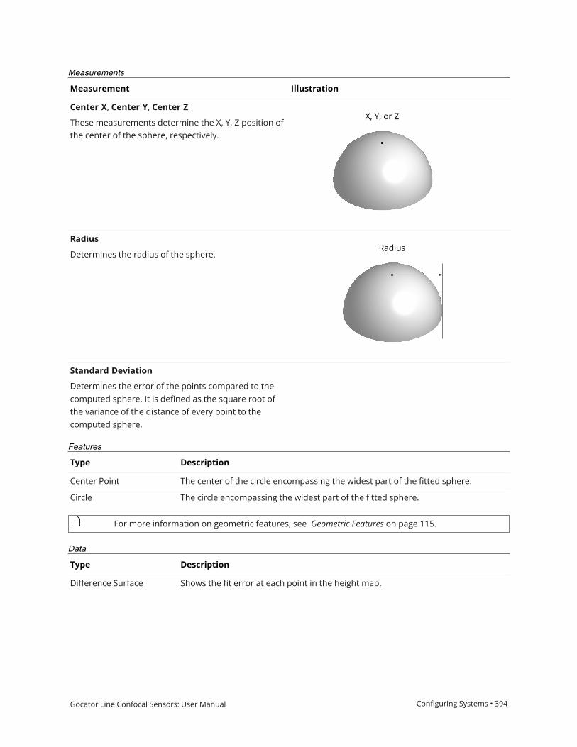
Gocator Line Confocal Sensors: User Manual Configuring Systems • 394
Measurement Illustration
Center X, Center Y, Center Z
These measurements determine the X, Y, Z position ofthe center of the sphere, respectively.
Radius
Determines the radius of the sphere.
Standard Deviation
Determines the error of the points compared to thecomputed sphere. It is defined as the square root ofthe variance of the distance of every point to thecomputed sphere.
Measurements
Type Description
Center Point The center of the circle encompassing the widest part of the fitted sphere.
Circle The circle encompassing the widest part of the fitted sphere.
Features
For more information on geometric features, see Geometric Features on page 115.
Type Description
Difference Surface Shows the fit error at each point in the height map.
Data

Gocator Line Confocal Sensors: User Manual Configuring Systems • 395
Type Description

Gocator Line Confocal Sensors: User Manual Configuring Systems • 396
Surface Stitch
The Stitch tool lets you combine up to 24 frames of scans into a single Surface scan. This lets you geta much larger scan volume with fewer sensors (either in a single sensor system or a multi-sensorsystem). For each scan, you can specify not only X, Y, and Z offsets (translations), but also X, Y, andZ angles (rotations), defining its relationship with the others. This means that when the sensorsystem is mounted to a robot, or if you are using, for example, an X-Y table, you can get a completescan with fewer sensors. The resulting combined scan can then be used as input by any otherSurface or Feature tool from its Surface Input drop-down.
The tool performs rotation first, and then translation.
The tool combines data simply by overwriting in sequence: it performs no averaging orblending. The tool also performs no fitting.
Results are only as accurate as the motion system.
Seams are often seen in combined data in stitching performed in anything other than along theY axis.
The tool returns one measurement, which simply indicates the number of scans successfully addedto the combined scan data.
The following shows three individual frames.
(The following screenshots are from a G2 sensor.)
In the following, the tool has combined the frames into a single surface.
Measurement Panel

Gocator Line Confocal Sensors: User Manual Configuring Systems • 397
For information on adding, managing, and removing tools, as well as detailed descriptions of settingscommon to most tools, see Tool Configuration on page 104.
Inputs
Name Description
Surface Input The data the tool applies measurements to or processes.
Inputs
Parameters
The following parameters are in the expandable Parameters section in the tool's configuration.
Parameter Description
Surface Count The number of scans to combine into a single surface. For each, a
Parameters

Gocator Line Confocal Sensors: User Manual Configuring Systems • 398
Parameter Description
"Surface Parameters" section is added. The tool accepts setting the number ofscans to one: in this case it, behaves like a transform tool.
Enforce Frame Order
Dependent settings
Start Frame Index
Operation
Restricts the stitching for specific frame indexes, starting at the frame indicated inStart Frame Index. If unchecked, an Operation drop-down is displayed.
This setting is disabled if you attempt to stitch data from individual scans acquiredusing the Snapshot button (that is, all frame indexes are at 1).
Start Frame IndexThe starting at the frame index.
OperationIf Enforce Frame Order is disabled, the Operation drop-down is displayed. Oneof the following:
l Normal: The tool automatically chooses this operation after you have chosenanother operation.
l Reset buffers: Resets the buffers used to stitch frames.
l Lock: Lets you lock the current processing and outputs of the tool. Usefulwhen you need to add another tool that will use this tool's output (for example,a Surface Section tool). If you do not lock the tool, as soon as you add the othertool, the output is cleared, which means you must re-execute the combinedoutput again to configure the additional tool. Be sure to unlock the tool afteryou have configured any other tools.
Reset On Start Clears buffers for the stitched surface when the sensor is started. Useful forsituations where the sensor is started and stopped frequently (to capture a smallnumber of frames), rather than starting the sensor and letting it run for a longperiod. Enable this parameter to prevent data from a previous capture sessionbeing stitched with data from the current capture session.
Bilinear Interpolation Evaluates the height of each transformed point (through translation or rotation)based on its neighbors. More precise, but has an impact on performance.
Surface Parameters {n} For each scan to be added to the combined surface scan, an expandable SurfaceParameters section is added. The following settings are available:
l X, Y, and Z Offsetl X, Y, and Z Anglel Mirror: Mirrors input Surface {n}.
External ID The external ID of the tool that appears in GoHMI Designer. For more information,see GoHMI and GoHMI Designer on page 501.

Gocator Line Confocal Sensors: User Manual Configuring Systems • 399
Outputs
Outputs section with a measurement expanded to show user-configurable decision min/max fields and an external ID
You configure theMin andMax parameters by expanding the measurement in the Outputs section.In order for a measurement to return a Pass decision, the measurement must be between maximumand minimum values; the range is inclusive.
Measurement
Captured
Indicates the number of scans successfully added to the combined surface scan.
Measurements
Only one of the following data types will contain data, depending on whether Uniform Spacingis enabled. For more information, see Scan Modes on page 71.
Type Description
Stitched Surface
Stitched Raw Surface
The stitched surface scan.
Only one data output will contain data, depending on whether Enable uniformspacing (resampling) on the Acquire page is enabled (in which case the Uniformoutput will contain data) or disabled (in which case the Point Cloud output willcontain data). For more information, see Scan Modes on page 71.
Data

Gocator Line Confocal Sensors: User Manual Configuring Systems • 400
Surface Stud
The Stud tool measures the location and radius of a stud.
The tool does not search for or detect the feature. The tool expects that the feature,conforming reasonably well to the defined parameters, is present and that it is on a sufficientlyuniform background.
The tool uses a complex feature-locating algorithm to find a hold and then return measurements.For a detailed explanation of the algorithm, see Stud Algorithm on the next page.
The location of the stud is defined at either the stud tip or the stud base. The tip is the intersection ofthe stud axis and the top of the stud; the base is the intersection of the stud axis and thesurrounding plane.
The stud shape is defined by the tip height and base height. The base and tip heights specify wherethe shaft with the nominal radius begins and ends.
Measurement Panel
For information on adding, managing, and removing tools, as well as detailed descriptions of settingscommon to most tools, see Tool Configuration on page 104.

Gocator Line Confocal Sensors: User Manual Configuring Systems • 401
Stud Algorithm
The Stud algorithm measures the stud in three steps: searching for the tip, finding the referenceplane, and shaft fitting. Note that the tip and the side of the stud must be within the measurementregion.
See the tool's parameters for an explanation of the options that affect the tool's algorithm.
Searching for the tip - The algorithm looks for the approximate location of the tip. If Auto-Tilt isenabled, the algorithm uses the flat surface around the tip to estimate the orientations of the part.The approximate tip is the location of the highest (maximum Z) pixel after correction for the nominaltilt angle.
Finding the reference plane - The reference regions are positioned using the approximate tip, thenominal angle values, and the nominal stud length. Compared to the hole/opening, misplaced studreference regions are more likely to cause a failure to produce any measurement.
Shaft fitting - The shaft region is determined based on the approximate tip position, the nominalangles, the reference plane position, and the stud nominal size parameters. Shaft fitting is successfulif the algorithm can fit at least three circles with the stud diameter along the shaft. Fitting each circlerequires sufficient data along the top portion the shaft. Because of occlusions, the bottom of theshaft is often not visible to the sensor and the algorithm is designed to handle this situation.
Inputs

Gocator Line Confocal Sensors: User Manual Configuring Systems • 402
To use a measurement as an anchor, it must be enabled and properly configured in the toolproviding the anchor. For more information on anchoring, see Measurement Anchoring onpage 116.
Name Description
Surface Input The data the tool applies measurements to or processes.
Anchor X
Anchor Y
Anchor Z
The X, Y, or Z measurement of another tool that this tool uses as a positionalanchor. Positional anchors are optional.
Inputs
Parameters
The following parameters are in the expandable Parameters section in the tool's configuration.
Parameter Description
Stud Radius Expected radius of the stud.
Stud Height Expected height/length of the stud.
Base Height The height above the base surface that will be ignored when the (truncated) coneis fitted to the stud data.
Tip Height The height from the top of the surface that will be ignored when the (truncated)
Parameters

Gocator Line Confocal Sensors: User Manual Configuring Systems • 403
Parameter Description
cone is fitted to the stud data.
Radius Offset
(Radius measurement only)
The distance from the tip of the stud from which the radius is measured.
Use Region When enabled, displays Region parameters (see below). When disabled, the tooluses all data.
Region The region to which the tool's measurements will apply. For more information, seeRegions on page 105.
Use Reference Region When enabled, displays the Reference Type setting.
Reference Type The tool uses the reference regions to calculate the base plane of the stud.Reference regions are relative to the base of the stud.
Tilt Correction Tilt of the target with respect to the alignment plane.
Autoset: The tool automatically detects the tilt. The measurement region to covermore areas on the surface plane than other planes.
Custom: You must enter the X and Y angles manually in the X Angle and Y Angleparameters (see below).
X Angle
Y Angle
The X and Y angles you must specify when Tilt Correction is set to Custom.
You can use the Surface Plane tool's X Angle and Y Angle measurements to get theangle of the surrounding surface, and then copy those measurement's values tothe X Angle and Y Angle parameters of this tool. For more information, see Plane.
External ID The external ID of the tool that appears in GoHMI Designer. For more information,see GoHMI and GoHMI Designer on page 501.

Gocator Line Confocal Sensors: User Manual Configuring Systems • 404
Outputs
Outputs section with a measurement expanded to show user-configurable decision min/max fields and an external ID
You configure theMin andMax parameters by expanding the measurement in the Outputs section.In order for a measurement to return a Pass decision, the measurement must be between maximumand minimum values; the range is inclusive.

Gocator Line Confocal Sensors: User Manual Configuring Systems • 405
Measurement Illustration
Tip X
Determines the X position of the stud tip.
Tip Y
Determines the Y position of the stud tip.
Tip Z
Determines the Z position of the stud tip.
Shaft X
Determines the X position of the stud shaft. Theposition is defined with the parameter Radius Offset.
Shaft Y
Determines the Y position of the stud shaft. Theposition is defined with the parameter Radius Offset.
Shaft Z
Determines the Z position of the stud shaft. Theposition is defined with the parameter Radius Offset.
Base X
Determines the X position of the stud base.
Base Y
Determines the Y position of the stud base.
Base Z
Determines the Z position of the stud base.
Radius
Determines the radius of the stud.
Measurements
Type Description
Tip Point The center point of the stud tip.
Shaft Point The center point of the stud shaft.
Base Point The center point of the stud base.
Features
For more information on geometric features, see Geometric Features on page 115.

Gocator Line Confocal Sensors: User Manual Configuring Systems • 406
Surface Track
The track editor is not currently available for GoPxL. An updated version of the editor will bereleased soon.
The Track tool lets you perform quality control and inspection along a path you define onrepresentative scan data. The Track tool is especially useful for inspecting materials such as glue /sealant beads. The tool returns width and height measurements of the material, as well as OK andNG ("no good") counts, which let you monitor material overflow and breaks. A major advantage ofthe tool is that it removes the need to configure individual tools for each location along the path. Youcan use point and line geometric features to anchor the tool (for more information on geometricfeatures, see Geometric Features on page 115).
Gocator sensors have a limited amount of space for storing path files. For this reason, whenworking with large datasets, we recommend that you run the Track tool through a PC instanceof GoPxL. For more information, see Running GoPxL on a Windows PC on page 491.
2D View 3D View
You define the path along which the tool performs its internal measurements using a separate, PC-based utility (the "track editor"). The following shows the relationship between the Track tool and thetrack editor.

Gocator Line Confocal Sensors: User Manual Configuring Systems • 407
For more information on the track editor, see Using the Track Editor on page 418.
All instances of the Track tool share the same path file set in File (ending in .user). For thisreason, you must be careful when editing or removing path files shared by another instance ofthe tool.
For information on adding, managing, and removing tools, as well as detailed descriptions of settingscommon to most tools, see Tool Configuration on page 104.
Key Concepts
The following are important concepts for using both the track editor (see Using the Track Editor onpage 418) and the Track tool itself:
Track: The material being measured, for example glue or sealant. The material can sit on a flat areaon the target, or sit in a groove where the material touches one or both sides.
Path: The ideal centerline of the track. You define the path in the track editor. You can define morethan one path for use on scanned targets, but the Track tool returns the combined results for allpaths. For more information on the track editor, see Using the Track Editor on page 418.
Ruler: A ruler is one of the areas perpendicular to the path you define. You define the size andspacing of the rulers in the track editor. The Track tool extracts a profile from the surface databeneath a ruler and performs internal measurements based on the values you choose in the Tracktool's parameters.
Ruler profiles: The profiles extracted from the surface data under a ruler. The tool's internalmeasurements, which are configured using the tool's settings, are applied to these profiles.
Segment: One portion of the path, between points created by clicking on an image of scan data inthe track editor. You can choose to configure rulers in segments independently, or choose toconfigure them in a batch mode.
The following shows a track with rulers and measurement results:
Track tool in data viewer, showing a track (lighter grey), path (dark blue line), rulers runningperpendicular to the track (white lines centered on light blue dots).Dots of other colors provide additional information (see below).

Gocator Line Confocal Sensors: User Manual Configuring Systems • 408
When you enable Show Measurement Results, the Track tool displays dots on the rulers to providethe following information (see also the images below):
l Light blue dots: The data points in the ruler profile. When you enable Show Path and Rulers, thetool displays a white line centered on these dots to indicate the location of the ruler.
l Dark blue dotes: The detected sides of the track. These represent the width of the track underthat ruler.
l Green dots: Center points on rulers that pass the criteria set in the tool. These count toward the"OK Count" measurement.
l Red dots: Center points on rulers that fail at least one of the criteria set in the tool. These counttoward the "NG Count" measurement.
l Orange dots: The peak (highest) point on the ruler. If the center point (green or red) is the sameas the peak point, the tool only shows the center point.
Three "OK" rulers, indicated by green center points. In the bottom two, the peak point (orange) is slightly to the left of the center point (green).

Gocator Line Confocal Sensors: User Manual Configuring Systems • 409
A "NG" ruler, indicated by the red center point.
Track Location
The tool attempts to locate the track using the profile data it extracts under each ruler, and does thisby first locating the "peak" (the highest point on the ruler profile, based on certain criteria) and thenlocating the side points representing the "sides" of the track.
Peak Detection
The tool determines the peak point on a ruler profile by moving two windows—one to each side ofthe point being examined—and comparing the average height in those windows with the height ofthe point being examined. (The size of these windows is specified in Center Window Size.) If theheight of the point being examined is greater than both the left and right average height by the valuespecified in Center Threshold, that point is considered a candidate peak point. The tool uses thecandidate point with the highest average height over both windows as the peak point.
Side Detection
After the tool has located the peak point, it locates the sides of the track starting from the peakpoint. You can choose between two methods for side detection: Maximum Gradient and HeightThreshold.
Maximum Gradient:

Gocator Line Confocal Sensors: User Manual Configuring Systems • 410
Use this side detection method when the slope of the two sides show a clear drop-off. The followingsettings define the area in which the tool searches for a maximum gradient, which will determine theedge of the track.
Side Window Size The size of the two adjacent windows the tool uses to determine the maximumslope on the left and right side of the track. Set this to roughly 3 to 5 times thesmaller of the X and Y resolution of the sensor.
Max Track Width The maximum width of the track over the ruler profile the tool searches for edgepoints. The tool uses this value to limit where the edge of the track might bedetected. Set this to slightly larger than Side Window Size.
Maximum Gradient Side Detection Parameters
Height Threshold:
Use this side detection method when the slope of two sides is very gradual. The tool finds the leftand right edges by averaging the height of small fixed-size windows moving away from the peakpoint. Edge points are the left-most and right-most window locations where the average height isbelow a minimum height threshold.
Side Height Threshold The minimum height that the average calculated in the fixed-width heightthreshold windows must be below.
Height Threshold Side Detection Parameters
Center Point Detection
The Track tool calculates the center point as the mid point between the left and right side points.This means that the center point may be different from the peak point.
Configuring the Track Tool
To configure the tool, you must first acquire scan data of a representative target; preferably, thematerial on the target will fall within the expected tolerances. Next, you save the scan data fromwithin the Track tool, and then load the scan data into the track editor. Then, after adding a path orpaths, and configuring rulers to the data, you load the track data back into the Track tool. Finally, youconfigure the tool. For more information on key concepts you need to understand to configure theTrack tool, see Key Concepts on page 407.
To configure the Track tool:
1. Scan a representative target, or load previously scanned data.
2. Add a Surface Track tool.
Gocator adds a Surface Track tool and creates a "C:\GoTools\SurfaceTrack" folder if it doesn't exist. Notethat previous versions of this tool created and placed files in a "C:\LMI" folder. Files are still read from bothlocations but only written to C:\GoTools. Rename the existing C:\LMI folder to C:\GoTools for seamlesstransition.
For more information on adding a tool, see Adding a Tool on page 89.
3. In the Surface Track tool, choose Create from the Operation drop-down.
The tool creates a file (for example, SurfaceTrack-0000.user) containing scan data in "C:/LMI/Surface Track".You will use the track editor to add path data to this file.

Gocator Line Confocal Sensors: User Manual Configuring Systems • 411
4. Launch the track editor and configure the path or paths.
For information on using the track editor, see Using the Track Editor on page 418.
5. After you have finished editing the track data in the track editor, in the Surface Track tool, choose Load inthe Operation drop-down to load the path data you just created.
6. Configure the Track tool as required.
For information on the tool's measurements and settings, see the below.
Inputs
You configure the tool's inputs in the expandable Inputs section.
Name Description
Surface Input The data the tool applies measurements to or processes.
Point
Line
Point and line geometric features (produced by another tool) that you can select asanchors for translation and rotation transformations, respectively. Currently, you
Inputs

Gocator Line Confocal Sensors: User Manual Configuring Systems • 412
Name Description
must select both in order for anchoring to work. For more information ongeometric features, see Geometric Features on page 115.
Parameters
You configure the tool's parameters in the expandable Parameters section.

Gocator Line Confocal Sensors: User Manual Configuring Systems • 413
Parameter Description
Track When expanded, displays file-related operations.
File The CSV file that contains scan and path data. You add path data to the file usingthe track editor. For more information on the track editor, see Using theTrack Editor on page 418.
Operation Provides operations related to the CSV scan / path data file. One of the following:
l Normal: Selected by the tool after you perform another file operation.
l Create: Creates a new CSV file for use with the track editor.
l Load: Loads the path file selected in File.
l Save: Saves changes made in the scan data, as well as the geometric featuresused as anchors in the Point Feature and Line Feature settings, to the fileselected in File.
l Delete: Deletes the path file selected in File.
l Refresh File List: Refreshes the list of files.
Interpolation Along Rulers Enables linear interpolation on the profile extracted from the rulers to achievesub-pixel accuracy in the width and height measurements.
Height Filter
Dependent settings
Threshold High
Threshold Low
When Height Filter is enabled, use the Threshold Low and Threshold Highsettings to set a range to filter out noise or exclude other undesired data along theruler profiles.
Median Filter
Dependent settings
Window Size
WhenMedian Filter is enabled, specify the window the tool will use to smooth theheight values of the points in the ruler profiles in theWindow Size setting.
Center Window Size The size of the left and right windows the tool moves along the ruler profile todetect whether the point centered between the two is the highest point along aruler (the center point).
Set this to roughly 50% of the typical width of the track as a starting point.
Center Threshold The center point is determined by moving two side-by-side windows (left and right,Center Window Size setting) over each ruler profile. At each point, the heightvalue between the two windows is compared to the average height of the left andright windows.
If the center point height is greater, by the amount set in Center Threshold, thanthe average height in both the left and right windows, that point is considered acandidate center point. The candidate center point with the highest average heightover both windows is used as the center point.
Main Parameters

Gocator Line Confocal Sensors: User Manual Configuring Systems • 414
Parameter Description
It may be necessary to use a negative number in some cases. It may be necessaryto use a negative value under some circumstances. For example, when the toppoint slightly dips below its surroundings.
Side Detection Method
Dependent settings
Side Window Size
Max Track Width
Side Height Threshold
The method the tool uses to detect the two sides of the track. One of the following:Maximum Gradient or Height Threshold. For more information on sidedetection method settings, see Side Detection on page 409.
Height Mode Determines how height values are interpreted in the tool's Nominal Heightsetting and what the returned height measurements represent. One of thefollowing:
Absolute Height - Height values are interpreted globally (the entire scan data).
Step Height - Height values are relative to the surrounding area of the track.
Show Profiles Output Generates the profile output.
Show Path and Rulers Displays the path and rulers (as defined in the track editor) on the scan data.
Show Measurement Result Shows dots on each ruler representing the results of the internal measurementson the profile extracted from the surface data under the ruler. For moreinformation, see Key Concepts on page 407.
Nominal Width The expected width of the track.
Width Tolerance The tolerance applied to the nominal width.
In the following, the distance between the blue dots indicating the width of thetrack under the ruler to the right (white vertical line) is greater than the widthtolerance; this is indicated by the red center point dot, and counts as a NGmeasurement. The widths of the track under the two rulers to the left are withintolerance; this is indicated by green center points, and count as OK measurements.The track is lighter grey than the surrounding surface.

Gocator Line Confocal Sensors: User Manual Configuring Systems • 415
Parameter Description
Nominal Height The expected height of the track. The expected height is the absolute height in thescan data, not relative to the surrounding area. This setting applies to the peakpoint, not the center point.
Height Tolerance The tolerance applied to the nominal height. This setting applies to the peak point,not the center point.
In the following, the red center points indicate that the height at that point isoutside of the height tolerance. Green points indicate heights within tolerance. Thetrack is lighter grey than the surrounding surface.
Nominal Area The expected cross-sectional area under the rulers on the track.
Area Tolerance The tolerance applied to the nominal area.
Offset Tolerance The maximum allowed distance between the center (highest) point on a ruler andthe path. This setting applies to the center point.
In the following, the top and bottom center points (green) are at an acceptabledistance from the blue path. The red center points fail because they are too far

Gocator Line Confocal Sensors: User Manual Configuring Systems • 416
Parameter Description
from the path. The track is lighter grey than the surrounding surface.
Include Null Edges
Dependent settings
Null Fill Value
When enabled, displays a Null Fill Value parameter you can set to replace nullvalues with the value.
External ID The external ID of the tool that appears in GoHMI Designer. For more information,see GoHMI and GoHMI Designer on page 501.
Outputs
All tools provide measurements, geometric features, or data as outputs.

Gocator Line Confocal Sensors: User Manual Configuring Systems • 417
Outputs section with a measurement expanded to show user-configurable decision min/max fields and an external ID
You configure theMin andMax parameters by expanding the measurement in the Outputs section.In order for a measurement to return a Pass decision, the measurement must be between maximumand minimum values; the range is inclusive.
Measurement Illustration
OK Count
Returns the number of rulers along the path that passall of the criteria set in the tool's parameters.
NG Count
Returns the number of rulers along the track path thatfail the criteria set in the tool's parameters. (They are"no good.")
Measurements

Gocator Line Confocal Sensors: User Manual Configuring Systems • 418
Measurement Illustration
Min Width
Max Width
Avg Width
These measurements return the minimum, maximum,and average width of the track.
Width measurements on a rulerprofile. The Track tool's settings determinethe locations of the "sides" of the track.
Min Height
Max Height
Avg Height
These measurements return the minimum, maximum,and average height of the track at the center point.
When Height Mode is set to Absolute Height, theheight returned is the global height. When it is set toStep Height, the height is relative to the surface nextto the track.
Height measurements on a rulerprofile with Height Mode set to
Absolute Height.
Height measurements on a rulerprofile with Height Mode set to
Step Height.
Min Area
Max Area
Avg Area
These measurements return the minimum, maximum,and average area under the rulers.
Area measurements under aruler profile.
Type Description
Diagnostics Surface Surface data created by combining the extracted profiles. Use for diagnostics.
Data
Using the Track Editor
You use the track editor to configure "path" and "ruler" information on a frame of scan data from asensor. The Track tool uses this information to inspect targets along the defined path.

Gocator Line Confocal Sensors: User Manual Configuring Systems • 419
The track editor
In the track editor, you can define one or more paths, and configure rulers along these paths.
Closeup of the track editor window, showing a track of material on a surface (yellow on green),a path (blue segments; red segment for the currently selected segment),
path points (green dots), and rulers (white rectangles).

Gocator Line Confocal Sensors: User Manual Configuring Systems • 420
The following assumes that you have already scanned a representative target and created aCSV file from within the Track tool. For more information, see the first steps of To configure theTrack tool: on page 410.
Loading and working with scan/track data:
1. In the track editor, in the Source drop-down, choose one of the following:
l PC: Choose this option if you are using the Track tool through the accelerator. The track editorwill retrieve the path data file from local (PC) storage and save changes there. (Choose the same ifyou are using the emulator).
l Sensor: Choose this option if you are not using the accelerator. The track editor will retrieve thepath data file from the sensor at the IP address specified in the IP field. Because sensors have alimited amount of space to store path data, only use this option for simple paths.
2. Click Load Tracks, navigate to "C:\GoTools\SurfaceTrack" (if you have chosen PC as the source), and choosethe .user file you created using the Surface Track tool.
The track editor loads the data. If paths have been previously defined, they are also loaded.
Note that previous versions of this tool created and placed files in a "C:\LMI" folder. Files are still read fromboth locations but only written to C:\GoTools. Rename the existing C:\LMI folder to C:\GoTools for seamlesstransition.
3. Do one or more of the following:
l Move the slider to the left or right to zoom in or out in the editor's viewer.
l Move the data in the track editor's window using the scrollbars or the mouse wheel.
l Set MinH and MaxH and then reload the track data to assign a narrower height range to theheight map colors. This may help make the track clearer in the editor.
After you have loaded the data, you must add a path and configure its rulers.
To add a path:
1. In the track editor, click on the middle of the track somewhere in the scan data, move the mouse pointer toanother location and click again.
A red segment between the first two green path points appears in the editor window.

Gocator Line Confocal Sensors: User Manual Configuring Systems • 421
You can move path points using the mouse at any time to adjust the path. You can also delete the last pointby clicking Delete Last. To delete all path points, click Delete All.
2. Continue clicking along the track to add more path points, building up the path.
When adding points on corners, add more points to follow the track more precisely.
3. Continue clicking until you complete the path along the track.
You cannot close the path: simply click close to the starting path point when you have finished.
4. Click Save Tracks to save the path information to the data.
5. (Optional) You can add other paths if necessary by clicking somewhere in the scan data after you havesaved the track data.
After you have finished adding a path, you must configure the rulers on the path (the dimensionsand the spacing of the rulers). You can choose to apply dimensions/spacing to all rulers in allsegments at the same time by checking Batch Setting. The settings also apply to all paths if youhave defined more than one path.
Otherwise, you must move through the individual path segments by clicking the spinner control inthe Segment field and set the ruler dimensions for each segment. If you have defined multiplepaths, you will have to click through the paths too, using the Track spinner.

Gocator Line Confocal Sensors: User Manual Configuring Systems • 422
The following table lists the ruler settings available in the track editor:
Setting Description
Length The dimension of the ruler perpendicular to the path. Be sure to use a value large
enough to cover the track from one side to another and to include enough surface
on each side of the track (the surface to which the material is applied) for the Track
tool to properly detect the track.
Width The dimension of the ruler along the path.
Space The space between rulers on the path. Because you will typically place path points
closer together around corners, you may need to use smaller spacing around
corners.
Track editor: ruler settings
Surface Transform
The Surface Transform tool generates a new surface based on the coordinate system of geometricfeatures the tool uses as input. The tool can take a zero-plane, line, and origin point to define thisnew coordinate system. You can then apply the built-in measurement tools or GDK tools to this newsurface data. This could let you, for example, get the height of a feature relative to a slightly tilted orwarped adjacent or surrounding reference surface, rather than the absolute height in the originalscan volume relative to the sensor. The result is increased repeatability of your measurements.
In Combinations of geometric feature inputs and results on page 425, the following geometric featuresare used by a Surface Transform tool in various combinations (a plane, a line, and a point).
A Surface Plane tool, with the region set to a small left-facing angled surface

Gocator Line Confocal Sensors: User Manual Configuring Systems • 423
A Surface Edge tool, with the region set to the left edge of a raised surface (upper left of data viewer).
A Surface Position tool (maximum Z), with the region set to the raised point near the top of the data viewer.
Furthermore, in the sections below, two types of data are shown: the original (input) scan data andthe transformed data. When the tool displays the original data, it overlays indicators of the new,transformed coordinate system on the data.

Gocator Line Confocal Sensors: User Manual Configuring Systems • 424
A Surface Transform tool using all three types of geometric feature inputs.The data viewer is set to display the input surface data with an overlay of the transformed coordinate system.
In the data viewer, the following is displayed:
X, Y, and Z axes
The transformed axes are represented above by the red, green, and blue lines intersecting on thesurface data above. Note how these are rotated with respect to the original coordinate system (thebackground grid, axes, and values along the axes).
Origin
The new origin is represented by the dark blue dot at the intersection of the transformed axes.
Plane
The new plane is represented by the cyan rectangle.
To switch between the original and transformed data, choose Surface or Tool in the first drop-down above the data viewer, respectively.
Inputs

Gocator Line Confocal Sensors: User Manual Configuring Systems • 425
Name Description
Surface Input The data the tool applies measurements to or processes.
Plane
Line
Point
The Plane, Line, and Point geometric features the tool uses to performtransformations. The required geometric features depends on your application.For more information, see Combinations of geometric feature inputs and resultsbelow.
Inputs
Combinations of geometric feature inputs and results
The Surface Transform tool accepts all combinations of input geometric features (plane, line, andpoint). For details and examples of each, see the following sections.
Plane
New Z=0 XY Plane New X Axis New Origin
Matches the input plane. Parallel to the old X axis. Old origin projected to plane.
Original data with overlay

Gocator Line Confocal Sensors: User Manual Configuring Systems • 426
Transformed data
Line
New Z=0 XY Plane New X Axis New Origin
The new plane contains the line. The intersection of the newplane and the old plane is perpendicular to the input line.
Matches the line. Old origin projected onto theline.
Original data with overlay

Gocator Line Confocal Sensors: User Manual Configuring Systems • 427
Transformed data
The direction of the X axis depends on the tool generating the line that Surface Transform takes asinput. You may need to adjust the direction using the Add Fixed Transform settings.
Point
New Z=0 XY Plane New X Axis New Origin
Through the input point, parallel to old Z=0 plane. Parallel to the old axis. The input point.
Original data with overlay

Gocator Line Confocal Sensors: User Manual Configuring Systems • 428
Transformed data
Plane + Line
New Z=0 XY Plane New X Axis New Origin
Matches the input plane. Line projected onto the plane. Old origin projected onto the projected line.
Original data with overlay

Gocator Line Confocal Sensors: User Manual Configuring Systems • 429
Transformed data
Plane + Point
New Z=0 XY Plane New X Axis New Origin
Matches the input plane. Parallel to the old X axis. At the input point, projected onto the plane.
Original data with overlay

Gocator Line Confocal Sensors: User Manual Configuring Systems • 430
Transformed data
Line + Point
New Z=0 XY Plane New X Axis New Origin
The new plane contains the line. The intersection of thenew plane and the old plane is perpendicular to the inputline.
Matches the line. The input point projected ontothe line.
Original data with overlay

Gocator Line Confocal Sensors: User Manual Configuring Systems • 431
Transformed data
Plane + Line + Point
New Z=0 XY Plane New X Axis New Origin
Matches the input plane. The input line projected onto the plane. The input point projected onto the inputline.
Original data with overlay

Gocator Line Confocal Sensors: User Manual Configuring Systems • 432
Transformed data
For information on adding, managing, and removing tools, as well as detailed descriptions of settingscommon to most tools, see Tool Configuration on page 104.
Parameters
The following parameters are in the expandable Parameters section in the tool's configuration.
Parameter Description
Use Region When enabled, displays Region parameters (see below). When disabled, the tooluses all data.
Region The region to which the tool's measurements will apply. For more information, seeRegions on page 105.
Add Fixed Transform When enabled, displays X, Y, and Z offset and angle fields you can use to setadditional transformations, which are applied after any transformations suppliedby the input geometric features.
Parameters

Gocator Line Confocal Sensors: User Manual Configuring Systems • 433
Parameter Description
Setting a fixed transformation can be useful if the geometric features the tool usesresults in data rotated to an unusual orientation; you could, for example, rotatethe data 90 or 180 degrees so that it is in the "expected" orientation, or shift it sothat it's easier to work with.
Resolution Mode
Resolution Mode
Outputs
Type Description
Transformed Surface The transformed surface. Available via the Stream drop-down in other tools.
Data

Gocator Line Confocal Sensors: User Manual Configuring Systems • 434
Surface Vibration Correction
The Vibration Correction tool analyzes variation in surface data to remove high frequency noise inthe data. The tool is useful for improving repeatability and accuracy of measurements when subtlevibrations in your transport system introduce height variations. The tool's intended use is to sendcorrected surface data to other tools.
The Vibration Correction tool requires at least 64 lines of data in the surface data it receives asinput to be able to output corrected surface data.
For information on adding, managing, and removing tools, as well as detailed descriptions of settingscommon to most tools, see Tool Configuration on page 104.
Inputs
You configure the tool's inputs in the expandable Inputs section.
Name Description
Surface Input The data the tool applies measurements to or processes.
Inputs
Parameters
You configure the tool's parameters in the expandable Parameters section.

Gocator Line Confocal Sensors: User Manual Configuring Systems • 435
Parameter Description
Correct Region Only If enabled, only the area under the region is corrected for vibration in the Surfacedata the tool outputs. This setting can be useful if vibration regularly occurs in aspecific area of the scan data.
When disabled, correction is applied to all of the scan data.
This option is only displayed if Use Region is enabled.
Use Region When enabled, lets you set a region and optionally choose to apply vibrationcorrection only to that region (by enabling Correct Region only).
Region The region whose data the tool will use to calculate the vibration correction.
If Correct Region Only is enabled, the tool applies vibration correction only to theregion.
If Correct Region Only is disabled, the tool applies vibration correction to all ofthe scan data.
External ID The external ID of the tool that appears in GoHMI Designer. For more information,see GoHMI and GoHMI Designer on page 501.
Parameters
Outputs
All tools provide measurements, geometric features, or data as outputs.
Type Description
Processed Surface Surface data corrected for vibration, available for use as input in other tools.
Difference Surface Diagnostic Surface data showing the difference between the corrected surface andthe original.
Data

Gocator Line Confocal Sensors: User Manual Configuring Systems • 436
Surface Volume
The Volume tool returns the volume, area, and thickness of a part.
For information on adding, managing, and removing tools, as well as detailed descriptions of settingscommon to most tools, see Tool Configuration on page 104.
Inputs
To use a measurement as an anchor, it must be enabled and properly configured in the toolproviding the anchor. For more information on anchoring, see Measurement Anchoring onpage 116.
Name Description
Surface Input The data the tool applies measurements to or processes.
Anchor X
Anchor Y
Anchor Z
The X, Y, or Z measurement of another tool that this tool uses as a positionalanchor. Positional anchors are optional.
Anchor Z Angle The Z Angle measurement of another tool to use as a rotational anchor for thistool. Rotational anchors are optional.
Inputs
Parameters
The following parameters are in the expandable Parameters section in the tool's configuration.

Gocator Line Confocal Sensors: User Manual Configuring Systems • 437
Parameter Description
Regions When expanded, displays the region- and mask-related settings.
Enable Enables regions and displays the region- and mask-related settings (see below).
Mask Mode
Region Type 1
Region 1
When you enable regions (see above), the tool displays additional settings relatedto the region type. For details on the regions supported by this tool and theirsettings, see Flexible Regions on page 106.
For general information on regions and the difference between standard and"flexible" regions, see Regions on page 105.
Thickness Types
(Thickness measurementonly)
One of the following:
l Maxl Minl Averagel Medianl Centroid 2D (height of the centroid in the XY plane)l Centroid 3D (height of the centroid in the XYZ space).
External ID The external ID of the tool that appears in GoHMI Designer. For more information,see GoHMI and GoHMI Designer on page 501.
Parameters
Outputs
All tools provide measurements, geometric features, or data as outputs.

Gocator Line Confocal Sensors: User Manual Configuring Systems • 438
Outputs section with a measurement expanded to show user-configurable decision min/max fields and an external ID
You configure theMin andMax parameters by expanding the measurement in the Outputs section.In order for a measurement to return a Pass decision, the measurement must be between maximumand minimum values; the range is inclusive.
Measurement Illustration
Volume
Measures volume in XYZ space.
Area
Measures area in the XY plane.
The area is the number of valid points multiplied bythe X and Y resolution. Note that this is differentcompared to the area calculations produced bySurface Segmentation and Surface Blob; for moreinformation, see the descriptions of the Area{n} measurements in Surface Segmentation on page 381and Surface Blob on page 236.
Measurements
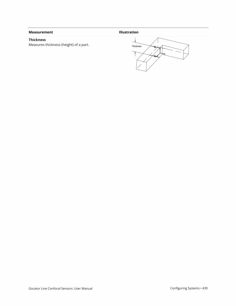
Gocator Line Confocal Sensors: User Manual Configuring Systems • 439
Measurement Illustration
ThicknessMeasures thickness (height) of a part.

Gocator Line Confocal Sensors: User Manual Configuring Systems • 440
Feature MeasurementThe following sections describe the Feature tools.
Feature tools generate or measure geometric features; for more information on geometric features,see Geometric Features on page 115. The tools let you work with more complex geometry, letting youimplement applications more quickly by reducing dependence on scripts and GDK tools to performthese kinds of measurements.
The "Create" tools (such as Feature Circle Create) generate geometric features from other tools orusing values you provide.
The Feature Dimension tool lets you take measurements using geometric features.
The Feature Robot Pose tool is for use with robots.

Gocator Line Confocal Sensors: User Manual Configuring Systems • 441
Feature Circle Create
The Feature Circle Create tool lets you generate a Circle geometric features from geometric featuresgenerated by other tools. You can also generate a circle from an arbitrary position and radius. Thefollowing outputs are available (for more information, see Output Types below):
l Constant circlel Circle from pointsl Circle from point and plane
For more information on geometric features, see Geometric Features on page 115.
Inputs
You configure the tool's inputs in the expandable Inputs section.
The tool's inputs depend on the output type you choose in the Output parameter. For informationon the required inputs and parameters of each output type, see Output Types below.
Parameters
You configure the tool's parameters in the expandable Parameters section.
Parameter Description
Output The type of output the tool generates.
Switching between the options changes the input types displayed in Input sectionand the parameters displayed in the Parameters section. For information on theoutput types and the related parameters and required inputs, see Output Typesbelow.
Project To 2D If checked, generates a circle in the XZ plane for Profile mode and in the XY planefor Surface mode. Otherwise, generates a 3D circle.
Not shown when Output is set to “Circle from point and plane”.
Show Detail Toggles the display of the input geometric features in the data viewer.
External ID The external ID of the tool that appears in GoHMI Designer. For more information,see GoHMI and GoHMI Designer on page 501.
Parameters
Output Types
The following sections describe the output types available in the tool's Output parameter, inaddition to the required inputs and parameters.
Constant Circle
The Constant circle output type is useful if scan data from frame to frame is reliably fixed and youwant to measure from an arbitrary circle to another feature. When you choose this output type, thetool displays the following parameters you can manually fill in to create a constant circle.
Disable Project To 2D to input an arbitrary normal vector (using the Normal parameters) to get atilted 3D circle.

Gocator Line Confocal Sensors: User Manual Configuring Systems • 442
Inputs Type-Related Parameters
Input
The Surface or Profile input.
Anchor X, Anchor Y, Anchor Z
The X, Y, and Z offsets the tool will apply to thegenerated circle.
Center X, Center Y, Center Z
The X, Y, and Z position, respectively, of the center ofthe constant circle.
Normal X, Normal Y, Normal Z
The X, Y, and Z for the normal vector. Only displayedwhen Project To 2D is disabled.
Radius
The radius of the constant circle.
Constant Circle Output Type - Inputs and Parameters
Circle from Points
The Circle from points output type takes three point geometric features generated by another tooland fits a circle to those points. The circle is always on the XY plane.
When Project To 2D is enabled, the circle is projected to the XY plane. When Project To 2D isdisabled, circle is tilted to fit the plane the three point inputs create.
Circle generated from the center points of the two holes and the corner of the chip (cyan points).(The corner is the intersect point resulting from the Feature Intersect tool,taking the left vertical and lower horizontal line edges of the chip as input.)
The X, Y, and Z measurements return the center of the circle. The X, Y, and Z Angle measurementsreturn arbitrary values.

Gocator Line Confocal Sensors: User Manual Configuring Systems • 443
Inputs Type-Related Parameters
Input
The Surface or Profile input.
Anchor X, Anchor Y, Anchor Z
The X, Y, and Z offsets the tool will apply to thegenerated circle.
Point 1, Point 2, Point 3
The three Point geometric features the tool uses as thecenter of the circle.
None.
Circle from points Output Type - Inputs and Parameters
Circle from point and plane
The Circle from point and plane output type generates a circle using Point and Plane geometricfeatures and a user-defined radius. The circle is on the Plane received as input.
Inputs Type-Related Parameters
Input
The Surface or Profile input.
Anchor X, Anchor Y, Anchor Z
The X, Y, and Z offsets the tool will apply to thegenerated circle.
Point
The Point geometric features the tool uses as thecenter of the circle.
Plane
The Point geometric features the tool uses as thecenter of the circle.
Radius
The radius of the circle.
Circle from point and plane Output Type - Inputs and Parameters
Outputs
All tools provide measurements, geometric features, or data as outputs.

Gocator Line Confocal Sensors: User Manual Configuring Systems • 444
Outputs section with a measurement expanded to show user-configurable decision min/max fields and an external ID
You configure theMin andMax parameters by expanding the measurement in the Outputs section.In order for a measurement to return a Pass decision, the measurement must be between maximumand minimum values; the range is inclusive.
For information specific to the different output types, see Output Types on page 441.
Measurement
Center X, Center Y, Center Z
The X, Y, and Z positions of the center of the circle.
Measurements

Gocator Line Confocal Sensors: User Manual Configuring Systems • 445
Measurement
Radius
The radius of the circle.
Normal X, Normal Y, Normal Z
The Normal X, Y, and Z values of the circle.
Type Description
Circle The generated Circle geometric feature. For more information, see Output Types onpage 441.
Features

Gocator Line Confocal Sensors: User Manual Configuring Systems • 446
Feature Line Create
The Feature Line Create tool lets you generate a Line geometric features from geometric featuresgenerated by other tools. You can also generate a line from arbitrary positions you provide. Thefollowing outputs are available (for more information, see Output Types below):
l Linel Constant linel Line from two pointsl Perpendicular line from point and linel Perpendicular line from point and planel Parallel line from point and linel Intersect line of two planesl Projected line on planel Bisect projected lines on planel Rotate line around point
For more information on geometric features, see Geometric Features on page 115.
Inputs
You configure the tool's inputs in the expandable Inputs section.
The tool's inputs depend on the output type you choose in the Output parameter. For informationon the required inputs and parameters of each output type, see Output Types below.
Parameters
You configure the tool's parameters in the expandable Parameters section.
Parameter Description
Output The type of output the tool generates.
Switching between the options changes the input types displayed in Input sectionand the parameters displayed in the Parameters section. For information on theoutput types and the related parameters, see Output Types below.
Show Detail Toggles the display of the input geometric features in the data viewer.
External ID The external ID of the tool that appears in GoHMI Designer. For more information,see GoHMI and GoHMI Designer on page 501.
Parameters
Output Types
The following sections describe the output types available in the tool's Output parameter, inaddition to the required inputs and parameters.
Line
The Line output type takes a Line geometric feature as input. This output is useful if the tool takes afeature generated by another Feature Create tool as input, on which you want to performmeasurements in a second Feature Create tool. This tool can also be useful if you have developedGDK tools that only generate geometric features (no measurements): you can use this tool to extractthose measurements.

Gocator Line Confocal Sensors: User Manual Configuring Systems • 447
The X, Y, and Z measurements return the midpoint of the line. The Z Angle measurement returns theangle of the line around the Z axis. The X angle and Y angle measurements return arbitrary values.
Inputs Parameters
Input
The Surface or Profile input.
Anchor X, Anchor Y, Anchor Z, Anchor Z Angle
The X, Y, and Z position measurements and theZ Angle measurement the tool uses as anchors.
Line
The Line geometric feature the tool uses to createanother Line geometric feature.
None.
Line Output Type - Inputs and Parameters
Constant Line
The Constant line output type displays parameters you can manually fill in to create a geometricfeature. This output type is useful if the scan data from frame to frame is reliably fixed and you wantto measure from an arbitrary line to another feature.
Inputs Parameters
Input
The Surface or Profile input.
Anchor X, Anchor Y, Anchor Z, Anchor Z Angle
The X, Y, and Z position measurements and theZ Angle measurement the tool uses as anchors.
Point 1 X, Point 1 Y, Point 1 Z
The X, Y, and Z position, respectively, of the first endpoint of the constant line.
Point 2 X, Point 2 Y, Point 2 Z
The X, Y, and Z position, respectively, of the secondend point of the constant line.
Line Output Type - Inputs and Parameters
Line from Two Points
The Line from two points output type takes two Point geometric features as input.
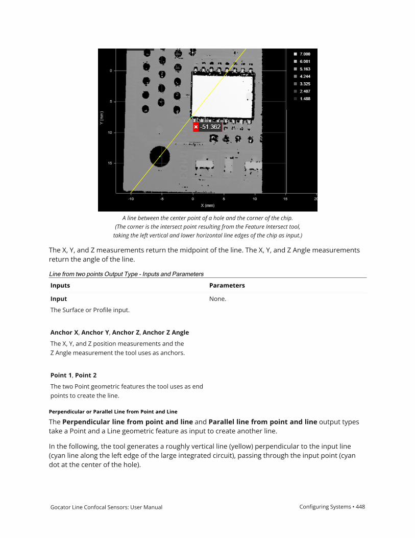
Gocator Line Confocal Sensors: User Manual Configuring Systems • 448
A line between the center point of a hole and the corner of the chip.(The corner is the intersect point resulting from the Feature Intersect tool,taking the left vertical and lower horizontal line edges of the chip as input.)
The X, Y, and Z measurements return the midpoint of the line. The X, Y, and Z Angle measurementsreturn the angle of the line.
Inputs Parameters
Input
The Surface or Profile input.
Anchor X, Anchor Y, Anchor Z, Anchor Z Angle
The X, Y, and Z position measurements and theZ Angle measurement the tool uses as anchors.
Point 1, Point 2
The two Point geometric features the tool uses as endpoints to create the line.
None.
Line from two points Output Type - Inputs and Parameters
Perpendicular or Parallel Line from Point and Line
The Perpendicular line from point and line and Parallel line from point and line output typestake a Point and a Line geometric feature as input to create another line.
In the following, the tool generates a roughly vertical line (yellow) perpendicular to the input line(cyan line along the left edge of the large integrated circuit), passing through the input point (cyandot at the center of the hole).

Gocator Line Confocal Sensors: User Manual Configuring Systems • 449
In the following, the tool generates a roughly horizontal line (yellow) parallel to the input line (cyanline along the bottom edge of the large integrated circuit), passing through the input point (cyan dotat the center of the hole).
For both of these types of line output, the X, Y, and Z measurements return the position of the point.
For perpendicular line output, the X, Y, and Z angle measurements return the angles of the line.
For parallel line output, the Z angle measurement returns the angle of the line; the X and Y anglemeasurements both return arbitrary values.

Gocator Line Confocal Sensors: User Manual Configuring Systems • 450
Inputs Parameters
Input
The Surface or Profile input.
Anchor X, Anchor Y, Anchor Z, Anchor Z Angle
The X, Y, and Z position measurements and theZ Angle measurement the tool uses as anchors.
Point
The Point geometric feature the tool uses to create theline.
Line
The Line geometric feature the tool uses to create theline.
None.
Line from Point and Line Output Types - Inputs and Parameters
Perpendicular Line from Point to Plane
The Perpendicular line from point to plane output type generates a perpendicular line from apoint up to a plane.
Inputs Parameters
Input
The Surface or Profile input.
Anchor X, Anchor Y, Anchor Z, Anchor Z Angle
The X, Y, and Z position measurements and theZ Angle measurement the tool uses as anchors.
Point
The Point geometric feature the tool uses to create theline.
Plane
The Plane geometric feature the tool uses to createthe line.
None.
Perpendicular line from point to plane Output Types - Inputs and Parameters
Intersect Line of Two Planes
The Intersect line of two planes output type takes two plane geometric features as input andcreates a line at their intersection.

Gocator Line Confocal Sensors: User Manual Configuring Systems • 451
The X, Y, and Z measurements return the midpoint. The X, Y, and Z Angle measurements return theangle of the line.
Inputs Parameters
Input
The Surface or Profile input.
Anchor X, Anchor Y, Anchor Z, Anchor Z Angle
The X, Y, and Z position measurements and theZ Angle measurement the tool uses as anchors.
Plane 1, Plane 2
The two Plane geometric feature the tool uses tocreate the line.
None.
Intersect line of two planes Output Type - Inputs and Parameters
Projected Line on Plane
The Projected line on a plane output type takes a Line and a Plane geometric feature to create aline projected onto a plane.
Inputs Parameters
Input
The Surface or Profile input.
Anchor X, Anchor Y, Anchor Z, Anchor Z Angle
The X, Y, and Z position measurements and theZ Angle measurement the tool uses as anchors.
Line
The Line geometric feature the tool uses to create theline.
Plane
The Plane geometric feature the tool uses to createthe line.
Projection Direction
One of the following: Perpendicular to Plane orAlong Z Axis.
Projected line on a plane Output Type - Inputs and Parameters
Bisect Projected Lines on Plane
The Bisect projected lines on plane output type creates a Line and a Plane geometric feature asinput and creates a line.

Gocator Line Confocal Sensors: User Manual Configuring Systems • 452
Inputs Parameters
Input
The Surface or Profile input.
Anchor X, Anchor Y, Anchor Z, Anchor Z Angle
The X, Y, and Z position measurements and theZ Angle measurement the tool uses as anchors.
Line
The Line geometric feature the tool uses to create theline.
Plane
The Plane geometric feature the tool uses to createthe line.
None.
Bisect projected lines on plane Output Type - Inputs and Parameters
Outputs
All tools provide measurements, geometric features, or data as outputs.

Gocator Line Confocal Sensors: User Manual Configuring Systems • 453
Outputs section with a measurement expanded to show user-configurable decision min/max fields and an external ID
You configure theMin andMax parameters by expanding the measurement in the Outputs section.In order for a measurement to return a Pass decision, the measurement must be between maximumand minimum values; the range is inclusive.
For information specific to the different output types, see Output Types on page 446.
Measurement
X, Y, Z
The X, Y, and Z positions of the midpoint of the line described by the Point geometric features. For moreinformation, see the sections above.
X Angle, Y Angle, Z Angle
The X, Y, and Z angles of the line. For more information, see the sections above.
Measurements
Type Description
Line The generated Line geometric feature.
Features
Gocator Line Confocal Sensors: User Manual Configuring Systems • 454
Feature Plane Create
The Feature Plane Create tool lets you generate a Plane geometric features from geometric featuresgenerated by other tools. You can also generate a plane from arbitrary values you provide. Thefollowing outputs are available (for more information, see Output Types below):
l Constant planel Plane from point and normall Plane from point and linel Plane from three pointsl Plane from circlel Parallel plane from point and planel Perpendicular plane from point and planel Perpendicular plane from line and planel Bisect plane from two planes
For more information on geometric features, see Geometric Features on page 115.
Inputs
You configure the tool's inputs in the expandable Inputs section.
The tool's inputs depend on the output type you choose in the Output parameter. For informationon the required inputs and parameters of each output type, see Output Types below.
Parameters
You configure the tool's parameters in the expandable Parameters section.
Parameter Description
Output The type of output the tool generates.
Switching between the options changes the input types displayed in Input sectionand the parameters displayed in the Parameters section. For information on theoutput types and the related parameters, see Output Types below.
Show Detail Toggles the display of the input geometric features in the data viewer.
External ID The external ID of the tool that appears in GoHMI Designer. For more information,see GoHMI and GoHMI Designer on page 501.
Parameters
Output Types
The following sections describe the output types available in the tool's Output parameter, inaddition to the required inputs and parameters.
Constant Plane
The Constant plane output type is useful if scan data from frame to frame is reliably fixed and youwant to measure from an arbitrary plane to another feature. When you choose this output type, thetool displays the parameters listed below you can manually fill in to create a constant plane.

Gocator Line Confocal Sensors: User Manual Configuring Systems • 455
Inputs Type-Related Parameters
Input
The Surface or Profile input.
Point X, Point Y, Point Z
The X, Y, and Z points that define the plane.
Normal X, Normal Y, Normal Z
The X, Y, and Z normals, respectively, of the constantplane.
Constant Plane Output Type - Inputs and Parameters
Plane from a Point and Normal
The tool uses the Line geometric feature as the normal of a plane, and positions the plane so that itintersects the Point geometric feature.
Inputs Type-Related Parameters
Input
The Surface or Profile input.
Point
The Point geometric feature with which the planeintersects.
Line
A Line geometric feature representing the normal thatthe tool uses to create the plane.
None.
Plane from Point and Normal Output Type - Inputs and Parameters
Plane from a Point and Line
The tool uses Line and Point geometric features to create a plane.
Inputs Type-Related Parameters
Input
The Surface or Profile input.
Point
The Point geometric feature with which the planeintersects.
Line
A Line geometric feature with which the planeintersects.
None.
Plane from Point and Line Output Type - Inputs and Parameters
Gocator Line Confocal Sensors: User Manual Configuring Systems • 456
Plane from Three Points
The Plane from three points output type creates a plane that intersects the three Point geometricfeatures passed to the tool as input.
Inputs Type-Related Parameters
Input
The Surface or Profile input.
Point 1, Point 2, Point 3
The three Point geometric features the tool uses tocreate the plane.
None.
Plane from Three Points Output Type - Inputs and Parameters
Plane from Circle
The Plane from circle output type creates a plane that intersects the Circle geometric featurepassed to the tool as input.
Inputs Type-Related Parameters
Input
The Surface or Profile input.
Circle
The Circle geometric features the tool uses to createthe plane.
None.
Plane from Three Points Output Type - Inputs and Parameters
Parallel Plane from Point and Plane
The Parallel plane from point and plane output type creates a plane parallel to the provided Planegeometric feature that intersects the provided Point geometric feature.
Inputs Type-Related Parameters
Input
The Surface or Profile input.
Point
The Point geometric feature with which the createdplane intersects.
Plane
The Plane geometric feature with which the createdplane is parallel.
None.
Parallel Plane from Point and Plane Output Type - Inputs and Parameters

Gocator Line Confocal Sensors: User Manual Configuring Systems • 457
Perpendicular Plane from Point and Plane
The Perpendicular plane from point and plane output type creates a plane perpendicular to theprovided Plane geometric feature that intersects the two provided Point geometric features.
Inputs Type-Related Parameters
Input
The Surface or Profile input.
Point 1, Point 2
The Point geometric features with which the createdplane intersects.
Plane
The Plane geometric feature with which the createdplane is perpendicular.
None.
Perpendicular Plane from Point and Plane Output Type - Inputs and Parameters
Perpendicular Plane from Line and Plane
The Perpendicular plane from line and plane output type creates a plane perpendicular to theprovided Plane geometric feature, which intersects the provided Line geometric feature.
Inputs Type-Related Parameters
Input
The Surface or Profile input.
Line
The Line geometric feature that bisects the createdplane.
Plane
The Plane geometric feature with which the createdplane is perpendicular.
None.
Perpendicular Plane from Line and Plane Output Type - Inputs and Parameters
Bisect Plane from Two Planes
The Bisect plane from two planes output type creates a plane from the two provided Planegeometric features.
Inputs Type-Related Parameters
Input
The Surface or Profile input.
None.
Bisect Plane from Two Planes Output Type - Inputs and Parameters

Gocator Line Confocal Sensors: User Manual Configuring Systems • 458
Inputs Type-Related Parameters
Plane 1, Plane 2
The Plane geometric features the tool uses to create abisecting plane
See Adding a Tool on page 89 for instructions on how to add measurement tools.
Outputs
All tools provide measurements, geometric features, or data as outputs.
Outputs section with a measurement expanded to show user-configurable decision min/max fields and an external ID
You configure theMin andMax parameters by expanding the measurement in the Outputs section.In order for a measurement to return a Pass decision, the measurement must be between maximumand minimum values; the range is inclusive.

Gocator Line Confocal Sensors: User Manual Configuring Systems • 459
All outputs provide an external ID (available by expanding the output in the Outputs panel) foroptional use in GoHMI Designer. For more information, see GoHMI and GoHMI Designer on page 501.
For information specific to the different output types, see Output Types on page 454.
Measurement
X Angle, Y Angle
Rotation angles of the plane, that is, angles such that rotating (0,0,1) around the Y axis by the Y Angle, and thenaround X axis by X Angle produces the normal.
Z Offset
The Z value of intersection of the plane and the Z axis.
Normal X, Normal Y, Normal Z
The normal X, Y, and Z vectors of the plane.
DistanceThe distance from the origin to the plane.
Measurements
Type Description
Plane The generated Plane geometric feature. For more information, see Output Types onpage 454.
Features

Gocator Line Confocal Sensors: User Manual Configuring Systems • 460
Feature Point Create
The Feature Point Create tool lets you generate a Point geometric features from geometric featuresgenerated by other tools. You can also generate a point from an arbitrary position you provide. Thefollowing outputs are available (for more information, see Output Types below):
l Pointl Constant pointl Point from offsetl Point from three planesl Point from line and circlel Point from line and linel Point from line and planel Projected point on linel Projected point on plane
For more information on geometric features, see Geometric Features on page 115.
Inputs
You configure the tool's inputs in the expandable Inputs section.
The tool's inputs depend on the output type you choose in the Output parameter. For informationon the required inputs and parameters of each output type, see Output Types below.
Parameters
You configure the tool's parameters in the expandable Parameters section.
Parameter Description
Output The type of output the tool generates.
Switching between the options changes the input types displayed in Input sectionand the parameters displayed in the Parameters section. For information on theoutput types and the related parameters, see Output Types below.
Show Detail Toggles the display of the input geometric features in the data viewer.
External ID The external ID of the tool that appears in GoHMI Designer. For more information,see GoHMI and GoHMI Designer on page 501.
Parameters
Output Types
The following sections describe the output types available in the tool's Output parameter, inaddition to the required inputs and parameters.
Point
The Point output type takes a Point geometric feature as input. This output is useful if the tool takesa feature generated by another Feature Create tool as input, on which you want to performmeasurements in a second Feature Create tool. This tool can be useful if you have developedGDK tools that only generate geometric features (no measurements): you can use this tool to extractthose measurements.

Gocator Line Confocal Sensors: User Manual Configuring Systems • 461
Inputs Parameters
Input
The Surface or Profile input.
Anchor X, Anchor Y, Anchor Z
The X, Y, and Z position measurements the tool usesas anchors.
Point
The Point geometric feature the tool uses to createanother Point geometric feature.
None.
Point Output Type - Inputs and Parameters
Constant Point
The Constant point output type displays parameters you can manually fill in to create a geometricfeature. This output type is useful if the scan data from frame to frame is reliably fixed and you wantto measure from an arbitrary point to another feature.
Inputs Parameters
Input
The Surface or Profile input.
Anchor X, Anchor Y, Anchor Z
The X, Y, and Z position measurements the tool usesas anchors.
Point X, Point Y, Point Z
The X, Y, and Z position, respectively, of the first endpoint of the constant line.
Line Output Type - Inputs and Parameters
Point from Offset
The Point from offset output type takes two Point geometric feature as input to determine the linealong which the generated point is offset, using the offset direction and distance you provide.
Inputs Parameters
Input
The Surface or Profile input.
Anchor X, Anchor Y, Anchor Z
The X, Y, and Z position measurements the tool usesas anchors.
Point 1, Point 2
The Point geometric features the tool uses to create
Offset Direction
The direction along the line running through the twoinput Point geometric features that the point is offset.One of two values: Forward or Backward. A Forwardoffset direction offsets the point along the line frommoving from Point 1 to Point 2. A Backward offsetdirection offsets the point along the line moving fromPoint 2 to Point 1.
Offset Distance
Point from Offset Output Type - Inputs and Parameters

Gocator Line Confocal Sensors: User Manual Configuring Systems • 462
Inputs Parameters
another Point geometric feature. The distance along the line running through the Pointgeometric features that the point is offset.
Point from Three Planes
The Point from three planes output type takes three Plane geometric features as input andgenerates a Point geometric feature at the intersection of those planes.
Inputs Parameters
Input
The Surface or Profile input.
Anchor X, Anchor Y, Anchor Z
The X, Y, and Z position measurements the tool usesas anchors.
Plane 1, Plane 2, Plane 3
The Plane geometric features the tool uses to generatethe Point geometric feature. The point is at theintersection of the planes.
None.
Point from Three Planes Output Type - Inputs and Parameters
Point from Line and Circle
The Point from line and circle output type takes a Line and a Circle geometric feature as input andgenerates a Point geometric feature where the line intersects the circle. The tool uses an intersectionoption to decide which intersection point to use.
Inputs Parameters
Input
The Surface or Profile input.
Anchor X, Anchor Y, Anchor Z
The X, Y, and Z position measurements the tool usesas anchors.
Line
The Line geometric feature the tool uses to generatethe Point geometric feature.
Circle
The Circle geometric features the tool uses to generate
Intersection Option
The intersection between the line and the circle thatthe tool uses to generate the Point geometric feature.One of the following: Upper, Lower, or Middle.
Upper: The uppermost intersection point in the datavisualizer.
Lower: The lowermost intersection point in the datavisualizer.
Middle: The midpoint between the two intersectionpoints.
Point from Line and Circle Output Type - Inputs and Parameters

Gocator Line Confocal Sensors: User Manual Configuring Systems • 463
Inputs Parameters
the Point geometric feature.
Point from Line and Line
When the Output parameter is set to Point from line and line, the tool takes two Line geometricfeature as input and generates a Point geometric feature where the lines intersect. The tool alsoreturns an angle measurement for the angle between the lines.
Inputs Parameters
Input
The Surface or Profile input.
Anchor X, Anchor Y, Anchor Z
The X, Y, and Z position measurements the tool usesas anchors.
Line 1, Line 2
The Line geometric features the tool uses to generatethe Point geometric feature.
Angle Range
The range returned by the Angle measurement. One ofthe following: "-180 to 180" or "0 to 360".
Point from Line and Line Output Type - Inputs and Parameters
Point from Line and Plane
When the Output parameter is set to Point from line and plane, the tool takes a Line and a Planegeometric feature as input and generates a Point geometric feature where the lines intersect. Thetool also returns an angle measurement for the angle between the lines.
Inputs Parameters
Input
The Surface or Profile input.
Anchor X, Anchor Y, Anchor Z
The X, Y, and Z position measurements the tool usesas anchors.
Line
The Line geometric features the tool uses to generatethe Point geometric feature.
Plane
The Plane geometric features the tool uses to generatethe Point geometric feature.
Angle Range
The range returned by the Angle measurement. One ofthe following: "-180 to 180" or "0 to 360".
Point from Line and Line Output Type - Inputs and Parameters

Gocator Line Confocal Sensors: User Manual Configuring Systems • 464
Projected Point on Line
The Projected point on line output type takes a Point and a Line geometric feature as input andgenerates a Point geometric feature.
Inputs Parameters
Input
The Surface or Profile input.
Anchor X, Anchor Y, Anchor Z
The X, Y, and Z position measurements the tool usesas anchors.
Point
The Point geometric features the tool uses to generatethe Point geometric feature.
Line
The Line geometric features the tool uses to generatethe Point geometric feature.
None.
Projected Point on Line Output Type - Inputs and Parameters
Projected Point on Plane
The Projected point on plane output type takes a Point and a Plane geometric feature as input andgenerates a Point geometric feature.
Inputs Parameters
Input
The Surface or Profile input.
Anchor X, Anchor Y, Anchor Z
The X, Y, and Z position measurements the tool usesas anchors.
Point
The Point geometric features the tool uses to generatethe Point geometric feature.
Plane
The Plane geometric features the tool uses to generatethe Point geometric feature.
Projection DirectionThe direction of the projection. One of thefollowing: Perpendicular to Plane or Along Z Axis.
Projected Point on Plane Output Type - Inputs and Parameters

Gocator Line Confocal Sensors: User Manual Configuring Systems • 465
Outputs
All tools provide measurements, geometric features, or data as outputs.
Outputs section with a measurement expanded to show user-configurable decision min/max fields and an external ID
You configure theMin andMax parameters by expanding the measurement in the Outputs section.In order for a measurement to return a Pass decision, the measurement must be between maximumand minimum values; the range is inclusive.
For information specific to the different output types, see Output Types on page 460.
Measurement
X, Y, Z
The X, Y, and Z positions of the Point geometric feature. For more information, see the sections above.
Measurements
Type Description
Point The generated Point geometric feature.
Features

Gocator Line Confocal Sensors: User Manual Configuring Systems • 466
Feature Intersect
The Feature Intersect tool returns the intersection of a line or plane geometric feature and a secondline or plane geometric feature. For line-line intersections, the lines are projected onto the Z =reference Z line plane for features extracted from a surface, and the intersection of the linesprojected onto the Y = 0 plane for features extracted from a profile. The angle measurementbetween the two lines is also returned. The lines the tool takes as input are generated by other tools,such as Surface Edge or Surface Ellipse.
The Feature Intersect tool can also generate a point geometric feature representing the point ofintersection of the lines that the Feature Dimension tool can use in measurements.
See Adding a Tool on page 89 for instructions on how to add measurement tools.
Inputs
You configure the tool's inputs in the expandable Inputs section.
The tool's inputs depend on the intersection type you choose in the Intersection Type parameter.For information on the required inputs and parameters of each output type, see Feature Intersectabove.
Name Description
Input The data the tool applies measurements to or processes.
Line or Plane The geometric features the tool uses to calculate an intersect. A combination ofLine or Plane geometric features.
Inputs
Parameters
You configure the tool's parameters in the expandable Parameters section.

Gocator Line Confocal Sensors: User Manual Configuring Systems • 467
Parameter Description
Intersection Type One of the following:
l Line and Linel Line and Planel Plane and Plane
The intersection type determines which inputs are available in the Inputs section.
Angle Range Determines the angle range.
External ID The external ID of the tool that appears in GoHMI Designer. For more information,see GoHMI and GoHMI Designer on page 501.
Parameters

Gocator Line Confocal Sensors: User Manual Configuring Systems • 468
Outputs
Outputs section with a measurement expanded to show user-configurable decision min/max fields and an external ID
You configure theMin andMax parameters by expanding the measurement in the Outputs section.In order for a measurement to return a Pass decision, the measurement must be between maximumand minimum values; the range is inclusive.
Measurement
X
Line-Line: The X position of the intersect point between the lines.
Line-Plane: The X position of the intersect point between the line and the plane.
Plane-Plane: The X position of the center of the line intersecting the planes.
Y
Line-Line: The Y position of the intersect point between the lines.
Line-Plane: The Y position of the intersect point between the line and the plane.
Plane-Plane: The Y position of the center of the line intersecting the planes.
Z
Line-Line: The Z position of the intersect point between the lines.
Measurements

Gocator Line Confocal Sensors: User Manual Configuring Systems • 469
Measurement
Line-Plane: The Z position of the intersect point between the line and the plane.
Plane-Plane: The Z position of the center of the line intersecting the planes.
Angle
Line-Line: The angle between the lines, as measured from the line selected in Reference Feature to the lineselected in Line.
Line-Plane:The angle between the line and the perpendicular projection of the line onto the plane, as measuredfrom the plane geometric feature selected in Reference Feature to the line selected in Line.
Plane-Plane:The angle between the two planes, as measured from the plane geometric features selected inFeature 1 and Feature 2.
For line-line and line-plane angle measurements, the Angle Range setting determines how angles areexpressed. (The setting does nothing with plane-plane angle measurements.)
Type Description
Intersect Point The intersect point of the two features.
Features

Gocator Line Confocal Sensors: User Manual Configuring Systems • 470
Feature Dimension
The Feature Dimension tool returns dimensional measurements from a point geometric feature to areference point, line, or plane geometric feature. Geometric features are available as outputs frommany tools, for example a Point geometric feature from Surface Position, or a line from SurfaceEdge. The feature creation tools such as Feature Circle Create, Feature Line Create, and so on, canalso create geometric feature. For more information on geometric features, see Geometric Featureson page 115.
Some examples:
l Measuring the thickness between multiple surfaces or profiles.
l Measuring the distance between the center of a hole and an edge.
l Measuring the distance between the centers of two holes.
l Measuring the distance between a point and a plane.
l Measuring the distance between a point and the closest point on a circle.
l Obtaining the length of a stud by measuring the distance between its tip and base.
See Adding a Tool on page 89 for instructions on how to add measurement tools.
In the following measurement descriptions, the first geometric feature is set in the Point drop-down. The second geometric feature is set in the Reference Feature drop-down.
When Reference Feature is set to a feature other than a point, such as a circle or a line,measurements are between the point in Point and the nearest point on the reference feature(for example, the nearest point on a circle).
Inputs
You configure the tool's inputs in the expandable Inputs section.

Gocator Line Confocal Sensors: User Manual Configuring Systems • 471
Name Description
Input The data the tool applies measurements to.
Point A point geometric feature generated by another tool.
Reference Feature A geometric feature generated by another tool. Dimensional measurements arecalculated from the reference feature to the point in the Point input.
Inputs
Parameters
You configure the tool's parameters in the expandable Parameters section.
Parameter Description
Width Absolute
Length Absolute
Height Absolute
The tools returns measurements as absolute values.
External ID The external ID of the tool that appears in GoHMI Designer. For more information,see GoHMI and GoHMI Designer on page 501.
Parameters
Outputs
All tools provide measurements, geometric features, or data as outputs.

Gocator Line Confocal Sensors: User Manual Configuring Systems • 472
Outputs section with a measurement expanded to show user-configurable decision min/max fields and an external ID
You configure theMin andMax parameters by expanding the measurement in the Outputs section.In order for a measurement to return a Pass decision, the measurement must be between maximumand minimum values; the range is inclusive.
Measurement Illustration
Width
Point-point: The difference on the X axis between thepoints.
Point-line: The difference on the X axis between thepoint and a point on the line. For profiles, the point onthe line is at the same Z position as the first point.
Length
Point-point: The difference on the Y axis between thepoints.
Point-line: The difference on the Y axis between thepoint and, for profiles, the nearest point on the line;currently, always zero.
Measurements

Gocator Line Confocal Sensors: User Manual Configuring Systems • 473
Measurement Illustration
Height
Point-point: The difference on the Z axis between thepoints.
Point-line: The difference on the Z axis between thepoint and, for profiles, a point on the line at the sameX position as the first point.
Distance
Point-point: The direct, Euclidean distance between twopoint geometric features.
Point-line: The direct, Euclidean distance between apoint and the nearest point on the line.
Plane Distance
Point-point: The distance between two point geometricfeatures. For profile data, the points are projectedonto the XZ plane (always the same as the Distancemeasurement).
Point-line: The distance between a point and a line. Forprofile data, projected onto the XZ plane (always thesame as the Distance measurement).

Gocator Line Confocal Sensors: User Manual Configuring Systems • 474
Array ToolsArray tools let you work with array data. An array is a group of data messages bundled into a singledata object, for example, an array of profiles or an array of surfaces. Array tools are useful whenworking with the multilayer output of G5 sensors. Array tools are also useful when working withmulti-sensor systems. Array tools are also useful with the outputs of certain measurement andprocessing tools, such as Surface Blob, which can produce a large number of outputs. Note thatArray data is "0-based," meaning that the first element is 0.
The following illustration is a representation of multilayer Profile scan data from a G5 sensor,showing four profiles.
The structure of an array containing these profiles could be represented as follows:
If you have configured a G5 sensor to output only a single layer, you do not need to use theArray Index tool to extract the layer's profile.

Gocator Line Confocal Sensors: User Manual Configuring Systems • 475
Two Array tools are available:
l Array Index: Takes an array of data (a group of data messages) as input and extracts a single pieceof data (such as a single profile or a single surface) at the user-provided index. Use this tool toseparate the multiple layers produced by a G5 sensor into individual profiles or surfaces. You canthen perform measurements on the individual profile or surface, or perform measurementsusing more than one piece of data, such as measuring the thickness represented by two profilesor surfaces. For more information on this tool, see Array Index on the next page.
l Array Create: Takes one or more individual profiles or surfaces (that is not array data), created byother tools or separate sensors, as input and creates an array containing those profiles orsurfaces as elements. For more information on this tool, see Array Create on page 479.

Gocator Line Confocal Sensors: User Manual Configuring Systems • 476
Array Index
The Array Index tool extracts a single piece of data (such as a profile or a surface) from the array ittakes as input at the position (the index) you specify.
A common use of the Array Index tool is to extract individual layers from the multilayer dataproduced by Gocator 5500 series sensors for measurement or processing.
If you have configured a G5 sensor to output only a single layer, you do not need to use theArray Index tool to extract the layer's profile.
For example, if your sensor is producing four layers of Profile data and you want to measure thethickness between the top two profiles, you can use two Array Index tools to extract those layers,one for each layer. You can then perform measurements on those extracted profiles, eitherindividually or combined, for example, in the Profile Thickness tool. (For more information on theProfile Thickness tool, see Profile Thickness on page 219.)
For general information on the Array tools, see Array Tools on page 474.
For information on adding, managing, and removing tools, as well as detailed descriptions of settingscommon to most tools, see Tool Configuration on page 104.

Gocator Line Confocal Sensors: User Manual Configuring Systems • 477
Inputs
Name Description
Array Input The data the tool applies measurements to or processes.
Inputs
Parameters
The following parameters are in the expandable Parameters section in the tool's configuration.
Parameter Description
Index The position (the index) in the array at which the tool extracts and outputs.
External ID The external ID of the tool that appears in GoHMI Designer. For more information,see GoHMI and GoHMI Designer on page 501.
Parameters

Gocator Line Confocal Sensors: User Manual Configuring Systems • 478
Outputs
The tool outputs only one of the types of data in the following table.
Type Description
Uniform Profile
Uniform Surface
Point Cloud Surface
Point Cloud Profile
The Profile or Surface data extracted from the provided index. Only one dataoutput will contain data, depending on whether uniform spacing is enabled on theAcquire > Scanners page, in the Scan Mode panel, and depending on the type ofthe input data (Profile versus Surface).
Data

Gocator Line Confocal Sensors: User Manual Configuring Systems • 479
Array Create
The Array Create tool combines individual profiles or surfaces into an array. For example, a numberof Surface scans could be combined into an array made up of those pieces of Surface data.Compatible measurement and processing tools can then take the array as input and perform batchoperations on the elements in the array, such as measurements on each element's data orprocessing each element's data.
For general information on the Array tools, see Array Tools on page 474.
For information on adding, managing, and removing tools, as well as detailed descriptions of settingscommon to most tools, see Tool Configuration on page 104.
Inputs
To use a measurement as an anchor, it must be enabled and properly configured in the toolproviding the anchor. For more information on anchoring, see Measurement Anchoring onpage 116.
Name Description
Input {n} An input that the tool will add to the output array. Each time you set an input, thetool displays an empty field for the next input, which you fill if required.
Inputs
Parameters
The following parameters are in the expandable Parameters section in the tool's configuration.

Gocator Line Confocal Sensors: User Manual Configuring Systems • 480
Parameter Description
External ID The external ID of the tool that appears in GoHMI Designer. For more information,see GoHMI and GoHMI Designer on page 501.
Parameters
Outputs
Type Description
Uniform Profile
Uniform Surface
Point Cloud Surface
Point Cloud Profile
An array containing the data specified in the Input{n} inputs. Only one data outputwill contain data, depending on whether uniform spacing is enabled on theAcquire > Scanners page, in the Scan Mode panel, and depending on the type ofthe input data (Profile versus Surface).
Data

Gocator Line Confocal Sensors: User Manual Configuring Systems • 481
Configuring ControlGocator sensors can transmit scan data, measurement results, and measurement decisions toexternal devices using various communication protocols and hardware interfaces.
The following sections describe the Control page and the available protocols and interfaces.
Parameter Description
Gocator The Gocator communication protocol uses TCP messages to control the scannerand to transmit data and measurement results to a client computer. You can selectwhich measurements and what type of scan data to send (image; range, profile, orsurface, depending on sensor model; or intensity).
For information on configuring the Gocator communication protocol in GoPxL, seeGocator Communication Protocol below.
For the Gocator communication protocol specification, see Gocator Protocol onpage 532.
Modbus The Modbus protocol can be used to operate a sensor from a ModbusProgrammable Logic Controller (PLC) over an Ethernet network.
For more information on part detection, see Profile Part Detection on page 181.
For more information on configuring the Modbus protocol in GoPxL, see ModbusProtocol on page 483.
For the Modbus protocol specification, see Modbus Protocol on page 533.
Control interfaces
Gocator Communication ProtocolThe Gocator communication protocol uses TCP messages to control the scanner and to transmitdata and measurement results to a client computer. You can select which measurements and whattype of scan data to send (image; range, profile, or surface, depending on sensor model; orintensity).
All of the tasks that you can accomplish in the web interface can be accomplished programmaticallyby sending and receiving the protocol control commands, with the SDK or the REST API. For moreinformation on the SDK and the REST API, see GoPxL SDK and REST API on page 520.

Gocator Line Confocal Sensors: User Manual Configuring Systems • 482
Element Description
1 Configuration area Lets you enable the protocol and configure automatic disconnect. Forinformation on the settings available here, see Configuration area parametersbelow.
2 Output selection list You use the output selection list to choose the outputs you want to send overthe protocol. The list also provides shortcut commands to add or removeoutputs. For example, the Add all measurement outputs shortcut adds allavailable measurement outputs.
3 Added outputs Outputs previously added from the output selection list.
Parameter Description
Enable Gocator Toggles whether the Gocator communication protocol is enabled.
Enable disconnect When enabled, automatically disconnects from the client if the sensor is unable tosend data.
Timeout When the Enable disconnect parameter (above) is enabled, this sets the timeoutvalue.
Configuration area parameters

Gocator Line Confocal Sensors: User Manual Configuring Systems • 483
Modbus ProtocolThe Modbus protocol can be used to operate a sensor from a Modbus Programmable LogicController (PLC) over an Ethernet network. Modbus only supports a subset of the tasks that can beaccomplished in the web interface (Start, Stop, Align and Switch Job), and only measurement resultscan be transmitted to the PLC.
For the specification of the Modbus protocol, see Modbus Protocol on page 533.
Element Description
1 Industrial Protocols Lets you enable the Modbus protocol and buffering.
Enable Modbus
Toggle this to enable and disable the Modbus protocol.
Buffering
Used to enable/disable buffering of scan outputs.
Buffering should be enabled when part detection is used and if multiple objectsmay be detected within a time frame shorter than the polling rate of the PLC. Ifbuffering is enabled, the PLC must send the 'Buffer Advance' command toadvance the queue before reading the measurement results. For moreinformation, see Control Input on page 535.
For more information on part detection, see Profile Part Detection on page 181.

Gocator Line Confocal Sensors: User Manual Configuring Systems • 484
Element Description
2 Protocol Lets you choose the industrial protocol to configure.
3 Add Connections Use Type to choose the type of connection (for example measurements orgeometric features). You can also add other blocks such as the Control andState register block; note that some of these blocks are added by default.
4 Connection map Lists the added outputs. Use the Reindex button to re-sequence connections.
HMIHMI control is not currently available on-sensor. To use HMI control, you must run the sensorthrough a PC instance of GoPxL. For information on starting a PC instance of GoPxL and addinga sensor to it, see Running GoPxL on a Windows PC on page 491.
The HMI panel lets you enable GoHMI, choose which outputs you want to send to an HMIapplication, and start communication with the HMI.
For details, see GoHMI and GoHMI Designer on page 501.
Element Description
1 HMI Lets you enable the HMI service. After you have enabled the service, thefollowing functions are available:
Start / Stop

Gocator Line Confocal Sensors: User Manual Configuring Systems • 485
Element Description
Starts / stops the connection with the HMI. You start the connection only afteryou choose the outputs you want to send in the Connections panel.
Import / Export
Lets you import and export HMIs so that you can transfer them to a differentplatform, for example, going from a PC to a GoMax device. Not currentlysupported.
2 Show HMI paths Toggles between showing the full internal path to an output and an alias, whichis simplified.
3 Tool & Scanner Outputs The list of outputs (scan data and tool outputs) that GoPxL will send to an HMI.You can remove an output from the list by hovering over an output and clickingthe Delete button.
4 Output selector Lists the available outputs. Click an output to add it to the outputs GoPxL willsend to an HMI.

Gocator Line Confocal Sensors: User Manual Configuring Systems • 486
Reporting
Report Description
Health The Health page lets you monitor system, scanner, and sensor health indicators, aswell as various counters, such as processing drops. For more information, seeHealth below.
Measurements The Measurements page provides statistics for each enabled measurement. Formore information, see Measurements on page 489.
Performance The Performance page provides performance statistics. For more information, seePerformance on page 490.
Available report pages
Health

Gocator Line Confocal Sensors: User Manual Configuring Systems • 487
In the Health panel, you can monitor system, scanner, and sensor health indicators, as well asvarious counters, such as processing drops.
The following tables list the information available in the Health panel.
Name Description
System State Current system state.
System health

Gocator Line Confocal Sensors: User Manual Configuring Systems • 488
Name Description
Application Version System software version.
Uptime Time since the system was power-cycled or reset.
CPU Usage Average Average system CPU usage for the system.
CPU Usage Max Maximum system CPU usage for the system.
Memory Usage Sensor memory utilization (MB used / MB total available).
Storage Usage Sensor flash storage utilization (MB used / MB total available).
Processing Drop The sum of various indicators related to processing drops including drops due toinsufficient CPU and buffer overflows.
Processing Latency Last delay from camera exposure start to when the results are ready for output.
Pipe Backlog TBD
Name Description
Current Speed Current speed of the sensor.
Scan Count Number of scans performed since sensor state last changed to Running.
Trigger Drops Count of camera frames dropped due to excessive trigger speed.
Encoder Value Current encoder value (ticks).
Encoder Frequency Current encoder frequency (Hz).
Scanner health
For each sensor in a system, you will find a table listing the health indicators for that sensor.
Name Description
Master Connected Whether the sensor is connected to a Master sensor networking hub.
Laser Safety Whether Laser Safety is enabled.
Sensor Uptime Time since the sensor was power-cycled or reset.
CPU Usage Average Average system CPU usage for the sensor.
CPU Usage Max Maximum system CPU usage for the sensor.
Ethernet Send Rate Rate at which data is being sent to the sensor over Ethernet.
Ethernet Receive Rate Rate at which data is being received by the sensor over Ethernet.
Ethernet Link Speed Speed of the Ethernet link.
Memory Usage Sensor memory utilization (MB used / MB total available).
Storage Usage Sensor flash storage utilization (MB used / MB total available).
Internal Temperature Internal sensor temperature (degrees Celsius).
Trigger Drops Count of camera frames dropped due to excessive trigger speed.
Camera Buffer Drops Count of camera buffer drops due to excessive trigger speed.
Sensor health

Gocator Line Confocal Sensors: User Manual Configuring Systems • 489
Currently, only the Processing Drop value in the History table returns valid drop information.
Name Description
Processing Drop The sum of various indicators related to processing drop including drops due toinsufficient CPU and buffer overflows.
Ascii Output Drop Count of frame drops due to slow Ethernet link.
Ethernet Output Drop Count of frame drops due to slow Ethernet link.
Modbus Output Drop Count of frame drops due to slow Ethernet link.
Profinet Output Drop Count of frame drops due to slow Ethernet link.
Analog Output 1 Drop Count of analog output drops because last output has not been completed.
Serial Output Drop Count of serial output drops because last output has not been completed.
Digital Output 1 Drop Count of digital output drops because last output has not been completed.
Digital Output 2 Drop Count of digital output drops because last output has not been completed.
Digital Output 1 HighCount
Count of high states on digital output.
Digital Output 2 HighCount
Count of high states on digital output.
Digital Output 1 LowCount
Count of low states on digital output.
Digital Output 2 LowCount
Count of low states on digital output.
History values
MeasurementsTheMeasurements page displays statistics for each measurement enabled in the Inspect > Toolspage, grouped by the tool that contains the measurement. Values are reset when the sensor isstarted. To reset statistics manually, click the Reset All Statistics button.
For each measurement, the following information is available:

Gocator Line Confocal Sensors: User Manual Configuring Systems • 490
Name Description
Value The most recent measurement value.
Minimum The minimummeasurement value that has been observed.
Maximum The maximummeasurement value that has been observed.
Average The average of all measurement values collected since the sensor was started.
Range The difference between Max and Min.
Standard Deviation The standard deviation of all measurement values collected since the sensor wasstarted.
Pass Count The number of pass decisions the measurement has generated.
Fail Count The number of fail decisions the measurement has generated.
Invalid Count The number of frames that returned no valid measurement value.
Measurement statistics
PerformanceThe Performance page displays performance statistics (execution time in milliseconds) for each tooladded in the Inspect page.
For each tool, the following information is available:
Name Description
Last The latest execution time of the tool.
Minimum The minimum execution time of the tool.
Maximum The maximum execution time of the tool.
Average The average execution time of the tool.
Average % The average percentage of the execution time of the tool.
Performance Statistics

Gocator Line Confocal Sensors: User Manual 491
Running GoPxL on a Windows PC
GoPxL is the software you use to configure Gocator sensors. Typically, you connect directly to asensor's IP address via a web browser, and use the GoPxL software running on the sensor. (Bydefault, a sensor's IP address is 192.168.1.10. If you can't find a sensor, see GoPxL Discovery Tool onpage 539.)
You can also run GoPxL on a Windows PC and connect it to a sensor. We call GoPxL running on aPC is a PC (or local) instance of GoPxL. A PC instance of GoPxL lets you do the following:
l Accelerate sensors: For applications where performance is critical, you should run a sensorthrough a PC instance of GoPxL. After you connect an instance of GoPxL running on the PC to asensor, the PC instance automatically handles the processing of the scan data, rather than thesensor. This improves system performance, potentially letting you increase scan rates or addmore tools. For more information, see Adding a Sensor to a Scanner on page 493.
l Use GoHMI. For information, see GoHMI and GoHMI Designer on page 501.l Load previously recorded scan data to examine it or to configure measurement tools offlineusing that data. For more information, see Loading Scan Data on page 498.
Currently GoPxL is only available for Windows PCs.
LMI STRONGLY recommends running Gocator 5500 series sensors through the PC version ofGoPxL.
The user interface of GoPxL running on a sensor and GoPxL running on a PC is largely the same, withthe exception of the following:
l GoHMI is curently only available through the Windows version of GoPxL.
l When you connect directly to a sensor, a scanner containing the sensor is already created. Whenyou launch GoPxL on a PC, no scanner is created. You must do this yourself, and add a sensor tothe scanner. For more information on this, see Adding a Sensor to a Scanner on page 493. Forinformation on scanners and sensors, see Sensors, Scanners, and Systems on page 21.
l When running a sensor through a PC instance of GoPxL, you can't upgrade or restart the sensor.You must remove the sensor from the scanner (or delete the scanner) and connect to the sensordirectly to perform these operations.
Note also that job files you create in a PC instance of GoPxL are separate from any jobs that are onthe sensor.
The first time you launch GoPxL for Windows, a GoPxL instance is automatically created, and theGoPxL interface opens in your default browser. You use the GoPxL Manager application (which is

Gocator Line Confocal Sensors: User Manual Running GoPxL on a Windows PC • 492
started when you start GoPxL for Windows) to add, remove, and configure instances. The followingassumes you have connected a sensor to a network and that you can access its web interface.
The GoPxL Manager application. An instance is automatically added the first time you launch GoPxL.
To launch a PC instance of GoPxL
1. On the PC connected to the sensor, download and unzip the GoPxL Utilities package (14405-x.x.x.xx_SOFTWARE_GO_Utilities.zip).
The version of the package must match the version of GoPxL on the sensor.
2. From the GoPxl folder, launch GoPxL x64.
GoPxL Manager creates a local, PC-based instance of GoPxL and launches it in a new tab in your defaultbrowser, using IP address 127.0.0.1. (Note that there is also a GoPxL x64 with console shortcut.LMI recommends using this only if you are troubleshooting with LMI's support staff.)
Windows will display a User Account Control dialog. Click Yes.

Gocator Line Confocal Sensors: User Manual Running GoPxL on a Windows PC • 493
Additionally, your firewall may ask if you want to allow the GoPxL Service Application to communicate overyour network. The Windows firewall default is to only allow communications over Private networks. Toavoid issues, LMI recommends allowing communication over both Public and Private networks.
At this point, you can do one of the following:
l Add a sensor to a scanner to 1) accelerate it and, optionally, 2) use it in conjunction with GoHMI.For information adding a sensor to a scanner, see Adding a Sensor to a Scanner below.
l Open scan data someone has previously recorded (in a .gprec file) and examine the data or use itto configure measurement tools without taking your sensor system offline. For more information,see Loading Scan Data on page 498. (For information on the file formats used with GoPxL, seeFile Formats on page 53.)
Adding a Sensor to a ScannerUsing a PC instance of GoPxL, you can accelerate a sensor or use a sensor in conjunction with anHMI you create using GoHMI. (For information on GoHMI, see GoHMI and GoHMI Designer onpage 501.)
If you have previously created scanner and need to add a sensor to it (for example, if you havetemporarily removed a sensor from a scanner to upgrade the sensor), see .
To create a scanner and add a sensor to it
1. In the browser, go to the Design panel on the System page and click Create Scanner...

Gocator Line Confocal Sensors: User Manual Running GoPxL on a Windows PC • 494
2. In Create Scanner, choose the scan engine appropriate for your device, check the Add checkbox next tothe device in the table, and click Create.

Gocator Line Confocal Sensors: User Manual Running GoPxL on a Windows PC • 495
The sensor is now running through the PC instance of GoPxL. The sensor is automatically accelerated.
To add a sensor to a previously created scanner
1. Go to the System > Design page and click the scanner's menu icon ( ).
2. In the menu that opens, click Add sensor....
3. In the dialog that opens, check the checkbox next to the sensor that you want to add and click OK.
The sensor is added to the PC instance of GoPxL and is automatically accelerated.

Gocator Line Confocal Sensors: User Manual Running GoPxL on a Windows PC • 496
If the sensor you want to add is running through another instance of GoPxL or running a different versionof GoPxL, it will not be listed. Remove it from the other instance, use the other instance, or upgradeGoPxL so that the on-sensor and the PC version you are running match.
For information on enabling and configuring GoHMI, see GoHMI and GoHMI Designer on page 501.
Removing a Sensor from a PC instance of GoPxLRemoving a sensor from a PC instance of GoPxL lets you upgrade the sensor's firmware or perform abackup / restore or a factory restore of the sensor.
To remove a sensor from a PC instance
1. In the GoPxL interface of the PC instance, go to the System > Design page.

Gocator Line Confocal Sensors: User Manual Running GoPxL on a Windows PC • 497
2. Click the sensor menu icon in the row containing the sensor you want to upgrade.
3. In the menu that opens, click Delete.
The sensor is removed from the scanner.
You can now upgrade the sensor by connecting to its IP address. If you don't use the sensor's IP address,make note of its serial number, find the sensor using the Discovery tool (looking for the serial number inthe list of discovered sensors), and launch its interface from the tool. For more information, seeGoPxL Discovery Tool on page 539.
If you need
You can also remove a sensor from a PC instance of GoPxL by deleting the scanner that contains it.However, doing this means you will have to re-create a scanner, add the sensor to it, and configurethe scanner.

Gocator Line Confocal Sensors: User Manual Running GoPxL on a Windows PC • 498
Loading Scan DataTo examine previously recorded scan data offline, you load a .gprec file into the PC instance ofGoPxL.
To load recorded data (.gprec)
1. In the GoPxL interface above the data viewer, click the Recording File Actions button.
2. In the drop-down that appears, click
3. In the Open dialog, locate and select the recording (.gprec) you want to load, and click Open.

Gocator Line Confocal Sensors: User Manual Running GoPxL on a Windows PC • 499
The recording loads in GoPxL, and GoPxL automatically switches to Replay mode.
You can now examine the recordings and configure tools using the data.
4. Use the replay controls above the data viewer to move through the frames, go to a specific frame, setcontinuous loop speed (FPS), and so on.
Hover over the replay controls for tooltips describing their function.

Gocator Line Confocal Sensors: User Manual Running GoPxL on a Windows PC • 500
Using continuous loop with a slow frame speed is useful for adjusting measurement tool settings andseeing the impact on scan data, without having to click Start or step through the frames of scan datamanually.
Continuous loop is also useful for demos.

Gocator Line Confocal Sensors: User Manual 501
GoHMI and GoHMI Designer
GoHMI lets you create flexible human-machine interfaces (HMIs), which lets you provide a customGUI containing system and inspection metrics. Your HMI can be touch-enabled. You edit HMIs inGoHMI Designer.
GoHMI Designer requires the Microsoft Visual C++ Redistributable package. Most PCs alreadyhave this installed but if you are unable to launch HMI Designer, you may need to install thispackage, which can be downloaded at https://docs.microsoft.com/en-us/cpp/windows/latest-supported-vc-redist?view=msvc-170.
The following provides a high level view of what you need to do to start creating an HMI. The firststeps below refer to general acquisition and measurement tool setup, which is described elsewherein the manual, whereas the remaining steps are described in further details below.
1. Launch GoPxL and add sensors to a scanner.
For information on launching a PC instance of GoPxL and adding a sensor to it, see Running GoPxL on aWindows PC on page 491.
2. Configure acquisition settings.
For information on configuring acquisition settings, see Configuring Acquisition on page 70.
3. Add and configure measurement and processing tools.
For more information, see Configuring Inspection and Processing Tools on page 87 or the topics for specifictools.
4. Enable and configure HMI control settings in the Control > HMI page.

Gocator Line Confocal Sensors: User Manual GoHMI and GoHMI Designer • 502
Remember that HMI control is currently only available through a PC instance of GoPxL. For moreinformation, see Enabling and Configuring GoHMI below.
5. Launch GoHMI Designer.
For more information, see Launching GoHMI Designer on page 505.
Enabling and Configuring GoHMIThis section describes how to enable and configure GoHMI. It assumes that you have created asensor system, configured acquisition, and added and enabled tools.
To enable and configure GoHMI
1. On the Control page, in the HMI panel, enable the HMI service.
The WebIQ Connect service launches, and the HMI panel displays the following:

Gocator Line Confocal Sensors: User Manual GoHMI and GoHMI Designer • 503
2. In the Connections panel to the right, click the outputs you want to send to an HMI.
After a few seconds, the output appears in the list of outputs that GoPxL will send to the HMI.

Gocator Line Confocal Sensors: User Manual GoHMI and GoHMI Designer • 504
You can toggle showing HMI item paths and item aliases.
If you don't see the output you want to add, check that you have enabled it in the measurement tool.
3. (Optional) If you see Has Workspace as the HMI status instead of Ready, you must clear the workspace inGoHMI Designer.
The status Has Workspacemeans that someone has previously worked on the HMI app, and has notcleared it from the workspace.
Do the following:
a. Launch GoHMI Designer.
For more information, see Launching GoHMI Designer on the next page.
b. In GoHMI Designer, in the main screen, clear the workspace.

Gocator Line Confocal Sensors: User Manual GoHMI and GoHMI Designer • 505
If you have unsaved changes, you should publish them to the project directory to save them. Note thatin GoHMI Designer, this is called "publishing" the HMI.
c. Return to the PC instance of GoPxL.
4. In the HMI panel in your browser, click Start to start the HMI service.
The service starts running.
Launching GoHMI DesignerAfter you have enabled the HMI service, added the outputs you want sent to the HMI, and startedthe HMI service, you can launch GoHMI Designer to create or edit an HMI.

Gocator Line Confocal Sensors: User Manual GoHMI and GoHMI Designer • 506
To launch GoHMI Designer
1. Switch to GoPxL Manager.
If you have minimized GoPxL Manager, you will find it in the notification area on the Windows taskbar.
2. In GoPxL Manager, click Discover Instances.
The Discovery utility opens.

Gocator Line Confocal Sensors: User Manual GoHMI and GoHMI Designer • 507
3. In the list of instances, click the row containing the PC instance you have used to configure the system andHMI control.
If you don't see your instance, you may need to click Refresh Table.
4. Click GoHMI Designer.
The GoHMI Designer login screen appears.

Gocator Line Confocal Sensors: User Manual GoHMI and GoHMI Designer • 508
5. Use your credentials to log in.
By default, use "gohmi" for the user name and "gohmi" for the password.
Opening, Editing, and Saving a ProjectThis section describes how to open the default GoHMI project (called GoHMI), modify it, and save it.
To open a project
1. In the Project List tab, hover the mouse over the GoHMI project and click Load.

Gocator Line Confocal Sensors: User Manual GoHMI and GoHMI Designer • 509
The designer loads the HMI into the workspace and switches to the Project Dashboard tab. When you click amanager in this tab, the HMI project opens in that manager.

Gocator Line Confocal Sensors: User Manual GoHMI and GoHMI Designer • 510
2. Click Layout Manager in the Project Dashboard tab.
The project opens in the Layout Manager.

Gocator Line Confocal Sensors: User Manual GoHMI and GoHMI Designer • 511
After you have loaded the HMI in the Layout Manager, you will add a label.
To add a label
1. Move the mouse over side bar on the left and click Layout Manger to make sure you're in the LayoutManager.
2. While still hovering over the side bar, move down to Widget List.
3. In the Widget List panel that opens, drag the Label widget toward the HMI in the Layout Manager.
4. Drag the widget until you see a pink line, which shows where you can insert the widget.

Gocator Line Confocal Sensors: User Manual GoHMI and GoHMI Designer • 512
5. Drop the widget.
The widget is added to the HMI, and initially shows "(no value)".
Understanding where widgets will "land" involves understanding container types and their settings.
Next you will need to configure the widget's inputs.
To configure the label's input
1. Click the widget so that it is highlighted in blue.
2. Switch from the Hierarchy tab to the Config tab.

Gocator Line Confocal Sensors: User Manual GoHMI and GoHMI Designer • 513
3. In the Config tab, in the Data Attributes section, click the Select Item icon ( ) next to Item.
4. In the dialog that opens, choose the measurement tool output you want and click Apply.

Gocator Line Confocal Sensors: User Manual GoHMI and GoHMI Designer • 514
The widget shows the value it receives from the measurement you chose.

Gocator Line Confocal Sensors: User Manual GoHMI and GoHMI Designer • 515
Now you can preview the HMI to test it by clicking the preview icon above the Layout Manger's editor( ). Doing this opens the HMI in the preview window. You can interact with it to test it.
You should save your work regularly. To do so, click the Save icon ( ) above the Layout Manager'seditor.
Changing Outputs in GoPxLTo add or remove measurements at a later date in the list of outputs that are sent to the HMIapplication, the HMI Status in GoPxL must say "Ready". If HMI Status shows "Has Workspace" or

Gocator Line Confocal Sensors: User Manual GoHMI and GoHMI Designer • 516
"Running", you must perform the following to be able to make changes:
l HMI Status shows "Has workspace": Follow the steps in Launching GoHMI Designer on page 505and then close the workspace.
l HMI Status shows "Running": Stop the HMI.
Adding a Data Viewer to an HMIThis section describes how you add a data viewer in an HMI.
To add a data viewer to an HMI
1. Set up a data viewer as required.
For example, pinning measurements or outputs, or choosing to display both a heightmap overlay andintensity if it is available.
2. Under the data viewer window, make sure the Displayed Outputs pane is expanded.

Gocator Line Confocal Sensors: User Manual GoHMI and GoHMI Designer • 517
3. Click the link icon ( ) in the lower left of the Displayed Outputs pane to copy the path to the data viewer.
4. Make sure GoHMI is enabled, configured, and started in the Control > HMI page.
For more information, see HMI on page 484.
5. Launch GoHMI Designer.
For information on launching GoHMI Designer, see Launching GoHMI Designer on page 505.
6. In GoHMI Designer, load your HMI project and open the Layout Manager.
7. In the Layout Manager, expand the widget list.

Gocator Line Confocal Sensors: User Manual GoHMI and GoHMI Designer • 518
8. From the widget list, drag an IFrame widget into the HMI.
Resize the IFrame widget if necessary.
9. In the Config tab, paste the URL you copied in Data Attributes > Source URL in step 3.
At first, the URL will look something like this:
127.0.0.1:8110/?host=127.0.0.1&controlPort=8110&visualizerOnly=true&displayedOutput
s=Surface.Top,
Youmust leave the comma at the end of the URL you pasted.
10. In the Source URL field, add "http://" before what you pasted in the previous step and press Enter.

Gocator Line Confocal Sensors: User Manual GoHMI and GoHMI Designer • 519
After few seconds, the data viewer from the connected instance of GoPxL appears in the IFrame widget.

Gocator Line Confocal Sensors: User Manual 520
GoPxL SDK and REST API
The GoPxL Software Development Kit (GoPxL SDK) includes open-source software libraries anddocumentation that you can use to programmatically access and control GoPxL devices.
These sections describe the Software Development Kit (GoPxL SDK).
GoPxL Development Kit (GDK) will be available in a later release.
Setup and Location of GoPxL SDK and REST API ReferencesThe GoPxL SDK and REST API references are available in the x.x.x.xx_SOFTWARE_GoPxL_SDK.zippackage.
l The full GoPxL SDK class reference is available in the following file: x.x.x.xx_SOFTWARE_DEV_GoPxL_SDK\doc\GoPxLSdk\GoPxLSdk.html.
l The full REST API reference is available in the following file: x.x.x.xx_SOFTWARE_DEV_GoPxL_SDK\doc\rest-api-doc.html.
Generate .sln and MakefileA generate.py script is in x.x.x.xx_SOFTWARE_DEV_GoPxL_SDK\Gocator\GoPxLSdk\. Run thisscript to generate a Visual Studio solution file in Windows and a makefile in Unix-like operatingsystems. You can then use these files to generate builds.
Python (+3.7) is required to run generate.py files.
To generate the Solution file, you can run the following command from the directory containinggenerate.py:
> python -m generate
In Linux, first ensure that you have the g++ compiler package and then run the following commandfrom the GoPxLSdk-Linux_X64.mk directory:
> make -f GoPxLSdk/GoPxLSdk-Linux_X64.mk
Building the SDKTo compile in Visual Studio, you may need to retarget the solution to the installed Windows SDKversion. To retarget a solution, open the solution in Visual Studio, right-click the solution in theSolution Explorer, choose Retarget solution in the context menu, and click OK.
The compiled Linux output libraries can be found in the GoPxL_SDK/lib/linux_x64 directory.
The GoPxL SDK can be compiled using the following environment requirements:

Gocator Line Confocal Sensors: User Manual GoPxL SDK and REST API • 521
l Visual Studio 2017; with more recent versions, you must retarget the solution
l GCC X64 compiler, version: 7.5.0 (GccX64_7.5.0-p3)
The GoPxL SDK uses mm, mm2, mm3, hertz, microseconds, and degrees as standard units unlessotherwise mentioned.
Header FilesHeader files are referenced with GoPxLSDK as the source directory, for example: #include<GoPxLSdk/GoRestClient.h>.
The SDK header files also reference files from the kApi directory, for example, #include<kApi/kApiDef.h>.
Sample ProjectsSample projects showing how to perform various operations are provided, each one targeting aspecific area. A makefile for Linux systems is also provided after running generate.py. Examples arelocated in x.x.x.xx_SOFTWARE_DEV_GoPxL_SDK\samples.
To generate the solution file for all samples, you can run the following command from thegenerate.py directory in x.x.x.xx_SOFTWARE_DEV_GoPxL_SDK\sample\cpp:
> python -m generate
Functional Hierarchy of ClassesGoPxL offers a simple programming API interface for connecting, configuring, and acquiring datafrom sensors and the GoMax vision accelerator.
All GoPxL SDK programs should have the following at the minimum:
1. Construct the SDK library by calling GoApiLib_Construct.
// Construct GoPxL API library.if ((status = GoApiLib_Construct(&goApiLib)) != kOK){ std::cout << "Error: " << status << " Failed to construct GoApiLib." << "\n";
return -1;}
You must call GoApiLib_Construct before any API functions are used.
2. Connect to the device at its known IP address
#define SENSOR_IP "192.168.1.10"kIpAddress ipAddress;kIpAddress_Parse(&ipAddress, SENSOR_IP);system = GoSystem(ipAddress);system.Connect();

Gocator Line Confocal Sensors: User Manual GoPxL SDK and REST API • 522
3. Instantiate GoGdpClient to handle data received from the device
auto gdpClient = std::make_unique<GoGdpClient>();if ((status = gdpClient->Connect(ipAddress)) != kOK){ std::cout << "Error: " << status << " - Failed to connect to the GDP server. Makesure Ethernet output is available." << std::endl;
return -1;}
// Establish an asynchronous data transfer.std::function<kStatus(GoDataSet* pDataSet)> func = onData;if ((status = gdpClient->ReceiveDataAsync(func)) != kOK){ std::cout << "Error: " << status << " - Failed to receive data. Make sure output datais available." << std::endl;
return -1;}
4. Start and stop the device.
// Start sensorif (system.RunningState() != GoSystem::State::Running){ system.Start();
printf("\nSensor started.\n");}
// Stop the sensor. system.Stop();
After the device starts running, data will be streamed to the onData function handler as it becomesavailable. For more information, see Receive Device Data on page 527.
If required, you can configure the device settings, such as changing exposure value, usingsystem.Client(). For more information, see Configure Device Settings on the next page.
The sequence above assumes you already know the IP address of the device. If the IP address is notfixed, an application can discover the devices that are available on the network using the GoPxL SDKdiscovery capability. For more information, see Discover Devices below.
Discover DevicesIf a device IP address is not known (for example, because it is assigned through DHCP), you candiscover the devices available on the network using the GoPxL SDK discovery function byinstantiating a GoDiscoveryClient class and calling the BlockingDiscover function.
// Discover GoPxL instances on the network.std::unique_ptr<GoDiscoveryClient> discovery = std::make_unique<GoDiscoveryClient>();discovery->BlockingDiscover(10000);

Gocator Line Confocal Sensors: User Manual GoPxL SDK and REST API • 523
After the discover function is completed, you can loop through the instances vector to get the deviceinformation and IP address:
auto instances = discovery->InstanceList();std::cout << "Number of GoPxL instances on the network: " << instances.size() <<std::endl;
std::cout << "Device ID: " << instance.GetSerialNumber() << std::endl;std::cout << "Device Model: " << instance.GetDeviceModel() << std::endl;auto ipAddress = instance.GetIpAddress();
For more information, see the Discover sample.
Configure Device SettingsYou configure GoPxL device settings, which are represented as JSON resources, through JSON-basedREST API commands. GoSystem includes a client class instance you can use to read and writesettings.
You use the system.Client().read and system.Client().write functions, among others, to access andmodify a wide variety of parameters using the following format:
"command /path/to/callable/resource {'argument':'value'}"
For the full list of resources available, please see the API resource reference in x.x.x.xx_SOFTWARE_DEV_GoPxL_SDK\doc\rest-api-doc.html.
The following sections describe the more common use cases.
It's important to understand that GoPxL device settings are divided into two general types:
l sensor-level: These settings only apply to individual sensors
l scanner-level: These settings apply to all of the sensors in a group of sensors (a "scanner")
To help explain the functions, some sections below include definitions of the API resources.
Accessing Sensor ResourcesThe most common use case is modifying sensor settings such as exposure or active area.

Gocator Line Confocal Sensors: User Manual GoPxL SDK and REST API • 524
If you know a device's serial number, you can access the corresponding resource using theSensorPath function.
std::string sensorPath = system.SensorPath(sensorSerialNumber);
You can then access the settings under the sensor resources.
// Update Single Exposure:system = GoSystem(ipAddress);
response = system.Client().Read(sensorPath).GetResponse().Content();std::cout << "\nPrevious Single Exposure value: " << response.At("/parameters/singleExposure") << std::endl;
response.Replace<double>("/parameters/singleExposure", 1200.0);if ((status = system.Client().Update(sensorPath, response).GetResponseFuture().get().Status()) != kOK){ std::cout << "Error: " << status << " - Could not send a PUT request to " <<sensorPath << std::endl;}

Gocator Line Confocal Sensors: User Manual GoPxL SDK and REST API • 525
else{ std::cout << "Updated Single Exposure value: " << response.At("/parameters/singleExposure") << std::endl;}
Accessing Scanner ResourcesYou access the scanner settings (those that apply to a defined group of sensors) through thescanner resources.
If you know the engine ID and scanner ID (available in the REST API reference documentation), youcan use the following to access the scanner and modify the trigger setting:
std::string scannerPath = ENGINES_PATH + engineId + "/scanners/" + scannerId;// Update Trigger Source:response = system.Client().Read(scannerPath).GetResponse().Content();int triggerSource = response.At("/parameters/trigger/source").Get<int>();
// Modify trigger source response.Replace<int>("/parameters/trigger/source", 1);

Gocator Line Confocal Sensors: User Manual GoPxL SDK and REST API • 526
if ((status = system.Client().Update(scannerPath, response).GetResponseFuture().get().Status()) != kOK){ std::cout << "Error: " << status << " Could not send a PUT request to " <<scannerPath << std::endl;}
Configuring scanner resources through the SDK is less common. These resources are related tophysical setup. Normally, you configure these settings through the user interface during the initialsystem installation and setup, and the settings don’t need to change for different production runs.
Accessing an Array ElementSome resources are returned as an array. One example is the visible sensors, which can havemultiple elements .
The following returns an array of sensors under the /scan/visibleSensors resource path.
GoJson sensors = system.Client().Read(VISIBLE_SENSORS_PATH).GetResponse().Content().At("sensors");

Gocator Line Confocal Sensors: User Manual GoPxL SDK and REST API • 527
You can then access elements of the returned array:
auto sensor = sensors.Begin();std::string sensorSerialNumber = sensor.Value().At("/serialNumber").Get<std::string>();
Instantiate a GoPxL Data Protocol Client (GoGdpClient) and connect it to the discovered device
// Connect to the GoPxL Data Protocol (GDP) server on the device
auto gdpClient = std::make_unique<GoGdpClient>();if ((status = gdpClient->Connect(instance.GetIpAddress())) != kOK){ std::cout << "Error :" << status << " Failed to connect to the GDP server. Make sureEthernet output is available." << std::endl;
return -1;}
Receive Device DataGoPxL streams out acquired data (such as Profile and Surface data, and measurements) using theGoPxL Data Protocol (GDP). To receive the data, you use a GoGdpClient instance, first connecting itto the device. You can use GoPxLSdk::MessageType to identify the type of received data and theassociated stamp information. Stamps contain encoder, trigger timing information, current time, andthe frame index, and are grouped into a dataset with their corresponding data.
auto gdpClient = std::make_unique<GoGdpClient>();auto ipAddress = instance.GetIpAddress();if ((status = gdpClient->Connect(ipAddress)) != kOK){ std::cout << "Error: " << status << " - Failed to connect to the GDP server. Makesure Ethernet output is available." << std::endl;
return -1;}
Data can be received on the same thread used for controlling the sensors (that is, synchronously) oron a different thread (that is, asynchronously).
For synchronous data retrieval:
// Surfaces take longer to generate, so need to wait longer.// Set to 3 seconds here.if ((status = gdpClient->ReceiveDataSync(3000000)) != kOK){ std::cout << "Error: " << status << " - Failed to receive data via synchronousconnection." << std::endl;
return -1;}
pDataSet = gdpClient->DataSet();if (pDataSet->Count() < 1)

Gocator Line Confocal Sensors: User Manual GoPxL SDK and REST API • 528
{ std::cout << "No data available." << std::endl;
return -1;}
For more information, see the ReceiveProfile and ReceiveSurface samples.
For asynchronous data retrieval:
std::function<kStatus(GoDataSet* pDataSet)> func = onData;if ((status = gdpClient->ReceiveDataAsync(func)) != kOK){ std::cout << "Error: " << status << " - Failed to receive data. Make sure output datais available." << std::endl;
return -1;}
Data is received in the onData function call:
kStatus onData(GoDataSet* pDataSet){ std::cout << "Total number of messages in this data set: " << pDataSet->Count() <<std::endl; …}
For more information, see the ReceiveAsync sample.
Note that data is received as the GoDataSet type. For more information on GoDataSet, see GDPData Types on the next page.
Receive Health InformationHealth information is sent out using the REST client interface.
static void StreamHandler(const std::shared_ptr<GoResponse>& notification){ std::cout << "appUpTime : " << notification->Content().Get<int>("/data/appUpTime") <<std::endl; std::cout << "cpuCoresUsedAvg : " << notification->Content().Get<int>("/data/cpuCoresUsedAvg") << std::endl; std::cout << "memCapacity : " << notification->Content().Get<int>("/data/memCapacity") std::endl; std::cout << "memUsed : " << notification->Content().Get<int>("/data/memUsed") <<std::endl; std::cout << std::endl;}
system.Client().SetStreamHandler(StreamHandler);system.Client().StartStream("/system/metrics");

Gocator Line Confocal Sensors: User Manual GoPxL SDK and REST API • 529
printf("Press any key to stop stream...\n");getchar();
system.Client().StopStream("/system/metrics");
For more information, see the ReceiveHealth sample.
Accelerated DevicesControl of devices accelerated by GoMax or a PC uses the same function API. The only difference isthat you must use the IP address of the GoMax device or the PC when connecting to the device (thatis, in system->Connect()).
GDP Data TypesValue TypesThe GoPxL SDK is built on a set of basic data structures, utilities, and functions, which are containedin the kApi library.
The following basic value types are used by the kApi library.
Type Description
k8u 8-bit unsigned integer
k16u 16-bit unsigned integer
k16s 16-bit signed integer
k32u 32-bit unsigned integer
k32s 32-bit signed integer
k64s 64-bit signed integer
k64u 64-bit unsigned integer
k64f 64-bit floating number
kBool Boolean, value can be kTRUE or kFALSE
kStatus Status, value can be kOK or kERROR
kIpAddress IP address
Value Data Types
Output TypesData outputs are encapsulated as data messages in the GoPxL SDK. The following message types areavailable in the SDK.

Gocator Line Confocal Sensors: User Manual GoPxL SDK and REST API • 530
Type Description
GoGdpBoundingBox Bounding Box results output based on part matching results
GoGdpFeaturePoint Feature point output
GoGdpFeaturePlane Feature plane output
GoGdpFeatureLine Feature line output
GoGdpFeatureCircle Feature circle output
GoGdpImage Video image
GoGdpMeasurement Measurement output
GoGdpMesh Mesh data output
GoGdpNull Contains no valid data. Received when a measurement tool’s data output doesn’tgenerate data when triggered. This messages allow user to synchronize messagefrom different outputs based on number of message received.
GoGdpProfilePointCloud Profile point cloud data (non-uniform spacing)
GoGdpProfileUniform Uniform spacing / resampled profile data
GoGdpRendering Graphics objects associated with a tool outputs*
GoGdpSpots Detected spots when overlay exposure is enabled*
GoGdpStamp Acquisition stamp
GoGdpSurfacePointCloud Surface point cloud data (non-uniform spacing)
GoGdpSurfaceUniform Uniform spacing / resampled surface data
Output Types
*Not commonly used in a production system.
All of the messages above are extended from GoGdpMsg. For more information, see GoDataSetbelow.
GoDataSetData is passed to the data handler in a GoDataSet object. The GoDataSet object is a container thatcan hold any type of data, including scan data (sections or surfaces), measurements, or results fromvarious operations. Data inside the GoDataSet object is represented as messages. The followingillustrates the content of a GoDataSet object of a Surface mode setup with two measurements.

Gocator Line Confocal Sensors: User Manual GoPxL SDK and REST API • 531
Measurement Values and DecisionsThere are two outputs for each measurement; value and decision. A measurement value is returnedas a 64-bit number.
The measurement decision specifies the state of the measurement value as follows:
Decision Description
1 The measurement value is between the maximum and minimum decision values.This is a pass decision.
0 The measurement value is outside the maximum and minimum. This is a faildecision.
-1 The measurement is invalid (for example, the target is not within range). Providesthe reason for the failure.
02 The tool containing the measurement is anchored and has received invalidmeasurement data from one of its anchors. Provides the reason for the failure.
Measurement Decisions

Gocator Line Confocal Sensors: User Manual 532
Integrations
GoPxL currently provides two types of integrations: Gocator (for use with the GoPxL SDK and API)and Modbus. For information on the protocols supported by GoPxL, see Protocols below.
For information on GoHMI, see GoHMI and GoHMI Designer on page 501.
ProtocolsGoPxL currently only supports the Gocator protocol. For more information, see Gocator Protocolbelow.
Gocator ProtocolThe following sections provide an overview of the Gocator Discovery and Control protocols, inaddition to the REST API. These protocols and the REST API give you complete control over sensorsystems, and also let you receive scan data and outputs.
l Send commands to run sensors, provide software triggers, read/write files, etc.
l Receive data, health, and diagnostic messages.
l Upgrade firmware.
To use the protocol, it must be enabled and configured in the active job.
Sensors send UDP broadcasts over the network over the Internal Discovery channel (port 2016)at regular intervals during operation to perform peer discovery.

Gocator Line Confocal Sensors: User Manual Integrations • 533
Modbus ProtocolGoPxL supports Modbus TCP communication to provide system, scanner, and scan output data to aPLC, as well as accept incoming commands. After enabling Modbus in the GoPxL web interface (formore information, see Modbus Protocol on page 483), the sensor starts listening on port 502 for oneor more Modbus clients. GoPxL operates as a Modbus server (slave), and a PLC that connects to itacts as the Modbus client (master). All communication is initiated by the PLC, with GoPxL respondingto the Modbus requests.
While the Modbus protocol includes several types of requests, the two basic operations are readingand writing registers. Commands are invoked by the PLC sending write-register requests. Data isrequested by the PLC by sending read-register requests.
There are 16-bits per register in the Modbus protocol. 32-bit and 64-bit values are stored inconsecutive registers in Big-Endian format.
If buffering is enabled with the Modbus protocol (when part detection is used and if multiple objectsmay be detected within a time frame shorter than the polling rate of the PLC), the PLC must send theBuffer Advance command to advance the queue before reading the measurement results (seeControl Input on page 535). For more information on part detection, see Profile Part Detection onpage 181.
Messages
All Modbus TCP messages consist of an MBAP header (Modbus Application Protocol), a functioncode, and a data payload.
The MBAP header contains the following fields:
Field Length (Bytes) Description
Transaction ID 2 Used for transaction pairing. The Modbus Client sets the value andthe Server (the sensor) copies the value into its responses.
Protocol ID 2 Always set to 0.
Length 2 Byte count of the rest of the message, including the Unit identifierand data fields.
Unit ID 1 Used for intra-system routing purpose. The Modbus Client sets thevalue and the Server (the sensor) copies the value into itsresponses.
Modbus Application Protocol Header
Modbus Application Protocol Specification describes the standard function codes in detail. Gocatorsupports the following function codes:

Gocator Line Confocal Sensors: User Manual Integrations • 534
Function Code Name Data Size (bits) Description
3 Read HoldingRegisters
16 Read multiple data values from the sensor.
4 Read Input Registers 16 Read multiple data values from the sensor.
6 Write Single Register 16 Send a command or parameter to the sensor.
16 Write MultipleRegisters
16 Send a command and parameters to the sensor.
Modbus Function Code
The data payload contains the registers that can be accessed by Modbus TCP messages. If a messageaccesses registers that are invalid, a reply with an exception is returned. Modbus ApplicationProtocol Specification defines the exceptions and describes the data payload format for eachfunction code.
The sensor data includes 16-bit, 32-bit, and 64-bit data. All data are sent in big endian format, withthe 32-bit and 64-bit data spread out into two and four consecutive registers.
Register Name Bit Position
0 32-bit Word 1 31 .. 16
1 32-bit Word 0 15 .. 0
32-bit Data Format
Register Name Bit Position
0 64-bit Word 3 63 .. 48
1 64-bit Word 2 47 .. 32
2 64-bit Word 1 31 .. 16
3 64-bit Word 0 15 .. 0
64-bit Data Format
Connections Map
The Modbus protocol supports various blocks types. Each block type can be either an input block oran output block. Input blocks contain write-only registers and are used by the Modbus client to sendcommands such as starting or stopping a scan. Output blocks contain read-only registers and areused to store various types information, such as control, system, and scanner state data as well asscan output data.
The starting address location of each block within the Modbus register map may be assigned usingthe GoPxL web interface.
The register address of a specific field within a block is equal to the block's address plus the field'saddress offset. For example, the command identifier in the Control Input block has an address offsetequal to 1. If the Control Input block is located at register address 100, the command identifier valueis located at register address 101.

Gocator Line Confocal Sensors: User Manual Integrations • 535
Supported Block Types
The block types supported by the Modbus protocol are listed in the table below. The size fieldindicates the number of registers that each block type requires.
Block TypeRead orWrite only?
Size (number ofModbus registers)
Description
Control Input WO 123 Command message set by the Modbus client.
Control Output RO 102 Result data corresponding to a command that was writtento the Control Input block.
System State RO 125 Information about the LMI device.
Scanner State RO 110 Information about a specific scanner.
Stamp RO 117 Stamp message information.
Measurement RO 3 Measurement data of a scan output measurement datamessage.
Supported Block Types
Control Input
The input of the Control Input block contains the fields described below:
Field Type Address offset Description
Command SequenceNumber
16u 0 The command sequence number is set by the externalclient to uniquely identify a command request. This numberis sent back in the Control Output.
This is an optional field but is recommended that Modbusclients use this to help the clients correlate the CommandStatus in the Control Output with a specific commandrequest in Control Input.
Command Identifier 16u 1 Identifies the requested action from the external client.
Supported actions:
0 = No Command
1 = Start Scanner
2 = Stop Scanner
3 = Align scanner
4 = Clear Alignment
5 = Load Job File
6 = Software Trigger
7 = Buffer Advance
Command Arguments 16u 2 Arguments for commands that require arguments.
For the Load Job File command, the command argumentswill contain the null terminated job file name. The job filename must not include the job file extension. The job
Control Input Fields

Gocator Line Confocal Sensors: User Manual Integrations • 536
Field Type Address offset Description
extension is automatically appended by the Modbus server.
This field takes up a maximum of 64 registers. Each registercontains a single character.
Reserved 16u 66 Not used. This field takes up 57 registers.
Control Output
The output of the Control Output block contains the fields described below:
Field Type Address offset Description
Command SequenceNumber
16u 0 The command sequence number received from the client inthe Control Input.
Command Status 16u 1 Status of the command, referenced by the CommandSequence Number.
0 = No Command Received
1 = In Progress
2 = Success
3 = Fail
This field takes up 1 register.
Reserved 16u 2 Not used. This field takes up 100 registers.
Control Outpu Fields
System State
The output of the System State block contains the fields described below:
Field Type Address offset Description
System State 16u 0 Whether system is running or not.
0 = System is stopped
1 = System is running
System Uptime 64u 1 Amount of time the application has been running, inseconds.
Current Job File NameLength
16u 5 Number of characters in the current job file name.
Current Job File Name 16u 6 Name of the job file currently loaded into the system,including extension.
Maximum length of job file name is 64 characters. Eachregister contains a single character.
Job file name is NOT null terminated.
Buffer Count 16u 70 The current amount of buffered scan output data whenbuffering is enabled.
Buffer Overflow 16u 71 A value of 0 indicates that no overflow has occurred.
System State Fields

Gocator Line Confocal Sensors: User Manual Integrations • 537
Field Type Address offset Description
A value of 1 indicates that overflow occurred and data isbeing lost.
This field takes up 1 register.
Reserved 16u 72 Not used. This field takes up 53 registers.
Scanner State
Field Type Address offset Description
Alignment State 16u 0 Indicator of whether all devices under the scanner arealigned (ie. they all have a non-identify transform matrix).
0 = Not Aligned
1 = Aligned
Current EncoderPosition
64s 1 The current encoder position.
Current Sync Time 64u 5 Current time of the clock used to stamp all scan outputmessages, in microseconds.
Laser Enabled 16u 9 Whether one or more devices under a scanner has its laserenabled to be able to turn on.
0 = All devices' lasers are disabled and cannot turn on
1 = One or more devices' lasers can be turned on
This field takes up 1 register.
Reserved 16u 10 Not used. This field takes up 100 registers.
Scanner State Fields
Stamp
Field Type Address offset Description
Digital Input States 16u 0 Digital input states of last frame.
Bit 0: State of digital input 1 on master or sensor
Bit 1: State of digital input 2 on master or sensor
Z Position 64s 1 Encoder position at time of last index pulse of last frame.
Encoder Position 64s 5 Encoder position of last frame when the image data wasscanned/taken.
Time 64u 9 Time stamp, in microseconds, of last frame.
Frame Index 64u 13 The frame number of the last frame.
This field takes up 4 registers.
Reserved 16u 17 Not used. This field takes up 100 registers.
Scanner State Fields

Gocator Line Confocal Sensors: User Manual Integrations • 538
Measurement
Field Type Address offset Description
Value 32s 0 Measurement value. This value is the actual measurementvalue scaled by 1000.
If the measurement value is invalid, the first register of themeasurement value is set to 0x8000.
Decision 16u 2 Measurement decision.
Bit 0: 0 = Fail1 = PassBit 1:0 = Decision value is valid1 = Decision value is invalidThis field takes up 1 register.
Scanner State Fields

Gocator Line Confocal Sensors: User Manual 539
Tools
The following sections describe some of the tools provided with a Gocator sensor, as well as theCSV format that a sensor can export. For information on the integrations available with a sensor, seeIntegrations on page 532.
You can get the tools in the utilities package (14405-x.x.x.x_SOFTWARE_GO_Utilities.zip)from the downloads area of the LMI Technologies website: https://lmi3d.com/product-downloads/.
l Bandwidth Tool: Use this tool to diagnose bandwidth-related issues.
l Discovery Tool: Used to find sensors on a network. See GoPxL Discovery Tool below.
l Replay Converter Tool: Lets you convert between .gprec/.rep/.rec files and .srf/.sur/.pcd files. Formore information, see Replay Converter Tool on the next page.
GoPxL Discovery ToolThe GoPxL Discovery tool lets you perform various operations with sensors running GoPxL andPC instances of GoPxL.
You can do the following with a sensor running GoPxL:
l Find a sensor if you have forgotten its IP address.
l Set the network configuration (IP address, mask, and so on) of a sensor, and also restore thesevalues to the default.
l Launch the GUI of a sensor in your default browser.
l Restart the sensor.
l Perform a factory restore on a sensor.
You can do the following with a GoPxL instance:
l Find the IP address of the instance.
l Launch the instance in your default browser.
l Launch GoHMI Designer. The designer will connect to the instance you have selected in the tool'stable. For more information on GoHMI and GoHMI Designer, see GoHMI and GoHMI Designer onpage 501.
You can get the tool in the utilities package (14405-x.x.x.x_SOFTWARE_GO_Utilities.zip)from the downloads area of the LMI Technologies website: https://lmi3d.com/product-downloads/.

Gocator Line Confocal Sensors: User Manual Tools • 540
To launch the tool after you have unzipped the package, go to the \Tools\Discovery\ folder andrun GoPxLDiscovery.exe. Note that you may need to allow the tool to communicate through yourfirewall. LMI recommends allowing communications over both Private and Public networks.
You can also launch the tool from the GoPxL Manager tool. For more information, see RunningGoPxL on a Windows PC on page 491.
When the GoPxL Discovery tool opens, it lists the sensors running GoPxL and the PC instances ofGoPxL that are currently visible on the network. Sensors are identified in the Device/ApplicationName column by their serial number, and in the Device Type column by their model. If a sensor isrunning through a PC instance of GoPxL, its status (at the bottom of the tool) is "Device is remotelyconnected", and you can't perform any operations on it from the tool. Otherwise, the sensor's statusis "OK".
GoPxL instances are identified in the Device/Application Name column by their name.
The tool provides important network-related information, namely, IP addresses and Web, Control,and GDP ports. The Web port is used when you connect to the GoPxL interface in a browser. TheControl port and the GDP ports are used by the SDK and the REST API. (For an introduction to these,see GoPxL SDK and REST API on page 520.)
If a sensor or GoPxL instance is missing, click the Refresh Table button. Optionally, you can alsoenable the Auto Refresh toggle; note however that you can't perform operations when this settingis enabled.
To perform operations on a sensor or a GoPxL instance, click its row in the tool.
Replay Converter ToolThe Replay Converter is a console application that lets you do the following conversions with Surfacescan data:
l .gprec containing point cloud Surface data OR uniform Surface data > .pcd file
l .pcd > .gprec containing point cloud Surface data

Gocator Line Confocal Sensors: User Manual Tools • 541
l .gprec containing uniform Surface data <==> .sur or .srf file
You can get the tool in the utilities package (14405-x.x.x.x_SOFTWARE_GO_Utilities.zip)from the downloads area of the LMI Technologies website: https://lmi3d.com/product-downloads/.
After downloading the utility package, unzip the file and run ReplayConverter.exe (underTools\ReplayConverter).
The tool provides the following parameters:
l -h/--help: Shows the instructions for use
l -i/--input: Specifies the file name of the input file
l -f/--frame: Specifies the frame in the recording data you want to export, using a 0-based index.The tool doesn't currently support ranges. Only used when converting from a recording file.(Default is 0.)
l -o/--output: Specifies the file name of the output file. If the input is a .pcd / .sur / .srf file and youomit the output file's name, the tool uses the input file's name for the output. So for example,ReplayConverter.exe myFile.pcd will output a .gprec file called myFile.gprec.

Gocator Line Confocal Sensors: User Manual 542
Specifications
The following sections describe the specifications of Gocator sensors and connectors, as well asMaster hubs.
Sensors 543
Gocator 5500 Series 544
Gocator 5504 545
Gocator 5512 548
Gocator 5516 551
Sensor Connectors 554
Gocator Power/LAN Connector 554
Grounding Shield 555
Power 555
Gocator I/O Connector 556
Grounding Shield 556
Digital Outputs 557
Inverting Outputs 557
Digital Input 557
Encoder Input 558
Serial Output 559
Analog Output 559
Master Network Controllers 561
Master 100 561
Master 100 Dimensions 562
Master 400/800 563
Master 400/800 Electrical Specifications 565
Master 400/800 Dimensions 566
Master 810/2410 567
Electrical Specifications 571
Encoder 572
Input 574
Master 810 Dimensions 575

Gocator Line Confocal Sensors: User Manual Specifications • 543
Master 2410 Dimensions 576
Master 1200/2400 578
Master 1200/2400 Electrical Specifications 580
Master 1200/2400 Dimensions 580
SensorsThe following sections provide the specifications of Gocator sensors.

Gocator Line Confocal Sensors: User Manual Specifications • 544
Gocator 5500 SeriesThe Gocator 5500 series consists of the following models:
MODEL 5504 5512 5516
Data Points / Profile 1792 1792 1792
Resolution X (µm)
(Profile Data Interval)
2.5 6.5 9.9
Repeatability Z (µm) 0.05 0.2 0.25
Clearance Distance (CD)
(mm)
7.8 19.1 60.75
Measurement Range
(MR) (mm)
1.1 3 5.5
Field of View (mm) 4.3 11.6 17.0
Dimensions (mm) 60 x 190 x 303 91 x 354 x 419 113 x 358 x 440
Weight (kg) 5 19 21
ALL 5500 SERIES MODELS
Scan Rate Up to 5 kHz
Interface Gigabit Ethernet
Inputs Differential / Single Ended Encoder, Trigger
Outputs 2x Digital output
Input Voltage (Power) Gocator 5512/5516: +24-48 VDC (+/- 5%) @ 62 W, Gocator 5504: +24-48 VDC (+/-5%) @ 48 W
Housing 5504: IP67
5512: IP55
5516: IP50
Operating Temp. 0–50 °C
Storage Temp. -30 to 70 °C
Vibration Resistance 10 to 55 Hz, 1.5 mm double amplitude in X, Y and Z directions, 2 hours perdirection
Shock Resistance 15 g, half sine wave, 11 ms, positive and negative for X, Y and Z directions
Mechanical dimensions, CD/FOV/MR, and the envelope for each sensor model are illustrated on thefollowing pages.

Gocator Line Confocal Sensors: User Manual Specifications • 545
Gocator 5504
Field of View / Measurement Range / Coordinate System Orientation
Dimensions

Gocator Line Confocal Sensors: User Manual Specifications • 546

Gocator Line Confocal Sensors: User Manual Specifications • 547
Envelope

Gocator Line Confocal Sensors: User Manual Specifications • 548
Gocator 5512
Field of View / Measurement Range / Coordinate System Orientation

Gocator Line Confocal Sensors: User Manual Specifications • 549
Dimensions

Gocator Line Confocal Sensors: User Manual Specifications • 550
Envelope

Gocator Line Confocal Sensors: User Manual Specifications • 551
Gocator 5516
Field of View / Measurement Range / Coordinate System Orientation
Dimensions

Gocator Line Confocal Sensors: User Manual Specifications • 552
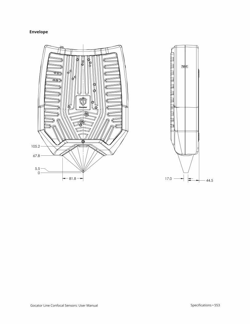
Gocator Line Confocal Sensors: User Manual Specifications • 553
Envelope

Gocator Line Confocal Sensors: User Manual Specifications • 554
Sensor ConnectorsThe following sections provide the specifications of the connectors on Gocator sensors.
Gocator Power/LAN ConnectorThe Gocator Power/LAN connector is a 16-pin, M16 style connector that provides power input, sync,and Ethernet.
This connector is rated IP67 only when a cable is connected or when a protective cap is used.
G5 sensors require a minimum input voltage of 24 VDC. Verify the accepted input voltage foryour sensor in the sensor's specifications; for specifications, see Sensors on page 543.
This section defines the electrical specifications for Power/LAN Connector pins found on G5 sensors,organized by function.
Function Pin Lead Color on Cordsets
24-48V (MAIN)* L Grey/Red
View: Looking into the connector on the sensor
GND_24-48V (MAIN)** M Grey/Black
24-48V (MAIN)* L Pink/Red
GND_24-48V (MAIN)** M Pink/Black
24-48V (AUX)* A Red
GND_24-48V (AUX)** N Black
24-48V (AUX)* A Orange/Red
GND_24-48V (AUX)** N Orange/Black
24-48V (AUX)* B Yellow/Red
GND_24-48V (AUX)** C Yellow/Black
- O -
- D -
Ethernet MX1+ E Violet/Red
Ethernet MX1- F Violet/Black
Ethernet MX2+ G Green/Red
Ethernet MX2- H Green/Black
Ethernet MX3- R Blue/Red
Ethernet MX3+ P Blue/Black
Ethernet MX4+ I Brown/Red
Ethernet MX4- K Brown/Black
Gocator Power/LAN Connector Pins
*All 24-48V wires (MAIN and AUX) are soldered together.
**All GND_24-48V (MAIN and AUX) wires are soldered together.

Gocator Line Confocal Sensors: User Manual Specifications • 555
Grounding Shield
The grounding shield should be mounted to the earth ground.
Power
Apply positive voltage to DC_24-48V.
Function Pins Min Max
DC 24-48V* L, A, and B 48 V 48 V
GND_24-48V (MAIN)** M, N, and C 48 V 48 V
Power requirements
* All 24-48V wires (MAIN and AUX) are soldered together.
** All GND_24-48V (MAIN and AUX) wires are soldered together.

Gocator Line Confocal Sensors: User Manual Specifications • 556
Gocator I/O ConnectorThe Gocator I/O connector is a 19 pin, M16 style connector that provides encoder, digital input,digital outputs, serial output, and analog output signals.
This connector is rated IP67 only when a cable is connected or when a protective cap is used.
This section defines the electrical specifications for I/O connector pins, organized by function.
Function PinLead Color onStandard Cordset
Lead Color on HighFlex Cordset
Trigger_in+ D Grey Blue / Red
View: Looking into theconnector on the sensor
Trigger_in- H Pink Blue / Black
Out_1+ (Digital Output0)
N Red Brown / Red
Out_1- (Digital Output0)
O Blue Brown / Black
Out_2+ (Digital Output1)
S Tan Green / Red
Out_2- (Digital Output1)
T Orange Green / Black
Encoder_A+ M White / Brown & Black Pink / Red
Encoder_A- U Brown / Black Pink / Black
Encoder_B+ I Black Yellow / Red
Encoder_B- K Violet Yellow / Black
Encoder_Z+ A White / Green & Black White / Red
Encoder_Z- L Green / Black White / Black
Serial_out+ B White Purple / Red
Serial_out- C Brown Purple / Black
E Blue / Black Red
G White / Blue & Black Black
Reserved P Green Gray / Red
Reserved F Yellow & Maroon /White
Gray / Black
& Orange / Black
Reserved R Maroon
(not connected)
Orange / Red
(not connected)
Gocator I/O Connector Pins
Grounding Shield
The grounding shield should be mounted to the earth ground.

Gocator Line Confocal Sensors: User Manual Specifications • 557
Digital Outputs
Each sensor has two optically isolated outputs. Both outputs are open collector and open emitter,which allows a variety of power sources to be connected and a variety of signal configurations.
Digital outputs cannot be used when taking scans using the Snapshot button, which takes asingle scan and is typically used to test measurement tool settings. Digital outputs can only beused when a sensor is running, taking a continuous series of scans.
Out_1 (Collector – Pin N and Emitter – Pin O) and Out_2 (Collector – Pin S and Emitter – Pin T) areindependent and therefore V+ and GND are not required to be the same.
Function PinsMax CollectorCurrent
Max Collector–EmitterVoltage
Min Pulse Width
Out_1 N, O 40 mA 70 V 20 µs
Out_2 S, T 40 mA 70 V 20 µs
The resistors shown above are calculated by R = (V+) / 2.5 mA.
The size of the resistors is determined by power = (V+)^2 / R.
Inverting Outputs
To invert an output, connect a resistor between ground and Out_1- or Out_2- and connect Out_1+ orOut_2+ to the supply voltage. Take the output at Out_1- or Out_2-. For resistor selection, see above.
Digital Input
Every sensor has a single optically isolated input. To use this input without an external resistor,supply 3.3 - 24 V to the positive pin and GND to the negative.

Gocator Line Confocal Sensors: User Manual Specifications • 558
Active High
If the supplied voltage is greater than 24 V, connect an external resistor in series to the positive. Theresistor value should be R = [(Vin-1.2V)/10mA]-680.
Active Low
To assert the signal, the digital input voltage should be set to draw a current of 3 mA to 40 mA fromthe positive pin. The current that passes through the positive pin is I = (Vin – 1.2 – Vdata) / 680. Toreduce noise sensitivity, we recommend leaving a 20% margin for current variation (i.e., uses a digitalinput voltage that draws 4mA to 25mA).
Function Pins Min Voltage Max Voltage Min Current Max Current Min Pulse Width
Trigger_in D, H 3.3 V 24 V 3 mA 40 mA 20 µs
Encoder Input
Encoder input is provided by an external encoder and consists of three RS-485 signals. These signalsare connected to Encoder_A, Encoder_B, and Encoder_Z.

Gocator Line Confocal Sensors: User Manual Specifications • 559
Function PinsCommon Mode Voltage Differential Threshold Voltage
Max Data RateMin Max Min Typ Max
Encoder_A M, U -7 V 12 V -200 mV -125 mV -50 mV 1 MHz
Encoder_B I, K -7 V 12 V -200 mV -125 mV -50 mV 1 MHz
Encoder_Z A, L -7 V 12 V -200 mV -125 mV -50 mV 1 MHz
Gocator only supports differential RS485 signalling. Both + and - signals must be connected.
G5 sensors also support single ended encoder connections. These signals are connected to positiveEncoder+ pins and encoder GND to the corresponding negative Encoder- pins.
Function PinsSingle Ended Voltage
Max Data RateMin Typ Max
Encoder_A+ M 2.65 V 5 V 5.7 V 1 MHz
Encoder_B+ I 2.65 V 5 V 5.7 V 1 MHz
Encoder_Z+ A 2.65 V 5 V 5.7 V 1 MHz
Encoders are normally specified in pulses per revolution, where each pulse is made up of thefour quadrature signals (A+ / A- / B+ / B-). Because the sensor reads each of the four quadraturesignals, you should choose an encoder accordingly, given the resolution required for yourapplication.
Serial Output
Serial RS-485 output is connected to Serial_out as shown below.
Function Pins
Serial_out B, C
Analog Output
The Sensor I/O Connector defines one analog output interface: Analog_out.
You do not need to supply an external power source.
Function Pins Current Range
Analog_out P, F 4 – 20 mA

Gocator Line Confocal Sensors: User Manual Specifications • 560
Current Mode Voltage Mode
To configure for voltage output, connect a 500 Ohm ¼Watt resistor between Analog_out+ andAnalog_ out- and measure the voltage across the resistor. To reduce the noise in the output, werecommend using an RC filter as shown below.

Gocator Line Confocal Sensors: User Manual Specifications • 561
Master Network ControllersThe following sections provide the specifications of Master network controllers.
Master 100The Master 100 accepts connections for power, safety, and encoder, and provides digital output.
*Contact LMI for information regarding this type of power supply.
Connect the Master Power port to the Gocator's Power/LAN connector using the Gocator Power/LANto Master cordset. Connect power RJ45 end of the cordset to the Master Power port. The EthernetRJ45 end of the cordset can be connected directly to the Ethernet switch, or connect to the MasterEthernet port. If the Master Ethernet port is used, connect the Master Host port to the Ethernetswitch with a CAT5e Ethernet cable.
To use encoder and digital output, wire the Master's Gocator Sensor I/O port to the Gocator IOconnector using the Gocator I/O cordset.
I/O Pin Master Pin Conductor Color
Encoder_A+ 1 White/Brown & Black
Encoder_A- 2 Brown/Black
Encoder_Z+ 3 White/Green & Black
Encoder_Z- 4 Green/Black
Trigger_in+ 5 Grey
Trigger_in- 6 Pink
Out_1- 7 Blue
Out_1+ 8 Red
Encoder_B+ 11 Black
Encoder_B- 12 Violet
Sensor I/O Port Pins
The rest of the wires in the I/O cordset are not used.

Gocator Line Confocal Sensors: User Manual Specifications • 562
Function Pin
Output_1+ (Digital Output 0) 1
Output_1- (Digital Output 0) 2
Encoder_Z+ 3
Encoder_Z- 4
Encoder_A+ 5
Encoder_A- 6
Encoder_B+ 7
Encoder_B- 8
Encoder_GND 9
Encoder_5V 10
Encoder/Output Port Pins
Master 100 Dimensions

Gocator Line Confocal Sensors: User Manual Specifications • 563
Master 400/800Master network controllers provide sensor power and safety interlock, and broadcast system-widesynchronization information (i.e., time, encoder count, encoder index, and digital I/O states) to alldevices on a sensor network.
It is not necessary to power down a sensor's power source such as a Master before unpluggingthe sensor from the Master. (Sensors can be "hot-swapped.")
The Phoenix connectors on Master 400/800/1200/2400 are not compatible with the connectorson Master 810/2410. For this reason, if you are switching models in your network, you mustrewire the connections to the Master.
Function Pin
+48VDC 1
+48VDC 2
GND (24-48VDC) 3
GND (24-48VDC) 4
5
6
Power and Safety (6 pin connector)
The following are the 6 pin connector's specifications:
CONNECTOR, 6 Position Terminal Block Plug, Female Sockets 0.200" (5.08mm) 180° Free Hanging (In-Line)

Gocator Line Confocal Sensors: User Manual Specifications • 564
Supplier Part Number 277-11017-ND
Manufacturer: Phoenix Contact
Manufacturer PN: 1912223
The power supply must be isolated from AC ground. This means that AC ground and DC groundare not connected.
Function Pin
Input 1 1
Input 1 GND 2
Reserved 3
Reserved 4
Reserved 5
Reserved 6
Reserved 7
Reserved 8
Reserved 9
Reserved 10
Reserved 11
Reserved 12
Reserved 13
Reserved 14
Reserved 15
Reserved 16
Input (16 pin connector)
The following are the 11 pin connector's specifications:
CONNECTOR, 11 Position Terminal Block Plug, Female Sockets 0.138" (3.50mm) 180° Free Hanging(In-Line)
Supplier Part Number 277-8897-ND
Manufacturer: Phoenix Contact
Manufacturer PN: 1847217
The Input connector does not need to be wired up for proper operation.
The following are the 10 pin connector's specifications:
CONNECTOR, 10 Position Terminal Block Plug, Female Sockets 0.138" (3.50mm) 180° Free Hanging(In-Line)

Gocator Line Confocal Sensors: User Manual Specifications • 565
Supplier Part Number 277-6350-ND
Manufacturer: Phoenix Contact
Manufacturer PN: 1847204
Function Pin
Encoder_A+ 1
Encoder_A- 2
Encoder_B+ 3
Encoder_B- 4
Encoder_Z+ 5
Encoder_Z- 6
GND 7
+5VDC 8
Encoder (8 pin connector)
Master 400/800 Electrical Specifications
Specification Value
Power Supply Voltage +48 VDC
Power Supply Current (Max.) 10 A
Power Draw (Min.) 5.76 W
Encoder Signal Voltage Differential (5 VDC)
Digital Input Voltage Range Logical LOW: 0 to +0.1 VDC
Logical HIGH: +3.3 to +24 VDC
Electrical Specifications
When using a Master hub, the chassis must be well grounded.
The power supply must be isolated from AC ground. This means that AC ground and DC groundare not connected.
The Power Draw specification is based on a Master with no sensors attached. Every sensor hasits own power requirements that need to be considered when calculating total system powerrequirements..

Gocator Line Confocal Sensors: User Manual Specifications • 566
Master 400/800 Dimensions
The dimensions of Master 400 and Master 800 are the same.

Gocator Line Confocal Sensors: User Manual Specifications • 567
Master 810/2410Master network controllers provide sensor power and safety interlock, and broadcast system-widesynchronization information (i.e., time, encoder count, encoder index, and digital I/O states) to alldevices on a sensor network.
It is not necessary to power down a sensor's power source such as a Master before unpluggingthe sensor from the Master. (Sensors can be "hot-swapped.")
Some sensors require a minimum input voltage of 48 VDC. Verify the accepted input voltage foryour sensor in the sensor's specifications; for specifications, see Sensors on page 543.
The following table summarizes Master 810 and 2410:
Master 810 and 2410
Input Voltage (Power) +24-48 VDC (2 Watts)1
Total Power Master 810 / 2410 input power + (sensor input power x number of sensors)
Capacity Master 810: up to 8 sensors
Master 2410: up to 24 sensors
I/O 4 digital inputs2
Single-Ended Active LOW: 0 to +0.8 VDC
Single-Ended Active HIGH: +3.3 to +24 VDC
Differential LOW: 0.8 to -24 VDC
Differential HIGH: +3.3 to +24 VDC
10-pin Phoenix
For more information, see Electrical Specifications on page 571.
Encoder Differential (5 VDC, 12 VDC)
Single-ended (5 VDC, 12 VDC)3
For more information, see Electrical Specifications on page 571.
LED Indicators Safety, power, encoder, input. For more information, see LED Indicators on the next
page.
Cable Dual CAT5e cable for power / safety / synchronization / data
Weight (kg) Master 810: 0.6
Master 2410: 0.9
Notes
1. Refer to sensor datasheets for additional power required by sensors.
2. Gocator only supports one digital input.
3. Supports open collector, pull-up resistor, line driver, push-pull, and TTL.
The following table describes the meanings of the encoder and sensor port LED indicators:

Gocator Line Confocal Sensors: User Manual Specifications • 568
Indicator Description
Power Device is on.
Safety Indicates the status of the Safety Interlock circuitry. The “On” state indicates that all
sensor light sources are active.
Encoder A Reserved
Encoder F On continuously: Forward motion with no indexing is detected.
Blinking: Forward motion with indexing is detected.
Encoder R On continuously: Forward motion with no indexing is detected.
Blinking: Forward motion with indexing is detected.
Input 1-4 Digital input ports 1-4 active.
SYNC IN and SYNC OUT Ports (Green
and Orange LEDs)
Reserved.
Sensor Port Green LED Indicates that a sensor is connected to the port and is powered up.
Sensor Port Orange LED Not used.
LED Indicators
The Phoenix connectors on Master 400/800/1200/2400 are not compatible with the connectorson Master 810/2410. For this reason, if you are switching models in your network, you mustrewire the connections to the Master.
Master 2410 can currently be used with encoders with a maximum quadrature frequency of 300 kHz.

Gocator Line Confocal Sensors: User Manual Specifications • 569
Function Pin
Power In+ 1
Power In+ 2
Power In- 3
Power In- 4
5
6
Power and Safety (6 pin connector)
The following are the 6 pin connector's specifications:
CONNECTOR, 6 Position Terminal Block Plug, Female Sockets 0.200" (5.08mm) 180° Free Hanging (In-Line)
Supplier Part Number 277-11017-ND
Manufacturer: Phoenix Contact
Manufacturer PN: 1912223
The power supply must be isolated from AC ground. This means that AC ground and DC groundare not connected.
On earlier revisions of Master 810 and Master 2410, the inputs are labeled 0-3.
The following are the 11 pin connector's specifications:
CONNECTOR, 11 Position Terminal Block Plug, Female Sockets 0.138" (3.50mm) 180° Free Hanging(In-Line)
Supplier Part Number 277-8897-ND

Gocator Line Confocal Sensors: User Manual Specifications • 570
Manufacturer: Phoenix Contact
Manufacturer PN: 1847217
Function Pin
Input 1 Pin 1 1
Input 1 Pin 2 2
Reserved 3
Reserved 4
Reserved 5
Reserved 6
Reserved 7
Reserved 8
GND (output for powering other devices) 9
+5VDC (output for powering other devices) 10
Input (10 pin connector)
The Input connector does not need to be wired up for proper operation.
For Input connection wiring options, see Input on page 574.
The following are the 10 pin connector's specifications:
CONNECTOR, 10 Position Terminal Block Plug, Female Sockets 0.138" (3.50mm) 180° Free Hanging(In-Line)
Supplier Part Number 277-6350-ND
Manufacturer: Phoenix Contact
Manufacturer PN: 1847204
Function Pin
Encoder_A_Pin_1 1
Encoder_A_Pin_2 2
Encoder_A_Pin_3 3
Encoder_B_Pin_1 4
Encoder_B_Pin_2 5
Encoder_B_Pin_3 6
Encoder_Z_Pin_1 7
Encoder_Z_Pin_2 8
Encoder (11 pin connector)

Gocator Line Confocal Sensors: User Manual Specifications • 571
Function Pin
Encoder_Z_Pin_3 9
GND (output for powering external devices) 10
+5VDC (output for powering external devices) 11
For Encoder connection wiring options, see Encoder on the next page.
Electrical Specifications
Some sensors require a minimum input voltage of 48 VDC. Verify the accepted input voltage foryour sensor in the sensor's specifications; for specifications, seeSensors on page 543
Specification Value
Power Supply Voltage +24 VDC to +48 VDC
Power Supply Current (Max.)* Master 810: 9 A
Master 2410: 25 A
* Fully loaded with 1 A per sensor port.
Power Draw (Min.) Master 810: 1.7 W
Master 2410: 4.8 W
Encoder Signal Voltage Single-Ended Active LOW: 0 to +0.8 VDC
Single-Ended Active HIGH: +3.3 to +24 VDC
Differential LOW: 0.8 to -24 VDC
Differential HIGH: +3.3 to +24 VDC
For more information, see Encoder on the next page.
Digital Input Voltage Range Single-Ended Active LOW: 0 to +0.8 VDC
Single-Ended Active HIGH: +3.3 to +24 VDC
Differential LOW: 0.8 to -24 VDC
Differential HIGH: +3.3 to +24 VDC
For more information, see Input on page 574.
If the input voltage is above 24 V, use anexternal resistor, using the following formula:
R = [(Vin - 1.2V) / 10mA] - 680
Electrical Specifications
When using a Master hub, the chassis must be well grounded.
The power supply must be isolated from AC ground. This means that AC ground and DC groundare not connected.
24 VDC power supply is only supported if all connected sensors support an input voltage of 24VDC.

Gocator Line Confocal Sensors: User Manual Specifications • 572
The Power Draw specification is based on a Master with no sensors attached. Every sensor hasits own power requirements that need to be considered when calculating total system powerrequirements..
Encoder
Master 810 and 2410 support the following types of encoder signals: Single-Ended (5 to 12 VDC, 12 to24 VDC) and Differential (5 to 12 VDC, 12 to 24 VDC).
For 5 to 12 VDC operation, pins 2 and 3 of each channel are used.
The 5-volt encoder input supports up to 12 volts for compatibility with earlier Master networkcontrollers. However, we strongly recommend connecting 12-volt output encoders to theappropriate 12-volt input to attain maximum tolerance.
For 12 to 24 VDC operation, pins 1 and 3 of each channel are used.
Although Master 810 and 2410 are currently labeled as only supporting up to 12 VDC, they cansupport up to 24 VDC.
To determine how to wire a Master to an encoder, see the illustrations below.
Single-Ended 5 VDC

Gocator Line Confocal Sensors: User Manual Specifications • 573
Single-Ended 12 VDC
Differential 5 VDC

Gocator Line Confocal Sensors: User Manual Specifications • 574
Differential 12 VDC
Input
Master 810 and 2410 support the following types of input: Differential, Single-Ended High, andSingle-Ended Low.
Currently, Gocator only supports Input 0.
For digital input voltage ranges, see the table below.
Differential
Single-Ended Active High

Gocator Line Confocal Sensors: User Manual Specifications • 575
Single-Ended Active Low
Input Status Min (VDC) Max (VDC)
Single-ended Active High Off 0 +0.8
On +3.3 +24
Single-ended Active Low Off (VDD - 0.8) VDD
On 0 (VDD - 3.3)
Differential Off -24 +0.8
On +3.3 +24
Digital Input Voltage Ranges
Master 810 Dimensions
With 1U rack mount brackets:

Gocator Line Confocal Sensors: User Manual Specifications • 576
With DIN rail mount clips:
Older revisions of Master 810 and 2410 network controllers use a different configuration for theDIN rail clip holes.
Master 2410 Dimensions
With 1U rack mount brackets:

Gocator Line Confocal Sensors: User Manual Specifications • 577
With DIN rail mount clips:
Older revisions of Master 810 and 2410 network controllers use a different configuration for theDIN rail clip holes.

Gocator Line Confocal Sensors: User Manual Specifications • 578
Master 1200/2400Master network controllers provide sensor power and safety interlock, and broadcast system-widesynchronization information (i.e., time, encoder count, encoder index, and digital I/O states) to alldevices on a sensor network.
It is not necessary to power down a sensor's power source such as a Master before unpluggingthe sensor from the Master. (Sensors can be "hot-swapped.")
The Phoenix connectors on Master 400/800/1200/2400 are not compatible with the connectorson Master 810/2410. For this reason, if you are switching models in your network, you mustrewire the connections to the Master.
Function Pin
+48VDC 1
+48VDC 2
GND (24-48VDC) 3
GND (24-48VDC) 4
5
6
Power and Safety (6 pin connector)
The following are the 6 pin connector's specifications:
CONNECTOR, 6 Position Terminal Block Plug, Female Sockets 0.200" (5.08mm) 180° Free Hanging (In-Line)

Gocator Line Confocal Sensors: User Manual Specifications • 579
Supplier Part Number 277-11017-ND
Manufacturer: Phoenix Contact
Manufacturer PN: 1912223
The power supply must be isolated from AC ground. This means that AC ground and DC groundare not connected.
Function Pin
Input 1 1
Input 1 GND 2
Reserved 3
Reserved 4
Reserved 5
Reserved 6
Reserved 7
Reserved 8
Reserved 9
Reserved 10
Reserved 11
Reserved 12
Input (12 pin connector)
The following are the 11 pin connector's specifications:
CONNECTOR, 11 Position Terminal Block Plug, Female Sockets 0.138" (3.50mm) 180° Free Hanging(In-Line)
Supplier Part Number 277-8897-ND
Manufacturer: Phoenix Contact
Manufacturer PN: 1847217
The Input connector does not need to be wired up for proper operation.
The following are the 10 pin connector's specifications:
CONNECTOR, 10 Position Terminal Block Plug, Female Sockets 0.138" (3.50mm) 180° Free Hanging(In-Line)
Supplier Part Number 277-6350-ND
Manufacturer: Phoenix Contact
Manufacturer PN: 1847204

Gocator Line Confocal Sensors: User Manual Specifications • 580
Function Pin
Encoder_A+ 1
Encoder_A- 2
Encoder_B+ 3
Encoder_B- 4
Encoder_Z+ 5
Encoder_Z- 6
GND 7
+5VDC 8
Encoder (8 pin connector)
Master 1200/2400 Electrical Specifications
Specification Value
Power Supply Voltage +48 VDC
Power Supply Current (Max.) 10 A
Power Draw (Min.) 5.76 W
Encoder Signal Voltage Differential (5 VDC)
Digital Input Voltage Range Logical LOW: 0 to +0.1 VDC
Logical HIGH: +3.5 to +6.5 VDC
Electrical Specifications
When using a Master hub, the chassis must be well grounded.
The power supply must be isolated from AC ground. This means that AC ground and DC groundare not connected.
The Power Draw specification is based on a Master with no sensors attached. Every sensor hasits own power requirements that need to be considered when calculating total system powerrequirements..
Master 1200/2400 Dimensions
The dimensions of Master 1200 and Master 2400 are the same.

Gocator Line Confocal Sensors: User Manual Specifications • 581

Gocator Line Confocal Sensors: User Manual 582
Accessories
Description Part Number
5m I/O cordset, open wire end 301175-5m
5m High Power and Ethernet cordset, 1x open wire end, 1x RJ45 end 301203-5m
5m I/O cordset, 90-deg, open wire end 301172-5m
5m High Power and Ethernet cordset, 90-deg, 1x open wire end, 1x RJ45 end 301202-5m
High Flex Gocator Cordsets - Straight Connectors
Notes related to cordsets
For information on cordset bend radius limits, see Cordset Bend Radius Limits on page 18.
Custom cordset lengths between 25 m and 60 m (maximum) and connector orientations areavailable upon request. Prices depend on length and orientation requested. Extension cordsets withone male and one female Gocator connector are also available on request.

Gocator Line Confocal Sensors: User Manual 583
Troubleshooting
Review the guidance in this chapter if you are experiencing difficulty with a sensor system.
If the problem that you are experiencing is not described in this section, see Return Policy onpage 584.
Mechanical/EnvironmentalThe sensor is warm.
l It is normal for a sensor to be warm when powered on. A sensor is typically 15° C warmer than the ambienttemperature.
ConnectionWhen attempting to connect to the sensor with a web browser, the sensor is not found (page doesnot load).
l Verify that the sensor is powered on and connected to the client computer network. The Power IndicatorLED should illuminate when the sensor is powered.
l Check that the client computer's network settings are properly configured.l Use the Sensor Recovery tool to verify that the sensor has the correct network settings. See GoPxL Discovery
Tool on page 539 for more information.
When attempting to log in, the password is not accepted.
l Use the Sensor Recovery tool. See GoPxL Discovery Tool on page 539 for steps to reset the password.
PerformanceThe sensor CPU level is near 100%.
l LMI recommends running G5 sensors through the PC-based version of GoPxL. For more information, seeRunning GoPxL on a Windows PC on page 491.
l Consider reducing the speed. If you are using a time or encoder trigger source, see Triggers on page 75 forinformation on reducing the speed. If you are using an external input or software trigger, consider reducingthe rate at which you apply triggers.
l Review the measurements that you have programmed and eliminate any unnecessary measurements.

Gocator Line Confocal Sensors: User Manual 584
Return Policy
Return PolicyBefore returning the product for repair (warranty or non-warranty) a Return Material Authorization(RMA) number must be obtained from LMI. Please call LMI to obtain this RMA number.
Carefully package the sensor in its original shipping materials (or equivalent) and ship the sensorprepaid to your designated LMI location. Please ensure that the RMA number is clearly written onthe outside of the package. Inside the return shipment, include the address you wish the shipmentreturned to, the name, email and telephone number of a technical contact (should we need todiscuss this repair), and details of the nature of the malfunction. For non-warranty repairs, apurchase order for the repair charges must accompany the returning sensor.
LMI Technologies Inc. is not responsible for damages to a sensor that are the result of improperpackaging or damage during transit by the courier.

Gocator Line Confocal Sensors: User Manual 585
Software Licenses
CLI11
Website:
https://github.com/CLIUtils/CLI11
License:
CLI11 1.8 Copyright (c) 2017-2019 University of Cincinnati, developed by Henry Schreiner under NSFAWARD 1414736.
All rights reserved. Redistribution and use in source and binary forms of CLI11, with or withoutmodification, are permitted provided that the following conditions are met:
1. Redistributions of source code must retain the above copyright notice, this list of conditions andthe following disclaimer.
2. Redistributions in binary form must reproduce the above copyright notice, this list of conditionsand the following disclaimer in the documentation and/or other materials provided with thedistribution.
3. Neither the name of the copyright holder nor the names of its contributors may be used toendorse or promote products derived from this software without specific prior written permission.
THIS SOFTWARE IS PROVIDED BY THE COPYRIGHT HOLDERS AND CONTRIBUTORS "AS IS" AND ANYEXPRESS OR IMPLIED WARRANTIES, INCLUDING, BUT NOT LIMITED TO, THE IMPLIED WARRANTIES OFMERCHANTABILITY AND FITNESS FOR A PARTICULAR PURPOSE ARE DISCLAIMED. IN NO EVENTSHALL THE COPYRIGHT HOLDER OR CONTRIBUTORS BE LIABLE FOR ANY DIRECT, INDIRECT,INCIDENTAL, SPECIAL, EXEMPLARY, OR CONSEQUENTIAL DAMAGES (INCLUDING, BUT NOT LIMITEDTO, PROCUREMENT OF SUBSTITUTE GOODS OR SERVICES; LOSS OF USE, DATA, OR PROFITS; ORBUSINESS INTERRUPTION) HOWEVER CAUSED AND ON ANY THEORY OF LIABILITY, WHETHER INCONTRACT, STRICT LIABILITY, OR TORT (INCLUDING NEGLIGENCE OR OTHERWISE) ARISING IN ANYWAY OUT OF THE USE OF THIS SOFTWARE, EVEN IF ADVISED OF THE POSSIBILITY OF SUCH DAMAGE.
xxhash
Website:
https://github.com/Cyan4973/xxHash
License:
xxHash Library

Gocator Line Confocal Sensors: User Manual Software Licenses • 586
Copyright (c) 2012-present, Yann Collet
All rights reserved.
BSD 2-Clause License (http://www.opensource.org/licenses/bsd-license.php)
Redistribution and use in source and binary forms, with or without modification, are permittedprovided that the following conditions are met:
* Redistributions of source code must retain the above copyright notice, this list of conditions andthe following disclaimer.
* Redistributions in binary form must reproduce the above copyright notice, this list of conditionsand the following disclaimer in the documentation and/or other materials provided with thedistribution.
THIS SOFTWARE IS PROVIDED BY THE COPYRIGHT HOLDERS AND CONTRIBUTORS "AS IS" AND ANYEXPRESS OR IMPLIED WARRANTIES, INCLUDING, BUT NOT LIMITED TO, THE IMPLIED WARRANTIES OFMERCHANTABILITY AND FITNESS FOR A PARTICULAR PURPOSE ARE DISCLAIMED. IN NO EVENTSHALL THE COPYRIGHT HOLDER OR CONTRIBUTORS BE LIABLE FOR ANY DIRECT, INDIRECT,INCIDENTAL, SPECIAL, EXEMPLARY, OR CONSEQUENTIAL DAMAGES (INCLUDING, BUT NOT LIMITEDTO, PROCUREMENT OF SUBSTITUTE GOODS OR SERVICES; LOSS OF USE, DATA, OR PROFITS; ORBUSINESS INTERRUPTION) HOWEVER CAUSED AND ON ANY THEORY OF LIABILITY, WHETHER INCONTRACT, STRICT LIABILITY, OR TORT (INCLUDING NEGLIGENCE OR OTHERWISE) ARISING IN ANYWAY OUT OF THE USE OF THIS SOFTWARE, EVEN IF ADVISED OF THE POSSIBILITY OF SUCH DAMAGE.
----------------------------------------------------
xxhsum command line interface
Copyright (c) 2013-present, Yann Collet
All rights reserved.
GPL v2 License
This program is free software; you can redistribute it and/or modify it under the terms of the GNUGeneral Public License as published by the Free Software Foundation; either version 2 of the License,or (at your option) any later version.
This program is distributed in the hope that it will be useful, but WITHOUT ANY WARRANTY; withouteven the implied warranty of MERCHANTABILITY or FITNESS FOR A PARTICULAR PURPOSE. See theGNU General Public License for more details.
You should have received a copy of the GNU General Public License along with this program; if not,write to the Free Software Foundation, Inc., 51 Franklin Street, Fifth Floor, Boston, MA 02110-1301USA.
JSON for C++
Website:

Gocator Line Confocal Sensors: User Manual Software Licenses • 587
https://github.com/nlohmann/json
License:
MIT License
Copyright (c) 2013-2019 Niels Lohmann
Permission is hereby granted, free of charge, to any person obtaining a copy of this software andassociated documentation files (the "Software"), to deal in the Software without restriction, includingwithout limitation the rights to use, copy, modify, merge, publish, distribute, sublicense, and/or sellcopies of the Software, and to permit persons to whom the Software is furnished to do so, subject tothe following conditions:
The above copyright notice and this permission notice shall be included in all copies or substantialportions of the Software.
THE SOFTWARE IS PROVIDED "AS IS", WITHOUT WARRANTY OF ANY KIND, EXPRESS OR IMPLIED,INCLUDING BUT NOT LIMITED TO THE WARRANTIES OF MERCHANTABILITY, FITNESS FOR APARTICULAR PURPOSE AND NONINFRINGEMENT. IN NO EVENT SHALL THE AUTHORS OR COPYRIGHTHOLDERS BE LIABLE FOR ANY CLAIM, DAMAGES OR OTHER LIABILITY, WHETHER IN AN ACTION OFCONTRACT, TORT OR OTHERWISE, ARISING FROM, OUT OF OR IN CONNECTION WITH THESOFTWARE OR THE USE OR OTHER DEALINGS IN THE SOFTWARE.
OpENer
Website:
https://github.com/EIPStackGroup/OpENer
License:
SOFTWARE DISTRIBUTION LICENSE FOR THE
ETHERNET/IP(TM) COMMUNICATION STACK
(ADAPTED BSD STYLE LICENSE)
Copyright (c) 2009, Rockwell Automation, Inc. ALL RIGHTS RESERVED. EtherNet/IP is a trademark ofODVA, Inc.
Redistribution of the Communications Stack Software for EtherNet/IP and use in source and binaryforms, with or without modification, are permitted provided that the following conditions are met:
Redistributions of source code must retain the above copyright and trademark notices, this list ofconditions and the following disclaimer in the documentation and/or other materials provided withthe distribution.
Redistributions in binary form must reproduce the above copyright notice, this list of conditions andthe following disclaimer in the documentation and/or other materials provided with the distribution.

Gocator Line Confocal Sensors: User Manual Software Licenses • 588
Neither the name of Rockwell Automation, ODVA, nor the names of its contributors may be used toendorse or promote products derived from this software without specific prior written permissionfrom the respective owners.
The Communications Stack Software for EtherNet/IP, or any portion thereof, with or withoutmodifications, may be incorporated into products for sale. However, the software does not, by itself,convey any right to make, have made, use, import, offer to sell, sell, lease, market, or otherwisedistribute or dispose of any products that implement this software, which products might becovered by valid patents or copyrights of ODVA, Inc., its members or other licensors nor does thissoftware result in any license to use the EtherNet/IP mark owned by ODVA. To make, have made,use, import, offer to sell, sell, lease, market, or otherwise distribute or dispose of any products thatimplement this software, and to use the EtherNet/IP mark, one must obtain the necessary licensefrom ODVA through its Terms of Usage Agreement for the EtherNet/IP technology, available throughthe ODVA web site at www.odva.org. This license requirement applies equally (a) to devices thatcompletely implement ODVA's Final Specification for EtherNet/IP (“Network Devices”), (b) tocomponents of such Network Devices to the extent they implement portions of the FinalSpecification for EtherNet/IP, and (c) to enabling technology products, such as any other EtherNet/IPor other network protocol stack designed for use in Network Devices to the extent they implementportions of the Final Specification for EtherNet/IP. Persons or entities who are not already licensedfor the EtherNet/IP technology must contact ODVA for a Terms of Usage Agreement.
THIS SOFTWARE IS PROVIDED BY THE COPYRIGHT HOLDERS AND CONTRIBUTORS "AS IS" AND ANYEXPRESS OR IMPLIED WARRANTIES, INCLUDING, BUT NOT LIMITED TO, THE IMPLIED WARRANTIES OFMERCHANTABILITY AND FITNESS FOR A PARTICULAR PURPOSE ARE DISCLAIMED. IN NO EVENTSHALL THE COPYRIGHT OWNER OR CONTRIBUTORS BE LIABLE FOR ANY DIRECT, INDIRECT,INCIDENTAL, SPECIAL, EXEMPLARY, OR CONSEQUENTIAL DAMAGES (INCLUDING, BUT NOT LIMITEDTO, PROCUREMENT OF SUBSTITUTE GOODS OR SERVICES; LOSS OF USE, DATA, OR PROFITS; ORBUSINESS INTERRUPTION) HOWEVER CAUSED AND ON ANY THEORY OF LIABILITY, WHETHER INCONTRACT, STRICT LIABILITY, OR TORT (INCLUDING NEGLIGENCE OR OTHERWISE) ARISING IN ANYWAY OUT OF THE USE OF THIS SOFTWARE, EVEN IF ADVISED OF THE POSSIBILITY OF SUCH DAMAGE.
picoc
Website:
https://github.com/jpoirier/picoc
License:
Copyright (c) 2009-2011, Zik Saleeba
Copyright (c) 2015, Joseph Poirier
All rights reserved.
Redistribution and use in source and binary forms, with or without modification, are permittedprovided that the following conditions are met:

Gocator Line Confocal Sensors: User Manual Software Licenses • 589
* Redistributions of source code must retain the above copyright notice, this list of conditions andthe following disclaimer.
* Redistributions in binary form must reproduce the above copyright notice, this list of conditionsand the following disclaimer in the documentation and/or other materials provided with thedistribution.
* Neither the name of the Zik Saleeba nor the names of its contributors may be used to endorse orpromote products derived from this software without specific prior written permission.
THIS SOFTWARE IS PROVIDED BY THE COPYRIGHT HOLDERS AND CONTRIBUTORS "AS IS" AND ANYEXPRESS OR IMPLIED WARRANTIES, INCLUDING, BUT NOT LIMITED TO, THE IMPLIED WARRANTIES OFMERCHANTABILITY AND FITNESS FOR A PARTICULAR PURPOSE ARE DISCLAIMED. IN NO EVENTSHALL THE COPYRIGHT OWNER OR CONTRIBUTORS BE LIABLE FOR ANY DIRECT, INDIRECT,INCIDENTAL, SPECIAL, EXEMPLARY, OR CONSEQUENTIAL DAMAGES (INCLUDING, BUT NOT LIMITEDTO, PROCUREMENT OF SUBSTITUTE GOODS OR SERVICES; LOSS OF USE, DATA, OR PROFITS; ORBUSINESS INTERRUPTION) HOWEVER CAUSED AND ON ANY THEORY OF LIABILITY, WHETHER INCONTRACT, STRICT LIABILITY, OR TORT (INCLUDING NEGLIGENCE OR OTHERWISE) ARISING IN ANYWAY OUT OF THE USE OF THIS SOFTWARE, EVEN IF ADVISED OF THE POSSIBILITY OF SUCH DAMAGE.
tar (binary only)
License:
0. Definitions.
“This License” refers to version 3 of the GNU General Public License.
“Copyright” also means copyright-like laws that apply to other kinds of works, such as semiconductormasks.
“The Program” refers to any copyrightable work licensed under this License. Each licensee isaddressed as “you”. “Licensees” and “recipients” may be individuals or organizations.
To “modify” a work means to copy from or adapt all or part of the work in a fashion requiringcopyright permission, other than the making of an exact copy. The resulting work is called a“modified version” of the earlier work or a work “based on” the earlier work.
A “covered work” means either the unmodified Program or a work based on the Program.
To “propagate” a work means to do anything with it that, without permission, would make youdirectly or secondarily liable for infringement under applicable copyright law, except executing it ona computer or modifying a private copy. Propagation includes copying, distribution (with or withoutmodification), making available to the public, and in some countries other activities as well.
To “convey” a work means any kind of propagation that enables other parties to make or receivecopies. Mere interaction with a user through a computer network, with no transfer of a copy, is notconveying.

Gocator Line Confocal Sensors: User Manual Software Licenses • 590
An interactive user interface displays “Appropriate Legal Notices” to the extent that it includes aconvenient and prominently visible feature that (1) displays an appropriate copyright notice, and (2)tells the user that there is no warranty for the work (except to the extent that warranties areprovided), that licensees may convey the work under this License, and how to view a copy of thisLicense. If the interface presents a list of user commands or options, such as a menu, a prominentitem in the list meets this criterion.
1. Source Code.
The “source code” for a work means the preferred form of the work for making modifications to it.“Object code” means any non-source form of a work.
A “Standard Interface” means an interface that either is an official standard defined by a recognizedstandards body, or, in the case of interfaces specified for a particular programming language, onethat is widely used among developers working in that language.
The “System Libraries” of an executable work include anything, other than the work as a whole, that(a) is included in the normal form of packaging a Major Component, but which is not part of thatMajor Component, and (b) serves only to enable use of the work with that Major Component, or toimplement a Standard Interface for which an implementation is available to the public in sourcecode form. A “Major Component”, in this context, means a major essential component (kernel,window system, and so on) of the specific operating system (if any) on which the executable workruns, or a compiler used to produce the work, or an object code interpreter used to run it.
The “Corresponding Source” for a work in object code form means all the source code needed togenerate, install, and (for an executable work) run the object code and to modify the work, includingscripts to control those activities. However, it does not include the work's System Libraries, orgeneral-purpose tools or generally available free programs which are used unmodified in performingthose activities but which are not part of the work. For example, Corresponding Source includesinterface definition files associated with source files for the work, and the source code for sharedlibraries and dynamically linked subprograms that the work is specifically designed to require, suchas by intimate data communication or control flow between those subprograms and other parts ofthe work.
The Corresponding Source need not include anything that users can regenerate automatically fromother parts of the Corresponding Source.
The Corresponding Source for a work in source code form is that same work.
2. Basic Permissions.
All rights granted under this License are granted for the term of copyright on the Program, and areirrevocable provided the stated conditions are met. This License explicitly affirms your unlimitedpermission to run the unmodified Program. The output from running a covered work is covered bythis License only if the output, given its content, constitutes a covered work. This Licenseacknowledges your rights of fair use or other equivalent, as provided by copyright law.
You may make, run and propagate covered works that you do not convey, without conditions so longas your license otherwise remains in force. You may convey covered works to others for the solepurpose of having them make modifications exclusively for you, or provide you with facilities for

Gocator Line Confocal Sensors: User Manual Software Licenses • 591
running those works, provided that you comply with the terms of this License in conveying allmaterial for which you do not control copyright. Those thus making or running the covered works foryou must do so exclusively on your behalf, under your direction and control, on terms that prohibitthem from making any copies of your copyrighted material outside their relationship with you.
Conveying under any other circumstances is permitted solely under the conditions stated below.Sublicensing is not allowed; section 10 makes it unnecessary.
3. Protecting Users' Legal Rights From Anti-Circumvention Law.
No covered work shall be deemed part of an effective technological measure under any applicablelaw fulfilling obligations under article 11 of the WIPO copyright treaty adopted on 20 December 1996,or similar laws prohibiting or restricting circumvention of such measures.
When you convey a covered work, you waive any legal power to forbid circumvention oftechnological measures to the extent such circumvention is effected by exercising rights under thisLicense with respect to the covered work, and you disclaim any intention to limit operation ormodification of the work as a means of enforcing, against the work's users, your or third parties'legal rights to forbid circumvention of technological measures.
4. Conveying Verbatim Copies.
You may convey verbatim copies of the Program's source code as you receive it, in any medium,provided that you conspicuously and appropriately publish on each copy an appropriate copyrightnotice; keep intact all notices stating that this License and any non-permissive terms added in accordwith section 7 apply to the code; keep intact all notices of the absence of any warranty; and give allrecipients a copy of this License along with the Program.
You may charge any price or no price for each copy that you convey, and you may offer support orwarranty protection for a fee.
5. Conveying Modified Source Versions.
You may convey a work based on the Program, or the modifications to produce it from the Program,in the form of source code under the terms of section 4, provided that you also meet all of theseconditions:
◾a) The work must carry prominent notices stating that you modifiedit, and giving a relevant date.
◾b) The work must carry prominent notices stating that it isreleased under this License and anyconditions added under section7. This requirement modifies the requirement in section 4 to “keepintact all notices”.
◾c) You must license the entire work, as a whole, under thisLicense to anyone who comes intopossession of a copy. ThisLicense will therefore apply, along with any applicable section 7additionalterms, to the whole of the work, and all its parts,regardless of how they are packaged. This Licensegives nopermission to license the work in any other way, but it does notinvalidate such permission ifyou have separately received it.

Gocator Line Confocal Sensors: User Manual Software Licenses • 592
◾d) If the work has interactive user interfaces, each must displayAppropriate Legal Notices;however, if the Program has interactiveinterfaces that do not display Appropriate Legal Notices,yourwork need not make them do so.
A compilation of a covered work with other separate and independent works, which are not by theirnature extensions of the covered work, and which are not combined with it such as to form a largerprogram, in or on a volume of a storage or distribution medium, is called an “aggregate” if thecompilation and its resulting copyright are not used to limit the access or legal rights of thecompilation's users beyond what the individual works permit. Inclusion of a covered work in anaggregate does not cause this License to apply to the other parts of the aggregate.
6. Conveying Non-Source Forms.
You may convey a covered work in object code form under the terms of sections 4 and 5, providedthat you also convey the machine-readable Corresponding Source under the terms of this License, inone of these ways:
◾a) Convey the object code in, or embodied in, a physical product(including a physical distributionmedium), accompanied by theCorresponding Source fixed on a durable physical mediumcustomarilyused for software interchange.
◾b) Convey the object code in, or embodied in, a physical product(including a physical distributionmedium), accompanied by awritten offer, valid for at least three years and valid for aslong as youoffer spare parts or customer support for that productmodel, to give anyone who possesses theobject code either (1) acopy of the Corresponding Source for all the software in theproduct that iscovered by this License, on a durable physicalmedium customarily used for software interchange, fora price nomore than your reasonable cost of physically performing thisconveying of source, or (2)access to copy theCorresponding Source from a network server at no charge.
◾c) Convey individual copies of the object code with a copy of thewritten offer to provide theCorresponding Source. Thisalternative is allowed only occasionally and noncommercially, andonly ifyou received the object code with such an offer, in accordwith subsection 6b.
◾d) Convey the object code by offering access from a designatedplace (gratis or for a charge), andoffer equivalent access to theCorresponding Source in the same way through the same place atnofurther charge. You need not require recipients to copy theCorresponding Source along with theobject code. If the place tocopy the object code is a network server, the Corresponding Sourcemaybe on a different server (operated by you or a third party)that supports equivalent copying facilities,provided you maintainclear directions next to the object code saying where to findtheCorresponding Source. Regardless of what server hosts theCorresponding Source, you remainobligated to ensure that it isavailable for as long as needed to satisfy these requirements.
◾e) Convey the object code using peer-to-peer transmission, providedyou inform other peers wherethe object code and CorrespondingSource of the work are being offered to the general public atnocharge under subsection 6d.
A separable portion of the object code, whose source code is excluded from the CorrespondingSource as a System Library, need not be included in conveying the object code work.

Gocator Line Confocal Sensors: User Manual Software Licenses • 593
A “User Product” is either (1) a “consumer product”, which means any tangible personal propertywhich is normally used for personal, family, or household purposes, or (2) anything designed or soldfor incorporation into a dwelling. In determining whether a product is a consumer product, doubtfulcases shall be resolved in favor of coverage. For a particular product received by a particular user,“normally used” refers to a typical or common use of that class of product, regardless of the status ofthe particular user or of the way in which the particular user actually uses, or expects or is expectedto use, the product. A product is a consumer product regardless of whether the product hassubstantial commercial, industrial or non-consumer uses, unless such uses represent the onlysignificant mode of use of the product.
“Installation Information” for a User Product means any methods, procedures, authorization keys, orother information required to install and execute modified versions of a covered work in that UserProduct from a modified version of its Corresponding Source. The information must suffice toensure that the continued functioning of the modified object code is in no case prevented orinterfered with solely because modification has been made.
If you convey an object code work under this section in, or with, or specifically for use in, a UserProduct, and the conveying occurs as part of a transaction in which the right of possession and useof the User Product is transferred to the recipient in perpetuity or for a fixed term (regardless of howthe transaction is characterized), the Corresponding Source conveyed under this section must beaccompanied by the Installation Information. But this requirement does not apply if neither you norany third party retains the ability to install modified object code on the User Product (for example,the work has been installed in ROM).
The requirement to provide Installation Information does not include a requirement to continue toprovide support service, warranty, or updates for a work that has been modified or installed by therecipient, or for the User Product in which it has been modified or installed. Access to a network maybe denied when the modification itself materially and adversely affects the operation of the networkor violates the rules and protocols for communication across the network.
Corresponding Source conveyed, and Installation Information provided, in accord with this sectionmust be in a format that is publicly documented (and with an implementation available to the publicin source code form), and must require no special password or key for unpacking, reading orcopying.
7. Additional Terms.
“Additional permissions” are terms that supplement the terms of this License by making exceptionsfrom one or more of its conditions. Additional permissions that are applicable to the entire Programshall be treated as though they were included in this License, to the extent that they are valid underapplicable law. If additional permissions apply only to part of the Program, that part may be usedseparately under those permissions, but the entire Program remains governed by this Licensewithout regard to the additional permissions.
When you convey a copy of a covered work, you may at your option remove any additionalpermissions from that copy, or from any part of it. (Additional permissions may be written to requiretheir own removal in certain cases when you modify the work.) You may place additionalpermissions on material, added by you to a covered work, for which you have or can giveappropriate copyright permission.

Gocator Line Confocal Sensors: User Manual Software Licenses • 594
Notwithstanding any other provision of this License, for material you add to a covered work, youmay (if authorized by the copyright holders of that material) supplement the terms of this Licensewith terms:
◾a) Disclaiming warranty or limiting liability differently from theterms of sections 15 and 16 of thisLicense; or
◾b) Requiring preservation of specified reasonable legal notices orauthor attributions in thatmaterial or in the Appropriate LegalNotices displayed by works containing it; or
◾c) Prohibiting misrepresentation of the origin of that material, orrequiring that modified versionsof such material be marked inreasonable ways as different from the original version; or
◾d) Limiting the use for publicity purposes of names of licensors orauthors of the material; or
◾e) Declining to grant rights under trademark law for use of sometrade names, trademarks, orservice marks; or
◾f) Requiring indemnification of licensors and authors of thatmaterial by anyone who conveys thematerial (or modified versions ofit) with contractual assumptions of liability to the recipient, foranyliability that these contractual assumptions directly impose onthose licensors and authors.
All other non-permissive additional terms are considered “further restrictions” within the meaning ofsection 10. If the Program as you received it, or any part of it, contains a notice stating that it isgoverned by this License along with a term that is a further restriction, you may remove that term. Ifa license document contains a further restriction but permits relicensing or conveying under thisLicense, you may add to a covered work material governed by the terms of that license document,provided that the further restriction does not survive such relicensing or conveying.
If you add terms to a covered work in accord with this section, you must place, in the relevant sourcefiles, a statement of the additional terms that apply to those files, or a notice indicating where to findthe applicable terms.
Additional terms, permissive or non-permissive, may be stated in the form of a separately writtenlicense, or stated as exceptions; the above requirements apply either way.
8. Termination.
You may not propagate or modify a covered work except as expressly provided under this License.Any attempt otherwise to propagate or modify it is void, and will automatically terminate your rightsunder this License (including any patent licenses granted under the third paragraph of section 11).
However, if you cease all violation of this License, then your license from a particular copyrightholder is reinstated (a) provisionally, unless and until the copyright holder explicitly and finallyterminates your license, and (b) permanently, if the copyright holder fails to notify you of theviolation by some reasonable means prior to 60 days after the cessation.
Moreover, your license from a particular copyright holder is reinstated permanently if the copyrightholder notifies you of the violation by some reasonable means, this is the first time you havereceived notice of violation of this License (for any work) from that copyright holder, and you curethe violation prior to 30 days after your receipt of the notice.

Gocator Line Confocal Sensors: User Manual Software Licenses • 595
Termination of your rights under this section does not terminate the licenses of parties who havereceived copies or rights from you under this License. If your rights have been terminated and notpermanently reinstated, you do not qualify to receive new licenses for the same material undersection 10.
9. Acceptance Not Required for Having Copies.
You are not required to accept this License in order to receive or run a copy of the Program. Ancillarypropagation of a covered work occurring solely as a consequence of using peer-to-peer transmissionto receive a copy likewise does not require acceptance. However, nothing other than this Licensegrants you permission to propagate or modify any covered work. These actions infringe copyright ifyou do not accept this License. Therefore, by modifying or propagating a covered work, you indicateyour acceptance of this License to do so.
10. Automatic Licensing of Downstream Recipients.
Each time you convey a covered work, the recipient automatically receives a license from the originallicensors, to run, modify and propagate that work, subject to this License. You are not responsiblefor enforcing compliance by third parties with this License.
An “entity transaction” is a transaction transferring control of an organization, or substantially allassets of one, or subdividing an organization, or merging organizations. If propagation of a coveredwork results from an entity transaction, each party to that transaction who receives a copy of thework also receives whatever licenses to the work the party's predecessor in interest had or couldgive under the previous paragraph, plus a right to possession of the Corresponding Source of thework from the predecessor in interest, if the predecessor has it or can get it with reasonable efforts.
You may not impose any further restrictions on the exercise of the rights granted or affirmed underthis License. For example, you may not impose a license fee, royalty, or other charge for exercise ofrights granted under this License, and you may not initiate litigation (including a cross-claim orcounterclaim in a lawsuit) alleging that any patent claim is infringed by making, using, selling,offering for sale, or importing the Program or any portion of it.
11. Patents.
A “contributor” is a copyright holder who authorizes use under this License of the Program or a workon which the Program is based. The work thus licensed is called the contributor's “contributorversion”.
A contributor's “essential patent claims” are all patent claims owned or controlled by the contributor,whether already acquired or hereafter acquired, that would be infringed by some manner, permittedby this License, of making, using, or selling its contributor version, but do not include claims thatwould be infringed only as a consequence of further modification of the contributor version. Forpurposes of this definition, “control” includes the right to grant patent sublicenses in a mannerconsistent with the requirements of this License.
Each contributor grants you a non-exclusive, worldwide, royalty-free patent license under thecontributor's essential patent claims, to make, use, sell, offer for sale, import and otherwise run,modify and propagate the contents of its contributor version.

Gocator Line Confocal Sensors: User Manual Software Licenses • 596
In the following three paragraphs, a “patent license” is any express agreement or commitment,however denominated, not to enforce a patent (such as an express permission to practice a patentor covenant not to sue for patent infringement). To “grant” such a patent license to a party means tomake such an agreement or commitment not to enforce a patent against the party.
If you convey a covered work, knowingly relying on a patent license, and the Corresponding Sourceof the work is not available for anyone to copy, free of charge and under the terms of this License,through a publicly available network server or other readily accessible means, then you must either(1) cause the Corresponding Source to be so available, or (2) arrange to deprive yourself of thebenefit of the patent license for this particular work, or (3) arrange, in a manner consistent with therequirements of this License, to extend the patent license to downstream recipients. “Knowinglyrelying” means you have actual knowledge that, but for the patent license, your conveying thecovered work in a country, or your recipient's use of the covered work in a country, would infringeone or more identifiable patents in that country that you have reason to believe are valid.
If, pursuant to or in connection with a single transaction or arrangement, you convey, or propagateby procuring conveyance of, a covered work, and grant a patent license to some of the partiesreceiving the covered work authorizing them to use, propagate, modify or convey a specific copy ofthe covered work, then the patent license you grant is automatically extended to all recipients of thecovered work and works based on it.
A patent license is “discriminatory” if it does not include within the scope of its coverage, prohibitsthe exercise of, or is conditioned on the non-exercise of one or more of the rights that arespecifically granted under this License. You may not convey a covered work if you are a party to anarrangement with a third party that is in the business of distributing software, under which youmake payment to the third party based on the extent of your activity of conveying the work, andunder which the third party grants, to any of the parties who would receive the covered work fromyou, a discriminatory patent license (a) in connection with copies of the covered work conveyed byyou (or copies made from those copies), or (b) primarily for and in connection with specific productsor compilations that contain the covered work, unless you entered into that arrangement, or thatpatent license was granted, prior to 28 March 2007.
Nothing in this License shall be construed as excluding or limiting any implied license or otherdefenses to infringement that may otherwise be available to you under applicable patent law.
12. No Surrender of Others' Freedom.
If conditions are imposed on you (whether by court order, agreement or otherwise) that contradictthe conditions of this License, they do not excuse you from the conditions of this License. If youcannot convey a covered work so as to satisfy simultaneously your obligations under this Licenseand any other pertinent obligations, then as a consequence you may not convey it at all. Forexample, if you agree to terms that obligate you to collect a royalty for further conveying from thoseto whom you convey the Program, the only way you could satisfy both those terms and this Licensewould be to refrain entirely from conveying the Program.
13. Use with the GNU Affero General Public License.
Notwithstanding any other provision of this License, you have permission to link or combine anycovered work with a work licensed under version 3 of the GNU Affero General Public License into asingle combined work, and to convey the resulting work. The terms of this License will continue to

Gocator Line Confocal Sensors: User Manual Software Licenses • 597
apply to the part which is the covered work, but the special requirements of the GNU Affero GeneralPublic License, section 13, concerning interaction through a network will apply to the combination assuch.
14. Revised Versions of this License.
The Free Software Foundation may publish revised and/or new versions of the GNU General PublicLicense from time to time. Such new versions will be similar in spirit to the present version, but maydiffer in detail to address new problems or concerns.
Each version is given a distinguishing version number. If the Program specifies that a certainnumbered version of the GNU General Public License “or any later version” applies to it, you have theoption of following the terms and conditions either of that numbered version or of any later versionpublished by the Free Software Foundation. If the Program does not specify a version number of theGNU General Public License, you may choose any version ever published by the Free SoftwareFoundation.
If the Program specifies that a proxy can decide which future versions of the GNU General PublicLicense can be used, that proxy's public statement of acceptance of a version permanentlyauthorizes you to choose that version for the Program.
Later license versions may give you additional or different permissions. However, no additionalobligations are imposed on any author or copyright holder as a result of your choosing to follow alater version.
15. Disclaimer of Warranty.
THERE IS NO WARRANTY FOR THE PROGRAM, TO THE EXTENT PERMITTED BY APPLICABLE LAW.EXCEPT WHEN OTHERWISE STATED IN WRITING THE COPYRIGHT HOLDERS AND/OR OTHER PARTIESPROVIDE THE PROGRAM “AS IS” WITHOUT WARRANTY OF ANY KIND, EITHER EXPRESSED OR IMPLIED,INCLUDING, BUT NOT LIMITED TO, THE IMPLIED WARRANTIES OF MERCHANTABILITY AND FITNESSFOR A PARTICULAR PURPOSE. THE ENTIRE RISK AS TO THE QUALITY AND PERFORMANCE OF THEPROGRAM IS WITH YOU. SHOULD THE PROGRAM PROVE DEFECTIVE, YOU ASSUME THE COST OF ALLNECESSARY SERVICING, REPAIR OR CORRECTION.
16. Limitation of Liability.
IN NO EVENT UNLESS REQUIRED BY APPLICABLE LAW OR AGREED TO IN WRITING WILL ANYCOPYRIGHT HOLDER, OR ANY OTHER PARTY WHO MODIFIES AND/OR CONVEYS THE PROGRAM ASPERMITTED ABOVE, BE LIABLE TO YOU FOR DAMAGES, INCLUDING ANY GENERAL, SPECIAL,INCIDENTAL OR CONSEQUENTIAL DAMAGES ARISING OUT OF THE USE OR INABILITY TO USE THEPROGRAM (INCLUDING BUT NOT LIMITED TO LOSS OF DATA OR DATA BEING RENDEREDINACCURATE OR LOSSES SUSTAINED BY YOU OR THIRD PARTIES OR A FAILURE OF THE PROGRAM TOOPERATE WITH ANY OTHER PROGRAMS), EVEN IF SUCH HOLDER OR OTHER PARTY HAS BEENADVISED OF THE POSSIBILITY OF SUCH DAMAGES.
17. Interpretation of Sections 15 and 16.
If the disclaimer of warranty and limitation of liability provided above cannot be given local legaleffect according to their terms, reviewing courts shall apply local law that most closely approximates

Gocator Line Confocal Sensors: User Manual Software Licenses • 598
an absolute waiver of all civil liability in connection with the Program, unless a warranty orassumption of liability accompanies a copy of the Program in return for a fee.
ant-design
Website:
https://ant.design/
array-move
Website:
https://github.com/sindresorhus/array-move
License:
MIT License
Copyright (c) Sindre Sorhus <[email protected]> (sindresorhus.com)
Permission is hereby granted, free of charge, to any person obtaining a copy of this software andassociated documentation files (the "Software"), to deal in the Software without restriction, includingwithout limitation the rights to use, copy, modify, merge, publish, distribute, sublicense, and/or sellcopies of the Software, and to permit persons to whom the Software is furnished to do so, subject tothe following conditions:
The above copyright notice and this permission notice shall be included in all copies or substantialportions of the Software.
THE SOFTWARE IS PROVIDED "AS IS", WITHOUT WARRANTY OF ANY KIND, EXPRESS OR IMPLIED,INCLUDING BUT NOT LIMITED TO THE WARRANTIES OF MERCHANTABILITY, FITNESS FOR APARTICULAR PURPOSE AND NONINFRINGEMENT. IN NO EVENT SHALL THE AUTHORS OR COPYRIGHTHOLDERS BE LIABLE FOR ANY CLAIM, DAMAGES OR OTHER LIABILITY, WHETHER IN AN ACTION OFCONTRACT, TORT OR OTHERWISE, ARISING FROM, OUT OF OR IN CONNECTION WITH THESOFTWARE OR THE USE OR OTHER DEALINGS IN THE SOFTWARE.
lodash
Website:
https://lodash.com/
License:
Copyright OpenJS Foundation and other contributors <https://openjsf.org/>
Based on Underscore.js, copyright Jeremy Ashkenas, DocumentCloud and Investigative Reporters &Editors <http://underscorejs.org/>

Gocator Line Confocal Sensors: User Manual Software Licenses • 599
This software consists of voluntary contributions made by many individuals. For exact contributionhistory, see the revision history available at https://github.com/lodash/lodash
The following license applies to all parts of this software except as documented below:
====
Permission is hereby granted, free of charge, to any person obtaining a copy of this software andassociated documentation files (the "Software"), to deal in the Software without restriction, includingwithout limitation the rights to use, copy, modify, merge, publish, distribute, sublicense, and/or sellcopies of the Software, and to permit persons to whom the Software is furnished to do so, subject tothe following conditions:
The above copyright notice and this permission notice shall be included in all copies or substantialportions of the Software.
THE SOFTWARE IS PROVIDED "AS IS", WITHOUT WARRANTY OF ANY KIND, EXPRESS OR IMPLIED,INCLUDING BUT NOT LIMITED TO THE WARRANTIES OF MERCHANTABILITY, FITNESS FOR APARTICULAR PURPOSE AND NONINFRINGEMENT. IN NO EVENT SHALL THE AUTHORS OR COPYRIGHTHOLDERS BE LIABLE FOR ANY CLAIM, DAMAGES OR OTHER LIABILITY, WHETHER IN AN ACTION OFCONTRACT, TORT OR OTHERWISE, ARISING FROM, OUT OF OR IN CONNECTION WITH THESOFTWARE OR THE USE OR OTHER DEALINGS IN THE SOFTWARE.
====
Copyright and related rights for sample code are waived via CC0. Sample code is defined as allsource code displayed within the prose of the documentation.
CC0: http://creativecommons.org/publicdomain/zero/1.0/
====
Files located in the node_modules and vendor directories are externally maintained libraries used bythis software which have their own licenses; we recommend you read them, as their terms maydiffer from the terms above.
mobx
Website:
https://mobx.js.org/README.html
ramda
Website:
https://ramdajs.com/
License:
The MIT License (MIT)

Gocator Line Confocal Sensors: User Manual Software Licenses • 600
Copyright (c) 2013-2019 Scott Sauyet and Michael Hurley
Permission is hereby granted, free of charge, to any person obtaining a copy of this software andassociated documentation files (the "Software"), to deal in the Software without restriction, includingwithout limitation the rights to use, copy, modify, merge, publish, distribute, sublicense, and/or sellcopies of the Software, and to permit persons to whom the Software is furnished to do so, subject tothe following conditions:
The above copyright notice and this permission notice shall be included in all copies or substantialportions of the Software.
THE SOFTWARE IS PROVIDED "AS IS", WITHOUT WARRANTY OF ANY KIND, EXPRESS OR IMPLIED,INCLUDING BUT NOT LIMITED TO THE WARRANTIES OF MERCHANTABILITY, FITNESS FOR APARTICULAR PURPOSE AND NONINFRINGEMENT. IN NO EVENT SHALL THE AUTHORS OR COPYRIGHTHOLDERS BE LIABLE FOR ANY CLAIM, DAMAGES OR OTHER LIABILITY, WHETHER IN AN ACTION OFCONTRACT, TORT OR OTHERWISE, ARISING FROM, OUT OF OR IN CONNECTION WITH THESOFTWARE OR THE USE OR OTHER DEALINGS IN THE SOFTWARE.
rc-menu
Website:
https://github.com/react-component/menu
License:
The MIT License (MIT)
Copyright (c) 2014-present yiminghe
Permission is hereby granted, free of charge, to any person obtaining a copy of this software andassociated documentation files (the "Software"), to deal in the Software without restriction, includingwithout limitation the rights to use, copy, modify, merge, publish, distribute, sublicense, and/or sellcopies of the Software, and to permit persons to whom the Software is furnished to do so, subject tothe following conditions:
The above copyright notice and this permission notice shall be included in all copies or substantialportions of the Software.
THE SOFTWARE IS PROVIDED "AS IS", WITHOUT WARRANTY OF ANY KIND, EXPRESS OR IMPLIED,INCLUDING BUT NOT LIMITED TO THE WARRANTIES OF MERCHANTABILITY, FITNESS FOR APARTICULAR PURPOSE AND NONINFRINGEMENT. IN NO EVENT SHALL THE AUTHORS OR COPYRIGHTHOLDERS BE LIABLE FOR ANY CLAIM, DAMAGES OR OTHER LIABILITY, WHETHER IN AN ACTION OFCONTRACT, TORT OR OTHERWISE, ARISING FROM, OUT OF OR IN CONNECTION WITH THESOFTWARE OR THE USE OR OTHER DEALINGS IN THE SOFTWARE.
react
Website:

Gocator Line Confocal Sensors: User Manual Software Licenses • 601
https://reactjs.org/
License:
MIT License
Copyright (c) Facebook, Inc. and its affiliates.
Permission is hereby granted, free of charge, to any person obtaining a copy of this software andassociated documentation files (the "Software"), to deal in the Software without restriction, includingwithout limitation the rights to use, copy, modify, merge, publish, distribute, sublicense, and/or sellcopies of the Software, and to permit persons to whom the Software is furnished to do so, subject tothe following conditions:
The above copyright notice and this permission notice shall be included in all copies or substantialportions of the Software.
THE SOFTWARE IS PROVIDED "AS IS", WITHOUT WARRANTY OF ANY KIND, EXPRESS OR IMPLIED,INCLUDING BUT NOT LIMITED TO THE WARRANTIES OF MERCHANTABILITY, FITNESS FOR APARTICULAR PURPOSE AND NONINFRINGEMENT. IN NO EVENT SHALL THE AUTHORS OR COPYRIGHTHOLDERS BE LIABLE FOR ANY CLAIM, DAMAGES OR OTHER LIABILITY, WHETHER IN AN ACTION OFCONTRACT, TORT OR OTHERWISE, ARISING FROM, OUT OF OR IN CONNECTION WITH THESOFTWARE OR THE USE OR OTHER DEALINGS IN THE SOFTWARE.
react-dnd
Website:
https://github.com/react-dnd/react-dnd/
License:
The MIT License (MIT)
Copyright (c) 2015 Dan Abramov
Permission is hereby granted, free of charge, to any person obtaining a copy of this software andassociated documentation files (the "Software"), to deal in the Software without restriction, includingwithout limitation the rights to use, copy, modify, merge, publish, distribute, sublicense, and/or sellcopies of the Software, and to permit persons to whom the Software is furnished to do so, subject tothe following conditions:
The above copyright notice and this permission notice shall be included in all copies or substantialportions of the Software.
THE SOFTWARE IS PROVIDED "AS IS", WITHOUT WARRANTY OF ANY KIND, EXPRESS OR IMPLIED,INCLUDING BUT NOT LIMITED TO THE WARRANTIES OF MERCHANTABILITY, FITNESS FOR APARTICULAR PURPOSE AND NONINFRINGEMENT. IN NO EVENT SHALL THE AUTHORS OR COPYRIGHTHOLDERS BE LIABLE FOR ANY CLAIM, DAMAGES OR OTHER LIABILITY, WHETHER IN AN ACTION OF

Gocator Line Confocal Sensors: User Manual Software Licenses • 602
CONTRACT, TORT OR OTHERWISE, ARISING FROM, OUT OF OR IN CONNECTION WITH THESOFTWARE OR THE USE OR OTHER DEALINGS IN THE SOFTWARE.
react-router
Website:
https://github.com/ReactTraining/react-router
License:
MIT License
Copyright (c) React Training 2016-2018
Permission is hereby granted, free of charge, to any person obtaining a copy of this software andassociated documentation files (the "Software"), to deal in the Software without restriction, includingwithout limitation the rights to use, copy, modify, merge, publish, distribute, sublicense, and/or sellcopies of the Software, and to permit persons to whom the Software is furnished to do so, subject tothe following conditions:
The above copyright notice and this permission notice shall be included in all copies or substantialportions of the Software.
THE SOFTWARE IS PROVIDED "AS IS", WITHOUT WARRANTY OF ANY KIND, EXPRESS OR IMPLIED,INCLUDING BUT NOT LIMITED TO THE WARRANTIES OF MERCHANTABILITY, FITNESS FOR APARTICULAR PURPOSE AND NONINFRINGEMENT. IN NO EVENT SHALL THE AUTHORS OR COPYRIGHTHOLDERS BE LIABLE FOR ANY CLAIM, DAMAGES OR OTHER LIABILITY, WHETHER IN AN ACTION OFCONTRACT, TORT OR OTHERWISE, ARISING FROM, OUT OF OR IN CONNECTION WITH THESOFTWARE OR THE USE OR OTHER DEALINGS IN THE SOFTWARE.
rxjs
Website:
https://github.com/ReactiveX/rxjs
License:
Apache License
Version 2.0, January 2004
http://www.apache.org/licenses/
TERMS AND CONDITIONS FOR USE, REPRODUCTION, AND DISTRIBUTION
1. Definitions.

Gocator Line Confocal Sensors: User Manual Software Licenses • 603
"License" shall mean the terms and conditions for use, reproduction, and distribution as defined bySections 1 through 9 of this document.
"Licensor" shall mean the copyright owner or entity authorized by the copyright owner that isgranting the License.
"Legal Entity" shall mean the union of the acting entity and all other entities that control, arecontrolled by, or are under common control with that entity. For the purposes of this definition,"control" means (i) the power, direct or indirect, to cause the direction or management of suchentity, whether by contract or otherwise, or (ii) ownership of fifty percent (50%) or more of theoutstanding shares, or (iii) beneficial ownership of such entity.
"You" (or "Your") shall mean an individual or Legal Entity exercising permissions granted by thisLicense.
"Source" form shall mean the preferred form for making modifications, including but not limited tosoftware source code, documentation source, and configuration files.
"Object" form shall mean any form resulting from mechanical transformation or translation of aSource form, including but not limited to compiled object code, generated documentation, andconversions to other media types.
"Work" shall mean the work of authorship, whether in Source or Object form, made available underthe License, as indicated by a copyright notice that is included in or attached to the work (anexample is provided in the Appendix below).
"Derivative Works" shall mean any work, whether in Source or Object form, that is based on (orderived from) the Work and for which the editorial revisions, annotations, elaborations, or othermodifications represent, as a whole, an original work of authorship. For the purposes of this License,Derivative Works shall not include works that remain separable from, or merely link (or bind byname) to the interfaces of, the Work and Derivative Works thereof.
"Contribution" shall mean any work of authorship, including the original version of the Work and anymodifications or additions to that Work or Derivative Works thereof, that is intentionally submittedto Licensor for inclusion in the Work by the copyright owner or by an individual or Legal Entityauthorized to submit on behalf of the copyright owner. For the purposes of this definition,"submitted" means any form of electronic, verbal, or written communication sent to the Licensor orits representatives, including but not limited to communication on electronic mailing lists, sourcecode control systems, and issue tracking systems that are managed by, or on behalf of, the Licensorfor the purpose of discussing and improving the Work, but excluding communication that isconspicuously marked or otherwise designated in writing by the copyright owner as "Not aContribution."
"Contributor" shall mean Licensor and any individual or Legal Entity on behalf of whom aContribution has been received by Licensor and subsequently incorporated within the Work.
2. Grant of Copyright License. Subject to the terms and conditions of this License, each Contributorhereby grants to You a perpetual, worldwide, non-exclusive, no-charge, royalty-free, irrevocablecopyright license to reproduce, prepare Derivative Works of, publicly display, publicly perform,sublicense, and distribute the Work and such Derivative Works in Source or Object form.

Gocator Line Confocal Sensors: User Manual Software Licenses • 604
3. Grant of Patent License. Subject to the terms and conditions of this License, each Contributorhereby grants to You a perpetual, worldwide, non-exclusive, no-charge, royalty-free, irrevocable(except as stated in this section) patent license to make, have made, use, offer to sell, sell, import,and otherwise transfer the Work, where such license applies only to those patent claims licensableby such Contributor that are necessarily infringed by their Contribution(s) alone or by combination oftheir Contribution(s) with the Work to which such Contribution(s) was submitted. If You institutepatent litigation against any entity (including a cross-claim or counterclaim in a lawsuit) alleging thatthe Work or a Contribution incorporated within the Work constitutes direct or contributory patentinfringement, then any patent licenses granted to You under this License for that Work shallterminate as of the date such litigation is filed.
4. Redistribution. You may reproduce and distribute copies of the Work or Derivative Works thereofin any medium, with or without modifications, and in Source or Object form, provided that You meetthe following conditions:
(a) You must give any other recipients of the Work or Derivative Works a copy of this License; and
(b) You must cause any modified files to carry prominent notices stating that You changed the files;and
(c) You must retain, in the Source form of any Derivative Works that You distribute, all copyright,patent, trademark, and attribution notices from the Source form of the Work, excluding thosenotices that do not pertain to any part of the Derivative Works; and
(d) If the Work includes a "NOTICE" text file as part of its distribution, then any Derivative Works thatYou distribute must include a readable copy of the attribution notices contained within such NOTICEfile, excluding those notices that do not pertain to any part of the Derivative Works, in at least one ofthe following places: within a NOTICE text file distributed as part of the Derivative Works; within theSource form or documentation, if provided along with the Derivative Works; or, within a displaygenerated by the Derivative Works, if and wherever such third-party notices normally appear. Thecontents of the NOTICE file are for informational purposes only and do not modify the License.
You may add Your own attribution notices within Derivative Works that You distribute, alongside oras an addendum to the NOTICE text from the Work, provided that such additional attribution noticescannot be construed as modifying the License. You may add Your own copyright statement to Yourmodifications and may provide additional or different license terms and conditions for use,reproduction, or distribution of Your modifications, or for any such Derivative Works as a whole,provided Your use, reproduction, and distribution of the Work otherwise complies with theconditions stated in this License.
5. Submission of Contributions. Unless You explicitly state otherwise, any Contribution intentionallysubmitted for inclusion in the Work by You to the Licensor shall be under the terms and conditionsof this License, without any additional terms or conditions. Notwithstanding the above, nothingherein shall supersede or modify the terms of any separate license agreement you may haveexecuted with Licensor regarding such Contributions.
6. Trademarks. This License does not grant permission to use the trade names, trademarks, servicemarks, or product names of the Licensor, except as required for reasonable and customary use indescribing the origin of the Work and reproducing the content of the NOTICE file.

Gocator Line Confocal Sensors: User Manual Software Licenses • 605
7. Disclaimer of Warranty. Unless required by applicable law or agreed to in writing, Licensorprovides the Work (and each Contributor provides its Contributions) on an "AS IS" BASIS, WITHOUTWARRANTIES OR CONDITIONS OF ANY KIND, either express or implied, including, without limitation,any warranties or conditions of TITLE, NON-INFRINGEMENT, MERCHANTABILITY, or FITNESS FOR APARTICULAR PURPOSE. You are solely responsible for determining the appropriateness of using orredistributing the Work and assume any risks associated with Your exercise of permissions underthis License.
8. Limitation of Liability. In no event and under no legal theory, whether in tort (including negligence),contract, or otherwise, unless required by applicable law (such as deliberate and grossly negligentacts) or agreed to in writing, shall any Contributor be liable to You for damages, including any direct,indirect, special, incidental, or consequential damages of any character arising as a result of thisLicense or out of the use or inability to use the Work (including but not limited to damages for loss ofgoodwill, work stoppage, computer failure or malfunction, or any and all other commercial damagesor losses), even if such Contributor has been advised of the possibility of such damages.
9. Accepting Warranty or Additional Liability. While redistributing the Work or Derivative Worksthereof, You may choose to offer, and charge a fee for, acceptance of support, warranty, indemnity,or other liability obligations and/or rights consistent with this License. However, in accepting suchobligations, You may act only on Your own behalf and on Your sole responsibility, not on behalf ofany other Contributor, and only if You agree to indemnify, defend, and hold each Contributorharmless for any liability incurred by, or claims asserted against, such Contributor by reason of youraccepting any such warranty or additional liability.

Gocator Line Confocal Sensors: User Manual 606
Support
For help with a component or product, please submit a technical support request athttp://support.lmi3d.com/.
If you are unable to submit a support request or prefer to contact LMI by phone or email, use thecontact information below.
Response times for phone or email support requests are longer than requests submittedthrough LMI's support request system.
North America
Phone Vancouver
+1 833 Gocator (+1 833 462 2867)
Detroit
+1 248 298 2839
Fax +1 604 516 8368
Email [email protected]
Europe
Phone +31 45 850 7000
Fax +31 45 574 2500
Email [email protected]

Gocator Line Confocal Sensors: User Manual 607
Contact
Americas EMEAR ASIA PACIFIC
LMI Technologies (Head Office)
Burnaby, Canada
+1 604 636 1011
LMI Technologies GmbH
Berlin, Germany
+49 (0)3328 9360 0
LMI (Shanghai) Trading Co., Ltd.
Shanghai, China
+86 21 5441 0711
LMI Technologies has sales offices and distributors worldwide. All contact information is listed atlmi3D.com/contact/locations.