
Ravnatelj: pedagog in/ali manager (Director: pedagogue and/or manager)
Upload
khangminh22Category
view
2download
0
User manual
GFK-1847A
Dec 2019
PACSystemsTM VersaMax REMOTE I/O MANAGER
USER MANUAL

User manual Contents GFK-1847A Dec 2019
Contents i
Contents
Chapter 1: Getting Started ...................................................... 1
1.1 Welcome to the Remote I/O Manager ................................................................. 1
1.1.1 Installing the RIO Manager ........................................................................ 1
1.1.2 Starting the RIO Manager .......................................................................... 2
1.1.3 Using the Hardware Configuration Toolbar ................................................ 3
1.1.4 Using the Parameter Editor ....................................................................... 3
1.1.5 Using Shortcut Keys for RIO Manager ........................................................ 5
1.1.6 Setting Options ......................................................................................... 6
Chapter 2: Configuring Remote I/O Racks................................ 8
2.1 Configuring the Rack System ............................................................................... 9
2.1.1 Configuring an NIU .................................................................................... 9
2.1.2 Rack/Module Operations ........................................................................... 9
2.1.3 Configuring VersaMax Modular Rack Systems ......................................... 14
2.2 Hardware Configuration Reference View ........................................................... 16
2.3 Hardware Configuration Log View ..................................................................... 17
2.4 Power Consumption View ................................................................................. 17
2.4.1 Power Consumption Limit Calculations ................................................... 18
2.4.2 Components of the Power Consumption View ........................................ 18
2.5 Printing Hardware Configuration ....................................................................... 19
Chapter 3: Communicating with the NIU ............................... 20
3.1 Communications Setup ..................................................................................... 20
3.2 Storing RIO Configuration.................................................................................. 20
3.3 Loading RIO Configuration ................................................................................ 21
3.4 Verifying RIO Configuration ............................................................................... 22
3.5 Clearing RIO Configuration ................................................................................ 22
Appendix A: Menus and Toolbars .............................................. 23
A-1 File Menu ........................................................................................................... 23
A-2 Edit Menu .......................................................................................................... 23
A-3 Edit menu, Expansion Rack System Sub-menu ................................................... 24
A-4 Edit menu, Expansion Receiver Sub-menu ......................................................... 24
A-5 Edit menu, Rack Operations Sub-menu .............................................................. 24
A-6 Edit menu, Module Operations Sub-menu ......................................................... 25

User manual Contents GFK-1847A Dec 2019
Contents ii
A-7 Parameter Menu ................................................................................................ 25
A-8 View Menu ........................................................................................................ 26
A-9 View Menu, Parameter Edit Sub-menu ............................................................... 26
A-10 Tools Menu ........................................................................................................ 26
A-11 Window Menu ................................................................................................... 26
A-12 Help Menu ......................................................................................................... 27
A-13 HWC Toolbar ..................................................................................................... 27
GFK-1847A Dec 2019
iii
Caution Notes as Used in this Publication
Caution
Caution notices are used where equipment might be damaged if care is not taken.
Notes: Notes merely call attention to information that is especially significant to understanding and operating the equipment.
These instructions do not purport to cover all details or variations in equipment, nor to provide for every possible contingency to be met during installation, operation, and maintenance. The information is supplied for informational purposes only, and Emerson makes no warranty as to the accuracy of the information included herein. Changes, modifications, and/or improvements to equipment and specifications are made periodically and these changes may or may not be reflected herein. It is understood that Emerson may make changes, modifications, or improvements to the equipment referenced herein or to the document itself at any time. This document is intended for trained personnel familiar with the Emerson products referenced herein. Emerson may have patents or pending patent applications covering subject matter in this document. The furnishing of this document does not provide any license whatsoever to any of these patents. Emerson provides the following document and the information included therein as-is and without warranty of any kind, expressed or implied, including but not limited to any implied statutory warranty of merchantability or fitness for particular purpose.

User manual Chapter 1 GFK-1847A Dec 2019
Getting Started 1
Chapter 1: Getting Started
1.1 Welcome to the Remote I/O Manager The Remote I/O Manager contains the configuration information for your VersaMax Remote
I/O rack. It also provides tools to allow you to monitor power consumption and I/O mapping
for modules added to your system.
The configuration information must match the physical hardware of your system. Typical
steps in configuring your Remote I/O hardware include:
• Selecting and configuring an NIU
• Configuring modules and customizing parameters for your application
• Saving the hardware configuration and storing it to the NIU
Detailed information about configuring parameters for a specific module is available
through the online help. To access this information, open the Parameter Editor window for
the module (double-click the module), then select Module Help from the Help menu.
Chapter Contents
• Installing the RIO Manager
• Starting the RIO Manager
• Using the Hardware Configuration Toolbar
• Using the Parameter Editor
• Using Shortcut Keys
• Setting Options
1.1.1 Installing the RIO Manager
Note: The RIO Manager must be installed on a hard drive in your computer. Do not attempt to install it on removable media such as Jaz® or Zip® drives.
1. It is recommended that you close all applications including virus checking, Internet
Explorer, and HMI software that might be running in the background. You may need
to check the task manager to determine if other applications are running.
2. Put the Remote I/O Manager CD in the CD-ROM Drive.
3. Select the CD drive from Windows Explorer.
4. Double click Setup.exe
5. Follow the user prompts to complete the installation. If you have a previous version of
the RIO Manager or VersaPro installed, the installation tool will first uninstall the
previous version. During this uninstall process, you may be asked whether you would
like to remove shared files. It is recommended that you always answer “No to All” to
ensure that no files are deleted that might be needed by another application.

User manual Chapter 1 GFK-1847A Dec 2019
Getting Started 2
1.1.2 Starting the RIO Manager You can start the RIO manager by pressing CTRL + ALT + R. To access the RIO Manager from
the Windows, Start menu, choose Programs, Emerson Software, VersaPro, Remote IO
Manager.
If a shortcut was placed on your desktop, you can start the RIO Manager by double clicking
the shortcut icon . An empty HWC window appears
Figure 1
User manual Chapter 1 GFK-1847A Dec 2019
Getting Started 3
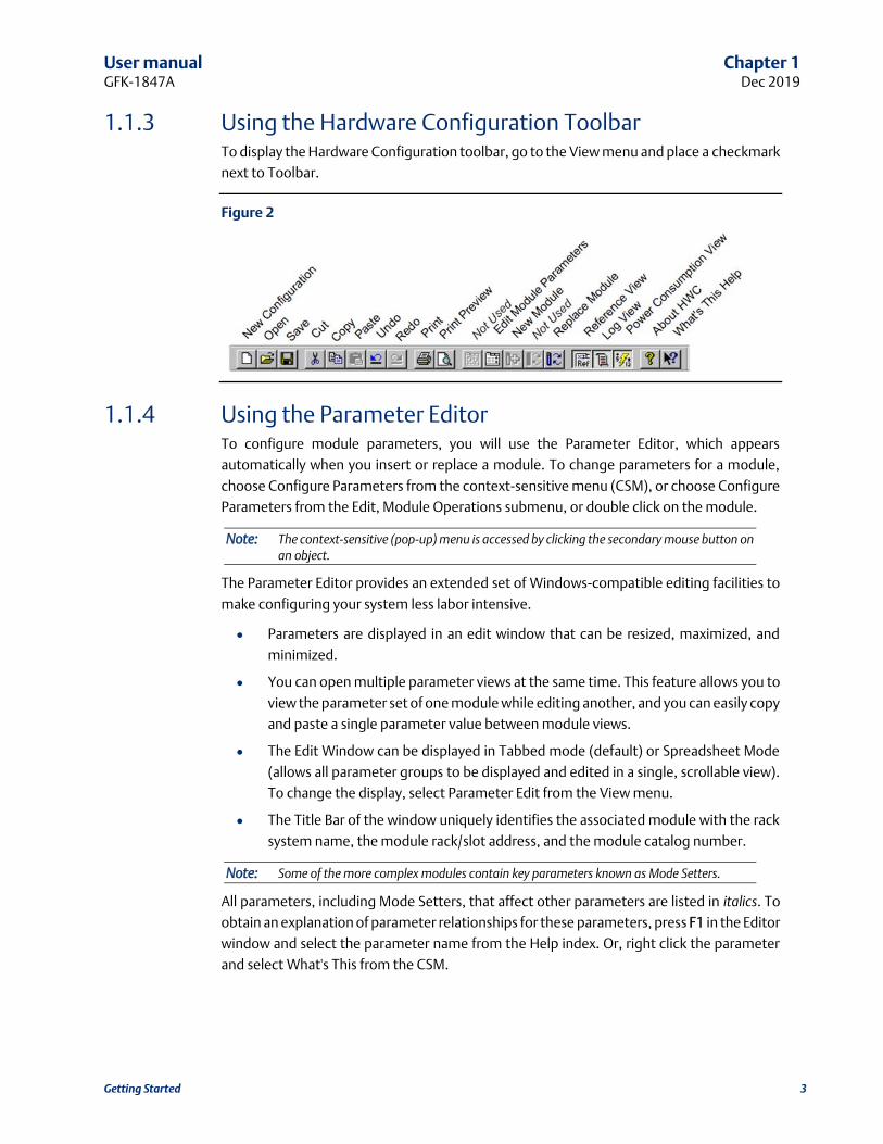
1.1.3 Using the Hardware Configuration Toolbar To display the Hardware Configuration toolbar, go to the View menu and place a checkmark
next to Toolbar.
Figure 2
1.1.4 Using the Parameter Editor To configure module parameters, you will use the Parameter Editor, which appears
automatically when you insert or replace a module. To change parameters for a module,
choose Configure Parameters from the context-sensitive menu (CSM), or choose Configure
Parameters from the Edit, Module Operations submenu, or double click on the module.
Note: The context-sensitive (pop-up) menu is accessed by clicking the secondary mouse button on an object.
The Parameter Editor provides an extended set of Windows-compatible editing facilities to
make configuring your system less labor intensive.
• Parameters are displayed in an edit window that can be resized, maximized, and
minimized.
• You can open multiple parameter views at the same time. This feature allows you to
view the parameter set of one module while editing another, and you can easily copy
and paste a single parameter value between module views.
• The Edit Window can be displayed in Tabbed mode (default) or Spreadsheet Mode
(allows all parameter groups to be displayed and edited in a single, scrollable view).
To change the display, select Parameter Edit from the View menu.
• The Title Bar of the window uniquely identifies the associated module with the rack
system name, the module rack/slot address, and the module catalog number.
Note: Some of the more complex modules contain key parameters known as Mode Setters.
All parameters, including Mode Setters, that affect other parameters are listed in italics. To
obtain an explanation of parameter relationships for these parameters, press F1 in the Editor
window and select the parameter name from the Help index. Or, right click the parameter
and select What's This from the CSM.

User manual Chapter 1 GFK-1847A Dec 2019
Getting Started 4
Figure 3
Sample Parameter Editor Window
Editing Tips
Valid values for each parameter are displayed in a tool tip that appears when you hover the
mouse cursor over the parameter cell. To edit parameter values:
• Type directly into the selected cell in a manner similar to typing into a spreadsheet
cell, or use the Data Entry Tool. To open the Data Entry Tool, right click in the
parameter cell and choose Data Entry Tool from the CSM, press the F2 key, or double
click.
• If the valid values consists of a list of choices with unique initial letters, select a value
by simply typing its first letter in the cell.
You can save time when entering the same value for multiple parameters (of the same type)
by Copying and Pasting or dragging and dropping one parameter value into other
parameter value cells. Copy/Paste and drag/drop can be used within the same module view
or between module views.
Drag/drop works with the keyboard as follows:
• To copy the data from the source cell to the drop cell, do not press any key, or press
the Ctrl key while dragging.
• To move the data from the source cell to the drop cell, press the Shift key while
dragging.
• To copy the data from the source cell to all cells between the source and drop cell
(including the drop cell), press the Alt key while dragging. This assumes that drag
and drop is occurring on the same Edit window and the source and drop cells are in
the same column. These features allows you to quickly fill an entire range of cells
with identical information.

User manual Chapter 1 GFK-1847A Dec 2019
Getting Started 5
Note: Parameter values that have been changed since the start of the editingsession are shown
in bold.
Undoing Changes
• To reset a single parameter to the Start of Edit Session value or to Factory Original
(default) setting, right click on the parameter and choose Reset Parameter from the
CSM.
• To reset all the parameters on a tab, right click anywhere in the tab, and choose Reset
Tab from the CSM.
• To Undo changes, choose Undo from the Edit menu, or click the Undo button on the
Editor toolbar.
• The Editor supports from 1 to 32 levels of Undo/Redo (default is 10).
Note: You cannot Undo changes that result from changing a Mode Setter parameter.
Error Notification
Erroneous values are displayed in the Error Color (red by default) and an explanatory ToolTip
is provided for the error.
To see the ToolTip for an erroneous setting in the Parameter Editor, hover the mouse cursor
over the parameter cell.
To change error notification colors
1. Select Options from the Tools menu.
2. In the Options dialog box, choose the General tab.
3. In the Colors list, choose the condition for which you want to set the color.
4. Click the Choose button. The Windows color selection dialog box will open.
5. Select a color, click OK in the color selection dialog box, then click OK in the Options
dialog box.
Correcting Errors
To automatically correct an erroneous value, right click on the value and select Auto Correct
from the CSM. If you attempt to close a configuration that contains an error, the Parameter
Error List dialog box will appear. To automatically correct all errors listed in this dialog box,
click the Auto Correct button.
1.1.5 Using Shortcut Keys for RIO Manager You can edit information in Hardware Configuration through menu bar selections, the CSM,
or short-cut key sequences.
• To start the RIO Manager, press CTRL + ALT + R.
• To edit modules using the menu bar, click the module or slot you want to configure,
go to the Edit menu, and select the appropriate action.
• To edit modules using the right mouse button, click the module or slot you want to
configure, click the right mouse button, and select the appropriate action.

User manual Chapter 1 GFK-1847A Dec 2019
Getting Started 6
• To edit modules using standard cut, copy, and paste functions, highlight the module
and use the Edit menu options or CTRL key shortcuts.
• To copy a module, click the module you want to copy and press CTRL+C. To paste
the module, click the new slot and press CTRL + V.
• To cut a module (which allows you to paste it in another slot), click the module and
press CTRL+X. To delete a module, click the module, and select Delete from the Edit
Menu or press the Delete key.
• To Undo a previous operation, press CTRL + Z.
• You can use drag and drop to move modules between slots. To use drag and drop,
highlight the module you want to move, click and hold the left-mouse button, and
drag the module to the new slot.
• To close a window, press CTRL + F4.
• To Close HWC, press ALT + F4
1.1.6 Setting Options To set HWC options, go to the Tools menu and select Options. To adjust the size and
content of the HWC System Log, enable Audit Trail Mode, set the number of Undo Levels,
and set Error and Warning colors, select the General Options tab.
Figure 4
To change the format of the Parameter Editor window and the mode for assigning the
next reference, select the Parameter Edit Options tab.

User manual Chapter 1 GFK-1847A Dec 2019
Getting Started 7
Figure 5

User manual Chapter 2 GFK-1847A Dec 2019
Configuring Remote I/O Racks 8
Chapter 2: Configuring Remote I/O Racks A VersaMax Remote I/O (RIO) rack consists of a network interface unit (NIU) and supported
I/O modules. Three types of NIUs are available: Genius (GNIU), Profibus (PNIU), and Ethernet
(ENIU). All VersaMax I/O modules are supported in the Remote I/O rack except
IC200BEM002 and IC200BEM103.
The Hardware Configuration (HWC) tool is used to configure the RIO rack system. The RIO
rack system is built by selecting carriers into which I/O and power supply modules are added.
The default configuration consists of a power supply (PWR001) and an NIU (GBI001 or the
NIU that was saved last time HWC was run). The default VersaMax rack system has a main
rack. Multiple power supplies are supported on the main rack, as required by the modules
you need to add into your rack system. The RIO supports two types of expansion networks:
Local Single Rack and Multiple Remote Rack. The Multiple Remote Rack configuration allows
up to seven expansion racks. Multiple power supplies can be used in expansion racks.
In the physical hardware, field wiring is connected to the module carriers instead of the
modules. HWC displays module wiring in the Module Parameters. If you move a module
between carriers, be sure to update the wiring information accordingly.
Chapter Contents
• Configuring the Rack System
• Hardware Configuration Reference View
• Hardware Configuration Log View
• Printing Hardware Configuration

User manual Chapter 2 GFK-1847A Dec 2019
Configuring Remote I/O Racks 9
2.1 Configuring the Rack System
2.1.1 Configuring an NIU The default NIU is IC200EBI001.
• To replace the NIU:
1. Click the secondary mouse button and choose Replace NIU from the CSM.
2. Select an NIU from the Module Catalog. The Parameter Editor window for the selected
NIU will appear.
3. Review and modify NIU parameters in the Parameter Editor.
4. When you are finished editing the NIU parameters, click the window close button
to close the Parameter Editor window.
• To view or change NIU parameters:
1. Click the secondary mouse button and choose Configure NIU Parameters from the
CSM. The Parameter Editor window for the NIU will appear.
2. Review and modify NIU parameters in the Parameter Editor.
3. When you are finished editing the NIU parameters, click the window close button
to close the Parameter Editor window.
2.1.2 Rack/Module Operations In addition to configuring the NIU, the VersaMax rack configuration is completed through
the following rack/module operations, as required:
• Changing/Configuring the Power Supply
• Adding Module Carriers
• Adding Power Supply Booster Bases
• Configuring a Power Supply for a Booster Base
• Adding/Configuring Modules
• Deleting Carriers
• Clearing the Rack
• Configuring VersaMax Expansion Networks
Changing/Configuring the Power Supply
The default power supply is the IC200PWR001. To change the default power supply:
1. Click the power supply slot, click the secondary mouse button and select Replace
Module. Select the new power supply from the Module Catalog.
2. The Parameter Editor window for the power supply will appear.
3. When you are finished reviewing the power supply parameters, click the window
close button to close the Parameter Editor window.

User manual Chapter 2 GFK-1847A Dec 2019
Configuring Remote I/O Racks 10
Adding Module Carriers
Carriers must be configured to house module in the VersaMax PLC. Perform these steps to
configure module carriers.
1. To add a carrier to the right of configured modules, click the right mouse button and
choose Add Base/Carrier. The Module Catalog for Carriers will appear.
To insert a carrier between two configured modules, highlight the module which will
be to the right of the new carrier, click the right mouse button and choose Insert
Base/Carrier. The Module Catalog for Carriers will appear.
Note: You must click the right mouse button over a module or carrier in the rack configuration to view configuration choices from the right mouse button.
2. Click the catalog number and description of the carrier you want to add, then click the
OK button.
Adding Power Supply Booster Bases
Power Supply boosters may be added into the system configuration to power modules
downstream from the booster. Perform these steps to add a power supply booster base:
1. To add a Power Supply Booster Base to the right of configured modules, click the right
mouse button and choose Add Base/Carrier. The Module Catalog will display.
To insert a Power Supply Booster base between two configured modules, highlight
the module which will be to the right of the new base, click the right mouse button
and choose Insert Base/Carrier. The Module Catalog will display.
2. Click the Power Supply Booster Bases tab. Click the catalog number to select the base,
then click the OK button.
3. To configure the power supply, click the right mouse button and choose Add Module.
Select the Power Supply from the list and click OK.
Configuring a Power Supply for a Booster Base
Power Supplies can be added throughout your VersaMax system. To add or replace a
configured power supply on a Booster Base:
1. Double-click the empty booster base. For booster bases with configured power
supplies, click the right mouse button and select Replace Module. The Power Supply
Module Catalog dialog box will appear.
2. Click the catalog number of the power supply you want to configure, then click the OK
button. The Parameter Editor will appear.
3. You can view information about the power supply. Click OK to complete power supply
configuration.
Adding/Configuring Modules
Once a carrier is configured, the module may be added to the system:
1. Highlight the carrier which will house the module.

User manual Chapter 2 GFK-1847A Dec 2019
Configuring Remote I/O Racks 11
2. Double-click on the empty carrier or click the right mouse button and choose Add
Module. (If you are replacing a previously configured module, click the right mouse
button and choose Replace Module.)
3. Click the tab describing the I/O module type you need (Discrete Input, Discrete
Output, Analog Input, Analog Output, etc.).
4. Click the catalog number and description of the module in your system, then click the
OK button.
Configuring Module Parameters
To configure the module’s parameters:
1. When you add or replace a module, the Parameter Editor appears. You can also access
this window by double-clicking the module slot from the Rack window.
2. Within the Parameter Editor, click the tab pertaining to the parameters you want to
view or modify (where applicable).
3. Click in the Values fields you want to edit. (See "Editing Tips" in chapter 1.)
4. When you have finished configuring module parameters, click the window close
button .
Deleting Rack Modules
Deleting a module removes it from the rack. If you save the Hardware Configuration after
deleting the module, the configuration information about the deleted module will be lost.
Perform these steps to delete a module:
1. Select the module you want to delete.
2. Press the Delete key or click the right mouse button and choose Delete Module.
Deleting Carriers
You must use the menu bar or right mouse operations to delete a carrier. Perform these
steps to delete a carrier:
1. Highlight the empty carrier you want to delete.
2. Click the right mouse button and choose Delete Carrier.
Clearing the Rack
Clearing the rack removes all modules (except the power supply and NIU). If you save the
Hardware Configuration after clearing the rack, the configuration information about the
deleted modules will be lost.
Perform these steps to clear the rack configuration:
1. Click anywhere in the Rack.
2. Click the right mouse button and choose Clear Rack.
3. A confirmation dialog box will appear. To confirm the clear rack operation, click the
Yes button.
Configuring VersaMax Expansion Networks

User manual Chapter 2 GFK-1847A Dec 2019
Configuring Remote I/O Racks 12
There are three types of configurations in the VersaMax rack system. To change the rack
configuration, select the type you want from the CSM or from the Edit, Expansion Rack
System submenu.
None
Includes only the Main VersaMax rack (no Expansion). Systems created using VersaPro 1.0
have this type of configuration. This is the default VersaMax System, which is created when
you select New from the File menu.
Local Single Rack
Includes the Main VersaMax I/O station and one Expansion rack. The Main VersaMax rack
does not contain a Transmitter. The Expansion rack contains a non-isolated Power Supply
and Receiver Integrated Unit (IC200ERM002). The power supply is not configured unless the
Receiver unit is active. The default power supply in the expansion rack will be the same as
the main rack's power supply. Replacing the main rack's primary power supply will not affect
the expansion rack's primary power supply.
Multiple Remote Rack
Allows you to configure up to seven Expansion racks (seven Rack tabs are always shown).
The Main VersaMax rack contains a Transmitter (IC200ETM001). The Non-Isolated Receiver
(IC200ERM002), which is configured by default, can be replaced by an Isolated Receiver
(IC200ERM001).
Note: The Transmitter and Receiver modules cannot be added from the module catalog. The only way to add these modules to a rack configuration is to choose the appropriate configuration type. Also, you cannot delete them from a rack configuration except by changing the rack configuration type.
If a single-ended receiver is configured and an expansion transmitter is present, a fatal “expansion transmitter mismatch” fault will be generated. This fault will also be generated if a differential (transmitter and receivers) is configured and no expansion transmitter is physically present. In these cases, no faults will be generated for individual modules in the expansion racks. The NIU detects the presence or absence of receiver modules connected through the expansion bus and compares the physical configuration with the programmed configuration. It will generate a “Loss of rack” alarm for missing receivers and an “Addition of or extra rack” alarm for extra receivers.
Switching Between VersaMax Rack Systems
You can switch from one VersaMax rack system type to another. This allows single rack
systems created in VersaPro versions earlier than 1.10 to be upgraded to Local Single Rack
and Multiple Remote Rack systems. Switching rack system types has the following effects:
When you switch configurations, a message is displayed which gives you the option of
carrying out the parameter changes of the existing NIU/modules to the new rack
configuration.
To change rack system type, choose Expansion Rack System from the CSM or the Edit menu.
Select an expansion rack type from the submenu.
User manual Chapter 2 GFK-1847A Dec 2019
Configuring Remote I/O Racks 13
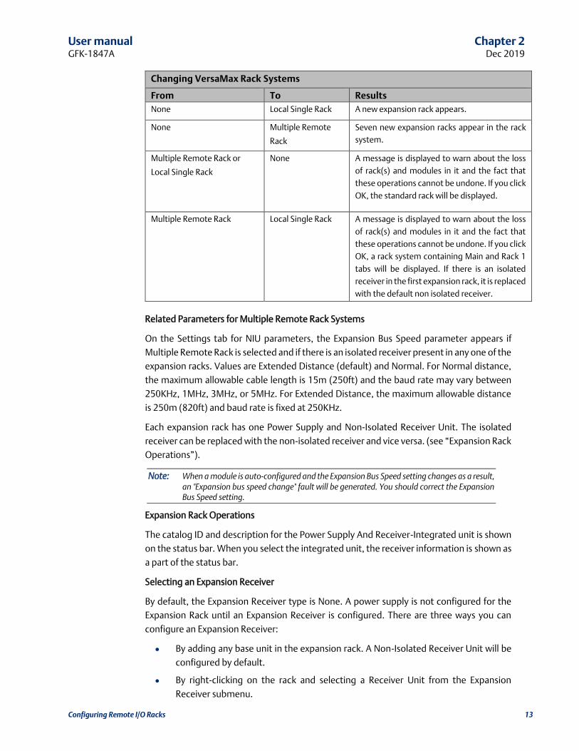
Changing VersaMax Rack Systems
From To Results
None Local Single Rack A new expansion rack appears.
None Multiple Remote
Rack
Seven new expansion racks appear in the rack
system.
Multiple Remote Rack or
Local Single Rack
None A message is displayed to warn about the loss
of rack(s) and modules in it and the fact that
these operations cannot be undone. If you click
OK, the standard rack will be displayed.
Multiple Remote Rack Local Single Rack A message is displayed to warn about the loss
of rack(s) and modules in it and the fact that
these operations cannot be undone. If you click
OK, a rack system containing Main and Rack 1
tabs will be displayed. If there is an isolated
receiver in the first expansion rack, it is replaced
with the default non isolated receiver.
Related Parameters for Multiple Remote Rack Systems
On the Settings tab for NIU parameters, the Expansion Bus Speed parameter appears if
Multiple Remote Rack is selected and if there is an isolated receiver present in any one of the
expansion racks. Values are Extended Distance (default) and Normal. For Normal distance,
the maximum allowable cable length is 15m (250ft) and the baud rate may vary between
250KHz, 1MHz, 3MHz, or 5MHz. For Extended Distance, the maximum allowable distance
is 250m (820ft) and baud rate is fixed at 250KHz.
Each expansion rack has one Power Supply and Non-Isolated Receiver Unit. The isolated
receiver can be replaced with the non-isolated receiver and vice versa. (see “Expansion Rack
Operations”).
Note: When a module is auto-configured and the Expansion Bus Speed setting changes as a result, an "Expansion bus speed change" fault will be generated. You should correct the Expansion Bus Speed setting.
Expansion Rack Operations
The catalog ID and description for the Power Supply And Receiver-Integrated unit is shown
on the status bar. When you select the integrated unit, the receiver information is shown as
a part of the status bar.
Selecting an Expansion Receiver
By default, the Expansion Receiver type is None. A power supply is not configured for the
Expansion Rack until an Expansion Receiver is configured. There are three ways you can
configure an Expansion Receiver:
• By adding any base unit in the expansion rack. A Non-Isolated Receiver Unit will be
configured by default.
• By right-clicking on the rack and selecting a Receiver Unit from the Expansion
Receiver submenu.

User manual Chapter 2 GFK-1847A Dec 2019
Configuring Remote I/O Racks 14
• By choosing a Receiver Unit from the Edit submenu, Expansion Receiver. To
deactivate the unit, select None from the Expansion Receiver submenu. (This option
is not available if the rack configuration contains one or more Carrier/Base units.
Changing Receiver Type for Expansion Racks in Multiple Rack Systems
The Power Supply And Receiver-Integrated unit consists of IC200PWR001 and
IC200ERM002 (non-isolated receiver) by default. For expansion racks in Multiple Remote
Rack systems, an isolated receiver (IC200ERM001) can be selected. To change the receiver,
choose Expansion Receiver from the Edit menu or the CSM.
Viewing Power Consumption Values
To view the parameters for the power supply, double click on the Power Supply and
Receiver-Integrated unit. Power values for the receiver are shown in the parameter dialog
of the receiver and the value is non-editable. Receiver power is included as part of the total
power consumption of the main power supply.
To view the parameters for the receiver, choose Configure Receiver Parameters from the
CSM or from the Edit, Rack Operations menu.
Clearing the Rack for Multiple Remote Rack Systems
When you select this option with focus on the Main rack, the transmitter will not be cleared.
If you select this option with focus on expansion rack, it clears all the modules except the
Power Supply And Receiver-Integrated unit.
Configuring Receiver Parameters
This option displays the Receiver parameters for the selected Expansion rack. (The Receiver
units have no configurable parameters.)
2.1.3 Configuring VersaMax Modular Rack Systems A VersaMax modular rack system containing a CPU can be opened in the RIO Manager.You
can modify the CPU parameters and I/O module configuration. You cannot replace the CPU
with a different CPU or connect to the CPU for load/store/verify operations. However, you
can replace the CPU with an NIU, converting the configuration to an RIO rack.
Configuring the CPU
This operation can only be performed on an existing VersaMax rack configuration that
contains a CPU.
1. Open a VersaMax rack configuration that contains a CPU.
2. Click the secondary mouse button and choose Configure CPU Parameters from the
CSM (or, from the Edit menu, choose Rack Operations, Configure CPU Parameters).
The Parameter Editor window for the CPU will appear.
3. Review and modify CPU parameters in the Parameter Editor.
4. When you are finished editing the CPU parameters, click the window close button
to close the Parameter Editor window.

User manual Chapter 2 GFK-1847A Dec 2019
Configuring Remote I/O Racks 15
Defining Ethernet Global Data Exchanges
This operation can only be performed on an existing VersaMax rack configuration that
contains a VersaMax CPUE05.
Ethernet Global Data (EGD) allows one device (the producer) to transfer (exchange) data to
one or more other devices (the consumers) at a regularly scheduled transfer rate. A
maximum of 64 exchanges can be defined for a CPUE05 system. This number can be divided
up into any combination of produced and consumed exchanges.
CAUTION
EGD exchanges are designed for simple, efficient communication of sampled data between
devices. They are not intended for event notification where the possible loss of a sample of
data would be significant. For event notification, it is recommended that a Service Request
Transfer Protocol (SRTP) connected service be used.
The exchange of data is uniquely defined through a combination of the Producer ID
(identification number) and the Exchange ID:
• Each device exchanging EGD on the network must be assigned its own unique
Producer ID. This Producer ID uniquely identifies the source device of Ethernet
Global data on the network. The Producer ID number is in dotted-decimal format
(like an IP Address). For example, 3.0.0.1 is a valid Producer ID.
• An Exchange ID is a unique number that identifies a particular variable or group of
variables to be transferred.
Producing devices and consuming devices operate completely asynchronously to each
other. Therefore, for each device, both the data that the device produces and the data that
the device consumes must be separately defined.
You need to specify the operating characteristics and data to be exchanged for each
exchange your PLC will produce or consume. Note the following exchange limitations:
• Up to 100 variables can be configured per exchange. The CPUE05 is restricted to a
total of 1200 variables across all EGD exchanges.
• The total size of a single exchange cannot exceed 1400 bytes. The total size is
defined to be the sum of the data type lengths of all of the variables within the list.
The exchange size is displayed in the Ethernet Global Data dialog box.
To define an EGD exchange:
1. In Hardware Configuration, go to the Edit menu, choose Rack Operations, and select
Ethernet Global Data (or click the right mouse button and choose Ethernet Global
Data from the pop-up menu).
2. In the Ethernet Global Data dialog box, click the Produced Exchanges tab to define
exchanges produced by your PLC orclick the Consumed Exchanges tab to define
exchanges consumed by your PLC.
For further details about configuring EGD exchanges, refer to the Remote I/O Manager
online help and the VersaMax PLC User’s Manual, GFK-1503

User manual Chapter 2 GFK-1847A Dec 2019
Configuring Remote I/O Racks 16
Replacing the CPU with an NIU
You cannot undo this operation. (To keep the CPU configuration, you can close the
configuration without saving or save the configuration with a new name.)
1. Open a VersaMax rack configuration that contains a CPU.
2. Click the secondary mouse button and choose Replace CPU from the CSM (or, from
the Edit menu, choose Rack Operations, Replace CPU). The Module Catalog listing
NIUs will appear.
3. Select an NIU and click OK. The Parameter Editor window for the NIU will appear.
4. Review and edit the NIU parameters as required for your application. When you are
finished editing the NIU parameters, click the window close button to close the
Parameter Editor window.
2.2 Hardware Configuration Reference View HWC Reference View provides information about references allocated when modules are
added to the rack system. This view is updated each time an I/O or specialty module is added
to or deleted from the system.
The Reference View is a dockable view, which means that you can select it with your mouse
and move it anywhere in the HWC main window. You can control display of the reference
view. To display or hide the reference view, select the View menu and click Reference View.
The reference view maintains a separate tab for each reference type used in HWC (%I, %Q,
%AI, %AQ, %G, %M, %R, …). To view reference information for a specific reference type, click
the tab that corresponds to that reference type.
Figure 6
Each row provides reference point assignments for a specific module. The columns are
configured as follows:
• Overlap: By default, non-fatal overlaps are identified in blue text and fatal overlaps
are identified in red text.
• Start: Displays the starting reference point assignment for the module.
• End: Displays the ending reference point assignment for the module.
• Addr: Displays the module’s Rack/Slot address in the form R.S where:
— . R is the relative rack number (0 indicates first, or main, rack)

User manual Chapter 2 GFK-1847A Dec 2019
Configuring Remote I/O Racks 17
— S is the relative slot number within the assigned rack (0 indicates the leftmost
slot)
• Mem Type: Identifies whether the module produces or consumes data in the
allocated memory area.
• Catalog #: Display’s the module’s catalog number.
2.3 Hardware Configuration Log View HWC offers a logging facility which records and maintains a history of HWC events and
status information. The data is saved in a separate log file on the PC hard disk and may be
accessed through multiple edit sessions. The default size of the log file default is 1MB. If the
log data exceeds this size, the oldest log information is overwritten with new log data.
Figure 7
HWC provides two modes for recording log data:
• Exception Only Mode: Only warnings and exception conditions are recorded in the
log.
• Audit Trail Mode (default mode): Informational messages (such as module deletes,
adds, etc.) are recorded in the log, in addition to warnings and exception conditions.
To change the setting for the log file, select the Tools menu and choose Options. The
Options dialog box will display, allowing you to set Audit Trail Mode and adjust the default
log file size.
The Log View is a dockable view, which means that you can select it with your mouse and
move it anywhere in the HWC main window. You can control display of the log view. To
display or hide the log view, select the View menu and click Log View.
2.4 Power Consumption View The Power View displays current power consumption statistics for the power supply that is
providing power to the currently selected module. These statistics are provided to assist you
in monitoring the power requirements of the I/O modules you are configuring in the
individual racks.

User manual Chapter 2 GFK-1847A Dec 2019
Configuring Remote I/O Racks 18
To enable or disable docking, choose Dock from the popup menu. To change the color
scheme, see Error Notification.
The following power consumption statistics are displayed:
• The bar graphs show the percentage of power used for each voltage.
• Used and Supplied power statistics are shown in Amps.
2.4.1 Power Consumption Limit Calculations The Power view displays graphs showing amount of consumption for the various voltages
produced by the power supply. The VersaMax power supplies are current limited, and
therefore display units are Amps.
Figure 8
VersaMax Power View
2.4.2 Components of the Power Consumption View Power Supply Whose Statistics are Displayed
This is always the most immediate leftmost power supply to the selected module. Because
a VersaMax rack supports multiple Power Supplies, the power supply can be in any slot and
is the first one encountered traveling left from the selected module.
Normal Range
Power Consumption percentage bars representing less than 75% consumption are
displayed in the Power Normal color (default is green).
Warning Range
Power Consumption percentage bars representing more than 75% to 100% consumption
are displayed in the Power Warning color (default is yellow).

User manual Chapter 2 GFK-1847A Dec 2019
Configuring Remote I/O Racks 19
Exceeded Range
Power Consumption percentage bars representing greater than 100% consumption are
displayed in the Power Error color (default is red). Note that if consumption is exceeded, the
label at the bottom of the graph displays the actual amount used, but the percentage bar
does not show greater than 100%.
Note: To change the normal, warning, and error colors in the Power Viewdisplay, choose Options from the Tools menu.
2.5 Printing Hardware Configuration You can print your Rack configuration by going to the File menu and choosing Print. To set
print options, click the Range button in the Print dialog box. The following print options are
available:
• You can choose to print hardware configuration information for the entire rack, or
for a range of modules (selected by rack:slot).
• You can select to print an overview and/or details for the configuration:
— Overview: Prints the Rack as shown on the screen.
— Detail: Prints the parameter information for each module in the Rack.
— Ethernet Global Data: Prints a listing of produced and consumed exchanges
(only available for racks containing a CPUE05 configured for EGD).
— Reference Details: Prints a table showing start and end memory locations, rack
slot addresses, and other reference data.
— Name Resolution: Not used.
If you want to change your target printer or paper size or orientation, click the Setup button
in the Print dialog box.
User manual Chapter 3 GFK-1847A Dec 2019
Communicating with the NIU 20
Chapter 3: Communicating with the NIU This chapter describes how to connect to the NIU and load, store, and verify RIO
configurations.
For Genius and Profibus NIUs, the Load, Store, and Verify operations require cable
IC200CBL002, which is used to connect a COM port on your PC to the serial port on the left
side of the VersaMax NIU.
For Ethernet NIUs, these operations use an Ethernet connection.
Chapter Contents
• Communications Setup
• Storing RIO Configuration
• Loading RIO Configuration
• Verifying RIO Configuration
• Clearing the RIO Configuration
3.1 Communications Setup To define communications parameters for the rack system, select Communications Setup
from the Tools menu. The main screen of the Communication Configuration Utility will
appear. (If a password has been defined for the Communication Configuration Utility, the
Password dialog box will appear. Enter your password and press OK to continue.)
When configuring a Device in the CCU for use with a GNIU or PNIU, you should assign a Name
and default Port. Port Type should be set to SNP_SERIAL. All other fields should be left at
their default values.
When configuring a Device for use with an ENIU, you should assign a Name, default Port,
and IP address. Port Type should be set to TCPIP_ETH.
3.2 Storing RIO Configuration 1. Choose Load/Store/Verify in the Tools menu.
If the configuration has not been saved, the message, “Please save this rack system
first,” will appear, followed by the “Save As” dialog box. You must save the rack system
once before the Load/Store/Verify dialog box can be opened. After you have saved the
rack system once, auto-saves will be performed when this command is invoked.
2. In the Load/Store/Verify Hardware Configuration dialog box select a Device and a Port.

User manual Chapter 3 GFK-1847A Dec 2019
Communicating with the NIU 21
Figure 9
3. Click the Store button. The programming software will automatically connect to the
NIU, perform the store, and disconnect from the NIU. The status of the operation will
be displayed in the Log window.
Note: If you attempt to store a hardware configuration to an NIU that does not match the type
selected in the configuration, an error message will appear and the operation will be stopped.
3.3 Loading RIO Configuration To load configuration data from the Rack System:
1. Choose Load/Store/Verify in the Tools menu.
2. In the Load/Store/Verify Hardware Configuration dialog box select a Device and a Port.
3. Click the Load button. The programming software will automatically connect to the
NIU.
Note: If you attempt to load a hardware configuration from an NIU that does not match the type
selected in the configuration, an error message will appear, and the operation will be stopped.
VersaMax Modules with Shared IDs
When the configuration is loaded from a rack system, HWC uses the hardware module ID to
determine the correct module catalog number and description. However, some VersaMax
modules share the same module IDs. When a VersaMax rack system containing these
modules is auto configured and the configuration is loaded an incorrect catalog number and
description may be displayed. You will need to select the correct module from the modules
catalog and store it to the rack system. After storing the configuration, you will be able to
load the configuration properly.
The following modules share hardware module IDs:
IC200MDL650 loads as IC200MDL636
IC200MDL750 loads as IC200MDL742

User manual Chapter 3 GFK-1847A Dec 2019
Communicating with the NIU 22
IC200MDL331 loads as IC200MDL329
IC200MDD844 loads as IC200MDD842
IC200MDL141 loads as IC200MDL140
3.4 Verifying RIO Configuration To verify the rack configuration:
1. In the Load/Store/Verify Hardware Configuration dialog box select a Device and a Port.
2. Click the Verify button. The programming software will automatically connect to the
NIU, perform the verification, and disconnect from the NIU. The Log window will
display the results of the operation.
3.5 Clearing RIO Configuration This procedure clears the configuration and forces an autoconfiguration. If you clear the NIU
and then do a load from the NIU, you will be loading a default configuration that will
overwrite your existing configuration.
1. In the Load/Store/Verify Hardware Configuration dialog box select a Device and a Port.
2. Click the Clear button. The programming software will automatically connect to the
NIU, clear the configuration, disconnect and display the results in the Log Window.

User manual Appendix A GFK-1847A Dec 2019
Menus and Toolbars 23
Menus and Toolbars This appendix shows the menu bars and toolbars used in the Remote I/O Manager.
A-1 File Menu The File menu offers the following commands:
Option Action
New (Ctrl + N) Creates a new Hardware Configuration Folder.
Open (Ctrl + O) Opens an existing Hardware Configuration Folder.
Close Closes an opened Hardware Configuration Folder.
Import Stand-Alone
HWC File
Imports an existing HWC Hardware Configuration Folder (.hwcfg) into the
current
Rack System Edit window. Import Hardware
Configuration Folder
Imports an IOCFG.CFG file, that was produced by either LM90 or CC90, into a
designated new HWC Hardware Folder.
Restore EGD and Name
Resolution
Not used.
Save (Ctrl + S) Saves an opened document using the same file name.
Save As Saves an opened document to a specified file name.
Convert To Not used.
Print (Ctrl + P) Prints all or portions of the current Rack System Hardware Configuration.
Print Preview Displays all, or portions, of the current Rack System Hardware Configuration
on the screen as it would appear when printed.
Print Setup Selects a printer and printer connection.
Exit Exits HWC.
A-2 Edit Menu Option Action
Undo (Ctrl + Z) Reverse previous Module operation. Up to 16 levels of Undo are
supported.
Redo (Ctrl + Y) Reverses previous Undo operation. Up to 16 levels of Redo are supported
Cut (Ctrl + X) Deletes the selected Module from the Rack System and moves it to the
clipboard.
Delete (Del) Deletes the currently selected Module from the Rack System and reverts it
to a blank slot.
Copy (Ctrl + C) Copies selected Module from the Rack System to the clipboard.
Paste (Ctrl + V) Pastes the previously cut or copied Module from the clipboard into the
selected slot of the Rack System.
Expansion Rack
System
Sub-menu of edit operations that are specific to VersaMax Rack Systems.
Expansion Receiver Sub-menu of edit operations that are specific to VersaMax Expansion Rack
Systems.
Rack Operations Sub-menu of edit operations that are specific to the Rack System.
Module Operations Sub-menu of edit operations that are specific to the selected Module.

User manual Appendix A GFK-1847A Dec 2019
Menus and Toolbars 24
A-3 Edit menu, Expansion Rack System Sub-menu The Expansion Rack System sub-menu of the Edit menu allows you to select the type of VersaMax system.
You can switch from one VersaMax system type to another, however resulting changes to the
configuration cannot be undone.
Option Action
None This is the default VersaMax system, which is created when you select New from
the File menu. It includes only the Main VersaMax I/O station (no Expansion).
Local Single Rack Includes the Main VersaMax I/O station and one Expansion I/O Station (Rack). The
Main VersaMax system does not contain a Transmitter. The Expansion I/O Station
contains a Non Isolated Receiver and Power Supply Integrated Unit
(IC200ERM002). Multiple Remote Rack Allows you to configure up to seven Expansion I/O Stations (seven Rack tabs are
always shown). The Main VersaMax rack contains a Transmitter
(IC200ETM001).Each Expansion I/O Station contains a Power Supply and Receiver
Integrated Unit. The Non Isolated Receiver (IC200ERM002), which is configured
by default, can be replaced by an Isolated Receiver (IC200ERM001).
Note: The Transmitter module cannot be selected from the module catalog. The only way to add this module to a rack configuration is to choose the appropriate configuration type. Also, you cannot delete a Transmitter module from a rack configuration except by changing the rack configuration type.
A-4 Edit menu, Expansion Receiver Sub-menu The Expansion Receiver sub-menu of the Edit menu allows you to select the receiver for a VersaMax
Local Single Rack or Multiple Remote Rack system.
Option Action
None Deactivates the Receiver. This is the default selection if no carrier/base is
configured. This option is not available if there is at least one carrier/base
configured in the expansion rack.
Non-Isolated Receiver Unit Selects the Non Isolated Receiver and Power Supply Integrated Unit
(IC200ERM002). This is the only receiver type allowed for Local Single Rack
systems.
Isolated Receiver Unit Selects the Non Isolated Receiver (IC200ERM002). This option is available only
for Multiple Remote Rack systems.
A-5 Edit menu, Rack Operations Sub-menu Option Action
Change Rack Type Not used.
Clear Rack Deletes all modules, excluding the Power Supply and CPU/NIU, for the selected
Rack.
Configure CPU Parameters Displays the Module Parameter Dialog, which allows editing of the
configuration parameters for the Rack System CPU.
Replace CPU Displays the Module Selection Dialog, which allows you to replace a CPU with
an NIU.
Configure NIU Parameters Displays the Module Parameter Dialog, which allows editing of the
configuration parameters for the Rack System NIU.

User manual Appendix A GFK-1847A Dec 2019
Menus and Toolbars 25
Option Action
Replace NIU Displays the Module Selection Dialog, which allows for the selection of an NIU.
Name Resolution and
Routing
Not used.
Ethernet Global Data Not used.
Add Base/Carrier Displays the VersaMax Add Base/Carrier Dialog, and extends the selected rack
with the selected Base/Carrier.
Delete Base/Carrier Deletes the currently selected Base/Carrier in a VersaMax rack
Insert Base/Carrier Displays the VersaMax Insert Base/Carrier Dialog, and inserts the selected
Base/Carrier in front of the selected slot of the VersaMax rack.
Replace Base/Carrier Displays the VersaMax Replace Base/Carrier Dialog, and replaces the selected
Base/Carrier in the selected slot of the VersaMax rack
Configure Receiver
Parameters
Displays the power consumption tab for the VersaMax expansion rack receiver,
which has no configurable parameters. This menu item is available only when
the receiver unit, located in the first slot of the expansion rack, is selected.
A-6 Edit menu, Module Operations Sub-menu Option Action
Configure Parameters
(Ctrl + E)
Displays the Module Parameter Dialog, which allows for the editing of the
configuration parameters for the selected Module.
Add Module Displays the Module Selection Dialog, which allows for the selection and
configuration of a new Module in the selected empty rack slot (or
Carrier/Base in a VersaMax modular
system). Replace Module Displays the Module Selection Dialog, which allows for the selection and
configuration of a replacement Module for the selected Module.
Delete Module Deletes the selected Module from the Rack system.
A-7 Parameter Menu Option Action
Data Entry Tool (F2) Opens the Data Entry Tool for a selected, editable parameter.
Reset Parameter Resets a single parameter to the Start of Edit Session value or to the Factory Original Value
Reset Tab Resets all the parameters on the tab to the Start of Edit Session value or to the Factory Original value.
Cancel Edit Session Closes the active parameter edit window without saving changes.
Insert Inserts a row with default values above the selected row in certain tabs, such as the Profibus Slave Information tab.
Delete Deletes the selected row in certain tabs such as the Profibus Slave Information tab and adds a default row to the end of the matrix.

User manual Appendix A GFK-1847A Dec 2019
Menus and Toolbars 26
A-8 View Menu Option Action
Toolbar Shows or hides the toolbar.
Status Bar Shows or hides the status bar.
Log View Shows or hides the on-line HWC Log View.
Reference View Shows or hides the on-line Rack System Reference View
Power Consumption Shows or hides the Power View window.
Parameter Edit Displays a sub-menu that allows you to change the Parameter Editor display format. These options are available only when a Parameter Editor window for a module is open.
A-9 View Menu, Parameter Edit Sub-menu
Note: These settings are not saved when you close the Parameter Editor. To set the default display mode for the Parameter Editor, go to the Tools menu, choose Options and select the Parameter Edit tab in the Options dialog box.
Option Action
Singlerow Tab Displays the Parameter Editor window in a tabbed format. If you resize the window so that it is too narrow to display all the tabs, a scroll bar is provided to access tabs that are not visible.
Multirow Tab Displays the Parameter Editor window in a tabbed format. If you resize the window so that it is too narrow to display the tabs in a single row, the tabs will be stacked.
Spreadsheet Displays the Parameter Editor window in a spreadsheet format. Tab headings are displayed in bold, underlined text.
Error Status Displays the Parameter Editor Error List, which identifies parameter errors and allows you to correct them before closing the window. This option is available only when the current Parameter Editor window contains errors.
A-10 Tools Menu Option Action
Hardware Configuration Data View
Displays the PLC Configuration Data in a tabbed dialog, allowing for both text and binary formatted presentation of the contained information.
Options Displays an Options dialog, which allows you to adjust certain application behavior such as Log size and Parameter Editor view.
Communications Setup
Opens the CCU. Allows you to define communications parameters.
Load/Store/Verify If an NIU is configured in the rack system, allows you to load, store, verify, or clear the hardware configuration.
A-11 Window Menu Option Action
Cascade Arranges windows in an overlapped fashion.
Tile Arranges windows in non-overlapped tiles.
Arrange Icons Arranges icons of closed windows.

User manual Appendix A GFK-1847A Dec 2019
Menus and Toolbars 27
Option Action
Window 1, 2, ... Goes to specified window.
A-12 Help Menu Option Action
Contents Displays a structured Help Table of Contents from which you can get help.
Help Index Offers you an index to topics on which you can get help.
Module Help Provides parameter-specific help for the selected Parameter Editor window.
How to Use Help
Enumerates the different types of Help available in HWC and describes how each can be applied to assist you in learning and using the program.
About HWC Displays the version number of this application.
A-13 HWC Toolbar Button Function
Not used.
Opens Parameter Editor window for selected module.
Opens the Module Catalog, from which you can select a module to be configured.
Not used.
Opens the Module Catalog, from which you can select a module to be configured in place of the
selected module.
Displays or hides the Reference View, which lists references configured for the rack system.
Displays or hides the Log View, which displays a history of significant events and status relative
to your hardware configuration editing activities.
Displays or hides the Power View, which shows the power consumed by the modules in the
system.

USER MANUAL
GFK-1847A
DEC 2019
Technical Support & Contact Information Home link: http://www.Emerson.com/Industrial-Automation-Controls Knowledge Base: https://www.emerson.com/Industrial-Automation-Controls/support
Note: If the product is purchased through an Authorized Channel Partner, please contact the seller directly for any support. Emerson reserves the right to modify or improve the designs or specifications of the products mentioned in this manual at any time without notice. Emerson does not assume responsibility for the selection, use or maintenance of any product. Responsibility for proper selection, use and maintenance of any Emerson product remains solely with the purchaser.
© 2019 Emerson. All rights reserved.
Emerson Terms and Conditions of Sale are available upon request. The Emerson logo is a trademark and service mark of Emerson Electric Co. All other marks are the property of their respective owners.
Copyright © 2022 FDOKUMEN


![Mission Manager[1]](https://static.fdokumen.com/doc/165x107/6313fe215cba183dbf075a68/mission-manager1.jpg)