Geovosion GV-NVR Dongle - Use-IP
14
Quick Start Guide http://www.geovision.com.tw GV-NVR V8.9 © 2020 GeoVision, Inc. All rights reserved. 2020/10 English NVRV89-A
-
Upload
khangminh22 -
Category
Documents
-
view
2 -
download
0
Transcript of Geovosion GV-NVR Dongle - Use-IP

Quick Start Guide
h t t p : / / w w w . g e o v i s i o n . c o m . t w
GV-NVR
V8.9
© 2020 GeoVision, Inc. All rights reserved.
2020/10
English
NVRV89-A
Gilly
Stamp

1 Introduction
Welcome to GV-NVR Quick Start Guide. In the following sections, you will learn the basic
requirements and configurations of GV-NVR. For the detailed instructions of use, see GV-DVR
/ NVR User’s Manual on our website.
Note: GV-NVR automatically comes with 32 free IP channels for GeoVision IP video
devices. To connect third-party IP devices, you need to purchase an NVR Dongle installed to
the computer.
Packing List
● Software DVD x 1
● Protection Key (NVR Dongle) available upon order x 1
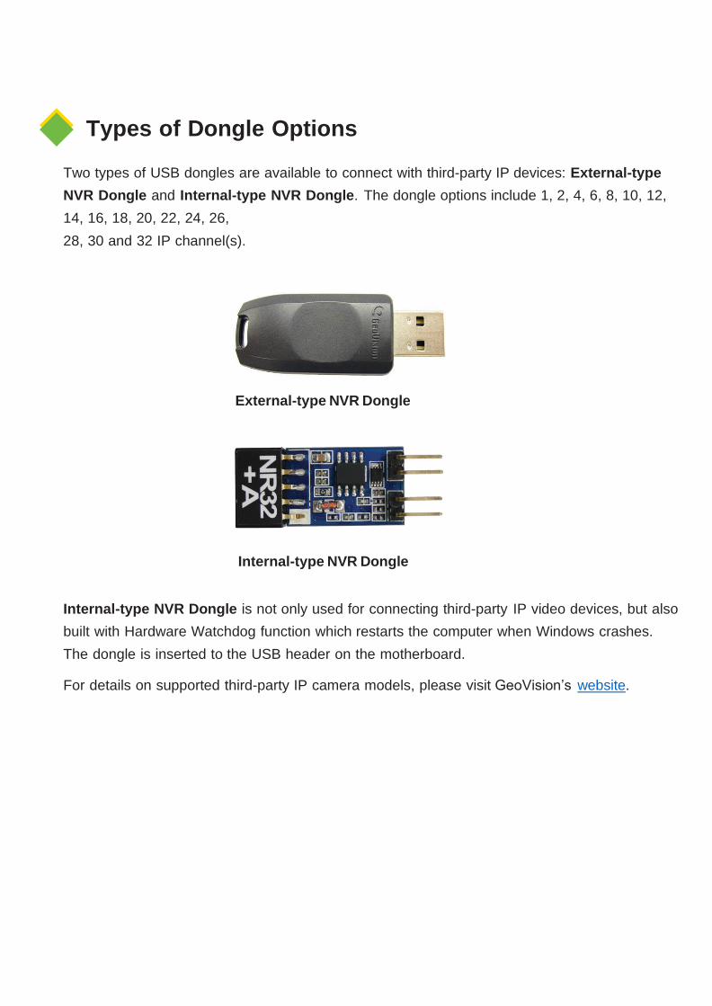
Types of Dongle Options
Two types of USB dongles are available to connect with third-party IP devices: External-type
NVR Dongle and Internal-type NVR Dongle. The dongle options include 1, 2, 4, 6, 8, 10, 12,
14, 16, 18, 20, 22, 24, 26,
28, 30 and 32 IP channel(s).
Internal-type NVR Dongle
Internal-type NVR Dongle is not only used for connecting third-party IP video devices, but also
built with Hardware Watchdog function which restarts the computer when Windows crashes.
The dongle is inserted to the USB header on the motherboard.
For details on supported third-party IP camera models, please visit GeoVision’s website.
External-type NVR Dongle

2 System Requirements
GV-NVR system can support up to 32 channels. The following table lists the minimum system
requirements needed to run GV-NVR.
Geovision
IP Camera
3rd-party
IP Camera
Up to 32
Channels
1 ~ 4
Channels
5 ~ 8
Channels
Up to 32
Channels
OS 64-bit Windows 10 / Server 2016
CPU 2nd Generation
Core i5, 3.3 GHz
2nd Generation
Core i3, 3.1 GHz
2nd Generation
Core i5, 3.3 GHz
2nd Generation
Core i7, 3.4 GHz
Memory 8 GB Dual Channels
VGA
HD Graphics 3000 HD Graphics 2000 HD Graphics 3000
To obtain the maximum frame rate possible, please see the GPU Decoding Specifications in datasheet.
Note:
1. GV-DVR / NVR / Hybrid DVR software has ended support for Windows 8.1 / 8 / 7 / XP / Vista / Sever 2012 R2 / Server 2008 / Server 2008 R2.
2. The system requirements are determined in round-the-clock setting with live view only, while remote connections and video analysis features being disabled.
IMPORTANT:
Some GeoVision hardware accessories and GV-DVR functions are not
available for GV-NVR users. Please note the following unavailable functions:
● Adjustment of codec and resolution for third-party devices
● Recording quality
● Pre-Recording using RAM
● Hard Disk Calculator
● Noise Detection to reduce file size
● Video Lowpass Filter

3 Options
Optional devices can expand your GV-NVR’s capabilities and versatility. Contact your dealer for
more information.
AVP (Advanced
Video Process)
AVP (Advanced Video Process) functions include Counter and
Intrusion Alarm setup using lines to outline the detection zones. You
can add the AVP functions to the GV-NVR by using an additional AVP
Dongle, or upgrading your external or internal NVR Dongle to have
the AVP functions.
Internal USB Dongle
The USB dongle can provide the Hardware Watchdog function to the
GV-NVR system by restarting the computer when Windows crashes.
You need to connect the dongle internally on the motherboard.
GV-Data Capture V3
GV-Data Capture V3 Box can integrate the GV-NVR to an electronic
POS system, while GV-Data Capture V3E Box can establish such
integration through LAN or Internet.
GV-Hub V2 An easy way for serial port extension. This hub can add 4 RS-232 /
RS-485 serial ports through the GV-NVR’s USB port.
GV-COM V3 GV-COM V3 can add 1 RS-485 port to your computer through a USB
connector.
GV-IO Box Series
GV-IO Box series (4E / 4 Ports / 8 Ports / 16 Ports) provide 4 / 8 / 16
inputs and relay outputs and support both DC and AC output voltages,
with optional support for Ethernet module and 4E additionally
supporting PoE, TCP/IP and RS-485 connection.
GV-NET/IO Card
(I/O Box Mode)
The GV-NET/IO Card is a RS-485 / RS-232 interface converter,
providing 4 inputs and 4 relay outputs. It supports both DC and AC
output voltages.
GV-Joystick
GV-Joystick facilitates the PTZ camera control. It can be either plugged
into the GV-NVR for independent use or connected to GV-Keyboard to
empower the operation.
GV-Keyboard V3
GV-Keyboard V3 is used to program and operate GV-NVR and PTZ
cameras. Through RS-485 configuration, it can control up to 16 GV-
NVR systems. In addition, you can connect PTZ cameras directly to the
keyboard for PTZ control.

4 USB Driver Installation 4 USB Driver Installation
It is required to install the driver of USB dongle before use. After you insert the USB dongle to the
computer where GV-NVR is installed, the Found New Hardware Wizard will automatically detect
the device. Ignore the Wizard and follow these steps to install the driver:
1. Insert the Software DVD. It will run automatically and a window pops up.
2. Select Install or Remove GeoVision GV-Series Driver, and then click Install GeoVision USB Devices Driver. This dialog box appears.
3. Click Install to install the driver. When the installation is complete, this message will appear: Install done!
4. To verify that the driver is installed correctly, go to Windows Device Manager and expand DVR-Devices. You should see the entry of GV-Series USB Protector.

5 System Installation
Before You Start
For optimal performance of your system, it is important to follow these
recommendations before installing GV-NVR:
● It is strongly recommended to use two separate hard disks. One is for installing Windows
OS and GV-NVR software, and the other is for storing recorded files and system logs.
● When formatting the two hard disks, select NTFS as the file system.
● When GV-NVR is running, it is not recommended to perform disk defragmentation.

● Since the size of transmitted data from IP cameras may be quite large and reach beyond
the transfer rate of a hard disk, you should note the total of recording frame rates that you
can assign to a single hard disk, as listed below:
Frame rate limit in a single hard disk
Video
resolution
H.264 H.265 MJPEG
Frame Rate Bitrate Frame Rate Bitrate Frame Rate Bitrate
12 MP
330 fps
14.47 Mbit/s
N/A
N/A
56 fps
65.98 Mbit/s
8 MP
550 fps
14.13 Mbit/s
N/A
N/A
96 fps
58.52 Mbit/s
5 MP
220 fps
16.48 Mbit/s
660 fps
6.73 Mbit/s
80 fps
30.4 Mbit/s
4 MP
330 fps
11.65 Mbit/s
550 fps
7.74 Mbit/s
105 fps
40.53 Mbit/s
3 MP
440 fps
10.48 Mbit/s
660 fps
5.35 Mbit/s
140 fps
38.67 Mbit/s
2 MP
660 fps
7.01 Mbit/s
N/A
N/A
210 fps
44.93 Mbit/s
1.3 MP
660 fps
5.05 Mbit/s
N/A
N/A
300 fps
32.26 Mbit/s
Note: The data above was determined using the bit rate listed above and hard disks with average
R/W speed above 110 MB/s.
Note: The data above was determined using the bit rate listed above and hard disks with
average R/W speed above 110 MB/s.
The frame rate limit is based on the resolution of video sources. The higher video
resolutions, the lower frame rates you can assign to a single hard disk. In other words, the
higher frame rates you wish to record, the more hard disks you need to install. For the
information of recording frame rates, you may consult the user’s manual of the IP camera
that you wish to connect to.

Installing GV-NVR
To install the GV-NVR, follow these steps:
1. Insert the Software DVD. The Install Program window pops up automatically.
2. Click Install GeoVision Primary Applications.
3. Select GV-DVR/NVR, and follow the on-screen instructions.
4. Follow the above steps to install other programs one by one.
Note: Special characters ‘@’ and ‘:’ are not supported to be used as the login
username and/or password of GV-DVR / NVR.

6 Adding IP Video Sources
The procedures for adding an IP camera, Video Server and Compact DVR may vary. The following
is the setup procedure for an IP camera in the system.
1. On the main screen, click the Configure button, select System Configure and click
IP Camera Install. This dialog box appears.
• To add an IP camera from a list of the IP cameras on the LAN, click
Scan Camera.
• To manually set up an IP camera, follow steps 2 to 7.
2. Click Add Camera. This dialog box appears.

3. Type the IP address, username and password of the IP camera. Keep or modify the default
HTTP port 80. Select a camera brand and device from the drop-down list. This dialog box
appears.
4. The options in the setup dialog box may vary depending on the camera brand.
• Port: Video streaming port number.
• Stream Type: You may have the option of single streaming only or
both single and dual streaming.
• Codec type: You may have the option of MPEG4, JPEG, or H264 / H265. If the
selected camera supports dual streaming, the preview codec and recording codec can
be set differently.
• Resolution: Select resolutions for preview and recording.

5. Click Apply. The IP camera is added to the list.
6. Click the listed camera, and select Display position to map the IP camera to a channel on the GV-System.
7. The Status column now should display “Connected”. Click OK.
For more details, see Hybrid and NVR Solution, Chapter 2, see GV-DVR / NVR User’s
Manual on our website.

7 Upgrading GV-NVR
The Black Dongle can be upgraded to include more functions or enhance the system. You need
to collect the data from your dongle and send it back to GeoVision for an upgrade. The upgrade
is charged services. To upgrade your dongle, follow these steps:
1. Each dongle has its own serial number. Find it on the side of the dongle. Later this
serial number will be used in naming the files for upgrading.
2. Insert the dongle to the computer.
3. In the GV folder, double-click GVUsbKeyUpClient.exe. This dialog box appears.
4. To retrieve the data from the dongle, click Select All. The information of the dongle will be
displayed in the information field. Note the displayed number of “HW Serial” should be the
same as that on the dongle.
SIC+7116442 SIC+7116442

5. To save the data to your local computer, click Save Key ID Data. If you have more than one
dongle to upgrade, click Batch Save. Different dongle data will be saved as separate files.
The file will be named after the serial number on the dongle and saved as *.out. For
example, if a dongle serial number is 7116442, the file is named “NVR-7116442.out”.
6. Send this data file to GeoVision at [email protected]. The GeoVision will examine
the data file and send an *.in file back to you. The file name also includes the serial
number of that dongle. In this example, the data file to be sent back is named “NVR-
7116442.in”.
7. After you receive the updated file, insert the correct dongle matching
the .in file you receive, and then run GVUsbKeyUpClient.exe.
8. Click Select All to read the dongle, click Upgrade and then open the updated file to upgrade
the dongle. You can also select more than one dongle in the list and click Batch Upgrade to
upgrade them at the same time. Make sure these dongles match the updated files you
receive.
9F, No. 246, Sec. 1, Neihu Rd.,
Neihu District, Taipei, Taiwan Tel:
+886-2-8797-8377
Fax: +886-2-8797-8335
http://www.geovision.com.tw

![@gVc # ]R\Y T`c`_R gV Z_ :_UZR - Daily Pioneer](https://static.fdokumen.com/doc/165x107/63128687aca2b42b580cdd60/gvc-ry-tcr-gv-z-uzr-daily-pioneer.jpg)


![[mga-nvr ru]-ces-5 0](https://static.fdokumen.com/doc/165x107/631c012dd5372c006e043975/mga-nvr-ru-ces-5-0.jpg)