Geometric calibration for a dual tube/ detector micro-CT system
10
Geometric calibration for a dual tube/detector micro-CT system Samuel M. Johnston, G. Allan Johnson, and Cristian T. Badea a Center for In Vivo Microscopy Box 3302, Duke University Medical Center, Durham, North Carolina 27710 Received 6 November 2007; revised 29 January 2008; accepted for publication 22 February 2008; published 16 April 2008 The authors describe a dual tube/detector micro-computed tomography micro-CT system that has the potential to improve temporal resolution and material contrast in small animal imaging studies. To realize this potential, it is necessary to precisely calibrate the geometry of a dual micro-CT system to allow the combination of projection data acquired with each individual tube/detector in a single reconstructed image. The authors present a geometric calibration technique that uses multiple projection images acquired with the two imaging chains while rotating a phantom containing a vertical array of regularly spaced metallic beads. The individual geometries of the imaging chains are estimated from the phantom projection images using analytical methods followed by a refine- ment procedure based on nonlinear optimization. The geometric parameters are used to create the cone beam projection matrices required by the reconstruction process for each imaging chain. Next, a transformation between the two projection matrices is found that allows the combination of projection data in a single reconstructed image. The authors describe this technique, test it with a series of computer simulations, and then apply it to data collected from their dual tube/detector micro-CT system. The results demonstrate that the proposed technique is accurate, robust, and produces images free of misalignment artifacts. © 2008 American Association of Physicists in Medicine. DOI: 10.1118/1.2900000 Key words: x-ray, micro-CT, calibration, small animal I. INTRODUCTION Micro-computed tomography micro-CT is a noninvasive imaging modality used to assess morphology and function in small animals. 1,2 Dual tube/detector micro-CT, in which two imaging chains consisting of an x-ray tube and a detector image the same object in parallel, offers several advantages over more conventional micro-CT. Dual simultaneous imag- ing can acquire the same amount of images as a conventional micro-CT in half the time, which facilitates functional imag- ing studies such as in cardiac, 3,4 pulmonary, 5,6 or perfusion investigations in small animals. 7 Dual tube/detector micro-CT also facilitates dual energy imaging, in which two different absorption coefficients at two different energies are recorded for the same location simultaneously, enhancing sensitivity and material differentiation. 8 To realize these advantages of dual tube/detector micro-CT imaging, it is necessary to reconstruct the images from the individual systems in one shared geometry. To ac- complish this, geometric calibration must be performed, in which a set of parameters describing the geometry of the system is calculated from a set of images acquired of some ideal object. The calibration parameters can then be provided to the CT reconstruction algorithm to map data from the pixels in the detector to voxels in the object. Several techniques have been proposed over the years for finding these calibration parameters in individual micro-CT systems for various geometries. These techniques have gen- erally fallen into two categories: those based on iterative nonlinear optimization 9–13 and those based on the direct so- lution of geometric equations. 14–18 The latter category has become favored in recent years because of superior perfor- mance and ease of implementation. Both categories entail the imaging of phantoms containing point-like structures, such as various arrangements of small metal beads, with varying requirements about the a priori knowledge of the phantom and the geometry. Although similar work has been done with multiple de- tectors in SPECT and PET, 12 we have not found any prior work on the calibration of dual tube/detector x-ray micro-CT. Therefore, in the construction of our dual tube/detector sys- tem, it was necessary to develop a new geometric calibration method. In this method we first employ an analytic algorithm to find estimates of the most important calibration param- eters and then use nonlinear optimization to find additional parameters and refine the results. Once this is done for both tube/detector chains, we use the parameters to create the cone beam projection matrices required by the reconstruction process for each imaging chain. We then find a transforma- tion between the two projection matrices to combine the two sets of projection data in a single reconstructed image. In this work we describe this method and test it in computer simu- lations and then apply it to data collected from our dual tube/detector system. II. MATERIALS AND METHODS II.A. Projection matrices Our approach is based on the use of projection matrices. 19–22 A cone beam projection matrix A has a 4 3 dimension and relates the mapping of a point in three- 1820 1820 Med. Phys. 35 „5…, May 2008 0094-2405/2008/35„5…/1820/10/$23.00 © 2008 Am. Assoc. Phys. Med.
Transcript of Geometric calibration for a dual tube/ detector micro-CT system

Geometric calibration for a dual tube/detector micro-CT systemSamuel M. Johnston, G. Allan Johnson, and Cristian T. Badeaa�
Center for In Vivo Microscopy Box 3302, Duke University Medical Center, Durham,North Carolina 27710
�Received 6 November 2007; revised 29 January 2008; accepted for publication 22 February 2008;published 16 April 2008�
The authors describe a dual tube/detector micro-computed tomography �micro-CT� system that hasthe potential to improve temporal resolution and material contrast in small animal imaging studies.To realize this potential, it is necessary to precisely calibrate the geometry of a dual micro-CTsystem to allow the combination of projection data acquired with each individual tube/detector in asingle reconstructed image. The authors present a geometric calibration technique that uses multipleprojection images acquired with the two imaging chains while rotating a phantom containing avertical array of regularly spaced metallic beads. The individual geometries of the imaging chainsare estimated from the phantom projection images using analytical methods followed by a refine-ment procedure based on nonlinear optimization. The geometric parameters are used to create thecone beam projection matrices required by the reconstruction process for each imaging chain. Next,a transformation between the two projection matrices is found that allows the combination ofprojection data in a single reconstructed image. The authors describe this technique, test it with aseries of computer simulations, and then apply it to data collected from their dual tube/detectormicro-CT system. The results demonstrate that the proposed technique is accurate, robust, andproduces images free of misalignment artifacts. © 2008 American Association of Physicists inMedicine. �DOI: 10.1118/1.2900000�
Key words: x-ray, micro-CT, calibration, small animal
I. INTRODUCTION
Micro-computed tomography �micro-CT� is a noninvasiveimaging modality used to assess morphology and function insmall animals.1,2 Dual tube/detector micro-CT, in which twoimaging chains consisting of an x-ray tube and a detectorimage the same object in parallel, offers several advantagesover more conventional micro-CT. Dual simultaneous imag-ing can acquire the same amount of images as a conventionalmicro-CT in half the time, which facilitates functional imag-ing studies such as in cardiac,3,4 pulmonary,5,6 or perfusioninvestigations in small animals.7 Dual tube/detectormicro-CT also facilitates dual energy imaging, in which twodifferent absorption coefficients at two different energies arerecorded for the same location simultaneously, enhancingsensitivity and material differentiation.8
To realize these advantages of dual tube/detectormicro-CT imaging, it is necessary to reconstruct the imagesfrom the individual systems in one shared geometry. To ac-complish this, geometric calibration must be performed, inwhich a set of parameters describing the geometry of thesystem is calculated from a set of images acquired of someideal object. The calibration parameters can then be providedto the CT reconstruction algorithm to map data from thepixels in the detector to voxels in the object.
Several techniques have been proposed over the years forfinding these calibration parameters in individual micro-CTsystems for various geometries. These techniques have gen-erally fallen into two categories: those based on iterativenonlinear optimization9–13 and those based on the direct so-
14–18
lution of geometric equations. The latter category has1820 Med. Phys. 35 „5…, May 2008 0094-2405/2008/35„5…/1
become favored in recent years because of superior perfor-mance and ease of implementation. Both categories entail theimaging of phantoms containing point-like structures, suchas various arrangements of small metal beads, with varyingrequirements about the a priori knowledge of the phantomand the geometry.
Although similar work has been done with multiple de-tectors in SPECT and PET,12 we have not found any priorwork on the calibration of dual tube/detector x-ray micro-CT.Therefore, in the construction of our dual tube/detector sys-tem, it was necessary to develop a new geometric calibrationmethod. In this method we first employ an analytic algorithmto find estimates of the most important calibration param-eters and then use nonlinear optimization to find additionalparameters and refine the results. Once this is done for bothtube/detector chains, we use the parameters to create thecone beam projection matrices required by the reconstructionprocess for each imaging chain. We then find a transforma-tion between the two projection matrices to combine the twosets of projection data in a single reconstructed image. In thiswork we describe this method and test it in computer simu-lations and then apply it to data collected from our dualtube/detector system.
II. MATERIALS AND METHODS
II.A. Projection matrices
Our approach is based on the use of projectionmatrices.19–22 A cone beam projection matrix A has a 4�3
dimension and relates the mapping of a point in three-1820820/10/$23.00 © 2008 Am. Assoc. Phys. Med.
1821 Johnston, Johnson, and Badea: Dual tube/detector micro-CT system geometric calibration 1821
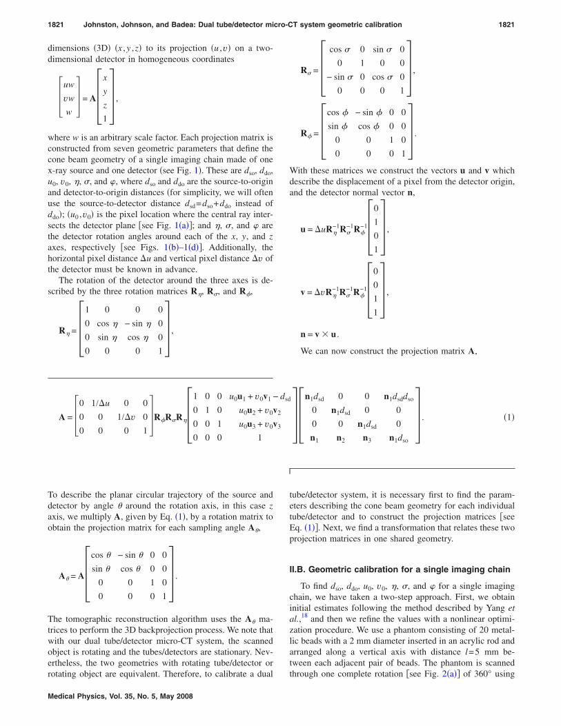
dimensions �3D� �x ,y ,z� to its projection �u ,v� on a two-dimensional detector in homogeneous coordinates
�uw
vw
w� = A�
x
y
z
1� ,
where w is an arbitrary scale factor. Each projection matrix isconstructed from seven geometric parameters that define thecone beam geometry of a single imaging chain made of onex-ray source and one detector �see Fig. 1�. These are dso, ddo,u0, v0, �, �, and �, where dso and ddo are the source-to-originand detector-to-origin distances �for simplicity, we will oftenuse the source-to-detector distance dsd=dso+ddo instead ofddo�; �u0 ,v0� is the pixel location where the central ray inter-sects the detector plane �see Fig. 1�a��; and �, �, and � arethe detector rotation angles around each of the x, y, and zaxes, respectively �see Figs. 1�b�–1�d��. Additionally, thehorizontal pixel distance �u and vertical pixel distance �v ofthe detector must be known in advance.
The rotation of the detector around the three axes is de-scribed by the three rotation matrices R�, R�, and R�,
R� = �1 0 0 0
0 cos � − sin � 0
0 sin � cos � 0� ,
0 0 0 1
rotating object are equivalent. Therefore, to calibrate a dual
Medical Physics, Vol. 35, No. 5, May 2008
R� = �cos � 0 sin � 0
0 1 0 0
− sin � 0 cos � 0
0 0 0 1� ,
R� = �cos � − sin � 0 0
sin � cos � 0 0
0 0 1 0
0 0 0 1� .
With these matrices we construct the vectors u and v whichdescribe the displacement of a pixel from the detector origin,and the detector normal vector n,
u = �uR�−1R�
−1R�−1�
0
1
0
1� ,
v = �vR�−1R�
−1R�−1�
0
0
1
1� ,
n = v � u .
We can now construct the projection matrix A,
A = �0 1/�u 0 0
0 0 1/�v 0
0 0 0 1�R�R�R��
1 0 0 u0u1 + v0v1 − dsd
0 1 0 u0u2 + v0v2
0 0 1 u0u3 + v0v3
0 0 0 1��
n1dsd 0 0 n1dsddso
0 n1dsd 0 0
0 0 n1dsd 0
n1 n2 n3 n1dso
� . �1�
To describe the planar circular trajectory of the source anddetector by angle � around the rotation axis, in this case zaxis, we multiply A, given by Eq. �1�, by a rotation matrix toobtain the projection matrix for each sampling angle A�,
A� = A�cos � − sin � 0 0
sin � cos � 0 0
0 0 1 0
0 0 0 1� .
The tomographic reconstruction algorithm uses the A� ma-trices to perform the 3D backprojection process. We note thatwith our dual tube/detector micro-CT system, the scannedobject is rotating and the tubes/detectors are stationary. Nev-ertheless, the two geometries with rotating tube/detector or
tube/detector system, it is necessary first to find the param-eters describing the cone beam geometry for each individualtube/detector and to construct the projection matrices �seeEq. �1��. Next, we find a transformation that relates these twoprojection matrices in one shared geometry.
II.B. Geometric calibration for a single imaging chain
To find dso, ddo, u0, v0, �, �, and � for a single imagingchain, we have taken a two-step approach. First, we obtaininitial estimates following the method described by Yang etal.,18 and then we refine the values with a nonlinear optimi-zation procedure. We use a phantom consisting of 20 metal-lic beads with a 2 mm diameter inserted in an acrylic rod andarranged along a vertical axis with distance l=5 mm be-tween each adjacent pair of beads. The phantom is scanned
through one complete rotation �see Fig. 2�a�� of 360° using
1822 Johnston, Johnson, and Badea: Dual tube/detector micro-CT system geometric calibration 1822
both imaging chains and projection images acquired every1°. Following scanning, the phantom’s projection images areprocessed in MATLAB �The MathWorks, Inc., Natick, MA� tocompute the trajectories of the center of mass of each imagedbead. Finding the beads’ centers of mass is a semiautomaticprocess that requires the user to select rectangular regions ofinterest �ROIs� around each bead only in the first projectionimage. In each ROI, the bead is segmented using adaptivelocal thresholding. An initial threshold is chosen halfway be-tween the maximum and minimum brightness values, andthis threshold is iteratively improved. At each iteration, thethreshold divides the pixels inside each ROI into two setscorresponding to the bead and background. The bead set isassigned the connected component containing the centralpixel. The background set is assigned the corner pixels, andthe threshold is recalculated to be halfway between the av-erages of these two sets. The iterations stop when the thresh-old no longer changes. After segmentation, the center ofmass �uc ,vc� for each bead is found using the bead pixelvalues of the segmented bead image I�u ,v�,
Medical Physics, Vol. 35, No. 5, May 2008
uc =�beadI�u,v� · u
�beadI�u,v�,
vc =�beadI�u,v� · v
�beadI�u,v�.
The radius of the bead projection is found by calculatingthe average distance from the perimeter to the center
r =�perimeter
��u − uc�2 + �v − vc�2
�perimeter1. �2�
Unlike in the first projection image, the ROIs in subsequentprojections are constructed automatically by predicting thelocation of the bead center using a linear fit of the mostrecent locations and setting a square around the predictedlocation with a side length equal to twice the radius given byEq. �2�.
For each bead i, an ellipse is fitted to the set of all centersof mass over all projection images. Point p in ellipse i is
FIG. 1. The geometry of an x-ray CTsystem, defined by �a� dso, ddo, u0, v0,�b� �, �c� �, and �d� �.
FIG. 2. �a� An x-ray image of the calibration phantom,with the centers of the projections of the beads overlaidin white, and �b� the ellipses that are fit to the centers.

1823 Johnston, Johnson, and Badea: Dual tube/detector micro-CT system geometric calibration 1823
denoted aip= �uip ,vip�, and the distance between pointsaip and ajp is denoted aipajp. The center, ai0= �ui0 ,vi0�, andfour principal corners, ai1, ai2, ai3, and ai4, are recorded foreach ellipse �see Fig. 2�b��. The centers of the ellipses, ai0,are computed as the mean of all points, aip, on the ellipse.The major axis line is obtained by linear regression on all thepoints, and the minor axis line is the line perpendicular to themajor axis that passes through the center. The angle of themajor axis is obtained as the inverse tangent of the slope. Allpoints aip are then projected onto the ellipse axes, and thecorners are the extreme points of the projections. With theseellipse parameters we now calculate the calibration param-eters, using geometric relations derived by Yang et al.18
II.B.1. Calculation of dsd and v0
For each bead i, we construct
xi =vi1 − vi2
ai3ai4
,
yi =vi1 + vi2
2.
The xi and yi are related by the linear function
yi = v0 + dsd�vxi.
We find v0 and dsd by linear regression over all i.
II.B.2. Calculation of � and u0
For each bead i, ui0, and vi0 are related by the linearfunction
ui0 = a + bvi0.
We find a and b by linear regression over all i, and thencalculate
u0 = a + bv0,
� = arctan b .
II.B.3. Calculation of dso
For each pair of beads i and j,
dso =l
ai0aj0�vdsd.
We average dso for each adjacent pair i and j. This formula issimpler than the one described by Yang et al.,18 since weassume that our phantom is placed parallel to the z axis.While this assumption may not always be valid, we note thatthe geometric parameters obtained by this analytic approachare just initial estimates that are further refined through anoptimization procedure.
II.B.4. Nonlinear optimization
The method described by Yang et al.18 does not determinethe out-of-plane detector rotations � and �, since it is
claimed that careful mechanical placement can reduce theseMedical Physics, Vol. 35, No. 5, May 2008
parameters to less than 5°, below which these values havelittle impact on reconstruction. However, in an imaging sys-tem with components that are frequently moved, as in ourcase, we cannot guarantee that the detectors will always beso well aligned. Furthermore, in a dual tube/detector system,the small changes caused by erroneous values for � and �will be amplified, since overlapping systems with slight in-dependent misalignments will produce pronounced doublecontours in the reconstruction. These rotations may bepresent in our system and should be addressed, so we use anonlinear optimization program to move from an initial esti-mate of �dsd dso u0 v0 � 0 0� to �dsd dso u0 v0 � � ��.
For the objective function, we must first construct theprojection lines from the x-ray source to the beads’ projec-tion centers of mass using the initial estimates of the geomet-ric parameters. These projection lines are constructed for allbeads in all projections. For each bead the minimum pair-wise distance between all its associated projection lines iscomputed. The objective function returns a vector with anentry for each bead representing the sum of the minimumpairwise distances between projection lines.
We pass this objective function to a nonlinear least-squares minimization function which successively recom-putes selected parameters in order to minimize the distancesbetween projection lines. We run the program in two steps.First, we allow � and � to vary while holding the otherparameters fixed since these parameters have no values andwould distort the other parameters. Next, we allow all pa-rameters dsd, dso, u0, v0, �, �, and � to vary together. Thistechnique estimates � and � accurately and refines the esti-mates of the other parameters.
II.C. Geometric calibration for a dual tube/detectorsystem
After computing the geometric parameters for each indi-vidual imaging chain, we can construct their respective pro-jection matrices A1 and A2 using Eq. �1�. However, thesematrices describe projection in two different systems of ref-erence. We need a transformation matrix T that will allow usto transform projection matrix A2 into A2�=A2T in the coor-dinate system of A1.
Since both systems image the same rotating object, theymust share the same axis of rotation, i.e., the z axis. Conse-quently, the transform between the two systems of coordi-nates can consist only of rotation around the z axis andtranslation �z along the z axis and thus the transformationmatrix T is given by
T = �cos − sin 0 0
sin cos 0 0
0 0 1 �z
0 0 0 1� .
Therefore, once we calibrate the individual systems, we needan additional step to find �z and to calibrate the entire dual
system �see Fig. 3�.
1824 Johnston, Johnson, and Badea: Dual tube/detector micro-CT system geometric calibration 1824
We first compute �z, using the sets of projections of thesame calibration phantom described previously which wereacquired with both imaging chains simultaneously. Themovement of each bead of the phantom is described by ro-tation around the z axis, therefore we expect the z coordinateto remain constant at each rotation step, and a single z valuefor each bead can be found in each system of geometry �seeFig. 4�a��. The same beads should be matched in the two setsof projection images from the two imaging chains. Knowingthe system parameters allows us to write the expressions ofvectors s for the x-ray source and p for a detector point �u ,v�in the object system of reference
FIG. 3. The geometry of a dual micro-CT system, defined by �z and inaddition to the parameters of the individual systems.
Medical Physics, Vol. 35, No. 5, May 2008
s = �− dso
0
0
1� ,
p = �p1
p2
p3
1� = �
ddo
0
0
1� + �u�u − u0�R�
−1R�−1R�
−1�0
1
0
1�
+ �v�v − v0�R�−1R�
−1R�−1�
0
0
1
1� . �3�
In a rotating object geometry as in our dual micro-CT sys-tem, the point at the center of the rotation of a bead shouldproject to the center of the ellipse trajectory that we found inthe individual system calibration, and therefore we set �u ,v�in Eq. �3� to be equal to �ui0 ,vi0� for ellipse i �see Fig. 4�b��.The line from the x-ray source s to the pixel p is constructedand its intersection with the z axis is given by
�− dso
0
0
1� + k��
p1
p2
p3
1� − �
− dso
0
0
1� = �
0
0
z
1� ,
FIG. 4. �a� The projection of beadsonto detectors in the dual system cali-bration technique, �b� the method forfinding �z using the line segmentsfrom the x-ray sources through theaxis of rotation to the centers of theellipses, �c� the lines from the x-raysources through a bead to the ellipses,and �d� the method for finding usingthe different x and y values found fromthe lines through the same bead.

1825 Johnston, Johnson, and Badea: Dual tube/detector micro-CT system geometric calibration 1825
k =dso
p1 + dso,
z = p3k ,
where k is the parameter describing the location of a pointalong the line. This gives us the z value for each bead in eachgeometry. The vertical displacement �z between the two sys-tems is the difference between the z coordinates for the samebead in the two different systems. We compute this value foreach bead i and report the average value as �z �see Fig.4�b��.
Following the computation of the z coordinate for eachbead, we proceed to determine the x and y coordinates ateach rotation step by constructing the line from s to p as
described before, where the pixel location �u ,v� is now theMedical Physics, Vol. 35, No. 5, May 2008
center of the projection of the bead �see Fig. 4�c��. The x andy coordinates for each bead at each rotation step are com-puted
k =z
p3,
x = k�p1 + dso� − dso,
y = kp2.
We can now compute the angle around the z axis betweenthe two imaging chains. For this purpose, we first find theangle of rotation � of each �x ,y� from some arbitrary startingpoint. Since tan �= �y /x�, we find �=arctan�y /x�. There are
FIG. 5. A flowchart of the completecalibration process.
two values of �, i.e., �1 and �2, corresponding to each imag-

1826 Johnston, Johnson, and Badea: Dual tube/detector micro-CT system geometric calibration 1826
ing chain �see Fig. 4�d��. The rotation angle is computed as=�2−�1. We perform this calculation for each bead in eachsimultaneous projection and report the average value as �see Fig. 4�d��.
Finally, we refine these estimates with the same nonlinearoptimization program used for the individual calibrations, byconstructing the transformed projection lines from the differ-ent detectors through the same beads and minimizing thepair-wise distances between the lines.
A flowchart of the complete calibration process is shownin Fig. 5.
II.C.1. Implementation
The above equations are implemented in MATLAB �Ver-sion 7.0�. The optimization function used is lsqnonlin, part ofthe MATLAB Optimization Toolbox, which uses precondi-tioned conjugate gradients constrained by a subspace trustregion. The ray-tracing programs called in the optimizationprocess were written in C to reduce computation time.
For our in-house developed dual tube/detector system �seeFig. 6�, we use two Varian A197 x-ray tubes with dual focalspots fs=0.6 /1.0 mm. The tubes are designed for angio-graphic studies with high instantaneous flux and total heatcapacity. Two high frequency x-ray generators �EPS 45-80,EMD Technologies, Quebec, Canada� are used to control thex-ray tubes. The system has two identical detectors with aGd2O2S phosphor �XDI-VHR 2 115 mm, Photonic Science,East Sussex, UK� with pixels of 22 m, 115 mm input tapersize, and 4008�2672 image matrix. Both detectors allowon-chip binning of up to 8�8 pixels, and subarea readout toallow high speed readout of more than 10 frames/s, i.e., atime resolution of 100 ms. Both tubes and detectors aremounted on a table together with the rotation stage. Thevertically positioned animal is placed in a cradle that is ro-tated via an Oriel model 13049 digital stepping motor. Thex-ray generators, tubes, detectors and the rotation are con-trolled by a sequencer application written in LABVIEW �Na-tional Instruments, Austin, TX� that also allows for in vivostudies, the flexible integration of cardiac and respiratoryphysiology with the imaging sequence.23 Images of the ro-tating object are acquired with a step-and-shoot acquisition
FIG. 6. Our in-house implemented dual tube/detector micro-CT system.
scheme.
Medical Physics, Vol. 35, No. 5, May 2008
For geometric calibration, the phantom described previ-ously, containing an array of steel beads placed in an acrylicrod, is attached to the imaging cradle and scanned prior tothe animal experiments. The projections and the computedprojection matrices are used with the COBRA EXXIM softwarepackage �EXXIM Computing Corp, Livermore, CA� thatimplements Feldkamp’s algorithm24 to reconstruct tomogra-phic data as 3D image arrays �5123�. The projection matricescomputed with our method are written to a geometry filecontaining one line for each angle, which is read by COBRA.
II.C.2. Experiments
To test our geometric calibration method we used bothsimulated and experimental data. Using Eq. �1� we simulatedthe projection operation on the calibration phantom in MAT-
LAB and performed the calibration method. Since our methodfirst involves finding the geometric parameters for each im-aging chain, it made sense to compare our results with thosefrom previous articles for single chain micro-CT systems.We used the same parameters as in Yang et al.,18 with thesame number of projections and beads, and the same noiseconditions: 48 m�48 m pixel pitch, 500 projection im-ages over 360°, eight beads, distance between beads l=2 mm, dsd=400 mm, dso=150 mm, u0=1005, v0=480,�=−1°, �=1.2°, and �=1.5°. We ran ten simulations withGaussian noise with standard deviation 0.4 pixels added tothe simulated bead projection centers.
We then simulated the projection operations with two or-thogonal imaging chains as in our dual tube/detector systemin which the parameters for the first chain were the same asbefore, and the parameters for the second chain were dsd
=420 mm, dso=160 mm, u0=900, v0=500, �=2°, �=2°,and �=−2°. The dual parameters were �z=5 mm for thez-axis displacement and =90° between the central rays ofthe two systems. We again performed ten simulations withGaussian noise with standard deviation 0.4 pixels added tothe simulated bead projection centers.
For the validation of our calibration method, experimentsinvolving our dual tube/detector system were also per-formed. We performed three sets of scans with the system,with the parameters of 80 kVp, 100 mA, and 10 ms perexposure. The small focal spot of 0.6 mm was used, and we
TABLE I. Calibration results for the single system parameters, compared withresults in similar conditions by Yang et al. �Ref. 18�, from ten computersimulations, with Gaussian noise of standard deviation 0.4 pixels added tosimulated bead projection centers, 500 images, eight beads.
True values Our method Yang’s method
dsd �mm� 400.00 399.99�0.06 401�1dso �mm� 150.00 149.62�0.06 150.2�0.5u0 �pixel� 1005.0 1005.0�0.0 1005.9�0.3v0 �pixel� 480.00 479.90�0.15 480�1
� �°� −1.0000 −1.0001�0.0002 −0.99�0.03� �°� 1.2000 1.1961�0.0116� �°� 1.5000 1.5018�0.0046
set the sampling distances to approximately dsd=750 mm
1827 Johnston, Johnson, and Badea: Dual tube/detector micro-CT system geometric calibration 1827
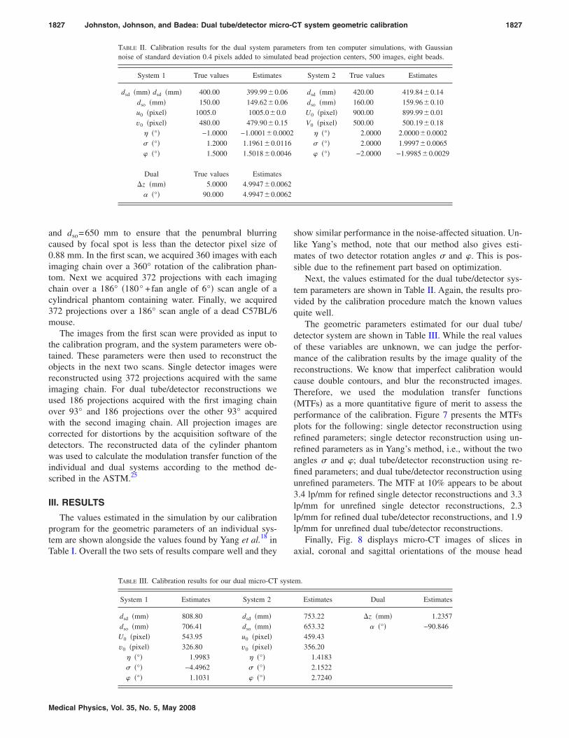
and dso=650 mm to ensure that the penumbral blurringcaused by focal spot is less than the detector pixel size of0.88 mm. In the first scan, we acquired 360 images with eachimaging chain over a 360° rotation of the calibration phan-tom. Next we acquired 372 projections with each imagingchain over a 186° �180° +fan angle of 6°� scan angle of acylindrical phantom containing water. Finally, we acquired372 projections over a 186° scan angle of a dead C57BL/6mouse.
The images from the first scan were provided as input tothe calibration program, and the system parameters were ob-tained. These parameters were then used to reconstruct theobjects in the next two scans. Single detector images werereconstructed using 372 projections acquired with the sameimaging chain. For dual tube/detector reconstructions weused 186 projections acquired with the first imaging chainover 93° and 186 projections over the other 93° acquiredwith the second imaging chain. All projection images arecorrected for distortions by the acquisition software of thedetectors. The reconstructed data of the cylinder phantomwas used to calculate the modulation transfer function of theindividual and dual systems according to the method de-scribed in the ASTM.25
III. RESULTS
The values estimated in the simulation by our calibrationprogram for the geometric parameters of an individual sys-tem are shown alongside the values found by Yang et al.18 inTable I. Overall the two sets of results compare well and they
TABLE II. Calibration results for the dual system panoise of standard deviation 0.4 pixels added to simu
System 1 True values Estimate
dsd �mm� dsd �mm� 400.00 399.99�0dso �mm� 150.00 149.62�0u0 �pixel� 1005.0 1005.0�0v0 �pixel� 480.00 479.90�0
� �°� −1.0000 −1.0001�0.� �°� 1.2000 1.1961�0.0� �°� 1.5000 1.5018�0.0
Dual True values Estimate�z �mm� 5.0000 4.9947�0.0
�°� 90.000 4.9947�0.0
TABLE III. Calibration results for our dual micro-CT
System 1 Estimates System 2
dsd �mm� 808.80 dsd �mm�dso �mm� 706.41 dso �mm�U0 �pixel� 543.95 u0 �pixel�v0 �pixel� 326.80 v0 �pixel�
� �°� 1.9983 � �°�� �°� −4.4962 � �°�� �°� 1.1031 � �°�
Medical Physics, Vol. 35, No. 5, May 2008
show similar performance in the noise-affected situation. Un-like Yang’s method, note that our method also gives esti-mates of two detector rotation angles � and �. This is pos-sible due to the refinement part based on optimization.
Next, the values estimated for the dual tube/detector sys-tem parameters are shown in Table II. Again, the results pro-vided by the calibration procedure match the known valuesquite well.
The geometric parameters estimated for our dual tube/detector system are shown in Table III. While the real valuesof these variables are unknown, we can judge the perfor-mance of the calibration results by the image quality of thereconstructions. We know that imperfect calibration wouldcause double contours, and blur the reconstructed images.Therefore, we used the modulation transfer functions�MTFs� as a more quantitative figure of merit to assess theperformance of the calibration. Figure 7 presents the MTFsplots for the following: single detector reconstruction usingrefined parameters; single detector reconstruction using un-refined parameters as in Yang’s method, i.e., without the twoangles � and �; dual tube/detector reconstruction using re-fined parameters; and dual tube/detector reconstruction usingunrefined parameters. The MTF at 10% appears to be about3.4 lp/mm for refined single detector reconstructions and 3.3lp/mm for unrefined single detector reconstructions, 2.3lp/mm for refined dual tube/detector reconstructions, and 1.9lp/mm for unrefined dual tube/detector reconstructions.
Finally, Fig. 8 displays micro-CT images of slices inaxial, coronal and sagittal orientations of the mouse head
ters from ten computer simulations, with Gaussianbead projection centers, 500 images, eight beads.
System 2 True values Estimates
dsd �mm� 420.00 419.84�0.14dso �mm� 160.00 159.96�0.10U0 �pixel� 900.00 899.99�0.01V0 �pixel� 500.00 500.19�0.18
� �°� 2.0000 2.0000�0.0002� �°� 2.0000 1.9997�0.0065� �°� −2.0000 −1.9985�0.0029
m.
Estimates Dual Estimates
753.22 �z �mm� 1.2357653.32 �°� −90.846459.43356.20
1.41832.15222.7240
ramelated
s
.06
.06.0
.150002116046
s062062
syste

1828 Johnston, Johnson, and Badea: Dual tube/detector micro-CT system geometric calibration 1828
using the single and dual tube/detector reconstructions. Al-though projections from both imaging chains were used inthe reconstruction of the dual tube/detector micro-CT im-ages, they show no misalignment artifacts and the imagequality of single and dual chain micro-CT are comparable,visual proof that the calibration method performed well.
FIG. 8. Axial ��a�, �b��, sagittal ��c�, �d��, and coronal ��e�, �f�� slices from areconstruction of a mouse from a single chain micro-CT system ��a�, �c�, �e��
and a dual micro-CT system ��b�, �d�, �f��.Medical Physics, Vol. 35, No. 5, May 2008
IV. DISCUSSION
We have presented here a geometric calibration methodsuitable for a dual tube/detector micro-CT system. We arenot aware of other published prior work on this subject.Since our method involves the geometric calibration of eachindividual chain, we could compare part of our results withthe previous work.18 Table I demonstrates that our methodfinds the calibration parameters with good accuracy and pre-cision, and improves upon the results of previous work forsingle chain imaging systems. We find values for dsd, u0, v0,and � that are both closer to the correct values and have lessvariance in the presence of noise than the method of Yang etal.18 The values for dso are within the margin of error ofprevious methods, but are not improved by the optimization,so we typically exclude dso from the optimization process.The values for angles � and � that were not estimated withother methods are now found accurately. Although we par-tially use the same formulas as Yang et al.18 to initially esti-mate five of the geometric parameters, our method for singlechain calibration shows advantages due to added refinementbased on optimization. Table II demonstrates that we alsofind accurate and precise values for the dual tube/detectorsystem parameters including �z and . The discrepancy be-tween the two chains in the accuracy of estimation of dso
further indicates the fragility of this parameter estimation.The optimization-based refinements improve the quality
of reconstruction as shown by the MTF plots �see Fig. 7�.The dual tube/detector system does not match the quality ofthe single chain, but is reasonably close. We suspect that thisloss in quality is due to the compounding of slight errors inthe separate single chain calibrations, since the impact ofoptimization is much stronger on the dual tube/detector MTF
FIG. 7. A plot of the modulation trans-fer functions for the reconstructionswith different calibration parametersfor the single and dual micro-CTsystems.
than the single tube/detector MTF. Further reductions in im-

1829 Johnston, Johnson, and Badea: Dual tube/detector micro-CT system geometric calibration 1829
age quality are caused by detector distortion, which is notcompletely corrected by the imaging software. We will ad-dress this issue in future work.
Figure 8 demonstrates that reconstructions from the dualmicro-CT system look very much like the reconstructionsfrom a single micro-CT system, and both reconstructionsshow few misalignment artifacts.
In our step-and-shoot acquisition scheme, with each tube/detector acquiring one quadrant, the radiation dose should bethe same as in the single tube/detector system.
Although the method shown here was tested for our dualtube/detector micro-CT system that is built with a rotatingobject geometry, we believe that the method could beadapted for rotating gantry geometry and could be used withother cone beam CT systems. We hypothesize that ourmethod could be extended to correct for other sources ofmisalignment artifacts, such as reproducible wobbling gantrymotion in C-arm-based systems.26 This could be accom-plished by adding an angle-dependent perturbation parameterthat could be found in the optimization step in the samemanner as � and �. Further work would be required for thevalidation of this hypothesis.
V. CONCLUSIONS
We have developed a method that accurately finds theparameters necessary to perform reconstruction with dualmicro-CT imaging systems. The method is currently usedwith a newly developed dual micro-CT system and is robust.The accuracy of the parameters estimated for the individualsources and detectors is equal to or higher than the accuracyof previous single micro-CT methods, and the parametersfound for the combined system enable accurate reconstruc-tions free of misalignment artifacts.
ACKNOWLEDGMENTS
All work was performed at the Duke Center for In VivoMicroscopy, NCRR National Biomedical Technology Re-source Center �P41 RR005959�, with additional support fromNCI �R21 CA124584-01, U24 CA092656�.
a�Author to whom correspondence should be addressed. Telephone: 919684-7509. Electronic mail: [email protected]
1S. H. Bartling, W. Stiller, W. Semmler, and F. Kiessling, “Small animalcomputed tomography imaging,” Curr. Med. Imaging Rev. 3, 45–59�2007�.
2M. J. Paulus, S. S. Gleason, M. E. Easterly, and C. J. Foltz, “A review ofhigh-resolution x-ray computed tomography and other imaging modalitiesfor small animal research,” Lab Anim. �NY� 30, 36–45 �2001�.
3C. T. Badea, B. Fubara, L. W. Hedlund, and G. A. Johnson, “4Dmicro-CT of the mouse heart,” Mol. Imaging 4, 110–116 �2005�.
4C. T. Badea, E. Bucholz, L. W. Hedlund, H. A. Rockman, and G. A.Johnson, “Imaging methods for morphological and functional phenotyp-ing of the rodent heart,” Toxicol. Pathol. 34, 111–117 �2006�.
5S. Shofer, C. Badea, S. Auerbach, D. A. Schwartz, and G. A. Johnson, “A
micro-computed tomography-based method for the measurement of pul-Medical Physics, Vol. 35, No. 5, May 2008
monary compliance in healthy and bleomycin-exposed mice,” Exp. LungRes. 33, 169–183 �2007�.
6N. L. Ford, E. L. Martin, J. F. Lewis, R. A. Veldhuizen, M. Drangova, andD. W. Holdsworth, “In vivo characterization of lung morphology andfunction in anesthetized free-breathing mice using micro-computed to-mography,” J. Appl. Physiol. 102, 2046–2055 �2007�.
7C. T. Badea, L. W. Hedlund, M. D. Lin, J. S. B. Mackel, E. Samei, and G.A. Johnson, “Tomographic digital subtraction angiography for lung per-fusion estimation in rodents,” Med. Phys. 34, 1546–1555 �2007�.
8P. Stenner, T. Berkus, and M. Kachelriess, “Empirical dual energy cali-bration �EDEC� for cone-beam computed tomography,” Med. Phys. 34,3630–3641 �2007�.
9G. T. Gullberg, B. M. W. Tsui, C. R. Crawford, and E. R. Edgerton,“Estimation of geometrical parameters for fan beam tomography,” Phys.Med. Biol. 32, 1581–1594 �1987�.
10J. Li, R. J. Jaszczak, H. Wang, K. L. Greer, and R. E. Coleman, “Deter-mination of both mechanical and electronic shifts in cone-beam SPECT,”Phys. Med. Biol. 38, 743–754 �1993�.
11A. Rougee, C. Picard, C. Ponchut, and Y. Trousset, “Geometrical calibra-tion of x-ray-imaging chains for 3-dimensional reconstruction,” Comput.Med. Imaging Graph. 17, 295–300 �1993�.
12P. Rizo, P. Grangeat, and R. Guillemaud, “Geometric calibration methodfor multiple-head cone-beam SPECT system,” IEEE Trans. Nucl. Sci. 41,2748–2757 �1994�.
13H. Wang, M. F. Smith, C. D. Stone, and R. J. Jaszczak, “Astigmatic singlephoton emission computed tomography imaging with a displaced centerof rotation,” Med. Phys. 25, 1493–1501 �1998�.
14F. Noo, R. Clackdoyle, C. Mennessier, T. White, and T. Roney, “Analyticmethod based on identification of ellipse parameters for scanner calibra-tion in cone-beam tomography,” Phys. Med. Biol. 45, 3489–3508 �2000�.
15L. von Smekal, M. Kachelriess, E. Stepina, and W. Kalender, “Geometricmisalignment and calibration in cone-beam tomography,” Med. Phys. 31,3242–3266 �2004�.
16Y. Cho, D. Moseley, J. Siewerdsen, and D. Jaffray, “Accurate techniquefor complete geometric calibration of cone-beam computed tomographysystems,” Med. Phys. 32, 968–983 �2005�.
17Y. Sun, Y. Hou, F. Y. Zhao, and H. Jiasheng, “A calibration method formisaligned scanner geometry in cone-beam computed tomography,” NDTInt. 39, 499–513 �2006�.
18K. Yang, A. L. C. Kwan, D. F. Miller, and J. M. Boone, “A geometriccalibration method for cone beam CT systems,” Med. Phys. 33, 1695–1706 �2006�.
19K. Wiesent, K. Barth, N. Navab, P. Durlak, T. Brunner, O. Schuetz, andW. Seissler, “Enhanced 3-D-reconstruction algorithm for C-arm systemssuitable for interventional procedures,” IEEE Trans. Med. Imaging 19,391–403 �2000�.
20M. Karolczak, S. Schaller, K. Engelke, A. Lutz, U. Taubenreuther, K.Wiesent, and W. Kalender, “Implementation of a cone-beam reconstruc-tion algorithm for the single-circle source orbit with embedded misalign-ment correction using homogeneous coordinates,” Med. Phys. 28, 2050–2069 �2001�.
21R. R. Galigekere, K. Wiesent, and D. W. Holdsworth, “Cone-beam re-projection using projection-matrices,” IEEE Trans. Med. Imaging 22,1202–1214 �2003�.
22C. Riddell and Y. Trousset, “Rectification for cone-beam projection andbackprojection,” IEEE Trans. Med. Imaging 25, 950–962 �2006�.
23C. Badea, L. W. Hedlund, and G. A. Johnson, “Micro-CT with respiratoryand cardiac gating,” Med. Phys. 31, 3324–3329 �2004�.
24L. A. Feldkamp, L. C. Davis, and J. W. Kress, “Practical cone-beamalgorithm,” J. Opt. Soc. Am. 1, 612–619 �1984�.
25A. S. T. a. M. �ASTM�, Standard Test Method for Measurements of Com-puted Tomography �CT� System Performance, 1995.
26R. Fahrig and D. W. Holdsworth, “Three-dimensional computed tomog-raphic reconstruction using a C-arm mounted XRII: Image-based correc-
tion of gantry motion nonidealities,” Med. Phys. 27, 30–38 �2000�.