Report of Assets and Liabilities of U.S. Branches and ... - FFIEC
Upload
khangminh22Category
view
4download
0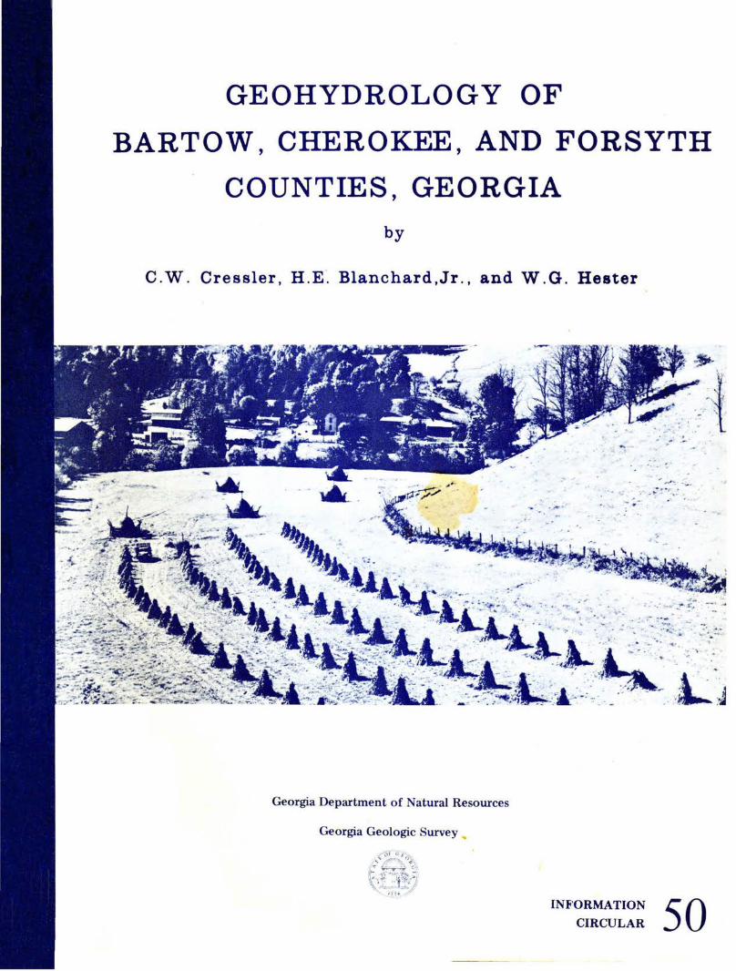
GEOHYDROLOGY OF
BARTOW, CHEROKEE, AND FORSYTH
COUNTIES, GEORGIA
by
C.W. Cressler, H.E·. Blanchard,Jr., and W.G. Hester
.. ,. ·.~ ;.·· .. ,./ " -
• . . : · ,
-~ ··. ..... . .)
• ·.,. ••• :' .,..· _!,'" ""r .. : • •
Georgia Department of Natural Resources
Georgia Geologic Survey ...
. . . _..... . .... .... . . . -"· ·-.. ..
INF'ORMATION
CIRCULAR 50
For convenience in selecting our reports from your bookshelves, they will be color-keyed across the spine by subject as follows:
Red Dk. Purple
Maroon Lt. Green Lt. Blue Dk .. Green Dk. Blue Olive
Yellow
Dk. Orange Brown Black Dk. Brown
Valley and Ridge mapping and structural geology Piedmont and Blue Ridge mapping and
structural geology Coastal Plain mapping and stratigraphy Paleontology Coastal Zone studies Geochemical and Geophysical studies Hydrology Economic geology Mining directory Environmental studies Engineering studies Bibliographies and lists of publications Petroleum and natural gas Field trip guidebooks Collections of papers
Colors have been selected at random and will be augmented as new subjects are published.
GEOHYDROLOGY OF
BARTOW, CHEROKEE, AND FORSYTH
COUNTIES, GEORGIA
by
C.W. Cressler, H.E. Blanchard,Jr., and W.G. Hester
GEORGIA DEPARTMENT OF NATURAL RESOURCES
Joe D. Tanner, Commissioner
ENVIRONMENTAL PROTECTION DIVISION
J. Leonard Ledbetter, Director
GEORGIA GEOLOGIC SURVEY
William H. McLemore, State Geologist
Prepared in cooperation with the
U.S. GEOLOGICAL SURVEY
Atlanta
1979
. INFORMATION
CIRCULAR 50

CONTENTS
Page Conversion table . . . . . . . . . . . . . . . . . . . . . . . . . . . . . . . . . . . . . . . . . . . . . . . . . . . . . . . . . . . . . . . . . . . . . . . . . . . . . . v Abstract . . . . . . . . . . . . . . . . . . . . . . . . . . . . . . . . . . . . . . . . . . . . . . . . . . . . . . . . . . . . . . . . . . . . . . . . . . . . . . . . . . . . . 1 Introduction . . . . . . . . . . . . . . . . . . . . . . . . . . . . . . . . . . . . . . . . . . . . . . . . . . . . . . . . . . . . . . . . . . . . . . . . . . . . . . . . . . 1
Purpose and scope . . . . . . . . . . . . . . . . . . . . . . . . . . . . . . . . . . . . . . . . . . . . . . . . . . . . . . . . . . . . . . . . . . . . . . . . . 2 Location and extent of area . . . . . . . . . . . . . . . . . . . . . . . . . . . . . . . . . . . . . . . . . . . . . . . . . . . . . . . . . . . . . . . . . 2 Previous studies . . . . . . . . . . . . . . . . . . . . . . . . . . . . . . . . . . . . . . . . . . . . . . . . . . . . . . . . . . . . . . . . . . . . . . . . . . . . 4 Acknowledgements · · · · · · · · · · · · ... · · . . . . . . . . . . . . . . . . . . . . . . . . . . . . . . . . . . . . . . . . . . . . . . . . . . . . . . . . 4
Occurrence and availability of ground water . . . . . . . . . . . . . . . . . . . . . . . . . . . . . . . . . . . . . . . . . . . . . . . . . . . . . . 5 Description of the water-bearing units and their hydrologic properties . . . . . . . . . . . . . . . . . . . . . . . . . . . . . . . . 5
Water-bearing unit A . . . . . . . . . . . . . . . . . . . . . . . . . . . . . . . . . . . . . . . . . . . . . . . . . . . . . . . . . . . . . . . . . . . . . . . 5 Character of the rock . . . . . . . . . . . . . . . . . . . . . . . . . . . . . . . . . . . . . . . . . . . . . . . . . . . . . . . . . . . . . . . . . . . . . 5 Water-bearing character. . . . . . . . . . . . . . . . . . . . . . . . . . . . . . . . . . . . . . . . . . . . . . . . . . . . . . . . . . . . . . . . . . . 6
Water-bearing unit C . . . . . . . . . . . . . . . . . . . . . . . . . . . . . . . . . . . . . . . . . . . . . . . . . . . . . . . . . . . . . . . . . . . . . . . 6 Character of the rock . . . . . . . . . . . . . . . . . . . . . . . . . . . . . . . . . . . . . . . . . . . . . . . . . . . . . . . . . . . . . . . . . . . . . 6 Water-bearing character ................................................................... 11
Water-bearing unit D ....................................................................... 11 Character of the rock ..................................................................... 11 Water-bearing character . . . . . . . . . . . . . . . . . . . . . . . . . . . . . . . . . . . . . . . . . . . . . . . . . . . . . . . . . . . . . . . . . . . 12
Water-bearing unit F ....................................................................... 12 Character of the rock ..................................................................... 12 Water-bearing character ................................................................... 13
Water-bearing unit G ....................................................................... 13 Character of the rock ..................................................................... 13 Water-bearing character ................................................................... 14
Water-bearing unit J ........................................................................ 14 Character of the rock ..................................................................... 14 Water-bearing character ................................................................... 14
Water-bearing unit K ....................................................................... 14 Character of the rock ..................................................................... 14 Water-bearing character ................................................................... 15
Water-bearing unit L ....................................................................... 15 Character of the rock ..................................................................... 15 Water-bearing character ................................................................... 15
Water-bearing unit :'lo/ ••••••••••••••••••••••••••••••••••••••••••••••••••••••••••••••••••••••• 15 Character of the rock ..................................................................... 15 Water-bearing unit character ............................................................... 15
Water-bearing unit P ....................................................................... 16 Character of the rock ..................................................................... 16 Water-bearing character ................................................................... 16
Use of ground water ........................................................................... 16 Wells ..................................................................................... 16 Springs ................................................................................... 16
Chemical quality of ground water ............................................................... 17 Fluctuations in spring flow ..................................................................... 17 Land subsidence and sinkhole formation ......................................................... 17 Ground-water pollution ........................................................................ 18
Pollution of wells .......................................................................... 18 Pollution of springs ......................................................................... 18
Ill
CONTENTS (Continued) Page
Ground-water pollution by landfill leachate . . . . . . . . . . . . . . . . . . . . . . . . . . . . . . . . . . . . . . . . . . . . . . . . . . . . . . . . . 21 Bartow County landfill ........................................................................ 21
Movement of leachate overland . . . . . . . . . . . . . . . . . . . . . . . . . . . . . . . . . . . . . . . . . . . . . . . . . . . . . . . . . . . . . . 21 Movement of leachate underground. . . . . . . . . . . . . . . . . . . . . . . . . . . . . . . . . . . . . . . . . . . . . . . . . . . . . . . . . . . 23
Other open-pit mines in the Cartersville area . . . . . . . . . . . . . . . . . . . . . . . . . . . . . . . . . . . . . . . . . . . . . . . . . . . . . 27 Methods for evaluating well sites . . . . . . . . . . . . . . . . . . . . . . . . . . . . . . . . . . . . . . . . . . . . . . . . . . . . . . . . . . . . . . . . . . 27
Evaluating sites ............................................................... · · · · · · · · · · · · · · · 27 Other factors affecting well yields .............................................. · · . · . · · · · · · · · · · 30
High-yielding wells ............................................................... · · · · · · · · · · · · · · · 31 Fault zones ............................................................... · · · · · · · · · · · · · · · · · · · 31 Zones of fracture concentration ...................................................... · ... · · · · · · 32 Contact zones between rocks of contrasting character ............................................. 35
Conclusions ......................................................................... · · · · . · · · · · · 39 Selected references .................................................................... · · · · . · · · · · · · 39 Appendix ....................................................................... · · .. · · · · · · · · · · · · 41
Plate I.
2. 3. 4. 5.
Figure I. 2. 3. 4. 5.
6. 7.
8. 9.
10. II. 12.
13. 14.
15. 16.
17.
ILLUSTRATIONS
Map showing water-bearing units and locations of selected wells and springs, Bartow County, Georgia ......................................................................... . Map showing water-bearing units and locations of selected wells, Cherokee County, Georgia Map showing water-bearing units and locations of selected wells, Forsyth County, Georgia . Geologic map of the Cartersville area, Bartow County, Georgia ........................ . Map of open-pit mines in the Cartersville, Georgia area large enough to be potential landfill sites
Map showing location of report area ................................................ . Map showing relative risk of sinkholes forming near high-yielding wells in Bartow County .. Geology of Bartow County landfill area, showing direction of surface leachate movement ... Diagram showing how leachate escaping from a landfill moves down the hydraulic gradient. Map showing water-level configuration in Cartersville, 1976, and direction that leachate may move underground from the Bartow County landfill .................................. . Diagram showing escape of landfill leachate through breach of bottom material .......... . Topographic map and profiles of ground surface showing rating in points for various topographic positions ........................................................................ . Graph showing rating in points for various conditions of soil thickness .................. . Graph indicating probability of getting a certain yield from a well at different sites having various total-point ratings ................................................................ . Photograph of countryside showing approximate ratings for topography ................. . Cross section of sheeted terrane showing water-filled joints in heavy dark lines ........... . Block diagram showing how zones of fracture concentration consist of nearly vertical, closely spaced fractures .................................................................. . Block diagram showing valley development localized along zones of fracture concentration . Block diagram illustrating how straight stream segments, abrupt angular changes in valley alignment, and alignment of sinkholes indicate the presence of zones of fracture concentration Map showing relation of zones of fracture concentration to well yields, Lake Arrowhead area Topographic map showing typical intermittent stream valleys in carbonate terrane, Bartow County ......................................................................... . Topographic map showing how permeable zones of fracture concentration commonly lie along straight valley segments ........................................................... .
IV
in pocket in pocket in pocket in pocket in pocket
3 19 20 24
25 26
28 28
28 30 31
33 34
35 36
37
38
TABLES Page
Table l. Chemical analyses of well water, Bartow, Cherokee, and Forsyth Counties.. . . . . . . . . . . . . . . 7 2. Minor chemical constituents in well and spring water, Bartow, Cherokee, and Forsyth Counties 8 3. Measured or estimated flows of springs, Bartow County . . . . . . . . . . . . . . . . . . . . . . . . . . . . . . . . 9 4. Chemical analyses of spring water,Bartow County . . . . . . . . . . . . . . . . . . . . . . . . . . . . . . . . . . . . . 10 5. Concentrations of metals and chloride in water sampled downstream from the Bartow County
landfill . . . . . . . . . . . . . . . . . . . . . . . . . . . . . . . . . . . . . . . . . . . . . . . . . . . . . . . . . . . . . . . . . . . . . . . . . . . 22 6. Use of numerical rating of well site to estimate the percent chance of success of a well. . . . . . 29
APPENDIX
Table 7. Record of wells in Bartow County . . . . . . . . . . . . . . . . . . . . . . . . . . . . . . . . . . . . . . . . . . . . . . . . . . . 41 8. Record of wells in Cherokee County . . . . . . . . . . . . . . . . . . . . . . . . . . . . . . . . . . . . . . . . . . . . . . . . . 44 9. Record of wells in Forsyth County . . . . . . . . . . . . . . . . . . . . . . . . . . . . . . . . . . . . . . . . . . . . . . . . . . 45
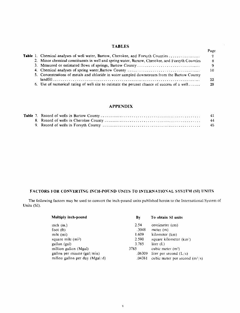
FACTORS FOR CONVERTING INCH-POUND UNITS TO INTERNATIONAL SYSTEM (SI) UNITS
The following factors may be used to convert the inch-pound units published herein to the International System of Units (Sl).
Multiply inch-pound
mch (in.) foot (ft) mile (mi) square mile (mi2) gallon (gal) million gallon (Mgal) gallon per minute (gal/ min) millon gallon per day (Mgaljd)
v
By
2.54 .3048
1.609 2.590 3. 785
3785 .06309 .04381
To obtain SI units
centimeter (em) meter (m) kilometer (km) square kilometer (km2) liter (L) cubic meter (m3) liter per second (Ljs) cubic meter per second (m3fs)
GEOHYDROLOGY OF
BARTOW, CHEROKEE, AND FORSYTH
COUNTIES, GEORGIA
By
C. W. Cressler, H. E. Blanchard, Jr.,and W. G. Hester
ABSTRACT
Bartow, Cherokee, and Forsyth Counties border the Atlanta Metropolitan Area, and are experiencing a rapid growth in urban and industrial development. Large areas not served by public water distribution systems rely on ground water to meet their requirements. Many new industries, resort communities, subdivisions, and private homes depend on ground water., most of which comes from wells.
The western part of Bartow County lies in the Valley and Ridge physiographic province, where rocks range in age from Early Cambrian to Middle Ordovician. The principal water-bearing units are shale, limestone, dolomite, and quartzite. In this area, well supplies of 3 to 25 gal/min (0.2 to 1.6 L/s) can be obtained nearly everywhere and, with rare exceptions, the water is moderately mineralized and is suitable for domestic and stock supplies.
Carbonate aquifers furnish industrial and municipal wells with 50 to 1,500 gal/min (3.2 to 95 L/s), and similar quantities may be available from selected sites in broad areas of Bartow County. The well water is moderately mineralized and is suitable for many industrial and other uses.
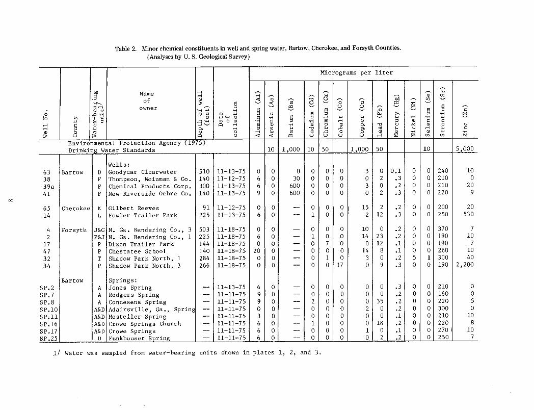
Springs in the carbonate aquifers discharge 25 to 3,000 gal/min (1.6 to 189 L/s). The spring water is of good chemical quality and can be used with minimum treatment for industrial supplies. Most of the springs are unused and represent a valuable untapped resource.
Well and spring pollution is widespread in the Valley and Ridge part of Bartow County. More than 20 percent of the drilled wells, 80 percent of the dug wells, and 80 percent of the large springs tested were polluted. The main causes of well polution are improper well construction and poor site selection. Many large springs are polluted because they are favorite watering places for wildlife. Similar percentages of wells and a large percentage of springs in the Piedmont part of the report area also may be polluted.
1 Barite mining in the Cartersville area left numerous open-pit mines in the residual soil of the Shady Dolomite. The Bartow County landfill occupies one of the mines, and others are being considered for landfill sites. Most of these mines are hydraulically connected
with the aquifer that supplies water to the industrial wells in Cartersville. Use of the mines for disposing of solid waste possibly can contaminate large areas of this important ground-water reservoir.
The Cartersville fault, generally believed to be a single thrust that crosses northwest Georgia from Tennessee to Alabama, has been found to be two thrust faults that intersect near Emerson, Bartow County: One fault extends southward from Tennessee to Emerson and is a continuation of the Great Smoky fault. The other fault trends northeastward from Alabama to Emerson, where it overrides the Great Smoky fault and continues northeastward across Lake Allatoona. To avoid confusion with the old Cartersville fault; the south-trending thrust is named the Great Smoky fault and the northeast-trending thrust is named the Emerson fault for the town of Emerson, near where it is well exposed.
The eastern one-fourth of Bartow County and all of Cherokee and Forsyth Counties lie in the Piedmont physiographic province, which is underlain by a variety of crystalline rocks including schist, gneiss, amphibolite, phyllite, and quartzite of uncertain age. The availability of ground water in the crystalline rock area is highly variable. Well supplies of 2 to 25 gal/min (0.1 to 1.6 L/s) generally can be obtained in areas having low to moderate relief. In some areas of moderate relief, and in many areas of high relief, well supplies may be unavailable. Although water from a few isolated wells contains some constituents in concentrations that greatly exceed the limits set for drinking water, most well water is moderately mineralized and is satisfactory for domestic and stock use.
Yields of 25 to 200 gal/min (1.6 to 13 L/s) are available from a few wells in the crystalline rocks. Yields of this size come from fault zones, zones of fracture concentration, and contact zones between rocks of contrasting character.
INTRODUCTION
Bartow, Cherokee, and Forsyth Counties border the Atlanta Metropolitan Area, and as a result are experiencing rapid growth in population and development. Many new industries, resort communities, and subdivisions being developed in the area need water
supplies. For most, surface-water treatment is too costly and springs are either too small or inconveniently located, so nearly all of the water requirements are met by wells. The quantities needed generally range from 25 to 1,500 gal/min (L6 to 95 L/s).
Developing adequate and dependable industrial and public water supplies from wells has been a problem in the three-county area for a long time. Problems arose because: (I) development sites were often acquired without first considering the availability of water, and (2) the potential yield of the water-bearing units was largely unknown prior to this study. Attempting to obtain large ground-water supplies in areas where the water-bearing units have a low yield potential resulted in costly and unproductive drilling, and ultimately in the abandonment of several developmental projects. Drilling sites that offered the greatest potential for ground-water supply were difficult to select without information about the water-bearing units. As a result, most existing large-capacity wells resulted from chance, rather than from careful site selection.
Purpose and Scope
The purpose of this study was to: (I) delineate all aquifers in the area: (2) determine the range of the yields of these aquifers and the chemical quality of their water: (3) map the direction of ground-water flow in the carbonate aquifers at Cartersville to determine the potential direction of movement of leachate from solid waste disposal sites: (4) measure and sample all large springs to determine their minimum annual flows and the chemical quality of the spring water: and (5) to produce geologic maps of sufficient detail to be useful in developing additional well supplies in the area. This study was designed to provide information that industries. consultants. city and county officials, land developers. and others may use to locate and develop ground-water supplies in the three-county area.
In making this study. records for industrial and other high-yielding wells and a representative sample of residential and farm wells were collected to determine their depths. yields, static water levels, and types of construction. Water samples were collected from several of these wells to determine the chemical quality of water from the water-bearing units. Aquifers in Forsyth County and in eastern Cherokee County were delineated mainly from geologic maps furnished by the Georgia Geologic Survey of the Georgia Department of 1\atural Resources. The geology of most of Bartow County and western Cherokee County was mapped during this study. Water levels were measured in 100 wells and auger
2
holes in the Cartersville area to determine the slope of the water table.
Data for springs having recorded discharges of 50 gal/min or more were collected and their discharges measured to determine their approximate minimum annual flows. Samples from eight springs were analyzed to determine the chemical quality of the spring water.
Surface geophysical techniques (resistivity and gravity) were used to map a highly permeable fault zone that supplies 100 to 1,500 gal/min (6.3 to 95 L/s) of water to industrial wells in Cartersville. Knowing the location of this conduit and the area that it drains is essential to the proper management of this valuable water resource. A gravity survey also was used to verify the identification of a thrust sheet in northern Bartow County.
The geologic structure and, so far as possible, the hydrology of the open-pit mines in the Cartersville area were studied to determine how disposing of solid waste in the mines could affect the ground-water reservoir. The water table was contoured near the Bartow County landfill to learn the direction of ground-water movement, and to predict the probable path of leachate flow.
Location and Extent of Area
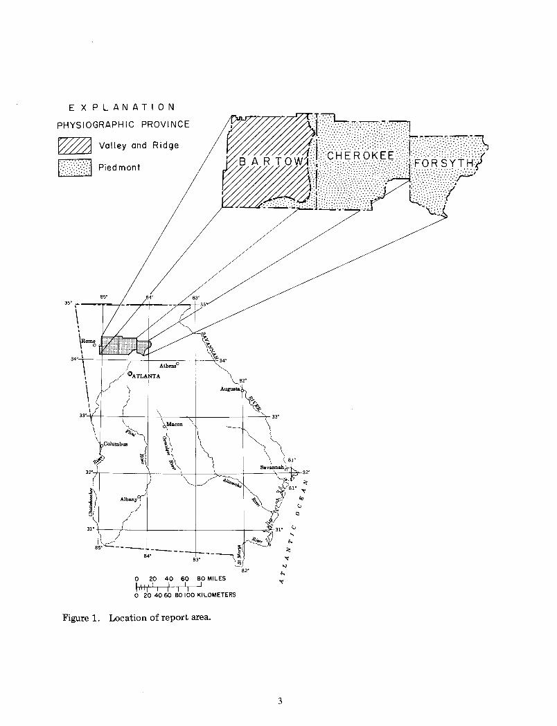
Bartow, Cherokee, and Forsyth Counties include an area of 1,147 mi2 (2,971 km 2) in northern Georgia (fig. I). The western part of Bartow County is in the Valley and Ridge physiographic province where the topography is dominated by north-south trending, low, generally rounded ridges and uplands, separated by both narrow and broad valleys. The uplands and higher ridges range in altitude from about 900 to I ,400 ft (274 to 427 m) above sea level; valleys generally are between 700 and 800 ft (213 and 244 m) above sea level.
The eastern part of Bartow County and all of Cherokee and Forsyth Counties are in the Piedmont physiographic province. The topography varies from steep, high ridges to rolling uplands and broad stream valleys. The altitude of the area ranges between 850 and 1,200 ft (259 and 366 m) above sea level.
Bartow County is drained by the Etowah River and its tributaries except for the extreme northern border of the county that is drained by the Oostanaula River. All of Cherokee County and the northwest half of Forsyth County are drained by the Etowah River system. The remainder of Forsyth County is drained by the Chattahoochee River system.
The counties have a mild climate. Their average January temperature is about 41° F and their average July temperature is about 77°F. The average annual
EXPLANATION
PHYSIOGRAPHIC PROVINCE
~ Valley and Ridge
r:/:/:·\/{] Piedmont
82'
O 20 40 60 80 MILES -.: I I I I I
0''' ~~do 6~ ~0 1b0 KILOMETERS
Figure 1. Location of report area.
3
precipitation in the three counties is about 53 in. ( 1,350 mm). including only a small amount of snow.
Rainfall in this part of the State has two peaks, one in winter and one in midsummer. separated by periods of lighter rains in spring and autumn. Autumn is the driest season of the year. Large variations can occur in the amount of rainfall received from year to year. and amounts from the wettest years may be about double those for the driest years. :'\/early half of the rainfall comes in amounts of l in. (25 mm) or more within 24 hours.
Dry spells occasionally cause heavy damage to crops and pastures and result in shortages in water supplies. Droughts of this severity are, however. usually limited to rather small areas so that any given locality. on the average, is not likely to have a serious drought more often than once in 10 to 15 years.
Previous StuJies
Butts and Gildersleeve ( 1948) reported on the general geology and the mineral resources of the Valley and Ridge part of Bartow County. The geology and mineral resources of the Cartersville Mining District. in eastern Bartow County, were studied in detail by Kesler ( 1950).
Croft ( 1963) investigated the geology and groundwater resources of Bartow County, and the generalized availability of water supplies is treated by Cressler and others ( 1976). The water resources of Cherokee and Forsyth Counties were examined by Thomson and others ( 1956).
Chemical analyses of water from several wells in the report area were tabulated by Grantham and Stokes ( 1976), and summarized by Sonderegger and others ( 1978).
Acknowledgements
This study was made by the U.S. Geological Survey in cooperation with the Georgia Geologic Survey of the Georgia Department of Natural Resources. The Georgia Geologic Survey provided a geologic map of Cherokee County by Mr. David E. Lawton, and of Forsyth County by Dr. Joseph B. Murray, for use as a base for the ground-water study.
The writers wish to acknowledge the many people in Bartow, Cherokee, and Forsyth Counties who gave assistance during this investigation. Property owners willingly supplied information about their wells and springs and permitted them to be measured and sampled.
Mr. Jimmy Fowler, Fowler Well Drilling Co., Canton, Ga., furnished construction and yield data on a large number of wells in Cherokee County. Mr.
4
Paul Helms, All Purpose Boring. Inc .. Cumming. Ga .. and his staff supplied similar data for wells in Forsyth County.
Mr. John Thomas and Mr. Bob Aiken of the Lake Arrowhead resort community in Cherokee County made available comprehensive engineering reports that contained construction data. lithologic logs, electric logs, and chemical analyses for wells on the property.
Mr. Pete Murray of Thompson, Weinman and Co., Cartersville, Ga., supplied information about the depth to bedrock and arranged access to company property for resistivity and gravity surveying.
The contacts between the quartzite-phyllite-shale sequence and the overlying dolomite unit, and the outcrop pattern of part of the gneiss body known as Corbin Granite (Precambrian) in eastern Bartow and western Cherokee Counties, were taken from a geologic map of the Cartersville Mining District by Mr. T. L. Kesler (1950). This map, made during a period of widespread mining in the Cartersville area prior to the filling of Allatoona Lake, shows these contacts more accurately than could be determined from present exposures in the time allotted.
Mr. Charles Adams and others of the Union Carbide Corp. furnished an engineering report that contained foundation boring data needed to trace the permeable fault zone beneath the industrial park in south Cartersville. They also opened unused company wells so water levels could be measured.
Dr. Thomas J. Crawford of West Georgia College, working in cooperation with the Georgia Geologic Survey and the U.S. Geological Survey, supplied geologic maps and lithologic descriptions of the Piedmont part of the Burnt Hickory Ridge and Taylorsville quadrangles and parts of the Acworth and Allatoona Dam quadrangles, including the area underlain by the Corbin Granite. He also correlated the crystalline rock units south of Cartersville with ones to the east, and spent many hours discussing the lithologic relationships and the geologic structure of the Cartersville area. Dr. Crawford worked in the field with the senior author to confirm that the Cartersville fault of former usage consists of two intersecting faults (Cressler and Crawford, 1976), and agreed to name the northeast-trending fault the Emerson fault for the town of Emerson, Bartow County, near where it is well exposed.
Dr. L. T. Long of the Georgia Institute of Technology planned and interpreted resistivity and gravity surveys in Bartow County to locate groundwater conduits and delineate major water-bearing units. The field work for these surveys was done by Mr. Wes Champion.
Mr. Paul A. Smith, Jr., graciously furnished construction data and chemical analyses, allowed the
installation of water-level recorders, and permitted the use of his equipment and power to conduct an aquifer test on his property in Dawson County, adjacent to the study area.
OCCURRENCE AND AVAILABILITY OF GROUND WATER
Ground water in Bartow, Cherokee, and Forsyth Counties occupies joints, fractures, and other secondary openings in bedrock and pore spaces in the overlying mantle of residual soil. Water recharges the underground openings by seeping through the soil or by flowing directly into openings in exposed rock. This recharge is from precipitation that falls in the area.
Unweathered and unfractured bedrock in the report area has very low porosity and permeability. Thus, the quantity of water that a rock unit can store is determined by the capacity and distribution of joints, fractures. and other types of secondary openings. The quantity of stored water that can be withdrawn by wells, or that is free to discharge from springs, depends largely on the extent to which the rock openings are interconnected.
The size, spacing, and interconnection of openings differs greatly from one type of rock to another and with depth below land surface. Open joints and fractures tend to become tighter and more widely spaced with increasing depth. Joints and other openings in soft rocks such as shale and phyllite tend to be tight and poorly connected; wells and springs in rocks of this character generally have small yields. Openings in more brittle rocks such as quartzite and graywacke tend to be larger and are better connected: wells and springs in these rocks normally supply greater yields. Other rocks. including amphibolite, schist, and gneiss. are variable in the size and connection of secondary openings and generally yield small to moderate quantities of water to wells and spnngs.
Carbonate rocks, which include limestone, dolomite, and marble, contain much larger and more extensively interconnected fracture systems. Openings in carbonate rocks commonly are enlarged by solution, and are capable of transmitting large quantities of water.
Fractures in slate, shale, sandstone, quartzite, and similar rocks in the Valley and Ridge province area tend to be concentrated within 250 ft (76 m) of the surface. Most solution-enlarged fractures in carbonate rocks are found at depths of less than 350 ft ( l 06 m). Therefore, when drilling for water in the Valley and Ridge province, it is rarely worthwhile to drill deeper than 350 ft ( l 06 m) in carbonates, or deeper than 250
5
ft (76 m) in other kinds of rock. If a well fails to produce the desired yield at these depths, it generally is best to try a new location.
In the Piedmont area, where the rocks have been subjected to greater deformation, water-yielding joints and fractures commonly occur deeper than 400ft ( 122 m). A significant number of wells obtain water from openings about 500 ft ( 152 m) deep, and a few produce water from as deep as 700 ft (213 m). However, a comparison of drilling costs with the probability of obtaining the required yield of about 5 gal j min (0. 3 L j s) indicates that it is seldom advisable to drill deeper than about 400 ft ( 122 m) for a residential supply. Well records show that drilling deeper than about 700ft (213m) cannot be justified unless geologic evidence indicates that openings extend to greater depth.
DESCRIPTION OF THE WATER-BEARING UNITS AND THEIR HYDROLOGIC PROPERTIES
The report area is underlain by more than 30 different kinds of rock, many of which have similar physical properties and yield water of comparable quantity and chemical quality. Thus, for convenience, the rocks in the report area have been grouped into 10 major water-bearing units and assigned letter designations. The areal distribution of the water-bearing units is shown on the accompanying maps, plates l. 2. and 3. The physical characteristics and the hydrologic properties of each water-bearing unit are described in the following section.
Because large ground-water supplies are essential to continued industrial growth in Cartersville and along the Interstate 75 corridor in eastern Bartow County, a detailed geologic map is included of that area. (See plate 4.) This map delineates the highyielding and low-yielding water-bearing units, and thus should facilitate the development of additional well supplies, especially where the underlying rock is obscured by a deep cover of soil and alluvium.
Water-Bearing t:nit A
Character of the rock-Unit A has the largest areal extent of any aquifer in Bartow County, but because it is generally overlain by a thick residual mantle, the bedrock rarely crops out. For this reason, its lithology is inferred from adjacent areas where it is better exposed. The bulk of the unit consists of thickly to massively bedded dolomite, mainly brown or tan in the lower part, and medium to light gray in the middle and upper parts. The unit throughout most of the county is made up of the Knox Group of Cambrian and Ordovician ages. Near Taylorsville and

Stilesboro, where the youngest part of the unit occurs, thick to massive layers of light- to medium-gray limestone locally account for about 50 percent of the section. The upper limestone-bearing section belongs to the :'\lewala Limestone of Ordovician age.
The unit probably is between 2,500 and 3,500 ft (762 and I ,070 m) thick in southwest Bartow County where the entire section is present. In the northern part of the county. the unit occupies narrow synclinal belts and probably ranges from 100 to 2,000 ft (30 to 610 m) thick.
The dolomite is highly siliceous and upon weathering produces a cherty, silty, clay residuum that generally ranges from 25 to 200 ft (7.6 to 61 m) thick. The residuum is highly permeable and readily absorbs precipitation, which it holds in temporary storage and slowly releases to bedrock openings. It is this steady supply of water from the residuum that sustains the high y"ields of wells and springs in the aquifer and minimizes the adverse effects of droughts.
Water-bearing character-Unit A is one of the most productive aquifers in the report area. Farm and home supplies generally are available everywhere except on steep slopes and narrow ridges. Drilled wells in the unit are very dependable and rarely decline in yield, even during periods of prolonged drought. Twenty-one wells having known yields furnish 4 to 92 gal/min (0.3 to 5.8 L/s). (See Appendix.) The chance of obtaining 5 gal/ min (0.3 L/ s) from a randomly located well in unit A, such as at most farms and homesites, is about 80 percent.
In adjacent counties of northwest Georgia where more wells have been drilled in the aquifer, supplies as large as 1,500 gal/min (95 L/s) are obtained from wells in favorable locations. Selected sites in Bartow County can be expected to furnish between I 00 and 1,500 gal;min (6.3 to 95 Ljs). (See the section on evaluating well sites.)
Sixty-four residential and farm wells in Bartow County have an average depth of 132 ft (40 m), and their casing depths range from 35 to 134ft (II to 41 m). The shallowest well recorded is 55 ft (17 m) deep; the deepest, 331 ft ( 10 I m). Most wells in the unit are cased to bedrock, leaving the remainder of the well an open hole in limestone and dolomite.
In areas where the depth to bedrock is greater than about 100 ft (30 m), a few wells are finished above the bedrock and derive water solely from the overlying residual soil. The soil contains permeable layers that yield 5 to 15 gal/ min (0. 3 to 0. 9 L 1 s) or more to wells.
In developing a well in residual soil, it is common practice to drill until a water-bearing zone is reached ~nd measure the yield. If the yield is adequate, casing 1s set to total depth, leaving only the open hole in the
6
bottom of the pipe to admit water. Thus, because of the small intake area, the full potential of the water-bearing zone rarely is utilized by this wellconstruction method. For wells that penetrate a thick layer of water-bearing material, or more than one layer, the yield generally can be increased by the use of slotted casing. This method is rarely employed, however, possibly because of increased cost. Gravelpacked wells also are successful and they commonly yield I 0 to 25 gal; min (0.6 to 1.6 L; s).
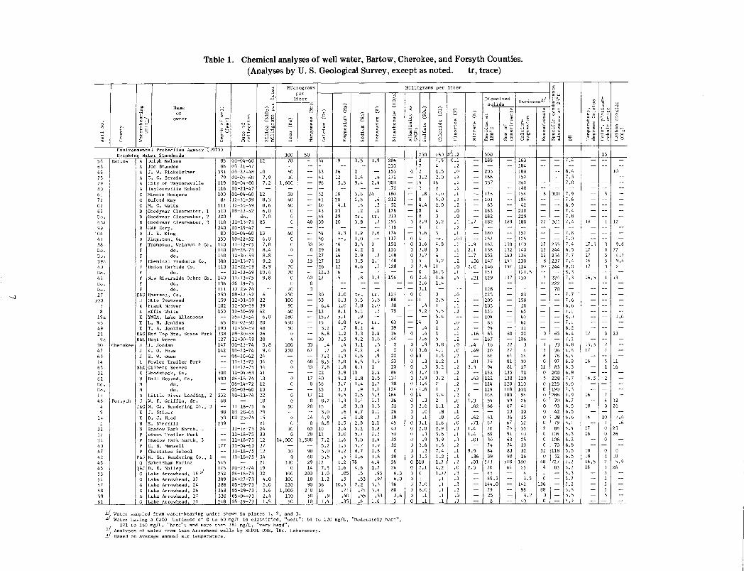
The chemical quality of the well water generally meets the standards set by the Georgia Department of Natural Resources (1970) and the Environmental Protection Agency (1975). (See tables I and 2.) Water from wells in bedrock is hard to very hard and most contains low concentrations of iron. Of 64 wells inventorjed, only two were reported to supply water containing objectionable amounts of iron. The iron concentration in water sampled from three bedrock wells ranged from 10 to 70 11g! L (micrograms per liter), which is fairly low.
Wells that obtain water solely from the residual soil above the bedrock yield soft water that is low in iron. Well owners refer to the water as "freestone", and report that it is very good for drinking and other domestic uses.
The largest springs in the report area discharge water from unit A. Fifteen springs discharge between 50 and 3,000 gal/min (3.2 and 189 L/s). The spring locations are shown in plate I, and their discharge rates are listed in table 3. Nearly all the springs are unused and represent a potentially important undeveloped resource.
The spring water is hard to very hard, and most is of good chemical quality suitable for many industrial uses. With chlorination, water from some springs can be used for public and private supplies. Chemical analyses of water sampled from representative springs in Bartow County are listed in tables 2 and 4.
Water-Bearing Unit C
Character of the rock-Unit C consists mainly of shale, but in some areas it includes significant thicknesses of limestone, dolomite, siltstone, and sandstone. The broad belts of the unit near Adairsville, Cassville, and Pine Log are mostly greenish, gray, and slightly purplish shale that weathers to various shades of tan, pink, and orange. Scattered throughout these areas are layers and lenses of limestone and dolomite a few feet to 100 ft (30 m) or more thick. The thicker carbonate layers generally underlie narrow valleys in the shale. The unit in these areas belongs to the Conasauga Formation of Middle and Late Cambrian age.
--1
0 z ..., ..., . :<
58 63 68 75 79 80 61 72 02 63 Do. 63a 99
104 141
38 Do. Do, 39a 40 Do. 41 Do. Do. 27
100 3 8
19a '•6 49 21 9a
30 47 63 14 65 32 62 Do. Do. 12 46
4 9
14 1
32 17 34 40 47 42 43 45 53 54 57 58 59 61
Table 1. Chemical analyses of well water, Bartow, Cherokee, and Forsyth Counties.
"" -~-
" f -~1 u "
~ ~ :l
:<
Name ..., ..., . , . . ~
(Analyses by U.S. Geological Survey, except as noted. tr, trace)
~ Micrograms Milligrams per liter ~
~ per "' § u
: liter,..... ,..... § Dis~~ ted Hardness.~/ 'g 1q --;::. ~ f ,......, ~ Q '-' ~ --; ~ .--, so ]_ s U) w ] ...... 0 '-' <tl '-' .--, .._, aJ 0 u !:>.. ,......., ..... .j../ 0 td ·r-1 Cll u 'll ...... :;..., U) '-' '-' z ..... ~ (\1 u ~ ffi -; ;;; '-' 5 c 9 ~ .!:: '-' '-' Ill ~ ! 5 g u
1-< ~ w 8 ....-! oM o C w w S·rl ..c .-1
e.~ '-' § .~ ~ 5 ~ -e ~(<) .5u '"0~ -~~ ~ ~ •riM C bll U C ..-1 Ill <ll alO '"'0 tfJ U C U U rlrl 0 c,.... bD "0 ...... u ..:.::u 000 sc ...-100 c Ill
~-g ;:: ~ 3 ~ a 6:: ~ ~8 ~~ ~3 8~ .g ~ ~~ • 0
" u 'R
Environmental Protection Agency (1975) Drinking Water Standards 300 50 250 250 lj/1.2 500
Bartow I A Dolph Nelson A Joe Brandon
Cherokee
Forsyth
A J. W, Pickelsimer A C. C. Strain A City of Taylorsville A Taylorsville School C Minnie Rodgers C Buford Kay C M. C. Watts D Goodyear Clearwater, 1 D Goodyear Clearwater, 2 D Goodyear Clearwater, 3 D GAF Corp. D J. E. King D Kingston, Ga. F Thompson, Weinman & Co. F do.
do. F !Chemical Products Co, F F
Union Carbide Co. do,
F !New Riverside Ochre Co. do,
F do, F&G Emerson, Ga.
J Otto Townsend K Frank McEver K Effie White K YMCA, Lake Allatoona K L. N. Jenkins K T. A. Jenkins
K&G Red Top Mtn. State Park K&L Hoyt Green
J J. Jordan J V. 0. Pass J E. W. Owen L I Fowler Trailer Park
N&K Gilbert Reeves K Woodstock, Ga. M Ball Ground, Ga. M do, M do. N Little River Landing, 2 J W. F. Griffin, Sr.
J&G N. Ga. Rendering Co., 3 K J. Stiner K D. J, Hood N E. Sherrill N Shadow Park North, 1 P Dixon Trailer Park P Shadow Park North, 3 P c. B. Mansell P Chestatee School
P&J N. Ga. Rendering Co,, 1 Q Habersham Marina
Q~J ~;k!• A~~!~~:ad, 16~/ G Lake Arrowhead, 17 G Lake Arrowhead, 24 G Lake Arrowhead, 26 G Lake Arrowhead, 27 G Lake Arrowhead, 31
85 01-04-60 112 86 03-21-47
331 03-27-48 10 79 01-05-60
119 01-04-60 116 03-21-47 100 01-04-60
87 12-31-59 111 12-31-59 510 09-22-52 320 do. 510 11-13-75 240 03-19-47 80 01-04-60
350 09-22-52 140 11-12-75 140 05-28-75 140 300 113
12-30-59 11-13-75 12-22-59
-- '12-22-59 140 111-13-75 136 06-19-75 111 250 159 102 150
65 190 338 127 147 142
10-29-74 09-22-52 12-31-59 12-30-59 12-30-59
'05-13-54 03-02-50 12-30-59 09-30-58 12-30-59 01-21-74 01-21-74
I 08-20-62
-- 11-13-75 11-12-75
7.9 7.2
12 8.3 8.6 6.0 7 .o
85
13 6.0 7.8 8.4 8.8 9.2 8. 9
10.4 9.8
6 22 39 42 6.0
20 48 26 30 5.8 9.4
24 34 34
500 400
11-04-63141 04-18-74 13 06-14-72 12
- I os-o3-6o 13 01-21-74 22
10 532
68 11-18-75 16
98 03-28-66 29 53 01-23-74 15
239 -- 21 11-18-75 24
-- 11-18-75 33 11-18-75 12
177 11-04-63 37 -- 11-18-75 12 - 11-18-75 14
545 - 21 175 01-23-74 19 252 04-16-73 32 309 04-27-73 4.0 288 05-29-73 5.0 248 05-29-73 3.6 330 05-04-73 2.4 248 05-29-73 1.5
70
50 10
1,600
50 40 40
0 0 0
40 0 0 0
0 70 70
0 0
20 250 100
90 40
280 450
50 0 4
100 250
0 0
50
0 0
10 0
14,000
10 0
310 0
100 100 230
1,000 100 so
34 119
-- 133 126 - 41 12 - 96 5.5
n u - " w - 10 4.1
43 25
- " H ~ H W
- 54 4.3 -- SO tr. 50 30 16
0 29 16 -- 27 16 15 27 15 - 26 12 - 22.3 16 40 27 15
0 --5
- 30 2.0 - 53 6.3 - 6.4 1.0
13 8.1 -- 15.7 5.1
15 6.0 -- 3.2 ,7 - 6.8 1.2
30 7.5 33 .4 .4 67 0 7 .6
7.2 1.3 40 8.5 2.0 so 7.8 1.8 -- 22 3.9 17 40 4.3
0 36 3.7 35 3.3
17 22 9.5 0 8.2 1.3
20 15 .8 -- 3.0 .6 14 4.9 .6
0 8.8 2.5 60 10 2.4 20 11 3.0
1,500 7.2 1.6 5.2 1.5
90 s.o 4.2 60 5.5 .5 29 72 1.2 14 7.5 1.6
200 1.0 .05 10 1.2 .s 90 36 10.5
210 16 .21 50 .9 .40 10 1.4 .35
3.5 I 1.9
2 I -1.4 .4 9.4 2.4
3.6 24 2.6 .6
.5 .3
.2 .1 tr. tr. 3.8 .7
1.9 2.6 1.0 -3.5 1 4.2 1 2.9 .7 3.5 1.1 6,6 0 7
.8 I 1.3
tr ., tr. 5,5 3.6 7,8 2.0 6.1 .3
.9 -tr, tr. 8,1 4 3,3 2.4 9,2 1.6 3,1 .3 4,2 .4 4.6 .9 6,5 1,5 6.1 1
10 2.4 1.8 1.5 1.4 1.2
.9 1.1 2.5 3.3 1.4 2.3 3,0 1.3 4.7 1.1 1.8 .7 2,8 1.1 5,2 1,8 s. 7 2.3 3.0 1.4 5. 7 1.9 6,7 2.6 1.6 1.6
78 4.4 4,6 1.7
.5 .95
.53 .97 2.2 3.3
,74 3.4 .55 .53 .6 1.6
204 -- 2 233 7 153 0 2 172 - 3.2 301 -- 4 172 -- 3 180 -- .8 212 - 8
52 -- 4.4 178 0 210 - 8 193 0 8.9 118 9 174 - 5.6 117 0 1 151 0 3.6 153 0 3.8 148 0 3.2 148 0 4 128 0 2.4
-- 0 156 0 2.4
-- 2.6 -- 3.1
127 0 0 188 - 1
38 -- 0 4 78 9.2
w 4 39 .4 36 0 .4
144 7.6 2 0 .9 2 0 3.6
22 0 3 53 0 .3 20 0 .5 86 0 3.2
137 0 3.9 130 0 1.6 124 0 1.6 164 0 4
36 0 .3 51 0 3.6 26 0 .o 19 0 .1 45 0 3.1 40 0 2.0 51 0 .s 30 0 .9 32 0 3. 6
0 0 .3 20 0 3.5 58 0 10 26 0 2.1 6,3 0 0 6.0 0 1
136 0 7.0 88 0 8.0
3.6 0 .1 3 0 .1
4.5 4 1.5 2.0
16 2 4.0 5.0 2.0 4 3 5.2 4 3 tr. 4.8 5 4 4.2
11 14.5 1.6 1.4
3 2.5
5.5 5.4 3 1 1 5 3.8 4.1 1.5 1.2 5.2
10 3.2 2 1 3.4 2 1.1
.8
.8 1.8 2.9 3.6 3.9 1.5 7.4 1.2 1.7 4.2 1.77
.1
.1 ,1 .1 .1
0.1 .2 .0 .2 .2 .2 .1 .2 .2 .o .o .1 • 2 .1 .01 .1 .1 .1 .2 .o ,1 .4
.o
.1
.1
.2
.0
.2
.1
.2
.o
.0
.2
.1
.2
.2
.1
.2
.3
.2
.0
.2
.1
.o
.o
.3
.1
.3
.2 ,1 .1 .2 .o .3 .3 .3 .3 .3 .3
-- '188
1
203 - 166 - 337
-- 178 - 201
63 - 163 - 182
1. 7 182
-- 180 -- 252
1.9 162 2.1 136 1. 7 153
.56 147 2.0 146
151 .21 129
128 225
-- 205 103 136 104
83 - 94
.16 65 - 167
1.4 16 .49 20 - 66
.01 78 3.3 94
- 152 .63 122 - 124 - 119
0 168 1.3 54
.02 66
.62 41
.71 67 1.4 70 1.4 89
.01 30 74
9.9 84 .36 39 .01 573
2.3 70 45
- 69.3 -- •144.0
79 25 8
-- 163 184 180 152 262
-- 140 154
-- 184 42
210 - 229
189 180
- 152 -- 125
150 140 152 140 143 134 141 130 140 114 -- 121.5
137 130
83 - 158
20 65 60 62
- 11 60 22 - 106 22 3 27 4 64 24 81 30 81 27
135 71 138 120 120 110 118 101 180 94
49 26 67 41 53 10 36 15 67 32 75 35 91 40 63 25 74 19 83 32 40 16
518 180 64 25
4 - 3.5 - 142
98 4.2
40
7.4
I --18 4
-- -- ,:5 - -- 7.0
6 300 7.9 - 7.6
-- 6.9 - -- 7.4 - 7.8 22 301 7.4
-- 7.8 -- 7 .o
17 255 7.4 13 244 6.5 12 254 7. 7
8 237 7,4 10 244 8.0 - - 8.3
2 224 7.3 -- 222 --- 70 -
-- 7 0 7 - 7.6
-- 6.6 - - 7.1
- 8.0 - 7.1
-- 6.2 0 65 6.4
- 7.1 1 33 4. 8 3 36 4.8 6 78 6.4 0 97 6.9
11 83 6.3 0 200 6.9 5 228 7 0 7 0 225 8.0 0 190 7.3 0 288 7.9 0 70 6. 7 0 93 6.5 0 42 6. 5 0 38 6. 6 0 79 8.1 2 88 5.4 0 104 6.5 0 106 6.2 0 70 6.8
32 118 5.5 0 52 6.5
140 727 7.2 4 83 6.2 1 -- 5.3 0 5. 7
136 - 7.2 88 - 6.8
0 - s.s 0 -- 5.9
1_/ Water sampled from water-bearing units shown in plates 1, 2, and 3. 2./ Water having a CaCO hardness of 0 to 60 mg/L is classified, "soft"; 61 to 120 mg/L, "moderately hard";
121 to 180 mg/L, "hard"; and more than 181 mg/L, "very hard", _]_/ Analyses of water from Lake Arrowhead wells by XEPOL ONE, INC. Laboratory. !!_I Based on average annual air temperature.
~
" ., 0 ~ . ...,
u • ou . ~ u • . . o.u ~ ~ '""
L/ ~ w .. , rl " '"" Uri 0 • rl.O
8 8
15
-I-- I 10
0 u
_, 5' -
18 I 1 112
17.51319.6 17 0 77 17 5 4. 7 16 5 9.4 17 3 2
16.s I 1 113
- ' -- ' 1.0
17 I 3 123
15.5 I 7 I -17 7 -
16 I 5 Ill - 1 16
16.s I 2 • -
16 I 'I -- 4 12 18 0 26
16
110 I' .6 -- 1 .6
17 0 25 16 0 26
- 0 -
18 0 0 18 1 10 16.5 2 5.9 16 3 26
- 3 -- 1 - 5 -
5 -5 -
00
0 z r-1 r-1 Cl)
::s:
63 38 39a 41
65 14
4 2
17 47 32 34
SP.2 SP. 7 SP.8 SP.lO SP.ll SP.l6 SP .17 SP.25
Table 2. Minor chemical constituents in well and spring water, Bartow, Cherokee, and Forsyth Counties. (Analyses by U.S. Geological Survey)
Micrograms per liter
bO Name r-1 ,..., ,..., ~ r-1 r-1 ,..., ,..., ).4 ,...,
•ri of Cl) ~ (Jl ,..., '"0 u ,..., ,..., bO ,..,....._ ~ ~ ....... ~ Ill u ....... 0 ;::l :I:
~i owner ,..., 0 ....... ~ ....... u u ,..., ....... 4-<+.1 •ri s ....... s ....... ....... ,.0
,.0 •ri 0 Cl) Cl) +.1 ;::l (.) ~ ;::l p.. » » I ~ Cl) +.1 4-< (.) ~ •ri ~ •ri +.1 ).4 ....... ).4
+.1 ).4 ;::l ..C:'-1-< ct1 0 Cl) •ri ~ •ri s r-1 Cl) ;::l
J:: Cl) +.1 ....... A r-1 ~ Cl) •ri s 0 ct1 p.. '"0 (.)
;::l +.1 p.. r-1 (Jl ).4 '"0 ).4 ,.0 p.. ct1 ).4
0 Ill Cl) 0 r-1 ).4 ct1 ct1 ..c: 0 0 Cl) Cl)
u ::s: A (.) ~ ~ ~ u u u u t-1 ;:.::
Environmental Protection Agency (1975) Drinking Water Standards 10 1,000 10 50 1,000 50
Wells: Bartow D Goodyear Clearwater 510 11-13-75 0 0 0 0 0 0 3 0 0.1
F Thompson, Weinman & Co. 140 11-12-75 6 0 30 0 0 0 0 2 .3 F Chemical Products Corp. 300 11-13-75 6 0 600 0 0 0 3 0 .2 F New Riverside Ochre Co. 140 11-13-75 9 0 600 0 0 0 0 2 .3
Cherokee K Gilbert Reeves 91 11-12-75 0 0 - 0 0 0 15 2 .2 L Fowler Trailer Park 225 11-13-75 6 0 - 1 0 0 2 12 .3
Forsyth J&G N. Ga. Rendering Co., 3 503 11-18-75 0 0 -- 0 0 0 10 0 .2 P&J N. Ga. Rendering Co., 1 225 11-18-75 6 0 -- 1 0 0 14 23 .2
p Dixon Trailer Park 144 11-18-75 0 0 -- 0 7 0 0 12 .1 p Chestatee School 140 11-18-75 20 0 -- 0 0 0 14 8 .1 T Shadow Park North, 1 284 11-18-75 0 0 - 0 1 0 3 0 .2 p Shadow Park North, 3 266 11-18-75 0 0 - 0 0 17 0 9 .3
Bartow Springs: A Jones Spring -- 11-13-75 6 0 -- 0 0 0 0 0 .3 A Rodgers Spring -- 11-11-75 9 0 -- 0 0 0 0 0 .2 A Connesena Spring -- 11-11-75 9 0 -- 2 0 0 0 35 .2
A&D Adairsville, Ga., Spring -- 11-11-75 0 0 -- 0 0 0 2 0 .2 A&D Mosteller Spring -- 11-11-75 3 0 - 0 0 0 0 0 .1 A&D Crowe Springs Church -- 11-11-75 6 0 -- 1 0 0 0 18 .2 A&D Crowe Springs -- 11-11-75 6 0 -- 0 0 0 1 0 .1
D Funkhouser Spring -- 11-11-75 6 0 -- 0 0 0 0 2 .2
~/ Water was sampled from water-bearing units shown in plates 1, 2, and 3.
,..., ,..., ).4 Cl) U) ,..., U) .......
•ri ....... z ~
,..., .......
~ ~ •ri N
r-1 ·ri +.1 ....... Cl) J:: J:: ....: Cl) 0 (.) (.) r-1 ).4 J::
•ri Cl) +.1 ·ri z U) U) N
10 5,000
0 0 240 10 0 0 210 0 0 0 210 20 0 0 220 9
0 0 200 20 0 0 250 530
0 0 370 7 0 0 190 10 0 0 190 7 0 0 260 10 5 1 300 40 0 0 190 2,200
0 0 210 0 0 0 160 0 0 0 220 5 0 0 300 0 0 0 210 10 0 0 220 8 0 0 270 10 0 0 250 7
Spring No.
4
8
10
ll
12
13
14
15
16
17
18
19
20
21
22
23
24
25
Spring name or owner
Davis Estate
C. C. Cox (Jones Spring)
Wallace Moore
Blue Hole Spring
Boiling Spring
Gillam Spring
Roger Gordon (Roger's Spring)
Connesena Spring
Kerr Spring
City of Adairsville
Mosteller Spring
Hayes Spring
Orma Adcock
Harvey Lewis
Pratt Spring
Crowe Spring Church
Crowe Spring
H. H. Lipscomb
Cartersville Spring
Mrs. W. B. Moss
Mrs. W. B. Moss
W. M. Vaughan
Wiley Vaughan
Copper Hill Mining Co. Oak Hill Spring
Funkhouser Spring
Table 3. Measured or estimated flow of springs, Bartow County. (E, estimated)
Waterbearing unit 1/
A
A
A
A
A
A
A
A
A
A
A
c
A
A
c
A
A
c
F
F
F
D
D
c
D
Location
1.5 miles NW. of Taylorsville, 1.1 miles N. of Polk County line.
2.8 miles N. of Taylorsville, E. side of road.
2.7 miles NE. of Taylorsville, 2.1 miles N. of Polk County line.
Date measured
or estimated
09-26-50 11-04-74
09-26-50 11-04-74
09-26-50 11-04-74
3.65 miles NNE. of Taylorsville, 09-26-50 3.42 miles N. of Polk County line. 11-04-74
2.6 miles NNE. of Euharlee, N. bank 09-27-50 of Euharlee Creek. 11-05-74
3.0 miles N. of Euharlee, N. bank of Etowah River.
1.97 miles NNE. of Kingston, N. side of Ga. Highway 20.
1.45 miles SW. of Halls, 0.2 mile N. of road.
0.6 mile W. of Halls, N. of road.
0.9 mile NW. of center of Adairsville at city waterworks.
5.05 miles ENE. of Adairsville, 0.2 mileS. of Ga. Highway 140.
6.64 miles ENE. of Adairsville, N. side of Ga. Highway 140.
4. 72 miles NW. of Pine Log, 0. 93 mile S. of Ga. Highway 140.
3.9 miles w. of Pine Log, 2.05 miles S. of Ga. Highway 140.
8. 2 miles NE. of center of Kingston, 3.4 miles E. of U.S. Highway 41, and E. side of Mud Creek.
5.5 miles WSW. of Pine Log, 8.34 miles SE. of Adairsville.
5.21 miles WSW. of Pine Log, 8.7 miles SE. of Mairsville.
2.95 miles SW. of Pine Log, 1.8 miles W. of U.S. Highway 411.
09-27-50 11-05-74
09-27-50
09-27-50 11-05-74
12- -59 11-05-74
09-27-50 11-05-74
09-28-50 11-06-74
09- -59 ll-06-74
12- -59 11-06-74
09- -59 11-06-74
09-28-50 11-06-74
09-28-50 11-06-74
09-28-50 11-06-74
08- -59
1.99 miles NW. of Fmerson, NW. bank 11- -74 of Etowah River. 11-06-7 5
1.7 miles SW. of Emerson, 2.0 miles N. of Paulding County line.
1.6 miles SW. of Emerson, 1.99 miles N. of Paulding County line.
1.25 miles SSE. of Pine Log, 0.7 mile W. of u.s. Highway 411.
1.0 mile SSE. of Pine Log, 0.7 mile W. of U.S. Highway 411.
2.75 miles ENE. of Pine Log, 0.08 mile S. of Ga. Highway 140.
3. 74 miles NNE. of Pine Log, 0. 35 mile w. of U.S. Highway 411.
12- -59 11-04-74
12- -59 11-04-74
08- -59 ll-07-74
08- -59 11-07-74
08- -59 11-06-75
09-29-50 11-07-74
Flow Mgal/ d Gal/min Remarks
1. 73 .94
1.4
.25 dry
4. 6
• 72 .36
1.08 .16
2. 9
1.44
• 29E .35
5.9 4.1
3.0 1.5
.OlE
.12
.29 E
.03
.OlE
.10
.34
.01
1.44 .46
• 74 .44
.08
.5E dry
• 29E .18
.29E • 79
.07E
.03
.OlE
.07
l.OE .3E
• 32 .21
1,200 655
960
170
3,200
500 250
750 108
Nov. 4, 1974, could not measure because of flooding by beaverdam.
Nov. 4, 1974, could not measure because of flooding by beaverdam.
Flows from rocks •
2, 000 In streambed.
1,000 Nov. S, 1974, could not - measure because of
flooding by beaverdam •
200E Pool spring. 243
4,100 Public supply. 2,870
2,100 Pool spring. 1,060
SOE Flows from rock opening 84
200E Seep spring. 20
50E Seep spring. 70
235 Developed. 7
1,000 Flows from rock opening 320
517 Developed. 300
60
350E Dry when Thompson, Weinman Co. well is pumping •
200E 125
200E 550
50E 18
50E 50
700E 200E
220 148
Pool spring.
Industrial supply •
}:__/ Water-bearing units are shown in plate 2.
9
...... 0
---~I '"' .... " " "" " .... .... Name Date
0 "' of z OJ or .n collection "" I owner
" .... ·r< OJ .... '"' p. "' "' ~
Environmental Protection Agency (1975) Drinking Water Standards
SP 2 A Jones Spring (C. C. Cox 11 13 75 SP-5 A Boiling Spring (Dunken) 07-26-43 SP-7 A Rodgers Spring 11-11-75 SP-8 A Connesena Spring 11-11-75 SP-10 A City of Adairsville 11-11-75
do. 03-12-59 do. 09-22-52
SP-11 A Mosteller Spring 11-11-75 SP-16 A Crowe Springs Church ll-11-75 SP-17 A&D Crowe Spring 11-11-75 SP-24 c Oak Hill Spring 12-31-59 SP-25 D Funkhouser Spring 11-11-75
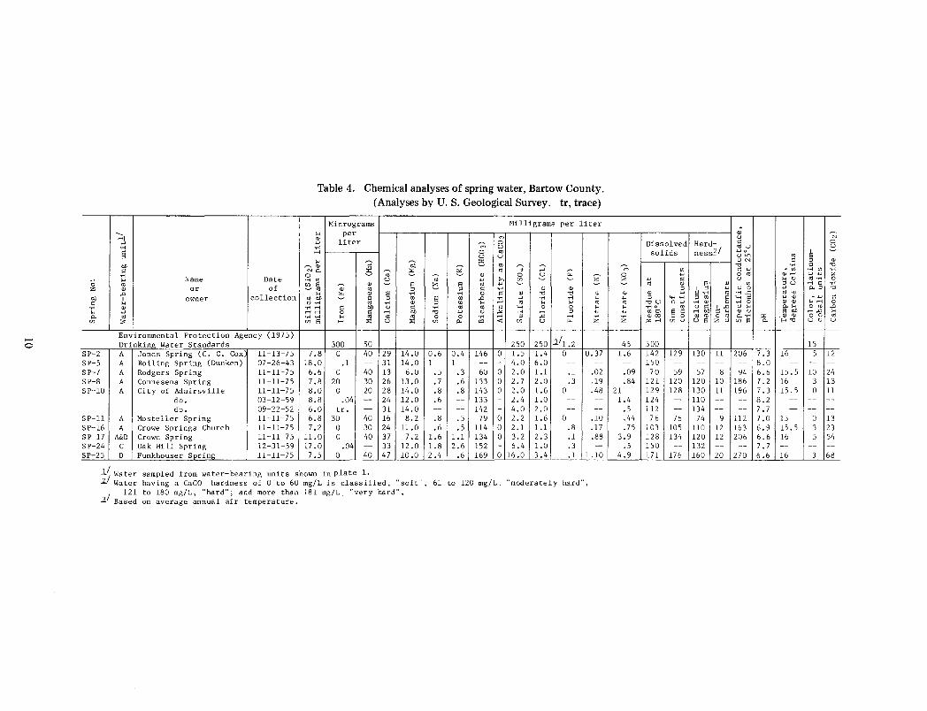
Table 4. Chemical analyses of spring water, Bartow County. (Analyses by U.S. Geological Survey. tr, trace)
Micrograms Milligrams per liter .... per OJ m
'"' liter 0 . ... m u .-< 0 "' u u ....
~ 00 "' ~OJ Q ~ "' ~ ;:; Np. ';;- ::<: "' " ;:: 0 ~ ';;- ~ OJ 0 u z .,.. "' u '"' "' "' ~ ~
"' s a; OJ ~ s z § "' '"' ~ ~
~"' "' " ~ " .... OJ OJ .... rz. OJ s .,.. .... 0 " OJ "0 "0 OJ
"' "" ~ " " "' 9 "' .n .... '"' ·r< or< '"' u ·r< "' •r< OJ "' .... .... "' .... .... "' ·r< .-< " "" u " ·r< "' "' "' .... c 0 .... .-<...-< 0 " ...-< "" "0 '"' u --"' .-< ...-< " '"' •H ·r-1 .... "' "' "' 0 0 ·r< ...-< " .n ..... z "' s H ::<: u ::<: (/) p. "' < (/) u rz.
300 50 250 250 3_1 1.2 7.8 0 40 29 14.0 0.6 0.4 146 0 1.5 1.4 0 0.37
18.0 .1 -- 31 14.0 1 1 -- - 4.0 6.0 -- --
6.6 0 40 13 6.0 .5 .3 60 0 2.0 1.1 .1 .02 7.8 20 30 26 13.0 0 7 .6 133 0 2.7 2.0 .3 .19 8.0 0 20 28 14.0 .8 .8 143 0 2.0 1.6 0 .48 8.8 .04 -- 24 12.0 .6 -- 133 - 2.4 1.0 -- --
6.0 tr. -- 31 14.0 -- -- 142 - 4.0 2.0 -- --
6.8 30 40 16 8.2 .8 .5 79 0 2.2 1.6 0 .10 7.2 0 30 24 11.0 .6 .5 114 0 2.1 l.l .8 .17
11.0 0 40 37 7.2 1.6 1.1 134 0 3.2 2.3 .1 .88 17.0 .04 -- 33 12.0 1.8 2.6 152 - 6.4 1.0 .3 --7.5 0 40 47 10.0 2.4 .6 169 0 16.0 3.4 .1 1.10
~/Water sampled from water-bearing units shown in plate 1. 2./ Water having a CaCO hardness of 0 to 60 mg/L is classified, "soft", 61 to 120 mg/L, "moderately hard",
I 121 to 180 mg/L, "hard"; and more than 181 mg/L. "very hard". 3 Based on average annual air temperature.
,; ~ u
Dissolved Hard- " 0
ness~/ <1lU _::;
solids '-'0 ~ U<n "' ""' " " OJ "0 .... " "0
m "' " '"' . "' .,.. "' .,.. ~ '"' 0 "'
OJ.-< '"''"' " '"' " u .... OJ "'.,.. 0 ~ "' OJ s OJ "' "u .-< "
.... " I " '"' u 0 '"' """ "0
OJ OJ '"' s ·r< {lj •r-i ...c "' "' .... " .... ·r< " "' " .... s .... OJ . '"' " "' "OU 0 '"' ·r< OJ 0 ·r-1 0 OJ OJ .... ..., 0 .... .... 0 "' u " 1.0 u .... p. ....
0 "' .n
'"' <flO s " .... "" " .... OJ u s "" .-<.n .... ..... OJ<Xl " 0 "'"' 0 "' p. ·r< "' ,OJ OJ 0 0 "' z "''"" "' u us z u "' s p. H"O u u u
45 500 15 1.6 142 129 130 11 206 7.3 16 5 12 -- 150 -- -- -- -- 8.0 -- -- --
.09 70 59 57 8 94 6.6 15 0 5 10 24
.84 121 120 120 10 186 7.2 16 3 13 21 129 128 130 11 196 7.3 15.5 0 11 1.4 124 -- 110 -- -- 8.2 -- -- --
.5 112 -- 134 -- -- 7 0 7 -- -- --
.44 76 76 74 9 112 7.0 15 0 13
.75 103 105 110 12 163 6.9 15.5 3 23 3.9 128 134 120 12 206 6.6 16 5 54
.5 150 -- 132 -- -- 7 0 7 -- -- --4.9 171 176 160 20 270 6.6 16 3 68
Two isolated exposures of unit C in southwest Bartow County consist mainly of clay shale in the lower part and silty, micaceous shale and siltstone in the upper part. The exposure north of Taylorsville is of Ordovician age and belongs to the Rockmark Slate. A sample of shale from the west edge of the outcrop (USGS Loc. No. 8813-CO) is interesting because it contains fish fragments. According to Dr. Richard Lund of Adelphi University, "* * * an occasional chip seems to indicate that the structures visible are composed of isolated odontodes. This suggests an affinity with Astraspis and the "other Ordovician Heterostraci, rather than with anything later. The * * * condition of the material makes this very tentative, however."
Shale from this same locality also contained one fragment of a scandodiform conodont element, one orthograptid (?) graptolite mold, and several indeterminate phosphatic brachiopod fragments. Dr. Robert B. Neuman of the U.S. Geological Survey stated that the graptolite mold is of a large biserial form, possibly an orthograptid, which indicates that the sample probably is of Middle Ordovician age.
The exposure of unit C south of the Cartersville airport is lithologically similar to the one north of Taylorsville and probably belongs to the Rockmart Slate.
Near Adairsville, the unit is about 700ft (213 m) thick (Spalvins, 1969, p. 46). It seems to thicken toward the east, and in the Pine Log area the width of the outcrop belt indicates that it probably is more than 1,000 ft (305 m) thick.
The easternmost outcrop belt of the unit, which extends from south of Cartersville northward through White, past Rydal, is composed of gray shale that weathers to shades of tan, pink, and purple. Much of the shale displays a distinctive silver sheen and locally is referred to as silver shale or slate. This part of the unit contains layers of sandstone and siltstone that generally are gray, purple, white, or tan. East of Rydal the sandstone is very hard and occurs in accumulations 30 ft (9.1 m) or more thick and forms low ridges. Poor exposures make determining the thickness of the unit in this area very difficult, but it probably is several hundred feet thick.
The outcrops of the unit that include Johnson Mountain and adjacent ridges 4 mi (6.4 km) northwest of Cartersville, and the ridges west and southwest of Aubrey Lake, are made up of purple, greenish, and dark-gray shale and thin to thick layers of fine- to medium-grained sandstone that weathers to brownish or purple. Cuts made during construction of Interstate 75 revealed that the fresh rock is very calcareous and occurs in a variety of colors including purple, pale red, white, gray, and green.
II
This outcrop area of the unit is irregular in shape, because it forms the upper plate of a flat-lying thrust fault that displaced the shale and sandstone of unit C westward into a position above the younger dolomite of unit D. A gravity survey conducted along the valley of Pettit Creek (plate 4) revealed that the shale and sandstone in that area are thin-probably less than 100 ft (30 m) thick-and the outcrop pattern of the unit indicates that the thrust sheet probably ranges between 100 and 400ft (30 and 122 m) thick. This means that in the thinner parts of the thrust sheet it may be practical to drill through the low-yielding rocks of unit C and derive as much as several hundred gallons per minute from the underlying dolomite of unit D.
The easternmost outcrop belt of the unit and the overthrust sheet at Johnson Mountain are both part of the Rome Formation of Early and Middle Cambrian age.
Water-bearing character-Most wells yield between 2 and 15 gal/min (0.1 and 0.9 L/s). Domestic and stock supplies generally are available in valley areas and on gentle slopes where randomly located wells have about a 60-percent chance of furnishing 5 gal/ min (0.3 L/ s). Wells on hills, ridges, and steep slopes commonly have inadequate yields, and some property owners in these areas have found it necessary to drill two or three wells.
Experience has shown that yields of 20 to 70 gal/min (1.3 to 4.4. L/s) can be developed from selected sites in the few areas where the unit includes thick sections of dolomite or limestone. These areas generally can be identified by the presence of limestone or dolomite cropping out in stream channels or along a valley floor. Well 97 (plate 1), which is in the valley north of Pine Log, yields 70 gal/ min ( 4.4 L/s) from limestone.
Wells in the unit range in depth from 50 to 558 ft (15 to 170m) and have an average depth of about 182 ft (55 m). Casing depths range from about 18 to 235 ft (5.5 to 72 m).
Depending upon the type of rock from which it comes, the well water varies from soft to very hard. Most of the water probably contains low to moderate concentrations of iron, as only a few well owners voiced objections about the amount of iron in their water.
Water-Bearing Unit D
Character of the rock-The composition and thickness of unit D varies greatly from one outcrop belt to another. In the belt that lies adjacent to water-bearing unit A (plate 1 ), it ranges from about 50 to 300 ft ( 15 to 91 m) thick and consists of thinly to massively bedded dolomite, commonly interlayered with clayey
limestone. In a few places, dark-gray limestone becomes the dominant rock type, and in others a few feet of dark-gray shale occurs near the top. The upper part of the unit contains abundant layers and nodules of black chert that contrast sharply with the light-gray chert in the overlying unit A, a fact that is helpful in distinguishing the two units.
The belt of the unit that crops out next to unit A is a rough equivalent of the Maynardville Limestone Member of the Conasauga Formation. The remainder of the unit belongs to the middle and lower parts of the Conasauga of Middle and Late Cambrian age.
The unit D that is exposed within the outcrop belts of unit C, north and west of Cassville and at Adairsville, consists of thin- to thick-bedded gray limestone. It has a maximum thickness of about 600 ft ( 183 m), but may be much thinner where it is bounded by a major fault (Spalvins, 1969, p. 4 7).
The eastern outcrop belt of the unit that extends from Cartersville and Rodgers northeastward, nearly to the Gordon County line, is composed mainly of thin- to massive-bedded, light- to medium-gray dolomite and some brown dolomite, probably between 500 and 1,000 ft (152 and 305 m) thick. The dolomite locally is oolitic and nearly all exposures are distinctively marked by pink or reddish bedding, joint planes, and stylolites. Some of the dolomite contains layers and nodules of dark, rarely oolitic chert. Good exposures of the dolomite can be viewed in the quarry north of White and along Nancy Creek at Rodgers. Southeast of Bolivar, thin- to massive-bedded gray impure limestone makes up sections 100 ft (30 m) or more thick at the top of the dolomite. In a few places, such as in the valley of Pine Log Creek near U.S. Highway 411, beds of gray limestone are interlayered with beds of dolomite to produce a banded rock similar in appearance to that in the belts farther west.
Much of the dolomite in the eastern belt contains abundant silica that chemical weathering converts to a hard chert-like rock called jasperoid. Small pieces of dense gray jasperoid are scattered about most of the outcrop area, and where faulting or tight folding has produced appreciable rock fracturing, masses as large as automobiles accumulate in the soil and locally form sizable ridges. North of Cartersville, and in Peoples Valley, massive jasperoid produces ridges of moderate relief. In some areas, especially in the southern part of the outcrop area, the jasperoid is recrystallized, has a fine- to medium-grained texture, and is easily mistaken for quartzite.
Because the jasperoid in unit D has a somewhat similar appearance to that in unit F, the two are sometimes confused. As a rule, however, freshly broken pieces of jasperoid from unit D are gray, whereas those from unit F tend to be tan or brown.
12
Water-bearing character-Unit D furnishes ample water nearly everywhere for domestic and stock supplies. Randomly located wells have about an 80-percent chance of producing 5 galjmin (0.3 L/s). The unit also is an important source of industrial and municipal supplies. Nineteen wells in the unit have an average yield of about 70 gal/min (4.4 L/s); the largest yield reported is 200 gal I min ( 13 LIs).
The only problems reported in developing well supplies in the unit were in the Bolivar area, where a resident had to drill two wells before he found enough water for a home supply. Wells east and southeast of Bolivar are reported to remain muddy for long periods after being drilled, and some never clear.
Thirty wells inventoried in the unit have an average depth of about 153 ft (47 m). About 90 percent of these wells are less than 250 ft (76 m) deep; the deepest well reported is 510 ft ( 155 m). The wells are cased to bedrock, generally 10 to 314ft (3 to 96 m) deep, and the bottom of the well is left an open hole that admits water from joints, fractures, and solution openings.
Water in the unit is moderately hard to very hard, generally contains low concentrations of iron, and is suitable for most uses.
Water-Bearing Unit F
Character of the rock-Unit F is between 300 and 500 ft (91 and 152 m) thick, consists of thinly to massively bedded light-gray to dark-gray dolomite and dolomitic limestone, and belongs to the Shady Dolomite of Early and Middle Cambrian age. The upper part of the unit includes thin layers and laminations of dark-gray shale (or phyllite?) that weather to shades of pink and have a silvery sheen nearly identical to some of the shale in overlying unit C.
The dolomite is highly siliceous, and in a weathering environment the silica accumulates in the soil as generally hard jasperoid. Pieces of this material can be seen scattered about the area and, where deformation is intense, it occurs in dense masses that form hills and ridges. The jasperoid is similar in character and appearance to that in unit 0, except that it commonly weathers to tan or brown, rather than gray.
Most, if not the entire section, of dolomite contains barite (BaSo 4 ) that has weathered out of the rock and been concentrated by erosional processes in the thick residual soil that is prevalent over the unit. Recovery of this barite has left the Cartersville area dotted with circular and elongate open-pit mines, some of the larger ones extending to depths of 50 and 100 ft (15 to 30 m). Most of the larger mines are hydraulically connected with the underlying dolomite.
The Bartow County landfill occupies one of these abandoned mines and several others are being considered for use as disposal sites for solid waste. The use of the mines for this purpose may contaminate ground water in the area, and the problem is discussed more fully in other sections of this report.
Water-bearing character-Unit F is the principal source of industrial ground-water supplies in Cartersville. Seven industrial wells in the city yield 150 to 1,500 gal/min (9.5 to 95 L/s). The aquifer underlies much of eastern and southern Cartersville where it seems to has large undeveloped potential. Broad, level areas underlain by the unit (indicated as es on plate 4) south of Oakland Heights and south of Buford Mountain have intermittent surface drainage with large catchment areas, and should supply sizable yields to wells.
Outside the city limits of Cartersville, most of the area underlain by unit F is devoted to farming and mining, or is woodland, so that the unit is little used as an aquifer. It is tapped in this area by only a few dug wells and two drilled wells, all of which are used for domestic supply. As the surface of the unit is fairly flat-lying, however, it seems likely that farm and home supplies should be readily available nearly everywhere. Judging from aquifers of similar nature, randomly located wells probably will have about an SO-percent chance of furnishing 5 gal/min (0.3 L/s).
Wells in the unit range from 80 to 300 ft (24 to 91 m) deep and have an average depth of 150ft (46 m). Their casing depths range from 30 to 70 ft (9.1 to 21 m) and are set in solid rock. All the wells derive water from solution-enlarged openings in dolomite, some of which are rather large and supply 300 galjmin (19 L/s) or more with almost no drawdown. Well 38 (plate 1) obtains water froTll an opening 29ft (8.8 m) high.
Water from the unit is moderately hard to hard and contains small concentrations of iron. The water is suitable for drinking and for many industrial uses.
The residual soil developed on unit F commonly is 50 to 100 ft (15 to 30 m) or more thick, is porous, and absorbs large quantities of precipitation, which it holds in storage for gradual release to solution openings in the underlying dolomite. The continual release of water from the residuum enables the aquifer to sustain large yields to wells, even through prolonged droughts. It is the thickness and character of the residuum that makes this unit the area's highest yielding aquifer. During 1976, wells in the unit supplied industries with a total of more than 3,000 gal/min (189 L/s).
13
Water-Bearing Unit G
Character of the rock-Unit G, in Bartow and western Cherokee Counties, consists mainly of quartzite, phyllite, shale, and arkose. West of the Great Smoky fault (plate 4) the quartzite is light to dark gray, buff to brown weathering, mostly fine grained, and locally conglomeratic. On natural exposures the thicker quartzite layers are resistant, forming ledges and low cliffs. In quarries and road cuts, on the other hand, the quartzite generally is close jointed and breaks up into small angular fragments, producing an abundance of rubble. Near the top of the unit the quartzite has a high clay and feldspar content, and generally is friable enough to be easily worked by earth-moving equipment. Decomposed quartzite and weathered shale are used for cover material in the Bartow County landfill. The part of the unit west of the Great Smoky fault belongs to the Chilhowee Group of Early Cambrian age.
East of the Great Smoky fault, quartzite in the unit is fine to coarse grained, locally conglomeratic and commonly feldspathic, particularly on the lower west slope of Pine Log Mountain where it contains feldspar in crystals more than 1 in. (25 mm) across. This quartzite tends to be very massive and remains so in both natural and manmade exposures. The basal part of the quartzite in several areas is arkosic, and the belt of the unit that passes along the east side of Lake Arrowhead in northwest Cherokee County is largely arkose.
Phyllite and shale in the unit west of the Great Smoky fault are dark gray and locally contain graphite. They are rather hard and brittle where fresh, but become conspicuously light gray to white and very soft upon weathering. East of the fault the phyllite is dark gray to black where fresh, and becomes medium gray to tan or pink when weathered; it rarely, if ever, assumes a light-gray to white character.
Much of the dark phyllite east of the fault in Bartow and western Cherokee Counties, particularly in the lower two-thirds of the section, weathers to a distinctive copper color. Copper-colored phyllite characterizes the unit east of the fault from the southernmost exposures near Emerson in Bartow County, along the full length of Hanging, Pine Log, and Dry Pond Mountains in Cherokee County, and beyond into Pickens County. The rocks in this belt of the unit probably belong to the Ocoee Supergroup of Precambrian age.
Belts of the unit in eastern Cherokee County and in Forsyth County consist of highly feldspathic and micaceous to almost pure fine- to coarse-grained
quartzite that is thinly to massively bedded. The quartzite is steeply inclined to the southeast and as a result, forms narrow ridges that have high, vertical cliffs at several places along their northwest sides.
The total thickness of the unit has never been determined, largely because faulting and folding cause duplication of the section. Judging from the width of the outcrop belts, the unit probably ranges from 100 ft (30 m) thick on narrow ridges to 1,000 ft (305 m) or more thick on broad exposures.
Water-bearing character-The rocks that make up unit G are very resistant to erosion and form narrow ridges and mountainous areas dissected by steep-sided "V"-shaped valleys. This rugged terrane is largely uninhabited; consequently, aquifer development has occurred only in a few isolated places.
In the localities where the topography is flat enough for farming, or level enough for home building, randomly located wells probably have about a 40-percent chance of supplying 5 gal/min (0.3 L/s). Wells drilled on steep slopes, narrow-crested ridges, and near scarp slopes are likely to be unsatisfactory for a residential supply, although domestic wells have been developed on the long dip slopes of moderately high ridges in Forsyth County.
The development of a water supply for the Lake Arrowhead resort community in northwest Cherokee County provided. the first information to become available about the water-yielding potential of the western outcrop belts of unit G. Fifteen wells drilled on the property range in yield from 1 to 200 gal/ min (0.06 to 13 L/s) and have an average yield of about 60 gal/min (4 L/s). Six of the wells yield 40 gal/min (2.5 Ljs) or more. The wells range in depth from 92 to 338 ft (28 to 103 m) and are cased to depths of 25 to 64 ft (7.6 to 20 m).
In Forsyth County where the unit is comparatively thin and steeply dipping, it forms long, narrow ridges. Wells on the ridge crests yield very little water, but those drilled at or near the east (down-dip) base of the ridges yield as much as 150 gal/min (9.5 L/s).
Large capacity wells in unit G have been developed thus far only in specific geologic and topographic settings. Methods of locating favorable well sites are discussed in detail in a later section of this report dealing with high-yielding wells.
Water from unit G ranges from soft to hard and generally is of good chemical quality. The low iron content of most of the well water makes it suitable for household use and for many other purposes.
Water-Bearing Unit J
Character of the rock-In Bartow County, unit J consists of silvery and dark-gray phyllite and fine-
14
grained schist that commonly contain graphite. The age of the unit is uncertain. The dark phyllite layers generally contain abundant pyrite cubes. Thin beds of quartzite and graywacke are widespread, and locally occur in sections 10 to 20 ft (3 to 6.1 m) thick that form ledges on steep slopes. South of Cartersville the unit includes thick layers of mylonite (rock ground to a fine texture) and light-colored phyllite and finegrained schist. That area also is marked by layers, probably several hundred feet thick, made up of dark-gray to black graphite schist.
The belts of the unit in western Cherokee County (plate 2) are of similar character to those in Bartow County, but toward the east the proportion of quartzite and graywacke lessens and the schist develops a distinctive knobby appearance due to the inclusion of large garnets. In central and eastern Cherokee County and in Forsyth County (plate 3) the outcrop areas of the unit are far less rugged than those farther west. The land is more suitable for farming and, thus, is much more populated.
The thickness of unit J varies greatly from one belt to another, but it probably ranges from several hundred to more than a thousand feet thick.
Water-bearing character-Ten wells in unit J produce between 1.5 and 25 gal/min (0.09 and 1.6 L/s). The quantity of water available in the unit is determined largely by the topography. In the rugged terrane of the western outcrop belt, dependable domestic supplies can be obtained only on the broader ridge crests and hilltops and in saddles and valleys between ridges. In central and eastern Cherokee County and in Forsyth County, where the unit is characterized by rounded hills and gentle slopes, residential and stock wells can be developed nearly everywhere. Randomly located wells in these areas probably have about a 40-percent chance of supplying 5 gal/min (0.3 L/s). The highest yields are obtained from wells that penetrate fractured layers of quartzite or graywacke.
Although the wells in the unit that were measured range from 86 to 450 ft (26 to 137 m) deep, all that supply more than 5 gal/min (0.3 L/s) are less than 166ft (51 m) deep. Casing depths range between 29 and 85 ft (8.8 and 25 m), below which the wells are finished as open holes in rock.
Water from unit J generally is soft and has low concentrations of total dissolved solids. The water from most wells is somewhat corrosive, having a pH less than 7 (table 1). In addition, it is moderately mineralized but is suitable for household use and for many other purposes.
Water-Bearing Unit K
Character of the rock-Unit K is composed chiefly of
gneiss. One large area that extends from southeast Bartow County into Cherokee County past the west side of Lake Arrowhead is an augen gneiss, commonly known as Corbin Granite (plate 4). In the southeast corner of Bartow County and in Cherokee and Forsyth Counties, unit K includes bodies of granite gneiss and biotite gneiss, all of uncertain age.
The thickness of the unit has never been accurately . determined. It is thought to vary greatly in thickness from one outcrop belt to another, but everywhere it probably is several hundred feet thick and, in places, may be several thousand feet thick.
Water-bearing character-Inventoried wells in unit K yield from 2 to 35 gal/min (0.1 to 2.2 L/s). Twenty-one measured wells are between 40 and 500 ft (12 and 152m) deep, and have an average depth of about 147ft (45 m). Nearly 90 percent of the wells are less than 250 ft (76 m) deep. The wells are cased from as little as 5 ft (1.5 m) to as much as 130ft (40 m) deep, the remainder being finished as open holes in rock.
Domestic and stock supplies can be developed in nearly all areas of the unit except on narrow ridges, and public-supply wells yielding more than 20 gal; min (1.3 Ljs) are common. Yields of 15 to 20 galjmin (0.9 to 1.3 L/ s) can be expected from wells in favorable topographic settings. The chance of obtaining 5 galjmin (0.3 Ljs) from randomly located wells probably is about 60 percent.
The well water generally is soft and most is reported to be satisfactory for household use and stock watering. The concentration of iron in the water generally is low, although water from two wells contained 280 and 450 JJ.gj L (table I).
Water-Bearing Unit L
Character of the rock-The unit is predominantly a garnet-mica schist, but between Waleska and Sharptop it also contains much mica schist speckled with minute grains of opaque minerals, interlayered with thin-bedded graywacke. In the belt that passes through North Canton and in other exposures north of there, the garnet-mica schist is interlayered with thinly to thickly bedded quartzite that occurs in masses 10 to 20 ft (3 to 6.1 m) or more thick. The rocks in this unit probably correlate with the Great Smoky Group, the age of which has not been determined.
The presence of thick layers of quartzite and graywacke in the mica schist may be indicated by the presence of rock fragments in the soil, or by the occurrence of narrow ridges that stand in relief above the surrounding country. Thinner layers may not be
15
apparent from debris in the soil, but are exposed in road cuts and along stream banks.
Water-bearing character-Twenty wells in unit L yield from 2 to 32 gal/min (0.1 to 2.0 Ljs), and are used almost exclusively for farm and home supply. Yields of 3 gal/min (0.2 L/s) or more generally can be developed anywhere in the area that is level enough for farming and in most places that people choose for homesites. However, randomly located wells probably have only about a 40-percent chance of furnishing 5 gal(min (0.3 Lfs), so special construction problems may be involved in developing an adequate home supply. Wells supplying larger yields probably obtain water from fractured rocks, such as quartzite and graywacke, that are scattered throughout much of the unit. The brittle rock layers dip steeply to the south or southeast, thus the chance of obtaining 5 gal/min (0.3 L/s) or more should be substantially increased by selecting drilling sites where the wells will penetrate these layers at some depth between about 100 and 200 ft (30 and 60 m). The largest yields will come from rock layers that project toward the surface beneath some potential source of recharge, such as a stream valley or a relatively flat area covered by deep soil.
The wells range from 72 to 400ft (22 to 122m) deep, having an average depth of about 160ft (49 m). Casing depths range from 15 to 112ft (4.6 to 34m), below which the wells are finished as open holes.
The well water generally is soft, contains low concentrations of iron and other constituents, and meets drinking water standards. Only one well in the unit was reported to produce water containing excess iron.
Water-Bearing Unit N
Character of the rock-In southeast Bartow County and in Cherokee County, unit N is chiefly hornblende gneiss and schist interlayed with amphibolite. In Forsyth County it is mainly amphibolite and hornblende gneiss. The amphibolite generally is a massive homogeneous rock that locally contains zones of closely spaced joints and fractures that increase permeability and supply large quantities of water.
Water-bearing character-Fourteen wells in unit N yield between 0.5 and 15 gal/min (0.03 and 0.9 L/s). Domestic supplies can be developed in most outcrop areas, but owing to the homogeneous character of the rock, topographic position is critical. For this reason, randomly located wells have only about a 40-percent chance of supplying 5 gal( min (0.3 Lfs). The wells range in depth from 50 to 240ft (15 to 73 m).
Three public supply wells drilled in favorable topographic and structural sites each furnish 200
gal/min (13 Ljs). Two of the wells, Forsyth County 32 and 33, derive water from a highly permeable zone of fracture concentration that appears as a straight valley segment on topographic maps. The presence of similar valley segments in the area indicates that it may be possible to locate wells of comparable yield in other places underlain by the unit, and this is discussed further in the section about high-yielding wells.
The other high-yielding well, Cherokee County 12, penetrated massive bedrock and remained dry for the first 525 ft (160 m), at which point it intersected a water-filled fracture that yielded 200 galjmin (13 L/s). The fracture probably is related to a fault that passes west of the well site.
Water-Bearing Unit P
Character of the rock-Unit P consists of gneiss, schist, and amphibolite of uncertain age interlayed in varying thicknesses and proportions. The rocks are steeply dipping and, consequently, most wells in the unit derive water from two or more lithologies. As thick soil obscures the bedrock in most areas, there generally is no easy way to predict in advance what type of rock a well will penetrate.
The thickness of the unit has never been measured. It probably is hundreds, if not thousands of feet thick.
Water-bearing character-Thirty-one wells for which records were collected in unit P yield from 0 to 90 gal/min (0 to 5.7 L/s). Domestic supplies can be obtained in most of the area, although several wells, mainly on steep slopes and narrow ridges, are reported to have insufficient yields. Randomly located wells probably have about a 60-percent chance of furnishing 5 galjmin (0.3 L/s).
The wells range in depth from 68 to 985 ft (21 to 300 m) and have an average depth of about 329 ft (100m). Casing depths range from 20 to 139ft (6.1 to 42 m), and the wells are completed as open holes in rock.
About 30 percent of the wells, for which records were collected in unit P, are deeper than 500 ft (!52 m). This is by far the highest percentage of wells this deep found in any of the water-bearing units. As all of these wells furnished less water than their owners needed, drilling apparently was continued to great depths in the hope of increasing the yield. Most wells in the unit that are deeper than 500 ft (!52 m) supply between 0 and 6 gal/min (0 and 0.4 L/s). For example, Forsyth County well 10 is 505ft (154m) deep and yields almost no water; well 27 is 755 ft (230 m) deep and yields only 0.5 gal/min (0.03 Ljs); well 19 is 820ft (250m) deep and supplies only 6 gal/min
16
(0.4 L/s); and, well 23 is 985ft (300m) deep and furnishes 5 gal/min (0.3 L/s).
The limited productivity of these wells indicates that drilling deeper than 500 ft (!52 m) has only a slight chance of increasing the yield beyond the 0 to 5 gal/min (0 to 0.3 L/s) range. In general, a 500-ft well (153m) that has not produced the required amount of water should be abandoned in favor of a new location.
The well water from unit P generally is soft and moderately mineralized and is suitable for domestic and farm use. Wells that penetrate local mineralized zones may yield water very high in some constituents. Water from well 34 in Forsyth County had an iron concentration of 14,000 pgj L and a manganese concentration of I ,500 pg 1 L, both of which greatly exceed the recommended limits for drinking water. The presence of such mineralized zones generally is not detectable in advance of drilling.
USE OF GROUND WATER
The distribution of water by public utilities is limited to the larger towns and to areas along some of the main roads, leaving thousands of rural residents totally dependent upon ground water. In addition, many dairies, poultry houses, farms, churches, schools, industries, and others also rely on ground water.
Wells
Well water is used by the towns of Kingston and White and by most rural residences and farms in the area. Wells are used by many industries, chiefly because the water is economical and has a realtively constant temperature and chemical quality.
Recreation areas around Lake Sidney Lanier and Allatoona Lake, and the Lake Arrowhead resort community, are totally dependent upon well supplies. Hundreds of permanent and vacation homes, numerous subdivisions, trailer parks, campgrounds, and marinas also use well water.
Springs
The largest single source of ground water in Bartow County is springs in the Valley and Ridge province (table 4 and plate I) that discharge between 200 and 3,000 gal/min (13 and 190 L/s). The city of Adairsville derives its municipal supply from a spring, and the town of Emerson reportedly is developing a spring supply. Several springs in the county furnish water to homes, farms, and churches.
Spring water offers the advantages of being readily available, inexpensive to develop, and fairly constant in temperature, chemical quality, and rate of discharge. Most springs in Bartow County are unused and represent potentially valuable undeveloped resources.
The crystalline rocks in the Piedmont part of the report area are characterized by a large number of small springs, nearly all of which are being used for domestic supplies or for stock watering. Although the springs experience yearly fluctuations in flow, their yields are reported to be very dependable.
CHEMICAL QUALITY OF GROUND WATER
The chemical quality of ground water in the study area varies significantly, depending mainly on the type of rock that forms the water-bearing units. In general, the water is moderately mineralized and is suitable for drinking and for most other purposes. Some of the water can be treated chemically to improve its taste, prevent it from staining, or make it softer.
Analyses of water from 61 wells and 10 springs in the study area are listed in tables I, 2, and 4. These analyses show that a few wells yield water containing one or more constituents in concentrations greater than the limits recommended for drinking water by the Environmental Protection Agency ( 1975). Of the 61 wells sampled, five contain excessive concentrations of iron, eight contain excessive maganese, one contains excessive sulfate, and one contains excessive dissolved solids (as residue at 180° C).
The quality of ground water in the sedimentary rocks in Bartow County is strongly dependent upon the composition of the water-bearing units. Sandstones and shales of units C and G produce water that ranges from soft [0 to 60 mgj L (milligrams per liter)] to very hard (greater than 180 mg/ L), and that generally is slightly acidic to near neutral (4.5 to 7.5 pH). Limestones and dolomites of units A, D, and F produce water ranging from hard (121 to 180 mg/L) to very hard (greater than 180 mg/L) and from slightly acidic to alkaline (greater than 6.5 pH).
Ground water from the crystalline rocks of Cherokee and Forsyth Counties and eastern Bartow County is generally soft (0 to 60 mg/ L) to moderately hard (61 to 120 mg/L), and acidic to near neutral (3.8 to 7.5 pH). Some of this water contains enough iron to cause staining of fixtures and clothing. Ground water from isolated mineralized zones is high in sulfate, hardness, and specific conductance.
FLUCTUATIONS IN SPRING FLOW
Spring flows in northwest Georgia fluctuate throughout the year in response to seasonal variations
17
in precipitation. Most springs reach a period of maximum discharge sometime during the winter or early spring and decline steadily to a period of minimum discharge that generally occurs in autumn. The minimum discharge may be 20 to 90 percent less than the maximum discharge. A potential user may need to know a spring's minimum rate of discharge in order to determine whether or not it will meet his year-round needs.
Measurements and estimates of spring discharge in Bartow County are given in table 3. Nearly all the measurements were made in late summer or autumn, so the smallest discharge listed for a spring generally will be close to its lowest discharge for the year of measurement. If the smallest flow listed for a spring approaches the quantity of water required for an intended use however, additional measurements should be made to insure that the supply will remain adequate all year. Measurements made on a spring biweekly from August through December should indicate the lowest discharge for that year. Some variation in lowest discharge can be expected from year to year, but it generally will be small unless rainfall is far heavier or lighter than normal.
Periodic measurements spanning more than 25 years in the Valley and Ridge area of Georgia indicate that the lowest discharge for most springs comes in late October or early November (Cressler and others, 1976). The time and duration of a spring's lowest discharge each year is largely determined by the character and thickness of the soil layer that overlies the spring's source. In general, the thicker the soil that overlies the rock unit supplying the spring, the greater the lag time between changes in precipitation and corresponding changes in spring flow. Lag time may range from as short as a few hours to as long as several months.
LAND SUBSIDENCE AND SINKHOLE FORMATION
The possibility of creating conditions that could lead to ground collapse should be considered in developing well supplies. The major water-bearing units in Bartow County consist of carbonate rocks that are deeply weathered and blanketed by a thick layer of residual soil. Ground-water solutioning has formed cavities in the carbonate rocks, and some of these cavities have thin soil roofs. Many of these cavities extend below the water table and their roofs are partially supported by the ground water. Any decline in the water table that removes this support can result in a sudden collapse. A lowering of the water table also can cause a gradual downward migration, or spalling, of soil into openings in the underlying carbonate rocks, leaving dome-shaped
cavities between the bedrock and the land surface (fig. 6). Upward enlargement of these cavities by the continued loss of soil into rock openings can result in the eventual collapse of the surface and the formation of a sinkhole (Newton and Hyde, 1971). Also, water-level declines unbalance the pore water pressures, resulting in the spalling of the base of clay plugs. Repeated declines cause stoping action and collapse.
Land subsidence and sinkhole formation also may result where large quantities of sediment or rock fragments are removed from water-yielding formations during drilling, well development, and production pumping. Subsidence is most likely to occur where: (1) the water table stands within the residual soil, or near the top of highly weathered bedrock, (2) well casing does not extend deep enough into the top of the bedrock, (3) large volumes of water are pumped from shallow depths, and (4) violent surging occurs during drilling. Collapse resulting from drilling is more common where the water table stands in residual soils (Parizek, 1971, p. 141-142). The relative risk of sinkholes forming near pumping centers in Bartow County is shown in figure 2.
GROUND-WATER POLLUTION Pollution of Wells
A study of the private water supplies in Bartow County (Davis, 1969, p. 11-12) revealed that bacterial pollution of private wells is widespread. Davis found coliform bacteria in 84 percent of the 55 dug wells he sampled, and in 22 percent of the I 0 I drilled wells sampled. Morever, 8 percent of these drilled wells showed evidence of fecal coliform bacteria, an indicator of comparatively recent, potentially dangerous pollution.
According to Davis, improper well construction was found to be the major cause of pollution in the drilled wells, even though their casings were set in carbonate or shale. The wells surveyed by Davis ranged in depth from 47 to 328 ft (14 to 100m). He found that 52 percent of the polluted wells had no apparent sanitary seal between the well casing and the surrounding soil, and 69 percent lacked a sanitary seal at the top of the casing. Thus, many poorly constructed wells are contaminated by surface water that leaks down between the casing and the surrounding soil.
The widespread pollution of wells results, in part, from the common practice of locating drilling sites for convenience rather than for protection of the water supply. Generally, wells are located as close as possible to homes or barns without regard to potential sources of pollution. Located in this manner, many
18
poorly constructed or shallow wells are subject to pollution.
The well sites that are least likely to become polluted are those located, as far as practical, upgradient from sources of contamination. Sealing wells against the entry of surface water and fitting pump caps tightly to keep out insects, rodents, and other impurities, are also necessary safety measures to protect wells from contamination.
No detailed study has been made of well pollution in Cherokee and Forsyth Counties, but wells there are subject to contamination in much the same way as those in Bartow County. Faulty well construction and improper site selection may result in about the same percentage of polluted wells.
A common practice in the area is to sterilize newly completed wells with laundry bleach, pump them until the bleach is removed, and then test the water for bacterial contamination. Nearly all new wells tested in this manner are found to be free of bacteria. The risk of contamination increases, however, after wells have been in use for a while, because pumping lowers the water table and this may eventually cause septic-tank effluent, barnyard runoff, or other contaminants to be drawn toward the well. Furthermore, lowering of the water table in carbonate rock aquifers such as units A, D, and F may cause sinkholes to form, thereby increasing the potential for polluted surface water to reach the ground-water reservoir. Some sinkholes are so small they go unnoticed, but they can quickly contaminate a water supply. Periodic testing for bacteria is the best means for detecting contamination of a water supply.
Pollution of Springs
Pollution of springs is widespread in Bartow County. Davis ( 1969, p. 17) sampled 19 springs in the county and found that 15 were contaminated by coliform bacteria, three of which contained fecal coliform bacteria.
All spring pools probably are contaminated at least part of the time, because they are favorite watering places for livestock and wildlife. In general, springs that discharge from rock fractures, through gravel, or from cave entrances protected from entry by humans or animals, are the least likely to be polluted. Nearly all springs in Cherokee and Forsyth Counties are of this type, so contamination is not as likely there as it is in Bartow County. A safe practice is to test spring water before using it for drinking or for water supply. County health departments will provide information and assistance for having spring water tested. Because uncontaminated springs may become polluted with changing conditions, such as when

Base f rom U.S.Geologicol Survey 5 Rome 1'250,000, 1958 :
I I 5
I l··r
0
0
E X p L
84° 45 ' I ,.,., .. ,.··==·'~=
I
5 10 MILES
1----~ 5 10 15 KILOMETERS
A NAT I 0 N
RELATIVE RISK OF Sl NKHOLES FORMING NEAR HIGH-YIELDING WELLS
-D MODERATE TO HIGH- During develop
ment and production
LOW TO MODERATE- Most I ikely to occur after weeks or months of pumping
SLIGHT- Except where carbonate rock occurs in or beneath unit, mak ing the risk MODERATE, mainly after long pumping period
.___ _ ___.·j NONE-Sinkholes ar.e not know to _ _ occur
Figure 2 . Relative risk of sinkholes forming near high-yielding wells in Bartow County.
19
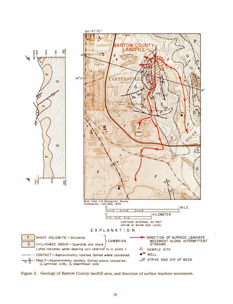
Base from U.S. Geolog i col Surve y Cartersville I ' 24 , 000, 1972
Or--.--.---.--.---.--------------~IMILE F"""3 F"""3 F"""3 I 0;---,--,--,--r-l,-------il K I LOM ETE R H H H
CONTOUR INTERVAL 20 FEET DATUM IS MEAN SEA LEVEL
EXPLANATION
I F I SHADY DOLOMITE-Dolomite } CAMBRIAN
{: : ~/::j CHILHOWEE GROUP-Quartzite and shale
Letter indicates water-bearing un it referred to in plate I
--···· CONTACT-Approximately located . Dotted where concealed
~ ~···FAULT-Approximately locately . Dotted where concealed . U, upthrown side; D, downthrown side
--~~-- DIRECTION OF SURFACE LEACHATE MOVEMENT ALONG INTERMITTENT STREAMS
£::. SAMPLE SITE
e 38 WELL
~ STRIKE AND DIP OF BEDS
Figure 3. Geology of Bartow County landfill area, and direction of surface leachate movement.
20
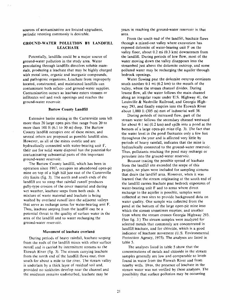
sources of i>Ontamination are located upgradient, periodic retesting commonly is desirable.
GROUND-WATER POLLUTION BY LANDFILL LEACHATE
Potentially, landfills could be a major source of ground-water pollution in the study area. Water percolating through landfills dissolves soluble materials, producing a leachate that may be highly charged with metal ions, organic and inorganic compounds, and pathogenic organisms .. Leachate from improperly located, constructed, and maintained landfills can contaminate both suface- and ground-water supplies. Contamination occurs as leachate enters streams or infiltrates soil and rock openings and reaches the ground-water reservoir.
Bartow County Landfill
Extensive barite mining in the Cartersville area left more than 20 large open pits that range from 20 to more than 100ft (6.1 to 30 m) deep. The Bartow County landfill occupies one of these mines, and several others are proposed as possible landfill sites. However, as all of the mines overlie and are hydraulically connected with water-bearing unit F, their use for solid waste disposal has the potential for contaminating substantial parts of this important ground-water reservoir.
The Bartow County landfill, which has been in operation since 1967, occupies an abandoned open-pit mine on top of a high hill just east of the Cartersville city limits (fig. 3). The north and south ends of the landfill are so steep that rainfall runoff produces gully-type erosion of the cover material and during wet weather, leachate seeps from both ends. A mixture of waste material and leachate is being washed by overland runoff into the adjacent valleys that serve as recharge areas for water-bearing unit F. Thus, leachate seeping from the landfill can be a potential threat to the quality of surface water in the area of the landfill and to water recharging the ground-water reservoir.
Movement of leachate overland
During periods of heavy rainfall, leachate seeping from the ends of the landfill mixes with other surface runoff and is carried by intermittent streams to the Etowah River (fig. 3). The stream carrying leachate from the north end of the landfill flows east,. then south for about a mile to the river. The stream valley is underlain by a thick layer of residual soil and, provided no sinkholes develop near the channel and the residuum remains undisturbed, leachate may be
21
years in reaching the ground-water reservoir in that area.
From the south end of the landfill, leachate flows through a mined-out valley where excavation has exposed dolomite of water-bearing unit F on the valley floor, about 0.2 mi (0.3 km) downstream from the landfill. During periods of low flow, most of the water moving down the .valley disappears into the streambed just above the dolomite outcrop, and some polluted water may be recharging the aquifer through bedrock openings.
Water flowing past the dolomite outcrop continues south another 0.1 mi (0.2 km) to the mouth of the valley, where the stream channel divides. During lowest flow, all the water follows the main channel along an irregular route under U.S. Highway 41, the Louisville & Nashville Railroad, and Georgia Highway 293, and finally empties into the Etowah River about 1,000 ft (305 m) east of industrial well 38.
During periods of increased flow, part of the stream water follows the secondary channel westward for about 0.1 mi (0.2 km) and spills into a pond at the bottom of a large open-pit mine (fig. 3). The fact that the water level in the pond fluctuates only a few feet throughout the year and is affected very little by periods of heavy rainfall, indicates that the mine is hydraulically connected to the ground-water reservoir. Thus, pollutants reaching the pond may recharge or percolate into the ground-water reservoir.
Because tracing the possible spread of leachate from the landfill site exceeded the scope of this project, no plans were included for sampling streams that drain the landfill area. However, when it was learned that the stream originating at the south end of the landfill carries leachate past bedrock exposures of water-bearing unit F and to areas where direct recharge to the aquifer is possible, samples were collected at two sites to provide background data on water quality. One sample was collected from the pond at the bottom of the large open-pit mine into which the stream sometimes empties, and another from where the stream crosses Georgia Highway 293. (See fig. 3.) The stream samples were analyzed for selected metals that commonly are concentrated in landfill leachate, and for chloride, which is a good indicator of leachate movement (U.S. Environmental Protection Agency, 1975). The analyses are listed in table 5.
The analyses listed in table 5 show that the concentrations of metals and chloride in the stream samples generally are low and comparable to levels found in water from the Etowah River and from nearby wells. Thus, the presence of leachate in the stream water was not verified by these analyses. The possibility that surface pollution may be occurring

Table 5. Concentrations of metals and chloride in water sampled downstream from the Bartow County landfill.
Micrograms per
t:: ,-.. ,-.. 0 r--1 r--1
Sample sites •r-1 < u ,-.. Q) +J ..._, ..._, ;::l +J 44 () u ,-.. ,-.. (1j 0 Q) 13 Q) ..._, Q) ,.0 p r--1 ;::l '1:l ~ p...
r--1 t:: ·r-1 1-1 ..._, ..._, 0 •r-1 1-1 Q) () 13 0 p.. t:: '1:l
;::l r--1 p.. 0 (1j r--1 ..c: 0 1-1 Q)
< u u H ...:l
Headwaters of stream at north end of Bartow County landfill (f~. 3)-- 03-14-75 7 210,000 9 79,000 10 undiluted leachate seepage.~
Pond, open-pit mine (fig. 3) .~1 02-28-75 0 -- 2 130 4
Stream at bridge on Georgia High-way 293, 0.55 mi north northeast 03-14-75 230 2,300 1 440 6 of well 38 (fig • 3 ) • ~/
Etowah River near Cartersville.~/ 01-31-73 -- -- - 900 --
Etowah River near Euharlee, Ga.~! 01-17-74 -- 4,000 - 3,400 --
New Riverside Ochre Company, well 41 (fig. 3). J:../ ll-13-75 9 1,600 0 0 2
Thompson, Weinman Company, well 38 (fig. 3). J:../ ll-12-7 5 6 4,800 0 0 2
1/ Unfiltered sample- results are for dissolved plus suspended constituents. ~/ Filtered sample - results are for dissolved constituents.
liter
,-..
:.€ ..._, Q)
rJJ Q)
t:: (1j bO t:: (1j
::E:
57,000
200
llO
50
290
40
50
-1-1 U) ..._, 13 ,-.. ;::l t::
•r-1 N +J ..._, t:: 0 ()
1-1 t:: +J •r-1 U) N
2,400 250
60 20
70 40
-- --
-- --
220 9
210 0
downstream from the landfill is not ruled out, however, because dilution and sorption of metals on stream sediments may reduce dissolved concentrations, but transport may continue on suspended sediment particles. A variety of organic com~ound_s and biological agents not tested for dunng this study also may be present in significant quantities. Moreover, the potential for contaminati~n by l~achate may_ inc_rease as expansion of the landfill contmues, resultmg m a possible increase in leachate. ~ischarge and the introduction of larger quantities of some pollutants. Periodic testing of streams that originate in the landfill area could determine if potentially harmful substances are reaching places where they may be contacted by unwary humans or animals.
Movement of leachate underground
A potentially serious problem of the Bartow County landfill is related to its geologic setting. The open-pit mine occupied by the landfill was excavated in the residual soil that overlies water-bearing unit F, the major aquifer at Cartersville. Dolomite making up the aquifer transmits water through solution-enlarged secondary openings, and pollutants reaching these openings can move rapidly for hundreds of feet without undergoing significant changes. Should leachate escape through the bottom of the landfill and enter bedrock openings, it might travel down the hydraulic gradient and spread through a large part of the aquifer.
To protect ground-water supplies from contamination by leachate, a minimum of 5 ft (1.5 m) of clayey residuum is needed between the base of a landfill and the top of the bedrock; if possible, a much thicker layer should be left in place (Miller and Maher, 1972, p. 18; Brunner and Keller, 1972, p. 24). The slow seepage of leachate through a layer of clayey residuum allows time for filtration, absorption and adsorption, and other reactions to remove some of the undesirable components. Passage through 5 to 10ft (1.5 to 3.0 m) of residuum should remove most readily decomposed organic matter and coliform bacteria. However, mineral pollutants and possibly viruses introduced to the landfill can pass through a much greater thickness of residuum (Miller and Maher, 1972, p. 18; Brunner and Keller, 1972, p. 24).
There seems to be no record of the character and thickness of the residuum over the bedrock in the Bartow County landfilL According to T. L. Kesler (oral commun., 1976), the mine occupied by the landfill originally extended deep enough to expose dolomite bedrock. This means that almost certainly the mine did not hold water, but drained through the bottom into bedrock openings, the same as all other
23
mines of this type in the area. Therefore, if a compacted layer of clayey residuum 5 ft (1.5 m) or more thick was spread over the bottom of the mine, it may temporarily prevent most pollutants from reaching bedrock openings. It rarely is possible, however, to totally contain leachate in a landfill. Even where the residuum is very thick in carbonate terrane, the possibility always exists that liquids in a landfill may suddenly escape (fig. 6) through a rupture in the bottom material (Brunner and Keller, 1971, p. 53-54). When this happens, leachate will move down the hydraulic gradient toward points of discharge (fig. 4).
The hydraulic gradient at the landfill, and hence the direction that leachate will migrate out of the landfill area, is controlled by the distribution of rock permeability. Quartzite and shale forming the east and west sides of the landfill have low permeability and should effectively prevent leachate movement in those directions. The dolomite underlying the landfill probably has much greater permeability and may transmit leachate northward and southward into the adjacent valleys. Leachate reaching the valleys then would be free to move in any direction down the hydraulic gradient toward points of natural or manmade discharge. Natural discharge is into the Etowah River; substantial manmade discharge is occurring in the heavily pumped unit F at the industrial park in Cartersville.
More than 10 years of industrial pumpage in the southern part of Cartersville has lowered the water table about 20 ft(6 m) and produced an elongate cone of depression (fig. 5). The water-level configuration shown in figure 5 reflects the maximum depression produced as of 1976 by ground-water withdrawal. Arrows on the map indicate the direction that ground water, along with any leachate it may contain, could be moving from the landfill area downgradient to the Etowah River and toward the center of industrial pumpage.
Owing to a lack of data, it was not possible to accurately locate the 700-foot water-level contour in the flat ground east of the cone of depression and north of ihe Etowah River. If the 700-foot contour reaches no farther southeast than the map indicates, leachate-bearing ground water could be moving from the area south of the landfill toward the pumping wells. Even if the contour extends farther southeast than the figure shows, continued (or increased) pumping may eventually expand the cone of depression eastward far enough to divert leachate toward the wells.
Continued pumpage at Cartersville also may cause the cone of depression to expand into the valley northwest of the landfill. This could reverse the ground-water gradient at the north end of the landfill
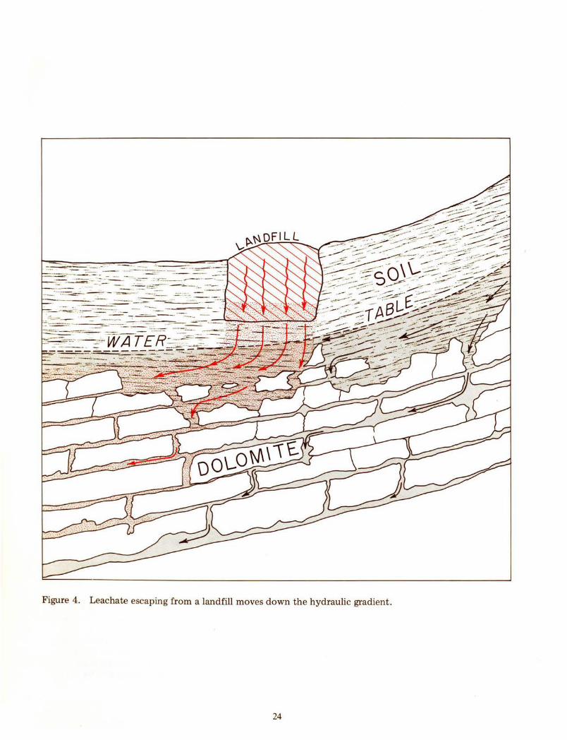
. ..:····---=:::-::.. __ ... -:-~--· ....... ;·:--· ·· · · ·=7;··.~- · · ·----· ---·
:: ··.~::.::::.. __ ..... . - --- ··· - -. -----~· . :~=-- ::~7"' - · ... ·--·---··--·-
···::-:~....;;,=.~· ·· ·-·-:~:- · ·- · -:.:::.~····-..:
··----·- ·----·
- -·-.... -.:.~-- .......... :
Figure 4. Leachate escaping from a landfill moves down the hydraulic gradient.
24
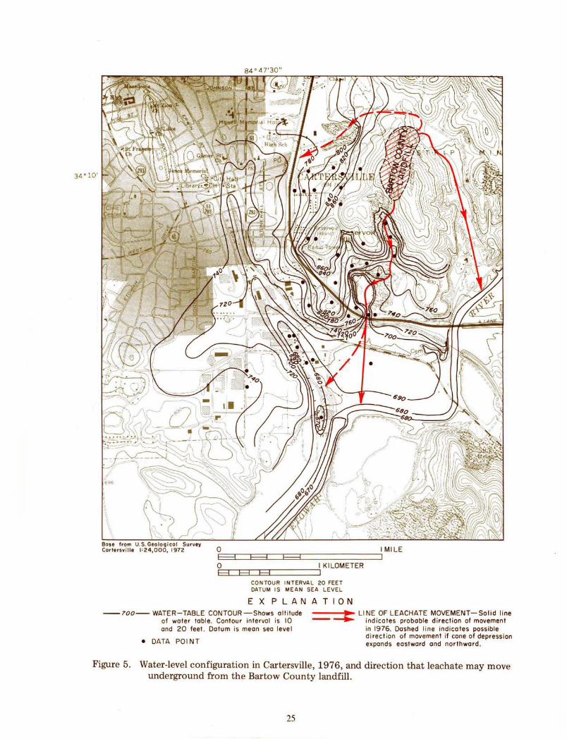
34 ° 10'
O;:.E--=!_~-~F--=!-~-~E--=!-~-----------,1 Ml LE
OEF=3=r~~~~~~c=======~\KILOMETER CON TOU R I NTERVA L 20 FEET DATUM I S MEAN SEA LEVEL
EXPLANATION --700-- WATER-TABLE CONTOUR -Shows alt itude
of wate r table. Contour interval is 10 and 20 feet . Datum is mean sea level
-----.~ LINE OF LEACHATE MOVEMENT-Solid line -......, indicates probable direction of movement
in 1976. Dashed l ine indicates possible di rect ion of movement if cone of depression expands eastward and northward . • DATA POl NT
Figure 5. Water-level configuration in Cartersville, 1976, and direction that leachate may move underground from the Bartow County landfill.
25
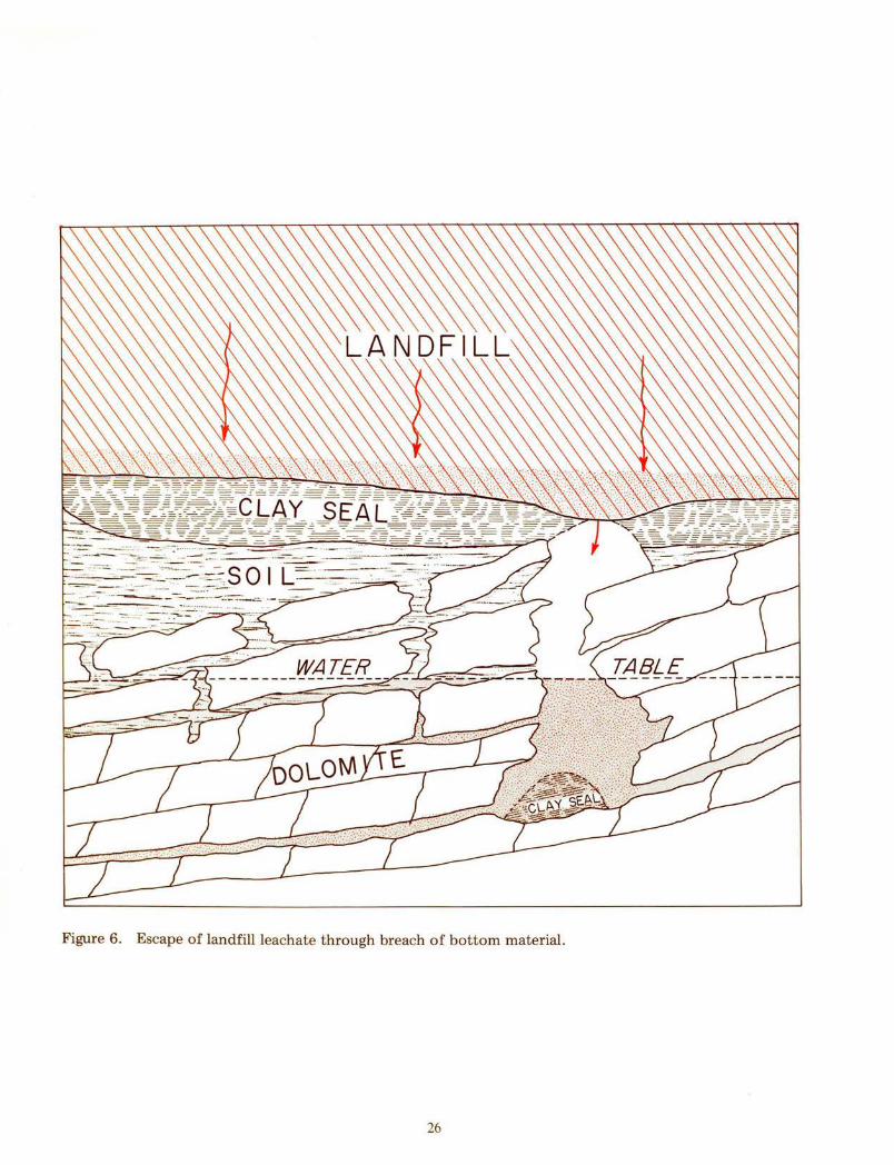
Figure 6. Escape of landfill leachate through breach of bottom material.
26
and draw leachate toward the center of pumpage, as shown in figure 5.
Movement of leachate from the landfill could be detected by sampling monitoring wells strategically placed along the lines of probable ground-water movement. Samples from these wells could be collected periodically for chemical analysis and compared with analyses of water from other wells in the same aquifer and with the analyses listed in this report (tables 1, 2, 4, and 5). The samples could be analyzed for metals such as lead, mercury, selenium, arsenic, strontium; for trace organic substances including pesticides, herbicides, phenols, industrial chemicals used in the area; and for bacteria. Increases in the concentration of any of these substances in the ground water could be an indication that leachate had reached the monitoring well.
Other Open-Pit Mines in the Cartersville Area
Most large mines in the Cartersville area extend down to carbonate bedrock and, as a consequence, do not hold water but drain through the bottom into bedrock openings. If any of the mines are used for waste disposal, even if lined with clay, leachate could eventually reach the ground-water reservoir either by percolating through the clay bottom seal or by sudden entry through a collapse of the bottom material (fig. 6).
The larger open-pit mines in the Cartersville area are shown in plate 5. The plate also shows the direction that ground water and leachate originating in the mines would likely follow down the hydraulic gradient, and indicates the extent of the aquifer that leachate emanating from the mines would likely contaminate.
As the plate indicates, disposing of solid waste in any of the large mines has the potential of contaminating substantial parts of water-bearing unit F. Most areas of the aquifer subject to contamination are either being used for industrial supply or are likely to be used for that purpose in the future. Only the mines southeast of Emerson are surrounded by rocks of low permeability that would confine leachate spread to a small area. Leachate generated in these mines probably would discharge into Pumpkinvine Creek after flowing about half a mile in the subsurface.
METHODS FOR EVALUATING WELL SITES
Because yields of individual wells in the area vary greatly within short distances, estimating the potential yield of prospective well sites is very difficult. A method for estimating, on a percentage basis, the chances for obtaining certain size yields from wells
27
under different geologic and topographic conditions was developed by LeGrand (1967). He based his method on a statistical study of hundreds of wells in the Piedmont and Blue Ridge provinces of eight Southeastern States.
Even though LeGrand's method. for evaluating well sites was developed primarily for use in metamorphic and igneous rocks found in the Piedmont and Blue Ridge areas, the same basic principles also apply to the sedimentary rocks of the Valley and Ridge area. The method is especially applicable to water-bearing units C and G composed of clastic rocks, but it also can be an aid to locating well sites in units A, D, and F, which consist of carbonate rock. By applying the method, a landowner or developer should be able to evaluate the yield potential of particular sites. The succeeding text is quoted directly from LeGrand (1967), but his figure numbers have been changed to fall in sequence with the other figures in this report. In LeGrand's text, "gpm" is an abbreviation for gallons per minute.
Evaluating Sites
"Although many factors determine the yield of a well, two ground conditions when used together serve as a good index for rating a well site. These conditions are topography and soil thickness. The ratings are based on the following statement: Highyielding wells are common where thick residual soils and relatively low topographic areas are combined, and low-yielding wells are common where thin soils and hilltops are combined. By comparing conditions of a site according to the topographic and soil conditions one gets a relative rating value. For example, the following topographic conditions are assigned point values:
Points 0 2 4 5 7 8 9
12 15 18
Topography Steep ridge top Upland steep slope Pronounced rounded upland Midpoint ridge slope Gentle upland slope Broad flat upland Lower part of upland slope Valley bottom or flood plain Draw in narrow catchment area Draw in large catchment area
"Figure 7 shows values for certain topographic conditions. Figure 8 shows rating values for soil thickness. The soil zone in this report includes the normal soils and also the relatively soft or weathered
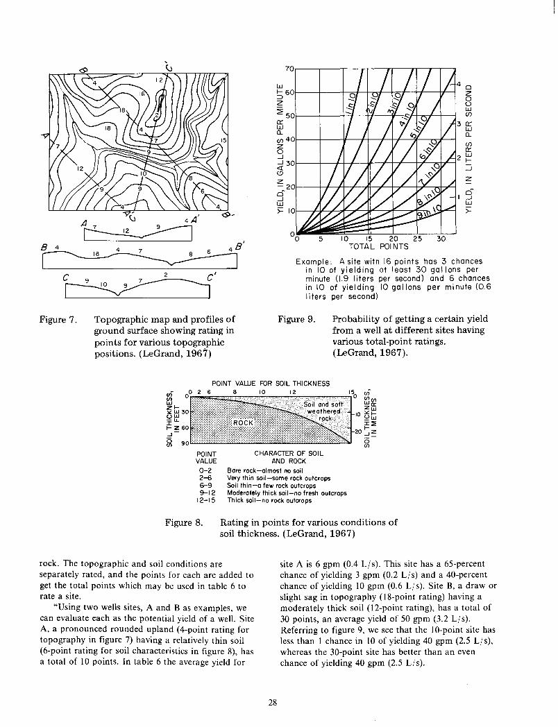
A G 4A'
~ a 4 4 7 6 4 a'
I
~ Figure 7. Topographic map and profiles of
ground surface showing rating in points for various topographic positions. (LeGrand, 196'7)
70
w ~60 z ~50 a:: w a.. (/) 40 z 0 _J
_J 30 <[ (.!)
z -20 0 _J w >= 10
(/)
a:: w f-:::J z
0 I _J
w >-
10 15 20 25 30 TOTAL POl NTS
Example: A site with 16 points has 3 chances in 10 of yielding at least 30 gallons per minute (1.9 liters per second) and 6 chances in 10 of yielding 10 gallons per minute (0.6 I i ters per second)
Figure 9. Probability of getting a certain yield from a well at different sites having various total-point ratings. (LeGrand, 1967).
POINT VAWE FOR SOIL THICKNESS
CHARACTER OF SOIL POINT VALUE
0-2 2-6 6-9 9-12
12-15
AND ROCK Bare rock-almost no soil Very thin soil-some rock outcrops Soil thin-a few rock outcrops Moderately thick soil-no fresh outcrops Thick soil-no rock outcrops
Figure 8. Rating in points for various conditions of soil thickness. (LeGrand, 1967)
rock. The topographic and soil conditions are separately rated, and the points for each are added to get the total points which may be used in table 6 to rate a site.
"Using two wells sites, A and B as examples, we can evaluate each as the potential yield of a well. Site A, a pronounced rounded upland (4-point rating for topography in figure 7) having a relatively thin soil (6-point rating for soil characteristics in figure 8), has a total of I 0 points. In table 6 the average yield for
28
site A is 6 gpm (0.4 L/s). This site has a 65-percent chance of yielding 3 gpm (0.2 L/s) and a 40-percent chance of yielding 10 gpm (0. 6 LIs). Site B, a draw or slight sag in topography (18-point rating) having a moderately thick soil (12-point rating), has a total of 30 points, an average yield of 50 gpm (3.2 L/s). Referring to figure 9, we see that the 10-point site has less than 1 chance in 10 of yielding 40 gpm (2.5 L/s), whereas the 30-point site has better than an even chance of yielding 40 gpm (2.5 L/s).
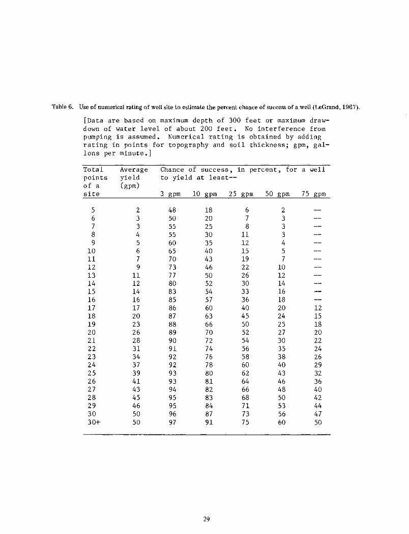
Table 6. Use of numerical rating of well site to estimate the percent chance of success of a well (LeGrand, 1967).
[Data are based on maximum depth of 300 feet or maximum draw-down of water level of about 200 feet. No interference from pumping is assumed. Numerical rating is obtained by adding rating in points for topography and soil thickness; gpm, gal-lons per minute.]
Total Average Chance of success, in percent, for a well points yield to yield at least--of a (gpm) site 3 gpm 10 gpm 25 gpm 50 gpm 75 gpm
5 2 48 18 6 2 6 3 50 20 7 3 7 3 55 25 8 3 8 4 55 30 11 3 9 5 60 35 12 4
10 6 65 40 15 5 11 7 70 43 19 7 12 9 73 46 22 10 13 11 77 50 26 12 14 12 80 52 30 14 15 14 83 54 33 16 16 16 85 57 36 18 17 17 86 60 40 20 12 18 20 87 63 45 24 15 19 23 88 66 50 25 18 20 26 89 70 52 27 20 21 28 90 72 54 30 22 22 31 91 74 56 35 24 23 34 92 76 58 38 26 24 37 92 78 60 40 29 25 39 93 80 62 43 32 26 41 93 81 64 46 36 27 43 94 82 66 48 40 28 45 95 83 68 50 42 29 46 95 84 71 53 44 30 50 96 87 73 56 47 30+ 50 97 91 75 60 50
29
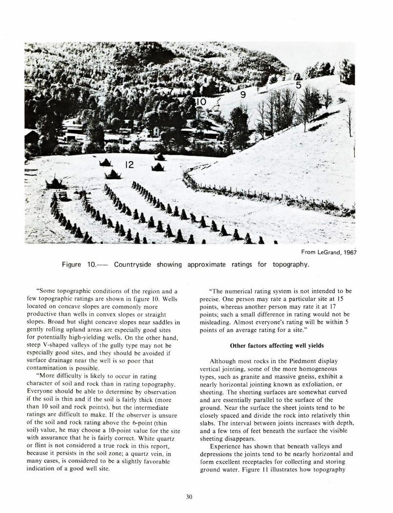
From LeGrand, 196l
Figure 10.- Countryside showing approximate ratings for topography.
"Some topographic conditions of the region and a few topographic ratings are shown in figure I 0. Wells located on concave slopes are commonly more productive than wells in convex slopes or straight slopes . Broad but slight concave slopes near saddles in gently rolling upland areas are especially good sites for potentially high-yielding wells . On the other hand , steep Y-shaped valleys of the gully type may not be especially good sites, and they should be avoided if surface drainage near the well is so poor that contamination is possible.
"More difficulty is likely to occur in rating character of soil and rock than in rating topography. Everyone should be able to determine by observation if the soil is thin and if the soil is fairly thick (more than 10 soil and rock points) , but the intermediate ratings are difficult to make. If the observer is unsure of the soil and rock rating above the 6-point (thin soil) value, he may choose a 10-point value for the site with assurance that he is fairly correct. White quartz or flint is not considered a true rock in this report , because it persists in the soil zone; a quartz vein, in many cases, is considered to be a slightly favorable indication of a good well site .
30
"The numerical rating system is not intended to be precise. One person may rate a particular site at 15 points, whereas another person may rate it at 17 points; such a small difference in rating would not be misleading. Almost everyone's rating will be within 5 points of an average rating for a site ."
Other factors affecting well yields
Although most rocks in the Piedmont display vertical jointing, some of the more homogeneous types, such as granite and massive gneiss, exhibit a nearly horizontal jointing known as exfoliation, or sheeting. The sheeting surfaces are somewhat curved and are essentially parallel to the surface of the ground . Near the surface the sheet joints tend to be closely spaced and divide the rock into relatively thin slabs. The interval between joints increases with depth, and a few tens of feet beneath the surface the visible sheeting disappears .
Experience has shown that beneath valleys and depressions the joints tend to be nearly horizontal and form excellent receptacles for collecting and storing ground water. Figure II illustrates how topography
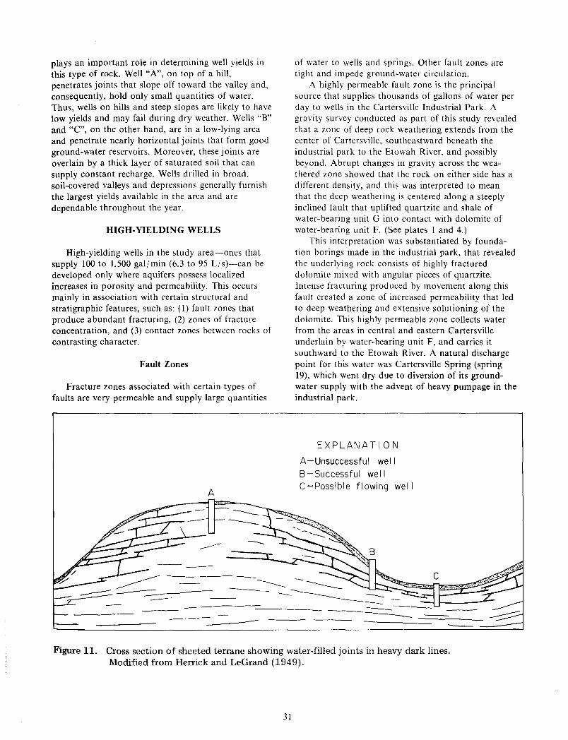
plays an important role in determining well yields in this type of rock. Well "A", on top of a hill, penetrates joints that slope off toward the valley and, consequently, hold only small quantities of water. Thus, wells on hills and steep slopes are likely to have low yields and may fail during dry weather. Wells "B" and "C", on the other hand, are in a low-lying area and penetrate nearly horizontal joints that form good ground-water reservoirs. Moreover, these joints are overlain by a thick layer of saturated soil that can supply constant recharge. Wells drilled in broad, soil-covered valleys and depressions generally furnish the largest yields available in the area and are dependable throughout the year.
HIGH-YIELDING WELLS
High-yielding wells in the study area--ones that supply 100 to 1,500 gal/min (6.3 to 95 Ljs)-can be developed only where aquifers possess localized increases in porosity and permeability. This occurs mainly in association with certain structural and stratigraphic features, such as: (I) fault zones that produce abundant fracturing, (2) zones of fracture concentration, and (3) contact zones between rocks of contrasting character.
Fault Zones
Fracture zones associated with certain types of faults are very permeable and supply large quantities
A
--
of water to wells and springs. Other fault zones are tight and impede ground-water circulation.
A highly permeable fault zone is the principal source that supplies thousands of gallons of water per day to wells in the Cartersville Industrial Park. A gravity survey conducted as part of this study revealed that a zone of deep rock weathering extends from the center of Cartersville, southeastward beneath the industrial park to the Etowah River, and possibly beyond. Abrupt changes in gravity across the weathered zone showed that the rock on either side has a different density, and this was interpreted to mean that the deep weathering is centered along a steeply inclined fault that uplifted quartzite and shale of water-bearing unit G into contact with dolomite of water-bearing unit F. (See plates I and 4.)
This interpretation was substantiated by foundation borings made in the industrial park, that revealed the underlying rock consists of highly fractured dolomite mixed with angular pieces of quartzite. Intense fracturing produced by movement along this fault created a zone of increased permeability that led to deep weathering and extensive solutioning of the dolomite. This highly permeable zone collects water from the areas in central and eastern Cartersville underlain by water-bearing unit F, and carries it southward to the Etowah River. A natural discharge point for this water was Cartersville Spring (spring 19), which went dry due to diversion of its groundwater supply with the advent of heavy pumpage in the industrial park.
EXPLANATION
A-Unsuccessful well B-Successful well C-Possible flowing well
Figure 11. Cross section of sheeted terrane showing water-filled joints in heavy dark lines. Modified from Herrick and LeGrand (1949).
31
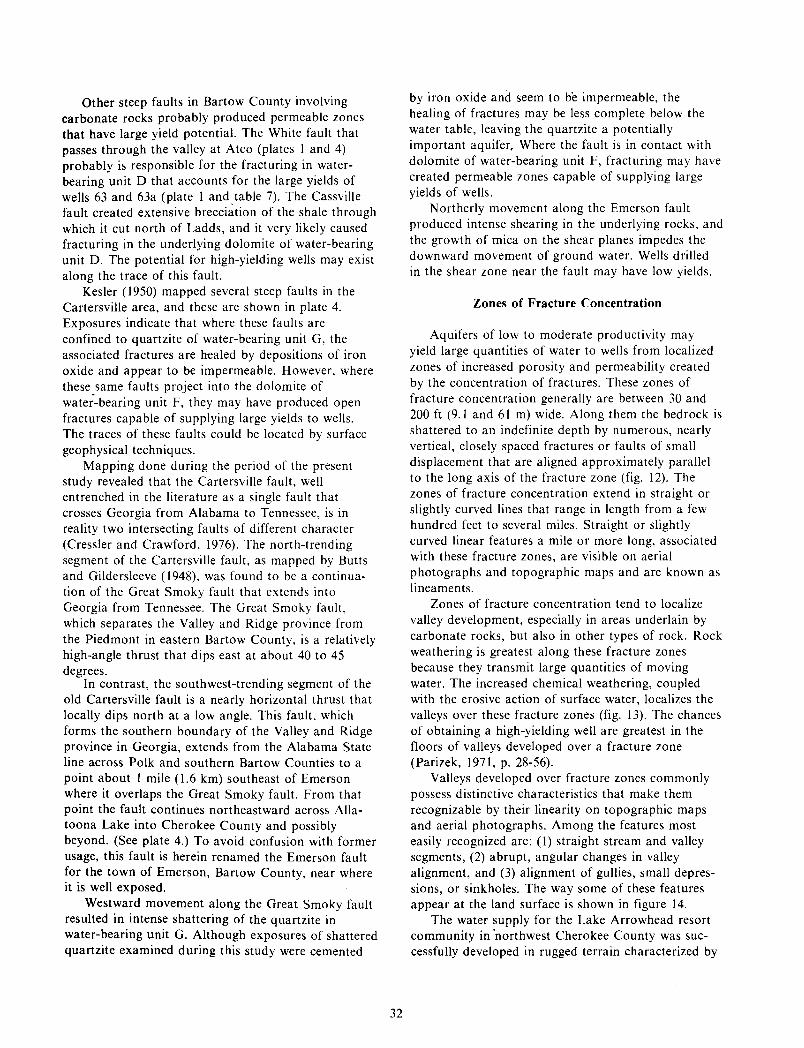
Other steep faults in Bartow County involving carbonate rocks probably produced permeable zones that have large yield potential. The White fault that passes through the valley at Atco (plates I and 4) probably is responsible for the fracturing in waterbearing unit D that accounts for the large yields of wells 63 and 63a (plate I and. table 7). The Cassville fault created extensive brecciation of the shale through which it cut north of Ladds, and it very likely caused fracturing in the underlying dolomite of water-bearing unit D. The potential for high-yielding wells may exist along the trace of this fault.
Kesler ( 1950) mapped several steep faults in the Cartersville area, and these are shown in plate 4. Exposures indicate that where these faults are confined to quartzite of water-bearing unit G, the associated fractures are healed by depositions of iron oxide and appear to be impermeable. However, where these .same faults project into the dolomite of water-bearing unit F, they may have produced open fractures capable of supplying large yields to wells. The traces of these faults could be located by surface geophysical techniques.
Mapping done during the period of the present study revealed that the Cartersville fault, well entrenched in the literature as a single fault that crosses Georgia from Alabama to Tennessee, is in reality two intersecting faults of different character (Cressler and Crawford, 1976). The north-trending segment of the Cartersville fault, as mapped by Butts and Gildersleeve ( 1948), was found to be a continuation of the Great Smoky fault that extends into Georgia from Tennessee. The Great Smoky fault, which separates the Valley and Ridge province from the Piedmont in eastern Bartow County, is a relatively high-angle thrust that dips east at about 40 to 45 degrees.
In contrast, the southwest-trending segment of the old Cartersville fault is a nearly horizontal thrust that locally dips north at a low angle. This fault, which forms the southern boundary of the Valley and Ridge province in Georgia, extends from the Alabama State line across Polk and southern Bartow Counties to a point about I mile (1.6 km) southeast of Emerson where it overlaps the Great Smoky fault. From that point the fault continues northeastward across Allatoona Lake into Cherokee County and possibly beyond. (See plate 4.) To avoid confusion with former usage, this fault is herein renamed the Emerson fault for the town of Emerson, Bartow County, near where it is well exposed.
Westward movement along the Great Smoky fault resulted in intense shattering of the quartzite in water-bearing unit G. Although exposures of shattered quartzite examined during this study were cemented
32
by iron oxide and seem to be impermeable, the healing of fractures may be less complete below the water table, leaving the quartzite a potentially important aquifer, Where the fault is in contact with dolomite of water-bearing unit F, fracturing may have created permeable zones capable of supplying large yields of wells.
Northerly movement along the Emerson fault produced intense shearing in the underlying rocks, and the growth of mica on the shear planes impedes the downward movement of ground water. Wells drilled in the shear zone near the fault may have low yields.
Zones of Fracture Concentration
Aquifers of low to moderate productivity may yield large quantities of water to wells from localized zones of increased porosity and permeability created by the concentration of fractures. These zones of fracture concentration generally are between 30 and 200ft (9.1 and 61 m) wide. Along them the bedrock is shattered to an indefinite depth by numerous, nearly vertical, closely spaced fractures or faults of small displacement that are aligned approximately parallel to the long axis of the fracture zone (fig. 12). The zones of fracture concentration extend in straight or slightly curved lines that range in length from a few hundred feet to several miles. Straight or slightly curved linear features a mile or more long, associated with these fracture zones, are visible on aerial photographs and topographic maps and are known as lineaments.
Zones of fracture concentration tend to localize valley development, especially in areas underlain by carbonate rocks, but also in other types of rock. Rock weathering is greatest along these fracture zones because they transmit large quantities of moving water. The increased chemical weathering, coupled with the erosive action of surface water, localizes the valleys over these fracture zones (fig. 13). The chances of obtaining a high-yielding well are greatest in the floors of valleys developed over a fracture zone (Parizek, 1971, p. 28-56).
Valleys developed over fracture zones commonly possess distinctive characteristics that make them recognizable by their linearity on topographic maps and aerial photographs. Among the features most easily recognized are: (!) straight stream and valley segments, (2) abrupt, angular changes in valley alignment, and (3) alignment of gullies, small depressions, or sinkholes. The way some of these features appear at the land surface is shown in figure 14.
The water supply for the Lake Arrowhead resort community in "northwest Cherokee County was successfully developed in rugged terrain characterized by
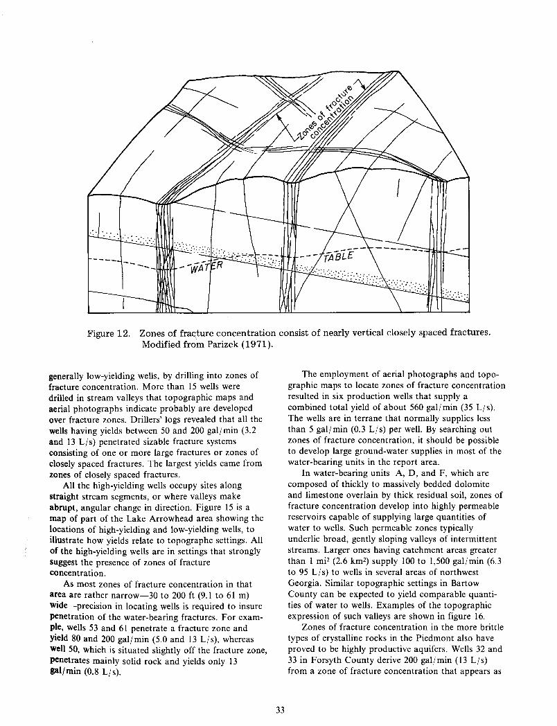
Figure 12. Zones of frac\ture concentration consist of nearly vertical closely spaced fractures. Modified from Parizek (1971).
generally low-yielding wells, by drilling into zones of fracture concentration. More than 15 wells were drilled in stream valleys that topographic maps and aerial photographs indicate probably are developed over fracture zones. Drillers' logs revealed that all the wells having yields between 50 and 200 galjmin (3.2 and 13 L/s) penetrated sizable fracture systems consisting of one or more large fractures or zones of closely spaced fractures. The largest yields came from zones of closely spaced fractures.
All the high-yielding wells occupy sites along straight stream segments, or where valleys make abrupt, angular change in direction. Figure 15 is a map of part of the Lake Arrowhead area showing the locations of high-yielding and low-yielding wells, to illustrate how yields relate to topographc settings. All of the high-yielding wells are in settings that strongly suggest the presence of zones of fracture concentration.
As most zones of fracture concentration in that area are rather narrow-30 to 200 ft (9.1 to 61 m) wide-precision in locating wells is required to insure penetration of the water-bearing fractures. For example, wells 53 and 61 penetrate a fracture zone and yield 80 and 200 galjmin (5.0 and 13 L/s), whereas well 50, which is situated slightly off the fracture zone, penetrates mainly solid rock and yields only 13 gal/min (0.8 Ljs).
33
The employment of aerial photographs and topographic maps to locate zones of fracture concentration resulted in six production wells that supply a combined total yield of about 560 gal/min (35 L/s). The wells are in terrane that normally supplies less than 5 gal/min (0.3 Ljs) per well. By searching out zones of fracture concentration, it should be possible to develop large ground-water supplies in most of the water-bearing units in the report area.
In water-bearing units A, D, and F, which are composed of thickly to massively bedded dolomite and limestone overlain by thick residual soil, zones of fracture concentration develop into highly permeable reservoirs capable of supplying large quantities of water to wells. Such permeable zones typically underlie broad, gently sloping valleys of intermittent streams. Larger ones having catchment areas greater than 1 mi2 (2.6 km2) supply 100 to 1,500 galjmin (6.3 to 95 LIs) to wells in several areas of northwest Georgia. Similar topographic settings in Bartow County can be expected to yield comparable quantities of water to wells. Examples of the topographic expression of such valleys are shown in figure 16.
Zones of fracture concentration in the more brittle types of crystalline rocks in the Piedmont also have proved to be highly productive aquifers. Wells 32 and 33 in Forsyth County derive 200 gal/min (13 Ljs) from a zone of fracture concentration that appears as
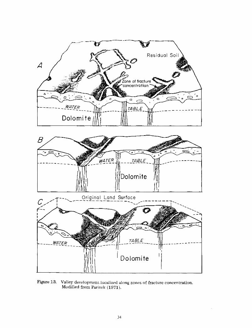
A
------- __ f1!ATER --------
TABLE -------- -----------
....,---- Original Land Surface c ,"""' I '-------- ----------
"" / r--
TAE}f-_E_ __
I Dolomite
---------
-------
Figure 13. Valley development localized along zones of fracture concentration. Modified from Parizek (1971).
34
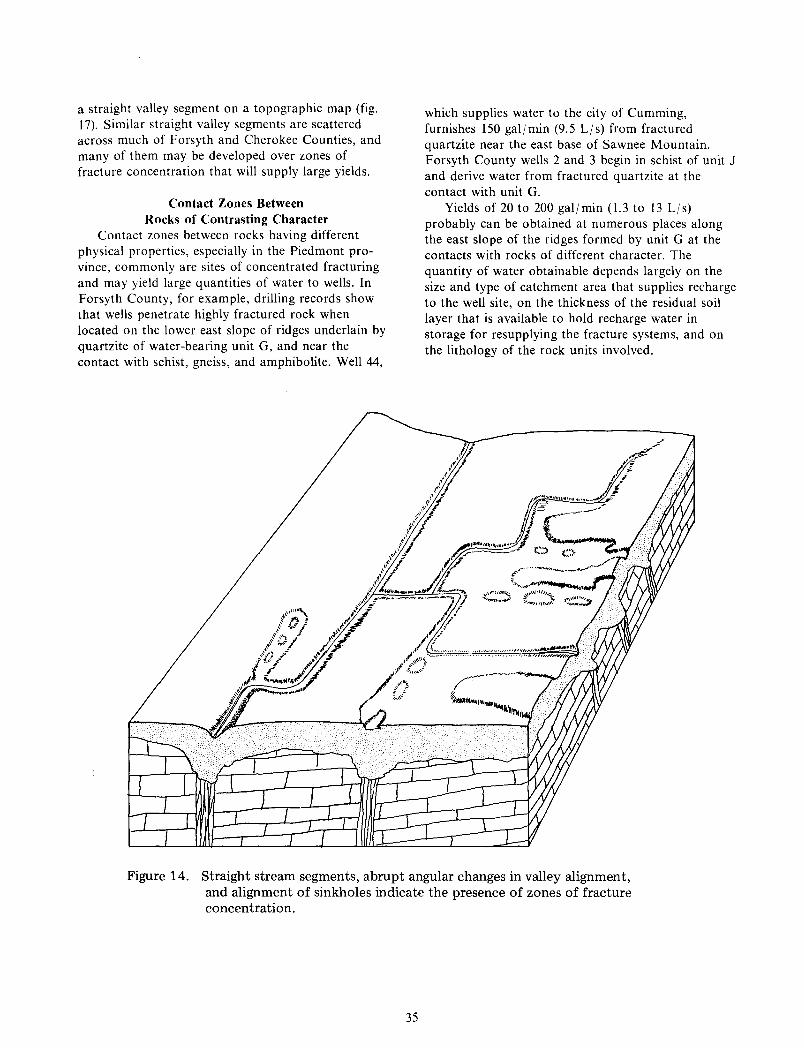
a straight valley segment on a topographic map (fig. 17). Similar straight valley segments are scattered across much of Forsyth and Cherokee Counties, and many of them may be developed over zones of fracture concentration that will supply large yields.
Contact Zones Between Rocks of Contrasting Character
Contact zones between rocks having different physical properties, especially in the Piedmont province, commonly are sites of concentrated fracturing and may yield large quantities of water to wells. In Forsyth County, for example, drilling records show that wells penetrate highly fractured rock when located on the lower east slope of ridges underlain by quartzite of water-bearing unit G, and near the contact with schist, gneiss, and amphibolite. Well 44,
which supplies water to the city of Cumming, furnishes 150 gal/min (9.5 L/s) from fractured quartzite near the east base of Sawnee Mountain. Forsyth County wells 2 and 3 begin in schist of unit J and derive water from fractured quartzite at the contact with unit G.
Yields of 20 to 200 gal/min (1.3 to 13 L/s) probably can be obtained at numerous places along the east slope of the ridges formed by unit G at the contacts with rocks of different character. The quantity of water obtainable depends largely on the size and type of catchment area that supplies recharge to the well site, on the thickness of the residual soil layer that is available to hold recharge water in storage for resupplying the fracture systems, and on the lithology of the rock units involved.
Figure 14. Straight stream segments, abrupt angular changes in valley alignment, and alignment of sinkholes indicate the presence of zones of fracture concentration.
35
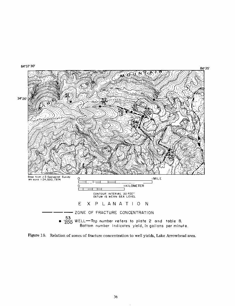
84°37'30"
Bose from U.S. Geological Survey Waleska lo24,000, 1974 0 I MILE
i-E-3---.---,E-3--.-----,E-3-,----------1
0 ,:--,-,-,-,-,----,1 KILOMETER H H H
CONTOUR INTERVAL 20 FEET DATUM IS MEAN SEA LEVEL
EXPLANATION
------ZONE OF FRACTURE CONCENTRATION
53 • 200 WELL-Top number refers to plate 2 and table 8.
Bottom number indicates yield, in gallons per minute.
Figure 15. Relation of zones of fracture concentration to well yields, Lake Arrowhead area.
36
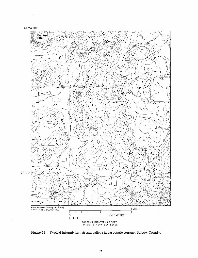
84 °52'30"
Bose from U.S.Geologico I Survey Cartersville I' 24,000, 1972 Or--.--.--.--.--r------------~IMILE F=l F-3 E3 I
OEH3=:=:JHE3=:JH::::3::====:::JI KILOMETER
CONTOUR INTERVAL 20 FEET DATUM IS MEAN SEA LEVEL
Figure 16. Typical intermittent stream valleys in carbonate terrane, Bartow County.
37
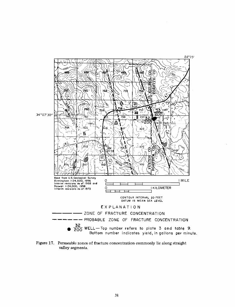
Base from U.S. Geological Survey Birmingham 1•24,000, 1956 Interim revisions os of 1968 and Roswell 1=24,000, 1956 Interim revisions as of 1973
0 I MILE rF-=3--.---,F-=3--.---F--dr--T--------------~
0 I KILOMETER rE=3-.-.E=3-.-.F3-.----------.
CONTOUR INTERVAL 20 FEET DATUM IS MEAN SEA LEVEL
EXPLANATION
---ZONE OF FRACTURE CONCENTRATION
------PROBABLE ZONE OF FRACTURE CONCENTRATION
32 e 200 WELL-Top number refers to plate 3 and table 9. Bottom number indicates yield, in gallons per minute.
Figure 17. Permeable zones of fracture concentration commonly lie along straight valley segments.
38
CONCLUSIONS
In the Valley and Ridge part of the report area, wells nearly everywhere supply water of adequate quality and quantity for domestic and farm purposes. In Bartow County, wells in water-bearing units D and F can furnish 100 to 1,500 galjmin (6.3 to 95 L/s), and yields of 50 to 1,500 galjmin (3.2 to 95 L/s) should be available from wells in selected sites in units A, D, and F.
Open joints and fractures tend to become tighter and more widely spaced with increasing depth. Fractures in slate, shale, sandstone, quartzite, and similar rocks in the Valley and Ridge area tend to be concentrated within 250 ft (76 m) of the surface. Most solution-enlarged fractures in carbonate rocks are found at depths of less than 350 ft (I 06 m). Therefore, when.drilling for water in the Valley and Ridge province, it is rarely worthwhile to drill deeper than 350 ft ( 106 m) in carbonates, or deeper than 250 ft (76 m) in other kinds of rock. If a well fails to produce the desired yield at these depths, it generally is best to try a new location.
Springs in water-bearing units A and D discharge 100 to 3,000 gal/min (6.3 to 189 L/s). The water is moderately mineralized and is satisfactory for many industrial and other uses. Most of the springs are unused and represent a potentially valuable untapped resource.
Well and spring pollution is widespread in the Valley and Ridge part of Bartow County. More than 20 percent of the drilled wells, 80 percent of the dug wells, and 80 percent of the large springs tested were polluted. The main causes of well pollution are improper well construction and poor site selection. Many large springs are polluted because they are favorite watering places for wildlife. Similar percentages of wells and a large percentage of springs in the Piedmont part of the report area also may be polluted.
Some abandoned open-pit mines in the Cartersville area of Bartow County have been used for solid waste disposal and others are being considered by local authorities for landfill development. However, the mines are hydraulically connected with underlying water-bearing unit F that supplies water to industrial wells in Cartersville. Thus, leachate from solid waste disposed of in these mines is a possible threat to contaminate large areas of this major ground-water reservoir. No leachate has been observed in the subsurface as yet, because sampling wells are not available in the critical areas.
In general, ground water is available in smaller quantities in the Piedmont province than it is in the Valley and Ridge. The largest yield obtained in the
39
crystalline rocks of eastern Bartow and in Cherokee and Forsyth Counties is 200 gal! min ( 13 L; s). Only II wells in this area are known to yield more than 50 galjmin (3.2 L/s), and most wells yield less than 15 galjmin (0.9 L/s). In some areas of moderate relief, and in many areas of high relief, well supplies adequate for residential or farm needs are either unavailable or very difficult to obtain.
In the Piedmont area, where the rocks have been subjected to severe deformation, water-yielding joints and fractures commonly occur deeper than 400 ft ( 122 m). A significant number of wells obtain water from openings about 500 ft (!52 m) deep, and a few produce water from as deep as 700 ft (213 m). However, a comparison of drilling costs with the probability of obtaining the required yield of about 5 gal/min (0.3 Ljs) indicates that it is seldom advisable to drill deeper than about 400ft (122m) for a residential supply. Well records show that drilling deeper than about 700ft (213m) cannot be justified unless geologic evidence indicates that openings extend to greater depth.
SELECTED REFERENCES
Bentley, R. D., Fairley, W. M., Fields, H. H., and others, 1966, The Cartersville fault problem: Guidebook No. 4, Georgia Geological Survey, 38 p.
Brunner, D. R., and Keller, D. J., 1972, Sanitary landfill design and operation: U.S. Environmental Protection Agency, Solid Waste Management series S W -65ts, 59 p.
Butts, Charles, and Gildersleeve, Benjamin, 1948, Geology and mineral resources of the Paleozoic area in northwest Georgia: Georgia Geological Survey Bulletin 54, 176 p., 8 pis.
Crawford, T. J., and Medlin, J. H., 1970, Stratigraphic and structural features between the Cartersville and Brevard fault zones: Guidebook, 5th Annual Field Trip, Georgia Geological Society, 37 p.
Cressler, C. W., 1963, Geology and ground-water resources of Catoosa County, Georgia: Georgia Geological Survey Information Circular 28, 19 p.
__ !964a, Geology and ground-water resources of the Paleozoic rock area, Chattooga County, Georgia: Georgia Geological Survey Information Circular 27, 14 p.
__ l964b, Geology and ground-water resources of Walker County, Georgia: Georgia Geological Survey Information Circular 29, 15 p.
__ 1970, Geology and ground-water resources of Floyd and Polk Counties, Georgia: Georgia Geological Survey Information Circular 39, 95 p.

__ 1974. Geology and ground-water resources of Gordon. Whitfield. and :vturray Counties. Georgia: Georgia Geological Suney Information Cir
cular 47. 56 p. Cressler. C. W .. and Crawford, T. L 1976, Carters
\ille fault found to be two intersecting thrusts, in Geological Suney Research 1976: U.S. Geological Suney Professional Paper 1000. 414 p.
Cressler. C. W .. Franklin. M. A., and Hester, W. G., 1976. Availability of water supplies in northwest Georgia: Georgia Geological Suney Bulletin 91,
140 p. Crickmay. G. W .. 1952. Geology of the crystalline
rocks of Georgia: Georgia Geological Survey Bulletin 5X. 54 p.
Croft. M.G .. 1963. Geology and ground-water re,ource' of Bartow County, Georgia: U.S. Geolog1cal Survey Water-Supply Paper 1619-FF.
32 p. __ !964. Geology and ground-water resources of
Dade County. Georgia: Georgia Geological Survey Information Circular 26. 17 p.
D<n is. Barry. 1969, Water 4uality survey, Bartow County. Georgia: Economic Development Administration Publication 265. 33 p.
Fairley. W. M .. 1965. The :vturphy syncline in the Tate 4uadrangle. Georgia: Georgia Geological Survey Bulletin 75. 71 p.
Georgia Department of .'\atural Resources. 1964, Water-supply 4uality control act no. 936. 10 p.
__ 1970. Rules and regulations for water-,upply 4uality control. chapter 270-5-15. 35 p.
Georgia Geological Survey, 1976, Geologic map of Georgia: Atlanta, Georgia, I :500,000.
Grantham. R. G .. and Stokes, W. R .. 1976. Groundwater 4uality for Georgia: U.S r;eological Survey basic data report, 31() p.
Herrick. S. M .. and LeGrand. H. E .. 1949. Geology and ground-water resources of the Atlanta area, Georgia: Georgia Geological Survey Bulletin 55. 124 p.
Kesler, T. L., 1950. Geology and mineral deposits of the Cartersville district, Georgia: U.S. Geological Survey Professional Paper 224, 97 p .. 19 pis.
LeGrand. H. E .. 1%7. Ground water of the Piedmont and Blue Ridge provinces in the Southeastern States: U.S. Geological Survey Circular 53X. 11 p.
Miller, R. A., and Maher, S. W., 1972. Geologic evaluation of sanitary landfill sites in Tennessee: Tennessee Division of Geology, Environmental Geology Series 1\o. I, 37 p.
Murray, J. B., 1973, Geologic map of Forsyth and north Fulton Counties, Georgia: Georgia Geological Survey Bulletin 88, pl. I.
40
Newton, J. G., and Hyde, L. W., 1971, Sinkhole problem in and near Roberts Industrial Subdivision, Birmingham, Alabama: Alabama Geological Survey Circular 6X, 42 p.
Parizek, R. R .. 1971, Hydrogeologic framework of folded and faulted carbonates, in Geological Society of America Guidebook. p. 9-56.
__ !971, Land use problems in carbonate terranes, in Geological Society of America Guidebook, p. 135-142.
Sonderegger, J. L.. Pollard, L. D., and Cressler, C. W., 1978, Quality and availability of ground water in Georgia: Georgia Geological Survey Information Circular 48, 25 p.
Spalvins, K .. 1969, Stratigraphy of the Conasauga Group in the vicinity of Adairsville, Georgia in Precambrian-Paleozoic Appalachian problems: Georgia Geological Survey Bulletin 80, p. 37-55.
Stewart, J. W .. 1964a, Infiltration and permeability of weathered crystalline rocks, Georgia Nuclear Laboratory, Dawson County, Georgia: U.S. Geological Survey Bulletin 1133- D, 58 p.
__ l964b, Geologic and hydrologic investigations at the site of the Georgia Nuclear Laboratory, Dawson County, Georgia: U.S. Geological Survey Bulletin 1133-F, 90 p.
Thomson, M. T.. Herrick, S. M., Brown, Eugene, and others, 1956, The availability and use of water in Georgia: Georgia Geological Survey Bulletin 65, 329 p.
U.S. Environmental Protection Agency, 1975, ::"Jational interim primary drinking water regulations: Federal Register, v. 40, no. 2 48. p. 59 56 6-
59588.
--1978. Solid waste disposal facilities: Federal Register. v. 43. no. 25, p. 4912-4955.
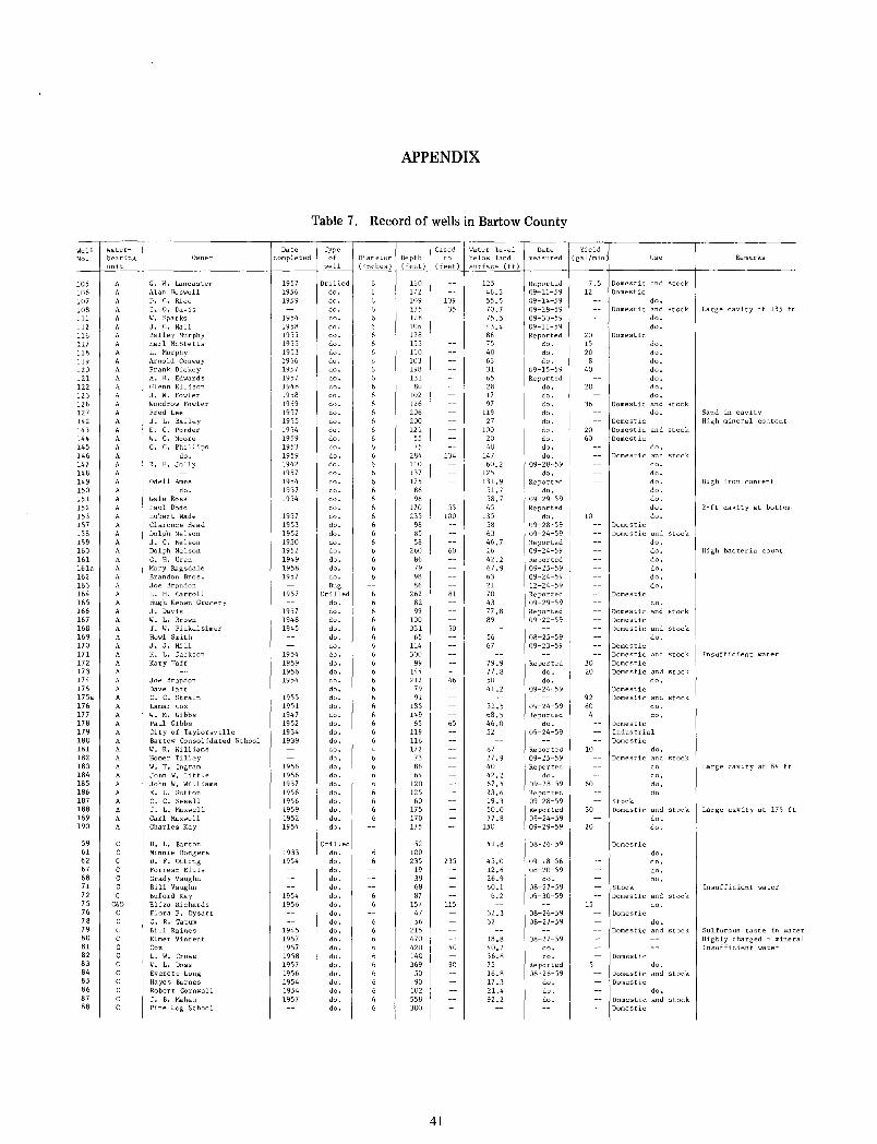
Well Water-No. bearing
105 106 107 108 111 112 116 117 118 119 120 121 122 123 126 127 142 143 144 145 146 L47 148 149 150 151 152 153 157 158 159 160 161 l6la 162 163 164 165 166 167 168 169 170 171 172 173 174 175 175a 176 177 178 179 180 181 182 183 184 185 186 187 188 189 190
59 61 62 67 68 71 72 75 76 78 79 80 81 82 83 84 85 86 87 88
unit
A A A A
A
A A A
A A A
A A A A A A A
A A
A A
A A
A A
A A A A A A A
A
A A A A
A
A
A
A
A A
C&D c c
Owner
G. W. Lancaster Alan Boswell D. C. Rice E. 0. Davis W. Sparks J. c. Hall Bailey Hurphy Earl McStetts L. Murphy Arnold Conway Frank Dickey A. R. Edwards Glenn Ellison J, W. Fowler Woodrow Fowler Fred Lee J. L. Bailey E. C. Porder W. C. Moore G. C. Phillips
do, R. F, Jolly
Odell Ames do.
Gale Ross Paul Dodd Hubert Wade Clarence Head Dolph Nelson J. C. Nelson Dolph Nelson G. H. Uren Mary Ragsdale Brandon Bros. Joe Brandon H. H. Carroll Hugh Keown Grocery J. Davis W. L. Brown J. W. Pickelsimer Howl Smith J. J. Hill H. L. Jackson Kary Taff
Joe Brandon Dave Taft C. C. Strain Lamar Cox W. M. Gibbs Paul Gibbs City of Taylorsville Bartow Consolidated School W. R. Williams Homer Tilley W. T. Ingram John W. Little John W. Williams E. L, Sutton C. C. Sewell J. L. Maxwell Carl Maxwell Charles Kay
H. L. Barton Minnie Rodgers D. F. Otting Forrest Ellis Grady Vaughn Bill Vaughn Buford Kay Eliza Richards Flora P. Dysart G. R. Tatum Bill Raines Elmer Vincent Cox L. W. Crowe v. L. Doss Everett Long Hayes Barnes Robert Cornwall J, B. Mahan Pine Log School
APPENDIX
Table 7. Record of wells in Bartow County
Date Type completed of
1957 1956 1959
1954 1958 1955 1955 1953 1956 1957 1957 1948 1958 1959 1957 1955 1954 1959 1953 1959 1942 1957 1954 1957 1954
1957 1953 1952 1950 1952 1949 1958 1957
1957
1957 1948 1945
1954 1959 1956 1954
1955 1951 1947 1952 1934 1939
1956 1956 1957 1956 1956 1959 1952 1954
1933 1954
1954 1956
1945 1957 1957 1958 1957 1956 1954 1954 1957
well
Drilled do. do. do. do, do. do. do. do. do. do. do. do. do. do. do. do. do. do, do. do. do. do. do, do. do. do. do. do. do. do, do. do. do. do, Dug
Drilled do, do, do, do. do. do, do. do, do. do. do. do. do. do. do. do, do. do. do. do, do. do. do. do, do. do. do,
Drilled do. do. do. do. do, do. do. do. do. do. do. do. do, do. do, do. do. do. do.
Cased Water level Date Yield Diameter Depth to below land measured (gal/min Use Remarks (inches) (feet) (feet) surface (ft)
160 172 109 l35 128 106 128 155 110 103 198 131
80 102 126 206 200 121
55 75
284 110 137 175
86 96
170 235
98 85 58
260 86 79 98 86
262 82 99
100 331
65 114 300
99 144 212
79 91
185 149
65 119 116 172
73 86 64
120 125
60 175 170 175
52 100 235
19 39 68 87
157 47 56
215 470 420 140 369
50 90
102 558 300
41
109 35
134
55 100
60
81
50
46
65
235
115
40
90
125 46.3 55.5 70.7 75.5 43.4 86 75 40 63 31 65 28 17 97
119 27
100 20 40
147 60.2
125 131.9
51.7 58.7 45
135 58 63 46,7 16 42.2 67.9 63 21 70 43 77.8 89
56 67
79,9 77.8 50 41.2
31.5 68.5 46,0 52
87 27.9 40 42.2 67.5 23.6 19.3 50.0 77.8
150
41.8
45.0 12.6 26,9 60.1 6.2
32,3 32
18.8 40.2 36,8 75 16.8 17.3 21,4 92.2
Reported 09-11-59 09-14-59 09-28-59 09-30-59 09-11-59 Reported
do. do. do,
09-15-59 Reported
do, do. do. do, do, do, do. do. do.
09-28-59 do.
Reported do,
09-29-59 Reported
do, 09-28-59 09-24-59 Reported 09-24-59 Reported 09-25-59 09-24-59 12-24-59 Reported 09-29-59 Reported 09-22-59
08-25-59 09-23-59
Reported do. do.
09-24-59
09-24-59 Reported
do. 09-24-59
Reported 09-25-59 Reported
do, 09-28-59 Reported 09-28-59 Reported 09-24-59 09-29-59
08-26-59
09-18-56 08-20-59
do. 08-27-59 09-30-59
08-26-59 08-27-59
08-27-59 do, do.
Reported 08-26-59
do. do. do.
7.5 Domestic and stock 12 Domestic
do. Domestic and stock Large cavity at 135 ft
do, do.
20 Domestic 15 do. 20 do.
8 do, 40 do.
do. 20 do.
do. 36 Domestic and stock
do. Sand in cavity Domestic High mineral content
20 Domestic and stock 60 Domestic
do. Domestic and stock
do, do. do, High iron content do. do. do, 2-ft cavity at bottom
10 do. Domestic Domestic and stock
do.
Domestic
do. High bacteria count do, do. do. do.
do. Domestic and stock Domestic Domestic and stock
do, Domestic Domestic and stock Insufficient water
30 Domestic 20 Domestic and stock
do. Domestic
92 Domestic and stock 60 do.
4 do, Domestic Industrial Domestic
10 do. Domestic and stock
do Large cavity at 84 ft do,
60 do. do
Stock 30 Domestic and stock Large cavity at 175 ft
do, 20 do,
Domestic do. do. do. do,
Stock Insufficient water Domestic and stock
15 do. Domestic
do. Domestic and stock Sulfurous taste in water
Highly charged - mineral Insufficient water
Domestic do.
Domestic and stock Domestic
do, Domestic and stock Domestic
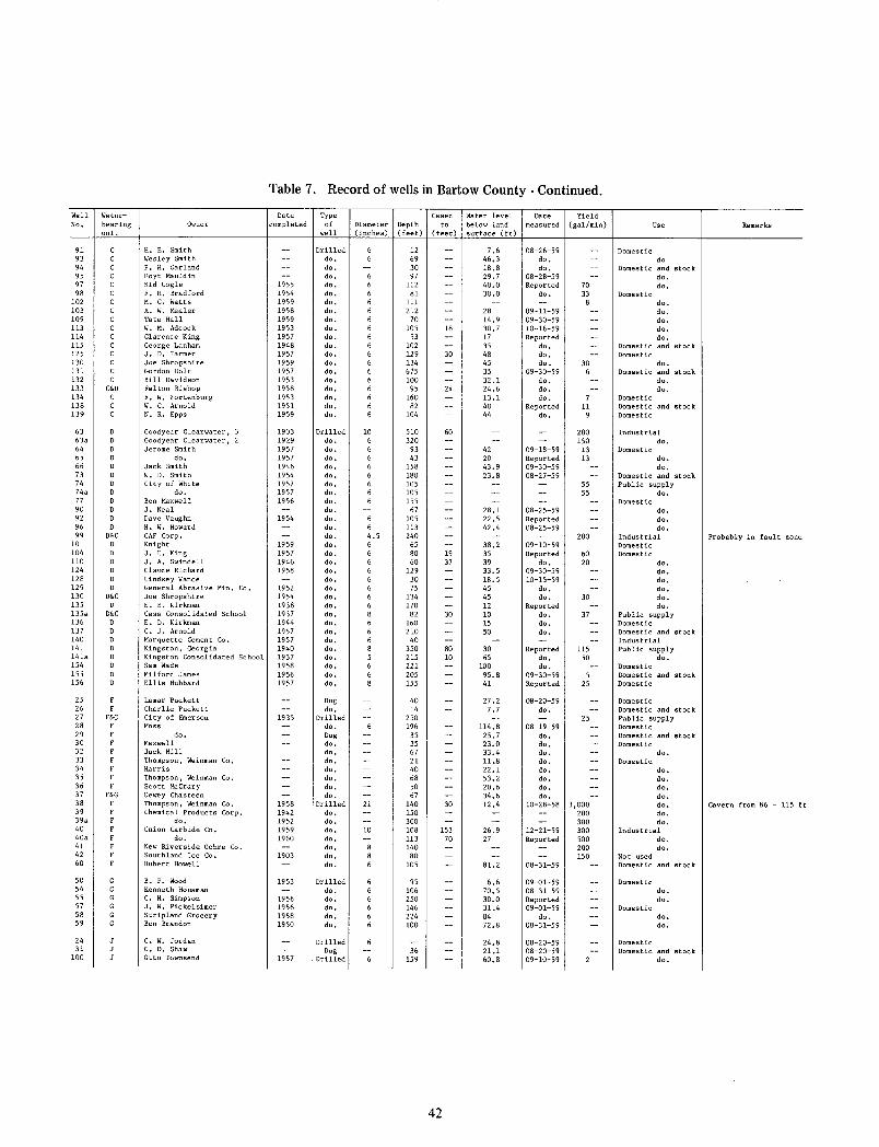
Well Water-No. bearing
91 93 94 95 97 98
102 103 109 113 114 115 125 130 131 132 133 134 138 139
63 63a 64 65 66 73 74 74a 77 90 92 96 99
101 104 110 124 128 129 130 135 135a 136 137 140 141 14la 154 155 156
25 26 27 28 29 30 32 33 34 35 36 37 38 39 39a 40 40a 41 42 60
50 54 55 57 58 59
24 31
100
unit
C&D c
D D&C
D
D O&C
D
D&C
F&G F
F
F F&G
F
Table 7. Record of wells in Bartow County - Continued.
Date Type Owner completed of
H. E. Smith Wesley Smith P. H. Garland Hoyt Mauldin Sid Cagle F. H. Bradford M. C. Watts A. W. Mealer Tate Hall w. M. Adcock Clarence King George Lanham J. D. Farmer Joe Shropshire Gordon Halt Bill Davidson Felton Bishop F. W. Fortenburg W. C. Arnold N. R. Epps
1955 1954 1959 1958 1959 1953 1957 1948 1957 1959 1957 1953 1958 1953 1951 1959
Goodyear Clearwater, 1903 Goodyear Clearwater, 1929 Jerome Smith 1957
do. 1957 Jack Smith 1946 W. D. Smith 1954 City of White 1957
do. 1957 Ben Maxwell 1956 J. Neal Dave Vaughn 1954 H. W. Howard GAF Corp. Knight 1959 J. E. King 1957 J. A. Swindell 1946 Claude Richard 1958 Lindsey Vance General Abrasive Min. Co. 1952 Joe Shropshire 1954 E. E. Kirkman 1938 Cass Consolidated School 1937 E. D. Kirkman 1944 C. J. Arnold 1957 Marquette Cement Co. 1957 Kingston, Georgia 1940 Kingston Con sol ida ted School 193 7 Sam Wade 1958 Milford James 1956 Ellis Hubbard 1957
Lamar Puckett Charlie Puckett City of Emerson 1935 Moss
do. Maxwell Jack Hill Thompson, Weinman Co. Harris Thompson, Weinman Co. Scott McCrary Dewey Chasteen Thompson, Weinman Co. 1958 Chemical Products Corp. 1942
do. 1952 Union Carbide Co. 1959
do. 1960 New Riverside Ochre Co. Southland Ice Co. 1903 Hubert Howell
B. F. Wood Kenneth Housman c. H. Simpson J. W. Pickelsimer Stripland Grocery Ben Brandon
C. w. Jordan C. D. Shaw Otto Townsend
1953
1956 1956 1958 1950
1957
well
Drilled do. do. do. do. do. do. do. do. do. do. do. do. do. do. do. do. do. do. do.
Drilled do. do. do. do. do. do. do. do. do. do. do. do. do. do. do. do. do. do. do. do. do. do. do. do. do. do. do. do. do.
Dug do.
Drilled do. Dug do. do. do. do. do. do. do.
Drilled do. do. do. do. do. do. do.
Drilled do. do. do. do. do.
Drilled Dug
Drilled
Cased Water level Date Yield Diameter Depth to below land measured (gal/min) (inches) (feet) (feet) surface (ft)
10 6 6 6 6 6 6 6 6
6 6 4.5 6 6 6 6 6 6 6 6 8 6 6 6 8 5 6 6 8
21
10
12 69 30 97
112 81
111 212
70 105
53 102 129 134 675 100
95 160
82 104
510 320
93 43
158 180 105 105 155
67 105 113 240
65 80 60
129 30 75
134 170
82 160 210 40
350 215 221 205 155
40 14
250 196
35 35 67 21 40 68 so 67
140 150 300 108 113 140
80 105
95 106 250 146 224 100
36 159
18
30
24
60
19 37
30
80 10
30
153 70
42
7.6 46.3 18.8 29.7 40.0 30.0
28 14.9 30.7 17 35 48 45 35 32.1 24.6 13.1 40 44
42 20 43.9 23.8
28.1 22.5 42.4
38.2 35 39 33.5 18.5 45 45 12 10 15 so
30 65
100 95.8 41
27.2 7. 7
114.8 25.7 23.0 33.4 ll.8 22.1 53.2 20.6 34.6 12.4
26.9 27
81.2
6.6 70.5 30.0 31.4 84 72.8
24.8 21.1 60.8
08-26-59 do. do.
08-28-59 Reported
do.
09-11-59 09-30-59 10-16-59 Reported
do. do. do.
09-30-59 do. do. do.
Reported do.
70 33
8
30 6
11 9
200 150
09-18-59 13 Reported 13 09-30-59 08-27-59
08-25-59 Reported 08-25-59
09-10-59
55 55
200
Reported 60 do. 20
09-30-59 10-15-59
do. do. 30
Reported do. 37 do. do.
Reported ll5 do. 50 do.
09-30-59 5 Reported 25
08-20-59 do.
08-19-59 do. do. do. do. do. do. do. do.
25
10-28-58 3,000 200 300
12-21-59 300 Reported 500
08-31-59
09-01-59 08-31-59 Reported 09-01-59
do. 08-31-59
08-20-59 08-20-59 09-10-59
200 150
Use
Domestic do
Domestic and stock do.
Domestic do.
do. do. do. do. do.
Domestic and stock Domestic
do. Domestic and stock
do. do.
Domestic Domestic and stock Domestic
Industrial do.
Domestic do. do.
Domestic and stock Public supply
Domestic do.
do. do. do.
Remarks
Industrial Probably in fault zone Domestic Domestic
do. do. do. do. do. do.
Public supply Domestic Domestic and stock Industrial Public supply
do. Domestic Domestic and stock Domestic
Domestic Domestic and stock Public supply Domestic Domestic and stock Domestic
Domestic do.
do. do. do. do. do. Cavern from 86 - llS ft do. do.
Industrial do. do.
Not used Domestic and stock
Domestic
Domestic
Domestic
do. do.
do. do.
Domestic and stock do.
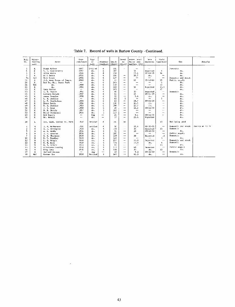
Table 7. Record of wells in Bartow County - Continued.
Well Water- Date Type Cased Water level Date Yield No. bearing Owner completed of Diameter Depth to below land measured (gal/min) Use Remarks
unit well (inches) (feet) (feet) surface (ft)
K Frank McEver 1957 Drilled 102 Domestic K c. c. Castleberry 1957 do. 107 36 Reported do. K Effie White 1946 do. 150 23.4 09-02-59 14 do. K Will Smith 1951 do. 104 18.7 do. do.
9a K&S Hoyt Green 1951 do. 127 Domestic and stock 11 K u.s. Army Corps of Engrs. 1960 do. 63 05-12-60 35 Public supply 20 K Red Top Mtn, State Park do. 203 6 do. 21 K&G do. 1958 do. 150 30 do. 22 do. 1951 do. 208 18 Reported 13.5 do. 23 Camp Marina do. 203 17 do. 43 c. B. Guyton 1951 do. 40 30 Reported Domestic 44 Luthern Knight 1957 do. 41 13 09-01-59 do. 45 James Temples 1958 do. 52 5.6 do. do. 46 K L. N. Jenkins do. 65 do. 47 K L. F. Starkebaun 1959 do. 65 28.7 09-01-59 do. 48 K Homer Davis 1956 do. 130 16.5 do. do. 49 K T. A. Jenkins 1953 do. 190 13.7 do. do. 51 J. Y. Ross 1958 do. 50 22.2 08-31-59 do. 52 K N. E. Norris 1957 do. 162 do. 53 K Daisy Stripland 1955 do. 115 do. 69 K Bob Segers Dug 26 9.1 08-31-59 do. 70 K Dr. Howell do. 37 25.6 Reported do.
19 Geo. Wash. Carver St. Park 1952 Drilled 140 54 10 Not being used
J. P. McPherson 1954 Drilled so 15.4 09-02-59 Domestic and stock Cavity at 41 ft
o. J. Arrington 1955 do. 128 35 Reported 13 Domestic w. E. Biddy 1954 do. 91 20 09-02-59 do.
J. F. Groover 1950 do. 100 Pub! ic supply
s. N. Thurmond 1959 do. 139 38 Reported .5 Domestic 10 R. v. Pendley 1959 do. 120 3 do.
12 L. D. Wright 1958 do. 157 13.0 Reported Domestic and stock 13 R. N. Keys 1958 do. 128 13.0 do. 6 Domestic 14 H. T. Alford 1955 do. 85 15 do.
15 Allatoona Landing 1952 do. 113 63 Reported Public supply 16 King Camp 1950 do. 106 35 do. 15 do.
17 Ballard Estate Dug 13 9.3 09-02-59 Domestic 18 N&K Norman Cox 1958 Drilled 145 41.3 do. do.
43
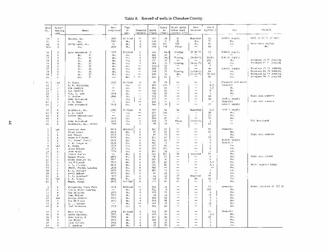
Table 8. Record of wells in Cherokee County.
Well Water- Date Type Cased Water level Date Yield
No. bearing Owner completed of Diameter Depth to below land measured (gal/min) Use Remarks
unit well (inches) (feet) (feet) surface ( ft)
20 D Nelson, Ga. 1947 Drilled 10 505 28 20 Reported 31 Public supply Well in 40 ft of marl
21 D do. 1962 do. 8 450 77 20 do. 32 do.
62 D Ballground, Ga. - do. 8 400 314 100 do. 85 do. Penetrates marble
62a D do. 1936 do. 8 240 238 Flows -- 84 -- do.
50 G Lake Arrowhead 14 1973 Drilled 6 328 49.6 Flowing 03-30-73 13 Public supply
51 G do. 11 do. do. 6 268 30 - -- 1 -52 G do. 13 do. do. 6 309 48.2 Flowing 03-20-73 12-15 Public supply
53 G do. 16 do. do. 6 252 30 - -- 200 do. Drawdown 55 ft pumping
54 G do. 17 do. do. 6 309 30 Flowing 04-11-73 47 do. Drawdown 64 ft pumping
56 G do. 20 do. do. - 310.5 30 - -- 7 --57 G do. 24 do. do. 10 288 25 -- -- 40 Public supply Drawdown 75 ft pumping
58 G do. 26 do. do. - 248 25 Flowing 05-04-73 89 do. Drawdown 84 ft pumping
59 G do. 27 do. do. - 330 35 do. 05-23-73 78-105 do. Drawdown 62 ft pumping
61 G do. 31 do. do. - 248 64 - -- 80 do. Drawdown 96 ft pumping
11 J&N M. Burns 1963 Drilled 6 96 70 - - 5 Domestic and stock
22 J D. w. Stripling -- do. - 185 173 - -- 4.5 Domestic
23 J Tim Jenkins -- do. - 305 65 - -- 1.5 do.
24 J Lyn Jenkins -- do. - 125 45 -- -- 8 do.
29 J Mrs. J. Land 1974 do. - 450 30 - -- 5 do.
30 J J. Jordan 1966 do. - 122 85 - -- 20 -- High iron content
31 J Lake Arrowhead -- do. 6 122 77 -- -- 20 Public supply
47 J v. D. Pass -- do. - 142 - -- -- -- Domestic High iron content
60 J Lake Arrowhead 1973 do. 6 166 29 -- -- 25 Public supply
32 K Woodstock, Ga. 1950 Drilled 8 500 84 35 Reported 6.5 Public supply
45 K L. G. Leach -- do. - 225 130 - -- 30 do.
48 K Coffee Enterprises -- do. - 225 - - -- 15 do.
49 K do. 1973 do. - 500 87 - -- 10 do.
55 K Lake Arrowhead 1973 do. 6 248 25 Flows 05-17-73 2 -- Not developed
64 K Woodstock, Ga., School 1940 do. 6 90 70 - -- 26 --
1 L&P Lawrence West 1973 Drilled 6 145 55 - -- 10 Domestic
2 L Lloyd Green 1974 do. 6 95 42 -- -- 12 do.
3 L Lee Fowler 1973 do. 6 85 53 - -- 5 do. High iron content
5 L Wayne Hillhouse 1973 do. 6 105 67 - -- 25 do.
6 L Mt. Carmel Church 1974 do. 6 165 83 - -- 3 Public supply
7 L J. w. Langston 1974 do. 6 165 15 - -- 9 Domestic
9 L&J E. Young 1973 do. 6 225 46 - - 5 do.
10 L Allen Roland 1974 do. 6 225 105 - -- 8 do.
13 L Jean Honea 1974 do. 6 165 58 - - 2 do.
14 L Jimmie Fowler - do. 6 225 112 30 Reported 15 do.
15 L Reggie Hines 1973 do. 6 130 75 - -- 6 do. High iron con tnt
16 L Grady Ghorley Co. 1974 do. 6 165 70 - -- 4 do.
17 L Roy Millwood 1973 do. 6 185 43 - -- 3. 5 do.
18 L E. L. Pittman 1972 do. 6 400 80 - -- 3. 5 do. Water appears dingy
19 L USACE, Fields Landing 1953 do. 8 168 - -- -- -- do.
38 L R. L. Anthony 1973 do. 6 185 55 -- -- 7 do.
39 L Larry Dobson 1973 do. 6 85 28 -- -- 8 do.
40 L F • E. Blackwell 1973 do. 6 62 33 25 Reported 32 do.
41 L&N L. D. Inbody 1951 do. 6 126 30 12 do. 12 do.
42 L Miguel Gorge 1973 Drilled 6 145 35 - -- 5 do.
4 N Whispering Pines Park 1974 Drilled -- 225 35 - -- 12 Domestic Water fracture at 525 f
12 N Little River Landing -- do. 6 532 6 -- -- 200 do.
25 N Van Allstine 1973 do. 6 lOS 55 - - 5 do.
26 N Tony Wilson 1973 do. 6 85 43 - -- 10 do.
27 N&P George Drennon 1973 do. 6 205 62 - -- 8 do.
28 N Sam Williams 1973 do. 6 240 68 - -- 5 do.
44 N J. J. Cotter -- do. - 105 75 - - 10 do.
46 N Paul Anderson 1973 do. 6 105 60 - -- 7 do.
33 p Mark Yother 1974 Drilled 6 125 90 - -- 15 Domestic
34 p Jerry Cantrell 1973 do. 6 145 60 - -- 3.5 do.
35 p Fred Haily, 6 1974 do 6 165 80 - -- 10 do.
36 p Joe Motes 1974 do. 6 185 63 -- -- 7 do.
37 p Jack Collett 1954 do. 6 90 30 - -- 5 do.
43 p c. Worshum 1974 do. 6 85 !8 - - 3 do.
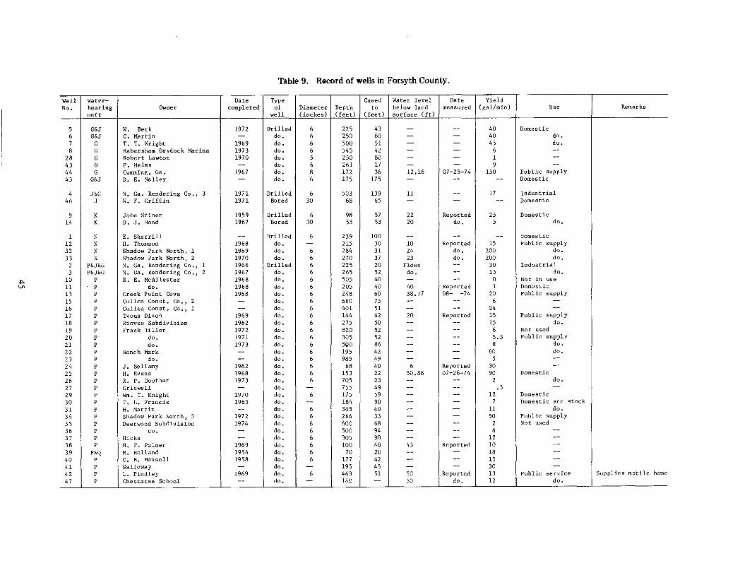
Table 9. Record of wells in Forsyth County.
Well Water- Date Type Cased Water level Date Yield No. bearing Owner completed of Diameter Depth to below land measured (gal/min) use Remarks
unit well (inches) (feet) (feet) surface (ft)
5 G&J w. Beck 1972 Drilled 6 225 43 -- -- 40 Domestic 6 G&J c. Martin -- do. 6 250 60 -- -- 40 do. 7 G T. T. Wright 1969 do. 6 500 51 -- -- 45 do. 8 G Habersham Drydock Marina 1973 do. 6 545 42 -- -- 6 --
28 G Robert Lawton 1970 do. 5 250 80 - -- 1 --43 G P. Helms -- do. 6 261 17 - -- 9 --44 G Cumming, Ga. 1967 do. 8 172 36 12.16 07-25-74 150 Public supply 45 G&J D. E. Nalley - do. 6 175 175 -- -- -- Domestic
4 J&G N. Ga. Rendering Co., 3 1971 Drilled 6 503 139 ll -- 17 Industrial 46 J w. F. Griffin 1971 Bored 30 68 65 - -- -- Domestic
9 K John Stiner 1959 Drilled 6 98 57 22 Reported 25 Domestic 14 K D. J. Hood 1967 Bored 30 53 53 20 do. 5 do.
1 N E. Sherrill -- Drilled 6 239 100 -- -- -- Domestic 12 N H. Thomson 1968 do. - 215 30 10 Reported 15 Public supply 32 N Shadow Park North, 1 1969 do. 6 284 31 24 do. 200 do. 33 N Shadow Park North, 2 1970 do. 6 270 37 23 do. 200 do.
2 P&J&G N. Ga. Rendering Co., 1 1966 Drilled 6 225 20 Flows -- 30 Industrial 3 P&J&G N. Ga. Rendering Co., 2 1967 do. 6 265 52 do. -- 15 do.
10 p R. E. McAllester 1968 do. 6 505 40 -- -- 0 Not in use 11 p do. 1968 do. 6 205 40 40 Reported 1 Domestic 13 p Creek Point Cove 1968 do. 6 248 60 38.17 08- -74 20 Public supply 15 p Cullen Canst. Co., 2 -- do. 6 660 75 -- -- 6 --16 p Cullen Canst. Co., 1 -- do. 6 401 51 -- -- 24 --17 p Ivous Dixon 1969 do. 6 144 42 20 Reported 15 Public supply 18 p Rieves Subdivision 1962 do. 6 275 50 -- -- 15 do. 19 p Frank Tiller 1972 do. 6 820 52 -- -- 6 Not used 20 p do. 1971 do. 6 305 52 -- -- 5.5 Public supply 21 p do. 1973 do. 6 5go 86 -- -- 8 do. 22 p Bench Mark -- do. 6 195 42 -- -- 60 do. 23 p do. -- do. 6 985 49 - -- 5 --24 p J. Bellamy 1962 do. 6 68 40 6 Reported 30 --25 p H. Evans 1968 do. 6 153 22 50.88 07-26-74 90 Domestic 26 p R. P. Douthat 1973 do. 6 705 23 -- -- 2 do. 27 p Griswell -- do. - 755 49 -- -- .5 --29 p Wm. T. Knight 1970 do. 6 175 59 -- -- 12 Domestic 30 p T. L. Francis 1965 do. -- 184 90 -- -- 7 Domestic and stock
31 p H. Martin -- do. 6 365 40 -- -- ll do. 34 p Shadow Park North, 3 1972 do. 6 266 33 - -- 50 Public supply 35 p Deerwood Subdivision 1974 do. 6 600 68 -- -- 2 Not used 36 p do. -- do. 6 500 94 -- -- 6 --37 p Hicks -- do. 6 305 90 -- -- 12 --38 p H. F. Palmer 1969 do. 6 100 40 45 Reported 10 --39 P&Q M. Holland 1956 do. 6 70 20 -- -- 18 --40 p c. B. Mansell 1958 do. 6 177 42 -- -- 15 --41 p Galloway - do. -- 195 45 -- -- 30 --42 p L. Pindley 1969 do. 6 463 51 50 Reported 13 Public service Supplies mobile home 47 p Chestatee School -- do. - 140 - 50 do. 12 do.

The Department of Natural Resources 1s an equal opportunity employer and offers all persons the opportunity to compete and participate in each area of DNR employment regardless of race. color. religion . sex . national ongin. age. handicap. or other non-merit factors .
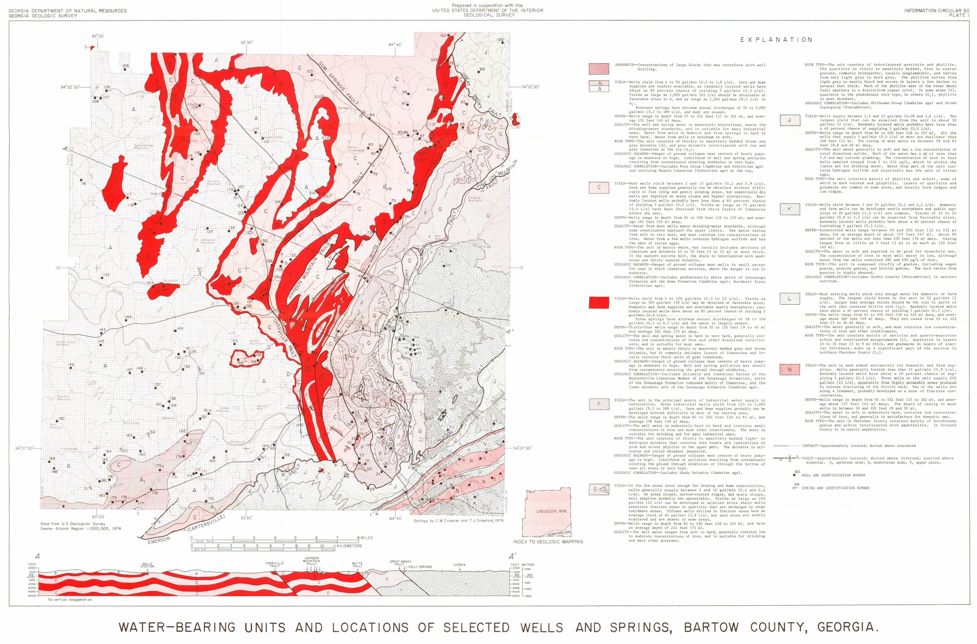
GEORGIA DEPARTMENT OF NATURAL RESOURCES GEORGIA GEOLOGIC SURVEY
A
' t" '" P:
I"; '· I ' 1: ,, 1:. f . .
' J .. r - ~.~-<· . . . . .
I·
I ' . I:.
ss·oo'
o--r .~-n 1
... .. 1 '· . . " • ' •• -. -r; •
I:
.. ,, . \ • . • ' • • :1 . . . . \
. ' .
.... . " . . . : (: . . :y ; :: .. : . -~--~->-< : .. i~!( -< .. . . : . . . . . \, _,. . . . . . . .
, f : . \
-. t A :, ' '
. I \ .,
; . '/: . ' · J .
' •
Base from U S. Geolog1COI Survey
Greater Atlanta Reg1on I 1000,0001 1974
No vert1cal exaggeration
.-.-....._ ~ ... .._ _., I I . . ....~- ...
': _ _ ~149 . ~ · ~
'\. \
--~ - -
' '>-' • J ........ _, _ ••
: ~~ ~: . . . '
)
f b • • •
'
j •
-. . - - .... . . ; .. >.:. . "·
J "·\~{~ ~__.;X"!" . . 1531 .. ....
. ,. . . . . . . . . ·\..·
. . ~ .. '11::
... ) :j
"<'·- --- 7j
> /
( I
OC=~C:E3C:~==:j2~~~~3=======J4~~~~5=======6~~~~7t=====;=J8MILES OCJ~ft====2~~~3t====4~~~5t====6~~37C:::=8~~~9::::JIO~~II.KILOMETERS
17-. ' [I ''
_j
'
Prepared in cooperation w1th the UNITED STATES DEPARTMENT OF THE INTERIOR
GEOLOGICAL SURVEY
' I
\ ' ' \',( "j
\ ,._jl
I I r r f' ,, -,. ( 't\ ' ' ) J \ 1-----34°22 30"
·'l---15'
r=-r·----' 'l . I r . , I I CRESSLER, 1976 '
Geology by C W Cressler ~ I ' ,·1 I ----·---' , L-~::_CRAW~~9~j
INDEX TO GEOLOGIC MAPPING
A' ,00
SEA LEVEL
,00
1000
1>00
~ LAd
WATER-BEARING UNITS AND LOCATIONS OF SELECTED WELLS AND
INFORMATION CI RCULAR 50 PLA T E I
E X PLANA TI ON
JASPEROID--Concentrations of large blocks that may interfere with well drilling.
YIELD--Wells yield from 4 to 92 gal/min (0.3 to 5 . 9 L/s). Farm and home supplies are readily available, as randomly located wells have about an 80 percent chance of yielding 5 gal/min (0 . 3 L/s) , Yields as large as 1,000 gal/min (63 L/s) should be obtainable at favorable sites in A, and as large as 1,500 gal/min (9.5 L/s) in Al •
Fourteen springs have minimum annual discharges of 50 to 3,000 gal/min (3.2 to 189 L/s), and most are unused.
DEPTH--Wells range in dept~ from 55 to 331 feet (17 to 101m), and average 132 feet (40 m) deep.
QUALITY--The well and spring water is moderately mineralized, meets the drinking-water standards, and is suitable for many industrial us;es . Water from wells in bedrock and from springs is hard to very hard . Water from wells in residuum is soft.
ROCK TYPE--The unit consists of thickly to massively bedded brown and gray dolomite (A), and gray dolomite inter layered with tan and gray limestone at the top (A 1).
GEOLOGIC HAZARDS--Danger of ground collapse near centers of heavy pumpage is moderate to high . Likelihood of well and spring pollution resulting from contaminants entering sinkholes is very high .
GEOLOGIC CORRELATION--Includes Knox Group (Cambrian and Ordovician age) and overlying Newala Limestone (Ordovician age) at the top.
YIELD--Most wells yield between 2 and 15 gal/min (0 . 1 and 0 . 9 L/s). Farm and home supplies generally can be obtained without difficulty in flat lying and gently sloping areas, but essentially dry wells are reported on steep slopes and higher elevations. Randomly loc.ated wells probably have less than a 60 percent chanc.e of yielding 5 gal/min (0 . 3 L/s) . Yields as large as 70 gal/min (4,4 L/s) have been obtained from thick layers of limestone within the unit.
DEPTH--Wells range in depth from 50 to 558 feet (15 to 170m), and average 182 feet (55 m) deep .
QUALITY--Water from most wells meets drinking-water standards, although some constituents approach the upper limits. The water varies from soft to very hard, and most contains low concentrations of iron, Water from a few wells contains hydrogen sulfide and has the odor of rot ten eggs.
ROCK TYPE--The unit is mainly shale, but locally includes sections of limestone and dolomite 10 to 50 feet (3 to 15 m) or more thick . In the eastern outcrop belt, the shale is interlayered with sandstone and thinly layered dolomite .
GEOLOGIC HAZARDS--Danger of ground collapse near wells is small except for ones in thick limestone sec.tions, where the danger is low to moderate.
GEOLOGIC CORRELATION--Includes predominantly shale parts of Conasauga Formation and the Rome Formation (Cambrian age); Rockmart Slate (Ordovic.ian age).
YIELD--Wells yield from 5 to 200 gal/min (0 .3 to 13 L/s). Yields as large as 300 gal/min (19 L/s) may be obtained at favorable sites. Do1mestic and farm supplies are available nearly everywhere; randmmly located wells have about an 80 perc.ent chance of yielding 5 gal/min (0.3 L/s) .
Three springs have minimum annual disc.harges of 18 to 150 gal/min (0 . 5 to 9.5 L/s) and the water is largely unused.
DEPTH--Thirty-four wells range in depth from 30 to 150 feet (9 to 46 m) and average 181 feet (55 m) deep .
QUALITY--The well and spring water is hard to very hard, generally contains low concentrations of iron and other dissolved constituents, and is suitable for most uses.
ROCK TYPE--The unit is mainly thinly to massively bedded gray and brown dolomite, but it commonly includes layers of limestone and locally c.ontains thick units of gray limestone.
GEOLOGIC HAZARDS--Danger of ground collapse near c.enters of heavy pumpage is moderate to high . Well and spring pollution may result from c.ontaminants entering the ground through sinkholes.
GEOLOGIC CORRELATION--Includes dolomite and limestone facies of the Maynardville Limestone Member of the Conasauga Formation, units of the Conasauga Fo rmation composed mainly of limestone, and the lower dolomite unit of the Conasauga Formation (Cambrian age) .
YIELD--The unit is the principal source of industrial water supply in Cartersville. Seven industrial wells yield from 150 to J ,000 gal/min (9 . 5 to 189 L/s). Farm and home supplies probably can be developed without difficulty in most of the outcrop area .
DEPTH--The wells range in depth from 80 to 300 feet (24 to 91 m), and average 158 feet (48 m) deep .
QUALITY--The well water is moderately hard to hard and c.ontains small concentrations of iron and most other constituents. The water is suitable for drinking and for many industrial uses.
ROCK TYPE--The unit consists of thinly to massively bedded light- to dark-gray dolomite that contains thin layers and laminations of pink and silver phyllite in the upper part. The dolomite is siliceous and yields abundant Jasperoid ,
GEOLOGIC HAZARDS--Danger of ground collapse near centers of heavy pumpage is high. Likelihood of pollution resulting from contaminants entering the ground through sinkholes or through the bottom of open pit mines is very high .
GEOLOGIC CORRELATION--Includes Shady Dolomite (Cambrian age).
YIELD--In the few areas level enough for farming and home construction 1
wells generally supply between 2 and 10 gal/min (0.1 and 0.6 L/!s) . On steep slopes, narrow-crested ridges. and scarp slopes, well supplies normally are unavailable . Yields as large as 200 gal/min (13 L/s) c.an be developed at selected sites where wells penetrate fracture zones in quartzite that are recharged by large catchment areas . Fifteen wells drilled in frac.ture zones have an average yield of 60 gal/min (3.8 L/s), but such sites are widely scattered and are absent in some areas.
DEPTH--Wells range in depth from 92 to 330 feet (28 to 101 m), and have an average depth of 241 feet (73 m).
QUALITY--The well water ranges from soft to hard, generally contains low to moderate c.oncentrations of iron, and is suitable for drinking and many other purposes.
~ ~
ROCK TYPE--The unit consists of interlayered quartzite and phyllite . The quartzite is thinly to massively bedded, fine to coarse grained, commonly feldspathic, locally conglomeratic, and varies from very light gray to dark gray. The phyllite varies from light gray to nearly black and occurs in layers a few inches to several feet thick . Muc.h of the phyllite east of the Great Smoky fault weathers to a distinctive copper color , In some areas (G), quartzite is the predominant rock type; in others (G 1) , phyllite is more abundant .
GEOLOGIC CORRELATION--Inc.ludes Chilhowee Croup (Cambrian age) and Ocoee Supergroup (Precambrian).
'ilELD--Wells supply between 1.5 and 25 gal/min (0 . 09 and 1.6 L/s) . The largest yield that can be expected from the unit is about 30 gal/min (2 L/s). Randomly located wells probably have less than a 40 percent chance of supplying 5 gal/min (0 . 3 L/s) .
DEPTH--Wells range in depth from 86 to 450 feet (26 to 137 m) . All the wells that supply 5 gal/min (0.3 L/s) or more are shallower than 166 feet (51 m). The casing in most wells is between 29 and 85 feet (8 . 8 and 26 m) deep .
QUALITY--The well water generally is soft and has a low concentration of total dissolved solids . Much of the water has a pH of less than 7.0 and may corrode plumbing. The concentration of iron in four wells sampled ranged from 0 to 250 ~g/L, which is within the limits set for drinking water. Water from part of the unit contains hydrogen sulfide and reportedly has the odor of rotten eggs .
ROCK TYPE--The unit consists mainly of phyllite and schist, some of which is dark c.olored and graphitic. Layers of quartzite and graywacke are common in some areas, and locally form ledges and low ridges.
YIELD--Wells yield between 2 and 35 gal/min (0.1 and 2.2 L/s) . Domestic and farm wells can be developed nearly everywhere and public supplies of 20 gal/min (1 . 2 L/s) are common . Yields of 15 to 20 gal/min (0.9 to 1.3 L/s) can be expected from favorable sites . Randomly loc.ated wells probably have about a 60 percent chanc.e of furnishing 5 gal/min (0.3 L/s).
DEPTH--Inventoried wells range between 40 and 500 feet (12 to 152 m) deep, for an average depth of about 155 feet (47 m) , About 90 percent of the wells are less than 250 feet (76 m) deep . Casing ranges from as little as 5 feet (2 m) to as much as 130 feet (40 m).
QUALITY--The water is soft and reported to be good for household use • The concentration of iron in most well water is low, although water from two wells contained 280 and 450 ~g/L of iron.
ROCK TYPE--The unit is c.omposed chiefly of gneiss, including augen gneiss, granite gneiss, and biotite gneiss . The rock varies from massive to highly sheared.
GEOLOGIC CORRELATION--Includes Corbin Granite (Precambrian) in western outcrops .
YIELD--Most existing wells yield only enough water for domestic or farm supply. The largest yield known in the unit is 32 gal/min (2 L/s). Larger than average yields should be the rule in parts of the unit that contains brittle rock (Lt). Randomly loc.ated wells have about a 40 percent chance of yielding 5 gal/min (0.3 L/s).
DEPTH--The wells range from 62 to 400 feet (19 to 122 m) deep, and average about 160 feet (49 m) deep. They are cased from 15 to 112 feet (5 to 34 m) deep.
QUALITY--The water generally is soft, and most contains low concentrations of iron and other constituents.
ROCK TYPE--The unit consists mainly of seric.ite and quartz-muscovite schist and interlayered metagraywacke (L). Quartzite in layers 10 to 30 feet (3 to 9 m) thick, and graywac.ke in layers of similar thickness, make up a significant part of the section in northern Cherokee County (Ll).
YIELD--The unit is used almost exclusively for domestic and farm supplies. Wells generally furnish less than 15 gal/min (0 . 9 L/s) , Randomly located wells have about a 40 percent c.hance of supplying 5 gal/min (0 . 3 L/s) . Three wells in the unit supply 200 gal/min (13 L/s), apparently from highly per meable zones produced by intense fracturing of the brittle rock . Two of the wells are along a linement, probably developed on a zone of fracture concentration.
DEPTH--Wells range in depth from SO to 532 feet (15 to 162m), and average about 137 feet (42 m) deep . The depth of casing in most wells is between 30 and 100 feet (9 and 30m) .
QUALITY--The water is soft to moderately hard, contains low concentrations . of iron, and generally is satisfactory for domestic use.
ROCK TYPE--The unit in Cherokee County consists mainly of hornblende gneiss and schist interlayered with amphibolite . In Forsyth County it is mainly amphibolite .
CONTACT--Approximately located; dotted where concealed
~-*-?. .. FAULT--Approximately located; dotted where inferred; queried where doubtful. ~. upthrown side; D, downthrown side; T, upper plate,
60 e WELL AND IDENTIFICATION NUMBER
54 C>- SPRING AND IDENTIFICATION NUMBER
SPRINGS, BARTOW COUNTY, GEORGIA.
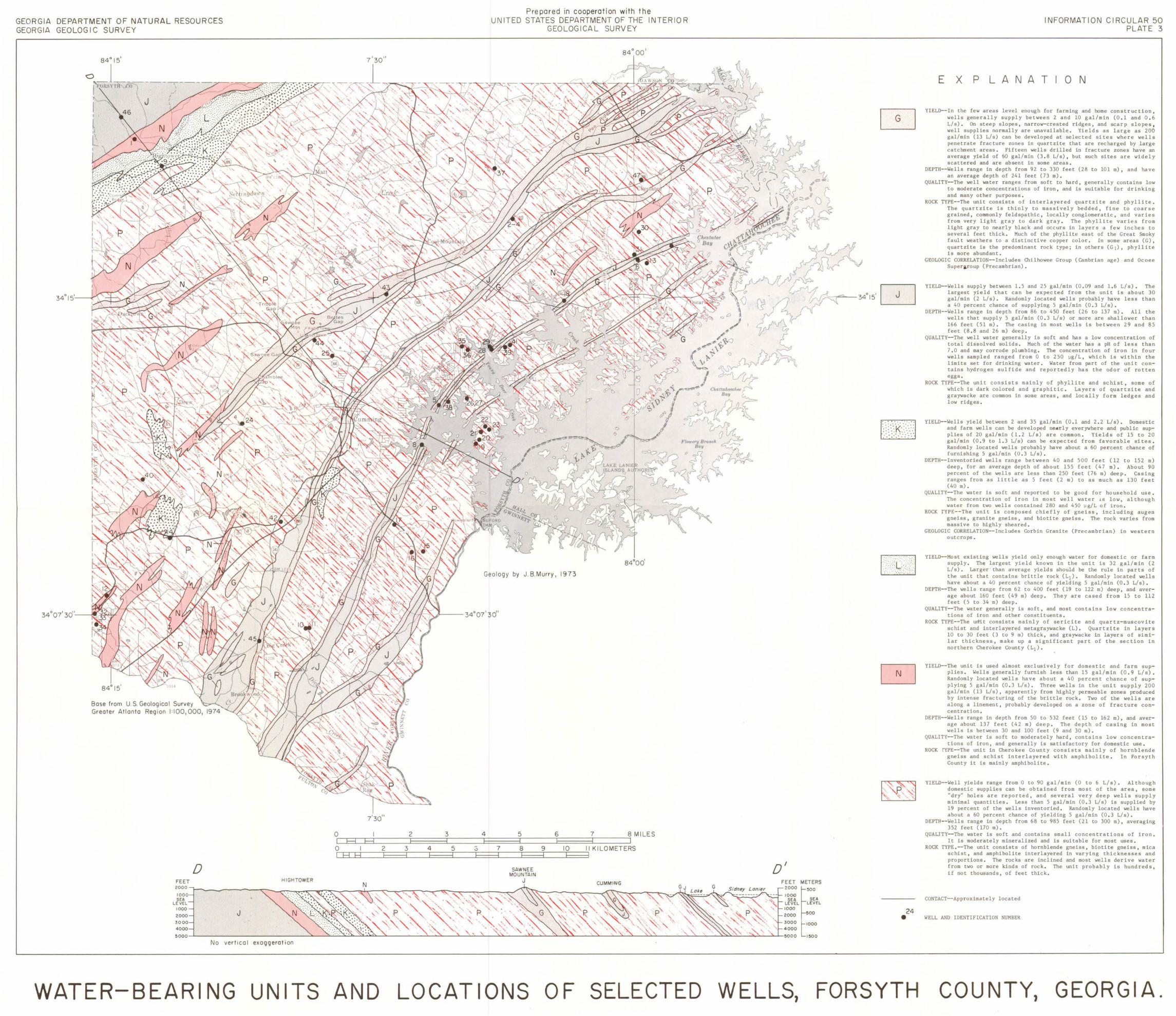
GEORGIA DEPARTMENT OF NATURAL RESOURCES GEORGIA GEOLOG I C SURVEY
Bose from U.S. Geol og ica l Survey Greoter At lonto Reg ion 1:100 ,000,
FEET 2000
1000 SEA
LEVEL
D HIGH TOWER
No ver t ica l exaggeration
7'30"
2
WATER-BEARING UNITS AND
2 3
3 4 5 3
Prepared in cooperat ion with the UNI TED STATES DEPARTMENT OF THE INTERIOR
GEOLOG ICAL SURVEY
s4· ool
a4•oo' Ge olog y by J. B.Murry , 1973
4 5 6
7 8 9 10
SAW NEE MOUNTAIN
J
LOCATIONS OF SELECTED
o' 2000
10 0 0 SEA
LEVEL 1000
2000
3000
4000
500 0
WELLS,
METERS
:500
SEA LEVEL
500
1000
1:500
~ L2iJ
24 •
FORSYTH
E X p
INFORMATION C IRCULAR 50 PLATE 3
L A N A T 0 N
YIELD--In the few areas level enough for farming and home const ruction , wells generally supply between 2 and 10 gal/min (0 . 1 and 0 . 6 L/s) . On steep slopes , nar row-crested ridges, and scarp slopes, well supplies normally are unavailable . Yields as large as 200 gal/min (13 L/s) can be developed at selected sites where wells penetra t e fracture zones in quartzite that are recharged by large catchment areas. Fifteen wells drilled in fractur e zones have an average yield of 60 gal/min (3 . 8 L/s), but such sites are widely scattered and are absent in some areas .
DEPTH--Wells range in depth from 92 to 330 feet (28 to 101 m) , and have an average depth of 241 feet (73 m) .
QUALITY--The well wate r r anges from soft to hard , gene r ally con t ains low to moder a t e concentrations of iron, and is suitable for d r inking and many other purposes .
ROCK TYPE--The unit consists of interlayered quartzite and phyllite . The quartzite is thinly to massively bedded, fine to coarse grained, commonly feldspathic, locally conglomeratic , and varies from very light gray to dark gray . The phyllite varies from light gray to nearly black and occurs in layers a few inches to several feet t hick . Much of the phyllite east of the Great Smoky fault weathers to a distinc t ive copper color . In some areas (G) , quartzite is the predominant rock type; in others (GJ), phyllite is more ab undant .
GEOLOGIC CORRELATION--Includes Chilhowee Group (Cambrian age) and Ocoee Super~oup (P r ecambr ian).
YIELD--Wells supply between 1 . 5 and 25 gal/min (0 . 09 and 1 .6 L/s) . The largest yield that can be expected f r om the unit is abo ut 30 gal/min (2 L/s) , Randomly located wells probably have less than a 40 percent chance of supplying 5 gal/min (0 . 3 L/s) .
DEPTH--Wells range in depth from 86 to 450 feet (26 t o 137m) . All the wells that supply 5 gal/min (0 . 3 L/s) or more are shallower than 166 feet (51 m) . The casing in most wells is between 29 and 85 feet (8 . 8 and 26 m) deep .
QUALITY--The well wate r gener ally is soft and has a low concentration of total dissolved solids . Much of the water has a pH of l ess t han 7 . 0 and may corrode plumbing . The concentration of iron in four wells sampled ranged f r om 0 to 250 ~g/L , which is within t he limits set for drinking water. Water from part of the unit contains hydrogen sulfide and reportedly has t he odor of ro t ten eggs .
ROCK TYPE-- The unit consists mainly of phyllite and schist , some of which is dark colored and graphitic . Layers of qua r tzite and graywacke are common in some areas , and locally fo r m le dges and low ridges .
YIELD--Wells yield between 2 and 35 gal/min (0 .1 and 2.2 L/s) . Domes t ic and farm wells can be developed ne.trly everywhere and public supplies of 20 gal/min (1.2 L/s) a r e common . Yields 'of 15 t o 20 gal/min (0 . 9 to 1.3 L/s) can be expected from favorable sites . Randomly located wells probably have about a 60 percent chance of furnishing 5 gal/min (0 . 3 L/s).
DEPTH-- Inventoried wells range between 40 and 500 feet (12 to 152 m) deep, for an average depth of about 155 feet (47 m) . About 90 percent of the wells are less than 250 feet (76 m) deep . Casing ranges from as little as 5 feet (2 m) to as much as 130 fee t (40 m) .
QUALITY--The water is sof t and reported to be good for household use . The concentration of iron in most well water is low, although water from two wells contained 280 and 450 ~g/L of i r on .
ROCK !YPE--The unit is composed chiefly of gneiss , including augen gneiss , granite gneiss , and biotite gneiss. The rock varies from massive to highly sheared .
GEOLOGIC CORRELATION--Includes Corbin Granite (Precambrian) in western outcrops .
YIELD--Most existing wells yield only enough water for domestic or fa r m supply , The largest yield known in the unit is 32 gal/min (2 L/s) . Larger · than average yields should be the rule in par t s of the unit that contains brittle rock (L1 ) . Randomly loca t e d wells have about a 40 percent chance of yielding 5 gal/min (0 . 3 L/s) .
DEPTH--The wells range from 62 to 400 feet (19 to 122 m) deep , and average about 160 feet (49 m) deep . They a r e cased f r om 15 t o ll2 feet (5 to 34 m) deep .
QUALITY--The water generally is soft, and most contains low concen t rations of iron and o t he r constituents .
ROCK TYPE- -The udit consists mainly of sericite and qua rt z- muscovite schist and inte r layered metag raywacke (L) . Qua r tzi t e in layers 10 to 30 feet (3 to 9 m) thick , and graywacke in layers of similar thickness, make up a significant par t of the section in northern Cherokee County (Ll) .
YIELD--The unit is used almost exclusively for domestic and fa r m supplies . Wells gene r ally furnish less t han 15 gal/min (0 . 9 L/ s) • Randomly located wells have about a 40 percent chance of supplying 5 gal/min (0 . 3 L/s) . Three wells in t he unit sup ply 200 gal/min (13 L/s), apparently from highly permeable zones produced by intense fracturing of the brittle rock . Two of the wells a r e along a linement , probably developed on a zone of f r acture concentration .
DEPTH--Wells range in depth from 50 to 532 feet (15 to 162m) , and average about 137 feet (42 m) deep . The dep t h of casing in most wells is between 30 and 100 feet (9 and 30m) .
QUALITY--The water is soft to moderately hard , contains low concentrations of i r on, and generally is satisfactory for domestic use .
ROCK rYPE--The unit in Cherokee County consists mainly of hornblende gneiss and schist interlayered wi t h amphibolite . In Forsyth County it is mainly amphibolite .
YIELD--Well yields range from 0 to 90 gal/min (0 to 6 L/s) . Although domestic supplies can be obtained from most of the area, some "dry" holes are reported, and several very deep wells supply minimal quantities . Less than 5 gal/min (0 . 3 L/s) is supplied by 19 percent of the wells inventoried, Randomly loca t ed wells have about a 60 percent chance of yielding 5 gal/min (0 . 3 L/s) .
DEPTH--Wells range in depth from 68 to 985 feet (21 to 300m) , averaging 352 feet (170m) .
QUALITY--The water is soft and contains small concen t rations of iron . It is moder ately mineralized and is sui t able for most uses .
ROCK TYPE .--The unit consists of ho r nblende gneiss , biotite gneiss , mica schist, and amphibolite interlayered in varying thicknesses an d proportions . The rocks are inclined and most wells deri ve wate r from two or mor e kinds of rock . The unit probably is hundreds , if not thousands, of feet thick.
CONTACT--Approximately located
WELL AND IDENTIFICATION NUMBER
COUNTY, GEORGIA .
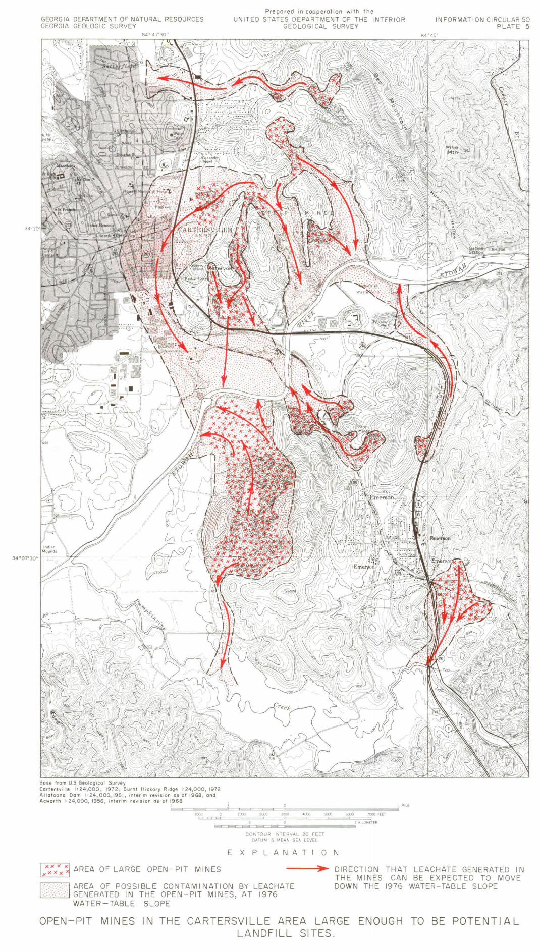
GEORGIA DEPARTMENT OF NATURAL RESOURCES GEORG IA GEOLOGIC SURVEY
8 4 ° 4 7'30"
Bose from US. Geological Survey Cartersville 1=24,000 , 1972, Burnt Hi ckory Ridge 1=24,000 , 1972 Allotoono Dam 1=24,000, 196 1, i nter im rev i s1on as of 1968, and
Prepared in cooperation wi th the UNITED STATES DEPARTMENT OF THE INTER IOR
GEOLOG I CAL SURVEY
Ac..,orth 1=24,000, 1956, inter im rev1s i on as of 1968 1 I 7 I MILE ~==~==~==~==~==~~~~~~~~~~
IOOOEJ=:El=:EO==::::JIOOOE=='E=='=:J2000==3::l000=:===:==4=r000==5000::EOE=='=6000=r:===7000 FEET
0 I KILO METER ~~~======~~~~~~
CO NTOU R IN TERVAL 20 FEET DATU M IS M EA N SEA LEVEL
EXPLANAT ON
INFORMAT ION CIRCULAR 50 PLATE 5
1::/x 1 AREA OF LARGE OPEN-PIT MINES ------~~ DIRECTION THAT LEACHATE GENERATED IN
~AREA OF POSSIBLE CONTAMINATION BY LEACHATE ~GENERATED IN THE OPEN-PIT MINES, AT 1976
WATER- TABLE SLOPE
THE MINES CAN BE EXPECTED TO MOVE DOWN THE 1976 WATER-TABLE SLOPE
OPEN-PIT MINES IN THE CARTERSVILLE AREA LARGE ENOUGH TO BE POTENTIAL LANDFILL SITES .
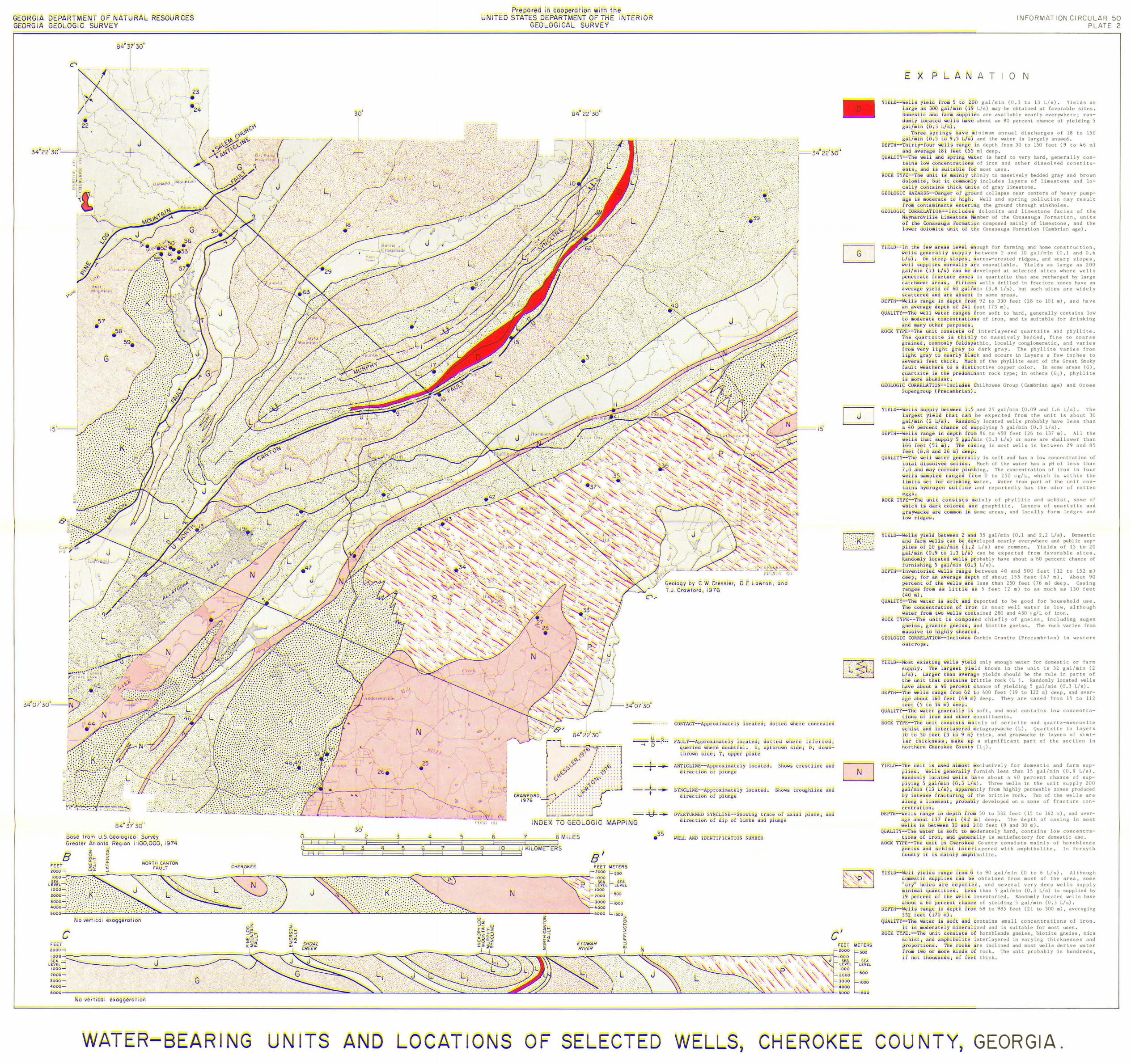
GEGRG A GEORG A
A R SO R CES
88se lfom § e818GIE81 9 rvey €; e8!er A l8n 8 ~eg l o n I loo, ()0(), I
~ B ~ 0
CG ~ ~
c
\J J ~ l1t
/Iili' I
74
WATER- BEARING
E
UN ITS
, pi\,. \ rt~kr~'ln\ dletr./ '
. : . .· . . ~ . ·.
~ : .. .... .. ..... . : ~ . : · , ·:
: · :· .- . ~ .. :.::.'" · .... .. , ' '
Flre pare In coopeF ITED STATE§ DEPARTME
GEO OG CAL
6 7 § L§§
N
ion wl t e T OFT E I sl.JR VEY
T R GR
eSI8gy 'y c w Cress ler, D T eraw 6 7 6
B' ETERS
u - - - ?. .. =I D
- =t- --
----,---
- --t+- --G
3:3 •
CONTA€T- -A ppr 8* rna e y £ E Ee
g y 8
1BE Ee
8vERTUR NEB SYN€LINE- - SR w!n d r ec Bn 8£ p sf 1 mbs
WE AN~ I E .TIFI AT I
t~~ wtl re l': nee eS
e ~ rS
wlier ~
R erre : !l , Bwn-
n
§ 9w tr 8 u It 1 ne ' d
R
c'
Seii.
Y EL
K
n riL
YiE
DEPT
R8eK:
YIE
Bfl T
se
EPT --
R eK
E X
'Maynadlv ~ c
1 wer ~
p A AT
INFORMATI ON CI RCU LAR 50 PLAT E 2
0 N
r w 5 E8 28!i gal/min (0 . 3 to 13 L/s), Yields as a /m n (1 L/s) may be obtained at favorable sites .
f rm sUPp s are available nea r ly everywhere ; ran about an 80 percent chance of yielding 5
of 18 to 150 and the water is largely unused ,
ran e ln depth f r om 30 to 150 feet (9 to 46 m) ~ 5 § m) deep.
is ha r d to very hard , gene r ally con dissolved constitu-
fracture zones have an such sites are widely
101 m), and have
rom soft to hard , generally contains low is suitable for d r tnking
In type ; in others
Group (Cambrian age) and Ocoee
The
soft and has a low concentration of of the water has a pH of less than
ns ~ mkinly of phylli t e and schist , some of re & n& gr aphitic . Layers of qua rt zite and
mmBn 1R ~orne areas , and locally form ledges and
(12 to 152 m) m) . About 90
feet
use .
in western
deep , and averThey are cased from 15 to 112
low concentra -
nly of se r icite and quartz - muscovite ye r~ metag raywacke (L) . Quartzite in laye r s
m) thick , and graywacke in layers of sirni -e ' ~ a significant part of the section in
(Ll) .
xclusively for domestic and farm sup-
f r acture con-
r Bm 50 to 532 feet (15 to 162m), and aver( 4 m ) deep . The depth of casing in most ~nd lao feet (9 and 30 m) .
o mo der ately hard, contains low concentra -8n aRa genera lly is sa t isfactory fo r domestic use .
10 ~He r8 kee County consis t s mainly of hornblende n8 s f fi S i n e r l aye r ed with amphibolite . In Forsyth ~ is Rl y m bolite .
6 L/s) . Although of the area , some
averaging
Eon tain s sma ll concen tr a tions of i ron . 1 zed and is suitable fo r most uses . Bf ho r nblende gneiss , biotite gneiss, mica
nte r laye r ed in va r ying t hicknesses and r e inc l ined and most wells derive water
Bf rock . The unit probably is hund r eds, t hick .
AND LOCAT IONS OF SELECTED WE6L3, CHEROKEE CO UN T Y, GEORGIA.
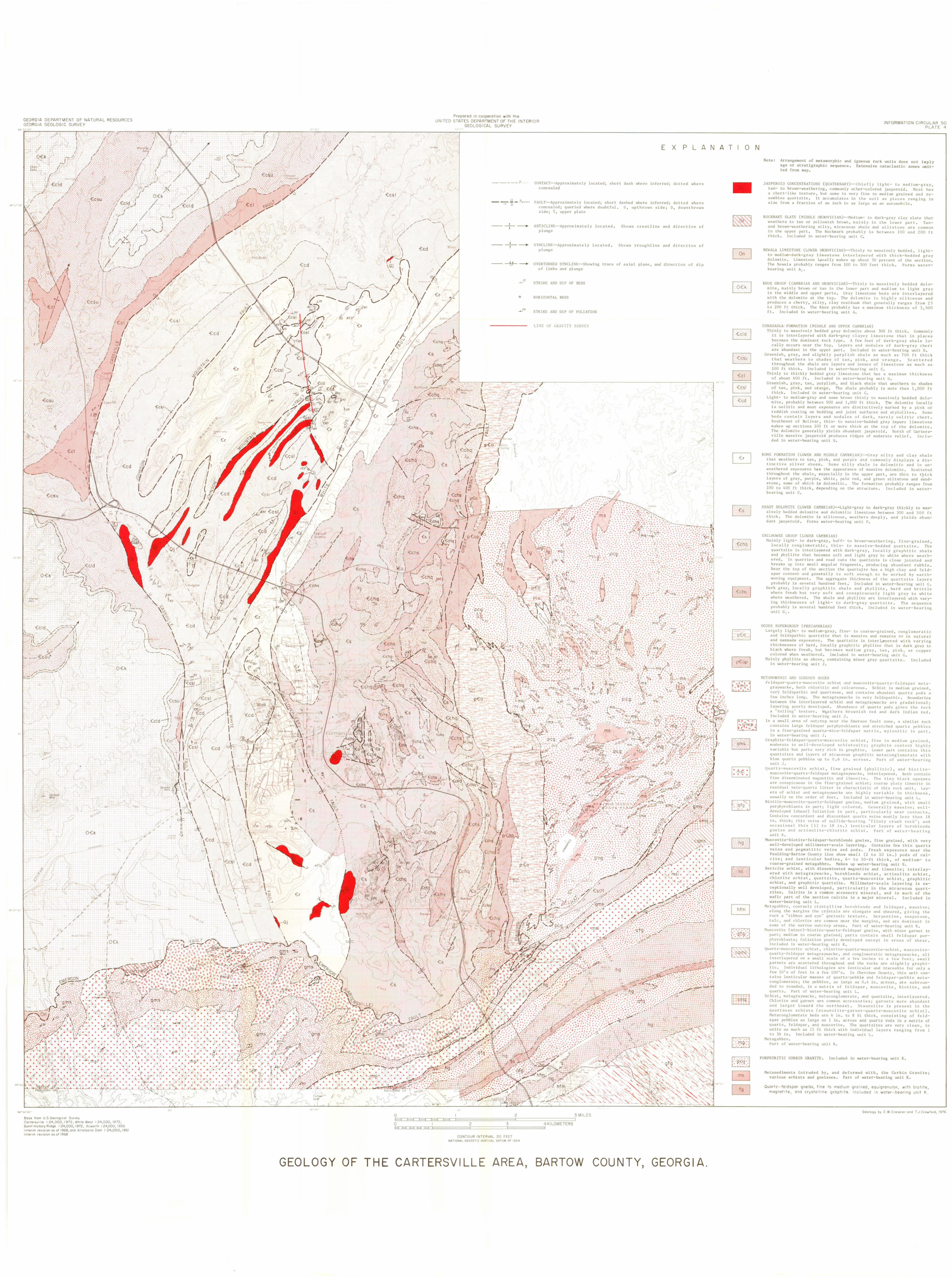
Copyright © 2022 FDOKUMEN