Generator Control Unit, GCU 100 - DEIF
15
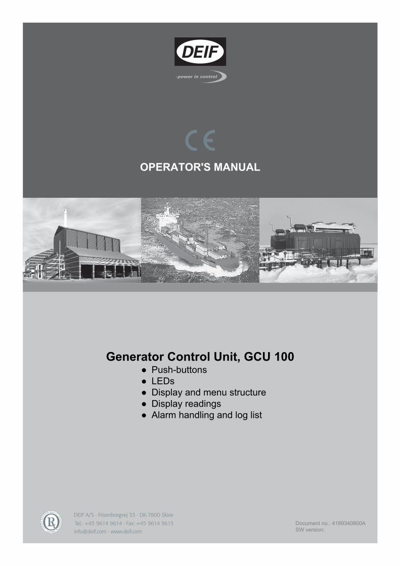
DEIF A/S · Frisenborgvej 33 · DK-7800 Skive Tel.: +45 9614 9614 · Fax: +45 9614 9615 [email protected] · www.deif.com OPERATOR'S MANUAL Generator Control Unit, GCU 100 ● Push-buttons ● LEDs ● Display and menu structure ● Display readings ● Alarm handling and log list Document no.: 4189340800A SW version:
-
Upload
khangminh22 -
Category
Documents
-
view
1 -
download
0
Transcript of Generator Control Unit, GCU 100 - DEIF
DEIF A/S · Frisenborgvej 33 · DK-7800 Skive · Tel.: +45 9614 9614 · Fax: +45 9614 9615 · [email protected] · www.deif.com
DEIF A/S · Frisenborgvej 33 · DK-7800 Skive · Tel.: +45 9614 9614 · Fax: +45 9614 9615 · [email protected] · www.deif.com
DEIF A/S · Frisenborgvej 33 · DK-7800 Skive · Tel.: +45 9614 9614 · Fax: +45 9614 9615 · [email protected] · www.deif.com
OPERATOR'S MANUAL
Generator Control Unit, GCU 100● Push-buttons● LEDs● Display and menu structure● Display readings● Alarm handling and log list
Document no.: 4189340800ASW version:
1. General information1.1. Warnings, legal information and safety..................................................................................................3
1.1.1. Warnings and notes ......................................................................................................................31.1.2. Legal information and disclaimer ..................................................................................................31.1.3. Safety issues ................................................................................................................................31.1.4. Electrostatic discharge awareness ...............................................................................................31.1.5. Factory settings ............................................................................................................................3
1.2. About the operator's manual..................................................................................................................41.2.1. General purpose ...........................................................................................................................41.2.2. Intended users ..............................................................................................................................41.2.3. Contents and overall structure ......................................................................................................4
2. Push-buttons and LEDs2.1. Unit.........................................................................................................................................................5
2.1.1. Push-button functions ...................................................................................................................52.1.2. LED functions ...............................................................................................................................6
3. Display and menu structure3.1. Menu......................................................................................................................................................8
3.1.1. Menu system.................................................................................................................................83.1.2. View menu.....................................................................................................................................83.1.3. Menu structure example ...............................................................................................................9
3.2. Display functions....................................................................................................................................93.2.1. Functional examples .....................................................................................................................9
4. Standard text4.1. Status line text......................................................................................................................................11
4.1.1. Status texts .................................................................................................................................114.1.2. Information text ...........................................................................................................................12
5. Running modes5.1. Running mode overview.......................................................................................................................13
6. Alarm handling and log list6.1. Alarm handling.....................................................................................................................................146.2. Log list..................................................................................................................................................14
GCU 100 Operators manual 4189340800UK
DEIF A/S Page 2 of 15

1. General information1.1 Warnings, legal information and safety
1.1.1 Warnings and notesThroughout this document, a number of warnings and notes with helpful user information will be presented.To ensure that these are noticed, they will be highlighted as follows in order to separate them from the gener-al text.
Warnings
Warnings indicate a potentially dangerous situation, which could result in death, personal in-jury or damaged equipment, if certain guidelines are not followed.
Notes
Notes provide general information, which will be helpful for the reader to bear in mind.
1.1.2 Legal information and disclaimerDEIF takes no responsibility for installation or operation of the generator set. If there is any doubt about howto install or operate the engine/generator controlled by the Multi-line 2 unit, the company responsible for theinstallation or the operation of the set must be contacted.
The Multi-line 2 unit is not to be opened by unauthorised personnel. If opened anyway, the war-ranty will be lost.
DisclaimerDEIF A/S reserves the right to change any of the contents of this document without prior notice.
1.1.3 Safety issuesInstalling and operating the Multi-line 2 unit may imply work with dangerous currents and voltages. Therefore,the installation should only be carried out by authorised personnel who understand the risks involved in work-ing with live electrical equipment.
Be aware of the hazardous live currents and voltages. Do not touch any AC measurement in-puts as this could lead to injury or death.
1.1.4 Electrostatic discharge awarenessSufficient care must be taken to protect the terminal against static discharges during the installation. Once theunit is installed and connected, these precautions are no longer necessary.
1.1.5 Factory settingsThe Multi-line 2 unit is delivered from factory with certain factory settings. These are based on average valuesand are not necessarily the correct settings for matching the engine/generator set in question. Precautionsmust be taken to check the settings before running the engine/generator set.
GCU 100 Operators manual 4189340800UK
General information
DEIF A/S Page 3 of 15
1.2 About the operator's manual
1.2.1 General purposeThis Operator's Manual mainly includes general product information, display readings, push-button and LEDfunctions, alarm handling descriptions and presentation of the log list.
The general purpose of this document is to give the operator important information to be used in the dailyoperation of the unit.
Please make sure to read this document before starting to work with the Multi-line 2 unit andthe generator set to be controlled. Failure to do this could result in human injury or damage tothe equipment.
1.2.2 Intended usersThis Operator's Manual is mainly intended for the daily user. On the basis of this document, the operator willbe able to carry out simple procedures such as start/stop and control of the generator set.
1.2.3 Contents and overall structureThis document is divided into chapters, and in order to make the structure simple and easy to use, eachchapter will begin from the top of a new page.
GCU 100 Operators manual 4189340800UK
General information
DEIF A/S Page 4 of 15
2. Push-buttons and LEDs2.1 Unit
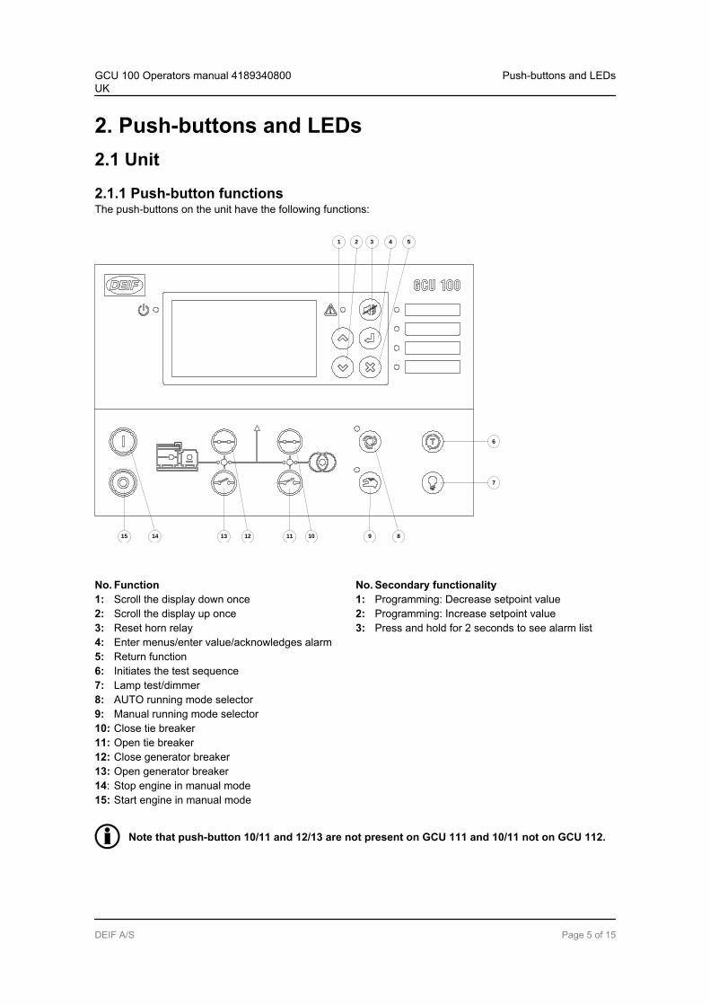
2.1.1 Push-button functionsThe push-buttons on the unit have the following functions:
7
6
9 8
4 5
15 14
1 2 3
10111213
No. Function No. Secondary functionality1: Scroll the display down once 1: Programming: Decrease setpoint value2: Scroll the display up once 2: Programming: Increase setpoint value3: Reset horn relay 3: Press and hold for 2 seconds to see alarm list4: Enter menus/enter value/acknowledges alarm5: Return function6: Initiates the test sequence7: Lamp test/dimmer8: AUTO running mode selector9: Manual running mode selector10: Close tie breaker11: Open tie breaker12: Close generator breaker13: Open generator breaker14: Stop engine in manual mode15: Start engine in manual mode
Note that push-button 10/11 and 12/13 are not present on GCU 111 and 10/11 not on GCU 112.
GCU 100 Operators manual 4189340800UK
Push-buttons and LEDs
DEIF A/S Page 5 of 15
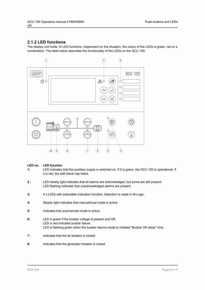
2.1.2 LED functionsThe display unit holds 10 LED functions. Dependent on the situation, the colour of the LEDs is green, red or acombination. The table below describes the functionality of the LEDs on the GCU 100:
5 410
3
67
21
89
LED no. LED function1: LED indicates that the auxiliary supply is switched on. If it is green, the GCU 100 is operational. If
it is red, the self-check has failed.
2 : LED steady light indicates that all alarms are acknowledged, but some are still present.LED flashing indicates that unacknowledged alarms are present.
3: 4 x LEDs with selectable indication function. Selection is made in M-Logic.
4: Steady light indicates that manual/local mode is active.
5: Indicates that auto/remote mode is active.
6: LED is green if the busbar voltage is present and OK.LED is red indicates busbar failure.LED is flashing green when the busbar returns mode is initiated "Busbar OK delay" time.
7: Indicates that the tie breaker is closed
8: Indicates that the generator breaker is closed.
GCU 100 Operators manual 4189340800UK
Push-buttons and LEDs
DEIF A/S Page 6 of 15
9: Indicates that generator voltage/frequency is present and OK.
10: Indicates that running feedback is present.
Note that LED 6/7/8 is not present on version GCU 111, and 6/7 is not present on version GCU112.
GCU 100 Operators manual 4189340800UK
Push-buttons and LEDs
DEIF A/S Page 7 of 15
3. Display and menu structure3.1 Menu
3.1.1 Menu systemThe display includes the menu systems listed below which can be used/viewed without password entry:
View menu system:This is the commonly used menu system, which contains displaying of the measured values.
Log menu:This menu contains event, alarm and battery logs.
Setup menu (not commonly used by the operator):This menu is used for setting up the unit, and if the operator needs detailed information that is notavailable in the view menu system.Changing of parameter settings is password-protected.
Alarm list:This list shows active acknowledged and unacknowledged alarms. It is also in this list that alarms
can be acknowledged by pressing
Service menu:This menu contains input-, output-, M-Logic status and data about the unit.
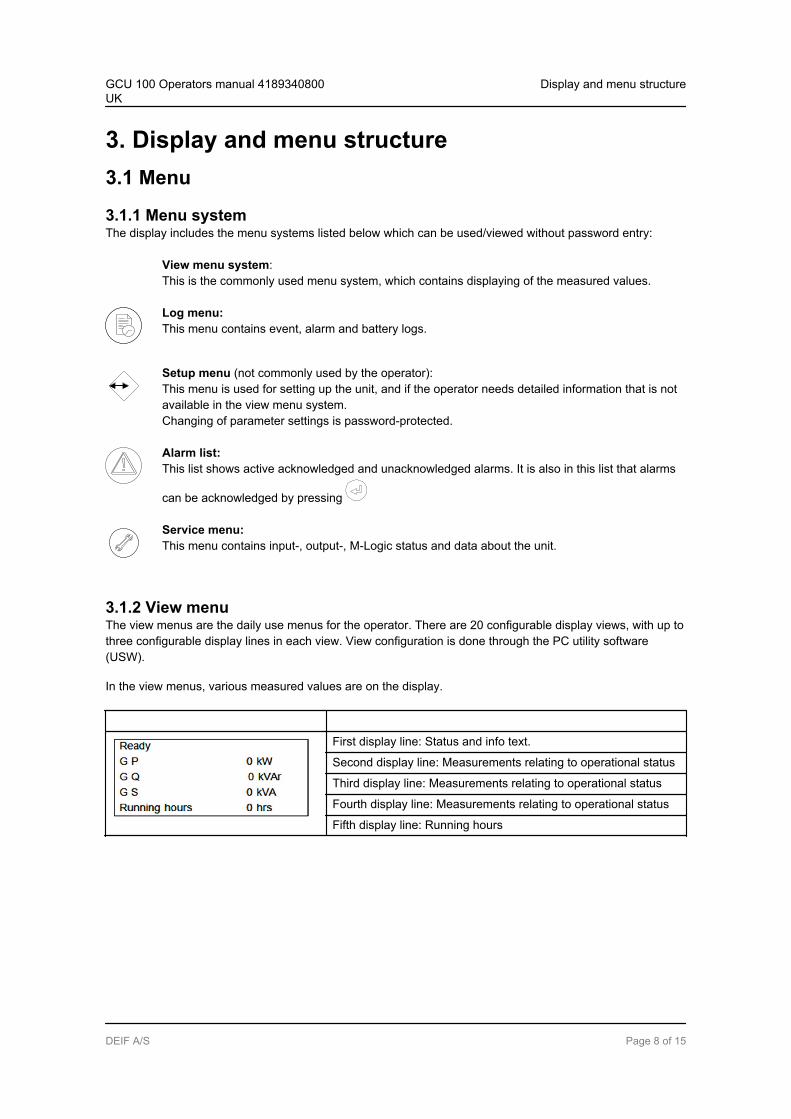
3.1.2 View menuThe view menus are the daily use menus for the operator. There are 20 configurable display views, with up tothree configurable display lines in each view. View configuration is done through the PC utility software(USW).
In the view menus, various measured values are on the display.
First display line: Status and info text.
Second display line: Measurements relating to operational status
Third display line: Measurements relating to operational status
Fourth display line: Measurements relating to operational status
Fifth display line: Running hours
GCU 100 Operators manual 4189340800UK
Display and menu structure
DEIF A/S Page 8 of 15
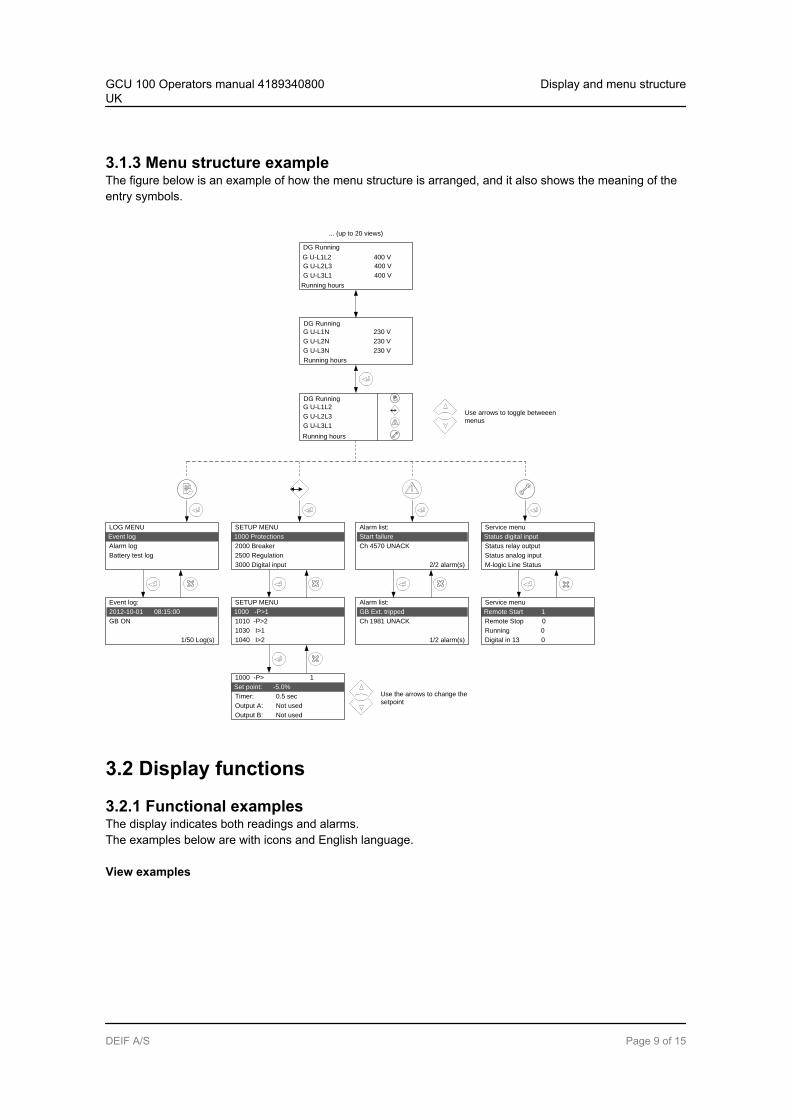
3.1.3 Menu structure exampleThe figure below is an example of how the menu structure is arranged, and it also shows the meaning of theentry symbols.
1000 Protections
SETUP MENU
2000 Breaker
3000 Digital input
2500 Regulation
Status digital input
Service menu
Status relay output
Status analog input
M-logic Line Status
Set point: -5.0%
1000 -P> 1
Timer: 0.5 sec
Output B: Not used
Output A: Not used
1000 -P>1
SETUP MENU
1010 -P>2
1040 I>2
1030 I>1
Remote Start 1
Service menu
Remote Stop 0
Running 0
Digital in 13 0
Alarm list:
Ch 1981 UNACK
1/2 alarm(s)
GB Ext. tripped
Event log:
GB ON
1/50 Log(s)
2012-10-01 08:15:00
Event log
LOG MENU
Alarm log
Battery test log
G U-L1L2
G U-L2L3
G U-L3L1
Alarm list:
Ch 4570 UNACK
2/2 alarm(s)
Start failure
Use arrows to toggle betweeen
menus
G U-L1L2 400 V
DG Running
G U-L2L3 400 V
G U-L3L1 400 V
Running hours
G U-L1N 230 V
G U-L2N 230 V
G U-L3N 230 V
... (up to 20 views)
Use the arrows to change the
setpoint
DG Running
DG Running
Running hours
Running hours
3.2 Display functions
3.2.1 Functional examplesThe display indicates both readings and alarms.The examples below are with icons and English language.
View examples
GCU 100 Operators manual 4189340800UK
Display and menu structure
DEIF A/S Page 9 of 15
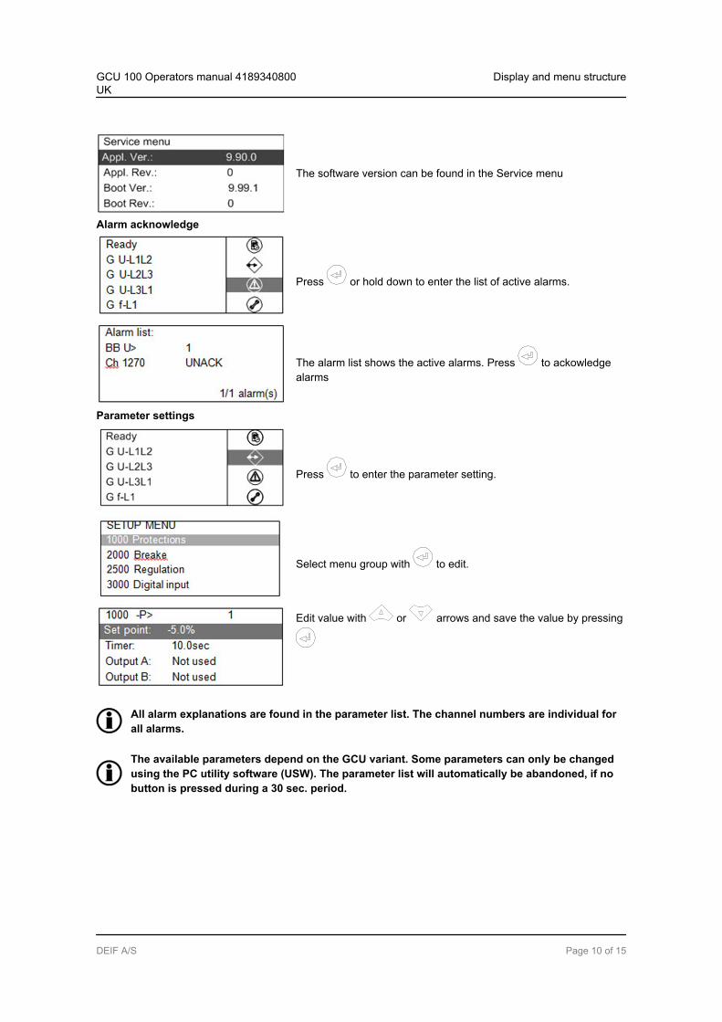
The software version can be found in the Service menu
Alarm acknowledge
Press or hold down to enter the list of active alarms.
The alarm list shows the active alarms. Press to ackowledgealarms
Parameter settings
Press to enter the parameter setting.
Select menu group with to edit.
Edit value with or arrows and save the value by pressing
All alarm explanations are found in the parameter list. The channel numbers are individual forall alarms.
The available parameters depend on the GCU variant. Some parameters can only be changedusing the PC utility software (USW). The parameter list will automatically be abandoned, if nobutton is pressed during a 30 sec. period.
GCU 100 Operators manual 4189340800UK
Display and menu structure
DEIF A/S Page 10 of 15
4. Standard text4.1 Status line text
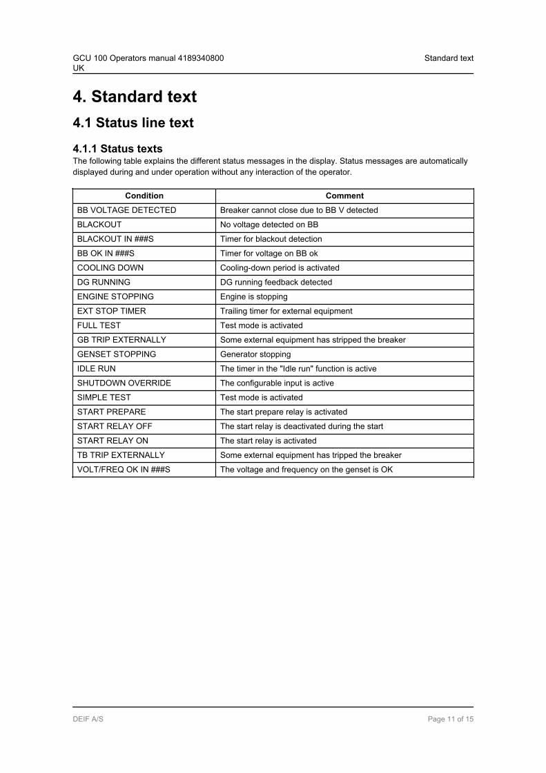
4.1.1 Status textsThe following table explains the different status messages in the display. Status messages are automaticallydisplayed during and under operation without any interaction of the operator.
Condition Comment
BB VOLTAGE DETECTED Breaker cannot close due to BB V detected
BLACKOUT No voltage detected on BB
BLACKOUT IN ###S Timer for blackout detection
BB OK IN ###S Timer for voltage on BB ok
COOLING DOWN Cooling-down period is activated
DG RUNNING DG running feedback detected
ENGINE STOPPING Engine is stopping
EXT STOP TIMER Trailing timer for external equipment
FULL TEST Test mode is activated
GB TRIP EXTERNALLY Some external equipment has stripped the breaker
GENSET STOPPING Generator stopping
IDLE RUN The timer in the "Idle run" function is active
SHUTDOWN OVERRIDE The configurable input is active
SIMPLE TEST Test mode is activated
START PREPARE The start prepare relay is activated
START RELAY OFF The start relay is deactivated during the start
START RELAY ON The start relay is activated
TB TRIP EXTERNALLY Some external equipment has tripped the breaker
VOLT/FREQ OK IN ###S The voltage and frequency on the genset is OK
GCU 100 Operators manual 4189340800UK
Standard text
DEIF A/S Page 11 of 15
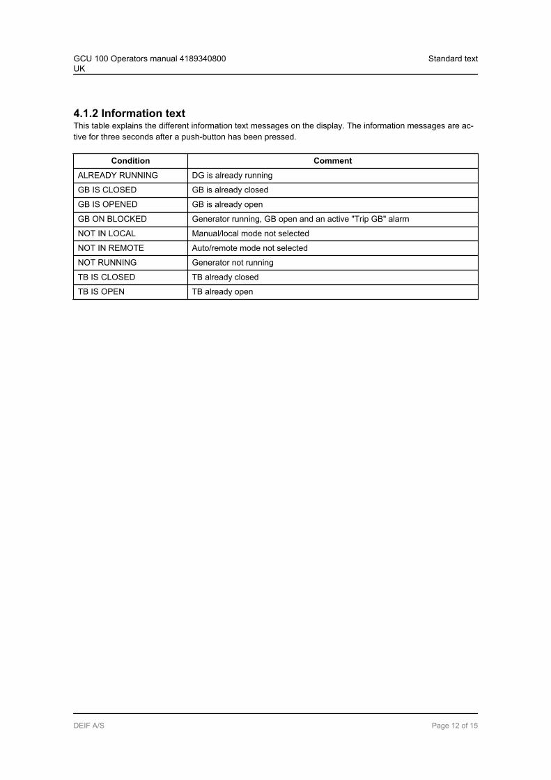
4.1.2 Information textThis table explains the different information text messages on the display. The information messages are ac-tive for three seconds after a push-button has been pressed.
Condition Comment
ALREADY RUNNING DG is already running
GB IS CLOSED GB is already closed
GB IS OPENED GB is already open
GB ON BLOCKED Generator running, GB open and an active "Trip GB" alarm
NOT IN LOCAL Manual/local mode not selected
NOT IN REMOTE Auto/remote mode not selected
NOT RUNNING Generator not running
TB IS CLOSED TB already closed
TB IS OPEN TB already open
GCU 100 Operators manual 4189340800UK
Standard text
DEIF A/S Page 12 of 15
5. Running modes5.1 Running mode overviewThe unit has three different running modes. The different running modes are selected by use of push-buttons,digital inputs on the display or the PC utility software. For detailed information, please see the designer's ref-erence handbook.
Auto/RemoteIn auto mode, the unit will operate automatically, and the operator cannot initiate any sequences manually.
Manual/LocalManual means that the unit will not initiate any sequences automatically, as is the case with the auto mode. Itwill only initiate sequences, if external signals are given.
TestThe test sequence will start when the test mode is selected.
GCU 100 Operators manual 4189340800UK
Running modes
DEIF A/S Page 13 of 15
6. Alarm handling and log list6.1 Alarm handlingWhen an alarm occurs, the unit will automatically go to the alarm list for display of the alarm.
If reading of the alarms is not desired, use the ESC push-button to exit the alarm list.
If you decide to enter the alarm list later, press the HORN push-button for 2 seconds to jump directly to thealarm list reading.
The alarm list contains both acknowledged and unacknowledged alarms provided that they are still active (i.e.the alarm condition is still present). Once an alarm is acknowledged and the condition has disappeared, thealarm will no longer be displayed in the alarm list.
This means that if there are no alarms, the alarm list will be empty.
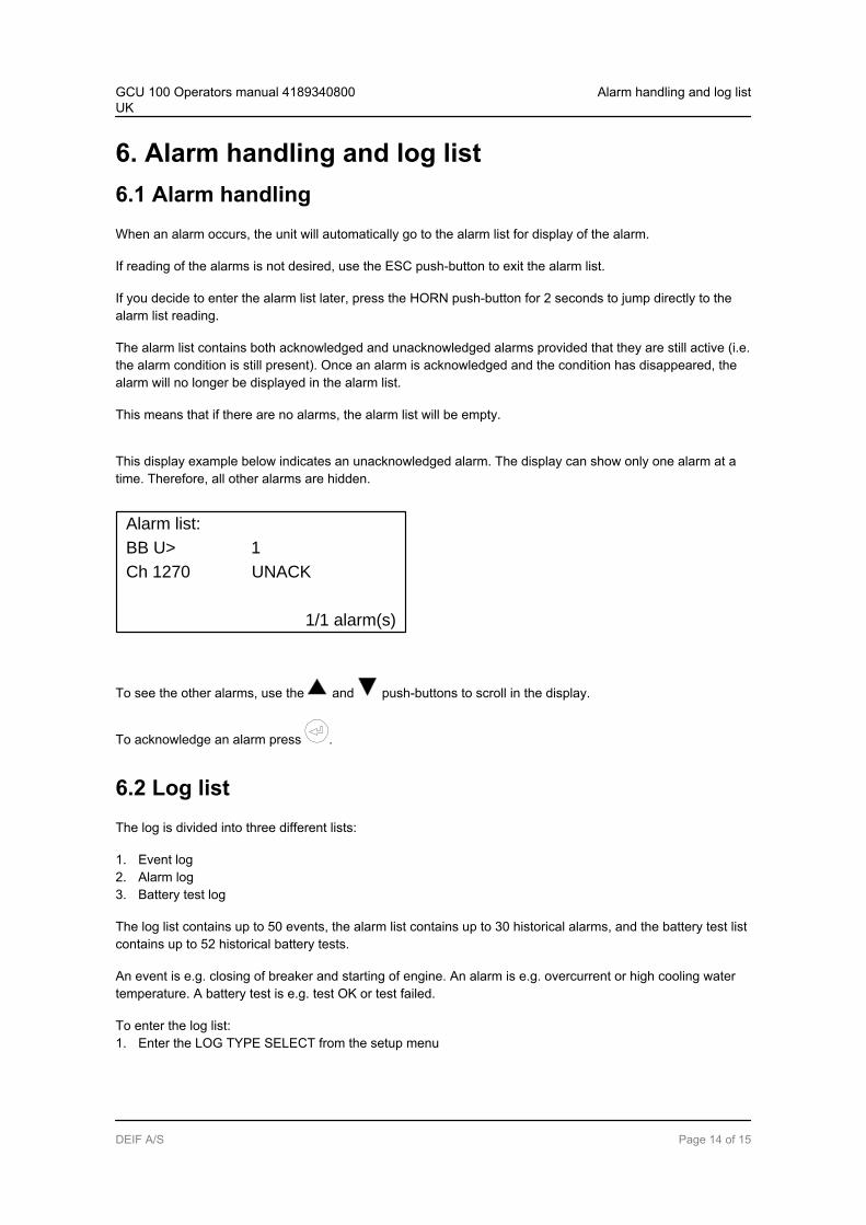
This display example below indicates an unacknowledged alarm. The display can show only one alarm at atime. Therefore, all other alarms are hidden.
Alarm list:
Ch 1270 UNACK
1/1 alarm(s)
BB U> 1
To see the other alarms, use the and push-buttons to scroll in the display.
To acknowledge an alarm press .
6.2 Log listThe log is divided into three different lists:
1. Event log2. Alarm log3. Battery test log
The log list contains up to 50 events, the alarm list contains up to 30 historical alarms, and the battery test listcontains up to 52 historical battery tests.
An event is e.g. closing of breaker and starting of engine. An alarm is e.g. overcurrent or high cooling watertemperature. A battery test is e.g. test OK or test failed.
To enter the log list:1. Enter the LOG TYPE SELECT from the setup menu
GCU 100 Operators manual 4189340800UK
Alarm handling and log list
DEIF A/S Page 14 of 15
2. Select the list which is needed with the and arrows and choose with the push-button.
3. To scroll up and down in the list, use the and push-buttons.
GCU 100 Operators manual 4189340800UK
Alarm handling and log list
DEIF A/S Page 15 of 15