Gen 2012 (v3.1) Release Note - Simulsoft Ingenieros
23
Gen 2012 (v3.1) Release Note Integrated Design System for Building and General Structures
-
Upload
khangminh22 -
Category
Documents
-
view
1 -
download
0
Transcript of Gen 2012 (v3.1) Release Note - Simulsoft Ingenieros

Gen 2012 (v3.1) Release Note Integrated Design System for Building and General Structures

Enhancements
Pre/Post Processing
Design
3
12
(1) Static Wind Loads as per IBC 2012 (ASCE 7-10)
(2) Static Seismic Loads as per IBC 2012 (ASCE 7-10)
(3) Response Spectrum as per IBC 2012 (ASCE 7-10)
(4) Static wind Loads as per IBC 2009 (ASCE 7-05)
(5) Static Seismic Loads as per IBC 2009 (ASCE 7-05)
(6) Response Spectrum as per IBC 2009 (ASCE 7-05)
(7) Multi-Tree Menu
(8) Perform Response Spectrum & Time-history Analysis in the Same Model file
(9) Display Selection option in the Legend
(1) ACI Design Code (ACI 318 - 11)
(2) ACI Design Code (ACI 318 – 08)
2

1. Static Wind Loads as per IBC 2012 (ASCE7-10)
Static Wind Loads (Alternate Method)
Load > Lateral Loads > Static Wind Loads
• Wind Design Specifications and Commentary of Buildings 2012
• Changes in IBC 2012
(1) Importance Factor. The need to define Importance Factor In alternate method has been eliminated The need to define Importance Factor has been Eliminated in Directional Procedure (Earlier Analytical Method )
Static Wind Loads ( Directional Procedure )
Gen 2012 Pre/Post Processing Enhancements Gen 2012 (v3.1) Release Note
3

2. Static Seismic Loads as per IBC 2012 (ASCE7-10)
Static Seismic Loads
Load > Lateral Loads > Static Seismic Loads
• Seismic Design Specifications and Commentary of Buildings 2012
• Changes in IBC 2012
(1) Risk Category : As defined in Table 1.5-1 of ASCE7-10 .
Period Calculator
Gen 2012 Pre/Post Processing Enhancements Gen 2012 (v3.1) Release Note
4

3. Response Spectrum as per IBC 2012 (ASCE7-10)
Load > Response Spectrum Analysis Data > Response Spectrum Function
• Seismic Design Specifications and Commentary of Buildings 2012
• Changes in IBC 2012
No significant changes has been made as compared to the IBC 2009.
Response Spectrum Design Function
Gen 2012 Pre/Post Processing Enhancements Gen 2012 (v3.1) Release Note
5
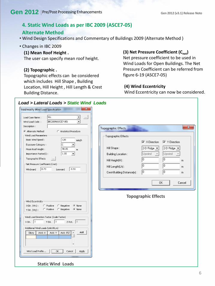
4. Static Wind Loads as per IBC 2009 (ASCE7-05)
Alternate Method
Static Wind Loads
Topographic Effects
Load > Lateral Loads > Static Wind Loads
• Wind Design Specifications and Commentary of Buildings 2009 (Alternate Method )
• Changes in IBC 2009
(1) Mean Roof Height . The user can specify mean roof height. (2) Topographic . Topographic effects can be considered which includes Hill Shape , Building Location, Hill Height , Hill Length & Crest Building Distance.
(3) Net Pressure Coefficient (Cnet) Net pressure coefficient to be used in Wind Loads for Open Buildings. The Net Pressure Coefficient can be referred from figure 6-19 (ASCE7-05) (4) Wind Eccentricity Wind Eccentricity can now be considered.
Gen 2012 Pre/Post Processing Enhancements Gen 2012 (v3.1) Release Note
6

Analytical Method
Static Wind Loads
Topographic Effects
Load > Lateral Loads > Static Wind Loads
• Wind Design Specifications and Commentary of Buildings 2009 (Analytical Method)
• Changes in IBC 2009
(1) Directional Factors Directional Factors as specified in ASCE7-05 table 6-4 can be considered.
(2) Wind Eccentricity Wind Eccentricity can now be considered. .
Gen 2012 Pre/Post Processing Enhancements Gen 2012 (v3.1) Release Note
7

5. Static Seismic Loads as per IBC 2009 (ASCE7-05)
Static Seismic Loads
Load > Lateral Loads > Static Seismic Loads
(1) Ss: Mapped MCE, 5 percent damped, spectral response acceleration parameter at a
period of 1 second as defined in section 11.4.1 of ASCE7-05 (2) Fa: Short Period Site Coefficient (at .2 s-period) , as defined in section 11.4.3 (3) Sds: Design , 5 percent damped , spectral response acceleration parameter at a period of 1s as defined in section 11.4.4 (4) S1: Mapped MCE , 5 percent damped, spectral response acceleration parameter at a period of 1second as defined in section 11.4.1 of ASCE7-05 (5) Fu: Long Period Site Coefficient (at 1 s-period) , as defined in section 11.4.3 (6) Sd1: Design , 5 percent damped , spectral response acceleration parameter at a period of 1s as defined in section 11.4.4 (7) Occupancy Category: As specified in table 1-1 (8) Period Coefficient: Cu & Tl as defined in section 11.4.5 (9) Approximate Period: Calculated automatically by the program as defined in 12.8-2
Period Calculator
Gen 2012 Pre/Post Processing Enhancements Gen 2012 (v3.1) Release Note
8

6. Response Spectrum Design Function as per IBC 2009 (ASCE7-05)
Load > Response Spectrum Analysis Data > Response Spectrum Function
• Seismic Design Specifications and Commentary of Buildings 2009
• Changes in IBC 2009
(1) Parameters : Ss, S1,Fa ,Fv, Sds,Sd1. have been added . (2) Response Modification Coefficient (R ) : Can be defined. (3) TL : Long Tran. Period : Can be defined .
Response Spectrum Design Function
Gen 2012 Pre/Post Processing Enhancements Gen 2012 (v3.1) Release Note
9

7. Multi-Tree Menu
Tools> Customize> Tree Menu 2
• To enhance the GUI features Multi-Tree Menu has been introduced so that the user can
work on Works Tree and Group Tree simultaneously. It is especially useful for wide screen
users.
Multi-Tree Menu
Gen 2012 Pre/Post Processing Enhancements Gen 2012 (v3.1) Release Note
8. Perform Response Spectrum & Time-history Analysis in the Same Model file
• In the previous versions, it was not allowed to run response spectrum and time-history
analysis simultaneously. Now, it is not necessary to use separate model files to perform both
analyses.
10

9. Display Selection option in the Legend
Results> Forces > Plate Forces/Moments
Results> Stresses > Plate Stresses, Solid Stresses
• It is useful when graphic results are included in the report.
Automatic Generation of Load Combination
Gen 2012 Gen 2012 (v3.1) Release Note
11
Pre/Post Processing Enhancements

1. Reinforced Concrete Design as per ACI 318-08 and ACI 318-11
Design> General Design Parameter > Seismic Design Type
(1) For Seismic Design: Apply seismic design for the selected members. (2) For Non-Seismic Design: Do not apply seismic design for the selected members. (3) For Non-Seismic-Force Resisting System : Apply the clause 21.13 Members not designated as part of the seismic-force-resisting system. Note : Available only when Special Moment Frames is selected.
Seismic Design Type
Gen 2012 Design Gen 2012 (v3.1) Release Note
Member type for seismic design
12
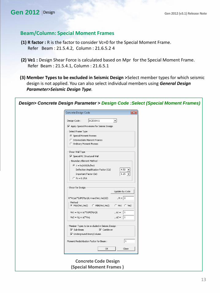
Design> Concrete Design Parameter > Design Code :Select (Special Moment Frames)
(1) R factor : R is the factor to consider Vc=0 for the Special Moment Frame. Refer Beam : 21.5.4.2, Column : 21.6.5.2 4 (2) Ve1 : Design Shear Force is calculated based on Mpr for the Special Moment Frame. Refer Beam : 21.5.4.1, Column : 21.6.5.1 (3) Member Types to be excluded in Seismic Design >Select member types for which seismic design is not applied. You can also select individual members using General Design Parameter>Seismic Design Type.
Concrete Code Design (Special Moment Frames )
Gen 2012 Design Gen 2012 (v3.1) Release Note
Beam/Column: Special Moment Frames
13
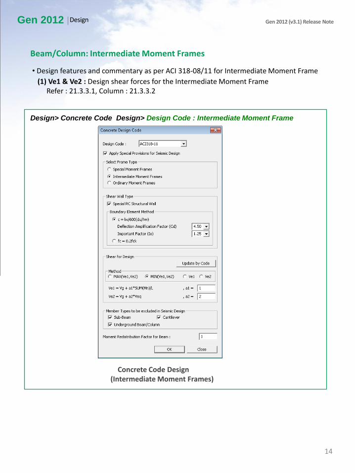
Design> Concrete Code Design> Design Code : Intermediate Moment Frame
• Design features and commentary as per ACI 318-08/11 for Intermediate Moment Frame
(1) Ve1 & Ve2 : Design shear forces for the Intermediate Moment Frame Refer : 21.3.3.1, Column : 21.3.3.2
Concrete Code Design (Intermediate Moment Frames)
Gen 2012 Design Gen 2012 (v3.1) Release Note
Beam/Column: Intermediate Moment Frames
14
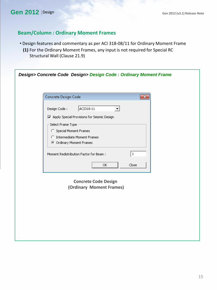
Design> Concrete Code Design> Design Code : Ordinary Moment Frame
• Design features and commentary as per ACI 318-08/11 for Ordinary Moment Frame
(1) For the Ordinary Moment Frames, any input is not required for Special RC Structural Wall (Clause 21.9)
Concrete Code Design (Ordinary Moment Frames)
Gen 2012 Design Gen 2012 (v3.1) Release Note
Beam/Column : Ordinary Moment Frames
15

Design> Concrete Design Parameter> Design Code : Check On Special RC Structural Wall
• Design features and commentary as per ACI 318-08/11
(1) Shear Wall Type : 21.9 Special structural walls Boundary Element Methods are provided as per 21.9.6.2 and 21.9.6.3
Concrete Code Design (Special RC Structural Wall)
Gen 2012 Design Gen 2012 (v3.1) Release Note
Reinforced Concrete Wall
21.9.6.2 21.9.6.3
Boundary element
condition
c ≥ lw/600(δu/hw) ※ δu = δe*Cd/Ie
(Design displacement) fc ≥ 0.2fc’
Boundary element
vertical length MAX[lw, Mu/(4Vu)] fc ≥ 0.15fc’
16

Design> Concrete Design Parameter> Design Criteria for Rebars / Design Criteria for
Rebars by Member
• Design features and commentary as per ACI 318-08/11
(1) When Special RC Structural Wall is checked on, Boundary Element reinforcement input is activated
Gen 2012 Design Gen 2012 (v3.1) Release Note
Reinforced Concrete Wall
Design Criteria for Rebars
Design Criteria for Rebars by Member
17

Design> Concrete Design parameter>Boundary Element Method by Wall ID
• Design features and commentary as per ACI 318-08/11
(1) Boundary Element design method and reference wall can be determined by Wall ID. • Displacement Based Method : 21.9.6.2. • Stress Based Method : 21.9.6.3.
Boundary Element Method
Gen 2012 Design Gen 2012 (v3.1) Release Note
Reinforced Concrete Wall
18

Design> Concrete Code Design >Wall Design
• Design features and commentary as per ACI 318-08/11
(1) Wall Design Result Dialogue Box : When Special RC Structural Wall is checked on, “B.E.” is included. • YES: Boundary Element is necessary. • - : Boundary Element is not necessary
Wall Design
Gen 2012 Design Gen 2012 (v3.1) Release Note
Reinforced Concrete Wall
19

Design> Concrete Code Design >Wall Design
(1) Wall Design Result Dialogue Box : When Special RC Structural Wall is checked on, “B.E.-Rebar, B.E.-L” is included.
Wall Design
Gen 2012 Design Gen 2012 (v3.1) Release Note
Reinforced Concrete Wall
B.E.-Rebar B.E.-L
Description Required horizontal reinforcement size and spacing
in the Boundary Element
When Boundary Element is
necessary, the required length of Boundary Element.
Boundary Element is necessary.
A-B-Dxx @yyy A : Number of rebars in the direction of wall
thickness B : Number of rebars in the direction of wall length
Dxx : Transverse rebar size yyy : Transverse rebar spacing
C (Length Unit)
Boundary Element is not necessary.
Not Use -
20

Design> Concrete Code Design >Wall Design report
• Design features and commentary as per ACI 318-08/11
(1) Wall Design Report
Summary Report
Gen 2012 Design Gen 2012 (v3.1) Release Note
Reinforced Concrete Wall
Graphic Report
Detail Report
21

View > Display Option
• Design features and commentary as per ACI 318-08/11
(1) Display Option : Display Options relating to Boundary Elements results have been added
Display Option
Gen 2012 Design Gen 2012 (v3.1) Release Note
Reinforced Concrete Wall
22

2. Load Combinations as per ACI 318-08 and ACI 318-11
Results> Combinations >Concrete Design > Design Code: ACI 318-08 & ACI 318-11
• Design features and commentary as per ACI 318-11
1) Wind Load factor : Select the Wind Load Factor as per service and strength level. 2) Seismic Load Factor : Select the Seismic load factor as per service and strength level . When we select Service level the Wind Loads & Seismic loads are multiplied by a factor of 1.6 & 1.4 respectively whereas when we select Strength-Level the Wind Loads & Seismic Loads are multiplied by a factor of 1.
Automatic Generation of Load Combination
Gen 2012 Design Gen 2012 (v3.1) Release Note
23