M70t Gen 3 and M80t Gen 3 User Guide - CNET Content ...
64
M70t Gen 3 and M80t Gen 3 User Guide
-
Upload
khangminh22 -
Category
Documents
-
view
0 -
download
0
Transcript of M70t Gen 3 and M80t Gen 3 User Guide - CNET Content ...

M70t Gen 3 and M80t Gen 3 User Guide
Read this first
Before using this documentation and the product it supports, ensure that you read and understand the following:
• Safety and Warranty Guide
• Generic Safety and Compliance Notices
• Setup Guide
First Edition (January 2022)
© Copyright Lenovo 2022.
LIMITED AND RESTRICTED RIGHTS NOTICE: If data or software is delivered pursuant to a General Services Administration “GSA” contract, use, reproduction, or disclosure is subject to restrictions set forth in Contract No. GS- 35F-05925.
Contents
Discover your Lenovo computer . . . . iii
Chapter 1. Meet your computer . . . . . 1Front . . . . . . . . . . . . . . . . . . . . 1Rear . . . . . . . . . . . . . . . . . . . . 4Features and specifications . . . . . . . . . . . 7USB specifications . . . . . . . . . . . . . . 9
Chapter 2. Get started with your computer . . . . . . . . . . . . . . . . 11Access networks . . . . . . . . . . . . . . 11
Connect to the wired Ethernet . . . . . . . 11Connect to Wi-Fi networks (for selected models) . . . . . . . . . . . . . . . . 11
Connect an external display . . . . . . . . . . 11Manage cables with a smart cable clip . . . . . . 11
Chapter 3. Explore your computer . . 13The Vantage app . . . . . . . . . . . . . . 13Set the power plan . . . . . . . . . . . . . 13Transfer data . . . . . . . . . . . . . . . . 13
Connect to a Bluetooth-enabled device (for selected models) . . . . . . . . . . . . 13Use the optical drive (for selected models) . . 14Use a media card (for selected models) . . . . 15
Purchase accessories . . . . . . . . . . . . 15
Chapter 4. Secure your computer and information . . . . . . . . . . . . 17Lock the computer . . . . . . . . . . . . . 17UEFI BIOS passwords . . . . . . . . . . . . 18Certificate based BIOS management . . . . . . 19Use software security solutions. . . . . . . . . 20
Windows firewalls . . . . . . . . . . . . 20Computrace Agent software embedded in firmware (for selected models) . . . . . . . 20
Use BIOS security solutions . . . . . . . . . . 20Wipe the storage drive data . . . . . . . . 20Cover presence switch . . . . . . . . . . 21Intel BIOS guard . . . . . . . . . . . . . 21Smart USB Protection . . . . . . . . . . 21
Chapter 5. UEFI BIOS . . . . . . . . . 23What is UEFI BIOS. . . . . . . . . . . . . . 23Enter the BIOS menu. . . . . . . . . . . . . 23Navigate in the BIOS interface . . . . . . . . . 23Change the display language of UEFI BIOS . . . . 23
Change the display mode of UEFI BIOS (for selected models) . . . . . . . . . . . . . . 24Set the system date and time . . . . . . . . . 24Change the boot priority order . . . . . . . . . 24Enable or disable the configuration change detection feature . . . . . . . . . . . . . . 25Enable or disable the automatic power-on feature . . . . . . . . . . . . . . . . . . 25Enable or disable the smart power-on feature (for selected models) . . . . . . . . . . . . . . 25Enable or disable the ErP LPS compliance mode . . 25Change the ITS performance mode . . . . . . . 26Change BIOS settings before installing a new operating system . . . . . . . . . . . . . . 26Update UEFI BIOS. . . . . . . . . . . . . . 27Recover from a BIOS update failure . . . . . . . 27Clear CMOS . . . . . . . . . . . . . . . . 28
Chapter 6. Diagnostics . . . . . . . . 29Lenovo diagnostic tools . . . . . . . . . . . 29The Vantage app . . . . . . . . . . . . . . 29
Chapter 7. CRU replacement . . . . . 31CRU list . . . . . . . . . . . . . . . . . . 31Remove or replace a CRU. . . . . . . . . . . 32
Computer cover . . . . . . . . . . . . . 32Optical drive . . . . . . . . . . . . . . 32Front bezel . . . . . . . . . . . . . . . 34Drive bay assembly . . . . . . . . . . . 352.5-inch hard disk drive . . . . . . . . . . 363.5-inch hard disk drive . . . . . . . . . . 37Memory module . . . . . . . . . . . . . 38M.2 solid-state drive and heat sink . . . . . 40M.2 solid-state drive bracket . . . . . . . . 42PCI-Express connector cable . . . . . . . 43PCI-Express card . . . . . . . . . . . . 44Power supply assembly . . . . . . . . . . 45E-lock . . . . . . . . . . . . . . . . . 46Coin-cell battery. . . . . . . . . . . . . 47
Chapter 8. Help and support . . . . . 49Self-help resources . . . . . . . . . . . . . 49Call Lenovo . . . . . . . . . . . . . . . . 51
Before you contact Lenovo . . . . . . . . 51Lenovo Customer Support Center . . . . . . 51
Purchase additional services. . . . . . . . . . 52
© Copyright Lenovo 2022 i
Appendix A. Compliance information . . . . . . . . . . . . . . . 53
Appendix B. Notices and trademarks. . . . . . . . . . . . . . . 55
ii M70t Gen 3 and M80t Gen 3 User Guide
Discover your Lenovo computer
Thank you for choosing a Lenovo® computer! We are dedicated to delivering the best solution to you.
Before starting your tour, please read the following information:
• Illustrations in this documentation might look different from your product.
• Depending on the model, some optional accessories, features, software programs, and user interface instructions might not be applicable to your computer.
• Documentation content is subject to change without notice. To get the latest documentation, go to https:// pcsupport.lenovo.com.
© Copyright Lenovo 2022 iii

iv M70t Gen 3 and M80t Gen 3 User Guide
Chapter 1. Meet your computer
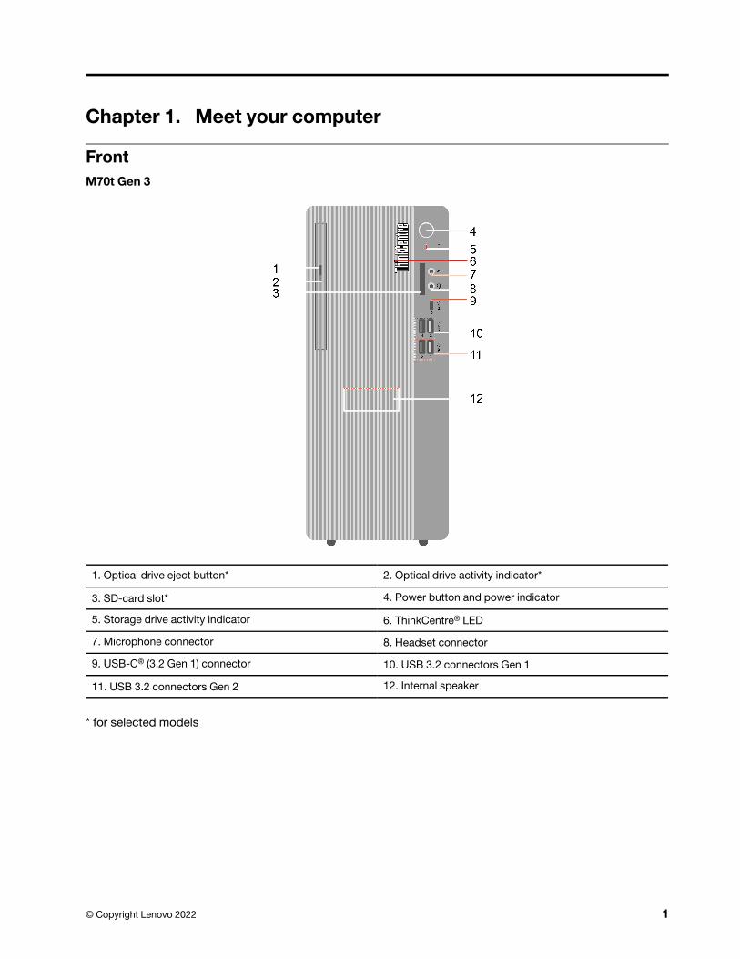
FrontM70t Gen 3
1. Optical drive eject button* 2. Optical drive activity indicator*
3. SD-card slot* 4. Power button and power indicator
5. Storage drive activity indicator 6. ThinkCentre® LED
7. Microphone connector 8. Headset connector
9. USB-C® (3.2 Gen 1) connector 10. USB 3.2 connectors Gen 1
11. USB 3.2 connectors Gen 2 12. Internal speaker
* for selected models
© Copyright Lenovo 2022 1
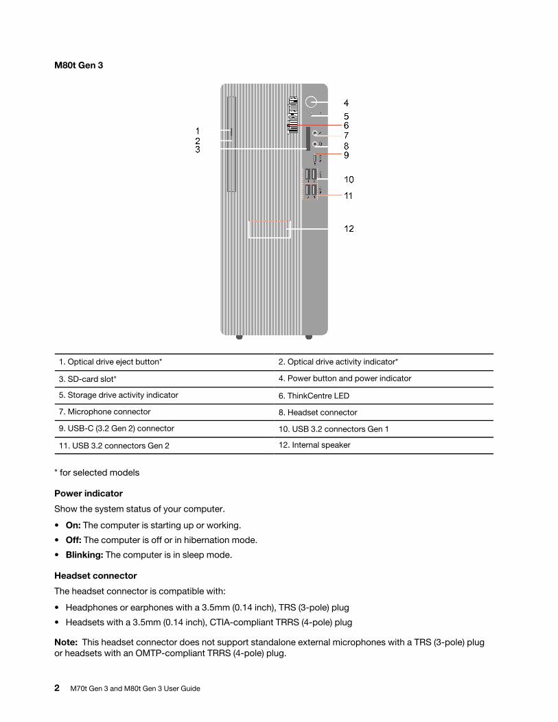
M80t Gen 3
1. Optical drive eject button* 2. Optical drive activity indicator*
3. SD-card slot* 4. Power button and power indicator
5. Storage drive activity indicator 6. ThinkCentre LED
7. Microphone connector 8. Headset connector
9. USB-C (3.2 Gen 2) connector 10. USB 3.2 connectors Gen 1
11. USB 3.2 connectors Gen 2 12. Internal speaker
* for selected models
Power indicator
Show the system status of your computer.
• On: The computer is starting up or working.
• Off: The computer is off or in hibernation mode.
• Blinking: The computer is in sleep mode.
Headset connector
The headset connector is compatible with:
• Headphones or earphones with a 3.5mm (0.14 inch), TRS (3-pole) plug
• Headsets with a 3.5mm (0.14 inch), CTIA-compliant TRRS (4-pole) plug
Note: This headset connector does not support standalone external microphones with a TRS (3-pole) plug or headsets with an OMTP-compliant TRRS (4-pole) plug.
2 M70t Gen 3 and M80t Gen 3 User Guide

Related topics
• “USB specifications” on page 9.
• “Use the optical drive (for selected models)” on page 14.
• “Use a media card (for selected models)” on page 15.
Chapter 1. Meet your computer 3
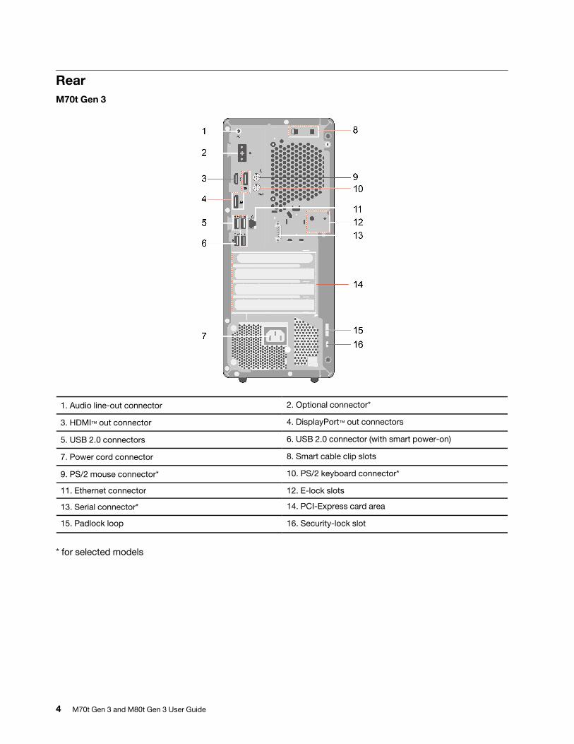
RearM70t Gen 3
1. Audio line-out connector 2. Optional connector*
3. HDMI™ out connector 4. DisplayPort™ out connectors
5. USB 2.0 connectors 6. USB 2.0 connector (with smart power-on)
7. Power cord connector 8. Smart cable clip slots
9. PS/2 mouse connector* 10. PS/2 keyboard connector*
11. Ethernet connector 12. E-lock slots
13. Serial connector* 14. PCI-Express card area
15. Padlock loop 16. Security-lock slot
* for selected models
4 M70t Gen 3 and M80t Gen 3 User Guide
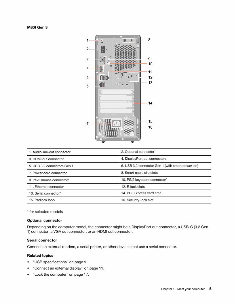
M80t Gen 3
1. Audio line-out connector 2. Optional connector*
3. HDMI out connector 4. DisplayPort out connectors
5. USB 3.2 connectors Gen 1 6. USB 3.2 connector Gen 1 (with smart power-on)
7. Power cord connector 8. Smart cable clip slots
9. PS/2 mouse connector* 10. PS/2 keyboard connector*
11. Ethernet connector 12. E-lock slots
13. Serial connector* 14. PCI-Express card area
15. Padlock loop 16. Security-lock slot
* for selected models
Optional connector
Depending on the computer model, the connector might be a DisplayPort out connector, a USB-C (3.2 Gen 1) connector, a VGA out connector, or an HDMI out connector.
Serial connector
Connect an external modem, a serial printer, or other devices that use a serial connector.
Related topics
• “USB specifications” on page 9.
• “Connect an external display” on page 11.
• “Lock the computer” on page 17.
Chapter 1. Meet your computer 5

• “Enable or disable the smart power-on feature (for selected models)” on page 25.
6 M70t Gen 3 and M80t Gen 3 User Guide
Features and specificationsFor detailed specifications of your computer, go to https://psref.lenovo.com.
Dimensions• Width: 145.0 mm (5.7 inches)
• Height: 346.0 mm (13.6 inches)
• Depth: 296.2 mm (11.7 inches)
Weight (without packaging) Maximum configuration as shipped: 5.9 kg (13 lb)
Hardware configuration Type Device Manager in the Windows search box and then press Enter. Type the administrator password or provide confirmation, if prompted.
Power supply
• 180-watt automatic voltage-sensing power supply
• 260-watt automatic voltage-sensing power supply
• 310-watt automatic voltage-sensing power supply
• 380-watt automatic voltage-sensing power supply
Electrical input • Input voltage: From 100 V ac to 240 V ac
• Input frequency: 50/60 Hz
Memory
• M70t Gen 3: Up to four Double data rate 4 (DDR4) unbuffered dual inline memory module (UDIMMs)
• M80t Gen 3: Up to four Double data rate 5 (DDR5) unbuffered dual inline memory module (UDIMMs)
Maximum memory capacity: 128 GB
Storage device
• 3.5-inch hard disk drive*
• 2.5-inch hard disk drive*
• M.2 solid-state drive*
To view the storage drive capacity of your computer, type Disk Management in the Windows search box and then press Enter.
Note: The storage drive capacity indicated by the system is less than the nominal capacity.
Video features
• The integrated graphics card supports the following:
– DisplayPort out connector
– HDMI out connector
– VGA-out connector*
– USB-C (3.2 Gen 1) connector* (on the rear panel)
• The optional discrete graphics card provides an enhanced video experience and extended capabilities.
Chapter 1. Meet your computer 7
Expansion
• Card reader*
• Memory slots
• M.2 solid-state drive slot
• Optical drive*
• Storage drive bay
M70t Gen 3
• PCI Express x16 card slot
• PCI Express x1 card slots
M80t Gen 3
• PCI Express x16 graphics card slot
• PCI Express x16 card slot (physical link width x16; negotiable link width x4)
• PCI Express x1 card slot
Network features• Bluetooth*
• Ethernet LAN
• Wireless LAN*
* for selected models
8 M70t Gen 3 and M80t Gen 3 User Guide
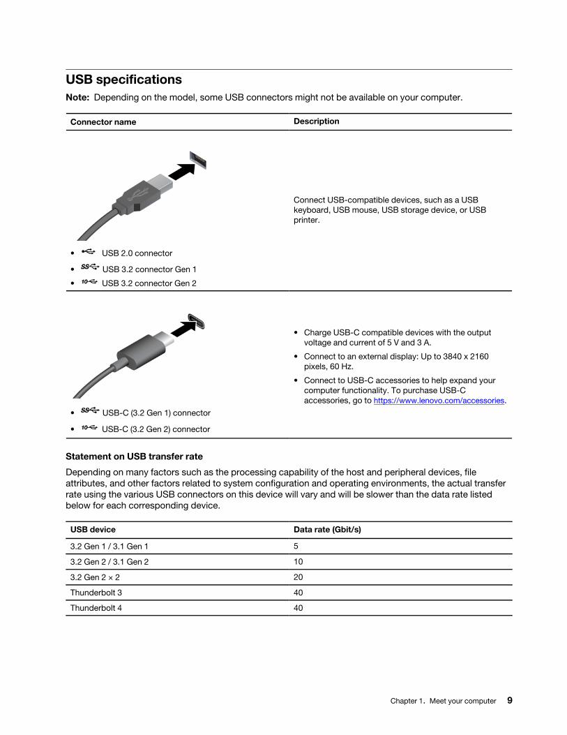
USB specificationsNote: Depending on the model, some USB connectors might not be available on your computer.
Connector name Description
• USB 2.0 connector
• USB 3.2 connector Gen 1
• USB 3.2 connector Gen 2
Connect USB-compatible devices, such as a USB keyboard, USB mouse, USB storage device, or USB printer.
• USB-C (3.2 Gen 1) connector
• USB-C (3.2 Gen 2) connector
• Charge USB-C compatible devices with the output voltage and current of 5 V and 3 A.
• Connect to an external display: Up to 3840 x 2160 pixels, 60 Hz.
• Connect to USB-C accessories to help expand your computer functionality. To purchase USB-C accessories, go to https://www.lenovo.com/accessories.
Statement on USB transfer rate
Depending on many factors such as the processing capability of the host and peripheral devices, file attributes, and other factors related to system configuration and operating environments, the actual transfer rate using the various USB connectors on this device will vary and will be slower than the data rate listed below for each corresponding device.
USB device Data rate (Gbit/s)
3.2 Gen 1 / 3.1 Gen 1 5
3.2 Gen 2 / 3.1 Gen 2 10
3.2 Gen 2 × 2 20
Thunderbolt 3 40
Thunderbolt 4 40
Chapter 1. Meet your computer 9

10 M70t Gen 3 and M80t Gen 3 User Guide
Chapter 2. Get started with your computer
Access networksThis section helps you access networks through connecting to a wired or wireless network.
Connect to the wired EthernetConnect your computer to a local network through the Ethernet connector on your computer with an Ethernet cable.
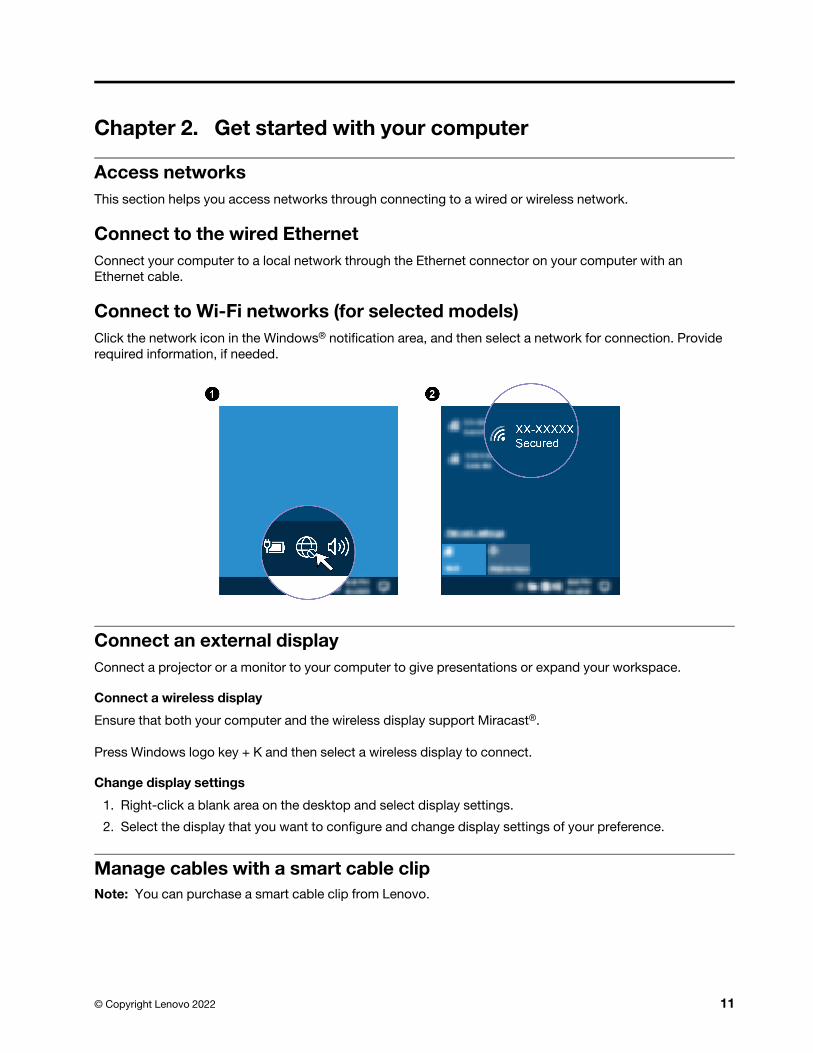
Connect to Wi-Fi networks (for selected models)Click the network icon in the Windows® notification area, and then select a network for connection. Provide required information, if needed.
Connect an external displayConnect a projector or a monitor to your computer to give presentations or expand your workspace.
Connect a wireless display
Ensure that both your computer and the wireless display support Miracast®.
Press Windows logo key + K and then select a wireless display to connect.
Change display settings
1. Right-click a blank area on the desktop and select display settings.
2. Select the display that you want to configure and change display settings of your preference.
Manage cables with a smart cable clipNote: You can purchase a smart cable clip from Lenovo.
© Copyright Lenovo 2022 11
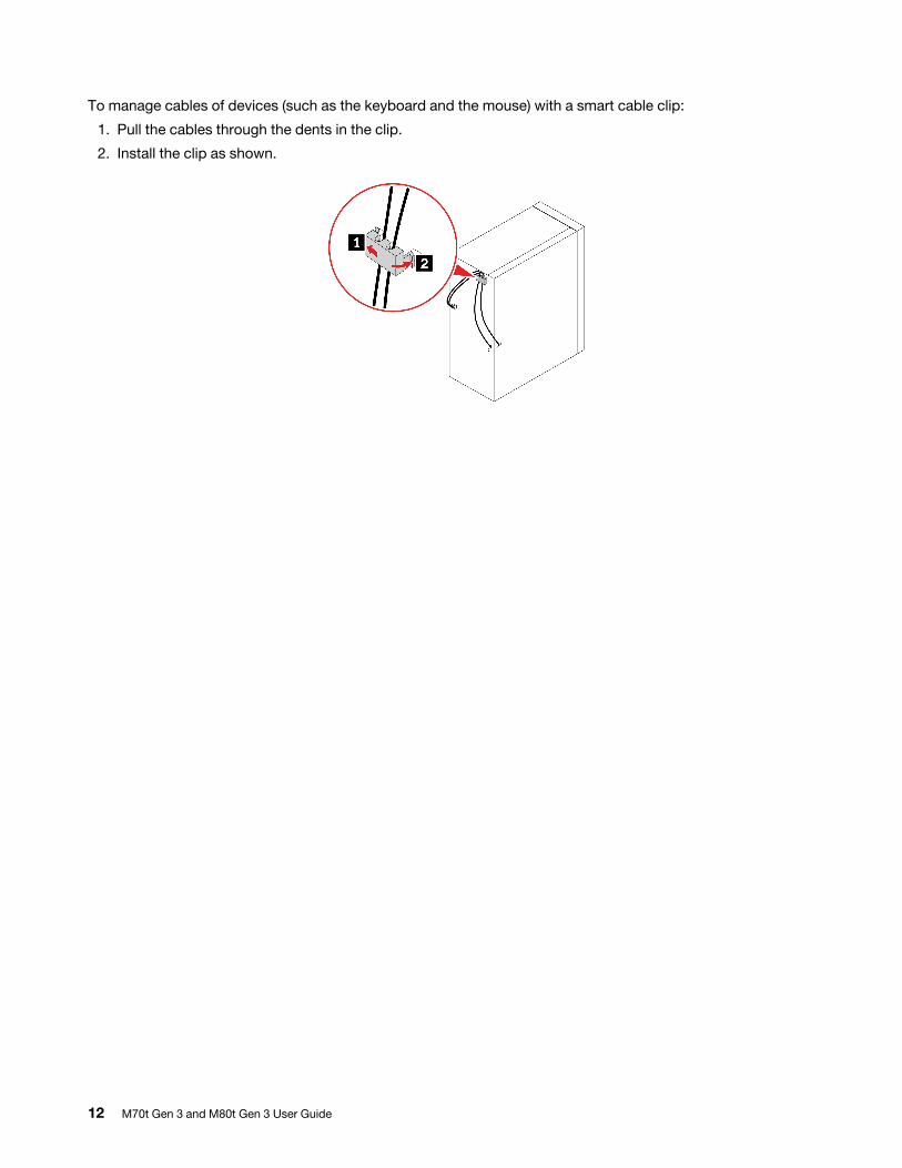
To manage cables of devices (such as the keyboard and the mouse) with a smart cable clip:
1. Pull the cables through the dents in the clip.
2. Install the clip as shown.
12 M70t Gen 3 and M80t Gen 3 User Guide
Chapter 3. Explore your computer
The Vantage appThe preinstalled Vantage app is a customized one-stop solution to help you maintain your computer with automated updates and fixes, configure hardware settings, and get personalized support.
To access the Vantage app, type Vantage in the Windows search box.
Key features
The Vantage app enables you to:
• Know the device status easily and customize device settings.
• Download and install UEFI BIOS, firmware and driver updates to keep your computer up-to-date.
• Monitor your computer health, and secure your computer against outside threats.
• Scan your computer hardware and diagnose hardware problems.
• Look up warranty status (online).
• Access User Guide and helpful articles.
Notes:
• The available features vary depending on the computer model.
• The Vantage app makes periodic updates of the features to keep improving your experience with your computer. The description of features might be different from that on your actual user interface.
Set the power planFor ENERGY STAR® compliant computers, the following power plan takes effect when your computers have been idle for a specified duration:
• turn off the display: After 10 minutes
• put the computer to sleep: After 25 minutes
To awaken the computer from Sleep mode, press any key on your keyboard.
To reset the power plan:
1. Right-click the battery status icon and select Power Options.
2. Choose or customize a power plan of your preference.
Transfer dataQuickly share your files using the built-in Bluetooth technology among devices with the same features. You also can install a disc or media card to transfer data.
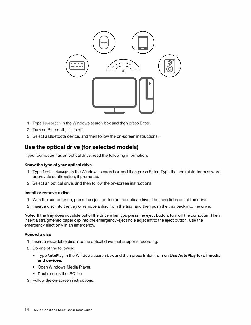
Connect to a Bluetooth-enabled device (for selected models)You can connect all types of Bluetooth-enabled devices to your computer, such as a keyboard, a mouse, a smartphone, or speakers. Place the device that you are attempting to connect to less than 10 meters (33 feet) from the computer.
© Copyright Lenovo 2022 13
1. Type Bluetooth in the Windows search box and then press Enter.
2. Turn on Bluetooth, if it is off.
3. Select a Bluetooth device, and then follow the on-screen instructions.
Use the optical drive (for selected models)If your computer has an optical drive, read the following information.
Know the type of your optical drive
1. Type Device Manager in the Windows search box and then press Enter. Type the administrator password or provide confirmation, if prompted.
2. Select an optical drive, and then follow the on-screen instructions.
Install or remove a disc
1. With the computer on, press the eject button on the optical drive. The tray slides out of the drive.
2. Insert a disc into the tray or remove a disc from the tray, and then push the tray back into the drive.
Note: If the tray does not slide out of the drive when you press the eject button, turn off the computer. Then, insert a straightened paper clip into the emergency-eject hole adjacent to the eject button. Use the emergency eject only in an emergency.
Record a disc
1. Insert a recordable disc into the optical drive that supports recording.
2. Do one of the following:
• Type AutoPlay in the Windows search box and then press Enter. Turn on Use AutoPlay for all media and devices.
• Open Windows Media Player.
• Double-click the ISO file.
3. Follow the on-screen instructions.
14 M70t Gen 3 and M80t Gen 3 User Guide
Use a media card (for selected models)If your computer has a SD-card slot, read the following information.
Install a media card
1. Locate the SD-card slot.
2. Ensure that the metal contacts on the card are facing the ones in the SD-card slot. Insert the card firmly into the SD-card slot until it is secured in place.
Remove a media card
Attention: Before removing the card:
1. Click the triangular icon in the Windows notification area to show hidden icons. Right-click the icon prompting you to safely remove hardware and eject media.
2. Select the corresponding item to eject the card from the Windows operating system.
3. Press the card and remove it from your computer. Store the card safely for future use.
Purchase accessoriesLenovo has a number of hardware accessories and upgrades to help expand the capabilities of your computer. Options include memory modules, storage devices, network cards, power adapters, keyboards, mice, and more.
To shop at Lenovo, go to https://www.lenovo.com/accessories.
Chapter 3. Explore your computer 15

16 M70t Gen 3 and M80t Gen 3 User Guide
Chapter 4. Secure your computer and information
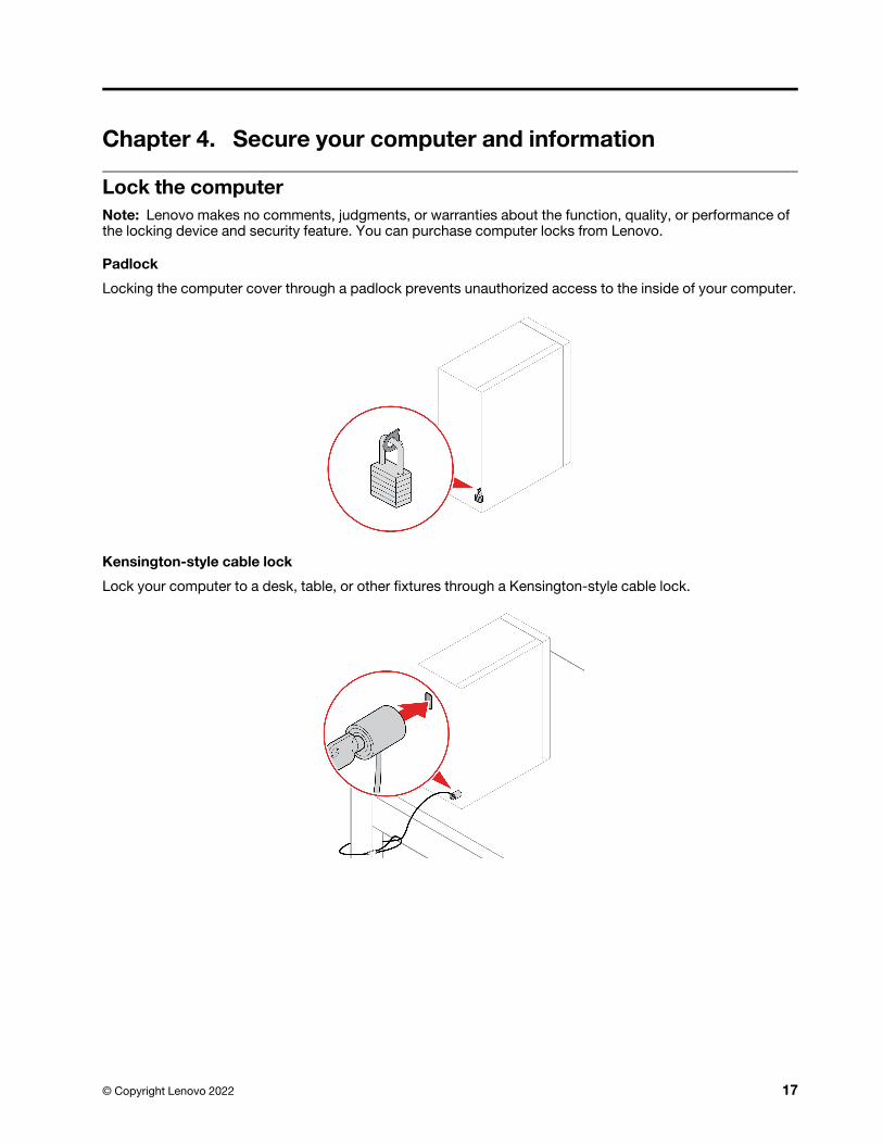
Lock the computerNote: Lenovo makes no comments, judgments, or warranties about the function, quality, or performance of the locking device and security feature. You can purchase computer locks from Lenovo.
Padlock
Locking the computer cover through a padlock prevents unauthorized access to the inside of your computer.
Kensington-style cable lock
Lock your computer to a desk, table, or other fixtures through a Kensington-style cable lock.
© Copyright Lenovo 2022 17
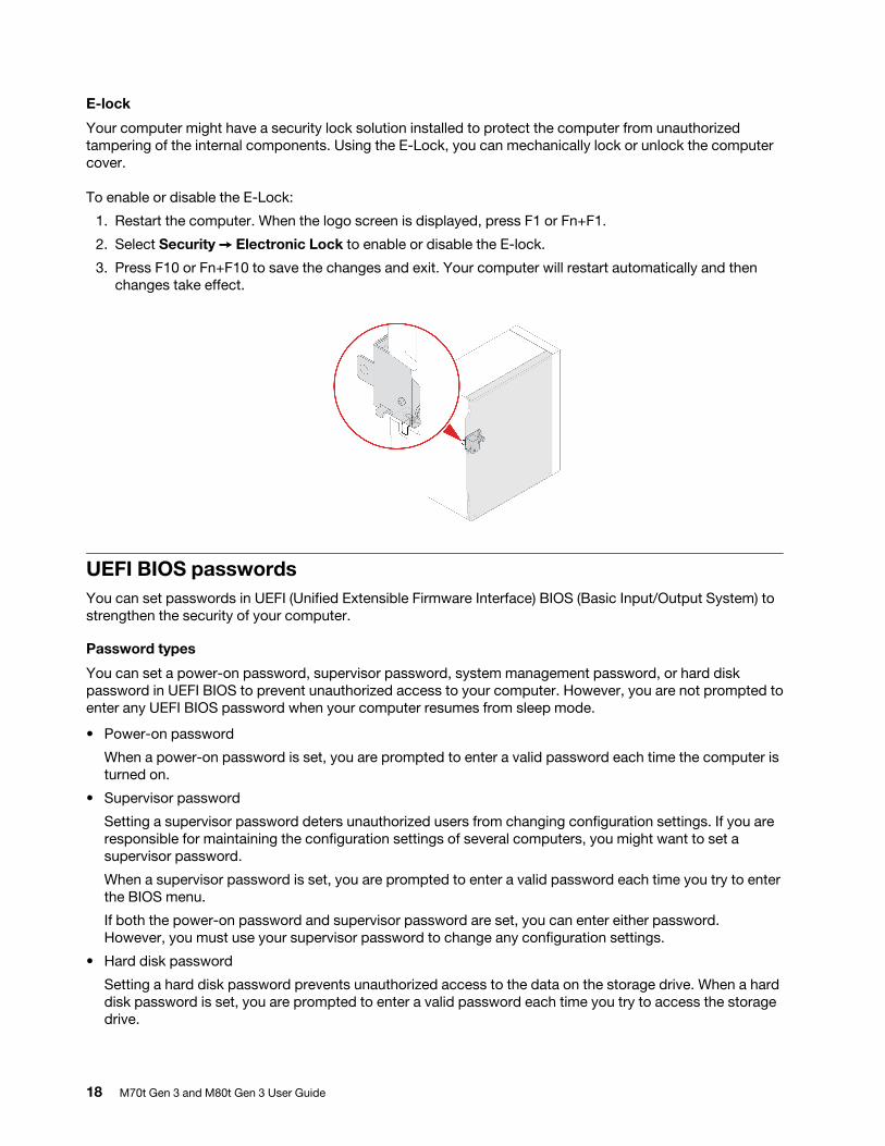
E-lock
Your computer might have a security lock solution installed to protect the computer from unauthorized tampering of the internal components. Using the E-Lock, you can mechanically lock or unlock the computer cover.
To enable or disable the E-Lock:
1. Restart the computer. When the logo screen is displayed, press F1 or Fn+F1.
2. Select Security ➙ Electronic Lock to enable or disable the E-lock.
3. Press F10 or Fn+F10 to save the changes and exit. Your computer will restart automatically and then changes take effect.
UEFI BIOS passwordsYou can set passwords in UEFI (Unified Extensible Firmware Interface) BIOS (Basic Input/Output System) to strengthen the security of your computer.
Password types
You can set a power-on password, supervisor password, system management password, or hard disk password in UEFI BIOS to prevent unauthorized access to your computer. However, you are not prompted to enter any UEFI BIOS password when your computer resumes from sleep mode.
• Power-on password
When a power-on password is set, you are prompted to enter a valid password each time the computer is turned on.
• Supervisor password
Setting a supervisor password deters unauthorized users from changing configuration settings. If you are responsible for maintaining the configuration settings of several computers, you might want to set a supervisor password.
When a supervisor password is set, you are prompted to enter a valid password each time you try to enter the BIOS menu.
If both the power-on password and supervisor password are set, you can enter either password. However, you must use your supervisor password to change any configuration settings.
• Hard disk password
Setting a hard disk password prevents unauthorized access to the data on the storage drive. When a hard disk password is set, you are prompted to enter a valid password each time you try to access the storage drive.
18 M70t Gen 3 and M80t Gen 3 User Guide
Note: After you set a hard disk password, your data on the storage drive is protected even if the storage drive is removed from one computer and installed in another.
• System management password (for selected models)
You can enable the system management password to have the same authority as the supervisor password to control security related features. To customize the authority of the system management password through the UEFI BIOS menu:
1. Restart the computer. When the logo screen is displayed, press F1 or Fn+F1.
2. Select Security ➙ System Management Password Access Control.
3. Follow the on-screen instructions.
If you have set both the supervisor password and the system management password, the supervisor password overrides the system management password.
Set, change, and remove a password
Before you start, print these instructions.
1. Restart the computer. When the logo screen is displayed, press F1 or Fn+F1.
2. Select Security.
3. Depending on the password type, select Set Supervisor Password, Set Power-On Password, Set System Management Password, or Hard Disk Password and press Enter.
4. Follow the on-screen instructions to set, change, or remove a password.
5. Press F10 or Fn+F10 to save the changes and exit.
You should record your passwords and store them in a safe place. If you forget the passwords, contact a Lenovo-authorized service provider to have the passwords removed.
Note: If the hard disk password is forgotten, Lenovo cannot remove the password or recover data from the storage drive.
Certificate based BIOS managementCertificate-based BIOS authentication (also called the password-less management mode) provides more secure UEFI BIOS management with password-free solution. It is used to replace the supervisor password / system management password for authentication if you have set one.
Note: Supervisor password / system management password are disabled automatically when certificate mode is enabled. But the power-on password / hard disk password still can be used normally in certificate mode if you have set one.
For certificate enrollment, see Certificate Enrollment Guide at: https://support.lenovo.com/docs/certificate_ enrollment_guide
Enter the BIOS menu with certificate
Once you have enrolled the certificate, you can enter the BIOS menu with the certificate.
1. Restart the computer. When the logo screen is displayed, press F1 or Fn+F1 to enter the BIOS menu.
2. The request data is displayed. Click Save to File to save the request data in a USB key and send the request data to IT admin by e-mail or phone.
3. Enter the unlock code provided by IT admin and click OK.
Notes:
Chapter 4. Secure your computer and information 19
• The unlock encode is a one-time password and is valid only during logon prompt (in one power-on cycle) for up to two hours.
• If you click Skip, you can enter the BIOS setup menu without BIOS management authority. But certificate reset is allowed.
Reset certificate
The enrolled certificate cannot be disabled. You can reset or remove it:
1. Restart the computer. When the logo screen is displayed, press F1 or Fn+F1.
2. Enter the BIOS menu with the certificate or skip the certification authentication process.
3. Select Security ➙ Reset Certificate.
4. Follow the on-screen instructions to enter the reset code provided by IT admin.
Use software security solutionsThis section provides software solutions to secure your computer and information.
Windows firewallsA firewall can be hardware, software, or a combination of both depending on the level of security required. Firewalls work on a set of rules to determine which inbound and outbound connections are authorized. If the computer is preinstalled with a firewall program, it helps protect against computer Internet security threats, unauthorized access, intrusions, and Internet attacks. It also protects your privacy. For more information about how to use the firewall program, refer to the help system of your firewall program.
To use Windows firewalls:1. Type Control Panel in the Windows search box and then press Enter. View by large icons or small icons.2. Click Windows Defender Firewall, and then follow the on-screen instructions.
Computrace Agent software embedded in firmware (for selected models)The Computrace Agent software is an IT asset management and computer theft recovery solution. The software detects if changes have been made on the computer, such as hardware, software, or the computer call-in location. You might have to purchase a subscription to activate the Computrace Agent software.
Use BIOS security solutionsThis section provides BIOS solutions to secure your computer and information.
Wipe the storage drive dataIt is recommended that you wipe the storage drive data before recycling the storage drive or the computer.
To wipe the storage drive data:
1. Restart the computer. When the logo screen is displayed, press F1 or Fn+F1.2. Select Security ➙ secure wipe ➙ Enabled.3. Press F10 or Fn+F10 to save the changes and exit.
4. Restart the computer. When the logo screen is displayed, press F12 or Fn+F12.5. Select App Menu ➙ secure wipe and press Enter.6. Select the storage drive you will wipe and click NEXT.
20 M70t Gen 3 and M80t Gen 3 User Guide
7. Select the entire storage drive or partition to wipe as desired.8. Select the method as desired and click NEXT.9. Click Yes to confirm your option when the prompting window is displayed.
10. If you have set a hard disk password for the storage drive, enter the password. Otherwise, set a temporary password following the on-screen instructions. Then, click NEXT. The wiping process begins.
Note: Duration of the wiping process varies depending on the storage drive capacity.11. Click Reboot when you are prompted to reset the system, and then one of the following will happen:
• If the system storage drive data is wiped, you will be prompted that no operating system is found.
• If the non-system storage drive data is wiped, the computer restarts automatically.
Cover presence switchThe cover presence switch prevents the computer from logging in to the operating system when the computer cover is not properly installed or closed.
To enable the cover presence switch connector on the system board:
1. Restart the computer. When the logo screen is displayed, press F1 or Fn+F1.
2. Select Security ➙ Cover Tamper Detected and press Enter.
3. Select Enabled and press Enter.
4. Press F10 or Fn+F10 to save the changes and exit.
If the cover presence switch is enabled and the computer cover is not correctly installed or closed, an error message will be displayed when you turn on the computer. To bypass the error message and log in to the operating system:
1. Properly install or close the computer cover.
2. Enter the BIOS menu, save and then exit.
Intel BIOS guardThe Intel® BIOS Guard module cryptographically verifies all BIOS updates. This hardware-based security helps prevent software and malware attacks on the computers BIOS.
Smart USB ProtectionThe Smart USB Protection function is a security function that helps prevent data from being copied from the computer to USB storage devices connected to the computer. You can set the Smart USB Protection function to one of the following modes:
• Disabled (default setting): You can use the USB storage devices without limitation.
• Read Only: You cannot copy data from the computer to the USB storage devices. However, you can access or modify data on the USB storage devices.
• No Access: You cannot access the USB storage devices from the computer.
To configure the Smart USB Protection function:
1. Restart the computer. When the logo screen is displayed, press F1 or Fn+F1.
2. Select Security ➙ Smart USB Protection and press Enter.
3. Select the desired setting and press Enter.
4. Press F10 or Fn+F10 to save the changes and exit.
Chapter 4. Secure your computer and information 21

22 M70t Gen 3 and M80t Gen 3 User Guide
Chapter 5. UEFI BIOS
This chapter provides information about configuring and updating UEFI BIOS, and clearing CMOS.
What is UEFI BIOSNote: The operating system settings might override any similar settings in UEFI BIOS.
UEFI BIOS is the first program that the computer runs when the computer is turned on. UEFI BIOS initializes the hardware components and loads the operating system and other programs. Your computer comes with a setup program with which you can change UEFI BIOS settings.
Enter the BIOS menuRestart the computer. When the logo screen is displayed, press F1 or Fn+F1 to enter the BIOS menu.
Note: If you have set BIOS passwords, enter the correct passwords when prompted. You also can select No or press Esc to skip the password prompt and enter the BIOS menu. However, you cannot change the system configurations that are protected by passwords.
Navigate in the BIOS interfaceAttention: The default configurations are already optimized for you in boldface. Improper change of the configurations might cause unexpected results.
Depending on your keyboard, you can navigate in the BIOS interface by pressing the following keys, or combinations of Fn and the following keys:
Key Function
F1 or Fn+F1 General Help
Esc or Fn+Esc Exit the submenu
↑↓ or Fn+↑↓ Locate an item
← → or Fn+← → Move keyboard focus
+/– or Fn++/– Change value
Enter Enter the submenu
F9 or Fn+F9 Setup Defaults
F10 or Fn+F10 Save and exit
Change the display language of UEFI BIOSUEFI BIOS supports three or four display languages: English, French, simplified Chinese, and Russian (for selected models).
To change the display language of UEFI BIOS:
1. Select Main ➙ Language and press Enter.
2. Set the display language as desired.
© Copyright Lenovo 2022 23
Change the display mode of UEFI BIOS (for selected models)You can use UEFI BIOS in the graphic mode or the text mode according to your needs.
The keys on the keyboard used to perform various tasks are displayed at the bottom of the screen. In addition to the keyboard, you also can use the mouse to make selections.
To change the display mode of UEFI BIOS:
1. Restart the computer. When the logo screen is displayed, press F1 or Fn+F1.
2. Select Main ➙ Setup Mode Select and press Enter.
3. Set the display mode as desired.
Set the system date and time1. Restart the computer. When the logo screen is displayed, press F1 or Fn+F1.2. Select Main ➙ System Time & Date and press Enter.
3. Set the system date and time as desired.4. Press F10 or Fn+F10 to save the changes and exit.
Change the boot priority orderIf the computer does not boot from a device as expected, you can change the boot priority order permanently or select a temporary boot device.
Change the boot priority order permanently
1. Depending on the type of the storage device, do one of the following:
• If the storage device is internal, go to step 2.
• If the storage device is a disc, ensure that the computer is on or turn on the computer. Then, insert the disc into the optical drive.
• If the storage device is an external device other than a disc, connect the storage device to the computer.
2. Restart the computer. When the logo screen is displayed, press F1 or Fn+F1.
3. Select Startup ➙ Boot Priority Order, and then follow the on-screen instructions to change the boot priority order.
4. You can also select the first priority device group by selecting Startup ➙ First Boot Device, and then follow the on-screen instructions to select the first boot device within this group. Your computer will boot from the first boot device before trying the boot priority order you set in the previous step.
5. Press F10 or Fn+F10 to save the changes and exit.
Select a temporary boot device
Note: Not all discs and storage drives are bootable.
1. Depending on the type of the storage device, do one of the following:
• If the storage device is internal, go to step 2.
• If the storage device is a disc, ensure that the computer is on or turn on the computer. Then, insert the disc into the optical drive.
• If the storage device is an external device other than a disc, connect the storage device to the computer.
24 M70t Gen 3 and M80t Gen 3 User Guide
2. Restart the computer. When the logo screen is displayed, press F12 or Fn+F12.
3. Select the storage device as desired and press Enter.
If you want to change the boot priority order permanently, select Enter Setup on Startup Device Menu and press Enter to enter the BIOS menu.
Enable or disable the configuration change detection featureIf you enable configuration change detection, when the POST detects configuration changes of some hardware devices (such as storage drives or memory modules), an error message will be displayed when you turn on the computer.
To enable or disable the configuration change detection feature:1. Restart the computer. When the logo screen is displayed, press F1 or Fn+F1.
2. Select Security ➙ Configuration Change Detection and press Enter.3. Enable or disable the feature as desired.4. Press F10 or Fn+F10 to save the changes and exit.
To bypass the error message and log in to the operating system, press F2 or Fn+F2. To clear the error message, enter the BIOS menu, save and then exit.
Enable or disable the automatic power-on featureThe Automatic Power On item in UEFI BIOS provides various options for you to make your computer start up automatically.
To enable or disable the automatic power-on feature:1. Restart the computer. When the logo screen is displayed, press F1 or Fn+F1.2. Select Power ➙ Automatic Power On and press Enter.
3. Select the feature as desired and press Enter.4. Enable or disable the feature as desired.5. Press F10 or Fn+F10 to save the changes and exit.
Enable or disable the smart power-on feature (for selected models)Ensure that the keyboard is connected to a USB connector supporting the smart power-on feature. With the smart power-on feature enabled, you can start up or wake up the computer from the hibernation mode by pressing Alt+P.
To enable or disable the smart power-on feature:1. Restart the computer. When the logo screen is displayed, press F1 or Fn+F1.
2. Select Power ➙ Smart Power On and press Enter.3. Enable or disable the feature as desired.4. Press F10 or Fn+F10 to save the changes and exit.
Enable or disable the ErP LPS compliance modeLenovo computers meet the eco-design requirements of the ErP Lot 3 regulation. For more information, go to: https://www.lenovo.com/us/en/compliance/eco-declaration
Chapter 5. UEFI BIOS 25
You can enable the ErP LPS compliance mode to reduce the consumption of electricity when the computer is off or in sleep mode.
To enable or disable the ErP LPS compliance mode:
1. Restart the computer. When the logo screen is displayed, press F1 or Fn+F1.
2. Select Power ➙ Enhanced Power Saving Mode and press Enter.
3. Depending on whether you select Enabled or Disabled, do one of the following:
• If you select Enabled, press Enter. Then, select Power ➙ Automatic Power On and press Enter. Check whether the Wake on LAN feature is disabled automatically. If no, disable it.
• If you select Disabled, press Enter. Then, go to the next step.
4. Press F10 or Fn+F10 to save the changes and exit.
When the ErP LPS compliance mode is enabled, you can wake up the computer by doing one of the following:
• Press the power button.
• Enable the Wake Up on Alarm feature to make the computer wake up at a set time.
To meet the off mode requirement of ErP compliance, you need to disable the Fast Startup function.
1. Go to Control Panel and view by large icons or small icons.2. Click Power Options ➙ Choose what the power buttons do ➙ Change settings that are currently
unavailable.
3. Clear the Turn on fast startup (recommended) option from the Shutdown settings list.
Change the ITS performance modeYou can adjust the acoustic and thermal performance of your computer by changing the ITS performance mode. Three options are available:
• Balance mode: The computer works at the balance mode with balanced noise and better performance.
• Performance mode (default setting): The computer works at the best performance with normal acoustic level.
Note: The term “best” only refers to the best effect among different settings of the product itself.
• Full Speed: All fans in the computer will run at full speed.
To change the ITS performance mode:
1. Restart the computer. When the logo screen is displayed, press F1 or Fn+F1.
2. Select Power ➙ Intelligent Cooling and press Enter.
3. Select Performance Mode and press Enter.
4. Set the performance mode as desired.
5. Press F10 or Fn+F10 to save the changes and exit.
Change BIOS settings before installing a new operating systemBIOS settings vary by operating system. Change the BIOS settings before installing a new operating system.
Microsoft constantly makes updates to the Windows operating system. Before installing a particular Windows version, check the compatibility list for the Windows version. For details, go to: https://support.lenovo.com/us/en/solutions/windows-support
26 M70t Gen 3 and M80t Gen 3 User Guide
To change the BIOS settings:
1. Restart the computer. When the logo screen is displayed, press F1 or Fn+F1.
2. From the main interface, select Security ➙ Secure Boot and press Enter.
3. Depending on the operating system to be installed, do one of the following:
• To install a Windows operating system that supports secure boot, select Enabled for Secure Boot.
• To install an operating system that does not support secure boot, such as some Linux operating systems, select Disabled for Secure Boot.
4. Press F10 or Fn+F10 to save the changes and exit.
Update UEFI BIOSWhen you install a new program, device driver, or hardware component, you might need to update UEFI BIOS. You can update the BIOS from your operating system or a flash update disc (supported only on selected models).
Download and install the latest UEFI BIOS update package by one of the following methods:
• From the Vantage app:
Open the Vantage app to check the available update packages. If the latest UEFI BIOS update package is available, follow the on-screen instructions to download and install the package.
• From the Lenovo Support Web site:
1. Go to https://pcsupport.lenovo.com.
2. Download the flash BIOS update driver for the operating system version or the ISO image version (used to create a flash update disc). Then, download the installation instructions for the flash BIOS update driver you have downloaded.
3. Print the installation instructions and follow the instructions to update the BIOS.
Recover from a BIOS update failure1. Remove all media from the drives and turn off all connected devices.2. Insert the BIOS update disc into the optical drive, and then turn off the computer.
3. Disconnect all power cords from electrical outlets. Then, remove any parts that impede access to the Clear CMOS/Recovery jumper.
4. Move the jumper from the standard position to the maintenance position.
5. Reconnect the power cords for the computer and the monitor to electrical outlets.6. Turn on the computer and the monitor. When the computer beeps, the recovery process begins.7. After the recovery process is completed, the computer will be turned off automatically.
Note: Depending on the computer model, the recovery process will take two to three minutes.
8. Disconnect all power cords from electrical outlets.9. Move the jumper back to the standard position.
10. Reinstall all the parts that have been removed. Then, reconnect the power cords for the computer and the monitor to electrical outlets.
11. Turn on the computer and the monitor. When the logo screen is displayed, press F1 or Fn+F1.12. To prevent data loss, ensure that BIOS settings are restored to an earlier point.
Chapter 5. UEFI BIOS 27
Clear CMOS1. Remove all media from the drives and turn off all connected devices and the computer.2. Disconnect all power cords from electrical outlets. Then, remove any parts that impede access to the
Clear CMOS/Recovery jumper.
3. Move the jumper from the standard position to the maintenance position.4. Reconnect the power cords for the computer and the monitor to electrical outlets.5. Turn on the computer and the monitor. When the computer beeps, wait for approximately 10 seconds.6. Turn off the computer by holding the power button for approximately four seconds.
7. Disconnect all power cords from electrical outlets.8. Move the jumper back to the standard position.9. Reinstall all the parts that have been removed. Then, reconnect the power cords for the computer and
the monitor to electrical outlets.10. Turn on the computer and the monitor. When the logo screen is displayed, press F1 or Fn+F1.11. To prevent data loss, ensure that BIOS settings are restored to an earlier point.
28 M70t Gen 3 and M80t Gen 3 User Guide
Chapter 6. Diagnostics
Use diagnostic solutions to test hardware components and report operating-system-controlled settings that interfere with the correct operation of your computer.
Lenovo diagnostic toolsFor information about Lenovo diagnostic tools, go to: https://pcsupport.lenovo.com/lenovodiagnosticsolutions
The Vantage appThe Vantage app is preinstalled on your computer. To diagnose problems with the Vantage app:
1. Type Vantage in the Windows search box and press Enter.
2. Follow the on-screen instructions and run a hardware scan.
If you are unable to isolate and resolve the problem after running the Vantage app, save and print the log files created by the program. You might need the log files when you speak to a Lenovo technical support representative.
© Copyright Lenovo 2022 29

30 M70t Gen 3 and M80t Gen 3 User Guide
Chapter 7. CRU replacement
Customer Replaceable Units (CRUs) are parts that can be upgraded or replaced by the customer. Lenovo computers contain the following types of CRUs:
• Self-service CRUs: Refer to parts that can be installed or replaced easily by customer themselves or by trained service technicians at an additional cost.
• Optional-service CRUs: Refer to parts that can be installed or replaced by customers with a greater skill level. Trained service technicians can also provide service to install or replace the parts under the type of warranty designated for the customer’s machine.
If you intend on installing the CRU, Lenovo will ship the CRU to you. CRU information and replacement instructions are shipped with your product and are available from Lenovo at any time upon request. You might be required to return the defective part that is replaced by the CRU. When return is required: (1) return instructions, a prepaid shipping label, and a container will be included with the replacement CRU; and (2) you might be charged for the replacement CRU if Lenovo does not receive the defective CRU within thirty (30) days of your receipt of the replacement CRU. For full details, see the Lenovo Limited Warranty documentation at: https://www.lenovo.com/warranty/llw_02
CRU listThe following is the CRU list of your computer.
Self-service CRUs
• 2.5–inch hard disk drive*
• 3.5–inch hard disk drive*
• Computer cover
• Front bezel
• Heat sink for M.2 solid-state drive*
• Keyboard*
• M.2 solid-state drive*
• M.2 solid-state drive bracket*
• Memory module
• Mouse*
• Optical drive*
• Optical drive bracket*
• PCI-Express card*
• PCI-Express connector cable*
• Power cord
• Smart cable clip*
Optional-service CRUs
• Coin-cell battery
• E-lock*
• Power supply assembly
© Copyright Lenovo 2022 31
* for selected models
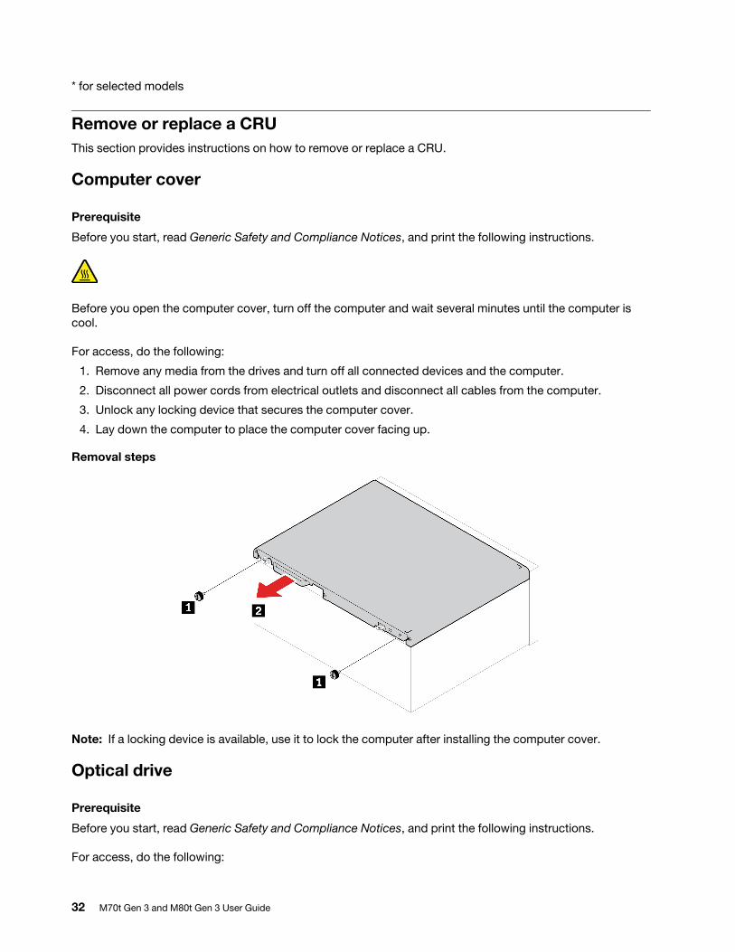
Remove or replace a CRUThis section provides instructions on how to remove or replace a CRU.
Computer cover
Prerequisite
Before you start, read Generic Safety and Compliance Notices, and print the following instructions.
Before you open the computer cover, turn off the computer and wait several minutes until the computer is cool.
For access, do the following:
1. Remove any media from the drives and turn off all connected devices and the computer.
2. Disconnect all power cords from electrical outlets and disconnect all cables from the computer.
3. Unlock any locking device that secures the computer cover.
4. Lay down the computer to place the computer cover facing up.
Removal steps
Note: If a locking device is available, use it to lock the computer after installing the computer cover.
Optical drive
Prerequisite
Before you start, read Generic Safety and Compliance Notices, and print the following instructions.
For access, do the following:
32 M70t Gen 3 and M80t Gen 3 User Guide
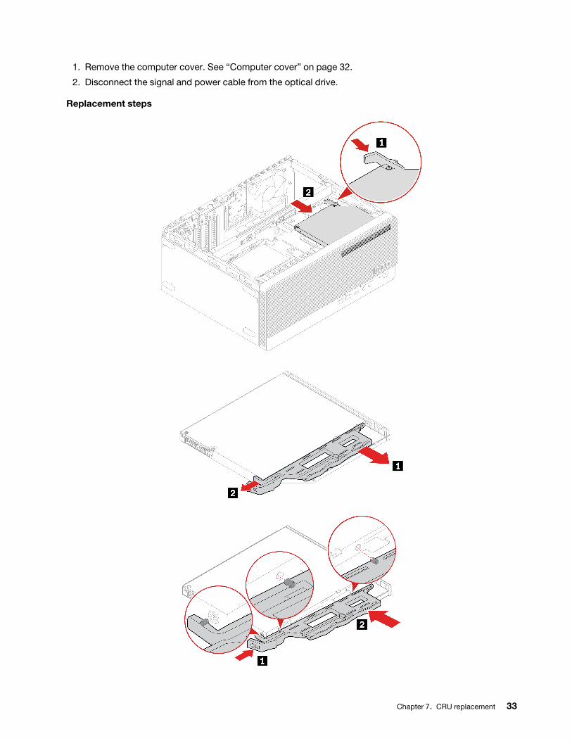
1. Remove the computer cover. See “Computer cover” on page 32.
2. Disconnect the signal and power cable from the optical drive.
Replacement steps
Chapter 7. CRU replacement 33
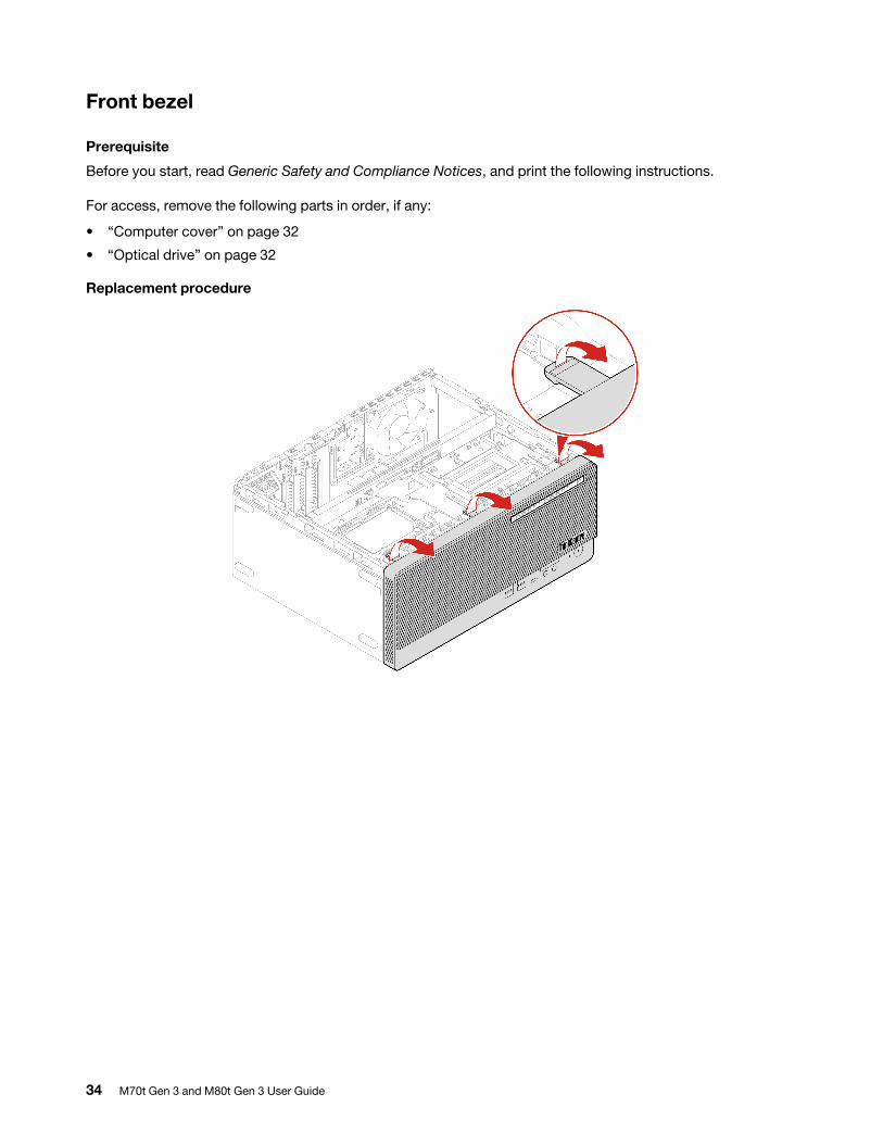
Front bezel
Prerequisite
Before you start, read Generic Safety and Compliance Notices, and print the following instructions.
For access, remove the following parts in order, if any:
• “Computer cover” on page 32
• “Optical drive” on page 32
Replacement procedure
34 M70t Gen 3 and M80t Gen 3 User Guide
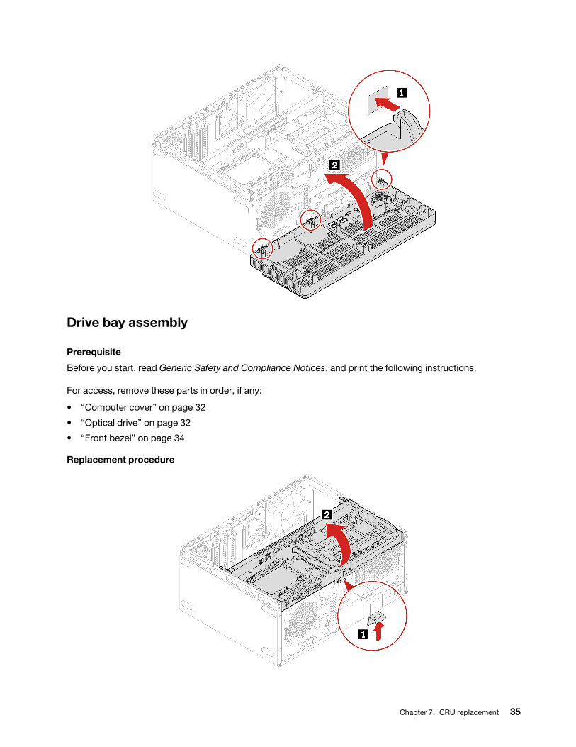
Drive bay assembly
Prerequisite
Before you start, read Generic Safety and Compliance Notices, and print the following instructions.
For access, remove these parts in order, if any:
• “Computer cover” on page 32
• “Optical drive” on page 32
• “Front bezel” on page 34
Replacement procedure
Chapter 7. CRU replacement 35
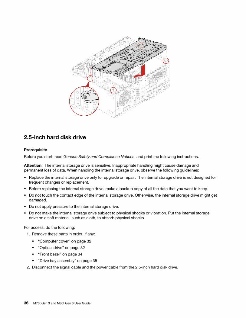
2.5-inch hard disk drive
Prerequisite
Before you start, read Generic Safety and Compliance Notices, and print the following instructions.
Attention: The internal storage drive is sensitive. Inappropriate handling might cause damage and permanent loss of data. When handling the internal storage drive, observe the following guidelines:
• Replace the internal storage drive only for upgrade or repair. The internal storage drive is not designed for frequent changes or replacement.
• Before replacing the internal storage drive, make a backup copy of all the data that you want to keep.
• Do not touch the contact edge of the internal storage drive. Otherwise, the internal storage drive might get damaged.
• Do not apply pressure to the internal storage drive.
• Do not make the internal storage drive subject to physical shocks or vibration. Put the internal storage drive on a soft material, such as cloth, to absorb physical shocks.
For access, do the following:
1. Remove these parts in order, if any:
• “Computer cover” on page 32
• “Optical drive” on page 32
• “Front bezel” on page 34
• “Drive bay assembly” on page 35
2. Disconnect the signal cable and the power cable from the 2.5-inch hard disk drive.
36 M70t Gen 3 and M80t Gen 3 User Guide
Removal steps
3.5-inch hard disk drive
Prerequisite
Before you start, read Generic Safety and Compliance Notices, and print the following instructions.
Attention: The internal storage drive is sensitive. Inappropriate handling might cause damage and permanent loss of data. When handling the internal storage drive, observe the following guidelines:
• Replace the internal storage drive only for upgrade or repair. The internal storage drive is not designed for frequent changes or replacement.
• Before replacing the internal storage drive, make a backup copy of all the data that you want to keep.
• Do not touch the contact edge of the internal storage drive. Otherwise, the internal storage drive might get damaged.
• Do not apply pressure to the internal storage drive.
• Do not make the internal storage drive subject to physical shocks or vibration. Put the internal storage drive on a soft material, such as cloth, to absorb physical shocks.
For access, do the following:
1. Remove these parts in order, if any:
• “Computer cover” on page 32
• “Front bezel” on page 34
• “Drive bay assembly” on page 35
2. Disconnect the signal cable and the power cable from the 3.5-inch hard disk drive.
Chapter 7. CRU replacement 37
Removal steps
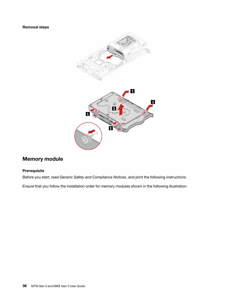
Memory module
Prerequisite
Before you start, read Generic Safety and Compliance Notices, and print the following instructions.
Ensure that you follow the installation order for memory modules shown in the following illustration.
38 M70t Gen 3 and M80t Gen 3 User Guide

For access, remove these parts in order, if any:
• “Computer cover” on page 32
• “Front bezel” on page 34
• “Drive bay assembly” on page 35
Replacement procedure
Note: During the installation, ensure that you align the memory module to the slot and press down on both ends until the latches are fully engaged with a click.
Chapter 7. CRU replacement 39
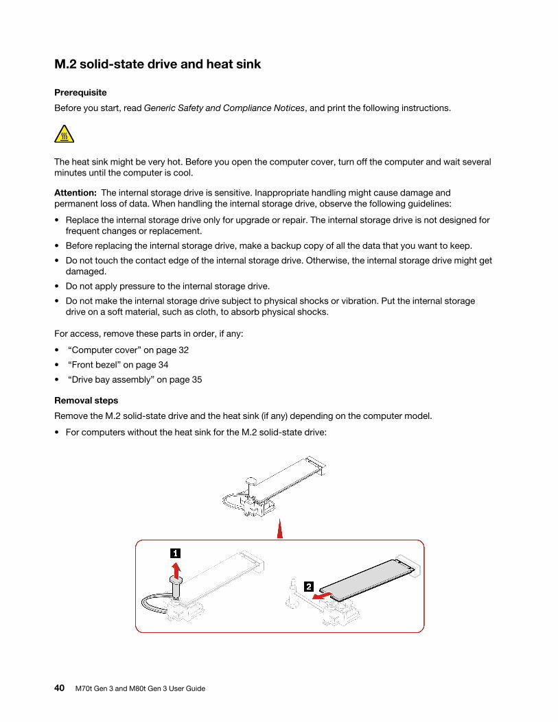
M.2 solid-state drive and heat sink
Prerequisite
Before you start, read Generic Safety and Compliance Notices, and print the following instructions.
The heat sink might be very hot. Before you open the computer cover, turn off the computer and wait several minutes until the computer is cool.
Attention: The internal storage drive is sensitive. Inappropriate handling might cause damage and permanent loss of data. When handling the internal storage drive, observe the following guidelines:
• Replace the internal storage drive only for upgrade or repair. The internal storage drive is not designed for frequent changes or replacement.
• Before replacing the internal storage drive, make a backup copy of all the data that you want to keep.
• Do not touch the contact edge of the internal storage drive. Otherwise, the internal storage drive might get damaged.
• Do not apply pressure to the internal storage drive.
• Do not make the internal storage drive subject to physical shocks or vibration. Put the internal storage drive on a soft material, such as cloth, to absorb physical shocks.
For access, remove these parts in order, if any:
• “Computer cover” on page 32
• “Front bezel” on page 34
• “Drive bay assembly” on page 35
Removal steps
Remove the M.2 solid-state drive and the heat sink (if any) depending on the computer model.
• For computers without the heat sink for the M.2 solid-state drive:
40 M70t Gen 3 and M80t Gen 3 User Guide
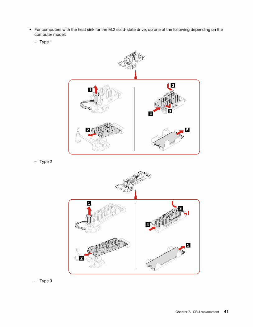
• For computers with the heat sink for the M.2 solid-state drive, do one of the following depending on the computer model:
– Type 1
– Type 2
– Type 3
Chapter 7. CRU replacement 41
Note: Remove the film that covers the thermal pad (if any) when installing the M.2 solid-state drive and the heat sink.
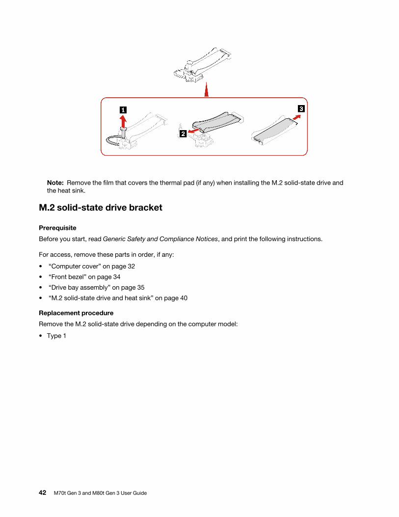
M.2 solid-state drive bracket
Prerequisite
Before you start, read Generic Safety and Compliance Notices, and print the following instructions.
For access, remove these parts in order, if any:
• “Computer cover” on page 32
• “Front bezel” on page 34
• “Drive bay assembly” on page 35
• “M.2 solid-state drive and heat sink” on page 40
Replacement procedure
Remove the M.2 solid-state drive depending on the computer model:
• Type 1
42 M70t Gen 3 and M80t Gen 3 User Guide
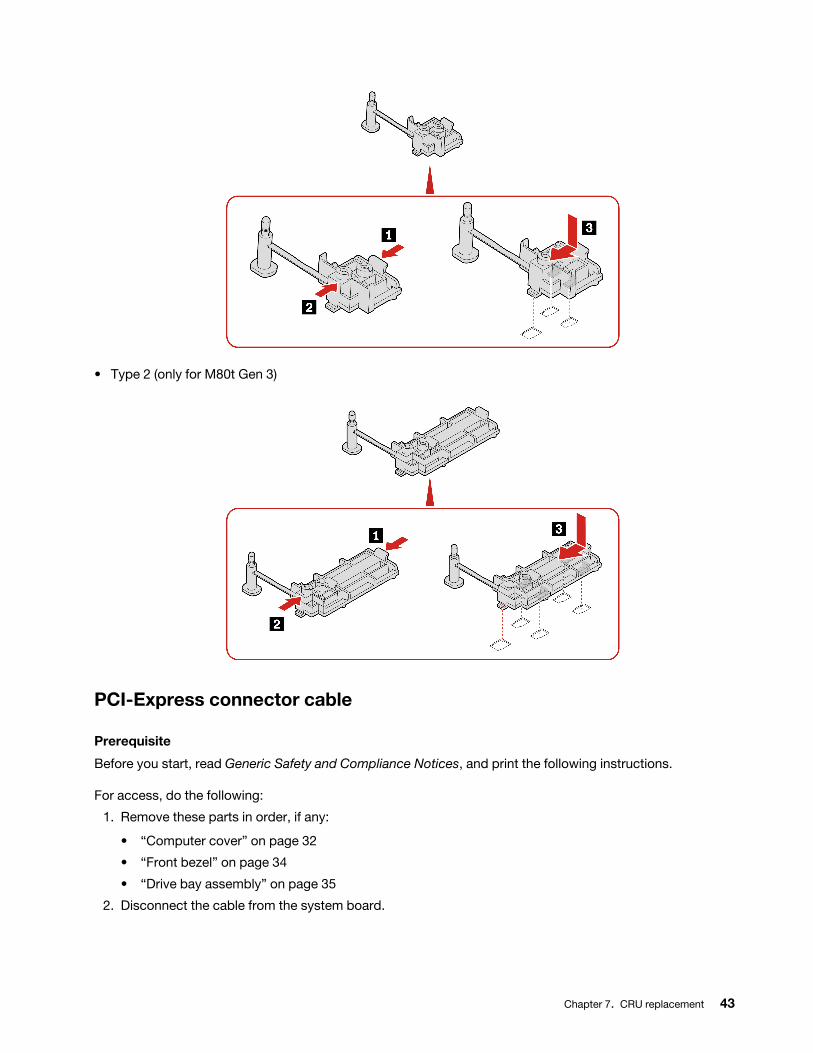
• Type 2 (only for M80t Gen 3)
PCI-Express connector cable
Prerequisite
Before you start, read Generic Safety and Compliance Notices, and print the following instructions.
For access, do the following:
1. Remove these parts in order, if any:
• “Computer cover” on page 32
• “Front bezel” on page 34
• “Drive bay assembly” on page 35
2. Disconnect the cable from the system board.
Chapter 7. CRU replacement 43
Removal steps
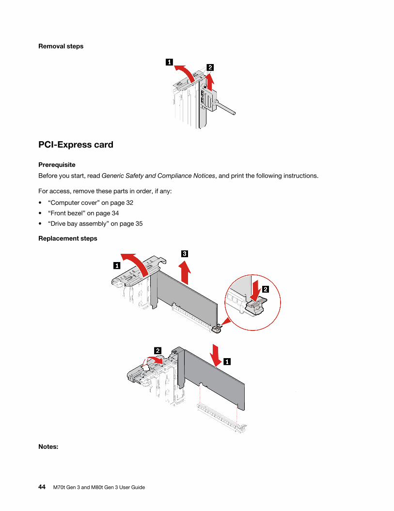
PCI-Express card
Prerequisite
Before you start, read Generic Safety and Compliance Notices, and print the following instructions.
For access, remove these parts in order, if any:
• “Computer cover” on page 32
• “Front bezel” on page 34
• “Drive bay assembly” on page 35
Replacement steps
Notes:
44 M70t Gen 3 and M80t Gen 3 User Guide
• Do not attempt to install any PCI-Express cards other than graphics card to the PCI-Express slot next to the microprocessor.
• Before installing a new PCI-Express card, remove any PCI-Express connector cables that impede the installation. See “PCI-Express connector cable” on page 43.
• To finish the installation, ensure that you align the PCI-Express card to the slot and press down on both ends until the latch is fully engaged with a click.
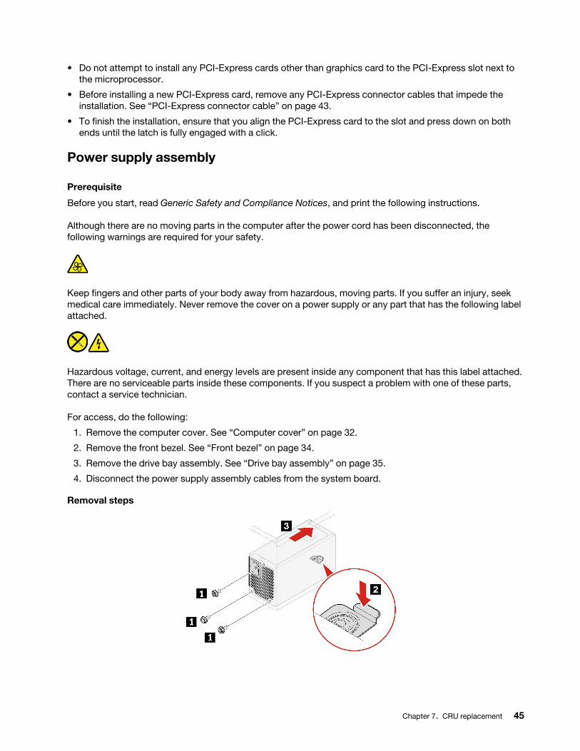
Power supply assembly
Prerequisite
Before you start, read Generic Safety and Compliance Notices, and print the following instructions.
Although there are no moving parts in the computer after the power cord has been disconnected, the following warnings are required for your safety.
Keep fingers and other parts of your body away from hazardous, moving parts. If you suffer an injury, seek medical care immediately. Never remove the cover on a power supply or any part that has the following label attached.
Hazardous voltage, current, and energy levels are present inside any component that has this label attached. There are no serviceable parts inside these components. If you suspect a problem with one of these parts, contact a service technician.
For access, do the following:
1. Remove the computer cover. See “Computer cover” on page 32.
2. Remove the front bezel. See “Front bezel” on page 34.
3. Remove the drive bay assembly. See “Drive bay assembly” on page 35.
4. Disconnect the power supply assembly cables from the system board.
Removal steps
Chapter 7. CRU replacement 45
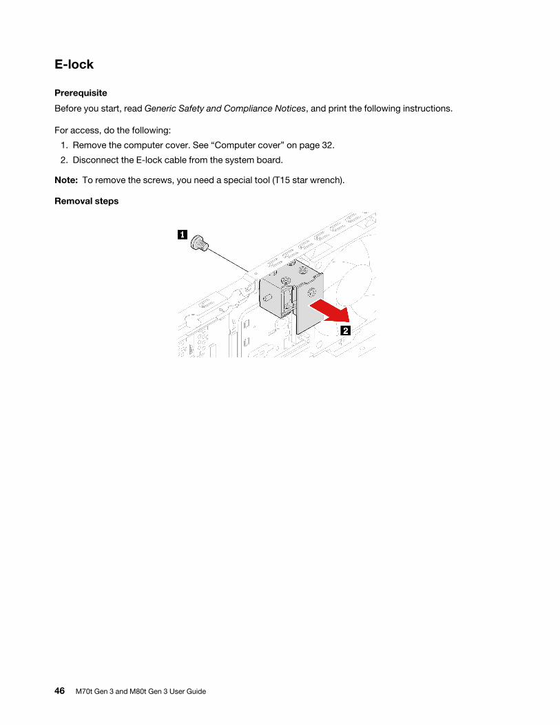
E-lock
Prerequisite
Before you start, read Generic Safety and Compliance Notices, and print the following instructions.
For access, do the following:
1. Remove the computer cover. See “Computer cover” on page 32.
2. Disconnect the E-lock cable from the system board.
Note: To remove the screws, you need a special tool (T15 star wrench).
Removal steps
46 M70t Gen 3 and M80t Gen 3 User Guide
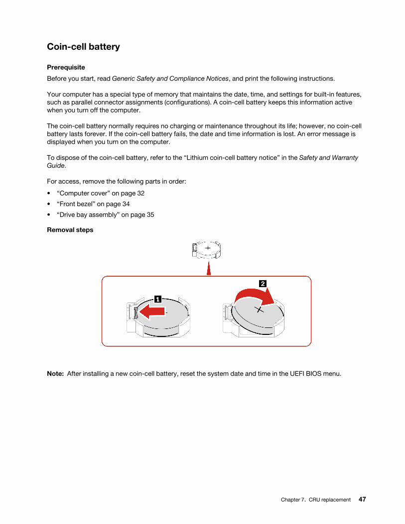
Coin-cell battery
Prerequisite
Before you start, read Generic Safety and Compliance Notices, and print the following instructions.
Your computer has a special type of memory that maintains the date, time, and settings for built-in features, such as parallel connector assignments (configurations). A coin-cell battery keeps this information active when you turn off the computer.
The coin-cell battery normally requires no charging or maintenance throughout its life; however, no coin-cell battery lasts forever. If the coin-cell battery fails, the date and time information is lost. An error message is displayed when you turn on the computer.
To dispose of the coin-cell battery, refer to the “Lithium coin-cell battery notice” in the Safety and Warranty Guide.
For access, remove the following parts in order:
• “Computer cover” on page 32
• “Front bezel” on page 34
• “Drive bay assembly” on page 35
Removal steps
Note: After installing a new coin-cell battery, reset the system date and time in the UEFI BIOS menu.
Chapter 7. CRU replacement 47

48 M70t Gen 3 and M80t Gen 3 User Guide
Chapter 8. Help and support
Self-help resourcesUse the following self-help resources to learn more about the computer and troubleshoot problems.
Resources How to access?
Troubleshooting and frequently asked questions • https://www.lenovo.com/tips
• https://forums.lenovo.com
Accessibility information https://www.lenovo.com/accessibility
Reset or restore Windows
• Use Lenovo recovery options.
1. Go to https://support.lenovo.com/ HowToCreateLenovoRecovery.
2. Follow the on-screen instructions.
• Use Windows recovery options.
1. Go to https://pcsupport.lenovo.com.
2. Detect your computer or manually select your computer model.
3. Click Diagnostics ➙ Operating System Diagnostics and then follow the on-screen instructions.
Use the Vantage app to:
• Configure device settings.
• Download and install UEFI BIOS, drivers and firmware updates.
• Secure you computer from outside threats.
• Diagnose hardware problems.
• Check the computer warranty status.
• Access User Guide and helpful articles.
Note: The available features vary depending on the computer model.
Type Vantage in the Windows search box.
Product documentation:
• Safety and Warranty Guide
• Generic Safety and Compliance Notices
• Setup Guide
• This User Guide
• Regulatory Notice
Go to https://pcsupport.lenovo.com. Then, follow the on- screen instructions to filter out the documentation you want.
© Copyright Lenovo 2022 49
Resources How to access?
Lenovo Support Web site with the latest support information of the following:
• Drivers and software
• Diagnostic solutions
• Product and service warranty
• Product and parts details
• Knowledge base and frequently asked questions
https://pcsupport.lenovo.com
Windows help information
• Open the Start menu and click Get Help or Tips.
• Use Windows Search or the Cortana® personal assistant.
• Microsoft support Web site: https://support.microsoft.com
50 M70t Gen 3 and M80t Gen 3 User Guide
Call LenovoIf you have tried to correct the problem yourself and still need help, you can call Lenovo Customer Support Center.
Before you contact LenovoPrepare the following before you contact Lenovo:
1. Record the problem symptoms and details:
• What is the problem? Is it continuous or intermittent?
• Any error message or error code?
• What operating system are you using? Which version?
• Which software applications were running at the time of the problem?
• Can the problem be reproduced? If so, how?
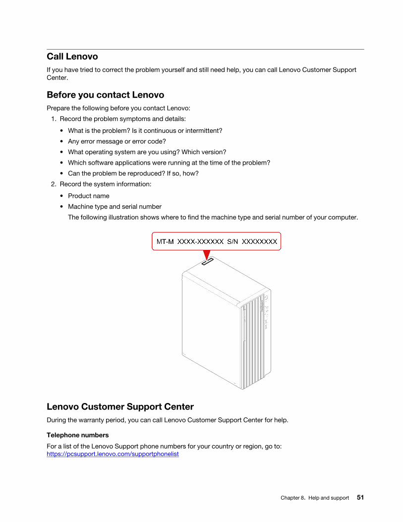
2. Record the system information:
• Product name
• Machine type and serial number
The following illustration shows where to find the machine type and serial number of your computer.
Lenovo Customer Support CenterDuring the warranty period, you can call Lenovo Customer Support Center for help.
Telephone numbers
For a list of the Lenovo Support phone numbers for your country or region, go to: https://pcsupport.lenovo.com/supportphonelist
Chapter 8. Help and support 51
Note: Phone numbers are subject to change without notice. If the number for your country or region is not provided, contact your Lenovo reseller or Lenovo marketing representative.
Services available during the warranty period
• Problem determination - Trained personnel are available to assist you with determining if you have a hardware problem and deciding what action is necessary to fix the problem.
• Lenovo hardware repair - If the problem is determined to be caused by Lenovo hardware under warranty, trained service personnel are available to provide the applicable level of service.
• Engineering change management - Occasionally, there might be changes that are required after a product has been sold. Lenovo or your reseller, if authorized by Lenovo, will make selected Engineering Changes (ECs) that apply to your hardware available.
Services not covered
• Replacement or use of parts not manufactured for or by Lenovo or nonwarranted parts• Identification of software problem sources• Configuration of UEFI BIOS as part of an installation or upgrade• Changes, modifications, or upgrades to device drivers• Installation and maintenance of network operating systems (NOS)• Installation and maintenance of programs
For the terms and conditions of the Lenovo Limited Warranty that apply to your Lenovo hardware product, see Safety and Warranty Guide that comes with your computer.
Purchase additional servicesDuring and after the warranty period, you can purchase additional services from Lenovo at: https://pcsupport.lenovo.com/warrantyupgrade
Service availability and service name might vary by country or region.
52 M70t Gen 3 and M80t Gen 3 User Guide
Appendix A. Compliance information
For more compliance information, refer to Regulatory Notice at https://pcsupport.lenovo.com and Generic Safety and Compliance Notices at https://pcsupport.lenovo.com/docs/generic_notices.
Certification-related informationProduct name Machine types
ThinkCentre M70t Gen 311T5, 11T6, 11T9, 11TA, 11X3, 11XE, 11V5, 11V6, 11Y7, and 11Y8
ThinkCentre M80t Gen 311TD,11TE, 11TH,11TJ, 11YV, 11YW, 12A0, and 12A1
Further compliance information related to your product is available at https://www.lenovo.com/compliance.
Operating environment
Maximum altitude (without pressurization)
• Operating: From 0 m (0 ft) to 3048 m (10 000 ft)
• Storage: From 0 m (0 ft) to 12192 m (40 000 ft)
Temperature
• Operating: From 5°C (41°F) to 35°C (95°F)
• Storage:
– For common desktop computers: From -40°C (-40°F) to 60°C (140°F)
– For all-in-one desktop computers: From -20°C (-4°F) to 60°C (140°F)
Relative humidity
• Operating: 20%-80% (non-condensing)
• Storage: 10%–90% (non-condensing)
© Copyright Lenovo 2022 53

54 M70t Gen 3 and M80t Gen 3 User Guide
Appendix B. Notices and trademarks
Notices
Lenovo may not offer the products, services, or features discussed in this document in all countries. Consult your local Lenovo representative for information on the products and services currently available in your area. Any reference to a Lenovo product, program, or service is not intended to state or imply that only that Lenovo product, program, or service may be used. Any functionally equivalent product, program, or service that does not infringe any Lenovo intellectual property right may be used instead. However, it is the user's responsibility to evaluate and verify the operation of any other product, program, or service.
Lenovo may have patents or pending patent programs covering subject matter described in this document. The furnishing of this document does not give you any license to these patents. You can send license inquiries, in writing, to:
Lenovo (United States), Inc. 8001 Development DriveMorrisville, NC 27560U.S.A.Attention: Lenovo Director of Licensing
LENOVO PROVIDES THIS PUBLICATION "AS IS" WITHOUT WARRANTY OF ANY KIND, EITHER EXPRESS OR IMPLIED, INCLUDING, BUT NOT LIMITED TO, THE IMPLIED WARRANTIES OF NON-INFRINGEMENT, MERCHANTABILITY OR FITNESS FOR A PARTICULAR PURPOSE. Some jurisdictions do not allow disclaimer of express or implied warranties in certain transactions, therefore, this statement may not apply to you.
Changes are made periodically to the information herein; these changes will be incorporated in new editions of the publication. To provide better service, Lenovo reserves the right to improve and/or modify the products and software programs described in the manuals included with your computer, and the content of the manual, at any time without additional notice.
The software interface and function and hardware configuration described in the manuals included with your computer might not match exactly the actual configuration of the computer that you purchase. For the configuration of the product, refer to the related contract (if any) or product packing list, or consult the distributor for the product sales. Lenovo may use or distribute any of the information you supply in any way it believes appropriate without incurring any obligation to you.
The products described in this document are not intended for use in implantation or other life support applications where malfunction may result in injury or death to persons. The information contained in this document does not affect or change Lenovo product specifications or warranties. Nothing in this document shall operate as an express or implied license or indemnity under the intellectual property rights of Lenovo or third parties. All information contained in this document was obtained in specific environments and is presented as an illustration. The result obtained in other operating environments may vary.
Lenovo may use or distribute any of the information you supply in any way it believes appropriate without incurring any obligation to you.
Any references in this publication to non-Lenovo Web sites are provided for convenience only and do not in any manner serve as an endorsement of those Web sites. The materials at those Web sites are not part of the materials for this Lenovo product, and use of those Web sites is at your own risk.
© Copyright Lenovo 2022 55
Any performance data contained herein was determined in a controlled environment. Therefore, the result obtained in other operating environments may vary significantly. Some measurements may have been made on development-level systems and there is no guarantee that these measurements will be the same on generally available systems. Furthermore, some measurements may have been estimated through extrapolation. Actual results may vary. Users of this document should verify the applicable data for their specific environment.
This document is copyrighted by Lenovo and is not covered by any open source license, including any Linux agreement(s) which may accompany software included with this product. Lenovo may update this document at any time without notice.
For the latest information or any questions or comments, contact or visit the Lenovo Web site: https://pcsupport.lenovo.com
Trademarks
LENOVO, LENOVO logo, THINKCENTRE, and THINKCENTRE logo are trademarks of Lenovo. Intel, and Thunderbolt are trademarks of Intel Corporation or its subsidiaries in the U.S. and/or other countries. Microsoft, Windows, and Cortana are trademarks of the Microsoft group of companies. DisplayPort is a trademark of the Video Electronics Standards Association. The terms HDMI and HDMI High-Definition Multimedia Interface are trademarks or registered trademarks of HDMI Licensing LLC in the United States and other countries. Wi-Fi, Wi-Fi Alliance, and Miracast are registered trademarks of Wi-Fi Alliance. USB-C is a registered trademark of USB Implementers Forum. All other trademarks are the property of their respective owners.
56 M70t Gen 3 and M80t Gen 3 User Guide