
KODAK i5x50 Series Scanners - CNET Content Solutions
138
A-61868 SK6213 dak i5x50 Series Scanners User's Guide User's Guide on Installation CD Guide d'utilisation sur le CD d'installation Benutzerhandbuch auf der Installations-CD Manuale per l'utente sul CD di installazione Gufa del usuario en el CD de instalaci6n Guia do Usuario no CD de instalaao Gebruikershandleiding op installatie-cd Kurulum CD'sindeki Kullarnm Kdavuzu Uzivatelska pirucka na instalacnfm disku CD ���F �ltt� { � } 4/A�-J�CD-- �xi CDI Ar§ ��A � WI �I l �\ PyKOBOBO nonb3osaren� Ha yaHOB04HOM KOMna-CKe Ghidul utilizatorului de pe CD-ul de instalare Felhasznal6i utmutat6 a telepit6 CD-n Podr�nik uzytkownika na instalacyjnym dysku CD 05rw� XP�o O CD EVKOTOO KODAK i5250 Scanner KODAK i5250V Scanner KODAK i5650 Scanner KODAK i5650V Scanner KODAK i5850 Scanner
-
Upload
khangminh22 -
Category
Documents
-
view
1 -
download
0
Transcript of KODAK i5x50 Series Scanners - CNET Content Solutions

A-61868
SK6213
Kodak
i5x50 Series Scanners
User's Guide
User's Guide on Installation CD Guide d'utilisation sur le CD d'installation
Benutzerhandbuch auf der Installations-CD Manuale per l'utente sul CD di installazione
Gufa del usuario en el CD de instalaci6n Guia do Usuario no CD de instalac;:ao
Gebruikershandleiding op installatie-cd Kurulum CD'sindeki Kullarnm Kdavuzu
Uzivatelska pi'irucka na instalacnfm disku CD
��,'ti!A:.t.�.lf.lF:tliii¥i �ltJ'tlit.t. � { �.If.I :ff :tliii¥i}
4/A�-J�CDO).:Z.--+f-.:;(:tj-{ !-: �xi CD.2.I Ar§ ��A-l
� '--'"'WI .1.�I '--'"'_;ill csk �\ J,l.iPyKOBO,QCTBO nonb3osaren� Ha ycraHOB04HOM KOMnaKT-,Q\11CKe
Ghidul utilizatorului de pe CD-ul de instalare Felhasznal6i utmutat6 a telepit6 CD-n
Podr�cznik uzytkownika na instalacyjnym dysku CD 05rw� XP�oric; OTO CD EVKOTClOTOOf'l<:;
KODAK i5250 ScannerKODAK i5250V ScannerKODAK i5650 ScannerKODAK i5650V ScannerKODAK i5850 Scanner

3rd Party Licenses
This software is based in part on the work of the Independent JPEG Group
Copyright (C)2009-2013 D. R. Commander. All Rights Reserved.
Redistribution and use in source and binary forms, with or without modification, are permitted provided that the following conditions are met:
- Redistributions of source code must retain the above copyright notice, this list of conditions and the following disclaimer.
- Redistributions in binary form must reproduce the above copyright notice, this list of conditions and the following disclaimer in the documentation and/or other materials provided with the distribution.
- Neither the name of the libjpeg-turbo Project nor the names of its contributors may be used to endorse or promote products derived from this software without specific prior written permission.
THIS SOFTWARE IS PROVIDED BY THE COPYRIGHT HOLDERS AND CONTRIBUTORS "AS IS", AND ANY EXPRESS OR IMPLIED WARRANTIES, INCLUDING, BUT NOT LIMITED TO, THE IMPLIED WARRANTIES OF MERCHANTABILITY AND FITNESS FOR A PARTICULAR PURPOSE ARE DISCLAIMED. IN NO EVENT SHALL THE COPYRIGHT HOLDERS OR CONTRIBUTORS BE LIABLE FOR ANY DIRECT, INDIRECT, INCIDENTAL, SPECIAL, EXEMPLARY, OR CONSEQUENTIAL DAMAGES (INCLUDING, BUT NOT LIMITED TO, PROCUREMENT OF SUBSTITUTE GOODS OR SERVICES; LOSS OF USE, DATA, OR PROFITS; OR BUSINESS INTERRUPTION) HOWEVER CAUSED AND ON ANY THEORY OF LIABILITY, WHETHER IN CONTRACT, STRICT LIABILITY, OR TORT (INCLUDING NEGLIGENCE OR OTHERWISE) ARISING IN ANY WAY OUT OF THE USE OF THIS SOFTWARE, EVEN IF ADVISED OF THE POSSIBILITY OF SUCH DAMAGE.

A-61868 November 2016 i
Contents
1 Overview .....................................................................................................................................1Supporting documentation .........................................................................................................2Accessories ................................................................................................................................2What’s in the box ........................................................................................................................3Scanner components .................................................................................................................4
Front view: all models ............................................................................................................4Front view: i5850 and i5850S Scanners ................................................................................6Front printer access view: all models ....................................................................................7Rear printer access view .......................................................................................................7Inside view: all models ..........................................................................................................8Rear view: i5250/i5250V/i5650/i5650V/i5650S Scanners .....................................................9Rear view: i5850 and i5850S Scanners ..............................................................................10
2 Installation ................................................................................................................................ 11Installing the scanner ............................................................................................................... 11
Installing the Kodak Driver Software ................................................................................... 11Attaching the output tray: i5x50/i5x50V Scanners ...............................................................12Attaching the output trays: i5650S/i5850S Scanners ..........................................................12Connecting the power cord and USB cable: i5250/i5250V/i5650/i5650V/i5650S Scanners 12Connecting the power cord and USB cable: i5850/ i5850S Scanners ................................13
Turning the scanner on ............................................................................................................14Power modes ...........................................................................................................................16
3 Scanning ...................................................................................................................................17Getting your scanner ready to scan .........................................................................................17
Adjusting the input elevator .................................................................................................17Installing the optional document extender ...........................................................................19Adjusting the output tray ......................................................................................................19Changing the dangler extensions (i5250, i5250V, i5650, i5650V, i5850) ............................21Installing the short document adapter .................................................................................21Adjusting the height of the scanner (i5850/i5850S Scanners only) .....................................22Using the rear document exit ..............................................................................................23Installing the rear document exit tray accessory .................................................................24
Getting your documents ready to scan ....................................................................................25Scanning documents ................................................................................................................26
Pausing and resuming scanning .........................................................................................27Using the Operator Control Panel touchscreen .......................................................................27Ready screen ...........................................................................................................................28
Clearing the Paper Path ......................................................................................................29Lowering the Elevator ..........................................................................................................29Toggle Counter ....................................................................................................................29Rear Exit ..............................................................................................................................30Viewing the Operator Log ....................................................................................................30Viewing Scanner Information ..............................................................................................31Diagnostics ..........................................................................................................................31
Viewing the Scan History ................................................................................................31Viewing the Maintenance Meters ....................................................................................32Performing a Print Test ...................................................................................................34Performing a Self Test ....................................................................................................35

ii A-61868 November 2016
Count Only ......................................................................................................................35Count Only - Multifeed ....................................................................................................36Count Only - Sorting options ..........................................................................................37Count Only - Simple Sorting ...........................................................................................37Count Only - Barcode Sorting .........................................................................................37Count Only - Patch Sorting .............................................................................................38Performing a Patch Test .................................................................................................38Performing a Patch Reader Test .....................................................................................39Performing a UDDS Calibration ......................................................................................40Performing a Touchscreen Calibration ............................................................................40Alterations .......................................................................................................................40
Ready screen when Indexing is enabled in the scanning application(for i5650/i5650S/i5850/i5850S Scanners only) ..................................................................41Verifying a multifed document .............................................................................................42Recovering from a document jam .......................................................................................43
Settings screen ........................................................................................................................44User Counter ..................................................................................................................45Automatic Elevator .........................................................................................................45Staple/Metal Protection ..................................................................................................46Changing the alarm volume ............................................................................................46Selecting the sound ........................................................................................................47Units ...............................................................................................................................47Misfeed OCP Control ......................................................................................................48Dual Stacking Toggle Patch ............................................................................................48
Overrides ..................................................................................................................................49Application overrides ...........................................................................................................51
Selecting a language ......................................................................................................52Printing ...........................................................................................................................52Maximum length detection ..............................................................................................53Automatically start scanning ...........................................................................................54Document handling .........................................................................................................54Paper source ..................................................................................................................55Post scan rotation ...........................................................................................................55Misfeed detection ...........................................................................................................56Scanner speed ...............................................................................................................56Multifeed detection .........................................................................................................57Multifeed sensors ...........................................................................................................57Changing the print offset .................................................................................................58Dual Stacking .................................................................................................................59
Reset All Settings ................................................................................................................59
4 Document Printing ...................................................................................................................61Printer specifications ................................................................................................................62Installing/Replacing the ink cartridge .......................................................................................63
Accessing the front printer ...................................................................................................63Accessing the rear printer (i5850 and i5850S) ....................................................................64Accessing the rear printer (i5250/i5250V/i5650/i5650V/ i5650S) ........................................64Installing the ink cartridge ....................................................................................................64
Changing print positions ...........................................................................................................66Moving the ink cartridge between the front and rear print carrier .............................................67Installing/Replacing the ink blotter strips (Front printer only) ...................................................68Problem solving ........................................................................................................................69

A-61868 November 2016 iii
5 Sorting and Stacking ...............................................................................................................71Adjusting output trays for the i5650S and i5850S Scanners ....................................................71
Adjusting the angle of the Upper tray ..................................................................................73Adjusting the side guides of the Upper tray or Rear Exit tray ..............................................74Removing the Rear Exit tray ...............................................................................................74Using the danglers ..............................................................................................................75Problem solving - i5650S and i5850S Scanners .................................................................75
Controlled Dual Stacking Accessory (not available with i5650S or i5850S) .............................77Stacking locations ...............................................................................................................77Recommended configurations .............................................................................................78Recommended paper specifications ...................................................................................78Length Protection Enabled for portrait scanning .................................................................79Tips for reliable stacking ......................................................................................................80Adjusting the Controlled Dual Stacking Accessory ..............................................................80
Adjusting the side guides on Stack #1 and Stack #2 ......................................................80Short document insert ....................................................................................................81Adjusting the end stop ....................................................................................................82
Overriding Controlled Dual Stacking ...................................................................................82Dual Stacking Toggle Patch ................................................................................................82Problem Solving - Controlled Dual Stacking Accessory ......................................................83
6 Patch Reading ..........................................................................................................................85What are patch pages? ............................................................................................................85Where are patch pages read? ..................................................................................................86Patch code requirements .........................................................................................................88
Color Toggle patch ..............................................................................................................88Patch pattern details ................................................................................................................89Bar pattern details ....................................................................................................................92Patch positioning ......................................................................................................................95Paper details ............................................................................................................................95
7 Maintenance ............................................................................................................................97Cleaning frequency chart .........................................................................................................97Cleaning tools and materials ....................................................................................................98Opening the scanner cover ......................................................................................................98Cleaning procedures ................................................................................................................99
Vacuuming the output tray and input elevator ...................................................................100Cleaning the rollers ...........................................................................................................100Cleaning the separation roller tires ....................................................................................101Cleaning the feed module tires ..........................................................................................102Cleaning the flippable white background strips .................................................................102Cleaning the imaging guides .............................................................................................103Running a transport cleaning sheet ...................................................................................103Final cleaning steps ...........................................................................................................103
Replacement procedures .......................................................................................................104Replacing the feed module or feed module tires ...............................................................104Replacing the separation roller or separation roller tires ...................................................108Replacing the pre-separation pad .....................................................................................109Replacing the imaging guides ........................................................................................... 110Replacing the flippable white background strip(s) ............................................................. 111
Supplies and consumables .................................................................................................... 112

iv A-61868 November 2016
8 Troubleshooting .................................................................................................................... 113Problem solving ...................................................................................................................... 113Power button/Indicator lights .................................................................................................. 115Upgrading software ................................................................................................................ 115Contacting Service ................................................................................................................. 115
Appendix A Specifications ....................................................................................................... 117System requirements ............................................................................................................. 118
Appendix B Warranty - US and Canada only ......................................................................... 119

Safety
User Precautions• Place the desktop scanner on a sturdy, level work surface capable of supporting 57.6 kg (127 lbs; or 65 kg/144 lbs for the
i5650S model only) and leave adequate clearance on all sides of the scanner. • When relocating the desktop scanner, it is recommended that at least two people lift the scanner and use safe lifting
techniques.• Do not install the scanner in a location subject to dust, humidity or steam. This may cause electrical shock or a fire. Only use
the scanner indoors in a dry location.• Make sure the electrical power outlet is located within 1.52 meters (5 feet) of the scanner and is easily accessible. • When disconnecting equipment from the electric socket, be sure to grasp the plug, not the cord.• Be sure the power cord is securely plugged into the wall outlet.• Do not damage, knot, cut or modify the power cord or use a damaged power cord.• The scanner requires a dedicated and properly grounded power outlet. Do not use an extension cord or power strip with the
scanner. • Leave sufficient space around the power outlet so it can be easily unplugged in case of an emergency.• Do not use the scanner if it becomes inordinately hot, has a strange odor, emits smoke, or makes unfamiliar noises.
Immediately stop the scanner and disconnect the power cord from the power outlet. Contact Service.• Do not disassemble, service or modify the scanner except as explained in the User’s Guide.• Do not move the scanner with the power cord and interface cable attached. This may cause damage to the cord/cable.
Remove the power cord from the wall outlet before moving or relocating the scanner.• Follow the Kodak Alaris recommended cleaning procedures. Do not use air, liquid or gas spray cleaners. These cleaners
displace dust, dirt and debris to other locations within the scanner, which may cause the scanner to malfunction.• Material Safety Data Sheets (MSDS) for chemical products are available on the Kodak Alaris website at:
www.kodakalaris.com/en-us/about/ehs. When accessing the MSDSs from the website, you will be required to provide the catalog number or keyword of the consumable you want the Material Safety Data Sheet for. See “Supplies and consumables” on page 112 for supplies and catalog numbers.
• This device is not intended for use in the direct field of view at visual display workplaces. To avoid incommoding reflexions at visual display workplaces, this device must not be placed in the direct field of view.
• Users and their employers need to observe the common sense precautions applicable to the operation of any machinery. These include, but are not limited to, the following:
• Do not wear loose clothing, unbuttoned sleeves, etc.• Do not wear loose jewelry, bracelets, bulky rings, long necklaces, etc.• Hair length should be kept short, using a hair net if needed, or tying long hair up in a bundle.• Remove all other loose objects from the area that could be drawn into the machine.• Take sufficient breaks to maintain mental alertness.• Use only the recommended cleaning supplies. • Do not use canned/compressed air.Supervisors should review their employee practices and make compliance with these precautions a part of the job description for operation of the scanner or any mechanical device.
Warning labelsCAUTION: Moving parts, avoid contact.
CAUTION: Hot surface, avoid contact.

Environmental information• The Kodak i5x50 Series Scanners are designed to meet worldwide environmental requirements.• Guidelines are available for the disposal of consumable items that are replaced during maintenance or service; follow local
regulations or contact Kodak Alaris locally for more information.• For recycling or reuse information, contact your local authorities, or in the USA, go to:
www.kodakalaris.com/go/scannerrecycling.• The product packaging is recyclable.• Kodak i5x50 Scanners are Energy Star compliant and shipped from the factory with the default time set to 15 minutes.
Battery Information This product contains a battery that is not user-serviceable. This battery can only be removed or replaced by a qualified Service Engineer. European Union
This symbol indicates that when the last user wishes to discard this product, it must be sent to appropriate facilities for recovery and recycling. Please contact your local Kodak Alaris representative or refer to www.kodakalaris.com/go/recycle for additional information on the collection and recovery programs available for this product.Please consult http://www.kodakalaris.com/en-us/about/ehs/product-declarations for information about the
presence of substances included on the candidate list according to article 59(1) of Regulation (EC) No. 1907/2006 (REACH).
Acoustic emissionMaschinenlärminformationsverordnung – 3, GSGVDer arbeitsplatzbezogene Emissionswert beträgt <70 dB(A).[Machine Noise Information Ordinance — 3, GSGVThe operator-position noise emission value is <70 dB(A).]
EMC statements - for Kodak i5250/i5250V/i5650/i5650V/i5650S ScannersUnited States: This equipment has been tested and found to comply with the limits for a Class B digital device pursuant to Part 15 of the FCC rules. These limits are designed to provide reasonable protection against harmful interference in a residential installation. This equipment generates, uses, and can radiate radio frequency energy and, if not installed and used in accordance with the instruction manual, may cause harmful interference to radio communications. However, there is no guarantee that interference will not occur in a particular installation. If this equipment does cause harmful interference to radio or television reception, which can be determined by turning the equipment off and on, the user is encouraged to try to correct the interference by one or more of the following measures:• Reorient or relocate the receiving antenna.• Increase the separation between the equipment and receiver.• Connect the equipment into an outlet on a circuit different from that to which the receiver is connected.• Consult the dealer or an experienced radio/TV technician for additional suggestions.Any changes or modifications not expressly approved by the party responsible for compliance could void the user’s authority to operate the equipment. Where shielded interface cables have been provided with the product or specified additional components or accessories elsewhere defined to be used with the installation of the product, they must be used in order to ensure compliance with FCC regulation.Korea: As this equipment has obtained EMC registration for household use, it can be used in an area including residential areas.
Japan: This is a Class B product based on the standard of the Voluntary Control Council for interference by information Technology Equipment (VCCI). If this is used near a radio or television receiver in a domestic environment, it may cause radio interference. Install and use the equipment according to the instruction manual.

EMC statements - for the Kodak i5850/i5850S ScannersUnited States: This equipment has been tested and found to comply with the limits for a Class A digital device pursuant to Part 15 of the FCC rules. These limits are designed to provide reasonable protection against harmful interference when the equipment is operated in a commercial environment. This equipment generates, uses, and can radiate radio frequency energy and, if not installed and used in accordance with the instruction manual, may cause harmful interference to radio communications. Operation of this equipment in a residential area is likely to cause harmful interference in which case the user will be required to correct the interference at his own expense.European Union: WARNING: This is a Class A product. In a domestic environment this product may cause radio interference in which case the user may be required to take adequate measures.Japan: This is a Class A product based on the standard of the Voluntary Control Council for interference by information Technology Equipment (VCCI). If this is used in a domestic environment, radio disturbance may arise. When such trouble occurs, the user may be required to take corrective actions.
Taiwan: WARNING: This is a Class A product. In a domestic environment this product may cause radio interference in which case the user may be required to take adequate measures.
Peoples Republic of China: WARNING: This is a Class A product. In a domestic environment this product may cause radio interference in which case the user may be required to take adequate measures.
Korea: Please note that this equipment has obtained EMC registration for commercial use. In the event that it has been mistakenly sold or purchased, please exchange it for equipment certified for home use.

Sicherheit Teilenr. 5K3729_de
Vorsichtsmaßnahmen für Benutzer• Stellen Sie den Scanner auf eine feste, ebene Oberfläche, die einem Gewicht von 57,6 kg standhält, und sorgen Sie für
genügend Freiraum um den Scanner.• Wenn Sie den Scanner an einem anderen Ort aufstellen möchten, sollte er von zwei Personen getragen werden. Seien Sie
vorsichtig beim Heben des Scanners.• Stellen Sie den Scanner nicht an einem staubigen oder feuchten Ort auf. Dies kann zu einem elektrischen Schlag oder einem
Brand führen. Der Scanner darf nur in geschlossenen, trockenen Räumen verwendet werden.• Achten Sie darauf, dass sich die Steckdose nicht weiter als 1,5 m vom Scanner entfernt befindet und leicht erreichbar ist. • Wenn Sie das Netzkabel von der Steckdose entfernen möchten, ziehen Sie am Stecker und nicht am Kabel.• Achten Sie darauf, dass das eine Ende des Netzkabels fest in der Steckdose sitzt. Andernfalls kann es zu einem elektrischen
Schlag oder einem Brand führen.• Beschädigen, knoten, schneiden oder ändern Sie das Netzkabel nicht und verwenden Sie kein beschädigtes Netzkabel. Dies
kann zu einem elektrischen Schlag oder einem Brand führen.• Für den Scanner ist eine eigene Steckdose mit ordnungsgemäßer Erdung erforderlich. Verwenden Sie kein Verlängerungskabel
und keine Steckerleiste für den Scanner. • Achten Sie darauf, dass die Steckdose leicht zugänglich ist, so dass Sie im Notfall schnell den Netzstecker herausziehen können.• Verwenden Sie den Scanner nicht, wenn er außergewöhnlich heiß wird, einen seltsamen Geruch verströmt, merkwürdige
Geräusche macht oder wenn Rauch aus dem Gerät austritt. Halten Sie in diesem Fall den Scanner sofort an und ziehen Sie den Stecker aus der Steckdose. Wenden Sie sich an den Kodak Kundendienst.
• Nehmen Sie den Scanner nicht auseinander, führen Sie keine Wartung durch und verändern Sie den Scanner nicht, außer wie im Benutzerhandbuch angegeben.
• Bewegen Sie den Scanner nicht, wenn das Netzkabel und das Schnittstellenkabel angeschlossen sind. Dies kann zu einer Beschädigung des Kabels führen. Ziehen Sie das Netzkabel aus der Steckdose, bevor Sie den Scanner bewegen oder an einen anderen Ort bringen.
• Befolgen Sie die von Kodak empfohlenen Reinigungsmethoden. Verwenden Sie keine Druckluft, Zerstäuber oder Sprays zum Reinigen. Diese verteilen nur den Staub und die Schmutzpartikel im Scanner, was zu Funktionsstörungen des Geräts führen kann.
• Sicherheitsdatenblätter (Material Safety Data Sheets, MSDS) für Chemikalien finden Sie auf der Kodak Website unter www.kodak.com/go/msds. Für den Zugriff auf die Sicherheitsdatenblätter über die Website benötigen Sie die Katalognummer oder das Schlüsselwort für das Verbrauchsmaterial, auf dessen Sicherheitsdatenblatt Sie zugreifen möchten. Diese sowie Angaben zum Zubehör finden Sie im Abschnitt „Zubehör und Verbrauchsmaterialien“ weiter hinten in diesem Handbuch.
• Hinweis: Das Gerät ist nicht für die Benutzung im unmittelbaren Gesichtsfeld am Bildschirmarbeitsplatz vorgesehen. Um störende Reflexionen am Bildschirmarbeitsplatz zu vermeiden, darf dieses Produkt nicht im unmittelbaren Gesichtsfeld platziert werden.
Die Benutzer des Scanners und deren Vorgesetzte müssen die üblichen Vorsichtsmaßnahmen für das Bedienen von Maschinen beachten. Diese umfassen u. a. Folgendes:
• Tragen Sie keine losen Kleidungsstücke, aufgeknöpften Manschetten u. dgl.
• Tragen Sie keinen losen Schmuck, keine Armbänder, großen Ringe, langen Halsketten usw.
• Kurze Haare sind zu empfehlen. Sie können auch ein Haarnetz verwenden oder lange Haare zusammenbinden.
• Entfernen Sie alle weiteren losen Objekte aus der Nähe des Scanners, die in das Gerät eingezogen werden könnten.
• Machen Sie genügend Pausen, damit Ihre Aufmerksamkeit nicht nachlässt.
• Verwenden Sie nur die empfohlenen Reinigungsmittel.
• Verwenden Sie keine Druckluft.
Vorgesetzte sollten die Einhaltung der Vorschriften durch ihre Mitarbeiter in der Praxis überprüfen und sie verbindlich in die Beschreibung des Gerätebetriebs für den Scanner bzw. andere mechanische Geräte aufnehmen.Warnplaketten
VORSICHT: Bewegliche Teile, Berührung vermeiden.
VORSICHT: Heiße Oberfläche, Berührung vermeiden.

August 2014
Product Disclosure Table - Kodak i5000 Series Scanners 有毒有害物质或元素名称及含量标识表
Table of hazardous substances’ name and concentration
部件名称
Component name
有毒有害物质或元素 hazardous substances’ name
铅
(Pb) 汞
(Hg) 镉
(Cd) 六价铬
(Cr6+) 多溴联苯
(PBB) 多溴二苯醚
(PBDE)
电线 Line Cord X O O O O O
USB 数据线 USB Cable X O O O O O
马达 Motor X O O O O O
传动轴 Transport Shaft X O O O O O
保险丝 Fuse X O O O O O
钢钉 Steel Pin (for i5850 Scanner only) X O O O O O
风扇 Fan X O O O O O
电源 Power supply X O O O O O
O: 该有毒有害物质在该部件所有均质材料中的含量均在 S J/T 11363-2006规定的限量要求以下。
X: 该有毒有害物质至少在该部件的某一均质材料中的含量超出 SJ/T 11363-2006规定的限量要求。 O indicates hazardous substance concentration lower than MCV X: indicates hazardous substance concentration higher than MCV
环保使用期限 (EPUP)
在中国大陆,该值表示电子信息产品中含有的有毒有害物质或元素在正常使用的条件下不会发生外泄或突变,用户
使用此产品不会对环境造成严重污染或对人身、财产造成严重损害的期限(以年计)。
该值根据操作说明中所规定的产品正常使用条件而定 Environmental Protection Use Period (EPUP)
In mainland China, this number indicates the time period (calculated by year) within which any hazardous substances present in the product are not expected to be released such that there is risk to human health, property, or the environment.
This value is assigned based on normal use of the product as described in the operating instructions.

Taiwan:
Equipment nameKodak i5250 Scanner / Kodak i5250V Scanner
Type designation (Type) / Kodak i5650 Scanner / Kodak i5650V Scanner/ Kodak i5850 Scanner
Unit Restricted substances and their chemical symbols
Lead(Pb)
Mercury(Hg)
Cadmium(Cd)
Hexavalent chromium
(Cr+6)
Polybrominated biphenyls
(PBB)
Polybrominated diphenyl ethers
(PBDE)
/Input/Output Trays
Plastic Covers and Parts
Control Panel
Sensors
Feed and Separation Modules / Rollers
Paper Sensors
Ports
Printer Accessory
Line cord
USB cable
Power supply
Locking pin
Transport Shaft
Fan
Motor
Fuse

Note 1 “Exceeding 0.1 wt %” and “exceeding 0.01 wt %” indicate that the percentage content of the restricted substance exceeds the reference percentage value of presence condition.
Note 2 “ ” indicates that the percentage content of the restricted substance does not exceed the percentage of reference value of presence.
Note 3 The “−” indicates that the restricted substance corresponds to the exemption.


1 Overview
The Kodak i5x50 Scanners include the following models:
Kodak i5250 Scanner — desktop duplex color scanner that scans up to 150 pages per minute (200/300 dpi, black and white/color/grayscale, landscape orientation) A4 size documents with Kodak Perfect Page technology.
Kodak i5250V Scanner — desktop duplex color scanner that scans up to 150 pages per minute (200/300 dpi, black and white/color/grayscale,
landscape orientation) A4 size documents, with Kofax VRS® Professional1 with built-in CGA hardware.
Kodak i5650 Scanner — desktop duplex color scanner that scans up to 180 pages per minute (200/300 dpi, black and white/color/grayscale, landscape orientation) A4 size documents with Kodak Perfect Page technology.
Kodak i5650V Scanner — desktop duplex color scanner that scans up to 180 pages per minute (200/300 dpi, black and white/color/grayscale, landscape
orientation) A4 size documents, with Kofax VRS® Professional with built-in CGA hardware.
Kodak i5650S Scanner — desktop scanner with the same functionality as the
i5650 Scanner2; also includes the ability to physically sort documents to separate trays based on horizontally printed patches, document length, document multifeeds, or barcodes.
Kodak i5850 Scanner — floor-standing duplex color scanner that scans up to 210 pages per minute (200/300 dpi, black and white/color/grayscale, landscape orientation) A4 size documents with Kodak Perfect Page technology.
Kodak i5850S Scanner — the same functionality
as the i5850 Scanner2, with the added ability to physically sort documents to separate trays based on horizontally printed patches, document length, document multifeeds, or barcodes.
This User’s Guide provides information and procedures for using and maintaining the Kodak i5x50 Scanners. The information in this guide is for use with all models unless otherwise noted.
NOTES:
• Most of the illustrations in this guide show the Kodak i5250/i5650 Scanner.
• Kodak i5250V/i5650V Scanners are intended to work with Kofax VRS enabled applications. Kodak Perfect Page technology is not supported on these models.
1.VRS is a registered trademark of Kofax.2.Sorting options may decrease pages per minute.
A-61868 November 2016 1
Supporting documentation
In addition to this User’s Guide, the following documentation is also available:
• Installation Guide — provides a step-by-step procedure for installing the scanner.
• Scanning Setup Guides — the TWAIN Datasource and ISIS Driver are included with the Kodak i5x50 Scanners. VRS is included with the Kodak i5250V/i5650V Scanners only. Each Scanning Setup Guide explains how to use basic image processing features. All Scanning Setup Guides are provided on the Installation CD/DVD in PDF format and are also available to download from the Kodak Alaris website: www.kodakalaris.com/go/scanners.
• Reference Guide — provides easy visual steps for cleaning your scanner. Keep this guide close to the scanner so you can use it as an easy reference.
Accessories See “Supplies and consumables” on page 112 for catalog numbers for the following accessories.
Kodak Enhanced Printer Accessory (Front and Rear) — provides an effective way to apply information to the scanned document. It operates at full scanner speed. The printer can add a date, time, document sequential counter and custom messages. See “4 Document Printing” on page 61 for more information.
Kodak Manual Feed Shelf — when the need arises to manually feed documents, the Manual Feed Shelf provides a flat work surface to aid in single-sheet feeding. The Manual Feed Shelf can be easily installed and removed. The Kodak Manual Feed Shelf comes with the shelf and two side guides which can be adjusted to the desired position for scanning.
Kodak Lead Edge Alignment Exit Tray Accessory— use this accessory when you want the edges of your documents to align against the output tray document stop after scanning.
Document Extenders — document extenders are available for scanning documents longer than 43.2 cm (17 inches). These extenders are available in 66.04 cm, 76.2 cm and 86.36 cm (26-, 30-, and 34-inch) lengths.
Kodak Feeder Kit for Ultralightweight Paper — allows you to feed
lightweight paper from a paper weight range of 25 g/m2 to 80 g/m2
(7 to 20 lbs). The Kodak Feeder Kit for Ultralightweight Paper includes a feed module and separation roller that are specially designed to feed lightweight paper through the scanner transport.
Kodak Dual Controlled Stacking Accessory (for i5850 only) — allows physical stacking of the scanned documents, based on size or the presence of a patch code on a document. It also chooses the stacking location of a document that is triggered by a multifeed event.
Kodak Rear Exit Tray for the i5250 and i5650 Scanners — attaches to the rear of the scanner and allows documents to be deposited directly into this tray.
Kodak A3 Flatbed Accessory — the Kodak A3 Flatbed adds scanning capability for exception documents up to 11 x 17-inch (A3) size paper to any of the Kodak i5x50 Scanner models.
Kodak Legal Flatbed Accessory — the Kodak Legal Flatbed adds scanning capability for exception documents up to: Legal / 8.5 x 14 in. / 216 x 356 mm.
2 A-61868 November 2016

What’s in the box Before you begin open the box and check the contents:
• Kodak i5250, i5250V, i5650, i5650V, i5650S, i5850, or i5850S Scanner
• Output tray
• Short document adapter
• USB cable
• AC power cord bundle
• Replacement tires and pre-separation pads
• Rear exit tray (only for i5650S/i5850/i5850S Scanners)
• Welcome Folio which includes:
- Installation CD/DVD - Application CDs/DVD - Dangler extensions- Printed User’s Guide, English- Printed Reference Guide (multi-languages)- Printed Installation Guide- Sample Cleaning Kit- Miscellaneous flyers/Safety sheets
The Kodak i5650S and i5850S Scanners have additional or alternate contents:
• Upper output tray
• Side guides for the Upper output tray and Rear Exit tray
• Alternate end stop extension
• Dangler extensions
• Welcome Folio which includes:
NOTE: The purchase of a Kodak i5650S, i5850, or i5850S Scanner includes unpacking and installation by a field service representative. Customers should not unpack/install the Kodak i5650S/i5850/i5850S Scanner. For more information regarding installation of the i5650S/i5850/i5850S Scanner, go to: www.kodakalaris.com/go/IMcontacts.
A-61868 November 2016 3
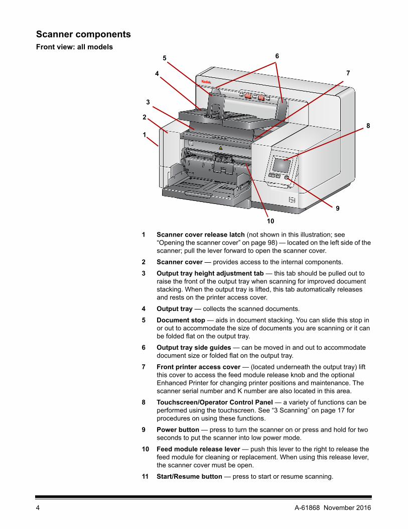
Scanner componentsFront view: all models
1 Scanner cover release latch (not shown in this illustration; see “Opening the scanner cover” on page 98) — located on the left side of the scanner; pull the lever forward to open the scanner cover.
2 Scanner cover — provides access to the internal components.
3 Output tray height adjustment tab — this tab should be pulled out to raise the front of the output tray when scanning for improved document stacking. When the output tray is lifted, this tab automatically releases and rests on the printer access cover.
4 Output tray — collects the scanned documents.
5 Document stop — aids in document stacking. You can slide this stop in or out to accommodate the size of documents you are scanning or it can be folded flat on the output tray.
6 Output tray side guides — can be moved in and out to accommodate document size or folded flat on the output tray.
7 Front printer access cover — (located underneath the output tray) lift this cover to access the feed module release knob and the optional Enhanced Printer for changing printer positions and maintenance. The scanner serial number and K number are also located in this area.
8 Touchscreen/Operator Control Panel — a variety of functions can be performed using the touchscreen. See “3 Scanning” on page 17 for procedures on using these functions.
9 Power button — press to turn the scanner on or press and hold for two seconds to put the scanner into low power mode.
10 Feed module release lever — push this lever to the right to release the feed module for cleaning or replacement. When using this release lever, the scanner cover must be open.
11 Start/Resume button — press to start or resume scanning.
9
8
7
65
4
3
2
1
10
4 A-61868 November 2016

12 Stop/Pause button — press once to temporarily pause scanning (the Start/Resume button can then be used to resume scanning). Press twice to stop scanning.
13 Input Elevator side guides — slide the guides in or out to accommodate the document size you want to scan. Side guides can be left-, center- and right-adjusted to accommodate documents of various widths. The side guides can also be locked into position.
Fold the side guides down when you want to close the input elevator when the scanner is not in use.
14 Input Elevator — holds up to 750 documents (20 lb./80 g/m2) in place. The input elevator can be set to accommodate stacks of 25, 100, 250, 500 or 750 documents. The input elevator can be folded up when it is not in use.
15 Input Elevator extender — pull this extender out to accommodate documents longer than 35.6 cm (14 inches).
16 Front print location indicators — if you are using the Enhanced Printer Accessory, use the detents at the edge of the input elevator as a visual guide to see where the printing position will be on the document.
17 Gap release toggle switch (i5250/i5250V/i5650/i5650V/i5650S Scanners) — push the “+“ button to increase the space between the feed module and separation roller for documents that require special handling.
NOTE: The gap release toggle switch is located in a different position on the i5850/i5850S Scanner. See “Front view: i5850 and i5850S Scanners” on page 6 for more information.
Additional adjustments are possible for the Sorter model scanners (i5650S and i5850S). See “Adjusting output trays for the i5650S and i5850S Scanners” on page 71.
17
11
1213141516
A-61868 November 2016 5

Front view: i5850 and i5850S Scanners
In addition to the components listed previously, the Kodak i5850/i5850S Scanner also has a workspace height adjustment switch which is used to raise and lower the workspace table on the scanner. The workspace table can be raised or lowered approximately 10 inches up or down.
There are four casters and four leveling feet on the bottom of the scanner. If you need to move the scanner, the leveling feet must be raised. Contact Technical Support before attempting to relocate the scanner.
Height adjustment switch
Leveling
Gap releasetoggle switch
feet
Casters
6 A-61868 November 2016

Front printer access view: all models
Even if you do not have the Kodak Enhanced Printer Accessory, you will still need to access this area of the scanner. The feed module release knob is located in this area.
1 Feed module release knob — turn this knob to release the feed module from it’s position for cleaning or replacement. Turn the arrow to right to disengage the feed module.
The following components are for front printing and are only present if the Enhanced Printer Accessory is installed.
2 Enhanced Printer carrier/cartridge — allows printing on documents.
3 Printer cable — this cable connects directly to the printer carrier to allow communication to the Enhanced Printer.
4 Print positions — the i5x50 Scanners allow front printing on your documents. Up to 39 positions are available when using the front printer.
Rear printer access view The following components are for rear printing and are only present if the Enhanced Printer Accessory is installed.
1 Printer cable — this cable connects directly to the printer carrier to allow communication to the Enhanced Printer.
2 Enhanced Printer carrier/cartridge — allows printing on documents.
3 Print positions (located on the underside of the rail) — the i5850/i5850S Scanner has the capability of front and rear printing. Up to 24 print positions are available when using the rear printer. Only one printer (front or rear) can be used at a time.
3
2
4
1
1
23
A-61868 November 2016 7

Inside view: all models When you pull the scanner cover release latch forward to open the scanner cover, the following internal components are visible.
1 Separation roller and pre-separation pad — provides smooth document feeding and separation of various sizes, thicknesses and textures of documents.
2 Black/White background — using your scanning application, this background can be changed to White or Black. Under normal scanning conditions you would use the black background. If you are scanning lightweight or thin paper with printing on one side, you can use the white background to help eliminate bleed-through in the final image. See the Scanning Setup Guides for TWAIN and ISIS for more information.
NOTE: VRS does not support scanning with a white background.
3 Imaging guides — keep imaging guides clean to obtain optimum image quality.
4 Rollers — provides smooth transport of documents through the scanner.
5 Intelligent document protection sensors — these sensors determine how aggressively the scanner detects documents that enter the scanner incorrectly.
6 Feed module — provides smooth document feeding and separation of various sizes, thicknesses and textures of documents.
1
2
3
3
2
4
6
8
10
5
7
9
8 A-61868 November 2016

7 Sensors — these five ultrasonic sensors cover the width of the paper path, which aids in detecting multifed documents.
8 Ink blotter channels and ink blotters (located underneath the drainage strip) — the ink blotters which are placed in these channels collect ink residue from the optional Enhanced Printer Accessory.
9 Metal detectors — detect any metal (e.g. staples, etc.) before it enters the scanner.
10 Paper present sensor — detects the presence of documents in the input elevator. Documents must be covering this sensor in order for the scanner to begin scanning.
Rear view: i5250/i5250V/i5650/i5650V/i5650S Scanners
1 Security lock port — connects a security lock to the scanner. You can purchase a standard security lock at an office supply store. Refer to the instructions provided with the security lock for installation procedures.
2 USB port — connects the scanner to the PC.
3 Rear document exit — allows you to have exception documents exit from the rear of the scanner.
4 Power port — connects the power cord to the scanner.
5 Main power switch — this switch must be On (I) to activate the power to the scanner.
6 Rear printer access door — provides access to the rear printer.
7 Screw — using a flat-head screwdriver, loosen this screw to remove the rear cover, which provides access to the rear printer.
41 2 3
5
6
7
A-61868 November 2016 9

Rear view: i5850 and i5850S Scanners
1 Rear document exit — allows you to have exception documents exit from the rear of the scanner.
2 USB port — connects the scanner to the PC.
3 Power port — connects the power cord to the scanner.
4 Main power switch — this switch must be On (I) to activate the power to the scanner.
5 Rear printer access door — provides access to the rear printer.
1
2
34
5
10 A-61868 November 2016

2 Installation
If desired, Kodak Alaris Professional Services provides professional installation and user training. Contact Technical Support for more details at www.kodakalaris.com/go/IMsupport.
The following installation procedures are for the Kodak i5250/i5250V/i5650/i5650V Scanners. Installation by a field service representative is included with the purchase of a Kodak i5650S, i5850, or i5850S Scanner.
Installing the scanner This section provides detailed information supporting the Installation Guide that is provided with your scanner. Follow these steps in the order they are provided to install your scanner.
NOTES:
• Before you begin, verify that your host PC meets the system requirements that are provided in Appendix A, Specifications.
• If you have already performed all of the steps in the Installation Guide, skip this section.
Updated drivers may be available at www.kodakalaris.com/go/scanners.
Installing the Kodak Driver Software
Do not install the USB cable before installing the Driver Software.
1. Insert the Kodak i5x50 or i5x50V Scanner Installation disk in the disk drive. The installation program starts automatically.
NOTE: If the disk does not start automatically, open the My Computer icon on your desktop. Double-click the icon indicating your disk drive, then double-click on setup.exe.
2. Follow the prompts that are displayed until the installation is complete.
3. Remove the Installation disk from the disk drive.
A-61868 November 2016 11

Attaching the output tray: i5x50/i5x50V Scanners
When you unpack the Kodak i5x50/i5x50V Scanner, the output tray is packed in a separate box.
• Locate the output tray slots on the scanner. Angle the output tray and align the output tray with the slots, slide it into place and lower it into position.
NOTE: Be sure to lift the output tray up to the scanning position before feeding documents. See “Adjusting the output tray” on page 19.
Attaching the output trays: i5650S/i5850S Scanners
Your Kodak Alaris representative will work with you to position the output trays for your scanning application. Refer to the “Sorting and Stacking” chapter later in this guide for more information.
Connecting the power cord and USB cable: i5250/i5250V/i5650/i5650V/i5650S Scanners
After the drivers have been installed, connect the power cord and USB cable to the scanner. Refer to the illustration below for making proper connections. Make sure the power outlet is located within 1.52 meters (5 feet) of the scanner and is easily accessible.
1. Select the appropriate AC power cord for your region from the supply of power cords packed with your scanner.
2. Plug the output power cord into the power port on the scanner. Be sure it is securely attached.
3. Plug the other end of the power cord into the wall outlet.
4. Attach the USB cable (either USB 2.0 or 3.0) to the scanner USB port.
5. Attach the other end of the USB cable to the proper USB port on your PC.
12 A-61868 November 2016

Connecting the power cord and USB cable: i5850/ i5850S Scanners
To connect the i5850/i5850S Scanner to power, refer to the illustration below for making proper connections. Make sure the power outlet is located within 1.52 meters (5 feet) of the scanner and is easily accessible.
1. Select the appropriate AC power cord for your region from the supply of power cords packed with your scanner.
2. Plug the output power cord into the power port on the scanner. Be sure it is securely attached.
3. Plug the other end of the power cord into the wall outlet.
4. Attach the USB cable (either USB 2.0 or 3.0) to the scanner USB port.
5. Attach the other end of the USB cable to the proper USB port on your PC.
A-61868 November 2016 13

Turning the scanner on
1. Press the main power switch on the back of the scanner to the On (I) position. The LED on the front of the scanner will be a steady yellow and nothing will be displayed on the Operator Control Panel (this is low power mode).
NOTES:
• It is not necessary to turn the main power switch off unless you are not going to use the scanner for a prolonged period of time, you are performing maintenance, you are going to move the scanner, or you are directed to turn the power off by a field service representative.
• For the Kodak i5850/i5850S Scanners only: There are four leveling feet on the bottom of the scanner. If you need to move the scanner, these leveling feet must be raised. Contact a field service representative before attempting to relocate the scanner.
• Damages incurred when moving a scanner will not be covered by the Equipment Service Agreement. Kodak Alaris Professional Services provide relocation services. Go to www.kodakalaris.com/go/IMcontacts for more information.
i5850/i5850S Scanners
i5250/i5250V/i5650/i5650V/i5650S Scanners
14 A-61868 November 2016

2. Press the Power button on the front of the scanner. The Power button LED will temporarily go off and the Operator Control Panel will remain blank.
After a few seconds the initialization screen will be displayed, and the Power LED will be a steady yellow.
During the initialization process, if the scanner input elevator is closed, it will automatically open. When the scanner goes to the Ready mode, the Power LED will turn a steady green, the scanner will sound an alert (if your Volume setting is not set to Off) and the Ready screen will be displayed.
A-61868 November 2016 15

Power modes The following chart provides information regarding the power modes of the scanner, LED status and the manual or automatic action that will put the scanner into a given power mode.
Mode LED Power consumption Action
Scanner off Off 0 wattsTurn the power switch on the back of the scanner to the Off position (O).
Standby Steady yellow < 1 watt
This is the mode the scanner is in when the power is first turned on (the power switch on the back of the scanner is in the On position [I]).
The scanner goes from Low Power mode to Standby mode by pressing the Power button for more than 2 seconds.
Low PowerFlashing yellow
< 4 wattsThe scanner goes from Ready mode to Low Power mode by pressing the Power button for more than 2 seconds.
Ready Steady green
< 115 watts not scanning(all models)
< 215 wattsscanning
(i5250/i5650/i5650S)
< 250 wattsscanning
(i5850/i5850S)
< 350 wattsscanning and lift
operation(i5850/i5850S)
The scanner goes from Standby mode to Ready mode by:
• Pressing the Power button, or
• placing paper in the input elevator.
The scanner goes from Low Power mode to Ready mode by:
• Pressing the Power button, or
• placing paper in the input elevator, or
• pressing the Start/Resume button, or
• receiving a host command.
16 A-61868 November 2016

3 Scanning
Getting your scanner ready to scan
1. Be sure the scanner is on and in Ready mode (Power button LED is green and constant).
2. Adjust the input elevator to meet your scanning needs. See “Adjusting the input elevator” on page 17.
3. Adjust the output tray to meet your scanning needs. See “Adjusting the output tray” on page 19.
4. Select your scanning application.
NOTE: The illustrations in this chapter show the i5250/i5650/i5250V/i5650V Scanner. All adjustments are the same for the i5850/i5650S/i5850S Scanners unless otherwise noted.
Adjusting the input elevator
You can adjust the side guides and input elevator height to accommodate your scanning needs. When the scanner is not in use, the input elevator can be folded up against the scanner.
NOTE: The input elevator must be in the lowest position and the elevator side guides must be folded down before closing it.
• Adjusting the side guides — the side guides can be adjusted for right-edge, left-edge or center feeding. The side guides can be moved together for center feeding or independently for offset feeding (right-edge or left-edge). Before moving the side guides, be sure the locking switch is not in the locked position (see below).
NOTE: When using the optional Enhanced Printer, documents should be placed in the input elevator in a manner that will align the print string in the proper location. See “4 Document Printing” on page 61 for more information.
• Locking the side guides — side guides may be locked into position after they are adjusted. This is helpful when the placement of a print string is important.
A-61868 November 2016 17

To lock the side guides, remove any documents from the input elevator and move the lock switch to the left (the locked position).
• Adjusting the height of the input elevator — the input elevator can be set to accommodate stacks of 25 or less, 100, 250, 500 or 750 documents of
20 lb./80 g/m2 bond paper. Input elevator settings are made through your scanning application software (i.e. TWAIN Datasource, ISIS Driver, or VRS).
If the input elevator is set to ADF mode (using the TWAIN Datasource or the ISIS Driver), or the Feed Source is set to Manual (VRS), then the input elevator will remain in the up position (i.e., 25 documents or less). When set to more than 25, the input elevator will automatically raise to feed documents and lower after the last document in your stack has been fed.
• Adjusting the input elevator
- Document lengths up to 35.6 cm (14 inches) — no adjustments are required.
- Document lengths from 35.6 to 43.2 cm (14 to 17 inches) — slowly pull out the document extender.
- To push the extender back into place, position your fingers on the sides of the extender (at the arrows on the extender) and squeeze and slide the extender back into place.
NOTES:
• Operator assistance may be required for scanning documents greater than 43.2 cm (17 inches).
18 A-61868 November 2016

• If you are scanning documents longer than 43.2 cm (17 inches), the scanning application must be set to accommodate these long documents. Be sure to verify that the Maximum Length option on the Device-General tab (TWAIN Datasource) or the Longest Document option on the Scanner tab (ISIS Driver) is set to slightly longer than the longest document being scanned. Setting a length longer than needed may impact throughput.
• For i5250V and i5650V Scanners: these scanners have a set maximum Document Length of 40 inches; therefore, no adjustment is necessary.
• It is recommended that you use a document extender if you are scanning documents longer than 43.2 cm (17 inches). Three sizes of document extenders are available for scanning documents from 43.2 cm (17 inches) to 86.36 cm (34 inches). See “Supplies and consumables” on page 112 for ordering information.
• Document weights — the maximum document weight for the input elevator is the approximate weight of a 500-sheet ream of A3 (11 x 17-inch) paper or a 750-sheet ream of A4 (8.5 x 11) paper. If you are scanning documents larger than A3 (11 x 17-inch), the recommended weight capacity should not exceed 4.5 kg (10 pounds). If the documents you are scanning are larger than A3 (11 x 17-inch), scan fewer than 100 sheets at a time.
Installing the optional document extender
• Insert the ends of the document extender into the holes on the input elevator and the output tray and lower the extender into position.
Adjusting the output tray Various document handling settings are available to adjust the way that documents are placed into the output tray (via the TWAIN Datasource, ISIS Driver or VRS). The highest throughput can be obtained by scanning documents of similar size using the output tray side guides and end stop with Normal document handling.
Other document handling options are available for better handling when scanning documents of varying size and thickness.
A-61868 November 2016 19

• Adjusting the angle of the output tray — it is strongly recommended that you scan documents with the angle of the output tray in the “up” position to achieve best stacking performance. Just lift the front of the output tray and the height adjustment tab will release from underneath the output tray.
To lower the output tray, gently push the height adjustment tab underneath the output tray while lowering the output tray on to the front printer access cover.
• Adjusting the side guides and document stop — the side guides and document stop can be adjusted in a variety of ways. Open and adjust the side guides on the output tray to match the position of the side guides on the input elevator. The side guides can also be folded flat against the output tray.
Adjust the output tray document stop to slightly longer than the longest document being fed. If you are scanning documents longer than the output tray will accommodate, fold the document stop flat on the output tray.
20 A-61868 November 2016

Changing the dangler extensions (i5250, i5250V, i5650, i5650V, i5850)
The scanner comes with a mount and danglers, which can easily be changed based on the document set you are scanning.
If desired, attach the mount to the top of the scanner. The dangler helps align the documents as they are deposited in the output tray. Three sizes of the danglers are available. Depending on the document set you are scanning, attach the size of the dangler that meets your needs.
NOTE: To change the dangler remove the mount, unclip the dangler, and snap the desired dangler into the slots as shown.
See “Using the danglers” on page 75 for the i5650S and i5850S scanners.
Installing the short document adapter
The short document adapter can be used when scanning small documents (e.g., checks). This adapter aids in better document stacking.
1. Open the document stop on the output tray as shown in the illustration.
2. Slide the short document adapter over the document stop and push it all the way down.
3. Adjust the sides guides if necessary.
A-61868 November 2016 21
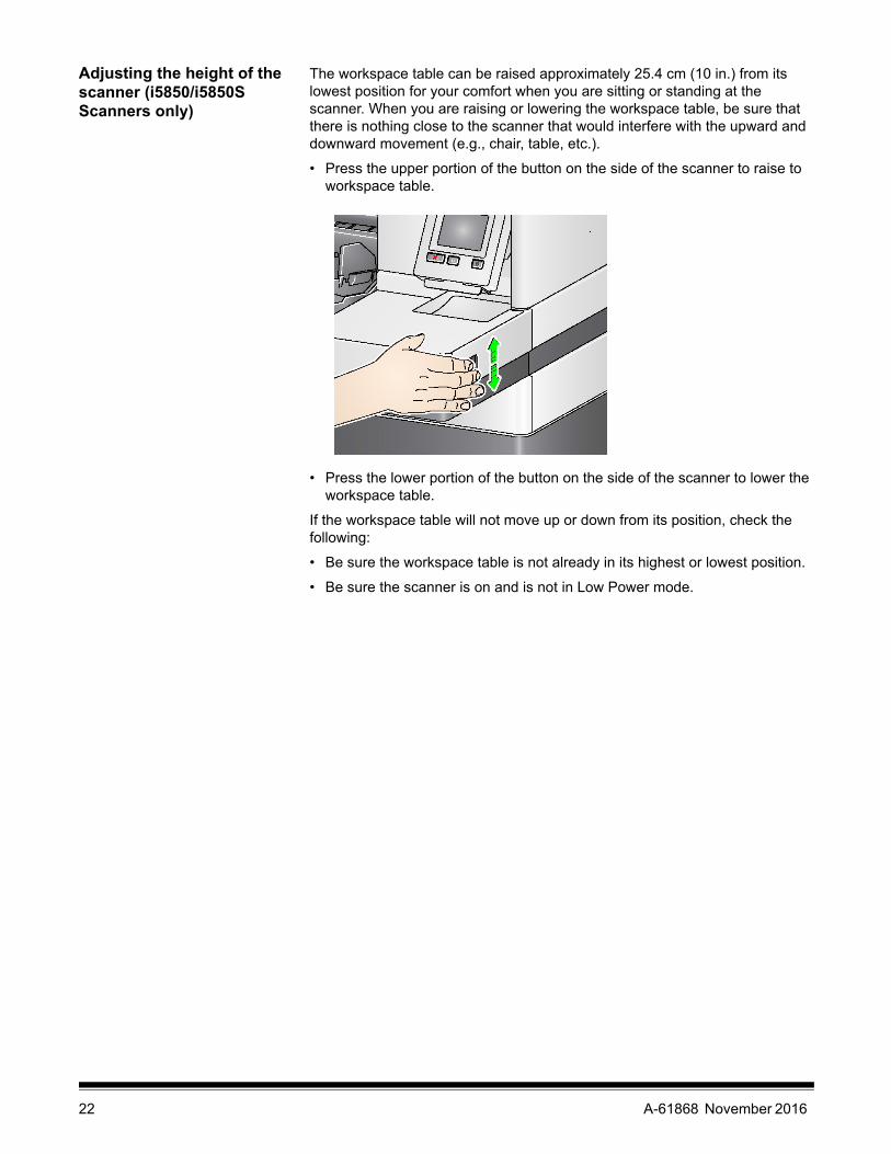
Adjusting the height of the scanner (i5850/i5850S Scanners only)
The workspace table can be raised approximately 25.4 cm (10 in.) from its lowest position for your comfort when you are sitting or standing at the scanner. When you are raising or lowering the workspace table, be sure that there is nothing close to the scanner that would interfere with the upward and downward movement (e.g., chair, table, etc.).
• Press the upper portion of the button on the side of the scanner to raise to workspace table.
• Press the lower portion of the button on the side of the scanner to lower the workspace table.
If the workspace table will not move up or down from its position, check the following:
• Be sure the workspace table is not already in its highest or lowest position.
• Be sure the scanner is on and is not in Low Power mode.
22 A-61868 November 2016

Using the rear document exit
Documents that require special handling (e.g., fragile documents, shipping envelopes, etc.) can be output using the rear document exit. This exit provides the straight-through paper path option that allows an exception document(s) to pass straight through the transport, thus reducing the possibility of a document jam.
Use the rear document exit when:
• documents are too stiff (e.g., rigid) to make the turn in the transport and are jamming.
• documents are fragile and you do not want to bend them.
• output stacking order is not important.
• scanning directly into the recycle bin when documents are no longer needed after scanning.
• scanning photographs.
NOTES:
• Select Rear Exit from the Operator Control Panel.
• Be sure that you have adequate clearance behind the scanner to feed the document(s) through, when using this option.
• When scanning several documents through the rear document exit, the documents will be output in the reverse scanning order.
• If you have the Rear Exit Tray Accessory, be sure it is attached. See “Accessories” on page 2 for more information.
A-61868 November 2016 23

Installing the rear document exit tray accessory
The Rear Document Exit Tray Accessory can be installed to collect the scanned documents from the rear document exit.
• The rear document exit tray for the i5250, i5650, and i5650S Scanners can scan documents up to 35.6 cm (14 inches).
• The rear document exit tray for the i5850 and i5850S Scanners can scan documents up to 43.2 cm (17 inches).
The exit tray installation is basically the same for all scanners.
1. Angle the tray slightly to place the slots on the rear exit tray into the slot locations inside the scanner and gently lower the tray in place.
2. Place the side guides on the exit tray in the desired location for your scanning needs.
24 A-61868 November 2016

NOTE: The locking knob on the bottom of the exit tray can be loosened to allow you to slide the tray forward or backward to accommodate the size of the documents you are scanning.
Getting your documents ready to scan
• Standard paper-size documents feed easily through the scanner. When organizing your documents for scanning, stack the documents so the lead edges are aligned and centered in the input elevator. This allows the feeder to introduce documents into the scanner one at a time.
• Remove all staples and paper clips before scanning. Staples and paper clips on documents may damage the scanner and documents.
• All inks and correction fluids on the paper must be dry before scanning is started.
• Torn, damaged or crushed pages can be transported successfully through the scanner. However, no scanner can transport every possible type of damaged paper. If in doubt about whether a specific damaged document can be transported through the scanner, place the document in a clear protective sleeve. Sleeves should be manually fed, one at a time, folded edge first, using the gap release toggle switch.
• Some very thick and/or stiff documents; such as shipping envelopes, may require the following:
- Use of the gap release toggle switch.
- Removal of the pre-separation pad.
- Use of the Fragile, Thick, Thin settings for Document Handling, which will reduce transport speed.
- Use of the rear document exit tray.
A-61868 November 2016 25

Scanning documents The scanner must be enabled to scan documents. This is done through the scanning application. After enabling the scanner, depending on how your scanner is configured, your scanner will either automatically start scanning (i.e., auto start), or will start scanning when you touch the Start/Resume button on the scanner. For more information, see the documentation that supports your scanning application.
1. After you prepare your documents according to the guidelines in the previous section, be sure your scan job is set up in your scanning application as desired.
2. Place the documents you want to scan in the input elevator.
3. Start scanning via your scanning application.
Depending on how your scanner is configured, the touchscreen will display either the Scanning screen or the Paused screen.
Auto start options:TWAIN: Automatically start scanningISIS: Automatically start transportVRS: ADF (Auto start enabled) / Panel Feed (Auto start disabled)
See the Scanning Setup Guides for TWAIN, ISIS and VRS for more information.
This screen will be displayed if the auto start option is enabled in your scanning application:
This screen will be displayed if the auto start option is disabled in your scanning application:
This screen will be displayed if the indexing (i5850/i5850S Scanners only) and auto start options are enabled in your scanning application:
This screen will be displayed if the indexing (i5850/i5850S Scanners only) and auto start options are disabled in your scanning application:
26 A-61868 November 2016

NOTE: If your scan job requires a temporary override (e.g., printing, patch reading, multifeed detection, etc.), then the auto start option must be disabled prior to starting your scan job to allow access to the Overrides screen.
Alternatively, pressing Stop/Pause while scanning will also provide access to the Batch Overrides screen.
For more information, see “Overrides” on page 49.
4. Touching any of the options displayed on the Scanning screen will perform the action (only for Omit Multifeed Detection) on the next document only. To perform these actions for the rest of the scan job, see “Overrides” on page 49.
5. You must press the Start/Resume button to begin scanning if auto start has been disabled by the scanning application.
Pausing and resuming scanning
You can manually stop/pause and start/resume the scanner while scanning documents.
• To temporarily pause scanning, touch the Stop/Pause button on the scanner once.
• If you want to stop scanning, you can touch Stop on the Operator Control Panel touchscreen, or press the Stop/Pause button twice.
• Press the Start/Resume button on the scanner to restart scanning after it has been paused.
NOTE: If your PC does not meet the minimum requirements, the scanner may automatically pause during scanning and resume scanning when enough internal buffer memory is free.
Using the Operator Control Panel touchscreen
There are a variety of options that can be accessed by using the Operator Control Panel touchscreen.
For more information and procedures for using these options, see the sections that follow.
To navigate through the touchscreen, touch the desired option with your finger. Using any object other than your finger may damage the touchscreen and void your warranty.
If there is an arrow after the option, another screen will be displayed allowing you to make additional choices.
If there is a checkbox next to the option, you can check and uncheck this box to turn an option On or Off. For example, if a checkmark is in the Rear Exit checkbox, this indicates that the Rear Exit is Open on the scanner.
Use the Up and Down arrows to scroll through the list of options displayed on the Operator Control Panel.
A-61868 November 2016 27

Ready screen The Ready screen provides a list of options that can be selected. In addition, the counter value is displayed in the status area at the top of the screen.
Following are the icons that may be displayed in the status area.
The counter value will start at 0 and be incremented with each page scanned. The maximum value that will be displayed is 999,999,999.
If the User Counter option is On, then the counter value is followed by the Document counter icon or the User counter icon to indicate which counter value is being displayed.
Indicates that the Document counter is being displayed.
Indicates that the User counter is being displayed.
For the i5850/i5850S Scanners only: indicates that batching is enabled.
Indicates an Application Override is enabled.
Indicates that documents are in the input elevator and the scanner will scan from the input elevator.
Indicates that no documents are in the input elevator.
Indicates that the rear exit is open and there are no documents in the input elevator.
Indicates that the rear exit is open and documents are in the input elevator.
Indicates a consumable needs to be replaced or attended to. See “Viewing the Maintenance Meters” on page 32.
Indicates an informational message. For example, No paper in input elevator. These messages are easily corrected by the operator.
Indicates a recoverable error condition. For example, Input elevator full or feed module missing or broken.
Indicates an error state. For example, paper may be in the transport, or imaging guides may not be installed correctly.
28 A-61868 November 2016

When the Ready screen is displayed, you can do the following:
• Clear Path — clears the scanner transport of any documents.
• Lower Elevator — lowers the input elevator to the lowest position.
• Rear Exit — allows you to open or close the rear exit.
NOTES:
- Additional rear exit setup and setup of stacking and sorting options can be found in the “Sorting and Stacking” chapter of this guide.
- OCP Rear Exit Open will override sorting decision on the i5650S/i5850S scanners.
• Operator Log — provides error code information, such as the time the error occurred, the error code and a brief description of the error.
• Information — provides scanner information, such as scanner model, firmware version, etc.
• Diagnostics — allows you to view Scan History, check the Maintenance Meters, run a Print Test, run a scanner Self Test, put the scanner in Count Only mode, run a Patch Test and a Patch Reader Test, perform a UDDS (ultrasonic) calibration, perform a Touchscreen calibration, and access Alterations. Alterations is for Kodak Alaris Technical Support only.
• Settings — allows you to access a variety of scanner settings. These settings are set infrequently. For more information, see “Settings screen” on page 44.
NOTE: If the User counter is set to On (see “User Counter” on page 45) the Reset User Counter and Toggle Document Counter will also be displayed on the Ready screen. These options allow you to select which counter value is being displayed as well as reset the value of the User counter (the Toggle Document Counter must be reset by the scanning application).
Clearing the Paper Path Touch Clear Path to allow the scanner to eject any documents that are left in the transport.
Lowering the Elevator Use this option whenever you need to make additional room in the input elevator for adding documents to the stack. The input elevator will descend to the lowest position (750-sheet) when you touch Lower Elevator.
Toggle Counter Toggle Counter will only be displayed on the Ready screen if the User Counter or Batch Counter is set to On. When this option is selected, the scanner will toggle between User Counter and Document Counter values in the status area. For more information, see “User Counter” on page 45.
A-61868 November 2016 29

Rear Exit Use this option when you have documents that require special handling (e.g., fragile documents, shipping envelopes, etc.). When scanning these types of documents, the rear exit allows a straight-through paper path that allows documents to easily pass through the transport. If using this option, open the rear exit by touching the checkbox. The touchscreen will indicate that the Rear Exit is Open.
Viewing the Operator Log When you touch Operator Log, the Operator Log screen will be displayed. This screen provides the time, message code and a message description.
The messages that are displayed in the log are only those messages that have occurred since the scanner was powered on. When you turn the power off or the scanner goes into Standby or Low Power mode, the Operator Log on the Operator Control Panel touchscreen will be cleared.
To view messages which have been cleared from the Operator Control Panel touchscreen, see “8 Troubleshooting” on page 113.
• After viewing the operator log, touch Close to return to the Ready screen.
30 A-61868 November 2016

Viewing Scanner Information
The Information screen provides information about your scanner (e.g., Firmware Version Number, Scanner Serial Number, Total Scanned Pages, etc.). Use the scroll bar to view all information.
• After viewing this information, touch Close to return to the Ready screen.
Diagnostics Select Diagnostics to view scan history, check the maintenance meters, run a print test, run a scanner self test, put the scanner in count only mode, run a patch test, run a patch reader test, perform a UDDS (ultrasonic) calibration, and perform a touchscreen calibration.
Viewing the Scan History 1. Touch Scan History. The Scan History for the last 7 days of scanning will be displayed.
2. When finished, touch Close.
A-61868 November 2016 31

Viewing the Maintenance Meters
Use the Maintenance Meters to view or change the Maintenance meter values and thresholds (the interval indicating how frequently a consumable needs to be replaced) and to monitor when you need to replace consumables.
1. Select Maintenance Meters. The Maintenance Meters screen will be displayed.
You can change the maintenance threshold of a consumable or reset the maintenance meters after replacing a consumable.
If you want to reset a maintenance threshold:
• Select Maintenance Thresholds to display the Maintenance Thresholds screen.
Allows you to change the maintenance threshold values.
Displays the Reset Meter screen which allows you to reset a consumable’s meter. For example, when you change a consumable, touch this icon to reset the meter to 0.
Displays the Reset Meter screen which indicates that you have met your maintenance threshold limit.
32 A-61868 November 2016

• Touch the Edit icon next to the consumable for which you want to change the threshold value.
• Use the Up and Down arrows to adjust the value, then touch OK.
If you want to reset a maintenance meter:
NOTE: When you reset the feed module counter meter, the feed tire meter will also be reset.
• Touch the consumable you want to reset a value for.
The Reset Meter screen will be displayed.
• Touch Yes to reset the meter to 0.
A-61868 November 2016 33

Performing a Print Test The print test checks to be sure the ink jets in the optional Enhanced Printer are working properly.
NOTE: This option works for both the front and rear printer.
1. Select Print Test. The Print Test screen will be displayed.
2. Place a blank sheet of paper in the input elevator.
3. Press the Start/Resume button. The document in the output tray will be scanned and the results of the print test will be displayed.
4. Remove the document from the output tray and evaluate the appearance of the test pattern.
• If the pattern is complete, you are ready to scan.
• If the test pattern is inconsistent, verify that the ink cartridge is installed properly, or you may need to clean the print head or change the ink cartridge.
NOTE: Clean the print head by removing it from the printer carrier and dabbing the print head with a damp cloth. For procedures on removing or changing the ink cartridge, see “4 Document Printing” on page 61.
5. Touch Cancel to return to the Ready screen.
Acceptable Unacceptable: pattern is inconsistent
34 A-61868 November 2016

Performing a Self Test The scanner Self Test will test the image capture subsystem to ensure that it is functioning correctly.
Count Only You may want to count the number of documents entering the scanner without actually scanning them.
1. Select Count Only. The Count Only screen will be displayed.
2. Place the documents you want to count in the input elevator.
3. Press the Start/Resume button. When the scanner has scanned all documents, the total number will be displayed.
4. Touch Cancel to return to the Ready screen.
NOTES:
• When you press the Stop/Pause button, the feeder and transport will stop. You can continue your Count only test by pressing the Start/Resume button.
• In Count only mode, Document Handling will default to Improved Stacking.
• Multifeed Detection is not enabled in Count only mode.
A-61868 November 2016 35

Count Only - Multifeed The Count Only - Multifeed option allows you to count documents without scanning, however, when a multifeed is detected the scanner will stop.
1. Select Count Only - Multifeed. The Count Only Test screen will be displayed.
2. Place the documents you want to count in the input elevator.
3. Press the Start/Resume button. When the scanner detects a multifed document, the following screen will be displayed.
4. Press Cancel to stop scanning and return to the Diagnostics screen.
36 A-61868 November 2016

Count Only - Sorting options Count Only can be done with sorting options to help diagnose problems with either the document set or the scanner.
Count Only - Simple Sorting 1. Select Count Only - Simple Sorting. The Simple Sort Test screen will be displayed.
2. Place documents for the test in the input elevator.
3. Press the Start/Resume button. One page will exit to the upper tray, the next to the lower tray, and the next to the rear tray; remaining pages will continue exiting to the three trays in this way.
4. Press Cancel to stop scanning and return to the Diagnostics screen.
Count Only - Barcode Sorting 1. Select Count Only - Barcode Sorting. The Barcode Sort Test screen will be displayed.
2. Place documents for the test in the input elevator.
3. Press the Start/Resume button. Any page where any of the supported barcode types are found, in any orientation on front or back of the page, will go to the upper tray. All other pages will exit to the lower tray.
4. Press Cancel to stop scanning and return to the Diagnostics screen.
A-61868 November 2016 37

Count Only - Patch Sorting 1. Select Count Only - Patch Sorting. The Patch Sort Test screen will be displayed.
2. Place documents for the test in the input elevator.
3. Press the Start/Resume button. Any page where any of the supported patch codes are read by the hardware patch readers (front side only) will go to the upper tray. All other pages will exit to the lower tray.
4. Press Cancel to stop scanning and return to the Diagnostics screen.
Performing a Patch Test Use the Patch Test to test the camera patch readers to verify that the patch sheets can be detected.
1. Select Patch Test. The Patch Test screen will be displayed.
2. Place a document(s) with a patch(es) in the input elevator.
3. Press the Start/Resume button. When the document(s) has been scanned, the results of the patch test will be displayed on the touchscreen. The results show the number of patches and patch types that were recognized by the scanner.
4. Touch Cancel to return to the Ready screen.
38 A-61868 November 2016

Performing a Patch Reader Test
Use the Patch Reader Test to test the hardware patch readers to verify that the patch sheets can be detected.
1. Select Patch Reader Test. The Patch Test screen will be displayed.
2. Place a document(s) with a patch(es) in the input elevator.
3. Press the Start/Resume button. When the document(s) has been scanned, the results of the patch test will be displayed on the touchscreen. The results show the number of patches and patch types that were recognized by the scanner.
A-61868 November 2016 39

Performing a UDDS Calibration
UDDS calibration is used to calibrate the ultrasonic document detection system for multifeeds. UDDS calibration is rarely needed. This calibration should only be performed if there is a feeding or multifeed detection issue.
1. Select Calibrate. The Calibration screen will be displayed.
2. Touch UDDS Calibration to display the UDDS Calibration screen.
3. You will be prompted to place a 20 lb. or 80 g/m2 bond sheet of paper in the input elevator in landscape orientation.
4. Press the Start/Resume button. The calibration results will be displayed.
5. When finished, touch Cancel to return to the Diagnostics screen.
6. Touch Close to return to the Ready screen.
Performing a Touchscreen Calibration
Touchscreen calibration is used to verify that the touch points on the touchscreen are working correctly. The touchscreen is factory-calibrated. Do not calibrate the touchscreen unless directed to do so by Technical Support.
Alterations Only use this option when directed to do so by Kodak Alaris Technical Support.
40 A-61868 November 2016

Ready screen when Indexing is enabled in the scanning application(for i5650/i5650S/i5850/i5850S Scanners only)
When Indexing and Batching are enabled, the Ready screen will have additional options. A Counter area will be displayed under the Status area. Depending on the Indexing selection in the scanning application, the Level area will be displayed differently. For example:
• If Single Page or Bates Stamp is selected (i.e., in the driver), this view will be displayed.
• If Multiple Pages is selected (i.e., in the driver), this view will be displayed.
• If Image Addressing is selected (i.e., in the driver), this view will be displayed.
NOTE: This option is not available on the i5650 Scanner.
The Batch icon is only displayed when Batching is enabled. It displays the number of documents to be counted before performing a predefined action
When Indexing is enabled:
• three indexing level buttons will be displayed in the Level area: Level 3, Level 2 and Level 1. You can increment the index level by touching one of the level buttons. During a scan session the level button that is highlighted is the level which will be assigned to the next document.
• an End Batch option will be available allowing you to manually end the batch.
Batch icon
A-61868 November 2016 41

Verifying a multifed document
When you encounter a multifeed and you have Multifeed Detection enabled, the scanner will stop and display the following screen allowing you to accept the image as is or rescan.
The image will be displayed on the Operator Control Panel and the PC when you have Multifeed Detection enabled and with the Interactive Multifeed Recovery option selected in the driver.
• The image will only be displayed on the Operator Control Panel if you have Multifeed Detection enabled and the Pause Scanning - (generate images) option set in the driver.
• The image will be displayed on your PC for easy viewing.
• If you want to accept the image as is, select Accept and the scanner will continue to scan.
• If you want to rescan the document, select Rescan and put the document back into the input elevator. The document will be rescanned.
If you press Stop/Pause on the Operator Control Panel, the images shown on the PC will be disregarded and the scanning session will end.
42 A-61868 November 2016

Recovering from a document jam
Your scanner can be configured to either Stop Scanning or Pause Scanning when a document jam occurs.
• If your scanner is configured to Stop Scanning and a document jam occurs, the scanner will stop. You can clear the jam from the scanner and press the Scan button in your scanning application to continue scanning.
• If your scanner is configured to Pause Scanning and a document jam occurs, the scanner will enter the Paused state. You can clear the jam from the scanner and press the Scan button on the Operator Control Panel. If you have Indexing, Batching or Printing enabled, the scanner will enter the Paused state and the following options (depending on what is setup for your job in the scanning application) will be available on the Operator Control Panel:
- Adjust Indexing Counters
- Adjust Batch Counter
- Adjust Printer Counter
When any of these screens are displayed, you can adjust the counters from the Operator Control Panel.
For example, if you have Index: Single Page selected in the scanning application and you encounter a document jam, you can use the Up and Down arrows to adjust the index count if needed.
A-61868 November 2016 43

Settings screen The Settings screen is accessed by touching Settings on the Ready screen.
• Touch the Settings option to display a list of options.
NOTE: The value displayed under the option is the current setting.
The Settings screen provides scanner settings that will only need to be set infrequently.
• User Counter — when enabled, counts all documents that are fed until you reset it.
• Automatic Elevator — when enabled, will automatically raise the input elevator when paper is added to an empty input elevator.
• Staple/Metal Protection — when enabled, the scanner will detect any metal (e.g., staples, paper clips, etc.) on your documents. This will protect your documents and scanner from damage.
• Volume — allows you to adjust the volume of the scanner alarm.
• Sounds — allows you to select a sound that you want the scanner to make when a scanner condition is encountered.
• Units — allows you to select the units of measurement used in the Print Offset option.
• Misfeed OCP Control — controls the action of the scanner when the Misfeed Detection button is touched during scanning.
• Dual Stacking Toggle Patch — when enabled, allows you to use patch sheets to out-sort any selected group of pages from the stack.
44 A-61868 November 2016

• Application Overrides — allows you to set the language, printing, maximum length detection, automatically start scanning, document handling, paper source, post scan rotation, misfeed detection and scanner speed options. Most screens that are accessed from the Application Overrides screen provide the Application Settings option. The Application Settings option is the default and indicates that the scanner will use the settings as defined in your scanning application.
For more information about Application Overrides, see “Application overrides” on page 51.
• Reset All Settings — resets all options to the factory default settings.
User Counter This option enables a counter that you can control. Once enabled, the counter goes to 0 and is incremented for every document fed. You can reset this counter at any time.
If the User Counter is set to On, the Toggle Counter and Reset User Counter options will be available from the Ready screen.
• If you touch Toggle Counter on the Ready screen, the Document counter
icon will be displayed in the status area of the Scanning and Ready screens next to the Counter value.
• If you touch Reset User Counter on the Ready screen, the User counter
icon will be displayed in the status area of the Scanning and Ready screens, next to the Counter value.
If the User Counter is set to Off, the Toggle Counter and Reset User Counter options will not be available from the Ready and Scanning screens. Only the Document Counter value will be displayed in the status area.
Automatic Elevator When this option is On, the input elevator will automatically raise to the feeding position when paper is added to an empty input elevator.
A-61868 November 2016 45
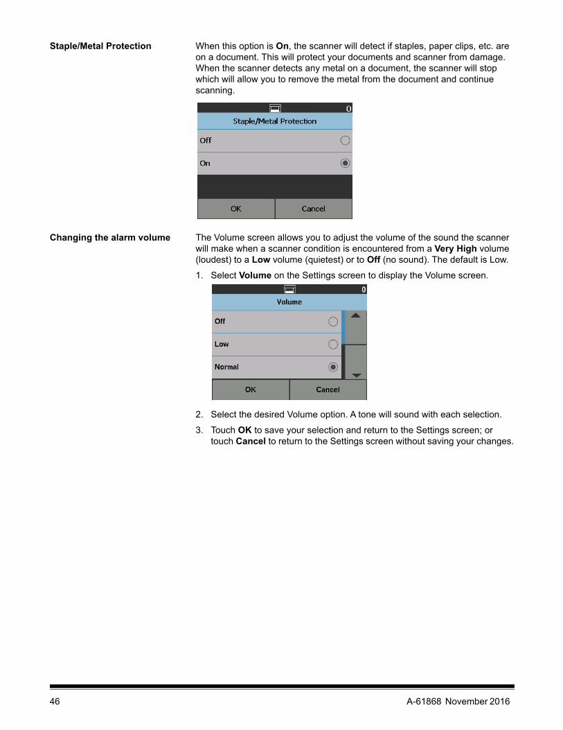
Staple/Metal Protection When this option is On, the scanner will detect if staples, paper clips, etc. are on a document. This will protect your documents and scanner from damage. When the scanner detects any metal on a document, the scanner will stop which will allow you to remove the metal from the document and continue scanning.
Changing the alarm volume The Volume screen allows you to adjust the volume of the sound the scanner will make when a scanner condition is encountered from a Very High volume (loudest) to a Low volume (quietest) or to Off (no sound). The default is Low.
1. Select Volume on the Settings screen to display the Volume screen.
2. Select the desired Volume option. A tone will sound with each selection.
3. Touch OK to save your selection and return to the Settings screen; or touch Cancel to return to the Settings screen without saving your changes.
46 A-61868 November 2016

Selecting the sound You can select the sound you want the scanner to make when a particular scanner condition is encountered such as, document jam or multifeed, etc.
1. Select Sounds to display the Sounds screen.
2. Select the event (e.g., Warning, Error, etc.) that you want a tone to be set for. When you select an Event, another screen will be displayed listing a variety of different sounds that you can choose from.
3. Select the type of sound you want to hear. A tone will sound with each selection.
4. Return to the Sounds screen to set other sounds for other events by repeating Steps 2 and 3.
5. Touch OK to save your selection and return to the Settings screen; or touch Cancel to return to the Settings screen without saving your changes.
Units The Units option is used to select the unit of measurement used in the Print Offset option. Select either English (for inches) or Metric (for millimeters) and touch OK to save your changes or Cancel to return to the Settings window without saving your changes.
A-61868 November 2016 47

Misfeed OCP Control Misfeed OCP Control allows you to control the action of the scanner when the Misfeed Detection button is touched during scanning.
• If One Page is selected when the Misfeed Detection option is touched during scanning, the Omit Misfeed will only be activated for one page and turn off after that one page.
• If Toggle is selected when the Misfeed Detection option is touched during scanning, the Omit Misfeed will stay activated until you press the Misfeed Detection button again or the scanner is disabled.
Dual Stacking Toggle Patch When using the Controlled Dual Stacker Accessory, the Dual Stacking Toggle Patch option allows you to use patch sheets when you are preparing your documents to automatically separate special document(s) from the stack. If, for example, you need to save invoices for amounts greater than $10k, then you could use this option to have them out-sorted at the scanner by putting a patch sheet in front and behind these invoice pages. You could also automatically out-sort all of the color documents if you are using the color toggle patch.
Also see “Dual Stacking Toggle Patch” on page 82.
48 A-61868 November 2016

Overrides There are three types of overrides:
• Immediate override: this override is performed during scanning. The only options that can be overridden directly from the Operator Control Panel during scanning are: Misfeed Detection, Omit Printing, Omit Patch and Allow Maximum Length.
• Batch override: this override is performed by touching the Overrides button on the Operator Control Panel and is only active for the current batch of documents. The Overrides option is available when you touch the Stop/Pause button on the scanner. The Overrides option allows you to override your scan job setup for Multifeed, Multifeed Sensors, Maximum Length Detection, Document Handling and Dual Stacking for the remainder of the scan job.
To access the Batch Overrides screen at the start of a scan job, the Automatically start scanning setting in the scanning application must be disabled. See “Scanning documents” on page 26.
To override a setting:
1. Touch Overrides on the Paused screen.
The Overrides screen will be displayed.
NOTE: Use the scroll bar to show all options.
2. Touch the option that you want to override, then touch Close to continue scanning.
A-61868 November 2016 49

• Application override: this override is setup via the Settings option. Application overrides will stay in place until they are changed. These application overrides are available: Language, Printing (if the printer is installed), Maximum Length Detection, Automatically start scanning, Document Handling, Paper Source, Post Scan Rotation, Misfeed Detection, and Speed. For more information, see “Application overrides” on page 51.
NOTE: Maximum Length Detection is not available on the i5250V/i5650V Scanners.
50 A-61868 November 2016
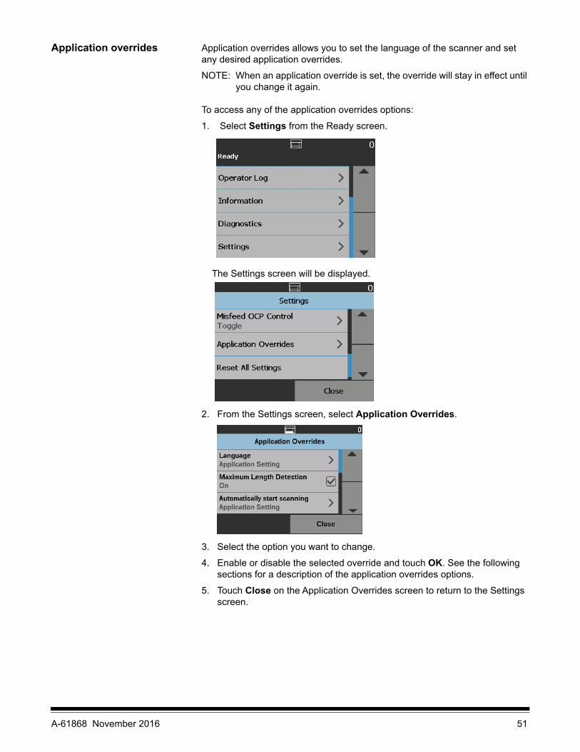
Application overrides Application overrides allows you to set the language of the scanner and set any desired application overrides.
NOTE: When an application override is set, the override will stay in effect until you change it again.
To access any of the application overrides options:
1. Select Settings from the Ready screen.
The Settings screen will be displayed.
2. From the Settings screen, select Application Overrides.
3. Select the option you want to change.
4. Enable or disable the selected override and touch OK. See the following sections for a description of the application overrides options.
5. Touch Close on the Application Overrides screen to return to the Settings screen.
A-61868 November 2016 51

Selecting a language The Kodak i5x50 Series Scanners support several languages. Select the language you want the information on the touchscreen to be displayed in.
1. From the Settings screen, touch Application Overrides. The Application Overrides screen will be displayed.
2. Select Language to display the Language screen.
3. Select the desired language. The screen will automatically be updated in the language of choice. If the language you want is not displayed on the screen, use the up and down arrows to display the desired language.
4. Touch OK to save your selection and return to the Settings screen; or touch Cancel to return to the Settings screen without saving your changes.
Printing If printing or electronic annotation has been enabled via the scanning application, you can temporarily disable it on all remaining documents in a scan job. This may be useful if rescanning a stack of documents that have already been printed on.
Once Printing is disabled, no documents will be printed on (or images annotated on) until the Printing option is enabled.
52 A-61868 November 2016

Maximum length detection This option allows you to override the maximum length detection that is setup in the scanning application for the scan job. The maximum length detection allowed is variable and dependent on many factors including the output resolution and format.
The following chart is a guideline and assumes two-sided scanning with compressed output.
NOTES:
• If Controlled Dual Stacking is enabled, the default maximum length detection will be set to 10 inches for all resolutions.
• For the Kodak i5250V and i5650V Scanners the maximum length detection is always set to 40 inches and cannot be overridden.
• Setting the maximum length detection longer than is needed may reduce throughput.
• Feeding a document longer than the maximum length detection will result in a document jam error.
Scanning DPI Resolution = Maximum Length Detection
100, 150, 200, 240, 300 Black and White = 180 inchesGray = 180 inchesColor = 58 inches
400 Black and White = 100 inchesGray = 100 inchesColor = 32 inches
500 Black and White = 64 inchesGray = 64 inchesColor = 18 inches
600 Black and White = 43 inchesGray = 43 inchesColor = 13 inches
A-61868 November 2016 53

Automatically start scanning This option overrides the Auto Start option that is set in the TWAIN Datasource, ISIS Driver and VRS. For more information see the Scanning Setup Guides for TWAIN, ISIS, and VRS.
If this option is Off, the scanner will go into a paused mode and you can press the Start/Resume button on the Operator Control Panel to start scanning.
Document handling Document handling allows you to select how the scanner transports documents through the scanner. This affects how the documents are fed into the scanner, how fast they move through the scanner, and how they are placed in the output tray.
NOTE: This option is not available when Controlled Dual Stacking is enabled.
The options displayed on this screen are based on what is set up in your scanning application for the current scan job. The options are: Normal, Improved Stacking and Best Stacking, OR Thick, Thin and Fragile.
If the scanning application has specified one of these three options: Normal, Improved Stacking or Best Stacking then only these three options will be displayed on the screen (as shown above).
• Normal — no additional handling is performed. This option is best used when all documents are similar in size. It is recommended that you use the side guides and document stop when scanning in the Normal mode. Normal mode is not available if Controlled Dual Stacking is enabled.
• Improved Stacking — aids in controlling how the documents are stacked/ordered in the output tray for mixed document sets. This should work for most mixed document sets.
• Best Stacking — when your document set contains a variety of sizes, this option provides the best control of how the documents are stacked/ordered in the output tray.
54 A-61868 November 2016

If the scanning application has specified one of these three options: Thick, Thin or Fragile, then only these three options will be displayed on the screen.
• Thick — select when scanning thick documents.
• Thin — select when scanning thin documents.
• Fragile — allows you to feed poor quality documents through the scanner transport at a slower pace for more reliable stacking. Select this option when you are feeding documents of very poor quality.
Paper source The Paper source option allows you to override the height of the input elevator.
• Document Feeder — the input elevator is in the highest position.
• 100 Sheets
• 250 Sheets
• 500 Sheets
• 750 Sheets
Post scan rotation The Post Scan Rotation option allows you to select a rotation option to be applied to the electronic image after is has been scanned.
• (none)
• Automatic
• Automatic - default to 90
• Automatic - default 180
• Automatic - default 270
• 90, 180 or 270 degrees
A-61868 November 2016 55

Misfeed detection This option provides a combination of several multifeed features of the scanner including multifeed detection sensitivity and intelligent document protection which determines how aggressively the scanner detects documents that enter the scanner incorrectly.
When Low, Medium or High is selected, multifeed detection will be enabled with the Interactive Multifeed action, and the middle three sensors will be turned on. The Intelligent Document Protection feature will also be enabled.
Scanner speed The Speed option provides a menu of options that control how fast pages will be scanned.
• Feed Adjustment — this option allows you to adjust the scanner’s throughput to match your personal scanning pace.
- Select from -1 to -9 (lowest speed) to reduce the rate at which pages are fed into the scanner.
- For the i5650/i5650V/i5650S/i5850/i5850S Scanners: Select +1 to scan at the fastest rate.
NOTE: Some pages may not feed as well when +1 is selected.
56 A-61868 November 2016

• Greater than 300 dpi — allows you to select one of the following options:
- Highest Quality: runs the scanner at a slower speed but produces the highest quality image.
- Highest Speed: runs the scanner at a faster speed but produces a good quality image. This does not affect the transport speed of the scanner.
Multifeed detection If Multifeed Detection is enabled via the scanning application, you can turn Multifeed Detection off for the rest of the current scan job.
Multifeed sensors If Multifeed Detection is enabled via the scanning application, you can turn any of the five scanner sensors On or Off. When the sensors are selected, touch OK.
A-61868 November 2016 57

Changing the print offset The Print Offset option allows you to temporarily move the print location on a document (e.g., if you need to rescan a document that has already been printed on).
When you change the print offset position, the change will stay in effect until the scanner returns to the Ready screen.
NOTES:
• The Print Offset option is only displayed on the touchscreen if the printer is enabled.
• Print Offset does not affect annotation.
• If your scanner is configured to auto start, it is recommended that you disable auto start if you want to use the Print Offset option for the first document.
• For more efficient scanning, it is recommended that you set the scanner to Pause Scanning (in the scanning application) when a multifeed occurs so the scanner will stay enabled.
• If you set the Print Offset to a dimension that is longer than your document, there will be no printing on your document.
1. Verify that Printing is enabled in the scanning application.
NOTE: The number displayed on the touchscreen is the additional offset from what was set by the scanning application. This number is 0 if the print offset has not been changed.
2. Select Print Offset. The following screen will be displayed.
3. Use the up and down arrows to increment or decrement the print offset value (in inches or mm). The printing will be incremented/decremented from the value that is set up in the scanning application. For example, if you have printing set up to start 1 inch / 25 mm from the lead edge of the document, and you increment the print offset position by 1 inch / 25 mm, printing will start at 2 inches / 50 mm from the lead edge.
4. When finished, touch OK.
58 A-61868 November 2016

Dual Stacking The Controlled Dual Stacking option allows you to separate and stack documents using the Kodak Controlled Dual Stacking Accessory based on size and patch code sheets. For more information see “5 Sorting and Stacking” on page 71.
Dual Stacking can be turned On or Off.
Reset All Settings When selected, resets all scanner settings to the factory defaults. The Reset Confirmation screen will be displayed.
• Touch Yes to reset your settings to the factory default settings.
A-61868 November 2016 59

60 A-61868 November 2016

4 Document Printing
This chapter provides information for using the optional Kodak Enhanced Printer Accessory. In order to use the printing option you must have purchased and installed the Kodak Enhanced Printer Accessory. See the instructions that came with the Enhanced Printer Accessory for procedures on how to install this accessory.
You can print on the front or rear of all pages scanned. Post scan or back of page printing occurs after the page is imaged. The front printing occurs before the page is imaged so the printing will be visible in the scanned image of the page. You may only use one printer (either front or rear) at a time. If you install printer cartridges in both the front and rear printers, an error will be displayed.
The Enhanced Printer operates at full scanner speed. The printer can add a date, time, document sequential counter, and custom messages.
The print string can be configured to include information that stays the same for each document; such as batch name or operator and information that may change for each page scanned (e.g., the document sequential counter).
Refer to the Scanning Setup Guide for the TWAIN Datasource, ISIS Driver, or VRS on the CD/DVD or your scanning application documentation for more information about enabling printing and setting up print strings.
NOTES:
• The Kodak i5x50 Series Scanners also include a digital printing feature that does not require an additional purchase. Digital printing provides all of the same options as physical printing but instead of printing on the physical page, the information is embedded in the image files. For more information on digital printing, see the Scanning Setup Guide for the TWAIN Datasource or ISIS Driver.
• Printing must be enabled and a single ink cartridge must be installed before starting a scan session.
• Clean the scanner’s paper path components daily when using the printer.
• If you attempt to scan with a job setup that has Printing enabled, and you do not have an Enhanced Printer installed, an error will be displayed.
• The illustrations in this section show the i5250/i5650/i5250V/i5650V Scanner. All adjustments for the printer are the same for the i5650S, i5850, and i5850S Scanners unless otherwise noted.
• Electronic image annotation is available on the i5250V and i5650V. Image annotation does not require the Enhanced Printer Accessory.
A-61868 November 2016 61

Printer specifications More information about the following specifications can be found in the Scanning Setup Guide for the TWAIN Datasource, ISIS Driver or VRS.
Characteristic Description
Maximum lines 1
Maximum characters 40 (including spaces)
Print locations (horizontal) Up to 39 front manually setUp to 24 rear manually set
Print locations (vertical) Set by the scanning application.
Print orientation 0, 90, 180 and 270 degrees
Font style Normal, Bold and Extra BoldFont digital printer = Roboto SlabFont Physical print = customNOTE: Not all languages can support a
Bold font based on the complexity of the characters, such as half-width Katakana.
Font size Ranges from smallest (-5) to largest (+5)
Print side Front (pre-scan)Rear (post-scan)
Minimum printing distance from document lead edge
0.64 cm (0.25 in.)
Ink cartridge Black: HP-C6602ARed: HP-C6602RGreen: HP-C6602GBlue: HP-C6602B
Characters per ink cartridge Up to 1,500,000 to 2,000,000 (based on font size used).
Static fields available User-specified messages via the scanning application.
Dynamic fields available 5 time formats9 date formats1 sequential counter: up to 9 digitsi5650/i5650S: 2 index countersi5850/i5850S: 3 index counters
Languages supported Any phonetic language. For example: Dutch, English, French, German, Italian, Portuguese, Spanish, Japanese (half-width Katakana).
62 A-61868 November 2016

Installing/Replacing the ink cartridge
You must install the ink cartridge before using the printer. Refer to “Supplies and consumables” on page 112 for ordering information.
After initial installation, replace the ink cartridge when:
• printed characters appear light or uneven
• missing characters are evident
• a print test reveals inconsistent character quality
• cleaning has not improved the overall print quality
IMPORTANT: Consult the Hewlett-Packard website for recycling printing supplies or dispose of the empty ink cartridge in accordance with all federal, state and local laws.
Accessing the front printer 1. Remove the output tray and open the printer access cover.
Continue with Step 2, “Installing the ink cartridge” on the next page.
NOTE: If you do not want to remove the output tray, you can lift the front of the output tray, then lift the printer access cover and position the printer access cover behind the height adjustment tab.
A-61868 November 2016 63

Accessing the rear printer (i5850 and i5850S)
1. If the shipping screw has not been removed, remove the screw.
2. Remove the rear access printer door by lifting the door up and out of position.
3. Continue with “Installing the ink cartridge”.
Accessing the rear printer (i5250/i5250V/i5650/i5650V/ i5650S)
For the tabletop scanner models of i5x50:
1. If the shipping screw has not been removed, remove the screw.
2. Remove the rear access printer door by lifting the door up and out of position.
Installing the ink cartridge 1. Open the ink cartridge package and remove the tab from the new ink cartridge.
64 A-61868 November 2016

2. Push down on the printer carrier tab to rotate the printer carrier.
3. Snap the ink cartridge into the printer carrier as shown.
4. Rotate the printer carrier back and snap it in place.
5. Slide the printer carrier into the desired print position. See “Changing print positions” on page 66.
6. Close the printer access cover and reinstall the output tray or if using the rear printer, reinstall the rear access printer door.
7. Run a print test (see “Performing a Print Test” on page 34).
A-61868 November 2016 65

Changing print positions
The horizontal print position must be changed manually.
NOTE: These instructions are the same for the front and rear printers. The illustrations shown are for the front printer.
1. Remove the output tray (for front printer only).
2. Open the printer access cover.
NOTES:• The horizontal print positions are visible by a small detent on the printer
rail. The front printer has 39 detent positions, and the rear printer has 24 detent positions.
• Printing automatically stops approximately 1.27 cm (½-inch) from the trailing edge of the document, even if the information has not been completely printed.
3. Slide the printer carrier to the desired position, so that is aligned with the slot on the printer carrier with the desired horizontal print position.
NOTE: For the front printer: The print location indicators at the edge of the input elevator can be used as a guide to verify your horizontal print position.
NOTE: For the rear printer: The detent positions are located on the underside of the printer rail; therefore, they are not easily visible.
4. Close the front printer access cover and reinstall the output tray, or reinstall the rear printer access door.
66 A-61868 November 2016

Moving the ink cartridge between the front and rear print carrier
When using the front and rear printers, you can only print using one printer at a time. When you want to change from the front to the rear printer (or vice versa), do the following:
1. Access the front or rear printer area to remove the ink cartridge. See the procedures in “Accessing the front printer” on page 63 and “Accessing the rear printer (i5850 and i5850S)” or “Accessing the rear printer (i5250/i5250V/i5650/i5650V/ i5650S)” on page 64.
2. Push down on the printer carrier tab to rotate the printer carrier and remove the ink cartridge.
NOTE: Be careful when moving the ink cartridge from front or rear (or rear to front) not to get ink on your hands.
3. Move the ink cartridge from the front or rear depending on where you want to print.
4. Snap the ink cartridge into the printer carrier as shown.
5. Rotate the printer carrier and snap it in place.
6. Slide the printer carrier into the desired print position. See “Changing print positions” on page 66.
7. Close the front printer access cover and reinstall the output tray or reinstall the rear access printer door.
8. Run a print test (see “Performing a Print Test” on page 34).
A-61868 November 2016 67

Installing/Replacing the ink blotter strips (Front printer only)
The three ink blotter strips on the scanner transport collect ink overflow from the printer. These strips should have been installed in the ink blotter channels at the time of printer installation. If they have not been installed, the following steps can be performed to install these strips for the first time.
Replace these strips as ink overflow collects on the blotter(s). Depending on your print position, all strips may not need to be replaced at the same time. To order additional ink blotter strips, see “Supplies and consumables” on page 112.
NOTE: No ink blotters are required for the rear printer.
1. Pull the scanner cover release latch forward to release and lift the scanner cover.
2. Remove the black drainage strip from the transport.
3. Locate the blotter strip channel. These channels are where the blotter strips will be installed or replaced.
4. If you are replacing a blotter strip, proceed with Step 5. If you are installing the blotter strips for the first time, go to Step 6.
5. Grasp the blotter strip(s) that needs to be replaced and carefully pull it off of the channel. Discard the soiled strip according to local regulations.
68 A-61868 November 2016

6. Remove the backing from a new blotter strip.
7. Align the blotter strip in the channel.
NOTE: Improperly aligned blotter strips may cause document jams.
8. Press the adhesive side of the blotter strip down firmly into the channel.
9. If other strips need to be replaced, repeat Steps 5-8.
10. Replace the black drainage strip.
11. Close the scanner cover.
Problem solving Use the list below as a guide to check possible solutions to problems you may encounter when using the printer.
Problem Possible Solution
Print quality is poor or inconsistent • Be sure the ink cartridge is not empty.• Be sure the ink cartridge is properly installed.• Be sure the ink cartridge is in the correct position for printing.• Verify that the printer has been enabled in the scanning application and
that the expected print string has been specified.• Verify that all printer connectors are securely fastened and that the
printer cable is securely attached.• Run a print test to verify that all jets are functioning properly. See
“Performing a Print Test” on page 34.• Clean the print head (see “Printing problems when starting up due to
dry print head” below.)
Printing problems when starting up due to dry print head
Remove the ink cartridge from the scanner and using a damp cloth or swab, dab (do not wipe) the ink jets on the ink cartridge, replace the ink cartridge and try again.
Not printing • Be sure that printing is enabled in the scanning application.• Check to be sure that the ink cartridge is secure in the desired print
position.• Be sure the tape is removed from the print head.
A-61868 November 2016 69

70 A-61868 November 2016

5 Sorting and Stacking
This chapter provides information for using:
• Sorter capabilities and trays for the i5650S and i5850S Scanners.
• The Rear Patch Sorting Option for the i5650S and i5850S Scanners.
• The optional Kodak Controlled Dual Stacking Accessory for the Kodak i5850 Scanner only. To use the stacking option you must have purchased this accessory and the feature must be enabled by a qualified Service Representative.
Adjusting output trays for the i5650S and i5850S Scanners
The scanner’s output trays can be adjusted to meet your scanning/sorting needs for documents up to 17 inches long. You may need to remove and reinsert the trays for adjustment or maintenance.
The documents to be specially identified (sorted/stacked) are called the exception documents. The TWAIN Datasource, ISIS Driver or your scanning application provides options on how you want to output your documents (e.g., based on size, patch sheets or multifeeds) by using the Sorting/Stacking option and allowing for the exception documents to be sorted to either the Lower output tray (Tray 1) or the Upper output tray (Tray 2).
• Tray 1/Lower tray: is the lower location where the document exits the scanner. This location allows for the largest number of documents in the output tray. It can be used for either the exception documents or the non-exception documents. If the majority of the documents being scanned are exception documents, then the lower output tray should be selected for the exception tray. Documents will be output in this tray if you do not have any document sorting/stacking options selected in your scanning application. If you need to remove or adjust this tray, see “Adjusting the output tray” on page 19.
A-61868 November 2016 71

• Tray 2/Upper tray: is located closest to the top and is typically used for exception documents, if the exception documents are in the minority. If you need to remove or adjust this tray, see “Adjusting the angle of the Upper tray” on page 73.
• Rear Exit tray: is located in the rear of the scanner.
Tray 1/Lower tray
Tray 2/Upper tray
72 A-61868 November 2016

Adjusting the angle of the Upper tray
The Upper tray can be adjusted in five different positions. The height of the Upper tray will depend on whether you want your documents lead-edge aligned or rear-edge aligned.
To change the angle of the tray:
1. Pull out the pin on each side of the tray and move the tray up or down to the desired hole.
2. When in the correct position, gently release the pins to lock the tray in place.
In general, if you have Best or Improved Stacking selected in your scanning application, the tray should be in the highest position (the pin should be in the bottom hole on the tray).
Highest position Lowest position
Pin
A-61868 November 2016 73

Adjusting the side guides of the Upper tray or Rear Exit tray
The side guides improve stacking of documents in the output trays. You may need to change the location of the side guides until you find the best stacking of your documents.
The side guides for the Upper tray are magnetized and can easily slide left or right to accommodate the size of your documents.
Side guides for the rear exit tray on the i5850 models adjust like the side guides of the Lower tray.
For the i5650S: if you need to remove the side guides, just lift them straight up and out of the tray.
Removing the Rear Exit tray
If you need to remove the Rear Exit tray, slightly tilt the tray up and lift it out of the scanner.
74 A-61868 November 2016

Using the danglers The scanner comes with 3 different-sized, magnetized danglers, which can easily be changed based on the document set you are scanning.
If desired, attach the dangler to the top of the scanner. (The dangler can also be attached for lower tray and rear exits.) The dangler helps align the documents as they are deposited in the output tray. Depending on the document set you are scanning, attach the size of the dangler that meets your needs. The dangler can also be cut to desired length.
Problem solving - i5650S and i5850S Scanners
Use the list below as a guide to check possible solutions to problems you may encounter when using the i5650S/i5850S Scanner.
Problem Possible Solution
Documents are not separating by length correctly
• Verify that the Length option on the Sorting tab in the scanning application is set. Paper sizes must differ by more than 0.5 inch to sort by length correctly.
Documents are not separating by patch sheets
• Verify all patches are printed horizontally.• Run the patch reader test (not patch test) via the Operator Control
Panel as described in Chapter 3 of this guide to verify that the scanner is reading your patches.
Documents are jamming in the upper transport area
See “8 Troubleshooting” on page 113 for possible causes of document jamming in the scanner. If you encounter a jam in the upper transport, do the following:
• Open the top cover.
• Locate the jammed document(s) and remove it.• Close the top cover and verify that it is latched; then resume scanning.
A-61868 November 2016 75

Problem Possible Solution
Documents are not stacking correctly in upper tray or lower tray
• Enable Best or Improved Stacking in your scanning application.• Adjust side guides and end stops as needed.
“Barcode sorted to wrong tray” message
• If the barcode page is 10-inch or longer, it will automatically sort to the default paper tray setting in the TWAIN or ISIS driver.
Documents not transporting properly
To verify that the scanner can output documents to all three output trays, run a Count only - Simple Sorting test from the Operator Control Panel.
1. Select Diagnostics.
2. Select Count only - Simple Sorting.
3. Place the documents you want to count in the input elevator.
4. Press the Start/Resume button. When the scanner has scanned all documents, the total number will be displayed.
NOTES:
• When this test is being run, the documents will be transported into the Lower output tray, the Rear Exit tray and the Upper output tray. When the test is complete, one-third of the stack of documents counted will end up in each of the three trays.
• When running this test, do not put more than 600 documents in the stack of documents to be counted.
• This test does not run at rated speed.• If the problem persists, call Service.
76 A-61868 November 2016

Controlled Dual Stacking Accessory (not available with i5650S or i5850S)
This accessory allows physical stacking of the scanned documents based on document size or a patch code. This accessory also has the ability to choose the stacking location of a document that triggers a multifeed event.
Refer to the Scanning Setup Guides for TWAIN and ISIS on the CD/DVD or your scanning application documentation for more information about enabling and setting up your scanner for using controlled dual stacking.
Use the guide below to help you locate parts when you are adjusting and using the Dual Controlled Stacking Accessory.
Stacking locations The Controlled Dual Stacking Accessory is designed to replace the standard exit tray on the i5x50 Scanners. The Controlled Dual Stacking Accessory has two stacking locations — Stack #1 and Stack #2.
Stack #1: is located closest to the top of the document transport where the document exits the scanner. This location is typically used as the exception stack when you want to separate shorter documents (less than 6 inches) from a document set.
Stack #2: is the lower location and is typically used as the exception stack when you want to separate patch pages from a document stack or separate a multifed document.
1
2
3
4
5
6
7
1 exit tray with extendable end stop
2 magnetic sides guides for Stack #1
2 magnetic side guides for Stack #2
1 short document insert
2 magnetic short document side guides
1 extender insert Stack #1
1 alternate end stop extension
Stack #1
Stack #2
A-61868 November 2016 77

Recommended configurations
The TWAIN Datasource, ISIS Driver or your scanning application provides options on how you want to output your documents (e.g., based on size, patch pages or multifeeds) using the Controlled Dual Stacking feature. See the Scanning Setup Guides for TWAIN and ISIS on the CD or your scanning application documentation for more information.
NOTES:
• After configuring the Controlled Dual Stacking feature, you may need to adjust the side guides on the Controlled Dual Stacking Accessory to accommodate your scanning setup.
• For documents less than 5 inches long use the optional short document insert.
Recommended paper specifications
Stack #2 requires that the paper has certain qualities to be released in an uncontrolled manner for it to stack correctly. Paper that lacks stiffness and sufficient mass will not reach Stack #2 and will ultimately create disorder in the output tray.
Recommended documents for reliable stacking in Stack #2
• A4 size documents that are in good condition and are 60 - 80 gsm and scanned in landscape orientation.
• US lettersize documents that are in good condition and are 16 - 24 lb. bond paper scanned in landscape orientation.
Documents that may not stack reliably in Stack #2
• Documents with folds perpendicular to the direction of the document transport
• Documents in poor condition
• Documents with lead edge curl or damage
• Documents less than 8 inches and longer than 12 inches
• 110 lb. index paper of any size
• Lettersize 28 lb. bond paper
• A4 size 70 lb. offset paper
• Any size onionskin paper, NCR paper or photographs
• Lettersize 200 lb. index paper
• A4 size 90 gsm paper
NOTE: Even though the conditions listed above may not be reliable stacking conditions, they may stack well under some circumstances.
Other factors that can affect stacking
• High and low humidity can cause documents to stack differently.
• Air disturbances, such as people walking near the scanner, fans, air vents, etc. may cause documents intended for Stack #2 to not stack properly.
• Exceeding the recommended stack height (200 documents, 20 lb. bond paper in good condition) in Stack #1 may prevent documents from stacking properly in Stack #2.
• Use of the magnetic side guides can greatly improve stacking neatness.
• Curled lead edges may increase or decrease Stack #2 stacking reliability depending on the direction of the curl and the paper type.
• Documents with lead edge tears, corner folds, tri-folds, or bi-folds can have an unpredictable effect when depositing into Stack #2.
78 A-61868 November 2016

Length Protection Enabled for portrait scanning
The Controlled Dual Stacking Accessory has been designed for stacking when feeding documents in landscape orientation. Stacking documents longer than 8.5 inches (215 mm) may not be possible and is dependent on the type and condition of the pages that are to be deposited in Stack #2. To prevent poor stacking of landscape pages, the Controlled Dual Stacking option, by default, will cause a jam condition if a page longer than 8.5 inches (215 mm) is scanned when stacking is enabled.
The message, Length Protection Enabled will be displayed on the Operator Control Panel to indicate that the maximum document length limit is in effect. If you want to stack documents longer than 8.5 inches (e.g., Portrait orientation), you should contact Technical Support for assistance.
NOTE: The Allow Maximum Length override will not disable Controlled Dual Stacking Length Protection.
Refer to the following table for best stacking conditions:
Stack #1
Maximum document stack capacity 1 inch (25 mm): Typically 200 documents, new condition, 20 lb. bond.
Maximum document length: landscape (when scanning a variety of paper types and conditions)
8.5 inches (215 mm): US lettersize
Maximum document length: portrait (when scanning only recommended paper types in good condition)
11.7 inches (297 mm): A4 letter
Maximum paper width (landscape) 11.7 inches (297 mm): A4 letter
Minimum paper width 2.5 inches (63 mm)
Minimum paper length 2.5 inches (63 mm)
Stack #1 (with short document insert)
Maximum document stack capacity 1 inch (25 mm): Typically 200 documents, new condition, 20 lb. bond.
Maximum paper length 5.85 inches (148 mm)
Maximum paper width 11.7 inches (297 mm)
Stack #2
Maximum document stack capacity 1 inch (25 mm): Typically 200 documents, new condition, 20 lb. bond.
Maximum document length: landscape (when scanning a variety of paper types and conditions)
8.5 inches (215 mm): US lettersize
Maximum document length: portrait (when scanning only recommended paper types in good condition)
11.7 inches (297 mm): A4 letter
Maximum paper width (landscape) 11.7 inches (297 mm): A4 letter
Minimum paper width 5.5 inches (139 mm)
Minimum paper length 5.5 inches (139 mm)
A-61868 November 2016 79

Tips for reliable stacking In addition to the guidelines outlined in “Recommended paper specifications” on page 78, use the tips below to achieve the best possible stacking results.
• For neater stacking use a jogger to align your document edges before scanning.
• If you are using patch sheets to separate documents, and if the patch sheets are not separating correctly, you can print your patch sheets on heavier weight paper. The heavier weight paper will aid in better Stack #2 stacking.
Adjusting the Controlled Dual Stacking Accessory
If the Controlled Dual Stacking Accessory is not installed, refer to the installation procedures that came with the accessory.
Adjusting the side guides on Stack #1 and Stack #2
The side guides improve stacking of documents. You may need to change the location of the side guides until you find the best stacking of your documents.
The side guides are magnetized. When removing the sides, you may need to tilt the guides to the left or right to remove them more easily.
NOTE: The handles of the side guides should always be facing outward.
Handles
80 A-61868 November 2016

Short document insert The short document insert can be used when stacking checks or other short documents in Stack #1.
To install the short document tray:
1. Remove the side guides from Stack #1.
2. Insert the short document insert. Refer to the illustration below for the correct orientation.
NOTE: It is suggested that you position the magnetic side guides about 2 inches (50.8 mm) from the back edge of the scanner. However, the side guides can be placed in any position that improves stacking.
A-61868 November 2016 81

Adjusting the end stop You can also adjust the end stop. It is recommended that the end stop be adjusted about 1.5 inches (38.1 mm) longer than the longest document that will be deposited into Stack #2. Use the thumbscrews on the bottom of Stack #1 to make adjustments.
1. Loosen both screws on the bottom of Stack #1.
2. Slide the end stop in or out to the desired length.
3. Tighten both screws.
Overriding Controlled Dual Stacking
Controlled Dual Stacking can be overridden by using the Overrides screen on the Operator Control Panel. See “Overrides” on page 49 for more information.
Dual Stacking Toggle Patch Dual Stacking Toggle Patch can be enabled from the Operator Control Panel.
The Dual Stacking Toggle Patch option allows you to use patch sheets when you are preparing your documents to automatically separate exception document(s) from the stack. This option allows you to separate exception document(s) by having a patch sheet before and after the exception document(s).
Rear Patch Sorting must be enabled on the Operator Control Panel for the patches to go to the Rear Exit tray and the exception document(s) to go to the designated exception tray.
82 A-61868 November 2016

Problem Solving - Controlled Dual Stacking Accessory
Use the list below as a guide to check possible solutions to problems you may encounter when using the Controlled Dual Stacking Accessory.
Problem Possible Solution
Documents are not separating • Verify that the Controlled Dual Stacking Accessory has been enabled by a field service representative.
Documents with patch codes are not stacking in Stack #2 correctly
• Try copying the patch sheet on a stiffer paper. Using stiff paper stock for printed patch sheets will allow the pages to be output into Stack #2 more reliably.
Some documents are not stacking neatly in Stack #1
• For neater stacking you can use a jogger to align document edges before scanning.
Documents stop in the scanner • The Length Protection option is limiting the scanner to only allow landscape feeding. See “Length Protection Enabled for portrait scanning” on page 79 for more information.
A-61868 November 2016 83

84 A-61868 November 2016

6 Patch Reading
What are patch pages?
Patch pages contain patch codes that are typically used as document separators when scanning. A patch code is a pattern of parallel, alternating black bars and spaces that is printed on a document. The patch pages, when scanned, instruct the scanner or scanning application to trigger a feature of the scanner or scanning application. Patch pages may have different patterns of bars and can have different formats.
Sample PDF files of the patch pages are available for download from the Kodak Alaris website: www.kodakalaris.com/go/IM. Click the Support Center tab then select: Document Scanners>Production>i5850 (i5250, i5650, i5250V, i5650V) and select User Manuals.
NOTE: These PDF versions are sized for printing on A4 and US lettersize paper. There are also TIFF source files that can be used to customize the patches for your business. Follow the instructions provided to ensure that the pages print accurately on your printer.
A-61868 November 2016 85

Where are patch pages read?
• Method 1: Using the cameras to read patches vertically. Vertical in this document means the bars of the patch pattern are aligned with how the document is fed into the scanner. This method of patch reading allows the patches to be anywhere across the top of a document and on the front or back of the document. A disadvantage to this method is that a page with a patch pattern on it will be printed before (with front, pre-scan printer) the patch is read so the printing on a page cannot be modified based on the presence of a patch on that page.
• Method 2: Using the cameras to read patches horizontally. Horizontal in this document means that the bars of the patch pattern are perpendicular to how the document is fed into the scanner. When reading patches in the horizontal orientation using the camera, the scanner creates four virtual patch readers in the same locations as the four physical patch readers. The patches must be located on the page in a location that would pass through the transport in the same location as the four physical patch readers.
This method of patch reading allows the patches to have horizontal bars and read patches on the front or rear of the page. A disadvantage to this method is that a page with a patch pattern will already be printed before the patch is read so the printing on a page cannot be modified based on the presence of a patch on that page.
• Method 3: Using the hardware patch readers to read patches horizontally. The patches must be located on the page in a location that passes through the transport in the same location as the four physical patch readers. An advantage to this method is that it allows a scanner with image address/ indexing capabilities to print the correct Document Locator Number (image address) on every page. Patch patterns must be on the front of the page.
i5850 Scanner patch reader locations as offset from the center of the scanner’s transport.
The Kodak i5x50 Scanners read patch patterns differently depending on your scanner model and what features are enabled.
i5250V/i5650V Scanners
• Intelligent printing – Patch Counting: patches 1, 2, 3, 5, 6 are read by the hardware patch readers in the scanner in horizontal orientation only.
• Color Toggle: color toggle patches are read by the cameras in vertical orientation or horizontally by the hardware patch readers in the scanner which prevents printing on the patch pages.
• Scanner Control: patches 10, 11, 12, 13, 14, 15 are read by the scanner hardware patch readers in the scanner in horizontal orientation only.
Left - 4 1/8th inch
Left Center - 2 7/16th inch
Right Center + 2 7/16th inch
Right + 4 1/8th inch
86 A-61868 November 2016

i5250/i5650/i5650S Scanners
• Intelligent printing – Patch Counting: patches 1, 2, 3, 5, 6 are read by the hardware patch readers in the scanner in horizontal orientation only.
• Intelligent printing – Indexing: patches 1, 2, 3, 5, 6 are read by the hardware patch readers in the scanner in horizontal orientation only.
• Color Toggle: color toggle patches are read by the cameras in vertical orientation or horizontally by the hardware patch readers in the scanner which prevents printing on the patch pages.
• Scanner Control: patches 10, 11, 12, 13, 14, 15 are read by the hardware patch readers in the scanner in horizontal orientation only.
i5850/i5850S Scanners
• Intelligent printing – Patch Counting: patches 1, 2, 3, 5, 6 are read by the hardware patch readers in the scanner in horizontal orientation only.
• Intelligent printing – Indexing: patches 1, 2, 3, 5, 6 are read by the hardware patch readers in the scanner in horizontal orientation only.
• Intelligent printing – Image Addressing: patches 1, 2, 3, 5, 6 are read by the hardware patch readers in the scanner in horizontal orientation only.
• Color Toggle: color toggle patches are read by the cameras in vertical orientation or horizontally by the hardware patch readers in the scanner which prevents printing on the patch pages.
• Scanner Control: patches 10, 11, 12, 13, 14, 15 are read by the hardware patch readers in the scanner in horizontal orientation only.
• Controlled Dual Stacker (for i5850 with this accessory): patches 1, 2, 3, 4, 5, 6, 10, 11, 12, 13, 14, 15 are read by the hardware patch readers in the scanner in horizontal orientation only or by the cameras in the vertical or horizontal orientation.
A-61868 November 2016 87

Patch code requirements
There are specific requirements for the size and location of the patch patterns so care should be taken to ensure that the patch pages are created correctly.
NOTE: For information regarding enabling scanner features that are used with a patch page, see the Scanning Setup Guides for TWAIN and ISIS or your scanning application documentation.
To enable feeding in any direction it is common that patch pages are created with patch patterns on each edge of the page.
Color Toggle patch It is also possible to create a patch page that can be used on any Kodak Scanner with bar patterns that will be read consistently with camera patch reading or hardware patch reading.
88 A-61868 November 2016

Patch pattern details There are three patch classifications:
Document/Batch separation patches (sometimes referred to Image Address patches) — these patches are traditionally used for scanning many different documents at one time with patch pages as separators. These patches are Type 2 (Document Separation) Type 3 (Batch Separation) and Type T which can be used for either Document or Batch Separation)...
Type 2Vertical
Type 3Vertical
Type T (5)Vertical
Horizontal Horizontal Horizontal
A-61868 November 2016 89

Feature patches — these patch pages traditionally are not used for document separation. These patches may be used to trigger scanner features (such as color toggling or multifeed detection control) or can be used to trigger software features. These patches are Type 1, Type 4 (color toggle) and Type 6...
NOTE: Do not print the above patch patterns for use in a scanner. These example patterns are not correctly sized for production use. Printable PDF versions are available for download from the Kodak Alaris website.
Type 6Vertical
Type 1Vertical
Type 4 (color toggle)Vertical
Horizontal Horizontal Horizontal
90 A-61868 November 2016

• Scanner Control patches — these patch pages are new with the Kodak i5x50 Scanners and were created to be used to control scanner features.
These patches are: Type 10, Type 11, Type 12, Type 13, Type 14 and Type 15..
NOTE: Do not print the above patch patterns for use in a scanner. These example patterns are not correctly sized for production use. Printable PDF versions are available for download from the Kodak Alaris website.
Type 10Vertical
Type 11Vertical
Type 12Vertical
Horizontal Horizontal Horizontal
Type 13Vertical
Type 14Vertical
Type 15Vertical
Horizontal Horizontal Horizontal
A-61868 November 2016 91

Bar pattern details A patch is a pattern of parallel, alternating black bars and spaces that is printed on a document. In order to prevent other document data from being detected as a patch, the scanner will only recognize a correctly formed bar pattern as a patch. The width of bars and spaces between the bars needs to be very tightly controlled to ensure that the scanner detects the bar pattern.
• The wide bars must be 0.20 (5 mm) wide + 0.01 inches (0.25 mm).
• The narrow bars and spaces should be 0.08 inches (2.03 mm) wide + 0.01 inches (0.25 mm).
• The maximum width of the patch code is dependent on the number of wide and narrow bars for any given patch pattern.
• The minimum overall length of the patch bars is 2 inches (50 mm).
The following table summarizes the patch code patterns used by Kodak Scanners:
For example, a Patch 1 is WWnn:
Wide bar followed by a space then another Wide bar followed by a space and then a narrow bar followed by a space then a narrow bar.
Patch Code Type
Graphic Pattern DescriptionMaximum
Width
0 No code detected
1 WWnn Kodak Patch Code #1
0.8 +/- 0.01
2 WnnW Kodak Patch Code #2
3 WnWn Kodak Patch Code #3
4 nWWn Kodak Patch Code #4
5 nWnW Kodak Patch Code #5
6 nnWW Kodak Patch Code #6
7 WWWn Kodak Patch Code #7 0.92 +/- 0.01
8 WWnW Kodak Patch Code #8
9 WnWW Kodak Patch Code #9
10 nWWW Kodak Patch Code #10
11 nnnW Kodak Patch Code #11 0.68 +/- 0.01
12 nnWn Kodak Patch Code #12
13 nWnn Kodak Patch Code #13
14 Wnnn Kodak Patch Code #14
15 WWWW Kodak Patch Code #15 1.04 +/- 0.01
92 A-61868 November 2016

Indexing or image address patch codes
Feature patch codes
Patch 2Intelligent Print usage
• Patch counting: can be used to increment or reset a patch.
• Indexing: Patch 2 is the only patch that can be used for indexing.
• Full image addressing: assigns image level 2 to the current document.
Patch 3Intelligent Print usage
• Patch counting: can be used to increment or reset a patch.
• Indexing: Patch 2 is the only patch that can be used for indexing.
• Full image addressing: assigns image level 3 to the current document.
Patch T / Transfer Patch /Patch 5Intelligent Print usage
• Patch counting: can be used to increment or reset a patch.
• Indexing: Patch 2 is the only patch that can be used for indexing.
• Full image addressing: assigns image level 2 or 3 to the next document.
Patch 1Intelligent Print usage
Can be used to trigger scanning application unique features.
• Patch counting: can be used to increment or reset a patch.
• Indexing: not used.• Full image addressing: not used.
Color Toggle Patch / Patch 4Intelligent Print usage
Can be used to trigger scanning application unique features.
• Patch counting: can be used to increment or reset a patch.
• Indexing: not used.• Full image addressing: not used.
Patch 6Intelligent Print usage
Can be used to trigger scanning application unique features.
• Patch counting: can be used to increment or reset a patch.
• Indexing: not used.• Full image addressing: not used.
A-61868 November 2016 93

Scanner Control patch codes
Can be used to control scanner features.Intelligent Print usage:Patch counting: not used.Indexing: not used.Full image addressing: not used.
Patch 10 Patch 11
Patch 12 Patch 13
Patch 14 Patch 15
94 A-61868 November 2016

Patch positioning Horizontal and vertical placement of the patch code is critical for reliable patch reading. If the patch code is placed improperly on the document, the scanner may fail to read the patch.
A Vertical patches should be placed such that there is at least 0.5 inches (12.7 mm) of white space between the lead edge of the page (the edge that goes into the scanner first) and the start of the printed bar patterns.
Horizontal patches should be placed such that there is at least 0.25 inches (6.35 mm) of white space between the lead edge of the page (the edge that goes into the scanner first) and the start of the printed bar patterns.
B There must be at least 0.25 inches (6 mm) of space between the patch code and the edge of the document.
C The patch reading window ends 2.0 inches (50.8 mm) from the lead edge of the document. Horizontal patches must not extend beyond the patch window.
D For vertical patches at least 0.75 inches (19 mm) of the patch code must appear within the patch reading area.
Paper details • Paper stock color — white paper is the most reliable choice for patch code reading. If you want to make the patch pages more visible to operators or people who prepare the documents for scanning, then you can use bright colors for the paper stock. Light yellow paper or a light pastel color that reflects at least 65% of the light source should work well. Use of dark color paper stock for patch pages may lead to unreliable patch reading.
• Print — the patch bars should always be printed in black. The printed black bars must reflect less than 20% of the light source. Caution should be used when photocopying patches. Photocopiers tend to automatically scale the document which can affect the size of black bars and white spaces, thus altering the print specifications. A photocopier with the scale set to 100% should be acceptable for the i5850 Scanner.
• Paper size — the length and width of the patch pages should be at least 5.5 inches (139.7 mm).
• Paper weight — if you want to reuse the patch pages after sorting, then the paper weight needs to be stiff enough to successfully fly into Stack #2. For more information refer to “Recommended paper specifications” on page 78.
A-61868 November 2016 95

96 A-61868 November 2016

7 Maintenance
This chapter describes the required cleaning and maintenance procedures for the Kodak i5x50 Scanners. The frequency of performing these procedures will vary with different scanning environments, paper types and image processing requirements. High volumes of scanning will demand more frequent cleaning of the scanner and more frequent replacement of consumables. Lower scanning volumes will allow longer times between these activities. Refer to the “Cleaning frequency chart” on the next page for cleaning guidelines. However, you will need to determine what works best for you. Many years of production scanning experience have proven that properly cleaning and maintaining your scanner will result in scanning more paper in less time with fewer issues. A properly maintained i5x50 Scanner will provide years of trouble-free operation.
Scanner consumables (tires, pre-separation pads, etc.) and cleaning supplies are available from your scanner supplier. Consumables are sold in kits of various sizes. The kits contain the proper mix of tires, rollers, and pre-separation pads so you can easily replace them at the recommended rate. For example, only replacing the tires and never replacing the separation roller will eventually minimize scanner performance. Replacing the consumables at the recommended frequency will ensure the best performance.
NOTE: The illustrations in this section show the i5250/i5650/i5250V/i5650V Scanner. All adjustments are the same for the i5650S, i5850, and i5850S Scanners unless otherwise noted.
Cleaning frequency chart
A recommended cleaning sequence includes vacuuming the scanner transport, cleaning the residue from the feed module tires, separation roller tires, and drive rollers, and cleaning the imaging guides.
Use the chart below as a guide to how frequently you should clean your scanner.
Procedure Start of day
Middle of shift
Start of new shift
Vacuum output tray and input areas (input elevator and transport)
x
Clean all rollers x x
Vacuum transport area x x x
Clean imaging guides x x x
Run transport cleaning sheet x x
A-61868 November 2016 97

Cleaning tools and materials
Use only these cleaning tools and materials when performing routine maintenance on your scanner. Use of any other cleaning materials could damage your scanner.
• Kodak Digital Science Transport Cleaning Sheets
• Kodak Digital Science Roller Cleaning Pads
• Staticide wipes for Kodak Scanners (Staticide wipes are not available in all countries)
• Brillianize Detailer Wipes for Kodak Scanners
• A vacuum cleaner and tools
Opening the scanner cover
1. Remove any documents from the input elevator and output tray.
2. Pull the scanner cover release latch forward. The scanner cover will open partially. Raise the cover up to fully open the cover for access to the internal components.
3. When finished cleaning the scanner or replacing a consumable, close the scanner cover with both hands.
98 A-61868 November 2016

Cleaning procedures Cleaning your scanner and performing preventative maintenance on a regular basis is required to ensure the best possible image quality.
Some document types generate more paper dust and debris and may require more frequent cleaning.
Before cleaning your scanner or replacing consumables, review the following information:
• Some debris from the rubber tires on the feed module and separation roller is normal. Tire debris does not always mean that the tires are worn or damaged. After cleaning, inspect the tires for wear, replace if needed and replace the separation roller or feed module if necessary.
• When cleaning rollers/tires, allow the rollers/tires to dry completely before scanning.
• Use only the recommended cleaning supplies. Using unapproved cleaning fluids or solvents may damage the rubber tires.
• Do not use cleaners in confined areas — use with adequate ventilation.
• Do not use cleaners on hot surfaces. Allow surfaces to cool to ambient temperature before cleaning.
• Do not use canned/compressed air. Use of compressed air may cause dust to be forced into the scanner’s imaging system and lodge in an area that causes image quality issues and cannot be cleaned without removing the camera.
• Do not use flammable compressed aerosols on or around the scanner.
• In addition to the recommended cleaning supplies, you may use a vacuum cleaner to remove debris from the scanner.
• Staticide wipes contain isopropanol which can cause eye irritation and dry skin. Wash your hands with soap and water after performing maintenance procedures. Refer to the Material Safety Data Sheet (MSDS) for more information. The MSDS is available on the website at: www.kodakalaris.com/en-us/about/ehs.
NOTE: To access the MSDS, you will need to provide the catalog number or keyword of the supply. See “Supplies and consumables” on page 112 for catalog numbers.
• The roller cleaning pad contains sodium lauryl ether sulfate and sodium silicate which can cause eye irritation. Refer to the MSDS for more information.
A-61868 November 2016 99

Vacuuming the output tray and input elevator
1. Power down the scanner.
2. Remove the output tray.
3. Thoroughly vacuum the output tray, the output tray area and the input elevator area.
Cleaning the rollers Cleaning the rollers includes all of the rollers in the transport area, the separation roller tires and the feed module tires.
1. Open the scanner cover.
2. Manually rotate and wipe the rollers with a roller cleaning pad.
NOTE: Do not use Staticide wipes or Brillianize Detailer wipes to clean the rollers.
3. Dry the rollers with a lint-free cloth.
100 A-61868 November 2016

Cleaning the separation roller tires
4. Pull the separation roller cover forward and remove the separation roller.
NOTE: The separation roller cover is spring-loaded. Hold the separation roller cover back until you remove the separation roller, then gently lower the separation roller cover back in place.
5. Manually rotate and wipe the separation roller tires with a roller cleaning pad. For best results wipe parallel to the ribs in order to remove any residue between the ribs.
6. Inspect the tires. If the tires show signs of wear or damage, replace the tires. See “Replacement procedures” on page 104.
7. Reinstall the separation roller by aligning the slots on the separation roller with the holders.
A-61868 November 2016 101

Cleaning the feed module tires
8. Clean the feed module tires by manually rotating and wiping the feed module tires with a roller cleaning pad. For best results wipe parallel to the ribs in order to remove any residue between the ribs. You do not need to remove the feed module to clean the tires.
NOTE: Do not use Staticide wipes or Brillianize Detailer wipes to clean the feed module tires.
9. Inspect the tires. If the tires show signs of wear or damage, replace the feed module tires. See “Replacement procedures” on page 104.
Cleaning the flippable white background strips
10. Wipe the upper and lower background strips with a Staticide wipe or a “Step 1” Brillianize Detailer wipe.
NOTE: Be careful not to touch the transport rollers.
11. Wipe the upper and lower background strips again with an almost-dry Staticide wipe or a “Step 2” Brillianize Detailer wipe to remove any streaks.
102 A-61868 November 2016
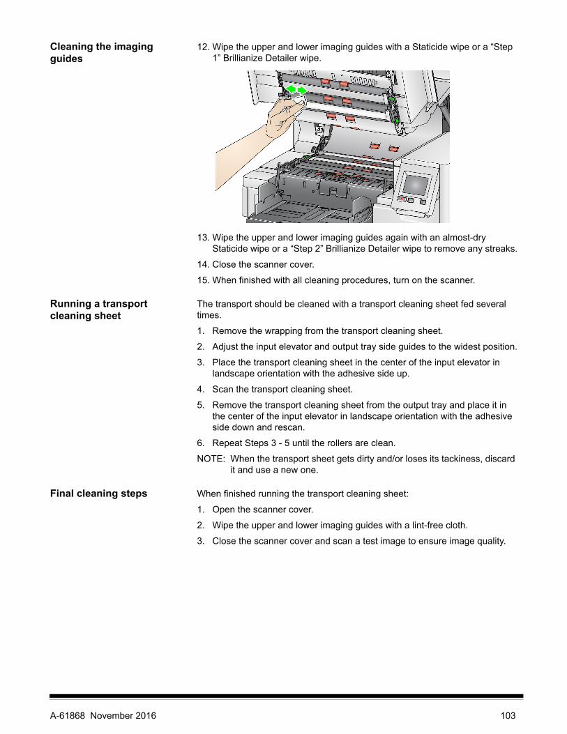
Cleaning the imaging guides
12. Wipe the upper and lower imaging guides with a Staticide wipe or a “Step 1” Brillianize Detailer wipe.
13. Wipe the upper and lower imaging guides again with an almost-dry Staticide wipe or a “Step 2” Brillianize Detailer wipe to remove any streaks.
14. Close the scanner cover.
15. When finished with all cleaning procedures, turn on the scanner.
Running a transport cleaning sheet
The transport should be cleaned with a transport cleaning sheet fed several times.
1. Remove the wrapping from the transport cleaning sheet.
2. Adjust the input elevator and output tray side guides to the widest position.
3. Place the transport cleaning sheet in the center of the input elevator in landscape orientation with the adhesive side up.
4. Scan the transport cleaning sheet.
5. Remove the transport cleaning sheet from the output tray and place it in the center of the input elevator in landscape orientation with the adhesive side down and rescan.
6. Repeat Steps 3 - 5 until the rollers are clean.
NOTE: When the transport sheet gets dirty and/or loses its tackiness, discard it and use a new one.
Final cleaning steps When finished running the transport cleaning sheet:
1. Open the scanner cover.
2. Wipe the upper and lower imaging guides with a lint-free cloth.
3. Close the scanner cover and scan a test image to ensure image quality.
A-61868 November 2016 103

Replacement procedures
This section provides procedures for replacing the following parts. Use the list below as a guideline for frequency of replacement.
• Feed module tires and separation roller tires, including the Kodak Ultra-lightweight Feed Module — tire life will vary depending upon paper types, environment, and cleanliness. Nominal tire life is approximately 500,000 documents; results will vary. Degradation of feeder performance, multiple feeds, stoppages, etc. indicate a need to change tires. Separation roller tires may wear faster than feed module tires. When replacing feed module tires, all four tires should be replaced at the same time. When replacing separation roller tires, both tires should be replaced at the same time.
• Feed module and separation roller, including the Kodak Ultra-lightweight feed module and separation roller — it is recommended that you install a new feed module and separation roller every 4th tire change. Install a new feed module and separation roller at the same time.
• Pre-separation pad, including the Kodak Ultra-lightweight pre-separation pad — it is recommended that you change the pre-separation pad at least as often as you change the feed module/separation roller tires.
• Imaging guides — replace when the imaging guides are heavily scratched and defects show in the image.
NOTE: The illustrations in this section may be slightly different depending on the consumable you are changing. For example, the ultralightweight feed module looks slightly different than the standard feed module. The installation procedures, however, are the same.
Meters should be maintained by the operator and reset when consumables are changed. The meters do not reset automatically when a consumable is changed. Meters show the number of pages scanned. For more information on viewing and using the Maintenance meters see “Viewing the Maintenance Meters” on page 32.
NOTE: When replacing parts, turn off the scanner.
Replacing the feed module or feed module tires
First, release the feed module. There are two methods of releasing the feed module.
Method 1:
1. Open the scanner cover.
2. Press the release tab to the right to release the feed module from the scanner.
104 A-61868 November 2016

Method 2:
1. Remove the output tray.
2. Lift up and open the printer access cover.
NOTE: If you do not want to remove the output tray, you can lift the front of the output tray, then lift the printer access cover and position the printer access cover behind the height adjustment tab.
3. Turn the feed module release knob to the Unlock symbol and release the feed module.
4. If you are just replacing the feed module, go to Step 11. If you are replacing the tires, proceed with Step 5.
A-61868 November 2016 105

5. With one hand, press the locking tabs (one on each side) while holding the lower housing with the other hand. Pull the upper housing up and away from the rollers.
6. Remove both rollers.
7. Remove each tire by sliding the tire off the core assembly.
8. Install each new tire by gently pulling it over the core assembly. The tires do not need to be installed in any specific orientation.
IMPORTANT:Do not overstretch the tire; it may tear.
9. Replace each roller in the lower feed module housing and align the tabs on the upper housing with the slots on the lower housing.
10. Press the upper and lower housings together until they snap into place.
Core assembly
106 A-61868 November 2016

11. Insert the pin on the left side of the feed module with the rod (1); align the upper tab with the slot (2); align the pin on the right side of the feed module with the rod (3) and turn the green feed module release knob so that it points to the Locked symbol on the left (4) to re-engage the feed module. Verify that the feed module is securely in place and moves freely after you install it.
12. Close the scanner cover and the printer access cover.
13. Reinstall the output tray.
14. When finished, access the Maintenance meters on the Operator Control Panel (see “If you want to reset a maintenance meter:” on page 33) and touch the Reset icon to reset the Feed Tires/Feed Module meter.
A-61868 November 2016 107

Replacing the separation roller or separation roller tires
1. Open the scanner cover.
2. Pull the separation roller cover forward and remove the separation roller.
NOTE: The separation roller cover is spring-loaded. Hold the separation roller cover back until you remove the separation roller, then gently lower the separation roller cover back in place.
If you want to replace the separation module, do Steps 3 and 4. If you want to replace the separation roller tires, go to Step 5.
3. Insert the new separation roller. Be sure to line up the slots on the separation roller with the holders.
4. Gently release the separation roller cover back in place and close the scanner cover.
108 A-61868 November 2016

To replace the tires:
5. Replace each tire by sliding the tire off the core.
6. Install each new tire by gently pulling it over the core.
IMPORTANT:Do not overstretch the tire; it may tear.
7. Reinstall the separation roller. Be sure to line up the slots on the separation roller with the holders.
8. Lower the separation roller holder back in place.
9. Close the scanner cover.
10. When finished, access the Maintenance meters on the Operator Control Panel (see “If you want to reset a maintenance meter:” on page 33) and touch the Reset icon to reset the Separation Roller Tires/Separation Roller meter.
Replacing the pre-separation pad
Change the pre-separation pad when the frequency of multifed documents increases.
1. Open the scanner cover.
2. Remove the pre-separation pad by lifting the pad up and out of position.
NOTE: The pre-separation pad fits snugly in place; therefore, a little force may be required to remove it.
3. Install the new pre-separation pad. Be sure it snaps into place.
4. Close the scanner cover.
5. When finished, access the Maintenance meters on the Operator Control Panel (see “If you want to reset a maintenance meter:” on page 33) and touch the Reset icon to reset the Pre-separation pad meter.
A-61868 November 2016 109
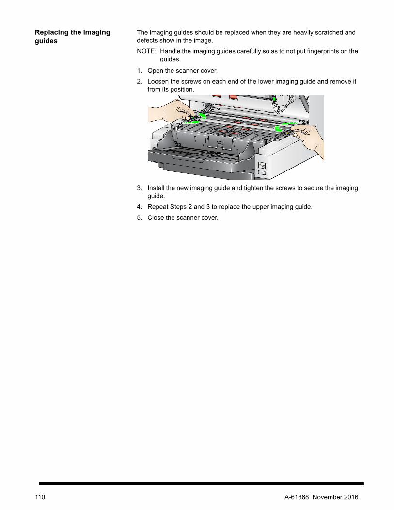
Replacing the imaging guides
The imaging guides should be replaced when they are heavily scratched and defects show in the image.
NOTE: Handle the imaging guides carefully so as to not put fingerprints on the guides.
1. Open the scanner cover.
2. Loosen the screws on each end of the lower imaging guide and remove it from its position.
3. Install the new imaging guide and tighten the screws to secure the imaging guide.
4. Repeat Steps 2 and 3 to replace the upper imaging guide.
5. Close the scanner cover.
110 A-61868 November 2016

Replacing the flippable white background strip(s)
In the rare case that you may need to replace the flippable white background strip(s), follow the procedures below.
1. Turn off the scanner.
2. Open the scanner cover.
3. Using your fingers or the supplied screwdriver, loosen the two screws on each end of the upper background strip and remove it from its position.
4. Disconnect the background strip connector.
5. Connect the new background strip connector with the cable. Be sure it is securely in place.
6. Install the new background strip and tighten both screws on each side to secure the background strip.
NOTE: Be sure to align the springs over the tabs in the scanner frame. Verify that the background moves up and down freely.
7. Repeat Steps 2 - 5 to replace the lower background strip.
8. Close the scanner cover.
A-61868 November 2016 111

Supplies and consumables
Contact your scanner supplier to order supplies.
Supplies/Consumables CAT No.
Kodak Feeder Consumables Kit 832 7538
Kodak Extra-Large Feeder Consumables Kit 838 7938
Kodak Extra-Extra-Large Feeder Consumables Kit 146 2415
Kodak Imaging Guide Set (without Enhanced Printer) 834 8054
Kodak Imaging Guide Set (with Enhanced Printer) 871 4438
Kodak i5x50S Imaging Guides (without Printer) 162 9500
Kodak i5x50S Imaging Guides (with Printer) 143 2244
Kodak i4x50/i5x50 Flippable White Background (without Enhanced Printer)
166 7641
Kodak i4x50/i5x50 Flippable White Background (with Enhanced Printer)
161 2605
Kodak i5X50S Backgrounds (without Printer) 190 8979
Kodak i5x50S Backgrounds (with Printer) 146 8933
Kodak Feeder Kit for Ultralightweight Paper 844 5280
Manual Feed Shelf (for i5250/i5650 Scanners) 167 3953
Manual Feed Shelf (for i5850 Scanner) 169 4256
Kodak Lead Edge Alignment Exit Tray Accessory 118 5859
Rear Exit Tray Accessory for i5250/i5650 Scanners 165 0621
Enhanced Printer Accessory 140 8756
i5850 Enhanced Printer Accessory (Front and Rear) 121 3743
Kodak i5x50S Enhanced Printer Accessory 197 5168
Kodak Printer Ink Blotters 125 7633
Enhanced Printer Black Ink Cartridge 818 3386
Enhanced Printer Red Ink Cartridge 159 6832
Green (HP-C6602G) and Blue (HP-C6602B) ink cartridges can also be used, however they are only available from a Hewlett-Packard reseller.
N/A
Enhanced Printer: Ink Cartridge Carrier 176 3218
66.04 cm (26 in.) document extenders (qty 1 per box) 183 3946
76.2 cm (30 in.) document extenders (qty 1 per box) 162 6803
86.36 cm (34 in.) document extenders (qty 1 per box) 149 8476
Kodak Digital Science Transport Cleaning Sheets (qty 50) 169 0783
Kodak Digital Science Roller Cleaning Pads (qty 24) 853 5981
Staticide Wipes for Kodak Scanners (qty 144) 896 5519
Brillianize Detailer Wipes / for Kodak Scanners 826 6488
112 A-61868 November 2016

8 Troubleshooting
Problem solving Use the chart below as a guide to check possible solutions to problems you may encounter when using the Kodak i5x50 Scanners.
Problem Possible Solution
Documents are jamming or multiple documents are feeding
Make sure that:
• all documents meet specifications for size, weight, and type, etc. as outlined in Appendix A, Specifications.
• all staples and paper clips have been removed from the documents.
• all rollers and tires are clean and the separation roller and feed module are properly installed. See the procedures in “7 Maintenance” on page 97.
• you check the Maintenance Meters on the Operator Control Panel to see if it is time to change the rollers and/or tires.
• the leading edges of all batched documents are centered in the feeder so that each document will come in contact with the feed rollers.
• documents with an unusual texture or surface are fed manually or using another Document Handling setting (e.g., Fragile, Thick, Thin). See the Scanning Setup Guide for the ISIS Driver, TWAIN Datasource or VRS for more information.
• the gap release toggle switch is not pushed in.
• you fan your documents to aid in document feeding.
• you select Omit Multifeed on the Scanning screen to ignore multifeed detection if scanning documents with a known multifeed condition.
To remove a document jam:
• Remove any documents from the feeder area.• Open the scanner cover.• Locate the jammed document(s) and remove it.• Close the scanner cover and resume scanning.
Long documents are not feeding or are jamming
• Make sure the input elevator and output tray extenders are pulled out to provide support for long documents or use the optional document extenders.
• For i5250/i5650/i5650S/i5850/i5850S Scanners: Make sure the Maximum Document Length is set high enough. Maximum Document Length will vary based on resolution and scanning depth.
• For i5250V/i5650V Scanners: Maximum Document Length is always set at 40 inches. This cannot be set by the user.
• Set a lower output resolution or an alternate output format.
“Metal detected at feeder” message on OCP
• Staples and paper clips will cause the scanner to stop and the OCP to display this message, if staple detection is enabled.
• Foil, e.g. foil holograms on checks, will be read by the metal sensor as a staple.
Image quality is poor or has degraded Make sure that the scanner and imaging guides are clean. Refer to Chapter 7, Maintenance.
A-61868 November 2016 113

Problem Possible Solution
“False” paper jams or multifeeds are occurring
• Make sure that the transport area is clean.
• Select a different Document Handling setting. See the Scanning Setup Guide for the ISIS Driver, TWAIN Datasource or VRS for more information.
• Recalibrate UDDS.
• Adjust the Multifeed Sensitivity setting in your scanning application. See the Scanning Setup Guide for the ISIS Driver, TWAIN Datasource or VRS for more information.
The scanner will not scan/feed documents
Make sure that:
• the power cord is plugged in and the power is on.
• the power button has been pushed on and the green LED is lit.
• the scanner cover is completely closed.
• documents are making contact with the feed module and are covering the paper present sensor.
• documents meet specifications for size, weight, and type, etc.
• for thicker documents, toggle the gap release toggle switch during feeding.
• you check the feed module and separation roller and pre-separation pad for signs of wear, and replace these parts if necessary.
You can also power the scanner down and power it up again.
Scanner is running slow • Your host PC may not meet the minimum requirements for the scanner.See “Appendix A Specifications” on page 117.
• Some image processing functions may reduce scanner speed.• Resolution (dpi) setting may be set too high.• Compression setting may not be set high enough.• Your anti-virus software may be scanning all TIFF or JPEG files.• Ensure you are scanning to a local drive.• Sorting options may reduce scanner speed.
Documents are skewed during scanning
Make sure that:
• the input elevator side guides are adjusted to fit the documents being fed.
• documents are being fed perpendicular to the feed module.
• all staples and paper clips have been removed from the documents.
• the feed module, separation roller, and drive rollers are clean.
• the scanner cover is firmly closed.
Scanner pauses excessively during scanning
Make sure that:
• the host PC meets minimum requirements for scanning. See “Appendix A Specifications” on page 117.
• there is enough free space on the hard disk drive.
• all other applications are closed.
• you are using a USB 2.0 connection.
You can also try changing the scanning options (compression, resolution, output format, etc.) in your scanning application.
Roller marks or streaks appear on documents after scanning
Clean the feed module, separation roller, and tires. Refer to Chapter 7, Maintenance.
Vertical lines appear on the image • Clean the imaging guides. Refer to Chapter 7, Maintenance.
• Enable the Streak Filter option in your scanning application or increase the aggressiveness.
114 A-61868 November 2016

Power button/Indicator lights
Steady green: the scanner is in Ready mode.
Flashing yellow: the scanner is in Low Power mode.
Steady yellow: the scanner is in Standby mode.
Upgrading software Kodak Alaris updates drivers and firmware to correct issues and add new features. If you encounter errors, verify that you are running the latest scanner software version before you call Technical Support. Go to: www.kodakalaris.com/go/IMsupport, access i5x50 Software and Drivers and download the most recent upgrade.
Contacting Service 1. Visit www.kodakalaris.com/go/IMcontacts to obtain the most current phone number for your country.
2. When calling, please have the following information ready:
• A description of your problem.
• The scanner model and serial number.
• Computer configuration.
• Scanning application you are using.
Problem Possible Solution
“USB communication error” on OCP When a flatbed scanner is being used with the i5x50 scanner, the order to power up the scanners is important.
• First power on the flatbed scanner, • Then power on the i5x50 scanner.• If the wrong power-on sequence is used, the USB communication error
message may appear on the OCP.
Multifed page(s) feed to the wrong exit If multifed pages are set up to go to the rear exit, and the multifeed response is set up to “Keep paper in path,” (either Stop or Pause), the multifed page may not go to the rear exit.
• Make sure that the multifeed response is not “Keep paper in path.”
A-61868 November 2016 115

116 A-61868 November 2016
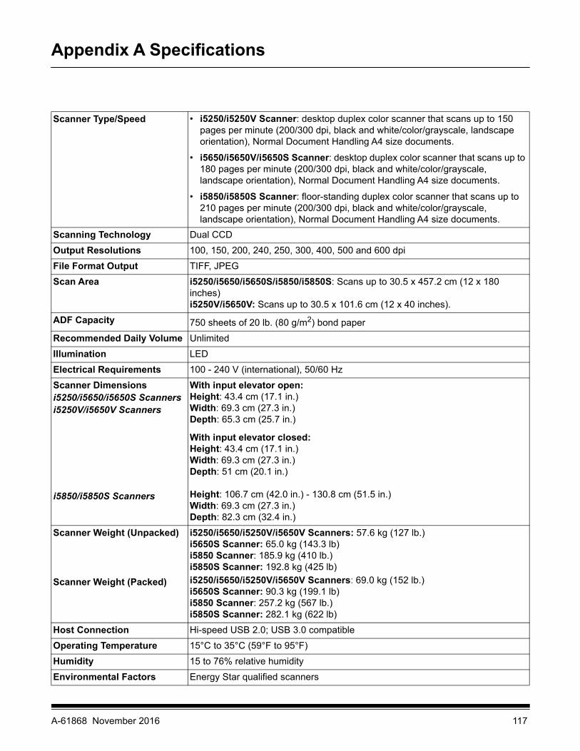
Appendix A Specifications
Scanner Type/Speed • i5250/i5250V Scanner: desktop duplex color scanner that scans up to 150 pages per minute (200/300 dpi, black and white/color/grayscale, landscape orientation), Normal Document Handling A4 size documents.
• i5650/i5650V/i5650S Scanner: desktop duplex color scanner that scans up to 180 pages per minute (200/300 dpi, black and white/color/grayscale, landscape orientation), Normal Document Handling A4 size documents.
• i5850/i5850S Scanner: floor-standing duplex color scanner that scans up to 210 pages per minute (200/300 dpi, black and white/color/grayscale, landscape orientation), Normal Document Handling A4 size documents.
Scanning Technology Dual CCD
Output Resolutions 100, 150, 200, 240, 250, 300, 400, 500 and 600 dpi
File Format Output TIFF, JPEG
Scan Area i5250/i5650/i5650S/i5850/i5850S: Scans up to 30.5 x 457.2 cm (12 x 180 inches)i5250V/i5650V: Scans up to 30.5 x 101.6 cm (12 x 40 inches).
ADF Capacity 750 sheets of 20 lb. (80 g/m2) bond paper
Recommended Daily Volume Unlimited
Illumination LED
Electrical Requirements 100 - 240 V (international), 50/60 Hz
Scanner Dimensionsi5250/i5650/i5650S Scannersi5250V/i5650V Scanners
i5850/i5850S Scanners
With input elevator open:Height: 43.4 cm (17.1 in.)Width: 69.3 cm (27.3 in.)Depth: 65.3 cm (25.7 in.)
With input elevator closed:Height: 43.4 cm (17.1 in.)Width: 69.3 cm (27.3 in.)Depth: 51 cm (20.1 in.)
Height: 106.7 cm (42.0 in.) - 130.8 cm (51.5 in.)Width: 69.3 cm (27.3 in.)Depth: 82.3 cm (32.4 in.)
Scanner Weight (Unpacked)
Scanner Weight (Packed)
i5250/i5650/i5250V/i5650V Scanners: 57.6 kg (127 lb.)i5650S Scanner: 65.0 kg (143.3 lb)i5850 Scanner: 185.9 kg (410 lb.)i5850S Scanner: 192.8 kg (425 lb)
i5250/i5650/i5250V/i5650V Scanners: 69.0 kg (152 lb.)i5650S Scanner: 90.3 kg (199.1 lb)i5850 Scanner: 257.2 kg (567 lb.)i5850S Scanner: 282.1 kg (622 lb)
Host Connection Hi-speed USB 2.0; USB 3.0 compatible
Operating Temperature 15°C to 35°C (59°F to 95°F)
Humidity 15 to 76% relative humidity
Environmental Factors Energy Star qualified scanners
A-61868 November 2016 117

System requirements Following is the recommended system configuration to run Kodak i5x50 Scanners.
Power Consumption - Scanner
Idle - not imaging: <115 watts (all models)Running - imaging:<215 watts (i5250/i5250V/i5650/i5650V/i5650S Scanners)<250 watts (i5850/i5850S Scanners)Low Power mode: <3.5 wattsStandby: <0.5 watts
Acoustic Noise(Sound Pressure level at Operator Position)
Scanning: less than 65 dB(A)Standby: less than 42.3 dB(A)
For i5250/i5650/i5850 Scanners
PC: Intel® Core™ i5 (Sandy Bridge or newer) running at 2.7 GHz or higher; USB 3.0 (Super Speed) or 2.0 (High Speed); 4 GB RAM or more
For i5250V/i5650V Scanners PC: Intel® Core™ Quad, 3GHz, 4 GB RAM, USB 2.0 or higher
Supported operating systems
• Microsoft Windows XP, SP3 (TWAIN Datasource only)
• Microsoft Windows Vista; SP1
• Microsoft Windows Vista x64 Edition
• Microsoft Windows 7 (32- and 64-bit)
• Microsoft Windows 8 (32- and 64-bit)
• Microsoft Windows 8.1 (32- and 64-bit)
• Microsoft Windows 10 (32- and 64-bit)
Included Drivers Windows operating systems: TWAIN, ISIS, WIAVRS (for Kodak i5250V and i5650V Scanners only)
118 A-61868 November 2016

Appendix B Warranty - US and Canada only
Congratulations on the purchase of a Kodak Scanner. Kodak Scanners are designed to provide end users with the highest performance and reliability. All Kodak Scanners are covered by the following Limited Warranty.
Limited Warranty for Kodak ScannersKodak Alaris Inc. provides the following Limited Warranty on Kodak Scanners (excluding spare parts and consumables) distributed by Kodak Alaris or through Kodak Alaris’ authorized distribution channels:
Kodak Alaris Inc. warrants that a Kodak Scanner, from the time of sale through the Limited Warranty period applicable to the Product, will be free of defects in materials or workmanship and will conform to the performance specifications applicable for the particular Kodak Scanner.
All Kodak Scanners are subject to the Warranty Exclusions described below. A Kodak Scanner found to be defective or which does not conform to the product specifications will be repaired or replaced with new or refurbished product at Kodak Alaris’ option.
Purchasers may determine the applicable Limited Warranty period for the Kodak Scanners purchased by visiting www.kodakalaris.com/go/IMsupport or by reviewing the Limited Warranty Summary Card enclosed with the Kodak Scanner.
Proof of purchase is required to demonstrate eligibility for warranty service.
Warranty exclusionsKodak Alaris’ Limited Warranty does not apply to a Kodak Scanner that has been subjected to physical damage after purchase, caused, for example, by casualty, accident, acts of God or transportation, including (a) by a failure to properly package and ship the Scanner back to Kodak Alaris for warranty service in accordance with Kodak Alaris’ then current Packaging and Shipping Guidelines, including failure to replace the shipping restraint prior to shipping, or by a failure to remove the shipping restraint prior to use; (b) resulting from the user’s installation, system integration, programming, re-installation of user operating systems or applications software, systems engineering, relocation, reconstruction of data, or removal of the product or any component (including breakage of a connector, cover, glass, pins, trays or seal); (c) from service, modification or repair not performed by Kodak Alaris or a service provider authorized by Kodak Alaris or by tampering, use of counterfeit or other non-Kodak Alaris components, assemblies, accessories, or modules; (d) by misuse, unreasonable handling or maintenance, mistreatment, operator error, failure to provide proper supervision or maintenance, including use of cleaning products or other accessories not approved by Kodak Alaris or use in contravention of recommended procedures or specifications; (e) by environmental conditions (such as excessive heat or other unsuitable physical operating environment), corrosion, staining, electrical work external to the product or failure to provide electro-static discharge (ESD) protection; (f) by failure to install firmware updates or releases available for the product and (g) by such other supplemental exclusions published from time to time online at www.kodakalaris.com/go/IMsupport.
Kodak Alaris provides no Limited Warranty for products purchased from countries other than the United States and Canada. Purchasers of products from foreign distribution channels must seek warranty coverage, if any, through the original source of purchase.
Kodak Alaris provides no Limited Warranty for products that are purchased as part of a third party manufacturer’s product, computer system or other electronic device.
Any warranty for these products is provided by the OEM (Original Equipment Manufacturer) as part of that manufacturer’s product or system.
The replacement product assumes the remainder of the Limited Warranty period applicable to the defective product or thirty (30) days, whichever is longer.
Installation Warning and DisclaimerKODAK ALARIS WILL NOT BE RESPONSIBLE FOR ANY CONSEQUENTIAL OR INCIDENTAL DAMAGES RESULTING FROM THE SALE, INSTALLATION, USE, SERVICING OR IMPROPER FUNCTIONING OF THIS PRODUCT, REGARDLESS OF THE CAUSE. SUCH DAMAGES FOR WHICH KODAK ALARIS WILL NOT BE RESPONSIBLE, INCLUDE, BUT ARE NOT LIMITED TO, LOSS OF REVENUE OR PROFIT, LOSS OF DATA, DOWNTIME COSTS, LOSS OF USE OF THE PRODUCT, COST OF ANY SUBSTITUTE PRODUCT, FACILITIES OR SERVICES OR CLAIMS OF CUSTOMERS FOR SUCH DAMAGES.
If there is any conflict between other sections of this appendix and the Limited Warranty, the terms of the Limited Warranty prevail.
A-61868 November 2016 119

How to obtain Limited Warranty service Kodak Scanners are supplied with information on unpacking, setup, installation and operation. Careful reading of the User’s Guide will answer most of the technical questions the end user might have regarding proper installation, operation and maintenance of the product. However, should additional technical support be required, you may visit our website at: www.kodakalaris.com/go/IMsupport or contact: Kodak Alaris’ Response Center: (800) 822-1414
The Response Center is available Monday – Friday (excluding Kodak Alaris holidays) 8 a.m. to 5 p.m. EST.
Before placing the call, the eligible purchaser should have the Kodak Scanner model number, part number, serial number and proof of purchase available. The eligible purchaser should also be prepared to provide a description of the problem.
Response Center personnel will assist the end user in resolving the problem over the phone. The end user may be asked to run some simple, self-diagnostic tests and report the resulting status and error code messages. This will assist the Response Center in determining if the problem is the Kodak Scanner or another component and if the problem can be resolved over the phone. If the Response Center determines a hardware problem exists that is covered either under the Limited Warranty or a purchased Maintenance Agreement, a Return Material Authorization Number (RMA) will be assigned as needed, a service request will be initiated and repair or replacement procedures will follow.
Packaging and shipping guidelinesPurchaser must ship all warranty returns in a method that guarantees full protection of the product from shipping damage. Failure to do so will void the Kodak Scanner warranty. Kodak Alaris advises the purchaser to keep the original box and packing materials for storing or shipping. Kodak Alaris is not responsible for issues related to shipping damage. The purchaser must return only the Kodak Scanner. Prior to shipment, purchaser must remove and retain all “add-on” items, (i.e. adapters, cables, software, manuals, etc.). Kodak Alaris accepts no responsibility for these items and they will not be returned with the repaired or replacement Kodak Scanner. All products should be returned to Kodak Alaris in the original shipping container, or an authorized packaging box for the units being returned. Purchaser must install the shipping restraint before the Kodak Scanner is shipped. When the original packaging is not available, contact Kodak Alaris’ Response Center at (800) 822-1414 for part numbers and replacement packaging ordering information.
Return procedureEligible purchasers seeking services for Kodak Scanners covered under this Limited Warranty must obtain a Return Material Authorization number (“RMA”) by calling (800) 822-1414 and within ten (10) business days from the date of issuance of the RMA must return the Kodak Scanner to the address designated in the RMA at the end user’s own expense and risk, in compliance with Kodak Alaris’ current Packaging and Shipping Guidelines.
Any defective products or parts replaced by Kodak Alaris become the property of Kodak Alaris.
Customer responsibilityBY REQUESTING SERVICE, THE ELIGIBLE PURCHASER ACKNOWLEDGES THE TERMS OF THE LIMITED WARRANTY, INCLUDING THE DISCLAIMER AND LIMITATION OF LIABILITY PROVISIONS. PRIOR TO SEEKING SERVICE, THE END USER MUST BACK-UP ANY DATA OR FILES THAT MAY BECOME DAMAGED OR LOST. KODAK ALARIS IS, WITHOUT LIMITATION, NOT RESPONSIBLE FOR LOST OR DAMAGED DATA OR FILES.
Warranty Service descriptions Kodak Alaris offers a range of service programs to support its Limited Warranty and to assist with the use and care of the Kodak Scanner (“Service Methods”). A Kodak Scanner represents an important investment. Kodak Scanners provide the productivity needed to stay competitive. The sudden loss of this productivity, even temporarily, could seriously affect the ability to meet commitments. Downtime can be very expensive, not just in the cost of the repair but also in time lost. To help alleviate these problems, Kodak Alaris may use one of the service methods listed below, depending upon product type, in providing service under its Limited Warranty.
Included with selected Kodak Scanners is a Limited Warranty Registration card and a Limited Warranty Summary card. The Limited Warranty Summary card is specific by model. The Limited Warranty Summary card contains important warranty information, including the model number and the Limited Warranty. Refer to the Limited Warranty Summary card to determine the available Service Methods applicable to the particular Kodak Scanner.
If the Limited Warranty Registration card or Limited Warranty Summary card cannot be located, additional information may be obtained about the product, including updated warranty and service program information and restrictions, online at www.kodakalaris.com/go/IMsupport.
To avoid service delays, Kodak Alaris urges end users to complete and return the enclosed Limited Warranty Registration Card at the first opportunity. If you cannot locate the Limited Warranty Registration card, you may register online at www.kodakalaris.com/go/IMsupport.
Kodak Alaris also provides a variety of service programs that may be purchased to assist with the use and care of the Kodak Scanner.
Kodak Alaris is committed to providing its customers with quality, performance, reliability and service under the Limited Warranty.
We expect to have a supply of spare parts and consumables for at least 5 years after product manufacture has been discontinued.
120 A-61868 November 2016

On-site serviceFor the selected Kodak Scanner, and after the Response Center verifies a hardware problem, a service call will be opened and logged. A Kodak Alaris Field Engineer will be dispatched to the product location to perform repair service if the product is located within the contiguous forty-eight (48) United States, in certain areas of Alaska and Hawaii, and if there are no security, safety or physical requirements that would restrict the Field Engineer’s access to the scanner. For additional information on service areas, visit our website at: www.kodakalaris.com/go/IM. On-Site Service will be provided between the hours of 8 a.m. and 5 p.m. local time, Monday through Friday (excluding Kodak Alaris holidays).
Advanced Unit Replacement (AUR)AUR may be one of the easiest and most comprehensive service offerings in the industry. In the unlikely event of a product defect, for eligible purchasers of certain Kodak Scanners, Kodak Alaris will replace that product within two business days.
The AUR provides advance replacement on specific failed or broken Kodak Scanner. To be eligible to take advantage of the AUR, the eligible purchaser must obtain an RMA number, sign an Advance Replacement Agreement and provide a credit card deposit to secure the replacement product. The RMA number should be kept in the event that the status of the replacement product needs to be checked. The eligible purchaser will be asked for the address where the replacement product is to be shipped. The eligible purchaser will also be faxed packing and shipping instructions for the malfunctioning product. The eligible purchaser will then receive a replacement product within 2 business days after the service call initiation and Kodak Alaris’ receipt of the signed agreement. The malfunctioning product must be received by Kodak Alaris within ten (10) days of the end user’s receipt of the replacement product or the end user’s credit card will be charged the list price of the replacement product. Shipment of replacement Imaging Product will be made at Kodak Alaris’ expense and choice of freight carrier. Shipments not made under Kodak Alaris’ directions and choice of freight carrier may void the Limited Warranty.
Before the product is returned to Kodak Alaris, be sure to remove all options and accessories (which include power cord, documentation, etc.) that are not covered by the Limited Warranty. The box and packaging in which the replacement product was shipped must be used to return the malfunctioning product. If the malfunctioning product is not returned in the box and packaging in which the replacement product was shipped the Limited Warranty may be voided. The Return Material Authorization Number (“RMA”) must be clearly marked on the outside of the box to ensure proper receipt and credit of the defective product.
Depot serviceIf the Kodak Scanner is not eligible for AUR or On-Site Service, an eligible purchaser may utilize our Depot Repair Service. The eligible purchaser will be instructed to ship the product to the nearest authorized Depot Repair Center. Product must be shipped at the eligible purchaser’s risk and expense to the repair center. Before the product is returned to the repair center, be sure to remove all options and accessories (which include power cord, documentation, etc.) not covered by the Limited Warranty. All products should be returned to Kodak Alaris in the original shipping container, or in a recommended packing box. The Kodak Scanner must have the shipping restraint installed before it is shipped. When the original packaging is not available, contact Kodak Alaris’ Response Center at (800) 822-1414, for ordering information. Eligible purchasers seeking services for Kodak Scanners must obtain a Return Material Authorization number (“RMA”) by calling (800) 822-1414, and within ten (10) business days from the date of issuance of the RMA must return the Kodak Scanner to the address designated in the RMA at the end user’s own expense and risk. The Return Material Authorization Number (“RMA”) must be clearly marked on the outside of the box to ensure proper receipt and credit of the defective product.
Upon receipt of the product, the repair center will repair product within ten (10) business days. The repaired product will be shipped back two-day express mail at no expense to the eligible purchaser.
Important restrictionsEligibility: The Advance Exchange Program and the Depot Service are available to eligible purchasers in the fifty (50) United States, and On-Site Service is available in the contiguous forty-eight (48) states and in certain areas of Alaska and Hawaii for products purchased from authorized distributors of Kodak Alaris. The Kodak Scanner will be ineligible for any service under warranty if the product falls under any of Kodak Alaris’ then-current Warranty Exclusions, including a purchaser’s failure to return defective products to Kodak Alaris in compliance with Kodak Alaris’ then current Packaging and Shipping Guidelines. Persons are only considered “eligible purchasers” or “end users” if they originally purchased the Kodak Scanner for their own personal or business use, and not for resale.
Consumables: Consumables are items that wear out under normal use and must be replaced by the end user as needed. Consumables, supplies, other expendable items and those items identified as being the user’s responsibility in the User’s Guide are not covered under the Limited Warranty.
Any defective products or parts replaced by Kodak Alaris become the property of Kodak Alaris.
A-61868 November 2016 121

Contacting Kodak AlarisFor Information on Kodak Scanners:
Website: www.kodakalaris.com/go/IM
For U.S. Service, Repair and Technical Assistance by Telephone:
Telephone technical support is available Monday-Friday between the hours of 5 a.m. to 5 p.m. excluding Kodak Alaris holidays. Phone: (800) 822-1414
For Technical Documentation and FAQ’s available 24 hours a day:
Website: www.kodakalaris.com/go/IM
For Service Program Information
Website: www.kodakalaris.comPhone: (800) 822-1414
122 A-61868 November 2016


Kodak Alaris Inc. 2400 Mount Read Blvd.
Rochester, NY 14615
© 2017 Kodak Alaris Inc. All rights reserved.
The Kodak trademark and trade dress are used under license
from Eastman Kodak Company.