Group composition and its impact on effective group treatment ...
Upload
khangminh22Category
view
3download
0
further informationwebcode: GW-1435
GEMÜ 1435 ePosIntelligent electro-pneumatic positioner
Features• Simple handling and commissioning• Simple electrical connection by detachable terminals• Automatically optimizes the valve control during initialization• No air consumption when idle• Robust coated aluminium housing
DescriptionThe GEMÜ 1435 ePos digital electro-pneumatic positioner is used to control process valves with single acting or double actinglinear or quarter turn actuators, and detects the position of the valve using an external travel sensor. It has a robust aluminiumhousing with protected operating buttons and an LCD display which allows the product to be individually adapted to the controltask. The operating times can be adjusted by integrated throttles. Connection and mounting to NAMUR is also possible. There-fore, the GEMÜ 1435 ePos is an optimal solution for control tasks with high requirements, especially in applications with harshenvironmental conditions.
Technical specifications• Ambient temperature: -20 to 60 °C• Operating pressure : 0 to 6 bar• Mode of action: Double acting l Single acting• Flow rate: 50 Nl/min l 90 Nl/min• Measuring range: Max. 30 mm, linear l Max. 50 mm, linear l Max. 75 mm, linear l Max. 90°, radial• Supply voltage: 24 V DC• Electrical connection types: M12 cable gland l M12 connector l M16 cable gland• Conformity: EACTechnical data depends on the respective configuration

www.gemu-group.com2 / 23GEMÜ 1435
Product line
GEMÜ 1434µPos
GEMÜ 1436 ecocPos
GEMÜ 1435ePos
GEMÜ 1436cPos
Controller type
Positioner l l l -
Positioner and processcontroller
- - - l
Ambient temperature 0 to 60 °C 0 to 60 °C -20 to 60 °C 0 to 60 °C
Supply voltage
24 V DC l l l l
Flow rate 15 Nl/min 150 l/min200 l/min
50 Nl/min90 Nl/min
150 l/min200 l/min300 l/min
Measuring range
Max. 30 mm, linear l l l l
Max. 50 mm, linear - l l l
Max. 75 mm, linear - l l l
Max. 90°, radial - l l l
Electrical connection type
M12 cable gland - - l -
M12 connector - l l l
M16 cable gland - - l -
M12 plug l - - -
M12 socket l - - -
Communication mode
DeviceNet - - - l
Profibus - - - l
ProfiNet - - - l
Without - - - l
Programmable outputs
No l l - -
Yes - - l l
Input option
No l l - -
Yes - - l l
Conformity
EAC l l l l
UL listed - l - -
Product line

GEMÜ 1435www.gemu-group.com 3 / 23
Product description
321
Item Name Materials
1 Housing Base: Aluminium, epoxy coated, blackCover: Aluminium, powder coated, silver
2 Display with cover PMMA
3 Operating elements with cover PMMA
Functions• Automatic initialization of actuator and positioner• Position standardization Min. Position• Position standardization Max. Position• Close tight function at Min./Max. position• Linearization function for set value → Position (linear, 1:25, 1:50, freely programmable)• Definition of freely programmable characteristic curve via 11 calibration points• For details see parameter table of operating instructions• Alphanumeric display, 2 lines with 16 digits each, with background light
Product description

www.gemu-group.com4 / 23GEMÜ 1435
GEMÜ CONEXOThe interaction of valve components that are equipped with RFID chips and an associated IT infrastructure actively increaseprocess reliability.
Thanks to serialization, every valve and every relevant valve component such as the body, actuator or diaphragm, and even auto-mation components, can be clearly traced and read using the CONEXO pen RFID reader. The CONEXO app, which can be in-stalled on mobile devices, not only facilitates and improves the "installation qualification" process, but also makes the mainten-ance process much more transparent and easier to document. The app actively guides the maintenance technician through themaintenance schedule and directly provides him with all the information assigned to the valve, such as test reports, testing doc-umentation and maintenance histories. The CONEXO portal acts as a central element, helping to collect, manage and processall data.
For further information on GEMÜ CONEXO please visit:www.gemu-group.com/conexo
OrderingGEMÜ Conexo must be ordered separately with the ordering option "CONEXO" (see order data).Installing the RFID chip
RFID chip
GEMÜ CONEXO

GEMÜ 1435www.gemu-group.com 5 / 23
AvailabilityOptioncode 1)
Actual value output Heating element Interface design
0 – 10 V 4 – 20 mA Cable gland M12 plug
0 X - - X -
1 X - - - X
2 - X - X -
3 - X - - X
4 - X X X -
5 X - X - X
6 X - X X -
7 - X X - X
Flow rate Action
Single acting Double acting
50 l/min (Code 01) X X
90 l/min (Code 02) X -
1) OptionCode 0: WithoutCode 1: Electrical connections M12, 5-pinCode 2: 4–20 mA, actual value outputCode 3: 4- 20 mA, actual value output, electrical connections M12, 5-pinCode 4: 4 - 20 mA, actual value output, heating elementCode 5: Electrical connections M12, 5-pin, heating elementCode 6: Heating elementCode 7: 4 - 20 mA, actual value output, electrical connections M12, 5-pin, heating element
Availability
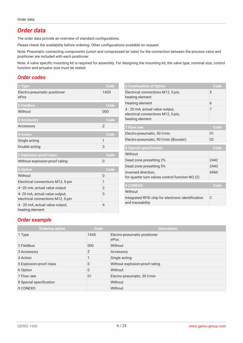
Order dataThe order data provide an overview of standard configurations.
Please check the availability before ordering. Other configurations available on request.
Note: Pneumatic connecting components (union and compressed air tube) for the connection between the process valve andpositioner are included with each positioner.
Note: A valve specific mounting kit is required for assembly. For designing the mounting kit, the valve type, nominal size, controlfunction and actuator size must be stated.
Order codes1 Type Code
Electro-pneumatic positionerePos
1435
2 Fieldbus Code
Without 000
3 Accessory Code
Accessory Z
4 Action Code
Single acting 1
Double acting 3
5 Explosion-proof class Code
Without explosion-proof rating 0
6 Option Code
Without 0
Electrical connections M12, 5-pin 1
4–20 mA, actual value output 2
4- 20 mA, actual value output,electrical connections M12, 5-pin
3
4 - 20 mA, actual value output,heating element
4
6 Continuation of Option Code
Electrical connections M12, 5-pin,heating element
5
Heating element 6
4 - 20 mA, actual value output,electrical connections M12, 5-pin,heating element
7
7 Flow rate Code
Electro-pneumatic, 50 l/min 01
Electro-pneumatic, 90 l/min (Booster) 02
8 Special specification Code
Without
Dead zone presetting 2% 2442
Dead zone presetting 5% 2443
Inversed direction,for quarter turn valves control function NO (2)
6960
9 CONEXO Code
Without
Integrated RFID chip for electronic identificationand traceability
C
Order exampleOrdering option Code Description
1 Type 1435 Electro-pneumatic positionerePos
2 Fieldbus 000 Without
3 Accessory Z Accessory
4 Action 1 Single acting
5 Explosion-proof class 0 Without explosion-proof rating
6 Option 0 Without
7 Flow rate 01 Electro-pneumatic, 50 l/min
8 Special specification Without
9 CONEXO Without
Order data
www.gemu-group.com6 / 23GEMÜ 1435

GEMÜ 1435www.gemu-group.com 7 / 23
Technical data
MediumWorking medium: Compressed air and inert gases
Dust content: Class 3, max. particle size 5 μm, max. particle density 5 mg/m³
Pressure dew point: Class 3, max. pressure dew point -20 °C
Oil content: Class 3, max. oil concentration 1 mg/m³Quality classes to DIN ISO 8573-1Note: Filter strainers are installed in the pneumatic connectors of the positioner to protect againstrough dirt particles. They can be ordered as spare parts with order number 1435 SFI. Each kit con-tains 3 filter strainers. These filter strainers are meant as an additional protection and do not re-place the requirement to filter all site compressed air.
TemperatureAmbient temperature: 0 – 60 °C (standard, Option code 0, 1, 2, 3)
-20 – 60 °C (with heating element, Option code 4, 5, 6, 7)≤ 5 °C (heating active)≥ 15 °C (heating inactive)
Storage temperature: 0 — 60 °C
Product complianceEMC Directive: 2014/30/EU
Technical standards used:Interference emission: DIN EN 61000-6-3
DIN EN 61326-1 (industry)Interference resistance: DIN EN 61000-6-2 (March 2006)
PressureOperating pressure: 0 — 6 bar
The applied pressure must not exceed the maximum control pressure of the process valve.
Flow rate: 50 Nl/min (Flow rate code 01)90 Nl/min (Flow rate code 02)
Air consumption: 0 Nl/min (when idle)
Mechanical dataInstallation position: Optional
Protection class: IP 65 acc. to EN 60529
Weight: 1.7 kg
Technical data

www.gemu-group.com8 / 23GEMÜ 1435
Travel sensor: Linear design Quarter turndesign
Detection range: 1 - 29 mm 1.5 - 48.5 mm 2.0 - 73 mm Angle of rotation5 - 90°
Operating range: 0 - 30 mm 0 - 50 mm 0 - 75 mm Angle of rotation0 - 93°
Resistance R: 3 kΩ 5 kΩ 5 kΩ 3 kΩ
Minimum travel sensorchange:
10% (only relevant for initialization)
Connection: Pre-fitted cable (max. 20 m)
Installation: external
Correlation - Travel sensor1)
spindle/valve position
Retracted (top) ≙ 100% (valve open) 90° ≙ 100 %(valve open)
Extended (bottom) ≙ 0 % (valve closed)
0° ≙ 0 % (valveclosed)
1) Design code 6960: Inversed mode of action compared with description(Travel sensor signal inversed). For valves with inverted correlation.
Electrical dataPower supplySupply voltage: 24 V DC (-5/+10%)
Power consumption: Single acting:Double acting / Booster:
≤ 6.5 W≤ 9.8 W
plus in each case: max. 36 W for active digital outputs with max. on-load currentmax. 25 W for operation with heating element
Reverse battery protec-tion:
Yes
Duty cycle: Continuous duty
Electrical protectionclass:
III
Analogue inputSet value input: 0/4 - 20 mA; 0 - 10 V
Input type: passive
Input load: 0/4–20 mA:50 Ω + approx. 0.7 V voltage drop due to reverse battery protection0–10 V:100 kΩ
Accuracy/linearity: ≤ ±0.3% of full flow
Temperature drift: ≤ ±0.5% of full flow
Resolution: 12 bit
Reverse battery protec-tion:
yes
Overload proof: Yes (up to ± 24 V DC)
Technical data

GEMÜ 1435www.gemu-group.com 9 / 23
Analogue outputNote: The analogue output 4-20 mA must be ordered using the ordering option "Option".
Actual value output: 0 - 10 V4 - 20 mA (optional)
Output type: active
On-load current: 0–10 V: Max. 10 mA
Load resistor: 4 – 20 mA:max. 600 Ω (for ordering option "Option" code 2, 3, 4, 7)
Accuracy/linearity: ≤ ±1% of full flow
Temperature drift: ≤ ±0.5% of full flow
Resolution: 12 bit
Short-circuit proof: Yes
Overload proof: Yes (up to ± 24 V DC)
Digital output signalsSwitching outputs: Alarm output 1
Alarm output 2Error message output
Switching voltage: Supply voltage
Drop voltage: Max. 2.5 V DC at 0.5 A
Short-circuit proof: yes
Overload proof: Yes (up to ± 24 V DC)
Type of contact: PNP
Pull-Down resistance: 120 kΩ
On-load current: max. 0.5 A
Travel sensor inputSupplyvoltage UP+:
Typically 10 V DC
Resistance range of re-mote potentiometers:
1 to 10 kΩ
Input voltagerange:
0 to UP+
Input resistance: 330 kΩ
Accuracy/linearity: ≤ ±0.3% of full flow
Temperature drift: ≤ ±0.3% of full flow
Resolution: 12 bit
Technical data

www.gemu-group.com10 / 23GEMÜ 1435
Positioner dataNote: Following diagram valid for valves with standard correlation between spindle position and valve po-
sition. (See section "Mechanical data, correlation between travel sensor spindle/valve position")
Control diagram: Default setting / The control characteristic is adjustable.
040
mAmAV
202010
15167,5
10125
582,5
0
75
100
50
25
Valv
e op
enin
g de
gree
[%]
During initialization, the 1435 ePos positioner automatically detects the control function of thevalve and adjusts itself by default so that the valve is closed when the signal is 0/4 mA or 0 V.*The assignment can be changed subsequently by means of parameters.* with double acting actuators dependent on pneumatic actuator
Control error: 1 % default setting≥ 0.1 % (adjustable)≤ 2.0 % (preset, K-no. 2442)≤ 5.0 % (preset, K-no. 2443)
Initialization: automatic (manual possible in ADVANCED system mode)
Close tight function: option
Technical data

GEMÜ 1435www.gemu-group.com 11 / 23
Dimensions
GEMÜ 1435 positioner
G 1/4M5M8x1.25
M6 3278
84
160170
90 50
40 G1/
4
Dimensions in mm
GEMÜ 4232 travel sensorHousing material aluminium
SW 27
h10
M16x1
ø 23,5
Travel sensorlength (code)
h
030 62.2
050 84.2
075 109.2
Dimensions in mm
Dimensions

www.gemu-group.com12 / 23GEMÜ 1435
Housing material PVDF or PP
Ø30M16x1
10h
Travel sensorlength (code)
h
030 69.6
050 91.6
075 116.6
Dimensions in mm
GEMÜ 4231 travel sensor with mounting bracketC
ø 29,5
WH
AB
D
30
WHShaft height
DHole spacing
A B C
20 80 40 59 100
30 80 50 69 100
50 130 70 89 150
Dimensions in mm
Dimensions

GEMÜ 1435www.gemu-group.com 13 / 23
Mounting bracket for GEMÜ 1435Mounting bracket for positioner wall mounting, order no. 1435 000 ZMP
11578
40
5080
81
ø 5,3ø 6,4
57,2
Dimensions in mm
Please order mounting bracket and travel sensor separately.
Dimensions

www.gemu-group.com14 / 23GEMÜ 1435
Electrical connection
Electrical connection with cable glandNote: Ordering option Option code 0, 2, 4, 6Position of the connections
X1
X3
X2
Connection X1/X2: M16 cable gland
Connection X3: M12 cable gland
Recommended cable dia-meter:
X1 / X2: 4 - 10 mmX3: 3.5 – 7 mm
Terminals: Wago 236
Cross section of wire: 0.5...2.5 mm² / AWG 20…12
Internal wiring:
10V XT
Uw+ Iw+ Iw- Uw- X+ X- GND 24V
A1 A2T
ERR
Key
10 V green 1) Connection of external travel sensor
X brown 1)
┴ white 1)
IW+ Set value input 0 / 4-20 mA
IW-
UW+ Set value input 0 - 10 V
UW-
X+ Actual value output 0 - 10 V4-20 mA (optional) - internal supplyX-
GND Supply voltage 24 V DC
24 V
Potential earth
A1 Alarm 1
A2 Alarm 2
ERR Error message output
┴ GND out
1) Core colours when using an external travel sensorGEMÜ 4231 or 4232. Connect in the specified order.Other external travel sensors may have different core colours.
Electrical connection

GEMÜ 1435www.gemu-group.com 15 / 23
Electrical connection with M12Note: Ordering option Option code 1, 3, 5, 7Position of the connectors
X1
X3
X2
Connection X1
1
4
3
2
5
Pin Ctr Signal name
1 I Uv, 24 V DC supply voltage
2 O Uo, error message output, 24 V DC
3 I Uv, GND supply voltage
4 O Uo, alarm output 1, 24 V DC
5 O Uo, alarm output 2, 24 V DC
Connection X2
1
4
3
2
5
Pin Ctr Signal name
1 I Iw+, set value input 0/4–20 mA *
2 I Iw-, set value input 0/4–20 mA *
3 O X+, actual value output 0 - 10 V / 4-20 mA
4 O X-, actual value output 0 - 10 V / 4-20 mA
5 X n.c.
* for set value input Uw = 0 - 10 V on-site rewiring is requiredConnection X3
1
54
3
2
Pin Ctr Signal name
1 O UP+, actual value supply 10 V DC
2 I UPsig, actual value input 0–10 V DC
3 O UP-, actual value supply GND
4 X n.c.
5 X n.c.
Electrical connection

www.gemu-group.com16 / 23GEMÜ 1435
Pneumatic connectionA2
A1
P
R
D1 RV
D2
Connection DIN ISO 1219-1 Designation
P 1 Air supply connection G1/4
R 3 Venting connection G1/4 with silencer
D1 V1 Exhaust air throttle for A1
D2 V2 Exhaust air throttle for A2 (only double acting type (code 3))
RV V3 Check valve
A1 2 Working connection for process valve
A2 4 Working connection for process valve (only double acting type (code 3))
Fail safe function
Error Working connection A1 Working connection A2
Electrical power supply failure Single acting: ventedDouble acting: vented
Single acting: non existentDouble acting: pressurized
Pneumatic supply failure Single acting: ventedDouble acting: undefined, dependent onthe operating conditions of the actuator
Single acting: non existentDouble acting: undefined, dependent onthe operating conditions of the actuator
This fail safe function is not a substitute for specific plant safety requirements.
Safety reaction
Error Working connection A1 Working connection A2
Set value < 4.0 mA* Single acting: ventedDouble acting: vented
Single acting: non existentDouble acting: pressurized
Set value > 20 mA or 10 V Single acting: ventedDouble acting: vented
Single acting: non existentDouble acting: pressurized
* only when using 4-20 mA set value type (parameter setting)
Pneumatic connection
GEMÜ 1435www.gemu-group.com 17 / 23
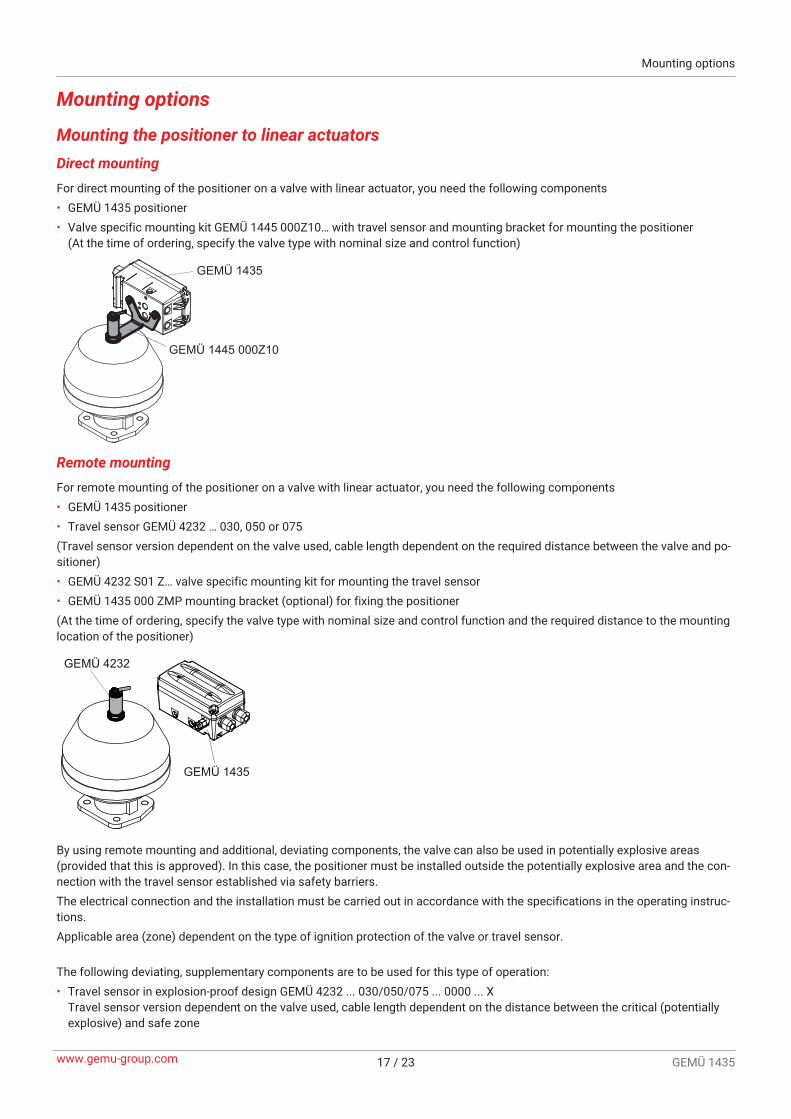
Mounting options
Mounting the positioner to linear actuatorsDirect mountingFor direct mounting of the positioner on a valve with linear actuator, you need the following components• GEMÜ 1435 positioner• Valve specific mounting kit GEMÜ 1445 000Z10… with travel sensor and mounting bracket for mounting the positioner
(At the time of ordering, specify the valve type with nominal size and control function)
GEMÜ 1445 000Z10
GEMÜ 1435
Remote mountingFor remote mounting of the positioner on a valve with linear actuator, you need the following components• GEMÜ 1435 positioner• Travel sensor GEMÜ 4232 … 030, 050 or 075(Travel sensor version dependent on the valve used, cable length dependent on the required distance between the valve and po-sitioner)• GEMÜ 4232 S01 Z… valve specific mounting kit for mounting the travel sensor• GEMÜ 1435 000 ZMP mounting bracket (optional) for fixing the positioner(At the time of ordering, specify the valve type with nominal size and control function and the required distance to the mountinglocation of the positioner)
GEMÜ 4232
GEMÜ 1435
By using remote mounting and additional, deviating components, the valve can also be used in potentially explosive areas(provided that this is approved). In this case, the positioner must be installed outside the potentially explosive area and the con-nection with the travel sensor established via safety barriers.The electrical connection and the installation must be carried out in accordance with the specifications in the operating instruc-tions.Applicable area (zone) dependent on the type of ignition protection of the valve or travel sensor.
The following deviating, supplementary components are to be used for this type of operation:• Travel sensor in explosion-proof design GEMÜ 4232 ... 030/050/075 ... 0000 ... X
Travel sensor version dependent on the valve used, cable length dependent on the distance between the critical (potentiallyexplosive) and safe zone
Mounting options

www.gemu-group.com18 / 23GEMÜ 1435
• Connector between travel sensor and positioner, GEMÜ 1219000Z0300SG00M0M125A, order number: 88208779 (onlyrequired for version with M12 plug - ordering option Option code 1, 3, 5, 7)
• Safety barrier A two-channel, safety barrier P626, order number: 99014203 *• Safety barrier B one-channel, safety barrier P630, order number: 99014207 *
* Alternative safety barriers with similar characteristics can be used on-site – technical properties available on request
Mounting options

GEMÜ 1435www.gemu-group.com 19 / 23
Mounting the positioner to quarter turn actuatorsDirect mountingFor direct mounting of the positioner on a valve with quarter turn actuator, you need the following components• GEMÜ 1435 positioner• GEMÜ 1445 000 PTAZ…000 valve specific mounting kit with travel sensor and mounting parts for mounting the positioner
(see following order data)(When ordering, specify valve type with actuator flange size)
GEMÜ 1445 PTAZ ... 000
GEMÜ 1435
For direct mounting of the positioner (via NAMUR adapter) to the horizontally or vertically aligned control air connectors of aquarter turn actuator, you need the following components• GEMÜ 1435 positioner• GEMÜ 1445 PTAZ…V or H valve specific mounting kit with travel sensor and mounting parts for mounting the positioner (see
following order data)(At the time of ordering, specify the valve type with actuator flange size, NAMUR size of the control air connectors and the re-quired distance to the mounting location of the positioner)
4
2
2
4
Control air connectororder code ...VB
Control air connectororder code ...VT
GEMÜ 1445 PTAZ ... V..
Reversecontrol direction
2
4 2
4
Control air connectororder code ...HL
Control air connectororder code ...HR
GEMÜ 1445 PTAZ ... H..Reversecontrol direction
Mounting options

www.gemu-group.com20 / 23GEMÜ 1435
Remote mountingFor remote mounting of the positioner on a valve with quarter turn actuator, you need the following components• GEMÜ 1435 positioner• GEMÜ 4231 travel sensor (cable length dependent on the required distance between the valve and positioner)• 4231PTAZ... ...090 000 valve specific mounting kit for mounting the travel sensor (see following order data)• GEMÜ 1435 000 ZMP mounting bracket (optional) for fixing the positioner(At the time of ordering, specify the actuator flange size and the required distance to the mounting location of the positioner)
GEMÜ 4231
GEMÜ 1435
GEMÜ 4231 PTAZ
By using remote mounting and additional, deviating components, the valve can also be used in potentially explosive areas(provided that this is approved). In this case, the positioner must be installed outside the potentially explosive area and the con-nection with the travel sensor established via safety barriers.The electrical connection and the installation must be carried out in accordance with the specifications in the operating instruc-tions.Applicable area (zone) dependent on the type of ignition protection of the valve or travel sensor.
The following deviating, supplementary components are to be used for this type of operation:• GEMÜ 4231 ... 0000 travel sensor
cable length dependent on the required distance between critical (potentially explosive) and safe zone• Connector between travel sensor and positioner, GEMÜ 1219000Z0300SG00M0M125A, order number: 88208779 (only
required for version with M12 plug - ordering option Option code 1, 3, 5, 7)• Safety barrier A two-channel, safety barrier P626, order number: 99014203 *• Safety barrier B one-channel, safety barrier P630, order number: 99014207 *
* Alternative safety barriers with similar characteristics can be used on-site – technical properties available on request
Mounting options

Order data of the valve specific mounting kits for quarter turn actuatorsThe order data provide an overview of standard configurations.
Please check the availability before ordering. Other configurations available on request.
Order codes1 Type Code
Mounting kit for GEMÜ 1435 1445
Mounting kit for GEMÜ 4231 4231
2 Mounting kit Code
For pneumatic quarter turn actuators PTAZ
3 Accessory adaption Code
Hole spacing 50 x 25, shaft height 15,(size AA 0, EN 15714-3)
00
Hole spacing 80 x 30, shaft height 20,(size AA 1, EN 15714-3)
01
Hole spacing 80 x 30, shaft height 30,(size AA 2, EN 15714-3)
02
Hole spacing 130 x 30, shaft height 30,(size AA 3, EN 15714-3)
03
Hole spacing 130 x 30, shaft height 50,(size AA 4, EN 15714-3)
04
4 Angle of rotation Code
Angle of rotation 90° 090
5 Connection for pilot valves Code
Mounting kit for GEMÜ 1435 (code 1445) andGEMÜ 4231 (code 4231)
Control air connector 000
5 Continuation of Connection for pilot valves Code
Mounting kit for GEMÜ 1435 (code 1445)
Control air connector G 1/8 and G 1/4,connection pattern horizontal,connector 2 on the left
4HL
Control air connector G 1/8 and G 1/4,connection pattern horizontal,connector 2 on the right
4HR
Control air connector G 1/8 and G 1/4,connection pattern vertical,connector 2 at the bottom
4VB
Control air connector G 1/8 and G 1/4,connection pattern vertical,connector 2 at the top
4VT
Control air connector G 3/8 and G 1/2,connection pattern horizontal,connector 2 on the left
8HL
Control air connector G 3/8 and G 1/2,connection pattern horizontal,connector 2 on the right
8HR
Control air connector G 3/8 and G 1/2,connection pattern vertical,connector 2 at the bottom
8VB
Control air connector G 3/8 and G 1/2,connection pattern vertical,connector 2 at the top
8VT
Order exampleOrdering option Code Description
1 Type 1445 Mounting kit for GEMÜ 1435
2 Mounting kit PTAZ For pneumatic quarter turn actuators
3 Accessory adaption 00 Hole spacing 50 x 25, shaft height 15,(size AA 0, EN 15714-3)
4 Angle of rotation 090 Angle of rotation 90°
5 Connection for pilot valves 000 Control air connector
Order data of the valve specific mounting kits for quarter turn actuators
GEMÜ 1435www.gemu-group.com 21 / 23

www.gemu-group.com22 / 23GEMÜ 1435
AccessoryGEMÜ 1435 000 ZMP
Mounting bracketGEMÜ 1435 000 ZMP… is a mounting bracket for wall mounting (for external mounting) the GEMÜ 1435ePos intelligent positioner.
Ordering information
Designation Order number
1435 000 ZMP 88209722
Accessory

GEMÜ Gebr. Müller Apparatebau GmbH & Co. KGFritz-Müller-Straße 6-8, 74653 Ingelfingen-Criesbach, GermanyPhone +49 (0) 7940 1230 · [email protected]
Subj
ect t
o al
tera
tion
| 09.
2021
| 88
1011
93
Copyright © 2022 FDOKUMEN