GBC Punch G2 Service Manual Part Number
362
GBC PUNCH G2 Service Manual Part Number: 7718806 Revision Number: A1 Issue Date: February 2019 GBC PUNCH G2 02/28/2019 Service Manual
-
Upload
khangminh22 -
Category
Documents
-
view
3 -
download
0
Transcript of GBC Punch G2 Service Manual Part Number
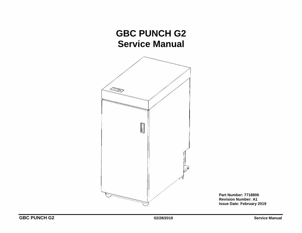
GBC PUNCH G2 Service Manual
Part Number: 7718806 Revision Number: A1 Issue Date: February 2019
GBC PUNCH G2 02/28/2019 Service Manual

NOTICE
All service documentation is supplied to external customers for informational purposes only. Service documentation is intended for use by certified, product trained service personnel only. GBC does not warrant or represent that such documentation is complete. GBC does not warrant or represent that it will notify or provide to such customer any future changes to this documentation. Service by the customer of the equipment, or modules, components, or parts of such equipment may void any otherwise applicable GBC warranties. If customer services such equipment, modules, components, or parts thereof, Customer releases GBC from any and all liability for actions by the Customer, and Customer agrees to indemnify, defend, and hold GBC harmless from any third party claims which arise directly or indirectly from such service.
Changes are periodically made to this document. Changes, technical inaccuracies, and typographic errors will be corrected in subsequent editions.
Copyright Notice
GBC ACCO Brands Inc. Four Corporate Drive Lake Zurich, IL 60047. USA
© Copyright 2014 by ACCO Brands Inc. All Rights reserved.
No part of this document may be photocopied or reproduced by any means, or translated to another language without prior written consent of GBC
All brand names, trademarks and registered trademarks are the property of their respective owners. Information contained within this document is subject to change without notice.
GBC products mentioned in this publication are registered trademarks of the ACCO Brands Corporation.
Table of Contents
Title Page
Service Call Procedures
Introduction............................................................... iii
1. Service Call Procedures ....................................1-1
2. Repair and Troubleshooting Procedures ........2-1
3. Punch Quality .....................................................3-1
4. Adjustment and Replacement Procedures......4-1
5. Parts List .............................................................5-1
6. General Procedures ...........................................6-1
7. Wiring Data .........................................................7-1
8. Installation ..........................................................8-1
Service Manual 02/28/2019 GBC PUNCH G2 ii

Introduction Section Contents
Title Page
Table of Contents..........................................................................ii Introduction ..................................................................................iii
Organization .............................................................................iv How to Use This Documentation ..........................................iv
Other Information ..................................................................... v The Use of Caution, Warning, and Note statements............ v
Safety Devices .........................................................................vi CAUTION .................................................................................vi Operational Safety....................................................................vi Important safeguards ..............................................................vii Acronyms.................................................................................vii
GBC PUNCH G2 02/28/2019 Service Manual iii

Organization This documentation is divided into eight sections. In addition to the Introduction, this documentation contains the following sections.
Section 1 Service Call Procedures
Section 2 Repairs and Troubleshooting Procedures
Section 3 Punch Quality
Section 4 Adjustments and Replacement Procedures
Section 5 Parts List
Section 6 General Procedures
Section 7 Wiring Data
Section 8 Installation Checklist
How to Use This Documentation
Introduction This section provides the Service Representative with information pertaining to the organization and use of this service documentation.
Section 1: Service Call Procedures This section is used by the Service Representative as a structured process for determining the type and sequence of actions that are performed during a service call. The Service Call Procedures section is designed to assist in the effective recognition of machine symptoms and problems, as well as to provide instructions for the maintenance and corrective actions that are required to return the machine to the full operating condition
Section 1 of this service documentation is the entry level for all service calls. The Service Representative should begin each service call with the Initial Action Procedure found in Section 1.
The Service Call Procedures section is composed of five integral elements: Initial Action, System Checks, Every Call Activities, Scheduled Maintenance, and Final Action.
The maintenance and diagnostic activities in this section may direct the Service Representative to perform additional service activities found elsewhere in the documentation, such as RTPs, Replacement Procedures, and Adjustment Procedures.
Section 2: Repairs and Troubleshooting Procedures (RTP) Section 2 of this documentation contains the Repair and Troubleshooting Procedures (RTPs) necessary to repair all faults associated with PUNCH G2. Service Representative will be referred to this section from some other section of this documentation during the service call. When a machine defect or fault has been resolved by using a RTP, the Service Representative should immediately return to the point in the service call from which Section 2 was entered. There are two types of RTPs found in Section 2. The first type is a RTP that is associated with the display of an error message in the RTP title. The second type is the Troubleshooting RTP. Troubleshooting RTPs are diagnostic procedures that are designed to address symptoms or problems that are not identified by, or associated with, a displayed status or fault code.
Section 3: Punch Quality This section is used to diagnose punch quality defect problems.
Section 4: Adjustments and Repair Procedures (ARP) This section contains all repair and adjustment procedures for the machine. Repairs (ARPs) and adjustments (ADJs) are identified by the use of a standard chain prefix number.
Section 5: Parts List This section contains a list of spare parts for the machine. All parts list page reference numbers begin with the letters “PL”, followed by a prefix number, a decimal point, and a sequential number used within the subsystem.
Service Manual 02/28/2019 GBC PUNCH G2 iv

Section 6: General Procedures This section contains procedures and information of a general nature that apply to the machine. This section is divided into two basic parts: General Procedures and General Information.
Section 7: Wiring Data This section contains support information to assist in the electrical diagnosis of machine problems and is a central location for electrical wiring diagrams. This section is used in conjunction with other diagnostic or maintenance procedures that are contained in other sections of the service documentation.
Section 8: Installation This section contains service information that supports the GBC PUNCH G2 Installation.
Other Information The Use of Caution, Warning, and Note statements Information relative to the completion of a task in a safe or thorough manner will be supplied in the form of a Caution, a Warning, or a Note statement. These statements are found throughout the service documentation.
Cautions, Warnings, and Note statements appear before the steps to which they apply. These statements should be read before continuing to the next step in a procedure.
Caution - A Caution statement indicates an operating or maintenance procedure, practice, or condition that, if not strictly observed, could result in damage to, or destruction of, equipment.
Warning - A Warning statement indicates an operating or maintenance procedure, practice, or condition that, if not strictly observed, could result in personal injury or loss of life.
Note - A Note statement indicates an operating or maintenance problem, practice, or condition that is necessary to accomplish a task efficiently.
GBC PUNCH G2 02/28/2019 Service Manual v

Safety Devices The GBC PUNCH G2 has door interlock to prevent personal injury when operating the machine.
When you open the Front Door, a Safety Interlock device automatically disables the drive motors until you close the Front Door.
When the Front Door is open, the Operator Panel displays the “CLOSE DOOR” message on the top line of the interface.
When you close the Front Door, the Operator Panel displays the “READY” message on the top line of the interface.
CAUTION Certain components in the GBC PUNCH G2 are susceptible to damage from electrostatic discharge. Observe all ESD procedures to avoid component damage.
Operational Safety Do not operate the GBC PUNCH G2 with the interlocks defeated.
Use care when a procedure in this Manual instructs you to “insert an Interlock Cheater into the Punch Door interlock Switch SW1,” in order to test the operation of a component.
WARNING Moving Parts, keep hands clear of nips and the belts when the Interlock Cheater is inserted.
This safety message means you might get seriously hurt or killed if you open the product and expose yourself to hazardous voltage. NEVER remove the screwed on covers. ALWAYS refer service requirements to qualified service personal
Service Manual 02/28/2019 GBC PUNCH G2 vi
A
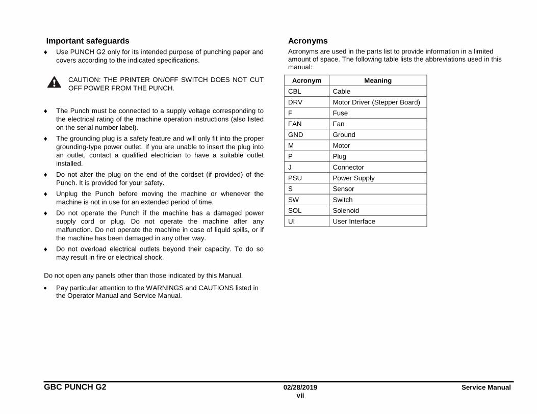
Important safeguards ♦ Use PUNCH G2 only for its intended purpose of punching paper and
covers according to the indicated specifications.
CAUTION: THE PRINTER ON/OFF SWITCH DOES NOT CUT OFF POWER FROM THE PUNCH.
♦ The Punch must be connected to a supply voltage corresponding to the electrical rating of the machine operation instructions (also listed on the serial number label).
♦ The grounding plug is a safety feature and will only fit into the proper grounding-type power outlet. If you are unable to insert the plug into an outlet, contact a qualified electrician to have a suitable outlet installed.
♦ Do not alter the plug on the end of the cordset (if provided) of the Punch. It is provided for your safety.
♦ Unplug the Punch before moving the machine or whenever the machine is not in use for an extended period of time.
♦ Do not operate the Punch if the machine has a damaged power supply cord or plug. Do not operate the machine after any malfunction. Do not operate the machine in case of liquid spills, or if the machine has been damaged in any other way.
♦ Do not overload electrical outlets beyond their capacity. To do so may result in fire or electrical shock.
Do not open any panels other than those indicated by this Manual.
• Pay particular attention to the WARNINGS and CAUTIONS listed in the Operator Manual and Service Manual.
Acronyms Acronyms are used in the parts list to provide information in a limited amount of space. The following table lists the abbreviations used in this manual:
Acronym Meaning CBL Cable DRV Motor Driver (Stepper Board) F Fuse FAN Fan GND Ground M Motor P Plug J Connector PSU Power Supply S Sensor SW Switch SOL Solenoid UI User Interface
GBC PUNCH G2 02/28/2019 Service Manual vii

Notes:
Service Manual 02/28/2019 GBC PUNCH G2 viii

1. Service Call Procedures Section Contents
Service Call Procedures
Title Page CALL FLOW.................................................1-2 INITIAL ACTION ..........................................1-3 SYSTEM CHECKS ......................................1-3 EVERY CALL ACTIVITIES..........................1-4 SCHEDULED MAINTENANCE ...................1-4 PREVENTATIVE MAINTENANCE ..............1-4 PUNCH G2 Maintenance Schedule ............1-5
Customer Maintenance.....................1-5 Periodic Maintenance .......................1-5 Periodic Replacement.......................1-6
HFSI.............................................................1-7 FINAL ACTION ............................................1-7
GBC PUNCH G2 4/14/2017 Service Call Procedures 1-1 Section Contents

!
!
CALL FLOW INITIAL ACTION
This step is used to gather information about the reason for the call, to determine the machine condition, and to run a punch sample if possible
SYSTEM CHECKS This step is used to suggest a direction for using the information obtained during Initial Action. You can then repair and verify the repair of the problem. This step may also provide information to assist in the identification of new problems and suggest actions to take to repair/resolve them.
FINAL ACTIONS This step is used to ensure that the punch quality, the punch performance, and the punch appearance are satisfactory. It will also provide direction to help complete administrative tasks.
Service Call Procedures 4/14/2017 GBC PUNCH G2 1-2

INITIAL ACTION At the start of every service call, you should perform the following.
1. If called for a problem, determine the exact nature of the service complaint. Determine the paper type and quality, especially as it relates to curl and identify if any media changes correlate with the emergence of the customer issue.
2. Do GP 6.1.9 PUNCH CYCLES to note down the total machine punch cycles.
3. Do GP 6.1.8 DIE CYCLES Procedure to check the cycle life on the Die Set installed in the PUNCH G2.
4. If any of the Die Set life cycles have exceeded 750,000 sheets (cycles) go to Section 3 and check the Hole Quality.
DIE CYCLES
500,129
• If the Hole Quality is acceptable monitor the Hole Quality frequently to ensure that the Hole Quality is okay.
• If the Hole Quality is not acceptable replace the Die Set.
5. Determine if the customer uses only one Die Set pattern (style) or if they switch between different patterns.
6. Determine the last time the Die Set was lubricated. Perform GP 6.7.3 to lubricate die if necessary.
7. Determine the date of the last preventative maintenance performed on the punch system. Perform Preventative Maintenance using the PUNCH G2 Maintenance Schedule on page 1-5 if needed.
8. Vacuum all paper path, punch, dust box area of scrap/debris.
SYSTEM CHECKS Purpose
Direct repair activity for problems found in Initial Action.
PROCEDURE
1. Select the appropriate condition from the list below and perform the directed service actions. • Replace any obviously broken parts.
• If there is a Punch Quality problem, go to 3.2 Initial Step in Section 3.
• If there is a Fault Code, go to Section 2 Table of Contents. Locate and perform the FAULT CODE RTP associated with the Fault Code.
• If there is an Operator Message that will not clear, go to Section 2 Table of Contents. Locate and perform the steps in the OPERATOR MESSAGE RTP associated with the Operator Message.
• If there is No Fault Code or Operator Message associated with the problem, go to Section 2 Table of Contents. Locate and perform the OTHER FAULTS RTP which most closely matches the problem described by the customer.
• If the problem is not repeatable, operate the PUNCH G2 in the same job conditions the customer used and recheck for a problem in the categories listed here.
• If the problem is still not reproduced, examine the Machine Service Log and note any repeating faults. Refer to the RTP for those faults in Section 2 to check if the RTP relates to the customer problem. If so, perform the RTP.
• If none of the above situations apply, go to EVERY CALL ACTIVITIES.
2. Verify that the problem is corrected and go to EVERY CALL ACTIVITIES.
GBC PUNCH G2 4/14/2017 Service Call Procedures 1-3

EVERY CALL ACTIVITIES Purpose
List service activities required on every service call.
PROCEDURE
1. Perform GP 6.5 Operational Inspection. 2. Perform GP 6.6 Internal Inspection. 3. Perform GP 6.8 External Cleaning. 4. Perform GP 6.9 Internal Cleaning 5. Perform GP 6.10 Base Cleaning 6. Perform GP 6.11 Chip Bin Cleaning 7. Perform GP 6.12 Die Guide Cleaning 8. Perform GP 6.17 Optical Sensor Cleaning
Service Call Procedures
SCHEDULED MAINTENANCE PROCEDURE
1. Do GP 6.1.8 DIE CYCLES Procedure to check the cycle life on the Die Set installed in the PUNCH G2.
2. See the PUNCH G2 Maintenance Schedule on page 1-5.
PREVENTATIVE MAINTENANCE Purpose
If operating properly, the PUNCH G2 will punch the same types of copy paper and cover materials handled by the printer and run at the same speed.
Hole quality will vary between different grades of paper.
See the PUNCH G2 Maintenance Schedule on page 1-5.
4/14/2017 GBC PUNCH G2 1-4

PUNCH G2 Maintenance Schedule Note: cycles = sheets of paper punched, not impressions.
Customer Maintenance Area/Unit Period See: Measures Remarks
Punch Die 100K Die cycles GP 6.7.3 Lubrication Oil the punch pins Die set shoulder bolts 200k Die cycles GP 6.7.4 Inspect and lubricate Grease
Periodic Maintenance Area/Unit Period See: Measures Remarks
Punch Drive Cams 5000K cycles GP 6.20 Inspect and lubricate Punch Motor Belt 1,000K cycles GP 6.21 Inspect Alignment Stepper Belt 1,000K cycles GP 6.21 Inspect Steering Carriage Belt 1,000K cycles GP 6.21 Inspect Steering Rollers 1,000K cycles GP 6.14 Inspect and clean Alcohol and Cloth Punch Clutch 1,000K GP 6.24 Clean Cloth Sensors S1 to S28 500K GP 6.17 Clean Air Drive and Idler Rollers 1,000K cycles GP 6.14 & GP 6.15 Inspect and clean Alcohol & cloth Solenoid Module 1,000K cycles GP 6.22 Inspect Idler Panel Closing Magnet Latches
1,000K cycles GP 6.16 Inspect
Acceleration Panel Latch 1,000K cycles GP 6.16 Inspect Paper Path Drive Timing Belts
1,000K cycles GP 6.21 Inspect and Adjust if necessary
Diverter Solenoid Assembly 1,000K cycles GP 6.25 Inspect Die Set Recognition Board Clips
1,000K cycles GP 6.26 Clean Cloth
Alignment Carriage Rails 500K Cycles GP 6.24 Inspect and Clean Air and Cloth Die Lock Mechanism and Die Rail Springs
1000K Cycles GP 6.27 Inspect
Die guide (rail) cleaning 500K cycles GP 6.12 Clean Vacuum Paper path 1000K cycles GP 6.18 & GP 6.19 Inspect and clean Cloth
GBC PUNCH G2 4/14/2017 Service Call Procedures 1-5

Periodic Replacement Area/Unit Part Number No. of pcs. Rough Standard Remarks
Die Set See PL 5-1 1 750K Cycles Replace as needed Punch Module 7715710 (115V)
7715810 (230V) 1 15M Cycles Replacement
Solenoid module 7715223 6 5M Cycles Replacement
Service Call Procedures 4/14/2017 GBC PUNCH G2 1-6

HFSI Replace the part if over threshold (See Pages 1-5 and 1-6).
Note down the DIE CYCLE counts (GP 6.1.8) and PUNCH CYCLE count (GP 6.1.9) when performing HFSI.
FINAL ACTION This section explains the actions a technician should take at the end of every service call. With each step, verify that the system runs smoothly and paper jam free.
Purpose
Ensure acceptable punch quality, punch performance, and punch appearance are satisfactory and to complete administrative tasks.
PROCEDURE
1. Install/close all covers and doors. 2. Inspect each Die Set visually and lubricate as needed. See GP 6.7,
Die Set Service 3. Use the customer’s primary Die Set pattern to run 200 simplex printed
test sheets through the punch mode and examine the output for clean hole quality and even hole alignment.
4. Use the customer’s primary Die Set pattern to run 200 duplex printed test sheets through the punch mode and examine the output for clean hole quality and even hole alignment.
5. Use any of the customer’s secondary Die Set pattern to run 100 simplex printed test sheets through the punch mode and examine the output for clean hole quality and even hole alignment.
6. Run 100 sheets simplex and 100 sheets duplex through the punch bypass mode.
7. Clean out all paper chips (chad) and paper dust from the chip tray, the bottom of the machine and from the floor around the bottom of the machine. See GP 6.10 Base Cleaning.
8. Explain to the customer the service work that was performed and ensure they are satisfied before you close the call.
Service Call Close
1. Record your service activities along with the Punch Cycle Count.
GBC PUNCH G2 4/14/2017 Service Call Procedures 1-7
Notes:
Service Call Procedures 4/14/2017 GBC PUNCH G2 1-8

2. Repair and Troubleshooting Procedures (RTPS) Section Contents
Introduction.......................................................................................... 2-3 Title Page
PAPER JAM J412 .........................................................................2-14
Troubleshooting Start Guide ................................................................ 2-4 OPERATOR MESSAGES..................................................................... 2-5 Top Row of Text................................................................................... 2-5 Bottom Row of Text.............................................................................. 2-5 Check Die............................................................................................. 2-6 Close Door ........................................................................................... 2-8 Chip Tray Out ....................................................................................... 2-9 Chip Tray Out message is not displayed when the Chip tray is out .... 2-9 Chip Tray Full ..................................................................................... 2-10
ERROR CODES .................................................................................. 2-11 ERROR E450 DIE TYPE/CODE INVALID......................................... 2-11 ERROR E451 DIE ENCRYPTION ERROR .................................... 2-12 ERROR E452 INCOMPATIBLE DIE............................................... 2-12
FAULT CODES ................................................................................... 2-13 Fault Code Text.................................................................................. 2-13 Fault Code Areas ............................................................................... 2-13 Fault Code and Jam Type.................................................................. 2-14
PAPER JAM J126 ......................................................................... 2-14 PAPER JAM J101 ......................................................................... 2-14 PAPER JAM J125 ......................................................................... 2-14 PAPER JAM J202 ......................................................................... 2-14 PAPER JAM J203 ......................................................................... 2-14 PAPER JAM J204 ......................................................................... 2-14 PAPER JAM J220 ......................................................................... 2-14 PAPER JAM J221 ......................................................................... 2-14 PAPER JAM J218 ......................................................................... 2-14 PAPER JAM J219 ......................................................................... 2-14 PAPER JAM J305 ......................................................................... 2-14 PAPER JAM J316 ......................................................................... 2-14 PAPER JAM J317 ......................................................................... 2-14 PAPER JAM J411 ......................................................................... 2-14
PAPER JAM J413 .........................................................................2-14 PAPER JAM J414 .........................................................................2-14 PAPER JAM J415 .........................................................................2-14 PAPER JAM J506 .........................................................................2-14 PAPER JAM J507 .........................................................................2-14 PAPER JAM J508 .........................................................................2-14 PAPER JAM J509 .........................................................................2-14 PAPER JAM J510 .........................................................................2-14 PAPER JAM J622 .........................................................................2-14 PAPER JAM J623 .........................................................................2-14 PAPER JAM J624 .........................................................................2-14 PAPER JAM J625 .........................................................................2-14 PAPER JAM J999 .........................................................................2-14
Jam Types ..........................................................................................2-15 1 POWER FAULTS..........................................................................2-16 RTP 1.1 No AC Power....................................................................2-16 RTP 1.2 No DC Power....................................................................2-18 RTP 1.3 Operator Panel Does Not Illuminate.................................2-19 RTP 1.4 Operator Panel Does Not Show Text ...............................2-20 RTP 1.5 Up, Down, Enter Keys Do Not Respond ..........................2-21 2 PAPER JAMS ...............................................................................2-22 RTP 2.1 Jam Type A ......................................................................2-22 RTP 2.2 Jam Type B ......................................................................2-23 RTP 2.3 Jam Type C ......................................................................2-24 RTP 2.4 Jam Type D ......................................................................2-26 RTP 2.5 Jam Type E ......................................................................2-27 RTP 2.6 Jam Type F.......................................................................2-28 RTP 2.7 Multiple Sheets Jammed - Die Pins Partially Through the
Sheets ..............................................................................2-29 RTP 2.8 Checking Obstruction in Paper Path ................................2-30
GBC PUNCH G2 02/28/2019 RTPS 2-1 Section Contents

3 SENSOR CHECKS....................................................................... 2-33 RTP 3.1 Check Sensors S1, S2, S3, S4, S5, S22, S23, S24, S25, S26
......................................................................................... 2-33 Sensor Cables............................................................................... 2-35
RTP 3.2 Check Sensors S6 to S21 ................................................ 2-36 RTP 3.3 Checking Sensor S28 Align Home Sensor ...................... 2-41 4 SOLENOID CHECKS ................................................................... 2-43 RTP 4.1 Check Solenoid SOL 1..................................................... 2-43 RTP 4.2 Check Solenoid SOL 2..................................................... 2-43 RTP 4.3 Check Solenoids SOL 3 to SOL 8.................................... 2-44 5 MOTOR CHECKS......................................................................... 2-46 RTP 5.1 Checking Stepper Motors................................................. 2-46 6 OTHER FAULTS........................................................................... 2-48 RTP 6.1 Die Set Will Not Slide In or Out Easily ............................. 2-48 RTP 6.2 Punch Overheats ............................................................. 2-48
GBC PUNCH G2 02/28/2019 RTPS 2-2

Introduction This section contains the Repair and Troubleshooting Procedures (RTPs).
Organization This section lists the Repair Analysis Procedure (RTP) for each Operator Message and Fault Code. In some cases, one Repair Analysis Procedure may apply to several Fault Codes. In those cases, subsequent Fault Codes include a cross reference to the pertinent RTP.
To help you locate each component, the Repair and Troubleshooting Procedures include part locators (PL x.y) that refer to the pertinent page in Section 5, Part List.
GBC PUNCH G2 02/28/2019 RTPS 2-3

Troubleshooting Start Guide Always do this RTP first.
Attempt to retrieve the number of Punch cycles (GP6.1.7) and note it down.
1. If the customer says that they have a punch quality problem, go to the Table of Contents for Section 3, and find the Punch Quality RTP that most closely fits the customer’s description of the problem.
2. Power off, then power on the Punch. Check that the Punch runs properly in all modes. The Punch runs properly. Yes- Go to INITIAL ACTION in Section 1; No- Go to Step 3.
3. Check the top row of text on the Operator Interface to determine if there is there an operator message. There is a operator message on line 1. Yes- Go to the Table of Contents for Section 2 and locate the RTP for that status message; No- Go to Step 4.
4. Check the top row of text on the Operator Interface to determine if there is there an Error Code. There is a Error Code on line 1. Yes- Go to the Table of Contents for Section 2 and locate the RTP for that fault code; No- Go to Step 5.
5. Check the top row of text on the Operator Interface to determine if there is there a Fault Code. There is a Fault Code on line 1. Yes- Go to the Table of Contents for Section 2 and locate the RTP for that fault code; No- Go to Step 6.
6. Is there a Power Fault (No AC Power, No DC Power, No power to Control Board, Operator Panel Does Not Illuminate). There is a Power Fault.
Yes- Go to the Table of Contents for Section 2 and locate the RTP for that power fault; No- Go to Step 7.
7. Is the problem one of the faults listed in Section 2 that does not generate a message on the Operator Interface (Die Set Will Not Slide Out Easily, Punch Overheats). The problem one of the known faults that does not generate a message
Yes- Go to the Table of Contents for Section 2 and locate the OTHER FAULTS RTP for that problem; No- Go to Step 8.
8. Can the operator use the Operator Interface to operate the equipment? The operator can use the Operator Interface to operate the equipment.
Yes- Go to INITIAL ACTION in Section 1; No- Check with the customer to determine what symptom they have. Go to the Table of Contents for Section 2 and find the RTP that most closely fits the customer’s description of the problem.
GBC PUNCH G2 02/28/2019 RTPS 2-4

OPERATOR MESSAGES The Operator Panel displays status messages and fault codes on two rows of text.
READY
SINGLE PUNCH
Top Row of Text Message Description Action
CLOSE DOOR The Front Door is open. Close the Front Door.
READY The system is ready. Use the Punch to punch paper or bypass the Punch.
Bottom Row of Text Message Description Action
CHECK DIE Check the Die Set Check the Die Set
BYPASS The Punch is in Bypass Mode Use the Punch in Bypass Mode.
SINGLE PUNCH The machine is in Single Punch Mode Use the machine in Single Punch Mode.
DOUBLE PUNCH The machine is in Double Punch Mode The machine is in Double Punch Mode
GBC PUNCH G2 02/28/2019 RTPS 2-5

Check Die The CHECK DIE message indicates that the Die Set is either missing or not fully installed.
1. Open the Front Door. 2. Unlock the Dieset, and remove the Dieset (see PUNCH G2 User
Manual). 3. Re-insert the Dieset and lock the lock it in place.
This clears the fault code. Yes- Normal operation; No- Go to step 4.
4. Do ARP 1.6 to remove the Rear Cover, and check if the Dieset Recognition Reader Board Cable (7715495) is connected properly at both ends (see PL 6.4 or Section 7 wiring). Note that the connector has 4 pins, and it should be properly inserted. This clears the fault code. Yes- Normal operation; No- Go to step 5.
5. Clean the Dieset Recognition Board in the Die and the Die set Recognition Reader Board in the machine. This clears the fault code.
Yes- Normal operation; No- Go to step 6
6. Check if the Dieset Recognition Reader Board Spring Clips contact the Dieset Recognition Board in the Dieset.
If Spring Clips are broken, Replace Dieset Recognition Reader Board. If the springs clips do not contact the Dieset Recognition Board, do ADJ 1.6 Dieset Recognition Board Adjustment.
This clears the fault code. Yes- Normal operation; No- Go to step 7.
7. If there is another Dieset, check if that Dieset shows the same message. Dieset shows the same message.
Yes- If the error is still present with all the diesets, do GP 6.2.12 FIRMWARE UPGRADE Procedure to reflash the firmware.
No- If the issue is with just one Dieset, then escalate to next level
This clears the fault code. Yes- Normal operation; No- Go to Step 8.
8. Replace the Dieset Recognition Cable #7715495 (Section 7 Wiring). This clears the fault code. Yes- Normal operation; No- Go to step 9.
GBC PUNCH G2 02/28/2019 RTPS 2-6

9. Do ARP 3.27 to Replace the Dieset Recognition Reader Board Assembly (PL 4.9). This clears the fault code. Yes- Normal operation; No- Go to step 10.
10. Do ARP 5.1 Main Control Board Replacement to Replace the Main Control Board (PL 6.1). This clears the fault code. Yes- Normal operation; No- Escalate to next level.
GBC PUNCH G2 02/28/2019 RTPS 2-7

Close Door The CLOSE DOOR message indicates that the Front Door is open or not completely closed.
1. Check that the Front Door is closed. The Front Doors is closed. Yes- Go to step 2; No- Close the Front Door and return to normal operation.
2. Insert an Interlock Cheater into the Punch Door interlock Switch SW4 (PL 1.2).
WARNING Moving Parts, keep hands clear of nips and the belts when the Interlock Cheater is inserted.
3. Check if the Close Front Door message is displayed. The Close Front Door message is displayed. Yes- Go to Step 4; No- Do ADJ 1.1 Door Latch adjustment and return to normal operation
4. Do ARP 1.6 to remove the Rear Cover and check if the Interlock Cable 7715487 is connected at J8 at the Main Control Board (PL 6.1). Interlock Cable is connected at J8. Yes- Go to step 5; No- Make the connection and return to normal operation.
5. Switch OFF the machine and unplug the Power Cord.
6. Remove the M4 Nuts (2) that hold the Interlock Switch Bracket (PL 1.2) and inspect the connections at the Interlock Switch (see ARP 1.11 Interlock switch Replacement for photos of the connections). Interlock cable is connected at the Interlock switch. Yes- Go to step 7; No- Make the connection and return to Normal operation.
7. Inspect the connection at J17 at the Main Control Board. It is a 16 pin connector to a 16 pin terminal. The connection at J17 is good. Yes- Go to step 8; No- Make the connection and return to normal operation.
8. Do GP 6.2.12 Firmware Upgrade procedure to re-flash the Firmware for Advanced Punch Pro, Re-flashing the firmware clears the fault. Yes- Return to normal operation; No- Go to step 9
9. Do ARP 1.11 Interlock Switch Replacement to Replace the Interlock switch. Replacing the switch clears the fault. Yes- Return to normal operation; No- Go to step 10.
10. Replace Interlock Switch Cable 7715487. Replacing the cable clears the fault. Yes- Return to normal operation; No- Replace the Main Control Board (PL 6.1).
GBC PUNCH G2 02/28/2019 RTPS 2-8

Chip Tray Out This message is displayed when the Chip tray is removed from the machine or when the chip tray is not fully inserted.
Use this procedure when the Chip Tray Out message is displayed when the Chip tray is inserted.
1. Open the Front door and insert the Chip Tray firmly. This clears the fault. Yes- Return to normal operation; No- Go to step 2
2. Inspect if the Spring Clip of the Chip tray home switch. If the Spring Clip is broken, do ARP 3.2 Chip Tray Home Switch Replacement. This clears the fault. Yes- Return to normal operation; No- Go to step 3
3. Do GP 6.2.12 Firmware Upgrade procedure to re-flash the Firmware for Advanced Punch Pro, Re-flashing the firmware clears the fault. Yes- Return to normal operation; No- Go to step 4
4. Do ARP 3.2, Replace Chip Tray Home Switch, This clears the fault. Yes- Return to normal operation; No- Go to step 5
5. Replace Cable 7715485 (See Section 7 Wiring). This clears the fault. Yes- Return to normal operation; No- Do ARP 5.1 Main Control Board Replacement to Replace the Main Control Board (PL 6.1).
Chip Tray Out message is not displayed when the Chip tray is out This message is displayed when the Chip Tray Out message is not displayed when the Chip tray is out.
1. Make sure the (2) spade connectors to the Chip tray home switch is securely inserted. (see ARP 3.2 for details) Connectors are securely connected. Yes- Go to step 2; No- Securely connect the (2) spade connectors
2. Do ARP 1.6 to remove the Rear Cover and check the 7715485 cable is connected to J27 at the Main Control Board (Section 7 Wiring)
See the Sensor Cables table on page 2-35 for cable numbers.
The connection is good. Yes- Go to step 3; No- Make the connection and return to normal operation.
3. Do GP 6.2.12 Firmware Upgrade procedure to re-flash the Firmware for Advanced Punch Pro, Re-flashing the firmware clears the fault. Yes- Return to normal operation; No- Go to step 4
4. Do ARP 3.2, Replace Chip Tray Home Switch, This clears the fault. Yes- Return to normal operation; No- Go to Step 5
5. Replace Cable 7715485. This clears the fault. Yes- Return to normal operation No- Do ARP 5.1 Main Control Board Replacement to Replace the Main Control Board (PL 6.1).
GBC PUNCH G2 02/28/2019 RTPS 2-9

Chip Tray Full The Chip Tray full message is displayed when the punch chips fill the chip 6. Do ARP 3.3 to Replace the Chip Level Emitter (PL 2.5). tray and the capacity is exceeded. This clears the fault 1. Remove the Chip tray and empty the punch chips. Yes- Return to normal operation No- Go to Step 7
This clears the fault. Yes- Return to normal operation No- Go to Step 2 7. Do ARP 3.3 to Replace the Chip Level Receiver (PL 2.5).
This clears the fault. 2. Clean the Chip Level Emitter and Chip Level Receiver Sensors Yes- Return to normal operation No- Go to Step 8.
(PL 2.5). Ensure the sensor path is clear with the Chip Tray installed.
The Chip Level Emitter and Receiver Sensors are located in the Chip 8. Replace cable 7715485 (Section 7 Wiring) Tray cavity in the lower portion of the front frame. See ARP 3.3 and This clears the fault. 3.4 for more details. Yes- Return to normal operation This clears the fault No- Do ARP 5.1 to Replace the Main Control Board (PL 6.1). Yes- Retun to normal operation No- Go to Step 3
3. Remove the Chip Tray and check if the Chip level Emitter and Chip level Receiver are plugged in.
The Chip level emitter and receiver are located in the Chip tray cavity in the lower portion of the front frame. See ARP 3.3 and ARP 3.4 for more details.
See the Sensor Cables table on page 2-35 for cable numbers.
The connections are good. Yes- Do ARP 1.6 to remove the Rear Cover and go to Step 4. No- Make the connection and return to normal operation.
4. Check if Cable 7715485 is connected to J27 at the Main Control Board (Section 7 Wiring). The connection is good. Yes- Go to Step 5 No- Make the connection and return to normal operation.
5. Do GP 6.2.12 Firmware Upgrade procedure to re-flash the Firmware for Advanced Punch Pro, Re-flashing the firmware clears the fault. Yes- Return to normal operation No- Go to Step 6
GBC PUNCH G2 02/28/2019 RTPS 2-10

ERROR CODES The User Interface displays two error messages when the firmware detects that an item is bad or not functioning. There are only 3 error codes.
Error Code Description E450 Die type/code invalid E451 Die encryption error E452 Incompatible die
ERROR E451
DIE ENCRYPTION ERROR
The top row of text displays the fault error message number the bottom row displays the description.
NOTE: If there is an ERROR message when downloading firmware (either RM_XX_XX.BIN or RC_XX_XX.BIN file), the firmware should be downloaded again.
ERROR E450 DIE TYPE/CODE INVALID This means that the die type is incorrectly set in the dieset.
1. Open the Front Door. 2. Remove the Die Set (see PUNCH G2 User Manual). 3. Check that the Die Set is the correct Die Set for the Punch.
The Die Set is the correct die Set for the Punch. Yes- Go to Step 4 No- Replace the Die Set
4. Slowly re-insert the die set into the machine and close the front door. This clears the fault. Yes- Resume normal operation No- Replace the Die Set and escalate to next level.
GBC PUNCH G2 02/28/2019 RTPS 2-11

ERROR E451 DIE ENCRYPTION ERROR This means that the die is not a GBC certified die or the dieset was not read properly.
1. Open the Front Door. 2. Remove the Die Set (see PUNCH G2 User Manual). 3. Check that the Die Set is the correct Die Set for the Punch.
The Die Set is the correct die Set for the Punch. Yes- Go to Step 4 No- Replace the Die Set
4. Slowly re-insert the die set into the machine and close the front door. This clears the fault. Yes- Resume normal operation No- Replace the Die Set and escalate to next level.
ERROR E452 INCOMPATIBLE DIE This means the die is not a certified Ricoh die.
1. Open the Front Door. 2. Remove the Die Set (see PUNCH G2 User Manual). 3. Check that the Die Set is the correct Die Set for the Punch.
The Die Set is the correct die Set for the Punch. Yes- Go to Step 4 No- Replace the Die Set
4. Slowly re-insert the die set into the machine and close the front door. This clears the fault. Yes- Resume normal operation No- Replace the Die Set and escalate to next level.
GBC PUNCH G2 02/28/2019 RTPS 2-12
I I
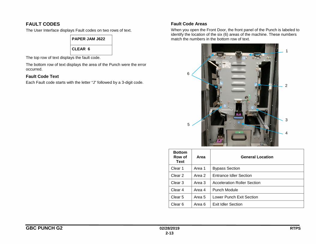
FAULT CODES Fault Code Areas The User Interface displays Fault codes on two rows of text. When you open the Front Door, the front panel of the Punch is labeled to
identify the location of the six (6) areas of the machine. These numbers PAPER JAM J622 match the numbers in the bottom row of text.
CLEAR 6
The top row of text displays the fault code.
The bottom row of text displays the area of the Punch were the error occurred.
6Fault Code Text Each Fault code starts with the letter “J” followed by a 3-digit code.
5
4
2
3
1
Bottom Row of
Text Area General Location
Clear 1 Area 1 Bypass Section
Clear 2 Area 2 Entrance Idler Section
Clear 3 Area 3 Acceleration Roller Section
Clear 4 Area 4 Punch Module
Clear 5 Area 5 Lower Punch Exit Section
Clear 6 Area 6 Exit Idler Section
GBC PUNCH G2 02/28/2019 RTPS 2-13

Fault Code and Jam Type The following table lists each Fault Code, and the corresponding Jam Type.
The table on the next page shows the RTP for each jam type.
To clear a jam, see the second line of the LCD display.
The display will indicate which area(s) to Clear jammed paper (Example-CLEAR 1,2,3).
Fault Code Jam Type PAPER JAM J126 F
PAPER JAM J101 A (if punch job); F (if bypass job)
PAPER JAM J125 A (if punch job); F (if bypass job)
PAPER JAM J202 B
PAPER JAM J203 B
PAPER JAM J204 B
PAPER JAM J220 B
PAPER JAM J221 B
PAPER JAM J218 B
PAPER JAM J219 B
PAPER JAM J305 C
Fault Code Jam Type PAPER JAM J316 C
PAPER JAM J317 C
PAPER JAM J411 C
PAPER JAM J412 C
PAPER JAM J413 C
PAPER JAM J414 C
PAPER JAM J415 C
PAPER JAM J506 D
PAPER JAM J507 D
PAPER JAM J508 D
PAPER JAM J509 D
PAPER JAM J510 D
PAPER JAM J622 E
PAPER JAM J623 E
PAPER JAM J624 E
PAPER JAM J625 E (if punch Job); F (if bypass job)
PAPER JAM J999 Unspecified jam
The Jam Types table on the next page describes each Jam type. Read the description and make sure it matches the nature of the paper jam in the machine. If it does not match the description, chose the appropriate RTP based on the information provided below.
If there is no jammed paper in the unit and there is a Fault code, use the RTP based on the jam type specified on the Fault Code and Jam Type table above.
GBC PUNCH G2 02/28/2019 RTPS 2-14

TYPE CLASSIF IC ATION L .E - L EAD EDGE PO SITION SHO\./N I N RED T.E- TRAIL EDGE POSITION SHO\./N IN BLUE
L .E. BEFORE Nl L.E PAST 1 BUT BEFORE N5 L.E. PAS T N5 BUT BEFORE N6 AND N7
8 8 r Ot NIJ NJ2 / N
NJO N2
N9 N3
NB N4
L .E. PAS T N6 AND N7 BU T T.E. BE FORE OR JUS T PAS T N6 /N7
NJ O N2
JAM TYPE C
N9 N3
NB N4
T.E. PAS T N6 AND N7 JAM I N BYPASS MODE
Jam Types The following table lists each paper jam type. It lists Jam Type (A, B, C, etc.) and the corresponding description (position of first jammed sheet).
Jam Type Description RTP Jam Type A The lead edge of the first jammed sheet is stopped by nip N1 Do RTP 2.1 Jam Type A
Jam Type B The lead edge of the first jammed sheet is stopped past nip N1 but before nip N5. Do RTP 2.2 Jam Type B
Jam Type C The lead of the first jammed sheet is stopped past nip N5 but before Steering Rollers N6 and N7 Do RTP 2.3 Jam Type C
Jam Type D The lead edge of the first jammed sheet is past N6 and N7 but its trail edge is before or just past N6/N7. Do RTP 2.4 Jam Type D
Jam Type E The trail edge of the first jammed sheet is past Steering rollers N6 and N7 Do RTP 2.5 Jam Type E
Jam Type F The paper jam is in the Bypass Assembly. Do RTP 2.6 Jam Type F
GBC PUNCH G2 02/28/2019 RTPS 2-15

1 POWER FAULTS
RTP 1.1 No AC Power Use this RTP when there is no AC power to the PUNCH G2. The Operator Panel does not illuminate and the PUNCH G2 does not operate.
1. Check that the Power Cord is attached to the AC Filter on the rear of the machine. Power Cord is attached to AC Filter. Yes- Go to Step 2 No- Attach the Power Cord.
2. Check that the Power Cord is properly plugged into the wall. Power Cord is plugged into the wall. Yes- Go to Step 3 No- Plug in the Power Cord.
3. Disconnect the Power Cord from the power source and check for input voltage - 110 VAC (60 Hz) or 240 VAC (50 Hz) - at the power receptacle. AC power is present at the recepticle. Yes- Go to Step 4 No- If there is no power at the outlet, ask the customer to call an
electrician to restore the AC power.
4. Reconnect the power cord to PUNCH G2.
5. Check that Ground Wire 7715525 is connected to the ground and to the AC Filter.
Ground Wire 7715525 is connected.
Yes- Go to Step 6 No- Connect Ground Wire 7715525.
6. Check that Cable 7715498 is connected at the AC filter.
Cable 7715498 is connected at the AC filter.
Yes- Go to Step 7 No- Connect Cable 7715498.
7. Check that Cable 7715498 is connected to the Communication board at Pin J14.
Cable 7715498 is connected to the Communication board.
Yes- Go to Step 8 No- Connect Cable 7715498 to the ELCB.
8. Check the Fuse on the Communications Board.
Fuse is okay
Yes- Go to Step 9 No- Replace the Fuse (PL 6.1).
9. Check that Wire 7715494 is connected to Pin J15 on the Communications Board.
Wire 7715494 is connected to Pin J15 on the Communications Board.
Yes- Go to Step 10 No- Connect Wire 7715494 to Pin J15 on the Communications
Board.
10. Check that Wire 7715494 is connected to Pin J4 on the Control Board.
Wire 7715494 is connected to Pin J4 on the Control Board.
Yes- Go to Step 11 No- Connect Wire 7715494 to Pin J4 on the Control Board.
11. Check for input voltage - 110 VAC (60 Hz) or 240 VAC (50 Hz) - at the AC Filter. There is AC power at the AC Filter. Yes- Go to Step 12 No- Replace the AC power cord to the AC Filter (PL 7.1).
12. Check for input voltage - 110 VAC (60 Hz) or 240 VAC (50 Hz) – on Cable 7715498 at the AC Filter (BRN & BLU wires). There is AC power on Cable 7715498 at the AC Filter. Yes- Go Step 13 No- Replace AC FILTER (PL 6.1).
GBC PUNCH G2 02/28/2019 RTPS 2-16

13. Check for input voltage - 110 VAC (60 Hz) or 240 VAC (50 Hz) – on Cable 7715498 at the Pin J14 on the Communications Board (BRN & BLU wires). There is AC power on Cable 7715498 at Pin J14 on the Communications Board. Yes- Go to Step 14 No- Replace Cable 7715498.
14. Check for input voltage - 110 VAC (60 Hz) or 240 VAC (50 Hz) – on Cable 7715494 at Pin J15 on the Communications Board (BLU & BRN wires). There is AC power on Cable 7715494 at Pin J15 the Communications Board. Yes- Go to Step 15 No- Replace the Communications Board (ARP 5.2).
15. Check for input voltage - 110 VAC (60 Hz) or 240 VAC (50 Hz) – on Cable 7715494 at Pin J4 on the Control Board (BLU & BRN wires). There is AC power on Cable 7715494 at Pin J4 the Control Board.
Yes- Replace the Main Control Board (ARP 5.1).
No- Replace Cable 7715494
GBC PUNCH G2 02/28/2019 RTPS 2-17
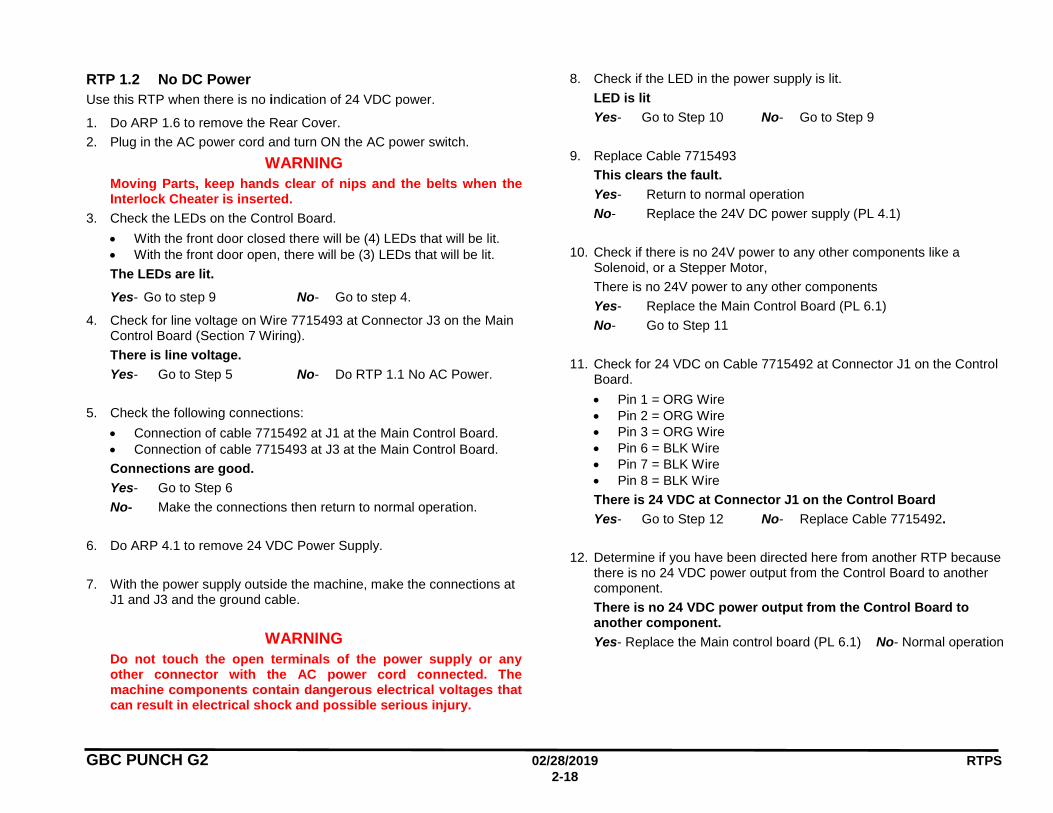
RTP 1.2 No DC Power 8. Check if the LED in the power supply is lit. Use this RTP when there is no indication of 24 VDC power. LED is lit
1. Do ARP 1.6 to remove the Rear Cover. 2. Plug in the AC power cord and turn ON the AC power switch.
WARNING Moving Parts, keep hands clear of nips and the belts when the Interlock Cheater is inserted.
3. Check the LEDs on the Control Board. • With the front door closed there will be (4) LEDs that will be lit. • With the front door open, there will be (3) LEDs that will be lit. The LEDs are lit.
Yes- Go to step 9 No- Go to step 4.
4. Check for line voltage on Wire 7715493 at Connector J3 on the Main Control Board (Section 7 Wiring). There is line voltage. Yes- Go to Step 5 No- Do RTP 1.1 No AC Power.
5. Check the following connections: • Connection of cable 7715492 at J1 at the Main Control Board. • Connection of cable 7715493 at J3 at the Main Control Board. Connections are good. Yes- Go to Step 6 No- Make the connections then return to normal operation.
6. Do ARP 4.1 to remove 24 VDC Power Supply.
7. With the power supply outside the machine, make the connections at J1 and J3 and the ground cable.
WARNING Do not touch the open terminals of the power supply or any other connector with the AC power cord connected. The machine components contain dangerous electrical voltages that can result in electrical shock and possible serious injury.
Yes- Go to Step 10 No- Go to Step 9
9. Replace Cable 7715493 This clears the fault. Yes- Return to normal operation No- Replace the 24V DC power supply (PL 4.1)
10. Check if there is no 24V power to any other components like a Solenoid, or a Stepper Motor, There is no 24V power to any other components Yes- Replace the Main Control Board (PL 6.1) No- Go to Step 11
11. Check for 24 VDC on Cable 7715492 at Connector J1 on the Control Board. • Pin 1 = ORG Wire • Pin 2 = ORG Wire • Pin 3 = ORG Wire • Pin 6 = BLK Wire • Pin 7 = BLK Wire • Pin 8 = BLK Wire There is 24 VDC at Connector J1 on the Control Board Yes- Go to Step 12 No- Replace Cable 7715492.
12. Determine if you have been directed here from another RTP because there is no 24 VDC power output from the Control Board to another component. There is no 24 VDC power output from the Control Board to another component. Yes- Replace the Main control board (PL 6.1) No- Normal operation
GBC PUNCH G2 02/28/2019 RTPS 2-18

RTP 1.3 Operator Panel Does Not Illuminate Use this RTP when the LCD Display does not illuminate.
1. Unplug the machine and plug it back in after 20 seconds The Operator Interface illuminates. Yes- Normal operation No- Go to Step 2
2. Close the Front door. Check if the printer screen shows a GBC punch related fault. Printer screen shows a GBC punch related fault Yes- Do RTP1.2 No DC power No- Go to Step 3
3. Do ARP 1.6 to remove the Rear Cover.
4. Plug in the AC Power Cord and turn on the Power Switch. WARNING
Do not perform Repair activities with the power on or electrical power supplied to the machine. Some machine components contain dangerous electrical voltages that can result in electrical shock and possible serious injury.
5. Check the LEDs on the Control Board. • With the front door closed there will be (4) LEDs that will be lit. • With the front door open, there will be (3) LEDs that will be lit. The LEDs are lit. Yes- Go to Step 6 No- Do RTP 1.2 No DC Power.
6. Check that LCD Cable 7715523 is connected at Connector J36 on the Control Board (Section 7 Wiring). Cable 7715523 is connected at Connector J36. Yes- Go to Step 8 No- Connect Cable 7715523
7. Check that LCD Cable 7715523 is connected at the LCD Panel on the rear of the User Interface. Do the following steps to access the rear of the User Interface. a. Open the front door.
b. Check if 7715523 cable (flat ribbon cable) is connected at the LCD panel.
Cable 7715523 is connected at the LCD Panel. Yes- Go to Step 8 No- Connect Cable 7715523
8. Check the condition of LCD Cable 7715523. LCD Cable 7715523 is okay. Yes- Go to Step 9 No- Replace LCD Cable 7715523 (PL #1.2).
9. Replace the LCD Board on the rear of the User Interface (ARP 1.12) This clears the fault Yes- Normal operation No- Go to Step 11
10. Check for 24 VDC on the LCD Cable 7715523 at Connector J36 on the Control Board. There is 24 VDC at Connector J36.
Yes- Escalate to next level.
No- Do the RTP 1.2 to check for 24 VDC into the Control Board.
GBC PUNCH G2 02/28/2019 RTPS 2-19

RTP 1.4 Operator Panel Does Not Show Text Use this RTP when the LCD Display does not show text but illuminates.
1. Unplug the machine and plug it back in after 20 seconds The Operator Interface illuminates. Yes- Normal operation No- Go to Step 2
2. Check that LCD Cable 7715523 (flat ribbon cable) is connected at Connector J36 on the Main Control Board (see Section 7 Wiring). Cable 7715523 is connected at Connector J36. Yes- Go to Step 3 No- Connect Cable 7715523
3. Check that LCD Cable 7715523 is connected at the LCD Panel on the rear of the User Interface (See Section 7 Wiring) Cable 7715523 is connected at the LCD Panel. Yes- Go to Step 4 No- Connect Cable 7715523
4. Upload firmware: Do GP 6.1.12
The Operator Interface shows text.
Yes- Return to normal operation No- Go to Step 5
5. Check the condition of LCD Cable 7715523 (Section 7- Wiring) LCD Cable 7715523 is okay. Yes- Go to Step 6 No- Replace LCD Cable 7715523.
6. Replace the LCD Board on the rear of the User Interface (ARP 1.12)
This clears the fault
Yes- Normal operation No- Go to Step 8
7. Check LCD for normal operation.
The Operator Interface shows text.
Yes- Normal operation No- Replace the Main Control Board (ARP 5.1).
GBC PUNCH G2 02/28/2019 RTPS 2-20

RTP 1.5 Up, Down, Enter Keys Do Not Respond Use this RTP when the Up, Down, Enter Keys on the LCD Panel do not respond.
1. Open the Front Door and check that the flat cable Membrane switch is connected to the LCD Display. a. Open the front door. b. Check if flat cable from the membrane switch (green colored) is connected at the LCD panel.
The Cable is connected.
Yes- Do ARP 1.13 LCD Panel Membrane switch.
No- Connect the Cable.
GBC PUNCH G2 02/28/2019 RTPS 2-21

2 PAPER JAMS This section describes paper jams based on the position of the lead edge/ trail edge of the first jammed sheet.
RTP 2.1 Jam Type A Do the following if the lead edge stopped by nip N1.
1. Check to see if there is any obstruction to paper flow at the entrance of the machine
Do RTP 2.8 Checking Obstruction in Paper Path - Area 1 (Entrance)
This clears the fault Yes- Return to normal operation; No- Go to Step 2
2. Do RTP 3.1 to check Sensors S21 and S25. This clears the fault Yes- Return to normal operation; No- Go to Step 3
3. Do RTP 5.1 Checking Stepper Motors to check Bypass Motor M8. This clears the fault Yes- Return to normal operation; No- Go to Step 4
4. Do GP 6.14 Idler Roller Inspection and Cleaning and GP 6.15 Drive Roller Inspection and Cleaning, to inspect and clean the rollers in Nip N1 (PL 2.6). This clears the fault Yes- Return to normal operation; No- Escalate to next level
GBC PUNCH G2 02/28/2019 RTPS 2-22

RTP 2.2 Jam Type B Do the following if the lead edge is stopped past nip N1 to lead edge is stopped just before nip N5.
1. Check to see if there is any obstruction in the paper path from nip N1 to nip N5
Do RTP 2.8 Checking Obstruction in Paper Path - Area 2 (Entrance Idler Panel Assembly).
This clears the fault Yes- Return to normal operation; No- Go to Step 2
2. Check Sensors S1,S2, S3,S4,S5,S18,S19,S20,S21, and S25 • Do RTP 3.1 Check Sensors S1, S2, S3, S4, S5, S22, S23, S24,
S25, S26 and
• Do RTP 3.2 Check Sensors S6 to S21. This clears the fault Yes- Return to normal operation; No- Go to Step 3
3. Do RTP 5.1, Checking Stepper Motors to check Motor M1 and Motor M8. This clears the fault Yes- Return to normal operation; No- Go to Step 4
4. Do RTP 4.3 Check Solenoids SOL 3 to SOL 8 to 8 to check solenoids SOL3 and SOL 4. This clears the fault Yes- Return to normal operation; No- Go to Step 5
5. Check the diverter mechanism- Do RTP 4.1 Check Solenoid SOL 1. This clears the fault Yes- Return to normal operation; No- Go to Step 6
6. Check the nip force of rollers N2, N3, N4. This can be done by: • Do GP 6.14 Idler Roller Inspection and Cleaning to inspect the
idler roller springs for these rollers. • Do GP 6.15 Drive Roller Inspection and Cleaning to check the
Drive Roller condition. Clean if necessary.
• Check the Paper path drive panel positions- see ADJ 1.8, Drive Panel Position Adjustment and perform adjustments if necessary.
• Check the Entrance Idler Panel position (PL 2.1)- see ADJ 1.7 Idler Panel Magnetic Latches Adjustment, perform adjustment as necessary.
This clears the fault Yes- Return to normal operation; No- Escalate to next level
GBC PUNCH G2 02/28/2019 RTPS 2-23

RTP 2.3 Jam Type C Do the following if the lead edge is stopped past nip N5 to lead edge is stopped just before Steering rollers N6 and N7.
1. Check to see if there is any obstruction in the paper path.
Do RTP 2.8 Checking Obstruction in Paper Path – Area 3 (Acceleration Roller Idler)
This clears the fault Yes- Return to normal operation; No- Go to Step 2
2. Check Sensors S1, S2, S3, S4, S5, S11, S12, S13, S14, S15, S16, S17, S18, S19, S20, S21, and S25. • Do RTP 3.1 Check Sensors S1, S2, S3, S4, S5, S22, S23, S24,
S25, S26 and
• Do RTP 3.2 Check Sensors S6 to S21 This clears the fault Yes- Return to normal operation; No- Go to Step 3
3. Do RTP 4.3 Check Solenoids SOL 3 to SOL 8 to check solenoids SOL3, SOL4 and SOL 5. This clears the fault Yes- Return to normal operation; No- Go to Step 4
4. Do RTP 5.1 Checking Stepper motors to check motors M1 and M2. This clears the fault Yes- Return to normal operation; No- Go to Step 5
5. Remove the Die Set and inspect the die throat. Make sure there is nothing restricting the flow of paper. This clears the fault Yes- Return to normal operation; No- Go to Step 6
6. Do RTP 2.8 Checking Obstruction in Paper Path – Area 4 (Punch Module). This clears the fault Yes- Return to normal operation; No- Go to Step 7
7. If the sheet is stopped by a die pin protruding through the die throat, do ADJ 1.5 to perform Punch Clutch Indexing. This clears the fault Yes- Return to normal operation; No- Go to Step 8
8. When a sheet is jammed with the lead edge (or one of the corners in the lead edge) at a location where the die pins are, do the following: • Open the front door. • Look through the gap along the exit side of the die set. You will
not be able to see the lead edge of the sheet. (One of the corners may be jammed in the die pin area, and the other corner may have advanced through the paper path).
Unlock the die and look through the entrance side of the die set, you will be able to see the sheet.
GBC PUNCH G2 02/28/2019 RTPS 2-24

• Unlatch the acceleration idler panel and Entrance Idler panel to see the trail edge of the sheet. (the trail edge of the sheet will be This clears the fault skewed if one of the corners is jammed as opposed to the whole Yes- Return to normal operation; No- Escalate to next level lead edge being jammed)
This clears the fault Yes- Return to normal operation; No- Go to Step 9
9. If there are multiple sheets jammed with the die pins partially through the sheet(s), do RTP 2.7 Multiple Sheets Jammed - Die Pins Partially Through the Sheets. This clears the fault Yes- Return to normal operation; No- Go to Step 10
10. Check the nip force of roller N5 • Do GP 6.16 Panel Latch Inspection to inspect the Acceleration
Idler Panel Latch. If the Acceleration Idler Panel is not closed firmly, there will be insufficient nip force at N5.
• Do GP 6.14 Idler Roller Inspection and Cleaning to inspect the idler roller springs for these rollers Inspect Idler Roller Spring
• Do GP 6.15 Drive Roller Inspection and Cleaning to check the Drive Roller condition. Clean if necessary.
• Check the Paper Path Drive Panel positions- see ADJ 1.8, Drive Panel Position Adjustment and perform adjustments if necessary.
GBC PUNCH G2 02/28/2019 RTPS 2-25

RTP 2.4 Jam Type D Do the following if the lead edge of the first jammed sheet is past N6 and N7 but its trail edge is before or just past N6/N7
1. Check to see if there is any obstruction in the paper path. This clears the fault Yes- Return to normal operation; No- Go to Step 2
2. Do RTP 3.1 to check Sensors S3, S4, S5, S22, S23, S24, and S25. This clears the fault Yes- Return to normal operation; No- Go to Step 3
3. Do RTP 3.2 to check Sensors S6, S7, S8, S9, S10, S11, S12, S13, S14, S15, S16, S17, and S22. This clears the fault Yes- Return to normal operation; No- Go to Step 4
4. Do RTP 3.3 to check Sensor S28. This clears the fault Yes- Return to normal operation; No- Go to Step 5
5. Do RTP 4.3 to check Solenoids SOL3 to SOL8. This clears the fault Yes- Return to normal operation; No- Go to Step 6
6. Do RTP 5.1 to check Motors M1, M2, M3, M4, M5, M6 and M7. This clears the fault Yes- Return to normal operation; No- Go to Step 7
7. Do RTP 2.8 Checking Obstruction in Paper Path - Area 4 Punch Module. This clears the fault Yes- Return to normal operation; No- Go to Step 8
8. Do GP 6.15 Drive Roller and Steering Drive Roller Inspection and Cleaning, to Inspect and Clean Steering Drive Rollers
This clears the fault Yes- Return to normal operation; No- Go to Step 9
9. Do GP 6.14.2 Steering Idler Roller and Springs Inspection and Cleaning. This clears the fault Yes- Return to normal operation; No- Go to Step 10
10. Inspect Punch Clutch Anti-Rotation Screw (M6 socket head screw) of the Punch clutch. If it is loose, tighten it. See ARP 3.7 for details. This clears the fault Yes- Return to normal operation; No- Go to Step 11
11. Check the (2x) Cone Point Set Screws of the Punch Clutch. Tighten if loose, Replace with new ones if missing. See ARP 3.7 for details. This clears the fault Yes- Return to normal operation; No- Go to Step 12
12. Do GP 6.23 Alignment Carriage Rails Cleaning. This clears the fault Yes- Return to normal operation; No- Go to Step 13
13. Inspect the ground strap in the Alignment Carriage Sub Assembly (PL 4.3). If continuity is missing, fasten it with the appropriate screw. If it is cut/damaged, replace the ground strap (PL 4.4). This clears the fault Yes- Return to normal operation; No- Go to Step 14
14. Check if the machine is docked properly- GP 6.4 This clears the fault Yes- Return to normal operation; No- Go to Step 15
15. Inspect the Lower Exit Panel’s magnetic latch, See ADJ 1.7 Idler Panel Magnetic Latches Adjustment. If the fault still exists, escalate to next level.
GBC PUNCH G2 02/28/2019 RTPS 2-26

RTP 2.5 Jam Type E Do the following if the first jammed sheet’s trail edge is past N6 and N7
1. Check to see if there is any obstruction in the paper path from N8 to N11.
Do RTP 2.8 Checking Obstruction in Paper Path.
This clears the fault Yes- Return to normal operation; No- Go to Step 2
2. Do RTP 3.1 to check Sensors S3, S4, S5, S22, S23, S24, and S25. This clears the fault Yes- Return to normal operation; No- Go to Step 3
3. Do RTP 3.2 to check Sensors S6, S7, S8, S9, S10, S11, S12, S13, S14, S15, S16, S17, S18, S19, S20, and S21. This clears the fault Yes- Return to normal operation; No- Go to Step 4
4. Do RTP 3.3 to check Sensor S28. This clears the fault Yes- Return to normal operation; No- Go to Step 5
5. Do RTP 4.3 to check Solenoids SOL3 to SOL8. This clears the fault Yes- Return to normal operation; No- Go to Step 6
6. Do RTP 5.1 to check Motors M6, M7, and M8. This clears the fault Yes- Return to normal operation; No- Go to Step 7
7. Check the nip forces of roller N8, N9, and N10. This can be done by: (same as Jam type B) • Do GP 6.14 Idler Roller Inspection and Cleaning to inspect the
idler roller springs for these rollers • Do GP 6.15 Drive Roller Inspection and Cleaning to check the
Drive Roller condition. Clean if necessary.
• Check the Paper path drive panel positions - do ADJ 1.8 Drive Panel Position Adjustment and perform adjustments if necessary.
• Check the Exit Idler Panel position - See ADJ 1.7 Idler Panel Magnetic Latches Adjustment. Perform adjustment if necessary
This clears the fault Yes- Return to normal operation; No- Escalate to next level
GBC PUNCH G2 02/28/2019 RTPS 2-27

RTP 2.6 Jam Type F Do the following if there is any obstruction in the paper path in the bypass section.
1. Check is there is any obstruction in the paper path in the bypass section.
Do RTP 2.1 Jam Type A.
This clears the fault Yes- Return to normal operation; No- Go to Step 2
2. Do RTP 3.1 Check Sensors S1, S2, S3, S4, S5, S22, S23, S24, S25, S26. This clears the fault Yes- Return to normal operation; No- Go to Step 3
3. Do RTP 5.1 Checking Stepper Motors to check Bypass Motor M8 (PL 2.6). This clears the fault Yes- Return to normal operation; No- Go to Step 4
4. Check the Diverter mechanism, do RTP 4.1. This clears the fault Yes- Return to normal operation; No- Go to Step 5
5. Check the nip force of rollers N1, N11, N12, N13 and N14. This can be done by: • Do GP 6.14 Idler Roller Inspection and Cleaning to inspect the
idler roller springs for these rollers • Do GP 6.15 Drive Roller Inspection and Cleaning to check the
Drive Roller condition. Clean if necessary. • Check the Paper path drive panel positions- see ADJ 1.8, and
perform adjustments if necessary. • Check the Exit Idler Panel position- see ADJ #1.7 Idler panel
Magnetic Latches adjustments, perform adjustment is necessary.
This clears the fault Yes- Return to normal operation; No- Escalate to second level
GBC PUNCH G2 02/28/2019 RTPS 2-28

RTP 2.7 Multiple Sheets Jammed - Die Pins Partially Through the Sheets
Use this RTP if there are multiple sheets jammed with the die pins partially through the sheets.
1. Crank the punch shaft in the clock-wise CW direction (when viewed from the front of the machine) using the flats in the front of the machine. Flats are also present in the back side of the shaft which can be accessed by removing the rear cover. (rotate counter clock wise CCW when viewed from the back side)
2. Remove the jammed sheets. 3. If it is too difficult to crank the punch shaft:
• Remove rear cover. • Disconnect the clutch wires at the Clutch Solenoid
• Rotate the Clutch along with the shaft in the opposite direction (clockwise CW direction when viewed from the back) until the pins exit the sheet.
• Remove the jammed sheets. • Return the Clutch Bracket and the Clutch to their positions and
install the Screws. • Connect the clutch wires at the Clutch Solenoid In the Function
mode of the LCD screen, run Cycle Punch to verify the punch cam returns to home position. If it does not, do ADJ 1.5 to perform Punch Clutch Indexing.
• Remove two screws that hold the Punch Clutch Bracket
GBC PUNCH G2 02/28/2019 RTPS 2-29

RTP 2.8 Checking Obstruction in Paper Path Area 2 (Entrance Idler Panel Assembly) Use this RTP to checking for an obstruction in the paper path. 1. At the top of Area 2 (Entrance Idler Panel Assembly), check if there is
a 2 to 3mm gap for sheet flow. When inspecting for obstruction to paper path, look for any ripped pieces of paper or any other objects like loose fasteners along the paper path. A few key areas to inspect are shown below:
Area 1 (Entrance)
1. Open the Front Door. 2. Open the Bypass Panel. 3. Inspect the gap between the Drive Roller and the sheet metal panel
for any objects.
2. If the Lower entrance panel (PL #) is bent, Replace it (ARP #); If the Inner Entrance panel (PL #) is bent, Replace it (ARP #).
GBC PUNCH G2 02/28/2019 RTPS 2-30

Area 4 (Punch Module) Area 3 (Acceleration Roller Idler) 1. Remove the Die Set and inspect at the following locations. 1. Inspect for any object wedged between the roller and sheet metal
window. 2. Check the Guide Brackets immediately upstream and downstream of the Die Set.
3. Remove the M4 Nuts (3) and the cover for Area 5.
4. Inspect the paper path for any obstructions closely.
(Cont.)
GBC PUNCH G2 02/28/2019 RTPS 2-31

5. Check that the Steering Drive (Drive Panel Steering Sub Assembly) and the Idler Panels should be centered to the guide brackets as shown.
6. If one of the below panels is bent, Replace • Steering idler panel weldment- PL 4.4; ARP 3.15 • Steering drive panel weldment- PL 4.5; ARP 3.17 • Alignment sensor bracket- PL 4.10; ARP 3.24 • Alignment sensor lower guide- PL 4.10; ARP 3.24
GBC PUNCH G2 02/28/2019 RTPS 2-32

3 SENSOR CHECKS Sensor S5 is on the Acceleration Roller Idler (PL 3.3)
RTP 3.1 Check Sensors S1, S2, S3, S4, S5, S22, S23, S24, S25, S26
Use this RTP to check sensors S1, S2, S3, S4, S5, S22, S23, S24, S25, S26.
1. Ensure that the front door is properly closed. Interrupted interlock connection can trigger sensor paper jam codes.
2. Do GP 6.2.4 SENSORS Procedure. Check to make sure all sensors should show “0” on the LCD when uncovered and “1” when covered. If any sensor shows “1” when uncovered, clean that sensor. Also check is there us any obstacle in the sensor window.
S5
S26
S25
S1
Sensors S1, S25, and S26 are on the Upper Bypass Panel (PL 3.5).
S2
S3
S4
S24
S23
S22
All sensors show “0” when uncovered and “1” when covered Yes- Return to the RTP that directed you here. No- Go to Step 2
Sensors S2, S3, and S4 are on the Entrance Idler Panel (PL 3.2).
GBC PUNCH G2 02/28/2019 RTPS 2-33

5. Make sure the sensor wire is connected securely at the Sensor and at the Main Control Board. Do ARP 1.6 to remove the Rear Cover to gain access to the connector at the Control Board.
See the Sensor Cables table on page 2-35 for cable numbers. See Section 7 Wiring for details on connection at the sensor(s)
All the connections are made securely Yes- Go to Step 3 No- Make the connection and return to normal operation.
11. Replace the Sensor with a new one (alternatively, swap the sensor in the faulty position with a sensor from a different good position to check if it is a bad sensor). See ARP 2.25 for Sensor Replacement.
Replacing the sensor corrects the issue Yes- Use the new sensor and return to normal operation No- Go to Step 4
12. Do GP 6.3 to Undock the PUNCH G2 and visually inspect the Cable from the sensor all the way to the Control Board (PL 6.1). If the Cable is damaged, replace the Cable.
See the Sensor Cables table on page 2-35 for cable numbers.
Sensor cable looks okay Yes- Go to Step 5 No- Go to Step 6
13. Do GP 6.2.12 FIRMWARE UPGRADE Procedure to Re-flash the firmware for the PUNCH G2. Re-flashing firmware clears the fault Yes- Resume normal operation; No- Go to Step 6
14. Replace the Sensor Cable. • Do GP 6.3 to Undock the PUNCH G2. • Remove the faulty cable from the sensor by releasing the
required cable clamps. • Replace with a new cable.
See the Sensor Cables table on page 2-35 for cable numbers.
Replacing the sensor cable corrects the issue Yes- Resume normal operation; No- Go to Step 7
15. Do ARP 5.1 to Replace the Main Control Board (PL 6.1). This clears the fault Yes- Resume normal operation; No- Escalate to second level
GBC PUNCH G2 02/28/2019 RTPS 2-34

Sensor Cables Sensor Description Cable # Header Interim
Cable # Control Board
Connector
S1 Entrance Sensor, S1 7715451 - - J21 Shares cable with S25, S26 S2 Entrance Sensor, Top 7715453 - - J22 Shares cable S2, S3, S4, S5 S3 Entrance Sensor, Middle 7715453 - - J22 Shares cable S2, S3, S4, S5 S4 Entrance Sensor, Bottom 7715453 - - J22 Shares cable S2, S3, S4, S5 S5 Accel Sensor 7715453 - - J22 Shares cable S2, S3, S4, S5 S6 Skew Sensor Board 7715508 Header 7715455 J23 S7 Skew Sensor Board 7715508 Header 7715455 J23 S8 Skew Sensor Board 7715508 Header 7715455 J23 S9 Skew Sensor Board 7715508 Header 7715455 J23 S10 Skew Sensor Board 7715508 Header 7715455 J23 S11 Alignment Sensor Board 7715509 Header 7715456 J24 S12 Alignment Sensor Board 7715509 Header 7715456 J24 S13 Alignment Sensor Board 7715509 Header 7715456 J24 S14 Alignment Sensor Board 7715509 Header 7715456 J24 S15 Alignment Sensor Board 7715509 Header 7715456 J24 S16 Trail Edge BG Sensor Board 7715510 Header 7715457 J25 Shares cable with S28
S17 Trail Edge BG Sensor Board 7715510 Header 7715457 J25 Shares cable with S28
S18 Large Mid Punch Sensor Bd 7715458 - - J26 Shares cable with S20/S21 S19 Large Mid Punch Sensor Bd 7715458 - - J26 Shares cable with S20/S21 S20 X-Large Mid Punch Sensor Bd 7715458 - - J26 Shares cable with S18/S19 S21 X-Large Mid Punch Sensor Bd 7715458 - - J26 Shares cable with S18/S19 S22 Exit Sensor, Bottom 7715459 - - J28 S23 Exit Sensor, Middle 7715459 - - J28 S24 Exit Sensor, Top 7715459 - - J28 S25 Exit Sensor 7715451 - - J21 Shares cable with S1, S26 S26 Bypass Sensor, Middle 7715451 - - J21 Shares cable with S1, S25 S28 Align Home Sensor 7715519 Header 7715457 J25 Shares cable with S16/S17 S29 Chip Level Sensor -
Emitter/Receiver 7715485 - - J27
S1B Clear Cover Sensor – Emitter/Receiver
7715536 - - J29
GBC PUNCH G2 02/28/2019 RTPS 2-35

RTP 3.2 Check Sensors S6 to S21 Use this RTP to check Sensors S6 to S21.
Sensors S6, S7, S8, S9, S10
To Access Sensors S6, S7, S8, S9, S10 • Undock PUNCH G2- This step is optional- if possible reach in through the jam access opening without undocking the punch. • Open Front Door. • Open Lower Exit Panel Assembly.
S6
Note: Sensors S6, 7, 8, 9 and 10 are on the Skew Sensor Board
S7
S8
S9
S10
S10 S9 S8 S7 S6
GBC PUNCH G2 02/28/2019 RTPS 2-36

• •
D D D D .__________,_
Sensors S11, S12, S13, S14 and S15
To Access Sensors S11, S12, S13, S14 and S15 • Undock PUNCH G2- This step is optional- if possible reach in through the jam access opening without undocking the punch. • Locate the Alignment Sensor Board
Sensors S11, 12, 13, 14 and 15 are on the Alignment Sensor Board
S15 S14 S13 S12 S11
GBC PUNCH G2 02/28/2019 RTPS 2-37

Sensors S16 and S17
To Access Sensors S16 and S17: • Open the Front Door. • Unlatch and open the Acceleration Idler Panel.
Sensors S16 and S17 are on Backgage Sensor Board.
S16
S17
GBC PUNCH G2 02/28/2019 RTPS 2-38

Sensors S18, S19, S20 and S21
To Access Sensors S18, S19, S20 and S21: • Open the Front Door. • Unlatch and open the Entrance Idler Panel.
S20 S21
S18 S19
Sensors S18 and S19 are on Mid Punch Large Backgage Sensor Board.
Sensors S20 and S21 are on Mid Punch XL Backgage Sensor Board.
GBC PUNCH G2 02/28/2019 RTPS 2-39

Procedure • Replace Sensor Cable. Replace the Sensor Cable from the
1. Do GP 6.2.5 SENSORS Procedure. Check to make sure all sensors should show “0” on the LCD when uncovered and “1” when covered. If any sensor shows “1” when uncovered, clean that sensor. Also check if there is any obstacle in the sensor window.
Sensor Board to Punch Frame first. If that does not solve the issue, Replace the Sensor Cable from the frame to Main Control Board. See the Sensor Cables table on page 2-35 for cable numbers.
All sensors show “0” when uncovered and “1” when covered Yes- Return to the RTP that directed you here. No- Go to Step 2
There is a bright light from all the sensors Yes- Go to Step 4; No- Replace the faulty component and resume normal operation
2. Check the connections to the faulty sensor(s). 4. Replace the faulty sensor board- ARP 2.25
See the Sensor Cables table on page 2-35 for cable numbers. This clears the fault Yes- Resume normal operation
• Remove Rear cover- ARP 1.6. Check the connection at the header in the Punch frame and the Main Control Board.
No- Go to Step 5
See Section 7 Wiring for the location of the Connector. • Remove the Punch module- ARP 3.1.1. Check the connection
from the sensor board to the header in the punch frame. S18 to 21 do not have headers, so inspect the connection at Sensor Board and Main Control Board (PL 6.1).
5. Replace the faulty sensor cable See the Sensor Cables table on page 2-35 for cable numbers. This clears the fault Yes- Resume normal operation
All the connections are made securely Yes- Go to Step 3 No- Make the connection and return to normal operation. 6.
No- Go to Step 6
Do GP 6.2.12 FIRMWARE UPGRADE Procedure to Re-flash the firmware for the PUNCH G2.
3. Light from sensor components can be viewed with a cell phone camera, if the sensor is working you will be able to see a bright light. Alternately a small mirror can be used. CAUTION: Sensor emits High Intensity narrow angle Infrared beam (940nm). It is invisible to naked eye, avoid looking directly at the sensor when the machine is powered ON.
a) If there is no light from any sensor on that particular board (S6-S10; S11-S15; S16-17; S18-19; S20-21),
• Replace cable. Replace the Cable from the Sensor Board to the Punch Frame first. If that does not solve the issue, Replace cable from frame to Main Control Board.
7.
This clears the fault Yes- Resume normal operation No- Go to Step 7
Do ARP 5.1 to Replace the Main Control Board This clears the fault Yes- Resume normal operation No- Escalate to second level
See the Sensor Cables table on page 2-35 for cable numbers. • Replace the faulty Sensor Board (ARP 2.25)
b) On the same board- If there is light from one sensor and there is no light from another sensor:
• Replace the faulty Sensor Board (ARP 2.25). GBC PUNCH G2 02/28/2019 RTPS
2-40

RTP 3.3 Checking Sensor S28 Align Home Sensor Location
To Access Sensor S28: • Open the Front Door. • To uncover this sensor, slide the Alignment carriage towards the
front of the machine. • To cover this sensor, slide the Alignment carriage towards the
rear of the machine.
S28
Procedure
1. Do GP 6.2.5 SENSORS Procedure. Check to make sure the sensor shows “1” on the LCD when the Alignment carriage flag blocks the sensor and “0” when the Alignment carriage flag unblocks the sensor. LCD shows “0” when unblocked and “1” when blocked Yes- Return to the RTP that directed you here. No- Go to Step 2
2. Make sure the sensor wire is connected securely at the header in the punch module frame and the main control board See the Sensor Cables table on page 2-35 for cable numbers. See Section 7 Wiring for the location of the Connector. Connection is secure at the punch frame and Control board. Yes- Go to Step 3; No- Make the connection and resume normal operation
3. With the front door open, check if the sensor wire is connected securely at the sensor and the punch module frame on the inside. Connection is secure at both ends Yes- Go to Step 4; No- Make the connection and resume normal operation
4. Replace the Align Home Sensor ARP 2.25.4 This clears the fault Yes- Resume normal operation; No- Go to Step 5
5. Visually inspect the Sensor cable 7715519 from Sensor to Punch frame header; 7715457 Punch frame header to Control board. If the cable is damaged, replace the cable. To closely inspect the sensor cable from sensor to header, it is recommended to undock the punch. Cable appears to be damaged Yes- go to Step 7 or 8; No- Go to Step 6
6. Do GP 6.2.12 FIRMWARE UPGRADE Procedure to Re-flash the firmware for the PUNCH G2. This clears the fault Yes- Resume normal operation; No- Go to Step 7
GBC PUNCH G2 02/28/2019 RTPS 2-41

7. Replace the Sensor Cable from Align Home Sensor to header; refer to Section 7- Wiring. This clears the fault Yes- Resume normal operation; No- Go to Step 8
8. Replace the cable from header to Main control board, refer to Section 7- Wiring. This clears the fault Yes- Resume normal operation; No- Go to Step 9
9. Do ARP 5.1 to Replace the Main Control Board (PL 6.1). This clears the fault Yes- Resume normal operation No- Escalate to second level
GBC PUNCH G2 02/28/2019 RTPS 2-42

4 SOLENOID CHECKS
RTP 4.1 Check Solenoid SOL 1 Solenoid SOL1 is the diverter solenoid- mechanical adjustment is covered in detail in ADJ 1.2 Diverter Solenoid Adjustment.
1. Open the front the door and insert an Interlock Cheater into the Punch Door interlock Switch SW4 (PL 2.8).
WARNING Moving Parts, keep hands clear of nips and the belts when the Interlock Cheater is inserted.
2. Do GP 6.2.6 SOLENOIDS Procedure to activate and deactivate Solenoid SOL1.
The diverter gate should rise and fall when SOL1 is cycled.
Diverter gate rises and falls when SOL1 is cycled Yes- Return to the RTP that directed you here No- Go to Step 3 and choose the appropriate condition
3. If SOL1 does not function, do the below steps: • Do ARP 1.6 to remove the Rear Cover. • Check the cable from the solenoid to the in-line header. This
cable is part of the solenoid body. • Check the cable 7715466 that connects the in-line header to the
Main Control Board. • Replace the SOL1 (ARP 2.28.1) or 7715466, as needed.
If SOL1 functions, do the below steps: • Go to ADJ 1.2 Diverter Solenoid Adjustment and perform
adjustment if necessary.
This clears the fault Yes- Return to normal operation No- Go to Step 4
4. Do GP 6.2.12 FIRMWARE UPGRADE Procedure to Re-flash the firmware for the PUNCH G2.
This clears the fault Yes- Return to normal operation; No- Go to Step 5
5. Do ARP 2.28.1 Diverter Solenoid Replacement. This clears the fault Yes- Return to normal operation; No- Go to Step 6
6. Do ARP 5.1. Main Control Board Replacement. This clears the fault Yes- Return to normal operation; No- Escalate to second level
RTP 4.2 Check Solenoid SOL 2 Solenoid SOL 2 is the Punch Clutch, see:
• RTP 2.4 Jam Type D. • RTP 2.7 Multiple Sheets Jammed - Die Pins Partially Through the
Sheets.
GBC PUNCH G2 02/28/2019 RTPS 2-43

RTP 4.3 Check Solenoids SOL 3 to SOL 8 Use this RTP to check Solenoids SOL3, SOL4, SOL5, SOL6, SOL7, and SOL8.
1. Open the front the door and insert an Interlock Cheater into the Punch Door interlock Switch SW4 (PL 1.2).
WARNING Moving Parts, keep hands clear of nips and the belts when the Interlock Cheater is inserted.
2. Do GP 6.2.6 SOLENOIDS Procedure to activate and deactivate the affected solenoid.
When the solenoid is not activated, the idler roller should be able to rotate freely, and in turn drive the drive roller.
When the solenoid is fully activated, the idler roller should completely lift off and not be able to drive the drive roller.
NOTE: Disengaging solenoid modules need to be Replaced every 5 million cycles.
To check the holding force of the solenoid, go to Step 3
If the solenoid does not actuate, go to Step 4
Alternate solenoid inspection method:
Mark a line on the idler roller shaft as shown in the picture.
Motor running + Solenoid actuated = Line not visible
Motor running + Solenoid not actuatuated = Line visible
Picture shows Motor running and solenoid actuated.
From the service mode solenoid can be actuated using GP 6.2.6 Solenoids Procedure, and the corresponding drive roller rotated manually to check this.
GBC PUNCH G2 02/28/2019 RTPS 2-44
3. Do the following to check the holding force of the Solenoid:
• Activate a good solenoid and the solenoid in question (bad solenoid).
• Try to push the plunger of the solenoid away from the body of the solenoid. Both solenoids should have approximately the same holding force. If the bad solenoid‘s Holding force is low, do ARP 2.28 Solenoid Replacement to Replace the Solenoid (PL 2.8).
This clears the fault Yes- Return to normal operation; No- Go to Step 6
4. If the solenoid does not activate at all, inspect the cables from solenoid to header to control board- See Section 7 Wiring
The solenoid cables look okay Yes- Go to Step 5; No- Replace the faulty solenoid module ARP 2.28
5. Do ARP 2.28 Solenoid Replacement to replace the faulty Solenoid (PL 2.8). This clears the fault Yes- Return to normal operation; No- Go to Step 6
6. Do GP 6.2.12 FIRMWARE UPGRADE Procedure to Re-flash the firmware for the PUNCH G2. This clears the fault Yes- Return to normal operation; No- Go to Step 7
7. Replace the cable from header to the main control for the solenoid in question. 7715466 or 7715467, see Section 7 Wiring This clears the fault Yes- Return to normal operation; No- Go to Step 8
8. Do ARP 5.1 to Replace the Main Control Board (PL 6.1).
This clears the fault
Yes- Return to normal operation; No- Escalate to second level
GBC PUNCH G2 02/28/2019 RTPS 2-45

5 MOTOR CHECKS
RTP 5.1 Checking Stepper Motors Use this RTP to check Stepper Motors.
1. Open the front the door and insert an Interlock Cheater into the Punch Door interlock Switch SW4
WARNING Moving Parts, keep hands clear of nips and the belts when the Interlock Cheater is inserted.
2. For motors M1, M2, M3, M4, M6, M7, and M8; do GP 6.2.7 Motors Procedure to check that the corresponding nip rollers turn (check Drive and idler Rollers, see PL 2.6 and PL 4.2 for the identifying the motors.
For Motor M5, do GP 6.2.8 FUNCTION TESTS Procedure (Aligner Test).
The table below identifies the nip rollers driven by the corresponding motors:
Motor Nip rollers M1 N2, N3 and N4 M2 N5 M3 N6- Front side steering roller M4 N7- Rear side steering roller M5 Alignment Carriage M6 N8, N9 M7 N10 M8 N1, N11, N12, N13, N14
3. Do ARP 1.6 to remove the Rear Cover. 4. If you are troubleshooting M3 or M4 or M5, do the below step, for
other motors directly go to Step 5. All the below connections are explained in detail in ARP3.1 Punch module Removal/Installation. M3- Make sure the connector for M3 is inserted into the header at the back of the punch module. M4- Make sure the connector for M3 is inserted into the header at the back of the punch module.
M5- Make sure the connector from M5 stepper motor is inserted into the driver board for motor M5. All the connectors are securely connected. Yes- Go to Step 5; No- Make the connection and resume operation
5. For the motor in question, make sure three connectors at the Stepper Driver board (J1, J2 and J3) and the below two connectors at the Main Control Board are inserted firmly. J17 and J16 for M3, M4 and M5 J17 and J15 for M6, M7 and M8 J17 and J14 for M1 and M2 All the connectors are securely connected. Yes- Go to Step 6; No- Make the connection and resume operation
6. Inspect the timing belt for the correspond motor drive- GP 6.21 Timing Belt Inspection. Follow the procedure to inspect the belts and Replace if necessary (ARP 2.22). Note: If the timing belt of motor M5 is damaged (PL 4.3), do ARP 3.11 to replace the entire Alignment Carriage Sub Assembly. For M5 Alignment Stepper Motor- Inspect the open ended belt in Alignment carriage Sub assembly (PL 4.3). If it is damaged, Replace the Alignment Carriage sub assembly (ARP 3.11) All timing belts are okay Yes- Go to Step 7; No- Replace the faulty belt and resume operation
7. Check the tightness of the set screw of pulley on the stepper motor shaft (Stepper and Mount assembly PL 2.6). Also check the set screws/ coiled spring pins for all the pulleys that are driven by the stepper motor in question. All the set screws are secured tightly Yes- Go to Step 8; No- Tighten the loose set screw and resume operation
8. For the motor in question, check the DIP switch settings for the corresponding Driver Board (see ARP 2.26). All the DIP switch setting are correct Yes- Go to Step 9; No- Correct the DIP switch and resume operation.
GBC PUNCH G2 02/28/2019 RTPS 2-46
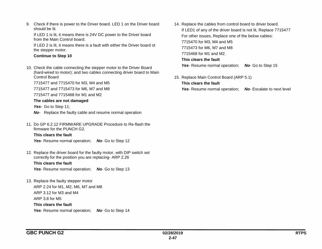
9. Check if there is power to the Driver board. LED 1 on the Driver board should be lit. If LED 1 is lit, it means there is 24V DC power to the Driver board from the Main Control board. If LED 2 is lit, it means there is a fault with either the Driver board ot the stepper motor. Continue to Step 10
10. Check the cable connecting the stepper motor to the Driver Board (hard-wired to motor); and two cables connecting driver board to Main Control Board 7715477 and 7715470 for M3, M4 and M5 7715477 and 7715473 for M6, M7 and M8 7715477 and 7715468 for M1 and M2 The cables are not damaged Yes- Go to Step 11; No- Replace the faulty cable and resume normal operation
11. Do GP 6.2.12 FIRMWARE UPGRADE Procedure to Re-flash the firmware for the PUNCH G2. This clears the fault Yes- Resume normal operation; No- Go to Step 12
12. Replace the driver board for the faulty motor, with DIP switch set correctly for the position you are replacing- ARP 2.26 This clears the fault Yes- Resume normal operation; No- Go to Step 13
13. Replace the faulty stepper motor ARP 2.24 for M1, M2, M6, M7 and M8 ARP 3.12 for M3 and M4 ARP 3.8 for M5 This clears the fault Yes- Resume normal operation; No- Go to Step 14
14. Replace the cables from control board to driver board. If LED1 of any of the driver board is not lit, Replace 7715477 For other issues, Replace one of the below cables: 7715470 for M3, M4 and M5 7715473 for M6, M7 and M8 7715468 for M1 and M2. This clears the fault Yes- Resume normal operation; No- Go to Step 15
15. Replace Main Control Board (ARP 5.1) This clears the fault Yes- Resume normal operation; No- Escalate to next level
GBC PUNCH G2 02/28/2019 RTPS 2-47

6 OTHER FAULTS
RTP 6.1 Die Set Will Not Slide In or Out Easily Use this RTP when the Die Set will not slide in or out using a moderate pull.
1. Do GP 6.27 Die Lock Mechanism and Die Rail Springs Inspection. This clears the fault Yes- Return to normal operation; No- Go to Step 2
2. Check if the Punch Cam needs to be indexed. Do ADJ 1.5 Punch Clutch Indexing and perform the adjustment if necessary. This clears the fault Yes- Return to normal operation; No- Escalate to second level
RTP 6.2 Punch Overheats Use this RTP if the Punch Overheats.
Note: To prevent excessive heat build-up, the maximum recommended monthly punch volume should not exceed 400,000. In addition, no more than 2 sheets of 300gsm per 5 sheets of 75 gsm.
1. Check that the Exhaust Fan operates when power is on. Do GP 6.2.8 Function Tests- Fan Test.
The exhaust fan operates
Yes- Go to Section 3.13 Punch specifications and make sure the machine is used per the Duty cycle specifications. Resume normal operation if specifications are met.
No- Go to step 2.
2. Check for obstructions at the vents in the Rear Cover. There are no obstructions at the vents in the Rear cover Yes- Go to Step 3 No- Clear the obstruction and resume normal operation.
3. Check for 24 VDC on Wire 7715267 at the Exhaust Fan. There is 24 VDC Yes- Replace the Exhause fan (PL #) No- Go to Step 4
4. Check for 24 VDC on Wire 7715267 at Connector J20 on the Control Board. There is 24 VDC Yes- Replace Wire 7715267. No- Do RTP 1.2 No DC power.
GBC PUNCH G2 02/28/2019 RTPS 2-48

Notes:
GBC PUNCH G2 02/28/2019 RTPS 2-49

3. Punch Quality Section Contents Title Page
3.1 Punch Quality....................................................................... 3 3.2 Initial Step............................................................................. 3 3.3 Hole Quality.......................................................................... 4
3.3.1 Hanging Chad ........................................................ 4 3.3.2 Holes are not cleanly cut........................................ 4 3.3.3 Oil on Paper ........................................................... 4
3.4 Alignment Offset................................................................... 4 3.5 Backgage Offset................................................................... 5 3.6 Skewed Punch ..................................................................... 6 3.7 Punching Accuracy Inconsistent .......................................... 6 3.8 Sheets Without Punched Holes ........................................... 9 3.9 Sheet in the middle of a job without punched holes .... Error!
Bookmark not defined. 3.10 Punched holes look elongated towards the trail edge of the
sheet................................................................................... 10 3.11 Sheet Damaged at the Lead Edge of the Sheet ................ 11 3.12 Scuff Marks on Paper......................................................... 12 3.13 Wrinkle in the sheet............................................................ 12 3.14 Clear Cover media hole position........................................ 12 3.15 Punch Specifications.......................................................... 13
GBC PUNCH G2 02/28/2019 Punch Quality
3-1

This page intentionally left blank.
Punch Quality 02/28/2019 GBC PUNCH G2 3-2

'¥
3.1
Punc
h Q
ualit
y 3.
2 In
itial
Ste
p Th
is s
ectio
n co
ntai
ns in
form
atio
n re
late
d to
the
qual
ity o
f the
out
put
Insp
ect t
he q
ualit
y of
the
punc
h by
refe
rrin
g to
the
spec
ifica
tions
for
such
as
hole
qua
lity
or a
lignm
ent.
Punc
h po
sitio
n an
d re
gist
ratio
n.
1.
Do
GP
6.1.
8 D
IE C
YCLE
S Pr
oced
ure
to c
heck
the
cycl
e lif
e on
th
e D
ie S
et in
stal
led
in th
e PU
NC
H G
2.
2.
If an
y of
the
Die
Set
life
cyc
les
have
exc
eede
d 75
0,00
0 sh
eets
(c
ycle
s) g
o to
Sec
tion
3.3
and
chec
k th
e H
ole
Qua
lity.
DIE
CYC
LES
750,
129
• If
the
Punc
h Q
ualit
y is
acc
epta
ble
mon
itor
the
Pun
ch
Qua
lity
frequ
ently
to e
nsur
e th
at th
e Pu
nch
Qua
lity
is o
kay.
• If
the
Hol
e Q
ualit
y is
not
acc
epta
ble
repl
ace
the
Die
Set
.
3.
Def
ects
in th
e ap
pear
ance
of t
he p
unch
suc
h as
hol
e sk
ew o
r no
n-un
iform
ity a
re d
iagn
osed
in th
e fo
llow
ing
sect
ions
.
GB
C P
UN
CH
G2
02/2
8/20
19
Punc
h Q
ualit
y
3-3

3.3 Hole Quality There are three different Hole Quality problems: • Hanging Chad • Holes are not cleanly cut • Oil on Paper
3.3.1 Hanging Chad This is caused when the clearance between the pin and hole in a die-set increases.
Do GP 6.1.8 Die Cycles Procedure to check the number of cycles for the installed Die Set.
If Die Set cycles have exceeded 750,000, replace the Die Set with a new one.
3.3.2 Holes are not cleanly cut This is usually caused due to lack of lubrication in the die-set. Do GP 6.7.3 Die Set Lubrication.
If lubricating the die set does not fix the issue, replace die-set.
3.3.3 Oil on Paper After a die-set is lubricated the next 25-50 sheets will come out with oil around the punched holes. Running test sheets is recommended until oil marks cease to appear.
3.4 Alignment Offset Use this procedure if the Alignment of all the punched sheets is consistently off.
If the Alignment is not consistent- go to Section 3.7 Punching Accuracy Inconsistent.
1. Is the die configured for the correct sheet size?
See Section 8 of PUNCH G2 User Manual for details.
Die-set is configured correctly Yes- Go to Step 2; No- Configure the die correctly and return to normal operation
2. Do GP 6.1.2 Alignment Offset
Figure 3-1 Hole Alignment on Finished Sheet
This clears the fault Yes- Return to normal operation; No- Go to Step 3
3. Inspect the Die Stop Magnet. ADJ 1.3, Die Stop Adjustment.
This clears the fault Yes- Return to normal operation; No- Go to Step 4
Punch Quality 02/28/2019 GBC PUNCH G2 3-4

4. Inspect the die stop block of the die set, tighten if necessary.
This clears the fault Yes- Return to normal operation; No- Go to Section 3.7 Punching accuracy inconsistent
3.5 Backgage Offset Do the following steps if the Backgage is offset from correct position on all sheets consistently.
• If the backgage position is correct for the first punched sheet in a job and incorrect for all subsequent sheets, go to Step 4.
• If the punched hole positions are not consistent for all sheets, go to section 3.7 Punching Accuracy Inconsistent.
1. Do GP 6.1.1 Backgage Setting.
This clears the fault Yes- Return to normal operation; No- Go to Step 2
2. If the backgage depth is too shallow (holes towards the trail edge of the sheet), do RTP 1.4 to check Solenoids SOL 6, SOL 7, and SOL 8.
This clears the fault Yes- Return to normal operation; No- Go to Step 3
3. Do RTP 3.1 to check Sensors S22, S23 and S24.
This clears the fault Yes- Return to normal operation; No- Go to Step 4
4. Do RAP 4.3 to check Solenoid SOL 6.
This clears the fault Yes- Return to normal operation; No- Go to Section 3.7 Punching Accuracy Inconsistent
GBC PUNCH G2 02/28/2019 Punch Quality
3-5

3.6 Skewed Punch 1. Check if the die is locked down properly. This is described in
Section 4 (A) of the PUNCH G2 User Manual.
Die is properly locked Yes- Go to Step 2; No- Lock the die properly and return to normal operation
2. If the holes are consistently skewed, do GP 6.2.9 Skew Offsets Adjustment. Otherwise go to section 3.7 Punching Accuracy Inconsistent.
This clears the fault Yes- Return to normal operation; No- Go to Section 3.7 Punching Accuracy Inconsistent
3.7 Punching Accuracy Inconsistent 1. Check if the die is locked down properly, by inspecting the die
lock plunger. This is described in Section 4 (A) of the PUNCH G2 User Manual.
Die is properly locked Yes- Go to Step 2; No- Lock the die properly and return to normal operation
2. Punching will be inaccurate if Solenoid SOL 6, SOL 7, or SOL 8 is not disengaging the roller completely when actuated (punched holes will be shifted towards the trail edge of the sheet in this case).
• Do the following to check whether SOL6, 7 or 8 is causing the punch accuracy inconsistency, 1. Leave the front door open and insert an interlock
cheater.
2. Leave the jam access panel of area #5 open.
3. Run a 2~3 sheet job in punch job through the printer.
4. Punched sheets will collect near area #5, gently pull the sheets and inspect the punch accuracy.
5. If the punching accuracy is good, it means SOL6 or SOL7 or SOL8 is not functioning properly.
6. Do RTP 4.3 to Check Solenoids SOL 6, SOL7 and SOL8.
For Double punched sheets, do RTP 4.3 to check Solenoids SOL 4 and SOL 5 in addition to the above steps.
This clears the fault Yes- Return to normal operation; No- Go to Step 3
3. Do ARP 3.1.1 to remove the Punch module and do Steps 4, 5 and 6.
4. Do GP 6.27 Die Lock Mechanism and Die Rail Springs Inspection.
This clears the fault Yes- Return to normal operation; No- Go to Step 5
Punch Quality 02/28/2019 GBC PUNCH G2 3-6

5. Do GP 6.24 Punch Clutch Inspection and Cleaning.
This clears the fault Yes- Return to normal operation; No- Go to Step 6
6. Check if the set screws in the pulleys of Aligner drive are secure. This can be checked by holding down the Alignment stepper pulley and trying to move the Aligner carriage on its rails. There should not be any play in the mechanism.
(Cont.)
The set screws are secured tightly.
Yes- Go to Step 7; No- Tighten set screw(s) and return to normal operation
7. There are 4 pulleys involved in the Aligner drive.
• Drive pulley of the Alignment stepper motor • Driven pulley of the Alignment Stepper motor • Pulley adjacent to the driven pulley (secured with a coiled
pin) • Pulley on the other shaft of the Aligner drive (secured with
an coiled pin) Make sure all the set screws are tightened securely, and the coiled pins are not broken.
GBC PUNCH G2 02/28/2019 Punch Quality
3-7

The set screws are secured tightly. Yes- Escalate to higher level No- Tighten set screw(s) and return to normal operation
Punch Quality 02/28/2019 GBC PUNCH G2 3-8

3.8 Sheets Without Punched Holes If some or all the sheets come out without punched holes, follow this procedure
1. Do RTP 4.1 to check the Diverter Solenoid.
This clears the fault Yes- Return to normal operation; No- Go to Step 2
2. Do RTP 3.2 to Check Sensors S6, S7, S8, S9 and S10. If it is Double punch job, also check S18, S19, S20, and S21.
This clears the fault Yes- Return to normal operation; No- Go to Step 3
3. Do RTP 3.1 to Check Sensor S5.
This clears the fault Yes- Return to normal operation; No- Go to Step 4
4. Do RTP 3.3 checking Sensor S28 Align Home Sensor.
This clears the fault Yes- Return to normal operation; No- Go to Step 5
5. Do GP 6.2.8 Function Tests- Cycle Punch and do the following steps.
6. If you do not hear the Punch cycles and do not hear the AC Motor running, remove the Rear Cover and do step 7.
If you do not hear the punch cycles, but you do hear the AC Motor Running, go to step 8 or step 9.
If you hear both the punch cycle and the AC motor running go to step 10
7. Check the AC Punch Motor connections at the header in the Rear Frame and the Control Board.
• Inspect the cable from the AC punch motor to the header and the cable from the header to Control board (7715476). If a cable is damaged, replace it.
• Do GP 6.2.12 FIRMWARE UPGRADE Procedure to Re-flash the firmware for the PUNCH G2.
• With the Rear Cover removed, do GP 6.2.8 Function tests-Cycle Punch. Check the relay towards the bottom right of the main control board. You should be able to see the relay make contact when the punch motor starts. If this does not happen, replace control board (ARP 5.1.).
• If the relay makes contact, replace the AC Punch motor (ARP 3.5).
This clears the fault Yes- Return to normal operation; No- Escalate to 2nd level
8. If the motor is running, but clutch is not operating:
• Remove the Rear Cover. • Check connection at the clutch and control board, inspect
clutch wires. • Do GP 6.2.12 FIRMWARE UPGRADE Procedure to Re-
flash the firmware for the PUNCH G2. • If the problem still exists, replace punch clutch.
This clears the fault Yes- Return to normal operation; No- Go to Step 9
9. Check the Belt and Pulley for the AC Punch Motor.
• Inspect the timing Belt between the AC Punch Motor and the Clutch (PL 4.1).
• Check the tightness of the Setscrew of the AC Punch Motor (PL 4.11). This clears the fault
GBC PUNCH G2 02/28/2019 Punch Quality
3-9

Yes- Return to normal operation; No- Escalate to higher 3.9 Punched holes look elongated towards the trail level. edge of the sheet
This failure usually occurs when the Punch cycle is slowed. 10. Check that the clutch set screws are secure to the shaft.
• Check that the clutch set screws are tight on the shaft (reference ARP 3.7 to access the clutch)
• If the set screws are loose perform ARP 3.7 Installation steps to reset them.
• If the clutch cannot be reoriented to align with the notches in the shaft, remove the clutch and inspect the shaft for damage (PL 4.1). If the shaft is undamaged reinstall the clutch in the proper position and resume operation.
• Replace the punch module shell if the shaft is damaged (PL 4.1)
This clears the fault Yes- Return to normal operation; No- Escalate to higher level.
1. Lubricate die-set. Do GP 6.7.3.
This clears the fault Yes- Return to normal operation; No- Go to Step 2
2. Check if correct pulley is used depending on 115V or 230V machine, 115V machine should use 38T pulley and 230V machine should use 34T pulley (PL 4.8).
The correct pulley is used. Yes- Go to Step 3; No- Change the pulley
3. Check the number of punch cycles of the machine, do GP 6.1.7 Punch Cycles. The normal life of the punch clutch is 15 million punch cycles. If the machines has completed 15 million punch cycles, do ARP 3.1 to replace the Punch Module.
The punch has less than 15 million cycles Yes- Go to Step 4; No- Replace the punch module (ARP 3.1)
4. Do GP 6.24 Punch Clutch Inspection and Cleaning.
This clears the fault Yes- Return to normal operation; No- Escalate to higher level
Punch Quality 02/28/2019 GBC PUNCH G2 3-10

3.10 Sheet Damaged at the Lead Edge of the Sheet 1. Do RTP 2.8 to check for an obstruction of the paper path.
This clears the fault Yes- Return to normal operation; No- Go to Step 2
2. Remove the die set and inspect the die set throat for any obstruction.
This clears the fault Yes- Return to normal operation; No- Escalate to higher level
GBC PUNCH G2 02/28/2019 Punch Quality
3-11

3.11 Scuff Marks on Paper 1. Clean all drive and idler rollers, do
• GP 6.14.1 Idler Roller Cleaning • GP 6.14.2 Steering Idler Roller and Springs Inspection and
Cleaning • GP 6.15 Drive roller and Steering drive roller Inspection
and Cleaning
This clears the fault Yes- Return to normal operation; No- Go to Step 2
2. Do RTP 4.3 to inspect Solenoids SOL 3, SOL 4, SOL 5, SOL 6, SOL 7, and SOL 8.
This clears the fault Yes- Return to normal operation; No- Go to Step 3
3. Do RTP 3.1 to inspect Sensors S3, S4, S5, S22, S23, and S24
This clears the fault Yes- Return to normal operation; No- Escalate to higher level
3.12 Wrinkle in the sheet 1. If the wrinkling is at the trail edge of the sheet, Do RTP 3.1 to
check Sensor S24.
This clears the fault Yes- Return to normal operation; No- Go to Step 2
2. Do RTP 4.3 to inspect Solenoids SOL 6, SOL 7, and SOL 8.
This clears the fault Yes- Return to normal operation; No- Escalate to higher level
3.13 Clear Cover media hole position 1. If the hole position (Backgage and Alignment) of Clear media
differs from the hole position of plain media, do GP 6.1.3 CLEAR COVER Procedure
This clears the fault Yes- Return to normal operation; No- Go to Step 2
2. Check the function of Sensor S1b.
Sensor S1b functions properly Yes- Escalate to next level; No- Go to Step 3
3. Ensure the sensor S1b is connected properly on the receiver side and emitter side.
Sensor S1b is connected properly Yes- Escalate to next level; No- Go to Step 4
4. Replace defective S1b receiver or emitter if needed.
New S1b sensors correct the issue. Yes- Continue normal operation; No- Escalate to next level.
Punch Quality 02/28/2019 GBC PUNCH G2 3-12

3.14 Punch Specifications
Sheet Entrance and Exit Specifications for Punch job Speed Up to 136 sheets per minute
Punch Sheet Size and Edge
LEF- Long Edge Fed SEF- Short Edge Fed
US Sizes LTR LEF LTR SEF- Single and Double punch Statement LEF Legal SEF Ledger SEF- Single and Double punch
ISO sizes A4 LEF A4 SEF- Single and Double punch A5 LEF A3 SEF- Single and Double punch
Paper Stock for Punch job
Plain: 75gsm - 300gsm (20# bond to 110# cover)
Coated: 120gsm - 300gsm (32# bond to 110# cover)
Bypass Mode Sheet size Paper sizes and stocks same as printer
Punch Capacity Single Sheet
Electrical Amps and Frequency
115V: 3.8 A; 60 Hz 230V: 1.9 A; 50 Hz
Safety cULus / GS
Dimensions L: 795mm; W: 445mm; H: 1040mm
Weight 102 kg
Curl variance at entrance Max of 10mm from mid face to edge
Registration variance at pick up (includes skew) ±10mm from center
Speed variance at pick up ±2%
Skew variance at pick up ±25 millirads (1.43 degree)
Registration variance at exit (includes skew) ±2mm from center
Skew variance at exit Punch: ±5 millirads (0.29 degree)
Speed variance at exit ±2%
Punch Accuracy
Hole Size ±2%
Alignment position ±0.5mm (with 1% ±0.5 to ±1.0mm)
Backgage Depth (at center) ±0.3mm (with 1% ±0.3 to ±0.8mm)
Skew ±0.6mm (with 1% ±0.6 to ±1.0mm)
GBC PUNCH G2 02/28/2019 Punch Quality
3-13

Duty Cycles
The GBC PUNCH G2 provides a flexible, cost effective punching solution for light to medium level punching production environments. It is designed for production print users that typically punch their documents at an average of 20-30% of their overall workflow. For customers that run continuous punching for long runs of over 4 hours, performance may vary or degrade due to a wide range of media weights and environmental conditions that can occur.
AMPV - Nominal 600,000 average monthly print volume (A4/letter), assuming volume is split 50/50 between punch and bypass (300,000 punch and 300,000 bypass).
Maximum Recommended Monthly Volume - The maximum recommended monthly punch volume should NOT exceed 400,000.
Maximum Punch Duty Cycle - In addition to the aforementioned conditions, no more than 2 sheets of 300gsm per 5 sheets of 75gsm should be punched. The heaviest paper stocks are typically used as only the front and back covers of the bound book application.
Punch Quality 02/28/2019 GBC PUNCH G2 3-14

4. Adjustments / Repairs Procedures Section Contents Title Page 1. Cabinet 4-3 ARP 2.11 Upper Bypass Panel Replacement ..................................4-39
ARP 1.1 Top Cover Replacement .................................................... 4-3 ARP 2.12 Lower Bypass panel replacement....................................4-41 ARP 1.2 Front Door Replacement.................................................... 4-4 ARP 2.13 Bypass Diverter Replacement..........................................4-42 ARP 1.3 Front Door Bottom Hinge Bracket Replacement ............... 4-5 ARP 2.14 Panel Close Magnet Replacement...................................4-43 ARP 1.4 Front Door Top Hinge Bracket Replacement..................... 4-6 ARP 2.15 Idler Roller Replacement..................................................4-44 ARP 1.5 Panel Open Magnet Replacement..................................... 4-6 ARP 2.16 Idler Panel Mount Bracket Replacement .........................4-46 ARP 1.6 Rear Cover Replacement .................................................. 4-7 ARP 2.17 Flange Ball Bearing Replacement ...................................4-47 ARP 1.7 Upstream Rear Side Cover Replacement ......................... 4-8 ARP 2.18 Snap-in Bearing Replacement .........................................4-48 ARP 1.8 Downstream Front Side Cover Replacement .................... 4-9 ARP 2.19 Bearing Housing Replacement ........................................4-49 ARP 1.9 Downstream Rear Side Cover Replacement................... 4-10 ARP 2.20 Accel Idler Latch Handle Replacement............................4-49 ARP 1.10 Door Latch Replacement ................................................. 4-11 ARP 2.21 Accel Idler Latch Shaft, Rear Latch and Front Latch
Assembly Replacement ...................................................4-50 ARP 1.11 Interlock Switch Replacement ......................................... 4-12 ARP 2.22 One Way Clutch and Pulley Sub-Assembly Replacement4-54 ARP 1.12 LCD Display Replacement............................................... 4-13 ARP 2.23 Drive Idler Roller Assembly Replacement .......................4-54 ARP 1.13 LCD Membrane Switch Panel Replacement ................... 4-14 ARP 2.24 Timing Pulley Replacement .............................................4-55 ARP 1.14 Caster Replacement ........................................................ 4-15 ARP 2.25 Timing Belt Replacement .................................................4-56 ARP 1.15 Docking Bracket Replacement ........................................ 4-15
ARP 2.25.1 534T Belt Replacement .............................................4-56 ARP 1.16 Exhaust Fan and Exhaust Fan Bracket Replacement..... 4-17 ARP 2.25.2 134T Belt Replacement ..............................................4-57
ARP 1.17 Drive roller cover removal ................................................ 4-18 ARP 2.25.3 150T Belt Replacement .............................................4-57 ARP 1.18 Side cover removal .......................................................... 4-19 ARP 2.25.4 179T Belt Replacement ..............................................4-58
2. Paper Path 4-20 ARP 2.26 Drive Roller Assembly Replacement ...............................4-59 ARP 2.1 Lower Entrance Panel Replacement ............................... 4-20 ARP 2.26.1 Drive Roller N5 Replacement ....................................4-61 ARP 2.2 Inner Entrance Panel Replacement................................. 4-21 ARP 2.27 Stepper and Mount Assembly Replacement....................4-64 ARP 2.3 Entrance Idler Panel Replacement .................................. 4-22 ARP 2.28 Paper Path Sensor Replacement ....................................4-65 ARP 2.4 Acceleration Roller Idler Assembly Replacement............ 4-25 ARP 2.28.1 Entrance Sensor (S1,) Exit Sensor (S25), and Bypass
Middle Sensor (S26) Replacement............................4-65 ARP 2.5 Entrance Drive Panel Assembly Replacement ................ 4-27 ARP 2.28.2 Top, Middle, & Bottom Entrance Sensor (S2, S3, S4) and
ARP 2.6 Lower Exit Panel Replacement........................................ 4-31 ARP 2.7 Exit Idler Panel Replacement
Top, Middle, & Bottom Exit Sensor (S22, S23, S24) .......................................... 4-32 Replacement..............................................................4-66
ARP 2.28.3 Accel Sensor (S5) Replacement................................4-67 ARP 2.8 Drive Exit Panel Replacement ......................................... 4-35 ARP 2.28.4 Align Home Sensor (S28) Replacement....................4-68
ARP 2.9 Punch Lower Exit Panel Replacement ............................ 4-37 ARP 2.10 Inner Exit Panel Replacement ......................................... 4-38 Backage Sensor Board Assembly (S20, S21)
ARP 2.28.5 Backage Sensor Board Assembly (S18, S19) and
Replacement..............................................................4-69 GBC PUNCH G2 02/28/2019 Adjustments/Repairs
4-1 Section Contents

ARP 2.28.6 Skew Sensor Board (S6 – S10) Replacement...........4-70 ARP 2.28.7 Alignment Sensor Board (S11 – S15) Replacement .4-71 ARP 2.28.8 Backage Sensor Board (S16, S17) Replacement .....4-73
ARP 2.29 Motor Driver (Stepper Board) Replacement.....................4-74 ARP 2.30 Solenoid Replacement .....................................................4-75
ARP 2.30.1 Diverter Solenoid Replacement .................................4-75 ARP 2.30.2 Entrance Idler Solenoid Replacement .......................4-77 ARP 2.30.3 Acceleration Roller Idler Solenoid Replacement .......4-77 ARP 2.30.4 Exit Idler Solenoid Replacement................................4-78
ARP 2.31 Upper Bypass Panel Anti-Static Brush Replacement ......4-78 3. Punch Module 4-79
ARP 3.1 Punch Module Replacement ..............................................4-79 ARP 3.1.1 Punch Module Removal...............................................4-79 ARP 3.1.2 Punch Module Installation............................................4-83
ARP 3.2 Chip Tray Home Switch Replacement .............................4-84 ARP 3.3 Chip Level Emitter Replacement......................................4-85 ARP 3.4 Chip Level Receiver Replacement...................................4-85 ARP 3.5 Punch Motor Replacement...............................................4-86 ARP 3.6 Punch Motor Belt Replacement (Timing Belt) ..................4-87 ARP 3.7 Clutch or Clutch Pulley Replacement...............................4-89 ARP 3.8 Punch Alignment Stepper Motor and Pulley Replacement,
and Alignment Stepper Bracket Replacement .................4-92 ARP 3.9 Steering Module Replacement .........................................4-93 ARP 3.10 Ground Strap Replacement..............................................4-96 ARP 3.11 Alignment Carriage Sub Assembly Replacement ............4-98 ARP 3.12 Steering Stepper Motor Replacement............................4-101 ARP 3.13 Steering Motor Belt (65 Groove) Replacement ..............4-103 ARP 3.14 Steering Drive Roller Shaft Replacement ......................4-105 ARP 3.15 Steering Idler Panel Weldment Replacement ................4-107 ARP 3.16 Steering Idler Roller Assembly Replacement.................4-109
ARP 3.16.1 Steering Idler Roller Bearing Replacement .............4-111 ARP 3.17 Steering Drive Panel Weldment Replacement...............4-112 ARP 3.18 Die Lock Plunger and Stripper Assembly Replacement 4-113 ARP 3.19 Punch shaft Ball Bearing Replacement..........................4-114 ARP 3.20 Die Stop Magnet Replacement ......................................4-114
Adjustments/Repairs
ARP 3.21 Die Lock Handle Replacement ...................................... 4-115 ARP 3.22 Die Lock Shaft Replacement ......................................... 4-116 ARP 3.23 Die Rail Assembly and Die Rail Springs Replacement . 4-118 ARP 3.24 Alignment Sensor Bracket and Alignment Sensor Bottom
Guide Replacement ....................................................... 4-120 ARP 3.25 Punch Module Mount Pin Replacement ........................ 4-122 ARP 3.26 Backgage Sensor Bracket Weldment and Backgage Sensor
Lower Bracket Replacement ......................................... 4-123 ARP 3.27 Die Set Recognition Replacement................................. 4-124
4. Power Supply 4-125 ARP 4.1 24V Power Supply Replacement................................... 4-125 ARP 4.2 AC Filter Replacement .................................................. 4-127
5. Electronics and Control 4-128 ARP 5.1 Main Control Board Replacement ................................. 4-128 ARP 5.2 Comm Board Replacement ........................................... 4-130 ARP 5.3 Dieset Recognition Reader Board Replacement........... 4-131
6. Adjustments 4-132 ADJ 1.1 Door Latch Adjustment .................................................. 4-132 ADJ 1.2 Diverter Solenoid Adjustment ........................................ 4-133 ADJ 1.3 Die Stop Magnet Adjustment......................................... 4-135 ADJ 1.4 Timing Belts Adjustment................................................ 4-136 ADJ 1.5 Punch clutch Indexing ................................................... 4-141 ADJ 1.6 Dieset Recognition Board Adjustment........................... 4-145 ADJ 1.7 Idler Panel Magnetic Latches Adjustment ..................... 4-146 ADJ 1.8 Drive Panel Position Adjustment ................................... 4-147
02/28/2019 GBC PUNCH G2 4-2

REPLACEMENTS
1. Cabinet ARP 1.1 Top Cover Replacement PARTS LIST ON PL 1.2
Use this procedure to remove and install the Top Cover Assembly.
Removal Procedure
WARNING Do not perform Repair activities with the power on or electrical power supplied to the machine. Some machine components contain dangerous electrical voltages that can result in electrical shock and possible serious injury. 1. Disconnect the Power Cord. 2. Open the Front Door. 3. Do ARP 1.6 to remove the Rear Cover. 4. Remove the Phillips Head Screws (4) from the Top Cover Tabs. (2
screws from front side and 2 screws from rear side)
5. Disconnect the LCD Panel Connector and release the LCD Cable from wire saddles.
6. Remove the Top Cover.
Installation Procedure
Use this procedure to install the Top Cover Assembly.
1. Place the Top Cover in position so the Tabs overlap the front and rear frame.
2. Install and tighten the Phillips Head Screws (4) through the Tabs. 3. Connect the LCD Panel Connector and place the LCD Cable in the
wire saddles 4. Close the Front Door. 5. Do ARP 1.6 to install the Rear Cover. 6. Connect the Power Cord.
GBC PUNCH G2 02/28/2019 Adjustments/Repairs 4-3

ARP 1.2 Front Door Replacement PARTS LIST ON PL 1.2
Use this procedure to remove and install the Front Door Assembly
Removal Procedure
WARNING Do not perform Repair activities with the power on or electrical power supplied to the machine. Some machine components contain dangerous electrical voltages that can result in electrical shock and possible serious injury. 1. Disconnect the Power Cord. 2. Open the Front Door. 3. Remove the Screws (2) from the Front Door Bottom Hinge Bracket.
4. Lower the Door down off the pin on the Front Door Top Hinge Bracket.
5. Remove the Front Door. 6. Remove the Interlock Switch (PL 1.2) from the old Door and install it
on the new Door. 7. Remove the Magnet Strike Plate from the old Door and install it on
the new Door.
Adjustments/Repairs
Installation Procedure
1. Insert the Front Door Top Hinge Bracket into the slot at the top of the Front Door.
2. Insert the bottom door pin into the Front Door Bottom Hinge Bracket
Front Door Bottom Hinge
Bracket
3. Screw the Front Door Btoom Hinge Bracket into the frame
(Cont.)
02/28/2019 GBC PUNCH G2 4-4

4. Close the Front Door. 5. Do ADJ 1.1 to adjust the Door Latch. 6. Connect the Power Cord.
ARP 1.3 Front Door Bottom Hinge Bracket Replacement Use this procedure to remove and install the Front Door Bottom Hinge Bracket.
1. Press the Power Switch to the off position. 2. Disconnect the Power Cord. 3. Do ARP 1.2 Front Door Replacement to remove the Front Door.
Front Door Bottom Hinge
Bracket
4. Remove the Screws (2) and the Front Door Bottom Hinge Bracket 5. Place the new Front Door Bottom Hinge Bracket in position and
tighten the Screws (2). 6. Do ARP 1.2 Front Door Replacement to install the Front Door. 7. Connect the Power Cord.
GBC PUNCH G2 02/28/2019 Adjustments/Repairs 4-5

ARP 1.4 Front Door Top Hinge Bracket Replacement Use this procedure to remove and install the Front Door Top Hinge Bracket.
1. Press the Power Switch to the off position. 2. Disconnect the Power Cord. 3. Do ARP 1.2 Front Door Replacement to remove the Front Door.
Front Door Top Hinge
Bracket
4. Remove the Screws (2) and the Front Door Top Hinge Bracket on the inside of the machine
5. Place the new Front Door Top Hinge Bracket in position and tighten the Screws (2).
6. Do ARP 1.2 Front Door Replacement to install the Front Door. 7. Connect the Power Cord.
Adjustments/Repairs
ARP 1.5 Panel Open Magnet Replacement Use this procedure to remove and install a Panel Open Magnet (PL 2.2).
1. Press the Power Switch to the off position. 2. Disconnect the Power Cord. 3. Open the Front Door. 4. Remove the Screws (2) and the Panel Open Magnet.
Screw (2)
Panel Open Magnet
5. Place the Panel Open Bracket in position and tighten the Screws (2). 6. Close the Front Door. 7. Connect the Power Cord.
02/28/2019 GBC PUNCH G2 4-6

ARP 1.6 Rear Cover Replacement PARTS LIST ON PL 1.2
Use this procedure to remove and install the Rear Cover Assembly
Removal Procedure
WARNING Do not perform Repair activities with the power on or electrical power supplied to the machine. Some machine components contain dangerous electrical voltages that can result in electrical shock and possible serious injury. 1. Disconnect the Power Cord. 2. Disconnect the Communication cables from the rear side of the
machine and remove the MK 737 boxes. 3. Hold the Rear Cover in place so it doesn’t fall as you remove the M4
X 8 Screws (6) from the Rear Cover. 4. Grasp the Rear Cover by the handle and remove the Rear Cover.
Installation Procedure
1. Place the Rear Cover in position. 2. Tighten the Screws (6) on the Rear Cover. 3. Install the MK 737 boxes 4. Connect the Communication cables. 5. Connect the Power Cord.
GBC PUNCH G2 02/28/2019 Adjustments/Repairs 4-7

ARP 1.7 Upstream Rear Side Cover Replacement PARTS LIST ON PL 1.2
Use this procedure to remove and install the Upstream Rear Side Cover.
Removal Procedure
WARNING Do not perform Repair activities with the power on or electrical power supplied to the machine. Some machine components contain dangerous electrical voltages that can result in electrical shock and possible serious injury. 1. Disconnect the Power Cord. 2. Do GP 6.3 to undock the Punch from the upstream and downstream
equipment. 3. Do ARP 1.6 to remove the Rear Cover. 4. Remove the Screw (5) securing the Upstream Rease Side Cover 5. Remove the Upstream Rear Side Cover. Installation Procedure
1. Place the Upstream Rear Side Cover in position. 2. Tighten the Screws (5) holding the Upstream Rear Side Cover. 3. Do ARP 1.6 to install the Rear Cover. 4. Do GP 6.4 to dock the Punch to the upstream and downstream
equipment. 5. Connect the Power Cord.
Adjustments/Repairs 02/28/2019 GBC PUNCH G2 4-8

ARP 1.8 Downstream Front Side Cover Replacement PARTS LIST ON PL 1.2
Use this procedure to remove and install the Downstream Front Side Cover.
Removal Procedure
WARNING Do not perform Repair activities with the power on or electrical power supplied to the machine. Some machine components contain dangerous electrical voltages that can result in electrical shock and possible serious injury. 1. Disconnect the Power Cord. 2. Do GP 6.3 to undock the Punch from the upstream and downstream
equipment. 3. Remove the M4 Screws (6).
4. Remove the Downstream Front Side Cover.
Downstream Front Side
Cover
Installation Procedure
1. Place the Downstream Front Side Cover in position. 2. Tighten the Screws (5). 3. Do GP 6.4 to dock the Punch to the upstream and downstream
equipment. 4. Connect the Power Cord.
GBC PUNCH G2 02/28/2019 Adjustments/Repairs 4-9

ARP 1.9 Downstream Rear Side Cover Replacement PARTS LIST ON PL 1.2
Use this procedure to remove and install the Downstream Rear Side Cover.
Removal Procedure
WARNING Do not perform Repair activities with the power on or electrical power supplied to the machine. Some machine components contain dangerous electrical voltages that can result in electrical shock and possible serious injury. 1. Disconnect the Power Cord. 2. Do GP 6.3 to undock the Punch from the upstream and downstream
equipment. 3. Do ARP 1.6 to remove the Rear Cover. 4. Remove the Screws (7) holding the Downstream Rear Side Cover.
Downstream Rear Side Cover
5. Remove the Downstream Rear Side Cover.
Installation Procedure
1. Place the Downstream Rear Side Cover in position. 2. Tighten the Screws (7) holding the Downstream Rear Side Cover. 3. Do ARP 1.6 to install the Rear Cover. 4. Do GP 6.4 to dock the Punch to the upstream and downstream
equipment. 5. Connect the Power Cord.
Adjustments/Repairs 02/28/2019 GBC PUNCH G2 4-10
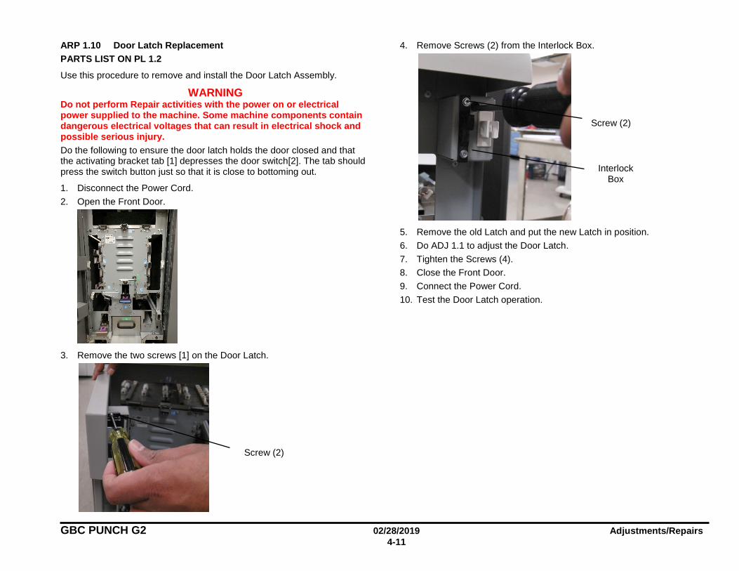
ARP 1.10 Door Latch Replacement PARTS LIST ON PL 1.2
Use this procedure to remove and install the Door Latch Assembly.
WARNING Do not perform Repair activities with the power on or electrical power supplied to the machine. Some machine components contain dangerous electrical voltages that can result in electrical shock and possible serious injury. Do the following to ensure the door latch holds the door closed and that the activating bracket tab [1] depresses the door switch[2]. The tab should press the switch button just so that it is close to bottoming out.
1. Disconnect the Power Cord. 2. Open the Front Door.
3. Remove the two screws [1] on the Door Latch.
4. Remove Screws (2) from the Interlock Box.
Screw (2)
Interlock Box
5. Remove the old Latch and put the new Latch in position. 6. Do ADJ 1.1 to adjust the Door Latch. 7. Tighten the Screws (4). 8. Close the Front Door. 9. Connect the Power Cord. 10. Test the Door Latch operation.
Screw (2)
GBC PUNCH G2 02/28/2019 Adjustments/Repairs 4-11

ARP 1.11 Interlock Switch Replacement PARTS LIST ON PL 1.2
Use this procedure to remove and install the Interlock Switch Assembly.
Removal Procedure
WARNING Do not perform Repair activities with the power on or electrical power supplied to the machine. Some machine components contain dangerous electrical voltages that can result in electrical shock and possible serious injury. 1. Disconnect the Power Cord. 2. Open the Front Door. 3. Remove the M4 screws (2).
Nuts (2)
Interlock Switch Bracket
4. Remove the Interlock Switch Bracket. 5. Press in the Tabs (2) on the sides of the Switch and remove the
Interlock Switch from the Interlock Switch Bracket.
Tabs (2)
Adjustments/Repairs
6. Note the location of the Wires (4); then disconnect the Wires from the Interlock Switch (PL 1.2).
Wires (4)
From right to left:
• Yellow wire – Position 8. • Black wire – Position 4. • White wire – Position 3. • Orange wire – Position 7.
7. Place the new Interlock Switch into the Interlock Switch Bracket. and press down until the Tabs lock in place.
8. Connect the Wires (4) to the new Interlock Switch. 9. Place the interlock Switch Bracket in position, and tighten the screws
(2). 10. Close the Front Door. 11. Connect the Power Cord.
02/28/2019 GBC PUNCH G2 4-12

ARP 1.12 LCD Display Replacement PARTS LIST ON PL 1.2
Use this procedure to remove and install the LCD Display.
Removal Procedure
WARNING Do not perform Repair activities with the power on or electrical power supplied to the machine. Some machine components contain dangerous electrical voltages that can result in electrical shock and possible serious injury. 1. Disconnect the Power Cord. 2. Open the Front Door. 3. Locate the LCD display under the top cover and disconnect the
cables from the LCD Display.
Cable
Cable
4. From the bottom side of the Top Cover, remove the Screws (3) holding the LCD Display to the Top Cover.
Screws
5. Remove the LCD Display.
Installation Procedure
1. Place the new LCD Display Panel in position. 2. Tighten the Screws (3) holding the LCD Display to the Top Cover. 3. Connect the Cable (2) to the LCD Display Panel. 4. Close the Front Door. 5. Connect the Power Cord.
GBC PUNCH G2 02/28/2019 Adjustments/Repairs 4-13

ARP 1.13 LCD Membrane Switch Panel Replacement PARTS LIST ON PL 1.2
Use this procedure to remove and install the LCD Membrane Switch Panel.
WARNING Do not perform Repair activities with the power on or electrical power supplied to the machine. Some machine components contain dangerous electrical voltages that can result in electrical shock and possible serious injury. 1. Disconnect the Power Cord. 2. Open the Front Door. 3. Disconnect the LCD Membrane Switch Connector from the LCD
Display.
Connector
4. Remove the M4 nut and release the ground strap
5. Peel off the old LCD Membrane Switch
Adjustments/Repairs
LCD Membrane Switch
6. Install the new Membrane within the indent of the Top Cover. 7. Close the Front Door. 8. Connect the LCD Membrane Switch Connector from the LCD Display. 9. Install the ground strap with M4 nut. 10. Connect the Power Cord.
02/28/2019 GBC PUNCH G2 4-14

ARP 1.14 Caster Replacement PARTS LIST ON PL 2.2
Use this procedure to remove and install the Caster Assembly.
Removal Procedure
WARNING Do not perform Repair activities with the power on or electrical power supplied to the machine. Some machine components contain dangerous electrical voltages that can result in electrical shock and possible serious injury. 1. Disconnect the Power Cord. 2. Carefully lift the corner of the Punch by the Caster. 3. Loosen the Jam Nut.
Jam Nut
Caster
4. Unscrew the Caster to remove it. 5. Place the new Caster in position and screw it in. 6. Tighten the Jam Nut. 7. Lower the Punch 8. Connect the Power Cord.
ARP 1.15 Docking Brackets Replacement PARTS LIST ON PL 1.2
Use this procedure to remove and install the Docking Brackets from the upstream device.
Removal Procedure
WARNING Do not perform Repair activities with the power on or electrical power supplied to the machine. Some machine components contain dangerous electrical voltages that can result in electrical shock and possible serious injury. 1. Disconnect the Power Cord. 2. Disconnect the Communication cable. 3. Do GP 6.3 Undock the Punch to separate the Punch from the
upstream and downstream devices. 4. Remove (8x) M4 screws that hold the docking brackets.
5. Remove the Docking Brackets from the upstream device.
GBC PUNCH G2 02/28/2019 Adjustments/Repairs 4-15

Installation Procedure
1. Place the Docking Brackets in position on the upstream devices and tighten the (8x) screws.
2. Do GP 6.4 Dock the Punch to connect the Punch to the upstream and downstream devices.
3. Connect the Communication cable. 4. Connect the Power Cord.
Adjustments/Repairs 02/28/2019 GBC PUNCH G2 4-16

ARP 1.16 Exhaust Fan and Exhaust Fan Bracket Replacement 4. Do the following to remove the Exhaust Fan from the Exhaust Fan Bracket. PARTS LIST ON PL 1.2
Use this procedure to remove and install the Exhaust Fan or the Exhaust Fan Bracket.
Removal Procedure
WARNING Do not perform Repair activities with the power on or electrical power supplied to the machine. Some machine components contain dangerous electrical voltages that can result in electrical shock and possible serious injury. 1. Disconnect the Power Cord. 2. Do ARP 1.6 to remove the Rear Cover. 3. Remove the Screws (2) and the Exhaust Fan Bracket.
Exhaust Fan Screws (2) Bracket
• Disconnect Cable 7715267 at Connector J20 on the Control Board (see Section 7 Wiring).
Nuts (4)
• Open the Wires Saddles. • Remove the Screws (4) from the front and the Nuts (4) from the
rear of the Bracket. • Remove the Exhaust Fan.
Installation Procedure
1. Do the following to install the Exhaust Fan on the Exhaust Fan Bracket. • Place the new Exhaust Fan in position on the Exhaust Fan
Bracket. The fan should be installed such that air flows out of the machine. An arrow mark in the exhaust fan indicates the direction of air flow.
• Connect Cable 7715267 at Connector J20 on the Control Board (see Section 7 Wiring).
• Install the Screws (4) from the front and tighten the Nuts (4) from the rear of the Bracket.
• Place Cable 7715267 into the Wires Saddles. 2. Place the Exhaust Fan Bracket Assembly in position and tighten the
Screws (2). 3. Connect Cable 7715267 at Connector J20 on the Control Board (PL
5.1). 4. Do ARP 1.6 to install the Rear Cover. 5. Connect the Power Cord.
GBC PUNCH G2 02/28/2019 Adjustments/Repairs 4-17

ARP 1.17 Drive roller cover removal 6. Remove the Drive roller cover. Use this procedure to remove the cover for Drive rollers on the entrance side or exit side to get access to other parts.
Removal Procedure 1. Disconnect Power cord. 2. Do GP 6.3 to undock the Punch from upstream and downstream
equipment 3. Do ARP 1.6 Rear Cover Replacement to remove the Rear Cover. 4. For the entrance side, remove (2) M4 screws from the front frame.
Screws (2)
5. Remove (2) M4 screws from the rear frame. 7. Use the same procedure for exit side drive roller cover by removing
the corresponding screws.
Installation Procedure
Reverse steps to re-install the cover.
Screws (2)
Adjustments/Repairs 02/28/2019 GBC PUNCH G2 4-18

1111111 111111111111
ARP 1.18 Side cover removal Use this procedure to remove the up and downstream covers to get access to other parts.
Removal Procedure 1. Disconnect Power cord. 2. Do GP 6.3 to undock the Punch from upstream and downstream
equipment 3. Remove (4) M4 screws and the bottom plate and (2) M4 screws on
the top.
Process is the same for the upstream side.
GBC PUNCH G2 02/28/2019 Adjustments/Repairs 4-19

2. Paper Path ARP 2.1 Lower Entrance Panel Replacement PARTS LIST ON PL 2.1
Use this procedure to remove and install the Lower Entrance Panel.
Removal Procedure
1. Disconnect the Power Cord. 2. Do GP 6.3 to undock the Punch from the upstream and downstream
equipment. 3. Do ARP 1.6 Rear Cover Replacement to remove the Rear Cover. 4. Do ARP 1.17 Drive Roller Cover removal for the entrance side cover. 5. Open the Upper Bypass Assembly. 6. Remove the Screws (2) from the Front Frame used to mount the
Lower Entrance Panel.
Screws (2)
7. Remove the Screws (2) from the Rear Frame used to mount the Lower Entrance Panel.
Adjustments/Repairs
Screws (2)
8. Remove the Lower Entrance Panel.
Installation Procedure
1. Place the Lower Entrance Panel in position. 2. Tighten the Screws (4) used to mount the Lower Entrance Panel 3. Close the Upper Bypass Assembly. 4. Do ARP 1.6 Rear Cover Replacement to install the Rear Cover. 5. Do ARP 1.17 Drive Roller Cover removal to replace the cover. 6. Do GP 6.4 to dock the Punch to the upstream and downstream
equipment. 7. Connect the Power Cord. 8. Do ADJ 1.2 Diverter Solenoid Adjustment.
02/28/2019 GBC PUNCH G2 4-20

ARP 2.2 Inner Entrance Panel Replacement PARTS LIST ON PL 2.1
Use this procedure to remove and install the Inner Entrance Panel.
Removal Procedure
WARNING Do not perform Repair activities with the power on or electrical power supplied to the machine. Some machine components contain dangerous electrical voltages that can result in electrical shock and possible serious injury. 1. Disconnect the Power Cord. 2. Do GP 6.3 Undock the Punch to separate the Punch from the
upstream and downstream devices. 3. Do ARP 1.6 to remove the Rear Cover. 4. Do ARP 1.17 to remove the Lower Entrance Panel. 5. Remove the screws (2) from the front frame and the Screws (2) from
the rear frame that are used to mount The Lower Entrance Panel.
6. Remove the Inner Entrance Panel.
Installation Procedure
1. Place the Inner Entrance Panel in position. Ttighten the screws (2) in the front frame and the Screws (2) in the rear frame that are used to mount The Lower Entrance Panel.
2. Do ARP 1.17 to install the Lower Entrance Panel. 3. Do ARP 1.6 to install the Rear Cover. 4. Do GP 6.4 Dock the Punch to connect the Punch to the upstream and
downstream devices. 5. Connect the Power Cord.
GBC PUNCH G2 02/28/2019 Adjustments/Repairs 4-21

ARP 2.3 Entrance Idler Panel Replacement PARTS LIST ON PL 2.2, PL 3.2
Use this procedure to remove and install the Entrance Idler Panel.
Removal Procedure
WARNING Do not perform Repair activities with the power on or electrical power supplied to the machine. Some machine components contain dangerous electrical voltages that can result in electrical shock and possible serious injury. 1. Disconnect the Power Cord. 2. Open the Front Door. 3. Do GP 6.3 Undock the Punch to separate the Punch from the
upstream and downstream devices. 4. Open the Cable Clamps to release all the sensor cables.
Docking Bracket
5. Disconnect the Connectors for Sensors S2, S3, & S4.
Sensor S2, S3, & S4 Connectors
Adjustments/Repairs
6. Remove the screw for ground strap
7. Disconnect the Connectors for Solenoids SOL3 & SOL4 from the header.
Solenoid SOL3 & SOL4 Connectors
8. Remove the E-Ring from the bottom of the Idler Panel Shaft.
E-Ring
02/28/2019 GBC PUNCH G2 4-22

(Cont.)
9. Remove the E-Ring from the top of the Idler Panel Shaft.
E-Ring
10. Open the Entrance Idler Panel from the front side.
11. Carefully remove the Shaft.
Shaft
(Cont.)
12. Grasp and remove the Entrance Idler Panel.
Entrance Idler Panel
13. Do the following to transfer the Sensors, Solenoid Modules, Idler Rollers, Springs, and Panel Magents to the new weldment. • ARP 2.4 Idler roller Assembly Replacement • ARP 2.28.3 Sensor (S2, S3, S4) Replacement • ARP 2.30.2 Disengaging Roller Solenoid Replacement
GBC PUNCH G2 02/28/2019 Adjustments/Repairs 4-23

Installation Procedure
1. Place the Entrance Idler Panel in position. 1. Insert the Shaft through the holes (2) at the left side of the Entrance
Idler Panel. 2. Install the E-Rings (2) at the top and bottom of the Shaft. 3. Connect the Connectors for Solenoids SOL3 & SOL4 to the header. 4. Connect the Connectors for Sensors S2, S3, & S4. 5. Place the sensor cables into the Cable Clamps, and close the
Clamps. 6. Install the screw for the ground strap. 7. Do ADJ 1.7 Idler Panel Magnetic Latches Adjustment. 8. Do GP 6.4 Dock the Punch to connect the Punch to the upstream
and downstream devices. 9. Close the Front Door. 10. Connect the Power Cord.
Adjustments/Repairs 02/28/2019 GBC PUNCH G2 4-24

ARP 2.4 Acceleration Roller Idler Assembly Replacement PARTS LIST ON PL 3.1, PL 3.3
Do the following to replace the Acceleration Idler Roller Assembly (or the Accel Idler Panel Weldment).
Removal Procedure
1. Disconnect the Power Cord. 2. Do GP 6.3 Undock the Punch to separate the Punch from the
upstream and downstream devices. 3. Open the Front Door.
Acceleration Idler panel Handle
4. Open the Acceleration Idler Roller Panel and remove the M4 screw for ground strap.
5. Open the Cable Clamps to release the Sensor Cable.
Cable Solenoid SOL5 Clamps Connector
Sensor S5 Connector
6. Disconnect the Accel Sensor S5 Connector at the the sensor 7. Disconnect the Acceleration Idler Roller Solenoid SOL5 Connector at
the rear frame. (Cont.)
GBC PUNCH G2 02/28/2019 Adjustments/Repairs 4-25

8. Remove the E-Ring (2) from each end of the Accel Idler Latch Shaft.
E-Ring E-Ring 9. Remove the Accel Idler Latch Shaft.
Shaft
10. Remove the Acceleration Idler Roller Assembly.
Acceleration Idler Roller Assembly
Adjustments/Repairs
11. To replace the Accel Idler Panel Weldment do the following procedures to remove and install these components. • ARP 2.28.3 Accel Sensor (S5) Replacement • ARP 2.30.2 Disengaging Roller Solenoid Replacement
Installation Procedure
1. Place the Acceleration Idler Roller Assembly in position. 2. Slide the Accel Idler Latch Shaft through the holes in the frame and
the holes at each end of the Acceleration Idler Roller Assembly. 3. Install the E-Ring (2) at each end of the Accel Idler Latch Shaft. 4. Connect the Acceleration Idler Roller Solenoid SOL5 Connector at
the header. 5. Connect the Acccel Sensor S5 Connector. 6. Place the Cable in the cable Clamps and close the cable Clamps. 7. Grasp the Handle and close the Acceleration Idler Roller Panel. 8. Close the Front Door. 9. Do GP 6.4 Dock the Punch to connect the Punch to the upstream
and downstream devices. 10. Connect the Power cord.
02/28/2019 GBC PUNCH G2 4-26

ARP 2.5 Entrance Drive Panel Assembly Replacement 3. Do ARP 3.1 to remove the Punch Module. PARTS LIST ON PL 2.1, PL 3.1
Use this procedure to remove and install the Entrance Drive Panel Assembly.
Removal Procedure
WARNING Do not perform Repair activities with the power on or electrical power supplied to the machine. Some machine components contain dangerous electrical voltages that can result in electrical shock and possible serious injury. 4. Do GP 6.3 Undock the Punch to separate the Punch from the 1. Disconnect the Power Cord. upstream and downstream devices. 2. Do ARP 1.6 to remove the Rear Cover. 5. Do ARP 2.3 to remove the Entrance Idler Panel.
Entrance Idler Panel
(Cont.)
GBC PUNCH G2 02/28/2019 Adjustments/Repairs 4-27

6. Do ARP 2.4 to remove the Acceleration Idler Roller Panel. 8. Do ARP 2.26.1 to remove the Drive Roller for Roller N5.
Drive Roller
Acceleration Roller Idler Assembly
7. Unhook the Acceleration Panel Latch Springs (2).
9. Open the Cable Clamps and release the Sensor Cables.
Sensor board connectors
Cable Clamps
10. Disconnect the Clear Cover Sensor.
Clear Cover sensor
Acceleration Panel Latch Springs
(Cont.)
Adjustments/Repairs 02/28/2019 GBC PUNCH G2 4-28

11. Remove the Screws (5) that hold the Entrance Drive Panel to the front Frame.
Entrance Drive Panel
Screws (5)
12. Remove the Screws (5) that hold the Entrance Drive Panel to the Rear Frame.
GBC PUNCH G2 02/28/2019 Adjustments/Repairs 4-29

13. If you cannot remove the Entrance Drive Panel, do ARP 2.16 to remove the Idler Panel Mount Bracket (PL 2.1) from the lower position only.
Idler Panel Mount Bracket
14. Remove the Entrance Drive Panel. 15. Transfer the sensor Boards and the Clear Cover Sensor to the new
Panel Weldment.
Adjustments/Repairs
Installation Procedure
Do the following to install the Entrance Drive Panel. 1. Place the Entrance Drive Panel in position. 2. Do ARP 2.16 to install the Idler Panel Mount Bracket (PL 2.1) at the
lower position 3. Install the Screws (5) that hold the Entrance Drive Panel to the rear
Frame. 4. Install the Screws (5) that hold the Entrance Drive Panel to the front
Frame. 5. Connect the Sensor Board Connectors (2). 6. Place the Sensor Cables in the Cable Clamps and close the Cable
Clamps. 7. Do ARP 2.26.1 to install the Drive Roller for Roller N5. 8. Hook the Acceleration Panel Latch Springs (2) to the Idler Panel side. 9. Do ARP 2.4 to install the Acceleration Idler Roller Panel. 10. Do ARP 2.3 to install the Entrance Idler Panel. 11. Do ARP 1.15 to install the Docking Bracket. 12. Do ARP 3.1 to install the Punch Module. 13. Do ADJ 1.8 Drive Panel Position Adjustment. 14. Do ARP 1.6 to install the Rear Cover. 15. Connect the Power Cord.
02/28/2019 GBC PUNCH G2 4-30

ARP 2.6 Lower Exit Panel Replacement 5. Slide the Shaft out of place. PARTS LIST ON PL 2.1
Use this procedure to remove and install the Lower Exit Panel.
Removal Procedure
WARNING Do not perform Repair activities with the power on or electrical power supplied to the machine. Some machine components contain dangerous electrical voltages that can result in electrical shock and possible serious injury. 1. Disconnect the Power Cord. 2. Open the Front Door. 3. Remove the screw for ground strap.
4. Remove the E-clips (2) from the Shaft.
6. Remove the Lower Exit Panel.
Installation Procedure
1. Place the Lower Exit Panel in position. 2. Slide the Shaft into place. 3. Install the E-clips (2) on the ends of the Shaft. 4. Close the Front Door. 5. Connect the Power Cord.
GBC PUNCH G2 02/28/2019 Adjustments/Repairs 4-31

--!t •' '-
' • ._, .. IIIII • \
'\. ...... ---~
~ • ' - ......_ ......__
• .......
ARP 2.7 Exit Idler Panel Replacement PARTS LIST ON PL 2.1, PL 3.4 6. Disconnect the Connectors for Sensors S22, S23, & S24 at the Use this procedure to remove and install the Exit Idler Panel. sensor
Removal Procedure
WARNING Do not perform Repair activities with the power on or electrical power supplied to the machine. Some machine components contain dangerous electrical voltages that can result in electrical shock and possible serious injury. 1. Disconnect the Power Cord. 2. Open the Front Door. 3. Do GP 6.3 Undock the Punch to separate the Punch from the
downstream devices. 4. Do ARP 1.18 to remove the Downstream side cover 5. Open the Cable Clamps to release all the sensor cables.
7. Disconnect the Connectors for Solenoids SOL6, SOL7, & SOL8 from the header at the rear frame.
Solenoid SOL6, SOL7 & SOL8
Connectors
(Cont.)
Adjustments/Repairs 02/28/2019 GBC PUNCH G2 4-32

8. Remove the M4 screw for the ground strap. 11. Open the Entrance Idler Panel from the front side.
12. Carefully remove the Shaft. 9. Remove the E-Ring from the bottom of the Idler Panel Shaft.
Shaft
E-Ring 13. Grasp and remove the Exit Idler Panel. 10. Remove the E-Ring from the top of the Idler Panel Shaft.
E-Ring
GBC PUNCH G2 02/28/2019 Adjustments/Repairs 4-33

14. To replace the Exit Idler Panel Weldment do the following procedures to remove and install these components. • ARP 2.15 Idler Roller Replacement • ARP 2.28.2 Top, Middle, & Bottom Exit Sensor (S22, S23, S24)
Replacement • ARP 2.30.4 Exit Idler Solenoid Replacement • ARP 2.6 Panel Close Magnet Replacement
Adjustments/Repairs
Installation Procedure
1. Place the Exit Idler Panel in position. 2. Insert the Shaft through the holes (2) at the left side of the Exit Idler
Panel. 3. Install the E-Rings (2) at the top and bottom of the Shaft. 4. Connect the Connectors for Solenoids SOL5, SOL6 & SOL7 to the
header. 5. Connect the Connectors for Sensors S22, S23, & S24. 6. Place the sensor cables into the Cable Clamps, and close the Clamps 7. Install the ground strap 8. Do ARP 1.18 to install the Downstream side cover. 9. Do GP 6.4 Dock the Punch to connect the Punch to the downstream
devices. 10. Close the Front Door. 11. Connect the Power Cord.
02/28/2019 GBC PUNCH G2 4-34

ARP 2.8 Drive Exit Panel Replacement PARTS LIST ON PL 2.1
Use this procedure to remove and install the Drive Exit Panel.
Removal Procedure
WARNING Do not perform Repair activities with the power on or electrical power supplied to the machine. Some machine components contain dangerous electrical voltages that can result in electrical shock and possible serious injury. 1. Disconnect the Power Cord. 8. Remove the Timing Belt Tensioner Assembly of Motor M6 by
removing (2) nuts. 2. Do GP 6.3 to undock the Punch from the upstream and downstream equipment.
3. Do ARP 1.18 Downstream side cover removal 4. Do ARP 2.6 to remove the Lower Exit Panel. 5. Do ARP 2.7 to remove the Exit Idler Panel. 6. Remove (3) M4 nuts to remove the Bracket in Area 5 of the machine.
9. Remove (5) screws from the front frame that mount the Exit drive panel.
7. Do ARP 2.27 to remove Motor M7 by removing (4) screws.
GBC PUNCH G2 02/28/2019 Adjustments/Repairs 4-35

10. Remove (5) screws from the rear frame that mount the Exit drive panel.
11. Remove the Drive Exit Panel.
Adjustments/Repairs
Installation Procedure
1. Place the Drive Exit Panel in position. 2. Install the new Drive exit panel, by installing the (5) screws in the front
frame and (5) screws in the rear frame. 3. Do ADJ 1.8 Drive Panel Position Adjustment 4. Place the Timing Belt Tensioner Assembly of Motor M6 in position
and tighten the (2) nuts. 5. Do ARP 2.27 to install Motor M7. 6. Place the Bracket in position in Area 5 of the machine, and tighten the
(3) M4 nuts. 7. Do ARP 2.7 to install the Exit Idler Panel. 8. Do ARP 2.6 to install the Lower Exit Panel. 9. Do ADJ 1.7 Idler Panel Magnetic Latches Adjustment. 10. Do ARP 1.18 Side cover removal. to install the downstream docking
plate 11. Do GP 6.4 to dock the Punch to the upstream and downstream
equipment. 12. Connect the Power Cord.
02/28/2019 GBC PUNCH G2 4-36

ARP 2.9 Punch Lower Exit Panel Replacement PARTS LIST ON PL 2.1
Use this procedure to remove and install the Lower Exit Panel
Removal Procedure
1. Disconnect the Power Cord. 2. Do GP 6.3 to undock the Punch from the upstream and downstream
equipment. 3. Do ARP 1.6 Rear Cover Replacement to remove the Rear Cover. 4. Do ARP 1.18 Downstream side cover removal 5. Do ARP 1.17 Drive roller cover removal to remove the downstream
side roller cover. 6. Open the Upper bypass panel. 7. Remove the Screws (2) from the Front Frame used to mount the
Lower Exit Panel.
8. Remove the Screws (2) from the Rear Frame used to mount the Lower Exit Panel.
9. Remove the Lower Exit Panel.
Installation Procedure
1. Place the Lower Exit Panel in position. 2. Tighten the Screws (4) used to mount the Inner Entrance Panel. 3. Do ARP 1.6 Rear Cover Replacement to install the Rear Cover. 4. Do ARP 1.18 to install Downstream side cover. 5. Do ARP 1.17 to install Drive roller cover. 6. Do GP 6.4 to dock the Punch to the upstream and downstream
equipment. 7. Connect the Power Cord. 8. Do ADJ 1.2 Diverter Solenoid adjustment.
GBC PUNCH G2 02/28/2019 Adjustments/Repairs 4-37

Patent Pending
~,::,r :::;;,:::,-:_;-< w~ ~.:..w.. ..... ., - _, 7718801
3.7A 60 1 PHASE
ASSEl'BlfD INT Al
ARP 2.10 Inner Exit Panel Replacement PARTS LIST ON PL 2.1
Use this procedure to remove and install the Inner Exit Panel.
Removal Procedure
WARNING Do not perform Repair activities with the power on or electrical power supplied to the machine. Some machine components contain dangerous electrical voltages that can result in electrical shock and possible serious injury. 1. Disconnect the Power Cord. 2. Do GP 6.3 Undock the Punch to separate the Punch from the
downstream devices. 3. Do ARP 1.6 to remove the Rear Cover. 4. Do ARP 1.18 Downstream side cover removal 5. Do ARP 2.9 to remove the Lower Exit Panel. 6. Remove (2) screws from the front frame and (2) screws from the rear
frame that hold the Inner Exit Panel.
Adjustments/Repairs
7. Remove the Inner Exit Panel.
Installation Procedure
1. Place the Inner Exit Panel in position. 2. Tighten the (2) screws in the front frame and (2) screws in the rear
frame that hold the Inner Exit Panel. 3. Do ARP 2.9 to install the Lower Exit Panel. 4. Do ARP 1.18 to install Downstream side cover 5. Do ARP 1.6 to install the Rear Cover. 6. Do GP 6.4 to dock the Punch to the downstream devices. 7. Connect the Power cord.
02/28/2019 GBC PUNCH G2 4-38

ARP 2.11 Upper Bypass Panel Replacement 6. Remove (2) E-clips from the hinge shaft and remove the shaft. PARTS LIST ON PL 2.1, PL 3.5
Use this procedure to remove and install the Upper Bypass Panel.
Removal Procedure
WARNING Do not perform Repair activities with the power on or electrical power supplied to the machine. Some machine components contain dangerous electrical voltages that can result in electrical shock and possible serious injury. 1. Disconnect the Power Cord. 2. Do GP 6.3 to undock the Punch from the upstream and downstream
equipment. 3. Do ARP 1.6 Rear Cover Replacement to remove the Rear Cover. 4. Unplug the Sensors from the Upper Bypass Panel and release the
sensor cables from the cable clamps.
5. Remove the screw and nut for the ground strap.
7. Remove (2) Idler panel magnetic latches from the Upper bypass assembly by unscrewing (4) screws.
GBC PUNCH G2 02/28/2019 Adjustments/Repairs 4-39

8. Remove the Handle assembly by removing (2) screws.
9. Remove the Idler Panel Mount Bracket from the rear frame.
10. Remove the Upper Bypass Assembly. Installation Procedure
1. Transfer the Idler rollers, springs, sensors, Bypass Open sensor flag, Magnetic latches to the new part.
2. Place the Upper Bypass Assembly.in position. 3. Install the the Handle Assembly. 4. Install the (2) Idler panel magnetic latches. 5. Install the Idler Panel Mount Brackets (2) on the rear frame. 6. Place the Shaft in position and install the (2) E-clips. 7. Connect the Sensors from the Upper Bypass Panel and place the
sensor cables in the cable clamps. 8. Install the gound strap. 9. Do ARP 1.6 Rear Cover Replacement to install the Rear Cover. 10. Do GP 6.4 to dock the Punch to the upstream and downstream
equipment. 11. Do ADJ 1.7Idler Panel Magnetic Latches adjustment. 12. Connect the Power Cord.
Adjustments/Repairs 02/28/2019 GBC PUNCH G2 4-40

ARP 2.12 Lower Bypass panel replacement Use this procedure to remove and install the Upper Bypass Panel.
Removal Procedure
WARNING Do not perform Repair activities with the power on or electrical power supplied to the machine. Some machine components contain dangerous electrical voltages that can result in electrical shock and possible serious injury. 1. Disconnect the Power Cord. 2. Do ARP 2.11 Upper bypass panel replacement to remove the Upper
bypass panel. 3. Remove (4) M4 screws from the Front frame.
4. Remove (4) M4 screws from the Rear frame.
Installation Procedure
Reverse the Steps in the Removal procedure.
GBC PUNCH G2 02/28/2019 Adjustments/Repairs 4-41

ARP 2.13 Bypass Diverter Replacement PARTS LIST ON PL 2.5
Use this procedure to remove and install the Bypass Diverter Assembly.
Removal Procedure
1. Disconnect the Power Cord. 2. Do ARP 1.6 to remove the Rear Cover. 3. Remove the E-clip from the Diverter Shaft on the front side.
4. Remove the M4 screws (2) from the Diverter Shaft on the rear side.
5. Remove the E-clip from the Diverter Shaft on the rear side.
Adjustments/Repairs
6. Slide the Diverter Assembly to the back side and remove the part.
Installation Procedure
1. Slide the Diverter Assembly into position through to the rear side. 2. Install the E-clip on the Diverter Shaft at the rear side. 3. Install the M4 screws (2) on the Diverter Shaft at the rear side. 4. Install the E-clip on the Diverter Shaft at the front side. 5. Do ARP 1.6 to install the Rear Cover. 6. Connect the Power Cord. 7. Do ADJ 1.2 Diverter Solenoid Adjustment.
02/28/2019 GBC PUNCH G2 4-42

ARP 2.14 Panel Close Magnet Replacement PARTS LIST ON PL 2.2 6. Do ADJ 1.7 Idler Panel Magnetic Latches Adjustment. Use this procedure to remove and install the Magnet and Magnet Bracket for the Entrance Idler Panel, the Exit Idler Panel, or the Upper Bypass Panel.
WARNING Do not perform Repair activities with the power on or electrical power supplied to the machine. Some machine components contain dangerous electrical voltages that can result in electrical shock and possible serious injury. 1. Disconnect the Power Cord. 2. Remove the Screws (2) and Nuts (2). 3. Remove the Magnet Bracket. 4. Remove the old Magnet.
7. Connect the Power Cord.
Magnet Bracket
Screws (2)
5. Place the Magnet Bracket in position and insert the Screws.
GBC PUNCH G2 02/28/2019 Adjustments/Repairs 4-43

ARP 2.15 Idler Roller Replacement 3. Lift the Extension Spring (2) up off the Bearing Housing (2) at each end of the Idler Roller Shaft. PARTS LIST ON PL 3.2, PL 3.3, PL 3.4, PL 3.5
Use this procedure to remove and install the Idler Rollers or the Retaining Idler Roller Shaft Idler Roller Springs in these assemblies:
• Entrance Idler Panel. • Acceleration Roller Idler Assy. • Exit Idler Panel. • Bypass Panel
Removal Procedure
WARNING Do not perform Repair activities with the power on or electrical power supplied to the machine. Some machine components contain dangerous electrical voltages that can result in electrical shock and possible serious injury. Bearing Housing 1. Disconnect the Power Cord. 2. Do the following to access the Idler Rollers. 4. Remove the Idler Roller with the Bearing Housings (2) from the
• For the Idler Rollers in the Entrance Idler Panel, Acceleration Bushing Forks. Roller panel, Exit Idler panel, undock the punch from upstream and downstream devices, GP 6.3
• For the Idler Rollers in the Bypass Panel, Open the Front Door.
Retaining Spring
5. Remove the Bearing Housing (2) at each end of the Idler Roller Shaft.
(Cont.)
Adjustments/Repairs 02/28/2019 GBC PUNCH G2 4-44

Installation Procedure
1. Place the Bearing Housings (2) on the ends of the Idler Roller Shaft. 2. Place the new Idler Roller with the Bearing Housings (2) into the
Bushing Forks.
3. Make sure the flat surface of the bushing aligns in the fork. 4. Rollers are non-directional so it does not matter which end goes in
each fork. 5. After the assembly is in place, gently pull the assembly outward and
release to ensure it moves freely in the fork. 6. Place the Extension Spring (2) over the Bearing Housings (2). 7. Place the hooks on the ends of the Extension Springs (2) on the
notches at the top of the Bushing Forks (2). 8. Connect the Power Cord.
GBC PUNCH G2 02/28/2019 Adjustments/Repairs 4-45

ARP 2.16 Idler Panel Mount Bracket Replacement PARTS LIST ON PL 2.1
Use this procedure to remove and install the Idler Panel Mount Bracket.
Removal Procedure
1. Disconnect the Power Cord. 2. Do ARP 1.6 to remove the Rear Cover. 3. There are 6 Idler Panel Mount Brackets in the machine (2 of them are
non-replaceble and marked with orange lacquer). Locate the appropriate Idler Panel Mount Bracket.
Idler Panel Mount Bracket
NOTE: To remove the Entrance Drive Panel (ARP 2.1), you must only remove the lower Idler Panel Mount Bracket.)
Adjustments/Repairs
4. Remove the Nuts (2) and the Idler Panel Mount Bracket.
Installation Procedure
1. Place the Idler Panel Mount Bracket in position and tighten the Nuts (2).
2. Do ARP 1.6 to install the Rear Cover. 3. Connect the Power Cord.
02/28/2019 GBC PUNCH G2 4-46

ARP 2.17 Flange Ball Bearing Replacement PARTS LIST ON PL 2.4 6. Place the new Flange Ball Bearing in position. Use this procedure to remove and install a Flange Ball Bearing Part # 7. Install the Flat Washer. 1821116 or 7706532). 8. Install the E-Ring. 1. Disconnect the Power Cord. 9. Connect the Power Cord. 2. Locate the Flange Ball Bearing.
Front side Rear side
• There are 22 Flange Ball Bearings (Pt # 1821116) on the Frame (PL 2.4).- shown in blue color
• There are 2 Flange Ball Bearings (Pt # 7706532) on the Frame (PL 2.4).- shown in green color
3. Remove the E-Ring. 4. Remove the Flat Washer. 5. Remove the Flange Ball Bearing.
NOTE: To Replace a Bearing from the rear side, do ARP 2.24 to remove the Pulley.
GBC PUNCH G2 02/28/2019 Adjustments/Repairs 4-47

ARP 2.18 Snap-in Bearing Replacement PARTS LIST ON PL 2.2, 2.3, 3.2, 3.3, 3.5, 3.4
Use this procedure to remove and install a Snap-in Bearing, located in one of the following assemblies.
• Entrance Idler Panel (PL 3.2) • Acceleration Roller Idler Assembly (PL 3.3) • Upper Bypass Panel (PL 3.5) • Exit Idler Panel (PL 3.4) • Lower Exit Panel (PL 2.2)
WARNING Do not perform Repair activities with the power on or electrical power supplied to the machine. Some machine components contain dangerous electrical voltages that can result in electrical shock and possible serious injury. 1. Disconnect the Power Cord. 2. Do one of the following to remove the panel so you can access the
Snap-in Bearing. • ARP 2.3 Entrance Idler Panel Replacement • ARP 2.5 Acceleration Roller Idler Assembly Replacement • ARP 2.7 Upper Bypass Panel Replacement • ARP 2.9 Exit Idler Panel Replacement • ARP 2.13 Lower Exit Panel Replacement
Adjustments/Repairs
3. Remove the Snap-in Bearing. 4. Place the new Snap-in Bearing in position. 5. Do one of the following to install the panel.
• ARP 2.3 Entrance Idler Panel Replacement • ARP 2.5 Acceleration Roller Idler Assembly Replacement • ARP 2.7 Upper Bypass Panel Replacement • ARP 2.9 Exit Idler Panel Replacement • ARP 2.13 Lower Exit Panel Replacement
6. Connect the Power Cord. 7. Press the Power Switch to the on position.
02/28/2019 GBC PUNCH G2 4-48

ARP 2.19 Bearing Housing Replacement PARTS LIST ON PL 3.2, PL 3.3, PL 3.4, PL 3.5
Use this procedure to remove and install the Bearing Housings for the Idler Rollers in these assemblies:
• Entrance Idler Panel. • Acceleration Roller Idler Assy. • Exit Idler Panel. • Bypass Panel
1. Do ARP 2.15 to remove the Idler Roller with the Bearing Housings (2) from the Bushing Forks.
Idler Roller
2. Remove the old Bearing Housings (2) from the ends of the Shaft. Bearing Housing
3. Place the new Bearing Housings (2) on the ends of the Shaft with the flange of the Bearing facing in toward the Idler Roller.
Bearing Housing
Bearing flange
ARP 2.20 Accel Idler Latch Handle Replacement PARTS LIST ON PL 2.2
Use this procedure to remove and install the Accel Idler Latch Handle or the Accel Idler Shaft.
Removal Procedure
WARNING Do not perform Repair activities with the power on or electrical power supplied to the machine. Some machine components contain dangerous electrical voltages that can result in electrical shock and possible serious injury. 1. Disconnect the Power Cord. 2. Open the Front Door. 3. Remove (2) screws from the Accel Idler Latch Handle.
4. Do ARP 2.15 to install the Idler Roller.
GBC PUNCH G2 02/28/2019 Adjustments/Repairs 4-49

4. Remove the Rubber Cap and transfer it to the new part, if re-using the rubber cap. If a new Rubber cap has been ordered, use the new part.
Installation Procedure
1. Place the Accel Idler Latch Handle in position and tighten the Screws (2).
2. Close the Front Door. 3. Connect the Power Cord.
Adjustments/Repairs
ARP 2.21 Accel Idler Latch Shaft, Rear Latch and Front Latch Assembly Replacement PARTS LIST ON PL 2.5
Use this procedure to remove and install one or more of the following:
• Accel Idler Latch Shaft • Accel Idler Panel Rear Latch Assembly • Accel Idler Panel Front Latch Assembly
Removal Procedure
1. Disconnect the Power Cord. 2. Do ARP 1.6 to remove the Rear Cover. 3. Do ARP 3.1.1 to remove the Punch Module. 4. Unhook the Extension Springs from the Accel Idler Panel Front and
Rear Latches.
02/28/2019 GBC PUNCH G2 4-50

7. Do ARP 2.20 to remove the Accel Idler Latch Handle. 8. Remove the E-clip from the Accel Idler Shaft on the front side. 5. Remove the M3 screws (2) from the Accel Idler Panel Front and Rear
Latches.
6. Remove the E-clip from the Accel Idler Shaft on the rear side.
9. For the Accel Idler Panel Rear Latch Assembly, slide the shaft towards the front side to remove.
GBC PUNCH G2 02/28/2019 Adjustments/Repairs 4-51

10. For the Accel Idler Panel Front Latch Assembly, slide the shaft towards the rear side to remove.
11. Remove Accel Panel Rear and Front Latch assemblies to remove the Accel Idler Latch shaft.
Adjustments/Repairs 02/28/2019 GBC PUNCH G2 4-52

Installation Procedure
1. Place the Accel Panel Rear and Front Latch Assemblies in position to install the Accel Idler Latch Shaft.
2. For the Accel Idler Panel Front Latch Assembly, slide the shaft towards the front side to install.
3. For the Accel Idler Panel Rear Latch Assembly, slide the shaft towards the rear side to install.
4. Install the E-clip on the Accel Idler Shaft from the front side. 5. Do ARP 2.20 to install the Accel Idler Latch Handle. 6. Install the E-clip on the Accel Idler Shaft from the rear side. 7. Install the M3 screws (2) in the Accel Idler Panel Front and Rear
Latches. 8. Hook the Extension Springs to the Accel Idler Panel Front and Rear
Latches. 9. Do ARP 3.1.2 to install the Punch Module. 10. Do ARP 1.6 to install the Rear Cover. 11. Connect the Power Cord.
GBC PUNCH G2 02/28/2019 Adjustments/Repairs 4-53

ARP 2.22 One Way Clutch and Pulley Sub-Assembly Replacement PARTS LIST ON PL 2.4
Use this procedure to remove and install the One Way Clutch and Pulley Sub-Assembly.
WARNING Do not perform Repair activities with the power on or electrical power supplied to the machine. Some machine components contain dangerous electrical voltages that can result in electrical shock and possible serious injury. 1. Disconnect the Power Cord. 2. Remove the E-Clip and Washer. 3. Slide the old One Way Clutch Assembly off the Shaft, while leaving
the Timing Belt in place.
One Way Clutch
E-Clip and Washer
4. Place the new One Way Clutch Assembly on to the Shaft. 5. Install the Washer and the E-Clip. 6. Connect the Power Cord.
ARP 2.23 Drive Idler Roller Assembly Replacement PARTS LIST ON PL 2.3
Use this procedure to remove and install a one way Drive Idler Roller Assembly.
Removal Procedure
WARNING Do not perform Repair activities with the power on or electrical power supplied to the machine. Some machine components contain dangerous electrical voltages that can result in electrical shock and possible serious injury. 1. Disconnect the Power Cord. 2. Do ARP 2.25.1 to remove the 534T Belt 3. Remove the E-ring and the Spacer. 4. Slide out the old Idler Roller from the Stud.
Stud
Idler Roller
5. Place the new Idler Roller on the Stud. 6. Install the Spacer and the E-ring. 7. Do ARP 2.25.1 to install the 534T Belt 8. Connect the Power Cord.
02/28/2019 GBC PUNCH G2 4-54
Adjustments/Repairs
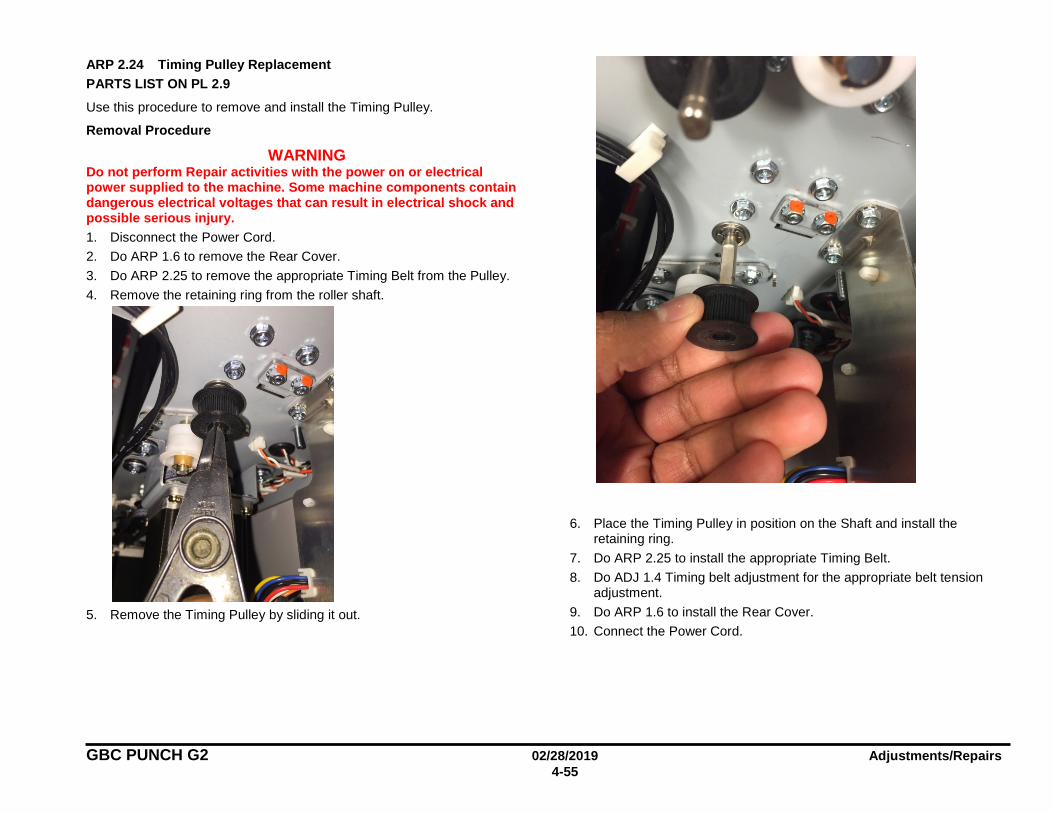
ARP 2.24 Timing Pulley Replacement PARTS LIST ON PL 2.9
Use this procedure to remove and install the Timing Pulley.
Removal Procedure
WARNING Do not perform Repair activities with the power on or electrical power supplied to the machine. Some machine components contain dangerous electrical voltages that can result in electrical shock and possible serious injury. 1. Disconnect the Power Cord. 2. Do ARP 1.6 to remove the Rear Cover. 3. Do ARP 2.25 to remove the appropriate Timing Belt from the Pulley. 4. Remove the retaining ring from the roller shaft.
5. Remove the Timing Pulley by sliding it out.
6. Place the Timing Pulley in position on the Shaft and install the retaining ring.
7. Do ARP 2.25 to install the appropriate Timing Belt. 8. Do ADJ 1.4 Timing belt adjustment for the appropriate belt tension
adjustment. 9. Do ARP 1.6 to install the Rear Cover. 10. Connect the Power Cord.
GBC PUNCH G2 02/28/2019 Adjustments/Repairs 4-55

ARP 2.25 Timing Belt Replacement There are eight (8) belts used at the rear of the Frame in the PUNCH G2.
Fie (5) belts connect to motors.
Type of Belt # Motor ARP Page Belt, 534T, 2MM 2GT 1 belt M8 ARP 2.25.1 4-56 Belt, 134T, 2MM 2GT 3 belts M1
M6 M7
ARP 2.25.2 4-57
Belt, 179T, 2MM 2GT, 6MM Wide
1 belt M2 ARP 2.25.4 4-57
Three (3) belts are used to connect two nip rollers.
Type of Belt # Connects Rollers
ARP Page
Belt, 150 T, 2MM 2GT 3 belts N1 and N2 N2 and N3 N8 and N9
ARP 2.25.3 4-57
Use the following procedures to Replace the belts.
Adjustments/Repairs
ARP 2.25.1 534T Belt Replacement PARTS LIST ON PL 2.9
Use this procedure to remove and install the 534T Belt for the Bypass Motor (M8).
WARNING Do not perform Repair activities with the power on or electrical power supplied to the machine. Some machine components contain dangerous electrical voltages that can result in electrical shock and possible serious injury. 1. Disconnect the Power Cord. 2. Do ARP 1.6 to remove the Rear Cover. 3. Loosen the Tensioner and remove the old Belt.
Tensioner
4. Place the new Belt in position around the Pulleys (11).
(Cont.)
5. Adjust the Belt Tension per ADJ 1.4 Timing Belt Adjustment. 6. Do ARP 1.6 to install the Rear Cover. 7. Connect the Power Cord.
02/28/2019 GBC PUNCH G2 4-56

ARP 2.25.2 134T Belt Replacement PARTS LIST ON PL 2.9
Use this procedure to remove and install the 134T Belt.
WARNING Do not perform Repair activities with the power on or electrical power supplied to the machine. Some machine components contain dangerous electrical voltages that can result in electrical shock and possible serious injury. 1. Disconnect the Power Cord. 2. Do ARP 1.6 to remove the Rear Cover. 3. Loosen the Tensioner and remove the old Belt.
4. Place the new Belt in position around the Pulleys. 5. Adjust the Belt Tension per ADJ 1.4 Timing Belt Adjustment. 6. Do ARP 1.6 to install the Rear Cover. 7. Connect the Power Cord.
ARP 2.25.3 150T Belt Replacement PARTS LIST ON PL 2.9
Use this procedure to remove and install the 150T Belt.
Removal Procedure
WARNING Do not perform Repair activities with the power on or electrical power supplied to the machine. Some machine components contain dangerous electrical voltages that can result in electrical shock and possible serious injury. 1. Disconnect the Power Cord. 2. Do ARP 1.6 to remove the Rear Cover. 3. Do ARP 2.24 to remove both of the Pulleys Connected to the Belt that
is being replaced.
4. Place the Belt in position between the Pulleys and slide the Pulleys on to the Shafts.
5. Install the retaining rings 6. Do ARP 1.6 to install the Rear Cover. 7. Connect the Power Cord.
GBC PUNCH G2 02/28/2019 Adjustments/Repairs 4-57

ARP 2.25.4 179T Belt Replacement PARTS LIST ON PL 2.9
Use this procedure to remove and install the Belt 179T, 2MM 2GT, 6MM Wide.
WARNING Do not perform Repair activities with the power on or electrical power supplied to the machine. Some machine components contain dangerous electrical voltages that can result in electrical shock and possible serious injury. 1. Disconnect the Power Cord. 2. Do ARP 1.6 to remove the Rear Cover. 3. Loosen the Tensioner and remove the old Belt.
4. Place the new Belt in position around the Pulleys. 5. Adjust the Belt Tension per ADJ 1.4 Timing Belt Adjustment. 6. Do ARP 1.6 to install the Rear Cover. 7. Connect the Power Cord.
Adjustments/Repairs 02/28/2019 GBC PUNCH G2 4-58

S25
0 0
S26
~ V Os□L2
S6,S7 Sl5,Sl 4
~ Q Sl l ~ ~~"~"" ~ N:,N: l
S2~8 PU CH M3 PIN
MS CENTER M4
S29 □
D
Chi p Tr u y
SI,./ I
□
ARP 2.26 Drive Roller Assembly Replacement PARTS LIST ON PL 2.2, PL 2.3, PL 2.4
Use this procedure to remove and install a Drive Roller Assembly (Part # 7715093) used in Nips N1 - N14, except Nip N5.
Do not use this procedure for Nip N5 (Part # 7715097), Do ARP 2.26.1.
Procedures for individual Drive Rollers are located immediately after this general procedure.
Removal Procedure
1. Do ARP 1.6 to remove the Rear Cover. 2. Open the Front Door. 3. Locate the appropriate Drive Roller.
4. For all Drive Rollers (except N1 and N11), do ARP 3.1 to remove the Punch Module.
5. Do ARP 2.25 to remove the Belt from the appropriate Drive Roller Shaft.
6. Do ARP 2.24 to remove the Pulley from the appropriate Drive Roller Shaft.
7. Remove the E-Ring and the Washer from the end of the Drive Roller Shaft at the front of the machine.
E-Ring
Washer Drive Roller Shaft
(Cont.)
GBC PUNCH G2 02/28/2019 Adjustments/Repairs 4-59

8. Remove the E-Ring and the Washer from the end of the Drive Roller Shaft at the rear of the machine.
E-Ring
Washer
Drive Roller Shaft 9. Remove the Drive Roller.
Drive Roller
10. Remove the Bearing from the front of the machine. 11. Remove the Bearing from the rear of the machine.
Adjustments/Repairs
Installation Procedure
1. Place the Drive Roller in position 2. Place the Bearing in position at the front of the machine. 3. Place the Bearing in position at the rear of the machine. 4. Place the Washer and the E-Ring in position the end of the Drive
Roller Shaft at the front of the machine. 5. Place the Washer and the E-Ring in position the end of the Drive
Roller Shaft at the rear of the machine. 6. Do ARP 2.24 to install the Pulley on the appropriate Drive Roller
Shaft. 7. Do ARP 2.25 to install the Belt on the appropriate Drive Roller. 8. For all Drive Rollers (except N1 and N11), do ARP 3.1 to install the
Punch Module. 9. Do ARP 1.6 to install the Rear Cover. 10. Close the Front Door. 11. Connect the Power Cord.
02/28/2019 GBC PUNCH G2 4-60

ARP 2.26.1 Drive Roller N5 Replacement 6. Remove the Belt from the Motor Pulley Do the following to remove and replace the Drive Roller for Nip N5.
Removal Procedure
1. Disconnect the Power Cord. 2. Do ARP 1.6 to remove the Rear Cover. 3. Do ARP 3.1 to remove the Punch Module. 4. Loosen the nuts (2) on the Tensioner of the M2 motor belt.
Tensioner
Nuts (2)
5. Remove the retaining ring from the shaft of roller N5.
(Cont.)
7. Slide the Pulley off the Roller Shaft.
GBC PUNCH G2 02/28/2019 Adjustments/Repairs 4-61
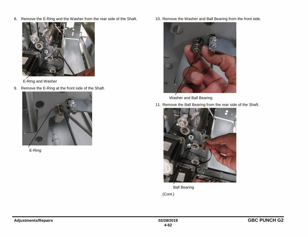
8. Remove the E-Ring and the Washer from the rear side of the Shaft. 10. Remove the Washer and Ball Bearing from the front side.
E-Ring and Washer
9. Remove the E-Ring at the front side of the Shaft.
Washer and Ball Bearing
11. Remove the Ball Bearing from the rear side of the Shaft.
E-Ring
Ball Bearing
(Cont.)
Adjustments/Repairs 02/28/2019 GBC PUNCH G2 4-62

12. Remove the Drive Roller. Installation Procedure
1. Place the Drive Roller in position. 2. Install the Ball Bearing at the rear side of the Shaft. 3. Install the Ball Bearing and the Washer at the front side of the Shaft. 4. Install the E-Ring at the front side of the Shaft 5. Install the Washer and the E-Ring at the rear side of the Shaft. 6. Slide the Pulley on to the Roller Shaft. 7. Place the Belt over the Pulley. 8. Install the retaining ring on the Drive Roller N5. 9. Move the Tensioner of the M2 motor belt into position and tighten the
Screws (2). 10. Do ARP 3.1 to install the Punch Module. 11. Do ARP 1.6 to install the Rear Cover. 12. Close the Front Door. 13. Connect the Power Cord.
Drive Roller.
GBC PUNCH G2 02/28/2019 Adjustments/Repairs 4-63

ARP 2.27 Stepper and Mount Assembly Replacement PARTS LIST ON PL 2.6
Use this procedure to remove and install the Entrance Motor (M1), Accel Motor (M2), Exit Motor (M6), Decel Motor (M7), or Bypass Motor (M8).
WARNING Do not perform Repair activities with the power on or electrical power supplied to the machine. Some machine components contain dangerous electrical voltages that can result in electrical shock and possible serious injury. 1. Disconnect the Power Cord. 2. Do ARP 1.6 to remove the Rear Cover.
M8
M7
M1 M6
M2
Adjustments/Repairs
3. Locate the affected Motor (see PL 2.6). 4. Disconnect the Motor Connector from the corresponding Motor Drrver
(PL 2.6). 5. Loosen the corresponding Timing belt tensioner by loosing (2) M4
nuts. 6. Remove the M4 Screws or nuts and the flat washer (4) and the
Stepper and Mount Assembly from the Rear Panel.
Washers (4)
Screws (4)
7. Place the Stepper and Mount Assembly in position and tighten the Screws (4).
8. Adjust the corresponding belt tension per ADJ 1.4 Timing belt adjustment procedure.
9. Connect the Motor Connector. 10. Do ARP 1.6 to install the Rear Cover. 11. Connect the Power Cord.
02/28/2019 GBC PUNCH G2 4-64

ARP 2.28 Paper Path Sensor Replacement PARTS LIST ON PL PL 3.1, 3.2, PL 3.3, PL 3.4, PL 3.5, 4.2
Use the following procedures to remove and install the paper path sensors.
WARNING Do not perform Repair activities with the power on or electrical power supplied to the machine. Some machine components contain dangerous electrical voltages that can result in electrical shock and possible serious injury.
Sensor # ARP # Sensor # ARP # S1 ARP 2.25.1 S15 ARP 2.25.7 S2 ARP 2.25.2 S16 ARP 2.25.8 S3 ARP 2.25.2 S17 ARP 2.25.8 S4 ARP 2.25.2 S18 ARP 2.25.5 S5 ARP 2.25.3 S19 ARP 2.25.5 S6 ARP 2.25.6 S20 ARP 2.25.5 S7 ARP 2.25.6 S21 ARP 2.25.5 S8 ARP 2.25.6 S22 ARP 2.25.2 S9 ARP 2.25.6 S23 ARP 2.25.2 S10 ARP 2.25.6 S24 ARP 2.25.2 S11 ARP 2.25.7 S25 ARP 2.25.1 S12 ARP 2.25.7 S26 ARP 2.25.1 S13 ARP 2.25.7 S28 ARP 2.25.4 S14 ARP 2.25.7
ARP 2.28.1 Entrance Sensor (S1,) Exit Sensor (S25), and Bypass Middle Sensor (S26) Replacement Use this procedure to remove and install the Sensor and Bracket Assembly for the Entrance Sensor, S1 and Exit Sensor, S25.
1. Disconnect the Power Cord. 2. Open the Front Door.
S25
S26
S1
3. Disconnect the Sensor Connector at the Sensor. 4. Remove the Barrell screw that secures the Sensor to the sheet metal
part. 5. Remove the old Sensor. 6. Place the new Sensor in position, then install the Barrell Screw. 7. Close the Front Door. 8. Connect the Power Cord.
GBC PUNCH G2 02/28/2019 Adjustments/Repairs 4-65

ARP 2.28.2 Top, Middle, & Bottom Entrance Sensor (S2, S3, S4) and Top, Middle, & Bottom Exit Sensor (S22, S23, S24) Replacement Use this procedure to remove and install the Sensor and Bracket Assembly for the Top, Middle, & Bottom Entrance Sensor (S2, S3, S4) and Exit Sensor (S22, S23, S24).
1. Disconnect the Power Cord. 2. Do GP 6.3 to undock the Punch from the upstream and downstream
equipment. 3. Remove the docking bracket as needed to access the Sensor 4. Disconnect the sensor wire and the Sensor. 5. Remove the Barrel Screw that secures the Sensor to the sheet metal
part.
S2
S3
S4
Adjustments/Repairs
S24
S23
S22
6. Remove the old Sensor. 7. Place the new Sensor in position, then install the Barrell Screw. 8. Do GP 6.4 to dock the Punch to the upstream and downstream
equipment. 9. Connect the Power Cord.
02/28/2019 GBC PUNCH G2 4-66

ARP 2.28.3 Accel Sensor (S5) Replacement Use this procedure to remove and install the Sensor and Bracket Assembly for the Accel Sensor (S5).
1. Disconnect the Power Cord. 2. Do GP 6.3 to undock the Punch from the upstream and downstream
equipment. 3. Disconnect the sensor connector at the Sensor. 4. Remove the Barrel Screw that secures the Sensor to the sheet metal
part.
Accel Sensor (S5)
5. Remove the old Sensor. 6. Place the new Sensor in position, then install the Barrell Screw. 7. Do GP 6.4 to dock the Punch to the upstream and downstream
equipment. 8. Connect the Power Cord.
GBC PUNCH G2 02/28/2019 Adjustments/Repairs 4-67

ARP 2.28.4 Align Home Sensor (S28) Replacement Use this procedure to remove and install the Sensor and Bracket Assembly for the Align Home Sensor (S28).
1. Disconnect the Power Cord. 2. Do GP 6.3 to undock the Punch from the upstream and downstream
equipment. 3. Disconnect the Sensor Wire Connector from the Sensor.
Sensor Wire Connector
4. Remove the M3 Screws (2) that secure the Sensor to the Bracket.
Sensor Bracket
Screws (2)
Adjustments/Repairs
5. Remove the Sensor Sub-assembly.
6. Place the new Sensor in position.
Sensor Sub-assembly
7. Tighten the M3 Screws (2) that secure the Sensor to the Bracket. 8. Connect the Sensor Connector to the Sensor. 9. Do GP 6.4 to dock the Punch to the upstream and downstream
equipment. 10. Connect the AC power cord
02/28/2019 GBC PUNCH G2 4-68

ARP 2.28.5 Backage Sensor Board Assembly (S18, S19) and 5. Disconnect the Sensor Board Connectors (2). Backage Sensor Board Assembly (S20, S21) Replacement Use this procedure to remove and install the Backage Sensor Board (S18, S19) or the Backage Sensor Board (S20, S21).
WARNING Do not perform Repair activities with the power on or electrical power supplied to the machine. Some machine components contain dangerous electrical voltages that can result in electrical shock and possible serious injury. 1. Disconnect the Power Cord. 2. Do ARP 1.6 to remove the Rear Cover. 3. Do ARP 3.1 to remove the Punch Module. 4. Locate the Drive Entrance Panel
• The upper board is the Backage Sensor Board (S20, S21).
Backage Sensor Board (S20, S21) Sensor Board Connector (2)
6. Remove the Nuts (3) and Washers (3). 7. Remove the old Backage Sensor Board. 8. Place the new Punch Sensor Board in position. 9. Place the Washers (3) in position and tighten the Nuts (3). 10. Connect the Sensor Board Connector. 11. Do ARP 3.1 to install the Punch Module. 12. Do ARP 1.6 to install the Rear Cover. 13. Connect the Power Cord.
Drive Entrance Panel Backage Sensor Board (S18, S19)
• The lower board is the Backage Sensor Board (S18, S19).
GBC PUNCH G2 02/28/2019 Adjustments/Repairs 4-69

ARP 2.28.6 Skew Sensor Board (S6 – S10) Replacement Use this procedure to remove and install the Skew Sensor Board (S6, S7, S8, S9, S10).
1. Disconnect the Power Cord. 2. Do ARP 1.6 to remove the Rear Cover. 3. Do ARP 3.1 to remove the Punch Module.
Skew Sensor Board
4. Disconnect the Skew Sensor Board Connector.
Skew Sensor Board Connector Skew Sensor Board
Adjustments/Repairs
5. Remove the Nuts (4), Washers (4), and the Skew Sensor Board. (do not remove the washers under the sensor board)
Skew Sensor Board 6. Place the new Skew Sensor Board in position. 7. Install the Washers (4) and tighten the Nuts (4). (Make sure there are
(4) washers below the sensor board). 8. Connect the Sensor Board Connector. 9. Do ARP 3.1 to install the Punch Module. 10. Do ARP 1.6 to install the Rear Cover. 11. Connect the Power Cord.
02/28/2019 GBC PUNCH G2 4-70

ARP 2.28.7 Alignment Sensor Board (S11 – S15) Replacement Use this procedure to remove and install the Alignment Sensor Board (S11, S12, S13, S4, S15).
1. Disconnect the Power Cord. 2. Do ARP 1.6 to remove the Rear Cover. 3. Do ARP 3.1 to remove the Punch Module. 4. Disconnect the Skew Sensor Board Connector.
Skew Sensor Board Connector 5. Release the Cable Clamp and move the Cable out of the way. 6. Remove the M4 Nuts (2) and remove the steering idler roller cover.
7. Remove the sleeve from the threaded stud.
8. Disconnect the Alignment sensor board connector.
9. Release the Cable Clamp and move the Cable out of the way. 10. Remove the M4 Nuts (2) and Washers (2),
11. Remove the Alignment Sensor Board.
M4 nuts (2) Washers (2)
GBC PUNCH G2 02/28/2019 Adjustments/Repairs 4-71

12. Place the new Alignment Sensor Board in position. 13. Install the Washers (2) and tighten the Nuts (2) (make sure there are
washers below the board). 14. Install the sleeve removed at step 7. 15. Place the Alignment Sensor Board Cable into the Cable Clamps and
close the Cable Clamps. 16. Connect the Alignment Sensor Board Connector. 17. Place the Roller Cover in position. 18. Place the Skew Sensor Board Cable into the Cable Clamps and close
the Cable Clamps. 19. Connect the Skew Sensor Board Connector. 20. Do ARP 3.1 to install the Punch Module. 21. Do ARP 1.6 to install the Rear Cover. 22. Connect the Power Cord.
Adjustments/Repairs 02/28/2019 GBC PUNCH G2 4-72

ARP 2.28.8 Backage Sensor Board (S16, S17) Replacement Use this procedure to remove and install the Backage Sensor Board (S16, S17) or the Backage Sensor Bracket.
1. Disconnect the Power Cord. 2. Do ARP 1.6 to remove the Rear Cover. 3. Do ARP 3.1 to remove the Punch Module.
6. Place the new Backage Sensor Board in position. 7. Install the Washers (3) and tighten the Nuts (3) 8. Connect the Sensor Board Connector. 9. Do ARP 3.1 to install the Punch Module. 10. Do ARP 1.6 to install the Rear Cover. 11. Connect the Power Cord.
Backage Sensor Board
4. Disconnect the Sensor Board Connector at the Board.
5. Remove the Nuts (3), Washers (3), and the Backage Sensor Board.
GBC PUNCH G2 02/28/2019 Adjustments/Repairs 4-73
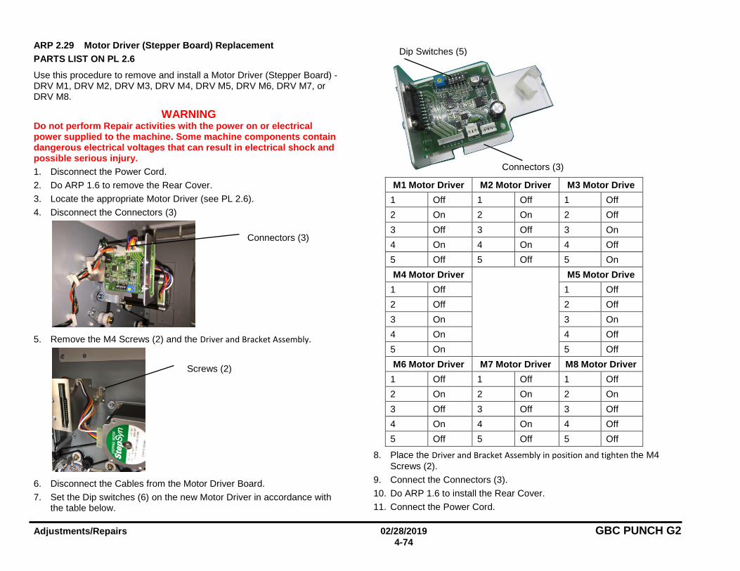
--
I I I
~
~
-I I I -
'
-
-
'
~
-
-
ARP 2.29 Motor Driver (Stepper Board) Replacement PARTS LIST ON PL 2.6
Use this procedure to remove and install a Motor Driver (Stepper Board) -DRV M1, DRV M2, DRV M3, DRV M4, DRV M5, DRV M6, DRV M7, or DRV M8.
WARNING Do not perform Repair activities with the power on or electrical power supplied to the machine. Some machine components contain dangerous electrical voltages that can result in electrical shock and possible serious injury. 1. Disconnect the Power Cord. 2. Do ARP 1.6 to remove the Rear Cover. 3. Locate the appropriate Motor Driver (see PL 2.6). 4. Disconnect the Connectors (3)
Connectors (3)
5. Remove the M4 Screws (2) and the Driver and Bracket Assembly.
Screws (2)
6. Disconnect the Cables from the Motor Driver Board. 7. Set the Dip switches (6) on the new Motor Driver in accordance with
the table below.
Adjustments/Repairs
Dip Switches (5)
Connectors (3)
M1 Motor Driver M2 Motor Driver M3 Motor Drive 1 Off 1 Off 1 Off 2 On 2 On 2 Off 3 Off 3 Off 3 On 4 On 4 On 4 Off 5 Off 5 Off 5 On M4 Motor Driver M5 Motor Drive
1 Off 1 Off 2 Off 2 Off 3 On 3 On 4 On 4 Off 5 On 5 Off M6 Motor Driver M7 Motor Driver M8 Motor Driver
1 Off 1 Off 1 Off 2 On 2 On 2 On 3 Off 3 Off 3 Off 4 On 4 On 4 Off 5 Off 5 Off 5 Off
8. Place the Driver and Bracket Assembly in position and tighten the M4 Screws (2).
9. Connect the Connectors (3). 10. Do ARP 1.6 to install the Rear Cover. 11. Connect the Power Cord.
02/28/2019 GBC PUNCH G2 4-74

ARP 2.30 Solenoid Replacement PARTS LIST ON PL 2.8 PL 3.2, PL 3.3, PL 3.4
Use this procedure to remove and install the Solenoids in these assemblies:
Solenoid Solenoid # ARP #
Diverter Subassembly SOL 1 ARP 2.30.1
Punch Clutch SOL 2 ARP 3.7
Entrance Idler Solenoid, Middle SOL 3 ARP 2.30.2
Entrance Idler Solenoid, Bottom SOL 4 ARP 2.30.2
Acceleration Roller Idler Solenoid SOL 5 ARP 2.30.3
Exit Idler Solenoid, Bottom SOL 6 ARP 2.30.4
Exit Idler Solenoid, Middle SOL 7 ARP 2.30.4
Exit Idler Solenoid, Top SOL 8 ARP 2.30.4
WARNING Do not perform Repair activities with the power on or electrical power supplied to the machine. Some machine components contain dangerous electrical voltages that can result in electrical shock and possible serious injury.
ARP 2.30.1 Diverter Solenoid Replacement PARTS LIST ON PL 2.3
Use this procedure to remove and install the Diverter Solenoid Assembly (SOL 1).
WARNING Do not perform Repair activities with the power on or electrical power supplied to the machine. Some machine components contain dangerous electrical voltages that can result in electrical shock and possible serious injury. Removal Procedure
1. Disconnect the Power Cord. 2. Do ARP 1.6 to remove the Rear Cover. 3. Do ARP 1.16 to remove the Exhaust Fan Bracket. 4. Remove the M4 (2) screws from the Diverter Shaft.
5. Disconnect the inline Connector for the Diverter Solenoid sub-assembly.
GBC PUNCH G2 02/28/2019 Adjustments/Repairs 4-75

\ 'I_:. ~, ~~~ ·-l f ~ -~
6. R
emove Screw
s (2) from the diverter solenoid sub assem
bly.
7. R
emove the D
iverter Solenoid Sub-assembly.
Installation Procedure
1. Place the new
Solenoid in position and tighten the Screw
s (2) to the rear fram
e and two screw
s to the diverter shaft 2.
Connect the inline C
onnector for the Diverter Solenoid.
3. Place the the C
able into the Cable C
lamps and close the C
able C
lamps
4. D
o ADJ 1.2 D
iverter solenoid adjustment.
5. D
o ARP 1.16 to install the Exhaust Fan Bracket
6. D
o ARP 1.6 to install the R
ear Cover.
7. C
onnect the Pow
er Cord.
Adjustm
ents/Repairs
02/28/2019 G
BC
PUN
CH
G2
4-76

ARP 2.30.2 Entrance Idler Solenoid Replacement Use this procedure to remove and install the Entrance Idler Solenoids (SOL 3 & SOL 4).
1. Disconnect the Power Cord. 2. Do GP 6.3 Undock the Punch. 3. Open the Front Door. 4. Disconnect the Solenoid Connector for the Solenoid being replaced.
ARP 2.30.3 Acceleration Roller Idler Solenoid Replacement Use this procedure to remove and install the Acceleration Roller Idler Solenoid (SOL 5).
1. Disconnect the Power Cord. 2. Do GP 6.3 Undock the Punch. 3. Open the Front Door. 4. Disconnect the Solenoid Connector.
SOL3
SOL4
5. Open the Cable Clamps and remove the Cable. 6. Remove the M4 Barrel Screws (3) and the Solenoid assembly. 7. Place the new Solenoid assembly in position and tighten the barrel
Screws (3). 8. Connect the Solenoid Connector. 9. Place the the Cable into the Cable Clamps and close the Cable
Clamps 10. Close the Front Door. 11. Do GP 6.4 Dock the Punch. 12. Connect the Power Cord.
SOL5
5. Open the Cable Clamps and remove the Cable. 6. Remove the M4 Barrel Screws (3) and the Solenoid. 7. Place the new Solenoid in position and tighten the barrel Screws (3). 8. Connect the Solenoid Connector. 9. Place the the Cable into the Cable Clamps and close the Cable
Clamps 10. Close the Front Door. 11. Do GP 6.4 Dock the Punch. 12. Connect the Power Cord.
GBC PUNCH G2 02/28/2019 Adjustments/Repairs 4-77

ARP 2.30.4 Exit Idler Solenoid Replacement Use this procedure to remove and install the Exit Idler Solenoids (SOL 6, SOL 7, & SOL 8)
1. Disconnect the Power Cord. 2. Do GP 6.3 Undock the Punch. 3. Do ARP 1.18 to remove the Downstream side cover. 4. Open the Front Door. 5. Disconnect the Solenoid Connector.
SOL 8
SOL 7
SOL 6
6. Open the Cable Clamps and remove the Cable. 7. Remove the M4 Barrel Screws (3) and the Solenoid. 8. Place the new Solenoid in position and tighten the Screws (3). 9. Connect the Solenoid Connector. 10. Place the the Cable into the Cable Clamps and close the Cable
Clamps 11. Close the Front Door. 12. Do GP 6.4 Dock the Punch. 13. Connect the Power Cord.
Adjustments/Repairs
ARP 2.31 Upper Bypass Panel Anti-Static Brush Replacement PARTS LIST ON PL 3.5
Use this procedure to replace the Anti-Static Brush on the Upper Bypass Panel.
WARNING Do not perform Repair activities with the power on or electrical power supplied to the machine. Some machine components contain dangerous electrical voltages that can result in electrical shock and possible serious injury. 1. Disconnect the Power Cord. 2. Do GP 6.3 to undock the Punch from the downstream equipment.
Anti-Static Brush
3. Peel off the old Anti-Static Brush. 4. Clean the surface with some rubbing alcohol 5. Affix the new brush inside referencing the cut-outs as shown above. 6. Do GP 6.4 to dock the Punch from the downstream equipment. 7. Connect the Power Cord.
02/28/2019 GBC PUNCH G2 4-78

3. Punch Module 5. Use the levers (blue) to open the Acceleration Roller Idler Panel and the Exit panel. ARP 3.1 Punch Module Replacement
PARTS LIST ON PL 4.1
Use this procedure to remove and install the Punch Module.
ARP 3.1.1 Punch Module Removal
WARNING Do not perform Repair activities with the power on or electrical power supplied to the machine. Some machine components contain dangerous electrical voltages that can result in electrical shock and possible serious injury. 1. Disconnect the Power Cord. 2. Do ARP 1.6 to remove the Rear Cover. 3. Open the Front Door. 4. If a die set is installed, remove it and store it in the die storage rack.
6. Remove the M4 X 10 Phillips Head Screw and the Die Lock Handle.
GBC PUNCH G2 02/28/2019 Adjustments/Repairs 4-79

7. Remove the M4 Screws (5) from the Front Frame. The screws to be 10. Disconnect the Connector for Sensor S28. removed are marked with a downward arrow ( ).
11. Disconnect the Connector for Solenoid SOL2.
8. Go to the rear of the Punch. 9. Disconnect the Connectors (2) for Sensors S6-S10 and S11-S15.
12. Disconnect the Connector for the M5 Motor Driver.
(Cont.)
(Cont.)
Adjustments/Repairs 02/28/2019 GBC PUNCH G2 4-80

13. Disconnect the Connectors (2) for the M3 Header and the M4 15. Disconnect the Connector for Sensors S16 and S17. Header.
16. Disconnect the Connector for Punch Motor M10.
14. Disconnect the Die Set Recognition Connector.
(Cont.)
GBC PUNCH G2 02/28/2019 Adjustments/Repairs 4-81

17. Do the following to remove the Punch Module Mount Bracket (Lock Plates). • Use a Phillips Head Screwdriver to remove the Screw from the
right Punch Module Mount Bracket. • Remove the right Punch Module Mount Bracket.
• Use a Phillips Head Screwdriver to remove the Screw from the right Punch Module Mount Bracket.
• Remove the right Punch Module Mount Bracket.
Adjustments/Repairs
18. Do the following to remove the Punch Module • Grasp the handle and slowly pull the punch module out for about
100mm.
• Reach in and grasp the rear handle and continue to slide the punch. Lift the punch off the rail- DO NOT let it drop on the control board.
02/28/2019 GBC PUNCH G2 4-82

• Place the Punch Module on a flat surface. ARP 3.1.2 Punch Module Installation Use this procedure to install the Punch Module.
1. Slide the Punch Module into the slot at the rear of the machine. 2. Install the punch module lock plates and tighten the captive screws. 3. Connect all electrical connectors for the below 10 components.
• Connector for Punch Motor M10. • Connector for Sensors S16 and S17. • Die Set Recognition Connector (2 terminals) • Connectors (2) for the M3 Header and the M4 Header. • Connector for the M5 Motor Driver • Connector Solenoid SOL2. • Connector for Sensor S28. • Connectors (2) for Sensors S6-S10 and S11-S15.
4. Go to the front of the Punch 5. Tighten the M4 Screws (5) into the Front Frame. 6. Install the Die Lock Handle and tighten the M4 X 10 Phillips Head
Screw. 7. Install the Die Set (see Operation Instructions Manual). 8. Close the Front Door. 9. Do ARP 1.6 to install the Rear Cover. 10. Connect the Power Cord.
GBC PUNCH G2 02/28/2019 Adjustments/Repairs 4-83

S25
0 0
S26
@ R S20,S21
Os□L2
S6,S7 S15,S14
S8 ~ 3Sl2
S18 Sl
0 Sll ~
0 1 B N6,N7
S2~8 PUNCH M3 PIN
M5 CENTER M4
S29 □ S'w 2
D
Chip Tro.y
S'w 1
□
ARP 3.2 Chip Tray Home Switch Replacement PARTS LIST ON PL 2.5
Use this procedure to remove and install the Chip Tray Home Switch (SW2).
1. Open the Front Door.
Chip Tray
Adjustments/Repairs
2. Remove the Chip Tray. 3. Disconnect Cable 7715485 at the Chip Tray Home Switch.
Chip Tray Home Switch Cable Screws (2)
4. Remove the Screws (2) and the old Chip Tray Home Switch Bracket. 5. Place the new Chip Tray Home Switch Bracket in position and tighten
the Screws (2). 6. Connect Cable 7715485 at the Chip Tray Home Switch. 7. Put the Chip Tray in position and push the Chip Tray Assembly in
firmly until it latches. 8. Close the Front Door. 9. Connect the Power Cord.
02/28/2019 GBC PUNCH G2 4-84

ARP 3.3 Chip Level Emitter Replacement PARTS LIST ON PL 2.5
Use this procedure to remove and install the Chip Level Emitter Assembly.
WARNING Do not perform Repair activities with the power on or electrical power supplied to the machine. Some machine components contain dangerous electrical voltages that can result in electrical shock and possible serious injury. 1. Disconnect the Power Cord. 2. Open the Front Door. 3. Remove the Chip Tray. 4. Locate the Chip Level Emitter on the Frame at the left (downstream)
side of the Chip Tray compartment. 5. Disconnect Cable 7715485 at the Chip Level Emitter.
Chip Level Emitter
Screws (2) Cable 7715485
6. Remove the Screws (2) and the old Chip Level Emitter. There will be Washers (4) between the Sensor and the sheet metal Bracket.
7. Place the new Chip Level Emitter, and the Washers (4), in position and tighten the Screws (2).
8. Connect Cable 7715485 at the Chip Level Emitter. 9. Put the Chip Tray in position and push the Chip Tray Assembly in
firmly until it latches. 10. Close the Front Door. 11. Connect the Power Cord.
ARP 3.4 Chip Level Receiver Replacement PARTS LIST ON PL 2.5
Use this procedure to remove and install the Chip Level Receiver Assembly.
WARNING Do not perform Repair activities with the power on or electrical power supplied to the machine. Some machine components contain dangerous electrical voltages that can result in electrical shock and possible serious injury. 1. Disconnect the Power Cord. 2. Open the Front Door. 3. Remove the Chip Tray. 4. Locate the Chip Level Receiver on the Frame at the right (upstream)
side of the Chip Tray compartment. 5. Disconnect Cable 7715485 at the Chip Level Receiver.
Screws (2)
Chip Level Receiver
Cable 7715485
6. Remove the Screws (2) and the old Chip Level Receiver. There will be Washers (4) between the Sensor and the sheet metal Bracket.
7. Place the new Chip Level Receiver, and the Washers (4), in position and tighten the Screws (2).
8. Connect Cable 7715485 at the Chip Level Receiver. 9. Put the Chip Tray in position and push the Chip Tray Assembly in
firmly until it latches. 10. Close the Front Door. 11. Connect the Power Cord.
GBC PUNCH G2 02/28/2019 Adjustments/Repairs 4-85

ARP 3.5 Punch Motor Replacement PARTS LIST ON PL 4.11
Use this procedure to remove and install the Punch Motor (M10).
Removal Procedure
WARNING Do not perform Repair activities with the power on or electrical power supplied to the machine. Some machine components contain dangerous electrical voltages that can result in electrical shock and possible serious injury. 1. Disconnect the Power Cord. 2. Do ARP 1.6 to remove the Rear Cover. 3. Do ARP 3.1 to remove the Punch Module.
Punch Motor Belt
4. Do ARP 3.6 Punch Motor Belt Replacement (Timing Belt) to remove the Punch Motor Belt.
Adjustments/Repairs
Cap Screws (4), Split Lock Washers (4),
Flat Washers (4)
5. Remove the M8 Hex Cap Screws (4), the M8 Split Lock Washers (4), and the Flat Washers (4).
6. Remove the old Punch Motor. Installation Procedure
1. Using the position marks on the Bracket, place the new Punch Motor in position.
Mark
2. Place the Flat Washers (4) and the M8 Split Lock Washers (4) in position.
3. Tighten the M8 Hex Cap Screws (4). 4. Do ARP 3.6 Punch Motor Belt Replacement (Timing Belt) to install the
Punch Motor Belt. 5. Do ARP 3.1 to install the Punch Module. 6. Do ARP 1.6 to install the Rear Cover. 7. Connect the Power Cord.
02/28/2019 GBC PUNCH G2 4-86

ARP 3.6 Punch Motor Belt Replacement (Timing Belt) PARTS LIST ON PL 4.1
Use this procedure to remove and install the Punch Motor Belt.
• (Belt, Timing, Punch Pulley, 115V) • Belt, Timing, Punch Pulley, 230V
WARNING Do not perform Repair activities with the power on or electrical power supplied to the machine. Some machine components contain dangerous electrical voltages that can result in electrical shock and possible serious injury. 1. Disconnect the Power Cord. 2. Do ARP 1.6 to remove the Rear Cover. 3. There is no need to uninstall the punch module, however for ease of
operation it is a good idea to uninstall it using ARP 3.1 4. Remove the JE-10 E-Ring.
5. Remove the Nylon Washer. 6. Remove the Ball Bearing. 7. Remove the Screws (2) and the Bearing Bracket.
8. Remove the old Belt.
Belt
Clutch Pulley
GBC PUNCH G2 02/28/2019 Adjustments/Repairs 4-87

9. Place the new Belt around the Timing Pulley on the Punch Motor and the Clutch pulley.
10. Place the Bearing Bracket in position and tighten the Screws (2). 11. Place the Ball Bearing in position. 12. Place the Nylon Washer in position. 13. Place the E-Ring in position.
NOTE: The tension on the Belt is set using the reference marks on the punch motor bracket (see ARP 3.5).
14. Do ARP 1.6 to install the Rear Cover. 15. Connect the Power Cord.
Mark
Adjustments/Repairs 02/28/2019 GBC PUNCH G2 4-88

ARP 3.7 Clutch or Clutch Pulley Replacement PARTS LIST ON PL 4.8
Use this procedure to remove and install the Clutch or the Clutch Pulley in the Punch Module.
Removal Procedure
WARNING Do not perform Repair activities with the power on or electrical power supplied to the machine. Some machine components contain dangerous electrical voltages that can result in electrical shock and possible serious injury. 1. Disconnect the Power Cord. 2. Do ARP 1.6 to remove the Rear Cover. 3. Do ARP 3.1.1 Punch Module Removal. (Cont.) Screw 4. Do ARP 3.6 to remove the Punch Motor Belt.
7. Loosen the Set Screws (2) from the Clutch. 5. To remove the Clutch Pulley
• Remove the M5X18 Screws (3) and Split Lock Washer (3) • Remove the Pulley and Flange.
Set Screws (2)
Clutch
You can press down on the actuator and turn the punch shaft to orient the set screw in any direction for easy access.
Screws
Pulley and Flange
6. Remove the Lock Nut and the long M6 Screw.
Lock Nut (2)
GBC PUNCH G2 02/28/2019 Adjustments/Repairs 4-89
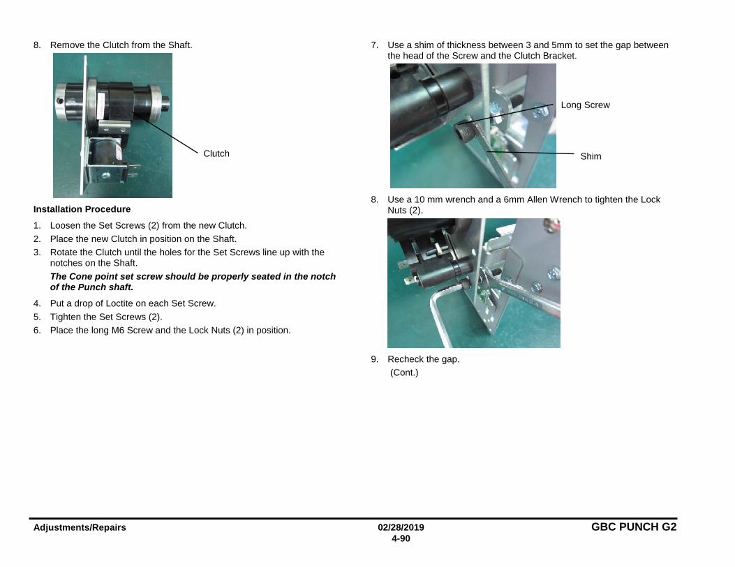
8. Remove the Clutch from the Shaft. 7. Use a shim of thickness between 3 and 5mm to set the gap between the head of the Screw and the Clutch Bracket.
Long Screw
Clutch Shim
8. Use a 10 mm wrench and a 6mm Allen Wrench to tighten the Lock Nuts (2).
1. Loosen the Set Screws (2) from the new Clutch. 2. Place the new Clutch in position on the Shaft. 3. Rotate the Clutch until the holes for the Set Screws line up with the
notches on the Shaft. The Cone point set screw should be properly seated in the notch of the Punch shaft.
4. Put a drop of Loctite on each Set Screw. 5. Tighten the Set Screws (2). 6. Place the long M6 Screw and the Lock Nuts (2) in position.
Installation Procedure
9. Recheck the gap. (Cont.)
Adjustments/Repairs 02/28/2019 GBC PUNCH G2 4-90

10. To replace the Clutch Pulley • Place the Pulley and Flange in position. • Tighten the M5X18 Screws (3) with the Split Lock Washers (3).
11. Place the Punch Shaft Bearing Bracket in position and tighten the Screws (2).
12. Do ARP 3.6 to install the Punch Motor Belt. 13. Do ARP 3.19 Ball Bearing Replacement to install the Ball Bearing. 14. Do ADJ 1.5 Punch Cam Indexing. 15. Do ARP 3.1.2 Punch Module Installation. 16. Do ARP 1.6 to install the Rear Cover. 17. Connect the Power Cord.
GBC PUNCH G2 02/28/2019 Adjustments/Repairs 4-91

ARP 3.8 Punch Alignment Stepper Motor and Pulley Replacement, and Alignment Stepper Bracket Replacement PARTS LIST ON PL 4.7
Use this procedure to remove and install the Punch Alignment Stepper Motor (M5) and Pulley, or the Alignment Stepper Mount Bracket.
Removal Procedure
WARNING Do not perform Repair activities with the power on or electrical power supplied to the machine. Some machine components contain dangerous electrical voltages that can result in electrical shock and possible serious injury. 1. Disconnect the Power Cord. 2. Do ARP 1.6 to remove the Rear Cover. 3. Do ARP 3.1 to remove the Punch Module. (This step is optional; it is
possible to replace the Alignment stepper bracket without removing the punch module.
Punch Alignment Stepper Motor (M5)
Adjustments/Repairs
4. Remove the Phillips Screws (4) and remove the timing belt.
Motor
Screws (4)
Belt 5. To replace the Alignment Stepper Mount Bracket
• Remove the Screws (2) and the old Bracket. • Place the new Bracket in position and tighten the Screws (2).
6. Remove the Punch Alignment Stepper Motor and Pulley. 7. Place the timing Belt around the Pulley. 8. Do ADJ 1.4 to adjust the tension on the Belt. 9. Tighten the Phillips Screws (4). 10. Do ARP 3.1 to install the Punch Module if necessary 11. Close the Front Door. 12. Do ARP 1.6 to install the Rear Cover. 13. Connect the Power Cord.
.
02/28/2019 GBC PUNCH G2 4-92

ARP 3.9 Steering Module Replacement 5. Do the following to take the Alignment stepper belt off the pulley. PARTS LIST ON PL 4.1 • Loosen the Phillips Screws (2).
Use this procedure to remove and install the Steering Module Sub Assembly. Screws (2) Removal Procedure
WARNING Do not perform Repair activities with the power on or electrical power supplied to the machine. Some machine components contain dangerous electrical voltages that can result in electrical shock and Motor possible serious injury. 1. Disconnect the Power Cord. 2. Do ARP 1.6 to remove the Rear Cover. 3. Do ARP 3.1 to remove the Punch Module. • Remove the Alignment stepper Belt from the Pulley.
4. Disconnect the Skew Sensor Board Connector. 6. Pull the Alignment stepper belt in through the hole in the Frame.
Belt Skew Sensor Board Connector
GBC PUNCH G2 02/28/2019 Adjustments/Repairs 4-93

7. Disconnect the Left/Right Steering Stepper Connectors at the Punch Frame. One of the Connectors has 6 pins the other has 7 pins.
9. Similarly remove the Alignment home sensor connector.
• Push the connector towards the outside of the frame.
10. Remove the Phillips Screws (8)- (4) from front side and (4) from rear side
• Press down on the top tab to remove it from the top side. Then press the bottom tab to release the connector fully.
Screws (8)
8. Release the Cable Clamp
Adjustments/Repairs 02/28/2019 GBC PUNCH G2 4-94

11. Remove the Steering Module from the Punch Module, by tilting the Steering Module as shown. This is to ensure the back side clears the self-clinching nut.
Steering Module
Installation Procedure
1. Place the Steering Module into the Punch Module. 2. Push the Steering Belt out through the hole in the Frame. 3. Install the Phillips Screws (8). 4. Connect the Align Home Sensor and the Left/Right Steering Motor
Connectors. 5. Place the Alignment Stepper motor Belt around the Pulley. 6. Tighten the Phillips Screws (2). 7. Do ARP 3.1 to install the Punch Module. 8. Close the Front Door. 9. Do ARP 1.6 to install the Rear Cover. 10. Connect the Power Cord.
GBC PUNCH G2 02/28/2019 Adjustments/Repairs 4-95

p; - , 'Y,_ - :rt • : '
-L~ - \ • • < --,-,~i " I ~ I I \ ... ',.. :~ ~· ... .
."f
.. , ,;:... ....... ~~ - "
1-.1
ARP 3.10 Ground Strap Replacement 6. Remove the Phillips Screw and Nut from the Ground Strap at the Alignment Carriage Sub Assembly. PARTS LIST ON PL 4.3
Removal Procedure
Use this procedure to remove and install the Steering Carriage Ground Strap.
WARNING Do not perform Repair activities with the power on or electrical power supplied to the machine. Some machine components contain dangerous electrical voltages that can result in electrical shock and possible serious injury. 1. Disconnect the Power Cord. 2. Do ARP 1.6 to remove the Rear Cover. 7. Remove the Ground Strap from the Wire Saddles. 3. Do ARP 3.1 to remove the Punch Module. 4. Do ARP 3.9 to remove the Steering Module.
8. Remove the Steering Carriage Ground Strap. Steering Module
5. Remove the Phillips Screw from the Motor Bracket on the Drive Panel Steering Sub Assembly.
Sc r e w
G r ound Str ap
Motor Br ac k et
Adjustments/Repairs 02/28/2019 GBC PUNCH G2 4-96

Installation Procedure
1. Place the Steering Carriage Ground Strap in position. 2. Insert the Phillips Screw through the Ground Strap loop at the
Alignment Carriage Sub Assembly; then tighten the Screw. 3. Insert the Phillips Screw through the Ground Strap loop and the Nut
at the Motor Bracket; then tighten the Screw. 4. Place the Ground Strap into the Wire Saddles. 5. Do ARP 3.9 to install the Steering Module. 6. Do ARP 3.1 to install the Punch Module. 7. Do ARP 1.6 to install the Rear Cover. 8. Connect the Power Cord.
GBC PUNCH G2 02/28/2019 Adjustments/Repairs 4-97

ARP 3.11 Alignment Carriage Sub Assembly Replacement PARTS LIST ON PL 4.3
Use this procedure to remove and install the Alignment Carriage Sub Assembly.
Removal Procedure
WARNING Do not perform Repair activities with the power on or electrical power supplied to the machine. Some machine components contain dangerous electrical voltages that can result in electrical shock and possible serious injury. 6. Remove (4) E-clips from steering drive roller shaft. 1. Disconnect the Power Cord. 2. Do ARP 1.6 to remove the Rear Cover. 3. Do ARP 3.1.1 to remove the Punch Module. 4. Do ARP 3.9 to remove the Steering module.
7. Remove the drive roller shaft and all the components on the drive shaft. (4 plastic washers; 2 springs; 2 drive rollers; 2 belts; 4 e-clips)
Steering Module
5. Remove the Steering Idler and Drive Panel assemblies by removing the M3 Nuts (4)
Adjustments/Repairs 02/28/2019 GBC PUNCH G2 4-98

8. Remove Align Home Sensor Bracket sub assembly by removing the screws (2) and its cable.
Align Home Sensor Bracket
9. Remove Left and Right Steering Stepper Motors along with their corresponding cables, by removing the Screws (8).
Installation Procedure
1. Install the parts that were removed in the new Alignment Carriage Sub assembly. Installation tip:
Look at the images for selecting the proper cable for the motors:
7715529
GBC PUNCH G2 02/28/2019 Adjustments/Repairs 4-99

7715528
2. Do ARP 3.9 to install the Steering module. 3. Do ARP 3.1.2 to install the Punch Module. 4. Do ARP 1.6 to install the Rear Cover. 5. Connect the Power Cord.
Adjustments/Repairs 02/28/2019 GBC PUNCH G2 4-100

ARP 3.12 Steering Stepper Motor Replacement PARTS LIST ON PL 4.5 5. Disconnect the Steering Motor Cable at the Motor and at the Header,
Use this procedure to remove and install the Front/Left Stepper Motor (M3) or the Rear/Right Stepper Motor (M4).
Removal Procedure
WARNING Do not perform Repair activities with the power on or electrical Steering power supplied to the machine. Some machine components contain Motor Cable dangerous electrical voltages that can result in electrical shock and possible serious injury.
6. Remove the M3 Screws (2) and the Align Home Sensor Bracket to 1. Disconnect the Power Cord. create more room.
2. Do ARP 1.6 to remove the Rear Cover. 3. Do ARP 3.1 to remove the Punch Module. 4. Do ARP 3.9 to remove the Steering Module.
7. Remove the M3 Phillips Head Screws (4).
Note: There is no need to remove the Steering module if you have a screwdriver or a 5.5mm nut driver that will reach the (4) screws through the opening in the punch frame.
However to remove the rear side steering motor, Alignment stepper motor sub-assembly needs to be removed- ARP 3.8
GBC PUNCH G2 02/28/2019 Adjustments/Repairs 4-101

8. Remove the Motor.
Installation Procedure
1. Place the new Motor in positions and tighten the Screws (4). 2. Connect the Steering Motor Cable at the Motor and at the Header. 3. Install the Screws (4) and tighten with the Belt in place making the
belt tension uniform between both sides. 4. Install the Align Home Sensor Bracket and tighten the M3 Screws (2). 5. Do ARP 3.9 to install the Steering Module. 6. Do ARP 3.1 to install the Punch Module. 7. Do ARP 1.6 to install the Rear Cover. 8. Connect the Power Cord.
Adjustments/Repairs 02/28/2019 GBC PUNCH G2 4-102

ARP 3.13 Steering Motor Belt (65 Groove) Replacement PARTS LIST ON PL 4.5 4. Remove the E-Ring from the Steering Drive Roller shaft from the side
that needs to be replaced and the two e-rings in side the bracket. Use this procedure to remove and install a 65 Groove Steering Belt, the Steering Drive Roller Assembly or the Steering Drive Roller Spring.
Removal Procedure
WARNING Do not perform Repair activities with the power on or electrical power supplied to the machine. Some machine components contain dangerous electrical voltages that can result in electrical shock and possible serious injury. 1. Disconnect the Power Cord. 2. Do ARP 1.6 to remove the Rear Cover. 3. Do ARP 3.1 to remove the Punch Module.
5. Slide the Shaft in the opposite direction so that the Steering Drive Roller Spring, (2) plastic washers and Steering Drive Roller can be removed (from the side that needs the part replaced).
GBC PUNCH G2 02/28/2019 Adjustments/Repairs 4-103

With the above parts removed, one or more of the below parts can be replaced:
• 65 Groove Steering Belt • Steering Drive Roller • Steering Drive Roller Spring.
Intallation Procedure
1. Place the belt around the Timing Pulley. 2. Install the Steering Drive Roller and the Flat Washers (2), and the
Spring on the end of the Shaft. 3. Install the E-Rings on the Steering Drive Roller Shaft. 4. Do ARP 3.1 to install the Punch Module. 5. Do ARP 1.6 to install the Rear Cover. 6. Connect the Power Cord.
Adjustments/Repairs 02/28/2019 GBC PUNCH G2 4-104
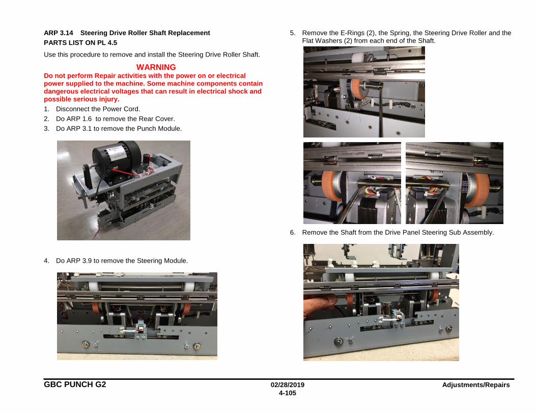
ARP 3.14 Steering Drive Roller Shaft Replacement 5. Remove the E-Rings (2), the Spring, the Steering Drive Roller and the Flat Washers (2) from each end of the Shaft. PARTS LIST ON PL 4.5
Use this procedure to remove and install the Steering Drive Roller Shaft.
WARNING Do not perform Repair activities with the power on or electrical power supplied to the machine. Some machine components contain dangerous electrical voltages that can result in electrical shock and possible serious injury. 1. Disconnect the Power Cord. 2. Do ARP 1.6 to remove the Rear Cover. 3. Do ARP 3.1 to remove the Punch Module.
6. Remove the Shaft from the Drive Panel Steering Sub Assembly.
4. Do ARP 3.9 to remove the Steering Module.
GBC PUNCH G2 02/28/2019 Adjustments/Repairs 4-105

7. Place the new Shaft into the Drive Panel Steering Sub Assembly. 8. Install the E-Rings (2), Spring, Steering Drive Roller and the Flat
Washers (2) on each end of the Shaft. 9. Do ARP 3.9 to install the Steering Module. 10. Do ARP 3.1 to install the Punch Module. 11. Do ARP 1.6 to install the Rear Cover. 12. Connect the Power Cord.
Adjustments/Repairs 02/28/2019 GBC PUNCH G2 4-106

ARP 3.15 Steering Idler Panel Weldment Replacement 5. Remove the Screws (4) that hold the Steering Idler Panel Sub Assembly to the Drive Panel Steering Sub Assembly. PARTS LIST ON PL 4.4
Use this procedure to remove and install a Steering Idler Panel Weldment.
Removal Procedure
WARNING Do not perform Repair activities with the power on or electrical power supplied to the machine. Some machine components contain dangerous electrical voltages that can result in electrical shock and possible serious injury. 1. Disconnect the Power Cord. 2. Do ARP 1.6 to remove the Rear Cover. 3. Do ARP 3.1 to remove the Punch Module.
4. Unplug the Skew Senor and release the Cable Clamp.
6. Remove the Steering Idler Panel Sub Assembly.
GBC PUNCH G2 02/28/2019 Adjustments/Repairs 4-107

7. Be sure not to lose the spacers on either end of the drive panel.
8. Transfer the Skew Sensor, Steering ldler Roller, Idler roller Cover, and all fasteners to the new Weldment.
Note: There is one nylon washer below and above the sensor board at each of the four locations.
Installation Procedure
1. Make sure the Spacers (2) are in position on the Steering Drive Panel Weldment (use semi perfs for placement).
2. Place the Steering Idler Panel Sub Assembly in position on the Drive Panel Steering Sub Assembly.
3. Install the Screws (4). 4. Do ARP 3.1 to install the Punch Module. 5. Do ARP 1.6 to install the Rear Cover. 6. Connect the Power Cord.
Adjustments/Repairs 02/28/2019 GBC PUNCH G2 4-108

ARP 3.16 Steering Idler Roller Assembly Replacement PARTS LIST ON PL 4.4 5. Release the Cable Clamp and move the Cable out of the way. Use this procedure to remove and install a Steering Idler Roller Assembly. 6. Remove the M4 Nuts (2).
Removal Procedure
WARNING Do not perform Repair activities with the power on or electrical power supplied to the machine. Some machine components contain dangerous electrical voltages that can result in electrical shock and possible serious injury. 1. Disconnect the Power Cord. 2. Do ARP 1.6 to remove the Rear Cover. 3. Do ARP 3.1 to remove the Punch Module. 7. Remove the Roller Cover.
8. Gently move the Springs (2) off the ends of the Roller.
4. Disconnect the Skew Sensor Board Connector.
GBC PUNCH G2 02/28/2019 Adjustments/Repairs 4-109

Installation Procedure
9. Remove the Roller Assembly. 1. Place the new Roller Assembly in position. 2. Gently move the Springs (2) on to the ends of the Roller.
Steering Idler Roller Assembly
Spring
3. Ensure the Springs (2) are over the white Roller Bushings (2). 4. Place the Roller Cover in position. 5. Install and tighten the M4 Nuts (2). 6. Place the Skew Sensor Board Cable in the Cable Clamp and close
the Cable Clamp. 7. Connect the Skew Sensor Board Connector. 8. Do ARP 3.1 to install the Punch Module. 9. Do ARP 1.6 to install the Rear Cover. 10. Connect the Power Cord.
Adjustments/Repairs 02/28/2019 GBC PUNCH G2 4-110

ARP 3.16.1 Steering Idler Roller Bearing Replacement PARTS LIST ON PL 4.4 3. Place the new Steering Idler Roller Bearing (2) on to the ends of
Shaft on the Steering Idler Roller Assembly. Use this procedure to remove and install a Steering Idler Roller Double "D" Flange Bearing. 4. Do ARP 3.16 Steering Idler Roller Replacement to install the Steering
Idler Roller. WARNING Do not perform Repair activities with the power on or electrical power supplied to the machine. Some machine components contain dangerous electrical voltages that can result in electrical shock and possible serious injury. 1. Do ARP 3.16 Steering Idler Roller Replacement to remove the
Steering Idler Roller.
Steering Idler Roller Assembly
2. Remove the Steering Idler Roller Bearing (2) from the ends of Shaft on the Steering Idler Roller Assembly.
Steering Idler Roller Bearing
GBC PUNCH G2 02/28/2019 Adjustments/Repairs 4-111

ARP 3.17 Steering Drive Panel Weldment Replacement PARTS LIST ON PL 4.5
Use this procedure to remove and install the Steering Drive Panel Weldment.
WARNING Do not perform Repair activities with the power on or electrical power supplied to the machine. Some machine components contain dangerous electrical voltages that can result in electrical shock and possible serious injury. Removal Procedure
1. Disconnect the Power Cord. 2. Do ARP 1.6 to remove the Rear Cover. 3. Do ARP 3.15 (through step 6) to remove the Steering Idler Panel Sub
Assembly.
4. Remove the Spacers (2).
Spacer Spacer
Adjustments/Repairs
5. Remove the Nuts (4) holding the Steering Drive Panel Weldment.
6. Replace with new part
Installation Procedure
1. Place the Steering Drive Panel Weldment in place. 2. Tighten the Nuts (4) that hold the Steering Drive Panel Weldment. 3. Install the Spacers (2). 4. Do ARP 3.15 to install the Steering Idler Panel Sub Assembly. 5. Do ARP 1.6 to install the Rear Cover. 6. Connect the Power Cord.
02/28/2019 GBC PUNCH G2 4-112

ARP 3.18 Die Lock Plunger and Stripper Assembly Replacement 5. Note the orientation of the Stripper Pad. PARTS LIST ON PL 4.1
Use this procedure to remove and install the Die Lock Plunger and Stripper Assembly or the Die Lock Bracket.
Removal Procedure
WARNING Do not perform Repair activities with the power on or electrical power supplied to the machine. Some machine components contain Stripper Pad dangerous electrical voltages that can result in electrical shock and possible serious injury. 1. Disconnect the Power Cord.
6. To replace the components in the Die Lock Plunger and Stripper, 2. Do ARP 1.6 to remove the Rear Cover. 3. Do ARP 3.1 to remove the Punch Module. • Remove the E-Clip
E-Clip
• Pull the Die Lock Plunger and Stripper out.
4. Remove the left or right Die Lock Bracket Screws (2).
Die Lock Plunger
and Stripper
Screws (2) 7. Install the Plunger and Stripper Assy. 8. Do ARP 3.1 to install the Punch Module. 9. Do ARP 1.6 to install the Rear Cover. 10. Connect the Power Cord.
GBC PUNCH G2 02/28/2019 Adjustments/Repairs 4-113

ARP 3.19 Punch shaft Ball Bearing Replacement PARTS LIST ON PL 4.1
Use this procedure to remove and install the Ball Bearing on the punch shaft
WARNING Do not perform Repair activities with the power on or electrical power supplied to the machine. Some machine components contain dangerous electrical voltages that can result in electrical shock and possible serious injury. 1. Disconnect the Power Cord. 2. Do ARP 1.6 to remove the Rear Cover.
Ball Bearing
Nylon Washer
E-Ring
3. Remove the E-Ring. 4. Remove the Nylon Washer. 5. Remove the Ball Bearing. 6. Place the new Ball Bearing in position. 7. Place the Nylon Washer in position. 8. Place the E-Ring in position. 9. Do ARP 1.6 to install the Rear Cover. 10. Connect the Power Cord.
Adjustments/Repairs
ARP 3.20 Die Stop Magnet Replacement PARTS LIST ON PL 4.1
Use this procedure to remove and install the Die Set Magnet.
1. Disconnect the Power Cord. 2. Loosen the Nut and Lock Screw.
3. Rotate the Die Set Magnet counterclockwise and remove it from the Shaft.
4. Place the new Die Set Magnet on the Shaft and rotate it clockwise. 5. Do ADJ 1.3 Die Stop Magnet Adjustment 6. Connect the Power Cord.
02/28/2019 GBC PUNCH G2 4-114

ARP 3.21 Die Lock Handle Replacement PARTS LIST ON PL 4.1
Use this procedure to remove and install the Die Stop Handle.
1. Disconnect the Power Cord. 2. Open the Front Door.
Die Lock Handle
3. Remove the Phillips Screw and the Die Stop Handle. 4. Place the new Die Stop Handle in position and tighten the Phillips
Screw. 5. Close the front Door. 6. Connect the Power Cord.
GBC PUNCH G2 02/28/2019 Adjustments/Repairs 4-115

ARP 3.22 Die Lock Shaft Replacement 7. Remove the Socket Head Cap Screw and Split Lock Washer from the Cam and the Shaft at the rear of the Punch Module. PARTS LIST ON PL 4.1
Use this procedure to remove and install the Die Lock Shaft.
Removal Procedure
WARNING Screw Do not perform Repair activities with the power on or electrical power supplied to the machine. Some machine components contain dangerous electrical voltages that can result in electrical shock and possible serious injury. 1. Remove the Die Set (see Operator Manual). 2. Press the Power Switch to the off position. 3. Disconnect the Power Cord. 4. Do ARP 1.6 to remove the Rear Cover. 5. Do ARP 3.1 to remove the Punch Module.
8. Remove the Socket Head Cap Screw and Split Lock Washer from the Cam and the Shaft at the front of the Punch Module.
Screw 6. Remove the Shoulder Screw from the hole in the Shaft at the rear of the Punch Module.
Shoulder Screw
Adjustments/Repairs 02/28/2019 GBC PUNCH G2 4-116

9. Remove the E-Ring from the Shaft at the rear of the Punch Module.
E-Ring
10. Remove the E-Ring from the Shaft at the front of the Punch Module.
E-Ring
11. Pull the Shaft out through the Cams (2) and out of the Punch Module.
Shaft
3. Push the Shaft through the Punch Module, through the hole in the other Cam, and out through the hole in the rear of the front of the Punch Module (cam portin against side Frame)
4. Insert the E-Ring on the Shaft at the front of the Punch Module. 5. Insert the E-Ring on the Shaft at the rear of the Punch Module. 6. Insert the Socket Head Cap Screw and Split Lock Washer into the
Cam and the Shaft at the front of the Punch Module. 7. Insert the Phillips Screw into the Cam and the Shaft at the rear of the
Punch Module. 8. Insert the Shoulder Screw the hole in the Shaft at the rear of the
Punch Module. Make sure it is in the correct phase (Shoulder Screw facing down as well as Cam Screws facing down).
9. Do ARP 3.1 to install the Punch Module. 10. Insert the Die Lock Handle into the Shaft at the front of the Punch
Module, and tighten the Screw. 11. Do ARP 1.6 to install the Rear Cover. 12. Connect the Power Cord.
Installation Procedure
1. Place a Die Lock Cam inside the Punch Module by the hole at the front of the Punch Module (cam portion against side Frame).
2. Insert the Die Lock Shaft through the hole at the front of the Punch Module and through the hole in the Cam.
GBC PUNCH G2 02/28/2019 Adjustments/Repairs 4-117

ARP 3.23 Die Rail Assembly and Die Rail Springs Replacement 7. Remove the (2) Screws from the front and (2) screws from the back that hold that Die Rail Assembly. PARTS LIST ON PL 4.10
Removal Procedure
Use this procedure to remove and install the Die Rail Assembly and Die Rail Springs
WARNINGDo not perform Repair activities with the power on or electrical power supplied to the machine.
Some machine components contain dangerous electrical voltages that can result in electrical shock and
possible serious injury. 1. Disconnect the Power Cord. 2. Do ARP 1.6 to remove the Rear Cover. 3. Do ARP 3.1 to remove the Punch Module. 4. Do ARP 3.24 to remove the Alignment sensor bracket and Alignment
Sensor bottom guide. 5. Unplug Back Gage Sensor Board and release the wires from cable
clamps.
9. Die rail springs can be replaced at this point by unscrewing M2 screws (4) and M2 lockwashers (4). If you are replacing only the springs, go to Installation procedure.
6. Remove the Screws (2) that hold the Dieset Recognition Bracket.
8. Remove the Die Rail Assembly.
Adjustments/Repairs 02/28/2019 GBC PUNCH G2 4-118

Remove the backgage sensor upper and lower brackets.
10. Remove Nuts (3) and the Chip Chute.
11. Remove the old Die Rail.
Installation Procedure
1. Place the new Die Rail Assembly in position. 2. Place the Chip Chute in position and tighten the Nuts (3). 3. Place the Springs (2) in position, install the M2 Lock Washers (4), and
tighten the the M2 Screws (4). 4. Install the backgage upper and lower brackets 5. Place the the Die Rail Assembly in position. 6. Install and tighten the Screws (4) that hold that Die Rail Assembly.
When installing (4) screws that hold the die rail, use 3mm reference holes for positioning the part. A 3mm pin can be inserted to hold the part in position while the screw is tightened.
7. Tighten the Screws (2) that hold the Dieset Recognition Bracket. 8. Install the upper and lower Alignment sensor brackets. 9. Connect the Back Gage Sensor Board and place the wires in the
Cable Clamps. 10. Do ARP 3.1 to install the Punch Module. 11. Do ADJ 1.6 Die set recognition board adjustment. 12. Do ARP 1.6 to install the Rear Cover. 13. Connect the Power Cord.
GBC PUNCH G2 02/28/2019 Adjustments/Repairs 4-119

ARP 3.24 Alignment Sensor Bracket and Alignment Sensor Bottom Guide Replacement PARTS LIST ON PL 4.10
Removal Procedure
Use this procedure to remove and install the Alignment Sensor Bracket and the Alignment Sensor Bottom Guide.
WARNING Do not perform Repair activities with the power on or electrical power supplied to the machine. Some machine components contain dangerous electrical voltages that can result in electrical shock and 7. . Remove M3 Nuts (2) that hold the Brackets. possible serious injury. 1. Disconnect the Power Cord. 2. Do ARP 1.6 to remove the Rear Cover. 3. Do ARP 3.1 to remove the Punch Module. 4. Unplug the Skew Sensor Connector and release the Cable from the
Cable Clamps.
8. Remove both upper and lower brackets as shown, do not pull on the Align sensor wires.
5. Remove the Steering Idler Roller Cover.
6. Unplug the Alignment Sensor Connector
9. The lower bracket can be replaced at this time.
Adjustments/Repairs 02/28/2019 GBC PUNCH G2 4-120

10. To replace the upper bracket, remove the cable clamps, cable, Alignment sensors, washers, nuts from the old bracket and transfer them to the new bracket.
Installation Procedure
1. Replace the bracket so the lower bracket (Alignment Sensor bottom guide) will overlap the top bracket when assembled.
2. Insert both Brackets and position them. 3. Install and tighten the M3 Nuts (2) that hold the Brackets. 4. Connect the Alignment Sensor Connector, and place the Cable in the
Cable Clamps. 5. Install the Steering Idler Roller Cover. 6. Connect the Skew Sensor Connector and place the Cable in the
Cable Clamps. 7. Do ARP 3.1 to install the Punch Module. 8. Do ARP 1.6 to install the Rear Cover. 9. Connect the Power Cord.
GBC PUNCH G2 02/28/2019 Adjustments/Repairs 4-121

ARP 3.25 Punch Module Mount Pin Replacement PARTS LIST ON PL 4.1
Use this procedure to remove and install the Punch Module Mount Pins.
WARNING Do not perform Repair activities with the power on or electrical power supplied to the machine. Some machine components contain dangerous electrical voltages that can result in electrical shock and possible serious injury. 1. Disconnect the Power Cord. 2. Do ARP 1.6 to remove the Rear Cover. 3. Do ARP 3.1 to remove the Punch Module. 4. Remove the Screw and the Mount Pin.
Mount Pin
5. Place the new Mount Pin in position and tighten the Screw. 6. Do ARP 3.1 to install the Punch Module. 7. Close the Front Door. 8. Do ARP 1.6 to install the Rear Cover. 9. Connect the Power Cord.
Adjustments/Repairs 02/28/2019 GBC PUNCH G2 4-122

ARP 3.26 Backgage Sensor Bracket Weldment and Backgage Sensor Lower Bracket Replacement PARTS LIST ON PL 4.10
Use this procedure to remove and install the Backgage Sensor Bracket Weldment and Backgage Sensor Lower Bracket.
WARNING Do not perform Repair activities with the power on or electrical power supplied to the machine. Some machine components contain dangerous electrical voltages that can result in electrical shock and possible serious injury. Removal Procedure
1. Disconnect the Power Cord. 2. Do ARP 1.6 to remove the Rear Cover. 3. Do ARP 3.1 to remove the Punch Module. 4. Remove the M3 Nuts (2) that hold both the Brackets.
5. If replacing only the lower bracket, replace the Bracket then go to the installation procedure.
6. Unplug the Backgage Sensor and release the wires from the Cable Clamps.
7. Transfer the Backgage Sensor and all fasteners to the new part.
Installation Procedure
1. Place the Brackets in positin so the lower bracket overlaps the upper bracket.
2. Connect the Backgage Sensor and place the wires in the Cable Clamps.
3. Tighten the M3 Nuts (2) that hold both the Brackets. 4. Do ARP 3.1 to install the Punch Module. 5. Do ARP 1.6 to install the Rear Cover. 6. Connect the Power Cord.
GBC PUNCH G2 02/28/2019 Adjustments/Repairs 4-123

ARP 3.27 Die Set Recognition Replacement 4. Remove the Screws (2) and the Die Set Recognition Board Mount Bracket. PARTS LIST ON PL 4.9
Use this procedure to remove and install the Die Set Recognition Assembly.
Removal Procedure
WARNING Do not perform Repair activities with the power on or electrical power supplied to the machine. Some machine components contain dangerous electrical voltages that can result in electrical shock and possible serious injury. 1. Disconnect the Power Cord. 2. Do ARP 1.6 to remove the Rear Cover. 3. Disconnect the Die Set Recognition Cable.
Screws (2)
Die Set Recognition Bracket
5. Place the new Die Set Recognition Board Mount Bracket in position and tighten the Screws (2).
6. Connect the Die Set Recognition Cable. 7. Do ARP 1.6 to install the Rear Cover. 8. Do ADJ 1.6 Die Set Recognition board adjustment procedure. 9. Connect the Power Cord.
Die Set Recognition Cable
(Cont.)
Adjustments/Repairs 02/28/2019 GBC PUNCH G2 4-124

4. Power Supply ARP 4.1 24V Power Supply Replacement PARTS LIST ON PL 2.5
Use this procedure to remove and install the 24V Power Supply Assembly. Screws (4) Removal Procedure
WARNING Do not perform Repair activities with the power on or electrical power supplied to the machine. Some machine components contain 6. Remove the power supply and the cables through the opening on top. dangerous electrical voltages that can result in electrical shock and Assist the connectors to get through the grommet while removing. possible serious injury. Cable clamps should also be released to free up the cables. 1. Disconnect the Power Cord. 2. Do ARP 1.6 to remove the Rear Cover. 3. Dsiconnect Connectors J1 and J3 from the Main Control Board.
Grommet
Connector
4. Remove the M4 Screw (1) and remove the Ground Cable from the Power Supply.
Screw
5. Remove the M4 Screws (4) from the side of the Base Frame.
GBC PUNCH G2 02/28/2019 Adjustments/Repairs 4-125

5.9A so.~ 21A
7. Transfer all wires to the new Power Supply. Installation Procedure
1. Tilt the Power Supply and insert it through the Chip Tray opening. 2. Tighten the M4 Screws (4) on the side of the Base Frame. 3. Place the Ground Cable in position on the Power Supply and tighten
the M4 Screw (1). 4. Connect Connectors J1 and J3 to the Main Control Board. 5. Do ARP 1.6 to install the Rear Cover. 6. Connect the Power Cord.
Adjustments/Repairs 02/28/2019 GBC PUNCH G2 4-126

ARP 4.2 AC Filter Replacement PARTS LIST ON PL 6.1
Use this procedure to remove and install the AC Filter Assembly.
Removal Procedure
WARNING Do not perform Repair activities with the power on or electrical power supplied to the machine. Some machine components contain dangerous electrical voltages that can result in electrical shock and possible serious injury. 1. Disconnect the Power Cord. 2. Do ARP 1.6 to remove the Rear Cover. 3. Remove the Phillips head Screws (2) and the AC Filter-USB Mount
Bracket.
4. Note the location of the wires (3).
5. Remove the Wires (3) and the AC Filter. 6. Place the new AC Filter in position and tighten the Screws (2). 7. Do ARP 1.6 to install the Rear Cover. 8. Connect the Power Cord.
GBC PUNCH G2 02/28/2019 Adjustments/Repairs 4-127

5. Electronics and Control ARP 5.1 Main Control Board Replacement PARTS LIST ON PL 6.1
Use this procedure to remove and install the Main Control Board. Before ARPlacing the Main Control board, attempt to retrieve the number of Punch cycles, do GP 6.1.9 Punch Cycles Procedure.
Removal Procedure
WARNING Do not perform Repair activities with the power on or electrical power supplied to the machine. Some machine components contain dangerous electrical voltages that can result in electrical shock and possible serious injury. 1. Disconnect the Power Cord. 2. Do ARP 1.6 to remove the Rear Cover. 3. Remove the M3 Screws (6) from the Main Control Board and the the
Comm Board.
Adjustments/Repairs
4. Use pliers to release the plastic Standoffs (13).
5. Disconnect the Connectors (29) from Main and Comm boards. 6. Remove the old Main Control Board and Comm Board.
7. Disconnect the plug-in Connector and remove the Comm Board.
02/28/2019 GBC PUNCH G2 4-128

Installation Procedure
1. Install the the Comm Board on the Main Control Board using the plug-in connector.
2. Place the new Main Control Board and Comm Board in position 3. Press the Control boards on the plasctic standoffs so that it snaps in
place (13). 4. Tighten the M3 Screw in the Main Control Board. 5. Connect the Connectors (29).
Refer to the Section 7 Wiring.
The following table lists the connectors starting at the top right and going counterclockwise.
6. Do ARP 1.6 to install the Rear Cover. 7. Connect the Power Cord.
Cable/Wire # Connector # 7715459 J28 7715458 J26 7715267 J20 7715470 J16 775538 J37 7715490 USB Connector 7715537 J12 7715494 J15 COMM Board 7715498 J14 COMM Board 7715726 J16 COMM Board
Cable/Wire # Connector # 7715523 J36 7715455 J23 7715467 J19 7715466 J18 7715536 J29 7715451 J21 7715485 J27 7715477 J17 7715473 J15 7715453 J22 7715495 J9 7715468 J14 7715457 J25 7715456 J24 7715476 J2 7715493 J3 7715494 J4 7715487 J8 7715492 J1
GBC PUNCH G2 02/28/2019 Adjustments/Repairs 4-129
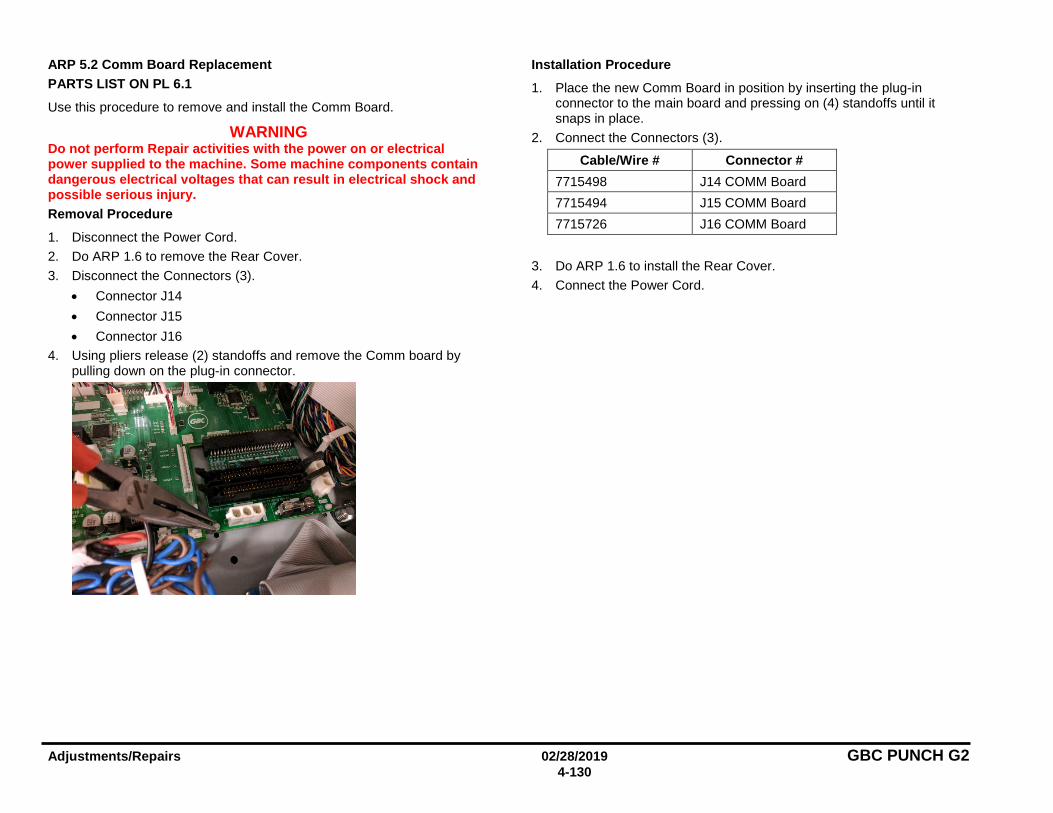
ARP 5.2 Comm Board Replacement PARTS LIST ON PL 6.1
Use this procedure to remove and install the Comm Board.
WARNING Do not perform Repair activities with the power on or electrical power supplied to the machine. Some machine components contain dangerous electrical voltages that can result in electrical shock and possible serious injury. Removal Procedure
1. Disconnect the Power Cord. 2. Do ARP 1.6 to remove the Rear Cover. 3. Disconnect the Connectors (3).
• Connector J14 • Connector J15 • Connector J16
4. Using pliers release (2) standoffs and remove the Comm board by pulling down on the plug-in connector.
Adjustments/Repairs
Installation Procedure
1. Place the new Comm Board in position by inserting the plug-in connector to the main board and pressing on (4) standoffs until it snaps in place.
2. Connect the Connectors (3).
Cable/Wire # Connector # 7715498 J14 COMM Board 7715494 J15 COMM Board 7715726 J16 COMM Board
3. Do ARP 1.6 to install the Rear Cover. 4. Connect the Power Cord.
02/28/2019 GBC PUNCH G2 4-130
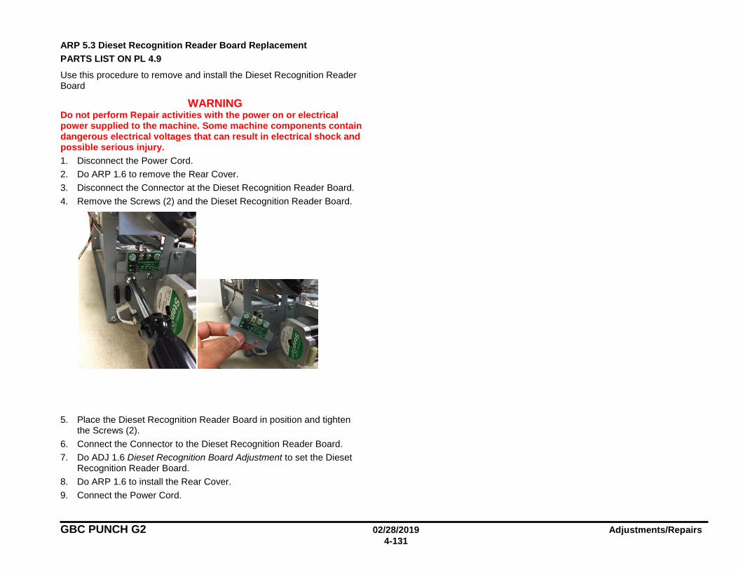
ARP 5.3 Dieset Recognition Reader Board Replacement PARTS LIST ON PL 4.9
Use this procedure to remove and install the Dieset Recognition Reader Board
WARNING Do not perform Repair activities with the power on or electrical power supplied to the machine. Some machine components contain dangerous electrical voltages that can result in electrical shock and possible serious injury. 1. Disconnect the Power Cord. 2. Do ARP 1.6 to remove the Rear Cover. 3. Disconnect the Connector at the Dieset Recognition Reader Board. 4. Remove the Screws (2) and the Dieset Recognition Reader Board.
5. Place the Dieset Recognition Reader Board in position and tighten the Screws (2).
6. Connect the Connector to the Dieset Recognition Reader Board. 7. Do ADJ 1.6 Dieset Recognition Board Adjustment to set the Dieset
Recognition Reader Board. 8. Do ARP 1.6 to install the Rear Cover. 9. Connect the Power Cord.
GBC PUNCH G2 02/28/2019 Adjustments/Repairs 4-131
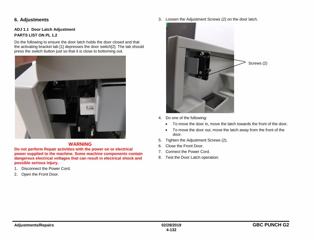
6. Adjustments
ADJ 1.1 Door Latch Adjustment PARTS LIST ON PL 1.2
Do the following to ensure the door latch holds the door closed and that the activating bracket tab [1] depresses the door switch[2]. The tab should press the switch button just so that it is close to bottoming out.
WARNING Do not perform Repair activities with the power on or electrical power supplied to the machine. Some machine components contain dangerous electrical voltages that can result in electrical shock and possible serious injury. 1. Disconnect the Power Cord. 2. Open the Front Door.
Adjustments/Repairs
3. Loosen the Adjustment Screws (2) on the door latch.
Screws (2)
4. Do one of the following: • To move the door in, move the latch towards the front of the door. • To move the door out, move the latch away from the front of the
door. 5. Tighten the Adjustment Screws (2). 6. Close the Front Door. 7. Connect the Power Cord. 8. Test the Door Latch operation.
02/28/2019 GBC PUNCH G2 4-132

ADJ 1.2 Diverter Solenoid Adjustment PARTS LIST ON PL 2.3 a. Loosen the Screws (2) that hold the Limiter Bracket. Use this procedure to adjust the position of the Diverter Solenoid Assembly.
1. Open the Front Door. 2. Do ARP 1.6 to remove the Rear Cover. 3. With the Interlock cheater inserted, do GP 6.2.6 to actuate SOL1
(L1-Diverter Solenoid). This will switch the diverter gate to punch mode. The Diverter gate will rise and hit the upper bypass panel.
b. Insert a 0.25 to 0.5mm shim between the Diverter and the Lower Entrance Panel.
Shim (0.25 to 0.5mm)
4. When the solenoid in not actuated, it needs to rest on the Diverter limiter bracket. To properly adjust the position of the limiter bracket do the following:
GBC PUNCH G2 02/28/2019 Adjustments/Repairs 4-133

c. Raise the Limiter Bracket so that it just touches the Diverter Link The clearance should be minimum 1.0 mm. and tighten theScrews (2).
NOTE: Raising the Limiter Bracket too high will position the diverter gate higher, which will obstruct the paper flow and cause jams.
5. Check the clearance between the Diverter and the cutout in the Lower Entrance Panel at both sides.
Adjustments/Repairs 02/28/2019 GBC PUNCH G2 4-134
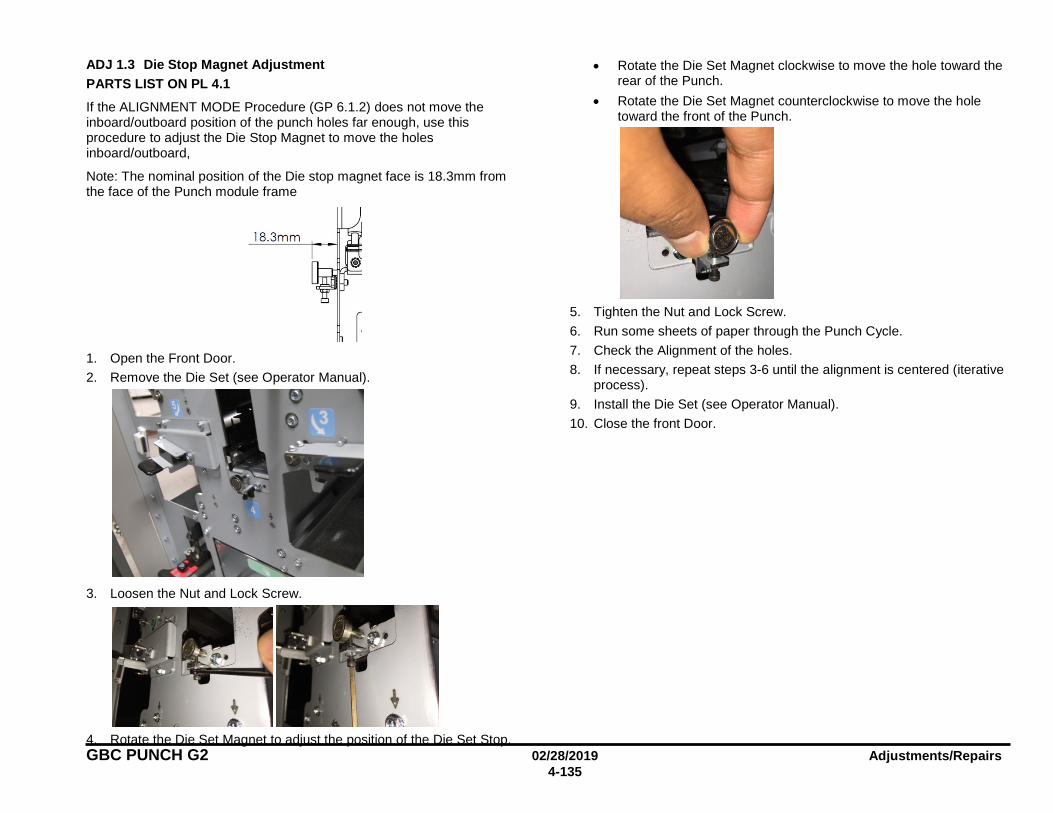
18.3mm
ADJ 1.3 Die Stop Magnet Adjustment PARTS LIST ON PL 4.1
If the ALIGNMENT MODE Procedure (GP 6.1.2) does not move the inboard/outboard position of the punch holes far enough, use this procedure to adjust the Die Stop Magnet to move the holes inboard/outboard,
Note: The nominal position of the Die stop magnet face is 18.3mm from the face of the Punch module frame
1. Open the Front Door. 2. Remove the Die Set (see Operator Manual).
3. Loosen the Nut and Lock Screw.
• Rotate the Die Set Magnet clockwise to move the hole toward the rear of the Punch.
• Rotate the Die Set Magnet counterclockwise to move the hole toward the front of the Punch.
5. Tighten the Nut and Lock Screw. 6. Run some sheets of paper through the Punch Cycle. 7. Check the Alignment of the holes. 8. If necessary, repeat steps 3-6 until the alignment is centered (iterative
process). 9. Install the Die Set (see Operator Manual). 10. Close the front Door.
4. Rotate the Die Set Magnet to adjust the position of the Die Set Stop. GBC PUNCH G2 02/28/2019 Adjustments/Repairs
4-135

ADJ 1.4 Timing Belts Adjustment
ADJ 1.4.1 Steering Sub-assembly Belt Adjustment PARTS LIST ON PL 4.3
Use this procedure to adjust the Steering Sub-assembly Belt tension.
1. Disconnect the Power Cord. 2. Do ARP 1.6 to remove the Rear Cover. 3. Do ARP 3.1 to remove the Punch Module. 4. Loosen the Phillips Screws (4).
Screws (4)
5. Adjust the belt tension such that there is a deflection of 1~2mm.
6. Tighten the Phillips Screws (4). 7. Do ARP 3.1 to install the Punch Module. 8. Do ARP 1.6 to install the Rear Cover. 9. Connect the Power Cord.
Adjustments/Repairs 02/28/2019 GBC PUNCH G2 4-136

ADJ 1.4.2 534T belt tension adjustment Use this procedure to adjust the Belt tension of 534T timing belt.
1. Disconnect the Power Cord. 2. Do ARP 1.6 to remove the Rear Cover. 3. Loosen the the tensioner.
4. Adjust the belt tension such that there is a deflection of 6~8mm.
5. Tighten the tensioner 6. Do ARP 1.6 to install the Rear Cover. 7. Connect the Power Cord.
GBC PUNCH G2 02/28/2019 Adjustments/Repairs 4-137

ADJ 1.4.3 134T Belt tension adjustment Use this procedure to adjust the Belt tension of 134T timing belt.
1. Disconnect the Power Cord. 2. Do ARP 1.6 to remove the Rear Cover. 3. Loosen the the tensioner.
4. Adjust the belt tension such that there is a deflection of 3~5mm.
5. Tighten the tensioner 6. Do ARP 1.6 to install the Rear Cover. 7. Connect the Power cord.
Adjustments/Repairs 02/28/2019 GBC PUNCH G2 4-138

ADJ 1.4.4 179T belt tension adjustment Use this procedure to adjust the Belt tension of 134T timing belt.
1. Disconnect the Power Cord. 2. Do ARP 1.6 to remove the Rear Cover. 3. Loosen the the tensioner.
4. Adjust the belt tension such that there is a deflection of 4~6mm.
5. Tighten the tensioner 6. Do ARP 1.6 to install the Rear Cover. 7. Connect the Power cord.
GBC PUNCH G2 02/28/2019 Adjustments/Repairs 4-139

ADJ 1.4.5 Steering motor belt tension adjustment Use the below setting for Steering motor belt tension.
Use this procedure to adjust the Steering Sub-assembly Belt tension.
1. Disconnect the Power Cord. 2. Do ARP 1.6 to remove the Rear Cover. 3. Do ARP 3.1 to remove the Punch Module. 4. Loosen the Phillips Screws (4) from the Steering stepper motor.
5. Adjust the belt tension such that there is a deflection of 1~2mm. 6. Tighten the Phillips Screws (4). 7. Do ARP 3.1 to install the Punch Module. 8. Do ARP 1.6 to install the Rear Cover. 9. Connect the Power Cord.
Adjustments/Repairs 02/28/2019 GBC PUNCH G2 4-140

The fl ats on the punch
shaft have to be
horizonta l as shown in
t hese pictures
ADJ 1.5 Punch clutch Indexing 2. If the flats are not horizontal (±5° from horizontal is acceptable), doPARTS LIST ON PL 4.8 the following procedure to set the shaft indexed postion.
Use this procedure to bring the punch cam to its home position after each Important note: Punch Shaft/Cam rotates in the Clockwise direction punch cycle. The punch cam should reach its home position to ensure when viewed from the front of the machine. proper paper flow though the die set.
Note: Some designs in the images may be slightly different from those on the machine you are working on but this does not affect the setting procedure.
1. Verify that the punch cam needs to be indexed. After a punch cycle the flats on the punch shaft have to be horizontal (±5° from horizontal is acceptable). See below for an image of a properly indexed punch shaft.
3. Disconnect the Power Cord. 4. Do ARP 1.6 to remove the Rear Cover. 5. Do ARP 3.1 to remove the Punch Module.
(Cont.)
GBC PUNCH G2 02/28/2019 Adjustments/Repairs 4-141

6. Inspect the punch cam position; the flat on the punch cam (or punch 8. Continue to move the spring clip towards the pulley. shaft) will indicate how far it has deviated from the horizontal position. In the example below the cam has rotated past the home position by 20°.
For some 230v machines, moving the stop collar towards the pulley may not expose the teeth completely. In such instances, remove the pulley off the clutch (3 sets of socket head screws and washers), see ARP 3.7 Clutch Pulley replacement.
7. To index the shaft to the correct position, remove the spring clip from the its groove in the Punch clutch.
9. Move the control collar towards the pulley. By doing this the toothed hub will be exposed.
Adjustments/Repairs 02/28/2019 GBC PUNCH G2 4-142

10. Rotate the Stop collar. 11. Slide the Stop collar back to its position and release the pawl.
If the Punch Cam needs to stop earlier, rotate the Stop Collar Clockwise (when viewed from the rear of the machine).
12. Manually rotate the pulley in the counter-clockwise direction by If the Punch Cam needs to stop later, rotate the Stop Collar Counter-holding the pulley (viewed from rear side) to complete a punch cycle. clockwise (when viewed from the rear side).
In this instance the cam needs to stop earlier, therefore rotate the Stop Collar Clockwise (when viewed from the rear side). This is done by manually lowering the pawl and freeing the Stop collar to rotate.
GBC PUNCH G2 02/28/2019 Adjustments/Repairs 4-143
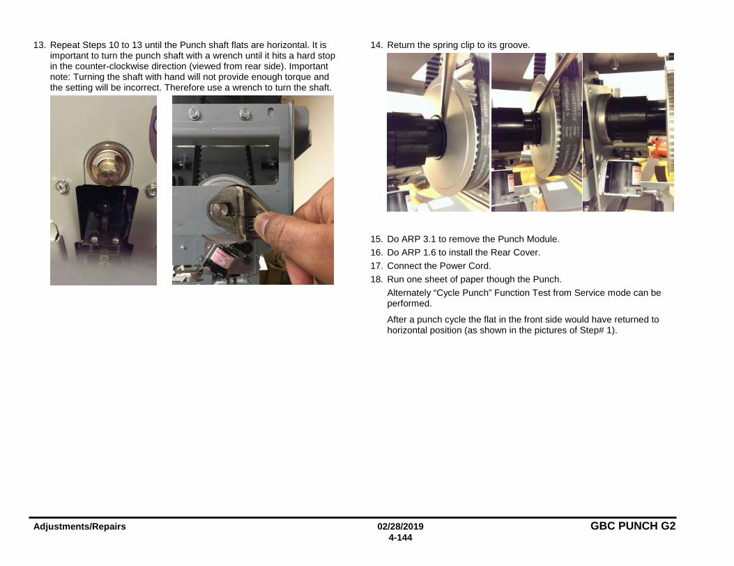
13. Repeat Steps 10 to 13 until the Punch shaft flats are horizontal. It is important to turn the punch shaft with a wrench until it hits a hard stop in the counter-clockwise direction (viewed from rear side). Important note: Turning the shaft with hand will not provide enough torque and the setting will be incorrect. Therefore use a wrench to turn the shaft.
Adjustments/Repairs
14. Return the spring clip to its groove.
15. Do ARP 3.1 to remove the Punch Module. 16. Do ARP 1.6 to install the Rear Cover. 17. Connect the Power Cord. 18. Run one sheet of paper though the Punch.
Alternately “Cycle Punch” Function Test from Service mode can be performed.
After a punch cycle the flat in the front side would have returned to horizontal position (as shown in the pictures of Step# 1).
02/28/2019 GBC PUNCH G2 4-144

ADJ 1.6 Dieset Recognition Board Adjustment PARTS LIST ON PL 4.9
Use this procedure to adjust the Dieset Recognition Board.
1. Do ARP 1.6 to remove the Rear Cover. 2. Loosen the Screws (2) that hold the Dieset Recognition Reader
Board.
3. Insert a die set until the Dieset is about to contact the spring clips in the Reader Board.
4. Raise/ Lower the Reader Board so that the top most point of the Reader Board is above the surface of the Dieset Recognition Board in the Dieset.
It can be set so that the top of the clips are just under the top surface of the recognition board. The spring clips will compress then the die set slides over. If the reader is set too low, the reader will not contact the recognition board. If the reader is set too high, there is a chance of mis-read and damage to clips.
5. Tighten the Screws (2) that hold the Dieset Recognition Reader Board.
6. Do ARP 1.6 to install the Rear Cover.
GBC PUNCH G2 02/28/2019 Adjustments/Repairs 4-145

Magnet pushed away from the panel to e limin ate play in the magnet body
d losed
ADJ 1.7 Idler Panel Magnetic Latches Adjustment PARTS LIST ON PL 3.2, PL 3.4, PL 3.5
Two round spacer studs should contact the drive panels completely (GP 6.16). When the Idler assembly is latched there should not be any movement in the assembly. If there is movement/play, do the below steps to adjust the assembly.
ADJ 1.4.6 Procedure This procedure applies to
• Entrance Idler Panel (PL 3.2) • Exit Idler Panel (PL 3.4) • Upper Bypass Panel (PL 3.5)
1. Loosen the two screws that hold the magnet. With the panel closed firmly, pull away the magnet away from the drive panel (to eliminate the play in the magnet) and tighten both screws. The screws should be tightened while the panel is closed firmly and the magnet pulled away as shown.
ADJ 1.4.7 Procedure This procedure applies to
• Lower Exit Panel Assembly (PL 2.1) 1. Loosen the two screws the hold the magnet. With the panel fully
closed (the panel will hit limiting tabs and you will hear a sound), tighten the two screws.
Adjustments/Repairs 02/28/2019 GBC PUNCH G2 4-146

ro o
ADJ 1.8 Drive Panel Position Adjustment PARTS LIST ON PL 2.2, PL 2.3, PL 3.1
Use this procedure to Inspect and adjust the Drive panel positions. The drive panels control how far the drive rollers protrude into the paper path, which in turn control the roller nip forces. All drive rollers should be protruding 1.5±0.5mm through the paper path.
This procedure applies to This drive panel controls the nip forces of N2, N3, N4 and N5.
1. To adjust the position of the drive panel loosen (5) screws from the Front frame and (5) screws from the rear frame.
• Entrance Drive Panel (PL 3.1) • Exit Drive Panel (PL 2.1) • Lower Bypass Panel (PL 2.1)
ADJ 1.4.8 ADJ 1.8.1 Entrance Drive Panel Position Adjustment
GBC PUNCH G2 02/28/2019 Adjustments/Repairs 4-147

2. Using the Reference holes in the front/rear frame (5 holes in the front frame and 5 holes in the rear frame) and the sheet metal panel, position the drive panel to ensure the drive rollers protrude 1.5±0.5mm through the drive panel.
Adjustments/Repairs 02/28/2019 GBC PUNCH G2 4-148

ADJ 1.4.9 ADJ 1.8.2 Exit Drive Panel Position Adjustment This drive panel controls the nip forces of N8, N9 and N10. 2. Using the Reference holes in the front/rear frame (4 holes in the front
frame and 4 holes in the rear frame) and the sheet metal panel, 1. To adjust the position of the drive panel loosen (5) screws from the position the drive panel to ensure the drive rollers protrude Front frame and (5) screws from the rear frame (Cover plate of Jam 1.5±0.5mm through the drive panel. area 5 needs to be removed).
GBC PUNCH G2 02/28/2019 Adjustments/Repairs 4-149

ADJ 1.4.11 ADJ 1.8.3 Lower Bypass Panel Position Adjustment This drive panel controls the nip forces of N12, N13 and N14. 2. Using the Reference holes in the front/rear frame (4 holes in the front
frame and 4 holes in the rear frame) and the sheet metal panel, 1. To adjust the position of the drive panel loosen (4) screws from the position the drive panel to ensure the drive rollers protrude Front frame and (4) screws from the rear frame. 1.5±0.5mm through the drive panel.
Adjustments/Repairs 02/28/2019 GBC PUNCH G2 4-150

Notes:
GBC PUNCH G2 02/28/2019 Adjustments/Repairs 4-151

5
10
15
20
25
30
Section Contents 1. Main Assembly.....................................................................................2
PL 1.1. Final Assembly .......................................................................2 PL 1.2. Cabinet - Covers.....................................................................3
2. Frame Assembly ..................................................................................4 PL 2.1. Frame Assembly- Paper path panels .....................................4 PL 2.2. Frame Assembly- Front side .................................................. PL 2.3. Frame Assembly- Rear Side ..................................................6 PL 2.4. Frame Assembly- Drive Rollers..............................................7 PL 2.5. Frame Assembly- Internal Parts.............................................8 PL 2.6. Frame Assembly- Motors and Motor Drivers .........................9 PL 2.7. Frame Assembly- Sensors ................................................... PL 2.8. Frame Assembly- Solenoids / Switches ...............................11 PL 2.9. Frame Assembly- Belts ........................................................12
3. Paper Path ..........................................................................................13 PL 3.1. Paper Path- Entrance Drive Panel .......................................13 PL 3.2. Paper Path- Entrance Idler Panel.........................................14 PL 3.3. Paper Path- Acceleration Roller Idler ................................... PL 3.4. Paper Path- Exit Idler Panel .................................................16 PL 3.5. Paper Path- Upper Bypass Panel ........................................17 PL 3.6. Paper Path- Disengaging Roller Solenoid............................18
4. Punch Module ....................................................................................19 PL 4.1. Punch Module.......................................................................19 PL 4.2. Punch Module (continued) ................................................... PL 4.3. Punch Module- Motors/Sensors ...........................................21 PL 4.4. Punch Module- Steering Module ..........................................22 PL 4.5. Punch Module- Steering Module - Steering Idler Panel
Sub Assembly.......................................................................23 PL 4.6. Punch Module- Steering Module - Drive Panel Steering......24 PL 4.7. Punch Module- Stepper Alignment Bracket ......................... PL 4.8. Punch Module- Punch Clutch...............................................26 PL 4.9. Punch Module- Die Set Recognition Reader Board.............27 PL 4.10. Punch Module- Die Rail, Backgage, Align Sensors,
Sub Assembly.......................................................................28 PL 4.11. Punch Module- AC Motor .....................................................29
5. Die Sets ............................................................................................... 6. Electronics..........................................................................................31
PL 6.1. Electronics PCB Assembly...................................................31 PL 6.2. Control Board Bracket Sub Assembly..................................32 PL 6.3. Cable Part Number Index.....................................................33
5. Parts List (PL) PL 6.4. Wiring Drawing ......................................................................34
7. Installation Kit Parts ..........................................................................36 8. Part Number Index .............................................................................37
GBC PUNCH G2 02/28/2019 Parts List 5-1

1.
I I I I I
Main Assembly ITEM Part # DESCRIPTION QTY PL 1.1. Final Assembly
7718801 PUNCH G2 115V 1
7718880 PUNCH G2 230V
1
Parts List 02/28/2019 GBC PUNCH G2 5-2

DETAIL A
s 14 ~
20
15
IJ \ ~9 ~
DETAIL D
7
2
13 ~
DETAIL B
PL 1.2. Cabinet- Covers
ITEM GBC Part # DESCRIPTION QTY
1 1823901 SCREW, PHILLIPS, HEX HD M3X6 5 2 1823905 SCREW, PHILLIPS HX HD M4X35 4 3 1824001 NUT, KEPS M4 4 4 7610501 INTERLOCK SWITCH 1 5 7706447 MAGNET, FRONT DOOR 1
6 7706486 LATCH, PUSH TO CLOSE 1 7 7715267 FAN, EXHAUST 1 8 7715527 LCD, DISPLAY 1
9 7715632 SCREW, ROUND TIP, HEX HD, PHILLIPS, M4 X 8 39
10 7718877
PANEL, LCD MEMBRANE SWITCH, KM 1
11 7718836 HINGE,, UPPER SUBASSY, KM 1
12 7718838 HINGE ASSY, LOWER, KM 1 13 7718840 COVER PANEL ASSY, BACK, KM 1 14 7718847 COVER WELDMENT, R-BACK, KM 1 15 7718856 COVER, POCKET 2 16 7718859 BRACKET, EXHAUST FAN, KM 1
17 7718862 COVER, WELDMENT, SIDE, DOWNSTREAM, REAR, KM 1
18 7718867 PANEL ASSY, BACK LEFT, SPARTA, KM 1
19 7718872 SPACER, KM SPARTA, MTG INTERFACE 4
20 7718873 FOAM, KM SPARTA 1
GBC PUNCH G2 02/28/2019 Parts List 5-3

A ,·
~ ' ~~ . ":~. :
• ," , I ~, ,/
. 0 ~' ; .,· .:;<, ·. ·. ~,,~· /~c .. , ~ '' ~~1~ / ; _;j?";;-<; . .. ' C
( . 0 . .'X 7 .\
i ,-·~>P'/ -~ ,t:5
11 ~
5 g D /
("
DETAIL A
.. . C . . .- :' .. .. t :
·,: • o .,. _o ··:i,;;_. • • • ~ • i O ,
I I l T -, -
~ -
-
-
-~ -
-
'
' -
'
'--
L__
' -
'
I,
2.Frame Assembly PL 2.1. Frame Assembly- Paper path panels
ITEM GBC DESCRIPTION QTY Part #
A PL 5.5 UPPER BYPASS PANEL 1
B PL 5.2 ENTRANCE IDLER PANEL 1
C PL 5.1 ENTRANCE DRIVE PANEL 1
D PL 5.3 ACCELERATION IDLER PANEL 1
E PL 5.4 EXIT IDLER PANEL 1
1 7715101 PANEL, ENTRANCE, LOWER 1
2 7715102 PANEL, ENTRANCE, INNER 1
3 7715146 PANEL, EXIT, LOWER 1
4 7715153 PANEL, EXIT, INNER 1
5 7715822 PANEL ASSEMBLY, LOWER, EXIT 1
6 7715209 SHAFT, IDLER PANEL HINGE 2
7 7715210 SHAFT,IDLR PANEL HINGE,LONG 3
8 7715251 BRACKET, IDLER PANEL MOUNT 6
9 7715150 PANEL WELDMENT, DRIVE, EXIT 1
10 7715128 PANEL WLDMNT, BYPASS,LOWER 1
SNAP-IN BEARING, 6MM ID 11 1821209 [Qty. (2) used on all Idler panels- #A, 10
#B, #D, #E and #5
Parts List 02/28/2019 GBC PUNCH G2 5-4

14 17
6 \
B
' . . . 10_/ l 5
.
8 DETAIL A
A
DETAIL B
PL 2.2. Frame Assembly- Front side ITEM GBC DESCRIPTION QTY
Part # 1 1821209 Snap-in Bearing, 6mm ID 2
2 1822202 E-RING, JE-5 4
3 1823711 JAM NUT, M16X2.0 4
4 1823901 SCREW, HX, W/SEMS,M3X6 2
5 1823909 SCREW, HX, W/SEMS M4X6 2
6 1824001 NUT, KEPS M4 3
7 1821606 SCREW, PHILLIPS PAN HD, M3X10 6
8 7715195 MAGNET, PANEL, OPEN, STRONG 1
9 7715215 HANDLE, ACCEL IDLER LATCH 1
10 7715385 MAGNET, BRACKET, ASSY 1
11 7715427 CHIP TRAY, ASSEMBLY 1
12 7715650 LATCH, BYPASS 1
13 7715637 POWER SUPPLY, 24V, MW SP 480, 1
14 7715789 MAGNET, PANEL, OPEN, WEAK 3
15 7708163 CAP, RUBBER, RAIN BLUE 2
16 7723799 CASTER, ADJUSTABLE, ASSY, KM 4
17 1823913 SCREW, HX, W/SEMS, M3 X 8 8
GBC PUNCH G2 02/28/2019 Parts List 5-5

2___,,/
DETAIL D
8
5
A
DETAIL B
3 4
19
14
PL 2.3. Frame Assembly- Rear Side
GBC ITEM DESCRIPTION QTY Part # 1 1821209 Snap-in Bearing, 6mm ID 2
2 1821611 SCREW, PHILLIPS HD W/SEMS, M3X10 2
3 1822005 WASHER, FLAT, 6.025 X 8 X 0.75 2
4 1822202 E-RING, JE-5 7
5 1823910 SCREW, PHILLIPS HX HD W/SEMS M4 X 14 12
6 1824001 NUT, KEPS M4 32
7 1825501 RETAINING RING, 6MM SHAFT 15
8 1902863 SCREW,MACHINE PAN #4-40x15/32 PHILLIPS 2
9 1925044 WSHR, .192 ID X .625 OD X .060 T 20
10 1952208 SPACER, TIMING BELT IDLERS, BRONZE 4
11 1954011 GROMMET, 3/8 I.D X 1/2 O.D 11
12 1954032 GROMMET, 1 1/4 I.D. X 1 1/2 O.D. 1
13 7712703 WIRE HEADER CONNECTOR, 2 POS 6
14 7714679 GROUND STRAP, M4 1
15 7715185 BRACKET, PUNCH MODULE MOUNT 2
16 7715383 ROLLER, IDLER, DRIVE ASSY, 4
17 7715390 WIRE CLAMP, EDGE 1
18 7715445 WIRE CLAMP, EDGE, SMALL 2
19 7715813 SOLENOID, BRACKET, DIVERTER, SUB ASSY 1
20 7715818 WIRE SADDLE, MEDIUM, LOCKING TOP, V-0 10
21 7715819 WIRE SADDLE, LARGE, LOCKING TOP, V-0 8
22 7715817 WIRE SADDLE, SMALL, LOCKING TOP, V-0 32
Parts List 02/28/2019 GBC PUNCH G2 5-6

3
DETAIL A 7 SCALE 1 • 2
DETAIL B 4 SCALE 1 • 2 4 7
n~,~
~~--~-5 DETAIL D SCALE 1 • 2
DETAIL C SCALE 1 • 2
3
B • :J!I) e • •"
c"K• -.".::, •
e
PL 2.4. Frame Assembly- Drive Rollers
ITEM
1
2
3
4
5
6
7
8
GBC Part #
7715093
7715097
1821116
1822005
1822202
7706532
1925222
7715862
DESCRIPTION
ROLLER ASSY, DRIVE
ROLLER ASSY, ONE WAY CLUTCH DRIVE
BEARING, BALL, FLANGE 6X13X5, SUJ2
WASHER, FLAT, 6.025 X 8 X 0.75
E-RING, JE-5
BEARING BALL FLANGE
WASHER FLAT, 1/4X3/8X/1/32
ONE WAY CLUTCH SUB ASSEMBLY
QTY
11
1
22
22
26
2
2
1
GBC PUNCH G2 02/28/2019 Parts List 5-7

DETAIL B
DETAIL D
4
DETAIL A
I
DETAIL C
3
"'
. ·o :· :b~· "'· " . " ,. "' "' .
"'" . "" c, ; ,,. · " • •• • . .
PL 2.5. Frame Assembly- Internal Parts
ITEM
1
2
3
4
5
6
7
8
9
10
GBC Part #
1822108
1823911
7711970
7711973
7715131
7715186
7715213
7715216
7715222
7715637
DESCRIPTION
WASHER, FLAT, 4.1X8X1.5
SCREW, PHILLIPS HX HD W/SEMS M4 X 10
EMITTER
RECEIVER
BYPASS DIVERTER
CHIP TRAY SENSOR MOUNT ASSY
SHAFT, ACCEL IDLER LATCH
LATCH, ASSY, REAR, ACCEL IDLER PANEL
LATCH, ASSY, FRONT, ACCEL IDLER PANEL
POWER SUPPLY, 24V, MW SP 480,
QTY
8
4
1
1
1
1
1
1
1
1
Parts List 02/28/2019 GBC PUNCH G2 5-8

PL 2.6. Frame Assembly- Motors and Motor Drivers
8
3
10
6
1
7
2
5
9
4
13
12
11
ITEM GBC Part # DESCRIPTION QTY
1 7715159 M1 ENTRANCE MOTOR STEPPER AND MOUNT ASSY 1
2 7715159 M2 ACCEL MOTOR STEPPER AND MOUNT ASSY 1
3 7715159 M6 EXIT MOTOR STEPPER AND MOUNT ASSY 1
4 7715159 M7 DECEL MOTOR STEPPER AND MOUNT ASSY 1
5 7715159 M8 BYPASS MOTOR STEPPER AND MOUNT ASSY 1
6 7715275 DRV M1
M1 STEPPER DRIVER DRIVER AND BRACKET ASSY, TWO PHASE
1
7 7715275 DRV M2
M2 STEPPER DRIVER DRIVER AND BRACKET ASSY, TWO PHASE
1
8 7715275 DRV M6
M6 STEPPER DRIVER DRIVER AND BRACKET ASSY, TWO PHASE
1
9 7715275 DRV M7
M7 STEPPER DRIVER DRIVER AND BRACKET ASSY, TWO PHASE
1
10 7715275 DRV M8
M8 STEPPER DRIVER DRIVER AND BRACKET ASSY, TWO PHASE
1
11 7715275 DRV M3
M3 STEPPER DRIVER DRIVER AND BRACKET ASSY, TWO PHASE
1
12 7715275 DRV M4
M4 STEPPER DRIVER DRIVER AND BRACKET ASSY, TWO PHASE
1
13 7715275 DRV M5
M5 STEPPER DRIVER DRIVER AND BRACKET ASSY, TWO PHASE
1
SEE PL 6.3 FOR STEPPER MOTOR M3, M4 AND M5 POSITIONS
GBC PUNCH G2 02/28/2019 Parts List 5-9

0 0
S26
@ R S20,S21
Os□L2
S6,S7 S15,Sl4
S8 :~ 3,S12
S18 S l
0 Sll ~
0 t l:l]j) N6,N7
S2~8 PUNCH M3 PIN
MS CENTER M4
S29 D S'w 2
D
Chip Tra.y
S'w 1
□
PL 2.7. Frame Assembly- Sensors ITEM GBC
Part # DESCRIPTION QT
Y 1 7715627 S1 ENTRANCE SENSOR, S1 1 2 7715291 S2 ENTRANCE SENSOR, TOP 1 3 7715291 S3 ENTRANCE SENSOR, MIDDLE 1 4 7715291 S4 ENTRANCE SENSOR, BOTTOM 1 5 7715291 S5 ACCEL SENSOR 1
6 7715692
S6 S7 S8 S9 S10
SKEW SENSOR BOARD 1
7 7718567
S11 S12 S13 S14 S15
ALIGNMENT SENSOR BOARD, SWITCHABLE 1
8 7715696 S16 S17
BACKAGE SENSOR BOARD ASSY 1
9 7715696 S18 S19
MID PUNCH LARGE, SENSOR BACKAGE SENSOR BOARD ASSY
1
10 7715696 S20 S21
MID PUNCH X- LARGE, SENSOR BACKAGE SENSOR BOARD ASSY
1
11 7715291 S22 EXIT SENSOR, BOTTOM 1 12 7715291 S23 EXIT SENSOR, MIDDLE 1 13 7715291 S24 EXIT SENSOR, TOP 1 14 7715291 S25 EXIT SENSOR 1 15 7715291 S26 BYPASS SENSOR, MIDDLE 1 16 7715597 S28 ALIGN HOME SENSOR 1
17 7711970 S29 CHIP LEVEL SENSOR - EMITTER 1 7711973 S29 CHIP LEVEL SENSOR - RECEIVER 1
18 7715774 S1B CLEAR COVER SENSOR-EMITTER 1 7711973 S1B CLEAR COVER SENSOR-RECEIVER 1
Parts List 02/28/2019 GBC PUNCH G2 5-10

S25
0 0
Efil
S26
~ V
Os□L2
S6,S7 S1 5,Sl4
S8 :~3,Sl2 0 Sl l
S18 Sl
:z:::
0 t l:iJil N6,N7
S2~8 PUNCH M3 PIN
MS CENTER M4
S29 D S'w 2
D
Chi p Tra.y
ss [[]
SOLS
~
□
PL 2.8. Frame Assembly- Solenoids / Switches
ITEM GBC Part #
DESCRIPTION QTY
1 7715813 SOL 1 DIVERTER SUBASSEMBLY 1
2 7715020 SOL 2 PUNCH CLUTCH 1
3
4
5
6
7
8
7715223
7715223
7715223
7715223
7715223
7715223
SOL 3
SOL 4
SOL 5
SOL 6
SOL 7
SOL 8
ENTRANCE IDLER SOLENOID, MIDDLE ENTRANCE IDLER SOLENOID, BOTTOM ACCELERATION ROLLER SOLENOID EXIT IDLER SOLENOID, BOTTOM EXIT IDLER SOLENOID, MIDDLE EXIT IDLER SOLENOID, TOP
1
1
1
1
1
1
9
10
7610501
7715186
SW1
SW2
FRONT DOOR INTERLOCK SWITCH CHIP TRAY HOME SWITCH ASSEMBLY
1
1
GBC PUNCH G2 02/28/2019 Parts List 5-11
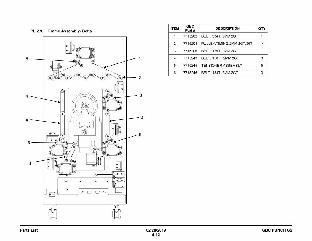
~ "---'----' o D
PL 2.9. Frame Assembly- Belts
4
4
6
5
3
1
2
6
4
6
ITEM GBC Part # DESCRIPTION QTY
1 7715202 BELT, 534T, 2MM 2GT 1
2 7715204 PULLEY,TIMING,2MM 2GT,30T 14
3 7715206 BELT, 179T, 2MM 2GT 1
4 7715243 BELT, 150 T, 2MM 2GT 3
5 7715245 TENSIONER ASSEMBLY 5
6 7715246 BELT, 134T, 2MM 2GT 3
Parts List 02/28/2019 GBC PUNCH G2 5-12

3.Paper Path PL 3.1. Paper Path- Entrance Drive Panel
ITEM
1
2
3
4
5
6
7
GBC
Part # 1824002
7711973 S187715696 S19 S207715696 S21
7715871
1822108
1822117
1823903
DESCRIPTION
NUT, KEPS, M3
RECEIVER MID PUNCH, LARGE, SENSOR BOARD BOARD ASSY, BACKGAGE SENSOR MID PUNCH, X LARGE, SENSOR BOARD BOARD ASSY, BACKGAGE SENSOR PANEL WLDMNT,DRIVE,ENTRANCE,SERVICE
WASHER, FLAT, 4.1X 8X1.5
WASHER, 3.2ID, 8OD, 0.75MM THICK
SCREW, PHILLIPS, HX HD M4X8
QTY
6
1
1
1
1
4
12
2
S20, S21
S18, S19
GBC PUNCH G2 02/28/2019 Parts List 5-13

-~ J
g I
4 ~ ~~]~"1_1,\ ~ I
1 , A
11 I
I
~ R
DETAIL A
.//~ / '}? 7_/
13
PL 3.2. Paper Path- Entrance Idler Panel ITEM GBC
Part # DESCRIPTION QTY
1 7711970 S1b EMITTER 1 2 7715103 ROLLER ASSY, IDLER 3 3 7715223 SOL3
SOL4 MODULE,SOLENOID,DISENGAGING ROLLER 2
S2 4 7715291 S3 SENSOR AND BRACKET ASSY 3
S4 5 7715380 SPRING,TRANSPORT IDLR ROLLER 6 6 7715382 BEARING HOUSING 6 7 7715384 HANDLE ASSY, IDLER PANELS 1
8 7715625 WIRE SADDLE, SHORT 2 9 7715629 SCREW, BARREL, M4, 7MM DEEP 13
10 7715639 WIRE SADDLE,SMALL,SIDE OPEN 11 11 7715873 PANEL WLDMT,IDLER,ENTRY 1 12 7714679 GROUND STRAP, M4 1 13 7708163 CAP, RUBBER 1
S2
S3
S1b SOL3
S4 SOL4
Parts List 02/28/2019 GBC PUNCH G2 5-14

PL 3.3. Paper Path- Acceleration Roller Idler ITEM GBC DESCRIPTION QTY
Part # 1 7708163 CAP, RUBBER 1
2 7715103 ROLLER ASSY, IDLER 1 SOL MODULE, SOLENOID, 3 7715223 15 DISENGAGING ROLLER
4 7715291 S5 SENSOR AND BRACKET ASSY 1
5 7715376 BRUSH, ANTI STATIC 1
6 7715380 SPRING,TRANSPORT IDLR ROLLER 2
7 7715382 BEARING HOUSING ASSY 2
8 7715817 WIRE SADDLE, SMALL 5
9 7715629 SCREW, BARREL, M4, 7MM DEEP 4
10 7715875 PANEL WLDMNT, IDLER, ACCEL 1
11 7714679 GROUND STRAP, M4 1
SOL5
S5
GBC PUNCH G2 02/28/2019 Parts List 5-15

•< I
I 7 DETAIL A
PL 3.4. Paper Path- Exit Idler Panel
SOL8
SOL7
SOL6
ITEM
1
2
3
4
5
6
7
8
9
10
11
12
GBC Part #
7715103
7715223
7715291
7715380
7715384
7715382
7715625
7715629
7715639
7715874
7714679
7708163
SOL6 SOL7 SOL8 S22 S23 S24
DESCRIPTION QTY
ROLLER ASSY, IDLER 3
MODULE,SOLENOID, DISENGAGING ROLLER 3
SENSOR AND BRACKET ASSY 3
SPRING,TRANSPORT IDLER 6 ROLLERS HANDLE ASSY, IDLER PANELS 1
BEARING HOUSING ASSY 6
WIRE SADDLE, SHORT 3
SCREW,BARREL,M4,7MM DEEP 12
WIRE SADDLE,SM,SIDE OPEN 8
PANEL WELDMENT,IDLER,EXIT 1
GROUND STRAP, M4 1
CAP, RUBBER 1
S24
S23
S22
Parts List 02/28/2019 GBC PUNCH G2 5-16

JET AIL A
l ~ 11
PL 3.5. Paper Path- Upper Bypass Panel
ITEM GBC Part #
DESCRIPTION QTY
1 1824002 NUT, KEPS, M3 1
2 7715103 ROLLER ASSY, IDLER 5
3 7715291 S25 S26
SENSOR AND BRACKET ASSEMBLY 2
4
5
7715376
7715380
BRUSH, ANTI-STATIC
SPRING, TRANSPORT IDLER ROLLER
1
10
6 7715382 BEARING HOUSING ASSY 10
7
8
7715384
7715627
S1
HANDLE ASSY, IDLER PANELS
SENSOR AND BRACKET ASSY,S1
1
1
9 7715629 SCREW, BARREL, M4, 7MM DEEP 3 10 7715872 PANEL WELDMENT, BYPASS, UPPER 1
11 7714679 GROUND STRAP, M4 1
12 7708163 CAP, RUBBER 1
13 1822117 WASHER, 3.2ID, 8OD, 0.75MM THICK 1
S25
S26
S1
GBC PUNCH G2 02/28/2019 Parts List 5-17

1
GBC ITEM Description QTY Part # PL 3.6. Paper Path- Disengaging Roller Solenoid SOL 3 SOL 4 SOL 5 MODULE, SOLENOID, 1 7715223 6SOL 6 DISENGAGING ROLLER SOL 7 SOL 8
Parts List 02/28/2019 GBC PUNCH G2 5-18

A
1 s 6
\_2
DETAIL A
4.Punch Module PL 4.1. Punch Module
ITEM GBC Part #
7723890
115V
DESCRIPTION
PUNCH MODULE, ASSY, 115V
QTY
1
1 2
7723891
1821118 1821215
230V
PUNCH MODULE, ASSY, 230V
BEARING,BALL,FLANGE,12X24X6,SUJ2 BEARING, CLIP, 12MM
1
3
2
3 1821802 Spring washer M4 2 4 5
1821532 1822016
SCREW, SHCS, M4 X 12 WASHER,NYLON, ID12.7, OD19, 1.5THK
2 2
6 1822205 E-RING, JE-10 5 7 8 9
1823203 1823911 1824003
SCREW,SOCKET,M5, 6MM SHOULDER SCREW, PHILLIPS W/SEMS M4X10 NUT, KEPS, M6
1
1 1
10 7715033 STEERING MODULE SUB ASSY 1 11 12
7715237 7715368
SHAFT, DIE LOCK HANDLE, DIE LOCK
1 1
13 7715818 WIRE SADDLE,MEDIUM,LOCK TOP,V-0 1 14 7715886 PUNCH MODULE SHELL, SERVICE 1
GBC PUNCH G2 02/28/2019 Parts List 5-19

3
DETAIL A
PL 4.2. Punch Module (continued) ITEM GBC QTY DESCRIPTION Part # 1 1 1821514 SHCS, M3X12
2 1821541 SCREW, SOCKET HD,M6,35MM LONG 1
3 1821655 SCREW, PHILLIPS, PAN HD, M4X25 2
4 1823903 SCREW, PHILLIPS, HX HD M4X8 54
5 1825203 WIRE SADDLE, SNAP TYPE, SMALL 2
6 1823701 NUT, HEX, M3 1
7 7715030 BRACKET, CLUTCH STUD 1
8 7715079 MOUNT PIN, PUNCH MODULE 2
7715232 115V BELT, TIMING, 82 GROOVE, 5MM HTD 1 9
7715372 230V BELT, TIMING, 80 GROOVE, 5MM HTD 1
10 7715238 BRACKET & BEARING ASSY,DIE LOCK 2
11 7715239 PLUNGER & STRIPPER ASSY,DIE LOCK 2
12 7715320 MAGNET, DIE STOP 1
13 7715374 SPRING, DIE LOCK RETURN 2
14 1824001 NUT, KEPS M4 2
Parts List 02/28/2019 GBC PUNCH G2 5-20

S\./1 TCH
PL 4.3. Punch Module- Motors/Sensors
ITEM GBC Part # DESCRIPTION QTY
1 7715857 M3 LEFT / FRONT STEERING
MOTOR AND PULLEY. 1
2 7715857 M4 RIGHT / REAR STEERING
MOTOR AND PULLEY. 1
3 7715859 M5 ALIGNMENT STEPPER MOTOR AND PULLEY. 1
S6 S7
4 7715692 S8 SKEW SENSOR BOARD 1 S9
S10 S11
5 7718567 S12 S13 S14
ALIGNMENT SENSOR BOARD, SWITCHABLE 1
S15
6 7715696 S16 S17
BACKAGE SENSOR BOARD 1
GBC PUNCH G2 02/28/2019 Parts List 5-21

I 1 1 I l 7 ---
- --
I I I I I I
PL 4.4. Punch Module- Steering Module ITEM GBC
Part # DESCRIPTION QTY
1 1823901 SCREW, PHILLIPS HX W/SEMS, M3X6 4 2 1823913 SCREW,PHILIPS-HEX LOCK, M3X8 4
3 1824002 NUT, KEPS, M3 1
4 7715445 WIRE CLAMP, EDGE, SMALL 1
5 7715597 S28 SENSOR, VEIN, BRACKET, SUB ASSLY 1
6 7715779 GROUND STRAP, STEERING CARRIAGE 1
7 7715877 ALIGNMENT CARRIAGE,SUB ASSY, SERVICE 1
Parts List 02/28/2019 GBC PUNCH G2 5-22

PL 4.5. Punch Module- Steering Module - Steering Idler Panel Sub Assembly ITEM
1
GBC Part #
1822117
DESCRIPTION
WASHER, 3.2ID, 8OD, 0.75MM THK
QTY
8
2 1824002 NUT, KEPS, M3 6
3 7706488 BEARING, DOUBLE "D" FLANGE 2
4 7715062 PANEL WELDMENT,IDLER,STEERING 1
5 7715379 SPRING, STEERING IDLER ROLLER 2
6 7715648 WIRE CLAMP, LOCKING 3
7 7715692
S6 S7 S8 S9 S10
BOARD ASSY, SKEW SENSOR 1
8 7715816 ROLLER ASSY, IDLER, STEERING 1
GBC PUNCH G2 02/28/2019 Parts List 5-23

PL 4.6. Punch Module- Steering Module - Drive Panel Steering
ITEM
1
2
3
GBC Part #
1822008
1822202
1823901
DESCRIPTION
WASHER, FLAT, 6.4X12X1.5
E-RING, JE-5
SCREW, PHILLIPS HX W/SEMS, M3X6
QTY
4
4
8
4 1824002 NUT, KEPS, M3 4
5 7715039 ROLLER ASSEMBLY, DRIVE, STEERING 2
6 7715044 SHAFT, STEERING DRIVE 1
7 7715047 BELT,STEERING,65 GROOVES,2MM 2GT 2
8 7715053 PANEL WELDMENT, DRIVE, STEERING 1
9 7715377 SPRING, STEERING DRIVE ROLLER 2
10 7715648 WIRE CLAMP, LOCKING 2
11
12
7715777
7715857
7715857
M3
M4
SLEEVE,SPIRAL, MOTOR WIRES
STEPPER MOTOR AND PULLEY,STEERING, SERVICE STEPPER MOTOR AND PULLEY,STEERING, SERVICE
1
1
1
Parts List 02/28/2019 GBC PUNCH G2 5-24

3
PL 4.7. Punch Module- Stepper Alignment Bracket
ITEM GBC Part # DESCRIPTION QTY
1 1823906 SCREW,PHILLIPS HX W/SEM M5X10 4
2 7715078 BRACKET,ALIGN STEPPER MOUNT 1
3 7715859 M5 STEPPER MOTOR AND PULLEY, ALIGNMENT, SERVICE 1
GBC PUNCH G2 02/28/2019 Parts List 5-25

PL 4.8. Punch Module- Punch Clutch GBC ITEM DESCRIPTION QTY Part #
1 1821531 SCREW, SHCS, M5X18 3
2 1821801 WASHER, SPLIT LOCK, M5 3
3 7715020 CLUTCH, WRAP SPRING 1
4 7715231 115V PULLEY & FLANGE,5MM HTD,38T 1
7715371 230V PULLEY & FLANGE,5MM HTD,34T 1
Parts List 02/28/2019 GBC PUNCH G2 5-26

I I I I I
PL 4.9. Punch Module- Die Set Recognition Reader Board ITEM GBC
Part # DESCRIPTION QTY
1 7715347 BOARD, READER, DIE SET RECOGNITION 1
2 1824002 NUT, KEPS, M3 2
GBC PUNCH G2 02/28/2019 Parts List 5-27

PL 4.10. Punch Module- Die Rail, Backgage, Align Sensors, Sub Assembly
ITEM
1
GBC Part #
1821610
DESCRIPTION
SCREW, PHILLIPS, PAN HD, M2, 3MM
QTY
4
2 1821808 LOCK WASHER, SPLIT, M2 4 3 1822114 WASHER, FLAT, 4.1x8x2 3 4 1822117 WASHER, 3.2ID, 8OD, 0.75MM THK. 7 5 1824002 NUT, KEPS, M3 9 6 7708814 CAP, RUBBER, 1/8 X 1/4 X .040 1
7 7715032 BRACKET, BACKGAGE SENSOR, LOWER 1 8 7715080 BRACKET WLDMNT, BACKGAGE SENSOR 1 9 7715640 WIRE SADDLE, SHORT, ALIGN SENSOR
WIRES 9 10 7715645 COVER, BACKGAGE SENSOR 1
11 7715787 S16 S17 BOARD ASSY, BACKGAGE SENSOR 1
12 7715799 SPRING, DIE RAIL, POSITION, 1 1
13 7715817 SPRING, DIE RAIL, POSITION, 2 1
14 7715986 WIRE SADDLE, SMALL, LOCKING TOP, V-0 2 15 7715988 DIE RAIL, ASSEMBLY 1
16 7715990 GUIDE, ALIGNMENT SENSOR, BOTTOM 1 17 7715787 BRACKET WLDMNT, ALIGNMENT SENSOR 1 S11
18 7718567 S12 S13 S14
BOARD ASSY, ALIGNMENT SENSOR, SWITCHABLE 1
S15
Parts List 02/28/2019 GBC PUNCH G2 5-28

PL 4.11. Punch Module- AC Motor GBC ITEM DESCRIPTION QTY Part #
1 1821807 WASHER, SPLIT LOCK, M8 4
2 1822113 WASHER, FLAT, 8X14X0.5 4
3 1823602 SET SCREW, NYLON PATCH, M4X6 1
4 1824703 SCREW, HEX CAP, M8, 16MM LONG 4 MOTOR AND PULLEY, PUNCH, 7715860 115V 1115V, SERVICE 5 MOTOR AND PULLEY, PUNCH, 7715861 230V 1230V, SERVICE
GBC PUNCH G2 02/28/2019 Parts List 5-29

5.
D
Die Sets ORDER THESE DIE-SETS THROUGH KONINCA MINOLTA SUPPLIES
ITEM DESCRIPTION 1 7714901 DIE, Coil, Rnd 2 7714902 DIE, Wire 2:1, Rnd 3 7714903 DIE, Wire 3:1, Rnd 4 7714904 DIE, 3 Hole, 8mm 5 7714905 DIE, 3/5/7 Hole, 8mm 6 7714906 DIE, 4 Hole, 8mm 7 7714907 DIE, 4 Hole, 6.5mm 8 7714908 DIE, 4 Hole Scan 9 7714909 DIE, VeloBind®, 11 Hole, Ltr 10 7714910 DIE, VeloBind®, 12 Hole, A4 11 7714911 DIE, CombBind 12 7714912 DIE, Wire 2:1, Sq 13 7714913 DIE, Wire 3:1, Sq 14 7714914 DIE, Coil, Oval 15 7714915 DIE, eWire 3:1, Rnd 16 7714916 DIE, eWire 3:1, Sq 17 7714917 DIE, Coil, Rnd, 47H HD 18 7714918 DIE, 3 Hole, 8mm, HD 19 7714919 DIE, CombBind, 21H HD
Parts List 02/28/2019 GBC PUNCH G2 5-30

6.Electronics PL 6.1. Electronics PCB Assembly
ITEM
1
2
3
4
GBC Part #
6195001
7718655
7718799
7715863
DESCRIPTION
RFI POWER FILTER
BOARD, CONTROL, MAIN
BOARD, CONTROL, COMM
FUSE,AC POWER, 250V, 5A
QTY
1
1
1
1
GBC PUNCH G2 02/28/2019 Parts List 5-31

( F? i
0
0 i
0 '@:
PL 6.2. Control Board Bracket Sub Assembly ITEM GBC
Part # DESCRIPTION QTY
1 7715183 STANDOFF, PLASTIC, 2 PHASE DRIVER 11
2 7715817 WIRE SADDLE, SMALL, LOCKING TOP, V-0 4
3 7715819 WIRE SADDLE, LARGE, LOCKING TOP, V-0 19
Parts List 02/28/2019 GBC PUNCH G2 5-32

PL 6.3. Cable Part Number Index
Refer to the Wiring drawing on the next page to locate the cables
GBC Part # DESCRIPTION
7715451 CABLE, SENSORS S1,S25,S26
7715453 CABLE, SENSORS, ENTRY
7715455 CABLE, SENSORS, SKEW, BRD TO HDR
7715456 CABLE, SENSORS, ALIGN, BRD TO HDR
7715457 CABLE, SENSORS, BG & ALGN HM, BRD TO HDR
7715458 CABLE, SENSORS, MID BG L & XL
7715459 CABLE, SENSORS, EXIT
7715466 CABLE, SOLENOIDS, ENTRY, BRD TO HDR
7715467 CABLE, SOLENOIDS, EXIT, BRD TO HDR
7715468 CABLE, ENTRANCE & ACCEL, DRIVER
7715470 CABLE, ALIGN & STEERING, DRIVER
7715473 CABLE, EXIT, DECEL & BYPASS DRIVER
7715476 CABLE, PUNCH MOTOR
7715477 CABLE, POWER, STEPPER, DRIVERS
7715485 CABLE, CHIP TRAY
7715487 CABLE, DOOR INTERLOCK
7715490 CABLE, USB
7715492 CABLE, DC POWER
7715493 CABLE, AC TO PSU
7715494 CABLE, AC TO BOARD
7715495 CABLE, DIESET RECOGNITION
7715535 CABLE, INLET FILTER TO AC SWITCH
7715508 CABLE, SKEW, HDR TO SENSOR
7715509 CABLE, ALIGN, HDR TO SENSOR
7715510 CABLE, BG, HDR TO SENSOR
7715519 CABLE, ALIGN HOME, HDR TO SENSOR
7715520 CABLE, LEFT STEER, DRV TO HDR
7715521 CABLE, RIGHT STEER, DRV TO HDR
7715523 CABLE, LCD
7715525 CABLE, AC FILTER, GROUND
7715528 CABLE, STEERING MOTOR, MTR TO HDR, LEFT
7715529 CABLE, STEERING MOTOR, MTR TO HDR, RIGHT
7715536 CABLE, THRU BEAM, CLEAR COVER
7715537 CABLE, DEBUG TO PANEL
7715539 CABLE, GROUND, PSU TO CHASSIS
7715538 CABLE, COMM TO PANEL
7715531 CABLE, DFA, UPSTREAM, SPARTA
7718876 CABLE, PASSTHROUGH, KM SPARTA
GBC PUNCH G2 02/28/2019 Parts List 5-33

24V PD\JER SUPPLY
CHASSIS
----"-""'"""'-----;;n;;-,,.;;:se::-=:: GPOJND
~
~
l -----------i_ ~
MS ALIGNMENT MOTOR
PL 6.4. Wiring Drawing
Parts List 02/28/2019 GBC PUNCH G2 5-34

~II'" fillJ13
L!lJ GND
J2
J 3
I• ••I J4
v
IJ3, J31
SPARTA CONTROLLER ~
J20
o;J FAN
Jl J7
l••····•®ll@•I
J 32 COMM INTERFACE
J3
COMMUNICATION BOARD .------------------.Jl
················· ··~ •••••••••••••••••••• • .--------------------.J2
············ ······ ·~ •••••••••••• •• •• •• •• J4
I· •
J38
r ,
,
• • J33
J5
I
PCB’S Main Control Board and Communication Board
GBC PUNCH G2 02/28/2019 Parts List 5-35

7.
1.
I I
Installation Kit Parts
ITEM GBC Part #
DESCRIPTION QTY
1 6200001 115V POWER CORD, US, 115V 1
2 6200002 230V POWER CORD, EUROPE 1
3 6200014 230V POWER CORD, UK, 1
4 6200015 230V POWER CORD, SWISS 1
5 7715684 DRIVE, USB STICK, FLASH DRIVE 1
6 7718832 BRKT SUBASSY, DOCKING, LOWER FRNT, KM 11
7 7718834 BRKT SUBASSY, DOCKING, UPPER FRNT, KM SPARTA 12
8 7715632 SCREW, ROUND TIP, M4 X 8 12
9 7610500 CABLE ASSY, INTERFACE (37 PINS) 2
10 7723873 DOCKING BRACKET ASSY, REAR, SPARTA, KM 2
11 7718832 BRKT SUBASSY, DOCKING, LOWER FRNT, KM 1
12 7710227 BRACKET, LOCK, FRONT, LOWER 1
13 7718834 BRKT SUBASSY, DOCKING, UPPER FRNT, KM 1
Miscellaneous Parts
ITEM GBC Part #
DESCRIPTION QTY
1 7718648 WIPES, CLEANING, ANTI-STATIC 1
Parts List 02/28/2019 GBC PUNCH G2 5-36

2.Part Number Index
Part # DESCRIPTION PL 1823901 SCREW, PHILLIPS, HEX HD W/SEMS, M3X6 1.2 1823905 SCREW, PHILLIPS HX HD W/SEMS, M4X35 1.2 1824001 NUT, KEPS M4 1.2 7610501 INTERLOCK SWITCH 1.2 7706447 MAGNET, FRONT DOOR 1.2 7706486 LATCH, PUSH TO CLOSE 1.2 7715267 FAN, EXHAUST 1.2 7715527 LCD, DISPLAY 1.2 7715632 SCREW, ROUND TIP, HEX HD, PHILLIPS, M4 X 8 1.2 7718877 PANEL, LCD MEMBRANE SWITCH, KM 1.2 7718836 HINGE, UPPER SUBASSY, KM 1.2 7718838 HINGE ASSY, LOWER, KM 1.2 7718840 COVER PANEL ASSY, BACK, KM 1.2 7718847 COVER WELDMENT, R-BACK, KM 1.2 7718856 COVER, POCKET 1.2 7718859 BRACKET, EXHAUST FAN, KM 1.2 7718862 COVER, WELDMENT, SIDE, DOWNSTREAM,
REAR, KM 1.2 7718867 PANEL ASSY, BACK LEFT, SPARTA, KM 1.2 7718872 SPACER, KM SPARTA, MTG INTERFACE 1.2 7718873 FOAM, KM SPARTA 1.2 PL 5.5 UPPER BYPASS PANEL 2.1 PL 5.2 ENTRANCE IDLER PANEL 2.1 PL 5.1 ENTRANCE DRIVE PANEL 2.1 PL 5.3 ACCELERATION IDLER PANEL 2.1 PL 5.4 EXIT IDLER PANEL 2.1
7715101 PANEL, ENTRANCE, LOWER 2.1 7715102 PANEL, ENTRANCE, INNER 2.1 7715146 PANEL, EXIT, LOWER 2.1 7715153 PANEL, EXIT, INNER 2.1 7715822 PANEL ASSEMBLY, LOWER, EXIT 2.1 7715209 SHAFT, IDLER PANEL HINGE 2.1 7715210 SHAFT, IDLER PANEL HINGE, LONG 2.1
Part # DESCRIPTION PL 7715251 BRACKET, IDLER PANEL MOUNT 2.1 7715150 PANEL WELDMENT, DRIVE, EXIT 2.1 7715128 PANEL WELDMENT, BYPASS, LOWER 2.1
1821209 SNAP-IN BEARING, 6MM ID [Qty. (2) used on all Idler panels- #A, #B, #D, #E and #5 2.1
1821209 Snap-in Bearing, 6mm ID for 1.45-2.34 mm Thk Mtrl 2.2 1822202 E-RING, JE-5 2.2 1823711 JAM NUT, M16X2.0 2.2 1823901 SCREW, PHILLIPS HX HD W/SEMS, M3 X 6 2.2 1823909 SCREW, PHILLIPS HX HD W/SEMS M4 X 6 2.2 1824001 NUT, KEPS M4 2.2 1821606 SCREW, PHILLIPS PAN HD W/SEMS M3 X 10 2.2 7715195 MAGNET, PANEL, OPEN, STRONG 2.2 7715215 HANDLE, ACCEL IDLER LATCH 2.2 7715385 MAGNET, BRACKET, ASSY 2.2 7715427 CHIP TRAY, ASSEMBLY 2.2 7715650 LATCH, BYPASS 2.2 7715637 POWER SUPPLY, 24V, MW SP 480, 2.2 7715789 MAGNET, PANEL, OPEN, WEAK 2.2 7708163 CAP, RUBBER, RAIN BLUE 2.2 7715630 CASTER, ADJUSTABLE 2.2 1823913 SCREW, PHILLIPS HX HD W/SEMS M3 X 8 2.2 1821209 Snap-in Bearing, 6mm ID 2.3 1821611 SCREW, PHILLIPS HD W/SEMS, M3X10 2.3 1822005 WASHER, FLAT, 6.025 X 8 X 0.75 2.3 1822202 E-RING, JE-5 2.3 1823910 SCREW, PHILLIPS HX HD W/SEMS M4 X 14 2.3 1824001 NUT, KEPS M4 2.3 1825501 RETAINING RING, 6MM SHAFT 2.3 1902863 SCREW,MACHINE PAN #4-40 X 15/32 PHILLIPS 2.3 1925044 WSHR, .192 ID X .625 OD X .060 T 2.3 1952208 SPACER, TIMING BELT IDLERS, BRONZE 2.3 1954011 GROMMET, 3/8 I.D X 1/2 O.D 2.3 1954032 GROMMET, 1 1/4 I.D. X 1 1/2 O.D. 2.3 7712703 WIRE HEADER CONNECTOR, 2 POS 2.3 7714679 GROUND STRAP, M4 2.3
GBC PUNCH G2 02/28/2019 Parts List 5-37

Part # DESCRIPTION PL 7715185 BRACKET, PUNCH MODULE MOUNT 2.3 7715383 ROLLER, IDLER, DRIVE ASSY, 2.3 7715390 WIRE CLAMP, EDGE 2.3 7715445 WIRE CLAMP, EDGE, SMALL 2.3 7715813 SOLENOID, BRACKET, DIVERTER, SUB
ASSEMBLY 2.3 7715818 WIRE SADDLE, MEDIUM, LOCKING TOP, V-0 2.3 7715819 WIRE SADDLE, LARGE, LOCKING TOP, V-0 2.3 7715817 WIRE SADDLE, SMALL, LOCKING TOP, V-0 2.3 7715093 ROLLER ASSY, DRIVE 2.4 7715097 ROLLER ASSY, ONE WAY CLUTCH DRIVE 2.4 1821116 BEARING, BALL, FLANGE 6X13X5, SUJ2 2.4 1822005 WASHER, FLAT, 6.025 X 8 X 0.75 2.4 1822202 E-RING, JE-5 2.4 7706532 BEARING BALL FLANGE 2.4 1925222 WASHER FLAT, NON-METALLIC 1/4X3/8X/1/32 2.4 7715862 ONE WAY CLUTCH SUB ASSEMBLY, SERVICE 2.4 1822108 WASHER, FLAT, 4.1X8X1.5 2.5 1823911 SCREW, PHILLIPS HX HD W/SEMS M4 X 10 2.5 7711970 EMITTER 2.5 7711973 RECEIVER 2.5 7715131 BYPASS DIVERTER 2.5 7715186 CHIP TRAY SENSOR MOUNT ASSY 2.5 7715213 SHAFT, ACCEL IDLER LATCH 2.5 7715216 LATCH, ASSY, REAR, ACCEL IDLER PANEL 2.5 7715222 LATCH, ASSY, FRONT, ACCEL IDLER PANEL 2.5 7715637 POWER SUPPLY, 24V, MW SP 480, 2.5 7715159 STEPPER AND MOUNT ASSEMBLY 2.6 7715275 DRIVER AND BRACKET ASSY, TWO PHASE 2.6 7715627 Entrance Sensor, S1 2.7 7715291 Entrance Sensor, Top 2.7 7715291 Entrance Sensor, Middle 2.7 7715291 Entrance Sensor, Bottom 2.7 7715291 Accel Sensor 2.7 7715692 Skew Sensor Board 2.7 7715694 Alignment Sensor Board 2.7 7715696 Backage Sensor Board Assy 2.7
7715696 Mid Punch Large, Sensor Board Backage Sensor Board Assy 2.7
Part # DESCRIPTION PL
7715696 Mid Punch X- Large, Sensor Board Backage Sensor Board Assy 2.7
7715291 Exit Sensor, Bottom 2.7 7715291 Exit Sensor, Middle 2.7 7715291 Exit Sensor, Top 2.7 7715291 Exit Sensor 2.7 7715291 Bypass Sensor, Middle 2.7 7715597 Align Home Sensor 2.7 7711970 Chip Level Sensor - Emitter 2.7 7711973 Chip Level Sensor - Receiver 2.7 7715774 Clear Cover Sensor - Emitter 2.7 7711973 Clear Cover Sensor - Receiver 2.7 7715813 Diverter Subassembly 2.8 7715020 Punch Clutch 2.8 7715223 Entrance Idler Solenoid, Middle 2.8 7715223 Entrance Idler Solenoid, Bottom 2.8 7715223 Acceleration Roller Solenoid 2.8 7715223 Exit Idler Solenoid, Bottom 2.8 7715223 Exit Idler Solenoid, Middle 2.8 7715223 Exit Idler Solenoid, Top 2.8 7610501 Front door Interlock Switch 2.8 7715186 Chip Tray Home Switch Assembly 2.8 7715202 BELT, 534T, 2MM 2GT 2.9 7715204 PULLEY, TIMING, 2MM 2GT, 30 GROOVES 2.9 7715206 BELT, 179T, 2MM 2GT 2.9 7715243 BELT, 150 T, 2MM 2GT 2.9 7715245 TENSIONER ASSEMBLY 2.9 7715246 BELT, 134T, 2MM 2GT 2.9 1824002 NUT, KEPS, M3 3.1 7711973 RECEIVER 3.1 7715696 MID PUNCH, LARGE, SENSOR BOARD
BOARD ASSY, BACKGAGE SENSOR 3.1
7715696 MID PUNCH, X LARGE, SENSOR BOARD BOARD ASSY, BACKGAGE SENSOR 3.1
7715871 PANEL WELDMENT, DRIVE, ENTRANCE, SERVICE 3.1
1822108 WASHER, FLAT, 4.1X 8X1.5 3.1 1822117 WASHER, 3.2ID, 8OD, 0.75MM THICK 3.1 1823903 SCREW, PHILLIPS, HX HD M4X8 3.1 7711970 EMITTER 3.2
Parts List 02/28/2019 GBC PUNCH G2 5-38

Part # DESCRIPTION PL 7715103 ROLLER ASSY, IDLER 3.2 7715223 MODULE, SOLENOID, DISENGAGING ROLLER 3.2 7715291 SENSOR AND BRACKET ASSEMBLY 3.2 7715380 SPRING, TRANSPORT IDLER ROLLERS 3.2 7715382 BEARING HOUSING 3.2 7715384 HANDLE ASSY, IDLER PANELS 3.2 7715625 WIRE SADDLE, SHORT 3.2 7715629 SCREW, BARREL, M4, 7MM THREAD DEPTH 3.2 7715639 WIRE SADDLE, SMALL, SIDE OPENING 3.2 7715873 PANEL WELDMENT, IDLER, ENTRANCE,
SERVICE 3.2 7714679 GROUND STRAP, M4 3.2 7715774 EMITTER ASSY, CLEAR COVER SENSOR 3.2 7708163 CAP, RUBBER 3.2 7708163 CAP, RUBBER 3.3 7715103 ROLLER ASSY, IDLER 3.3 7715223 MODULE, SOLENOID, DISENGAGING ROLLER 3.3 7715291 SENSOR AND BRACKET ASSEMBLY 3.3 7715376 BRUSH, ANTI STATIC 3.3 7715380 SPRING, TRANSPORT IDLER ROLLERS 3.3 7715382 BEARING HOUSING ASSY 3.3 7715817 WIRE SADDLE, SMALL, LOCKING TOP 3.3 7715629 SCREW, BARREL, M4, 7MM THREAD DEPTH 3.3 7715875 PANEL WELDMENT, IDLER, ACCEL, SERVICE 3.3 7714679 GROUND STRAP, M4 3.3 7715103 ROLLER ASSY, IDLER 3.4 7715223 MODULE, SOLENOID, DISENGAGING ROLLER 3.4 7715291 SENSOR AND BRACKET ASSEMBLY 3.4 7715380 SPRING, TRANSPORT IDLER ROLLERS 3.4 7715384 HANDLE ASSY, IDLER PANELS 3.4 7715382 BEARING HOUSING ASSY 3.4 7715625 WIRE SADDLE, SHORT 3.4 7715629 SCREW, BARREL, M4, 7MM THREAD DEPTH 3.4 7715639 WIRE SADDLE, SMALL, SIDE OPENING 3.4 7715874 PANEL WELDMENT, IDLER, EXIT, SERVICE 3.4 7714679 GROUND STRAP, M4 3.4 7708163 CAP, RUBBER 3.4 1824002 NUT, KEPS, M3 3.5 7715103 ROLLER ASSY, IDLER 3.5 7715291 SENSOR AND BRACKET ASSEMBLY 3.5 7715376 BRUSH, ANTI-STATIC 3.5 7715380 SPRING, TRANSPORT IDLER ROLLERS 3.5
Part # DESCRIPTION PL 7715382 BEARING HOUSING ASSY 3.5 7715384 HANDLE ASSY, IDLER PANELS 3.5 7715627 SENSOR AND BRACKET ASSEMBLY, S1 3.5 7715629 SCREW, BARREL, M4, 7MM THREAD DEPTH 3.5 7715872 PANEL WELDMENT, BYPASS, UPPER, SERVICE 3.5 7714679 GROUND STRAP, M4 3.5 7708163 CAP, RUBBER 3.5 1822117 WASHER, 3.2ID, 8OD, 0.75MM THICK 3.5 7715223 Module, Solenoid, Disengaging Roller 3.6 7723890 PUNCH MODULE, ASSY, 115V 4.1 7723891 PUNCH MODULE, ASSY, 230V 4.1 1821118 BEARING, BALL, FLANGE, 12X24X6, SUJ2 4.1 1821215 BEARING, CLIP, 12MM 4.1 1821802 Spring washer M4 4.1 1821532 SCREW, SHCS, M4 X 12 4.1 1822016 WASHER, NYLON,ID 12.7, OD 19, 1.5MM THK 4.1 1822205 E-RING, JE-10 4.1 1823203 SCREW, SHOULDER, SOCKET HD, M5, 6MM
SHOULDER 4.1 1823911 SCREW, PHILLIPS HX HD W/SEMS M4 X 10 4.1 1824003 NUT, KEPS, M6 4.1 7715033 STEERING MODULE SUB ASSY 4.1 7715237 SHAFT, DIE LOCK 4.1 7715368 HANDLE, DIE LOCK 4.1 7715818 WIRE SADDLE, MEDIUM, LOCKING TOP, V-0 4.1 7715886 PUNCH MODULE SHELL, SERVICE 4.1 1821514 SHCS, M3X12 4.1 1821541 SCREW, SOCKET HD, M6, 35MM LONG 4.1 1821655 SCREW, PHILLIPS, PAN HD, M4X25 4.1 1823903 SCREW, PHILLIPS, HX HD M4X8 4.1 1825203 WIRE SADDLE, SNAP TYPE, SMALL, 3mm 4.1 1823701 NUT, HEX, M3 4.1 7715030 BRACKET, CLUTCH STUD 4.1 7715079 MOUNT PIN, PUNCH MODULE 4.1 7715232 BELT, TIMING, 82 GROOVE, 5MM HTD 4.1 7715372 BELT, TIMING, 80 GROOVE, 5MM HTD, 15MM
WIDE 4.1 7715238 BRACKET AND BEARING ASSY, DIE LOCK 4.1 7715239 PLUNGER AND STRIPPER ASSY, DIE LOCK 4.1 7715320 MAGNET, DIE STOP 4.1 7715374 SPRING, DIE LOCK RETURN 4.1 1824001 NUT, KEPS M4 4.1
GBC PUNCH G2 02/28/2019 Parts List 5-39

Part # DESCRIPTION PL 7715857 Left / Front Steering Motor and Pulley. 4.2 7715857 Right / Rear Steering Motor and Pulley. 4.2 7715859 Alignment Stepper Motor and Pulley. 4.2 7715692 Skew Sensor Board 4.2 7718567 Alignment Sensor Board 4.2 7715696 Backage Sensor Board 4.2 1823901 SCREW, PHILLIPS HX HD W/SEMS, M3 X 6 4.3 1823913 SCREW, PHILIPS-HEX HD W/EXT STAR WASHER,
M3 X 8 4.3 1824002 NUT, KEPS, M3 4.3 7715445 WIRE CLAMP, EDGE, SMALL 4.3 7715597 SENSOR, VEIN, BRACKET, SUB ASSEMBLY 4.3 7715779 GROUND STRAP, STEERING CARRIAGE 4.3 7715877 ALIGNMENT CARRIAGE, SUB ASSEMBLY,
RICOH, SERVICE 4.3 1822117 WASHER, 3.2ID, 8OD, 0.75MM THK. 4.4 1824002 NUT, KEPS, M3 4.4 7706488 BEARING, DOUBLE "D" FLANGE 4.4 7715062 PANEL WELDMENT, IDLER, STEERING 4.4 7715379 SPRING, STEERING IDLER ROLLERS 4.4 7715648 WIRE CLAMP, LOCKING 4.4 7715692 BOARD ASSY, SKEW SENSOR 4.4 7715816 ROLLER ASSY, IDLER, STEERING 4.4 1822008 WASHER, FLAT, 6.4X12X1.5 4.5 1822202 E-RING, JE-5 4.5 1823901 SCREW, PHILLIPS HX HD W/SEMS, M3 X 6 4.5 1824002 NUT, KEPS, M3 4.5 7715039 ROLLER ASSEMBLY, DRIVE, STEERING 4.5 7715044 SHAFT, STEERING DRIVE 4.5 7715047 BELT, STEERING, 65 GROOVES, 2MM 2GT 4.5 7715053 PANEL WELDMENT, DRIVE, STEERING 4.5 7715377 SPRING, STEERING DRIVE ROLLER 4.5 7715648 WIRE CLAMP, LOCKING 4.5 7715777 SLEEVE, SPIRAL, STEERING MOTOR WIRES 4.5 7715857 STEPPER MOTOR AND PULLEY, STEERING,
SERVICE 4.5
7715857 STEPPER MOTOR AND PULLEY, STEERING, SERVICE 4.5
1823906 SCREW, PHILLIPS HX HD W/SEMS M5 X 10 4.6 7715078 BRACKET, ALIGNMENT STEPPER MOUNT 4.6
Part # DESCRIPTION PL
7715859 STEPPER MOTOR AND PULLEY, ALIGNMENT, SERVICE 4.6
1821531 SCREW, SHCS, M5X18 4.7 1821801 WASHER, SPLIT LOCK, M5 4.7 7715020 CLUTCH, WRAP SPRING 4.7 7715231 PULLEY AND FLANGE, 5MM HTD, 38T, ASSY 4.7 7715371 PULLEY AND FLANGE, 5MM HTD, 34T, ASSY 4.7 7715347 Board, ASM, Reader, Die Set Recognition 4.8 1824002 NUT, KEPS, M3 4.8 1821808 LOCK WASHER, SPLIT, M2 4.9 1822117 WASHER, 3.2ID, 8OD, 0.75MM THK. 4.9 1824002 NUT, KEPS, M3 4.9 7715986 DIE RAIL, ASSEMBLY 4.9 7715032 BRACKET, BACKGAGE SENSOR, LOWER 4.9 7715080 BRACKET WELDMENT, BACKGAGE SENSOR 4.9 7715990 BRACKET WELDMENT, ALIGNMENT SENSOR, 4.9 7715988 GUIDE, ALIGNMENT SENSOR, BOTTOM 4.9 7715640 WIRE SADDLE, SHORT, ALIGN SENSOR WIRES 4.9 7718567 BOARD ASSY, ALIGNMENT SENSOR 4.9 7715696 BOARD ASSY, BACKGAGE SENSOR 4.9 7715787 SPRING, DIE RAIL, POSITION, 1 4.9 7715799 SPRING, DIE RAIL, POSITION, 2 4.9 1821807 WASHER, SPLIT LOCK, M8 4.10 1822113 WASHER, FLAT, 8X14X0.5 4.10 1823602 SET SCREW, NYLON PATCH, M4X6 4.10 1824703 SCREW, HEX CAP, M8, 16MM LONG 4.10 7715860 MOTOR AND PULLEY, PUNCH, 115V, SERVICE 4.10 7715861 MOTOR AND PULLEY, PUNCH, 230V, SERVICE 4.10 7714901 DIE, Coil, Rnd 5.1 7714902 DIE, Wire 2:1, Rnd 5.1 7714903 DIE, Wire 3:1, Rnd 5.1 7714904 DIE, 3 Hole, 8mm 5.1 7714905 DIE, 3/5/7 Hole, 8mm 5.1 7714906 DIE, 4 Hole, 8mm 5.1 7714907 DIE, 4 Hole, 6.5mm 5.1 7714908 DIE, 4 Hole Scan 5.1 7714909 DIE, Ricoh, Velobind®, 11 Holes, Ltr. 5.1 7714910 DIE, Ricoh, Velobind®, 12 Holes, A4 5.1 7714911 DIE, CombBind 5.1
Parts List 02/28/2019 GBC PUNCH G2 5-40

Part # DESCRIPTION PL 7714912 DIE, Wire 2:1, Sq 5.1 7714913 DIE, Wire 3:1, Sq 5.1 7714914 DIE, Coil, Oval 5.1 7714917 DIE, Coil, Rnd, 47H HD 5.1 7714918 DIE, 3 Hole, 8mm, HD 5.1 7714919 DIE, CombBind, 21H HD 5.1 6195001 RFI POWER FILTER 6.1 7718655 BOARD, CONTROL, MAIN 6.1 7718799 BOARD, COMMUNICATION, KM 6.1 7715863 Fuse, AC Power, 250V, 5A 6.1 1823901 SCREW, PHILLIPS HX HD W/SEMS, M3 X 6 6.2 7715183 WIRE SADDLE, LARGE, LOCKING TOP, V-0 6.2 7715819 STANDOFF, PLASTIC, 2 PHASE DRIVER 6.2 6200001 POWER CORD, US, 115V 7.1 6200002 POWER CORD, EUROPE 7.1 6200014 POWER CORD, UK, 7.1 6200015 POWER CORD, SWISS 7.1 7715684 DRIVE, USB STICK, FLASH DRIVE 7.1 7718832 BRKT SUBASSY, DOCKING, LOWER FRNT, KM 7.1 7718834 BRKT SUBASSY, DOCKING, UPPER FRNT, KM
SPARTA 7.1 7715632 SCREW, ROUND TIP, M4 X 8 7.1 7610500 CABLE ASSY, INTERFACE (37 PINS) 7.1 7723873 DOCKING BRACKET ASSY, REAR, SPARTA, KM 7.1 7718832 BRKT SUBASSY, DOCKING, LOWER FRNT, KM 7.1 7710227 BRACKET, LOCK, FRONT, LOWER 7.1 7718834 BRKT SUBASSY, DOCKING, UPPER FRNT, KM 7.1 7718648 WIPES, CLEANING, ANTI-STATIC 7.1
GBC PUNCH G2 02/28/2019 Parts List 5-41

Revision History Date Page# PL# Item# Notes
5/31/2017 Initial Release 6/7/2017 KM Part number columns
removed 02/28/2019 5-36 7.1 7718648 7718648 added
Parts List 02/28/2019 GBC PUNCH G2 5-42

Section Contents Title Page General Procedures................................................................... 6-3
User Interface............................................................................ 6-3 Settings.................................................................................. 6-4 Information............................................................................. 6-4 User Interface Screen Map ................................................... 6-5 GP 6.1 User Interface Procedure................................... 6-6 Settings Procedure ................................................................ 6-6 GP 6.1.1 BACKGAGE SETTING Procedure .................... 6-7 GP 6.1.2 ALIGNMENT SETTING Procedure.................... 6-9 GP 6.1.3 CLEAR COVER Procedure ............................. 6-11 GP 6.1.4 LANGUAGE SETTINGS Procedure ................ 6-13 GP 6.1.5 UNITS Procedure............................................. 6-14 GP 6.1.7 INFORMATION Procedure .............................. 6-15 GP 6.1.8 DIE TYPE Procedure ....................................... 6-16 GP 6.1.9 DIE CYCLES Procedure .................................. 6-17 GP 6.1.10 PUNCH CYCLES Procedure ........................... 6-18 GP 6.1.11 FIRMWARE Procedure.................................... 6-19
Service User Interface............................................................. 6-20 Service Interface Screen Map ............................................. 6-22 GP 6.2 Service User Interface Procedure.................... 6-23 GP 6.2.1 PAPER SIZE Setting........................................ 6-24 GP 6.2.2 MAX BYPASS Setting...................................... 6-24 GP 6.2.3 RUN MODE Setting ......................................... 6-25 GP 6.2.4 DIE CYCLES.................................................... 6-26 GP 6.2.5 SENSORS Check ............................................ 6-27 GP 6.2.6 SOLENOIDS Check......................................... 6-30 GP 6.2.7 MOTORS Check .............................................. 6-31 GP 6.2.8 FUNCTION TESTS (Cycle Punch, Aligner Test, Fan
Test) ................................................................. 6-32 GP 6.2.9 SKEW OFFSETS Adjustment.......................... 6-34 GP 6.2.10 ALIGN OFFSETS Adjustment ......................... 6-38 GP 6.2.11 LOG.................................................................. 6-40 GP 6.2.12 FIRMWARE UPGRADE Procedure................. 6-41 GP 6.3 Undock the Punch (Moving the punch to Service position)
......................................................................... 6-43
6. General Procedures and Information
GP 6.4 Dock the punch (Moving the punch to Operating position) .........................................................................6-43
GP 6.5 Operational Inspection .....................................6-44 GP 6.6 Internal Inspection............................................6-44 GP 6.7 Die Set Service ................................................6-45 GP 6.7.1 Die Set Life Expectancy................................... 6-45 GP 6.7.2 Die Set Components ........................................ 6-45 GP 6.7.3 Die Set Lubrication........................................... 6-46 GP 6.7.4 Die Set Shoulder Bolts ..................................... 6-47 GP 6.8 External Cleaning.............................................6-48 GP 6.9 Internal Cleaning ..............................................6-48 GP 6.10 Base Cleaning..................................................6-49 GP 6.11 Chip Bin Cleaning ............................................6-49 GP 6.12 Die Guide Cleaning ..........................................6-50 GP 6.13 Door Latch Inspection ......................................6-50 GP 6.14 Idler Roller and Idler Springs Inspection ..........6-51 GP 6.14.1 Idler Roller Cleaning......................................... 6-52
......................................................................... 6-53 GP 6.14.2 Steering Idler Roller and Springs Inspection and Cleaning
GP 6.15. Drive Roller and Steering Drive Roller Inspection and Cleaning .........................................................................6-54
GP 6.16 Panel Latch Inspection.....................................6-55 GP 6.17 Optical Sensor Cleaning ..................................6-58 GP 6.18 Bypass Paper Path Inspection and Cleaning...6-59 GP 6.19 Punch Paper Path Inspection and Cleaning ....6-60 GP 6.20 Punch Drive Cam Lubrication ..........................6-61 GP 6.21 Timing Belt Inspection......................................6-62 GP 6.22 Solenoid Cleaning and Inspection ...................6-63 GP 6.23 Alignment Carriage Rails Cleaning ..................6-64 GP 6.24 Punch Clutch Inspection and Cleaning ............6-64 GP 6.25 Diverter Solenoid Assembly Inspection ...........6-65 GP 6.26 Die Set Recognition Board Clips Inspection ....6-66 GP 6.27 Die Lock Mechanism and Die Rail Springs Inspection6-66
General Information .................................................................6-68
GBC PUNCH G2 02/28/2019 General Procedures and Information 6-1 Section Contents

Principle of Operation.............................................................. 6-68 Punch Path .............................................................................. 6-68
Single Punch ....................................................................... 6-68 Double Punch (Mid punch + trail edge punch) .................... 6-69
Bypass Path ............................................................................ 6-69 Glossary of Terms ................................................................... 6-71 Specifications .......................................................................... 6-72 Die Sets 6-73
Die Sets List ........................................................................ 6-74 Die Sets List (cont’d) ........................................................... 6-75
Tools 6-76 Standard Tools (metric) .......................................................6-76 Other Recommended Tools and Supplies...........................6-76
Lubrication 6-76 Cleaning Materials ...................................................................6-77 Serial Numbers ........................................................................6-77
General Procedures and Information 02/28/2019 GBC PUNCH G2 6-2

I I
General Procedures User Interface The User Interface consists of an LCD screen, an Up Arrow button, a Down Arrow button and an Enter Button.
The buttons on the User Interface allow you to change the backgage, alignment, language, and the units.
The User Interface displays status messages and fault codes on two rows of text.
READY
SINGLE PUNCH
In the User Interface, the top row of text displays the status of the Punch (Ready, Close Door). The bottom row of text displays the options selected on the User Interface (Single Punch).
To change the settings on the User Interface:
1. From the top level screen, press either the up arrow button or the down arrow button then press the ENTER button to display the SETTINGS/ INFORMATION screen.
SETTINGS
INFORMATION
• The up arrow indicates that there is a menu option above the option displayed.
• The down arrow indicates that there is a menu option below the option displayed.
• The return symbol indicates the option that will open when you press the ENTER button.
2. To select SETTINGS, press the ENTER button when the return symbol is next to the word Settings.
3. To select INFORMATION, press the down arrow button to move the return symbol down until it is next to the word Information, then press the ENTER button.
GBC PUNCH G2 02/28/2019 General Procedures and Information 6-3

Settings
Backgage
The Backgage feature allows you to scroll up or down to change the backgage setting.
Alignment
The Alignment feature allows you to scroll up or down to change the alignment setting.
You can change the alignment of the paper passing through the punch inboard and outboard +2.0 mm.
Clear Cover
The Clear Cover feature allows you to set the Backgage and Alignment values for Clear Cover media only. This setting does not affect any other type of media.
Language
The Language feature allows you to select the language for the user interface. The language options are: English, Francais, Espanol, Deutsch, and Italiano.
Units
The Units feature allows you to select the units displayed on the user interface. Select MM for millimeters of IN for inches.
Information The User Interface allows you to view information about. Die Type, Die Cycles, Punch Cycles, and Firmware
Die Type
The Die Type feature identifies the type of Die Set installed to the PUNCH G2.
Die Cycles
The Die Cycles feature lists the number of punch cycles completed by the die set that is presently installed in the machine.
Punch Cycles
The Punch Cycles feature lists the number of punch cycles completed by the Punch.
Firmware
The Firmware feature identifies the level of the firmware installed to the PUNCH G2.
General Procedures and Information 02/28/2019 GBC PUNCH G2 6-4
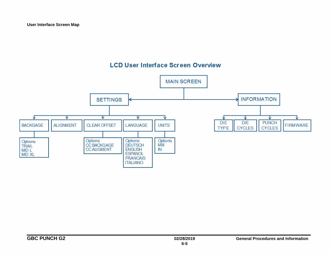
.... BA_. _c_~ .... GA_G_E __ I ALIGNMENT
Options: TRAIL MID L MID XL
LCD User Interface Scr,een Overview
SETTINGS
CLEAR OFFSET
Options: CCBACKGAGE CCALJGMENT
MAIN SCREEN
..,_ ______ ____, _________ ---;IJ INFORMATION
LANGUAGE
Options: DEUTSCH ENGLISH ESPA OL FRANCAIS ITALIANO
Q:ltions: MM IN
PUNCH CYCLES
FIRMWARE
User Interface Screen Map
GBC PUNCH G2 02/28/2019 General Procedures and Information 6-5
GP 6.1 User Interface Procedure Settings Procedure Use the following procedures to change the settings on the User Interface:
Settings
• GP 6.1.1 BACKGAGE SETTING Procedure
• GP 6.1.2 ALIGNMENT SETTING Procedure
• Error! Reference source not found. CLEAR COVER Procedure
• GP 6.1.4 LANGUAGE SETTINGS Procedure
• GP 6.1.5 UNITS Procedure
Information
• GP 6.1.8 DIE TYPE Procedure
• GP 6.1.9 DIE CYCLES Procedure
• GP 6.1.10 PUNCH CYCLES Procedure
• GP 6.1.11 FIRMWARE Procedure
General Procedures and Information 02/28/2019 GBC PUNCH G2 6-6
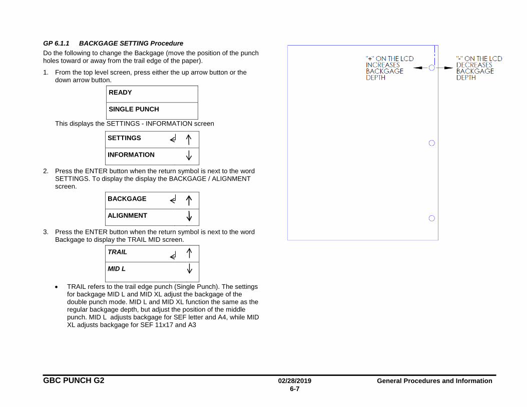
"+" ON THE LCD I " - " ON THE LCD INCREASES - d - DECREASES BACK GAGE BACK GAGE DEPTH DEPTH
0
0
GP 6.1.1 BACKGAGE SETTING Procedure Do the following to change the Backgage (move the position of the punch holes toward or away from the trail edge of the paper).
1. From the top level screen, press either the up arrow button or the down arrow button.
READY
SINGLE PUNCH
This displays the SETTINGS - INFORMATION screen
SETTINGS
INFORMATION
2. Press the ENTER button when the return symbol is next to the word SETTINGS. To display the display the BACKGAGE / ALIGNMENT screen.
BACKGAGE
ALIGNMENT
3. Press the ENTER button when the return symbol is next to the word Backgage to display the TRAIL MID screen.
TRAIL
MID L
• TRAIL refers to the trail edge punch (Single Punch). The settings for backgage MID L and MID XL adjust the backgage of the double punch mode. MID L and MID XL function the same as the regular backgage depth, but adjust the position of the middle punch. MID L adjusts backgage for SEF letter and A4, while MID XL adjusts backgage for SEF 11x17 and A3
GBC PUNCH G2 02/28/2019 General Procedures and Information 6-7

I
~ 11 I
~ l I
I
I
~
I ~
I ~ I I I
I ~ l I I l I
4. Do steps 5 - 12 to use TRAIL to adjust the Backgage for a Single Punch job:
TRAIL
MID L
5. Press the ENTER button when the return symbol is next to the word TRAIL to select Trail Backgage.
6. This displays the TRAIL OFFSET screen.
TRAIL OFFSET
0.0 mm
7. Press the up arrow button or the down arrow button to change the offset by+ 0.2mm
TRAIL OFFSET
0.2 mm
• A + offset moves the position of the punch holes away from the trail edge of the paper (increases the Backgage depth).
• A - offset moves the position of the punch holes toward the trail edge of the paper (decreases the Backgage depth).
• The maximum Backgage range is 16mm (max) and 1mm (min) -distance between the trail edge and edge of the punched hole.
8. Press the ENTER button to enter the new Backgage value. This displays the TRAIL / MID L screen.
TRAIL
MID L
9. Press the up arrow button to display the PREVIOUS MENU option.
10. Press the up or down arrow button to display the EXIT option.
EXIT
PREVIOUS MENU
11. Press the ENTER button to display the SAVE VALUES screen.
SAVE VALUE?
YES NO
• To select YES, press the ENTER button. • To select NO, press the down arrow button, to move the return
symbol. Then press the ENTER button.
This displays the top level screen.
READY
SINGLE PUNCH
NOTE: The BACKGAGE feature has the option to save as it defines the backgage for that particular die type. This means that for any die of that type inserted into that machine, the saved backgage will apply. If the user does not save the new backgage, the next time a die of this type is inserted in the machine, it will revert to the default depth for that die.
PREVIOUS MENU
TRAIL
General Procedures and Information 02/28/2019 GBC PUNCH G2 6-8

I
~
~ t I
"+" ON THE LCD INCREASES i ALIGNMENT OFFSET
t 0
~ t ' i "-" ON THE LCD DECREASES ALIGNMENT OFFSET
t 0
0
GP 6.1.2 ALIGNMENT SETTING Procedure 5. Press the up arrow button or the down arrow button to change the Do the following to change the Alignment (move the inboard/outboard offset by+ 0.1mm. position of the punch holes). This setting applies to all paper sizes
1. From the top level screen, press either the up arrow button or the down arrow button.
READY
SINGLE PUNCH • A + offset moves the position of the punch holes toward the rear of the machine (shallower).
ALIGNMENT OFFSET
0.0 mm
• A - offset moves the position of the punch holes toward the front This displays the SETTINGS - INFORMATION screen
SETTINGS
INFORMATION
of the machine (deeper)..
2. Press the ENTER button when the return symbol is next to the word SETTINGS. To display the display the BACKGAGE/ ALIGNMENT screen.
BACKGAGE
ALIGNMENT
3. Press the down arrow button once so the return symbol is next to the word ALIGNMENT.
BACKGAGE
ALIGNMENT
4. Press the ENTER button when the return symbol is next to the word Alignment to display the ALIGNMENT OFFSET screen.
ALIGNMENT OFFSET
0.0 mm
• The maximum alignment change is + 2.0 mm.
GBC PUNCH G2 02/28/2019 General Procedures and Information 6-9

I ~ t I I ~ t I
I I
6. Press the ENTER button to input the new Alignment value, and display the ALIGNMENT / CLEAR OFFSET screen.
ALIGNMENT
CLEAR OFFSET
7. Press the up or down arrow button to display the EXIT option.
EXIT
PREVIOUS MENU
Press the ENTER button to return to the top level screen. 8.
READY
SINGLE PUNCH
General Procedures and Information 02/28/2019 GBC PUNCH G2 6-10

I I I ~ 11
I
~ 11 I
~ I
I ~ 11 I
~ 11
I
~ 11 I
~ 11
I I
GP 6.1.3 CLEAR COVER Procedure 1. From the top level screen, press either the up arrow button or the
down arrow button.
READY
SINGLE PUNCH
This displays the SETTINGS - INFORMATION screen
SETTINGS
INFORMATION
2. Press the ENTER button when the return symbol is next to the word SETTINGS. To display the display the ALIGNMENT / CLEAR COVER screen.
ALIGNMENT
CLEAR COVER
3. Press the ENTER button when the return symbol is next to the word CLEAR OFFSET to display the CLEAR OFFSET screen.
CLR BACKAGE
CLR ALIGNMENT
• For CLR BACKGAGE go to step 5.
• For CLR ALIGNMENT go to step 8 (See page Error! Bookmark not defined.).
4. To set the BACKGAGE value for Clear Cover media, press the ENTER button when the return symbol is next to the words CLR BACKGAGE,
CLR BACKAGE
CLR ALIGNMENT
This displays the CLR BACKGAGE screen. Enter the desired value, the Offsets are in +/-0.2mm increments
CLR BACKGAGE
0.0 mm
5. Press the ENTER button to display the CLR BACKGAGE / CLR ALIGNMENT screen.
CLR BACKGAGE
CLR ALIGNMENT
6. Press the up or down arrow button to display the EXIT option.
EXIT
PREVIOUS MENU
• Press the ENTER button to return to the top level screen
READY
SINGLE PUNCH
(Cont.)
GBC PUNCH G2 02/28/2019 General Procedures and Information 6-11

I ~ 11 I
~ 11
I
I
I ~ I
I
~ 11
I
~ 11
7. To set the ALIGNMENT value for Clear Cover media, press the 10. Press the up or down arrow button to display the EXIT option. ENTER button when the return symbol is next to the words CLR ALIGNMENT,
CLR BACKAGE
CLR ALIGNMENT 11. Press the ENTER button to return to the top level screen
EXIT
PREVIOUS MENU
This displays the CLR ALIGNMENT screen. Enter the desired value, the Offsets are in +/-0.2mm increments
READY
SINGLE PUNCH CLR ALIGNMENT
0.0 mm
8. Press the ENTER button to display the CLR ALIGNMENT / PREVIOUS MENU screen.
CLR ALIGNMENT
PREVIOUS MENU
9. Press the ENTER button to display the CLR OFFSET / LANGUAGE screen.
CLEAR COVER
LANGUAGE
General Procedures and Information 02/28/2019 GBC PUNCH G2 6-12

I I
I ~ I
~ l I I
~ l I I
~ l I ~ l I I
I
I ~ 11 I I
I ~ I
GP 6.1.4 LANGUAGE SETTINGS Procedure Do the following to select the Language mode.
1. From the top level screen, press either the up arrow button or the down arrow button.
READY
SINGLE PUNCH
This displays the SETTINGS - INFORMATION screen
SETTINGS
INFORMATION
2. Press the ENTER button when the return symbol is next to the word SETTINGS to display the display the BACKGAGE/ ALIGNMENT screen.
BACKGAGE
ALIGNMENT
3. Press the down arrow button THREE times so the return symbol is next to the word Language.
CLEAR OFFSET
LANGUAGE
4. Press the ENTER button when the return symbol is next to the word Language. to display the LANGUAGE screen.
5. Press either the up arrow button or the down arrow button to change language.
LANGUAGE
ESPANOL
• English • Espanol • Francais • Italiano • Deutsch
6. Press the ENTER button to input the new language value, and display the Language / Units screen.
CLEAR OFFSET
LANGUAGE
7. Press the up or down arrow button to display the EXIT option.
EXIT
PREVIOUS MENU
8. Press the ENTER button to return to the top level screen
READY
SINGLE PUNCH
LANGUAGE
ENGLISH
GBC PUNCH G2 02/28/2019 General Procedures and Information 6-13

I I
I ~ 11
I
~ 11 I
~ 11
I I
I
~ 11
I ~ 11
I ~ I
GP 6.1.5 UNITS Procedure 6. Press the ENTER button to input the new language value, and display the Language / Units screen. Do the following to select the Language mode.
1. From the top level screen, press either the up arrow button or the down arrow button.
READY
SINGLE PUNCH 7. Press the up or down arrow button to display the EXIT option.
This displays the SETTINGS - INFORMATION screen
CLEAR OFFSET
LANGUAGE
SETTINGS
INFORMATION 8. Press the ENTER button to return to the top level screen
EXIT
PREVIOUS MENU
2. Press the ENTER button when the return symbol is next to the word SETTINGS to display the display the BACKGAGE/ ALIGNMENT screen.
READY
SINGLE PUNCH
BACKGAGE
ALIGNMENT
3. Press the down arrow button so the return symbol is next to the word Units.
LANGUAGE
UNITS
4. Press the ENTER button when the return symbol is next to the word UNITS to display the UNITS screen.
UNITS
MM
5. Press either the up arrow button or the down arrow button to change units from mm to inch or vice versa.
UNITS
INCH
General Procedures and Information 02/28/2019 GBC PUNCH G2 6-14

I
I
~ l I
I ~ l I
I
~ l I
GP 6.1.7 INFORMATION Procedure Do the following to view information about: Die Type, Die cycles, Punch Cycles, and Firmware
1. From the top level screen,
READY
SINGLE PUNCH
2. Press either the up arrow button or the down arrow button then press the ENTER button to display the SETTINGS/ INFORMATION screen.
SETTINGS
INFORMATION
3. Press the down arrow button to move the return symbol down until it is next to the word INFORMATION.
SETTINGS
INFORMATION
4. Press the ENTER button to display the DIE TYPE/DIE CYCLES screen.
DIE TYPE
DIE CYCLES
See the following pages for
- Die Type Information
- Die Cycles Information
- Punch Cycles Information
- Firmware Information
GBC PUNCH G2 02/28/2019 General Procedures and Information 6-15

I I I
~ 11
I
~ 11 I
~ 11
I
I I
~ 11
I
~ 11
GP 6.1.8 DIE TYPE Procedure The Die Type feature identifies the type of Die Set installed to the PUNCH 6. Press the ENTER button to return to the DIE TYPE – DIE CYCLES G2. screen. 1. From the top level screen,
READY
SINGLE PUNCH
DIE TYPE
DIE CYCLES
7. Press the up or down arrow button to display the EXIT option. 2. Press either the up arrow button or the down arrow button to display
the SETTINGS/ INFORMATION screen.
SETTINGS
INFORMATION 8. Press the ENTER button to return to the top level screen
EXIT
PREVIOUS MENU
3. Press the down arrow button to move the return symbol down until it is next to the word INFORMATION,
READY
TO PUNCH SETTINGS
INFORMATION
4. Press the ENTER button to display the DIE TYPE – DIE CYCLES screen.
DIE TYPE
DIE CYCLES
5. Press the ENTER button when the return symbol down is next to the words DIE TYPE. This displays the DIE TYPE screen,
DIE TYPE
WIRE 3:1 SQUARE
General Procedures and Information 02/28/2019 GBC PUNCH G2 6-16

I
~ 11
I
~ 11
I ~ 11
I
~ 11
I
~ I
I 11
GP 6.1.9 DIE CYCLES Procedure 7. Press the up or down arrow button to display the EXIT option. The Die Cycles feature shows the number of cycles for the die set that is currently installed in the machine.
1. From the top level screen,
READY
SINGLE PUNCH
8. Press the ENTER button to return to the top level screen
EXIT
PREVIOUS MENU
2. Press either the up arrow button or the down arrow button to display the SETTINGS/ INFORMATION screen.
READY
SINGLE PUNCH
SETTINGS
INFORMATION
3. Press the down arrow button to move the return symbol down until it is next to the word Information,
SETTINGS
INFORMATION
4. Press the ENTER button to display the DIE TYPE – DIE CYCLES screen.
DIE TYPE
DIE CYCLES
5. Press the ENTER button when the return symbol is next to the words DIE CYCLES to display the DIE CYCLES screen.
DIE CYCLES
23,495
6. Press the ENTER button to display the DIE TYPE – DIE CYCLES screen.
DIE TYPE
DIE CYCLES
GBC PUNCH G2 02/28/2019 General Procedures and Information 6-17

I
~ 11
I
~ 11
I ~ 11
I
~ 11
I
~ I
I 11
7. Press the up or down arrow button to display the EXIT option. GP 6.1.10 PUNCH CYCLES Procedure The Punch Cycles feature shows the number of punch cycles for the machine.
1. From the top level screen,
READY
SINGLE PUNCH
8. Press the ENTER button to return to the top level screen
EXIT
PREVIOUS MENU
2. Press either the up arrow button or the down arrow button to display the SETTINGS/ INFORMATION screen.
READY
SINGLE PUNCH
SETTINGS
INFORMATION
3. Press the down arrow button to move the return symbol down until it is next to the word Information,
SETTINGS
INFORMATION
4. Press the ENTER button to display the DIE TYPE – DIE CYCLES screen.
DIE TYPE
DIE CYCLES
5. Press the ENTER button when the return symbol is next to the words PUNCH CYCLES to display the PUNCH CYCLES screen.
PUNCH CYCLES
1,420,428
6. Press the ENTER button to display the DIE TYPE – DIE CYCLES screen.
PUNCH CYCLES
FIRMWARE
General Procedures and Information 02/28/2019 GBC PUNCH G2 6-18

I
I
I
~ I
I
~ l I I ~ l I
I
I
~ l I ~ l I
I I
I
~ 11
I ~ l I
GP 6.1.11 FIRMWARE Procedure The Firmware feature identifies the level of the firmware installed to the PUNCH G2.
1. From the top level screen,
READY
SINGLE PUNCH
1. Press either the up arrow button or the down arrow button to display the SETTINGS/INFORMATION screen.
SETTINGS
INFORMATION
2. Press the down arrow button to move the return symbol down until it is next to the word INFORMATION,
SETTINGS
INFORMATION
3. Press the ENTER button to display the DIE TYPE – DIE CYCLES screen.
5. Press the ENTER button when the return symbol is next to the word Firmware to display the FIRMWARE screen.
FIRMWARE
0B.48 B1.20
6. Press the ENTER button to display the PUNCH CYCLES – FIRMWARE screen.
PUNCH CYCLES
FIRMWARE
7. Press the up or down arrow button to display the EXIT option.
INFORMATION
EXIT
8. Press the ENTER button to return to the top level screen
READY
SINGLE PUNCH
DIE TYPE
DIE CYCLES
4. Press the down arrow button so the return symbol is next to the word FIRMWARE.
PUNCH CYCLES
FIRMWARE
GBC PUNCH G2 02/28/2019 General Procedures and Information 6-19

Service User Interface The Service User Interface allows you to:
• Set the Paper Size, Max Bypass sheet length and Run Mode.
• Check the operation of the Sensors, Solenoids, and the Motors.
• Run the Cycle Punch, Aligner Test, Exhaust fan test routines.
• Set the Skew Offsets and Align Offsets.
• View Die cycles and Machine log
• Upgrade Firmware
When the Service user Interface is open, the top row of text and the bottom row of text display the options on the Service User Interface menu.
Paper Size
The Paper Size feature allows you to select the desired paper size.
• ANSI • ISO
Max Bypass
The Max Bypass feature allows you to set the maximum sheet length that will be bypassed through PUNCH G2.
Run Mode
The Run Mode feature allows you to select the desired run mode.
• AUTO RUN • AUTO CYCLE
Sensors
The Sensors feature allows you to view the state of each of the 29 sensors to the PUNCH G2.
• 0 means the sensor is open. • 1 means the sensor is covered
Press the Up Arrow button and Down Arrow buttons to scroll through the list of sensors.
Solenoids
The Solenoid feature allows you to test the operation of each of the 8 solenoids to the PUNCH G2.
Press the Up Arrow button and Down Arrow buttons to scroll through the list of solenoids.
General Procedures and Information 02/28/2019 GBC PUNCH G2 6-20

Motors
The Motors feature allows you to test the operation of each of the 9 motors to the PUNCH G2.
Press the Up Arrow button and Down Arrow buttons to scroll through the list of motors.
Function Tests
The Function Tests feature allows you to run the Cycle Punch and Aligner Test routines.
Press the Up Arrow button and Down Arrow buttons to highlight the desired test.
Press the Enter button to run the test. Press the Enter button again to stop the test.
The Cycle Punch Test starts the Punch Motor, waits for 2 seconds, the triggers the Punch at 1 punch per second for 5 cycles.
The Aligner Test moves the home Aligner CW 10mm, back to home, CCW 10mm, then back to home. It repeats this cycle 5 times.
The Fan Test starts the Exhaust Fan at the rear of the Punch..
Skew Offsets
The Skew Offsets feature allows you to setup the skew offsets to straighten and offset punch depth. The options are:
• BG LEFT • BG RIGHT • BG DP L LEFT • BG DP L RIGHT • BG DP XL LEFT • BG DP XL RIGHT
Align Offsets
The Align Offsets feature allows you to setup the align offsets to straighten and offset punch depth.
Log
The LOG file download option will save the information about the last 50 punched sheets to a USB flash drive.
Die Cycles
This displays the number of cycles punched with the dieset that is currently installed in the machine.
Firmware Update
The Firmware Update feature allows you to update the firmware for the Punch.
GBC PUNCH G2 02/28/2019 General Procedures and Information 6-21

PAPER SIZE
I
Options: ANSI ISO
' , MAX
BYPASS
LCD Service Interface Screen Overview
Main Screen
"' 'Ii,, 'Ii,, "' RUN MODE SENSORS MOTORS
SKEW OFFSETS
I I I I
Options: Options: Opt ions: Opt ions:
AUTO RUN S1, S2, 53, 54, S5, M l , M2, BG LE FT
AUTO CYCLE Sl b, 56, 57, S8, M3,M4, BG RI GHT
S9, S10, S11, M6, M7, M8 BG DP L LEFT S12,513,S14,S 15, BG DP L RIGHT S16, S17, S18, BG DP XL LEFT
S19, S20, BG DP XL RI GHT S21,522, 523,
524, 525, 526, S27,528
" ' I ' I \ I
DIE CYCLES SOLENOIDS FUNCTION
TESTS ALIGN
OFFSETS
Opt ions:
Ll , L2, L3, L4,
LS, L6, L7, L8
Options:
CYCLE PUNCH
A LI GN ER TEST FAN
FUNCTION 4
Options:
511
512 513
514 515
'Ii,,
LOG
' I
FIRM UPGRADE
Options:
MAIN
COMM
Service Interface Screen Map
General Procedures and Information 02/28/2019 GBC PUNCH G2 6-22

GP 6.2 Service User Interface Procedure To enter the Service User Interface:
1. Press and hold both the Up Arrow button and the Down Arrow button for 5 seconds. Then while still holding down the Up Arrow button and the Down Arrow button, press the Enter button.
The Service User Interface screen will appear.
The buttons on the User Interface allow you to change the punch mode, the Backgage, alignment, language, and the units.
Use the following procedures to use Service User Interface:
• GP 6.2.1 PAPER SIZE
• GP 6.2.2 MAX BYPASS
• GP 6.2.3 RUN MODE
• GP 6.2.4 DIE CYCLES
• GP 6.2.5 SENSORS
• GP 6.2.6 SOLENOIDS
• GP 6.2.7
MOTORS
• GP 6.2.8 FUNCTION TESTS (Cycle Punch, Aligner Test, Fan Test)
• GP 6.2.9 SKEW OFFSETS
• GP 6.2.10 ALIGN OFFSETS
• GP 6.2.11 LOG
• GP 6.2.12 FIRMWARE UPGRADE
GBC PUNCH G2 02/28/2019 General Procedures and Information 6-23

GP 6.2.1 PAPER SIZE Setting 4. 1260mm is the Max Bypass setting. To reduce the Max Bypass
This setting is used for manufacturing set-up only. setting, press the down arrow to the desired setting, and then press OK.
GP 6.2.2 MAX BYPASS Setting 5. The below screen will appear. You may now return to the Previous Do the following to set the maximum bypass sheet length through the Menu or Exit to the Main screen. PUNCH G2. 1. At the top level screen,
READY
SINGLE PUNCH
MAX BYPASS
PREVIOUS MENU
Press and hold both the Up Arrow button and the Down Arrow button for 5 seconds.
Then while still holding down the Up Arrow button and the Down Arrow button, press the Enter button.
The Service User Interface screen will appear.
PAPER SIZE *
MAX BYPASS
2. Press the down arrow button to move the return symbol next to MAX BYPASS. Press OK to enter the Max Bypass setting
PAPER SIZE *
MAX BYPASS
3. The below screen will appear
MAX BYPASS *
700mm
General Procedures and Information 02/28/2019 GBC PUNCH G2 6-24

3. Press the down arrow to scroll through the speed options GP 6.2.3 RUN MODE Setting
• AUTO RUN – This feature is used for manufacturing set-up only. When PUNCH G2 is connected to a finisher this menu will show CONNECTED • AUTO CYCLE – Covering Sensor S25 will enable all When PUNCH G2 is not connected to a finisher and the punch is components: all motors, all solenoids. It can be used to check the powered ON, do the following to select the desired run mode. functioning of all motors and solenoids.
1. At the top level screen, 4. Press the OK button to set the RUN MODE and return to Service mode options. Press up or down arrow button to exit to Main screen. READY
SINGLE PUNCH
Press and hold the both Up Arrow button and the Down Arrow button for 5 seconds.
Then while still holding down the Up Arrow button and the Down Arrow button, press the Enter button.
The Service User Interface screen will appear.
PAPER SIZE *
MAX BYPASS
2. Press the down arrow so the return symbol is next to the words RUN MODE. Then press OK to enter the RUN MODE setting.
MAX BYPASS *
RUN MODE
GBC PUNCH G2 02/28/2019 General Procedures and Information 6-25
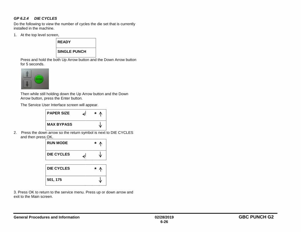
I I
I
~
:1
I ~ :1
I :1
GP 6.2.4 DIE CYCLES Do the following to view the number of cycles the die set that is currently installed in the machine.
1. At the top level screen,
READY
SINGLE PUNCH
Press and hold the both Up Arrow button and the Down Arrow button for 5 seconds.
Then while still holding down the Up Arrow button and the Down Arrow button, press the Enter button.
The Service User Interface screen will appear.
PAPER SIZE *
MAX BYPASS
2. Press the down arrow so the return symbol is next to DIE CYCLES and then press OK.
RUN MODE *
DIE CYCLES
DIE CYCLES *
501, 175
3. Press OK to return to the service menu. Press up or down arrow and exit to the Main screen.
General Procedures and Information 02/28/2019 GBC PUNCH G2 6-26

I I
I ~ I I
GP 6.2.5 SENSORS Check A sensor can fail in two modes: Do the following to check the sensors.
• Failed in High state: Machine thinks there is no sheet even 1. At the top level screen, when a sheet is present. In this mode, the LCD will always show "0" for that sensor, and will not go to "1" when a sheet is present.
• Failed in Low state: The converse of the above. "PAPER JAM...." message will be seen on LCD.
READY
SINGLE PUNCH
It is unlikely for a sensor to fail in a Low state. Therefore a bad sensor will most likely not give a "PAPER JAM..." message.
When there is "Paper Jam..." it is most likely because there is a sheet/piece of paper, or paper dust collecting over the sensor.
Procedure
Do the following to check the status of any of the sensors.
The Sensors feature allows you to view the state of each of the 29 sensors to the PUNCH G2.
Press and hold both the Up Arrow button and the Down Arrow button for 5 seconds.
Then while still holding down the Up Arrow button and the Down Arrow button, press the Enter button.
Cover each sensor to check if the sensor status changes from “0” to “1””.
• 0 means the sensor is open. • 1 means the sensor is covered.
The Service User Interface screen will appear.
PAPER SIZE *
MAX BYPASS
NOTE: Door can be open to do this.
(Cont.)
GBC PUNCH G2 02/28/2019 General Procedures and Information 6-27

I :1 I
~ :1
I
I
:1 :1
I :1
I :1
I :1
I :1
2. Press the down arrow so the return symbol is next to the words SENSORS. S22=0 S23=0 *
S24=0 S25=0
S26=0 S27=0 *
S28=1
3. Press the ENTER button when the return symbol is next to the word SENSORS to display the display the first SENSORS screen.
S1=0 S2=0 S3=0 *
S4=0 S5=0 S1b=0 When the Steering Carriage moves left/right, the Align Home Sensor (S28) is covered / uncovered.
DIE CYCLES *
SENSORS
Uncovered = 0
Covered = 1
4. Press the down arrow to scroll through the sensor options.
S6=0 S7=0 S8=0 *
S9=0 S10=0
S11=0 S12=0 *
S13=0 S14=0
S15=0 *
S16=0 S17=0
S18=0 S19=0 *
S20=0 S21=0
Sensor S28 covered
Sensor S28 uncovered
(Cont.)
General Procedures and Information 02/28/2019 GBC PUNCH G2 6-28

I J : I
If you use the down arrow to scroll through the complete list:
When you scroll down from the S26-S27-S28 screen, the system displays the Previous Menu / EXIT screen.
PREVIOUS MENU *
EXIT
You can either exit to the Previous Menu or Exit to Main Screen.
GBC PUNCH G2 02/28/2019 General Procedures and Information 6-29

I I
I ~ :1
I ~ :1
GP 6.2.6 SOLENOIDS Check Do the following to check the sensors.
1. At the top level screen,
READY
SINGLE PUNCH
Press and hold both the Up Arrow button and the Down Arrow button for 5 seconds.
Then while still holding down the Up Arrow button and the Down Arrow button, press the Enter button.
The Service User Interface screen will appear.
PAPER SIZE *
MAX BYPASS
2. Press the down arrow so the return symbol is next to the words SOLENOIDS.
3. Press the ENTER button when the return symbol is next to the word SOLENOIDS to display the display the SOLENOIDS screen.
L1 L2 L3 L4 *
L5 L6 L7 L8 BACK
4. To check the Solenoids: NOTE: Door needs to be closed or Interlock Cheater inserted to do this.
• Press the down arrow to scroll through the solenoid options. • The selected solenoid will flash on and off. • Pressing the Enter button will turn ON/OFF the solenoid. • You should hear the Solenoid click when it is cycled. • Repeat as needed to check the other Solenoids. • If a Solenoid does not operate do GP 6.22 Solenoid Cleaning and
Inspection. 5. When you finish checking the Solenoids:
• Press the up arrow or down arrow to highlight the BACK option. • Press the ENTER button to display Service mode menu. • Press up or down to display the Previous Menu and Exit Options.
SENSORS *
SOLENOIDS
General Procedures and Information 02/28/2019 GBC PUNCH G2 6-30

I I
I ~ :1
I ~ :1
GP 6.2.7 MOTORS Check Do the following to test any of the Stepper Motors.
The Motors feature allows you to test the operation of each of the 8 stepper motors to the PUNCH G2.
Do the following to check the Motors.
1. At the top level screen,
READY
SINGLE PUNCH
Press and hold both the Up Arrow button and the Down Arrow button for 5 seconds.
Then while still holding down the Up Arrow button and the Down Arrow button, press the Enter button.
The Service User Interface screen will appear.
PAPER SIZE *
MAX BYPASS
2. Press the down arrow so the return symbol is next to the words SOLENOIDS.
3. Press the ENTER button when the return symbol is next to the word Motors to display the display the first MOTORS screen.
M1 M2 M3 M4 *
M6 M7 M8 BACK
4. To check the Stepper Motors: NOTE: Door needs to be closed to do this.
• Press the down arrow to scroll through the motor options. • The selected motor will flash on and off. • Press the Enter button to turn the selected motor on. • You should hear the motor running
(a low whine for Motors M1, M2, M6, M7< & M8) (a soft whine for Motors M3, & M4),
• Press the Enter button again to turn the selected motor off • Repeat as needed to check the other Stepper Motors.
5. When you finish checking the Motors: • Press the up or down arrow to highlight the BACK option. • Press the ENTER button to display the Service mode menu • Press up or down to display the Previous Menu and Exit Options.
SOLENOIDS *
MOTORS
GBC PUNCH G2 02/28/2019 General Procedures and Information 6-31

I I
I ~ :1
GP 6.2.8 FUNCTION TESTS (Cycle Punch, Aligner Test, Fan Test) Do the following to test any of the Function Tests.
The Function Tests feature allows you to run the Cycle Punch, Aligner Test, and Fan Test routines.
Do the following to check the Motors.
1. At the top level screen,
READY
SINGLE PUNCH
Press and hold both the Up Arrow button and the Down Arrow button for 5 seconds.
Then while still holding down the Up Arrow button and the Down Arrow button, press the Enter button.
The Service User Interface screen will appear.
PAPER SIZE *
MAX BYPASS
2. Press the down arrow so the return symbol is next to the words FUNCTION TESTS.
MOTORS *
FUNCTION TESTS
3. Press the ENTER button when the return symbol is next to the words FUNCTION TESTS to display the display the FUNCTION TESTS screen.
CYCLE PUNCH *
ALIGNER TEST
4. To run the CYCLE PUNCH test: • Press the Enter button when the return symbol is next to the
words CYCLE PUNCH. • The CYCLE PUNCH Test starts the Punch Motor, waits for 2
seconds, the triggers the Punch at 1 punch per second for 5 cycles.
• After the test is complete it stops automatically, you may scroll down to Previous Menu or Exit.
5. To run the ALIGNER TEST: • Press the down arrow to move the return symbol next to the
words ALIGNER TEST. • Press the Enter button when the return symbol is next to the
words ALIGNER TEST. • The Aligner Test moves the home Aligner CW 10mm, back to
home, CCW 10mm, then back to home. It repeats this cycle 5 times.
• After the test is complete it stops automatically, you may scroll down to Previous Menu or Exit.
6. To run the FAN TEST: • Press the down arrow to move the return symbol next to the
words FAN TEST. • Press the Enter button when the return symbol is next to the
words FAN TEST. • The Fan Test turns the Exhaust Fan on and off. • After the test is complete it stops automatically, you may scroll
down to Previous Menu or Exit. NOTE: The FUNCTION 4 test is not assigned.
FUNCTION 4 *
PREVIOUS MENU
(Cont.)
General Procedures and Information 02/28/2019 GBC PUNCH G2 6-32

7. When you finish running the tests: • From the CYCLE PUNCH screen, press the up arrow twice to
display the EXIT / PREVIOUS MENU screen. • From the ALIGNER TEST, press the up arrow three times to
display the EXIT / PREVIOUS MENU screen. • From the FAN TEST, press the up arrow four times to display the
EXIT / PREVIOUS MENU screen.
EXIT *
PREVIOUS MENU
• You may return to the main Service mode menu or Exit to the Main Screen.
GBC PUNCH G2 02/28/2019 General Procedures and Information 6-33

I I
I
: I ~
I
I
~ I
~
:1 -
I
~ I
I
: I ~
I
: I
I
~
: I
~
GP 6.2.9 SKEW OFFSETS Adjustment Do the following to setup the skew offsets to straighten and offset punch depth.
Do the following to setup the skew offsets.
1. At the top level screen,
READY
SINGLE PUNCH
Press and hold both the Up Arrow button and the Down Arrow button for 5 seconds.
Then while still holding down the Up Arrow button and the Down Arrow button, press the Enter button.
The Service User Interface screen will appear.
PAPER SIZE *
MAX BYPASS
2. Press the down arrow so the return symbol is next to the words SKEW OFFSETS.
FUNCTION TESTS *
SKEW OFFSETS
3. Press the ENTER button when the return symbol is next to the words SKEW OFFSETS to display the SKEW OFFSETS screen.
BG LEFT *
BG RIGHT
4. Press the down arrow to scroll through the Skew Offset options. • BG LEFT
• BG RIGHT • BG DP L LEFT
(for LTR Short Edge and A4 Short edge Double punch) • BG DP L RIGHT
(for LTR Short Edge and A4 Short edge Double punch) • BG DP XL LEFT
(for 11 x 17 Short Edge and A3 Short Edge Double punch) • BG DP XL RIGHT
(for 11 x 17 Short Edge and A3 Short Edge Double punch) 5. Scroll until the return symbol is next to the desired Skew Offset,
BG RIGHT *
BG DP L LEFT
• Press the ENTER key to display the Skew Offset screen for that setting.
BG DP L LEFT
0
• Press the up arrow button or the down arrow button to change the offset by + 1 increment.
BG DP L LEFT
-1
• When you reach the desired Skew Offset, press the ENTER button to return to the previous Skew Offset screen.
BG RIGHT *
BG DP L LEFT
• If you want to change another Skew Offset, press the down arrow to scroll through the Skew Offset options, then repeat the this entire step for the other Skew Offset option.
6. From any Skew Offset screen, you can scroll up or down through the entire list of Skew Offset options.
General Procedures and Information 02/28/2019 GBC PUNCH G2 6-34
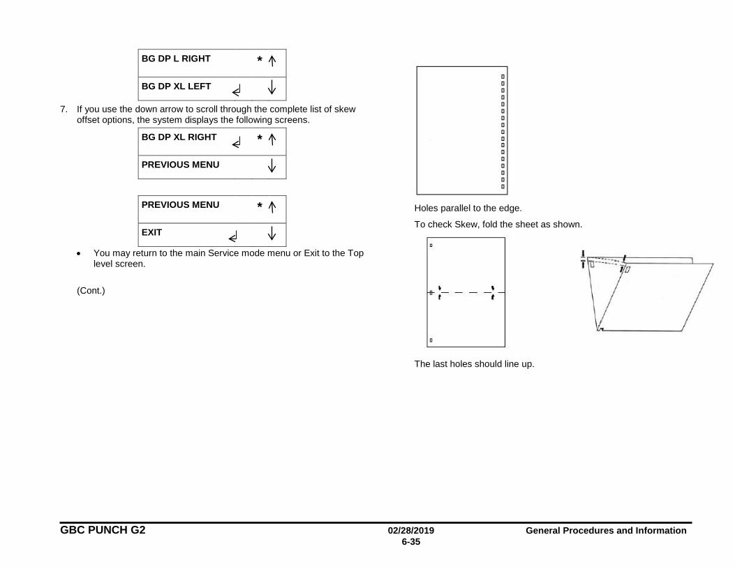
:1 □
I
□ □ □ □ □ □ □ □ □
:1 □ □
I
□ □ □ □ □
:1 I □ ~
• ' - -t t
BG DP L RIGHT *
BG DP XL LEFT
7. If you use the down arrow to scroll through the complete list of skew offset options, the system displays the following screens.
BG DP XL RIGHT *
PREVIOUS MENU
PREVIOUS MENU *
EXIT
• You may return to the main Service mode menu or Exit to the Top level screen.
(Cont.)
Holes parallel to the edge.
To check Skew, fold the sheet as shown.
The last holes should line up.
GBC PUNCH G2 02/28/2019 General Procedures and Information 6-35

□ 'Ill D II]
Eli D □, D
□ D I[!] I!]
D □ Jl ID a 1!11
rm 11!1
D D ill 1fll Cl D 1l ll]I
lil □ El! D
D
D D
□ l!)J
!li D g ll
IDI D
,0 C
11!1
1;11
liJI
QI
ID
0 □ Iii
,□ D
□ D
l!JI D
a lil
D II
iii! l(i
□ I
Bottom most hole is at correct Backgage depth, but the top hole is too far from the edge of the paper.
BG RIGHT ‘– ‘ Select 1 1, 2, 3…etc. until the holes are parallel to the edge.
Top most hole is at correct Backgage depth, but the bottom hole is too far from the edge of the paper.
BG LEFT ‘-’ Select 1 1, 2, 3…etc. until the holes are parallel to the edge.
The bottom hole is in the correct position, but the top hole is too close to the edge of the paper.
BG RIGHT ‘+’ Select 1 1, 2, 3…etc. until the holes are parallel to the edge.
The top hole is in the correct position, but the bottom hole is too close to the edge of the paper.
BG LEFT ‘+‘ Select 1 1, 2, 3…etc. until the holes are parallel to the edge.
General Procedures and Information 02/28/2019 GBC PUNCH G2 6-36

□ □ □ [I □ C!
□ D □ 'C!
□ 0 □ a □ □ □ Q
□ □' □ ' □ li)I □ 0
□ IJ □ [!
□ Iii □ !!I
□ D □ 0
□ D □ [I
□ 0 □ 11
□ a □ □
□ 0 □ 'I!)
□ IJ □ 0
□ D □ [I
□ G □ fill
□ □
For Double punch skew offsets, the same principle applies. Examples shown below:
BG DP L RIGHT ‘+’ Select 1, 2, 3…etc. until the holes are parallel to the edge.
BG DP L LEFT ‘+’ Select 1, 2, 3…etc. until the holes are parallel to the edge.
GBC PUNCH G2 02/28/2019 General Procedures and Information 6-37

I
~
:1
I ~ :1
I
~
:1
I I I
~ :1
I ~ I
GP 6.2.10 ALIGN OFFSETS Adjustment Do the following to setup the align offsets.
Procedure
Do the following to make adjustments to the Align Offsets. The Align Offsets is same as the Alignment Offset in the User setting, except:
- The User Alignment setting adjusts the Alignment position of all sheets (regardless of size) that are processed by PUNCH G2.
- The ALIGN OFFSETS described here are performed to individual sensors. Therefore adjusting a sensor’s Align Offsets will only impact the sheet sizes using that particular sensor.
The below table shows the sensor for each sheet size:
Sensor Sheet sizes
S11 none
S12 A4-LEF, A4 tab, A3-SEF
S13 LTR-LEF, LTR tab, 11x17-SEF
S14 none
S15 1/2LTR-LEF, 1/2LTR tab, LTR-SEF, Legal SEF
A5-LEF, A5 tab, A4-SEF
1. At the top level screen,
READY
SINGLE PUNCH
Press and hold both the Up Arrow button and the Down Arrow button for 5 seconds.
Then while still holding down the Up Arrow button and the Down Arrow button, press the Enter button.
The Service User Interface screen will appear.
PAPER SIZE *
MAX BYPASS
2. Press the down arrow so the return symbol is next to the words ALIGN OFFSETS.
SKEW OFFSETS *
ALIGN OFFSETS
3. Press the ENTER button when the return symbol is next to the words ALIGN OFFSETS to display the ALIGN OFFSETS screen.
S11 *
S12
4. Press the down arrow to scroll through the Skew Offset options. • S11 • S12 • S13 • S14 • S15
5. Scroll until the return symbol is next to the desired Align Offset,
S11 *
S12
• Press the ENTER key to display the Align Offset screen for that setting.
S12
0
General Procedures and Information 02/28/2019 GBC PUNCH G2 6-38

~ I I ~ :1
I :1 ~
:1 ~
I ~ :1
• Press the up arrow button or the down arrow button to change the offset by + 1 increment.
S12
-1
• When you reach the desired Align Offset, press the ENTER button to return to the previous Align Offset screen.
S11 *
S12
• If you want to change another Align Offset, press the down arrow to scroll through the Align Offset options, then repeat the entire step 5 for the other Align Offset option.
6. From any Align Offset screen, you can scroll up or down through the entire list of Align Offset options.
S14 *
S15
7. If you use the down arrow to scroll through the complete list of skew offset options, the system displays the following screens.
S15 *
PREVIOUS MENU
PREVIOUS MENU *
EXIT
From this screen you can:
• Return to the Service mode menu
• Exit to the Top level screen
GBC PUNCH G2 02/28/2019 General Procedures and Information 6-39

I ~ :1
I ~ :1
GP 6.2.11 LOG The LOG file download option will store the following data for download via USB.
Debug data for last 50 sheets. • Sheet size measured i.e S,M,L,LG or XL • Skew sensors used • First deskew steps • Alignment sensor used • Second deskew steps. • Align fail safe stop (if occurred)
Sensor timings for last 10 sheets. • Punch mode, time from LE S1 to LE S8 • Punch mode, time from LE S8 to LE at S25
Other data • Punch cycle count • Bypass cycle count • Individual die type counts • Record the last 20 Jam codes in a column format
Do the following steps to capture the LOG files. 8. Remove (2) M4 screws and the USB/Debug/E-wire port cover. 9. Insert a USB flash drive. 10. At the top level screen,
READY
SINGLE PUNCH
Press and hold both the Up Arrow button and the Down Arrow button for 5 seconds.
Then while still holding down the Up Arrow button and the Down Arrow button, press the Enter button.
The Service User Interface screen will appear.
PAPER SIZE *
MAX BYPASS
11. Press the down arrow so the return symbol is next to the words ALIGN OFFSETS.
ALIGN OFFSETS *
LOG
5. Pressing OK when the return symbol is next to LOG will open the LOG file capture option.
SAVE TO USB *
PREVIOUS MENU
6. You have the following options: • Pressing OK will save the LOG files to the inserted USB flash
drive. After the Complete message is displayed, exit to the Previous Menu or Exit. You may remove the USB flash drive and replace the cover.
• Return to the Previous Menu • Exit to Top level screen
General Procedures and Information 02/28/2019 GBC PUNCH G2 6-40

I I
I
~
:1 I
~ : I
I
~
I
I ~ : I
GP 6.2.12 FIRMWARE UPGRADE Procedure Do the following to upgrade the firmware.
1. Remove (2) M4 screws and the USB port cover. 2. Save the firmware file you want to upload to the USB flash drive
provided. IMPORTANT NOTE: Only one Main and one Comm file should be present in the USB flash drive.
3. At the top level screen,
READY
SINGLE PUNCH
Press and hold both the Up Arrow button and the Down Arrow button for 5 seconds.
Then while still holding down the Up Arrow button and the Down Arrow button, press the Enter button.
The Service User Interface screen will appear.
PAPER SIZE *
MAX BYPASS
4. Insert the USB Flash drive with the firmware file you want to upload. Note: this step can be done at any time before you press the Enter button for Main or Comm firmware upload (in Step 8).
5. Press the down arrow button so the return symbol is next to the words FIRMWARE UPGRADE.
6. Press the ENTER button when the return symbol is next to the words FIRMWARE UPGRADE to display the FIRMWARE UPGRADE screen.
MAIN *
COMM
7. Press the down arrow to scroll through the Firmware Upgrade options. • MAIN (the Control Board) – Select this to update the Main
firmware.
• COMMS (The Communications Board) – Select this to update the Comm firmware
If uploading both, do MAIN first.
• PREVIOUS MENU takes you to the FIRMWARE UPGRADE / EXIT screen
8. If you press the ENTER button when the return symbol is next to the word MAIN, the system displays this screen.
LOADING *
• When the update is complete, the system displays this screen
COMPLETE
• Press ENTER to return to the Main Screen.
LOG *
FIRMWARE UPGRADE
GBC PUNCH G2 02/28/2019 General Procedures and Information 6-41

I
~ : I
I
~
:1
I
~ :1
I I
9. For COMM, COMPLETE is NOT displayed. The system automatically returns to the previous screen.
LOADING *
• Press the ENTER button to return the then MAIN / COMM screen.
MAIN *
COMM
10. Press the down arrow to scroll through the Firmware Upgrade options until the return symbol is next to the Word EXIT.
FIRMWARE UPGRADE *
EXIT
11. Press the ENTER button when the return symbol is next to the word EXIT to return to the top level screen.
READY
SINGLE PUNCH
12. Remove the USB flash drive with the firmware file you uploaded. 13. Install the Cover for USB port and tighten the Screws (2). 14. Switch off the machine. Wait 10 seconds, and then switch the
machine back on again.
General Procedures and Information 02/28/2019 GBC PUNCH G2 6-42

GP 6.3 Undock the Punch (Moving the punch to Service position) Use this procedure to move the punch to Service position
1. Unplug the AC power cord.
2. Unplug the Communications cable.
3. Unscrew the locking screw.
4. Pull on the punch forward to disengage the locking pins.
5. Follow the instructions for undocking the downstream device. After undocking,
GP 6.4 Dock the punch (Moving the punch to Operating position) Use this procedure to move the PUNCH G2 to operating position.
1. Slide the punch to Operating position, ensure the positioning
stud in the upstream device slides into the positioning plate.
2. Slide in the upstream and downstream docking mechanisms and install the locking screws.
3. Connect the Communications cables.
4. Connect the AC power cord.
5. Run a small test job in both Punch and Bypass mode to ensure the machine is working properly.
GBC PUNCH G2 02/28/2019 General Procedures and Information 6-43

GP 6.5 Operational Inspection Do the following on every service call to make sure the system is operating properly.
1. Make sure the punch operates smoothly and produces the desired holes in the customer’s paper.
2. Refer to section 3.13 Punch Specifications.
GP 6.6 Internal Inspection Do the following whenever the cover has been removed for corrective maintenance,
1. Visually inspect for defects and problems such as damaged components, loose screws or nuts, abraded wire insulation, loose terminals, etc.
2. Correct any problems before returning the machine to service.
General Procedures and Information 02/28/2019 GBC PUNCH G2 6-44

GP 6.7 Die Set Service The Die Set assembly is not serviceable other than inspection and periodic lubrication.
If a Die Set is at its end of life, it will tend to cause paper jam due to hanging chips. This is a result of die plate wear, and not pin wear, which cannot be corrected. When this occurs, the Die Set should be replaced with a new one.
GP 6.7.1 Die Set Life Expectancy The PUNCH G2 Die Sets have a minimum life expectancy of 750K cycles (sheets of paper punched, when punching 75 gsm paper). With periodic lubrication and optimum paper types, life can exceed this number.
Use the Die Cycles feature on the User Interface to view the number of cycles on the Die Set.
Variables that affect life expectancy:
• Failure to follow the lubrication schedule or using the incorrect lubricant
• Variety and types of paper being punched
• Cover stocks being punched
• Length of the average job
• Other environmental conditions
GP 6.7.2 Die Set Components
Serviceable Components
• Punch pins [1]
• Felt pad (on some Die Sets) [2]
GBC PUNCH G2 02/28/2019 General Procedures and Information 6-45

GP 6.7.3 Die Set Lubrication Periodic lubrication extends the life of the Die Sets. This can be done by the user or the service technician.
Maintenance Schedule
Lubricate and inspect Die Set pins every 100K cycles.
Procedure
1. Inspect the punch pins for signs of wear or mis-alignment. Periodic lubrication extends the life of the Die Sets.
2. The customer or operator can perform this maintenance between technician inspections.
Inspect Punch Pins
To lubricate Die Set pins that do not have felt pads:
1. Depress the Die Set so that the pins protrude from the bottom plate. 2. Apply a drop of high quality machine oil to the end of each pin. 3. Wipe clean, leaving a light coat of oil on them. 4. Oil from the die may blemish the first few punched sheets after oil has
been applied. Run test punched copies until clean copies can be made.
To lubricate Die Set pins that have felt pads:
1. Lubricate with a high quality machine oil. 2. Apply oil lightly along the length of the pad [1], but do not over
saturate. 3. Do not use spray lubricants because they tend to dry up quickly and
leave a sticky residue. 4. Oil from the die may blemish the first few punched sheets after oil has
been applied. Run test punched copies until clean copies can be made.
Die Set Lubrication Points
General Procedures and Information 02/28/2019 GBC PUNCH G2 6-46

D
Die Set Inspection
1. Set the Die Set on a table and press the top plate straight down at both ends at the same time and look for a smooth operation. The top plate and pins should retract fully when you release.
Check For Free Movement
2. Reinstall the Die Set into the punch and run several sheets of the customer’s paper through the punch. Inspect the holes. • Holes should be clean and even with no tearing or frayed edges. • Holes should be punched completely, leaving no chip attached. • Holes should be straight (no skew) and evenly spaced from the
edge of the paper and aligned. (See GP 6.2.9, SKEW OFFSETS ).
GP 6.7.4 Die Set Shoulder Bolts Do the following to inspect and lubricate the Die Set Shoulder Bolts every 200k Die cycles.
1. Lubricate with high quality Teflon-based grease. 2. Apply grease to Shoulder Bolts and Springs [2]. 3. Wipe up any excess grease.
GBC PUNCH G2 02/28/2019 General Procedures and Information 6-47
w
GP 6.8 External Cleaning Do the following to clean the exterior of the PUNCH G2.
1. Clean the exterior covers with a soft cloth moistened with mild detergent and warm water.
Do not use chemical cleaners or solvents as these may have a harmful effect. Use detergent sparingly to avoid contact with electrical components.
GP 6.9 Internal Cleaning Do the following to clean the interior of the PUNCH G2.
1. Occasionally remove the covers and remove paper dust and chips. Paper dust can accumulate throughout the punch including around the motor and other electrical components. Use a vacuum cleaner if possible. A small paintbrush can also be used but extreme care should be used around electrical components.
2. Clean non-electrical components with alcohol, an approved cleaner, or a soft cloth moistened with mild detergent and warm water.
3. Clean the Rollers with alcohol. Warning: Make sure you disconnect the PUNCH G2 from its power source before cleaning. Failure to observe this warning could result in death or serious Injury.
Warning: Make sure you disconnect the PUNCH G2 from its power source before cleaning. Failure to observe this warning could result in death or serious Injury.
General Procedures and Information 02/28/2019 GBC PUNCH G2 6-48

GP 6.10 Base Cleaning Chips and paper dust falls to the bottom of the punch. Clean every service call.
1. Clean with a vacuum cleaner each time the machine is serviced. 2. The customer can also do this between the technician’s visits.
GP 6.11 Chip Bin Cleaning Do the following on every service call to clean the Chip Tray.
1. Remove the Chip Bin and empty it. 2. Vacuum out paper chips and dust from the Chip Bin tray, especially at
the holes on the sides of the Chip Tray.
GBC PUNCH G2 02/28/2019 General Procedures and Information 6-49

GP 6.12 Die Guide Cleaning Do the following to clean the Die Guide every 500K cycles.
1. Remove the Die Set and clean the guide [1] with a vacuum cleaner.
GP 6.13 Door Latch Inspection Inspect the Door Latch every 1000K cycles.
The door latch must hold the door closed and ensure that the switch activation tab is depressing the door switch [1]. The switch tab [2] should press the switch button just so that it is close to bottom.
1. Ensure latch holds door closed. 2. Ensure switch is activated when the door is closed. 3. To adjust the door latch, see ADJ 1.1
General Procedures and Information 02/28/2019 GBC PUNCH G2 6-50

S25
~
S26
@ R S20,S21
Os□L2
0 0 S6,S7 S15,Sl4
~~:~m 0 t
S18 Sl
~ N6,N7 S2~8 PUNCH
M3 PIN MS CENTER
M4
S29 o S'v/ 2 □
Chip Tro.y
S'v/ 1
□
~
GP 6.14 Idler Roller and Idler Springs Inspection Idler rollers press against the drive rollers and move the paper through the bypass [1] or the punch [2].
Maintenance Schedule
Inspect and clean every 1000K cycles.
Procedure
1. For the Idler Rollers in the following nips, inspect the rollers for wear, debris, toner marks, unevenness, and dents.
N1 N9 N2 N10 N3 N11 N4 N12 N5 N13 N8 N14
2. Inspect Springs (2) for each Idler Roller, and make sure they are correctly hooked.
Idler Roller Shaft Idler Roller
Bearing Housing
3. Inspect the Bearing Housing. The Bearing Housing should slide freely in the Bearing Forks.
Retaining Spring
GBC PUNCH G2 02/28/2019 General Procedures and Information 6-51

GP 6.14.1 Idler Roller Cleaning Use this procedure to clean the Idler Rollers in these assemblies:
• Entrance Idler Panel.
• Acceleration Roller Idler Assy.
• Exit Idler Panel.
• Bypass Idler Assembly
Maintenance Schedule
Inspect and clean every 1000K cycles.
Procedure
1. Do ARP 2.4 Idler Roller Replacement to remove the Idler Roller.
Idler Roller Shaft Idler Roller
Bearing Housing
2. Clean the Idler Rollers with a soft cloth and alcohol. 3. Inspect rollers for wear patterns or groves. The roller surface should
be smooth. 4. Ensure the rollers turn freely on the shaft and that the idler roller shaft
"floats" freely in the bushing forks. 5. Do ARP 2.4 Idler Roller Replacement to install the Idler Roller.
Retaining Spring
General Procedures and Information 02/28/2019 GBC PUNCH G2 6-52
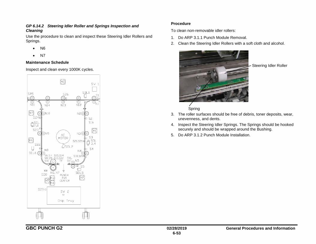
Efil SI,./ 1
□ S25 S26
@ R S20,S21
Os□L2
0 0 S6,S7 S!5,Sl4
'l ~~,:~ '·"' ~ 0 Si l
~ N:,N: ! S2~8 PUNCH
M3 PIN MS CENTER
M4
S29 D SI,./ 2 □
Chip Troy
GP 6.14.2 Steering Idler Roller and Springs Inspection and Cleaning Use the procedure to clean and inspect these Steering Idler Rollers and Springs.
• N6
• N7
Maintenance Schedule
Inspect and clean every 1000K cycles.
Procedure
To clean non-removable idler rollers:
1. Do ARP 3.1.1 Punch Module Removal. 2. Clean the Steering Idler Rollers with a soft cloth and alcohol.
Spring
Steering Idler Roller
3. The roller surfaces should be free of debris, toner deposits, wear, unevenness, and dents.
4. Inspect the Steering Idler Springs. The Springs should be hooked securely and should be wrapped around the Bushing.
5. Do ARP 3.1.2 Punch Module Installation.
GBC PUNCH G2 02/28/2019 General Procedures and Information 6-53

S25
0 0
Efil
S26
@ R S20,S21
Os□L2
S6,S7 S15,Sl4
S8 ~ 3,S!2
S18 Sl
Q Sll ~
0 t liLlll N6,N7
S2~8 PUNCH M3 PIN
MS CENTER M4
S29 D S'w 2
D
Ch ip Tra.y
S'w 1
□
~
GP 6.15 Drive Roller and Steering Drive Roller Inspection and Cleaning Do this procedure to inspect and clean the Drive Rollers and Steering Drive Rollers.
Maintenance Schedule
Inspect and clean every 1000K cycles.
Procedure
Some drive rollers are not easily accessible. Those that are [1], should be inspected and cleaned when the idler rollers are removed.
Where practical, make sure the rollers are clean. Clean with a soft cloth and alcohol.
See also, GP 6.14.1 Idler Roller Cleaning
It is recommended to clean the Drive Rollers with the Punch Module removed, because with the Punch Module removed it is easy to access all Drive Rollers.
1. Do ARP 3.1.1# Punch Module Removal. 2. Clean all Drive Rollers N1 – N16 with a clean cloth and alcohol. 3. The Drive Roller should be free of toner deposits, wear marks, scuff
marks, dents, etc. 4. Use the above procedure to clean the Steering Drive Rollers
5. Do ARP 3.1.2# Punch Module Installation.
Steering Drive Rollers
General Procedures and Information 02/28/2019 GBC PUNCH G2 6-54

GP 6.16 Panel Latch Inspection 3. When the idler panel is opened and closed, you should be able to see Magnetic latches on the Entrance and Exit Idler Panels, and the Upper the Idler springs extend, which will ensure proper idler roller pressure. Bypass Idler Assembly hold the Idler Panels in place, which in turn keep even pressure on the idler rollers.
The latch for the Acceleration Idler Panel ensures the Acceleration Panel remains firmly closed to keep even pressure on the Acceleration Idler Roller.
Maintenance Schedule
Inspect every 1,000K cycles.
Entrance Idler Panel Latch, Exit Idler Panel Latch, Upper Bypass Panel Latch Inspection
To inspect these three latches follow the procedure below:
• Entrance Idler Panel Latch
• Exit Idler Panel Latch
• Upper Bypass Panel Latch
1. Open the Front door. 2. When the idler panel is latched, the idler panel spacers ((2) spacers
for each Idler assembly) should contact the drive panels completely. There should not be any movement in the idler assembly (toward or away from the drive panel).
4. To adjust the Idler Panel magnetic Latches, do ADJ 1.7 Idler Panel Magnetic Latches Adjustment.
GBC PUNCH G2 02/28/2019 General Procedures and Information 6-55

Acceleration Idler Latch Inspection
To inspect the Acceleration Idler latch follow the below procedure:
1. Open the Front door. 2. Undock PUNCH G2. 3. When the Acceleration panel latch is fully engaged, the tabs in the
Idler panel should contact the drive panel. Inspect this for the latches in the front side and rear side.
4. Do ARP 3.1.1 Punch Module Removal to remove the Punch Module. 5. Inspect the Acceleration Idler Panel latch assembly (front and rear
side). There should be two springs between the latch mechanism and the Entrance Drive panel.
Acceleration panel latch springs
6. If the springs are damaged, do ARP 2.17 Accel Idler Panel Rear Latch Assembly Replacement or ARP 2.17 Accel Idler Panel Front Latch Assembly Replacement.
General Procedures and Information 02/28/2019 GBC PUNCH G2 6-56

7. When the idler panel is opened and closed, you should be able to see the Idler springs extend, which will ensure proper idler roller pressure.
8. To adjust the Acceleration Idler Panel Latch, do ADJ 1.8 Entrance Drive Panel Position Adjustment.
GBC PUNCH G2 02/28/2019 General Procedures and Information 6-57
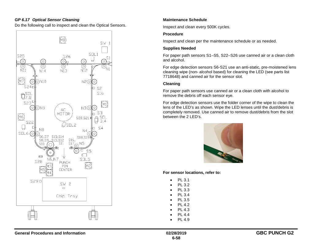
S25
0 0
S26
~ V
Os□L2
S6,S7 S15,S14 S8 i53Si2 0 Sl l ~
G ! S18 ,
S16, s
iIIll N6,N7 S2~8 PUNCH
M3 PIN M5 CENTER
M4
S29 o S\./ 2
D
Chip Tro.y
S\./ 1
□
GP 6.17 Optical Sensor Cleaning Do the following call to inspect and clean the Optical Sensors.
Maintenance Schedule
Inspect and clean every 500K cycles.
Procedure
Inspect and clean per the maintenance schedule or as needed.
Supplies Needed
For paper path sensors S1–S5, S22–S26 use canned air or a clean cloth and alcohol.
For edge detection sensors S6-S21 use an anti-static, pre-moistened lens cleaning wipe (non- alcohol based) for cleaning the LED (see parts list 7718648) and canned air for the sensor slot.
Cleaning
For paper path sensors use canned air or a clean cloth with alcohol to remove the debris off each sensor eye.
For edge detection sensors use the folder corner of the wipe to clean the lens of the LED’s as shown. Wipe the LED lenses until the dust/debris is completely removed. Use canned air to remove dust/debris from the slot between the 2 LED’s.
For sensor locations, refer to:
• PL 3.1 • PL 3.2 • PL 3.3 • PL 3.4 • PL 3.5 • PL 4.2 • PL 4.3 • PL 4.4 • PL 4.9
General Procedures and Information 02/28/2019 GBC PUNCH G2 6-58

Bypass Paper Path Inspection and Cleaning
Do the following to inspect and clean the Bypass Paper Path every 1000K cycles.
1. Inspect the Bypass panel, rollers, and entrance guide for wear, damage, and obstructions.
2. Inspect the rollers for wear patterns or groves. The surface should be rough and even. Make sure the rollers are clean. Clean rollers with a soft cloth and alcohol. See also Error! Reference source not found. Error! Reference source not found. and Error! Reference source not found. Error! Reference source not found..
3. Raise the panel and ensure the magnet holds it in open [4]. Inspect the path for obstructions. Clean as needed.
4. Close the panel and check that it is flat and that paper will pass under it.
5. Ensure the bypass diverter moves freely and returns to the bypass position.
GBC PUNCH G2 02/28/2019 General Procedures and Information 6-59

GP 6.18 Punch Paper Path Inspection and Cleaning Do the following to inspect and clean the Punch Paper Path every 1000K cycles.
1. Inspect the entire paper path through the punch. Look for wear, damage, and obstructions.
2. Inspect the rollers for wear patterns or groves. 3. Open the Entrance Idler Panel, Acceleration Roller Idler, and Exit
Idler Panel and make sure there are no obstructions. 4. Confirm that the Entrance Idler Panel Latch, Acceleration Roller Idler
Latch, and Exit Idler Panel Latch hold the panels tightly in place. If the latch is bent or damaged, replace the Entrance Idler Panel (ARP 2.3), Acceleration Roller Idler Assembly (ARP 2.5), or the Exit Idler Panel (ARP 2.9).
5. Clean as needed.
General Procedures and Information 02/28/2019 GBC PUNCH G2 6-60
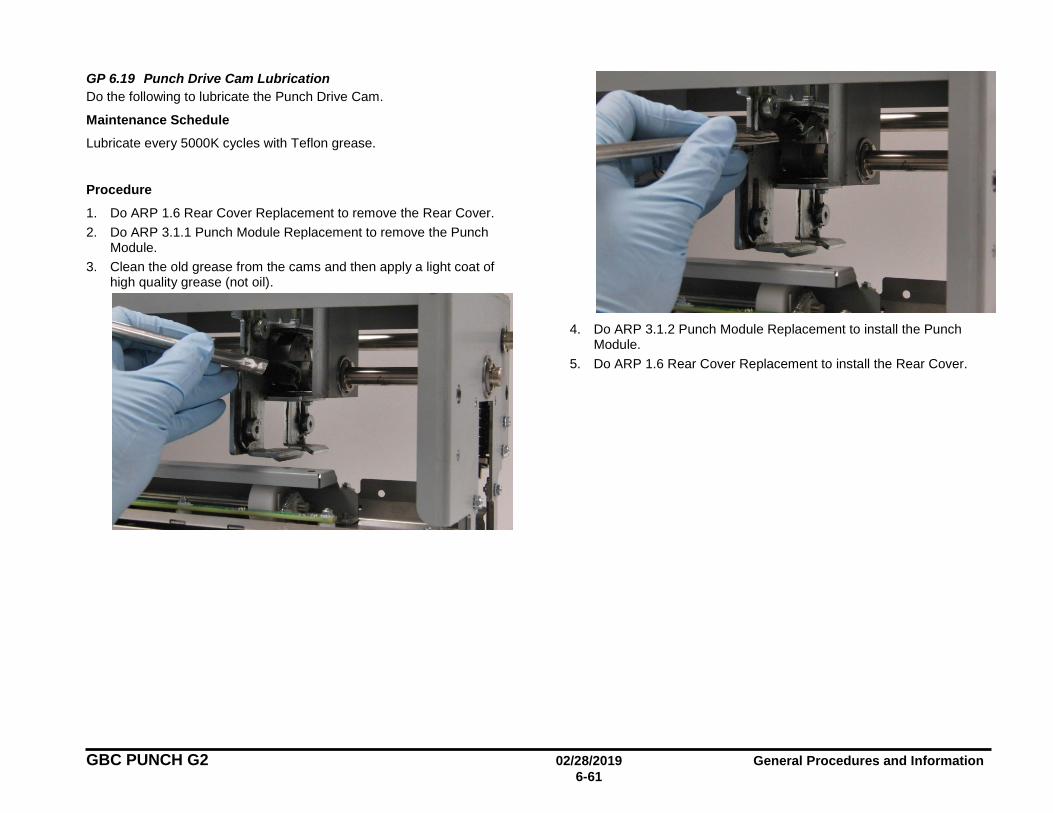
GP 6.19 Punch Drive Cam Lubrication Do the following to lubricate the Punch Drive Cam.
Maintenance Schedule
Lubricate every 5000K cycles with Teflon grease.
Procedure
1. Do ARP 1.6 Rear Cover Replacement to remove the Rear Cover. 2. Do ARP 3.1.1 Punch Module Replacement to remove the Punch
Module. 3. Clean the old grease from the cams and then apply a light coat of
high quality grease (not oil).
4. Do ARP 3.1.2 Punch Module Replacement to install the Punch Module.
5. Do ARP 1.6 Rear Cover Replacement to install the Rear Cover.
GBC PUNCH G2 02/28/2019 General Procedures and Information 6-61

GP 6.20 Timing Belt Inspection There are 11 belts used in the PUNCH G2.
Assembly # of Belts Punch Module 1 belt Steering Module 1 belt Drive Panel Steering Sub Assembly
2 belts
Frame 8 belts
Five of the belts at the rear of the Frame have Tensioner Assemblies. It is these five belts that should be checked.
Maintenance Schedule
Inspect the Timing Belt every 1000K cycles.
Procedure
Do the following to inspect the Timing Belts.
1. Inspect all timing belts for wear, missing teeth, frayed edges, and cracks.
2. For replacement, see ARP 2.2Timing Belt Replacement 3. Check for proper deflection of belts.
The belts should be slightly loose with approximately 1/4” deflection [1].
Belts that are too loose will not drive properly and belts that are too tight can wear out prematurely or damage their driven components.
General Procedures and Information 02/28/2019 GBC PUNCH G2 6-62

GP 6.21 Solenoid Cleaning and Inspection Do the following to inspect and clean the Solenoids every 1000K cycles.
1. Open the front the door and insert an Interlock Cheater into the Punch Door interlock.
WARNING Moving Parts, keep hands clear of nips and the belts when the Interlock Cheater is inserted.
2. Do GP 6.2.6 SOLENOIDS Check to activate and deactivate the affected solenoid.
When the solenoid is not activated, the idler roller should be able to rotate freely and in turn will drive the drive roller.
not activated fully activated
When the solenoid is fully activated, the idler roller should completely lift off and not be able to drive the drive roller.
NOTE: Disengaging solenoid modules need to be replaced every 5 million cycles.
3. Clean the solenoid and surrounding area with a vacuum cleaner and canned air.
1. Make sure the solenoid is clean and dry. 2. Inspect for dirt or obstructions, wear or a damage spring. 3. Inspect and ensure the Solenoid linkage moves freely. Press linkage
down and release. Linkage should return. Note: Do not apply lubricants to the solenoid or linkage.
GBC PUNCH G2 02/28/2019 General Procedures and Information 6-63

GP 6.22 Alignment Carriage Rails Cleaning Do this procedure to clean the Alignment Carriage Rails.
Preventative Maintenance:
Do this every 500K cycles.
Procedure
1. Do ARP 3.1.1 to remove the Punch Module 1. Use a can of compressed air to remove dust from the alignment
carriage rails. The carriage can be moved back and forth on the rails to clean the entire surface. Alternately, a soft cloth and alcohol can be used.
Important Note: DO NOT use any lubricant on the rail.
2. Once the rails are cleaned, check the motion of Alignment carriage on the rails. It should move when a force less than 2kgf is applied. If there is binding in the rails, replace the Alignment Carriage sub-assembly.
3. Do ARP 3.1.2 to install the Punch Module.
GP 6.23 Punch Clutch Inspection and Cleaning Use this procedure to inspect and clean the punch clutch every 1000K cycles.
If the Punch Module is removed from the machine for servicing other components, do all steps. Otherwise do all steps except step 9.
4. Disconnect the Power Cord. 5. Do ARP 1.6 to remove the Rear Cover. 6. With a cloth wipe the collar of the clutch and remove any oil from the
surface.
7. Inspect the collar stop and the metal insert pawl for any wear.
General Procedures and Information 02/28/2019 GBC PUNCH G2 6-64

' ·\ ' / .· ',~
,~ i~ . , . • J • ~r~-a :, :,,
8. Check the tightness of (2) cone point set screws in the clutch. 9. Inspect the tightness of the M6 lock nut and M6 socket head cap
screw.
10. Check the indexing of the Punch clutch, ADJ 1.5 Punch Clutch Indexing.
11. Do ARP 1.6 to install the Rear Cover, 12. Connect the Power Cord. 13. Do GP 6.2.8 FUNCTION TESTS (Cycle Punch, Aligner Test, Fan
Test).
GP 6.24 Diverter Solenoid Assembly Inspection Use this procedure to inspect the Diverter Solenoid Assembly every 1000K cycles.
1. Disconnect the Power Cord. 2. Do ARP 1.6 to remove the Rear Cover. 3. Clean the Solenoid and surrounding area with a vacuum cleaner and
canned air. 4. Make sure the solenoid is clean and dry. 5. Raise the Diverter Solenoid by hand and release it. The Diverter
should fall freely. Make sure the linkage operates smoothly.
6. Open the front door and insert an Interlock Cheater into the Punch Door Interlock switch
7. Press the Power Switch to the on position. Warning
Moving Parts, keep hands clear of nips and the belts when the Interlock is cheater is inserted.
8. Do GP 6.2.6 SOLENOIDS to activate and deactivate Solenoid SOL1. The diverter gate should rise and fall when SOL1 is cycled.
GBC PUNCH G2 02/28/2019 General Procedures and Information 6-65

GP 6.25 Die Set Recognition Board Clips Inspection Use this procedure to Inspect and clean the Die Set recognition board clips every 1000K cycles.
1. Press the Power Switch to the off position. 2. Disconnect the Power Cord. 3. Do ARP 1.6 to remove the Rear Cover. 4. Inspect the Die Set Recognition reader spring clips to check if they
are bent. When a die set is inserted, the spring clips should deform and fully contact the Die Set Recognition Board in the Die Set .
5. Wipe the spring clips with a clean cloth. 6. Do ARP1.6 to install rear cover
GP 6.26 Die Lock Mechanism and Die Rail Springs Inspection Use this procedure to inspect the Die lock mechanism every 1000K cycles
1. Press the Power Switch to the off position. 2. Disconnect the Power Cord. 3. Do ARP 1.6 to remove the Rear Cover. 4. Do ARP 3.1.1 to remove the Punch Module. 5. Raise the die lock plunger by hand to inspect if there is a heavy
spring force. There is an internal spring in the mechanism that provides the locking load. The load is quite heavy and the plunger may not move up. This is normal and can be verified again during Step 10.
6. Inspect (4) plastic bushings in the Die lock brackets. (2) in the front and (2) in the back.
General Procedures and Information 02/28/2019 GBC PUNCH G2 6-66

7. Inspect the surface of the cam and cam follower pad, if there is any debris, clear it.
8. Inspect the (2) external compression springs. 9. Inspect the Die rail springs. The tip of the springs should be in contact
with the side face of the die rail.
Good Spring Deformed Spring
10. Insert a Die set in the die rail and lock the Die set and check if the tip contacts the die set base plate only. The Die lock mechanism should not contact anywhere else.
11. The Die Set should also slide in easily deforming the Die rail springs.
GBC PUNCH G2 02/28/2019 General Procedures and Information 6-67

S29 D
S26
k ~
Os□L2
Chip Troy
S\,t I
□
~
General Information Principle of Operation The GBC PUNCH G2 is a machine that punches various die set hole patterns into single sheets of paper. The machine is placed between a printer or copier and a finisher. The punch has two paper paths.
• The punch path.
• The bypass section.
Punch Path
If the Punch is enabled, the transport and punch motors are started, and the Divert Solenoid SOL 1 is activated to direct the sheets into the punch path.
There are two modes of operation Single Punch and Double Punch.
Single Punch The sheet enters the Punch at roller N1 running at printer line speed.
When the lead edge of the sheet reaches Sensor S5 (plus a delay to ensure the sheet is in roller N5) the sheet is accelerated to system speed of 1300mm/s.
The sheet enters the steering rollers N6 & N7 and the angle of the sheet is measured by Sensors S6-S10 and is then de-skewed by rollers N6 & N7.
After deskew, the front edge of the sheet is moved to alignment sensor S11-S15.
The sheet is transported by N6 & N7 until the trail edge is close to the Backgage Sensors S16 & S17.
The sheet is slowed and moves until the trail edge is detected at Sensors S16 & S17, at which point it moves a further set number of steps (backgage) and stops.
The sheet is punched on the trail edge.
Once the punch cycle is complete the sheet is accelerated by N6 & N7 to the system line speed.
Once the lead edge hits S24 (plus a delay to ensure the sheet is in roller N10) the sheet is decelerated to the printer line speed.
General Procedures and Information 02/28/2019 GBC PUNCH G2 6-68

Double Punch (Mid punch + trail edge punch) The sheet enters at roller N1 running at printer line speed.
When the lead edge of the sheet reaches S5 (plus a delay to ensure the sheet is in roller N5) the sheet is accelerated to system speed of 1300mm/s.
The sheet enters the steering rollers N6 & N7 and the angle of the sheet is measured by S6-S10 and then deskewed by rollers N6 & N7.
After deskew the front edge of the sheet is moved to alignment sensor S11-S15.
The sheet is transported by N6 & N7 until the trail edge is close to the Backgage Sensors S18 & S19 for SEF A4/SEF LTR and S19 & S20 for SEF A3/11x17.
The sheet is slowed and moves until the trail edge is detected at sensors S18 & S19 for SEF A4/SEF LTR and S19 & S20 for SEF A3/11x17, at which point it moves a further set number of steps (backgage) and stops.
The sheet is mid-punched.
Once the punch cycle is complete the sheet is accelerated by N6 & N7 to the system line speed.
The front edge of the sheet is moved to Alignment Sensors S11-S15.
When the trail edge is close to the Backgage Sensors S16 & S17 the sheet is slowed and moves until the trail edge is detected at S16 & S17, at which point it moves a further set number of steps (backgage) and stops.
The sheet is punched on the trail edge.
Once the punch cycle is complete the sheet is accelerated by N6 & N7 to the system line speed.
Once the lead edge hits S24 (plus a delay to ensure the sheet is in roller N10) the sheet is decelerated to the printer line speed.
Bypass Path If the Punch is not enabled, the Advanced Punch will run in bypass mode (no punching).
The sheet enters the Punch at roller N1 running at printer line speed.
The Divert Solenoid SOL 1 is not activated, so the sheets are directed into the bypass path.
When the lead edge of the sheet reaches nip 13, the sheet is detected by Bypass Sensor S26,
The sheet is transported by N12, N13, N14, and N11 until the trail edge of the sheet reaches Exit Sensor S26.
GBC PUNCH G2 02/28/2019 General Procedures and Information 6-69

Refer to the electrical wiring information and to Parts List PL 2.7, Frame Assembly Sensors, when reading the following material on Inputs and Output signals.
Table 6.1 Input Devices Input
Sensor S1 Sensor S2 Sensor S3 Sensor S4 Sensor S5 Sensor S6 Sensor S7 Sensor S8 Sensor S9 Sensor S10 Sensor S11 Sensor S12 Sensor S13 Sensor S14 Sensor S15 Sensor S16 Sensor S17 Sensor S18 Sensor S19 Sensor S20 Sensor S21 Sensor S22 Sensor S23 Sensor S24 Sensor S25 Sensor S26 Sensor S28 Sensor S29
Type Optical Optical Optical Optical Optical Circuit Board Circuit Board Circuit Board Circuit Board Circuit Board Circuit Board Circuit Board Circuit Board Circuit Board Circuit Board Circuit Board Circuit Board Circuit Board Circuit Board Circuit Board Circuit Board Optical Optical Optical Optical Optical Optical Emitter/Receiver
Function Entrance Sensor Entrance Idler Panel Sensor Entrance Idler Panel Sensor Entrance Idler Panel Sensor Accel Sensor Skew Board Sensor Skew Board Sensor Skew Board Sensor Skew Board Sensor Skew Board Sensor Alignment Sensor Alignment Sensor Alignment Sensor Alignment Sensor Alignment Sensor Backgage Sensor Backgage Sensor Large Mid Punch Backgage Sensor Large Mid Punch Backgage Sensor XL Mid Punch Backgage Sensor XL Mid Punch Backgage Sensor Exit Idler Panel Sensor Exit Idler Panel Sensor Exit Idler Panel Sensor Exit Sensor Bypass Sensor Align Home Sensor Chip Tray Full Emitter/Receiver
General Procedures and Information
Input Solenoid SOL1 Solenoid SOL2 Solenoid SOL3 Solenoid SOL4 Solenoid SOL5 Solenoid SOL6 Solenoid SOL7 Solenoid SOL8 Switch SW1
Switch SW
02/28/2019 6-70
Type Mechanical Mechanical Mechanical Mechanical Mechanical Mechanical Mechanical Mechanical Mechanical
Mechanical
Function Divert Solenoid Punch Clutch Solenoid Entrance Idler Solenoid Entrance Idler Solenoid Accel Idler Solenoid
Exit Idler Solenoid
Punch Door Interlock Switch, no machine movement if door is open Chip Tray Home Switch
GBC PUNCH G2

I "+" ON THE LCD I " - " ON THE LCD INCREASES - d-- DEC REASES BACK GAGE BACK GAGE DEPTH DEPTH
0
0
"+" ON THE LCD INCREASES ALIGNMENT
_______________ OFFSET
t 0
' 0
0
"-" ON THE LCD DECREASES ALIGNMENT OFFSET
Glossary of Terms These terms are common to the punch and bindery industry.
Alignment A predetermined distance of the top punched hole from the side edge of the sheet (viewed from the punch output orientation.
Backgage A predetermine distance from the trail edge of the sheet of paper to the punched hole(s).
Deskew The term used to describe the process of aligning the sheet of paper until it is parallel to the paper path.
Skew The term used to describe the fact that the sheet of paper is not parallel to the paper path.
GBC PUNCH G2 02/28/2019 General Procedures and Information 6-71

Specifications
Speed Up to 136 sheets per minute Punch Sheet Size and Edge
LEF- Long Edge Fed SEF- Short Edge Fed
Tab Stock
US Sizes LTR LEF LTR SEF LTR SEF Double Punch Statement LEF Legal SEF Ledger SEF Ledger SEF Double Punch
ISO sizes A4 LEF A4 SEF A4 SEF Double Punch A5 LEF A3 SEF A3 SEF Double Punch
US Sizes LTR, with 3,4,5,8 and 10 tabs Statement, with 3 and 5 tabs
ISO Sizes A4, with 5 and 10 tabs A5, with 3 and 5 tabs
Paper Stock
Clear Cover
Plain: 75gsm - 300gsm (20# bond to 110# cover)
Coated: 120gsm - 300gsm (32# bond to 110# cover)
7mil Bypass mode stock and sizes
Paper sizes and stocks same as printer
Punch Capacity Single Sheet
Power Supply 115V, 60Hz, Single Phase
230V, 50Hz, Single Phase
Electrical Amps and
Frequency Safety Certification cULus
Dimensions L: 775mm; W: 445mm; H: 1020mm L: 30.5"; W: 17.5"; H: 40.2"
Weight 95 kg 210 lbs
General Procedures and Information 02/28/2019 GBC PUNCH G2 6-72

Die Sets The PUNCH G2 uses a variety of easily interchangeable die sets that allow you to punch documents in line for several different binding styles.
Please note that each punching style listed below requires a separate die set for the PUNCH G2. The PUNCH G2 can hold up to three Die Sets in its cabinet (one in the operating slot and two in the storage area).
Die Sets will decrease in performance over time based on the types of stocks and weights that are being punched.
The expected life of a die set is 750K punches when punching 20 lb bond (75 gsm paper).
Die Sets should be regarded as a long-term supply item.
To purchase additional or replacement Die Sets, contact your authorized sales representative.
GBC PUNCH G2 02/28/2019 General Procedures and Information 6-73

Die Set Description
For Plastic Comb Binding:
=-----------------=-= 19-LTR 21-A
PB Plaslic Bind; Hole Size: 8mm x 2.9mm (0.313" x D.116j (lxW); Center-to-Center Hole Spacing: 14.3mm (D.563")
For Twin Loop™ Binding:
□■■••························••□■□ 32-LTR 34-A4
W3 Wire; Square; 3 Holes pe,- inch; Hole Size: 4mm x 4lm1 (D.156" x 0. 156j (L x W); Center-to-Celller Hole Spru:ing: 8.5mm (0.333")
□-------------------□-□ 21-LTR 23-A4
W2 Wire; Rectangle; 2 Holes per inch; Hole Size: 6.4mm x 5.4mm (D.250" x D.214")(L xW); Celller-ta-Center Hole Spacing: 12.7mm (D.500")
o••••••••••••••••••••••••••••••o•o 32-LTR 34-A4
W3 Wire; Round; 3 Holes per inch; Hole Size: 4mm (D.158") Diameter; Center-ta-Center Hole Spacing: 8.5mm (0.335")
0 • e e e e • e e e e • e e e • e • e e O e 0 21-LTR 23-A
W2 Wire; Rourod; 2 Holes per inch; Hole Size: 6.5mm (0.0.256") Diameter; Center-ta-Center Hole Spacing: 12.7rrvn (D.Sj
For Color Coil™ Binding:
o••••••••••••••••••••••••••••••••••••••••••o••o 44-LTR 47-A4
C4 Coil; Rour-.l; 4 Holes per inch; Hole Size: 4.4mm (0.174") Diameter; Center-ta-Center Hole Spacing: 6.3mm (D-2475")
0••••••••••••••••••••••••••••••••••••••••••0110 44-LTR 47-A4
C4 Coil; Oval; 4 Holes per inch; Hole Size: 4mm x 5mm (0. 158" x 0.197") (L x W); Cenler-to-Cellter Hole Spacing: 6.3mm (0.2475")
Konica Minolta Part Number
Die, Konica Minolta, Comb Bind Die, Konica Minolta, Comb Bind, HD
Die, Konica Minolta , Wire 3.1, Sq _
Die, Konica Minolta , Wire 2.1, Sq.
Die, Konica Minolta , Wire, 3 1, Rnd.
Die, Konica Minolta , Wire , 2:1, Rnd .
Die, Konica Minolta , Coi l, Rnd _ Die, Konica Minolta, Coil, Rnd, HD
Die, Konica Minolta , Coi l, Oval
Die Sets List By selecting the appropriate die set, you can use your PUNCH G2 to punch documents in any of the binding styles indicated in the tables below.
General Procedures and Information 02/28/2019 GBC PUNCH G2 6-74
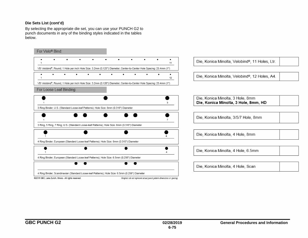
For Velo® Bind:
• • 11 Die, Konica Minolta , Velobiind®, 11 Holes, U r.
VB Velobind0 ; Round; 1 Ho.le per inch Ho.le Size: 3.2rrvn (D.125i Diameter; Center-ta-Center Hole Sp& ing: 25-4mm (1 ")
• • • • 12 Die, Konica Minolta , Velobiind®, 12 Holes, A4.
VB Velobind0 ; Round; 1 Ho.le per inch Ho.le Size: 3.2rrvn (D.126") Diameter; Center-ta-Center Hole Sp& ing: 25-4mm (1 ")
For Loose Leaf Binding:
• • • Die, Konica Minolta, 3 Hole, 8mm 3 Die, Konica Minolta, 3 Hole, 8mm, HD
3 Ring Binder; U.S. (Standard Loose-leaf Patterns); Hole Size: 8mm (0.316") Diameter
• • • • • • • 7 Die, Konica Minolta , 3/5/7 Hole, 8mm
3 Ring, 5 Ring, 7 Ring; U.S. (Standard Loose-leaf Patterns); Hole Size: 8mm (0.316") Diametec
• • • • 4 Die, Kon ica Minolta , 4 Hole, 8mm
4 Ring Binder; European (Standard l oose-leaf Patterns); Hole Size: 8mm (0.315") Diameler
• • • • 4 Die, Konica Minolta , 4 Hole, 6.5mm
4 Ring Binder; European (Standard l oose-leaf Patterns); Hole Size: 6.5mm (0.256") Diameter
• • • • Die, Kon ica Minolta , 4 Hole, Scan
4 Ring Binder; Scandinavian (Standard Loose-leaf Patterns); Hole Size: 6.5mm (0.256") Diameter
€0ll16 GBC, Lake Ziaich. ll inois · All righ1s res€fVed. GrttplUCS th I\YM 16prt-seM lE1mi J1WiC}t pamnt .£rmeJtriom ar .spat;i1,g.
Die Sets List (cont’d) By selecting the appropriate die set, you can use your PUNCH G2 to punch documents in any of the binding styles indicated in the tables below.
GBC PUNCH G2 02/28/2019 General Procedures and Information 6-75

Tools Tools recommended for service of the GBC PUNCH G2:
Standard Tools (metric) • 7mm Nut Driver
• 5.5mm Nut Driver
• 7mm Open End Wrench
• 5.5mm Open End Wrench
• Needle Nose Pliers
• Phillips Screwdriver
• Flathead Screwdriver
• Wire Cutters
• Metric Allen Key Set (1.5mm, 2mm, 2.5mm, 3mm, 4mm, 5mm)
Other Recommended Tools and Supplies • 0.25mm, 1mm, and 3mm Shim Gauges
• 0 to 2 kgf Tension meter (also called Spring gage)
Lubrication For General lubrication please see the following sections
• GP 6.7.3, Die Set Lubrication
• GP 6.20, Punch Drive Cam Lubrication
General Procedures and Information 02/28/2019 GBC PUNCH G2 6-76

Cleaning Materials Use a clean, soft, lint-free cloth to clean the following.
• GP 6.8, External Cleaning
• GP 6.9, Internal Cleaning - small paintbrush
Use a soft cloth and alcohol to clean the following.
• GP 6.14, Idler Roller Inspection and Cleaning
• GP 6.15, Drive Roller Inspection and Cleaning
Use canned air or soft cloth to clean the following.
• GP 6.17, Optical Sensor Cleaning
• GP 6.23, Alignment Carriage Rails
Use canned air or vacuum cleaner to clean the following.
• GP 6.22, Solenoid Cleaning and Inspection
Serial Numbers The GBC PUNCH G2 Serial Number is located inside the Front Door on the front frame just below the Bypass Section
GBC PUNCH G2 02/28/2019 General Procedures and Information 6-77

This page intentionally left blank.
General Procedures and Information 02/28/2019 GBC PUNCH G2 6-78

Notes:
GBC PUNCH G2 02/28/2019 General Procedures and Information 6-79

7. Wiring Data Section Contents Wiring Data
Title Page System Wiring (7715763) ...................................................................... 7-3 Plug Jack connectors............................................................................. 7-3
GBC PUNCH G2 4/14/2017 Wiring Data 7-1 Section Contents

This page intentionally left blank.
Wiring Data 4/14/2017 GBC PUNCH G2 7-2

~
~ ~
24V P □ w'ER SUPPLY
System Wiring (7715998)
GBC PUNCH G2 4/14/2017 Wiring Data 7-3

~II"' fiillJ13
L!lJ GND
J2
J 3
l•••I ~
1r~*~ 7 I ll) ~ ..
• • I I
J4
JlO
._____I_· lj,. SPARTA CONTROLLER
~~;Nti
J20
[I:] FAN
Jl J7
1-~~••••@l l@~I
J 3 2 COMM INTERFACE
J3
COMMUNICATION BOARD • ··. ■ • ·· ••• ■• ■ ••• ■) • . , . iJ(] ••••••••••••••••••••
----------------J2 •••••••••••• •• •• •• •• •••••••••••• •••••••• J4
I· •
J5
I
Plug Jack connectors
Wiring Data 4/14/2017 GBC PUNCH G2 7-4

8. Installation Instructions Section Contents Title Page 8.1. Required Parts ..............................................................................8-3 8.2. Unpacking .....................................................................................8-4 8.3. Docking Procedure .......................................................................8-5
GBC PUNCH G2 02/28/2019 Installation Instructions 8-1 Section Contents

This page intentionally left blank.
Installation Instructions 02/28/2019 GBC PUNCH G2 8-2

'~
~ ~ I ~
8.1. Required Parts The PUNCH G2 is shipped with an installation kit containing the following components.
No. Description Picture Qty
1 Power Cord (US) 1
2 Power Cord (UK) 1
3 Power Cord (EU) 1
4 Power Cord (Swiss) 1
5 Screw, Round tip, M4 x 8
12
6 Cable Assembly, Interface (37 pin)
2
7 Cover Plate, MK737 Cables
1
8 Docking Bracket, Rear
2
9 Docking Bracket, Lower Front
1
10 Docking Lock, Lower Front
1
11 Docking Bracket, Upper Front
1
GBC PUNCH G2 02/28/2019 Installation Instructions 8-3

t t
t : ~ \ t ,. ,,.,
I\ ~\. ' . I Ii. -~
\ ~\.\ .... ~ Ii\ .. .. ~ . \
~,f\, ~
8.2.
Unp
acki
ng
Rem
ove
plas
tic w
rap
and
stra
ps fr
om th
e pa
ckag
e us
ing
a cu
tting
tool
Lift
of th
e lid
and
rem
ove
the
inst
alla
tion
kit a
nd s
et it
asi
de, i
t con
tain
s th
e ite
ms
in s
ectio
n 1
Inst
alla
tion
Kit
Rem
ove
the
four
inne
r an
d 4
oute
r co
rner
gua
rds
and
then
lift
the
shel
l st
raig
ht u
p to
rem
ove
it C
orne
r G
uard
s
She
ll
Inst
alla
tion
Inst
ruct
ions
Rem
ove
the
tape
hol
ding
the
pla
stic
bag
clo
sed
and
pull
back
the
bag
ex
posi
ng th
e ca
ster
s
Cut
the
corn
ers
of th
e lo
wer
box
and
with
two
peop
le s
lide
the
punc
h so
th
at th
e w
heel
s ov
erha
ng th
e ed
ge
With
tw
o pe
ople
, lif
t th
e pu
nch
hold
ing
the
top
cove
r so
tha
t it
stan
ds
uprig
ht o
n th
e ca
ster
s
02/2
8/20
19
GB
C P
UN
CH
G2
8-4

Remove the plastic cover, tape, and foam from all locations 8.3. Docking Procedure Before docking the machine, adjust the casters so that the paper path is the same height as the upstream unit (710.5mm from ground) and the top of the machine is level.
To adjust the casters, loosen the top nut on the caster, and rotate the wheel by hand. Clockwise to lower, counterclockwise to raise. Once the desired height is achieved, tighten the top nut to secure the caster.
Raise Lower
Install the front and rear docking brackets (Items 8, 9, and 11), on the upstream device. Note the rear docking bracket is the same part upper and lower.
Item 8
GBC PUNCH G2 02/28/2019 Installation Instructions 8-5

Item 9 Item 11
Push the PUNCH G2 directly upstream so that the brackets slide into the openings
Once the brackets are aligned with the holes in the PUNCH G2, push the punch back so that it engages the alignment pins. Install item 10 in the lower right front bracket and secure the upper bracket using a M4 screw.
The upstream docking brackets should align with holes in the PUNCH G2
Installation Instructions 02/28/2019 GBC PUNCH G2 8-6

1111111111 11 1111111111 11
SpacersSpacers
Remove the two M4 screws from each spacer. The spacers are held to the PUNCH G2 with adhesive and should remain in place. Use these screws to secure the brackets provided with the downstream device. See the Konica Minolta Installation manual for more details.
M4
The PUNCH G2 comes with four spacers installed for the mounting of the Bracket supplied with downstream brackets. downstream device
See the Konica Minolta installation manual for cable connection Spacers instructions.
GBC PUNCH G2 02/28/2019 Installation Instructions 8-7