di-acro #2 hand punch press instruction manual
11
REV. E 6/12 1 DI-ACRO #2 HAND PUNCH PRESS INSTRUCTION MANUAL
-
Upload
khangminh22 -
Category
Documents
-
view
1 -
download
0
Transcript of di-acro #2 hand punch press instruction manual
REV. E 6/12
1
DI-ACRO
#2 HAND PUNCH PRESS
INSTRUCTION MANUAL
REV. E 6/12
2
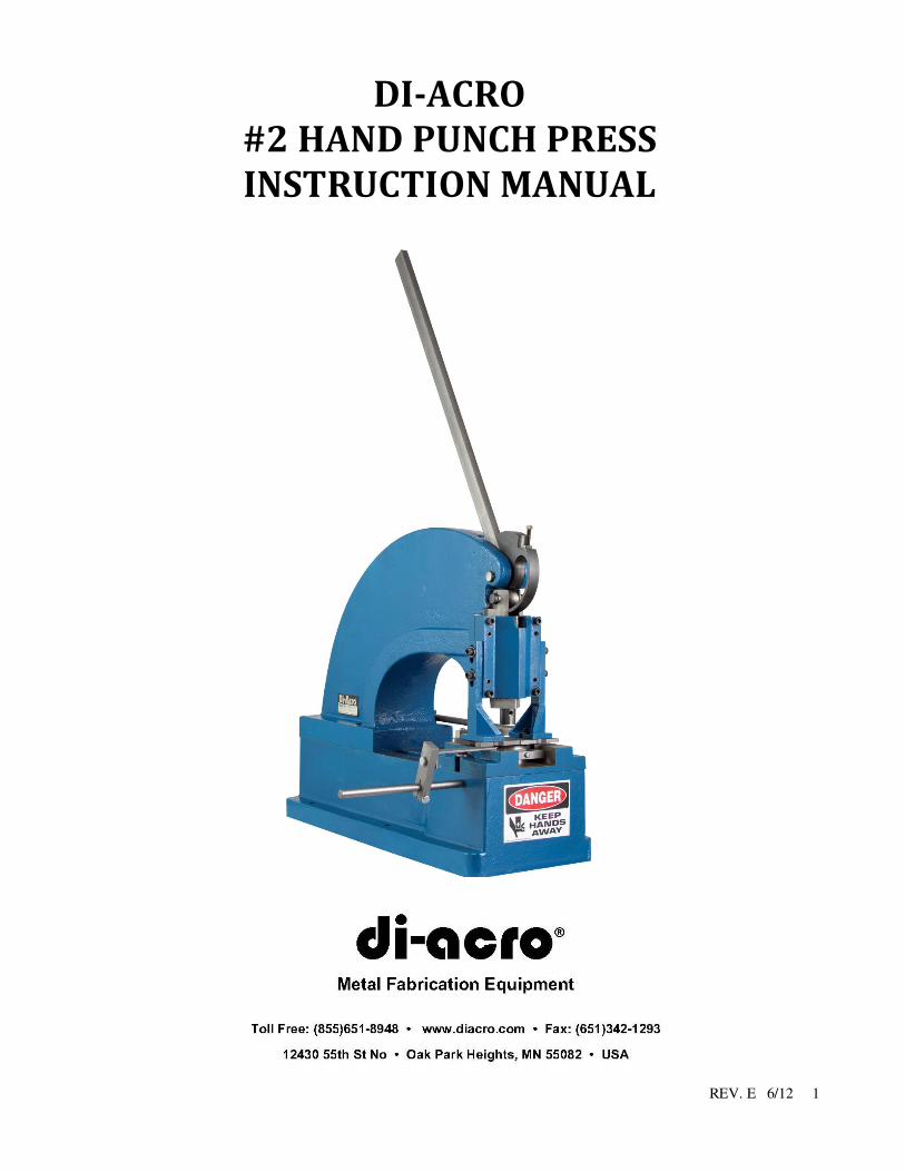
TABLE OF CONTENTS
A. SAFETY INFORMATION PG. 3
B. SET UP PROCEDURE & MOUNTING PUNCHES & DIES PG. 3-4
C. MAINTENANCE PG. 4
D. TECHNICAL DATA PG. 4
PARTS LIST PG. 5-6-7
E. DIE HOLDERS/ADAPTERS & PUNCHES PG. 7-8
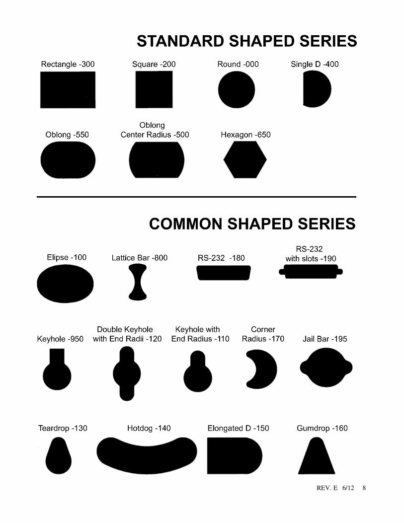
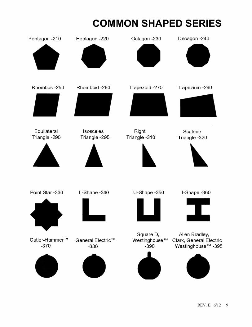
F. STANDARD & COMMON PUNCH & DIE SHAPES PG. 9-10
G. STAND PG. 11
WARRANTY PG. 12
REV. E 6/12
3
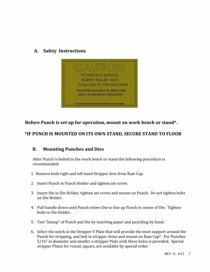
A. Safety Instructions
Before Punch is set up for operation, mount on work bench or stand*.
*IF PUNCH IS MOUNTED ON ITS OWN STAND, SECURE STAND TO FLOOR
B. Mounting Punches and Dies
After Punch is bolted to the work bench or stand the following procedure is
recommended:
1. Remove both right and left hand Stripper Arm from Ram Cap.
2. Insert Punch in Punch Holder and tighten set screw.
3. Insert Die in Die Holder, tighten set screw and mount on Punch. Do not tighten bolts
on Die Holder.
4. Pull handle down until Punch enters Die to line up Punch in center of Die. Tighten
bolts in Die Holder.
5. Test “lineup” of Punch and Die by inserting paper and punching by hand.
6. Select the notch in the Stripper V Plate that will provide the most support around the
Punch for stripping, and bolt to stripper Arms and mount on Ram Cap*. For Punches 5/16” in diameter and smaller a stripper Plate with three holes is provided. Special stripper Plates for round, square, are available by special order.

REV. E 6/12
4
*Adjust Stripper Plate vertically as close to material as possible. Leave enough clearance
for easy insertion of the material. When Stripper Plate is set too high, material may become
deformed. #1 (See Pg.3) #2 (See Pg.3) #3 (See Pg.3) Stripper Arms Punch Holder Die Holder
C. Maintenance
Put Grease in grease fitting periodically.
D. Technical Data
SPECIFICATIONS
Model #2 Punch Inch Metric
Tonnage 4 3.6
Max. Punch Size 4 101.6
Punch Capacity 1-1/2 38
Throat Depth 12 304.8
Throat Height 3 76
Material Thickness 16 ga.
Mild steel 1.5 ga.
Mild steel
Stroke of Ram 5/8 15.9
Hole in Ram (dia.) 1 25.4
Shipping Weight 350 lbs. 159 kg
REV. E 6/12
5
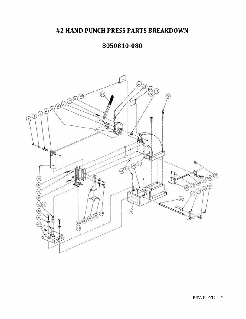
#2 HAND PUNCH PRESS PARTS BREAKDOWN
8050810-080
REV. E 6/12
6
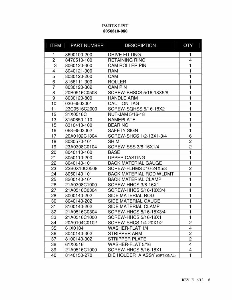
PARTS LIST
8050810-080
ITEM PART NUMBER DESCRIPTION QTY
1 8690100-200 DRIVE FITTING 1
2 8470510-100 RETAINING RING 4
3 8060120-300 CAM ROLLER PIN 1
4 8040121-300 RAM 1
5 8030120-200 CAM 1
6 8156111-300 ROLLER 1
7 8030120-302 CAM PIN 1 8 20B0516C0508 SCREW-BHSCS 5/16-18X5/8 1
9 8030120-800 HANDLE ARM 1
10 030-6503001 CAUTION TAG 1 11 23C0516C2000 SCREW-SQHSS 5/16-18X2 1
12 31X0516C NUT-JAM 5/16-18 1 13 8150650-110 NAMEPLATE 1
15 8310410-100 BEARING 1 16 068-6503002 SAFETY SIGN 1
17 20A0102C1304 SCREW-SHCS 1/2-13X1-3/4 6
18 8030570-101 SHIM 2 19 23A0308C0104 SCREW-SSS 3/8-16X1/4 2
20 8040110-100 BASE 1 21 8050110-200 UPPER CASTING 1
22 8040140-101 BACK MATERIAL GAUGE 1 23 22B0X10C0508 SCREW-FLHMS #10-24X5/8 2
24 8050140-101 BACK MATERIAL ROD WLDMT 1
25 8200140-101 BACK MATERIAL CLAMP 1 26 21A0308C1000 SCREW-HHCS 3/8-16X1 1
27 21A0516C0304 SCREW-HHCS 5/16-18X3/4 1 28 8000140-202 SIDE MATERIAL ROD 1
30 8040140-202 SIDE MATERIAL GAUGE 1
31 8100140-202 SIDE MATERIAL CLAMP 1 32 21A0516C0304 SCREW-HHCS 5/16-18X3/4 1
33 21A0516C1000 SCREW-HHCS 5/16-18X1 1 34 20A0104C0102 SCREW-SHCS 1/4-20X1/2 2
35 61X0104 WASHER-FLAT 1/4 4 36 8040140-302 STRIPPER ARM 2
37 8100140-302 STRIPPER PLATE 2
38 61X0516 WASHER-FLAT 5/16 4 39 21A0516C1000 SCREW-HHCS 5/16-18X1 4
40 8140150-270 DIE HOLDER A ASSY (OPTIONAL) 1
REV. E 6/12
7
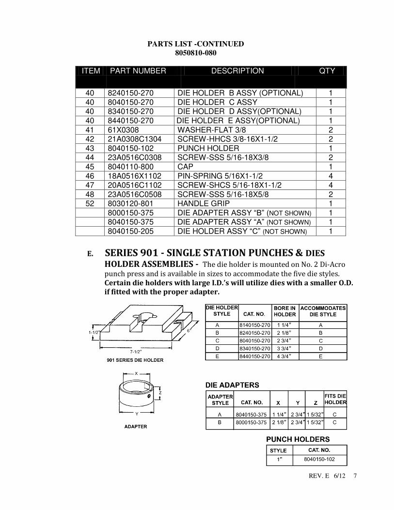
PARTS LIST -CONTINUED
8050810-080
ITEM PART NUMBER DESCRIPTION QTY
40 8240150-270 DIE HOLDER B ASSY (OPTIONAL) 1
40 8040150-270 DIE HOLDER C ASSY 1
40 8340150-270 DIE HOLDER D ASSY(OPTIONAL) 1
40 8440150-270 DIE HOLDER E ASSY(OPTIONAL) 1
41 61X0308 WASHER-FLAT 3/8 2
42 21A0308C1304 SCREW-HHCS 3/8-16X1-1/2 2
43 8040150-102 PUNCH HOLDER 1 44 23A0516C0308 SCREW-SSS 5/16-18X3/8 2
45 8040110-800 CAP 1
46 18A0516X1102 PIN-SPRING 5/16X1-1/2 4 47 20A0516C1102 SCREW-SHCS 5/16-18X1-1/2 4
48 23A0516C0508 SCREW-SSS 5/16-18X5/8 2 52 8030120-801 HANDLE GRIP 1
8000150-375 DIE ADAPTER ASSY “B” (NOT SHOWN) 1 8040150-375 DIE ADAPTER ASSY “A” (NOT SHOWN) 1
8040150-205 DIE HOLDER ASSY “C” (NOT SHOWN) 1
E. SERIES 901 - SINGLE STATION PUNCHES & DIES
HOLDER ASSEMBLIES - The die holder is mounted on No. 2 Di-Acro
punch press and is available in sizes to accommodate the five die styles.
Certain die holders with large I.D.’s will utilize dies with a smaller O.D.
if fitted with the proper adapter.
REV. E 6/12
8
REV. E 6/12
9
REV. E 6/12
10
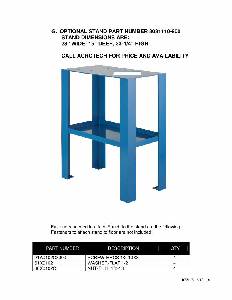
G. OPTIONAL STAND PART NUMBER 8031110-900 STAND DIMENSIONS ARE: 28” WIDE, 15” DEEP, 33-1/4” HIGH
CALL ACROTECH FOR PRICE AND AVAILABILITY
Fasteners needed to attach Punch to the stand are the following: Fasteners to attach stand to floor are not included.
PART NUMBER DESCRIPTION QTY
21A0102C3000 SCREW-HHCS 1/2-13X3 4
61X0102 WASHER-FLAT 1/2 4
30X0102C NUT-FULL 1/2-13 4

REV. E 6/12
11
Warranty & Limitation of Liability
Defective parts, of a product manufactured by DI-ACRO, will be replaced or repaired at no charge for twelve (12) months following delivery to the original purchaser. Labor is included for the first 90 days. This warranty becomes void when products have not been used according to instructions furnished by DI-ACRO, nor does it cover any altered parts or unauthorized repairs. We cannot be responsible for the cost of repairs made or attempted outside of our factory. All other warranty claims are made FOB our plant, providing such items(s) is returned freight prepaid to our plant for examination. This warranty does not apply to parts, components or systems not manufactured by DI-ACRO. These products are covered instead by the existing warranties, if any, of their manufacturers. Normal service items with a reasonable life expectancy of less than one year are warranted only to the extent of the reasonable life under normal use and service. Authorization must be obtained from DI-ACRO before returning parts or equipment to the factory. DI-ACRO will satisfy this warranty by replacing the product or refunding the purchase price upon receipt, inspection and defect identification. DI-ACRO’s liability under this warranty shall not exceed the amount paid for the product. THIS IS DI-ACRO’S SOLE WARRANTY IN LIEU OF ALL OTHER WARRANTIES, EXPRESS OR IMPLIED, WHICH ARE HEREBY EXCLUDED, INCLUDING IN PARTICULAR ALL WARRANTIES OF MERCHANTABILITY, FITNESS OR ANY LOSS, DAMAGE OR EXPENSES DIRECTLY OR INDIRECTLY RELATED TO THE USE OF ITS PRODUCT OR FROM ANY OTHER CAUSE OR FOR CONSEQUENTIAL DAMAGES INCLUDING, WITHOUT LIMITATION, LOSS OF TIME AND LOSS OF PRODUCTION. IT IS EXPRESSLY UNDERSTOOD THAT DI-ACRO IS NOT RESPONSIBLE FOR DAMAGE OR INJURY CAUSED TO OTHER PRODUCTS, MACHINERY, PROPERTY OR PERSONS BY REASON OF THE USE OF ITS PRODUCTS.
c Copyright 2012