GAS MANAGEMENT SYSTEM REHABILITATION AND ...
484
Matthew Pagendarm Dan Gagne Michael Harrison John Pepper Robinette CONTRACT DOCUMENTS FOR THE CONSTRUCTION OF SACRAMENTO REGIONAL WASTEWATER TREATMENT PLANT GAS MANAGEMENT SYSTEM REHABILITATION AND IMPROVEMENTS 8295 CONTRACT NUMBER BID SET VOLUME 1 OF 3 PART A – CONTRACT REQUIREMENTS (DIV 00 AND DIV 01) PART B – TECHNICAL SPECIFICATIONS (DIV 02 THROUGH DIV 43) January 2019 Version: 10 BOARD OF DIRECTORS J. Bruins L. Carr S. Frost E. Guerra J. Harris K. Howell P. Hume P. Kennedy S. Ly R. McGarvey D. Nottoli Q. Orozco S. Peters P. Serna O. Villegas A. Warren
-
Upload
khangminh22 -
Category
Documents
-
view
0 -
download
0
Transcript of GAS MANAGEMENT SYSTEM REHABILITATION AND ...

Matthew Pagendarm Dan Gagne
Michael Harrison John Pepper Robinette
CONTRACT DOCUMENTS FOR THE CONSTRUCTION OF
SACRAMENTO REGIONAL WASTEWATER TREATMENT PLANT
GAS MANAGEMENT SYSTEM REHABILITATION AND IMPROVEMENTS
8295
CONTRACT NUMBER
BID SET
VOLUME 1 OF 3 PART A – CONTRACT REQUIREMENTS (DIV 00 AND DIV 01) PART B – TECHNICAL SPECIFICATIONS (DIV 02 THROUGH DIV 43)
January 2019
Version: 10
BOARD OF DIRECTORS J. Bruins L. Carr S. Frost E. Guerra J. Harris K. Howell P. Hume P. Kennedy S. Ly R. McGarvey D. Nottoli Q. Orozco S. Peters P. Serna O. Villegas A. Warren

This page intentionally left blank.

01/28/19 Gas Management System Rehabilitation and Improvements
00 01 10 - 1
SECTION 00 01 10
TABLE OF CONTENTS
VOLUME 1
PART A - CONTRACT REQUIREMENTS DIVISION 00 – PROCUREMENT AND CONTRACTING REQUIREMENTS RFB REQUEST FOR BID (RFB) Document including appendices 00 62 05 00 73 19
PROPRIETARY INFORMATION AGREEMENT HEALTH AND SAFETY REQUIREMENTS
00 73 83 DISPUTE RESOLUTION DIVISION 01 – GENERAL REQUIREMENTS 01 12 16 WORK SEQUENCE 01 14 13 ACCESS TO SITE 01 14 16 COORDINATION WITH OCCUPANTS 01 14 19 USE OF SITE 01 14 20 CONTRACT TIME 01 26 00 CONTRACT MODIFICATION PROCEDURES 01 26 13 REQUESTS FOR INTERPRETATION 01 29 76 PROGRESS PAYMENT PROCEDURES 01 31 19 PROJECT MEETINGS 01 31 26 ELECTRONIC COMMUNICATION PROTOCOLS 01 32 16 CONSTRUCTION PROGRESS SCHEDULE 01 32 23 SURVEY AND LAYOUT DATA 01 32 33 PHOTOGRAPHIC DOCUMENTATION 01 33 00 SUBMITTAL PROCEDURES 01 33 16 DESIGN DATA 01 41 26 PERMIT REQUIREMENTS 01 45 00 QUALITY CONTROL 01 51 00 TEMPORARY UTILITIES 01 52 00 CONSTRUCTION FACILITIES 01 55 26 TRAFFIC CONTROL 01 56 00 TEMPORARY BARRIERS AND ENCLOSURES 01 57 19 TEMPORARY ENVIRONMENTAL CONTROLS 01 57 23 TEMPORARY STORM WATER POLLUTION CONTROL 01 64 00 OWNER-FURNISHED PRODUCTS 01 65 00 PRODUCT DELIVERY REQUIREMENTS

01/28/19 Gas Management System Rehabilitation and Improvements
00 01 10 - 2
DIVISION 01 – GENERAL REQUIREMENTS 01 73 24 DESIGN REQUIREMENTS FOR NON-STRUCTURAL
COMPONENTS AND NON-BUILDING STRUCTURES 01 73 33 RESTORATION OF IMPROVEMENTS 01 74 23 FINAL CLEANING 01 78 23 OPERATION AND MAINTENANCE DATA 01 78 39 PROJECT RECORD DOCUMENTS 01 78 43 SPARE PARTS 01 79 10 TRAINING 01 91 00 COMMISSIONING 01 91 10 REFERENCE FORMS
DIVISION 02 – EXISTING CONDITIONS 02 41 13 SELECTIVE SITE DEMOLITION
PART B – TECHNICAL SPECIFICATIONS
DIVISION 03 – CONCRETE 03 11 00 CONCRETE FORMING 03 11 32 CONCRETE CRACK REPAIR 03 20 00 CONCRETE REINFORCING 03 30 00 CAST-IN-PLACE CONCRETE 03 34 13 CONTORLLED LOW STRENGTH CONCRETE 03 40 00 PRECAST CONCRETE 03 60 00 GROUTING
DIVISION 05 – METALS 05 05 14 HOT-DIP GALVANIZING 05 05 20 ANCHOR BOLTS 05 10 00 STRUCTURAL METAL FRAMING 05 59 00 METAL SPECIALTIES
DIVISION 09 – FINISHES 09 06 90 SCHEDULES FOR PAINTING AND COATING 09 90 00 PAINTING AND COATING
DIVISION 13 – SPECIAL CONSTRUCTION 13 34 19 PRE-ENGINEERED METAL STRUCTURES

01/28/19 Gas Management System Rehabilitation and Improvements
00 01 10 - 3
VOLUME 2 DIVISION 26 – ELECTRICAL 26 05 00 COMMON WORK RESULTS FOR ELECTRICAL 26 05 21 ELECTRICAL POWER CONDUCTORS AND CABLES 26 05 26 GROUNDING AND BONDING FOR ELECTRICAL SYSTEMS 26 05 34 RACEWAYS, BOXES, MANHOLES, AND HANDHOLES FOR
ELECTRICAL SYSTEMS 26 06 20.21 ELECTRICAL RACEWAY SCHEDULE 26 06 20.25 ELECTRICAL CABLE SCHEDULE 26 08 10 ACCEPTANCE TESTING OF ELECTRICAL SYSTEMS 26 09 16 ELECTRICAL CONTROLS AND RELAYS
DIVISION 31 – EARTHWORK 31 10 00 SITE CLEARING 31 20 00 EARTH MOVING 31 41 00 SHORING
DIVISION 32 – EXTERIOR IMPROVEMENTS 32 12 16 ASPHALT PAVING
DIVISION 40 – PROCESS INTERCONNECTIONS 40 05 03 COMMON WORK RESULTS FOR PIPING SYSTEMS 40 05 07 HANGERS AND SUPPORTS FOR PROCESS PIPING 40 05 23 STAINLESS STEEL PROCESS PIPE AND TUBING 40 05 24 STEEL PROCESS PIPE 40 05 32 POLYETHYLENE PROCESS PIPE 40 05 57 ACTUATORS FOR PROCESS VALVES AND GATES 40 05 63 BALL VALVES 40 05 64 40 05 66
BUTTERFLY VALVES FIRE-RATED FIRE ISOLATION VALVES
40 06 60.13 POWER ACTUATED VALVE AND GATE SCHEDULES 40 06 70 SCHEDULES OF INSTRUMENTATION FOR PROCESS SYSTEMS 40 61 13 PROCESS CONTROL SYSTEM GENERAL PROVISIONS 40 61 21 PROCESS CONTROL SYSTEM TESTING 40 61 26 PROCESS CONTROL SYSTEM TRAINING 40 61 93.20 PROGRAMMABLE LOGIC CONTROLLER INPUT/OUTPUT 40 61 96.10 PLANT COMPUTER CONTROL SYSTEM CONTROL
STRATEGIES

01/28/19 Gas Management System Rehabilitation and Improvements
00 01 10 - 4
DIVISION 40 – PROCESS INTERCONNECTIONS 40 61 96.20 PROGRAMMABLE LOGIC CONTROLLER CONTROL
NARRATIVES 40 63 43 PROGRAMMABLE LOGIC CONTROLLERS 40 66 35 FIBER OPTIC CABLE, CONNECTORS, AND PANELS 40 67 00 CONTROL SYSTEM EQUIPMENT PANELS AND RACKS 40 70 00 INSTRUMENTATION FOR PROCESS SYSTEMS 40 79 00 MISCELLANEOUS INSTRUMENTS, CALIBRATION
EQUIPMENT, INSTRUMENTATION VALVES, AND FITTINGS DIVISION 43 – PROCESS GAS AND LIQUID HANDLING PURIFICATION, AND STORAGE EQUIPMENT 43 05 10 COMMON WORK RESULTSFOR GAS HANDLING EQUIPMENT 43 13 43 WASTE GAS BURNER SYSTEM 43 13 43.01 GROUND FLARE REFURBISHMENT 43 41 23.01 43 41 23.03
50” WC WATER SEAL CONDENSATE TANK FSG CONDENSATE TANK
DIVISION 46 – WATER AND WASTEWATER EQUIPMENT (NOT USED) APPENDICES APPENDIX A EQUIPMENT DATA FORMS APPENDIX B SIT, SAT, COMMISSIONING PLAN, REFERENCE FORMS

THIS PAGE INTENTIONALLY LEFT BLANK

1
REQUEST FOR BID This Is Not An Order - Make A Copy For Your File - Return Original SACRAMENTO REGIONAL COUNTY
SANITATION DISTRICT 8521 LAGUNA STATION ROAD
ELK GROVE, CA 95758-9550
Issue Date January 28, 2019
Bid Number RFB No. 8295
CONTRACTOR
Return your Bid in envelope, sealed and clearly marked on outside with Bid number and date shown below to:
SACRAMENTO REGIONAL COUNTY SANITATION DISTRICT
8521 LAGUNA STATION ROAD ELK GROVE, CA 95758-9550
ATTN: RFB #8295
Bids must be received at Sacramento Regional County Sanitation District Reception and logged in prior to the date and time indicated. Bids will not be accepted after 3:00 P.M. on:
March 7, 2019 For Additional Information Contact
Issuing Officer: Tamblynn Stewart
PHONE: (916) 875-9014 Merchandise or Service for Delivery To:
Sacramento Regional County Sanitation District 8521 Laguna Station Road Elk Grove, CA 95758
FAILURE TO SIGN THIS SECTION MAY DISQUALIFY YOUR RESPONSE The undersigned offers and agrees to furnish the articles and/or services listed in this document at the prices and terms stated, subject to all of this Request for Bid:
Firm Name Terms of Sale: Net 30
Signature F.O.B. Point Destination
Printed Name CSLB No.:
Federal Tax ID Number DIR Registration No.:
Date E-Mail:
Telephone: Fax:
Gas Management System Rehabilitation and Improvements Project

2
NOTICE TO CONTRACTORS
NOTICE IS HEREBY GIVEN THAT the Sacramento Regional County Sanitation District (Regional San)
invites sealed bids to provide all labor and equipment necessary for RFB #8295 – Gas Management System
Rehabilitation and Improvements Project, located at 8521 Laguna Station Rd. Elk Grove, CA 95758.
ENGINEER’S ESTIMATE: $ 4,232,752
Bids will be received at the Regional San’s Office, 8521 Laguna Station Rd, Elk Grove, CA 95758 until
3:00p.m., March 7, 2019 to be publicly opened and declared aloud by Regional San representatives.
1) Any bidder who wishes its bid to be considered is responsible for making certain that its bid is
actually delivered to the Regional San Office. Bids shall be addressed to the Sacramento Regional
County Sanitation District, 8521 Laguna Station Rd, Elk Grove, CA 95758, Attn: RFB #8295
2) Bidder envelope must clearly list contractor name and return address. Envelopes that do not list
contractor name and address will not be opened.
Department of Industrial Relations (DIR) Compliance
A. No contractor or subcontractor may be listed on a bid for a public works project unless
registered with the Department of Industrial Relations pursuant to Labor Code section 1725.5
B. No contractor or subcontractor may be awarded a contract for public work on a public works
project unless registered with the Department of Industrial Relations pursuant to Labor Code
section 1725.5.
C. This project is subject to compliance monitoring and enforcement by the Department of
Industrial Relations.
D. No contractor or subcontractor may be listed on a bid proposal for a public works project
unless registered with the Department of Industrial Relations pursuant to Labor Code section
1725.5 [with limited exceptions from this requirement for bid purposes only under Labor
Code section 1771.1(a)].
E. No contractor or subcontractor may be awarded a contract for public work on a public works
project unless registered with the Department of Industrial Relations pursuant to Labor Code
section 1725.5.
LABOR COMPLIANCE PROGRAM: The County of Sacramento received final approval
from the Director of California Department of Industrial Relations as a Labor Compliance
Program effective March 15, 1994. All questions regarding this Labor Compliance Program and
prevailing wage requirements should be directed to the Labor Compliance Section at (916) 875-
2711. In accordance with Section 1771.5 of the California Labor Code, the payment of the
general prevailing rate of per diem wages or the general prevailing rate of per diem wages for
holiday and overtime is not required for any public works project of twenty-five thousand dollars
($25,000) or less when the project is for construction work, or for any public works project of
fifteen thousand dollars ($15,000) or less when the project is for alteration, demolition, repair, or
maintenance work.
This is a (construction/alteration/demolition/repair/maintenance) project in accordance with
Section 1771.5 of the California Labor Code.

3
A. Pursuant to California Labor Code Section 1720 and following, and Section 1770 and following,
the successful bidder shall pay not less than the prevailing rate of per diem wages as determined by the Director of the California Department of Industrial Relations. Copies of the prevailing wage determinations are on file at the office of the County of Sacramento Labor Compliance Program, 9700 Goethe Road, Suite D, Sacramento, CA 95827, and are also available on the internet at http://www.dir.ca.gov/DLSR/PWD
A Mandatory pre-bid meeting will be held on February 20, 2019 at 9:00AM at 8521 Laguna Station Rd, Elk Grove, CA 95758. The purpose of the meeting is to review and clarify project requirements, respond to questions from the bidders and allow prospective bidders the opportunity to observe the condition and location of the project area, which may affect performance and pricing. It is the responsibility of prospective bidders to familiarize themselves with all requirements of the solicitation and identify any issues at this meeting. Pre-Bid Meeting attendees must e-mail Jorge Melendez at [email protected] with attendee names no later than 24 hours prior to the meeting. This information is required to provide access to the site. Bid request documents for RFB #8295 can be obtained by contacting Tamblynn Stewart at (916) 875-9014 or [email protected] or by visiting the Regional San website https://www.regionalsan.com/general-opportunities Bid bond/deposit not less than ten (10) percent of the aggregate total bid is required to be submitted with the sealed bid. Successful Bidder must furnish a 100 percent Performance Bond and Payment Bond per Appendix D and Appendix E respectively. Bidders are hereby notified that pursuant to Part 7, Chapter 1, Article 2, Section 1770, et seq., of the Labor Code of the State of California, the successful CONTRACTOR and its subcontractors shall pay their labor forces not less than the general prevailing rate of wages as determined by the Director of the Department of Industrial Relations, and travel and subsistence pay as such are defined in applicable collective bargaining agreements filed in accordance with Section 1773.8 of said Labor Code, for work needed and performed on this project. It shall, pursuant to the provisions of Section 1773.2 of said Labor Code, be a requirement of the work for the successful bidding contractor to post and maintain a copy of said wages’ determinations at the project site throughout the duration of the work. Regional San hereby notifies all bidders that it will affirmatively insure that in any contract entered into pursuant to this advertisement, minority business enterprises will be afforded full opportunity to submit bids in response to this invitation and will not be discriminated against on the grounds of race, creed, color, national origin, ancestry, sexual orientation, political affiliations of beliefs, sex, age, physical handicap, medical condition, marital status or pregnancy as set forth hereunder. Regional San reserves the right to reject any or all bids and waive any irregularity in bids received.

4
SCOPE OF WORK
The Gas Management System Rehabilitation and Improvements Project - Regional San operates a digester gas management system (GMS) for treatment, delivery, and disposal of the sludge gas produced by the anaerobic digesters. Low-pressure sludge gas is collected from the digesters and typically treated for hydrogen sulfide using a series of iron sponge media scrubbers. The scrubbed gas is then compressed (medium-pressure sludge gas) and, under normal operation, transferred to the Carson Cogeneration Facility (Cogen) and the Regional San boilers. When there is excess sludge gas produced or if Cogen is not available, the low-pressure sludge gas can be disposed at the enclosed flares or the Waste Gas Burners (WGBs). The WGBs can be used for disposal of scrubbed or unscrubbed sludge gas, while the enclosed flares are limited to burning only scrubbed gas based on current permit requirements. Changes in digester gas production and consumption has resulted in periodic uncontrolled venting from the digesters. The GMS Improvements and Rehabilitation Project was initiated to prevent periodic uncontrolled venting of digester gas and to bring the GMS into compliance. Because the GMS needs to remain in operation, the Project will be staged into different phases of construction that will have critical durations. The scope of the work includes improvements to the following areas within the GMS:
1. In and around the MSG Building 2. Ground Flares & WGB’s 3. LSG Scrubbers 4. LSG, MSG, & FSG Condensate Systems 5. LSG Holders & Horton Spheres piping
The work to be completed in RFB No. 8295 includes all labor, abatement and disposal cost, equipment and materials necessary to complete this project as stated in this RFB and on the drawings and specifications. The following documents are also incorporated into this contract: Drawings: Gas Management System Rehabilitation and Improvements Project (full set) Project Specifications Sacramento County Standard Construction Specifications (current version) –
www.saccountyspecs.net Such other items or details not mentioned above that are required by the plans or these specifications shall be performed, placed, constructed, or installed in accordance with the latest version of the Sacramento County Standard Construction Specifications or Special Provisions. Contract days will be added for weather per Section 7 of the Sacramento County Standard Construction Specifications.

5
KEY ACTION DATES
Bid Issue: January 28, 2019 RFB Advertisement: January 28, 2019 and February 4, 2019 Mandatory Pre-Bid Meeting February 20, 2019 at 9:00AM Location 8521 Laguna Station Rd Elk Grove, CA 95758 Question Due Date: February 27, 2019 DIR Registration Due: March 6, 2019
Bids from Contractors not registered on the Department of Industrial Relations website by this date, will not be opened.
Bid Due Date: March 7, 2019 by 3:00 PM Intent to Award: March 14, 2019 Contract Award: March 21, 2019 Provide Required Insurance and Bonds April 4, 2019 Vet Bonds April 5, 2019 Notice to Proceed: April 8, 2019
Pre-Construction Meeting: To Be Determined
Project Completion: See Specification 01 14 20
6
INTRODUCTION
INVITATION – The Sacramento Regional County Sanitation District, Purchasing & Material Support, invites Responses which offer to provide the goods and/or services identified in this RFB. DEFINITIONS - We intend to express our expectations clearly, and they are to be legally interpreted in our favor. Certain words are used throughout this document: We/Us/Our are terms which refer to the Sacramento Regional County Sanitation District, a duly organized public entity. They may also be used as pronouns for various subsets of Regional San organization, including, as the context will indicate: Regional San - Sacramento Regional County Sanitation District
Sacramento Regional Wastewater Treatment Plant – (SRWTP)
You/Your are terms which refer to businesses having some sort of relationship to or with us. The term may apply differently as the context will indicate. For instance, “you” as a Contractor will have different obligations than “you” as a Bidder or Supplier will have:
Supplier - A business entity which may provide the subject goods and/or services Bidder - A business entity submitting a Response to this request for bid. Suppliers which may express interest in this RFB, but which do not submit a Response, have no obligations with respect to the bid requirements. Contractor - The Bidder, whose Response to this RFB, is found by Purchasing to meet the needs of Regional San. Contractor will be selected for award, and will enter into a contract for provision of the goods and/or services described in the RFB.
RFB - This entire document, including attachments. Response - The written, signed and sealed document submitted according to the RFB instructions. Response does not include any verbal or documentary interaction you may have with us apart from submittal of a formal response. RFB CLARIFICATION - Questions regarding this RFB should be directed in writing to the Issuing Officer specified on the Cover Sheet, page 1. Answers, citing the question, but not identifying the questioner, will be distributed simultaneously to all known prospective Bidders. RFB Amendment - If it becomes evident that this RFB must be amended, we will issue a formal written addendum to all known prospective Bidders. Bidder Responsibility - We expect you to be thoroughly familiar with all specifications and requirements of this RFB. Your failure or omission to examine any relevant form, article, site or document will not relieve you from any obligation regarding this RFB. By submitting a Response, you are presumed to concur with all terms, conditions and specifications of this RFB. AWARD – Award will be made to the lowest responsible bidder. CONTRACT EXECUTION - This RFB and the Contractor’s Response will be made part of any resultant Contract and will be incorporated in the Contract as set forth.

7
PROTESTS - After receipt of the Regional San’s “Intent to Award” notice, any bidder who has questions or concerns should immediately contact the Issuing Officer for discussion. Any bidder who believes that they have grounds for a protest must submit a written protest on company letterhead within three (3) non-holiday, business days after the Intent to Award letter has been sent out. Any protest letter must state the specific grounds for protest and the actions being requested of Regional San. No protest received after 4 p.m. on the 3rd business day shall be accepted. PRECEDENCE - In the event of contradictions or conflicts between the provisions of the documents comprising the Contract, they will be resolved by giving precedence in the following order: 1) the provisions of the Contract (as it may be amended); 2) the provisions of the Bidder’s Response (as it may be clarified); 3) the provisions of the RFB (as it may be supplemented);
4) the provisions of the County Standard Specifications. CLAIMS - Claims shall be handled in accordance with Section 9-18 of the County Standard Construction Specifications. ISSUING OFFICER - The issuing officer and mailing address to send Bids, questions, and all other correspondence concerning this RFB is:
Tamblynn Stewart Senior Contract Services Officer Sacramento Regional County Sanitation District (916) 875-9014 [email protected]
PROJECT CONTACT -
Jorge Melendez, Project Manager Sacramento Regional County Sanitation District (916) 875-9074
[email protected] CONTRACTOR EXAMINATION OF THIS RFB/QUESTIONS - Contractor shall examine carefully the entire RFB and any addenda thereto, and all related materials and data referenced in the RFB or otherwise available, and shall become fully aware of the system needs through discussion and visits with Regional San. If contractors discover an ambiguity, conflict, discrepancy, omission or other errors in the RFB, they shall immediately notify the Issuing Officer of such error in writing and request modification of the document. Modifications shall be made by addenda. Contractors requiring clarification of the intent or content of this RFB or on procedural matters regarding the bid process may request clarification by contacting the Issuing Officer identified above. SUBMISSION OF BIDS - Bids should be prepared in such a way as to provide a straight forward, concise delineation of capabilities to satisfy the requirements of the RFB. Expensive binding, colored displays, promotional materials, etc., are not necessary or desired. Emphasis should be concentrated on conformance
8
and clarity of content. Contractor bids shall be completed in all respects as indicated. A Bid may be rejected if it is conditional or incomplete, or if it contains irregularities of any kind. Bids which contain false or misleading statements, or which provide references which do not support an attribute or capability of the proposed system may be rejected. If, in the opinion of Regional San, such information was intended to mislead Regional San in its evaluation of the Bid and the attribute, condition or capability as a requirement of the RFB, the bid shall be rejected. The bid must be signed by an individual who is authorized to bind the proposing firm contractually. The signature should indicate the title or position that the individual holds in the firm. Firms who sign their contracts with the name of the firm must provide the name of the corporate officer for signature validation by Regional San. An unsigned Bid shall be rejected. ACCEPTANCE AND REJECTION OF BIDS – Regional San reserves the right: To reject any or all Bids, or any part thereof; To waive any informality in the Bid; To accept the Bid that is in the best interest of Regional San. Regional San’s decision shall be final. HOLIDAYS Regional San will observe the legal holidays as defined by the County Standard Construction Specifications Section 1-3. Contractors will not schedule work on these holidays without permission from Regional San.
9
BID INQUIRES -
Questions regarding this bid should be referred to:
SACRAMENTO REGIONAL COUNTY SANITATION DISTRICT Purchasing & Material Support 8521 Laguna Station Rd. Elk Grove, CA 95758 Attn: Tamblynn Stewart Senior Contract Services Officer (916) 875-9014 [email protected]
Questions regarding drawings and specifications shall be referred to:
Jorge Melendez, Project Manager (916) 875-9074
These inquiries are to be submitted by February 27, 2019. Any interpretations by Regional San will be made in the form of a written addendum. The receipt of such an addendum must be acknowledged on the cost response sheet. Oral explanations or instructions given before the award of the contract will not be binding.
Bidder Response: Interested bidders must complete and return the following pages/sections by the closing date and time shown on the cover page in order to be considered.
Cover Page with authorized signature
Regarding Insurance Coverage (See Appendix A)
Instruction for Bid Security (Appendix B)
Bid Guaranty Bond (See Appendix C)
Instruction for Performance Bond (See Appendix D)
Instruction for Payment Bond (See Appendix E)
Cost Response (See Appendix F)
Subcontractors (See Appendix G)
Exception to Bid (See Appendix H)
Contractor’s License Certification (See Appendix I)
Noncollusion Declaration (See Appendix J)
Two (2) copies of the bid and mark the original as the “Original” or “Master Copy” Note: Regional San will not accept bids by way of facsimile transmission or e-mail. Bids must be signed and received in a sealed envelope by 3:00PM on March 7, 2019. Refer to instructions on the cover page.

10
PRIMARY SPECIFICATIONS
MANDATORY PRE-BID MEETING A mandatory Pre-Bid meeting will be held on February 20, 2019, at 9:00AM at the SRWTP facility, 8521 Laguna Station Road, Elk Grove, CA95758. The purpose of the meeting is to review and clarify project requirements, conduct site inspection to become familiar with the scope of work, and to respond to questions from the bidders. Failure to examine the site shall not constitute a basis for claims for extra work occasioned by lack of knowledge or location of hidden conditions, which could affect the scope of work. ADDENDA The correction of any discrepancies in, or omission from, the drawings, specifications, or other contract documents, or any interpretation thereof, during the bidding period will be made only by an addendum issued by Regional San. A copy of each such addendum issued by Regional San will be e-mailed to each person receiving a set of these documents, and shall be made a part of the contract. Any other interpretation or explanation of such documents will not be considered binding.
Each bidder shall be responsible that all firms or persons submitting bids to them, i.e., prospective subcontractors, manufacturers, suppliers, etc. are informed of any such addendum. START OF WORK AND TIME OF COMPLETION The work shall commence no later than 5 working days after receipt of Notice to Proceed. Failure to diligently pursue the work may result in the termination of Contract by Regional San.
The time for completion of this contract shall be based on the time specified in CONTRACT TIME section 01 14 20, unless Regional San approves a time extension. The work shall be scheduled for the earliest completion possible and the shortest on-site construction time possible. LIQUIDATED DAMAGES Liquidated damages shall be $2,337 for each calendar day delay, per County Standard Construction Specifications Section 7-15, beyond “Project Completion” final date. SUBMITTALS Prior to the commencement of any construction activities, the contractor shall submit the required submittals. Submittals include, but are not limited to product data, shop drawings, samples, test procedures, test results, annotated PLC program listings, requests for substitutions, descriptive data, certificates, methods, schedules, marked contract drawings and specifications, manufacturer’s installation and other instructions, and miscellaneous work items. Submittals also include all other information as may reasonably be required. Submittals shall be submitted to Regional San at least 7 days before the date needed. Review of submittal information shall not waive or change any requirements of the contract documents. Submittal requirements are included in Specification Section 01 33 00 and as mentioned in drawings. AS-BUILT DOCUMENTS All contract drawings shall be marked-up to clearly, accurately, and correctly depict the as-constructed conditions of installed or modified structures and materials of the completed job. FACILITY ACCESS: Sacramento Regional Wastewater Treatment Plant, continuously receives and treats wastewater. The Work shall be planned and executed without interfering or interrupting Regional San personnel, plant operations or treatment processes. Reliability of plant systems, operations and utilities shall be maintained at all times.
11
Access to facilities and shutdown of operating systems or processes will only be allowed when approved by Regional San.
Regional San has permits to treat and discharge wastewater. These permits establish discharge limits for wastewater, storm water, and air emissions. Discharge of partially treated wastewater, storm water, air pollution or odors is controlled. Violation of Regional San permits shall not result from the Work. Any discharge or bypassing shall immediately be reported to the Plant Control Center (PCC).
Regional San will require Contractor to stop or restrict any activity that has or could result in an unauthorized discharge or permit violation. Regional San will prevent or remedy the situation by the most expeditious means. Contractor will be responsible for all costs incurred including fines.
This project will require an approved Access Request (AR) prior to commencement of work. The AR shall be submitted by the Contractor for approval at least 10 working days prior to the start of any construction. Interruption of or connection to an existing system, operation or process requires a Shutdown Plan to be included with the Access Request. All Contractor and subcontractor staff assigned to work at the Plant shall obtain an identification badge and shall wear/display their badges at all times while at the Plant. The Contractor must submit to the Regional San Representative a weekly list which includes scheduled deliveries to the job site and staff members who have received badges. All Contractor staff must attend Plant Safety Orientation and badge use training at a minimum prior to issuance of badges. Training is anticipated to be 3 hours total in duration
A. INTERRUPTION OF POWER, CONTROLS, INSTRUMENTATION
1. The number and duration of outages of existing power, control and instrumentation systems will be limited. Work shall be completed in a minimum of time. Alternate power sources or generators may be required. Only one power source to a substation may be de-energized at a time. Power, control and instrumentation systems shall be returned to service at the end of each day. Work that prevents returning a power, control or instrumentation system to service at the end of the shift shall be pursued to completion utilizing overtime and additional workers.
2. Regional San will isolate, de-energize, and re-energize existing power, control and
instrumentation systems.
B. DRAINING, DEWATERING AND CLEANING 1. Regional San will drain pipelines, channels, basins, tanks and other facilities to the level of the
lowest outlet. Existing gates and valves leak. Additional draining, dewatering or pumping necessary for the Work shall be done by Contractor. Rinsing, flushing and cleaning that is necessary for the Work shall be done by Contractor.
2. An Access Request shall be submitted for approval of the disposal method for leakage, pumping or cleaning water
C. SAFETY
1. See spec section 00 73 19 Health and Safety Requirements D. INDEMNIFICATION
To the fullest extent permitted by law, Contractor shall indemnify, defend, and hold harmless Regional San, Sacramento Area Sewer District, and the County of Sacramento, their respective
12
governing Boards, officers, directors, officials, employees, and authorized volunteers and agents, (collectively “Indemnified Parties”) from and against any and all claims, demands, actions, losses, liabilities, damages, and all expenses and costs incidental thereto (collectively “Claims”) including cost of defense, settlement, arbitration, and reasonable attorneys' fees, resulting from injuries to or death of persons, including but not limited to employees of either Party hereto, and damage to or destruction of property or loss of use thereof, including but not limited to the property of either Party hereto, arising out of, pertaining to, or resulting from the acts or omissions of the Contractor, its officers, employees, or agents, or the acts or omissions of anyone else directly or indirectly acting on behalf of the Contractor, or for which the Contractor is legally liable under law regardless of whether caused in part by an Indemnified Party. Contractor shall not be liable for any Claims to the extent caused by the active negligence of an Indemnified party, where such indemnification would be invalid under Section 2782 of the Civil Code. This indemnity shall not be limited by the types and amounts of insurance or self-insurance maintained by the Contractor or the Contractor’s Subcontractors. Nothing in this Indemnity shall be construed to create any duty to, any standard of care with reference to, or any liability or obligation, contractual or otherwise, to any third party. The provisions of this Indemnity shall survive the expiration or termination of the Agreement.
E. EXISTING UTILITIES
It is recognized by Regional San and the Contractor that the location of existing utility facilities as shown on contract drawings and specifications are approximate; their exact location is unknown.
The Contractor agrees and is required to coordinate and fully cooperate with Regional San and utility owners for the location, relocation, and protection of utilities.
Unless otherwise indicated in the contract, the Contractor shall maintain in service all drainage,
water, gas, and sewer lines, including house services, power, lighting, and telephone conduits, and any other surface or subsurface structure of any nature that may be affected by the Work.
Unless otherwise indicated in the contract, the Contractor shall be responsible for protecting all existing utilities.
F. TEMPORARY UTILITIES
Temporary utilities such as power and portable restrooms shall be furnished by the contractor.
INSPECTION The work shall be coordinated through and conducted under the review and inspection of the Regional San Engineer or authorized representative. Final inspection of the project shall be made upon the Contractor’s written request. If the work is satisfactory and in accordance with the contract, the work shall be accepted. MINIMUM QUALIFICATIONS Bidder must be a licensed contractor authorized to perform work in the State of California, and provide certification of license on the form included in Appendix I. STORAGE OF SUPPLIES, MATERIALS, EQUIPMENT, ETC. Contractor shall assume all responsibility for storage of tools, materials, and equipment on the job site. Regional San will designate an area as the Contractor’s staging area. Only the area designated by Regional San can be used for storage.
13
Contractor shall assume all responsibility for vehicular parking of his or his subcontractor’s and employee’s vehicles to assure that they shall not park in prohibited areas and shall not obstruct normal traffic. Supplies, materials, and equipment shall not be piled or stored in any location which may interfere with the normal operation and use of the building or site, or constitute a hazard to persons or property. Required safety precautions such as signs, danger signals, lanterns, barricades, etc., shall be installed by the Contractor prior to the start of construction and maintained as required during the construction period. GUARANTEE The contractor agrees to abide by the conditions of the attached Contractor Guarantee form that shall be signed and delivered to Regional San before the final payment is made. SURVEY Contractor shall be responsible to do all necessary surveying to layout and control the work to elevations, lines, and dimensions shown on the drawings. Regional San will provide benchmarks and control monuments as shown on the drawings. The contractor will be responsible for all expenses related to the replacement of a benchmark or control monument damaged by the contractor. CLEANUP AND PROTECTION OF WORK The Contractor shall keep the site clean at all times of rubbish or debris and shall remove from the premises any such accumulation immediately upon notification by Regional San. In the event the Contractor does not remove promptly the debris from the premises after notification by Regional San, Regional San shall have the right to cause its removal and to deduct such charges from the monies owed to the Contractor. ASPHALT & CONCRETE Asphalt and concrete work per County of Sacramento, Standard Construction Specifications. SAFETY Regional San shall make every possible effort to accommodate the needs of the Contractor, consistent with safety and operational requirements, in the interest of prompt completion of the work. Contractor shall comply with the requirements of the current Plant safety Manual, CAL OSHA and Title 8 of the California Code of Regulations. In certain areas, the plant safety requirements exceed California OSHA safety requirements and those safety requirements will be provided prior to the start of the work. As part of OSHA’s National Emphasis Program (NEP), any contractor or subcontractor working on or adjacent to chlorine, sulfur dioxide, and/or digester gas systems during a PSM inspection will also be inspected by OSHA per CPL 02-09-06. CONTRACT CHANGES Regional San may increase, decrease, alter or change the Work. An equitable adjustment will be made to the Contract Amount and Contract Time. Contractor shall provide a written response to each proposed change within 7 days. The response shall indicate the cost, time and impact of the change. Changes will be made by Change Order or Field Instruction issued by Regional San. A Field Instruction will direct Contractor to proceed with a change or extra work. The Contract Amount will be adjusted by one of the following methods: Lump Sum, Unit Prices from the Bidding Schedule, Force Account. Force Account payment shall only include the direct costs for labor, material, equipment and incidental items. The cost for labor shall include wages, payroll taxes, benefits, and worker compensation insurance. The cost for material shall include sales tax and delivery costs. The cost for equipment shall include operation and maintenance expenses.
14
A 20 percent markup of the direct costs will be allowed for indirect expenses, overhead, insurance, bond and profit for Force Account work performed by Contractor. A 5 percent markup will be allowed for Force Account work performed by subcontractors. A cost tabulation and receipts shall be submitted with each Force Account payment request. DISCREPANCIES IN SPECIFICATIONS AND PLANS The specifications and drawings are intended to be explanatory of each other. Any work shown in the contract drawings and not in the specifications, or vice versa, is to be executed as if indicated in both. In case of conflict, this Contract, including Special Provisions and Technical Specifications, shall govern over all. The contract drawings shall govern over the County Standard Construction Specifications.
15
GENERAL TERMS AND CONDITIONS
INSURANCE The insurance provisions must be complied with by you if awarded the order. Proof of insurance must be provided to Regional San prior to commencement of work under the contract.
PREVAILING WAGES Pursuant to the provisions of Articles 1 and 2 of Chapter 1, Part 7, Division II, of the Labor code of the State of California, not less than the general prevailing rate of per diem wages, and not less than the general prevailing of per diem for holidays and overtime work, for each craft, classification or type of workman needed to execute the work contemplated under this Agreement shall be paid to all workers, laborers and mechanics employed in the execution of said work. The appropriate determination of the Director of the California Department of Industrial Relations is filed with, and available for inspection at the office of, the clerk of the Governing Board.
Contractor shall post, at each job site, a copy of such prevailing rate of per diem wages as determined by the Director of the California Department of Industrial Relations. CONTRACTOR LICENSE Contractor shall have a Class A General Engineering. Additionally, an Electrical C10 license is required to assist with the electrical portion of the work. Contractor licenses shall be pursuant to the Business and Professions Code of the State of California, Section 7030. SUBCONTRACTORS Each bid shall have listed on the form provided herewith (Appendix G) the name, address, license number, and DIR Registration number of each subcontractor to whom the bidder proposes to sublet portions of the work in excess of one-half of one percent of the total amount of the bid. For the purpose of this paragraph, a subcontractor is defined as one who contracts with the Contractor to furnish materials and labor, or only for the performance of work at the site of the work or who will specially fabricate a portion of the work off the site pursuant to detailed drawings in the contract documents.
BID GUARANTY The bid shall be accompanied by a bid guaranty bond duly completed by a guaranty company authorized to carry on business in the State of California for payments to the Owner in the sum of at least 10% of the total amount of the bid, or alternatively by a certified or cashier check made payable to the Owner in the sum of a least 10% of the total amount of the bid. The amount payable to the Owner under the bid guaranty bond, or the certified or cashier’s check and the amount thereof, as the case may be, shall be forfeited to the Owner in case of a failure or neglect of the bidder to furnish, execute and deliver to the Owner the required performance bond, evidences of insurance and to enter into, execute and deliver to the Owner the agreement on the form provided herewith, within ten (10) days after being notified in writing by the Owner that the award has been made and the agreement is ready for execution TERMINATION OF CONTRACT Whenever, in the opinion of the Board, the Contractor has failed to supply an adequate force of labor, equipment, or materials of proper quality, or has failed in any other respect to prosecute the work with diligence or should there be persistent or repeated refusal or failure to comply with laws, ordinances, or directions of the Engineer; or should there be consistent failure to make prompt payments to subcontractors, for labor or materials, the Board may give written notice of at least 5 calendar days to the Contractor and sureties that if the defaults are not remedied within a time specified in such notice, the Contractor's control over the work will be terminated.
16
If the Contractor should be adjudged bankrupt, or make an assignment for the benefit of creditors, or if a receiver should be appointed on account of insolvency, the Board may declare the Contractor's control over the work terminated, and so notify the Contractor and sureties. Upon such termination, the Board may direct the Engineer to take possession of and use all or any part of the Contractor's materials, tools, equipment and appliances upon the premises to complete the work; Regional San assuming responsibility for the final relinquishment of such equipment at the conclusion of the work, or sooner, at its option, in as good condition as when it was taken over, reasonable wear and tear excepted, and Regional San agrees to pay for such materials and the use of said equipment a reasonable compensation to be mutually agreeable to the Board and the Contractor. The Engineer may permit the surety to complete or cause the Work to be completed, or the Engineer may direct that all or any part of the work be completed by day labor, or by employment of other contractors. Such informal contracts may be awarded after a bid form has been prepared and a copy served upon the Contractor whose control has been terminated and upon the surety, and not less than 3 calendar days allowed thereafter, so that others may bid. If the work is completed as provided above, the Contractor is not entitled to receive any portion of the amount to be paid under the Contract until it is fully completed. After completion, if the unpaid balance exceeds the sum of the amount expended by Regional San in finishing the work, plus all damages sustained or to be sustained by Regional San, plus any unpaid claims on account of labor, materials, tools, equipment, or supplies contracted for by the Contractor for the work herein contemplated, provided that sworn statements of said claims shall have been filed with the Board, the excess not otherwise required by these specifications to be retained shall be paid the Contractor. If the sum so expended exceeds the unpaid balance, the Contractor and surety are liable to Regional San for the amount of such excess. If the surety completes the Work, such surety shall be subrogated to money due under the Contract and to money which shall become due in the course of completion of the surety. Regional San may, without prejudice to any other remedy it may have under the provisions of the Contract, terminate this Contract, in whole or in part, at any time by giving written notice to Contractor or its representative by certified mail, return receipt requested. Termination shall be effective upon receipt of notice by Contractor. Contractor shall immediately discontinue work and take all reasonable steps with its suppliers and subcontractors to minimize cancellation charges and other costs. In the event of termination for reasons other than default of Contractor, Contractor shall be entitled to recover all reasonable costs incurred in connection with performance of the Work, plus any cost and expense reasonably and necessarily incurred in connection with such termination, plus a percentage of the profit based on the percentage of completion of the Work. If the work is stopped by order of a court, a public authority or Regional San for a period of 90 calendar days or more through no act or fault of the Contractor, then the Contractor may terminate the Contract 10 calendar days after written notice to Regional San. Upon receipt of the written notice, Regional San shall terminate the contract.

17
AGREEMENT for Gas Management System Rehabilitation and Improvements Project
THIS AGREEMENT made and entered into this day of , 2018, between the Sacramento Regional County Sanitation District, a political subdivision of the State of California, hereinafter referred to as " Regional San " and , hereinafter referred to as "Contractor";
WITNESSETH WHEREAS, Regional San heretofore caused plans and specifications for the work hereinafter mentioned to be prepared, and therefore did approve and adopt said plans and specifications; and WHEREAS, Regional San did cause to be published for the time and in the manner required by law, a Notice to Contractors inviting sealed bids for the performance of said work; and WHEREAS, the Contractor, in response to such Notice, submitted to Regional San within the time specified in said Notice, and in the manner provided for therein, a sealed bid for the performance of the work specified in said plans and specifications, which said bid, and the other bids submitted in response to said Notice, Regional San publicly opened and canvassed in the manner provided by law; and WHEREAS, the Contractor was the lowest responsible bidder for the performance of said work, and Regional San, as a result of the canvass of said bids, did determine and declare Contractor to be the lowest responsible bidder for said work and award to it a contract therefor. NOW, THEREFORE, in consideration of the promises herein, it is mutually agreed between the parties hereto as follows: I. CONTRACT DOCUMENTS: The following documents are by this reference incorporated in and made a part of this Agreement: The 2016 Standard Construction Specifications adopted by the Sacramento County Board of Supervisors; the Special Provisions; the contract drawings, all addenda; the Notice to Contractors; the bid; all required bonds; and all supplemental Agreements covering alterations, amendments, or extensions to the contract. The documents which describe the work to be performed are sometimes collectively referred to herein as the Plans and Specifications. In the case of conflicting documents this agreement takes precedent over all others. II. SCOPE OF WORK: The Contractor shall furnish all labor, equipment, and materials, required for RFB #8295 – Gas Management System Rehabilitation and Improvements Project, as provided for and set forth in said plans and specifications, or in either of them, which said plans and specifications are hereby referred to and by such reference incorporated herein and made a part of this Agreement. All of the said work done under this Agreement shall be under the supervision of and performed to the satisfaction of the Regional San Engineer who shall have the right to reject any and all materials and supplies furnished by the Contractor which do not comply with said Scope of Work and plans and specifications, together with the right to require the Contractor to replace any and all work furnished by the Contractor which shall not be in strict accordance with said plans and specifications. III. COMPLETION: Said work shall be completed and ready for acceptance as indicated on the list of Key Action Dates under the Project Completion.
18
IV. PAYMENT: Attached hereto as Appendix “F” [Cost Response Page] and by reference made a part hereof, is the bid and proposal of Contractor. Said bid and proposal containing, as required by the terms of said specifications, the full and complete schedule of the different items with the lump sums or unit prices as so specified. Regional San agrees, in consideration of the work to be performed herein and subject to the terms and conditions hereof, to pay Contractor all sums of money which may become due to Contractor in accordance with the terms of the aforesaid bid and proposal, and this Agreement, with: . Said sum shall be paid in accordance with Section 8 of the Standard Specifications. With respect to that portion of the above sum as is based upon the estimated quantities specified for the general scope of the work to be performed herein, actual payment will be based upon the quantities as measured upon completion. No payment made under this Contract shall be construed to be an acceptance of defective work or improper materials. V. PREVAILING WAGES: Pursuant to the provisions of Articles l and 2 of Chapter l, Part 7, Division II, of the Labor Code of the State of California, not less than the general prevailing rate of per diem wages, and not less than the general prevailing rate of per diem wages for holidays and overtime work, for each craft, classification or type of worker needed to execute the work contemplated under this Agreement shall be paid to all workers, laborers and mechanics employed in the execution of said work by Contractor, or by any subcontractor doing or contracting to do any part of said work. The appropriate determination of the Director of the California Department of Industrial Relations is filed with, and available for inspection at the office of, the Clerk of the Governing Board. Contractor shall post, at each jobsite, a copy of such prevailing rate of per diem wages as determined by the Director of the California Department of Industrial Relations. VI. INSURANCE: The Contractor shall carry and maintain during the life of this Agreement, such public liability, property damage and contractual liability, auto, workers' compensation and builders risk insurance as required by Appendix A of this RFB. VII. WORKER'S COMPENSATION CERTIFICATE: By execution of this Agreement, the Contractor certifies as follows:
"I am aware of the provisions of Section 3700 of the Labor Code which require every employer to be insured against liability for worker's compensation or to undertake self-insurance in accordance with the provisions of that code, and I will comply with such provisions before commencing the performance of the work of this contract."
VIII. PERFORMANCE AND PAYMENT BONDS: The Contractor shall, before beginning said work, file two bonds with Regional San, each made payable to the Regional San. These bonds shall be issued by a surety company authorized to do business in the State of California, and shall be maintained during the entire life of the Agreement at the expense of the Contractor. One bond shall be in the amount of one hundred percent (100%) of the Agreement and shall guarantee the faithful performance of the Agreement. The second bond shall be the payment bond required by Division 3, Part 4, Title 15, Chapter 7, of the Civil Code of the State of California, and shall be in the amount of one hundred percent (100%) of the Agreement. Any alterations made in the specifications which are a part of this Agreement or in any provision of this Agreement shall not operate to release any surety from liability on any bond required hereunder and the consent to make such alterations is hereby given, and any surety on said bonds hereby waives the provisions of California Civil Code Sections 2819 and 2845.
19
IX. INDEMNIFICATION: The Contractor shall defend, indemnify and save harmless Regional San and the Engineer (including their officers, agents, members, employees, affiliates, and representatives) as set forth in Section 6-2 of the Standard Construction Specifications. X. MISCELLANEOUS PROVISIONS: a. This Agreement shall bind and inure to the heirs, devisees, assignees, and successors in interest of Contractor and to the successors in interest of Regional San in the same manner as if such parties had been expressly named herein. b. All times stated herein or in the Contract Documents are of the essence hereof. c. As used in this instrument the singular includes the plural, and the masculine includes the feminine and the neuter. d. This Agreement may create a possessory interest subject to property taxation, and Contractor may be subject to the payment of property taxes levied on such interest. XI. TRENCH EXCAVATION; PLAN FOR PROTECTION FROM CAVING: That excavation of any trench or trenches 5 feet or more in depth shall require, in advance of excavation, a detailed plan showing the design of shoring, bracing, sloping, or other provisions to be made for worker protection prepared by a California registered civil or structural engineer. IN WITNESS WHEREOF, Regional San and Contractor have caused this Agreement to be executed as of the day and year first above written. SACRAMENTO REGIONAL COUNTY SANITATION DISTRICT By Tamblynn Stewart Senior Contact Services Officer By Authorized Representative By Authorized Representative
20
APPENDIX
The following items are included in the Appendix:
A. Regarding Insurance Coverage B. Instructions for Bid Security C. Bid Guaranty Bond D. Instruction for Performance Bond E. Instruction for Payment Bond F. Cost Response G. Subcontractors H. Exception to Bid I. Contractor License Certification J. Noncollusion Declaration
21
INSURANCE REQUIREMENTS FOR CONTRACTORS
Without limiting Contractor's indemnification, Contractor shall procure and maintain for the duration of the Agreement insurance against claims for injuries to persons or damages to property which may arise from or in connection with the performance of the Agreement by the Contractor, his agents, representatives or employees. Regional San shall retain the right at any time to review the coverage, form, and amount of the insurance required hereby. If in the opinion of the County's Risk Management Office the insurance provisions in these requirements do not provide adequate protection for Regional San and for members of the public, Regional San may require Contractor to obtain insurance sufficient in coverage, form and amount to provide adequate protection Regional San's requirements shall be reasonable but shall be imposed to assure protection from and against the kind and extent of risks that exist at the time a change in insurance is required. Verification of Coverage Contractor shall furnish Regional San with certificates evidencing coverage required below. Copies of required endorsements must be attached to provide certificates. Regional San may approve self-insurance programs in lieu of required policies of insurance if, in the opinion of the Risk Manager, the interests of Regional San and the general public are adequately protected. All certificates or evidences of self-insurance are to be received and approved by Regional San before performance commences. Regional San reserves the right to require that Contractor provide complete, certified copies of any policy of insurance offered in compliance with these specifications. As an alternative to insurance certificates, the Contractor's insurer may voluntarily provide complete, certified copies of all required insurance policies, including endorsements, affecting the coverage required by these specifications. Minimum Scope of Insurance Coverage shall be at least as broad as:
1. GENERAL LIABILITY: Insurance Services Office’s Commercial General Liability occurrence coverage form CG 0001. Including, but not limited to Premises/Operations, Products/Completed Operations, and Personal & Advertising Injury, without exclusions or limitations unless approved by County Risk Management Office.
2. AUTOMOBILE LIABILITY: Insurance Services Office’s Commercial Automobile Liability
coverage form CA 0001, auto coverage symbol “1” (any auto). The Contractor’s commercial automobile policy shall be specifically endorsed to include coverage for the transportation of pollutants and/or hazardous materials. If there are no owned or leased vehicles, symbols 8 and 9 for non-owned and hired autos shall apply.
3. WORKERS’ COMPENSATION: Statutory requirements of the State of California and
Employer's Liability Insurance.
4. CONTRACTOR’S POLLUTION LIABILITY: Insurance which includes coverage arising out of the handling, remediation, cleanup or transport of hazardous materials or hazardous wastes.
5. UMBRELLA or Excess Liability policies are acceptable where the need for higher liability limits
is noted in the Minimum Limits of Insurance and shall provide liability coverage that at least follows from over the underlying insurance requirements where necessary for Commercial General Liability, Automobile Liability, Employers’ Liability, and any other liability coverage designated under the Minimum Scope of Insurance.
22
Minimum Limits of Insurance Contractor shall maintain limits no less than:
1. General Liability shall be on an Occurrence basis (as opposed to Claims Made basis). Minimum limits and structure shall be:
General Aggregate: $2,000,000 Products Comp/Op Aggregate: $2,000,000 Personal & Adv. Injury: $1,000,000 Each Occurrence: $2,000,000
Building Trades Contractors and Contractors engaged in other projects of construction shall have their general liability Aggregate Limit of Insurance endorsed to apply separately to each job site or project, as provided for by Insurance Services Office form CG-2503 Amendment-Aggregate Limits of Insurance (Per Project).
2. Automobile Liability: $1,000,000 Combined Single Limit per accident for bodily injury and
property damage. If Contractor will utilize any heavy, extra-heavy, or tractor trailer vehicles in performance of the work or services, then a minimum $2,000,000 each accident shall be required regardless of the number or mix of vehicles.
3. Workers' Compensation: Statutory.
4. Employer's Liability: $1,000,000 per accident for bodily injury or disease. 5. Contractor’s Pollution Liability: $1,000,000 per claim or occurrence and $1,000,000 aggregate.
6. UMBRELLA or Excess Liability policies are acceptable where the need for higher liability limits
is noted in the Minimum Limits of Insurance and shall provide liability coverages that at least follow form over the underlying insurance requirements where necessary for Commercial General Liability, Commercial Automobile Liability, Employers’ Liability, and any other liability coverage designated under the Minimum Scope of Insurance.
Deductibles and Self-Insured Retention
Any deductibles or self-insured retention must be declared to and approved by Regional San. At the option of Regional San, either: the insurer shall reduce or eliminate such deductibles or self-insured retention as Regional San, its officers, officials, employees and volunteers; or the Contractor shall procure a bond guaranteeing payment of losses and related investigations, claim administration and defense expenses. Other Insurance Provisions The insurance policies required in this Agreement are to contain, or be endorsed to contain, as applicable, the following provisions:
1. ADDITIONAL INSURED STATUS: Regional San, Sacramento Area Sewer District, and the County of Sacramento, their respective governing boards, officers, directors, employees and authorized agents and volunteers are to be endorsed as additional insureds as respects: liability
23
arising out of activities performed by or on behalf of the Contractor; products and completed operations of the Contractor; premises owned, occupied or used by the Contractor; or automobiles owned, leased, hired or borrowed by the Contractor. The coverage shall contain no endorsed limitations on the scope of protection afforded to Regional San and the County of Sacramento, their respective governing boards, officers, directors, employees and authorized agents and volunteers. Applicable to General Liability and, Auto Liability Policies.
The additional insured endorsement to the general liability policy shall be provided by issuance of both ISO Form CG 2010 1001 and ISO Form CG 2037 1001 additional insured endorsements, or such other endorsement as acceptable to Risk Management Department
2. PRIMARY INSURANCE: For any claims related to this agreement, the Contractor's insurance
coverage shall be endorsed to be primary insurance as respects the Regional San, Sacramento Area Sewer District, and the County, their respective governing boards, officers, directors, employees and authorized agents and volunteers. Any insurance or self-insurance maintained by Regional San, Sacramento Area Sewer District, or the County, their respective governing boards, officers, directors, officials, employees, and authorized agents and volunteers shall be excess of the Contractor's insurance and shall not contribute with it. Applicable to General Liability and Auto Liability policies.
3. FAILURE TO COMPLY: Any failure to comply with reporting or other provisions of the
policies including breaches of warranties shall not affect coverage provided to Regional San, Sacramento Area Sewer District, and the County, their respective governing boards, officers, directors, officials, employees, agents or volunteers. Applies to policies in which Regional San, Sacramento Area Sewer District, and the County are named as an additional insured.
4. SEVERABILITY OF INTEREST: The Contractor's insurance shall apply separately to each
insured against whom claim is made or suit is brought, except with respect to the limits of the insurer's liability. Applicable to General Liability and Auto Liability policies.
5. MAINTENANCE OF INSURANCE COVERAGE: The Contractor shall maintain all
insurance coverages in place at all times and provide Regional San with evidence of each policy's renewal ten (10) days in advance of its anniversary date. Contractor is required by this Agreement to immediately notify Regional San if they receive a communication from their insurance carrier or agent that any required insurance is to be canceled, non-renewed, reduced in scope or limits or otherwise materially changed. Contractor shall provide evidence that such cancelled or non-renewed or otherwise materially changed insurance has been replaced or its cancellation notice withdrawn without any interruption in coverage scope or limits. Failure to maintain required insurance in force shall be considered a material breach of the Agreement. Applicable to all policies.
6. WORKERS’ COMPENSATION WAIVER OF SUBROGATION: The workers'
compensation policy required hereunder shall be endorsed to state that the workers' compensation carrier waives its right of subrogation against Regional San, Sacramento Area Sewer District, and the County, their respective governing boards, officers, directors, employees and authorized agency and volunteers, which might arise by reason of payment under such policy in connection with performance under this Agreement by the Contractor.
7. CIVIL CODE PROVISION: Coverage shall not extend to any indemnity coverage for the
active negligence of the additional insured in any case where an agreement to indemnify the additional insured would be invalid under Subdivision (b) of Section 2782 of the Civil Code.

24
8. ACCEPTABILITY OF INSURERS: Insurance is to be placed with insurers with a current A.M. Best's rating of no less than A-VII. The County Risk Manager may waive or alter this requirement, or accept self-insurance in lieu of any required policy of insurance if, in the opinion of the Risk Manager, the interests of Regional San and the general public are adequately protected.
9. SUBCONTRACTORS: Contractor shall require all subcontractors to maintain adequate insurance. Subcontractors shall name CONTRACTOR as additional insured on their General Liability policies. CONTRACTOR shall maintain copies of certificates of insurance and additional insured endorsements as provided by contractor's subcontractor. All coverage’s for subcontractors shall be subject to all of the requirements stated herein.
10. NOTIFICATION OF CLAIM: If any claim for damages is filed with Contractor or if any
lawsuit is instituted against Contractor, that arise out of or are in any way connected with Contractor’s performance under this Agreement and that in any way, directly or indirectly, contingently or otherwise, affect or might reasonably affect County, Contractor shall give prompt and timely notice thereof to County. Notice shall not be considered prompt and timely if not given within thirty (30) days following the date of receipt of a claim or ten (10) days following the date of service of process of a lawsuit.
25
APPENDIX A
REGARDING INSURANCE COVERAGE
To Be Submitted with Bid Bidder HEREBY CERTIFIES that the Bidder has reviewed and understands the insurance coverage requirements specified in the Request for Bid No. 8295 – Gas Management System Rehabilitation and Improvements Project. Should the Bidder be awarded a contract for the work, Bidder further certifies that the Bidder can meet the specified requirements for insurance, including insurance coverage of the subcontractors, and agrees to name the Sacramento Regional County Sanitation District and other entities as Additional Insured for the work specified.
Name of Proposer (Person, Firm, or Corporation)
Signature of Proposer’s Authorized Representative
Name & Title of Authorized Representative
Date of Signing

26
PREVAILING WAGE
PREVAILING WAGE - Pursuant to Section 1770, and following, of the California Labor Code, the Contractor shall pay not less than the prevailing rate of per diem wages as determined by the Director of the California Department of Industrial Relations. Copies of such prevailing rate of per diem wages are on file at the office of the Clerk of the Board of Supervisors, Suite 2450, 700 "H" Street, Sacramento, California 95814. Copies shall be made available to any interested party on request. The wage rates determined by the Director of the California Department of Industrial relations refer to expiration dates. Prevailing wage determinations with a single asterisk (*) after the expiration date which are in effect on the date of advertisement for bids remain in effect for the duration of the project. Prevailing wage determinations with double asterisks (**) after the expiration date indicate that the basic hourly wage rate, overtime and holiday pay rates, and employer payments to be paid for work performed after this date have been determined. If work is to extend past this date, the new rate must be paid and should be incorporated in contracts entered into. The Contractor should contact the prevailing wage unit, DLSR, (415) 703-4281 or the Sacramento County Labor Compliance Section, (916) 875-2700, to obtain predetermined wage changes. All determinations that do not have double asterisks (**) after the expiration date remain in effect for the duration of the project. The Contractor shall forfeit, as penalty to Regional San, not more than fifty dollars ($50) for each calendar day, or portion thereof, for each worker paid less than the stipulated prevailing rates for any work done under the contract by him/her or by any subcontractor under the contractor, in violation of the provisions of such Labor Code. The provisions of section 1775 of said labor code shall be complied with.
27
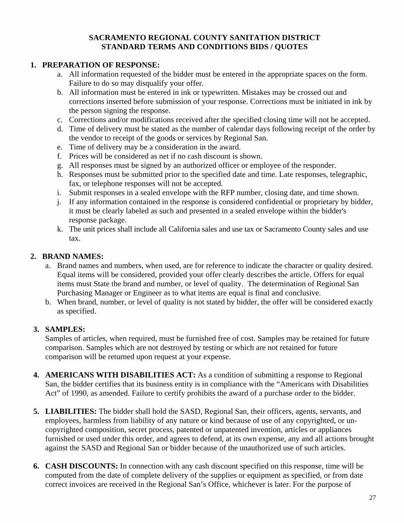
SACRAMENTO REGIONAL COUNTY SANITATION DISTRICT
STANDARD TERMS AND CONDITIONS BIDS / QUOTES
1. PREPARATION OF RESPONSE: a. All information requested of the bidder must be entered in the appropriate spaces on the form.
Failure to do so may disqualify your offer. b. All information must be entered in ink or typewritten. Mistakes may be crossed out and
corrections inserted before submission of your response. Corrections must be initiated in ink by the person signing the response.
c. Corrections and/or modifications received after the specified closing time will not be accepted. d. Time of delivery must be stated as the number of calendar days following receipt of the order by
the vendor to receipt of the goods or services by Regional San. e. Time of delivery may be a consideration in the award. f. Prices will be considered as net if no cash discount is shown. g. All responses must be signed by an authorized officer or employee of the responder. h. Responses must be submitted prior to the specified date and time. Late responses, telegraphic,
fax, or telephone responses will not be accepted. i. Submit responses in a sealed envelope with the RFP number, closing date, and time shown. j. If any information contained in the response is considered confidential or proprietary by bidder,
it must be clearly labeled as such and presented in a sealed envelope within the bidder's response package.
k. The unit prices shall include all California sales and use tax or Sacramento County sales and use tax.
2. BRAND NAMES:
a. Brand names and numbers, when used, are for reference to indicate the character or quality desired. Equal items will be considered, provided your offer clearly describes the article. Offers for equal items must State the brand and number, or level of quality. The determination of Regional San Purchasing Manager or Engineer as to what items are equal is final and conclusive.
b. When brand, number, or level of quality is not stated by bidder, the offer will be considered exactly as specified.
3. SAMPLES:
Samples of articles, when required, must be furnished free of cost. Samples may be retained for future comparison. Samples which are not destroyed by testing or which are not retained for future comparison will be returned upon request at your expense.
4. AMERICANS WITH DISABILITIES ACT: As a condition of submitting a response to Regional
San, the bidder certifies that its business entity is in compliance with the “Americans with Disabilities Act” of 1990, as amended. Failure to certify prohibits the award of a purchase order to the bidder.
5. LIABILITIES: The bidder shall hold the SASD, Regional San, their officers, agents, servants, and
employees, harmless from liability of any nature or kind because of use of any copyrighted, or un-copyrighted composition, secret process, patented or unpatented invention, articles or appliances furnished or used under this order, and agrees to defend, at its own expense, any and all actions brought against the SASD and Regional San or bidder because of the unauthorized use of such articles.
6. CASH DISCOUNTS: In connection with any cash discount specified on this response, time will be
computed from the date of complete delivery of the supplies or equipment as specified, or from date correct invoices are received in the Regional San’s Office, whichever is later. For the purpose of

28
earning the discount, payment is deemed to be made on the date of mailing of the County of Sacramento warrant or check.
7. DEFAULT BY VENDOR: In case of default by vendor, SASD or Regional San may procure the
articles or services from other sources and may deduct from any monies due, or that may thereafter become due to the vendor, the difference between the price named in the contract or purchase order and actual cost thereof to the SASD or Regional San. Prices paid by Regional San must be considered the prevailing market price at the time such purchase is made. Periods of performance may be extended if the facts as to the cause of delay justify such extension in the opinion of Regional San Purchasing Manager.
8. AWARDS:
a. Regional San reserves the right to: (1) award response’s received on the basis of individual items, or groups of items, or on the entire list of items, (2) reject any or all response’s, or any part thereof; (3) waive any informality in the responses; and (4) accept the response that is in the best interest of Regional San. Regional San’s decision shall be final.
b. Preference for California-made materials. Pursuant to Sections 4330-4333 of the Government Code, Regional San, in awarding the purchase, must prefer supplies partially manufactured, grown or processed in California, price, fitness and quality being equal. In order to receive preference, responses must clearly specify the item(s) for which preference is claimed and the preference applicable.
9. RIGHT TO AUDIT: Regional San reserves the right to verify, by examination of vendors’ records, all
invoiced amounts when firm prices are not set forth in the purchase agreement. 10. ASSIGNMENT: In submitting a response to a public purchasing body, the responder offers and agrees
that if the response is accepted, it will assign to the purchasing body all rights, title, and interest in and to all causes of action it may have under Section 4 of the Clayton Act (15 U.S.C. Sec. 15) or under the Cartwright Act (Chapter 2 [commencing with Section 16700] of part 2 of Division 7 of the Business and Professions Code), arising from the purchases of goods, materials, or services by the quoter for sale to the purchasing body pursuant to the quote. Such assignment must be made and become effective at the time the purchasing body tenders final payment to the responder.
11. APPLICABILITY TO HEIRS: Time is of the essence of each and all the provisions of this agreement
and, subject to the limitations of Paragraph 12, the provisions of this agreement shall extend to and be binding upon and inure to the benefits of the heirs, executors, administrators, successors, and assigns of the respective parties hereto.
12. SPECIAL CONDITIONS: Regional San standard terms and conditions must govern any contract
awarded. If, after award of contract, vendor provides additional terms or conditions, they will be considered void. To the extent not otherwise Stated in the contract, the California Commercial Code shall apply.
13. CHARGES NOT INCLUDED ON FACE NOT ACCEPTABLE: No charge will be accepted for
packing, boxing, or cartage, except as specified in the Notice of Award. Freight collect shipments will not be accepted. Merchandise will not be accepted if payment is to be made at the time of delivery.
14. TITLE: Except as otherwise expressly provided herein, title to and risk of loss on all items shipped by
seller to buyer shall pass to the buyer upon buyer’s inspection and acceptance of such items at buyer’s building.

29
15. CHANGES WITHOUT NOTICE PROHIBITED: No changes in price, quantity or merchandise will be recognized Regional San without written notice of acceptance thereof prior to shipment.
16. ALL UNDERSTANDINGS IN WRITING: It is mutually understood and agreed that no alteration or
variation of terms of this award shall be valid unless made in writing and signed by the parties hereto, and that no oral understandings or agreements not incorporated herein, and no alterations or variations of the terms hereof unless made in writing between the parties hereto shall be binding on any of the parties hereto.
17. FORCE MAJEURE: The vendor will not be held liable for failure or delay in the fulfillment of
conditions of purchase order/contract if hindered or prevented by fire, strikes, or Acts of God.

30
APPENDIX B
INSTRUCTIONS FOR BID SECURITY No Bid will be considered unless it is accompanied by a bid security in the form of a certified check or a cashier’s check, payable to the order of the SACRAMENTO REGIONAL COUNTY SANITATION DISTRICT, for the sum not less than ten percent (10%) of the total Bid amount, or a Bidders Bond in the same amount executed as surety by a corporation acceptable to Regional San and authorized to issue such surety bonds in the state of California. Payment of the security in cash or personal check will not be acceptable. Within fifteen (15) calendar days after execution by Regional San of the Contract and in any event not later than ninety (90) calendar days after the bid opening, Regional San will return to each bidder the bid security which accompanied its bid, except such security which may have been forfeited in accordance with the bid request.
Firm Name
Signature
Printed Name

31
APPENDIX C
BID GUARANTY BOND Bid Form
KNOW ALL PERSONS BY THESE PRESENTS: THAT , hereinafter called the Principal, and , hereinafter called the Surety, are jointly and severally held and firmly bound unto the Sacramento Regional County Sanitation District, hereinafter called the Obligee, each in the penal sum of 10 percent of the total amount of the bid of the Principal for the work, this sum not to exceed dollars ($ ) of lawful money of the United States for the payment thereof unto the Obligee, the Principal and Surety jointly and severally bind themselves forever firmly by these presents. WHEREAS, the Principal is herewith submitting its offer for the fulfillment of Obligee's contract for Gas Management System Rehabilitation and Improvements Project, RFB #8295. NOW, THEREFORE, the condition of this obligation is such that if the Principal is awarded the contract, and if the Principal, within the time specified in the bid for such contract, enters into, executes, and delivers to the Obligee an agreement in the form provided herein complete with evidences of insurance, and if the Principal within the time specified in the bid gives to the Obligee the performance and payment bonds on the form provided herein, then this obligation shall be void; otherwise, the Principal and Surety will pay unto the Obligee the difference in money between the total amount of the bid of the Principal and the amount for which the Obligee legally contracts with another party to fulfill the contract if the latter amount be in excess of the former, but in no event shall the Surety's liability exceed the penal sum hereof. AND IT IS HEREBY DECLARED AND AGREED that the Surety shall be liable under this obligation as Principal, and that nothing of any kind or nature whatsoever that will not discharge the Principal shall operate as a discharge or a release of liability of the Surety. IT IS HEREBY FURTHER DECLARED AND AGREED that this obligation shall be binding upon and inure to the benefit of the Principal, the Surety, and the Obligee and their respective heirs, executors, administrators, successors and assigns. SIGNED AND SEALED this day of , 2018. (SEAL) Principal Signature for Principal Title of Signatory (SEAL) Surety Signature for Surety Title of Signatory

32
APPENDIX D
INSTRUCTION FOR PERFORMANCE BOND
The successful Bidder shall be required to execute through a corporate surety the Performance Bond included herein. The successful Bidder and surety shall be held and firmly bound unto Regional San in the penal sum equal to 100% of the total Contract amount. The entire cost of the bond shall be borne by the successful Contractor. The successful Bidder agrees to execute and have notarized the Labor and Material Bond and deliver to Regional San within ten (10) working days after notice of intent to award the contract. These bonds will be provided to Regional San at the pre-construction meeting.
Firm Name
Signature
Printed Name
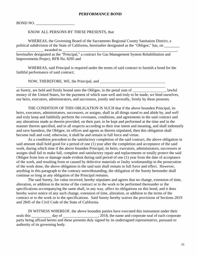
33
PERFORMANCE BOND BOND NO. KNOW ALL PERSONS BY THESE PRESENTS, that WHEREAS, the Governing Board of the Sacramento Regional County Sanitation District, a political subdivision of the State of California, hereinafter designated as the "Obligee," has, on awarded to , hereinafter designated as the "Principal," a contract for Gas Management System Rehabilitation and Improvements Project, RFB No. 8295 and WHEREAS, said Principal is required under the terms of said contract to furnish a bond for the faithful performance of said contract; NOW, THEREFORE, WE, the Principal, and as Surety, are held and firmly bound unto the Obligee, in the penal sum of , lawful money of the United States, for the payment of which sum well and truly to be made, we bind ourselves, our heirs, executors, administrators, and successors, jointly and severally, firmly by these presents. THE CONDITION OF THIS OBLIGATION IS SUCH that if the above bounden Principal, its heirs, executors, administrators, successors, or assigns, shall in all things stand to and abide by, and well and truly keep and faithfully perform the covenants, conditions, and agreements in the said contract and any alterations made as therein provided, on their part, to be kept and performed at the time and in the manner therein specified, and in all respects according to their true intent and meaning, and shall indemnify and save harmless, the Obligee, its offices and agents as therein stipulated, then this obligation shall become null and void; otherwise, it shall be and remain in full force and virtue. As a condition precedent to the satisfactory completion of the said contract, the above obligation in said amount shall hold good for a period of one (1) year after the completion and acceptance of the said work, during which time if the above bounden Principal, its heirs, executors, administrators, successors or assigns shall fail to make full, complete and satisfactory repair and replacements or totally protect the said Obligee from loss or damage made evident during said period of one (1) year from the date of acceptance of the work, and resulting from or caused by defective materials or faulty workmanship in the prosecution of the work done, the above obligation in the said sum shall remain in full force and effect. However, anything in this paragraph to the contrary notwithstanding, the obligation of the Surety hereunder shall continue so long as any obligation of the Principal remains. The said Surety, for value received, hereby stipulates and agrees that no change, extension of time, alteration, or addition to the terms of the contract or to the work to be performed thereunder or the specifications accompanying the same shall, in any way, affect its obligations on this bond, and it does hereby waive notice of any such change, extension of time, alteration, or addition to the terms of the contract or to the work or to the specifications. Said Surety hereby waives the provisions of Sections 2819 and 2845 of the Civil Code of the State of California. IN WITNESS WHEREOF, the above bounden parties have executed this instrument under their seals this day of , 2018, the name and corporate seal of each corporate party being affixed hereto and these presents duly signed by its undersigned representative, pursuant to authority of its governing body.

34
Principal By Signature of Principal Title of Signatory Surety By Signature for Surety (SEAL) Title of Signatory (This bond must be submitted in sets of two, each bearing original signatures. The signature of the Attorney-In-Fact for the Surety must be acknowledged by a Notary Public. Bonds must be accompanied by a current power of attorney appointing such Attorney-In-Fact.)

35
APPENDIX E
INSTRUCTIONS FOR PAYMENT BOND
The successful Bidder shall be required to execute through a corporate surety the Payment Bond included herein. The successful Bidder and surety shall be held and firmly bound unto Regional San in the penal sum equal to 100% of the total Contract amount. The entire cost of the bond shall be borne by the successful Contractor. The successful Bidder agrees to execute and have notarized the Labor and Material Bond and deliver to Regional San within ten (10) working days after notice of intent to award the contract. These bonds will be provided to Regional San at the pre-construction meeting.
Firm Name
Signature
Printed Name

36
PAYMENT BOND BOND NO. KNOW ALL PERSONS BY THESE PRESENTS, that WHEREAS, the Governing Board of the Sacramento Regional County Sanitation District, a political subdivision of the State of California, hereinafter designated as the "Obligee," has, on awarded to , hereinafter designated as the "Principal," a contract for the Gas Management System Rehabilitation and Improvements Project, RFB # 8295 and WHEREAS, said Principal is required under the terms of said contract to furnish a bond for the faithful performance of said contract; NOW, THEREFORE, WE, the Principal, and as Surety, are held and firmly bound unto the Obligee, in the penal sum of , lawful money of the United States, for the payment of which sum well and truly to be made, we bind ourselves, our heirs, executors, administrators, and successors, jointly and severally, firmly by these presents. THE CONDITION OF THIS OBLIGATION IS SUCH that if the above bounden Principal, its heirs, executors, administrators, successors, or assigns, shall in all things stand to and abide by, and well and truly keep and faithfully perform the covenants, conditions, and agreements in the said contract and any alterations made as therein provided, on their part, to be kept and performed at the time and in the manner therein specified, and in all respects according to their true intent and meaning, and shall indemnify and save harmless, the Obligee, its offices and agents as therein stipulated, then this obligation shall become null and void; otherwise, it shall be and remain in full force and virtue. As a condition precedent to the satisfactory completion of the said contract, the above obligation in said amount shall hold good for a period of one (1) year after the completion and acceptance of the said work, during which time if the above bounden Principal, its heirs, executors, administrators, successors or assigns shall fail to make full, complete and satisfactory repair and replacements or totally protect the said Obligee from loss or damage made evident during said period of one (1) year from the date of acceptance of the work, and resulting from or caused by defective materials or faulty workmanship in the prosecution of the work done, the above obligation in the said sum shall remain in full force and effect. However, anything in this paragraph to the contrary notwithstanding, the obligation of the Surety hereunder shall continue so long as any obligation of the Principal remains. The said Surety, for value received, hereby stipulates and agrees that no change, extension of time, alteration, or addition to the terms of the contract or to the work to be performed thereunder or the specifications accompanying the same shall, in any way, affect its obligations on this bond, and it does hereby waive notice of any such change, extension of time, alteration, or addition to the terms of the contract or to the work or to the specifications. Said Surety hereby waives the provisions of Sections 2819 and 2845 of the Civil Code of the State of California.

37
IN WITNESS WHEREOF, the above bounden parties have executed this instrument under their seals this day of , 2018, the name and corporate seal of each corporate party being affixed hereto and these presents duly signed by its undersigned representative, pursuant to authority of its governing body. Principal By Signature of Principal Title of Signatory Surety By Signature for Surety (SEAL) Title of Signatory (This bond must be submitted in sets of two, each bearing original signatures. The signature of the Attorney-In-Fact for the Surety must be acknowledged by a Notary Public. Bonds must be accompanied by a current power of attorney appointing such Attorney-In-Fact.)

38
APPENDIX F
COST RESPONSE
The cost of all labor, material and equipment necessary for the completion of the work itemized, even though not shown or specified, shall be included in the unit price for the various items shown herein.
Regional San reserves the right to increase or decrease the quantity of any item or omit items as may be deemed necessary, and the same shall in no way affect or make void the contract, except that appropriate additions or deductions from the contract total price will be made at the stipulated unit price.
Regional San future reserves the right to reject any or all bids, to waive any informality or irregularity in any bid or the bidding procedure, and to delete any items of work in the award of contract.
Item
Description
Estimated
Quantity
Units
Unit Price
($/unit)
Total Bid
(Dollars)
1. BASE BID:
Construction of all work associated with the Gas Management System Rehabilitation and Improvements Project, complete as shown.
1 LS N/A
2. BUILDERS RISK INSURANCE:
All costs associated with the acquisition of Builders Risk Insurance as required. (not
1 LS N/A
3 SHORING:
All labor, equipment, materials, engineering fees, permits, including removal of temporary shoring and sheeting.
1 LS N/A
4.
ALLOWANCE:
For un-anticipated site conditions, and purchase of spare parts as directed by the District Representative
1 LS N/A $100,000
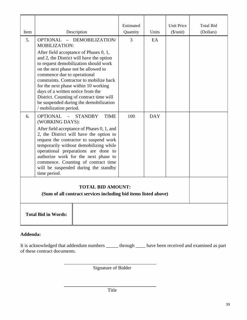
39
Item
Description
Estimated
Quantity
Units
Unit Price
($/unit)
Total Bid
(Dollars)
5. OPTIONAL – DEMOBILIZATION/ MOBILIZATION:
After field acceptance of Phases 0, 1, and 2, the District will have the option to request demobilization should work on the next phase not be allowed to commence due to operational constraints. Contractor to mobilize back for the next phase within 10 working days of a written notice from the District. Counting of contract time will be suspended during the demobilization / mobilization period.
3 EA
6. OPTIONAL - STANDBY TIME (WORKING DAYS):
After field acceptance of Phases 0, 1, and 2, the District will have the option to request the contractor to suspend work temporarily without demobilizing while operational preparations are done to authorize work for the next phase to commence. Counting of contract time will be suspended during the standby time period.
100 DAY
TOTAL BID AMOUNT:
(Sum of all contract services including bid items listed above)
Total Bid in Words:
Addenda: It is acknowledged that addendum numbers _____ through ____ have been received and examined as part of these contract documents. ______________________________________ Signature of Bidder ______________________________________ Title
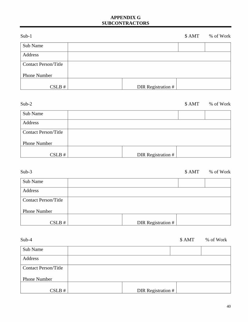
40
APPENDIX G SUBCONTRACTORS
Sub-1 $ AMT % of Work
Sub-2 $ AMT % of Work
Sub-3 $ AMT % of Work
Sub-4 $ AMT % of Work
Sub Name
Address
Contact Person/Title Phone Number
CSLB #
DIR Registration #
Sub Name
Address
Contact Person/Title Phone Number
CSLB #
DIR Registration #
Sub Name
Address
Contact Person/Title Phone Number
CSLB #
DIR Registration #
Sub Name
Address
Contact Person/Title Phone Number
CSLB #
DIR Registration #
41
APPENDIX H
EXCEPTION/RESPONSE PAGE
List any exceptions to the criteria requested above. Site the Item number, RFB page, paragraph number, and a description of the exception. If no exceptions are listed, the bid will be deemed to have no exceptions. ______________________________________________________________________________________
______________________________________________________________________________________
______________________________________________________________________________________
______________________________________________________________________________________
______________________________________________________________________________________
______________________________________________________________________________________
______________________________________________________________________________________
______________________________________________________________________________________
______________________________________________________________________________________
______________________________________________________________________________________

42
APPENDIX I
CONTRACTOR LICENSE CERTIFICATION
Pursuant to the Business and Professions Code of the State of California, Section 7030:
“Contractors are required by law to be licensed and regulated by the Contractors State License Board. Any questions concerning a contractor may be referred to the Registrar, Contractors State License Board, 9821 Business Park Drive, Sacramento, California 95827, Mailing Address: P.O. Box 26000, Sacramento, California 95826.”
The undersigned Contractor certifies that it is now licensed in accordance with the provisions of the
Contractor’s License Law of the State of California, and the number of said license is
, and the classification of said license is , and the said license expires
.
Company Name
Business Address By:
Authorized Signature
Type or Print Name
Title Dated:
Corporate Seal
If Contractor is a Corporation State of Incorporation:

43
APPENDIX J
NONCOLLUSION DECLARATION
The undersigned declares:
I am the _______________ of ____________________, the party making the foregoing bid.
The bid is not made in the interest of, or on behalf of, any undisclosed person, partnership, company, association, organization, or corporation. The bid is genuine and not collusive or sham. The bidder has not directly or indirectly induced or solicited any other bidder to put in a false or sham bid. The bidder has not directly or indirectly colluded, conspired, connived, or agreed with any bidder or anyone else to put in a sham bid, or to refrain from bidding. The bidder has not in any manner, directly or indirectly, sought by agreement, communication, or conference with anyone to fix the bid price of the bidder or any other bidder, or to fix any overhead, profit, or cost element of the bid price, or of that of any other bidder. All statements contained in the bid are true. The bidder has not, directly or indirectly, submitted his or her bid price or any breakdown thereof, or the contents thereof, or divulged information or data relative thereto, to any corporation, partnership, company, association, organization, bid depository, or to any member or agent thereof, to effectuate a collusive or sham bid, and has not paid, and will not pay, any person or entity for such purpose.
Any person executing this declaration on behalf of a bidder that is a corporation, partnership, joint venture, limited liability company, limited liability partnership, or any other entity, hereby represents that he or she has full power to execute, and does execute, this declaration on behalf of the bidder. I declare under penalty of perjury under the laws of the State of California that the foregoing is true and correct and that this declaration is executed on _________[date], at ________________________ [city], ________________[state].” Signature ________________________________

44
CONTRACTOR GUARANTEE The Contractor agrees to use and abide by the conditions of the following guarantee: GUARANTEE FOR: Sacramento Regional County Sanitation District (SRCSD) PROJECT: RFB #8295 – Gas Management System Rehabilitation and Improvements Project We hereby guarantee that the work completed under RFB #8295 has been furnished in accordance with the drawings and specifications and that the Work as constructed will fulfill the requirements of the guarantee included in the specifications. We agree to repair or replace any or all of our work and any consequential damages to other improvements, together with any other adjacent work which may be displaced in so doing, that may prove to be defective in its workmanship or materials within a period of one (1) year from the date of acceptance of the above named facility by Regional San without any expense whatsoever to said Regional San, ordinary wear or tear and unusual abuse or neglect excepted. In the event of our failure to comply with the above-mentioned conditions within 10 days after receipt of written notice from Regional San, Regional San is hereby authorized to make such repairs at our expense without further notice and without any notice to the surety. However, in case of emergency where, in the opinion of the Regional San’s Representative, delay would cause serious loss or damages, or a serious hazard to the public, the repairs may be made or lights, signs, and barricades erected, without prior notice to us or surety, and we shall pay the entire costs thereof. We do hereby authorize said Regional San to proceed to have said defects repaired and made good at our expense and we will honor and pay the costs and charges therefore upon demand. Date: Signed: Contractor

01/28/19 Gas Management System Rehabilitation and Improvements
00 62 05 - 1
SECTION 00 62 05
PROPRIETARY INFORMATION AGREEMENT
The Sacramento Regional County Sanitation District (hereinafter referred to as District) wishes to receive from (hereinafter referred to as Contractor) certain technical information claimed by the Contractor to be proprietary and hereinafter referred to as "Proprietary Data." Submittal of Proprietary Data by Contractor to District is required by the contract for testing, operating, and maintaining equipment, equipment assemblies and systems furnished under the contract. Contractor and District agree for a period of ______ years as follows:
1. The Proprietary Data is submitted to the District based on the understanding that the District would not disclose the same to others outside the District, nor reproduce the contents of said Proprietary Data or provide copies thereof to others outside the District without authorization from Contractor. Contractor claims proprietary rights in the contents of the Proprietary Data as a basis for preventing disclosure of the contents thereof to others. Contractor understands that the District has reservations as to the propriety of excluding the Proprietary Data from disclosure under the California Public Records Act (Government Code Section 6250, et seq.).
2. The District may make such disclosure or reproduction of the Proprietary Data as is
reasonably necessary to operate and maintain the subject equipment and to otherwise fully enjoy the use and benefit of the subject equipment.
3. Except as provided in paragraph 2, above, if any person makes a proper request to
review or be provided with copies of the Proprietary Data or any part thereof, immediately upon notification thereof, Contractor agrees to defend the District and its officers, agents, and employees against any action resulting from denial of such request. If Contractor fails to promptly provide such defense, the District, its officers, agents, and employees shall be free to grant such requests.
4. Contractor’s indemnity obligation is as set forth in the INSTRUCTIONS TO
BIDDERS Section (00 21 13).

01/28/19 Gas Management System Rehabilitation and Improvements
00 62 05 - 2
EXECUTED on this day of , 20 . SACRAMENTO REGIONAL COUNTY (Contractor) SANITATION DISTRICT By By Title: Title:
**END OF SECTION**

01/28/19 Gas Management System Rehabilitation and Improvements
00 73 19 - 1
SECTION 00 73 19
HEALTH AND SAFETY REQUIREMENTS
1.01 GENERAL
A. All operations shall conform to applicable occupational safety and health standards, rules, regulations and orders which include, but are not limited to: Title 29 of the Code of Federal Regulations and the Electrical, Construction, Tunnel and General Industry Safety Orders issued by the Division of Industrial Safety (Cal/OSHA) of the State of California. In the event of a conflict between the requirements in the referenced standards, the most stringent standard shall prevail.
B. The Contractor shall submit their Injury and Illness Prevention Program (IIPP) for review.
C. All contractors, vendors and visitors will wear hardhats and safety vests at all times while in construction areas. In addition, if necessary, but not limited to: appropriate foot, eye and ear protection shall be worn.
D. Contractor shall have a Site Specific Safety Plan that has been specifically prepared for the contemplated work. Site Specific Safety Plan shall comply with section 3203 of Cal/OSHA and shall be applicable to all individuals engaged in the Work, including the Contractor’s subcontractors, suppliers and others.
E. An Emergency Action Plan and a Fire Prevention Plan in accordance with sections 3220 and 3221 respectively of Cal/OSHA shall be included in Site Specific Safety Plan.
F. The responsibility for safety rests with the Contractor who must provide a safe work site for workers and other individuals entering the area.
G. District reserves the right to stop any work activity that creates a serious safety violation as defined by Cal/OSHA,
H. In accordance with OSHA’s National Emphasis Program (NEP), any contractor or subcontractor working on or adjacent to chlorine, sulfur dioxide, and/or digester gas systems during a Process Safety Management (PSM) inspection will also be inspected by OSHA per CPL 02-09-06.
1.02 PROJECT SPECIFIC SAFETY PROGRAM
A. Project Specific Safety Program shall include:
1. Designation of Safety Manager. A resume shall be provided.
2. Detailed description of Site Specific Safety Plan.

01/28/19 Gas Management System Rehabilitation and Improvements
00 73 19 - 2
3. Policies and procedures to ensure compliance with regulations.
4. Staffing plan and organization chart for implementation of the safety program.
5. Training program including new employee orientation.
6. List of equipment, supplies, materials and personal protective devices that will be available and utilized.
7. Description of accountability for foreman and supervisors.
8. Site Specific Emergency Response Plan for accidents/incidents and injuries.
9. Description of accident investigation and reporting procedures.
10. Description and frequency of tailgate and regular safety meetings.
11. Participation of subcontractors, suppliers and others in Project Safety Program.
12. Method of identifying, correcting, or remedying situations that are unsafe or not in compliance with Project Safety Program.
13. Plans and procedures for confined space entries.
14. Provisions for excavation safety.
15. Procedure for preparation of Work Permits.
16. Method to remedy nonconforming situations.
B. Project Specific Safety Program and revisions shall be reviewed by full time Safety Professional. The full time Safety Professional shall state that the Site Specific Project Safety Program is adequate and complies with the regulations applicable to the Work. The Project Specific Safety Program shall be submitted to the District Representative, for review, prior to commencement of work and shall remain in effect until the Work has been completed. Site Specific Safety Plan shall be reviewed, updated, and changes submitted as they occur.
1.03 SAFETY MANAGER
A. A Safety Manager shall be designated who has responsibility for safety of the Work and who has the duty to implement and secure compliance with the Site Specific Safety Plan. This individual shall be independent from the construction work force and shall have the authority to act and affect all aspects of the Project Safety Program. Safety Manager shall have the authority to remedy or correct any unsafe or noncompliance situations or problems.

01/28/19 Gas Management System Rehabilitation and Improvements
00 73 19 - 3
B. Safety Manager or designated alternate individual shall be on site when Work is being pursued. Contractor will be permitted to designate an alternate individual to act on behalf of Safety Manager when Safety Manager is absent from the work site.
C. Safety Manager shall have 5 years of industrial and heavy construction experience on projects similar to the Work. Three years of this experience shall involve full-time, construction site safety responsibilities. Safety Manager shall be knowledgeable of occupational health and safety rules and regulations.
D. Safety Manager shall prepare Work Permits for each confined space entry and shall organize and observe each entry.
E. Safety Manager and a District Representative shall tour the site on a weekly basis to observe the Work.
1.04 PROTECTION OF WORKERS
A. The SRWTP receives sewage and industrial wastes. There is a possibility that solvents, fuels and hazardous material may be in the wastewater. The wastewater and the associated facilities should be considered contaminated. Individuals who contact wastewater, debris or existing facilities should take appropriate safety and health precautions such as personal protective equipment and inoculations for disease.
B. Safety equipment and precautions shall be utilized to protect workers, District personnel, and the general public during the work.
1.05 WORK PERMITS
A. There are areas and operations at the SRWTP which are potentially hazardous or dangerous if the appropriate precautions are not taken. The Work Permit process is utilized to review proposed work activities and to ensure good work practices and appropriate safety measures are followed. Contractor is required to prepare Work Permits and comply with the stipulated conditions. A Work Permit shall provide a detailed description of the proposed activities and sequencing.
B. The Work Permit procedure is described in the COORDINATION WITH OCCUPANTS Section (01 14 16). Examples of activities which require a Work Permit are:
1. Operations that have open flames, the potential for sparks or activities that may result in high temperatures. Examples include welding, cutting, grinding and electrical work.
2. The use of tools or electrical equipment in classified areas.
3. Work on equipment or piping which contains, or has contained, a flammable or hazardous material, chemical or gas. Work on or in proximity to chemical or gas storage facilities.

01/28/19 Gas Management System Rehabilitation and Improvements
00 73 19 - 4
4. The use of hazardous materials.
5. Activities which involve electricity at greater than 500 volts.
6. Activities that involve pressures greater than 150 psi.
7. Activities that involve work in a confined space including the opening of vaults and manholes.
8. Activities that involve special precautions required by Cal/OSHA.
1.06 REPORTING
A. Monthly, Safety Manager shall prepare and submit a narrative report describing actions, incidents, near-misses and topics related to safety. The report shall indicate past events and proposed future activities. A summary of events of weekly job site tours shall be included.
B. All incidents that are reportable on OSHA Form 300 or that result in property damage in excess of $1,000 shall be promptly reported to District. A detailed description of the incident including names and statements of witnesses shall be provided within 5 days of the occurrence.
C. Contractor shall inform the District within 5 days of any claims, suits, or citations of violations that may arise from an incident or injury.
1.07 NON COMPLIANCE
A. When a serious hazard is identified, the Contractor will receive a verbal notification of the problem and a request to rectify the situation. If the situation is not corrected in the allotted time or reoccurs, a written notification will be issued to the Contractor that will clearly describe the condition, date Contractor initially was notified, the recommended action and the expected date of compliance. If the situation is not corrected, the Contractor’s worker’s compensation insurance carrier will be notified.
**END OF SECTION**
01/28/19 Gas Management System Rehabilitation and Improvements
00 73 83 - 1
SECTION 00 73 83
DISPUTE RESOLUTION
1.01 GENERAL
A. A sincere cooperative effort shall be made to complete the Work while recognizing that disputes and disagreements may occur. District and Contractor shall make a good faith effort to equitably resolve and settle disputes, disagreements and claims.
B. Contractor shall continue to pursue completion of the Work even though a dispute, disagreement or claim may occur.
C. It is understood that the terms dispute and claim may be used interchangeably in the Contract Documents and shall have similar meaning and intent. A dispute or claim is a request for a change in the Total Bid Amount or a request for a change in the Contract Time. All claims shall be pursued in strict compliance with the Contract Documents and applicable statutes.
D. The purpose of this Section shall be to provide a process for the resolution of construction contract disputes at the project level prior to initiating any other claims process or legal action against the District. Where a claim seeks payment by the District of money or damages, compliance with this Section shall be a prerequisite to, but not a substitute for, compliance with the government claims process set forth in Title, 1, Division 3.6 (beginning at Section 810) of the California Government Code
E. All claims must be submitted in writing to District prior to Contractor’s acceptance of the Final Payment.
F. In making a claim Contractor agrees to provide all records and information requested by District in order to establish the validity of the claim. Failure to provide records and information shall act to waive the claim.
G. Claims procedures shall be in accordance with Section 9204 of the Public Contract Code as restated and supplemented herein.
1.02 NOTIFICATION
A. Contractor shall promptly provide written notification to District of any situation, event or occurrence that may result in a claim or dispute. This notice shall be submitted no more than 30 days after the discovery of the event that is the basis for the claim. Failure to provide timely notice shall act to waive the claim.
B. A claim with supporting information shall be submitted within 60 days of the event that it is based upon. Claims must be sent by registered mail or certified mail with return receipt requested. District may grant additional time to prepare and submit the supporting information if warranted by the complexity and circumstances of the claim.
01/28/19 Gas Management System Rehabilitation and Improvements
00 73 83 - 2
A detailed description of the claim with references to the relevant Contract Documents, such as specifications and drawings; other pertinent information, evidence and documentation; and a detailed analysis of the time and cost impacts shall be provided.
C. Contractor shall certify that the claim is not in violation of Section 12650-12655 of the Government Code, False Claims Act.
1.03 NO WAIVER OF GOVERNMENT CLAIM PROCESS
A. No statement in the County of Sacramento Standard Construction Specifications or any Special Provisions for this Contract shall constitute a waiver of government claim filing requirements pursuant to Title 1, Division 3.6 of the California Government Code or as otherwise set forth in local, state and federal law.
1.04 CLAIM RESOLUTION PROCESS
A. Upon receipt of a claim pursuant to this section, the District shall conduct a reasonable review of the claim and, within a period not to exceed 45 days, shall provide the Contractor a written statement identifying what portion of the claim is disputed and what portion is undisputed. Upon receipt of a claim, the District and Contractor may, by mutual agreement, extend the time period provided in this Section.
B. If the District requires approval from the Board of Directors to provide the Contractor a written statement identifying the disputed portion and the undisputed portion of the claim, and the Board of Directors does not meet within the 45 days or within the mutually agreed to extension of time following receipt of a claim sent by registered mail or certified mail, return receipt requested, the District shall have up to three days following the next duly publicly noticed meeting of the Board after the 45-day period, or extension, expires to provide the Contractor a written statement identifying the disputed portion and the undisputed portion.
C. Any payment due on an undisputed portion of the claim shall be processed and made within 60 days after the District issues its written statement. If the District fails to issue a written statement, the following paragraph shall apply.
D. If the Contractor disputes the District’s written response, or if the District fails to respond to a claim issued pursuant to this section within the time prescribed, the Contractor may demand in writing an informal conference to meet and confer for settlement of the issues in dispute. A demand by the Contractor for a meet-and-confer conference shall be sent within fifteen (15) days of issuance or deadline for issuance of the District’s written statement on the claim. Upon receipt of a demand in writing sent by registered mail or certified mail, with return receipt requested, the District shall schedule a meet-and-confer conference to be held within 30 days for settlement of the dispute.
E. If Contractor does not request a meet-and-confer conference within the required time period, the parts of the claim remaining in dispute shall be subject to the government
01/28/19 Gas Management System Rehabilitation and Improvements
00 73 83 - 3
claims process set forth in Title 1, Division 3.6 (beginning at Section 810) of the California Government Code.
F. Within 10 business days following the conclusion of the meet-and-confer conference, if the claim or any portion of the claim remains in dispute, the District shall provide the Contractor a written statement identifying the portion of the claim that remains in dispute and the portion that is undisputed. Any payment due on an undisputed portion of the claim shall be processed and made within 60 days after the District issues its written statement. Any disputed portion of the claim, as identified by the Contractor in writing, shall be submitted to nonbinding mediation, with the District and the Contractor sharing the associated costs equally. For purposes of this Section, mediation includes any mutually agreeable nonbinding process in which an independent third party assists the parties in dispute resolution through negotiation or by issuance of an evaluation. Any mediation utilized shall conform to the timeframes in this section. Each party shall bear the fees and costs by its respective efforts and share equally the fees and costs in connection with the selection of a mutually agreed upon neutral mediator. If mediation is unsuccessful, the parts of the claim remaining in dispute shall be subject to the government claims process set forth in Title 1, Division 3.6 (beginning at Section 810) of the California Government Code.
G. Failure by the District to respond to a claim from the Contractor within the time periods described in this Section or to otherwise meet the time requirements of this Section shall result in the claim being deemed rejected in its entirety. A claim filed pursuant to this Section that is denied by reason of the public entity’s failure to have responded to a claim, or its failure to otherwise meet the time requirements of this section, shall not constitute an adverse finding with regard to the merits of the claim or the responsibility or qualifications of the claimant.
H. If a subcontractor or a lower tier subcontractor lacks legal standing to assert a claim against a public entity because privity of contract does not exist, the contractor may present to the public entity a claim on behalf of a subcontractor or lower tier subcontractor.
1.05 OTHER REMEDIES
A. If the matter remains in dispute, the case shall be submitted to judicial reference pursuant to California Code of Civil Procedure sections 638, former subdivision 1, and 641 through 645.1 or any successor statutes thereto. The Parties shall cooperate in good faith to ensure that all necessary and appropriate parties are included in the judicial reference proceeding. The District shall not be required to participate in the judicial reference proceeding unless it is satisfied that all necessary and appropriate parties will participate. The District and the Contractor shall share equally in the fees and costs of the referee, unless the referee orders otherwise.
1. The referee’s final statement of decision shall be binding upon the District and the Contractor provided that the parties first have an opportunity to comment on and seek changes to the proposed statement of decision. Upon filing of the final
01/28/19 Gas Management System Rehabilitation and Improvements
00 73 83 - 4
statement of decision with the clerk of the court, or with the judge where there is no clerk, the court may enter judgment hereon. The decision of the referee shall be appealable as if rendered by the court. This provision shall in no way be construed to limit any valid cause of action which may be brought by District of the Contractor.
B. Contractor agrees to utilize the dispute resolution methods cited in the Contract before initiating legal action. Litigation shall be pursued through a Sacramento County Court of appropriate jurisdiction or the United States District Court for the Eastern District of California.
**END OF SECTION**

DIVISION 01 – GENERAL REQUIREMENTS 01 12 16 WORK SEQUENCE01 14 13 ACCESS TO SITE01 14 16 COORDINATION WITH OCCUPANTS01 14 19 USE OF SITE01 14 20 CONTRACT TIME01 26 00 CONTRACT MODIFICATION PROCEDURES01 26 13 REQUESTS FOR INTERPRETATION 01 29 76 PROGRESS PAYMENT PROCEDURES01 31 19 PROJECT MEETINGS01 31 26 ELECTRONIC COMMUNICATION PROTOCOLS 01 32 16 CONSTRUCTION PROGRESS SCHEDULE01 32 23 SURVEY AND LAYOUT DATA01 32 33 PHOTOGRAPHIC DOCUMENTATION01 33 00 SUBMITTAL PROCEDURES01 33 16 DESIGN DATA01 41 26 PERMIT REQUIREMENTS01 45 00 QUALITY CONTROL01 51 00 TEMPORARY UTILITIES01 52 00 CONSTRUCTION FACILITIES01 55 26 TRAFFIC CONTROL01 56 00 TEMPORARY BARRIERS AND ENCLOSURES01 57 19 TEMPORARY ENVIRONMENTAL CONTROLS 01 57 23 TEMPORARY STORM WATER POLLUTION CONTROL 01 64 00 OWNER-FURNISHED PRODUCTS01 65 00 PRODUCT DELIVERY REQUIREMENTS01 73 24 DESIGN REQUIREMENTS FOR NON-STRUCTURAL
COMPONENTS AND NON-BUILDING STRUCTURES 01 73 33 RESTORATION OF IMPROVEMENTS01 74 23 FINAL CLEANING01 78 23 OPERATION AND MAINTENANCE DATA01 78 39 PROJECT RECORD DOCUMENTS01 78 43 SPARE PARTS01 79 10 TRAINING 01 91 00 COMMISSIONING01 91 10 REFERENCE FORMS
01/28/19 Gas Management System Rehabilitation and Improvements
01 12 16 - 1
SECTION 01 12 16
WORK SEQUENCE
PART 1 GENERAL
1.01 CONTINUITY OF PLANT OPERATIONS A. The existing wastewater treatment plant is currently and continuously receiving
and treating sewage, and those functions shall not be interrupted except as specified herein. The CONTRACTOR shall coordinate the work to avoid any interference with normal operation of plant equipment and processes.
1.02 SUBMITTALS A. In accordance with the SUBMITTAL PROCEDURES Section (01 33 00), the
CONTRACTOR shall submit a detailed outage plan and time schedule for operations which will make it necessary to remove a tank, pipeline, channel, electrical circuit, equipment, or structure from service. The schedule shall be coordinated with the construction schedule and shall meet the restrictions and conditions specified in this section. The detailed plan shall describe the CONTRACTOR's method for preventing bypassing of other treatment units, the length of time required to complete said operation, the necessary plant, and equipment which the CONTRACTOR shall provide in order to prevent bypassing of associated treatment units.
B. The CONTRACTOR shall observe the following restrictions:
1. Systems or individual equipment items shall be isolated, dewatered, purged, decommissioned, deenergized, or depressurized in accordance with the detailed outage plan and schedule.
2. The Construction Manager shall be notified in writing at least one week in advance of the planned operation.
1.03 GENERAL CONSTRAINTS ON SEQUENCE AND SCHEDULING WORK A. The CONTRACTOR shall include costs for compliance with the specific
limitations and constraints pertaining to maintaining the operational capacity of the PLANT including but not limited to:
1. Reduced construction efficiency and productivity. 2. Overtime costs for performing work outside of normal working hours, if
required. 3. Work related to temporary facilities needed to maintain PLANT operations. 4. Preparation and revision of schedule and planned Sequence of Work. 5. Design and construction of temporary bracing, underpinning, or special
sequencing necessary to support or brace existing structures. 6. Materials required for purging gas pipelines into and out of service.
01/28/19 Gas Management System Rehabilitation and Improvements
01 12 16 - 2
7. Valves, blind flanges and caps required for temporary isolation of piping systems.
B. Hours of Work:
1. Normal work hours are from 7:00 A.M. to 5:00 P.M. weekdays, not work during the weekend nor during District observed holidays. Obtain written approval from the District prior to initiating Work hours outside of the hours allowed by this Contract.
2. The CONTRACTOR shall request work-hour variations, in writing, a minimum of seven (7) days prior to the start of the proposed work period.
1.04 PLANT ACCESS
A. Limited Entrance: The proposed location for the Project Site are within the gated and locked area. Access to the construction site is through the PLANT Main Gate for ingress/egress as designated by the District.
B. Maintain restricted access to the PLANT at all times through the gates, fences, or other approved means.
C. OPERATIONS AND MAINTENANCE ACCESS: Provide and maintain safe, continuous access to process control equipment and chemical deliveries for the PLANT operations staff and other personnel contracted to perform Work at the PLANT.
D. The CONTRACTOR shall be aware that PLANT operations and maintenance staff and PLANT site visitors frequently travel on the PLANT’S roads as pedestrians, on bicycles, in carts, in cars and trucks. All work shall be planned in accordance with all restrictions indicated in the Contract Documents, all applicable PLANT rules, regulations, posted signage, policies, and procedures and as necessary to accommodate safe working conditions for all on the site. The CONTRACTOR shall be aware that the rate of the material hauling operation and other transportation activities within the site may be impacted by normal activity on the site.
1.05 CONTRACTOR’S STAGING AREA
A. A staging area has been designated for use by the the CONTRACTOR for staging construction operations.
B. Maintain the staging area and construction site during construction in a manner that will not unnecessarily obstruct roads or access to the PLANT. The CONTRACTOR shall proceed with work in an orderly manner, maintaining the construction site free of debris and unnecessary equipment or materials.

01/28/19 Gas Management System Rehabilitation and Improvements
01 12 16 - 3
1.06 ACCESS REQUEST (AR)
A. The CONTRACTOR shall review the instructions and template form attached at the end of COORDINATION WITH OCCUPANTS Section (01 14 16).
B. The CONTRACTOR shall submit a completed AR form and associated documentation to the District at least 28 days prior to the planned date of shutdown.
C. The CONTRACTOR shall prepare and submit a AR for the following conditions:
1. Shutdowns, diversions, and tie-ins to the existing PLANT. 2. Process start up activities. 3. Power interruption and tie-ins. 4. Switch over between temporary and permanent facilities, equipment,
piping, and electrical and instrumentation systems. 5. Process constraints requiring interruption of operating processes or utilities. 6. Other Work not specifically listed as determined necessary by the
CONTRACTOR, PLANT, and/or District.
1.07 INTERRUPTION OF GAS MANAGEMENT PROCESS
A. The District will evaluate and approve the ARs based on the PLANT’s ability to meet reliably capacity demands.
1. The CONTRACTOR shall indicate required shutdowns of existing facilities or interruptions of existing operations on the Project’s Progress Schedule. Shutdowns will be permitted to the extent that existing operations of the PLANT will not be jeopardized, and when constraints identified in this section have been satisfied.
2. The CONTRACTOR shall submit a completed AR form and associated documentation to the District as specified in this Section.
3. Following receipt of a notice of planned shutdown, DISTRICT will notify the CONTRACTOR as to the feasibility of the requested date and duration of the activity.
4. The DISTRICT will maintain the ability to abort on the day of the scheduled shutdown.
B. The CONTRACTOR shall minimize shutdown times by thorough advanced planning.
C. The CONTRACTOR shall not begin shutdowns or alterations of existing facilities until District’s written permission has been received.
D. The CONTRACTOR shall provide temporary pumping, plugs, power, lighting, controls, instrumentation, and safety devices when required to minimize treatment process interruptions and comply with shutdown constraints specified in this Section.

01/28/19 Gas Management System Rehabilitation and Improvements
01 12 16 - 4
1.08 REQUIREMENTS FOR MAINTAINING CONTINUOUS OPERATION OF EXISTING FACILITIES
A. Continuous operation of facilities is of critical importance. The CONTRACTOR shall schedule and conduct activities to enable existing facilities to operate continuously, unless otherwise specified. The CONTRACTOR shall cooperate fully with PLANTs’ personnel for existing facilities. The PLANT may restrict the time and duration of shutdowns, and other disruptions to facility operations.
B. The CONTRACTOR shall cooperate fully with PLANT’s personnel for existing facilities. The PLANT may restrict the time and duration of shutdowns, and other disruptions to PLANT operations. In the event of conflict between construction activities and facility operations, facility operations have priority.
C. The CONTRACTOR shall perform all necessary Work, as detailed in these specifications, in such manner as not to interfere in any way with normal PLANT operations. Wherever the CONTRACTOR finds it necessary to involve temporary operating arrangements and/or modify existing equipment in pursuit of Work required under the Contract, the CONTRACTOR shall give adequate written notice as described in this Section to the District, to allow coordination of PLANT operating procedures.
D. Facilities or conditions required to keep the PLANT operational include, but are not limited to, the following:
1. Electrical power including transformers, distribution wiring, and motor control centers.
2. Piping for conveyance of wastewater, chemical, and utilities between treatment units.
3. Chemical storage, metering, conveyance, and control facilities. 4. Plant water. 5. Plant air (process air and instrument air). 6. Laboratory facilities. 7. Office, toilets, and washrooms. 8. Fencing and gates, site security. 9. Lighting. 10. Heating, ventilation, and air conditioning. 11. Plant Computer Control System (PCCS). 12. Instrumentation, meters, controls, and telemetry equipment. 13. Safety equipment and features. 14. Parking for PLANT’s employees and vehicles required for operation and
maintenance of the PLANT. 15. Telephone system, all communication system. 16. Storm drainage. 17. Natural gas service, digester gas 18. All truck deliveries for chemicals and material to the plant
01/28/19 Gas Management System Rehabilitation and Improvements
01 12 16 - 5
E. The CONTRACTOR shall conduct the Work and plan, design, and provide temporary services and facilities required to keep the PLANT continuously operational.
F. The CONTRACTOR shall not close lines, open or close valves, or take other action that would affect the operation or existing systems, except as specifically required by the Contract Documents and after authorization by the District.
G. Do not remove or demolish existing facilities required to keep the existing PLANT operation at the capacities specified until the existing facilities are replaced by temporary, new or upgraded facilities or equipment. The replacement facilities shall have been tested and demonstrated to be operational prior to removing or demolishing existing facilities.
1.09 OPERATIONS AND MAINTENANCE ACCESS A. The CONTRACTOR shall provide and maintain safe, continuous access to
process control equipment and chemical deliveries as well as emergency vehicles for PLANT operations and maintenance staff and other personnel contracted to perform Work at the PLANT.
B. CONTRACTOR shall maintain site and facilities in a safe and proper condition during CONTRACTOR shutdown activities.
1.10 SHUTDOWN CONSTRAINTS A. A shutdown is defined herein as that period of time during which a normal
treatment function and activity of the PLANT cannot take place.
B. Shutdown Requirements:
1. Short-Term Shutdowns: a. Short-term shutdowns shall be used for tie-ins for utilities, electrical,
and communication relocations. b. Short-term shutdowns require 72 hours notification and an approved
AR. c. Short-term shutdowns shall not be performed by the CONTRACTOR
until the CONTRACTOR has received written authorization from the District.
d. Short-term shutdowns shall not be longer than two (2) hours in duration unless otherwise approved in writing by the District.
2. Longer-Term Shutdowns: a. Longer-term shutdowns will be used where complete or partial
process shutdown is required. b. Longer-term shutdowns require advanced notification as specified
herein and an approved AR. c. The CONTRACTOR shall submit an AR and a dry run procedure for
each longer-term shutdown. AR and a dry run procedure shall be in accordance with format and procedures attached at the end of this

01/28/19 Gas Management System Rehabilitation and Improvements
01 12 16 - 6
Section. The procedure shall include contingency measures and provisions for rapid closure in the event that shutdown and work progress difficulties are encountered.
d. Longer-term shutdowns shall not be performed by the CONTRACTOR until the CONTRACTOR has received written authorization from the District.
1.11 UTILITIES A. The CONTRACTOR shall maintain electrical, telephone, electronic
communication, water, gas, sanitary facilities, and other utilities within existing facilities in service. The CONTRACTOR shall provide temporary utilities when necessary.
B. The CONTRACTOR shall provide advance notice to and utilize services of Underground Services Alert (USA) for location and marking of underground utilities operated by utility agencies other than the PLANT.
C. When modifications, additions, connections, and abandonments will be made or are required to existing water and sewer mains, services, fire lines, and fire hydrants, the CONTRACTOR shall contact the respective District Department for notifications and/or required procedures prior to any work. The CONTRACTOR shall properly plan for this, include in the schedule, and not disrupt normal PLANT functions as specified herein.
1.12 ODOR CONTROL A. Construction activities shall not be the source of nuisance odors, either due to the
CONTRACTOR’s activity or exposing noxious sources.
PART 2 PRODUCTS (NOT USED)
PART 3 EXECUTION
3.01 COORDINATION OF WORK
A. The CONTRACTOR shall maintain overall coordination of execution of Work, including coordination with the District and PLANT operations personnel.
B. The CONTRACTOR shall obtain construction schedules from subcontractor’s and suppliers and assume responsibility for correctness.
C. District and CONTRACTOR shall incorporate schedules from subcontractors and suppliers into Progress Schedule to plan for and comply with sequencing constraints.
D. CONTRACTOR shall coordinate work with other CONTRACTORS working in the same general area. Coordination of work shall be an agenda item at
01/28/19 Gas Management System Rehabilitation and Improvements
01 12 16 - 7
construction progress meetings. District will notify CONTRACTOR of other contracts being performed concurrently, during the pre-construction meeting.
3.02 WORK BY OTHERS
A. Where proper execution of the Work depends upon work by others (i.e. other CONTRACTORS or District), inspect and promptly report discrepancies and defects to ther District.
B. CONTRACTOR shall coordinate all work with current and ongoing work at the site.
3.03 GENERAL REQUIREMENTS FOR EXECUTION OF WORK
A. Operating processes, systems, individual equipment items and controls shall be isolated, dewatered, decommissioned, de-energized, or depressurized only by the District’s Operations staff in accordance with the detailed outage plan and schedule. The CONTRACTOR is advised that existing gates and valves may leak and some additional pumping may be required during the course of the shutdown to perform the work.
B. Any additional pumping required to perform the shutdown shall be the CONTRACTOR’s responsibility. Exisiting piping or structures may not completely drain and the CONTRACTOR may be required to pump any remaining process fluids from pipes or structures. Any additional time required for pumping shall be coordinated with the shutdown period.
C. If the planned circumstances under which the outage was to be conducted change, the District shall have the right to cancel or terminate an outage when the potential for a safety hazard or violation of the discharge permit exists. Such action shall be considered an avoidable delay in accordance with the Article 3, General Provisions.
D. The District retains the authority to terminate any scheduled shutdown up to and including the day of the scheduled shutdown.
E. Pursuant to the AR requirements specified hierin, the CONTRACTOR shall notify the District in writing in advance of any planned outage in any area. If requested by the District, the CONTRACTOR shall send a representative to a Pre-AR Meeting with District to plan activities during the requested outage.
F. Sequence, schedule, and coordinate work in and around the activities of other contractors on the site to avoid obstruction of work access and interference with, or delay of, the work of other contractors on the site.
G. Provide temporary pumping, piping, power (including portable generators as required), lighting, controls, instrumentation, communication systems, and safety devices required to comply with the contraints specified in this Section.

01/28/19 Gas Management System Rehabilitation and Improvements
01 12 16 - 8
H. Confirm required equipment, materials, and labor is on site a minimum of 3 days before commencing any work covered in a AR.
I. Establish temporary erosion and sediment controls prior to commencing any clearing, grading, or excavation that may result in discharges to waters of the State.
J. Do not begin shutdowns or alterations of existing facilities until receiving District’s approval of the corresponding AR.
K. Unless otherwise specified, normal daily operation and maintenance of the existing treatment facilities will be performed by PLANT personnel. Whenever operational functions on existing facilities or new facilities which affect operating systems are required to permit construction operations, these functions will also be performed by plant personnel. CONTRACTOR shall not operate valves, gates or other operating equipment or systems in the PLANT for existing or accepted Work that is part of or may affect PLANT operations.
L. Locate temporary facilities in a manner that minimizes interference to District’s operation and maintenance personnel.
M. Unless otherwise specified, install temporary pipelines of the same size as its connection to the existing facility at the downstream end of the pipeline. Provide temporary piping of suitable material for the material being conveyed.
N. Provide submittals on proposed temporary pumping facilities, temporary plugs, and temporary electrical and instrumentation components necessary to maintain existing facilities.
O. Dewater and promptly clean existing structures and pipelines temporarily removed from the operation where required.
P. Where shown, dimension for all existing structures, piping, paving, and other nonstructural items are approximate. The CONTRACTOR shall field verify all dimensions and conditions and report any discrepancies to the District a minimum of 14 days in advance of any construction in the area.
Q. Discrepancies between coordinates, bearings and lengths, and stationing shall be resolved in the following order of precedence:
1. Coordinates 2. Bearing and lengths 3. Stationing
01/28/19 Gas Management System Rehabilitation and Improvements
01 12 16 - 9
3.04 WORK SEQUENCE AND CONSTRAINTS
A. General:
1. CONTRACTOR shall utilize the description of critical events in the Work Sequence in Part 4 as a guideline for scheduling and completing the Work.
2. The Work Sequence and Constraints presented in Part 4 do not include all items affecting the completion of the Work but are intended to describe in general the critical events necessary to minimize disruptions of the existing facilities.
3. This section itemizes the major known disruptions to plant operations and processes that will occur during the course of the work and describes the suggested sequencing methodology to develop the project construction schedule and adhering to the construction limitations and constraints specified herein.
4. To permit continuous consumption and disposal of digester gas with Air Quality permit restrictions, the construction schedule required in the General Conditions of the Contract Documents shall provide for the specific conditions included herein.
5. CONTRACTOR may propose alternate methods to those listed to the District for approval. Not all temporary systems are described or shown.
3.05 ACCESS REQUEST
A. General:
1. A Access Request (AR) is a detailed document submitted by the CONTRACTOR for the purpose of requesting process shutdown(s), utility tie-in(s), work in areas that may risk unanticipated outages, or flow diversions to accommodate construction activities during a project. Such activities may include (but are not limited to) new tie-ins to utilities or structures, mechanical modifications to process piping or equipment, demolition, temporary valve installation, and cleaning processes.
2. The purpose of the AR is to provide a detailed plan for the PLANT and District that describes specific aspects of the work, a shutdown, diversion, or tie-in including its purpose, time of execution, and anticipated impacts on the treatment or business processes. The AR shall include information from each trade (such as mechanical, electrical, plumbing, HVAC) associated with the particular task requiring a shutdown, diversion, or tie-in. Information within each AR will be used by the PLANT for defining operational procedures and methods to safely and successfully assist the CONTRACTOR in performing the Work activities.
3. When the duration of the needed facility shutdown exceeds the specified allowable outage duration, prepare an outage mitigation plan describing measures that CONTRACTOR will implement to mitigate the impact to PLANT operations.
01/28/19 Gas Management System Rehabilitation and Improvements
01 12 16 - 10
B. Submittal Process and Acceptance
1. Pre-AR Meeting: a. The CONTRACTOR initiates the AR process by requesting a pre-AR
meeting with the District to discuss the nature of the shutdown, diversion, or tie-in, and to gather the information necessary to complete the AR form. The requirement for a pre-AR meeting may be waived by the District if the nature of the work is deemed to be minor. The CONTRACTOR shall complete the AR Form (attached), and submit in accordance with the SUBMITTAL PROCEDURES Section (01 33 00) for approval by the District following the pre-AR meeting. The District will distribute the AR for review.
2. AR Content: a. The CONTRACTOR shall describe the nature of the work within the
AR form. The description shall include details of all relevant trades associated with the required shutdown, diversion, or tie-in. If any of the trades are subcontracted, the CONTRACTOR shall be responsible for making the subcontractor provide and include the specific details required by that trade for the associated shutdown, diversion, or tie-in.
b. The CONTRACTOR shall provide sufficient details on process isolation, work sequencing, and safety (i.e., control of significant hazards unique to the shutdown, diversion, or tie-in) to demonstrate an understanding of the Work and how it will be completed within the associated constraints, and the Work’s impact on the treatment process. The District can provide information on the process-related aspects of the shutdown during the pre-AR meeting.
c. CONTRACTOR shall include any work required by the District in preparation of the CONTRACTOR’s Work and requested timing of this work.
d. The AR will be reviewed for completeness, accuracy, compliance with the construction schedule, constraints defined in Contract Documents, and confirm that the requested shutdown, diversion, or tie-in does not negatively affect the operations or other concurrent activities at the PLANT. Additional information may be requested from the CONTRACTOR to understand the nature of the Work and method for completing the Work activities. The District will return the AR to the CONTRACTOR for revision if any of these criteria are not met. Requirements for resubmittal or modifications resulting from the District’s review shall not be cause for any delay claims. Once the AR is acceptable to all parties, the AR will be accepted by signature, and an original copy distributed by the District to the CONTRACTOR.
3. AR Submittal Timing: a. Each AR must be accepted by the District a minimum of ten (10)
calendar days in advance of the Work activities defined in the AR. CONTRACTOR shall allow a minimum of ten (10) calendar days

01/28/19 Gas Management System Rehabilitation and Improvements
01 12 16 - 11
from the time of submission to the Facility for acceptance of the AR. Therefore, the CONTRACTOR shall submit the first/original AR a minimum of twenty (20) calendar days prior to the associated shutdown, diversion, or tie-in unless a longer period of time is specifically called out in the specifications for a particular activity. For each resubmittal resulting from the District’s review, CONTRACTOR shall modify and update the associated AR within seven (7) calendar days and allow an additional ten (10) calendar days for District review and comments. Any resubmittal efforts associated with the AR shall not be cause for CONTRACTOR cost or schedule adjustments.
C. Identification, Scheduling and Tracking
1. The CONTRACTOR shall submit a preliminary list of anticipated ARs for the project a minimum of seven (7) calendar days prior to the Pre-Construction Meeting. This list shall be developed for, but is not limited to, those shutdowns, diversions, or tie-ins described in the Contract Documents. Scheduled ARs shall be incorporated as tasks on the established baseline schedule, as well as the 3-week progress schedules prepared by the CONTRACTOR throughout the construction period. Scheduled ARs shall be dated to coincide with the construction activities. Updates to this list shall be made throughout the duration of the project as new ARs are identified.
2. In addition to this list, the CONTRACTOR shall keep a AR log for the purpose of tracking active ARs. This log shall be updated weekly and distributed at the regularly scheduled construction progress meetings.
D. AR Process Detail
1. STEP 1. CONTRACTOR identifies ARs needed on Log and Baseline Schedule. a. CONTRACTOR submits a preliminary list of anticipated project ARs
identified but not limited to those shutdowns, diversions, or tie-ins described in the Contract Documents in a log. Incorporate ARs as tasks in Baseline Schedule. ARs are scheduled to coincide with the appropriate construction activities. If other ARs are identified during the course of this project, CONTRACTOR shall immediately notify the District of any additional ARs. For each additional AR, CONTRACTOR shall then follow the steps outlined here.
2. STEP 2. Pre-AR Meeting. a. CONTRACTOR requests a Pre-AR Meeting with the Facility’s staff
and District to discuss the nature of the shutdown, diversion, or tie-in, and to gather the information necessary to complete the AR Form. The pre-AR meeting may be waived by the District if the work is deemed to be minor.
3. STEP 3. Submit AR.

01/28/19 Gas Management System Rehabilitation and Improvements
01 12 16 - 12
a. CONTRACTOR completes the AR Form and submits for approval to the District.
4. STEP 4. Review AR. a. The District reviews the AR Form for completeness, accuracy,
compliance with both the construction schedule, constraints defined in Contract Documents, and to ensure that the requested work does not negatively impact PLANT operations or other concurrent activities. Additional information may be requested from CONTRACTOR to better understand the nature of and method for completing the Work.
5. STEP 5. AR finalized. a. Once the AR is agreed to by all parties, the AR will be finalized by
signature. 6. STEP 6. Complete Readiness Checklist.
a. CONTRACTOR verifies everything is ready for the work. 7. STEP 7. Complete Safety Checklist.
a. CONTRACTOR ensures safety. 8. STEP 8. Complete work.
a. CONTRACTOR completes work. 9. STEP 9. Update AR Log and Progress Schedules.
a. CONTRACTOR updates AR Log weekly and distributes at the regularly scheduled construction progress meetings.
PART 4 ADDITIONAL REQUIREMENTS
4.01 GENERAL A. The following work sequences are organized by process types and list the major
work items, constraints and suggested work sequences. The sequences outlined below represent one approach to meeting the construction constraints. The sequences do not address every operation or construction detail; see other parts of the construction documents for additional requirements. The CONTRACTOR may propose modifications to the sequences as long as the construction constraints are met.
B. The Gas Mangement System, overall, must stay in operation throughout the construction. Individual subsystems may be out of service for limited periods.
C. The CONTRACTOR shall note that not all valves that may be used to isolate lines will completely seal. The CONTRACTOR shall allow for leakage in planning its work and may, with the District’s concurrence, test certain valves before work involving isolation has begun. The CONTRACTOR shall clean the work areas as required to perform work.
D. Only District personnel shall perform operational functions or shutdown of existing facilities or systems required to facilitate the CONTRACTOR’S operation. The CONTRACTOR shall not adjust or operate any in-service equipment.

01/28/19 Gas Management System Rehabilitation and Improvements
01 12 16 - 13
E. The District’s operation and maintenance personnel will cooperate in every way that is practicable in order to facilitate CONTRACTOR’S operation; however, certain shutdown and connections may only be permissible at times other than normal working hours.
4.02 DEMOLITION A. Demolition shown on the drawings must be performed in phases based on the
requirements in this Section.
B. CONTRACTOR shall be responsible for temporary valves, caps and blind flanges required for execution of phased demolition.
4.03 SAFE PURGING PRACTICES A. The DISTRICT shall perform all purging operations in coordination with the
CONTRACTOR.
B. CONTRACTOR shall be responsible for safe work practices related to work on hazardous piping systems.
4.04 PHASE 0: NEW WASTE GAS BURNER TIE-IN WORK ITEMS A. Uncrubbed digester gas will be disposed of at the ground flares or WGBs while
this work is performed. Gas will not be exported to cogen during this work.
B. Work Sequence as follows:
1. District to open and close valves to allow digester gas to be burned at the ground flares or WGBs and shut down MSG system.
2. District to isolate and purge the gas scrubber system and all downstream systems.
3. Remove V87522. Remove the spool piece between 87LSG545 and V87522.
4. Install new fire-rated V87522 and new spool piece with 20” tee connection, 20” piping, isolation valve 87LSG169, and associated purge and sample valves and inspection ports.
5. Provide temporary blind flange on 87LSG169 and temporary pipe support for new piping. Leak check new piping and purge.
6. District to return scrubber system to service, without using LSG-2 for scrubbed gas. Leave 87LSG546 closed.
C. Work Constraints as follows:
1. District to perform initial isolation and purging in preparation for construction
2. System can’t be returned to service until District completes all Management of Change (MOC) activities and internal approvals
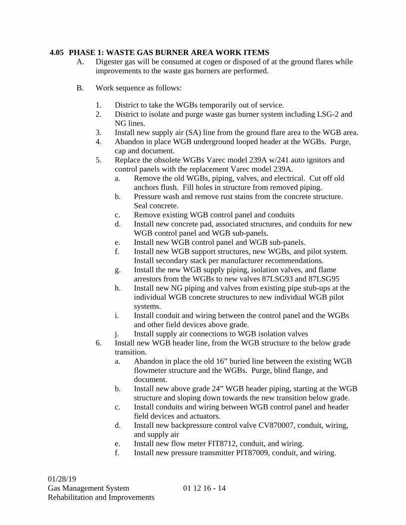
01/28/19 Gas Management System Rehabilitation and Improvements
01 12 16 - 14
4.05 PHASE 1: WASTE GAS BURNER AREA WORK ITEMS A. Digester gas will be consumed at cogen or disposed of at the ground flares while
improvements to the waste gas burners are performed.
B. Work sequence as follows:
1. District to take the WGBs temporarily out of service. 2. District to isolate and purge waste gas burner system including LSG-2 and
NG lines. 3. Install new supply air (SA) line from the ground flare area to the WGB area. 4. Abandon in place WGB underground looped header at the WGBs. Purge,
cap and document. 5. Replace the obsolete WGBs Varec model 239A w/241 auto ignitors and
control panels with the replacement Varec model 239A. a. Remove the old WGBs, piping, valves, and electrical. Cut off old
anchors flush. Fill holes in structure from removed piping. b. Pressure wash and remove rust stains from the concrete structure.
Seal concrete. c. Remove existing WGB control panel and conduits d. Install new concrete pad, associated structures, and conduits for new
WGB control panel and WGB sub-panels. e. Install new WGB control panel and WGB sub-panels. f. Install new WGB support structures, new WGBs, and pilot system.
Install secondary stack per manufacturer recommendations. g. Install the new WGB supply piping, isolation valves, and flame
arrestors from the WGBs to new valves 87LSG93 and 87LSG95 h. Install new NG piping and valves from existing pipe stub-ups at the
individual WGB concrete structures to new individual WGB pilot systems.
i. Install conduit and wiring between the control panel and the WGBs and other field devices above grade.
j. Install supply air connections to WGB isolation valves 6. Install new WGB header line, from the WGB structure to the below grade
transition. a. Abandon in place the old 16” buried line between the existing WGB
flowmeter structure and the WGBs. Purge, blind flange, and document.
b. Install new above grade 24” WGB header piping, starting at the WGB structure and sloping down towards the new transition below grade.
c. Install conduits and wiring between WGB control panel and header field devices and actuators.
d. Install new backpressure control valve CV870007, conduit, wiring, and supply air
e. Install new flow meter FIT8712, conduit, and wiring. f. Install new pressure transmitter PIT87009, conduit, and wiring.

01/28/19 Gas Management System Rehabilitation and Improvements
01 12 16 - 15
7. Maintain ability to burn unscrubbed gas at the ground flares from valves 80LSG101 and 80LSG102. a. Blind flange piping at the below grade-to-above grade transition riser
at the existing WGB flowmeter structure. b. Abandon in place the remaining old 16” buried line between the
WGB structure and the WGB flowmeter structure. Purge, blind flange, and document.
c. Remove the old WGB flowmeter structure. 8. Install new above and below grade WGB feed piping and condensate
drainage from the WGB area in the East to the new above WGB manifold at the gas scrubbers. a. Install new above and below grade WGB feed piping from the WGB
area in the Easttransition sloping toward the north vault containing 80LSG101 and 80LSG102.
b. Install new 24” spool at the low point in the north vault with drain lines connecting between the new ground flare header to the existing 16” connections to LSG-1 and LSG-2. Tie drain valve 87LSG171 into the downstream side (East, purged side) of 80LSG101. Tie drain valve 87LSG152 into the downstream side (East, purged side) of 80LSG102.
c. Install new 24” WGB header below grade between the scrubber area and the north vault, sloping toward the new low point spool in the north vault.
9. Install new above-grade manifold piping at the gas scrubbers to provide new WGB tie-in at the gas scrubbers. a. Remove temporary blind flange from 87LSG169. 87LSG169 must
remain closed. b. Install new above grade 20” WGB manifold piping from isolation
valves 87LSG169 and 87LSG165 to the transition below grade in the scrubber area.
c. Connect 87LSG169 to the new 20” manifold, connecting LSG-1 to the WGB manifold. 87LSG169 must remain closed.
10. Install new connection between LSG-2 and the WGB manifold a. Isolate LSG-2 through the scrubber system. Close 87LSG502,
87LSG504, 87LSG506, 87LSG508, 87LSG510, 87LSG514, 87LSG516, 87LSG518, and 87LSG520
b. Purge LSG-2 from 87LSG546 and 87LSG547 c. Remove V87521 and 87LSG546. Remove the spool piece between
87LSG54 and V87521. d. Install new fire-rated V87521. e. Cut off existing LSG-2 elbow feeding the gas scrubbers. f. Install new piping between LSG-2, the gas scrubbers (V87251), and
the WGB feed manifold (new valve 87LSG165) g. Replace 87LSG546. h. Install remaining new valves, including purge and sample valves.
11. Complete related PLC and PCCS changes.

01/28/19 Gas Management System Rehabilitation and Improvements
01 12 16 - 16
12. District to return WGBs to service when all work items have been completed.
C. Contraints as follows:
1. District to perform initial isolation and purging in preparation for construction
2. System can’t be returned to service until District completes all Management of Change (MOC) activities and internal approvals
4.06 PHASE 2: GROUND FLARE AREA WORK ITEMS A. Digester gas can be exported to COGEN or consumed/disposed of at the waste
gas burners while improvements to the ground flares and abandoning the gas holders in place are performed.
B. Ground Flare System Work sequence as follows:
1. District to isolate and purge ground flare system. 2. Overhaul the ground flares and the ground flare control panels. 3. Replace all valves identified for replacement at the ground flares. 4. Replace control panel for each flare. Complete PLC changes and PCCS
changes to accommodate new panels and automated startup and shutdown of the flare system.
5. Excavate and replace 2” condensate drain piping on the south end of FSG-1 & 2 with new individual blowoff piping and valves just below grade in a valve box.
6. Remove T87306 & T87307 and associated piping. 7. Install new pressurized FSG condensate tank T870023.
a. Excavate and install new 2” HDPE condensate drain taps and equalization lines on FSG-1 & 2 (4 lines total), west of the Ground Flare Pit. Run new individual 2” HDPE pipes to Ground Flare Pit. Core bore pit wall. Replace 87LSG106 & 87LSG107 with 87FSG71 & 87FSG72.
b. Connect FSG drain lines and equalization lines to T870023 c. Install PSV vent piping to run immediately next to vent piping from
T87305 and to vent next to the existing vent. 8. Install drain piping from the new tank directly to the sump
C. Abandon Gas Holders in Place Work Sequence as follows:
1. District to isolate and purge Gas holders and piping associated with gas Holders
2. Remove piping on holder side of V87209 and V87211 and install blind flanges on valves and exposed pipe.
3. Provide support for abandoned piping at both holders 4. Remove V827212, 87LSG208, V87208, and 87LSG206. Blind flange
exposed pipe. 5. Condensate valve work near holders (time sensitive, return T87305 to
service within 48 hours)
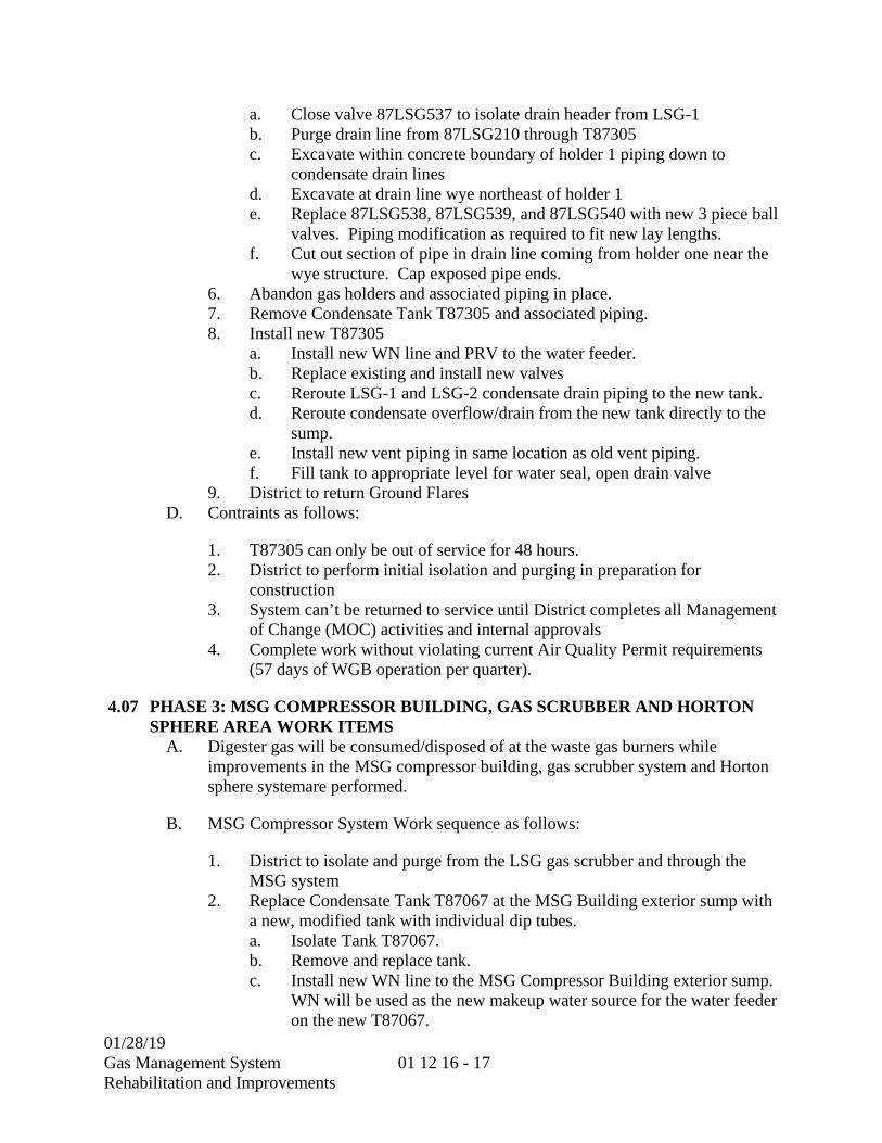
01/28/19 Gas Management System Rehabilitation and Improvements
01 12 16 - 17
a. Close valve 87LSG537 to isolate drain header from LSG-1 b. Purge drain line from 87LSG210 through T87305 c. Excavate within concrete boundary of holder 1 piping down to
condensate drain lines d. Excavate at drain line wye northeast of holder 1 e. Replace 87LSG538, 87LSG539, and 87LSG540 with new 3 piece ball
valves. Piping modification as required to fit new lay lengths. f. Cut out section of pipe in drain line coming from holder one near the
wye structure. Cap exposed pipe ends. 6. Abandon gas holders and associated piping in place. 7. Remove Condensate Tank T87305 and associated piping. 8. Install new T87305
a. Install new WN line and PRV to the water feeder. b. Replace existing and install new valves c. Reroute LSG-1 and LSG-2 condensate drain piping to the new tank. d. Reroute condensate overflow/drain from the new tank directly to the
sump. e. Install new vent piping in same location as old vent piping. f. Fill tank to appropriate level for water seal, open drain valve
9. District to return Ground Flares D. Contraints as follows:
1. T87305 can only be out of service for 48 hours. 2. District to perform initial isolation and purging in preparation for
construction 3. System can’t be returned to service until District completes all Management
of Change (MOC) activities and internal approvals 4. Complete work without violating current Air Quality Permit requirements
(57 days of WGB operation per quarter).
4.07 PHASE 3: MSG COMPRESSOR BUILDING, GAS SCRUBBER AND HORTON SPHERE AREA WORK ITEMS
A. Digester gas will be consumed/disposed of at the waste gas burners while improvements in the MSG compressor building, gas scrubber system and Horton sphere systemare performed.
B. MSG Compressor System Work sequence as follows:
1. District to isolate and purge from the LSG gas scrubber and through the MSG system
2. Replace Condensate Tank T87067 at the MSG Building exterior sump with a new, modified tank with individual dip tubes. a. Isolate Tank T87067. b. Remove and replace tank. c. Install new WN line to the MSG Compressor Building exterior sump.
WN will be used as the new makeup water source for the water feeder on the new T87067.
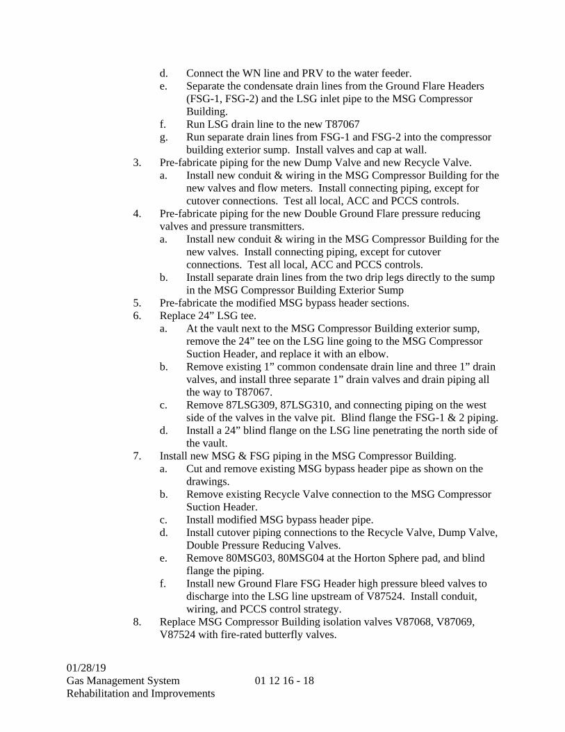
01/28/19 Gas Management System Rehabilitation and Improvements
01 12 16 - 18
d. Connect the WN line and PRV to the water feeder. e. Separate the condensate drain lines from the Ground Flare Headers
(FSG-1, FSG-2) and the LSG inlet pipe to the MSG Compressor Building.
f. Run LSG drain line to the new T87067 g. Run separate drain lines from FSG-1 and FSG-2 into the compressor
building exterior sump. Install valves and cap at wall. 3. Pre-fabricate piping for the new Dump Valve and new Recycle Valve.
a. Install new conduit & wiring in the MSG Compressor Building for the new valves and flow meters. Install connecting piping, except for cutover connections. Test all local, ACC and PCCS controls.
4. Pre-fabricate piping for the new Double Ground Flare pressure reducing valves and pressure transmitters. a. Install new conduit & wiring in the MSG Compressor Building for the
new valves. Install connecting piping, except for cutover connections. Test all local, ACC and PCCS controls.
b. Install separate drain lines from the two drip legs directly to the sump in the MSG Compressor Building Exterior Sump
5. Pre-fabricate the modified MSG bypass header sections. 6. Replace 24” LSG tee.
a. At the vault next to the MSG Compressor Building exterior sump, remove the 24” tee on the LSG line going to the MSG Compressor Suction Header, and replace it with an elbow.
b. Remove existing 1” common condensate drain line and three 1” drain valves, and install three separate 1” drain valves and drain piping all the way to T87067.
c. Remove 87LSG309, 87LSG310, and connecting piping on the west side of the valves in the valve pit. Blind flange the FSG-1 & 2 piping.
d. Install a 24” blind flange on the LSG line penetrating the north side of the vault.
7. Install new MSG & FSG piping in the MSG Compressor Building. a. Cut and remove existing MSG bypass header pipe as shown on the
drawings. b. Remove existing Recycle Valve connection to the MSG Compressor
Suction Header. c. Install modified MSG bypass header pipe. d. Install cutover piping connections to the Recycle Valve, Dump Valve,
Double Pressure Reducing Valves. e. Remove 80MSG03, 80MSG04 at the Horton Sphere pad, and blind
flange the piping. f. Install new Ground Flare FSG Header high pressure bleed valves to
discharge into the LSG line upstream of V87524. Install conduit, wiring, and PCCS control strategy.
8. Replace MSG Compressor Building isolation valves V87068, V87069, V87524 with fire-rated butterfly valves.

01/28/19 Gas Management System Rehabilitation and Improvements
01 12 16 - 19
9. Install new FSG header fire valves V870012 and V870013. Include conduit, wiring, and PCCS control strategy. a. Revise the control strategy to relocate the Ground Flare fire isolation
valve function from V87308 & V87309 to the two new fire isolation valves at the MSG Compressor Building.
10. Remove FSG fire isolation valves V87308 & V87309 in the South Vault, and replace them with stainless steel spools. Terminate wiring.
11. Replace MSG Compressor Suction Header low-low cutout pressure switch PSL8759 with a pressure transmitter, conduit, wiring, and PCCS control strategy.
12. Complete related PLC and PCCS changes. C. Gas Scrubber System Work Items:
1. Replace Gas Scrubber fire isolation valve V87523 with a fire-rated butterfly valve. Install a new spool between V87523 and 87LSG550 to accommodate the new lay length.
2. Install pressure indicating transmitters on the Gas Scrubber inlet headers, and on the Gas Scrubber discharge headers. Total of 4. Install conduit, wiring, and PCCS indication.
3. Replace other identified valves. 4. Complete related PCCS changes. 5. District to return MSG, Gas Scrubbers, and Ground Flares to service.
D. Horton Sphere System Work Items:
1. Remove Horton Sphere valve pad isolation valves 80LSG33 & 80LSG34, and blind flange the piping. Support remaining piping as needed.
2. Abandon below grade piping to Horton sphere area, north of compressor building, document.
E. Contraints as follows:
1. Complete work without violating current Air Quality Permit requirements (57 days of WGB operation per quarter).
**END OF SECTION**

01/28/19 Gas Management System Rehabilitation and Improvements
01 12 16 - 20
THIS PAGE INTENTIONALL LEFT BLANK

01/28/19 Gas Management System Rehabilitation and Improvements
01 14 13 - 1
SECTION 01 14 13
ACCESS TO SITE
1.01 PROJECT LOCATION
A. The work specified under this Contract will be performed at the Sacramento Regional Wastewater Treatment Plant (Plant). The Plant is located south of the Sacramento City limits, west of Franklin Boulevard and north of Sims Road at 8521 Laguna Station Road, Elk Grove, California 95758.
1.02 SITE ACCESS AND ACCESS ROADS
A. Access to the site for construction related traffic (except as noted below) shall be via Dwight Road from Laguna Boulevard.
1. Contractor shall access the site through Dwight Road Security Facility via Laguna Boulevard.
2. Under circumstances where use of Dwight Road Security Facility is not feasible or recommended, Contractor shall obtain District’s approval prior to accessing the site via the Sims Road Gate.
B. Contractor is required to submit an Access Request (AR) for District approval prior to mobilizing any equipment or facilities onto the construction site in accordance with the COORDINATION WITH OCCUPANTS Section (01 14 16). Contractor’s AR for mobilization shall include but not limited to a site plan showing access routes, office location, sanitary facilities location, storage yard, parking areas, temporary construction fencing, and temporary walkways around construction site. Contractor shall coordinate with the District Representative prior to submitting the AR.
C. Contractor shall be aware that Dwight Road and other roads within the site will be utilized by other contractors and Plant personnel during the duration of this contract.
D. The Contractor’s personnel will be required to park personal vehicles in the approved or designated areas. Each Contractor shall be responsible for policing the common parking area for cleanliness and efficient parking procedures to ensure use by all. Existing parking in the process area may not be used by the Contractor’s workers.
E. The Contractor will maintain a visitor log to document the arrival and departure of all delivery personnel and periodic visitors.
F. In the event of an evacuation, the contractor and all staff, subcontractors, delivery personnel and visitors will report to the congregation area with copies of the visitor log for roll call. All personnel will remain at the congregation area until released by authorized District Management.

01/28/19 Gas Management System Rehabilitation and Improvements
01 14 13 - 2
1.03 CONTRACTOR IDENTIFICATION BADGE POLICY AND PROCEDURES
A. IDENTIFICATION:
1. All Contractor and subcontractor staff assigned to work at the Plant shall obtain an identification badge and shall wear/display their badges at all times while at the Plant. The Contractor must submit to the District Representative a weekly list which includes scheduled deliveries to the job site and staff members who have received badges.
B. TRAINING:
1. All Contractor staff must attend Plant Safety Orientation and badge use training at a minimum prior to issuance of badges. Training is anticipated to be 1 hour total in duration and will include the environmental and cultural education training as described in the TEMPORARY ENVIRONMENTAL CONTROLS Section (01 57 19).
C. BADGE SECURITY LEVELS:
1. Contractors and subcontractors will have different access authority levels through process security gates depending upon the time of day, and/or their assigned duties.
2. If access is denied, contact the District Representative.
D. FORGOTTEN BADGE:
1. If a person forgets their badge, they will have to enter the Plant as a visitor. This requires logging in and out of the Plant by the security guard at the gate.
a. Use the inside entry lane (closest to the guard station).
b. Guard will ask your name and other information and allow entry.
c. Guard will give you a visitor parking permit.
d. Display it on your rear-view mirror.
e. Leave plant using inside exit lane (closest to guard station).
f. Return parking permit to guard, then guard will allow exit.
E. LOST BADGE:
1. A badge categorized as forgotten will be considered lost after 72 hours. Lost badges shall be reported to the District Representative as soon as the loss is realized. A replacement badge will be issued and the lost badge will be deactivated

01/28/19 Gas Management System Rehabilitation and Improvements
01 14 13 - 3
and will no longer work in the security system. If found, the lost badge shall be turned into the District Representative.
1.04 GATE ENTRY/EXIT PROCEDURES
A. GENERAL:
1. Badges are required to enter or exit through the guard gate stations. No "piggy backing" of other vehicles is allowed.
2. There are three entrance and three exit lanes at the Dwight Road Security Facility and two entrance and two exit lanes at the Sims Road Gate:
a. The outside lanes are exclusively for persons with badges.
b. The inner lanes are to be used by
1) Visitors;
2) Deliveries; and
3) Employees without badges
c. NOTE: If a person with a badge chooses the inner lanes, they may get behind someone that needs to be checked in or out extending the wait time in that lane.
3. There is a “cell-phone pullout” area outside of the Dwight Road Security Facility and the Sims Road gate. A single pullout area is provided to allow visiting vehicles and trucks to park and obtain additional information from the receiving party, if needed prior to reaching the gate. Unexpected visitors who proceed to the gate without prior notification to receiving parties could be directed to turn around at the gate. If permission is granted, the receiving party shall notify the guard at the gate to allow entry of the visitor.
**END OF SECTION**
01/28/19 Gas Management System Rehabilitation and Improvements
01 14 13 - 4
THIS PAGE INTENTIONALLY LEFT BLANK

01/28/19
Gas Management System Rehabilitation and Improvements
01 14 16 - 1
SECTION 01 14 16
COORDINATION WITH OCCUPANTS
1.01 GENERAL
A. Contractor work activities that impact existing District operations, property or facilities (such as pipelines, ductbanks, manholes, treatment processes, environmental resources, and access roads to District facilities) require an approved, signed Access Request (AR) prior to commencement of work. Interruption of flow or connection to an existing system or interceptor requires a Shutdown Plan and Location Map to be included with the Access Request. In addition to the Shutdown Plan, any activity that requires special safety precautions to be taken will require a Safety Work Plan to be included with the Access Request.
B. ACCESS REQUEST:
1. Allows District Operations time to review the proposed work and to schedule and coordinate necessary process or equipment shutdowns,
2. Allows District Safety office review of proposed work and contractors’ safe work practices related to the specific work to be performed,
3. Informs the contractor of any special hazards or exposures related to the specific work.
C. The District maintains permits to collect, treat and discharge wastewater. These permits establish discharge limits for wastewater, storm water, and air emissions and establish spill reporting requirements and fines. Violation of District permits shall not result from the Contractor’s work. Any unauthorized discharge or spill shall immediately be reported to the District’s Plant Control Center (916-875-9400). The District will require the Contractor to stop or restrict any activity that has or could result in an unauthorized discharge or permit violation. The District will prevent or remedy the situation by the most expeditious means. The Contractor will be responsible for all costs incurred including fines.
01/28/19
Gas Management System Rehabilitation and Improvements
01 14 16 - 2
1.02 REQUIREMENTS
A. COORDINATION AND ACCESS:
1. Activities that affect the operation of existing District equipment, including Plant processes, Interceptor pipelines or facilities, or access to District property will require coordination between District and Contractor.
2. Access Requests are generally required based on impending work activities discussed at weekly construction coordination meetings, and approval is issued jointly by the District O&M Support office and District Safety Office.
3. Unrestricted access for District personnel and equipment shall be provided at all times to existing facilities, unless a reduced level of access is explicitly allowed in the approved Access Request.
1.03 SCOPE
A. An Access Request provides notification of a Work Item or other activity proposed by the Contractor. An Access Request describes the contemplated work including when, where and how it will be accomplished. An Access Request shall be submitted by a qualified representative of the Contractor who is familiar with all aspects of the work and pertinent safety requirements. An Access Request may be required whenever any of the following conditions are contained in or will be affected by Contractor’s work:
1. General Project mobilization or District property access,
2. Work in, connection to, or removal of any pipeline, manhole, pump station, asset or wastewater process or equipment.
3. Any work that may impact environmental resources on District property,
4. Any work that may impact or disrupt other activities on District property such as leased agricultural operations, scientific studies, or concurrent construction projects,
5. Excavation on District property by location, dewatering of any excavation, structure, tank, vessel, or piping system
6. Installation or removal of bulkheads, cofferdams and isolation devices
B. Depending on the activities within the project, multiple Access Requests may be required.
C. A fully completed Access Request form shall be submitted in accordance with the ELECTRONIC COMMUNICATION PROTOCOLS Section (01 31 26) at least
01/28/19
Gas Management System Rehabilitation and Improvements
01 14 16 - 3
10 working days prior to the date proposed for commencement of work. An Access Request meeting may be required prior to the approval of the work or upon the District’s request.
D. Contractors are required to describe the proposed work activity, indicate the property, system or equipment that will be affected, list the labor and equipment to be utilized, indicate the date, time and duration of the work, describe measures that will be implemented to reduce impacts to District property and facilities, and describe safety precautions to be observed. Drawing and section numbers shall be indicated where appropriate. A Shutdown plan shall be included with the Access Request when the work affects an existing system or process.
E. The Contractor shall plan and schedule Access Requests as early as possible. An Access Request will be reviewed and returned within 10 working days after submission of all necessary information. Sufficient information and detail shall be included with an Access Request to permit District to evaluate the proposed operation and the associated risks. Insufficient information on an Access Request may delay approval within 10 working days.
F. Contractor shall not be allowed to proceed with any work, or any portion of the work, described in an Access Request without complying with all the conditions, in their entirety, of the Access Request approval. All conditions of approval, including additional safety precautions added by the District Safety Office, shall be complied with and effectively communicated to Contractor's personnel and subcontractors. If the Contractor does not agree with the additional safety requirements, work shall not start until resolution is attained. Changes in the proposed activities or field conditions of an Access Request, or delay of the work, will require the submission of a new or revised Access Request.
1.04 SHUTDOWN PLAN
A. A Shutdown Plan shall be included with an Access Request whenever an existing operating system or facility such as a pipeline, basin, tank, channel, power supply, control circuit, instrumentation, equipment, pump, meter, or structure is affected. Shutdowns shall be planned and coordinated to minimize the number and duration of activities that affect existing operations.
B. The District will limit the duration of shutdowns for critical systems. Stated durations are the total time period between when the system is made available to Contractor and when it is ready for return to service. If the Contractor cannot complete the work within the allowed time, Contractor shall immediately request an extension from the
01/28/19
Gas Management System Rehabilitation and Improvements
01 14 16 - 4
District. If the District does not approve the requested extension, Contractor shall complete the work or return the system to operable condition. The District will complete the work if Contractor does not return the system to operable condition as directed. Contractor is responsible for extra costs or damages incurred by the Contractor or the District to meet these requirements.
C. REQUIREMENTS:
1. Designate the equipment or system that will be affected or removed from service. Describe the work to be undertaken. Identify the portion of the system that will be isolated, dewatered, decommissioned, de-energized, depressurized, or drained.
2. List the labor, equipment, materials, tools, utilities and incidental items to be used.
3. Indicate measures to prevent discharge of wastewater, stormwater pollution, odor or disruption of treatment processes.
4. Indicate dewatering method and means for disposal of leakage water.
5. Provide details for bulkheads, cofferdams and isolation devices.
6. Describe safety precautions and equipment.
7. Describe recovery plan if the shutdown cannot be completed as planned
8. List activities to be done by the District.
9. Indicate the time estimated to complete the shutdown.
** END OF SECTION **

01/28/19
Gas Management System Rehabilitation and Improvements
01 14 16 - 5
SACRAMENTO REGIONAL COUNTY SANITATION DISTRICT
ACCESS REQUEST
Prime Contractor Contract # Date
Sub-Contractor AR # Revision
Contact for Contractor Work Item # CPM Activity #
Phone □ Work Plan Attached □ Drawing Attached
PART 1 – CONTRACTOR WORK PERMIT Start Date/Time Completion Date/Time
Reference Contract Drawings/Specifications
Equipment or System to be Worked On
Location of Work
Provide RMP/MOC no. for work affecting SRWTP Gas Mgmt. or Chemical Handling Areas:
Type of Work (check all that apply)
□ Civil □ Mechanical □ Electrical □ Instrumentation
□ Process □ Coating □ Hotwork □ Other (specify)
□ Mobilization □ Traffic/Ped. Access □ Shutdown
Description
of Work
Anticipated Hazards
Tools/Equipment to be Used
□ Cutting/Welding Torches □ Arc Welders □ Jack Hammers
□ Power Saws □ Grinders □ Pneumatic Tools
□ Backhoe □ Crane □ Radioactive Test Device
Revised 11-2015 Access Request – Page 1 of 3
Access Request Instructions 1. Contractor fills out AR with sufficient information to define the work and anticipated safety hazards and
signs at bottom of page 2. 2. If it is a CIP - R.E. reviews AR and signs on page 3 prior to delivering AR to District Representative. 3. District Representative(s) reviews and approves the AR with conditions, restrictions, or additional Safety
items (all additional safety items on page 2 will be initialed). 4. District Rep/RE gives approved AR back to contractor prior to contractor performing the work. 5. Contractor reviews AR conditions and Safety page prior to beginning work.
Note: For ARs for utility or outside agency work, contractor interacts directly with District Representative
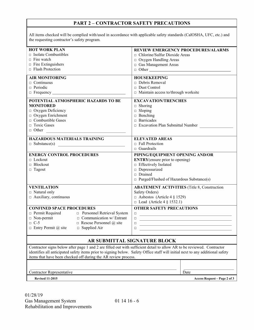
01/28/19
Gas Management System Rehabilitation and Improvements
01 14 16 - 6
PART 2 – CONTRACTOR SAFETY PRECAUTIONS All items checked will be complied with/used in accordance with applicable safety standards (CalOSHA, UFC, etc.) and the requesting contractor’s safety program.
HOT WORK PLAN □ Isolate Combustibles □ Fire watch □ Fire Extinguishers □ Flash Protection
REVIEW EMERGENCY PROCEDURES/ALARMS □ Chlorine/Sulfur Dioxide Areas □ Oxygen Handling Areas □ Gas Management Areas □ Other
AIR MONITORING □ Continuous □ Periodic □ Frequency
HOUSEKEEPING □ Debris Removal □ Dust Control □ Maintain access to/through worksite
POTENTIAL ATMOSPHERIC HAZARDS TO BE MONITORED □ Oxygen Deficiency □ Oxygen Enrichment □ Combustible Gases □ Toxic Gases □ Other
EXCAVATION/TRENCHES □ Shoring □ Sloping □ Benching □ Barricades □ Excavation Plan Submittal Number
HAZARDOUS MATERIALS TRAINING □ Substance(s)
ELEVATED AREAS □ Fall Protection □ Guardrails
ENERGY CONTROL PROCEDURES □ Lockout □ Blockout □ Tagout
PIPING/EQUIPMENT OPENING AND/OR ENTRY(ensure prior to opening) □ Effectively Isolated □ Depressurized □ Drained □ Purged/Flushed of Hazardous Substance(s)
VENTILATION □ Natural only □ Auxiliary, continuous
ABATEMENT ACTIVITIES (Title 8, Construction Safety Orders) □ Asbestos (Article 4 § 1529) □ Lead (Article 4 § 1532.1)
CONFINED SPACE PROCEDURES □ Permit Required □ Personnel Retrieval System □ Non-permit □ Communication w/ Entrant □ C-5 □ Rescue Personnel @ site □ Entry Permit @ site □ Supplied Air
OTHER SAFETY PRECAUTIONS □ □ □ □
AR SUBMITTAL SIGNATURE BLOCK Contractor signs below after page 1 and 2 are filled out with sufficient detail to allow AR to be reviewed. Contractor identifies all anticipated safety items prior to signing below. Safety Office staff will initial next to any additional safety items that have been checked off during the AR review process.
Contractor Representative
Date
Revised 11-2015 Access Request – Page 2 of 3
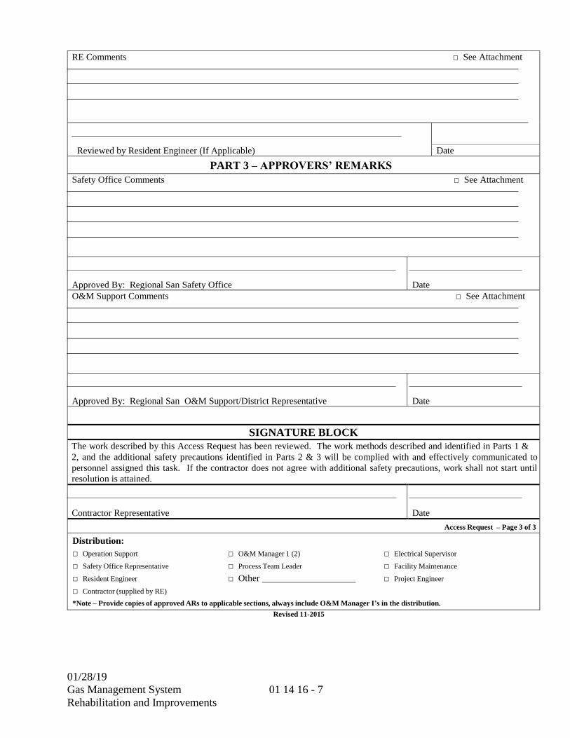
01/28/19
Gas Management System
Rehabilitation and Improvements
01 14 16 - 7
RE Comments □ See Attachment
Reviewed by Resident Engineer (If Applicable)
Date
PART 3 – APPROVERS’ REMARKS
Safety Office Comments □ See Attachment
Approved By: Regional San Safety Office
Date
O&M Support Comments □ See Attachment
Approved By: Regional San O&M Support/District Representative
Date
SIGNATURE BLOCK
The work described by this Access Request has been reviewed. The work methods described and identified in Parts 1 &
2, and the additional safety precautions identified in Parts 2 & 3 will be complied with and effectively communicated to
personnel assigned this task. If the contractor does not agree with additional safety precautions, work shall not start until
resolution is attained.
Contractor Representative
Date
Access Request – Page 3 of 3
Distribution:
□ Operation Support □ O&M Manager 1 (2) □ Electrical Supervisor
□ Safety Office Representative □ Process Team Leader □ Facility Maintenance
□ Resident Engineer □ Other □ Project Engineer
□ Contractor (supplied by RE)
*Note – Provide copies of approved ARs to applicable sections, always include O&M Manager I’s in the distribution.
Revised 11-2015

THIS PAGE INTENTIONALLY LEFT BLANK
01/28/19 Gas Management System Rehabilitation and Improvements
01 14 19 - 1
SECTION 01 14 19
USE OF SITE
PART 1 -- GENERAL
1.01 GENERAL REQUIREMENTS
A. The District's operating personnel will be responsible for operating the existing treatment plant throughout the execution of this contract. Do not adjust or operate serviceable or functioning equipment or systems.
B. Equipment presently installed in the treatment plant must be safely available to plant personnel at all times for use, maintenance, and repair.
C. If it is necessary in the course of operating the plant for the Contractor to move its equipment, materials, or any material included in the work, it shall be done promptly. The equipment or material shall be placed in an area which does not interfere with the plant operation.
D. Requirements of this section include, but are not limited to, requirements specified in the COORDINATION WITH OCCUPANTS Section (01 14 16) and the TEMPORARY UTILITIES Section (01 51 00).
E. The existing treatment plant will remain in operation throughout the execution of this contract. Schedule and conduct work to minimize necessary shutdowns and interference with normal plant operations and maintenance. An Access Request Form included and described in the COORDINATION WITH OCCUPANTS Section (01 14 16) shall be submitted to the District Representative each time access to existing facilities is necessary.
F. Comply with the safety requirements of the Sacramento Regional Wastewater Treatment Plant (Plant) Safety Manual as a minimum when working in the Plant process area. Provide additional safety considerations which are deemed necessary to protect Contractor and District employees during the conduct of the work.
G. Provide notice to the District Representative, in accordance with the COORDINATION WITH OCCUPANTS Section (01 14 16), 2 weeks prior to taking out of service any existing tank, pipeline, channel, electrical circuit, equipment or structure. Provide whatever temporary piping, pumping, power, and control facilities as required to maintain continuous plant operation and complete treatment except as
01/28/19 Gas Management System Rehabilitation and Improvements
01 14 19 - 2
otherwise specified. The integrity of existing plant utilities shall be maintained at all times.
H. Contractor laydown area within the project site is designated on the design drawings.
I. The Contractor's work force shall not use existing washrooms during the conduct of the work. Use of existing utilities shall be in accordance with the TEMPORARY UTILITIES Section (01 51 00). The Contractor shall be responsible for keeping areas in the existing treatment plant where work is done clean and safely accessible for the District's operating personnel.
**END OF SECTION**
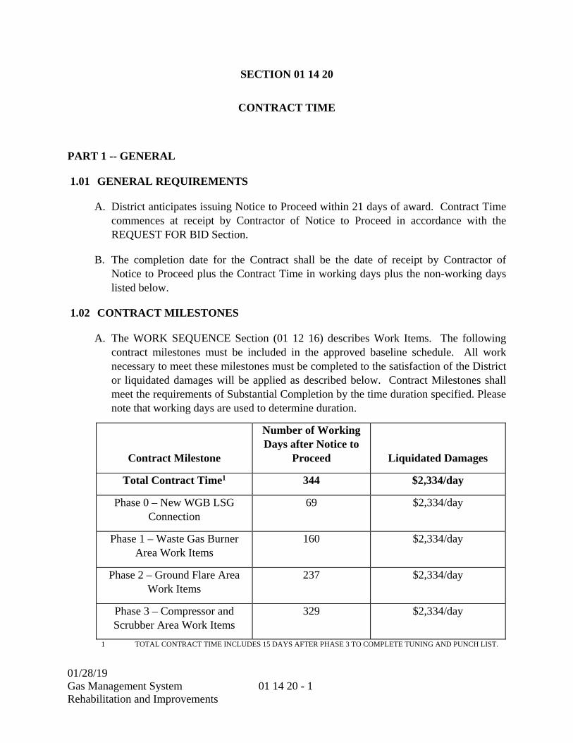
01/28/19 Gas Management System Rehabilitation and Improvements
01 14 20 - 1
SECTION 01 14 20
CONTRACT TIME
PART 1 -- GENERAL
1.01 GENERAL REQUIREMENTS
A. District anticipates issuing Notice to Proceed within 21 days of award. Contract Time commences at receipt by Contractor of Notice to Proceed in accordance with the REQUEST FOR BID Section.
B. The completion date for the Contract shall be the date of receipt by Contractor of Notice to Proceed plus the Contract Time in working days plus the non-working days listed below.
1.02 CONTRACT MILESTONES
A. The WORK SEQUENCE Section (01 12 16) describes Work Items. The following contract milestones must be included in the approved baseline schedule. All work necessary to meet these milestones must be completed to the satisfaction of the District or liquidated damages will be applied as described below. Contract Milestones shall meet the requirements of Substantial Completion by the time duration specified. Please note that working days are used to determine duration.
Contract Milestone
Number of Working Days after Notice to
Proceed Liquidated Damages
Total Contract Time1 344 $2,334/day
Phase 0 – New WGB LSG Connection
69 $2,334/day
Phase 1 – Waste Gas Burner Area Work Items
160 $2,334/day
Phase 2 – Ground Flare Area Work Items
237 $2,334/day
Phase 3 – Compressor and Scrubber Area Work Items
329 $2,334/day
1 TOTAL CONTRACT TIME INCLUDES 15 DAYS AFTER PHASE 3 TO COMPLETE TUNING AND PUNCH LIST.

01/28/19 Gas Management System Rehabilitation and Improvements
01 14 20 - 2
1.03 LIQUIDATED DAMAGES
A. Time is of the essence. Damages and expenses will be sustained by District if the Work is not completed within the Contract Time or by the Contract Milestone Completion Dates listed in the table above. It is agreed that the liquidated damages are reasonable compensation to District if the Work or Work Items are not completed within the specified times. Liquidated damages are additive and cumulative for each day that the Work or Work Item is not completed.
B. Liquidated damages will be assessed against payments due under Contract.
1.04 WORKING DAYS
A. A working day is any day after Notice to Proceed except:
1. Saturday, Sunday and holidays listed below. However, weekends, holidays, and week nights may be worked as described in the GENERAL CONDITIONS Section (00 72 00).
2. Days specifically designated in Contract for cessation of Work.
3. Days that Work is suspended by District.
4. Inclement weather days as described in the CONSTRUCTION PROGRESS SCHEDULE Section (01 32 16).
1.05 TIME OF COMPLETION AND DELAYS
A. TIME OF COMPLETION:
1. For the purposes of determining completion of the Work within the specified times, the Engineer will furnish the Contractor a weekly statement showing the number of working days charged to the contract for the preceding week and the number of working days charged to date for each Work Item with a completion time. The Contractor will be allowed 15 calendar days to file a written protest of the working day statement, otherwise the counting of working days shall be deemed accepted by the Contractor.
B. UNFAVORABLE WEATHER AND OTHER CONDITIONS:
1. During unfavorable weather and other conditions, the Contractor shall pursue only portions of the work that will not be damaged. The Contractor shall take appropriate measures to protect the Work from the impacts of weather. No portions of the work whose satisfactory quality or efficiency will be affected by any unfavorable conditions shall be constructed while these conditions remain, unless,
01/28/19 Gas Management System Rehabilitation and Improvements
01 14 20 - 3
by special means or precautions approved by the Engineer, the Contractor shall be able to overcome them. Costs associated with implementation of any such special means or precautions shall be paid by the Contractor.
C. DELAYS:
1. NOTICE OF DELAYS:
a. Whenever the Contractor foresees any delay in the prosecution of the work, and in any event within 24 hours of the occurrence of any delay which is regarded as an unavoidable delay, the Contractor shall notify the Engineer in writing of the probability of the occurrence of such delay and its cause, in order that the Engineer may take steps to prevent the occurrence or continuance of the delay, and may determine whether the delay is to be considered avoidable or unavoidable, how long it continues, and to what extent the prosecution and completion of the work are to be delayed.
b. After the completion of any part or the whole of the work, the Engineer, in estimating the amount of time extensions and compensation, if any, due the Contractor, will assume that any and all delays which have occurred have been avoidable delays, except such delays as shall have been called to the attention of the Engineer at the time of their occurrence and found to have been unavoidable. The Contractor will make no claims that any delay not called to the attention of the Engineer at the time of its occurrence has been an unavoidable delay.
2. AVOIDABLE DELAYS:
a. Avoidable delays in the prosecution of the work shall include delays which could have been avoided by the exercise of care, prudence, foresight and diligence on the part of the Contractor or subcontractors. Avoidable delays include, but are not limited to, the following:
1) Delays which may in themselves be unavoidable but which affect only a portion of the work and do not necessarily prevent or delay the prosecution of controlling items of work nor the completion of the whole work within the Contract Time.
2) Time associated with the reasonable interference of other contractors employed by the District which do not necessarily prevent the completion of the whole work within the Contract Time.
01/28/19 Gas Management System Rehabilitation and Improvements
01 14 20 - 4
3. UNAVOIDABLE DELAYS:
a. The Contractor will be granted an extension of time for delays which the Engineer has determined resulted from causes beyond the control of the Contractor and which could not have provided for by the exercise of care, prudence, foresight, and diligence.
b. Unavoidable delays shall be those caused by acts or neglect of the District which could not have been reasonably anticipated by the Contractor; by acts of God or of the public enemy, fire, floods, epidemics, or strikes. Material shortages and delays in utility company relocations may be classified as an unavoidable delay if the Contractor can produce satisfactory evidence of having acted in a timely manner. Any curtailment of the Contractor's operations due to the action of the Air Pollution Control Board not related to Contractor’s action or inaction shall be considered an unavoidable delay. Actions by the Air Pollution Control Board as a result of Contractor’s actions or inactions will be considered an avoidable delay.
c. Delays in the prosecution of parts of the work which may in themselves be unavoidable but do not necessarily prevent or delay the prosecution of controlling items of work nor the completion of the whole work within the time specified will not be considered as unavoidable delays. Reasonable loss of time resulting from the necessity of submitting plans for approval of the Engineer, from the making of surveys, measurements, inspections by the Engineer or from interference by other contractors which does not necessarily prevent the completion of the whole work within the time herein specified, will not be considered as unavoidable delays.
D. EXTENSION OF TIME:
1. The Contractor shall be allowed an extension of time for unavoidable delays, plus any adjustments of Contract Time due to change orders. Applications for an extension of time must be made in writing before the expiration of the times fixed in the Contract for the completion of Work Items specified in the CONTRACT TIME Section (01 14 20), or of the time granted by extension.
2. Where the time for completion for a Work Item is specified as a date, rather than working days, the Contractor may not be allowed an extension of time to complete the Work Item. In such cases, the District will consider payment of costs associated with acceleration of the work.
01/28/19 Gas Management System Rehabilitation and Improvements
01 14 20 - 5
a. AVOIDABLE DELAYS:
1) In case the work is not completed in the time specified, including extension of time as may have been granted for unavoidable delays, the Contractor will be assessed liquidated damages.
b. UNAVOIDABLE DELAYS:
1) For delays which the Contractor considers to be unavoidable, complete information demonstrating the effect of the delay on the controlling operation in the Construction Schedule shall be submitted to the Engineer. The submission shall be made within 30 calendar days of the occurrence which is the cause of the unavoidable delay. The Engineer shall review the Contractor's submission and determine the number of days of unavoidable delay and the effect of such unavoidable delay on controlling operations. The District agrees to grant an extension of time to the extent that unavoidable delays affect controlling operations. The Contractor will be granted a time extension as a result of inclement weather as provided for in Part 3 of the CONSTRUCTION PROGRESS SCHEDULE Section (01 32 16).
2) It is understood and agreed by the Contractor and District that time extensions due to unavoidable delays will be granted only if such unavoidable delay involves controlling operations which would prevent completion of the Work Items within the Contract Times.
c. EFFECT OF EXTENSION OF TIME:
1) The granting of an extension of time for the completion of the Work on account of delays which are unavoidable delays, or which are granted for extra or additional work, shall in no way operate as a waiver on the part of the District of any of its rights under this contract.
E. COMPENSATION FOR DELAYS:
1. AVOIDABLE DELAYS--NO COMPENSATION: The Contractor shall not receive any additional compensation for avoidable delays.
2. UNAVOIDABLE DELAYS--NO COMPENSATION: The Contractor shall not receive any additional compensation due to inclement weather or conditions resulting therefrom; by acts of God or of the public enemy, fire, floods, epidemics, strikes, material shortages or due to action of the Air Pollution Control Board not attributed to Contractor actions or inactions.

01/28/19 Gas Management System Rehabilitation and Improvements
01 14 20 - 6
3. UNAVOIDABLE DELAYS--COMPENSATION: The Contractor shall be entitled to additional compensation for unavoidable delays which the Engineer has determined resulted from an act or neglect of the District, except as modified below:
a. Compensation for unavoidable delays shall not be granted when the delay could have been reasonably anticipated by the Contractor.
b. When two or more concurrent delays occur with at least one or more being noncompensable, no compensation other than time extension shall be provided.
c. Compensation for unavoidable delays shall be granted only if such unavoidable delay affects controlling operations which would prevent completion of the Work.
4. DAMAGES FOR DELAY: For the period of time that any portion of the work remains unfinished after the time fixed for completion of any Work Item or Contract Milestone as specified in the CONTRACT TIME Section (01 14 20), as modified by extensions of time, it is understood and agreed that liquidated damages are due.
1.06 HOLIDAYS
A. The following days are holidays (note that the District may observe the holiday on a preceding or subsequent business day):
DAY DATE
New Year’s Day January First
Dr. Martin Luther King, Jr. Day Third Monday in January
Lincoln’s Birthday February Twelfth
George Washington’s Birthday Observance Third Monday in February
Caesar Chavez Day March Thirty-first
Memorial Day Last Monday in May
Independence Day July Fourth
Labor Day First Monday in September
Columbus Day Second Monday in October
Veterans Day November Eleventh

01/28/19 Gas Management System Rehabilitation and Improvements
01 14 20 - 7
DAY DATE
Thanksgiving Day Fourth Thursday in November
Thanksgiving Friday Friday after Thanksgiving Day
Christmas December Twenty-fifth
**END OF SECTION**

01/28/19 Gas Management System Rehabilitation and Improvements
01 14 20 - 8
THIS PAGE INTENTIONALLY LEFT BLANK
01/28/19
Gas Management System Rehabilitation and Improvements
01 26 00 - 1
SECTION 01 26 00
CONTRACT MODIFICATIONS PROCEDURES
PART 1 -- GENERAL
1.01 GENERAL REQUIREMENTS
A. The District may require changes to the Work. Changes will be directed by Field Orders (also known as Field Instructions) issued by the District Representative. A Field Instruction will describe:
1. The nature of the change,
2. The work to be done,
3. Changes in Contract Time, and
4. Adjustments to the Total Bid Amount.
B. Field Instructions will be incorporated into change orders to be executed by the Contractor and submitted to the Board for approval prior to payment.
C. Work required by Field Instruction shall be in accordance with the Contract except for the specific change delineated in the Field Instruction.
D. Whenever corrections, alterations, or modifications of the Work are required by the District Representative and increase the amount of work to be done, such additional work shall be extra work. When corrections, alterations, or modifications decrease the amount of work to be done, it shall be deleted work.
E. Following are the requirements for Field Instructions, preparing cost proposals and evaluating cost proposals for extra work and deleted work.
1.02 CHANGES IN CONTRACT PRICE
A. The District Representative may issue a Field Instruction at any time during the course of the Work. The Contractor shall comply with the requirements of the Field Instruction. Drawings which are included with Field Instructions shall be part of the Contract and shall be incorporated into the As-Built documents.
B. Field Instructions may require extra work or deleted work. Within 10 days of receipt of a Field Instruction, the Contractor shall provide a cost and time proposal. If a request for additional time to prepare a proposal is not received within 5 days, the Contractor shall perform the work in accordance with the Field Instruction with no additional compensation or time.
01/28/19
Gas Management System Rehabilitation and Improvements
01 26 00 - 2
C. The Contractor shall delete work when required by Field Instruction.
D. An equitable adjustment will be provided for the cost of a change. The adjustment shall be determined by one of the following methods:
1. Unit prices listed in the Bid Form.
2. Agreed upon unit prices.
3. Lump sum.
4. Force account.
E. The Contractor shall submit an itemized breakdown with supporting data of the quantities of work and quantities of costs of direct craft labor, construction equipment and materials used in computing the cost of a change. This requirement pertains to extra work, deleted work or a combination of both. Deleted work shall be estimated and priced on the same basis as extra work.
F. The prices agreed upon and any agreed upon adjustment in Contract Time shall be incorporated in a Field Instruction which shall be written so as to indicate an acceptance by the Contractor as evidenced by signature. By signing the Field Instruction, the Contractor acknowledges that the adjustments to cost and time are full satisfaction and accord, payment in full, and so waives any right to claim any further cost and time impacts at any time during and after completion of the Contract.
G. Whenever the Contractor is requested to prepare an estimate for work and if the work is not performed, the Contractor shall be entitled to reasonable costs incurred in the preparation of the estimate.
H. In the event the District Representative and the Contractor fail to reach agreement on the price for work described in a Field Instruction, the District shall have the right to direct the Contractor to proceed with the work with payment by force account.
I. If the Contractor refuses to accept a change order, the District may unilaterally issue the change order and incorporate it into the Work without the concurrence of the Contractor. The Contractor shall comply with the change order. The District will provide an equitable adjustment to the Total Bid Amount. If the Contractor does not agree that the payment is equitable, a claim may be submitted in accordance with the DISPUTE RESOLUTION Section (00 73 83).
1.03 UNIT PRICE AND LUMP SUM PAYMENT
A. Under Methods 2 and 3 described above, the Contractor shall submit substantiating documentation with an itemized breakdown of Contractor and subcontractor direct costs, including direct craft labor, material, construction equipment, and approved services, pertaining to such ordered work in the form and detail acceptable to the

01/28/19
Gas Management System Rehabilitation and Improvements
01 26 00 - 3
District Representative. The direct costs shall include only costs as described in this specification section.
1.04 FORCE ACCOUNT PAYMENT
A. GENERAL:
1. The Contractor shall keep an accurate account of the cost of work which is not part of the Contract. The Contractor will be paid for direct craft labor, materials and construction equipment actually used during the performance of the extra or directed work as described below. The Contractor shall use the District's Daily Work Report in preparing billings for force account work.
2. In order to facilitate agreement on direct craft labor hours, on construction equipment hours, and on material quantities, the Contractor shall notify the District Representative not less than 4 hours prior to starting force account work. The Contractor shall submit Daily Work Reports to the District Representative for signature not later than 9 am the day after the force account work is performed. Daily Work Report shall list names of all Contractor’s staff, the craft or trade employed as, all craft or trade labor hours, all material, and all construction equipment used that day.
3. Daily Work Reports shall be fully priced-out and submitted to the District Representative.
1.05 DIRECT COST CATEGORIES
A. The categories described below are defined to be direct costs. No other type of costs will be allowable as a direct cost. Direct costs shall not include any labor costs pertaining to the Contractor’s and subcontractor’s managers or superintendents, their office and engineering staffs and office facilities, or anyone not directly employed on such work, nor the cost of their offices, facilities, vehicles and small tools and supplies. All such items are considered indirect costs which form a part of the Contractor’s and subcontractor’s overhead expense.
1. DIRECT CRAFT LABOR: The Contractor will be paid the cost of direct craft labor including foremen, when authorized by the District Representative, used in the actual and direct performance of the work. Except as otherwise provided, the Contractor shall receive no additional compensation for wage premiums resulting from overtime work performed under force account without the prior written authorization from the District Representative.
a. The cost of direct craft labor, whether the employer is the Contractor, subcontractor, or other forces, will be the sum of the following:

01/28/19
Gas Management System Rehabilitation and Improvements
01 26 00 - 4
1) ACTUAL WAGES: The actual wages paid shall include any employer payments to or on behalf of the workers for health and welfare, pension, vacation, and similar purposes.
2) LABOR SURCHARGE: The actual labor surcharge costs for: state and federal taxes, workers compensation insurance, and other payments made on or on behalf of the worker shall be added to actual wages.
3) SUBSISTENCE AND TRAVEL ALLOWANCE: The actual subsistence and travel allowance paid to workers.
2. MATERIALS: The actual cost of the materials to the purchaser, whether the Contractor, a subcontractor, or other forces. If the Contractor does not furnish satisfactory evidence of the cost of such materials, it shall be deemed to be the lowest current price at which the materials are available in the quantities delivered. The District reserves the right to furnish such materials as it deems advisable, and the Contractor shall have no claims for costs or profit on such materials.
3. CONSTRUCTION EQUIPMENT: The use of construction equipment whether on site or moved on site exclusively for extra work shall be paid for at the rates listed in the current compilation of rental rates of the State of California, Department of Transportation applicable to Sacramento County. If the construction equipment is not shown on the above mentioned list, the Contractor shall be paid the reasonable hourly rental rates that are agreed upon by the Contractor and the District Representative prior to use of the equipment plus 33-1/3% for fuel, oil, lubrication, repairs and maintenance. In no case shall the agreed hourly rate exceed the rental rates of established distributors or equipment rental agencies serving the area or the reasonable invoice cost for the equipment rental from outside the Contractor’s or subcontractor’s organization. Individual items of construction equipment or small tools which cost $500 or less shall not be charged to force account work unless it can be demonstrated that the particular item is needed solely for the completion of the force account work.
a. If the construction equipment is moved on to the site and used exclusively for extra work, the Contractor will be paid for the cost of transporting it to the site and returning it to its original location. The rental period shall begin when the equipment is unloaded at the site of the extra work, and shall include each day that the equipment is at the site of such extra work, excluding Saturdays, Sundays, and legal holidays, unless extra work is performed on such days, and shall terminate at the end of the day on which such extra work is completed or the District Representative directs the Contractor to discontinue the use of such equipment. Compensation for idle time for construction equipment moved on to the site exclusively for extra work shall be made in accordance with this specification section.
b. The rental time for construction equipment already on the site, or which is used for other than such extra work shall be the actual time the construction
01/28/19
Gas Management System Rehabilitation and Improvements
01 26 00 - 5
equipment is in operation on the extra work, plus the time required to move the construction equipment to the site of the extra work and return it to its original location.
1.06 MARKUPS
A. The Contractor shall be entitled to compensation for indirect and overhead costs, bond and insurance costs and profit for Field Instruction work. This compensation shall be in the form of markup percentages applied to the direct cost of the work as described below.
B. If a Field Instruction involves both extra and deleted work which is also referred to as net extra work, the markups shall be applied to the cost of the net extra work. The Contractor shall not be entitled to indirect and overhead costs or profits on the deleted work.
C. For Field Instructions involving forward priced extra work or net extra work, the following maximum percentage markups shall be applied to the total direct costs for each cost category. These markups provide for all indirect and overhead costs and profit:
Direct Craft Labor 20 percent Materials - New Vendors/Suppliers 15 percent Materials - Existing Vendors/Suppliers 5 percent Construction Equipment 15 percent
D. For Field Instructions involving force account work, the following maximum percentage markups shall be applied to the total costs for each cost category. These markups provide for all indirect and overhead costs and profit.
Direct Craft Labor 15 percent Materials - New Vendors/Suppliers 15 percent Materials - Existing Vendors/Suppliers 5 percent Construction Equipment 15 percent
E. Existing vendors and suppliers shall be defined as vendors and suppliers that have an existing contract, purchase order or other agreement for other Contract related work with the Contractor or existing subcontractors.
F. A maximum markup of 2 percent shall be added to the sum of direct craft labor, materials, construction equipment, profit, overhead and indirect cost markups for bond costs and insurance costs including any insurance which may be allocable as a direct cost within the Contractor's accounting system.

01/28/19
Gas Management System Rehabilitation and Improvements
01 26 00 - 6
G. For Field Instruction work performed by a subcontractor, compensation for shall be based on all direct costs of the subcontractor plus the above direct craft labor, materials, construction equipment, and markup percentages. The Contractor may add a maximum of 5 percent to the subcontractor's cost for profit, overhead and indirect costs and a maximum of 2 percent for bond and insurance.
H. The total indirect and overhead cost and profit markup for forward priced extra work or net extra work shall not exceed 20 percent of the direct cost of the work. The total indirect and overhead cost and profit markup for force account work shall not exceed 15 percent of the direct cost of the work. Direct cost is the summation of the Contractor’s direct costs and all subcontractors’ and suppliers direct costs prior to application of any markups. Distribution of the markup amount among the Contractor and subcontractors and suppliers shall be determined by the Contractor.
I. For deleted work a minimum of 8 percent shall be added to the sum of direct craft labor, materials and construction equipment as a deduction for indirect and overhead costs and profit. Reduced bond and insurance costs of 2 percent shall also be deducted from the sum of deleted work and deducted markup.
J. The allowances for profit, overhead and indirect costs shall include full compensation for any and all items of overhead and indirect items including but not limited to superintendence, consumable small tools and supplies, safety, insurance, as-built documentation, operation and maintenance manual documentation, cost proposal preparation, schedule analysis and preparation and all other office expenses.
1.07 COST PRICING DATA AND ACCESS TO RECORDS
A. All cost and pricing data submitted by the Contractor with respect to any change, prospective or executed, or any claim for extra compensation shall be a true, complete, accurate and current representation of actual cost and pricing of the work. The District Representative may require a certification as to cost and pricing data submitted by the Contractor.
B. The District Representative shall have access, upon reasonable notice during normal business hours, to any books, documents, accounting records, papers, project correspondence, project files, scheduling information and other relevant records of the Contractor and all subcontractors directly or indirectly pertinent to the Work and the Contract for the purpose of making audit, examination, excerpts and transcriptions and in order to verify or evaluate any change, prospective or executed, or any claim for which compensation has been requested or notice of potential claim has been submitted.
C. All books, documents, and other records mentioned above shall include, but are not limited to those necessary to determine the amount of direct and indirect costs, job site, area and home office overhead and delay and impact costs, however characterized, and shall include the original bid and all documents related to the bid and its preparation, as well as the schedule and related documents.
01/28/19
Gas Management System Rehabilitation and Improvements
01 26 00 - 7
D. This access shall include the right to examine and audit records and make excerpts, transcriptions, and photocopies.
1.08 DISPUTE REGARDING CONTRACT REQUIREMENTS
A. If the Contractor and District fail to agree whether or not any work or other matter is within the scope of the Contract, the Contractor shall nevertheless immediately perform such work upon receipt of a written Field Instruction or other written directive. Within 10 working days after receipt of the Field Instruction or other written directive, the Contractor may submit a written protest detailing the Contract requirements exceeded and the appropriate cost and/or time change. Failure to submit a protest within the specified period constitutes a waiver of the Contractor’s rights to adjustments in the Total Contract Price and/or Contract Time for the disputed Contract requirement.
B. The Contractor shall not stop performing the Work pending resolution of a dispute, unless ordered in writing by the District.
C. If the District agrees with the Contractor’s written protest, the Total Contract Price and/or Contract Time will be adjusted through a Contract Change Order. Protests and claims denied by the District will be so stated in writing.
1.09 CONSTRUCTION INCENTIVE CHANGE PROPOSAL
A. GENERAL:
1. The Construction Incentive Change Proposal (CICP) program provides a mechanism by which the Contractor can be motivated to use construction expertise to improve contract performance and thereby create an overall reduction in the total cost of the contract. The Contractor and subcontractors may participate in the CICP program; however, participation of the subcontractors shall be through the Contractor. In addition, the sharing arrangement between the Contractor and subcontractor must be mutually agreed upon and written evidence of such agreement will be provided with the submittal of a CICP.
2. A CICP will not be considered for proposed changes that delete work or make modifications to work that are considered to be extra, net extra or deleted work. These types of deletions or modifications often occur and shall be administered in accordance with this section. The District Representative will determine if a proposed change qualifies as a CICP.
3. While a CICP is being considered or processed, the Contractor shall continue to pursue the Work.

01/28/19
Gas Management System Rehabilitation and Improvements
01 26 00 - 8
B. DESCRIPTION:
1. A CICP is a formally written proposal for a change to the Contract. A CICP must be initiated, developed, and identified by the Contractor. A CICP must result in a net capital cost reduction while causing no increase in the total life cycle cost and shall comply with the following requirements:
a. Required function, reliability and safety will be maintained without detracting from the life expectancy and without increasing maintenance requirements.
b. The proposed change will not delay the Work, nor delay the completion of the project.
c. The proposed change shall be in compliance with all local permits and regulations and code requirements.
d. The proposed change shall not involve payment of royalties by the District.
2. A CICP must produce a net savings of at least $50,000 before it will be considered by the District. A CICP which produces a net savings less than $50,000 will be considered a deductive change in the Work.
C. SUBMITTALS:
1. Submittals shall be in accordance with the SUBMITTAL PROCEDURES Section (01 33 00).
2. A synopsis of the proposed CICP shall be submitted. The District will review the CICP and will request a detailed proposal if the CICP has merit and potential savings.
3. CICP submittal must contain the following information:
a. Name of individuals associated with the development and preparation of the CICP.
b. A description of the CICP with plans and specifications showing the present design and the proposed changes. All advantages and disadvantages shall be identified.
c. A detailed procedure and schedule for implementing the proposed change with all necessary contract amendments. Also indicated must be the latest date that the CICP can be approved for implementation.
d. A summary of estimated costs which shall include the following:
1) Project costs before and after the CICP. This shall be a detailed estimate identifying the following items for each craft involved in the CICP:

01/28/19
Gas Management System Rehabilitation and Improvements
01 26 00 - 9
a) Quantities of material and equipment. b) Unit prices of materials and equipment. c) Labor hours and rates for installation. d) Subcontractor and prime contractor markups.
2) Operation and maintenance costs before and after the CICP.
3) Cost for implementing the CICP not included in item above.
4) Contractor's share of the savings.
5) Other data required for permits, regulations and code requirements.
6) Time required for acceptance of the proposed change.
e. A copy of the current schedule showing all changes which would occur if the CICP was accepted.
4. District will not be responsible for the Contractor’s cost to develop the CICP if it is rejected. If the CICP is not acted upon within the time frame indicated by the Contractor, the CICP shall be considered to have been rejected by the District.
D. ACCEPTANCE:
1. If a CICP is accepted by the District, a Field Instruction will be issued. If the CICP is rejected, the Contractor may not appeal the decision.
E. SHARING PROVISIONS:
1. CONSTRUCTION SAVINGS SHARING: Upon acceptance of the CICP, the Contractor will share the net capital savings pursuant to this contract based on the following formula:
Net Savings = Contract Cost Prior to CICP - (Revised Contract Cost after
CICP + CICP Development Cost + CICP Implementation Cost)
2. The cost for developing the CICP is limited to the costs directly associated with the submittal and will be reimbursed to the Contractor.
3. The CICP implementation costs will include the District’s costs for review and redesign. However, costs for processing the CICP by the District are excluded.
F. SHARING FORMULA:
1. The Contractor will receive 50 percent of the net savings based on the computation above. Payment will be made at the time that the original construction would have been completed.
01/28/19
Gas Management System Rehabilitation and Improvements
01 26 00 - 10
1.10 VARIATION IN QUANTITIES FOR UNIT PRICE BID ITEMS
A. GENERAL:
1. Increases or decreases in the quantity of a unit price item will be determined by comparing the total pay quantity for the item with the quantity in the Bid Form.
2. If the total pay quantity of an item varies from the Bid Form quantity by 25 percent or less, payment will be made at the contract unit price.
3. If the total pay quantity of any item varies from the Bid Form quantity by more than 25 percent, in the absence of a Field Instruction specifying the compensation to be paid, the compensation payable to the Contractor will be determined in accordance with the following:
B. INCREASES GREATER THAN 25 PERCENT:
1. Payment for the quantity in excess of 125 percent will be paid at an adjusted unit price or by force account.
2. The adjusted unit price for quantities in excess of 125 percent will be the actual unit cost for the item up to 125 percent of the Bid Form quantity. Fixed costs for the item will be deducted from the actual unit costs.
3. The District may elect to pay for items in excess of 125 percent of the Bid Form quantity at the price in the Bid Form if the total amount is $5,000 or less.
4. An appropriate adjustment in contract time will also be provided if the increased quantity delays completion of the Work.
C. DECREASES GREATER 25 PERCENT:
1. An equitable adjustment of the unit price will be made if the quantity of an item is less than 75 percent of the Bid Form quantity and a price adjust is requested by the Contractor.
D. ELIMINATED ITEMS
1. Should any Work be eliminated in its entirety, in the absence of a Field Instruction covering such elimination, payment will be made to the Contractor for actual costs incurred in connection with such eliminated contract item if incurred prior to notification from the District Representative.
2. If acceptable material is ordered by the Contractor for the eliminated item prior to notification, and if orders for the material cannot be canceled, it will be paid for at the actual cost plus a 5 percent mark-up. The material shall become the property of the District.
01/28/19
Gas Management System Rehabilitation and Improvements
01 26 00 - 11
3. If the material is returned to the vendor, the Contractor will be paid the actual costs including handling.
1.11 COMPENSATION FOR DELAYS
A. CONSTRUCTION EQUIPMENT:
1. Compensation for idle construction equipment shall be made for those allowable delay periods provided that the equipment remains on site for a duration beyond which is indicated on the schedule. Compensation may be provided for the idle construction equipment used exclusively for Field Instruction work. Compensation shall be determined in accordance with the current rental rates of the Department of Transportation of the State of California which are applicable to the County of Sacramento with the following exceptions:
a. The right-of-way delay factor for each classification of equipment shown in the Department of Transportation publication entitled “Labor Surcharge Equipment Rental Rates” of the State of California will be applied to the rental rate.
b. Compensation will be provided for the actual time during which a delay exists, but not more than 8 hours per day.
c. Compensation will be provided for each day or portion of a day excluding Saturdays, Sundays and holidays for the duration of the delay. Weekly or monthly rates shall apply if the duration of the delay is extended.
B. JOBSITE INDIRECT AND OVERHEAD COSTS:
1. For allowable delays as described in the GENERAL CONDITIONS Section (00 72 00), compensation to the Contractor for indirect and overhead costs shall be limited to the following:
a. Actual payroll costs for field office staff incurred as a result of the delay including: management, supervision, estimating, engineering, drafting, clerical, secretarial and accounting including all taxes, insurance, fringe benefits and any and all other payments made to or on the behalf of the employee, including workers compensation insurance, shall be added to the payroll costs.
b. Actual cost for third-party services provided for the field office such as: management, supervision, estimating, engineering, drafting, clerical, secretarial and accounting utilized in lieu of employees.
c. Field office expenses for rent and utilities which are applicable and substantiated by invoice.
2. Compensation for: on-site plant, incidentals, utilities, and facilities for non-field office personnel including branch office and home office personnel will not be

01/28/19
Gas Management System Rehabilitation and Improvements
01 26 00 - 12
provided. Compensation for these items and other incidental shall be considered to be included in the markups.
C. MARKUPS FOR DELAYS:
1. For idle equipment a maximum of 5 percent shall be added for profit, bond, and insurance costs.
2. For jobsite indirect and overhead costs a maximum of 10 percent shall be added for home office and branch office indirect and overhead costs.
3. To the total costs calculated above, a maximum of 5 percent shall be added for profit, bond, and insurance costs.
4. Distribution of the above markups among the Contractor and subcontractors and suppliers shall be determined by the Contractor.
D. DUPLICATED OVERHEAD COSTS:
1. In the event that the Contractor is compensated for delay periods as described above, and the delay was attributable to direct cost changes to which markups were added, equitable adjustments shall be made to eliminate the duplication of compensation for indirect and overhead costs and profit.
**END OF SECTION**
01/28/19 Gas Management System Rehabilitation and Improvements
01 26 13 - 1
SECTION 01 26 13
REQUEST FOR INTERPRETATION
PART 1 -- GENERAL
1.01 GENERAL REQUIREMENTS
A. Contractor shall prepare a Request for Interpretation (RFI) when additional information, clarification or interpretation of the Contract Documents is needed. RFIs may also be used for apparent conflicts, inconsistencies, ambiguities, or omissions. “Request for Interpretation” and “Request for Information” shall have the same meaning.
B. RFIs shall be submitted to the District Representative sufficiently in advance of the work to permit time for investigation and preparation of a response. Any work undertaken prior to receipt of a RFI response shall be at the risk of Contractor.
C. RFIs generated during submittal and shop drawing preparation must be submitted by the Contractor sufficiently in advance to not only allow for investigation and preparation of a response, but also for inclusion of the response into the submittal and shop drawing. Failure by the Contractor to provide sufficient time will not be cause for entitlement to a time extension.
D. RFIs shall not be used for submittals or for substitute of material, equipment or for waiving of requirements.
1.02 SUBMITTAL
A. RFIs shall be submitted on an approved form and numbered consecutively. A status log shall be prepared and updated by Contractor. Each RFI shall deal with only one topic, item, issue or system.
B. RFIs shall clearly describe the problem and specifically state what is needed. Relevant portions of the Contract Documents shall be cited, marked-up and attached.
C. The Contractor shall review each RFI before submitting and compare it with the Contract Documents to verify that a response is required. RFIs will only be accepted from the Contractor and not from subcontractors or suppliers.
D. A recommendation or proposed solution may be included when appropriate or expedient.
E. Known schedule or cost impacts shall be noted in the RFI.
01/28/19 Gas Management System Rehabilitation and Improvements
01 26 13 - 2
1.03 RESPONSE
A. The District Representative will normally respond within 10 days. The Contractor shall indicate a priority for responses if more than five (5) RFIs are pending at the same time.
B. The Contractor shall reply within 10 days if there is disagreement concerning the RFI response.
C. Subsequent resubmittals shall be identified with the same RFI number and a consecutive letter designation. Resubmittals shall clearly state the reason for resubmitting.
**END OF SECTION**

01/28/19
Gas Management System Rehabilitation and Improvements
01 29 76 - 1
SECTION 01 29 76
PROGRESS PAYMENT PROCEDURES
PART 1 -- GENERAL
1.01 GENERAL
A. Progress payments will be made monthly in accordance with the Bidding Schedule and instructions provided in this section.
B. Payment for items with a unit price will be based on the number of units completed.
C. Payment for lump sum items will be based on an estimate of the percent of work completed as indicated in the approved monthly update of the cost loaded CPM schedule.
D. Payment for other items will be based on the Schedule of Values as described below.
E. Progress Payment Requests shall be submitted electronically to the PCS in accordance with the ELECTRONIC COMMUNICATION PROTOCOLS Section (01 31 26)
1.02 SCHEDULE OF VALUES
A. The cost loaded CPM schedule shall represent the Schedule of Values. Refer to the CONSTRUCTION PROGRESS SCHEDULE Section (01 32 16) for detailed requirements of cost loading. Primavera P6 shall be utilized to generate the monthly progress payment request.
B. The process for approval of the monthly Schedule of Values leading to invoice payment is described in the CONSTRUCTION PROGRESS SCHEDULE Section (01 32 16).
C. LIMITATIONS:
1. The values of the activities listed below are limited as indicated. The limit is the percent of the Total Bid Amount.
ACTIVITY LIMIT
Mobilization 3.0 Percent-maximum
O&M Data (Manuals) 0.7 Percent-minimum
Testing 1.0 Percent-minimum
As-Built Documents 1.3 Percent-minimum
Demobilization 0.5 Percent-minimum

01/28/19
Gas Management System Rehabilitation and Improvements
01 29 76 - 2
ACTIVITY LIMIT
Contractor Quality Control Plan 2.0 Percent-minimum
D. Payment for mobilization will be prorated until all the following items have been completed. Mobilization includes:
1. Project manager on site full-time.
2. Plant and construction equipment for activities for first month on-site.
3. Field office setup with all utilities (including CM office if applicable).
4. Fire protection established.
5. Construction yard setup with storage and maintenance facilities and utilities setup.
6. Stormwater Best Management Practices (BMPs) installed.
7. Safety Plan submitted and required notices posted.
8. Quality Control Plan submitted.
9. QC Manager on site full-time
10. Permits acquired.
11. Payment of premiums for all Bonds and Insurance required.
E. AS-BUILT DOCUMENTATION AND MAINTENANCE:
1. Progress payments for as-built documentation will be made based on the quantity of documents submitted in accordance with weighting established in the PROJECT RECORD DOCUMENTS Section (01 78 39). The progress payment will be based on the number of documents submitted and accepted in proportion to the total number of as-built documents.
F. Demobilization includes:
1. Submittal of warranties.
2. Removal of plant and construction equipment.
3. Removal of field office, construction yards and related facilities, utilities and project signs.
4. Cleanup and disposal of materials, supplies, equipment and debris.

01/28/19
Gas Management System Rehabilitation and Improvements
01 29 76 - 3
5. Restoration of areas, roads and other facilities damaged or altered as a result of the Work.
1.03 PAYMENT PROCEDURE
A. Each month, following submittal of the Draft Progress Update Schedule and agreement on the progress achieved as described in the CONSTRUCTION PROGRESS SCHEDULE Section (01 32 16), the Contractor shall submit a Final Schedule of Values on the first Friday of each month. Supporting documentation shall be included. The District will review the request and make payment for those items in accordance with the requirements of the Contract and the Schedule of Values. Payment will not be made for deficient or defective work. Progress payment requests shall be submitted via the Project Control System in accordance with the ELECTRONIC COMMUNICATION PROTOCOLS Section (01 31 26).
B. Progress payments do not constitute acceptance of the Work or a waiver of any terms or conditions of the Contract.
1.04 RETENTION
A. Five percent of each progress payment will be retained until the Work has been completed and accepted by the Board. If the work is progressing in accordance with the Contract, the Contractor may request, after 50 percent of the Work has been completed, including change orders, that the withholding of additional retention cease. The District Representative will review the progress to date and the remaining work. If it appears that the work will be successfully completed, the District will waive the retention on the remaining work.
B. Contractor may deposit securities in lieu of retention pursuant to Section 22300 of the Public Contract Code.
C. At the request and expense of the Contractor, securities having a value equivalent to or greater than the withheld amount may be deposited with a state or federally chartered bank as escrow agent payable in whole or in part to the District upon demand and certification by the District Representative that the Contractor has defaulted in the performance of the obligation under the contract and setting forth the amount of security needed to satisfy the completion of the obligation of the Contractor.
D. The Contractor shall be the beneficiary of any securities for monies withheld and shall receive any interest thereon.
1.05 WITHHOLDING
A. The District will withhold additional amount from progress payments for the following causes:
1. Claims against the Contractor for non-payment for labor, equipment or materials.

01/28/19
Gas Management System Rehabilitation and Improvements
01 29 76 - 4
2. Defective work.
3. Failure to pursue the Work in accordance with the schedule.
4. Damage to District facilities or to other parties.
5. The cost to the District if the Work is not completed within the Contract Time.
6. Costs for replacement insurance due to cancellation or insufficient coverage.
7. Failure to pay prevalent wages or submit certified payroll records.
8. Failure to provide submittals, as-built documentation or operating and maintenance manuals
9. Payments due the District from the Contractor.
10. Provisions of law that enables or requires the District to withhold payments.
B. Withheld funds which are not a penalty will be paid to the Contractor when the reason for the withhold has been resolved.
C. The District may use withheld or retained funds to pay valid claims. In so doing, the District shall be considered an agent of the Contractor and shall not be liable for payments made in good faith. Such payments may be made without judicial determination of the claim. A complete and proper accounting will be provided.
1.06 FINAL PAYMENT
A. A final estimate will be prepared by the District upon completion of the Work and a request for final payment. All prior estimates, progress payments, retention, withholdings and change orders shall be considered. A copy of the final estimate will be provided to the Contractor.
B. The Contractor shall accept the final estimate or provide a written statement of exceptions with sufficient detail to ascertain the basis and amount within 15 days. Failure to provide a statement of exceptions within the allotted time shall indicate acceptance.
C. The District will release retention in accordance with the Field Acceptance subsection of the GENERAL CONDITIONS Section (00 72 00).
D. Acceptance of the final payment shall release the District, its agents and consultants from any and all claims or liability on account of the work under the Contract or any alterations thereof.
**END OF SECTION**

01/28/19 Gas Management System Rehabilitation and Improvements
01 31 19 - 1
SECTION 01 31 19
PROJECT MEETINGS
PART 1 -- GENERAL
1.01 GENERAL REQUIREMENTS
A. Meetings will be required throughout the duration of the Contract to facilitate communication, coordination and resolution of issues. District, Contractor, Design Consultant, subcontractors, and other parties involved in the Work shall attend.
B. There will be meetings to discuss particular aspects of the Work such as: scheduling, coordination, submittals, procedures, Access Requests, changes orders, testing, startup, and other topics as needed.
C. District Representative will designate the purpose, date, time, and location for meetings. Contractor may request meetings as needed.
1.02 PRECONSTRUCTION
A. A preconstruction meeting will be held prior to commencement of Work. This meeting will provide an opportunity for individuals to discuss initiation of the Work. Topics to be discussed include: mobilization, access, temporary facilities, utilities, subcontractors, schedules, procedures, correspondence, progress payments, payroll records, Access Requests, coordination, safety, quality control, personnel assignments and other topics as appropriate.
B. District, Contractor, Design Consultant, and major subcontractors shall attend.
1.03 PROGRESS
A. Weekly progress meetings will be conducted throughout the duration of the Contract. The purpose of these meetings is to inform, discuss and resolve issues related to the Work. Topics to be discussed include: progress, schedules, Access Requests, Requests for Information, Change Orders, Field Instructions, field coordination, submittals, quality control, testing, startup and other topics related to the Work.
B. District, Contractor, Design Consultant, subcontractors and suppliers as appropriate shall attend.
**END OF SECTION**

01/28/19 Gas Management System Rehabilitation and Improvements
01 31 19 - 2
THIS PAGE INTENTIONALLY LEFT BLANK

01/28/19 Gas Management System Rehabilitation and Improvements
01 31 26 - 1
SECTION 01 31 26
ELECTRONIC COMMUNICATION PROTOCOLS
PART 1 -- GENERAL
1.01 PROJECT CONTROL SYSTEM DESCRIPTION
A. The District will use and maintain a Project Control System (PCS) as the primary means of communication related to the Contractor’s Correspondence, Submittals, Requests for Information (RFI), Access Requests, Progress Payment Requests, Non-Compliance Issues, and Daily Attendance Sheets. The PCS will be on a SharePoint platform developed by the District. The Contractor shall be required to use this PCS for its administrative communications with the District Representative.
B. The PCS will provide a location for correspondence and other required documentation related to the project. The Contractor and all PCS participants shall be responsible for frequent monitoring of the PCS.
C. Electronic copies of documents shall be in accordance with the SUBMITTAL PROCEDURES Section (01 33 00).
1. Note that the use of PCS does not waive the requirement for the provision of hard copies of all formal correspondence, submittals, and RFIs. The hard copies of all documents must match the electronic copies of correspondence, RFIs and submittals.
1.02 SUBMITTALS
A. Provide a list of Contractor’s key PCS personnel during preconstruction. Include descriptions of key personnel’s roles and responsibilities for this project. Contractor should also identify their organizations administrator on the list.
1.03 EQUIPMENT
A. In order to process formal correspondence and other required documentation, the Contractor must have in place the required basic components outlined below:
1. HARDWARE: The Contractor shall use computer hardware that meets the following minimum requirements of the Sharepoint PCS: CPU-Intel i5 3.0GHz, RAM-4GB, HDD-200GB, and Video Graphics- 512MB VGA.
2. SOFTWARE: Adobe Acrobat Professional Version 11.0, Internet Explorer 9, Microsoft Office 2010, or higher. Other software may be utilized if compatible with the District’s standards and approved by the District. The Contractor shall use

01/28/19 Gas Management System Rehabilitation and Improvements
01 31 26 - 2
computer software that meets the following minimum requirements of the Sharepoint PCS: OS-Windows 7 (Service Pack 1) and Office-MS Office 2013 SP1.
3. FACILITIES: The Contractor shall be responsible for providing all computers, printers, plotters, scanners or other hardware and software for his use. The District will provide connectivity to the internet for the purpose of accessing PCS and uploading and downloading of associated data and files from the project site, in accordance with the TEMPORARY UTILITIES Section (01 51 00). All networking equipment and associated cabling within the Contractor’s office is the responsibility of the Contractor.
1.04 CONTRACTOR RESPONSIBILITY
A. Accepted users shall be knowledgeable in the use of computers, including Internet Browsers, email programs, CAD drawing applications, and Adobe Portable Document Format (PDF) document distribution programs.
B. Adobe PDF documents will be created through electronic conversion rather than optically scanned whenever possible. The Contractor is responsible for the training of their own personnel in the use of other programs indicated above, as needed.
C. Entry of information exchanged and transferred between the Contractor and its subcontractors and suppliers on PCS shall be the responsibility of the Contractor.
1.05 TRAINING
A. Contractor shall have at least one staff person dedicated to PCS administration. The District will conduct up to four (4) group training sessions (assume 8 hours of training total) for Contractor-designated personnel on the use of PCS. The Contractor is responsible for training replacement personnel. The District will provide the location, date and time of training to the Contractor during the period between Contract Award and Notice to Proceed.
**END OF SECTION**

01/28/19
Gas Management System Rehabilitation and Improvements
01 32 16 - 1
SECTION 01 32 16
CONSTRUCTION PROGRESS SCHEDULE
1.01 GENERAL
A. SUMMARY
1. This section specifies the scheduling requirements for this project. In addition to being used by the Contractor, schedules are utilized to monitor the Contractor’s progress, coordinate work with plant operations, coordinate work with other Contractors and coordinate future projects. The District considers the schedule requirements to be a benefit to both the District and the Contractor. The submittal and acceptance of realistic schedules shall be given high priority. Because of its importance to plant operations and the success of this project, failure to adhere to the scheduling requirements will result in a 10% withhold on monthly progress estimates, which can become a permanent deduction if the corrections aren’t made by the second month’s schedule update following notification. The schedule shall comply with commonly accepted CPM scheduling practices.
B. TYPES
1. The following terms are used in this section:
a. Baseline Schedule: The schedule delineating the original planned sequence of construction and procurement of Major Equipment.
b. Monthly Updated Schedule: The monthly update of the schedule which depicts completed activities and remaining duration for incomplete activities.
c. Rolling Schedule: A look ahead which presents what work the Contractor plans to pursue in the next two weeks.
d. Revised Schedule: A schedule which incorporates accepted changes in sequence or scope of work.
e. Final As-Built Schedule: A schedule that reflects the final as-built sequence of construction.
C. PRE-CONSTRUCTION SCHEDULING CONFERENCE
1. Within five (5) calendar days following Notice to Proceed, the District shall schedule and conduct a pre-construction scheduling conference to commence development of the required construction schedule. Attendance by the Contractor’s Senior Construction Scheduler is mandatory. At the meeting, the requirements of this section will be reviewed with the Contractor, the Contractor shall present their proposed methodology for the Baseline Schedule preparation. The Contractor shall

01/28/19
Gas Management System Rehabilitation and Improvements
01 32 16 - 2
submit to the District a written copy of its proposed WBS structure at this meeting. The District shall review the WBS structure within five (5) calendar days after submission by the Contractor. The Contractor shall make all modifications to the proposed WBS structure that are requested by the District Representative. The WBS shall be correlated with the Contractor’s Schedule of Values and the cost loaded schedule. At this conference the District shall present to the Contractor the reporting layouts, any activity codes that need to be setup in the schedule and the P6 software settings necessary for processing the schedules into the District’s master schedule. The Contractor shall bring to the Pre-Construction Scheduling Conference any schedules used in bid preparation.
D. FLOAT
1. Float in any activity, milestone completion date or contract completion date shall be considered a resource available to both the District and the Contractor. Neither the District nor the Contractor has ownership of the float. Float is for the benefit of the project. Acceptance of the Baseline Schedule, Monthly Update or Revised Schedule, when based on less time than the maximum time allowed for milestone or contract completion does not serve to change any Contract duration, nor serve as a waiver of the Contractor's nor the District's right to utilize the full amount of time specified in the Contract.
E. ACCEPTANCE
1. Review of the project schedule, up-dates or revisions is to determine conformance with the Contract Documents. Acceptance of a project schedule, updates or revisions does not relieve Contractor of responsibility for the feasibility of the project schedule or requirements for accomplishing milestones and completion within Contract Time. Acceptance of the project schedule, updates or revisions does not warrant or acknowledge the reasonableness of the schedule’s logic, durations, labor estimates or equipment productivity.
1.02 SUBMITTALS
A. All schedules described below shall be submitted electronically in accordance with the ELECTRONIC COMMUNICATION PROTOCOLS Section (01 31 26).
B. GENERAL - FORMAT
1. Each of the types of submittal format shall conform to these requirements. All printed reports, tabular reports, bar charts and graphic plots shall be generated from and be consistent with the overall project schedule. The plot date, data date and projected project finish date shall be clearly shown. Unless noted otherwise, all print formats shall be 11 inches by 17 inches with a minimum font size of six points.

01/28/19
Gas Management System Rehabilitation and Improvements
01 32 16 - 3
a. ACTIVITY BAR CHART REPORT: Shall include milestones and show relationships, activity ID numbers and activity descriptions grouped by WBS Item. Each activity shall indicate the appropriate Contractor or subcontractor responsibility and be sorted by start date. Activity Bar Chart Report shall be time-scaled and show continuous flow from left to right grouped by Work Item. The critical paths shall be readily identifiable through the use of red printing. Activity ID numbers and activity descriptions shall be listed in columns at the left of the sheet. Plots shall show early start and early finish dates and total float for each activity. The calendar being used should be identified.
b. CRITICAL PATH REPORT: Sorted by start date
c. MILESTONE REPORT: summarizing the planned and actual milestone dates compared against the approved baseline dates
d. The following information shall be furnished as a minimum for each activity:
1) Activity description and ID number.
2) Activity predecessors and successors
3) Original duration and remaining duration of each activity.
4) Early start date.
5) Early finish date.
6) Late start date.
7) Late finish date.
8) Total float.
9) Constrained dates.
10) Percentage of activity completed and actual number of working days remaining (for updates only).
11) An electronic copy of the native xer file along with a pdf copy shall be submitted for the Baseline and Monthly Update Schedules.
C. BASELINE SCHEDULE
1. The sequence below describes the submittal and review process for the Baseline Schedule for all work:

01/28/19
Gas Management System Rehabilitation and Improvements
01 32 16 - 4
a. Within ten (10) calendar days after the Pre-Construction Scheduling Conference, and before work commences on any non-mobilization work activity, the Contractor shall submit a P6 CPM schedule representing in detail, all planned submittal, procurement and on-site construction activities. A Narrative Report shall be included explaining the basis and assumptions of the planned sequence of work. A review meeting with the Contractor and appropriate subcontractors will be conducted within 10 days of the receipt of the CPM schedule. Comments will be provided within 7 days after the review meeting. This provision shall hold regardless of the commencement of counting of working days. This schedule shall be updated monthly with progress and will be used as the basis for payment. No payments beyond mobilization will be made until the Baseline Schedule is accepted.
b. The Baseline Schedule shall be cost loaded as described in the Cost Loading Section of this specification.
c. The District Representative shall be the judge of the acceptability of the proposed Baseline Schedule.
D. MONTHLY UPDATES
1. Contractor’s monthly payment applications shall not be accepted and processed for payment by the District Representative without Master Baseline Schedule progress updates submitted in the time and manner required by this specification which accurately reflect the allowable costs due under the Contract Documents, and are accepted by the District Representative.
2. Following acceptance of the baseline schedule, on the last Friday of each month the Contractor shall submit a detailed Monthly Schedule of Values in pdf format from the Schedule Update generated in Oracle Primavera. This submittal is commonly known as a "pencil copy." The Data Date shall be set to the first Monday after the last Friday of the month. Two working days prior to the last Friday of the month, the Contractor will attend a Schedule Review Meeting with the District Representative to review the current schedule status, any changes or revised logic and address any schedule issues. Contractor staff involved with the schedule are required to attend. Two working days after the last Friday of the month, the Contractor will meet and\or walk the project to finalize the schedule progress on the Monthly Schedule of Values. The Contractor will incorporate the District Representative's progress comments and resubmit the detailed Monthly Schedule Update and Schedule of Values for final acceptance by the Friday following the last Friday of the month. A narrative shall be provided describing the status of the project including major slippage or problems and if appropriate proposed corrective measures are needed.
01/28/19
Gas Management System Rehabilitation and Improvements
01 32 16 - 5
3. The Schedule Update Submittal shall include:
a. A detailed Gantt chart showing all activities organized by Preconstruction/Construction, Phase/Stage, Location/Area, then sorted by Actual Start then Early Start. The activity columns on the tabular data portion of the schedule shall include Activity ID, Activity Name, Original Duration, Remaining Duration in Full Work Days, Duration % Complete, Physical % Complete, Early Start, Early Finish, and Total Float. The critical path and relationship lines (logic) shall be clearly shown.
b. A Critical Path Gantt chart showing critical activities organized by Preconstruction/Construction, Phase/Stage, Location/Area, then sorted by Early Start. The activity columns on the tabular data portion of the schedule shall include Activity ID, Activity Name, Original Duration, Remaining Duration in Full Work Days, Duration % Complete, Physical % Complete, Early Start, Early Finish, and Total Float. The critical path and relationship lines (logic) shall be clearly shown and based upon the critical and longest path
4. Revisions to durations, constraints, predecessors, successors or logic which have been accepted shall be included in the monthly update. Schedule revisions are not to be included in the monthly update until accepted by the District Representative.
E. SCHEDULE REVISIONS
1. A Revised Schedule shall be prepared and submitted if any of the following conditions occur:
a. A Revised Schedule shall be submitted within 10 days of the District Representative request when it is determined that the analysis and review of the schedule warrants a revision.
b. A Revised Schedule shall be submitted within 10 days if requested by the District Representative when the completion of any milestone or Work Item is projected to be more than 10 working days later than the completion specified in the Contract plus approved time extensions.
2. If any of the above conditions occur, a revised P6 schedule showing how the lost time will be recovered to complete the project or Work Item within the specified time of completion shall be submitted for acceptance. A narrative report shall be provided with each Revised Schedule and shall detail any special problems or assumptions in the schedule and shall itemize all proposed new activities, changed durations, and changed activity constraints.
3. Upon acceptance of the revised pure logic diagram, the Contractor shall incorporate the accepted changes in the next monthly update schedule.
01/28/19
Gas Management System Rehabilitation and Improvements
01 32 16 - 6
F. PERIODIC SCHEDULES
1. 4-WEEK ROLLING SCHEDULE: 4-week rolling schedules shall be provided weekly which provides an accurate representation of the work performed the previous week, work planned for the current week, and work planned for the subsequent two weeks.
2. The schedule shall be produced using the latest version of Primavera P6 software and generated from the latest Monthly Schedule Update.
3. The schedule shall include activity ID number, activity description, and start and finish dates both scheduled and actual and the activity total float. Each activity shall be coded to note those activities on the critical path and which are behind schedule. The 4-week rolling schedule will be an agenda item at the Weekly Progress Meetings
4. FINAL AS-BUILT SCHEDULE: A final as-built schedule recording all activities and actual start and completion dates shall be submitted with the final progress pay estimate.
1.03 REQUIREMENTS
A. GENERAL REQUIREMENTS
1. The following requirements shall hold for all schedule submittals and subsequent revisions.
a. SCHEDULE TYPE: The Contractor shall prepare a critical path method schedule (CPM) using either Primavera P6 version 8 or later.
b. LEVEL OF DETAIL: The schedule shall depict construction activities and sequence of work. In addition, mobilization, key submittals, key procurement, access requests, plant shutdowns, testing, demobilization, cleanup and punch list activities shall be included in the schedule. Milestone and Contract completion dates and other constraints or requirements described in the WORK SEQUENCE Section (01 12 16) and CONTRACT TIME Section (01 14 20) shall be shown.
c. The critical path shall be identified using both the Critical and Longest Path filters in P6.
d. Every activity, except the project start and finish milestones, shall have a minimum of one predecessor and one successor. All paths through the project schedule shall proceed in the direction representing the progression of time. Activity lags shall not have a negative value. The use of lags shall be kept to a minimum and shall be subject to acceptance by the District Representative.

01/28/19
Gas Management System Rehabilitation and Improvements
01 32 16 - 7
Lags on the critical path are not permitted. Redundant ties to preceding activities in a sequential series of activities will not be permitted.
e. ACTIVITY CONSTRAINTS: Date/time constraint(s), other than those required by the contract, will not be allowed unless accepted by the District Representative. Identify any constraints proposed and provide an explanation for the purpose of the constraint in the Narrative Report. The Contractor shall not use any manual date entries that override schedule driven dates based on duration and network logic.
f. The use of lags shall be kept to a minimum and shall be subject to acceptance by the District Representative. Lags on the critical path are not permitted. Redundant ties to preceding activities in a sequential series of activities will not be permitted.
g. Any calendar differing from the current District working day calendar and its holidays must be approved by the District Representative.
h. Any activity codes utilized must be global. The District will provide the required activity codes at the Pre-Construction Scheduling Conference along with the Activity ID prefix to be used and the file name structure being used by the District.
i. SOFTWARE SETTINGS: Schedule calculations and Out-of-Sequence progress (if applicable) shall be handled through Retained Logic, not Progress Override. All activity durations and float values will be shown in days. Activity progress will be shown using Remaining Duration. Default activity type set to "Task Dependent". User preference settings shall be set to hours with the show unit label box checked and zero decimal places. The “Durations Format” shall be set to days with the show durations label box checked, and zero decimal places
j. Activities unless otherwise approved will be “physical percent complete” type. Duration percent complete will only be used on District-related activities such as submittal reviews.
k. Duration Type shall be set to Fixed Duration and Units.
l. SUBNETS: The schedule shall be broken down into primary subnetworks equivalent to Work Items described in the WORK SEQUENCE Section (01 12 16).
m. ACTIVITY COST AND DURATION LIMITATION: No activity in the schedule shall have a duration greater than 10 working days. Construction activities with durations greater than 10 working days shall be subdivided.
1) Submittal, fabrication and delivery activities may have durations greater than 10 working days. Submittal review activities shall have, as a

01/28/19
Gas Management System Rehabilitation and Improvements
01 32 16 - 8
minimum, durations specified in the SUBMITTAL PROCEDURES Section (01 33 00) and requirements for acceptance of QC Plans as specified in the QUALITY CONTROL Section (01 45 00). Testing activities shall have, as a minimum, durations as specified in the COMMISSIONING Section (01 91 00). Submittal review and testing activity durations specified in calendar days shall be converted to working days before entry into the schedule.
n. Subcontractor and Vendor Involvement: The schedule shall show subcontractor work and vendor activities.
o. Non-working Days and Holidays: The schedule shall designate non-working days and holidays. Holidays are defined in the CONTRACT TIME Section (01 14 20).
B. DETAILED REQUIREMENTS
1. All schedules shall show the sequence and inter-dependence of activities and shall indicate:
a. Milestone dates and the start and finish dates of all activity.
b. Activities for procurement, submittal review, delivery and installation of Major Equipment. Activities for products, equipment, materials and supplies which have a fabrication and delivery lead time greater than 20 working days.
c. Submission, review and approval of Access Requests involving coordination with plant operations and processes listed in the COORDINATION WITH OCCUPANTS Section (01 14 16).
d. Activities for testing described in the COMMISSIONING Section (01 91 00).
e. Days per week and shifts per day worked.
2. Every activity except the first and last activity shall have a predecessor and successor.
3. Out of sequence progress shall be resolved through retained logic not progress overrides.
C. COST LOADING
1. The activities contained within the schedules shall be cost loaded using labor, non-labor and material resources, and they shall equal the Contract Total Price with Sub-Totals that match the Schedule of Values as described in the PROGRESS PAYMENT PROCEDURES Section (01 29 76). Contractor is required to cost load the construction schedule using price per unit. For example, the labor unit would be $ per hour; the material unit would be material cost per unit installed.
01/28/19
Gas Management System Rehabilitation and Improvements
01 32 16 - 9
2. Procured items should be budgeted as part of separate procurement activities such that the installation activity is not statused as started when the procured material onsite and installation has begun. Refer to the PROGRESS PAYMENT PROCEDURES Section (01 29 76) for further details.
3. Overhead and profit shall be prorated evenly on all cost loaded activities.
4. Every construction activity that contains labor shall be cost loaded.
5. Fabricate and Deliver activities shall be cost loaded to cover the material costs. The Fabrication activities shall utilize a material resource.
6. Commissioning activities shall be cost loaded using a labor resource.
7. The cost loading and progress payments for any long lead procurement items will be discussed at the pre-construction scheduling conference.
8. At the Pre-Construction Scheduling Conference, the District Representative shall discuss the setup of monthly pay periods to correctly input the actual costs so they can be transferred correctly to the master schedule. This requirement has no impact on the actual ‘last Friday of the month” pay period date used by the Contractor. It’s a P6 reporting criteria. For example, the Financial Period in P6 for July must be stated as 01-Jul-14 to 31-Jul-14, regardless of the actual start and finish date of the July pay period.
9. Once the Schedule of Values is accepted with the Baseline Schedule, requests for changes to the Baseline Schedule of Values will not be approved unless approved in writing by the District Representative.
D. EVALUATION CRITERIA
1. Schedules shall provide sufficient detail to assure adequate planning and execution of the work and to allow monitoring, inspection, evaluation and plant coordination of progress in the performance of the work. The Contractor is responsible for the accuracy of the information contained in the schedules. The following criteria will be used to evaluate schedule submittals:
a. A schedule extending beyond the Contract Time or containing negative float will not be acceptable.
b. A schedule showing the work completed in less than the Contract Time may not be accepted.
c. A schedule which is inconsistent with the contract documents, or includes logic which is not practical or physically impossible, will not be accepted. A schedule with sequestered float will not be accepted.
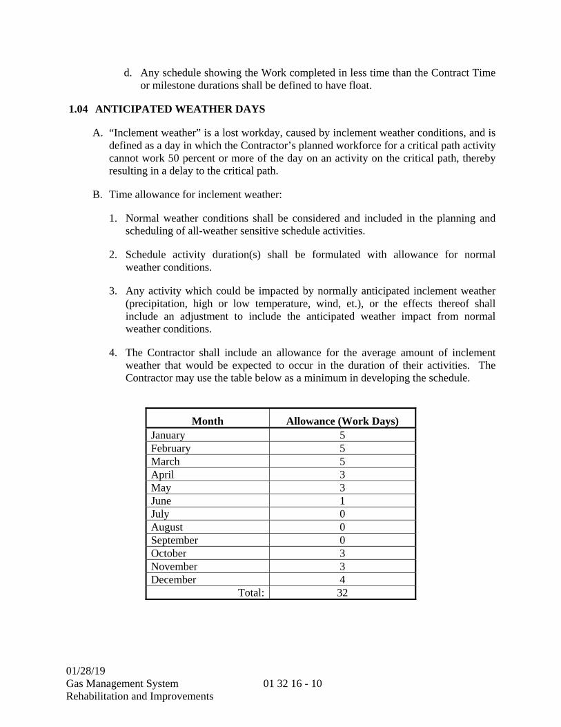
01/28/19
Gas Management System Rehabilitation and Improvements
01 32 16 - 10
d. Any schedule showing the Work completed in less time than the Contract Time or milestone durations shall be defined to have float.
1.04 ANTICIPATED WEATHER DAYS
A. “Inclement weather” is a lost workday, caused by inclement weather conditions, and is defined as a day in which the Contractor’s planned workforce for a critical path activity cannot work 50 percent or more of the day on an activity on the critical path, thereby resulting in a delay to the critical path.
B. Time allowance for inclement weather:
1. Normal weather conditions shall be considered and included in the planning and scheduling of all-weather sensitive schedule activities.
2. Schedule activity duration(s) shall be formulated with allowance for normal weather conditions.
3. Any activity which could be impacted by normally anticipated inclement weather (precipitation, high or low temperature, wind, et.), or the effects thereof shall include an adjustment to include the anticipated weather impact from normal weather conditions.
4. The Contractor shall include an allowance for the average amount of inclement weather that would be expected to occur in the duration of their activities. The Contractor may use the table below as a minimum in developing the schedule.
Month Allowance (Work Days) January 5February 5March 5April 3May 3June 1July 0August 0September 0October 3November 3December 4
Total: 32
01/28/19
Gas Management System Rehabilitation and Improvements
01 32 16 - 11
1.05 WEATHER CALENDAR AND ACCOUNTING OF DAYS
A. The Contractor shall include a calendar for weather sensitive activities. This calendar shall be a working day calendar that includes the above stated Inclement Weather Allowance and all District holidays. The weather allowance for each month shall be shown as non-working days and spread throughout the corresponding month. The weather calendar shall be assigned to all weather sensitive activities in the schedule.
B. The accounting of weather days shall occur once monthly corresponding to the Monthly Schedule Update. The actual non-working days affecting the critical path attributable to weather shall be accounted for in the Weekly Statement of Contract Time, as prepared by the District, independent of the weather allowance. Actual weather days shall be added to the schedule monthly as a one work day schedule activities behind the data date with an actual date equal to the non-working day as reflected in the Weekly Statement of Contract Time. A monthly reconciliation will occur between the inclement weather allowance and actual weather impact, as reflected in the Weekly Statement of Contract Time. Should the Contractor meet all contract requirements for demonstrating unavoidable delay, the Contractor shall be granted a time extension for actual weather impact days, beyond the weather allowance days for the same time period, for activities on the critical path. Weather related delays shall not entitle Contractor to any additional compensation.
C. No contract time adjustment shall be made in the event that actual non-working days attributable to weather affecting the critical path DOES NOT exceed the allowance. Unused weather allowance shall become project float.
**END OF SECTION**

01/28/19
Gas Management System Rehabilitation and Improvements
01 32 16 - 12
THIS PAGE INTENTIONALLY LEFT BLANK
01/28/19 Gas Management System Rehabilitation and Improvements
01 32 23 - 1
SECTION 01 32 23
SURVEY AND LAYOUT DATA
1.01 GENERAL
A. Contractor shall be responsible to do all necessary survey to layout and control the Work to the elevations, lines, and dimensions shown on the drawings. Any deviations must receive approval of the District Representative. All surveys affecting the line or elevation shall be performed by or under the direction and supervision of a registered civil engineer or licensed land surveyor, licensed by the State of California to do such surveys.
B. Survey points shall be shown for all transition points (change of direction, change in elevation, etc.) and for all outer dimensions of buried items. This information will be added to the appropriate as-built drawing to record field conditions. Contractor is referred to the PROJECT RECORD DOCUMENTS Specification Section (01 78 39) for related requirements.
C. District will provide project benchmarks and control monuments as shown in the contract drawings for Contractor's use at Contractor's request. Contractor is advised against relying on vertical and horizontal control established under prior contracts. Contractor shall verify lines and grades supplied under District provided controls and shall notify the District Representative immediately, in writing, if any discrepancies are found.
D. Contractor shall be responsible for all expenses related to the replacement of benchmarks and control monuments damaged, including the cost of resurvey by a California registered land surveyor.
**END OF SECTION**

01/28/19 Gas Management System Rehabilitation and Improvements
01 32 23 - 2
THIS PAGE INTENTIONALLY LEFT BLANK

01/28/19 Gas Management System Rehabilitation and Improvements
01 32 33 - 1
SECTION 01 32 33
PHOTOGRAPHIC DOCUMENTATION
PART 1 -- GENERAL
1.01 PRECONSTRUCTION PHOTOGRAPHS
A. Prior to the commencement of the work, the Contractor and the District Representative shall jointly survey the site, existing buildings and facilities, paving, and other items noting and photographing existing conditions and damage such as cracks, sags and other damage. All photographs shall be color, minimum 10 mega pixel, and taken with a camera which will automatically indicate on the front of each print the date, name of work, and the location where the photograph was taken. A minimum of 100 color photographs shall be taken by the Contractor prior to construction. Before construction may start, the photographs shall be delivered to the District’s Representative electronically. Samples of digital photos of acceptable quality and identification are available in the Office of the Resident Engineer for examination. The photographer shall be equipped to photograph either interior or exterior exposures. This record shall serve as a basis for determination of subsequent damage due to settlement, movement or due to the Contractor's operations.
1.02 CONSTRUCTION PHOTOGRAPHS (NOT USED)
1.03 MONTHLY AERIAL PHOTOGRAPHS (NOT USED)
**END OF SECTION**
01/28/19 Gas Management System Rehabilitation and Improvements
01 32 33 - 2
THIS PAGE INTENTIONALLY LEFT BLANK

01/28/19
Gas Management System Rehabilitation and Improvements
01 33 00 - 1
SECTION 01 33 00
SUBMITTAL PROCEDURES
PART 1 -- GENERAL
1.01 GENERAL REQUIREMENTS
A. Submittals include, but are not limited to, product data, shop drawings, test procedures, test results, annotated PLC program listings, AutoCAD® generated drawings, samples, requests for substitutions, descriptive data, certificates, methods, schedules, marked contract drawings and specifications, manufacturer's installation and other instructions, and miscellaneous work-related items. Submittals also include all other information as may reasonably be required, in the opinion of the District Representative, to demonstrate fully that the materials and equipment to be furnished and the methods of work comply with the provisions and intent of the contract documents. Additional submittal requirements are specified in each individual section of the specifications. Items to be submitted are specified in these individual technical specification sections.
B. All submittals will be submitted via the Project Controls System (PCS) as described in the ELECTRONIC COMMUNICATION PROTOCOLS Section (01 31 26). Minimum size lettering height on all submittals shall be 12-point font for text documents, 1/16 inch height for 8-1/2 by 11 inch and 11 by 17 inch documents and 1/8-inch height for documents larger than 11 by 17.
C. The review of the Contractor's drawings or other descriptive material shall not relieve the Contractor of responsibility for any error or of any obligation for accuracy of dimensions and details, for agreement and conformity with the contract drawings and specifications, or responsibility to fulfill the contract as prescribed and required by the REQUEST FOR BID Section. If errors or omissions exist in the Contractor's submittals which are not noted by the District during the District's review, it shall be the Contractor's responsibility, at no additional cost to the District, to correct the errors and omissions, to correct field conditions, and to repair any damage inflicted to new or existing equipment and other improvements as a result of the errors or omissions.
D. Where specified, the Contractor shall furnish submittals to the District Representative for information only. An electronic version and two hard copies these submittals, 1 full size reproducible on 20 lb. white bond for document/drawings larger than 11 by 17 inches shall be transmitted to the District Representative. Designation "For Information Only" does not preclude the District Representative from reviewing or commenting on the submittal contents as specified in this section.
E. All other submittals shall be submitted by the Contractor to the District Representative for review and comment. An electronic version and two hard copies of these

01/28/19
Gas Management System Rehabilitation and Improvements
01 33 00 - 2
submittals, 1 full size reproducible on 20 lb. white bond for documents/drawings larger than 11 by 17 inches shall be transmitted to the District Representative.
F. All submittal data including shop drawings will become part of the and O&M data and project records furnished under the PROJECT RECORD DOCUMENTS Section (01 78 39) and the OPERATION AND MAINTENANCE DATA Section (01 78 23). All changes or modifications during construction to original equipment submittals must be recorded and become part of the project record and O&M process as outlined in their respective sections.
1.02 DEFINITIONS
A. GENERAL:
1. The definitions of types of drawings, diagrams and other forms of submittal documents shall include the terms used in the following paragraphs. Whenever the following terms for drawings or other forms of submittal documents are used in submittal requirements, the definitions in the following paragraphs shall apply. The following set of definitions is not comprehensive. They are included to help clarify the meanings of certain terms applicable to mechanical, electrical, instrumentation and control system documents.
B. SINGLE-LINE DIAGRAMS:
1. A single-line diagram shall show by means of single lines and graphical symbols the course of an electrical circuit or system of circuits and components, devices, or parts used therein. Physical relationships are represented schematically.
C. ELEMENTARY OR SCHEMATIC DIAGRAM:
1. An elementary or schematic diagram shall show all circuits and devices of a system, equipment item, or assembly, or any defined functional portion thereof. A system is defined as any assembly of electrical, electronic, mechanical, hydraulic, pneumatic, and other various types of components and devices and/or materials which are combined, connected, and integrated as necessary to perform some specific function. Such a diagram emphasizes the functional arrangement of system components and devices as opposed to their physical arrangement and is intended to provide a functional understanding the operation of the system or circuit. "Elementary" and "schematic" are equivalent terms unless additional definitions or requirements are stated. However, the term "elementary" as used herein for electrical drawings generally refers to those drawings and diagrams which show the connection and control of electrical devices, whereas the term "schematic" generally refers to those drawings or diagrams which show the connection and application of electronic devices. (Note: Most elementary diagrams provided in the contract drawings are located on "X" drawings titled "Control and Logic Diagrams.")

01/28/19
Gas Management System Rehabilitation and Improvements
01 33 00 - 3
D. LOOP DIAGRAM:
1. Loop diagrams shall show a schematic representation of a complete hydraulic, electric and pneumatic circuit. Diagrams show all system devices with alphanumeric identification of each component in the loop. All connected equipment terminals are shown with manufacturer's identification markings. All interconnecting cables and pneumatic tubing are shown with color code and alpha-numeric identification. The location of all devices in the loop are shown; for example, field, panel front, panel rear, termination cabinet, computer I/O cabinet, etc. Diagrams also show the process lines and equipment to which the devices in the loop are connected with a description of the controller actions. The loop diagrams also show references to all other applicable drawings. Loop diagrams have symbols and layout in conformance with ISA S5.1 and S5.4.
E. CONNECTION DIAGRAM:
1. Connection diagrams shall show the physical placement and wiring of devices and terminals in a panel, cabinet, console, assembly or system. Devices and terminals are shown arranged in the physical layout (not necessarily to scale) as they would appear to a person who is servicing the equipment.
F. INTERCONNECTION DIAGRAM:
1. Interconnection diagrams shall show the external wiring between terminals of associated equipment, control panels, motor control centers, area control centers, terminal boxes, field switches, and any other device, panel, or enclosure.
G. PANEL FABRICATION DRAWINGS:
1. Panel fabrication drawings are scaled drawings that shall show the physical dimensions, materials, and construction of panels, cabinets, terminal boards, consoles, or other electrical or mechanical equipment enclosures. These drawings show the physical arrangement and mounting of all components in or on a panel, terminal board, cabinet, console, or enclosure. These drawings show the physical dimensions, and the space and mounting requirements of mechanical, electrical, control and instrumentation devices or pieces of equipment. Other information provided may include ventilation requirements, locations of connections, weight, and paint color, material and dry film thickness.
H. ELECTRONIC ASSEMBLY DRAWINGS:
1. Electronic assembly diagrams shall document circuit board assemblies, enclosures, and associated devices. They include circuit schematics, circuit board assembly drawings, and chassis layouts which show, locate, and identify all circuit assemblies, components, and component electrical connections and wiring.
01/28/19
Gas Management System Rehabilitation and Improvements
01 33 00 - 4
I. INSTRUMENT INSTALLATION DRAWINGS:
1. Instrument installation drawings shall show the mounting and piping details of field mounted instruments and instrument racks.
J. BILL OF MATERIALS:
1. Materials identified on the drawing and listed by item number, a brief description, manufacturer, model number (and/or page number), serial number (if available), and quantity used. Associated equipment numbers must be shown. The items must match the field installation and the drawing.
1.03 STANDARD COMPLIANCE
A. When materials or equipment are required to conform to the standards of organizations such as the American National Standards Institute (ANSI), American Society for Testing and Materials (ASTM), National Electrical Manufacturers Association (NEMA) and Underwriter's Laboratories (UL), documents showing or proving conformance shall be submitted.
B. If an organization uses a label or listing to indicate compliance with a particular standard, the label or listing will be acceptable evidence, unless otherwise specified in the individual sections. In lieu of the label or listing, the Contractor shall submit a certificate from an independent testing organization which is competent to perform acceptable tests and is approved by the District’s Representative. The certificate shall state that the item has been tested and found to be in conformance with the specified organization's standard. For materials and equipment whose compliance with organizational standards or specifications is not regulated by an organization using its own listing or label as proof of compliance, a certificate of compliance from the manufacturer shall be submitted for approval. The certificate shall identify the manu-facturer, the product and the referenced standard and shall state that the manufacturer certifies that the product conforms to all requirements of the project specification and of the referenced standards listed.
1.04 SUBMITTAL REVIEW
A. When review and comment is required of any drawing or information regarding materials and equipment, the Contractor shall post the submittal information to the Project Control System in accordance with the ELECTRONIC COMMUNICATION PROTOCOLS Section (01 31 26). Within a reasonable time as specified in this section after receipt of said submittal, the District Representative will return electronically one copy of the submittal documents indicating one of the following four actions by item number:
1. If review and comment indicates no exceptions, copies will be returned marked "NO EXCEPTIONS TAKEN". Work may begin immediately on incorporating the material and equipment covered by the submittal into the work.

01/28/19
Gas Management System Rehabilitation and Improvements
01 33 00 - 5
2. If review and comment indicates limited corrections are required, copies will be returned marked "MAKE CORRECTIONS NOTED". Work may begin immediately on incorporating the material and equipment covered by the submittal document into the work.
3. If review and comment indicates insufficient or incorrect data has been submitted, copies will be returned marked "AMEND AND RESUBMIT." The Contractor is not authorized to begin incorporating the material and equipment covered by this submittal document into the work until the submittal document is revised, resubmitted and returned marked either "NO EXCEPTIONS TAKEN" or "MAKE CORRECTIONS NOTED".
4. If review and comment indicates the material and equipment submittal is unacceptable, copies will be returned marked "REJECTED - SEE REMARKS". The Contractor is not authorized to begin incorporating the material and equipment covered by this submittal into the work until a new submittal is made, resubmitted, and returned marked either "NO EXCEPTIONS TAKEN" or "MAKE CORRECTIONS NOTED".
B. When submittal documents are referred to in these specifications as "approved," "reviewed" or "accepted," this means that they are stamped as in case 1 or 2 above.
C. Designation of submittal documents "for information only," does not preclude the District’s Representative from reviewing or commenting on the submittal contents. Information only submittals returned to the Contractor marked "AMEND AND RESUBMIT" or "REJECTED - SEE REMARKS" shall be revised and resubmitted by the Contractor.
PART 2 -- PRODUCTS
2.01 SHOP DRAWINGS
A. GENERAL:
1. Shop drawings shall include data of all forms which have been custom prepared for this project. This includes detail drawings for structural, architectural, mechanical, piping, HVAC, electrical, logic diagrams, software programs, electronic, instrumentation, control, and communication equipment, assemblies, and systems which are installed or fabricated as a part of this project. All shop drawings shall be drawn in CAD format, as specified in this section, at an approved drawing scale. Also included are drawings and data which show fabrication, layout, setting or erection details. This includes any data which is prepared by the Contractor, subcontractors, vendors, suppliers, manufacturers or their representatives, specifically for this project.

01/28/19
Gas Management System Rehabilitation and Improvements
01 33 00 - 6
2. Shop drawings shall have drawing numbers, scale, revision date and number, Contractor name, subcontractor name, supplier name, name of detailer or engineer who prepared the document, relation to adjacent structures, materials, drawing cross references, standards references, Contractor's certification stamp, and registered engineer's stamp, if required, shown on them. Maximum sheet size shall be 22 inches by 34 inches. Minimum sheet size for drawings shall be 11 inches by 17 inches, except as allowed by the District Representative.
3. Shop drawings specifically prepared for this project shall be created in Computer-Aided Drawing (CAD) format, using the most current AutoCAD® software, by Autodesk, Inc.
B. CAD DRAWINGS:
1. All drawings shall be prepared in a CAD format, using the most current AutoCAD® software by Autodesk, Inc. The following drawings are specifically required in CAD format:
a. Panel drawings including area control centers (ACC), panel fabrication, layout and point-to-point wiring (connection diagrams).
b. Elementary diagrams (control and logic).
c. Electronic assembly drawings.
d. Terminal panels or terminal boxes.
e. Interconnect drawings.
f. Loop drawings (digital and discrete).
g. Custom created concrete products specifically prepared for this project.
h. Shop drawings which are specifically prepared for this project.
2. All CAD drawings shall comply with the United States National CAD Standard® (NCS). All Contractor submissions requiring CAD shall be in accordance with NCS Version 5.0, or the latest release, and the U.S. National BIM Standard (NBIMS). Additional information or clarification can be obtained from the United States National CAD Standard® (NCS) website at www.nationalcadstandard.org/ncs5. The National Institute of Building Sciences owns the copyright to the work known as the United States National CAD Standard® (NCS) and reserves all rights to said work under United States and international law.
a. Exceptions to the NCS are as follows:
1) All annotation shall be capitalized.
01/28/19
Gas Management System Rehabilitation and Improvements
01 33 00 - 7
2) All annotation shall be a minimum 1/8-inch Arial for full size drawings and a minimum 1/16-inch Arial for half size drawings.
3) All arrowheads shall match the font size (1/8-inch) of the annotation in the drawing.
3. The Contractor shall require that the CAD drawings prepared by all subcontractors or vendors meet the requirements of these standards.
4. The Contractor shall upload the submittal drawing files (in both native and pdf format) to the Program Controls System in accordance with the ELECTRONIC COMMUNICATION PROTOCOLS Section (01 31 26).
C. ELECTRICAL AND CONTROL DOCUMENT REQUIREMENTS:
1. GENERAL:
a. For each piece of mechanical equipment and for each process instrumentation and control loop, all applicable electrical and control documents specified herein shall be submitted as a package. If any of the electrical, control and instrumentation circuits of the subject mechanical equipment or process loop have an "interface" drawing on the "E" or "X" series contract drawings, the Contractor shall field verify the accuracy of the drawings and verify existing conditions. The "interface" drawings include the Interconnection Diagrams and Reconnection Diagrams on the "E" drawings, and the set of Interface and Demolition Diagrams on the "X" drawings. Demolition Interconnection Diagrams based on existing referenced drawings must be verified.
b. If the Contractor finds any errors or omissions on the interface drawings, they shall mark up two copies of the affected contract drawings and submit them to the District Representative for clarification. If the errors or omissions are confirmed by the District Representative, the affected contract drawings will be corrected and reissued through a contract change order.
c. The Contractor shall then prepare all detailed electrical and control documents required for the subject mechanical equipment or process loop or circuit and submit them for review. After successful completion of the review process, the Contractor shall then proceed with shop fabrication and field installation.
d. Additional electrical and control document requirements are specified in the technical specifications.
e. For each type of drawing specified in the following paragraphs, the Contractor shall submit at least two examples a minimum of 30 days prior to beginning the preparation of any additional electrical and control documents. The purpose of this sample submittal is to allow the District Representative to perform a detailed review of the Contractor's drawings for compliance with contract

01/28/19
Gas Management System Rehabilitation and Improvements
01 33 00 - 8
requirements for format, content, and level of detail. These examples shall receive a "MAKE CORRECTIONS NOTED" or "NO EXCEPTIONS TAKEN" review before the Contractor proceeds with shop drawings which include these types of drawings.
2. CUSTOM SOFTWARE DOCUMENTATION: Unless otherwise specified, custom software prepared for this project shall be specially documented in accordance with the latest edition of one of the following formats: ISA S5.1, Instrumentation Symbols and Identification; ISA S5.3, Graphic Symbols for Distributed Control/Shared Display Instrumentation, Logic, and Computer Systems; the format and Symbols used in the contract drawings for Control and Logic Diagrams, "X-Series" drawings; or a format acceptable to and approved by the District Representative. Software documentation shall also include a complete listing of all application programs together with comments and annotations. Complete software documentation shall be submitted for all mechanical, electrical and control systems, subsystems, assemblies, parts, components, and equipment which incorporate programmable devices which are custom programmed/ configured for this project. In addition, complete annotated program listings clearly indicating logic produced by the applicable programmable device or device programming unit shall be provided along with all applicable functional diagrams. All instructions, hardware, and machine-readable media necessary to load, store, modify, and activate the associated custom software source codes and programs shall be provided. Contractor shall submit annotated program listing on electronic media as appropriate.
3. SINGLE-LINE DIAGRAMS: Single-line diagrams shall be drawn to a format similar to the single-line diagrams in the contract documents. Single-line diagrams shall be prepared for all new 480 volt switchgear. Single-line diagrams shall be submitted along with other drawings and data specified in Division 26.
4. ELEMENTARY DIAGRAMS: Unless otherwise specified, electrical elementary diagrams shall be drawn in accordance with the latest issue of Joint Industrial Council (JIC) Electrical Standards for Mass Production Equipment (EMP-1). All circuits and devices of a system shall be shown. A written description of the sequence of operation of the circuit shall be included. Elementary diagrams shall be prepared and submitted for all assemblies and systems for which elementary diagrams have not been included on the contract drawings, or where only partial elementary diagrams have been included in the contract documents. Elementary diagrams shall be prepared using the format shown in the Control and Logic Diagrams in the Example Wiring Diagrams located in the Contract Drawings following the "X-series" drawings.
5. LOOP DIAGRAMS: Loop diagrams shall be prepared in compliance with ISA-S5.4 and using the format shown in the loop diagrams in the Example Wiring Diagrams located in the Contract Drawings following the "X"-series drawings. In the event of conflict between ISA-S5.4 and the Example Wiring Diagrams, the Example Wiring Diagrams shall govern. Loop diagrams shall show circuits and

01/28/19
Gas Management System Rehabilitation and Improvements
01 33 00 - 9
devices of a system. These diagrams shall be arranged to emphasize device elements and their functions as an aid to understanding the operation of a system and maintaining or troubleshooting that system. Loop diagrams shall also show cable numbers, wire numbers, input and output signals (e.g., 4-20 mA DC, 10-50 mA DC, 1-5V DC, 3-15 psig, 6-30 psig, etc.), power and instrument air supplies to devices (e.g., 120V AC, 65V DC, 24V DC, 80 psig, etc.), signal polarity, all wire and shield terminations, and terminal block numbers in physical order. Loop diagrams shall also show all pneumatic components of instrumentation loops. Loop diagrams shall be printed on 11-inch by 17-inch sheets. Loop diagrams shall be prepared and submitted for all electric and pneumatic, analog and discrete, instrumentation monitoring, control, and alarm circuits. Every 24 volt DC circuit shall be documented in a loop diagram. Only one circuit shall be shown on each drawing; multiple circuits on a single drawing with an application table are unacceptable. Loop diagrams will show references to the computer tie-in point with cabinet, row, column, and channel number. A list of existing tie-in points will be provided to the Contractor by the District.
6. CONNECTION DIAGRAMS:
a. Connection diagrams shall show the placement, labeling and wiring of components within MCC cubicles, panels, terminal boards, cabinets and consoles. Components shall be shown arranged in the physical layout as it would appear to a person servicing the equipment. Terminal blocks shall be shown in sequential physical order including all spares. Wires shall be shown as a continuous line between their termination points. The direction of entry to a wire bundle shall be shown. Wire lists and wireless diagrams are unacceptable. All additions and deletions of devices and wires in existing enclosures shall be clearly shown. Each wire label designation shall be shown. The wire label designations on each end of a single wire must be identical. All wire termination point numbers shall be shown. Each wire and cable size, color code, type and rating shall be shown. Signal and DC circuit polarities shall be shown. All jumper, shielding and grounding details shall be shown. Multiple conductor cables shall show all wires. All spare wires and spare termination points shall be shown.
b. Contractor shall submit connection diagrams for all new MCC cubicles, panels, terminal boards, cabinets and consoles. The Contractor shall also prepare and submit connection diagrams for existing panels, terminal boards, cabinets and consoles which are to be modified or refurbished. Connection diagrams shall be submitted along with associated elementary, loop, interconnection, and other associated panel submittal data as a complete package for review.
7. INTERCONNECTION DIAGRAMS:
a. Interconnection diagrams shall show for each piece of equipment all wiring between all devices, panels, cabinets, consoles, terminal boxes, control equipment, motor control centers, area control centers and any other devices
01/28/19
Gas Management System Rehabilitation and Improvements
01 33 00 - 10
and equipment. Drawing references shall be shown to all diagrams which interface to the interconnection diagrams. Interconnection diagrams shall be of the continuous line type. Bundled wires shall be shown as a single line with the direction of entry/exit of individual wires clearly shown. Wireless diagrams and wire lists are unacceptable. Non-sequential terminals, on which wires are landed, shall be shown with gaps on the terminal block to depict they are not adjacent. Equipment terminal blocks shall be shown in the exact physical order (including spares) as they are installed. Each wire labeling code as actually installed shall be shown. The wire labeling code for each end of the same wire must be identical. All device and equipment labeling codes shall be shown. Terminal blocks within equipment with interconnection wiring connected shall be shown complete with labeling code and all termination point labeling codes shown. All jumper, shielding and grounding termination details not shown on the connection diagrams shall be shown on the interconnection diagrams. Each wire and cable size and color code shall be shown. Signal and DC circuit polarities shall be shown. Multiple conductor cables shall show all wires. Wire and cable routing through wireways, junction boxes, terminal boxes, manholes, handholes, and other electrical enclosures shall be shown with the appropriate equipment labels. Labeling codes for terminal blocks, terminals, wires, cables, panels, cabinets, instruments, devices, and equipment shall be shown. All spare wires and cables shall be shown. Examples of the required format for interconnection diagrams are contained in the Example Wiring Diagrams, located in the Contract Drawings following the "X-series" drawings. Additional information related to wire tagging which is required on interconnection diagrams is specified in the COMMON WORK RESULTS FOR ELECTRICAL Section (26 05 00).
b. Interconnection diagrams shall be submitted for each piece of equipment. The Contractor shall simultaneously submit in one package all backup material used to develop each interconnection diagram. This material includes current issues of panel schematics, connection diagrams, terminal block diagrams, submittals, contract drawings, vendor drawings and all other data used to develop the interconnection diagram. All interconnection diagrams shall be prepared under the supervision of or by a registered electrical engineer and shall bear that Engineer's professional stamp and signature. All deletions and additions of equipment, wires and cables shall be clearly shown. Interconnects shall include a list of all applicable reference drawings, requests for clarifications, field instructions and change orders.
c. Cable shall not be pulled into raceway until the interconnection diagrams depicting the cable are approved.
8. ELECTRONIC ASSEMBLY DIAGRAMS: Electronic assembly diagrams shall document the design and wiring of circuit board assemblies, enclosures and electrical/electronic devices. Circuit board schematic and fabrication drawings, and chassis layout and wiring diagrams, shall be provided to show, locate and identify all circuit assemblies, components and component wiring. All chassis and circuit

01/28/19
Gas Management System Rehabilitation and Improvements
01 33 00 - 11
board components shall be identified by original manufacturer's name and part number. Component values, ratings and tolerances shall be shown. Adjustments, jumpers and switch positions shall be shown in the installed positions. Voltage and/or current levels, set points, and timing values shall be shown.
9. INSTRUMENT INSTALLATION DRAWINGS: Instrument installation drawings shall be drawn to an approved scale and shall show the mounting, piping, and wiring details for field and rack mounted instruments. Mounting dimensions, piping slopes, complete bill of material and installation notes shall be shown. Mounting heights, sense of line routing and process line tap heights relative to the instrument shall be shown. Viewing, adjustment, operation, and service access shall be shown. Groupings of instruments shall be drawn to an approved scale. Instrument installation drawings shall be submitted for all field mounted instruments and instrument racks. Installation drawings shall list all applicable equipment numbers.
10. PANEL FABRICATION AND LAYOUT DRAWINGS:
a. As a minimum, panel fabrication and layout drawings shall include a bill of materials; front, back, and section views; the locations of all components to be mounted in or on the panel, terminal boards, cabinet, console, enclosure or assembly; drawing scale; nameplate engraving schedule; and structural materials and supports. All drawings shall be drawn to an approved scale. Overall dimensions and minimum clearances shall be shown. Sufficient detail shall be included to demonstrate material choices, construction methods, and seismic force resistance. Panel drawings will show drawing references to appropriate connection diagrams, interconnects, and control and logic drawings.
b. Panel fabrication and layout drawings shall be submitted for all assemblies, panels, terminal boards, cabinets and consoles which contain mechanical, electrical, and electronic devices and equipment and for the systems which contain these assemblies, panels, cabinets, and consoles. Outline drawings for mechanical and electrical equipment (sometimes referred to as "dimension drawings") shall be drawn to an approved scale and include, as a minimum, overall dimensions in front, back and section view, complete mounting frame details and dimensions, the location and size of all conduit entrances, the location and dimensions of any mechanical connections, and the weight of the device or equipment.
2.02 MANUFACTURER'S PRODUCT DATA
A. Product data shall include data of all forms which define design, performance and function of manufactured products or materials. This includes all preprinted literature, performance specifications, drawings, instruction manuals, and data which are available from the original equipment manufacturer and/or supplier. Product data shall also include all software and firmware encoded on programmable device readable
01/28/19
Gas Management System Rehabilitation and Improvements
01 33 00 - 12
media. Product data shall be submitted for all manufactured products and material as specified in this section and in the Technical Specifications, Divisions 03 through 50.
B. Specific Asset Attribute data related to the product data shall be submitted separately and is specified in the DESIGN DATA Section (01 33 16).
2.03 TEST PROCEDURES AND RESULTS
A. Refer to the individual technical specifications and the COMMISSIONING Section (01 91 00) for the submittal requirements of test procedures and results.
2.04 SAMPLES
A. GENERAL:
1. Samples shall include both fabricated and un-fabricated physical examples of materials, products and work, both as complete units and smaller portions of units of work. Mock-ups are special forms of samples. The electronic submittal for these items shall be processed concurrent with the submission of samples and mock-ups.
2. When specified, samples or test specimens of the materials proposed to be used shall be prepared at the expense of the Contractor and furnished in such quantities and sizes as may be required for proper examination and tests, with all freight charges prepaid, and with complete information as to the type, kind, or size of material, and its source. All samples shall be submitted in ample time to permit the making of proper tests, analyses, or examinations before the time at which it is desired to incorporate the materials into the work, and no materials shall be used in the work unless or until the submittal has been reviewed by the District’s Representative. All tests of materials shall be made by the Engineer in accordance with recognized standard practice. The Contractor will pay the cost of the second test and any subsequent retest of any area or material which does not meet the specifications. Samples shall be supplied by the Contractor whenever deemed necessary by the District Representative to determine the quality of materials. The Contractor is required to give one working day advance notice for any requested on-site testing or inspection unless the nature of the work mandates shorter notice.
3. Provide units identical with the final condition of the materials or products proposed for the work. Include "range" samples (not less than three units) where variations occur, and identify each unit of each set. Provide a full set of optional samples where the District Representative selection is required. Prepare samples to match the Engineer's sample where so indicated. Include information with each sample to show generic description, source or product name and manufacturer, limitations, and compliances with standards. Samples are submitted for review and confirmation of color, pattern, texture and kind by the District Representative.
01/28/19
Gas Management System Rehabilitation and Improvements
01 33 00 - 13
B. SUBMITTAL:
1. The Contractor may choose to provide a preliminary submittal of a single set of samples for review. Otherwise, the initial submittal is the final submittal unless it is rejected and/or requires re-submittal. Submit two sets of samples in the final submittal, one set will be returned.
C. QUALITY CONTROL SET:
1. The Contractor shall maintain the returned final set of samples at the project site, in suitable condition and available for quality control comparisons by the District Representative.
D. REUSABLE SAMPLES:
1. Samples which are intended or permitted to be returned and actually incorporated in the work are so indicated in the individual work sections, but must be in undamaged condition at the time of installation.
2.05 MISCELLANEOUS SUBMITTALS
A. These include, but are not limited to, stormwater BMP plans and descriptions, warranties, guarantees, certifications, maintenance agreements, quality testing reports and similar information, devices and materials.
2.06 PROJECT RECORD DRAWINGS AND DATA
A. Refer to the PROJECT RECORD DOCUMENTS Section (01 78 39) for the submittal requirements of as-built drawings and data.
2.07 OPERATION AND MAINTENANCE INSTRUCTIONS
A. Refer to the OPERATION AND MAINTENANCE DATA Section (01 78 23) for the submittal requirements of operation and maintenance instructions. Operation and maintenance instructions will not be submitted until approved equipment or material submittals are received.
2.08 BURIED UTILITIES
A. Plan and profile drawing shall be supplied for all outside underground utilities including, but not limited to, piping, electrical duct banks and cables. All plan and profile drawings shall be submitted for as-built review in accordance with the PROJECT RECORD DOCUMENTS Section (01 78 39).

01/28/19
Gas Management System Rehabilitation and Improvements
01 33 00 - 14
2.09 SCHEDULE
A. Refer to the CONSTRUCTION PROGRESS SCHEDULE Section (01 32 16) for submittal requirements for Schedules.
PART 3 -- EXECUTION
3.01 SUBMITTAL REQUIREMENTS
A. GENERAL:
1. Submittals shall be reviewed and coordinated by the Contractor before transmittal to the District Representative in accordance with the QUALITY CONTROL Section (01 45 00). Submittals shall be complete and fully identified by the Contractor.
B. PREPARATION:
1. Each submittal shall contain documents which are related to only one material, product or system. Normally, a separate transmittal form shall be used for each specific item or class of material, equipment or system. Exceptions may be allowed only when the items taken together constitute a manufacturer's "package" or are so functionally related that expediency indicates checking or review of the group or "package" as a whole. The Contractor shall mark each submittal document with the submittal number, letter suffix and item number.
2. Prior to preparation of each "major submittal package," the Contractor shall arrange for an 8-hour pre-submittal meeting, to be attended by the Contractor, District’s Representative, and vendor(s) of the major submittal package. The purposes of the pre-submittal meeting will be to discuss how the submittal package will be organized, content of the submittal package, anticipated schedule for submittal and review, major features of the equipment/materials and basic compliance with specified equipment/materials, and coordination needed with related equipment/material submittals. Pre-submittal meetings shall be held for the following major submittal packages:
a. 01 78 23 – Operation and Maintenance Data
b. 43 13 43 – Waste Gas Burner System
c. 43 13 43.01 – Ground Flare Refurbishment
C. TRANSMITTAL FORM:
1. The District Representative will define a submittal numbering scheme which the Contractor shall use. Items omitted, or incorrectly or ambiguously listed on the transmittal form will be deemed to be not included in the submittal. Where items

01/28/19
Gas Management System Rehabilitation and Improvements
01 33 00 - 15
listed in the transmittal by equipment number conflicts with other descriptions contained in the submittal, the listed equipment numbers shall be deemed to be the intended scope. The Contractor shall bear all costs and damages sustained to the District attributable to omitted, or incorrectly or ambiguously listed submitted items.
2. Submittals shall be transmitted by utilizing the District-furnished web based Project Controls System. Prior to the first submittal, the Contractor shall attend a submittal transmittal meeting to work out all compatibility requirements. Each transmittal shall contain the following information as a minimum:
a. Date
b. Submittal or re-submittal number
c. Contract title and number
d. Contractor's name and address
e. List of documents being submitted, by preparer, number and version
f. Contract documents references (including specific specification section and drawing numbers) for each submittal document
g. Plant system references for each submittal document
h. Previous submittal number and item number for each submittal document
i. Notification of deviation(s) from contract documents for each submittal document
j. Complete list of equipment numbers and auxiliaries included with each submittal document
k. Contractor's certification of having reviewed and coordinated the submittal
l. Description of intended use in this contract
D. DOCUMENT IDENTIFICATION:
1. If multiple items are included within a single submittal, each separate document within the submittal shall contain the following information:
a. Document (Item) number within this submittal
b. Identification of product or material
c. Manufacturer's name
01/28/19
Gas Management System Rehabilitation and Improvements
01 33 00 - 16
d. Equipment number
E. RESUBMITTALS:
1. Revise returned submittal documents as indicated and as required. Resubmit using the same submittal procedure as for an initial submittal. All resubmittals shall use the previous submittal number with a letter suffix and shall refer to the previous item number.
2. Resubmittals shall address all comments from the District Representative. Partial re-submittals may be returned "REJECTED." The Contractor will be responsible for the District Representative's review costs for each re-submittal in excess of the first resubmittal. These costs will be back charged to the Contractor and will be deducted from progress payments.
3. Time extensions will not be granted for delays resulting from the necessity for the Contractor to provide resubmittals due to inaccurate, incomplete or rejected submittals.
F. COORDINATION AND SEQUENCING:
1. Review priority will be based on the schedule unless otherwise requested in writing by the Contractor. The Contractor in scheduling submittals shall submit no more than 10 per week. In the event the Contractor submits more than 10 per week, the District Representative's review time may exceed the review time outlined.
2. The Contractor shall coordinate submittals with the work so that work will not be delayed. Submittals shall be coordinated and scheduled into different categories, so that one will not be delayed for lack of coordination with another. No extension of time will be allowed because of failure to properly schedule submittals. The Contractor shall not proceed with work related to a submittal until the submittal process is complete and the submittal document has been returned to the Contractor stamped "No Exceptions Taken" or "Make Corrections Noted."
3. All submittals, including shop drawings, shall be submitted in sufficient time to allow the District Representative not less than 30 days for review of such submittals.
4. These review periods do not include any time that the District Representative cannot proceed further with the review because of having to wait for further information of clarification from the Contractor.
5. Normally, initial submittals will be returned to the Contractor within 30 days, and resubmittals will be returned within 20 days, exclusive of any time awaiting clarification or further information, and exclusive of "major submittals" as described above. However, the time for return will necessarily vary and may

01/28/19
Gas Management System Rehabilitation and Improvements
01 33 00 - 17
exceed the time described above depending upon the complexity of the submittal, the number of submittals, and the express needs of the Contractor.
6. Submittals for material or equipment which are not specified by name, and which are being submitted as an "or equal" to that specified and submittals for material or equipment with arrangements or requirements that are different than that shown in the contract documents, will normally require 42 days for the review process.
G. CONTRACTOR'S RESPONSIBILITIES:
1. The Contractor shall review submittals before they are transmitted to the District Representative to ensure that there are no conflicts with other submittals. The Contractor shall coordinate submittals from subcontractors and suppliers to ensure that they are complete and that there are no conflicts.
2. The Contractor is responsible for errors and omissions in submittals even though the District’s Representative reviews the submittal.
3. The District Representative shall be notified in writing at the time the submittal is transmitted of deviations from the requirements of the contract documents. The Contractor is responsible for correcting deviations from the contract documents even though the District Representative has reviewed the submittal, unless the deviations are clearly described in writing in the submittal transmittal form.
4. The Contractor shall be responsible for distributing submittals which have been returned with the District’s Representative's action to subcontractors and suppliers. Installation shall not be started until the submittal data with the "No Exceptions Taken" or "Make Corrections Noted" stamp is in the possession of the installer.
5. No changes shall be made by the Contractor in any submittal after it has been approved. The equipment or materials provided shall not deviate from the submittal documents which are stamped with the "No Exceptions Taken" or "Make Corrections Noted" stamp in any way except with written approval by the District Representative.
6. The Contractor shall certify on each submittal document that the submittal has been reviewed, field conditions have been verified and contract documents have been complied with.
7. The Contractor may authorize a material or equipment supplier to deal directly with the District Representative with regard to such submittals; however, ultimate responsibility for the accuracy and completeness of the information contained in the submittal shall remain with the Contractor.
H. REQUESTS FOR SUBSTITUTION:
1. The Contractor may offer to substitute material or equipment if permitted by the technical specifications. The District will consider offers for substitution only from
01/28/19
Gas Management System Rehabilitation and Improvements
01 33 00 - 18
the Contractor unless the substitution/or equal submission is made pre-bid as described in the REQUEST FOR BID Section. Post-bid the District will not acknowledge or consider such offers from suppliers, distributors, manufacturers, or subcontractors.
2. The Contractor's offers of substitution shall be made in writing to the District Representative in ample time to permit review without delaying the work. Until and unless such substitutions are approved by the District Representative, no deviations from the specifications shall be allowed. Time extensions will not be granted for requests for substitution which are subsequently denied by the District Representative. Time extensions will not be granted for substitutions which are not submitted in a timely manner. Any request for substitutions shall include sufficient data to enable the District Representative to assess the acceptability of the material or equipment for the particular application and requirements.
3. The Contractor shall submit a brief description of the proposed substitution prior to preparing a detailed submittal. The brief description shall be submitted on a Request for Substitution/Construction Incentive Change Proposal (CICP) form. Within 15 working days, the District Representative will review the proposal in concept and respond. If the District Representative accepts the concept of the substitution, the Contractor may prepare a detailed submittal conforming to the requirements of this section.
4. Any cost differential associated with a request for substitution must be negotiated with the District Representative. These costs or savings must be covered by a change order which modifies the contract documents.
I. DRAWINGS FOR MODIFIED PANELS AND OTHER CONTROL SYSTEM COMPONENTS:
1. GENERAL: Where work is in existing panels, or otherwise interfaces with existing control system components, the Contractor shall prepare new connection, interconnection, loop elementary, CSA schematic and other drawings as necessary in CAD format to show all work and shall provide required submittals. If existing drawings are available in CAD format, the District will provide CAD copies of existing drawings within 14 days of receipt of a written request, except that no more than 75 drawings per week will be provided by the District. The written request must include the drawing numbers of the drawings requested, request date, requestor's name, and any other necessary information.
2. FORMAT: Contractor's submittals of modified District provided drawings shall clearly delineate new work as shown in the Example Wiring Diagrams. New items shall be drawn with lines thicker than the existing lines, deletions shall be made by removing the item from the drawing (cross outs are not acceptable). All new work shall be outlined with a "cloud" of connected half circles. Clouds shall be drawn in pencil on the back of the drawings so that they may be easily erased by the District

01/28/19
Gas Management System Rehabilitation and Improvements
01 33 00 - 19
in the future. Entries shall be made in the revision blocks giving the date and a brief description of the revisions.
3. SIGNAL CIRCUITS: Modifications to all existing signal circuits shall be shown on existing loop drawings.
4. EQUIPMENT: For all equipment requiring modifications to existing control circuits and/or power circuits feeding the equipment, modifications shall be shown on existing interconnection drawings.
5. ACC PANELS: Modifications to existing ACC control panels shall be shown on existing panel layout drawings, connection diagrams, and CSA schematics.
6. OTHER PANELS: Modifications to all panels except ACC control panels shall be shown on existing panel layout drawings and connection diagrams.
3.02 PROPRIETARY INFORMATION
A. All of the information required herein shall be provided even though it may be considered to be proprietary. If any of the information required herein is considered to be proprietary, the District's standard proprietary agreement as found in the PROPRIETARY INFORMATION AGREEMENT Section (00 62 05) shall be executed between the District and the Contractor, prior to contract award, stipulating that all such information will be supplied by the Contractor and kept confidential by the District.
B. Not more than 90 percent of all work shall be paid for until all proprietary information has been submitted and approved. Proprietary information shall describe the final as-built work. No part of the work covered by the proprietary agreement shall be modified after proprietary submittal acceptance until after updated proprietary information has been submitted by the Contractor and accepted by the District. Updated proprietary information shall fully document all modifications to be implemented. All proprietary data shall be marked "PROPRIETARY" by the Contractor.
3.03 MANAGEMENT OF THE SUBMITTAL PROCESS
A. The Contractor shall develop with assistance of the District Representative and Design Engineer a comprehensive management plan for all submittals required for the project. The intent of the management plan shall be to provide an orderly and timely process for the submission and review of submittals. The submittal management plan shall be developed and implemented within 60 days following Notice to Proceed. The submittal management plan shall incorporate the following elements:
1. The Contractor shall submit a list of submittals which require review within the first 120 days of the project, within 10 days following the Notice to Proceed.

01/28/19
Gas Management System Rehabilitation and Improvements
01 33 00 - 20
2. The Contractor shall develop a comprehensive Master Submittal List of all specified submittals. The list shall be serially numbered in accordance with the appropriate specification section. The list shall be developed and submitted to the District Representative for review within 21 days following the Notice to Proceed. The District Representative will conduct a meeting to review the Master Submittal List with the Contractor within 3 working days following receipt of the list.
3. The Contractor shall develop a schedule for the submission and review of all specified submittals for the project. The schedule shall be developed in accordance with the CONSTRUCTION PROGRESS SCHEDULE Section (01 32 16). The schedule shall include individual activities for submission and review (and fabrication and delivery for equipment and material) for each submittal. The submittal schedule shall be a separate subnet of the master CPM construction schedule with each submittal activity linked to the appropriate construction activity. Every projected submittal shall be listed and incorporated into the schedule.
4. The Contractor shall meet at least once per month with the District Representative to review the status of all submittals. In addition, the Contractor shall develop and transmit monthly, a written list of the submittals which require review within the following 90 days. The list of projected submittals shall include the estimated date of submission for each submittal and a reference Master Submittal List for each item to be included in the submittal.
B. This section shall not supersede or modify any specific requirements for submittals or the submittal process described elsewhere in these specifications, but shall be a supplement to the existing requirements.
**END OF SECTION**

01/28/19 Gas Management System Rehabilitation and Improvements
01 33 16 - 1
SECTION 01 33 16
DESIGN DATA
PART 1 -- GENERAL
1.01 GENERAL REQUIREMENTS
A. SCOPE:
1. The Design Data consists of critical Asset Attribute Data used in the District’s Computerized Maintenance Management System (CMMS). Asset Attribute Data is collected for all Assets identified by the District in the Master Equipment List (MEL).
2. The Contractor shall enter Asset Attribute data electronically into the EXCEL based equipment data forms for all equipment and submit the data forms along with the O&M Data submittal.
3. Hard copies of the Equipment Data Forms are attached to these specifications as an appendix.
1.02 SUBMITTALS
A. The following information shall be submitted for review in accordance with SUBMITTAL PROCEDURES Section (01 33 00):
1. All equipment data forms shall be completed and submitted with the O&M Data draft submittal in accordance with the OPERATION AND MAINTENANCE DATA Section (01 78 23).
PART 2 -- PRODUCTS (NOT USED)
PART 3 -- EXECUTION
3.01 GENERAL
A. Data from the Equipment Data Forms are used to load Asset data the District’s CMMS. All asset attribute data that is to be loaded into the CMMS have been identified during the design process and have been given a Location ID/Equipment Tag Number. Depending upon the type of equipment, specific equipment data forms shall be filled in by the Contractor.
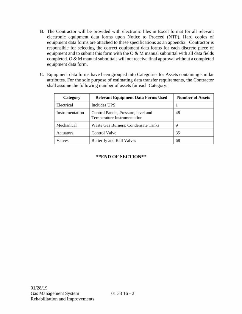
01/28/19 Gas Management System Rehabilitation and Improvements
01 33 16 - 2
B. The Contractor will be provided with electronic files in Excel format for all relevant electronic equipment data forms upon Notice to Proceed (NTP). Hard copies of equipment data forms are attached to these specifications as an appendix. Contractor is responsible for selecting the correct equipment data forms for each discrete piece of equipment and to submit this form with the O & M manual submittal with all data fields completed. O & M manual submittals will not receive final approval without a completed equipment data form.
C. Equipment data forms have been grouped into Categories for Assets containing similar attributes. For the sole purpose of estimating data transfer requirements, the Contractor shall assume the following number of assets for each Category:
Category Relevant Equipment Data Forms Used Number of Assets
Electrical Includes UPS 1
Instrumentation Control Panels, Pressure, level and Temperature Instrumentation
48
Mechanical Waste Gas Burners, Condensate Tanks 9
Actuators Control Valve 35
Valves Butterfly and Ball Valves 68
**END OF SECTION**

01/28/19
Gas Management System Rehabilitation and Improvements
01 41 26- 1
SECTION 01 41 26
PERMIT REQUIREMENTS
PART 1 -- GENERAL
1.01 GENERAL REQUIREMENTS
A. Building, plumbing, heating, electrical and similar permits which the Contractor is required to obtain from the County or City Building Inspection Divisions for District-owned projects are fee exempt. These permits will be obtained by the District’s Representative. Drainage fees, utility connection fees, and other permits and licenses unique to the project will be paid by District. The Contractor shall procure all permits and licenses necessary for the normal conduct of its business operations.
B. The California Environmental Quality Act of 1979 (CEQA) as amended may be applicable to permits, licenses and other authorizations which the Contractor must obtain from local agencies in connection with performing the Work of the Contract. The Contractor shall comply with the provisions of said statutes in obtaining such permits, licenses and other authorizations and they shall be obtained in sufficient time to prevent delays.
C. In the event the District has obtained permits, licenses or other authorizations applicable to the work in conformance with the requirements of CEQA, the Contractor shall comply with the provisions of said permits, licenses and other authorizations as presented in the WORK SEQUENCE Section (01 12 16).
Permit Regulatory Agency Party Responsible for
Obtaining Permit
Air Quality Permit Sacramento Metropolitan Air Quality Management District
District
NPDES Permit No. CA0077682
California Regional Water Quality Control Board, Central Valley Region
District
Biological Opinion U.S. Fish and Wildlife Service District
Fire Cosumnes Fire District District

01/28/19
Gas Management System Rehabilitation and Improvements
01 41 26- 2
D. Whenever an operation is required in which a hazardous condition exists, the Contractor shall be responsible for, and shall comply with, the Work Permit procedures specified in the SRWTP Safety Manual.
1.02 PAYMENT
A. Full compensation for work involved in compliance with the requirements of this section shall be considered included in the contract unit prices paid for the various items of work involved and no additional compensation will be allowed therefore.
**END OF SECTION**
01/28/19
Gas Management System Rehabilitation and Improvements
01 45 00 - 1
SECTION 01 45 00
QUALITY CONTROL
PART 1 -- GENERAL
1.01 GENERAL REQUIREMENTS
A. Contractor shall establish and maintain an effective quality control plan and organization. Contractor's Quality Control Plan (CQCP) shall consist of procedures necessary to provide and ensure materials, equipment, workmanship, fabrication, construction, and operations comply with the requirements of the Contract. CQCP shall provide controls adequate to cover all operations including on-site and off-site fabrication. The District Representative may perform inspection functions for the purposes of confirming adequacy of CQCP or to provide quality assurance. Tests in Divisions 2 through 50 which are to be performed by District Representative shall be considered quality assurance tests. The District Representative’s quality assurance inspections and testing shall in no way be interpreted to be a substitution for CQCP or construed to be acceptance of the Work.
B. Contractor Certification shall indicate compliance with the requirements of the Contract.
1.02 COORDINATION MEETING
A. Before start of construction, Contractor shall meet with District Representative to review CQCP. During this meeting CQCP shall be discussed including, procedures for recording CQCP operations, CQCP activities, non-compliance reporting, and the relationship between CQCP staff and the District Representative’s inspection staff.
1.03 QUALITY CONTROL PLAN
A. Not later than 30 days after receipt of the Notice to Proceed and prior to starting work, Contractor shall submit 4 copies of CQCP for review and approval in accordance with the SUBMITTAL PROCEDURES Section (01 33 00). Construction may not start until Contractor submits an acceptable CQCP plan unless an acceptable interim plan is furnished. CQCP shall identify personnel, procedures, instructions, records, and forms to be used to ensure the construction is in accordance with the drawings and specifications. CQCP is the means by which Contractor provides assurance that the construction complies with the requirements of the Contract. The controls shall be adequate to cover all construction operations, including both on-site and off-site fabrication, and shall be keyed to the proposed construction sequence.

01/28/19
Gas Management System Rehabilitation and Improvements
01 45 00 - 2
B. This plan shall include, as a minimum, the following:
1. A description of Quality Control organization, including an organizational chart showing lines of authority.
2. A copy of a letter to QC Manager signed by a principal or officer of Contractor, which describes the responsibilities of QC Manager and delegates full authority to QC Manager to act in all matters related to CQCP.
3. Procedures for scheduling, managing and certifying submittals comply with the contract requirements, including those of subcontractors and suppliers.
4. Procedures for ensuring construction activities, materials and equipment conform to contract requirements.
5. Reporting procedures and distribution including proposed reporting formats.
6. Procedures for ensuring that coordination drawings are prepared to resolve trade, system and space conflicts.
7. Procedures for ensuring that lift drawings are prepared for concrete placements.
8. Procedures for certifying all integral elements of poured-in-place and precast concrete placements are in place and forms are to line and grade prior to placing concrete.
9. Frequency for tests performed to confirm the adequacy of CQCP such as soil, concrete, and welding tests.
10. Procedures to maintain current records and logs of Quality Control activities. Quality Control records shall be submitted weekly to District Representative in accordance with the SUBMITTAL PROCEDURES Section (01 33 00). Quality Control records shall include, but are not limited to:
a. Submittal status and tracking.
b. Noncompliance reports.
c. Test results and Contractor Certifications for equipment, materials and workmanship.
d. Equipment and material installation records.
e. Testing records.
f. Record of any corrective actions or measures taken.
01/28/19
Gas Management System Rehabilitation and Improvements
01 45 00 - 3
C. After acceptance of CQCP, Contractor shall notify District Representative in writing of any proposed change. Proposed changes are subject to acceptance by District Representative.
1.04 QUALITY CONTROL ORGANIZATION
A. Contractor shall employ a Quality Control Manager whose responsibility is management of CQCP. Quality Control Manager shall be fully qualified by education and have at least 5 years’ experience in construction practices required for this project. Quality Control Manager shall have the authority to act in all quality control matters and shall be independent of Contractor's field work force. Prior to starting work, but not later than 30 days following Notice to Proceed, the name, qualifications, and experience of Quality Control Manager shall be submitted. Superintendent may fill role of Quality Control Manager in addition to other duties.
B. Staff shall be maintained as necessary under the direction of QC Manager to perform all QC activities.
1.05 NONCOMPLIANCE
A. District Representative will notify Contractor of any noncompliance with the drawings or specifications as they become known. This notification is not a substitute for CQCP notification process. Contractor shall be responsible for correcting all notices of non-conformance and taking action necessary to prevent reoccurrence. If Contractor fails or refuses to comply, District Representative may issue a stop notices for all or part of the work until satisfactory corrective action has been taken. Time lost due these stop notices shall be considered an avoidable delay--no compensation. in accordance with the CONTRACT TIME Section (01 14 20).
1.06 REFERENCE MATERIALS
A. Codes, standards, standard specifications, standard drawings and other publications are part of the Contract. Contractor to be knowledgeable or have the means to become knowledgeable of any referenced material, code or standard.
1.07 PAYMENT
A. Quality Control requirements described in this section are a part of the Work and the costs shall be included in the Total Bid Amount. The schedule of values shall provide at least 2.0 percent of the Total Bid Amount for CQCP.
B. Payment for Quality Control shall be prorated to the value of work as it progresses and paid with the progress payment. CQCP must effectively ensure that the quality requirements are consistently obtained due to the efforts of Contractor.
**END OF SECTION**

01/28/19
Gas Management System Rehabilitation and Improvements
01 45 00 - 4
THIS PAGE INTENTIONALLY LEFT BLANK

01/28/19
Gas Management System Rehabilitation and Improvements
01 51 00 - 1
SECTION 01 51 00
TEMPORARY UTILITIES
PART 1 -- GENERAL
1.01 GENERAL REQUIREMENTS
A. Contractor shall be responsible for providing and maintaining the required utilities for construction facilities, such as telephone, electric, and water service necessary for use at Contractor's expense except as noted in this section. Construction facilities are described in the CONSTRUCTION FACILITIES Section (01 52 00).
B. Contractor shall provide temporary utilities which will enable construction processes and will accommodate other necessary activities at the site. Providing adequate temporary utilities is Contractor's responsibility, and is not limited to the minimums established by the requirements hereof.
C. The types of temporary utilities required for the project include (but are not necessarily limited to) the following:
1. Field offices for Contractor;
2. Electric power;
3. Potable water;
4. Sanitary facilities;
5. Collection/disposal of waste materials;
6. Telephones;
7. Internet and computer network communications;
8. Non-potable water for construction activities.
D. The District has designated a general contractor laydown area, as shown on Contract Drawing 66G012.
E. Contractor shall not use existing plant utilities such as water supplies (WP, WN, WRH, and WRL), air supplies (UA and SA), steam system, telephone, public address system, radio frequency, etc.

01/28/19
Gas Management System Rehabilitation and Improvements
01 51 00 - 2
F. The following tabulation shows details of District's intent for responsibility of providing utilities:
Facility Contractor-Supplied
Utilities
Resident Engineer Office None
Contractor and subcontractor field offices
All
Contractor and subcontractor on site storage facilities
All
Construction utilities Contractor shall provide all utilities required for work.
Construction Water District will supply non-potable water sources from existing wells; the primary source is located near the southeast corner of SSB 1, and the secondary source is located at the corner of Laguna Station Road and Glacier Way. The Contractor shall identify adequate sources for the water and pay all costs associated with obtaining and delivering the water. Contractor to provide connection to non-potable water well and all other utilities.
Contractor shop areas All
Performance Testing District will supply power and Contractor shall provide the water and temporary connections and conveyance and all other utilities and fluids including lubricants and hydraulic fluid as needed except as specified in the USE OF SITE Section (01 14 19). If permanent power is unavailable, the Contractor shall provide standby power as described in this section.
Operational and Reliability Testing
District will supply all connected utilities (i.e. cooling water, seal water, power). If permanent utility power is unavailable, the Contractor shall provide standby power as described in this section. Contractor shall supply hydraulic fluids, lubricants, etc.

01/28/19
Gas Management System Rehabilitation and Improvements
01 51 00 - 3
1.02 QUALITY ASSURANCE
A. REGULATIONS:
1. Comply with governing regulations for the installation and use of general service facilities, including health and safety regulations.
B. STANDARDS:
1. Comply with Subchapter 4, CAC Title 8, Construction Safety Orders, and Subchapter 7, General Industrial Safety Orders, as applicable.
C. RESPONSIBILITIES:
1. Except as otherwise indicated, the assignment of responsibilities for installing utilities and for complying with trade regulations and union jurisdictions associated therewith, is Contractor's obligation.
1.03 SUBMITTALS
A. Submit to the District Representative for information only copies of inspection reports, certificates, permits and similar documentation required in accordance with the SUBMITTAL PROCEDURES Section (01 33 00).
1.04 SCHEDULED USES
A. Provide temporary utilities at the time first needed at the site; and maintain, expand and modify the facilities as needed throughout the construction period.
1.05 CONDITIONS OF USE
A. Operate, maintain, control and protect temporary utilities in a manner which will prevent fire, discomfort to users, flooding, interference with the construction work, and similar deleterious effects.
PART 2 -- PRODUCTS
2.01 MATERIALS AND EQUIPMENT
A. GENERAL:
1. Unless otherwise specified, Contractor may provide either new or used materials and equipment for general service facilities, which are in substantially undamaged condition and without significant deterioration and which are recognized in the construction industry by compliance with appropriate standards, as being suitable for the intended use in each application.
01/28/19
Gas Management System Rehabilitation and Improvements
01 51 00 - 4
B. NONPOTABLE WATER:
1. Contractor may use the existing well located near the southwest corner of Laguna Station Road and Glacier Way. Use of this well will be shared with other contractors and District staff. The approximate capacity of the well pump is 1,100 gpm. Contractor shall use care when using this well and shall follow all District operating procedures. Contractor shall notify the District’s Representative immediately if Contractor observes any issues with the wells.
2. Contractor may also use the existing well located near the northwest corner of Sims Road and Echo Road. Use of this well will be shared with other contractors and District staff. The approximate capacity of the well pump is 1,100 gpm.
3. Contractor may also use the existing well located north of ESB-D Road and west of Sims Road. Use of this well will be shared with other contractors. The approximate capacity of the well pump is 900 gpm. Contractor shall use care when using these wells and shall follow all District operating procedures. Contractor shall notify the District’s Representative immediately if Contractor observes any issues with the wells.
PART 3 -- EXECUTION
3.01 INSTALLATION OF TEMPORARY UTILITIES
A. GENERAL:
1. Locate utilities where they will serve the total project construction work adequately, and result in minimum interference with performance of the work. Relocate, modify and extend utilities as required during the course of the work, to properly accommodate the entire work of the project. Provide a reasonably neat and uniform appearance in general service facilities, acceptable to the District Representative.
2. Except as otherwise indicated, do not plan to change over from use of temporary utilities to use of permanent facilities until time of substantial completion, or for longer periods of time as requested by District. However, it is recognized that certain utilities will need to be removed from the site at or near the time of field acceptance, and that Contractor's personnel remaining at the site beyond that time will be permitted to use certain permanent facilities, under restricted use conditions which are acceptable to the District Representative.
B. DRINKING WATER:
1. Supply drinking water for construction personnel by either water-system connected drinking fountains or by containerized tap-dispensers with paper cups, (or both), at Contractor's option.

01/28/19
Gas Management System Rehabilitation and Improvements
01 51 00 - 5
C. ELECTRICAL POWER
1. The Contractor shall provide temporary power connections and meters for the Contractor's field office(s) and all Contractor equipment requiring electrical power. The Contractor shall provide all power required for construction. If permanent utility power is not available at the time performance testing begins, a standby diesel engine generator shall be provided, connected, operated, maintained, and removed. The Contractor shall determine the capacity of the generator needed to power all components of the project.
D. SANITARY SEWER
1. Sanitary facilities include toilets, wash facilities, drinking water fixtures and food/beverage service facilities (if any). Comply with governing regulations including safety and health codes for the type, number, location, operation, and maintenance of fixtures and facilities, but provide not less than the specified requirements. Install sanitary facilities in available locations which will best serve the needs of personnel at the project site.
2. Distribute toilets and drinking water fixtures as necessary. Plant washroom, toilet, and drinking water facilities shall not be used by Contractor or subcontractor personnel.
3. Supply and maintain toilet tissue, paper towels, paper cups and similar disposable materials as appropriate for each sanitary facility, and provide and empty waste paper containers for used materials.
E. NETWORK AND TELEPHONE COMMUNICATIONS
1. Contractor will provide all necessary network and telephone communications. Plant network or telephones shall not be used by Contractor or subcontractor personnel.
2. Post a listing of telephone numbers at each telephone location, including local police, fire department, doctor, ambulance service and similar emergency numbers as well as temporary and home offices of contractors, principal subcontractors, architects, engineers, representatives of District, and others involved with the performance of the work.
3.02 MAINTENANCE AND TERMINATIONS
A. MAINTENANCE:
1. Operate and maintain temporary utilities in good operating condition through the time of use, and until removal is authorized. Protect from damage by weather.

01/28/19
Gas Management System Rehabilitation and Improvements
01 51 00 - 6
B. TERMINATION AND REMOVAL:
1. When the need has ended for each temporary utility, or at the time of substantial completion, promptly remove the utility unless requested by the District Representative to retain it. Complete or restore permanent work which may have been delayed or otherwise affected by the temporary utility. Replace work which cannot be satisfactorily restored.
**END OF SECTION**
01/28/19 Gas Management System Rehabilitation and Improvements
01 52 00 - 1
SECTION 01 52 00
CONSTRUCTION FACILITIES
PART 1 -- GENERAL
1.01 GENERAL REQUIREMENTS
A. Contractor shall be responsible for providing and maintaining the necessary field offices, material storage and sanitary facilities necessary for use at Contractor's expense except as noted in this section. Temporary utilities for construction facilities are described in the TEMPORARY UTILITIES Section (01 51 00).
B. Contractor shall provide temporary facilities which will enable construction processes, and will accommodate other necessary activities at the site. Providing adequate general services is Contractor's responsibility, and is not limited to the minimums established by the requirements hereof. Except as otherwise indicated, the use of alternative general services equivalent to those specified is Contractor's option, subject to acceptance by the District Representative. Temporary general services exclude inspection and testing services, surveys, photographs, security provisions, protection, safety, final cleaning, start-up of systems, instructions to District personnel and other services which are recognized to be similar to the work of this section but are specified in other sections hereof, if required.
C. The types of temporary facilities and general services required for the project include (but are not necessarily limited to) the following:
1. Field offices for Contractor and subcontractor;
2. On-site storage facilities for Contractor and subcontractor;
3. Sanitary facilities;
4. Collection/disposal of waste materials; and
5. Miscellaneous general services.
D. Contractor shall not use existing plant facilities such as restrooms, lunchrooms, etc.
1.02 QUALITY ASSURANCE
A. REGULATIONS:
1. Comply with governing regulations for the installation and use of general service facilities, including health and safety regulations.

01/28/19 Gas Management System Rehabilitation and Improvements
01 52 00 - 2
B. STANDARDS:
1. Comply with Subchapter 4, CAC Title 8, Construction Safety Orders, and Subchapter 7, General Industrial Safety Orders, as applicable.
C. RESPONSIBILITIES:
1. Except as otherwise indicated, the assignment of responsibilities for installing facilities and performing general services, and for complying with trade regulations and union jurisdictions associated therewith, is Contractor's obligation.
1.03 SUBMITTALS
A. Submit to the District Representative for information only copies of inspection reports, certificates, permits and similar documentation required or issued in connection with general services in accordance with the SUBMITTAL PROCEDURES Section (01 33 00).
1.04 SCHEDULED USES
A. Provide temporary general services at the time first needed at the site; and maintain, expand and modify the facilities as needed throughout the construction period.
1.05 CONDITIONS OF USE
A. Operate, maintain, control and protect general service facilities in a manner which will prevent fire, hazardous exposures, health problems, unsanitary conditions, pollution, contamination, discomfort to users, flooding, interference with the construction work, public nuisances and similar deleterious effects.
PART 2 -- PRODUCTS
2.01 MATERIALS AND EQUIPMENT OF GENERAL SERVICES
A. GENERAL:
1. Unless otherwise specified, Contractor may provide either new or used materials and equipment for general service facilities, which are in substantially undamaged condition and without significant deterioration and which are recognized in the construction industry by compliance with appropriate standards, as being suitable for the intended use in each application.
B. CONSTRUCTION MATERIALS:
1. For offices, fabrication shops, storage sheds and similar construction, provide standard-manufactured prefabricated or mobile home construction insulated and weather-tight where indicated to be heated or air conditioned, or provide equivalent

01/28/19 Gas Management System Rehabilitation and Improvements
01 52 00 - 3
job-built construction. Equip each unit with locked entrances, operable windows, roofing, adequate foundations for usual loading including wind loads, serviceable finishes of the types indicated, and mechanical/electrical equipment as needed to achieve the ambient conditions indicated.
C. SELF-CONTAINED TOILET UNITS:
1. Single-occupant, self-contained units of the chemical aerated recirculation type fully enclosed with a glass fiber reinforced polyester shell or similar nonabsorbent material, properly vented and maintained in operation.
PART 3 -- EXECUTION
3.01 INSTALLATION OF GENERAL SERVICE FACILITIES
A. GENERAL:
1. The District has designated a general contractor laydown area, as shown on Contract Drawing 97GC002. Parking on existing road shoulders, in District parking areas, or parking in any way that affects the District’s ingress/egress shall not be acceptable. Any single Contractor trailer must not exceed 3,600 square feet.
2. Locate facilities within the designated Contractor area where they will serve the total project construction work adequately, and result in minimum interference with performance of the work. Relocate, modify and extend facilities as required within the designated area during the course of the work, to properly accommodate the entire work of the project. Provide a reasonably neat and uniform appearance in general service facilities, acceptable to the District Representative.
3. Except as otherwise indicated, do not plan to change over the use of permanent facilities of the project to replace the use of temporary general service facilities. However, it is recognized that certain general service facilities will need to be removed from the site at or near the time of field acceptance, and that Contractor's personnel remaining at the site beyond that time will be permitted to use certain permanent facilities, under restricted use conditions which are acceptable to the District Representative.
B. SANITARY FACILITIES:
1. GENERAL:
a. Sanitary facilities include toilets, wash facilities, drinking water fixtures and food/beverage service facilities (if any). Comply with governing regulations including safety and health codes for the type, number, location, operation, and maintenance of fixtures and facilities, but provide not less than the specified requirements. Install sanitary facilities in available locations which will best serve the needs of personnel at the project site.

01/28/19 Gas Management System Rehabilitation and Improvements
01 52 00 - 4
b. Distribute toilets and drinking water fixtures as necessary. Plant washroom, toilet, and drinking water facilities shall not be used by Contractor or subcontractor personnel.
c. Supply and maintain toilet tissue, paper towels, paper cups and similar disposable materials as appropriate for each sanitary facility, and provide and empty waste paper containers for used materials.
2. TOILETS: Provide in quantity that will sufficiently serve Project work force, choice of either self-contained toilet units or water/sewer connected temporary toilet installations (or both) is Contractor's option to the extent permitted by governing regulations. The provision of water/sewer connections is Contractor's responsibility in accordance with the TEMPORARY UTILITIES Section (01 51 00).
3. DRINKING WATER FIXTURES: Supply drinking water for construction personnel by either containerized tap-dispensers with paper cups, or by water-system connected drinking fountains (or both), at Contractor's option. Refer to the TEMPORARY UTILITIES Section (01 51 00) for temporary potable water supply.
4. SHOWERS: Contractor may provide a shower facility for which Contractor would be responsible for providing potable water and sewer connection in accordance with the TEMPORARY UTILITIES Section (01 51 00). Location of shower facility shall be approved by the District Representative, and may possibly be placed in the plant facility somewhat remote from the project site. Existing District showers may not be used by Contractor, except as approved by the District Representative for unusual situations.
C. COLLECTION AND DISPOSAL OF WASTES:
1. Establish and enforce a daily system for collecting and disposing of waste materials from construction areas and elsewhere at the project site. No waste material can be stored in tunnels or buildings, it must be disposed of daily. Do not hold collected materials at the site for periods of more than 7 days, nor for periods of more than 3 days during hot weather (when daily temperatures can be expected to rise above 80 degrees F). Handle hazardous, dangerous, unsanitary, contaminated, polluting and similar harmful wastes separately from inert materials. Store and dispose of hazardous wastes in a lawful and timely manner. Allowable mandated storage retention times may be less than the 7-day limit stated for nonhazardous wastes. Dispose of each category of waste material in a lawful manner. Do not bury or burn waste materials on District property.
01/28/19 Gas Management System Rehabilitation and Improvements
01 52 00 - 5
D. MISCELLANEOUS GENERAL SERVICES:
1. Include whatever general services may be required, or are found to be necessary, for the accommodation of the work. The items of general service which may be needed include, but are not necessarily limited to, the installation of postal delivery service, parking spaces at the temporary offices, walkways in and around the construction area and personal protection items for employees and visitors.
3.02 OPERATIONS AND TERMINATIONS
A. SUPERVISION:
1. Enforce strict discipline in the use of general services at the project site. Limit availability of facilities to essential and intended uses, so as to minimize wastes and the possibility of abuses and the resulting unsanitary and hazardous or dangerous conditions. Do not allow temporary offices and similar temporary or permanent spaces to be used as living quarters, or for other unintended occupancies or uses.
B. JANITORIAL SERVICES:
1. Provide daily janitorial services for temporary offices, toilets, wash facilities, and similar areas at the project site. Require users of other general services to maintain clean and orderly premises.
C. MAINTENANCE:
1. Operate and maintain general services in good operating condition through the time of use, and until removal is authorized. Protect from damage by weather.
D. TERMINATION AND REMOVAL:
1. When the need has ended for each temporary general service facility, or at the time of substantial completion, promptly remove the facility unless requested by the District Representative to retain it. Complete or restore permanent work which may have been delayed or otherwise affected by the temporary facility. Replace work which cannot be satisfactorily restored. Except as otherwise indicated, the materials and equipment of temporary general services remain the property of Contractor. District reserves the right to take possession of project identification signs.
**END OF SECTION**

01/28/19 Gas Management System Rehabilitation and Improvements
01 52 00 - 6
THIS PAGE INTENTIONALLY LEFT BLANK
01/28/19
Gas Management System Rehabilitation and Improvements
01 55 26 - 1
SECTION 01 55 26
TRAFFIC CONTROL
PART 1 -- GENERAL
1.01 GENERAL REQUIREMENTS
A. SCOPE:
1. This section specifies traffic control requirements to be implemented by Contractor through the entire duration of this project. Contractor shall be responsible for the safety of traffic within all areas of Contractor's work and on the approaches to the areas of work. Contractor shall furnish, erect, and maintain such warning devices as are necessary to protect the public, and the District Representative may point out inadequacies of such warning devices. However, Contractor shall not be relieved of the responsibility to protect the public by any approval given by the District Representative or by the District Representative's failure to point out a deficiency. As a minimum, traffic control shall be implemented in the following areas:
B. CONSTRUCTION TRAFFIC MANAGEMENT:
1. The Contractor shall comply with the EchoWater Traffic Management Plan (TMP) and limit construction traffic to Interstate-5, Laguna Blvd and Dwight Road. For the purposes of bidding, the contractor shall assume workers will not access the site during the peak traffic hours of 7 to 8 am. Contractor shall work with the District Representative to reduce construction traffic congestion, including implementation of the following traffic reduction measures:
a. Staggering the beginning and ending times of construction worker shifts during peak travel times;
b. Utilize alternative haul routes as directed by the District Representative; and
c. Provide monthly construction traffic projections (i.e., traffic volumes, vehicle type, and durations) for future planning.
C. TRAFFIC CONTROL ON CONTRACTORS' ACCESS ROAD:
1. Contractor shall provide general control of traffic on Contractors' Access Road. The traffic on Contractors' Access Road will mainly consist of construction contractors and their road vehicles, other contractor deliveries of material and equipment, and inspection vehicles driven by the District Representative.
01/28/19
Gas Management System Rehabilitation and Improvements
01 55 26 - 2
2. Contractor shall not allow any disturbance of the pavement on Contractors' access road other than as required for the construction of the improvements included in this contract.
D. LEVEE ROADS:
1. Contractor shall provide general control of traffic on levee. The general traffic control shall include:
a. Limiting Contractor traffic to only those construction vehicles necessary to perform the work.
1.02 QUALITY ASSURANCE
A. Contractor shall, 48 hours in advance of beginning any work, notify the District Representative in writing of the name, location, and 24-hours-per-day telephone number of the company which will supply barricade and warning devices for the project. Said supplier must be approved by District’s Representative, and must be available on a 24-hour basis for maintaining, placing, and replacing lighted barricades and warning devices. If the District Representative is unable to contact Contractor or superintendent, the supplier will be called directly, and Contractor shall accept charges made by the supplier for service performed, as a result of the District Representative's call.
B. Contractor shall furnish and install all traffic and warning signs, lighted barricades, etc., as per Section 12, "Temporary Traffic Control," of the Caltrans Standard Specifications. Contractor attention is directed to Section 7-1.03, "Public Convenience," Section 7-1.04, "Public Safety," of the Caltrans Standard Specification.
1.03 SUBMITTALS
A. The following information shall be provided in accordance with the SUBMITTAL PROCEDURES Section (01 33 00) and the EARTH MOVING Section (31 20 00):
1. A copy of this specification section, with addenda updates, with each paragraph check marked to show specification compliance or marked to show deviation.
2. Traffic control plan for Contractors' access road.
3. Traffic control plan for Contractors' access road bypass.
B. The traffic control plan shall include drawings showing work areas, traffic signs, barricades, flag people, and temporary signals locations and control descriptions, including proposed Caltrans standard drawings and specifications. The traffic control plan for each area shall be submitted to District’s Representative for review prior to commencing work in the area.

01/28/19
Gas Management System Rehabilitation and Improvements
01 55 26 - 3
C. All costs, including flagging, shall be borne by Contractor. Contractor shall provide safe passage for vehicular and pedestrian traffic through the work at all times.
PART 2 -- PRODUCTS (NOT USED)
PART 3 -- EXECUTION
3.01 GENERAL
A. No work shall commence until approved traffic control signs have been placed at the job site. All signs shall be in accordance with Caltrans standard specifications concerning size, reflectorization, and color. All signs shall be post-mounted unless otherwise specified by the District Representative.
B. District’s Representative may require Contractor to install additional signs or other safety controls as required for public safety.
C. All roadway closures shall be minimized and coordinated in accordance with the COORDINATION WITH OCCUPANTS Section (01 14 16) such that access to all facilities remains open and accessible for plant use and emergency vehicles.
3.02 DUCT BANKS, CONDUITS, PIPING
A. The excavation plan and schedule for constructing all duct banks, conduits, piping and manholes located in plant roads shall be coordinated with District’s Representative in accordance with the COORDINATION WITH OCCUPANTS Section (01 14 16). The duct banks, conduits, piping and manholes shall be constructed in a sequence to minimize interruption to plant traffic. Contractor shall provide temporary access to all plant traffic during closures of roadway during construction in accordance with the requirements of the WORK SEQUENCE Section (01 12 16) and the COORDINATION WITH OCCUPANTS Section (01 14 16). All excess dirt excavated during construction shall be disposed at the site identified in the drawings of the Site Work Key Plan.
3.03 TEMPORARY SUPPORT FOR TRENCHES
A. Contractor shall provide steel plates for temporary trench crossings. The temporary trench crossings shall be able to safely withstand traffic loads from heavy material delivery trucks and any other plant traffic.
B. Contractor shall provide steel plating over excavations for continuous access by District staff when work is not in progress in those excavated areas adjacent to equipment in operation.
**END OF SECTION**

01/28/19
Gas Management System Rehabilitation and Improvements
01 55 26 - 4
THIS PAGE INTENTIONALLY LEFT BLANK

01/28/19
Gas Management System Rehabilitation and Improvements
01 56 00 - 1
SECTION 01 56 00
TEMPORARY BARRIERS AND ENCLOSURES
PART 1 -- GENERAL
1.01 GENERAL REQUIREMENTS
A. This section specifies minimum requirements of temporary provisions for temporary barriers and enclosures not specified elsewhere.
B. The providing of adequate security and protection is Contractor's responsibility, and is not limited to minimums established by requirements hereof. Except as otherwise indicated, use of alternative security and protection methods of facilities equivalent to those specified is Contractor's option. The work of this section is not intended to include required insurance coverage, individual provisions for safe performance of specific work, first aid requirements, general supervision, quality control, damage surveys, prequalification of construction personnel, temporary enclosure of completed work and stored materials, inspection and tests of the work, instructions to District personnel and similar recognized protection/security provisions, which may be required.
C. The types of security and protection facilities required for the project include but are not necessarily limited to the following:
1. Barricades, warning signs, lights;
2. Enclosure fence for project site and construction areas; and
3. Security enclosure and lockup of work.
D. The types of temporary barriers required for the project include:
1. Species control barriers for giant garter snake habitat to prevent the species from entering active construction areas.
1.02 QUALITY ASSURANCE
A. REGULATIONS:
1. Comply with governing regulations for installation and operation of security and temporary barrier facilities.
B. RESPONSIBILITIES:
1. The assignment of responsibilities for security and temporary barriers such as installation, maintenance and operation, is Contractor's obligation.

01/28/19
Gas Management System Rehabilitation and Improvements
01 56 00 - 2
C. DELIVERIES:
1. No deliveries will be accepted by the District. All deliveries shall be made to the Contractor.
1.03 JOB CONDITIONS
A. SCHEDULED USES:
1. Provide temporary barriers, security and protection at site. Maintain, expand and modify facilities as needed throughout construction period.
B. TEMPORARY USE OF PERMANENT FACILITIES:
1. The Contractor shall be required to assume responsibility for its operation, maintenance and protection prior to acceptance of the facility by the District Representative.
C. CONDITIONS OF USE:
1. Use temporary barriers, security and protection facilities and services in a safe, sanitary, lawful, and publicly acceptable manner, which will not interfere unduly with performance of the work nor result in other deleterious effect.
D. TEMPORARY FENCING:
1. Provide and maintain temporary fencing and barriers as shown on the Drawings for the duration of the contract or as directed by the District Representative.
PART 2 -- PRODUCTS
2.01 SECURITY AND PROTECTION FACILITIES
A. GENERAL:
1. Provide either new or used materials and equipment, which are in substantially undamaged and serviceable condition.
B. OPEN-MESH FENCING:
1. No. 11 gage galvanized chain link fabric 6 foot high; galvanized steel pipe posts, 1-1/2-inch line posts, 2-inch corner posts, 2-1/2-inch gate and pull posts.

01/28/19
Gas Management System Rehabilitation and Improvements
01 56 00 - 3
2.02 (NOT USED)
2.03 (NOT USED)
PART 3 -- EXECUTION
3.01 INSTALLATION OF SECURITY/PROTECTION FACILITIES
A. GENERAL:
1. Locate facilities to serve total project construction work adequately, and to result in minimum interference with performance of the work. Relocate, modify and extend facilities as required during course of the work, to properly accommodate entire work of the project. Provide and maintain a reasonably neat and uniform appearance in security and protection facilities, acceptable to District.
2. Do not plan to change over from use of temporary security and protection facilities to use of permanent facilities until time of substantial completion, or for longer periods of time as requested by District.
B. BARRICADES, WARNING SIGNS AND LIGHTS:
1. Comply with recognized standards and code requirements for erection of substantial and structurally adequate barricades where needed to prevent accidents and losses. Paint with appropriate colors, graphics and warning signs to inform personnel at site, and the general public where exposure exists, of hazard being protected. Provide lighting where appropriate and needed for recognition of facility, including flashing red lights where appropriate.
2. Provide and maintain all barricades, warning lights, signs, fences and other work for the protection and safety of the public and workers as required by the District’s Representative. Contractor shall at all times have at least 50 unused barricades on site whenever excavation of any type is taking place.
3. Construction areas within the existing buildings shall be adequately signed and partitioned off so that such areas can be secured, at all times, against unauthorized entry.
C. ENCLOSURE FENCING:
1. Install temporary fencing prior to excavation, or other substantial elements of the work at the project site. Install fencing so as to exclude entrance to the site except at gates.
2. Temporary fencing shall be minimum 6'-0" high, shall be constructed of chain-link mesh with vertical and horizontal supports as required for sturdy barrier.

01/28/19
Gas Management System Rehabilitation and Improvements
01 56 00 - 4
3. Gates in temporary fencing shall be as required for Contractor's access and facility use. All gates shall be lockable with padlocks, padlocks to be furnished by Contractor for gates. Furnish one key to the District Representative for Contractor's padlocks. Gates in temporary fencing shall be hinged and of construction which will not cause problems for District and as approved.
4. Provide fencing within the site, as required, with posts set in compacted earth/gravel mixture or temporary concrete footings.
D. SECURITY ENCLOSURE AND LOCKUP:
1. The Contractor shall be responsible for the security of all equipment, materials and work until it is accepted by the District Representative.
3.02 (NOT USED)
3.03 (NOT USED)
3.04 TERMINATION AND REMOVAL
A. Maintain protection and security facilities and services in good operating condition through time of use and until completion and use of permanent work makes each temporary service unnecessary, or until District occupancy has replaced the need for service or until its discontinuation has been otherwise authorized. Remove each facility promptly after its use has been terminated. Complete or restore permanent work which may have been delayed or otherwise affected by temporary facility. Replace work which cannot be satisfactorily restored. Except as otherwise indicated, materials and equipment of temporary security and protection facilities remain the property of the Contractor.
**END OF SECTION**

01/28/19 Gas Management System Rehabilitation and Improvements
01 57 19 - 1
SECTION 01 57 19
TEMPORARY ENVIRONMENTAL CONTROLS
PART 1 -- GENERAL
1.01 HOUSEKEEPING
A. Throughout the construction period, Contractor shall keep the site of the work in a presentable condition, shall dispose of any surplus materials appropriately, clean out all drainage ditches and structures, and repair any fences or other property damaged during the progress of the work, to the satisfaction of the District Representative.
B. Upon completion of the work, and prior to requesting final inspection, Contractor shall thoroughly clean the site of the work of all rubbish, excess material, and equipment, and all portions of the work shall be left in a neat and orderly condition. The final inspection will not be made until this has been accomplished.
1.02 (NOT USED)
1.03 AIR POLLUTION CONTROL
A. Contractor shall comply with all air pollution control rules, regulations, ordinances, and statutes which apply to any work performed pursuant to the contract, including any air pollution control rules, regulations, ordinances, and statutes, specified in Section 11017 of the Government Code.
1.04 SOUND CONTROL REQUIREMENTS
A. Contractor shall comply with all local sound control and noise level rules, regulations, and ordinances which apply to any work performed pursuant to the contract.
B. Each internal combustion engine shall be equipped with a muffler of a type recommended by the manufacturer. No internal combustion engine shall be operated without said muffler.
C. No internal combustion engine shall be operated in the tunnel system or enclosed below grade spaces or HVAC air intakes.
1.05 WATER POLLUTION AND SOIL CONTAMINATION
A. Contractor shall comply with all federal state, and local rules, regulations, ordinances, and statutes which apply to water pollution and soil contamination, including the TEMPORARY STORM WATER POLLUTION CONTROL Section (01 57 23).
01/28/19 Gas Management System Rehabilitation and Improvements
01 57 19 - 2
B. In order to minimize the possibility of water or soil contamination due to spills of crankcase oil, gasoline and other fuels, Contractor shall designate an area for the storage and handling of lubricants, fuels and other supplies which is acceptable to the District Representative.
1.06 HAZARDOUS MATERIALS
A. Contractor shall comply with all applicable federal environmental regulations by the U.S. Environmental Protection Agency (US EPA), United States Department of Transportation (US DOT), Occupational Safety and Health Administration (OSHA), the Resource Conservation and Recovery Act (RCRA), state environmental regulations and local environmental regulations and ordinances for hazardous waste/materials management.
B. Contractor shall develop and submit a Hazardous Material Plan (HMP) for hazardous materials anticipated during the project to the regulating authority (Sacramento County’s Environmental Management Department has been designated as the Sacramento region’s Certified Unified Program Agency (CUPA) by Cal EPA). A HMP is mandated when hazardous material/waste is stored in the reportable quantities:
1. Liquid: 55 gallons or greater
2. Solid: 500 pounds or greater
3. Gas: 200 cubic feet (at standard temperature and pressure) or greater
Note: A reportable quantity is the aggregate of all similar materials and accounts for the capacity to store. Example: 15 gallons of a hazardous waste stored in a 55 gallon container must be reported. The District will require any material meeting or exceeding the reportable quantity to be reported.
C. Contractors shall obtain a permit from Cosumnes Fire Department (Administration Section) for tanks that contain hazardous materials greater than 125 gallons that will be stored on District property. The Cosumnes Fire Department has permit requirements for the following hazardous materials and tanks:
1. Above-ground flammable/combustible liquid tank/cylinders; and
2. Above-ground hazardous material tank(s).
D. Contractor is required to secure all required regulatory permits and licenses necessary prior to performing all aspects of the work in accordance with the PERMIT REQUIREMENTS Section (01 41 26). A copy of the HMP, HMP amendments, permits, licenses, clearances or authorizations obtained by the Contractor shall be provided to the District Representative prior to bringing or storing hazardous materials on site.
E. Contractor shall be responsible for ensuring that Contractor personnel including subcontractors are adequately trained and understand how to handle, store, transport

01/28/19 Gas Management System Rehabilitation and Improvements
01 57 19 - 3
and dispose of waste per this specification. Contractor shall further ensure that personnel involved in the work area are aware of the spill prevention and containment responsibilities.
F. Contractor shall comply with all Federal and State laws for employee right-to-know in association with the use and storage of hazardous substances on-site. Contractor to have on the project site the Material Safety Data Sheets (MSDS)/Safety Data Sheets for all hazardous substances stored or used on-site, readily available to employees and inspectors at all times. Contractor is responsible for the removal and disposition of all surplus chemicals (e.g., paints, lubricants, and cleaning products) that they bring onsite as part of the work.
G. Contractor shall provide immediate notice to the District Representative in the event of a spill. Any release or threatened release on land or in watercourses, regardless of quantity, shall be cleaned up immediately.
H. The Contractor shall furnish certified copies of manifests (interim storage and final disposal) within regulatory requirements. Within 180 days from the acceptance of the waste by the disposal facility, the Contractor shall provide the District Representative with the Certificate of Disposal documentation.
I. Only Contractors licensed to transport hazardous materials/waste (under EPA and US DOT) shall be permitted to transport hazardous materials/waste. Transportation of hazardous material shall be conducted in accordance with all applicable regulations for proper packaging, marking/labeling, handling, and documenting. Contractors are responsible for ensuring that personnel preparing the shipment are properly trained and that proper shipping papers accompany shipments of hazardous materials.
J. Contractor shall be responsible and fully bear costs incurred by the District as a result of violations with applicable Federal, State and local Agencies for spills, unauthorized releases, and discharge, including but not limited to penalties assessed or levied, third party claims, citizen suites, labor materials, laboratory analyses, and handling and disposal of waste. Fines shall be deducted from contract payments specified in the PROGRESS PAYMENT PROCEDURES Section (01 29 76).
1.07 PETROLEUM POLLUTION PREVENTION
A. Contractor shall comply with petroleum pollution prevention measures in accordance with the United States Environmental Protection Agency regulations contained in Title 40, Code of Federal Regulations, Part 112, the California Aboveground Petroleum Storage Act (APSA), and the California Health and Safety Code (Section 25270.4.5). Additionally, all fuel stored on site shall be stored in compliance with the Uniform Fire Code, NFPA standards, and all other applicable laws.
B. If above-ground fuel storage will exceed 55 gallons per container or 1,320 gallons aggregate, Contractor shall develop and submit a Spill Prevention, Control, and Countermeasure (SPCC) Plan as required by 40 CFR 112 Oil Pollution Prevention. The

01/28/19 Gas Management System Rehabilitation and Improvements
01 57 19 - 4
SPCC plan requirement is in addition to the requirements specified in the TEMPORARY STORM WATER POLLUTION CONTROL Section (01 57 23).
C. The SPCC plan shall be prepared and certified by a registered Professional Engineer. Maintain a certified copy of the SPCC plan on-site at all times during construction activities that is readily available to Contractor personnel, inspectors, and regulators. A copy of the SPCC and all amendments shall be submitted to the District Representative for review.
**END OF SECTION**
01/28/19
Gas Management System Rehabilitation and Improvements
01 57 23 - 1
SECTION 01 57 23
TEMPORARY STORM WATER POLLUTION CONTROL
PART 1 -- GENERAL
1.01 GENERAL REQUIREMENTS
A. This section specifies the requirements for Stormwater Pollution Prevention which includes a Water Pollution Control Plan (WPCP) for a project resulting in less than one acre of soil disturbance, any size project fully within the Sacramento Regional Wastewater Treatment Plant (SRWTP) process area, or any project that is not otherwise subject to the requirements of the State Water Resources Control Board (SWRCB), Water Quality Order No. 2009-009-DWQ, National Pollutant Discharge Elimination System (NPDES), General Permit No. CAS000002, Waste Discharge Requirements (WDRs) for Discharges of Storm Water Runoff Associated with Construction Activity (Construction General Permit) to control storm water discharges from construction sites.
B. Contractor may opt to implement a more restrictive program than that which is required. The Contractor must then conform to all requirements of both the minimum applicable program and the more restrictive program.
C. Contractor shall implement Best Management Practices (BMPs) including good housekeeping practices and erosion and sediment control, to prevent the direct and indirect contribution of any contaminants into the storm drain system or waters of the United States.
D. BMPs shall be implemented according to the California Stormwater BMP Handbook – Construction (2009) with updated 2011 BMP fact sheets. Non-structural and structural BMPs shall be acceptable to the District Representative and instituted or placed, as appropriate, before commencement of each phase of clearing, grading, excavation, trenching, or staging of materials that may be potential pollutants.
E. Furnish all labor, materials, equipment, and incidentals necessary to perform all installation, maintenance, removal, and area cleanup related to erosion and sediment control BMPs necessary to prevent the movement of sediment from the construction site to off-site areas including roadways, surface waters, storm drains, disposal locations, and flood control facilities.
F. Contractor shall be responsible and fully bear costs incurred by the District as a result of violations under the Federal Clean Water Act, the State Porter-Cologne Water Quality Control Act, or for unauthorized release or discharge from the work including but not limited to penalties assessed or levied, third party claims, citizen suits, labor, materials, analytical analyses, and handling of waste. Fines shall be deducted from

01/28/19
Gas Management System Rehabilitation and Improvements
01 57 23 - 2
contract payments specified in the PROGRESS PAYMENT PROCEDURES Section (01 29 76).
1.02 REFERENCES
A. The publications referred to hereinafter form a part of this specification to the extent referenced. The publications are referred to in the text by the basic designation only. The latest edition of the referenced publications in effect at the time of the bid shall govern. In case of conflict between the requirements of this section and the listed references, the requirements of this section shall govern.
Reference Title
California Stormwater Quality Association (CASQA)
California Stormwater BMP Handbook – Construction
1.03 SUBMITTALS
A. The following information shall be submitted for review and approval in accordance with the SUBMITTAL PROCEDURES Section (01 33 00):
1. A copy of this specification section, with addenda updates, with each paragraph check marked to show specification compliance or marked to show deviation.
2. The Contractor shall designate a Storm Water Pollution Prevention Coordinator. This person shall have previous experience in erosion and sediment control with similar type and size projects and shall submit a resume to the District Representative for approval. This person will be responsible for preparing and implementing the WPCP.
3. The WPCP shall be submitted to the District within 10 days of the NTP and prior to the commencement of the Work.
4. Completed inspection and maintenance reports within 3 working days of preparation.
5. Upon completion of the project, submit the complete WPCP and relevant documents and amendments to the District Representative.

01/28/19
Gas Management System Rehabilitation and Improvements
01 57 23 - 3
PART 2 -- PRODUCTS (NOT USED)
PART 3 -- EXECUTION
3.01 GENERAL
A. The Contractor shall assume responsibility for stormwater runoff management and erosion and sediment control at the project site during construction. Fully comply with all applicable state and local regulations, and requirements related to stormwater management, erosion and sediment control.
B. Prior to commencement of any land disturbing activity, the contractor shall submit the WPCP to the District Representative. No activity having the potential to cause water pollution, as determined by the District Representative, shall be performed until the District Representative has approved the WPCP and appropriate BMPs have been installed by the Contractor.
3.02 WATER POLLUTION CONTROL PLAN
A. Develop a Water Pollution Control Plan (WPCP) to identify potential pollutants associated with each phase of construction activity and non-structural and structural BMPs appropriate to each phase of the work. The WPCP shall detail the following, if applicable:
Schedule Location of soil stockpiles Location of solid waste containers Vehicle and equipment fueling, servicing, cleaning and storage areas Material storage areas Chemicals, potential pollutants and hazardous materials to be used and
methods for safekeeping Site drainage during execution of the Work Stabilization of vehicle access to site De-watering operations Methods for spill prevention and control Secondary containment Handling and disposal of solid waste Storage and dispensing of fuel and lubricants Clean out and disposal of ready mix concrete Sanitation provisions Disposal location for excess excavated material Haul Routes
B. The WPCP shall include BMPs to prevent an unauthorized release or discharge of pollutants, contaminants, chemicals, hazardous substances or materials. The BMPs will be described in both narrative form and proper placement illustrated on figures.
01/28/19
Gas Management System Rehabilitation and Improvements
01 57 23 - 4
C. Maintain one copy of the WPCP and amendments at the project site. The WPCP shall be made available upon request by a representative of the Regional Water Quality Control Board (RWQCB), State Water Resources Control Board (SWRCB), United States Environmental Protection Agency (USEPA), or the local stormwater management agency. Requests by the public shall be directed to the District Representative. At completion of construction, submit the complete WPCP, amendments, inspection and maintenance records, and any other relevant documents to the District’s Representative.
3.03 INSPECTIONS AND MAINTENANCE
A. Make a visual inspection of all BMPs as necessary to ensure proper operation but not less than once per week. For rain events predicted at a 50 percent (50%) chance or higher (as reported at www.srh.noaa.gov), inspections are to be conducted within 48 hours before. For rain events measuring 0.50 inches or greater (as reported at www.srh.noaa.gov), inspections are to be conducted at least every 48 hours during and within 48 hours after. If such inspection reveals that existing measures are damaged or that additional measures are needed to prevent movement of sediment to off-site areas, promptly repair, replace or install additional devices as needed within 24 hours of notification. Sediment controls in need of maintenance shall be repaired within 24 hours of notification.
B. Maintenance of BMPs shall be per the Construction BMP Handbook. Perform routine maintenance consisting of debris removal, silt/sediment removal, clearing of vegetation around flow control devices to prevent clogging, and maintenance of healthy vegetative cover.
C. The Contractor shall be responsible for preparing and maintaining inspection and maintenance records. Inspection and maintenance reports are to be submitted to the District Representative within 3 working days.
3.04 DISPOSAL OF EXCESS EXCAVATED MATERIAL
A. Excess excavated material is defined as material from onsite excavations that are beyond the volumes necessary to meet the finish grades shown on the Contract Documents.
B. The Contractor shall be responsible for the disposal of excess excavated material. The Contractor shall be responsible for hauling excess excavated material offsite in accordance with laws and regulations regarding disposal of such material.
3.05 NOTIFICATION AND REPORTING
A. The Contractor is responsible for identifying and bringing to the attention of the District’s Representative all activities that may result in a non-stormwater discharge prior to commencing with such work. Any uncontrolled non-stormwater discharge shall be reported to the District Representative immediately.

01/28/19
Gas Management System Rehabilitation and Improvements
01 57 23 - 5
3.06 REMOVAL AND FINAL CLEANUP
A. Once the site has been fully stabilized against erosion, remove sediment control devices and all accumulated silt. Dispose of silt and waste materials in proper manner.
B. Provide post-construction erosion controls, including soil stabilization, in accordance with the Contract Documents. Materials subject to degradability shall have a minimal functional longevity of 12-months.
**END OF SECTION**

01/28/19
Gas Management System Rehabilitation and Improvements
01 57 23 - 6
THIS PAGE INTENTIONALLY LEFT BLANK

01/28/19 Gas Management System Rehabilitation and Improvements
01 64 00 - 1
SECTION 01 64 00
OWNER-FURNISHED PRODUCTS
PART 1 -- GENERAL
1.01 DESCRIPTION
A. The work specified in this Section includes inspection, handling installation, connection, and testing of District-furnished equipment as indicated in this Specification Section, on the Plans, and as specified herein.
B. The District will furnish, without charge, those materials so designated and listed in this Specification. All other material necessary and required for the work under this contract, including bolts, nuts, gaskets, and miscellaneous items, shall be furnished by the Contractor.
1. DISTRICT will furnish valves listed in the table below along with the necessary actuators and air valves for the Project. DISTRICT will also furnish supply air equipment and an expansion joint.
ID Number Description Size (in)
87FSG11 Drain Isolation Valve for FSG-1, end of run 2
87FSG10 Drain Isolation Valve for FSG-2, end of run 2
87FSG12 Drain Isolation Valve for FSG-1, at Compressor Building 1
87FSG13 Drain Isolation Valve for FSG-2, at Compressor Building 1
87MSG75 Isolation Valve Upstream of Recycle Valve 6
87LSG159 Isolation Valve Downstream of Recycle Valve 6
87MSG76 Isolation Valve Upstream of Dump Valve 6
87LSG160 Isolation Valve Downstream of Dump Valve 6
CV870015 Flare Pressure Reducing Valve 1, Vee Ball Valve 6
CV870017 Flare Pressure Reducing Valve 2, Vee Ball Valve 6
87FSG16 Isolation Valve Upstream of Bleed Valve 1 1
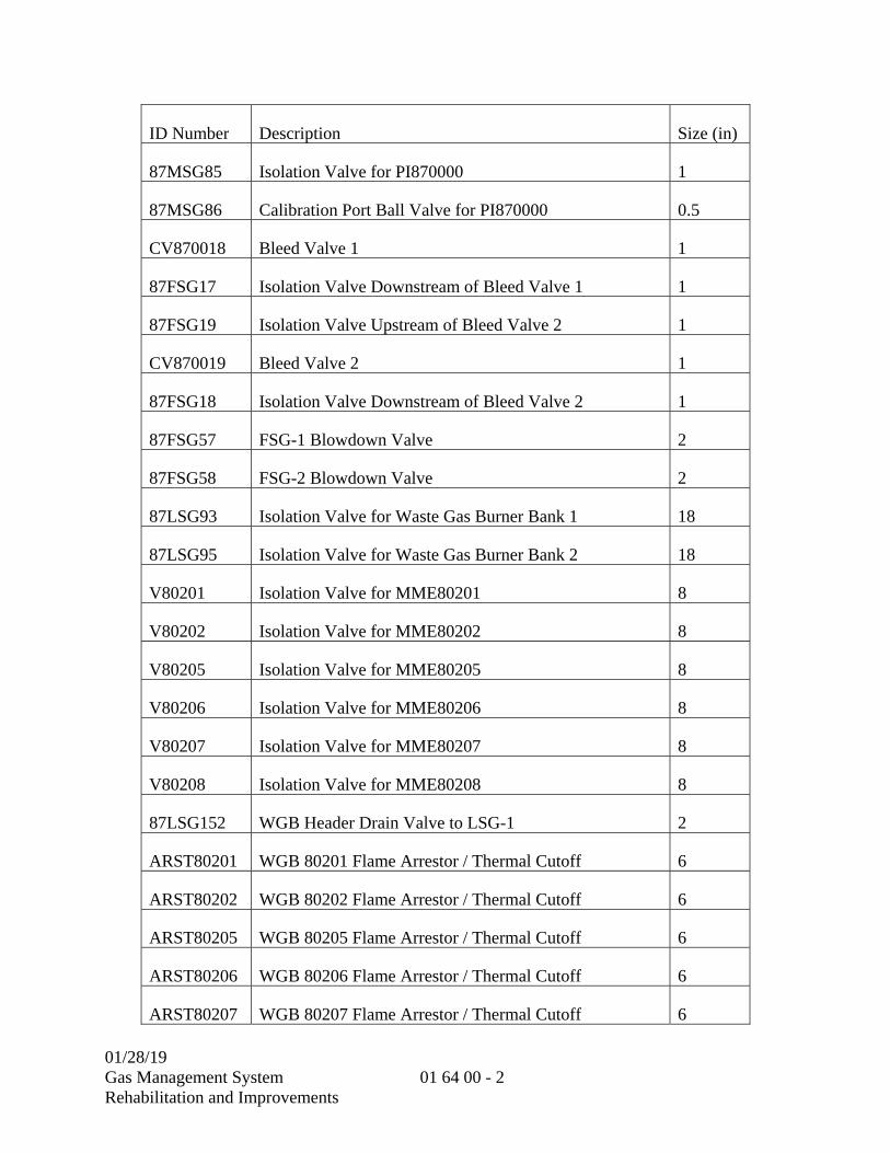
01/28/19 Gas Management System Rehabilitation and Improvements
01 64 00 - 2
ID Number Description Size (in)
87MSG85 Isolation Valve for PI870000 1
87MSG86 Calibration Port Ball Valve for PI870000 0.5
CV870018 Bleed Valve 1 1
87FSG17 Isolation Valve Downstream of Bleed Valve 1 1
87FSG19 Isolation Valve Upstream of Bleed Valve 2 1
CV870019 Bleed Valve 2 1
87FSG18 Isolation Valve Downstream of Bleed Valve 2 1
87FSG57 FSG-1 Blowdown Valve 2
87FSG58 FSG-2 Blowdown Valve 2
87LSG93 Isolation Valve for Waste Gas Burner Bank 1 18
87LSG95 Isolation Valve for Waste Gas Burner Bank 2 18
V80201 Isolation Valve for MME80201 8
V80202 Isolation Valve for MME80202 8
V80205 Isolation Valve for MME80205 8
V80206 Isolation Valve for MME80206 8
V80207 Isolation Valve for MME80207 8
V80208 Isolation Valve for MME80208 8
87LSG152 WGB Header Drain Valve to LSG-1 2
ARST80201 WGB 80201 Flame Arrestor / Thermal Cutoff 6
ARST80202 WGB 80202 Flame Arrestor / Thermal Cutoff 6
ARST80205 WGB 80205 Flame Arrestor / Thermal Cutoff 6
ARST80206 WGB 80206 Flame Arrestor / Thermal Cutoff 6
ARST80207 WGB 80207 Flame Arrestor / Thermal Cutoff 6

01/28/19 Gas Management System Rehabilitation and Improvements
01 64 00 - 3
ID Number Description Size (in)
ARST80208 WGB 80208 Flame Arrestor / Thermal Cutoff 6
SV870018 Bleed Valve 1 1
SV870019 Bleed Valve 2 1
SV80201 Isolation Valve for MME80201 8
SV80202 Isolation Valve for MME80202 8
SV80205 Isolation Valve for MME80205 8
SV80206 Isolation Valve for MME80206 8
SV80207 Isolation Valve for MME80207 8
SV80208 Isolation Valve for MME80208 8
87D25 FSG Drip Leg 1 Drain 1
87LSG171 WGB Header Drain Valve to LSG-2 2
87LSG169 LSG-1 Valve to WGB 20
87LSG165 LSG-2 Valve to WGB 20
87LSG168 PI/PIT 870022 Isolation Valve 24
87LSG167 PI/PIT 870021 Isolation Valve 24
87LSG164 PI/PIT 870020B Isolation Valve 24
87LSG197 PI/PIT 870020A Isolation Valve 24
87LSG161 PI/PIT 870009 Isolation Valve 24
87WN16 Isolation Valve for Condensate Tank 0.75
87WN10 Isolation Valve for Condensate Tank 0.75
87LSG172 Drain Valve to LSG-2 1
87LSG173 Drain Valve to LSG-2 1
87LSG166 Drain Valve LSG-2 TO WGB 1

01/28/19 Gas Management System Rehabilitation and Improvements
01 64 00 - 4
ID Number Description Size (in)
87FSG49 Drain Valve Between Bleed and Isolation Valve 1
87FSG50 Drain Valve Between Bleed and Isolation Valve 1
87FSG51 Drain Valve Between Bleed and Isolation Valve 1
87FSG52 Drain Valve Between Bleed and Isolation Valve 1
87LSG162 Drain Valve Downstream of Recycle Valve 1
87LSG163 Drain Valve Downstream of Dump Valve 1
87MSG79 Drain Valve Upstream of Recycle Valve 1
87MSG80 Drain Valve Upstream of Dump Valve 1
87FSG54 Drain Valve on FSG 1
87FSG55 Drain Valve on FSG 1
87FSG56 Drain Valve on FSG 1
80LSG43 Drain Valve 1
80LSG44 Drain Valve 1
87FSG53 Pressure Transducer Valve 1
87LSG174 Condensate Valve, WGB Valve PIT 2
87LSG173 Purge Valve, WGB Valve Pit 1
POP80201 Isolation Valve for MME80201 8
POP80202 Isolation Valve for MME80202 8
POP80205 Isolation Valve for MME80205 8
POP80206 Isolation Valve for MME80206 8
POP80207 Isolation Valve for MME80207 8
POP80208 Isolation Valve for MME80208 8
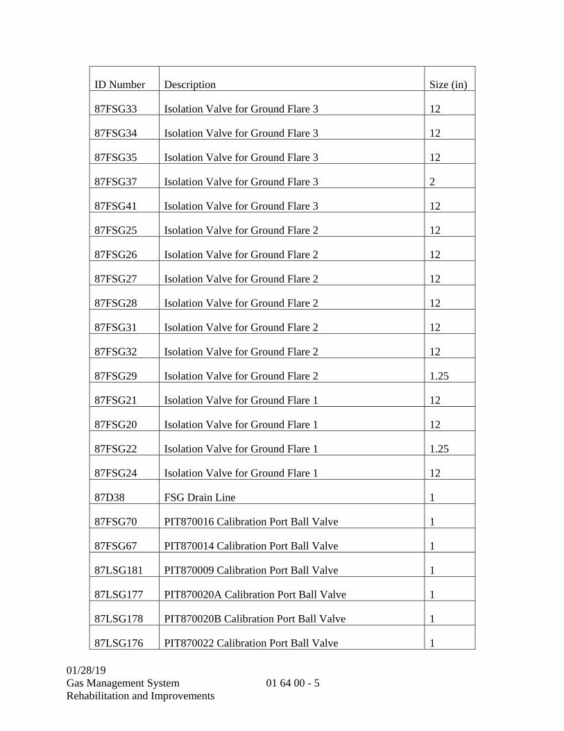
01/28/19 Gas Management System Rehabilitation and Improvements
01 64 00 - 5
ID Number Description Size (in)
87FSG33 Isolation Valve for Ground Flare 3 12
87FSG34 Isolation Valve for Ground Flare 3 12
87FSG35 Isolation Valve for Ground Flare 3 12
87FSG37 Isolation Valve for Ground Flare 3 2
87FSG41 Isolation Valve for Ground Flare 3 12
87FSG25 Isolation Valve for Ground Flare 2 12
87FSG26 Isolation Valve for Ground Flare 2 12
87FSG27 Isolation Valve for Ground Flare 2 12
87FSG28 Isolation Valve for Ground Flare 2 12
87FSG31 Isolation Valve for Ground Flare 2 12
87FSG32 Isolation Valve for Ground Flare 2 12
87FSG29 Isolation Valve for Ground Flare 2 1.25
87FSG21 Isolation Valve for Ground Flare 1 12
87FSG20 Isolation Valve for Ground Flare 1 12
87FSG22 Isolation Valve for Ground Flare 1 1.25
87FSG24 Isolation Valve for Ground Flare 1 12
87D38 FSG Drain Line 1
87FSG70 PIT870016 Calibration Port Ball Valve 1
87FSG67 PIT870014 Calibration Port Ball Valve 1
87LSG181 PIT870009 Calibration Port Ball Valve 1
87LSG177 PIT870020A Calibration Port Ball Valve 1
87LSG178 PIT870020B Calibration Port Ball Valve 1
87LSG176 PIT870022 Calibration Port Ball Valve 1
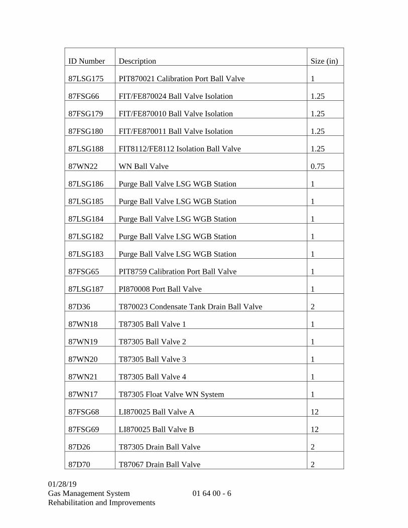
01/28/19 Gas Management System Rehabilitation and Improvements
01 64 00 - 6
ID Number Description Size (in)
87LSG175 PIT870021 Calibration Port Ball Valve 1
87FSG66 FIT/FE870024 Ball Valve Isolation 1.25
87FSG179 FIT/FE870010 Ball Valve Isolation 1.25
87FSG180 FIT/FE870011 Ball Valve Isolation 1.25
87LSG188 FIT8112/FE8112 Isolation Ball Valve 1.25
87WN22 WN Ball Valve 0.75
87LSG186 Purge Ball Valve LSG WGB Station 1
87LSG185 Purge Ball Valve LSG WGB Station 1
87LSG184 Purge Ball Valve LSG WGB Station 1
87LSG182 Purge Ball Valve LSG WGB Station 1
87LSG183 Purge Ball Valve LSG WGB Station 1
87FSG65 PIT8759 Calibration Port Ball Valve 1
87LSG187 PI870008 Port Ball Valve 1
87D36 T870023 Condensate Tank Drain Ball Valve 2
87WN18 T87305 Ball Valve 1 1
87WN19 T87305 Ball Valve 2 1
87WN20 T87305 Ball Valve 3 1
87WN21 T87305 Ball Valve 4 1
87WN17 T87305 Float Valve WN System 1
87FSG68 LI870025 Ball Valve A 12
87FSG69 LI870025 Ball Valve B 12
87D26 T87305 Drain Ball Valve 2
87D70 T87067 Drain Ball Valve 2

01/28/19 Gas Management System Rehabilitation and Improvements
01 64 00 - 7
ID Number Description Size (in)
87WN11 T87067 Float Valve WN System 1
87WN12 T87067 Ball Valve 1 1
87WN13 T87067 Ball Valve 2 1
87WN14 T87067 Ball Valve 3 1
87WN15 T87067 Ball Valve 4 1
87FSG64 Ball Valve FSG Line 12
PRV870023 Pressure Relief Valve 1.5
87LSG13 Drain Isolation Valve for LSG Header to Ground Flares 4
87FSG60 FSG-1 Line Ball Valve 1
87FSG61 FSG-2 Line Ball Valve 1
87FSG62 Level Indicator Ball Valve 1
87FSG63 Level Indicator Ball Valve 1
87LSG189 Ball Valve LSG 1
87LSG190 Ball Valve LSG 1
87LSG191 Ball Valve LSG 1
87LSG192 Ball Valve LSG 1
87LSG93 Ball Valve LSG 1
87LSG194 Ball Valve LSG 1
87LSG195 Ball Valve LSG 1
87LSG196 Ball Valve LSG 1
87NG17 Natural Gas Ball Valve 0.75
87NG18 Natural Gas Ball Valve 0.75
87NG19 Natural Gas Ball Valve 0.75

01/28/19 Gas Management System Rehabilitation and Improvements
01 64 00 - 8
ID Number Description Size (in)
87NG20 Natural Gas Ball Valve 0.75
87NG21 Natural Gas Ball Valve 0.75
87NG22 Natural Gas Ball Valve 0.75
87D37 T87305 Drain Ball Valve 2
C. Unless another condition is specified, District-furnished materials are assumed to be in perfect condition upon delivery to the Contractor. The Contractor shall inspect and ascertain the condition of the materials at the time of delivery to him and shall assume all responsibility for the materials from time of delivery until final acceptance of the work by the District. Any material found to be defective after delivery to the Contractor and before final acceptance of the work by the District shall be replaced and installed by the Contractor at his own expense.
D. Upon completion of the required work, all excess materials furnished by the District shall be returned promptly to the location designated by the District. The value as carried on the District's books of all materials furnished to the Contractor and not accounted for by being incorporated in the work or by being returned to the District will be deducted from the Contractor's final payment.
1.02 CONTRACTOR COORDINATION WITH EQUIPMENT MANUFACTURER
A. Contractor shall be in close coordination with service representatives of the manufacturer of the District-furnished equipment in every phase of installation. Both the Contractor and the Equipment Manufacturer have separate responsibilities, both of which must necessarily be interwoven as regards the installation, testing and acceptance of the equipment.
1.03 QUALITY ASSURANCE
A. Equipment specifications:
1. The Contractor shall be presumed cognizant, prior to entering into the Contract, of the provisions of the Equipment Specifications.
B. Installation:
1. District-furnished equipment shall be installed as specified in Article 1.05.
01/28/19 Gas Management System Rehabilitation and Improvements
01 64 00 - 9
C. Operation:
1. District-furnished equipment shall be operated in accordance with the written instructions furnished with the equipment, and with the instructions issued by representatives of equipment manufacturers.
D. Testing:
1. After installation, and following certification in writing by the Equipment Manufacturer that the installation is ready for electrical testing, the Contractor shall make electrical tests (see Article 1.06) on District-furnished equipment. The tests shall prove that the equipment has been properly installed; that power, control, instrumentation, and alarms are properly connected and wired from the equipment to points of supply or receipt of signals and are properly calibrated; and that all other work performed by the Contractor renders the equipment operational as intended.
1.04 DELIVERY, STORAGE, AND HANDLING
A. Delivery of District-furnished equipment:
1. In all cases, materials to be furnished by the District will be issued only upon approval of the Engineer. Receipts for materials signed by the Contractor shall be conclusive evidence of delivery.
2. All handling, loading, hauling and storage from their delivery point of materials furnished by the District shall be the responsibility of the Contractor, unless otherwise specified. Contractor shall be responsible for providing any special storage requirements. All loading, hauling and unloading of materials returned to designated locations shall be performed by the Contractor. Contractor shall provide all tiedowns and dunnage.
B. Protection of District-furnished equipment:
1. The Contractor shall protect the equipment in accordance with the Equipment Manufacturer's recommendations against weather conditions, including construction of a temporary cover or installing a low wattage heater, if required. Contractor shall be responsible for any damage to the equipment due to moisture intrusion.
1.05 EQUIPMENT INSTALLATION
A. The Contractor shall install District-furnished equipment in accordance with the instructions and recommendations furnished with the equipment, submittals, instructions by equipment manufacturer’s representative and installation manuals, and as indicated
01/28/19 Gas Management System Rehabilitation and Improvements
01 64 00 - 10
on the Plans. Seismic calculation shall be approved and stamped by a California licensed Civil or Structural Engineer.
1.06 EQUIPMENT FIELD TESTING
A. General:
1. Field Testing shall be performed by the Contractor, Equipment Manufacturer’s representative, and District staff.
2. The Contractor shall schedule, coordinate, and perform all field testing required to prove that the equipment has been properly installed and is in satisfactory operating condition. The Contractor will have a factory-trained representative from the Equipment Manufacturer and District personnel present to provide technical guidance during field testing.
1.07 SERVICES OF EQUIPMENT MANUFACTURER'S REPRESENTATIVES
A. The Equipment Manufacturers (through the District) will provide services of skilled representatives for inspecting the installation, adjustments, start-up and testing of District-furnished equipment. The services will be provided as requested by the Engineer. The Contractor and his employees shall fully cooperate with the manufacturer's representatives.
B. The Contractor shall notify the Engineer in writing thirty (30) calendar days before he needs the equipment manufacturer's representative to be present at the site.
1.08 JOB CONDITIONS
A. The Contractor shall repair, replace or correct to the satisfaction of the Engineer all defective equipment items caused by the Contractor's improper placement and handling of District-furnished equipment. After testing, the Contractor shall repair, replace, or correct faulty work.
B. Contractor's acceptance:
1. Upon Contractors’ acceptance of District-furnished equipment, it shall be understood that the Contractor assumes the responsibilities assigned to him in these Specifications in relation to the installation of District furnished equipment.
The Contractor shall verify the conditions of District-furnished equipment and shall submit to the Engineer within seven (7) days after delivery date a statement listing all defective equipment items. The list shall include the cost and extension to the Contract Time that the Contractor estimates for the correction and repair of each defective equipment item and a statement of the Contractor's opinion as of the cause of the defective equipment items.

01/28/19 Gas Management System Rehabilitation and Improvements
01 64 00 - 11
1) If the Contractor makes no submittal within the time period specified, it shall be understood that the District-furnished equipment is in satisfactory condition and that the Contractor's acceptance has occurred as of the date of delivery.
2) If the Contractor makes a submittal listing defective equipment items within the time period specified, the Engineer will decide on the course of action to be taken.
The Engineer will decide the course of action on each defective equipment item. The possible courses of action by the Engineer include:
3) To authorize the Contractor to proceed with the correction and repair of defective equipment items through the issuance of a Change Order. The Contractor's consent to perform such repair and correction shall be construed as Contractor's acceptance for the items included in the Change Order.
4) To direct the Contractor to proceed with the correction and repair of defective equipment items through the procedures specified for force account work. It shall be understood that Contractor's acceptance has occurred for the items covered under force account work on the date of the issuance of the Engineer's directive.
5) To have others perform the correction and repair of defective equipment items. The Contractor shall observe the work done by others and notify the Engineer in writing of all irregularities, faulty workmanship, or unsatisfactory work done by others. The Contractor observations shall be carried out without obstruction or interference to others performing work. Upon completion of the correction and repair, the Engineer will notify the Contractor and it shall be understood that Contractor's acceptance has occurred for items repaired by others upon receipt of the Engineer's notification.
6) To modify the Plans and Specifications in order to meet changing conditions. It shall be understood that Contractor's acceptance has occurred upon receipt of the Engineer's modifications to Plans and Specifications.
7) To state to the Contractor that an item listed by the Contractor is not a defective equipment item. Regarding such items, it shall be
8) understood that Contractor's acceptance has occurred on the delivery date.
C. Scheduling:
1. It shall be understood that the Contractor's review of the Equipment Specifications has allowed him to schedule his operations in accordance with the specified dates for the delivery of District-furnished equipment.

01/28/19 Gas Management System Rehabilitation and Improvements
01 64 00 - 12
**END OF SECTION**

01/28/19
Gas Management System Rehabilitation and Improvements
01 65 00 - 1
SECTION 01 65 00
PRODUCT DELIVERY REQUIREMENTS
PART 1 -- GENERAL
1.01 GENERAL REQUIREMENTS
A. Equipment, products and materials shall be shipped, handled, stored, maintained and installed in ways which will prevent damage to the items. Damaged items will not be permitted as part of the work except in cases of minor damage that have been satisfactorily repaired and are acceptable to the District Representative.
B. Failure of Contractor to properly store and maintain equipment and materials will result in rejection of the equipment or material or a withholding from the progress payment.
C. Deliveries to the SRWTP must include the contract number and name of the project on all delivery manifests.
1.02 MATERIALS
A. Materials shall be handled, stored, and installed as recommended by the manufacturer. Pipes with paint, tape coatings, linings or the like shall be stored to protect the coating or lining from physical damage or other deterioration. Plastic pipes including PVC conduit shall be stored with UV protection until placed or installed. Pipes shipped with interior bracing shall have the bracing removed only when recommended by the pipe manufacturer.
1.03 EQUIPMENT
A. PACKAGE AND MARKING:
1. All equipment shall be protected against damage from moisture, dust, handling, or other cause during transport from manufacturer's premises to site. Each item or package shall be marked with the number unique to the specification reference covering the item.
2. Stiffeners shall be used where necessary to maintain shapes and to give rigidity. Parts of equipment shall be delivered in assembled or subassembled units where possible.
01/28/19
Gas Management System Rehabilitation and Improvements
01 65 00 - 2
B. IDENTIFICATION:
1. Each item of equipment and valve shall have permanently affixed to it a label or tag with its equipment or valve number designated in this contract. Label or tag shall be of stainless steel. Location of label will be easily visible.
C. SHIPPING:
1. Bearing housings, vents and other types of openings shall be wrapped or otherwise sealed to prevent contamination by grit, dirt and water vapor.
2. Damage shall be corrected to conform to the requirements of the contract before the assembly is incorporated into the work. Contractor shall bear the costs arising out of dismantling, inspection, repair and reassembly.
D. FACTORY APPLIED COATINGS:
1. Unless otherwise specified, each item of equipment shall be shipped to the site of the work with the manufacturer's shop applied prime coating which is compatible with the field applied coating as specified in the PAINTING AND COATING Section (09 90 00). The prime coating shall be applied over clean dry surfaces in accordance with the coating manufacturer's recommendations. The prime coating will serve as a base for field-applied finish coats. Electrical equipment and materials shall be painted by manufacturer as specified in the PAINTING AND COATING Section (09 90 00).
E. STORAGE:
1. During the interval between the delivery of equipment to the site and installation, all equipment, unless otherwise specified, shall be stored in an enclosed space affording protection from weather, dust and mechanical damage and providing favorable temperature, humidity and ventilation conditions to ensure against equipment deterioration. Manufacturer's recommendations shall be adhered to in addition to these requirements.
2. Equipment and materials to be located outdoors may be stored outdoors if protected against moisture condensation. Equipment shall be stored at least 6 inches above ground. Temporary power shall be provided to energize space heaters or other heat sources for control of moisture condensation. Space heaters or other heat sources shall be energized without disturbing the sealed enclosure.
F. PROTECTION OF EQUIPMENT AFTER INSTALLATION:
1. After installation, all equipment shall be protected from damage from, including but not limited to, dust, abrasive particles, debris and dirt generated by the placement, chipping, sandblasting, cutting, finishing and grinding of new or
01/28/19
Gas Management System Rehabilitation and Improvements
01 65 00 - 3
existing concrete, terrazzo and metal; and from the fumes, particulate matter, and splatter from welding, brazing and painting of new or existing piping and equipment. As a minimum, vacuum cleaning, blowers with filters, protective shieldings, and other dust suppression methods will be required at all times to adequately protect all equipment. The protection of equipment shall also apply to disassembled equipment. During concreting, including finishing, all equipment that may be affected by cement dust must be completely covered. During painting operations, all equipment nameplates, grease fittings, and similar openings shall be covered to prevent the entry of paint. Electrical switchgear, unit substation, and motor load centers shall not be installed until after all concrete work and sandblasting in those areas have been completed and accepted and the ventilation systems installed.
G. PREVENTIVE MAINTENANCE:
1. All equipment in storage and during and after installation shall be maintained by qualified Contractor personnel. Contractor shall set up a preventive maintenance program for all equipment. This program shall include as a minimum all manufacturer's recommendations and operation and maintenance manual requirements for the preventive maintenance of each piece of equipment including environmental, lubrication and rotation procedures. Record sheets of the preventive maintenance program shall be submitted to the District Representative monthly in accordance with the SUBMITTAL PROCEDURES Section (01 33 00).
1.04 SUBMITTALS
A. Prior to equipment delivery, Contractor shall submit pre and post installation preventive maintenance (PM) instructions recommended by the manufacturers for Major Equipment. Contractor shall conduct an ongoing monthly PM program during construction on all Major Equipment and any minor equipment requiring PM per the manufacturer's recommendations. The PM program shall be witnessed by the District Representative. Contractor shall monthly submit information in accordance with the SUBMITTAL PROCEDURES Section (01 33 00) on the status of all equipment in the PM program. Failure of Contractor to properly maintain the equipment shall result in rejection of the equipment or a withholding from the progress payment.
**END OF SECTION**

01/28/19
Gas Management System Rehabilitation and Improvements
01 65 00 - 4
THIS PAGE INTENTIONALLY LEFT BLANK

01/28/19
Gas Management System Rehabilitation and Improvements
01 73 24 - 1
SECTION 01 73 24
DESIGN REQUIREMENTS FOR NON-STRUCTURAL COMPONENTS AND NON-BUILDING STRUCTURES
PART 1 -- GENERAL
1.01 SUMMARY
A. Section includes: Minimum structural requirements for the design, anchorage, and bracing of non-structural components such as architectural, mechanical, HVAC, and electrical components, equipment, or systems, and non-building structures such as tanks.
B. The requirements of this section apply to design of the structural elements and features of equipment and to platforms/walkways that are provided with equipment or non-building structures.
C. This section applies to non-building structures and non-structural components that are permanently attached to structures as defined below and in ASCE 7.
D. Design and conform to criteria and design codes listed within this section. Engineering design is not required for attachments, anchorage, or bracing detailed on the Drawings or where the size of attachments, anchorage, or bracing is defined in the technical specification sections.
1.02 REFERENCES
A. REFERENCE STANDARS: The publications referred to hereinafter form a part of this specification to the extent referenced. The publications are referred to in the text by the basic designation only. The latest edition of referenced publications in effect at the time of the bid shall govern. In case of conflict between the requirements of this section and the listed references, the requirements of this section shall prevail.
Reference Title Aluminum Design Manual
Aluminum Association, Aluminum Design Manual with Specifications and Guidelines for Aluminum Structures
AAMA American Architectural Manufacturer’s Association
ACI 318 Building Code Requirements for Structural Concrete
AISC 341 Seismic Provisions for Structural Steel Buildings
ACI 360 Specification for Structural Steel Buildings

01/28/19
Gas Management System Rehabilitation and Improvements
01 73 24 - 2
Reference Title ASCE 7 Minimum Design Loads for Buildings and Other Structures
ASTM C635 Manufacture, Performance and Testing of Metal Suspension Systems for Acoustical Tile and Lay-in Panel Ceilings
ASTM C636 Installation for Metal Ceiling Suspension Systems for Acoustical Tile and Lay-in Panel Ceilings
AWS D1.1 Structural Welding Code – Steel
AWS D1.2 Structural Welding Code – Aluminum
AWS D1.6 Structural Welding Code – Stainless Steel
Cal/OSHA California Industrial Safety and Health Act Division of Occupational Safety and Health
CBC California Building Code (2016)
NFPA-13 Installation of Sprinkler Systems
OSHA U.S. Dept. of Labor, Occupational Safety and Health Administration
SMACNA Seismic Restraint Manual Guidelines for Mechanical Systems
1.03 DEFINITIONS
A. Structures: The structural elements of a building that resist gravity, seismic, wind, and other types of loads. Structural components include columns, posts, beams, girders, joists, bracing, floor or roof sheathing, slabs or decking, load-bearing walls, and foundations.
B. Non-structural Components: The non-structural portions of a building include every part of the building and all its contents, except the structural portions, that carry gravity loads and that may also be required to resist the effects of wind, snow, impact, temperature and seismic loads. Non-structural components include, but are not limited to, ceilings, partitions, windows, equipment, piping, ductwork, furnishings, lights, etc.
C. Non-building Structures: Self-supporting structures that carry gravity loads and that may also be required to resist the effects of wind, snow, impact, temperature and seismic loads. Non-building structures include, but are not limited to, pipe racks, storage racks, stacks, tanks, vessels and structural towers that support tanks and vessels.

01/28/19
Gas Management System Rehabilitation and Improvements
01 73 24 - 3
1.04 SUBMITTALS
A. The following information shall be submitted for review in accordance with SUBMITTALS PROCEDURES Section (01 33 00):
1. A copy of this specification section with each paragraph check-marked to indicate specification compliance or marked to indicate requested deviations from specification requirements.
2. Check-marks () shall denote full compliance with a paragraph as a whole. Deviations shall be underlined and denoted by a number in the margin to the right of the identified paragraph. The remaining portions of the paragraph not underlined will signify compliance on the part of the Contractor with the specifications. Include a detailed, written justification for each deviation. Failure to include a copy of the marked-up specification sections, along with justification(s) for any requested deviations to the specification requirements, with the submittal shall be sufficient cause for rejection of the entire submittal with no further consideration.
3. Complete calculations, details, and complete reference drawings that are required to be submitted as part of a deferred submittal and as defined in the CBC and the Contract Documents, shall be prepared, stamped, signed, and furnished by a Professional Civil or Structural Engineer licensed to practice in the State of California. The following requirements apply for each deferred submittal:
a. Qualification of Civil or Structural Engineer: Minimum of three (3) years of experience in water, wastewater or similar public works projects.
b. The Civil or Structural Engineer shall be responsible to obtain all necessary reference drawings and data from the CONTRACTOR or Manufacturer for his or her calculations.
4. Calculations shall be independently checked and signed by a Professional Civil or Structural Engineer licensed to practice in the State of California.
a. Qualification of Civil or Structural Engineer: Minimum of three (3) years of experience in water, wastewater or similar public works projects.
5. Minimum Calculation and Reference Drawing Requirements:
a. Calculations shall be comprehensible and complete. When evaluating the structural strengths, indicate stress for comparing with strengths or show the demand versus capacity ratio in the structural elements. Evaluating the results by stating “Okay by Inspection” is not acceptable. When spreadsheets are used, clearly reference equations and formulas presented in submittal calculations.
01/28/19
Gas Management System Rehabilitation and Improvements
01 73 24 - 4
b. Reference drawings shall include plans, sections, details and equipment information as necessary for seismic calculations. Indicate the location of the equipment on plan which is necessary for load calculations.
c. Submittals shall be returned without review if:
1) Submittals include only calculations without reference drawings
2) Calculations have no sheet numbers or sheets are missing
3) Calculations or reference drawings are illegible
4) Calculations are made based on wrong information, assumptions or design parameters
5) Information in reference drawings is insufficient for calculations or review
6. The calculations and details shall demonstrate a complete vertical and lateral load path, and shall clearly indicate all forces imposed on the supporting structure.
7. Anchor Bolt Calculations and Details:
a. Anchor bolt calculations shall clearly show that the capacity of the anchor and the capacity of the concrete that the anchor is embedded in are adequate to resist all applicable load combinations, including wind and seismic loads.
1) The design of anchors resisting seismic forces shall satisfy the ductility requirements stated in the 2016 CBC, ASCE 7-10, and ACI 318-14.
b. Reduction factors associated with edge distance, embedment length, grout and base plate thickness, and bolt spacing shall be considered in the design and clearly indicated on the submittal drawings.
c. Anchor bolts shall be designed for bending due to eccentricity where raised grout pads will be installed for leveling.
d. Anchor bolt details shall include the required bolt diameter, embed, spacing, and edge distances consistent with the calculations.
1.05 QUALITY ASSURANCE
A. Quality Control by District:
1. Special Inspection of non-structural components and non-building structures, and their anchorages shall be performed by the Special Inspector under contract with the District and in conformance with Chapter 17 of the CBC. Special Inspector(s) and laboratory shall be acceptable to the District in their sole discretion. Special Inspection is in addition to, but not replacing, other inspections and quality control
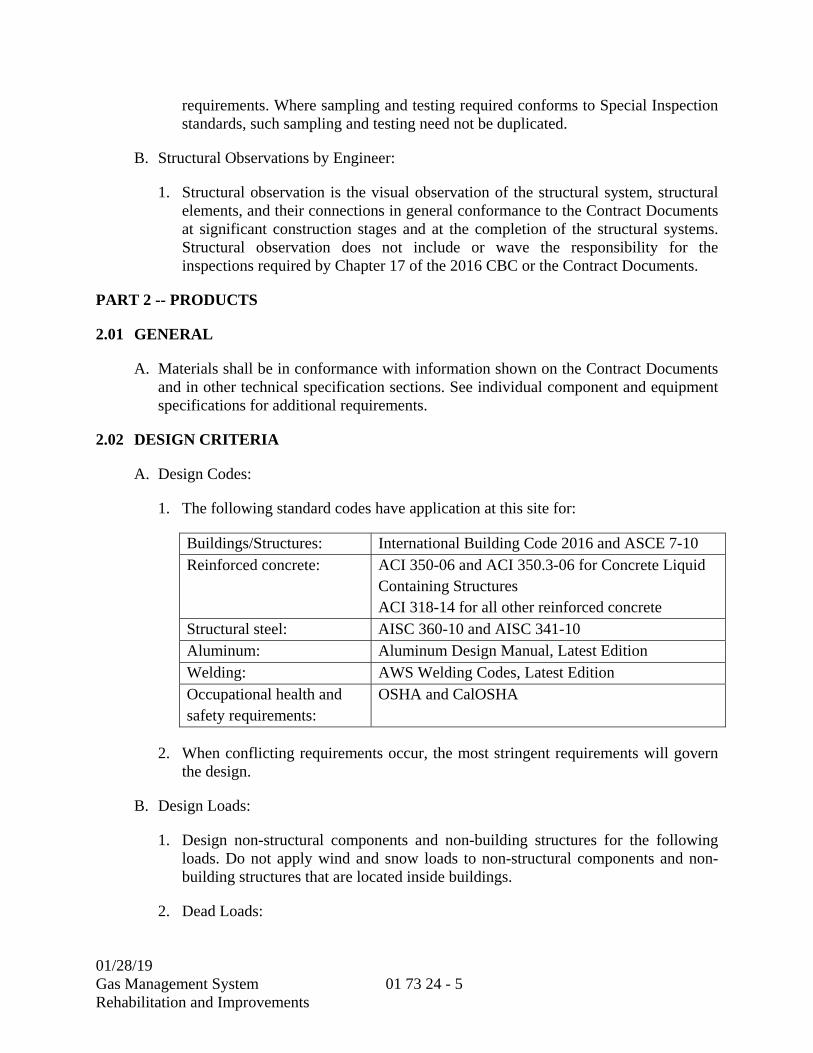
01/28/19
Gas Management System Rehabilitation and Improvements
01 73 24 - 5
requirements. Where sampling and testing required conforms to Special Inspection standards, such sampling and testing need not be duplicated.
B. Structural Observations by Engineer:
1. Structural observation is the visual observation of the structural system, structural elements, and their connections in general conformance to the Contract Documents at significant construction stages and at the completion of the structural systems. Structural observation does not include or wave the responsibility for the inspections required by Chapter 17 of the 2016 CBC or the Contract Documents.
PART 2 -- PRODUCTS
2.01 GENERAL
A. Materials shall be in conformance with information shown on the Contract Documents and in other technical specification sections. See individual component and equipment specifications for additional requirements.
2.02 DESIGN CRITERIA
A. Design Codes:
1. The following standard codes have application at this site for:
Buildings/Structures: International Building Code 2016 and ASCE 7-10 Reinforced concrete: ACI 350-06 and ACI 350.3-06 for Concrete Liquid
Containing Structures ACI 318-14 for all other reinforced concrete
Structural steel: AISC 360-10 and AISC 341-10 Aluminum: Aluminum Design Manual, Latest Edition Welding: AWS Welding Codes, Latest Edition Occupational health and safety requirements:
OSHA and CalOSHA
2. When conflicting requirements occur, the most stringent requirements will govern the design.
B. Design Loads:
1. Design non-structural components and non-building structures for the following loads. Do not apply wind and snow loads to non-structural components and non-building structures that are located inside buildings.
2. Dead Loads:
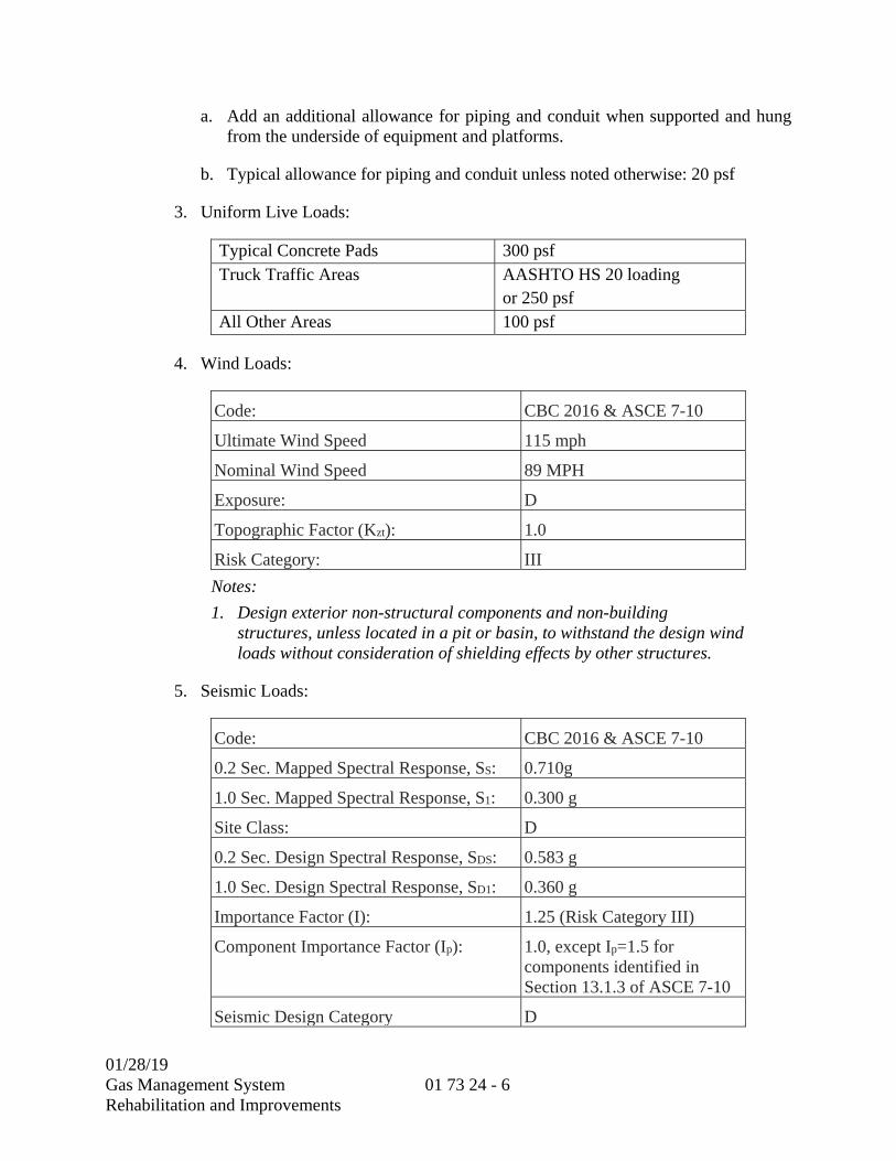
01/28/19
Gas Management System Rehabilitation and Improvements
01 73 24 - 6
a. Add an additional allowance for piping and conduit when supported and hung from the underside of equipment and platforms.
b. Typical allowance for piping and conduit unless noted otherwise: 20 psf
3. Uniform Live Loads:
Typical Concrete Pads 300 psf Truck Traffic Areas AASHTO HS 20 loading
or 250 psf All Other Areas 100 psf
4. Wind Loads:
Code: CBC 2016 & ASCE 7-10
Ultimate Wind Speed 115 mph
Nominal Wind Speed 89 MPH
Exposure: D
Topographic Factor (Kzt): 1.0
Risk Category: III
Notes:
1. Design exterior non-structural components and non-building structures, unless located in a pit or basin, to withstand the design wind loads without consideration of shielding effects by other structures.
5. Seismic Loads:
Code: CBC 2016 & ASCE 7-10
0.2 Sec. Mapped Spectral Response, SS: 0.710g
1.0 Sec. Mapped Spectral Response, S1: 0.300 g
Site Class: D
0.2 Sec. Design Spectral Response, SDS: 0.583 g
1.0 Sec. Design Spectral Response, SD1: 0.360 g
Importance Factor (I): 1.25 (Risk Category III)
Component Importance Factor (Ip): 1.0, except Ip=1.5 for components identified in Section 13.1.3 of ASCE 7-10
Seismic Design Category D

01/28/19
Gas Management System Rehabilitation and Improvements
01 73 24 - 7
Notes: 1. Calculate seismic loads on the basis of the governing building code.
Include equipment operating loads in the structure dead load. 2. Check individual members for seismic and full member live load acting
simultaneously, except that flooded equipment loads (infrequent occurrence) need not be combined with seismic loads. Combine equipment operating loads with seismic loads.
6. Impact Loads:
a. Consider impact loads in the design of support systems.
b. Use the following impact load factors unless recommendations of the equipment manufacturer will cause a more severe load case.
Rotating machinery: 20% of moving load
7. Temperature:
a. Include the effects of temperature in design where non-structural components and non-building structures are exposed to differential climatic conditions. See climatic conditions below for temperature extremes.
C. Load Combinations
1. Design all non-structural components and non-building structures to withstand the load combinations as specified in the governing building code. Where the exclusion of live load or impact load would cause a more severe load condition for the member under investigation, then ignore the load when evaluating that member.
D. Design Considerations
1. Design non-structural components and non-building structures for the following conditions.
2. Climatic Conditions:
Maximum design temperature 110 degrees Fahrenheit
Minimum design temperature 20 degrees Fahrenheit
3. Foundations:
a. Extend foundations supporting non-structural components and non-building structures below soil susceptible to heaving.

01/28/19
Gas Management System Rehabilitation and Improvements
01 73 24 - 8
E. Deflections
1. Maximum beam deflections as a fraction of span for walkways and platforms: L/240 for total load and L/360 for live load.
2. Maximum total load deflection for equipment supports: L/450.
PART 3 -- EXECUTION
3.01 GENERAL
A. Make attachments and braces in such a manner that the component force is transferred to the lateral force-resisting system of the structure. Base attachment requirements and size and number of braces on the calculations submitted by the Contractor.
B. All anchorage of equipment is specified to be made by cast-in anchor bolts in concrete elements unless specifically noted otherwise on the Drawings or other specification sections. Contractor shall be responsible for any remedial work or strengthening of concrete elements because of superimposed seismic loading if anchor bolts are improperly installed or omitted due to lack of submittal review or improper placement for any reason, at no additional cost to the District.
C. Provide anchor bolts in accordance with ANCHOR BOLTS Section (05 05 20). Base size of anchor bolts and embedment on the submitted calculations.
1. Anchorage to Concrete:
a. Anchorage to concrete shall be designed in accordance with the 2016 CBC, Chapter 1901.3 and ACI 318-14, Chapter 17.
b. Post-installed anchors must comply with ICC-ES AC193 and AC308.
D. Details of and calculations for anchorages shall be submitted prior to placement of concrete or erection of other structural supporting members. Submittals received after structural supports are in place will be rejected if proposed anchorage method would create an overstressed condition of the supporting member. The Contractor shall be responsible for revisions to the anchorages and/or strengthening of the structural support so that there is no overstress condition at no additional cost to the District.
**END OF SECTION**
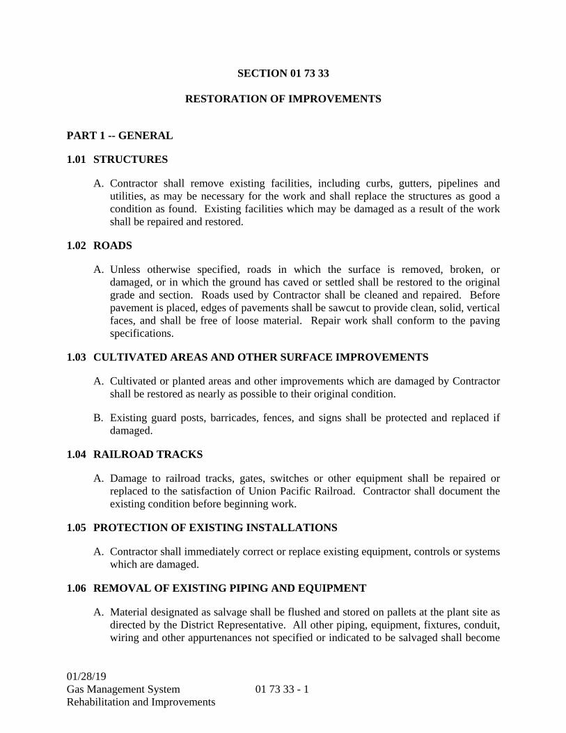
01/28/19
Gas Management System Rehabilitation and Improvements
01 73 33 - 1
SECTION 01 73 33
RESTORATION OF IMPROVEMENTS
PART 1 -- GENERAL
1.01 STRUCTURES
A. Contractor shall remove existing facilities, including curbs, gutters, pipelines and utilities, as may be necessary for the work and shall replace the structures as good a condition as found. Existing facilities which may be damaged as a result of the work shall be repaired and restored.
1.02 ROADS
A. Unless otherwise specified, roads in which the surface is removed, broken, or damaged, or in which the ground has caved or settled shall be restored to the original grade and section. Roads used by Contractor shall be cleaned and repaired. Before pavement is placed, edges of pavements shall be sawcut to provide clean, solid, vertical faces, and shall be free of loose material. Repair work shall conform to the paving specifications.
1.03 CULTIVATED AREAS AND OTHER SURFACE IMPROVEMENTS
A. Cultivated or planted areas and other improvements which are damaged by Contractor shall be restored as nearly as possible to their original condition.
B. Existing guard posts, barricades, fences, and signs shall be protected and replaced if damaged.
1.04 RAILROAD TRACKS
A. Damage to railroad tracks, gates, switches or other equipment shall be repaired or replaced to the satisfaction of Union Pacific Railroad. Contractor shall document the existing condition before beginning work.
1.05 PROTECTION OF EXISTING INSTALLATIONS
A. Contractor shall immediately correct or replace existing equipment, controls or systems which are damaged.
1.06 REMOVAL OF EXISTING PIPING AND EQUIPMENT
A. Material designated as salvage shall be flushed and stored on pallets at the plant site as directed by the District Representative. All other piping, equipment, fixtures, conduit, wiring and other appurtenances not specified or indicated to be salvaged shall become

01/28/19
Gas Management System Rehabilitation and Improvements
01 73 33 - 2
the property of Contractor and shall be removed from the site and properly disposed of at the expense of Contractor.
1.07 MODIFICATION OF STRUCTURES
A. Contractor shall alter or rework existing concrete structures as shown and specified. Generally, when items of equipment and piping are removed, the areas and surfaces from which items were removed shall be left with a neat appearance and finish compatible with surrounding areas, colors and surfaces. Holes and pipe and conduit penetrations in walls and slabs shall be filled with grout. Contractor shall do all painting, sanding, grouting, sacking, resurfacing, and other work as necessary. Prior to structural modifications, all surfaces shall be inspected by the District Representative. Colors shall match existing.
B. Contractor shall take care when handling materials to prevent dropping them into an operating tank, channel, conduit, pipeline or the like. Contractor shall notify the District Representative immediately if anything is added to any tank, channel, conduit, or pipeline.
1.08 CONNECTIONS TO HYDRAULIC STRUCTURES
A. Connections to existing hydraulic structures, for the purpose of transferring flow to completed portions of the work, shall be as specified.
**END OF SECTION**

01/28/19
Gas Management System Rehabilitation and Improvements
01 74 23 - 1
SECTION 01 74 23
FINAL CLEANING
PART 1 -- GENERAL
1.01 GENERAL REQUIREMENTS
A. As a condition precedent to final acceptance or release of a structure, space or process unit for use by District, Contractor shall thoroughly clean all floors, ceilings, roofs, walls, woodwork, counters, sinks, fixtures and windows to leave same in first-class condition.
B. All pits and sumps shall be cleared of silt, sand, debris and construction materials. Ductwork, air intakes, and exhaust grilles shall be inspected and cleared of extraneous dust and material. All filters shall be replaced or cleaned to like new condition. All grounds shall be cleared of all debris and reseeded and restored to its original condition. Finish floors shall be thoroughly cleaned, sealed and given a final coat of wax. Blinds, all furniture and cabinets shall be dusted. Replace all burned out lamps.
C. Contractor shall not proceed with this work until authorized in writing by the District Representative.
**END OF SECTION**
01/28/18 Gas Management System Rehabilitation and Improvements
01 74 23 - 2
THIS PAGE INTENTIONALLY LEFT BLANK

01/28/19
Gas Management System Rehabilitation and Improvements
01 78 23 - 1
SECTION 01 78 23
OPERATION AND MAINTENANCE DATA
PART 1 -- GENERAL
1.01 WORK DESCRIPTION
A. The work consists of providing equipment operation and maintenance (O&M) data in conformance with the requirements of this specification.
B. The Contractor shall submit O&M data after the subject equipment or material submittal has been approved. The O&M data submittal will be returned if it is included with the equipment or material submittal.
C. O&M data submittals shall be prepared and submitted in accordance with this specification and the SUBMITTAL PROCEDURES Section (01 33 00).
1.02 PAYMENT
A. Payment for any system, equipment, or material for which O&M data are required shall be as specified in the PROGRESS PAYMENT PROCEDURES Section (01 29 76).
B. The O&M data (manuals) shall have a value of not less than zero point seven percent (0.7%) of the Total Bid Amount. For additional work, the O&M data (manuals) value shall be determined by Field Instructions or Change Orders as outlined in the general conditions of this contract. O&M data additional work shall meet all conditions of this section.
C. The Contractor and District shall meet to determine the total number of O&M data (manuals) for the contract. The value of the O&M data (manuals) shall be distributed equally across the total number of O&M data (manuals) for the contract.
D. A Draft and Final submittal shall be required for each O&M data (manual). The Draft, and Final submittals comprise 75%, and 25%, respectively, of the calculated value for each O&M data (manual). Payment will be provided upon acceptance of each submittal.
PART 2 -- PRODUCTS
2.01 GENERAL REQUIREMENTS
A. Each document in the O&M data shall include the Equipment Tag Number/Location ID and associated auxiliary Equipment Tag Number that it represents.
01/28/19
Gas Management System Rehabilitation and Improvements
01 78 23 - 2
B. O & M data shall include completed equipment data form(s) as specified in the DESIGN DATA Section (01 33 16).
C. The manufacturer's standard documents shall be neatly marked with arrows or boxes to indicate the specific information that is applicable to the equipment, assembly, subassembly, or material supplied.
1. Non applicable items shall be crossed out.
2. Highlighting is not acceptable.
D. All O&M data materials shall be made from original materials. Original materials shall be published literature or computer printouts with resolution of at least 600 dots per inch (dpi). Photo copies, scanned copies, and FAX transmittals are not acceptable.
E. O&M data shall be organized into one electronic document bookmarked using an Adobe Acrobat PDF format and submitted to the project controls website in accordance with the SUBMITTAL PROCEDURES Section (01 33 00).
F. The District reserves the right to be the sole authority on quality and legibility of O&M data materials.
G. The District reserves the right to delay commissioning if the O&M data submittals are incomplete, inaccurate, or otherwise unsuitable for use by the District’s O&M staff. No contract extensions or extra costs will be allowed for delays in commissioning due to O&M data submittal delays.
2.02 SUBMITTALS
A. The following information shall be submitted for review in accordance with the SUBMITTAL PROCEDURES Section (01 33 00):
1. A copy of this specification section (with addenda updates) with each paragraph check marked to show specification compliance or marked to show deviations.
a. Mark “NA” for requirements that do not apply, and if the submittal does not conform to a requirement, explain the exception.
b. A check mark shall denote full compliance with a paragraph as a whole.
c. If deviations from the specification are indicated, and therefore requested by the Contractor, each deviation shall be underlined and denoted by a number in the margin to the right of the identified paragraph referenced to a detailed written explanation for requesting the deviation.
d. The District shall be the final authority for determining acceptability of requested deviations.

01/28/19
Gas Management System Rehabilitation and Improvements
01 78 23 - 3
e. The remaining portions of the paragraph not underlined will signify compliance on the part of the Contractor with the specification.
f. Failure to include a copy of the marked-up specification section, along with justification(s) for any requested deviations to the specification requirements, with the submittal shall be sufficient cause for rejection of the entire submittal with no further consideration.
B. Deliverables
1. Equipment Submittal
a. Initial shop drawing equipment submittals for individual pieces of equipment should contain adequate storage, installation, operation, and maintenance information from the manufacturer. This information must be sufficient to allow the District to confirm compliance with the manufacturer’s recommendations during the storage, installation, and initial startup and testing of the equipment. Such O&M data information in initial equipment submittals will be checked only to verify that the appropriate documents for these purposes are provided. The O&M data submittals required below are in addition to the initial equipment submittal, even though it contained O&M information. Furthermore, the O&M data submittal requires that approved equipment submittal information be incorporated.
2. O&M Data Draft Submittal
a. The draft O&M data submittals shall be submitted electronically to the Project Control System (PCS) in accordance with the ELECTRONIC COMMUNICATION PROTOCOLS Section (01 31 26). The submittals shall be submitted as individual specification sections, and may be submitted one specification section at a time. Each draft submittal shall be submitted by the Contractor within 30 calendar days after District approval of the corresponding equipment submittal. District review will be completed within 30 calendar days after receipt of each draft submittal. Unless the submittal is returned marked as “Amend or Resubmit” or “Rejected – See Remarks”, District comments will be formally addressed and incorporated into the O&M data in preparation of the training lesson plans and materials for vendor training.
3. O&M Data Final Submittal
a. Within 21 calendar days after substantial completion, the District will notify the Contractor of deficiencies in the draft submittal. The Contractor shall revise and replace, remove, or add documents to correct any such deficiencies. Such revisions will include whatever changes are necessary to reflect “as-built” conditions, such as instrument settings, field changes of panels, electrical equipment, etc. Such revisions shall include resolution of any comments from commissioning and follow up training sessions. Submission of the O&M data

01/28/19
Gas Management System Rehabilitation and Improvements
01 78 23 - 4
final submittal shall be submitted and District approved prior to Field Acceptance. The District shall be allowed a review period of 14 calendar days after receipt of each final submittal.
b. Electronic versions of the O&M data shall be corrected by submitting the document, in its entirety, to the project controls website.
PART 3 -- EXECUTION
3.01 O&M DATA REQUIREMENTS
A. COVER SHEET:
1. The cover sheet shall show a functional title of the system, equipment or material; list of the Equipment Tag Number(s), including all associated auxiliary Equipment Tag Number(s), and corresponding functional description(s); revision date; and specification reference.
B. TABLE OF CONTENTS:
1. The table of contents shall give a detailed description of what is in each tab, including applicable Equipment Tag Number.
C. WARRANTIES & GUARANTEES:
1. A copy of the manufacturer’s warranty and/or guarantee certificate shall be provided with the O&M data. The original certificate shall separately accompany the O&M data.
2. List and explain the various warranties and include the servicing and technical precautions prescribed by the manufacturers or contract documents to keep warranties in force. Where warranty is conditional on the manufacturer’s approval of the installer, submit the manufacturer’s approval of the installing firm.
D. TECHNICAL DATA:
1. Manufacturer's technical specification and engineering data sheets for each component, part, device and auxiliary equipment which make up the equipment or assembly shall be supplied. Include the manufacture’s vibration, temperature, and sound data when specified in the technical specifications. All documents contained in this section shall provide a table of contents of the documents, referencing Equipment Tag Number, the manufacturer's name, model numbers, and product numbers. Each document shall be cross-referenced to the items, components and parts described above. Label all documents with appropriate Equipment Tag Number.
01/28/19
Gas Management System Rehabilitation and Improvements
01 78 23 - 5
2. Certified performance curve(s) marked to show the operating conditions specified in the technical specification section.
3. Provide protective device settings and safety information.
4. Equipment Data Forms for each equipment tag number contained in the O & M manual as specified in DESIGN DATA Section (01 33 16). Equipment data forms shall be supplied as part of the O & M data as separate EXCEL files.
E. STANDARD O&M MANUAL:
1. The O&M manuals must explain and illustrate clearly and simply the principles and theory of operation, operating instructions, and preventive and corrective maintenance precautions and procedures to be followed. The O&M manuals and appurtenant materials shall be written entirely in English and all dimensions shall be in English units. The manuals shall include the following information, as applicable:
a. OPERATING INSTRUCTIONS: Specific instructions, procedures, and illustrations shall be provided for the following:
1) SAFETY PRECAUTIONS: List personnel hazards for equipment and list safety precautions for all operating conditions/modes.
2) INSTALLATION AND PRE-OPERATIONAL CHECKOUTS: Provide recommendations and checklists for installation, adjustment, calibration, and troubleshooting to prepare each equipment/system for operation.
3) START-UP, SHUTDOWN, AND POSTSHUTDOWN PROCEDURES: Provide step-by-step equipment-specific procedures for each of these operations.
4) NORMAL OPERATIONS: Provide control diagrams with data and step-by-step procedures to explain operation and control of systems and specific equipment.
5) EMERGENCY OPERATIONS: Provide emergency procedures for equipment malfunctions to permit a short period of continued operation or to shut down the equipment to prevent further damage to systems and equipment. Include emergency shutdown instructions for fire, explosion, spills, or other foreseeable contingencies. Provide guidance on emergency operations of all utility systems including valve locations and portions of systems controlled.
6) ENVIRONMENTAL CONDITIONS: Provide a list of environmental conditions (temperature, humidity, dust, indoor/outdoor, and other relevant data) which are best suited for each product or piece of equipment and
01/28/19
Gas Management System Rehabilitation and Improvements
01 78 23 - 6
describe conditions under which equipment should not be allowed to run due to applicable industry and regulatory standards and codes.
b. PREVENTIVE MAINTENANCE (PM):
The following information shall be provided for PM:
1) LUBRICATION DATA: Provide the following:
Manufacturer’s recommended lubrication schedules showing service interval and frequency;
Diagrams illustrating equipment lubrication points;
A table identifying recommended types and grades of lubricants for specific temperature ranges and applications; and
A table identifying equipment lubrication capacities and an estimate of yearly lubricant quantities required for all equipment supplied.
2) PM PLAN AND SCHEDULE: Provide the following in a tabular format for each PM:
The manufacturer’s recommended preventative maintenance task;
Recommended steps or procedures to complete the PM;
Recommended scheduled interval and frequency for performing the PM;
The craft responsible and the person’s skill level for performing the PM (i.e., operator, mechanic, electrician, or control systems technician);
The estimated amount of labor required to perform the PM;
Required materials or parts; and identify the equipment’s energy source(s) (i.e., water, heat, light, electrical, etc.).
c. CORRECTIVE MAINTENANCE:
Manufacturer's recommendations shall be provided on procedures and instructions for correcting problems and making repairs.
1) TROUBLESHOOTING GUIDES AND DIAGNOSTIC TECHNIQUES: Provide step-by-step procedures to promptly isolate the cause of typical malfunctions. Describe clearly why the checkout is performed and what conditions are to be sought. Identify tests or inspections and test equipment

01/28/19
Gas Management System Rehabilitation and Improvements
01 78 23 - 7
required to determine whether parts and equipment may be reused or requires replacement.
2) MAINTENANCE AND REPAIR PROCEDURES: Provide instructions and a list of specialized tools required to restore product or equipment to proper conditions or operating standards. Include the specialized tool’s part number and/or detailed fabrication drawing.
3) REMOVAL AND REPLACEMENT INSTRUCTIONS: Provide step-by-step procedures and a list with part numbers and/or fabrication drawings for all required specialized tools and supplies for removal, replacement, disassembly, and assembly of components, assemblies, subassemblies, accessories, and attachments. Provide safety precautions, recommended tolerances, dimensions, settings, critical bolt torques, and adjustments required. Instructions shall include a combination of text and illustrations.
4) PARTS LIST: Provide a complete list of components and parts which make up the equipment or assembly. All parts and components listed shall be identified using arrows or boxes by the original manufacturer's name, part number, and a purchase order number. Enough information shall be provided to allow purchasing of parts from any supplier who may stock them. If listed components or parts are themselves repairable and made up of components and parts, parts lists shall be provided for them to all repairable levels. The parts list shall have the generic title, identification number, and material of construction of each component part of equipment. Include the bearing manufacturer for every bearing.
5) DRAWING: Disassembly and assembly drawings in Adobe PDF format shall be provided which identify and cross reference all components and parts listed in the parts lists. Exploded or cut views of equipment shall be provided if available as a standard item of the manufacturer's information. When exploded or cut views are not available, plan and section views shall be provided as a minimum.
6) SPARE PARTS AND SUPPLY LISTS: Provide recommended list of spare parts (with quantities) and supplies required for maintenance and repair to ensure continued service or operation without unreasonable delays. Included with the list shall be any special storage precautions. In addition, list spare parts and supplies that have a long lead time to obtain (provide estimated lead time). If no spare parts are recommended by the manufacturer, provide a statement to that effect. Spare parts data shall be provided in a table as shown in Attachment A and is available upon request.
7) PARTS SUPPLIER LIST: Provide the manufacturer’s or supplier’s name, address, and telephone number of the nearest supplier and spare parts

01/28/19
Gas Management System Rehabilitation and Improvements
01 78 23 - 8
warehouse for all parts. Each part’s purchase order number shall also be provided.
8) SPECIAL TOOLS LIST: Provide recommended special tools, including description and use, for all equipment supplied. Special tools are defined as needed tools that are not generally commercially available except from the manufacturer.
F. SHOP/REPAIR MANUAL:
1. Provide a Shop or Repair Manual written by the manufacturer specifically for the equipment or assembly. The manual shall include additional troubleshooting tips, routine maintenance hints, and specific repair information not found in a standard O&M manual, includes references to specialized tools and other information uniquely known by the manufacturer.
G. SUPPLEMENTAL DRAWINGS AND INSTRUCTIONS
1. Drawings shall be provided which completely document the equipment, assembly, subassembly or material. As applicable and at a minimum, the following drawings shall be provided:
a. Fabrication details
b. Shop and vendor drawings
c. Layout and dimension drawings
d. Piping schematics for all equipment supplied
e. Installation drawings
f. Electrical equipment:
1) Schematics for all electrical equipment supplied
2) Electrical component fabrication drawings
3) Panel fabrication layout drawings with Bill of Materials
4) Panel schedules
5) Elevations and cross-sections
6) One-line and three-line diagrams
7) Wiring and connection diagrams

01/28/19
Gas Management System Rehabilitation and Improvements
01 78 23 - 9
8) Interconnection diagrams from approved shop drawings and vendor’s documentation
g. Instrumentation and Controls:
1) Panel elevations
2) Panel fabrication layout drawings with Bill of Materials
3) Wiring diagrams for control panels
4) Internal and external connection wiring diagrams
5) Connections between existing systems and new additions
6) Block and logic diagrams
7) Ladder logic for computer based systems
8) Drawings shall have adjustments such as calibrations and set points for relays, and control or alarm contact settings
9) Contractor-set manual set points and any Contractor provided programming that resides locally and not in the District’s PCCS
10) Loop drawings
11) Interconnection diagrams from approved shop drawings and vendor’s documentation
H. SUBMITTAL DATA
1. This section includes approved shop drawings submittal information such as catalog cuts, sales brochures, supplemental drawings, product data, equipment data, system data, or material data not already contained in other sections of the O&M data submittal. Approved shop drawings not related to the operation or maintenance of equipment or processes shall not be included.
**END OF SECTION**

01/28/19
Gas Management System Rehabilitation and Improvements
01 78 23 - 10
THIS PAGE INTENTIONALLY LEFT BLANK
01/28/19
Gas Management System Rehabilitation and Improvements
01 78 23 - 11
ATTACHMENT A
SPARE PARTS RECORD
01/28/19
Gas Management System Rehabilitation and Improvements
01 78 23 - 12
THIS PAGE INTENTIONALLY LEFT BLANK
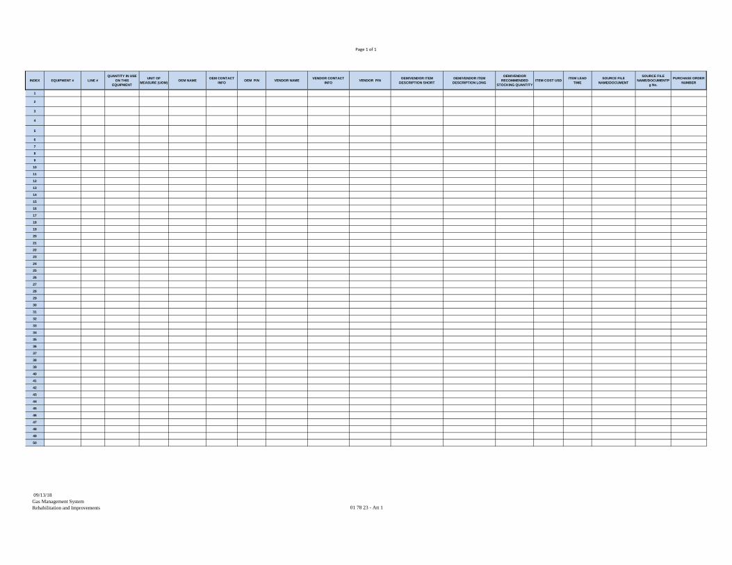
Page 1 of 1
INDEX EQUIPMENT # LINE #QUANTITY IN USE
ON THIS EQUIPMENT
UNIT OF MEASURE (UOM)
OEM NAMEOEM CONTACT
INFOOEM P/N VENDOR NAME
VENDOR CONTACT INFO
VENDOR P/NOEM/VENDOR ITEM
DESCRIPTION SHORTOEM/VENDOR ITEM DESCRIPTION LONG
OEM/VENDOR RECOMMENDED
STOCKING QUANTITYITEM COST USD
ITEM LEAD TIME
SOURCE FILE NAME/DOCUMENT
SOURCE FILE NAME/DOCUMENTP
g No.
PURCHASE ORDER NUMBER
1
2
3
4
5
6
7
8
9
10
11
12
13
14
15
16
17
18
19
20
21
22
23
24
25
26
27
28
29
30
31
32
33
34
35
36
37
38
39
40
41
42
43
44
45
46
47
48
49
50
09/13/18Gas Management SystemRehabilitation and Improvements 01 78 23 - Att 1

THIS PAGE INTENTIONALLY LEFT BLANK
01/28/19
Gas Management System Rehabilitation and Improvements
01 78 39 - 1
SECTION 01 78 39
PROJECT RECORD DOCUMENTS
PART 1 -- GENERAL
1.01 GENERAL REQUIREMENTS
A. Project record documents (commonly known as “as-builts”) shall show the actual as-constructed conditions of installed or modified systems, equipment and material at the time of field acceptance of the related portions of work. The purpose of as-built documents is to provide accurate information for the future modification, expansion, operation and maintenance of the plant.
B. The project record documents are especially important for recording field conditions of embedded or concealed material and equipment. These embedded or concealed items shall include, but are not limited to, buried structures, thrust restraints, backfill material, piping, cables and raceways.
C. Work related to Field Instructions (FI), Contract Change Orders (CCO), Clarifications or other agreements between Contractor and the District Representative shall be considered part of the project record process. Contractor shall record conditions and/or changes relating to this work on the project record documents.
D. Project record documents shall clearly be shown as part of the CPM activity schedule.
E. Divisions 1 through 50 may contain additional project record document requirements which shall be met in accordance with the requirements of this section.
1.02 VALUES
A. Project record documents shall have a value of not less than one percent (1.3%) of the contract value. For additional work, the project record document value shall be determined by Field Instructions or Change Orders as outlined in the REQUEST FOR BID Section of this contract. Project record documents for additional work shall meet all conditions of this section.
B. The value of project record documents as specified in the PROGRESS PAYMENT PROCEDURES Section (01 29 76) shall be distributed in the following categories with an associated drawing weight:
01/28/19
Gas Management System Rehabilitation and Improvements
01 78 39 - 2
No. Project Record Categories Drawing Weight
1. Electrical interconnects and referenced drawings.
10
2. Loop drawings and referenced drawings, process and instrumentation drawings.
9
3. Control and logic drawings, schedules and PLC documents; both Engineer and Contractor supplied.
7
4. Electrical and Instrumentation, Area Control Center connection drawings; both District and Contractor supplied.
5
5. Process and Piping Schematic, Power, single and three-line drawings.
3
6. All other contract drawings. 1
C. The sum of the total number of approved drawings in each category multiplied by the assigned weight, divided by the sum of the total number of drawings in each category multiplied by the assigned weight will provide the weighted percent complete for as-built drawings. The weighted percent complete will be used to determine progress payments for project record drawings.
PART 2 -- PRODUCTS
2.01 DISTRICT-SUPPLIED DRAWINGS AND CONTRACT DOCUMENTS
A. The following District-supplied drawings, contract documents, and AutoCAD files are to be submitted in as-built condition for review by the District Representative:
1. Contract drawings and specification schedules.
2. Contract supplemental drawings, existing plant drawings, schedules affected by the work of this contract. These drawings and documents cover electrical distribution systems, electrical control panels, instrumentation panels, control panels, Area Control Centers (ACC), telephone systems, intercom systems, the sound powered telephone system, Process Control Centers (PCC), and terminal panels.
3. Drawings, agreements, tabulations, and schedules supplied by District as a result of Requests for Information (RFIs), Field Instructions (FIs), and Change Orders (COs).

01/28/19
Gas Management System Rehabilitation and Improvements
01 78 39 - 3
2.02 CONTRACTOR-SUPPLIED DRAWINGS AND OTHER DOCUMENTS
A. The following Contractor supplied drawings, other contract documents, and AutoCAD files shall be submitted in project record condition for review by the District Representative:
1. Shop drawings generated by Contractor, sub-contractors, vendors or suppliers as defined in the SUBMITTAL PROCEDURES Section (01 33 00).
2. Programmable logic controllers (PLC) and analog controller program documentation with control and logic diagrams which have been submitted for construction.
3. Operation and maintenance manual documents, drawings, and schedules supplied by Contractor, subcontractors, vendors, or suppliers.
PART 3 -- EXECUTION
3.01 GENERAL
A. Contractor immediately upon setting up the job site field office shall set up a designated area for project record keeping. An accurate neatly marked complete set of full-size contract drawings, documents and shop drawings (including specifications and schedules) shall be designated as the as-built record set.
B. Contractor shall immediately start recording project record information upon doing any work.
C. Contractor shall keep those documents current with changes reflecting as-built status as construction proceeds.
D. Although some drawings are considered diagrammatic with respect to placement of conduit, piping, etc., Contractor must closely follow the routing shown. If there are deviations, Contractor must show the as-built conditions as work progresses and provide all changes to the project record documents with dimensions as outlined below:
1. Buried or embedded items within buildings, tunnels and other structures including but not limited to, piping, thrust restraints, electrical raceways, cables, duct banks, or other related appurtenances, in or under concrete, asphalt or soil, which are not placed as shown on the drawings, shall show as-built dimensions horizontally and vertically from a wall, formed footing, finish floor, ceiling or finish top of curb. Items placed in the center of concrete slabs do not need to have vertical dimensions.
01/28/19
Gas Management System Rehabilitation and Improvements
01 78 39 - 4
2. All buried or embedded items as described above which are outside of buildings shall be tied to the plant survey grid system both horizontally and vertically with proper stationing, invert elevations and/or top of buried item. Survey data shall show all transition points (changes in direction, change in elevation, etc.). All items which are installed by horizontal or vertical curves shall show as-built curve data.
3.02 PROJECT RECORD KEEPING
A. All project record documents shall be marked-up copies using the following color coding:
1. Red - Additions including notes and dimensions.
2. Green - Deletions (By hash marks or appropriate lines through the deletion.)
3. Graphite - General comments and notes used by Contractor or District’s Representative and not required on the as-built.
4. Yellow - Work completed as shown and used by District’s Representative in field review of the as-built, during the submittal phase.
5. Blue - District’s Representative's office verification and notes required to be added and noted by District’s Representative in review of the as-built, during submittal phase.
B. All work shall be neatly organized and legible using the same standards and symbols as the original drawing.
3.03 MAINTAINING PROJECT RECORD DOCUMENTS
A. Contractor shall maintain a neatly marked full size set of project record documents. All District-supplied documents shall have shop drawing references clearly marked with clouds around the areas which are detailed on the shop drawing. Shop drawings referenced to other associated shop drawings shall have drawing references clearly marked with clouds around the area representing the shop drawing.
B. Abbreviation of the drawing Originator (Contractor, subcontractors, vendors or suppliers) referenced on the contract documents is unacceptable.
C. In areas where detail does not permit showing as-built conditions clearly on contract drawings but a shop drawing depicts actual as-built condition of the area, a cloud with shop drawing reference may be accepted at the District Representative's discretion. Otherwise all as-built conditions shall be shown on the contract drawings.
D. The project record documents and one copy of all approved shop drawings and one copy of the approved O&M instructions (per the OPERATION AND
01/28/19
Gas Management System Rehabilitation and Improvements
01 78 39 - 5
MAINTENANCE DATA Section [01 78 23]) shall be kept in a central location on the job site providing access for all associated with the contract, for updating of as-built information and for review during normal business hours.
E. The project record documents shall be kept current using the mark-up procedures described herein. These documents shall be available for inspection by the District Representative at all times.
F. If project record documents are not kept current based upon weekly review by the District Representative, the current progress payment shall be limited as specified in the PROGRESS PAYMENT PROCEDURES Section (01 29 76).
3.04 PROJECT RECORD SUBMITTAL PROCESS
A. GENERAL:
1. All project record documents shall be submitted electronically in accordance with the SUBMITTAL PROCEDURES Section (01 33 00) and the ELECTRONIC COMMUNICATION PROTOCOLS Section (01 31 26).
2. Project record documents shall be submitted showing the as-built conditions within 30 working days after completion of Clean Water Commissioning of an area or subsystem. Project record documents shall be completed and submitted prior to Substantial completion of each area or subsystem. Contractor shall compare all as-built documents with the actual field conditions and show the actual field conditions on the as-built documents before submitting them for review.
3. Project record submittals shall be rejected without any part being reviewed for any of the following reasons:
a. Work has not been completed, including work related to Field Instructions, Change Orders, clarifications, or other agreements pending.
b. Not all components and equipment have been properly labeled on the drawings. All equipment numbers (device and equipment number labeling codes) shall be shown on all drawings depicting the equipment. Equipment numbers must be coordinated with the plans and drawings and shown on all District-supplied and all contractor supplied drawings that depict equipment. The Contractor shall request equipment numbers from the District for all new equipment installed.
c. Actual field conditions are not substantially shown on the documents.
d. Drawing cross references are incomplete. District supplied drawings must be cross referenced to Contractor-supplied drawings and Contractor-supplied drawings must be cross referenced back to the District-supplied drawings.

01/28/19
Gas Management System Rehabilitation and Improvements
01 78 39 - 6
B. PROJECT RECORD GROUPS AND SYSTEMS:
1. All project record documents shall be submitted together in the following logical groups or systems:
a. All site drawings including survey data and data related to an area.
b. All mechanical and piping related to an area, or by piping system. Process and Piping Schematics shall be submitted with the mechanical and piping package.
c. All structural and architectural data related to an area.
d. All electrical and instrumentation data related to an area, including Interconnection and Instrument Loop Drawings, together with all associated shop drawings and connection drawings; all related drawings found in the O&M manuals; process and Instrumentation diagrams.
C. PRELIMINARY REVIEW PROCESS:
1. In order to minimize the number of re-submittals, the following procedure shall be used:
a. Upon assembly of a project record submittal, Contractor shall notify the District Representative that the submittal is ready for review. Prior to review, a list of project record documents with all drawing numbers, descriptions and originators listed shall be submitted to District’s Representative for review. The District Representative will review the list of project record documents and meet with Contractor to review the submittal for completeness and accuracy. Contractor may be required to add or subtract some documents as directed by the District Representative to ensure a complete and reviewable package.
b. Some drawings may show work in several areas or systems. When this occurs, the list shall indicate this type of drawing. The area on this type of drawing which is to be reviewed as part of this submittal shall be clearly outlined by Contractor.
c. Documents that represent more than one area of work must be submitted for each area of work it represents and must receive approval for each area of work.
d. After the preliminary review, Contractor shall submit the as-built package with the necessary corrections for as-built review.
D. PROJECT RECORD SUBMITTALS FOR REVIEW AND COMMENTS
1. Contractor shall submit the original full size markups, one (1) set of full size copies of all District-supplied documents and two (2) sets of Contractor-supplied as-built record documents for each submittal or re-submittal as outlined in this section.

01/28/19
Gas Management System Rehabilitation and Improvements
01 78 39 - 7
One (1) set of Contractor supplied as-built documents shall be returned after each submittal review.
2. Contractor shall correct the original hard copy drawings and AutoCAD drawings once the District Representative has returned the marked up Contractor supplied documents "NO EXCEPTIONS TAKEN" or "MAKE CORRECTIONS NOTED". Contractor shall then supply the mark-ups, and the AutoCAD drawing files electronically as part of the resubmittal package, along with a hard copy of the drawing files.
E. DOCUMENT IDENTIFICATION:
1. Each separately bound document within a submittal shall have the following information shown on it:
a. Submittal number.
b. Document item number within this submittal.
c. Identification of product or material.
d. Manufacturer's name.
F. COORDINATION AND SEQUENCE:
1. Contractor shall coordinate the submittals with the work as outlined in this section. No extension of time will be allowed because of failure to properly schedule as-built submittals as outlined in this section. The submittal will be returned to Contractor within forty (40) working days of receipt by the District Representative, exclusive of any time waiting for clarification or further information from Contractor. The time for return will vary and may exceed 40 days depending on the complexity of the submittal and the number of submittals.
G. PROJECT RECORD RE-SUBMITTALS:
1. Returned project record submittal documents shall be revised as indicated by the District Representative's comments as required. Re-submittal shall be done by using the same submittal number with an alpha suffix after the submittal number. Reference to the previous submittal number and item number is required when resubmitting. Re-submittals shall address all comments from the District Representative. Partial re-submittals will not be reviewed and will be returned in their entirety REJECTED. Contractor will be responsible for the District Representative's review cost for each re-submittal in excess of the first re-submittal. These costs will be back-charged to Contractor and will be deducted from the progress payment.
01/28/19
Gas Management System Rehabilitation and Improvements
01 78 39 - 8
H. SUBMITTAL REVIEW:
1. GENERAL: The following are the four (4) possible Review Codes each document item can receive:
a. "A" - NO EXCEPTIONS TAKEN: the as-built document is approved as is.
b. "B" - MAKE CORRECTIONS NOTED: limited corrections are required. Copies will be returned with remarks as to corrections required.
c. "C" - AMEND AND RESUBMIT: insufficient or incorrect data has been submitted or data is missing to complete the review. Copies will be returned with remarks requiring re-submittal with deficiencies corrected.
d. "D" - REJECTED: Submittal is unacceptable and does not meet the requirements of these specifications, the document will be returned with remarks. A complete submittal may be REJECTED for excessive errors.
2. The Review Status and approval of District supplied drawings and documents shall be as follows:
a. As-built drawings and documents which receive an "A" Review Status are approved as, as-built. District’s Representative will stamp the document As-Built, sign and date it. The document will not be returned to Contractor unless it is a partial or tied to a related document which has not received an "A" status in the submittal.
b. As-built drawings and documents which receive a "B," "C" or "D" Review Status will be returned with comments indicating corrections needed.
c. Submittals of as-built AutoCAD drawings shall be subject to the same submittal requirements as other as-built documents.
3. The Review Status and approval of Contractor supplied drawings and documents shall be as follows:
a. As-built drawings and documents receiving an "A" Review Status are approved as, as-built. District’s Representative will stamp the document As-built, sign and date it. This document will be returned for AutoCAD update, as required.
b. As-built drawings and documents receiving an "B", "C", or "D" will be returned with comments directed at corrections needed.
c. Submittals of as-built AutoCAD drawings shall be subject to the same submittal requirements as other as-built documents.
01/28/19
Gas Management System Rehabilitation and Improvements
01 78 39 - 9
3.05 PAYMENT
A. Payment shall be part of the progress payment schedule as outlined in the PROGRESS PAYMENT PROCEDURES Section (01 29 76).
B. No partial payments shall be made for project record documents.
C. Only after all the project record documents for a work activity area have been submitted, received, reviewed and approved, will a progress payment be made.
D. Project record documents that include more than one area of work activity will only receive payment upon submittal and approval at the final area of work they represent.
E. Progress payments for Contractor supplied project record documents (including shop drawings) shall only be made for approved original documents and plotted AutoCAD drawings together with the electronic copy of the documents.
F. Progress payments for District-supplied documents shall be given for approved submittal only.
**END OF SECTION**

01/28/19
Gas Management System Rehabilitation and Improvements
01 78 39 - 10
THIS PAGE INTENTIONALLY LEFT BLANK
01/28/19 Gas Management System Rehabilitation and Improvements
01 78 43 - 1
SECTION 01 78 43
SPARE PARTS
PART 1 -- GENERAL
A. The Contractor’s bid shall not include costs for replacement parts, spare parts, or special tools. No spare parts or special tools shall be furnished to the District by the Contractor. If specified in the equipment technical specification sections, this section shall govern.
B. Furnishing, storing, and maintaining a supply of on-hand spare parts or special tools shall be at the discretion of the Contractor. Upon completion of the contract, the Contractor shall remove all Contractor furnished spare parts and special tools from the site of work.
C. Commissioning testing is in accordance with the COMMISSIONING Section (01 91 00).
D. The manufacturer’s recommended spare parts and special tools lists shall be in accordance with the OPERATION AND MAINTENANCE DATA Section (01 78 23).
**END OF SECTION**
01/28/19 Gas Management System Rehabilitation and Improvements
01 78 43 - 2
THIS PAGE INTENTIONALLY LEFT BLANK
01/28/19 Gas Management System Rehabilitation and Improvements
01 79 10 - 1
SECTION 01 79 10
TRAINING PART 1 – GENERAL 1.01 DESCRIPTION
A. Where specified for individual pieces of equipment or systems, the Contractor shall make available experienced factory-employed representatives of the manufacturers of all the various pieces of equipment or systems to provide training for the District's personnel in the operation and maintenance thereof. These representatives shall be factory-trained, have a minimum of one year of experience at the manufacturer's factory, and shall be experienced in the start-up and troubleshooting of the supplied equipment. The time required for this training shall be as specified for the systems or equipment items.
1.02 SEQUENCE:
A. This training shall be completed prior to the beginning of the operational testing or, if no operational testing is required by these specifications, prior to the beginning of the reliability test.
B. O&M manuals in accordance with OPERATION AND MAINTENANCE DATA
Section (01 78 23) for the specific equipment shall be submitted and accepted by the District’s Representative prior to the start of any training.
1.03 REQUIRED NOTIFICATION:
A. The Contractor shall notify the District’s Representative and provide a detailed training schedule at least 30 days prior to the start of each training session. Unless otherwise specified, all training shall be conducted on consecutive days. At the direction of the District’s Representative, certain sessions of training may be required to be conducted on specific days of the week to accommodate the attendee's scheduling requirements. At least five days notice shall be given to the District’s Representative if the Contractor must postpone any training (including additional training). If any training session is postponed or canceled by the Contractor without at least five working days notice, the Contractor shall pay to the District all expenses incurred by the District as a result of the postponement or cancellation. The Contractor is advised that such expenses shall include, but not be limited to, labor for all scheduled attendees, possibly on overtime. At least 21 days notice shall be required to reschedule any training session postponed at the Contractor's request.

01/28/19 Gas Management System Rehabilitation and Improvements
01 79 10 - 2
1.04 EXECUTION:
A. The District shall have the right to videotape all training. The Contractor shall supply all necessary handouts and instructional material.
1.05 ACCEPTANCE:
A. Upon completion of the training for an individual piece of equipment, the Contractor shall provide a completed training certification form for the District’s Representative's signature. These forms shall be submitted weekly for review in accordance with SUBMITTAL PROCEDURES Section (01 33 00) and shall be included in the master test log book.
PART 2 – PRODUCTS 2.01 ADDITIONAL TRAINING FUND (NOT USED) 2.02 TRAINING OUTLINES
A. Specified training of the District's personnel shall be done by experienced manufacturers' representatives as specified in paragraph 01 79 10-1.01. Training shall be a combination of desk-top classroom and hands-on field training. Attendees will include members of operations, mechanical maintenance, control and instrumentation maintenance, electrical maintenance, and preventive maintenance craft staffs. As directed by the District’s Representative, the total hours of training specified shall be divided into sessions which shall be targeted to the craft attending the session.
B. For each course, the Contractor shall submit for review a course outline and a
resume for the representative presenting the course. As a minimum, the outline shall include all the subjects listed in the following outline and be customized for the equipment being supplied.
SACRAMENTO REGIONAL WASTEWATER TREATMENT PLANT GENERAL OUTLINE FOR MANUFACTURER PRESENTATIONS
1. Familiarization
a. Review catalog, parts lists, drawings, etc., which have been
previously provided for the plant files and O&M manuals. b. Check out the installation of the specific equipment items. c. Demonstrate the unit and indicate how all parts of the
specifications are met. d. Answer questions.

01/28/19 Gas Management System Rehabilitation and Improvements
01 79 10 - 3
2. Safety
a. Using material previously provided, review safety references. b. Discuss proper precautions around equipment.
3. Operation
a. Using material previously provided, review reference literature. b. Explain all modes of operation (including emergency). c. Check out District's personnel on proper use of the equipment (let
them do it).
4. Preventive Maintenance
a. Using material previously provided, review preventive maintenance lists including:
1) Reference material. 2) Daily, weekly, monthly, quarterly, semiannual and annual
jobs. 3) Discuss known wear parts.
b. Show how to perform Preventive Maintenance jobs. c. Show District's personnel what to look for as indicators of
equipment problems.
5. Corrective Maintenance
a. List possible problems. b. Discuss repairs and point out special problems. c. Discuss overhaul and rebuilding of all components d. Open up equipment and demonstrate procedures, where practical.
6. Parts
a. Show how to use previously provided parts list and how to order
parts. b. Make recommendations regarding spare parts that should be kept
in stock at the plant.
7. Local Representatives
a. Where to order parts: Name, address, telephone. b. Service problems:
01/28/19 Gas Management System Rehabilitation and Improvements
01 79 10 - 4
1) Who to call. 2) How to get emergency help.
8. O&M Manuals
a. Review any other material submitted. b. Update material as required.
**END OF SECTION**
01/28/19 Gas Management System Rehabilitation and Improvements
01 91 00 - 1
SECTION 01 91 00
COMMISSIONING
PART 1 -- GENERAL
1.01 DESCRIPTION
A. This section identifies commissioning testing required for all structural, electrical, mechanical, instrumentation, control, networks, communications, and other contract equipment provided, modified, or installed as part of this contract. Commissioning is further divided into the following stages:
1. Pre-Commissioning
2. Commissioning
3. Start-Up/Activation
B. Unless otherwise specified, each stage of commissioning must be successfully completed and accepted by the District before initiating a subsequent stage.
C. The subject equipment shall not be accepted unless the requirements of this specification section and other related specification sections are met. Sufficient time shall be provided in the construction schedule to accomplish the completion of all commissioning testing, including retesting as needed. No additional contract time shall be provided if retesting is necessary. No additional compensation shall be made for changes required to test any system to meet the contract specifications. Unless otherwise specified, all costs for installation, inspection, operation, maintenance, testing, training, and any other commissioning activities shall be borne by the Contractor.
D. Requirements of applicable codes, as listed in each specification division, shall supersede these specifications except where these specifications are more stringent.
E. If the Contractor fails to submit acceptable completed delivery inspection signoff sheets and equipment test reports, the District shall limit payment on Major Equipment as specified in the PROGRESS PAYMENT PROCEDURES Section (01 29 76).
F. Unless otherwise specified or directed, the Contractor shall be responsible for organizing, scheduling, coordinating, and conducting all installations, inspections, operations, maintenance, tests, and training sessions with subcontractors, suppliers, and District staff.
G. At a minimum, the Contractor shall furnish labor, materials, consumables, instruments, oils, fluids, temporary power, temporary equipment, and services for checking and testing all equipment during commissioning. This includes services from the manufacturers’ representatives, subcontractors, electricians, instrumentation technicians,

01/28/19 Gas Management System Rehabilitation and Improvements
01 91 00 - 2
pipe-fitters, and other staff as required during commissioning. Replacement parts, spare parts, and special tools shall be provided in accordance with the SPARE PARTS Section (01 78 43).
H. At a minimum, Table 1 identifies activities or deliverables required during Pre-Commissioning, Commissioning, and Start-Up/Activation. Unless otherwise specified, all Pre-Commissioning and Commissioning work shall be performed by the Contractor and witnessed by a District Representative. Start-Up/Activation is performed by the District and supported by Contractor.
Table 1. Commissioning Activities and Deliverables
Pre
-Com
mis
sion
ing
Contractor’s Commissioning Plan, test plans, and test forms
Vendor draft O&M manuals
Factory acceptance tests (FATs)
Delivery acceptance inspections
Storage and maintenance of equipment
Piping system pressure/leakage tests and cleaning/flushing
Electrical equipment tests (e.g., power distribution systems, wire & cables)
Mechanical equipment pre-operational checkouts and manufacturers’ installation certifications
Instrumentation and control system tests (e.g., network and communication systems, signals & cables, fiber optic cables, instrument calibration, and input and output (I/O) checkouts
Vendors’ training lesson plans
Vendor training of District staff
Site Acceptance Tests (SATs)
Com
mis
sion
ing
Equipment operational & performance tests
Site Integration Tests (SITs)
Maintenance of equipment
Sta
rt-U
p an
d A
ctiv
atio
n
Reliability Acceptance Test (RAT)
Maintenance of equipment
Final O&M manuals
01/28/19 Gas Management System Rehabilitation and Improvements
01 91 00 - 3
1.02 PRE-COMMISSIONING WORK
A. Pre-Commissioning includes pre-operational tests of the completed structural, electrical, mechanical, instrumentation, control systems, networks and communications systems, and other auxiliary systems as required per the specification sections. Associated tests and inspections include, at a minimum, FATs; delivery acceptance inspections; demonstration and certification of equipment maintenance; piping system pressure and leakage tests; International Electrical Testing Association (NETA) acceptance tests; equipment pre-operational checkouts and manufacturers’ installation certifications; network and communication systems inspections and tests; instrument installation and calibration tests; I/O tests; SATs;; and other auxiliary systems tests. Where it is stated the Pre-Commissioning tests provide verification and testing of all safety devices, hardwired shutdowns, and loop control safety features, all primary control safety devices must be physically tested where possible, not just inputting a signal into a control loop.
B. The Contractor shall be responsible for organizing, scheduling, coordinating, and conducting the associated tests and activities, recording and submitting the test results to the project controls website per the ELECTRONIC COMMUNICATIONS PROTOCOLS Section (01 31 26), and, in general, ensuring the installation of the equipment is verified and ready for continuous operation during Commissioning.
C. The Contractor shall be responsible for storing and maintaining the equipment in accordance with the manufacturers’ recommendations and the PRODUCT DELIVERY REQUIREMENTS Section (01 65 00).
D. The Contractor shall be responsible for submitting and implementing the proposed Commissioning Plan, test plans, and test forms; commissioning testing schedule; vendor draft O&M manuals; and vendor training lesson plans and materials.
E. Vendor training shall be in accordance with the TRAINING Section (01 79 10).
F. Unless otherwise specified, the Contractor may proceed to Commissioning after the successful completion and District acceptance of all Pre-Commissioning tests, activities, and deliverables.
1.03 COMMISSIONING WORK
A. Commissioning includes equipment operational checkouts, equipment performance tests, and the SITs.
B. The Contractor shall be responsible for organizing, scheduling, coordinating and conducting the associated tests and activities, recording and submitting the test results to the project controls website per the ELECTRONIC COMMUNICATIONS PROTOCOLS Section (01 31 26), and, in general, ensuring the operation of the equipment is verified and ready for normal day-to-day operation during Start-Up.
C. The Contractor shall be responsible for maintaining the equipment in accordance with the manufacturers’ warranty requirements.
01/28/19 Gas Management System Rehabilitation and Improvements
01 91 00 - 4
D. The Contractor shall be responsible for submitting the vendor draft final O&M manuals in accordance with the OPERATION AND MAINTENANCE DATA Section (01 78 23).
E. Vendor training shall be in accordance with the TRAINING Section (01 79 10).
1.04 START-UP AND ACTIVATION WORK
A. Start-Up includes completion of the RAT under normal operating conditions.
B. The Contractor shall be responsible for maintaining the equipment in accordance with the manufacturers’ warranty requirements.
C. District shall be operating the system during the RAT. The Contractor shall be available at that time to support the District with maintenance or any needed repair work.
D. Unless otherwise specified, the District shall release a Notice of Substantial Completion after the successful completion and District acceptance of the RAT and Final O&M manuals.
1.05 FIELD ACCEPTANCE
A. In accordance with the GENERAL CONDITIONS Section (00 72 00), the District shall issue a Field Acceptance Letter after final inspections verified the completion of the Contractor’s punch list items. Field Acceptance initiates the commencement of the warranty periods; at which time, the District assumes facility maintenance responsibilities. In conjunction with Field Acceptance, the District shall record a Notice of Completion with the County Recorder. The District then provides Final Acceptance of all contract Work, or the portion of the Work indicated in the Field Acceptance Letter.
B. The Contractor shall continue to be responsible for maintaining the equipment in accordance with the manufacturers’ warranty requirements until Field Acceptance.
C. The Contractor shall be responsible for submitting the vendor final O&M manuals in accordance with the OPERATION AND MAINTENANCE DATA Section (01 78 23).
1.06 COMMISSIONING TEAM
A. The Contractor shall assemble a commissioning team under the direction of a Commissioning Coordinator, duly authorized to commit the Contractor’s personnel and resources. The Contractor, subcontractors, and equipment suppliers shall provide qualified personnel for supporting the commissioning testing.
B. COMMISSIONING COORDINATOR:
1. The Commissioning Coordinator shall lead all commissioning efforts and use representatives from the Contractor’s mechanical, electrical, instrumentation, and control systems subcontractors, Senior Project Scheduler, and others as appropriate for commissioning activities and testing. This person shall at all times be equipped
01/28/19 Gas Management System Rehabilitation and Improvements
01 91 00 - 5
and ready to provide emergency repairs, adjustments, and corrections to the equipment and systems installed and modified as part of this Contract (or coordinate the proper personnel to perform the Work) within 2 hours’ notice by telephone.
2. The Commissioning Coordinator shall be approved by the District within 30 calendar days from the effective date of Notice to Proceed. The Commissioning Coordinator shall be experienced in all activities related to commissioning which includes scheduling, operations, maintenance, inspections, tests, adjustments, and measurements. The Commissioning Coordinator shall have a minimum of ten years’ experience in operations and commissioning of facilities of similar type, size, and capacity. The Commissioning Coordinator shall be experienced in all aspects of commissioning and testing or as may be supplemented by similarly experienced assistants.
3. RESPONSIBILITIES:
a. The Commissioning Coordinator shall organize, plan, provide schedule information to the Senior Project Scheduler, coordinate, and direct all commissioning testing, maintenance, and training. At a minimum, the Commissioning Coordinator’s responsibilities include the following:
1) Dedicated exclusively to commissioning activities in accordance with the requirements of this specification section or other related specification sections.
2) Manage or prepare the submittals required for the Work of this specification section or other related specification sections.
3) TESTING SCHEDULE:
a) Prepare a detailed commissioning testing schedule setting forth a sequence for performing the Work to be included in all schedules per the CONSTRUCTION PROJECT SCHEDULE Section (01 32 16). Separate testing and commissioning schedules identifying only those activities shall be submitted with the monthly construction schedule.
b) The test schedule shall detail the equipment and systems to be inspected or tested and shall be submitted, reviewed, and accepted by the District as part of the Baseline Construction Schedule. The schedule shall show the start date, duration of the test, and the completion of each commissioning inspection or test.
c) At a minimum, the schedule will show the following:
i. Factory acceptance tests, NETA tests, piping system tests, manufacturer’s installation certifications and pre-operational checkouts, networks and communications checkouts,
01/28/19 Gas Management System Rehabilitation and Improvements
01 91 00 - 6
instrumentation calibrations, I/O tests, SATs, equipment operational and performance tests, SITs, and RAT.
ii. Anticipated dates for Substantial Completion and Field Acceptance.
iii. Dates for tie-ins and shutdowns to existing plant processes.
iv. Dates for the vendor training sessions (the Commissioning Coordinator shall coordinate the scheduling of the vendor training sessions with the District).
v. Dates for all documentation and deliverable submittals including O&M manual submittals.
d) The test schedule shall be updated monthly to show testing work not less than 90 days in advance of the first scheduled tests. The updated schedules shall incorporate all current information including commissioning progression, approved adjustments of time duration, and proposed changes in sequence or logic.
e) At a minimum, the four-week look-ahead test schedules shall be updated weekly to show actual dates of test work, indicate equipment and system testing successfully completed, and scheduled vendor training sessions.
4) COORDINATION MEETINGS:
a) The Commissioning Coordinator shall coordinate, schedule, and conduct commissioning meetings on an as needed basis or monthly, at a minimum, from District’s acceptance of the Commissioning Coordinator until the start of Pre-Commissioning.
b) Once an activity is in Pre-Commissioning, the Commissioning Coordinator shall coordinate, schedule, and conduct weekly commissioning meetings.
c) The Commissioning Coordinator shall coordinate, schedule, and conduct daily commissioning meetings during Clean Water Commissioning and Start-Up to discuss items such as the test schedule, scheduled daily activities, test results or issues from the previous day, and access requests. This meeting shall provide communication and coordination between the commissioning teams.
d) When required, the meetings shall include coordination with other District projects concurrently under construction or commissioning.
01/28/19 Gas Management System Rehabilitation and Improvements
01 91 00 - 7
5) Provide a list of lockout/tagout and valve positions prior to and following each stage of commissioning.
6) Coordinate and schedule the maintenance and servicing of all contract equipment upon delivery to site. Unless otherwise specified or directed, maintenance and servicing records shall be submitted monthly.
C. DISTRICT:
1. Unless waived in writing, the District shall witness all inspections and tests for compliance with the contract documents. The District shall not be obligated to provide more than two teams for the simultaneous witnessing of inspections or tests; however, the Contractor may request additional District personnel due to schedule impacts. Unless otherwise specified, the District’s commissioning team shall only be available during normal working hours (Monday through Friday from 8 am to 5 pm).
2. Provide and coordinate classroom facilities and availability of District staff for the vendor training.
3. Provide District personnel in the SRWTP Plant Control Center (PCC) for controlling and confirming equipment responses through the Plant Computerized Control System (PCCS) during the SATs, equipment performance tests, and SITs.
4. Provide District personnel during Start-Up to operate the facility in order to protect public health, safety, and water quality. District operations shall perform the following:
a. Continuous monitoring of the facility.
b. Perform daily rounds, record operational data, and record equipment or process issues. The District will not conduct any manufacturer recommended maintenance until the Field Acceptance Letter is issued.
PART 2 -- PRODUCTS
2.01 COMMISSIONING PLAN
A. The Commissioning Plan shall be prepared by the Contractor, to meet the requirements of this specification section, other related specification sections, and the equipment supplied or installed. The Commissioning Plan shall not be construed as limiting the testing required by the specification sections. The Commissioning Plan outline and objectives are included in Appendix B for information only as an example for the Contractor to provide detailed testing schedules and identification of the required labor, resources, and materials to successfully complete the specified commissioning activities.
B. The equipment test plans (manual valves and gates, motor operated valves and gates, mechanical equipment, electrical equipment, instrumentation, structural, and piping, etc.)

01/28/19 Gas Management System Rehabilitation and Improvements
01 91 00 - 8
identify the required tests and corresponding test form for each asset. Examples of the test forms used to conduct and record the equipment tests are located in the REFERENCE FORMS Section (01 91 10). Separate sections are provided to record the item description, equipment number, test description, date, data, observations, and the legible full name and initials of representatives of the manufacturer, Contractor, and District Representative.
C. The equipment test plans may not be all inclusive (e.g., wires, cables, sections of piping, networks and communications, and auxiliary equipment); thus, the Contractor shall ensure the equipment test plans identify the tests required for all contract assets.
2.02 SUBMITTALS
A. GENERAL:
1. In accordance with the SUBMITTAL PROCEDURES Section (01 33 00), the Contractor shall submit the following to the project controls website per the CONSTRUCTION PROJECT SCHEDULE Section (01 32 16) for District review and acceptance:
a. A complete and detailed list of the expected commissioning submittals in accordance with this specification section and other related specification sections.
b. A complete list of the expected O&M manual submittals.
c. The proposed Commissioning Plan to include the equipment test plans, test forms, SAT plans and SIT plans.
d. Inspection and test reports in accordance with this specification section and other related specification sections.
e. Safety program to include, at a minimum:
1) Lockout/Tagout policies and procedures
2) Proper personal protective equipment
3) District safety requirements
f. Operating permits
g. Other documentation as required in accordance with this specification section and other related specification sections.

01/28/19 Gas Management System Rehabilitation and Improvements
01 91 00 - 9
2. COMMISSIONING PLAN:
a. The Contractor shall submit the Commissioning Plan and the equipment test plans for District review and acceptance at least 30 calendar days prior to submitting the first equipment submittal.
1) Unless otherwise specified or directed, the District accepted equipment test plans shall be used by the Contractor and District Representative as a checklist (i.e., Microsoft Excel) to track the completion of asset testing. In addition, information such as delivery dates, installation dates, maintenance dates, test dates, and test acceptance dates shall be recorded as they are completed. Unless otherwise specified or directed, the Contractor shall be responsible for maintaining a master checklist. Revisions to the equipment test plans (i.e., addition or deletion of assets) shall be identified and closely coordinated with the District Representative to ensure all asset testing is completed.
b. The Contractor shall submit the proposed equipment test forms, SAT plans and SIT plans for District review and acceptance at least 90 calendar days prior to each scheduled date of testing. District accepted test plans and test forms shall be accessed through the project controls website.
c. TEST FORMS:
1) Each test form submittal shall include the following:
a) All prerequisite tests shall be identified on the submitted test form.
b) The test form shall include step-by-step descriptions for all inspections, setup and testing activities, adjustments, measurements to be taken, and pass/fail criteria. The test form shall include the manufacturer’s recommended pre-operational procedures, requirements of the specification section, or accepted industry standards, whichever are more stringent. The test procedures shall be carefully developed to ensure equipment is not damaged.
c) A list of assets requiring the specified test, including equipment and/or loop number and system description (i.e., assets identified in the equipment test plans).
d) A description of all labor, temporary instrumentation, temporary equipment, test equipment, power, piping and appurtenances, test water (total volume, flow, duration, and level), and other facilities required. The description of test equipment shall include common functional description, manufacturer's name, model, serial numbers, manufacturer's specifications, calibration documentation, and proposed location for each piece of test equipment.

01/28/19 Gas Management System Rehabilitation and Improvements
01 91 00 - 10
2) Test forms shall be indexed by numeric equipment or loop numbers, first, then alphabetically within a group of equipment numbers.
3) Unless otherwise specified or directed, test results shall be submitted to the project controls website per the CONSTRUCTION PROJECT SCHEDULE Section (01 32 16) within 3 calendar days after performing the test.
B. PRE-COMMISSIONING SUBMITTALS:
At a minimum, the following documentation shall be submitted by the Contractor and accepted by the District prior to initiating Commissioning:
1. Vendor draft O&M manuals in accordance with the OPERATION AND MAINTENANCE DATA Section (01 78 23).
2. FAT reports
3. Delivery acceptance inspection reports
4. Equipment storage and maintenance servicing logs and records in accordance with the manufacturer’s warranty requirements and the PRODUCT DELIVERY REQUIREMENTS Section (01 65 00).
5. Piping system pressure, leakage, cleaning and flushing test reports (arranged by piping system or plant area)
6. Equipment installation dates
7. NETA acceptance test reports
8. Mechanical equipment pre-operational test reports
9. Manufacturers’ installation certificates including certification of installation and complete testing of all equipment and personnel safety devices.
10. Networks and communications test reports
11. Instrumentation calibration test reports
12. I/O test reports
13. SAT reports
14. Vendor training lesson plans in accordance with the TRAINING Section (01 79 10).
C. COMMISSIONING SUBMITTALS:
At a minimum, the following documentation shall be submitted by the Contractor and accepted by the District prior to initiating Start-Up:

01/28/19 Gas Management System Rehabilitation and Improvements
01 91 00 - 11
1. Equipment operational and performance test reports
2. SIT reports
3. Equipment maintenance servicing logs and records in accordance with the manufacturer’s warranty requirements.
4. Vendor instruction certificates
5. Vendor draft final O&M manuals in accordance with the OPERATION AND MAINTENANCE DATA Section (01 78 23).
D. START-UP AND ACTIVATION SUBMITTALS:
At a minimum, the following documentation shall be submitted by the Contractor and accepted by the District prior to commencement of Activation:
1. Equipment maintenance servicing logs and records in accordance with the manufacturer’s warranty requirements.
2. Contractor’s punch list
3. Vendor final O&M manuals in accordance with the OPERATION AND MAINTENANCE DATA Section (01 78 23).
PART 3 -- EXECUTION
3.01 INSTALLATION OVERVIEW
A. GENERAL:
1. Equipment and materials provided, modified, or used under this contract shall conform or be installed in accordance with the contract documents, the manufacturer’s recommendations, or accepted industry standards, whichever are more stringent. If the manufacturer’s installation recommendations conflict with the specific requirements of the contract documents, the Contractor shall bring the matter to the attention of the District Representative as specified in the GENERAL CONDITIONS Section (00 72 00).
2. The Contractor shall provide all lubricating oil, hydraulic oil, grease, packing, and insulating and lubricating fluids and filters required to clean, blow out, flush, and initially charge equipment and systems.
B. EXISTING WIRING AND LOOPS:
1. The Contractor shall submit for District review and acceptance new loop drawings for signal loops proposed to be re-terminated by the Contractor. The Contractor shall field verify the existing signal loops or loop components to be re-used, record all
01/28/19 Gas Management System Rehabilitation and Improvements
01 91 00 - 12
termination information (e.g., the functionality of I/O points, instruments, and signal wire), and submit for District review and acceptance prior to beginning work on the associated loop. All field verification work shall be witnessed and coordinated with the District Representative.
C. MANUFACTURER’S FIELD SERVICES:
1. Where required by the specification sections, the Contractor shall install the equipment under the supervision of factory-trained installation specialists furnished by the equipment manufacturer. Supervision by factory-trained installation specialists shall consist of at least four hours per week, or more if required by the specification sections, of on-site supervision during installation.
2. Where required by the specification sections, the Contractor shall provide the services of the manufacturer’s representative during the equipment pre-operational testing, operational and performance testing, and training of District personnel. Upon request by the District Representative, the Contractor shall submit qualifications and experience records substantiating the skills and training of all manufacturers’ representatives engaged in the installation, operation, maintenance, and training of the specified equipment.
3. The manufacturer’s representative shall resolve assembly or installation problems attributable to or associated with their products and equipment.
4. For purposes of furnishing the manufacturer’s services, the following definitions shall apply:
a. Manufacturer’s Representative: An employee of the manufacturer or vendor who is factory trained and knowledgeable in the installation, operation, maintenance, and technical aspects of their products and systems.
b. Person-Day or Instructor-Day: One person for eight (8) hours straight time, exclusive of Saturdays, Sundays or holidays, and does not include travel time.
5. SCHEDULING OF MANUFACTURER’S FIELD SERVICES:
a. Where required by the specification sections, the manufacturer’s representative shall visit the site of Work to inspect, check, adjust if necessary, perform pre-operational checkouts, and accept the equipment installation by submitting a Manufacturer’s Installation Certification form located in the REFERENCE FORMS Section (01 91 10).
b. Unless otherwise specified or directed, the manufacturer’s representative shall submit a written report certifying the equipment is properly installed and lubricated, all safety devices have been tested and properly installed, is in accurate alignment, and is free from undue stress imposed by connecting piping or anchor bolts. In most cases, the pre-operational checklist provided by the
01/28/19 Gas Management System Rehabilitation and Improvements
01 91 00 - 13
manufacturer in the equipment or O&M data submittal shall be used to record the inspections.
c. Where required by the specification sections, the manufacturer’s representative shall return to the site of Work during Commissioning to perform the manufacturer’s recommended startup procedures. While the equipment is operating, the manufacturer’s representative shall check for abnormal vibration, temperature, amperage draw, harmonics, voltage, and other abnormal operating characteristics. The manufacturer’s representative shall perform adjustments to equipment settings as necessary to meet the operational performance requirements as specified in the contract documents and the manufacturer’s performance claims included with the equipment and O&M data submittals. The manufacturer’s representative shall revisit the site of Work as often as necessary until the equipment meets the performance requirements.
d. The scheduling of visits to the site of Work by the manufacturer’s representative shall be organized by the Contractor and accepted by the District Representative. The Contractor shall notify the District Representative and the respective equipment manufacturer at least 21 calendar days prior to the equipment’s scheduled date for testing.
3.02 TESTING OVERVIEW
A. GENERAL:
1. All equipment and partially complete or fully completed portions of the Work included in the contract shall be tested and inspected as specified herein.
B. SEQUENCE:
1. Testing and commissioning sequence shall follow the phases of construction identified in WORK SEQUENCE Section (01 12 16).
2. No inspections or tests shall be conducted until all submittals for the item and the test plans and test forms associated with the item are received and, when required, reviewed and returned "No Exceptions Taken" or "Make Corrections Noted".
3. No test shall begin until the item is inspected, all preceding tests are successfully completed and accepted by the District Representative, and the District Representative gives approval for the test to start. Unless waived in writing, each and every step in the inspection and test procedures shall be witnessed by the District Representative.
C. EXECUTION:
1. Prior to starting an inspection or test, the Contractor shall fill out the item description, equipment number, and all other information required on the test form. The Contractor shall then measure, collect, and record the data required on the test form
01/28/19 Gas Management System Rehabilitation and Improvements
01 91 00 - 14
as the inspection or test is performed. Unless otherwise permitted by the District Representative, all information and test data shall be recorded electronically on the test forms and submitted as a PDF file to the project controls website per the CONSTRUCTION PROJECT SCHEDULE Section (01 32 16).
2. Unless otherwise specified, the Contractor shall be responsible for the operation of the contract equipment, perform and record preventive and corrective maintenance until Field Acceptance, complete the testing as identified in the District accepted test plans, record data on the appropriate test forms while the test or inspection is performed, and submit the completed test forms to the project controls website for District review and acceptance.
D. ACCEPTANCE:
1. In accordance with the specification sections, equipment shall not be granted substantial completion until the inspection and test results are within the specified tolerances. If tolerances are not specified, test results shall conform to tolerances established by recognized industry standards or the manufacturer's published data, whichever are more stringent. Where the results of a test fail to comply with the contract requirements, the Contractor shall be responsible for performing repeat tests as may be necessary to demonstrate conformance to the contract requirements. The repeat tests shall be made at the Contractor’s expense.
2. Failure to successfully complete a test procedure in three attempts shall cause the item or system being tested to be rejected.
E. SYSTEM TESTING DEFINITIONS:
1. “Significant interruption” may include, but is not limited to, the following events:
a. Failure of the Contractor to maintain on-site personnel as specified during testing.
b. Failure of a process system that is not permanently corrected within 6 hours after such failure occurs.
c. Failure of a process equipment unit that is not permanently corrected within 8 hours after such failure occurs.
2. Occurrence of a significant interruption shall require the test then in-progress to be stopped and restarted at time equals zero (i.e., restart at Day 1) after permanent corrections are made.
a. “Permanently corrected” means without a repeat failure during the remaining duration of the test and shall consist of the following:
1) Work repaired or replaced to conform to specified functional or performance requirements.
01/28/19 Gas Management System Rehabilitation and Improvements
01 91 00 - 15
2) Without impacting the warranty, parts replaced as recommended by the original manufacturer and conforming to accepted submittals.
3) Piping and valves properly installed and connected.
4) Wiring properly terminated and enclosed in raceways or conduit.
5) The system is back on line and operating within design parameters.
F. FAILURES:
1. A failure is defined as the inability of equipment to perform its intended function regardless of the cause or severity of the failure.
2. The Contractor shall not be responsible for correction to software configuration failures outside its scope of work.
3. If the system under test fails, the cause of the failure shall be identified and rectified by the Contractor. The Contractor shall record the failure and the corrective action(s) required to restore the system to proper operation. The Contractor shall provide a copy of the documentation to the District within 24 hours of the failure or notification of the failure.
4. Operator training or testing involving shutting down and re-starting systems shall not be considered as failures.
G. RETESTING OF EQUIPMENT:
1. When testing or operation of the equipment demonstrates the equipment does not meet the specified requirements, the Contractor shall repeat or perform all additional tests as necessary and as required by the District.
2. When retesting is caused by failure of the Contractor to perform the Work satisfactorily, as a required procedure, or for minor changes to the equipment, the Contractor will not be granted an increase in the contract price, nor an extension of contract time.
3. If the District causes changes and the change results in delays to the critical path, the Contractor shall be entitled to compensation of time and/or dollars.
H. TEST EQUIPMENT AND MATERIALS:
1. Gauges, meters, recorders, monitors, and other test equipment shall be provided by the Contractor as required to supplement the instrumentation system provided under this contract to allow measurement of parameters evaluated during testing. All devices employed for the purpose of measuring the performance of the facility's equipment and systems shall be specifically selected to be consistent with the variables to be monitored. Installation of all test gauges, meters, recorders, monitors,

01/28/19 Gas Management System Rehabilitation and Improvements
01 91 00 - 16
and other test equipment shall be in accordance with the manufacturer's recommendations, accepted industry standards, or the specification sections, whichever are more stringent.
2. Test equipment shall be calibrated by a testing laboratory which can prove traceability to the National Bureau of Standards. The Contractor shall submit the credentials and certification of the proposed testing laboratory for District review and acceptance.
3. Calibration procedures shall be in accordance with applicable standards of ASTM, ISA, and IEEE. The Contractor shall verify the test equipment is calibrated and is not overdue for recalibration. The Contractor shall calibrate the test equipment at least once per year, or more often as per manufacturer recommendations, and shall provide a calibration check of test equipment as required by the District Representative. A calibration sticker shall be attached to the test equipment identifying, as a minimum, the name of the calibration laboratory and the date of calibration.
4. The Contractor shall submit the manufacturer, model number, common functional description, last calibration date, next required calibration date, and copies of calibration certificates for the test equipment. This information shall be updated and resubmitted within 30 calendar days after the test equipment is recalibrated or added. The Contractor shall maintain the original calibration data and certification sheets from the testing laboratory in a bound set kept at the site of Work or on the project controls website and shall provide them to the District Representative for review upon request.
5. Only test equipment listed on the previously submitted test equipment list and containing a current calibration sticker shall be used during testing. If the Contractor elects to proceed with un-calibrated test equipment, the District Representative may reject the test results and the test shall be repeated at the Contractor's expense using calibrated test equipment.
6. Test equipment used to simulate inputs and read outputs shall be furnished by the Contractor and shall have a rated accuracy at the point of measurement at least three times greater than the component under test.
7. The District shall supply the utilities specified in the TEMPORARY UTILITIES Section (01 51 00). Other utilities required for testing shall be provided by the Contractor.
8. The Contractor shall provide all labor, temporary piping and appurtenances, temporary pumping, power systems, heating, ventilation and air conditioning and other necessary items and work to complete the testing. Temporary facilities shall be maintained until permanent systems are in service. Unless otherwise specified, the Contractor shall be responsible for removing all temporary facilities from the site of
01/28/19 Gas Management System Rehabilitation and Improvements
01 91 00 - 17
Work after the completion of testing. The Contractor shall ensure the facilities are in place to operate in its fully operational mode.
3.03 COMMISSIONING TESTS AND INSPECTIONS
A. PRE-COMMISSIONING TEST AND INSPECTIONS:
1. FACTORY ACCEPTANCE TESTS:
a. Individual Factory Acceptance Tests shall be required for the Waste Gas Burner PLC equipment and the Ground Flare packaged control systems. The MSG Compressor Building PLC will not have a separate FAT. Each FAT test plan shall be structured in a step-by-step manner with checkpoints at critical points.
b. In accordance with the International Electrotechnical Commission (IEC) standard (IEC 62381), the FAT is defined as an activity to demonstrate the vendor system and additional supplied systems are in accordance with the specification.
c. Where specified in the specification sections, FATs shall be performed at the place of manufacture during and/or on completion of manufacturing. These tests shall include, but not be limited to, factory noise tests, vibration tests, hydraulic pressure tests, electric and instrumentation subsystems tests, bench testing, performance and operating tests, and inspections in accordance with the relevant standards of the industry or as detailed in the specification sections. The item shall be rejected if the FAT is not successfully completed within three tries.
d. Unless waived in writing, the District shall witness the FATs. The Contractor shall notify the District Representative in writing at least 21 calendar days prior to the scheduled date of testing. This notification shall include the completed FAT form (located in the REFERENCE FORMS Section (01 91 10)).
e. The FAT plan shall be submitted for District review and acceptance prior to the scheduling of the FAT. At a minimum, the FAT plan shall include the description of the equipment, description of the tests performed, acceptance criteria, method of simulation, and testing sheet. The FAT plan shall also include timing requirements for fixing a failed test, resuming or aborting the test, and rescheduling the FAT. Tests shall include hardware and software tests associated with packaged equipment.
f. As a minimum, the following information shall be included in the Factory Acceptance Test Plan for each test:
1) Test ID number
2) Test Name and Description
3) List of all equipment to be tested including any special test equipment required.
01/28/19 Gas Management System Rehabilitation and Improvements
01 91 00 - 18
4) Description of test procedures for PLC control system functionality and performance testing including PLC Networks and equipment
5) Description of expected response verifying completion of each logical step
6) Space for recording results of the test, time, date, and signature lines for approval by District and Contractor or subsystem supplier.
g. The final draft of the software and hardware documentation shall be used during these tests to ascertain the accuracy and completeness of the documentation.
2. DELIVERY ACCEPTANCE INSPECTIONS:
a. Delivery acceptance inspections shall be performed on items delivered at the site of Work or to an authorized place of storage. The inspections shall verify the equipment and materials are of the specified quality, are in good order and condition at the time of delivery, conform to accepted submittals, and suitable for installation. For District pre-purchased items, District will notify Contractor where the items are stored on site and Contractor will verify the items.
b. The Contractor shall notify the District Representative by telephone when the subject delivery truck arrives. The District Representative shall respond to witness the inspection within 30 minutes of notification for site of Work deliveries or 30 minutes plus travel time to an authorized place of storage.
c. At all times during delivery acceptance inspections, the Contractor shall have a copy of the accepted submittal for the item being inspected as well as applicable checkout and signoff sheets.
d. The delivery acceptance inspection checklist and signoff sheet shall include a description of the inspected item and detailed, specific step-by-step procedures for inspecting the item. The manufacturer's storage instructions and preventive maintenance recommendations shall be included with the delivered item, if not previously submitted with the equipment or O&M data submittals.
1) At the minimum, the checklist shall have spaces specifically labeled to record the equipment number, equipment submittal number, equipment description, applicable specification section, quantity received, factory applied markings, model numbers, nameplate information, serial numbers, date received, notation of visible damage, and the legible full name and signature of the Contractor and the District Representative. The checklist and associated signoff sheet shall be on the same page, if possible. The Contractor shall include additional information in the checklist, as directed by the District Representative, to fully evaluate and record the nature and condition of the item received.
01/28/19 Gas Management System Rehabilitation and Improvements
01 91 00 - 19
e. The Contractor shall provide and complete the information on each checklist and signoff form. The Contractor shall be prepared to remove all coverings, containers or crates to permit the inspection.
f. The form of evidence of satisfactory fulfillment of delivery acceptance inspection requirements shall be, at the discretion of the District Representative, either by inspections or by certificates or reports of inspections carried out by persons or organizations accepted by the District Representative. If the District Representative finds indication of damage or deficient quality, the Contractor shall provide the necessary documentation or conduct such tests deemed necessary by the District Representative to demonstrate compliance with the requirements of the specification sections. Costs of tests and work related thereto arising out of this requirement shall be borne by the Contractor.
3. PRE-OPERATIONAL TESTS:
a. GENERAL:
1) As identified in the equipment test plans or other related specification sections, pre-operational testing shall ensure the items provided or installed under the contract are stored, maintained, assembled, serviced, aligned, connected, calibrated, and adjusted in accordance with the contract documents and the manufacturer’s recommendations prior to being place into service.
b. PIPE PRESSURE TESTING AND CLEANING:
1) Perform leak tests on pipe, fittings, valves, gaskets and seals in accordance with the specification sections.
2) Clean and flush pipes in accordance with the specification sections.
c. ELECTRICAL TESTING:
1) At the minimum, check for correct connections, operation, and performance of electrical power distribution equipment in accordance with the ACCEPTANCE TESTING OF ELECTRICAL SYSTEMS Section (26 08 10), COMMON WORKS RESULTS FOR ELECTRICAL Section (26 05 00), and other related specification sections.
d. MECHANICAL EQUIPMENT TESTING:
1) At a minimum, the mechanical equipment pre-operational tests include the following:
a) Inspect and clean equipment, devices, and connected piping so they are free of foreign material.

01/28/19 Gas Management System Rehabilitation and Improvements
01 91 00 - 20
b) Open and close valves by hand and operate other devices to check for binding, interference, or improper functioning.
c) Under dry conditions, test the motor operated gates and valves using manual controls and independent of the PCCS.
i. Stroke the valves and gates between the end of travel limits and verify stop positions.
ii. Adjust as necessary to obtain specified travel. If not specified, then travel shall be fully open or closed.
iii. Adjust as necessary until proper timing is obtained and then place the gates and valves in their normal operating position.
d) Check power supply to electric-powered equipment for correct voltage.
e) Inspect and verify proper anchorage and grounding of equipment.
f) Unless otherwise specified or directed, obtain the manufacturer’s installation certification.
e. INSTRUMENTATION AND CONTROLS TESTING:
1) Perform I/O testing in accordance with the following:
a) The following I/O tests shall be performed by the Contractor:
i. Unwitnessed (PLC to equipment).
ii. Witnessed by the District Representative (PLC to equipment).
iii. Test results shall be submitted to the project controls website per the ELECTRONIC COMMUNICATIONS PROTOCOLS Section (01 31 26) for both the un-witnessed and witnessed tests.
b) The I/O test form shall organize and track the inspection, adjustment, and calibration of each I/O. At a minimum, the test form shall include the following:
i. Project name
ii. I/O and loop number
iii. Equipment number for each component
iv. Check off/sign offs for each component
v. Tag/identification in place in accordance with the District requirements

01/28/19 Gas Management System Rehabilitation and Improvements
01 91 00 - 21
vi. Installation complete in accordance with the District requirements
vii. Termination wiring/tubing
viii. Calibration/adjustment
ix. The loop drawings and/or red-lined loop drawings
x. Check-offs and sign-offs for the I/O or loop to include the following:
Panel interface terminations
I/O interface terminations with the PLC
I/O checked to PLC database
Total loop operational
Correct loop drawing and/or red-lined loop drawing
f. INSTRUMENT CALIBRATION:
1) GENERAL:
a) Calibrate all instruments furnished under this contract. Each instrument listed in the instrument schedule and all instruments supplied with mechanical (including pressure gauges) or electrical equipment shall be calibrated on site prior to installation in accordance with the manufacturer's recommended procedure. Instruments shall then be tested in compliance with ISA S51.1 and this paragraph and the data entered on the applicable test form. Alarm trips, control trips, and switches listed in the instrument schedule shall be set to initial values at this time. Final elements shall be checked for range, deadband, and speed of response.
b) Any component which fails to meet the required tolerances shall be repaired by the manufacturer or replaced, at no expense to the District, and the above tests repeated until the component is within tolerance. Systems not accessible for standard calibration shall be furnished with the manufacturer's verification of factory calibration. Proper manufacturer's reports will be acceptable as evidence of calibration when field testing is not possible.
c) If an item of existing equipment cannot be calibrated to the specified tolerances, immediately notify the District, who will have the subject item repaired or replaced or will waive the tolerances for that item.
01/28/19 Gas Management System Rehabilitation and Improvements
01 91 00 - 22
d) At the District's discretion, existing magmeters and other existing devices which require factory calibration and cannot reasonably be field calibrated may be checked for proper calibration in lieu of full recalibration. The Contractor's method of checking for proper calibration shall be approved by the District.
2) CALIBRATION PROCEDURE: Each analog instrument shall be calibrated at 0 percent, 10 percent, 50 percent, 90 percent and 100 percent of its specified full scale. Each signal sensing trip and process sensing switch shall be adjusted to the required setting(s). All instrument calibration test data shall be entered on applicable test forms. A report shall be delivered to the District containing all instruments, listed by instrument number, certifying that each instrument has been calibrated and meets contract requirements.
4. LOOP TESTING:
a. Each instrument loop shall be tested as an integrated system. Check operation from field instruments to transmitter to receiving components to control panel. Test signals shall be injected at the process input to the instruments where possible, otherwise at the most primary signal access point.
b. Testing of loops with an interface to the PLC shall include verification of the PLC I/O assignment. If output control or input monitoring device fails to indicate properly, make corrections to the loop circuitry, device, or PLC program and repeat until device operates as required.
c. Each analog loop shall be tested for accuracy by injecting calibrated signals at the primary sensing element's output signal connection. Measure and record the response at each device in the loop. Where applicable, loops shall be tested for accuracy by manually setting the output of the loop controller and measuring the response at the final control element. All analog loops shall be tested at 0, 10, 50, 90 and 100 percent of span. Also, alarms, current signal trips, and other analog-to-discrete trip devices shall be tested at their set point to verify the trip point is within published tolerances.
d. The difference between the signal injected at the primary sensing element and the value displayed in the PLC shall not exceed the acceptable instrument tolerance (stated in the appropriate units or as 0-100 percent). Also, the difference between the controller output setting and the final control element response shall not exceed the calculated tolerance. If the observed difference is greater than the allowable tolerance, corrections to the loop circuitry shall be made as necessary and the test repeated until the difference is within the allowable tolerance. If any final element moves in the wrong direction or fails to move over the required range, corrections shall be made as necessary and the test repeated until final element action is correct.

01/28/19 Gas Management System Rehabilitation and Improvements
01 91 00 - 23
e. Measure and record the resistance of each loop. For loops powered by 4-wire transmitters, this shall be accomplished by disconnecting the loop transmitter and injecting a 20mA signal with a loop calibrator. Measure and record the loop voltage at 20mA and calculate the resistance. For loops with 2-wire transmitters in the field and powered from the ACC, disconnect the transmitter and regulate (simulate) loop current to 20mA with a loop calibrator. Measure the voltage at the transmitter at 0 and 20mA and calculate the resistance at 20mA. For powered signal isolators, use the 4-wire transmitter test. Non-powered signal isolators are included in the 2-wire transmitter test. Where signal isolators are used, disconnect the output leads on the isolator and measure the loop resistance.
f. Each analog signal circuit leaving the PLC control panel connected to field transmitters and final control elements shall be tested to verify that the circuit is isolated from electrical ground. This test shall be performed after the individual component calibration and test, after all circuit components have been connected, and may be performed prior to, or as part of, the loop test. The field signal leads of the circuit under test shall be disconnected from the field terminals in the PLC panel and connected together. Connect a 25-volt DC (Maximum) ohmmeter between the (joined) signal leads and the panel ground bus and measure the resistance. Values of resistance less than 2 million ohms are not acceptable. If the loop fails the test, troubleshoot and modify the circuit to achieve isolation from ground greater than 2 million ohms. Test shall be repeated until the circuit passes.
g. Digital control and logic end-to-end testing shall demonstrate proper operation of each discrete control loop to insure the proper operation of hand switches, interlocks, solenoid valves, other auxiliary devices, status lights, and alarms.
1) LOGIC TEST: For each Control and Logic Diagram demonstrate, in a step-by-step fashion, that the PLC program operates according to the PROGRAMMABLE LOGIC CONTROLLERS CONTROL NARRATIVES Section (40 61 96.20) and the depicted logic on the “X” drawings.
2) DISCRETE I/O TEST: Discrete inputs shall be tested to verify proper state when the field device is switched between states. Discrete outputs shall be tested to verify field equipment responds properly (start, stop, etc.). Record the successful completion of points by annotating the PROGRAMMABLE LOGIC CONTROLLER INPUT/OUTPUT Section (40 61 93.20).
3) MODIFICATIONS: All circuit modifications required to pass the tests shall be incorporated into the as-built drawings. A completed legible set of Control & Logic diagrams shall be attached to the test form and filed with the Master Test Log.
01/28/19 Gas Management System Rehabilitation and Improvements
01 91 00 - 24
h. SITE ACCEPTANCE TESTS:
1) GENERAL:
a) In accordance with IEC 62381, the SAT is defined as an activity to demonstrate the installation of the various vendor systems are in accordance with the applicable specifications and installation instructions.
b) The SAT plans are included with the Commissioning Plan and are typically conducted after the completion of the mechanical checkouts, NETA tests, network and communication systems tests, instrumentation tests, and I/O checkouts.
c) The SATs shall demonstrate the equipment, communications, and programming operating together to verify the controls and logic of individual equipment. The equipment shall be tested under local and remote control (through the PCCS).
d) Individual inputs are tested to verify proper state or value when the field device is switched between states while individual outputs are tested to verify field equipment responds properly to the inputs.
e) Conducted under dry conditions, equipment requiring water to operate (e.g., pumps, blowers, mixers) shall be de-energized to prevent damage. The Contractor shall provide the means and method to verify the appropriate equipment response.
f) In accordance with the submittals section of this specification, the Contractor shall submit the SAT plan for District review and acceptance prior to starting the test. After the successful completion of a SAT, the SAT test results shall be submitted for District review and acceptance.
2) TESTING:
a) A SAT plan shall include an equipment schedule, equipment controls description, and procedures clearly stating or listing test objectives. At a minimum, the test procedures shall include the following:
i. Perform tests for on-off controls, open-close controls, limit switches, and indicating lamps.
ii. Perform tests for alarms, signals, and fail-safe or system shutdown controls.
iii. Perform tests for PLC control narratives to demonstrate the functionality specified in the PROGRAMMABLE LOGIC
01/28/19 Gas Management System Rehabilitation and Improvements
01 91 00 - 25
CONTROLLERS CONTROL NARRATIVES Section (40 61 96.20)
iv. Perform tests for the PCCS Control Strategies to demonstrate the functionality specified in the PCCS Control Strategies Section (40 61 96.10)
v. Local protective, hard-wired interlocks provided in local control panel relay logic and software protective interlocks programmed into the PLC and/or PCCS software shall be identified in the test plans. Each interlock shall be successfully demonstrated to verify proper function and alarm indication at the PCCS.
vi. Verify electrical operation of auxiliaries such as solenoids, remote indicating devices, and monitoring instrumentation.
3) RESPONSIBILITIES:
a) Contractor responsibilities, but not limited to, shall include:
i. The SATs shall be organized, scheduled, and coordinated by the Contractor’s Commissioning Coordinator and Senior Project Scheduler to determine that all features and equipment systems and subsystems are properly designed, manufactured, installed and adjusted, and function properly as specified.
ii. The Contractor shall be responsible for providing the appropriate field personnel for performing tasks such as energizing or de-energizing equipment, turning on or off breakers and disconnect switches, simulating process variables, and confirming equipment responses.
iii. Unless otherwise specified or directed, the Contractor shall record the results of the test procedures. If a failure occurs, the Contractor shall record the failure and the corrective action(s) required to restore the component or system to proper operation.
iv. The Contractor shall be responsible for and bear the costs of the labor and materials required to perform necessary repairs, replacements, and preventive and corrective maintenance of the contract equipment.
b) District responsibilities, but not limited to, shall include:
i. The District Representative shall witness and provide District personnel in the PCC for controlling and confirming equipment responses at the PCCS.

01/28/19 Gas Management System Rehabilitation and Improvements
01 91 00 - 26
4) ACCEPTANCE:
a) The SATs shall be considered complete after the test procedures are successfully demonstrated and witnessed, and all testing deficiencies are resolved and accepted by the District Representative.
B. COMMISSIONING TESTS:
1. SITE INTEGRATION TESTS:
a. GENERAL:
1) In accordance with IEC 62381, the SIT is defined as an activity to demonstrate the merging of the various vendor systems to one overall system and all components work together as specified.
2) The SIT plans are included with the Commissioning Plan.
3) The SITs shall verify the system controls (PLC control narratives and PCCS control strategies) by simulating various operating conditions to demonstrate the normal and abnormal operation of equipment under minimum and maximum design conditions, to the extent test conditions allows. The equipment shall be tested under remote | automatic control and serve as a precursor to the operating conditions expected during Start-Up.
4) Unless otherwise specified or directed, the equipment identified in each SIT plan shall operate continuously for at least 240 consecutive hours or until successful completion of the test procedures, whichever is greater. The test shall start when the equipment is placed into continuous service. The test shall not begin on Fridays, Weekends, Holidays, or on the day before a holiday.
5) In accordance with the submittals section of this specification, the Contractor shall submit the SIT plan for District review and acceptance prior to starting the test. After the successful completion of a SIT, the SIT results shall be submitted for District review and acceptance.
b. TESTING:
1) At a minimum, a SIT plan shall include a description of the system, test objectives and the test approach, identification of prerequisites, equipment configuration tables, procedures clearly stating or listing test objectives, worksheets for recording test data, and reference documentation.
2) The test plan shall provide step-by-step descriptions for the systematic testing of the equipment within a system. All operating modes and conditions identified in the control strategies shall be tested unless relief is provided on an ad hoc basis. Failures to equipment, instrumentation, power,
01/28/19 Gas Management System Rehabilitation and Improvements
01 91 00 - 27
communications, and processes shall be demonstrated to verify the appropriate equipment and system response.
c. LOOP TUNING TEST:
1) All control loops that could not be tuned without digester gas are tuned during Activation Testing.
2) Control loop tuning tests shall demonstrate stable operation of a control loop under actual operating conditions. This test shall include adjustment of closed loop tuning parameters.
3) Tuning parameters (such as proportional gain, integral time constant, and derivative time constant) for each control loop shall be adjusted to provide 1/4-amplitude damping (subsidence ratio of 4).
4) The loop response to a step disturbance shall be provided for each loop. Two graphs shall be made for cascaded control loops, one showing the secondary loop response with its set point in manual, and the second showing overall loop response.
5) Control loops with "batch" features shall be adjusted to provide optimum response following start-up from an integral action saturation condition.
6) Graph recording shall be provided showing the response and made at sufficient speed and amplitude to show 1/4 amplitude damping. Label to show loop number and title, and settings of parameters and set point.
7) Where a loop is controlled under the direction of a programmable logic controller, the District will perform the necessary adjustment of loop tuning parameters and setpoints; Contractor shall record the loop response, adjusting final elements, and assuring total integrated loop performance as specified.
d. PREREQUISITES:
1) The Contractor shall ensure the availability of required support and process systems, type and source of test media, measurement and test equipment, required temporary piping and equipment configurations, and proper equipment and piping labeling.
a) Support systems such as power, plant water, potable water, reclaimed water, and utility air shall be identified and must be ready for operation and available for use during the test.
b) Related process systems shall be identified and in some cases shall run in conjunction with the equipment under test.
01/28/19 Gas Management System Rehabilitation and Improvements
01 91 00 - 28
c) Valve, equipment, and instrumentation configuration tables shall be provided for each SIT plan.
d) A pre-test walkthrough shall be conducted to confirm proper valve position and equipment set-up in accordance with the configuration tables. The walkthrough shall familiarize the testing participants with the equipment while also providing verification of proper tagging and equipment identification.
e. RESPONSIBILITIES:
1) Contractor responsibilities, but not limited to, shall include:
a) The SITs shall be organized, scheduled, and coordinated by the Contractor’s Commissioning Coordinator and Senior Project Scheduler to determine that all features and equipment systems and subsystems are properly designed, manufactured, installed and adjusted, function properly as specified and are capable of operating simultaneously and continuously at all capacities throughout their operating range.
b) The Contractor shall be responsible for providing the appropriate field personnel for supporting the operation of the contract equipment, troubleshooting, or responding to equipment failures. In addition, the field personnel may be required to perform tasks such as energizing or de-energizing equipment, turning on or off breakers and disconnect switches, simulating process variables, and confirming equipment responses.
c) Unless otherwise specified or directed, the Contractor shall record the results of the test procedures, record data, and record deviations from specified operating parameters. If a failure occurs, the Contractor shall record the failure and the corrective action(s) required to restore the component or system to proper operation.
d) The Contractor shall be responsible for and bear the costs of the labor and materials required to perform necessary repairs, replacements, preventive and corrective maintenance of the contract equipment, and cleanup if due to equipment or piping failure.
2) District responsibilities, but not limited to, shall include:
a) The District Representative shall witness and provide District personnel in the PCC for controlling and confirming equipment responses at the PCCS.

01/28/19 Gas Management System Rehabilitation and Improvements
01 91 00 - 29
f. ACCEPTANCE:
1) The SITs shall be considered complete after the test procedures are successfully demonstrated and witnessed, and all testing deficiencies are resolved and accepted by the District Representative. Test issues and equipment operating data shall be logged by the Contractor in the provided SIT worksheets.
2) The test shall be halted if the facility or equipment constructed, furnished, or installed under this contract is unable to perform the specified function and the District Representative determines it is unable to perform due to a significant interruption. If the SIT is halted due to a significant interruption or due to failure of the Contractor's test facilities, the cause of the failure shall be identified and rectified by the Contractor and the test shall be repeated in its entirety until the specified period of operation is completed without significant interruption.
3) After District acceptance of the SITs and if the installed temporary facilities are not required for Start-Up, then the Contractor shall remove the temporary facilities and place the facility in its fully operational mode.
C. START-UP TESTS:
1. RAT:
a. GENERAL:
1) The RAT is a District-led test to demonstrate the operation of the various vendor systems working together under standard conditions in accordance with the applicable specifications. The RAT will be conducted after all the construction phases are completed.
2) The RAT plans are included in the Commissioning Plan.
3) The RAT shall be performed concurrently on all equipment, systems, and facilities provided or installed as part of the contract. The RAT shall demonstrate the normal day-to-day operation of the facilities for an uninterrupted period of 10 days. In some cases, separate RATs may be required for various systems under contract.
4) The RAT plan shall identify operating parameters to be monitored and recorded and shall include, if necessary, a sampling plan.
b. PREREQUISITES:
1) The Contractor shall install required temporary facilities, submit an Access Request(s) for the required Work, ensure the availability of required support and process systems, all equipment and piping have permanent labeling, and

01/28/19 Gas Management System Rehabilitation and Improvements
01 91 00 - 30
conduct a pre-test walkthrough to confirm proper valve configuration and equipment set up in accordance with the equipment, valve, and instrumentation configuration tables.
c. RESPONSIBILITIES:
1) Contractor responsibilities, but not limited to, shall include:
a) The RAT shall be organized, scheduled, and coordinated by the Commissioning Coordinator and Senior Project Scheduler.
b) The Contractor shall be responsible for and bear the costs of the labor and materials required to perform necessary repairs, replacements, preventive and corrective maintenance of the contract equipment, and cleanup if due to equipment or piping failure.
c) The Contractor shall be available at all times (i.e., 24 hours per day, 7 days per week) to provide immediate assistance in case of a failure to the contract equipment. This assistance shall arrive at the location of the equipment within 2 hours of notification by the District Representative.
2) District responsibilities, but not limited to, shall include:
a) District operations shall provide continuous monitoring of the facility, record operational data, perform daily rounds, and collect water/wastewater samples for District environmental laboratory testing.
b) The District shall be responsible for normal (as per the design intent and contract documents) operating costs. Equipment or system failures due to District staff negligence shall require proof prior to acceptance of claims.
d. ACCEPTANCE:
1) The RAT shall be considered complete when the entire project or a specified portion thereof has operated continuously without significant interruption.
2) The Contractor shall verify the equipment operated satisfactorily without excessive power use, wear or need for lubrication, or requiring undue attention, and if all rotating parts operate without excessive vibration or noise within its normal operating range.
3) When the RAT is successfully completed and all corrections required by the District Representative to assure a reliable, completely operational and functional facility meeting the specifications are complete, the District Representative will sign-off on the completion of the RAT.
**END OF SECTION**
01/28/19 Gas Management System Rehabilitation and Improvements
01 91 10- 1
SECTION 01 91 10
REFERENCE FORMS
PART 1 -- GENERAL
1.01 DESCRIPTION
A. SCOPE:
1. The forms listed in this section are identified by the referenced specification section and a suffix corresponding to the type of form. The types of forms are as follows:
Suffix Type of Test
A Factory Test
B Delivery Inspection
C Pre-Operational
D Operational
E Instruction Certification
2. The forms are included with these specifications in Appendix B – REFERENCE FORMS. The provided forms are included as examples for the Contractor to conduct and document the associated checkouts, tests, inspections, or certifications. The forms shall not be construed as limiting the testing requirements per the individual technical specification sections, regulatory codes, or industry standards. In accordance with the COMMISSIONING Section (01 91 00), the Contractor shall submit the proposed test forms for District acceptance prior to conducting a test and may submit alternative forms for consideration and acceptance by the District Representative.
01/28/19
Gas Management System Rehabilitation and Improvements
01 91 10- 2
Form No. Title
General
01 79 10 E Instruction Certification
01 91 00 A Factory Acceptance Test
01 91 00 B1 Delivery Acceptance Inspection (Equipment)
01 91 00 B2 Delivery Acceptance Inspection (Piping)
Structural/Mechanical
01 91 00 C1 Mechanical Equipment Pre-Operational Test
01 91 00 C2 Manufacturer’s Installation Certification
40 05 03 C3 Pipe Pressure & Leakage Test (Gas, Air, & Vapor)
40 05 03 C4 Pipe Cleaning & Flushing Test (Gas, Air, & Vapor)
40 05 03 C5 Pipe Pressure & Leakage Test (Drain & Vent)
40 05 57 C Valve Operator Pre-Operational Test
Electrical Instrumentation and Controls
40 61 21 C1 Wiring Continuity & Insulation Resistance Test
40 61 21 C3 Field Switch Calibration Test
40 61 21 C4 Transmitter Calibration Test
40 61 21 C5 Input and Output Test
40 61 21 C6 Control and Logic Test
40 61 21 C7 Pressure Gauge Test
40 61 21 C8 Final Element Calibration Test (Modulating Valve or Gate)
**END OF SECTION**

DIVISION 02 – EXISTING CONDITIONS 02 41 13 SELECTIVE SITE DEMOLITION

THIS PAGE INTENTIONALLY LEFT BLANK

01/28/19 Gas Management System Rehabilitation and Improvements
02 41 13 - 1
SECTION 02 41 13
SELECTIVE SITE DEMOLITION
PART 1 GENERAL
1.01 DESCRIPTION
A. SCOPE: This section specifies:
1. Demolition and removal of all or portions of buildings and structures.
2. Demolition and removal of exposed piping, equipment and appurtenances.
3. Demolition and removal of buried piping and electrical conduit.
4. Removal of equipment, electrical controllers and instruments for salvage or relocation.
5. Safety requirements for protecting individuals, property and the environment.
6. Disposal of demolition products.
7. Modification of existing equipment.
1.02 REFERENCES
A. REFERENCE STANDARDS: The publications referred to hereinafter form a part of this specification to the extent referenced. The publications are referred to in the text by the basic designation only. The adopted edition of referenced publications in effect at the time of the bid shall govern. In case of conflict between the requirements of this section and the listed references, the requirements of this section shall prevail.
Reference Title
CBC California Building Code
CCR Title 8 California Code of Regulations, Industrial Regulations
CCR Title 22 California Code of Regulations, Social Security
CCR Title 26 California Code of Regulations, Toxics
SSPWC Standard Specifications for Public Works Construction
1.03 DEFINITIONS:
A. Remove: Detach items from existing construction and legally dispose of them off-site unless indicated to be removed and salvaged or removed and reinstalled.
B. Remove and Salvage: Carefully detach from existing construction, in a manner to prevent damage, and deliver to District.
01/28/19 Gas Management System Rehabilitation and Improvements
02 41 13 - 2
C. Remove and Reinstall: Detach items from existing construction, prepare for reuse, and reinstall where indicated.
D. Existing to Remain: Existing items of construction that are not to be permanently removed and that are not otherwise indicated to be removed, removed and salvaged, or removed and reinstalled.
E. Abandon-In-Place: Render item permanently nonoperational in its existing location, detach from any existing construction and cease to maintain.
1.04 SUBMITTALS
A. The following information shall be submitted for review in accordance with SUBMITTAL PROCEDURES Section (01 33 00):
1. A copy of this specification section, with addenda updates, with each paragraph check marked to show specification compliance or marked to show deviations.
2. Submit a plan of proposed methods and operations for conducting the demolition Work, including drawings, that includes measures proposed for protecting individuals and property, for environmental protection, for dust control, and for noise control. Indicate proposed locations and construction of barriers.
3. Schedule of Demolition Activities for each Demolition Phase: Schedule the following activities in conjunction with the requirements of the WORK SEQUENCE Section (01 12 16) and the CONSTRUCTION PROGRESS SCHEDULE Section (01 32 16):
a. Detailed sequence of demolition and removal work, with starting and ending dates for each activity. Ensure District’s on-site operations are uninterrupted.
b. Interruption of utility services. Indicate the frequency and duration of each utility, power and instrumentation service interruption.
c. Coordination for utility shutoff, capping, and continuation of service to facilities that will remain in service.
d. Coordination of District’s continuing occupancy of portions of existing facilities and of District’s partial occupancy of completed Work.
4. Inventory: Submit an updated list of items to be removed and salvaged or relocated and delivered to District prior to start of demolition. Include proposed dates for delivery of salvaged items to District.
5. All demolition permits issued and demolition reports required to be filed by District, County, State and Federal agencies.
6. Vehicular and pedestrian traffic control and protection and restoration plans approved by the District
7. Inventory: Submit separate lists of items that have been removed and salvaged, removed and relocated, and removed and disposed.
01/28/19 Gas Management System Rehabilitation and Improvements
02 41 13 - 3
1.05 PRE-DEMOLITION MEETING
A. A pre-demolition conference will be held at Project site in accordance with the PROJECT MEETINGS Section (01 31 19). A separate pre-demolition meeting will be held for each area to be disturbed. Topics to be discussed include:
1. Inspect and discuss condition of construction areas to be demolished.
2. Review and finalize demolition schedule and verify availability of materials, demolition personnel, equipment and facilities needed to make progress and avoid delays.
3. Review requirements of work performed by other trades that rely on substrates exposed by demolition operations.
4. Review areas where existing construction is to remain and requires protection.
PART 2 PRODUCTS – NOT USED
PART 3 EXECUTION
3.01 GENERAL
A. Provide all materials and equipment in suitable and adequate quantity as required to accomplish the demolition work shown, specified herein, and as required to complete the Work.
3.02 SITE CONDITIONS
A. The demolition Drawings are based on available information, but the structures and facilities therein may differ from what is presented. The CONTRACTOR is responsible for determining the existing conditions and the scope and intent of the required work prior to submittal of bid.
1. Visit the site and inspect the existing facilities.
2. Request and review existing drawings available from the District to assist in clarifying existing conditions.
B. The Demolition Reference Drawings are representative of the nature of the structures, mechanical equipment, piping and other facilities to be encountered and demolished, salvaged, modified or relocated. Neither the District nor the Designer warrants the accuracy of the existing information shown on the Demolition Reference Drawings and used to depict the nature of the demolition requirements. Except as noted, all piping, equipment and other facilities within the limits marked for demolition shall be demolished whether or not the facilities marked for demolition are accurately represented.

01/28/19 Gas Management System Rehabilitation and Improvements
02 41 13 - 4
C. The Demolition Photos drawings accurately depict current facilities at the time of the photograph, including the portions thereof to be demolished.
D. The location and general condition of the facilities to be demolished are shown on the Drawings and/or listed in the Specifications. The CONTRACTOR shall rely upon the Project Specifications, the Site inspection, the Project demolition drawings, existing drawings, and reference materials provided pertaining to the facilities to be demolished for a complete understanding of the Project demolition Work requirements. The CONTRACTOR shall make allowance in its Bid for actual condition of facilities to be demolished. No claim for additional compensation for alleged extra demolition work will be considered on the basis that the marked or example demolition drawings did not fully depict the scope of the demolition.
E. Major obstructions encountered that are not shown or indicated on the Drawings or specifications, or in the available reference materials, and could not have been foreseen by visual inspection of the site prior to bidding, shall immediately be brought to the attention of the District. The District will make a determination for proceeding with the work.
3.03 PROTECTION AND DEMOLITION METHODS
A. Provide protection devices including barricades, fencing, warning signs, lights, and whatever else is necessary to ensure the security of, and within, the facility during all phases of demolition. Comply with requirements of federal, state and local statutes and regulations regarding demolition and public safety.
B. Ensure safe passage of persons around areas of demolition. Conduct operations to prevent damage to adjacent buildings, structures, other facilities, and people.
C. Provide temporary six feet tall chain link fencing around each demolition Work area to keep District and unauthorized personnel and vehicles out of the demolition Work areas. Temporary fencing design shall provide for controlled access for District personnel across demolition Work areas where required for normal operation of the plant, such as access to active District facilities (e.g., buildings, utility tunnels, electrical rooms, etc.). The temporary fencing perimeter may extend up to 50 feet beyond the demolition boundary where necessary to allow for placement of equipment (e.g., cranes, trucks, etc.) required to conduct the demolition and debris removal. Demolition shall not be conducted by reaching across open sections of any facilities to be protected in place or reaching across active plant facilities other than enclosed utility tunnels. Submit proposed temporary fencing design and signage to District for review and acceptance prior to submittal as product data. Submittal shall address restoration of the undemolished areas within the fenced areas to the original pre-contract condition following removal of the temporary fencing.
D. Provide K rails to block all treatment plant roads that will be inaccessible during performance of demolition Work. Roads shall not be closed or obstructed without written permission from District.

01/28/19 Gas Management System Rehabilitation and Improvements
02 41 13 - 5
E. Interior and exterior shoring, bracing, or supports shall be provided to prevent movement, settlement, or collapse of structures to be demolished or partially demolished, and to adjacent structures or other facilities to remain.
F. Existing landscaping materials, structures, and appurtenances, which are not to be demolished, shall be protected and maintained as necessary.
G. Protect and maintain conduits, drains, sewers, pipes, and wires that are to remain on the property.
H. Demolition by deliberate collapse, wrecking ball, explosion or implosion methods will not be allowed.
3.04 POLLUTION CONTROL
A. See Specification Section 01 57 19 for details.
3.05 HAZARDOUS MATERIALS
A. CONTRACTOR shall follow all of the requirements of the Contract Documents and the applicable laws and regulations in demolition of hazardous materials.
B. Unknown hazardous materials encountered during performance of demolition work shall immediately be brought to the attention of the District. The District will make a determination for removal of the unknown hazardous materials.
C. Existing facilities or portions thereof to be demolished may contain hazardous materials such as:
1. Asbestos cement piping.
2. Asbestos-containing pipe insulation.
3. Residual chemicals in existing or abandoned piping.
4. Lead-based paint.
5. Digester Gas
6. Or other unknown hazardous materials.
D. Take all necessary precautions when handling these hazardous materials. Protect personnel and work areas at all times until hazardous materials are stored in specially treated containers and the areas have been cleaned.
E. Remove and dispose of hazardous materials in accordance with federal, state and local regulations.
F. Obtain all permits necessary to remove hazardous materials at no cost to the District.

01/28/19 Gas Management System Rehabilitation and Improvements
02 41 13 - 6
3.06 PRE-DEMOLITION
A. Prior to the removal of existing construction, create photographs or videos of the existing construction to be removed to provide complete documentation of the existing facility and its surroundings. Submit these photographs and /or videos to the District during the pre-demolition meetings described in Part 1.
B. Prior to each phase of demolition, make arrangements with the District’s operations and maintenance staff to walk through the demolition areas. Any items to be salvaged or relocated are described in the contract drawings. Prior to the walk through, request from the District an updated list of any items to be salvaged or relocated. The CONTRACTOR shall tag all salvage and relocation items during the walk through. The tags shall indicate what the item is, the location, and the equipment it is part of or connected to; and the date of removal shall be added by the CONTRACTOR on the date of removal.
C. Apply color-coded spray–paint markings to identify the exposed equipment, piping and conduit located in tunnels and galleries that is planned to be removed for each phase of demolition Work. Color shall be acceptable to the District.
D. Existing Utilities in Demolition Areas:
1. Prior to starting demolition, determine whether there are utilities in demolition areas that are needed for continued service to other facilities. All such utilities shall be identified and protected in place or relocated to continue serving facilities to remain, or disconnected, de-energized, removed and capped prior to starting demolition.
2. When necessary, provide temporary services during interruptions to existing utilities as acceptable to District.
3. Utilities serving facilities to be demolished shall be isolated as shown on the Drawings or as may be directed by the District. Where not shown or not directed by the District, isolation shall occur at a point closest to the remaining active portion of the utility.
E. Obtain District’s written approval to proceed with each phase of demolition, salvage and relocation work.
3.07 GENERAL DEMOLITION REQUIREMENTS
A. Protect in place structures, equipment, piping and utilities to remain from damage during demolition, salvage and relocation Work. Any facilities damaged during the demolition process shall be repaired or replaced to the original pre-contract condition at the CONTRACTOR’s expense.
B. Unless otherwise specified, equipment and materials marked or specified to be demolished, including piping and utilities within the limits of demolition, will become the property of the CONTRACTOR.
01/28/19 Gas Management System Rehabilitation and Improvements
02 41 13 - 7
C. The Contract Documents indicate existing facilities to be demolished, salvaged, relocated, retained or electrical reconnected. Auxiliary utilities including such services as water, air, hot water, chemicals, drainage, lubrication, fluid power, electrical wiring, controls, and instrumentation are not necessarily indicated. The CONTRACTOR shall verify the scope of the Work to remove or electrically re-feed the equipment indicated; coordinate its shutdown, removal, or reconnection; and submit an outage plan. The removal of existing facilities for demolition, salvage or relocation shall include the following requirements:
1. Only remove equipment specified herein, shown on the Drawings, designated by the District in the field for removal, or approved by the District during construction. Comply with the sequence of equipment removal and remove equipment with minimal damage. The limits of removal of equipment shall be as specified on the Drawings, specified herein, or as directed by the District. Equipment removal includes removal of such items as equipment, piping and accessories, supports, piping and tubing supports, fasteners, anchor bolts, connected utilities (such as water, air, hydraulic fluid, etc.), and other items. Removal of equipment includes removal of conduits and wiring as specified in section 4.09. Removal of equipment includes removal of concrete pads that support equipment, piping and other accessories.
2. Remove equipment and piping, supports including concrete pads, baseplates, mounting bolts, support hangers except for overhead concrete inserts for threaded rods, and seismic and thrust restraints. Cut off all pipes, structural attachments, and embedded metal supports 2-inches into the wall, floor or ceiling. Repair the concrete as specified in section 4.14.
3. Exposed piping including vents, drains, and valves shall be removed. Where exposed piping penetrates existing floors, walls or ceilings, the piping, including wall thimbles, shall be removed to a minimum depth of 2-inches. Remove all pipe hangers, supports and mounting bolts. Resultant openings in the structures shall be repaired as specified in section 4.14. For walls in fire rated areas, plug empty pipes or sleeves through walls with fireproof sealant to maintain fire ratings for walls.
4. Embedded anchor bolts remaining after demolition of equipment, supports and other items shall be removed to a minimum depth of 2-inches. Repair the concrete as specified in section 4.14.
5. Auxiliary utility support systems shall be removed.
6. Where equipment is removed from a structure or demolished, repair the surface of the remaining structure as specified in section 4.14.
7. In areas where concrete portions are to be removed from a structure, cut the edge of removal with a concrete saw to leave a perpendicular edge, or core drill when the required removal is circular in shape. Cut and remove all reinforcing unless otherwise shown or instructed. Remove cracked or damaged concrete to solid concrete. Spalled edges may be required to be re-sawn at the discretion of the District.
8. When existing pipe is removed, the CONTRACTOR shall plug the resulting open pipe ends whether or not so indicated, unless noted otherwise. Where removed

01/28/19 Gas Management System Rehabilitation and Improvements
02 41 13 - 8
piping is exposed, the remaining piping shall be blind-flanged or fitted with a removable cap or plug using like materials suitable for the piping system test pressures. A welded cap and insulation shall be applied to remaining process hot water piping.
9. When existing piping is removed from existing structures, the CONTRACTOR shall fill resulting openings in the structures and repair any damage using reinforced concrete and as specified in section 4.14. Wall and floor openings in below grade structures and ceiling openings in tunnels shall be reinforced as required or indicated and filled with non-shrink grout to be watertight and as specified in section 4.14. In locations where the surface of the grout will be exposed to view, the grout shall be recessed approximately 1/2-inch and the recessed area filled with cement mortar grout.
10. Electrical reconstruction shall be conducted by the CONTRACTOR in a safe and proper manner to avoid injury from electrical shock to the District’s and CONTRACTOR’s personnel. Electrical equipment to be shut off for a period of time shall be tagged, locked out, and sealed with a crimped wire and lead seal and made inoperable. At no time shall electrical wiring or connections which are energized or could become energized be accessible to CONTRACTOR, District, or other personnel without suitable protection or warning signs.
11. The CONTRACTOR shall perform a functional test of existing equipment that is relocated or electrically reconnected to ensure the equipment functions in the manner documented during the initial inspection. The CONTRACTOR shall inform the District in writing a minimum of 5 Days prior to the functional testing in order for the District to witness the test. If, in the opinion of the District, the reconnected equipment does not function in a satisfactory manner, the CONTRACTOR shall make repairs and modifications necessary to restore the equipment to its pre- construction operating condition at no additional cost to the District.
12. Additional structural demolition requirements are specified in section 4.08.
13. Additional electrical demolition requirements are specified in section entitled 4.09.
3.08 REMOVAL FOR SALVAGE OR RELOCATION
A. The District will determine the condition of any equipment to be salvaged or relocated prior to removal.
B. General removal requirements are specified in section 4.06.
C. Items of existing equipment, piping, valves, electrical gear, instrumentation, utilities, and appurtenances indicated to be salvaged shall be removed without any degradation in condition from that prior to removal. Salvaged items shall be stockpiled for not less than 14 days and protected in the same condition as when removed, at a Site location directed by the District. Properly safeguard all salvaged items against damage and loss during removal, handling and storage.

01/28/19 Gas Management System Rehabilitation and Improvements
02 41 13 - 9
1. Upon request of the District, the CONTRACTOR shall deliver all salvaged items to the District at the Site location designated by the District.
D. Items of existing equipment, piping, valves, electrical gear, instrumentation, utilities, and appurtenances indicated to be relocated shall be removed without any degradation in condition from that prior to removal. Properly safeguard the relocated items against damage and loss during removal, handling, storage, and the installation and testing process in the new location, until accepted by the District.
E. Damaged salvaged and relocated equipment shall be repaired by the CONTRACTOR to the satisfaction of the District or replaced at the CONTRACTOR’s expense. All non- salvageable items shall be removed at the CONTRACTOR’s expense.
3.09 STRUCTURAL DEMOLITION
A. Building structures and appurtenances shall be demolished as shown on the Contract Documents or as required to complete Work in conformance with governing regulations.
B. Small structures may be removed intact when acceptable to the District and approved by authorities having jurisdiction.
C. Remove all structures that are scheduled for demolition to their full depth, including foundation slabs and footings, unless otherwise shown or specified.
D. Partial demolition procedures shall not impair the integrity of the existing structures that are to remain. Where necessary and where shown, the CONTRACTOR shall saw cut or line core drill the existing structure to prevent rupturing or cracking facilities that remain in use. Those structures damaged by the CONTRACTOR that are to remain in service or be rehabilitated shall be repaired at the CONTRACTOR’s expense.
E. Drawings define portions of facilities and structures to be removed. Unless otherwise shown, clean saw cuts shall be made to limits of demolition shown. If cuts or breaks are made exceeding limits shown, repair the cuts or breaks back to the dimensions shown on Drawings at the CONTRACTOR’s expense. Submit repair procedures for District review.
F. Unless otherwise noted on the drawings where concrete removal occurs, existing reinforcing that is exposed shall be burned off at least 2 inches into the remaining concrete. All holes shall be patched as specified in section 4.14.
G. Demolition shall proceed in a systematic manner, in accordance with permits and accepted submittals.
H. Concrete and masonry shall be demolished in sections. Use bracing and shoring to prevent collapse.

01/28/19 Gas Management System Rehabilitation and Improvements
02 41 13 - 10
I. Demolition equipment shall be dispersed throughout the structure and demolished materials removed in a timely manner to prevent excessive loads on supporting walls, floors, or framing.
3.10 ELECTRICAL DEMOLITION AND MODIFICATION
A. Provide all labor, materials and incidentals required to modify and/or remove the electrical and instrumentation systems and equipment as shown on the Drawings and/ or as specified herein.
B. The electrical modifications and removal work shall consist of, but not necessarily be limited to, removal or modification of existing equipment as described in the following generalized categories:
1. Unless otherwise noted on the Drawings, demolish existing electrical equipment, components, and panels including related exposed conduit and all wire associated with the equipment indicated for removal under this Contract.
2. Unless otherwise noted on the Drawings, demolish existing instrumentation and control equipment and related exposed conduit and all wire associated with the equipment indicated for removal under this Contract.
C. Enclosures and other panels including motor control centers requiring modification under this Work shall comply with the following general requirements:
1. For existing motor control centers where process equipment loads are being removed and disconnected from the existing motor control center the starter controls and breaker will remain as spares where noted on the drawings. The CONTRACTOR shall remove the existing nameplate and replace with a new nameplate labeled “SPARE”.
D. Removal of instrumentation and electrical equipment shall be as follows:
1. Not all existing conduits are shown on the Drawings. In general, existing conduits are shown only where they may be reused; or where they potentially affect or may be affected by work under this Contract; or for providing useful background information to the CONTRACTOR regarding the existing electrical installation.
2. Prior to removal of existing relays, power supplies, etc. the wires shall be tagged indicating the device it is connected to and the related existing equipment.
3. Where existing conduit or wire associated with removed equipment is to be reused, it is specifically noted on the Drawings. Where existing conduit is clearly required to be removed or relocated including the buried or embedded portion due to new construction, it is noted as such on the Drawings. In instances where existing electrical underground or concealed work is close to but not clearly in the way of new construction, it shall be the CONTRACTOR’s responsibility to notify and coordinate with the District for potential conflicts during construction.
4. No existing conduits, wiring, or electrical appurtenances shall be removed or in any way damaged unless allowed by the provisions of this Section. Any existing conduits or wiring or other electrical appurtenances that are encountered as an

01/28/19 Gas Management System Rehabilitation and Improvements
02 41 13 - 11
obstruction to new construction and which are not covered by the provisions of this Specification shall be brought to the attention of the District. The District will make a determination of the required action.
5. Equipment removed shall not be reused under this contract unless specifically noted on the Drawings or Specifications. Prior to disposal of equipment, notify the District.
6. To minimize disruptions to the existing plant operations, the schedule for modifications and removal of existing equipment shall be coordinated with the work sequence and restrictions specified in Section 01 14 00 and approved by the District.
7. Completely remove exposed portions of demolished conduits and pull all demolished wire out of the entire conduit system. Unless otherwise noted on the Drawings, demolished conduits hidden in slabs or walls shall be cut off 2-inches below the existing finished surfaces and permanently sealed with non-shrink grout or other approved permanent sealing compound.
8. For existing conduit to remain in place, intercept existing conduit at the most convenient location or as shown and extend conduit to new location shown on the Drawings.
3.11 MISCELLANEOUS DEMOLITION
A. All existing pavement, landscaping, and other surface features demolished because of the CONTRACTOR’s activities shall be replaced back to its original condition unless other restoration work is called for on the Drawings.
3.12 ABANDONMENT
A. Existing structures and piping to be abandoned shall be prepared as indicated. Where existing buried piping is to be abandoned, the CONTRACTOR shall remove the abandoned pipe for a distance of 5-feet from any connecting structures. The pipe wall penetrations shall be removed and the wall openings at the existing structures shall be repaired as specified in section 4.14. Unless otherwise noted, where buried piping to be abandoned is connected to exposed piping to be demolished, the exposed portion of the buried piping shall be removed to a pipe joint at least 30 inches below grade. The remaining buried pipe shall be cleaned, capped then abandoned in place. Cleaning shall be performed as specified in section 4.12.
3.13 CLEANING TANKS, PIPES AND DEMOLITION IMPACTS
A. The District will drain tanks and process pipes to be demolished. The CONTRACTOR shall be responsible for cleaning, flushing, removing and disposing of residual materials remaining in the tanks and process pipes to be demolished, modified or abandoned. Process pipes are identified in the Contract Documents by the abbreviations listed on the contract drawings.
01/28/19 Gas Management System Rehabilitation and Improvements
02 41 13 - 12
B. The CONTRACTOR shall remove and dispose of any residual caustic remaining in caustic tanks or piping. Caustic is hazardous material and shall be hauled off-site to an appropriate landfill site for disposal and will not be allowed in the plant drainage or sewer system.
C. During and upon completion of demolition work, the CONTRACTOR shall promptly remove unused tools and equipment, surplus materials, rubbish, debris and dust, and shall leave areas affected by Work in a clean condition, acceptable to the District.
D. Clean adjacent structures and facilities of dust, dirt, and debris caused by demolition, as directed by the District, and return adjacent areas to the condition that existed prior to start of Work.
E. The CONTRACTOR shall remove and legally dispose of demolished materials and debris from the Site.
F. The CONTRACTOR shall clean and sweep the streets and roads daily if deemed necessary by District personnel.
3.14 DISPOSAL OF DEMOLITION MATERIALS
A. Safely remove demolition products from the work site and dispose in accordance with all local laws, codes and ordinances at the CONTRACTOR’s expense. CONTRACTOR is responsible for determining these regulations and shall bear all costs associated with disposal of these items. Items to be demolished include those items indicated on Contract Documents.
B. Conduct demolition and removal of debris to ensure minimum interference with roads, streets, walks, and other adjacent occupied or used facilities, which shall not be closed or obstructed without permission from District. Provide alternate routes around closed or obstructed traffic ways.
C. Remove debris, rubbish, and other materials resulting from demolition operations at the CONTRACTOR’s expense. On site burning of removed materials from demolition operations is not allowed.
D. Provide a schedule for acceptance by the District, for removal of demolished materials. Removal and disposal shall be performed in a timely manner.
E. Dispose of lead paint and asbestos in accordance with requirements of Specification Section 02 83 13 (Asbestos) and 02 83 19 (Lead).
3.15 PATCHING AND REPAIRING
A. The CONTRACTOR shall provide cleaning, patching, replacing, repairing, and refinishing of damaged areas involved in demolition as necessary to match the existing adjacent surfaces, whether shown or not shown on the Drawings, with materials and procedures accepted by the District. The finished structure repairs shall
01/28/19 Gas Management System Rehabilitation and Improvements
02 41 13 - 13
appear as new homogeneous units with little or no indication of where the new and old materials join.
B. The CONTRACTOR shall repair all damages caused to adjacent facilities by the demolition Work as directed by the District and at the CONTRACTOR’s expense.
C. The CONTRACTOR shall make a detailed inspection after patching and repairing has been completed and shall carefully remove splattering of mortar from adjoining Work (particularly, but not limited to, plumbing fixtures, trim, tile, and finish metal surfaces), and repair any damage caused by such cleaning operations.
**END OF SECTION**

01/28/19 Gas Management System Rehabilitation and Improvements
02 41 13 - 14
THIS PAGE INTENTIONALLY LEFT BLANK

DIVISION 03 - CONCRETE 03 11 00 CONCRETE FORMING03 11 32 CONCRETE CRACK REPAIR03 20 00 CONCRETE REINFORCING03 30 00 CAST-IN-PLACE CONCRETE03 34 13 CONTORLLED LOW STRENGTH CONCRETE03 40 00 PRECAST CONCRETE03 60 00 GROUTING

THIS PAGE INTENTIONALLY LEFT BLANK
01/28/19
Gas Management System Rehabilitation and Improvements
03 11 00 - 1
SECTION 03 11 00
CONCRETE FORMING
PART 1 -- GENERAL
1.01 GENERAL REQUIREMENTS
A. SCOPE:
1. Formwork Requirements for Concrete Construction: Forms shall be constructed and maintained to ensure that the finished concrete will have true surfaces, free of offsets, tapers, and bulges after the removal of the forms. Forms shall conform accurately to the dimensions, lines, elevations, and positions as required to meet the Contract Documents. Form accessories and form release agents shall be provided as indicated within this Section.
2. Embedded Items in Formwork: Forms shall be constructed to allow for openings where required for other work in accordance with the Contract Documents. Anchor bolts, ledgers, grating rebates, and other items furnished in the METAL SPECIALTIES Section (05 59 00) shall be installed in accordance with the Contract Documents.
3. Falsework: Where applicable, falsework shall be designed, detailed, furnished, and installed by the Contractor. Falsework shall be sealed and signed by a Professional Civil Engineer registered in the State of California.
1.02 REFERENCES
A. REFERENCE STANDARDS: The publications referred to hereinafter form a part of this specification to the extent referenced. The publications are referred to in the text by the basic designation only. The latest edition of referenced publications in effect at the time of the bid shall govern. In case of conflict between the requirements of this section and the listed references, the requirements of this section shall prevail.
References Title ACI 117 Specifications for Tolerances for Concrete Construction and
Materials (latest edition) ACI 301 Specifications for Structural Concrete (2016) ACI 347R Guide to Formwork for Concrete (2014) NIS PS 1 Construction and Industrial Plywood (National Institute of Standards)

01/28/19
Gas Management System Rehabilitation and Improvements
03 11 00 - 2
1.03 SUBMITTALS
A. Action Submittals:
1. Procedures: Section 01 33 00.
2. A copy of this specification section with each paragraph check-marked to indicate specification compliance or marked to indicate requested deviations from specification requirements.
3. Check-marks () shall denote full compliance with a paragraph as a whole. Deviations shall be underlined and denoted by a number in the margin to the right of the identified paragraph. The remaining portions of the paragraph not underlined will signify compliance on the part of the Contractor with the specifications. Include a detailed, written justification for each deviation. Failure to include a copy of the marked-up specification sections, along with justification(s) for any requested deviations to the specification requirements, with the submittal shall be sufficient cause for rejection of the entire submittal with no further consideration.
4. Complete product literature, including product data with installation instructions for the following:
a. Form materials.
b. Form release compound.
c. Void forms.
d. Falsework (if applicable)
5. Falsework: Where applicable, falsework shall be designed, detailed, furnished, and installed by the Contractor. Falsework shall be sealed and signed by a Professional Civil Engineer or Structural Engineer registered in the State of California. Current and relative calculations for falsework and construction drawings shall be submitted.
1.04 QUALITY ASSURANCE
A. GENERAL:
1. Provide design of formwork, shoring and reshoring systems by the Contractor’s Professional Civil or Structural Engineer currently registered in the State of California.
2. Design, engineering, and construction of formwork, shoring, and reshoring systems is the responsibility of the Contractor.
01/28/19
Gas Management System Rehabilitation and Improvements
03 11 00 - 3
3. Develop a procedure and schedule for removal of shores (and installation of reshoring).
4. Structural record calculations, signed and sealed by the Contractor’s Professional Civil or Structural Engineer licensed in the state of California, are required to prove that all portions of the structure, in combination with the remaining forming and shoring systems, have sufficient strength to safely support their own weight plus the loads placed thereon.
5. When developing procedures, schedules, and structural calculations; consider the structural system that exists, effects of imposed loads, and the strength of concrete at each stage of construction.
B. Design Criteria:
1. Design formwork in accordance with ACI 301 and ACI 318 for building structures to provide concrete finishes as specified in Section 03 30 00.
2. Design systems for full height of wet concrete pressure.
3. Design formwork to limit maximum deflection of form facing materials, as reflected in concrete surfaces exposed to view, to 1/240 of span.
PART 2 -- PRODUCTS
2.01 FORM SYSTEM
A. Utilize a manufacturer's standard system or a custom designed system which shall include clamps, lugs, brackets, jacks, braces, aligners, ties, spreaders, and all other hardware necessary for a wood, or steel form system.
2.02 FORM MATERIALS
A. WOOD FORMS:
1. Provide new and unused exterior grade plywood panels manufactured in accordance with American Plywood Association (APA) and bearing the trademark of that group.
a. Forms for concrete surfaces exposed to view: use APA High Density Overlay (HDO) Plyform Class I Exterior 48" X 96" X 3/4".
b. Forms for other concrete surfaces: use APA Douglas Fir B-B Plyform Class I Exterior 48” X 96” X 3/4-inch.
2. When approved, plywood may be reused.
01/28/19
Gas Management System Rehabilitation and Improvements
03 11 00 - 4
B. METAL FORMS:
1. Aluminum forms shall not be used. Provide forms free of rust and straight without dents to provide members of uniform thickness.
2.03 FORM TIES
A. Commercially fabricated for use in form construction. Fabricated so that ends or end fasteners can be removed without causing spalling at surfaces of the concrete. Cone on ends shall be 3/4 inch to 1 inch diameter. Provide embedded portion of tie not less than 1 1/2 inch from face of concrete after cone ends have been removed.
B. Tapered through-bolts may be used when approved. Use 1-inch minimum diameter at the smallest end. Fill tapered tie holes after cleaning to produce watertight construction.
2.04 FORM RELEASE COMPOUND
A. Coating form surfaces in contact with concrete using a non-staining, non-residual, water based, bond breaking form coating.
PART 3 -- EXECUTION
3.01 GENERAL
A. Design construction, erection, use and removal are the Contractor's responsibility and shall conform to ACI 301, 347R, and SP-4 and as specified herein.
B. Formwork shall be installed so that it will safely support all vertical and lateral loads that might be applied until such loads can be supported by the concrete structure. Vertical or lateral loads must be carried to the ground by the formwork and shoring system or by the in-place construction that has adequate capacity for that purpose. Formwork and falsework vertical and lateral loads shall also include live loads, wind loads, and construction loads together with appropriate safety factors and load multipliers to conform with ACI 347R. All formwork shall be mortar tight. Tie systems shall provide for positive pressure at all joints to preclude grout leakage.
C. Provide openings for mechanical and electrical work and work of other sections. Place items specified in the METAL SPECIALTIES Section (05 59 00) which are to be embedded in concrete and support on framework. Seal forms around openings to prevent concrete seepage.
D. Unless otherwise specified, exposed edges of concrete shall be chamfered or beveled at an angle of 45 degrees by using a chamfer strip with nailing leg, such bevel being 3/4-inch on a side. However, the Contractor shall provide square edges for any portion of the work if so directed by the District Representative.

01/28/19
Gas Management System Rehabilitation and Improvements
03 11 00 - 5
E. Tape and seal all reveal strips to prevent leakage and leave a smooth finish.
3.02 PREPARATION
A. Cover surface of forms with form release compound prior to form installation in accordance with manufacturer’s recommendations.
B. Do not permit excess form coating material to stand in puddles on forms or hardened concrete surfaces against which fresh concrete is to be placed.
C. Clean surfaces of forms, reinforcing steel and other embedded items of accumulated mortar, grout, or other foreign materials from previous concreting or construction activities before concrete is placed.
3.03 FORMWORK CONSTRUCTION
A. Form vertical surfaces of cast-in-place concrete including sides of footings.
B. Construct and place forms so that the resulting concrete will be of the shape, lines, dimensions, and appearance indicated on the Contract Documents. Brace or tie forms together to maintain position and shape under the load of freshly-placed concrete.
C. Tighten forms to prevent leakage.
D. Provide temporary openings(windows) at base of column and wall forms and at other points where necessary to facilitate cleaning and observation immediately before concrete is placed.
E. Provide temporary openings to limit height of free fall of concrete and to limit the lateral movement of concrete during placement. Openings are required in wall placements greater than 20 feet in height, spaced no more than 8 feet on center measured horizontally and vertically.
F. Place a 3/4-inch chamfer strip at exposed to view corners of formed surfaces.
G. At construction joints, overlap hardened concrete surface by at least 1 inch. Brace forms against hardened concrete to prevent movement, offsets, or loss of mortar at construction joint and to maintain a true surface. Where possible, locate juncture of built-in-place forms at architectural lines, control joints, or at other inconspicuous lines.
H. Where circular sections are formed using flat faced materials, use flat form lengths not exceeding 2 feet wide and the resulting deflection angles at the joints is not greater than 3-1/2 degrees.
I. Construct wood forms for openings to facilitate loosening. Anchor forms so that movement of any part of the formwork system is prevented during concrete placement.

01/28/19
Gas Management System Rehabilitation and Improvements
03 11 00 - 6
J. At platforms constructed to move equipment over in-place reinforcement, provide beams, struts, and/or legs, supported directly on formwork or other structural members without resting on reinforcing steel.
K. Provide a positive means of adjustment (wedges or jacks) at shores and struts to take up settlement during concrete placement. Brace forms against lateral deflection. Fasten in-place wedges and shims used for final adjustment of forms prior to concrete placement.
L. Place tapered through-bolt form ties with the larger end on the side of the structure in contact with liquid.
3.04 TOLERANCES
A. Install formwork with tolerances in accordance with ACI 117 and the following (the more stringent requirement controls):
1. Install formwork in accordance with manufacturer’s written instructions.
2. Vertical surface tolerance from plumb; walls, columns, piers, and risers: 1/2 inch for entire height 1/4 inch in any 10 feet of height
3. Vertical surface tolerance from plumb; exposed wall corners, end columns, control-joint grooves, and other exposed to view vertical lines: 1/2 inch for entire height 1/4 inch in any 20 feet of height
4. Horizontal variation from level or from grade; top of slabs, slab soffits, ceilings, and beam soffits, measured before removal of supporting shores: 3/4 inch for entire length 3/8 inch for any bay or 20 foot length 1/4 inch in any 10 feet of length
5. Horizontal variation from level or from grade; exposed lintels, sills, parapets, horizontal grooves, and other exposed-to-view horizontal lines: 1/2 inch for entire length 1/4 inch in any 20 feet of length.
6. Plan position variation; columns, walls, and partitions: 3/4 inch for entire length 3/8 inch for any bay or 20 foot length
7. Plan location and size; sleeves, floor openings, walls, wall openings, beams, and columns: 1/2 inch
01/28/19
Gas Management System Rehabilitation and Improvements
03 11 00 - 7
8. Cross sectional dimensions; columns and beams and thickness of slabs and walls: 3/8 inch
9. Plan dimensions; footings and foundations: minus 1/2 inch + 2 inches
10. Misplacement or eccentricity; footings and foundations: 2 percent of footing width in direction of misplacement not more than 2 inches
11. Thickness; footings and foundations: minus 5 percent no limit on the maximum increase except that which may interfere with other construction.
12. Step variance in flight of stairs: Rise 1/16 inch Tread from level 1/8 inch
13. Use control points and benchmarks for reference purposes to check tolerances. Establish and maintain reference points in an undisturbed condition until final completion and acceptance of the work.
14. Regardless of tolerances listed, no portion of a structure shall extend beyond the legal boundary of work site.
15. Camber formwork to compensate for anticipated deflections in formwork under wet load of concrete. Adjust camber to maintain above specified tolerances in hardened concrete after forms and shoring are removed.
3.05 INSPECTION
A. At least two (2) hours prior to a scheduled concrete placement, the Contractor shall notify the District Representative in writing that forms, embeds, blockouts, penetrations, reinforcing steel, etc. are installed in conformance with the accepted coordination drawings; the forms are properly constructed, aligned and braced; and that the forms have been cleaned of all debris and deleterious matter.
B. After notification and prior to concrete placement, the District Representative and Contractor will review and certify that the concrete placement is ready for concrete.
3.06 CONSTRUCTION AND SURFACE FINISH
A. Forms shall be substantial, true to line, and level, sufficiently tight to prevent leakage and shall conform exactly to dimensions indicated on the Drawings. Provide cleanout holes at bottom of forms. Remove debris before concrete is placed. Construct forms
01/28/19
Gas Management System Rehabilitation and Improvements
03 11 00 - 8
for exposed surfaces so that joints in forms are either horizontal or vertical. All form joints in forms for exposed-to-view concrete shall be sealed with specified form tape to prevent leakage. Provide positive means of adjustment for shores and struts. Take up settlement as concrete is placed.
3.07 REMOVAL AND REUSE
A. Do not impose construction loads or remove shoring from any part of the structure until that portion of the structure in combination with remaining forming and shoring systems has sufficient strength to safely support its weight and loads placed thereon.
B. If forms are loosened and not removed, proceed same day with wet curing operations to soak surfaces of concrete where forms are loosened. When wet curing is not practical or not planned, loosen, remove, and start approved curing procedures on the same day.
C. When required for concrete curing in hot weather, required for repair of surface defects, or when required for finishing at an early age; remove forms as soon as concrete has hardened sufficiently to resist damage from removal operations or lack of support.
D. Remove top forms on sloping surfaces as soon as concrete has attained sufficient stiffness to prevent sagging. Make repairs or finishing treatment on such sloping surfaces immediately after form removal.
E. Remove wood forms for wall openings as soon as this can be accomplished without damage to concrete.
F. Remove formwork from columns, walls, sides of beams, and other parts not supporting weight of concrete as soon as concrete has hardened sufficiently to resist damage from removal.
G. When shores and supports are so arranged such that non-load-carrying form facing material can be removed without loosening or disturbing other shores and supports, facing material may be removed when concrete has sufficiently hardened to resist damage from removal.
H. In all cases, proceed with curing same day as form removal.
I. Where no reshoring is planned, forms and shoring used to support weight of concrete shall be left
3.08 SHORING
A. Shoring operations shall conform to ACI 347R.
01/28/19
Gas Management System Rehabilitation and Improvements
03 11 00 - 9
B. Do not impose construction loads or remove shoring from any part of the structure until that portion of the structure, in combination with remaining forming and shoring systems, has sufficient strength to safely support its weight and loads placed thereon.
C. While reshoring is underway, no superimposed dead or live loads are permitted on the new construction.
D. During reshoring, do not subject concrete in structural members to combined dead and construction loads in excess of loads that the structural members can adequately support.
E. Place reshores as soon as practicable after stripping operations are complete, but in no case later than the end of working day on which stripping occurs.
F. Place reshores to carry their required loads without overstressing.
G. Where a reshoring procedure is planned, supporting formwork may be removed when concrete has reached the concrete strength specified by the formwork engineer’s structural calculations and verified by field cured test cylinders or other approved method.
**END OF SECTION**

01/28/19
Gas Management System Rehabilitation and Improvements
03 11 00 - 10
THIS PAGE INTENTIONALLY LEFT BLANK
01/28/19 Gas Management System Rehabilitation and Improvements
03 11 32 - 1
SECTION 03 11 32
CONCRETE REPAIR
PART 1 -- GENERAL
1.01 GENERAL REQUIREMENTS
A. SCOPE:
1. Section Includes: Specifies the repair and rehabilitation for new and existing concrete. Repair damage to concrete and concrete surfaces from the removal of embedded items, from construction activities, or which existing previously in the structures indicated to be repaired.
1.02 REFERENCES
A. REFERENCE STANDARDS: The references listed below are part of this section. Where a referenced document cites other standards, such standards are included as references under this section as if referenced directly. In the event of conflict, the requirements of this section shall prevail.
Reference Title
ACI 301 Specifications for Concrete
ACI 562 Code Requirements for Assessment, Repair, and Rehabilitation of Existing Concrete Structures
ASTM A615 Standard Specification for Deformed and Plain Carbon-Steel Bars for Concrete Reinforcement.
ASTM C109 Standard Test Method for Compressive Strength of Hydraulic Cement Mortars (Using 2-in. or [50-mm] Cube Specimens).
ASTM C531 Standard Test Method for Linear Shrinkage and Coefficient of Thermal Expansion of Chemical Resistant Mortars, Grouts, Monolithic Surfacings, and Polymer Concrete.
ASTM C596 Standard Test Method for Drying Shrinkage of Mortar Containing Hydraulic Cement
ASTM C666 Standard Test Method for Resistance of Concrete to Rapid Freezing and Thawing.

01/28/19 Gas Management System Rehabilitation and Improvements
03 11 32 - 2
Reference Title
ASTM C779 Standard Test Method for Abrasion Resistance of Horizontal Concrete Surfaces.
ASTM C882 Standard Test Method for Bond Strength of Epoxy-Resin Systems Used with Concrete by Slant Shear.
ASTM C928 Standard Specification for Packaged, Dry, Rapid-Hardening Cementitious Materials for Concrete Repairs.
ASTM C1012 Standard Test Method for Length Change of Hydraulic-Cement Mortars Exposed to a Sulfate Solution.
ASTM C1202 Standard Test Method for Electrical Indication of Concrete’s Ability to Resist Chloride Ion Penetration.
ASTM C1583 Standard Test Method for Tensile Strength of Concrete Surfaces and the Bond Strength or Tensile Strength of Concrete Repair and Overlay Materials by Direct Tension (Pull-off Method).
ASTM D638 Standard Test Method for Tensile Properties of Plastics.
ASTM D695 Standard Test Method for Compressive Properties of Rigid Plastics.
ASTM D4258 Standard Practice for Surface Cleaning Concrete for Coating.
ASTM D4259 Standard Practice for Abrading Concrete.
ASTM E699 Standard Practice for Evaluation of Agencies Involved in Testing, Quality Assurance, and Evaluating of Building Components.
Environmental Protection Agency (EPA), U.S. Code of Federal Regulations (CFR), Title 40: 52.254, Approval and Promulgation of Implementation Plans.
ICRI 210.2 Technical Guideline: Using In-Situ Tensile Pulloff Tests to Evaluate Bond of Concrete Surfaces Materials
ICRI 310.1 Guide for Surface Preparation
1.03 DEFINITIONS
A. DEFINITIONS
1. Abrasive Blasting: Surface preparation method that uses compressed air intermixed with an abrasive medium to clean surface of substrate concrete, exposed steel, and reinforcing steel. Compressed air and abrasive medium is projected at high speed
01/28/19 Gas Management System Rehabilitation and Improvements
03 11 32 - 3
through a nozzle directly at the surface. Method is used to remove corrosion by-products, laitance, or other materials that may inhibit bond of repair concrete.
2. Defective Area: As defined in Section 03 30 00 - Cast-in-Place Concrete.
3. High-Pressure Water Blasting: Sometimes referred to as hydro-demolition. Uses water that may contain an abrasive medium, projected under high pressure and high velocity. Used for demolition, cutting, partial or full depth removal, cleaning, scarifying, or roughening of concrete surfaces, or removing existing coatings, for preparation of substrate concrete surfaces.
4. New Concrete: As defined in Section 03 30 00 - Cast-in-Place Concrete
1.04 SUBMITTALS
A. The following information shall be submitted for review in accordance with the SUBMITTAL PROCEDURES Section (01 33 00):
1. A copy of this specification section with each paragraph check-marked to indicate specification compliance or marked to indicate requested deviations from specification requirements.
2. Check-marks () shall denote full compliance with a paragraph as a whole. Deviations shall be underlined and denoted by a number in the margin to the right of the identified paragraph. The remaining portions of the paragraph not underlined will signify compliance on the part of the Contractor with the specifications. Include a detailed, written justification for each deviation. Failure to include a copy of the marked-up specification sections, along with justification(s) for any requested deviations to the specification requirements, with the submittal shall be sufficient cause for rejection of the entire submittal with no further consideration.
3. Complete product literature, including mixing, handling and placement instructions for the following and materials used for concrete repair and rehabilitation.
4. Drawings and photographs indicating location, size, estimated quantity, and proposed repair system for each repair location.
5. Drawings indicating results of sounding for hollow areas including location, size, estimated quantity, of hollow-sounding areas for each repair location.
6. Informational Submittals: The following minimum informational submittals shall be submitted in accordance with the timing requirements specified in these Contract Documents, prior to Substantial Completion and in accordance with SUBMITTAL PROCEDURES Section (01 33 00).
a. Repair System: Manufacturer’s preparation and installation instructions.
01/28/19 Gas Management System Rehabilitation and Improvements
03 11 32 - 4
b. Written description of equipment proposed for concrete removal and surface preparation.
c. Certificates:
1) Manufacturer’s Certificate of Compliance, in accordance with QUALITY CONTROL Section (01 45 00), that material meets requirements of ASTM C928.
2) Manufacturer’s Certificate of Compliance, in accordance with Section 01 60 00 - Product Storage and Handling Requirements, that proposed repair mortar systems meet or exceed specified performance criteria when tested in accordance with Article Field Quality Control.
3) Manufacturer’s Certificate of Compliance, in accordance with QUALITY CONTROL Section (01 45 00), that repair mortar systems are prepackaged, shrinkage compensated, specially designed for use on horizontal surfaces that are exposed to weather and receive traffic.
4) Mortar Manufacturer’s Certificate of Proper Installation, in accordance with QUALITY CONTROL Section (01 45 00).
5) Confirmation that epoxy resin bonding agents conform to ASTM C882.
7. Statements of Qualification:
a. Repair mortar system applicator.
b. Independent Testing Laboratory.
8. Repair system manufacturer’s proposed modified test procedures for ASTM C109 and C882 test methods.
1.05 QUANITY ASSURANCE
A. Quality Control by District
1. The Owner will provide the services of a qualified Special Inspector in accordance with the 2016 CBC and the Contract Documents.
B. Quality Control by Contractor
1. Provide the services of an independent testing laboratory which complies with the requirements of ASTM E329 if a product other than those listed below is proposed and test data is not available from the supplier to demonstrate equivalence to the specified grout. The testing laboratory shall sample and test the proposed grout materials. Costs of testing laboratory services shall be borne by the Contractor.

01/28/19 Gas Management System Rehabilitation and Improvements
03 11 32 - 5
C. Certifications
1. Installer certification shall be in accordance with ACI / CRSI Adhesive Anchor Installer Certification Program for installers of horizontal or upwardly inclined reinforcing bar dowels grouted using adhesive.
D. Qualifications:
1. Repair Mortar System Applicator: Trained and experienced applicator endorsed by repair mortar system manufacturer.
2. Repair Mortar System Manufacturer’s Representative: As specified in QUALITY CONTROL Section (01 45 00).
3. Independent Testing Laboratory: Meet criteria stated in ASTM E699.
4. Pre-repair Conference:
a. Required Meeting Attendees:
1) Contractor.
2) Repair Subcontractor.
3) Technical representative for repair material manufacturer.
b. District Representative.
1) Schedule and conduct prior to incorporation of respective products into the Work. Notify the District Representative of location and time.
c. Agenda shall include, but not limited to:
1) Review of field conditions. Conduct field observations of the work to be performed.
2) Based on above observations, repair material manufacturer’s technical representative shall confirm material selection and make Work-specific repair method recommendations.
3) Technical representative for repair material manufacturer shall review proposed surface preparation, material application, consolidation, finishing, curing, and protection of repair material from weather conditions.
4) Other specified requirements requiring coordination.
01/28/19 Gas Management System Rehabilitation and Improvements
03 11 32 - 6
1.06 DELIVERY, STORAGE, AND HANDELING
A. Package repair mortar system products in moisture-resistant bags, pails, or moisture-resistant bulk bags.
B. Deliver, store, and handle repair materials in accordance with Manufacturer’s printed instructions.
PART 2 -- PRODUCTS
2.01 SYSTEM NO. 1—MAGNESIUM PHOSPHATE REPAIR MORTAR
A. One or two-component, magnesium-ammonium-phosphate concrete mortar.
B. Compressive Strength, ASTM C109 modified:
1. One (1) Hour: 2,000 psi minimum.
2. Three (3) Hours: 5,000 psi minimum.
3. One (1) Day: 6,000 psi minimum.
4. Twenty-eight (28) Days: 7,500 psi minimum.
C. Flexural Strength, ASTM C78 Modified (3-inch by 4-inch by 16-inch prism) at one (1) Day: 550 psi minimum.
D. Modulus of Elasticity, ASTM C469 at seven (7) Days: 4.18 by 106 psi minimum.
E. Freeze-thaw Resistance and Resistance to Deicing Chemicals, ASTM C666, Procedure A, at 300 Cycles: 80 percent RDM minimum.
F. Sulfate Resistance, ASTM C1012, Length Change after fifty-two (52) Weeks: 0.09 percent maximum.
G. Application Temperature Range: 20 degrees F to 85 degrees F for normal weather applications 85 degrees F to 100 degrees F for hot weather applications.
H. Manufacturers and Products:
1. BASF Construction Chemicals, LLC - Building System, Shakopee, MN; MasterEmaco T545
2. Euclid Chemical Co., Cleveland, OH; Eucospeed MP and Eucospeed MP Hot Weather.
01/28/19 Gas Management System Rehabilitation and Improvements
03 11 32 - 7
2.02 SYSTEM NO. 2—HIGH EARLY STRENGTH REPAIR MORTAR
A. One (1) or two (2)-component, fast-setting, high-early-strength repair mortar.
B. Compressive Strength, ASTM C109:
1. Two (2) Hours: 1,500 psi minimum.
2. One (1) Day: 4,500 psi minimum.
3. Seven (7) Days: 8,000 psi minimum.
4. Twenty-eight (28) Days: 9,000 psi minimum.
C. Flexural Strength, ASTM C348:
1. One (1) Day: 850 psi minimum.
2. Seven (7) Days: 1,000 psi minimum.
3. Twenty-eight (28) Days: 1,100 psi minimum.
D. Modulus of Elasticity, ASTM C469:
1. One (1) Day: 3.8 by 106 psi minimum.
2. Twenty-eight (28) Days: 4.5 by 106 psi minimum.
E. Slant Shear Bond Strength, ASTM C882:
1. One (1) Day: 2,500 psi minimum.
2. Seven (7) Days: 2,900 psi minimum.
3. Twenty-eight (28) Days: 3,100 psi minimum.
F. Splitting Tensile Strength, ASTM C496:
1. One (1) Day: 850 psi minimum.
2. Seven (7) Days: 1,200 psi minimum.
3. Twenty-eight (28 Days: 1,300 psi minimum.
G. Freeze-thaw Resistance, ASTM C666, Procedure A, at 300 Cycles: 98 percent RDM.
H. Chloride Ion Permeability Based on Charge Passed, ASTM C1202 or AASHTO T277, twenty-eight (28) Days: 960 coulombs maximum.
01/28/19 Gas Management System Rehabilitation and Improvements
03 11 32 - 8
1. Manufacturers and Products:
a. BASF Construction Chemicals, LLC - Building Systems, Shakopee, MN; Emaco T415.
b. Euclid Chemical Co., Cleveland, OH; VersaSpeed.
2.03 SYSTEM NO. 3—SHRINKAGE COMPENSATED REPAIR MORTAR
A. One (1) or two (2)-component cement-based, flowable, shrinkage compensated repair mortar system.
B. Compressive Strength, ASTM C109:
1. 1 Day: 2,500 psi minimum.
2. 7 Days: 6,000 psi minimum.
3. Twenty-eight (28) Days: 8,000 psi minimum.
C. Flexural Strength, ASTM C348 at twenty-eight (28) Days: 770 psi minimum.
1. Modulus of Elasticity, ASTM C469 at 28 Days: 5.9 by 106 psi minimum.
2. Slant Shear Bond Strength, ASTM C882 Modified:
a. Seven (7) Days: 2,150 psi minimum.
b. Twenty-eight (28) Days: 3,000 psi minimum.
D. Freeze-thaw Resistance, ASTM C666, Procedure A, at 300 Cycles: 97.0 percent RDM.
1. Chloride Ion Permeability Based on Charge Passed, ASTM C1202 at twenty-eight (28) Days: 1050 coulombs maximum.
2. Sulfate Resistance, ASTM C1012 after 6 Months: 0.01 percent length change maximum.
E. Manufacturers and Products:
1. BASF Construction Chemicals, LLC - Building Systems, Shakopee, MN; MasterEmaco S466 CI.
2. Euclid Chemical Co., Cleveland, OH; Eucocrete Supreme.

01/28/19 Gas Management System Rehabilitation and Improvements
03 11 32 - 9
2.04 SYSTEM NO. 4—METALLIC AGGREGATE REPAIR MORTAR
A. One (1) or two (2)-component cement-based, flowable, metallic-aggregate repair mortar system:
B. Compressive Strength, ASTM C109:
1. One (1) Day: 5,000 psi minimum.
2. Seven (7) Days: 8,800 psi minimum.
3. Twenty-eight (28) Days: 12,000 psi minimum.
C. Abrasion Resistance, ASTM C779, Procedure A: Eight (8) times more wear resistance than plain concrete, 0.017 inch maximum.
1. Density: 215 pound per cubic foot.
2. Manufacturers and Products:
a. BASF Construction Chemicals, LLC - Building Systems, Shakopee, MN; Mastertop 300.
b. Euclid Chemical Co. (The), Cleveland, OH; Super Euco-Top.
2.05 SYSTEM NO. 5—POLYMER MODIFIED REPAIR MORTAR
A. One (1) or two (2) component, fast-setting, polymer modified cementitious based repair mortar system.
B. Compressive Strength, ASTM C109:
1. One (1) Day: 2,500 psi minimum.
2. Seven (7) Days: 5,000 psi minimum.
3. Twenty-eight (28) Days: 7,000 psi minimum.
C. Flexural Strength, ASTM C348 at twenty-eight (28) Days: 1,500 psi minimum.
D. Slant Shear Bond Strength, ASTM C882 at twenty-eight (28) Days: 2,000 psi minimum.
E. Splitting Tensile Strength, ASTM C496 at twenty-eight (28) Days: 600 psi minimum.
a. Abrasion Resistance Depth of Wear, ASTM C779, Procedure A, at sixty (60) Minutes: 0.033 inch maximum.

01/28/19 Gas Management System Rehabilitation and Improvements
03 11 32 - 10
2. Drying Shrinkage, ASTM C157 Modified, at twenty-eight (28) Days: 0.09 percent maximum.
a. Rapid Chloride Ion Permeability Based on Charge Passed, ASTM C1202: twenty-eight (28) Days: Under 850 coulombs maximum.
F. Manufacturers and Products:
1. BASF Construction Chemicals, LLC - Building Systems, Shakopee, MN; MasterEmaco R310 CI.
2. Euclid Chemical Co., Cleveland, OH; Duraltop Flowable Mortar.
G. WATER:
1. Clean and free from oil, acid, alkali, organic matter, or other deleterious substances, meeting federal drinking water standards, as specified in CAST-IN-PLACE CONCRETE Section (03 30 00).
2.06 REINFORCEMENT
A. Deformed Reinforcing Bars:
1. As specified in CONCRETE REINFORCING Section (03 20 00).
2.07 CEMENTITIOUS BONDING AGENT AND REINFORCEMENT COATING
A. Cementitious adhesive, specifically formulated for bonding plastic Portland cement concrete or mortar to hardened Portland cement concrete.
B. Mixed Bonding Agent Properties:
1. Pot Life: 75 minutes to 105 minutes.
2. Contact Time: twenty-four (24) hours.
3. Color: Concrete gray.
C. Cured Cementitious Adhesive Properties:
1. Splitting Tensile Strength, ASTM C496 at twenty-eight (28) Days: 600 psi minimum.
2. Flexural Strength, ASTM C348: 1,000 psi minimum.
3. Slant Shear Bond Strength, ASTM C882:
a. Two (2)-Hour Open Time: 2,500 psi minimum.

01/28/19 Gas Management System Rehabilitation and Improvements
03 11 32 - 11
b. Twenty-four (24)-Hour Open Time: 2,000 psi minimum.
4. Bonding agent shall not produce a vapor barrier.
5. Compatible with repair mortar system.
D. Manufacturers and Products:
1. BASF Construction Chemicals, LLC - Building Systems, Shakopee, MN; MasterEmaco P124.
2. Sika Corp., Lyndhurst, NJ; Sika Armatec 110 EpoCem.
3. Euclid Chemical Co., Cleveland, OH; Dural Prep AC.
2.08 EPOXY BONDING AGENT
A. Two-component, moisture insensitive, 100 percent solids epoxy resin.
B. Tensile Strength, ASTM D638, at fourteen (14) Days: 4,400 psi minimum.
C. Elongation at Break, ASTM D638: 1.49 percent minimum.
D. Compressive Strength, ASTM D695, at twenty-eight (28) Days for Application Temperature of 73 Degrees F to 77 Degrees F: 8,000 psi minimum.
E. Bond Strength, ASTM C882, at fourteen (14) Days: 1,800 psi minimum.
F. Pot Life, at 73 Degrees F to 77 Degrees F: seventy-five (75) minutes minimum.
G. Manufacturers and Products:
1. BASF Construction Chemicals, LLC - Building Systems, Shakopee, MN; MasterEmaco ADH 326 when ambient temperature is 73 degrees F or higher.
2.09 EVAPORATION RETARDANT
A. As specified in CAST-IN-PLACE CONCRETE Section (03 30 00).
2.10 CURING COMPOUND
A. As specified in CAST-IN-PLACE CONCRETE Section (03 30 00).
01/28/19 Gas Management System Rehabilitation and Improvements
03 11 32 - 12
PART 3 -- EXECUTION
3.01 GENERAL
A. Repair deficiencies in new concrete structures constructed under this Contract with applicable repair system.
3.02 PREPARATION
A. Identify unsound and deteriorated concrete by sounding techniques, or as directed by the District. Review proposed extent of repair with the District.
B. Remove unsound, deteriorated, or otherwise defective areas of concrete from work areas.
1. Use 8,000 psi minimum psi high-pressure water blasting machine, as appropriate to suit Site conditions. Alternatively, high-pressure abrasive blasting machine may be used subject to acceptance by the District.
2. Remove concrete to abrade substrate concrete surface to a minimum amplitude roughness of 3/16 inch measured between high and low points with a 3-foot-long straightedge, in accordance with ASTM D4259.
3. Where final surface is required to be flush with existing adjacent surface, remove existing concrete depth as required for application of minimum thickness of repair mortar.
C. Do not use power-driven jackhammers, chipping hammers, scabblers, or scarifiers unless water blasting is not permitted or practical due to Site conditions, or may cause other damage to equipment or facilities. In such cases where chipping hammers are required, limit size of chipping hammer to 16 pounds or lighter, or use small electric chipping hammer, to reduce formation of micro-fractures in substrate concrete surface.
D. Following removal of unsound or deteriorated concrete, check substrate concrete surface by sounding techniques to identify unsound concrete remaining or resulting from use of chipping hammer.
E. Remove unsound concrete to satisfaction of the District.
F. Square edges of patch areas by sawing or chipping to avoid tapered shoulders or featheredges. Avoid cutting embedded reinforcing steel. Roughen polished saw-cut edge by high-pressure water blasting or alternatively high-pressure abrasive blasting may be used subject to acceptance by the District.
G. Remove concrete adjacent to reinforcing bar to a minimum of 1-inch clearance around reinforcing bar for application and bonding of new repair mortar to entire
01/28/19 Gas Management System Rehabilitation and Improvements
03 11 32 - 13
circumference of exposed reinforcing bar if one or more of the following surface conditions exist:
1. 50 percent or more of circumference around reinforcing bar is exposed during concrete removal.
2. 25 percent or more of circumference around reinforcing bar is exposed during concrete removal and corrosion is present to extent that more than 25 percent loss of section has occurred.
3. Otherwise evident that bond between existing concrete and reinforcing bar has been destroyed or has deteriorated as determined by the District.
H. Clean exposed reinforcing steel bars of loose rust and concrete splatter per recommendations of repair material manufacturer and in accordance with ASTM D4258.
I. Keep areas from which concrete has been removed free of dirt, dust, and water blasting waste slurry. Remove laitance and other bond inhibiting contaminates from prepared areas.
J. Substrate Concrete Surface in Areas to Receive Repair Mortar System Nos. 1, 2, 3, or 5: Dampen repair areas at least 6 inches beyond area to receive repair mortar for at least twenty-four (24) hours to provide saturated surface dry (SSD) condition without standing water at time of application of mortar, as required by and in accordance with repair mortar manufacturer’s printed instructions.
K. Substrate Concrete Surface in Areas to Receive System No. 4 Repair Mortar: Dry, in accordance with material manufacturer’s printed instructions.
L. Spalled Joints:
1. Saw cut edge 1 inch deep and 6 inches back from old joint.
2. Remove unsound concrete and concrete between saw cut and joint.
3. Place wood or fiber spacer to thickness of joint at joint line.
M. Overlays:
1. Square cut edges to a minimum of 1/4 inch deep.
2. Do not feather edge area.
3. Perform special preparation recommended by mortar manufacturer.
01/28/19 Gas Management System Rehabilitation and Improvements
03 11 32 - 14
N. Collect and dispose of spent water and concrete debris from removal operations off-site in manner and location acceptable to the District.
3.03 REINFORCMENT INSTALLATION
A. Provide reinforcement when existing reinforcement is not exposed, and when mortar application is more than 3 inches deep, unless otherwise directed.
B. Replace deteriorated reinforcing with new reinforcing equivalent in cross-sectional area to original reinforcing.
C. Install mesh anchors in accordance with mesh manufacturer’s instructions.
D. Fasten reinforcement to chairs or mesh anchors with tie wire to prevent from moving during placement of repair mortar.
E. Lap reinforcement mesh a minimum of one mesh spacing and securely fasten mesh to mesh anchors, or to reinforcement fastened to mesh anchors, with tie wire at intervals no more than 12 inches to prevent movement during application of repair mortar.
F. Coat exposed new and existing reinforcing bars with cementitious reinforcement coating at the same time as substrate concrete is coated, as specified below, per repair mortar and cementitious reinforcement coating manufacturers’ printed instructions.
3.04 PROTECTION
A. If cementitious coating or bonding agent is used, protect adjacent surfaces from over application. Promptly remove bonding agent applied beyond repair area.
B. Protect adjacent surfaces, and equipment from spillage of repair mortar and dust, as applicable for repair mortar system used.
3.05 APPLICATION
A. General:
1. Repair Mortar System No. 1: Patches, joints, and overlays 1/2 inch to 3 inches thick. Return to service in one (1) hour.
2. Repair Mortar System No. 2: Patches, joints, or overlays 1/2 inch to 3 inches thick. Return to service in three (3) hours to seven (7) days.
3. Repair Mortar System No. 3: Patches, joints, or overlays 1 inch thick or greater. Return to service in seven (7) days or more.
4. Repair Mortar System No. 4: Heavy-duty joints or overlays 2 inches thick or greater. Return to service in seven (7) days or more.
01/28/19 Gas Management System Rehabilitation and Improvements
03 11 32 - 15
5. Repair Mortar System No. 5:
a. Patches and Overlays: 1/4 inch to 3 inches thick.
b. Return to service for foot traffic in four (4) hours; wheel traffic in seven (7) days.
c. Working Time: 30 minutes at 70 degrees F.
d. Application Temperature Range: 45 degrees F to 90 degrees F.
B. Repair Mortar System Nos. 1, 2, 3, or 5:
1. Remove standing and free water from prepared area.
2. Apply bond scrub coat of mortar to prepared surface in accordance with Manufacturer’s instructions. Do not apply more scrub coat of mortar than can be covered with repair mortar before scrub coat begins drying.
3. Immediately place mixed repair mortar into prepared area from one side to the other side.
4. Work material firmly into bottom and sides of patch to ensure a good continuous bond.
5. Level repair mortar and screed to elevation of existing concrete.
6. Finish to same texture as existing concrete around patch.
7. Repair Mortar System No. 5 screed or use self-leveling mixture to obtain a uniform and plane surface.
C. Repair Mortar System No. 4:
1. Remove free water from prepared area.
2. Apply bonding agent to prepared surface in accordance with Manufacturer’s instructions. Do not apply more bonding agent than can be covered with mortar before bonding agent cures, past tacky to the touch.
3. Immediately place mixed repair mortar into prepared area from one side to the other side.
4. Work material firmly into bottom and sides of patch to ensure a good continuous bond.
5. Level repair mortar and screed to elevation of existing concrete.
01/28/19 Gas Management System Rehabilitation and Improvements
03 11 32 - 16
6. Finish to same texture as existing concrete around patch.
D. Joint Repair:
1. Remove joint spacer when repair mortar is hard enough that a pointed trowel will penetrate surface less than 1/2 inch.
2. When repair mortar is cured and ready for use, fill joint in accordance with repair mortar system manufacturer’s instructions.
3.06 FINISHING
A. Spray full strength evaporation retardant on fresh concrete to prevent rapid drying during hot and windy weather.
3.07 CURING
A. Repair Mortar System No. 1:
1. No curing is required.
2. Protect from rain immediately after placing.
3. Liquid-membrane curing compounds or plastic sheeting may be used in accordance with repair mortar manufacturer’s instructions to protect the early surface from precipitation.
4. Never wet cure.
B. Repair Mortar System Nos. 2, 3, 4, or 5: Apply curing compound in accordance with CAST-IN-PLACE CONCRETE Section (03 30 00).
3.08 FIELD QUALITY CONTROL
A. Sounding for Hollow Areas:
1. Chain drag or light hammer tap repaired areas listening for hollow sound to determine areas that have not properly bonded to substrate concrete.
2. Mark hollow areas for removal and replacement.
B. Compression Strength Test:
1. Test in accordance with ASTM C109, except modified by making samples using repair mortar.

01/28/19 Gas Management System Rehabilitation and Improvements
03 11 32 - 17
2. Obtain production samples of mixed materials from mixer during construction for compliance with Specifications.
3. Provide minimum of three (3) samples for each 1,000 square feet of mortar repair, and a minimum of three (3) samples in total, whichever is greater for testing.
4. Record location where repair mortar is being applied at time production samples are obtained.
C. Direct Tension Bond Test:
1. In Situ Bond Testing: Perform tension bond test in accordance with ASTM C1583.
a. Shall be used for testing in liquid holding structures
b. Record locations on in situ bond tests on each type of applied repair mortar.
2. Laboratory Bond Testing:
a. Shall be used in non-liquid holding structures
b. Core two (2) 2-1/2-inch or 3-inch diameter core drilled samples per ASTM C42 for each 2,000 square feet of repair work for direct tension bond testing. Where total area repaired is less than 2,000 square feet, core two (2) 2-1/2-inch or 3-inch diameter samples for direct tension bond testing. Record locations of core drilled samples extracted from each type of applied repair mortar.
c. Cut core samples through cured mortar repair and into base concrete to total depth equal to at least 2.5 times repair mortar thickness.
d. Saw cut core samples after removal to trim base concrete thickness to same thickness as mortar so bond line is at center of prepared core sample.
e. Bond core samples to steel plates at each end using epoxy bonding agent.
f. Perform tension bond testing using calibrated independent test laboratory equipment and eyebolts or threaded connectors tapped and threaded into baseplate in order that tension load is concentric with the center of the core sample.
g. Bond Strength of Repair Mortar to Substrate Concrete: 300 psi minimum in direct tension without failure or movement.
D. Testing laboratory retained by City will test the following:
1. Compression Strength Test:
01/28/19 Gas Management System Rehabilitation and Improvements
03 11 32 - 18
a. Testing will follow a “modified” ASTM C109.
b. A minimum of three (3) production samples of mixed material will be obtained from each 1,000 square feet of mortar repair, and a minimum of three (3) samples in total, whichever is greater, for testing at seven (7) days, and twenty-eight (28) days. Alternatively, take core samples in accordance with ASTM C42 from applied mortar material for testing at seven (7) days, and twenty-eight (28) days.
c. Record location where repair mortar is being applied at time production samples are obtained.
2. Direct Tension Bond Test:
a. Two (2) core samples will be obtained and tested for each 2,000 square feet of repair work.
b. Cores will be 2-1/2-inch or 3-inch diameter to a total depth equal to at least 2.5 times repair mortar thickness.
c. Bond Strength of Repair Mortar to Substrate Concrete: 300 psi minimum in direct tension without failure or movement.
d. Record locations of bond tests on each type of applied repair mortar tested.
E. Retest mortar repairs that do not meet test requirements.
F. Repair and fill holes using same repair mortar where core samples have been removed.
3.09 MORTAR REPAIR FAILED TEST
A. Remove and replace unacceptable work.
B. Hollow Sounding Areas: Saw cut hollow sounding areas to a new square edge, remove unsound mortar repair. Prepare substrate surface and reapply repair mortar as specified herein above.
C. Failed Compression Strength Test: Remove affected areas of repair mortar represented by failed compression strength test results. Prepare substrate surface and reapply repair mortar as specified herein above.
D. Failed Bond Tests: Remove affected areas of repair mortar represented by failed bond test results. Prepare substrate surface and reapply repair mortar as specified herein above.
E. Retest areas where repair mortar was removed and replaced, in accordance with test requirements specified herein above.

01/28/19 Gas Management System Rehabilitation and Improvements
03 11 32 - 19
3.10 MANUFACTURERS’ SERVICES
A. Provide mortar manufacturer’s representative at Site in accordance with QUALITY CONTROL Section (01 45 00), for advice on product selection, review acceptability of surface preparation, mixing and installation assistance, inspection, and Certification of Proper Installation.
3.11 CLEANING
A. Remove excess repair mortar materials as the work proceeds. Remove waste materials, unsound material from concrete surfaces, material chipped from structure, and water used in preparation of repair areas, finishing, and curing, and dispose off-site at approved disposal site.
3.12 TESTING (NOT USED)
3.13 TRAINING (NOT USED)
**END OF SECTION**

01/28/19 Gas Management System Rehabilitation and Improvements
03 11 32 - 20
THIS PAGE INTENTIONALLY LEFT BLANK
01/28/19
Gas Management System Rehabilitation and Improvements
03 20 00 - 1
SECTION 03 20 00
CONCRETE REINFORCING
PART 1 -- GENERAL
1.01 GENERAL REQUIREMENTS
A. SCOPE:
1. This section specifies reinforcing steel for use in reinforced concrete.
1.02 REFERENCES
A. REFERENCE STANDARDS: The publications referred to hereinafter form a part of this specification to the extent referenced. The publications are referred to in the text by the basic designation only. The latest edition of referenced publications in effect at the time of the bid shall govern. In case of conflict between the requirements of this section and the listed references, the requirements of this section shall prevail.
Reference Title ACI 117 Specification for Tolerances for Concrete Construction and Materials ACI 315 Details and Detailing of Concrete Reinforcement ACI 318 Building Code Requirements for Structural Concrete (2014) ACI SP-66 ACI Detailing Manual ASTM A615 Deformed and Plain Carbon Billet-Steel Bars for Concrete
Reinforcement ASTM A706 Low-Alloy Steel Deformed Bars for Concrete Reinforcement ASTM A1064 Carbon-Steel Wire and Welded Wire Reinforcement, Plain and
Deformed, for Concrete AWS D1.4 Structural Welding Code - Reinforcing Steel CRSI-PRB Placing Reinforcing Bars CRSI-MSP 1 Manual of Standard Practice
01/28/19
Gas Management System Rehabilitation and Improvements
03 20 00 - 2
FEDSPEC Wire, Steel, Carbon (Round, Bare and Coated) QQ-W-461H
1.03 SUBMITTALS
A. Procedures: Section 01 33 00.
B. A copy of this specification section with each paragraph check-marked to indicate specification compliance or marked to indicate requested deviations from specification requirements.
C. Check-marks () shall denote full compliance with a paragraph as a whole. Deviations shall be underlined and denoted by a number in the margin to the right of the identified paragraph. The remaining portions of the paragraph not underlined will signify compliance on the part of the Contractor with the specifications. Include a detailed, written justification for each deviation. Failure to include a copy of the marked-up specification sections, along with justification(s) for any requested deviations to the specification requirements, with the submittal shall be sufficient cause for rejection of the entire submittal with no further consideration.
D. Mill certificates of mill analysis, tensile, and bend tests for all reinforcing.
E. Manufacturer and type of proprietary reinforcing steel splices. Submit a current ICC Report and manufacturer’s literature that contains instructions and recommendations for each type of coupler used.
F. Qualifications of welding operators, welding processes and procedures.
G. Reinforcing Steel Shop Drawings shall include the following:
1. Reinforcing steel shop drawings showing reinforcing steel bar grade and strength.
2. Reinforcing steel shop drawings showing reinforcing steel bar quantities, sizes, spacing, dimensions, configurations, locations, mark numbers, lap splice lengths, hooks and locations, concrete cover and reinforcing steel supports.
3. Reinforcing steel shop drawings shall be of sufficient detail to permit installation of reinforcing steel without reference to the contract drawings.
4. Shop drawings shall not be prepared by reproducing the plans and details indicated on the contract drawings but shall consist of completely redrawn plans and details as necessary to indicate complete fabrication and installation of reinforcing steel, including large scale drawings at joints detailing bar placement in congested areas. Placement drawings shall be in accordance with ACI 315. Reinforcing details shall be in accordance with ACI SP-66.
01/28/19
Gas Management System Rehabilitation and Improvements
03 20 00 - 3
H. Changes to the Contract Documents made by the Contractor in reinforcing steel shop drawings shall be called out in the letter of submittal. Such changes will not be acceptable unless the Engineer has expressed consent to such changes in writing.
I. Review of shop drawings by the District Representative will be limited to compliance with the general intent of the Contract Documents. Contractor is responsible for correctness of information on shop drawings.
1.04 DELIVERY, STORAGE, AND HANDLING
A. Ship reinforcing steel to the jobsite with attached plastic or metal tags having permanent mark numbers which match the shop drawing mark numbers. All reinforcing shall be supported and stored above ground. Use only plastic tags secured to the reinforcing steel bars with nylon or plastic tags for epoxy coated reinforcing steel bars.
PART 2 -- PRODUCTS
2.01 BAR REINFORCEMENT
A. Reinforcing steel bars shall be deformed billet steel in conformance with ASTM A615, Grade 60.
B. Reinforcing steel bars to be welded shall be deformed billet steel conforming to ASTM A706. Welding of reinforcing steel shall be approved by the Engineer of Record prior to the work being performed.
C. All reinforcement bars lacking grade identification marks shall on delivery be accompanied by a manufacturer's guarantee of grade.
D. All bars shall be new stock free from rust scale, loose mill scale, excessive rust, dirt, oil, and other coatings which adversely affect bonding capacity when placed in the work. Any bars having excessive rust scale, loose mill scale, or a thick rust coat shall be thoroughly cleaned, or shall be rejected and removed from the premises upon order of the District Representative.
E. Bars shall be delivered bundled and tagged with identifying tags.
2.02 EPOXY COATED BAR REINFORCEMENT (NOT USED)
2.03 THREADED BARS (NOT USED)

01/28/19
Gas Management System Rehabilitation and Improvements
03 20 00 - 4
2.04 MECHANICAL COUPLERS
A. Reinforcing steel mechanical splices shall be a positive connecting threaded type mechanical splice system manufactured by Erico, Inc., Dayton Superior, Williams Form Engineering Company, or approved equal.
B. Type 1 mechanical splices shall develop in tension or compression a strength of not less than 125 percent of the ASTM specified minimum yield strength of the reinforcement and shall meet all other ACI 318 requirements. Where splices at the face of wall are shown or approved, form saver-type mechanical couplers may be used. Form-saver couplers shall have integral plates designed to positively connect coupler to formwork.
2.05 WIRE FABRIC
A. Wire fabric shall be welded steel mesh conforming to ASTM A1064.
2.06 TIE WIRE
A. The wire shall be minimum 16 gage annealed steel conforming to FEDSPEC QQ-W-461H
2.07 BAR SUPPORTS
A. Bar supports coming into contact with forms shall be CRSI Class 1 plastic protected or Class 2 stainless steel protected and shall be located in accordance with CRSI-MSP and placed in accordance with CRSI-PRB. Plastic coating on legs shall extend at least 0.5-inch upward from form surface.
B. Provide precast concrete blocks, four inches square in plan, with embedded tie wires (wire dobies) as specified by CRSI 1 MSP for footing and slabs on grade. Do not use brick, broken concrete masonry units, spalls, rocks, construction debris, or similar material for supporting reinforcing steel. Precast concrete blocks shall have same or higher compressive strength as specified for concrete in which they are located.
C. Provide stainless steel or plastic protected plain steel supports for other work.
2.08 FABRICATON
A. Fabricate reinforcing steel bars in accordance with ACI 315 and the following tolerances:
1. Sheared lengths: +/-1 inch.
2. Overall dimensions of stirrups, ties, and spirals: +/-1/2 inch.
3. All other bends: +0 inch, -1/2 inch

01/28/19
Gas Management System Rehabilitation and Improvements
03 20 00 - 5
4. Minimum diameter of bends of reinforcing steel bars: Per ACI 318.
PART 3 -- EXECUTION
3.01 GENERAL
A. The District is defining the quality of concrete reinforcement by specifying in this part some of the means, methods, techniques, sequences, and procedures for installation of concrete reinforcement. The Contractor, without relinquishing authority and responsibility for supervision and direction of the work, agrees to follow the specified means, methods, techniques, sequences, and procedures.
B. Reinforcing steel shall not be bent or straightened in a manner which will injure the material. Bars with kinks or with bends not shown on the shop drawings shall not be used. Heating or welding bars shall be performed in accordance with AWS Dl.4. Bars shall not be welded at the bend. Tack welding of cross bars is not acceptable.
3.02 PLACEMENT TOLERANCE
A. Reinforcing steel placement tolerance shall conform to the requirements of ACI 117, ACI 318, and the following:
B. Reinforcing steel bar clear distance to formed surfaces shall be within +/-1/4 inch of specified clearance and minimum spacing between bars shall be a maximum of 1/4 inch less than specified.
C. Reinforcing steel spacing shall be placed within +/- one bar diameter or +/- 1 inch, whichever is greater.
D. The minimum clear distance between reinforcing steel bars shall be equal to the greater of 1 inch or the reinforcing steel bar diameter for beams, walls and slabs, and the greater of 1 1/2 inches or 1.5 times the reinforcing steel bar diameter for columns.
3.03 CONCRETE COVER
A. Unless specified otherwise on the Drawings, reinforcing steel bar cover shall conform to the following:
1. Reinforcing steel bar cover shall be 3 inches for concrete cast against earth.
2. Reinforcing steel bar cover shall be 2 inches for reinforcing steel bars for formed concrete surfaces exposed to earth and weather.
3. Reinforcing steel bar cover shall be 2 inches for any formed surfaces exposed to or above any liquid.

01/28/19
Gas Management System Rehabilitation and Improvements
03 20 00 - 6
4. Reinforcing steel bar cover shall be 1 ½ inches for reinforcing not in the above categories unless noted otherwise on the design drawings.
3.04 SPLICING
A. Reinforcing steel splicing shall conform to the following:
1. Use Class B splice lengths in accordance with ACI 318 for all reinforcing steel bars unless shown otherwise on the drawings.
2. For welded wire fabric the splice lap length measured between the outermost cross wires of each fabric sheet shall not be less than one spacing of cross wires plus 2 inches, nor less than 1.5 times the development length nor less than 6 inches.
3. Splices of reinforcement steel bars not specifically indicated or specified shall be subject to the approval of the Engineer. Mechanical proprietary splice connections may be used when approved by the Engineer or as indicated on the drawings.
4. Welding of reinforcing steel bars is not allowed unless approved by the Engineer.
3.05 BAR SUPPORTS
A. Bar supports shall be located and placed in accordance with CRSI standards. Concrete block supports shall be provided for footings and slabs on grade only. Bar supports at all other work shall be hot-dip galvanized steel. All bar supports shall be furnished in sufficient number to prevent sagging and to support loads during construction, but in no case shall the quantities and locations of the supports be less than indicated in ACI 315. Bar supports, where used in slabs which will be exposed to view, shall be equipped with plastic tips. No use shall be made of brick, broken concrete masonry units, spalls, rocks, or similar material for supporting reinforcing steel.
3.06 CLEANING
A. Reinforcing steel bars at time of concrete placement shall be free of mud, oil, loose rust, or other materials that may affect or reduce bond. Reinforcing steel bars with rust, mill scale or a combination of both may be accepted without cleaning or brushing provided dimensions and weights including heights of deformation on a cleaned sample are not less than required by applicable ASTM standards.
3.07 PLACEMENT
A. Reinforcing steel bar placement shall conform to the following:
1. Uncoated reinforcing steel bars shall be supported and fastened together to prevent displacement by construction loads or concrete placement. For concrete placed on ground, furnish concrete block supports or metal bar supports with non-metallic bottom plates. For concrete placed against forms furnish plastic or plastic coated
01/28/19
Gas Management System Rehabilitation and Improvements
03 20 00 - 7
metal chairs, runners, bolsters, spacers and hangers for the reinforcing steel bar support. Only tips in contact with the forms require a plastic coating.
2. Support reinforcing steel bars over cardboard void forms by means of concrete supports which will not puncture or damage the void forms nor impair the strength of the concrete member.
3. Where parallel horizontal reinforcement in beams is indicated to be placed in two or more layers, reinforcing steel bars in the upper layers shall be placed directly over the reinforcing steel bars in the bottom layer with the clear distance between each layer to be 2 inches unless otherwise noted on the Drawings. Place spacer reinforcing steel bars at a maximum of 3’-0” on center to maintain the minimum clear spacing between layers.
4. Extend reinforcement to within 2 inches of formed edges and 3 inches of the concrete perimeter when concrete is placed against earth.
5. Reinforcing steel bars shall not be bent after embedding in hardened concrete unless approved by the Engineer.
6. Tack welding or bending reinforcing steel bars by means of heat is prohibited.
7. Where required by the contract documents, reinforcing steel bars shall be embedded into the hardened concrete utilizing an adhesive anchoring system specifically manufactured for that application. Installation shall be per the manufacturer’s written instructions.
8. Bars with kinks or with bends not shown shall not be used.
9. Heating or welding bars shall be performed in accordance with AWS D1.4 and shall only be permitted where specified or approved by the Engineer. Bars shall not be welded at the bend.
3.08 FIELD QUALITY CONTROL
A. Field quality control shall include the following:
1. Notify the Engineer whenever the specified clearances between the reinforcing steel bars cannot be met. The concrete shall not be placed until the Contractor submits a solution to the congestion problem and it has been approved by the Engineer.
2. The reinforcing steel bars may be moved as necessary to avoid other reinforcing steel bars, conduits or other embedded items provided the tolerance does not exceed that specified in this section. The Engineer’s approval of the modified reinforcing steel arrangement is required where the specified tolerance is exceeded.
01/28/19
Gas Management System Rehabilitation and Improvements
03 20 00 - 8
No cutting of the reinforcing steel bars shall be done without written approval of the Engineer.
3. An independent laboratory shall be employed to review and approve Contractor welding procedures and qualify welders in accordance with AWS D1.4. The laboratory shall visually inspect each weld for visible defects and conduct non-destructive field testing (radiographic or magnetic particle) on not less than one sample for each 10 welds. If a defective weld is found, the previous 5 welds by the same welder shall also be tested.
**END OF SECTION**
01/28/19 Gas Management System Rehabilitation and Improvements
03 30 00 - 1
SECTION 03 30 00
CAST-IN-PLACE CONCRETE
PART 1 -- GENERAL
1.01 GENERAL REQUIREMENTS
A. SCOPE:
1. This section specifies cast-in-place concrete produced at a ready-mixed plant and truck-mixed or produced on-site which consists of furnishing all material, mixing and transporting equipment, and performing all labor for the proportioning, mixing, transporting, placing, consolidating, finishing and curing of concrete.
B. QUALITY ASSURANCE:
1. QUALITY CONTROL BY DISTRICT:
a. Special Inspection of concrete work shall be performed by the Special Inspector under contract with the District and in conformance with the Chapter 17 of the 2016 California Building Code (CBC). Special Inspector(s) and laboratory shall be acceptable to the District in their sole discretion. Special Inspection of concrete is in addition to, but not replacing, other inspections and quality control requirements herein. Where sampling and testing required herein conforms to Special Inspection standards, such sampling and testing need not be duplicated.
b. All structural concrete work shall receive Special Inspection in accordance with Chapter 17 of the CBC and the Contract Documents.
c. Special Inspections and testing shall be performed by an approved agency shall be objective, competent, and independent from the Contractor responsible for the work being inspected and tested in accordance with Chapter 1703 of the 2016 CBC. An approved agency shall provide inspection, testing, and Special Inspections in accordance with the Contract Documents and ASTM E329.
2. QUALITY CONTROL BY CONTRACTOR:
a. The Contractor shall provide literature pertaining to the testing of materials in the cast-in-place concrete mixes as required by the Contract Documents, the CBC, and ACI.
3. BASIS FOR QUALITY:
a. Cast-in-place concrete shall conform to the requirements of ACI 301, except as modified herein.

01/28/19 Gas Management System Rehabilitation and Improvements
03 30 00 - 2
1.02 REFERENCES
A. REFERENCE STANDARDS: The publications referred to hereinafter form a part of this specification to the extent referenced. The publications are referred to in the text by the basic designation only. The latest edition of referenced publications in effect at the time of the bid shall govern. In case of conflict between the requirements of this section and the listed references, the requirements of this section shall prevail.
Reference Title
ACI 117 Tolerances for Concrete Construction and Materials
ACI 211.1 Selecting Proportions for Normal, Heavy Weight and Mass Concrete
ACI 301 Structural Concrete for Buildings
ACI 305.1 Specification for Hot Weather Concreting
ACI 306.1 Standard Specification for Cold Weather Concreting
ACI 318 Building Code Requirements for Structural Concrete (2014)
ACI 350 Code Requirements for Environmental Engineering Concrete Structures
ASTM C31 Making and Curing Concrete Test Specimens in the Field
ASTM C33 Concrete Aggregates
ASTM C39 Compressive Strength of Cylindrical Concrete Specimens
ASTM C40 Organic Impurities in Fine Aggregate for Concrete
ASTM C42 Obtaining and Testing Drilled Cores and Sawed Beams of Concrete
ASTM C88 Soundness of Aggregates by Use of Sodium Sulfate or Magnesium Sulfate
ASTM C94 Ready-Mixed Concrete
ASTM C117 Materials Finer Than 75-m (No. 200) Sieve in Mineral Aggregates by Washing
ASTM C131 Resistance to Degradation of Small-Size Coarse Aggregate by Abrasion and Impact in the Los Angeles Machine
ASTM C136 Sieve Analysis of Fine and Coarse Aggregates
ASTM C142 Clay Lumps and Friable Particles in Aggregates
ASTM C143 Slump of Hydraulic Cement Concrete
ASTM C150 Portland Cement
ASTM C157 Length Change of Hardened Cement Mortar and Concrete

01/28/19 Gas Management System Rehabilitation and Improvements
03 30 00 - 3
Reference Title
ASTM C172 Sampling Freshly Mixed Concrete
ASTM C192 Making and Curing Concrete Test Specimens in the Laboratory
ASTM C231 Air Content of Freshly Mixed Concrete by the Pressure Method
ASTM C260 Air-Entraining Admixtures for Concrete
ASTM C309 Liquid Membrane-Forming Compounds for Curing Concrete
ASTM C494 Chemical Admixtures for Concrete
ASTM C595 Blended Hydraulic Cements
ASTM C618 Coal Fly Ash and Raw or Calcined Natural Pozzolan for Use in Concrete
ASTM C881 Epoxy-Resin-Base Bonding Systems for Concrete
ASTM C989 Slag Cement for use in Concrete and Mortars
ASTM C1059 Latex Agents for Bonding Fresh to Hardened Concrete
ASTM C1260 Potential Alkali Reactivity of Aggregates (Mortar-Bar Method)
ASTM C1567 Potential Alkali-Silica Reactivity of Combinations of Cementitious Materials and Aggregate (Accelerated Mortar Bar Method)
ASTM C1602 Mixing Water Used in the Production of Hydraulic Cement Concrete
ASTM D75 Sampling Aggregates
ASTM D2419 Standard Test Method for Sand Equivalent Value of Soils and Fine Aggregate
ASTM E329 Agencies Engaged in Construction Inspection and/or Testing
CBC California Building Code (2016)
B. DEFINITIONS: (Not Used)
1.03 SUBMITTALS
A. The following information shall be submitted for review in accordance with the SUBMITTAL PROCEDURES Section (01 33 00):
1. A copy of this specification section, with addendum updates included, and all referenced and applicable sections, with addendum updates included, with each

01/28/19 Gas Management System Rehabilitation and Improvements
03 30 00 - 4
paragraph check-marked to indicate specification compliance or marked to indicate requested deviations from specification requirements. Check marks () shall denote full compliance with a paragraph as a whole. If deviations from the specifications are indicated, and therefore requested by the Contractor, each deviation shall be underlined and denoted by a number in the margin to the right of the identified paragraph, referenced to a detailed written explanation of the reasons for requesting the deviation. The Engineer shall be the final authority for determining acceptability of requested deviations. The remaining portions of the paragraph not underlined will signify compliance on the part of the Contractor with the specifications. Failure to include a copy of the marked-up specification sections, along with justification (s) for any requested deviations to the specification requirements, with the submittal shall be sufficient cause for rejection of the entire submittal with no further consideration.
2. Submit each proposed concrete mix design with the following in accordance with the Contract Documents:
a. The expected concrete compressive strength at 28 days.
b. The corresponding slump before and after the introduction of high-range water-reducing admixtures.
c. Water/cement ratios.
d. Weights and test results of the ingredients.
e. Aggregate gradation and aggregate test results for alkali-silica reactivity per ASTM C1260.
f. Test results of mix design prepared by an independent testing laboratory.
g. Other physical properties necessary to review each mix design for conformance with the Contract Documents.
3. Each concrete mix design shall be sealed and signed by a Professional Civil Engineer or Structural Engineer registered in the state of California.
4. Product literature and technical data for aggregates, cement, and pozzolan.
5. Product literature, technical data and dosage of all proposed admixtures including, but not limited to, air entraining, water reducing and/or retarding admixtures and shrinkage reducing admixtures at liquid containing concrete (if applicable).
6. Anticipated average delivery time from batch plant to site. If this time exceeds the limit specified in this Specification, include proposed method to extend set time without deleterious effects on final product. Construction Manager or Engineer reserves the right, in their sole discretion, to accept or reject such proposed methods.
01/28/19 Gas Management System Rehabilitation and Improvements
03 30 00 - 5
7. Curing program description in sufficient detail to demonstrate acceptable strength, finish and crack control as specified.
8. Product literature and technical data for waterstops (if applicable), curing and sealing compounds, bonding compounds, epoxy and chemical grout for crack injection, retardant, bearing pads and trench drains (if applicable).
9. Concrete delivery truck tickets showing the information listed in ASTM C94, Section 14.
10. The Contractor shall prepare concrete placement drawings. The placement drawings shall include the intended placement sequencing, location of each placement, the size of the concrete placements, joint locations, embedded items, and waterstop locations (if applicable). Each placement shall also be label with a mix design and the type of finish the concrete surface is to receive.
1.04 OPERATION AND MAINTENANCE INSTRUCTIONS (NOT USED)
PART 2 -- PRODUCTS
2.01 MATERIALS
A. CEMENT:
1. Portland cement shall be ASTM C150, Type II (general use).
2. Type V, (high sulfate resistance) low alkali, containing less than 0.60 percent by weight of alkalies.
3. Dual rated Type II/V.
4. Portland pozzolan cement shall be ASTM C595, Type IP (MS), interground, low alkali.
B. AGGREGATES:
1. GENERAL:
a. Except as modified herein, fine and coarse aggregates shall conform to ASTM C33.
b. Fine and coarse aggregates shall be regarded as separate ingredients. Aggregates shall be nonreactive and shall be washed before use.
c. Make tests for size and grading of the fine and coarse aggregates in accordance with ASTM C136.
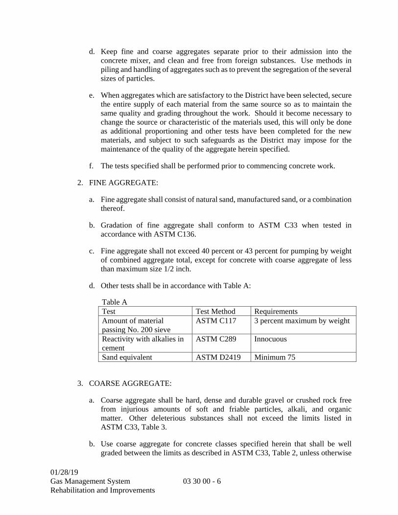
01/28/19 Gas Management System Rehabilitation and Improvements
03 30 00 - 6
d. Keep fine and coarse aggregates separate prior to their admission into the concrete mixer, and clean and free from foreign substances. Use methods in piling and handling of aggregates such as to prevent the segregation of the several sizes of particles.
e. When aggregates which are satisfactory to the District have been selected, secure the entire supply of each material from the same source so as to maintain the same quality and grading throughout the work. Should it become necessary to change the source or characteristic of the materials used, this will only be done as additional proportioning and other tests have been completed for the new materials, and subject to such safeguards as the District may impose for the maintenance of the quality of the aggregate herein specified.
f. The tests specified shall be performed prior to commencing concrete work.
2. FINE AGGREGATE:
a. Fine aggregate shall consist of natural sand, manufactured sand, or a combination thereof.
b. Gradation of fine aggregate shall conform to ASTM C33 when tested in accordance with ASTM C136.
c. Fine aggregate shall not exceed 40 percent or 43 percent for pumping by weight of combined aggregate total, except for concrete with coarse aggregate of less than maximum size 1/2 inch.
d. Other tests shall be in accordance with Table A:
Table A Test Test Method Requirements Amount of material passing No. 200 sieve
ASTM C117 3 percent maximum by weight
Reactivity with alkalies in cement
ASTM C289 Innocuous
Sand equivalent ASTM D2419 Minimum 75
3. COARSE AGGREGATE:
a. Coarse aggregate shall be hard, dense and durable gravel or crushed rock free from injurious amounts of soft and friable particles, alkali, and organic matter. Other deleterious substances shall not exceed the limits listed in ASTM C33, Table 3.
b. Use coarse aggregate for concrete classes specified herein that shall be well graded between the limits as described in ASTM C33, Table 2, unless otherwise
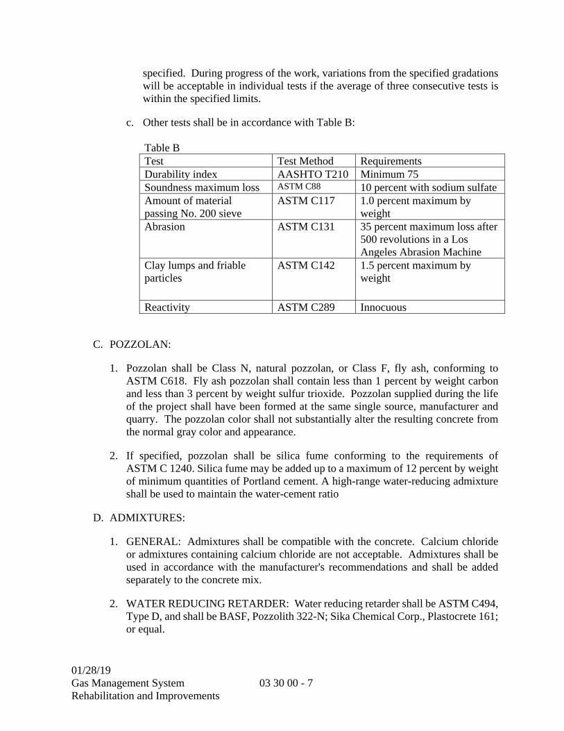
01/28/19 Gas Management System Rehabilitation and Improvements
03 30 00 - 7
specified. During progress of the work, variations from the specified gradations will be acceptable in individual tests if the average of three consecutive tests is within the specified limits.
c. Other tests shall be in accordance with Table B:
Table B Test Test Method Requirements Durability index AASHTO T210 Minimum 75 Soundness maximum loss ASTM C88 10 percent with sodium sulfateAmount of material passing No. 200 sieve
ASTM C117 1.0 percent maximum by weight
Abrasion ASTM C131 35 percent maximum loss after 500 revolutions in a Los Angeles Abrasion Machine
Clay lumps and friable particles
ASTM C142 1.5 percent maximum by weight
Reactivity ASTM C289 Innocuous
C. POZZOLAN:
1. Pozzolan shall be Class N, natural pozzolan, or Class F, fly ash, conforming to ASTM C618. Fly ash pozzolan shall contain less than 1 percent by weight carbon and less than 3 percent by weight sulfur trioxide. Pozzolan supplied during the life of the project shall have been formed at the same single source, manufacturer and quarry. The pozzolan color shall not substantially alter the resulting concrete from the normal gray color and appearance.
2. If specified, pozzolan shall be silica fume conforming to the requirements of ASTM C 1240. Silica fume may be added up to a maximum of 12 percent by weight of minimum quantities of Portland cement. A high-range water-reducing admixture shall be used to maintain the water-cement ratio
D. ADMIXTURES:
1. GENERAL: Admixtures shall be compatible with the concrete. Calcium chloride or admixtures containing calcium chloride are not acceptable. Admixtures shall be used in accordance with the manufacturer's recommendations and shall be added separately to the concrete mix.
2. WATER REDUCING RETARDER: Water reducing retarder shall be ASTM C494, Type D, and shall be BASF, Pozzolith 322-N; Sika Chemical Corp., Plastocrete 161; or equal.
01/28/19 Gas Management System Rehabilitation and Improvements
03 30 00 - 8
a. The water reducing retarder shall reduce the water required at least 8 percent for a given concrete consistency and shall comply with the water/cement ratio standards of ACI 211.1.
3. HIGH RANGE WATER REDUCING ADMIXTURES: High range water reducing (superplasticizing) admixtures shall conform to ASTM C494, Type F. Acceptable products include: BASF “Glenium 3000NS”; Sika Chemical Corp. “Sikament FF or 686”; Euclid Chemical Co. “Eucon 37”; W.R. Grace “ADVA 195”; or equal.
4. HIGH RANGE WATER REDUCING AND RETARDING ADMIXTURES: High range water reducing and retarding admixtures shall conform to ASTM C494, Type G. Acceptable products include: W.R. Grace “Daracem 100”; Euclid Chemical Co. “Eucon 537”; or equal.
5. AIR ENTRAINING AGENT: Air entraining agent shall be BASF, MB-AE90; or equal. For concrete that will not be treated with surface hardener, the air entraining agent added shall produce an entrained air content between 3 and 5 percent, in accordance with ASTM C260. Entrained air shall be less than or equal to 3 percent where surface hardener is required.
6. WATER REDUCING ACCELERATOR: Not permitted.
7. SHRINKAGE REDUCING ADMIXTURE: Not required.
8. GROUND GRANULATED BLAST-FURNACE SLAG (GGBFS) ADMIXTURE: GGBFS shall conform to requirements of ASTM C 989, Grade 100 or 120. GGBFS may replace Portland cement at a ratio of 1.0 pound GGBFS for each pound of Portland cement replaced. A maximum of 70 percent by weight of cement may be replaced with GGBFS.
9. CALCIUM NITRATE CORROSION INHIBITOR ADMIXTURE: Calcium nitrate based corrosion inhibitor shall contain 30 percent, plus or minus 2 percent, calcium nitrate by weight. Calcium nitrate based corrosion inhibitor shall be added at a rate of 1.0 to 6.0 gallons per cubic yard of concrete to achieve the desired level of corrosion mitigation. Calcium nitrate based corrosion inhibitor shall be Master Builders/BASF Rheocrete CN1, Grace Construction Products DC1, or equal.
E. WATER:
1. Water for washing aggregate, mixing, wetting forms, and curing shall be clean potable water free from injurious amounts of oil, alkalies, organic materials and other deleterious substances.

01/28/19 Gas Management System Rehabilitation and Improvements
03 30 00 - 9
2.02 CONCRETE PRODUCED ON-SITE (NOT USED)
2.03 CONCRETE CHARACTERISTICS
A. MIX PROPORTIONING:
1. An approved laboratory shall design all mixes. Comply with ACI 211.1 and ACI 304R to produce plastic, workable mixture suitable for concrete work indicated, which will develop required compressive strengths indicated.
2. Normal weight concrete shall be composed of specified cement, pozzolan, admixtures, aggregates and water proportioned and mixed to produce a workable, strong, dense, and impermeable concrete. The Contractor may substitute interground portland-pozzolan cement conforming to ASTM C595, containing the specified amount of pozzolan in lieu of portland cement and pozzolan.
3. Concrete classes shall be provided in accordance with Table C:
Table C – Concrete Classes
Concrete Class
ASTM C33 Coarse Aggre-gate Size Number
Nominal Size Laboratory Sieve
Minimum Cementitious Material Content (pounds/cuyd concrete)
Pozzolan, Percent by Weight of Portland Cement a
Air Entraining Agent
Water Reducing Retarder
Water Reducing Accelerator
Minimum 28-day Compressive Strength b
1 57 1" x No.4 560 15-20 yes yes no 4000 psi2 67 ¾" x No.4 560 15-20 yes yes no 4000 psi3 67 ¾” x No.4 590 15-20 yes yes no 5000 psi4 57 1" x No.4 420 0 yes no no 3000 psi5 c 57 1" x No.4 375 15-20 yes no no 2000 psiNotes for table: a Cement can be replaced by pozzolan pound per pound, up to 15 to 20 percent of total weight. b Compressive strength shall be determined at the end of 28 days based on test cylinders made and tested in accordance with ASTM C39. Maximum water/cement ratio shall not exceed 0.40 by weight for compressive strength of 4500 psi or higher, 0.45 for compressive strength of 3000 psi, and 0.65 for other strength concrete. Maximum water/cement ratio shall not exceed 0.38 for concrete containing high range water reducing admixtures. Water/cement ratio is based on the combined amount of cement and pozzolan. c Concrete encasement for electrical and signal conduit shall contain 2 pounds of red oxide per sack of cement.
B. USE:
1. Concrete shall be provided by class for the corresponding use as listed in Table D: Table D
Type of Use
Class of Concrete
Working Slump (Inches) [+/- 1]
Slabs 24 inches thick or less, structural concrete unless otherwise noted
1 or 2 4
Precast structural concrete 3 4 Site pavement, and civil detail concrete 4 4

01/28/19 Gas Management System Rehabilitation and Improvements
03 30 00 - 10
Table D
Type of Use
Class of Concrete
Working Slump (Inches) [+/- 1]
Pipe encasement and electrical or signal ductbanks 5 6
C. MIX ACCEPTANCE:
1. GENERAL: Before beginning concrete work, the Contractor shall determine the proper proportions of materials for each class of concrete. The mix shall consist of specified cement, pozzolan, admixtures, aggregate and water. Methods for selecting and adjusting proportions of the ingredients shall be in accordance with ACI 211.1. Verification of mix characteristics for submittal may be achieved using either the Trial Mix Design method or Field Experience method. Concrete shall not be placed in the field until the submitted mix design and trial batch mix test results, as applicable, have been accepted by the District.
2. TRIAL MIX DESIGN
a. Class 1 and 2 Concrete:
1) The Contractor shall submit mix designs to the District for approval. The mix design shall include:
2) Concrete supplier’s mix number with proportions of materials per cubic yard.
3) Supplier certifications for cement, pozzolan, and aggregate.
4) Product data for admixtures.
b. Upon approval of the submitted concrete mix designs, the Contractor shall make arrangements for field trial batches with the supplier and the District. The District shall be notified 1 week in advance of trial batch mix work. Trial batch mix work shall be performed with representatives of the District and Contractor’s testing laboratory being present. Sampling and testing of concrete shall be done by the Contractor’s testing laboratory. Certified copies of the laboratory test results shall be submitted to the District. The District reserves the right to sample and test the trial batches.
c. The trial batches shall establish field proportions for mixes which may contain minor adjustments to the submitted mix design. Trial batches shall be tested for compressive strength and drying shrinkage.
1) COMPRESSIVE STRENGTH: Eight standard test cylinders, prepared in accordance with ASTM C31, shall be obtained from each trial batch. Slump shall be measured in accordance with ASTM C143. Cylinders shall be tested in compression in accordance with ASTM C39. Four test cylinders shall be
01/28/19 Gas Management System Rehabilitation and Improvements
03 30 00 - 11
tested at 7 days and the remaining four at 28 days. The ratio of average 7-day and 28-day strength shall be established. The average compressive strength of the four test cylinders tested at 28 days shall be equal to or greater than the required average compressive strength (f’cr) on which the mix design is based. The required average compressive strength (f’cr) shall be calculated as specified strength (f’c) plus 1200 psi.
d. Class 4 and 5 Concrete:
1) The Contractor shall submit mix designs to the District for approval. The mix design shall include:
a) Concrete supplier’s mix number with concrete proportions per cubic yard
b) Certifications for cement, pozzolan, and aggregate
c) Product data for admixtures
d) Historical compressive strength test results for same mix number used on other projects within the last 12 calendar months. Test records shall represent materials, quality control procedures, and conditions expected to apply to this work. At least 30 consecutive tests or two groups of consecutive tests totaling at least 30 tests shall be used to establish a standard deviation and a required average compressive strength (f’cr), as described in ACI 318, Part 3, Chapter 5. The arithmetic average of at least 10 consecutive test results, not used in calculating the standard deviation, shall exceed f’cr.
2) If there is insufficient historical compressive strength data for the submitted mix design, then the mix design shall undergo trial batch testing as described for Class 1 and 2 concrete.
3. FIELD EXPERIENCE DATA: When sufficient test data for a particular mix design is available which is identical or substantially similar to that proposed for use, Contractor may substitute use of this data in lieu of a trial mix design. Field data, reports, and analysis shall conform to ACI 318 Section 5.3, except as modified herein. Use of historical mix design data does not allow modification of the project mix specifications herein without the express review and acceptance of the District.
a. Historical mix design proportions for which data are submitted may vary from the specified mix within the following limits:
1) f’c as specified or up to 500 psi above;
2) w/cm ratio as specified or lower;
3) Pozzolan content within 5 percent of that specified;
01/28/19 Gas Management System Rehabilitation and Improvements
03 30 00 - 12
4) Maximum coarse aggregate size may not vary smaller, but gradation of coarse aggregate may vary;
5) Fine aggregate fraction within +0/ 5 percent of that specified; and
6) Slump after introduction of admixtures +0/-1 inch.
2.04 JOINT SEALERS
A. Joint sealers shall be performed asphalt fiberboard joint filler shall be in accordance with ASTM D994 and shall be 1/2 inch thick unless otherwise specified.
2.05 BONDING COMPOUNDS
A. Epoxy resin bonding compounds shall be used for wet areas.
1. Sika Chemical Corporation, Sikadur 35 hi-mod LV, 32 hi-mod, 32 hi-mod LTL, 31 hi-mod gel as applicable; or equal by Master Builders Technologies; or equal.
B. Nonepoxy bonding compounds shall be used for areas not classified as wet areas.
1. Burke Acrylic Bondcrete; Imperial Chemical Industrial Inc. Thoro System Products Division, Acryl 60 or Thorobond; or equal.
2.06 RETARDANT
A. Retardant for exposing aggregates for nonformed surfaces in construction joints shall be Sika Rugasol-S, Horn Aggretex-H, or Burke True Etch Surface Retarder, or equal. Retardant shall be applied in accordance with manufacturer's instructions sufficient to assure a minimum penetration of 1/8 inch.
2.07 SURFACE HARDENER
A. Surface hardener shall be premixed, noncolored, nonmetallic, and dry shake applied.
1. Mastercron by Master Builders Technologies; Burke Non Metallic Hardener; or equal.
2.08 CURING MATERIALS
A. LIQUID MEMBRANE-FORMING COMPOUNDS:
1. Curing Compounds:
a. Curing compounds shall conform to ASTM C309.
1) Burke Wax Emulsion Clear; Burke Aqua Resin Cure; W.R. Meadows Sealtight 1300-Clear; or equal.
01/28/19 Gas Management System Rehabilitation and Improvements
03 30 00 - 13
b. Curing compound shall be of the dissipating-resin type in applications where concrete finishes (such as waterproofing, coatings and floor coverings) may require removal of curing compound prior to application of finish.
1) Burke Res X, All Resin Cure VOC; W.R. Meadows Sealtight 1100-Clear; or equal.
2. Curing and Sealing Compounds:
a. Curing and sealing compounds shall conform to ASTM C309, Type 1, and shall be suitable for interior and exterior concrete use.
b. Masterseal by Master Builders Technologies; W.R. Meadows Sealtight VOCOMP-20; or equal.
B. SHEETING:
1. Polyethylene-coated burlap for use as concrete curing blanket shall be 4-mil thick, white opaque polyethylene film impregnated or extruded into one side of the burlap. Burlap shall weigh not less than 9 ounces per square yard. The loss of moisture, when determined in accordance with the requirements of ASTM C156, shall not exceed 0.055 gram per square centimeter of surface.
2. Waterproof Paper and Plastic:
a. Polyethylene-coated waterproof paper-sheeting for use as concrete curing blanket shall consist of white polyethylene sheeting free of visible defects, uniform in appearance, having a nominal thickness of 2 mils and permanently bonded to waterproof paper conforming to the requirements of Federal Specification UU-B-790A (Int. Amd. 1). The loss of moisture, when determined in accordance with the requirements of ASTM C156, shall not exceed 0.055 gram per square centimeter of surface.
b. Polyethylene sheet for use as concrete curing blanket shall be white and shall have a nominal thickness of 6 mils. The loss of moisture when determined in accordance with the requirements of ASTM C156 shall not exceed 0.055 gram per square centimeter of surface.
3. Curing rugs for use in water curing, as specified herein, shall be heavy shag rugs or carpets or cotton mats that weigh a minimum of 12 ounces per square yard when dry.
2.09 EVAPORATION REDUCER
A. Evaporation reducer shall reduce surface moisture evaporation by forming a monomolecular film when sprayed on concrete surfaces.
1. Confilm by Master Builders Technologies; Eucobar by Euclid Chemical Co.; or equal.
01/28/19 Gas Management System Rehabilitation and Improvements
03 30 00 - 14
2.10 SAMPLES OF CONCRETE FLOOR AND WALL FINISHES
A. A sample concrete panel, representative of the workmanship and finish required, shall be prepared. Panel dimensions shall be 2 feet by 2 feet by 3 inches thick, unless prior arrangements have been made with the District to incorporate the sample panel within the completed work. Sample concrete panels are required for the following finishes, as defined in Part 3:
1. Smooth Rubbed Finish
2. Grout Cleaned Finish (Sacking)
3. Sandblast Finish
4. Float Finish
5. Steel Trowel Finish
6. Broom Finish
B. The District shall approve the sample prior to use.
PART 3 -- EXECUTION
3.01 GENERAL
A. The District is defining in this part the quality of cast-in-place concrete by specifying some of the methods, techniques, sequences and procedures for construction of cast-in-place concrete. The Contractor, without relinquishing authority and responsibility for supervision and direction of the work, agrees to follow the specified methods, techniques, sequences and procedures.
B. The District will conduct field quality assurance tests for concrete strength. The testing laboratory may be the Public Works Materials Testing Laboratory. The Contractor shall notify the District Representative at least 48 hours in advance whenever a sample and test of concrete materials is required by these specifications.
3.02 FORMWORK
A. Formwork shall conform to the CONCRETE FORMING Section (03 11 00).
3.03 CONCRETE REINFORCEMENT
A. Concrete reinforcement shall conform to the CONCRETE REINFORCING Section (03 20 00).

01/28/19 Gas Management System Rehabilitation and Improvements
03 30 00 - 15
3.04 CONSTRUCTION JOINTS
A. Construction joints are not anticipated for this project. Provide concrete placement schedule and proposed joint locations for review if proposing to use construction joints.
3.05 INSERTS AND EMBEDMENTS
A. Inserts and embedments shall include such items as pipes, castings, conduits, sleeves, anchor bolts, or other miscellaneous metal parts that pass through or are embedded in concrete. Nailing blocks, plugs, strips, and similar items necessary for the attachment of trim, finish, or similar work shall also be embedded.
B. Aluminum items shall not be embedded in concrete unless effectively coated to prevent aluminum-concrete reaction or electrolytic action between aluminum and steel.
C. All inserts and embedded items shall be positioned accurately and supported against displacement. Install ties and supports necessary to keep items in place. Anchor bolts shall be positioned using templates.
D. Inserts and embedments shall not interfere with clearance and alignment of steel reinforcement, or concrete cover. Additional reinforcement shall be provided around large openings as shown on the drawings.
E. Voids in sleeves and anchor slots shall be filled temporarily with readily removable material to prevent the entry of concrete into the voids.
F. Prior to placing concrete, inserts and embedments shall be cleaned, inspected, and approved.
3.06 CONCRETE MIXING AND TRANSPORTING
A. Concrete shall be truck-mixed, ready-mixed concrete conforming to the applicable portions of ASTM C94. Materials shall be proportioned by weighing. Pozzolan shall be introduced into the mixer with cement and other components of the concrete mix; pozzolan shall not be introduced into a wet mixer ahead of other materials or with mixing water. Water shall be introduced at the time of charging the mixer; additional water may be introduced within 45 minutes from charging the mixer, provided the specified slump is not exceeded.
B. Each load of ready-mixed concrete delivered to the job site shall be accompanied by a batch ticket and weigh ticket showing the information listed in ASTM C94, Section 16.
3.07 BATCHING AND MIXING CONCRETE PRODUCED ON SITE
A. Concrete produced on site is not allowed for this project.

01/28/19 Gas Management System Rehabilitation and Improvements
03 30 00 - 16
3.08 CONVEYING AND PLACING CONCRETE
A. CONVEYING CONCRETE:
1. Concrete shall be conveyed from the mixer to the forms in accordance with ACI 301, Chapter 8. Concrete which has segregated in conveying shall be removed from the site of the work.
B. PLACING CONCRETE:
1. GENERAL:
a. Concrete shall be placed in accordance with ACI 301.
b. Limit free drop of concrete to 6 feet.
c. Concrete shall be placed at or near its final position. Do not use vibrators for extensive shifting of fresh concrete.
d. Concrete discharge shall be completed within 90 minutes after introduction of the water to the mixture.
2. SLAB-ON-GRADE:
a. Concrete slab-on-grade shall be placed only upon surfaces that are free from frost, ice, mud, loose or unsound rock, and other detrimental substances.
b. Place concrete only after subgrade, forms and reinforcement have been approved by the District.
3. ELEVATED SLABS:
a. Concrete shall not be placed until shoring, bracing, and falsework has been inspected per the CONCRETE FORMING Section (03 11 00).
C. PLACING CONCRETE BY PUMPING:
1. CONCRETE PUMP:
a. Use only piston type pumps that are reversible.
b. Do not use aluminum or aluminum lined pipe, or aluminum fittings.
c. A standby pump of no less capacity than that in operation at the job shall be available within one hour's notice.
2. PUMP PRIMING:
01/28/19 Gas Management System Rehabilitation and Improvements
03 30 00 - 17
a. Before starting each pumping operation, the pump and line shall be primed with a cement slurry to lubricate the system. Cement slurry shall be wasted outside the forms.
3. SLUMP:
a. Water shall not be added after 45 minutes from the time of initial mixing at the batch plant. Within 45 minutes from the time of initial mixing at the batch plant, water may be added to achieve the slump limits specified in Table D.
b. Slump adjustment—when concrete slump test results are below the required slump, the slump may be adjusted by adding water up to the amount allowed in the accepted mixture proportions. Addition of water shall be in accordance with ASTM C94/C94M. Do not exceed the specified water/cement ratio or slump. Do not add water to concrete delivered in equipment not acceptable for mixing. After plasticizing or high-range water-reducing admixtures are added to the concrete at the site to achieve flowable concrete, do not add water to the concrete. Measure slump and air content of air-entrained concrete after slump adjustment to verify compliance with specified requirements.
c. Slump may be measured at the transit mix truck or hose discharge at the discretion of the District. Slump loss in pumping, measured between the pumping unit inlet hopper and the hose discharge, shall not exceed 1 inch.
d. The mix design entered on delivery ticket shall comply with that ordered.
D. TEMPERATURE OF CONCRETE:
1. The temperature of concrete when it is being placed shall not be less than 50 degrees F. For sections less than 24 inches thick, the temperature of concrete shall not exceed 90 degrees F. For sections 24 to 36 inches thick, the temperature of concrete shall not exceed 80 degrees F. For sections greater than 36 inches thick, the temperature of concrete shall not exceed 75 degrees F. The Contractor shall employ effective means, such as using ice or hot water, placing at night, or other means as necessary to maintain the temperature of the concrete within the required temperature range.
E. COLD WEATHER PLACEMENT:
1. Remove snow, ice, and frost from all surfaces, including reinforcement against which concrete is to be placed. Embedded items shall be warmed to above 32 degrees F. Concrete shall not be placed when ambient temperature is below 40 degrees F unless provisions are made, in accordance with cold weather curing and sealing provisions of this specification, to keep the concrete and immediate surroundings at or above 50 degrees F for 72 hours after placement.

01/28/19 Gas Management System Rehabilitation and Improvements
03 30 00 - 18
3.09 CONSOLIDATING CONCRETE
A. Concrete shall be consolidated in accordance with ACI 309R.
B. Vibration and tamping operations shall conform to ACI 309R. As concrete is placed in forms, work concrete around reinforcing steel, embedded items and into corners and angles. Extra care shall be given to work concrete around inserts, reveals, quirks, corners and plastic cones of ties to preclude rock pockets, air pockets, and other defects. Each 18-inch layer shall be compacted by mechanical internal vibrating equipment within 5 minutes of being placed supplemented by hand spading, tamping, and rodding.
C. Vibrators shall not be used to transport concrete inside forms. The use of form vibrators will not be permitted. Internal vibrators shall maintain a speed of not less than 7,000 impulses per minute when submerged in the concrete. Duration of vibration shall be limited to time necessary to produce satisfactory consolidation without causing objectionable segregation. Vibrators shall be applied at uniformly spaced points not farther apart than the visible effectiveness of the machine. Insert vibrator into previous unset layer to prevent cold joints. Supplement vibration by suitable methods to eliminate voids along forms for full depth of layer. Do not allow vibrators to strike overlaid plywood surfaces.
D. Keep at least one spare vibrator on job at all times while concrete is being placed.
3.10 FLOOR AND SLAB FINISHES
A. GENERAL:
1. The finishes specified herein include surface finishes, treatments and toppings for floors and slabs. Floors shall be sloped to drain uniformly. Unless otherwise specified, slope shall be minimum 1/8 inch per foot towards nearest drain. Dry cement shall not be used on fresh concrete surfaces to absorb excess moisture. Edges shall be rounded to a radius of 1/2 inch.
B. FLOAT FINISH:
1. Float finish shall conform to ACI 301, Chapter 11. Floating shall be performed with a hand float. Floating shall compact and smooth the surface and close any cracks.
2. Wet well slab shall be float finished, as a minimum, unless otherwise required by equipment manufacturer.
C. STEEL TROWEL FINISH:
1. Not used.
D. BROOM FINISH:
1. Broom finish shall conform to ACI 301, Chapter 11.
01/28/19 Gas Management System Rehabilitation and Improvements
03 30 00 - 19
2. Broom finish shall be provided for sidewalks, walkways, decks, slabs on grade with exterior exposure, and where otherwise indicated or specified.
3.11 FORMED SURFACE FINISHES
A. GENERAL:
1. After removal of forms, the surfaces of formed concrete shall be given a finish as specified below.
B. ROUGH FORM FINISH:
1. Rough form finish shall conform to ACI 301, Chapter 10, except as modified herein. Tie holes shall be patched. Holes, depressions, bulges, or other defects 3/8 inch or larger shall be patched. Fins exceeding ¼ inch shall be chipped off or rubbed off. Unsound concrete in rock pockets shall be removed, and the void patched.
2. Unless otherwise specified in the specifications or shown on the drawings, rough form finish shall be used on concrete surfaces buried below grade; interior surfaces of wet wells; and tanks and channels from 1 foot below minimum water surfaces to the bottom.
3.12 RELATED SURFACE FINISHES
A. MONOLITHIC SURFACING:
1. Monolithic surfacing shall be provided on floor areas as specified. Monolithic surfacing shall consist of a steel trowel finish hardened with a surface hardener as specified in this Section. Surface hardener shall be applied in accordance with the manufacturer's recommendations and directions.
B. FINISHING OF UNFORMED SURFACES:
1. Tops of walls or buttresses, horizontal offsets, and similar unformed surfaces occurring adjacent to formed surfaces shall be struck smooth after concrete is placed and shall be floated to a texture consistent with that of the adjacent formed surfaces. Final treatment of formed surfaces shall continue uniformly across the unformed surfaces.
3.13 CURING AND SEALING
A. GENERAL:
1. Beginning immediately after placement, concrete shall be protected from premature drying, excessively hot or cold temperatures, and mechanical injury, and shall be maintained with minimal moisture loss at a relatively constant temperature for the period necessary for hydration of cement and hardening of concrete.
01/28/19 Gas Management System Rehabilitation and Improvements
03 30 00 - 20
2. Concrete temperature shall be maintained between 50 and 90 degrees F during the curing period.
B. CURING OF CONCRETE:
1. Unless otherwise specified in this Section, curing shall be continued for at least 7 days.
2. Moisture retention measures for concrete surfaces not in contact with forms shall be provided by one of the following methods:
a. Complete and continuous application of water which does not contain deleterious compounds harmful to the concrete.
b. Use of curing rugs or blankets kept continuously wet.
c. Use of waterproof paper or plastic.
d. Application of liquid membrane forming compound applied per manufacturer’s recommendations.
3. Moisture loss from concrete surfaces placed against wooden or metal forms shall be minimized by keeping the forms wet until they can be safely removed. As soon as can be done without damaging the concrete, the forms shall be loosened, and water shall run down inside of them. After form removal, the concrete shall be cured using one of the methods above for the duration of the curing period.
4. Curing compound shall not be used on concrete surfaces to be coated, waterproofed, moistureproofed, tiled, roofed or where other coverings are to be bonded, unless the curing compound is compatible with the final finish covering or it is removed prior to covering.
5. Steel troweled finish concrete floors which are not to receive tile, roofing, grout, terrazzo or other bonded coverings shall be cured with a curing and sealing compound. It shall be applied as soon as the concrete has set sufficiently so it is not marred by the application. Preparation of surfaces, quantities used, application procedures and installation precautions shall be followed in strict compliance with the manufacturer's instructions.
6. High-early-strength concrete shall be cured for at least 3 days, and shall be cured with methods that use water during the curing period. Application of liquid membrane forming compound is not acceptable.
C. ADDITIONAL REQUIREMENTS FOR CURING DURING COLD WEATHER:
1. When the mean daily outdoor temperature is less than 40 degrees F, provisions shall be made, as necessary, for heating, covering, insulating, or housing the concrete to maintain concrete temperature within the specified range. The use of combustion

01/28/19 Gas Management System Rehabilitation and Improvements
03 30 00 - 21
heaters shall be controlled in order to avoid damaging the concrete due to concentration of heat.
D. ADDITIONAL REQUIREMENTS FOR CURING DURING HOT WEATHER:
1. Hot weather is any condition or combination of conditions that accelerate the rate of moisture loss and/or rate of cement hydration. These conditions include high ambient heat (above 90 degrees F), high concrete temperature, low relative humidity, and/or wind velocity. During hot weather, provisions shall be made, as necessary, for windbreaks, shading, fog spraying, continuous sprinkling, or wet coverings. Such protective measures shall be taken as quickly as concrete hardening and finishing operations allow.
3.14 PROTECTION
A. Concrete shall be protected from injurious action by sun, rain, flowing water, frost, freezing, and mechanical injury.
B. Do not place concrete during rainy weather unless approved measures are taken to prevent damage to concrete.
C. Protect concrete placed during periods of drying winds, low humidity, high temperatures and other conditions that may cause rapid drying. Apply a fine spray of water applied immediately after finishing and continue until final curing operations have begun.
D. Slabs in areas subject to construction traffic shall be protected with 6-mil kraft paper or polyethylene membrane for at least 2 weeks after placement.
3.15 CONCRETE REPAIRS AND MODIFICATION OF EXISTING CONCRETE
A. REPAIR OF SURFACE DEFECTS:
1. Surface defects, including tie holes, rock pockets, honeycombing or otherwise defective concrete shall be repaired immediately following form removal. Excessive cracking or leaking cracks shall be repaired in accordance with this Specification Section.
2. Defective areas shall be chipped or cut back to solid concrete to a depth of at least 1 inch. Where half or more of the rebar circumference is exposed, remove concrete a minimum of 1” around the rebar. The edges of the cut shall be perpendicular to the surface of the concrete. Feathered edges shall not be permitted. The areas to be patched shall be cleaned by abrasive blasting or high pressure water jetting. Concrete substrate shall be free of any deleterious materials, and shall have a roughened surface with a minimum amplitude of 1/4 inch. Presoak concrete substrate to saturated surface dry condition immediately prior to application of bond coat for concrete repair material.

01/28/19 Gas Management System Rehabilitation and Improvements
03 30 00 - 22
3. Portland cement mortar patching material shall be a mixture of the same materials and of approximately the same proportions as used for the concrete, except that coarse aggregate shall be omitted. Brush cement slurry bond coat into the surfaces. Before bond coat dries, apply dry pack and consolidate into place. Curing for the patched area shall be as specified for the concrete. As an alternative to field-mixed Portland cement mortar patching material, a commercial patching compound may be used per manufacturer’s recommendations, if submitted and approved in advance of concrete repair work.
4. Repaired area shall be equal in color, workmanship, texture and general appearance to that of the adjacent concrete.
B. ACCEPTANCE OF CONCRETE:
1. Completed cast-in-place concrete work shall conform to the applicable requirements of ACI 301 and the Contract Documents. Concrete work that fails to meet the requirements of ACI 301 or the Contract Documents shall be repaired as approved by the District to bring the concrete into compliance. Concrete that cannot be brought into compliance by approved repair methods will be rejected. Rejected concrete work shall be removed and replaced. Repair methods shall be in accordance with ACI standards and are subject to the approval of the District. The cost of repairs and replacement of defective concrete shall be borne by the Contractor.
C. REPAIR METHODS:
1. Damaged or excessively cracked concrete, as determined by the District in their sole discretion, shall be repaired by one of the following methods as approved by the District:
a. REPAIR METHOD 1: Fill the joint or crack by drilling holes to the affected area, install injection ports and force epoxy or chemical grout (expanding urethane) into the joint under pressure. The material type, whether epoxy or chemical grout shall be approved by the District. After injection and curing, ports, sealing mix and surface generally shall be cleaned and worked to match the specified finish.
b. REPAIR METHOD 2: Fill cracks with low viscosity epoxy, applied by pouring/flooding crack zone until cracks are filled. Prepare surface, install, and cure according to manufacturer’s recommendations. At a minimum, prepare surface to result in a clean, dry surface and with no visible detrimental material in cracks to be filled. Conform to temperature limitations for epoxy to be used. Finish to match adjacent areas.
c. REPAIR METHOD 3: Cut a bevel groove 3/8 to 1/2 inch in width and depth, and caulk with sealant in accordance with manufacturer’s instructions. This repair method is only to be used where expressly allowed by the District. Groove

01/28/19 Gas Management System Rehabilitation and Improvements
03 30 00 - 23
and caulk shall be applied on wet or hydrostatic pressure side of surface where occurs.
2. REPAIR METHOD USE:
a. Repair Method 1 shall be used for all cracks in walls, surfaces sloped 1:1 or greater, beams, columns, slabs, overhead surfaces and generally for liquid retaining surfaces. Need for repair depends upon crack width, location, and surface conditions under service conditions. Epoxy grout shall be used for repair of structural cracks and chemical grout (expanding urethane) shall be used for repair of non-structural cracks at liquid-containing structures. The District shall determine whether a crack is classified as structural or non-structural.
b. Repair Method 2 may be utilized in lieu of Method 1 for slabs which receive a raked finish. Method 2 may also be used with Construction Manager’s approval for exposed trowelled and broom finishes after review of conditions, degree of exposure to public, and proposed repair product and installation. Finish shall substantially match adjacent surfaces.
c. Repair Method 3 shall be limited to dry-surface slabs, walls subject to less than three feet of liquid pressure, or as specifically directed by the District. Method 3 is not an equivalent repair method to Methods 1 or 2, which shall be considered the standards.
3.16 FIELD SAMPLING AND TESTS
A. GENERAL:
1. The District will conduct field sampling and tests to assure the quality of the materials and work used throughout the project. The District laboratory will provide the necessary labor, materials and facilities for sampling the aggregate, and for casting, handling and storing the concrete samples at the site of work. Aggregate will be sampled at the batch plant not less than 30 days prior to the use of such aggregate in the work, and at least weekly during concrete operations. Concrete will be sampled at the time of placement.
B. SAMPLING:
1. AGGREGATES:
a. GENERAL: Fine and coarse aggregates shall be sampled in accordance with ASTM D75. Samples shall be obtained from the concrete batch plant at the discharge gates of the bins feeding the weigh hopper or belt samples. The Contractor shall provide safe and suitable facilities for obtaining samples. Sampling shall be repeated when the source of material is changed or when unacceptable deficiencies or variations from the specified requirements of
01/28/19 Gas Management System Rehabilitation and Improvements
03 30 00 - 24
materials are found in testing. Aggregate samples shall be tagged and their sources identified.
b. COARSE AGGREGATE: A sample weighing between 50 and 60 pounds shall be taken after the batch plant is brought up to full operation. The samples shall be taken so that a uniform cross section, accurately representing the materials on the belt or in the bins, is obtained.
c. FINE AGGREGATE: Samples shall be taken as specified for coarse aggregate. Samples of sand shall be taken when the sand is moist.
2. CONCRETE: Samples of freshly mixed concrete shall be obtained in accordance with ASTM C172. At the discretion of the District, samples of concrete may be taken at the transit mix truck chute, the pump hopper, or the hose discharge point.
C. TESTING:
1. AGGREGATE: A minimum of one test of coarse aggregate per 400 cubic yards of concrete and a minimum of one test of fine aggregate per 200 cubic yards of concrete used shall be made to confirm continuing conformance with specifications for gradation, specific gravity, cleanliness, and sand equivalent, as applicable.
2. CONCRETE:
a. STRENGTH TESTS: Verification of mix design strength shall be accomplished by testing standard cylinders of concrete samples taken at the job site. Standard cylinders shall represent the concrete placed in the forms. One set of five standard cylinders shall be cast of each class of concrete for each 100 cubic yards or less in each separate structure. Casting, handling and curing of cylinders shall be in accordance with ASTM C31. Additional cylinders shall be provided when an error in batching is suspected. For the first 24 hours after casting, the cylinders shall be kept moist and measures taken so that air temperature will be between 60 and 80 degrees F. At the end of 24 hours, the cylinders shall be transported to the testing laboratory.
1) Testing of specimens for compressive strength shall be in accordance with ASTM C39. Tests shall be made at 7 and 28 days from time of casting. One test cylinder from each group of five shall be tested at the end of 7 days and two shall be tested at the end of 28 days. The fourth and fifth cylinder shall be tested only when the strength test fails to meet the required compressive test at 28 days.
2) Each strength test result shall be the average of the strengths of two test cylinders at 28 days. However, if one cylinder in the set of two shows evidence of low strength due to improper sampling, casting, handling or curing, the result from the fourth cylinder shall be used.

01/28/19 Gas Management System Rehabilitation and Improvements
03 30 00 - 25
3) The average of any three consecutive 28-day strength test results of the cylinders representing each class of concrete for each structure shall be equal to or greater than the specified strength and not more than 10 percent of the strength test results shall have values less than the specified 28-day strength for the total concrete placement. No individual strength test results shall be less than the specified strength by more than 500 pounds per square inch.
4) If the 28-day test results fall below the specified compressive strength for the class of concrete required for any portion of the work, adjustment in the proportions, water content, or both, shall be made as necessary at the Contractor's expense. Changes and adjustments shall be submitted to the District for approval.
5) If compressive test results indicate concrete in place may not meet structural requirements, tests shall be made to determine if the structure or portion thereof is structurally sound. Tests may include, but not be limited to, cores in accordance with ASTM C42 and any other analyses or load tests acceptable to the District. Costs of such tests shall be borne by the Contractor.
b. TESTS FOR CONSISTENCY OF CONCRETE: The slump shall be as specified when measured in accordance with ASTM C143. Samples for slump determination shall be taken from the concrete during placing. Tests shall be made at the beginning of concrete placement operation and at subsequent intervals to ensure that the specification requirements are met. Slump tests shall also be performed whenever standard cylinders are cast.
c. TESTS FOR TEMPERATURE AND AIR CONTENT: Temperature tests shall be made at frequent intervals during hot or cold weather conditions until satisfactory temperature control is established. Whenever standard cylinders are cast, temperature tests shall be performed. Air content shall be as specified when measured in accordance with ASTM C231. Air content shall be measured whenever standard cylinders are cast.
3.17 CLEANUP
A. Upon completion of the work and prior to final inspection, the Contractor shall clean all concrete surfaces as follows:
1. FLOORS WITH CURING AND SEALING COMPOUNDS: Cleaned of loose dirt and debris by sweeping with ordinary brooms, then washed and mopped with clean water. Finally, one additional coat of the same initial curing and sealing compound shall be applied per manufacturer’s recommendations. The Contractor shall receive approval from the District prior to application of the final coat.
01/28/19 Gas Management System Rehabilitation and Improvements
03 30 00 - 26
2. EXTERIOR SLAB ON GRADE WITHOUT CURING AND SEALING COMPOUNDS: Cleaned of loose dirt and debris by sweeping with ordinary brooms, then washed with clean water.
**END OF SECTION**
01/28/19 Gas Management System Rehabilitation and Improvements
03 34 13 - 1
SECTION 03 34 13
CONTROLLED LOW STRENGTH CONCRETE
PART 1 -- GENERAL
1.01 GENERAL REQUIREMENTS
A. SCOPE:
1. This section specifies controlled low strength concrete (CLSC) which is a self-compacting, cementitious fill material. This section consists of furnishing all material, mixing and transporting equipment, and performing all labor for the proportioning, mixing, transporting, placing, consolidating, finishing and curing of CLSC.
2. CLSC shall not be used in lieu of concrete for pipe encasement or electrical duct banks.
B. QUALITY ASSURANCE:
1. GENERAL:
a. All testing during the work will be done by a testing laboratory of the District's choice at the District's expense except as otherwise noted in the specifications.
b. In case the tests of the CLSC show noncompliance with the specifications, the Contractor shall accomplish such remedy as may be required to ensure compliance. Subsequent testing to show compliance shall be by a testing laboratory selected by the District and shall be at the Contractor's expense.
c. The sampling of freshly mixed CLSC delivered to the project site shall be in accordance with ASTM D5971.
2. CONSISTENCY, UNIT WEIGHT, AND COMPRESSIVE STRENGTH:
a. Consistency of CLSC shall be determined in accordance with ASTM C143.
b. Unit weight of CLSC shall be determined in accordance with ASTM D6023.
c. The compressive strength shall be determined in accordance with ASTM D4832.
01/28/19 Gas Management System Rehabilitation and Improvements
03 34 13 - 2
1.02 REFERENCES
A. REFERENCE STANDARDS: The publications referred to hereinafter form a part of this specification to the extent referenced. The publications are referred to in the text by the basic designation only. The latest edition of referenced publications in effect at the time of the bid shall govern. In case of conflict between the requirements of this section and the listed standards, the requirements of this section shall prevail.
Reference Title
ASTM C33 Specification for Concrete Aggregate
ASTM C94 Specifications for Ready-Mixed Concrete
ASTM C143 Test Method for Slump of Hydraulic Cement Concrete
ASTM C150 Specification for Portland Cement
ASTM C260 Specification for Air-Entraining Admixtures for Concrete
ASTM C494 Specification for Chemical Admixtures for Concrete
ASTM C618 Specification for Fly Ash and Raw or Calcined Natural Pozzolan for Use as a Mineral Filler in Portland Cement Concrete
ASTM D4832 Preparation and Testing of Soil-Cement Slurry Test Cylinders
ASTM D5971 Sampling Freshly Mixed Controlled Low Strength Material
ASTM D6023 Test Method for Unit Weight, Yield and Air Content (Gravimetric) of Controlled Low Strength Material
1.03 SUBMITTALS
A. The following information shall be submitted for review in accordance with SUBMITTAL PROCEDURES Section (01 33 00):
1. A copy of this specification section, with addenda updates, with each paragraph check marked to show specification compliance or marked to show deviations.
2. CLSC mix designs that show the proportions of all materials proposed for each class of CLSC specified. Mix design shall also include gradations and certifications of all materials.
3. An independent testing laboratory shall test the mix designs for properties specified. Results from previous projects may be submitted as long as the mix proportions and materials are the same.
01/28/19 Gas Management System Rehabilitation and Improvements
03 34 13 - 3
PART 2 -- PRODUCTS
2.01 MATERIALS
A. GENERAL:
1. CLSC shall be an excavatable mixture of cement, pozzolan, coarse and fine aggregate, admixtures, and water which has been mixed in accordance with ASTM C94.
2. The actual mix proportion, slump, and admixtures shall be determined by the Contractor to meet the uses specified herein. The entrained air content shall be a minimum of 6 percent and a maximum of 20 percent.
B. CEMENT:
1. Cement shall be Type II or V in accordance with the requirements of ASTM C150.
C. POZZOLAN:
1. Pozzolan shall be added to improve the flowability and shall be Type F in accordance with the requirements of ASTM C618.
D. AGGREGATE:
1. Coarse aggregate shall consist of a well-graded mixture of gravel, crushed rock, or pea gravel with a maximum size aggregate of 3/8 inch. Coarse aggregate shall in accordance with the requirements of ASTM C33.
2. Fine aggregate shall be in accordance with the requirements of ASTM C33.
3. All material shall be free from organic matter and not contain more alkali, sulfates, or salts than the native materials at the site work.
E. ADMIXTURES:
1. Air entraining admixture shall be added to improve the flowability and shall be in accordance with the requirements of ASTM C260.
2. Water reducing agent shall be added to improve the workability and shall be in accordance with the requirements of ASTM C494.
F. WATER:
1. Water shall be potable, clean, and free from objectionable quantities of silty organic matter, alkali, salts, and other impurities.

01/28/19 Gas Management System Rehabilitation and Improvements
03 34 13 - 4
PART 3 -- EXECUTION
3.01 GENERAL
A. The District is defining the quality of CLSC by specifying in this part some of the means, methods, techniques, sequences and procedures for installation of CLSC. The Contractor, without relinquishing authority and responsibility for supervision and direction of the work, agrees to follow the specified means, methods, techniques, sequences and procedures.
B. The District will conduct field quality control tests for CLSC strength. The Contractor shall notify the District at least 2 days in advance whenever a sample and test of CLSC materials is required by these specifications.
C. CLSC with a non-segregating consistency that readily flows shall be used as follows:
Use
28-day Compressive
Strength (ASTM D4832)
Slump (ASTM C143)
Unit weight (ASTM D6023)
Bedding & initial backfill at: Exposed existing utilities Utility crossings Stacked utilities
50 to 150 psi 6 to 8 inches 115 to 145 pcf
Filling of abandoned underground structures
100 to 300 psi 6 to 8 inches 115 to 145 pcf
Structural fills 300 to 1200 psi 4 to 6 inches 115 to 145 pcfPavement bases 400 to 1200 psi 4 to 6 inches 115 to 145 pcf
3.02 INSTALLATION
A. PREPARING PLACEMENT FOR CLSC:
1. The subgrade, compacted fill and/or trench to receive CLSC shall be complete and acceptable in accordance with the EARTH MOVING Section (31 20 00).
B. MIXING AND DELIVERING CLSC:
1. CLSC shall be batched by a ready-mix batching plant.
2. CLSC shall be delivered to the work in standard transit mix trucks.
C. PLACING CLSC:
1. CLSC shall be delivered in place by means of tailgate discharge, conveyor belts, pump, chute, or other means acceptable to the District.

01/28/19 Gas Management System Rehabilitation and Improvements
03 34 13 - 5
2. For pipe bedding and initial backfill, measures shall be taken to prevent CLSC from floating the pipe. Measures may include, placing CLSC in lifts with sufficient set-up time between lifts, sandbags placed over the pipe, straps around the pipe anchored into the soil, or other methods approved by the District. For flexible wall pipes, CLSC shall be placed in lifts so that lateral support can develop along the side of the pipe before CLSC is placed over the pipe.
3. For trench backfill, bulkheads shall be provided to contain long open-ended segments.
4. For structural fills, CLSC shall be placed in lifts with sufficient set-up time between lifts to prevent overloading retaining structures.
5. Where fresh CLSC must be placed against existing CLSC, the placement shall be clean of all loose and foreign material. The surface of existing control density shall be soaked with water before placing new control density. No standing water will be allowed before starting placement of fresh CLSC.
6. CLSC shall be directed in place by means of a vibrator to ensure that all voids, crevices, and pockets are filled.
D. FINISHING CLSC:
1. The finish surface of CLSC shall be smooth and to the grade shown on the drawings or directed by the District. Finishing by wood float, steel trowel, or other similar methods is not required.
E. PROTECTING CLSC:
1. CLSC shall be protected from running water, rain, freezing, or other conditions that could damage the material.
2. In order to avoid a quick-sand type hazard, CLSC shall be covered or otherwise protected until hardening occurs.
3. No equipment, traffic, or backfill shall be allowed on the CLSC until the surface of the CLSC is able to withstand a 20 psi load without displacement or damage. If necessary, the Contractor shall provide steel trench plates that span the trench until the CLSC has reached the required strength.
3.03 TESTING (NOT USED)
3.04 TRAINING (NOT USED)
**END OF SECTION**
01/28/19 Gas Management System Rehabilitation and Improvements
03 34 13 - 6
THIS PAGE INTENTIONALLY LEFT BLANK
01/28/19 Gas Management System Rehabilitation and Improvements
03 40 00 - 1
SECTION 03 40 00
PRECAST CONCRETE
PART 1 -- GENERAL
1.01 GENERAL REQUIREMENTS
A. SCOPE:
1. This section specifies the materials and labor required for the manufacture and erection of precast concrete, including the top slab of the wet well.
1.02 REFERENCES
A. REFERENCE STANDARDS: The publications referred to hereinafter form a part of this specification to the extent referenced. The publications are referred to in the text by the basic designation only. The latest edition of referenced publications in effect at the time of the bid shall govern. In case of conflict between the requirements of this section and the listed references, the requirements of this section shall prevail.
Reference Title
ACI 318 Building Code Requirements for Reinforced Concrete
AWS D1.1
AWS D1.4
Structural Welding Code – Steel
Structural Welding Code – Reinforcing Steel
ASTM A36 Structural Steel
ASTM A615
Deformed and Plain Billet-Steel Bars for Concrete Reinforcement
ASTM C33 Concrete Aggregates
ASTM C150 Portland Cement
ASTM C330 Lightweight Aggregates for Structural Concrete
Caltrans State of California, Department of Transportation, Standard Specifications
CBC California Building Code (2016)

01/28/19 Gas Management System Rehabilitation and Improvements
03 40 00 - 2
B. DEFINITIONS: (Not Used)
1.03 SUBMITTALS
A. The following information shall be submitted for review in accordance with the SUBMITTAL PROCEDURES Section (01 33 00):
1. A copy of this specification section, with addenda updates, with each paragraph check marked to show specification compliance or marked to show deviation.
2. SHOP DRAWINGS. The Contractor shall review all drawings relating to precast structural members for required openings, embedded items, inserts, etc., for preparing shop drawings. The Contractor shall submit complete shop drawings to the District Representative for his review. These drawings shall show product location, fabrication details, number identification marks, reinforcement, connection details, openings, embedded items and inserts, dimensions and relationship to adjacent materials in sufficient detail to cover manufacture, handling and erection. Shop drawings shall be sealed and signed by a Professional Civil Engineer or Structural Engineer registered in the State of California.
3. DESIGN CALCULATIONS FOR PRECAST ELEMENTS DESIGNED BY THE MANUFACTURER. Structural calculations shall be sealed and signed by a Professional Civil Engineer or Structural Engineer registered in the State of California. Design calculations shall include the effects of dead loads, live loads, wind loads, seismic loads, floatation, and all superimposed uniform and concentrated loads shown on the Drawings.
4. CONCRETE MIX DESIGN. Prior to casting any precast elements, concrete mix design shall be submitted to the District Representative for acceptance. Concrete mix design shall conform to the CAST-IN-PLACE CONCRETE Section (03 30 00).
5. QUALITY ASSURANCE PLAN. To comply with tolerance and specified requirements.
6. SAMPLE OF FINISHED PANELS:
a. GENERAL: The Contractor shall submit finished and sealed 10-inch by 10-inch samples of precast concrete to illustrate quality, color, and texture of surface finish.
b. ARCHITECTURAL SAMPLES: Contractor shall prepare sample panels to serve as a standard for quality, color, texture and workmanship. Three 1-foot square panels shall be submitted to the District Representative for preliminary approval in accordance with the SUBMITTALS PROCEDURES Section (01 33 00). After the preliminary approval, three 4-foot square panels shall be submitted to the District Representative for approval in accordance with the
01/28/19 Gas Management System Rehabilitation and Improvements
03 40 00 - 3
SUBMITTALS PROCEDURES Section (01 33 00). The three 4-foot square panels shall have three different finishes or levels of blasting. One full-size representative section, cast in an actual mold showing all pertinent features of precast elements, including form joints, patched tie holes, architectural grooves, etc., shall be submitted to the District Representative for final review prior to any fabrication. Approved sample panels shall then be put on display at the job site. Display sample panels shall be clearly labeled on the back, indicating project, date of casting, type of finish, type and size of aggregate, cement, admixture and name of manufacturer. All precast panels furnished and erected by the Contractor shall match the display panels.
c. FINISH: The finish of the exterior surfaces of the panels, exposed to view, shall match in all respects the color, texture, type of aggregates and matrix, of the sample on display in the District Representative's office. Interior surfaces of the panels, specified to be painted, shall have a finish as specified in PAINTING AND COATING Section (09 90 00). Surfaces not exposed to view may have a float finish.
1.04 OPERATION AND MAINTENANCE INSTRUCTIONS (NOT USED)
1.05 QUALITY ASSURANCE
A. GENERAL:
1. The Contractor shall provide certification from the precast concrete manufacturer that the materials and manufacture of precast work supplied conforms to these specifications. Certification shall be provided to the District Representative as information and shall be certified correct under penalty of perjury by an officer of the manufacturer's corporation.
2. The responsibility for furnishing and installing precast concrete conforming to the specifications is solely that of the Contractor.
B. TESTING LABORATORY:
1. The District may conduct its own quality assurance tests. The Contractor is responsible for quality control testing.
PART 2 -- PRODUCTS
2.01 PERFORMANCE AND DESIGN REQUIREMENTS
A. Minimum compressive strength shall be 5000 psi at age 28 days, as determined by tests of 6-inch diameter by 12-inch long cylinders. Slump of concrete shall be 2 inch minimum to 3 inch maximum. Absorption shall not exceed 5 percent.
01/28/19 Gas Management System Rehabilitation and Improvements
03 40 00 - 4
2.02 PRECAST CONCRETE MATERIALS
A. GENERAL:
1. Precast concrete materials shall conform to the CONCRETE REINFORCING Section (03 20 00) and the CAST-IN-PLACE CONCRETE Section (03 30 00) except as specified or modified herein. Precast concrete shall be Class 3 concrete. Precast concrete materials shall match the appearance of adjacent concrete structures.
B. CEMENT:
1. Portland cement shall be ASTM C150, Type II or V for all wall panels and lift slabs.
C. AGGREGATES:
1. Aggregates shall conform to ASTM C33 with a maximum size of 3/4 inch. Aggregates for exposed surfaces of the panels shall be as required to match samples as specified in the above paragraph 1.03-A6c. Fine and coarse aggregates for each type of exposed finish shall be from a single source for the entire project. They shall be clean, hard, durable, inert, and free from staining or deleterious materials.
2. Existing precast panels were made from locally available aggregate. Aggregate for the engineering building completed on a separate contract was local. The fine/coarse mix was adjusted to achieve the desired texture after sandblasting and the color was adjusted using a percentage of white cement.
D. WATER:
1. Water shall be clean, potable, free from injurious amounts of oil, alkalies, organic materials and other deleterious substances.
E. ADMIXTURE:
1. Admixture shall be Pozzolith 300-R manufactured by Master Builders, Plastiment manufactured by Sika Chemical Corp., or equal. A minimum of 2 ounces per sack of cement shall be added to the concrete mix. Calcium chloride or any admixture containing calcium chloride shall not be used.
F. INTEGRAL COLOR:
1. Integral color, if used, shall be pure mineral oxide, limeproof and nonfading. Amount and type of coloring agent used shall not reduce the quality of concrete

01/28/19 Gas Management System Rehabilitation and Improvements
03 40 00 - 5
below that specified. The color of finished concrete shall match the color of the adjacent concrete to the satisfaction of the District Representative.
G. REINFORCING STEEL:
1. Unless otherwise specified, all reinforcing steel in precast concrete shall conform to ASTM A615, Grade 60.
H. EMBEDDED ITEMS AND ANCHORAGE DEVICES:
1. All embedded items and inserts, bolts, clips, angles, and other anchorage devices exposed to view, moisture or weather shall be stainless steel. Anchorage devices shall be fabricated from ASTM A36 steel. Rigid plastic inserts shall be subject to acceptance by the District Representative.
I. MOLDS:
1. Material from which molds are to be fabricated shall be steel, concrete, fiberglass, reinforced plastic or wood. The selection of materials for molds shall be at the manufacturer's option, except that wood shall not be used without the express approval of the District Representative. All elements shall be cast in molds of rigid construction, accurate in detail with precise corners and arises, and designed to provide a close control of dimensions, radii and details as indicated on the drawings.
2. Prior to casting of precast elements, molds shall have all surface joints, radii, corners, etc., filled, ground, filed, straightened or otherwise removed to provide a finished concrete surface that is smooth and dense, free of honeycombing, air pockets, offsets, sinkages, or other irregularities.
J. PARTING COMPOUND:
1. All molds shall be coated with parting compound to facilitate removal of elements from molds. Parting compound shall be nonpetroleum, nonstaining and shall be of a nature and composition not deleterious to concrete.
K. IDENTIFICATION:
1. Each panel or member shall have an identification mark and date of casting.

01/28/19 Gas Management System Rehabilitation and Improvements
03 40 00 - 6
PART 3 -- EXECUTION
3.01 GENERAL
A. HANDLING AND STORAGE:
1. Unless specified otherwise, fabrication, handling and erection of precast elements shall be in accordance with the recommendations made by ACI 318 and ACI Committee 533.
2. Precast elements shall be properly supported to avoid damage during curing, storage, handling and hauling. Lateral support shall be sufficient to prevent bowing, warping, or permanent set due to creep. Edges of the units shall be adequately protected by padding or other means to prevent staining, chipping or spalling of concrete.
3.02 INSTALLATION
A. CASTING:
1. Casting shall be accomplished by methods and equipment that are in conformance with generally acceptable systems for this type of work. All precast concrete manufactured off site shall be manufactured by a plant thoroughly experienced in this type of work. The manufacturer shall meet all production schedules. Work shall be accomplished at the manufacturer's plant or manufactured on site. Surfaces on which units are cast shall be level and free from any imperfections detrimental to the surface appearance of the finished units. Unless otherwise approved by the District Representative, all exposed faces shall be cast against forms. Parting compound shall be applied evenly in accordance with manufacturer's recommendations.
2. Concrete shall be so handled as to prevent segregation of materials and shall be continuously vibrated during casting, either internally or externally, to achieve proper compaction, finish and distribution of concrete. All precautions must be taken to keep the reinforcing steel in the proper location during placing and consolidation of the concrete. Unless shown otherwise, all reinforcing steel shall have a minimum cover of 3/4 inch. Embedded items shall be accurately placed and maintained in their proper location during the casting operation. Special inserts or other devices for handling of panels for the convenience of the manufacturer shall not be exposed to view after panels are erected. Embedded anchors, inserts, plates, angles and other cast-in items shall have sufficient anchorage and embedment for design requirements.
3. Casting, bowing, warpage and dimensional tolerances shall be in accordance with the following:
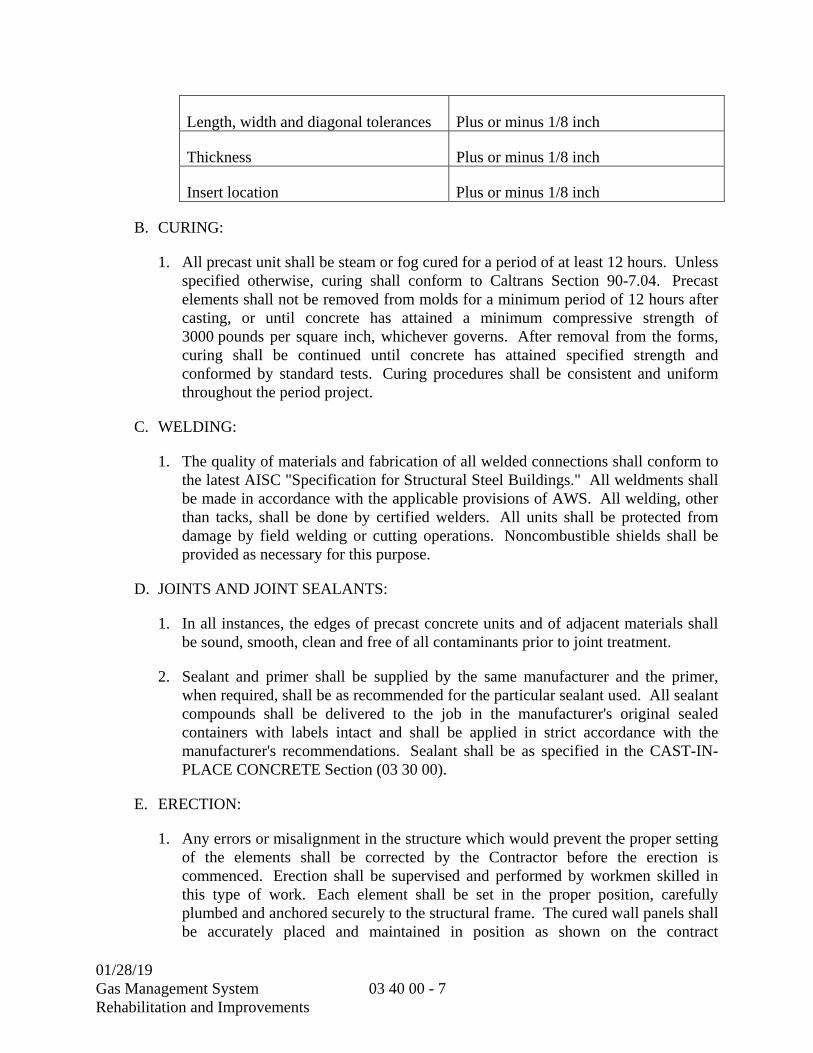
01/28/19 Gas Management System Rehabilitation and Improvements
03 40 00 - 7
Length, width and diagonal tolerances Plus or minus 1/8 inch
Thickness Plus or minus 1/8 inch
Insert location Plus or minus 1/8 inch
B. CURING:
1. All precast unit shall be steam or fog cured for a period of at least 12 hours. Unless specified otherwise, curing shall conform to Caltrans Section 90-7.04. Precast elements shall not be removed from molds for a minimum period of 12 hours after casting, or until concrete has attained a minimum compressive strength of 3000 pounds per square inch, whichever governs. After removal from the forms, curing shall be continued until concrete has attained specified strength and conformed by standard tests. Curing procedures shall be consistent and uniform throughout the period project.
C. WELDING:
1. The quality of materials and fabrication of all welded connections shall conform to the latest AISC "Specification for Structural Steel Buildings." All weldments shall be made in accordance with the applicable provisions of AWS. All welding, other than tacks, shall be done by certified welders. All units shall be protected from damage by field welding or cutting operations. Noncombustible shields shall be provided as necessary for this purpose.
D. JOINTS AND JOINT SEALANTS:
1. In all instances, the edges of precast concrete units and of adjacent materials shall be sound, smooth, clean and free of all contaminants prior to joint treatment.
2. Sealant and primer shall be supplied by the same manufacturer and the primer, when required, shall be as recommended for the particular sealant used. All sealant compounds shall be delivered to the job in the manufacturer's original sealed containers with labels intact and shall be applied in strict accordance with the manufacturer's recommendations. Sealant shall be as specified in the CAST-IN-PLACE CONCRETE Section (03 30 00).
E. ERECTION:
1. Any errors or misalignment in the structure which would prevent the proper setting of the elements shall be corrected by the Contractor before the erection is commenced. Erection shall be supervised and performed by workmen skilled in this type of work. Each element shall be set in the proper position, carefully plumbed and anchored securely to the structural frame. The cured wall panels shall be accurately placed and maintained in position as shown on the contract

01/28/19 Gas Management System Rehabilitation and Improvements
03 40 00 - 8
drawings. All bearing surfaces shall be true to line and grade. Top of grout joints on roofs shall be troweled adequately smooth to prevent any unevenness that might interfere with the placing of, or cause damage to, insulation and roofing. Transition due to differential levels should be finished not steeper than 1:12.
2. Erection tolerances shall be in accordance with the following: Installation alignment of the tops of all precast wall units with a true horizontal plane shall not exceed plus or minus 1/8 inch. Faces of installed panels shall be within 1/16 inch of a common plane, i.e., 1/8-inch offset maximum. All joints shall be uniform and straight.
F. CLEANING AND REPAIRING:
1. After installation, precast elements shall be protected from all damage until final acceptance by the District Representative. Precast units with cracks, spalls, and other defects shall be subject to rejection. Units approved for repair shall be repaired to the satisfaction of the District Representative. Just before final acceptance by the District Representative, all precast units shall be thoroughly cleaned to remove all dirt and stains. Care shall be taken that no part of adjacent areas be damaged or that the finish be changed by the cleaning material or process.
3.03 TESTING (NOT USED)
3.04 TRAINING (NOT USED)
**END OF SECTION**

01/28/19 Gas Management System Rehabilitation and Improvements
03 60 00 - 1
SECTION 03 60 00
GROUTING
PART 1 -- GENERAL
1.01 GENERAL REQUIREMENTS
A. SCOPE:
1. Section Includes: Grout for column base plates, other structural supports, equipment bases, reinforcing bar dowels, surface repair, grout toppings, and patching of fresh concrete. This section does not include grouting for masonry.
1.02 REFERENCES
A. REFERENCE STANDARDS: The references listed below are part of this section. Where a referenced document cites other standards, such standards are included as references under this section as if referenced directly. In the event of conflict, the requirements of this section shall prevail.
Reference Title ASTM C109 Test Method for Compressive Strength of Hydraulic Cement
Mortars (Using 2 inch or 50 mm Cube Specimens) ASTM C230 Flow Table for Use in Tests of Hydraulic Cement ASTM C307 Standard Test Method for Tensile Strength of Chemical-Resistant
Mortar, Grouts, and Monolithic Surfacings ASTM C939 Test Method for Flow of Grout for Preplaced-Aggregate Concrete
(Flow Cone Method) ASTM C531 Standard Test Method for Linear Shrinkage and Coefficient of
Thermal Expansion of Chemical-Resistant Mortars, Grouts, Monolithic Surfacings, and Polymer Concretes
ASTM C579 Standard Test Methods for Compressive Strength of Chemical-Resistant Mortars, Grouts, Monolithic Surfacings and Polymer Concretes
ASTM C882 Standard Test Method for Bond Strength of Epoxy-Resin Systems Used with Concrete by Slant Shear
ASTM C942 Standard Test Method for Compressive Strength of Grouts for Preplaced-Aggregate Concrete in the Laboratory
ASTM C1107 Packaged Dry, Hydraulic-Cement Grout (Non-shrink) ASTM C1181 Standard Test Methods for Compressive Creep of Chemical-
Resistant Polymer Machinery Grouts
01/28/19 Gas Management System Rehabilitation and Improvements
03 60 00- 2
Reference Title ASTM E329 Agencies Engaged in Construction Inspection, Testing, or Special
Inspection CBC California Building Code (2016) COE CRD-C611 Flow of Grout for Preplaced Aggregate Concrete COE CRD-C621 Non-shrink Grout
1.03 SUBMITTALS
A. The following information shall be submitted for review in accordance with the SUBMITTAL PROCEDURES Section (01 33 00):
1. Procedure: Section 01 33 00:
2. A copy of this specification section with each paragraph check-marked to indicate specification compliance or marked to indicate requested deviations from specification requirements.
3. Check-marks () shall denote full compliance with a paragraph as a whole. Deviations shall be underlined and denoted by a number in the margin to the right of the identified paragraph. The remaining portions of the paragraph not underlined will signify compliance on the part of the Contractor with the specifications. Include a detailed, written justification for each deviation. Failure to include a copy of the marked-up specification sections, along with justification(s) for any requested deviations to the specification requirements, with the submittal shall be sufficient cause for rejection of the entire submittal with no further consideration.
4. Complete product literature, including mixing, handling and placement instructions for the following: Cementitious non-shrink grout, epoxy grout, adhesive for reinforcing bar dowel grouting, concrete repair mortar, and prepackaged cement grout products to be used on the project.
5. Mix design for cement grout that is not prepackaged, including product data for aggregates and cement in accordance with Section 03 30 00.
6. Current ICC-ESR or IAPMO UES reports for adhesives used for reinforcing dowels.
7. Installer certification in accordance with ACI/CRSI Adhesive Anchor Installer Certification Program for installers of horizontal or upwardly inclined reinforcing bar dowels grouted using adhesive.
8. Certified test results verifying the compressive strength, shrinkage and expansion requirements specified herein.
01/28/19 Gas Management System Rehabilitation and Improvements
03 60 00- 3
B. LABORATORY TEST REPORTS:
1. Before delivery of materials, the reports of the tests specified herein shall be submitted. Test reports on previously tested materials shall be accompanied by the manufacturer's statement that the previously tested material is the same type, quality, manufacture, and make as that proposed for use in this project. Test reports are required for the following:
a. Cement
b. Aggregates
c. Admixtures
d. Bonding compounds
e. Epoxy Resin
2. To demonstrate conformance with the specified requirements for grout, the Contractor shall provide the services of an independent testing laboratory which complies with the requirements of ASTM E329. The testing laboratory shall sample and test grout materials as required in this section. Costs of testing laboratory services shall be borne by the Contractor.
C. EVIDENCE OF TESTING LABORATORY COMPETENCE:
1. The Contractor shall require that the laboratory provide directly to the District Representative evidence of the most recent inspection of its facilities by the Cement and Concrete Reference Laboratory of the National Bureau of Standards. The evidences shall show that deficiencies mentioned in the report of that inspection have been corrected. The evidence of inspection shall be submitted and approved prior to delivery of materials to the job site.
1.04 QUANITY ASSURANCE
A. Quality Control by District
1. The Owner will provide the services of a qualified Special Inspector in accordance with the 2016 CBC and the Contract Documents.
2. Adhesive anchors installed in horizontal or upwardly inclined orientations to resist sustained tension loads shall be continuously inspected during installation by a Special Inspector.
a. The Special Inspector shall furnish a report to the Engineer, Owner’s Representative and Building Official that the work covered by the report has
01/28/19 Gas Management System Rehabilitation and Improvements
03 60 00- 4
been performed and that the materials used and the installation procedures used conform with the approved Project Manual and the Manufacturer’s Printed Installation Instructions (MPII).
B. Quality Control by Contractor
1. Provide the services of an independent testing laboratory which complies with the requirements of ASTM E329 if a product other than those listed below is proposed and test data is not available from the supplier to demonstrate equivalence to the specified grout. The testing laboratory shall sample and test the proposed grout materials. Costs of testing laboratory services shall be borne by the Contractor.
C. Certifications
1. Installer certification shall be in accordance with ACI/CRSI Adhesive Anchor Installer Certification Program for installers of horizontal or upwardly inclined reinforcing bar dowels grouted using adhesive.
D. Compression test specimens will be taken during construction from the first placement of each type of grout and at intervals thereafter as selected by the Engineer to insure continued compliance with these Specifications.
1. Compression tests and fabrication of specimens for epoxy grout will be performed as specified in ASTM C579, Method B, at intervals during construction as selected by the Engineer. A set of three specimens will be made for testing at seven days and any other time period as appropriate.
2. Compression tests and fabrication of specimens for cement grout and non-shrink grout will be performed as specified in ASTM C109 at intervals during construction as selected by the Engineer. A set of three specimens will be made for testing at seven days, 28 days and any additional time period as appropriate.
E. Manufacturer Qualifications
1. Manufacturer shall have a minimum of (5) five years experience of producing products substantially similar to that required and shall be able to submit documentation of at least (5) five satisfactory installations that have been in successful operation for at least five years each.
F. When required, provide services of manufacturer's full-time employee, factory-trained in handling, use, and installing the products required, with at least 5 years of experience.
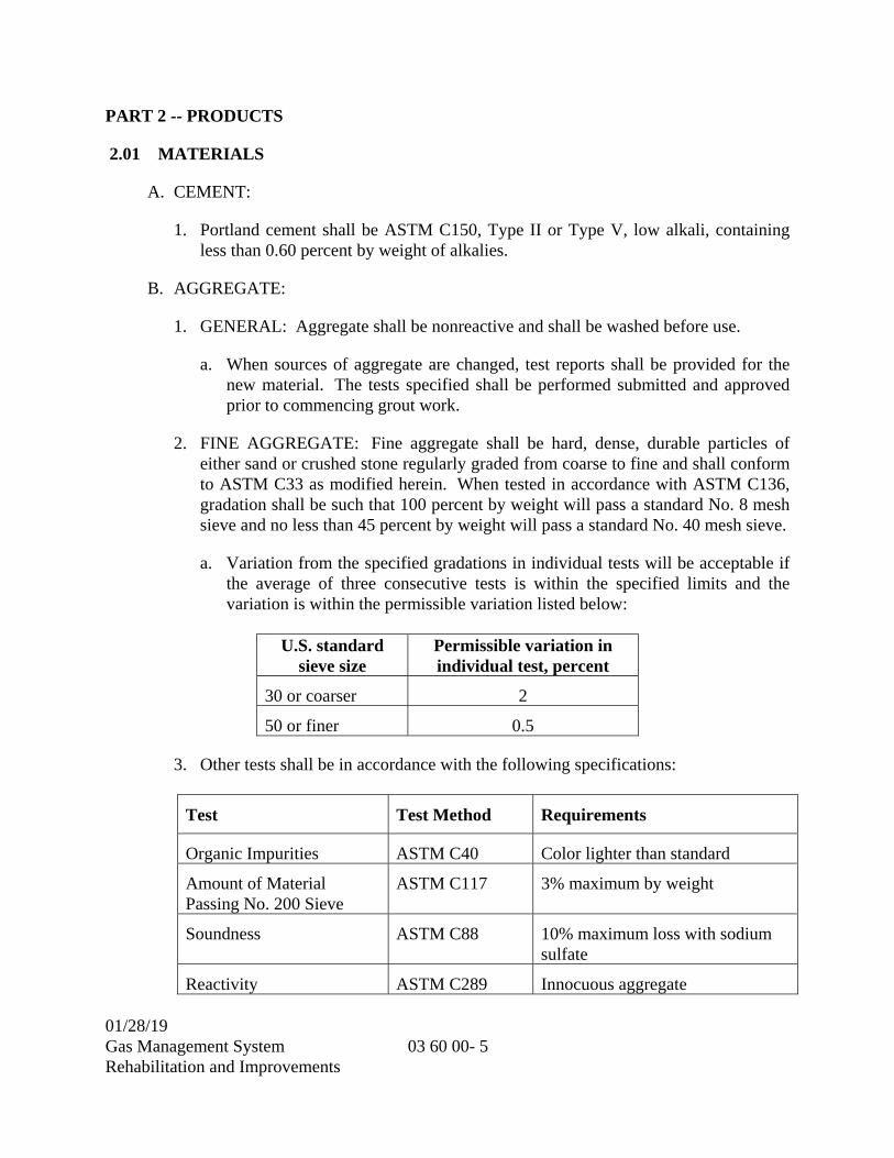
01/28/19 Gas Management System Rehabilitation and Improvements
03 60 00- 5
PART 2 -- PRODUCTS
2.01 MATERIALS
A. CEMENT:
1. Portland cement shall be ASTM C150, Type II or Type V, low alkali, containing less than 0.60 percent by weight of alkalies.
B. AGGREGATE:
1. GENERAL: Aggregate shall be nonreactive and shall be washed before use.
a. When sources of aggregate are changed, test reports shall be provided for the new material. The tests specified shall be performed submitted and approved prior to commencing grout work.
2. FINE AGGREGATE: Fine aggregate shall be hard, dense, durable particles of either sand or crushed stone regularly graded from coarse to fine and shall conform to ASTM C33 as modified herein. When tested in accordance with ASTM C136, gradation shall be such that 100 percent by weight will pass a standard No. 8 mesh sieve and no less than 45 percent by weight will pass a standard No. 40 mesh sieve.
a. Variation from the specified gradations in individual tests will be acceptable if the average of three consecutive tests is within the specified limits and the variation is within the permissible variation listed below:
U.S. standard
sieve size Permissible variation in individual test, percent
30 or coarser 2
50 or finer 0.5
3. Other tests shall be in accordance with the following specifications:
Test Test Method Requirements
Organic Impurities ASTM C40 Color lighter than standard
Amount of Material Passing No. 200 Sieve
ASTM C117 3% maximum by weight
Soundness ASTM C88 10% maximum loss with sodium sulfate
Reactivity ASTM C289 Innocuous aggregate
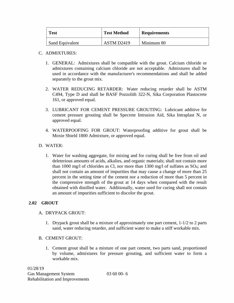
01/28/19 Gas Management System Rehabilitation and Improvements
03 60 00- 6
Test Test Method Requirements
Sand Equivalent ASTM D2419 Minimum 80
C. ADMIXTURES:
1. GENERAL: Admixtures shall be compatible with the grout. Calcium chloride or admixtures containing calcium chloride are not acceptable. Admixtures shall be used in accordance with the manufacturer's recommendations and shall be added separately to the grout mix.
2. WATER REDUCING RETARDER: Water reducing retarder shall be ASTM C494, Type D and shall be BASF Pozzolith 322-N, Sika Corporation Plastocrete 161, or approved equal.
3. LUBRICANT FOR CEMENT PRESSURE GROUTING: Lubricant additive for cement pressure grouting shall be Specrete Intrusion Aid, Sika Intraplast N, or approved equal.
4. WATERPOOFING FOR GROUT: Waterproofing additive for grout shall be Moxie Shield 1800 Admixture, or approved equal.
D. WATER:
1. Water for washing aggregate, for mixing and for curing shall be free from oil and deleterious amounts of acids, alkalies, and organic materials; shall not contain more than 1000 mg/l of chlorides as Cl, nor more than 1300 mg/l of sulfates as SO4; and shall not contain an amount of impurities that may cause a change of more than 25 percent in the setting time of the cement nor a reduction of more than 5 percent in the compressive strength of the grout at 14 days when compared with the result obtained with distilled water. Additionally, water used for curing shall not contain an amount of impurities sufficient to discolor the grout.
2.02 GROUT
A. DRYPACK GROUT:
1. Drypack grout shall be a mixture of approximately one part cement, 1-1/2 to 2 parts sand, water reducing retarder, and sufficient water to make a stiff workable mix.
B. CEMENT GROUT:
1. Cement grout shall be a mixture of one part cement, two parts sand, proportioned by volume, admixtures for pressure grouting, and sufficient water to form a workable mix.
01/28/19 Gas Management System Rehabilitation and Improvements
03 60 00- 7
2. Cement grout shall be comprised of cement, fine aggregate, coarse aggregate, water, and admixtures proportioned and mixed in accordance with this Section.
a. Minimum Compressive Strength: 4,500 psi at 28 days.
b. Maximum Water Cement Ratio: 0.42 by weight.
c. Coarse Aggregate: ASTM C33/C33M, No. 8 size.
d. Fine Aggregate: ASTM C33/C33M, approximately 60 percent by weight of total aggregate.
e. Air Content: Five percent (plus or minus one percent).
f. Minimum Cement Content: 564 pounds per cubic yard.
g. Slump for grout fill shall be adjusted to match placing and finishing conditions, and shall not exceed four inches.
C. NONSHRINK NONMETALLIC GROUT:
1. The grout material shall be an approved ready to use mixture requiring only water for use at the job site. The 2-inch cubes shall have a minimum compressive strength of 3,000 psi at 7 days and 7,000 psi at 28 days.
2. Cementitious non-shrink non-metallic aggregate grout shall be:
a. BASF, Masterflow 928
b. Euclid Chemical Company, Hi-Flow Grout
c. Five Star Products, Inc., Five Star Grout
d. Sika Corporation, SikaGrout 212
e. Approved Equal
3. Non-shrink grout shall conform to CRD-C 621 and ASTM C1107, Grade B or C when tested at a maximum fluid consistency of 30 seconds per ASTM C939 at temperature extremes of 45 degrees Fahrenheit and 90 degrees Fahrenheit and an extended working time of 15 minutes.
4. Fluid grout shall pass through the flow cone, with continuous flow, one hour after mixing.
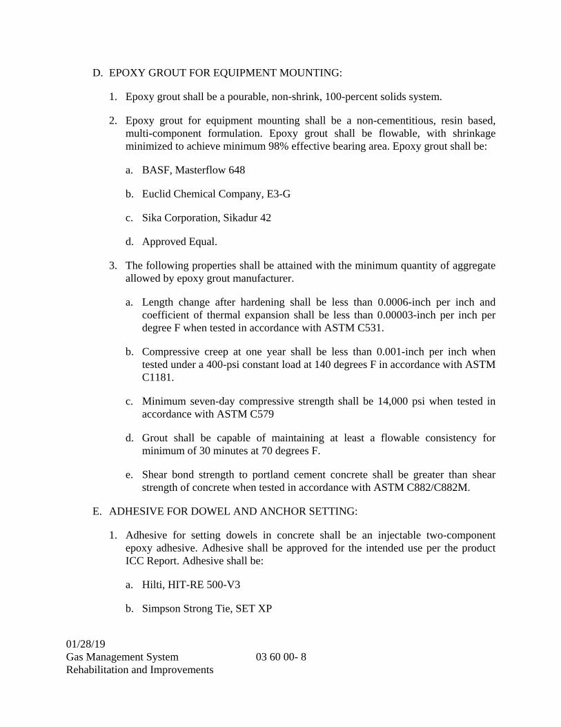
01/28/19 Gas Management System Rehabilitation and Improvements
03 60 00- 8
D. EPOXY GROUT FOR EQUIPMENT MOUNTING:
1. Epoxy grout shall be a pourable, non-shrink, 100-percent solids system.
2. Epoxy grout for equipment mounting shall be a non-cementitious, resin based, multi-component formulation. Epoxy grout shall be flowable, with shrinkage minimized to achieve minimum 98% effective bearing area. Epoxy grout shall be:
a. BASF, Masterflow 648
b. Euclid Chemical Company, E3-G
c. Sika Corporation, Sikadur 42
d. Approved Equal.
3. The following properties shall be attained with the minimum quantity of aggregate allowed by epoxy grout manufacturer.
a. Length change after hardening shall be less than 0.0006-inch per inch and coefficient of thermal expansion shall be less than 0.00003-inch per inch per degree F when tested in accordance with ASTM C531.
b. Compressive creep at one year shall be less than 0.001-inch per inch when tested under a 400-psi constant load at 140 degrees F in accordance with ASTM C1181.
c. Minimum seven-day compressive strength shall be 14,000 psi when tested in accordance with ASTM C579
d. Grout shall be capable of maintaining at least a flowable consistency for minimum of 30 minutes at 70 degrees F.
e. Shear bond strength to portland cement concrete shall be greater than shear strength of concrete when tested in accordance with ASTM C882/C882M.
E. ADHESIVE FOR DOWEL AND ANCHOR SETTING:
1. Adhesive for setting dowels in concrete shall be an injectable two-component epoxy adhesive. Adhesive shall be approved for the intended use per the product ICC Report. Adhesive shall be:
a. Hilti, HIT-RE 500-V3
b. Simpson Strong Tie, SET XP

01/28/19 Gas Management System Rehabilitation and Improvements
03 60 00- 9
c. Approved Equal (equivalent product must have ICC approval for use in cracked concrete in areas with high seismic risk).
F. CONCRETE REPAIR MORTAR
1. Horizontal Applications: Repair mortars shall be:
a. BASF, MasterEmaco S 466CI
b. Sika Corporation, SikaTop 111 Plus
c. Approved Equal
2. Vertical and Overhead Applications: Repair mortars shall be:
a. BASF, MasterEmaco 1500HCR Vertical Overhead
b. Sika Corporation, SikaTop 123 Plus
c. Approved Equal
2.03 EPOXY INJECTION SYSTEM
A. Epoxy for pressure grouting/crack injection shall be a two-component, moisture insensitive, high modulus, injection grade, 100 percent solids, blend of epoxy-resin compounds. The consistency shall be as required to achieve complete penetration in hairline cracks and larger. Material shall conform to ASTM C881, Type 1, Grade 1. Candidate manufacturers include Sika Corporation Sikadur 52, BASF SCB Concresive 1300 series, and Adhesive Technology Corporation SLV 300 series, or equal.
PART 3 -- EXECUTION
3.01 GENERAL
A. Holes required for grouting shall be blown clean. Horizontal holes for grouting shall be drilled at a slight downward angle to facilitate holding the grout until setting is complete. Bolts or reinforcing steel installed in horizontal grout holes shall be bent slightly accordingly. Bonding compound for use with grout is specified in the CAST-IN-PLACE CONCRETE Section (03 30 00). Mechanically mix the grout materials with or without fillers in strict accordance with the manufacturer's instruction. All application of the mixed materials shall be performed within the working life or pot life of the grout system. Unused mixed materials which have reached the end of the working or pot life shall be removed from the job site.
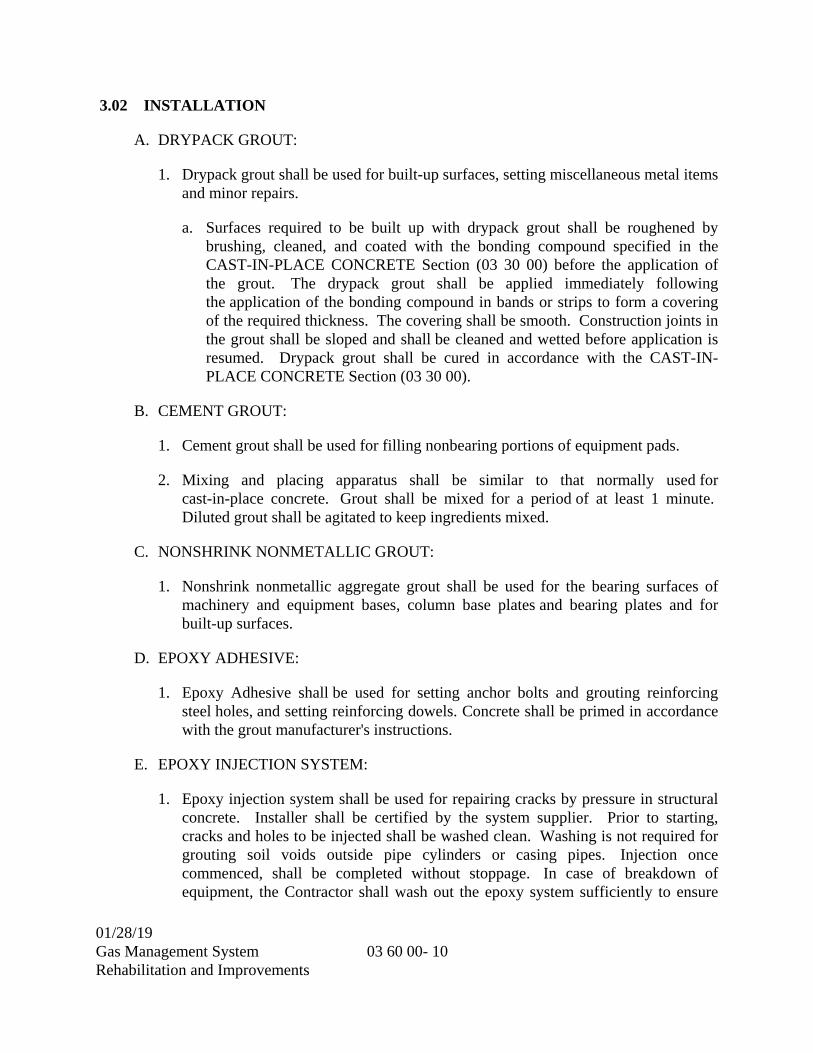
01/28/19 Gas Management System Rehabilitation and Improvements
03 60 00- 10
3.02 INSTALLATION
A. DRYPACK GROUT:
1. Drypack grout shall be used for built-up surfaces, setting miscellaneous metal items and minor repairs.
a. Surfaces required to be built up with drypack grout shall be roughened by brushing, cleaned, and coated with the bonding compound specified in the CAST-IN-PLACE CONCRETE Section (03 30 00) before the application of the grout. The drypack grout shall be applied immediately following the application of the bonding compound in bands or strips to form a covering of the required thickness. The covering shall be smooth. Construction joints in the grout shall be sloped and shall be cleaned and wetted before application is resumed. Drypack grout shall be cured in accordance with the CAST-IN-PLACE CONCRETE Section (03 30 00).
B. CEMENT GROUT:
1. Cement grout shall be used for filling nonbearing portions of equipment pads.
2. Mixing and placing apparatus shall be similar to that normally used for cast-in-place concrete. Grout shall be mixed for a period of at least 1 minute. Diluted grout shall be agitated to keep ingredients mixed.
C. NONSHRINK NONMETALLIC GROUT:
1. Nonshrink nonmetallic aggregate grout shall be used for the bearing surfaces of machinery and equipment bases, column base plates and bearing plates and for built-up surfaces.
D. EPOXY ADHESIVE:
1. Epoxy Adhesive shall be used for setting anchor bolts and grouting reinforcing steel holes, and setting reinforcing dowels. Concrete shall be primed in accordance with the grout manufacturer's instructions.
E. EPOXY INJECTION SYSTEM:
1. Epoxy injection system shall be used for repairing cracks by pressure in structural concrete. Installer shall be certified by the system supplier. Prior to starting, cracks and holes to be injected shall be washed clean. Washing is not required for grouting soil voids outside pipe cylinders or casing pipes. Injection once commenced, shall be completed without stoppage. In case of breakdown of equipment, the Contractor shall wash out the epoxy system sufficiently to ensure
01/28/19 Gas Management System Rehabilitation and Improvements
03 60 00- 11
fresh epoxy and adequate bond and penetration will occur upon restarting the injection operation. Pressure shall be maintained until grout has set.
2. Pressure grouting equipment shall include a mixer and holdover agitator tanks and shall be designed to place grout at pressures up to 50 psi. Gages shall be provided to indicate pressure used. The mixer shall be provided with a meter capable of indicating to one-tenth of a cubic foot the volume of grout used.
F. CONCRETE REPAIR MORTAR
1. Installed per manufacturer’s installation instructions and current and relevant ICC Report.
G. WEATHER LIMITATIONS:
1. Work shall not proceed when weather conditions detrimentally affect the quality of patching or bonding concrete. Apply grout materials only when the contact surfaces are prepared and if the atmospheric temperature range and contact surfaces are suitable for the specified type of epoxy adhesive or grout material.
H. CLEANUP:
1. Leave finished work and work area in a neat, clean condition. Remove all spillovers onto adjacent areas to the satisfaction of the District Representative. For epoxy injection system, after the epoxy resin adhesive has cured, the epoxy resin adhesive for sealing cracks and porting devices shall be removed. Clean the substrate in a manner to produce a finish appearance acceptable to the District Representative.
3.03 TESTING (NOT USED)
3.04 TRAINING (NOT USED)
**END OF SECTION**

01/28/19 Gas Management System Rehabilitation and Improvements
03 60 00- 12
THIS PAGE INTENTIONALLY LEFT BLANK
DIVISION 05 – METALS 05 05 14 HOT-DIP GALVANIZING05 05 20 ANCHOR BOLTS05 10 00 STRUCTURAL METAL FRAMING05 59 00 METAL SPECIALTIES

THIS PAGE INTENTIONALLY LEFT BLANK

01/28/19 Gas Management System Rehabilitation and Improvements
05 05 14 - 1
SECTION 05 05 14
HOT-DIP GALVANIZING
PART 1 -- GENERAL
1.01 GENERAL REQUIREMENTS
A. SCOPE:
1. This section specifies the application of hot-dip galvanizing of steel materials.
1.02 REFERENCES
A. REFERENCE STANDARDS: The publications referred to hereinafter form a part of this specification to the extent referenced. The publications are referred to in the text by the basic designation only. The latest edition of referenced publications in effect at the time of the bid shall govern. In case of conflict between the requirements of this section and the listed references, the requirements of this section shall prevail.
Reference Title
ASTM A123 Zinc (Hot-Dip Galvanized) Coatings on Iron and Steel Products
ASTM A143 Safeguarding Against Embrittlement of Hot-Dip Galvanized Structural Steel Products and Procedure for Detecting Embrittlement
ASTM A153 Zinc Coating (Hot-Dip) on Iron and Steel Hardware
ASTM A384 Safeguarding Against Warpage and Distortion During Hot-Dip Galvanizing of Steel Assemblies
ASTM A385 Providing High-Quality Zinc Coatings (Hot-Dip)
ASTM A780 Repair of Damaged and Uncoated Areas of Hot-Dip Galvanized Coatings
ASTM B6 Zinc
ASTM D6386 Preparation of Zinc (Hot-Dip Galvanized) Coated Iron and Steel Product and Hardware Surfaces for Painting
ASTM E536 Test Methods for Chemical Analysis of Zinc and Zinc Alloys
DOD-P-21035A Paint, High Zinc Dust Content, Galvanizing Repair
01/28/19 Gas Management System Rehabilitation and Improvements
05 05 14 - 2
B. DEFINITIONS (Not Used)
1.03 SUBMITTALS
A. The following information shall be submitted for review in accordance with the SUBMITTAL PROCEDURES Section (01 33 00):
1. A copy of this specification section, with addenda updates, with each paragraph check marked to show specification compliance or marked to show deviations.
2. Check-marks () shall denote full compliance with a paragraph as a whole. Deviations shall be underlined and denoted by a number in the margin to the right of the identified paragraph. The remaining portions of the paragraph not underlined will signify compliance on the part of the Contractor with the specifications. Include a detailed, written justification for each deviation. Failure to include a copy of the marked-up specification sections, along with justification(s) for any requested deviations to the specification requirements, with the submittal shall be sufficient cause for rejection of the entire submittal with no further consideration.
3. Coating applicator's Certificate of Compliance that the hot-dip galvanized coating meets or exceeds the specified requirements of ASTM A123 or A153, as applicable.
4. Name and address of applicator shop. Evidence that the galvanized coating applicator is a member of the American Galvanizing Association.
1.04 OPERATION AND MAINTENANCE INSTRUCTIONS (NOT USED)
PART 2 -- PRODUCTS
2.01 MATERIALS
A. Zinc used for galvanizing shall conform to ASTM B6, and shall be at least equal to the grade designated as Prime Western.
B. Maximum amount of aluminum added to a galvanizing bath shall not exceed 0.01 percent.
C. Hot-Dip Galvanized Coating: Conform to ASTM A123 and A153, as applicable.
D. Repair: Zinc dust-zinc oxide coating conforming to DOD-P-21035A and containing 95 percent zinc in the dry film. Acceptable product is ZRC Galvilite Galvanizing Compound by ZRC Worldwide, or approved equal.
01/28/19 Gas Management System Rehabilitation and Improvements
05 05 14 - 3
2.02 FABRICATION REQUIREMENTS
A. Fabrication practices for products to be galvanized: In accordance with applicable portions of ASTM A143, A384 and A385. Avoid fabrication techniques that could cause steel distortion or embrittlement.
B. Coordinate with steel detailer to provide vent and drain holes of sufficient size and quantity to achieve specified galvanized coating.
PART 3 -- EXECUTION
3.01 GENERAL (NOT USED)
3.02 PREPARATION
A. Casting surfaces to be galvanized shall be sand blasted or ground smooth. When a smooth cast is required, castings shall be tumbled and all high spots ground flush. Castings shall be normalized to prevent cracking. Malleable iron shall be safeguarded against embrittlement by pre-annealing.
B. Steel work shall be precleaned utilizing a caustic bath, acid pickle and flux or shall be blast cleaned and fluxed to obtain an acceptable surface for quality hot dip galvanizing.
3.03 SURFACE PREPARATION
A. Pre-clean steel works in accordance with accepted methods to produce an acceptable surface for hot-dip galvanizing.
B. Remove by blast cleaning or other methods surface contaminants and coatings which would not be removable by the normal chemical cleaning process in the galvanizing operation.
3.04 COATING APPLICATION
A. Steel members, fabrications and assemblies shall be finished with a hot-dip galvanized coating after fabrication in accordance with ASTM A-123 or A-153.
B. Safeguard products against steel embrittlement in accordance with ASTM A-143.
C. Ensure that items are protected against mechanical damage or distortion during material handling operations.
3.05 COATING REQUIREMENTS
A. Steel Members, Fabrications, and Assemblies: Hot-dip galvanize after fabrication in accordance with ASTM A123.
01/28/19 Gas Management System Rehabilitation and Improvements
05 05 14 - 4
B. Steel Bolts, Screws, Nuts, Washers and Hardware Components: Hot-dip galvanize in accordance with ASTM A153.
C. Coating weight shall comply with criteria noted in paragraph 6.1 of ASTM A-123, or paragraph 4.3 of ASTM A-153, as appropriate.
D. Special thickness requirements should refer to ASTM A-123, paragraph 3.1, section 7, and be specified as the minimum average mils of thickness.
E. Surface finish shall be continuous, adherent, smooth and evenly distributed, and free from any defects detrimental to the stated end use of the coated material.
F. Adhesion of the coating shall withstand normal handling consistent with the nature and thickness of the coating, and normal use of the article.
G. Include visual examination and testing in accordance with ASTM A-123 or A-153 as applicable to determine the zinc coating thickness.
H. Furnish Certificate of Compliance with ASTM Standards and Specification herein listed. The Certificate shall be signed by the galvanizer and contain a details description of the material processed and ASTM standard governing application.
3.06 GALVANIZED SURFACES TO BE PAINTED
A. Where galvanized surfaces are specified to be painted in Section 09 90 00 or elsewhere in the Project Manual, conform to ASTM D6386.
3.07 REPAIR OF DEFECTIVE GALVANIZED COATING
A. Where hot dip galvanized coating has been damaged, clean substrate surface and repair with zinc-tin-copper solder alloy in accordance with ASTM A780. Apply solder in accordance with manufacturer’s recommendations to achieve a minimum film thickness of 4 mils. Galva-Guard, or equal..
B. Remove items not physically damaged, but which have insufficient or deteriorating zinc coatings, and items damaged in shipment or prior to installation, from the project site for repair by the hot-dip zinc coating method.
3.08 TESTING
A. Chemical analysis for impurities in the bath shall be made in conformity with ASTM E536.
B. Test Requirements and Methods: In accordance with ASTM A123 or ASTM A153, as applicable.

01/28/19 Gas Management System Rehabilitation and Improvements
05 05 14 - 5
3.09 TRAINING (NOT USED)
**END OF SECTION**

01/28/19 Gas Management System Rehabilitation and Improvements
05 05 14 - 6
THIS PAGE INTENTIONALLY LEFT BLANK

01/28/19 Gas Management System Rehabilitation and Improvements
05 05 20 - 1
SECTION 05 05 20
ANCHOR BOLTS
PART 1 -- GENERAL
1.01 SUMMARY
A. SCOPE:
1. Section includes: Bolts and all-thread rods used to attach structural elements and equipment to concrete. Included are cast-in-place and post-installed anchors (adhesive systems and wedge type expansion anchors), nuts and washers.
2. Cast-in-place and post-installed anchors shall be Type 316 stainless steel unless noted otherwise.
1.02 REFERENCES
A. REFERENCE STANDARDS: The publications referred to hereinafter form a part of this specification to the extent referenced. The publications are referred to in the text by the basic designation only. The latest edition of referenced publications in effect at the time of the bid shall govern. In case of conflict between the requirements of this section and the listed references, the requirements of this section shall prevail.
Reference Title
ACI 318 Building Code Requirements for Structural Concrete
ASTM A193 Alloy-Steel and Stainless Steel Bolting for High Temperature or High Pressure Service and Other Special Purpose Applications
ASTM A194 Carbon and Alloy Steel Nuts for Bolts for High Pressure or High Temperature Service, or Both
ASTM A320 Alloy-Steel and Stainless Steel Bolting for Low-Temperature Service
ASTM A563 Carbon and Alloy Steel Nuts
ASTM F593 Stainless Steel Bolts, Hex Cap Screws, and Studs
ASTM F594 Stainless Steel Nuts
ASTM F844 Washers, Steel, Plain (Flat), Unhardened for General Use
ASTM F1554 Anchor Bolts, Steel, 36, 55, 105-ksi Yield Strength
CBC California Building Code (2016)
01/28/19 Gas Management System Rehabilitation and Improvements
05 05 20 - 2
1.03 SUBMITTALS
A. The following information shall be submitted for review in accordance with the SUBMITTAL PROCEDURES Section (01 33 00):
1. A copy of this specification section with each paragraph check-marked to indicate specification compliance or marked to indicate requested deviations from specification requirements.
2. Check-marks () shall denote full compliance with a paragraph as a whole. Deviations shall be underlined and denoted by a number in the margin to the right of the identified paragraph. The remaining portions of the paragraph not underlined will signify compliance on the part of the Contractor with the specifications. Include a detailed, written justification for each deviation. Failure to include a copy of the marked-up specification sections, along with justification(s) for any requested deviations to the specification requirements, with the submittal shall be sufficient cause for rejection of the entire submittal with no further consideration.
3. Anchor bolt placement plans.
4. Anchor bolt, nut, and washer material information, including material certifications.
5. Record copy of design calculations and details showing the required diameter, length, embedment, edge distance, confinement, anchor reinforcement, anchor bolt sleeves, connection redesign, and other conditions, stamped and signed by a Professional Civil or Structural Engineer currently registered in the state of California. Calculations shall comply with the provisions of ACI 318-14, Chapter 17. Base anchor capacity determination on cracked concrete condition and compressive strength of new concrete per Section 03 30 00. Assume compressive strength of existing concrete is 3,000 psi unless otherwise noted.
a. Reference Section 01 73 24 for additional information relating to anchorage calculations that consider seismic and wind design, respectively.
6. Submit record copy of proof loading test results within five days after test.
7. Product Data:
a. ICC-ES or IAPMO UES Reports for post-installed adhesive type anchors and expansion (wedge type) anchors when allowed. Products shall be ICC approved for use in cracked concrete in high seismic areas (Seismic Design Category D, E and F).
b. Product data indicating load capacity charts/calculations.
c. Chemical resistance.
01/28/19 Gas Management System Rehabilitation and Improvements
05 05 20 - 3
d. Temperature limitations.
e. Manufacturers written installation instructions.
8. Installer certification for horizontal or upwardly inclined adhesive anchors in accordance with ACI/CRSI Adhesive Anchor Installer Certification Program.
1.04 QUALITY ASSURANCE
A. Quality Assurance by District:
1. Special inspection of anchor bolts shall be performed by the Special Inspector under contract with the District and in accordance with CBC Chapter 17.
2. Adhesive anchors installed in horizontal or upwardly inclined orientations to resist sustained tension loads shall be continuously inspected during installation by a Special Inspector.
3. The Special Inspector shall furnish a report to the Engineer, District’s Representative, and Building Official that the work covered by the report has been performed and that the materials used and the installation procedures used conform with the approved Project Manual and the Manufacturer’s Printed Installation Instructions (MPII).
B. Certifications:
1. Installer certification shall be in accordance with ACI/CRSI Adhesive Anchor Installer Certification Program for installers of horizontal or upwardly inclined adhesive anchors.
PART 2 -- PRODUCTS
2.01 GENERAL
A. Anchor bolt holes in equipment support frames shall not exceed the bolt diameters by more than 1/4 inch. Minimum anchor bolt diameter shall be 1/2 inch.
B. Tapered washers shall be provided where mating surface is not square with the nut.
C. Anchor bolts shall be cast-in-place anchors unless post-installed anchors are specified or shown on the Drawings. Substitution of post-installed anchors will not be permitted unless specifically requested by the Contractor and approved by the Engineer.
2.02 PERFORMANCE/DESIGN CRITERIA
A. Anchor bolts for equipment shall be designed by the equipment manufacturer to include equipment operational loads combined with seismic and wind forces when

01/28/19 Gas Management System Rehabilitation and Improvements
05 05 20 - 4
applicable. Design criteria provided in DESIGN REQUIREMENTS FOR NONSTRUCTURAL COMPONENTS AND NONBUILDING STRUCTURES Section (01 73 24).
2.03 MATERIALS
A. Anchor bolt materials shall be as specified in the following table:
Material Specification
Stainless Steel Anchor Bolts ASTM A193, B8M, Class 2
Threaded Rods (Anchor Rods) ASTM A93, Grade B7
Stainless Steel Nuts ASTM A194 Heavy Hex Nuts, Type 316
ASTM F594 Heavy Hex Nuts at Adhesive Anchors, Type 316
Stainless Steel Washers Type 316 to match bolt material
Carbon Steel Anchor Bolts ASTM F1554, Grade 36, Hot Dip Galvanized
High-Strength Carbon Steel Anchor Bolts
ASTM F1554, Grade 55, Weldable per Supplementary Requirement S1, Hot Dip Galvanized
Carbon Steel Nuts and Washers ASTM A563 and F844, Heavy Hex, Hot-Dip Galvanized
Concrete Adhesive Anchors
Hilti “HIT-RE 500v3”, Simpson Strong-Tie “SET-XP”, or approved equal, with Type 316 Stainless Steel threaded rods
Concrete Expansion (wedge) Anchors *
Hilti “KWIK BOLT TZ”, or approved equal, Type 316 Stainless Steel
2.04 STAINLESS STEEL FASTENER LUBRICANT (ANTI-SEIZING)
A. Anti-seizing Lubricant for Stainless Steel Threaded Connections:
1. Formulated to resist washout.
2. Acceptable manufacturers are Bostik, Saf-T-Eze, or equal.
2.05 ANCHOR BOLT SLEEVES
A. Provide anchor bolt sleeves as shown on design drawings and as required by equipment manufacturer’s design.
1. Provide high density polyethylene plastic sleeves of single unit construction with deformed sidewalls such that the concrete and grout lock in place.

01/28/19 Gas Management System Rehabilitation and Improvements
05 05 20 - 5
2. The top of the sleeve shall be self-threading to provide adjustment of the threaded anchor bolt projection.
3. Acceptable manufacturers are Contec, Wilson, or equal.
PART 3 -- EXECUTION
3.01 GENERAL
A. Anchor bolts shall be cast-in-place anchors unless post-installed anchors are specified or shown on the Drawings.
B. Grouting of anchor bolts using plastic sleeves with non-shrink or epoxy grout, where specified, shall be as specified on the Contract Drawings.
C. The threaded end of anchor bolts and all-thread rods shall be long enough to project through the entire depth of the nut and if too long, shall be cut off at ½-inch beyond top of nut and ground smooth.
3.02 CAST-IN-PLACE ANCHOR BOLTS
A. Anchor bolts to be embedded in concrete shall be placed accurately and held in correct position using templates while the concrete is placed.
B. After anchor bolts have been embedded, their threads shall be protected by grease and the nuts run on.
3.03 ADHESIVE ANCHOR BOLTS
A. Note that adhesive anchors shall not be substituted for cast-in-place anchor bolts unless the adhesive anchors have been specified or shown on the Drawings, or approval has been obtained from the Engineer that substitution of adhesive anchors is acceptable for the specific use and location. Use of adhesive anchors shall be subject to the following conditions:
1. Limit to locations where intermittent or continuous exposure to the following is extremely unlikely:
a. Acid concentrations higher than 10 percent
b. Chlorine gas
c. Machine or diesel oils
2. Limit to applications where exposure to the following is extremely unlikely:
a. Fire
01/28/19 Gas Management System Rehabilitation and Improvements
05 05 20 - 6
b. Concrete or rod temperature above 120 degrees F
3. Overhead applications (such as pipe supports) shall not be allowed unless approved by the Engineer and installation is by an Installer specially certified for overhead applications.
4. Approval from Engineer for specific application and from supplier of equipment to be anchored, if applicable.
5. Anchor diameter and material shall be per Contract Documents or equipment manufacturer’s specifications. Anchor shall be threaded or deformed the full length of embedment and shall be free of rust, scale, grease, and oils.
6. Embedment depth shall be as specified or as required by the equipment manufacturer.
7. Follow the anchor system manufacturer’s installation instructions.
8. Holes shall have rough surfaces created by using a hammer drill with carbide bit. Core drilled holes are not allowed.
9. Holes shall be blown clean with oil-free compressed air and be free of dust or standing water prior to installation. Follow additional requirements of the adhesive manufacturer.
10. Concrete and air temperature shall be compatible with curing requirements of adhesives per adhesive manufacturer’s instructions. Anchors shall not be placed in concrete when the temperature is below 25 degrees F.
11. Anchors shall be left undisturbed and unloaded for full adhesive curing period, which is based on temperature of the concrete.
3.04 EXPANSION ANCHORS
A. Expansion (wedge type) anchors shall not be substituted for cast-in-place anchor bolts or adhesive anchors unless approved by the Engineer for a specific application. Use of expansion anchors shall be subject to conditions 4 through 9 as specified above for adhesive anchors. Expansion anchors shall not be used in a submerged condition or in mounting of equipment subject to vibration or cyclic motion.
3.05 REINFORCING STEEL CONFLICTS WITH POST-INSTALLED ANCHOR INSTALLATION
A. When reinforcing steel is encountered in the drill path, slant drill to clear obstruction and provide beveled washer to match angle of anchor. Drill shall not be slanted more than 10 degrees.

01/28/19 Gas Management System Rehabilitation and Improvements
05 05 20 - 7
B. Where slanting the drill does not resolve the conflict, notify the District Representative and resolve the conflict to the satisfaction of the District Representative in consultation with the Engineer.
C. Abandoned post-installed anchor holes shall be cleaned and filled with non-shrink grout and struck off flush with adjacent surface.
D. The costs of determining and executing the resolution shall be borne by the Contractor. The determination and execution of the resolution shall not result in additional cost to the District.
E. Reinforcing steel in masonry shall not be damaged.
F. In order to avoid or resolve a conflict, locate embedded reinforcing steel using non-destructive methods and/or redesign the attachment.
1. Redesign shall be done by the Contractor’s Professional Engineer currently registered in the state of California.
2. Calculations and details for redesign shall be submitted.
**END OF SECTION**

01/28/19 Gas Management System Rehabilitation and Improvements
05 05 20 - 8
THIS PAGE INTENTIONALLY LEFT BLANK
01/28/19 Gas Management System Rehabilitation and Improvements
05 10 00 - 1
SECTION 05 10 00
STRUCTURAL METAL FRAMING
PART 1 -- GENERAL
1.01 DESCRIPTION
A. SCOPE:
1. This section specifies structural metals consisting of standard shapes, fasteners, rods and plates that are used in structural framing, supports, bracing members, and connections.
B. QUALITY ASSURANCE:
1. Structural assemblies and shop and field welding shall meet the requirements of the AISC Manual of Steel Construction and the AISC Specification for Structural Steel Building.
2. The use of salvaged, reprocessed or scrap materials shall not be permitted.
C. QUALIFICATIONS:
1. STEEL FABRICATOR:
a. Minimum of (10) ten years of experience in fabrication of structural steel and shall be certified under AISC Quality Certification Program Category MB.
b. Use a professional engineer on fabrication staff.
2. STEEL ERECTOR:
a. Minimum of (10) ten years of experience in erection of structural steel.
b. With an active and enforced quality assurance program in place, as described in the Building Code.
3. Qualify welding procedures and welding operators in accordance with AWS.
1.02 REFERENCES
A. REFERENCE STANDARDS: The publications referred to hereinafter form a part of this specification to the extent referenced. The publications are referred to in the text by the basic designation only. The latest edition of referenced publications in effect at the time of the bid shall govern, except where a specific date or edition is given below.

01/28/19 Gas Management System Rehabilitation and Improvements
05 10 00 - 2
In case of conflict between the requirements of this section and the listed standards, the requirements of this section shall prevail.
Reference Title
Aluminum Design Manual
The Aluminum Association, Aluminum Design Manual with Specifications and Guidelines for Aluminum Structures
AISC 201 AISC Certification Program for Structural Steel Fabricators
AISC 303 Code of Standard Practice for Steel Buildings and Bridges
AISC 341 Seismic Provisions for Structural Steel Buildings
AISC 360 Specification for Structural Steel Buildings
AISC 810 Erection Bracing of Low-Rise Structural Steel Frames
ASTM A6 General Requirements for Rolled Structural Steel Bars, Plates, Shapes, and Sheet Piling
ASTM A36 Specifications for Carbon Structural Steel
ASTM A53 Pipe, Steel, Black and Hot-Dipped, Zinc-Coated, Welded and Seamless
ASTM A193 Alloy-Steel and Stainless Steel Bolting Materials for High Temperature or High Pressure Service and Other Special Purpose Applications
ASTM A194 Carbon and Alloy Steel Nuts for Bolts for High Pressure or High Temperature Service, or Both
ASTM A320 Alloy-Steel and Stainless Steel Bolting for Low Temperature Service
ASTM A325 Structural Bolts, Steel, Heat Treated, 120/105 ksi Minimum Tensile Strength
ASTM A384 Safeguarding Against Warpage and Distortion During Hot-Dip Galvanizing of Steel Assemblies
ASTM A500 Cold-Formed Welded and Seamless Carbon Steel Structural Tubing in Rounds and Shapes
ASTM A563 Carbon and Alloy Steel Nuts
ASTM A992 Structural Steel Shapes
ASTM B209 Aluminum and Aluminum-Alloy Sheet and Plate
ASTM B241 Aluminum and Aluminum-Alloy Seamless Pipe and Seamless Extruded Tube
ASTM B308 Aluminum-Alloy 6061-T6 Standard Structural Profiles
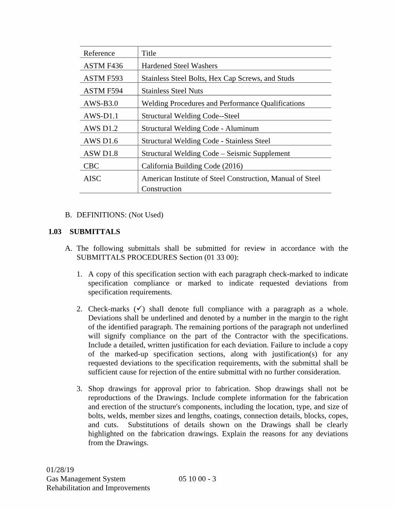
01/28/19 Gas Management System Rehabilitation and Improvements
05 10 00 - 3
Reference Title
ASTM F436 Hardened Steel Washers
ASTM F593 Stainless Steel Bolts, Hex Cap Screws, and Studs
ASTM F594 Stainless Steel Nuts
AWS-B3.0 Welding Procedures and Performance Qualifications
AWS-D1.1 Structural Welding Code--Steel
AWS D1.2 Structural Welding Code - Aluminum
AWS D1.6 Structural Welding Code - Stainless Steel
ASW D1.8 Structural Welding Code – Seismic Supplement
CBC California Building Code (2016)
AISC American Institute of Steel Construction, Manual of Steel Construction
B. DEFINITIONS: (Not Used)
1.03 SUBMITTALS
A. The following submittals shall be submitted for review in accordance with the SUBMITTALS PROCEDURES Section (01 33 00):
1. A copy of this specification section with each paragraph check-marked to indicate specification compliance or marked to indicate requested deviations from specification requirements.
2. Check-marks () shall denote full compliance with a paragraph as a whole. Deviations shall be underlined and denoted by a number in the margin to the right of the identified paragraph. The remaining portions of the paragraph not underlined will signify compliance on the part of the Contractor with the specifications. Include a detailed, written justification for each deviation. Failure to include a copy of the marked-up specification sections, along with justification(s) for any requested deviations to the specification requirements, with the submittal shall be sufficient cause for rejection of the entire submittal with no further consideration.
3. Shop drawings for approval prior to fabrication. Shop drawings shall not be reproductions of the Drawings. Include complete information for the fabrication and erection of the structure's components, including the location, type, and size of bolts, welds, member sizes and lengths, coatings, connection details, blocks, copes, and cuts. Substitutions of details shown on the Drawings shall be clearly highlighted on the fabrication drawings. Explain the reasons for any deviations from the Drawings.
01/28/19 Gas Management System Rehabilitation and Improvements
05 10 00 - 4
4. Certification that steel fabricator is approved to perform steel fabrication without special inspection.
5. AISC quality certification: Evidence that steel fabricator has AISC 201 Certification as a “Standard Steel Building Structures” fabricator. Certificate to show name and address of certified firm, effective date, and category of certification.
6. Welding procedures, qualifications, and inspection report.
7. Certified mill test reports for structural steel and high-strength bolts and nuts.
8. In accordance with CBC Chapter 17, Fabricator at the completion of fabrication to submit Certification of Compliance stating that the fabrication was performed in accordance with the design documents.
9. Certified copies of all surveys conducted by a registered professional engineer or surveyor showing elevations and locations of base plates and anchor bolts to receive structural steel or aluminum, and final elevations and locations for major members. Indicate discrepancies between actual installation and contract documents.
1.04 QUALITY CONTROL BY OWNER:
A. Quality Control by Owner:
1. Special Inspection of structural metals work shall be performed by the Special Inspector under contract with the Owner and in conformance with the CBC Chapter 17. Special Inspector(s) and laboratory shall be acceptable to the Owner in their sole discretion. Special Inspection of structural metals is in addition to, but not replacing, other inspections and quality control requirements herein. Where sampling and testing required herein conforms to Special Inspection standards, such sampling and testing need not be duplicated.
2. All structural steel work shall receive Special Inspection in accordance with CBC, Chapter 17. Structural steel includes all steel elements that resist code-defined loads and whose failure would affect life safety. Items to be inspected include, but are not limited to, mechanical/electrical supports, beams, stringers, columns, access walkways and stairways.
B. Fabricator Qualifications:
1. A qualified fabricator must participate in the AISC 201 Certification program and be designated an AISC Certified Plant, Category STD (Standard for Steel Building Structures).
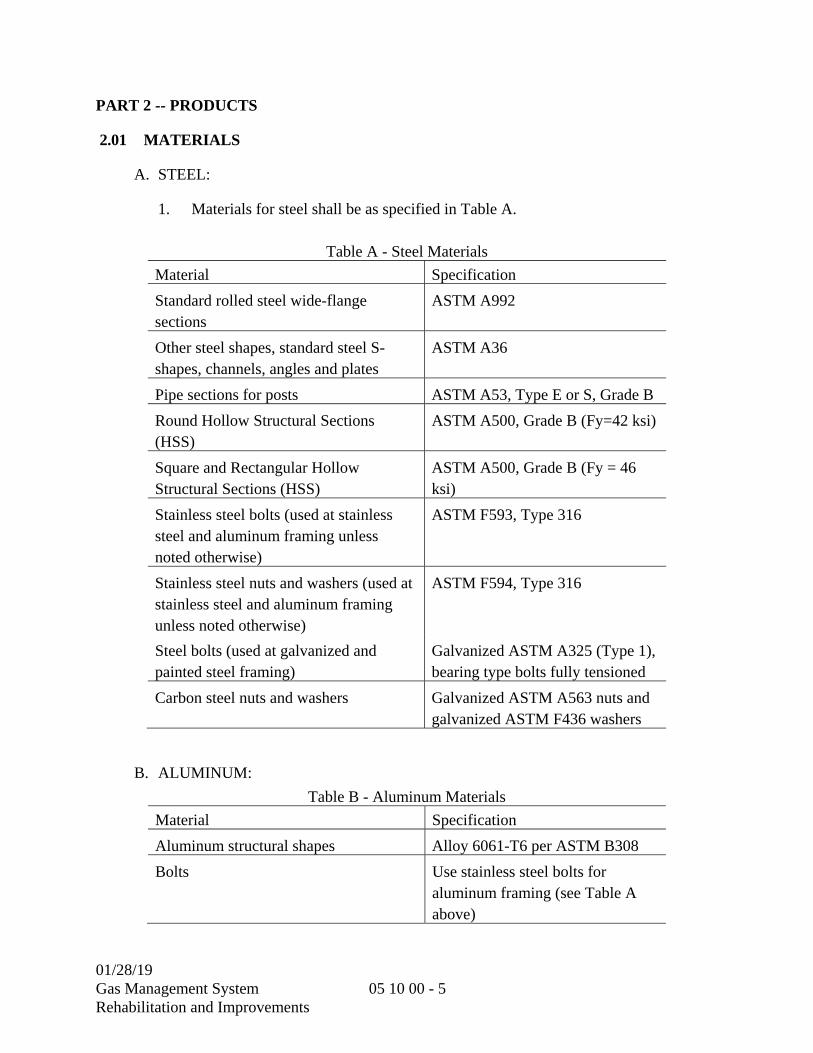
01/28/19 Gas Management System Rehabilitation and Improvements
05 10 00 - 5
PART 2 -- PRODUCTS
2.01 MATERIALS
A. STEEL:
1. Materials for steel shall be as specified in Table A.
Table A - Steel Materials
Material Specification
Standard rolled steel wide-flange sections
ASTM A992
Other steel shapes, standard steel S-shapes, channels, angles and plates
ASTM A36
Pipe sections for posts ASTM A53, Type E or S, Grade B
Round Hollow Structural Sections (HSS)
ASTM A500, Grade B (Fy=42 ksi)
Square and Rectangular Hollow Structural Sections (HSS)
ASTM A500, Grade B (Fy = 46 ksi)
Stainless steel bolts (used at stainless steel and aluminum framing unless noted otherwise)
ASTM F593, Type 316
Stainless steel nuts and washers (used at stainless steel and aluminum framing unless noted otherwise)
ASTM F594, Type 316
Steel bolts (used at galvanized and painted steel framing)
Galvanized ASTM A325 (Type 1), bearing type bolts fully tensioned
Carbon steel nuts and washers Galvanized ASTM A563 nuts and galvanized ASTM F436 washers
B. ALUMINUM:
Table B - Aluminum Materials
Material Specification
Aluminum structural shapes Alloy 6061-T6 per ASTM B308
Bolts Use stainless steel bolts for aluminum framing (see Table A above)

01/28/19 Gas Management System Rehabilitation and Improvements
05 10 00 - 6
Table B - Aluminum Materials
Material Specification
Aluminum guardrail and handrail pipe Alloy 6061-T6 or 6063-T6 per ASTM B241
Aluminum plates Alloy 6061-T6 per ASTM B209
C. BITUMASTIC COATING:
1. Material shall be Kop-coat, bitumastic black solution; Porter, Tarmastic No. 100, Tnemec 499 heavy-duty black; or equal.
2.02 FABRICATION
A. Fabrication of steel shall be in accordance with the applicable provisions of the AISC Steel Construction Manual, Fourteenth Edition. The fabricating plant shall be certified under AISC 201 for Category STD (Standard for Steel Building Structures).
B. Compression joints depending on contact bearing shall have a surface roughness not in excess of 500 micro-inch and ends shall be square within the tolerances for milled ends specified in ASTM A6.
C. Fabrication of aluminum shall be in accordance with Aluminum Design Manual – Latest Edition. Fabrication and assembly shall be done in the shop to the greatest extent possible.
D. Shop splices of members will be permitted only where indicated on the Drawings. Splices not indicated require the approval of the Engineer.
E. Verify measurements at the job site prior to fabrication. Fabricate to match job site measurements.
F. Provide holes as necessary or as indicated for securing other work to structural steel framing, and for passage of other work through steel framing members.
G. FABRICATION TOLERANCES:
1. MEMBER LENGTH:
a. Both ends finished for contact bearing: 1/32 inch
b. Framed members 30 feet or less: 1/16 inch
c. Framed members over 30 feet: 1/8 inch
01/28/19 Gas Management System Rehabilitation and Improvements
05 10 00 - 7
2. MEMBER STRAIGHTNESS:
a. COMPRESSION MEMBERS: 1/1000 of axial length between points laterally supported.
b. NON-COMPRESSION MEMBERS: ASTM A6 tolerance for wide flange shapes.
PART 3 -- EXECUTION
3.01 GENERAL
A. Measurements shall be verified at the job.
B. Holes shall be punched 1/16 inch larger than the nominal size of the bolts, unless otherwise specified. Whenever needed, because of the thickness of the metal, holes shall be subpunched and reamed or drilled. No drifting of bolts nor enlargement of holes will be allowed to correct misalignment. Mismatched holes shall be corrected with new material.
C. Dissimilar metals shall be protected from galvanic corrosion by means of pressure tapes, coatings or isolators. Aluminum in contact with concrete or grout shall be protected with multiple heavy coats of bituminous paint to a minimum dry film thickness of 10 mils.
D. Metalwork to be embedded in concrete shall be as specified in the CAST-IN-PLACE CONCRETE Section (03 30 00). Metalwork shall be placed accurately and held in correct position while the concrete is placed. Only where specifically shown on the construction plans, recesses or blockouts shall be formed in the concrete. After the concrete design strength is attained the metalwork shall be grouted in place in accordance with the GROUTING Section (03 60 00). The surfaces of metalwork in contact with or embedded in concrete shall be thoroughly cleaned.
E. Structural steel completely encased in concrete shall not be painted and shall have a clean surface for bonding to concrete. Metalwork which is bent, broken or otherwise damaged shall be repaired or replaced by the Contractor.
F. Until all elements of the permanent structure and lateral bracing system are complete, provide temporary bracing designed, furnished, and installed by the Contractor for the partially complete structure.
01/28/19 Gas Management System Rehabilitation and Improvements
05 10 00 - 8
3.02 INSTALLATION
A. GENERAL
1. Erection of structural steel shall be in accordance with the applicable provisions of AISC Steel Construction Manual. Erection plan shall conform to AISC 303. For low-rise structural steel buildings, 60 feet tall or less and a maximum of 2 stories, the structure shall be erected in accordance with AISC 810.
2. Coordinate installation of anchor bolts and other connectors required for securing structural steel to in place work.
3. Employ a Registered Professional Engineer or Surveyor registered in the state of California for accurate erection of the structural steel. Check elevations of concrete and locations of anchor bolts before erection proceeds and report discrepancies to the Engineer.
4. Placement tolerances shall be in accordance with AISC 303.
5. After final positioning of steel members, provide full bearing under base plates and bearing plates using non-shrink grout. Place non-shrink grout in accordance with the manufacturer's instructions.
6. Protect dissimilar metals from galvanic corrosion by means of pressure tapes, coatings or isolators. Protect aluminum in contact with concrete or grout with a heavy coat of bituminous paint.
7. Metalwork to be embedded in concrete shall be placed accurately and held in correct position while the concrete is placed. The surfaces of metalwork in contact with or embedded in concrete shall be thoroughly cleaned.
8. Structural steel completely encased in concrete shall not be galvanized or painted and shall have a clean surface for bonding to concrete.
9. Metalwork which is bent, broken or otherwise damaged shall be repaired or replaced.
B. WELDING:
1. Welding shall be done by welders, welding operators, and tackers who have been qualified by tests as prescribed by AWS to perform the type of work required. The quality of welding shall conform to AWS Codes.
2. Develop and submit the Welding Procedure Specifications (WPS) for all welding, including welding done using prequalified procedures.
01/28/19 Gas Management System Rehabilitation and Improvements
05 10 00 - 9
3. Provide continuous seal welds for plates or structural shapes that are exposed to or submerged in water or wastewater.
C. BOLTED CONNECTIONS:
1. Bolted connections, unless noted otherwise, shall conform to AISC 360 and AISC 341, and shall be bearing type connections with bolts fully tensioned unless connecting HSS shapes.
2. Punch, subpunch and ream, or drill bolt holes perpendicular to the surface of the member. Holes shall be punched 1/16 inch larger than the nominal size of the bolts, unless otherwise specified. Holes shall not be cut or enlarged by burning.
3. Bolts, nuts, and washers shall be clean of dirt and rust and lubricated immediately prior to installation. No drifting of bolts or enlargement of holes will be allowed to correct misalignment. Mismatched holes shall be corrected with new material.
3.03 CORROSION PROTECTION
A. Unless otherwise specified, all structural metal and structural steel, including that used in the fabrication of process equipment, shall be coated in accordance with the PAINTING AND COATING Section (09 90 00). Surface preparation shall be as specified in the PAINTING AND COATING Section (09 90 00). and shall include the following operations:
1. Grind the exterior and interior edges of all flame-cut plates or members to a smooth surface.
2. Grind all sharp edges off of the sheared plates and punched holes.
3. Grind uneven or rough welds with high beads to a smooth finish.
B. Application requirements shall be as specified in the PAINTING AND COATING Section (09 90 00).
3.04 CLEANING
A. After installation, damaged surfaces of shop primed metals shall be cleaned and touched up in accordance with the PAINTING AND COATING Section (09 90 00). Damaged surfaces of galvanized metals shall be repaired as specified in the Specifications.
3.05 TESTING
A. The District will engage inspectors to inspect welded connections and to perform tests. The inspection and tests will be paid for by the District.

01/28/19 Gas Management System Rehabilitation and Improvements
05 10 00 - 10
B. Ten percent of all butt and bevel welds which extend continuously for 24 inches or less shall be completely tested in accordance with AWS D1.1, Part B, Radiographic Testing of Welds, Chapter 6. All butt and bevel welds which extend continuously for more than 24 inches shall be spot tested at intervals not exceeding 36 inches.
C. Welds that are required by the District to be corrected shall be corrected or redone and retested as directed, at the Contractor's expense and to the satisfaction of the District.
D. The costs for all initial testing shall be paid by the District. However, the Contractor shall pay for all costs for any additional testing and inspection on work which does not meet specifications.
3.06 TRAINING (NOT USED)
**END OF SECTION**

01/28/19 Gas Management System Rehabilitation and Improvements
05 59 00 - 1
SECTION 05 59 00
METAL SPECIALTIES
PART 1 -- GENERAL
1.01 GENERAL REQUIREMENTS
A. SCOPE:
1. This section specifies miscellaneous metalwork, which consists of custom fabricated steel metalwork other than structural metalwork.
1.02 REFERENCES
A. REFERENCE STANDARDS: The publications referred to hereinafter form a part of this specification to the extent referenced. The publications are referred to in the text by the basic designation only. The latest edition of referenced publications in effect at the time of the bid shall govern. In case of conflict between the requirements of this section and the listed references, the requirements of this section shall prevail.
Reference Title
Aluminum Design Manual
The Aluminum Association, Aluminum Design Manual with Specifications and Guidelines for Aluminum Structures
AISC 303 Code of Standard Practice for Steel Buildings and Bridges
AISC 360 Specification for Structural Steel Buildings
AISC Steel Construction Manual
American Institute of Steel Construction, Manual of Steel Construction
ANSI A14.3 Standard for Ladders - Fixed - Safety Requirements
ASTM A36 Carbon Structural Steel
ASTM A48 Gray-Iron Castings
ASTM A53 Pipe, Steel, Black and Hot-Dipped, Zinc-Coated, Welded and Seamless
ASTM A108 Steel Bar, Carbon and Alloy, Cold-Finished
ASTM A123 Zinc (Hot Dip Galvanized) Coatings on Iron and Steel Products
ASTM A153 Zinc Coating (Hot-Dip) on Iron and Steel Hardware
ASTM A193 Alloy-Steel and Stainless Steel Bolting for High Temperature or High Pressure Service and Other Special Purpose Applications
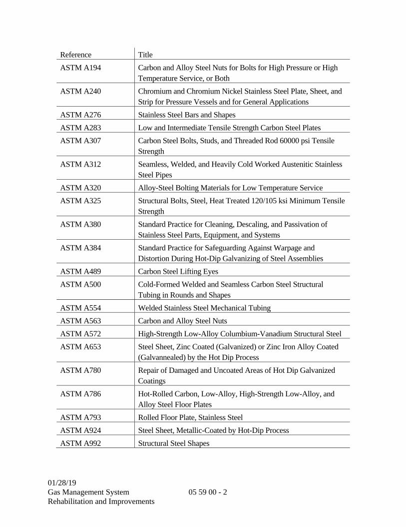
01/28/19 Gas Management System Rehabilitation and Improvements
05 59 00 - 2
Reference Title
ASTM A194 Carbon and Alloy Steel Nuts for Bolts for High Pressure or High Temperature Service, or Both
ASTM A240 Chromium and Chromium Nickel Stainless Steel Plate, Sheet, and Strip for Pressure Vessels and for General Applications
ASTM A276 Stainless Steel Bars and Shapes
ASTM A283 Low and Intermediate Tensile Strength Carbon Steel Plates
ASTM A307 Carbon Steel Bolts, Studs, and Threaded Rod 60000 psi Tensile Strength
ASTM A312 Seamless, Welded, and Heavily Cold Worked Austenitic Stainless Steel Pipes
ASTM A320 Alloy-Steel Bolting Materials for Low Temperature Service
ASTM A325 Structural Bolts, Steel, Heat Treated 120/105 ksi Minimum Tensile Strength
ASTM A380 Standard Practice for Cleaning, Descaling, and Passivation of Stainless Steel Parts, Equipment, and Systems
ASTM A384 Standard Practice for Safeguarding Against Warpage and Distortion During Hot-Dip Galvanizing of Steel Assemblies
ASTM A489 Carbon Steel Lifting Eyes
ASTM A500 Cold-Formed Welded and Seamless Carbon Steel Structural Tubing in Rounds and Shapes
ASTM A554 Welded Stainless Steel Mechanical Tubing
ASTM A563 Carbon and Alloy Steel Nuts
ASTM A572 High-Strength Low-Alloy Columbium-Vanadium Structural Steel
ASTM A653 Steel Sheet, Zinc Coated (Galvanized) or Zinc Iron Alloy Coated (Galvannealed) by the Hot Dip Process
ASTM A780 Repair of Damaged and Uncoated Areas of Hot Dip Galvanized Coatings
ASTM A786 Hot-Rolled Carbon, Low-Alloy, High-Strength Low-Alloy, and Alloy Steel Floor Plates
ASTM A793 Rolled Floor Plate, Stainless Steel
ASTM A924 Steel Sheet, Metallic-Coated by Hot-Dip Process
ASTM A992 Structural Steel Shapes
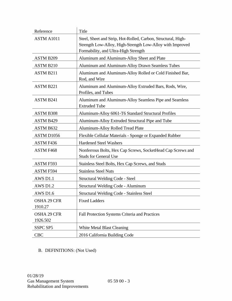
01/28/19 Gas Management System Rehabilitation and Improvements
05 59 00 - 3
Reference Title
ASTM A1011 Steel, Sheet and Strip, Hot-Rolled, Carbon, Structural, High-Strength Low-Alloy, High-Strength Low-Alloy with Improved Formability, and Ultra-High Strength
ASTM B209 Aluminum and Aluminum-Alloy Sheet and Plate
ASTM B210 Aluminum and Aluminum-Alloy Drawn Seamless Tubes
ASTM B211 Aluminum and Aluminum-Alloy Rolled or Cold Finished Bar, Rod, and Wire
ASTM B221 Aluminum and Aluminum-Alloy Extruded Bars, Rods, Wire, Profiles, and Tubes
ASTM B241 Aluminum and Aluminum-Alloy Seamless Pipe and Seamless Extruded Tube
ASTM B308 Aluminum-Alloy 6061-T6 Standard Structural Profiles
ASTM B429 Aluminum-Alloy Extruded Structural Pipe and Tube
ASTM B632 Aluminum-Alloy Rolled Tread Plate
ASTM D1056 Flexible Cellular Materials - Sponge or Expanded Rubber
ASTM F436 Hardened Steel Washers
ASTM F468 Nonferrous Bolts, Hex Cap Screws, SocketHead Cap Screws and Studs for General Use
ASTM F593 Stainless Steel Bolts, Hex Cap Screws, and Studs
ASTM F594 Stainless Steel Nuts
AWS D1.1 Structural Welding Code - Steel
AWS D1.2 Structural Welding Code - Aluminum
AWS D1.6 Structural Welding Code - Stainless Steel
OSHA 29 CFR 1910.27
Fixed Ladders
OSHA 29 CFR 1926.502
Fall Protection Systems Criteria and Practices
SSPC SP5 White Metal Blast Cleaning
CBC 2016 California Building Code
B. DEFINITIONS: (Not Used)

01/28/19 Gas Management System Rehabilitation and Improvements
05 59 00 - 4
1.03 SUBMITTALS
A. The following information shall be submitted for review in accordance with the SUBMITTAL PROCEDURES Section (01 33 00):
1. A copy of this specification section, with addenda updates, with each paragraph check marked to show specification compliance or marked to show deviations.
2. Certified test reports. Before delivery of any miscellaneous metalwork, the Contractor shall provide certificates which attest to their material compliance with these specifications.
3. Manufacturer's product data of each item submitted.
4. Detailed Shop Drawings:
a. Fabrication drawings showing layouts with dimensions consistent with the Contract Drawings, connections to structural system, and anchoring details. Anchoring details shall include the required bolt diameter, embed, spacing, and edge distances consistent with the calculations.
b. Erection and installation drawings indicating thickness, type, grade, material strength, class of metal, coating system and dimensions.
c. Construction details, reinforcement, anchorage, and installation with relation to the building construction.
5. Calculations:
a. Where calculations are required as part of a deferred submittal, the following requirements shall be met: Complete calculations, details, and complete reference drawings that are required to be submitted as part of a deferred submittal and as defined in the CBC and the Contract Documents, shall be prepared, stamped, signed, and furnished by a Professional Civil or Structural Engineer licensed to practice in the State of California.
b. Calculations shall be comprehensible and complete. When evaluating the structural strengths, indicate stress for comparing with strengths or show the demand versus capacity ratio in the structural elements. Evaluating the results by stating “Okay by Inspection” is not acceptable. When spreadsheets are used, clearly reference equations and formulas presented in submittal calculations.
c. Reference drawings shall include plans, sections, details and equipment information as necessary for seismic calculations. Indicate the location of the equipment on plan which is necessary for load calculations.
6. Submittals shall be returned without review if:
01/28/19 Gas Management System Rehabilitation and Improvements
05 59 00 - 5
a. Submittals include only calculations without reference drawings
b. Calculations have no sheet numbers or sheets are missing
c. Calculations or reference drawings are illegible
d. Calculations are made based on wrong information, assumptions or design parameters
e. Information in reference drawings is insufficient for calculations or review
7. The calculations and details shall demonstrate a complete vertical and lateral load path, and shall clearly indicate all forces imposed on the supporting structure.
8. Anchor Bolt Calculations and Details:
a. Anchor bolt calculations shall clearly show that the capacity of the anchor and the capacity of the concrete that the anchor is embedded in are adequate to resist all applicable load combinations, including wind and seismic loads.
1) The design of anchors resisting seismic forces shall satisfy the ductility requirements stated in the 2016 CBC, ASCE 7-10, and ACI 318-14.
2) Reduction factors associated with edge distance, embedment length, grout and base plate thickness, and bolt spacing shall be considered in the design and clearly indicated on the submittal drawings.
3) Anchor bolts shall be designed for bending due to eccentricity where raised grout pads will be installed for leveling.
4) Reference NON-STRUCTURAL COMPONENTS AND NON-BUILDING STRUCTURES Section (01 73 24).
9. Welding procedures and welder certificates and qualifications.
10. U-Channel Concrete Inserts: Manufacturer’s product description and allowable load tables.
11. Passivation method for stainless steel fabrications.
1.04 QUALITY ASSURANCE
A. Qualifications
1. Fabricator shall have a minimum of (5) five years’ experience in fabrication of metal specified.
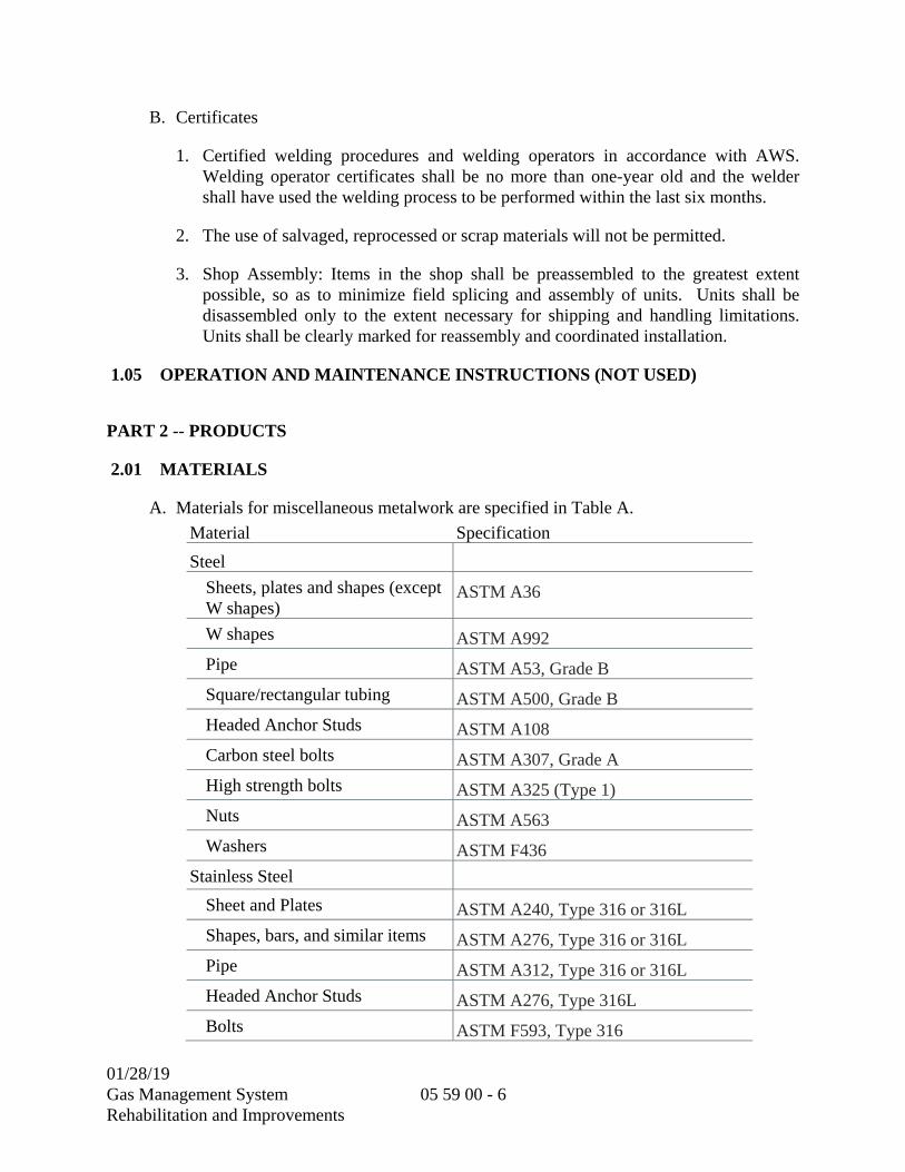
01/28/19 Gas Management System Rehabilitation and Improvements
05 59 00 - 6
B. Certificates
1. Certified welding procedures and welding operators in accordance with AWS. Welding operator certificates shall be no more than one-year old and the welder shall have used the welding process to be performed within the last six months.
2. The use of salvaged, reprocessed or scrap materials will not be permitted.
3. Shop Assembly: Items in the shop shall be preassembled to the greatest extent possible, so as to minimize field splicing and assembly of units. Units shall be disassembled only to the extent necessary for shipping and handling limitations. Units shall be clearly marked for reassembly and coordinated installation.
1.05 OPERATION AND MAINTENANCE INSTRUCTIONS (NOT USED)
PART 2 -- PRODUCTS
2.01 MATERIALS
A. Materials for miscellaneous metalwork are specified in Table A.
Material Specification
Steel
Sheets, plates and shapes (except W shapes)
ASTM A36
W shapes ASTM A992
Pipe ASTM A53, Grade B
Square/rectangular tubing ASTM A500, Grade B
Headed Anchor Studs ASTM A108
Carbon steel bolts ASTM A307, Grade A
High strength bolts ASTM A325 (Type 1)
Nuts ASTM A563
Washers ASTM F436
Stainless Steel
Sheet and Plates ASTM A240, Type 316 or 316L
Shapes, bars, and similar items ASTM A276, Type 316 or 316L
Pipe ASTM A312, Type 316 or 316L
Headed Anchor Studs ASTM A276, Type 316L
Bolts ASTM F593, Type 316

01/28/19 Gas Management System Rehabilitation and Improvements
05 59 00 - 7
Material Specification
Nuts ASTM F594, Type 316
Aluminum
Sheets and plates ASTM B209, Type 6061-T6
Bars, flats and similar items ASTM B211 or B221, Type 6061-T6
Shapes ASTM B308, Type 6061-T6
Round tubing and pipe ASTM B241, Type 6061-T6
Square and rectangular tubing ASTM B221, Type 6063-T52
Pipe ASTM B211 or B241, Type 6061-T6
Bolts, Stainless Steel ASTM F593, Type 316
Nuts, Stainless Steel ASTM F594, Type 316
Checker Plate
Steel ASTM A786
Stainless steel ASTM A793, Type 304
Aluminum ASTM B632, Type 6061-T6
Other steel items
Iron castings ASTM A48
Eyebolts ASTM A489
Threaded rods ASTM A36
2.02 FABRICATION
A. GENERAL:
1. Conform to AISC or Aluminum Association standards as applicable. Where Code defined loads apply, also conform to CBC requirements.
2. Shop and field welding shall conform to the requirements of AISC, the Aluminum Design Manual, and applicable AWS procedures and specifications as required by the material being welded.
3. Grind exposed joints flush and smooth with adjacent finish surface. Make exposed joints butt, tight, flush, and hairline. Remove burrs and weld splatter. Ease exposed edges to small uniform radius.
01/28/19 Gas Management System Rehabilitation and Improvements
05 59 00 - 8
4. Holes shall be punched 1/16 inch larger than the nominal size of the bolts, unless otherwise specified. Whenever needed, because of the thickness of the metal, holes shall be subpunched and reamed or shall be drilled.
5. Fabrication, including cutting, drilling, punching, threading and tapping required for fabrications or adjacent work, shall be performed prior to galvanizing.
B. SEAT ANGLES, SUPPORTS AND BRACKETS:
1. Provide recessed seat angle frames for grating and floor plates. Miter corners to ensure accurate fit. Match depth of recess with grating or floor plate thickness. Anchor frames in concrete with headed studs. Steel angle support frames shall be stainless steel, ASTM A276, Type 316, unless indicated otherwise.
C. IRON CASTINGS:
1. Castings shall be as specified on the drawings. Castings weighing less than 100 pounds shall be hot-dip galvanized after machining. Castings weighing greater than 100 pounds shall be galvanized where shown.
D. COVER PLATES AND FRAMES:
1. Fabricate aluminum cover plates weighing not more than 80 pounds per cover with a raised pattern nonslip top surface conforming to ASTM B632. Reinforce to sustain a live load of 100 pounds per square foot (foot traffic only) or as indicated on the Drawings. Frames shall be stainless steel angles and plates, with stainless steel headed anchors welded to frame for anchoring to concrete. Miter and weld corners and butt joint straight runs. Provide flush drop handles for removal. Remove sharp edges and burrs from cover plates and exposed edges of frames. Weld connections and grind top surface smooth. Provide 1/8 inch clearance at edges.
E. BOLLARDS:
1. Provide minimum 4 inch galvanized standard weight steel pipe or as indicated on the Drawings. Pipe to be in accordance with ASTM A53. Anchor posts in concrete and fill solidly with concrete of a minimum compressive strength of 4,000 psi. Coat galvanized pipe above grade in accordance with PAINTING AND COATING Section (09 90 00). Top coat cover color shall be safety yellow.
F. PIPE SLEEVES:
1. Unless otherwise indicated on the Drawings, fabricate pipe sleeves from schedule 40 steel pipe with 3/16 inch thick by 3 feet wide seep ring continuously seal welded to the outside of the pipe. Galvanize after fabrication in accordance with ASTM A123.

01/28/19 Gas Management System Rehabilitation and Improvements
05 59 00 - 9
G. OTHER MISCELLANEOUS STEEL METALWORK:
1. Other miscellaneous steel metalwork including embedded and nonembedded steel metalwork, hangers and inserts shall be as shown on the drawings and shall be hot-dip galvanized after fabrication.
2.03 FINISHES
A. Galvanizing
1. Galvanize items specified to be zinc-coated, after fabrication where practicable. Galvanizing in accordance with ASTM A123, ASTM A153, ASTM A653 or ASTM A924, Z275 G90, as applicable. Galvanize anchor bolts, grating fasteners, washers, and parts or devices necessary for proper installation, unless indicated otherwise.
2. Repair damaged Zinc-Coated surfaces with galvanizing repair method and paint conforming to ASTM A780 or by application of stick or thick paste material specifically designed for repair of galvanizing, as approved by Owner’s Representative.
3. Safeguard against warpage and distortion during galvanizing of steel in accordance with ASTM A384. Straighten items after galvanizing so that they are straight, free of racking and distortion.
B. Shop Painting
1. Prepare and coat surfaces in accordance with PAINTING AND COATING Section (09 90 00).
2. Steel to be embedded in concrete shall be free of dirt and grease.
C. Aluminum Surfaces
1. Surface condition aluminum before finishes are applied. Remove roll marks, scratches, rolled-in scratches, kinks, stains, pits, orange peel, die marks, structural streaks, and other defects which will affect uniform appearance of finished surfaces.
2. Aluminum finishes for unexposed sheet, plate and extrusions may have mill finish as fabricated.
3. Provide other aluminum items with a standard mill finish.
4. Provide a coating thickness not less than that specified for protection.

01/28/19 Gas Management System Rehabilitation and Improvements
05 59 00 - 10
5. Provide decorative type finishes for items used in interior occupied locations or architectural type finish for items used in exterior locations.
6. Provide a polished satin finish on items to be anodized.
D. Stainless Steel Passivation
1. Stainless steel to be cleaned, descaled, and passivated after fabrication in accordance with ASTM A380. Passivate to remove iron compounds from the surface of the stainless steel.
PART 3 -- EXECUTION
3.01 GENERAL
A. Fieldwork shall not be permitted on galvanized items. Drilling of bolts or enlargement of holes to correct misalignment will not be allowed.
B. Dissimilar metals shall be protected from galvanic corrosion by means of pressure tapes, coatings or isolators.
C. Metalwork to be embedded in concrete shall be placed accurately and held in correct position while the concrete is placed or, where shown on the drawings, recesses or blockouts shall be formed in the concrete. The surfaces of metalwork in contact with or embedded in concrete shall be thoroughly cleaned. If accepted, recesses may be neatly cored in the concrete after it has attained its design strength and the metalwork grouted in place. Embedments shall be as specified in CAST-IN-PLACE CONCRETE Section (03 30 00).
3.02 INSTALLATION
A. SEAT ANGLES, SUPPORTS AND GUIDES:
1. Seat angles for grating and supports for floor plates shall be set so that they are flush with the floor and also maintain the grating and floor plates flush with the floor.
B. WELDING:
1. Welding shall be done by operators who have been qualified to perform the type of work required by tests as prescribed by AWS D1.1, Section 5. The quality of welding shall conform to AWS D1.1, Section 3.
2. Steel which is required to be coated for corrosion protection shall be continuously welded at all joints.

01/28/19 Gas Management System Rehabilitation and Improvements
05 59 00 - 11
3. Unless otherwise shown on the drawings, continuous welds shall be provided on all structural members exposed to weather or submerged in water or wastewater. Continuous seal welds shall be provided on all sides of all plates or structural shapes in contact with or submerged in water or wastewater.
3.03 CORROSION PROTECTION
A. All structural metal and structural steel, including that used in the fabrication of process equipment, shall be coated in accordance with the PAINTING AND COATING Section (09 90 00). Surface preparation shall be as specified in the PAINTING AND COATING Section (09 90 00) and shall include the following operations:
1. Grind the exterior and interior edges of all flame-cut plates or members to a smooth surface.
2. Grind all sharp edges off of the sheared plates and punched holes.
3. Grind uneven or rough welds with high beads to a smooth finish.
B. Application requirements shall be as specified in the PAINTING AND COATING Section (09 90 00).
3.04 CLEANING
A. After installation, damaged surfaces of shop primed metals shall be cleaned and touched up in accordance with the PAINTING AND COATING Section (09 90 00). Damaged surfaces of galvanized metals shall be repaired as specified in the HOT DIP GALVANIZED COATING Section (05 05 14).
3.05 TESTING
A. The District will engage inspectors to inspect welded connections and to perform tests. The District will pay for the inspection and tests.
B. Ten percent of all butt and bevel welds which extend continuously for 24 inches or less shall be completely tested in accordance with AWS D1.1, Part B, Radiographic Testing of Welds, Chapter 6. All butt and bevel welds which extend continuously for more than 24 inches shall be spot tested at internals not exceeding 36 inches.
C. Welds that are required by the District to be corrected shall be corrected or redone and retested as directed, at the Contractor's expense and to the satisfaction of the District Representative.
D. The District shall pay the costs for all initial testing. However, the Contractor shall pay for all costs for any additional testing and inspection on work which does not meet specification.

01/28/19 Gas Management System Rehabilitation and Improvements
05 59 00 - 12
3.06 TRAINING (NOT USED)
**END OF SECTION**

DIVISION 09 - FINISHES 09 06 90 SCHEDULES FOR PAINTING AND COATING09 90 00 PAINTING AND COATING
THIS PAGE INTENTIONALLY LEFT BLANK
01/28/19 Gas Management System Rehabilitation and Improvements
09 06 90 - 1
SECTION 09 06 90
SCHEDULES FOR PAINTING AND COATING
PART 1 -- GENERAL
1.01 GENERAL REQUIREMENTS
A. SCOPE:
1. This section lists the specific coating systems and colors for rooms, galleries, piping, equipment, and other items. Coating system requirements are specified in the PAINTING AND COATING Section (09 90 00).
1.02 REFERENCES (NOT USED)
1.03 SUBMITTALS (NOT USED)
1.04 OPERATION AND MAINTENANCE INSTRUCTIONS (NOT USED)
PART 2 -- PRODUCTS (NOT USED)
PART 3 -- EXECUTION
3.01 GENERAL (NOT USED)
3.02 INSTALLATION (NOT USED)
3.03 TESTING (NOT USED)
3.04 TRAINING (NOT USED)
3.05 COATING SYSTEMS SCHEDULE
A. Refer to the PAINTING AND COATING Section (09 90 00) for coating system designations.
B. Specific coating systems and colors for rooms, galleries, piping, equipment, and other items are specified in the attached Coating System Schedule.
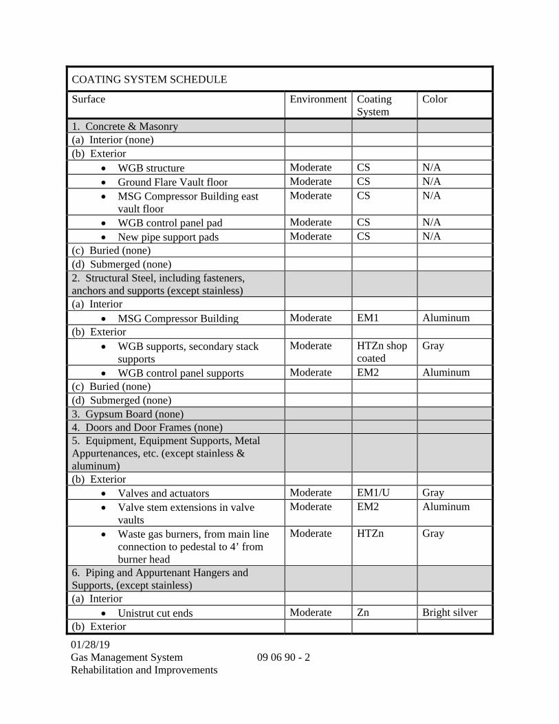
01/28/19 Gas Management System Rehabilitation and Improvements
09 06 90 - 2
COATING SYSTEM SCHEDULE
Surface Environment Coating System
Color
1. Concrete & Masonry (a) Interior (none) (b) Exterior
WGB structure Moderate CS N/A Ground Flare Vault floor Moderate CS N/A MSG Compressor Building east
vault floor Moderate CS N/A
WGB control panel pad Moderate CS N/A New pipe support pads Moderate CS N/A
(c) Buried (none) (d) Submerged (none) 2. Structural Steel, including fasteners, anchors and supports (except stainless)
(a) Interior MSG Compressor Building Moderate EM1 Aluminum
(b) Exterior WGB supports, secondary stack
supports Moderate HTZn shop
coated Gray
WGB control panel supports Moderate EM2 Aluminum (c) Buried (none) (d) Submerged (none) 3. Gypsum Board (none) 4. Doors and Door Frames (none) 5. Equipment, Equipment Supports, Metal Appurtenances, etc. (except stainless & aluminum)
(b) Exterior Valves and actuators Moderate EM1/U Gray Valve stem extensions in valve
vaults Moderate EM2 Aluminum
Waste gas burners, from main line connection to pedestal to 4’ from burner head
Moderate HTZn Gray
6. Piping and Appurtenant Hangers and Supports, (except stainless)
(a) Interior Unistrut cut ends Moderate Zn Bright silver
(b) Exterior

01/28/19 Gas Management System Rehabilitation and Improvements
09 06 90 - 3
COATING SYSTEM SCHEDULE
Surface Environment Coating System
Color
Natural gas pilot line Moderate HTZn Gray Pipe supports Moderate EM2 Aluminum
(c) Buried Sleeve-type couplings, flanges Not
ApplicablePET
7. Conduit, Outlet and Junction Boxes, Hangers and Supports, Panels, Lighting Transformers, etc. (except stainless)
(a) Interior
Galvanized rigid steel conduit threaded ends
Moderate Zn Bright silver
Unistrut cut ends Moderate Zn Bright silver (b) Exterior
Galvanized rigid steel conduit Moderate EM2 Aluminum Conduit supports Moderate EM2 Aluminum Panel supports Moderate EM2 Aluminum
(c) Buried PVC conduit Not
ApplicableNone
PVC-to-rigid conduit transitions Not Applicable
PET
8. Other (a) Interior (none)
**END OF SECTION**

01/28/19 Gas Management System Rehabilitation and Improvements
09 06 90 - 4
THIS PAGE INTENTIONALLY LEFT BLANK

01/28/2019 Gas Management System Rehabilitation and Improvements
09 90 00 - 1
SECTION 09 90 00
PAINTING AND COATING
PART 1 -- GENERAL
1.01 GENERAL REQUIREMENTS
A. SCOPE:
1. This section specifies coating systems, surface preparations, and application requirements.
1.02 REFERENCES
A. REFERENCE STANDARDS: The publications referred to hereinafter form a part of this specification to the extent referenced. The publications are referred to in the text by the basic designation only. The latest edition of referenced publications in effect at the time of the bid shall govern. In case of conflict between the requirements of this section and the listed references, the requirements of this section shall prevail.
Reference Title
ASTM D16 Standard Terminology for Paint, Related Coatings, Materials, and Applications
ASTM D6386 Practice for Preparation of Zinc (Hot-Dip Galvanized) Coated Iron and Steel Product and Hardware Surfaces for Painting
SMAQMD Rule 442
Sacramento Metropolitan Air Quality Management District - Architectural Coatings
SMAQMD Rule 451
Sacramento Metropolitan Air Quality Management District – Surface Coating of Miscellaneous Metal Parts and Products
SSPC Good Painting Practice
SSPC: The Society for Protective Coatings (formerly Steel Structures Painting Council) Specifications, Vol. 1 and 2, latest edition.
SSPC Guide 6 Guide for Containing Surface Preparation Debris Generated During Paint Removal Operations
B. DEFINITIONS:
1. Specific coating terminology used in this section is in accordance with definitions contained below and in ASTM D16:
01/28/2019 Gas Management System Rehabilitation and Improvements
09 90 00 - 2
a. DRY FILM THICKNESS (DFT): The thickness of one fully cured continuous application of coating.
b. WET FILM THICKNESS (WFT): The thickness of one wet layer of coating taken shortly after application.
c. FIELD COAT: The application of a coating after installation of the surface at the site of the work.
d. SHOP COAT: One or more coats applied in a shop or plant prior to shipment to the site of erection or fabrication, where the field or finishing coat is applied.
e. TIE COAT: An intermediate coat used to bond different types of paint coats. Coatings used to improve the adhesion of a succeeding coat.
f. VINYL ACID WASH COAT: A coating supplied as one or two component systems on clean light alloy or ferrous surfaces, and on many nonferrous surfaces, to provide adhesion with the substrates, and for the application of subsequent coats of paint.
g. PHOTOCHEMICALLY REACTIVE ORGANIC MATERIAL: Any organic material that will react with oxygen, excited oxygen, ozone or other free radicals generated by the action of sunlight on components in the atmosphere giving rise to secondary contaminants and reaction intermediates in the atmosphere which can have detrimental effects.
h. VOLATILE ORGANIC CONTENT: The portion of the coating that is a compound of carbon, is photochemically reactive, and evaporates during drying or curing, expressed in grams per liter or pounds per gallon.
i. TOUCH UP PAINTING: The application of paint on small areas of painted surfaces to repair marks, scratches, and small areas where the coating has deteriorated to restore the coating film to an unbroken condition.
j. STRIPE COAT: Coating with brush or spray gun to all edges, corners, bolts and welds, with coating material prior to application of full surface coat. Striping will extend at least one inch minimum from all edges, corners and welds.
k. The terms "solvent cleaning", "hand tool cleaning", "wire brushing", and "blast cleaning", or similar words of equal intent in these Specifications or in paint manufacturer's specifications refer to the applicable SSPC Surface Preparation Standards.
l. SPREADING RAGE: The amount of product that is applied to a specified area of a surface to be coated. The spreading rate is specified in square feet per gallon (SFPG) or square feet per gallon per coat (SFPGPC).

01/28/2019 Gas Management System Rehabilitation and Improvements
09 90 00 - 3
m. FERROUS METAL: Iron, steel, and alloys containing iron as the principal element, except stainless steel.
n. INTERIOR: Inside of a building or structure, unless otherwise specified.
o. EXTERIOR: Outside of building or structures and exposed to weather elements.
p. BURIED: Surfaces that are underground and either in contact with soil or encased in concrete.
q. SUBMERGED: Surfaces that are underwater or are below the top elevation of structures or facilities that contain water, under normal operating conditions.
r. MILD ENVIRONMENT: Standard commercial facility conditions.
s. MODERATE ENVIRONMENT: Industrial facility conditions where surfaces may be occasionally exposed to light-moderately aggressive liquids or gases.
t. HARSH ENVIRONMENT: Industrial facility conditions where surfaces may be subject to aggressive liquids or gases, or normally exposed to light-moderately aggressive liquids or gases.
1.03 SUBMITTALS
A. The following information shall be submitted for review in accordance with SUBMITTAL PROCEDURES Section (01 33 00):
1. A copy of this specification section, with addenda updates, with each paragraph check marked to show specification compliance or marked to show deviations.
2. Manufacturer's standard product data and material safety data sheet for all field applied primer, tie coat, thinners, intermediate and finish coating, abrasives and all shop applied primers, intermediate and finish coating including those from equipment manufacturers and suppliers. Copies of these data shall be posted at the job site at each field application area.
3. List of materials proposed to be used under this section.
4. Manufacturer's literature and written instructions for surface preparation, mixing and application of each primer and finish coating.
5. Manufacturer's complete color selection chart.
6. Applicator's SSPC QP-1 certification and manufacturer's certification of installation contractor.
7. Containment system plan.

01/28/2019 Gas Management System Rehabilitation and Improvements
09 90 00 - 4
8. Shop and field inspection records.
1.04 OPERATION AND MAINTENANCE INSTRUCTIONS (NOT USED)
1.05 REGULATORY REQUIREMENTS
A. All applicable federal, state, and local regulatory agency requirements shall be complied with during the course of the work. The Contractor's attention is directed to the following list of agency requirements that generally apply to coatings work; the Contractor is responsible for identifying and complying with any other agencies or requirements not listed.
1. OSHA – Personnel protection during all phases of work, including exposure to airborne solvents, dust, and lead.
2. CAL/OSHA – Personnel protection; requirements may supersede OSHA regulations.
3. California Title 22 – Environmental requirements, including definition of abrasive blast materials and residue relative to hazardous waste disposal requirements. Abrasives shall not contain metals or other substances that would classify abrasive as a hazardous waste under California Title 22 requirements.
4. California Air Resources Board (CARB) and Sacramento Metropolitan Air Quality Management District (SMAQMD) – Environmental requirements for equipment and products. Also, environmental requirements for limiting emissions produced by paint removal and coating operations. Maximum VOC limits shall comply with SMAQMD Rule 442 and Rule 451.
1.06 QUALITY ASSURANCE
A. QUALIFICATIONS:
1. SSPC Painting Contractor Certification Program, QP-1 certification.
2. Coating manufacturer approved applicator when coating manufacturer has approved applicator program.
B. INSPECTION:
1. The District may retain the services of an independent third party NACE CIP Level III-Certified Inspector for partial or full-time inspection of the work.
2. The Contractor shall give the District Representative a minimum of 14 calendar days advanced notice of the start of all coating application work to allow scheduling for shop and field observation.
3. Provisions shall be made to allow the District Representative full access to facilities and appropriate documentation regarding coating materials, coating material storage,

01/28/2019 Gas Management System Rehabilitation and Improvements
09 90 00 - 5
surface preparation and coating application. The Contractor shall provide access to the District Representative at all times during the contract period to observe the work.
4. Observation by the District Representative or the waiver of observation of any particular portion of the work shall not be construed to relieve the Contractor of his responsibility to perform the work in accordance with these Specifications.
5. Coating materials shall be subject to testing for conformance with this specification prior to or during incorporation into the work.
1.07 DELIVERY, STORAGE AND HANDLING
A. Materials shall be delivered to the job site in their original, unopened containers. Each container shall bear the manufacturer's name, coating type, batch number, date of manufacture, and special directions. All materials delivered to the job site shall be accompanied by the manufacturer's latest product data sheets which indicate storage life.
B. All protective coating materials shall be used within the manufacturer’s recommended shelf life. Shelf life shall not be extended beyond the stated periods for any reason, including statements or certifications by the manufacturer.
C. Deliver and store abrasives in their original moisture-proof bags or airtight bulk containers.
D. Materials shall be stored in enclosed structures and shall be protected from weather and excessive heat or cold. Flammable materials shall be stored in accordance with state and local codes. Materials exceeding storage life recommended by the manufacturer shall be removed from the site.
E. Where shop-primed or shop-finished items are to be shipped to the job site, protect coatings from damage by the use of battens, padded straps, and nonmetallic slings. Excessive shipping damage will be considered grounds for rejection of shop primers and shop finishes.
F. The Contractor shall keep and maintain records for all products delivered to the site. Information should include batch numbers, quantities, and dates used for all paints, solvents, and cleaners used. These records should be reported to the District Representative weekly.
PART 2 -- PRODUCTS
2.01 GENERAL
A. Materials and supplies provided shall be the standard products of manufacturers. Materials in each coating system shall be the products of a single manufacturer.
01/28/2019 Gas Management System Rehabilitation and Improvements
09 90 00 - 6
B. The standard products of manufacturers other than those specified will be accepted when it is demonstrated to the District that they are equal in composition, durability, usefulness, and convenience for the purpose intended. Requests for substitutions, in accordance with the SUBMITTAL PROCEDURES Section (01 33 00), will be considered, provided the criteria specified in the SUBMITTAL PROCEDURES Section (01 33 00) are satisfied and the following minimum conditions are met:
1. The proposed coating system shall use an equal number of coats to achieve the required dry film thickness.
2. The proposed coating system shall use coatings of the same generic type as that specified.
3. Requests for substitution shall have directions for application and descriptive literature which includes generic type, percent solids by volume, volatile organic content (grams per liter), flammability, toxicity, and any other information required to determine if the substitution is equal to the specified coating system.
4. The Contractor shall provide a list of references where paint of the same generic type has been applied. The reference list shall give the project name, city, state, owner, phone number of owner, coating system reference and number, and year coating material was applied.
5. Any shop applied coating materials shall be compatible with the field applied coating materials specified.
6. Coatings shall contain ≤ 0.0000% lead.
7. Coatings shall contain ≤ 0.0000% zinc-chromate and ≤ 0.0000% strontium-chromate.
8. Coatings shall contain ≤ 0.0000% asbestos.
9. Coatings shall contain ≤ 0.0000% mercury and ≤ 0.0000% mercury compounds.
10. Coatings shall not contain any toxic chemicals in amounts greater than the amounts in the specified acceptable products.
11. Abrasives shall not contain metals or other substances that would classify abrasive as a hazardous waste under California Title 22 requirements.
12. Maximum VOC limits shall comply with Sacramento Metropolitan Air Quality Management District (SMAQMD) Rule 442 and Rule 451.
2.02 COATING SYSTEM SPECIFICATION SHEETS
A. Coating systems are specified on the following Coating System Specification sheets:

01/28/2019 Gas Management System Rehabilitation and Improvements
09 90 00 - 7
COATING SYSTEM SPECIFICATIONS
Coating System:
Concrete Sealer Symbol: CS
Description: Acceptable Products: Prime Coat: Water based, non-toxic, chemically
reactive complex silicate compound providing penetration up to 7” and reducing moisture and vapor migration to 0.015 perms.
Moxie International: 1500 Concrete Sealer
Intermediate Coat: Water based, non-toxic, chemically reactive complex silicate compound providing penetration up to 7” and reducing moisture and vapor migration to 0.015 perms.
Moxie International: 1500 Concrete Sealer
Finish Coat: Water based, non-toxic, chemically reactive complex silicate compound providing penetration up to 7” and reducing moisture and vapor migration to 0.015 perms.
Moxie International: 1500 Concrete Sealer
Services: Interior, Exterior, Buried, Submerged Mild, Moderate, Harsh
Surfaces: Concrete Surface Preparation: In accordance with manufacturer’s written instructions, plus the following:
1. Remove any wax, grease, rubber, paint, or any other type of surface sealer.
2. Perform water absorption test. 3. Abrade surface as necessary via shotblasting or grinding to
provide an absorptive enough surface to allow proper penetration of the concrete sealer.
Application: In accordance with manufacturer’s written instructions, plus the following: 1. Mist surface to dampen the substrate. 2. Apply 4 coats of the concrete sealer at full strength per the
manufacturer’s application directions, including watering and re-application procedures.
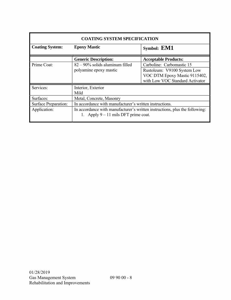
01/28/2019 Gas Management System Rehabilitation and Improvements
09 90 00 - 8
COATING SYSTEM SPECIFICATION
Coating System: Epoxy Mastic Symbol: EM1
Generic Description: Acceptable Products: Prime Coat: 82 – 90% solids aluminum filled
polyamine epoxy mastic Carboline: Carbomastic 15Rustoleum: V9100 System Low VOC DTM Epoxy Mastic 9115402, with Low VOC Standard Activator
Services: Interior, Exterior Mild
Surfaces: Metal, Concrete, MasonrySurface Preparation: In accordance with manufacturer’s written instructions. Application: In accordance with manufacturer’s written instructions, plus the following:
1. Apply 9 – 11 mils DFT prime coat.
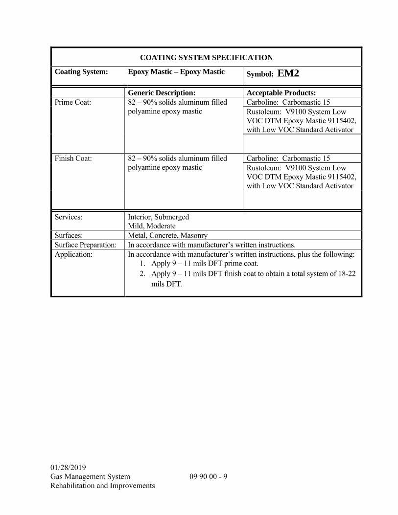
01/28/2019 Gas Management System Rehabilitation and Improvements
09 90 00 - 9
COATING SYSTEM SPECIFICATION
Coating System: Epoxy Mastic – Epoxy Mastic Symbol: EM2
Generic Description: Acceptable Products: Prime Coat: 82 – 90% solids aluminum filled
polyamine epoxy mastic Carboline: Carbomastic 15Rustoleum: V9100 System Low VOC DTM Epoxy Mastic 9115402, with Low VOC Standard Activator
Finish Coat: 82 – 90% solids aluminum filled polyamine epoxy mastic
Carboline: Carbomastic 15Rustoleum: V9100 System Low VOC DTM Epoxy Mastic 9115402, with Low VOC Standard Activator
Services: Interior, Submerged Mild, Moderate
Surfaces: Metal, Concrete, MasonrySurface Preparation: In accordance with manufacturer’s written instructions. Application: In accordance with manufacturer’s written instructions, plus the following:
1. Apply 9 – 11 mils DFT prime coat. 2. Apply 9 – 11 mils DFT finish coat to obtain a total system of 18-22
mils DFT.
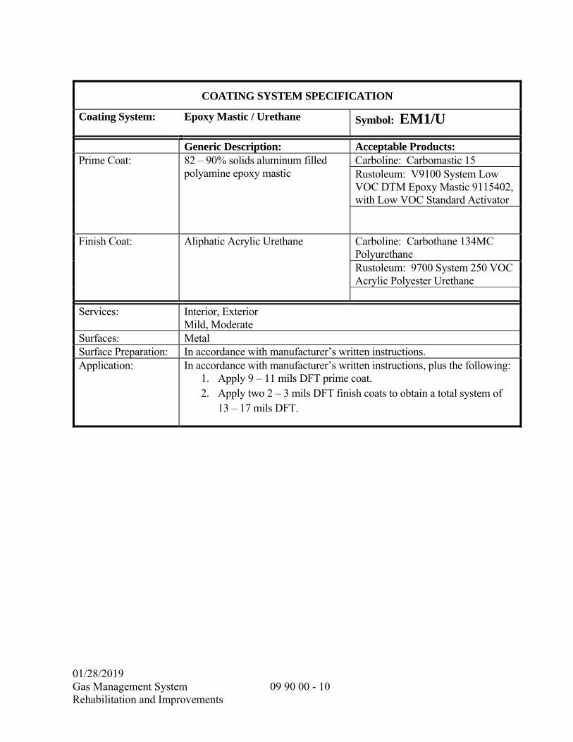
01/28/2019 Gas Management System Rehabilitation and Improvements
09 90 00 - 10
COATING SYSTEM SPECIFICATION
Coating System:
Epoxy Mastic / Urethane Symbol: EM1/U
Generic Description: Acceptable Products: Prime Coat: 82 – 90% solids aluminum filled
polyamine epoxy mastic Carboline: Carbomastic 15Rustoleum: V9100 System Low VOC DTM Epoxy Mastic 9115402, with Low VOC Standard Activator
Finish Coat: Aliphatic Acrylic Urethane Carboline: Carbothane 134MC Polyurethane Rustoleum: 9700 System 250 VOC Acrylic Polyester Urethane
Services: Interior, Exterior Mild, Moderate
Surfaces: Metal Surface Preparation: In accordance with manufacturer’s written instructions. Application: In accordance with manufacturer’s written instructions, plus the following:
1. Apply 9 – 11 mils DFT prime coat. 2. Apply two 2 – 3 mils DFT finish coats to obtain a total system of
13 – 17 mils DFT.

01/28/2019 Gas Management System Rehabilitation and Improvements
09 90 00 - 11
COATING SYSTEM SPECIFICATIONS
Coating System:
High Temperature Inorganic Zinc Symbol: HTZn
Generic Description: Acceptable Products: Prime coat Solvent based inorganic zinc coating
with 84% zinc by weight in the dried film finish. Rated for 750°F continuous service without a top coat. Rated ASTM B117 Salt Spray = 70,000 hours.
Carboline: Carbozinc 11HS
Finish coat Solvent based inorganic zinc coating with 84% zinc by weight in the dried film finish. Rated for 750°F continuous service without a top coat. Rated ASTM B117 Salt Spray = 70,000 hours.
Carboline: Carbozinc 11HS
Services: Interior, Exterior Mild, Moderate
Surfaces: Ferrous Metal, Galvanized SteelSurface Preparation: In accordance with manufacturer’s written instructions. Application: In accordance with manufacturer’s written instructions, plus the following:
1. Apply 2 – 3 mils DFT prime coat. 2. Apply 2 – 3 mils DFT finish coat to obtain a total system of 4 – 6
mils DFT.

01/28/2019 Gas Management System Rehabilitation and Improvements
09 90 00 - 12
COATING SYSTEM SPECIFICATIONS
Coating System:
Petrolatum Tape System Symbol: PET
Generic Description: Acceptable Products: Prime Coat: Petrolatum tape primer Denso: Denso Paste
Trenton: Wax Tape PrimerIntermediate Coat: Petrolatum profiling mastic Denso: Denso Profiling Mastic
Trenton: Trenton Fill-Pro PM-GP Profiling Mastic
Finish Coat: Petrolatum impregnated tape Denso: Densyl Tape Trenton: #1 Wax Tape
Services: Buried Mild, Moderate, Harsh
Surface: Metal Surface Preparation: In accordance with manufacturer’s written instructions, plus the following:
Remove loose scale, rust, dirt, excessive moisture, or frost from the surface in accordance with SSPC SP-2 or SP-3.
Application: In accordance with manufacturer’s written instructions, plus the following: All surfaces shall be hand rubbed or brushed with petrolatum primer over the entire surface. On irregular shaped surfaces, i.e., nuts, bolts, flanges, etc., apply petrolatum profiling mastic over the primer by hand in sufficient quantity to build an even contour over the entire surface. Ensure that all folds and air pockets within the mastic layer are thoroughly pressed out. Petrolatum tape shall be spirally wrapped on the surface with an overlap of 55 percent. Apply sufficient tension to provide continuous adhesion without stretching the tape. On vertical applications, begin at the bottom and proceed upwards creating a weatherboard overlap.
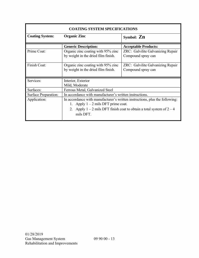
01/28/2019 Gas Management System Rehabilitation and Improvements
09 90 00 - 13
COATING SYSTEM SPECIFICATIONS
Coating System:
Organic Zinc Symbol: Zn
Generic Description: Acceptable Products: Prime Coat: Organic zinc coating with 95% zinc
by weight in the dried film finish. ZRC: Galvilite Galvanizing Repair Compound spray can
Finish Coat: Organic zinc coating with 95% zinc by weight in the dried film finish.
ZRC: Galvilite Galvanizing Repair Compound spray can
Services: Interior, Exterior Mild, Moderate
Surfaces: Ferrous Metal, Galvanized SteelSurface Preparation: In accordance with manufacturer’s written instructions. Application: In accordance with manufacturer’s written instructions, plus the following:
1. Apply 1 – 2 mils DFT prime coat. 2. Apply 1 – 2 mils DFT finish coat to obtain a total system of 2 – 4
mils DFT.

01/28/2019 Gas Management System Rehabilitation and Improvements
09 90 00 - 14
PART 3 -- EXECUTION
3.01 GENERAL (NOT USED)
3.02 INSTALLATION
A. SURFACE PREPARATION:
1. GENERAL:
a. Surface preparations for each type of surface shall be in accordance with the specific manufacturer’s requirements of each coating and its intended service, and the Coating System Specification sheets.
b. All surfaces to be coated shall have a sharp angular surface profile of the minimum depth specified by the coating manufacturer.
c. It is shall be the Contractors responsibility to coordinate with the District to ensure that lead testing was performed to determine if detrimental levels of lead are present in the existing surfaces prior to new coatings. If lead testing was not performed, it shall be the Contractor’s responsibility to ensure that lead testing is performed by a qualified agency or service company to determine if detrimental levels of lead are present in the existing surfaces prior to new coatings.
2. ABRASIVE BLAST MEDIA:
a. Blast media shall CARB-approved.
3. ABRASIVE BLAST CONTAINMENT SYSTEM:
a. Provide a Class 3A Containment System in accordance with SSPC Technology Guide 6.
b. Utilize Method G, Visual Assessment of Site Cleanliness, to monitor the amount of dust or debris that may escape the work area.
B. METAL SURFACE PREPARATION (UNGALVANIZED):
1. ABRASIVES:
a. The type and size of abrasive shall be selected to produce a surface profile as specified and as recommended by the coating manufacturer for the particular coating and service conditions.
b. Abrasive blasting nozzles shall be equipped with “deadman” emergency shut-off nozzles. Blast nozzle pressure shall be a minimum of 95 PSI and shall be verified by using an approved nozzle pressure gauge at each start-up period or as directed
01/28/2019 Gas Management System Rehabilitation and Improvements
09 90 00 - 15
by the Engineer. The number of nozzles used during all blast cleaning operations must be sufficient to ensure timely completion of project.
c. Interior blast cleaning shall be by dry method unless otherwise directed.
d. The Contractor shall keep the area of his work in a clean condition and shall not permit blasting materials to accumulate as to constitute a nuisance or hazard to the workers or the existing facilities. Spent abrasives and other debris shall be removed at the Contractor’s expense, as directed by the District Representative.
e. Blast cleaned and coated interior surfaces shall be cleaned prior to application of specified coatings via a combination of blowing with clean dry air, brushing/brooming and/or vacuuming as necessary to achieve a clean surface condition.
f. Compressed air for air blast cleaning shall be supplied at adequate pressure from well-maintained compressors equipped with oil and moisture separators which remove at least 95 percent of the contaminants. An oil and moisture separator shall be provided in the air line between the compressor and blast machine.
g. Do not abrasive blast when air temperature is less than 5 degrees above the dew point.
C. METAL SURFACE PREPARATION (GALVANIZED):
1. Galvanized surfaces shall be prepared in accordance with ASTM D6386.
D. PROTECTION OF SURFACES NOT TO BE COATED:
1. Surfaces which are not to receive protective coatings shall be protected during surface preparation, cleaning, and coating operations.
2. All hardware, lighting fixtures, switchplates, machined surfaces, couplings, shafts, bearings, nameplates on machinery, and other surfaces not to be painted shall be removed, masked or otherwise protected. Dropcloths shall be provided to prevent coating materials from falling on or marring adjacent surfaces. The working parts of all mechanical and electrical equipment shall be protected from damage during surface preparation and coating operations. Openings in motors shall be masked to prevent entry of coating or other materials.
3. Project is subject to intermittent shutdown if, in the opinion of the District Representative, any operations are creating a condition detrimental to the site personnel or adjacent property. In the event of emergency shutdown by the District Representative, Contractor shall immediately correct deficiencies. All additional costs created by shutdown shall be borne by Contractor.

01/28/2019 Gas Management System Rehabilitation and Improvements
09 90 00 - 16
E. APPLICATION:
1. GENERAL:
a. Coating products shall not be used until the District has inspected the materials.
b. All of the manufacturer's printed recommendations with respect to surface preparation, mixing instructions, thinning, application method, application equipment, pot life, drying times, and any other manufacturer’s recommendations deemed applicable by the District shall be strictly adhered to by the Contractor.
c. All steel coating application shall also comply with SSPC-PA 1.
d. Application of the first coat shall follow immediately after completion of final surface preparation, dust removal operations, and before any rusting or other deterioration of the surface occurs. Cleaning shall be limited to only those surfaces that can be prime-coated in the same working day.
e. All irregular surfaces shall receive a brush coat of the specified product prior to application of each coat. Irregular surfaces include edges, angles, weld seams, flanges, nuts and bolts, ends and flanges of structural members, crevices, surfaces with restricted access for spray application, and other places where insufficient film thicknesses are likely to be applied. During application to irregular surfaces, paint shall be brushed in multiple directions to ensure penetration and coverage. Care shall be exercised to ensure that the resulting dry film thicknesses do not exceed the maximum thicknesses allowed by the manufacturer for each product.
2. SHOP-APPLIED COATINGS:
a. Except as otherwise specified herein, coatings may be shop applied or field applied. All coatings, whether shop applied or field-applied shall comply with the specifications.
b. Shop-applied primers shall be compatible with the specified coating system and shall be applied at the dry film thickness recommended by the manufacturer. Product data sheets identifying the shop primer used shall be provided to the on-site finish coat applicator.
c. If the shop-applied prime coat meets the requirements of this section, the field coating may consist of touching up the shop prime coat with a compatible field prime coat and then applying compatible intermediate and/or finish coats to achieve the specified film thickness and continuity. Intermediate or finish coats shall not be applied beyond the primer recoat window. If the primer recoat window is exceeded, the item shall be re-blasted and re-primed in accordance with the manufacturer’s recommendations.

01/28/2019 Gas Management System Rehabilitation and Improvements
09 90 00 - 17
d. Damaged, deteriorated and/or poorly applied shop coatings that do not meet the requirements of this section shall be removed and the surfaces recoated.
3. WORKMANSHIP:
a. Coated surfaces shall be free from runs, drops, ridges, waves, laps, and brush marks. Coats shall be applied so as to produce an even film of uniform thickness completely coating corners and crevices. Painting shall be done in accordance with the requirements of SSPC Paint Application Specification No. 1.
b. Each coat of paint shall be applied evenly and sharply cut to line. Each coat shall give a uniform appearance throughout. Lap marks for multiple coats shall be staggered. Care shall be exercised to avoid overspraying or spattering paint on surfaces not to be coated. Glass, hardware, floors, roofs, and other adjacent areas and installations shall be protected by taping, drop cloths, or other suitable measures.
c. Where two or more coats of epoxy mastic are required, the alternate coats shall be of contrasting colors.
d. Existing coating systems damaged by new construction shall be repaired and coated in accordance with the appropriate system specified for new work.
e. Items which have been newly coated shall not be handled, worked on, or otherwise disturbed, until the paint is completely dry and hard.
F. CLEANUP:
1. Upon completion of coating, the Contractor shall remove surplus materials, protective coverings, and accumulated rubbish, and thoroughly clean all surfaces and repair any overspray or other paint related damage.
G. COATING SYSTEMS SCHEDULE:
1. Existing surfaces not damaged by work in this contract shall not be coated unless specifically shown on the drawings. Existing surfaces damaged by work in this contract shall be repaired to match existing coating and color.
2. Specific coating systems and colors for rooms, galleries, piping, equipment, and other items are specified in the SCHEDULES FOR PAINTING AND COATING Section (09 06 90).
01/28/2019 Gas Management System Rehabilitation and Improvements
09 90 00 - 18
3.03 TESTING
A. FIELD QUALITY CONTROL:
1. GENERAL:
a. The District shall have the right to inspect at all times any tools, instrument, materials, staging, or equipment used or to be used in the performance of the work accessible for these inspections. The District shall have the right to take samples of the coating material at any time during the coating operation.
b. The District shall have the right to observe all application procedures during the time the work is in progress, inspect and approve the surface preparation prior to the application of any coating, and to inspect and approve the condition of each coat prior to the application of the following one.
c. The Contractor shall provide the same access to the inspector as for his painters. If necessary for safe inspection, scaffolding shall be provided for use by the inspector.
d. The Contractor shall notify the District Representative 48 hours before work or part of the work commences.
e. Where applicable, inspection of substrate anchor patterns shall be done with a surface profile indicator, surface profile comparator or Testex Press O Film Replica Tape.
f. Abrasive blast samples shall be utilized for inspection purposes throughout the duration of blast cleaning operations.
g. District may inspect coatings during application with a wet mil gauge. After drying, the District may inspect coatings with an Elcometer, Positest, or equivalent DFT instrument.
h. Contractor shall furnish, until Final Acceptance of such coatings, inspection devices in good working condition for the detection of holidays and measurement of dry-film thicknesses of protective coatings.
i. Contractor shall provide the services of a trained operator for the holiday detection devices.
j. Holiday detection testing of coatings for submerged and severe service shall be performed in accordance with AWWA D.102-06 and NACE SPO 188.
1) Testing shall be performed in the presence of the District Representative and shall be performed until the subject surfaces are 100% holiday-free.
01/28/2019 Gas Management System Rehabilitation and Improvements
09 90 00 - 19
2) Contractor shall holiday test all coated ferrous surfaces. Areas which contain holidays shall be marked and repaired or recoated in accordance with the coating manufacturer’s printed instructions and then retested.
3) COATINGS WITH THICKNESS EXCEEDING 20 MILS: For surfaces having a total dry film coating thickness exceeding 20 mils, a pulse-type holiday detector such as Tinker & Rasor Model AP-W, D.E. Stearns Co. Model 14/20, or equal shall be used. The unit shall be adjusted to operate at the voltage required to cause a spark jump across an air gap equal to twice the specified coating thickness.
4) COATINGS WITH THICKNESS OF 20 MILS OR LESS: For surfaces having a total dry film coating thickness of 20 mils or less, a Tinker & Rasor Model M1non-destructive type holiday detector, K-D Bird Dog, or equal shall be used. The unit shall operate at less than 75-volts. For thicknesses between 10 and 20 mils, a non-sudsing type wetting agent, such as Kodak Photo-Flo, or equal, shall be added to the water prior to wetting the detector sponge.
k. District may perform destructive coating adhesion tests with an Elcometer, Positest, or equivalent pull-off adhesion tester. Contractor shall be responsible for repairing the coatings.
2. FILM THICKNESS TESTING:
a. On ferrous metals, the dry film coating thickness shall be measured in accordance with the SSPC-PA2 using a magnetic-type dry film thickness testing device such as Mikrotest model FM, Elcometer model 111/1EZ, “Inspector” or “Positest” or equal. Each coat shall be tested for the correct thickness.
b. No measurements shall be made until at least 8 hours after application of the coating. On non-ferrous metals and other substrates, the coating thicknesses shall be measured at the time of application using a wet film gauge.
3. REJECTED WORK AND EQUIPMENT:
a. The District shall have the right to condemn any and all tools, instruments, materials, staging, equipment, or work which does not conform to the specifications and CAL/OSHA regulations. Condemned areas of coating applications shall be marked with a compatible paint of contrasting color.
b. Any condemned coating applications, defective preparatory work (i.e., blast cleaning, staging) or any defective work not conforming to this specification shall be rectified by the Contractor at no additional cost to the District. Any condemned tools, instruments, materials or equipment shall be replaced or rectified at no additional costs to the District.

01/28/2019 Gas Management System Rehabilitation and Improvements
09 90 00 - 20
4. APPROVAL:
a. Prior to acceptance of part of the work or the complete work, an inspection of the work will be conducted by the District.
B. WARRANTY:
1. ELEVENTH MONTH INSPECTION:
a. The District will conduct an inspection of coated surfaces prior to the end of the warranty period. The Contractor will be notified in advance of this inspection and may attend at his option and at no additional cost to the District. A list of all coating defects and failures identified during the inspection will be prepared and transmitted to the Contractor. The list will serve as notice of repairs required under warranty, at no additional cost to the District.
2. REPAIRS:
a. All defective coatings shall be repaired by Contractor using coating materials, equipment, and methods similar to those used in the original work. Materials shall be of fresh manufacture and within the manufacturer's stated shelf life, at the time of application.
b. Contractor shall complete all required coating repairs within 90 calendar days of the eleventh month inspection.
3.04 TRAINING (NOT USED)
**END OF SECTION**
DIVISION 13 – SPECIAL CONSTRUCTION 13 34 19 PRE-ENGINEERED METAL STRUCTURES

THIS PAGE INTENTIONALLY LEFT BLANK
01/28/19
Gas Management System Rehabilitation and Improvements
13 49 19 - 1
SECTION 13 34 19
PRE-ENGINEERED METAL STRUCTURES
PART 1 GENERAL
1.01 SUMMARY
A. THE REQUIREMENT:
1. Design, detail, supply and the installation of a pre-engineered metal canopy as shown on the Contract Drawings, including: structural steel system primary and secondary members, including purlins and girts; metal roof system;; column base plates and anchor bolts; trim, lighting, flashing and accessories; sealants; gutters and downspouts; and galvanizing and coatings as described in this section and related sections and shown on the Contract Drawings.
B. SYSTEM DESCRIPTIONS:
1. Pre-Engineered Metal Structure: An open mono-sloped roof canopy structure as shown on the Contract Documents.
2. Roof System: Standing seam metal roof over a structural metal roof deck. No insulation is required for the open structure. Rain gutters shall be included on each end of the sloped roof (longitudinal ends).
3. Lateral System: As defined by the Pre-Engineered Metal Structure engineer in accordance with the applicable codes. The canopy structure shall be open on all sides. No cross-bracing will be accepted due to the accessibility requirement of the equipment.
1.02 RELATED SECTIONS
A. RELATED SECTIONS: This section contains specific references to the following related sections. Additional related sections may apply that are not specifically listed below.
1. Section 01 73 24 – Design Requirements For Non-Structural Components and Non-Building Structures
2. Section 03 30 00 - Cast-in-Place Concrete
3. Section 05 05 14 - Hot-Dip Galvanizing
4. Section 05 05 20 - Anchor Bolts
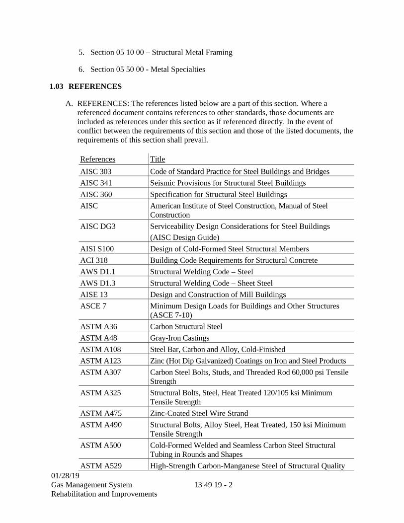
01/28/19
Gas Management System Rehabilitation and Improvements
13 49 19 - 2
5. Section 05 10 00 – Structural Metal Framing
6. Section 05 50 00 - Metal Specialties
1.03 REFERENCES
A. REFERENCES: The references listed below are a part of this section. Where a referenced document contains references to other standards, those documents are included as references under this section as if referenced directly. In the event of conflict between the requirements of this section and those of the listed documents, the requirements of this section shall prevail.
References Title
AISC 303 Code of Standard Practice for Steel Buildings and Bridges
AISC 341 Seismic Provisions for Structural Steel Buildings
AISC 360 Specification for Structural Steel Buildings
AISC American Institute of Steel Construction, Manual of Steel Construction
AISC DG3 Serviceability Design Considerations for Steel Buildings
(AISC Design Guide)
AISI S100 Design of Cold-Formed Steel Structural Members
ACI 318 Building Code Requirements for Structural Concrete
AWS D1.1 Structural Welding Code – Steel
AWS D1.3 Structural Welding Code – Sheet Steel
AISE 13 Design and Construction of Mill Buildings
ASCE 7 Minimum Design Loads for Buildings and Other Structures (ASCE 7-10)
ASTM A36 Carbon Structural Steel
ASTM A48 Gray-Iron Castings
ASTM A108 Steel Bar, Carbon and Alloy, Cold-Finished
ASTM A123 Zinc (Hot Dip Galvanized) Coatings on Iron and Steel Products
ASTM A307 Carbon Steel Bolts, Studs, and Threaded Rod 60,000 psi Tensile Strength
ASTM A325 Structural Bolts, Steel, Heat Treated 120/105 ksi Minimum Tensile Strength
ASTM A475 Zinc-Coated Steel Wire Strand
ASTM A490 Structural Bolts, Alloy Steel, Heat Treated, 150 ksi Minimum Tensile Strength
ASTM A500 Cold-Formed Welded and Seamless Carbon Steel Structural Tubing in Rounds and Shapes
ASTM A529 High-Strength Carbon-Manganese Steel of Structural Quality

01/28/19
Gas Management System Rehabilitation and Improvements
13 49 19 - 3
References Title
ASTM A563 Carbon and Alloy Steel Nuts
ASTM A572 High-Strength Low-Alloy Columbium-Vanadium Structural Steel
ASTM A653 Steel Sheet, Zinc Coated (Galvanized) or Zinc Iron Alloy Coated (Galvannealed) by the Hot Dip Process
ASTM A792 Standard Specification for Steel Sheet, 55 % Aluminum-Zinc Alloy-Coated by the Hot-Dip Process
ASTM A992 Structural Steel Shapes
ASTM A1011 Steel, Sheet and Strip, Hot-Rolled, Carbon, Structural, High-Strength Low-Alloy, High-Strength Low-Alloy with Improved Formability, and Ultra-High Strength
ASTM A1039 Steel, Sheet, Hot Rolled, Carbon, Commercial, Structural, and High-Strength Low-Alloy, Produced by Twin-Roll Casting Process
ASTM B209 Aluminum and Aluminum-Alloy Sheet and Plate
ASTM C553 Mineral Fiber Blanket Thermal Insulation for Commercial and Industrial Applications
ASTM D2244 Calculation of Color Tolerances and Color Differences from Instrumentally Measured Color Coordinates
ASTM D4214 Test Methods for Evaluating the Degree of Chalking of Exterior Paint Films
ASTM E96 Test Methods for Water Vapor Transmission of Materials
ASTM E108 Spread-of Flame Testing: Class 1A Rating
ASTM E283 Test Method for Determining the Rate of Air Leakage Through Exterior Windows, Curtain Walls, and Doors Under Specified Pressure Differences Across the Specimen
ASTM E331 Test Method for Water Penetration of Exterior Windows, Skylights, Doors, and Curtain Walls by Uniform Static Air Pressure Difference
ASTM E1592 Test Method for Structural Performance of Sheet Metal Roof and Siding Systems by Uniform Static Air Pressure Difference
ASTM E1646 Test Method for Water Penetration of Exterior Metal Roof Panel Systems by Uniform Static Air Pressure Difference
ASTM E1680 Test Method for Rate of Air Leakage Through Exterior Metal Roof Panel Systems
ASTM E2140 Test Method for Water Penetration of Metal Roof Panel Systems by Static Water Pressure Head
ASTM F436 Hardened Steel Washers
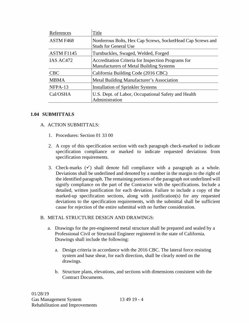
01/28/19
Gas Management System Rehabilitation and Improvements
13 49 19 - 4
References Title
ASTM F468 Nonferrous Bolts, Hex Cap Screws, SocketHead Cap Screws and Studs for General Use
ASTM F1145 Turnbuckles, Swaged, Welded, Forged
IAS AC472 Accreditation Criteria for Inspection Programs for Manufacturers of Metal Building Systems
CBC California Building Code (2016 CBC)
MBMA Metal Building Manufacturer’s Association
NFPA-13 Installation of Sprinkler Systems
Cal/OSHA U.S. Dept. of Labor, Occupational Safety and Health Administration
1.04 SUBMITTALS
A. ACTION SUBMITTALS:
1. Procedures: Section 01 33 00
2. A copy of this specification section with each paragraph check-marked to indicate specification compliance or marked to indicate requested deviations from specification requirements.
3. Check-marks () shall denote full compliance with a paragraph as a whole. Deviations shall be underlined and denoted by a number in the margin to the right of the identified paragraph. The remaining portions of the paragraph not underlined will signify compliance on the part of the Contractor with the specifications. Include a detailed, written justification for each deviation. Failure to include a copy of the marked-up specification sections, along with justification(s) for any requested deviations to the specification requirements, with the submittal shall be sufficient cause for rejection of the entire submittal with no further consideration.
B. METAL STRUCTURE DESIGN AND DRAWINGS:
a. Drawings for the pre-engineered metal structure shall be prepared and sealed by a Professional Civil or Structural Engineer registered in the state of California. Drawings shall include the following:
a. Design criteria in accordance with the 2016 CBC. The lateral force resisting system and base shear, for each direction, shall be clearly noted on the drawings.
b. Structure plans, elevations, and sections with dimensions consistent with the Contract Documents.

01/28/19
Gas Management System Rehabilitation and Improvements
13 49 19 - 5
c. Primary and secondary framing systems, location, sizes, material strength, and connection details for the lateral force resisting system in each direction. Unless otherwise noted, the section properties for the primary and secondary framing used in the design shall be clearly noted on the drawings.
d. Roof diaphragm and connections that substantiate a clear and direct load path consistent with the calculations. Roof diaphragm section properties, material strength, and their connections shall be clearly noted on the drawings.
e. Siding, roofing materials, ventilation and roof drainage system details (if applicable).
b. Design calculations of the pre-engineered metal structures, shall be prepared and sealed by a Professional Civil or Structural Engineer registered in the state of California. The minimum calculation and reference drawing requirements:
a. Calculations shall be comprehensible and complete. When evaluating the structural strengths, indicate stress for comparing with strengths or show the demand versus capacity ratio in the structural elements. Evaluating the results by stating “Okay by Inspection” is not acceptable. When spreadsheets are used, clearly reference equations and formulas presented in submittal calculations.
b. Design calculation shall substantiate a complete load path for the wind and seismic lateral force resisting systems. Including the design of drag members, collectors, and lateral force-resisting system elements (bracing, frames, connections) required to transfer loading, including the applicable overstrength factors (as code requires).
c. Design calculations shall include supporting information for the structural roof deck with a current and relative ICC-ES or IAPMO-UES report substantiating the capacity of the roof deck to act as a diaphragm to transfer in-plane and out-of-plane loading. The structural roof deck shall and roof deck connections shall be designed to withstand wind components and cladding forces in accordance with the 2016 CBC and ASCE 7-10.
d. Reference drawings shall include plans, sections, details and equipment information as necessary for seismic calculations. Indicate the location of the equipment on plan which is necessary for load calculations (if applicable).
e. Submittals shall be returned without review if:
1) Submittals include only calculations without reference drawings
2) Calculations have no sheet numbers or sheets are missing.
3) Calculations or reference drawings are illegible.
01/28/19
Gas Management System Rehabilitation and Improvements
13 49 19 - 6
4) Calculations are made based on wrong information, assumptions or design parameters.
5) Information in reference drawings is insufficient for calculations or review.
f. The calculations and details shall demonstrate a complete vertical and lateral load path, and shall clearly indicate all forces imposed on the supporting structure.
c. Letter of Design Certification prepared and sealed by a Professional Civil or Structural Engineer registered in the state of California confirming responsibility for the design and attesting that the design prepared meets the performance criteria required by the Contract Documents, the requirements of governing authorities having jurisdiction at the Site, and conforms to prevailing standards of practice. The Letter of Design Certification shall include the following:
a. Design Loads:
1) Including dead load, roof live load, collateral loads, impact loads, roof snow load (if applicable).
2) Deflections for vertical members and overall lateral deflection of the structure (drift).
3) Ultimate and nominal wind speed, risk category, wind exposure, topographic factor, design wind speeds for the main wind force resisting system, and components and cladding wind pressures.
4) Design spectral response accelerations at short and 1-second periods (SDS & SD1), risk category, seismic importance factor (Ie), response modification factor (R), seismic response coefficient (Cs), and design base shear in each direction. The lateral force resisting system shall be clearly identified in each direction with an associated response modification coefficient.
5) Auxiliary loads, such as loading superimposed on the system by erection equipment.
b. Verification that the metal roofing system is Factory Mutual approved for the Factory Mutual Rating required at the site. The pre-engineered metal structure supplier shall calculate the Factory Mutual Rating required in accordance with FM Global Property Loss Prevention Data Sheet 1-28, latest revision, using the Basic Wind Speed and Exposure information in this Section.
C. ANCHOR BOLT DESIGN AND DRAWINGS:
a. Drawings that include anchor bolt location plans, anchor bolt size, spacing, quantity, embedment, material, orientation, maximum not to exceed grout pad thickness, and structure column base plate details and base attachments where
01/28/19
Gas Management System Rehabilitation and Improvements
13 49 19 - 7
required. The minimum edge distance, consistent with the calculations, shall be included on the anchor bolt drawings.
b. Anchor bolt drawings shall include the unfactored structure column loads imposed on the foundations. Unfactored column load are to be separately shown for dead load, live loads, snow loads (if applicable), wind loads and seismic loads.
c. Anchor bolt calculations prepared and sealed by a Professional Civil or Structural Engineer registered in the state of California.
a. Anchor bolt calculations shall clearly show that the capacity of the anchor and the capacity of the concrete that the anchor is embedded in are adequate to resist all applicable load combinations and overstrength factors.
1) The design of anchors resisting seismic forces shall satisfy the ductility requirements stated in the 2016 CBC, ASCE 7-10, and ACI 318-14.
b. Reduction factors associated with edge distance, embedment length, grout and base plate thickness, and bolt spacing shall be considered in the design and consistent with the submittal drawings.
c. Anchor bolts shall be designed for bending due to eccentricity where raised grout pads will be installed for leveling.
d. Reference Specification Section 01 73 23 – Bracing and Anchoring for information not indicated in this section.
2. Erection drawings showing roof framing, transverse cross sections, covering and trim details, and accessory installation details to clearly indicate proper assembly of the structure components.
3. Product Data: Manufacturer's product information, specifications, and installation instructions for structure components, accessories, and vapor barrier (if applicable).
4. Color charts showing full range of colors, textures and patterns available.
5. Samples: Two of each of the following samples will be used as basis for evaluating quality of finished roof and wall systems and selection of colors.
a. Twelve inches long by actual width of roofing with specified finishes.
b. Fasteners for application of roofing and soffit panels.
6. QUALITY CONTROL SUBMITTALS:
a. Certification that the Pre-Engineered Metal Structure Manufacturer has a minimum of 5 years experience in the manufacture of metal structures.
01/28/19
Gas Management System Rehabilitation and Improvements
13 49 19 - 8
b. Certification that the Pre-Engineered Metal Structure Erector has a minimum of 5 years experience in the erection of metal structures.
c. Manufacturer’s Certificate of Accreditation with IAS AC472.
1.05 QUALITY ASSURANCE
A. QUALIFICATIONS
1. MANUFACTURER QUALIFICATIONS:
a. The manufacturer shall have a minimum of (10) ten years experience in the manufacture of metal structures and shall be accredited under the IAS AC472.
2. ERECTOR QUALIFICATIONS:
a. Erector shall have a minimum of (5) five years experience in the erection of metal structures.
b. Erector shall be familiar with Manufacturer’s pre-engineered metal structure systems, standard and/or custom concepts.
c. Erection shall be performed by qualified erector using proper tools and equipment in accordance with manufacturer’s recommendations.
3. WORKMAN QUALIFICATIONS:
a. The erector shall provide at least one person who shall be present at all times during execution of the work and who shall be thoroughly familiar with the pre-engineered metal structure concept and the requirements, and who shall direct all work performed.
b. Workers employed by the erector shall be skilled in performing tasks related to pre-engineered metal structures.
c. Certified welding procedures and welding operators in accordance with AWS.
4. SOURCE LIMITATIONS:
a. Obtain metal structure components, including primary and secondary framing and metal panel assemblies, from single source from single manufacturer.
1.06 DELIVERY, STORAGE AND HANDLING
A. The pre-engineered metal structure manufacturer and their installation Contractor are responsible for the delivery, storage and handling of materials.

01/28/19
Gas Management System Rehabilitation and Improvements
13 49 19 - 9
B. Materials shall be delivered in a dry and undamaged condition and stored out of contact with the ground. Materials other than framing and structural members shall be covered with weather tight covering and kept dry. Storage accommodations for roof and wall covering shall provide good air circulation and protection from surface staining.
C. The Owner will make adequate lay down and staging areas available to the erector. Details of access and lay down areas shall be finalized at the pre-award conference.
1.07 SPECIAL WARRANTY
A. Provide a Special Warranty in accordance with the following:
1. 1 year workmanship guarantee against failures caused by faulty erection.
2. 2 year materials guarantee against failures.
3. Manufacturer’s written weather tightness warranty for 10 years against leaks in roof panels arising out of or caused by ordinary wear and tear under normal weather and atmospheric conditions.
4. Manufacturer’s paint film written warranty for 20 years against chipping, cracking, peeling, chalking, and fading of the coating on painted wall panels, painted roof panels and soffit panels.
a. Chalking shall not exceed #8 per ASTM D4214.
b. Fading shall be 5 NBS units or less per ASTM D2244.
PART 2 PRODUCTS
2.01 MANUFACTURERS
A. Candidate manufacturers are listed below. The manufacturer’s standard product may require modification to conform to specified requirements:
1. American Buildings Company
2. Butler Manufacturing
3. Ceco Building Systems
4. Garco Building Systems
5. Star Building Systems
6. Varco-Pruden Buildings
7. Approved Equal
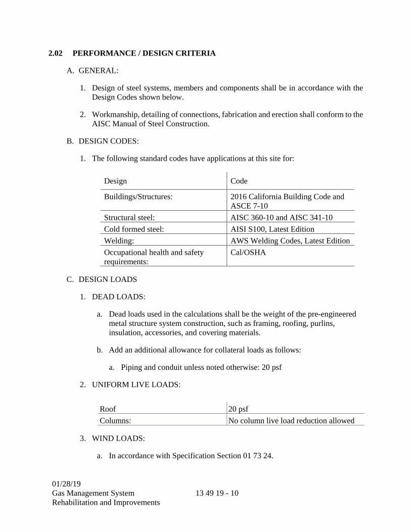
01/28/19
Gas Management System Rehabilitation and Improvements
13 49 19 - 10
2.02 PERFORMANCE / DESIGN CRITERIA
A. GENERAL:
1. Design of steel systems, members and components shall be in accordance with the Design Codes shown below.
2. Workmanship, detailing of connections, fabrication and erection shall conform to the AISC Manual of Steel Construction.
B. DESIGN CODES:
1. The following standard codes have applications at this site for:
Design Code
Buildings/Structures: 2016 California Building Code and ASCE 7-10
Structural steel: AISC 360-10 and AISC 341-10
Cold formed steel: AISI S100, Latest Edition
Welding: AWS Welding Codes, Latest Edition
Occupational health and safety requirements:
Cal/OSHA
C. DESIGN LOADS
1. DEAD LOADS:
a. Dead loads used in the calculations shall be the weight of the pre-engineered metal structure system construction, such as framing, roofing, purlins, insulation, accessories, and covering materials.
b. Add an additional allowance for collateral loads as follows:
a. Piping and conduit unless noted otherwise: 20 psf
2. UNIFORM LIVE LOADS:
Roof 20 psf
Columns: No column live load reduction allowed
3. WIND LOADS:
a. In accordance with Specification Section 01 73 24.

01/28/19
Gas Management System Rehabilitation and Improvements
13 49 19 - 11
Code: 2016 California Building Code and ASCE 7-10
Risk Category: III
Ultimate Wind Speed: 115 mph
Nominal Design Wind Speed: 89 mph
Exposure: D
Topographic Factor (Kzt): 1.0
Internal Pressure Coefficients: 2016 CBC and ASCE 7-10
Components and Cladding Wind Pressure
2016 CBC and ASCE 7-10
Note: 1. Design to withstand the design wind loads without consideration of shielding effects by other structures.
4. SEISMIC LOADS:
a. In accordance with Specification Section 01 73 24:
Code: 2016 California Building Code and ASCE 7-10
Risk Category: III
Importance Factor (Ie): 1.25
0.2 Sec. Mapped Spectral Response, SS: 0.710 g
1.0 Sec. Mapped Spectral Response, S1: 0.300 g
Site Class: D
0.2 Sec. Design Spectral Response, SDS: 0.583 g
1.0 Sec. Design Spectral Response, SD1: 0.360 g
Component Importance Factor (Ip): 1.0, except Ip=1.5 for components identified in Section 13.1.3 of ASCE 7
Seismic Design Category D
5. TEMPERATURE:
a. Include the effects of temperature in design where the pre-engineered metal structure systems are exposed to differential climatic conditions. See climatic conditions below for temperature extremes.
D. LOAD COMBINATIONS:
1. Design pre-engineered metal structure systems to withstand the load combinations as specified in the governing building code. Where the exclusion of live load or impact load would cause a more severe load condition for the member under investigation, then ignore the load when evaluating that member.

01/28/19
Gas Management System Rehabilitation and Improvements
13 49 19 - 12
E. DESIGN CONSIDERATIONS:
1. Minimum roof slope: 1/2 inch per foot or as shown on Drawings.
2. Design structures and components for the following climatic conditions.
a. Climatic Conditions:
Maximum design temperature: 105 degrees Fahrenheit
Minimum design temperature: 32 degrees Fahrenheit
F. DEFLECTIONS:
1. Calculations for structure deflections shall be performed using only the bare frame method. Reductions based on engineering judgment using the assumed composite stiffness of the structure envelope shall not be allowed.
2. PRIMARY FRAMING:
a. Horizontal Drift: In accordance with ASCE 7-10.
b. Vertical Deflection: In accordance with the 2016 CBC limits; L/450 for members supporting a monorail.
3. SECONDARY FRAMING:
a. Horizontal Deflection: L/360 for load cases that include wind and L/180 for load cases that include seismic.
b. Vertical Deflection: In accordance with the 2016 CBC limits.
4. Deflections not listed above shall be in accordance with the applicable provisions of the AISC Steel Design Guide Series 3 – Serviceability Design Considerations for Steel Buildings.
G. GUTTERS AND DOWNSPOUTS:
1. Exterior gutters and downspouts shall be designed for rainfall intensity based upon a 5-year recurrence interval for a five-minute duration. Interior gutters, valleys, and downspouts shall be designed for rainfall intensity based upon a 25-year recurrence interval based on a five-minute duration.
H. PRIMARY FRAMING AND ANCHOR BOLTS:
1. Unless specifically designed as a cantilevered type system, the column bases shall be designed as pinned connections. No moments shall be assumed to be transferred to the foundations.

01/28/19
Gas Management System Rehabilitation and Improvements
13 49 19 - 13
2. Anchor bolt design, size and arrangements shall be coordinated between the pre-engineered metal structure manufacturer and the foundation design as shown on the Drawings. Anchor bolt arrangements shall meet the minimum bolt spacing requirements per AISC codes. Anchor bolt design shall meet the requirements of ACI 318-14, Chapter 17.
I. SECONDARY FRAMING
1. Purlins at the standing seam roofs shall be braced in accordance with FMRC standards when a standing seam roof is used. Where an accepted FMRC design does not exist, the design of the roof purlins and associated bracing shall meet or exceed requirements in the latest version of the American Iron and Steel Institute (AISI) “North American Specification for the Design of Cold-Formed Steel Structural Members”.
J. METAL PANELS
1. Roof paneling system shall be designed to support design roof live load and wind components and cladding loads. Panels shall be designed to support a 200 pound load over a 2 foot square area centered between purlins without exceeding a panel deflection to span ratio as indicated in the 2016 CBC.
2.03 MATERIALS
A. MATERIAL SPECIFICATIONS:
Material Specification
Primary Framing Steel
Mill-Rolled Structural Sections ASTM A36, ASTM A572 Grade 50, or ASTM A992 as applicable
Built Up Sections ASTM A572, ASTM A529, or ASTM A1011
Secondary Framing Steel
Purlins, girts, eave struts, and “C” sections
ASTM A36, ASTM A572, ASTM A529, or ASTM A1011
Structural Bolts
Steel ASTM A325
Galvanized Steel ASTM A325 (Type 1)
Roof and Wall Panels
Galvanized Steel ASTM A653 Grade 80 or Grade 50 (Class 3)
Aluminum ASTM B209
B. See Specification Sections 05 05 14, 05 05 20, 05 10 00 and 05 59 00 for additional metal material information.
01/28/19
Gas Management System Rehabilitation and Improvements
13 49 19 - 14
2.04 MANUFACTURED UNITS AND COMPONENTS
A. PRIMARY FRAMING SYSTEM:
1. INTERIOR FRAMES:
a. Use clear span rigid frames. Interior columns are allowed only where indicated on the Drawings.
b. Frames shall consist of tapered or straight columns and roof beams constructed from welded-up plate section or hot-rolled wide flange columns and beams complete with necessary splice plates for bolted field assembly.
c. Bolts for field assembly of frame members shall be A325 galvanized A325 (Type 1) bolts.
2. ANCHOR BOLTS
a. Anchor bolts to concrete shall be in accordance with Section 05 05 20.
B. SECONDARY STRUCTURAL MEMBERS:
1. ROOF PURLINS AND WALL GIRTS (IF APPLICABLE):
a. Purlins and girts shall be G90 zinc-coated per ASTM A653. Purlins and girts shall be "Z" shaped, precision roll formed. The interior flange of girts shall be turned down to avoid forming a pocket for dust and debris.
2. EAVE STRUTS (IF APPLICABLE):
a. Eave Struts shall be 8 inch, 9 1/2 inch, or 11 inch deep "C" sections.
3. BRACING:
a. Bracing may be located at perimeter walls in locations where it will not interfere with openings or future expansions as shown on the Drawings. Interior bracing is not allowed (i.e. vertical bracing to interior columns).
b. Diagonal bracing shall be hot-rolled rods and attached to columns and roof beams. Rods shall be furnished to length and equipped with bevel washer, cut washers and nuts at each end.
c. Rigid frame beam and column flange braces back to purlins or girts shall be cold formed.
01/28/19
Gas Management System Rehabilitation and Improvements
13 49 19 - 15
C. ROOF PANELS:
1. Roof panels shall be factory roll-formed roof panels. Panel material shall be a minimum 24 gauge with G90 zinc-coated per ASTM A653. Finish coating of the panels shall be as specified below in the “Finish” paragraph of this section.
2. Panels of maximum possible lengths shall be used to minimize end laps. Eave panels shall extend beyond the structural line of the sidewall.
3. Panel end splices shall be floating and allow the roof panels to expand and contract with roof panel temperature changes.
4. Ridge assembly shall be designed to allow roof panels to move lengthwise with expansion or contraction as the roof panel temperature changes. Panel closures shall be installed to seal the panel ends at the ridge.
5. Endwall trim and roof transition flashings shall allow the roof panel to move relative to the wall panels as the roof expands and contracts with temperature changes.
6. Roof System Performance Testing:
a. UL Wind Uplift Classification Rating, UL 580: Class 90.
b. Structural Performance Under Uniform Static Air Pressure Difference: Test roof system in accordance with ASTM E 1592.
c. Roof system has been tested in accordance with U.S. Army Corps of Engineers Unified Facilities Guide Specification Section 07 61 13.
d. FM Global (Factory Mutual):
a. Roof system has been tested in accordance with FMRC Standard 4471 and approved as a Class 1 Panel Roof.
b. Pre-Engineered Metal Structure : Provide specific assemblies to meet required wind rating in accordance with FM Global.
c. Installation modifications or substitutions can invalidate FM Global approval.
D. LINER PANELS;
1. 24 gage minimum, pre-painted G90 zinc-coated.
2. Fasteners shall be color coordinated with a same coating system as panels.
01/28/19
Gas Management System Rehabilitation and Improvements
13 49 19 - 16
E. TRIMS AND FLASHING:
1. The system shall be complete with integrated pre-engineered trims and flashings to accommodate reasonable variances in tolerances and thermal movement. Minor flashings may be field fabricated.
2. Rake flashing, corner trim, eave trim, and all other necessary trim shall be 26 gage G90 zinc-coated, pre-painted, color to match wall panels.
3. Pipe flashing shall be of one piece construction and fabricated from an EPDM membrane and shall have an aluminum base formed to roof panel profile.
4. Trims and flashings shall be painted with the metal panel coating system listed below and shall match the color of the wall or roof panels.
F. GUTTERS AND DOWNSPOUTS:
1. Gutters shall be 24-gage G90 zinc-coated, pre-painted, color coordinated to match wall panels.
2. Downspouts shall be rectangular, 28 gage G90 zinc-coated, pre-painted, color coordinated to match wall panels.
3. Gutters shall be provided on the exterior of the structure along perimeter.
4. Downspouts shall be provided at corners. Intermediate downspouts shall be provided to limit spacing between downspouts to 50 feet.
5. Gutters and downspouts shall be painted with metal panel coating system listed below.
G. CLOSURES AND SEALANTS:
1. Preformed closed cell non-shrinking, laminated polyethylene closures along the eave, ridge, and rake for weather tightness.
2. 20 gage metal closures at standing seam roof panels, color coordinated with the same coating system as roof panels.
3. Sealant for end laps, roof flashing laps, ridges, and eave shall be tape mastic, 100% solid ethylene propylene copolymer tape.
4. Sealant for gutter and downspout joints, roof accessories shall be polyurethane.
01/28/19
Gas Management System Rehabilitation and Improvements
13 49 19 - 17
2.05 FINISHES
A. COATING OF PRIMARY FRAMING AND SECONDARY MEMBERS:
1. Primary structural steel framing shall be galvanized per ASTM A123. Secondary steel, such as purlins and girts, shall be G90 zinc-coated per ASTM A653. Field touch up shall be with Galvicon 1-4853 by Southern Coatings or approved equal. Coating system substitutions may only be used after written approval has been received from the Owner’s Representative.
2. Prior to galvanizing, steel shall be cleaned of loose rust, loose mill scale, dirt and other foreign material.
B. Coating of Panels
1. The metal panel coating system for the exterior side of roof and wall panels shall be a full strength, 70% Kynar 500®/Hylar 5000(TM) fluoropolymer coating, Flurothane IV system, or approved equal.
2. The interior side of the roof panels, wall panels and trim material shall be coated with primer and a universal off-white polyester paint coat.
PART 3 EXECUTION
3.01 EXAMINATION
A. Examine and accept existing conditions before beginning work.
B. Check lines and elevations of concrete bearing surfaces.
C. Confirm locations of anchor bolts and similar devices before the pre-engineered metal structure erection proceeds.
D. Report discrepancies immediately to the Owner. Do not proceed with erection until corrections have been made, or until compensating adjustments to the steelwork have been agreed upon.
3.02 PREPARATION
A. Prior to performing work of this section, verify that work of other trades, as applicable, is complete for commencement of installation.
B. Obtain manufacturer’s written instructions before commencing erection or installation.

01/28/19
Gas Management System Rehabilitation and Improvements
13 49 19 - 18
3.03 ERECTION
A. Erect the work in accordance with Specifications, Drawings, and manufacturer's directions.
B. Conform to configurations and connections indicated on reviewed and accepted shop and erection drawings.
C. Accurately position and assemble structural framing to lines and members of framing system prior to permanent fastening.
D. Erector shall not make any field modifications to any structural member except as authorized and/or specified by manufacturer in writing, with a copy to the Owner.
E. APPROVED FIELD MODIFICATION: Perform in manner not to impair appearance, weather tightness, or structural quality of material or structure.
F. Install metal panels, fasteners, trim, louvers, and related items in conformance with approved drawings and requirements of manufacturers. Protect installed panels and structures from damage by other trades.
G. Temporary shoring and bracing: Provide members with connections of sufficient strength to bear imposed loads. Remove temporary members and connections when permanent members are in place and final connections have been made. Provide temporary guy lines to achieve proper alignment of structures as erection proceeds.
3.04 REPAIR AND RESTORATION
A. Replace damaged panels and other components that cannot be repaired by finish touch-up or similar minor repair.
B. Touch-up coatings: Immediately after erection, clean field welds, bolted connections, and areas where coating is abraded. Apply coating to exposed areas using same material as used for shop coating.
C. Replace or restore the following to original condition:
1. Surface finishes damaged prior to or during erection.
2. Components where material and workmanship does not meet specified requirements.
D. Minor Scratches, Dents, And Holes: Repair and paint with similar enamel of thickness and color to match original coating.

01/28/19
Gas Management System Rehabilitation and Improvements
13 49 19 - 19
3.05 FIELD QUALITY CONTROL
A. MANUFACTURER’S FIELD SERVICES: The Pre-Engineered Metal Structure’s Representative shall be present at jobsite for installation assistance, inspection, and certification of installation.
B. The Owner’s Special Inspector will inspect and indicate if work is in conformance with specifications. This inspection will include products, erection, welding, grouting and similar construction. The Inspector will verify that the work has been performed in accordance with AISC and this specification.
C. Maximum deviations from plumb, level, and alignment are not to exceed AISC specifications, and tolerances specified in this section.
D. Defective Work: Promptly remove and replace materials and fabricated components that do not comply. Furnish, perform, and install to specified requirements.
3.06 CLEANING
A. Upon completion of the services, the Pre-Engineered Metal Structure Manufacturer and their installation Contractor shall remove excess materials, tools, scaffolds and rubbish which has accumulated on the premises and leave same in a clean and satisfactory condition.
**END OF SECTION**

01/28/19
Gas Management System Rehabilitation and Improvements
13 49 19 - 20
THIS PAGE INTENTIONALLY LEFT BLANK