
Embedded Control System for a High Precision Flow ... - DiVA-Portal
Upload
khangminh22Category
view
1download
0
Linköpings University
Bachelor Thesis
Garden monitoring with embedded systems
Author:Karl-Johan von Hacht
Supervisor:Michael Josefsson
The construction of a lightweighted system suggested as a help in the developmentof modern agriculture
at the
Department of Electrical Engineering
August 2015
Declaration of Authorship
I, Karl-Johan von Hacht, declare that this thesis titled, ’Garden monitoring with
embedded systems’ and the work presented in it are my own. I confirm that:
This work was done wholly or mainly while in candidature for a research degree at
this University.
Where any part of this thesis has previously been submitted for a degree or any
other qualification at this University or any other institution, this has been clearly
stated.
Where I have consulted the published work of others, this is always clearly at-
tributed.
Where I have quoted from the work of others, the source is always given. With the
exception of such quotations, this thesis is entirely my own work.
I have acknowledged all main sources of help.
Where the thesis is based on work done by myself jointly with others, I have made
clear exactly what was done by others and what I have contributed myself.
Signed:
Date:
i

“Our greatest weakness lies in giving up. The most certain way to succeed is always to
try just one more time."
Thomas A. Edison

LINKÖPINGS UNIVERSITY
AbstractFaculty Name
Department of Electrical Engineering
Bachelor
Garden monitoring with embedded systems
by Karl-Johan von Hacht
In today’s modern society the process of handling crops in an accountable way without
loss have become more and more important. By letting a gardener evaluate the progress
of his plants from relevant data one can reduce these losses and increase effectiveness of
the whole plantation. This work is about the construction of such a system composed
from a developers perspective of three different platforms, from the start of data sampling
within the context of gardening to and end user easily able to understand the data then
translated. The first platform will be created from scratch with both hardware and
software, the next assembled from already finished hardware components and build with
simpler software. The last will essentially only be a software solution in an already
finished hardware environment.

Acknowledgements
Many thanks to the people at Broccoli Engineering, especially Björn for giving me the
opportunity, Henrik for the insights, also Benny and Anders for both the society and help.
Another special thanks to my supervisor Micke for somewhere along the way planting
knowledge I now figured out to be very resourceful.
iv
Contents
Declaration of Authorship i
Abstract iii
Acknowledgements iv
List of Figures vii
Abbreviations ix
1 1. Introduction 11.1 Background . . . . . . . . . . . . . . . . . . . . . . . . . . . . . . . . . . . 11.2 Aim . . . . . . . . . . . . . . . . . . . . . . . . . . . . . . . . . . . . . . . 11.3 Development process . . . . . . . . . . . . . . . . . . . . . . . . . . . . . . 21.4 Thesis outline . . . . . . . . . . . . . . . . . . . . . . . . . . . . . . . . . . 3
2 2. Tools 42.1 System tasks . . . . . . . . . . . . . . . . . . . . . . . . . . . . . . . . . . 42.2 Hardware . . . . . . . . . . . . . . . . . . . . . . . . . . . . . . . . . . . . 8
2.2.1 Microcontroller Unit . . . . . . . . . . . . . . . . . . . . . . . . . . 82.2.2 Wireless Communication . . . . . . . . . . . . . . . . . . . . . . . . 122.2.3 Measurement tools and LCD . . . . . . . . . . . . . . . . . . . . . 18
2.3 Software . . . . . . . . . . . . . . . . . . . . . . . . . . . . . . . . . . . . . 202.3.1 C programming on the Slave platform . . . . . . . . . . . . . . . . 202.3.2 Arduino programming on the Master platform . . . . . . . . . . . . 222.3.3 Android application development on a smartphone . . . . . . . . . 232.3.4 Other software . . . . . . . . . . . . . . . . . . . . . . . . . . . . . 24
3 3. Data Acquisition System 263.1 Planning . . . . . . . . . . . . . . . . . . . . . . . . . . . . . . . . . . . . . 263.2 Building . . . . . . . . . . . . . . . . . . . . . . . . . . . . . . . . . . . . . 31
3.2.1 Establishing a wireless network connection . . . . . . . . . . . . . . 313.2.2 The measurements tools . . . . . . . . . . . . . . . . . . . . . . . . 33
3.3 Summation . . . . . . . . . . . . . . . . . . . . . . . . . . . . . . . . . . . 36
4 4. Main Node 37
v

Contents vi
4.1 Planning . . . . . . . . . . . . . . . . . . . . . . . . . . . . . . . . . . . . . 374.2 Building . . . . . . . . . . . . . . . . . . . . . . . . . . . . . . . . . . . . . 39
4.2.1 Fetching wireless data for display . . . . . . . . . . . . . . . . . . . 404.2.2 Further forwarding via Bluetooth . . . . . . . . . . . . . . . . . . . 41
4.3 Summation . . . . . . . . . . . . . . . . . . . . . . . . . . . . . . . . . . . 43
5 5. Human Interface 455.1 Planning . . . . . . . . . . . . . . . . . . . . . . . . . . . . . . . . . . . . . 455.2 Building . . . . . . . . . . . . . . . . . . . . . . . . . . . . . . . . . . . . . 475.3 Summation . . . . . . . . . . . . . . . . . . . . . . . . . . . . . . . . . . . 48
6 6. Summation and evaluation 506.1 A system network summation . . . . . . . . . . . . . . . . . . . . . . . . . 506.2 Possible fields of practical use . . . . . . . . . . . . . . . . . . . . . . . . . 52
A Component list 53
B Schematics 54
Bibliography 56
List of Figures
1.1 Development Process . . . . . . . . . . . . . . . . . . . . . . . . . . . . . . 2
2.1 Chain of Platforms . . . . . . . . . . . . . . . . . . . . . . . . . . . . . . . 52.2 Hardware needed for the Slave . . . . . . . . . . . . . . . . . . . . . . . . 62.3 Hardware needed for the Master . . . . . . . . . . . . . . . . . . . . . . . 72.4 Arduino UNO . . . . . . . . . . . . . . . . . . . . . . . . . . . . . . . . . . 92.5 Pin Mapping . . . . . . . . . . . . . . . . . . . . . . . . . . . . . . . . . . 92.6 UART seen through oscilloscope . . . . . . . . . . . . . . . . . . . . . . . 112.7 ZigBee Stack . . . . . . . . . . . . . . . . . . . . . . . . . . . . . . . . . . 122.8 Network Topologys . . . . . . . . . . . . . . . . . . . . . . . . . . . . . . . 132.9 XBee . . . . . . . . . . . . . . . . . . . . . . . . . . . . . . . . . . . . . . . 152.10 JY-MCU . . . . . . . . . . . . . . . . . . . . . . . . . . . . . . . . . . . . . 172.11 Soil Fork . . . . . . . . . . . . . . . . . . . . . . . . . . . . . . . . . . . . . 192.12 Sun cell . . . . . . . . . . . . . . . . . . . . . . . . . . . . . . . . . . . . . 192.13 LCD . . . . . . . . . . . . . . . . . . . . . . . . . . . . . . . . . . . . . . . 192.14 Arduino Software . . . . . . . . . . . . . . . . . . . . . . . . . . . . . . . . 232.15 Android Studio . . . . . . . . . . . . . . . . . . . . . . . . . . . . . . . . . 242.16 Hyperterminal . . . . . . . . . . . . . . . . . . . . . . . . . . . . . . . . . 252.17 X-CTU . . . . . . . . . . . . . . . . . . . . . . . . . . . . . . . . . . . . . 25
3.1 RC-oscillation under different temperature conditions . . . . . . . . . . . . 273.2 ISP connector . . . . . . . . . . . . . . . . . . . . . . . . . . . . . . . . . . 283.3 Slave data . . . . . . . . . . . . . . . . . . . . . . . . . . . . . . . . . . . . 293.4 Slave base circuit . . . . . . . . . . . . . . . . . . . . . . . . . . . . . . . . 313.5 Soil moisture voltage division . . . . . . . . . . . . . . . . . . . . . . . . . 333.6 The Slave in it’s real plumage . . . . . . . . . . . . . . . . . . . . . . . . . 36
4.1 Master base circuit . . . . . . . . . . . . . . . . . . . . . . . . . . . . . . . 394.2 The package from Master to the Human Interface sent as a string of char-
acters. . . . . . . . . . . . . . . . . . . . . . . . . . . . . . . . . . . . . . . 434.3 Final Master construction . . . . . . . . . . . . . . . . . . . . . . . . . . . 44
5.1 First sketch of application . . . . . . . . . . . . . . . . . . . . . . . . . . . 465.2 Final Android application . . . . . . . . . . . . . . . . . . . . . . . . . . . 49
6.1 The Final Flow of the System . . . . . . . . . . . . . . . . . . . . . . . . . 50
vii

Listings
2.1 Makefile for compiling and writing code to the ATmega328p . . . . . . . . 213.1 Fuseoption variable . . . . . . . . . . . . . . . . . . . . . . . . . . . . . . . 303.2 C functions for communication via UART signal . . . . . . . . . . . . . . 323.3 Count one second in the timer ISR . . . . . . . . . . . . . . . . . . . . . . 354.1 The storage of Slave data . . . . . . . . . . . . . . . . . . . . . . . . . . . 384.2 Arduino UNO XBee receive and send . . . . . . . . . . . . . . . . . . . . . 404.3 Arduino UNO communication with LCD . . . . . . . . . . . . . . . . . . . 414.4 Function for converting one row of Slave data to a hexadecimal number. . 425.1 Collect data within the Bluetooth thread and update the UI thread . . . . 47
viii

Abbreviations
DAQ Data Acquisition system
ADC Analog to Digital Converter
LCD Liquid Crystal Display
OS Operating System
MCU Micro Controller Unit (or microcontroller)
ISP In-System Programming
IDE Integrated Development Environment
API Application Programming Interface
UART Universal Asynchronous Receiver/Transmitter
USB Universal Serial Bus
RX Receive (data pin)
TX Transmit (data pin)
IEEE Institute of Electrical and Electronics Engineers
PHY Physical layer
MAC Media Access Control
WPAN Wireless Personal Area Networks
EDR Enhanced Data Rate
EEPROM Electrically Erasable Programmable Read Only Memory
GUI Graphical User Interface
LED Light Emitting Diode
ISR Interrrupt Service Routine
ix

This page intentionally left blank.
x

This page intentionally left blank.
xi

Chapter 1
1. Introduction
A short summary of the process behind and outline of this thesis.
1.1 Background
This thesis is the final part of my Bachelor degree in Electrical Engineering at the Insti-
tute of technology at Linköpings University (LiTH) performed at the company Broccoli
Engineering. The work reflects many of the studies conducted at LiTH combining mostly
classical areas in the Electronics Engineering field such as hands on soldering of circuits
with programming of microcontrollers.
1.2 Aim
The goal of this work should be to develop an fully functional system that could measure
mainly two aspects related to the well being of crops, vegetables or similar. These
measurements should also easily be understood by the help of an user interface and
relevant when it comes to deciding the next step in a process of gardening1, with the
possibility in mind to develop the system further.
1Wholly based upon assumptions without no further research with little claim to understand thebiology field of studies, all rejection from a man of this profession is granted.
1
Chapter 1. Introduction 2
1.3 Development process
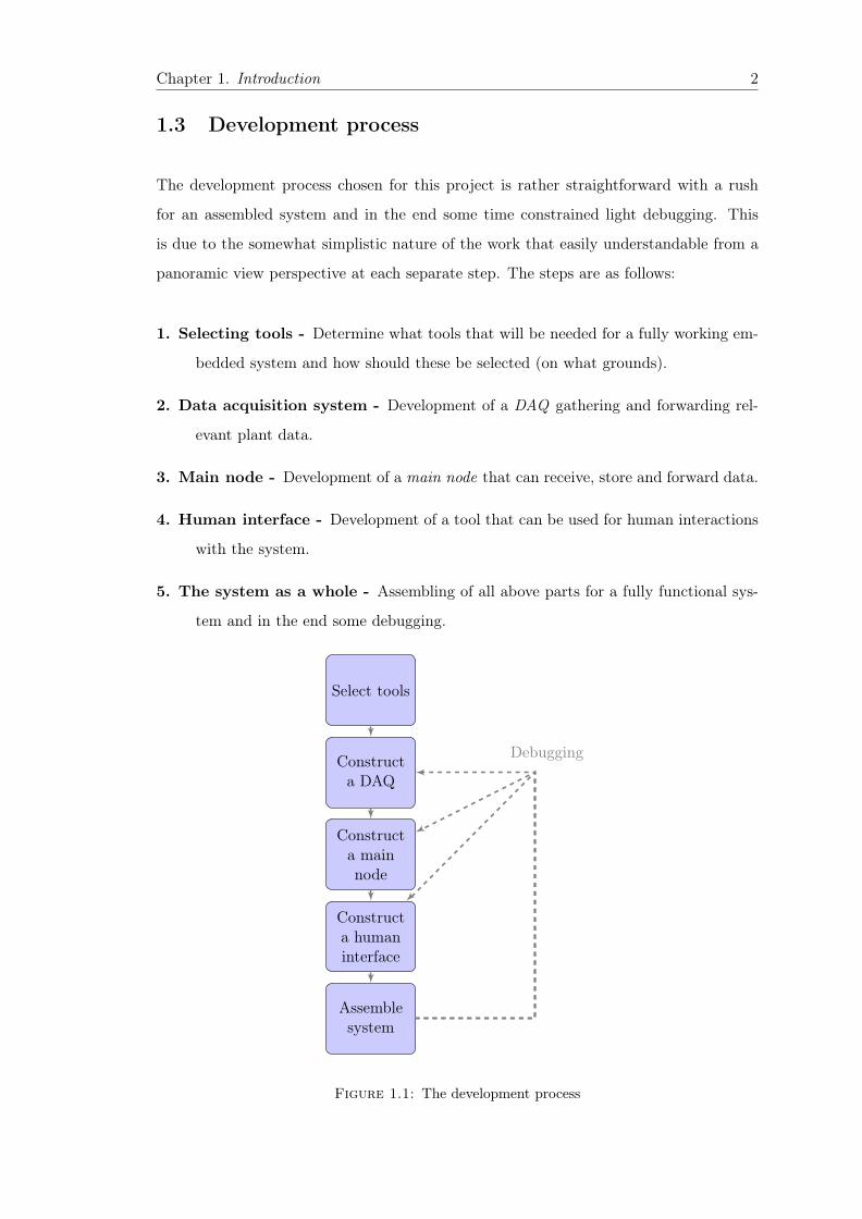
The development process chosen for this project is rather straightforward with a rush
for an assembled system and in the end some time constrained light debugging. This
is due to the somewhat simplistic nature of the work that easily understandable from a
panoramic view perspective at each separate step. The steps are as follows:
1. Selecting tools - Determine what tools that will be needed for a fully working em-
bedded system and how should these be selected (on what grounds).
2. Data acquisition system - Development of a DAQ gathering and forwarding rel-
evant plant data.
3. Main node - Development of a main node that can receive, store and forward data.
4. Human interface - Development of a tool that can be used for human interactions
with the system.
5. The system as a whole - Assembling of all above parts for a fully functional sys-
tem and in the end some debugging.
Select tools
Constructa DAQ
Constructa mainnode
Constructa humaninterface
Assemblesystem
Debugging
Figure 1.1: The development process

Chapter 1. Introduction 3
1.4 Thesis outline
The outline of this thesis are as following:
• Chapter 2 Tools - The process of choosing tools used to create the system.
• Chapter 3 Data Acquisition System - Hardware combined with software to
create the DAQ.
• Chapter 4 Main Node - Hardware combined with software to create the main
node.
• Chapter 5 Human Interface - Construction of the human interface.
• Chapter 6 Summation and evaluation - The flow of data starting with the
DAQ measurements ending in a practical human usage and a system evaluation
with possible future development.

Chapter 2
2. Tools
This chapter will discuss what the system should be constructed for, how this
affects the selection of tools as well as how these should be selected.
2.1 System tasks
Before venturing forth one has to decide upon what two measurements the system should
focus on and for simplicity these have been chosen in correspondence to the tools. The
measurement of soil moisture and the measurement of sun time is both somewhat inter-
esting when it comes to gardening and after a bit of research quite easy to implement as
a Data Acquisition System (DAQ). Calculations and theoretical assumptions have been
made from use of an Analog-to-Digital converter (ADC) in combination with a voltage
divider for the soil moisture measurement.
For the sun time measurement one could use the fact that different logical levels re-
sides within a sun cell which is lighten/not lighten on by the sun. A more outlaid
description of the theory behind these assumptions can be viewed in chapter 3-4. The
second task after fetching the data is to convert it and then the third and last task will
be to transport it onto a new platform.
One should note though that the procedure of the tasks will be repeated in the same
manner on the new platform although sometimes under new hardware conditions. So
for a clarification on the chain of platforms these will be the DAQ, the main node and
4

Chapter 2. Tools 5
DAQfetch Main Node HumanInterface
transport
transport/fetch
convert
transport/fetch
convert convert
Figure 2.1: From plant data to the human eye three different platforms with threedifferent tasks, a first simple sketch of the system.
the human interface. How these different platforms work along the way from a fetch in
the DAQ to be looked at by a human (if the human interface to the human eye would
represent the last transportation) is followed up through chapter 3-6. Also note that
these are not exactly all system tasks but these are the main system tasks and if all
were to be fulfilled with no weight on how they were fulfilled the result would be a fully
working system.
When knowing the system tasks one could start planning on what tools is needed for the
different platforms fulfilling the tasks.
The first and most fundamental tool will be the microcontroller unit (MCU). The MCU
will be implemented in both the DAQ and the main node. In the DAQ there will also
be two different tools for each separate measurement, a soil fork in combination with a
resistor for the measuring of soil moisture and one or several sun cells for the measuring
of sun time. When both are attached to the MCU of the DAQ the first two tasks can be
handled i.e. the fetch and converting of data but for the last task of transportation an
additional communication tool will be required.
Chapter 2. Tools 6
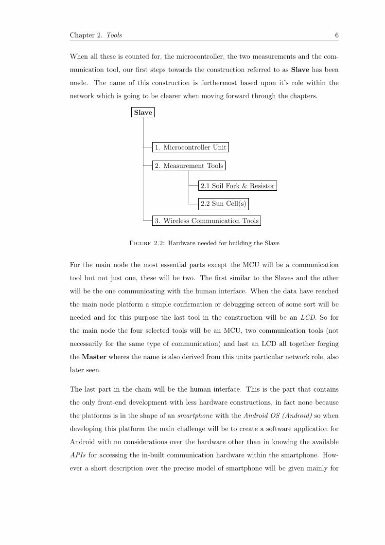
When all these is counted for, the microcontroller, the two measurements and the com-
munication tool, our first steps towards the construction referred to as Slave has been
made. The name of this construction is furthermost based upon it’s role within the
network which is going to be clearer when moving forward through the chapters.
Slave
1. Microcontroller Unit
2. Measurement Tools
2.1 Soil Fork & Resistor
2.2 Sun Cell(s)
3. Wireless Communication Tools
Figure 2.2: Hardware needed for building the Slave
For the main node the most essential parts except the MCU will be a communication
tool but not just one, these will be two. The first similar to the Slaves and the other
will be the one communicating with the human interface. When the data have reached
the main node platform a simple confirmation or debugging screen of some sort will be
needed and for this purpose the last tool in the construction will be an LCD. So for
the main node the four selected tools will be an MCU, two communication tools (not
necessarily for the same type of communication) and last an LCD all together forging
the Master wheres the name is also derived from this units particular network role, also
later seen.
The last part in the chain will be the human interface. This is the part that contains
the only front-end development with less hardware constructions, in fact none because
the platforms is in the shape of an smartphone with the Android OS (Android) so when
developing this platform the main challenge will be to create a software application for
Android with no considerations over the hardware other than in knowing the available
APIs for accessing the in-built communication hardware within the smartphone. How-
ever a short description over the precise model of smartphone will be given mainly for

Chapter 2. Tools 7
Master
1. Microcontroller Unit
2. Wireless Communication Module (to Slave)
3. Liquid Crystal Display
4. Wireless Communication Module (to Human Interface)
Figure 2.3: Hardware needed for building the Master
the difference that sometimes can occurs when dealing with application development for
Android.

Chapter 2. Tools 8
2.2 Hardware
2.2.1 Microcontroller Unit
The first selection of hardware was the microcontroller unit it is the most important
piece of hardware and can be seen as a glue between the rest of selected tools resulting
in that much of the other selections is based on the possibilities of what the MCU has
to offer.
In the case of the Slave a more lightweighted microcontroller is sufficient because the
data in the tasks of fetch, convert and communicate will be issued straight away with no
need for either storage or monitoring as in the case of the Master. So for these purposes
an 8-bit register sized ATmega328p from Atmel were chosen. The ATmega328p is a dual
in-line 28-pins microcontroller[1] that easily can be hooked onto a home brewed develop-
ment environment, e.g. a breadboard in combination with In-system programming (ISP)
interface for the start-up process (no fancy stuff is needed in that regard). However in the
aspect of time if one were to get away with this cheap setup some planning and consider-
ations must be taken over how to construct this development environment for not getting
stuck in a tiresome troubleshooting mess. The Master on the other hand needs to be a
little more advanced because, as earlier mentioned, it needs to display and store data.
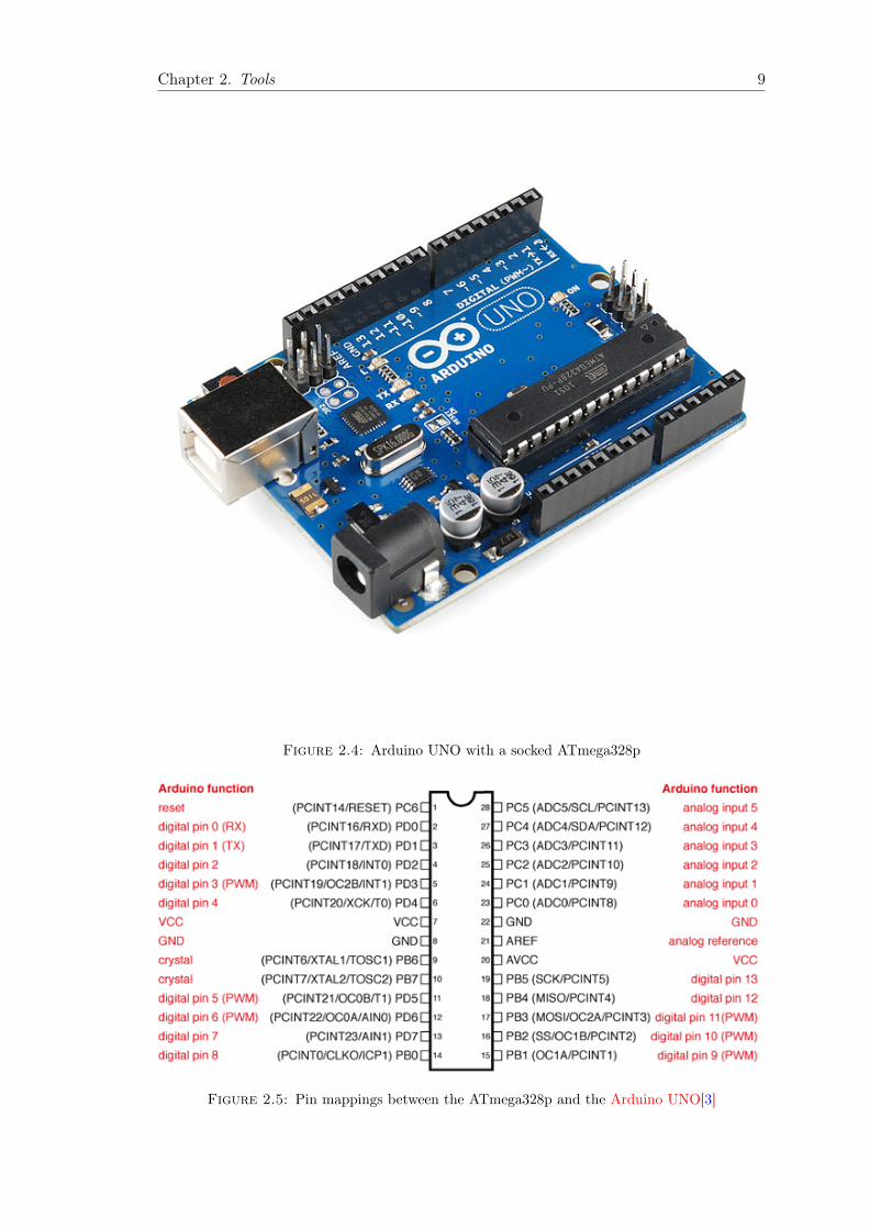
Therefore the more advanced built but easy-to-use Arduino UNO was selected. This
microcontroller board (hereafter referenced to as microcontoller unit) is build around
the ATmega328p[2] and encapsulate many of it’s properties, but comes with an simple
IDE including many useful APIs decreasing (in a huge sense) the development time. For
a comparison with the ATmega328p no work needs to be conducted in order for it to
run, only connect it to a computer and launch the IDE. So in the chain of platforms the
Arduino UNO will be the first that can confirm that correct data flows through or is
gathered by the Slave with another kind of certainty than as for the ATmega328p.
Chapter 2. Tools 9
Figure 2.4: Arduino UNO with a socked ATmega328p
Figure 2.5: Pin mappings between the ATmega328p and the Arduino UNO[3]

Chapter 2. Tools 10
There are also several options for plugging the ATmega328p onto a developing board
with debugging possibilities like the AVR Dragon 1 but as always one needs to make
the choice over price in contrast with developing time where the latter may have been
preferred reduced if the task at hand would be of a more critical nature (like hard real
time executions or many similar microcontrollers to be programmed).
Both the ATmega328p and Arduino UNO have the possibilities to measure soil moisture
and solar hours, which can be remembered if one would like to quickly test an outlined
method firstly on the Arduino UNO (which due to it’s simplicity is faster), although
the ATmega328p is the MCU that is going to do the actual measuring in the system.
This and many other similarities is good to keep track of when facing challenges in the
development because this particular obstacle may have already been removed on the
platform encapsulating the other microcontroller unit. As earlier mentioned the ADC
is going to be used for the measurement of soil moisture and this is supported by both
MCU[1][2]. The solar hours measurement could also be implemented in the same way
but here another approach was chosen. This approach is to use the interrupt on change
which can be attached to the solar cells and respond to different logical levels as the
voltage changes with the sun. This interrupt is also easy to enable from the default off
state with setting some software parameters codewise in the ATmega328p but the Ar-
duino UNO have embedded this function within it’s API so in that case it could become
a little bit trickier[1][4].
The power consumption varies between the Arduino UNO and the ATmega328p due
to their separate looks. The original thought is to place them in different electrical en-
vironments e.g. the Slave on a field of crops and the Master near a house. The Master
will be attached to a constant power source which is supported by the Arduino UNO
instantly, either through the power jack or from anUSB connector[2] this in contrast to
the Slave which is intended to run on an external accumulator with a little more config-
uring. If the Arduino UNO was to be unplugged or not fed with enough current from it’s
power source, that must at all time be 5V [2], it would cause a problem due to the fact
that data temporarily stored with Slave information could be erased affecting the system
as a whole, as we will later see not working. The Slave would not face this problem
because it’s sole purpose is to fetch and then forward data straight away as a dummy1See the Atmel Corporation official product website for more info.

Chapter 2. Tools 11
and if disabled it would not harm the network in any kind of. So the source of current
for the ATmega328p will not be as ideal as the one to the Arduino UNO. The source
of power can be accomplished by the possibility for the ATmega328p microcontroller to
work on voltages between 1.8− 5.5V and also to use the sleep mode tweaks available for
reducing power consumption when not measuring or communicating[1].
Also worth mentioning is the Universal Asynchronous Receiver/Transmitter (UART)
that have been important in the choosing of the above mentioned MCUs. This 8-bit
serial interface [5, p. 12] is supported by a huge amount of the hardware found on to-
day’s embedded market 2 and were in this work decided upon to be the default interface
between all peripherals in the Slave and Master part of the system. The UART can
without a handshake communicate through only two pins, often mentioned as the RX
for receiving data and TX for transmitting data [5, p. 44]. Support for this commu-
nication can be found on both microcontroller, the ATmega328p can issue an interrupt
when receiving the last bit of data[1] and the Arduino UNO have the same properties
but with an simple API found in it’s Serial library[6].
Figure 2.6: The Universal Serial Asynchronous Receive/Transmitter signal in actionseen through an oscilloscope. The in signal in yellow of 210 = 000000102 with the
replica out signal in blue.
2A quick search of the word "UART" on the popular website for electronics alibaba.com brings outa result 134 292 products at the time of this writing.
Chapter 2. Tools 12
2.2.2 Wireless Communication
The benefit of choosing a wireless communication over a wire is the result of a more
dynamic system, especially when less consideration over the terrain needs to be taken.
However the wireless communication have some drawbacks like an outsider trying to hack
the network without the need of interfering with a cable and in some cases packet losses
when placing the transmitter to far away from the receiver, but the priority in this work
have been to at first establish a working communication chain i.e. a system with three
separate parts - Slave, Master and a Human Interface talking with each other. This will
reflect the choices made in the regard of a quick launch over a secure featured network
not disregarding the possibility to the latter but seeing it as plus rather than a must.
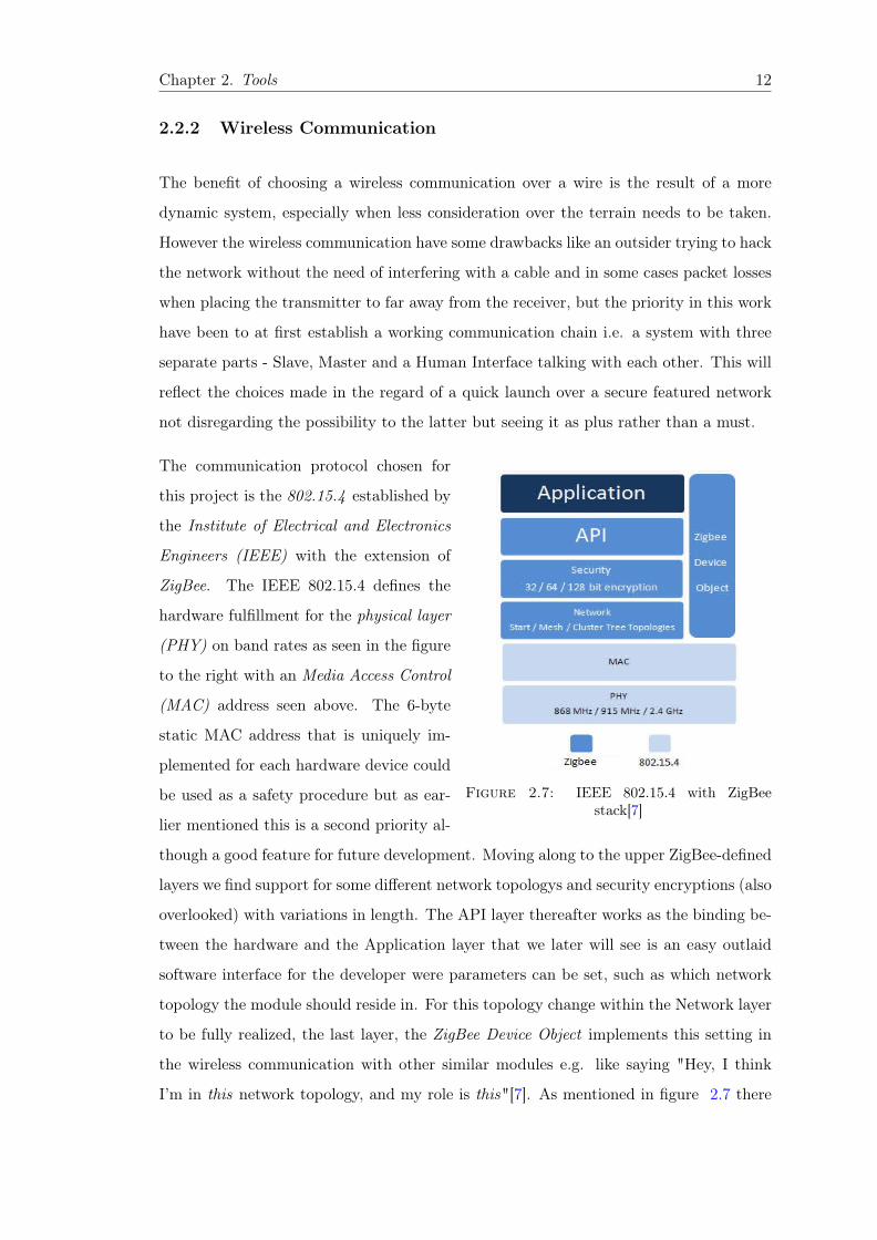
Figure 2.7: IEEE 802.15.4 with ZigBeestack[7]
The communication protocol chosen for
this project is the 802.15.4 established by
the Institute of Electrical and Electronics
Engineers (IEEE) with the extension of
ZigBee. The IEEE 802.15.4 defines the
hardware fulfillment for the physical layer
(PHY) on band rates as seen in the figure
to the right with an Media Access Control
(MAC) address seen above. The 6-byte
static MAC address that is uniquely im-
plemented for each hardware device could
be used as a safety procedure but as ear-
lier mentioned this is a second priority al-
though a good feature for future development. Moving along to the upper ZigBee-defined
layers we find support for some different network topologys and security encryptions (also
overlooked) with variations in length. The API layer thereafter works as the binding be-
tween the hardware and the Application layer that we later will see is an easy outlaid
software interface for the developer were parameters can be set, such as which network
topology the module should reside in. For this topology change within the Network layer
to be fully realized, the last layer, the ZigBee Device Object implements this setting in
the wireless communication with other similar modules e.g. like saying "Hey, I think
I’m in this network topology, and my role is this"[7]. As mentioned in figure 2.7 there
Chapter 2. Tools 13
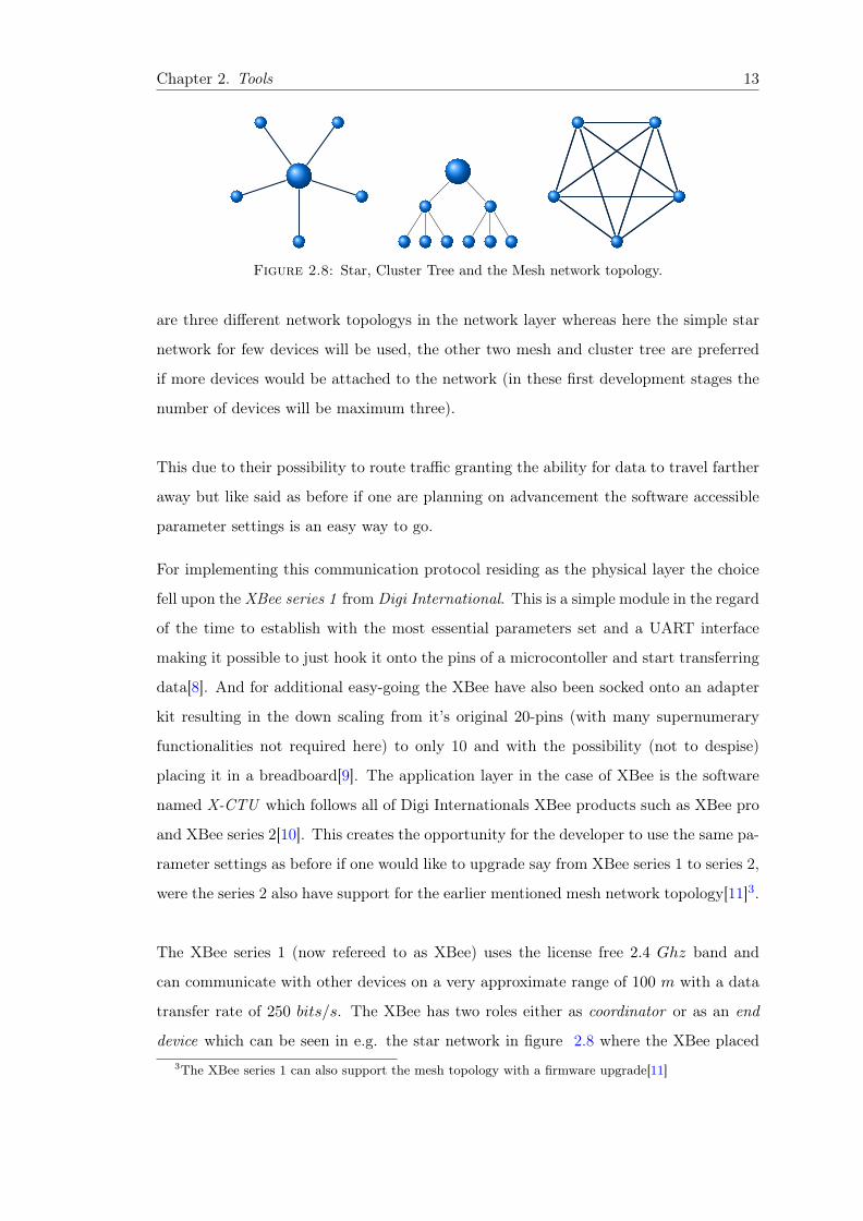
Figure 2.8: Star, Cluster Tree and the Mesh network topology.
are three different network topologys in the network layer whereas here the simple star
network for few devices will be used, the other two mesh and cluster tree are preferred
if more devices would be attached to the network (in these first development stages the
number of devices will be maximum three).
This due to their possibility to route traffic granting the ability for data to travel farther
away but like said as before if one are planning on advancement the software accessible
parameter settings is an easy way to go.
For implementing this communication protocol residing as the physical layer the choice
fell upon the XBee series 1 from Digi International. This is a simple module in the regard
of the time to establish with the most essential parameters set and a UART interface
making it possible to just hook it onto the pins of a microcontoller and start transferring
data[8]. And for additional easy-going the XBee have also been socked onto an adapter
kit resulting in the down scaling from it’s original 20-pins (with many supernumerary
functionalities not required here) to only 10 and with the possibility (not to despise)
placing it in a breadboard[9]. The application layer in the case of XBee is the software
named X-CTU which follows all of Digi Internationals XBee products such as XBee pro
and XBee series 2[10]. This creates the opportunity for the developer to use the same pa-
rameter settings as before if one would like to upgrade say from XBee series 1 to series 2,
were the series 2 also have support for the earlier mentioned mesh network topology[11]3.
The XBee series 1 (now refereed to as XBee) uses the license free 2.4 Ghz band and
can communicate with other devices on a very approximate range of 100 m with a data
transfer rate of 250 bits/s. The XBee has two roles either as coordinator or as an end
device which can be seen in e.g. the star network in figure 2.8 where the XBee placed3The XBee series 1 can also support the mesh topology with a firmware upgrade[11]

Chapter 2. Tools 14
in the middle is a coordinator and the outer placed XBees take on the role as end de-
vices. If using an XBee straight from the factory with it’s default settings the XBee is
set as an end device with peer-to-peer network establishments meaning all XBees in the
network listens and receive traffic and if one were to send all other were to fetch. With
the coordinator parameter the XBees can be configured to receive and send data within
certain time intervals which grants the possibility for the XBee to e.g. sleep when not
being an active part of the network. This is an interesting aspect if one would like to
reduce the power consumption in say the Slave running on the accumulator.
Other possible options could be to enable the sleep pin in X-CTU and attach it to a
microcontroller unit telling it to sleep when asserting the sleep pin high or vice verse for
wakening it up.
The XBees with the ZigBee protocol will be the first part of the communication chain i.e.
between the Slave and Master platforms. The support for UART communication in the
on-mounted adapter kit will simplify the installment which is just to attach the TX and
RX pin as described in chapter 3 and 4 onto the same pins found on the MCU but in the
other way around of course. The Master will be placed in the middle of the star network
topology in the case of more Slaves to be launched set as a coordinator. The Slave(s) will
be set as end-devices so that no interference would happen if the coordinator (Master)
were to be given wake up signals to a Slave set in the cyclic sleep mode. The cyclic sleep
mode were the Slave is sleeping a while decided in advance and then woken up by first
seeing if data is available at the coordinator and if so stay awake while fetching it[8].
The current consumption on the XBee is rather droughtful when communicating i.e.
receive and transmit, about 50 mA is required[8] which can cause certain problems in
the Slave construction. The ideal scenario would have been if the whole Slave went to
sleep when not being required and woken if so. This would create an circuit in which
the only two components (the ATmega328p and XBee) that actually consumed current
consumed approximately 11 µA[8][1] when sleeping. However something must waken the
system and this is not possible since the XBee only can be woken by an internal call
e.g. sleep pin high and not by an external radio frequency request. So the options that
would take one closest to a low power consuming Slave is combining the XBees cyclic
sleep with the ATmega328p sleep modes and if a packet were to be received it would be

Chapter 2. Tools 15
fetched when the XBee checked the line and if so waking the XBee which in turn woke
the ATmega328p making it the component kick-starting the Slave.
Figure 2.9: XBee placed on top of an adapter kit reducing the 20 pins to 10[9] werethe only needed pins for running the device is outlaid, the sleep pin is found uppermost
from Common Ground.
Chapter 2. Tools 16
The other wireless network communication is the one between the Master and the Hu-
man Interface, this one is Bluetooth and were chosen based upon the support found in
almost all smartphones. To access the Bluetooth hardware device within the smartphone
a simple structure of API calls is issued[12] but for mounting it onto a microcontroller
the easiest way is to buy some external hardware as in this case. The tool used will the
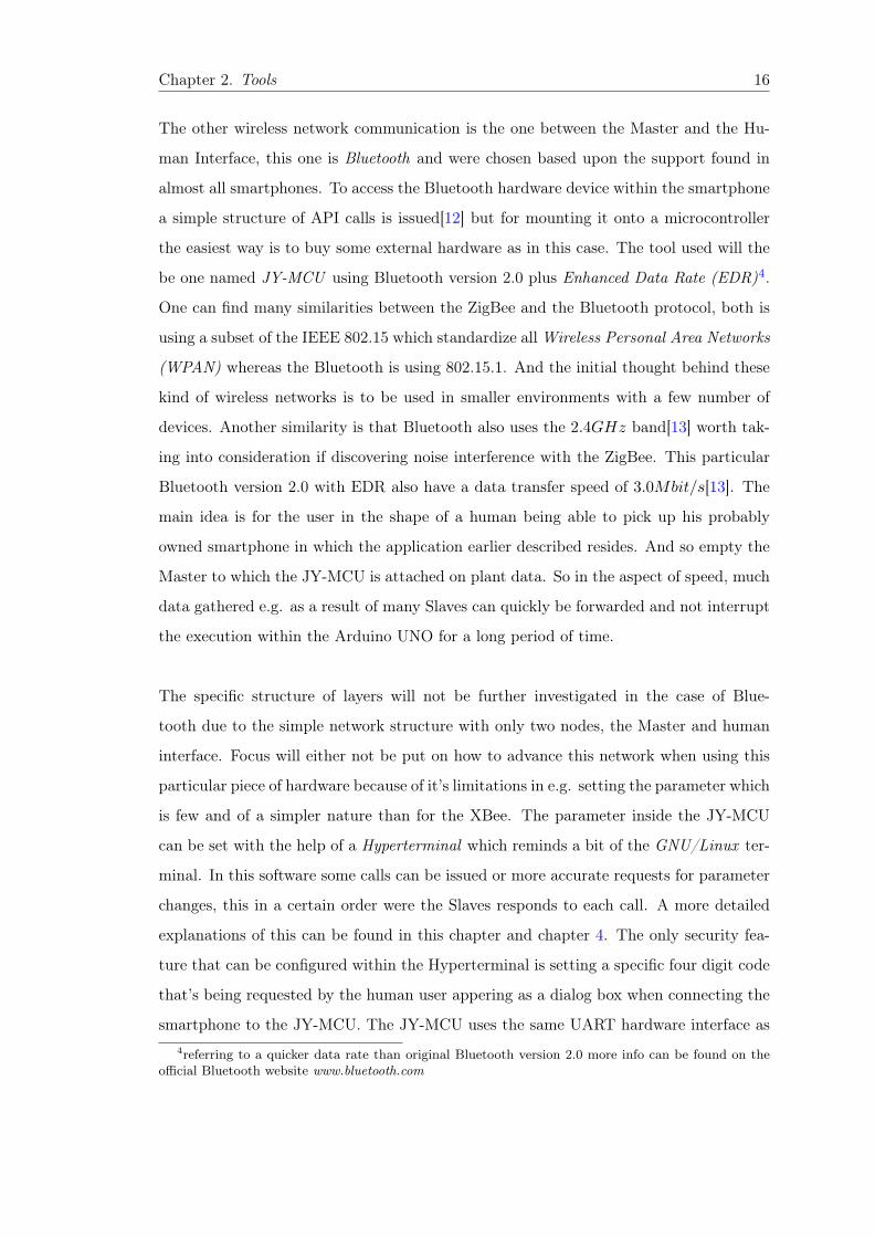
be one named JY-MCU using Bluetooth version 2.0 plus Enhanced Data Rate (EDR)4.
One can find many similarities between the ZigBee and the Bluetooth protocol, both is
using a subset of the IEEE 802.15 which standardize all Wireless Personal Area Networks
(WPAN) whereas the Bluetooth is using 802.15.1. And the initial thought behind these
kind of wireless networks is to be used in smaller environments with a few number of
devices. Another similarity is that Bluetooth also uses the 2.4GHz band[13] worth tak-
ing into consideration if discovering noise interference with the ZigBee. This particular
Bluetooth version 2.0 with EDR also have a data transfer speed of 3.0Mbit/s[13]. The
main idea is for the user in the shape of a human being able to pick up his probably
owned smartphone in which the application earlier described resides. And so empty the
Master to which the JY-MCU is attached on plant data. So in the aspect of speed, much
data gathered e.g. as a result of many Slaves can quickly be forwarded and not interrupt
the execution within the Arduino UNO for a long period of time.
The specific structure of layers will not be further investigated in the case of Blue-
tooth due to the simple network structure with only two nodes, the Master and human
interface. Focus will either not be put on how to advance this network when using this
particular piece of hardware because of it’s limitations in e.g. setting the parameter which
is few and of a simpler nature than for the XBee. The parameter inside the JY-MCU
can be set with the help of a Hyperterminal which reminds a bit of the GNU/Linux ter-
minal. In this software some calls can be issued or more accurate requests for parameter
changes, this in a certain order were the Slaves responds to each call. A more detailed
explanations of this can be found in this chapter and chapter 4. The only security fea-
ture that can be configured within the Hyperterminal is setting a specific four digit code
that’s being requested by the human user appering as a dialog box when connecting the
smartphone to the JY-MCU. The JY-MCU uses the same UART hardware interface as4referring to a quicker data rate than original Bluetooth version 2.0 more info can be found on the
official Bluetooth website www.bluetooth.com

Chapter 2. Tools 17
for the XBee on adapter kit with the TX and RX for transmitting and receiving data
sent from the Arduino UNO making it very easy to install.
Figure 2.10: The JY-MCU Bluetooth module.
Chapter 2. Tools 18
2.2.3 Measurement tools and LCD
When measuring the soil moisture as explained before a soil fork in combination with a
resistance is used, where the soil fork essentially is two metal plates pricked down into
the ground with a space between them were current is trying to flow from one side to the
other. And the major thing here is to notice is the material of the metal plates because
it could oxidize, if one were to use this material for longer periods of time a rust layer
easily could appear on the metal reducing the ability for the metal to conduct electricity.
For starters this hasn’t been taken into consideration when developing. But as we later
will see the resolution of the ADC value, constructed from an ideal scenario fetched from
ground, will change due to the level of rust thereby said the materials used here is not
good for a permanent solution but enough for testing the methodology. When picking
the solar cell it must reflect the voltage levels and for a guideline the transistor-transistor
logic (TTL) 5 levels is used, these declare that a logic 0 is between 0 − 0.8V and 1 is
between 2 − 5 V were the level between 0.8 − 2 V is undefined. For fulfilling this scale
two solar cells have been connected in serial, each of 2V . The logical levels in the AT-
mega328p doesn’t follow the TTL to the letter[1] but the guidelines is enough and if one
were to connect the solar cells to the interrupt pin the MCU would react to the light
on/off by a flashlight used as a representation of the sun in a test environment which is
sufficient.
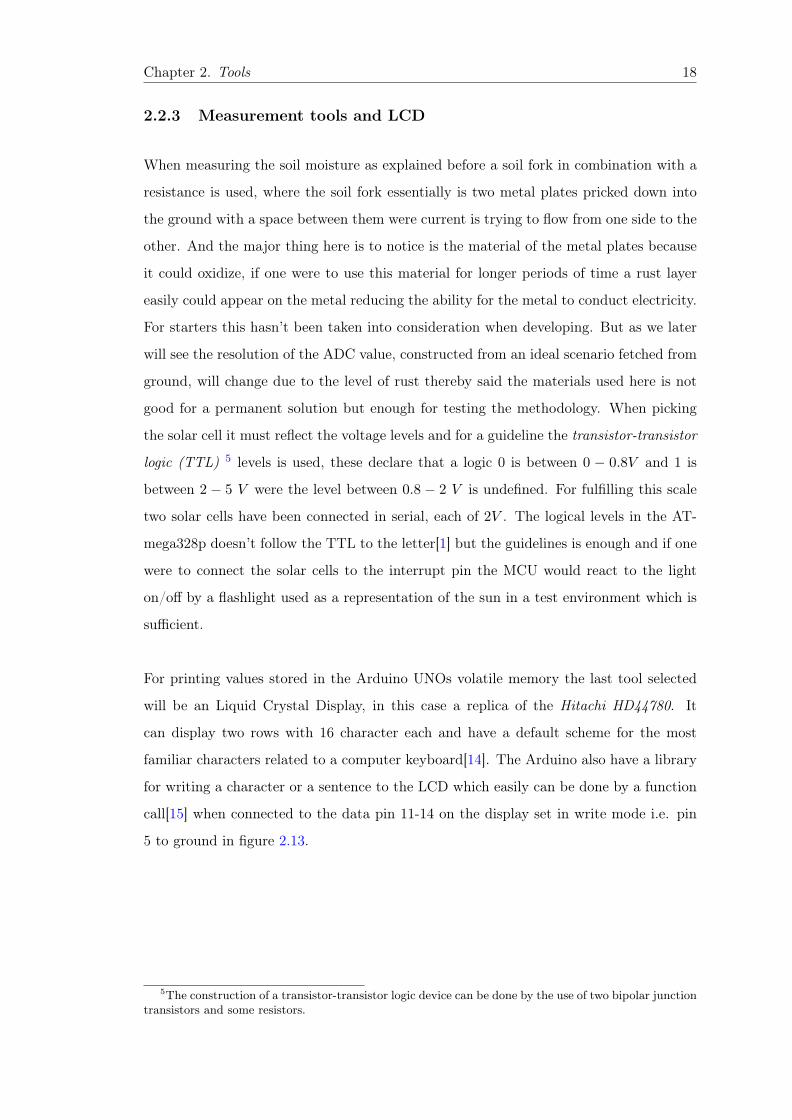
For printing values stored in the Arduino UNOs volatile memory the last tool selected
will be an Liquid Crystal Display, in this case a replica of the Hitachi HD44780. It
can display two rows with 16 character each and have a default scheme for the most
familiar characters related to a computer keyboard[14]. The Arduino also have a library
for writing a character or a sentence to the LCD which easily can be done by a function
call[15] when connected to the data pin 11-14 on the display set in write mode i.e. pin
5 to ground in figure 2.13.
5The construction of a transistor-transistor logic device can be done by the use of two bipolar junctiontransistors and some resistors.

Chapter 2. Tools 19
Figure 2.11: Soil fork with two metal plates
Figure 2.12: One sun cell of 2V
Figure 2.13: LCD with used pins outlaid.

Chapter 2. Tools 20
2.3 Software
The software can be seen through three different perspectives where the most basic soft-
ware developments starts at the Slave platform with the language of C and is going forth
with C++ until reaching the Human Interface were all software is written in JAVA. Tree
different software approaches on three different platforms each with it’s own languages.
2.3.1 C programming on the Slave platform
The most light development environment is the one used with the ATmega328p in the
Slave platform. The basic avr toolchain will here be used, were avr is the name of the
series in which the ATmega328p belongs distributed by Atmel. Within this toolchain one
can find a compiler built on top of the GNU C compiler named avr-gcc, a library named
avr-libc and a tool called avrdude for ISP programming as well as other thoughtfully
handheld embedded development tools. For the most essential software one could issue
the following command within a bash terminal found in most of today’s GNU/Linux
OSes:
sudo $PKMANAGER avr-gcc avr-binutils avr-libc avr-gdb avrdude
were the variable $PKMANAGER is to be set after the distro specific package manager.
Together with a text editor all tools needed for starting the software development for the
ATmega328p have now been outlined. But before starting it can be a good idea to do
some preparations especially when it could become tiresome remembering all options and
hierarchy of the compiler chain. Therefore the following makefile have been constructed
for simplification:

Chapter 2. Tools 21
all:
whoami
avr-gcc -Os -DF_CPU=16000000UL -mmcu=atmega328p -c -o Create.o slave.c
avr-gcc -mmcu=atmega328p Create.o -o Create
avr-objcopy -O ihex -R .eeprom Create Create.hex
avrdude -p m328p -P usb -c avrispmkII -U flash:w:Create.hex $FUSEOPTIONS
clean:
rm -rf "Create.o" "Create" "Create.hex"
Listing 2.1: Makefile for compiling and writing code to the ATmega328p

Chapter 2. Tools 22
Due to the need of running with root privileges when using the avrdude a quick feedback
on who is running the makefile is first given reducing fault searching if occurred. After
that the compiling is under way were several flags that must be declared. Some can
easily be read-out e.g. on the first compiler line, type of microcontroller speed 16 MHz
and type of microcontoller ATmega328p also seen on the second line, the other flags like
the optimization for size can be viewed in the man-pages for avr-gcc and avr-objcopy 6.
The brief description of what happens in the compiling process is first a creation of
the object file Create.o encapsulating the man written C code in machine language
forging a linker that together with avr-libc can create the binary although in this case
not in the form of zeros and ones but in hexadecimal (exactly the same information given
but with another radix) and describe which kind of memory type the file should reside
in on the target platform, in this case Electrically Erasable Programmable Read Only
Memory (EEPROM). The Create.hex will then be used in the avrdude programming of
the ATmega328p, this is done with the AVRISP mkII device granting the ISP interface7.
The last variable before a cleanup of not longer needed files is the $FUSEOPTIONS this
variable is optional and changes the fuse settings within the ATmega328p which will be
needed when changing the internal oscillation to an external crystal seen later in chapter
3.
2.3.2 Arduino programming on the Master platform
When programming the Arduino UNO it’s easiest to use the integrated development
environment (IDE) referenced to only as Arduino Software which can be seen as a sim-
plification of the AVR toolchain in combination with C++. The IDE is foremost built
for people with no experience from the software engineering field and a broad spectra
of example code is included in the Arduino software which can be launched straight
away[16]. The only drawback is that special use of functions within the ATmega328p
like the external interrupt is already hooked into the application user interface (API) i.e.
if one would like to combine the default Arduino C++ like code with avr-libc it could
cause a compiler error.6With use of the command man in the bash terminal before almost all standard GNU/Linux program
the user will be given a list of options (flags).7For a longer description of this particular device see http://www.atmel.com/tools/avrispmkii.
aspx

Chapter 2. Tools 23
Figure 2.14: Self explained example program in the Arduino Software.
The main structure of an Arduino program is two functions, the first setup() is the
initialization were stuff needed through the rest of microcontroller execution is declared,
like a pin to be input or output or calling upon an API starting the LCD with 16 columns
and two rows like lcd.begin(16, 2). The next function loop() is essentially were ev-
erything happens over and over again precis as the name hints and were most of the
coding will be done.
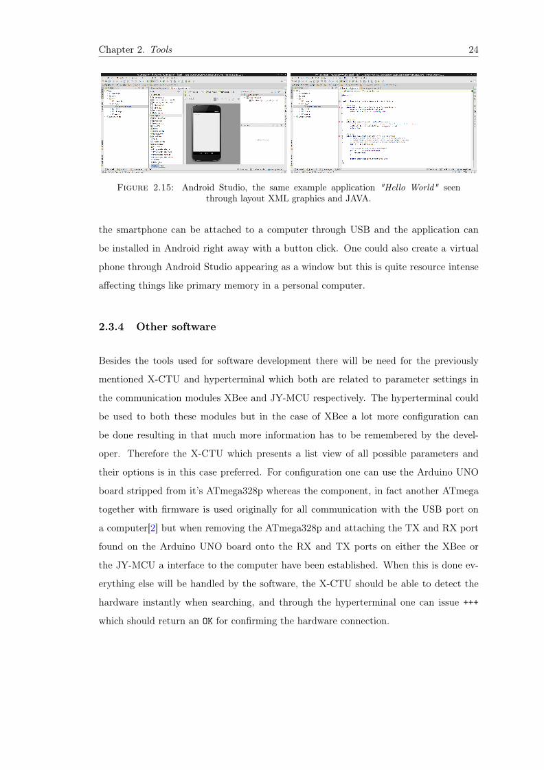
2.3.3 Android application development on a smartphone
The last IDE for development of software used in the last platform the Human Interface
will be Android Studio. It’s the main IDE for most of the application development within
Android were everything is written in JAVA. Here will also the most complex (from the
perspective of an embedded developer) code be written e.g. this is the only platform
supporting multithreading. However Google like Arduino have a huge database of exam-
ple code and tips on how to get the most out of ones specific hardware device[17]. In this
work the exact platform will be Samsung Galaxy S3 and code written will furthermost be
custom to this smartphone worth noting is thing like the screen size which is 4.8 inches
wide and the Android version 4.3 Jelly Bean. Just as in the case of the Arduino UNO
Chapter 2. Tools 24
Figure 2.15: Android Studio, the same example application "Hello World" seenthrough layout XML graphics and JAVA.
the smartphone can be attached to a computer through USB and the application can
be installed in Android right away with a button click. One could also create a virtual
phone through Android Studio appearing as a window but this is quite resource intense
affecting things like primary memory in a personal computer.
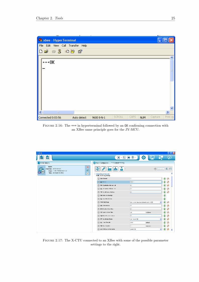
2.3.4 Other software
Besides the tools used for software development there will be need for the previously
mentioned X-CTU and hyperterminal which both are related to parameter settings in
the communication modules XBee and JY-MCU respectively. The hyperterminal could
be used to both these modules but in the case of XBee a lot more configuration can
be done resulting in that much more information has to be remembered by the devel-
oper. Therefore the X-CTU which presents a list view of all possible parameters and
their options is in this case preferred. For configuration one can use the Arduino UNO
board stripped from it’s ATmega328p whereas the component, in fact another ATmega
together with firmware is used originally for all communication with the USB port on
a computer[2] but when removing the ATmega328p and attaching the TX and RX port
found on the Arduino UNO board onto the RX and TX ports on either the XBee or
the JY-MCU a interface to the computer have been established. When this is done ev-
erything else will be handled by the software, the X-CTU should be able to detect the
hardware instantly when searching, and through the hyperterminal one can issue +++
which should return an OK for confirming the hardware connection.
Chapter 2. Tools 25
Figure 2.16: The +++ in hyperterminal followed by an OK confirming connection withan XBee same principle goes for the JY-MCU.
Figure 2.17: The X-CTU connected to an XBee with some of the possible parametersettings to the right.
Chapter 3
3. Data Acquisition System
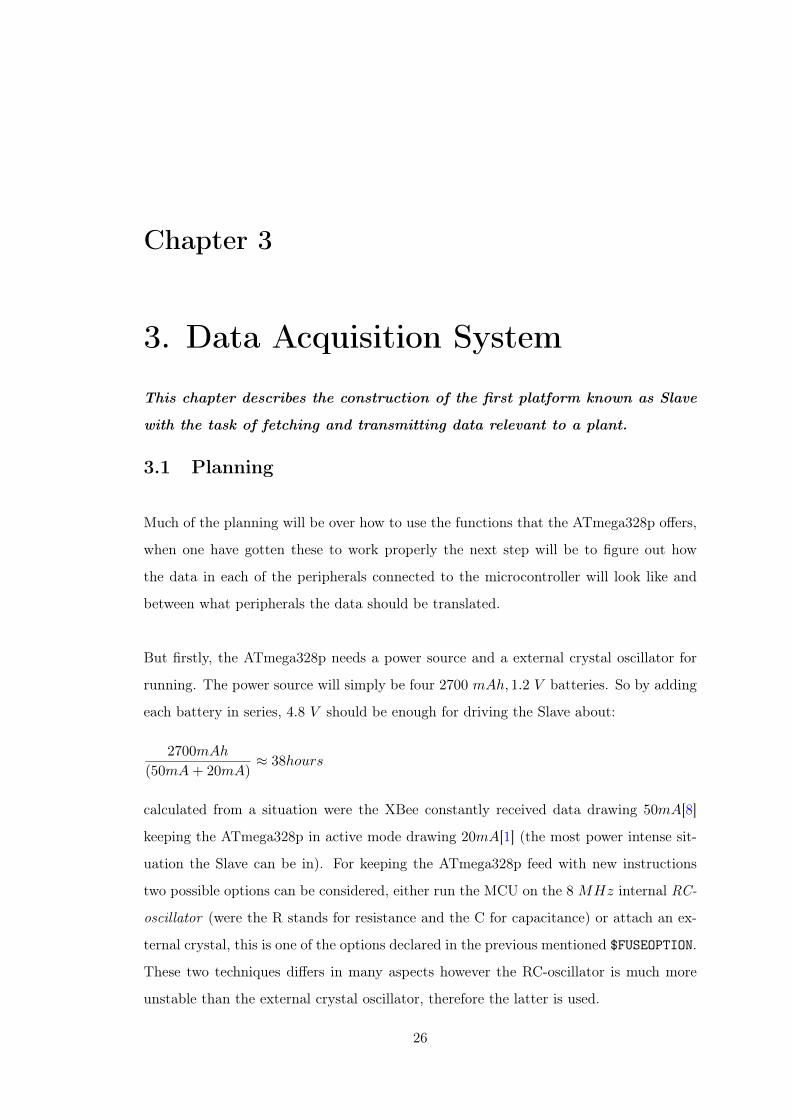
This chapter describes the construction of the first platform known as Slave
with the task of fetching and transmitting data relevant to a plant.
3.1 Planning
Much of the planning will be over how to use the functions that the ATmega328p offers,
when one have gotten these to work properly the next step will be to figure out how
the data in each of the peripherals connected to the microcontroller will look like and
between what peripherals the data should be translated.
But firstly, the ATmega328p needs a power source and a external crystal oscillator for
running. The power source will simply be four 2700 mAh, 1.2 V batteries. So by adding
each battery in series, 4.8 V should be enough for driving the Slave about:
2700mAh
(50mA+ 20mA)≈ 38hours
calculated from a situation were the XBee constantly received data drawing 50mA[8]
keeping the ATmega328p in active mode drawing 20mA[1] (the most power intense sit-
uation the Slave can be in). For keeping the ATmega328p feed with new instructions
two possible options can be considered, either run the MCU on the 8 MHz internal RC-
oscillator (were the R stands for resistance and the C for capacitance) or attach an ex-
ternal crystal, this is one of the options declared in the previous mentioned $FUSEOPTION.
These two techniques differs in many aspects however the RC-oscillator is much more
unstable than the external crystal oscillator, therefore the latter is used.
26
Chapter 3. Data Acquisition System 27
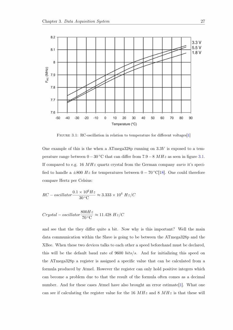
Figure 3.1: RC-oscillation in relation to temperature for different voltages[1]
One example of this is the when a ATmega328p running on 3.3V is exposed to a tem-
perature range between 0− 30 C that can differ from 7.9− 8 MHz as seen in figure 3.1.
If compared to e.g. 16 MHz quartz crystal from the German company auris it’s speci-
fied to handle a ±800 Hz for temperatures between 0 − 70 C[18]. One could therefore
compare Hertz per Celsius:
RC − oscillator0.1 × 106Hz
30 C≈ 3.333 × 10⁴ Hz/C
Crystal − oscillator800Hz
70 C≈ 11.428 Hz/C
and see that the they differ quite a bit. Now why is this important? Well the main
data communication within the Slave is going to be between the ATmega328p and the
XBee. When these two devices talks to each other a speed beforehand must be declared,
this will be the default baud rate of 9600 bits/s. And for initializing this speed on
the ATmega328p a register is assigned a specific value that can be calculated from a
formula produced by Atmel. However the register can only hold positive integers which
can become a problem due to that the result of the formula often comes as a decimal
number. And for these cases Atmel have also brought an error estimate[1]. What one
can see if calculating the register value for the 16 MHz and 8 MHz is that these will

Chapter 3. Data Acquisition System 28
give almost the exact same error estimate, the formula from Atmel for the register value
is outlined as follows:
Chosen Frequency
16 ×Baud Rate− 1 = Register V alue (3.1)
Were the register value rounded to the first positive integer will be 51 and 103 for the
8 MHz and 16 MHz respectively. These will then when rephrased the formula as:
Chosen Frequency
16 × (Register V alue+ 1)= Baud Rate (3.2)
give one identical baud rate value of approximate 9615.3846 bits/s. And the error esti-
mate will result in when compared against the desired baud of 9600 bits/s be:
(9615.3846
9600− 1) × 100 ≈ 0.16%errorrate
Which is a pretty small number reflecting the no difference between the techniques. But
if instead the chosen frequency would drop for the RC-oscillator from 8 − 7.9Mhz with
a temperature change it could lead to register value of 50, given the approximate baud
rate of 9681.3725 with an error estimate of:
(9681.3725
9600− 1) × 100 ≈ 0.85%errorrate
Almost one percent, a much higher risk for the communication to falter, like a bit gone
missing with no receive interrupt triggered for the asynchronous mode were it’s supposed
to count in all bits that will be an 8-bits message and 1 stop bit. So the choice of an
external 16Mhz quartz crystal has been made in the regard of reducing the possible
communication error.
Figure 3.2: ISP connector thatcan be mounted with e.g. a ISP
cable
When the power source and oscillator is decided it could
be a good idea to plan for a confirmation Light Emitting
Diode (LED), simply a red lamp connected to one of the
ATmega328p pins that can be lighten in the early stages
of the development helping the developer not just con-
firm that the ATmega328p is running but could also be
called from different places in the C code for confirming

Chapter 3. Data Acquisition System 29
e.g. correct function calls. This as well as an ISP connector of simply 6 pins which can
be mounted as seen in figure 3.2.
Now that one have the tools for powering, programming and confirming that the AT-
mega328p is alive it can be good to reflect upon what kind of data that’s begin handled
by the Slave. As mentioned it will be the Analog-to-Digital converter that’s going to
fetch the value of moisture in the soil, this value have a 10-bit resolution[1]. The other
measurement of sun time will start counting hours 1 and set a bit which represents the
the sun mode up/down together fitting a maximum of 4-bits, were bit 0-2 will be at
most 7 hours and bit 3 will be zero for sun down and one for vice verse. The data shall
then be forwarded to the XBee implicating that it must fit a UART packages i.e. a
message on 8-bits. The choice have also been made to reserve the highest nibble, bit 4-7
for a specific measurement description. The description will for now simply be a specific
number representing each measurement, one for the measurement of soil moisture and
two for the measurement of sun time. Except for the two measurements a last UART
signal will be forwarded which simply contains a number unique for each Slave, simply
called Slave number. The three packages can be seen is outlined as follows starting with
the Slave number, then the soil measurement and ending with the sun time measurement:
0 1 2 3 4 5 6 7
Slave number
Soil Moisture Value Measurement Description
Sun Time Mode Measurement Description
Figure 3.3: The whole Slave package sent in parts of 8-bits via UART starting withthe Slave number.
Here one may notice that the ADC value returned in 10-bits won’t fit 4-bits, however
this can easily be solved by constructing a wet and dryness scale of ten levels by dividing
the ADC value gathered and using the fact that some data types misses the ability to
store decimal numbers, they plainly becomes decapitated from the rest of the number.
The following formula can therefore be used:
ADC V alue
100= Wet/Dry scale (3.3)
1The moisture change in soil counted in seconds or minutes from a gardeners perspective have beenguessed not to be that important.

Chapter 3. Data Acquisition System 30
Now one also have all that is needed to declare the $FUSEOPTION variable, the variable
is just three extra flags in the end of the avrdude command but can be good to keep
separate for a reminder of what running environment chosen for the ATmega328p. Here
a separate bash script is used were $FUSEOPTION is used as a global variable:
#!/bin/bash
$FUSEOPTION=$(-U lfuse:w:0xd7:m -U hfuse:w:0xf1:m -U efuse:w:0xff:m)
Listing 3.1: Fuseoption variable
Here the register of low, high and extended fuse byte registers is set to match the options
of full-swing crystal with no additional start up time and a bootstrap word memory
size of 2048, preserving the eeprom memory through a memory chip-erase (granting the
possibility to store data in a more hard disk drive similar memory environment)[1] 2.
2There are several fuse calculators out there, for a more detailed description with direct fuse optionsin hexadecimal numbers one could visit the website www.engbedded.com(2014-05-02) were the AVR FuseCalculator is found on the first page.

Chapter 3. Data Acquisition System 31
3.2 Building
The first construction will be the base circuit constructed from the ideas that originated
in the planning phase. This circuit can be seen in figure 3.4 and will be enough for
testing if the ATmega328p is running. Here PB1(within the cuboid ATmega328) can be
set high resulting (if no faults occurs) in a lighted red colored LED.
Figure 3.4: Slave base circuit with an external crystal, a red LEDas well as an ISP interface.
3.2.1 Establishing a wireless network connection
The reason for as soon as possible putting the XBee in place is for creating a link with
the outside world. The X-CTU software has the possibility to send and receive messages
through an in-built terminal so one just have to connect an additional XBee to the
computer and a first link is established. From a hardware perspective this construction
is quite simple, connect the RX and TX pin of the ATmega328p to the TX and RX pin
on the XBee respectively, then the XBee only needs a power source and everything is set.
Codewise the ATmega328p should before trying to communicate be initialized with the
register value from formula 3.1 defining the baud rate, set the UART signal format to 8
message bits and 1 stop bit and enable the interrupt to trigger when all bits in a receive
UART signal is counted for on the RX pin, thus enabling the asynchronous mode. Then
it can be smart to construct three separate functions one with the purpose of receiving
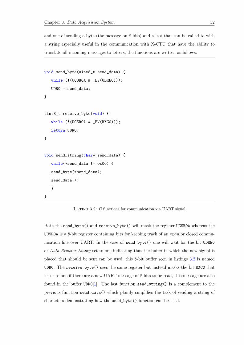
Chapter 3. Data Acquisition System 32
and one of sending a byte (the message on 8-bits) and a last that can be called to with
a string especially useful in the communication with X-CTU that have the ability to
translate all incoming massages to letters, the functions are written as follows:
void send_byte(uint8_t send_data)
while (!(UCSR0A & _BV(UDRE0)));
UDR0 = send_data;
uint8_t receive_byte(void)
while (!(UCSR0A & _BV(RXC0)));
return UDR0;
void send_string(char* send_data)
while(*send_data != 0x00)
send_byte(*send_data);
send_data++;
Listing 3.2: C functions for communication via UART signal
Both the send_byte() and receive_byte() will mask the register UCSR0A whereas the
UCSR0A is a 8-bit register containing bits for keeping track of an open or closed commu-
nication line over UART. In the case of send_byte() one will wait for the bit UDRE0
or Data Register Empty set to one indicating that the buffer in which the new signal is
placed that should be sent can be used, this 8-bit buffer seen in listings 3.2 is named
UDR0. The receive_byte() uses the same register but instead masks the bit RXC0 that
is set to one if there are a new UART message of 8-bits to be read, this message are also
found in the buffer UDR0[1]. The last function send_string() is a complement to the
previous function send_data() which plainly simplifies the task of sending a string of
characters demonstrating how the send_byte() function can be used.

Chapter 3. Data Acquisition System 33
3.2.2 The measurements tools
A construction of the Analog-to-Digital used as the main principle behind the measure-
ment of soil moisture can easily be created from one additional resistor in series with the
soil fork, were the soil fork in a theoretical sense represents the the variable load based
upon the current flowing through the soil as seen in figure 3.5.
Figure 3.5: The voltage division sampled byPIN ADC0 found on the ATmega328p micro-
controller.
The formula for the voltage level on ADC0
in figure 3.5 is thus:
R2
R1 +R2= ADC0
Where the resistance in R2 is given by the
water level within the soil i.e. how eas-
ily will current flow through the soil. The
value is then used in formula 3.3 to create
a number that can be forwarded through
the chain of platforms. So essentially after
the Slave have forwarded it’s Slave number
after the scheme in figure 3.3 a next pack-
age can be forged through simply calling:
send_byte(0x10+(mval/0x64)) from list-
ings 3.2 that for e.g. mval set to 101110
would send 10010 + 1010 = 11010 = 000110012. For initializing and fetching the value
from the ADC i.e creating the mval one largely has to keep track of an multiplexer for
reaching the right pin (here ADC0). Starting the Analog-to-Digital converter in hardware
and keeping track of the voltage reference that in figure 3.5 would be +4.8V . When
performing the actual measuring a bit has to be set in the register named ADCSCR[1],
then some looping (similar to the listing 3.2) until another bit in the same register is set
confirming that the 10 bits value can be read[1].
The next measurement of sun time will be two sun cells in series that in theory can
switch between a voltage of low-high, 0 − 4V connected to one of the external ISR pins
of the ATmega328p. So after a pretty simple hardware installation the initialization of
Chapter 3. Data Acquisition System 34
software can begin and precise as before all settings is written to a register, here en-
abling an interrupt each time a voltage change occurs on the chosen pin[1]. So the whole
idea behind this measurement is to first start a counter when the voltage triggers the
interrupt on high, then the Master fetches data say about two hours after the counter
have started, resulting in a sun time of 2 in figure 3.3. The counter is then off until the
next pin change interrupt occurs and then stops again when the Master fetches the data
returning the value of sun time. The counter is easily started with an separate ISR the
hardest part is trying to get the as close as possible to the real time of hours (because
seconds and minutes is overlooked). So firstly the 16 Mhz external crystal will be the
speed in which the Slave MCU is working on this means that:
1
16 × 106= 62.5 ns
Is the time it takes for one instruction to be read and could be very hard to work with if
one were trying to aim for an hour. So when configuring the timer ISR two register will
be the used for downscaling this speed with the help of an predetermined frequency that
corresponds to e.g. a second or an millisecond. The formula used for this configuring
reminds a bit of the formula 3.1 for the Universal Asynchronous Receiver/Transmitter
and is also set into a register, outlined as follows[1]:
Input Frequency
( Prescaler
Target Frequency
)− 1 = Register Counter V alue (3.4)
Here the Input Frequency will be the one given from the external oscillator of 16 MHz,
the Prescaler is the value used for prescaling down the Input Frequency and here the
middle value of 64 is used[1]. The Target Frequency is essentially the one aimed for and
when counting the value of Register Counter Value of two different times i.e. seconds
(1 Hz) and milliseconds (1 kHz) the result will be:

Chapter 3. Data Acquisition System 35
16 × 106
64
1
− 1 = 249999 as Register Counter V alue
16 × 106
64
1 × 10³
− 1 = 249 as Register Counter V alue
The first value of 249999 can quickly be rejected due to the Register Counter Values
ability to only store a number of maximum 8 bits. So when issuing the command
OCR0A |= 249 the timer will tick 1 millisecond i.e. issuing the timer ISR. And from
here the counting of seconds can begin by counting up one additional second counter
with the possibility to store 32 bits in other word approximate 199 × 104 hours shown
in listings 3.3. When forwarding this value a division with the value 3600 will therefore
first be conducted granting hours and is in fact the Sun Time value placed in the UART
signal seen before in figure 3.3.
ISR( TIMER0_COMPA_vect )
++counter;
if(counter==1000)
++second;
counter = 0;
Listing 3.3: Count one second in the timer ISR

Chapter 3. Data Acquisition System 36
3.3 Summation
A brief summation of the Slave’s tasks with the right components:
A Measure the soil moisture with a current flowing through a soil fork and measure the
sun time with two sun cells in series upon which light is reflected (or not).
B Be controlled by the microprocessor ATmega328p and consume energy from a battery
pack.
C Handles all communication with the outside world as well as knowing when to wake up
the system with the use of XBee implementing the wireless ZigBee communication.
Figure 3.6: The final construction of the Slave, 1. ATmega328p, 2. XBee (with anISP connector under and a RED led next to it), 3. Soil Fork, 4. Battery pack, 5. Two
Sun cells in series.

Chapter 4
4. Main Node
This chapter described the construction of the second platform known as Mas-
ter with the task of fetching data from the Slaves as well as storing and
transmitting it.
4.1 Planning
The Main Node also known as Master will be handling mainly three different tasks.
These will in order be fetching the Slave data, outputting relevant debugging informa-
tion onto the LCD and at last handle the communication with the human interface i.e.
sending information over bluetooth. The first two tasks will be critical in an aspect of
time due to the possibility for the Master platform being able to show the information
it encapsulates so the developer quickly can guarantee that correct data is being handled.
Due to the many simplistic Application User Interfaces e.g. Serial Library[6] combined
with the many guidelines[19] the biggest tasks will be to figure out how to store the data
fetched from a Slave or Slaves if building a larger network. To make it as simple as pos-
sible the Master gathers the data straight away and stores it exactly as it comes through
the UART communication with the wireless Xbee hardware. Two constant variable will
define the size of the multidimensional array, the first is how many Slaves that resides in
the network the same as Slave number in figure 3.3 the other keeps track of how many
37
Chapter 4. Main Node 38
data packages that’s begin sent from each Slave i.e. the Slave number, the soil moisture
data and at last the sun time data.
const byte MAX_KNOWN_SLAVES = 0x4, MAX_KNOWN_MODULES = 0x3;
byte slave_data[MAX_KNOWN_SLAVES][MAX_KNOWN_MODULES] = 0x0;
Listing 4.1: The storage of Slave data
When the data have been gathered the last part similar to the Slave will be how to
convert it between the peripherals. The different hardware that is going to take part
of the slave_data sent from the XBee in seen in listings 4.1 will be the LCD that can
output it straight away but it could be hard to remember just numbers so therefore some
simple confirmation in text can be good for implementation as well. The last part after
fetching the data via XBee, store it, and display it will be how to forward it via the
Blutooth communication in JY-MCU much decided upon on how the Human Interface
can handle it.
Chapter 4. Main Node 39
4.2 Building
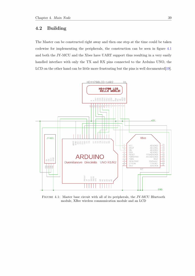
The Master can be constructed right away and then one step at the time could be taken
codewise for implementing the peripherals, the construction can be seen in figure 4.1
and both the JY-MCU and the Xbee have UART support thus resulting in a very easily
handled interface with only the TX and RX pins connected to the Arduino UNO, the
LCD on the other hand can be little more frustrating but the pins is well documented[19].
Figure 4.1: Master base circuit with all of its peripherals, the JY-MCU Bluetoothmodule, XBee wireless communication module and an LCD
Chapter 4. Main Node 40
4.2.1 Fetching wireless data for display
The Master will communicate with the Slave(s) in the following way:
1 The Master sends a request i.e. a Slave number.
2 The Slave matching the unique Slave number will wake up.
3 The Slave responds with the Slave package (figure 3.3).
4 The Master fetches the package and stores it.
5 Transaction ends.
6 Back to 1 with new Slave number.
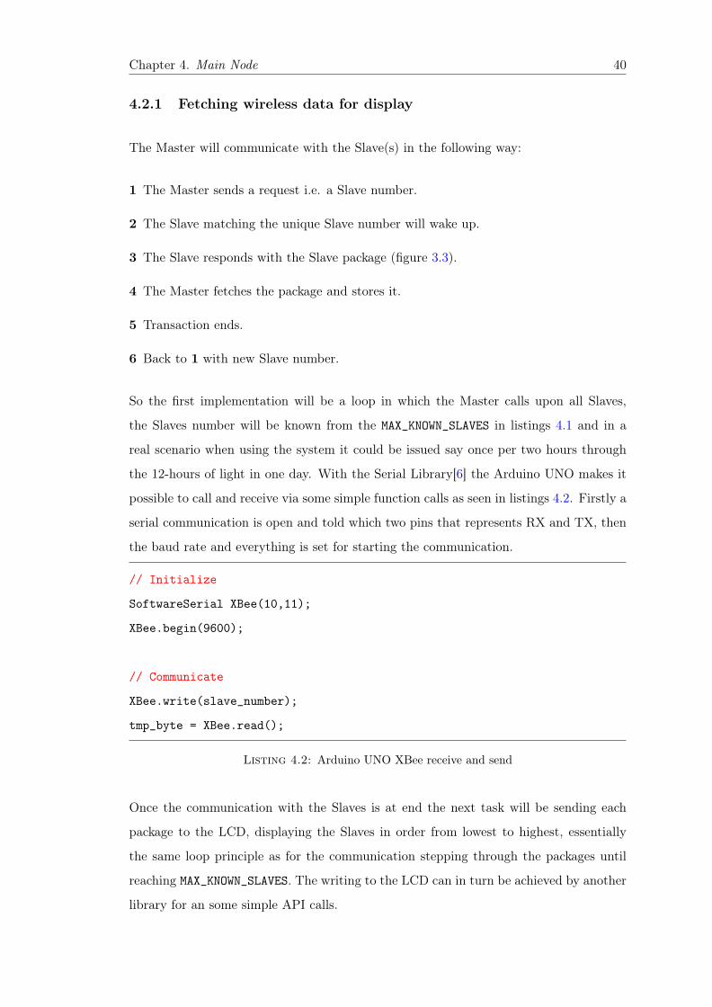
So the first implementation will be a loop in which the Master calls upon all Slaves,
the Slaves number will be known from the MAX_KNOWN_SLAVES in listings 4.1 and in a
real scenario when using the system it could be issued say once per two hours through
the 12-hours of light in one day. With the Serial Library[6] the Arduino UNO makes it
possible to call and receive via some simple function calls as seen in listings 4.2. Firstly a
serial communication is open and told which two pins that represents RX and TX, then
the baud rate and everything is set for starting the communication.
// Initialize
SoftwareSerial XBee(10,11);
XBee.begin(9600);
// Communicate
XBee.write(slave_number);
tmp_byte = XBee.read();
Listing 4.2: Arduino UNO XBee receive and send
Once the communication with the Slaves is at end the next task will be sending each
package to the LCD, displaying the Slaves in order from lowest to highest, essentially
the same loop principle as for the communication stepping through the packages until
reaching MAX_KNOWN_SLAVES. The writing to the LCD can in turn be achieved by another
library for an some simple API calls.

Chapter 4. Main Node 41
// Initialize
LiquidCrystal lcd(7,6,5,4,3,2);
lcd.begin(16,2);
lcd.setCursor(0,0);
// Communicate
lcd.print("Hello World");
Listing 4.3: Arduino UNO communication with LCD
From the listings 4.3 one only needs to keep track of the LCD pins[14] i.e. the ones
connected between the Arduino UNO and the display. Thereafter 16 columns and two
rows and the were to set the cursor when starting the print sequence. The lcd.print()
can print both numbers with the base of ten and strings such as the shown Hello World.
Now everything is set for the Master to enable a communication with the Slave as well
as confirming that the data received is the correct one.
4.2.2 Further forwarding via Bluetooth
Before the data can reach the last platform in the chain of platforms, figure 2.1 the data
must come in another shape and a communication pattern must be chosen. The latter
will be chosen accordingly to the idea that the user of the system can connect to the
JY-MCU with a smartphone and then download data with the result that the user can
estimate how long the sun have been up and the two hour change in moisture. The data
is cleared when fetched and otherwise stored within memory 1. So when the Human
Interface or smartphone is requesting the stored data a function will take care of the
conversion. The purpose of this conversion is to translate the whole data package 3.3 to
a hexadecimal number represented as letters. This can easily be done by creating a the
C++ data type String from the previous slave_data. The principle behind the function
is to call it with one row at the time returning the row as a String i.e. returning all data
of one Slave. The highest hexadecimal number figuring as a letter will be F16 = 11112
so each 8 bit part of the slave package 3.3 needs to taken apart forming the high and1A quick response to this scenario if reflected upon would be out of memory, this must be taken
notice of in a further development but is for the time being overlooked.
Chapter 4. Main Node 42
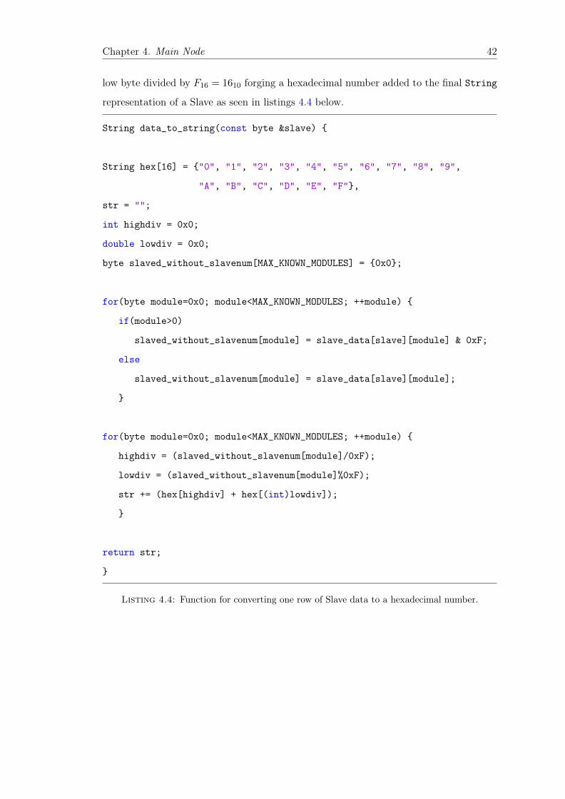
low byte divided by F16 = 1610 forging a hexadecimal number added to the final String
representation of a Slave as seen in listings 4.4 below.
String data_to_string(const byte &slave)
String hex[16] = "0", "1", "2", "3", "4", "5", "6", "7", "8", "9",
"A", "B", "C", "D", "E", "F",
str = "";
int highdiv = 0x0;
double lowdiv = 0x0;
byte slaved_without_slavenum[MAX_KNOWN_MODULES] = 0x0;
for(byte module=0x0; module<MAX_KNOWN_MODULES; ++module)
if(module>0)
slaved_without_slavenum[module] = slave_data[slave][module] & 0xF;
else
slaved_without_slavenum[module] = slave_data[slave][module];
for(byte module=0x0; module<MAX_KNOWN_MODULES; ++module)
highdiv = (slaved_without_slavenum[module]/0xF);
lowdiv = (slaved_without_slavenum[module]%0xF);
str += (hex[highdiv] + hex[(int)lowdiv]);
return str;
Listing 4.4: Function for converting one row of Slave data to a hexadecimal number.

Chapter 4. Main Node 43
The new String package with an underlying example will look like the following:
Slave Number Soil Moisture Value/Measurement D Sun Time/Mode/Measurement D116 9116 9216
Figure 4.2: The package from Master to the Human Interface sent as a string ofcharacters.
4.3 Summation
A brief summation of the Masters tasks with the right components:
A Fetching all Slave data through the XBee.
B Control the network of Slave(s) and it’s own environment by using the microcontroller
board Arduino UNO.
C Handles possible debugging by the ability to write internally stored data onto the
LCD.
D Transmitting internally stored data via the JY-MCU Bluetooth module upon request
from a smartphone.
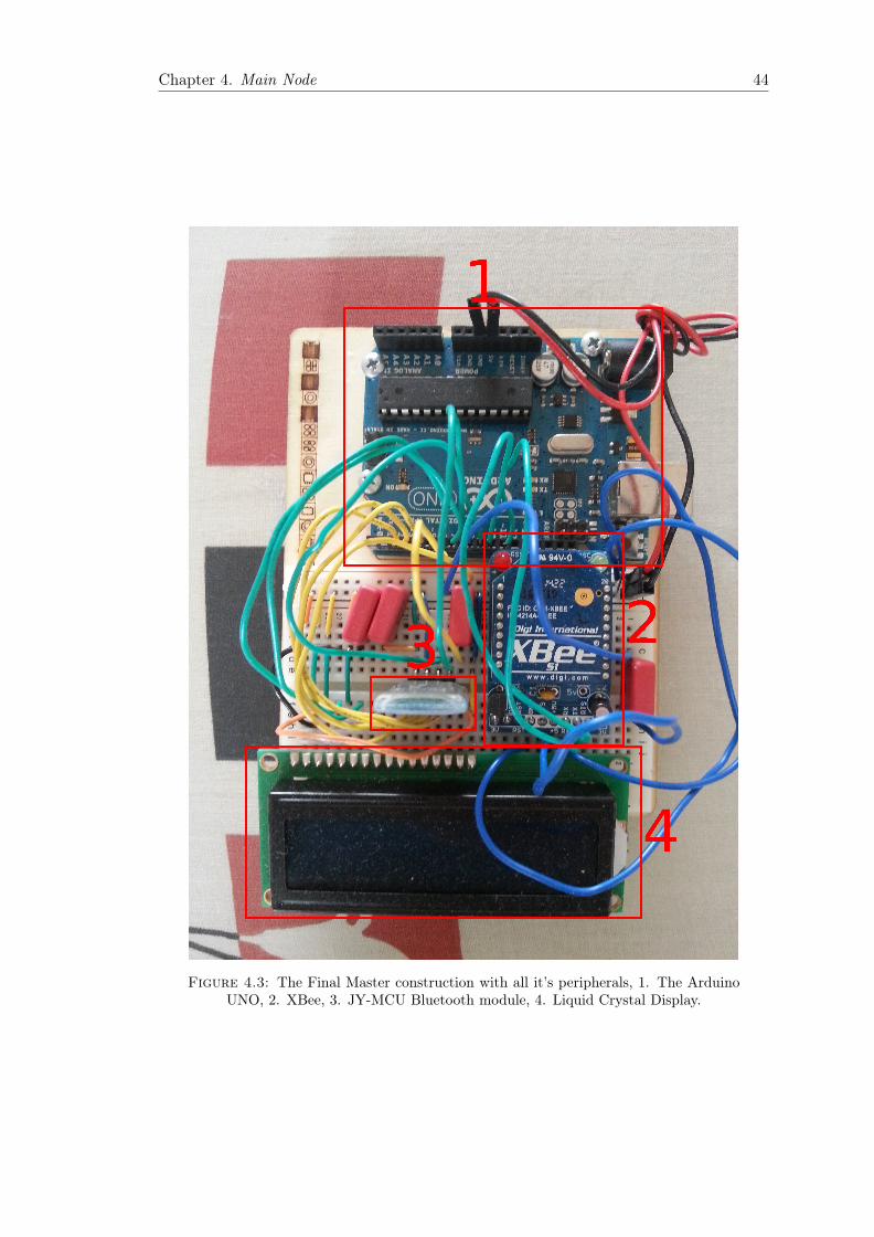
Chapter 4. Main Node 44
Figure 4.3: The Final Master construction with all it’s peripherals, 1. The ArduinoUNO, 2. XBee, 3. JY-MCU Bluetooth module, 4. Liquid Crystal Display.

Chapter 5
5. Human Interface
This chapter describes the construction of the last platform known as Hu-
man Interface figuring as an smartphone receiving data through an software
application.
5.1 Planning
For developing the human interface two things it needed, a smartphone, in this case a
Samsung Galaxy S3 and an IDE, the one named Android Studios. The only real work
(i.e. no hardware constructions like the one in previous platforms) that needs to be
conducted is the development of software in Android Studios.
The package as in previous chapter mentioned will come as a string which needs to
be picked apart in Slave number, soil moisture measurement and the sun time measure-
ment. When this have been done it can be produced in a so called android activity,
the JAVA class handling the interactions with the human user, like knowing what to do
when a particular button is pressed. So the activity can pop a new value on a graph
and check if the sun is set, if so printing the value of hours from when the sun were up
until it went down. If thinking in graphics and buttons the whole process of fetching the
string could be assigned one button and another could be assigned to stop the fetching
of data thus enabling a continuous stream of data if the whole platform chain would be
going much faster starting with the Slave sampling a value each one minute instead of
45

Chapter 5. Human Interface 46
the previous suggested sample of two hours.
Next a reset button is added for a possibility go to back and restarting the sampling
process of data and above the three buttons a graph view is placed. It’s designed after
the Analog-to-Digital converter value between 1 − 10 originated from the Slave formula
3.3 representing the level of moisture in the soil. The level of moisture is display on an
y-axis and the time update is displayed on the x-axis (it will furthermost be tested with
short interval of time updates, like one minute). Above the graph a simple text view is
out written for the sun time measurement, either telling the user that the sun is up or
else the time interval from sun up until down. At last there will also be a list view which
will represent the particular Slave one would wish to inspect.
Figure 5.1: The first sketch ofthe Android application
In figure 5.1 one can see the initial thoughts be-
hind the application description, from above down
the there the first thing is the list view, then
the text view were the sun time measurement is
display. The gray box is where the xy-axis is
supposed to be displayed and under it the three
buttons which all are self explaining. So this
is the true Human Interface were all interactions
with the system is thought to take place and the
building process can be now be launched from
the point of what should happen when pressing
one of the four possibilities within figure the fig-
ure.
One additional thing before the coding can take place is to have some basic knowl-
edge of software threading and how these are executed mainly due to the fact that on if
the graph would be continuously updated when start is pressed this would be done in a
thread named User Interface (UI) thread [20] were no other tasks should be performed
than the one changing the parts of the application in a graphical way, thereby said that
the communication with the Master should be handled in another thread.

Chapter 5. Human Interface 47
5.2 Building
The building will be done by adding one action for each press able item on the activity
screen 5.1. The first action presented for the user will be the possibility to press start, this
action will start a thread named Bluetooth thread that will run simultaneously alongside
the UI thread. This will be the thread that connects the smartphone to the Master and
after a success handles all communication calling the UI thread with new data when a
receive is completed.
try
if (inStream.available() > 0)
while ((tmp = inStream.read()) != (int)endOfString)
str += (char) tmp;
catch (IOException e)
e.printStackTrace();
if (str.length() != 6)
continue;
for (int b = 0; b < dataFromSlave.length; ++b)
dataFromSlave[b] = intFromString(str, b);
runOnUiThread(new Runnable()
@Override
public void run()
if(updateSlaveList(dataFromSlave[0]))
Start.setEnabled(true);
Reset.setEnabled(true);
Dropdown.setEnabled(true);
if (startGraph && dataFromSlave[0] == nowSelectedSlave)
updateGraph(dataFromSlave);
updateSun(dataFromSlave[2]);

Chapter 5. Human Interface 48
);
Listing 5.1: Collect data within the Bluetooth thread and update the UI thread
In listings 5.1 the methodology behind the most essential part of the application is outlaid
within the Bluetooth thread. It starts with collecting the string through inStream.read()
which must not be bigger than six characters easily realized if checking the Master pack-
age 4.2 which then is picked apart and placed in a separate dataFromSlave array variable.
The last part is to update the UI thread and important is to always keep it as short as
possible due to the fact that it occupies the UI threads execution time. When pressing
start the first time the list view will be updated with all the possible Slaves that the
Master have been able to found i.e. even though to possible Slaves is hard coded into
the Master in listings 4.1 some Slaves when called upon may not respond. If one or
more Slave are found the user will be able to choose it from the drop down menu and
start the measuring of it or resenting the whole process, the list view will be updated
each time a new Slave is found. And last the update of values in the UI thread is issued
with updating the graph with the soil moisture value and the sun time i.e. the text view
above the graph.
5.3 Summation
The following tasks will thus be handled by the Human Interface:
A Gathering data after a request from the Master.
B Granting the user a possibility to choose a Slave from a list view.
C When the Slave have been chosen the user can press a start button issuing a measuring
of the soil moisture level and sun time.
D The user can then stop the process by a button click and restart the measuring by
choosing another Slave.

Chapter 5. Human Interface 49
Figure 5.2: The application in action, here Slave 3 is chosen for the first time, thesun is down (with no time since last sun due to the first time running) and the level ofdryness is ten here translated to maximum dry. Note that the return is equivalent to
reset button.

Chapter 6
6. Summation and evaluation
The last chapter will give a brief overview of the system as a whole and
discuss the systems practical usage.
6.1 A system network summation
The data that is transported through the chain of platform and how this is done is given
by the figure 6.1. Note here that the Master is implemented to handle more Slaves in a
hard coded way, see chapter 4.
Slave Master HumanInterface
2. Data (ZigBee)
1. Request (ZigBee)
4. Data (Bluetooth)
3. Request (Bluetooth)
Figure 6.1: The flow of data through the system.
In the system the Master will be the platform that keeps control over the network i.e.
issuing the request for data from the Slaves as well as interacts with the Human Interface.
If the environment would be a household with surrounding gardens the Master from a
developers perspective could be placed to a constant power source either in-house or
50

Chapter 6. Summation and evaluation 51
close to the building. When the Master is switched on it will instantly start to either
fetch data or wait dependent of the time scenario e.g. started by night it would wait.
The surrounding gardens will each be mounted with one Slave and a somewhat track of
different vegetables, flowers or such that needs different care. The user preferably with
some knowledge in the area of gardening these plants can then reflect over the data, soil
moisture and solar hours that have been gathered by the Master through request calls
to the Slaves if these were to be more than one in figure 6.1 i.e. the 1. Request call and
2. Data receive would be repeated until the last know Slave were contacted. The user
can then access this data through the Human Interface were it in an ideal scenario could
be view as an application to the most popular smartphones of today.
In detail this can be viewed as (with a following realistic scenario):
1 Requesting data from Slave(s) e.g. sends 000000012 = 110 via ZigBee - see 4
2 Responds with data via ZigBee e.g. sends in three separate UART packages:
000000012 = 110, 000100012 = 1110 and 001010002 = 4010
In other words the data from the measurement, see chapter 3
3 Requesting data from the Master i.e. only connects.
4 Responds automatically with data via Bluetooth e.g. sends a string of characters
01112816, see chapter 5

Chapter 6. Summation and evaluation 52
6.2 Possible fields of practical use
To create a healthier office of plants, a major city subway with an element of vegetation or
a public garden of fresh air with as little manpower as possible this system could maybe
find a practical usage in combination with the traditional gardener. The system could
be an additional tool for monitoring the plants in a more accurate and exact way. This
especially if several Slaves placed through a suggested growth environment containing a
big spectra of different plants had different requirements for their well being e.g. plant
A could need more water and less sun light in contrast to plant B who would require the
vice verse.
The application that now will monitor the sun light and soil moisture could be an even
greater tool if the data collected by the Human Interface would be translated in a way
that would grant the ability to anyone willing to be a gardener. The work could take a
greater leap towards a larger system connecting the biologist with the engineer creating
a database over as many plants as possible and their need of care downgrading the ad-
vancement level on the application to only telling the user simple things as "Now it is
time to water plant A".
If lower the advancement level a broader group could take part of the system and within
this group one could also maybe count farmers in the third world countries. If a scenario
were old smartphones reused and tailored for furthermost handling the application the
aim could be to increase and effective the harvest.

Appendix A
Component list
Quantity Part More info Platform1 ATmega328p See [1] Slave1 Quartz Crystal See [18] Slave2 47µF Capacitor - Slave1 Light Emitting diode See [21] Slave1 57kΩ Resistor - Slave1 220Ω Resistor - Slave1 Soil fork (or separated metal plates) - Slave4 2700 mAh/1.2 V Batteries - Slave2 200 mA/2 V Sun cell - Slave1 XBee Adapter kit [v1.1] See [9] Slave & Master2 XBee R© 802.15.4 See [8] Slave & Master1 Arduino UNO See [2] Master1 JY-MCU HC-06 Bluetooth Module - Master1 Hitachi HD44780 Liquid Crystal Display controller See [14] Master1 Samsung Galaxy S III GT-i9300 - Human Interface
53

Appendix B
Schematics
Figure B.1: Final schematics of Slave circuit.
54

Appendix B. Schematics 55
Figure B.2: Final schematics of the Master circuit.

Bibliography
[1] ATmega48PA/88PA/168PA/328P. Atmel Corporation, 2325 Orchard Parkway, San
Jose, CA 95131, USA., 09 2010. URL: www.atmel.com/images/doc8161.pdf.
[2] Arduino Uno. Arduino, Ivrea Institute Interaction Design , Turin, Italy., 02 2015.
URL: http://arduino.cc/en/Main/arduinoBoardUno.
[3] ATmega168/328-Arduino Pin Mapping. Arduino, Ivrea Institute Interaction Design
, Turin, Italy., 02 2015. URL: http://arduino.cc/en/Hacking/PinMapping168.
[4] Interrupts. Arduino, Ivrea Institute Interaction Design , Turin, Italy., 02 2015. URL:
http://playground.arduino.cc/Code/Interrupts.
[5] Jan Axelson. Serial Port Complete. Lakeview Research LLC., 2 edition, 2007. .
[6] Serial. Arduino, Ivrea Institute Interaction Design , Turin, Italy., 02 2015. URL:
http://arduino.cc/en/reference/serial.
[7] Zigbee. National Instruments, Austin, Texas, U.S., 03 2013. URL: http://www.ni.
com/white-paper/7118/en/.
[8] XBee /XBee-PRO RF Modules. Digi International Inc., 11001 Bren Road East
Minnetonka., 09 2009. URL: http://www.sparkfun.com/datasheets/Wireless/
Zigbee/XBee-Datasheet.pdf.
[9] Lady Ada. Simple wireless communication. Adafruit, New York City, 02 2015. URL:
https://learn.adafruit.com/xbee-radios/.
[10] XCTU. Digi International Inc., 11001 Bren Road East Minnetonka., 02 2015.
URL: http://www.digi.com/products/wireless-wired-embedded-solutions/
zigbee-rf-modules/xctu#overview.
56

Bibliography 57
[11] The Major Differences in the XBee Series 1 vs. the XBee Series 2. Digi International
Inc., 11001 Bren Road East Minnetonka., 02 2015. URL: http://www.digi.com/
support/kbase/kbaseresultdetl?id=2213.
[12] Android. Bluetooth. Google Inc, 1600 Amphitheatre Parkway, Mountain
View, CA 94043, 02 2015. URL:http://developer.android.com/guide/topics/
connectivity/bluetooth.html.
[13] Bluetooth. National Instruments, Austin, Texas, U.S, 04 2014. URL:http://www.
ni.com/white-paper/7104/en/.
[14] HD44780U (LCD-II). Hitachi, Chiyoda, Tokyo, Japan, 03 2015. URL:https://
www.sparkfun.com/datasheets/LCD/HD44780.pdf.
[15] LiquidCrystal Library. Arduino, Ivrea Institute Interaction Design , Turin, Italy.,
02 2015. URL: http://arduino.cc/en/Reference/LiquidCrystal.
[16] Examples. Arduino, Ivrea Institute Interaction Design , Turin, Italy., 02 2015. URL:
http://arduino.cc/en/Tutorial/HomePage.
[17] Android. Android Studio. Google Inc, 1600 Amphitheatre Parkway, Mountain View,
CA 94043, 02 2015. URL:http://developer.android.com/sdk/index.html.
[18] Quartz THT. auris, 02 2015. URL:www1.elfa.se/data1/wwwroot/assets/
datasheets/htAURIS_mini-Quarz-HC49US_EN.pdf.
[19] LiquidCrystal - Hello World! Arduino, Ivrea Institute Interaction Design , Turin,
Italy., 02 2015. URL: http://arduino.cc/en/Tutorial/LiquidCrystal.
[20] Android. Processes and Threads. Google Inc, 1600 Amphitheatre Parkway, Moun-
tain View, CA 94043, 02 2015. URL:http://developer.android.com/guide/
components/processes-and-threads.html.
[21] T-1 3/4 (5mm) SOLID STATE LAMP. Kingbright, Taipei, Taiwan, 10
2010. URL:http://arduino.cc/documents/datasheets/LEDR-L-7113ID-12V%
28Ver1287713938.7%29.pdf.
Copyright © 2022 FDOKUMEN