gantry crane - baixardoc
10
SUMITOMO CORPORATION PROJECT : SKS, Prai - 350MW CCGT Power Plant Checked By Page of DOC.TITLE: Design of Super structure-Design of Crane-girder Area: Turbine build. DOC. NO : CGPR1-100-5-011 Rev 0 Dept Structural DESIGN CALCULATIONS REFERENCES / REMARKS 6.4.a DESIGN OF CRANE GANTRY GIRDER 11M span All below references are a) INPUT DATA :- BS 5950, (Refer Appendix-E, for EOT drawing) part-1, UNO Crane Capacity = 1050 kN Weight of Crab = 320 kN Weight of Crane Bridge = 780 kN Self weight of the Rail = 2 kN/m Width of Walk way = 0.6 m Dead Load of the Walkway = 1.5 kN/m² Live Load of the Walkway = 5 kN/m² Height of the Crane Rail = 65 mm Span of the Crane Girder, Lg = 11 m Centre to centre distance of , Lc = 32 m Rail (i.e. Span of Crane Bridge) Mini. approach of crane hook to the gantry = 1.800 m No. of Wheels = 4 Wheel Spacing1 = 1.40 m Wheel Spacing2 = 4.70 m C.G of loading from left load = 3.75 m 1.40 4.70 1.40 Impact Factor : Vertical = 30 % Horizontal = 10 % (Transverse to rail) Deflection Factor Vertical = 600 Table:5 Horizontal = 500 Load Factor : Imposed load vertical - = 1.6 Imposed load Horiz.gIh = 1.6 Dead load gdf = 1.4 Design strength of steel, py = 265.0 N/mm 2 Table:6 Maximum unsupported length Top Flange = 2.60 m 146905687.xls.ms_office .xls REF gvrs/ST
-
Upload
khangminh22 -
Category
Documents
-
view
0 -
download
0
Transcript of gantry crane - baixardoc
SUMITOMO CORPORATION
PROJECT : SKS, Prai - 350MW CCGT Power Plant Checked By Page of
DOC.TITLE: Design of Super structure-Design of Crane-girder Area: Turbine build.
DOC. NO : CGPR1-100-5-011 Rev 0 Dept Structural
DESIGN CALCULATIONS REFERENCES /
REMARKS
6.4.a DESIGN OF CRANE GANTRY GIRDER 11M span All below
references are
a) INPUT DATA :- BS 5950,
(Refer Appendix-E, for EOT drawing) part-1, UNO
Crane Capacity = 1050 kN
Weight of Crab = 320 kN
Weight of Crane Bridge = 780 kN
Self weight of the Rail = 2 kN/m
Width of Walk way = 0.6 m
Dead Load of the Walkway = 1.5 kN/m²
Live Load of the Walkway = 5 kN/m²
Height of the Crane Rail = 65 mm
Span of the Crane Girder, Lg = 11 m
Centre to centre distance of , Lc = 32 m
Rail (i.e. Span of Crane Bridge)
Mini. approach of crane hook to the gantry = 1.800 m
No. of Wheels = 4
Wheel Spacing1 = 1.40 m
Wheel Spacing2 = 4.70 m
C.G of loading from left load = 3.75 m 1.40 4.70 1.40
Impact Factor : Vertical = 30 %
Horizontal = 10 %
(Transverse to rail)
Deflection Factor Vertical = 600 Table:5
Horizontal = 500
Load Factor : Imposed load vertical -g = 1.6
Imposed load Horiz.gIhf = 1.6
Dead load gdf = 1.4
Design strength of steel, py = 265.0 N/mm2
Table:6
Maximum unsupported length Top Flange = 2.60 m
146905687.xls.ms_office .xls REF gvrs/ST

SUMITOMO CORPORATION
PROJECT : SKS, Prai - 350MW CCGT Power Plant Checked By Page of
DOC.TITLE: Design of Super structure-Design of Crane-girder Area: Turbine build.
DOC. NO : CGPR1-100-5-011 Rev 0 Dept Structural
DESIGN CALCULATIONS REFERENCES /
REMARKS
Depth of the surge girder = 0.60 m
Maximum unsupported length Bottom Flange = 2.60 m
1.80m (1050+320)kN 780 kN
Kicker
RL 32.00m RR
RL = (1370 x 30.20 + 780 x 32.00/2)/32.00= 1682.938 kN
Wheel Load by calculation 420.73 kN/wheel
b) LOAD CALCULATIONS:
b.1) Vertical Loads
b.1.a) Conc. Loads
Max. static Wheel Load say Wm = 421 kN
875.7 875.7
Load due to Impact = 0.30 x 421 = 126.3 kN
Total load = 547 kN
Factored Load Wmf = 1.60 x 547.30 = 875.68 kN 1.40 4.70 1.40
b.1.b) Uniform Dirstributed Load
Self weight of rail = 2.00 kN/m
Walkway Dead Load = 0.45 kN/m
Walkway Live Load = 1.50 kN/m
Self weight of girder = 4.66 kN/m
8.61 kN/m
Factored load Wdf = 1.40 x 8.61 12.06 kN/m
b.2) Horizontal Loads
Maximum lateral load per wheel is equal to 10% Static vertical wheel load,
l = 0.1 from Fig-1
Max. Lateral load WH = 0.10(421*4) = 168.4 kN BS:2573,part-1
4 wheels are resisting the total lateral load
Factored lateral load Wdf = 1.60 x 168.40 / 4 67.36 kN/wheel
146905687.xls.ms_office .xls REF gvrs/ST
SUMITOMO CORPORATION
PROJECT : SKS, Prai - 350MW CCGT Power Plant Checked By Page of
DOC.TITLE: Design of Super structure-Design of Crane-girder Area: Turbine build.
DOC. NO : CGPR1-100-5-011 Rev 0 Dept Structural
DESIGN CALCULATIONS REFERENCES /
REMARKS
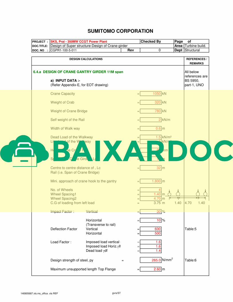
c) MAXIMUM BENDING MOMENT AND SHEAR FORCE:
c.1) For vertical loads
c.1.a) Bending Moment :-
The maximum Bending moment under moving loads occurs when line of
action of one load and centre of gravity of the loads are at equal distance
from the centre of span.
875.68kN 875.68kN 875.68kN 875.68kN
12.06kN/m
C
RA RB
11.00m
Reactions :-
Ra = 4x875.68x(11 - 11*0.5 - 0.25*4.7)/ = 1443.525 kN
+ 12.06 x 11 /2
Rb = 4x875.68+12.06x11- 1,443.525 = 2191.834 kN
Maximum Bending moment occurs at C. =
Mux1 = (1443.53 x 4.33) -875.68 x 1.4 - (12.06 x 4.33²/2)
= 4904.517 kN.m
c.1.b) Shear Force:-
875.68kN 875.68kN 12.06kN/m
RA 11.00m
Reactions:
RA = 4 x 875.7 x [11.0-3.8] /11+ (12.1 x 11.0/2) 2374.930 kN
RB = (4 x 875.7) + (12.1 x 11.0) - 2374.93 1260.428 kN
Max. Reaction = 2374.930 kN
c.2) For Horizontal loads :-
CG. OF LOADS
Mid Span of Crane Girder
= =
CG. OF GANTRY
146905687.xls.ms_office .xls REF gvrs/ST
SUMITOMO CORPORATION
PROJECT : SKS, Prai - 350MW CCGT Power Plant Checked By Page of
DOC.TITLE: Design of Super structure-Design of Crane-girder Area: Turbine build.
DOC. NO : CGPR1-100-5-011 Rev 0 Dept Structural
DESIGN CALCULATIONS REFERENCES /
REMARKS
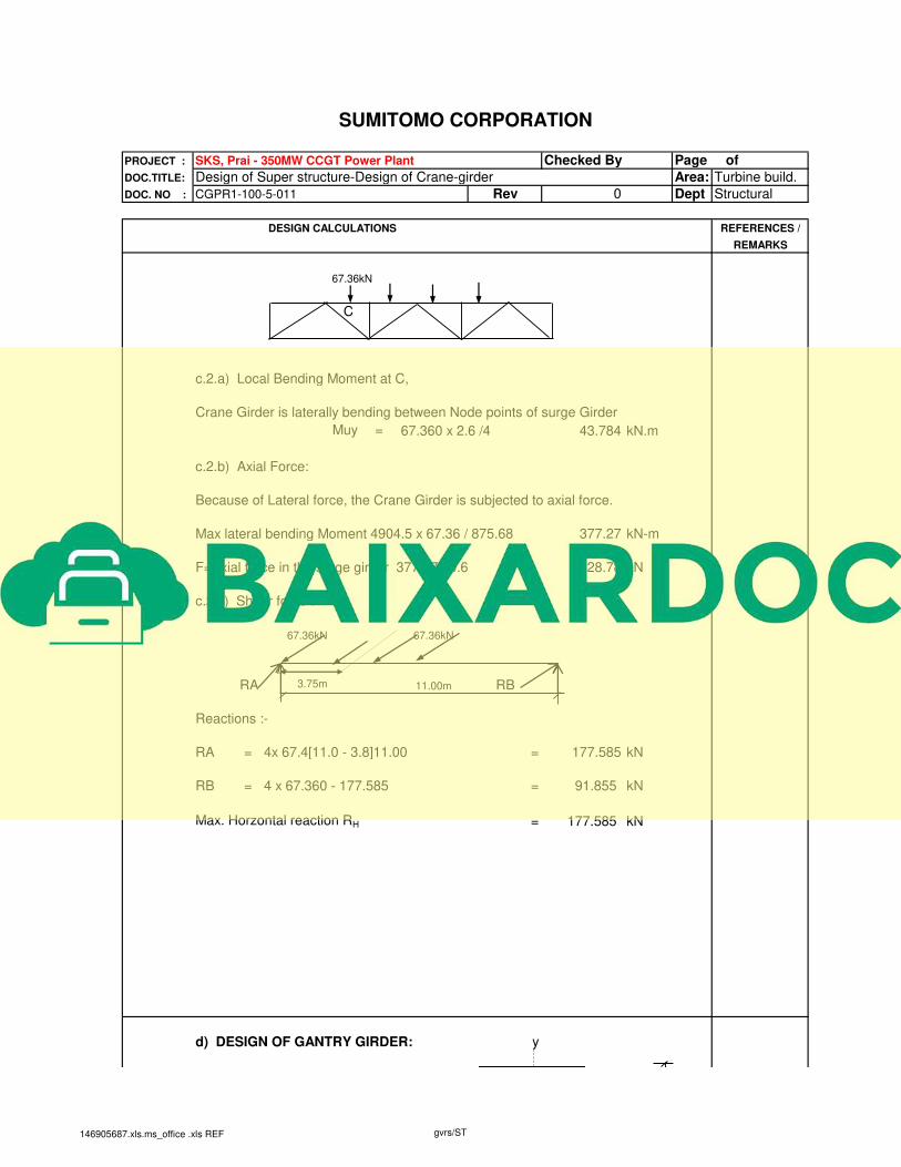
67.36kN
C
c.2.a) Local Bending Moment at C,
Crane Girder is laterally bending between Node points of surge Girder
Muy = 67.360 x 2.6 /4 43.784 kN.m
c.2.b) Axial Force:
Because of Lateral force, the Crane Girder is subjected to axial force.
Max lateral bending Moment 4904.5 x 67.36 / 875.68 377.27 kN-m
F=Axial force in the surge girder 377.27 / 0.6 628.78 kN
c.2.c) Shear force :-
67.36kN 67.36kN
RA 3.75m 11.00m RB
Reactions :-
RA = 4x 67.4[11.0 - 3.8]11.00 = 177.585 kN
RB = 4 x 67.360 - 177.585 = 91.855 kN
Max. Horzontal reaction RH = 177.585 kN
d) DESIGN OF GANTRY GIRDER: y
146905687.xls.ms_office .xls REF gvrs/ST

SUMITOMO CORPORATION
PROJECT : SKS, Prai - 350MW CCGT Power Plant Checked By Page of
DOC.TITLE: Design of Super structure-Design of Crane-girder Area: Turbine build.
DOC. NO : CGPR1-100-5-011 Rev 0 Dept Structural
DESIGN CALCULATIONS REFERENCES /
REMARKS
Depth 1250 mm
Width 450 mm 20
t = 20 mm x x 1250
T = 40 mm
40
450
Properties :-
Depth of the section, D = 1250 mm
Width of the section, B = 450 mm
Thickness of web, t = 20 mm
Thickness of flange, T = 40 mm
Effective depth of web, d = 1170 mmSecond moment of inertia, Ixx = 1.59E+10 mm
4
Second moment of inertia, Iyy = 6.08E+08 mm4
rmin = 101.19 mm
Section modulus, Zxx = 2.54E+07 mm3
Section modulus, Zyy = 2.70E+06 mm3
Plastic modulus, Sxx = 2.96E+07 mm3
Plastic modulus, Syy = 4.28E+06 mm3
Buckling parameter, u = 1 conservatively
Torsional index, x : D/T = 31.25 as per Cl.4.3.7.5
Sectional Area, A = 59400 mm2
Flange Area on one side, Ag = 18000 mm2
Out stand width of panel, b = 215 mm
Constant, e, = sqrt(275/py) = 1.02
Outstand element of compression flange, b/T = 5.38 Plastic Cl.3.5.2 and
Web slenderness, d/t = 58.50 Plastic Table:7
d.1) Shear Capacity
Web slenderness, d/t = 58.50 < 63*1.02 Cl.4.4.4.1
Satisfactory
Shear area parallel to the web, Avx=t*d = 23400 mm2 Cl.4.2.3,
Critical Shear strength, qcr for t/d =58.50 = 159 N/mm2 Table:21,
Shear Capacity, Vcr=qcr*Avx = 3720.6 kN Cl.4.4.5.3
>2,374.93 kN Satisfactory
d.2) Moment capacity, Mb
146905687.xls.ms_office .xls REF gvrs/ST
SUMITOMO CORPORATION
PROJECT : SKS, Prai - 350MW CCGT Power Plant Checked By Page of
DOC.TITLE: Design of Super structure-Design of Crane-girder Area: Turbine build.
DOC. NO : CGPR1-100-5-011 Rev 0 Dept Structural
DESIGN CALCULATIONS REFERENCES /
REMARKS
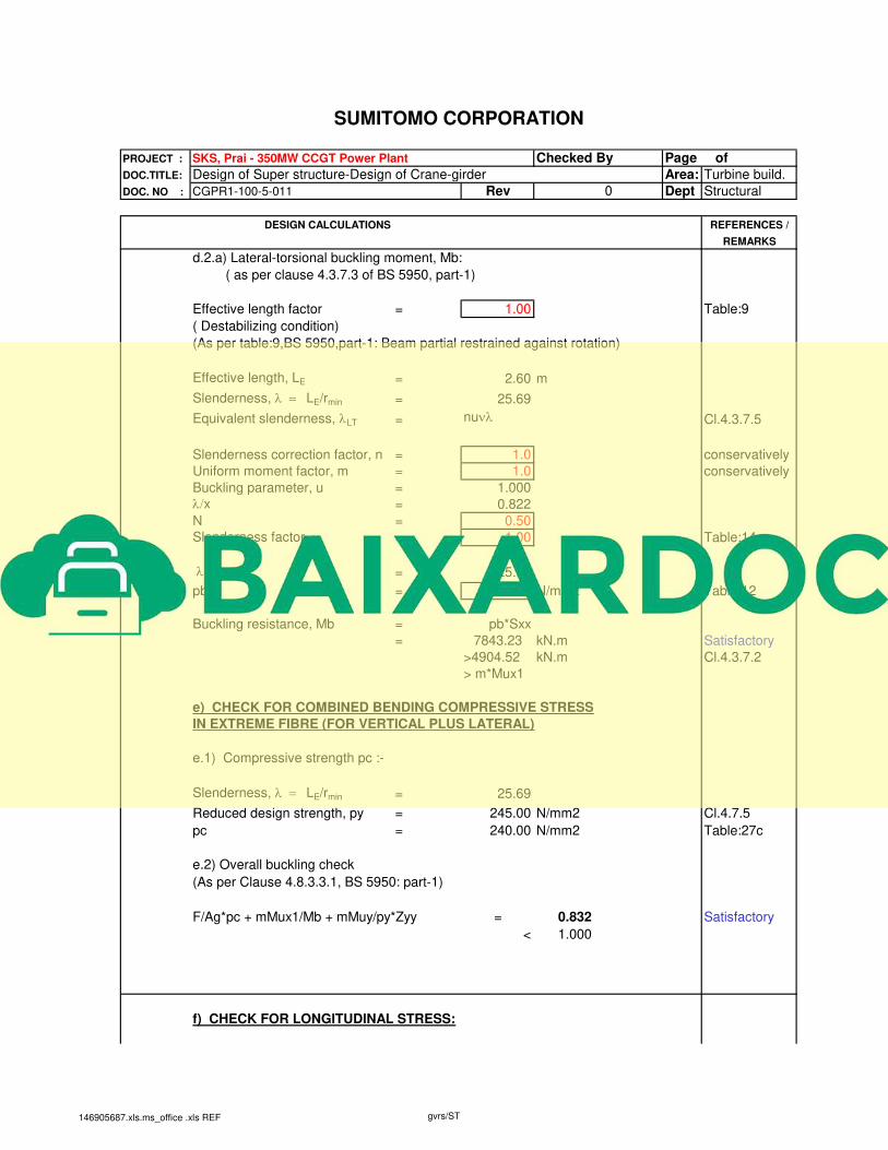
d.2.a) Lateral-torsional buckling moment, Mb:
( as per clause 4.3.7.3 of BS 5950, part-1)
Effective length factor = 1.00 Table:9
( Destabilizing condition)
(As per table:9,BS 5950,part-1: Beam partial restrained against rotation)
Effective length, LE = 2.60 m
Slenderness, l = LE/rmin = 25.69
Equivalent slenderness, lLT = nunl Cl.4.3.7.5
Slenderness correction factor, n = 1.0 conservatively
Uniform moment factor, m = 1.0 conservatively
Buckling parameter, u = 1.000
l/x = 0.822
N = 0.50
Slenderness factor, n = 1.00 Table:14
lLT = 25.69
pb = 265.00 N/mm2 Table:12
Buckling resistance, Mb = pb*Sxx
= 7843.23 kN.m Satisfactory
>4904.52 kN.m Cl.4.3.7.2
> m*Mux1
e) CHECK FOR COMBINED BENDING COMPRESSIVE STRESS
IN EXTREME FIBRE (FOR VERTICAL PLUS LATERAL)
e.1) Compressive strength pc :-
Slenderness, l = LE/rmin = 25.69
Reduced design strength, py = 245.00 N/mm2 Cl.4.7.5
pc = 240.00 N/mm2 Table:27c
e.2) Overall buckling check
(As per Clause 4.8.3.3.1, BS 5950: part-1)
F/Ag*pc + mMux1/Mb + mMuy/py*Zyy = 0.832 Satisfactory
< 1.000
f) CHECK FOR LONGITUDINAL STRESS:
146905687.xls.ms_office .xls REF gvrs/ST

SUMITOMO CORPORATION
PROJECT : SKS, Prai - 350MW CCGT Power Plant Checked By Page of
DOC.TITLE: Design of Super structure-Design of Crane-girder Area: Turbine build.
DOC. NO : CGPR1-100-5-011 Rev 0 Dept Structural
DESIGN CALCULATIONS REFERENCES /
REMARKS
Height of rail = 65 mm
5% of the static wheel load = 5/100 x4x 875.7 175.14 kN
Bending moment in the longitudinal direction is equal to Longitudinal Force into
Crane Rail Depth plus half of Crane Girder depth
Mux2 = 175136 x (65 + 625.0) 120.84 kN.m
CHECK FOR COMBINED BENDING COMPRESSIVE STRESS
IN EXTREME FIBRE (FOR VERTICAL PLUS LONGITUDINAL)
F/Ag*pc + m(Mux1+Mux2)/Mb = 0.681 Satisfactory
g) CHECK FOR DEFLECTION:
Allowable deflection for vertical loads
d lim, v = Span / 600 =11,000.0 / 600.0 = 18.33 mm
Allowable deflection for horizontal loads
d lim, h = Span / 500 = 11,000.0 /500 = 22.00 mm
Vertical Deflection:-
3.15
1.75
547.3kN 547.3kN 8.61kN/m
c
RA 11.00 RB
d v =
= #VALUE!
{( 2 x 547300 x 11000³)/( 48 x 205000 x 1.59E+10)} x
{[3 x 1.75/11 - 4 x (1.75/11)³] + [3 x 3.15/11 - 4 x (3.15/11)³]}
= 11.960 mm
CHECK dv < Allowable Deflection 11.960 < 18.3 HENCE SAFE
h) Crane Girder Welding Calculation
Top Flange & Web is welded by full Penetration Butt weld.
úúû
ù
êêë
é÷øö
çèæ
úúû
ù
êêë
é÷øö
çèæ
-´+-´+´3333
L
a23a2
48EI
PL
L
a13a1
48EI
PL
EI
WL
384
5
LL44
4
CG. OF GANTRY
CG OF LOADS
==
146905687.xls.ms_office .xls REF gvrs/ST

SUMITOMO CORPORATION
PROJECT : SKS, Prai - 350MW CCGT Power Plant Checked By Page of
DOC.TITLE: Design of Super structure-Design of Crane-girder Area: Turbine build.
DOC. NO : CGPR1-100-5-011 Rev 0 Dept Structural
DESIGN CALCULATIONS REFERENCES /
REMARKS
Bottom Flange Weld.
Horizontal Shear = FAy/ Ixx
A- Area of the Bottom Flange = 18000 mm2
y - C.G of flange Plate from C.G of section = 605 mm
Ixx of the section = 1.59E+10 mm4
Maximum vertical shear = 2374.930 kN
Horizontal Shear 2,374.9 x 1000 x 18000x605 / 15851055 1631.626 N/mm
Size of the weld on each side 1,631.6/ ( 2 x 215x 0.707) 5.421 mm
Provide weld as = 12 mm
i) DESIGN OF BEARING STIFFENER
Bearing check:
Minimum area of stiffener in contact with the flange = 0.8*Fx/pys Cl.4.5.4.2
Fx = External reaction
pys = Design strength of stiffener
Minimum Area of stiffener required = 7169.60 mm2
Conside Thk. Of Stiffener , ts = 25.00 mm
Width of the stiffener, bs = 450.00 mm
Area of the stiffener = 11250.00 mm2 Satisfactory
Check for outstands
Outstand from the face of the web = bs/2-web thickness
= 215.00 mm
Outstand of web stiffeners, as per Cl.4.5.1.2 of BS5950: Limits:
19tse = 483.88 mm
13tse = 331.08 mm Satisfactory
Bearing resistance of the stiffener
Bearing Stress in member = 211.10 N/mm2
146905687.xls.ms_office .xls REF gvrs/ST

SUMITOMO CORPORATION
PROJECT : SKS, Prai - 350MW CCGT Power Plant Checked By Page of
DOC.TITLE: Design of Super structure-Design of Crane-girder Area: Turbine build.
DOC. NO : CGPR1-100-5-011 Rev 0 Dept Structural
DESIGN CALCULATIONS REFERENCES /
REMARKS
< 265 N/mm2 Satisfactory
Buckling resistance of the stiffner
(as per Cl.4.5.1.5 of BS5950,part-1)
Design strength of the stiffner in buckling = py-20 Cl.4.5.1.5
= 245.0 N/mm2
Buckling resistance check as a column:
Area of combined section 450 x25 + 20 x 20 x 20 19250.00 mm2
Ixx = 1.90E+08 mm4
= 99.38 mm
l = l / Rmin =1250x 1000 / 99.4 = 12.58
Compressive strength, pc = 245.00 N/mm2 Tb.27c,
Buckling resistance of the stiffener = 4716.25 kN
> 2374.93 kN Satistactory
Weld between Stiffener & web
Vetical Height avilable for Welding = 1170.00 mm
Thk. of weld reqd =2,374.9 x1000/(1170x2x0.7*215) 6.74 mm
Provide weld thickness = 12.00 mm
j) Shear buckling of Web under Wheel load
Web bearing under wheel load
(as per Cl.4.11.4,BS 5950, part-1)
Load dispersion under wheel,lw= 2(Height of the wheel + Thickness of the flange)
= 210 mm
Bearing Capacity = lw*py*t = 1113 kN
> 875.68 kN Satisfactory
Web buckling under wheel load
(as per Cl.4.5.2.1, BS 5950,part-1)
AI /Rmin =
146905687.xls.ms_office .xls REF gvrs/ST
SUMITOMO CORPORATION
PROJECT : SKS, Prai - 350MW CCGT Power Plant Checked By Page of
DOC.TITLE: Design of Super structure-Design of Crane-girder Area: Turbine build.
DOC. NO : CGPR1-100-5-011 Rev 0 Dept Structural
DESIGN CALCULATIONS REFERENCES /
REMARKS
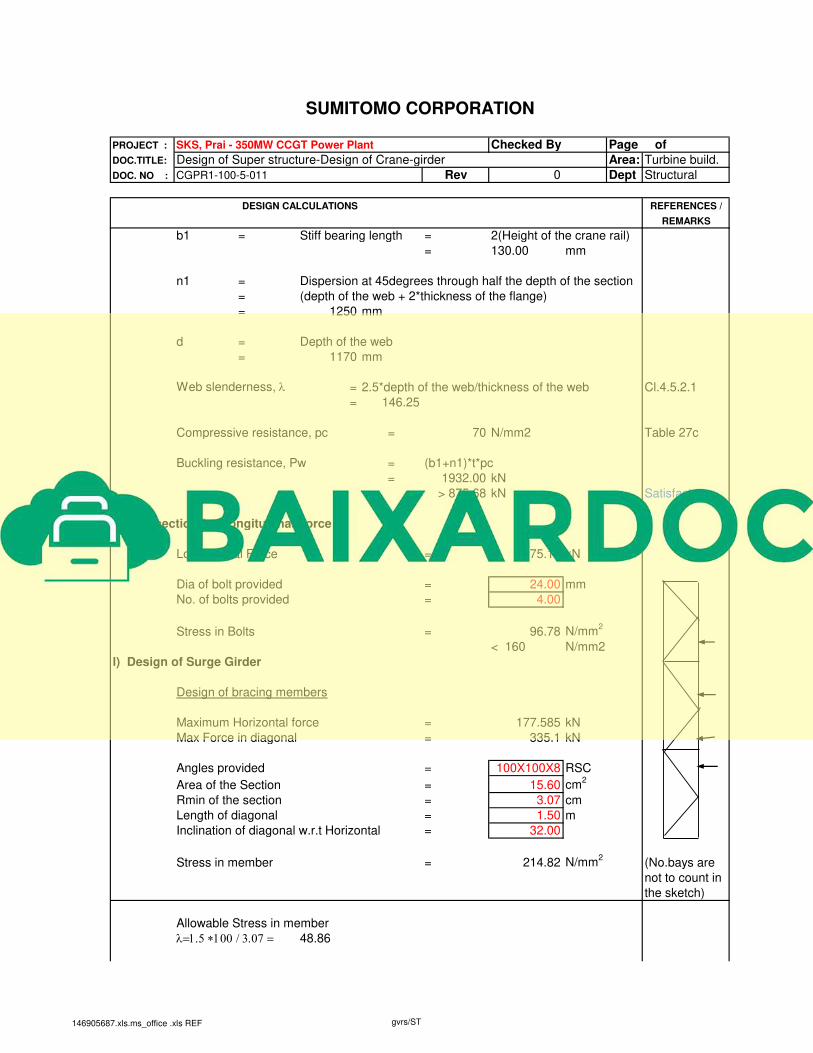
b1 = Stiff bearing length = 2(Height of the crane rail)
= 130.00 mm
n1 = Dispersion at 45degrees through half the depth of the section
= (depth of the web + 2*thickness of the flange)
= 1250 mm
d = Depth of the web
= 1170 mm
Web slenderness, l = 2.5*depth of the web/thickness of the web Cl.4.5.2.1
= 146.25
Compressive resistance, pc = 70 N/mm2 Table 27c
Buckling resistance, Pw = (b1+n1)*t*pc
= 1932.00 kN
> 875.68 kN Satisfactory
k) Connection for Longitudinal Force
Longitudinal Force = 175.14 kN
Dia of bolt provided = 24.00 mm
No. of bolts provided = 4.00
Stress in Bolts = 96.78 N/mm2
< 160 N/mm2
l) Design of Surge Girder
Design of bracing members
Maximum Horizontal force = 177.585 kN
Max Force in diagonal = 335.1 kN
Angles provided = 100X100X8 RSC
Area of the Section = 15.60 cm2
Rmin of the section = 3.07 cm
Length of diagonal = 1.50 m
Inclination of diagonal w.r.t Horizontal = 32.00
Stress in member = 214.82 N/mm2
(No.bays are
not to count in
the sketch)
Allowable Stress in member
l=1.5 *100 / 3.07 = 48.86
146905687.xls.ms_office .xls REF gvrs/ST