FUSION ENERGY DIVISION ANNUAL PROGRESS REPORT
303
i ORNL-6624 OAK RIDGE NATIONAL LABORATORY FUSION ENERGY DIVISION MARTIN MARIETTA • D I ANNUAL PROGRESS REPORT Period Ending December 31, 1989 MANAGED BY MARTIN MARIETTA ENERGY SYSTEMS, INC. FORTHEUNffEDSTATES DBST r_l,'--_ s_ ..,'T',O_.,,, _... c_ r_-;;_;_:.:,,:. J_i_; __r,, =_;.,:ts _..,.',4 Lir_eTE.O DEPARTMENT OFENERGY
-
Upload
khangminh22 -
Category
Documents
-
view
1 -
download
0
Transcript of FUSION ENERGY DIVISION ANNUAL PROGRESS REPORT
i
ORNL-6624
OAK RIDGENATIONAL
LABORATORY FUSION ENERGYDIVISION
MARTIN MARIETTA
• D
I
ANNUAL PROGRESSREPORT
Period Ending December 31, 1989MANAGEDBYMARTINMARIETTAENERGYSYSTEMS,INC.
FORTHEUNffEDSTATES DBSTr_l,'--_s_..,'T',O_.,,,_... c_ r_-;;_;_:.:,,:.J_i_;__r,,=_;.,:ts _..,.',4Lir_eTE.ODEPARTMENTOFENERGY
This report has been reproduceddirectly from the best available copy.
Available to DOE and DOE contractors from the Office of Scientific and Techni-
cal Information, P.O. Box 62, Oak Ridge, TN 37831; prices available from (615)576-8401, FTS 626-8401.
Available to the public from the National Technical Information Service, U.S.Department of Commerce, 5285 Port Royal Rd., Springfield, VA 22161.
This report was prepared as an account of work sponsored by an agency ofthe United States Government. Neither the United States Government nor anyagency thereof, nor any of their employees, makes any warranty, express orimplied, or assumes any legal liability or responsibility for the accuracy, corn-pleteness, or usefulnessof any information, apparatus, product, or process dis-closed, or represents that its use would not infringe privately owned rights.Reference herein to any specific commercial product, process, or service bytrade name, trademark, manufacturer, or otherwise, does not necessarily consti-
tute or imply its endorsement, recommendation, or favoring by the United StatesGovernment or any agency thereof. The views and opinions of authorsexpressed herein do not necessarily state or reflect those of the United StatesGovernment or any agency thereof.
Dist. CateORNL--6624
DE92 000388
FUSION ENERGY DIVISIONANNUAL PROGRESS REPORT
Period Ending December 31, 1989
J. SheffieldC. C. Baker
M. J. Saltmarsh
Fusion Energy Division Staff
Date Published: July 1991
Prepared for theOffice of Fusion Energy
Budget Activity No. 25 19 00 00 0
Prepared by theOAK RIDGE NATIONAL LABORATORY
Oak Ridge, Tennessee 37831-6285managed by
MARTIN MARIETTA ENERGY SYSTEMS, INC.for the
U.S. DEPARTMENT OF ENERGY _, i_:,_:_i: .:_- ,under contract DE-AC05-84OR21400 - -,,_._ii_:
I _'|_.) ! rl_: ._'tJ i ' ' '_ ' _ '_" il'Jll I ['_U
Report previously issued in this series are as follows:
ORNL-2693 Period Ending January 31, 1959ORNL-2802 Period Ending July 31, 1959ORNL-2926 Period Ending January 31, 1960ORNL-3011 Period Ending July 31, 1960ORNL-3104 Period Ending January 31, 1961ORNL-3239 Period Ending October 31, 1961ORNL-3315 Period Ending April 30, 1962ORNL-3392 Period Ending October 31, 1962ORNL-3472 Period Ending April 30, 1963ORNL-3564 Period Ending October 31, 1963ORNL-3652 Period Ending April 30, 1964ORNL-3760 Period Ending October 31, 1964ORNL-3836 Period Ending April 30, 1965ORNL-3908 Period Ending October 31, 1965ORNL-3989 Period Ending April 30, 1966ORNL-4063 Period Ending October 31, 1966ORNL-4150 Period Ending April 30, 1967ORNL-4238 Period Ending October 31, 1967ORNL-4401 Period Ending December 31, 1968ORNL-4545 Period Ending December 31, 1969ORNL-4688 Period Ending December 31, 1970ORNL-4793 Period Ending December 31, 1971ORNL-4896 Period Ending December 31, 1972ORNL-4982 Period Ending December 31, 1973ORNL-5053 Period Ending December 31, 1974ORNL-5154 Period Ending December 31, 1975ORNL-5275 Period Ending December 31, 1976ORNL-5405 Period Ending December 31, 1977ORNL-5549 Period Ending December 31, 1978ORNL-5645 Period Ending December 31, 1979ORNL-5674 Period Ending December 31, 1980ORNL-5843 Period Ending December 31, 1981ORNL-5919 Period Ending December 31, 1982ORNL-6015 Period Ending December 31, 1983ORNL-6111 Period Ending December 31, 1984ORNL-6234 Period Ending December 31, 1985ORNL-6332 Period Ending December 31, 1986ORNL-6452 Period Ending December 31, 1987ORNL-6528 Period Ending December 31, 1988
CONTENTS
SUMMARY .................. xi1. TOROIDAL CONFINEMENT ACTIVITIES . 1
SUMMARY OF ACTIVITIES ........ 31.1 THE ATF PROGRAM ............ 4
1.1.1 Overview ........... 41.1.2 Confinement Studies ......... 4
1.1.3 Fluctuation Studies ..... 6[ 1.1.4 Impurity Studies ........ 9I 1.1.4.1 Gettering and impurity radiation ...... 10
1.1.4.2 Effects of gettering on plasma performance . . 121.1.4.3 Impurity injection ....... 16
1.2 EDGE PHYSICS AND PARTICLE CONTROL PROGRAM . 19
1.2.1 Edge Plasma Studies and Particle Control in ATF .... 201.2.1.1 Initial measurements of edge plasma turbulence using a
fast reciprocatng Langmuir probe . . 201.2.1.2 Gettering techniques ....... 22
1.2.2 Helium Removal Experiments and H,a Studies onALT-II in TEXTOR ......... 23
1.2.2.1 Helium exhaust and transport studies .... 23
1.2.2.2 Modeling of He, emission and plasma confinement . 241.2.2.3 Analysis of recycling energy distributions from
Ht, measurements . • 25
1.2.3 Pump Limiter Studies on Tore Supra: Measurements ofPressure Buildup and Particle Fluxes . . 26
1.2.4 The DIII-D Advanced Divertor Program . . . 27
1.2.4.1 Neutral particle modeling . . 271.2.4.2 The pre-VORTEX code . 281.2.4.3 Diagnostics . . . 301.2.4.4 Divertor pumping . 31
1.3 ATF-II STUDIES . . • 32
1.3.1 Transport Code Development 331.3.2 Effect of the Electric Field . 33
1.3.3 Results of Reactor Surveys . . 341.3.4 Conclusions 35
REFERENCES 35
iii
2. ATOMIC PHYSICS AND PLASMA DIAGNOSTICSDEVELOPMENT ....... 37SUMMARY OF ACTIVITIES ...... 392.1 EXPERIMENTAL ATOMIC COLLISIONS ..... 41
2.1.1 Electron Capture in O3+ + H (D) _:_d O4+ + H (D) CollisionsUsing Merged Beams ......... 41
2.1.2 Dissociation and Ionization of CD_ by Electron Impact ..... 422.1.3 Studies of Angular Dependence and Line Shapes for Auger
Electron Emission in Low-Energy He q+ + He Collisions . . 43
2.1.4 Auger Spectroscopy of Low-Energy Multicharged Ion-AtomCollisions ........... 45
2.1.5 Electron Spectroscopy of Multicharged Ion-SurfaceInteractions ...... 47
2.1.6 Merged-Beams Experiment for Electron-Impact Excitationof Ions .......... 49
2.1.7 Electron-Impact Ionization of Ta8+ ..... 492.2 ATOMIC COLLISION THEORY ..... 50
2.2.1 Abstract of "Strong-Field Laser Ionization of AlkaliAtoms Using 2-D and 3-D Time-DependentHartree-Fock Theory" . ....... 50
2.2.2 Abstract of "Coupling Effects for Electron-Impact Excitationin the Potassium Isoelectronic Sequence" . .... 50
2.2.3 Abstract of "Indirect Processes in the Electron ImpactIonization of Atomic Ions" . . 50
2.2.4 Abstract of"Correlation Enhancement of the Electron-ImpactIonization Cross Section for Excited State Ne-Like Ions" . 50
2.2.5 Time-Dependent Hartree-Fock Studies of Ion-AtomCollisions ........ 51
2.3 CONTROLLED FUSION ATOMIC DATA CENTER . . 512.4 ADVANCED PLASMA DIAGNOSTICS DEVELOPMENT . 53
2.4.1 Small-Angle CO2 Laser Thomson Scattering Diagnostic for D-TFusion Product Alpha Particles . 53
2.4.2 Multichannel Far-Infrared Interferometer and Scattering Systemfor the Advanced Toroidal Facility . 53
2.4.3 Feasibility Studies of a Two-Color Interferometer/Polarimeterfor the Compact Ignition Tokamak . 55
2.4.4 Optics Damage and Irradiation Studies 57REFERENCES 58
3. FUSION THEORY AND COMPUTING . 61SUMMARY OF ACTIVITIES . 63
3.1 EQUILIBRIUM AND STABILITY 653.1.1 Overview 65
iV

3.1.2 Highlights of 1989 .... 663.1.2.1 ATF operation in the second stability regime 663.1.2.2 Stability of helical-axis stellarators . 67
3.1.3 Advanced VMEC Equilibrium Analysis . 673.2 TURBULENCE ....... 69
3.2.1 Overview ....... 69
3.2.2 Highlights of 1989 .......... 703.2.2.1 The hybrid fluid-kinetic model ..... 703.2.2.2 Trapped-electron modes .... 713.2.2.3 Edge turbulence modeling ....... 71
3.3 KINETIC THEORY ............... 723.3.1 Cause and Effect of Electric Fields in Toroidal Devices . . 72
3.3.2 Ripple Losses of Alpha Particles in ITER .... 733.3.3 Benchmark Studies of Neutral Beam Injection
for Stellarators/Heliotrons ................ 73
3.3.4 Beam Deposition and TF Ripple in TEXT ........ 733.4 TRANSPORT AND CONFINEMENT MODELING ..... 77
3.4.1 General Transport Studies ............ 773.4.2 ITER Studies ................ 773.4.3 CIT Studies ............ 773.4.4 ATF Studies ............... 78
3.4.5 Pellet Injection Studies on JET ....... 783.5 RF HEATING ................... 79
3.5.1 Global ICRF Wave Propagation in Edge Plasma andFaraday Shield Regions ............ 80
3.5.2 Fast-Wave Current Drive Modeling for ITER and DIII-D .... 803.5.3 Electron Heating and Static Sheath Enhancement
in Front of Energized RF Antenna ....... 823.6 COMPUTING AND OPERATIONS ......... 84
REFERENCES .......... 85
4. PLASMA TECHNOLOGY . . . 89SUMMARY OF ACTIVITIES ....... 911.1 PLASMA FUELING PROGRAM . 93
4.1.I Pellet InJector Development . 934.1.1.1 Electron-beam rocket pellet injector 9.44.1.1.2 CIT and ITER fueling . 964.1.1.3 Tritium injector 974.1.1.4 Two-stage light gas gun . 98
4.1.2 Pellet Injector Applications . 1034.1.2.1 ATF pellet injector . 1034.1.2.2 Tore Supra pellet injector 1044.1.2.3 JET . . 105
4.1.3 Pellet Projects: High-Speed Injector 1074.1.4 Work for Others . . 107
4.2 RF TECHNOLOGY . . 108
4.2.1 Basic Development !084.2.1.1 Faraday shield studies . 1084.2.1.2 Plasma-materials interactions 1104.2.1.3 Fast-wave current drive 111
4.2.1.4 Folded waveguide . . 1134.2.1.5 RF modeling . . . 115
4.2.2 RF Projects .... 1194.2.2.1 Tore Supra antenna . 1194.2.2.2 Alcator C-Mod ICRF antenna project . 1204.2.2.3 Fast-wave current drive antenna for DIII-D 1234.2.2.4 CIT antenna .... 124
4.2.3 ICRH Experiments on TFTR ...... 1244.3 NEUTRAL BEAMS ......... 125
4.3.1 Ion Sources ........ 125
4.3.1.1 Enhancement of negative ion extraction and electron
suppression by a magnetic field ..... 1254.3.1.2 Measurement of the H- thermal energy by two-laser
photodetachment ....... 1264.3.1.3 Analysis of the initial stages of H- evolution . 126
4.3.2 RFQ-Accelerated High-Energy Beams . . . 1294.3.2.1 Ion source ......... 129
4.3.2.2 Low-energy beam transport system .... 1304.3.2.3 RF accelerator ...... 1304.3.2.4 Neutralizer . . . 130
4.3.2.5 Beam dump ..... 131
4.3.3 Negative Ion Beams ...... 1314.3.4 Upgrade of the T-15 Long-Pulse Ion Source . . . 132
REFERENCES ...... 136
5. SUPERCONDUCTING MAGNET DEVELOPMENT . 139SUMMARY OF ACTIVITIES ....... 1415.1 EXPERIMENTAL WORK ..... 142
5.1.1 Superconducting Magnet Design . 1425.1.2 Quench Propagation, Pressure Rise, and Thermal Expulsion
of Helium from a Cable-in-Conduit, Forced-Flow
Superconductor . . 1425.1.3 Magnetic Heat Pump Test . 1425.1.4 Large Coil Task . . . 143
vi

5.2 THEORETICAL RESEARCH ........ 1435.2.1 The Gorter-Mellink Pulsed-Source Problem in Cylindrical
and Spherical Geometry ........... 1435.2.2 Propagation of Normal Zones of Finite Size in Large,
Composite Superconductors ............. 144REFERENCES ....................... 144
6. ADVANCED SYSTEMS PROGRAM ................ 145SUMMARY OF ACTIVITIES .................. 1476.1 CIT ......................... 149
6.1.1 Ex-Vessel Remote Maintenance .............. 1496.1.1.1 Remote maintenance systems ........ 149
6.1.1.2 Graphic modeling ................. 1496.1.1.3 Task evaluations ............... 151
6.1.1.4 Special tools ................ 1536.1.2 Vacuum System and Shield ................ 153
6.1.2.1 Vacuum system ................. 1536.1.2.2 Thermal shield ................. 154
6.1.3 Ion Cyclotron Resonance Heating System .......... 1546.1.4 Fueling System ...................... 1556.1.5 Insulation for the TF Coils ................ 157
6.1.6 MHD Equilibrium and Poloidal Field System Studies ..... 1586.1.7 Plasma Disruption Simulations ............... 1596.1.8 Structural Materials ................ 160
6.2 ITER ........................... 160
6.2.1 Plasma Engineering ................. 1606.2.1.1 Systems analysis ............ 1616.2.1.2 Plasma disruption simulations ......... 161
6.2.2 Engineering .................... 1636.2.2.1 Configuration and maintenance ........ 1646.2.2.2 Electromagnetic and structural analysis . . . 1656.2.2.3 Fast-wave curt'mt drive system ..... 1666.2.2.4 Pellet injection system .......... 167
6.2.3 Physics ............... 1726.2.3.1 ITER physics design guidelines . . . 1726.2.3.2 ITER confinement capability ...... 1736.2.3.3 ITER global stability limits ...... 173
6.3 ARIES ................... 174
6.3.1 MHD Equilibrium and Stability ......... 1746.3.2 Pellet Fueling .............. 177
REFERENCES .......... 177
vii

7. FUSION MATERIALS RESEARCH . 179SUMMARY OF ACTIVITIES . . 1817.1 STRUCTURAL MATERIALS .... 182
7.1.1 Austenitic Stainless Steels: The U S.-Japan CollaborativeProgram . . . 182
7.1.2 ITER Design Database . 1837.1.2.1 Tensile properties . . 1847.1.2.2 Swelling . . . 186
7.1.3 Reduced-Activation Steels . 1877.1.4 Conventional Ferritic Steels 189
7.1.5 Copper ..... 1927.1.6 Vanadium Alloys . . . 1937.1.7 Corrosion Studies ...... 194
7.2 GRAPHITE AND CARBON-CARBON COMPOSITES . 1957.3 CERAMICS .......... 1967.4 HFIR EXPERIMENTS ......... 198
REFERENCES ........ 199
8. NEUTRON TRANSPORT ............. 201SUMMARY OF ACTIVITIES ............... 2038.1 RADIATION SHIELDING INFORMATION CENTER . . . 2048.2 DATA EVALUATION AND PROCESSING FOR
FUSION NEUTRONIC DATA NEEDS ........ 2058.3 REACTION RATE DISTRIBUTIONS AND RELATED DATA IN
THE FUSION NEUTRON SOURCE PHASE II EXPERIMENTS:COMPARISON OF MEASURED AND CALCULATED DATA . 205
REFERENCES .............. 206
9. NONFUSION APPLICATIONS ....... 207SUMMARY OF ACTIVITIES ........ 209
9.1 MICROWAVE PROCESSING OF RADIOACTIVE WASTES . 2109.2 MICROWAVE SINTERING ......... 212
9.2.1 Background ..... 2129.2.2 Technical Progress ...... 213
9.3 PLASMA PROCESSING .... 2159.4 DIAMOND FILMS .... 2179.5 EHD ION SOURCE ........ 217
REFERENCES ........ 219
10. MANAGEMENT SERVICES, QUALITY ASSURANCE,AND SAFETY ..... 221
SUMMARY OF ACTIVITIES . . 22310.1 MANAGEMENT SERVICES . 224
10.!.1 General Administration Services . 224
viii

10.1.1.1 Personnel ............. 22410.1.1.2 Procurement .................. 224
10.1.1.3 International agreements and collaboration ..... 22510.1.2 Engineering Services ................ 22510.1.3 Financial Services ................... 225
10.1.4 Library Services ..................... 22610.1.5 Publications Services ................... 227
10.2 QUALITY ASSURANCE .................... 22810.2.1 QA Program Development and Training ........... 22810.2.2 QA Program Implementation ................ 228
10.3 SAFETY AND ENVIRONMENTAL PROTECTION ......... 228
10.3.1 Safety ......................... 22810.3.2 Environment ....................... 228
Appendix 1. PUBLICATIONS AND PRESENTATIONS ............ 231Appendix 2. ACRONYMS AND ABBREVIATIONS ............. 277Appendix 3. FUSION ENERGY DIVISION ORGANIZATION CHART ...... 283
ix

SUMMARY
The Fusion Program of Oak Ridge National Laboratory (ORNL) carries out research inmost areas of magnetic confinement fusion. The program is directed toward the developmentof fusion as an energy source and is a strong and vital component of both the U.S. fusionprogram and the international fusion community.
Issued as the annual progress report of the ORNL Fusion Energy Division, this reportalso contains information from components of the Fusion Program that are carried out byother ORNL organizations (about 15% of the program effort).
The areas addressed by the Fusion Program and discussed in this report include thefollowing:
• :,xperimental and theoretical research on magnetic confinement concepts,• engineering and physics of existing and planned devices, including remote handling,• development and testing of diagnostic tools and techniques in support of experiments,• assembly and distribution to the fusion community of databases on atomic physics and
radiation effects,• development and testing of technologies for heating and fueling fusion plasmas,• development and testing of superconducting magnets for containing fusion plasmas,• development and testing of materials for fusion devices, and• exploration of opportunities to apply the unique skills, technology, and techniques de-
veloped in the course of this work to other areas.
Highlights from program activities follow.
Toroidal Confinement Activities
Experimental research in the toroidal confinement area is concentrated mainly in twoprograms, the Advanced Toroidal Facility (ATF) Program and the Edge Physics and PanicleControl (EPPC) Program. The ATF Program is an element of the U.S. Advanced ToroidalProgram, which seeks to study improvements to the mainline fusion confinement concept,the basic first-stability tokamak. ATF, the world's largest stellarator, was designed to explorea broad spectrum of toroidal physics issues, including the second stability regime. TheEPPC Program aims to characterize edge plasma behavior and to explore edge modificationtechniques for improved performance. This prog-ram is collaborative in nature and is carriedout on a number of major confinement research facilities: TEXTOR (Jtilich, Germany), ToreSupra (Cadarache, France, with support from the European Community), DIII-D (San Diego,California), and ATE In addition, some research on advanced fusion projects is carried outin this area.
The progress of ATF during 1989 was quite satisfactory. Although only modest im-provements in the facility and the diagnostics were possible owing to budget constraints, theresults of the physics studies were notable. Since the removal of a field error that createdlarge magnetic islands in the plasma, pl_.sma profiles are broader and the operational space issignificantly expanded (to longer-lived plasmas, higher density and stored energy, and longerenergy confinement time). The plasma parameters are now similar to those of tokamaks ofsimilar size. The flexibility of the magnetic configuration has been used in studies of boot-strap current. Several diagnostics are addressing plasma fluctuations in a coordinated effort
xi

directed toward understanding their effect on transport, in support of the Tokamak TransportInitiative (TFI) of the U.S. Department of Energy (DOE). The behavior of impurities hasbeen much more thoroughly documented. Collaboration continues to be an important partof the ATF program, with many international visitors to ORNL and exchanges with otherexperimental programs.
It: the EPPC area, helium transport and removal studies were the focus oi collaborativework on TEXTOR. Additional pump limiter diagnostics were installed and commissioned onTore Supra. Contributions to the Advanced Divertor Program on DIII-D included predictionsof divertor performance, evaluation of possible pumping systems, and preparation of divertordiagnostics.
Advanced woject activity was extended to studies extrapolating the ATF-II compacttorsatron approach to a reactor.
Atomic Physics and Plasma Diagnostics Development
Activities in the atomic physics and plasma diagnostics development program are di-vided among atomic collisions research, atomic data compilation and evaluation, and plasmadiagnostics development.
Atomic collisions research focuses on inelastic processes that are important for deter-mining the energy balance and impurity t,ansport in high-temperature fusion plasmas and fordiagnostic measurements. The electron-ion crossed-beams experiment was equipped with anew high-resolution electron gun as part of a collaboration with Niigata University, Japan,improving the electron energy resolution. In addition, an electron-ion merged-beams appa-ratus from the Joint Institute for Laboratory Astrophysics was installed on the main electroncyclotron resonance (ECR) beam line. Ejected Auger electron intensities and line shapesfrom collisions of helium atoms and ions with helium atoms were measured at different
emission angles.Data compilation and evaluation are carried out by the Controlled Fusion Atomic Data
Center. Volume 6 of the "Redbook" series, Atomic Data for Fusion, was issued. The DataCenter also continued its major role in the development and implementation of a universalsystem for the computer storage, retrieval, and exchange of recommended atomic data.
The plasma diagnostics program concentrates on the development of advanced diagnos-tics for magnetic fusion experiments. The pulsed-laser Thomson scattering diagnostic foralpha particles, which is being tested on ATF, was commissioned, and the multichannel far-infrared ir_terferometer was installed on ATF and operated on seven channels by the endof the ' -_'r. A 28-t_m water vapor laser and an electro-optic polarization modulator werebuilt and tested for use in a two-color interferometer/polarimeter for the Compact IgnitionTokamak (CIT).
Fusion Theory and Compuling
The fusion theory and computing effort is characterized by close interaction with thedivision's experimental programs and with the national and international fusion programs.
Progress continued in the a_"eaof turbulence and confinement degradation in toroidalsystems. In support of the TYI mission to characterize, understand, and control anomaloustransport losses in toroidal systems, turbulent transport phenomena in the edge regions of
vi,ii/'_ Jt A

ATF and the Texas Experimental Tokamak (TEXT) were modeled in detail. Cooperativework with the TEXT group led to substantial progress in determining the appropriate modelsto represent the experimental data.
The influence of the radial electric field on the transition from the L-mode to the H-mode
of operation (identified by lower and higher energy confinement times) was studied further.Data from several exl"eriments provided increasing support for the bifurcation theories pro-posed by ORNL researchers.
Theoretical modeling of the antenna and Faraday shield regions and of the wave prop-agation and energy deposition processes in the plasma has become increasingly importantas heating and current drive _ystems for new experiments are developed. Results from theORION and RAYS codes were used in the International Thermonuclear Experimental Reac-tor (ITER) and CIT programs and in proposals by the DIII-D group at General Atomics andby Princeton Plasma Physics Laboratory (PPPL).
Work to understand the behavior of ATF was a key part of the program. Theoreticalcalculations were compared with experimental data in studies of the second stability regimeand of the dependence of the bootstrap current on geometrical factors.
Existing computational tools were improved and new ones formulated. Examples in-clude expressions for the neoclassical viscosity with strong rotation and plateau regime col-lisionality, a hybrid fluid-kinetic model for plasma turbulence, methods for speeding up andimproving the convergence of the widely used VMEC equilibrium code, and testipg andapplicatioh of orbit-follewing models.
Experiments undertaken on the Joint European Torus (JET) to refine the theoreticalunderstanding of pellet penetration showed that the velocity dependence of the penetrationdepth is greater than previously predicted. This improves the likelihood of finding a methodof depositing fuel near the center of a device at the ITER and demonstration reactor scales.
In the computing area, efforts focused on improving the ATF data acquisition systemand the associated software. New workstation computers are being used to improve thevisualization of scientific data and to provide effective analysis.
Plasma Technology
The Plasma Technology Section carries out the division's research into and developmentof plasma fueling systems, rf technology, and neutral beams.
Development of the centrifuge and pneumatic pellet injector concepts and of advancedconcepts to achieve higher pellet speeds for more demanding plasma fueling applications(e.g., CIT and ITER) continued. The centrifugal pellet injector for the Tore Supra tokamakwas installed and successfully tested, and an eight-pellet pneumatic injector was installed andoperated on ATE Testing of the tritium proof-of-principle pneumatic injector on the TritiumSystems Test Assembly at Los Alamos National Laboratory was completed, demonstratingthe feasibility of tritiunl fueling for CIT and ITER. The ORNL repeating pneumatic injectorcontinued to be a key in the achievement of impressive plasma parameters on JET. Devel-opment of the electron-beam rocket accelerator and the two-stage light gas gun continued.Interest at PPPL in injecting high-velocity impurity pellets to peak the electron density pro-file in high-temperature discharges in the Tokamak Fusion Test Reactor (TFI'R) led to acollaboration in which the two-stage light gas gun was used to accelerate several LiH pelletsto velocities of 3.6 to 4.4 km/s.
xiii
In the rf technology program, the ion cyclotron range of frequencies (ICRF) heatingsystems on TFTR were operated at new power levels and pulse lengths; the ORNL antennareached a power level of >1.0 MW for 1.0-s pulses. The ICRF antenna for Tore Suprawas tested in the Radio Frequency Test Facility (RFTF) and then shipped to Cadarache,installed on Tore Supra, and tested. The design of a four-strap, 2-MW ICRF antenna forDIII-D was completed, and construction was under way at year's end; the antenna will beused for a high-field test of current drive and for core plasma heating. The folded waveguideantenna was tested in RFFF, with encouraging results. St adies of interactions between rfpower and materials, also conducted on RFTF, were completed, demonstrating that rf powerincreased plasma edge temperatures and potentials, consistent with modeling results. Theelectromagnetic properties of several Faraday shield geometries were calculated.
The radio-frequency quadrupole (RFQ) concept for high-energy neutral beams was thefocus of a broad collaborative effort that led to the development of an architecture for anITER-relevant neutral beam line. A collaboration with Ecole Polytechnique (France) on thevolume negative ion source continued, as did modeling of negative ion sources and ion beamdynamics.
Superconducting Magnet Development
The Magnetics and Superconductivity Section carries out experimental and theoreticalresearch in applied superconductivity. Activities this year focused on optimization of con-ductor design, exploration of new applications for technology developed in support of fusionresearch, and development and application of mathematical techniques for designing and un-derstanding superconducting magnets. Analysis of the extensive data from the internationalLarge Coil Task conti_:ued.
Advanced Systems
The Advanced Systems Program was organized in 1987 as a focal point for design studiesof future fusion experiments. The Fusion Engineering Design Center (FEDC) is the majorengineering resource for this program. The principal activities of the Advanced SystemsProgram during 1989 were the CIT project, directed by PPPL; the ITER project, under theauspices of the International Atomic Energy Agency; and the Advanced Reactor Innovationand Evaluation Studies (ARIES) project, managed by the University of California at LosAngeles. Some work on the spherical torus concept was carried out.
ORNL continued to be have lead responsibility for design integration and for six elementsof the CIT design: ex-vessel remote maintenance, vacuum systems, ICRF heating, shielding,external structure, and fueling, with additional responsibility for toroidal field (TF) coilinsulation. A conceptual design for a pellet injection system was developed, and candidateTF coil materials were tested.
The conceptual design phase of the ITER project, ,,n international collaboration involv-ing the United States, the U.S.S.R., the European Community, and Japan, continued through1989. The Design Center led the U.S. effort in configuration development, design integration,mechanical design of plasma-facing components and blankets, facilities, reliability and avail-ability analysis, remote maintenance, design and analysis of heating and current drive, andcost estimating. Design Center representatives participated in the ITER joint work sessions in
xiv

Garching. The FEDC designs for the divertor and the plasma vacuum vessel were acceptedas the reference designs, and the FEDC interval segmentation approach was identified as thepreferred approaci_. A concept was developed for a fast-wave current drive system. TheTETRA systems code, developed and maintained under the direction of the Design Center,was used to examine the operational space for the ITER technology phase.
As input to development of the ARIES-II concept, D-3He ignition and bum criteria wereexamined. The results were more favorable for a configuration based on a spherical torusthan for one based on a second-stability tokamak.
ORNL was asked by Culham Laboratory to analyze the efficacy of Culham's novelcompression approach to create spherical torus plasmas with 200-kA plasma currents andaspect ratios of ._1.2 for the small, tight-aspect-ratio tokamak (START) experiments. Therequest also included a charge to develop collaborative programs for spherical torus researchand device design.
Materials Research and Development
The Fusion Materials Program is focused on the development of materials for use in com-ponents of a fusion reactor that will be exposed to high neutron fluences during their designlife. Austenitic and martensitic steels are being developed for first wall and structural applica-tions; copper alloys, graphite, anO carbon-carbon composites for high-heat-flux components;and ceramics for electrical insulators, rf windows, and possible structural applications.
A collaborati, e program with the Japan Atomic Energy Research Institute to study theproperties of austenitic and martensitic steels for fusion entered its sixth year. Four spectrallytailored experiments were designed for the High-Flux Isotope Reactor (HFIR). Data fromexperiments in the Fast Flux Test Facility appear to indicate radiation-induced depletion ofchromium, which increases the susceptibility of austenitic stainless steels to intergranularstress-corrosion cracking. Standard chemical immersion tests showed that reduced-activationaustenitic steels are more prone to thermal sensitization and thus to intergranular corrosionthan standard 300-series stainless steels. A database on the mechanical properties of austeniticstainless steels is being assembled for ITER under the leadership of ORNL.
In a long-range program to study the effects of transmutation-produced helium on theproperties of the ferritic/martensitic steels, it was found that irradiation in HFIR with heliumconcentrations of 30 to 100 appm produces a large upward shift of the ductile-to-brittletransition temperature. This problem must be addressed before these steels can be consideredviable structural materials for fusion.
The fatigue behavior of copper and Glidcop AI-15 is being investigated for the ITERdivertor assembly. At room temperature, Glidcop has a lifetime of --_5 x105 cycles at150 MPa, an order of magnitude longer than the fatigue lifetime of copper.
Polycrystalline specimens of spinel and alumina were irradiated at room temperatureand at 650°C with either dual or triple ion beams to investigate the effects of simultaneousdamage displacement and helium implantation. Catastrophic amounts of cavitation wereobserved at the grain boundaries in spinel when displacement damage exceeded a criticallevel (,--,40 dpa) in the presence of a fusion-relevant helium concentration.
XV

Neutron Transport
The Neutron Transport Program, carried out within the Engineering Physics and Mathe-matics Division, includes three elements: analyses, cross-section evaluation and processing,and the work of the Radiation Shielding Information Center.
The analysis program is part of a joint U.S.-Japan neutronics program and is directedat validating computer codes and cross-section data by comparing calculated results withexperimental data obtained from the Fusion Neutron Source facility at the Japan AtomicEnergy Research Institute.
The data evaluation and processing program is directed at producing accurate cross-section data for materials that are of interest to fusion reactor designers.
The Radiation Shielding Information Center responds to inquiries about radiation trans-port problems from an international community. Staff members provide guidance by drawingon a technical database that includes a computerized literature file, a collection of computerprograms, and a substantial body of nuclear data libraries.
Nonfusion Applications
In recent years, fusion technology development has been broadened to include nonfusionapplications. Challenging opportunities have been identified in many areas in which thetechnology to be advanced is related to fusion in that advances expected to result from thework will directly benefit future fusion systems, although the initial application may not bedirectly fusion related.
The nonfusion technology applications are concentrated in four technical fields: (1) en-ergy, (2) U.S. DOE facility environmental restoration and waste management, (3) defense,and (4) technology transfer to industry, through which the competitive position of the UnitedStates can be improved. Efforts during 1989 included microwave processing of radioac-tive wastes, microwave sintering of ceramics, plasma processing for semiconductors, anddiamond film growth.
The range of activities, the scope of the collaborative work, and the technical achieve-ments in a variety of areas that are described in this report clearly demonstrate the diversityand strengths of the ORNL Fusion Program.
J. SheffieldDirector, ORNL Fusion Energy Division
C. C. Baker
Associate Director for Development and Technology,ORNL Fusion Energy Division
M. J. SaltmarshAssociate Director for Operations,
ORNL Fusion Energy Division
xvi
1TOROIDAL CONFINEMENT
ACTIVITIES

J. L. Dunlap, Toroidal Continement Section tlead
S. C. Aceto 1 S.E. Grebenshchikov t4 J. Lee 2c) K.A. Sarksvan _aD. L. Akers:' D.E. Greenwood s U.P. Lickliter _' C.R. Schaich
E. Anabitarte 3 A.D. Guttery 2 K.M. Likin 14 S. W Schwcntcrly _2
F. S. B. Anderson 4 C.L. I-tahs 15 J.W. Lue 22 K.C. Shaing 11
G. C. Barber s J.W. Halliwell V.E. Lynch s R.C. Shanlevcr _'
L. R. Baylor t' G.R. Hanson 16 J.F. Lyon M.G. Shats laG. L. Bell 7 J.H. Harris C.H. Ma 17 P.L. Shaw 16
J. D. Bell 8 G.R. Haste s R. Maingi 2s J. Sheffield es
R. D. Benson 6 C.L. Hedrick 11 L.A. Massengill T.D. Shepard s
T. S. Bigelow 5 M.A. Henderson 7 W.S. Mayfield 6 J.E. Simpkins
C. B. Brooks 7 G.H. Henkel T.J. McManamy 6 P.N. Stevens 2_
C. E. Bush C. Hidalgo s M.M. Menon K.A. Stewart lt
E. J. Byrnes 9 D.L. Hillis D.L. Million 8 K.D. St. Onge _'K Carter t° S. ttiroe P.K. Mioduszewski S. Sudo 2_'
B. A. Carreras 11 S.P. Hirshman II S. Morita 19 Y. Takeiri t_
T. L. Clark lz J.T. I-Iogan _t R.N. Morris _ V.I. Tereshin 27
R. J, Colchin P.A. ttolliday 2 M. Murakami C.E. Thomas t6
M. J. Cole 6 L.D. Horton G.H. Neilson M.S. Thompson 2
L. A. Charlton s W.A. Houlberg 11 B.E. Nelson 6 J.S. Tolliver _K. A. Connor I H.C. Howe tt R.H. Nelson 6 T. Uckan
E. C. Crume, Jr. D.P. Hutchinson 17 D.R. Overbey 11 W.I. van Rij _L. E. Deleanu 8 R.C. Isler L.W. Owens M.R. Wade 1_'
W. R. DeVan 6 T.C. Jernigan S.L. Painter z° E.R. Wells t8
N. Dominguez 11 L.M. Johnson t_ V.K. Par6 ts J.A. White 6
R. A. Dory ;_ R.L. Johnson 6 E.M. Passmore z J.B. WilgenG. R. Dyer G.H. Jones 6 T.C. Patrick 11 C.T. Wilson e'
A. C. England R.W. Jones 2 J.L. Ping 6 W.R. Wing
D. T. Fehling lt H. Kaneko _9 A.L. Quails 2° R.J. Wood 6P. W. Fisher J3 K.L... Kannan 8 D.A. Rasmussen A.J. Wootton m
J. W. Forseman 6 G.T. King 2° T.F. Rayburn R.E. Wright s
R. H. Fowler 8 K.C. Klos t6 "lr. M. Rayburn 2° R.B. Wysor t'
W. A. Gabbard C.C. Klepper W. J, Redmond H. Yarnada t9
R. F. Gandy 7 M. Kwon 16 T.L. Rhodes t° J.L. Yarber
C. A. Giles 8 R.A. Langley R.K. Richards K.G. Young 11D. C. Giles 8 V.D. Latham 21 Cb. P. Ritz I° J.J. Zielinski 1
J. C. Glowienka E.A. Lazarus P.S. Rogers 2°J. M. Gossett t2 J.N. Leboeuf 11 J.A. Rome lt
R. H. Goulding 5 D.K. Lee 8 M.J. Saltmarsh 24
1. Rensselaer Polytechnic Institute, Troy, N.Y. 14. General Physics Institute, Moscow, U.S.S.R.2. Section secretary. 15. Instrumentation and Controls Division.
3. Centro de lnvestigaciones Energeticas, 16. Georgia Institute of Technology, Atlanta.Medioambientales, y Tecnologicas (CIEMAT), 17. Physics Division.Madrid, Spain. 18. Management Services Group.
4. University of Wisconsin, Madison. 19. National Institute of Fusion Science, Nagoya,5. Plasma Technology Section. Japan.6. Engineering Division, Martin Marietta Energy 20. University of Tennessee, Knoxville.
Systems, Inc. 21. Maintenance Division, Y-12 Plant.7. Auburn University, Auburn, Ala. 22. Magnetics and Superconductivity Section.8. Computing and Telecommunications Division, 23. North Carolina State University, Raleigh.
Martin Marietta Energy Systems, Inc. 24. Associate Division Director, Fus,on Energy9. Quality Department. Division.
lf). Fusion Research Center, University of Texas 25. Division Direx'tor, Fusion Energy Division.at Austin, Austin. 26. Plasma Physics l.ab<)ratory, Kyoto University,
11. Plasma Theory Section. UJi, Japan.12. Tennessee Technological University, 27. Kharkm, Institute of Physics anti "li:chnc_logy,
('{x)keville. Kharkov, ILS.S.R.
13. Chemical "lcchnolc_gy Division.
2
m
1. TOROIDAL CONFINEMENT ACTIVITIES
SUMMARY OF ACTIVITIES
Experimental research in the toroidal confinement area is concentrated mainly in twoprograms, the Advanced Toroidal Facility (ATF) program and the Edge Physics and ParticleControl (EPPC) program. The ATF program is an element of the U.S. Advanced ToroidalProgram, which seeks to study improvements on the mainline fusion confinement concept,the basic first-stability tokamak. The ATF is a stellarator, the world's largest, designed toexplore a broad spectrum of toroidal physics topics, including the second stability regime.In the future, it will also be used to investigate steady-state operation at high beta. TheEPPC program aims to characterize edge plasma behavior and to explore edge modificationtechniques for improving performance. This program is collaborative in nature and is carriedout on a number of major confinement research facilities throughout the world: TEXTOR(Jtilich, Federal Republic of Germany), Tore Supra (Cadarache, France, with support fromthe European Community), DIII-D (San Diego, California), and ATE
The progress of ATF has been quite pleasing during this first full year of operation withthe field error removed. Only modest facility and diagnostic improvements were possible,but the results of the physics studies were notable. The plasma profiles are broader, andthe operational space is significantly expanded (to longer-lived plasmas, higher density andstored energy, and longer energy confinement time). The plasma parameters are now aboutthose of tokamaks of similar size. The flexibility of the magnetic configuration is provingtt_: worth in such studies as that of bootstrap current. Several diagnostics are addressing
plasma fluctuations in a coordinated effort directed at understanding their effect on transport.The behavior of impurities is much better documented. Collaboration continues to be animportant part of the ATF program.
Helium transport and removal studies were the focus of work on TEXTOR. Additionalpump limiter diagnostics were installed and commissioned.on Tore Supra. Contributionsto the Advanced Divertor Program on DIII-D included predictions of divertor performance,evaluations of possible pumping systems, and preparation of divertor diagnostics.
The advanced project activity was extended to studies extrapolating the ATF-II compacttorsatron approach to a reactor.

1.1 THE ATF PROGRAM Tecnologicas (CIEMAT) in Madrid, Spain.The Thomson scattering system was com-
1.1.1 Overview missioned to its full radial scan capabilitywith 15 spectrometers, and the far-infrared
J. L. Dunlap (FIR) interferometer was commissioned inmultiple-channel mode.
This report covers the second year of A number of these improvements wereoperation of the Advanced Toroidal Facility significant factors in obtaining the results(ATF). lt is the first full year of operation detailed in Sects. 1.1.2-1.1.4.with the field error corrected.
Budget constraints required reducing bothpersonnel- and material-related expenses. 1.1.2 Confinement StudiesOur response was to concentrate on theshorter-term physics returns at the expense M. Murakami and the ATF Groupof longer-term capabilities of the facility.The ongoing work toward installation of Confinement studies in ATF yielded sig-the 2-MW ion cyclotron heating supply nificantresults in 1989. Plasma performanceand toward installation of the third neutral has improved substantially with improvedbeam injector was halted. Planned work on wall conditioning and particle fueling. En-particle and power handling was deferred, ergy confinement time in ATF has reachedFacility and diagnostic improvements with a level approximately equal to those inhigh impact on the physics returns were tokamaks of similar size, and the scaling iscontinued, though generally at a slowed similar to the gyro-reduced Bohm scaling.pace. The bootstrap current observed during elec-
Getter assemblies, improved gas valving, tron syclotron heating (ECH) is in agreementhelical field power supply controls neces- with predictions of the neoclassical theory.sary for 2-T operation, bus connections Extensive gettering (_60-80% wall cov-to enable use of the mid-vertical field erage) and better gas programming have ledcoils (the shaping coils), a second 200- to extended longevity for discharges withkW, 53.2-GHz gyrotron, and an eight-shot neutral beam injection (NBI); dischargespellet injector are facility improvements that lasting up to 0.35 s with a quasi-stationarywere completed. Diagnostic installations state for up to 0.15 s were achieved. 1included the scanning mount for the neutral Figure 1.1 compares plasma performanceparticle analyzer (NPA); a laser ablation parameters achieved during NBI operationimpurity injection system; the heavy-ion in 1988 and in 1989. The improvement isbeam probe (HIBP) primary beam and de- substantial. The maximum value obtained
tector systems, with Rensselaer Polytechnic for stored energy IVp (27 kJ at B0 = 1.9 T)Institute (RPI); a fast reciprocating Langmuir is 3.5 times "he level achieved in 1988, andprobe, similar to one used on the Texas values of liL.z-average density increased byExperimental Tokamak (TEXT) and supplied a factor of 2.5.by the University of Texas at Austin; and a Figure 1.2 shows the time evolutionmicrowave interferometer as part of a three- of several plasma parameters for a typicalway collaboration with Georgia Institute discharge with NBI (H° into D+, 1.2 MWof Technology and the Centro de Investi- total from co- and counter-injecting beams,gaciones Energeticas, Medioambientales, y 130 = 1.9 T, titanium gettering). "Reheating"

ORNL-DWG90M-2300RFED occurs after cessation of the strong gas puff30 r r r _ 1 T---- _ _ 1 1
_" ! 19881989BT[_ • at the beginning of the beam pulse. At7 _ • o-9s ,, " - the peak of the soft X-ray signal, the line-Z I • 1.90 •,,, t average density fie ,-_ 6.1 x 10¹⁹ m -3
o i the diamagnetically measured plasma storedO , A&A_'>..
_ • - energy l'Vp = 20 kJ, the global energy= b, %lPi'" _ • • confinement time 7- = n = 16 ms,z I0 _iii
< 1 * • • and the "apparent" ion temperature obtainedF . _•% from neutral particle analysis is 0.28 keV.
5 _______.___ Profile analysis based on Thomson scattering0 l 1 k.... ___L____J._______t__.__
o 2 . 6 8 lO profiles taken at this time indicates that thePLASMA DENSITY (1019 m"3 )
apparent ion temperature is approximatelyFig. 1.1. Comparison of plasma parameters consistent with neoclassical ion conductivity.
obtained during NBI operation in 1988 and 1989. The analysis yields a stored energy of 17 kJ
(with a 5% contribution from the fast-ioncomponent), and a (thermal) gross energy
o_,_.o_-_o,_o confinement time, (I.V_ + Wi)l(Pbe + Pbi) =
SHOT NO. 7869 SEQ 89101950 Bo=1.9T 15 ms _ r_.0,8 l l ! i i i I l
t Pc,,,,-........ :--.-..-...... t Confinement scaling studies 1'2 have ben-
0.4_- Y Pco_ efited from the improvements in plasma
L p_c.___,.._ __ performance. Global confinement times ofor7_-7 ._ i J _ _ _ _20 ms have been obtained with injected
70 , , , , , , , _a0 power > 1 MW. These confinement times areE 15 •3s- /"" "_ comparable to those obtained in tokamaks
2 _ \' L _ of similar size, such as the Impurity Studyo _ h----_ .... o Experiment (ISX-B). The highest volume-
250 I , 1 I 1 I I Jvv,,,_,.._, average beta (= 1.5%) was achieved with
_ NBI into a target plasma created with third_125 -
w,,:,_,/ -.-- k.._ |1 harmonic ECH at /30 = 0.63 T. Higher0--'-'---_" , , _ , ,--_.-,--_ densities are possible with NBI, and the
0 8 /_ °°(ECE)_' ' ' ' ' ' / positive density dependence (Fig. 1.1) of' _*N_..._ _.T_(TS) _ the energy confinement time offsets the
0.4 =I= = * *'_x'x\ x - q'T,(NPA)II confinement degradation with power. Globalo _ , _ J J . confinement in ATF is consistent with the35 i l _ I i 1 t _ I 10
Large Helical Drive (LHD) scaling, 3-'1lison xs_v--..- ,q _ r}_!lD 0.58n0.69B0.84 a2.0R0.75_75 ,-" \ ., _/ / lo5 e- _, =0.17P- ,
o -+---'T_,__.. - o - (with r_ lD in seconds, P in megawatts, 7zin
,8r , , ll l particles x 102°m-3'Bintesla'andaand
I _ I i I 0.50
h P_°_--Z j R in meters). The ATF (and other stellarator)., ,-, li, / - data also fit the drift wave turbulence (gyro-o ' -'_-"-"-"_ _ o reduced Bohm) scaling, 4'5o o_ 0.2 0.3 04
TIME (S) 7.-_W = 10-9p-O.6rt.o.6B 0.8Fig. 1.2. Time evolution of a typical discharge
with 1.1-MW NBI at /30 = 1.9 T. x 82"4/_0"6/-; 4F 0"2". • (SI units),
ORNL-DWG90M-2351FED
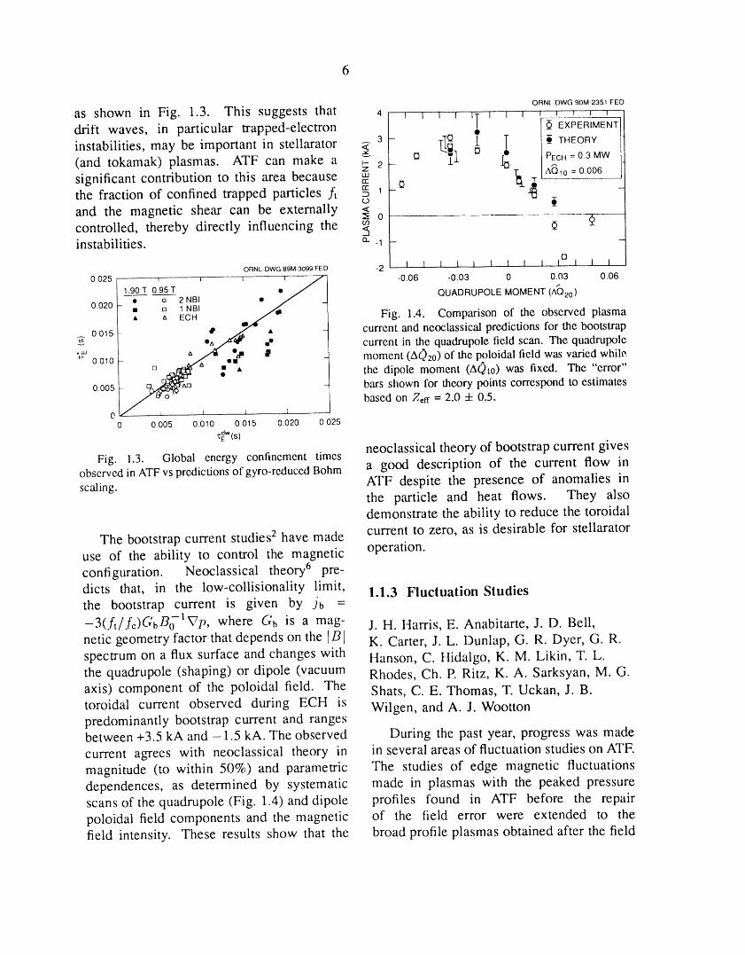
as shown in Fig. 1.3. This suggests that 4 _ _ _ _ _T _ _ _ ' ' ' ' 'drift waves, in particular trapped-electron • [_ EXPER-_-E_"
3 - t,[__ .L T [ O_ THEORYinstabilities, may be important in stellarator ,_ _ -_l Q _ PECH= 0.3MW(and tokamak) plasmas. ATF can make a E 2-
Z _ AQlo = 0.006significant contribution to this area because _-"' _the fraction of confined trapped particles J_ __ 1 -oand the magnetic shear can be externally <
z_ 0 { ....controlled, thereby directly influencing the _instabilities, a. _1 _ -
o
ORNL-DWG89M3099FED -2 I I 1 I 1 I I I I I 1 I 1
0.025 1 _ r q------j_'-] -0.06 -0.03 0 0.03 0.061.90 T 0.95 T o ,,,,/ QUADRUPOLE MOMENT (AQ20)-"-o_ _ 2 NBI • / _0.020 • n 1 NBI /
• t, ECH mJ _ Fig. 1.4. Comparison of the observedplasma
-a oo15 B_ _ - current and neoclassical predictions for the bootstrapv • current in the quadrupole field scan. The quadrupole•_ " _ °_m ,lP
o.01o- _ _., moment (AO2o) of the poloidal field was varied while.
__ - _ " the dipole moment (AQxo) was fixed. The "error"0.005t__ bars shown for theory points correspond to estimates
based on Z,rf = 2.0 + 0.5.0 1 I 1 1
0 0.005 0.010 0.015 0.020 0.025
"_:"'(s)neoclassical theory of bootstrap current gives
Fig. 1.3. Global energy confinement timesobserved in ATFvspredictions of gyro-reduced Bohm a good description of the current flow in
ATF despite the presence of anomalies inscaling.the particle and heat flows. They alsodemonstrate the ability to reduce the toroidal
The bootstrap current studies 2 have made current to zero, as is desirable for stellarator
use of the ability to control the magnetic operation.
configuration. Neoclassical theory 6 pre-
dicts that, in the low-collisionality limit, 1.1.3 Fluctuation Studiesthe bootstrap current is given by jb =
-3(.ft/fc)GbBo127p, where Gb is a mag- J.H. Harris, E. Anabitarte, J. D. Bell,
netic geometry factor that depends on the ]B K. Carter, J. L. Dunlap, G. R. Dyer, G. R.
spectrum on a flux surface and changes with Hanson, C. Hidalgo, K. M. Likin, T. L.the quadrupole (shaping) or dipole (vacuum Rhodes, Ch. P. Ritz, K. A. Sarksyan, M. G.
axis) component of the poloidal field. The Shats, C. E. Thomas, T. Uckan, J. B.
toroidal current observed during ECH is Wilgen, and A. J. Woottonpredominantly bootstrap current and rangesbetween +3.5 kA and -1.5 kA. The observed During the past year, progress was made
current agrees with neoclassical theory in in several areas of fluctuation studies on ATF.
magnitude (to within 50%) and parametric The studies of edge magnetic fluctuationsdependences, as determined by systematic made in plasmas with the peaked pressure
scans of the quadrupole (Fig. 1.4)anddipole profiles found in ATF before the repair
poloidal field components and the magnetic of the field error were extended to thefield intensity. These results show that the broad profile plasmas obtained after the field

error repair. Microwave reflectometry was in the fluctuations correspond to values ofused to study plasma density fluctuations rotational transform in the outer part of thein the outer portion of both ECH and NBI plasma (_ >_ 1/2), as would be expected forplasmas. A reciprocating Langmuir probe broad pressure profiles. In 1990-91, high-system was used to make measurements of beta experiments on ATF with (/3) _> J.5%plasma edge turbulence for comparison with will attempt to reach the second stabilityresults from tokamaks. Work was begun regime with broader pressure profiles (ason the development of a 2-mm scattering opposed to the very peaked pressure profilessystem with which to study drift wave used in the initial ATF second stabilityturbulence inside ECH plasmas. In ali of studiesS).these activities, collaboration with teams In collaboration with Georgia I;.stitutefrom other institutions has been essential, of Technology and CIEMAT, a novel diag-
Measurements of fluctuations in the nostic technique that uses a two-frequency,poloidal magnetic field (t) 0) at the plasma quadrature-phase detection microwave re-edge were used to characterize the behavior flectometer was developed and used to studyof NBI plasmas obtained in ATF since plasma density fluctuation spectra and radialthe field error was repaired, 7 in preparation correlation lengths inside ECH plasmas andfor experiments to try to reach the second at the edge of NBI plasmas. Figure 1.6stability regime in full-bore plasmas at high illustrates some of the initial results obtainedbeta in 1990-91. The results (Fig. 1.5) with this system: in NBI discharges inshow that with the broader profiles now which the plasma stored energy increases,seen in ATF, the helical resonances seen pauses, and then increases again (showing
ORNL-DWG89M3064 FED
1.2li............_---:..O,,m__2,,_.........._...........' ....__ 1_!f........';.........._n_-o................'.......,I1989!1'0 / ";_*,;"n=l 1 12_ :7_ ". 'm=3" l t lr I
0.8 , _'°"°_o ',_.st='_" 11 _ n = 1 .# I_" 0.8| *,,°'", ", ..:._L-_':-#'4. i _ n:2"_ ° ".."fiF.e,tN_ . ,, ! • a_. • •
o, ![ " .-._.-_.._:.._.. . |o.21 _.. o:......o ! 3 ,_,,o,
0 10 20 30 40 50 60 0 1 2 3 4 5
FREQUENCY(kHz)_...._- - TOROIDALMODENUMBER,n_1 " F---------rV---_ r -T----- .... q" T i _ ,t=W] J"
o.8!._/ooF " -I/ 1
i
0.2 r
0 L_....... _'--........ _L ' _ .L........0 0.2 0.4 0.6 0.8 1.0
ria
Fig. 1.5. Summary of mode numbers observed for magnetic fluctuations before repair of the field error
[1988, peaked p(r)] and after repair of the field error [1989, broad p(r)].

ORNL- DWG 89M-3063R F Ii D
200 7 I 1 I [ I I 1 I l
J/
150 - _-
c'" S(co)
100
5O
00 20 40 60 80 20 40 60 80
FREQUENCY (kHz) FREQUENCY (kHz)
40 , I I I 20SHOT 7803
30 neI [,_ 15
_o20 I We_
--_ 5r-
10
0
0 I I I I0 01 0.2 0.3 0.4 0.5
TIME (s)
Fig. 1.6. Correlation of change in edge density fluctuation power spectra S(_.,) with improvement in globalthe chordal electron density (nj) and the stored energy (W_)confinement. The dme traces showenergy
determined from poloidal magnetic field measurements. The fluctuation spectra were measured at r/a '_ 0.9using microwave rellectometry at 33 GHz (cutoff density = 1.35 x 1013 cm-3). The spectra were averagedover 12.5-ms intervals centered at the times indicated. The NBI power (balanced injection) was 1.4 MW.
improved confinement), a marked change other plasma regimes and higher microwavein the density fluctuation spectrum at the frequencies.
plasma edge is observed. The spectrum In collaboration with the TEXT groupmeasured with the reflectometer changes to at the University of Texas, a fast recip-
a narrow-band spectrum with a strong peak rocating Langmuir probe (FRLP) has beenbetween 20 and 40 kHz. This oscillation is installed on ATF and used to measure
coherent with high-n (n >_ 3) components plasma density and potential fluctuations in
of the /)0 signal. By separately tuning the the edge region (Te _< 40 eV) of ECH
two frequency channels of the reftectometer plasmas. 9,1° The results show broadbandto reflect off plasma layers at different fluctuations in density, /'_/7_ ,-_ 5%, and
radii, it is possible to determine the radial floating potential, _/kTe "_ 10%, just inside
correlation length of density fluctuations, the last closed magnetic surface (Hfi "--'0.95).
This technique yields correlation lengths of The outward particle transport induced by
1-2 cm in ECH plasmas and <0.5 cm at these fluctuations is comparable to that
the edge of NBI plasmas. Plans include estimated from the global particle balancethe extension of the reflectometer studies to if the flux is assumed to be poloidally and
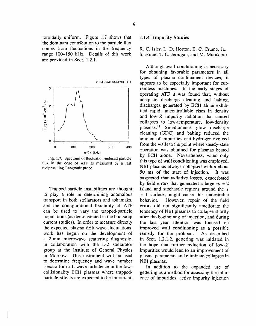
toroidally uniform. Figure 1.7 shows that 1.1.4 Impurity Studiesthe dominant contribution to the particle fluxcomes from fluctuations in the frequency R.C. Isler, L. D. Horton, E. C. Crume, Jr.,range 100-150 kHz. Details of this work S. Hiroe, T. C. Jernigan, and M. Murakamiare provided in Sect. 1.2.1.
Although .wall conditioning is necessaryfor obtaining favorable parameters in alitypes of plasma confinement devices, it
ORNL-DWG90-2489RFED appears to be especially important for cur-3 rentless machines. In the early stages of
operating ATF it was found that, without._ adequate discharge cleaning and bakiog,• 2 discharges generated by ECH alone exhib-
ited rapid, uncontrollable rises in densityand low-Z impurity radiation that caused
_1 _ collapses to low-temperature, low-density
_ plasmas. 11 Simultaneous glow discharge
lt..,
cleaning (GDC) and baking reduced theamount of impurities and hydrogen evolved0 ">,,
' ' ' from the wzll_ t,-. ti_e point where steady-state0 100 200 300 400 ..........operation was obtained for plasmas heated
0J/2n(kHz) by ECH alone. Nevertheless, when onlyFig. 1.7. Spectrumof fluctuation-inducedparticle this type of wall conditioning was employed,flux in the edge of ATF as measured by a fast
reciprocating Langmuir probe. NBI plasmas always collapsed within about50 ms of the start of injection. It wassuspected that radiative losses, exacerbatedby field errors that generated a large rrz = 2
Trapped-particle instabilities are thought island and stochastic regions around theto play a role in determining anomalous = 1 surface, might cause this undesirabletransport in both stellarators and tokamaks, behavior. However, repair of the fieldand the configurational flexibility of ATF errors did not significantly ameliorate thecan be used to vary the trapped-particle tendency of NBI plasmas to collapse shortlypopulations (as demonstrated in the bootstrap after the beginninng of injection, and duringcurrent studies). In order to measure directly the last year attention was focused onthe expected plasma drift wave fluctuations, improved wall conditioning as a possiblework has begun on the development of remedy for the problem. As describeda 2-mm microwave scattering diagnostic, in Sect. 1.2.1.2, gettering was initiated inin collaboration with the L-2 stellarator the hope that further reduction of Iow-Zgroup at the Institute of General Physics impurities would lead to an improvement ofin Moscow. This instrument will be used plasma parameters and eliminate collapses into determine frequency and wave number NBI plasmas.spectra for drift wave turbulence in the low- In addition to the expanded use ofcollisionality ECH plasmas where trapped- gettering as a method for assessing the influ-particle effects are expected to be important, ence of impurities, active impurity injection
l0
experiments were performed to gain more and gettered sequences in which chromiuminsight into the effects of contaminants on and titanium were evaporated with differentATF plasmas. A laser ablation system was fractions of wall coverage. The effects ofinstalled in order to determine the impurity gettering are best evaluated from the quasi-
transport coefficients and to permit more steady ECH plasmas, since the percentage ofaccurate modeling of the impurity behavior, radiation can vary substantially during NBI.Neon injection experiments were also used Emissions from the low ionization stages ofto assess power losses and to determine the carbon, nitrogen, and oxygen were lowerlevel of radiation that the plasmas could by factors of 2 to 5 in the discharges withsupport, chromium gettering than in the nongettered
The changes of impurity radiation under discharges. This result does not indicatevarious conditions, improvements of plasma the reduction of the influx of low-Z ionsparameters as a result of gettering, and by the same factor owing to the nonlinearimpurity injection experiments are described response of peripheral emissions to changesin Sects. 1.1.4.1-1.1.4.3. of plasma conditions. Indeed, charge-
exchange excitation (CXE) signals, whichprovide a direct measure of the impurity
1.1.4.1 Gettering and impurity radiation content in the interior of plasmas, indicated adrop of about 30% in the density of carbon
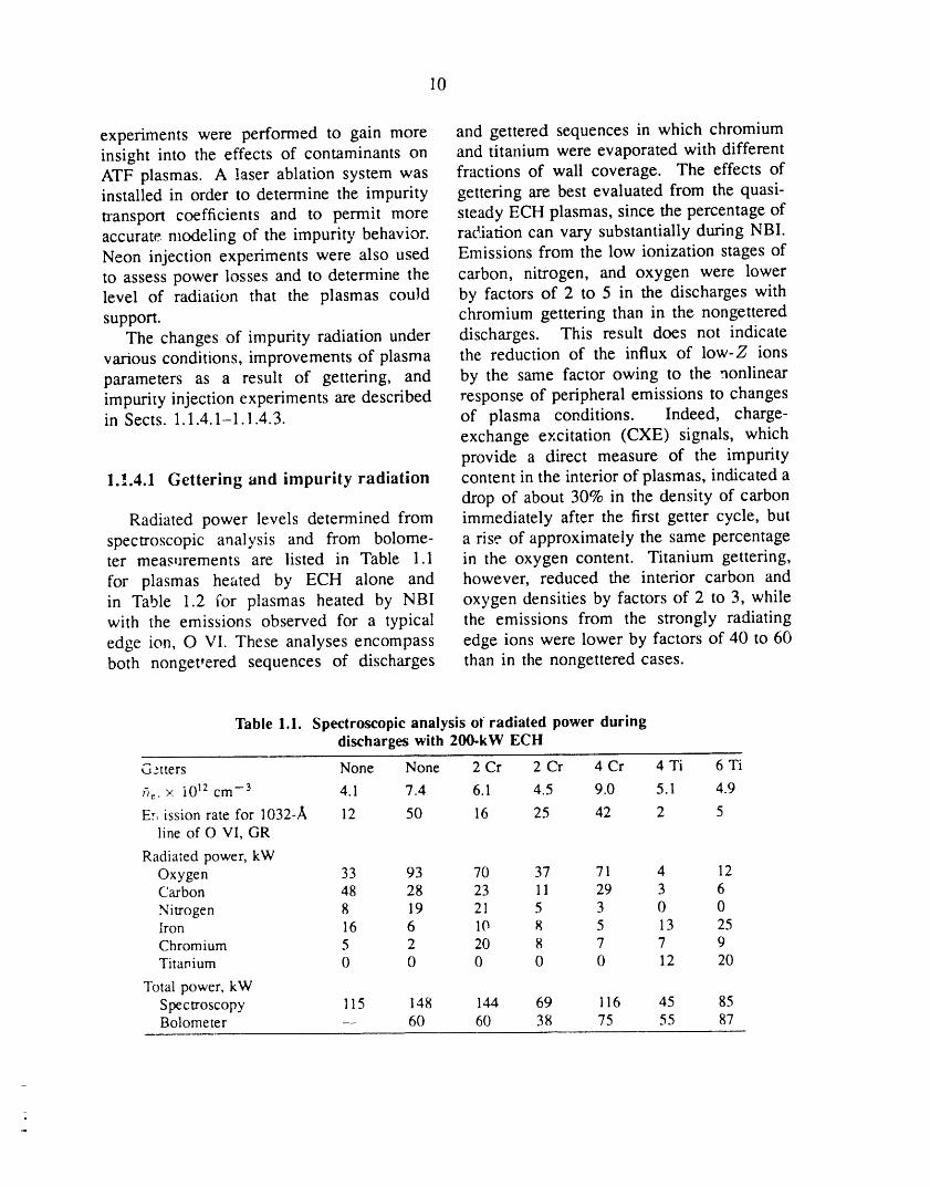
Radiated power levels determined from immediately after the first getter cycle, butspectroscopic analysis and from bolome- a rise of approximately the same percentageter measurements are listed in Table 1.1 in the oxygen content. Titanium gettering,for plasmas heated by ECH alone and however, reduced the interior carbon andin Table 1.2 for plasmas heated by NBI oxygen densities by factors of 2 to 3, whilewith the emissions observed for a typical the emissions from the strongly radiatingedge ion, O VI. These analyses encompass edge ions were lower by factors of 40 to 60both nonget,ered sequences of discharges than in the nongettered cases.
Table 1.1. Spectroscopic analysis of radiated power duringdischarges with 200-kW ECH
Gztters None None 2 Cr 2 Cr 4 Cr 4 Ti 6 Ti
fi_. × 1012 cm -3 4.1 7.4 6.1 4.5 9.0 5.1 4.9
Ev, ission rate for 1032-A 12 50 16 25 42 2 5
line of O VI, GR
Radiated power, kWOxygen 33 93 70 37 71 4 12Carbon 48 28 23 11 29 3 6
Nitrogen 8 19 21 5 3 0 0Iron 16 6 10 8 5 13 25Chromium 5 2 20 8 7 7 9Titar_ium 0 0 0 0 0 12 20
Total power, kWSpectroscopy 115 148 144 69 116 45 85Bolometer 60 60 38 75 55 87
11
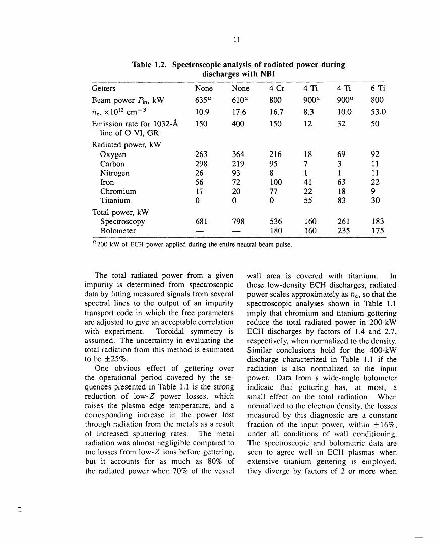
Table 1.2. Spectroscopic analysis of radiated power duringdischarges with NBI
Getters None None 4 Cr 4 Ti 4 Ti 6 Ti
Beam power Pm, kW 635 a 610 a 800 900 a 900 a 800
fie, xl0 _2cm -3 10.9 17.6 16.7 8.3 10.0 53.0
Emission rate for 1032-A 150 400 150 12 32 50line of O VI, GR
Radiated power, kWOxygen 263 364 216 18 69 92Carbon 298 219 95 7 3 11
Nitrogen 26 93 8 1 1 11Iron 56 72 100 41 63 22Chromium 17 20 77 22 18 9Titanium 0 0 0 55 83 30
Total power, kWSpectroscopy 681 798 536 160 261 183Bolometer -- -- 180 160 235 175
a 200 kW of ECH power applied duringthe entire neutral beam pulse.
The total radiated power from a given wall area is covered with titanium. Inimpurity is determined from specla'oscopic these low-density ECH discharges, radiateddata by fitting measured signals from several power scales approximately as fie, so that thespectral lines to the output of an impurity spectroscopic analyses shown in Table 1.1transport code in which the free parameters imply that chromium and titanium getteringare adjusted to give an acceptable correlation reduce the total radiated power in 200-kWwith experiment. Toroidal symmetry is ECH discharges by factors of 1.4 and 2.7,assumed. The uncertainty in evaluating the respectively, when normalized to the density.total radiation from this method is estimated Similar conclusions hold for the 400-kW
to be -t-25%. discharge characterized in Table 1.1 if theOne obvious effect of gettering over radiation is also normalized to the input
the operational period covered by the se- power. Data from a wide-angle bolometerquences presented in Table 1.1 is the strong indicate that gettering has, at most, areduction of low-Z power losses, which small effect on the total radiation. Whenraises the plasma edge temperature, and a normalized to the electron density, the lossescorresponding increase in the power lost measured by this diagnostic are a constantthrough radiation from the metals as a result fraction of the input power, within 4-16%,of increased sputtering rates. The metal under ali conditions of wall conditioning.radiation was almost negligible compared to The spectroscopic and bolometric data arethe losses from low-Z ions before gettering, seen to agree well in ECH plasmas whenbut it accounts for as much as 80% of extensive titanium gettering is employed;the radiated power when 70% of the vessel they diverge by factors of 2 or more when
12
the low-Z ions dominate the radiative losses, titanium-gettered plasmas. No gas is addedThe dichotomy between the two types of during NBI in the low-density case. Inanalyses remains an unresolved problem, fact, the gas puff is reduced throughout
the NBI phase, and any increase in n_
1.1.4.2 Effects ot gettering on plasma comes from beam fueling or from particlesreleased from the walls. Such plasmas
performance manifest the typical evolution observed forRegardless of any uncertainty about the nongettered or chromium-gettered plasmas.
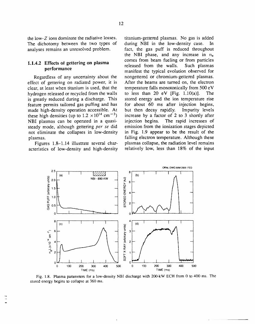
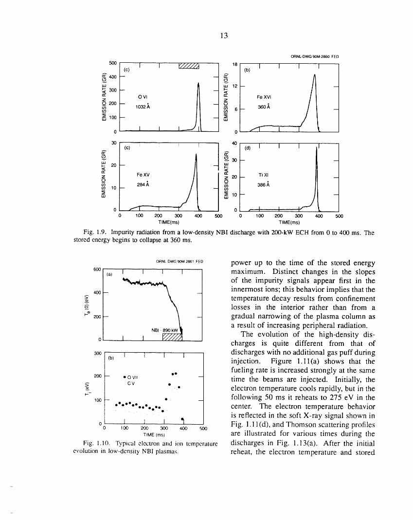
effect of gettering on radiated power, it is After the beams are turned on, the electronclear, at least when titanium is used, that the temperature falls monotonically from 500 eVhydrogen released or recycled from the walls to less than 20 eV [Fig. 1.10(a)]. Theis greatly reduced during a discharge. This stored energy and the ion temperature risefeature permits tailored gas puffing and has for about 60 ms after injection begins,made high-density operation accessible. At but then decay rapidly. Impurity levelsthese high densities (up to 1.2 x 1014 cm -3) increase by a factor of 2 to 3 shortly afterNBI plasmas can be operated in a quasi- injection begins. The rapid increases ofsteady mode, although gettering per se did emission from the ionization stages depictednot eliminate the collapses in low-density in Fig. 1.9 appear to be the result of theplasmas, falling electron temperature. Although these
Figures 1.8-1.14 illustrate several char- plasmas collapse, the radiation level remainsacteristics of low-density and high-density relatively low, less than 18% of the input
OFINL-DWGgOM-2859FED
2.5 t l _/////j ...... 81 I l t t
.._ (a) 6_ 2.0 -- NBI-890 KW _
1.5 - _ rrI.,u
_ _ 4 --
(.9_nu-u-1'0__.__.._0.5 _-- orrUjr"m_..2 --
o 1 I"-"'-t'---_- o LI ,
8 (c) I 1 I I _ 4 1r"
6-- = 3 --z",._
04- _ 2 -x
c 2 x 1 --
o_" 1 1 I0 100 200 300 400 500 0 100 200 300 400 500
TIME (ms) TIME (ms)
Fig. 1.8. Plasma parameters for a low-density NBI discharge with 200-kW ECH from 0 to 400 ms. The
stored energy begins to collapse at 360 ms.
13
ORNL-DWG90M-2860 FED
500 I 1 _/S///A la I I I I(c) (b)
rr" 400 _
m m 12__'300 _ _-rr 0 VI rr Fe XVlz z
o 2oo- _oa2L - o __ 6-- 360 _
/100 _ _;uJ _ LU
o I I I__..) L o /"T-:-'1 'q" L
30 i , ' 4| ,o
(c) ' ' (d) ! I 1 Irr
LU _ 30 _20 -- w
-o" i =o
Fe XV Ti XI
z //z 20 - i -
284 ,g, 386 ico 10 --
10-- ) --uJ
J I 1o .-"'1_1 1 k o -- , ,---- , l0 100 200 300 400 500 0 100 200 300 400 500
TIME(ms) TIME(ms)
Fig. 1.9. Impurity radiation from a low-density NBI discharge with 200-kW ECH from 0 to 400 ms. Thestored energy begins to collapse at 360 ms.
ORNL-DWGgOM,2861FED power up to the time of the stored energy6o0 I I 1 I maximum. Distinct changes in the slopes(a)
of the impurity signals appear first in the4o0- _ innermost ions; this behavior implies that the
temperature decay results from confinementoZ losses in the interior rather than from a
_-=2o0- gradual narrowing of the plasma column as
a result of increasing peripheral radiation.0. I I _'/.//,/j] The evolution of the high-density dis-charges is quite different from that of
3o0 I I I I discharges with no additional gas puff during(b) injection. Figure 1.11(a) shows that the
• . fueling rate is increased strongly at the same20o- -oy - time the beams are injected. Initially, the
cv • • electron temperature cools rapidly, but in the10o- . _ following 50 ms it reheats to 275 eV in the
• •0••0• •
•..... center. The electron temperature behavior• is reflected in the soft X-ray signal shown in
o 1 1 1 '_ Fig. 1 l l(d) and Thomson scattering profiles0 100 200 300 400 500 " " '
TIME(ms) are illustrated for various times during theFig. 1.10. Typical electron and _ontemperature discharges in Fig. 1.13(a). After the initial
evolution in low-density NBI plasmas, reheat, the electron temperature and stored

14
ORNL-DWG90M-2862 FED
60 I' (a) _/'///////////_ 12 (b) I 1
__1- ""-,,J I - _O 3
o I I - o
4o , 2 (d)/i '(c)
_- -20 -- -- _ 1 _ a --
o >-
_ n_
=°_°- tzO
0 200 4OO 6O0 0 200 4O0 6O0
TIME (ms) TIME (ms)
Fig. 1.1 l. Plasma parameters for a high-density NBI discharge with 200-kW ECH from 0 to 220 ms. Nocollapse occurs.
ORNL-DWG90M-2863 FED
_5o Villi/Ill/ld i 30 I I_" NBI - 750 kW rr"
v Hl --w - __ 20 --p.. 100 _ << rr" Ti Xll
. OV__lZZ/,Z O °o_ _o_ _ _oo co 10_o_ 50_
uJ u.J
o/ _ 1 _ o
8j I I 0.5 ,, I I(c) _ (d)
_" t _ 0.4 I - _ Ti XlX
(_9 6 Fe XV _ LMuJ 170
. -
o_ "_ °°'-o_ _/ -"_uJ 2 | - uJ 0.1 --
o LI 0 [ I0 200 400 600 0 200 400 600
TIME (ms) TIME (ms)
Fig. 1.12. Impuzity radiation from high-density NBI discharges wiLh 200-kW F_.CH(a, b) from 0 to 220 msand (c, d) from 0 to ]80 ms. No collapse occurs.

15
ORNL-DWG90M-2O64FED energy increase slightly until the end of the
1000 _1 I I I (a) NBI pulse with no sign of evolving toward.a collapse. The central ion temperature,
800 -X- - measured from the Doppler broadening ofO VII spectral lines, exhibits a brief rise
_ 6oo-- _95ms - when the beams are turnedon butreturns"-" to the preinjection level within 16 ms.t-_ 400 370ms \ Modeling indicates that this ion is spread out
2oo ""_._.._.i._._._i_'_.',_.'.'_.'_--... over a region where the electron temperature28orns........................'_...i.i..'".......... is 200 to 300 eV, and it is not now understood
0 I I _1 ........Z'.-.:., why the electron and ion temperatures should0 0.2 o.4 0.6 0.8 .0 be so different in these high-density, lOW-REDUCEDRADIUS
temperature plasmas.200 l I (b) Emissions from the lower ionization
stages of oxygen, titanium, and iron15o- ° - (Fig. 1.12) are seen to be almost constant•vii
• • after 400 ms. The Ti XIX signal disappears
loo --i• °%••• °•••••°•° - before 400 ms because the electron temper-_-- ature in the plasma is too low to sustain a
cv - measurable density of this ion. (The loss of50 ,,oooooo signals from Fe XV and Ti XIX at 230 ms) _ ( _, _. ,_ 00 O(-)O()O00C,
• 00__ 0 " "' O"-"r,u_C;O,_• ,9 _, ,,oV v° ° i . .*°,_°°** Iv results from termination of ECH heating
0 200 400 600 before NBI begins in these discharges. NoteTIME(ms) that the plasma still reheats when the beam
Fig. 1.13. Typical electron and ion temperature turns on.) As in the low-density case,evolutionin high-density NBI plasmas, radiated power remains a modest 25% of
the input power throughout the discharges.Without gettering, it has not been possibleto achieve such high-density, quasi-steady
ORNL-DWG90M-286SFED discharges. The comparable fractions ofo.lo t 1 i i radiated power in the NBI phases of both
the transient and the quasi-steady discharges0.o8- - indicate that global radiation losses are not a
primary factor in initiating collapses.0.o6- - Modeling of the profiles of radiated
power from the spectroscopic data alsoA
0.04-----------"--__ / _ indicates that radiation is veryunlikely to
o:- be responsible for initiating the loss of
0.02- confinement in the interior inferred fromthe data of Fig. 1.9. Figure 1.14 shows
0 I 1 I 1 that the radiated power during low-density0 0.2 0.4 0.6 o.a .0 discharges is approximately 0.04 W.cm -3
P fr_:n the center of the plasma to a reducedFig. 1.!4. Radiation profile deduced from spec-
troscopy for a low-density, titanium-gettered sequence minor radius of 0.8. If all the power fromof discharges, a 1-MW neutral beam is deposited in this
16
volume, it is more than 10 times this level below the level that initiates a continuous
on average, drop in the electron temperature, lt isintroduced in a 7-ms-wide pulse at 200
1.1.4.3 Impurilv injeelion ms. The emissions from the low stages" peak about 80 ms later, then decline until
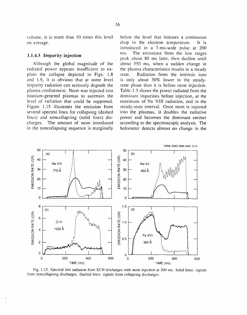
Although the global magnitude of the about 350 ms, when a sudden change inradiated power appe,'u's insufficient to ex- the plasma characteristics results in a steadyplain the collapse depicted in Figs. 1.8 state. Radiation from the intrinsic ionsand 1.9, it is obvious that at some level is only about 30% lower in the steady-impurity radiation can seriously degrade the state phase than it is before neon injection.plasnla confinement. Neon was injected into Table 1.3 shows the power radiated from thetitanium-gettered plasmas to ascertain the dominant impurities before injection, at thelevel of radiation that could be supported, maximum of Ne VIII radiation, and in theFigure 1.15 illustrates the emission from steady-state interval. Once neon is injectedseveral spectral lines for collapsing (dashed into the plasmas, it doubles the radiativelines) and noncollap:dng (solid lines) dis- power and becomes the dominant emittercharges. The amount of neon introduced according to the spectroscopic analysis. Thein the noncollapsing sequence is marginally bolometer detects almost no change in the
ORNL-DWG 90M-2866 FED
50 50(a) ] ..1 ] (b) ] ]
,, ,, p.,',
uu Ne VIII : : uu Ne VII :,, ,:!'F- '_ p-
< 30 /, .. _ ao- j, :. ::..,,.::,.rr" 770 , , 465o i %l_'l''ll •Z _ " Z , '..,.,'.",
O " O ' '¢"" _;
0 0 --- -- ],
8 1.5(c) I I {d) I 1
rr" , , . 137. '°""
; ¢'. CO _ .zg;; • 'LU _ ",;
O VI : ,,;_,%, _ 1.0< , <rr" • ' Y"Z 4 _ 1032 A : ,,., rr
, _ Z
_(2 : _ocn ,: m
0 0 "'""'"l'"'"'"'"".,0 200 400 600 0 200 400 600
TIME (ms) TIME (ms)
Fig. 1.15. Spectral line radiation from ECH discharges with neon injection at 2(X) ms. Solid lines: signalsfrom noncollapsing discharges. Dashed lines: signals from collapsing discharges.
17
Table 1.3. Spectroscopic analysis of than they are at 180 ms before the neonradiated power during NBI heating is introduced. This direct observation of
edge cooling supports the similar inferenceTime, ms from the behavior of the iron emission [Fig.
200 300 400 1.15(d)]. The profile is again relativelybroad at 400 ms. A sudden change in
/-_, x l012 cm -3 4.2 4.9 4.8 the profile around 350 ms is apparentlyEmission rate for 770-A 1.5 21 11 responsible for the transition to the steady-
line of Ne VIII, GR state emission levels observed in the spectral
Radiated power, kW lines.Neon 5.2 61.5 27.2 Lengthening the neon pulse from 7 _o
Oxygen 2.6 3.2 1.8 8 ms causes the plasmas to evolve to aCarbon 1.8 0.8 1.1 collapse, as shown by the dashed linesNitrogen 0.5 0.3 0.4 in Fig. 1.15. The temperatures after theIron 15.6 6.1 9.8 collapse in this experiment are not as lowChromium 5.6 3.1 4.5 as those usually observed; O VI remains,Titanium 0 0 0 uncharacteristically, a dominant ion in the
Total spectroscopic 44 87 56 afterglow. The erosion of the plasma edgepower, kW has been proposed as a possible mechanism
for the collapse on the basis of predictivecalculations using the PROCTR code. The
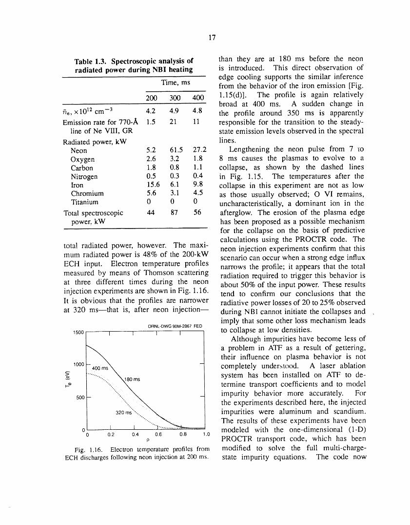
total radiated power, however. The maxi- neon injection experiments confirm that thismum radiated power is 48% of the 200-kW scenario can occur when a strong edge influxECH input. Electron temperature profiles narrows the profile; it appears that the totalmeasured by means of Thomson scattering radiation required to trigger this behavior isat three different times during the neon about 50% of the input power. These resultsinjection experiments are shown in Fig. 1.16. tend to confirm our conclusions that the
It is obvious that the profiles are narrower radiative power losses of 20 to 25% observedat 320 ms--that is, after neon injection-- during NBI cannot initiate the collapses and .
imply that some other loss mechanism leadsORNL-DWG90M-2867 FED
_500 I I I _ to collapse at low densities.Although impurities have become less of
a problem in ATF as a result of gettering,their influence on plasma behavior is not
_o00 - completely understood. A laser ablationsystem has been installed on ATF to de-
___ termine transport coefficients and to model
500 impurity behavior more accurately. For
32f,ws.i,iii,..i.,_,,__I the experiments described here, the injected
' impurities were aluminum and scandium.
' ....I....._._._ The results of these experiments have been0 1 modeled with the one-dimensional (l-D)0 0.2 0.4 0.6 0.8 .0
p PROCTR transport code, which has been
Fig. 1.16. Electron temperature profiles from modified to solve the full multi-charge-ECH discharges followingneon injectionat 2(10ms. state impurity equations. The code now
18
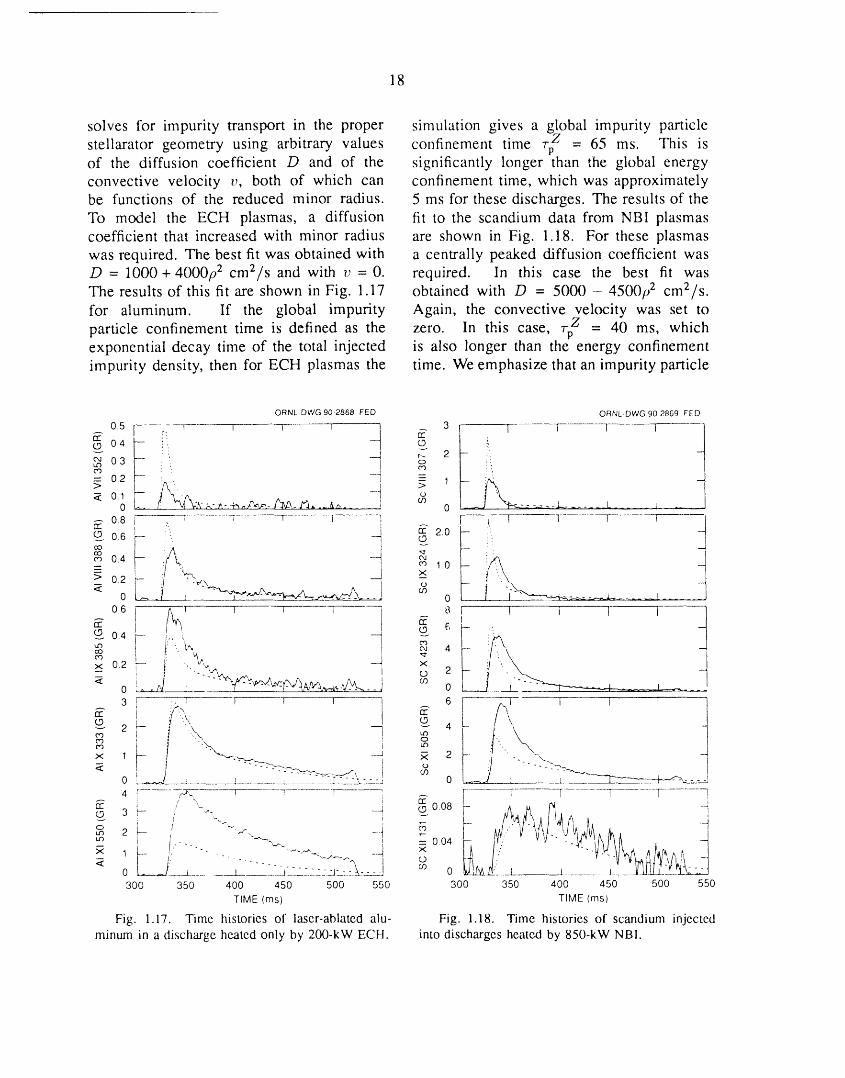
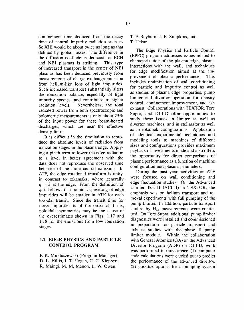
solves for impurity transport in the proper simulation gives a global impurity particle
stellarator geometry using arbitrary values confinement time .r_' = 65 ms. This isof the diffusion coefficient D and of the significantly longer than the global energyconvective velocity v, both of which can confinement time, which was approximatelybe functions of the reduced minor radius. 5 ms for these discharges. The results of theTo model the ECH plasmas, a diffusion fit to the scandium data from NBI plasmascoefficient that increased with minor radius are shown in Fig. 1.18. For these plasmaswas required. The best fit was obtained with a centrally peaked diffusion coefficient wasD = 1000+4000p 2 cmZ/s and with v = 0. required. In this case the best fit wasThe results of this fit are shown in Fig. 1.17 obtained with D = 5000 - 4500p z cm2/s.for aluminum. If the global impurity Again, the convective velocity was set to
particle confinement time is defined as the zero. In this case, "rf = 40 ms, whichexponential decay time of the total injected is also longer than the energy confinementimpurity density, then for ECH plasmas the time. We emphasize that an impurity particle
QRNL.DWG 90-2868 FED ORNL DWG 90 2869 FED
0.5[ :'. T 1 1 1 | 3 1 T........ [ [ 1E E
© 0.4 _ ---1__i O t
_ 0.3 __j r-- 2 -t._ I o3° ";0'3
= 0.2 -- 1 --> > I
0 7.,-_,-4_.,,t%-___J_., I_,..Jx_ ..... 0 .... J........ L ..... l
, _ 1 I I 1 i f [ .... |
rr 0.8 i ,.. i E 2.0 - -
_ 0.6F_ p i/_:":' _1 © f i._ ' 1
ooco 0.4 --_ 04, co 1.0
-- _ ;."7',. __j x
_ O ......
06 t t_ _ _ _ T _ i I I 1 I ]© 6
_'_" 0"4 {-- i:"..., x'_,,i,'_ -- _" _ _'_o , 4 " 4' [: ,'_,_ -J x
x 0.2 :-- _ "'-_, i 2-- i 0co
o ._,_ __ - -,__,w_.,._._,7:.,,._._.o L___ ___
3 t :. E I I I 6 ----_-q I I 1
(.9 2 ' '_ )" _"_ 4 , \
0'3 0 "L,, \-. ___-_->._._.._
0 _ _ , . .......... L-_ '_..,:- -J 0 ._ i , "--q'_---_.__-', ....4 r ......... --KT_,_ V i T i _ "...... [ ....... T......... --7 ...... T............
u_ .-- ""-"-,-'- l = 0.04 t_ q
<- L_m:__l,. -.......-.... o0 __]_........ ____1 .... j--------.--z--_.__:.. CO 0 ll)Li/3&.L!:......_1 1_......... J.... __UJJ_L........
300 350 400 450 500 550 300 350 400 450 500 550
TIME (ms) TIME (ms)
Fig. ].]7. Timc historics of lascr-ablatcd alu- Fig. 1.18. Timc historics of scandium injcctcd
minum in a discharge heated only by 200-kW ECH. into discharges heated by 850-kW NBI.
19
confinement time deduced from the decay T.F. Rayburn, J. E. Simpkins, andtime of central impurity radiation such as T. UckanSc XIII would be about twice as long as that
The Edge Physics and Particle Controldefined by global losses. The difference inthe diffusion coefficients deduced for ECH (EPPC) prouam addresses issues related to
characterizatio_ of the plasma edge, plasmaand NBI plasmas is striking. This typeof increased transport in the center of NBI interactions with the wall, and techniquesplasmas has been deduced previously from for edge modification aimed at the im-measurements of charge-exchange emission provement of plasma performance. This
includes optimization of wall conditioningfrom helium-like ions of light impurities.for particle and impurity control as wellSuch increased transport substantially altersas studies of plasma edge properties, pumpthe ionization balance, especially of lightlimiter and divertor operation for densityimpurity species, and contributes to higher
radiation levels. Nevertheless, the total control, confinement improvement, and ash
radiated power from both spectroscopic and exhaust. Collaborations with TEXTOR, Torebolometric measurements is only about 25% Supra, and DIII-D offer opportunities toof the input power for these beam-heated study these issues in limiter as well asdischarges, which are near the effective divertor machines, and in stellarator as welldensity limit, as in tokamak configurations. Application
It is difficult in the sim_liation to repro- of identical experimental techniques andduce the absolute levels of radiation from modeling tools to machines cf different
sizes and configurations provides maximumionization stages in the plasma edge. Apply-ing a pinch term to lower the edge radiation payback of investments made and also offers
the opportunity for direct comparisons ofto a level in better agreement with thedata does not reproduce the observed time plasma performance as a function of machinebehavior of the more central emission. In configuration and plasma parameters.
ATF, the edge rotational transform is unity, During the past year, activities on ATFin contrast to tokamaks, where generally were focused on wall conditioning andq -- 3 at the edge. From the definition of edge fluctuation studies. On the Advancedq, it follows that poloidal spreading of edge Limiter Test-II (ALToII) in TEXTOR, theimpurities will be smaller in ATF for each emphasis was on helium transport and re-toroidal transit. Since the transit time for moval experiments with full pumping of the
pump limiter. In addition, particle transportthese impurities is of the order of 1 ms,studies by Ha measurements were contin-poloidal asymmetries may be the cause of
the overestimates shown in Figs. 1.17 and ued. On Tore Supra, additional pump limiter1.18 for the emissions from low ionization diagnostics were installed and commissioned
stages, in preparation for particle transport andexhaust studies with the phase II pumplimiter module. Within the collaboration
1.2 EDGE PHYSICS AND PARTICLE with General Atomics (GA) on the AdvancedCONTROL PROGRAM Divertor Program (ADP) on DIII-D, work
was performed in three areas: (1) computerP. K. Mioduszewski (Program Manager), code calculations were carried out to predictD. L. Hillis, J. T. Hogan, C. C. Klepper, the performance of the advanced divertor,R. Maingi, M. M. Menon, L. W. Owen, (2) possible options for a pumping system
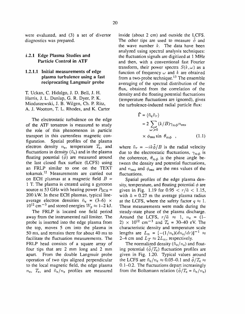
20
were evaluated, and (3) a set of divertor inside (about 2 cm) and outside the LCFS.diagnostics was prepared. The other tips are used to measure _ and
the wave number k. The data have been
analyzed using spectral analysis techniques:1.2.1 Edge Plasma Studies and the fluctuation signals are digitized at 1 MHz
Particle Control in ATF and then, with a conventional fast Fourier
transform, their power spectra S(/,-,_) as a1.2.1.1 Initial measurements of edge function of frequency ,., and k are obtair, ed
plasma turbulence using a fast from a two-probe technique. 13 The ensemblereciprocating Langmuir probe averaging of the spectral distribution of the
flux, obtained from the correlation of theT. Uckan, C. Hidalgo, J. D. Bell, J.H. density and the floating potential fluctuationsHarris, J. L. Dunlap, G. R. Dyer, P.K. (temperature fluctuations are ignored), givesMioduszewski, J. B. Wilgen, Ch. R Ritz, the turbulence-induced radial particle flux:A. J. Wootton, T. L. Rhodes, and K. Carter
The electrostatic turbulence on the edgeof the ATF torsatron is measured to study = 2 Z (k/B)Tn4'nrmsthe role of this phenomenon in particle ,_>0
transport in this currentless magnetic con- x 4,,_ssin 0n4_ , (1.1)figuration. Spatial profiles of the plasmaelectron density he, temperature Te, and where i_. = -ik_/B is the radial velocityfluctuations in density (fie) and in the plasma due to the electrostatic fluctuations, "/nO isfloating potential (_) are measured around the coherence, 0n4, is the phase angle be-the last closed flux surface (LCFS) using tween the density and potential fluctuations,an FRLP similar to one on the TEXT and n_msand 4,rmsare the rms values of thetokamak. 12 Measurements are carried out fluctuations.
on ECH plasmas at a magnetic field B = Spatial profiles of the edge plasma den-1 T. The plasma is created using a gyrotron sity, temperature, and floating potential 4' aresource at 53 GHz with heating power/-_clt = given in Fig. 1.19 for 0.95 < r/fi < 1.15,200 kW. In these ECH plasmas, typical line- with fi - 0.27 m the average plasma radiusaverage electron densities /_._ = (3-6) x at the LCFS, where the safety factor q _ 1.1012 cm -3 and stored energies lVp _ 1-2 kJ. These measurements were made during the
The FRLP is located one field period steady-state phase of the plasma discharge.away from the instrumented raillimiter. The Around the LCFS, r/_t _ 1, n_ = (1-probe is inserted into the edge plasma from 2) x 1012 cm -3 and T_ = 30-40 eV. Thethe top, moves 5 cm into the plasma in characteristic density and temperature scale50 ms, and remains there for about 40 ms to lengths are Ln = [-(1/ne)(dne/dr)] -1facilitate the fluctuation measurements. The 2-4 cm and L T _ 2Lh, respectively.FRLP head consists of a square array of The normalized density (5_/n,,)and float-four tips that are 2 mm long and 2 mm ing potential (_5/T_) fluctuation profiles areapart. From the double Langmuir probe given in Fig. 1.20. Typical values aroundoperation of two tips aligned perpendicular the LCFS are he/he _ 0.05-0.1 and _b/Te ,_to the local magnetic field, the edge plasma 0.1-0.2. The fluctuations depart increasinglyhe, Te, and fiehe profiles are measured from the Boltzmann relation (@Te = 5e/he)

21
ORNL-DWG 90-2485 FED ORNL-DWG 90-2486 FED
0.30 1
1.4 O he/he
Z_ ~ /T e
1.2 o o _ 0.25El
, o o A10 o20"
× 0.8 Pl D j_v _ 0.15 A
o.6 ,,, O.lO z_ _,'4'_- gZ 0.4 0 []uJ []
'-' 5 o.o5,,, _BB_ B°0.2 rc
0 • i • , • ! • i0 • i • i • i • i 0.90 0.95 1.00 1.05 1.10 .15
50 r/_
[] Fig. 1.20. Relative fluctuation levels for edge40 []B density and potentizJ.> DQ
v QOv-• o o
30 o []rc
_- n 0rc< 20 O The fluctuation spectra of /'-_ anduJ rl
Q- have been examined for frequencies up touJ
_0 400 kHz. Observed wave number-frequencypower spectra S(k,w) are broad and mostlyin the range 40-300 kHz. The estimated0 • i • i • i • i
0 wave numbers k = 1-3 cm -1 satisfy kpso 0.05-0.1, where ps is the ion Larmor radius
at the sound speed. The propagation of-10 0 []o the fluctuations is in the ion diamagnetic_J
-< direction for r/_ > 1 but it reverses to theZ,,, electron diamagnetic direction for r/?_ < 1_- -20oo_ The fluctuation-induced particle flux is
o estimated from Eq. (1 1), using 7n¢ _ 0.8_Z []_- o _ 0.2 beyond_-30 o• up to 150 kHz and 7n¢
E/ o_5[] 250 kHz. The phase angle is 07_4, _ 40 °[] around 150 kHz. The spatial profile of the[]
-40 , • " "0.90 0.95 1.0; 105 1.1'0 1.15 total particle flux [" is given in Fig. 1.21
r/_ for fze = 3.5 X 1012 cm -3. The flux
Fig. 1.19. Spatial profiles of the ATF edge plasma is always outward and at the LCFS hasdensity,temperature,and floatingpotential, a value [" ,-_ 4 x 1015 cm-2.s -1. The
corresponding fluctuation-induced particleconfinement time is _p= 0.75(_/2)fi/[" _ 8-10 ms for the assumed parabolic plasm_
as the probe is moved into the core plasma density profile. Using He measurementswhere T_ > 20 eV, and _/Te _ 2fi_/r_ at to estimate the particle flux at the LCFS is
r/__ _ 0.95. rather difficult because of the complicated
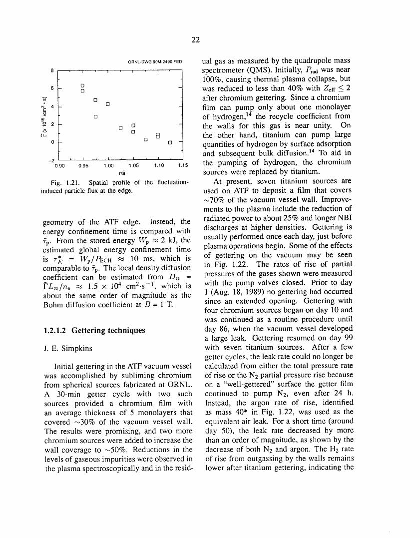
22
ORNL-DWG90M-2490FED ual gas as measured by the quadrupole mass8 , , , , , , , , , spectrometer (QMS). Initially, P,,d was near
100%, causing thermal plasma collapse, butD6 D - was reduced to less than 40% with Zef f _ 2
_- [] after chromium gettering. Since a chromium
"E 4 [] film can pump only about one monolayer[] of hydrogen, 14 the recycle coefficient from
ov._2 [] [][] the walls for this gas is near unity. OnIt. [] R the other hand, titanium can pump large
0 - = quantities of hydrogen by surface adsorptionand subsequent bulk diffusion. 14 To aid in
-2 , , , L , , , i , pi hydr0.90 0.95 1.00 1.05 1.10 1.15 the pum ng of ogen, the chromiumr/_ sources were replaced by titanium.
Fig. 1.21. Spatial profile of the fluctuation- At present, seven titanium sources areinducedparticle fluxat the edge. used on ATF to deposit a film that covers
,-_70% of the vacuum vessel wall. Improve-ments to the plasma include the reduction of
geometry of the ATF edge. Instead, the radiated power to about 25% and longer NBIenergy confinement time is compared with discharges at higher densities. Gettering is?p. From the stored energy IVp _ 2 kJ, the usually performed once each day, just beforeestimated global energy confinement time plasma operations begin. Some of the effects
is 7-_: = Wp//_.ctt _ 10 ms, which is of gettering on the vacuum may be seencomparable to "_p.The local density diffusion in Fig. 1.22. The rates of rise of partialcoefficient can be estimated from Dn = pressures of the gases shown were measured
F'f_,n/7_e '_ 1.5 × 10 4 cm2.s -1, which is with the pump valves closed. Prior to dayabout the same order of magnitude as the 1 (Aug. 18, 1989)no gettering had occurredBohm diffusion coefficient at B = 1 T. since an extended opening. Gettering with
four chromium sources began on day 10 andwas continued as a routine procedure until
1.2.1.2 Gettering techniques day 86, when the vacuum vessel developeda large leak. Gettering resumed on day 99
J. E. Simpkins with seven titanium sources. After a fewgetter cycles, the leak rate could no longer be
Initial gettering in the ATF vacuum vessel calculated from either the total pressure ratewas accomplished by subliming chromium of rise or the Nz partial pressure rise becausefrom spherical sources fabricated at ORNL. on a "well-gettered" surface the getter filmA 30-min getter cycle with two such continued to pump Nz, even after 24 h.sources provided a chromium film with Instead, the argon rate of rise, identifiedan average thickness of 5 monolayers that as mass 40* in Fig. 1.22, was used as thecovered ,--,30% of the vacuum vessel wall. equivalent air leak. For a short time (aroundThe results were promising, and two more day 50), the leak rate decreased by morechromium sources were added to increase the than an order of magnitude, as shown by thewall coverage to ,_50%. Reductions in the decrease of both N2 and argon. The H2 ratelevels of gaseous impurities were observed in of rise from outgassing by the walls remainsthe plasma spectroscopically and in the resid- lower after titanium gettering, indicating the
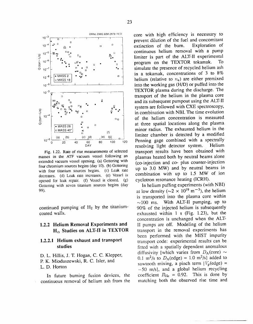
23
ORNL-DWGSOM-2870FED core with high efficiency is necessary to10 -3 t_ w _ T----------T l
o prevent dilution of the fuel and concomitant10-4 .,3 u o• o extinction of the burn. Exploration of
lo_5.,,:•. o_. o _ continuous helium removal with a pump• ° []o & limiter is part of the ALT-II experimental
• 10--6 • _o •o _
o'- - •" : []_-. " [] . •[] program on the TEXTOR tokamak. Tolo-7_ " [] • [] ". - simulate the presence of recycled helium ash[] •
"'•% in a tokamak, concentrations of 3 to 8%10-8 I"_MASS2 • %• • oMASS18 helium (relative to he) are either premixed10-9 _ _ _ _ ' into the working gas (H/D) or puffed into the
TEXTOR plasma during the discharge. The10 -3 ] 1 I I I
_, transport of the helium in the plasma core• [][] _- and its subsequent pumpout using the ALT-II
_Z_ • .• _. _" .° °" " ._ system are followed with CXE spectroscopy,
• •#. ".2 . ° ._ " in combination with NBI. The time evolution• 10-4 • °o [],_ of the helium concentration is measured
_. _ £ [] , at three spatial locations along the plasma[; MASS28 ] " [] minor radius. The exhausted helium in theMASS 40" _j (f)
10 -5 (a) i(b) _t. (c) t(d) ,(e) (g)l .xa__ limiter chamber is detected by a modified0 20 40 60 80 100 120 Penning gage combined with a spectrallyDAY resolving light detector system. Helium
Fig. 1.22. Rate of rise measurements of selected transport results have been obtained withmasses in the ATF vacuum vessel following an plasmas heated both by neutral beams aloneextended vacuum vessel opening. (a) Gettering with (co-injection and co- plus counter-injectionfour chromium sources begins (day 10). (b) Getteringwith four titanium sources begins. (c) Leak rate up to 3.0 MW) and by neutral beams in
decreases. (d) Leak rate increases. (e) Vessel is combination with up to 1.5 MW of ionopened for leak repah'. (0 Vessel is closed. (g) cyclotron resonance heating (ICRH).Gettering with seven titanium sources begins (day In helium puffing experiments (with NBI)99). at low density (-.,2 x 1019 m-3), the helium
is transported into the plasma core within,-..100 ms. With ALT-II pumping, up to
continued pumping of H2 by the titanium- 90% of the injected helium is subsequentlycoated walls, exhausted within 1 s (Fig. 1.23), but the
concentration is unchanged when the ALT-
1.2.2 Helium Removal Experiments and II pumps are off. Modeling of the heliumHa Studies on ALT-II in TEXTOR transport in the removal experiments has
been performed with the MIST impurity1.2.2.1 Helium exhaust and transport transport code: experimental results can be
studies fitted with a spatially dependent anomalous
D. L. Hillis, J. T. Hogan, C. C. Klepper, diffusivity [which varies from DA(core) "-_P. K. Mioduszewski, R. C. Isler, and 0.1 mZ/s to DA(edge) = 1.0 m2/s] added to
sawtooth mixing, a pinch term [I'p(edge) =L. D. Horton -50 m/sl, and a global helium recycling
In future burning fusion devices, the coefficient RlI,, = 0.92. This is done bycontinuous removal of helium ash from the matching both the observed rise time and
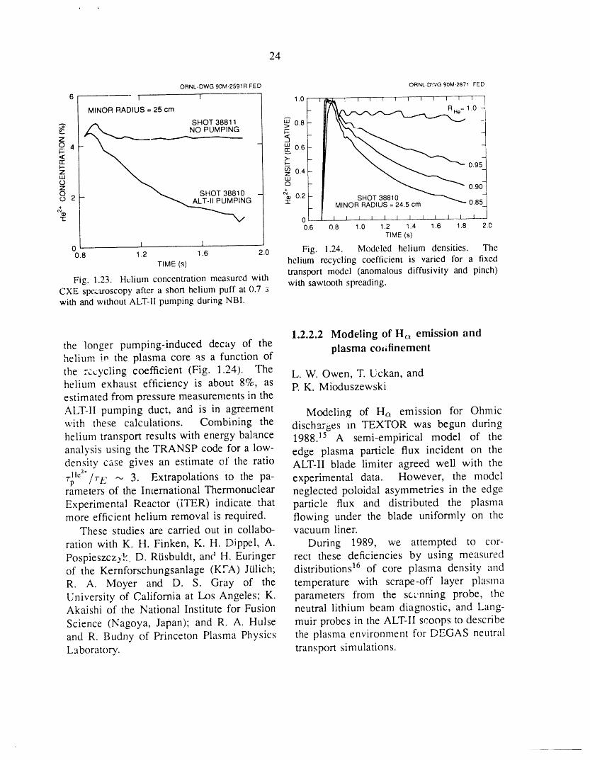
24
ORNL-DWG 90M-2591R FED ORNL.DWG 90M-2871 FED
6 ! I 1.0 1 i_ 1 I l 1 ! t t t I I 1
MINORRADIUS=25cm t"_,k _ RHo=1.0SHOT 38811 _ 0.8O PUMPING 7--
z -- <J94 - _o.6-F--<: >- _
Z 0.4-LLI LUO _ --Z
O _ _. SHOT 38810 - '_ 0.2 -O 2 _ ALT-IIPUMPING -_ SHOT38810 _ 0.85MINOR RADIUS = 24.5 cm
_'_ _ --1= o _ _ J t t t t L _ t J t0.6 0.8 1.0 1.2 1.4 1.6 1.8 2.0
TIME (s)
0 I I0.8 1.2 1.6 2.0 Fig. 1.24. Modeled helium densities. The
TIME(s) helium recycling coefficient is varied for a fixedtransport model (anomalous diffusivity and pinch)
Fig. 1.23. Helium concentration measured with with sawtooth spreading.CXE spc,ctroscopy after a short helium puff at 0.7 swith and without ALT-II pumping during NBI.
1.2.2.2 Modeling of Ha emission and
the longer pumping-induced decay of the plasma co_ifinementhelium in the plasma core as a function of
the recycling coefficient (Fig. 1.24). The L.W. Owen, T. Uckan, andhelium exhaust efficiency is about 8%, as P.K. Mioduszewskiestimated from pressure measurements in the
ALT-II pumping duct, and is in agreement Modeling of Hc_ emission for Ohmicwith these calculations. Combining the disch_-_es m TEXTOR was begun duringhelium transport results with energy balance 1988. Is A semi-empirical model of the
analysis using the TRANSP code for a low- edge plasma particle flux incident on thedensity ca_e gives an estimate of the ratio ALT-II blade limiter agreed well with the
T_XJ'/TE "_ 3. Extrapolations to the pa- experimental data. However, the modelrameters of the International Thermonuclear neglected poloidal asymmetries in the edge
Experimental Reactor (iTER) indicate that particle flux and distributed the plasmamore efficient helium removal is required, flowing under the blade uniformly on the
These studies are carried out in collabo- vacuum liner.
ration with K. H. Finken, K. H. Dippel, A. During 1989, we attempted to cor-
PospieszczyE D. Rtisbuldt, an(* H. Euringer rect these deficiencies by using measuredof the Kernforschungsanlage (KTA) Jtilich; distributions 16 of core plasma density and
R. A. Moyer and D. S. Gray of the temperature with scrape-off layer plasma
University of California at Los Angeles; K. parameters from the sct,nning probe, theAkaishi of the National Institute for Fusion neutral lithium beam diagnostic, and Lang-
Science (Nagoya, Japan); and R. A. Hulse muir probes in the ALT-II scoops to describe
and R. Budny of Princeton Plasma Physics the plasma environment for DEGAS neutralLaboratory. transport simulations.
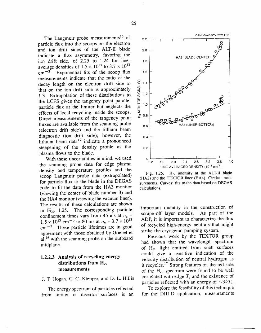
25
ORNL-DWG90M-2578FED
The Langmuir probe measurements 16 of 2.2 i i I i I I
particle flux into the scoops on the electronand ion drift sides of the ALT-II blade 2.o- o -indicate a flux asymmetry, favoring theion drift side, of 2.25 to 1.24 for line- 1.8-
average densities of 1.5 x 10¹³ to 3.7 x 10¹³
cm -3 Exponential fits of the scoop flux 1.6-measurements indicate that the ratio of the
decay length on the electron drift side to >--._1.4 -that on the ion drift side is approximately z<
1"3" Extrap°lati°n°fthesedistributi°nst° _ 12- S _j_/the LCFS gives the tangency point parallel --- 1.0 -particle flux at the limiter but neglects the ,--, mt30,_
effects of local recycling inside the scoops. :_ _ _Direct measurements of the tangency point :_ 08 - nofluxes are available from the scanning probe 0.6 - -- v,.,-- HA4 (LINEFt-BOTTO'A) _
(electron drift side) and the lithium beamdiagnostic (ion drift side); however, the o4-lithium beam data 17 indicate a pronounced
steepening of the density profile as the o2-plasma flows to the blade.
With these uncertainties in mind, we used o I _ i _ _
the scanning probe data for edge plasma ,2 1.6 2.0 2.4 2.8 3.2 3.6 4.0LINE-AVERAGED DENSITY (1013 cm 3 )
density and temperature profiles and thescoop Langmuir probe data (extrapolated) Fig. 1.25. Ha intensity at the ALT-II blade(HA3) and the TEXTOR liner (HA4). Circles: mea-for particle flux to the blade in the DEGAS surements. Curves: fits to the data based on DEGAScode to fit the data from the HA3 monitor calculations.
(viewing the center of blade number 3) andthe HA4 monitor (viewing the vacuum liner).The results of these calculations are shown
in Fig. 1.25. The corresponding particle important quantity in the construction ofconfinement times vary from 45 ms at ne = scrape-off layer models. As part of the1.5 x 1013 cm -3 to 80 ms at ne = 3.7 x 10¹³ ADP, it is important to characterize the flux
cm -3 These particle lifetimes are in good of recycled high-energy neutrals that mightagreement with those obtained by Goebel et strike the cryogenic pumping system.al. ]6 with the scanning probe on the outboard Previous work by the TEXTOR group
had shown that the wavelength spectrummidplane, of Ha light emitted from such surfaces
could give a sensitive indication of the1.2.2.3 Analysis of recycling energy velocity distribution of neutral hydrogen as
distributions from Hc_ it recycles. ]7 Strong features on the red sidemeasurements of the H_ spectrum were found to be well
J. T. Hogan, C. C. Klepper, and D. L. Hillis correlated with edge Te and the existence ofparticles reflected with an energy of ,--,3kTe.
The energy spectrum of particles reflected To explore the feasibility of this techniquefrom limiter or divertor surfaces is an for the DIII-D application, measurements
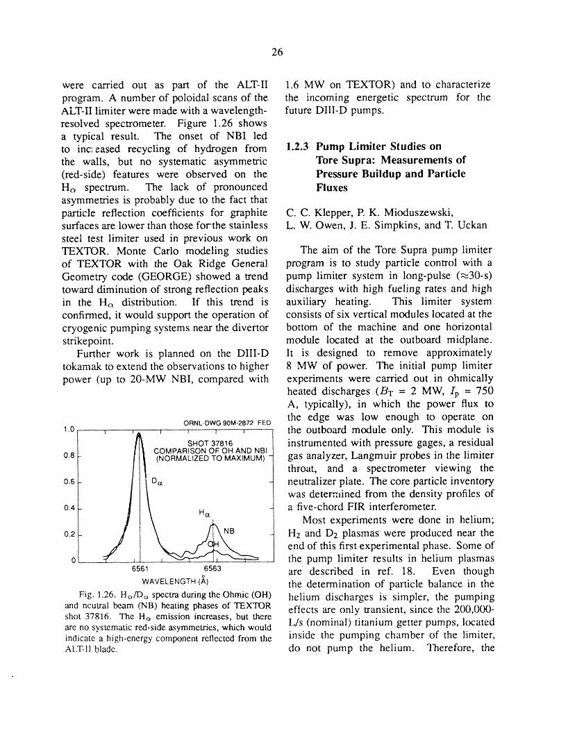
26
were carried out as part of the ALT-II 1.6 MW on TEXTOR)and to characterizeprogram. A number of poloidal scans of the the incoming energetic spectrum for theALT-II limiter were made with a wavelength- future DIII-D pumps.resolved spectrometer. Figure 1.26 showsa typical result. The onset of NBI ledto increased recycling of hydrogen from 1.2.3 Pump Limiter Studies onthe walls, but no systematic asymmetric Tore Supra: Measurements of(red-side) features were observed on the Pressure Buildup and ParticleHt, spectrum. The lack of pronounced Fluxesasymmetries is probably due to the fact thatparticle reflection coefficients for graphite C.C. Klepper, P. K. Mioduszewski,surfaces are lower than those forthe stainless L.W. Owen, J. E. Simpkins, and T. Uckansteel test limiter used in previous work onTEXTOR. Monte Carlo modeling studies The aim of the Tore Supra pump limiterof TEXTOR with the Oak Ridge General program is to study particle control with aGeometry code (GEORGE) showed a trend pump limiter system in long-pulse (_30-s)toward diminution of strong reflection peaks discharges with high fueling rates and highin the Ht, distribution. If this trend is auxiliary heating. This limiter systemconfirmed, it would support the operation of consists of six vertical modules located at thecryogenic pumping systems near the divertor bottom of the machine and one horizontalstrikepoint, module located at the outboard midplane.
Further work is planned on the DIII-D lt is designed to remove approximatelytokamak to extend the observations to higher 8 MW of power. The initial pump limiterpower (up to 20-MW NBI, compared with experiments were carried out in ohmically
heated discharges (BT = 2 MW, lp = 750A, typically), in which the power flux tothe edge was low enough to operate onORNL-DWG 90M-2872 FED
1.0 , , , , the outboard module only. This module isSHOT 37816 instrumented with pressure gages, a residual
COMPARISON OF OH AND NBI0.8 - (NORMALIZED TO MAXIMUM) gas analyzer, Langmuir probes in the limiter
throat, and a spectrometer viewing the0.6- D,_ - neutralizer plate. The core particle inventory
was deterr';lined from the density profiles of
0.4- Nak,. ` - a five-chord FIR interferometer.Most experiments were done in helium;
0.2 NB H2 and D2 plasmas were produced near the
j] end of this first experimental phase. Some of0 .... the pump limiter results in helium plasmas6561 6563 are described in ref. 18. Even though
WAVELENGTH (A) the determination of particle balance in theFig. 1.26. Ha/Dc, spectra duringtheOhmic (OH) helium discharges is simpler, the pumping
and neutral beam (NB) heating phases of TEXTOR effects are only transient, since the 200,000-shot 37816. The Ha emission increases, but there L/s (nominal) titanium getter pumps, locatedare no systematicred-sideasymmetries,whichwouldindicate a high-energycomponentreflected from the inside the pumping chamber of the limiter,ALT-IIblade, do not pump the helium. Therefore, the
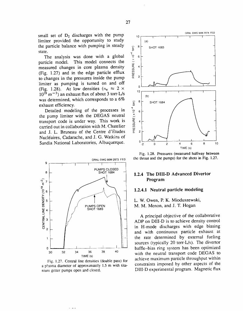
27
ORN[-DWG 90M 2874 FED
small set of D2 discharges with the pump lo _ _ _ _ _ ........limiter provided the opportunity to study la)the particle balance with pumping in steady _2 8 - SHOT1683
£state. ,r
The analysis was done with a global ? 6-particle model. This model connects the 2"measured changes in core plasma density g 4-¢.O
(Fig. 1.27) and in the edge particle efflux _
to changes in the pressures inside the pump __ 2 - _._limiter as pumping is turned on and off 0L _ i(Fig. 1.28). At low densities (he _ 2 x10¹⁹ m -3) an exhaust flux of about 3 torr.L/s 10 _ _ _ w(b)was determined, which corresponds to a 6%exhaust efficiency, g_ 8 - SHOT 1684 -
Detailed modeling of the processes in "r 6-
the pump limiter with the DEGAS neutraltransport code is under way. This work is _ 4-carried out in collaboration with M. Chatelier
4'_ rrand J. L. Bruneau of the Centre u l.,tudes __ 2-Nuclraires, Cadarache, and J. G. Watkins ofSandia National Laboratories, Albuquerque. °-2 0 2 4 6 8 10
TIME (s)
Fig. 1.28. Pressures (measured halfway between
ORNL-DWG90M-2873FED the throat and the pumps) for the shots in Fig. 1.27.9 I 1 I I 1
PUMPS CLOSED8 - SHOT 1684 - 1.2.4 The DIII-D Advanced Divertor
_E7 - _ Program
6 - - 1.2.4.1 Neutral particle modeling
_" ,."'°"° °""""°""° °""'"l"
I--
5 _ - L.W. Owen, R K. Mioduszewski,Z -- tILl
a .J PUMPSOPEN M M. Menon, and J. T. HoganIII ;" _ 'z 4 -- - SHOT 1683 ___
_3"a _ .....} _ A principal objective of the collaborative_- ADP on DIII-D is to achieve density controlZ
"' _ in H-mode discharges with edge biasing02 and with continuous particle exhaust at
1 - the rate determined by external fueling
L sources (typically 20 torr.L/s). The divertor0 l i 1 ___1__ baffle-bias ring system has been optimized30 32 34 36 38 40 with the neutral transport code DEGAS to
TIME (s)
Fig. ].27. Central line densities (double pass) for achieve maximum particle throughput withina p!asma diameter of approximately 1.5 m with tim- constraints imposed by other aspects of the
nium getter pumps open and closed. DIII-D experimental program. Magnetic flux

28
surfaces and plasma parameters from the H- A cryopump configuration that meets themode documentation series are used to estab- objective of removing half of the incominglish the dependence of baffle entrance slot particle flux is shown in Fig. 1.29. Theconductance, baffle pressure, and particle positions and orientations of the componentsthroughput on the baffle-bias ,'ing geometry, of the liquid-nitrogen-cooled radiation shield
For typical H-mode discharges, approxi- were optimized with DEGAS to maximizemately 40 torr.L/s enters the outboard baffle the conductance from the baffle entrancechamber. With an entrance slot conductance to the cryopump and simultaneously min-of 50,000 L/s, a pumping speed of the imize the power deposited on the liquidsame order is required to remove half of helium tube. For typical quiescent H-the incoming particle flux. Increasing the mode conditions, the heat load on theexhaust fraction with higher pumping speed cryopump resulting from energetic particlesis self-limiting, because of the reduction of is negligibly small for this configuration.the recycling particle flux with increasingdivertor exhaust. The required pumping o,_,_owG_0_,_,_,__t_
speed of 50,000 L/s can be achieved with BAFFLE _/_either titanium pumps or cryopumps but PLATE., / //
' -../.-- i//evaluation of bo_h systems, as described in RADIATIONSHIELD.-..... / //
Sect. 1.2.4.4, led to the conclusion that a BIASn.,G.,_ "__ _//wccryopump will be more compatible with theenvironment of the DIII-D divertor. - uuM
An important consideration in the design _Loof an in-vessel cryopump is the power L .Z_::_
deposition on the cold surfaces of the pump _---f _--1 ,_" ,._-t_oopand radiation shield. No experimental data ___1 ' ROOMTEMPERATURESURFACE
exist for particle and energy reflection in the Fig. 1.29. Schematicdiagram of the cryoconden-energy range (a few electron volts) of neutral sation pump insidethe bafflechamber.atoms in the baffle chamber. Consequently,there is considerable uncertainty in the powerdeposition estimates from neutr',d transportsimulations in this low-energy regime. Ruzic 1.2.4.2 The pre-VORTEX codeand Chiu 19 have developed a fractal surfaceroughness model for use in the TRIM J.T. Hoganbinary collision model code 20 and the EAMmolecular dynamics code. 21 Reflection co- To determine the effect of pumping onefficients generated with these fractal codes plasma performance, an internally consistentfor deuterium on carbon have been used model for particle transport in an openin DEGAS to calculate the energetic atom- divertor geometry has been developed. Em-energy flux on the cold surfaces of the pump. bodied in a new code, pre-VORTEX, thePreliminary results indicate that the heat model couples the particle balance in theload is somewhat lower than that obtained plasma core, the scrape-off layer, the openwith reflection coefficients extrapolated from divertor channels, and the vacuum regions.the 100-eV range, where experimental data The plasma core is considered to haveexist, a relatively quiescent center and a less
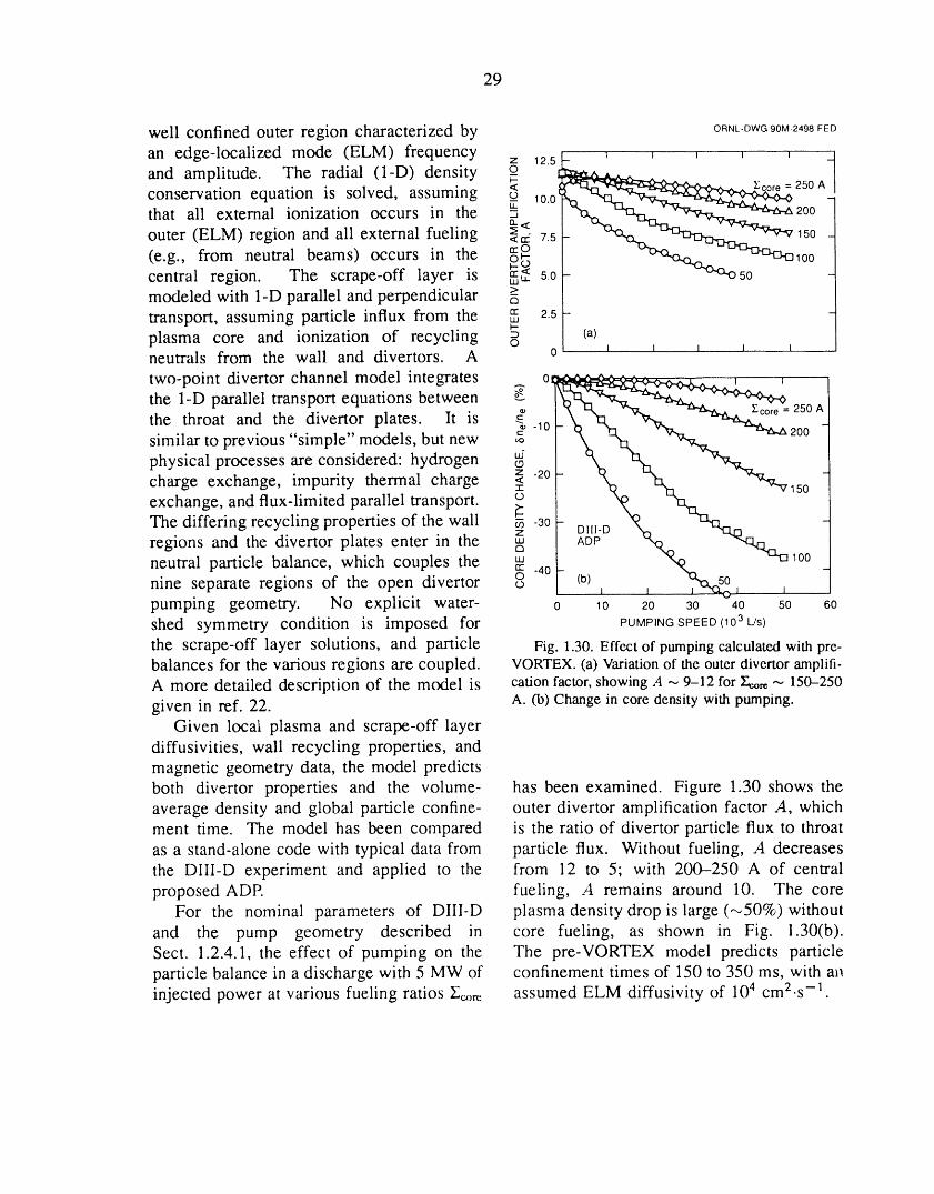
29
well confined outer region characterized by ORNL-DWGg0M-2498FED
an edge-localized mode (ELM) frequency z 125_____..__ i " , , , Jand amplitude. The radial (l-D) density _o
_- _ E_re = 250 Aconservation equation is solved, assuming <that ali external ionization occurs in the -_ 200
outer (ELM)region and all external fueling "_<-<=7s L "xx_z__:_>a_'__ la0
(e.g., from neutral beams) occurs in the _0__0<50- -'--c__50-,-_100central region. The scrape-off layer is _,,modeled with 1-D parallel and perpendicular o->transport, assuming particle influx from the ,,,rr 2.5 -I--
plasma core and ionization of recycling o_ (a)neutrals from the wall and divertors. A o , _ i i z
two-point divertor channel model integrates _ 0x _'_=the 1-D parallel transport equations between 250 A
the throat and the divertor plates It is _ 10 200similar to previous "simple" models, but new _g ta,,_ "'v-v.._
physical Processes are c°nsidered: hydr°gen Wez-20 ___charge exchange, impurity thermal chargeexchange, and flux-limited parallel transport, o 150The differing recycling properties of the wall -3o -
z DIII-D
regions and the divertor plates enter in the w ADP£3100
neutral particle balance, which couples the "'rr -40 -
nine separate regions of the open divertor o (b)0 I
pumping geometry. No explicit water- 0 10 20 30 40 50 60shed symmetry condition is imposed for PUMPINGSPEED(10 3 L/S)
the scrape-off layer solutions, and particle Fig. 1.30. Effect of pumping calculated with pre-balances for the various regions are coupled. VORTEX.(a) Variationof the outer divertor amplifi-
A more detailed description of the model is cation factor,showing A ,--,9-12 forT-,c,orc "-" 150-250given in ref. 22. A. Co) Change in core density with pumping.
Given locat plasma and scrape-off layerdiffusivities, wall recycling properties, andmagnetic geometry data, the model predictsboth divertor properties and the volume- has been examined. Figure 1.30 shows theaverage density and global particle confine- outer divertor amplification factor A, whichment time. The model has been compared is the ratio of divertor particle flux to throatas a stand-alone code with typical data from particle flux. Without fueling, A decreasesthe DIII-D experiment and applied to the from 12 to 5; with 200-250 A of centralproposed ADR fueling, A remains around 10. The core
For the nominal parameters of DIII-D plasma density drop is large (,--,50%) withoutand the pump geometry described in core fueling, as shown in Fig. 1.30(b).Sect. 1.2.4.1, the effect of pumping on the The pre-VORTEX model predicts particleparticle balance in a discharge with 5 MW of confinement times of 150 to 350 ms, with a_injected power at various fueling ratios Z_,_ assumed ELM diffusivity of 104 cm2.s -1

3O
1.2.4.3 Diagnostics a relation between the fast particle flux andthe corresponding pressure buildup inside the
C. C. Klepper, M. M. Menon, C. L. Hahs, housing.
J. E. Simpkins, and P. K. Mioduszewski Visible spectroscopy
Optical measurements of recycling at theORNL is responsible for the diagnostics divertor strikepoints are made with external
of the ADP in two areas: fast pressure optics and direct, vertical views throughmeasurements inside the closed divertor re- viewports located on the top part of thegion and visible spectroscopy of the divertor machine. When the divertor baffle isstrike region under the biased plate, added, the outer divertor strikepoint will be
inaccessible from external ports. For thisFast pressure gages reason, special vacuum-compatible, high-
The fast gages developed by Gunther temperature optical fibers 23 will be usedHaas of the ASDEX group will be used inside the DIII-D vacuum vessel. The fibersfor fast pressure measurements. Such gages will not be in contact with the plasmas;are already employed in DIII-D, where they will only be inside the closed divertorthey work more reliably when enclosed in pumping chamber. At least one fiber mayhousing.," that prevent energetic neutrals or be embedded into a tile at the strikepoint toions f,'om arriving directly (or after a single provide a view perpendicular to the tile. Thisbounce) at the gage. These housings provide has the advantage of allowing the fiber toa slot where the particles may enter and a "see" the peak of the distribution of energeticset of baffles to ensure that the particles are particles reflected off the tile. Thesethermalized before reaching the gage. In reflected particles are expected to follow adesigning such housings, care must be taken cosine law in their angular distribution withnot to substantially reduce the response time respect to the tile.of the system by limiting the conductance. On the outside, fiber cables (1-mmA typical response time of the electronics fiber) that are fully protected with 3.5-mmis 5 ms. Therefore, the maximum response polyethylene tubing will be attached to thetime of the housings should not exceed 5 ms. vacuum fibers by means of standard SMA
Two gages will be used; the second will connectors. The connectors of the vacuumbe employed to detect the effects of the fibers will be rigidly attached to a plate toenergetic particles. In the design of the prevent breakage of the vacuum fibers. Thepumps for the closed divertor, the modeling light will then be transmitted by the externalincluded energetic particle fluxes based on cables to a spectrometer/OMA, which willassumed reflection fractions and energies at be in a room outside the biological shield.the strike point. These measurements will The design of the telescope/fiber holder,provide an experimental basis for checking shown in Fig. 1.31, includes fused silicathese assumptions, lenses to control the viewing volume. Two
The gages will be installed in the closed such telescopes will be employed insidedivertor region, near the future location of the vacuum vessel. One or both of thesethe cryogenic pump, by means of a re- holders (telescopes) might be turned to viewentrant tube. For the energetic neutrals gage, tangentially at another toroidal location ofDEGAS modeling will be used to determine the strikepoint.
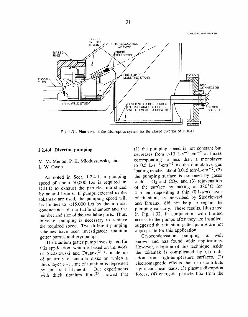
31
ORNL-DWG90M-2464FED
CLOSEDDIVERTORR_IC_N JJ FUTURE LOCATION / /
BIII_SGED\ _ _ AFIEBEER_copE _'_f ,/
FLOOR-- \'_1 _ '14--,'=_.,,-- _ I ., I" MOUNTING STAND ___._
T, ES / /ill I;,.,J//fll/ (|
Fig. 1.31. Plan view of the fiber-optics system for the closed divertor of DIII-D.
1.2.4.4 Divertor pumping (1) the pumping speed is not constant butdecreases from >10 L.s-].cm -2 at fluxes
M. M. Menon, E K. Mioduszewski, and corresponding to less than a monolayerL. W. Owen to 0.5 L.s-l.cm -2 as the cumulative gas
loading reaches about 0.015 torr.L.cm -2, (2)As noted in Sect. 1.2.4.1, a pumping the pumping surface is poisoned by gases
speed of about 50,000 L/s is required in such as O2 and CO2, and (3) rejuvenationDIII-D to exhaust the particles introduced of the surface by baking at 380°C for
by neutral beams. If pumps external to the 4 h and depositing a thin (0.1-/_m) layertokamak are used, the pumping speed will of titanium, as prescribed by Sledziewskibe limited to <15,000 L/s by the toroidal and Druaux, did not help to regain theconductance of the baffle chamber and the pumping capacity. These results, illustratednumber and size of the available ports. Thus, in Fig. 1.32, in conjunction with limitedin-vessel pumping is necessary to achieve access to the pumps after they are installed,the required speed. Two different pumping suggested that titanium getter pumps are notschemes have been investigated: titanium appropriate for this application.getter pumps and cryopumps. Cryocondensation pumping is well
The titanium getter pump investigated for known and has found wide applications.this application, which is based on the work However, adoption of this technique insideof Sledziewski and Druaux, z4 !s made up the tokamak is complicated by (1) radi-of an array of annular disks on which a ation from t igh-temperature surfaces, (2)thick layer (_1 ttm) of titanium is deposited electromagnetic effects that can contributeby an axial filament. Our experiments significant heat loads, (3) plasma disruptionwith thick titanium films z5 showed that forces, (4) energetic particle flux from the
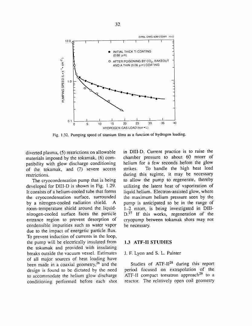
32
ORNL-DWG 90M-2334R FED
10.0(_ I I I I I I 1 _
I
_
• INITIAL THICK Ti COATING
(0.66 pm)
E O AFTER POISONING BY CO 2, BAKEOUTo AND A THIN (0.06 I.tm) COATING• ,,-4
_J
10 '_
__ 0_0_0."
_ _t,_. O_.O.,.. O
-_ "'°"-°"--"i
o.1 I I I I I 1 I0 5 10 15 20 25 30 35 40
HYDROGEN GAS LOAD (torr ° L)
Fig. 1.32. Pumping speed of titanium films as a function of hydrogen loading.
diverted plasma, (5) restrictions on allowable in DIII-D. Current practice is to raise thematerials imposed by the tokamak, (6)com- chamber pressure to about 60 mtorr ofpatibility with glow discharge conditioning helium for a few seconds before the glowof the tokamak, and (7) severe access strikes. To handle the high heat loadrestrictions, during this regime, it may be necessary
The cryocondensation pump that is being to allow the pump to regenerate, therebydeveloped for DIII-D is shown in Fig. 1.29. utilizing the latent heat of vaporization oflt consists of a helium-cooled tube that forms liquid helium. Electron-assisted glow, wherethe cryocondensation surface, surrounded the maximum helium pressure seen by theby a nitrogen-cooled radiation shield. A pump is anticipated to be in the range ofroom-temperature shield around the liquid- 1-2 mtorr, is being investigated in DIII-nitrogen-cooled surface faces the particle D. 27 If this works, regeneration of theentrance region to prevent desorption of cryopump between tokamak shots may notcondensible impurities such as water vapor be necessary.due to the impact of energetic particle flux.To prevent induction of currents in the loop,the pump will be electrically insulated from 1.3 ATF-II STUDIESthe tokamak and provided with insulatingbreaks outside the vacuum vessel. Estimates J.F. Lyon and S. L. Painterof ali major sources of heat loading havebeen made in a coaxial geometry, 26 and the Studies of ATF-II 28 during this reportdesign is found to be dictated by the need period focused on extrapolation of theto accommodate the helium glow discharge ATF-II compact torsatron approach z9 to aconditioning performed before each shot reactor. The relatively open coil geometry

33
of the M = 6 configuration should allow ation assuming a coronal model with fixedgood access for tritium breeding blanket fractions of carbon and iron, synchrotronmodules and for remote maintenance, but the radiation with 90% wall reflectivity), andaccompanying field tipple coupled with low- diffusive losses [Shaing's neoclassical rip-aspect-ratio toroidal effects could lead to an pie model with electric field includingunacceptable level of energetic alpha particle the off-diagonal terms (K77_,KT_), Chang-losses and of ripple-induced heat conduction. Hinton a,.Asymmetric neoclassical losses, andRevisiting the reactor extrapolation in light anomalous electron losses based on theof our improved understanding and better Alcator model].computational techniques should help toclarify the issues that ATF-II would have toaddress. 1.3.2 Effect of the Electric Field
The electric field should p!ay a dominant1.3.1 Transport Code Development role in reactor-grade stellarator plasmas. Its
effect on transport enters through the electricOur previous study of compact torsatron field dependence of the heat diffusivities
reactors 3° used the POPCON (Plasma OPer- X and through the V_ term in the heatating CONtours) feature of the WHIST 1-D balance equations. Because the coefficienttransport code, 31 modified for stellarators, of the xT_ term has opposite sign for ionsto define the reactor operating conditions, and electrons, this term reduces the heatThis code did not include alpha particle flux for one species and increases it for theenergy losses and, because the POPCON other. These effects lead to two qualitativelyplots were generated by varying the input different modes of operation, depending onpower P to linearly ;amp the temperature whether the electric field is positive (theat fixed density, ti_e WHIST calculations electron-root condition, which retards thedid not treat the thermally unstable region electron heat flux) or negative (the ion-root(OP/OT < 0) properly. A new, fast 1-D condition, which retards the ion heat flux).transport code, COLTRANE, was written to This is illustrated in Fig. 1.33 for an M = 6address these issues. It solves the steady- compact torsatron reactor with major radiusstate radial 1-D power balance equations for Ro = 10 m, average plasma radius ft,= 2 m,electrons and ions in integral form using the and on-axis field ]3o = 7 T. Both cases havespectral collocation method. It assumes fixed broad density profiles and parabolic potentialforms for the density and potential profiles profiles parameterized by _0 = e_(0)/kTi(0).and varies these forms to test the sensitivity The two POPCON plots show contours ofto the forms assumed. This approach is used constant auxiliary heating power required forbecause there are large uncertainties in the operation at a given value of volume-averagecalculation of these profiles, and there are dens;ty (Tz)and density-average temperaturetechniques that may be used to control them. (T) = W/2(r_), where W is the total plasma
COLTRANE incorporates ali relevant thermal energy.physical processes: external heating sources, For the electron-root case [Fig. 1.33(a)alpha particle heating (with or without direct- with (0 = +3], ignition (P = 0 contour)orbit and scattered energy losses), electron- occurs at high temperature (low collisionalityion Coulomb collisions, radiative losses t.,*), where the electrons are just entering(hydrogenic bremsstrahlung, impurity radi- the ,y o< 1./* regime and the ions are deep
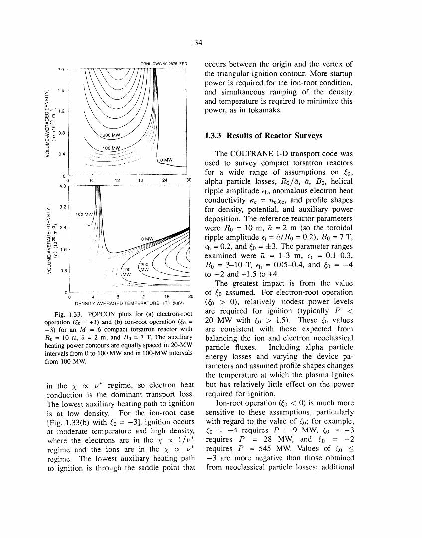
34
ORNL-DWG90-2875FED Occurs between the origin and the vertex of
20 ___, the triangular ignition contour. More star tnp
i............. -r............
power is required for the ion-root condition,_- 1_ and simultaneous ramping of the density
z and temperature is required to minimize this
° _'E1.2 power, as in tokamaks.
> _ 0.8< A 1.3.3 Results of Reactor Surveystile
3
o> 04 .__-:_=:-_!i _ The COLTRANE 1-D transport code was............ OMW used to survey compact torsatron reactors
0 for a wide range of assumptions on _0,0 6 12 18 24 30 alpha particle losses, Roft, ft, Bo, helical4.0 ..... '-........ _---- ' -
ripple amplitude eh, anomalous electron heat
_wJ/ conductivity _;e = n_Xc, and profile shapes
_- 3.2 for density, potential, and auxiliary power1oo MW
, deposition. The reference reactor parameters
'E2.4 ; __1_00 _ _-.__ were Ro = 10 m, _ = 2 m (so the toroidal
_ /I!_ ripple amplitude et = g/Ro = O.2), Bo = 7 T,'" _ - _ eh = 0.2, and _0 = +3. The parameter ranges>_1.6 _ i
I1'1 vC ....... -_ _ examined were a--" 1-3 m, _t -- 0.1---0.3,
3 B0 = 3-10 T, eh = 0.05-0.4, and _0 = -4o 08 / to -2 and +1.5 to +4.> _ ("_........ The greatest impact is from the value
0 of _0 assumed. For electron-root operation0 4 8 12 16 20
DENSITY-AVERAGEDTEMPERATURE, (Z)(keV) (_0 > 0), relatively modest power levels
Fig. 1.33. POPCONplots for (a) electron-root are required for ignition (typically P <operation ((0 = +3) and (b) ion-root operation ((o = 20 MW with (0 > 1.5). These (0 values-3) for an M = 6 compact torsatron reactor with are consistent with those expected from
Ro = l0 na, _ = 2 m, and B0 = 7 T. The auxiliary balancing the ion and electron neoclassical
heating power contours are equally spaced in 20-MW particle fluxes. Including alpha particle
intervals from 0 to 100 MW and in IO0-MW intervals energy losses and varying the device pa-from 100 MW.rameters and assumedprofile shapeschangesthe temperature at which the plasma ignites
in the _ _x u* regime, so electron heat but has relatively little effect on the powerconduction is the dominant transport loss. required for ignition.The lowest auxiliary heating path to ignition Ion-root operation (_0 < 0) is much moreis at low density. For the ion-root case sensitive to these assumptions, particularly[Fig. 1.33(b) with _0 = -3], ignition occurs with regard to the value of _0; for example,at moderate temperature and high density, _0 = -4 requires P = 9 MW, _0 = -3where the electrons are in the X o( l/u* requires P = 28 MW, and _0 = -2regime and the ions are in the X o( u* requires P = 545 MW. Values of _0 <_regime. The lowest auxiliary heating path -3 are more negative than those obtainedto ignition is through the saddle point that from neoclassical particle losses; additional
35
ion losses would need to be induced or a are close to that seen in the experiment and
large negative electric field would have to to that estim,_ted from the LHD scaling.be imposed to sustain these values of (0,
requiring additional power input. REFERENCESAlpha particle energy losses can also have
a significant effect on ion-root operation.The startup power (in megawatts) can be 1. R. J. Colchin et al.,"Overview of Results from
approximated by the ATF Torsatron," Phys. Fluids B 2, 1347 (1990).2. M. Murakami et al., "Overview of Recent
P _ 1.1 × 10⁷_o5"2eO'57elh'4Bol'Sgt -0"4 Resultsfrom the AdvancedToroidalFacility,"p.77 inProceedings of the 1st International Toki Conference
(with B0 in tesla and _ in meters) without on Plasma Physics and Controlled Nuclear Fusionthese losses and by Research, NIFS-PROC-3, National Institute for Fu-
sion Science, Nagoya, Japan, 1990; also published asP "-_2.9 x 108_0 6e_'87el'TB-2"la-0"89- h 0 ORNL/TM-11453, Martin Marietta Energy System-.
Inc., Oak Ridge National Laboratory, February 1990.when alpha particle energy losses are in- 3. S. Sudoetal.,"ScalingsofEnergyConfinement
cluded, for the range of parameters con- and Density Limit in Stellarator/Heliotron Devices,"sidered here. For the reference case, this Nucl. Fusion 30, 11 (1990).
amounts to a requirement for "2_25MW of 4. F. W. Perkins, p. 977 in lteating in Toroidaladditional power. Varying the shape of the Plasmas: Proceedings of the 4th InternationalSym-
potential profile (and hence the value of the posium, Rome, March 1984, vol. 2, edited by
electric field) also has a large effect; for H. Knoepfel and E. Sindoni,InternationalSchool ofPlasma Physics, Varenna, 1984.
the reference case with alpha particle losses, 5. R. Goldston, "_x/_/vs. vii f3/B as the Causea parabolic _(r) requires P = 52 MW, a of Transport in Tokamaks," Bull. Am. Phys. Soc. 34,
parabolic-squared _(r) requires P = 24 MW, 1964 (1989).
and a square-root-parabolic _(r) requires 6. K. C. Shaing et al., "Bootstrap Current ControlP = 95 MW. in Stellarators," Phys. Fluids B 1, 1663-70 (1989).
7. J. H. Harris et al., "Second Stability in the ATF
Torsatron--Experiment and Theory," Phys. Fluids B
1.3.4 Conclusions 2, 1353(1990).8. J. H.Harris et al., "SecondStabilityin the ATFTorsatron,"Phys. Rev. Lett. 63, 1249-52 (1989).
The electron-root mode of reactor oper- 9. T. Uckan et al., "ATF Edge Plasma Studiesation appears to be preferable to the ion- Using a Fast Recipr_ating Langmuir Probe (FRLP),"root mode. These calculations now need Bull. Am. Phys. Soc. 34, 1948 (1989).
to be applied to the ATF-II case with the 10. Ch. P. Ritz et al., "Comparison of EdgeTurbulence of TEXT anO ATF," Bull. Am. Phys. Soc.same assumptions used in the reactor studies. 34, 2153 (1989).For this purpose, additional power losses 11. R. C. Isler et al., "'Soectroscopic Studies ofhave been included in the COLTRANE Plasma Collapse in the AdvancedToroidalFacility,"
code: convection, charge exchange, and Nucl. Fusion 29, 1384-90 (1989).
ionization through a coupled 1-D neutrals 12. Cb. P. Ritz et al., Nucl. Fusion 27, 1133
code and additional Bohm-like losses glob- (1987).13. J. M. Beall, Y. C. Kim, and E. J. Powers, J.
ally when MHD limits on ([3) are violated Appl. Phys. 43, 3993 (1982).and locally when stability limits on Vp are 14. J. E. Simpkins, P. K. Mioduszewski, and L. W.violated. Preliminary results give energy Stratton, "Studies of Chromium Gettering," J. Nucl.
confinement times for ATF parameters that Mater. 111& 112, 827-30 (1982).
36
15. T. Uckan et al., "Ht, Studies," pp. 25-26 Divertors and Pump Limiters in Reactors-Relevantin Fusion Energy Division Annual Progress Report Conditions," Rev. Sci. lnstrum. 61, 2943 (1990).for Period Ending December 31, 1989, ORNL-6528, 24. Z. Sledziewski and J. Druaux, "TitaniumMartin Marietta Energy Systems, Inc., Oak Ridge Getter Pump for the Tore Supra Neutral Beam Lines,"National Laboratory, February 1990. pp. 533-8 in Fusion Technology: Proceedings of the
16. D. M. Goebel et al., "ALT-II Toroidal Belt 14th Symposium, Avignon, 1986, Vol. 1, Pergamon
Pump Limiter Performance in TEXTOR," J. Nucl. Press, Oxford, 1986.Mater. 162-164, 115 (1989). 25. M. M. Menon and P. K. Mioduszewski,
17. U. Samm et al., "Plasma Edge Physics in "Pumping Scheme for the DIII-D Collaborativethe TEXTOR Tokamak with Poloidal and Toroidal Advanced Divertor Program," Bull. Am. Phys. Soc.Limiters," J. Nucl. Mater. 162-164, 25 (1989). 34, 2121 (1989).
18. C. C. Klepper et al., "Spectroscopic Studies 26. M. M. Menon and P. K. Mioduszewski,of Plasma Surface Interactions in Tore Supra," "Particle Exhaust Schemes in the DIII-D AdvancedEurophys. Conf. Abstr. 13B, 1007 (1989). Divertor Configuration," pp. 542--6 in Proceedings of
19. D. N. Ruzic and H. K. Chiu, "Modeling the 13th IEEE Symposium on Fusion Engineering,of Particle-Surface Reflections Including Surface Knoxville, 1989, Vol. 1, IEEE, New York, 1990.Roughness Characterized by Fractal Geometry," J. 27. G. A. Jackson, General Atomics, personalNucl. Mater. 162-164, 904 (1989). communication, 1989.
20. J. P. Biersack and L. G. Haggmark, "A 28. J. F. Lyon et al., "Advanced Toroidal FacilityMonte Carlo computer Program for the Transport of II Studies," Fusion Technol. 17, 188 (1990).Energetic Ions in Amorphous Targets," Nucl. lnstrum. 29. B. A. Carreras et al., "Low-Aspect-RatioMethods 174, 257 (1980). Torsatron Configurations," Nucl. Fusion 28, 1195
21. M. I. Baskes, "Dynamical Calculation of Low (1988).Energy Hydrogen Reflection,"J. Nucl. Mater. 128 & 30. J. F. Lyon et al., "Compact Torsatron129, 676 (1984). Reactors," Fusion Technol. 15, 1401 (1989).
22. J. T. Hogan, The Pre-VORTEX Code, 31. W. A. Houlberg, S. E. Attenberger, and L. M.ORNL/TM-11562, Martin Marietta Energy Systems, Hively, "Contour Analysis of Fusion Reactor PlasmaInc., Oak Ridge National Laboratory, 1990. Performance," Nucl. Fusion 22, 935 (1982).
23. C. C. Klepper et al., "Application of ModernOptical Fiber Technology in the Study of Closed

2ATOMIC PHYSICS AND
PLASMA DIAGNOSTICSDEVELOPMENT

R. A. Phaneuf, 1 Program Manager
I. Alvarez 2 J.W. Hale 1 M.S. Pindzola 11
C. F. Barnett 3 C.C. Havener 1 K.J. Reed 22
D. Beli64 H.T. Hunter 1 R.K. Richards
C. A. Bennett s D.P. Hutchinson 1 K. Rinn 8
C. Bottcher 1 R.K. Janev 13 K. Sommer 23
G. J. Bottrell 6 M.I. Kirkpatrick I N. Stolterfoht 23
C. Cisneros 2 C.H. Ma 1 D. Swenson 24
B. DePaola 7 E.W. McDaniel TM J.K. Swenson 25
G. H. Dunn 8 E W. Meyer 1 H. Tawara 26
L. K. Fletcher 9 T.J. Morgan 15 E.W. Thomas 14
Y. M. Fockedey 1° D.W. MueUer 16 J.S. Thompson 8
L. Forand s A. MiJller 17 C. Timmer 27
H. B. Gilbody 11 M.P. Nesnidal TM K.L. Vander Sluis 1
D. C. Gregory I K. Okuno 19 E. W_ihlin s
D. C. Griffin 12 F.M. Ownby 2° D.M. Zehner 2s
1. Physics Division. 15. Consultant, Wesleyan University, Middletown,2. Instituto de Ffsica, Universidad Nacional Conn.
Aut6noma de M6xico. 16. University of North Texas, Denton.
3. Consultant; deceased. 17. Institut ftir Ke-'nphysik, University of Giessen,
4. Belgrade University, Belgrade, Yugoslavia. Giessen, Federal Republic of Germany.5. University of North Carolina, Asheville. 18. ORNL-GLCA/ACM Science Semester Student.6. University of Georgia, Athens. 19. Tokyo Metropolitan University, Japan.7. Kansas State University, Manhattan. 20. Program secretary.8. Joint Institute for Laboratory Astropr,ysics, 21. Consultant, Auburn University, Auburn, Ala.
Boulder, Colo. 22. Lawrence Livermore National Laboratory,9. Graduate student, Tennessee Technological Livermore, Calif.
University, Cookeville. 23. Hahn-Meitner-Institut, Berlin, Federal Republic10. Catholic University of Louvain, Louvain-la- of Germany.
Neuve, Belgium. 24. Los Alamos National Laboratory, Los Alamos,11. Consultant, Qaeen's University, Belfast, N.M.
Northern Ireland. 25. University of Tennessee, Knoxville.12. Research subcontractor, Rollins College, 26. Institute of Plasma Physics, Nagoya
Winter Park, Florida. Universe:y, Japan.13. Consultant, Institute of Physics, Belgrade, 27. Jet Propulsion Laboratory, Pasadena, Calif.
Yugoslavia, and International Atomic Energy 28. Solid State Division.Agency, Vienna, Austria.
14. Consultant, Georgia Institute of Technology,Atlanta.
38
2. ATOMIC PHYSICS AND PLASMADIAGNOSTICS DEVELOPMENT
SUMMARY OF ACTIVITIES
Research in atomic physics and plasma diagnostics development is part of the ORNLFusion Program and is carried out within the ORNL Physics Division. The principal activitiesof this program are threefold: atomic collisions research, atomic data compilation andevaluation, and advanced plasma diagnostics development.
The atomic collisions research program focuses on inelastic processes that are criticalfor determining the energy balance and impurity transport in high-temperature plasmasand for plasma diagnostic measurements. The objective is to obtain a better fundamentalunderstanding of collision processes involving highly ionized impurity atoms at kineticenergies that are characteristic of magnetic fusion plasmas and to determine cross sectionsfor these processes. Close coordination of experimental and theoretical programs guidesthe selection of key experiments and provides both benchmarks and challenges for theory.Central to the experimental effort is an electron cyclotron resonance (ECR) multicharged ionsource, which provides ions for colliding-beams experiments. A crossed-beams approach isapplied to the measurement of cross sections for electron-impact ionization of highly ionized
D+ions in initial charge states as high as +16. Electron-impact dissociation of C 4 has alsobeen studied using the crossed-beams approach. Merged beams have been used to studycharge-exchange collisions of multiply charged plasma impurity ions (e.g., 03+ and 04+ )with hydregen (deuterium) atoms at the lower kinetic energies relevant to the edge plasma.A new collaborative electron-ion merged-beams experiment to measure cross sections forelectron-impact excitation of multiply charged ions by energy-loss spectroscopy is in thefinal testing phase and will be a major part of the experimental effort for the next severalyears. Ejected-electron spectroscopy has also been applied as a diagnostic too! to the studyof electron capture and to the interaction of multiply charged ions with a solid surface. Thetheoretical effort has focused on the development of close-coupling methods for treatingelectron-impact excitation of highly charged ions, in support of the planned merged-beamsexperiments. These calculations require the development and implementation of sophisticatedcomputer codes and depend heavily on the advanced computing capabilities of the NationalMagnetic Fusion Energy Computer Center.
The Controlled Fusion Atomic Data Center (CFADC) is operated by the atomic physicsgroup, with the assistance of a network of expert consultants under contract. The CFADCsearches the current literature and maintains a_l up-to-date bibliography of fusion-relatedatomic and molecular processes, which is available for on-line searching. This facilitates
39
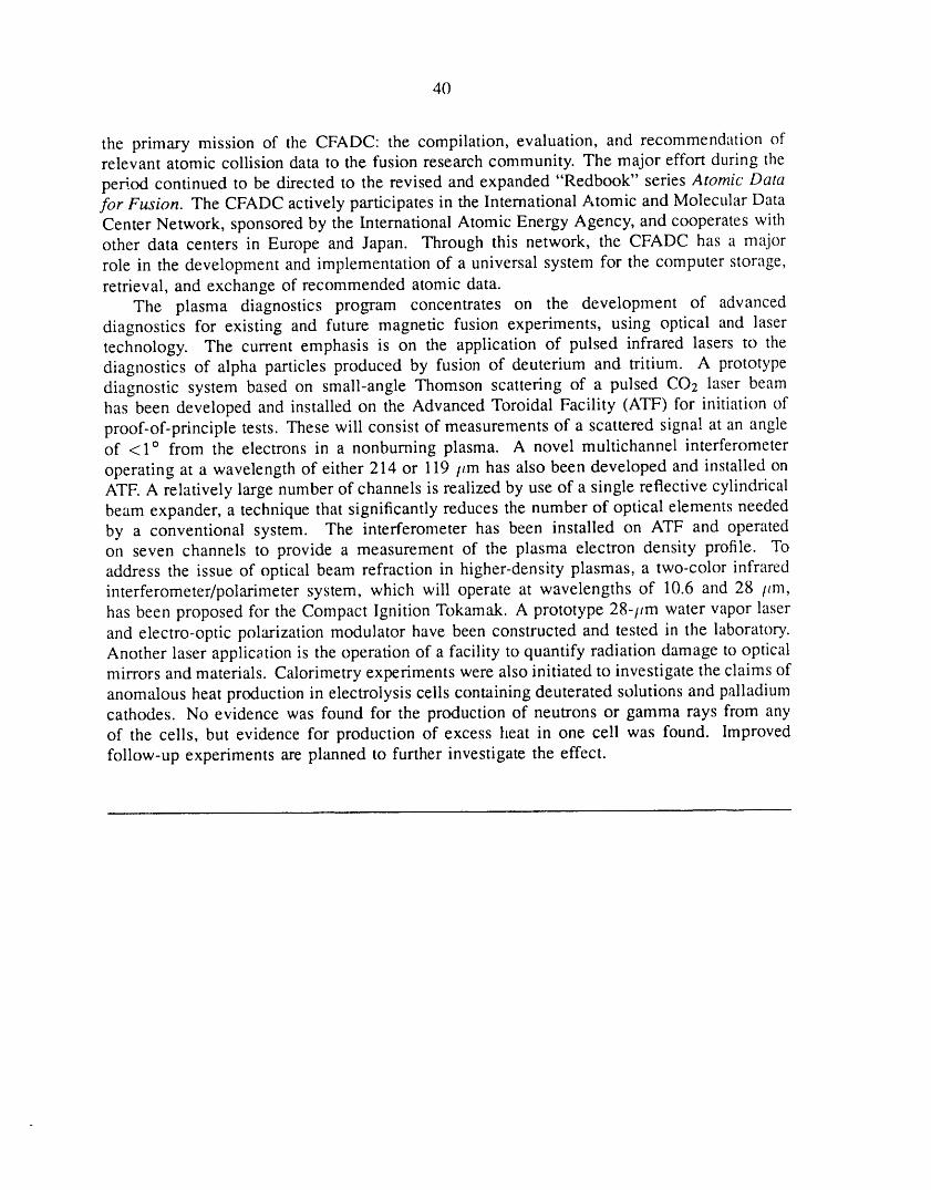
40
the primary mission of the CFADC: the compilation, evaluation, and recommendation ofrelevant atomic collision data to the fusion research community. The major effort during the
period continued to be directed to the revised and expanded "Redbook" series Atomic Datafor Fusion. The CFADC actively participates in the International Atomic and Molecular DataCenter Network, sponsored by the International Atomic Energy Agency, and cooperates withother data centers in Europe and Japan. Through this network, the CFADC has a majorrole in the development and implementation of a universal system for the computer storage,retrieval, and exchange of recommended atomic data.
The plasma diagnostics program concentrates on the development of advanceddiagnostics for existing and future magnetic fusion experiments, using optical and lasertechnology. The current emphasis is on the application of pulsed infrared lasers to thediagnostics of alpha particles produced by fusion of deuterium and tritium. A prototypediagnostic system based on small-angle Thomson scattering of a pulsed CO2 laser beamhas been developed and installed on the Advanced Toroidal Facility (ATF) for initiation ofproof-of-principle tests. These will consist of measurements of a scattered signal at an angleof <1 ° from the electrons in a nonburning plasma. A novel multichannel interferometeroperating at a wavelength of either 214 or 119 t_m has also been developed and installed onATF. A relatively large number of channels is realized by use of a single reflective cylindricalbeam expander, a technique that significantly reduces the number of optical elements neededby a conventional system. The interferometer has been installed on ATF and operatedon seven channels to provide a measurement of the plasma electron density profile. Toaddress the issue of optical beam refraction in higher-density plasmas, a two-color infraredinterferometer/polarimeter system, which will operate at wavelengths of 10.6 and 28 t_m,has been proposed for the Compact Ignition Tokamak. A prototype 28-/tm water vapor laserand electro-optic polarization modulator have been constructed and tested in the laboratory.Another laser application is the operation of a facility to quantify radiation damage to opticalmirrors and materials. Calorimetry experiments were also initiated to investigate the claims ofanomalous heat production in electrolysis cells containing deuterated solutions and palladiumcathodes. No evidence was found for the production of neutrons or gamma rays from anyof the cells, but evidence for production of excess heat in one cell was found. Improvedfollow-up experiments are planned to further investigate the effect.
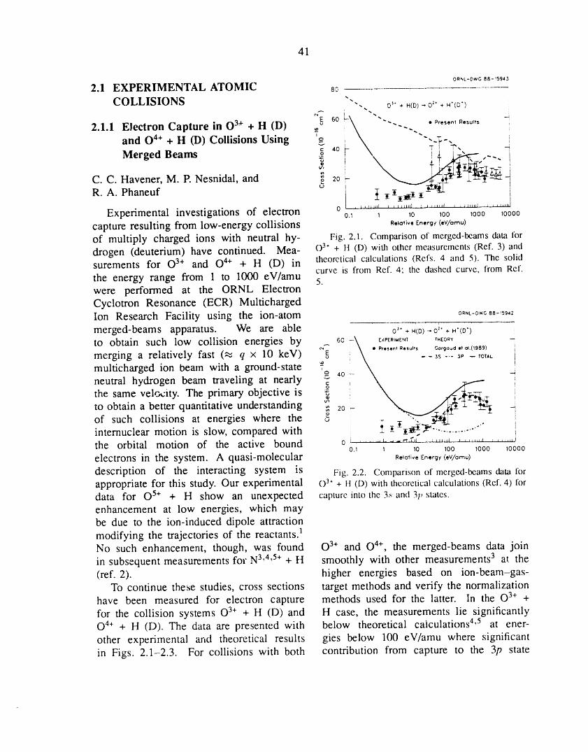
41
OI_NL-DWG 88-_5943
2.1 EXPERIMENTAL ATOMIC 8o
COLLISIONS ""- o'" +.(D)--o2"+H'(D')
2.1.1 Electron Capture in 0 3.++ H (D) ._ so _-\ -... . . P,,,.o,R,,o,,,7 i "-..and O4+ + H (D) Collisions Using o _\ --;-. i
v L \ 7_ -r',,,Merged Beams _ X. __:Tt?'__i-_f _ :
C. C. Havener, M. P. Nesnidal, and _ 20_ ___'__'__
R. A. Phaneuf _' i _ i i_iI t iExperimental investigations of electron o ....... ,1 ........ 1 ........ L ........ , ....... J0.1 1 10 100 1000 10000
capture resulting from low-energy collisions R,,o,;v,Eo,rgyi,v/om,,)of multiply charged ions with neutral hy- Fig. 2.1. Comparison of merged-beams data lhrdrogen (deuterium) have continued. Mea- o3* + H (D) with other measurements (Ref. 3) andsurements for O3+ and O4+ + H (D) in theoretical calculations (Refs. 4 and 5). The solid
curve is from Ref. 4; the dashed curve, frorn Ref.the energy range from 1 to 1000 eV/ainu 5.were performed at the ORNL ElectronCyclotron Resonance (ECR) MultichargedIon Research Facility using the ion-atom 0 " N L l D W _ 8 8 -- ] _ 9 ' 2
merged-beams apparatus. We are able o'". HCt_)-"0i' , .'(D') !_ EXPERIMENT THEORY -_
to obtain such low collision energies by 6o \ • Prl$1ntRe'*ult$ Gorgaud.to,,(1989) I
merging a relatively fast (_ q x 10 keV) _ ! --3s--_, -,o,,L imulticharged ion beam with a ground-state ?o !neutral hydrogen beam traveling at nearly c 4o athe same velocity. The primary objective is _ !
to I
to obtain a better quantitative understanding _ 20 -_of such collisions at energies where the o Iinternuclear motion is slow, compared with ithe orbital motion of the active bound o ....... '-'-":'_" ........' ........' ........o,1 i 1o 1oo 1ooo 1ooooelectrons in the system. A quasi-molecular R,,o,_,_-,,,rgv(.v/omr)description of the interacting system is Fig. 2.2. Comparison of merged-beams data lhrappropriate for this study. Our experimental o 3"+ H (D) with theoretical calculations (Ref. 4) fordata for 0 5+ + H show an unexpected capture into the 3._and 31, states.
enhancement at low energies, which maybe due to the ion-induced dipole attraction
]modifying the trajectories of the reactants.No such enhancement, though, was found 03+ and O4+, the merged-beams data joinin subsequent measurements for N3'4'5+ + H smoothly with other measurements 3 at the(ref. 2). higher energies based on ion-beam-gas-
To continue these studies, cross sections target methods and verify the normalizationhave been measured for electron capture methods used for the latter. In the 03+ +for the collision systems 03+ + H (D) and H case, the measurements lie significantlyO4+ + H (D). The data are presented with below theoretical calculations 4'5 at ener-other experimental and theoretical results gies below 100 eV/ainu where significantin Figs. 2.1-2.3. For collisions with both contribution from capture to the 3p state
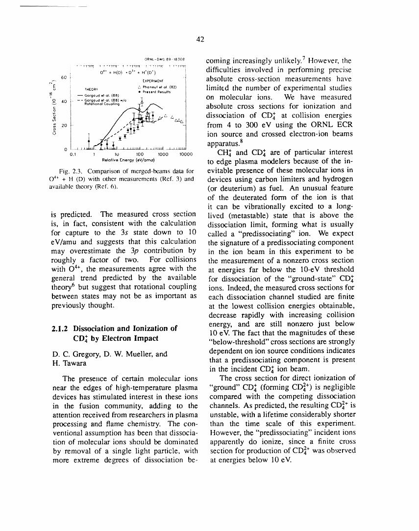
42
o_,_-o_o_.-,_o_ coming increasingly unlikely. 7 However, the' • t_tttt T _ x rtttr H _ _ _1TTTT1 T _ T?Tr]T_ T r rT]tTT]
I difficulties involved in performing preciseO" + H(D) .O _" + H'(O') i
_. 6o_ _xPe,,_,e., _ absolute cross-section measurements haveT.Eo,_ _ p".... ,,,o, _82) limited the number of experimental studies• Present Results
, --oo,go_,,o,(88_ on molecular ions We have measuredaO _. -- - Gargaud et 01. (88) w/o _,
,o,o,,o°o,coo_,,o_f._:/--._ absolute cross sections for ionization and__
t__,____, "/-r_z"_ dissociation of CD_ at collision energies
20 ;"P-__L from 4 to 300 eV using the ORNL ECRion source and crossed electron-ion beams
o ....,_-,_--_-_-_-,_-._-_-_-_ apparatus.So._ _ _0 _0o _0oo _0000 CH_ and CD_ are of particular interest
r_ot_ e_rg_(.v/o_,) to edge plasma modelers because of the in-Fig. 2.3. Comparison of merged-beams data for evitable presence of these molecular ions in
0 4+ + H (D) with other measurcments (Ref. 3) and devices using carbon limiters and hydrogenavailable thex)ry (Ref. 6). (or deuterium) as fuel. An unusual feature
of the deuterated form of the ion is that
it can be vibrationally excited to a long-is predicted. The measured cross section lived (metastable) state that is above theis, in fact, consistent with the calculation dissociation limit, forming what is usuallyfor capture to the 3s state down to 10 called a "predissociating" ion. We expecteV/amu and suggests that this calculation the signature of a predissociating componentmay overestimate the 3p contribution by in the ion beam in this experiment to beroughly a factor of two. For collisions the measurement of a nonzero cross sectionwith O4+, the measurements agree with the at energies far below the 10-eV thresholdgeneral trend predicted by the available for dissociation of the "ground-state" CD_theory 6 but suggest that rotational coupling ions. Indeed, the measured cross sections forbetween states may not be as important as each dissociation channel studied are finitepreviously thought, at the lowest collision energies obtainable,
decrease rapidly with increasing collision
2.1.2 Dissociation and Ionization of energy, and are still nonzero just below10 eV. The fact that the magnitudes of these
CD_ by Electron Impact "below-threshold" cross sections are strongly
D. C. Gregory, D. W. Mueller, and dependent on ion source conditions indicatesH. Tawara that a predissociating component is present
in the incident CD_ ion beam.The presence of certain molecular ions The cross section for direct ionization of
near the edges of high-temperature plasma "ground" CD_ (forming CD4z+) is negligibledevices has stimulated interest in these ions compared with the competing dissociationin the fusion community, adding to the channels. As predicted, the resultingCD] . isattention received from researchers in plasma unstable, with a lifetime considerably shorterprocessing and flame chemistry. The con- than the time scale of this experiment.ventional assumption has been that dissocia- However, the "predissociating" incident ionstion of molecular ions should be dominated apparently do ionize, since a finite crossby removal of a single light particle, with section for production of CD4z+ was observedmore extreme degrees of dissociation be- at energies below 10 eV.
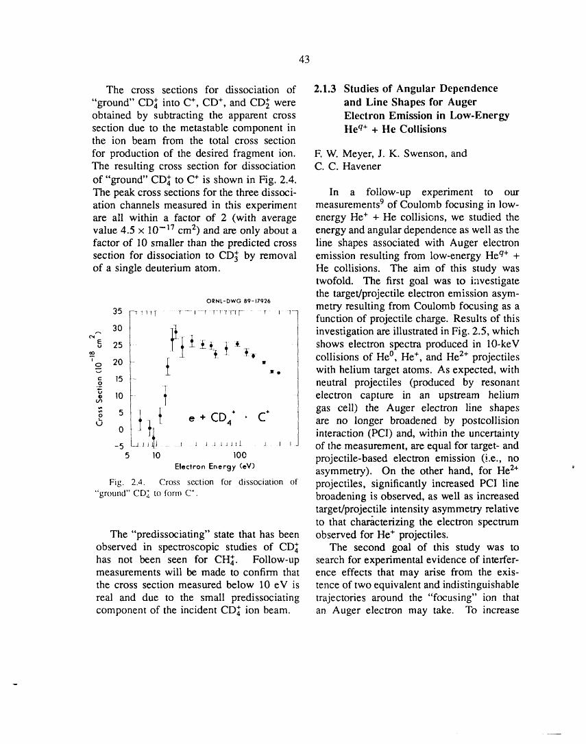
43
The cross sections for dissociation of 2.1.3 Studies of Angular Dependence"ground" CD_ into C., CD +, and CD_ were and Line Shapes for Augerobtained by subtracting the apparent cross Electron Emission in Low-Energysection due to the metastable component in Heq+ + He Collisionsthe ion beam from the total cross section
for production of the desired fragment ion. E W. Meyer, J. K. Swenson, andThe resulting cross section for dissociation C.C. Havenerof "ground" CD_ to C. is shown in Fig. 2.4.The peak cross sections for the three dissoci- In a follow-up experiment to ouration channels measured in this experiment measurements 9 of Coulomb focusing in low-are ali within a factor of 2 (with average energy He . + He collisions, we studied thevalue 4.5 x 10-]7 cm 2) and are only about a energy and angular dependence as well as thefactor of 10 smaller than the predicted cross line shapes associated with Auger electronsection for dissociation to CD_ by removal emission resulting from low-energy Heq. +of a single deuterium atom. He collisions. The aim of this study was
twofold. The first goal was to investigatethe target/projectile electron emission asym-
ORNL-DWG89-17926 metry resulting from Coulomb focusing as a35 _ Tl_T...... r.......r -Tr _-r-rrr- r T T-function of projectile charge. Results of this
,-. 30 _l:_iitl -_ _i investigation are illustrated in Fig. 2.5, which"_ 25 _ _ _ :*- -- shows electron spectra produced in 10-keV_- _-_ collisions of He°, He ., and He2+ projectiles' 20 - [O
,,. with helium target atoms. As expected, withc 15 -o neutral projectiles (produced by resonant® lo- electron capture in an upstream helium
= 5 -_t_ CD4. C . gas cell) the Auger electron line shapes
o _ e + • are no longer broadened by postcollisionU 0
i_4 interaction (PCI) and, within the uncertainty_ j J ..... J.....J J _ _Jlit J _ ' of the measurement, are equal for target- and5 10 10e projectile-based electron emission (i.e., no
Electron Energy (eV) asymmetry). On the other hand, for He2+Fig. 2.4. Cross section for dissociation of projectiles, significantly increased PCI line
"ground" CD,_to form C*. broadening is observed, as well as increasedtarget/projectile intensity asymmetry relativeto that characterizing the electron spectrum
The "predissociating" state that has been observed for He. projectiles.observed in spectroscopic studies of CD_ The second goal of this study was tohas not been seen for CHI. Follow-up search for experimental evidence of interfer-measurements will be made to confirm that ence effects that may arise from the exis-the cross section measured below 10 eV is tence of two equivalent and indistinguishablereal and due to the small predissociating trajectories around the "focusing" ion thatcomponent of the incident CD_ ion beam. an Auger electron may take. To increase
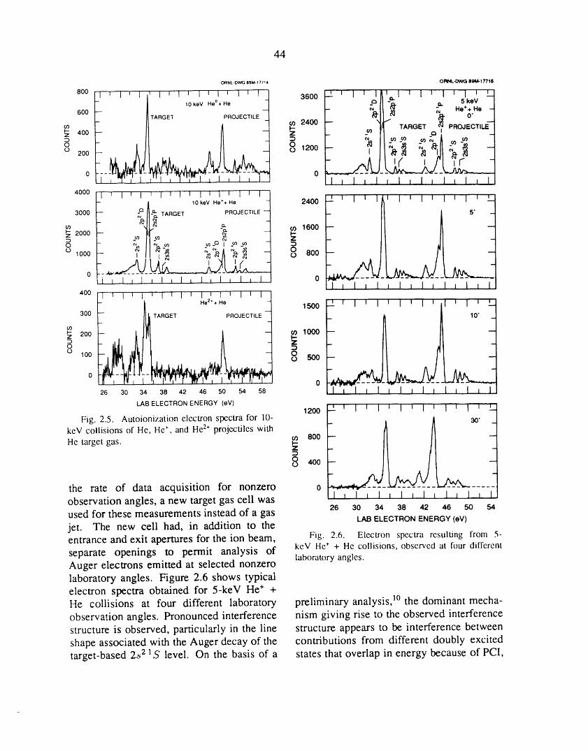
44
ORNL.DWG89M-17714 ORNL-DWQ 8_bA-17716
800I j EL I I I , I t I I i I 1 I
T II I., 1 I II ] I i I I 1 I 3600 r a -__ _. 5keV /
lOkeV He°. He L _" _ _ "*.; He
600-_ll _' TARGET PROJECTILES_ _ \ i_1_ I_1_ -1_ "i 00 2400 L t_ TARGET Q _ PROJECTILE]
tc) : I--
_ 4oo z: = ;',^ __-_ _;, A ,,._ /
o ,,.,, o,,,,, jL.,4000 ' I ' I ' l = I v I i I z l z I J
- | 10keVHe** He ] 2400 --2-'I I I I I I I I I I I I L3000 _ 5" -
# _]-_. TARGET PROJECTILE -"1
- (n 1600 -- --
2000 _ I1 _ _ .j I--Z -
0 _._ "_ _/ _ _ 2 ::3 Z --o looo ! II i,_ -_/_ ", ,,, 1 o° 8oo
o 7I _ 1 t 1 j I, I I l J I J I , 1 1 0 -I I I I I I _ I J I I I 1
4O0
1500 --3OO
z 200 _ 1000
o 1oo _o 500
0 026 30 34 38 42 46 50 54 58 I _ I _ l I I i 1
LABELECTRONENERGY(eV)1200 _ 1 I I I I I i I ' I _ I _ '--
Fig. 2.5. Autoionization electron spectra for 10- 30" _keV collisions of He, He*,and He2. projectileswith
Hetarget gas. _ 800 --_
0 400
the rate of data acquisition for nonzero o ........ _ .....1 i 1 _ 1 _ I _ 1 _ 1 ] 1 _ 1observation angles, a new target gas cell wasused for these measurements instead of a gas 26 30 34 38 42 46 50 54
LAB ELECTRON ENERGY (eV)jet. The new cell had, in addition to theentrance and exit apertures for the ion beam, Fig. 2.6. Electron spectra resulting from 5-separate openings to permit analysis of kev He . + He collisions, observed at four differentlaboratory angles.Auger electrons emitted at selected nonzerolaboratory angles. Figure 2.6 shows typicalelectron spectra obtained for 5-keV He+ +He collisions at four different laboratory preliminary analysis, ]° the dominant mecha-observation angles. Pronounced interference nism giving rise to the observed interferencestructure is observed, particularly in the line structure appears to be interference betweenshape associated with the Auger decay of the contributions from different doubly excitedtarget-based 2_2 ]S level. On the basis of a states that overlap in energy because of PCI,
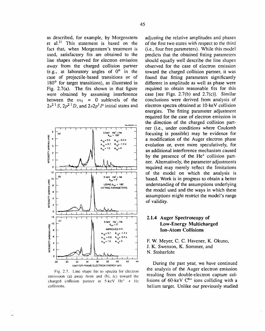
45
as described, for example, by Morgenstern adjusting the relative amplitudes and phaseset al. ]_ This statement is based on the of the first two states with respect to the thirdfact that, when Morgenstern's treatment is (i.e., four free parameters). While this modelused, satisfactory fits are obtained to the predicts that the obtained fitting parametersline shapes observed for electron emission should equally well describe the line shapesaway from the charged collision partner observed for the case of electron emission(e.g., at laboratory angles of 0 ° in the toward the charged collision partner, it wascase of projectile-based transitions or of found that fitting parameters significantly180 ° for target transitions), as illustrated in different in amplitude as well as phase wereFig. 2.7(a). The fits shown in that figure required to obtain reasonable fits for thiswere obtained by assuming interference case [see Figs. 2.7(b) and 2.7(c)]. Similarbetween the mz = 0 sublevels of the conclusions were derived from analysis of2s21 S, 2p2 _D, and 2s2p IP initial, states and electron spectra obtained at 10-keV collision
energies. The fitting parameter adjustmentrequired for the case of electron emission inthe direction of the charged collision part-
''' _' _' _' _' ' ' ' ' 1 ner (i.e., under conditions where Coulomb
5 keV He+ + He 7
"_ 0_--,8o. ._] focusing is possible) may be evidence for' _,_.0_ ,,c_.,, | a modification of the Auger electron phase
a,o-0, ,,o.-,3, .q evolution or, even more speculatively, foralp- 1.0 01p" 0
2 an additional interference mechanism causedby the presence of the He + collision part-
-_' _. A_ k. ner. Alternatively, the parameter adjustments0 .... ;V"7-7"-] required may merely reflect the limitations_2 , _ , 1 ,....i , , • _ , _ ' _ _ of the model on which the analysis is
(b) _l 5keV He*,He __ ,o - I| 0,_=0. based. Work is in progress to obtain a better
8 - III uSmNG0=--,8o" _ understanding of the assumptions underlying
)16 - _ the model used and the ways in which these, assumptions might restrict the model's range
of validity.
0 ................I , I l I t I i I l I _ I _ I i
_2 , ,, _, , : _ , _, ,, 1 _ 2.1.4 Auger Spectroscopy of(c) hl 5 keV Ha' , He
,o - I_ o_=o - Low-Energy Multicharged8 -- [I_ IMPROVED FIT:
_" li a,s'°7 *,s"_3_ Ion-Atom Collisions
_', 1[ a,p-,0 ,,_-0 F.W. Meyer, C.C. Havener, K. Okuno,J. K. Swenson, K. Sommer, and
2 _/.,/_ N. Stolterfoht- ...........o , I _ I I I _ I , I _ i J I i _
2_ _o _ 34 36 3_ ,o ,2 ,, During the past year, we have continuedEMI'I-I'ER FRAME ELECTRON ENERGY (aM)
the analysis of the Auger electron emissionFig. 2.7. Linc shapc tiL'; to spectra for electron
cmisssion (a) away from and (b), (c) toward thc resulting from double-electron capture Col-charged collision partncr in 5-keV Hc* + tic lisions of 60-keV C6+ ions colliding with acollisions, helium target. Unlike our previously studied
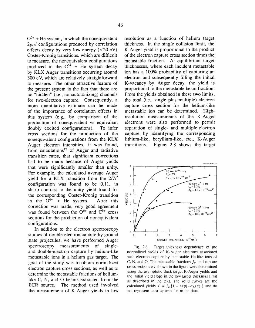
46
0 6+ + He system, in which the nonequivalent resolution as a function of helium target2pnl configurations produced by correlation thickness. In the single collision limit, theeffects decay by very low energy (<20-eV) K-Auger yield is proportional to the productCoster-Kronig transitions, which are difficult of the electron capture cross section times theto measure, the nonequivalent configurations metastable fraction. At equilibrium targetproduced in the C6+ + He system decay thicknesses, where each incident metastableby KLX Auger transitions occurring around ion has a 100% probability of capturing an300 eV, which are relatively straightforward electron and subsequently filling the initialto measure. The other attractive feature of K-vacancy by Auger decay, the yield isthe present system is the fact that there are proportional to the metastable beam fraction.no "hidden" (i.e., nonautoionizing) channels From the yields obtained in these two limits,for two-electron capture. Consequently, a the total (i.e., single plus multiple) electronmore quantitative estimate can be made capture cross section for the helium-likeof the importance of correlation effects in metastable ion can be determined. Iiigh-this system (e.g., by comparison of the resolution measurements of the K-Augerproduction of nonequivalent vs equivalent electrons were also performed to permitdoubly excited configurations). To infer separation of single- and multiple-electroncross sections for the production of the capture by identifying the correspondingnonequivalent configurations from the KLX lithium-like, beryllium-like, etc., K-AugerAuger electron intensities, it was found, transitions. Figure 2.8 shows the targetfrom calculations 12 of Auger and radiativetransition rates, that significant correctionshad to be made because of Auger yields ....................that were significantly smaller than unity, r _ J _...x-,----_ ' "_
I / 50 keV NS.+ He
For example, the calculated average Auger __ //, _:__7O/o._ _ •yield for a KLX transition from the 217ff 6 12x10"Ocmo ._i
L / •configuration was found to be 0.11, in s . / fm=63o/°sharp contrast to the unity yield found for _ /, ..,.rf. ,;'_=4Sx10'%m2
the corresponding Coster-Kronig transition _4)/" /J "in the 0 6* + He system. After this qcorrection was made, very good agreement _3_/ ,Z/..I..t-_-°----_ '°60 keV O6++ He
was found between the 0 6+ and C6+ cross 2 o,=loxlo"rcm2 -sections for the production of nonequivalent II/
configurations. _ _,/' -In addition to the electron spectroscopy " 1 I I I I I0
studies of double-electron capture by ground o _ 2 3 4 s 6 7state projectiles, we have performed Auger TARGET THICKNESS(10'Scm2)
spectroscopy measurements of single- Fig. 2.8. Target thickness dependence of theand double-electron capture by helium-like normalized yields of K-Auger electrons associated
metastable ions in a helium gas target. The with electron capture by metastableHe-likeions ofgoal of the study was to obtain normalized c, N, and O.The metastablefractions./',,,and capture
cross sections crKshown in the figure were determinedelectron capture cross sections, as well as todetermine the metastable fractions of helium- using the asymptotic thick target K-Auger yields and
the initial yield slope in the low uirget thickness limitlike C, N, and O beams extracted from the as described in the text. The solid curves are the
ECR source. The method used involved calculated yields _ = f,,,{l - expl--crK(,'r)]} and do
the measurement of K-Auger yields in low not represent least-squares Ills to the daub.
47
thickness dependence of the normalized K- shell vacancies in the target, which giveAuger yield for the collision systems studied, rise to Auger emission characteristic of theThe target thickness was calibrated using a metal. The important time scales of thecapacitance manometer, while the electron neutralization of the projectile ion (the ratespectrometer efficiency was determined by at which electrons fill the higher levels andnormalizing to the known 13 Auger electron the rate of decay of the inner-shell vacancy)emission cross section for 10-keV He+ + He are only qualitatively understood. 15collisions. The metastable fractions deter- In order to quantitatively determine neu-mined from these measurements are consis- tralization times above the surface, we
tent with independent measurements of this monitor the target Auger emission resultingquantity using ion-surface collisions. 14 For from collisions of the projectile with theali three ion species investigated, the total target atoms. The variation of the nitrogenelectron capture cross sections determined projectile KLL peak and the gold targetfor the metastable ions were in reasonable NVV (69-eV) and NNV (220-eV) peaks
agreement with the total ground-state elec- were measured for N 6. incident on gold attron capture cross sections obtained from various angles of incidence (see Fig. 2.9).the literature. Further work is planned to If neutralization is assumed to begin at aresolve single- vs multiple-electron capture critical distance 16above the surface at whichprocesses by analysis of the high-resolution the Coulomb barrier between the projectileK-Auger spectra, and the metal falls below the Fermi level
(equal to about 16 atomic units for N 6+ ions),. each angle of incidence, O, corresponds to
a different above-surface neutralization time
2.1.5 Electron Spectroscopy of _. Since the observed nitrogen KLL peakMulticharged Ion-Surface position is relatively insensitive to incidentInteractions angle, it is inferred that filling of the upper
L levels is accomplished quickly comparedF. W. Meyer, C. C. Havener, D. M. Zehner, to the relevant KLL Auger decay. Theand K. J. Reed disappearance of the 69-eV target line at
the lowest angles of incidence indicates that: We have continued our collaborative the nitrogen K-vacancy does not survive the
effort to study the interaction of multi- neutralization process before interacting withcharged ions with surfaces. Our previous the surface. The areas under the 69-eV andmeasurements of a variety of projectile ions 220-eV gold peaks are plotted in Fig. 2.10 asincident on copper and gold single crystals a function of the above-surface neutralizationhave shown electron Auger emission from time. The slopes of both curves are nearlyboth the projectile and the target. The the same and lead to an estimate of the K-projectile Auger electrons result from the vacancy lifetime T above the surface on thedecay of inner-shell vacancies either carried order of 1.5 × l0 -14 S.into the collision or produced by vacancy lt is hoped that this technique can be ap-transfer from empty outer projectile levels plied to a system where the various electronvia close collisions with target atoms. If configurations leading to Auger emissionthe incident projectile vacancy survives the may be resolved in the electron emissionneutralization process above the surface, spectra. Comparison of the observed andsubsequent close collisions with the target calculated decay rates may then lead to aatoms may lead to the creation of inner- better understanding of the neutralization

48
ORNf,.-DWO 89M-I T718
I i I I 1
Au _ 6.
N KLL3000 -- e" TRANSITIONS
Au NVV
TRANSITIONS ,/2!' 1 t - _
'-"-' -- 3.2 x 10"14SC
.-. _ 1.3x tn.v14S
2000 -
121.--I
LM
_oZ_.o__1000 _- g_ _lVi_a'_'"-_LIN _, 10"20. },1_ll TM _°l's -
w 0 IM_ i _ ..p/'r2o:_
"J 50 70 90LU
0 ImWll_'"" I I I100 180 260 340 420 500
ELECTRON ENERGY(eV)
Fig .... -). Electron energy distributions for 50-kev N6+ ions incident on gold, for four different observationangles t), and corresponding above-surface neutralization times /.
ORNL DWG 8_)M.t7717
I I I _5.0 --
O
•- -- F ~ 1.75x 10"14s -- "-"x x< _ AuNVVPEAK <w 2.0 - wrr. rr"
< <LU 0..a. 1.0 1.0 w> >z _>z z
< 0,5 o£3LU -- F ~ 1.2x 10¹⁴s_ -- LMNN
<'7 __ AU NNV PEAK _ -- <-J(69 eV) _
cE _ CE
O 0.2 Oz z
0.1 ] I I 0.10 1 2 3
TIME ABOVE SURFACE (10"14s_
Fig. 2.10. Semi-log plot of the area under the two observed gold lines as a function of atx)ve-surfaceneutralization time. The slopes of the straight-line fit to the data lead to estimates for the lifetime of thenitrogen K-vacancy above the surface.
49
process, especially the apparent rapid filling completed, and preliminary measurements ofof the upper levels, excitation of C+ were initiated. 17
The apparatus will be transported toORNL in early 1990, with subsequent
2.1.6 Merged-BeamsExperiment for initiation of collaborative measurementsElectron-Impact Excitation of electron-impact excitation of multiplyoJ Ions charged ions. In preparation, modifications
were made to the main beam line of the
E. W_ihlin, C. Timmer, L. Forand, ORNL ECR ion source, and the existingD. Swenson, B. DePaola, R. A. Phaneuf, crossed-beams and merged-beams experi-D. Belir, K. Rinn, J. S. Thompson, ments were relocated. Collaborative ex-A. Mtiller, and G. Dunn periments using this experimental approach
will constitute a significant fraction of ourApart from their fundamental importance, experimental effort in electron-ion collisions
cross sections for electron-impact excitation during the next several years.of multiply charged plasma impurity ionsare critical to radiative power loss and
diagnostics of magnetic fusion plasmas. All 2.1.7 Electron-Impact IoniT_tion of Ta 8+such excitation cross-section measurements
to date have been based on the crossed- D.C. Gregorybeams approach and on absolute intensitymeasurements of the radiation emitted as the In the next generation of magnetic fu-excited states decay. The number of such sion experiments, such as the proposedmeasurements has been severely limited by International Thermonuclear Experimentallow intensities and efficiencies of photon Reactor (ITER), the power loading at thedetection. Resonances are predicted to play vacuum vessel walls and divertor plates will
a major role in the near-threshold region, but exceed the capabilities of low-Z materialsthe experiments performed to date have had such as carbon, which is widely used ininsufficient energy resolution to adequately current devices. Refractory metals such astest theoretical calculations, tungsten and tantalum are being considered.
A novel experimental approach to this Such high-Z elements will be only partiallyproblem has been under development for a ionized in the hot plasma, and radiation fromnumber of years at the Joint Institute for these ions will cool the edge region, insu-Labor_,tory Astrophysics (JILA) in Boulder, lating the vacuum vessel from the hot coreColo. This approach involves merging fast plasma. Line radiation from specific chargebeams of electrons and multiply charged ions states will provide a useful diagnostic ofin a uniform axial magnetic field and using the plasma. Accurate modeling will requireelectron energy loss spectroscopy to detect knowledge of cross sections for electron-electron-impact excitation events. This impact ionization and recombination of theseexperiment has been developed specifically high-Z elements.for use in conjunction with the ORNL ECR Preliminary measurements of electron-multicharged ion source. During a six-month impact ionization cross sections for Ta 8+ asassignment of R. A. Phaneuf to JILA during a function of collision energy have beenFY 1989, the proof of principle of the tech- made. The experiment used the ORNL ECRnique was established, systematic tests were ion source and electron-ion crossed-beams
5O
apparatus. This was the first use of heavy M.S. Pindzola, D. C. Griffin, andrefractory metal ion beams from this source C. Bottcherin an experiment. The measurements inthis preliminary study show that the cross Electron-impact excitation cross sectionssection is approximately 50% larger than for outer-subshell transitions in Ca+, Sc2+,
Ti3+ Cr s+, and Fe7+ are calculated in thethat predicted by the simple Lotz formulafor collision energies over the energy range close-coupling and distorted-wave approxi-from 150 to 900 eV. There are no indications mations. Coupling effects, beyond the first-
of a high-lying metastable component in the order perturbation included in the distorted-incident ion beam or of sharp features in the wave approximation, are found to decreasecross-section energy dependence. Possible rapidly as one moves to higher Z along thefuture experiments include a remeasurement potassium isoelectronic sequence. Only forof this cross section in greater detail as well Fe7+, however, are the close-coupling andas ionization measurements for additional distorted-wave results in agreement to 10%
charge states, or better for ali the excitations studied.
2.2.3 Abstract of "Indirect Processes in2.2 ATOMIC COLLISION THEORY
the Electron Impact Ionization ofAtomic Ions "a°
2.2.1 Abstract of "Strong-Field Laser
Ionization of Alkali Atoms Using M.S. Pindzola, D. C. Griffin, and2-D and 3-D Time-Dependent C. BottcherHartree-Fock Theory ''18
General theoretical methods for the calcu-
M. S. Pindzola, G. J. Bottrell, and lation of indirect processes in the electron-C. Bottcher impact ionization of atomic ions are re-
viewed. Theory is compared with theThe time-dependent SchrOdinger equation results of recent crossed-beams experiments
is solved directly for an alkali atom sub- for several atomic ions.ject to an arbitrarily strong electromagneticfield. Two methods are compared. Atridiagonal finite difference method is used 2.2.4 Abstract of "Correlationto solve SchrSdinger's equation on a three- Enhancement of the
dimensional (3-D) Cartesian coordinate lat- Electron-Impact Ionizationtice. Multiphoton ionization cross sections Cross Section for Excited Stateare extracted from the two-dimensional Ne-Like Ions ''21(2-D) calculations for hydrogen and lithium
and then compared with previous perturba- M.S. Pindzola, D. C. Griffin, andtion theory results. Single-photon ionization C. Bottcherprobabilities are compared from the 2-D and3-D calculations for hydrogen. The electron-impact ionization cross sec-
tion is calculated in the distorted-wave
approximation for the neon-like ions Ar 8+,2.2.2 Abstract of "Coupling Effects for Ti 12+,Fe 16+,Zn 2°+, and Se 24+. For ionization
Electron-Impact Excitation in the from the 2p6 ground state, the contributionsPotassium Isoelectronic from inner-shell excitation followed by auto-Sequence ''19 ionization are negligible. However, when

51
ORNL-DWG90M-3192 FED
these ions are initially in the 2p53s excited lO-_ I I I Iconfiguration, contributions arising from the _ 0.5 _inner-shell excitations 2p53s --_ 2p43sT_l 10-a _ P .... 2.5
........ 5.5and 2p53s _ 2s2p53sTzl are large. The 10-3overall branching ratio for autoionization ofthe 2p43srtl and 2s2p53sT_l levels increases ,,, lO-4 - "- ___-°'''''''°''''°°-! "" q"_,
when the atomic structure calculations are _-o10-5 - "'"'........""-, -extended beyond the single-configuration ap- "-...
proximation to include configuration interac- 10-4 - "".................tion. The resulting correlation enhancement 10-7 ............. -
of the excited state ionization cross section (a)is found to increase as a function of Z. 10-4 I I I IFor Se 24+ the correlation enhancement of the 1°-a
" total ionization cross section is found to be42%. 10-3 -
t.u 10-4
Q.."O
2.2.5 Time-Dependent Hartree-Fock 1°-5".
Studies of Ion-Atom Collisions "'--...10-6
-- %%.=......o... .... °.... ,.o=.
G. J. Bottrell and C. Bottcher (b)10-7 I I I 1
We have completed studies on p + H 0 0.5 10 15 20 2.5E (hartrees)and C6+ + Ne collisions using our 3-Dtime-dependent Hartree-Fock (TDHF) codes. Fig. 2.11. Secondary electron energy distributionsCalculations have been made for p + H at in projectile (P) and target (T) frames for a p + ttcollision at _, = 1. The curves refer to three impacttwo ion velocities, v = 1 and 2 atomic units, parameters: solid line, v = 0.5; dashed line, v = 2.5;and for C6+ + Ne at one velocity, v = 6. dotted line, ,, = 55.For each velocity and a range of impactparameters, we have extracted excitation and
capture probabilities and secondary electron 2.3 CONTROLLED FUSIONspectra in the target and projectile frames. ATOMIC DATA CENTERTypical energy distributions are shown inFig. 2.11. The p + H runs at v = 2 I. Alvarez, C. F. Barnett, C. Cisneros, H. B.show evidence of "ridge" electrons, trailing Gilbody, D. C. Gregory, C. C. Havener,behind the projectile at a relative velocity H.T. Hunter, R. K. Janev, M. I.
v_ = v/2. We expect that a definitive picture Kirkpatrick, E. W. McDaniel, F. W. Meyer,will emerge when the angular distributions T. J. Morgan, R. A. Phaneuf, M. S.are plotted. The amount of data arising Pindzola, and E. W. Thomasfrom all possible excitations of the five activeorbitals of C6+ + Ne is rather large. Thus The Controlled Fusion Atomic Data Cen-far, the results agree with intuition based on ter (CFADC) collects, reviews, evaluates,the geometry of the orbitals and the extent and recommends numerical atomic collisionto which the electrons' velocities match the data that are relevant to controlled thermonu-
velocity of the projectile, clear fusion research. The CFADC operates

52
with an equivalent of 1.5 full-time staff • the Research Information Center at themembers and a number of expzrt consultants Institute of Plasma Physics (IPP), Nagoyaunder contract, ielembers of the Exveri- University, Japan; andmental Atomic Physics for Fusion Group • the Atomic and Nuclear Data Centeralso contribute a sinai 1 fraction of their time of the Japan Atomic Energy Researchto literature searches and categorization of Institute (JAERI), Tokai, Japan.
relevant publications.The major activities of the CFADC are: Updates of our bibliography are sent peric_li-
• the maintenance of an on-line computer cally on computer diskettes to the IAEA anddatabase of fusion-related publications to both Japanese data centers. This forms theon atomic collision processes and the basis for the semiannual IAEA Internationalperiodic distribution of updates to other Bulletin on Atomic and Molecular Data fardata centers; Fusion.
• the preparation and publication of compi- During this reporting period, work haslations of recommended atomic collision continued on preparation of the "Redbook"data; series of recommended data, Atomic Data
• the deduction of scaling laws and parame- for Fusion. Volume 6 of this series,entitled Spectroscopic Data for Titanium," terization of atomic collision data for ease
of application in fusion research; Chromium, and Nickel, by W. Wiese and• the establishment of a computer database A. Musgrove of the National Institute of
of recommended atomic collision data Standards and Technology (NIST), wasand a data exchange format to facilitate published and distributed as ORNL-6551,their application in fusion research; Vols. 1-3. Data compilation and evaluation
• the review of the existing atomic collision have been completed for another volume,database with respect to current applica- entitled Collisions of H, H2, He and Litions L' fusio_ research, identification of Atoms and Ions with Atoms and Molecules.data needs, and coordination of research Publication and distribution of this volumeto fill those ,,eeds; and (ORNL-6086) are planned for 1990. Ali
• the handling of individual requests for tabular and graphical data for this seriesspecific data or literature searches on are computer-generated in publication-readyformat. Maxwellian rate coefficients arespecific processes, calculated from the cross-section data, and
The CFADC pani,:il3ates in the Atomic Chebyshev polynomial fits are given for alia;ld NSolecular Dat_. Center Network estab- the recommended data.
: lished oy the Inter'national Atomic Energy The CFADC also participated in twoAgency (IAEA) in Vienna and has coopera- IAEA-sponsored workshops held in Viennative a reements with a number of other data during the period: a specialists' meeting oncenters. These include review of the status of atomic and molecular
• the Atomic and Molecular Processes data for fusion edge plasma studies andInformation Center at JILA; the consultants' meeting of the Atomic and
• the Data Center for Atomic Spectral Molecular Data Center Network.Lines and Transition Probabilities at the A major role of the CFADC is to assistNational Institute for Stanuards and Tech- with the implementation of a new atomicnolo_v, Gaithersburg, Md.; data interface program, called ALADDIN, a
• the I-tkEA Atomic and Mc, ecular Data FORTRAN code designed to facilitate e,ffec-Unit in Vienna; tive exchange of data and the establishment
53
of a computer database for "users." It alpha particles must deposit this energy incan accept a wide range of data formats, the plasma fuel. Because of this critical lm-including tabular, parameterized, and fitted portance, the demonstration of alpha particledata, and operates on a wide range of com- heating is the main physics goal of the nextpurer systems, including personal computers generation of fusion reactors. 22 To study the(PCs). Plans call for a diskette containing behavior of alpha particles in a plasma asthe data and the ALADDIN program to they lose energy and produce a distributionbe distributed with the next volume of the characteristic of this energy loss, we have"Redbook" series, proposed a Thomson scattering diagnostic. 23
In collaboration with JAERI, work also With a scattering source at the CO2 laserhas continued on the scaling, parameteri- wavelength (10.6 #m), the background fromzation, and fitting of heavy-particle ioniza- electron scattering requires that small-angletion data using functional forms based on (_1°) detection be used to monitor the alphaanalytical physical models for the process, particle distribution.Often the available data are limited to a As a measure of this diagnostic capabilitynarrow energy range, and such "physical" in detecting scattered signals at these smallfitting formulas permit extrapolation of the scattering angles, a proof-of-principle test isdata outside this range with some measure currently in progress on a nonburning plasmaof confidence. Such extrapolation of data is in the Advanced Toroidal Facility (ATF).impossible with polynomial fits. The goal is to measure a scattered signal
The death of C. F. Barnett, the founder (in this case a low-level signal from plasmaof the CFADC, in June 1989 is a most electrons) at an angle of 0.86 °. The majorsignificant loss to the data center. "Barney" hardware components have been installedserved as director of the CFADC until at the ATF facility, and preliminary testshis retirement from ORNL in 1985 and have been conducted using the extremelysubsequently a'- a consultant until the time sensitive heterodyne receivers. Tests of theof his death. His keen insights and tireless full scattering system to demonstrate proof ofefforts will be sorely missed, principle are scheduled for the second half of
FY 1990.
2.4 ADVANCED PLASMADIAGNOSTICS DEVELOPMENT 2.4.2 Multichannel Far-Infrared
Interferometer and Scattering2.4.1 Small-Angle CO2 Laser Thomson System for the Advanced
Scattering Diagnostic for D-T Toroidal FacilityFusion Product Alpha Particles
C. H. Ma, D. P. Hutchinson, C. A. Bennett,R. K. Richards, C. A. Bennett, D.P. Y.M. Fockedey, and K. L. Vander SluisHutchinson, L. K. Fletcher, Y. M.Fockedey, H. T. Hunter, and K.L. During the past year, a multichannelVander Sluis far-infrared (FIR) interferometer system has
been fully installed on ATF to measureThe deuterium-tritium (D-T) fusion reac- the line-integrated electron density along 15
tion produces alpha particles at 3.5 MeV. For vertical chords on the 4_ - 0 ° plane of thea IU_tUtl t_a_tut Iu "-"_:'_*'_;" ;,_,-,;,;,.r, th,._,_ ATr-,' lab:rna The _:y_tern ix a mcwlification111 KI.I I ! I,g_l I 1 1 _ 11 ,t t.1 _,..,Pi 1, t.a t _... ,o _,, .... p ...................
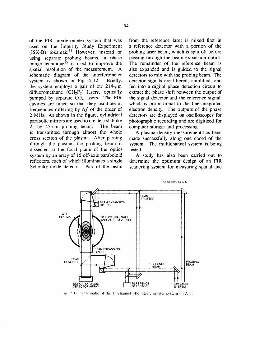
54
of the FIR interferometer system that was from the reference laser is mixed first inused on the Impurity Study Experiment a reference detector with a portion of the(ISX-B) tokamak. 24 However, instead of probing laser beam, which is split off beforeusing separate probing beams, a phase passing through the beam expansion optics.image technique 25 is used to improve the The remainder of the reference beam isspatial resolution of the measurement. A also expanded and is guided to the signalschematic diagram of the interferometer detectors to mix with the probing beam. Thesystem is shown in Fig. 2.12. Briefly, detector signals are filtered, amplified, andthe system employs a pair of cw 214-pm fed into a digital phase detection circuit todifluoromethane (CHzF2) lasers, optically extract the phase shift between the output ofpumped by separate CO/ lasers. The FIR the signal detector and the reference signal,cavities are tuned so that they oscillate at which is proportional to the line-integratedfrequencies differing by Af of the order of electron density. The outputs of the phase2 MHz. As shown in the figure, cylindrical detectors are displayed on oscilloscopes forparabolic mirrors are used to create a slablike photographic recording and are digitized for2- by 45-cm probing beam. The beam computer storage and processing.is transmitted through almost the whole A plasma density measurement has beencross section of the plasma. After passing made successfully along one chord of thethrough the plasma, the probing beam is system. The multichannel system is beingdissected at the focal plane of the optics tested.system by an array of 15 off-axis paraboloid A study has also been carried out toreflectors, each of which illuminates a single determine the optimum design of an FIRSchottky-diode detector. Part of the beam scattering system for measuring spatial and
ORNL-DWG 89-8732
"" " BEAM
SPLITTER
BEAM EXPANSIONOPTICS
ATF
PLASMA _ STRUCTURAL SHELL
iD VACUUM VESSEL
BEAM EXPANSIONOPTICS
BEAM _
COMBINER PROBING_.. REFERENCE BEAM
BEAM #%
ffSCHOTTKY-DIODE REFERENCE FROM LASERDETECTOR ARRAY ETECTOR SYSTEM
_I:i,, "3 1? Schematic (_1 lhc 15-_.hanncl FIR intcrlcrometer system on ATF.
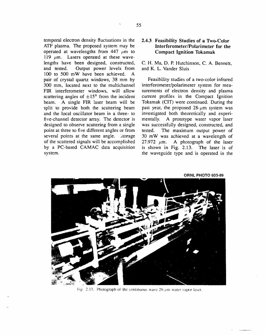
" 55
temporal electron density fluctuations in the 2.4.3 Feasibility Studies of a Two-ColorATF plasma. The proposed system may be Interferometer/Polarimeter for theoperated at wavelengths from 447 /zm to Compact Ignition Tokamak119 /zm. Lasers operated at these wave-lengths have been designed, constructed, C.H. Ma, D. P. Hutchinson, C. A. Bennett,and tested. Output power levels from and K. L. Vander Sluis100 to 500 mW have been achieved. A
pair of crystal quartz windows, 38 mm by Feasibility studies of a two-color infrared300 mm, located next to the multichannel interferometer/polarimeter system for mea-FIR interferometer windows, will allow surements of electron density and plasmascattering angles of +15 ° from the incident current profiles in the Compact Ignitionbeam. A single FIR laser beam will be Tokamak (CIT)were continued. During thesplit to provide both the scattering beam past year, the proposed 28-/_m system wasand the local oscillator beam in a three- to investigated both theoretically and experi-five-channel detector array. The detector is mentally. A prototype water vapor laserdesigned to observe scattering from a single was successfully designed, constructed, andpoint at three to five different angles or from tested. The maximum output power ofseveral points at the same angle. _torage 30 mW was achieved at a wavelength ofof the scattered signals will be accomplished 27.972 /Lm. A photograph of the laserby a PC-based CAMAC data acquisition is shown in Fig. 2.13. The laser is ofsystem, the waveguide type and is operated in the
ORNL PHOTO 603-89
Fig 2.13. Photograph of the c()ntinuous wave 2_-l_rn water ValX)r la_cr.
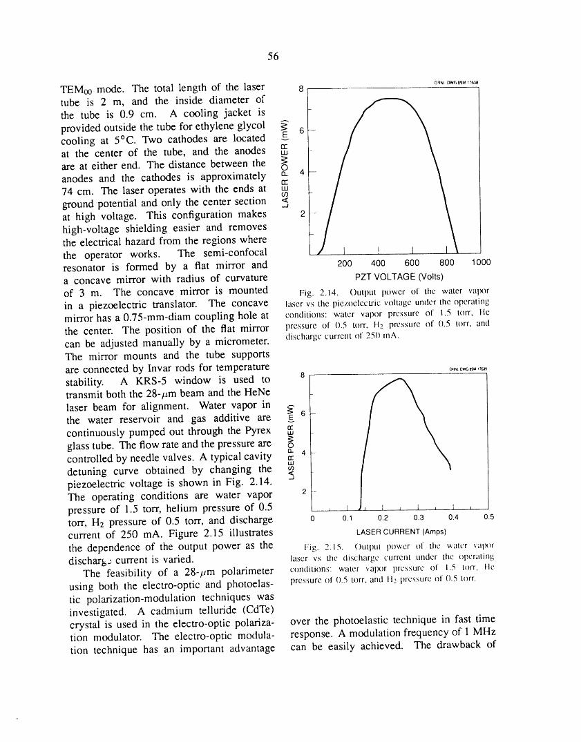
56
OllNtDWGB9M17638
TEM00 mode. The total length of the laser 8tube is 2 m, and the inside diameter ofthe tube is 0.9 cre. A cooling jacket is
provided outside the tube for ethylene glycol _" 6cooling at 5°C. Two cathodes are located gat the center of the tube, and the anodes rrLM
are at either end. The distance between the O
anodes and the cathodes is approximately a. 4rr74 cm. The laser operates with the ends at ,,,(/3
ground potential and only the center sectionat high voltage. This configuration makes 2high-voltage shielding easier and removesthe electrical hazard from the regions wherethe operator works. The semi-confocalresonator is formed by a flat mirror and 200 400 600 800 1000a concave mirror with radius of curvature PZTVOLTAGE(Volts)
of 3 m. The concave mirror is mounted Fig. 2.14. Output power of the water ValX_rin a piezoelectric translator. The concave laser vs the piezoelectric voltage under the operatingmirror has a 0.75-mm-diam coupling hole at conditions: water vapor pressure of 1.5 torr, lte
the center. The position of the flat mirror pressure of 0.5 torr, H._ pressure of 0.5 torr, and
can be adjusted manually by a micrometer, discharge current of 25(1tnA.The mirror mounts and the tube supportsare connected by Invar rods for temperature o.._._,,_8stability. A KRS-5 window is used totransmit both the 28-#m beam and the HeNe
laser beam for alignment. Water vapor in _ 6the water reservoir and gas additive arecontinuously pumped out through the Pyrex rrt.u
glass tube. The flow rate and the pressure are _ocontrolled by needle valves. A typical cavity _. 4uJ
detuning curve obtained by changing the ipiezoelectric voltage is shown in Fig. 2.14. -_ |The operating conditions are water vapor 2 Jpressure of 1.5 torr, helium pressure of 0.5 , I , 1 , l , 1 ,torr, H2 pressure of 0.5 torr, and discharge o o._ o.2 o.3 o.4 o.5current of 250 mA. Figure 2.15 illustrates LASER CURRENT (Amps)
the dependence of the output power as the Fig. 2.15. ()Utl)Ut power of the water ValX_rdischarg.: current is varied, laser vs the discharge current under the opcraling
The feasibility of a 28-t_m polarimeter conditions' water vapor pressure of 1.5 torr, lie
using both the electro-optic and photoelas- pressure oi 0.5 torr, and !t2 pressure of 0.5 u)rr.
tic polarization-modulation techniques wasinvestigated. A cadmium telluride (CdTe)crystal is used in the electro-optic polariza- over the photoelastic technique in fast timetion modulator. The electro-optic modula- response. A modulation frequency of 1 MHz
tion technique has an important advantage can be easily achieved. The drawback of
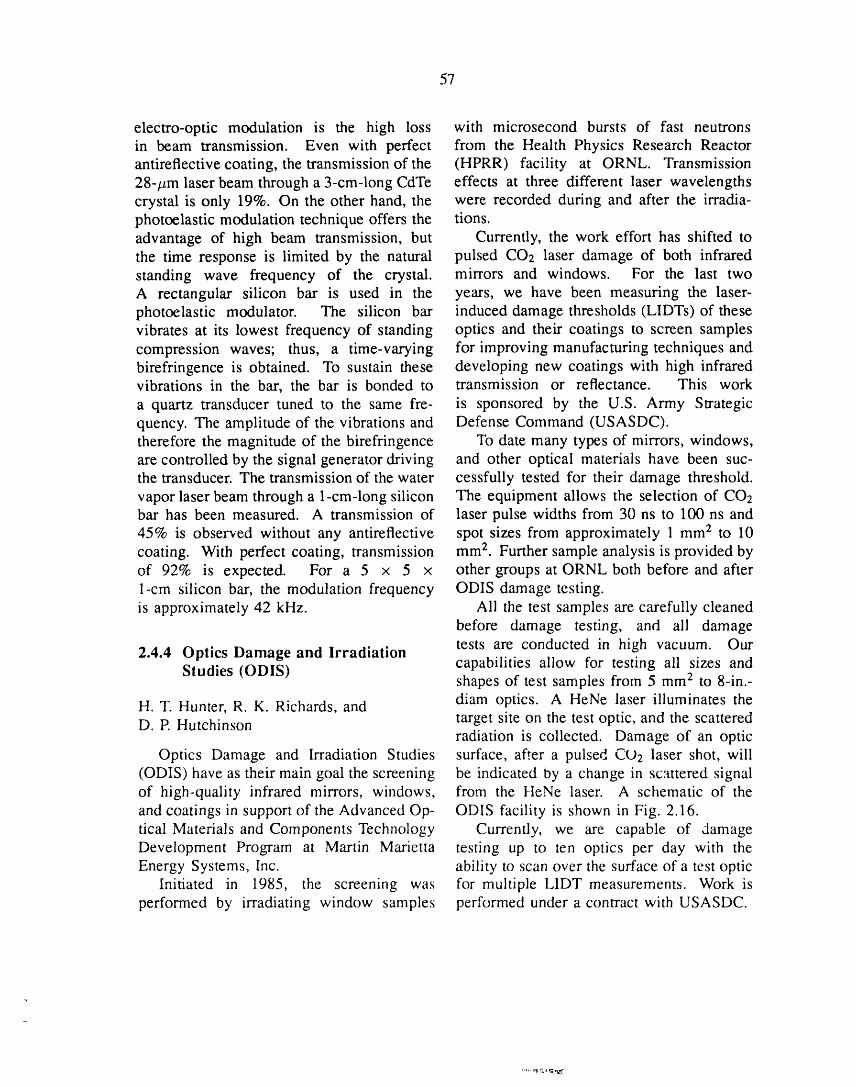
57
electro-optic modulation is the high loss with microsecond bursts of fast neutronsin beam transmission. Even with perfect from the Health Physics Research Reactorantireflective coating, the transmission of the (HPRR) facility at ORNL. Transmission28-#m laser beam through a 3-cm-long CdTe effects at three different laser wavelengthscrystal is only 19%. On the other hand, the were recorded during and after the irradia-photoelastic modulation technique offers the tions.advantage of high beam transmission, but Currently, the work effort has shifted tothe time response is limited by the natural pulsed COE laser damage of both infraredstanding wave frequency of the crystal, mirrors and windows. For the last twoA rectangular silicon bar is used in the years, we have been measuring the laser-photoelastic modulator. The silicon bar induced damage thresholds (LIDTs) of thesevibrates at its lowest frequency of standing optics and their coatings to screen samplescompression waves; thus, a time-varying for improving manufacturing techniques andbirefringence is obtained. To sustain these developing new coatings with high infraredvibrations in the bar, the bar is bonded to transmission or reflectance. This worka quartz transducer tuned to the same fre- is sponsored by the U.S. Army Strategicquency. The amplitude of the vibrations and Defense Command (USASDC).therefore the magnitude of the birefringence To date many types of mirrors, windows,are controlled by the signal generator driving and other optical materials have been suc-the transducer. The transmission of the water cessfully tested for their damage threshold.vapor laser beam through a 1-cm-long silicon The equipment allows the selection of COEbar has been measured. A transmission of laser pulse widths from 30 ns to 100 ns and45% is observed without any antireflective spot sizes from approximately 1 mm 2 to 10coating. With perfect coating, transmission mm z. Further sample analysis is provided byof 92% is expected. For a 5 × 5 x other groups at ORNL both before and after1-cm silicon bar, the modulation frequency ODIS damage testing.is approximately 42 kHz. Ali the test samples are carefully cleaned
before damage testing, and ali damagetests are conducted in high vacuum. Our2.4.4 Optics Damage and Irradiation
Studies (ODIS) capabilities allow for testing ali sizes andshapes of test samples from 5 mm 2 to 8-in.-diam optics. A HeNe laser illuminates theH. T. Hunter, R. K. Richards, and
D. P. Hutchinson target site on the test optic, and the scatteredradiation is collected. Damage of an optic
Optics Damage and Irradiation Studies surface, after a pulsed CO2 laser shot, will(ODIS) have as their main goal the screening be indicated by a change in scattered signalof high-quality infrared mirrors, windows, from the HeNe laser. A schematic of theand coatings in support of the Advanced Op- ODIS facility is shown in Fig. 2.16.tical Materials and Components Technology Currently, we are capable of damageDevelopment Program at Martin Marietta testing up to ten optics per day with theEnergy Systems, Inc. ability to scan over the surface of a test optic
Initiated in 1985, the screening was for multiple L1DT measurements. Work isperformed by irradiating window samples performed under a contract with USASDC.
..... r'_lL;_"_ 'l;,?',,.'f
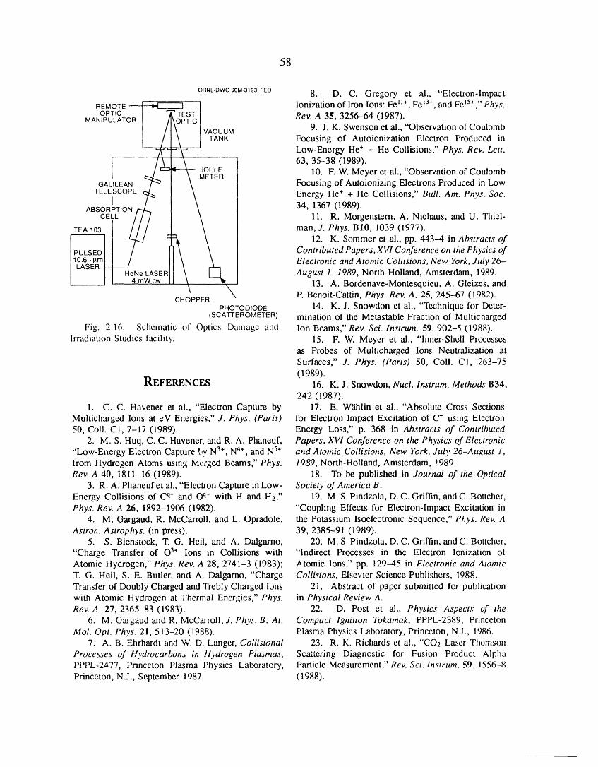
58
ORNL-DWGgOM-3193FED 8. D. C. Gregory et al., "Electron-ImpactREMOTE _ ] Ionization of Iron Ions: Fe lI+, Fe 13+,and FelS+,'' Phys.OPTIC I T TESTI
_,,_o_To, I Rev. A 35, 3256--64 (1987).I / I \ I VACUUM 9. J. K. Swenson et al., "Observation of Coulomb
I / I \ I TANK Focusing of Autoionization Electron Produced in
"-/f"-l'-"_-' Low-Energy He+ + He Collisions," Phys. Rev. Lett.- 63, 35-38 (1989).
JOULE 10. F. W. Meyer et al., "Observation of Coulombi _-L., I \ METERGALILEAN [-" I \ Focusing of Autoionizing Electrons Produced in Low
TELEISCOPE _j_ I \ EnergyHe++HeC°llisi°ns'"Bull'Am'Phys'S°c"ABSORPTION /'_ l \ 34, 1367 (1989).
CELL // / I \ 11. R. Morgenstern, A. Niehaus, and U. Thiel-
TEAl03 1 /_ t:_ _ man, J. Phys. BlO, 1039(1977).
12. K. Sommer et al., pp. 443-4 in Abstracts of
PULSED Contributed Papers, XVi Conference on the Physics of
IO_6sEPRm Electronic and Atomic Collisions, New York, July 26-August 1, 1989, North-Holland, Amsterdam, 1989.
13. A. Bordenave-Montesquieu, A. Gleizes, andP. Benoit-Cattin, Phys. Rev. A. 25, 245--67 (1982).
PHOTODIODE 14. K.J. Snowdon et al., "Technique for Deter-(SCATTEROMETER) mination of the Metastable Fraction of Multicharged
Fig. 2.16. Schematic of Optics Damage and Ion Beams," Rev. Sci. lnstrum. 59, 902-5 (1988).
Irradiation Studies facility. 15. F. W. Meyer et al., "Inner-Shell Processesas Probes of Multicharged lons Neutralization at
Surfaces," J. Phys. (Paris) 50, Coll. C1, 263-75
REFERENCES (1989).16. K. J. Snowdon, Nucl. lnstrum. Methods B34,242 (1987).
1. C. C. Havener et al., "Electron Capture by 17. E. Wahlin et al., "Absolute Cross Sections
Multicharged Ions at eV Energies," J. Phys. (Paris) for Electron Impact Excitation of C . using Electron50, Coll. C1, 7-17 (1989). Energy Loss," p. 368 in Abstracts of Contributed
2. M. S. Huq, C. C. Havener, and R. A. Phaneuf, Papers, XV! Conference on the Physics of Electronic"Low-Energy Electron Capture by N3+, N4+, and N 5+ and Atomic Collisions, New York, July 26-August 1,from Hydrogen Atoms using Ivicrged Beams," Phys. 1989, North-Holland, Amsterdam, _989.Rev. A 40, 1811-16 (1989). 18. To be published in Journal of the Optical
3. R. A. Phaneuf et al., "Electron Capture in Low- Society of America B.Energy Collisions of C q. and Oq. with H and H2," 19. M. S. Pindzola, D. C. Griffin, and C. Bottcher,Phys. Rev. A 26, 1892-1906 (1982). "Coupling Effects for Electron-Impact Excitation in
4. M. Gargaud, R. McCarroll, and L. Opradole, the Potassium Isoelectronic Sequence," Phys. Rev. AAstron. Astrophys. (in press). 39, 2385-91 (1989).
5. S. Bienstock, T. G. Heil, and A. Dalgarno, 20. M. S. Pindzola, D. C. Griffin, and C. Bottcher,"Charge Transfer of 03+ Ions in Collisions with "Indirect Processes in the Electron Ionization ofAtomic Hydrogen," Phys. Rev. A 28, 2741-3 (1983); Atomic Ions," pp. 129-45 in Electronic and AtomicT. G. Heil, S. E. Butler, and A. Dalgarno, "Charge Collisions, Elsevier Science Publishers, 1988.
Transfer of Doubly Charged and Trebly Charged Ions 21. Abstract of paper submitted for publicationwith Atomic Hydrogen at Thermal Energies," Phys. in Physical Review A.Rev. A. 27, 2365-83 (1983). 22. D. Post et al., Physics Aspects of the
6. M. Gargaud and R. McCarroll, J. Phys. B: At. Compact Ignition Tokamak, PPPL-2389, PrincetonMol. Opt. Phys. 21,513-20 (1988). Plasma Physics Laboratory, Princeton, N.J., 1986.
7. A. B. Ehrhardt and W. D. Langer, Collisional 23. R. K. Richards et al., "CO2 Laser Thomson
Processes of ttydrocarbons in llydrogen Plasmas, Scattering Diagnostic for Fusion Product AlphaPPPL-2477, Princeton Plasma Physics Laboratory, Panicle Measurement," Rev. Sci. lnstrum. 59, 1556-8Princeton, N.J., September 1987. (1988).

59
24. C. H. Ma et al., "Measurements of Electron 25. C. A. J. Hugenholtz and B. J. H. Meddens,Density and Plasma Current Distributions in Tokamak Rev. Sci. lnstrum. 53, 171 (1982).Plasmas," Int. J. Infrared Millimeter Waves 3,263-77(1982).

3FUSION THEORY
AND COMPUTING
R. A. Dory
C. L. Alejaldre 1 C.E. Gibson G.S. LeeA. F. Amer 2 C.A. Giles 3 V.E. Lynch 3
S. E. Attenberger 3 D.C. Giles 3 J.F. Lyon 7
D. B. Batchelor R.C. Goldfinger 3 D.L. Million 3R. D. Burris 3 D.E. Greenwood 3 D.R. Overbey
H. J. Burum J.H. Han 8 L.W. Owen 3
J. D. Callen 4 J.D. Hanson 1° T.C. PatrickB. A. Carreras C.L. Hedrick J.A. Rome
M. D. Carter S.P. Hirshman K.C. Shaing
J. R. Cary 5 L.M. Hively D.J. Sigrnar 11L. A. Charlton 3 J.T. Hogan D.A. Spong
p. J. Christenson 6 J.A. Holmes 3 K.A. Stewart 3
E. C. Crume, Jr. 7 W.A. Houlberg D.J. Tate
P. H. Diamond s H.C. Howe J.S. Tolliver 3
N. Dominguez J.V. Hughes N.A. Uckan 7
P. C. Dziurzynski M.M. Hutchinson W.I. van Rij 3
D. T. Fehling E.F. Jaeger A.G. Varias 1R. H. Fowler 3 K.L. Kannan 3 M.B. Wright 3
L. Garcia 9 J-N. Leboeuf K.G. YoungD. K. Lee 3
1. Centro de Investigaciones Energeticas, Medioambientales, y Tecnologicas, Madrid, Spain.2. Graduate student, The University of Tennessee, Knoxville.3. Computing and Telecommunications Division, Martin Marietta Energy Systems, Inc.4. Consultant, University of Wisconsin, Madison.5. Consultant, University of Colorado, Boulder.6. Graduate student, The University of Michigan.7. Toroidal Confinement Section.8. Institute for Fusion Studies, University of Texas, Austin.9. Universidad Complutense, Facultad de Ciencias Fisicas, Madrid, Spain.
10. Consultant, Aubum University, Auburn, Alabama.11. Massachusetts Institute of Technology, Cambridge.
62

3. FUSION THEORY AND COMPUTING
SUMMARY OF ACTIVITIES
The most visible progress in fusion theory during 1989 continued to be in the area ofturbulence and confinement degradation in toroidal systems--most notably in tokamaks, butalso, mutatis mutandis, in stellarator devices. As a part of the Tokamak Transport Initiativeof the U.S. Department of Energy, detailed modeling was undertaken of turbulent transportphenomena in the outer regions of the Texas Experimental Tokamak (TEXT) at the Universityof Texas and the Advanced Toroidal Facility (ATF) stellarator at ORNL. The two devicesare similar in size, have plasmas of roughly similar characteristics, and are arrayed withsensors for diagnosing fluctuating densities, temperatures, and electric fields. As a result ofcooperative work with the Texas group, substantial progress has been made in distinguishingwhich of several competing models best reproduce experimental data; these are impurity-driven rippling mode turbulence in TEXT and resistive pressure-gradient-driven phenomenain ATF.
Obtaining a picture of the way the radial electric field Er influences the transition betweenthe L-mode and the H-mode (identified by lower and higher energy confinement times) intokamaks has remained a major issue in the world fusion program. Data from severalexperiments give increasing indication that the bifurcation theories proposed by Shaing havepinpointed the key mechanisms. Further work is required, however, to obtain a clear pictureof how Err affects turbulence and, conversely, how turbulence contributes to the developmentof Ev.
The design and development of new heating and current drive experiments for tokamaksand stellarators place increasing reliance on theoretical modeling of the antenna and Faradayshield regions and the wave propagation and energy deposition processes within the plasma.Results obtained with the ORION and RAYS codes have been used in the International
Thermonuclear Experimental Reactor (ITER) and Compact Ignition Tokamak programs, aswell as in proposals from the DIII-D group at General Atomics and the Tokamak Fusion TestReactor group at Princeton Plasma Physics Laboratory.
Understanding the behavior of the ATF stellarator in more general terms is a key part ofour activity, with substantial progress made in comparing the results of theoretical calculationswith data. During 1989, the primary areas were the study of entry into the second regimeof stability and the dependence of the bootstrap current Ib on geometrical factors, which isimportant in determining the extent to which collisional phenomena dominate Ib; turbulenceeffects are much less important than they are for energy transport.
63
64
Improving the "tools of the trade" was a key activity, with important progress made insharpening the existing models and formulating new ones. Examples include expressions forthe neoclassical viscosity in the presence of strong rotation and plateau regime collisionality,
a hybrid fluid-kinetic model for turbulence, methods for speeding up and improving theconvergence of the widely used VMEC equilibrium code, and testing and application oforbit-following models using the symplectic integration technique developed by J. R. Caryof the University of Colorado.
Contributions were also made to the ITER program in the analysis of general confinement
physics and the effects on beta limits of nonoptimal profiles influenced by transport and bynon-Ohmic current drive schemes.
Specific experiments were undertaken on the Joint European Torus in the U.S.-EuropeanCommunity collaboration to refine the theoretical understanding of the penetration ofenergetic pellets used to fuel a plasma and modify its distributions. As a result, it has beendetermined that the velocity dependence of the penetration depth is greater than previously
predicted. This improves the likelihood of finding a method to deposit fuel near the centerof a device at the ITER and demonstration reactor scales.
Continued improvements were made to the ATF data acquisition system and theassociated software for analysis, formation of the overall database, and retrospective analysisof the data. This made possible the rapid assessment of results and modification of the
experimental program to capitalize on the resulting understanding. The capabilities of thenew workstation computers are being applied to improving the visualization of scientificdata and to providing effective analysis at the mesoscale, where massive computers are notrequired.
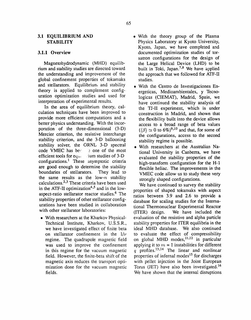
65
3.1 EQUILIBRIUM AND • With the theory group of the PlasmaSTABILITY Physics Laboratory at Kyoto University,
Kyoto, Japan, we have completed and3.1.1 Overview documented optimization studies of tor-
satron configurations for the design ofMagnetohydrodynamic (MHD) equilib- the Large Helical Device (LHD) to be
rium and stability studies are directed toward built in Toki, Japan. 7,8 We have appliedthe understanding and improvement of the the approach that we followed for ATF-IIglobal confinement properties of tokamaks studies.
and stellarators. Equilibrium and stability • With the Centro de Investigaciones En-theory is applied to complement config- ergeticas, Medioambientales, y Tecno-uration optimization studies and used for logicas (CIEMAT), Madrid, Spain, weinterpretation of experimental results, have continued the stability analysis of
In the area of equilibrium theory, cal- the TJ-II experiment, which is underculation techniques have been improved to construction in Madrid, and shown thatprovide more efficient computations and a the flexibility built into the device allowsbetter physics understanding. With the incor- access to a broad range of beta valuesporation of the three-dimensional (3-D) ((ft) '-_0 to 6%) 9,10 and that, for some ofMercier criterion, the resistive interchange the configurations, access to the secondstability criterion, and the 3-D ballooning stability regime is possible.stability solver, the ORNL 3-D spectral • With researchers at the Australian Na-
code VMEC has be(" _ one of the most tional University in Canberra, we haveefficient tools for eq_,. ium studies of 3-D evaluated the stability properties of theconfigurations. 1 These asymptotic criteria high-transform configuration for the H-1are good enough to determine the stability flexible heliac. The improvements in theboundaries of stellarators. They lead to VMEC code allow us to study these verythe same results as the low-n stability strongly shaped configurations.calculations. 2,3These criteria have been used We have continued to survey the stabilityin the ATF-II optimization 4,5 and in the low- properties of shaped tokamaks with aspectaspect-ratio stellarator reactor studies. 6 The ratios between 3.9 and 2.6 to provide astability properties of other stellarator config- database for scaling studies for the Intema-urations have been studied in collaboration tional Thermonuclear Experimental Reactorwith other stellarator laboratories: (ITER) design. We have included the• With researchers at the Kharkov Physical- evaluation of the resistive and alpha particle
Technical Institute, Kharkov, U.S.S.R., stability prope_ies for ITER equilibria in thewe have investigated effect of finite beta ideal MHD database. We also continuedon stellarator confinement in the 1/v to evaluate the effect of compressibilityregime. The quadrupole magnetic field on global MHD modes, 11,12 in particularwas used to improve the confinement applying it to m = 1 instabilities for differentin this regime for the vacuum magnetic q profiles. 13'14 The linear and nonlinearfield. However, the finite-beta shift of the properties of infernal modes 15for dischargesmagnetic axis reduces the transport opti- with pellet injection in the Joint Europeanmization done for the vacuum magnetic Torus (JET) have also been investigated. 16fields. We have shown that the internal disruptions

66
observed in some of these discharges can be Second, a 3-D drift wave code z3 wascaused by this instability, implemented; it uses the results from VMEC
An important area of research is the as input. This code has been used to studyapplication of equilibrium and stability the- trapped-electron instabilities in stellarators.ory to the analysis of experimental data. The trapping in the helical wells can haveA focus of this activity has been the important effects, such as lowering theAdvanced Toroidal Facility (ATF), which collisionality threshold and increasing thestarted operation in 1988. In the initial phase radial width of the instability. On theof ATF operation in 1988, the plasma minor other hand, the external magnetic controlsradius and the edge rotational transform were in the stellarator permit external control ofreduced by field errors. New methods for the shear length and the fraction of confinedevaluating the magnetic island width were trapped particles. Therefore, stellarators indeveloped in interpreting the experimental general and ATF in particular are excellentresults. 17 The presence of magnetic islands devices in which to study these instabilities.caused an effective change of the magneticconfiguration that improved the stability
properties, allowing access to the second 3.1.2 Highlights of 1989stability regime, as discussed in Sect. 3.1.2.1.
Discharges with electron cyclotron heat- 3.1.2.1 ATF operation in the seconding (ECH) in ATF at different settings of the stability regimevertical field (VF) coil currents and differentplasma positions have been analyzed, and the ATF was designed to have stable accessbootstrap current Ib has been evaluated. 16'17 to the second stability regime. For theThe results show very good agreement with design conditions, this access should occur
.,,the theoretical predictions. The predicted at beta values of /30 -_ 5%. In the initial•dependence on the quadrupole and dipole phase of operation, the plasma minor radiusmoments of the VF coils has been demon- _ and the edge rotational transform .t-(a)strated. This analysis of the experimental were reduced by field errors, which haveresults shows that the bootstrap current in since been repaired. This reduction of _ anda stellarator can be externally controlled _-(a) caused a large increase in the Shafranovand reduced to zero for proper stellarator shift and, as a consequence, a reduction inoperation, the beta value needed to access the second
Some of the efforts in the MHD group stability regime. 24-26 From low-n and high-were dedicated to code development. Two n stability analysis using experimentallymain areas were investigated, measured profiles, 27 the threshold to second
First, a stellarator stability code, CHA- stability was found to be as low as /30 "_FAR, was implemented using the stellarator 1.0%. The beta values reached in theexpansion approach in flux coordinates. 2°-22 experiment, up to /30 _ 3.0%, are wellThe averaging is done directly from a 3-D above this threshold value (Fig. 3.1). Theequilibrium calculated with the VMEC code. magnetic fluctuation measurements showedThis method eliminates the need forcalculat- a reduction of the fluctuation level for
ing an averaged equilibrium independently /30 _- 1%. These fluctuation levels are inof the full 3-D calculation and reduces the reasonable agreement with the theoreticalnumber of codes involved in the stability calculations based on the resistive pressure-evaluations for stellarators, gradient-driven turbulence and support the
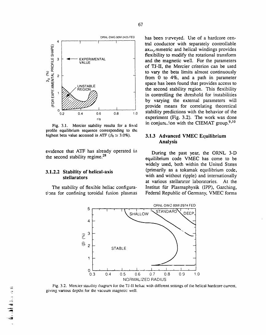
67
ORNL-DWG90M-2425FED has been s,aweyed. Use of a hardcore cen-4 1 ] _ tral conductor with separately controllable,,....
lit
a.< ax_mmetfic and helical windings provides"r-
flexibility to modify the rotational transform3 - _ EXPERIMENTAL
_"a VALUE and the magnetic weil. For the parameterso of TJ-II, the Mercier criterion can be usedtr
._ a. to vary the beta limits almost continuously
_z from 0 to 4%, and a path in parameter_ space has been found that provides access to
the second stability region. This flexibilityt:X. 1x in controlling the threshold for instabilitiesut
tr by varying the external parameters willoprovide means for correlating theoretical
0 1 I0.2 0.4 0.6 0.8 .0 stability predictions with the behavior of the
r/a experiment (Fig. 3.2). The work was donein conjuncSon with the CIEMAT gToup.9'1°Fig. 3.1. Mercier stability results for a fi×txl
profile equilibrium sequence corresponding to the
highest beta value accessed in ATF (rio _'23.0%). 3.1.3 Advanced VMEC E£1uilibriumAnalysis
evidence that ATF has already operated ia During the past year, the ORNL 3-Dthe second stability regime. 28 equilibrium code VMEC has come to be
widely used, both within the United States
3.1.2.2 Stability of helical-axis (primarily as a tokamak equilibrium code,stellarators with and without ripple) and internationally
at various stellarator laboratories. At the
The stability of flexible heliac configura- Institut ffir Plasmaphysik (IPP), Garching,tivns for confining toroidal fusion plasmas Federal Republic of Germany, VMEC forms
ORNL-DWO 89M-2974 FED5
4-
_3
_'2
1
0 , l , _L , 10.3 0.4 0.5 0.6 0.7 0.8 0.9 1.0
NORMALIZED RADIUS
Fig. 3.2. Mercier smt, ility diagram for the TJ-II heliac with different settings of the helical hardcore current,giving various depths for the vacuum magnetic weil.
-

68
the core of the effort to optimize the so- boundary equilibrium, which is especiallycalled "Helias" configuration for both MHD important for the discharges with very highand 'aansport performance. 29 At Kharkov, a poloidal beta tb_at are of present interest.version of VMEC that runs on a personal The correct interpretation of these data iscomputer is installed but not yet fully important, for example, in analyzing theoperational. In the United States, Princeton effect of bootstrap currents at high pressures.Plasma Physics Laboratory (PPPL) is a ma- We have also participated in a number ofjor customer for the two-dimensional (2-D) collaborations to assess the effects of 3-Dversion of VMEC. Analyses of discharges ripple on self-consistent tokamak equilibriain the Tokamak Fusion Test Reactor (TFTR) for both TEXT and ITER. The ITER workuse VMEC in its fixed-boundary mode, was begun over two years ago; the recentand preliminary efforts are ufider way to numerical improvements in VMEC haveadapt the TRANSP code to use the free- made possible the computation of equilibriaboundary mode. The aL,ility of VMEC for this device. In the course of this work, ato treat finite-beta rippled tokamak fields simple numerical procedure was developedhas led to collaborations with the Texas for checking the integrity of the magneticExpenme.'tal Tokamak (TEXT) and ITER field data arising from the external coilsgrovps. Work at ORNL to analyze ATF (these data are used as input to VMEC,equilibria in the presence of various shaping and its numerical convergence is adverselyfields and to determine the effects of these affected if they are not accurate enough tofields on bootstrap current control constitute_ preserve the assumed stellarator symmetry ofa major impetus for further developme:,t of the magnetic field).this code. VMEC is also being used for analyzing
Continuing numerical improvement of the effects of field shaping in ATE TheVMEC was done in conjunction with several comparison of VMEC-generated vacuumphysics l:_'_iects. The Green's function configurations with field line tracings for var-formulat_Dn i'or the vacuum region has been ious combinations of dipole and quadrupolecoupled with the free-boundary version of fields has proved to be a valuable tool inVMEC to predict the ex,ernal magnetic improving the free-boundary convergence ofsignals that Rogowski loops w:,ll measure at VMEC equilibria.arbritrary positions and for various pressure We have collaborated with Japanese re-and iota profiles. 3° We have collaborated searchers to aid them in computing finite-with our Rassian colleagues to compare ou.- beta effects on free-boundary equilibria fornumerical computations with analytic calcu- the Compact Helical System (CHS).lations based on the method of averaging. A collaboration was begun with M.This work was completed in December 1989, Wakatani (Kyoto University) and J. L. John-during a visit by the Russians. son (PPPL) to use the VMEC equilibrium
Improved convergence for the free- as input to a stability code for analyzingboundary version of VMEC has led to a long-wavelength modes using the method ofnumber of useful applications. VMEC is averaging.now used in its fixed-boundary form as A fruitful collaboration with O. Betan-the main equilibrium solver in the PPPL court of New York University has resulteddizcharge analysis code, TRANSR Efforts in a significant improvement in the conver-u.lC tallUCi Wily ............ i_,_ ,-,,-,,,-,-,_,--,t ¢v.,__ ono_ time, t_f VM_(" 31 With a rnc_dificati_m
li
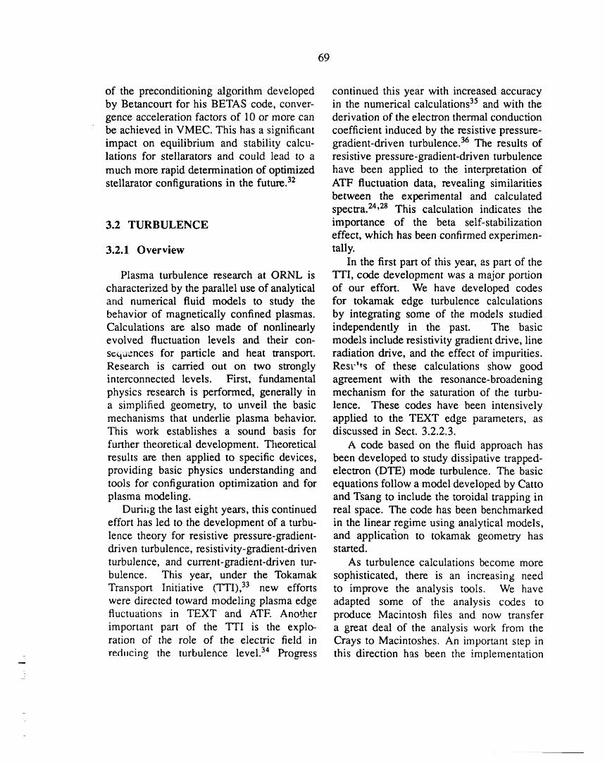
69
of the preconditioning algorithm developed continued this year with increased accuracyby Betancourt for his BETAS code, conver- in the numerical calculations 35 and with thegence acceleration factors of 10 or more can derivation of the electron thermal conductionbe achieved in VMEC. This has a significant coefficient induced by the resistive pressure-impact on equilibrium and stability calcu- gradient-driven turbulence. 36 The results oflations for stellarators and could lead to a resistive pressure-gradient-driven turbulencemuch more rapid determination of optimized have been applied to the interpretation ofstellarator configurations in the future. 32 ATF fluctuation data, revealing similarities
between the experimental and calculatedspectra. 24,28 This calculation indicates the
3.2 TURBULENCE importance of the beta self-stabilizationeffect, which has been confirmed experimen-
3.2.1 Overview tally.In the first part of this year, as part of the
Plasma turbulence research at ORNL is Tri, code development was a major portioncharacterized by the parallel use of analytical of our effort. We have developed codesand numerical fluid models to study the for tokamak edge turbulence calculationsbehavior of magnetically confined plasmas, by integrating some of the models studiedCalculations are also made of nonlinearly independently in the past. The basicevolved fluctuation levels and their con- models include resistivity gradient drive, linescqaences for particle and heat transport, radiation drive, and the effect of impurities.Research is carried out on two strongly Rest'ts of these calculations show goodinterconnected levels. First, fundamental agreement with the resonance-broadeningphysics research is performed, generally in mechanism for the saturation of the turbu-a simplified geometry, to unveil the basic lence. These codes have been intensivelymechanisms that underlie plasma behavior, applied to the TEXT edge parameters, asThis work establishes a sound basis for discussed in Sect. 3.2.2.3.
further theoretical development. Theoretical A code based on the fluid approach hasresults are then applied to specific devices, been developed to study dissipative trapped-providing basic physics understanding and electron (DTE) mode turbulence. The basictools for configuration optimization and for equations follow a model developed by Cattoplasma modeling, and Tsang to include the toroidal trapping in
Duriz_g the last eight years, this continued real space. The code has been benchmarkedeffort has led to the development of a turbu- in the linear regime using analytical models,lence theory for resistive pressure-gradient- and application to tokamak geometry hasdriven turbulence, resistivity-gradient-driven started.turbulence, and current-gradient-driven tur- As turbulence calculations become morebulence. This year, under the Tokamak sophisticated, there is an increasing needTransport Initiative (TTI), 33 new efforts to improve the analysis tools. We havewere directed toward modeling plasma edge adapted some of the analysis codes tofluctuations in TEXT and ATE AnotJaer produce Macintosh files and now transferimportant part of the TTI is the explo- a great deal of the analysis work from theration of the role of the electric field in Crays to Macintoshes. An important step inreducing the turbulence level. 34 Promess this direction has been the implementation
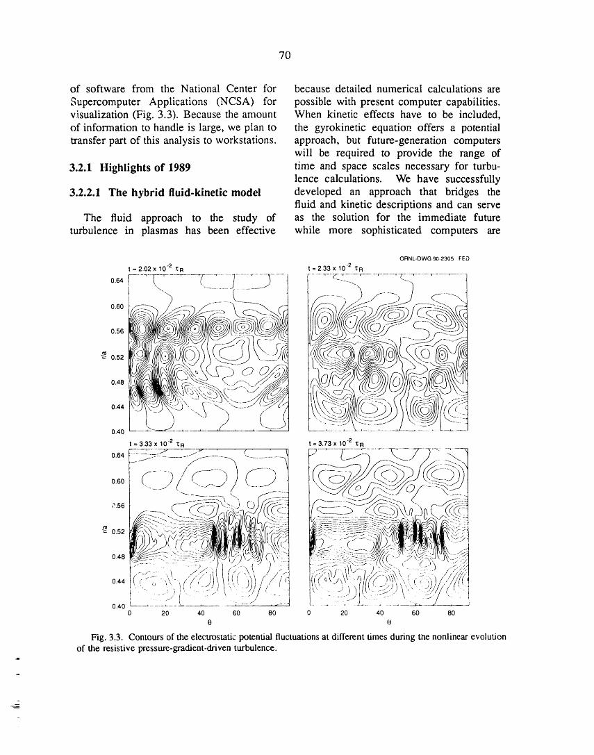
7O
of software from the National Center for because detailed numerical calculations are
Supercomputer Applications (NCSA) for possible with present computer capabilities.visualization (Fig. 3.3). Because the amount When kinetic effects have to be included,of information to handle is large, we plan to the gyrokinetic equation offers a potentialtransfer part of this analysis to workstations, approach, but future-generation computers
will be required to provide the range of
3.2.1 Highlights of 1989 time and space scales necessary for turbu-lence calculations. We have successfully
3.2.2.1 The hybrid fluid-kinetic model developed an approach that bridges thefluid and kinetic descriptions and can serve
The fluid approach to the study of as the solution for the immediate futureturbulence in plasmas has been effective while more sophisticated computers are
ORNL-DWG 90-2305 FED
= 2.02 x 10 -2 .{R = 2.33 x 10 -2 _ R
0.56 " C._._p_,
0.44,oCj\\J )'%:-O ,... \ -.. ----.... .7 <-"t tt,<t,,.,\_ '
0.40........ --- ....;:7_7:_"_t = 3.33 x 10 .2 _lul -- 3.73 x 10 .2 I R
o.4__U_TA;7:........ ::)C_;_7)_WJ:__;.hD,,_,"-:7._J_Jc\,' _"-km---L-.._F-__::.--::..-,-.:_--__..-_-_:,i_i_:::---_:._/J/__>/LT<"_77_-I,_I/_,--+d
0 20 40 60 80 0 20 40 60 80
e e
Fig. 3.3. Contours of the el_trostatic potential fluctuations at different times during _e nonlinear evolutionof the resistive pressure-gradient-driven turbulence.

71
developed. The hybrid fluid-kinetic model of helically trapped and toroidally trappedtreats the ions with fluid equations but particles. In ATF it is possible to study DTEfollows the electrons as particles obeying modes and to evaluate and test their rolethe drift kinetic equation. In the hybrid in plasma confinement. In this way, somemodel, the low-frequency wave resonances of the fundamental physics of these modesof the electrons are described exactly. In can be better understood and the theoreticalslab geometry, the hybrid model accurately results validated.reproduces sound waves as well as densityand ion temperature gradient drift waves.Nonlinear studies of the latter show that the
nonlinear kinetic electron response signifi- 3.2.2.3 Edge turbulence modelingcantly alters the features of the turbulence
in the saturated state. Kinetic electrons are The turbulence at the edge of the TEXTcurrently being imported into our higher- tokamak is characterized by a high leveldimensional fluid turbulence parameters and of density and potential fluctuations thatgeometries characteristic of fluid models and do not obey the adiabaticity condition,a direct assessment of electron transport in since eqS/kTe can be larger or smaller thanthe presence of fluid turbulence. Trapped- fi/7_. We have incorporated impurity lineelectron modes can play an important role in radiation in our 3-D nonlinear resistive
enhancing losses in a toroidal confinement MHD computer model of impurity-drivendevice. They could be one of the causes rippling mode turbulence. 35'36 Experimentalfor the deterioration of confinement with beta TEXT edge parameters were used as inputin tokamaks. For straight stellarators, it has for the model equilibrium profiles. Thebeen shown that the helical ripple and short radiation function was taken to be a shiftedconnection lengths allow for strongly local- coronal one, with a rate enhancement ofized solutions to the drift wave equation, a factor of 4 over the nominal coronal
Therefore, in shearless stellarators trapped- rate for carbon impurities. Results ofelectron modes may be more unstable than the computer calculations in the nonlinearlyin tokamaks, saturated state (the equilibrium profiles and
radiation source were held fixed throughoutthe calculation) show excellent agreementwith the analytical predictions for ecb/kT_,
3.2.2.2 Trapped-electron modes provided the average poloidal wave numberrn at each radial position is taken into
In contrast to tokamaks, stellarators have account (Fig. 3.4). The nonlinear computerthe advantage that the vacuum magnetic field calculations are also in good agreementcan be changed substantially by modifying with the experimentally measured levels andthe currents in the VF coils. In ATF, for radial variation for edp/kTe, 7"lTe, and Br.,example, changing the dipolar or quadrupo- with ec_/kTe larger than fi/n . Finally, thelar moment of the VF coils changes lbl average rn is measured to range from 12 toalong the field lines, therefore changing the 50, which yields an average poloidal wavetrapping regions and local curvature. This number of 0.8-1.8 cm -l, compared to thepresents the opportunity of changing the ratio experimentally measured 2-3 cm- 1.

72
O_,-DW_,O,.,._O_E_ of dc electric fields like those observed1.2 _ V ........... q 1.....
O NUMERICAL RESULTS experimentally.¢_NUMERICAL RESULTS
1.0- SCALED TOEXPERIMENTAL It was found, not surprisingly, that dcf_ADIATION MEASUREMENT
"_ _ EXPERIMENTAL DATA electric fields have a strong effect on direct
_convectiv ossesn e ,asmae ,e. his_'° l T effect lessens for direct convective losses_ 0.6 - • -dO T nearer the plasma center. Direct convective
• 1 • losses can penetrate a _.onsiderable distance0.4 - o I
o l toward the plasma center, causing a large• • o o o • volume of the plasma to be dominated0.2 - oo o
by direct convection. Interestingly, a key0 1 I I I -0.82 0,84 0.86 0.88 0.90 0.92 parameter for this penetration is (a/r) z,
r/a which occurs in an exponential, rather than
Fig. 3.4. Potential fluctuation levels from the as (r/a) 2 as in local diffusive losses.TEXT experimental results, compared with the The magnitude of the direct convectivenumerical results of modeling the edge plasma turbu- losses was determined at about the same
lence using a thermal convective cell driven by line time that the magnitude of the fluctuatingradiation plus resistivity-gradient-driven turbulence. edge electric field measurements from TEXT
became available. A natural question waswhat effect these locally strong fluctuations
3.3 KINETIC THEORY had on particle orbits and direct convectivelosses. By making the approximation that
3.3.1 Cause and Effect of Electric kll = k4, = 0, and using the frequencyFields in Toroidal Devices and wavelength properties of the observed
fluctuations, we were able to extend the
We summarize a sequence of calculations previous analysis for dc electric fields tothat establish the cause and effect of dc include fluctuating electric fields. Severalelectric fields in toroidal devices. These points followed from this orbit analysis.calculations were originally motivated by the First, the localized fluctuating electricobservation that the edge radial electric fields field, while strongly affecting orbits andin the Impurity Study Experiment (ISX-B), direct convective losses at the very edge,ATF, and TEXT had similar properties, did not substantially affect direct convectiveBecause of their greater simplicity, we losses from points nearer the plasma center.have initially limited ourselves to symmetric Thus, the relevance of the calculations fortokamaks, purely dc electric fields was established.
Guided by the experimental measure- Second, fluctuating electric fields nonlin-merits, we carried out nonlocal orbit analyses early affect ion orbits more than they donumerically and analytically to see what electron orbits. As a consequence, nonlineareffect such dc electric fields had on par- fluctuations should not lead to intrinsic orticle orbits. Reasonably compact analytic automatic equality of the ion and electronexpressions were developed that allowed us losses. That is, nonlinear fluctuations playto determine the region in phase space of a role in the formation of the dc radialunconfined orbits. This in turn allowed electric field. At the same time, other ORNL
development of analytic expressions for the theorists observed that advection (VE • VVE,direct convective loss of ions in the presense where VE is the E x B drift velocity) was

73
nonlinear, leading to dc radial electric fields have been engaged in a long series ofin their numerical modeling of tokamak edge benchmarks of neutral beam injection (NBI)fluctuations. Thus, further understanding of into stellarators. 4° For the purposes of thisthe role of edge fluctuations in the formation investigation, we studied perpendicular in-of dc electric fields should receive increased jection into Heliotron E, which reveals more
emphasis in the near future, types of fast-ion orbit topology than doestangential injection into ATF.
Two Oak Ridge codes and one Kyoto3.3.2 Ripple Losses of Alpha code were benchmarked. If ali codes solved
Particles in ITER exactly the same problem, they ali obtainedthe same answers. However, we were
The prompt loss of alpha particles in surprised at the sensitivity of the answer toITER resulting from toroidal field (TF)tipple some of the physical models. If two codeseffects has been studied by numerous ITER used slightly different models, they couldparticipants. Generally, losses near the 3.5- obtain significantly different answers.MeV alpha birth energy have been found to The birth deposition profiles were care-be negligible. The next opportunity for alpha fully calculated, including the effects ofloss is when the alphas start pitch-angle beam shape and divergence and of aperturescattering below the critical energy, where losses. They agreed quite well when thethey begin to interact with the background same parameters were used.ions. The location of the loss boundary caused
We have studied alpha losses in this range the most sensitive differences. If the lossby starting an alpha distribution at the critical boundary was assumed to be the last closedenergy (which is a function of radius) and flux surface, almost 50% of the fast ionusing a Monte Carlo code to follow the alpha energy was lost. However, if the actualparticles until they have thermalized. 39 To Heliotron E vacuum vessel was used as themodel the ripple, we used an axisymmetric loss boundary, this loss dropped to < 1%ITER equilibrium and the tipple fields due for the high-density case and about 7% forto filamentary models for the 14 TF coils, the low-density case. To obtain the correct
About 6% of the alphas were lost owing answer, it is also _,ecessary to include theto a combination of neoclassical and tipple effects of charge-exchange losses in thislosses. This corresponds to only 0.6% of the outer region. Although it is difficult toinitial alpha energy, accurately model the neutral density profile
For future calculations, we expect to use (we used the PROCTR code), the charge-the free-boundary version of the VMEC exchange losses were estimated to be aboutequilibrium code to obtain self-consistent 10% for the high-density case and about 22%finite-beta equilibria, which will be used to for the low-density case.further study the ITER tipple effects.
3.3.3 Benchmark Studies of Neutral 3.3.4 Beam Deposition and TF
Beam Injection for Ripple in TEXTStellarators/Heliotrons
In TEXT, a vertically injected beam isIn conjunction with K. Hanatani of used as a target for the charge-exchange
the Kyoto Plasma Physics Laboratory, we diagnostic. Because the TEXT TF coils
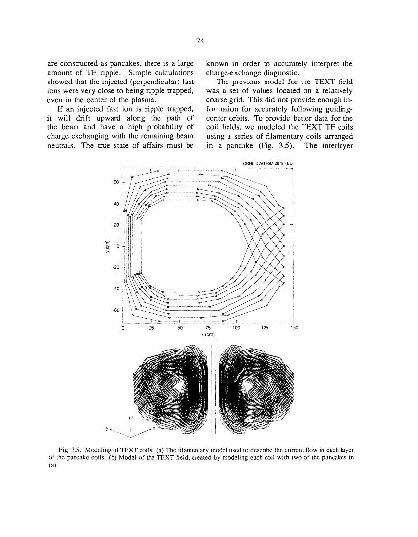
74
are constructed as pancakes, there is a large known in order to accurately interpret theamount of TF ripple. Simple calculations charge-exchange diagnostic.showed that the injected (perpendicular) fast The previous model for the TEXT fieldions were very close to being tipple trapped, was a set of values located on a relativelyeven in the center of the plasma, coarse grid. This did not provide enough in-
If an injected fast ion is tipple trapped, for._.':_ationfor accurately following guiding-it will drift upward along the path of center orbits. To provide better data for thethe beam and have a high probability of coil fields, we modeled the TEXT TF coilscharge exchanging with the remaining beam using a series of filamentary coils arrangedneutrals. The true state of affairs must be in a pancake (Fig. 3.5). The interlayer
ORNL-DWG 90M2878 FEE)
7- ..................... _ .................. ; .152 TY2-?7..... ; ................ T........... T .........: !
6o_.- 4
\
40
g 0v::>.,
i-40 -4
J
-60 F- -4i
l I
0 25 50 75 100 125 150
X (cm)
i..... F
f
.,_
Fig. 3.5. Modeling of TEXT coils. (a) The filamentary model used to describe the current flow in each layerof the pancake coils. (b) Model of the TEXT field, created by modeling each coil with two of the panc_es in(a).

75
connections of the coil occur only at the consistent rippled tokamak equilibria at finiteouter edge of the coil, and this is reflected (but low) beta for TEXT. The resulting fluxby the fact that each filament goes to the surfaces (Fig. 3.7) were almost circular andouter edge and back in again. The locations showed a distinct poloidal bulge on theof the filaments were determined by using midplane, which is caused by the interlayerfinite element models. We used several connections of the TF coils. There was
panc_'kes arranged so that the ripple on the also a toroidal bulge between the TF coilsinner edge was minimized (although it is still of about 1 cm due to the TF ripple. Bothoverestimated in our model). The resulting of these results seem to be consistent withripple contours for TEXT are shown in TEXT experimental data, although it is veryFig. 3.6. difficult to measure the profiles with this
accuracy.ORNL-DWG 90M-2879 FED
0.3
_-----T ......................... ORNL-DWG 90-2880 FED
0.40.2 I
0.1
o0 -
-0.1 N
-0.2
-0.30.7 0.8 0.9 1.0 1.1 1 2 1.3
R (m) -0.4 10.725 1.125 1.525
Fig. 3.6. The ripple contours that result from the
10-filament model of Fig. 3.5. R_,_ = 16.58; /_in = R (m)0.05. Fig. 3.7. The free-boundary, finite-beta, self-
consistent TEXT equilibrium calculated using theexperimentallyobtained q and pressure profiles andthe field model of Fig. 3.6.
We also needed a representation for theTEXT equilibrium so that we could properlyaccount for the poloidal fields due to the We then converted the output of VMECcurrent in the plasma. Because TEXT has an to Boozer coordinates and followed the beamiron core, this presents a difficult modeling orbits. The result was that, indeed, thoseproblem. We obtained reasonable results by ions born in the outer half of the TEXTusing the experimental TEXT profiles for plasma a_e ripple trapped. Figure 3.8 showsrotational transform and pressure, together the orbit of a typical 25-keV injected ionwith our TF model and a uniform vertical in TEXT. Because this plot is in Boozerfield to provide in/out centering of the equi- coordinates, the bounce points (which liel_brium. Using the free-boundary VMEC along a vertical I/31contour) do not appearequilibrium code, we obtained the first self- to be on a vertical line. In this plot, the

'75
1.00
0.75
_- 0.50
0.25
0 ' '
1.00 -
0.50 -
> 0 -"='>
-0.50
-1.00
2.25 ,, ; ,, ; :
2.00 , ' ' ' _j_ -" " ..... '
..o 1.75 - e,,,,
1.5b ...... ', , : ,, ,, ,, , , ,,
1.25 ; ' ° '0 0.25 0.50 0.75 1.00 1.25 1.50 1.75 2.00
TIME (ms)
Fig. 3.8. Orbit of a downward-injected, 25-keV ion from the diagnostic neutral beam in TEXT, whicheventually becomes ripple trapped and leaves the system.

77
beam is injected downward. The ion is born 3.4.2 ITER Studiesat _b = 0.22 but eventually becomes tippletrapped at about _b= 0.5. ORNL physicists actively participated in
the ITER Conceptual Design Joint Workduring the winter (February-March 1989)
3.4 TRANSPORT AND CONFINEMENT and summer (July--October 1989) sessionsMODELING at IPP Garching and played a key role in
the evolution of the ITER physics design.3.4.1 General Transport StudiesThe primary areas of ORNL contributions to
Work continued on the development of ITER physics studies were in MHD stabilitya model for the L-H transition. An and beta limits, confinement assessment,
expression for neoclassical viscosity that fast-wave current drive (FWCD), and pelletis valid for high poloidal rotation velocity fueling. Work was also carried out onwas derived; it exhibits a maximum as axisymmetric magnetics, alpha particle ef-the rotation speed is increased. 4_ As col- fects, helium ash accumulation and exhaust,lisionality decreases and ion orbit losses and plasma-wall interactions. Details areincrease at the plasma boundary, the radial described in Sect. 6 of this report. Briefelectric field Er becomes more negative highlights from these :zeas are as follows:and poloidal rotation increases to drive a (1) physics design guidelines and physicsradial current (through the viscosity) to specifications for the design informationbalance the nonambipolar ion loss. At document were prepared and published; 48,49low enough collisionality, the balance be- (2) limitations to the operational space aris-tween the orbit and viscosity-driven currents ing from MHD instabilities (ideal and resis-exhibits a bifurcation that appears as an tive, linear and nonlinear, fluid and kinetic)abrupt increase in the poloidal rotation (or, were estimated; 5°-52 (3) the MHD databaseequivalently, an even more negative value of for current drive and peaked pressure andEr), as observed experimentally in DIII-D. 42 current density profiles was extended; 53Shear in the toroidal rotation introduces (4) various transport models were comparedan additional decorrelation mechanism for with the ITER L-mode database, and the
turbulence, reducing fluctuation amplitudes confinement capability of ITER was as-and transport. 43'44 An assessment oi the sessed using these models; 54,55 (5)DIII-D
and TFTR databases for volt-second con-status and issues of tr_-sport modeling wascompleted as part of the TYI. 45 A set of sumption during the current ramp phase,major program recommendations was also especially with regard to MHD-influencedissued.46 (fast ramp) scenarios, were analyzed; 56
The relationship between global confine- (6) particle transport and fueling (gas puffingvs pellet fueling) issues were assessed; 57 andment and local thermal conductivity was
evaluated in work that required generation (7) detailed estimates of FWCD efficiencyof a LOCUS database for WHIST runs. 47 were made using a 2-D, full-wave code. 58
This approach to testing transport models 3.4.3 CIT Studieswas shown to be very efficient and shouldhelp in future testing of theoretical models An assessment of NBI parameters for theagainst experimental data. Compact Ignition Tokamak (CIT) showed

78
the influences of beam energy, geometry, and is used extensively by the ATF experimentalorientation and plasma density on heating staff to define the plasma position relative toprofiles and shinethrough. Tangential in- the vacuum vessel, limiters, and diagnosticjection gives the widest range of operating chords. The geometry database also formsdensities but requires roughly twice the the starting point for Thomson scattering andenergy of normal injection and presents more far-infrared (FIR) profile fitting and analysisdifficult access requirements. 59 with the PROCTR-MOD code set.6z
The impact of the uncertainty in the Several additions were madevelocity scaling of pellet penetration on CIT to PROCTR-MOD to allow analysis of CHSoperation was evaluated. If the velocity plasmas in Nagoya, Japan. This work wasscaling of recent JET experiments holds, performed in collaboration with Dr. Yamadathen deep penetration in the plasma burn during a visit to ORNL. Dr. Yamada took astage with pellets at a nominal velocity of copy of the PROCTR-MOD code set back to5 km/s may be possible. 6° See Sect. 6.1.4 Nagoya, where it will be the primary profilefor more details on CIT studies, analysis tool for CHS. Thus, PROCTR-
MOD is being used for analysis of data from
3.4.4 ATF Studies both Japanese torsatrons (Heliotron E andCHS), and it may be adapted for analysis
The PROCTR-MOD database system was of the future LHD experiment in Toki.extended by addition of a LOCUS database The predictive transport code PROCTR isthat contains scalar machine parameters being used for specialized studies involvingfrom ATF for input to the profile analysis temporal discharge evolution. During thecode PROCTR-MOD. Previous analysis of past year, PROCTR continued to be used tomeasured ATF temperature profiles indicated understand the collapse of the plasma tem-a region of poor energy confinement in the perature in NBI-heated discharges in ATE Toouter half of the plasma that was attributed this end, the following additions were madeto field errors. After repair of the field to PROCTR. (1) A source term was addederrors, further profile analysis showed that to the multispecies impurity source termsthe region of enhanced energy loss in the for modeling laser-blowoff impurity pulses.peripheral region is still present, although at (2) The atomic physics database packagea reduced level. 61 ALADDIN, supported by the International
A geometry database was created that Atomic Energy Agency, was added as theallows online display of the ATF flux source of atomic physics coefficients forsurface geometry for a given ATF shot. ionization, recombination, and line emissionThe geometry is calculated on one of the in the multispecies impurity model. (3)TheCray computers at the National Magnetic fast ion Fokker-Planck (FIFPC)routine wasFusion Energy Computer Center (NMFECC) revised to allow the detailed treatment ofat Lawrence Livermore National Laboratory inje_.ed fast ions in the presence of loss(LLNL) wiffi either a field-line-following cones. 63,64 Further discussion of the ATFcode (for vacuum surfaces) or VMEC (for modeling studies is contained in Sect. 1.1.4.finite-beta surfaces). The calculated geom-
etr,/ is then stored in a database on the 3,4.5 Pellet Injection Studies on .IETlocal VAXcluster. A utility called PLOTGdisplays the geometry for the coil currents The shielding physics in present pelletmeasured for a given shot. This capability ablation models was re-examined. A series
79
of experiments at varying pellet velocities 3.5 RF HEATING(0.4-1.4 km/s) was performed on JET usingthe ORNL-supplied multiple-pellet injector. The task of rf heating and current driveThe results she,wed a definite velocity depen- theory is to develop and test theories ofdence in the penetration depth that confirmed (1) plasma wave generation, (2) propagation,the scaling of the original neutral gas shield- (3) absorption, and (4) plasma responseing model but indicated higher shielding in ali frequency regimes relevant to fusionfactors. The present model with combined (Alfv6n, ion cyclotron, lower hybrid, andneutral and plasma shielding had exhibited electron cyclotron). These theories areno scaling with velocity because of the way incorporated into analytical and numericalin which the plasma shield was incorporated, predictive models that are used to inter-but it had yielded good agreement with ex- pret experimental results from tokamaks,perimental results at full pellet velocity over stellarators, and other devices; to developa wide range of plasma conditions and pellet means for enhancing the effectiveness ofsizes. Leading candidates for increasing plasma heating; and to evaluate and op-the shielding of the neutral gas shielding timize designs for future experiments andmodel while maintaining the scaling with technologies. By definition, the objectivevelocity are elongating the neutral shield of rf heating or current drive is to modifyalong the magnetic field (rather than using the plasma distribution function in a specifica spherical approximation for the shield) way. Therefore, the rf theory efforts areand/or including magnetic shielding. 6° closely coupled to kinetic theory, to transport
Analysis of transport properties in the theory, and to stability and are closelycore of JET plasmas showed that the local allied with experimental, engineering, andparticle diffusivity and thermal diffusivity technology studies.are highly correlated. When the density In the past year the It" program hasprofile is highly peaked fellowing pellet been heavily involved in modeling ICRFinjection, core diffusivity is significantly heating on TFTR, JET, ATF, and CIT;reduced well into the following ion cyclotron in interpreting electron cyclotron r,¢sonanceresonant frequency (ICRF) heating phase, heating (ECRH) experiments on the ATF andThere appeared to be no evidence of an L-2 stellarators; in design and optimizationanomalous particle pinch in the core under of antennas for TFTR and DIII-D; and inany operating conditions; the neoclassical assessment of ICRF current drive scenariosWare pinch could be used to explain both for ITER. Significant progress was madethe modest peaking of the density profile in our capability to model the depositionin nonpellet cases and the decay of peaked of fast ICRF wave power using 2-D full-density profiles from pellet injection. This wave codes, to calculate rf-driven currents,work illustrated the need to consider a and to study in detail the fields in thefull transport matrix, with both neoclassical vicinity of realistic ICRF antennas. Weand turbulence-driven transport processes have also begun to develop an understandingcontributing to the fluxes. 65'66 of the mechanisms by which ICRF power
Other aspects of JFT experimental analy- perturbs the plasma edge and produces addedsis are described in Se_,. 4.1.2. impurities.
8O
3.5.1 Global ICRF Wave Propagation Our numerical approach introduces thein Edge Plasma and electromagnetic potentials A and _bwith theFaraday Shield Regions Coulomb gage V.A = 0. This formulation
properly includes electrostatic effects, whichOne of the major issues in the theoretical we find to be important in the region
modeling of high-power ion cyclotron res- surrounding the Faraday shield. Special careonance heating (ICRH) experiments is the is taken to devise a"conservative" numericaleffect of wave fields on the low-density scheme that is consistent with the gagesurface plasma, especially the influence of conditions (V.A = 0). An alternative ap-these fields on impurity generation. Such proach would be to solve the wave equationissues have stimulated interest in calcula- directly in terms of E rather than potentials.tions of global ICRH wave fields in the This approach has proved useful in the
surface and antenna regions. Therefore, Ell = 0 limit, but we encounter numericalwe extended the ORION code to include difficulties when it is applied to problems
finite Ell and made detailed calculations of in which electrostatic effects are dominant.the wave field structure in the low-density As expected, applications to high-densityedge plasma immediately surrounding the plasmas agree with previous calculations in
antenna and Faraday shield structure. The the Ell = 0 limit. More interesting is themagnetic field model is general enough application to the edge plasma and Faradayto allow applications to both axisymmetric shield region, where the parallel electrictokamak and helically symmetric stellarator field is found to peak strongly in the gapsgeometries. The equation solved is the between the Faraday shield blades. Scaling
so-called "reduced-order" wave equation in with rotational transform shows that IEII[iswhich the value of k.l- (the perpendicular directly proportional to the electrostaticallywave number) that appears in the warm- induced electric field in the gap betweenplasma dielectric tensor does not come self- the blades (Fig. 3.9). The constant ofconsistently from the wave solution but proportionality depends on the edge densityrather comes from an independent solution as well as the parallel wave number.of the warm-plasma dispersion relation.Both fast-wave and Bernstein wave rootsare calculated, but the Bernstein root is 3.5.2 Fast-Wave Current Drive
discarded, thus "reducing the order" of the Modeling for ITER and DIII-Dresulting differential equation from fourth tosecond order. This differential system re- It is widely recognized that a key elementtains warm-plasma effects such as cyclotron in the development of an attractive tokamakdamping, Landau damping, and transit-time reactor, and in the successful achievementmagnetic pumping (TI'MP) while avoiding of the mission of ITER, is the developmentthe numerical difficulties associated with the of an efficient steady-state current driveshort-wavelength ion Bernstein wave (IBW). technique. The use of ICRF fast wavesWhile such warm-plasma effects are of little is being studied as a technique for steady-consequence in the edge region, they are state cun'ent drive in large tokamaks suchincluded for convenience in benchmarking as ITER and fusion reactors. A simple slabagainst previous calculations for the warm model has been developed to design and
central plasma in the Ell -_ 0 limit, optimize phased antenna arrays to achieve

81
ORNL-DWG89-2623 FED 1. Can an acceptable antenna be designed to
I _ produce a kll spectrum with most of theo.4s ,2_,.. -_.s power in the phase velocity range where
the efficiency of current drive is high?IE,I 2. Will the rf power be efficiently absorbed
by electrons in the desired velocity range
_o io "/ without unacceptable parasitic damping
IE,I/IEyl 0.085 <4;)
o._o- - ,.o ?. by fuel ions and alpha particles?
--a -o An important figure of merit in this
\o o_ --_ context is
- \\S --_ ne R
o.os- ,_-,,,,,,. - o.s 3' = 1020 m_3 Irr_-d_= 1.6 x 10⁻³Tc5/i5 •(3.1)
Ehst has provided a simple algebraicexpression for .7/_ obtained as a fit to
o I I o the Fokker-Planck results of Karney ando o.s _.o Fisch, employing a momentum-conserving
<_'> collision operator including trapped-particleFig. 3.9. Numerical survey showing parametric effects.
dependenceof IEIII, levi, and IEIII/IEvlon rotational To address these issues we have employedtransform. Here z = 0.425 m, V = 0.t365m, kz = the slab model for rapid comparison of var-9.84 m-t, n_te = 3 x 1012 cm -3. ious antenna designs and phasings to show
trends of obtainable current drive efficiencyunder various assumptions. The ORION 2-D
the required directivity and concentration of full-wave code gives power absorption andhigh parallel phase velocity components in current drive profiles. This code realisticallythe power launched into the plasma. Various models the launched antenna spectrum withdesigns are being evaluated for the individual radial focusing, includes toroidal eigenmodeantenna elements, including multiple-loop, effects (multiple-pass absorption) if present,recessed-cavity antennas. Also, the full- and includes the effects of ion cyclotronwave ICRF heating code ORION is being harmonic and alpha particle damping.used to calculate power deposition in the Results have been computed for ITER forvarious plasma species and to calculate both the 60-MHz and 20-MHz scenarios anddriven current profiles produced by fast for theDllI-Dproof-of-principleexperiment.waves in large, noncircular tokamaks such as In ITER the most promising results areITER. The primary current drive mechanism obtained with the low-frequency option,in these cases is TTMP. Wave damping where parasitic ion resonances are absent.
processes that are included are ion cyclotron Since damping is relatively weak for thisdamping by the fuel components, electron case, eigenmode effects are ve:'y important.Landau damping, "VFMP, and absorption The current drive figure of merit 7 andby fusion decay products such as energetic loading resistance per unit length per strapalpha particles. Two primary issues are to be BL are sensitively dependent on density. Bydetermined: careful matching of the kll spectrum to the
82
eigenmode structure we have obtained _ up time-independent (static) sheath near theto 0.6 and RL up to 17 f_m. shield when electrons are strongly heated by
These results are very encouraging, al- evanescent rf electric fields parallel to thethough there are uncertainties in the calcu- static magnetic field B, at the locations wherelations. The high values of 7 are obtained the field line intersects a grounded structure.by phasing the array so as to produce The sheathenhancementresultsfrom the fact
a spectrum near nii = 1 where 3lP is that the rf-excited electron distribution canfavorable and trapped particle effects are be far from a collisional Maxwellian. Thism_._--:imized,and by relying on a high-Q model demonstrates that the production ofcavity mode to enhance the comparatively impurities in this region can easily resultlow electron absorption. Relativistic effects from the high-energy ions that are producedare not included in the model, although this in the low-density plasma near the front faceis not thought to be a significant source of of the Faraday shield.error. The ORION code, being a straight Meaningful electron excitation occurstokamak model, does not accurately treat only when some phase decorrelation mech-
the variation of 7_]1across the plasma cross anism exists such that electrons can besection. If significant upshifts in ArT occur heated rather than simply oscillating in the
in multiple reflections, the favorable nii rf fields. One decorrelation mechanism thatspectrum will not be maintained. Also, if can give rise to electron heating is analogousadditional parasitic loss mechanisms appear, to Fermi acceleration when observed in asuch as collisional absorption or losses due frame that is oscillating with the electron into the shear AlfvEn resonance, the current the parallel rf electric field Ell. In contrastdrive efficiency will decrease, to previous works, where the amplitude of
the sheath oscillates within a few Debyelengths Ao of the wall, we considered anelectron that is free to oscillate in the rf
3.5.3 Electron Heating and Static electric field except when it reaches a wall,Sheath Enhancement in Front where a strong, localized static potential canof Energized RF Antennas force the electron to turn before completing
an rf cycle. In the oscillating frame, theThe generation of impurities from the static sheath that occurs within a few AD
Faraday shield and surrounding structures of the grounded structure appears to beis a commonly observed phenomenon when oscillating in space rather than amplitude.an ICRF antenna is energized. One of the An electron will be reflected by this staticmore interesting experimental observations sheath if its parallel energy at the timeis the heating of electrons in the region of impact is less than the static sheathnear the antenna. We have developed an potential. Decorrelation can occur on ananalytic model that considers rf near-field electron transit time scale, and the electronseffects that occur within a plasma rf skin are heated either until they overcome thelayer of the Faraday shield in the limit that static sheath potential at the end of the fieldthe rf plasma response is linear. The heating line or until an adiabatic heating limit isof electrons by the rf near fields is treated by reached.using a quasi-linear electron heating model. We have used ',he ORION code to solveThe production of high-energy ions can then for the rf fields in the vicinity of a Faradaybe understood in terms of an enhanced shield with plasma present. The code
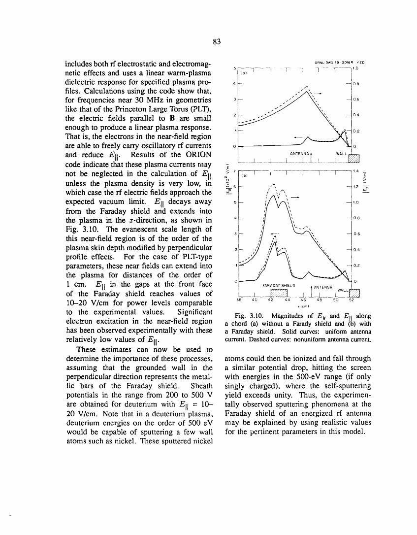
83
includes both rf electrostatic and electromag- OR,L-0wO893o,6_,_o5 _.0
netic effects and uses a linear warm-plasma --_-_.... r--......l ..........-r- ......_ Y ]
dielectric response for specified plasma pro- , - -_ o8files. Calculations using the code show that, " 'for frequencies near 30 MHz in geometries 3- .." ",. --o6
1"' x
like that of the Princeton Large Torus (PLT), .-" ',
the electric fields parallel to B are small 2- ..-" ,, -04enough to produce a linear plasma response. _ ' _ 02That is, the electrons in the near-field regionare able to freely carry oscillatory rf currents o o
and reduce Ell. Results of the ORION l j 1ANT_N,_II__L_ LWA_L_i_code indicate that these plasma currents may -_
z I I I I I J _.4 ._not be neglected in the calculation of Ell % (_,unless the plasma density is very low, in _ o- ,,_, -,2which case the rf electric fields approach the _ , ',,",
expected vacuum limit. Ell decays away _ _ .;/!/k"Vh',"---"from the Faraday shield and extends into ';/ _,,the plasma in the z-direction, as shown in 4- l/ \', -o8
Fig. 3.10. The evanescent scale length of /,_i- ""-_
i \ -- 0.6
'Fthis near-field region is of the order of the
plasma skin depth modified by perpendicular 2_ "7 ,'/ _', "%, 04profile effects. For the case of PLT-type _.:.f/:/.. .,_,,,__
parameters, these near fields can extend into _F ,-,1 .E_ o2the plasma for distances of the order of
O 0
1 cm. Ell in the gaps at the front face _D_s.! _ I WALL_
of the Faraday shield reaches values of J _ [_t ! J I I""_['_10-20 V/cm for power levels comparable _8 _o 42 o_ 4_ _8 5o 52_(cm)
to the experimental values. Significant Fig. 3.10. Magnitudes of Ey and Ell alongelec_on excitation in the near-field region a chord (a) without a Farady shield and (b) withhas been observed experimentally with these a Faraday shield. Solid curves: uniform antenna
relatively low values of Ell. current. Dashed curves: nonuniform antenna current.These estimates can now be used to
determine the importance of these processes, atoms could then be ionized and fall throughassuming that the grounded wall in the a similar potential drop, hitting the screenperpendicular direction represents the metal- with energies in the 500-eV range (if onlylic bars of the Faraday shield. Sheath singly charged), where the self-sputteringpotentials in the range from 200 to 500 V yield exceeds unity. Thus, the experimen-
are obtained for deuterium with Ell = 10- tally observed sputtering phenomena at the20 V/cm. Note that in a deuterium plasma, Faraday shield of an energized rf antennadeuterium energies on the order of 500 eV may be explained by using realistic valueswould be capable of sputtering a few wall for the pertinent parameters in this model.atoms such as nickel. These sputtered nickel
84
3.6 COMPUTING AND OPERATIONS ATF data from its initial repository onprimary disks to secondary disks and then
Computing in the Fusion Energy Division on to the jukebox. The primary disks (acan be roughly divided into three categories: set of shadowed fast disks) store the datathe User Service Center (USC), experimental in uncompressed form and thus provide thedata acquisition, and support of personal shortest access time. Before the data arecomputers (PCs). Funding restrictions have transferred to secondary disk storage, theyplaced a considerable premium on develop- are compressed and also copied to tapeing methods of providing support in these for offsite vault storage. Data compressionareas with fewer people. The USC now slightly slows the access time (_30%) butoperates with only partial operator coverage, allows the storage of three times as muchand many labor-intensive activities have data on the secondary disks. Finally,been automated or shifted to hardware that the oldest data migrate off the secondarycan operate almost unattended. Examples disks to their final repository in the opticalinclude an ion-deposition printer, which jukebox. Ali disks in the jukebox appearrequires far less manual paper handling to be on line simultaneously. In reality,and operator intervention than the Versatec the number of disks spinning at the sameprinters; a helical-scan tape unit purchased time is the same as the number of readlast year for evaluation, which has proved stations (currently two). Since data appearsatisfactory and is now used for the routine to "age" fairly quickly (users most oftendaily incremental backups (these can now be access recent data, sometimes access olderrun as an unattended batch job); and the use data, and only sporadically access the oldestof the optical jukebox purchased last year data), the jukebox can provide an illusionfor "near-line" storage of ATF data. This that ali data are on line as long as there areplaces ali ATF data in machine-mountable enough data in secondary storage to meetstorage and removes any need for manual the moderate-access demands. Data can betape or disk mounting, which was a continual read directly from the jukebox or copiedproblem for the data archive systems on ear- back to a recall area on the secondary disklier fusion experiments at ORNL. In the PC string. Since analyzed data files can bearea, the most interesting development was modified while in this area, and since thebridging the AppleTalk zones in the building storage medium in the jukebox can onlyto the Ethernet backbone and connecting be written once, data stored there can bethem to the VAXcluster with AlisaShare. superseded but not erased and rewritten.Finally, in the first move toward creating a This placed interesting design constraintsfourth category of computing, the division on the automatic migration software topurchased its first workstations this past year. guarantee that modified files were properlyThese workstations (two DECStation 3100s detected, tracked, and archived.and a Silicon Graphics Personal Iris) offer A complete rewrite of the ORNL Fusionsignificant advances in dedicated computing Energy Division CAMAC device driverpower at a very attractive price, package was completed this year. This
Software development has concentrated rewrite, which has been under considerationin the area of experimental support and for some time, has allowed the internals ofdata acquisition. A suite of fully automatic the driver to be modernized significantly.migration procedures was developed for the The driver is now compatible with sym-optical jukebox. These procedures stage metric multiprocessing CPUs from Digital
85
Equipment Corporation (DEC); in addition, 8. Y. Nakamura et al., "Relation Between Mercier
ali the hardware register dependences are Criterion and Low-n Mode Stability," paper 4P-2 in
localized to one point in the code. The Proceedings of the Seventh International StellaratorWorkshop, Oak Ridge, 1989, IAEA-TECDOC-558,
resulting code can be ported to other branch International Atomic Energy Agency, Vienna, 1990.driver designs with much less work than 9. A. Varias et al., "Ideal Mercier Stability for thewould have been required in the past. TJ-II," Europhys. Conf. Abstr. 13B, 607 (1989).
Additional development has continued in 10. A. Vafias et al., "Stability Studies for TJ-
support of the division's involvement with II," paper 4P-12 in Proceedings of the Seventh
Tore Supra and TEXTOR (see Sects. 1.2.2 International Stellarator Workshop, Oak Ridge, 1989,IAEA-TECDOC-558, International Atomic Energy
and 1.2.3). Communications software was Agency, Vienna, 1990.developed for exchanging data files and 11. L. A. Charlton et al., "Compressible Lin-synchronizing shot information with Tore ear and Nonlinear Resistive MHD Calculations in
Supra's host data acquisition computers Toroidal Geometry,"J. Comput. Phys. 86, 270 (1990).
(which are non-DEC). This software under- 12. L. A. Charlton and B. A. Carreras, "The Effect
went a major upgrade this year to improve of Compressibility on Magnetohydrodynamic Insta-bilities in Toroidal Tokamak Geometry," Phys. Fluids
its reliability and robustness. Development B 2, 539-47 (1990).of basic data acquisition programs continued 13. J. A. Holmes, B. A. Carreras, and L. A. Charl-
at both sites, ton, "MHD Stability of Shaped Tokamak Plasmaswith Low Shear and Inflection Point at the q = 1Surface," presented at the Workshop on Resistive
REFERENCES MHD Instabilities in Tokamaks with Emphasis on theEffect on Noncircularity and Finite Beta, Princeton,N.J., November 7-9, 1989.
1. V. E. Lynch etal., "Three-Dimensional Equilib- 14. J. A. Holmes, B. A. Carreras, and L. A.ria and Mercier Stability Calculations," paper PMA5 Charlton, "MHD Stability and Nonlinear Evolutitmpresented at the 13th Conference on the Numerical of the m = 1 Mode in Toroidal Geometry for SafetySimulation of Plasmas, Santa Fe, N.M., September Factor Profiles with an Inflection Point," Phys. Fluids17-20, i989. B 1,788 (1989).
2. N. Dominguez et al., "Ideal Low-n and Mercier 15. L. A. Charlton et al., "Linear and NonlinearMode Stability Boundaries for l - 2 Torsatrons," Infernal Modes in Shaped Plasmas," presented at theNucl. Fusion 29, 2079 (1990). Workshop on Resistive MHD Instabilities in Toka-
3. N. Dominguez et al., "Ideal Low-n and maks with Emphasis on the Effect on NoncircularityMercier Mode Stability Boundaries for l --- 2 and FiniteBeta, Princeton, N.J., November 7-9, 1989.Torsatrons,"paperO2-6 in Proceedings oftheSeventh 16. L. A. Charlton et al., "MHD Analysis ofInternational Stellarator Workshop, Oak Ridge, 1989, Peaked-Density Profiles l_'oduced by Pellet InjectionIAEA-TECDOC-558, International Atomic Energy in JET," presented at the Annual Controlled FusionAgency, Vienna, 1990. Theory Conference: 1989 Sherwood Meeting, San
4. J. E Lyon et al., "ATF-II Studies," Fusion Antonio, Tex., April 3-5, 1989.Technol. 17, 188 (1990). 17. J. D. Hanson et al., "A Simple Method for
5. B. A. Carreras et al., Confinement Improvement Calculation of Magnetic Island Widths," paper 5P7 inof Low-Aspect-Ratio Torsatrons, ORNL/TM-11101, Proceedings of the Seventh International StellaratorMartin Marietta Energy Systems, Inc., Oak Ridge Workshop, Oak Ridge, 1989, IAEA-TECDOC-558,Natl. Lab., 1989. International Atomic Energy Agency, Vienna, 1990;
6. J. E Lyon et al., "Compact Torsatron Reactors," also presented at the Annual Controlled FusionFusion Technol. 15, 1401 (1989). Theory Conference: 1989 Sherwood Meeting, San
7. Y. Nakamura et al., "Equilibrium, Stability, and Antonio, Tex., April 3-5, 1989.Deeply Trapped Particle Orbit Calculations for e = 2 18. K. C. Shaing et al., "Bootstrap CurrentTorsatron/Heliotron Configurations," Fusion Technol. Control and the Effects t,," the Radial Electric
15, accepted for publication (1990). Field in Stellarators," paper 05-7 in Proceedings
86
of the Seventh International Stellarator Workshop, 30. R. N. Morris et al., "Finite-Beta EquilibriumOak Ridge, 1989, IAEA-TECDOC-558, International Magnetic Field Perturbations in Stellarator Plasmas,"Atomic Energy Agency, Vienna, 1990. Nucl. Fusion 29, 2115 (1989).
19. K. C. Shaing et al., "Bootstrap Current Control 31. S. P. Hirshman and O. Betancourt, "Precondi-in Stellarators," Phys. Fluids B 1, 1663-70 (1989). tioned Descent Algorithm for Rapid Calculations of
20. L. Garcia et al., "Low-n Stability Calculations Magnetohydrodynamic Equilibria," J. Comput. Phys.,for Three-Dimensional Stellarator Configurations," accepted for publication (1990).
Phys. Fluids B 2, 2162 (1990). 32. S. P. Hirshman et al., "Low-Aspect-Ratio21. L. Garcia, B. A. Carreras, and N. Dominguez, Optimization Studies for ATF-II," paper 04-6 in
"Stability of Local Modes in Low-Aspect-Ratio Proceedings of the Seventh International StellaratorStellarators," Europhys. Conf. Abstr. 13B, 611 (1989). Workshop, Oak Ridge, 1989, IAEA-TECDOC-558,
22. L. Garcia, B. A. Carreras, and N. Dominguez, International Atomic Energy Agency, Vienna, 1990."Averaged Equilibrium and Stability in Low-Aspect- 33. A. J. Wootton et al., Fluctuations andRatio Stellarators," paper 4P-1 in Proceedings of Anomalous Transport in Tokamaks, FRCR-340 (DOE-the Seventh International Stellarator Workshop, ER/53267-52), Fusion Research Center, University ofOak Ridge, 1989, IAEA-TECDOC-558, International Texas, Austin, 1989.Atomic Energy Agency, Vienna, 1990. 34. K. C. Shaing et al., "Radial Electric Field
23. B. A. Carreras et al., "Dissipative Trapped and Enhanced Confinement Regimes in TokamaksElectron Modes in Stellarators," paper 4P-9 in and Stellarators," presented at the Aanual ControlledProceedings of the Seventh International Stellarator Fusion Theory Conference: 1989 Sherwood Meeting,Workshop, Oak Ridge, 1989, IAEA-TECDOC-558, San Antonio, Tex., April 3-5, 1989.International Atomic Energy Agency, V|enna, 1990; a 35. G. S. Lee, B. A. Carreras, and L. Gar-related paper was presented at the Annual Controlled cia, "Fluctuation Spectrum of Resistive Pressure-Fusion Theory Conference: 1989 Sherwood Meeting, Gradient-Driven Turbulence," Phys. Fluids B 1, 119-San Antonio, Tex., April 3-5, 1989. 133 (1989).
24. J. H. Harris et al., "Second Stability in the 36. B. A. Carreras and P. H. Diamond, "ThermalATF Torsatron," Phys. Rev. Lett. 63, 1249-52 (1989). Diffusivity Induced by Resistive Pressure-Gradient-
25. M. Murakami et al., "Second Stability Studies Driven Turbulence," Phys. Fluids B 1, 1011-17in the ATF Torsatron," Europhys. Conf. Abstr. 13B, (1989).575 (1989); also published as ORNL/TM-11138, 37. D. R. Thayer, P. H. Diamond, B. A. Carreras,Martin Marietta Energy Systems, Inc., Oak Ridge J.A. Holmes, J. N. Leboeuf, Cb. P. Ritz, and A. J.National Laboratory, 1989. Wootton, "Drift-Rippling Theory of Edge Turbulent
26. B. A. Carreras et al., "Access to Second Transport," presented at the Annual Controlled Fusion
Stability in ATF," presented at the Annual Controlled Theory Conference: 1989 Sherwood Meeting, SanFusion Theory Conference: 1989 Sherwood Meeting, Antonio, Tex., April 3-5, 1989.San Antonio, Tex., April 3-5, 1989. 38. D. K. Lee et al., "Modeling of Fluctuations
27. V. E. Lynch et al., "Equilibrium and Ideal Sta- in the Edge of the TEXT Tokamak," presented at thebility Studies for ATF," paper 4P-10 in Proceedings Annual Controlled Fusion Theory Conference: 1989of the Seventh International Stellarator Workshop, Sherwood Meeting, San Antonio, Tex., April 3-5,Oak Ridge, 1989, IAEA-TECDOC-558, International 1989.Atomic Energy Agency, Vienna, 1990. 39. L. M. Hively and J. A. Rome, "TF Ripple
28. B. A. Carreras et al., A First Glance at the Losses of Alphas Below the Critical Energy in ITER,"
Initial ATF Experimental Results, ORNL/TM-11102, Nucl. Fusion 30, 1129-35 (1990).Martin Marietta Energy Systems, Inc., Oak Ridge 40. R. H. Fowler et al., "Neutral Beam InjectionNational Laboratory, 1989. Benchmark Studies for Stellarators/Heliotrons," Nucl.
29. J. Ntthrenberg and R. Zille, "Optimization of Fusion 30, 997-1010 (1990).Helias for Wendelstein VII-X," p. 17 in Proceedings 41. K. C. Shaing and E. C. Crume, Jr., "Aof the 2hd Workshop on Wendelstein VII-X, Schloss Bifurcation Theory of Poloidal Rotation in Tokamaks:Ringberg, 1988, EUR 11705 EN, Commission of the A Model for the L-H Transition," Phys. Rev. Lett. 63,European Communities, Brussels, 1988. 2369 (1989).
87
42. K. C. Shaing, E. C. Crume, and W.A. 54. N. A. Uckar_, "Tokamak Confinement Projec-Houlberg, "Bifurcation of Poloidal Rotation and tions and Performance Goals," Fusion Technol. 15,Suppression of Turbulent Fluctuations: A Model for 391 (1989).the L-H Transition in Tokamaks," Phys. Fluids B 2, 55. S. E. Attenberger, W. A. Houlberg, and N. A.1492 (1990). Uckan, "Transport Analysis of Ignited and Current-
43. K. C. Shaing, G. S. Lee, B. A. Carreras, W.A. Driven ITER Designs," Fusion Technol. 15, 629-36Houlberg, and E. C. Crume, Jr., "A Model for the L-H (1989).
Transition in T,_kamaks," p. 13 in Plasma Physics and 56. J. T. Hogan and T. Taylor, PreliminaryControlled Nuclear Fusion Research 1988: Twelfth Examination of DIH-D Volt-Second Database, ITER-Conference Proceedings, Nice, 12-19 October 1988, IL-PH-2-9-U-5, International Thermonuclear Engi-
vol. 2, International Atomic Energy Agency, Vienna, neering Reactor Activity, Garching, Federal Republic1989. of Germany, September 1989.
44. K. C. Shaing, "Suppression of Turbulent 57. W. A. Houlberg, ITER Pellet Fueling, ITER-Fluctuations by Radial Electric Fields and Confine- IL-PH-9-9-U-1, International Thermonuclear Engi-ment Enhancement in Toroidal Plasmas," Comments neering Reactor Activity, Garching, Federal RepublicPlasma Phys. Controlled Fusion, submitted for of Germany, March 1989.publication (1990). 58. D. B. Batchelor et al., "Fast Wave Cur-
45. W. A. Houlberg et al., "Modeling Transport in rent Drive Modeling for ITER and Prospects forToroidal Plasmas: Status and Issues," Phys. Fluids B a Near-Term Proof-of-Principle Experiment," AIP2, accepted for publication (1990). Conf. Proc. 190,218 (1989).
46. J. D. Callen et al., ''Transport Task Force 59. R. A. Dory, W. A. Houlberg, and S. E.Issues and Recommendations," May 1989. Attenberger, "Energy Requirements for Neutral Beam
47. W. A. Houlberg et al., "The Relationship Current Drive in a Large Tokamak," CommentsBetween Local Transport and Global Confinement," Plasma Phys. Controlled Fusion 13, 29--44 (1989).presented at the Annual Controlled Fusion Theory 60. W. A. Houlberg, L. R. Baylor, and S. L.Conference: 1989 Sherwood Meeting, San Antonio, Milora, "Velocity Dependence of Pellet PenetrationTex., April 3-5, 1989. in JET," Bull. Am. Phys. Soc. 34, 2057 (1989).
48. N. A. Uckan and ITER Physics Group, ITER 61. M. Murakami et ai., "Magnetic ConfigurationPhysics Design Guidelines: Version 1, ITER-TN-PH- Studies in the ATF Torsatron," Bull. Am. Phys. Soc.8-7, International Atomic Energy Agency, Vienna, 34, 1946 (1989).January 1989. 62. D. A. Rasmussen et al., "Electron Tem-
49. ITER Team, ITER Concept Definition Phase perature and Density Profile Analysis in ATF,"Report, vols. 1 and 2, ITER Documentation Series 3, Bull. Am. Phys. Soc. 34, 1947 (1989).International Atomic Energy Agency, Vienna, 1989. 63. L. D. Horton et al., "Modeling of Radiation
50. J. T. Hogan, Stability of ITER Profiles with and Density Limits in ATF," Bull. Am. Phys. Soc. 34,q(0) < 1, ITER-IL-PH-12-9-U-4, International Ther- 1949 (1989).monuclear Engineering Reactor Activity, Garching, 64. H. C. Howe et al., "Transport ModelingFederal Republic of Germany, September 1989. of ECH and Neutral-Beam-Heated Plasmas in the
51. J. A. Holmes, Resistive MHD Beta Limits, Advanced Toroidal Facility," Europhys. Conf. Abstr.ITER-IL-PH-12-9-U-3, International Thermonuclear 13B, 683 (1989).Engineering Reactor Activity, Garching, Federal 65. L. R. Baylor et al., "Particle TransportRepublic of Germany, September 1989. Analysis of Pellet-Fueled JET Plasmas," pp. 107-
52. D. A. Spong, P. Christenson, and J.A. 12 in Pellet Injection and Toroidal Confinement:
Holmes, Modification of ITER Ballooning Stability by Proceedings of the Technical Committee Meeting,an Energetic Alpha Population, ITER-IL-PH-1-9-U- Gut Ising, 1988, IAEA-TECDOC-534, International3, International Thermonuclear Engineering Reactor Atomic Energy Agency, Vienna, 1989.
Activity, Garching, Federal Republic of Germany, 66. W. A. Houlberg et al., "WHIST TransportSeptember 1989. Analysis of High-Neutron-Production, ICRF-Heated,
53. J. T. Hogan, Stability of ITER Current- Pellet-Fueled JE1_ Plasmas," pp. 137-42 in PelletDriven Profiles with q(0) > 1.5, ITER-IL-PH-12-9-U- Injection and Toroidal Conjinement: Proceedings of5, International Thermonuclear Engineering Reactor the Technical Committee Meeting, Gut Ising, 1988,
Activity, Garching, Federal Republic of Germany, IAEA-TECDOC-534, International Atomic EnergySeptember 1989. Agency, Vienna, 1989.
4PLASMA TECHNOLOGY

H. H. Haselton, Section HeadD. W. Swain, Assistant Section Head
B. E. Argo M.J. Gouge P.F. Rice
S. E. Attenberger 1 R.H. Goulding K.E. Rothe 1
M. Bacal 2 G.R. Haste P.M. Ryan
E W. Baity P- P" Helton D.E. SchechterG. C. Barber D.J. Hoffman A. Schempp 17
L. R. Baylor 3 W.A. Houlberg 7 G.L. Schmidt TM
W. R. Becraft 4 G.E. Isham 9 R.C. Shanlever 3
p. Berlemont 2 T.C. Jernigan 1° T.D. Shepard
T. S. Bigelow L.M. Johnson 11 D.W. Simmons
R. A. Brown 3 R.L. Johnson 3 D.A. Skinner 2
j. Bruneteau 2 C.C. Jones 11 F. Sluss
J. B. O. Caughman 5 H.D. Kimrey C.W. Sohns 19L. A. Charlton I J. E King 12 D.O. Sparks
M. J. Cole 3 M. Kwon 13 R.A. Stern 2°
S. K. Combs R. Leroy 2 W.L. StirlingJ. F. Cox R.L. Livesey K.D. St. Onge 3
K. R. Crandall 6 E S. Meszaros I D.J. Taylor 3
W. K. Dagenhart G.E. McMichael TM C.C. TsaiE. G. Elliott S.L. McNair 12 J.M. Walters 3
A. Fadnek S.L. Milora T. E Wangler 21
D. T. Fehling 7 K. Moses 15 D.J. Webster 3
E W. Fisher s B.D. Murphy I J.H. Whealton
S. C. Forrester E L. Nguyen 5 G.A. White
C. A. Foster J.L. Ping 3 T.L. White
C. R. Foust A.L. Qualls 16 R.E. Wright
W. L. Gardner R.J. Raridon I R.B. Wysor 3E L. Goranson 3 J" J" Yug°22
1. Computing and Telecommunications Division, 13. Georgia Institute of Technology, Atlanta.Martin Marietta Energy Systems, Inc. 14. Chalk River Nuclear Laboratories, Chalk
2. Ecole Polytechnique, Palaiseau, France. River, Ontario, Canada.3. Engineering Division, Martin Marietta Energy l Y Plasma Technology Division, JAYCOR.
Systems, Inc. 16. The University of Tennessee, Knoxville.4. Grumman Corporation, Bethpage, N.Y. 17. University of Frankfurt, Frankfurt, Federal5. University of Illinois, Champaign-Urbana. Republic of Germany.6. AccSys Technology, Inc. 18. Princeton Plasma Physics Laboratory,7. Plasma Theory Section. Princeton, N.J.8. Chemical Technology Division. 19. Instrumentation and Controls Division.9. Finance and Materials Division, Martin 20. University of Colorado, Boulder.
Marietta Energy Systems, Inc. 21. Los Alamos National Laboratory, Los Alamos,10. Toroidal Confinement Section. N.M.11. Management Services Group. 22. Fusion Engineering Design Center and TRW,12. Metals and Ceramics Division. Inc., Redondo Beach, Calif.
90

4. PLASMA TECHNOLOGY
SUMMARYOF ACTIVITIES
During 1989, the Plasma Technology Section continued its activities in development andapplication of fusion technology. Work in related nonfusion research areas is described inSect. 9 of this report.
In the plasma fueling program, the long-pulse pellet fueling system for thesuperconducting Tore Supra tokamak in Cadarache, France, was succes,ffully tested andinstalled on the facility, with the first pellets injected in December. Tests of the tritiumproof-of-principle injector in the Tritium Systems Test Assembly at Los Alamos NationalLaboratory were completed.
The development of advanced pellet acceleration methods continued with the successfultesting of the proof-of-principle e-beam rocket accelerator in February and the developmentof a repetitive two-stage light gas gun facility, concluding with the first demonstration ofrepetitive operation at 0.7 Hz. Conceptual designs for pellet injection systems for the CompactIgnition Tokamak and the International Thermonuclear Engineering Reactor (ITER), based onthe single-stage pneumatic and two-stage light gas gun approaches, are described in Sect. 6of this report.
Pellet fueling experiments included the construction and commissioning of an eight-shotpneumatic injector system for the Advanced Toroidal Facility, with the first pellet experimentsperformed in May. A conceptual design for a four-pellet impurity pellet injector, based on theORNL two-stage light gas gun, was completed for the Tokamak Fusion Test Reactor (TFTR)in support of the U.S. Tokamak Transport Initiative. In the continuing collaboration on theJoint European Torus (JET) in the area of pellet fueling, the fusion product, no(O)Ti(O)r E,was increased to 5 x 10²⁰ m-3.kV.s, which represents one of the highest fusion productsobtained to date on JET.
In the rf technology program, new methods of attaching graphite tiles to Faraday shieldtubes were devised; computational methods of quantitatively determining the effect of theFaraday shield geometry on antenna parameters were developed; and the rf power dissipationdistribution on the shield was calculated. Experimental studies on the Radio FrequencyTest Facility with the development antenna showed increased electron temperatures, plasmapotential_, and ion impact energies on the Faraday shield during high-power ion cyclotronresonance heating (ICRH) operation.
Current drive technology efforts included optimizing the geometry of the multiple-straplauncher array and developing control circuitry and tuning algorithms to adjust and maintainproper phasing between the straps. The folded waveguide successfully completed its high-power vacuum testing, and the double-strap ICRH antenna for Tore Supra was completed,
91
92
tested, and shipped to France. Design work for a single-strap antenna for Alcator C-Modcontinued, and fabrication of a four-strap fast-wave current drive (FWCD) phased-arraylauncher for the DIII-D experiment began. In the experimental collaboration with PrincetonPlasma Physics Laboratory (PPPL), a combined 4.5 MW of ICRH power was injected intoTFTR using both the PPPL and ORNL antennas.
In the neutral beam development area, the collaborative work on the rf quadrupoleconcept for high-energy neutral beams continued. An architecture was produced for anITER-relevant beam line, and an experimental proof-of-principle demonstration proposalwas developed. In the development of the volume negative ion source, diagnostics weredeveloped to measure ion temperature within the source plasma. Atomic processes wereanalyzed to establish operating points and directions for optimization, and experiments andanalyses were performed to evaluate techniques used to reduce the electron density near theextraction sheath. The Lawrence Berkeley Laboratory volume negative ion source was alsoanalyzed, and an explanation of rms transverse emittance of the extracted ion beam wasprovided.
In summary, the Plasma Technology Section continued to expand its leading role in thedevelopment and implementation of the technology needed for fusion.

93
4.1 PLASMA FUELING PROGRAM a conventional 1-m-long single-stage gasgun system using hydrogen propellant gas.
4.1.1 Pellet Injector Development During the work, the gun received severalmodifications, which were performed on thecontaminated system through the glove-box
S. L. Milora ports. This demonstrated that maintenance
In 1989 the Plasma Fueling Group of of future tritium injectors could be cardedthe Plasma Technology Section participated out using similar techniques.in a broad range of research activities in In the area of more advanced develop-support of the magnetic fusion program in ment of higher-speed pellet injectors, ORNLthe United States and abroad. Research continued the development of the electron-and development (R&D) activities of the beam (e-beam) rocket pellet accelerator andgroup continued in the general areas of the two-stage light gas gun concepts, withpneumatic and centrifugal pellet injector the following highlights:development to support the present and near- • The proof-of-principle (POP) e-beamterm applications and advanced development rocket accelerator was completed andin support of more demanding applications successfully tested in Febnmry 1989.anticipated for the Compact Ignition Toka- Cylindrical hydrogen and deuterium pel-mak (CIT) and International Thermonuclear lets, 4 mm in diameter by 12 mmEngineering Reactor (ITER) devices, long, were accelerated to a speed of
In the area of centrifugal pellet injector 300 m/s by high-power pulsed electron
development, ORNL completed testing of a beams at various e-beam currents andlong-pulse pellet fueling system for the Tore pulse lengths in a 0.6-m-long accelerationSupra tokamak and installed the system at column. PTeliminary results indicate thatthe Tore Supra facility in Cadarache, France, the burn velocity is consistent with the-in October 1989. The injector, which has oretical estimates and that extrapolationsbeen under development since 1986, was to higher speeds would be feasible with adesigned to fuel Tore Supra plasmas for up multistage accelerator.to 30 s. In qualification tests at ORNL, • The ORNL two-stage light gas gun facil-the system demonstrated the capability of ity successfully operated at velocities ofreliably forming up to 100 pellets at 10 Hz up to 4.5 km/s with 35-mg plastic pelletsand accelerating them to velocities in the and velocities of 2.85 km/s with 4-mmrange of 600 to 900 m/s. The first pellets deuterium pellets. The efforts in 1989were injected into Tore Supra in December. concentrated on the development of the
In the area of pneumatic injector develop- repetitive two-stage device, concludingment, ORNL completed testing of the tritium with the first demonstration of repetitiveproof-of-principle (TPOP) experiment on the operation at 0.7 Hz. This was madeTritium Systems Test Assembly (TSTA) at possible by the addition of an automaticLos Alamos National Laboratory (LANL). loading mechanism that can easily loadIn the course of the experimental program, pellets at the rate of 1 Hz.nearly 1500 pellets were fired from the gun, ORNL was also responsible for comple-and about a third of these were tritium or tion of conceptual designs for pellet injectionmixtures of deuterium and tritium. Pure systems for CIT and ITER based on the
tritium pellets 4 mm in diameter were single-stage pneumatic and two-stage lightsuccessfully accelerated to 1500 m/s in gas gun approaches°
94
ORNL staff members participated in 4.1.1.1 Electron-beam rocket pellet
pellet fueling experiments on a number of injectorplasma confinement devices in the UnitedStates and abroad. An eight-shot pneumatic C.A. Foster, D. E. Schechter, and
injector system was built and commissioned C.C. Tsaion the Adva_aced Tort.idal Facility (ATF)device, and the first pellet experiments were The e-beam rocket pellet injector concept
performed in May 1989. A conceptual de- is being developed for injecting ultrahigh-sign was completed for a four-pellet impurity speed pellets to fuel ITER-class fusionpellet injector, based on the ORNL two- confinement devices. 1-3 This research isstage light gas gun, for the Tokmaak Fusion partially supported by U.S. ITER R&DTest Reactor (TFTR) at Princeton Plasma funds. A theoretical evaluation indicates
Physics Laboratory (PPPL) in support of the that a practical injector can be developed toU.S. Tokamak Transport Initiative. ORNL deliver deuterium or tritium pellets at speedsstaff also participated in major international of several kilometers per second. Significantcollaborations between the U.S. Department results from a POP device 4 are summarized
of Energy (DOE) and the French Commis- here, including a brief description of asariat h l'Energie Atomique (CEA) on the conceptual design for an ultrahigh-speedsuperconducting Tore Supra tokamak and pellet injector.between DOE and the European Atomic A POP device, shown in Fig. 4.1, has
Energy Community (EURATOM) on the been designed, fabricated, and assembled.continua_a of the collaboration on the Joint lt was first operated to demonstrate pellet
European Torus (JET) in the area of pellet acceleration by means of e-beam heating infueling. In 1989 the JET device underwent February 1989. Figure 4.2 shows prelim-extensive modifications to allow it to operate inary results from this study. Cryogenicwith beryllium as a first-wall material, cylindrical (4-mm-diam) pellets of frozenDuring the brief run period from June to hydrogen (12 mm long)and of frozen der,-September 1989, pellet injection operations terium (18 mm long) were reliably injectedwere extensive as the JET program was from the cryostat where they were formeddirected toward an early evaluation of the into accelerator guide rails and detectedeffects of the beryllium modifications on by optical pellet monitors. Pellets arehigh-power discharges. The experimental accelerated by partially ablating the back ofprogram primarily emphasized the fueling the pellet with high-power pulsed electronof high-performance discharges. The fusion beams at various electron energies, beamproduct, nD(O)T(O)rE, was increased to currents, and pulse lengths. A typical speed5 x 1020 m--_"c'.s for electron and ion increment of up to 300 m/s is observed,
temperatures in the 7- to 9-keV range. This increasing with the beam power. Therepresents one of the highest fusion products preliminary results of the experimental studyobtained to date on JET. Analysis of the data reveal an estimated burn velocity consistentfrom the 1988 campaign was completed, and with theoretical estimates. 3'4 The exhausta major new result was the determination velocity and acceleration efficiency are beingof particle diffusivity profiles for peaked- studied in the ongoing experiments.
. density-profile target plasmas with high- The POP device consists of a pellet cryo-power ion cyclotron range of frequencies stat, an electron gun, and a pellet accel-(ICRF) heating, erating column that includes guide rails and

95
ORNL-DWG 88-3555A3 FED
PISTON
H2 BUFFER
H 2 FEED _ e FLOW
TOVACUUMPUMP T, I / --'GU,DE BE-PELLETFEEI PELLET / "_--(_/- / / / / / RAMPI FREEZING / _',,,Q"Y_ /,=,// // / /i i\ ...\_I CELL / I_/I "_?.._"_/.._/ / / I I_.\_-pELLET \
(_) /_ ELECTRON L_ V / _ _p_LJi_l_--%-_ Ion1 ,'\ BEAM _ " I - I /
TO ----t .... ' / _ _ \'" "\v,cuu.* I ,,\ K//,.///A
PUMP CHAMBER I.il-PD2 , _ _4 I/,'/// / / I r-,,_,,,_I_ ,/ BEAM DEFINING
HV_NSULATOR 1] , APERTU% ._.-/..... TRON A1.41----PELLET , '_ -
CATHODE I _" _L_, P-HN "\\ GUIDE TUBE TO VACUL/M PUMPASSEMBLY--/ | n \D_.._,v,,._v \\ ' PD3 PD4 PD5 PD6- _ PD7 MD SA
I-I .__ _ / n
I<.ill ., - - . -/" O U" "" DIAGNOSTI
J. | / l _ VACUUM¥ o._c.ce.J / SOLENOID GUIDE P=.-r PUMP
TO VACUUM o ...... / MAGNETS RAILS _v
PUMP /-- PELLETACCELERATOR
COLUMN
Fig. 4. I. Experimental setup for the e-beam rocket pellet accelerator.
ORNL-DWG89M-2812FED a set of axial magnets for beam compression14o , ,_ ,_ , and confinement. The pellet maker can
_ produce hydrogen or deuterium pellets by
condensing a fixed amount of gas on a liquid-12o - =----""---_- helium-cooled copper block, punching out
the resulting frozen pellet with a mechanical- plunger, and injecting the pellet through alOO -
baffle chamber and a guide tube into a pellet
_ feed ramp. The innovative design of the8o - pellet feed ramp loads the pellet from an
LH
off-axis trajectory in the guide tube intot--LH60 - - the accelerator guide rails. The pellet is_J
1 constrained to travel down a set of three
BEAMON 0.6-m-long graphite guide rails. In this40 - k.__V.V- acceleration column, the pellet is ablated and
----o---- 0---o---6_ accelerated by the electron beam.
20 - _ 8._ - The pellet monitors (see Fig. 4.1) include: _.s a television ('FV) camera station at PD7 for= 134
imaging the accelerated pellet and light trip0 t I I I I
0 100 200 300 400 500 detectors PD1 to PD6, a microwave massPELLETPATH(cm) detector MD, and a shock accelerometer SA
Fig. 4.2. Acceleration of pellets with e-beam for measuring the pellet speed before androcket pellet accelerator, during e-beam acceleration. The distances of
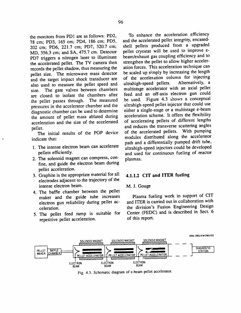
96
the monitors from PD1 are as follows: PD2, To enhance the acceleration efficiency78 cm; PD3, 165 cm; PD4, 186 cm; PD5, and the accelerated pellet integrity, encased-202 cm; PD6, 221.7 cm; PD7, 320.7 cm; shell pellets produced from a upgradedMD, 356.3 cm; and SA, 475.7 cm. Detector pellet cryostat will be used to improve e-PD7 triggers a nitrogen laser to illuminate beam/exhaust gas coupling efficiency and tothe accelerated pellet. The TV camera then strengthen the pellet to allow higher acceler-records the pellet shadow, thus measuring the ation forces. This acceleration technique canpellet size. The microwave mass detector be scaled up simply by increasing the lengthand the target impact shock transducer are of the acceleration column for injectingalso used to measure the pellet speed and ultrahigh-speed pellets. Alternatively, asize. The gate valves between chambers multistage accelerator with an axial pelletare closed to isolate the chambers after feed and an off-axis electron gun could
the pellet passes through. The measured be used. Figure 4.3 shows a conceptualpressures in the accelerator chamber and the ultrahigh-speed pellet injector that could usediagnostic chamber can be used to determine either a single-stage or a multistage e-beamthe amount of pellet mass ablated during acceleration scheme, lt offers the flexibilityacceleration and the size of the accelerated of accelerating pellets of different lengths
pellet, and reduces the transverse scattering anglesThe initial results of the POP device of the accelerated pellets. With pumping
indicate that: modules distributed along the acceleratorpath and a differentially pumped drift tube,
1. The intense electron beam can accelerate ultrahigh-speed injectors could be developedpellets efficiently, and used for continuous fueling of reactor
2. The solenoid magnet can compress, con- plasmas.fine, and guide the electron beam duringpellet acceleration.
3. Graphite is the appropriate material for all 4.1.1.2 CIT and ITER fuelingelectrodes adjacent to the trajectory of theintense electron beam. M.J. Gouge
4. The baffle chamber between the pelletmaker and the guide tube increases Plasma fueling work in support of CITelectron gun reliability during pellet ac- and ITER is carried out in collaboration withceleration, the division's Fusion Engineering Design
5. The pellet feed ramp is suitable for Center (FEDC) and is described in Sect. 6repetitive pellet acceleration, of this report.
ORNL-DWG91M-2943FED
SOLENOIDMAGNET SOLENOIDMAGNET SOLENOIDMAGNET
ELECTRON ELECTRON ELECTRONBEAM BEAM BEAM
Fig. 4.3. Schematic diagram of e-beam pellet accelerator.
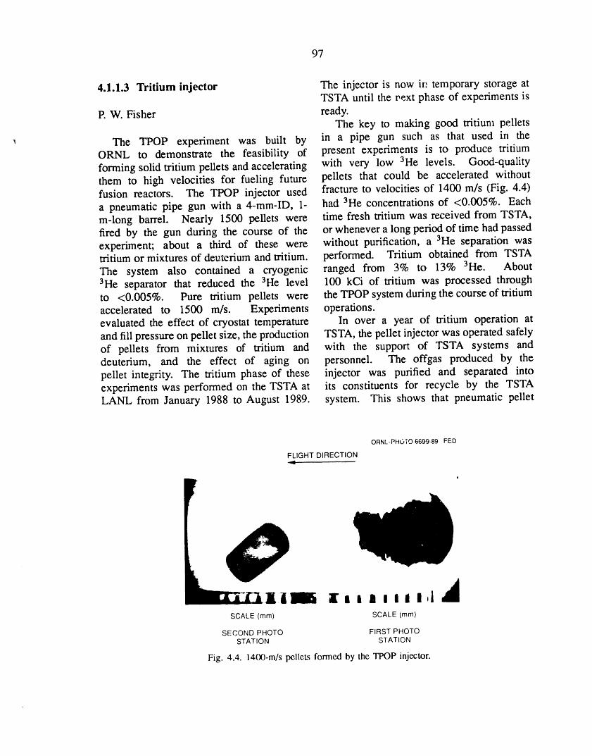
97
4.1.1.3 Tritium injector The injector is now irr temporary storage atTSTA until the text phase of experiments is
P. W. Fisher ready.The key to making good tritium pellets
The TPOP experiment was built by in a pipe gun such as that used in theORNL to demonstrate the feasibility of present experiments is to produce tritium
forming solid tritium pellets and accelerating with very low 3He levels. Good-qualitythem to high velocities for fueling future pellets that could be accelerated withoutfusion reactors. The TPOP injector used fracture to velocities of 1400 m/s (Fig. 4.4)a pneumatic pipe gun with a 4-mm-ID, 1- had 3He concentrations of <0.005%. Eachm-long barrel. Nearly 1500 pellets were time fresh tritium was received from TSTA,fired by the gun during the course of the or whenever a long period of time had passedexperiment; about a third of these were without purification, a 3He separation wastritium or mixtures of deuterium and tritium, performed. Tritium obtained from TSTA
The system also contained a cryogenic ranged from 3% to 13% 3He. About3He separator that reduced the 3He level 100 kCi of tritium was processed throughto <0.005%. Pure tritium pellets were the TPOP system during the course of tritiumaccelerated to 1500 m/s. Experiments operations.evaluated the effect of cryostat temperature In over a year of tritium operation atand fill pressure on pellet size, the production TSTA, the pellet injector was operated safelyof pellets from mixtures of tritium and with the support of TSTA systems anddeuterium, and the effect of aging on personnel. The offgas produced by thepellet integrity. The tritium phase of these injector was purified and separated intoexperiments was performed on the TSTA at its constituents for recycle by the TSTALANL from January 1988 to August 1989. system. This shows that pneumatic pellet
ORNL-PHOTO6699-89 FED
FLIGHT DIRECTION
r
li I I I II I,I- 9lD
SCALE (mm) SCALE (mm)
SECOND PHOTO FIRST PHOTOSTATION STATION
Fig. 4.4. 1400-m/s pellets formed by the TPOP injector.
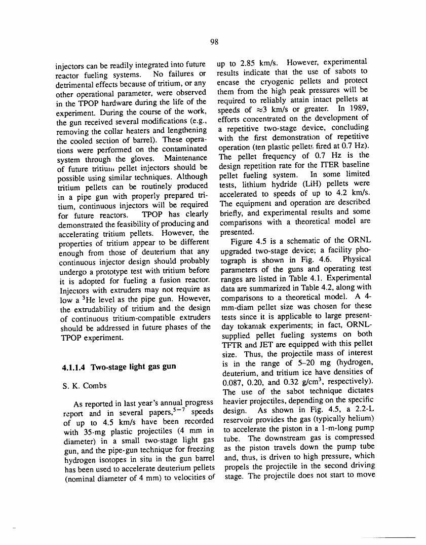
98
injectors can be readily integrated into future up to 2.85 km/s. However, experimentalreactor fueling systems. No failures or results indicate that the use of sabots todetrimental effects because of tritium, or any encase the cryogenic pellets and protect
other operational parameter, were observed them from the high peak pressures will bein the TPOP hardware during the life of the required to reliably attain intact pellets at
experiment. During the course of the work, speeds of _3 km/s or greater. In 1989,the gun received several modifications (e.g., efforts concentrated on the development ofremoving the collar heaters and lengthening a repetitive two-stage device, concludingthe cooled section of barrel). These opera- with the first demonstration of repetitivetions were performed on the contaminated operation (ten plastic pellet._,fired at 0.7 Hz).system through the gloves. Maintenance The pellet frequency of 0.7 Hz is theof future tritiu,, pellet injectors should be design repetition rate for the ITER baseline
possible using similar techniques. Although pellet fueling system. In some limitedtritium pellets can be routinely produced tests, lithium hydride (LiH) pellets werein a pipe gun with properly prepared tri- accelerated to speeds of up to 4.2 km/s.tium, continuous injectors will be required The equipment and operation are describedfor future reactors. TPOP has clearly briefly, and experimental results and somedemonstrated the feasibility of producing and comparisons with a theoretical model areaccelerating tritium pellets. However, the presented.properties of tritium appear to be different Figure 4.5 is a schematic of the ORNLenough from those of deuterium that any upgraded two-stage device; a facility pho-continuous injector design should probably tograph is shown in Fig. 4.6. Physicalundergo a prototype test with tritium before parameters of the guns and operating testit is adopted for fueling a fusion reactor, ranges are listed in Table 4.1. ExperimentalInjectors with extruders may not require as data are summarized in Table 4.2, along withlow a 3He level as the pipe gun. However, comparisons to a theoretical model. A 4-the extrudability of tritium and the design mm-diam pellet size was chosen for theseof continuous tritium-compatible extruders tests since it is applicable to large present-should be addressed in future phases of the day tokamak experiments; in fact, ORNL-
TPOP experiment, supplied pellet fueling systems on bothTFTR and JET are equipped with this pelletsize. Thus, the projectile mass of interest
4.1.1.4 Two-stage light gas gun is in the range of 5-20 mg (hydrogen,deuterium, and tritium ice have densities of
S. K. Combs 0.087, 0.20, and 0.32 g/crn 3, respectively).The use of the sabot technique dictates
As reported in last year's annual progress heavier projectiles, depending on the specificreport and in several papers, 5-7 speeds design. As shown in Fig. 4.5, a 2.2-Lof up to 4.5 km/s have been recorded reservoir provides the gas (typically helium)with 35-ing plastic projectiles (4 mm in to accelerate the piston in a 1-m-long pumpdiameter) in a small two-stage light gas tube. The downstream gas is compressedgun, and the pipe-gun technique for freezing as the piston travels down the pump tubehydrogen isotopes in situ in the gun barrel and, thus, is driven to high pressure, whichhas been used to accelerate deuterium pellets propels the projectile in the second driving
(nominal diameter of 4 mm) to velocities of stage. The projectile does not start to move
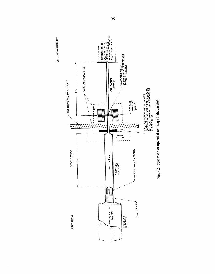
99
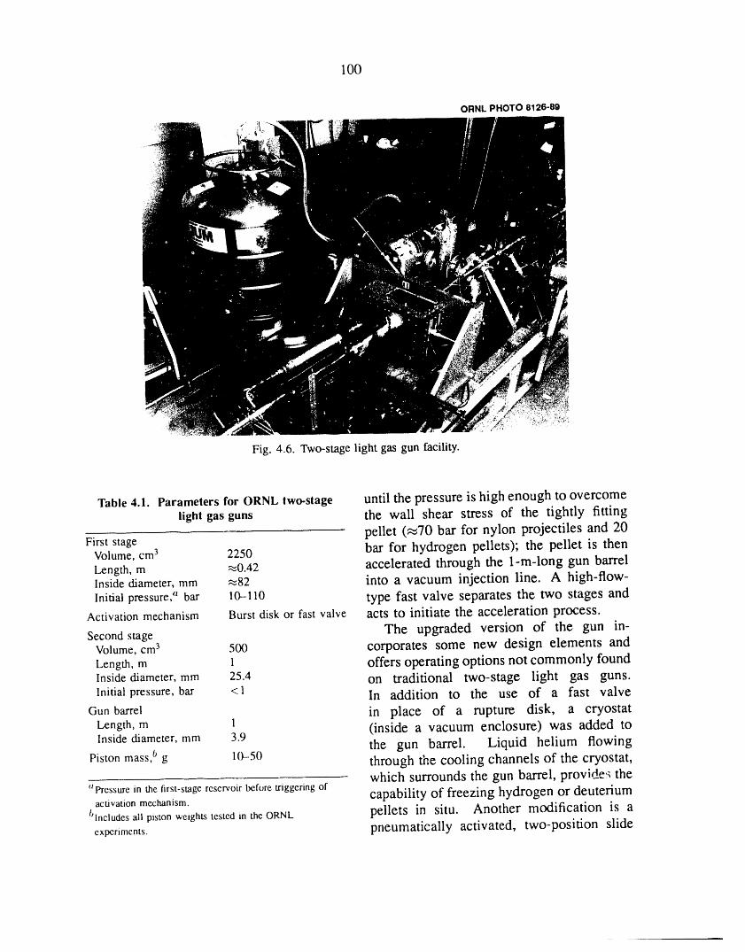
100
ORNL PHOTO 8126-89
Fig. 4.6. Two-stage light gas gun facility.
Table 4.1. Parameters for ORNL two-stage until the pressure is high enough to overcomelight gas guns the wall shear stress of the tightly fitting
pellet (,_70 bar for nylon projectiles and 20First stage
Volume, cm 3 2250 bar for hydrogen pellets); the pellet is thenLength, m ,_0.42 accelerated through the 1-m-long gun barrelInside diameter, mm ,_82 into a vacuum injection line. A high-flow-Initial pressure, a bar 10-110 type fast valve separates the two stages and
Activation mechanism Burst disk or fast valve acts to initiate the acceleration process.
Second stage The upgraded version of the gun in-Volume, cm 3 500 corporates some new design elements andLength, m 1 offers operating options not commonly foundInsidediameter, mm 25.4 on traditional two-stage light gas guns.Initial pressure, bar <1 In addition to the use of a fast valve
Gun barrel in piace of a rupture disk, a cryostatLength, m 1 (inside a vacuum enclosure) was added toInsidediameter, mm 3.9 the gun barrel. Liquid helium flowing
Piston mass,b g 10--50 through the cooling channels of the cryostat,which surrounds the gun barrel, provide_ the
"Pressure in the first-stage reservoir before triggering of capability of freezing hydrogen or deuteriumactivation mechanism.
blncludes ali piston weights tested in the ORNL pellets in situ. Another modification is aexperiments, pneumatically activated, two-position slide

101
Table 4.2. Experimental data for test shots and results from gas dynamics modelValues in parentheses are inputs for or results from code calculations
Shot number
1210 5041 5064 5088 5089 5165
Projectile Nylon Deuterium Deuterium Deuterium Deuterium LiH
Temperature, K 295 10 10 10 10 295
Projectile mass, mg 35 -- (10) -- (10) -- (10) -- (10) 26
Piston mass, g 19.6 25.5 25.5 25.5 25.5 51.0a
First-stage pressure, b bar 72.0 (51.7) c 13.8 (13.8) c 39.9 (34.8) c 38.3 (34.8) c 42.0 (34.8) c 66.4 (81.1) c
Second-stage pressure, bar 0.8 0.8 0.8 0.8 0.8 0.8
Peak pump tube pressure, bar 3670 (/ (4690) -- (180) m (1600) -- (1600) -- (1600) -- (3350)
Piston travel time, ms 3.20 (3.24) 8.20 (8.00) 5.10 (4.85) 4.90 (4.85) 5.10 (4.85) 5.15 (5.14)
Maximum piston speed, mis -- (391) -- (152) -- (265) -- (265) -- (265) -- (269)
Peak pellet acceleration, m/s 2 -- (5.6 x 10⁷) -- (4.3 x 10⁶) -- (6.7 x 10⁶) -- (6.7 x 10⁶) -- (6.7 x 10⁶) -- (2.3 x 10⁷)
Pellet velocity, km/s 4.50 (4.88) 1.60 (1.63) 2.60 (2.75) 2.70 (2.75) 2.85 (2.75) 4.20 (4.00)
aTwo 25.5-g pistons were used in pump tube for this shot; they were modeledas a single piston.bThis is not the reservoir pressure but the maximum pressureestimated from the oulput of the Iransducerlocatedat the upstream endofthe pumptube.
CFirst-stagepressure for the code calculation;it was adjusted so that the calculated piston travel time closely matched the experimentallymeasuredvalue; for shots 5064, 50'38,and 5089, the same pressurewas used, so the code resultsare the same.
dFlat profileof pressure pulse at peak on this shot suggested that instrumentor data acquisitionmay have missed maximumvalue.
mechanism (located inside a second vacuum within a few minutes. The automatic loadingenclosure). This mechanism essentially mechanism can easily load pellets at aseparates the pump tube and the gun barrel, rate of 1 Hz. O-ring-type seals and aFor cryogenic operation, the slide acts as pneumatic clamp provide adequate sealinga shutoff valve in position 2 (Fig. 4.5) at the interface between the pump tube, theand separates the cryostat and pellet from slide mechanism, and the gun barrel dunngthe room-temperature helium propellant gas. the firing phase, when high peak pressuresIt is moved into position 1 immediately are generated in the gun. The pneumaticbefore the gun is fired; the open hole in clamp releases when the slide is moved tothe slide bar is accurately aligned with the minimize the possibility of damage to thegun barrel. For room-temperature operation O-rings. Details of the mechanical designwith plastic pellets, single projectiles can be are not shown in Fig. 4.5.loaded manually into the hole when the slide Another two-stage gun using a biggerbar is in position 2, and the gun can be fired pump tube (41.3-mm ID) was also con-after the slide bar is returned to position 1. structed in 1989 and will be used to evaluate
A recent addition is an automatic loading the performance of a larger second-stagemechanism that can be used to remotely load volume. Both experiments are equipped witha pellet into the slide mechanism when it is instrumentation (not shown in figures) toin position 2. This loading mechanism can eva_uate gun performance. A programmablehold up to 36 4-mm-diam pellets (it could logic controller (PLC) and a CAMAC dataeasily be modified to accommodate hundreds acquisition system are used for preciseof pellets) and can be reloaded manually control of the systems, for accurate timing,

102
and for recording and archiving the transient "gORN L-DWG 89-2394 FED
data for each shot. ,,, 4000 ]rr"
In preliminary experimental tests, repet- g _ SHOT4240 /_PEAK =3670 ber -co
itive operation of the two-stage gun was "' ilo, 9872#srr 3000-
demonstrated with 50-mg plastic pellets (3.9 _- • CODE I / -uJ _ PREDICTION] Imm in diameter by 3.5 mm long). The "F 2000
weight of these test pellets is probably close _-:_ ---_
to the combined mass of a hydrogen isotope __pellet and a sabot. The automatic loading :_,_40o0LtJ
mechanism was used to fire ten pellets at ,"k-m 0 l
0.7 ttz. The first-stage reservoir pressure _= 97_6 982t 9927 40032was 100 bar for this series of shots; the o0 TIME(/Ts)
second-stage initial pressure was 0.8 bar. Fig. 4.7. Pressuremeasuredat downstreamendofPellet velocities were consistent, ranging pumptube duringa high-speedshotdfa 35-mgnylonfrom 2.3 to 2.5 km/s. The equivalent speed projectile; calculated predictions from a gas dynamics
of lighter deuterium pellets is 3.0 km/s, code are also shown.
or greater, at similar operating conditions.In these tests, each pellet was remotelyloaded and fired in a automatically controlled
sequence. The preliminary results are ble 4.2. As noted, the velocity in shot 1210encouraging and suggest that operation at is the highest recorded to date (4.5 km/s).> 1 Hz is attainable. The code indicates that the gas is driven to- In some limited tests, 3.9-mm-diam, 2.8- temperatures approaching 10,000 K during
mm-long LiH pellets were shot with the the compression. Figure 4.7 is a comparisongun. These pellets were machined from of the downstream pump tube pressure fromstock material at the Oak Ridge Y- 12 Plant. the code calculations with the experimentally
The density of the material is 0.78 g/cm3; measured values. The estimated peakthus, the LiH projectiles weighed ,_26 rag. acceleration for this shot is 4.5 x 10⁷ m/sz.In shots 5164 and 5165, speeds of 3.2 In general, the code predicts the gunand 4.2 km/s, respectively, were recorded, performance for deuterium pellets very weil;The corresponding pressures in the first- calculated speeds are within 6% of thestage reservoir for these shots were 69 measured values, as shown in Table 4.2. Forand 110 bar. The information for shot operation with higher pump tube pressures5165 is summarized in Table 4.2. High- (as in shots 5064, 5088, and 5089), the
speed "impurity injection" of such materials maximum acceleration indicated by the codehas been proposed for studying transport is 6.7 x 10⁶ m/s 2. The pellet velocity andphenomena in tokamak plasmas, acceleration rate calculated from the code
A two-stage Lagrangian gas dynamics are shown in Fig. 4.8 as a function ofcode 7 is used to model the interior ballistics the pellet p 'ition in the gun barrel. For
of the two-stage light gas gun. Extensive many shots at these conditions and even atcomputer modeling runs have been made slightly lower first-stage pressures, brokenfor both nylon pellets (mass of 35 mg) pellets were observed at the gun muzzle.and deuterium pellets (mass of 10 mg). This is consistent with the accelerationExperimental data and some inputs to and limit of (5-6) X 10 6 m/s z reported byoutputs from the code are shown in Ta- other researchers. 8'9 For reliable operation at
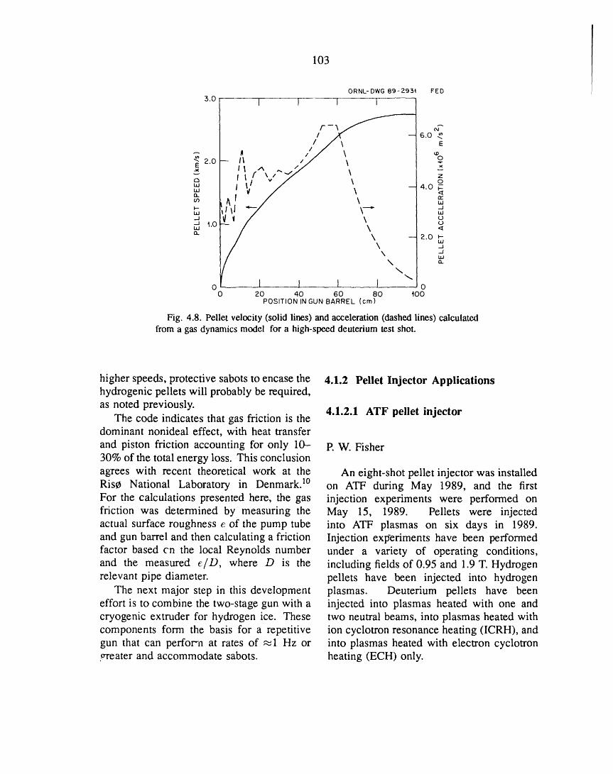
103
ORNL- DWG 89- 2934 FED
3.o 1 I I I
/ -y N"- 6.0 #,
/_\\\ E"" A / Lp"_ 2.0 II / o
Jl ^ ,. "/I I f \/"_,/ \ z
\ -4.o w
Ld
9 _.o \ '-'o
\ -- 2.o _-w\ _J
k -JLU\ o.
\
o 1 I I I \ o0 20 40 60 80 400
POSITION IN GUN BARREL (cre)
Fig. 4.8. Pellet velocity (solid lines) and acceleration (dashed lines) calculatedfrom a gas dynamics model for a high-speed deuterium test shot.
higher speeds, protective sabots to encase the 4.1.2 Pellet Injector Applicationshydrogenic pellets will probably be required,as noted previously.
The code indicates that gas friction is the 4.1.2.1 ATF pellet injectordominant nonideal effect, with heat transferand piston friction accounting for only 10- P.W. Fisher30% of the total energy loss. This conclusion
agrees with recent theoretical work at the An eight-shot pellet injector was installedRis_ National Laboratory in Denmark. ]° on ATF during May 1989, and the firstFor the calculations presented here, the gas injection experiments were performed onfriction was determined by measuring the May 15, 1989. Pellets were injectedactual surface roughness e of the pump tube into ATF plasmas on six days in 1989.and gun barrel and then calculating a friction Injection experiments have been performedfactor based cn the local Reynolds number under a variety of operating conditions,and the measured e/D, where D is the including fields of 0.95 and 1.9 T. Hydrogenrelevant pipe diameter, pellets have been injected into hydrogen
The next major step in this development plasmas. Deuterium pellets have beeneffort is to combine the two-stage gun with a injected into plasmas heated with one andcryogenic extruder for hydrogen ice. These two neutral beams, into plasmas heated withcomponents form the basis for a repetitive ion cyclotron resonance heating (ICRH), andgun that can perfor'n at rates of _1 Hz or into plasmas heated with electron cyclotron_eater and accommodate sabots, heating (ECH) only.

104
A record stored energy was achieved with changes in the critical feed timing; enlarge-pellet injection on ATF for 0.95-T operation, ments in the rotor entrance aperture andA simultaneous stored energy of 10.5 kJ and guide tube entrance aperture, which alsoa line-averaged electron number density of increase the fr,',ction of pellets accelerated;3 x 1013 cm -3 were obtained using pellet an ice scraper to improve the formationinjection with gas puffing at 0.95 T. A stored of the deuterium ice rim and eliminate aenergy of 23 kJ has been obtained with pellet previous problem of the ice disk locking,injection at 1.9 T. Multiple-pellet injection which had prevented long-pulse operation;has been performed with up to three pellets and the implementation of an extrusioninjected during one discharge, system to rapidly reload the ice disk.
The system, as delivered, could make upto 100 pellets of variable mass at rates up to
4.1.2.2 Tore Supra pellet injector 10 Hz and accelerate them to a speed of 600to 900 m/s. The reliability of the injector
C. A. Foster was improved so that, on a given shot, fromA cennifuge pellet injector was com- 60% to 90% of the pellets were delivered.
pleted and delivered to the Tore Supra super- Further improvements in this parameter areconducting tokamak at Cadarache, France, envisioned, and a special circuit that detectsas part of a cooperative research program a missing pellet and fires a replacementbetween DOE and the French CEA. The has been successfully implemented since thepellet injector, which has been under devel- equipment was installed on Tore Supra.opment since 1986, was designed to fuel A highlight of the year was the rapidTore Supra for 30 s. Cryogenic pellets and efficient installation of the equipment onof frozen deuterium are fabricated by a Tore Supra. The equipment was designedunique device (based on a liquid-helium- as a complete package and constructed on acooled rotating disk) and injected into a high- metal pallet. Therefore, a minimum amountspeed rotating ann made of a graphite epoxy of disassembly and reassembly was requiredcomposite. An acceleration track molded for shipping. During a period of six weeks,into the arm guides the pellet to the tip of the apparatus, which weighs two tons, wentthe arm, where it is ejected at twice the from an operational state in Oak Ridge,peripheral speed of the rotor, which has been through crating and shipment to France, totested to tip speeds of 800 m/s. During 1989, setup on Tore Supra and operation from thethe acceleration system and the pellet feed Tore Supra control room under control of thesystems, individually developed and tested in Tore Supra computer system.previous years, were integrated; initial pellet During 1990, the pellet injector will beacceleration tests were undertaken; several used for combined long-pulse fueling andminor but important adjustments and im- exhaust studies on Tore Supra. Initialprovements were made; reliability tests were experiments show promise for both the pelletperformed; acceptance tests by the French injector and the pump limiter systems, whichstaff were made; and the equipment was are also part of the DOE-CEA exchangepacked and shipped to Cadarache, installed program. Figure 4.9 shows a 9-s plasmaon Tore Supra, and put into operation, discharge, which was fueled by four pellets,
The improvements included a timing one of the first deuterium discharges madeelectronics modification, which adjusted for on Tore Supra.
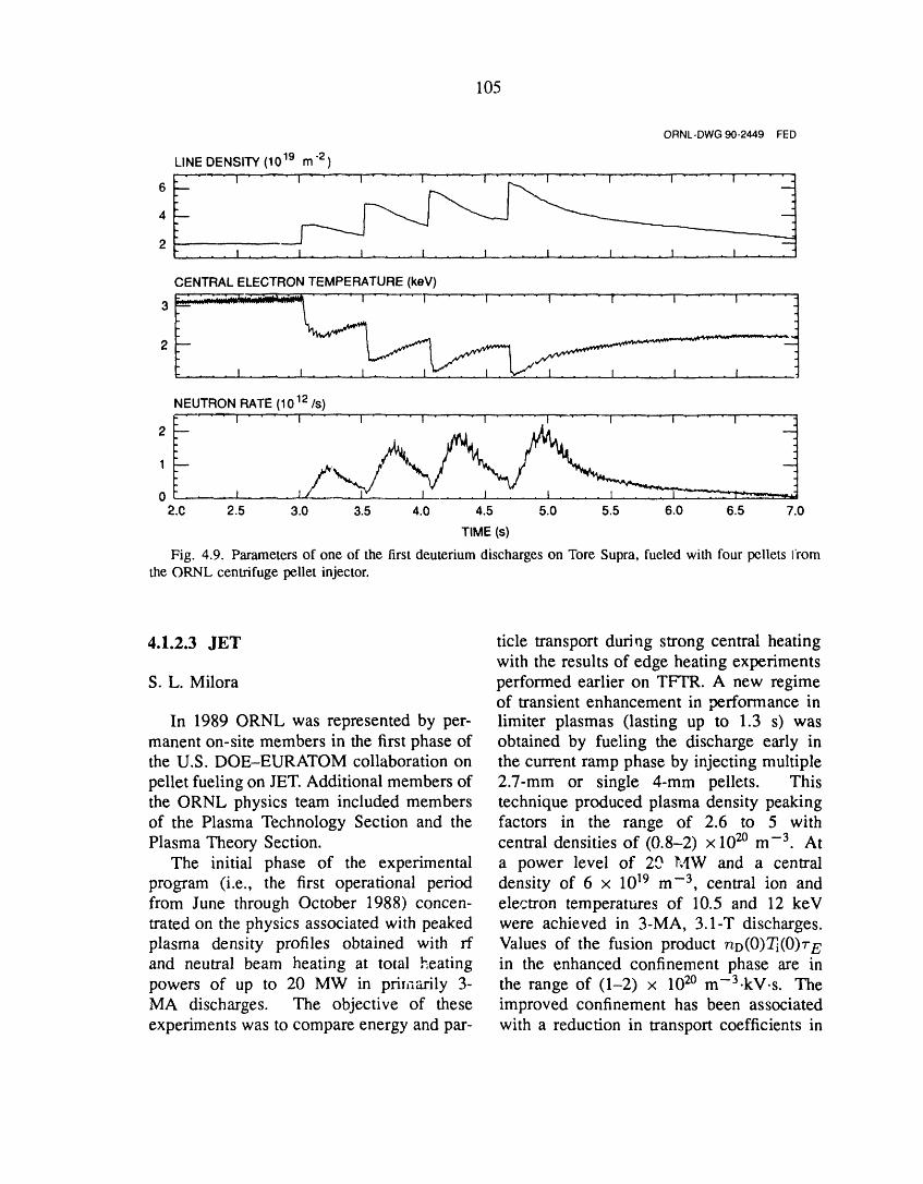
105
ORNL-DWG90-2449 FED
LINE DENSITY (1019 m "2)
6 I " I ..... " " " _ ........ ..... I .... I' I
4
2 I I I i I 1 ! ...... I ..... i
CENTRAL ELECTRON TEMPERATURE (keV)lr -- • .. L.. _==..=a__.-..'.=' • - " 'P .... - ........................
3 ::::::::::::::::::::::::::.......... " ''1 .... I I 1 t I I '1
NEUTRON RATE (1012 Is)
2_ "--I .... i .... I ..... I .... I .... I .... I .... I .... I .... I
I
0 J _S2.C 2.5 3.0 3.5 4.0 4.5 5.0 5.5 6.0 6.5 7.0
TIME (s)
Fig. 4.9. Parameters of one of the first deuterium discharges on Tore Supra, fueled with four pellets from
the ORNL centrifuge pellet injector.
4.1.2.3 JET ticle transport during strong central heatingwith the results of edge heating experiments
S. L. Milora performed earlier on TFTR. A new regimeof transient enhancement in performance in
In 1989 ORNL was represented by per- limiter plasmas (lasting up to 1.3 s) wasmanent on-site members in the first phase of obtained by fueling the discharge early inthe U.S. DOE-EURATOM collaboration on the current ramp phase by injecting multiplepellet fueling on JET. Additional members of 2.7-mm or single 4-mm pellets. Thisthe ORNL physics team included members technique produced plasma density peakingof the Plasma Technology Section and the factors in the range of 2.6 to 5 withPlasma Theory Section. central densities of (0.8-2) × 1020 m -3 At
The initial phase of the experimental a power level of 20 ]_AW and a centralprogram (i.e., the first operational period density of 6 x 10¹⁹ m -3, central ion andfrom June through October 1988) concen- electron temperatures of 10.5 and 12 keVtrated on the physics associated with peaked were achieved in 3-MA, 3.1-T discharges.plasma density profiles obtained with rf Values of the fusion product r_o(0)Ti(0)r Eand neutral beam heating at total heating in the enhanced confinement phase are inpowers of up to 20 MW in primarily 3- the range of (1-2) x 1020 m-3-kV.s. TheMA discharges. The objective of these improved confinement has been associatedexperiments was to compare energy and par- with a reduction in transport coefficients in

106
the plasma core region, where the density was increased, it was possible to maintainprofile peaking is most pronounced, relatively deep pellet penetration and central
In 1989 the JET device underwent ex- plasma densities in excess of 1 x I0 TMm -3
tensive modifications to provide a capabil- during a 4-s fueling pulse.ity for beryllium evaporation on internal One of the goals of the physics pro-vacuum vessel surfaces and to install a gram in FY 1989 was to produce andfull toroidal beryllium belt limiter. Plasma heat peaked density profiles in H-modeoperations during the abbreviated physics discharges. Although a successful techniquecampaign amounted only to about 50% of was not found to accomplish this in the shortthe 1988 level, but significant scientific time available, good results were obtainedprogress was achieved, thanks in large part in pellet-fueled H-mode discharges. Theto the ease of operation with beryllium- fusion product, nD(0)ri(0)r E, was increasedgettered and limited discharges uesulting in to 5 x 10²o m-3.kV.s for electron and ionreductions of the effective plasma charge temperatures in the 7- to 9-keV range. Thisby approximately a factor of two). Dur- represents one of the highest fusion productsing the brief run period from June to obtained on JET to date.September 1989, pellet injection operations ORNL assumed the lead role in twowere extensive as the JET program was areas on JET: pellet ablation physics anddirected toward an early evaluation of the particle transport modeling. In the former, aeffects of the beryllium modifications on unique experiment was performed in whichhigh-power discharges. Pellet injection was the pellet velocity was varied by a factorused in a total of 33 experimental sessions of three to determine the dependence onby the Limiter, H-Mode, and Beryllium pellet velocity of pellet penetration. TheAssessment Task Forces. For the most penetration was found to vary accordingpart, the experimental program emphasized to the one-third power of the velocity,fueling of high-performance discharges and which is in agreement with the originalattempts to extend the pellet-enhanced mode neutral gas shielding model (as compareddiscovered in the 1988 campaign to the with the more recent plasma and neutralH-mode and higher current regimes. The gas shielding model, which predicts a muchdensity limit was increased substantially by weaker velocity dependence). This resultthe lower oxygen and carbon content of has obvious important consequences for theberyllium limiter discharges, and for the first CIT and ITER pellet injector developmenttime it was possible to inject pellets from programs.the 6-mm gun. This was accomplished Several transport codes were used toin both 4-MA X-point and 5-MA limiter analyze particle and heat transport during thedischarges in which peak plasma densities decay phase of Ohmic and ft-heated JETof 3.4 x 10²° m -3 and 2.7 x 10²o m -3, discharges studied in the 1988 campaign.respectively, were measured immediately The PTRANS code was written by toafter pellet injection. Pellet fueling of high- interpret particle diffusivity from the six-power discharges with auxiliary heating was channel interferometer and edge H_ data.also demonstrated for the first time on JET Particle diffusivity D in the core of theduring experiments in which a series of plasma was found to depend on the density4-mm pellets was injected into a 10-MW profile shape. For peaked density profilesneutral-beam-heated limiter discharge. By (peaking factor > 2), a value of D =raising the power gradually as the density 0.08 m2/s was inferred in the core region;
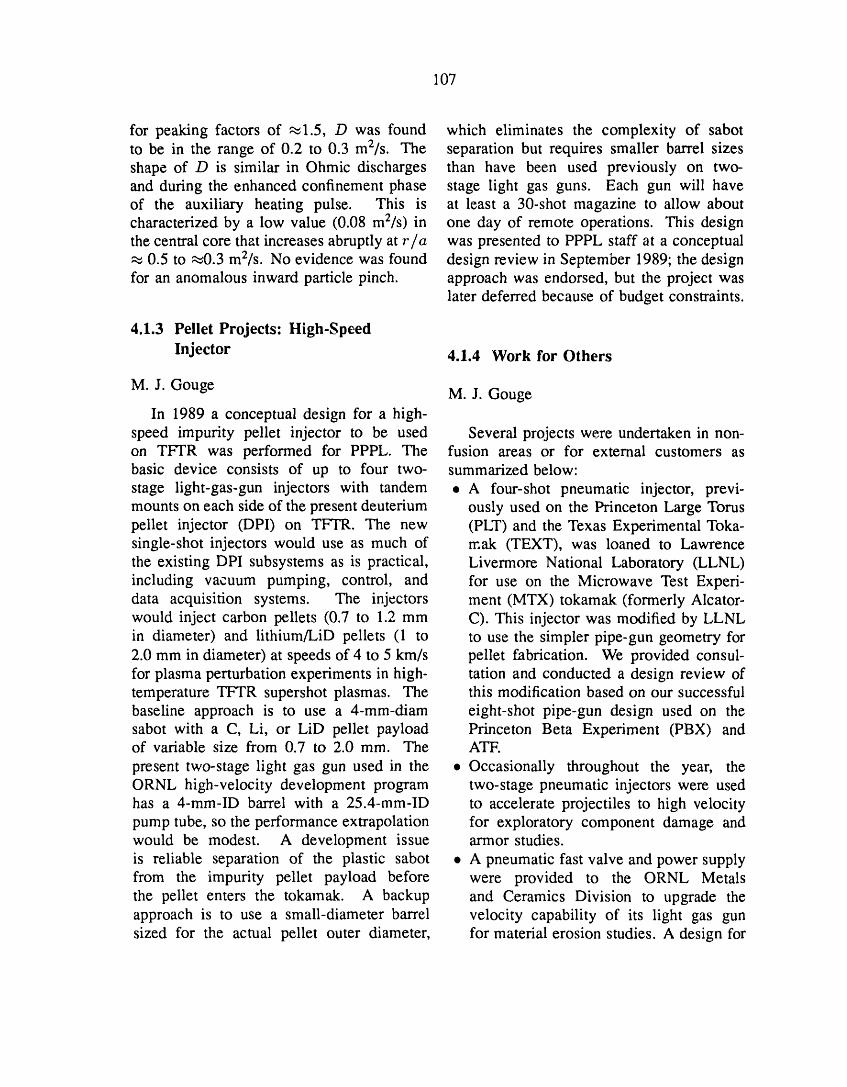
107
for peaking factors of ,_1.5, D was found which eliminates the complexity of sabotto be in the range of 0.2 to 0.3 m2/s. The separation but requires smaller barrel sizesshape of D is similar in Ohmic discharges than have been used previously on two-and during the enhanced confinement phase stage light gas guns. Each gun will haveof the auxiliary heating pulse. This is at least a 30-shot magazine to allow aboutcharacterized by a low value (0.08 m2/s) in one day of remote operations. This designthe central core that increases abruptly at ria was presented to PPPL staff at a conceptual,_ 0.5 to _0.3 m2/s. No evidence was found design review in September 1989; the designfor an anomalous inward particle pinch, approach was endorsed, but the project was
later deferred because of budget constraints.
4.1.3 Pellet Projects: High-Speed
Injector 4.1.4 Work for Others
M. J. Gouge M.J. GougeIn 1989 a conceptual design for a high-
speed impurity pellet injector to be used Several projects were undertaken in non-on TFTR was performed for PPPL. The fusion areas or for external customers asbasic device consists of up to four two- summarized below:stage light-gas-gun injectors with tandem • A four-shot pneumatic injector, previ-mounts on each side of the present deuterium ously used on the Princeton Large Toruspellet injector (DPI) on TFTR. The new (PLT) and the Texas Experimental Toka-single-shot injectors would use as much of mak (TEXT), was loaned to Lawrencethe existing DPI subsystems as is practical, Livermore National Laboratory (LLNL)including vacuum pumping, control, and for use on the Microwave Test Experi-data acquisition systems. The injectors ment (MTX) tokamak (formerly Alcator-would inject carbon pellets (0.7 to 1.2 mm C). This injector was modified by LLNLin diameter) and lithium/LiD pellets (1 to to use the simpler pipe-gun geometry for2.0 mm in diameter) at speeds of 4 to 5 km/s pellet fabrication. We provided consul-for plasma perturbation experiments in high- tation and conducted a design review oftemperature TFTR supershot plasmas. The this modification based on our successfulbaseline approach is to use a 4-mm-diam eight-shot pipe-gun design used on thesabot with a C, Li, or LiD pellet payload Princeton Beta Experiment (PBX) andof variable size from 0.7 to 2.0 mm. The ATF.
present two-stage light gas gun used in the • Occasionally throughout the year, theORNL high-velocity development program two-stage pneumatic injectors were usedhas a 4-mm-ID barrel with a 25.4-mm-ID to accelerate projectiles to high velocitypump tube, so the performance extrapolation for exploratory component damage andwould be modest. A development issue armor studies.is reliable separation of the plastic sabot • A pneumatic fast valve and power supplyfrom the impurity pellet payload before were provided to the ORNL Metalsthe pellet enters the tokamak. A backup and Ceramics Division to upgrade theapproach is to use a small-diameter barrel velocity capability of its light gas gunsized for the actual pellet outer diameter, for material erosion studies. A design for

108
a new single-shot, light gas gun capable 4.2.1 Basic Developmentof velocities in the range from 300 to500 m/s was completed. 4.2.1.1 Faraday shield studies
T. D. Shepard, E W. Baity, and4.2 RF TECHNOLOGY D.J. Hoffman
Faraday shield with nonbrazed graphiteIn the rf technology basic development armor
program, new methods of attaching graphitetiles to Faraday shield tubes were developed A new, simpler method for attachingand :ested. Computational methods of quan- graphite tiles to Faraday shield tubes wastitatively determining the effect of the Fara- investigated. Rather t_:an brazing the tilesday shield geometry on magnetic shielding, directly to the tubes, small radial holes werechange in antenna inductance, and reduction drilled through the tiles. Small metal rodsin phase velocity were developed, and the rf were inserted through the holes, tack-weldedpower dissipation distribution on the shield directly to the surface of the tube, and thenwas calculated. Experimental studies on the cut flush with the surface of the graphite.Radio Frequency Test Facility (RFTF) with The method has two principal advantages:the development antenna showed increased a b_oken tile may be easily replaced with-electron temperatures, higher plasma poten- out disassembling the antenna at all, andtials, and enhanced ion impact energies on the loose mechanical connection eliminatesthe Faraday shield during high-power ICRH thermal stresses in both the tile and the tube.operation. The primary disadvantage is that the thermal
Significant advances !n ff current drive contact between the tile and the tube istechnology were made by optimizing the poor, so this method might not be usable forgeometry of ;he multiple-strap launcher array long-pulse applications without some kind ofand by developing control circuitry and tun- modification to improve the thermal contact.ing algorithms to adjust and maintain proper A sample con._isting of a single, hollow,phasing between the straps. The folded stainless steel tube (water-cooled) with sixwaveguide (F_;G) successfully completed tiles attached was constructed. The sampleits high-power vacuum testing, was placed under vacuum and exposed to
The two-strap ICRH antenna for Tore a hydrogen ion beam with a peak powerSupra was completed, tested, and shipped density of 200 W/cm 2. The sample wasto Cadarache, France. Design work for exposed to 5000 2-s pulses at 10-s intervalsa single-strap antenna for Alcator C-Mod and then to 333 3-s pulses, also at 10-scontinued, and design work was completed intervals. The beam power absorbed by theand fabrication begun for a four-strap fast- sample was 670 W. The graphite tiles glowedwave ct_rrent drive (FWCD) phased-array brightly when struck by the beam but werelauncher for the DIII-D experiment. We not damaged in any way. The graphite didcontinued our experimental collaboration not 5racture, nor did it separate from the tube,with PPPL, injecting a combined 4.5 MW of and there was no evidence of thermal stress
ICRH power into TFTR using both the PPPL in the tube. We have not yet performed tests(Bay M) and the ORNL (Bay L) antennas, to determine the maximum pulse length that

109
this configuration can withstand, lt is clear the lowest for ali the shields we haveat this point that this configuration can be tested. While this may seem disconcerting,quite useful, at least in relatively short-pulse in any particular antenna design there isapplications, a range of allowable shield transmission
coefficients, depending on the maximumtolerable voltages and currents in the device.
Effects of Faraday shields on ICRH A particular shield design should not be ruledantenna coupling out because of low transmission coefficients
unless the overall design of the antennaIn a continuation of earlier work, 11 is considered. In fact, the actual design
the transmission characteristics of Faraday process involves a trade-off between theshields composed of elements with triangular shield's transparency and its ability to protectcross secdons were investigated. The overall the interior of the antenna against plasmaemphasis of this work is to understand how bombardment. In general, the interior of anthe shape of the currem strap and the geom- antenna is better protected by dense shieldetry of the Faraday shield affect the currents structures, and one would intuitively expectand voltages generated on an antenna for a such structures to have low magnetic fieldgiven power, in order to provide guidance transmission.for antenna design optimization. A key In a related study, 13 we investigatedissue in this study is the nonideal magnetic the interaction between variation in currenttransmission property of Faraday shields, strap shape and variation in Faraday shieldwhich reduces the amplitude of the coupled geometry, to see if the current strap and themagnetic field in front of an antenna from Faraday shield geometry could be optimizedthat in the case where no Faraday shield separately. It was found that the optimizationis present. The motivation for studying could indeed be done separately, in spite ofshields with triangular cross sections is that the fact that the current distribution on thesuch a geometry was recently proposed by current strap was affected by the FaradayPerkins 12 as a means for reducing impurity shield. This current redistribution effectgeneration by ICRH antennas and is being was explained intuitively in terms of theconsidered for use in the antennas for the diamagnetic eddy currents that flow in theAlcator C-Mod tokamak, surface of the shield elements in response
A prototype shield was constructed and to the component of the applied rf fieldattached to the same antenna that was normal to the surface of the element. These
previously used to test a large variety of diamagnetic eddy currents have previouslydifferent strap/shield configurations} 1 The been cited to explain the nonideal magnetictriangular shields were set up in a single shielding effect. 14 An important observationlayer with tips pointing inward (toward the that is particularly relevant to this study iscurrent strap), in a double layer with tips that, given a fixed "density" of the Faradayof both tiers pointing inward (the Perkins shield (in terms of the fraction of the antennaconfiguration), and also in a single layer surface area obstructed from view by thewith alternating tip direction (the Alcator shield), the eddy current effect is reducedC-Mod configuration). Variation in the by using a large number of small shieldspacing between shield elements was also elements rather than a small number of largestudied. In all cases, the measured magnetic elements. This consideration favors simplefield transmission coefficients were among tubular Faraday shield elements like those
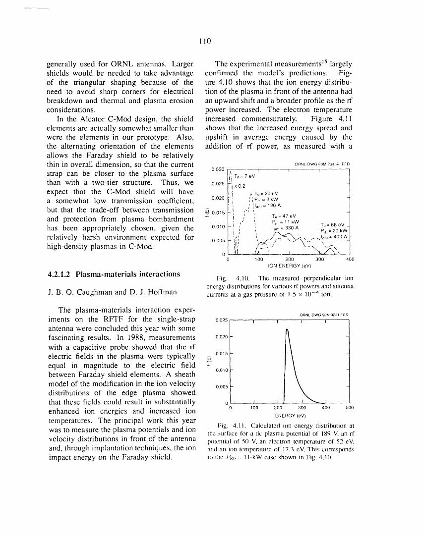
110
generally used for ORNL antennas. Larger The experimental measurements 15 largely
shields would be needed to take advantage confirmed the model's predictions. Fig-
of the triangular shaping because of the ure 4.10 shows that the ion energy distribu-
need to avoid sharp corners for electrical tion of the plasma in front of the antenna had
breakdown and thermal and plasma erosion an upward shift and a broader profile as the rf
considerations, power increased. The electron temperature
In the Alcator C-Mod design, the shield increased commensurately. Figure 4.11
elements are actually somewhat smaller than shows that the increased energy spread andwere the elements in our prototype. Also, upshift in average energy caused by the
the alternating orientation of the elements addition of rf power, as measured with a
allows the Faraday shield to be relativelythin in overall dimension, so tharthe current oRNt.Dwc_gM_._o._E__
0.030 T I Istrap can be closer to the plasma surface
i To= 7 eV
than with a two-tier structure. Thus, we 0.025rixo.2expect that the C-Mod shield will have 'i ,,To=20eVa somewhat low transmission coefficient, 0.020-, _',Pr,=2kW
I ',Ian, = 120 Abut that the trade-off between transmission _ 001s - ,"'
and protection from plasma bombardment - ,l ', To = 47eV, _, Prr = 11 kW T_= 68 eV
has been appropriately chosen, given the o.olo- " " lam=330A Pr, = 20 kW-
relatively harsh environment expected for 000s '; ,, ._/j__., _..J_,_,=400A._high-density plasmas in C-Mod. iii v ,,
00 100 200 300 400
ION ENERGY (eV)
4.2.1.2 Plasma-materials interactionsFig. 4.10. The measured perpendicular ion
energy distributions lhr various rf powers and antennaJ. B. O. Caughman and D. J. Hoffman currents at a gas pressure of 1.5 x 10⁻⁴ torr.
The plasma-materials interaction exper- ORNL-DWG90M-3221FED
iments on the RFTF for the. single-strap 0.025 ..., _ _
antenna were concluded this year with some
fascinating results. In 1988, measurements 0.020-
with a capacitive probe showed that the rf
electric fields in the plasma were typically _ o.ols-equal in magnitude to the electric field "
between Faraday shield elements. A sheath 0.010-
model of the modification in the ion velocity 000s - 4distributions of the edge plasma showed
that these fields could result in substantially o _ J -J
enhanced ion energies and increased ion o loo 200 300 400 sooENERGY (eV)
temperatures. The principal work this yearFig. 4.11. Calculated ion energy distribution at
was to measure the plasma potentials and ion the surface for a dc plasma potential of 189 V, an rfvelocity distributions in front of the antenna polenliai of 50 V, an ele,ctron temperature of 52 eV,and, through implantation techniques, the ion and an ion temperature of 17.3 eV. This correspondsimpact energy on the Faraday shield, to the I'_f:= l l-kW case shown m Fig. 4.10.
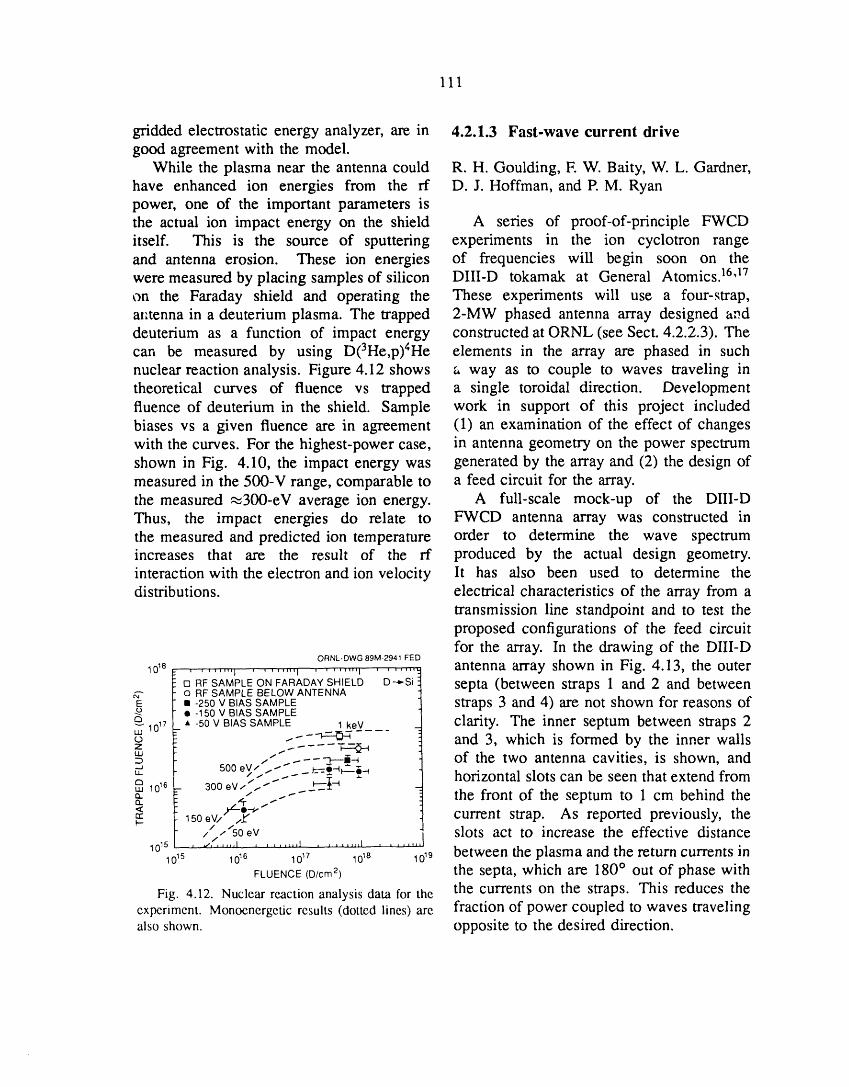
111
gridded electrostatic energy analyzer, are in 4.2.1.3 Fast-wave current drivegood agreement with the model.
While the plasma near the antenna could R.H. Goulding, E W. Baity, W. L. Gardner,have enhanced ion energies from the rf D.J. Hoffman, and P. M. Ryanpower, one of the important parameters isthe actual ion impact energy on the shield A series of proof-of-principle FWCDitself. This is the source of sputtering experiments in the ion cyclotron rangeand antenna erosion. These ion energies of frequencies will begin soon on thewere measured by placing samples of silicon DIII-D tokamak at General Atomics) 6J7on the Faraday shield and operating the These experiments will use a four-strap,ar,tenna in a deuterium plasma. The trapped 2-MW phased antenna array designed anddeuterium as a function of impact energy constructed at ORNL (see Sect. 4.2.2.3). Thecan be measured by using D(3He,p)4He elements in the array are phased in suchnuclear reaction analysis. Figure 4.12 shows a way as to couple to waves traveling intheoretical curves of fluence vs trapped a single toroidal direction. Developmentfluence of deuterium in the shield. Sample work in support of this project includedbiases vs a given fluence are in agreement (1) an examination of the effect of changeswith the curves. For the highest-power case, in antenna geometry on the power spectrumshown in Fig. 4.10, the impact energy was generated by the array and (2) the design ofmeasured in the 500-V range, comparable to a feed circuit for the array.the measured ,_300-eV average ion energy. A full-scale mock-up of the DIII-DThus, the impact energies do relate to FWCD antenna array was constructed inthe measured and predicted ion temperature order to determine the wave spectrumincreases that are the result of the rf produced by the actual design geometry.interaction with the electron and ion velocity lt has also been used to determine thedistributions, electrical characteristics of the array from a
transmission line standpoint and to test theproposed configurations of the feed circuitfor the array. In the drawing of the DIII-D
ORNL-DWG 89M-2941 FED
_0_8...... ,,,j ....... ,, ........ , ........ antenna array shown in Fig. 4.13, the outer[] RFSAMPLEONFARADAYSHIELD D-,-S_ septa (between straps 1 and 2 and betweenO RF SAMPLE BELOW ANTENNA
E •• -125050vV BIAsBIASSAMPLESAMPLE straps 3 and 4) are not shown for reasons of
Q-_1017_ *-50V BIASSAMPLE 1keV clarity. The inner septum between straps 2uJ
o --"--*='_ and 3, which is formed by the inner wallsI..IJ / t
._---r---i-_ of the two antenna cavities, is shown, and500 eV// . - _j:.=___$__" - -- horizontal slots can be seen that extend from
auj 10 _6 300 eV//,.- ,`.".`'. ---_-_'-I_- -" ....-" the front of the septum to 1 cm behind the= 150eV/ ,.z" current strap. As reported previously, theF--
// .,'/50eV slots act to increase the effective distance10_5 , ,,,,f, .... I _ _ j ,_,,,1 , ....... I .......
_o_S 10,6 10_7 1018 10_9 between the plasma and the return currents inFLUENCE(D/cm 2) the septa, which are 180 ° out of phase with
Fig. 4.12. Nuclear reactionanalysis data for the the currents on the straps. This reduces theexperiment. Monoenergetic results (dotted lines) are fraction of power coupled to waves travelingalso shown, opposite to the desired direction.
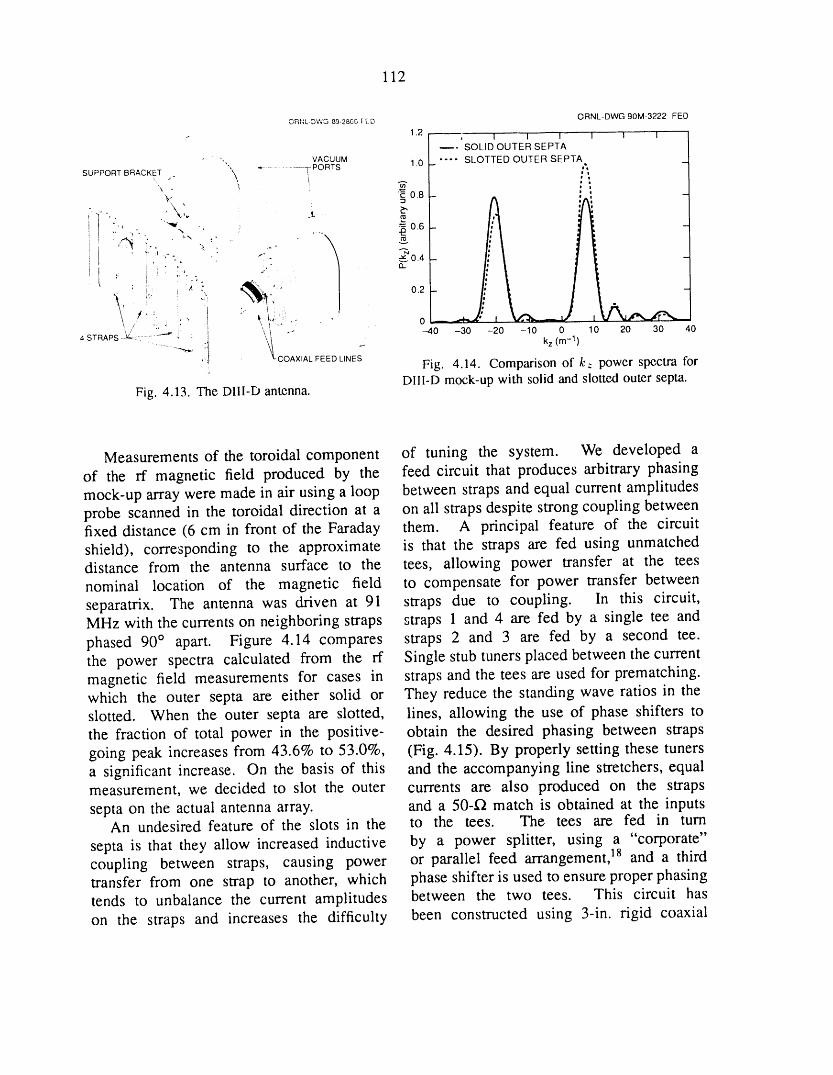
112
ORt_L-DWG Bg-2BO0rED ORNL-DWG 90M-3222 FED
_. SOLID OUTER SEPTA
• VACUUM 1.0 .... SLOTTED OUTER SEPTA"" "_........... T PORTS iSUPPORT BRACKET ;" "\, ,
x - _ "_ 0.8 -Ai
"_" - _ 0.6 - I -
• '° : "" _0.4 -
:i ' .. \_l_. ,.._.: . I " _.. o J VXw,Je,._
4 STRAPS_v.=-............._ -_,_,: :ii \!_1 - -40 -30 -20 -10 kz (m-1)0 10 20 30 40, -COAXIALFEEDLINES Fig. 4.14. Comparisonof k:. power spectra for
DlII-D mock-upwith solid and slotted outer septa.Fig. 4.13. The DIII-D antenna.
Measurements of the toroidal component of tuning the system. We developed aof the rf magnetic field produced by the feed circuit that produces arbitrary phasingmock-up array were made in air using a loop between straps and equal current amplitudesprobe scanned in the toroidal direction at a on all straps despite strong coupling betweenfixed distance (6 cm in front of the Faraday them. A principal feature of the circuitshield), corresponding to the approximate is that the straps are fed using unmatcheddistance from the antenna surface to the tees, allowing power transfer at the teesnominal location of the magnetic field to compensate for power transfer between
separatrix. The antenna was driven at 91 straps due to coupling. In this circuit,MHz with the currents on neighboring straps straps 1 and 4 are fed by a single tee and
phased 90 ° apart. Figure 4.14 compares straps 2 and 3 are fed by a second tee.the power spectra calculated from the rf Single stub tuners placed between the currentmagnetic field measurements for cases in straps and the tees are used for prematching.which the outer septa are either solid or They reduce the standing wave ratios in theslotted. When the outer septa are slotted, lines, allowing the use of phase shifters tothe fraction of total power in the positive- obtain the desired phasing between strapsgoing peak increases from 43.6% to 53.0%, (Fig. 4.15). By properly setting these tunersa significant increase. On the basis of this and the accompanying line stretchers, equalmeasurement, we decided to slot the outer currents are also produced on the straps
septa on the actual antenna array, and a 50-f_ match is obtained at the inputsAn undesired feature of the slots in the to the tees. The tees are fed in turn
septa is that they allow increased inductive by a power splitter, using a "corporate"coupling between straps, causing power or parallel feed arrangement, 18 and a thirdtransfer from one strap to another, which phase shifter is used to ensure proper phasingtends to unbalance the current amplitudes between the two tees. This circuit has
on the straps and increases the difficulty been constructed using 3-in. rigid coaxial
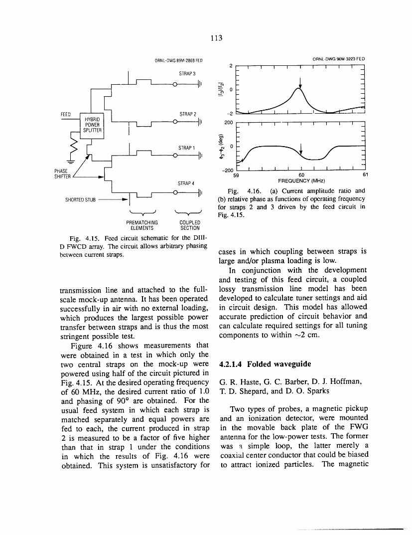
113
ORNL-DWG89M-2869FED ORNL-DWG90M-3223FED
2 I I I I I I I I I ]STRAP3
r----q o II, -/[ -
FEED | STRAP2 -2,,,-,,,--i
/ ,t__l o II, 200 I I I I I I I I I _
I m
- _
PHASE -200 I I I I I I I ! ISHIFTER 59 60 61
STRAP4 FREQUENCY (MHz)
t____z o II, Fig. 4.16. (a) Current amplitude ratio andISHORTEDSTUB I (b) relative phase as functions of operating frequency
ifor straps 2 and 3 driven by the feed circuit in
_ Fig. 4.15.PREMATCHING COUPLED
ELEMENTS SECTION
Fig. 4.15. Feed circuit schematic for the DI[l-D FWCD array. The circuit allows arbitrary phasingbetween current straps, cases in which coupling between straps is
large and/or plasma loading is low.In conjunction with the development
and testing of this feed circuit, a coupledtransmission line and attached to the full- lossy transmission line model has been
scale mock-up antenna. It has been operated developed to calculate tuner settings and aidsuccessfully in air with no external loading, in circuit design. This model has allowedwhich produces the largest possible power accurate prediction of circuit behavior andtransfer between straps and is thus the most can calculate required settings for ali tuningstringent possible test. components to within ,--,2cm.
Figure 4.16 shows measurements thatwere obtained in a test in which only thetwo central straps on the mock-up were 4.2.1.4 Folded waveguidepowered using half of the circuit pictured inFig. 4.15. At the desired operating frequency G.R. Haste, G. C. Barber, D. J. Hoffman,of 60 MHz, the desired current ratio of 1.0 T.D. Shepard, and D. O. Sparksand phasing of 90 ° are obtained. For theusual feed system in which each strap is Two types of probes, a magnetic pickupmatched separately and equal powers are and an ionization detector, were mountedfed to each, the current produced in strap in the movable back plate of the FWG2 is measured to be a factor of five higher antenna for the low-power tests. The formerthan that in strap 1 under the conditions was a simple loop, the latter merely ain which the results of Fig. 4.16 were coaxial center conductor that could be biasedobtained. This system is unsatisfactory for to attract ionized particles. The magnetic
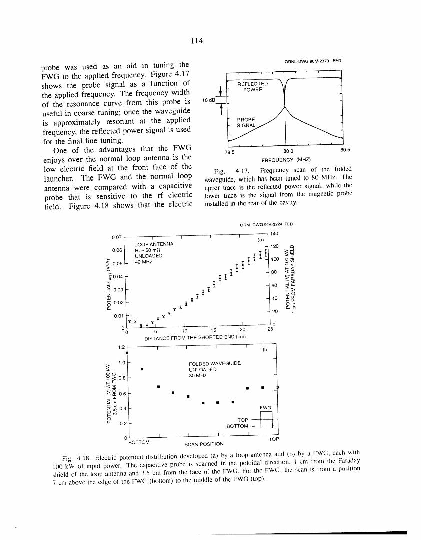
114
probe was used as an aid in tuning the ORNL-DWG90M-2373 FEDFWG to the applied frequency. Figure 4.17
shows the probe signal as a function of
the applied frequency. The frequency widthof the resonance curve from this probe is 10aB
useful in coarse tuning; once the waveguide
is approximately resonant at the applied
frequency, the reflected power signal is usedfor the final fine tuning.
One of the advantages that the FWG 79.5 80.0 805
enjoys over the normal loop antenna is the FREQUENCY (MHZ)
low electric field at the front face of the Fig. 4.17. Frequency scan of the folded
launcher. The FWG and the normal loop waveguide, which has be,cn tuned to 8(1 MHz. The
antenna were compared with a capacitive upper trace is the retlected power signal, while the
probe that is sensitive to the rf electric lower trace is the signal from the magnetic probefield. Figure 4.18 shows that the electric installed in the rear of the cavity.
ORNL-DWG 90M-3224 FED
1400.07 i i I I
I.OOP ANTENNA (a) - 120
0.06 Rr ~ 50 mQ I _ _32
UNLOADED J" 100 8 u)< 0.05 42 MHz "r I _ _ J"._ ,,...->..
- D
0.04- i i " 30 <"<u-J _ 60 <
< ooa- - °=_ZuJ -'_ -40 uarc• F-la-
0.02- - "o _-
- 20 .-0.01 - _ _ "
0 ; "i I I 1 00 5 10 15 20 25
DISTANCE FROM THE SHORTED END (cm)
1.2 I I I I rb) t
•
1.0 - FOLDED WAVEGUIDE• UNLOADED
o _, 0.8 - 80 MHz,,,..-I-'-<_ • • • p
_°°6- " _-_t
_:u_ •
-- E • • • TOP
I- uZ u_ 0.4 -uJ_
0.2 - BOTTOM --
0 a I 1 I I TOPBOTTOM SCAN POSITION
Fig. 4.18. Electric potential distribution developed (a) by a loop antenna and (b) by a FWG, each with
1()0 kW of input power. The capacitive probe is scanned in the poloidal direction, 1 cm lrom the Faradayshield of the loop antenna and 3.5 cm from the face of the FWG. For the FWG, the scan is lrom a position
7 cm above the edge of the FWG (bottom) to the middle of the FWG (top).
115
field is roughly two orders of magnitude strap; and (3) to reduce the electrostaticlower for the FWG under comparable power coupling between the current strap andconditions, the antenna. The antenna designer needs
High-power testing in the separate vac- to know the effect of a Faraday shielduum chamber, discussed in the 1988 annual design on the antenna performance: its
report, continued. Up to 13 kW continuous power transmission, its power dissipation,wave (cw) was applied to the FWG, but at and its effect on the antenna inductance andthat power level the waveguide temperature capacitance.increased rapidly, necessitating termination A three-dimensional (3-D) magnetostaticof testing after 30 min. The FWG was analysis 19 was developed to calculate themoved to RFTF to continue testing to higher electromagnetic transmission properties of
power levels. Multipacting was observed representative Faraday shield designs, par-there as well as in the separate vacuum ticularly those intended for application onchamber, but it could be overcome with the ICRF antennas for Alcator C-Mod andcontinued operation. After conditioning CIT. The analysis uses the long-wavelengtheliminated interior multipacting, visual ob- approximation to obtain a 3-D Laplaceservation of the front of the waveguide solution for the magnetic scalar potentialshowed that exterior discharges were occur- over one poloidal period of the Faraday
ring. Again, continued operation caused this shield, from which the complete magneticexternal multipacting to disappear, field distribution may be obtained. Once
Repetitive pulsing at successively higher the magnetic field distributions in the pres-power allowed operation at 140 kW for 50- ence and absence of a Faraday shield arems pulses with a duty cycle of 6% and known, the flux transmission coefficient canoperation at 200 kW for 12-ms pulses with be found, as well as any change in thea duty cycle of 1.2%. For comparison, distributed inductance of the current strap.testing of the Tore Supra loop antenna was The distributed capacitance of the strap canterminated at 500-ms pulses of 200 kW. The be found from an analogous 3-D electrostaticdifference between the two was the lack of calculation, enabling the phase velocity of
cooling for the FWG. the slow-wave structure to be determined.Figure 4.19 shows a typical geometry
for a double-tier Faraday shield mounted4.2.1.5 RF modeling in front of a current strap in a recessed
P. M. Ryan, K. E. Rothe, and cavity. Magnetic scalar potentials of Wm =#O[strap/2 and 0 are applied to the plane
J. H. Whealton of toroidal symmetry; these determine theFaraday shield rf power transmission magnitude of the strap current/strap, although
The Faraday shield is an integral part the distribution of this current around theof an ICRH antenna, and its design has strap is determined self-consistently fromfundamental consequences for the antenna the boundary conditions. All other surfacesperformance. The purpose of the Faraday (metallic walls, Faraday shield elements,shield is essentially threefold: (1) to protect conducting "plasma," and poloidal sym-the antenna from line-of-sight radiation from metry surfaces) have Neumann boundarythe plasma; (2) to exclude plasma from conditions on Win, which force the normalthe immediate environment of the current magnetic field component to vanish.

116
ORNL, DWG 90-3198 FED
CAVITYBACK WALL ,- CURRENT
// STRAP
'\ ,/
CAVITY i ..... L/2 ---/: "l
SIDE/I___WALL-__//i' ¼ _'/'_
FARADAY _ REAR TIER _ ? /1SHIELD_FRONTTIER--._ /'_ " 1
-_ ........ LPm= laol/2
h = ONE POLOIDAL PERIOD _t'm = 0
LI // _'-tJ j £<,,%
"PLASMA" SURFACE "j cD4,_..t,_L_x_
Fig. 4.19. Thc gcomcU'yuscdin lhc 3-D magnctostaticanalysis,rcprcscntinglhc currcntstrap,antcnnacavity,andFaradayshicldoveroncpoloidalpcriod.Theapplicdboundaryconditionsarccxplaincdin thc text.
The flux transmission efficiency is found to the plasma while keeping the electromag-
by comparing the flux to the plasma in netic coupling as high as possible. Thethe presence of the shield to that in the capacitance per unit length can be deter-absence of the shield for the same strap mined by the same 3-D analysis and the samecurrent. This efficiency is dependent on geometry as in Fig. 4.19, with a change in
cavity/strap geometry, since the presence the boundary conditions. The strap is set to aof the shield redistributes the strap current constant electrostatic equipotential • = _0,toward the front of the strap, which has the all other metallic surfaces are grounded (_ =effect of lowering the strap inductance and 0), and Neumann boundary conditions arecreating more magnetic flux for the same applied to all surfaces of symmetry (thestrap current. When this inductance change normal electric fidd component vanishes).is taken into account, the result is the flux The capacitance can be determined from thetransmission coefficient, which is dependent resulting electric field distribution.
only on the shield geometry. The power Table 4.3 compares calculated and mea-transmission coefficient is the square of the sured power transmission coefficients andflux transmission coefficient, since the rf the changes in inductance and capacitance
power delivered to the plasma is proportional per unit length for some representative Fara-to the square of the magnetic field, day shield geometries; these meo.surements
The presence of the shield also changes are discussed in Sect. 4.2.1.1. The calculatedthe strap capacitance per unit length, much power transmission coefficients do not takemore drastically than the change in induc- into account the power dissipated in thetance per unit length, since the shield is shield from induced eddy currents, whiledesigned to eliminate electrostatic coupling the measured power transmission does. The

117
Table 4.3. Calculated and measured power transmission coefficients
Geometry
ORNLSingle-tier Double-tier C-Mod MITtriangular "Perkins" (shield 10) C-Mod "ASDEX"
Dimensions, cmCavity
Depth 24.4 24.4 10 15 10Width 20 20 19 16 19
StrapThickness 2.5 2.5 3.5 2 3.5Width 8 8 5.5 7.2 5.5
Strap to shield 3.9 3.9 1.8 1.0 1.8
Power transmission (Tp)Measured 0.672 0.577 0.805 -- 0.588Calculated 0.775 0.697 0.840 0.667 0.687Effective 0.718 0.583 -- --
ALt/L I, %Measured -3.0 -3.7 -7.5 _ -9.6Calculated - 1.3 - 1.8 -9.0 - 15.7 -8.1
Calculated ACt/C t, % +24.5 +23.4 +109 -- --
calculated power transmission coefficient surface current distribution is essentially
is modified by this dissipation to give divergence free, the divergence of the azi-the effective transmission, by a procedure muthal current may be considered the source
discussed below, of this longitudinal current. Flux compres-sion leads to large longitudinal currents and
hence large divergences of the azimuthal
Faraday shield power dissipation current; that is, the tangential magnetic fieldon the plasma side of the shield will be lower
The magnetic field component tangential than that on the strap side of the shield.
to the Faraday shield is not compressed as lt is this mechanism that governs both the
the magnetic flux passes through the shield; flux transmission coefficient and the power
it induces surface currents on the shield dissipated in the Faraday shield.
that flow around the circumference of the Figure 4.20 shows an example of flux
tier. The normal or perpendicular component compression through a double-tier Faradayof the magnetic field is compressed as shield; Figs. 4.21 and 4.22 show the dissi-
the flux passes through the gaps of the pated power distribution along the FaradayFaraday shield; it induces currents that shield for an antenna designed for Alcator
flow longitudinally along the length of the C-Mod, both without and with compression
Faraday shield. This longitudinal current is of the normal field. Clearly, the longitudinal
highest in the narrow gaps, where the flux is currents flowing primarily along the gaps ofmost compressed and the surface magnetic the shield are responsible for most of the
fields are thus the highest. Because the total power dissipated in the Faraday shield.

118
ORNL-DWG 90-3199 FED
I ............ \ FRONT TIER I,;:',:;---:=--_Y=-:-_--------=----._:::--'---::__::i_:i:-:::-__
::::::::::::::::::::: ,./:":;::'";"?".;_h_===_"_'"-."'"':i:::---:":-::-
I i_i_i___ii_iiiiii__ REAR T,ER _ _''!:i!:i-'_!:-: !--'_---!-i
TOWARDTOWARD PLASMA CURRENT STRAP
Fig. 4.20. Demonstration of the compression of magnetic flux as it passes through one [x)loidal pericxl ofa double-tier Faraday shield. The more compressed the flux, the higher the magnetic field, leading to largersurface currents in the Faraday shield.
ORNL-DWG 90M-3225 FED ORNL-DWG 90M-3226 FED
_41T_ I ' ' I o_Boo,n_' / --8 _,,,_' I=A ,¢_ o'COMPRE_SEDo _ j ._J 2
_. 10 < uJ , cO /_ -- (Bnorm) + (Bran) _ I _ I O O _I_ -- COMPRESSEDI Ii l _ 2 2
I
_ 6 _ _ _j_ _ "STRAP'I _%._.,.__ ,_O 2 HA _. 0 ..........
0 .... DISTANCE ALONG FARADAY SHIELD (cm)0 2 4 6 8 10 12
DISTANCE ALONG FARADAY SHIELD (cm) Fig. 4.22. The tangential and normal coml)oncnts
Fig. 4.21. The tangential and normal components of the magnetic field when the Ilux compressionof the magnetic field along lhc Faraday shield at shown in Fig. 4.20 is taken into account. Thea given poloidal position. The front of the shield tangential field is uncompressed and remains un-extends from 3.1 cm to 10.8 cm (the ccntcrlinc of the changed, while the normal field is greatly enhanccAdevice), the current strap extends from 6.4 to 10.8 by compression and dominates lhc power dissipation.cm, and the side of lhc shield extends from 0.4 cmto 3.1 cm. Both components of the field arc peakednear the end of the current strap, where lhc current ITER, and CIT and of FWCD launche,'s fordistribution is peaked. DIII-D.
Multiple dielectrics
Antenna modelingThe two-dimensional analysis used for
In 1989 the antenna modeling effort modeling rf windows and feedthroughs was
supported the design and evaluation of ICRH modified to include multiple dielectrics andantennas for Tore Supra, Alcator C-Mod, arbitrary geometries. In addition tc) these
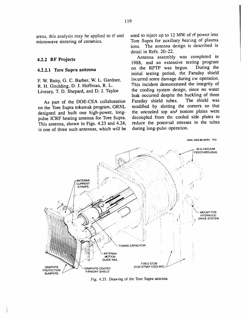
119
areas, this analysis may be applied to rf and used to inject up to 12 MW of rf power intomicrowave sintering of ceramics. Tore Supra for auxiliary heating of plasma
ions. The antenna design is described indetail in Refs. 20-22.
4.2.2 RF Projects Antenna assembly was completed in1988, and an extensive testing program
4.2.2.1 Tore Supra antenna on the RFTF was begun. During theinitial testing period, the Faraday shield
F. W. Baity, G. C. Barber, W. L. Gardner, incurred some damage during cw operation.R. H. Goulding, D. J. Hoffman, R.L. This incident demonstrated the integrity ofLivesey, T. D. Shepard, and D. J. Taylor the cooling system design, since no water
leak occurred despite the buckling of three
As part of the DOE-CEA collaboration Faraday shield tubes. The shield wason the Tore Supra tokamak program, ORNL modified by slotting the comers so thatdesigned and built one high-power, long- the uncooled top and 0ottom plates werepulse ICRF heating antenna for Tore Supra. decoupled from the. cooled side plates toThis antenna, shown in Figs. 4.23 and 4.24, reduce the potential stresses in the tubesis one of three such antennas, which will be during long-pulse operation.
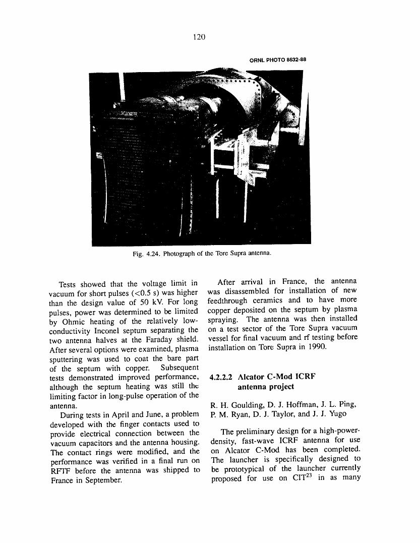
120
ORNL PHOTO 8632-88
Fig. 4.24. Photographof the ToreSupraantenna.
Tests showed that the voltage limit in After arrival in France, the antennavacuum for short pulses (<0.5 s) was higher was disassembled for installation of newthan the design value of 50 kV. For long feedthrough ceramics and to have morepulses, power was determined to be limited copper deposited on the septum by plasmaby Ohmic heating of the relatively low- spraying. The antenna was then installedconductivity Inconel septum separating the on a test sector of the Tore Supra vacuumtwo antenna halves at the Faraday shield, vessel for final vacuum and rf testing beforeAfter several options were examined, plasma installation on Tore Supra in 1990.sputtering was used to coat the bare partof the septum with copper. Subsequenttests demonstrated improved performance, 4.2.2.2 Alcator C-Mod ICRFalthough the septum heating was still the antenna projectlimiting factor in long-pulse operation of theantenna. R.H. Goulding, D. J. Hoffman, J. L. Ping,
During tests in April and June, a problem P.M. Ryan, D. J. Taylor, and J. J. Yugodeveloped with the finger contacts used toprovide electrical connection between the The preliminary design for a high-power-vacuum capacitors and the antenna housing, density, fast-wave ICRF antenna for useThe contact rings were modified, and the on Alcator C-Mod has been completed.performance was verified in a final run on The launcher is specifically designed toRFTF before the antenna was shipped to be prototypical of the launcher currently
France in September. proposed for use on CIT 23 in as many
121
aspects as possible, and it incorporates the loop feed point. This system canmany features of general interest for next- handle power levels up to 2 MW/strap, whilegeneration tokamaks. The antenna is a being compact enough so that the entiresingle-strap, end-fed configuration with the matching system can fit within the CIT shieldstrap grounded at the center, lt is designed wall, eliminating spurious resonances andto operate at power levels up to 2 MW, for power handling difficulties caused by longpulse lengths up to 1 s, at a frequency of unmatched transmission line runs. lt also80 MHz. lt fits entirely within a 20- by 68- allows tuning in two to three frequencycm port and is radially movable over a 15-cm bands without modifying the physical layoutrange, of the system. 23
Several notable features of the design A side view of the launcher, installedmake it well suited to application in next- in the Alcator C-Mod vacuum vessel, isgeneration tokamaks, lt features a disruption shown in Fig. 4.25. The primary vacuumsupport system able to withstand loads feedthroughs and capacitive tuning elementsgenerated by a 3-MA, 3-ms disruption at 9 T, are evident in the figure. A secondarywhile allowing considerable thermal expan- vacuum feedthrough allows the entire ex-sion of the antenna box relative to the port in ternal tuning loop to be run either underwhich it is located or, conversely, contraction pressure or in vacuum in order to maximizeof the port with respect to the antenna power handling. A top view is shown inbox. The design of the disruption support Fig. 4.26. lt can be seen that the endsstructure allows installation or removal of of the Faraday shield elements are bent bythe entire launcher, including supports, from 90 ° before they enter the Faraday shieldoutside the port, greatly simplifying remote frame in order to reduce thermal stresses.maintenance. These bends also form radiating side slots
The Faraday shield elements, which are that increase the coupling of power to thecylindrical Inconel rods coated with titanium plasma. The antenna is cooled by radiationcarbide, are designed to have very low and conduction to the backplane, which isprimary thermal stresses, facilitating the cooled using either water or gas. Thishandling of high power densities. In the system is practical because of the low dutyCIT Faraday shield, these solid Inconel rods cycle, with 20 min between pulses. At thecan be replaced by tubes, allowing direct 2-MW power level, the average rf powerliquid cooling of shield elements without flux through the shield is _1600 W/cm 2.changing the electrical characteristics of the Preliminary calculations indicate that theshield design, maximum temperature reached by shield
Ceramic feedthroughs are located outside tubes in this case is 620°C. 25the vacuum vessel, where exposure to Continued design work on this launcherionizing radiation, which may enhance rf has been suspended owing to budget con-losses and seriously degrade the feedthrough straints. However, the novel features inlife expectancy, 24 can be limited. There this design, including the low thermal stress,are no ceramic supports between the current the bent-tube Faraday shield, and the high-strap and these feedthroughs, performance rf feed and matching system,
The antenna is tuned and matched using will very likely be incorporated into lateran external resonant loop that employs loop antenna designs by the rf developmentintegral capacitors to achieve a match at group.

lib.. L
122
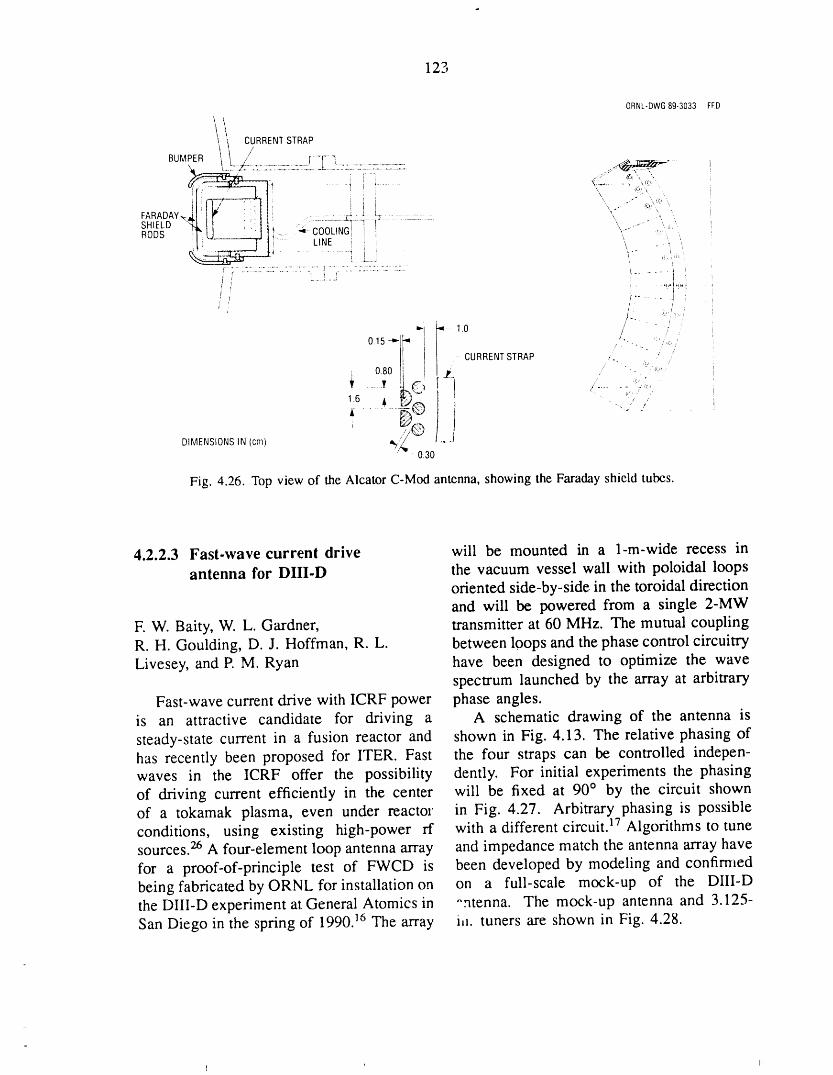
123
ORNL-DWG89-3033 FFD
!,!1_ CURRENT STRAP
BUMPER I _, // _ !'-q
' T _ fr,
( ; - ............ t i , .... , ,,;, .
FARADAY,_.JII I" • , III .-- - " z a __ z5........ _:.:_ "
_H ! _[ :i I I .......... ] ] -- --' .............. " " " .....
SHIELD ., I 'RODS _-- "-- COOLINGI
',[',-- [ Ii " LINE i !
fr , _ , -/ t....... . ......_....!, t r ....
ols-,,-fl.*" #-1.o '- ..! CURRENT STRAP ..., o8o__i - "
' ko- ) ,..........DIMENSIONS IN (cm) %,',_
0.30
Fig. 4.26. Top view of the Alcator C-Mod antenna, showing the Faraday shield tubes.
4.2.2.3 Fast-wave current drive will be mounted in a 1-m-wide recess inantenna for DIII-D the vacuum vessel wall with poloidal loops
oriented side-by-side in the toroidal directionand will be powered from a single 2-MW
F. W. Baity, W. L. Gardner, transmitter at 60 MHz. The mutual couplingR. H. Goulding, D. J. Hoffman, R.L. between loops and the phase control circuitryLivesey, and P. M. Ryan have been designed to optimize the wave
spectrum launched by the array at arbitraryFast-wave current drive with ICRF power phase angles.
is an attractive candidate for driving a A schematic drawing of the antenna is
steady-state current in a fusion reactor and shown in Fig. 4.13. The relative phasing ofhas recently been proposed for ITER. Fast the four straps can be controlled indepen-waves in the ICRF offer the possibility dently. For initial experiments the phasingof driving current efficiently in the center will be fixed at 90 ° by the circuit shownof a tokamak plasma, even under reactor in Fig. 4.27. Arbitrary phasing is possibleconditions, using existing high-power rf with a different circuit. _7Algorithms to tunesources. 26 A four-element loop antenna array and impedance match the antenna array havefor a proof-of-principle test of FWCD is been developed by modeling and confirmedbeing fabricated by ORNL for installation on on a full-scale mock-up of the DIII-Dthe DIII-D experiment at General Atomics in -ntenna. The mock-up antenna and 3.125-San Diego in the spring of 1990.16 The array i,_. tuners are shown in Fig. 4.28.
I II

124
ORNLDWGg0M3227_E_ 4.2.2.4 CIT antennaFIXED 90 _'PHASING BETWEEN STRAPS
D. W. Swain, £. W. Baity, R. H. Goulding,PHASESHIFTER ..... oSTRAP 1 11_ D.J. Hoffman, P. M. Ryan, and J. J. Yugo
_ Responsibility for the design, fabrication,
fl _ _ smApall' installati°n' and testing °f the lCRH system
O r'--. I for CIT is shared by the Plasma TechnologyI.t" SmAP21t, Section and the ORNL FEDC. Activities in
support of this assignment are described inSHORTEDSTUB- S'[RAP4tl, Sect. 6.1.3 of this report.
COUPtED 4.2.3 ICRH Experiments on TFTRSECI-ION
Fig. 4.27. Feed circuit to be used for initial D.J. Hoffman and W. [,. Gardnerexperimentson DIII-D.
The TFTR rf program explored a numberof important plasma conditions, including rf
OnNLpHOTO84_6.89 heating of Ohmic, pellet-fueled, and beam-heated plasmas. A combined maximumpower of 4.5 MW from the two antennaswas launched into the tokamak, enough tobegin some serious core heating. The targetcentral densities ranged from 1 x 1013 cm -3
to 3 x 1014cm -3, with electron or ion heating
being observed in ali cases. The principalphysics results for the year were as follows:
1. Central l,cating was observed at virtuallyall densities.
2. We could run in a mode where sawteeth
were stabilized by the rf power.3. We achieved significant enhancement of
i the neutron production when pellets andrf power were combined.
'-, 4. Impurities injected from the antennasremained low for these rf power levels.
On tile technological side, the detailsof the Bay L antenna:s rf circuit wereextensively measured and confirmed thatwe had indeed been operating at veryhigh voltages. The capacitor system waschanged to use high vacuum as the high-
Fig. 4.28. The mtx:k-upantenna and 3.125-in. voltage insulating medium rather than SF6,tuners used for Dill-I)modeling. this increased the working voltage on the
125
capacitors to 60 kV, with the breakdown our collaboration with its inventor, M. Bacal.limit as yet untested. As a result of Diagnostics were developed to measure ionthis improvement, we achieved a combined temperature within the source plasma. Anal-power of 1.7 MW into the antenna's pair of yses considering numerous atomic processesstraps and 1.1 MW into a single strap (the were made to establish operating points andsecond strap was temporarily disabled by an a_rections for optimization. Experiments andarc protection circuit failure, preventing us analyses were performed to evaluate tech-from applying power to it). The antenna niques used to reduce the electron densityitself has worked in excess of the design near the extraction sheath. These techniques,voltage and current, but the power is below pioneered in the course of this three-yearthe design value of 2 MW per strap because collaboration, are now used worldwide tothe coupling is low as a result of the very improve the negative ion sources.low edge density. A volume negative ion source was
The next area of research will focus on also analyzed, and an explanation of rmsthe high-density mode, where we hope to transverse emittance of the extracted ionachieve more central heating by increasing beam was provided. The anomalously highthe combined power from both antennas to emittance at high currents was previouslya total of 6-7 MW. Generally, we hope to attributed to ion temperature in the sourceachieve this by itself.
1. increasing the plasma edge density,2. moving the antennas closer to the plasma,
and
3. increasing the antenna conditioning 4.3.1 Ion Sourcespower.
M. Bacal, J. Bruneteau, R. Leroy, R. A.Stem, P. Berlemont, and J. H. Whealton
4.3 NEUTRAL BEAMS
4.3.1.1 Enhancement of negative ionThe rf quadrupole (RFQ) concept for extraction and electron
high-energy neutral beams was further de- suppression by a magnetic fieldveloped in a collaborative effort by AccSysTechnology, Chalk River Nuclear Labora- Experiments on extracting negative andtories in Canada, JAYCOR, the University positive ions and electrons from a multicuspof Frankfurt in the Federal Republic of volume ion source were carried out. TheGermany, LANL, and ORNL. An archi- effect of a transverse magnetic field in fronttecture was produced for an ITER-relevant of the plasma electrode was evaluated forbeam line that can capitalize on the highly three extracted species when the bias of thedeveloped volume negative ion source, and plasma electrons was changed. Also, thean experimental proof-of-principle demon- effects of the discharge current and of thestration proposal was developed. The pressure were determined. The experimentsproposal features a >l-MW, 2-MEV RFQ indicate that the magnetic field enhances theion accelerator, using existing test facilities negative ion current and suppresses a greatand power supplies for economy, part of electrons from the extracted current.
Further progress in the development of An explanation based on electron behaviorthe volume negative ion source was made in in the magnetic field was proposed. 27

126
4.3.1.2 Measurement of the o_N_._wc,_oM:,_ _ tj
H- thermal energy by two-laser LASER2pholodetachment
The negative ion thermal energy was 50O/oTRANSPARENCY
systematically measured using a new two- ./ M_RROR
laser beam facility (see Sect. 4.3.1.3). The _ ._-(_LASER1dependences of the negative ion temperature _--on discharge current (at constant pressure) BAFFLE W_NDOW
and on pressure (at constant discharge I I wALL
current) were measured. The relationship _o_tbetween the negative ion temperature and the PROBE
electron temperature was established using I__ TOSCOPEthe data obtained in the center of the plasma _.] CERAM,C_+2s_at various pressures and discharge currents. " _.DC. B_AS
New results on negative ion extraction (a)and electron suppression were obtained un-
der higher transverse magnetic field con- j CHAMBERWALLditions in the scurce extraction region by _W_NDOwapplying a meth,'xl that we proposed in To CERAM,CF'RO_EM,___(_________VLE
AMPLIFIER,__,,,71_/"_ _ _ TlP ""--_N__]I--Ii (_
1986. lt was shown that with a transverse AND 6ShF
field of 60 G in front of the TO SCOPE]/_ LASERmagnetic 5O el
plasma electrode, and a suitable bias of this I_a__-: DCBIASelectrode, the electron component can bereduced to a small fraction (_20%) of the (b)extracted negative ion current. 28
4.3.1.3 Analysis of the initial stages _ , U_SERof H- evolution U
A study was conducted to establish thetheory underlying the laser photodetachment GR,D i:..technique for measuring the negative ion - _ . ....... /PE
velocity in ion sources.2e Results on H- __- I--_--ll /_"',,__LN_TRAP
new two-laser beam facility (see Fig. 4.29). ZThis facility consists of two identical laser TC)PUMP EXTRACTORoscillators, synchronized with a jitter of less (*)than 1 ns and capable of generating laser Fig. 4.29. The two-laser pholodctachment
pulses with variable delays ranging from cxperimer.t. In these experiments, ttle cylindricalprobe, which was movable along the source radius,30 ns to I0 ms. We described an apparentwas coaxial with the laser beams. (a) Top view.
effect of laser intensity, which turns out to be (b) Side view. (c) Hybrid multicusp source, pumpeddue to reflected laser light, and several data lhrough a single extraction aperture, with an area of
reduction problems, lt was shown that the o.5 cm2.
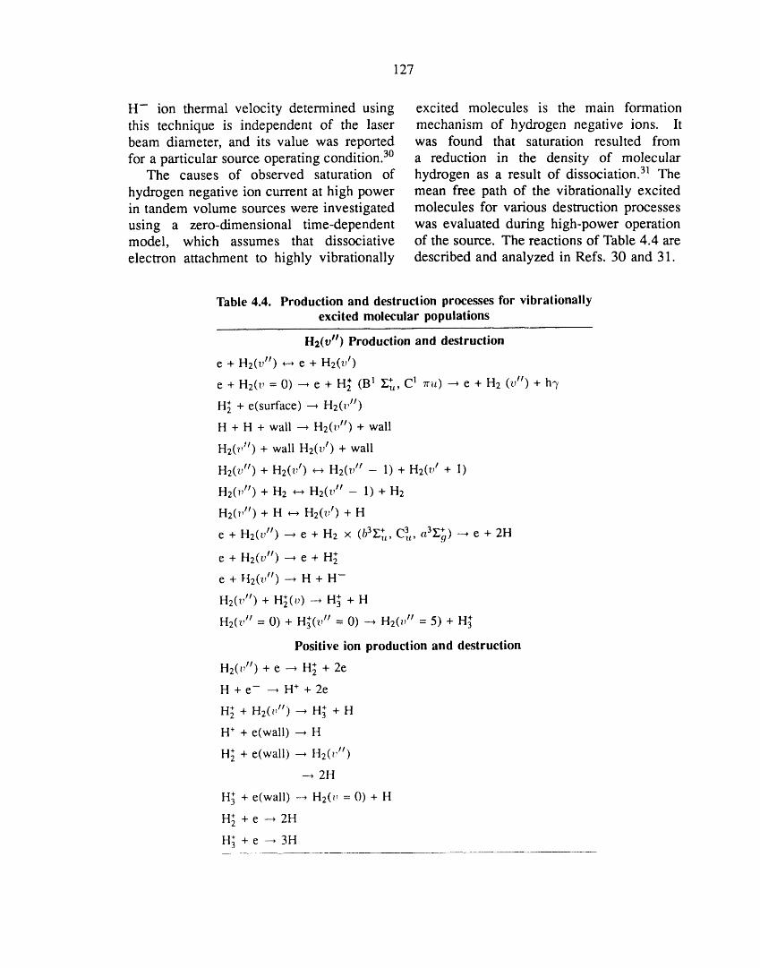
127
H- ion thermal velocity determined using excited molecules is the main formation
this technique is independent of the laser mechanism of hydrogen negative ions. ltbeam diameter, and its value was reported was found that saturation resulted from
for a particular source operating condition. 3° a reduction in the density of molecularThe causes of observed saturation of hydrogen as a result of dissociation. 31 The
hydrogen negative ion current at high power mean free path of the vibrationally excitedin tandem volume sources were investigated molecules for various destruction processes
using a zero-dimensional time-dependent was evaluated during high-power operationmodel, which assumes that dissociative of the source. The reactions of Table 4.4 are
electron attachment to highly vibrationally described and analyzed in Refs. 30 and 31.
Table 4.4. Production and destruction processes for vibrationallyexcited molecular populations
H2(v") Production and destruction
e + H2(v tl) _-* e + H2(v 1)
e + H2(v = 0) _ e + H_ (B 1 £_, C 1 Tru) _ e + H2 (v tr) + h3,
H_ + e(surface) _ H2(v')
H + H + wall --, H2('vlt) + wall
H2(v It) + wall H2(v t) + wall
H2(t/¢) + H2(v r) _ H2(v tt - 1) + H2(vt + 1)
H2(v tr) + H2 _ H2(v tt - 1) + H2
H2(v It) + H _ H2(v I) + H
e + H2(v tr) --* e + H2 × (b3y._t C3t, 3 +, aG o) _e+2H
e+H2(v") _ e+ H_
e + Ft2(v') --, H + H-
H2(v") + H_(v) _ H_ + H
H2(v I/ = 0) + H_(_," = 0) _ H2(v H = 5) + H_
Positive ion production and destruction
H2(vH)+e _ H_ +2e
H + e- _ H . + 2e
H_ +H2(_ ,H) _ H_- +H
H+ + e(wall) ---, H
H_ + e(wall) _ H2(_'iI)
--+ 2H
H._ + e(wall) --+ H2(_, = 0) + H
H_ + e -+ 2H
H._ +e--+ 3H
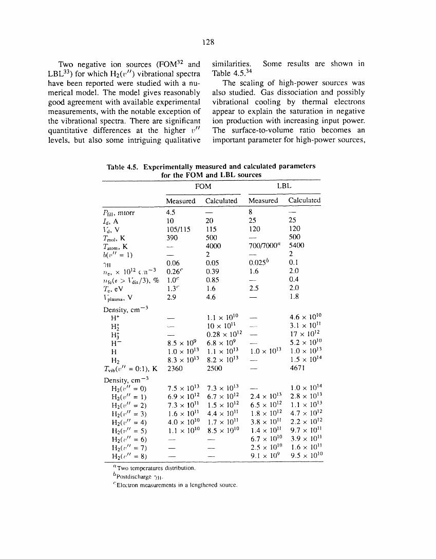
128
Two negative ion sources (FOM 32 and similarities. Some results are shown in
LBL 33) for which H2(v tr) vibrational spectra Table 4.5. 34
have been reported were studied with a nu- The scaling of high-power sources was
merical model. The model gives reasonably also studied. Gas dissociation and possibly
good agreement with available experimental vibrational cooling by thermal electronsmeasurements, with the notable exception of appear to explain the saturation in negative
the vibrational spectra. There are significant ion production with increasing input power.
quantitative differences at the higher v tt The surface-to-volume ratio becomes an
levels, but also some intriguing qualitative important parameter for high-power sources,
Table 4.5. Experimentally measured and calculated parametersfor the FOM and LBL sources
FOM LBL
Measured Calculated Measured Calculated
/)fill, mtorr 4.5 -- 8 --ld, A 10 20 25 25]_, V 105/115 115 120 120Tmol, K 390 500 -- 500Tatom, K -- 4000 700/7000 'l 5400b(t' tl = 1) -- 2 -- 2_li 0.06 0.05 0.025 b 0. Ir_e, x 1012 c;a -3 0.26 c 0.39 1.6 2.07+fe(f _> I_tis/3), % 1.0c 0.85 -- 0.4Tc, eV 1.3'" 1.6 2.5 2.0
p_asma,V 2.9 4.6 1.8--3
Density, cmH+ -- 1.1 x 101° -- 4.6 x 101°
H_ _ 10 x 1011 -- 3.1 x 10¹¹H_ -- 0.28 x 10¹² _ 17 X 1012II- 8.5 x 10⁹ 6.8 x 10⁹ -- 5.2 x 101°H 1.0x 10¹³ 1.1 x 10¹³ 1.0x 10¹³ 1.0 x 10_3
H 2 8.3 × 10¹³ 8.2 × 10¹³ _ 1.5 × 10¹⁴
Tvib(t', tt = 0:1), K 2360 2500 _ 4671
Density, cm -3H2(t 'tr = 0) 7.5 X 10¹³ 7.3 x 10¹³ -- 1.0 x 10¹⁴H2(t' tt = 1) 6.9 x 10¹² 6.7 x 10¹² 2.4 x 10¹³ 2.8 x 10¹³H2('_, tt = 2) 7.3 x 10¹¹ 1.5 x 10¹² 6.5 x 1()I_ 1.1 x 10¹³
H2(_ 't' = 3) 1.6 x 10¹¹ 4.4 x 1()11 1.8 X 10¹² 4.7 x 10¹²
H2(t, tt = 4) 4.0 x 1()1° 1.7 x 1()11 3.8 x 1()11 2.2 x 1()12H2(7,tr = 5) 1.1 x 101° 8.5 x 1@° 1.4 x 1()11 9.7 x 1()11H2(t_ ,tr = 6) -- -- 6.7 x 10_° 3.9 x 10_iH2(_,'t = 7) _ -- 2.5 x 101° 1.6 x 10¹¹H2(_' tr= 8) -- -- 9.1 x 10⁹ 9.5 x 101°
*tTwotemperaturesdistribution.bpostdischarge"Iii.':Electronmeasurementsin a lengthenedsource.
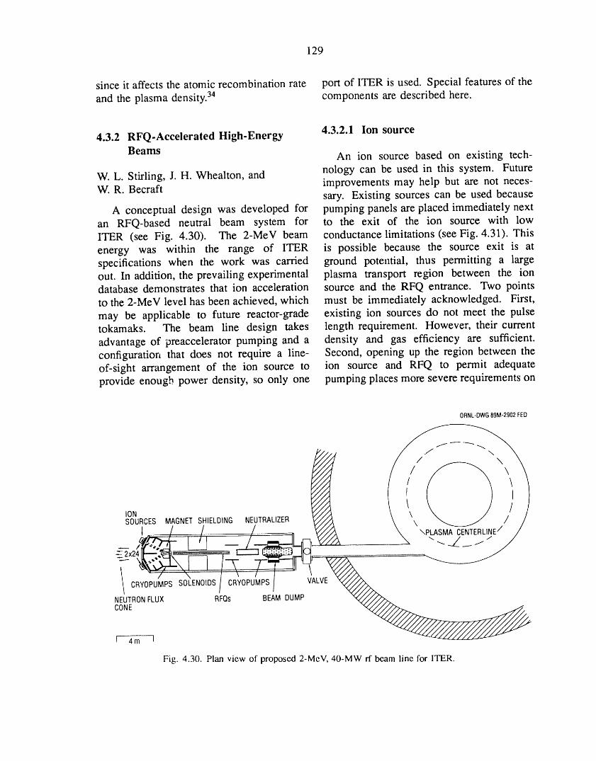
129
since it affects the atomic recombination rate port of ITER is used. Special features of the
and the plasma density. 34 components are described here.
4.3.2 RFQ-Accelerated High-Energy 4.3.2.1 Ion source
Beams An ion source based on existing tech-
W. L. Stirling, J. H. Whealton, and nology can be used in this system. FutureW. R. Becraft improvements may help but are not neces-
sary. Existing sources can be used because
A conceptual design was developed for pumping panels are placed immediately nextan RFQ-based neutral beam system for to the exit of the ion source with lowITER (see Fig. 4.30). The 2-MEV beam conductance limitations (see Fig. 4.31). Thisenergy was within the range of ITER is possible because the source exit is atspecifications when the work was carried ground potential, thus permitting a largeout. In addition, the prevailing experimental plasma transport region between the iondatabase demonstrates that ion acceleration source and the RFQ entrance. Two pointsto the 2-MEV level has been achieved, which must be immediately acknowledged. First,
may be applicable to future reactor-grade existing ion sources do not meet the pulsetokamaks. The beam line design takes length requirement. However, their current
advantage of preaccelerator pumping and a density and gas efficiency are sufficient.configuration that does not require a line- Second, opening up the region between theof-sight arrangement of the ion source to ion source and RFQ to permit adequateprovide enough power density, so only one pumping places more severe requirements on
ORNL-DWG89M-2902FED
IONSOURCES MAGNETSHIELDING NEUTRALIZER
1 / / / -_ 2×24 _--=-_, c____a _
CONE
[ 4m I
Fig. 4.30. Plan view of proposed 2-MEV, 40-MW rf beam line for ITER.
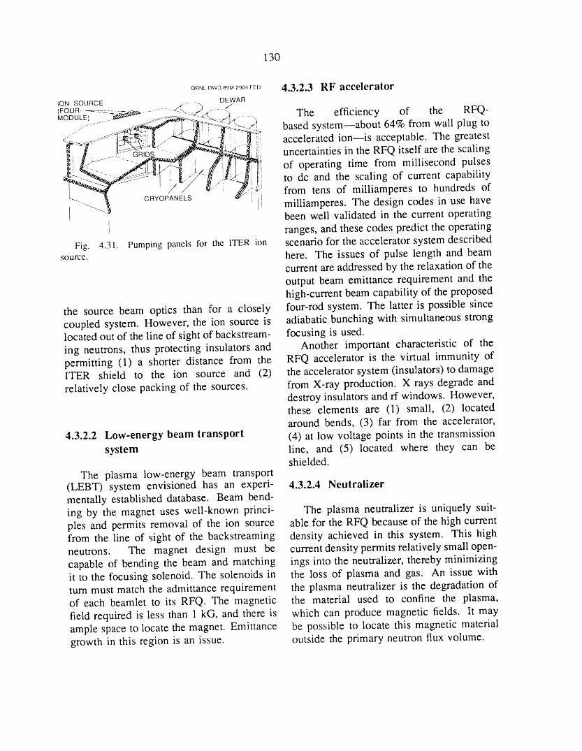
130
ORNL DWG 89M 2904 FED 4.3.2.3 RF acceleratorSOURCE ...... -..
(FOUR-'ON............ "_ ................4( _ ........D-E/WAR RFQ-MODULE) ........ _ .... <:_._,i_: -- :___.q._............. The efficiency of the
.............. __ _L_I_i ; ----i_<_:._, based system--about 64% from wall plug to
_--_f .............il_!i"!_ <-/__i_-. ......._1], accelerated ion--is acceptable. The greatest_;_l.)J- ....._,-G_ "_i uncertainties in the RFQ itself are the scaling
i '- /_l _._/ff !]_j ,, of operating time from millisecond pulses
___C 'O#/NEL_s_'_i/ , "_/,......... ,_":"/_J to dc and the scaling of current capability-"---___ 1tll from tens of milliamperes to hundreds of- Rv , I! milliamperes. The design codes in use have
""- been well validated in the current operating
I ranges, and these codes predict the operating
Fig. 4.31. Pumping panels for the ITER ion scenario for the accelerator system describedsource, here. The issues of pulse length and beam
current are addressed by the relaxation of theoutput beam emittance requirement and thehigh-current beam capability of the proposed
the source beam optics than for a closely four-rod system. The latter is possible sincecoupled system. However, the ion source is adiabatic bunching with simultaneous stronglocated out of the line of sight of backstream- focusing is used.
ing neutrons, thus protecting insulators and Another important characteristic of thepermitting (1) a shorter distance from the RFQ accelerator is the virtual immunity ofITER shield to the ion source and (2) the acceleratorsystem (insulators) todamagerelatively close packing of the sources, from X-ray production. X rays degrade and
destroy insulators and rf windows. However,these elements are (1) small, (2) locatedaround bends, (3) far from the accelerator,
4.3.2.2 Low-energy beam transport (4) at low voltage points in the transmissionsystem line, and (5) located where they can be
shielded.
The plasma low-energy beam transport(LEBT) system envisioned has an experi- 4.3.2.4 Neutralizermentally established database. Beam bend-ing by the magnet uses well-known princi- The plasma neutralizer is uniquely suit-pies and permits removal of the ion source able for the RFQ because of the high currentfrom the line of sight of the backstreaming density achieved in this system. This highneutrons. The magnet design must be current density permits relatively small open-capable of bending the beam and matching ings into the neutralizer, thereby minimizingit to the focusing solenoid. The solenoids in the loss of plasma and gas. An issue withturn must match the admittance requirement the plasma neutralizer is the degradation ofof each beamlet to its RFQ. The magnetic the material used to confine the plasma,field required is less than 1 kG, and there is which can produce magnetic fields, lt mayample space to locate the magnet. Emittance be possible to locate this magnetic materialgrowth in this region is an issue, outside the primary neutron flux volume.
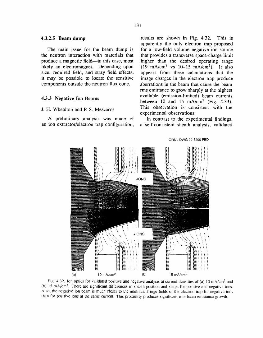
131
4.3.2.5 Beam dump results are shown in Fig. 4.32. This isapparently the only electron trap proposed
The main issue for the beam dump is for a low-field volume negative ion sourcethe neutron interaction with materials that that provides a transverse space-charge limitproduce a magnetic field--in this case, most higher than the desired operating rangelikely an electromagnet. Depending upon (19 mA/cm 2 vs 10-15 mA/cm2), lt alsosize, required field, and stray field effects, appears from these calculations that theit may be possible to locate the sensitive image charges in the electron trap producecomponents outside the neutron flux cone. aberrations in the beam that cause the beam
rms emittance to grow sharply at the highestavailable (emission-limited) beam currents
4.3.3 Negative Ion Beams between 10 and 15 mA/cm 2 (Fig. 4.33).
J. H. Whealton and P. S. Meszaros This observation is consistent with theexperimental observations.
A preliminary analysis was made of In contrast to the experimental findings,an ion extractor/electron trap configuration; a self-consistent sheath analysis, validated
ORNL-DWG 90-3200 FED
, , ,,',',, ",, , +IONS " " ;, ,, ,,',,',,",,', ",, i
N(a) 10 mAcre2 (b) 15 mA/cre2
Fig. 4.32. Ion optics for validated positive and negative analysis at current densities of (a) 10 mA/cm 2 and
(b) 15 mA/cm 2. There are significant differences in sheath position and shape for positive and negative ions.
Also, the negative ion beam is much closer to the nonlinear fringe fields of the electron trap for negative ions
than for positive ions at the same current. This proximity produces significant nns beam emittance growth.

132
ORNl. DWG 90M 3230 f [ D
16 , _ _ ---r--- the electron trap fringe fields. The striking• difference is shown in Fig. 4.32. Further
analysis and optimization of this source8 - might prove fruitful.
An example of a full 3-D calculation of4 a negative ion extraction sheath is shown in
Fig. 4.34. Including the effect of E × B_- electrons (B _ 100 G) makes the sheath_ 2- oblique and nonaxisymmetric, as shown irl7_
_ ,, Fig. 4.34(b).
1 / 4.3.4 Upgrade of the T-15
/ Long-Pulse Ion Source0.5 •
J.H. Whealton and P. S. Meszaros02s ;/ - Calculations for the long-pulse T-15 pos-
itive ion source, which represents a step_ _ L__ tow,'u'd optimization of the extractor, have50 60 70 80 90
,-(mA) been carried out.
Fig. 4.33. Effective ion temperature vs beam Theoretical results for rms divergence ascurrent, a function of current have been obtained
for a short-pulse injector and the originallong-pulse design. Other scenarios are also
only for positive ions, shows that the beam represented. The optics at the minimumemittance drops sharply in the same region divergence for the two cases are shown in(10-15 mA/cre 2) and is little affected by Figs. 4.35 and 4.36.

133
' | I _ l , , /:li
\
///
/
i //
/
li _'''-'_....i __(b) END VIEW
Fig. 4.34. Three-dimensional calculation of a negative-ion extraction sheath (a) without and (b) with theeffect of E x B electrons (It --_ 100 G). These electrons make the sheath oblique and nonaxisymmetric.

134
• m . ....... -- ........
'_______., ! _'"h ' '%'
Fig. 4.35. The optics at the minimum divergence for the short-pulse injector. At tx)ttom is the extractorgeometry. Above it is an enlargement of the extractor at the minimum divergence. In the upper right corner, theideal emittance diagram, corresponding to the right-hand side of the enlargement, shows the degree of linearity
of the optics halfway down the accelerator.
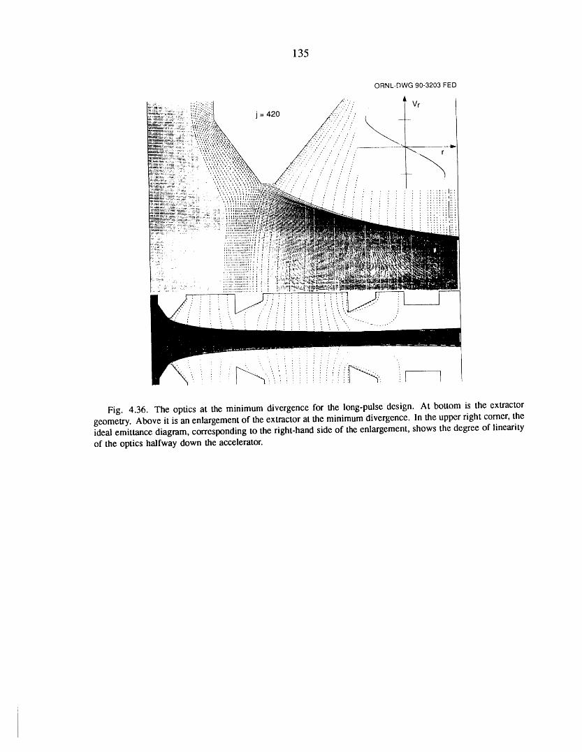
135
Fig. 4.36. The optics at the minimumdivergencefor the long-pulsedesign. At bottom is the extractorgeometry.Aboveit is an enlargementof the extractorat the minimumdivergence.In the upperrightcomer,theideal emittancediagram,correspondingto the right-handside of the enlargement,shows the degreeof linearityof the optics halfway clownthe accelerator.
136
REFERENCES 14. D. W. Faulconer, J. Appl. Phys. 54, 3810(1983).
1. C. A. Foster et al., "The ORNL/Tore Supra 15. J. B. O. Caughman, D. N. Ruzic, and D.Pellet Injector and The E-Beam Rocket Pellet Accel- J. Hoffman, "E×perimental Evidence of Increasederator," in Pellet Injection and Toroidal Confinement Electron Temperature, Plasma Potential, and lon(Proceedings of the IAEA Technical Committee Meet- Energy Near an ICRF Antenna Faraday Shield,"ing, Gut Ising, 1988), IAEA-TECDOC-534, IAEA, Fusion Eng. Des. 12, 179 (1990).Vienna, 1989. 16. M. J. Mayberry et al., "60-MHz Fast Wave
2. C. A. Foster et al., "Electron Beam Rocke, P-_.I- Current Drive Experiments for DIII-D," p. 298 in1_ Accelerator," presented at the International Pellet Radio-Frequency Power in Plasmas, R. McWilliams,Fueling Workshop, La Jolla, California, October 30- ed., AlP Conf. Proc. 190, American Institute ofNovember 3, 1985. Physics, New York, 1989.
3. C. A. Foster, C. C. Tsai, and D. E. Schechter, 17. F. W. Baity et al., "Spectral Shaping and"Electron-Beam Rocket Pellet Accelerator," presented Phase Control of a Fast-Wave Current Drive Antennaat the 36th Annual Symposium of the American Array," p. 214 in Radio-Frequency Power in Plasmas,Vacuum Society, Boston, Massachusetts, October 23- R. McWilliams, ed., AlP Conf. Proc. 190, American27, 1989. Institute of Physics, New York, 1989.
4. C. C. Tsai, C. A. Foster, and D. E. Schechter, 18. W. L. Stu_man and G. A. Thiele, Antenna"Characteristics of Electron-Beam Rocket Pellet Ac- Theory and Design, John Wiley & Sons, New York,celerator," pp. 1230-35 in Proceedings of the IEEE 1981.
13th Symposium on Fusion Engineering, ed. M.S. 19. P, M. Ryan et al., "Determination of ICRFLubell, M. B. Nestor, and S. F. Vaughan, Vol. 2, IEEE, Antenna Fields in the Vicinity of a 3-D Faraday ShieldNew York, 1990. Structure," Fusion Eng. L;?s. 12, 37 (1990).
5. S. K. Combs et al., "Develop, .-_ntt;f a Two- 20. U.S. Patent 4,755,345.
Stage Light Gas Gun to Acc_.;erate Hych'ogen Pellets 21. D. J. Hoffman et al., "The Design of High-to High Speeds for Plasma Fueling Application-?' J. Power ICRF Antennas for TFTR and Tore Supra," inVac. Sci. Technol. A 7 (3), 963-7 (1989). Applications of Radio-Frequency Power to Plasmas,
6. S. K. Combs et al., "Acceleration of Small, ed. S. Bernabei and R. W. Motley, AlP Conf. Proc.Light Projectiles (Including Hydrogen Isotopes) to 159, American Institute of Physics, New York, 1987.High Speeds Using a Two-Stage Light Gas Gun," J.
22. Fusion Energy Division Annual ProgressVac. Sci. Technol. A 8, 1814 (1990). Report for the Period Ending December 31, 1988,
7. M. J. Gouge et al., "Design Considerations ORNL-6528, Martin Marietta Energy Systems, Inc.,for Single-Stage and Two-Stage Pneumatic 7ellet
Oak Ridge National Laboratory, 1989, pp. l l 2-4.Injectors," Rev. Sci. Instrum. 60 (4), 570-5 (; .989).
8. A. Reggiori et al., J. Vac. Sci. Techna' A 6 (4), 23. R. H. Goulding et al., "ICRF Antenna Designs2556 (1983). for CIT and Alcator C-Mod," pp. 250--3 in Radio
9. K. Sonnenberg et al., "Prototype of a High Frequency Power in Plasmas, cd. R. McWilliams,Speed Pellet Launcher for JET," p. 715 in Fusion AlP Conf. Proc. 190, American Institute of Physics,Technology 1988, Vol. 1, ed. A. M. Van Ingen, New York, 1989.i_. Nijsen-Vis, and H. T. Klippel, Elsevier Science 24. S. N. Buckley and P. Agnew, "Radiation-Publishers B.V., North-Holland, Amsterdam, 1989. Induced Changes in the Dielectric Properties of
10. Ming-Lun Xue, M-2663, RisO National Lab- Insulating Ceramics at ICRH Frequencies," J. Nucl.oratory, Roskilde, Denmark, October 1987. Mater. 155--157, 361-5, 1988.
11. D. J. Hoffman et al., "Experimental Measure- 25. R. H. Goulding et al., "Design of a CITments of Ion Cyclotron Antennas' Coupling and RF Prototypical Fast-Wave ICRF Antenna for Alcator C-Characteristics," Fusion Technol. 8, 411 (I985). Mod," Bull. Am. Phys. Soc. 34, 2095 (1989).
12. F. W. Perkins, Nucl. Fusion 29,583 (1989). 26. D. A. Ehst, Fast-Wave Current Drive. Experi-13. M. Kwon ct "ai., 'Measurement of the Effects mental Status and Reactor Prospects, ANL/q:PP/TM-
of Faraday Shields on ICRH Antenna Coupling," 219, Argonne National Laboratory, Argonne, Ii1.,IEEE Trans. Plasma Sci. P,e-18, 184 (1990). March 1988.

137
27. J. Bruneteau et al., "Enhancement of Nega- under Subcontract No. 19X-91351V with Martin Ma-tive Ion Extraction and Electron Suppression by a rietta Energy Systems, Inc., for the U.S. Department
Magnetic Field/' presented at the 5th International of Energy.Symposium on the Production and Neutralization 31. M. Bacal et 'al., Volume Negative Hydrogenof Negative Ions and Beams, Brookhaven National Ion Beam Production: Tenth Quarterly TechnicalLaboratory, October 30-November 3, 1989. Report, October 1-December 31, 1988, Laboratoire
28. M. Bacal et al., Volume Negative Hydrogen de Physique des Milieux Ionis6s, Ecole Polytech-Ion Beam Production: Thirteenth Quarterly Technical nique, under Subcontract No. 19X-91351V with
Report, July l-September 30, 1989, Laboratoire de Martin Marietta Energy Systems, Inc., for the U.S.Physique des Milieux Ionis6s, Ecole Polytechnique, Department of Energy.under SubcontractNo. 19X-91351Vwith Martin Ma- 32. P. J. Eenshuistra, A. W. Kleyn, and J.
rietta Energy Systems, Inc., for the U.S. Deparlment H. Hopman, Europhys. Lett. 8, 423 (1989); P. J.of Energy. Eenshuistra et al., Phys. Rev. A40, 3613 (1980).
29. M. Bacal and R. A. Stern, Volume Negative 33. G. C. Stutzin et al., Chem. Phys. Lett. 155,
Hydrogen Ion Beam Production: Twelvth Quarterly 475 (1989); G. C. Stu_in et al., Rev. Sci. lnstrum. 61Technical Report, April 1-June 30, 1989, Laboratoire (1), 619-21 (1990).de Physique des Milieux lonis6s, Ecole Polytech- 34. M. Bacal, P. Berlemont, and D. A. Skinner,nique, under Subcontract No. 19X-91351V with Volume Negative ttydrogen Ion Beam Production:Martin Marietta Energy Systems, Inc., for the U.S. Ninth Quarterly Technical Report, July 1-September
Department of Energy. 30, 1988, Laboratoire de Physique des Milieux30. M. Bacal et "al., Volume Negative tlydrogen lonis6s, Ecole Polytechnique, under Subcontract No.
Ion Beam Production: Eleventh Quarterly Technical 19X-91351V with Martin Marietta Energy Systems,
Report, January 1-March 31, 1989, Laboratoire de Inc., for the U.S. Department of Energy.Physique des Milieux lonis6s, Ecole Polytechnique,

5SUPERCONDUCTING MAGNET
DEVELOPMENT

M. S. Lubell, Magnetics and Superconductivity Section Head
L. DresnerW. A. Fietz 1
P. N. Haubenreich z
W. J. KenneyJ. W. Lue
J. S. Luton
S. W. SchwenterlyS. F. Vaughan 3
1. On assignment to the Office of Fusion Energy, U.S. Departmentof Energy, Washington.2. On assignment to the InternationalAtomic Energy, Agency,Vienna.3. Sectionsecretary.
i40
5. SUPERCONDUCTING MAGNETDEVELOPMENT
SUMMARY OF ACTIVITIES
The Magnetics and Superconductivity Section carries out experimental and theoreticalresearch in applied superconductivity. Activities this year focused on new applications fortechnology developed in support of fusion research and on mathematical techniques fordesigning and understanding superconducting magnets. Analysis of the extensive data fromthe international Large Coil Task continued.
141
142
5.1 EXPERIMENTAL WORK single triplex of 1.25-mm-diam NbTi wiresin a circular 3.9-mm-diam conduit. _ The total
5.1.1 Superconducting Magnet Design sample length is 50 m, wound in a bifilarcoil. Heaters of several different lengths are
It is now possible to design supercon- provided, both at the center and at one endducting magnets that use forced-flow cooling of the sample, and the heated end can beof cable-in-conduit NbTi superconductor and closed off to simulate a normal zone centeredoperate at high fields (8-12 T) and high in a 100-m conductor. Heaters are mountedcurrent densities (5-15 kA/cm 2) in a stable on the triplex wires and on the outside ofmanner (margins of 50-300 mJ/cm3). High the conduit to ascertain the effect of heatingcurrent density leads to smaller, lighter, the wires directly vs heating the helium.and thus less expensive coils. Forced- The sample coil is mounted in vacuumflow cooling provides confined helium, full so that heat flow occurs only along tileconductor insulation, and a rigid winding conductor. The propagation rates, pressurepack for better load distribution. The cable- and temperature profiles, and expulsion ttowin-conduit conductor configuration ensures rates vs time are being measured for initiala high stability margin for the magnet, normal zones of various lengths. TheThe NbTi superconductor has reached a results will be compared with theoreticalgood engineering material standard, and calculations.its strain-insensitive critical parameters areparticularly well suited to complicated coilwindings like those needed for stellarators.
A procedure for optimizing the design of 5.1.3 Magnetic Heat Pump Testsuch a conductor, based on the theoreticaland experimental work at ORNL over the A magnetic heat pump test was performedpast decade, has been developed. The with a gadolinium sample in a water column
inserted into an 18-in. dewar containing thedatabase for such coils is still very sparse,and a few issues remain to be addressed. NbTi, forced-flow-cooled, cable-in-conduit
coil built at ORNL 10 years ago. TheThese include the amount of cyclic loadingthat NbTi cable can withstand and normal- coil was refurbished and installed in the
zone propagation in cable-in-conduit con- dewar, which was modified to make a 3-in.ductor. Work is in progress to address these room-temperature access bore for the testissues and to incorporate the results into sample. The magnet was cooled by two-designing coils for fusion experiments and phase helium at 1 to 1.4 atm. Although thefor other applications, magnet was originally designed and built for
dc operation, it was successfully charged to7.5 T (at the winding) in 18 s. Cyclic runs
5.1.2 Quench Propagation, Pressure in triangular waveform were performed toRise, and Thermal Expulsion of 5.1 T in a 20-s period and to 6.8 T in aHelium from a Cable-in-Conduit, 30-s period for more than 15 min each. TheForced-Flow Superconductor ramp rates in ali tests were limited by the
power supply voltage. Use of the overheadThe quench behavior of a forced-flow, crane to raise and lower the water column
cable-in-conduit superconductor is being was not successful in establishing a desirableinvestigated on a sample consisting of a temperature gradient from the temperature
143
swing in the gadolinium generated by the Unintentional shorting of the plates causedfield sweep, large eddy currents when the coil was
rapidly discharged, extending the coolingtime needed between tests. However, the
5.1.4 Large Coil Task shorted plates absorbed some of the coilenergy and thus reduced the possible hot-
The Large Coil Task (LCT) was a spot temperature in the conductor. Themultinational cooperative research and de- coil withstood high voltages (maximum ofvelopment program, carried out under the 2.44 kV), despite the need to insulate everyauspices of the International Energy Agency, turn of the conductor from the groundto demonstrate the feasibility of building and potential because of the plate scheme. Notoperating large superconducting coils in a potting the conductor to the plates resultedtoroidal array. The goals of the LCT were in local stick-slip under mechanical loadsto obtain exp0erimental data, to demonstrate and poor thermal contact between conductorreliable operation of large superconducting and plates. The results demonstrated thecoils, and to prove design principles and feasibility of manufacturing a long (4.7-km),fabrication techniques under consideration helium-tight, stainless steel conduit for afor the toroidal magnets of thermonuclear force-cooled magnet, even without a her-reactors, tactic case. Auxiliary cooling channels to
Six coils, three contributed by the United remove heat (e.g., nuclear heating) from theStates and one each from Japan, Switzerland, conductor would be desirable, and separateand the European Community, were tested cooling for the structure appears prudent.in the International Fusion SuperconductingMagnet Test Facility (IFSMTF) at ORNL.The test facility was placed under vac-uum in October 1985 and operated until 5.2 THEORETICAL RESEARCHSeptember 1987. The main test resultsare summarized in Ref. 2; analysis of the 5.2.1 The Gorter-Mellink Pulsed-Sourceextensive data acquired during the 22 months Problem in Cylindrical andof operation continues. The performance of Spherical Geometrythe refrigerator compressors was describedin discussions of compressor experience The diffusion of heat in turbulent su-during U.S.-U.S.S.R. exchange 1.8 during perfluid He-II is described by the nonlinearNovember 1989. equation Ct = xT.(xTC)1/3, sometimes called
One of the six coils tested as part the Gorter-Mellink diffusion equation. Theof the LCT was built by Westinghouse pulsed-source problem was solved earlier inElectric Corporation; it was the only coil plane geometry 3 and has now been solved forto use Nb3Sn conductor, which was in cylindrical and spherical geometry. 4 After aa loose cable form rather than a rigid pulse, the central temperature falls with timemonolith, and it used aluminum alloy plates t faster than (to- t)9/2 in spherical geometryto provide a distributed coil structure rather and faster than exp(-2/3t) in cylindricalthan a lumped case structure. Analysis of geometry (with to and /3 constants thatthe LCT data showed that the distributed depend on the initial heat distribution). This
structure of the Westinghouse coil was useful contrasts with its t -3/2 behavior in planein eliminating large stress concentrations, geometry.

144
5.2.2 Propagation of Normal Zones REFERENCES
of Finite Size in Large, CompositeSuperconductors 1. S. w. Schwenterly, J. W. Lue, and L. Dresner,
"Quench Propagation, Pressure Rise, and Thcr-
Very large composite superconductors of mal Expulsion of Helium from a Cable-in-ConduitForced-Flow Super conductor," presented at CEC89:the type proposed for use in energy storage The 1989 Cryogenic Engineering Conference, Losmagnets 5 can sustain normal zones of finite Angeles, July 24-28, 1989 [to be published in Adv.size that travel at a uniform velocity along Cryog. Eng. 35 (1990)].
the conductor. A simple analytical model has 2. D. S. Beard ct al., eds., "The IEA Large
been developed 6 to determine the conditions CoilTask: Development of Superconducting Toroidalunder which such zones can exist and the Field Magnets for FusionPower," Fusion Eng. Des.7, 1-232 (1988).size and velocity of these zones. The 3. L. Dresner,"Transient Heat Transfer in Super-
transport current has a threshold value below fluid Helium," Adv. Cryog. Eng. 29,323-33 (1984).which finite normal zones cannot exist, and 4. L. Dresner, "The Gorter-Mellink Pulsed-Source
the propagation velocity corresponding to Problem in Cylindrical and Spherical Geometry," pre-
this current, though not zero, is the smallest sented at CEC89: The 1989 Cryogenic Engineering
possible. The results of the model show Conference, Los Angeles, July 2428, 1989 [to bepublished in Adv. Cryog. Eng. 35 (1990)].that in a typical energy storage magnet, 5. J. Waynert, Y. Eyssa, and X. Huang, "Thewith 1000 km of conductor, a finite normal Transient Stability of Large Scale Superconductors
zone could take 3.17 d to traverse the entire Cooled in Superfluid Helium," Adv. Cryog. Eng. 33,
winding, releasing a steady power of more 187-94 (1988).than 8.22 kW that would have to be removed. 6. L. Dresner, "Propagation of Normal Zones in
Finite Size in Large, Composite Superconductors,"
Thus, conductors in energy storage magnets presented at MTll: The llth International Conferenceshould be designed to operate in the stable on Magnet Technology, Tsukuba, Japan, August
region that does not permit the propagation 28-September 1, 1989 (to be published in theof normal zones of finite size. proceedings).

6ADVANCED SYSTEMS PROGRAM
T. E. Shannon 1
M. K. Bullock 2 D.J. Lousteau 1
T. W. Burgess 3 T.J. McManamy 1L. S. Dale 4 J.F. Monday 1
F. C. Davis 1 G.H. Neilson 11
C. A. Flanagan 5 B.E. Nelson 1
p. j. Fogartyl Y-K. M. Peng
J. D. Galambos 6 R.L. Reid 1
I. Gomes 7 R.O. Sayer 6
L. D. Gomes 7 D.J. Strickler 6
P. L. Goranson 1 D.W. Swain
M. J. Gouge s S.L. Thomson I2
J. T. Hogan 9 N.A. Uckanll
H. W. Jernigan J.C. Whitson 6G. H. Jones 1 J" J" Yug°13
D. P. Kuban I K.L. Zell 4
V. D. Lee _°
1. Engineering Division, Martin Marietta Energy Systems, Inc.2. AG & Associates.3. Robotics and Process Systems Division.4. Section secretary.5. Westinghouse Electric Corporation, Madison, Pa.6. Computing and Telecommunications Division, Martin Marietta Energy Systems, Inc.7. The University of Tennessee, Knoxville.8. Plasma Technology Section.9. Plasma Theory Section.
10. McDonnell Douglas Astronautics Corporation, St. Louis.11. Toroidal Confinement Section.12. Bechtel National, Inc., San Francisco.13. TRW, Inc., Redondo Beach, Calif.
146
6. ADVANCED SYSTEMS PROGRAM
SUMMARY OF ACTIVITIES
The Advanced Systems Program has been organized as a focal point for design studies offuture fusion experiments. The Fusion Engineering Design Center is the major engineeringresource for the program. This group of 20 to 25 persons consists of both ORNL and outsideindustrial participants. Since its formation in 1979, the Design Center has played a leadingrole in the design of next-generation devices. In 1989, the Advanced Systems Programcomprised two principal activities, the Compact Ignition Tokamak (CIT) project and theInternational Thermonuclear Experimental Reactor (ITER) project.
The CIT project, led by Princeton Plasma Physics Laboratory, was begun in 1985. Aspart of the national CIT design team, ORNL has made major contributions to this project. In1989, these contributions included lead responsibility for design integration and for six WorkBreakdown Structure (WBS) elements: ex-vessel remote maintenance, vacuam systems, ioncyclotron resonance heating, shielding, external structure, and fueling.
The ITER design study continued from its 1988 beginning as an outgrowth of a U.S.-U.S.S.R. summit agreement that was formalized by the International Atomic Energy Agency(IAEA). The purpose of this activity is to cooperate it, the international conceptual designof a fusion test reactor under the auspices of the IAEA. The ITER concept includesreactor-relevant features such as superconducting magnets, steady-state or extended-burncapability, and testing of nuclear components and materials. In the United States, theprogram is organized as a national study under the direction of Lawrence Livermore NationalLaboratory. In 1989, the program involved international participation in a program forresearch, development, and conceptual design that will continue through 1990. The majorparticipants in the program are the United States, the U.S.S.R., Japan, and the EuropeanCommunity.
The Design Center led the U.S. effort in configuration development, design integration,mechanical design of the plasma-facing components and blankets, facilities, reliability andavailability analysis, remote maintenance, design and analysis of heating and current drive,and cost estimating. Support was provided in the design of poloidal field systems and instructural analysis. Several members of the Design Center staff participated in the five-month-long Joint Work Session in Garching, Federal Republic of Germany, and in numerousspecialists' meetings.
The Design Center also led the national effort to develop and maintain the tokamak systemscode TETRA. The Design Center was responsible for performance of numerous systems andtrade studies required to support the evolution of the ITER design concept and providedsupport in poloidal plasma magnetics, plasma control analysis, and disruption analysis.
147
148
A three-year tokamak reactor study, the Advanced Reactor Innovation and EvaluationStudy (ARIES) program, was initiated in January 1988. The Design Center played a key rolein several aspects of this project, including the ARIES equilibrium and stability evaluationand the poloidal field system design. Work to evaluate the potential of pellet fueling and ofrf heating and current drive in ARIES was initiated at the end of the year.
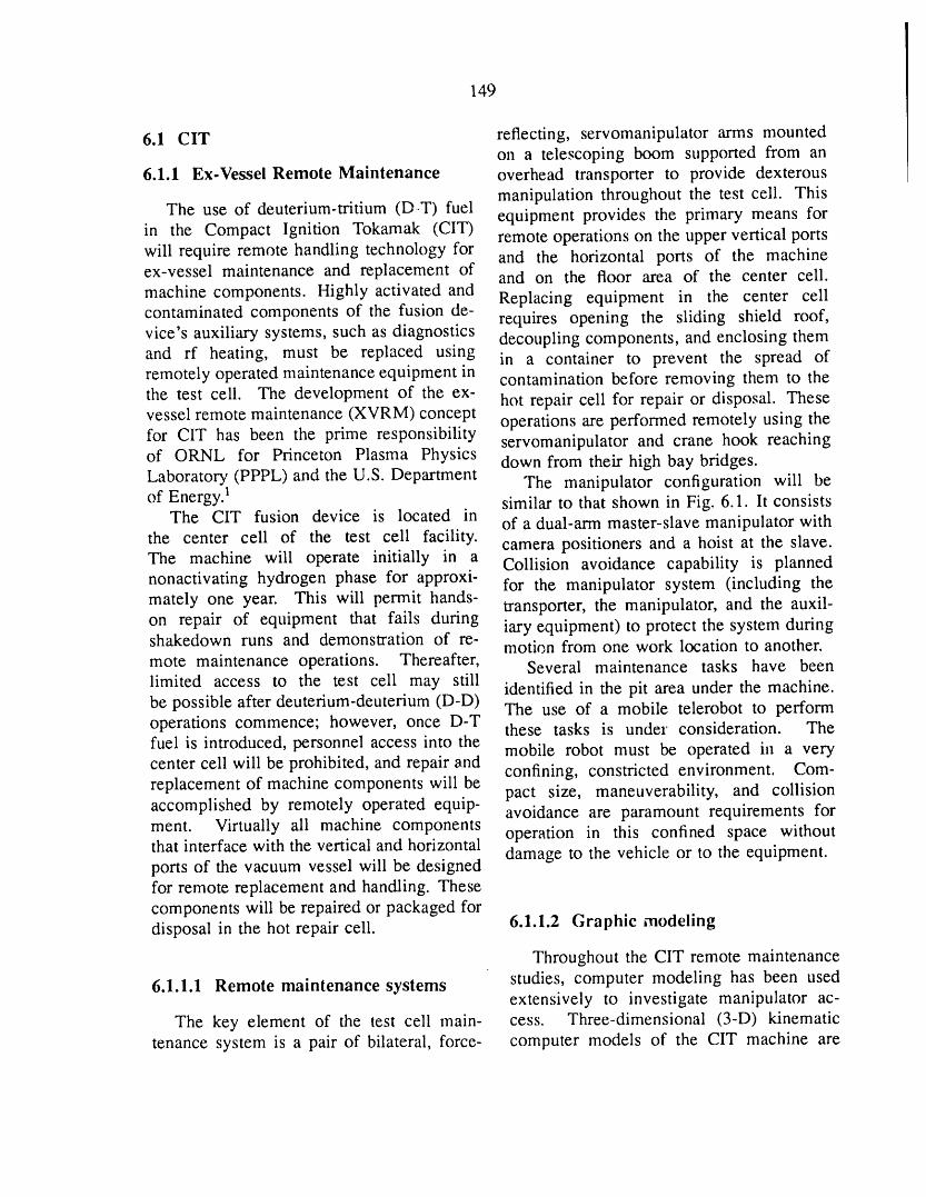
149
6.1 CIT reflecting, servomanipulator arms mountedon a telescoping boom supported from an
6.1.1 Ex-Vessel Remote Maintenance overhead transporter to provide dexterousmanipulation throughout the test cell. This
The use of deuterium-tritium (DIT) fuel equipment provides the primary means forin the Compact Ignition Tokamak (CIT) remote operations on the upper vertical portswill require remote handling technology for and the horizontal ports of the machineex-vessel maintenance and replacement of and on the floor area of the center cell.machine components. Highly activated and Replacing equipment in the center cellcontaminated components of the fusion de- requires opening the sliding shield roof,vice's auxiliary systems, such as diagnostics decoupling components, and enclosing themand rf heating, must be replaced using in a container to prevent the spread ofremotely operated maintenance equipment in contamination before removing them to thethe test cell. The development of the ex- hot repair cell for repair or disposal. Thesevessel remote maintenance (XVRM) concept operations are performed remotely using thefor CIT has been the prime responsibility servomanipulator and crane hook reachingof ORNL for Princeton Plasma Physics down from their high bay bridges.Laboratory (PPPL) and the U.S. Department The manipulator configuration will beof Energy) similar to that shown in Fig. 6.1. lt consists
The CIT fusion device is located in of a dual-arm master-slave manipulator withthe center cell of the test cell facility, camera positioners and a hoist at the slave.The machine will operate initially in a Collision avoidance capability is plannednonactivating hydrogen phase for approxi- for the manipulator system (including themately one year. This will permit hands- transporter, the manipulator, and the auxil-on repair of equipment that fails during iary equipment) to protect the system duringshakedown runs and demonstration of re- motion from one work location to another.mote maintenance operations. Thereafter, Several maintenance tasks have been
limited access to the test cell may still identified in the pit area under the machine.be possible after deuterium-deuterium (D-D) The use of a mobile telerobot to performoperations commence; however, once D-T these tasks is under consideration. Thefuel is introduced, personnel access into the mobile robot must be operated in a verycenter cell will be prohibited, and repair and confining, constricted environment. Com-replacement of machine components will be pact size, maneuverability, and collisionaccomplished by remotely operated equip- avoidance are paramount requirements formont. Virtually ali machine components operation in this confined space withoutthat interface with the vertical and horizontal damage to the vehicle or to the equipment.ports of the vacuum vessel will be designedfor remote replacement and handling. Thesecomponents will be repaired or packaged fordisposal in the hot repair cell. 6.1.1.2 Graphic modeling
Throughout the CIT remote maintenance
6.1.1.1 Remote maintenance systems studies, computer modeling has been usedextensively to investigate manipulator ac-
The key element of the test cell main- cess. Three-dimensional (3-D) kinematictenance system is a pair of bilateral, force- computer models of the CIT machine are
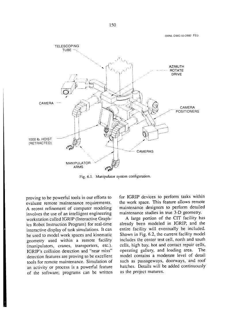
150
ORNL-DWG 90-2882 FED
1000 lb. HOIST/.,d
(RETRACTED) / ./'--/ %
CAMERAS
MANIPULATOR -L-v"'•ARMS
Fig. 6.1. Manipulator system configuration.
proving to be powerful tools in our efforts to for IGRIP devices to perform tasks withinevaluate remote maintenance requirements, the work space. This feature allows remoteA recent refinement of computer modeling maintenance designers to perform detailedinvolves the use of an intelligent engineering maintenance studies in true 3-D geometry.workstation called IGRIP (Interactive Graph- A large portion of the CIT facility hasics Robot Instruction Program) for real-time already been modeled in IGRIP, and theinteractive display of task simulations. It can entire facility will eventually be included.be used to model work spaces and kinematic Shown in Fig. 6.2, the current facility modelgeometry used within a remote facility includes the center test cell, north and south(manipulators, cranes, transporters, etc.), cells, high bay, hot and contact repair cells,IGRIP's collision detection and "near miss" operating gallery, and loading area. Thedetection features are proving to be excellent model contains a moderate level of detailtools for remote maintenance. Simulation of such as passageways, doorways, and roof
an activity or"process is a powerful feature hatches. Details will be added continuouslyof the software; programs can be written as the project matures.
151
ORNL-DWG 90-2883 FED
CONT._.r,TREPA R '3ELL LOADING
AREA
NORTH CELL
OPERATING CENTERGALLERY TEST CELL
HOT REPAIRCELL
SLIDINGSHIELD ROOF
SOUTH CELL
Fig. 6.2. Shielded cell configuration.
6.1.1.3 T,.,.,k evaluations and the ways in which computer modelingenhances the design process. Remote
The simulation capabilities of IGRIP maintenance designers have incorporatedhave been used with the CIT model to several design features to facilitate remote
depict XVRM activities. In conjunction maintenance for the plasma/IRTV diagnosticw;th iGRIP's interference detection, the (Fig. 6.3).simulations hz,ve allowed the evaluation The remote handling needs for the re-of access co_,straints and problems that placement of the central solenoid have
m:ght otherwise have gone unnoticed until been studied. This task presents severalhardware mock-ups were constructed, concerns, primarily because of the solenoid's
The removal of a plasma/infrared tele- weight (100 tons) and size (22.5 ft longvision (IRTV) diagnostic was completely by 5.5 ft in diameter). Various scenariossimulated, as described in ref. 2. A pre- were developed for extracting the "hot"sentation describing this simulation included cylindrical solenoid from the center of thea videotape of the remote replacement of a machine and transporting it to a suitableplasma viewing assembly. The simulation location for disposal. A special lifting
........ t. ........ : ......... ;,_.aA 4qvt ...... t'_nc;ct_rao nfa _trnnerhark fitted withiiiusaatc_ ..,u,,,cof t,,c _.u,,_,,,_,.,,_,,_,-,,.......................... _,......... ,=,.............
_- with typical remote maintenance activities two 50-ton ball screwjacks was designed.
' ' III!

152
ORNL-DWG90-2884FED
- FLANGESUPPORT
' t/ ILiII " BRACKET -REMO E
II ....... -...... ..yT-_- " . "" MOTORS
I'_T' '" ' _- ]t _ t li ...._ u_. I "'-REMOTELYREPLACEABLEI/ l_ tl ['_ ll_' _{.._ "_'_" M RROR ADJUSTMENT SYSTEM
! , I [- " " " ( ! _ ................ VACUUM ISOLATION VALVE// SECONDARY Ii. ---_. , _,
/J-- TELESCOPINGSUPPORT COLLARREMOTELYREPLACEABLE " ---MIRROR ASSEMBLY [ - DRIVE SCREW DRIVEN BY•" lMPACT TOOL
t s OPTICAL RELAY STAGE
........ r SUPPORT TUBE.J
,/-"
///
" /- CAMERA SHIELDING
_ . ........ " " / CAMERA ACCESSDOOR.... . ...... / ../._ (SHIELDED)
/
- , "1" REMOTELY REPLACEABLE
i':" _-_ j_ CAMERA MODULE WITH
:._/ ,[ ._1,,4_,,i " PAN/TILT
Fig. 63. Plasma/IRTV design for remote maintenance.
153
This fixture provides the 4-ft vertical travel 6.1.2 Vacuum System and Shieldneeded to supplement the maximum cranehook height so that the solenoid can be lifted 6.1.2.1 Vacuum systemclear of the test cell roof hatch.
A remotely maintainable ion cyclotron CIT will require an ultrahigh-vacuumresonance heating (ICRH) concept was de- pumping system to evacuate the plasmaveloped. The special design features include chamber from atmospheric pressure to low
pressure and to maintain the required vac-• vertical removal of higher-maintenance uum levels during bakeout, discharge clean-
items such as vacuum feedthroughs, ing, and pulsed burn operation. The base• in-piace capacitor maintenance with ma- partial pressure requirements are 1.34 ×
nipulator, 10-6 Pa (1 × 10⁻⁷ torr) for fuel gasesmanipulator access between neighboring and 1.34 x 10 -8 Pa (1 × 10 -9 torr) totalICRH units, for ali other constituents. These pressure
• relatively short radial length (about 8 ft), requirements are very stringent for a systemand of this size, with a volume of over 80 m 3
• placement of the vacuum feedthrough out and a surface area of 300 m2. In addition,of the direct line of the neutron flux. the presence of tritium in the pumped stream
prevents the use of lubricants or organic seal
6.1.1.4 Special tools materials anywhere in the system.The present CIT vacuum pumping system
T. W. Burgess, a member of the CIT design calls for six 2000-L/s magnetic bear-remote maintenance design team, remained ing turbomolecular pumps backed by twoon assignment to the ex-vessel mock-up 600-ma/h mechanical scroll pumps. Earlierprogram of the Joint European Torus (JET) concepts included diaphragm pumps to backJoint Undertaking. During this assignment, up the scroll pumps, but further investi-Mr. Burgess has participated in the major gations have indicated that the diaphragmshutdown activities associated with the re- pumps are not necessary. One of the
placement of the failed toroidal field (TF) turbomolecular pumps and one of the twocoil in octant 3. In September 1989, four scroll pumps are provided for redundancy.members of the CIT remote maintenance The pumps are located in a shielded vaultdesign team visited the JET facility to below the experimental enclosure and arediscuss the remote maintenance problems connected to the torus via a vertical duct andthat have been addressed to date (e.g., a single radial duct. The low conductancevacuum flange couplings and seals, fluid of the radial-duct into the torus restrictsand mechanical couplings, decontamination the net pumping speed of the system andof components, pipe cutting and wclding, may require changing the configuration tomanipulator design) and may be applicable include a second radial duct. The shieldingto CIT. JET staff members presented design of the vacuum pun_ps is sufficient to preventdrawings and specifications for prototypes neutron activation.of several welding and cutting tools and a Experience in operating the scroll pumpsremote connector that provides for several is necessary to ensure that they will reli-hydraulic, pneumatic, and electrical supplies ably pump fusion gases (H2, D2, T2) andin a single connector, perform according to the assumptions of
154
the analysis. A research and development philosophy that has evolved requires access(R&D) program is planned to procure rep- to any part of the device with a minimumresentative pumps, install them in a test amount of interference from the cryostat. Astand, and run performance characterization new, modular approach to the cryostat designtests. Communication and collaboration will be undertaken in FY 1992 when fundswith other laboratories and programs [includ- become available.
ing Kernforschungszentrum Karlsruhe (KfK) An R&D program is in piace to identifyand JET] will continue to be beneficial, thermal insulation materials that will remain
In summary, calculations and design effective after exposure to the high neutronstudies indicate that an oil-free, ultrahigh- flux. Several candidate materials have beenvacuum pumping system can be provided for identified through a literature search, andCIT. The major uncertainties include (1) the these materials will be irradiated and testedability to provide sufficient pumping speed for deterioration of thermal and mechanicalthrough a single pumping duct and (2) the properties during FY 1991 and 1992.performance of the scroll pumps as backingpumps for pumping fusion gases. Theseissues will be resolved as the design and 6.1.3 Ion Cyclotron Resonance
R&D programs progress. Heating System
On the basis of experimental resultsfrom several tokamaks worldwide [primarily
6.1.2.2 Thermal shield the Tokamak Fusion Test Reactor (TFTR)
CIT will require a thermal shield to and JET], the CIT antenna geometry wasi:lsulate the coil set, which is cooled with modified. Dual current straps in the
liquid nitrogen to 77 K before each operating toroidal direction replaced the single currentpulse. The liquid nitrogen coolant is intro- strap. Experimentally, dual-strap antennasduced through piping into the coil set and driven out of phase have shown smallerthen vented from the coils directly into the impedance variations, smaller edge density
space formed by the thermal shield. Some and temperature increases, and higher break-of the nitrogen does not change phase during down voltages than in-phase antennas. Ascooldown, so the thermal shield must form shown in Table 6.1, antenna dimensionsa container, or cryostat, to collect the liquid, were reduced to accommodate the additionalIn addition, the nitrogen left in the system straps in the port. Calculations of the sys-during a pulse becomes activated by the high tem's plasma coupling and electrical char-neutron fluence, which imposes a strict leak acteristics showed that with dual-strap an-
rate requirement on the system, tennas a launched power of approximatelyThe original cryostat design consisted of 4.0 MW/port would be feasible. The ICRH
a double-wall, all-weldedsandwich structure system would occupy five of the largewith thermal insulation between the walls, horizontal ports to launch 20 MW to theThis design offered good stiffness, low plasma during initial operations and wouldthermal mass for cooldown, and double be expandable to a 28-MW system usingcontainment for the nitrogen. However, this seven ports. The antenna power limit was
approach limits access to the coil set and determined by a peak voltage in the antennastructure and is very difficult from a remote and transmission line system of 50 kV for amaintenance viewpoint. The new design plasma loading impedance of 4 f_/m.
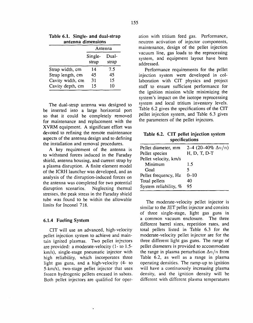
155
Table 6.1. Single-and dual-strap ation with tritium feed gas. Performance,antenna dimensions neutron activation of injector components,
Antenna maintenance, design of the pellet injectionvacuum line, gas loads to the reprocessing
Single- Dual- system, and equipment layout have beenstrap strap addressed.
Strap width, cm 14 7.5 Performance requirements for the pelletStrap length, cm 45 45 injection system were developed in col-Cavity width, cna 31 15 laboration with CIT physics and projectCavity depth, cm 15 10 staff to ensure sufficient performance for
the ignition mission while minimizing thesystem's impact on the isotope reprocessing
The dual-strap antenna was designed to system and local tritium inventory levels.be inserted into a large horizontal port Table 6.2 gives the specifications of the CITso that it could be completely removed pellet injection system, and Table 6.3 givesfor maintenance and replacement with the the parameters of the pellet injectors.XVRM equipment. A significant effort was
devoted to refining the remote maintenance Table 6.2. CIT pellet injection systemaspects of the antenna design and to defining specificationsthe installation and removal procedures.
A key requirement of the antenna is Pellet diameter, mm 2-4 (20-40% ATz/Tz)to withstand forces induced in the Faraday Pellet species H, D, T, D-Tshield, antenna housing, and current strap by Pellet velocity, km/sa plasma disruption. A finite element model Minimum 1.5
Goal 5of the ICRH launcher was developed, and an
Pellet frequency, Hz 0-10analysis of the disruption-induced forces onthe antenna was completed for two potential Total pellets 40disruption scenarios. Neglecting thermal System reliability, % 95stresses, the peak stress in the Faraday shieldtube was found to be within the allowable
The moderate-velocity pellet injector islimits for Inconel 718. similar to the JET pellet injector and consists
of three single-stage, light gas guns in
6.1.4 Fueling System a common vacuum enclosure. The threedifferent barrel sizes, repetition rates, and
CIT will use an advanced, high-velocity total pellets listed in Table 6.3 for thepellet injection system to achieve and main- moderate-velocity pellet injector are for thetain ignited plasmas. Two pellet injectors three different light gas guns. The range ofare provided: a moderate-velocity (1- to 1.5- pellet diameters is provided to accommodatekm/s), single-stage pneumatic injector with the range in plasma perturbation Art/r_ fromhigh reliability, which incorporates three Table 6.2, as well as a range in plasmalight gas guns, and a high-velocity (4- to operating densities. The ramp-up to ignition5-km/s), two-stage pellet injector that uses will have a continuously increasing plasmafrozen hydrogenic pellets encased in sabots, density, and the ignition density will beBoth pellet injectors are qualified for oper- different with different plasma temperatures
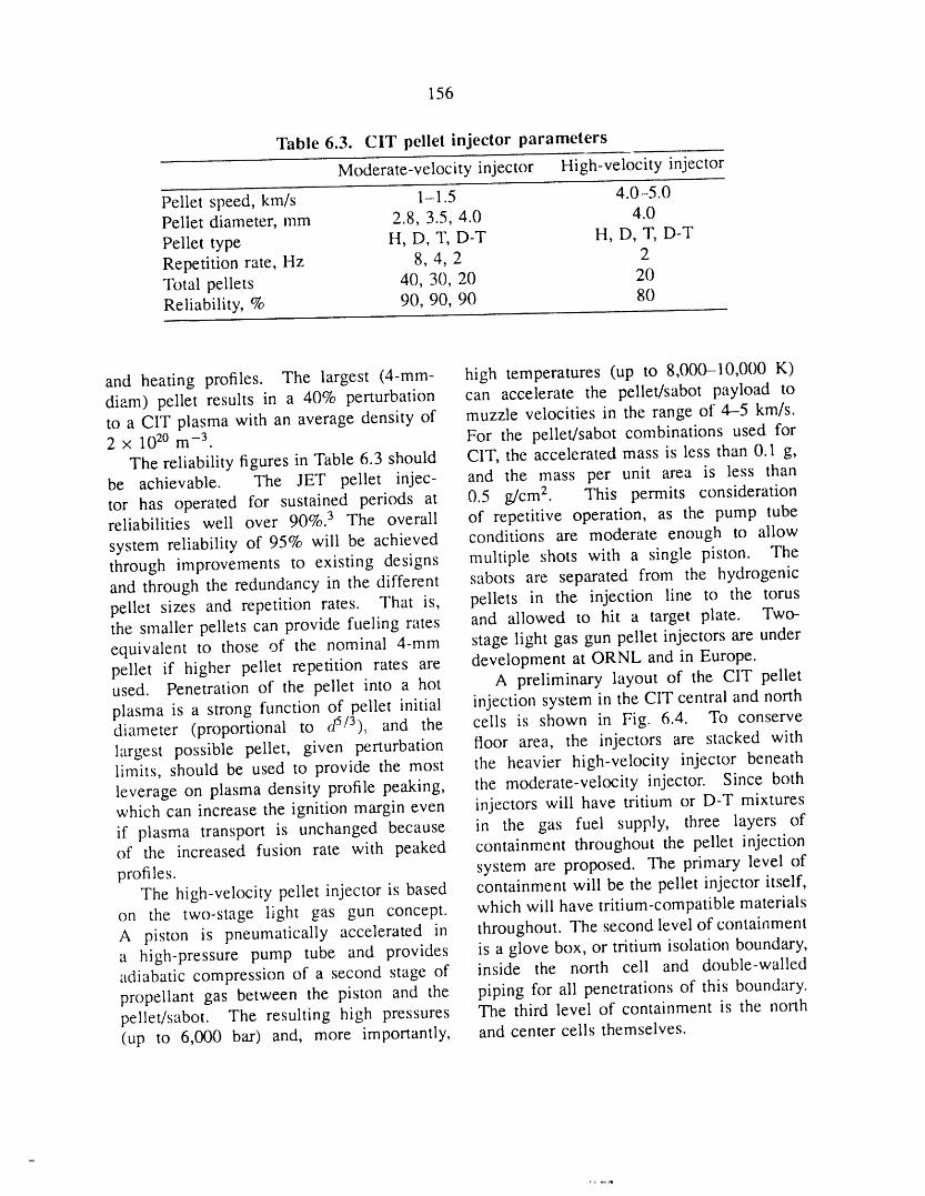
156
Table 6.3. CIT pellet injector parameters
Moderate-velocity injector High-velocity injector
Pellet speed, km/s 1-1.5 4.0-5.0Pellet diameter, mm 2.8, 3.5, 4.0 4.0
Pellet type H, D, T, D-T H, D, T, D-TRepetition rate, Hz 8, 4, 2 2Total pellets 40, 30, 20 20Reliability, % 90, 90, 90 80
and heating profiles. The largest (4-mm- high temperatures (up to 8,000-10,000 K)diam) pellet results in a 40% perturbation can accelerate the pellet/sabot payload toto a CIT plasma with an average density of muzzle velocities in the range of 4-5 km/s.2 x 102o m -3 For the pellet/sabot combinations used for
The reliability figures in Table 6.3 should CIT, the accelerated mass is less than 0.1 g,be achievable. The JET pellet injec- and the mass per unit area is less thantor has operated for sustained periods at 0.5 g/cm 2. This permits considerationreliabilities well over 90%. 3 The overall of repetitive operation, as the pump tube
system reliability of 95% will be achieved conditions are moderate enough to allowthrough improvements to existing designs multiple shots with a single piston. Theand through the redundancy in the different sabots are separated from the hydrogenicpellet sizes and repetition rates. That is, pellets in the injection line to the torusthe smaller pellets can provide fueling rates and allowed to hit a target plate. Two-equivalent to those of the nominal 4-mm stage light gas gun pellet injectors are underpellet if higher pellet repetition rates are development at ORNL and in Europe.used. Penetration of the pellet into a hot A preliminary layout of the CIT pellet
plasma is a strong function of pellet initial injection system in the CIT central and northd.S/3).diameter (proportional to and the cells is shown in Fig. 6.4. To conserve
largest possible pellet, given perturbation floor area, the injectors are stacked withlimits, should be used to provide the most the heavier high-velocity injector beneathleverage on plasma density profile peaking, the moderate-velocity injector. Since bothwhich can increase the ignition margin even injectors will have tritium or D-T mixtures
if plasma transport is unchanged because in the gas fuel supply, three layers ofof the increased fusion rate with peaked containment throughout the pellet injection
profiles, system are proposed. The primary level ofThe high-velocity pellet injector is based containment will be the pellet injector itself,
on the two-stage light gas gun concept, which will have tritium-compatible materialsA piston is pneumatically accelerated in throughout. The second level of containmenta high-pressure pump tube and provides is a glove box, or tritium isolation boundary,adiabatic compression of a second stage of inside the north cell and double-walledpropellant gas between the piston and the piping for all penetrations of this boundary.pellet/sabot. The resulting high pressures The third level of containment is the north(up to 6,000 bar) and, more importantly, and center cells themselves.
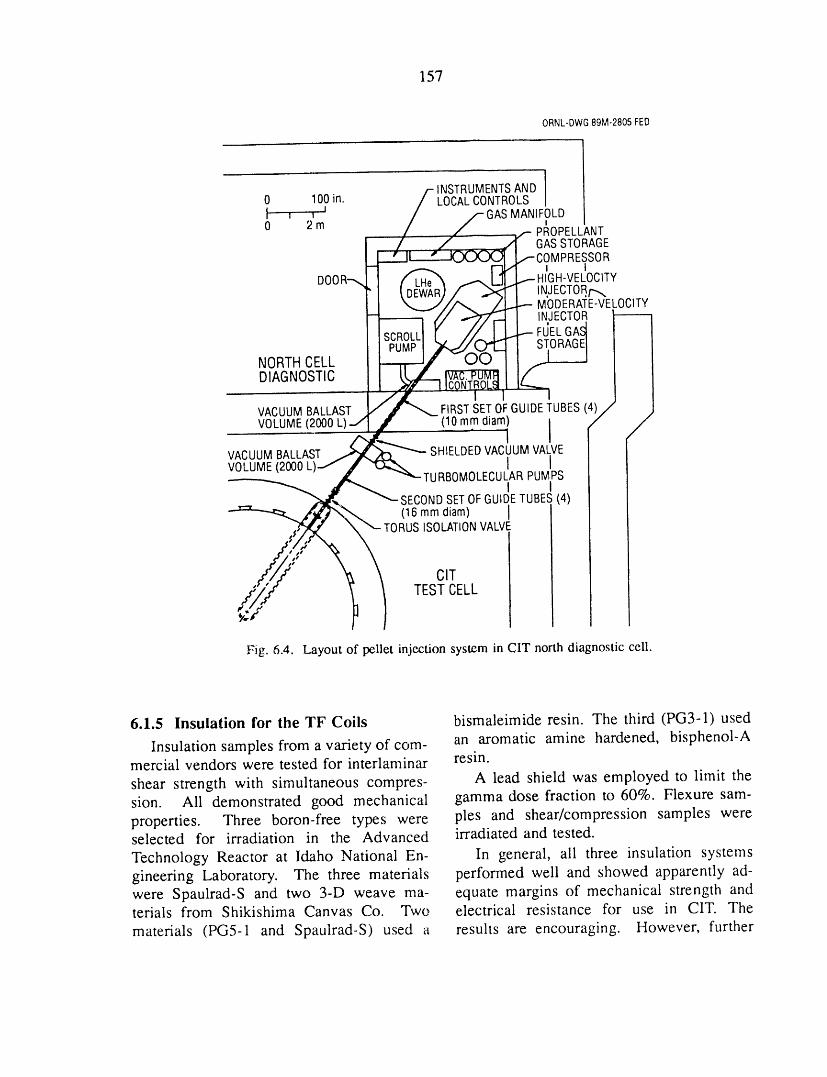
157
ORNL-DWG89M-2805FED
INSTRUMENTSAND I0 100in. LOCALCONTROLSI i i J GASMANIFOLD0 2m tPROPELLANT
GASSTORAGE;OMPRESSORI I
DOD -IIGH-VELOCITYINJECTOR/'-,,,MODERATE-VELOCITYINJECTOR
FdELGAdSTORAGE[ INORTHCELL I
DIAGNOSTIC Ii
FIRSTSETOFGUIDETUBES(4)/2VACUUMBALLASTVOLUME(2000L) (10mmdiam) I /
IVACUUMBALLAST SHIELDEDVACUUMVALVEVOLUME(2000 I I
TURBOMOLECULARPUMPSI I
SECONDSETOFGUIDETUBES(4)(16mm diam) [
TORUSISOLATIONVALVE
Fig. 6.4. Layout of pellet injection system in CIT north diagnostic cell.
6.1.5 Insulation for the TF Coils bismaleimide resin. The third (PG3-1) usedan aromatic amine hardened, bisphenol-AInsulation samples from a variety of com-
mercial vendors were tested for interlaminar resin.
shear strength with simultaneous compres- A lead shield was employed to limit thesion. Ali demonstrated good mechanical gamma dose fraction to 60%. Flexure sam-properties. Three boron-free types were pies and shear/compression samples wereselected for irradiation in the Advanced irradiated and tested.
Technology Reactor at Idaho National En- In general, ali three insulation systemsgineering Laboratory. The three materials performed well and showed apparently ad-were Spaulrad-S and two 3-D weave ma- equate margins of mechanical strength andterials from Shikishima Canvas Co. Two electrical resistance for use in CIT. Thematerials (PG5-1 and Spaulrad-S) used a results are encouraging. However, further
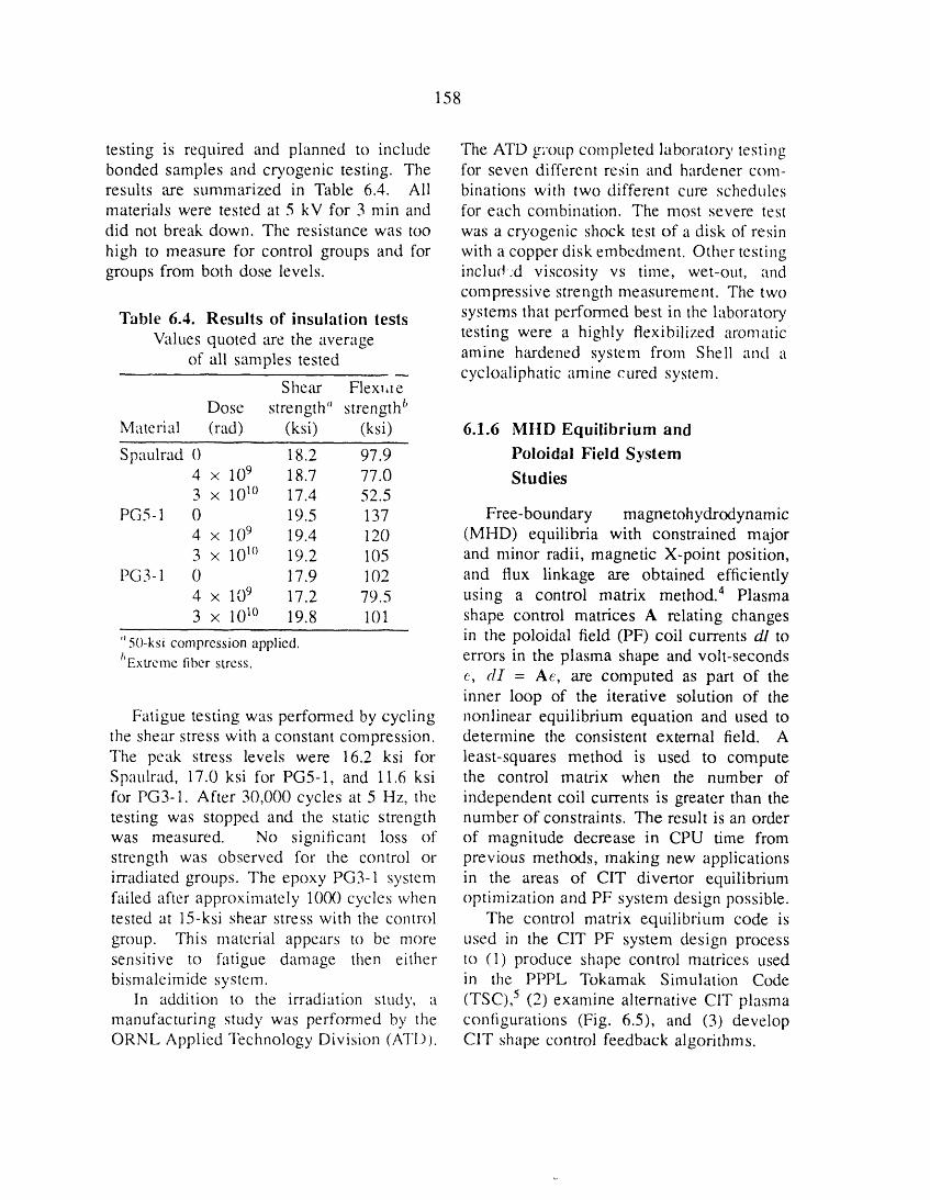
158
testing is required and planned to include The ATD group completed laborator), testingbonded samples and cryogenic testing. The for seven different resin and hardener com-results are summarized in Table 6.4. Ali binations with two different cure schedulesmaterials were tested at 5 kV for 3 rain and for each combination. The most severe test
did not break down. The resistance was too was a cryogenic shock test of a disk of resinhigh to measure for control groups and for with a copper disk embedment. Other testinggroups from both dose levels, includ:d viscosity vs time, wet-out, and
compressive strength measurement. The two
Table 6.4. Results of insulation tests systems that performed best in the laboratorytesting were a highly flexibilized aromaticValues quoted are the average
of all samples tested amine hardened system from Shell and acycloaliphatic amine cured system.
Shear Flex_ae
Dose strength" strength bMaterial (rad) (ksi) (ksi) 6.1.6 MHD Equilibrium and
Spaulrad 0 18.2 97.9 Poloidal Field System4 × 109 18.7 77.0 Studies3 × 101° 17.4 52.5
PG5-1 0 19.5 137 Free-boundary magnetohydrodynamic4 × 109 19.4 120 (MHD) equilibria with constrained major3 × 101° 19.2 105 and minor radii, magnetic X-point position,
PG3-1 0 17.9 102 and flux linkage are obtained efficiently4 x 109 17.2 79.5 using a control matrix method. 4 Plasma3 x 10_° 19.8 101 shape control matrices A relating changes
"50-ksi compression applied, in the poloidal field (PF) coil currents di tot'Extrcmefiber stress, errors in the plasma shape and volt-seconds
e, di = Ae, are computed as part of theinner loop of the iterative solution of the
Fatigue testing was performed by cycling nonlinear equilibrium equation and used tothe shear stress with a constant compression, determine the consistent external field. AThe peak stress levels were 16.2 ksi for least-squares method is used to computeSpaulrad, 17.0 ksi for PG5-1, and 11.6 ksi the control matrix when the number offor PG3-1. After 30,000 cycles at 5 Hz, the independent coil currents is greater than thetesting was stopped and the static strength number of constraints. The result is an orderwas measured. No significant loss of of magnitude decrease in CPU time fromstrength was observed for the control or previous methods, making new applicationsirradiated groups. The epoxy PG3-1 system in the areas of CIT divertor equilibriumfailed after approximately 10(30cycles when optimization and PF system design possible.tested at 15-ksi shear stress with the control The control matrix equilibrium code isgroup. This material appears to be more used in the CIT PF system design processsensitive to fatigue damage then either to (1) produce shape control matrices usedbismaleimide system, in the PPPL Tokamak Simulation Code
In addition to the irradiation study, a (TSC), 5 (2)examine alternative CIT plasmamanufacturing study was performed by the contigurations (Fig. 6.5), and (3) developORNL Applied Technology Division (ATI)). CIT shape control feedback algorithms.
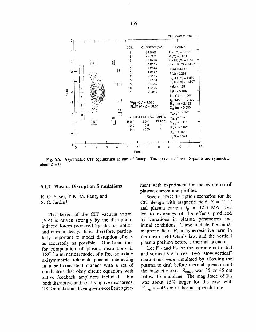
159
ORNL-DWG90-2885 FED
5 1 I ] I I 1 I I I 1 l
COIL CURRENT (MA) PLASMA4--
1 38.8769 RO (m) = 2.1382 25.7475 a (m) = 0.661
3- I il 3 -26798 RxIulCml=1.839-4 -6.8959 Z x (U) (m) = 1.5071
I 3 161 5 1.2546 K (u) = 2.011 _2-- __._/_: 6 4.0142 S (U)=0.284
/
1_ -" 7.,,, 7 7.1135 Rx (L)(m)= 1.839"', 8 -6.2154 Z x (L) (m) = -1.507 -
1 I_.... //:" ' 7 [_-_] 9 -2.8455
E" 0 -- 11 0.7242 5 (L) = 0.109 --N" B m (T) = 11.000
-1 _.:_ 7[ ] lp (MA)=-12.300 _I2 WpF(GJ) : 1.525 Ra (m) : 2.182
- " FLUX (V • s) = 38.00 Z a (m) = 0.050[__- _ k.__. 11
-2 - i-- _ _ _ _axis ='2"973 -
_8 10 DIVERTOR STRIKE POINTS _X.U = 0.473
-3 -- [--9____ _ R (m) Z (m) PLATE _X_L= 0.818 -1.640 1.612 113(%) = 1.025
1.944 1.686 1-4 -- _3p = 0.165 -
9.i/2 = 0.391
I I I I I I I I I I 1-50 1 2 3 4 5 6 7 8 9 10 11 2
R(m)
Fig. 6.5. Asymmetric CIT equilibrium at start of flattop. The upper and lower X-points are symmetric
about Z = 0.
6.1.7 Plasma Disruption Simulations ment with experiment for the evolution ofplasma current and profiles.
R. O. Sayer, Y-K. M. Peng, and Several TSC disruption scenarios for theS. C. Jardin* CIT design with magnetic field B = 11 T
and plasma current /p = 12.3 MA have
The design of the CIT vacuum vessel led to estimates of the effects produced(VV) is driven strongly by the disruption- by variations in plasma parameters andinduced forces produced by plasma motion initial conditions. These include the initialand current decay. It is, therefore, particu- magnetic field B, a hyperresistive term inlarly important to model disruption effects the mean field Ohm's law, and the verticalas accurately as possible. Our basic tool plasma position before a thermal quench.for computation of plasma disruptions is Let FR and Fz be the extreme net radialTSC, 5 a numerical model of a free-boundary and vertical VV forces. Two "slow vertical"axisymmetric tokamak plasma interacting disruptions were simulated by allowing thein a self-consistent manner with a set of plasma to drift before thermal quench untilconductors that obey circuit equations with the magnetic axis, Zmag, was 35 or 45 cmactive feedback amplifiers included. For below the midplane. The magnitude of Fzboth disruptive and nondisruptive discharges, was about 15% larger for the case withTSC simulations have given excellent agree- Zmag = -45 cm at thermal quench time.

160
Fast ((dlp/Ctt) __ -3.0 MA/ms) radial net radial VV force Fie and contributions toand vertical disruptions were simulated with FI_ from diamagnetic poloidal and toroidaland without a hyperresistive term. Inclusion VV currents as functions of time for radialof hyperresistivity gave a 10% increase in disruptions with (diprg) __ -3.0 MA/ms.plasma current and 10% higher magnitude For the case with low (high) initial beta,for the inboard radial VV force at thermal the diamagnetic poloidal VV current actsquench time. to increase (decrease) the magnitude of F/_.
Fast radial disruptions with high initial For the case with low initial beta, at peakbeta (/3 = 0.051) and low initial beta Fn, the contributions from toroidal and(/3 = 0.003) yielded nearly identical ex- poloidal currents are -10.5 MN/rad andtreme net radial VV forces. This rather -4.9 MN/rad, respectively. Poloidal VVunexpected result is due to the contribution currents substantially alter the distribution offrom "diamagnetic" poloidal VV currents VV forces and must be taken into account inproduced by plasma paramagnetism changes, simulations of major disruptions for tokamakFigure 6.6 illustrates the evolution of the VV design. The relative magnitudes of
poloidal and toroidal components are quitesensitive to the initial beta value.
ORNL-DWG90M-2886FED *Princeton Plasma Physics Laboratory, Princeton,4 T _ t 't
_\ 0819E N.J.2 •
\0
"lD
6.1.8 Structural Materialsz -2 POLOIDAL -_. ..... TOROIDAL
Lt. --4 POLOIDAL+TOROIDAL Research aimed at developing structural
I_t materials for CIT is carried out as part--6.... of the Fusion Materials Program, which is
-sL t ---_- i .... t j described in Sect. 7 of this report.4 1 _ _ _ |
t1114D2 6.2 ITER
o 6.2.1 Plasma Engineering
=, -2 '_''7,,,," --------- ....... The plasma engineering effort for the
_- --4 ...... International Thermonuclear ExperimentalReactor (ITER) was primarily involved with
-6 systems and disruption analysis. The sys-1-8 _ -----r- _ terns analysis provided operational scenarios
0 4 8 12 16 20 for the steady-state and technology testingTIME(ms) phases. This information is used as input
Fig. 6.6. Net radial VV force Fn and contribu- for design work on a wide range of topicstions to Fit from diamagnetic poloidal and toroidalVVcurrentsas functionsof time for radialdisruptions (heat loads, plasma current levels, etc.).with (dip/dO ". --3.0 MA/ms. Initial lp = 12.3 MA, The disruption simulations provided detailedBtor = 11 T. (a) Troyon beta (0.051). (b) Low beta analysis of the plasma current decay process(0.003). and the associated eddy currents induced
161
in the vacuum vessel. The high level of found. Hybrid operation is characterized bysophistication in this modeling procedure medium density (1020 m -3) and temperatureallows these results to be used as a basis (T_ near 15 keV) and by reduced plasmaof comparison for other calculations. These current levels (near 15 MA).results are also used in the mechanical design Another approach to alleviating the di-of the first wall and vacuum vessel, vertor heat load problem is to seed the
plasma with impurities, in order to radiatelarge fractions of the power deposited in
6.2.1.1 Systems analysis the plasma. This would permit operationat higher wall loads but requires more
The primary emphasis of the 1989 ITER confinement capability than the nonseededsystems analysis was the identification of op- case.
erational scenarios for the ITER technology Sensitivity studies indicate that increasingphase. These studies were done using the the installed injection power allows opera-TETRA systems code, and the operational tion at higher wall loads. This option couldpoints identified with TETRA are used as be used if performance is not satisfactorythe baseline design points. 6 with the initial installed power capability
The ITER program has mission goals (near 100 MW).of demonstrating both an ignited plasmawith steady-state operation and extended-burn technology testing. Accomplishing thesecond of these goals, called the technology 6.2.1.2 Plasma disruption simulations
phase, is complicated by the need to inject R.O. Sayer, Y-K. M. Peng, andlarge amounts of power into the plasma D.J. Stricklerto drive the plasma current noninductively.This injection power exacerbates an already Design of ITER tokamak conductingtroublesome divertor heat load. In order structures is driven strongly by the disrup-to identify desirable technology-phase opera- tion-induced forces produced by plasma mo-tion points that satisfy the divertor limits, the tion and current decay. TSC has been usedHarrison-Kukushkin analytic divertor model to model ITER disruptions and to predictwas incorporated into TETRA. the time evolution of currents and forces
The divertor constraint prohibits steady- on the vacuum vessel, internal control (lC)state operation at high neutron wall loads coil, and passive stabilizing (PS) structures. 5(>0.5 MW/m2). Typically, the steady-state Both inward-shifting and vertically movingplasma operation is optimal at low density disrupting plasmas and a range of current(ne < 0.7 x 10²⁰ m-3), high temperature decay rates were studied.(Te > 15 keV), and plasma current levels Conducting structures were representedlower than those in the ignition phase, by groups of filamentary wires of specified
To satisfy the technology testing mis- resistivity. Figure 6.7(a) illustrates thesion statement, a hybrid operation scenario, filamentary models for the vacuum vessel,which uses a combination of inductive and IC coil, and PS structures, ali of whichnoninductive current drive, was identified, were located within the computational grid.With this approach, operational points with Also shown in Fig. 6.7(a) is an overlay plothigh wall loads (>0.8 MW/m 2) and long of plasma boundaries during the disruptionpulse times (thousands of seconds) were phase of a vertical disruption simulation.
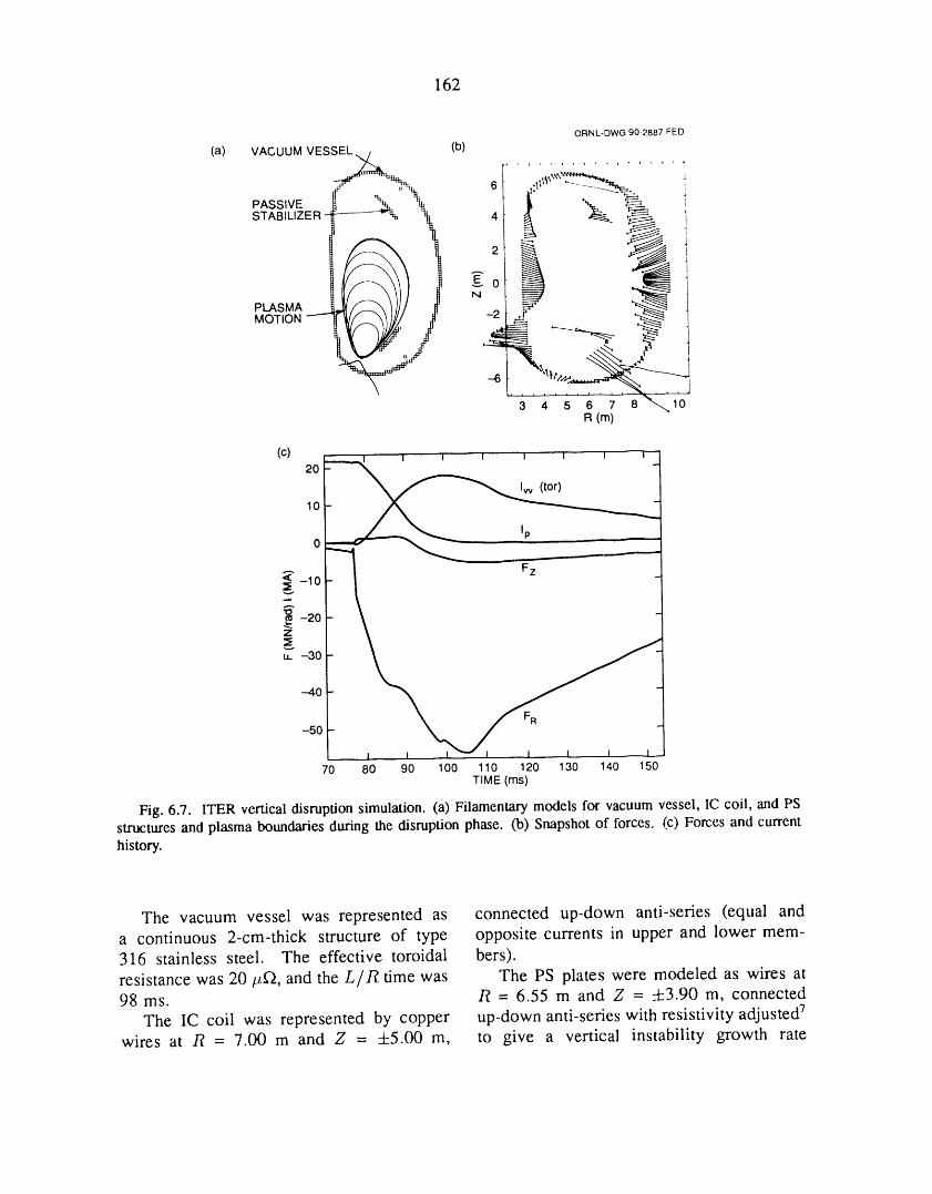
162
ORNL-DWG 90-2887 FED
(a) VACUUM VESSEL _ (b) r.................
PASSIVE _'- 'h..h.%% !) "% __ i
STABILIZER -tf--_-"'% _ 4 I _ _ _ i
I-2 t .--d' _ ]
MOTION _ .,,_ '-----_..--_ _ ,_
R(m)
(c)_ i i i I i i i20
lp _0 '
< -10
_ -20Z
gu. -30
--40
-50- I 1 I _ 1 I I 1 I
70 80 90 100 110 120 130 140 150TIME (ms)
Fig. 6.7. ITER vertical disruption simulation. (a) Filamentary models for vacuum vessel, lC coil, and PS
structures and plasma boundaries during the disruption phase. (b) Snapshot of forces. (c) Forces and current
history.
The vacuum vessel was represented as connected up-down anti-series (equal anda continuous 2-cre-thick structure of type opposite currents in upper and lower mem-316 stainless steel. The effective toroidal bers).resistance was 20 #f_, and the L/R time was The PS plates were modeled as wires at98 ms. /_ = 6.55 m and Z = _-k3.90 m, connected
The lC coil was represented by copper up-down anti-series with resistivity adjusted 7wires at /? = 7.00 m and Z = +5.00 m, to give a vertical instability growth rate
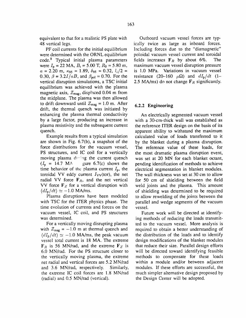
163
equivalent to that for a realistic PS plate with Outboard vacuum vessel forces are typ-48 vertical legs. ically twice as large as inboard forces.
PF coil currents for the initial equilibrium Including forces due to the "diamagnetic"were determined with the ORNL equilibrium poloidal vacuum vessel current and toroidalcode. 8 Typical initial plasma parameters fields increases F t_ by about 6%. Thewere Ip - 22 MA, Bt - 5.00 T, Ro = 5.80 m, maximum vacuum vessel disruption pressurea = 2.20 m, x95 = 1.89, _95 "- 0.32, li2 = is 1.0 MPa. Variations in vacuum vessel0.30,/3 = 3.2I/c_B, and/3pol = 0.70. For the resistance (20-160 #_) and dipdr (1-vertical disruption simulations, a TSC initial 2.5 MA/ms) do not change FR significantly.equilibrium was achieved with the plasmamagnetic axis, Zm_g, displaced 0.04 m fromthe midplane. The plasma was then allowed
to drift downward until Zmag = 1.0 m. After 6.2.2 Engineeringdrift, the thermal quench was initiated byenhancing the plasma thermal conductivity An electrically segmented vacuum vesselby a large factor, producing an increase in with a 30-cre-thick wall was established asplasma resistivity and the subsequent current the reference ITER design on the basis of itsquench, apparent ability to withstand the maximum
Example results from a typical simulation calculated value of loads transferred to itare shown in Fig. 6.7(b), a snapshot of the by the blanket during a plasma disruption.force distributions for the vacuum vessel, The reference value of these loads, for
PS structures, and IC coil for a vertically the most dramatic plasma disruption event,moving plasma d,,:,lg the current quench was set at 20 MN for each blanket octant,(Ip = 14.7 MA gure 6.7(c) shows the pending identification of methods to achievetime behavior of the plasma current Ip, the electrical segmentation in blanket modules.toroidal VV eddy current Ivv(tor), the net The wall thickness was set at 30 cm to allowradial VV force FR, and the net vertical for 50 cm of shielding between the fieldVV force Fz for a vertical disruption with weld joints and the plasma. This amount(dipdr) _-1.0 MA/ms. of shielding was determined to be required
Plasma disruptions have been modeled to allow rewelding of the joints between thewith TSC for the ITER physics phase. The parallel and wedge segments of the vacuumtime evolution of currents and forces on the vessel.
vacuum vessel, lC coil, and PS structures Future work will be directed at identify-was determined, ing methods of reducing the loads transmit-
For a vertically moving disrupting plasma ted to the vacuum vessel. More analysis iswith Zmag = -1.0 m at thermal quench and required to obtain a better understanding of(dipdr) _ -1.0 MA/ms, the peak vacuum the distribution of the loads and to identifyvessel total current is 18 MA. The extreme design modifications of the blanket modulesFR is 56 MN/rad, and the extreme Fz is that reduce their size. Parallel design efforts6.0 MN/rad. For the PS structure closer to will be directed toward identifying feasiblethe vertically moving plasma, the extreme methods to compensate for these loadsnet radial and vertical forces are 5.2 MN/rad within a module and/or between adjacentand 3.6 MN/rad, respectively. Similarly, modules. If these efforts are successful, thethe extreme IC coil forces are 1.8 MN/rad much simpler alternative design proposed by(radial) and 0.5 MN/rad (vertical). the Design Center will be adopted.
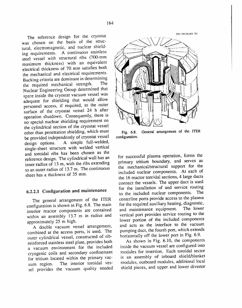
164
The reference design for the cryostat ORNL-DWG89+2876FED
was chosen on the basis of the struc- ,_yrural, electromagnetic, and nuclear shield-ing requirements. A continuous stainless _steel vessel with structural ribs (700-mmmaximum thickness) with an equivalentelectrical thickness of 70 mm satisfies boththe mechanical and electrical requirements.Bucking criteria are dominant in determiningthe required mechanical strength. TheNuclear Engineering Group determined that
space inside the cryostat vacuum vessel was ._adequate for shielding that would allowpersonnel access, if required, to the outersurface of the cryostat vessel 24 h after
operation shutdown. Consequently, there isno special nuclear shielding requirement on @ J>t_/
the cylindrical section of the cryostat vessel ,other than penetration shielding, which must Fig. 6.8. General arrangement of the ITER
be provided independently of cryostat vessel configuration.design options. A simple full-welded,single-sheet structure with welded verticaland toroidal ribs has been chosen as thereference design. The cylindrical wall has an for successful plasma operation, forms theinner radius of 13 m, with the ribs extending primary tritium boundary, and serves asto an outer radius of 13.7 m. The continuous the mechanical/structural support for thesheet has a thickness of 35 mm. included nuclear components. At each of
the 16 reactor toreidal sections, 4 large ductsconnect the vessels. The upper duct is used
6.2.2.1 Configuration and maintenance for the installation of and service routingto the included nuclear components. The
The general arrangement of the ITER centerline ports provide access to the plasmaconfiguration is shown in Fig. 6.8. The main for the required auxiliary heating, diagnostic,interior reactor components are contained and maintenance equipment. The lowerwithin an assembly 13.7 m in radius and vertical port provides service routing to theapproximately 25 m high. lower portion of the included components
A double vacuum vessel arrangement, and acts as the interface to the vacuumcombined at the access ports, is used. The pumping duct, the fourth port, which extends
outer cylindrical vessel, constructed of rib- horizontally off the lower port in Fig. 6.9.reinforced stainless steel plate, provides both As shown in Fig. 6.10, the componentsa vacuum environment for the included inside the vacuum vessel are configured into
cryogenic coils and secondary confinement modules for insertion. Each toroidal sectorfor tritium located within the primary vac- is an assembly of inboard shield/blanket
uum region. The interior toroidal yes- modules, outboard modules, additional localsel provides the vacuum quality needed shield pieces, and upper and lower divertor
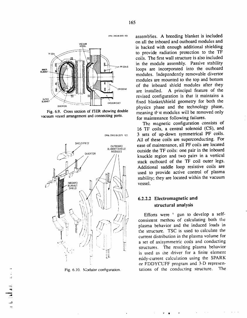
165
o,,_Dw0,,_,,,,Ep assemb!ies. A breeding blanket is included
v,cuuM on ali the inboard and outboard modules andv_ssa is backed with enough additional shielding
T_CO,L_ _ to provide radiation protection to the TF
___ coils. The first wall structure is also included_,,, in the module assembly. Passive stability
,..E. II __l!:l_l i __]_--w_ ----__I-_''_'_'_'--L-_--'_- PFco,_sloops are incorporated into the outboardi_ modu,es.,.,c,ent,yremovab'eor
i_P ,,''_''- _''''' ',Z_-7',,q,_i--r-i_ ]_/_, _,_-_-_ modules are mounted to the top and bottomi !',I_L'.- '_"_1"ii_l! _.-_ " _ of the inboard shield modules after they_ii__;__ _ "-c,_0s,,, are installed. A principal feature of thex-_ 7- _ , revised configuration is that it maintains a
Bw,_, ""-,L'-z__- l Ill I ' fixed blanket/shield geometry for both the, --_------.=s---_ L vACUUMouc_0,v_,_0, physics phase and the technology phase,
Fig. 6.9. Cross section of I'[ER showingdouble meaning that modules will be removed onlyvacuumvessel arrangementand connectingports, for maintenance following failures.
The magnetic configuration consists of16 TF coils, a central solenoid (CS), and
0_,_D_G_9_8__D 3 sets of up-down symmetrical PF coils.Ali of these coils are superconducting. For
r[ SHIELDPIECE
/ OUrBOARD ease of maintenance, ali PF coils are locatedIll / BLANKETISHIELD_t_....._¢ MODULES outside the TF coils" one pair in the inboard
.-_ ":C---_..-4 DIVERIOR -- -
[.._"_._--_" " knuckle region and two pairs in a vertical
-__/ ///_/!_ stack outboard of the TF coil outerlegs.
Additional saddle loop resistive coils areused to provide active control of plasma
_'_J I_BIA_D _ _//_ _ ]1 stability; they are located within the vacuum
_:/ II_B_ I_x _ _-_ II vessel.
_-__I_" x_.._ ! 6.2.2.2 Electromagnetic and'_ \! _--1'_if } I structural analysis
----,_:'<_'_"..!_il_ I-T_I Efforts were ' gun to develop a self-
x_.-.. "_.... "_ i_, [ . _ i"--'_ consistent methou of calculating both the':, . ]'., _ ,_, _ f/f _ [ plasma behavior and the induced loads in
" _1 L ],i l ..- ...... i/
.- I /,;, ' -, _...... , the structure, TSC is used to calculate the.'I L t / / !--qi / iii I I!• ... , ,: _- =,, , = distribution in the plasma volume fort /Li ! i_ i! current
_.=_., .... //_ : i l ._ a set of axisymmetfic coils and conducting-_, M!./ I_i i IIi Iii
._i(,':: " +'_: aJ structures. The resulting plasma behavior
[4 Iii. is used as _he driver for a finite elementeddy-current calculation using the SPARK_ or F DDYCUFF oro_zram and 3-D represen-
Fig. 6.10. Modular configuration, rations of the conducting structure. The=
=,i
166
eddy currents in the conducting structure that 6.2.2.3 Fast-wave current drive systemare computed by the finite element methodand TSC are compared, and appropriate Members of the Design Center and the RFadjustments are made in the TSC model. The Development Group continued their workprocess is repeated until the two calculations on the conceptual design of a fast-wave
. agree, current drive (FWCD) system for ITER. TwoInitial results were presented to the ITER designs were carried out: in one, all antennas
team and were instrumental in establishing are mounted in the midplane horizontalthe following project guidelines: ports; in the second, the antenna elements are
mounted in the blanket modules. Members
1. The effects of the size of the electrical participated in a specialists' meeting ongaps and surface resistivity are important. FWCD at Garching, Federal Republic of
2. Electromagnetic loads should be specified Germany, August 21-September 1, 1989, atas a function of the electrical segmenta- which a common design approach among thetion of the in-vessel components. Typical four participating parties was obtained. This
• values for the inboard blankets are" design features20 MN for one electrical segment=_
per sector, • an operating frequency of 15-60 MHz;FWCD can be done at 17 MHz (and10 MN for three electrical seg-
ments per sector, and possibly at 55 MHz), and plasma heatingusing ICRH can be done at intermediate4 MN for nine electrical segments
per sector, frequencies;V.,lues for the outboard blanket are: • an array of 30-60 antenna elements
20 MN for one electrical segment mounted in blanket modules, with con-per sector, and stant spacing and phase difference be-
10 MN for three electrical seg- tween antennas;mL :ts per sector. • rf coaxial lines embedded in the blanket
3. Since the electromagnetic loads are not module and emerging through the top ofup-down antisymmetric in the case of the blanket module;
: a vertical disruption, they are not self-compensated within the sector. In gen- • up to 60 2-MW rf power units, each
connected by a separate transmission- eral, the loads from a vertical disruption line and tuning/matching network to anare more severe than those from a
antenna._" symmetric disruption.
4. Maximizing electrical segmentation, An elevation view of this system is shown iv,while minimizing mechanical segmenta- Fig. 6.11. The most critical element of this
• tion, seems most desirable for inboard assembly is the antenna and Faraday shieldblanket design, system. The preseat design has two antennas
5. The maximum forces occur at the electri- mounted in each blanket module. With 96
cal breaks, so separation of the electrical blanke', modules surrounding the machine,and mechanit.a! breaks seems promising 30 antennas extend approximately one-thirdfrom the viewpoint of supporting the of the way around the torus, and 60 go two-electromagnetic loads, thirds of the way around.
6. The divertor must be highly segmented Calculations by the Plasma Theory Groupand electrically, isolated from its support yield a current drive e.tficiency factor "-, =
-- pl_e. (0.3-0.4) × 10:° A/W.m 2 for this design.
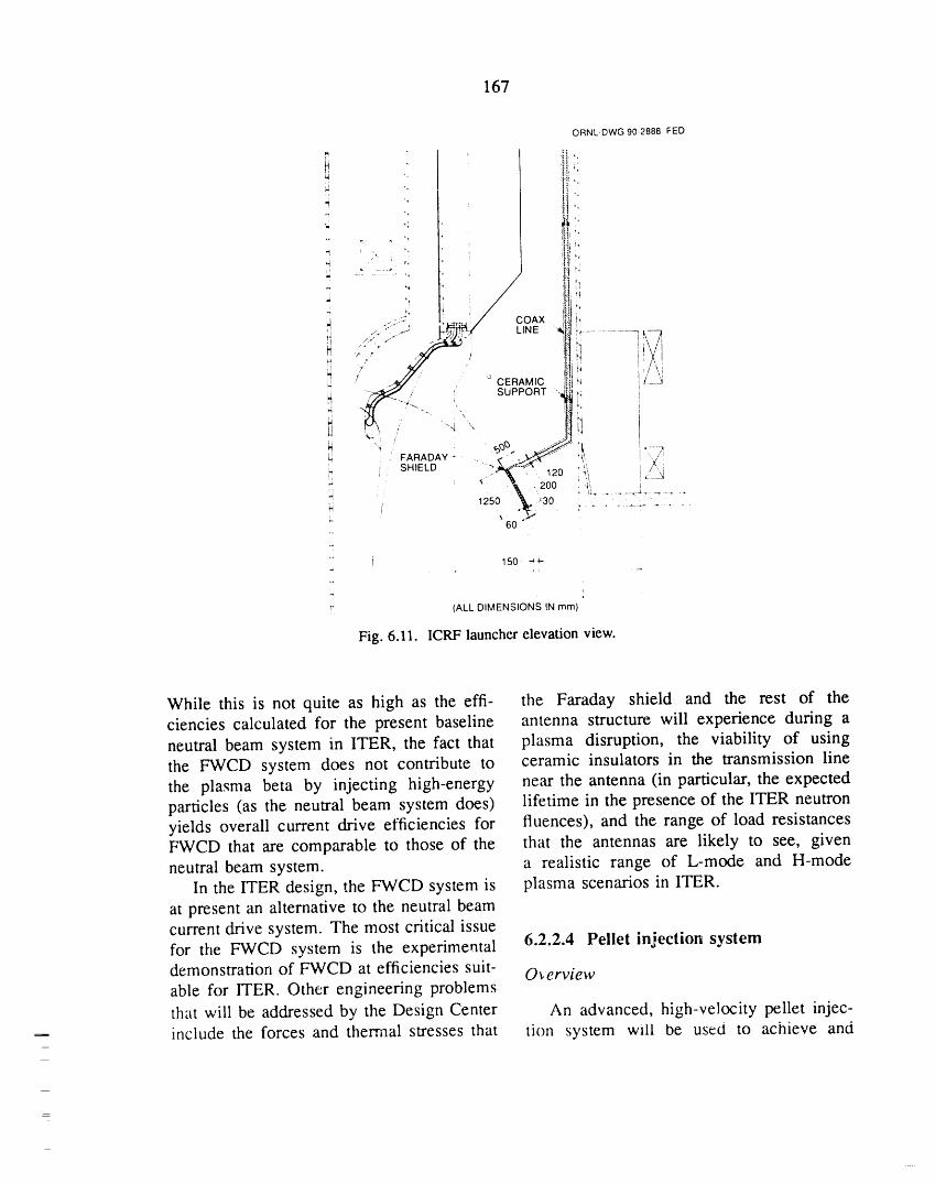
167
150 ""_.
-
- (ALL DIMENSIONS IN mm)
Fig. 6.11. ICRF launcher elevation view.
While this is not quite as high as the effi- the Faraday shield and the rest of theciencies calculated for the present baseline antenna structure will experience during aneutral beam system in ITER, the fact that plasma disruption, the viability of usingthe FWCD system does not contribute to ceramic insulators in the transmission linethe plasma beta by injecting high-energy near the antenna (in particular, the expectedparticles (as the neutral beam system does) lifetime in the presence of the ITER neutronyields overall current drive efficiencies for fluences), and the range of load resistancesFWCD that are comparable to those of the that the antennas are likely to see, givenneutral beam system, a realistic range of L-mode and H-mode
In the ITER design, the FWCD system is plasma scenarios in ITER.at present an alternative to the neutral beamcurrent drive system. The most critical issuefor the FWCD system is the experimental 6.2.2.4 Pellet injection system
demonstration of FWCD at efficiencies suit- O_erviewable for ITER. Other engineering problemsthat will be addressed by the Design Center An advanced, high-velocity pellet injec-include the forces and thermal stresses that tion system will be used to achieve and

168
maintain ignited plasmas on ITER. Staff extrapolation to ITER, in addition to itsmembers participated in a series of meetings contribution to the understanding of theof fuel cycle experts at Garching and have physics of pellet-fueled high-temperaturedeveloped a conceptual design description plasmas.for a flexible plasma fueling system, which Performance requirements for the 1TERincludes three pellet injectors in addition to pellet injection system were developed inthe traditional gas puffing system. For ramp- collaboration with ITER physics and engi-up to ignition, a highly reliable, moderate- neering staff to ensure sufficient performancevelocity (1- to 1.5-km/s), single-stage pneu- for the ITER mission while minimizingmatic injector and a high-velocity (4- to 5- impact on the isotope reprocessing systemkm/s), two-stage pneumatic pellet injector and local tritium inventory levels. Other as-using frozen hydrogenic pellets encased in pects considered are the need to develop thesabots will be used. For the steady-state burn suppporting technology in time for design,
phase, a continuous, single-stage pneumatic fabrication, and testing of the ITER pelletinjector is proposed; this injector will pro- injection system, followed by installation onvide a flexible source of fuel that penetrates ITER, to meet the first plasma milestone andto well beyond the edge region to aid in the need for technology that is adequate fordecoupling the plasma edge (constrained accelerating repetitive pellets (repetition rateby divertor requirements) from the high- of order 1 Hz) for long pulses (100 to 1000 s)temperature burning plasma. All three pellet at high component reliability (of order 90 toinjectors are designed for operation with 95%). These considerationseliminatedsometritium and D-T feed gas. Issues such as of the more advanced methods of plasmaperformance, neutron activation of injector fueling, such as electron-beam pellet ablationcomponents, maintenance, design of the and compact toroid fueling, from furtherpellet ipiection vacuum line, gas loads to the consideration.reprocessing system, and equipment layouthave been addressed. System descrzption
Staff members are also conducting R&D
in support of ITER fueling requirements, The specifications of the ITER pellet in-as described in Sect. 4 of this report, jection system are summarized in Table 6.5.Tritium single-pellet fabrication and accel- These specifications are met by a systemeration experiments have been conducted with three pneumatic pellet injectors: a high-on the Tritium Systems Test Assembly velocity (two-stage light gas gun) injectorat Los Alamos National Laboratory, and and two moderate-velocity (single-stage light
a program has been initiated to develop gas gun) injectors. The parameters of thesetritium-compatible extruders for long-pulse injectors are summarized in Table 6.6. Theirfueling. High-velocity pellet accelerators are arrangement in ITER is shown in Figs. 6.12uhde: development, including a repetitive and 6.13, with components identified intwo-stage pneumatic injector (4-5 km/s) Table 6.7.and, in the longer term, an electron-beam- The desigr, of the moderate-velocity in-heated, mass-ablation system. ORNL is jectors is similar to that of the JET pelletalso operating and maintaining state-of-the- injector. Each injector consists of two single-art pellet fueling systems on TFTR, Tore stage light gas guns in a vacuum enclosure.Supra, and JET. This experience _sproviding The diameters of the formed pellets (and ofan operational and reliability database for the gun barrels) may have to be 10 to 15%
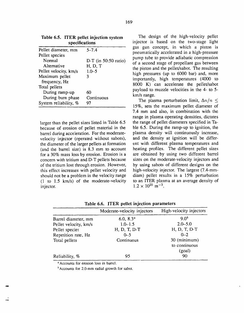
169
Table 6.5. ITER pellet injection system The design of the high-velocity pelletspecifications injector is based on the two-stage light
gas gun concept, in which a piston isPellet diameter, mm 5-7.4 pneumatically accelerated in a high-pressurePellet species pump tube to provide adiabatic compression
Normal D-T (in 50:50 ratio) of a second stage of propellant gas betweenAlternative H, D, T
the piston and the pellet/sabot. The resultingPellet velocity, km/s 1.0-5 high pressures (up to 6000 bar) and, moreMaximum pellet 3 importantly, high temperatures (4000 to
frequency, Hz 8000 K) can accelerate the pellet/sabotTotal pellets payload to muzzle velocities in the 4- to 5-
During ramp-up 60 km/s range.During burn phase Continuous The plasma perturbation limit, An/n <
System reliability, % 97 15%, sets the maximum pellet diameter of7.4 mm and also, in combination with therange in plasma operating densities, dictates
larger than the pellet sizes listed in Table 6.5 the range of pellet diameters specified in Ta-because of erosion of pellet material in the ble 6.5. During the ramp-up to ignition, thebarrel during acceleration. For the moderate- plasma density will continuously increase,velocity injector (operated wi_,ilout sabots), and the density at ignition will be differ-the diameter of the larger pellets at formation ent with different plasma temperatures and(and the barrel size) is 8.3 mm to account heating profiles. The different pellet sizesfor a 30% mass loss by erosion. Erosion is a are obtained by using two different barrelconcern with tritium and D-T pellets because sizes on the moderate-velocity injectors andof the tritium lost through erosion. However, by using sabots of different designs on thethis effect increases with pellet velocity and high-velocity injector. The largest (7.4-mm-should not be a problem in the velocity range diam) pellet results in a 15% perturbation(1 to 1.5 km/s) of the moderate-velocity to an ITER plasma at an average density ofinjector. 1.2 x 10²⁰ m -3.
Table 6.6. ITER pellet injection parameters
Moderate-velocity injectors High-velocity injectors
Barrel diameter, mm 6.0, 8.3 a 9.0 t'Pellet velocity, km/s 1.0-1.5 2.0-5.0Pellet species H, D, T, D-T H, D, T, D-TRepetition rate, Hz 0-5 0-2Total pellets Continuous 30 (minimum)
to continuous
(goal)Reliability, % 95 90
aAccounts for erosion loss in barrel.bAccountsfor 2.0-mmradial growth for sabot.
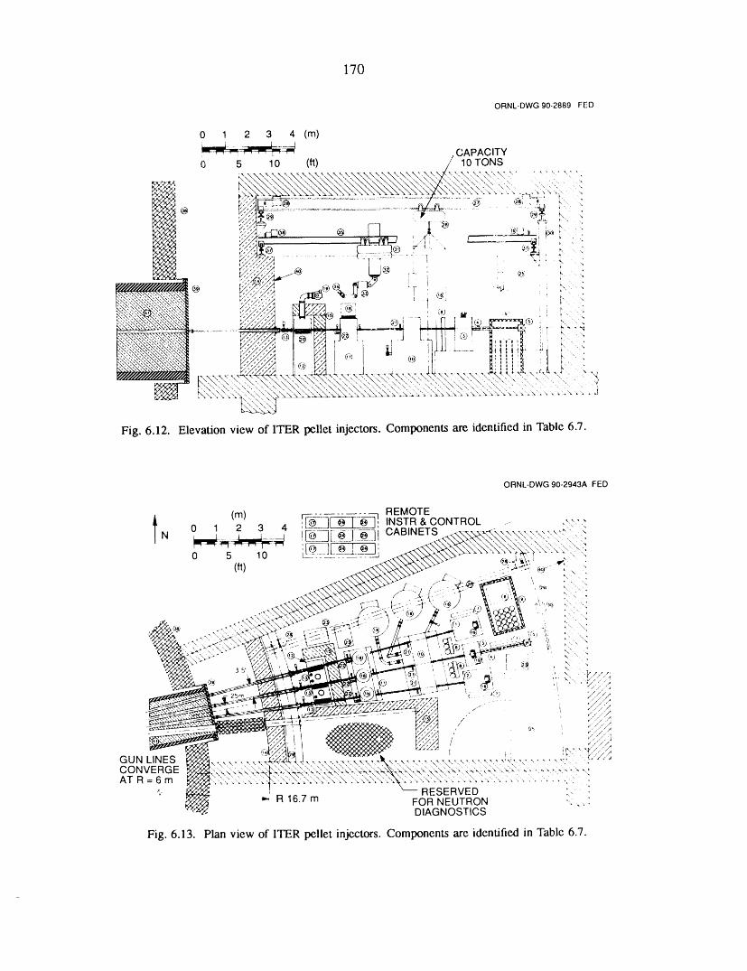
170
ORNL-DWG90-2889FED
0 1 2 3 4 (m)
__-=4_ /CAPACITY
0 5 10 (,ft) / 10 TONS ,
, , _ )J!;..... 1+,,.... .
, -',"-.'-_---.',U - ..\\. Q, "\\ _"."_. %.\.'..'.:.\"-". _",_.\.'-?- "..""-".\"._. "- .....7-;"..... ' . .. :"
;t_tt-..,:t:
Fill, 6.12, Elevation view of ITER pellet injectors. Corrlponents are identified in Table 6.7.

171
Table 6.7. Components of the ITER pellet injectorsNumbers refer to Figs. 6.12 and 6.13
1. Moderate-velocity injector 22. Rotatable targets2. Moderate-velocity injector 23. Backing pumps3. High-velocity injector (HVI) 24. Instrumentation cabinets4. HVI pump tube 25. Airlock5. HVI propellant reservoir 26. Crane, 10-ton capacity6. HVI propellant compressor 27. Crane beam7. Propellant gas manifolds 28. Crane beam gearnaotors8. Fuel gas manifolds 29. Crane rails9. High-pressure cage 30. Crane rail columns
10. Low-vacuum chamber 31. Manipulator turret11. Mid-vacuum chamber 32. Telescoping boom
12. High-vacuum chamber 33. Manipulator and camera13. Torus isolation valves, breaks, bellows 34. Dual replaceable end effectors14. Structural shielding wall 35. Manipulator bridge15. Modular shielding 36. Manipulator bridge gearmotors16. Normetex 1300-m3/h scroll pumps 37. Manipulator bridge rails17. Normetex control cabinets 38. ITER cryostat
18. Turbopumps, 5000 L/s 39. ITER vacuum vessel port 1619. Turbopumps, 500 L/s 40. Metal room liner20. Rotatable shielding drums and motors 41. In-port shielding21. Flow-limiting fast valves
As discussed in Sect. 6.1.4, the reliability centerline of vacuum vessel port 16, approx-
figures in Table 6.6 should be achievable, imately 24.5 m from the center of the ITERAlso, during the ramp-up to ignition, the machine. The moderate-velocity injectorshigh-velocity injector and one of the two are on either side of the two-stage pneumaticmoderate-velocity injectors will be used. injector; the centerlines of the three injectorsHaving two moderate-velocity injectors that converge in the midplane at the ITER majorcan be used interchangeably increases the radius of 6.0 m. To prevent the propellantsystem reliability, gas from reaching the torus, the injectors
The second moderate-velocity injector are isolated from the vacuum vessel by awill be used for continuous fueling, with series of three separately pumped vacuumpenetration significantly beyond the edge chambers connectedby conductance-limitingregion, during the burn phase. The high- pellet guide tubes and fast-acting flow-velocity injector can also be used during the limiting valves. The pellet injector bay isburn phase if piston lifetimes of 100 to 1000 shielded by the structural shielding wall;cycles can be achieved, by a rotating, eccentrically bored shielding
A plan view of the pellet injector in- drum in each injection line (to limit line-stallation is shown in Fig. 6.13. The two- of-sight exposure of the injectors); and bystage high-velocity injector is located on the modular shielding around the high-vacuuw
l

172
isolation chamber. The bay also serves as models. The DIII-D and TFTR databases fora redundant containment boundary and is volt-second consumption during the currentsealed by bellows at the shielding wall and ramp-up phase, especially as they apply toby an airlock at the entrance. Equipment in MHD-influenced (fast ramp) scenarios, werethe pellet injector bay is serviced by a 10- analyzed. Particle transport and fuelington crane and a bridge-mounted articulated (g:_.,_puffing vs pellet fueling) issues weremanipulator supported on curved rails at a_:_ssed. Detailed estimates of FWCD effi-machine radii of approximately 15.7 m and ciency were made with a two-dimensional,29.5 m. full-wave code. Finally, the ITER physics
R&D contributions received from various
experimental groups were coordinated.
6.2.3 ITER Physics *PlasmaTheory Section.
N. A. Uckan, J. T. Hogan, D. B. Batchelor,* "_Computing and Telecommunications Division,
B. A. Carreras,* J. A. Holmes,] W.A. MartinMariettaEnergy Systems, Inc.
Houlberg,* E. E Jaeger,* D. A. Spong,*
and D. W. Swain 6.2.3.1 ITER physics design guidelines
ORNL physicists actively participated in N. A. Uckan and ITER Physics Group*the ITER Conceptual Design Joint Work
during the winter (February-March 1989) The physics requirements for the ITERand summer (July-October 1989) sessions design have been set to provide reasonableat the Max Planck Institut ftir Plasmaphysik assurance thet the plasma performance will(IPP) Garching and played a key role in be sufficient to meet the goals of ITER inthe evolution of the ITER physics design, both the physics phase and the technologyThe primary areas of ORNL contributions to phase of operation. Considerations forITER physics studies were in MHD stability an adequate level of energy confinementand beta limits, confinement assessment, with a stable plasma, a satisfactory powerFWCD, and pellet fueling. In addition, and particle control system, an efficientwork has been carried out on axisymmetric heating and current drive scheme, a suitablemagnetics, alpha particle effects, helium ash plasma control system, a sufficient levelaccumulation and exhaust, and plasma-wall of volt-seconds, a need for high-fluenceinteractions, burn, etc., along with several engineering
Physics design guidelines and physics and technology constraints, set the machinespecifications for the design information parameters (size, field, current, etc.). Thedocument were prepared and published, physics _,pecifications and guidelines for theLimitations to the operational space arising ITER design are based on reasonable ex-from MHD instability (ideal and resistive, trapolations of the tokamak physics databaselinear and nonlinear, fluid and kinetic) were as assessed during the ITER Joint Workestimated, and the MHD databases for se,sions. The original guidelines, covetingcurrent drive and for peaked pressure and the period up to 1989, were summarized incurrent density profiles were extended. Vari- a recent publication. 9
' ous transport models were compared with theITER L-mode database, and the confinement *ITER Physics Group members: K. Borrass,capability of ITER was assessed using these S. Cohen, F. Engelmann, N. Fujisawa, M. Harrison,

173
J. Hogan, H. Hopman, S. Krasheninnikov, T. Mi- with favorable MHD stability properties can
zoguchi, V. Mukhovatov, W. Nevins, G. Pacher, be realized• lt is found that peaking theH. Pacher, V. Parail, D. Post, S. Putvinskij, density profile (from nominal square-rootM. Sugihara, D. Swain, T. Takizuka, T. Tsunematsu, parabolic form to parabolic squared) in theN. Uckan, J. G. Wegrowe, J. Wesley, S. Yamamoto, reference ITER scenario yields about the
R. Yoshino, and K. Young. same results as lowering the helium ashconcentration by about a factor of 2 (from thebaseline value of 10% to 5%) or increasing
the plasma current by about 20% (from6.2.3.2 ITER confinement capability the baseline value of 22 MA to 25 MA).
N A. Uckan and J. T. Hogan The ITER technology phase accommodates• several operational scenarios (ranging from
The confinement capability of ITER long-pulse to steady-state operation) with
physics and technology phase plasmas was Q > 5 and I _ 15-22 MA. Access to high-examined for a number of operational Q operation depends sensitively on the MHDscenarios, using the ITER physics design beta limits, current drive efficiency, andguidelines. 9 The impact of changes in these bootstrap current fraction. Representativeguidelines on ITER performance projections results are given in Figs. 6.14 and 6.15.was investigated. Both empirically basedconfinement scaling expressions (deducedfrom the ITER L- and H-mode databases) 6.2.3.3 ITER global stability limitsand several theoretical models were used in J. T. Hogan and N. A. Uckanthe analyses. Areas considered were theeffect of changes in density and temperature The stability-related limits to the opera-(pressure) profiles that can be realized from tional space of ITER physics and technologyvarious fueling and heating scenarios (sub- phase plasmas have been examined using theject to sawtooth and MHD stability consid- PEST 2 code (furnished by J. Manickamerations), operational boundaries, impurity of PPPL). Experimental results cannot beand helium ash concentrations, current drive
efficiency, bootstrap current fraction, and al-lowable fusion power (Pfus) levels. Achieve- ORNL-DWG90M-2891FEDTent of adequate energy confinement time 20 , ,(rE) for ignition (or energy multiplication HELIUMASH
CONCENTRATIONfactor Q > 10) in ITER requires attainment tz o%of an H-mode level of enhanced confinement o _,_,,_xx'_ ,_ [] 5%.FX"X")O(_ .'
with rE(H-mode) 2 x rz(L-mode). The o .....,,,,. _ 10%
reference scenario for the physics phase x _5 _, .---___"__"_
¢"'1
(I 22 MA with capability up to 25- "' t
= o28 MA, Pfu_ "-' 1.1 GW, average neutron ,,,wall loading _-, 1 MW/m 2) has substantial zignition (or Q >_ 10) capability. The , ,ignition capability of ITER can be further 10• 22 25 28
improved if some of the limits on operational I(MA)boundaries can be relaxed and if centrally Fig. 6.14. ITER ignition capability at 1 MW/m 2
peaked density and heat deposition profiles (ITER-P scaling).
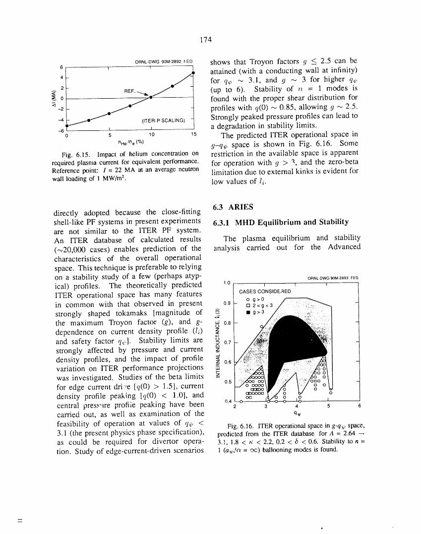
174
ORNL-DWG90M-2892FED shows that Troyon factors 9 -< 2.5 can be6 ' ' .., attained (with a conducting wall at infinity)4
/_ for q,/, ,-_ 3.1, and 9 _ 3 for higher q_,l
2- REF.-...._ /- (up to 6). Stability of n = 1 modes is<
0 /" found with the proper shear distribution for-2 /" profiles with q(0) _ 0.85, allowing 9 '_ 2.5.
/" Strongly peaked pressure profiles can lead to-4 /, (ITER-P SCALING)
4 , _ a degradation in stability limits.0 5 10 5 The predicted ITER operational space in
nile/he(°/°) 9-q,l, space is shown in Fig. 6.16. SomeFig. 6.15. Impact of helium concentrationon restriction in the available space is apparent
required plasma current for equivalent performance, for operation with 9 > "_,and the zero-betaReference point: / = 22 MA at an average neutron limitation due to external kinks is evident forwall loading of 1 MW/mz. low values of li.
6.3 ARIESdirectly adopted because the close-fittingshell-like PF systems in present experiments 6.3.1 MHD Equilibrium and Stabilityare not similar to the ITER PF system.An ITER database of calculated results The plasma equilibrium and stability
(--_20,000 cases) enables prediction of the analysis carried out for the Advancedcharacteristics of the overall operational
space. This technique is preferable to relyingon a stability study of a few (perhaps atyp- ORNL-OWGg0M-2893FEOical) profiles. The theoretically predicted 1.0 , , ,ITER operational space has many features CASESCONSlDE;qEDo g>0in common with that observed in present 0.9 [] 2< g < 3
strongly shaped tokamaks [magnitude of _ • g:,3,:_-
the maximum Troyon factor (g), and g- _j 0.8dependence on current density profile (Ii) z<i--and safety factor q_,]. Stability limits are o=0.7a
strongly affected by pressure and current z__.1
density profiles, and the impact of profile <z 0.6
variation on ITER performance projections iiii-.
was investigated. Studies of the beta limits z 0.5
for edge current dri.,e [q(0) > 1.5], currentO
density profile peaking [q(0) < 1.0], and ocentral pres.,"lre profile peaking have been o.42 3 4 5 6
carried out, as well as examination of the q_,feasibility of operation at values of q,;, < Fig. 6.16. ITER operationalspace in g'q4.,space,3.1 (the present physics phase specification), predicted from the ITER database for A = 2.64 --,
as could be required for divertor opera- 3.1, 1.8 < h; < 2.2, 0.2 < 6 < 0.6. Stabilityto n =tion. Study of edge-current-driven scenarios I (au,/c_'= c'<))ballooningmodes is found.
mm
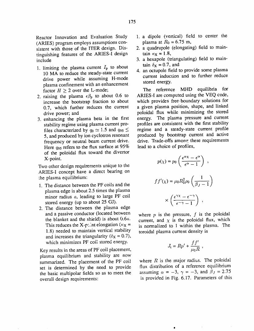
175
Reactor Innovation and Evaluation Study 1. a dipole (vertical) field to center the
(ARIES) program employs assumptions con- plasma at Ro = 6.75 m,sistent with those of the ITER design. Dis- 2. a quadrupole (elongating) field to main-
tinguishing features of the ARIES-I design tain nx = 1.8,include 3. a hexapole (triangulating) field to main-
1. limiting the plasma current I l, to about tain _x = 0.7, and10 MA to reduce the steady-state current 4. an octupole field to provide some plasmadrive power while assuming H-mode current induction and to further reduceplasma confinement with an enhancement stored energy.factor H > 2 over the L-mode; The reference MHD equilibria for
2. raising the plasma eflp to about 0.6 to ARIES-I are computed using the VEQ code,increase the bootstrap fraction to about which provides free-boundary solutions for0.7, which further reduces the current a given plasma position, shape, and linkeddrive power; and poloidal flux while minimizing the stored
3. enhancing the plasma beta in the first energy. The plasma pressure and currentstability regime using plasma current pro- profiles are consistent with the first stabilityfiles characterized by q0 -_ 1.5 and q95 _ regime and a steady-state current profile5, and produced by ion cyclotron resonant produced by bootstrap current and activefrequency or neutral beam current drive, drive. Trade-offs among these requirementsHere q95 refers to the flux surface at 95% lead to a choice of profiles,of the poloidal flux toward the divertor
- ,°)X-point. P(X) = po k, e°' 1 'Two other design requirements unique to theARIES-I concept have a direct bearing on
:heplasmaequilibrium" ( 1 )1. The distance between the PF coils and the ff'(x) = #ol_po _j - 1
plasma edge is about 2.5 times the plasma
minor radius a, leading to large PF coil (e'rX-e-'r_stored energy (up to about 25 GJ). x \ _-22f_- _ / ,
2. The distance between the plasma edge
and a passive conductor (located between where p is the pressure, f is the poloidalthe blanket and the shield) is about 0.6a. current, and X is the poloidal flux, whichThis reduces the X-p_'nt elongation (nx = is normalized to 1 within the plasma. The1.8) needed to maintain vertical stability toroidal plasma current density isand increases the triangularity (_x = 0.7),which minimizes PF coil stored energy.
Key results in the areas of PF coil placement, Jt = Rp' + f f-----_'poR '
plasma equilibrium and stability are nowsummarized. The placement of the PF coil where R is the major radius. The poloidalset is determined by the need to provide flux distribution of a reference equilibriumthe basic multipolar fields so as to meet the assuming o_= -3, _ = -3, and /_j = 2.75overall design requirements: is provided in Fig. 6.17. Parameters of this
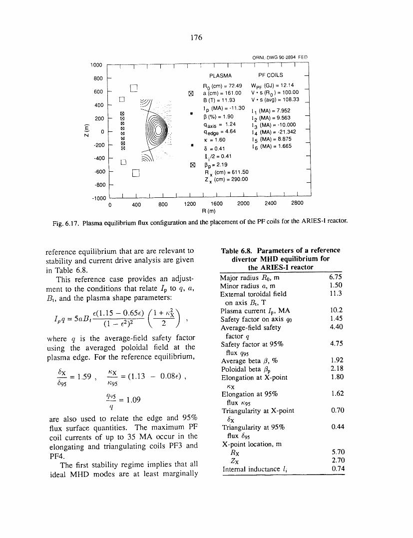
176
ORNL-DWG90-2894FED
1000 ...... 1' I----T-- 1 1- 1 I 1 1 I [ F- I 1
PLASMA PF CQILS -800 -
RO(cm) = 72.49 WpF (GJ) = 12.14600 - [_ [] a (cm) = 161.00 V. s (R0) = 100.00 -
[] _ . ,.ii. B (T) = 11.93 V. s (avg) = 108.33 _400 - lp (MA)=-11.30 11 (MA)=7.952[] m200 - [] _ (%) = 1.90 12 (MA) = 9.563 -
... I_ qaxis = 1.24 13 (MA) = -10.000o- _
N _ qedge = 4.64 14 (MA) = -21.342_ = 1.60 15 (MA) = 8.875
-200 - [] , -[] • 8 = 0.41 16 (MA) = 1.665
_ " .• " /2 = 0.41 -
-400 -- " 9,i
[] [] _p= 2.19 m
-600 - [_ R x (cm) = 611.50Z x (cm) = 290.00
-800 -
-1000 I I I I I I I I l 1 I I I 10 400 800 1200 1600 2000 2400 2800
R (rn)
Fig. 6.17. Plasma equilibrium flux configuration and the placement of the PF coils for the ARIES-I reactor.
reference equilibrium that are are relevant to Table 6.8. Parameters of a reference
stability and current drive analysis are given divertor MIlD equilibrium forin Table 6.8. the ARIES-I reactor
This reference case provides an adjust- Major radius Ro, m 6.75
ment to the conditions that relate lp to q, a, Minor radius a, m 1.50External toroidal field 11.3
/3t, and the plasma shape parameters: on axis Br, T
ipC1=5aBte(X}15_O.65e) (1+,_.) Plasmacurrent/p, MA 10.21 - e2)2 2 ' Safety factor on axis q0 1.45Average-field safety 4.40
where q is the average-field safety factor factor q
using the averaged poloidal field at the Safety factor at 95% 4.75flux q95
plasma edge. For the reference equilibrium, Average beta/3, % 1.92
_x _X Poloidal beta/3p 2.18= 1.59 , - (1.13 - O.08e) , Elongation at X-point 1.80
_95 _95 _cX
Elongation at 95% 1.62q,_5 _ 1.09 flux /';95
q Triangularity at X-point 0.70are also used to relate the edge and 95% _Sx
flux surface quantities. The maximum PF Triangularity at 95% 0.44
coil currents of up to 35 MA occur in the flux _95
elongating and triangulating coils PF3 and X-point location, mPF4. Rx 5.70
The first stability regime implies that ali Zx 2.70Internal inductance li 0.74ideal MHD modes are at least marginally
177
stable in the absence of a conducting 6.3.2 Pellet Fuelingshell beyond the plasma edge. Whilethis requirement is broad in scope, it is An advanced pneumatic pellet injectionusually adequate to examine only the high-n system was developed for the ARIES-Iballooning modes and the low-n (n = 1) kink fusion reactor study. The flexible system willmodes to determine the stability beta limit, use three pneumatic pellet injectors based onAs an input to design trade-offs involving existing or near-term technology to achieveplasma shaping, profile, aspect ratio, and the and maintain ignited D-T plasmas. Duringbeta limit, our study emphasizes clarifying the density ramp-up to ignition, a moderate-the dependences of beta on .4, x95, q0, and velocity (1- to 1.5-km/s), single-stage pneu-q95. Only the traditionally successful profile matic injector and a high-velocity (4- to 5-functions have been used for the analysis, km/s), two-stage pneumatic pellet injectorsuch as those used for ITER and in reviews using frozen hydrogenic pellets encased in
of the large body of information in the sabots will be used. For the continuous-literature. Calculations are carried out for burn phase, a single-stage pneumatic injector
high-A (A = 4.5 and 6.0) ARIES-I plasmas is proposed. This injector will provideusing the PEST equilibrium and stability a flexible fueling source beyond the edgecodes to "fill in" data where needed. The region to allow decoupling the edge region
combined database of the stability analysis (constrained by divertor requirements) fromcovers a range of A = 2.6-6.0, t¢95 "- 1.6- the high-temperature burning plasma. Ali3.2, q0 = 1.05-2.0, and q95 <_ 5. three pellet injectors are qualified fi,r oper-
ation with tritium feed gas. Issues such asThe dependence of the beta limit on n95and e (= 1lA), expressed in terms of the performance, neutron activation of injectorTroyon factor limit (CT = /3aBt/Ip, in components, maintenance, design of pellet%.m.T/MA) is injection vacuum line, gas loads to the
reprocessing system and equipment layout
1 -0,4(_95 -- 1) 2 have been addressed.CT = 2.8
(1 - e)1"5 ' REFERENCES
which gives CT _ 3.4 and _ _-,2.1% for the 1. D. Macdonald, "Maintenance Concept Devel-
reference plasma parameters in Table 6.8. It opment for the CIT," presented at the ANS Thirdhas also been shown that for A _> 3, this Topical Meeting on Robotics and Remote Systems,
beta limit remains relatively unchanged as Charleston, S.C., March 1989.long as li remains below 0.75. Additional 2. R. E. DePew and D. Macdonald, "Remotestudies of the beta limit have been carried Maintenance of Compact Ignition TokamakEx-VesselOUt for plasmas using polynomial profiles Systems,"pp. 593-6 in Proceedingsof the IEEE 13rhand parameters encompassing the reference Symposiumon Fusion Engineering,Knoxville,1989,case: Ip ranging from 16 to 8 MA, q95 from vol. 1, IEEE, New York, 1990.3 to 6, and/3p from 1.4 to 3. The value of CT 3. S. K. Combs et al., "Performance of ais 3.1 to 3.2 as long as q95 is above 3.7. This Pneumatic Hydrogen-Pellet Injection System on theresult is considered conservative relative to Joint European Torus,"Rev. Sci. lnstrum. 60, 2697-the preceding indicatiot :. Design values of 2700 (1989).
CT = 3.2 (corresponding 'o /3 = 1.9%) and 4. D.J. Strickleret al.,"MHD Equilibrium Using
li = 0.74 are therefore adopted for ARIES-I Free-BoundaryControl Matrix,"Bull.Am. Phys.Soc.(see Table 6.8). 34, 1972(1989).
178
5. s. c. Jardin, N. Pomphrey, and J. Dclucia, 7. J. Leuer, private communication.
"Dynamic Modeling of Transport and Positional 8. D. J. Strickler et al., Equilibrium Modeling of
Control of Tokamaks," J. Comput. Phys. 66, 481 the TFCX Poloidal Field Coil System, ORNL/FEDC-
(1986). 83/10, Martin M,-u-ietta Energy Systems, Inc., Oak
6. ITER Systems Group and ITER Physics Group, Ridge National Laboratory, April 1984.
ITER Operational Scenarios for Ignition, Steady- 9. N. A. Uckan and the ITER Physics
Stcte and llybrid Modes: Final Performance for Group, ITER Physics Design Guidelines 1989,
the New Impurity Specifications, ITER-IL-SA-1-9-36, IAEA/ITER/DS-10, IAEA, Vienna, February 1990.International Thermonuclear Experimental Reactor
Joint Working Group, Garching, Federal Republic of
Germany, 1989.
7FUSION MATERIALS RESEARCH

E. E. Bloom 1
Fusion Materials Program Manager
D. J. Alexander 1 R J. Maziasz 1
G. E. C. Bell a A. E Rowcliffe 1
D. N. Braski 1 T. Sawai /
T. D. Burchell 1 R.L. Senn 3
M. L. Grossbeck 1 I.I. Siman-Tov 3
T. Inazumi 2 R.E. Stoller 1
R. L. Klueh 1 K.R. Thorns 3
A. W. Longest 3 E F. Tortorelli 1
L. K. Mansur I S" J" Zinklel
1. Metals and Ceramics Division.
2. Japan Atomic Energy Research Institute, Ibaraki-ken, Japan.3. Engineering Technology Division.
180
7. FUSION MATERIALS RESEARCH
SUMMARY OF ACTIVITIES
The Fusion Materials Program at ORNL is active in three areas of materials research anddevelopment: structural materials for the first wall and blanket, graphite and carbon-carboncomposites for plasma-interactive and high-heat-flux components, and ceramics for electrical,optical, and possible structural applications. About 75% of our work directly supportsthe Compact Ignition Tokamak and the International Thermonuclear Experimental Reactor(ITER). The remainder is focused on longer-term issues associated with the developmentof structural materials for fusion power reactors. Research on Fe-Cr-Ni austenitic steels,leading candidates for ITER structural applications, is conducted collaboratively with theJapan Atomic Energy Research Institute. This research will provide the major portion of thedatabase on structural materials for first wall and blanket design. Research on irradiation-induced stress-corrosion cracking of austenitic steels, effects of irradiation on low-temperaturefracture toughness, development of low-activation Fe-Cr-Mn austenitic steels, mechanicalbehavior of copper and copper alloys, irradiation performance of ceramics, and irradiationeffects in graphite and carbon-carbon composites also addresses critical questions identifiedin the initial phases of the ITER project. In the longer term, the economic and environmentalacceptability of fusion will depend in large measure on the development of materials thatminimize the radioactive waste burden and have adequate properties from the viewpointsof systems engineering, safety, and lifetime capability. To address this question, we arepursuing the development of low-activation austenitic and ferritic steels, vanadium alloys,and structural ceramics.
181
182
7.1 STRUCTURAL MATERIALS damage rate, helium generation rate, andneutron fluence characteristic of the first
7.1.1 Austenitic Stainless Steels: The wall and blanket (FWB) structure of theU.S.-Japan Collaborative Program International Thermonuclear Experimental
Reactor (ITER). These spectrally tailoredThe austenitic stainless steels have occu- experiments completed their initial dose
pied a central position in structural materials increment of 8 dpa in the ORR and haveprograms worldwide for the past decade. A been re-encapsulated for further irradiationvast amount of commercial experience exists in the HFIR RB* positions. The third seton fabrication, welding, and mechanical and of experiments consists of a set of eightcorrosion behavior. Irradiation behavior in HFIR target capsules containing isotopicallyfast breeder reactor environments has been tailored alloys. These experiments willextensively studied. It has been shown explore the swelling resistance of advancedthat alloys such as D9 and prime candidate austenitic steels that have been composi-alloy (PCA) maintain swelling resistance and tionally and microstructurally adjusted tofavorable mechanical behavior at neutron improve the swelling resistance of the PCAdoses approaching 100 displacements per in the fusion environment. These experi-atom (dpa) for temperatures in the range ments will explore doses up to 70 dpa atfrom 400 to 650°C. temperatures ranging from 300 to 600°C
The U.S.-Japan collaborative program is and will provide information relevant to thefocused on determining the behavior of design of advanced FWB module conceptsaustenitic stainless steels under irradiation for ITER.
conditions that are more typical of the fusion During the past year, data were obtainedenvironment. Irradiation experiments are from the ORR 6J/7J spectrally tailoredconducted in the mixed-spectrum fission experiments on swelling, tensile, and creepreactors [the Oak Ridge Research Reactor properties of U.S. and Japanese alloys, lt(ORR) and the High-Flux Isotope Reactor is concluded that void swelling will not(HFIR)]. The two-step reaction between the be a problem for AISI 316 or PCA undernickel component of the steel and thermal ITER conditions, provided FWB tempera-neutrons results in the generation of helium; tures remain below 400°C. Swelling couldthe rate of helium generation can be adjusted be significant at 300°C, however, if a low-either by modifying the ratio of thermal to carbon version of AISI 316 is used. Forfast neutrons (spectral tailoring) or by adjust- temperatures up to 500°C, tensile propertiesing the ratio of SSNi and 6°Ni isotopes in the are not very sensitive to spectral or damagesteel (isotopic tailoring). The collaborative rate variations. At temperatures belowprogram embraces three sets of irradiation 400°C, the spectrally tailored experimentsexperiments. The first set of experiments have shown that the most significant effectwas conducted in HFIR target positions and of neutron irradiation is radiation hardeningexplored the effects of high concentrations coupled with a severe reduction in workof helium (>2000 appm) on the tensile, hardening capacity. The possible impact offatigue, and swelling properties of austenitic this phenomenon on fracture toughness isstainless steels at temperatures in the range being studied under a further collaborativefrom 300 to 600°C; this work was completed experiment.in 1988. The second set of experiments Using miniature pressurized tubes, it waswas designed to reproduce the temperatures, shown that irradiation creep is a significant
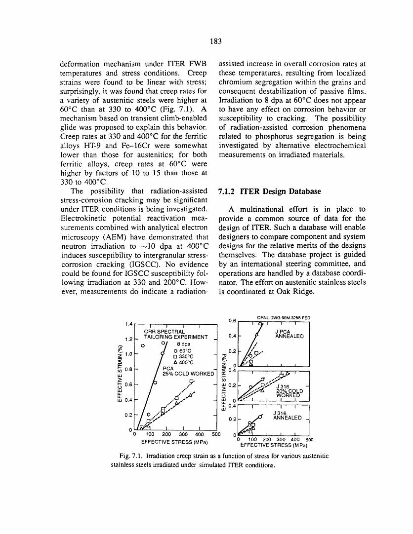
183
deformation mechanism under ITER FWB assisted increase in overall corrosion rates at
temperatures and stress conditions. Creep these temperatures, resulting from localizedstrains were found to be linear with stress; chromium segregation within the grains andsurprisingly, it was found that creep rates for consequent destabilization of passive films.a variety of austenitic steels were higher at Irradiation to 8 dpa at 60°C does not appear60°C than at 330 to 400°C (Fig. 7.1). A to have any effect on corrosion behavior ormechanism based on transient climb-enabled susceptibility to cracking. The possibilityglide was proposed to explain this behavior, of radiation-assisted corrosion phenomenaCreep rates at 330 and 400°C for the ferritic related to phosphorus segregation is beingalloys HT-9 and Fe-16Cr were somewhat investigated by alternative electrochemicallower than those for austenitics; for both measurements on irradiated materials.ferritic alloys, creep rates at 60°C werehigher by factors of 10 to 15 than those at330 to 400°C,
The possibility that radiation-assisted 7.1.2 ITER Design Databasestress-corrosion cracking may be significantunder ITER conditions is being investigated. A multinational effort is in piace toElectrokinetic potential reactivation mea- provide a common source of data for thesurements combined with analytical electron design of ITER. Such a database will enablemicroscopy (AEM) have demonstrated that designers to compare component and systemneutron irradiation to --_10 dpa at 400°C designs for the relative merits of the designsinduces susceptibility to intergranular stress- themselves. The database project is guidedcorrosion cracking (IGSCC). No evidence by an international steering committee, andcould be found for IGSCC susceptibility fol- operations are handled by a database coordi-lowing irradiation at 330 and 200°C. How- nator. The effort on austenitic stainless steelsever, measurements do indicate a radiation- is coordinated at Oak Ridge.
ORNL-DWG90M-3258FED0.6 u u u I
_!oRRSPECTa , JPCATAILORING EXPERIMENT 0.4 ANNEALED
1.2| o o/ 8dpa °.-. ,,,L d o 6o°c 0.2 , •
_z_.o/ lrl 330°C - ._"
< -- /PCIA& 400°Crr" z 0 I l I_" 0.8touJ / 25% COLD WORKED- _ °'41 ' ' .[_,O, ' I
JF- 0.6 _ J 3160 _ 0.2 -III d'°q'°
,, .." , @ / /...¢;,"_ 20% COLD.4_', ,,'_' _ I,,(_,_';";-"" WORKEDLt. ,uJ 0 lP.;,'- I I I I
,,,0, / m°4i ' ' ' ' //o _ -0.2 / _;;_..- 0.21.. _ _' ANNEALED 1r_- _ _ ,
0 0 100 200 300 400 500 0 I I I
EFFECTIVE STRESS (MPa) 0 100 200 300 400 5ooEFFECTIVE STRESS (M Pa)
Fig. 7.1. Irradiationcreep strain as a functionof stress forvariousausteniticstainlesssteels irradiatedunder simulatedITER conditions.
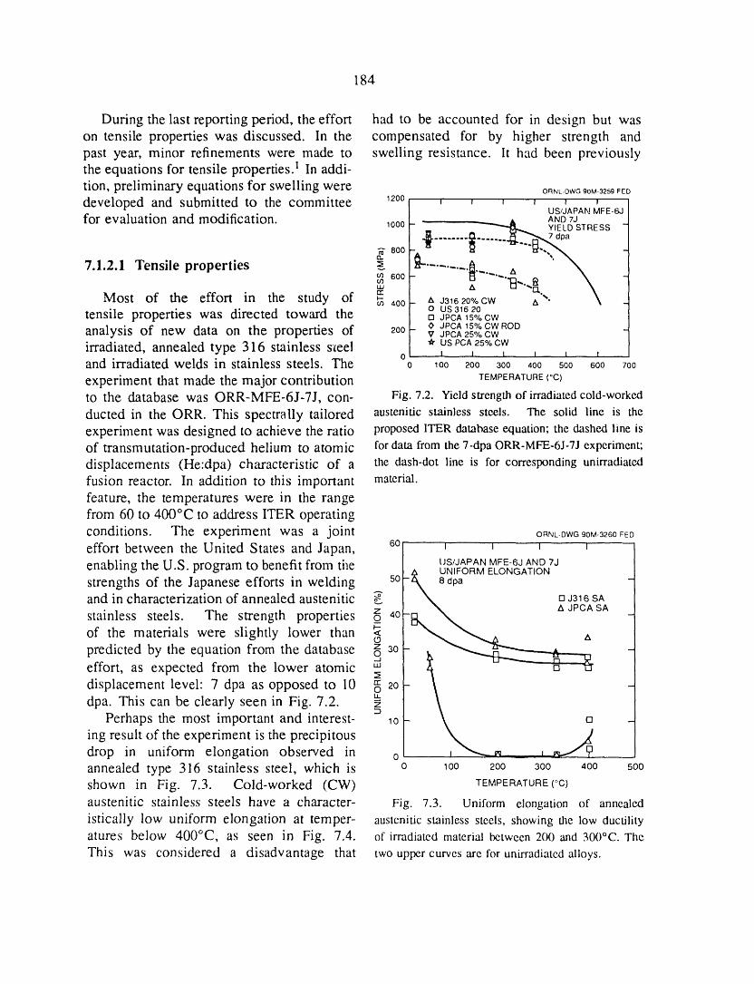
184
During the last reporting period, the effort had to be accounted for in design but wason tensile properties was discussed. In the compensated for by higher strength andpast year, minor refinements were made to swelling resistance. It had been previouslythe equations for tensile properties. _ In addi-tion, preliminary equations for swelling were oRNLDWG90,.,32_F_t,developed and submitted to the committee 1200 _. , , , , . ,US/JAPAN MFE-6J
for evaluation and modification, looo A AND7J- _ YIELD STRESS -
{ ...............7.1.2.1 Tensile properties _ 800
Most of the effort in the study of _ 400- " Jal_20yoCW _'". \0 US 316 20
tensile properties was directed toward the n JPCA15%CWanalysis of new data on the properties of 200- VOJPcAJPCA25'/,,15°/°CWRODcwirradiated, annealed type 3 16 stainless smel * us PCA2SO/ocw
o 1 I I I 1 Iand irradiated welds in stainless steels. The o lo0 200 a00 400 500 600 700
experiment that made the major contribution TEMPERATURE (°C)
to the database was ORR-MFE-6J-7J, con- Fig. 7.2. Yieldstrengthof irradiatedcold-worked
ducted in the ORR. This spectrally tailored austenitic stainless steels. The solid line is theexperiment was designed to achieve the ratio proposedITER databaseequation;the dashed line isof transmutation-produced helium to atomic for data from the 7-dpaORR-MFE-6J-7Jexperiment;displacements (He:dpa) characteristic of a the dash-dot line is for corresponding unirradiatedfusion reactor. In addition to this important material.feature, the temperatures were in the rangefrom 60 to 400°C to address ITER operatingconditions. The experiment was a joint On_L-0WGg0M326OFEOeffort between the United States and Japan, 6o _ _ _enabling the U.S. program to benefit from tim US/JAPANMFE-6JAND7J,_ UNIFORM ELONGATION
strengths of the Japanese efforts in welding 5o-N 8 dpaand in characterization of annealed austenitic _ N []J316SA
stainless steels. The strength properties Z_o40 _:__" AJPCASA _
of the materials were slightly lower than _ -'__^ A© a
predicted by the equation from the database _ 30 - _ __--_---.__effort, as expected from the lower atomic
displacement level: 7 dpa as opposed to 10 _ 20 [__ A -
dpa. This can be clearly seen in Fig. 7.2. zPerhaps the most important and interest- _ _o
ing result of the experiment is the precipitousdrop in uniform elongation observed in o = .... 'annealed type 316 stainless steel, which is o _oo 200 aoo 400 500shown in Fig. 7.3. Cold-worked (fW) TEMPERATURE(°C)austenitic stainless steels have a character- Fig. 7.3. Uniform elongation of annealedistically low uniform elongation at temper- austenitic stainless steels, showing the low ductilityatures below 400°C, as seen in Fig. 7.4. of irradiated material between200 and 300°C. TheThis was considered a disadvantage that two upper curves are for unirradiatedalloys.

185
OFINL-DWG90M-3261 FED ORNL-DWG 90M-3262 FED
30 I I I I I ITEST TEMPERATURE (OF)
A J316 20% CWo_ 25- DJPCA15%CW - 32 212 392 572 752 932 1112 1292 1472
¢ JPCA15 .ROD 801 ' ' ' ' ' ' ' I0 20 0 us 316 20'/_cwr-- - _r US PCA25',/.CW - | STRAIN RATE (min-1) /
? 70r o02.--. I A 0.02 /
0 15-A - o_ _Ld D 0.004 j_u _ US/JAPANMFE-6JAND7J 60_; 10 - % UNIFORMELONGATION _ _ -_ V 0.0004 q
I_ _ 7dpa I __, j,, I_, "__ _ I _ 50__ s I-U", "- ...... o_ --I _ "_'
t
= I° "-.. .......;:i". I 7° , ......v.. ";0 / .A , .... 1_...... "'J_'"L_" i I / O 40uJ
0 100 200 300 400 o 500 600 700TEMPERATURE(C) _ 30,9
Fig. 7.4. Uniform elongation for cold-worked _ 20 - "". '_'*o
austenitic stainless steels. The dashed curves are "_tfor unirradiated alloys; the solid curve is for 10- Icorresponding alloys irrdiated in the ORR-MFE-6J- 0 I I I I I
7Jexperiment. 0 100 200 300 400 500 600 700 800TEST TEMPERATURE (°C)
Fig. 7.5. Uniform elongation as a function of test
temperature at several strain rates for 16-mm (0.625-thought that annealed material did not suffer in.) plate of the reference heat (8092297) of type 316
this premature plastic instability leading to stainless steel in the reannealedcondition.low uniform elongation. As a result of theORR experiment, it is now known that thisis an incorrect perception.
The reason for this behavior is not relevant to this behavior is the presence of
yet understood. However, analysis of the a yield point at temperatures below 400°C.fracture surfaces and transmission electron This alone suggests the involvement of
microscopy (TEM) studies are both planned dislocation barriers that diffuse too slowlyto help determine the mechanism of this at low temperatures to remain with thebehavior. Some possible mechanisms that dislocations. The next question to askcan contribute to the observed behavior are is whether any interstitial impurities arediscussed here. sufficiently mobile at temperatures of 200°C
As can be seen from Fig. 7.3, even to cause a change in behavior as temperaturethe unirradiated alloy experiences decreasing decreases in this range. Diffusivity data foruniform elongation as temperature increases carbon, nitrogen, and boron were used tofrom 60 to 200°C. This behavior has been construct the plot in Fig. 7.6 (ref. 3). Boron
previously observed in austenitic stainless is not considered a major impurity in thesesteels, as shown by the data in Fig. 7.5, alloys but was included for completenesswhich were obtained as part of the U.S. in the analysis. Carbon is, of course, theBreeder Reactor Program. 2 The first step in most likely candidate, and it is seen thatunderstanding the very precipitous drop in the diffusion distance (Dr) ]/2, where D isuniform elongation in irradiated material is the diffusivity and t is the time available,to understand the mechanism active in the is on the order of ten atomic diametersunirradiated material. The first observation for a 1-min time interval at 200°C. At
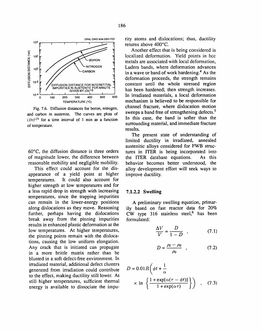
186
ORNL-DWGg0M-3263FEDrity atoms and dislocations; thus, ductility104_ I ' ' ' j....2.._ -_ returns above 400°C.
I _ -_-- Another effect that is being considered is
_- 10a . localized deformation. Yield points in bccz metals are associated with local deformation,<I--o9 / fJ \ X'NITROGEN Luders bands, where deformation advances
z in a wave or band of work hardening. 4 As theodeformation proceeds, the strength remains
10-2-----. "/'_ISTANCE FORINTERSTITIAL constant until the whole stressed regiono / _SlNAUSTENITE PER MINUTE
" GIVENBY(DI)1/2 , has been hardened; then strength increases.10-, _ _ t _ In irradiated materials, a local deformation0 100 200 300 400 500 600
TEMPERATURE (°C) mechanism is believed to be responsible for
Fig. 7.6. Diffusiondistancesfor boron, nitrogen, channel fracture, where dislocation motionand carbon in austenite. The curves are plots of sweeps a band free of strengthening defects. 5(Dr) 1/2 for a time interval of 1 min as a function In this case, the band is softer than the
surrounding material, and immediate fractureof temperature.results.
The present state of understanding oflimited ductility in irradiated, annealedaustenitic alloys considered for FWB struc-
60°C, the diffusion distance is three orders tures in ITER is being incorporated intoof magnitude lower, the difference between the ITER database equations. As thisreasonable mobility and negligible mobility, behavior becomes better understood, the
This effect could account for the dis- alloy development effort will seek ways toappearance of a yield point at higher improve ductility.temperatures. It could also account forhigher strength at low temperatures and for
a less rapid drop in strength with increasing 7.1.2.2 Swellingtemperatures, since the trapping impuritiescan remain in the lower-energy positions A preliminary swelling equation, primar-along dislocations as they move. Reasoning ily based on fast reactor data for 20%further, perhaps having the dislocations CW type 316 stainless steel, 6 has beenbreak away from the pinning impurities formulated:results in enhanced plastic deformation at thelow temperatures. At higher temperatures, AV Dthe pinning points remain with the disloca- _ = 1 - D ' (7.1)tions, causing the low uniform elongation.Any crack that is initiated can propagate D = Pf--/90 (7.2)I
in a more brittle matrix rather than be p0blunted in a soft defect-free environment. Inirradiated material, additional defect clusters [ 1
generated from irradiation could contribute D = 0.0lR _t +- O_
to the effect, making ductility still lower. At
stillhighertemperatures, sufficientthermal xln {l+exp[a(r-_O]})energy is available to dissociate the impu- 1 +exp(o_r) , (7.3)
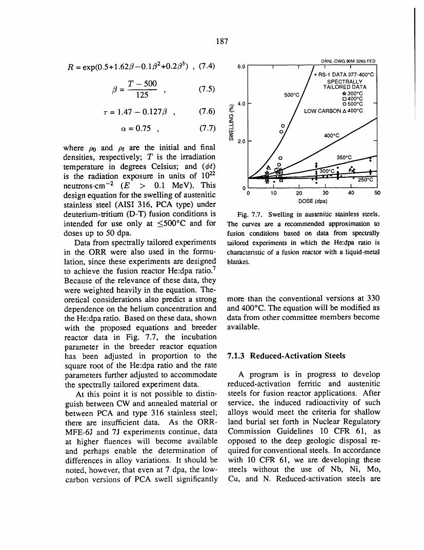
187
ORNL-DWG90M-3265FED
R=exp(0.5+l.62_--0.1f12+0.2fl 3) , (7.4) 6.0 I I / I I
/* RS-1 DATA 377-400°C] SPECTRALLY
,8 : T -125500 (7.5) / TAILOREDDATA500oc / _ 300°C/ El400°C
._.40 - / osoooc -7-= 1.47-0.127fl (7.6) _ / LOWCARBONA400*C(.9
--I, o_ - 0.75 , (7.7) _
2.o-
where po and pf are the initial and final
densities, respectively; T is the irradiation / o __ 3s0_cj........-_,temperature in degrees Celsius; and (q_t) /_xc_,f _a... ,_is the radiation exposure in units of 1022
• 250 °Cneutrons.cre -2 (E > 0.1 MEV). This 0 i i i idesign equation for the swelling of austenitic 0 10 20 30 40 sostainless steel (AISI 316, PCA type) under DOSE(dpa)deuterium-tritium (D-T) fusion conditions is Fig. 7.7. Swelling in austenitic stainless steels.intended for use only at <500°C and for The curves are a recommended approximation todoses up to 50 dpa. fusion conditions based on data from spectrally
Data from spectrally tailored experiments tailored experiments in which the He:dpa ratio isin the ORR were also used in the formu- characteristicof a fusion reactor with a liquid-metallation, since these experiments are designed blanket.
to achieve the fusion reactor He:dpa ratio. 7Because of the relevance of these data, theywere weighted heavily in the equation. The-oretical considerations also predict a strong more than the conventional versions at 330dependence on the helium concentration and and 400°C. The equation will be modified asthe He:dpa ratio. Based on these data, shown data from other committee members becomewith the proposed equations and breeder available.reactor data in Fig. 7.7, the incubationparameter in the breeder reactor equationhas been adjusted in proportion to the 7.1.3 Reduced-Activation Steelssquare root of the He:dpa ratio and the rateparameters further adjusted to accommodate A program is in progress to developthe spectrally tailored experiment data. reduced-activation ferritic and austenitic
At this point it is not possible to distin- steels for fusion reactor applications. Afterguish between CW and annealed material or service, the induced radioactivity of suchbetween PCA and type 316 stainless steel; alloys would meet the criteria for shallowthere are insufficient data. As the ORR- land burial set forth in Nuclear RegulatoryMFE-6J and 7J experiments continue, data Commission Guidelines 10 CFR 61, asat higher fluences will become available opposed to the deep geologic disposal re-and perhaps enable the determination of quired for conventional steels. In accordancedifferences in alloy variations, lt should be with 10 CFR 61, we are developing thesenoted, however, that even at 7 dpa, the low- steels without the use of Nb, Ni, Mo,carbon versions of PCA swell significantly Cu, and N. Reduced-activation steels are

188
being developed to replace the conventional steels could be improved if the microstruc-steels that are now considered fusion re- ture were completely bainite.actor candidate alloys. Femtic steel can- To verify that the microstructure was thedidates to be replaced are Cr-Mo steels determining factor on the impact propertiesthat include 21/4Cr-lMo, 9Cr-IMoVNb, and of the low-chromium steels, ali eight steels12Cr-IMoVW steels; austenitic steels to be were heat treated in two section sizes, thereplaced are type 316 stainless steel and smaller size being chosen so that the low-PCA. chromium steels were entirely bainitic after
Studies on the ferritic steels are ori- a typical normalizing-and-tempering heatented toward developing steels analogous treatment. Indeed, it was found that theto the present Cr-Mo candidates (similar impact properties of the three low-chromiumchromium concentration), but with molyb- steels previously having low toughness de-denum replaced by tungsten and niobium pended critically on microstructure, whichreplaced by vanadium and tantalum. Eight was affected by cooling rate after austen-experimental steels were produced. These itization. By heat treating to change theincluded steels with 21h, 5, 9, and 12 wt % microstructure from one containing 20 toCr, each containing 2% W and 0.25% V 75% ferrite to 100% bainite, the ductile-(designated 21_Cr-2WV, 5Cr-2WV, 9Cr- to-brittle transition temperature (DBTT) for2WV, and 12Cr-2WV). To determine the these three steels was reduced substantially.effect of tungsten and vanadium, 21/4Cr steels On the other hand, cooling rate had no effectwere produced with 2% W and 0% V on the high-chromium steels, which were(21/4Cr-2W) and with 0.25% V and 0% W 100% martensite regardless of the cooling(21_CrV) and 1% W (21/4Cr-lWV). A 9Cr rate. No change was observed for thesteel containing 2% W, 0.25% V, and 0.07% 21£Cr-2W, which was entirely bainite inTa (9Cr-2WVTa) was also studied. Ali both section sizes.alloys contained 0.1% C. The type of bainite formed also affects
Two of these steels, the 2_ACr-2WV the toughness. In particular, two morpho-and the 9Cr-2WVTa, were shown to have logical variations of bainite could be de-strengths similar to those of the strongest tected, depending on the hardenability ofCr-Mo steels, the 9Cr-IMoVNb and 12Cr- the steel. These different morphologies,1MoVW. Although the 9Cr-2WVTa steel termed granular and acicular bainite, werehad toughness properties better than those affected differently by tempering. For theof the Cr-Mo steels (as measured in a acicular bainite, acceptable toughness couldCharpy impact test), the 21/_Cr-2WV steel be achieved by a relatively mild temperhad inferior properties. Ali of the high- (low temperature or short time), whereaschromium steels (5 to 12% Cr) had impact a more severe temper was required for
properties comparable to those of the Cr- granular bainite. With the more severeMo steels, as did the 21_Cr-2W steel, temper, the strength was decreased more forThe other two 21/_Cr steels had impact the granular bainite. Thus it appears thatproperties comparable to the 21/4Cr-2WV. if an acicular bainite could be developed, itThe inferior properties of these three steels would have a higher combination of strengthwere attributed to the duplex microstructure and toughness (toughness is the most impor-of bainite and polygonal ferrite (the 21/4Cr- tant mechanical property for fusion reactor2W was 100% bainite). Therefore, it was applications). The development of acicularpostulated that the toughness of these three --bainite depends on the hardenability of

189
the low-chromium steel, and we are now stable region in the Fe-Mn-Cr-C systemattempting to develop a steel with improved was determined. A base compositionhardenability to provide optimum strength of Fe-20%Mn-12%Cr-0.25%C was chosen,and toughness, and this steel was shown to have tensile
Irradiation of ferritic steels with neutrons properties as good as or better than those forin the range between room temperature type 316 stainless steel in both the solution-and _-,450°C results in lattice hardening, annealed (SA) and CW conditions. On thewhich causes an increase in strength and a basis of this work, the base compositiondecrease in ductility. Some investigators had was alloyed for strength and irradiationconcluded that reduced-activation ferritic resistance. Heats of the base compositionsteels with 2 to 3% Cr would harden more were produced to which Ti, W, V, B, andthan high-chromium steels. To examine P were added in various combinations tothis possibility, the eight reduced-activatior_, determine the effects of these elements onCr-W steels and 9Cr-IMoVNb and 12Cr- precipitate formation and strength. TEM1MoVW steels were irradiated to -,_7 dpa at studies showed that, by the proper combi-365°C in the Fast Flux Test Facility (FFTF). nation of these elements, fine MC precipitateAli of the steels hardened. Observations similar to that found in the titanium-modified
on the Cr-W steels indicated that steels Fe-Cr-Ni PCA could be produced.containing 2.25% Cr and a combination of These experimental alloys were tested forvanadium and tungsten hardened less than strength. Figure 7.8 shows a comparisonthose to which only vanadium or tungsten of the yield strength of an Fe-20Mn-12Cr-had been added. Of the steels containing 0.25C-1W-O.1Ti-0.1V-0.04P-0.005B alloy2% W, 0.25% V, and 2.25, 5, 9, or 12% Cr, with type 316 stainless steel in an SA condi-the steel with 12% Cr hardened the most. tion. The low-activation steel is considerablyThe other three steels hardened less, with stronger than the conventional stainless steel.the 21_Cr-2WV steel hardening somewhat Similarly, the ultimate tensile strength ofless than the others. The 9Cr-2WVTa steel the high-manganese steel exceeded that ofdeveloped the smallest amount of hardening type 316 stainless steel. Despite its higherof ali of the reduced-activation steels. In a strength, the ductility of the high-manganesecomparison of hardening behavior of the Cr- steel was Comparable to that of the type 316W and Cr-Mo steels, it was found that anal- stainless steel. This observation on ductilityogous steels hardened by similar amounts: is important, because it means that thesethe 9Cr-2WVTa and 9Cr-IMoVNb steels new steels represent a significant gain inshowed similar amounts of hardening, as strength that does not come at the expensedid the 12Cr-2WV and the 12Cr-IMoVW of ductility. The superior strength andsteels. These results indicate that low- ductility of the high-manganese steels werecbromium steels should not be eliminated as also observed when the steels were tested infusion reactor materials because of excessive the 20% CW condition.
hardening, since they offer some advantagesfor this application.
The approach to developing a reduced- 7.1.4 Conventional Ferritic Steelsactivation austenitic steel involves the re-
placement of nickel by manganese in con- Work continued on the conventionalventional Fe-Ni-Cr stainless steels. As steels that are candidates for fusion reactor
the first part of this effort, the austenite- applications. Conventional ferritic steels

190
ORNLDWG90M-3266FED the swelling behavior of 9Cr-IMoVNb and400 D _ _ _ _ _ 12Cr-IMoVW steels. Helium also affects
SOLUTION ANNEALED 1 h 1050"C[] MnSS the tensile behavior in the temperature range
_- 300 A 316SS - of 300 to 450°C and the tensile and impact:_ properties with irradiation at a temperature
as low as ,_50°C. Preliminary work alsoCt)
ind te that e, um tsthe'mpact'_o properties of standard 12Cr-IMoVW steel- irradiated at 300 and 400°C in HFIR to 4-9
_°° I -_ dpa. During the past year, we published data01 _ i _ _ _ _ for conventional 9Cr-IMoVNb and 12Cr-
0 100 zoo 300 4oo 50o 6oo 700 1MoVW steels that support this observation.TEMPERATURE("C) Charpy impact tests were conducted
Fig. 7.8. Yield stress as a function of temper- on hglf-size specimens of standard 9Cr-ature for an experimental reduced-activationhigh- 1MoVNb and 12Cr-IMoVW steel irradiatedmanganesestainlesssteel and type316 stainlesssteel, at 300 and 400°C in HFIR. Specimens
irradiated at 400°C had damage levels of38 to 42 dpa, while those irradiated at
of interest are 21/4Cr-lMo, 9Cr-IMoVNb, 300°C had levels of 20 to 34 dpa. Heliumand 12Cr-IMoVW. Although these steels concentrations were considerably differenthave excellent radiation resistance in fast in the 9Cr-IMoVNb and 12Cr-IMoVWreactor irradiation, information about their steels, because the 12Cr-IMoVW has a
performance when irradiated under condi- higher nickel content than the 9Cr-IMoVNbtions where displacement damage occurs (0.43% Ni compared to 0.11% Ni). Irradi-and transmutation helium forms is needed ation in HFIR produced up to ,-,110 appmbecause the high-energy neutrons generated He in the 12Cr-IMoVW and ,-_35 appm Hein the fusion reaction can produce large in the 9Cr-IMoVNb. The shifts in DBTTamounts of helium in a fusion reactor FWB (AoBvr) for the 9Cr-IMoVNb were 167°C atstructure. Information on irradiation damage 300°C and 204°C at 400°C; the shifts for the
developed on the conventional steels will 12Cr-IMoVW steel were 105°C at 300°Calso be of interest for the reduced-activation and 242°C at 400°C. These increases insteels, because they are expected to behave DBTT were accompanied by large decreasessimilarly, in upper-shelf energy. The ADB_ values for
One way to study both displacement the 9Cr-IMoVNb and 12Cr-IMoVW steelsdamage and helium effects is to irradiate irradiated at 400°C in HFIR were the largestnickel-containing steels in a mixed-spectrum ever observed for these steels.reactor, such as HFIR. Displacement damage Results from these experiments at 400°Cis produced by the fast neutrons in the are significantly different from those ob-spectrum, while helium is produced by a tained when these steels were irradiated attwo-step (n,o,) reaction of 58Ni with the 390°C in the Experimental Breeder Reactor-thermal neutrons in the spectrum. This II (EBR-II), a fast reactor in which littletechnique has been used on the ferritic helium formed during irradiation. In thesteels by irradiating the standard steels and EBR-II experiments, steels were irradiatedsamples of these steels doped with up to to 13 and 26 dpa, and a saturation in ADBTT2% Ni. Helium was shown to affect was observed. That is, when specimens
191
were irradiated to 26 dpa, there was no To the extent that helium preempts va-fcrther increase in the ADB"rr over that cancies from recombining with mobile self-obtained by irradiation to 13 dpa. Saturation interstitials, either more self-interstitials willvalues of _54 and 144°C were observed for be present at a given time or more self-the 9Cr-IMoVNb and 12Cr--1MoVW steels, interstitials will migrate and cluster to formrespecti'vely. This compared with 242 and and grow sinks (i.e., loops). Such a process204°C for these steels when irradiated to 40 would cause additional hardening as heliumdpa in HFIR. Thus, the saturation indicated builds up. Excess self-interstitials couldafter irradiation in EBR-II does not apply to cause more loop nucleation and/or growthspecimens irradiated in HFIR. Furthermore, relative to lower helium concentrations.the ADBTr is considerably higher for steels Helium-enhanced loop formation and growthirradiated in HFIR. and a buildup of helium-vacancy clusters in
Differences were previously observed the matrix could cause additional strengthen-between HFIR and EBR-II for the only other ing over that caused by displacement damageCharpy specimens irradiated in HFIR. In alone.that experiment, capsules that contained half- Regardless of the cause of the loss ofsize specimens of a different heat of 12Cr- toughness, these experiments demonstrated1MoVW steel were irradiated to 4-9 dpa that fractme properties are more seriouslyat 4000C. A ADBTr value of 195°C was degraded in a mixed-neutron-spectrum envi-obtained, again considerably larger than the ronment than in a fast neutron environment.144°C observed in EBR-II. This value is also Further experimental evidence on hardeningquite a bit lower than the 242°C observed and microstructure fractography are requiredin the present experiment. Therefore, no before the origins of this difference cansaturation in ADB'rr in HFIR has yet been be reliably defined. However, it hasobserved, and irradiations to higher dpa already been established that helium bubblelevels are required, and void development is enhanced in a
These observations led to the tentative mixed-spectrum environment, indicating thatconclusion that helium affected the impact helium plays a role. Although the roleproperties, although the mechanisms by of solid transmutants cannot be ignored,which helium affects strength are not yet increased helium generation must be consid-understood. When helium is in an interstitial ered the most likely cause of the worseningposition, it can readily diffuse through an fracture behavior. If this is true, thenalloy, ltowever, interstitial helium can even more serious degradation of propertiesbecome immobilized when trapped by a can be expected to occur in steels dopedvacancy into a substitutional position. De- with sufficient nickel to attain the fusiontrapping c_,'t_rs either directly (replacement He:dpa ratio. Such data will becomeby a self-interstitial) or by irradiation (by available during the next year. lt must bea neutron collision or by the knock-on concluded, therefore, that the occurrence ofprocess). Helium-vacancy clusters can form transition temperatures as high as 242°C inwhen the helium and vacancies are mobile, these experiments, coupled with the drasticThere are also indications that helium refines reduction in upper-shelf energy, confirmsthe scale of loop nucleation and prolongs that radiation-induced loss of toughness is aloop stability to high fluences, serious problem. Clearly, this phenomenon
.i
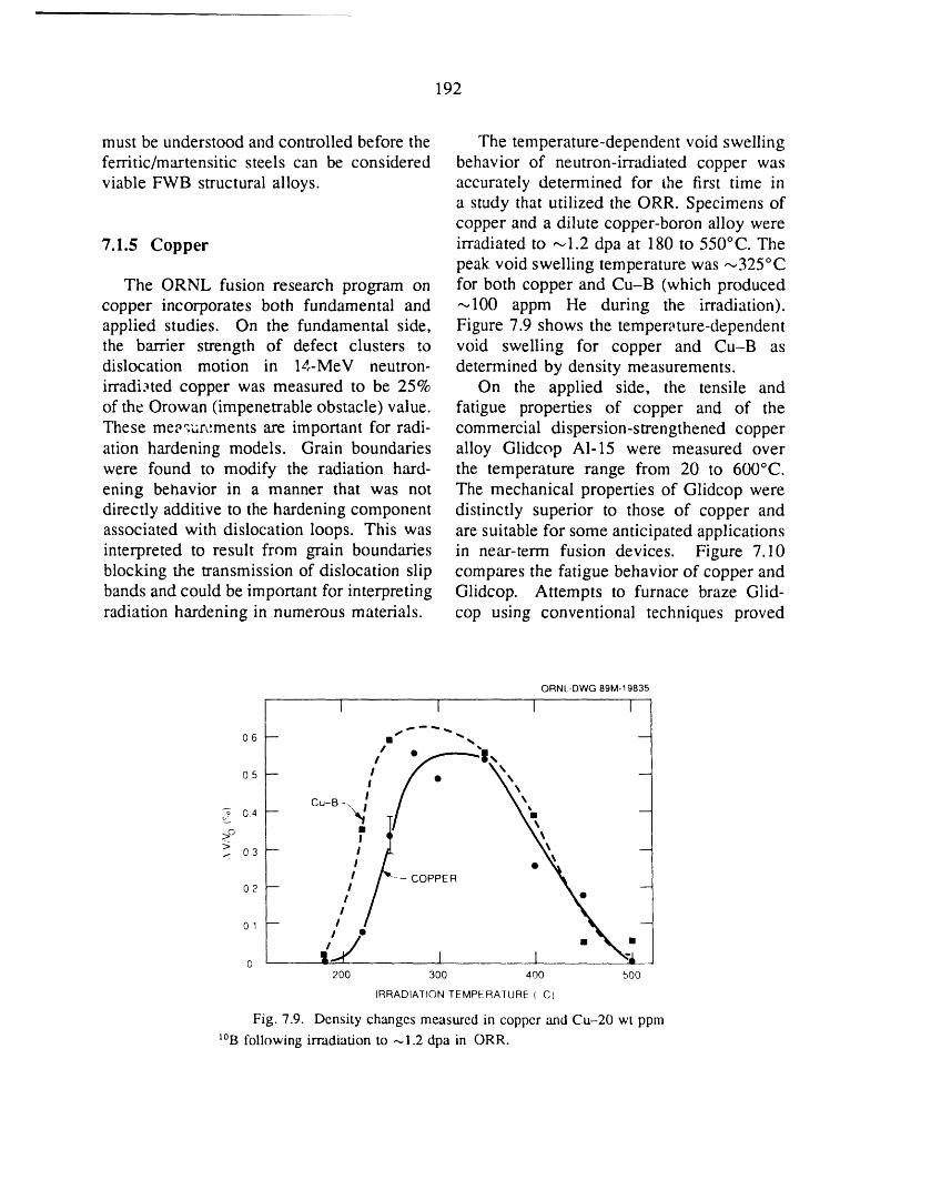
192
must be understood and controlled before the The temperature-dependent void swellingferritic/martensitic steels can be considered behavior of neutron-irradiated copper wasviable FWB structural alloys, accurately determined for the first time in
a study that utilized the ORR. Specimens ofcopper and a dilute copper-boron alloy were
7.1.5 Copper irradiated to ,--,1.2 dpa at 180 to 550°C. Thepeak void swelling temperature was --_325°C
The ORNL fusion research program on for both copper and Cu-B (which producedcopper incorporates both fundamental and ,--,100 appm He during the irradiation).applied studies. On the fundamental side, Figure 7.9 shows the tempen, ture-dependentthe barrier strength of defect clusters to void swelling for copper and Cu-B asdislocation motion in 14-MEV neutron- determined by density measurements.irradi._ted copper was measured to be 25% On the applied side, the tensile andof the Orowan (impenetrable obstacle) value, fatigue properties of copper and of theThese me_qurcments are important for radi- commercial dispersion-strengthened copperation hardening models. Grain boundaries alloy Glidcop Al-15 were measured overwere found to modify the radiation hard- the temperature range from 20 to 600°C.ening behavior in a manner that was not The mechanical properties of Glidcop weredirectly additive to the hardening component distinctly superior to those of copper andassociated with dislocation loops. This was are suitable for some anticipated applicationsinterpreted to result from grain boundaries in near-term fusion devices. Figure 7.10blocking the transmission of dislocation slip compares the fatigue behavior of copper andbands andcould be important for interpreting Glidcop. Attempts to furnace braze Glid-radiation hardening in numerous materials, cop using conventional techniques proved
ORNL-DWG 89M-19835
I 1 1 I
06 -- mi _'_ --
,/.
l/,o,_ il. -X -COPPER
o, / x, -o !-,4" I I \'!
200 300 400 500
IRRADIATION TEMPERATURE (C)
Fig. 7.9. Density changcs measured in copper and Cu-20 wt ppm
I°B following irradiation to ,,_1.2 dpa in ORR.
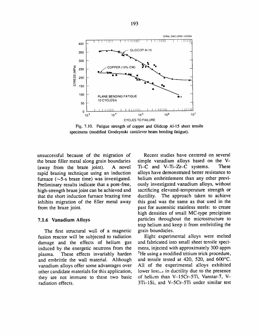
193
ORNL DWG 89M 19098A
1 I ] Illt]l I I I IIIII1 I I I i]llll 1 I i I1lli400 -
or--o_°_, t_" GLIDCOP AI15350- _ _,o_.
300 -
_ _- (lo'/ocwl _*x. "°a.. 250 - _/COPPER
cn 200 - °_ -UJ III1_ 'l_rr I-I_,1F-
oo 150 -- _ -
100 -- _PLANE BENDING FATIGUE10 CYCLES/s
50 -
0 I I I lltlll I L I I1111l 1 I I lilltl 1 I I I1111110 3 10 4 10 5 10 6 10 7
CYCLES TO FAILURE
Fig. 7.10. Fatigue strength of copper and Glidcop Al-15 sheet tensilespecimens (modifiedGro6zynski cantileverbeambending fatigue).
unsuccessful because of the migration of Recent studies have centered on severalthe braze filler metal along grain boundaries simple vanadium alloys based on the V-
(away from the braze joint). A novel Ti-C and V-Ti-Zr-C systems. Theserapid brazing technique using an induction alloys have demonstrated better resistance tofurnace (_5-s braze time) was investigated, helium embrittlement than any other previ-Preliminary results indicate that a pore-free, ously investigated vanadium alloys, withouthigh-strength braze joint can be achieved and sacrificing elevated-temperature strength orthat the short induction furnace brazing time ductility. The approach taken to achieveinhibits migration of the filler metal away this goal was the same as that used in thefrom the braze joint, past for austenitic stainless steels: to create
high densities of small MC-type precipitate
7.1.6 Vanadium Alloys particles throughout the microstructure totrap helium and keep it from embrittling the
The first structural well of a magnetic grain boundagj'es.fusion reactor will be subjected to radiation Eight experimental alloys were melteddamage and the effects of helium gas and fabricated into small sheet tensile speci-induced by the energetic neutrons from the mens, injected with approximately 300 appmplasma. These effects invariably harden 3He using a modified tritium trick procedure,and embritfle the wall material. Although and tensile tested at 420, 520, and 600°C.vanadium alloys offer some advantages over All of the experimental alloys exhibitedother candidate materials for this application, lower loss,,6 in ductility due to the presencethey are not immune to these two basic of heli_:m than V-15Cr-5Ti, Vanstar-7, V-radiation effects. 3Ti-lSi, and V-5Cr-5Ti under similar test
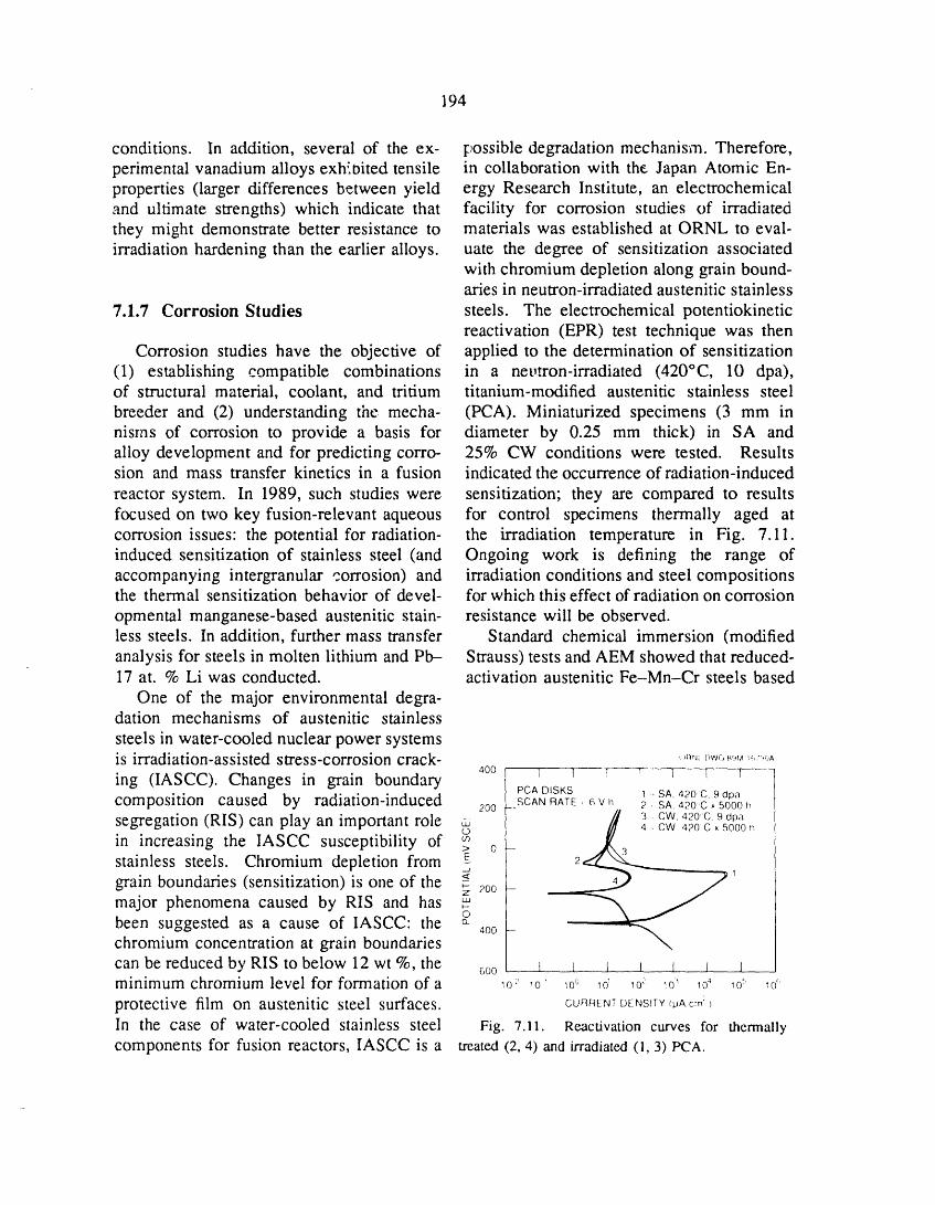
194
conditions. In addition, several of the ex- possible degradation mechanism. Therefore,perimental vanadium alloys exh:,bited tensile in collaboration with the Japan Atomic En-properties (larger differences between yield ergy Research Institute, an electrochemicaland ultimate strengths) which indicate that facility for corrosion studies of irradiatedthey might demonstrate better resistance to materials was established at ORNL to eval-irradiation hardening than the earlier alloys, uate the degree of sensitization associated
with chromium depletion along grain bound-aries in neutron-irradiated austenitic stainless
7.1.7 Corrosion Studies steels. The electrochemical potentiokineticreactivation (EPR) test technique was then
Corrosion studies have the objective of applied to the determination of sensitization(1) establishing compatible combinations in a nevtron-irradiated (420°C, 10 dpa),of structural material, coolant, and tritium titanium-modified austenitic stainless steelbreeder and (2) understanding the mecha- (PCA). Miniaturized specimens (3 mm innisms of corrosion to provide a basis for diameter by 0.25 mm thick) in SA andalloy development and for predicting corro- 25% CW conditions were tested. Resultssion and mass transfer kinetics in a fusion indicated the occurrence of radiation-induced
reactor system. In 1989, such studies were sensitization; they are compared to resultsfocused on two key fusion-relevant aqueous for control specimens thermally aged atcorrosion issues: the potential for radiation- the irradiation temperature in Fig. 7.11.induced sensitization of stainless steel (and Ongoing work is defining the range ofaccompanying intergranular corrosion) and irradiation conditions and steel compositionsthe thermal sensitization behavior of devel- for which this effect of radiation on corrosion
opmental manganese-based austenitic stain- resistance will be observed.less steels. In addition, further mass transfer Standard chemical immersion (modifiedanalysis for steels in molten lithium and Ph-- Strauss) tests and AEM showed that reduced-17 at. % Li was conducted, activation austenitic Fe-Mn-Cr steels based
One of the major environmental degra-dation mechanisms of austenitic stainless
steels in water-cooled nuclear power systemsis irradiation-assisted stress-corrosion crack- "_''_"_'-,_":"."';_
ing (IASCC). Changes in grain boundary 40o I i l i l I I• PCA DISKS 1 :, SA, 420 C, 9 dpa
composition caused by radiation-induced 200 __SCAN RATE : 6 V h 2 : SA, 420_C × 5000 h/1 3 • CW, 420:C 9 dpasegregation (RIS) can play an important role _ 420C,_000h
in increasing the IASCC susceptibility of _ o-stainless steels. Chromium depletion from _ 2
grain boundaries (sensitization) is one of the g _ /_major phenomena caused by RIS and has ___2oo -been suggested as a cause of IASCC" the _ ..400 --
chromium concentration at grain boundaries "_can be reduced by RIS to below 12 wt %, the 6o0 . I l I l l l J _minimum chromium level for formation of a o _o' _o° _o: _o:' _o' _o_ _o_ _o"
protective film on austenitic steel surfaces. CUnnE,TD_,S,T¥_Ao_:_In the case of water-cooled stainless steel Fig. 7.11. Reactivation curves for thermally
components for fusion reactors, IASCC is a treated (2.4) and irradiated(1.3) PCA.
195
on Fe-20Mn-12Cr-0.25 (wt %) are ex- out in support of plasma-interactive (PI)tremely prone to thermal sensitization and and high-heat-flux (HHF) materials. Theresulting intergranular corrosion because of interest in carbon-based materials stemsthF,ir high carbon contents and low chromium from carbon's low atomic number, whichconcentrations. Therefore, this susceptibility minimizes radiative heat losses from theto sensitization after appropriate thermal plasma. The eventual practical application ofaging, fabrication, or irradiation makes their these materials to plasma-facing componentsuse in aqueous and certain other environ- requires control of erosion and excellentmerits problematical. Excellent correlation resistance to thermal shock and irradiationbetween intergranular corrosion induced by damage.immersion io the acidified CuSO4 solution There is an extensive database on neutronand the presence of narrow chromium- damage in bulk graphites. However, contin-depleted zones around grain boundaries, as uing research on C/C materials is required.determined by AEM, was found. Because There is extensive evidence that the thermalof the need to meet reduced-activation shock resistance of properly designed C/Crequirements, the opportunities to increase composite structures is adequate for fusionthe sensitization resistance of fully austenitic reactor applications. Thus, the problemsFe-Mn-Cr steels by alloy design are limited, to be solved for C/C composites lie in
Weight losses as a function of time improving their resistance to erosion andwere analyzed for austenitic and ferritic to neutron irradiation damage. C/C com-steels exposed to molten Pb-17 at. % Li posites have other desirable attributes; theyand lithium at temperatures of >500°C may be fabricated in large sizes and tounder thermal convection conditions. In near net shape, and their mechanical and
both liquid-metal environments, paralinear physical properties may be tailored throughweight loss kinetics were observed for type appropriate selection of fiber type, weave316 stainless steel, while dissolution losses architecture, and processing parameters.of Fe-12Cr-IMoVW steel rapidly became The problems of neutron damage canlinearly proportional to time. The difference probably be solved by using (1) small unitbetween the kinetic behavior for these two cell size to permit semicontinuous design
types of steel can be explained on the basis characteristics; (2) three-dimensional archi-of the contribution of preferential dissolution tecture, with fiber fractions and directions(of nickel) to the corrosion of the austenitic favoring the physical property geometrysteel and the resultant surface destabilization requirements; and (3) highly crystallineprocess during the first few thousand hours filaments (pitch-based fibers) and matrices.of exposure. After extended exposures To verify these assumptions, a test matrix(>3000 h), both types of steels exhibited of C/C composite materials (pitch and PANlinear weight loss kinetics indicative of the fibers) of differing architecture has beendissolution of Fe-Cr surfaces, assembled and will be irradiated at ORNL.
Additionally, pitch fibers of varying elastic
7.2 GRAPHITE AND CARBON- modulus and degree of crystallinity will beCARBON COMPOSITES irradiated. Some C/C composite materials
have been heat treated to above normal
Research on bulk graphite and carbon- processing temperatures to improve theircarbon (C/C) composites has been carried crystallinity.
196
Neutron irradiations will be performed component of ICRH systems, lt is importantin the target region of the HFIR reactor at for these windows to remain transparent toORNL. Four target capsules are planned, the rf energy, in part because excessive rfOne (HTFC 3) will be irradiated at 900°C absorption could lead to their mechanicalto maximum fluences of 20 dpa. The failure. The rf power absorbed in theseremaining three (HTFC 1, 2, and 4) will be ceramics is proportional to the so-called lossirradiated at 600°C to maximum fluences of tangent. The loss tangent, tan /5, is defined8, 16, and 32 dpa, respectively. Capsules as the ratio of the imaginary part to theHTFC 1 and 2 contain materials from the real part of the dielectric constant, tan /5 =test matrix (C/C composites and fibers) e'/e'. Typical values for the loss tangent inand samples of a reference graphite (H- unirradiatedceramics of interest to the fusion451). Capsule HTFC 3 contains samples program are from 10 -4 to 10 -3, with 10 -3
of GraphNOL N3M, a fine-grained, high- being near the maximum tolerable value.sn'ength aerospace graphite developed at Postirradiationmeasurements have shownORNL (N3M is the current backup option that ionizing and displacive irradiation canto C/C composites for ITER), in addition increase the value of the loss tangent, butto materials from the test matrix. Capsules there have been no relevant measurementsHTFC 1 and 2 have been constructed and of dielectric properties during irradiation.are expected to be loaded into HFIR in There is some concern that the losses mayJune 1990. Capsule HTFC 3 is currently be higher during irradiation because of thein construction and irradiation is planned to higher density of charge carriers that willcommence during summer 1990. Capsule exist. To address this concern, a series ofHTFC 4 will not commence assembly until irradiation experiments has been planned tothe postirradiation examination cf materials measure the dielectric properties of typicalfrom HTFC 1 and 2 has been completed, ceramics in situ. The experiments callThis will allow the substitution of improved for the use of two facilities. The first isC/C materials and the removal of those the Spent Core Facility of HFIR. Decay ofmaterials whose performance in HTFC 1 and fission products in HFIR spent cores leads2 is deemed unsatisfactory, to an ionizing damage rate of 108 rad/h,
One further irradiation experiment is which is comparable to that expected in CIT.planned. Its purpose is to determine the Since the HFIR spent cores do not provide aeffect of neutron damage on the thermal component ofdisplacive irradiation, TRIGA,conductivity of C/C composite materials, a small research reactor at the University ofThe experiment will run to a peak fluence Illinois, will be used to obtain data on theof <1 dpa in either the Buffalo Materials influence of displacive irradiation. A beamTest Reactor or the Bulk Shielding Reactor tube that runs adjacent to the core of TRIGAat ORNL. will be used for these experiments. When
TRIGA is operated in a pulsed mode, boththe disp!acive and ionizing damage rates are
7.3 CEPAMICS near those expected in the CIT.Alumina (A1203) is a prime candidate
Ion cyclotron resonance heating (ICRH) material for use in rf heating systems.has been proposed as a major heating source Therefore, the initial measurements willfor the Compact Ignition Tokamak (CIT), focus on this material. The experimentaland ceramic vacuum windows are a critical matrix includes the use of oriented single-
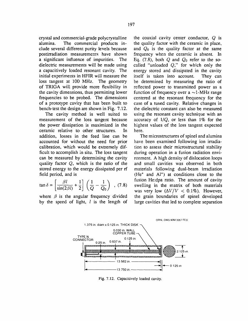
197
crystal and commercial-grade polycrystalline the coaxial cavity center conductor, Q isalumina. The commercial products in- the quality factor with the ceramic in place,clude several different purity levels because and Q0 is the quality factor at the samepostirradiation measurements have shown frequency when the ceramic is absent. Ina significant influence of impurities. The Eq. (7.8), both Q and Q0 refer to the so-dielectric measurements will be made using called "unloaded Q," for which only thea capacitively loaded resonant cavity. The energy stored and dissipated in the cavityinitial experiments in HFIR will measure the itself is taken into account. They canloss tangent at 100 MHz. The geometry be determined by measuring the ratio ofof TRIGA will provide more flexibility in reflected power to transmitted power as athe cavity dimensions, thus permitting lower function of frequency over a _,I-MHz rangefrequencies to be probed. The dimensions centered at the resonant frequency for theof a prototype cavity that has been built to case of a tuned cavity. Relative changes inbench-test the design are shown in Fig. 7.12. the dielectric constant can also be measured
The cavity method is well suited to using the resonant cavity technique with anmeasurement of the loss tangent because accuracy of 1/Q, or less than 1% for thethe power dissipation is maximized in the highest values of the loss tangent expectedceramic relative to other structures. In here.
addition, losses in the feed line can be The microstructuresofspinelandaluminaaccounted for without the need for prior have been examined following ion irradia-calibration, which would be extremely dif- tion to assess their microstructural stabilityficult to accomplish in situ. The loss tangent during operation in a fusion radiation envi-can be measured by determining the cavity ronment. A high density of dislocation loopsquality factor Q, which is the ratio of the and small cavities was observed in bothstored energy to the energy dissipated per rf materials following dual-beam irradiationfield period, and is (He + and A1+) at conditions close to the
[ _l 1} (1 1 ) fusion He:dpa ratio. The amount of cavitytan6 = sin(2/3/) + Q Q0 , (7.8) swelling in the matrix of both materialswas very low (AV/V < 0.1%). However,
where /3 is the angular frequency divided the grain boundaries of spinel developedby the speed of light, l is the length of large cavities that led to complete separation
ORNL-DWG90M-3267FED
1.375 in. diam x 0.125 in. THICK DISK -_
0.030 in. WALL \COPPER TUBE -N \
TYPE N \ \0.25 in. • " • t \ \[ ..............&.............%........... I ................X........X....
irt.
13.562 in. --_--0.125 in.,_ 13.750 in.
Fig. 7.12. Capacitively loaded cavity.
198
of the grains. These results suggest that the U.S.-Japan collaborative program on de-polycrystalline spinel cannot be used in velopment of austenitic stainless steels, twoa fusion irradiation environment, whereas highly complex, instrumented, and spectrallyalumina and single-crystal spinel may be tailored capsules have been assembled forsuitable materials, irradiation in the HFIR reflector region,
A program was initiated to study the and eight smaller uninstrumented capsulesirradiated behavior of SiC/SiC composite were assembled for irradiation in the targetceramic. This material is a possible region. The reflector region capsules containfirst wall material and has attractive (low) specimens previously irradiated to aboutlevels of induced long-lived radioactivity 8 dpa in ORR. These specimens werein a fusion environment. The interfacial retrieved and reloaded into newly designedfriction between the SiC fiber and matrix and fabricated capsules. During irradiation,is considered to be a key factor that will the capsules will be surrounded by a 4.2-control the mechanical properties of the mm-thick hafnium tube, which will reduceirradiated composite. The Nanoindenter the thermal neutron flux by about 85%,mechanical properties microprobe was used permitting the specimens to achieve theto make initial measurements of the fiber- corrzct He:dpa ratio after an additional 8-dpamatrix friction on nonirradiated material, exposure.
and specimens were implanted with helium The eight target capsules contain a va-at temperatures between 25 and 800°C in riety of mechanical specimens that will bepreparation for further measurements that irradiated to damage fluences as high aswill examine helium effects. In addition, 70 dpa. Included in these experiments areplans were developed for in situ measure- the first specimens to use the isotopicallymerit of the electrical conductivity of SiC and tailored technique to achieve the correctSiC/SiC composites in an ionizing radiation He:dpa ratio at the completion of irradiation.field. In this technique the nickel content in the
TEM disks of numerous advanced struc- steel is made up of the appropriate isotopictural ceramics were obtained for an up- ratios such that the two-step nickel reactioncoming __rradiation in HFIR. This irradiation produces the correct helium level at the endwill provide the first data on the irradiated of irradiation.properties of a wide range of technologically Two experiments have been assembled,important ceramics that may be useful for a and a third has been designed, to irradiatenumber of fusion reactor applications. The a variety of state-of-the-art and advancedmaterials collected include toughened ceram- C/C composite materials in the HFIR targetics, whisker and fiber-reinforced ceramics, region.and chemical vapor deposition (CVD) dia- Two additional experiments have beenmond films, designed to irradiate a variety of ceramic
materials using isotopic tailoring to studythe effects of helium in neutron-irradiated
7,4 HFIR EXPERIMENTS ceramics, i_adiation of these experiments inthe HFIR target region is expected to begin
Numerous irradiation experiments have next year.been assembled in support of the Fusion In support of the ITER program, threeMaterials Program at ORNL and are await- experiments are being designed to irradiateing full-power operation of the HFIR. For fracture toughness specimens in the HFIR
199
target region at temperatures of about 100 4. J. Weertman and J. R. Weertman, "Mechanical
and 250°C. These experiments au'e to be Properties, Mildly Temperature-Dependent," pp. 735-
assembled and irradiation is to begin next 92 in Physical Metallurgy, ed. R. W. Cahn, North
year. Holland, Amsterdam, 1965.5. M.L. Grossbeck, J. O. Stiegler, and J. J.
Holmes, "Effects of Irradiation on the Fracture
REFERENCES Behavior of Austenitic Stainless Steels," presented
at the International Conference on Breeder Reactor
1. M. L. Grossbeck, "Empirical Relations for Structural Materials, Scottsdale, Ariz., June 1977.
Tensile Properties of Austenitic Stainless Steels 6. J. F. Bates and M. K. Korenko, Nucl. Technol.
Irradiated in Mixed Spectrum Reactors," J. Nucl. 48, 303-14 (1990).
Mater., accepted for publication (1990). 7. R.E. Stoller, P. J. Maziasz, A. F. Rowcliffe,2. V. K. Sikka, B. L. P. Booker, M. K. Booker, and M. P. Tanaka, "Swelling Behavior of Austenitic
and J. W. McEnemey, Tensile and Creep Data on 7)_pe Stainless Steels in a Spectrally Tailored Reactor316 Stainless Steel, ORNLFFM-7110, Union Carbide
Experiment: Implications for Near-Term Fusion Ma-
Corp., Nuclear Div., Oak Ridge National Laboratory, chines," J. Nucl. Mater. 155--157, 1328-34 (1988).January 1980.
3. M. A. Krishtal, Diffusion Processes in Iron
Alloys, U.S. Dept. of Commerce, Springfield, Va.,1970.

8NEUTRON TRANSPORT
R. G. Alsmiller, Jr. 1
J. M. Barnes / D.M. Hetrick 2 R.T. Santoro 1
J. Bartley 1 D.C. Larson 1 D.K. Trubey 1C. Y. Fu 1 R.A. Lillie I J.E. White 1
R. W. Roussin I
1. Engineering Physics and Mathematics Division.2. Computing and Telecommunications Division, Martin Marietta Energy Systems, Inc.
202

8. NEUTRON TRANSPORT
SUMMARY OF ACTIVITIES
The neutron transport program includes three elements: the work of the RadiationSh:_olding Information Center (RSIC), cross-section evaluaSon and processing, and analyses.
Staff members of the RSIC serve as technical consultants to the fusion energy research
community, as well as a variety of other research communities, on ali matters relating toneutron transport. The evaluation and processing program is directed at producing accuratecross-section data for materials that are of specific interest to fusion reactor designers. Theanalysis program at present is part of a joint U.S.-Japan neutronics program and is directed atvalidating available computer codes and cross-section data by comparing calculated resultswith experimental data obtained from the Fusion Neutron Source Facility at the Japan AtomicEnergy Research Institute.
203
204
8.1 RADIATION SHIELDING of Wisconsin DKR radioactivity and doseINFORMATION CENTER rate code system for fusion reactors was
extended for fission and hybrid _ystems,denoted CCC-541/FDKR, and submitted by
R. W. Roussin, D. K. Trubey, the Southwestern Institute of Physics, Le-
J. E. White, and J. Bartley shan, People's Republic of China. TheJapan Atomic Energy Research Institute
The Radiation Shielding Information (JAERI), Tokai Establishment, providedCenter (RSIC) serves an international com- the CCC-430/EDMULT 2.1 electron depthmunity by responding to inquiries about dose code system, and the Tokyo Insti-radiation transport problems. Staff members tute of Technology submitted the CCC-provide guidance by drawing on a technical 535/MORSE-CV multigroup Monte Carlodatabase that includes a computerized liter- system for calculating the covariance ofature file, a collection of complex computer mean spectral values. The PSR-146/ALICE-
programs, and a substantial body of nuclear 87 nuclear model code was contributed bydata libraries pertinent to the solution of such the International Atomic Energy Agency,problems. Vienna, Austria, via the Organisation for
Acquiring the needed computer-based Economic Co-operation and Developmenttechnology base requires the collaboration (OECD) Nuclear Energy Agency, Saclay,of the neutronics community with RSIC France. From the University of Californiastaff members to collect, organize, process, at Los Angeles came the CCC-537/TRIPOSevaluate, and package relevant technology ion transport code. Los Alamos Nationaldeveloped in the community. This tech- Laboratory provided CCC-200/MCNP-3B, anology is disseminated to the community general-purpose Monte Carlo system; PSR-with a mechanism for feedback of experience 171/NJOY89, a cross-section processingthrough use, which results in an improved system for ENDF/B-VI; and PSR-27/ZOTT,product. The resulting technology base an evaluator of correlated data. Oak Ridgeprovides an advancement of the state of the National Laboratory contributed the DLC-art. 146/HUGO 86 photon interaction library,
A sample of some recent products of the PSR-273/FERD-PC spectrum unfoldingthis information cycle process shows the code (PC version), and the CCC-543/TORTinternational character of the RSIC com- three-dimensional discrete ordinates system.
munity. The National Committee for This selection represents a small por-Nuclear and Alternative Energies (ENEA), tion of the total activity of the center.
Bologna, Italy, contributed PSR-271/MILER Information processing (including evalua-for coverting NJOY-produced cross-section tion and packaging) is a daily function.libraries into AMPX format. A multigroup In addition to a comprehensive literature
cross-section library, DLC-135/SHAMSI, for database, RSIC-packaged products includefusion neutronics analysis was provided by 146 data packages (DLC), 545 neutronicsthe Joint Research Centre of the European and shielding code packages (CCC), and
Atomic Energy Community (EURATOM) in 277 data processing and other miscellaneousIspra, Italy. A version of the University code packages (PSR).
I
205
8.2 DATA EVALUATION AND at Lawrence Livermore National Laboratory.PROCESSING FOR FUSION The VITAMIN-E data and AMPX-II com-NEUTRONIC DATA NEEDS puting technology are also available from the
RSIC.D. C. Larson, C. Y. Fu, D. M. Hetrick,and J. E. White
Evaluated and processed neutron cross- 8.3 REACTION RATEsection data are produced to meet the DISTRIBUTIONS ANDneeds of fusion reactor designers. Nuclear RELATED DATA IN THEdata needs for the magnetic fusion energyprogram are given in ref. 1 and include FUSION NEUTRON SOURCEevaluated cross sections for copper, nickel, PHASE II EXPERIMENTS:and chromium. This year, isotopic evalua- COMPARISON OF MEASUREDtions for chromium, copper, and nickel were AND CALCULATED DATAaccepted for ENDF/B-VI. Also accepted forENDF/B-VI were isotopic evaluations for R.T. Santoro, R. G. Alsmiller, Jr., andiron and lead and an evaluation for natural J.M. Barnescarbon. Several of the evaluations were
selected by an international committee for Neutronics parameters including theinclusion in the Fusion Evaluated Nuclear source neutron spectrum, activation rates,Data Library (FENDL). This will be the first and the tritium breeding in the Li20 test zoneI,
version of ENDF in which special attention of the phase II experiment performed on thehas been paid to data of priority to fusion Fusion Neutron Source Facility at JAERIenergy. Ali of this work has been jointly have been calculated using the Monte Carlofunded by the Offices of Fusion Energy, code MORSE with ENDF/B-V transportBasic Energy Sciences, and Nuclear Physics and reaction cross sections. Favorablein the U.S. Department of Energy. (DOE) and comparisons between the measured andthe Defense Nuclear Agency. calculated results have been achieved for
Evaluated cross sections must be pro- the Z7Al(n, o_), 58Ni(n, p), 93Nb(n, 2n),cessed into forms that can be used in and 197Au(n, 2n) reactions. Calculatedradiation transport computer codes. The 58Ni(n, 2n) and 197Au(n, 3') reactions did notfocus of this effort has been the development agree with measured values within 10--40%.of VITAMIN-E, z a 174-neutron, 38-gamma- For the nickel reaction the differences mayray group cross-section library, lt can result from poor data in the ORACT flies;be used in conjunction with the AMPX-II discrepancies for the gold data may resultsystem 3 to derive cross-section data suited from unknown quantities of hydrogen-richto a particular application, epoxy used to coat the LiECO3 blocks used
A continuing effort is under way to main- in the test assembly walls. The calculatedtain VITAMIN-E and the relevant AMPX- tritium breeding in the LiEO agreed withII computing technology on the National experimental values within -t-10% for 6LiMagnetic Fusion Energy Computing Center and +15-20% for 7Li.

206
REFERENCES Cross-Section Library for Deriving Application-
Dependent Working Libraries for Radiation Transport
I. Proceedings of the Fifth Coordination Meeting Calculations [computer program], available from the
of Participan's in the Office of Basic Energy Radiation Shielding Information Center, Engineering
Sciences Program to Meet ttigh Priority Nuclear Physics and Mathematics Division, Oak Ridge Na-
Data Needs of the Office of Fusion Energy, Ar- tional Laboratory, as DLC-113/VITAMIN-E.
gonne, Illinois, September 17-19, 1986, Appendix D, 3. N. M. Greene et al., AMPX: A Modular Code
DOE/ER/02490-4, Ohio State University, Columbus, System for Generating Coupled Multigroup Neutron
1986. Gamma Libraries from ENDF/B, ORNL-3706, Union
2. R. W. Roussin et al., VITAMIN-E: A Carbide Corp. Nuclear Div., Oak Ridge National
Coupled 174-Neutron, 38-Gamma-Ray Multigroup Laboratory, 1976.

9NONFUSION APPLICATIONS

H. H. Haselton
G. D. Alton 1 W.L. Gardner R S. Meszaros 9
M. Bacal 2 S.M. Gorbatkin 5 B.D. Murphy 9
F. W. Baity M.J. Gouge R.J. Raridon 9G. C. Barber R.H. Goulding J.B. Roberto 5
R. L. Beatty 3 D.J. Hoffman K.E. Rothe 9W. R. Becraft 4 G.E. Isham 6 E M. Ryan
L. A. Berry M.A. Janney 3 D.E. Schechter
T. S. Bigelow R.L. Johnson v W.B. Snyder 11S. K. Combs C.C. Jones s D.O. Sparks
J. F. Cox J.O. Kiggans 3 C.C. Tsai
W. K. Dagenhart H.D. Kimrey J.H. WhealtonE. G. Elliott R.L. Livesey G.A. White
C. A. Foster G.E. McMichael 1° T.L. White
S. L. McNair 3
1. Physics Division.2. Ecole Polytechnique, Palaiseau, France.3. Metals and Ceramics Division.4. Grumman Corporation, Bethpage, N.Y.5. Solid State Division.6. Finance, Materials, and Services Division, Y-12 Plant.7. Engineering Division, Martin Marietta Energy Systems, Inc.8. Management Services Group.9. Computing and Telecommunications Division, Martin Marietta Energy Systems, Inc.
10. Chalk River Nuclear Laboratories, Chalk River, Ontario, Canada.
11. Engineering Technology Division.
208
9. NONFUSION APPLICATIONS
SUMMARY OF ACTIVITIES
During recent years, fusion technology development programs have been broadenedto include nonfusion applications. The technologies that have been central to the fusionmission have been found by other sponsors to be appropriate matches for their future needs.Many fusion-related, challenging, and important research and development (R&D) programopportunities have been identified. It is expected that fusion technology will continue tocontribute to critical advancements needed by the country.
The concentration of program initiation and development efforts in the nonfusion areafollows two basic guidelines: the technology to be advanced is related to fusion in thatthe majority of advances (e.g., microwave and rf developments) expected to result from thework will directly benefit future fusion system designs, and the technology is expected to beapplicable to fusion, although the initial application may not be directly fusion related. Anexample is plasma processing work for others that will eventually provide the potential ofdiamond coatings for critical fusion reactor components.
The nonfusion technology applications are concentrated in four main technical fields:(1) energy, (2) U.S. Department of Energy facility environmental restoration and wastemanagement, (3) defense, and (4) technology transfer to industry through which the U.S.competitive position in the world can be improved.
The R&D efforts conducted to date address ali of these areas. The highlights of the pastyear's work are presented in this section. Some of the endeavors apply to more than onefield.
209
210
9.1 MICRO_VAVE PROCESSING OF Last year, however, we showed thatRADIOACTIVE WASTES microwaves can be used to process the RH-
TRU liquids over the entire temperatureT. L. White range in a batch microwave oven. The
wasteform produced satisfied the WasteThe ORNL Waste Handling and Packag- Isolation Pilot Plant waste acceptance criteria
ing Plant (WHPP)is developing a micro- and was similar to wasteforms producedwave process to reduce and solidify remote- by conventional evaporation technologies.handled transuranic (RH-TRU) liquids and Because of this success, we are developing asludges that are now stored in large tanks more aggressive microwave processing flowat ORNL. The microwave expertise and sheet with the potential to greatly simplifyequipment of the Fusion Energy Division are the conceptual WHPP liquid processing flowbeing used in this development effort, which sheet by replacing the wiped-film evapo-has focused on drying RH-TRU liquids and rator/microwave drum heater with a singlesludges in the final storage container and microwave in-drum process.then melting the salt residues to form a solid Microwave energy heats the RH-TRUmonolith, liquid waste directly because the oscillat-
A proprietary microwave applicator at ing electric fields directly couple to theone-third scale was designed and fabricated molecular bonds of the chemicals in theto demonstrate the essential features of the waste, causing frictional heating. This directmicrowave design and to provide input into heating eliminates the need for separatethe design of a full-scale applicator. Testing heating elements or heat transfer surfaces.recently began on an in-drum process using The microwave process that we are de-nonradioactive RH-TRU surrogates, veloping contains no moving parts and is
In the conceptual design stage, the WHPP designed to heat the liquid waste in theprocess required the use of conventional final storage container, thus eliminating thewiped-film evaporators or extruders to per- need to transport hot chemicals form theform the liquid evaporation and melting; heated casingofthe wiped-film evaporator ormicrowaves would have been used only to extruder into the storage container. Anothermaintain the temperature in a drum during possibility is using a conventional evaporatorfilling operations. These evaporators and (e.g., a wiped-film evaporator) to concentrateextruders require separate heating elements the liquid, which would then be melted byor heat transfer surfaces and moving parts the in-drum microwave process.to wipe a thin film across the heat transfer The 1/3-scale microwave system is shownsurfaces. The moving parts are subject in Fig. 9.1. The surrogate RH-TRU liquid isto wear, especially if small hard particles stored in a mixing tank and pumped throughare present in the waste (ORNL records a slurry transport loop to keep solids fromindicate that some of the RH-TRU storage clogging the loop. A smaller metering pumptanks may contain hard particles such as taps off a small portion of the loop flowgrout and other hard deposits). Frequent near the applicator to control the amountmaintenance of wiped-film evaporators or of surrogate that is fed to the applicator.extruders would be very complicated in a hot The line from the metering pump to thecell environment, applicator is kept as short as possible to
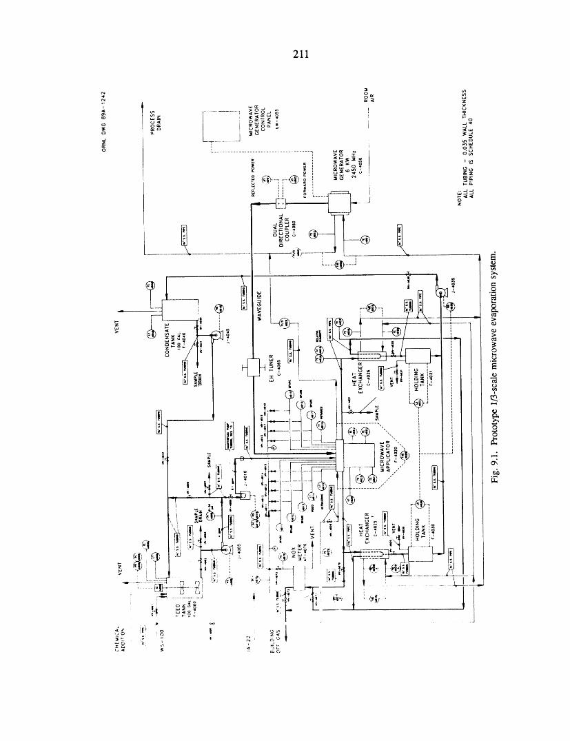
211
212
avoid clogging. The metering pump is strength, toughness, reliability, and unifor-reversible so that surrogate in this short line mity of prooerties for energy conversioncan be drawn back out of the applicator feed systems, using microwave processing topipe. The applicator feed pipe is located engineer and control critical componentabove the stainless steel waste container, microstructures. For oxide ceramics, thewhich is 18 cm in diameter and 23 cm objective is to develop the mechanical prop-deep, with a 4.6-L usable volume. The erties and reliability of zirconia-toughenedapplicator is powered by a 6-kW, 2450-MHz alumina to levels beyond those currentlymicrowave generator. Forward and reflected obtainable with conventional sintering.microwave power levels are monitored by adual-directional waveguide coupler (50 dBcoupling, 30 dB directivity) so that net ab-sorbed microw_ove power can be measured. 9.2.1 BackgroundAn E-H tuner matches the applicator to the
Microwave sintering has unique attributeswaveguide system to maximize the powerabsorbed by the applicator. The offgases and has the potential to be developed as afrom the waste are removed through evenly new technique for controlling microstructurespaced openings around the sides of the to improve the properties of advanced ceram-applicator. These openings are connected ics. Because microwave radiation penetratesby a manifold that feeds a pair of heat most ceramics, uniform volumetric heatingexchangers used to remove water vapor from is possible. Thermal gradients, which arethe offgases. The distillate is collected and produced during conventional sintering bystored for later analysis and/or recycling conductive and radiative heat transfer toto the mixing tank. An NO_: meter is and within the part, can be minimized.connected to the offgas system to monitor This makes it possible to reduce internalthe amount of NO_ gases produced during stresses that contribute to the cracking ofprocessing. A humidity/temperature probe parts during sintering and to create a moreis being procured to monitor the drying of uniform microstructure, which may lead tothe wasteform during processing, improved mechanical properties and reliabil-
Early tests have verified the correct ity. With uniform volumetric temperatures,the nonuniform particle/grain growth causedapplicator mode, and further testing is under
way. The microwave process is much less by temperature gradients and associateddeveloped than conventional technologies; sintering gradients can be regulated.the goal is to develop a full-scale microwave Recent investigations have identified ad-process so that all technologies can be at the ditional be_efits of microwave sintering.pilot plant stage before the WHPP is built. Using 28-GHz _-adiation, we demonstrated
that alumina could be densified at tem-
peratures 300-400°C below those used in9.2 MICROWAVE SINTERING conventional processing and that a uni-
form, fine-grained microstructure could beH. D. Kimrey, R. L. Beatty, M. A. Janney, obtained. Lower-temperature processingJ. O. Kiggans, and W. B. Snyder should reduce grain growth, vaporization,
and interactions between phases, whichThe microwave sintering effort is directed are often significant in the fabrication of
toward developing ceramics with improved advanced ceramics.
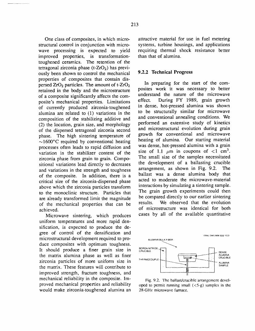
213
One class of composites, in which micro- attractive material for use in fuel meteringstructural control in conjunction with micro- systems, turbine housings, and applicationswave processing is expected to yield requiring thermal shock resistance betterimproved properties, is transformation- than that of alumina.toughened ceramics. The retention of thetetragonal zirconia phase (t-ZrO2) has previ-ously been shown to control the mechanical 9.2.2 Technical Progressproperties of composites that contain dis-persed ZrO 2 particles. The amount of t-ZrO2 In preparing for the start of the com-retained in the body and the microstructure posites work it was necessary to better
understand the nature of the microwaveof a composite significantly affects the com-posite's mechanical properties. Limitations effect. During FY 1989, grain growthof currently produced zirconia-toughened in dense, hot-pressed alumina was shownalumina are related to (1) variations in the to be structurally similar for microwavecomposition of the stabilizing additive and and conventional annealing conditions. We(2) the location, grain size, and morphology performed an extensive study of kineticsof the dispersed tetragonal zirconia second and microstructural evolution during grainphase. The high sintering temperature of growth for conventional and microwave--_1600°C required by conventional heating heating of alumina. Our starting materialprocesses often leads to rapid diffusion and was dense, hot-pressed alumina with a grainvariation in the stabilizer content of the size of 1.1 itm in coupons of <1 cm 3.
zirconia phase from grain to grain. Compo- The small size of the samples necessitatedsitional variations lead directly to decreases the development of a ballasting crucibleand variations in the strength and toughness arrangement, as shown in Fig. 9.2. The
ballast was a dense alumina body thatof the composite. In addition, there is acritical size of the zirconia-dispersed phase acted to moderate the microwave-materialabove which the zirconia particles transform interactions by simulating a sintering sample.to the monoclinic structure. Particles that The grain growth experiments could then
are already transformed limit the magnitude be compared directly to our earlier sinteringof the mechanical properties that can be results. We observed that the evolutionachieved, of microstructure was identical for both
Microwave sintering, which produces cases by ali of the available quantitativeuniform temperatures and more rapid den-sification, is expected to produce the de-gree of control of the densification and OFINI.DWG 90M-3232 FED
microstructural development required to pro- _,uM,N_8u_F,BERduce composites with optimum toughness. _'_,
BORON NITRIDE _ [--'-1
It should produce a finer grain size in CRUCIBLEt-_..1 _ DENSEthe matrix alumina phase as well as finer E______+__--f-q j [ ALUMINACRUCIBLE
zirconia particles of more uniform size in T,ERMOCOUP,__.._
ALUMINA
the matrix. These features will contribute to SAM_E
improved strength, fracture toughness, and
mechanical reliability in the composite. Im- Fig. 9.2. The ballast/cruciblearrangementdevel-proved mechanical properties and reliability oped to permit running small (<5-g) samples in thewould make zirconia-toughened alumina an 28-GHz microwavefurnace.
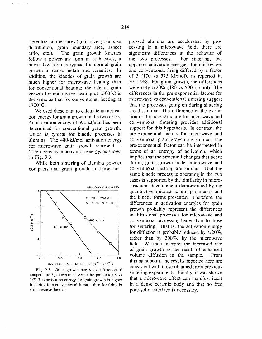
214
stereological measures (grain size, grain size pressed alumina are accelerated by pro-distribution, grain boundary area, aspect cessing in a microwave field, there areratio, etc.). The grain growth kinetics significant differences in the behavior offollow a power-law form in both cases; a the two processes. For sintering, thepower-law form is typical for normal grain apparent activation energies for microwavegrowth in dense metals and ceramics. In and conventional firing differed by a factoraddition, the kinetics of grain growth are of 3 (170 vs 575 kJ/mol), as reported inmuch higher for microwave heating than FY 1988. For grain growth, the differencesfor conventional heating; the rate of grain were only _20% (480 vs 590 kJ/mol). Thegrowth for microwave heating at 1500°C is differences in the pre-exponential factors forthe same as that for conventional heating at microwave vs conventional sintering suggest1700°C. that the processes going on during sintering
We used these data to calculate an activa- are dissimilar. The difference in the evolu-
tion energy for grain growth in the two cases, tion of the pore structure for microwave andAn activation energy of 590 kJ/mol has been conventional sintering provides additionaldetermined for conventional grain growth, support for this hypothesis. In contrast, thewhich is typical for kinetic processes in pre-exponential factors for microwave andalumina. The 480-kJ/mol activation energy conventional grain growth are similar. Thefor microwave grain growth represents a pre-exponential factor can be interpreted in20% decrease in activation energy, as shown terms of an entropy of activation, whichin Fig. 9.3. implies that the structural changes that occur
While both sintering of alumina powder during grain growth under microwave andcompacts and grain growth in dense hot- conventional heating are similar. That the
same kinetic process is operating in the twocases is supported by the similarity in micro-
On'_L-DWGgOM-=_'3VEDstructural development demonstrated by the-' \ ,% _ , quantitative microstructural parameters and
\ [] MICROWAVE the kinetic forms presented. Therefore, the
vXN,,N _° CONVENT'ONAt- differences in activati°n energies f°r grain-2- - growth probably represent the differences
in diffusional processes for microwave and
'_'" -3"-- 0% _0 kJ/mol conventional processing better than do those630kJ,'mo,_ _ for sintering. That is, the activation energy
for diffusion is probably reduced by _20%,-4- rather than by 300%, by the microwave
field. We then interpret the increased rateof grain growth as the result of enhanced
-5 _ _ \ i volume diffusion in the sample. From4.5 50- 5.5 60 6.5this standpoint, the results reported here are
INVERSE TEMPERATURE 1,q (K -1) (x 10 .-4 )
consistent with those obtained from previousFig. 9.3. Grain growth rate K as a functionofsintering experiments. Finally, it was showntemperatureT, shownas an Arrheniusplot of logK vs
lfl'. The activationenergy for grain growth is higher that a microwave effect can manifest itselffor firingin a conventionalfurnace than for firing in in a dense ceramic body and that no freea microwavefurnace, pore-solid interface is necessary.
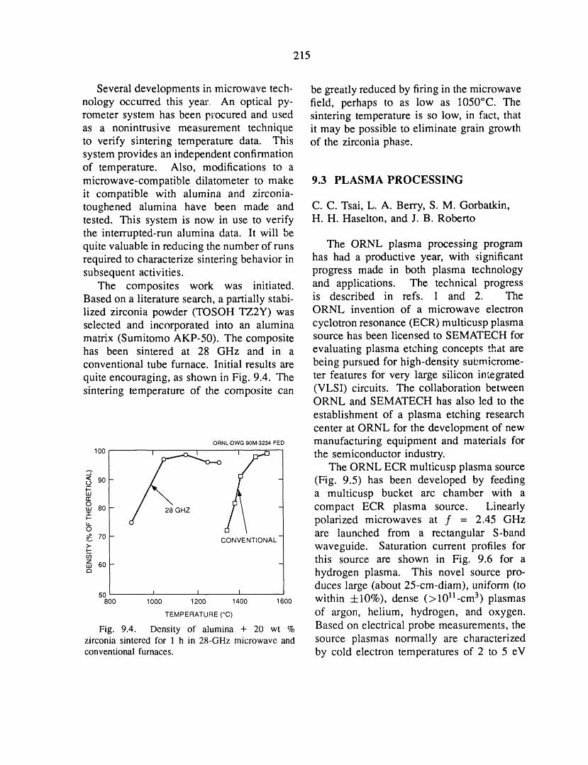
215
Several developments in microwave tech- be greatly reduced by firing in the microwavenology occurred this year. An optical py- field, perhaps to as low as 1050°C. Therometer system has been procured and used sintering temperature is so low, in fact, thatas a nonintrusive measurement technique it may be possible to eliminate grain growthto verify sintering temperature data. This of the zirconia phase.system provides an independent confirmationof temperature. Also, modifications to amicrowave-compatible dilatometer to make 9.3 PLASMA PROCESSINGit compatible with alumina and zirconia-toughened alumina have been made and C.C. Tsai, L. A. Berry, S. M. Gorbatkin,tested. This system is now in use to verify H.H. Haselton, and J. B. Robertothe interrupted-run alumina data. It will bequite valuable in reducing the number of runs The ORNL plasma processing programrequired to characterize sintering behavior in has had a productive year, with _ignificantsubsequent activities, progress made in both plasma technology
The composites work was initiated, and applications. The technical progressBased on a literature search, a partially stabi- is described in refs. 1 and 2. Thelized zirconia powder (TOSOH TZ2Y)was ORNL invention of a microwave electronselected and incorporated into an alumina cyclotron resonance (ECR)multicusp plasmamatrix (Sumitomo AKP-50). The composite source has been licensed to SEMATECH forhas been sintered at 28 GHz and in a evaluating plasma etching concepts that areconventional tube furnace. Initial results are being pursued for high-density sut_microme-
quite encouraging, as shown in Fig. 9.4. The ter features for very large silicon integratedsintering temperature of the composite can (VLSI) circuits. The collaboration between
ORNL and SEMATECH has also led to the
establishment of a plasma etching researchcenter at ORNL for the development of new
OnNLt_Wa00M323,FED manufacturing equipment and materials for100 _ _ the semiconductor industry.
_ The ORNL ECR multicusp plasma source'_ 90- - (Fig. 9.5) has been developed by feedingo_I-.-,,, a multicusp bucket arc chamber with arro,,, 8o- - compact ECR plasma source. Linearly-1-
polarized microwaves at f = 2.45 GHzo _ are launched from a rectangular S-band
70- CONVENTIONAL
_- waveguide. Saturation current profiles forz this source are shown in Fig. 9.6 for am 60-o hydrogen plasma. This novel source pro-
duces large (about 25-cm-diam), uniform (to50 I I 1
800 1000 1200 1400 1600 within +10%), dense (>1011-cm 3) plasmasTEMPERATURE(°C) of argon, helium, hydrogen, and oxygen.
Fig. 9.4. Density of alumina + 20 wt % Based on electrical probe measurements, thezirconia sintered for 1 h in 28-GHz microwave and source plasmas normally are characterizedconventionalfurnaces, by cold electron temperatures of 2 to 5 eV
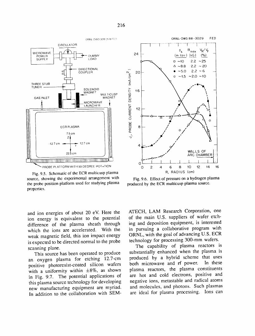
216
ORNLDWG00M:5:_[ [_ ORNL-DWG B8-3029 FED
CIRCULATOR | I ......]......... ]-...........F.... ]- ....... ] ........ T.........
I _ _ Ps Bm(]× VR/rFi MICROWAVEpowERI----4 F-z--4---Hl----mlI [ ___..___] _ DUMMY 24 (rr, lorr ) (kG) (%) -
SUPPLY ['--'--1--]_1_ L-I LOAD _ U--,0 2.2"-'25Z_ --8.8 2.2 "-. 20
.._ _ DIRECTIONAL
___ COUPLER e4 20--E "_._5.O 2.2_6 --
,o o _t.5 ,-,2.0 ~t0<
THREE STUB _ E ,,.-,.O--TUNER _ I _ _ /'
L--T-T-J SOLENOID >-" -- \ O ,,I I I I MAGNET _ 4 6[] I I n-",-- MUL]ICUSP _ X I \GAS INLET n_n MAGNET LdZ t/
i ml .._ MICROWAVE J. Q
3 Ld t2 -rrrr •
,,, / o
Et_ ECR PLASMA75 cm _ Onrr 8-- // O,/ J" t3_/ / 13
___ _ -127cm 12.7cm 4 __....---_" _
- IF---- / WALLS OF i_l_- L 22.5cm _,) ...,C_" ARC CHAMBER
___i____________________!_i_'__________________i___i'`__i_____'___________i______________L " I l ] [O ........
PROBE PLATFORM WITH 90-DEGREE ROI,,TION 0 2 4 6 8 10 42 t4 t6
Fig. 9.5. Schematicof the ECRmulticuspplasma R, RADI US (cm)
source, showing the experimental arrangementwith Fig. 9.6. Effectof pressureona hydrogenplasmathe probe positionplatformused for studyingplasma producedby the ECR multicuspplasma source.properties.
and ion energies of about 20 eV. Here the ATECH, LAM Research Corporation, oneion energy is equivalent to the potential of the main U.S. suppliers of wafer etch-difference of the plasma sheath through ing and deposition equipment, is interestedwhich the ions are accelerated. With the in pursuing a collaborative program with
weak magnetic field, this ion impact energy ORNL, with the goal of advancing U.S. ECRis expected to be directed normal to the probe technology for processing 300-mm wafers.scanning plane. The capability of plasma reactors is
This source has been operated to produce substantially enhanced when the plasma is
an oxygen plasma for etching 12.7-cm produced by a hybrid scheme that usespositive photoresist-coated silicon wafers both microwave and rf power. In thesewith a uniformity within +8%, as shown plasma reactors, the plasma constituentsin Fig. 9.7. The potential applications of are hot and cold electrons, positive andthis plasma source technology for developing negative ions, metastable and radical atomsnew manufacturing equipment are myriad, and molecules, and photons. Such plasmasIn addition to the collaboration with SEM- are ideal for plasma processing. Ions can
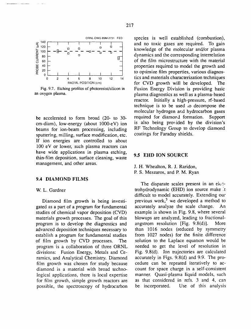
217
ORNL-DWG89M-2731FED species is well established (combustion),_ 140 I I I I _ I and no toxic gases are required. To gain_120 -- o --
_- [] [] [] knowledge of the molecular and/or plasmaZ 100 -- --B 0 -'0 -- --LU [] []
rr 80 - [] dynamics and the corresponding interrelationrr B-0 60 - - of the film microstructure with the material"' 4o - - properties required to model the growth andO 20 --_ to optimize film properties, various diagnos-a. 0 I 1 I I I I
0 2 4 6 8 10 12 14 tics and materials characterization techniquesRADIALPOSITION(cm) for CVD growth will be developed. The
Fig. 9.7. Etchingprofilesof photoresist/siliconin Fusion Energy Division is providing basican oxygenplasma, plasma diagnostics as well as a plasma-based
reactor. Initially a high-pressure, rf-basedtechnique is to be used Lo decompose themolecular hydrogen and hydrocarbon gases
be accelerated to form broad (20- to 30- required for diamovd formation. Supportcm-diam), low-energy (about 1000-eV) ion is also being provided by the division'sbeams for ion-beam processing, including RF Technology Group to develop diamondsputtering, milling, surface modification, etc. coatings for Faraday shields.If ion energies are controlled to about100 eV or lower, such plasma reactors can
have wide applications in plasma etching, 9.5 EHD ION SOURCEthin-film deposition, surface cleaning, waste
management, and other areas. J.H. Whealton, R. J. Raridon,P. S. Meszaros, and P. M. Ryan
9.4 DIAMOND FILMSThe disparate scales present in an ei_z-
W. L. Gardner trohydrodynamic (EHD) ion source make ,'tdifficult to model accurately. Extending our
Diamond film growth is being investi- previous work, 3 we developed a method togated as a part of a program for fundamental accurately analyze the scale change. Anstudies of chemical vapor deposition (CVD) example is shown in Fig. 9.8, where severalmaterials growth processes. The goal of this blowups are analyzed, leading to fractional-program is to develop the diagnostics and angstrom resolution [Fig. 9.8(d)]. Moreadvanced deposition techniques necessary to than 1016 nodes (reduced by symmetryestablish a program for fundamental studies from 1027 nodes) for the finite differenceof film growth by CVD processes. The solution to the Laplace equation would beprogram is a collaboration of three ORNL needed to get the level of resolution indivisions: Fusion Energy, Metals and Ce- Fig. 9.8(d). Ion trajectories are calculatedramics, and Analytical Chemistry. Diamond accurately in Figs. 9.8(d) and 9.9. The pro-film growth was chosen for study because cedure can be repeated iteratively to ac-diamond is a material with broad techno- count for space charge in a self-consistentlogical applications, there is local expertise manner. Quasi-plasma liquid models, suchfor film growth, simple growth reactors are as that considered in refs. 3 and 4, canpossible, the spectroscopy of hydrocarbon be incorporated. Use of this analysis
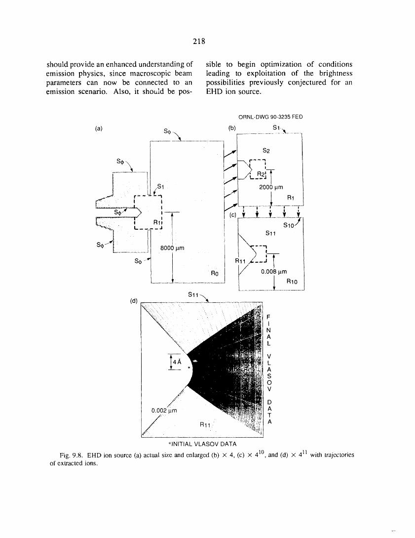
218
should provide an enhanced understanding of sible to begin optimization of conditionsemission physics, since macroscopic beam leading to exploitation of the brightnessparameters can now be connected to an possibilities previously conjectured for anemission scenario. Also, it should be pos- EHD ion source.
ORNL-DWG90-3235FED
(b) Sl-__(a) S¢ -.. ..........
,,,_[ s2
sm__ ..r--q__ --"V_s_:TSl .._ 2000 pm
" I --i ........ I .... i
_2,i:_i:.......[...."_,j / s,o,,
S¢ ,8000lam 7
s0- I /_o/ _/" O.OO8.m
S11-.,,_(d)
'.,".,," FI
%..._% . A
"\2; L
LAS0V
D_r. '
0.002 p.m AT
*INITIAL VLASOV DATA
Fig. 9.8. EHD ion source (a) actual size and enlarged (b) X 4, (c) x 410, and (d) x 411 with trajectoriesof extracted ions.

219
Fig. 9.9. EHD ion source with trajectories of extracted ions (a) actual size and enlarged (b) x 4 and(c) X 410.
REFERENCES ergy Systems, Inc., Oak Ridge National Laboratory,March 1990.
3. J. H. Whealton et ",ii.,"Extraction Induced
1. L. A. Berry et al., "Characteristics of the Emittance Growth for Negative Ion Sources," Rev.
ORNL ECR Multicusp Plasma Source," presented Sci. lnstrum. 61,568 (1990).
at the SRC Topical Research Conference on Plasma 4. J. H. Whealton et al., "ElectrohydrodynamicEtching, Cambridge, Mass., February 1-2, 1989. Ion Source Extraction," pp. 122-3 in Fusion Energy
2. C. C. Tsai et al., "Potential Applications of Division Annual Progress Report for Period Ending
an Electron Cyclotron Resonance Multicusp Plasma December 31, 1988, ORNL-6528, Martin MariettaSource," J. Vac. Sci. Technol. A 8, 2900 (1990); also Energy Systems, Inc., Oak Ridge National Labora-
published as ORNL/TM-11442, Martin Marietta En- tory, 1990.

10MANAGEMENT SERVICES,
QUALITY ASSURANCE,AND SAFETY

Management Services
E E. Gethers*/E. R. Wells*
D. R. Alford J.M. Finger J.C. Parrott 3
L. R. Ballard J.R. Jernigan t'4 J.O. Richardson
B. J. Beem I C.H. Johnson 3 G.G. Ross 3'4
J. B. Booth / D.Y. Johnson 3 E.M. RuckartD. P. Brooks L.M. Johnson 5 S.R. Schwartz 3
S. H. Buechler 3 C.C. Jones D.G. Sharp
J. L. Burke I.A. Kunkel B.J. Smith 3
M. W. Darnell 3 J.C. Neeley 3 P.A. Sumner 3
A. G. Evers M.B. Nestor M.S. Thompson I
Quality Assurance
E. J. Byrnes 6
Safety
E E. Gethers*/E. R. Wells*
*Dual capacity.1. Group secretary.2. Information Services Division, Administrative Services Organization, Martin Marietta Energy Systems, Inc.
3. Publications Division, Administrative Services Organization, Martin Marietta Energy Systems, Inc.
4. Part-time.
5. Finance and Materials Division, Martin Marietta Energy Systems, Inc.
6. Quality Department.
• 222
10. MANAGEMENT SERVICES,QUALITY ASSURANCE,
AND SAFETY
SUMMARY OF ACTIVITIES
Broad technical and administrative support for the programmatic research and developmentactivities of the Fusion Energy Division is provided by the Management Services Group andby the division's Quality Assurance (QA) and Safety programs.
The Management Services Group provides support in the following areas:
• General personnel administration, material and service procurement, subcontracting, andcoordination of national and international agreements.
• Nonprogrammatic engineering services for support systems and equipment; identification,planning, and coordination of general plant project and facility improvements; coordina-tion of maintenance and production shop work; labor relations; and telecommunications.
• Financial management.• Library services and resources.• Publications services.
Support is provided through effective communication with division programmatic staff andthrough the coordination of resources from disciplines outside the division.
The QA activity in the division emphasizes the development and documentation of aQA program that conforms to national standards, the review and approval of engineeringdocuments, supplier surveillance, identification and documentation of nonconforming items,audits, and QA assessments/plans.
The division's safety activities include a formal safety program and environmentalprotection services. A safety resource team was established to improve the environmental,safety, and health upgrade program in the division, and a hazard communication programwas established.
223
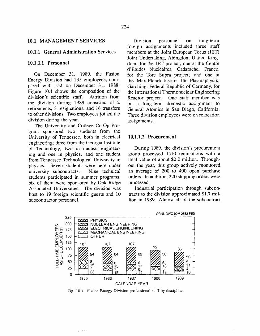
224
10.1 MANAGEMENT SERVICES Division personnel on long-termforeign assignments included three staff
10.1.1 General Administration Services members at the Joint European Torus (JET)Joint Undertaking, Abingdon, United King-
10.1.1.1 Personnel dora, for *.heJET project; one at the Centred'Etudes Nucl6aires, Cadarache, France,
On December 31, 1989, the Fusion for the Tore Supra project; and one atEnergy Division had 135 employees, com- the Max-Planck-Institut ffir Plasmaphysik,pared with 152 on December 31, 1988. Garching, Federal Republic of Germany, forFigure 10.1 shows the composition of the the International Thermonuclear Engineeringdivision's scientific staff. Attrition from Reactor project. One staff member wasthe division during 1989 consisted of 2 on a long-term domestic assignment toretirements, 3 resignations, and 16 transfers General Atomics in San Diego, California.to other divisions. Two employees joined the Three division employees were on relocationdivision during the year. assignments.
The University and College Co-Op Pro-gram sponsored two students from theUniversity of Tennessee, both in electrical 10.1.1.2 Procurementengineering; three from the Georgia Instituteof Technology, two in nuclear engineer- During 1989, the division's procurementing and one in physics; and one student group processed 1510 requisitions with afrom Tennessee Technological University in total value of about $2.0 million. Through-physics. Seven students were here under out the year, this group actively monitoreduniversity subcontracts. Nine technical an average of 200 to 400 open purchasestudents participated in summer programs; orders. In addition, 220 shipping orders weresix of them were sponsored by Oak Ridge processed.Associated Universities. The division was Industrial participation through subcon-host to 19 foreign scientific guests and 10 tracts to the division approximated $1.7 mil-subcontractor personnel, lion in 1989. Almost all of the subcontract
ORNL-DWG90M-2552FED
225 _ PHYSICS |
03 200 -_ NUCLEAR ENGINEERING -t
w ,-- _ ELECTRICAL ENGINEERINGw_ 175 ->- rr [:'777] MECHANICAL ENGINEERINGOLU 150 -["---'1 OTHER
"° t125 - 107 107 107
LUO 95 86
I !t 675 54 64 2 58
_J
.j co 50 8 6 6< 15 15 _ 17 13 1u_ 25 I- 7 7 5
0 23 15 ] 1....14 13 101985 1986 1987 1988 1989
CALENDAR YEAR
Fig. 10.1. Fusion Energy Division professional staff by discipline.
225
cost ($1.2 million) was applicable to the limited resources, continued during 1989.ORNL Fusion Program. The Engineering Services Group worked
The procurement status database provides closely with the Engineering Division ofusers with the status of individual procure- Martin Marietta Energy Systems, Inc., andments and serves as an eff-ctive tool for cost with Fusion Energy Division researcherscontrol, to install needed improvements. In this
reporting period, construction was nearingcompletion on phase 4 of a six-phase effort
10.1.1.3 International agreements to improve the air-handling systems inand collaboration Bldg. 9201-2. Engineering is complete for
the first and second phases of an upgrade forThe division participated in several per- the 480-V electrical distribution system.
sonnel exchanges and collaborations during The demineralized water system in Bldg.1989. The Management Services Group 9201-2 provides cooling water for the Ad-(MSG) played a key role in organizing vanced Toroidal Facility (ATF), the Radio- _these activities, with responsibility for coor- Frequency Test Facility (RFTF), and otherdinating administrative, legal, and protocol test facilities and for the building air con-matters for outbound Fusion Program repre- ditioners. During 1989, the Engineeringsentatives and inbound foreign guests. Services Group provided data for a quality
In this cz_.pacity, MSG staff members investigation report on pump problems. Newinteracted with the ORNL Foreign National and improved polypropylene filters and pres-Office, the ORNL and Y-12 Plant secu- sure drop indicators were installed. Waterrity organizations, the Office of General quality was improved dramatically. CostCounsel and the Office of the Comptroller reductions through electrical power savingsand Treasurer of Martin Marietta Energy were accomplished by the Performance Im-Systems, and the Washington and Oak provement Process (PIP) program.Ridge Operations offices of DOE, as well The liquid nitrogen tank installed in 1988as other support and service organizations, as part of a PIP project continued to save theResponsibilities included ensuring adherence division an estimated $90,000 yearly.to general laboratory and company policies Housekeeping and safety of building andand to federal procedures and laws, moni- grounds have been brought to a new leveltoting the processing of paperwork to ensure of consciousness, including active industrialtimeliness and accuracy, obtaining the neces- hygiene work to eliminate chemical prob-sary approvals, and generally supporting the lems and industrial safety w_rk to eliminatesatisfactory implementation of exchanges, other hazards.cooperative programs, and collaborations.
10.1.3 Financial Services
10.1.2 Engineering ServicesThe Finance Office is a functional part of
The Engineering Services Group coor- the MSG and provides financial managementdinates all engineering work performed on support for administrative, engineering, andgeneral facilities additions, modifications, research personnel in areas that includeand repairs in the division. Active work to budget preparation, cost scheduling, andimprove the physical plant facilities, despite variance analysis. The office also provides
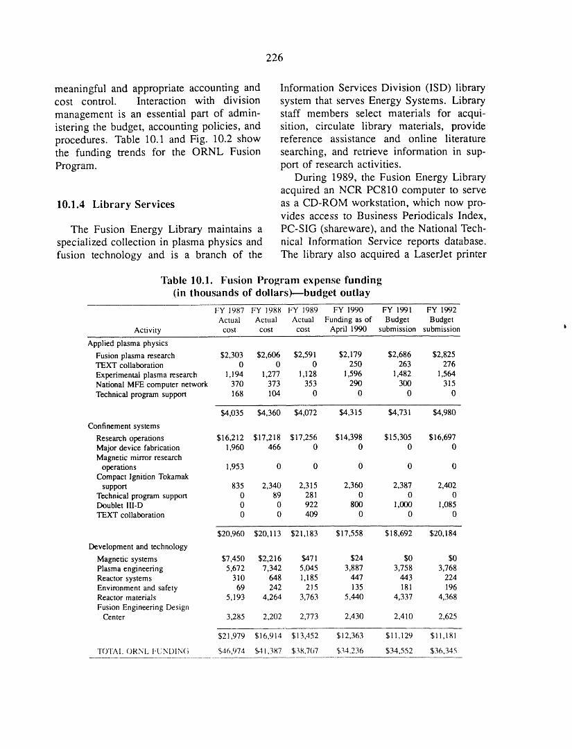
226
meaningful and appropriate accounting and Information Services Division (ISD) librarycost control. Interaction with division system that serves Energy Systems. Librarymanagement is an essential part of admin- staff members select materials for acqui-istering the budget, accounting policies, and sition, circulate library materials, provideprocedures. Table 10.1 and Fig. 10.2 show reference assistance and online literaturethe funding trends for the ORNL Fusion searching, and retrieve information in sup-Program. port of research activities.
During 1989, the Fusion Energy Libraryacquired an NCR PC810 computer to serve
10.1.4 Library Services as a CD-ROM workstation, which now pro-vides access to Business Periodicals Index,
The Fusion Energy Library maintains a PC-SIG (shareware), and the National Tech-specialized collection in plasma physics and nical Information Service reports database.fusion technology and is a branch of the The library also acquired a LaserJet printer
Table 10.1. Fusion Program expense funding(in thousands of dollars)--budget outlay
FY 1987 FY 1988 FY 1989 FY 1990 FY 1991 FY 1992Actual Actual Actual Funding as of Budget Budget
Activity cost cost cost April 1990 submission submission h
Applied plasma physics
Fusion plasma research $2,303 $2,606 $2,591 $2,179 $2,686 $2,825TEXT collaboration 0 0 0 250 263 276
Experimental plasma research 1,!94 1,277 1,128 1,596 1,482 1,564National MFE computer network 370 373 353 290 300 315Technical program support 168 104 0 0 0 0
$4,035 $4,360 $4,072 $4,315 $4,731 $4,980
Confinement systems
Research operations $16,212 $17,218 $17,256 $14,398 $15,305 $16,697Major device fabrication 1,960 466 0 0 0 0Magnetic mirror research
operations 1,953 0 0 0 0 0Compact Ignition Tokamak
support 835 2,340 2,315 2,360 2,387 2,402Technical program support 0 89 281 0 0 0Doublet III-D 0 0 922 800 1,000 1,085TEXT collaboration 0 0 409 0 0 0
$20,960 $20,113 $21,183 $17,558 $18,692 $20,184
Development and technology
Magnetic system s $7,450 $2,216 $471 $24 $0 $0Plasma engineering 5,672 7,342 5,045 3,887 3,758 3,768Reactor systems 310 648 1,185 447 443 224Environment and safety 69 242 215 135 181 196Reactor materials 5,193 4,264 3,763 5,440 4,337 4,368
Fusion Engineering DesignCenter 3,285 2,202 2,773 2,430 2,410 2,625
$21,979 $16,914 $13,452 $12,363 $11,129 $11,181
TOTAl. ORNL FUNI)IN(; 546,974 $41,387 $38,7()7 $34,236 $34,552 $36,345
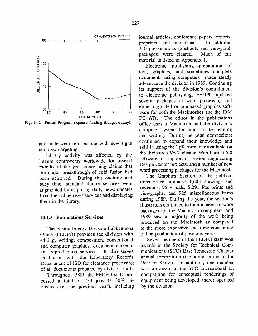
227
ORNL-DWG90M-2553FED journal articles, conference papers, reports,60 1 _ _ t preprints, and one thesis. In addition,
310 presentations (abstracts and viewgraphpackages) were cleared. Much of this03
a: material is listed in Appendix 1"_ 50 -Electronic publishingwpreparation of
text, graphics, and sometimes completeo documents using computersmmade steady03
advances in the division in 1989. Continuing_q,40._ its support of the division's commitment
..... ....- to electronic publishing, FEDPO updatedseveral packages of word processing and
30 I _ I R either upgraded or purchased graphics soft-87 88 89 90 91 92 ware for both the Macintoshes and the IBM
FISCALYEAR PC ATs. The editor in the publicationsFig. 10.2. FusionProgram expense funding(budgetoutlay), office uses a Macintosh and the division's
computer system for much of her editingand writing. During the year, compositors
and underwent refurbishing with new signs continued to expand their knowledge andand new carpeting, skill in using the TEX formatter available on
Library activity was affected by the the division's VAX cluster, WordPerfect 5.0intense controversy worldwide for several software for support of Fusion Engineeringmonths of the year concerning claims that Design Center projects, and a number of newthe major breakthrough of cold fusion had word processing packages for the Macintosh.been achieved. During this exciting and The Graphics Section of the publica-
tions office produced 1,605 drawings andbusy time, standard library services wereaugmented by acquiring daily news updates revisions, 95 visuals, 5,291 Pos prints andfrom the online news services and displaying viewgraphs, and 925 miscellaneous itemsthem in the library, during 1989. During the year, the section's
illustrators continued to train in new software
packages for the Macintosh computers, and10.1.5 Publications Services 1989 saw a majority of the work being
produced on the Macintosh as comparedThe Fusion Energy Division Publications to the more expensive and time-consuming
Office (FEDPO) provides the division with online production of previous years.editing, writing, composition, conventional Seven members of the FEDPO staff wonand computer graphics, document makeup, awards in the Society for Technical Com-and reproduction services, lt also serves munications (STC) East Tennessee Chapteras liaison with the Laboratory Records annual competition (including an award forDepartment of ISD for clearance processing Best of Show). In addition, one memberof ali documents prepared by division staff, won an award at the STC international art
Throughout 1989, the FEDPO staff pro- competition for conceptual renderings ofcessed a total of 230 jobs (a 30% in- equipment being developed and/or operatedcrease over the previous year), including by the division.
228
In December 1989, FEDPO merged with Laboratory Quality Department performedthe Engineering Technology Division Pub- an audit of the division.lications Office (ETDPO) to form the En-gineering Technology/Fusion Energy Divi-sion Publications Office (ET/FE DPO). The 10.3 SAFETY AND ENVIRONMENTALET/FE DPO is committed to providing high- PROTECTIONquality, cost-effective publications support toboth of its host divisions. 10.3.1 Safety
In an effort to improve the environment,
10.2 QUALITY ASSURANCE safety, and health (ES&H) upgrade programin the division, a safety resource team wasestablished in 1989. The team included a
10.2.1 QA Program Development member from each section in the division.and Training Its purpose was to identify safety hazards
in division facilities and develop plans ofDuring the year, one new procedure action to correct or resolve the issues. The
was added to the division quality assurance team successfully initiated activities such as(QA) manual. The NQA-1 orientation the identification of 400 safety-related issues,and portions of the QA training program planned and executed a division-wide safetywere completed. The 213 participants work day, prepared the division for auditsincluded division staff; Y-12 Plant super- preceding the Technical Safety Appraisalvisors, planners, and ciaft workers; staff (TSA) and for the actual TSA, and continuedof other ORNL divisions supporting Fusion to monitor the division's safety and healthEnergy Division; staff of the Energy Systems policies. The team also assisted in theEngineering and Publications divisions; and improvement of safety documentation andDOE staff, records, which included safety assessments,
operating procedures, and safety study re-ports.
10.2.2 QA Program Implementation In general, the division has continued torecognize the need for its safety awareness
The division's QA engineer reviewed program and housekeeping efforts. Theengineering and procurement documents, monthly safety meetings are being used as aincluding drawings and specifications defin- training forum to address these isues. Withing technical requirements for items to be the increased emphasis on these programs,fabricated, to ensure that they clearly defined division staff are expected to develop athe QA requirements to be met. Five safer attitude and improve the division'snonconformance reports, four quality inspec- performance in 1990.tion reports, and one unusual occurrencereport were written to document problems,produce corrective action, and disseminate 10.3.2 Environmentinformation to other organizations. Onevendor surveillance was performed during The division implemented new activitiesthe year. The Princeton Plasma Physics and programs to address environmental

229
concerns, compliance issues, and improved evaluated, and a restoration plan is beingemployee communications in 1989. These prepared.activities included a hazard communication New procedures and directives are beingprogram, which enables employees to deter- implemented in areas of air and watermine the hazardous level of the chemicals pollution, polychlorinated biphenyl (PCB)in laboratories, and noise level and asbestos contamination, radiation controls, etc. Thesesurvey programs. An area of concern in initiatives will assist the division in improve-Bldg. 9201-2 is the basement; this area was ment and protection of the environment.
Appendix 1
PUBLICATIONS AND PRESENTATIONS
BOOKS AND JOURNAL ARTICLES .......... 233PRESENTATIONS ......................... 245CONGRESSIONAL TESTIMONY ................... 267SEMINARS .......................... 269REPORTS ............................ 271
ORNL Reports ......................... 271ORNL Technical Memoranda .................... 271
ORNL Fusion Engineering Design Center Reports ............ 272Reports Prepared by ORNL for the U.S. Department of Energy ........ 272Reports Published by Other Institutions ................. 272
THESES AND DISSERTATIONS ...................... 275
231
233
BOOKS AND JOURNAL ARTICLES
F. S. B. Anderson, F. Middleton, R. J. Colchin, and D. Million, "Accurate Electron Gun-Positioning
Mechanism for Electron Beam-Mapping of Large Cross-Section Magnetic Surfaces," Rev. Sci.lnstrum. 60, 795-7 (1989)
S. E. Attenberger, W. A. Houlberg, and N. A. Uckan, "Transport Analysis of Ignited and Current-DrivenITER Designs," Fusion Technol. 15, 629-36 (1989)
D. B. Batchelor, E. E Jaeger, B. A. Carreras, V. E. Lynch, H. Weitzner, K. Imre, D. C. Stevens, V. Fuchs,and A. Bers, "Full-Wave Modeling of Ion Cyclotron Heating in Tokamaks," p. 611 in PlasmaPhysics and Controlled Nuclear Fusion Research 1988: Twelfth Conference Proceedings, Nice, 12-19October 1988, vol. 1, International Atomic Energy Agency, Vienna, 1989
D. B. Batchelor, E. E Jaeger, and P. L. Colestock, "Ion Cyclotron Emission from Energetic FusionProducts in Tokamak Plasmas--A Full-Wave Calculation," Phys. Fluids B 1, 1174-84 (1989)
D. B. Batchelor, E. E Jaeger, and H. Weitzner, "2D Full Wave Modeling of ICRF with Finite Ell,"pp. 691-8 in Theory of Fusion Plasmas: Proceedings of the Joint Varenna-Lausanne WorkshopHeld at Hotel du Signal, Chexbres (near Lausanne), Switzerland, October 3-7, 1988, ed. J. Vaclavik,F. Troyon, and E. Sindoni, Editrice Compositori, Bologna, Italy, 1989
L. R. Baylor, W. A. Houlberg, G. L. Schmidt, S. L. Milora, and the JETAJ.S. Pellet Team, "Particle
Transport Analysis of Pellet-Fueled JET Plasmas," pp. 107-12 in Pellet Injection and ToroidalConfinement: Proceedings of the Technical Committee Meeting, Gut Ising, 1988, IAEA-TECDOC-534, International Atomic Energy Agency, Vienna, 1989
W. R. Becraft, J. H. Whealton, T. P. Wangler, A. Schempp, G. E. McMichael, M. A. Akerman, G. C.Barber, W. K. Dagenhart, H. H. Haselton, R. J. Raridon, K. E. Rothe, B. D. Murphy, and W. L.Stirling, "RF Accelerated High Energy (1-3 MeV) Neutral Beams for Tokamak Plasma Heating,Current Drive and Alpha Diagnostics," Fusion Technol. 15, 734 (1989)
G. E. Bell, M. A. Abdou, and P. F. Tortorelli, "Experimental and Analytical Investigation of MassTransport Processes of 12Cr-IMoVW Steel in Thermally Convected Lithium Systems," Fusion Eng.Des. 8, 421-7 (1989)
M. G. Bell, V. Arunasalam, C. W. Barnes, M. Bitter, H.-S. Bosch, N. L. Bretz, R. Budny, C. E. Bush,A. Cavallo, T. K.Chu, S. A. Cohen, P. L. Colestock, S. L. Davis, D. L. Dimock, H. F. Dylla,P. C. Efthimion, A. B. Ehrhardt, R. J. Fonck, E. D. Fredrickson, H. P. Furth, G. Gammel, R. J.Goldston, G. J. Greene, B. Grek, L. R. Grisham, G. W. Hammett, R. J. Hawryluk, H. W. Hendei,K. W. Hill, E. Hinnov, J. C. Hosea, R. B. Howell, H. Hsuan, R. A. Hulse, K. P. Jaehnig, A. C.Janos, D. L. Jassby, F. C. Jobes, D. W. Johnson, L. C. Johnson, R. Kaita, C. Kieras-Phillips, S. J.Kilpatrick, V. A. Krupin, P. H. LaMarche, W. D. Langer, B. LeBlanc, R. Little, A. Lysojvan, D. M.Manos, D. K. Mansfield, E. Mazzucato, R. T. McCann, M. P. McCarthy, D. C. McCune, K. M.McGuire, 12. q. McNeill, D. M. Meade, S. S. Medley, D. R. Mikkelsen, R. W. Motley, D. Mueller,Y. Murakami, J. A. Murphy, E. B. Nieschmidt, D. K. Owens, H: K. Park, A. T. Ramsey, M. H.Redi, A. L. Roquemore, P. H. Rutherford, T. Saito, N. R. Sauthoff, G. Schilling, J. Schivell, G. L.Schmidt, S. D. Scott, J. C. Sinnis, J. E. Stevens, W. Stodiek, B. C. Suatton, G. D. Tait, G. Taylor,J. R. Timberlake, H. H. Towner, M. Ulrickson, S. Von Goeler, R. M. Wieland, M. D. Williams, J. R.Wilson, K.-L. Wong, S. Yoshikawa, K. M. Young, M. "Zarnstorff, and S. J. Zweben, "An Overviewof TFTR Confinement with Intense Neutral Beam Heating," p. 27 in Plasma Physics and ControlledNuclear Fusion Research 1988: Twelfth Conference Proceedings, Nice. 12-19 October 1988, vol. 1,International Atomic Energy Agency, Vienna, 1989
C. A. Bennett and D. P. Hutchinson, "Far Field Propagation of the Truncated EHII Dielectric WaveguideMode," Appl. Opt. 28, 2581-83 (1989)
H. Biglari, P. H. Diamond, M. N. Rosenbluth, R. E. Waltz, R. R. Dominguez, P. W. Terry, N. Mattor,P. Lyster, J. N. Leboeuf, B. A. Carreras, G. S. Lee, L. Garcia, N. Dominguez, and J. H. Han,"Advances in the Theory of Ion-Temperature-Gradient-Driven Turbulence," p. 261 in Plasma Physics

234
and Controlled Nuclear Fusion Research 1988: Twelfth Conference Proceedings, Nice, 12-19October 1988, vol. 2, International Atomic Energy Agency, Vienna, 1989
A. Boileau, M. von Hellermann, L. D. Horton, J. Spence, and H. P. Summers, "The Deduction of Low-ZIon Temperatures and Densities in the JET Tokamak Using Charge Exchange RecombinationSpectroscopy," Plasma Phys. Controlled Fusion 31,779 (1989)
A. Boileau, M. von Hellermann, L. D. Horton, H. E Summers, and la. D. Morgan, "Analysis of Low-Z
Impurity Behaviour in JET by Charge Exchange Measurements," Nucl. Fusion 29, 1449 (1989)
K. H. Burrell, S. L. Allen, G. Bramson, N. H. Brooks, R. W. Callis, T. N. Carlstrom, M. S. Chance,M. S. Chu, A. E Colleraine, D. Content, J. C. DeBoo, R. R. Dominguez, S. Ejima, J. Ferron,R. L. Freeman, H. Fukumoto, P. Gohil, N. Gottardi, C. M. Greenfield, R. J. Groebner, G. Haas,
R. W. Harvey, W. W. Heidbrink, F. J. Helton, D. N. Hill, F. L. Hinton, R.-M. Hong, N. Hosogane,W. Howl, C. L. Hsieh, G. L. Jackson, G. L. Jahns, R. A. James, A. G. Kellman, J. Kim,S. Kinoshita, L. L. Lao, E. A. Lazarus, E Lee, T. LeHecka, J. Lister, J. M. Lohr, E J. Lomas,T. C. Luce, J. L. Luxon, M. A. Mahdavi, K. Matsuda, M. Mayberry, C. P. Moeller, Y. Neyatani,
T. Ohkawa, N. Ohyabu, T. H. Osborne, D. O. Overskei, T. Ozeki, W. A. Peebles, S. Perkins,M. Perry, E I. Petersen, T. W. Petrie, K. Philipono, J. C. Phillips, R. Pinsker, G. D. Porter, R. Prater,D. B. Remsen, M. E. Rensink, K. Sakamoto, M. J. Schaffer, D. P. Schissel, J. T. Scoville, R. E
Seraydarian, M. Shimada, T. C. Simonen, R. T. Snider, G. M. Staebler, B. W. Stallard, R. D.Stambaugh. R. D. Stay, H. St. John, R. E. Stockdale, E. J. Strait, 1a. L. Taylor, T. T. Taylor, P. K.Trost, A. Turnbull, U. Stroth, R. E. Waltz, and R. Wood, "Energy Confinement in Auxiliary Heated
Divertor and Limiter Discharges in the DIII-D Tokamak," p. 193 in Plasma Physics and ControlledNuclear Fusion Research 1988: Twelfth Conference Proceedings, Nice, 12-19 October 1988, vol. 1,International Atomic Energy Agency, Vienna, 1989
J. D. Callen, Y. B. Kim, A. K. Sundaram, B. A. Carreras, L. Garcia, K. C. Shaing, D. A. Spong,
H. Biglari, P. H. Diamond, and O. J. Kwon, "Neoclassical MHD Description of Tokamak Plasmas,"p. 33 in Plasma Physics and Controlled Nuclear Fusion Research 1988: Twelfth ConferenceProceedings, Nice, 12-19 October 1988, vol. 2, International Atomic Energy Agency, Vienna, 1989
B. A. Carreras and P. H. Diamond, "Thermal Diffusivity Induced by Resistive Pressure-Gradient-Driven
Turbulence," Phys. Fluids B l, 1011-17 (1989)
B. A. Carreras, N. Dominguez, L. Garcia, J. F. Lyon, S. L. Painter, V. E. Lynch, J. R. Cary, and J. D.
Hanson, "Low-Aspect-Ratio Torsatrons," p. 397 in Plasma Physics and Controlled Nuclear FusionResearch 1988: Twelfth Conference Proceedings, Nice, 12-19 October 1988, vol. 2, InternationalAtomic Energy Agency, Vienna, 1989
M. D. Carter, D. B. Batchelor, and C. L. Hedrick, "Drift Loss Transport Driven by RadiofrequencyHeating," Nucl. Fusion 29, 729-44 (1989)
M. D. Carter, E. E Jaeger, and D. B. Batchelor, "Non-Linear Core Plasma Response to ICRF Heating withTransport," Nucl. Fusion 29, 2141 (1989)
J. B. O. Caughman II, D. N. Ruzic, and D. J. Hoffman, "Floating Potential Measurements in the NearField of an Ion Cyclotron Resonance Heating Antenna," J. Vac. Sci. 7"echnol. A 7, 1092-98 (1989)
L. A. Charlton, R. J. Hastie, and T. C. Hender, "Ideal and Resistive Infernal Modes," Phys. Fluids B 1,
798 (1989)
R. J. Colchin, F. S. B. Anderson, A. C. England, R. E Gandy, J. H. Harris, M. A. Henderson, D. L.Hillis, R. R. Kindsfather, D. K. Lee, D. L. Million, M. Murakami, G. H. Neilson, M. J. Saltmarsh,and C. M. Simpson, "Electron Beam and Magnetic Field Mapping Techniques Used to DetermineField Errors in the ATF Torsatron," Rev. Sci. lnstrum. 60, 2680 (1989)
S. K. Combs, C. A. Foster, S. L. Milora, D. D. Schuresko, M. J. Gouge, P. W. Fisher, B. E. Argo, G. C.Barber, L. R. Baylor, M. J. Cole, D. T. Fehling, C. R. Foust, F. E. Gethers, H. H. Haselton, T. C.Jernigan, N. S. Ponte, A. L. Quails, D. E. Schechter, D. W. Simmons, C. W. Sohns, D. O. Sparks,C. C. Tsai, and J. C. Whitson, "Pellet Injector Research at ORNL," p. 709 in Fusion Technology1988: Proceedings of the 15th Symposium on Fusion Technology, Utrecht, 7"he Netherlands, 19-23

235
September 1988, Vol. 1, edited by A. M. Van Ingen, A. Nijsen-Vis, and H. T. Klippel, North-Holland, Amsterdam, 1989
S. K. Combs, T. C. Jernigan, L. R. Baylor, S. L. Milora, C. R. Foust, P. Kupschus, M. Gadeberg, andW. Bailey, "Performance of a Pneumatic Hydrogen-Pellet Injection System on the Joint EuropeanTorus," Rev. Sci. lnstrum. 60, 2697-2700 (1989)
S. K. Combs, S. L. Milora, C. R. Foust, M. J. Gouge, D. T. Fehling, and D. O. Sparks, "Development
of a Two-Stage Light Gas Gun to Accelerate Hydrogen Pellets to High Speeds for Plasma FuelingApplications," J. Vac. Sci. Technol. A 7, 963-7 (1989)
W. A. Cooper, S. P. Hirshman, and D. K. Lee, "The Beta Limit in the Advanced Toroidal Facility due toLocal Ideal MHD Instabilities," Nucl. Fusion 29, 617 (1989)
N. Dominguez, J. N. Leboeuf, B. A. Carreras, and V. E. Lynch, "Ideal Low-n and Mercier Mode StabilityBoundaries for _ = 2 Torsatrons," Nucl. Fusion 29, 2079 (1989)
D. G. Doran and R. L. Klueh, "Reduced Activation Alloy Development for Fusion," MRS Bull. XIV,45-57 (1989) R. A. Dory, "Matrices and Contour Plots," Comput. Phys. 3 (3), 84 (1989)
R. A. Dory, "Ordinary Differential Equations," Comput. Phys. 3 (5), 88 (1989)
R. A. Dory, "WingZ as a Scientific Aid," Comput. Phys. 3 (3), 93 (1989)
R. A. Dory, W. A. Houlberg, and S. E. Attenberger, "Energy Requirements for Neutral Beam CurrentDrive in a Large Tokamak," Comments Plasma Phys. Controlled Fusion 13, 29--44 (1989)
L. Dresner, "Bubble Growth in Superheated He-II," Cryogenics 29, 509 (1989)
L. Dresner, "Quench Pressure, Thermal Expulsion, and Normal Zone Propagation in IntemaUy CooledSuperconductors," IEEE Trans. Magn. MAG-25, 1710 (1989)
C. L. Dunford, D. C. Larson, and P. G. Young, "ENDF/B-VI Nuclear Data Evaluations for FusionApplications," Fusion Technol. 15, 429 (1989)
C. L. Easterly, G. S. Hill, and J. B. Cannon, "Environmental Effects of Fusion Power Plants. Part III:Potential Radiological Impact of Environmental Releases," Fusion Technol. 16, 125 (1989)
A. C. England, O. C. Eldridge, S. E Knowlton, M. Porkolab, and J. R. Wilson, "Power Transmission andCoupling for RF Heating of Plasmas," Nucl. Fusion 29, 1527-1632 (1989)
P. W. Fisher, M. L. Bauer, L. R. Baylor, S. K. Combs, L. E. Deleanu, D. T. Fehling, C. A. Foster, M. J.Gouge, S. L. Milora, D. D. Schuresko, D. O. Sparks, and J. C. Whitson, "Tritium Pellet InjectorResults," J. Vac. Sci. Technol. A 7, 938-43 (1989)
J. D. Galambos, Y-K. M. Peng, R. L. Reid, M. S. Lubell, L. Dresner, and J. R. Miller, "Comparison of
Nb3Sn and NbTi Superconducting Magnets for ITER Devices," Fusion Technol. 15, 1046 (1989)
J. D. Galambos, D. J. Strickler, Y-K. M. Peng, and R. L. Reid, "Plasma Elongation Studies for ITER-LikeTokamaks," Fusion Technol. 15, 483 (1989)
L. Garcia, C. Alejaldre, A. L. Fraguas, J. Guasp, A. Varias, B. A. Carreras, N. Dominguez, and V. E.Lynch, "Equilibrium and Stability Studies for Low-Aspect-Ratio Stellarator Configurations," p. 389in Plasma Physics and Controlled Nuclear Fusion Research 1988: Twelfth Conference Proceedings,
Nice, 12-19 October 1988, vol. 2, International Atomic Energy Agency, Vienna, 1989
R. C. Goldlinger and D. B. Batchelor, "A Numerical Model for Electron Cyclotron Heating Profiles inStellarator Geometry," Nucl. Fusion 29, 1743 (1989)
M. J. Gouge, S. K. Combs, P. W. Fisher, and S. L. Milora "Design Considerations for Single-Stage andTwo-Stage Pneumatic Pellet Injectors, " Rev. Sci. lnstrum. 60, 570-75 (1989)
D. L. Grekov, M. D. Carter, and A. I. Pyatak, "Ion Trapping Effect on Cyclotron Fast Magnetosonic WaveAbsorption in a Tokamak," Fiz. Plasmy 15, 1143 (1989).
D. C. Griffin, M. S. Pindzola, and P. Krylstedt, "Distorted-Wave Calculations of Dielectronic
Recombination for C3. and 05+ in Small Elect.ric Fields," Phys. Rev. A 40, 6699-6701 (1989)
S. P. Grotz, N. M. Ghoniem, TITAN Research Group, J. R. Bartlit, C. G. Bathke, J. P. Blanchard, E. T.Cheng, Y. Chu, R. W. Conn, P. I. H. Cooke, R. L. Creedon, A. Dabiri, W. P. Duggan, O. Fischer,

236
]9. j. Gierszewski, G. E. Gorker, M. Z. Hasan, C. G. Hoot, D. C. Keeton, W. P. Kelleher, C. E.Kessel, R. A. Krakowski, O. Kveton, D. C. Lousteau, R. C. Martin, R. L. Miller, F. Najmabadi,
R. A. Nebel, G. E. Orient, A. K. Prinja, K. R. Schulz, S. Sharafat, D. Steiner, D. K. Sze, S. L.Thomson, S. G. Visser, E. L. Vold, K. A. Werley, and C. P. C. Wong, "Overview of the TITAN-IFusion-Power Core," Fusion Eng. Des. 9, 357-73 (1989)
J. H. Harris, M. Murakami, B. A. Carreras, J. D. Bell, G. L. Bell, T. S. Bigelow, L. A. Charlton,
N. Dominguez, J. L. Dunlap, J. C. Glowienka, L. D. Horton, H. C. Howe, R. C. Isler, H. Kaneko,R. R. Kindsfather, J. N. Leboeuf, V. E. Lynch, M. M. Menon, R. N. Morris, G. H. Neilson, V. K.Par6, D. A. Rasmussen, J. B. Wilgen, and W. R. Wing, "Second Stability in the ATF Torsatron,"Phys. Rev. Lett. 63, 1249-52 (1989)
E N. Haubenreich, S. Shimamoto, P. Komarek, and G. V6csey, "International Development of
Superconducting Magnets for Fusion Power," Fusion Technol. 15, 909 (1989)
C. C. Havener, M. S. Huq, E W. Meyer, and R. A. Phaneuf, "Electron Capture by Multicharged Ions ateV Energies," J. Phys. (Paris) 50, Coll. C1, 7-17 (1989)
C. C. Havener, M. S. Huq, H. E Krause, P. A. Schulz, and R. A. Phaneuf, "Merged-Beams Measurementsof Electron-Capture Cross Sections for 05+ + H at Electron-Volt Energies," Phys. Rev. A 39,1725--40 (1989)
C. C. Havener, K. J. Reed, K. J. Snowdon, N. Stolterfoht, D. M. Zehner, and F. W. Meyer, "Evidence forProduction of Inner-Shell Vacancies in Slow Multicharged F Ions Interacting with a Cu Surface,"
Surf. Sci. 216, L357-L365 (1989)
C. C. Havener, K. J. Reed, K. J. Snowdon, D. M. Zehner, and F. W. Meyer, "Interaction of MultipleCharged Ions with Solid Surfaces," Radiat. Efr. Defects Solids 109, 99-109 (1989)
D. M. Hetrick, C. Y. Fu, and D. C. Larson, "ENDF/B-VI Evaluations for Isotopes of Cr, Fe, Ni, Cu, andPb," Fusion Technol. 15, 453 (1989)
D. L. Hillis, E K. Mioduszewski, R. H. Fowler, J. A. Rome, O. Motojima, T. Mizuuchi, N. Noda,T. Mutoh, H. Zushi, R. Takahashi, T. Obiki, A. liyoshi, and K. Uo, "Experimental Investigation of
the Natural Divertor Configuration in Heliotron-E," J. Nucl. Mater. 162-164, 629 (1989)
D. J. Hoffman and G. C. Barber, "The Technology of the Ion Cyclotron Range of Frequencies," FusionTechnol. 15, 719 (1989)
J. T. Hogan, C. C. Klepper, D. L. Hillis, and T. Uckan, "Modeling of Spectroscopic Measurements ofEdge Recycling," J. Nucl. Mater. 162-164, 469 (1989)
J. A. Holmes, B. A. Carreras, and L. A. Charlton, "Magnetohydrodynamic Stability and NonlinearEvolution of the m = 1 Mode in Toroidal Geometry for Safety Factor Profiles with an InflectionPoint," Phys. Fluids B 1, 788-97 (1989)
J. A. Holmes, L. A. Charlton, J. T. Hogan, B. A. Carreras, and E. A. Lazarus, "Maximum Beta for aSmall-Aspect-Ratio Tokamak," Phys. Fluids B 1, 358--63 (1989)
W. A. Houlberg, S. L. Milora, C. K. Phillips, J. S. Tolliver, and the JET/U.S. Pellet Team, "WHISTTransport Analysis of Bigh-Neutron-Production, ICRF-Heated, Pellet-Fueled JET Plasmas,"pp. 137--42 in Pellet Injection and Toroidal Confinement: Proceedings of the Technical CommitteeMeeting, Gut Ising, 1988, IAEA-TECDOC-534, International Atomic Energy Agency, Vienna, 1989
M. S. Huq, C. C. Havener, and R. A. Phaneuf, "Low-Energy Electron Capture by N 3+, Nn+, and N5+ fromHydrogen Atoms Using Merged Beams," Phys. Rev. A 40, 1811-16 (1989)
R. C. Isler, E. C. Crume, L. D. Horton, H. C. Howe, and G. S. Voronov, "Spectroscopic Studies of PlasmaCollapse in the Advanced Toroidal Facility," Nucl. Fusion 29, 1384-90 (1989)
R. C. lsler, L. D. Horton, G. S. Voronov, E. C. Crume, G. L. Bell, R. Fo Gandy, J. H. Harris, J. C.Giowienka, M. Murakami, G. H. Neilson, D. A. Rasmussen, J. B. Wilgen, and W. R. Wing,"Temperature Behaviour During Neutral Beam Injection in a Torsatron (ATF) with Field Errors,"Nucl. Fusion 29, 1391-97 (1989)
237
JET Team (ORNL staff members: L. R. Baylor, W. A. Houlberg, T. C. Jernigan, and S. L. Milora), "HighTemperature Experiments and Fusion Product Measurements in JET," p. 247 in Plasma Physics andControlled Nuclear Fusion Research 1988: Twelfth Conference Proceedings, Nice, 12-19 October1988, vol. 1, International Atomic Energy Agency, Vienna, 1989
JET Team (ORNL staff members: L. R. Baylor, W. A. Houlberg, T_ C. Jernigan, and S. L. Milora),"Heating of Peaked Density Profiles Produced by Pellet Injection in JET," p. 215 in Plasma Physicsand Controlled Nuclear Fusion Research 1988: Twelfth Conference Proceedings, Nice, 12-19October 1988, vol. 1, International Atomic Energy Agency, Vienna, 1989
JET Team (ORNL staff members: L. R. Baylor, W. A. Houlberg, T. C. Jernigan, and S. L. Milora),"The JET H-Mode at High Current ,,,,d Power Levels," p. 159 in Plasma Physics and ControlledNuclear Fusion Research 1988: Twelfth Conference Proceedings, Nice, 12-19 October 1988, vol. 1,International Atomic Energy Agency, Vienna, 1989
JET Team (ORNL staff members: L. R. Baylor, W. A. Houlberg, T. C. Jernigan, and S. L. Milora),"Latest JET Results and Future Prospects," p. 41 in Plasma Physics and Controlled Nuclear FusionResearch 1988: 7'welfth Conference Proceedings, Nice, 12-19 October 1988, vol. 1, InternationalAtomic Energy Agency, Vienna, 1989
E. A. Kenik, P. J. Maziasz, and R. L. Klueh, "Phase Stability of a Manganese-Stabilized AusteniticStainless Steel," pp. 284-5 in Proceedings of t;'e 47th Annual Meeting of the Electron MicroscopySociety of America, San Antonio, Texas, August 6-11, 1989, ed. G. W. Bailey, San Francisco Press,Inc., San Francisco, 1989
J. F. King, F. W. Bzity, D. J. Hoffman, J. C. Walls, and D. J. Taylor, "Materials Tests and Analyses ofFaraday Shield Tubes for ICRF Antennas," Fusion Technol. 15, 1093-,5 (1989)
C. C. Klepper, L. W. Owen, P. if M!oduszewski, and A. Grosman, "Modeling of Neutral Transport andImpurity Generation in the ,"_re Sut_ra Pump Limiter," J. Nucl. Mater. 162-164, 696 (1989)
R. L. Klueh, "Heat Treat.,|ent Behavior aud Tensile Properties of Cr-W Steels," Metall. Trans. 20A,463-70 (1989)
R. L. Klueh, "Impact Behavior of Cr-W Steels," J. Mater. Eng. 11, 169-75 (1989)
R. L. Klueh, "Tensile Property Behavior of Irradiated Martensitic Alloys," Trans. Am. Nucl. Soc. 60,296-7 (1989)
R. L. Klueh and P. J. Maziasz, "The Microstructure of Chromium-Tungsten Steels," Metall. Trans. 20A,373-82 (1989)
R. L. Klueh and J. M. Vitek, "Fluence and Helium Effects on the Tensile Properties of Ferritic Steels at
Low Temperatures," J. Nucl. Mater 161, 13-23 (1989)
H. W. Kugel, G. M. Gammel, L. R. G:isham, R. Kaita, J. Kamperschroer, R. A. Langley, C. W. Magee,S. S. Medley, T. J. Murphy, A. L,. Roquemore, and M. D. Williams, "Measurements of Neutral BeamSpecies, Impurities, Spatial Divergence, Energy Dispersion, Pressure, and Reionization Using theTFTR U.S. Common Long Pulse Ion Source," Rev. Sci. instrum. 60, 37-52 (1989)
R. A. Langley, "Helium-Ion-Induced Release of Hydrogen from Graphite," J. Nucl. Mater. 162-164, 1030(1989)
R. A. Langley, "Initial Results for Ion-lnduced Release of Hydrogen and Deuterium from AXF-5QGraphite by Hydrogen and Deuterium," J. Vac. Sci. Technol. A 7, 1060--4 (1989)
R. A. Langley, J. W. Halliwell, G. R. Dyer, and J. L. Yarber, "G_ Injection System for the AdvancedToroidal Facility," J. Vac. Sci. Technol. A 7, 2423-6 (1989)
LCT Team, L. Dresner, W. A. Fietz, S. Gauss, P. N. Haubenrcich, B. Jakob, T. Kato, P. Komarek,
M. S. Lubell, J. W. Lue, J. N. Luton, W. Maurer, K. Okuno, S. W. Schwenterly, S. Shimamoto,Y. Takahashi, A. Ulbricht, G. Vecsey, F. Wuechncr, and J. A. Zichy, "The Results of the International'Large Coil Task'. a Milestone for Superconducting Magnets in Fusion Power," p. 381 in PlasmaPhysics and ContrL _led Nuclear Fusion Research 1988: Twelfth Conference Proceedings. Nice, 12-19
1. October 1988, vol. 3, International Atomic Energy Agency, Vienna, 1989

238
G. S. Lee, B. A. Carreras, and L. Garcia, "Fluctuation Spectrum of Resistive Pressure-Gradient-DrivenTurbulence," Phys. Fluids B 1, 119-33 (1989)
G. S. Lee, P. H. Diamond, and Z. G. An, "Dynamics of Magnetic Relaxation in a High-Femperature,Current-Carrying Plasma," Phys. Fluids B 1, 99-108 (1989)
D. C. Lousteau, "Impact of Maintainability on the International Thermonuclear Experimental Reactor(ITER) Configuration Options," Fusion Technol. 15, 649 (1989)
G. E. Lucas, G. R. Ode_re, and A. F. Rowcliffe, "Innovations in Testing Methodology for Fusion ReactorMaterials Development," MRS Bull. XIV, 29-35 (1989)
V. E. Lynch and B. A. Carreras, "Fusion Calculations on Cray Supercomputers," ORNL Review 21, 17(1989)
J. F. Lyon, B. A. Carreras, V. E. Lynch, J. S. Tolliver, and I. N. Sviatoslavsky, "Compact TorsatronReactors," Fusion Technol. 15. 1401-19 (1989)
J. Manickam, V. Arunasalam, C. W. Barnes, M. G. Bell, M. Bitter, H.-S. Bosch, N. L. Bred, R. Budny,C. E. Bush, A. Cavallo, T. K.Chu, S. A. Cohen, P. L. Colestock, S. L. Davis, D. L. Dimock, H. F.
Dylla, P. C. Efthimion, A. B. Ehrhardt, R. J. Fonck, E. D. Fredrickson, H. P. Furth, G. Gammel,R. J. Goldston, G. J. Greene, B. Grek, L. R. Grisham, G. W. Hammett, R. J. Hawryluk, H. W.Hendel, K. W. Hill, E. Hinnov, J. C. Hosea, R. B. Howell, H. Hsuan, R. A. Hulse, K. P. Jaehnig,
A. C. Janos, D. L. Jassby, F. C. Jobes, D. W. Johnson, J. L. Johnson, L. C. Johnson, R. Kaita,C. Kieras-Phillips, S. J. Kilpatrick, V. A. Krupin, G. Kuo-Petravic, P. H. LaMa,-che, W. D. Langer,B. LeBlanc, R. Little, A. Lysojvan, D. M. Manos, D. K. Mansfield, E. Mazzucatg, R. T. McCann,M. P. McCarthy, D. C. McCune, K. M. McGuire, D. H. McNeill, D. M. Meade, S. S. Medley, D. R.Mikkelsen, A. Miller, D. A. Monticello, R. W. Motley, D. Mueller, Y. Murakami, J. A. Murphy,E. B. Nieschmidt, D. K. Owens, H. K. Park, W. Park, A. T. Ramsey, M. H. Redi, A. L. Roquemore,P. H. Rutherford, T. Saito, N. R. Sauthoff, G. Schilling, J. Schivell, G. L.Schmidt, S. D. Scott, J. C.Sinnis, J. E. Stevens, W. Stodiek, B. C. Stratton, G. D. Tait, G. Taylor, J. R. Timberlake, H. H.Towner, M. Ulrickson, S. Von Goeler, R. M. Wieland, M. D. Williams, J. R. Wilson, K.-L. Wong,S. Yoshikawa, K. M. Young, M. Zarnstorff, and S. J. Zweben, "Stability of TFTR Plasmas," p. 395in Plasma Physics and Controlled Nuclear Fusion Research 1988: Twelfth Conference Proceedings,Nice, 12-19 October 1988, vol. 1, International Atomic Energy Agency, Vienna, 1989
P. J. Maziasz, "'Developing an Austenitic Stainless Steel for Improved Performance in Advanced FossilPower Facilities," J. Met. 41, 14-20 (1989)
R J. Maziasz, "Formation and Stability of Radiation-lnudced Phases in Neutron-Irradiated Austenitic andFerritic Steels," J. Nucl. Mater. 169, 95-115 (1989)
R J. Maziasz, "Microstructural Evolution of Martensitic Steels During Fast Neutron Irradiation," Trans.Am. Nucl. Soc. 60, 297-9 (1989)
R J. Maziasz, R. L. Klueh, and A. E Rowcliffe, "Using ,t,nalytical Electron Microscopy to DesignRadiation Resistant STeels eor Fusion Applications," MRS Bull. XIV, 36-44 (1989)
T. J. McManamy, R. D. Benson, R. L. Brown, G. H. Henkel, E. A. Lazarus, D. E. Williamson, and C. T.Wilson, Jr., "STX Magnet Fabrication and Testing to 16 T," Fusion Technol. 15, 1064 (1989)
F. W. Meyer, C. C. Havener, S. H. Overbury, K. J. Reed, K. J. Snowdon, and D. M. Zehner, "Inner-ShellProcesses as Probes of Multicharged lon_ Neutralization at Surfaces," J. Phys. (Paris) 50, Coll. C1,263 -75 (1989)
S. L. Milora, "Review of Hydrogen Pellet InjEction Technology for Plasma Fueling Applications," J. Vac.Sci. Technol. A 7, 925-37 (1989)
R K. Mioduszewski, J. D. Bell, T. S. Bigelow, R. J. Colchin, E. C. Crume, J. L. Dunlap, G. R. Dyer,A. C. England, J. C. Glowienka, J. W. Hailiwell, J. H. Harris, G. R. Haste, D. L. Hillis, S. Hiroe,
L. D. Horton, H. C. Howe, R. C. Isler, T. C. Jernigan, R. R. Kindsfather, R. A. Langley, J. ELyon, M. M. Menon, T. Mizuuchi, O. Motoiima, M. Murakami, G. H. Neilson, V. K. Pard, D. A.Rasmussen, M J. " ........ '- F. c .... ol E _ir'npl:in¢ T l I(2kan, T. 1.. White. J. B. Wilgen, and• _.,_(.111111"112_i1, OtltiltJ,_ . L,. v .......... ,, . .
239
W. R. Wing, "Initial Operation and Edge Plasma Studies in ATF," J. Nucl. Mater. 162-164, 825(1989)
R. N. Morris, J. C. Glowienka, G. H. Neilson, S. E Hirshman, and E Merkel, "Finite-Beta EquilibriumMagnetic Field Perturbations in Stellarator Plasmas," Nucl. Fusion 29, 2115 (1989)
D. W. Mueller, L. J. Wang, and D. C. Gregory, "Electron-Impact Double-Ionization Cross Sections forXeS+, '' Phys. Rev. A 39, 2381-4 (1989)
B. D. Murphy, J. H. Whealton, G. E. McMichael, W. R. Becraft, and H. H. Haselton, "High-Current RadioFrequency Quadrupole Accelerators for Current Drive in Tokamaks," Nucl. lnstrum. Methods Phys.Res. A275, 157 (1989)
M. Nakagawa, T. Mori, K. Kosako, T. Nakamura, M. Z. Youssef, Y. Watanabe, C. Y. Gung, R. T. Santoro,R. G. Alsmiller, Jr., J. Barnes, and T. A. Gabriel, "Analysis of Neutronics Parameters Measured inPhase-II Experiments on the JAERI/US Collaborative Program on Fusion Blanket Neutronics, Part I:Source Characteristics and Reaction Rate Distributions," Fusion Eng. Des. 9, 315-22 (1989)
B. E. Nelson for the ATF Team, "Final Assembly and Initial Operation of the Advanced Toroidal Facility,"pp. 391-97 in Fusion Technology 1988: Proceedings of the 15th Symposium on Fusion Technology,Utrecht, The Netherlands, 19-23 September 1988, Vol. 1, edited by A. M. 'Van Ingen, A. Nijsen-Vis,and H. T. Klippel, North-Holland, Amsterdam, 1989
H. Noguchi, C. L. Easterly, and M. R. Bennett, "Conversion of Low-Concentration Tritium Gas toTritiated Water," Fusion Technol. 16, 137 (1989)
S. L. Painter and J. E Lyon, "Alpha-Particle Losses in Compact Torsatron Reactors," Fusion Technol. 16,157-71 (1989)
R. R. Parker, G. Bateman, E L. Colestock, H. P. Furth, R. J. Goldston, W. A. Houlberg, D. Ignat, S. C.Jardin, J. L. Johnson, S. Kaye, C. Kieras-Phillips, J. Manickan, D. B. Montgomery, R. Myer,M. Phillips, R. Pillsbury, N. Pomphrey, M. Porkolab, D. E. Post, P. H. Rutherford, R. Sayer,J. Schmidt, G. Sheffield, D. J. Sigmar, D. Stoffer, D. Strickler, R. Thome, R. Weiner, and J. C.Wesley, "Compact Ignition Tokamak Physics and Engineering Basis," p. 341 in Plasma Physics andControlled Nuclear Fusion Research 1988: Twelfth Conference Proceedings, Nice, 12-19 October1988, vol. 3, International Atomic Energy Agency, Vienna, 1989
R. R. Parker, J. Sheffield, M. Wakatani, J-E Watteau, and G. Grieger, "Plasma Physics and ControlledNuclear Fusion Research (Summaries of the 12th International Conference, Nice, France, 12-19October 1988)," Nucl. Fusion 29, 489 (1989)
R. A. Phaneuf, P. Defrance, D. C. Griffin, Y. Hahn, M. S. Pindzola, L. Roszman, and W. Wiese, "Review
of Spectroscopic and Electron-Impact Collision Data Base for Fusion Plasma Research," Phys. Scr.T28, 5-7 (1989)
M. W. Phillips, M. H. Hughes, A. M. M. Todd, J. T. Hogan, R. A. Dory, F. J. Helton, J. M. Greene,J. W. Helton, S. Jardin, J. L. Johnson, J. Manickam, R. R. Parker, and N. Pomphrey, "Effect ofShaping on the Equilibrium and Stability of High Current, High Beta Tokamaks," p. 65 in Plasma
Physics and Controlled Nuclear Fusion Research 1988." Twelfth Conference Proceedings, Nice, 12-19October 1988, vol. 2, International Atomic Energy Agency, Vienna, 1989
M. S. Pindzola, D. C. Griffin, and C. Bottcher, "Coupling Effects for Electron-Impact Ionization in thePotassium Isoelectronic Sequence," Phys. Rev. A 39, 2385-_1 (1989)
M. S. Pindzola, D. C. Moores, and D. C. Griffin, "Electron-Impact of Highly Charged Ions in Lowest-Order QED Theory," Phys. Rev. A 40, 4941-46 (1989)
A. E. Pontau, D. K. Brice, D. A. Buchenauer, R. A. Causey, B. L. Doyle, W. L. Hsu, S. R. Lee,
R. T. McGrath, B. Mills, W. R. Wampler, K. L. Wilson, R. Langley, H. E Dyila, D. B. Heifer,S. Kilpatrick, P. H. LaMarche, R. A. P. Sissingh, M. Ulrickson, and J. N. Brooks, "TFTR Tritium
Inventory Analysis," Fusion Eng. Des. 10, 365-71 (1989)
R. L. Reid, Y-K. M. Peng, and J. D. Galambos, "System Studies for ITER," Fusion Technol. 15, 605(!989)

240
B. W. Riemer, "Estimation of Toroidal Field Coil Stresses from Magnetic Loads in FER and NET byAnalytic Methods," Fusion 7"echnol. 15, 1051 (1989)
A. F. Rowcliffe, E. E. Bloom, D. G. Doran, D. L. Smith, and T. C. Reuther, "Low-Activation Materialsfor Fusion," p. 429 in Plasma Physics and Controlled Nuclear Fusion Research 1988: TwelfthConference Proceedings, Nice, 12-19 October 1988. vol. 3, International Atomic Energy Agency,Vienna, 1989
J. A. Rome, "An Improved Method of Calculating Flux Coordinates," J. Co._..put. Phys. 82, 348--61 (1989)
M. J. Saltmarsh, E S. B. Anderson, G. L. Bell, J. D. Bell, T. S. Bigelow, M. D. Carter, R. J. Colchin,E. C. Crume, Jr., J. L. Dunlap, G. R. Dyer, A. C. England, R. F. Gandy, J. C. Glowienka, R. C.Golclfinger, R. H. Goulding, J. W. Halliwell, J. H. Hams, D. L. Hiilis, S. Hiroe, L. D. Horton, H. C.
Howe, R. C. Isler, T. C. Jernigan, H. Kaneko, R. R. Kinclsfather, R. A. Langley, D. K. Lee, J. F.Lyon, M. Kwon, M. M. Menon, P. K. Mioduszewski, T. Mizuuchi, O. Motojima, M. Mur'akami,G. H. Neilson, V. K. Par6, N. E Perepelkin, D. A. Rasmussen, F. Sand, J. Sheffield, J. E. Simpkins,C. E. Thomas, T. Uckan, G. S. Voronov, M. R. Wade, T. L. White, J. B. Wilgen, and W. R. Wing,"Initial Experimental Results from the ATF Torsatron," p. 349 in Plasma Physics and ControlledNuclear Fusion Research 1988: Twelfth Conference Proceedings, Nice, 12-19 October 1988, vol. 2,International Atomic Energy Agency, Vienna, 1989
M. Sataka, S. Ohtani, D. Swenson, and D. C. Gregory, "Experimental Cross Sections for Electron-ImpactIonization of Chromium Ions" Cr6+, Cr 7+, Cr _+, and Crl°+, '' Phys. Rev. A 39, 2397-2403 (1989)
J. Schivell, C. E. Bush, D. K. Mansfield, S. S. Medley, H. K. Park, and F. J. Stauffer, "Survey of Featuresin Radiative Power Loss Profiles in the Tokamak Fusion Test Reactor," Fusion Technol. 15, 1520(1989)
G. L. Schmidt, L. R. Baylor, G. Hammett, the JET/U.S. DOE Pellet Collaboration, R. Hulse, andD. K. Owens, "Pellets in Large Tokamaks: TFTR and JET," in Pellet Injection and 7broidalConfinement: Proceedings of the Technical Committee Meeting, Gut Ising, 1988, IAEA-TECDOC-534, International Atomic Energy Agency, Vienna, 1989
D D. Schnack, D. S. Harned, J. McBride, H. Biglari, P. H. Diamond, E Y. Gang, E. J. Caramana, R. A.Nebel, B. A. Carreras, E. Hamieri, H. R. Strauss, Y. L. Hd, and S. C. Prager, "Advances in Reverse-Field Pinch Theory and Computations," p. 467 in Plasma Physics and Controlled Nuclear FusionResearch 1988: Twelfth Conference Proceedings, Nice, 12-19 October 1988, vol. 2, InternationalAtomic Energy Agency, Vienna, 1989
T. Schober and D. N. Braski, "The Microstructure of Selected Annealed Vanadium-Base Alloys," Metall.Trans. 20A, 1927-32 (1989)
K. R. Schultz, R. Gallix, C. Baxi, B. Bourque, L. Creedon, D. Vance, W. Barr, W. Neff, J. Haines, J. A.
Koski, R. McGrath, R. Causey, G. Listvinsky, and C. Carson, "Divertor and First Wall Armor Designfor the TIBER-II Engineering Test Reactor," Fusion Eng. Des. 9, 15-23 (1989)
D. D. Schuresko, M. J. Cole, P. W. Fisher, A. L. Qualls, M. L. Bauer, R. B. Wysor, P. Lickliter,D. J. Webster, B. E. Argo, S. K. Combs, S. L. Milora, C. A. Foster, C. R. Foust, A. Fadnek,
H. Takahashi, and T. Kozub, "Simplified Eight-Shot Pneumatic Pellet Injector for Plasma FuelingApplications on the Princeton Beta Experiment and on the Advanced Toroidal Facility," J. Vac. Sci.Technol. A 7, 949-54 (1989)
S. D. Scott, M. Bitter, R. J. Fonck, R. J. Goldston, R. B. Howell, H. Hsuan, K. P. Jaehnig, G. Pautasso,G. Schilling, B. C. Stratton, M. Zarnstorff, C. W. Barnes, M. G. Bell, H.-S. Bosch, C. E. Bush,A. Cavallo, H. E Dylla, A. B. Ehrhardt, E. D. Fredrickson, G. Gammel, B. Grek, L. R. Grisham,
G. W. Hammett, R. J. Hawryluk, H. W. Hendcl, K. W. Hill, A. C. Janos, D. L. Jassby, F. C. Jobes,D. W. Johnson, S. J. Kilpatrick, B. LeBlanc, D. K. Mansfield, R. T. McCann, D. C. McCune, K. M.McGuire, D. H. McNeill, S. S. Medley, D. M_jeller, J. A. Murphy, D. K. Owens, H. K. Park, A. T.Ramsey, A. L. Roqucmore, J. Schivell, J. E. Stevens, G. D. Tait, G. Taylor, J. R. Timberlake,H. H. Towner, M. Ulrickson, R. M. Wieland, M. D. Williams, K.-L. Wong, S. J. Zwebcn, and theTVI'R Group, "Current Drive and Confinement of Angular Momentum in TFTR," p. 655 in Plasma

241
Physics and Controlled Nuclear Fusion Research 1988: Twelfth Conference Proceedings, Nice, 12-19October 1988, vol. 1, International Atomic Energy Agency, Vienna, 1989
K. C. Shaing and E. C. Crume, Jr., "A Bifurcation Theory of Poloidal Rotation in Tokamaks: A Model forthe L-H Transition," Phys. Rev. Lett. 63, 2369-72 (1989)
K. C. Shaing, B. A. Carreras, N. Dominguez, V. E. Lynch, and J. S. Tolliver, "Bootstrap Current Controlin Stellarators," Phys. Fluids B 1, 1663-70 (1989)
K. C. Shaing, E. C. Crume, Jr., J. S. Tolliver, S. P. Hirshman, and W. I. van Rij, "Bootstrap Current andParallel Viscosity in the Low Collisionality Regime in Toroidal Plasmas," Phys. Fluids B 1, 148-52(1989)
K. C. Shaing and S. P. Hirshman, "Relaxation Rate of Poloidal Rotation in the Banana Regime inTokamaks," Phys. Fluids B 1, 705-7 (1989)
K. C. Shaing, G. S. Lee, B. A. Carreras, W. A. Houlberg, and E. C. Crume, Jr., "A Model for the L-HTransitions in Tokamaks," p. 13 in Plasma Physics and Controlled Nuclear Fusion Research 1988:Twelfth Conference Proceedings, Nice, 12-19 October 1988, vol. 2, International Atomic Energy
Agency, Vienna, 1989
T. E. Shannon, "Design and Cost Evaluation of a Generic Magnetic Fusion Reactor Using the D-D FuelCycle," Fusion Technol. 15, 1245 (1989)
J. Sheffield, "Summary on Alternative Concepts," p. 577 in Plasma Physics and Controlled NuclearFusion Research 1988: Twelfth Conference Proceedings, Nice, 12-19 October 1988, vol. 3,
International Atomic Energy Agency, Vienna, 1989
J. Sheffield, "Tokamak Transport in the Presence of Multiple Mechanisms," Nucl. Fusion 29, 1347 (1989)
J. E. Simpkins, R. A. Strehlow, P. K. Mioduszewski, and T. Uckan, "Control of Water Absorption by GasPurification of Graphite," J. Nucl. Mater. 162-164, 871 (1989)
C. J. Sofield, L. B. Bridwell, C. D. Moak, P. D. Miller, D. C. Gregory, C. M. Jones, G. D. Alton, P. L.Pepmiller, and J. Hall, "Charge-Exchange Cross Sections for 445 MeV CI Ions in Solid C Targets,"Phys. Rev. A 40, 59-68 (1989)
W. M. Stacey, Jr., D. A. Ehst, C. A. Flanagan, Y-K. M. Peng, N. Pomphrey, D. E. Post, D. L. Smith, andP. T. Spampinato, "U.S. Contribution to the International Tokamak Reactor Workshop, Phase 2A, Part3, 1985-1987," Fusion Technol. 15, 1485 (1989)
N. Stolterfoht, K. Sommer, D. C. Griffin, C. C. Havener, M. S. Huq, J. K. Swenson, and F. W. Meyer,"Studies of Electron Correlation Effects in Multicharged Ion-Atom Collisions Involving Double
Capture," Nucl. lnstrum. Methods. Phys. Res. B40/41, 28-32 (1989)
E. J. Strait, L. L. Lao, T. S. Taylor, M. S. Chu, J. K. I ee, A. D. Turnbull, S. L. Allen, N. H. Brooks,K. H. Burrell, R. W. Callis, T. N. Carlstrom, M. S. Chance, A. P. Colleraine, D. Content, J. C.DeBoo, J. Ferron, J. M. Greene, R. J. Groebner, W. W. Heidbrink, E J. Helton, D. N. Hill, R.-M.
Hong, N. Hosogane, W. Howl, C. L. Hsieh, G. L. Jackson, G. L. Jahns, A. G. Kellman, J. Kim,S. Kinoshita, E. A. Lazarus, P. J. Lomas, J. L. Luxon, M. A. M'ahdavi, Y. Neyatani, T. Ohkawa,T. H. Osborne, D. O. Overskei, T. Ozeki, M. Perry, P. I. Petersen, T. W. Petrie, J. C. Phillips,G. D. Porter, D. P. Schissel, J. T. Scoville, R. P. Seraydarian, M. Shimada, T. C. Simonen, R. T.Snider, R. D. Stambaugh, R. D. Stav, H. St. John, R. E. Stockdale, U. Stroth, and R. Wood,"Stability of High Beta Discharges in the DIII-D Tokamak," p. 83 in Plasma Physics and ControlledNuclear Fusion Research 1988: Twelfth Conference Proceedings, Nice, 12-19 October 1988, vol. 1,International Atomic Energy Agency, Vienna, 1989
J. K. Swenson, C. C. Havener, N. Stolterfoht, K. Sommer, and F. W. Meyer, "Observation of Coulomb
Focusing of Autoionization Electrons Produced in Low-Energy He + + He Collisions," Phys. Rev.Lett. 63, 35-38 (1989)
D. K. Sze, J. Gordon, S. Piet, E. T. Cheng, J. DeVan, and A. Klein, "Engineering, Safety, and EconomicEvaluations of ASPIRE," Fusion Eng. Des. 9, 471-475 (1989)
242
D. J. Taylor, F. W. Baity, R. A. Brown, W. E. Bryan, A. Fadnek, D. J. Hoffman, J. F. King, R. L.Livesey, and R. L. McIlwain, "Resonant Double Loop Antenna Development at ORNL," FusionTechnol. 15, 1088 (1989)
D. R. Thayer, P. H. Diamond, H. Biglari, Ch. P. Ritz, A. J. Wootton, B. A. Carreras, G. G. Craddock,T. S. Hahm, S. J. Zweben, O. J. Kwon, P. W. Terry, J. K. Lee, N. Ohyabu, and E Wagner,
"Resistive Fluid Turbulence and Tokamak Edge Plasma Dynamics," p. 277 in Plasma Physics andControlled Nuclear Fusion Research 1988: Twelfth Conference Proceedings, Nice, 12--19 October1988, vol. 2, International Atomic Energy Agency, Vienna, 1989
K. Tinschert, A. Mfiller, G. Hoffman, K. Huber, R. Becker, D. C. Gregory, and E. Salzborn, "ExperimentalCross Sections for Electron Impact Ionization of Hydrogen-Like Ions Li2+, '' J. Phys. B22, 531-40(1989)
N. A. Uckan, "Ignition and Steady-State Current Drive Capability of INTOR Plasma," Fusion Technol. 15,1076 (1989)
N. A. Uckan, "Tokamak Confinement Projections and Performance Goals," Fusion Technol. 15, 391 (1989)
M. Ulrickson, M. G. Bell, R. Budny, C. E. Bush, H. E Dylla, A. B. Ehrhardt, J. Gilbert, R. Goldston,O. Griesbach, R. J. Hawryluk, D. B. Heifetz, K. W. Hill, A. C. Janos, F. C. Jobes, S. Kilpatrick,P. H. LaMarche, W. D. Langer, D. Mansfield, S. S. Medley, D. Mueller, D. K. Owens, H. Park,
A. T. Ramsey, J. Schivell, J. E. Stevens, B. C. Stratton, G. Tait, K.-L. Wong, M. Zamstorff, TFTRGroup, R. Bastasz, D. A. Buchenauer, R. A. Causey, W. L. Hsu, B. E. Mills, A. E. Pontau, K. L.Wilson, D. Brice, B. L. Doyle, R. T. McGrath, S. R. Lee, W. R. Wampler, J. N. Brooks, Y. Hirooka,
and R. A. Langley, "Tritium Retention and Conditioning of Graphite Limiters in TFTR," p. 419 inPlasma Physics and Controlled Nuclear Fusion Research 1988: Twelfth Conference Proceedings,Nice, 12-19 October 1988, vol. 3, International Atomic Energy Agency, Vienna, 1989
W. I. van Rij and S. P. Hirshman, "Variational Bounds for Transport Coefficients in Three-DimensionalToroidal Plasmas," Phys. Fluids B I, 563-9 (1989)
R. E. Waltz, R. R. Dominguez, F. W. Perkins, J. C. Wiley, W. H. Miner, D. W. Ross, P. W. Terry, P. M.Valanju, P. H. Diamond, and J. Sheffield, "Theoretical Models for Tokamak Ignition Projections,"p. 369 in Plasma Physics and Controlled Nuclear Fusion Research 1988: Twelfth ConferenceProceedings, Nice, 12-19 October 1988, vol. 3, International Atomic Energy Agency, Vienna, 1989
H. Weisen, M. von Hellerman, A. Boileau, L. D. Horton, W. Mandl, and H. P. Summers, "Charge
Exchange Spectroscopy Measurements of Ion Temperature and Toroidal Rotation in JET," Nucl.Fusion 29, 2187 (1989)
J. H. Whealton, W. R. Becraft, W. L. Stirling, K. E. Rothe, R. J. Rariclon, B. D. Murphy, P. S. Meszaros,H. H. Haselton, P. M. Ryan, G. E. McMichael, T. P. Wangler, A. Schempp, M. A. Akerman,G. C. Barber, and W. K. Dagenhart, "Technology of Megavolt-Multiampere Negative Ion BeamAcceleration with Application to ITER Neutral Beam Current Drive," p. 534 in Fusion Technology1988: Proceedings of the 15th Symposium on Fusion Technology, Utrecht, The Netherlands, 19-23September 1988, Vol. 1, edited by A. M. Van Ingen, A. Nijsen-Vis, and H. T. Klippel, North-Holland, Amsterdam, 1989
J. H. Whealton, P. S. Meszaros, R. J. Raridon, K. E. Rothe, M. Bacal, J. Bruneteau, and P. Devynck,"Validation and Comparison of Nonlinear Negative Extraction Theory for Two ExperimentalConfigurations," Rev. Phys. Appl. 24, 945-49 (1989)
J. R. Wilson, M. G. Bell, A. Cavallo, P. L. Colestock, W. Dorland, W. Gardner, G. J. Greene, G. W.Hammett, R. J. Hawryluk, H. W. Hendel, D. J. Hoffman, J. C. Hosea, K. P. Jaehnig, F. C. Jobes,R. Kaita, C. Kieras-Phillips, A. Lysojvan, D. K. Mansfield, S. S. Medley, D. Mueller, D. K. Owens,D. Smithe, J. E. Stevens, D. Swain, G. D. Tait, G. Taylor, M. Ulrickson, K.-L. Wong, S. J. Zwebcn,and the TFTR Group, "ICRF Heating on the TFTR Tokamak for Ptf up to 2.5 MW," p. 691 in
Plasma Physics and Controlled Nuclear Fusion Research 1988." Twelfth Conference Proceedings,Nice, 12-19 October 1988, vol. 1, International Atomic Energy Agency, Vienna, 1989
243
J. J. Yugo, S. Bernabei, P. Bonoli, R. S. Devoto, M. Fenstermacher, M. Porkolab, and J. Stevens, "LowerHybrid Waves for Current Drive and Heating in Reactors," p. 485 in Fusion Technology 1988:Proceedings of the 15th Symposium on Fusion Technology, Utrecht, The Netherlands, 19-23September 1988, Vol. 1, edited by A. M. Van Ingen, A. Nijsen-Vis, and H. T. Klippel, North-Holland, Amsterdam, 1989
M. C. Zarnstorff, V. Arunasalam, C. W. Barnes, M. G. Bell, M. Bitter, H.-S. Bosch, N. L. Bretz,
R. Budny, C. E. Bush, A. Cavallo, T. K.Chu, S. A. Cohen, P. L. Colestock, S. L. Davis, D. L.Dimock, H. F. Dylla, P. C. Efthimion, A. B. Ehrhardt, R. J. Fonck, E. D. Fredrickson, H. P.Furth, G. Gammel, R. J. Goldston, G. J. Greene, B. Grek, L. R. Grisham, G. W. Hammett, R. J.
Hawryluk, H. W. Hendel, K. W. Hill, E. Hinnov, J. C. Hosea, R. B. Howell, H. Hsuan, R. A.Hulse, K. P. Jaehnig, A. C. Janos, D. L. Jassby, F. C. Jobes, D. W. Johnson, L. C. Johnson,R. Kaita, C. Kieras-Phillips, S. J. Kilpatrick, V. A. Krupin, P. H. LaMarche, B. LeBlanc, R. Little,
A. Lysojvan, D. M. Manos, D. K. Mansfield, E. Mazzucato, R. T. McCann, M. P. McCarthy, D. C.McCune, K. M. McGuire, D. H. McNeill, D. M. Meade, S. S. Medley, D. R. Mikkelsen, R. W.Motley, D. Mueller, Y. Murakami, J. A. Murphy, E. B. Nieschmidt, D. K. Owens, H. K. Park, A. T.Ramsey, M. H. Redi, A. L. Roquemore, P. H. Rutherford, T. Saito, N. R. Sauthoff, G. Schilling,J. Schivell, G. L.Schmidt, S. D. Scott, J. C. Sinnis, J. E. Stevens, W. Stodiek, J. D. Strachan, B. C.Stratton, G. D. Tait, G. Taylor, J. R. Timberlake, H. H. Towner, M. Ulrickson, S. Von Goeler, R. M.Wieland, M. D. Williams, J. R. Wilson, K.-L. Wong, S. Yoshikawa, K. M. Young, and S. J. Zweben,"Transport in TFTR Supershots," p. 183 in Plasma Physics and Controlled Nuclear Fusion Research1988: Twelfth Conference Proceedings, Nice, 12-19 October 1988, vol. 1, International AtomicEnergy Agency, Vienna, 1989
S. J. Zinkle, "Hardness and Depth Dependent Microstructure of Ion-Irradiated Magnesium AluminateSpinel," J. Am. Ceram. Soc. 72, 1343--51 (1989)
S. J. Zinkle, "Ion Irradiation Studies of Oxide Ceramics," pp. 219-29 in Structure-Property Relationshipsin Surface-Modified Ceramics, Kluwer Academic Publishers, 1989
S. J. Zinkle, "Microstructural Characterization of AI203 Following Simultaneous Triple Ion Bombardment,"
Mat. Res. Soc. Symp. Proc. 128, 363-8 (1989)
S. J. Zinkle and K. Farrell, "Void Swelling and Defect Cluster Formation in Reactor-Irradiated Copper,"J. Nucl. Mater. 168, 262-7 91989)

245
PRESENTATIONS
January
ITER Nuclear Group Meeting, San Diego, California, January 1, 1989
B. E. Nelson, G. H. Jones, J. A. Mayhall, and D. E. Williamson, "Solid Breeder Blanket MechanicalDesign and Configuration"
Transport Task Force: Enhanced Confinement Subcommittee Meeting, Austin, Texas, January 11-13,1989
H. Howe and N. A. Uckan, "A Method for Comparison of Local Transport Models with TokamakExperimental Results"
J. N. Leboeuf, "Kinetic/Fluid Hybrid Approach to Modeling of Low Frequency Plasma Turbulence"
K. C. Shaing, G. S. Lee, B. A. Carreras, W. A. Houlberg, and E. C. Crume, "Role of Radial ElectricField in Enhancing Confinement in Tokamaks and Stellarators"
International Society for Optical Engineering Meeting and Exhibition on Optoelectroncis and LaserApplications in Science and Engineering (OE/LASE 89), Los Angeles, California, January 15-20, 1989. Proceedings to be published in Proc. SPIE.
W. L. Stirling, M. A. Akerman, G. C. Barber, W. R. Becraft, W. K. Dagenhart, A. Fadnek, D. E.Schechter, T. D. Steckler, C. C. Tsai, and J. H. Whealton, "Production of Intense Negative IonBeams in Strong Magnetic Field Ion Sources: VITEX and Ringatron"
J. H. Whealton, P. S. Meszaros, R. J. Raridon, K. E. Rothe, W. R. Becraft, and B. D. Murphy, "NonlinearDynamics of Negative Ion Extraction From a Plasma, Acceleration and Transport"
U.S.-Japan Workshop on the Role of Edge Physics and Particle Control in Core PlasmaCharacteristics, San Diego, California, January 17-19, 1989
M. M. Menon, J. T. Hogan, P. K. Mioduszewski, and L. W. Owen, "Conceptual Studies of DivertorPumping in DIII-D"
Japan/U.S. Workshop on Radiation Damage: Theory and Calculation, Tsukuba, Japan, January 18-20, 1989
L. K. Mansur, "On Theoretical Modeling of Radiation-Induced Deformation Relevant to Fusion ReactorMaterials"
Conference on Particle Simulation of the Edge Plasma for ICRF Heating, January 26-27, 1989
J. H. Whealton and P. M. Ryan, "ICRF/Faraday Shield Antenna Plasma Sheath Physics"
J. H. Whealton and P. M. Ryan, "3D Quasistatic Antenna Field Model Using Magnetic Scalar Potential"
February
Semiconductor Research Corporation Topical Research Conference on Plasma Etching, Cambridge,Massachusetts, February 1-2, 1989
L. A. Berry, S. M. Gorbatkin, J. B. Roberto, C. C. Tsai, W. Holber, and J. Yeh, "Characteristics of theORNL ECR Multipole Plasma Source"
IEA Workshop on the International Fusion Materials Irradiation Facility, February 14-17, 1989
S. Ishino, P. Schiller, and A. F. Rowcliffe, "Need for and Requirements for Neutron Irradiation Facility forFusion Materials Testing"
Sixteenth Annual WATTec Interdisciplinary Technical Conference and Exhibition, Knoxville,Tennessee, February 14-17, 1989
E. E. Bloom, "Materials for Fusion Reactors"
M. S. Lubell, "Niobium-Based Superconductors and Their Application in Magnets"

246
ITER Working Session, Garching, Federal Republic of Germany, February 20-April 30, 1989
D. B. Batchelor, E. E Jaeger, and M. D. Carter, "Fast Wave Current Drive Modeling for ITER"
J. Yugo, R. Goulding, and D. Batchelor, "Fast Wave Current Drive System for ITER"
IEA Low-Activation Workshop, Los Angeles, California, February 21-22, 1989
R. L. Klueh, "The Development of Low-Activation Alloys at ORNL"
Workshop on Internal Magnetic Structure, Austin, Texas, February 22-24, 1989
B. A. Can'eras, N. Dominguez, J. N. Leboeuf, V. E. Lynch, L. A. Charlton, J. H. Harris, M. Murakami,J. D. Bell, V. K. Par6, and J. L. Dunlap, "Magnetic Fluctuations and Access to Second Stability inATF"
C. H. Ma, C. A. Bennett, D. P. Hutchinson, and K. L. Vander Sluis, "A Two-Wavelength InfraredInterferometer System for CIT"
15th Symposium on Waste Management, Tucson, Arizona, February 26-March 2, 1989. Proceedingspublished as Waste Management '89 by the Arizona Board of Regents, Tucson, 1989.
T. L. White, R. D. Peterson, and A. J. Johnson, "Microwave Processing of Remote-Handled Transuranic
Wastes at Oak Ridge National Laboratory," vol. 1, p. 263
Transport Task Force Meeting, Germantown, Maryland, February 28-March 1, 1989
W. A. Houlberg, D. W. Ross, G. Bateman, S. C. Cowley, P. C. Efthimion, W. W. Pfeiffer, G. D.Porter, D. E. Shumaker, L. E. Sugiyama, and J. C. Wiley "Transport Modeling: Status, Issues,Recommendations"
March
IAEA Specialists' Meeting on Alpha Particle Ripple Loss, Garching, Federal Republic of Germany,March 8-10, 1989
J. A. Rome, S. P. Hirshman, and L. M. Hively, "Distortion of ITER Flux Surfaces Due to TF Ripple"
3rd American Nuclear Society Topical Meeting on Robotics and Remote Systems, Charleston, SouthCarolina, March 13-16, 1989
D. Macdonald, "Maintenance Concept Development for the Compact Ignition Tokamak"
J. D. Snider, "Development of a Remotely Maintainable Radio Frequency Module for the CompactIgnition Tokamak"
16th European Conference on Controlled Fusion and Plasma Physics, Venice, Italy, March 13-17,1989. Contributed papers published by the European Physical Society in Europhys. Conf. Abstr. 13B,parts I-IV (1989).
C. O. Beasley, C. L. Hedrick, and W. I. van Rij, "Optimization of Transport and Direct High-EnergyLosses in Stellarators and Torsatrons," part II, p. 671
W. R. Becraft, J. H. Whealton, T. P. Wangler, H. Klein, A. Schempp, G. E. McMichael, M. A. Akerman,G. C. Barber, W. K. Dagenhart, R. A. Dory, H. H. Haselton, W. A. Houlberg, E M. Ryan, and W.L. Stirling, "Advantages of High Energy RF Accelerated Neutral Beams for Tokamak Plasma Current
Drive, Heating, and Profile Control"
R. Carrera, G. Y. Fu, J. Helton, L. Hively, E. Montalvo, C. Ordonez, M. N. Rosenbluth, S. Tamor, and
J. W. Van Dam, "Analysis of the Ignition Experiment IGNITEX," part I, p. 375
M. Chatelier, C. C. Klepper, E Chapuis, C. Gil, D. Guilhem, M. Lipa, L. Rodriguez, J. C. Vellet, D.VanHoutte, and J. G. Watkins, "First Pump Limiter Experiments in Tore Supra"
R. J. Colchin, J. H. Hams: F. S. B. Anderson, A. C. England, R. E Gandy, J. D. Hanson, M. A.Henderson, D. L. Hillis, T. J. Jernigan, D. K. Lee, V. E. Lynch, M. Murakami, G. H. Neilson, J. A.Rome, M. J. Saltmarsh, and C. M. Simpson, "Correction of Field Errors in the ATF Torsatron," part
II, p. 615
247
L. Garcia, B. A. Can'eras, and N. Dominguez, "Stability of Local Modes in Low-Aspect-Ratio
Stellarators," part II, p. 611
W. L. Gardner, D. J. Hoffman, F. W. Baity, T. S. Bigelow, R. H. Goulding, G. R. Haste, P. M. Ryan, andD. W. Swain, "Technology Development in the U.S. ICRF Heating Program"
H. C. Howe, L. D. Horton, E. C. Crume, J. H. Harris, R. C. Isler, M. Murakami, D. Rasmussen, J. B.
Wilgen, and W. R. Wing, "Transport Modeling of ECH and Neutral-Beam-Heated Plasmas in theAdvanced Toroidal Facility," part II, p. 683
R. C. Isler, L. D. Horton, E. C. Crume, H. C. Howe, and G. Voronov, "Impurity Studies in the Advanced
Toroidal Facility," part II, p. 619
C. C. Klepper, W. R. Hess, T. Fall, J. T. Hogan, A. Grosman, and D. Guilhem, "Spectroscopic Studies ofPlasma-Surface Interactions in Tore Supra," part III, p. 1007
J. B. Lister, J. M. Moret, E. A. Lazarus, A. Kellman, T. S. Taylor, and J. R. Ferron, "High Decay Index
Plasmas in DIII-D," part I, p. 107
S. L. Milora, D. V. Bartlett, L. R. Baylor, K. Behringer, D. J. Campbell, L. Charlton, A. Cheetham, J. G.
• Cordey, S. Corti, M. Gadeberg, R. Galvao, A. Gondhalekar, N. A. Gottardi, R. Granetz, G. Hammett,M. von Hellermann, K. Hirsch, J. T. Hogan, W. A. Houlberg, O. N. Jarvis, T. C. Jemigan, P.Kupschus, G. S. Lee, P. Morgan, C. K. Phillips, J. O'Rourke, G. Sadler, G. L. Schmidt, J. Snipes, P.Stubberfield, A. Taroni, B. Tubbing, and H. Weisen, "Summary of Energy and Particle Confinementin Pellet-Fuelled, Auxiliary-Heated Discharges on JET," part I, p. 91
P. K. Mioduszewski, T. Uckan, D. L. Hillis, J. A. Rome, R. H. Fowler, J. C. Glowienka, M. Murakami,
and G. H. Neilson, "Edge Plasma and Divertor Studies in the ATF Torsatron," part II, p. 623
M. Murakami, B. A. Carreras, J. H. Harris, F. S. B. Anderson, G. L. Be!l, J. D. Bell, T. S. Bigelow, R. J.
Colchin, E. C. Crume, N. Dominguez, J. L. Dunlap, A. C. England, J. C. Glowienka, L. D. Horton,H. C. Howe, R. C. Isler, H. Kaneko, R. R. Kindsfather, J. N. Leboeuf, V. E. Lynch, M. M. Menon,R. N. Morris, G. H. Neilson, V. K. Par6, D. A. Rasmussen, J. B. Wilgen, and W. R. Wing, "SecondStability Studies in the ATF Torsatron," part II, p. 575
A. Pospieszczyk, J. Hogan, Y. Ra, Y. Hirooka, R. W. Conn, D. Goebel, B. LaBombard, and R. E. Nygren,"Spectroscopic Determination of Molecular Fluxes and the Breakup of Carbon-Containing Moleculesin PISCES-A," part III, p. 987
D. W. Swain, D. B. Batchelor, M. D. Carter, E. E Jaeger, P. M. Ryan, and D. J. Hoffman, "Fast-WaveIon Cyclotron Current Drive for ITER and Prospects for Near-Term Proof-of-Principle Experiments,"part IV, p. 1311
T. Taylor, E. Strait, L. Lao, A. Turnbull, J. Lee, M. Chu, J. Ferron, G. Jackson, A. Kellman, E. Lazarus,T. Osborne, M. Schaffer, and R. Stambaugh, "Ideal and Resistive Stability near the Beta Limit in
DIII-D," part II, p. 521
A. Varias, A. L. Fraguas, L. Garcia, B. A. Carreras, N. Dominguez, and V. E. Lynch, "Ideal MercierStability for the TJ-II," part II, p. 607
IAEA Technical Committee Meeting on H-Mode Physics, Gut Ising, Federal Republic of Germany,March 20-22, 1989
W. A. Houiberg, "CIT Pellet Fueling"
W. A. Houlberg, "ITER Density Profile with Pellet Injection"
W. A. Houlberg, "ITER Pellet Fueling"
W. A. Houlberg, "ITER Transport Analysis"
W. A. Houlberg, "Pellet Ablation and Ablation Model Development"
K. C. Shaing, W. A. Houlberg, G. S. Lee, B. A. Carreras, and E. C. Crume, Jr., "L-H Transition ModelBased on Turbulence Processes"

248
April
Sherwood Controlled Fusion Theory Conference, San Antonio, Texas, April 3-5, 1989
R. Carrera, G. Fu, J. Helton, L. M. Hively, E. Montalvo, C. Ordonez, M. N. Rosenbluth, S. Tamor, andJ. W. Van Dam, "Plasma Physics Considerations in the Fusion Ignition Experiment IGNITEX"
B. A. Can'eras, N. Dominguez, J. N. Leboeuf, V. E. Lynch, L. A. Charlton, J. H. Harris, M. Murakami, J.D. Bell, V. K. Pa.r0,, and J. L. Dunlap, "Access to Second Stability in ATF"
M. D. Carter, D. B. Batchelor, and E. F. Jaeger, "Nonlinear Core Plasma Response to RF PowerAbsorption and Transport in Tokamaks"
L. A. Charlton, L. R. Baylor, B. A. Carreras, J. T. Hogan, G. S. Lee, S. L. Milora, A. Edwards, and J.O'Rourke, "MHD Analysis of Peaked Density Profiles Produced by Pellet Injection in JET"
N. Dominguez, K. C. Shaing, and B. A. Carreras, "Dissipative Trapped Electron Modes in ,e = 2Torsatre_ls"
R. C. Go',dfinger and D. B. Batchelor, "Analytic Model for Electron Cyclotron Heating Profiles"
J. D. Hanson, J. R. Cary, B. A. Carreras, and V. E. Lynch, "A Simple Method for Calculation of MagneticIsland Widths"
C. L. Hedrick, "Edge Electric Field Effects on Orbits in Tokamaks and Stellarators"
S. P. Hirshman, R. N. Morris, J. A. Rome, C. L. Hedrick, and J. E Lyon, "Low Aspect Ratio Stellarator
Optimization"
L. M. Hively, S. E Hirshman, and J. A. Rome, "TF-Rippled Equilibrium for ITER"
J. A. Holmes, "Nonlinear Interaction of Resistive Modes for q < 1 Tokamaks"
W. A. Houlberg, S. E. Attenberger, H. C. Howe, and N. A. Uckan, "The Relationship Between LocalTransport and Global Confinement"
E. F. Jaeger, D. B. Batchelor, M. D. Carter, and D. W. Swain, "Fast Wave Current Drive in LargeNoncircular TokamakswA Global Wave Calculation"
J. N. Leboeuf, B. A. Carreras, and E H. Diamond, "Three-Dimensional Fluid Computer Calculations ofIon Temperature Gradient Driven Instabilities"
D. K. Lee, B. A. Can'eras, R. H. Fowler, J. A. Holmes, J. N. Leboeuf, Ch. P. Ritz, A. J. Wootton, D. R.
Thayer, and P. H. Diamond, "Modeling of Fluctuations in the Edge of the TEXT Tokamak"
G. S. Lee and B. A. Carreras, "Study of the Magnetic Fluctuations in Resistive Pressure-Gradient-DrivenTurbulence"
Y-K. M. Peng, "Thr E Comparisons of Tokamak Reactors of Different Aspect Ratios"
J. A. Rome, R. H. Fowler, and E K. Merkel, "Coil Realization for Low Aspect Ratio Stellarators"
K. C. Shaing, W. A. Houlberg, G. S. Lee, B. A. Carreras, and E. C. Crume, Jr., "Radial Electric Field andEnhanced Confinement Regimes in Tokamaks and Stellarators"
D. A. Spong, K. C. Shaing, and B. A. Carreras, "Extension of Braginskii Fluid Equations to the Banana-Plateau Regime and Application to Resistive Instabilities"
A. Sykes, P. S. Haynes, T. C. Hender, T. N. Todd, Y-K. M. Peng, and J. C. Whitson, "Theoretical Studiesof Tight Aspect Ratio Tokamaks"
D. R. Thayer, P. H. Diamond, B. A. Carreras, J. A. Holmes, J. N. Leboeuf, Ch. P. Ritz, and A. J.
Wootton, "Drift-Rippling Theory of Edge Turbulent Transport"
J. S. Tolliver, E. E Jaeger, B. A. Caneras, V. E. Lynch, D. B. Batchelor, P. L. Colestock, and D. N.
Smithe, "Comparison of RF Codes: ORION, HYPERION, and SHOOT"
A. Varias, C. Alejaldre, L. Garcia, A. L6pez-Fraguas, B. A. Carreras, N. Dominguez, and V. Lynch,"Stability Beta Limit of Local Modes for the TJ-II Flexible Heliac"

249
AVS Topical Conference on Surface Conditioning of Vacuum Systems, Los Angeles, California, April3-7, 1989. Proceedings published in Surface Conditioning of Vacuum Systems, American Institute ofPhysics, New York (AlP Conf. Proc. 199), 1990.
R. A. Langley, T. L. Clark, J. C. Glowienka, R. H. Goulding, P. K. Mioduszewski, D. A. Rasmussen,T. E Rayburn, C. R. Schaich, T. D. Shepard, J. E. Simpkins, and J. L. Yarber, "Recent Results onCleaning and Conditioning the ATF Vacuum System"
R. A. Langley and J. M. McDonald, "A Technique for Efficiently Cleaning and Conditioning Low- andMedium-Energy Accelerators"
Division of Environmental Chemistry, American Chemical Society, Dallas, Texas, April 9-14, 1989
T. L. White and J. B. Berry, "Microwave Processing of Radioactive Materials--I"
IAEA Technical Committee Meeting, 7th International Workshop on Stellarators, Oak Ridge,Tennessee, April 10--14, 1989. Proceedings published as Stellarator Physics, IAEA-TECDOC-558,by the International Atomic Energy Agency, Vienna, 1990.
E S. B. Anderson, A. C. England, R. J. Colchin, J. H. Harris, D. L. Hillis, M. Murakami, G. H. Neilson,J. A. Rome, M. J. Saltmarsh, M. A. Henderson, and C. M. Simpson, "Electron Beam Mapping ofthe ATF Vacuum Magnetic Surfaces," p. 389
J. D. Bell, J. H. Harris, J. L. Dunlap, V. K. Par6, M. Murakami, and H. Kaneko, "Fluctuation Studies inATF," p. 307
T. S. Bigelow, C. R. Schaich, and T. L. White, "Measurements of ECH Absorption on ATF using aPolarization-Controlled Beam Launcher," p. 243
B. A. Can'eras, N. Dominguez, J. N. Leboeuf, V. E. Lynch, and P. H. Diamond, "Dissipative TrappedElectron Modes in g = 2 Torsatrons," p. 329
M. D. Carter, "Plasma Production Using Microwave and Radio Frequency Sources," p. 275
J. R. Cary, J. D. Hanson, B. A. Carreras, and V. E. Lynch, "Simple Method for Calculating IslandWidths," p. 413
L. A. Charlton, 13. A. Carreras, J-N. Leboeuf, and V. E. Lynch, "Magnetic Fluctuations Due to PressureDriven Instabilities in ATF," p. 313
R. J. Colchin, A. C. England, J. H. Harris, D. L. Hillis, T. C. Jernigan, M. Murakami, G. H. Neilson,J. A. Rome, M. J. Saltmarsh, F. S. B. Anderson, R. F. Gandy, J. D. Hanson, M. A. Henderson,D. K. Lee, V. E. Lynch, and C. M. Simpson, "ATF Flux Surfaces and Related Plasma Effects,"p. 369
N. Dominguez, J. N. Leboeuf, B. A. Carreras, and V. E. Lynch, "Ideal Low-n and Mercier Mode StabilityBoundaries for g = 2 Torsatrons," p. 225
L. Garcia, B. A. Carreras, and N. Dominguez, "Averaged Equilibrium and Stability in Low-Aspect-RatioStellarators," p. 289
R. C. Goldfinger and D. B. Batchelor, "An Analytic Model for Electron Cyclotron Heating Profiles,"p. 281
J. H. Harris, M. Murakami, B. A. Carreras, J. D. Bell, G. L. Bell, T. S. Bigleow, L. A. Charlton,N. Dominguez, J. L. Dunlap, J. C. Glowienka, H. C. Howe, H. Kaneko, R. R. Kindsfather, J. N.
LeBoeuf, V. E. Lynch, M. M. Menon, R. N. Morris, G. H. Neilson, V. K. Par6, N. F. Perepelkin,D. A. Rasmussen, J. B. Wilgen, and W. R. Wing, "Second Stability Studies in ATF," p. 223
C. L. Hedrick, C. O. Beasley, and W. I. van Rij, "Optimization of Transport in Stellarators," p. 93
S. Hiroe, R. R. Kindsfather, J. B. Wilgen, D. B. Batchelor, T. S. Bigelow, W. R. Wing, G. L. Bell, R. F.
Gandy, and R. C. Goldlinger, "Bolometric Measurements in ATF," p. 167
S. P. Hirshman, R. N. Morris, C. L. Hedrick, J. E Lyon, J. A. Rome, S. L. Painter, and W. I. van Rij,"Low-Aspect-Ratio Optimization Studies for ATF-II," p. 493
L. D. Horton, E. C. Crume, H. C. Howe, and R. C. Islet, "Impurity Studies and Transport in ATF," p. 333
250
H. C. Howe, L. D. Horton, E. C. Crume, J. H. Harris, R. C. Isler, M. Murakami, D. Rasmussen, J. B.
Wilgen, and W. R. Wing, "Transport Modeling of ECH and Neutral-Beam-Heated Plasmas in theAdvanced Toroidal Facility," p. 79
R. A. Langley, T. L. Clark, J. C. Glowienka, R. H. Goulding, E K. Mioduszewski, D. A. Rasmussen,T. F. Rayburn, C. R. Schaich, T. D. Shepard, J. E. Simpkins, and J. L. Yarber, "Wall Conditioning inATF," p. 127
D. K. Lee, J. H. Harris, R. J. Colchin, A. C. England, G. S. Lee, V. E. Lynch, G. H. Neilson, M. J.Saltmarsh, E S. B. Anderson, and J. D. Hanson, "Field Error Modeling Studies in ATF," p. 393
J. W. Lue, L. Dresner, and M. S. Lubell, "High-Field, High-Current-Density, Stable SuperconductingMagnets for Fusion Machines," p. 551
V. E. Lynch, B. A. Carreras, N. Dominguez, and J. N. Leboeuf, "Equilibrium and Ideal Stability Studiesfor ATF," p. 333
J. E Lyon, S. C. Aceto, F. S. B. Anderson, G. L. Bell, J. D. Bell, T. S. Bigelow, B. A. Carreras, M. D.Carter, R. J. Colchin, K. A. Connor, E. C. Crume, N. Dominguez, J. L. Dunlap, G. R. Dyer, A.
C. England, R. H. Fowler, R. F. Gandy, J. C. Glowienka, R. C. Goldfinger, R. H. Goulding, J. W.Halliwell, J. D. Hanson, J. H. Harris, M. A. Henderson, D. L. Hillis, S. Hiroe, L. D. Horton, H.C. Howe, D. P. Hutchinson, R. C. Isler, T. C. Jernigan, H. Kaneko, R. R. Kindsfather, M. Kwon,
R. A. Langley, D. K. Lee, J. N. Leboeuf, V. E. Lynch, C. H. Ma, M. M. Menon, F. W. Meyer, P.K. Mioduszewski, T. Mizuuchi, R. N. Morris, O. Motojima, M. Murakami, G. H. Neilson, V. K.Par6, N. F. Perepelkin, D. A. Rasmussen, R. K. Richards, E S. Rogers, J. A. Rome, M. J. Saltmarsh,E Sano, P. L. Shaw, J. Sheffield, T. D. Shepard, J. E. Simpkins, C. M. Simpson, Y. Takeiri, C. E.Thomas, T. Uckan, K. L. Vander Sluis, G. S. Vornonov, M. R. Wade, T. L. White, J. B. Wilgen, W.
R. Wing, and J. J. Zielinski, "Overview of the ATF Program," p. 33
C. H. Ma, D. E Hutchinson, Y. Fockedey, K. L. Vander Sluis, and C. A. Bennett, "FIR Interferometer andScattering Measurements on ATF," p. 155
P. K. Mioduszewski, T. Uckan, D. L. Hillis, J. A. Rome, R. H. Fowler, J. C. Glowienka, M. Murakami,
and G. H. Neilson, "Edge Plasma and Divertor Studies in the AFF Torsatron," p. 121
R. N. Morris, C. L. Hedrick, S. P. Hirshman, J. F. Lyon, and J. A. Rome, "Numerical Methods forStellarator Optimization," p. 539
¥. Nakamura, K. Ichiguchi, H. Sugama, M. Wakatani, H. Zushi, J. L. Johnson, G. Rewoldt, B. A.Carreras, N. Dominguez, J. N. Leboeuf, J. A. Holmes, and V. E. Lynch, "Relation between MercierCriterion and Low-n Mode Stability," p. 295
S. L. Painter and J. F. Lyon, "Alpha-Particle Loses in Compact Torsatron Reactors," p. 557
S. L. Painter and J. F. Lyon, "Transport Survey Calculations using the Spectral Collocation Method,"p. 567
D. A. Rasmussen, A. C. England, M. Murakami, H. C. Howe, T. L. Clark, R. R. Kindsfather, T. M.Rayburn, P. S. Rogers, K. A. Stewart, G. L. Bell, P. L. Shaw, and C. E. Thomas, "Recent ElectronTemperature and Density Results from the ATF Thomson Scattering System," p. 159
J. A. Rome, R. N. Morris, S. P. Hirshman, R. H. Fowler, and P. Merkel, "Coil Configurations for LowAspect Ratio Stellarators," p. 545
K. C. Shaing, "The Role of the Radial Electric Field in Enhanced Confinement Regimes in Stellarators,"p. 97
K. C. Shaing, B. A. Carreras, E. C. Crume, N. Dominguez, S. P. Hirshman, V. E. Lynch, J. S. Tolliver,and W. I. van Rij, "Bootstrap Current Control and the Effects of the Radial Electric Field inStellarators," p. 611
A. Varias, C. Alejaldre, A. Lopez-Fraguas, B. A. Carreras, N. Dominguez, and V. Lynch, "Stability Studiesfor TJ-II," p. 341
ARIES Project Meeting, Los Angeles, California, April 12-14, 1989
R. L. Reid, "Economics of Alternative Current Drive Systems for the ARIES-I Concept"
251
R. L. Reid, "TETRA-R/ARIES System Codes Cost Comparison"
Y-K. M. Peng, "Low Aspect Ratio Tokamak as an Optimum Reactor: Spherical Torus"
91st Annual Meeting of the American Ceramics Society, Indianapolis, Indiana, April 23-27, 1989
H. D. Kimrey, M. K. Ferber, and M. A. Janney, "Sintering Dilatometry in a High-Frequency MicrowaveField"
CIT Physics Workshop, Princeton, New Jersey, April 27, 1989
W. A. Houlberg, "CIT Pellet Fueling Issues"
May
American Physical Society 1989 Spring Meeting: Special Sessions on Cold Fusion, Baltimore,Maryland, May 1-2, 1989. Abstracts published in Bull. Am. Phys. Soc. 34, No. 8 (1989).
D. P. Hutchinson, R. K. Richards, C. A. Bennett, C. C. Havener, C. H. Ma, F. G. Perey, R. R. Spencer, J.K. Dickens, B. D. Rooney, J. Bullock IV, and G. L. Powell, "A Search for Cold Fusion Neutrons atORELA," p. 1860
Sth Topical Conference on Radio Frequency Power in Plasmas, Irving, California, May 1-3, 1989.Proceedings published as AIP Conf. Proc. 190 by the American Institute of Physics, New York,1989.
F. W. Baity, D. B. Batchelor, W. L. Gardner, R. H. Goulding, D. J. Hoffman, P. M. Ryan, and J. J. Yugo,"Spectral Shaping and Phase Control of a Fast-Wave Current Drive Antenna Array," p. 214
D. B. Batchelor, E. F. Jaeger, M. D. Carter, and D. W. Swain, "Fast Wave Current Drive Modeling forITER and Prospects for a Near-Term Proof of Principle Experiment," p. 218
T. S. Bigelow, C. R. Schaich, and T. L. White, "Polarization Controlled Beam Launch for the ATF ECHSystem"
J. B. O. Caughman, II, D. N. Ruzic, and D. J. Hoffman, "Ion Energy and Plasma Measurements in theNear Field of an ICRF Antenna," p. 226
P. Colestock, A. Cavallo, W. Dorland, J. Hosea, G. Greene, G. Hammett, H. W. Hendel, B. Howell, K.Jaehnig, R. Kaita, S. S. Medley, C. K. Phillips, A. L. Roquemore, G. Schilling, J. Stevens, B.Stratton, D. Smithe, A. Ramsey, G. Taylor, J. R. Wilson, S. J. Zweben, TFTR Group, W. Gardner,and D. Hoffman, "ICRF and ICRF Plus Neutral Beam Heating Experiments on TFTR," p. 189
R. H. Goulding, F. W. Baity, P. L. Goranson, D. J. Hoffman, P. M. Ryan, D. J. Taylor, and J. J. Yugo,"ICRF Antenna Designs for CIT and Alcator C-MOD," p. 250
G. J. Greene, P. L. Colestock, J. C. Hosea, C. K. Phillips, D. N. Smithe, J. E. Stevens, J. R. Wilson, W.Gardner, and D. Hoffman, "ICRF Coupling on TFTR Using the PPPL Antenna," p. 254
G. R. Haste and D. J. Hoffman, "High-Power Testing of the Folded Waveguide," p. 266
D. J. Hoffman, W. L. Gardner, G. J. Greene, J. C. Hosea, P. M. Ryan, J. R. Wilson, and J. E. Stevens,"ICRF Heating on TFTR with the ORNL Antenna," p. 274
J. Hosea, P. Bonanos, P. Colestock, G. Greene, S. Medley, C. Phillips, J. Stevens, J. Wilson, TFTR Group,W. Gardner, D. Hoffman, and D. Swain, "ICRF Antenna Designs and Relative Performances onTFTR," p. 278
K. Imre, H. Weitzner, D. C. Stevens, and D. B. Batchelor, "ICRH in Large Tokamaks with PoloidalMagnetic Field," p. 282
C. K. Phillips, A. Cavallo, P. L. Colestock, D. M. Smithe, G. J. Greene, G. W. Hammett, J. C. Hosea,J. E. Stevens, J. R. Wilson, D. J. Hoffman, and W. L. Gardner, "Sawtooth Mixing Effects on ICRFPower Deposition in Tokamaks," p. 310
P. M. Ryan, K. E. Rothe, J. H. Whealton, and D. W. Swain, "Determination of Fields near an ICRH
Antenna Using a 3D Magnetostatic Laplace Formulation," p. 322

252
T. D. Shepard, M. D. Carter, R. H. Goulding, and M. Kwon, "'Loading, Absorption, and Fokker-PlanckCalculations for Upcoming ICIiF Experiments on ATF," p. 334
J. Stevens, C. Bush, P. Colestock, G. J. Greene. K. W. Hill, J. Hosea, C. K. Phillips, P. Stratton, S. von
Goeler, J. R. _;_3oii, W. Gardner, D. _offman, and A. Lysojvan, "Metal Impurity Behavior DuringICRF Heating on Tb-qR," p. 342
J. H. Whealton, P. M. Ryan, and R. J. Raridon, "ICRF Faraday Shield Plasma Sheath Physics: ThePerkins Paradigm," p. 366
J. R. Wilson, P. L. Colestock, G. J. Greene, J. C. Hosea, C. K. Phillips, J. E. Stevens, D. J. Hoffman, andW. L. Gardner, "The TFTR ICRF Antenna-Power Feed and Phase Control of Two Mutually CoupledAntenna Elements," p. 370
J. J. Yugo, D. B. Batchelor, P. L. Goranson, R. H. Goulding, E. F. Jaeger, and P. M. Ryan, "A Fast-WaveCurrent Drive System Design for ITER," p. 378
J. J. Yugo, P. Colestock, P. L. Goranson, R. H. Goulding, D. J. Hoffman, E. F. Jaeger, and P. M. Ryan,"ICRH Antenna for the Compact Ignition Tokamak"
American Chemical Society, Environmental Chemistry Division Winter Symposium on EmergingTechnologies for Hazardous Waste Treatment, Atlanta, May 1-4, 1989
T. L. White and J. B. Berry, "Microwave Processing of Radioactive Materials--II"
6th Am ,al Conference on Real-Time Computer Applications in Nuclear, Particle and PlasmaPhysics, Williamsburg, May 16-19, 1989. Proceedings to be published in IEEE Trans. Nucl. Sci.
K. A. Stewart, R. R. Kindsfather, and D. A. Rasmussen, "The Data Acquisition and Control System forThomson Scattering on ATF"
Initial Workshop on Tokamak Improvement, University of California, Los Angeles, California,May 22-23, 1989
Presented by: J. Sheffield Contributors: C. C. Baker, W. R. Becraft, L. A. Berry, E. E. Bloom, R. A.Dory, H. H. Haselton, D. J. Hoffman, M. S. Lubell, and S. L. Milora, "Advances in Technologyand Design for Tokamak Improvement"
Presented b). N. A. Uckan Contributors: D. Batchelor, L. A. Berry, B. A. Can'eras, R. Dory, J. Hogan,W. Houlberg, G. S. Lee, S. Milora, M. Murakami, Y-K. M. Peng, K. Shaing, J. Sheffield, J. Callen,and C.._.aker, "Tokamak Physics Improvements: Operational Boundaries and Ways to Extend Them"
16th IEEE International Conference on Plasma Science, Buffalo, New York, May 22-24, 1989
R. Carrera, M. Barrington, R. Bickerton, D. Booth, Y. Chen, 2. Dong, M. Driga, S. Eways, G. Fu,J. Gully, G. Hallock, J. Helton, N. Hertel, L. Hively, J. Howell, K. Hsieh, J. Ling, G. Miller,E. Montalvo, C. Ordonez, D. Palmrose, T. parish, M. Rosenbluth, S. Tamor, D. Tesar, J. Van Dam,P. Varghese, A. Walls, W. Weldon, M. Werst, and H. Woodson, "IGNITEX Experiment"
A. C. England, K S. B. Anderson, R. J. Colchin, R. F. Gandy, J. D. Hanson, J. H. Hams, M. A.He'_derson, D. L. Hillis, T. C. Jemigan, D. K. Lee, V. E. Lynch, D. L. Million, M. Murakami, G.H. Neilson, J. A. Rome, M. J. Saltmarsh, and C. M. Simpson, "Measurements of Flux Surfaces inth,_ ATF Torsatron"
G. Fu, R. Bickerton, R. Carrera, J. Dong, J. Helton, L. Hively, E. Montalvo, C. Ordonez, M. Rosenbluth,S. Tamor, and J. Van Dam, "S)hmic and Alpha Heating in the High-Field IGNITEX Tokamak"
D. A. Rasmussen, E S. B. Anderson, G. L. Bell, J. D. Bell, R. D. Bengtson, T. S. Bigelow, B. A.Carrer_, K. R. Carter, R. J. Colchin, E. C. Crume, N. Dominguez, J. L. Dunlap, A. C. England,R. H. Fowler, R. F. Gandy, J. C Glowienka, S. Hiroe, J. H. Harris, D. L. Hillis, L. D. Horton, H.C. Howe, R. C. Islet, T. C. Jernlgan, H. Kaneko, R. R. Kindsfather, J. N. Leboeuf, V. E. Lynch, J.E Lyon, C. H. Ma, M. M. l_lenon, P. K. Mioduszewski, R. N. Morris, M. Murakami, G. H. Neilsoo,V. K. Par6, T. L. Rhodes, R. K. Richards, C. P. Ri_, J. A. Rome, C. E. Thomas, T. Uckan, M. R.
"vV_dc,j. B. _':' ..... ,.,,,.,,+_,,,. D W;,,,o, "Thr,.... l_nlc" nf Stellarators in Understanding Toroidal TransportPhysics"
253
E M. Ryan, K. E. Rothe, J. H. Whealton, and D. W. Swain, "Determination of Field Structure Near anICRH Antenna Using a 3D Magnetostatic Laplace Formulation"
J. H. Whealton, R. J. Raridon, and P. M. Ryan, "Plasma Sheath Modeling Near an ICRF Faraday Shield"
Engineering Test Reactor Technical Oversight Committee (ETOC) Meeting, Livermore, California,May 25, 1989
J. Sheffield, "A Differt',nt Logic for ITER"
June
Fusion Power Associates Symposium, Washington, D.C., June 1-2, 1989
J. Sheffield, "Recent Progress in Fusion Research at the Oak Ridge National Laboratory"
International Thermonuclear Experimental Reactor Specialists' Meeting on Electromagnetics,Garching, Federal Republic of Germany, June 22, 1989
R. O. Sayer, "ITER Disruption Modeling with TSC"
5th Conference on Radiation Effects in Insulators, Crystalling Oxides and Ceramics Session,Hamilton, Ontario, Canada, June 19-23, 1989
S. J. Zinkle and S. Kojima, "Microstructural Changes in MgAI204 Induced by Ion Irradiation"
July
International Conference on Ion Sources, Berkeley, California, July 10-14, 1989. Proceedingspublished in Rev. Sci. lnstrum. 61 (1990).
C. C. Tsai, M. A. Akerman, W. R. Becraft, W. K. Dagenhart, J. J. Donaghy, H. H. Haselton, D. E.Schechter, W. L. Stirling, and J. H. Whealton, "Factors Affecting Emittance Measurements of IonBeams," pp. 783-7
J. H. Whealton, P. S. Meszaros, R. J. Raridon, and K. E. Rothe, "Extraction Induced Emittance Growthfor Negative Ion Sources," p. 436
J. H. Whealton, P. S. Meszaros, K. E, Rothe, R. J. Raridon, and P. M. Ryan, "Beam Dynamics of aLiquid Metal Ion Source," pp. 568-70
Workshop on High-Intensity Electro-Magnetic and Ultrasonic Effects on Inorganic MaterialsBehavior and Processing, Raleigh, North Carolina, July 16-17, 1989
H. D. Kimrey and M. A. Janr, ey, "Effects Other Than Heating by High-Intensity, High-FrequencyMicrowaves in Materials Processing"
Cryogenic Engineering Conference, Los Angeles, California, July 24-28, 1989. Proceedings publishedin Adv. Cryog. Eng. 35 (1990).
W. A. Fietz, "Experience in the Operation of the International Fusion Superconducting Magnet TestFacility"
S. W. Schwenterly, J. W. Lue, and L. Dresner, "Quench Propagation, Pressure Rise, and ThermalExpulsion of Helium From a Cable-in-Conduit Forced-Flow Superconductor"
NSF Workshop on Future Directions in Electromagnetics Research, Cambridge, Massachusetts, July25-26, 1989
T. S. Bigelow, "High-Power Microwave Transmission and Launching Systems for Fusion Plasma HeatingSystems"
August
Neutron Calibration Techniques Workshop, Princeton, New Jersey, August 1-3, 1989
A. C. England, J. N. Sumner, and K. G. Young, "Calibration of Neutron Dctcctors at the ORNL AdvancedToroidal Facility"
_

254
47th Annual Meeting of the Electron Microscopy Society of America, San Antonio, Texas, August6--11, 1989. Proceedings published by San Francisco Press, Inc., San Francisco, 1989.
E. A. Kenik, P. J. Maziasz, and R. L. Klueh, "Phase Stability of a Manganese-Stabilized Austenitic
Stainless Steel," pp. 284-5
1989 Faculty Workshop for Nuclear Engineers, Oak Ridge, Tennessee, August 7-18, 1989
P. J. Maziasz, "Development of New Austenitic Steels and Alloys for Advanced Nuclear and Fossil EnergyApplications"
M. J. Saltmarsh, "Fusion and Cold Fusion R&D"
10th International Conference on Structural Mechanics in Reactor Technology (SMiRT-10), Anaheim,
California, August 14-18, 1989
J. W. Lue, L. Dresner, M. S. Lubell, J. N. Luton, and T. J. McManamy, "Experience with the Plate
Structure of the Westinghouse Coil for the Large Coil Task"
24th Microwave Power Symposium, Stamford, Connecticut, August 20-23, 1989
H. D. Kimrey, "Progress in Microwave Sintering Technology at Oak Ridge National Laboratory"
Tokamak Transport Initiative Meeting, San Diego, August 21, 1989
B. A. Carreras, "Resistive MHD and Anomalous Transport"
B. A. Carreras, N. Dominguez, R. H. Fowler, L. Garcia, J. N. Leboeuf, and P. H. Diamond, "TrappedElectron Modes in Stellarators and Tokamaks"
J. H. Harris, "Edge Fluctuations in ATF"
J. H. Harris, "Second Stability in ATF"
G. H. Neilson, "Stellarator Contributions to Toroidal Transport Understanding"
K. C. Shaing, "Thc Effects of Rotations on Plasma Confinement and the L-H Transition"
International Thermonuclear Experimental Reactor Fast Wave Current Drive Workshop, Garching,Federal Republic of Germany, August 21-September I, 1989
J. J. Yugo, "Design and Analysis of a FWCD Antenna for ITER"
Workshop on Magnetic Confinement Fusion, Universidad Internacional Menendez Pelayo, Santander,Spain, August 28, 1989
B. A. Carreras, "Equilibrium and Stability of Toroidal Confinement Systems"
llth International Conference on Magnet Technology, Tsukuba, Japan, August 28-September 1, 1989
L. Dresner, "Propagation of Normal Zones of Finite Size in Large, Composite Superconductors"
September
IAEA Specialists' Meeting on Superconducting Materials and Magnets, Tokyo, Japan, September 4-6, 1989
L. Dresner, "Rational Design of High-Current Cable-in-Conduit Superconductors"
Third European Fusion Theory Conference, Oxford, England, September 11-13, 1989
C. Alejaldre, A. Varias, A. Lopez Fraguas, L. Garcia, B. Carreras, N. Dominguez, and V. E. Lynch,"Second Stability Studies for TJ-II"
L. Garcia, B. Carreras, N. Domingucz, and V. E. Lynch, "Low-n Stability Calculations for Ti_ree-Dimensional Stellarator Configurations"
A. Varias, C. Alejaldre, A. Lopez Fraguas, L. Garcia, B. Carreras, N. Dominguez, and V. E. Lynch,"Mercier Stability Limits of Some TJ-II Configurations"
First International Youth School on Plasma Physics and Controlled Fusion, Narva, U.S.S.R.,September 11-25, 1989
B. A. Carreras, "Fluid Approach to Plasma 7urbuience'"

255
13th Conference on the Numerical Simulation of Plasmas, Santa Fe, New Mexico, September 17-20,1989
J-N. Leboeuf, R. H. Fowler, J. H. Hart, and P. M. Lyster, "Hybrid Particle-Fluid Approach to LowFrequency Turbulence in Magnetically Confined Plasmas"
V. E. Lynch, N. Dominguz, B. A. Carreras, A. Varias, C. Alejadre, and A. L. Fraguas, "Three-DimensionalEquilibria and Mercier Stabilty Calculations"
ITER R&D Specialists' Meeting on Density Limits, Garching, Federal Republic of Germany,September 20-22, 1989
L. D. Horton, E. C. Crume, H. C. Howe, and R. C. Isler, "Modeling of Radiative Collapse and DensityLimits in ATF"
1989 European Workshop on Lead Lithium and Lithium Corrosion and Chemistry, Seibersdorf,Austria, September 20-22, 1989
P. F. Tortorelli, "Kinetic Analysis of Corrosion in Pb-17 at. % Li and Comparison to Pure Lithium"
P. F. Tortorelli and G. E. Bell, "A Lower Temperature Lithium Purification Process Incorporating WarmTrapping"
P. F. Tortorelli and G. E. Bell, "Mass Transport Processes in Li/Fe-12Cr-IMoVW Systems"
ITER Technical Committee Meeting, Garching, Federal Republic of Germany, September 27, 1989
L. M. Hively and J. A. Rome, "TF-Rippl, Loss of Suprathermal Alphas in ITER"
Workshop on Radiation Damage Correlation for Fusion Conditions, Silkeborg, Denmark, September27-October 3, 1989
M. L. Grossbeck, K. Ehrlich, and C. Wassilew, "An Assessment of Tensile, Irradiation Creep, CreepRupture, and Fatigue Behavior in Austenitic Stainless Steels with Emphasis on Spectral Effects"
October
ICRtt/Edge Physics, Garching, Federal Republic of Germany, October 2-5, 1989. Proceedingspublished in Fusion Eng. Des. 12 (1990).
M. D. Carter, D. B. Batchelor, and E. F. Jaeger, "Electron Heating and Static Sheath Enhancement inFront of Driven RF Antennas," pp. 105-10
J. B. O. Caughman, II, D. N. Ruzic, and D. J. Hoffman, "Experimental Evidence of Increased ElectronTemperature, Plasma Potential, and Ion Energy Near an ICRF Antenna Faraday Shield," p. 179
P. M. Ryan, K. E. Rothe, J. H. Whealton, and T. D. Shepard, "Determination of ICRF Antenna Fields inthe Vicinity of a 3-D Faraday Shield Structure," pp. 37--42
J. H. Whealton, P. M. Ryan, and R. J. Raridon, "ICRF Faraday Shield Plasma Sheath Models: Low andHigh Conductivity Limits," pp. 121--6
7th American Physical Society Topical Conference on Atomic Processes in Plasmas, Gaithersburg,Maryland, October 2-5, 1989
J. T. Hogan, A. Pospieszczyk, Y. Ra, Y. Hirooka, and R. Conn, "Modeling Hydrocarbon Fueling ofTokamak Edge Plasma," invited
L. D. Horton, H. C. Howe, E. C. Crume, Jr., and R. C. Isler, "Application of Quantitative SpectroscopicData to Modeling of Global Plasmas Evolution in ATF"
R. C. Isler, L. D. Horton, E. C. Crume, and C. B. Brooks, "Charge-Exchange Excitation of He-Like Ionsin ATF"
13rh Symposium on Fusion Engineering, Knoxville, Tenn,.ssee,...... October 2--6, 1989. Proceedingspublished by IEEE, New York, 1990.
S. E. Attenberger and W. A. Houlberg, "Transport Simulation of ITER Startup," vol. 1, p. 99
L. R. Baylor, T. C. Jcrnigan, and K. A. Stewart, "The Control System for the lVlultiple-Pellct Injector on'2_.0j_i,_, _,,,',-,pcan Ter,_,s," :'o!. 2, p. !474
256
L. Bromberg, J. Wei, D. B. Montgomery, D. R. Cohn, and T. J. McManamy, "Upgrade Possbilities for theCentral Solenoid in CIT," vol. 1, p. 605
R. Buende, G. Ollivier, and C. A. Flanagan, "ITER Guide for Reliability Analysis," vol. 2, p. 816
J. B. O. Caughman, II, D. N. Ruzic, D. J. Hoffman, R. A. Langley, M. B. Lewis, and P. M. Ryan, "AnAssessment of the Lifetime of Faraday Shield Elements," vol. 2, p. 921
S. K. Combs, T. C. Jernigan, L. R. Baylor, S. L. Milora, C. R. Foust, P. Kupschus, M. Gadeberg, andW. Bailey, "Operation and Reliability of a Pneumatic Hydrogen Pellet Injection System on the JointEuropean Torus," vol. 2, p. 1305
F. C. Davis and D. P. Kuban, "Remote Maintenance for Fusion: Requirements vs Technology Gap,"vol. 1, p. 251
R. E. DePew and D. Macdonald, "Remote Maintenance of Compact Ignitiion Tokamak Ex-Vessel Systems"vol. 1, p. 593
S. E. Eways, W. D. Booth, R. Carrera, M. E. Oakes, and E. F. Jaeger, "Cavity Resonance Mode PlasmaBreakdown for the IGNITEX Experiment," vol. 2, p. 838
P. W. Fisher, D. T. Fehling, M. J. Gouge, and S. L. Milora, "Tritium Proof-of-Principle Pellet InjectorResults," vol. 2, p. 1236
J. D. Galambos and Y-K. M. Peng, "Accomplishing Dual Missions of the International ThermonuclearExperimental Reactor (ITER), Bi-Modal or Retrofitting?" vol. 1, p. 243
Y. Gohar, H. Attaya, M. C. Billone, P. Finn, S. Majum "dar, L. R. Turner, C. C. Baker, B. E. Nelson, andR. Raffray, "Solid Breeder Blanket Option for the ITER Conceptual Design," vol. 1, p. 53
M. L. Goins, "Preliminary Design of the CIT Cryostat," vol. 2, p. 1168
M. J. Gouge, S. K. Combs, P. W. Fisher, and S. L. Milora, "The CIT Pellet Injection System: Descriptionand Supporting Research and Development," vol. 2, p. 1240
M. J. Gouge, S. L. Milora, C. A. Foster, S. K. Combs, P. W. Fisher, C. C. Tsai, B. E. Argo, G. C. Barber,L. R. Baylor, D. T. Fehling, C. R. Foust, T. C. Jernigan, A. L. Quails, D. E. Schechter, D. W.Simmons, C. W. Sohns, and D. O. Sparks, "The ORNL Plasma Fueling Program," vol. 2, p. 1299
R. H. Goulding, D. J. Hoffman, S. N. Golovato, C. J. Hammonds, P. M. Ryan, D. J. Taylor, and J. J.Yugo, "The ORNL Fast-Wave ICRF Antenna for Alcator C-MOD," vol. 1, p. 215
S. P. Grotz, E Najmabadi, the ARIES Team, D. K. Sze, Y-K. M. Peng, R. L. Creedon, C. P. C. Wong, R.L. Miller, and D. Bromberg, "Design Integration of the ARIES-I Tokamak Reactor," vol. 2, p. 1031
J. W. Halliwell, G. R. Dyer, and J. E. Simpkins, "Design and Development of a Fast-Response IonizationGauge Controller," vol. 1, p. 178
C. J. Hammonds, B. E. Nelson, J. C. Walls, D. J. Hoffman, and F. W. Baity, "Thermal and StressAnalysis of the Faraday Shield for the ORNL/TF"FR RF Antenna," vol. 1, p. 1432
D. J. Hoffman, F. W. Baity, W. L. Gardner, R. H. Goulding, G. R. Haste, P. M. Ryan, D. J. Taylor, D.W. Swain, M. J. Mayberry, and J. J. Yugo, "The Technology of Fast-Wave Current Drive Antennas,"vol. 1, p. 1267
T. A. Kozub, J. M. Carson, P. W. Fisher, K. T. Frank, G. J. Gibilisco, D. D. Schuresko, H. Takahashi, and
R. W. Yagcr, "Initial Performance and Characteristics of the PBX-M Pellet Injector," vol. 2, p. 1256
R. A. Langley, "Graphite as a First Wall Material in Fusion Experiments," vol. 1, p. 522
D. C. Lousteau, B. E. Nelson, V. D. Lee, and J. N. Doggett, "The International ThermonuclearEngineering Reactor Configuration Evolution," vol. 1, p. 247
T. J. McManamy, J. Brasier, and P. Snook, "Insulation Interlaminar Shear Strength Testing withCompression and Irradiation," vol. 1, p. 342
M. M. Menon and P. K. Mioduszewski, "Particle Exhaust Schemes in the DIII-D Advanced Divertor
Configuration," vol. 1, p. 542

257
E. Montalvo, R. Carrera, G. Y. Fu, J. Helton, L. Hively, H. Howe, C. Ordonez, M. N. Rosenbluth, D.Sigmar, S. Tamor, and J. Van Dam, "Fusion Physics Study of the IGNITEX Experiment," vol. 2,p. 1226
F. Najmabadi, R. W. Conn, and the ARIES Team (ORNL staff members: W. R. Becraft, J. T. Hogan, Y-K. M. Peng, R. L. Reid, D. J. Strickler, and J. W. Whitson), "The ARIES Tokamak Fusion ReactorStudy," vol. 2, p. 1021
G. H. Neilson, S. C. Aceto, E. Anabitarte, F. S. B. Anderson, G. L. Bell, J. D. Bell, R. D. Benson, T. S.Bigelow, B. A. Carreras, T. L. Clark, R. J. Colchin, E. C. Crume, W. R. DeVan, J. L. Dunlap, G. R.Dyer, A. C. England, J. C. Glowienka, J. W. Halliwell, G. R. Hanson, J. H. Harris, C. L. Hedrick,C. Hidalgo, D. L. Hillis, S. Hiroe, L. D. Horton, H. C. Howe, R. C. Isler, T. C. Jernigan, R. A.Langley, D. K. Lee, J. W. Lue, J. F. Lyon, C. H. Ma, C. H. Ma, P. K. Mioduszewski, R. N. Morris,M. Murakami, D. A. Rasmussen, Ch. P. Ritz, P. S. Rogers, S. W. Schwenterly, P. L. Shaw, T. D.
Shepard, J. E. Simpkins, C. E. Thomas, T. Uckan, M. R. Wade, J. A. White, J. B. Wilgen, C. T.Wilson, W. R. Wing, H. Yamada, and J. J. Zielinski, "Studies of Plasma Performance and Transportin the Advanced Toroidal Facility (ATF)," invited paper, vol. 1, p. 7
C. A. Ordonez, R. Carrera, P. H. Edmonds, J. Howell, G. Rodin, and H. C. Howe, "Impurity Release
Disruption Effects and Thermomechanical Stress Analysis of the First Wall System for the IGNITEXExperiment," vol. 2, p. 927
S. L. Painter and J. F. Lyon, "Transport Studies of Low-Aspect-Ratio Stellarator Reactors," vol. 1, p. 102
Y-K. M. Peng, D. J. Strickler, J. T. Hogan, J. C. Whitson, C. G. Bathke, S. C. Jardin, M. Klasky, K.Evans, J. A. Leuer, and the ARIES Team, "MHD Equilibrium and Stability Considerations for High-Aspect-Ratio ARIES-I Tokamak Reactors," vol. 1, p. 1278
A. L. Quails, P. W. Fisher, J. B. Wilgen, D. D. Schuresko, D. T. Fehling, and M. J. Gouge, "Eight-ShotPneumatic Pellet Injector for the Advanced Toroidal Facility," vol. 2, p. 1244
R. L. Reid and Y-K. M. Peng, "Parameter Trade-Offs and Optimization of ITER-Like Reactors," vol. 1,p. 258
J. F. Santarius, J. P. Blanchard, G. A. Emmert, I. N. Sviatoslavsky, L. J. Wittenberg, N. M. Ghoniem, M.
Z. Hasan, T. K. Mau, E. Greenspan, J. S. Herring, W. Kernbichler, A. C. Klein, G. H. Miley, R. L.Miller, Y-K. M. Peng, M. J. Schaffer, C. P. C. Wong, D. Steiner, D. K. Sze, and the ARIES Team,"Energy Conversion Options for ARIES-III--A Conceptual D-3He Tokamak Reactor," vol. 2, p. 1039
S. W. Schwenterly, W. A. Gabbard, C. R. Schaich, and J. L. Yarber, "Location and Repair of Air Leaks inthe ATF Vacuum Vessel," vol. 2, p. 978
R. T. C. Smith, J. Booth, P. S. Haynes, T. C. Hender, J. B. Hicks, A. Sykes, K. Thompson, T. N. Todd,Y-K. M. Peng, and J. C. Whitson, "Design of the START Experiment," vol. 2, p. 866
W. L. Stirling, W. R. Becraft, J. H. Whealton, and H. H. Haselton, "A Neutral Particle Beam System forITER with RF Acceleration," vol. 2, p. 1448
D. J. Strickler, N. Pomphrey, and S. C. Jardin, "Equilibrium Shape Control in CIT PF Design," vol. 2,p. 898
S. L. Thomson, "ITER Reactor Building Design Study," vol. 1, p. 424
C. C. Tsai, C. A. Foster, and D. E. Schechter, "Characteristics of an Electron-Beam Rocket Pellet
Accelerator," vol. 2, p. 1230
N. A. Uckan, "Confinement Projections Ibr the Compact Ignition Tokamak"
N. A. Uckan and the ITER Physics Group, "Physics Design Guidelines for ITER"
J. H. Whealton, P. M. Ryan, and R. J. Raridon, "ICRF Faraday Shield Plasma Sheath Physics"
J. H. Whealton, W. R. Becraft, W. L. Stirling, and H. H. Haselton, "Prospects tbr High-Energy NeutralBeams for Current Drive"
J. J. Yugo, D. W. Swain, D. B. Batchelor, P. L. Goranson, R. H. Goulding, D. J. Hoffman, E. F. Jaeger,and P. M. Ryan, "Design and Analysis of a Fast-Wave Current Drive Antenna for the InternationalThermonuclear Experimental Reactor (ITER)"
258
J. J. Yugo, D. W. Swain, D. B. Batchelor, P. L. Goranson, R. H. Goulding, D. J. Hoffman, E. F. Jaeger,and P. M. Ryan, "Ion Cyclotron Heating Antenna for the Compact Ignition Tokamak"
NSF-EPRI Workshop on Anomalous Effects in Deuterated Metals, Washington, D.C., October 16-18,1989
D. P. Hutchinson, C. A. Bennett, R. K. Richards, J. Bullock IV, and G. L. Powell, "Initial CalorimetryExperiments in the Physics Division of ORNL"
Optical Society of America Annual Meeting, Orlando, Florida, October 16-20, 1989
R. C. Isler, "Spectroscopic Techniques for Studying Magnetic Fusion Plasmas"
U.S.-Japan Workshop on Theoretical Problems with Non-Axisymmetric Toroidal Configurations,Plasma Physics Laboratory, Kyoto University, Uji, Kyoto, Japan, October 16-20, 1989
S. P. Hirshman, "Preconditioned Descent Algorithm for Computation of MHD Equilibria"
DOE/PNC Technical Specialists' Meeting, Mito City, Japan, October 17, 1989
T. L. White, "'Microwave Process Development Status for ORNL TRU Waste"
IAEA Technical Committee Meeting on Alpha Particles/Confinement and Heating, Kiev, U.S.S.R.,October 23-26, 1989
D. A. Spong, J. A. Holmes, J-N. Leboeuf, and P. J. Christenson, "Destabilization of Tokamak Pressure-Gradient Driven Instabilities by Energetic Alpha Populations"
D. A. Spong, J-N. Leboeuf, J. A. Holmes, and P. J. Christenson, "Alpha Modification of TokamakBallooning Instabilities"
36th National Vacuum Symposium and Topical Conference of the American Vacuum Society, Boston,Massachusetts, October 23-27, 1989. Proceedings published in J. Vac. Sci. Technol. A 8 (1990).
J. B. O. Caughman, II, D. N. Ruzic, D. J. Hoffman, R. A. Langley, and M. B. Lewis, "Ion Energy andErosion Measurements at the Surface of an ICRF Antenna Faraday Shield"
S. K. Combs, C. R. Foust, M. J. Gouge, and S. L. Milora, "Acceleration of Small, Light Projectiles(Including Hydrogen Isotopes) to High Speeds Using a Two-Stage Light Gas Gun," pp. 1814-19
C. A. Foster, C. C. Tsai, and D. E. Schechter, "Electron-Beam Rocket Pellet Accelerator"
D. J. Hoffman, F. W. Baity, W. L. Gardner, R. H. Goulding, D. J. Taylor, P. M. Ryan, and J. C. Hosea,"The Impact of Experimental ICRF Results from Tokamaks and Tests on Antenna Development forCIT"
R. A. Langley, J. C. Glowienka, P. _,_..Mioduszewski, T. E Rayburn, J. E. Simpkins, and J. L. Yarber,"Wall Conditioning in ATF"
R. A. Langley, J. C. Glowienka, P. K. Mioduszewski, M. Murakami, T. F. Raybum, J. E. Simpkins, S. W.Schwenterly, and J. L. Yarber, "Wall Conditioning and Leak Localization in the Advanced ToroidalFacility," pp. 3058--62
R. L. Livesey, E W. Baity, R. A. Brown, A. Fadnek, W. L. Gardner, D. J. Hoffman, and D. J. Taylor,"Vacuum Issues Encountered During Design Construction and Testing of the Tore Supra ResonantDouble Loop Antenna"
J. E. Simpkins, G. R. Dyer, and J. W. Halliwell, "A Fast Response Ionization Gauge Controller"
C. C. Tsai, L. A. Berry, S. M. Gorbatkin, H. H. Haselton, J. B. Roberto, and W. L. Stirling, "PotentialApplications of An Electron Cyclotron Resonance Multicusp Plasma Source," pp. 2900-2903
U.S.-Japan Workshop on Comparison of Theoretical and Er;perimental Transport in ToroidalSystems, Nagoya, Japan, October 23-27, 1989
W. A. Houlberg, S. E. Attenberger, H. C. Howe, and N. A. Uckan (presented by S. P. Hirshman),"Numerical Analysis of the Relationship Between Local Transport and Global Confinement inTokamaks"
K. C. Shaing (presented by S. P. Hirshman), "The Role of the Radial Electric Field in ProducingConfinement Enhancement in Tokamaks"
259
5th International Symposium on Production and Neutralization of Negative Ions and Beams, Upton,New York, October 29-November 3, 1989
J. H. Whealton, "Extraction Induced RMS Emittance Growth for Volume Negative Ion Source"
November
Workshop on Resistive MHD Instabilities in Tokamaks with Emphasis on the Effect onNoncircularity and Finite Beta, Princeton, New Jersey, November 7-9, 1989
L. A. Charlton, B. A. Carreras, J. A. Holmes, R. J. Hastie and T. C. Hender, "Linear and Nonlinear
Infernal Modes in Shaped Plasmas"
J. A. Holmes, B. A. Carreras, and L. A. Charlton, "MHD Stability of Shaped Tokamak Plasmas with LowShear and Inflection Point at the q = 1 Surface"
ETOC Meeting, Cambridge, Massachusf_ts, November 8-9, 1989
J. Sheffield, "ORNL Contributions to ITER in the Engineering Design Phase"
Symposium on Charpy Impact Test: Factors and Variables, Orlando, Florida, November 8-9, 1989
D. J. Alexander and R. L. Klueh, "Specimen Size Effects in Charpy Impact Testing"
Southeastern Section of the American Physical Society, Tuscaloosa, Alabama, November 9-11, 1989
J. H. Harris, "Plasma Confinement Experiments in the ATF Torsatron"
Thirty-first Annual Meeting of the American Physical Society Division of Plasma Physics, Anaheim,California, November 13-17, 1989. Abstracts published in Bull. Am. Phys. Soc. 34, No. 9 (1989).
S. C. Aceto, K. A. Connor, P. E. McLaren, J. G. Schatz, J. J. Zielinski, G. H. Henkel, and J. C.Glowienka, "Analyzer Calibration for the ATF Heavy Ion Beam Probe," p. 1950
C. Alejaldre, L. Garcia, A. Lopez-Fraguas, A. Varias, B. Carreras, N. Dominguez, and V. Lynch, "SecondStability Studies in the TJ-II Flexible Heliac," p. 1930
F. W. Baity, W. L. Gardner, R. H. Goulding, D. J. Hoffman, and P. M. Ryan, "60-MHz Fast-Wave CurrentDrive Antenna for DIII-D," p. 2093
L. R. Baylor, W. A. Houlberg, S. L. Milora, and the JETAJ.S. Pellet Injection Team, "Particle Confinementand Transport in Pellet Fueled JET Discharges," p. 2057
G. L. Bell, J. B. Wilgen, R. F. Gandy, T. S. Bigelow, and D. A. Rasmussen, "ECE Electron TemperatureMeasurements on ATF," p. 1947
J. D. Bell, J. H. Hams, J. L. Dunlap, and V. K. Par6, "Magnetic Fluctuations in ATF," p. 1948
T. S. Bigelow, J. B. Wilgen, and C. R. Schaich, "ECH Absorption Measurements on ATF UsingPolarization Controlled Beam Launch," p. 1949
C. E. Bush, J. Schivell, R. J. Goldston, M. G. Bell, B. Grek, D. W. Johnson, J. H. Kamperschroer, K.McGuire, H. K. Park, S. D. Scott, E. Synakowski, G. Taylor, and R. M. Wieland, "Studies of H-Mode Plasmas on TFTR," p. 2012
R. Carte ra, G. Y. Fu, L. Hively, G. Miley, E. Montalvo, M. N. Rosenbluth, D. Sigmar, S. Tamor, and J.Van Dam, "Description of Alpha Physics Phenomena in the IGNITEX Experiment," p. 2146
B. A. Carreras, N. Dominguez, R H. Diamond, and L. Garcia, "Dissipative Trapped Electron Modes inToroidal Confinement Devices," p. 2046
M. D. Carter, D. B. Batchelor, and E. F. Jaeger, "RF Field Estimates and Particle Orbits Near AntennaStructures," p. 2035
J. B. O. Caughman II, D. N. Ruzic, and D. J. Hoffman, "Measurements of Increased Electron Temperatureand Ion Energies Near the Surface of an ICRF Antenna Faraday Shield," p. 2035
L. A. Charlton, J.-N. Leboeuf, B. A. Carreras, and V. E. Lynch, "MHD Analysis of the ATF SecondStability Behavior," p. 2059
R J. Christenson, D. A. Spong, J. A. Holmes, and T. K'eunmash, "Trapped Alpha Effects on BallooningStability," p. 2145
260
R. J. Colchin, "Overview of Results from the ATF Torsatron," invited paper, p. 1999
R. J. Colchin, A. C. England, J. H. Harris, D. L. Hillis, M. Murakami, E S. B. Anderson, R. F. Gandy,M. A. Henderson, D. K. Lee, and C. M. Simpson, "Flux Surface Measurements in ATF FollowingField Error Repair," p. 1950
E. C. Crume, Jr., R. C. Isler, L. D. Horton, H. C. Howe, and C. B. Brooks, "Impurity Behavior in ATF,"p. 1949
K. H. Dippel, K. H. Finken, J. G. Watkins, R. A. Moyer, D. S. Gray, and D. L. Hillis, "ThermographicMeasurements at TEXTOR," p. 2166
N. Dominguez, B. A. Carreras, L. A. Charlton, J-N. Leboeuf, and V. E. Lynch, "Stability Beta Limit fromBallooning Modes for the ATF Device," p. 1951
J. C. Dooling, K. G. Moses, and J. H. Whealton, "Diagnostic Neutral Beam Generated with a CompactRF-Driven Ion Source---Experimental and Numerical Results," p. 2067
D. A. Ehst, D. B. Batchelor, E. F. Jaeger, M. D. Carter, T. K. Mau, and C. F. E Karney, "Fast Wave
Heating/Current Drive Options for ITER," p. 1968
A. C. England, D. A. Rasmussen, T. L. Clark, H. C. Howe, R. R. Kindsfather, K. C. Klos, M. Murakami,T. M. Rayburn, P. S. Rogers, P. L. Shaw, K. A. Stewart, and C. E. Thomas, "Electron Temperatureand Density Results from the ATF Thomson Scattering System," p. 1947
T. E. Evans, C. C. Klepper, and the Tore Supra Group, "A Survey of Ergodic Divertor ExperimentalResults in Tokamak TORE SUPRA," p. 2168
S. E. Eways, W. D. Booth, R. Carrera, M. E. Oakes, and E. F. Jaeger, "Cavity-Resonance-Mode PlasmaBreakdown for tl,e IGNITEX Experiment," p. 2146
K. H. Finken, D. L. Hillis, A. Hardtke, K. H. Dippel, R. A. Moyer, D. S. Gray, J. G. Watkins, K.Akaishi, and S. Sengoku, "Helium Detection in the Pump Limiter ALT-II at TEXTOR," p. 2167
C. A. Foster, D. E. Schechter, and C. C. Tsai, "Characteristics of an Electron-Beam Rocket PelletAccelerator"
R. H. Fowler, J.-N. Leboeuf, B. A. Carreras, P. H. Diamond, and P. M. Lyster, "Studies of TrappedElectron Modes Using a Particle-Fluid Model," p. 2046
J. D. Galambos, Y-K. M. Peng, and L. J. Perkins, "Hybrid Current Drive to Insure Long Pulse ITER
Operation," p. 1968
W. L. Gardner, D. J. Hoffman, R. H. Goulcling, E W. Baity, and P. M. Ryan, "Spectral Shaping and PhaseControl of a Fast-Wave Current Drive Antenna," p. 1093
J. C. Glowienka, T. S. Bigelow, G. R. Dyer, P. W. Fisher, J. W. Halliwell, R. A. Langley, J. W. Lue, M.Murakami, B. E. Nelson, G. H. Neilson, A. L. Quails, J. E. Simpkins, J. A. White, and W. R. Wing,"Operating Window Enhancement of the ATF Torsatron," p. 1946
R. C. Goldfinger and D. B. Batchelor, "Fast Wave Current Drive Calculations Using the GeometricalOptics Code RAYS," p. 1950
R. H. Goulding, D. J. Hoffman, C. J. Hammonds, P. M. Ryan, D. J. Taylor, and J. J. Yugo, "Design of aCIT Prototypical Fast-Wave ICRF Antenna for Alcator C-Mod," p. 2095
D. S. Gray, R. A. Moyer, R. P. Doerner, R. W. Conn, K. H. Dippel, K. H. Finken, D. Reiter, D. L. Hillis,C. C. Klepper, S. Sengoku, J. G. Watkins, and M. Ciotti, "Particle Exhaust Performance of the ALT-II Pump Limiter with Neutral Beam Heating in TEXTOR," p. 2166
D. J. Guilhem, J. A. Koski, J. G. Watkins, M. Chatelier, C. Klepper, P. Chappuis, and I. Fleury, "Power
Deposition to the Pumped Limiters in Tore-Supra with Ohmic Plasmas," p. 2168
J. H. Hart, J. N. Leboeuf, R. H. Fowler, and P. M. Lyster, "Particle and Hybrid Simulations of Finite 13Interchange Modes in Sheared Slab Geometry," p. 2043
G. R. Hanson, C. E. Thomas, E. Anabitarte, J. H. Harris, and J. B. Wilgen, "Microwave ReflectometrySystem for ATF," p. 1948
J. H. Harris, "Second Stability in the ATF Torsatron--Experiment and Theory," invited paper, p. 1992
261
G. R. Haste, P. L. Nguyen, D. J. Hoffman, and T. D. Shepard, "Folded Waveguide Development," p. 2093
C. L. Hedrick, "Radial Electric Field Effects on Tokamak Orbits"
E J. Helton, J. M. Greene, L. L. Lao, E. A. Lazarus, and T. S. Taylor, "Ideal MHD Properties ofElongated DIII-D Shots," p. 2118
D. L. Hillis, R. C. Isler, C. C. Klepper, J. T. Hogan, P. K. Mioduszewski, A. Pospieszczyk, D. Rusbtildt,R. Schorn, K. H. Dippel, K. H. Finken, R. Moyer, and the ALT-II Team, "Helium Removal Studieswith a Pump Limiter in TEXTOR," p. 2166
S. Hiroe, C. E. Bush, J. B. Wilgen, P. W. Fisher, T. S. Bigelow, A. L. Quails, G. Renda, and J. Schivell,"Bolometric Measurements in ATF," p. 1949
S. P. Hirshman and O. Betancourt, "SPEC: Spectral Preconditioned Equilibrium Code," p. 1975
L. M. Hively, J. A. Rome, and S. P. Hirshman, "Suprathermal Alpha Loss Due to Ripple in ITER,"p. 1971
D. J. Hoffman, F. W. Baity, W. L. Gardner, R. H. Goulding, D. J. Taylor, P. M. Ryan, and J. C. Hosea,"The Impact of Experimental ICRF Results from Tokamaks and Tests on Antenna Development forCIT," p. 2035
J. T. Hogan, C. C. Klepper, D. L. Hillis, R. Schorn, D. Rusbueldt, A. Pospieczszyk, K.-H. Dippel, R.Moyer, and R. P. Doerner, "Analysis of Recycling Energy Distributions from Hc_ Measurements onTEXTOR," p. 2169
J. T. Hogan and P. K. Mioduszewski, "Global Modeling of the Particle Balance in DIII-D with a PumpedDivertor," p. 2121
J. A. Holmes, B. A. Carreras, J. N. Leboeuf, D. K. Lee, C. P. Ritz, A. J. Wootton, D. R. Thayer, and P.
H. Diamond, "Thermally Driven Convective Cell Turbulence at the Edge of TEXT," p. 2158
L. D. Horton, H. C. Howe, E. C. Crume, Jr., and R. C. Isler, "Modeling of Radiation and Density Limits
in ATF," p. 1949
J. Hosea, P. Colestock, G. J. Greene, J. Stevens, J. R. Wilson, and D. Hoffman, "TFTR ICRF AntennaConfiguration Circuit Models," p. 2013
W. A. Houlberg, L. R. Baylor, S. L. Milora, and the JET/U.S. Pellet Injection Team, "VelocityDependence of Pellet Penetration in JET," p. 2057
R. C. Isler, L. D. Horton, E. C. Crume, and C. B. Brooks, "Ion Temperatures and Plasma Rotation inATF," p. 1948
ITER Physics Team and N. A. Uckan, "Confinement Capability of ITER," p. 1966
E. F. Jaeger, D. B. Batchelor, P. M. Ryan, and J. S. Tolliver, "Fast Wave Current Drive with RecessedAntenna Arrays," p. 2035
T. C. Jernigan, T. S. Bigelow, R. J. Colchin, A. C. England, D. L. Hillis, S. Hiroe, R. C. Isler, L. A.Massengill, M. M. Menon, M. Murakami, D. A. Rasmussen, W. L. Stirling, T. Uckan, M. R. Wade,and W. R. Wing, "Power Accountability in ATF," p. 1949
C. C. Klepper, J. E. Simpkins, P. K. Mioduszewski, M. Chatelier, J. L. Bruneau, A. Grosman, and J. G.Watkins, "Measurements of Pressure Buildup and particle Fluxes in the Tore Supra Pump Limiter,"p. 2168
M. Kwon, R. H. Goulding, T. D. Shepard, and C. E. Thomas, Jr., "Edge Plasma and RF FieldMeasurements during Fast-Wave ICRH Experiments on ATF," p. 1950
E. A. Lazarus, A. G. Kellman, J. A. Leuer, A. D. Turnbull, E. J. Strait, J. F. Helton, and T. S. Taylor,
"Axisymmetric Stability in DIII-D," p. 1940
J. N. Leboeuf, B. A. Carreras, J. A. Holmes, D. K. Lee, C. E Ritz, A. J. Wootton, D. R. Thayer, and R
H. Diamond, "Resistivity Gradient Driven Turbulence at the Edge of TEXT," p. 2159
D. K. Lee, J. H. Harris, and G. S. Lee, "Calculation of Magnetic Island Widths due to Field Errors in a
Toroidal Stellarator Device," p. 1950
262
G. S. Lee, "Characterization of the Magnetic Fluctuations in Resistive Pressure-Gradient-DrivenTurbulence," p. 1926
B. Lloyd, G. L. Jackson, E. Lazarus, T. Luce, R. Prater, and T. S. Taylor, "Low Voltage Start-Up withECH in DIII-D," p. 1967
C. H. Ma, C. A. Bennett, D. P. Hutchinson, and K. L. Vander Sluis, "FIR Interferometer and ScatteringMeasurements on ATF," p. 1947
M. M. Menon, and P. K. Mioduszewski, "Pumping Schemes for the DIII-D Collaborative AdvancedDivertor Program," p. 2121
D. R. Mikkelsen, M. G. Bell, C. E. Bush, R. J. Goldston, B. Grek, T. S. Hahm, K. W. Hill, D. W.
Johnson, D. K. Mansfield, H. K. Park, A. T. Ramsey, M. H. Redi, G. Rewoldt, G. Schilling, J.Schivell, B. C. Stratton, E. J. Synakowski, W. M. Tang, G. Taylor, H. H. Towner, M. Zamstorff,and S. J. Zweben, "Comparison of Predicted and Measured Temperature Profiles in TFTR Plasmas,"p. 2011
P. K. Mioduszewski and L. W. Owen, "Particle Exhaust Studies for the DIII-D Collaborative AdvancedDivertor Program," p. 2121
R. N. Morris, J. F. Lyon, and J. A. Rome, "Effect of Finite Drift Orbit Size on Interpretation of NeutralParticle Analyzer Spectra," p. 1948
M. Murakami, G. L. Bell, T. S. Bigelow, A. C. England, J. C. Glowienka, J. H. Harris, H. C. Howe, D.K. Lee, R. N. Morris, G. H. Neilscn, D. A. Rasmussen, and W. R. Wing, "Magnetic ConfigurationStudies in the ATF Torsatron," p. 1946
C. A. Ordonez, R. Carrera, J. Howell, G. Rodin, and H. C. Howe, "Operation of the Ignition ExperimentIGNITEX with a Limiterless First Wall System," p. 2146
L. W. Owen, P. K. Mioduszewski, J. T. Hogan, and M. Rensink, "Neutral Particle Modeling of the DIII-DAdvanced Divertor Performance," p. 2121
Y-K. M. Peng, J. C. Whitson, and A. H. Glasser, "Access to Second Ballooning Stability in DivertorPlasmas," p. 1971
Y-K. M. Peng, D. J. Strickler, J. T. Hogan, J. C. Whitson, C. G. Bathke, K. Evans, Jr., S. C. Jardin, M.
Klasky, and J. A. Leuer, "MHD Equilibrium and Stability for ARIES-I"
L. J. Perkins, D. T. Blackfield, and J. D. Galambos, "The Impact of Confinement on the Design Of ITERand Reactors: Why ITER Is Where lt Is Today," p. 1966
A. L. Quails, P. W. Fisher, M. J. Cole, A. C. England, D. T. Fehling, M. J. Gouge, W. A. Houlberg, T. C.Jernigan, S. L. Milora, and J. B. Wilgen, "Pellet Ablation Studies on ATF," p. 1947
D. A. Rasmussen, G. L. Bell, T. L. Clark, A. C. England, R. F. Gandy, H. C. Howe, R. R. Kindsfather,K. C. Klos, R. N. Morris, M. Murakami, T. M. Rayburn, P. S. Rogers, P. L. Shaw, K. A. Stewart,C. E. Thomas, and J. B. Wilgen, "Electron Temperature and Density Profile Analysis in ATF,"p. 1947
Ch. P. Ritz, C. Hidalgo, H. Lin, M. Meier, T. L. Rhodes, A. J. Wootton, T. Uckan, J. D. Bell, J. L.
Dunlap, J. H. Harris, and G. H. Neilson, "Comparison of Edge Turbulence of TEXT and ATF,"p. 2153
J. A. Rome and A. Ouroua, "Diagnostic Neutral Beam Calculations for TEXT," p. 2156
P. M. Ryan, K. E. Rothe, J. H. Whealton, and T. D. Shepard, "Determination of ICRF Antenna Fields inthe Vicinity of a 3-D Faraday Shield Structure," p. 2036
R. O. Sayer, Y-K. M. Peng, J. C. Wesley, and S. C. Jardin, "ITER Disruption Modeling Using TSC,"p. 1969
K. C. Shaing, "Bifurcation Theory of Poloidal Rotation and L-H Transition in Tokamaks," invited paper,p. 2162
K. C. Shaing and R. D. Hazeltine, "Enhanced Trapped Particle Pinch from Asymmetric ElectrostaticPotentials in Tokamaks," p. 2084
263
T. D. Shepard, R. H. Goulding, M. Kwon, M. R. Wade, and C. E. Thomas, "Fast-Wave ICRF HeatingExperiments on the ATF Torsatron," p. 1949
D. A. Spong and K. C. Shaing, "Neoclassical MHD Modifications of Resistive Instabilities in the Banana-Plateau Regime," p. 2058
J. E. Stevens, P. L. Colestock, G. J. Greene, J. C. Hosea, C. K. Phillips, D. J. Hoffman, and W. L.
Gardner, "ICRF Phasing Experiments on TFTR," p. 2013
W. L. Stirling, J. H. Whealton, W. R. Becraft, P. M. Ryan, and W. K. Dagenhart, "An RF LinearAccelerator Beam Line Design for ITER," p. 2066
D. P. Stotler, C. E. Bush, and D. E. Post, "Applications of Radiation-Dominated and Density LimitSimulations to ITER," p. 1969
E. J. Strait, J. R. Ferron, L. L. Lao, T. S. Taylor, M. S. Chu, F. J. Helton, W. L. Howl, A. G. Kellman, E.Lazarus, J. K. Lee, T. H. Osborne, R. D. Stambaugh, and A. D. Turnbuli, "High Beta Discharges in
DIII-D," p. 1939
D. J. Strickler, Y-K. M. Peng, S. C. Jardin, and N. Pomphrey, "MHD Equilibrium Using Free-BoundaryControl Matrix," p. 1972
D. W. Swain, D. B. Batchelor, M. D. Carter, R. H. Goulding, D. J. Hoffman, E. F. Jaeger, P. M. Ryan,
and J. J. Yugo, "Fast Ion Cyclotron Wave Current Drive System for ITER," p. 2095
D. R. Thayer, P. H. Diamond, B. A. Can'eras, J. A. Holmes, J. N. Leboeuf, Ch. P. Ritz, and A. J.Wootton, "Tokamak Edge Turbulent Transport," p. 2085
J. S. Tolliver and D. B. Batchelor, "A 2D Model for Recessed Phased Antenna Arrays," p. 2035
C. C. Tsai, L. A. Berry, S. M. Gorbatkin, H. H. Haselton, J. B. Roberto, and D. E. Schechter, "PotentialApplications of ORNL Multicusp Plasmatron," p. 2128
N. A. Uckan, "Tokamak Physics Improvements: Implications for CIT an cl ITER," p. 1967
T. Uckan, J. D. Bell, J. L. Dunlap, G. R. Dyer, J. H. Harris, D. L. Million, P. K. Mioduszewski, G. H.Neilson, J. B. Wilgen, C. P. Ritz, K. R. Carter, and C. Hidalgo, "ATF Edge Plasma Studies Using a
Fast Reciprocating Langmuir Probe (FRLP)," p. 1948
A. Varias, C. Alejaldre, A. L. Fraguas, L. Garcia, B. A. Carreras, N. Dominguez, and V. E. Lynch,"Stability of Local Modes of High Rotational Transform TJ-II Configurations," p. 1931
M. R. Wade, R. J. Colchin, J. F. Lyon, and C. E. Thomas, "Neutral Particle Measurements on ATF,"p. 1948
J. H. Whealton, P. M. Ryan, and R. J. Raridon, "ICRF Faraday Shield Plasma Sheath Physics," p. 2036
J. C. Whitson, Y-K. M. Peng, A. Sykes, T. N. Todd, and T. C. Hender, "Spherical Torus Production byMajor Radius Compression in the START Experiment," p. 2166
J. B. Wilgen, G. L. Bell, J. D. Bell, A. C. England, P. W. Fisher, H. C. Howe, D. P. Hutchinson, C. H.Ma, M. Murakami, A. L. Quails, D. A. Rasmussen, R. K. Richards, T. Uckan, and W. R. Wing,
"Pellet Injection into ATF Plasmas," p. 1947
J. R. Wilson, P. L. Colestock, G. J. Greene, J. C. Hosea, C. K. Phillips, J. E. Stevens, D. J. Hoffman, and
W. L. Gardner, "High Power ICRF Heating on TFTR," p. 2012
W. R. Wing, G. R. Dyer, J. C. Glowienka, J. H. Harris, J. W. Halliwell, and G. H. Neilson, "ATFDiamagnetic Measurements," p. 1946
J. J. Zielinski, S. C. Aceto, K. A. Connor, J. E Lewis, J. C. Glowienka, G. H. Henkel, W. R. DeVan,K. D. St. Onge, D. K. Lee, and A. Carnevali, "Initial Operation of the HIBP Primary Beamline on
ATF," p. 1950
American Nuclear Society 1989 Winter Meeting, San Francisco, California, November 26-30, 1989.Proceedings published as Trans. Am. Nucl. Soc. 60 (1989).
M. L. Grossbeck, L. L. Horton, and L. K. Mansur, "An Investigation of Irradiation Creep in Ferritic
Alloys in the Oak Ridge Research Reactor at 60 to 400°C ''
R. L. Klueh, "Tensile Property Behavior of Irradiated Martensitic Alloys," pp. 296-7

264
P. J. Maziasz, "Microstructural Evolution of Martensitic Steels During Fast Neutron Irradiation," pp. 297-9
Materials Reseach Society Symposium, Boston, Massachusetts, November 30-December 5, 1989.Proceedings published as Mat. Res. Soc. Symp. Proc. 128 (1989).
S. J. Zinkle, "Microstructural Characterization of A1203 Following Simultaneous Triple Ion Bombardment,"
pp. 363-8
December
First International Toki Conference on Plasma Physics and Controlled Nuclear Fusion Research,Toki, Japan, December 4--8, 1989. Proceedings published as NIFS-PROC-3, by the NationalInstitute for Fusion Sciel_ce, Nagoya, Japan, i990.
B. A. Carreras, N. Dominguez, J. N. Leboeuf, V. E. Lynch, and P. H. Diamond, "Dissipative TrappedElectron Modes in g = 2 Torsatrons," p. 118-21
L. A. Charlton, J. N. Leboeuf, B. A. Carreras, N. Dominguez, and V. E. Lynch, "Resistive MHD Studiesfor ATF Plasmas During Operation in the Second Stability Regime," pp. 41--44
R. L. Dewar, H. J. Gardner, G. J. Cooper, S. M. Hzunberger, L. E. Sharp, B. D. Blackwell, T. Y. Tou, G.D. Conway, X-H. Shi, D-F. Zhou, J. Howard, B. A. Carreras, N. Dominguez, and V. E. Lynch, "TheANU Heliac Program"
R. E Gandy, G. L. Bell, J. B. Wilgen, T. S. Bigelow, and D. A. Rasmussen, "ECE Electron TemperatureMeasurements on ATF"
J. F. Lyon, B. A. Carreras, L. Dresner, S. P. Hirshman, R. N. Morris, S. L. Painter, and J. A. Rome,"Overview of the ATF-II Studies"
M. Murakami, E. Anabitarte, F. S \nderson, G. L. Bell, J. D. Bell, T. S. Bigelow, B. A. Carreras,L. A. Charlton, T. L. Clarl, Colchin, E. C. Crume, Jr., N. Dominguez, J. L. Dunlap, G. R.
Dyer, A. C. England, P. W. _'ish_'r, R. F. Gandy, J. C. Glowienka, R. H. Goulding, G. R. Hanson,J. H. Harris, G. R. Haste, C. Hidalgo-Vera, D. L. Hillis, S. Hiroe, L. D. Horton, H. C. Howe, D.E. Hutchinson, R. C. Isler, T. C. Jernigan, K. L. Kannan, H. Kaneko, M. Kwon, R. A. Langley,
J-N. Leboeuf, D. K. Lee, J. W. Lue, V. E. Lynch, J. F. Lyon, C. H. Ma, M. M. Menon, P. K.Mioduszewski, R. N. Morris, G. H. Neilson, A. L. Quails, D. A. Rasmussen, Ch. P. Ritz, P. S.Rogers, S. W. Schwenterly, K. C. Shaing, P. L. Shaw, T. D. Shepard, J. E. Simpkins, K. A. Stewart,S. Sudo, C. E. Thomas, J. S. Tolliver, T. Uckan, M. R. Wade, J. B. Wilgen, W. R. Wing, H.Yamada, and J. J. Zielinski, "Overview of Recent Results from the Advanced Toroidal Facility,"pp. 77-80
4lh International Conference on Fusion Reactor Materials (ICFRM-4), Kyoto, Japan, December 4-8,1989
G. E. C. Bell, P. E Tortorelli, T. Inazumi, and R. L. Klueh, "An Investigation of the Stress CorrosionCracking Behavior of Fe-Cr-Mn Austenitic Steels"
G. E. C. Bell, P. E Tortorelli, E. A. Kenik, and R. L. Klueh, "An Investigation of the SensitizationBehavior of Fe-Cr-Mn Austenitic Steels"
T. D. Burchell and W. P. Eatherly, "The Effects of Radiation Damage on the Properties of Graphnol N3M"
M. L. Grossbeck, "Empirical Relations for Tensile Properties of Austenitic Stainless Steels Irradiated inMixed Spectrum Reactors"
T. In_umi, G. E. C. Bell, A. Hishinuma, and R. L. Klueh, "Electrochemical Evaluation of Sensitization inAustenitic Stainless Steels Using Miniaturized Specimens"
S. Jitsukawa, M. L. Grossbeck, and A. Hishinuma, "Stress-Strain Relations of HFIR-Irradiated AusteniticStainless Steels"
R. L. Klueh, "Irradiation Hardening of Ferritic Steels: Effects of Composition"
R. L. Klueh and D. J. Alexander, "Impact Behavior of 9Cr-IMoVNb and 12Cr-IMoVW Steels Irradiatedin HFIR"

265
R. L. Klueh, D. J. Alexander, and E J. Maziasz, "Heat Treatment Effects on Impact Properties ofReduced-Activation Steels"
S. Kojima and S. J. Zinkle, "Contributions to Radiation Hardening in Neutron Irradiated PolycrystallineCopper"
H. T. Lin and B. A. Chin, "The Feasibility of Welding Irradiated Materials"
T. J. Miller, S. J. Zinkle, and B. A. Chin, "Strength and Fatigue of Dispersion-Strengthened Copper"
T. Sawai, P. J. Maziasz, and A. Hishinuma, "Microstructural Evolution of Welded Austenitic Stainless
Steels Irradiated in Spectrally Tailored ORR Experiment"
T. Sawai, M. Suzuki, P. J. Maziasz, and A. Hishinuma, "The Thickness Measurement of Reactor Irradiated
TEM Specimens by Contamination Spot Separation Method"
S. J. Zinkle, "Microstructural Analysis of a Neutron-Irradiated Copper-Boron Alloy"
S. J. Zinkle and S. Kojima, "Microstructural Evaluation of lon-Irradiated Ceramics"
IEA/U.S.-Japan Workshop on Next-Generation Experiments, National Institute for Fusion Science,Nagoya, Japan, December 8-9, 1989
J. F. Lyon, "ATF-II Optimization Studies"
J. F. Lyon, "ATF-II Compact Torsatron Studies"
J. E Lyon, "Status of the ATF-II Studies"
J. E Lyon, "Orbit Confinement and Transport in Large Stellarators"
Workshop on Reactor Fuel-Materials Interactions, Tokyo, Japan, December 11-12, 1989
W. P. Eatherly and T. D. Burchell, "The Fundamental Understanding of the Physical Properties ofGraphite--A Review"
P-149 Workshop on Evaluation of Radiation Damage in Ceramics and Graphite, Tokyo, Japan,December 12-13, 1989
T. D. Burchell and W. P. Eatherly, "Radiation Damage in Graphite---Physical and Chemical Aspects"
ITER Nuclear Group Meeting, Argonne, lilinois, December 13, 1989
B. E. Nelson, "Vacuum Vessel Configuration Studies"

267
CONGRESSIONAL TESTIMONY
L. A. Berry, "Magnetic Fusion Research at Oak Ridge National Laboratory," Subcommittee on EnergyResearch and Development, House Committee on Science, Space and Technology, February 21, 1989
M. J. Saltm:_rsh, "Cold Fusion Investigations at ORNL," House Committee on Science, Space, andTechnology, April 26, 1989
J. Sheffield, "Magnetic Fusion Energy," Subc_nmmitteeon Investigations and Oversight, House Committeeon Science, Space, and Technology, October 4, 1989

269
SEMINARS
B. A. Carreras, "Access to the Second Stability Regime in ATF," Kyoto University, Kyoto, Japan,May 12-14, 1989
B. A. Carreras, "Stability Studies for the TJ-Ii Heliac," "M = 3 Heliac Evaluation Studies," TohokuUniversity, Sendai, Japan, June 6, 1989
S. K. Combs, Kiwanis Club, Oak Ridge, June 1989
J. G. Delene, "An Economic Study of Fusion Energy," Department of Electrical and ComputerEngineering, University of Tennessee, Knoxville, March 31, 1989
J. C. Glowienka, "Fusion," Meeting of the East Tennessee Chapter of the Health Physics Society,Oak Ridge, Tennessee, June 14, 1989
D. C. Gregory, "Electron Impact Ionization of Ions: What Is and Is Not Important," Lawrence LivermoreNational Laboratory, Livermore, California, June 29, 1989
C. C. Havener, "Cold Fusion or ConFusion," Catholic University of Louvain, Belgium, May 10, 1989
C. C. Havener, "Ion-Atom Collisions," Catholic University of Louvain, Belgium, May 1989
C. C. Havener, "Ion-Surface Collisions," Utrecht, The Netherlands, May 25, 1989; KVI Groningen,
May 26, 1989C. C. Havener, "Low Energy Multicharged Ion-Atom Collisions," Physics Department, University ofLouisville, Louisville, Kentucky, November 1989
E J. Maziasz and R. W. Swindeman, "Development of New Austenitic Steels and Alloys for Advanced. Nuclear and Fossil Energy Applicatioas," Department of Engineering Physics, School of i:!ngineering,
Air Force Institute of Technology, W ight-Patterson Air Force Base, Dayton, Ohio, August 30, 1989
F. W. Meyer, "Multicharged Ion Collision Studies at the ORNL ECR Source Facility," Physics Department,North Carolina State University, April 3, 1989
F. W. Meyer, "Recent Experiments at the ORNL ECR Source Facility," Chemical Physics Seminar, ORNL,March 27, 1989
M. Murakar_. "Recent ATF Results," Plasma Physics Laboratory, Kyoto University, Uji, Japan,Dece._abe_ 11, 1989
M. Murakami (with K. Matsuoka), "Recent Results from ATF and CHS," National Institute for Fusion
Science, Nagoya, Japan, De=ember 14, 1989
R. A. Phaneuf, "Laboratory Experimental Atomic Physics of Highly Charged Ions," Princeton PlasmaPhysics Laboratory, Princeton, New Jersey, December 6, 1989
R. A. Phaneuf, "Low Energy Electron Capture by Multiply Charged Ions," Kansas State University,
j Manhattan, Kansas, April 12, 1989J. A. Rome, "Stellarators--A New Twist on an Old Idea," University of Colorado, Boulder, Feb,'uary 27,
1989
J. Sheffield, "Prospects for Fusion Power," Johns Hopkins University, Baltimore, March 17, 1989
D. A. Spong, "Neoclassical MHD Effects in Tokamaks," Kuichatov Institute, Moscow, U.S.S.R.,October 31, 1989
P. F. Tortorel,'i, "Recent ORNL Results on the Development of Fe-Mn-Cr Steels," European CommunityJoint Research Center, Ispra, Italy, September 25, 1989
271
REPORTS
ORNL Reports
ORNL-6551 Spectroscopic Data for Titanium, Chromium, and Nickel: Vol. 1, Titanium; Vol. 2,Chromium, Vol. 3, Nickel
W. L. Wiese and A. MusgroveSeptember 1989
ORNL Technical Memoranda
ORNL/ATD-23 Stress Analysis of the Princeton Plasma Physics Laboratory 1/2- X l/2-in.ShearCompression Test FixtureH. W. BlakeOctober 1989
ORNL/TM-10988 Runaway Studies in the ATF TorsatronA. C. England, G. L. Bell, W. R. DeVan, C. C. Eberle, and R. H. FowlerJanuary 1989
ORNL/FM-11075 Application of Theta Functions for Numerical Evaluation of Complete EllipticIntegrals of the First and Second KindsD. K. Lee
Febr'aar7 1989
ORNL/TM- 11101 Confinement Improvement of Low-Aspect-Ratio TorsatronsB. A. Carreras, V. E. Lynch, N. Dominguez, J-N. Leboeuf, and J. F. LyonMarch 1989
ORNL/TM-11102 A First Glance at the Initial ATF Experimental Results
B. A. Carreras, N. Dominguez, J. N. Leboeuf, V. E. Lynch, and L. A. CharltonMay 1989
ORNL/TM-11138 Second Stability Studies in the ATF TorsatronM. Murakami, B. A. Carreras, J. H. Harris, F. S. B. Anderson, G. L Bell, J. D.Bell, T. S. Bigelow, R. J. Colchin, E. C. Crume, N. Dominguez, J. L. Dunlap, A. C.England, J. C. Glowienka, L. D. Ho;ton, H. C. Howe, R. C. Isler, H. Kaneko, R. R.Kindsfather, J. N. Leboeuf, V. E. Lynch, M. M. Menon, R. N. Morris, G. H. Neilson,V. K. Par6, D. A. Rasmussen, J. B. Wilgen, and W. R. WingMarch 1989
ORNL/TM- 11158 Simulation of the Welding of Irradiated MaterialsH. T. Lin
July 1989ORNL/TM-11177 Bibliography of Fusion Product Physics in Tokamaks
L. M. Hively and D. J. SigmarAugust 1989
ORNL/TM-11253 Construction and Initial Operation of the Advanced Toroidal FacilityJ. F. Lyon, G. L. Bell, J. D. Bell, R. D. Benson, T. S. Bigelow, K. K. Chipley, R. J.Colchin, M. J. Cole, E. C. Crume, J. L. Dunlap, A. C. England, J. C. Glowienka,R. H. Goulding, J. H. Harris, D. L. Hillis, S. Hiroe, L. D. Horton, H. C. Howe,
R. C. Isler, T. C. Jernigan, R. L. Johnson, R. A. Langley, M. M. Menon, P. K.Mioduszewski, R. N. Morris, M. Murakami, G. H. Neilson, B. E. Nelson, D. A.
Rasmussen, J. A. Rome, M. J. Saltmarsh, P. B. Thompson, M. R. Wade, J. A. White,T. L. White, J. C. Whitson, J. B. Wilgen, and W. R. WingAugust 1989
OI_NLp'M- 11254 ATF-II Studies
J. K Lyon, B. A. Carreras, N. Domingucz, L. Dresner, C. L. Hedrick, S. P Hirshman.
M. 5. Lubell, J. W. Lue, R. N. Morns, 5. L. Painter, J. A. Rome, and W. i. van Rij- September 1989

272
ORNL/TM-11255 Near-Term Directions in the World Stellarator Program
J. F. LyonOctober 1989
ORNL Fusion Engineering Design Center Reports
ORNL/FEDC-88/7 MIlD Equilibrium Methods for ITER PF Coil Design and Systems AnalysisD. J. Strickler, J. D. Galambos, and Y-K. M. PengMarch 1989
Reports Published by ORNL for the U.S. Department of Energy
DOE/ER-0313/5 Fusion Reactor Materials Semiannual Progress Report for Period Ending September30, 1988
A. E Rowcliffe, comp.April 1989
DOE/ER-0313/6 Fusion Reactor Materials Semiannual Progress Report for Period Ending March 31,1989
A. 17.Rowcliffe, comp.1989
DOE/ER-0313/'7 Fusion Reactor Materials Semiannual Progress Report for Period Ending September30, 1989R. Price
September 1989
Reports Published by Other Institutions
DOE/ER-0421 Review of Computer Applications in the Magnetic Fusion Energy Theory ProgramH. R. Lewis, B. A. Carreras, B. I. Cohen, J. P. Freidberg, S. C. Jardin,W. Pfeiffer, J. L. Schwarzmeier, and A. B. White
U.S. Department of Energy, Washington, D.C.July 1989
FRCR-340 Fluctuations and Anomalous Transport in Tokamaks(DOE/ER 53267-52) A.J. Wootton, B. A. Carreras, H. Matsumoto, K. McGuire, R. McKnight,
T. Peebles, Ch. Ritz, P. W. Terry, and S. ZwebenFusion Research Center, University of Texas, Austin1989
GA-AI9581 Control of the Vertical Instability in TokamaksE. A. Lazarus, J. B. Lister, and G. H. Neilson
General Atomics, San Diego, California1989
IFSR-371 Enhanced Radiation Driven by a DC Electric Field(DOE/ET-53088-371) T. Tajima, A. O. Benz, M. Thacker, and J-N. Leboeuf
Institute for Fusion Studies, University of Texas, AustinMay 1989
ITER-IL-Ph-I-9-1 Summary Report: ITER Alpha Particle Ripple Loss MeetingS. Putvinskii, N. A. Uckan, K. Borrass, and T. Tsunematsu
ITER Conceptual Design Activity, Garching, Federal Republic of Germany1989
ITER-IL-Ph-4-9-U8 ITER Transport AnalysisW. A. HoulbergITER Conceptual Design Activity, Garching, Federal Republic of Germany1989

273
ITER-IL-Ph-9-9-U 1 ITER Pellet FuelingW. A. HoulbergITER Conceptual Design Activity, Garching, Federal Republic of Germany1989
ITER-IL-Ph-9-9-U2 ITER Density Profile with Pellet InjectionW. A. HoulbergITER Conceptual Design Activity, Garching, Federal Republic of Germany1989
ITER-TN-PH-8-7 ITER Physics Design Guidelines: Version 1N. A. Uckan and ITER Physics Group
ITER Conceptual Design Activity, Garching, Federal Republic of GermanyJanuary 1989
ITER-TN-PH-9-7 ITER Physics Design Guidelines: Version 2N. A. Uckan and ITER Physics GroupITER Conceptual Design Activity, Garching, Federal Republic of Germany1989
SAND89-0863 A Technique for Efficiently Cleaning and Conditioning Low- and Medium-EnergyAccelerators
R. A. Langley and J. M. McDonald
Sandia National Laboratories, Albuquerque, New Mexico1989
TAERF-47 Fusion Ignition Experiment (IGNITEX)R. Carrera, M. B_rrington, W. D. Booth, Y. Chen, B. Daugherty, M. Driga,G. Fu, J. Gully, G. Hallock, J. Helton, N. Hertel, L. Hively, J. Hopf, K. Hsieh,M. Kerwick, T. Lovett, J. Ling, G. Miller, E. Montalvo, C. Ordonez, D. Palmrose,T. Parish, M. N. Rosenbluth, D. Sreevijayan, S. Tamor, D. Tesar, J. Van Dam,P. Varghese, A. Walls, W. Weldon, M. Werst, and H. WoodsonFusion Research Center, University of Texas, Austin1989

275
THESES AND DISSERTATIONS
L. R. Baylor, "Partr_.r,_.eTransport in Pellet Fueled JET Plasmas," Ph.D., The University of Tennessee,Knoxville, I3e.¢_waber 1989

Appendix 2
ABBREVIATIONS AND ACRONYMS
"_ "7 "7LI/

279
ABBREVIATIONS AND ACRONYMS
ADP Advanced Divertor ProgramAEM analytical electron microscopyALT-II Advanced Limiter Test IIamu atomic mass unit
appm atomic parts per millionARIES Advanced Reactor Innovation and Evaluation Studies
ATF Advanced Toroidal Facility
bcc body-centered cubic
C/C carbon-carbon
CEA Commissariat _ l'Energie AtomiqueCFADC Controlled Fusion Atomic Data Center
CHS Compact Helical SystemCIEMAT Centro de Invesfigaciones Energ_ticas,
Medioambientales, y Tecnol6gicasCIT Compact Ignition TokamakCPU central processing unitCVD chemical vapor depositionCW cold-workedcw continuous wave
CXE charge-exchange excitation
DBq"r ductile-to-brittle transition temperatureD-D deuterium -deuterium
DOE U.S. Department of Energydpa displacements per atomDPI deuterium pellet injectorD-T deuterium-tritium
DTE dissipative trapped-electronDIII-D tokamak experiment at General Atomics
EBR-II Experimental Breeder Reactor-IIECE electron cyclotron emissionECH electron cyclotron heatingECR electron cyclotron resonanceECRH electron cyclotron resonance heatingEHD electrohydrodynamicEPPC Edge Physics and Particle ControlEPR electrochemical potentiokinetic reactivationEURATOM European Atomic Energy Community
FEDC Fusion Engineering Design CenterFFTF Fast Flux Test FacilityFIR far-infrared
280
FRLP fast reciprocating Langmuir probeFWB first wall and blanketFWCD fast-wave current driveFWG folded waveguideFY fiscal year
GA General AtomicsGDC glow discharge cleaning
HF helical fieldHFIR High-Flux Isotope ReactorHHF high heat fluxHIBP heavy-ion beam probe
IAEA International Atomic Energy AgencyIASCC irradiation-assisted stress-corrosion crackingIBW ion Bernstein waveICRF ion cyclotron range of frequenciesICRH ion cyclotron resonance heatingIFSMTF International Fusion Superconducting Magnet Test FacilityIGSSC intergranular stress-corrosion crackingIPP Garching Max Planck Institut f_ir Plasmaphysik, Garching, Federal
Republic of GermanyISX-B Impurity Study ExperimentITER International Thermonuclear Experimental Reactor
JAERI Japan Atomic Energy Research InstituteJET Joint European TorusJILA Joint Institute for Lab,gratory Astrophysics
KFA KernforschungsanlageKfK Kernforschungszentrum Karlsruhe
LANL Los Alamos National LaboratoryLBL Lawrence Berkeley LaboratoryLCFS last closed flux surfaceLCT Large Coil TaskLHD Large Helical DeviceLIDT laser-induced damage thresholdLLNL Lawrence Livermore National Laboratory
MHD m agnetoh ydrodyn am icMSG Management Services GroupMTX Microwave Tokamak Experiment
NBI neutral beam injectionNMFECC National Magnetic Fusion Energy Computer CenterNPA neutral particle analyzer
i
281
ODIS Optics Damage and Irradiation StudiesORNL Oak Ridge National LaboratoryORR Oak Ridge Research Reactor
PBX Princeton Beta ExperimentPC personal computerPCA prime candidate alloyPCI postcollision interactionPF poloidal fieldPI plasma-interactivePLC programmable logic controllerPLT Princeton Large TorusPOP proof-of-principlePPPL Princeton Plasma Physics Laboratory
QA quality assuranceQMS. quadrupole mass spectrometer
R&D research and developmentrf radio frequencyRFQ radio-frequency quadrupoleRFTF Radio-Frequency Test FacilityRH-TRU remote-handled transuranicRPI Rensselaer Polytechnic InstituteRSIC Radiation Shielding Information CenterRTD resistance temperature detector
SA solution-annealed
TEM transmission electron microscopyTEXT Texas Experimental TokamakTEXTOR Torus Experiment for Technology Oriented ResearchTF toroidal fieldTFTR Tokamak Fusion Test Reactor
TPOP tritium proof-of-principleTSC Tokamak Simulation Code
TSTA Tritium Systems Test AssemblyTI'I Tokamak Transport InitiativeTTMP transit-time magnetic pumping
USASDC U.S. Army Strategic Defense CommandUSC User Service Center
VF vertical fieldVV vacuum vessel
WHPP Waste Handling and Packaging Plant

282
XVRM ex-vessel remote maintenance
1-D one-dimens'.onal2-D two-dimensional3-D three-dimensional

Appendix 3
FUSION ENERGY DIVISIONORGANIZATION CHART
283


_OO_O=_D

287
ORNL-6624
Dist. Category UC-420
INTERNAL DISTRIBUTION
1-5. R.G. Alsmiller
6. E W. Baity 66. G.H. Henkel7-11. C.C. Baker 67. S. Hiroe
12. L.R. Baylor 68. D.J. Hoffman13. W.R. Becraft 69. J.A. Holmes14. J.D. Bell 70. L.D. Horton15. R.D. Benson 71. W.A. Houlberg
16. L.A. Berry 72. D.W. J ared17-21. E.E. Bloom 73. Ii. W. Jernigan
22. J.L. Burke 74. T.C. Jernigan23. B.A. Carreras 75. C.C. Klepper24. L.A. Charlton 76. J-N. Leboeuf
25. R.E. Clausing 77. D.K. Lee26, R.J. Colchin 78. R.P. Leinius27. S.K. Combs 79-83. M.S. Lubell28. E.C. Crume, Jr. 84. J.N. Luton, Jr.29. W, K. Dagenhart 85. J. E Lyon30. W.R. DeVan 86. M.M. Menon
31. N. Dominguez 87. E W. Meyer32-36. R.A. Dory 88. S.L. Milora
37. L. Dresner 89-93. P.K. Mioduszewski38-42. J.L. Dunlap 94. O.B. Morgan
43. G.R. Dyer 95. R.N. Morris44. W.A. Fietz 96. M. Murakami45. P.W. Fisher 97. G.H. Neilson _46. S.C. Forrester 98-99. M.B. Nestor47. R.H. Fowler 100. D.R. Overbey48. W. Fulkerson 101. S.L. Painter49. W.L. Gardner 102. V. K Pard
50-54. F.E. Gethers 103-104. J.C. Parrott55. R.W. Glass 105. Y-K. M. Peng56. J.C. Glowienka 106. R.A. Phaneuf
57. R.C. Goldfinger 107. D.A. Rasmussen58. R.H. Goulding 108. R.K. Richards59. D.C. Gregory 109. J.A. Rome
60-64, H.H. Haselton 110. M.W. Rosenthal65. G.R. Haste 111. R.W. Roussin
112. P.M. Ryan
288
113-117. M.J. Saltmarsh 141. T.L. White118. C.R. Schaich 142. F.W. Wiffen119. D.E. Schechter 143. J.B. Wilgen120. S.W. Schwenterly 144. W.R. Wing
121-125. T.E. Shannon 145. R.E. Wright126-130. J. Sheffield 146. R.B. Wysor
131. W.L. Stirling 147. R.A. Zuhr132. D.J. Strickler 148-149. Laboratory Records Department133. D.W. Swain 150. Laboratory Records, ORNL-RC134. A. Trivelpiece 151. Central Research Library135. C.C. Tsai 152. Document Reference Section136. N.A. Uckan 153. Fusion Energy Division Library137. T. Uckan 154-156. Engineering Technology/Fusion Energy138. W.I. van Rij Division Publications Office139. J.H. Whealton 157. ORNL Patent Office140. J.A. White
EXTERNAL DISTRIBUTION
Office of Fusion Energy, Office of Energy Research, Germantown, U.S.Department of Energy, Washington, DC 20545
158. D. S. Beard, ER-531159. S. E. Berk, ER-533160. R. A. Blanken, ER-542161. C. Bolton, ER-55162. M. Cohen, ER-533163. D. H. Crandall, ER-542164. R. Dagazian, ER-55165. N. A. Davies, ER-51166. V. Der, ER-531167. W. F. Dove, ER-543168. R. J. Dowling, ER-53169. S. A. Eckstrand, ER-55170. T. V. George, ER-531171. T. R. James, ER-55172. A. Katz, ER-52173. D. Markevich, ER-55174. W. Marton, ER-55175. R. H. McKnight, ER-542176. G. R. Nardella, ER-533177. D. B. Nelson, ER-54178. E. Oktay, ER-55179. A. Opdenaker, ER-532180. R. E. Price, ER-55181. T. C. Reuther, ER-533

289
182. W. Sadowski, ER-541183. C. Sege, ER-52184. H. S. Staten, ER-531185. J. W. Willis, ER-55
Lawrence Livermore National Laboratory, P.O. Box 5511, Livermore, CA 94550
186. J. Denavit, L- 18187. F. Coensgen188. C. D. Henning, L-644189. B. G. Logan190. L. D. Pearlstein, L-630191. R. E Post192. K. I. Thomassen, L-637
Los Alamos National Laboratory, P.O. Box 1663, Los Alamos, NM 87545
193. J. L. Anderson194. H. Dreicer, MS-F640195. R. A. Krakowski196. R. K. Linford, MS-F646197. J. D. Rogers
National Institute of Standards and Technology, University of Colorado, CampusBox 440, Boulder, CO 80309
198. V. D. Arp199. A. Clark200. G. H. Dunn
201. A. V. Phelps202. F. R. Fickett
Naval Research Laboratory, Washington, DC 20375203. W. R. Ellis204. B. Hui205. A. Robson, Code 4760
Oak Ridge Associaled Universities, P.O. Box 117, Oak Ridge, TN 37831
206-286. J. M. Haffey, Information Services287. A. M. Weinberg, IEA288. University Programs Department289. Institute for Energy Analysis
Pacific Northwest Laboratories, Battelle Boulevard, P.O. Box 999, Richland, WA99352
290. D. A. Dingee291. B. E Gore292. L. L. Schmid
290
Princeton Plasma Physics Laboratory, RO. Box 451, Princeton, NJ 08543293. T. K. Ct" _.294. P. L. Colestock295. R. C. Davidson296. J. File297. R. B. Fleming298. J. W. French299. R. J. Goldston300. K. W. Hill301. J. C. Hosea302. S. M. Kaye303. D. M. Meade304. R. G. Mills305. E H. Rutherford306. J. A. Schmidt307. M. L. Shoaf308. T. H. Stix309. S. Yoshikawa
Sandia National Laboratories, RO. Box 5800, Albuquerque, NM 87185
310. W. B. Gauster, Div. 1837311. E L. Vook, Org. 1100312. J. B. Whitley, Div. 6248
Bechtel National, Inc., P.O. Box 3965, San Francisco, CA 94119
313. E. von Fischer
314. H. K. Forsen, Advanced Technology Division
EG&G ORTEC, 100 Midland Road, Oak Ridge, TN 37830
315. J. Ayers316. D. A. Gedcke
General Atomics, P.O. Box 85608, San Diego, CA 92138-5608
317. R. L. Freeman318. R. Harder319. C. Moeller320. D. O. Overskei321. T. Ohkawa322. J. M. Rawls323. T. Simonen324. R. D. Stambaugh325. T. Tamano
General Dynamics--Convair Division, EO. Box 85377, San Diego, CA 92138
326. R. E Beuligmann327. D. S. Hackley328. R. A. Johnson, MZ 16-1070
291
Grumman Corporation, Bethpage, NY 11714329. R. Botwin330. A. Favale331. C. von Keszycki332. F. Thomas
TRW, Inc., 1 Space Park, Redondo Beach, CA 92078
333. J. Gordon334. N. H. Lazar335. J. A. Maniscalco
Westinghouse Electric Corporation, Advanced Reactors Division, P.O. Box 158,Madison, PA 15663
336. A. Anderson337. G. G. Gibson
Atlanta University, Atlanta, GA 30314
338. C. R. Handy339. R. E. Mickens
Auburn University, Auburn, AI., 36849-3511
340. M. S. Pindzola, Physics Department341. D. G. Swanson342. R. F. Gandy, Physics Department
Denison University, Granville, OH 43032
343. W. A. Hoffman344. R. R. Winters
University of California at Los Angeles, Los Angeles, CA 90024345. M. Abdou346. R. W. Conn, Mechanical, Aerospace, and Nuclear Engineering Department
University of California at San Diego, La Jolla, CA 92093347. M. N. Rosenbluth348. P. H. Diamond
Georgia Institute of Technology, Atlanta, GA 30332
349. J. N. Davidson350. R. K. Feeney, School of Electrical Engineering351. W. M. Stacey, School of Nuclear Engineering352. C. E. Thomas, School of Nuclear Engineering353. E. W. Thomas, School of Physics
University of Illinois, Urbana, IL 61801
354. K. K. Kim, Department of Electrical Engineering355. W. Sutton, Department of Nuclear Engineering
292
University of Maryland, College Park, MD 20742
356. V. L. Granatstein, Electrical Engineering Department357. H. R. Griem, Laboratory for Plasma and Fusion Studies358. C. S. Liu, Department of Physics and Astronomy
Massachusetts Institute of Technology, 77 Massachusetts Ave., Cambridge, MA02139.
359. G. Bekefi, 36-213360. D. R. Cohn361. B. Coppi, 26-217362. J. P. Freidberg, NW16-240363. K. Molvig, NW16-240364. D. B. Montgomery, NW17-288364. R. R. Parker, NW16-288366. J. Schultz367. R. J. Thome, NW17-223
Rensselaer Polytechnic Institute, P.O. Box 2000, Troy, NY 12181
368. R. L. Hickok369. W. C. Jennings370. D. Steiner
The University of Tennessee, Knoxville, TN 37916
371. I. Alexeff, Dept. of Electrical Engineering372. E. G. Harris, Dept. of Physics373. J. R. Roth, Dept. of Electrical Engineering374. P. N. Stevens, Dept. of Nuclear Engineering
University of Texas, Austin, TX 78712
375. D. Baldwin, Institute for Fusion Studies, RLM 11.222376. H. L. Berk, Institute for Fusion Studies377. K. W. Gentle, Dept. of Physics378. D. W. Ross, Dept. of Physics379. H. H. Woodson, Dept. of Electrical Engineering380. A. J. Wootton, Fusion Research Center
University of Wisconsin, Madison, WI 53706
381. J. D. Callen, Nuclear Engineering Department382. J. R. Conrad, Nuclear Engineering Department383. D. W. Kerst384. G. Kulcinski385. D. C. Larbalestier386. J. L. Shohet, Torsatron/Stellarator Laboratory387. J. C. Sprott, Department of Physics

293
Research School of Physical Sciences, Australian National University, P.O. Box4, Canberra, A.C.T. 2601, Australia
388. S. M. Hamberger, Plasma Research Laboratory389. Plasma Research Laboratory
Plasma Research Section, Physics Division, Forskningscenter, Ris0, P.O. Box 49,DK-4000 Roskilde, Denmark
390. C. T. Chang391. V. O. Jensen392. O. Kofoed-Hansen
JET Joint Undertaking, Abingdon, Oxon OX14 3EA, United Kingdom
393. J. G. Cordey394. K. J. Dietz395. D. Duchs396. A. Gibson397. M. Keilhacker398. P. H. Rebut399. P. E. Stott
400. T. E. Stringer401. E. Thompson402. Library
UKAEA, Culham Laboratory, Abingdon, Oxon OX14 3DB, United Kingdom
403. R. Hancox404. T. C. Hender405. Library406. M. W. Lomer407. D. C. Robinson408. D. R. Sweetman
409. J. B. Taylor
CEN/Cadarache, B.P. 1, F-13108 Saint-Paul-lez-Durance, France
410. C. Mercier411. J. Tachon412. Biblioth_que
CEN/Saclay, B.P. No. 2, F-91191 Gif-sur-Yvette, France
413. H. Desportes, STIPE414. J. C. Lottin
KFA Jfilich, Postfach 1913, D-5170 JiJlich 1, Federal Republic of Germany415. Bibliothek416. H. Conrads417. E. Hintz418. A. Rogister419. G. Wolf
294
Kernforschungszentrum Karlsruhe GmbH, Postfach 3640, D-7500 Karlsruhe 1,Federal Republic of Germany
420. O. Hagena, Nuclear Engineering Institute421. W. Klose, Division of Ne, Technology and Basic Research422. R Komarek, Institute for "iechnical Physics423. A. Ulbricht, Instit'ate for Technical Physics424. J. E. Vetter, Nuclear Fusion Project425. Bibliothek
Max-Planck Institut fiir Plasmaphysik, D-8046 Garching, Federal Republic ofGermany426. Bibliothek427. G. von Gierke428. G. Grieger429. J. Junker430. M. Kaufman431. M. Keilhacker432. A. Knobloch433. K. Lackner
434. L. L. Lengyel435. D. Pfirsch436. K. Pinkau437. H. Renner438. A. Schltiter439. R. Toschi440. E Wagner
ENEA Centro di Frascati, C.P. 65, 1-00044 Frascati (Roma), Italy
441. A. Bracci, Fusion Department442. H. E. Knoepfel443. Library444. N. Sacchetti, Technology Division445. G. Sacerdoti446. M. Spadoni, Fusion Reactor Engineering Project
International Centre for Theoretical Physics, EO. Box 586, 1-34100 Trieste, Italy447. A. M. Hamende448. Library
National Institute for Fusion Science, Chikusa-ku, Nagoya 464-01, Japan449. T. Amano
450. M. Fujiwara451. K. Husimi
452. A. Iiyoshi453. H. Ikegami454. S. Okamura455. Research Information Center456. T. Uchida457. Library
295
Japan Atomic Energy Research Establishment, Naka Fusion Research Establish-ment, Naka-machi, Naka-gun, Ibaraki-ken 311-02, Japan
458. S. Shimamoto459. K. Tomabechi460. M. Yoshikawa461. Library
Plasma Physics Laboratory, Kyoto University, Gokasho, Uji, Kyoto 531, Japan
462. Library463. K. Uo464. M. Wakatani465. T. Obiki
Plasma Research Center, University of Tsukuba, Sakura-mura, Niihari-gun, Ibaraki305, Japan
466. Y. Kiwamoto467. S. Miyoshi
FOM-Instituut voor Plasmafysica, Rijnhuizen, Postbus 1207, NL-3430 BENieuwegein, The Netherlands
468. M. J. van der Wiel469. Library
Division de Fusion Termonuclear, EURATOM/CIEMAT, Avenida Complutense22, 28040 Madrid, Spain
470. J. Alvarez-Rivas471. A. Perez Navarro472. M. Soler473. B. Zurro
Centre de REcherches en Physique des Plasmas, Ecole Polytechnique F6dErale deLausanne, 21 Avenue des Bains, CH- 1007 Lausanne, Switzerland
474. Biblioth_que475. F. Troyon
Paul Scherrer Institute, CH-523,-, Villigen, Switzerland
476. Library477. G. V6csey
I. V. Kurchatov Institute of Atomic Energy, P.O. Box 3402, 123182 Moscow,U.S.SR.
478. G. A. Eliseev479. V. D. Shafranov
296
Institute of General Physics, U.S.S.R. Academy of Sciences, Ulitsa Vavilova 38,1779246 Moscow, U.S.S.R.
480. I. S. Danilkin481. L. M. Kovrizhnykh482. I. Shpigel
Kharkov Physico-Technical Institute, Ukranian S.S.R. Academy of Sciences,310108 Kharkov, U.S.S.R.
483. A. Y. Omelchenko484. O. S. Pavlichenko
485. R. E. Aamodt, Lodestar Research Corporation, P.O. Box 4545, Boulder, CO 80306486. E. Anabitarte, Avenida de los Castros s/n, Dpt. Fisica Aplicada, Universidad de
Cantabria, 39005 Santander, Spain487. W. D. Ard, McDonnell Douglas Astronautics Company, P.O. Box 516, St. Louis,
MO 63166488. M. P. G. Avanzini, NIRA S.p.A., C.P. 1166, 16100 Genova, Italy489. W. Bauer, Dept. 8340, Sandia National Laboratories, P.O. Box 969, Livermore,
CA 94550490. P. R. Bell, 132 Westlook Circle, Oak Ridge, TN 37830491. R. A. Berry, Varian Associates, Inc., 611 Hansen Way, Palo Alto, CA 94303492. G. Bohner, Forschungslaboratorien, Siemens AG, Postfach 325, D-8520 Erlangen
2, Federal Republic of Germany493. R. A. E. Bolton, IREQ Hydro-Quebec Research Institute, 1800 Mont6e Ste.-Julie,
Varennes, P.Q. JOL 2PO Canada494. M. H. Brennan, Australian Atomic Energy Commission, Lucas Heights Research
Laboratories, New Illawara Road, Lucas Heights, Private Mail Bag, Sutherland,N.S.W., Australia 2232
495. G. Briffod, CEN/Grenoble, B.P. 85X, F-38041 Grenoble, France496. P. Catto, Lodestar Research Corporation, P.O. Box 4545, Boulder, CO 80306497. R. N. Cherdack, Burns & Roe, Inc., 700 Kinder Kamack Road, Oradell, NJ 07649498. G. Clemens, University Library of Essen, Gustav-Hicking-Strasse 15, D-4300
Essen, Federal Republic of Germany499. E. W. Collings, Battelle Memorial Institute, 505 King Ave., Columbus, OH 43201500. J. G. Crocker, EG&G Idaho.. Inc., Idaho National Engineering Laboratory, Idaho
Falls, ID 83401501. F. L. Culler, Electric Power Research Institute, P.O. Box 10412, Palo Alto, CA
94303502. R. A. Dandl, Applied Microwave Plasma Concepts, Inc., 2075 N. Portico
de Nogal, Carlsbad, CA 92009503. S. O. Dean, Fusion Power Associates, Inc., 2 Professional Drive, Suite 248,
Gaithersburg, MD 20879504. H. W. Deckman, Advanced Energy Systems Lzboratory, Exxon Research and
Engineering Company, P.O. Box 8, Linden, NJ 07306505. Department of Nuclear Engineering Sciences, 202 Nuclear Science Center,
University of Florida, Gainesville, FL 32611506. Director, Technical Library, Defense Atomic Support Agency, Sandia Base,
Albuquerque, NM 87185
297
507. D. R. Dobrott, Science Applications International Corporation, EO. Box 2351,La Jolla, CA 92037
508. T. J. Dolan, Department of Nuclear Engineering, University of Missouri, Rolla,MO 65401
509. G. W. Donaldson, School of Electrical Engineering, University of New SouthWales, EO. Box 1, Kensington, N.S.W., Australia
510. E. Dullni, NB-05/639, Experimentalphysik, Ruhr-Universitat Bochum, D-4630Bochum, Federal Republic of Germany
511. R. W. Fast, Experimental Facilities, National Accelerator Laboratory, EO. Box500, Batavia, IL 60510
512. T. K. Fowler, University of California at Berkeley, Berkeley, CA 92740513. Y. Furuto, Superconducting Group, Central Research Laboratory, Furukawa
Electric Company, Ltd., 915, 2-Chome, Futaba, Shinagawaku, Tokyo 141, Japan514. W. E Gauster, Neuwaldeggerstrasse 9-2-5, A- 1170 Vienna, Austria515. F. C. Gilbert, Division of Military Applications, U.S. Department of Energy,
Washington, DC 20545516. H. B. Gilbody, Department of Pure and Applied Physics, Queens University,
Belfast BT7 1NN, Northern Ireland, United Kingdom517. R. W. Gould, California Institute of Technology, Building 116-81, Pasadena, CA
91125518. D. C. Griffin, Rollins College, Winter Park, FL 32789519. R. A. Gross, Department of Applied Physics & Nuclear Engineering, Columbia
University, New York, NY 10027520. T. G. Heil, Department of Physics and Astronomy, University of Georgia, Athens,
GA 30602521. W. R. Husinsky, Technical University of Vienna, Karlsplatz 13, A-1040 Vienna,
Austria522. S. Ihara, Central Research Laboratory, 8th Department, Hitachi Ltd., Kokubunji,
Tokyo 185, Japan523. M. Iwamoto, Central Research Laboratory, Mitsubishi Electric Corporation, 80
Nakano, Minamishimizu, Amagasaki, Hyogo 661, Japan524. C. K. Jones, Cryogenic Research Laboratory, Westinghouse Electric Corporation,
Research and Development Center, 1310 Beulah Road, Pittsburgh, PA 15235525. R. W. Jones, Physics Department, Emporia State University, 1200 Commercial,
Emporia, KS 66801526. R. Jones, Department of Physics, National University of Singapore, Bukit Timah
Road, Singapore 10.25527. D. Klein, Westinghouse Electric Corporation, Strategic Operations Division, EO.
Box 598, Pittsburgh, PA 15230528. A. C. Kolb, Maxwell Laboratories, Inc., 9244 Balboa Avenue, San Diego, CA
92123529. K. Koyama, Electrotechnical Laboratory, 1-1-4 Umezono, Sakura-mura, Niihari-
gun, Ibaraki-ken 305, Japan530. N. A. Krall, Krall Associates, 1070 America Way, Del Mar, CA 92014531. A. H. Kritz, 69 Lillie Street, Princeton Junction, NJ 08550532. K. Kuroda, Central Research Laboratory, 1-280, Higa Shiko Igakubo, Kokubumji,
Tokyo 185, Japan
298
533. Laboratory for Plasma and Fusion Studies, Department of Nuclear Engineering,Seoul National University, Shinrim-dong, Gwanak-ku, Seoul 151, Korea
534. Laser Fusion Group, Department of Mechanical and Aerospace Science, RiverCampus Station, University of Rochester, Rochester, NY 14627
535. B. Lehnert, Department of Plasma Physics and Fusion Research, Royal Instituteof Technology, S-10044 Stockholm 70, Sweden
536. C. M. Loring, EIMAC Division of Varian, 301 Industrial Way, San Carlos, CA94070-2682
537. V. A. Maroni, CEN 205, Argonne National Laboratory, Argonne, IL 60439538. E. A. Mason, Brown University, Providence, RI 02912539. D. G. McAlees, Advanced Nuclear Fuels Corperation, 600 108th Ave., NE,
Bellevue, WA 98009540. O. Mitarai, Department of Electrical Engineering, Kumamoto Institute of
Technology, Ikeda 4-22-1, Kumamoto 860, Japan541. E Moon, Department of Theoretical and Applied Mechanics, Cornell University,
Ithaca, NY 14850542. T. J. Morgan, Physics Department, Wesleyan University, Middletown, CT 06457543. K. G. Moses, JAYCOR, 2811 Wilshire Boulevard, Suite 690, Santa Monica, CA
90403
544. C. Oberly, Aero Propulsion Laboratory, Power Distribution Branch, Wright-Patterson Air Force Base, OH 45433
545. T. Ogasawara, Department of Physics, College of Science and Technology, NihonUniversity, Kanda-Surugadai, Chiyoda-ku, Tokyo 101, Japan
546. H. Ogiwara, Toshiba Research and Development Center, 1 Komukai Tsohiba-cho,Saiwai, Kawasaki, Kanagawa 210, Japan
547. R. J. Ortega, Nuclear Engineering Group, College of Engineering, VirginiaPolytechnic Institute and State University, Blacksburg, VA 24061
548. B. Outten, Jr., Western Metal Products Company, 1300 Weber Street, Orlando,FL 32803
549. D. Palumbo, via Gabriele d'Annunzio 52, Palermo 1-90144, Italy550. K. Pr61ec, Brookhaven National Laboratory, Upton, NY 11973551. F. C. Rock, Plasma Physics Laboratory, Department of Physics and Astronomy,
Brigham Young University, Provo, UT 84602552. R. H. Rohrer, Department of Physics, Emory University, Atlanta, GA 30322553. P. A. Sanger, Airco, 600 Milik St., Carteret, NJ 07008554. S. St. Lorant, Stanford Linear Accelerator Center, P.O. Box 4349, Stanford, CA
94305555. M. M. Satterfield, The Nucleus, 761 Emory Valley Road, Oak Ridge, TN 37830556. Y. Sawada, Heavy Apparatus Engineering Laboratory, Toshiba Corp., 2-4 Suehiro-
cho, Tsurumi-ki, Yokohama 230, Japan557. J. H. Schneider, Joint Research Centre, Ispra Establishment, 1-21020 Ispra
(Varese), Italy558. G. R. Siegel, Tennessee Valley Authority, 25 33A Missionary Ridge Place,
Chattanooga, TN 37402559. Z.J.J. Stekly, Magnetics Corporation of America, 47 Hartz St., No. 2, Gloucester,
MA 01930
560. B. R Strauss, Magnetics Corporation of America, 179 Bear Hill Rd., Waltham,MA 02154
299
561. U. Stiefel, Eidg. Institut f_ir Reaktorforschung, CH-5301 W_irenlingen, Switzer-land
562. K. Tachikawa, Chief, Electric Materials Laboratory, National Research Institutefor Metals, 3-12, 2-Chome, Nakameguro, Meguru, Tokyo, Japan
563. R. J. Taylor, Center for Plasma Physics and Fusion Engineering, University ofCalifornia, Los Angeles, CA 90024
564. L. F. Temple, Construction Project Management Support Division, ER-15, U.S.Department of Energy, Washington, DC 20545
565. D. P. Tewari, Department of Physics, Indian Institute of Technology, New Delhi110016, India
566. M. Thumm, Institut f_ir Plasmaforschung, Pfaffenwaldring 31, D-7000 Stuttgart80, Federal Republic of Germany
567. J. F Traexler, Westinghouse Electric Corp., Quadrangle 2WII-203, Orlando, FL32817
568. G. Vahala, Department of Physics, College of William and Mary, Williamsburg,VA 23185
569. T. C. Varljen, Westinghouse Hanford, P.O. Box 1970, Richland, WA 99352570. R. Varma, Physical Research Laboratory, Navrangpura, Ahrnedabad 380009, India571. C. Waiters, Technology Division, Building R25, Rutherford Laboratory, Chilton,
Didcot, Oxon OX11 0QX, United Kingdom572. C. N. Watson-Munro, University of Sydney, Wills Plasma Project, Sydney, N.S.W.,
Australia573. H. Weitzner, Courant Institute for Mathematical Sciences, New York University,
251 Mercer St., New York, NY 10012574. J. Wong, Supercon, Inc., 9 Erie Drive, Natick, MA 01760575. S. B. Woo, Department of Physics, University of Delaware, Newark, DE 19711576. H. Yoshikawa, Manager, Materials Engineering, Hanford Engineering Develop-
ment Laboratory, P.O. Box 1970, Richland, WA 99352577. V. A. Glukhikh, Scientific-Research Institute of Electro-Physical Apparatus,
188631 Leningrad, U.S.S.R.578. D. D. Ryutov, Institute of Nuclear Physics, Siberian Branch of the Academy of
Sciences of the U.S.S.R., Sovetskaya St. 5, 630090 Novosibirsk, U.S.S.R.579. Deputy Director, Southwestern Institute of Physics, P.O. Box 15, Leshan, Sichuan,
China (PRC)580. Director, The Institute of Plasma Physics, P.O. Box 26, Hefei, Anhui, China (PRC)581. M-L. Xue, Institute of Mechanics, Academia Sinica, Beijing, China (PRC)582. Office of Assistant Manager for Energy Research and Development, U.S.
Department of Energy, Oak Ridge Operations Office, P.O. Box 2001, Oak Ridge,TN 37831-8705
583-62,... Given distribution as shown in DOE/OSTI-4500/R75, Energy Research (CategoryUC-420, Magnetic Fusion Energy) (40 copies)