Fuller® AutoShift and UltraShift Transmissions TRIG0930 EN ...
134
Installation Guide Fuller® AutoShift and UltraShift Transmissions TRIG0930 EN-US June 2014 F-5405B-DM3 F-5505B-DM3 F-6405B-DM3 F-6505B-DM3 FM-14D310B-LST FM-15D310B-LST FO-16D313E-LEP FO-5406B-DM3 FO-5505B-DM3 FO-6406B-DM3 FO-6505B-DM3 FOM-16D313E-LEP RTLO-14918A-AS3 RTLO-16913L-DM3 RTLO-16913L-DM3 RTLO-16918A-AS3 RTLO-18918A-AS3 RTLO-20918A-AS3 RTLO-22918A-AS3 RTLOM-16913L-DM3 RTO-10910B-AS3 RTO-10910B-DM3 RTO-12910B-AS3 RTO-12910B-DM3 RTO-14910B-AS3 RTO-14910B-DM3 RTO-14910C-AS3 RTO-16910B-AS3 RTO-16910B-DM3 RTO-16910C-AS3 RTO-18910B-AS3 RTOM-16910B-DM3
-
Upload
khangminh22 -
Category
Documents
-
view
1 -
download
0
Transcript of Fuller® AutoShift and UltraShift Transmissions TRIG0930 EN ...
Installation Guide
Fuller® AutoShift and UltraShift TransmissionsTRIG0930 EN-USJune 2014
F-5405B-DM3F-5505B-DM3F-6405B-DM3F-6505B-DM3FM-14D310B-LSTFM-15D310B-LSTFO-16D313E-LEPFO-5406B-DM3FO-5505B-DM3FO-6406B-DM3FO-6505B-DM3FOM-16D313E-LEPRTLO-14918A-AS3RTLO-16913L-DM3RTLO-16913L-DM3RTLO-16918A-AS3
RTLO-18918A-AS3RTLO-20918A-AS3RTLO-22918A-AS3RTLOM-16913L-DM3RTO-10910B-AS3RTO-10910B-DM3RTO-12910B-AS3RTO-12910B-DM3RTO-14910B-AS3RTO-14910B-DM3RTO-14910C-AS3RTO-16910B-AS3RTO-16910B-DM3RTO-16910C-AS3RTO-18910B-AS3RTOM-16910B-DM3

Warnings and CautionsW
arnings and Cautions
Warnings and Cautions
The description and specifications contained in this service publication are current at the time of printing.
Eaton reserves the right to discontinue or modify its models and/or procedures and to change specifications at any time without notice.
Important Notice
Any reference to brand name in this publication is made as an example of the types of tools and materials recommended for use and should not be considered an endorsement. Equivalents may be used.
Always use genuine Eaton replacement parts.
Every effort has been made to ensure the accuracy of all information in this guide. However, Eaton makes no expressed or implied warranty or representation based on the enclosed information.
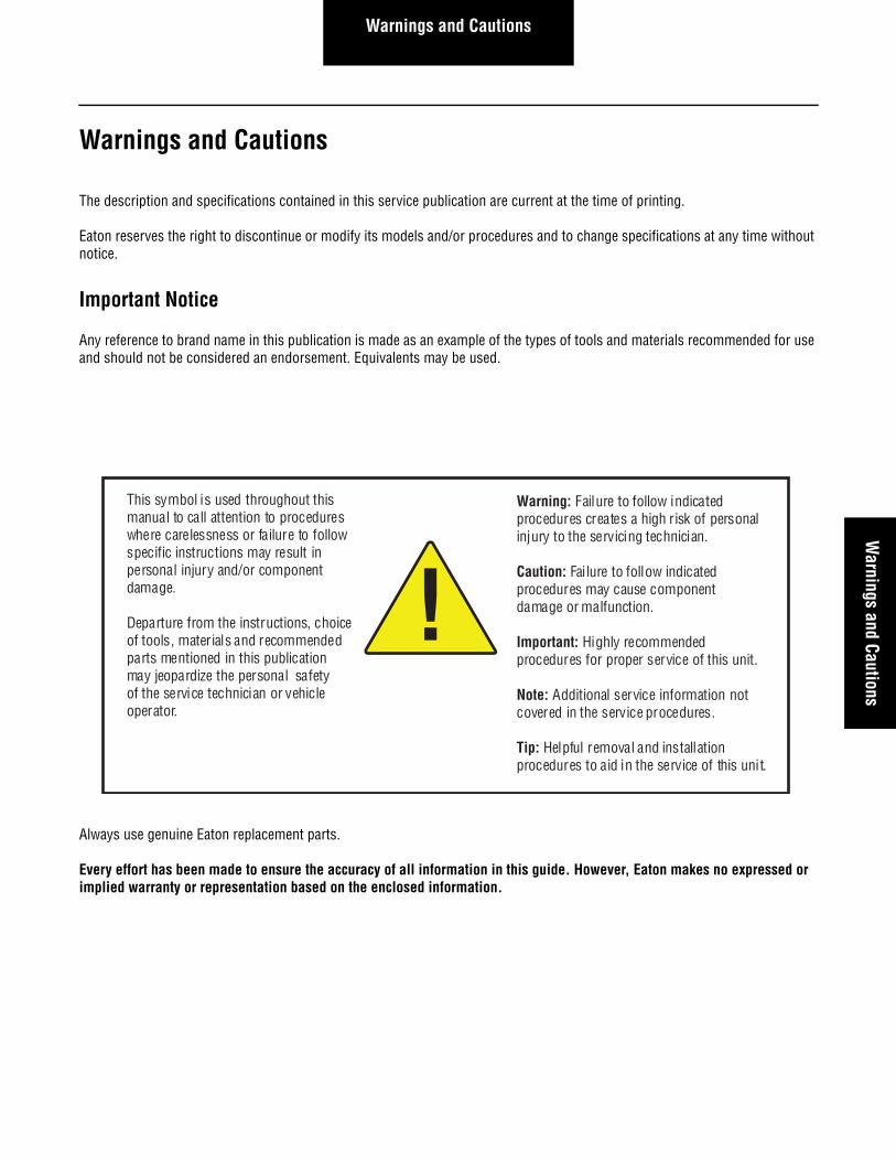
This symbol is used throughout this manual to call attention to procedures where carelessness or failure to follow specific instructions may result in personal injury and/or component damage.
Departure from the instructions, choice of tools, mater ials and recommended parts mentioned in this publication may jeopardize the personal safety of the service technician or vehicle operator.
Warning: Failure to follow indicated procedures creates a high r isk of personal injury to the servicing technician.
Caution: Failure to follow indicated procedures may cause component damage or malfunction.
Important: Highly recommended procedures for proper service of this unit.
Note: Additional service information not covered in the service procedures.
Tip: Helpful removal and installation procedures to aid in the service of this uni t.
!
Table of Contents
General Information
How to Use this Manual .............................................. 1
Electrical RequirementsRequirements .............................................................. 2System Integration Requirements ............................... 5Lubrication Requirements ......................................... 16Cooler Requirements ................................................ 20Dipstick and Tube Requirements UltraShift AW3 ...... 23Air Supply Requirements Heavy Duty ....................... 25Engine Retarder Requirements ................................. 26Eaton Shift Console Space Requirements ................. 27Flywheel/Drive Coupler UltraShift AW3 ..................... 30Medium Duty DM Clutch Installation ......................... 31Heavy Duty DM Clutch Installation ............................ 33Transmission Mounting Requirements ..................... 35
FeaturesCable ......................................................................... 37Wiring Diagrams OEM Responsibility ....................... 41Eaton Shift Lever and Tower Space Requirements .... 46Typical System with Eaton Push Button .................... 49Typical System with Eaton Shift Lever ...................... 50Typical System with Eaton Park Shift Lever .............. 51Typical System with OEM Shift Lever ........................ 52Typical System with OEM J-1939 Shift Input Device 53Power Harness .......................................................... 54Ignition Circuit Detail ................................................. 59J-1587 Data Link ....................................................... 60J-1939/15 Data Link .................................................. 61Dimmer Control Input Connection ............................ 63Typical Start Enable Circuit ....................................... 64Typical Ignition Interrupt Circuit (MEIIR) .................. 66Vehicle Harness Routing ........................................... 68Outside Cab Features ................................................ 72Power Take-Off “Split Shaft” ..................................... 73Power Take-Off “Countershaft driven” ...................... 74Inertia Brake Relocation Instructions 8 to 6-Bolt PTO
Opening ............................................................. 75Power Take-Off “Thru-Shaft Driven” ......................... 78UltraShift AW3 Auto Neutral Feature ......................... 79Auto Neutral and PTO Wiring Diagrams .................... 80
Line InspectionLine Inspection and Road Test Instructions ...............82Line Inspection Form - UltraShift AW3 ......................85Line Inspection Form - AutoShift AS3 .......................86Line Inspection Form - UltraShift DM3 ......................87
Line Inspection Form OEM Wiring Connector/Harness .............................................88
Troubleshooting ........................................................89
AppendixLifting Eyes and Sensor Positions .............................90Connector Pin Descriptions .......................................94UltraShift DM3 6-Speed Wiring Diagram with
Analog Shifter .....................................................97UltraShift DM3 6-Speed Wiring Diagram with
Push Button ........................................................99UltraShift HVP 6-Speed Wiring Diagram with
Cable Shifter .....................................................101UltraShift AW3 6-Speed Wiring Diagram with
Analog Shifter ...................................................103UltraShift AW3 6-Speed Wiring Diagram with
Push Button ......................................................105AutoShift 10-Speed Wiring Diagram with
Analog Shifter ...................................................107AutoShift 10-Speed Wiring Diagram with
Push Button ......................................................109UltraShift 10-Speed Wiring Diagram with
Analog Shifter ...................................................111UltraShift 10-Speed Wiring Diagram with
Push Button ......................................................113UltraShift 13-Speed Wiring Diagram with
Analog Shifter ...................................................115UltraShift 13 Speed Wiring Diagram with
Push Button ......................................................117AutoShift 18-Speed Wiring Diagram with
Analog Shifter ...................................................119AutoShift 18 Speed Wiring Diagram with
Push Button ......................................................121Suggested Tools/Publications .................................123Torque Specifications ..............................................124Vendor List ..............................................................127
1
General InformationGeneral
Information
How to Use this Manual
This Eaton publication is intended to be a reference guide for the installation of the AutoShift™/ UltraShift™ Gen 3 transmissions. General vehicle and transmission information is provided to cover the wide range of applications. This information benefits the OEM installer by providing the correct installation procedures to ensure the utmost in satisfactory operation and long service life. For additional transmission information, see the Suggested Tools section in the back of this manual. For specific engine informa-tion contact the engine OEM.
Failure to adhere to Eaton Installation Requirements may affect transmission performance and/or warranty coverage.
AutoShift/UltraShift Gen 3 are compatible with electronically governed engines equipped with a J-1939 data link and certified by Eaton. Transmissions installed at OEM facilities must meet and be approved by Eaton Application Engineering. Contact Eaton Application Engineering or your OEM Application Engineering department for the proper Application form. All applications must be submitted for approval.
OEM facilities must submit a design package to Eaton OEM Engineering Support Group for approval prior to any OEM build. A design package consists of the following information.
Electrical Systems
Wiring Schematic: This should show how the AutoShift™/UltraShift™ Gen 3 would interface with the vehicle.
Individual Harness Drawings: This should show the construction of each harness.
Harness Routings: This should show how each harness is routed in the vehicle. The locations of relays, fuses, power connec-tions, tie-downs, etc.
Transmission Air Supply (if required)
Transmission Cooling System (if required)
Cooler size/type
Cooler line routing
Every effort has been made to ensure the accuracy of the information contained in this manual. However, Eaton makes no war-ranty, either expressed or implied, based on the information provided. With each new application, engine manufactures should be contacted to make sure desired engines are compatible with these systems.
Installation Requirements
Requirements
Eaton AutoShift/UltraShift Gen 3 transmission systems installed at OEM facilities must meet the requirements and be approved using the Eaton Transmission Application Approval Form. Please contact Eaton Application Engineering or your OEM's Applica-tion department for the latest Application form.
1. Cab Floor Access Plate - A cab floor access plate is necessary for access and removal of components from the trans-mission top. Plate size must be sufficient to allow removal of the transmission Controller or the Electric Shifter.
2. Clutch Requirements - Power assisted clutch release system is required for all rear engine coach applications. All Heavy Duty AutoShifts require adjustment free clutches. All UltraShift DM3 use the DM Clutch module. It is the OEM responsibility to ensure the engine is not allowed to idle between 625 and 825 rpm with HD UltraShift DM3 clutch mod-ules. Base engine idle is recommended at 625 rpm and all methods (cruise/idle/PTO switch) used to raise the idle have a 200 rpm increment.
3. Lubrication Requirements - Transmission Gear Box - Eaton® Roadranger® CD50 or equivalent E500 synthetic as specified in Eaton publication TCMT0021.WetClutch for UltraShift AW3 uses synthetic Dexron III, VI, or Allison Trans-Synd. Approved lubricants are specified in Eaton publication TCMT0021.[see page 16]
4. Electrical Wiring Requirements - It is the OEM responsibility to provide power and ground to the Transmission Con-troller (TECU) from a reliable battery source from the battery which supplies the starter. The power (+) connection must include overload protection per Federal Motor Carrier Safety Regulations, Section 393.31.The TECU Main Power and Ground must be a direct connection from the battery posts to the TECU connector. At 120°C, these conductors must be able to carry 30 amps @ 9 volts with no more than 0.05 ohms per wire (0.1 ohms total) for a total voltage drop from the battery posts to the TECU connector not to exceed 3.0 volts.
• All wiring installation shall conform to Federal Motor Carrier Safety Administration Regulations Sections 393.27 Wiring specifications; 393.28 Wiring to be protected; 393.29 Grounds; 393.31 Overload protective devices; and 393.33 Wiring, installation.[see page 37]
• The cable for the Deutsch connector shall be:
- 16 GXL max 18 TXL min for Communication and control wires- 12 GXL for Power Supply wires- 12 GXL or 14 SXL for V-Ignition wires
Note: These sizes are requirements for proper connector sealing and current carrying capacity.[see page 37]
• When the Eaton Push Button Shift Control is used the CAN (Control Area Network communications link between the Shift Control and the Transmission Controller) must be a J-1939/15 twisted pair cable.[see page 49]
• The J-1939 (the communications link between the Transmission ECU and the Engine Controller ECM) must follow SAE J-1939 specifications for either J-1939/11 or J-1939/15. [see page 61]
• The diagnostic connector (6-pin required 9-pin recommended) must be easily accessible and mounted on the driv-ers side of the cab.[see page 60]
• Splices are not allowed.[see page 37]
• The Main Power 30 amp fuse connection for the Transmission ECU must be identified with a tag at the battery.[see page 56]
• Battery Positive and Negative must be disconnected PRIOR to any type of welding on any Eaton Automated trans-missionequipped vehicles.[see page 54]
• Battery Negative must be disconnected PRIOR to removal or installation of ECU harness connectors.[see page 54]
2
Installation RequirementsInstallation
Requirements
• The Transmission ECU shall be wired to a Non-switched power source at the battery. If a disconnect switch is required, the recommended practice is to wait a minimum of three minutes before using the disconnect switch. [see page 54]
• Application of more than 36 volts to the system (such as jump starting) will cause system shutdown and possible electrical component damage.[see page 54]
• Removal of fuses is not recommended as the method of disconnecting power from the ECU. Making and breaking a circuit through tin plated terminals (e.g. ring terminals, fuses, most connectors) will destroy the plating on the terminal. Opening a switch contact or the main power link is the recommended method of interrupting power.[see page 54]
• There should be nothing mounted to the TECU, brackets, mounting studs, or contacting the TECU case electrically or mechanically.[see page 68]
• The transmission wire harness should not be tie wrapped to any cables or hoses. Anchor points on the transmis-sion may be used as long as addition of cables or hoses do not interfere with the existing harness.[see page 68]
• Harness and in-line connectors shall be anchored to prevent free movement. An anchor point shall be no further than 6 in. [15.24 cm] (recommended 3 in. [7.62 cm]) from a connector. The length of an unanchored section of harness should be no more than 12 in. [30.48 cm].[see page 68]
Note: If a connection to the harness or ECU is required before vehicle installation, Eaton requires the use of a connector with a spring loaded contact rather than a standard mating connector. The spring loaded contact is intended to make the electri-cal connection with the tip of the terminal without touching the mating surface. This will protect the terminal plating, the NyoGel 760G™ and retain the original durability and reliability of the connector system.[see page 37]
Note: Eaton highly recommends the use of (NyoGel 760G) on all electrical contacts and the amount used. For further information contact your Eaton OEM Engineering Support Group.[see page 37]
Note: The preferred method of application is to use a metered dispensing mechanism that places the material on the socket of the connector. It is also preferred that the material be placed immediately prior to connector mating to reduce the probabil-ity of contamination.[see page 37]
5. Speedometers - No mechanical speedometers. The 10 o’clock position on Heavy Duty and 12’ o’clock position on Medium Duty are reserved for the Eaton speed sensor.[see page 90]
6. Neutral Switch - The transmission neutral switch provides an indication of neutral, but does not guarantee a true neu-tral position or provide a "confirmed neutral" output. This switch must not be used as the sole indication that the trans-mission is in neutral.
7. Line Inspection - Each transmission system installed at the OEM must pass the line checklist requirements per the Eaton Line Inspection Form prior to shipment from the OEM plant.[see page 82]
8. Oil Cooler (UltraShift AW3)- A clutch cooler must be used with the Eaton UltraShift AW3 transmission. The cooler siz-ing must meet the requirements specified in this document.[see page 20]
9. Oil Cooler (Heavy Duty) - Transmissions must not be operated at temperatures above 250°F [121°C]. Operation at tem-peratures above 250°F [121°C] causes loaded gear tooth temperatures to exceed 350°F [177°C] which will ultimately destroy the heat treatment of the gears. If the elevated temperature is associated with an unusual operating condition that will recur, a cooler should be added, or the capacity of the existing cooling system increased.[see page 20].
10. Engine Retarder - An engine retarder (compression or exhaust) is required on AutoShift 10 and 18-Speed and 13-Speed UltraShift transmissions. It is recommended on the 10-Speed UltraShift transmission.The recommended prac-tice is for the exhaust brake on/off switches to be wired in the engine ECM separately from the exhaust brake solenoid. Failure to comply with this recommended practice can cause Eaton AutoShift/UltraShift transmissions to miss shifts when the exhaust brake is required. For more information contact Eaton Application Engineering and refer to the J-1939 Engine Requirements for Eaton AutomatedTransmissions.[see page 26]
3
Installation Requirements
11. Lifting Eyes and Sensor Position - The Eaton shift bar housing, ECU, sensor, and lifting eye retaining fasteners as well as those associated with any gasketed transmission surfaces are not intended for use in securing additional OEM brack-ets. Removal of these can compromise transmission system operation and overall system reliability.[see page 90]
12. Air Dryer Requirements - It is required to use a high quality commercially available air dryer in the air supply line before the transmission.[see page 25]
13. Fan Drive Requirements - The recommended practice is for the engine fan to be wired into the engine ECM, this includes the manual fan override switch. The OEM should use fan clutches that can be controlled by the engine (i.e. electromechanical). Failure to comply with this recommended practice can cause Eaton transmissions to inhibit shifts when the engine fan is on.
14. PTO and Auto Neutral Options - Eaton recommends the OEM provide a connector and wiring coming from the Trans-mission ECU 38-Way (Vehicle Interface) with the AW3 Auto Neutral and PTO wires installed.[see page 72]
15. Gear Display - The OEM is responsible for supplying the Gear Display, Wiring, and its location per FMVSS.[see page 13]
16. Tone Module - The OEM is responsible for supplying the tone module with the Eaton Shift Lever or OEM Driver Inter-face Device. The tone module is supplied in the Eaton Push Button Shift Control.[see page 14]
17. Transmission Component Temperature Requirements - The temperature limit for all electrical and air system compo-nents is 250F° (121°C). This temperature limit must not be exceeded. If sufficient air gap clearance can not be achieved, the OEM must provide Eaton approved heat shielding.The systems to be protected are the Shift Motors, Sensors, Sole-noids, Air Filter Regulator, Inertia Brake, Wire Harness, Transmission Controller, Oil Cooler and Hoses, and the Trans-mission Case.
18. Engine Configuration - Prior to shipment of Eaton Automated Transmission Systems installed at OEM plants, the engine ECU must contain the proper configuration settings. For the proper engine configuration settings required for Eaton Automated Transmission operation refer to the “Engine Configuration Settings Installation Guide” on road-ranger.com under the literature center.
19. Typical Ignition Interrupt Circuit (MEIIR) - There must be no other systems in the ignition circuit between the MEIIR and the engine ECM. If there are other systems in the ignition circuit between the ignition switch and the MEIIR, contact Eaton for guidance.[see page 66]
20. Battery and Ignition Power - Battery and Ignition power and ground to the TECU must not be switched off during the engine start process.[see page 59][see page 56]
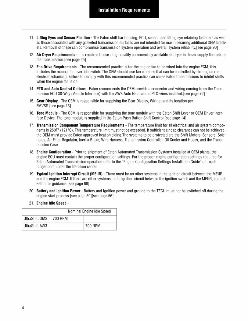
21. Engine Idle Speed -
Nominal Engine Idle Speed
UltraShift DM3 700 RPM
UltraShift AW3 700 RPM
4
Installation RequirementsInstallation
Requirements
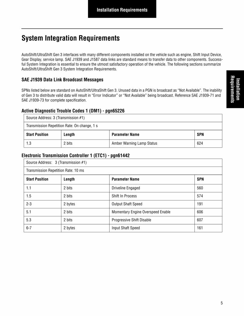
System Integration Requirements
AutoShift/UltraShift Gen 3 interfaces with many different components installed on the vehicle such as engine, Shift Input Device, Gear Display, service lamp. SAE J1939 and J1587 data links are standard means to transfer data to other components. Success-ful System Integration is essential to ensure the utmost satisfactory operation of the vehicle. The following sections summarize AutoShift/UltraShift Gen 3 System Integration Requirements.
SAE J1939 Data Link Broadcast Messages
SPNs listed below are standard on AutoShift/UltraShift Gen 3. Unused data in a PGN is broadcast as “Not Available”. The inability of Gen 3 to distribute valid data will result in “Error Indicator” or “Not Available” being broadcast. Reference SAE J1939-71 and SAE J1939-73 for complete specification.
Active Diagnostic Trouble Codes 1 (DM1) - pgn65226
Electronic Transmission Controller 1 (ETC1) - pgn61442
Source Address: 3 (Transmission #1)
Transmission Repetition Rate: On change, 1 s
Start Position Length Parameter Name SPN
1.3 2 bits Amber Warning Lamp Status 624
Source Address: 3 (Transmission #1)
Transmission Repetition Rate: 10 ms
Start Position Length Parameter Name SPN
1.1 2 bits Driveline Engaged 560
1.5 2 bits Shift In Process 574
2-3 2 bytes Output Shaft Speed 191
5.1 2 bits Momentary Engine Overspeed Enable 606
5.3 2 bits Progressive Shift Disable 607
6-7 2 bytes Input Shaft Speed 161
5
Installation Requirements
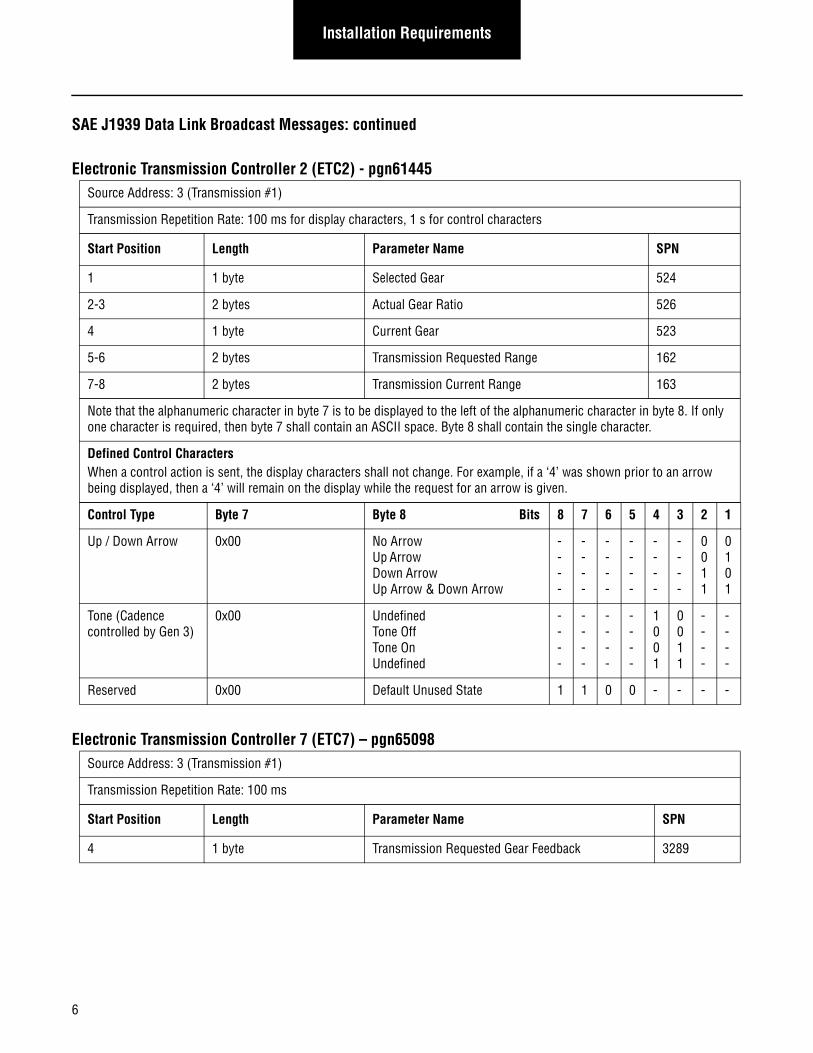
SAE J1939 Data Link Broadcast Messages: continued
Electronic Transmission Controller 2 (ETC2) - pgn61445
Electronic Transmission Controller 7 (ETC7) – pgn65098
Source Address: 3 (Transmission #1)
Transmission Repetition Rate: 100 ms for display characters, 1 s for control characters
Start Position Length Parameter Name SPN
1 1 byte Selected Gear 524
2-3 2 bytes Actual Gear Ratio 526
4 1 byte Current Gear 523
5-6 2 bytes Transmission Requested Range 162
7-8 2 bytes Transmission Current Range 163
Note that the alphanumeric character in byte 7 is to be displayed to the left of the alphanumeric character in byte 8. If only one character is required, then byte 7 shall contain an ASCII space. Byte 8 shall contain the single character.
Defined Control Characters When a control action is sent, the display characters shall not change. For example, if a ‘4’ was shown prior to an arrow being displayed, then a ‘4’ will remain on the display while the request for an arrow is given.
Control Type Byte 7 Byte 8 Bits 8 7 6 5 4 3 2 1
Up / Down Arrow 0x00 No Arrow Up Arrow Down Arrow Up Arrow & Down Arrow
- - - -
- - - -
- - - -
-- - -
- - - -
- - - -
0 0 1 1
0 1 0 1
Tone (Cadence controlled by Gen 3)
0x00 Undefined Tone Off Tone On Undefined
- - - -
- - - -
- - - -
- - - -
1 0 0 1
0 0 1 1
- - - -
- - - -
Reserved 0x00 Default Unused State 1 1 0 0 - - - -
Source Address: 3 (Transmission #1)
Transmission Repetition Rate: 100 ms
Start Position Length Parameter Name SPN
4 1 byte Transmission Requested Gear Feedback 3289
6
Installation RequirementsInstallation
Requirements
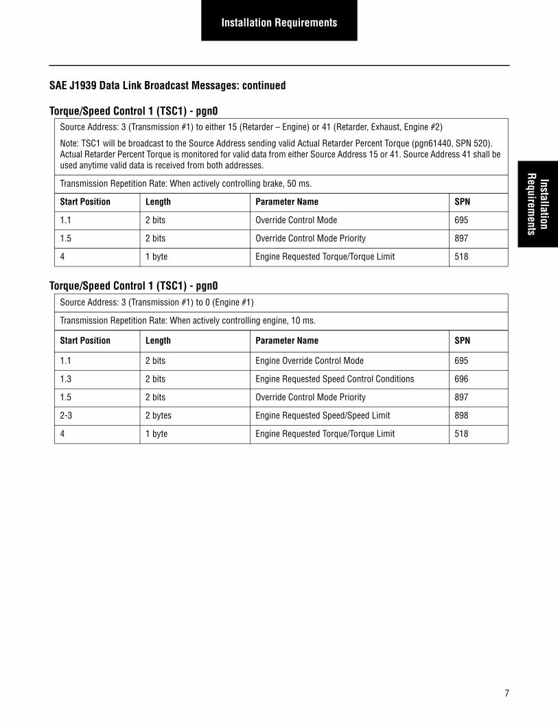
SAE J1939 Data Link Broadcast Messages: continued
Torque/Speed Control 1 (TSC1) - pgn0
Torque/Speed Control 1 (TSC1) - pgn0
Source Address: 3 (Transmission #1) to either 15 (Retarder – Engine) or 41 (Retarder, Exhaust, Engine #2)
Note: TSC1 will be broadcast to the Source Address sending valid Actual Retarder Percent Torque (pgn61440, SPN 520). Actual Retarder Percent Torque is monitored for valid data from either Source Address 15 or 41. Source Address 41 shall be used anytime valid data is received from both addresses.
Transmission Repetition Rate: When actively controlling brake, 50 ms.
Start Position Length Parameter Name SPN
1.1 2 bits Override Control Mode 695
1.5 2 bits Override Control Mode Priority 897
4 1 byte Engine Requested Torque/Torque Limit 518
Source Address: 3 (Transmission #1) to 0 (Engine #1)
Transmission Repetition Rate: When actively controlling engine, 10 ms.
Start Position Length Parameter Name SPN
1.1 2 bits Engine Override Control Mode 695
1.3 2 bits Engine Requested Speed Control Conditions 696
1.5 2 bits Override Control Mode Priority 897
2-3 2 bytes Engine Requested Speed/Speed Limit 898
4 1 byte Engine Requested Torque/Torque Limit 518
7
Installation Requirements
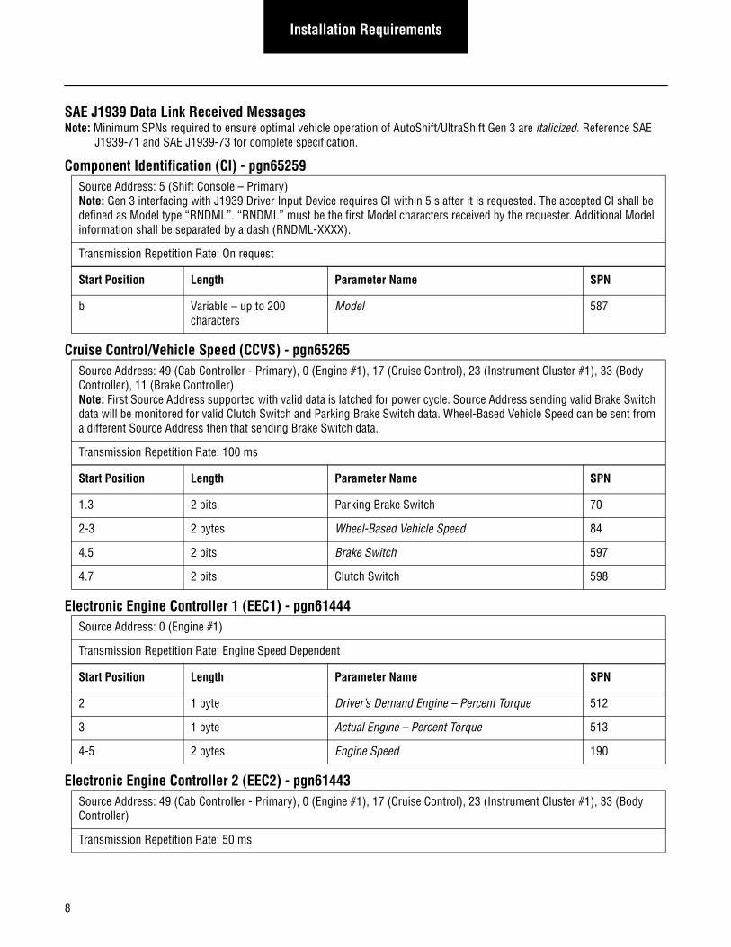
SAE J1939 Data Link Received MessagesNote: Minimum SPNs required to ensure optimal vehicle operation of AutoShift/UltraShift Gen 3 are italicized. Reference SAE
J1939-71 and SAE J1939-73 for complete specification.
Component Identification (CI) - pgn65259
Cruise Control/Vehicle Speed (CCVS) - pgn65265
Electronic Engine Controller 1 (EEC1) - pgn61444
Electronic Engine Controller 2 (EEC2) - pgn61443
Source Address: 5 (Shift Console – Primary)Note: Gen 3 interfacing with J1939 Driver Input Device requires CI within 5 s after it is requested. The accepted CI shall be defined as Model type “RNDML”. “RNDML” must be the first Model characters received by the requester. Additional Model information shall be separated by a dash (RNDML-XXXX).
Transmission Repetition Rate: On request
Start Position Length Parameter Name SPN
b Variable – up to 200 characters
Model 587
Source Address: 49 (Cab Controller - Primary), 0 (Engine #1), 17 (Cruise Control), 23 (Instrument Cluster #1), 33 (Body Controller), 11 (Brake Controller)Note: First Source Address supported with valid data is latched for power cycle. Source Address sending valid Brake Switch data will be monitored for valid Clutch Switch and Parking Brake Switch data. Wheel-Based Vehicle Speed can be sent from a different Source Address then that sending Brake Switch data.
Transmission Repetition Rate: 100 ms
Start Position Length Parameter Name SPN
1.3 2 bits Parking Brake Switch 70
2-3 2 bytes Wheel-Based Vehicle Speed 84
4.5 2 bits Brake Switch 597
4.7 2 bits Clutch Switch 598
Source Address: 0 (Engine #1)
Transmission Repetition Rate: Engine Speed Dependent
Start Position Length Parameter Name SPN
2 1 byte Driver’s Demand Engine – Percent Torque 512
3 1 byte Actual Engine – Percent Torque 513
4-5 2 bytes Engine Speed 190
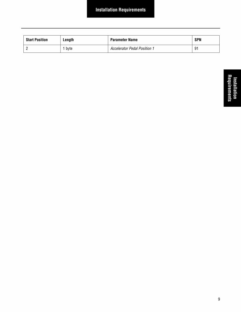
Source Address: 49 (Cab Controller - Primary), 0 (Engine #1), 17 (Cruise Control), 23 (Instrument Cluster #1), 33 (Body Controller)
Transmission Repetition Rate: 50 ms
8
Installation RequirementsInstallation
Requirements
Start Position Length Parameter Name SPN
2 1 byte Accelerator Pedal Position 1 91
9
Installation Requirements
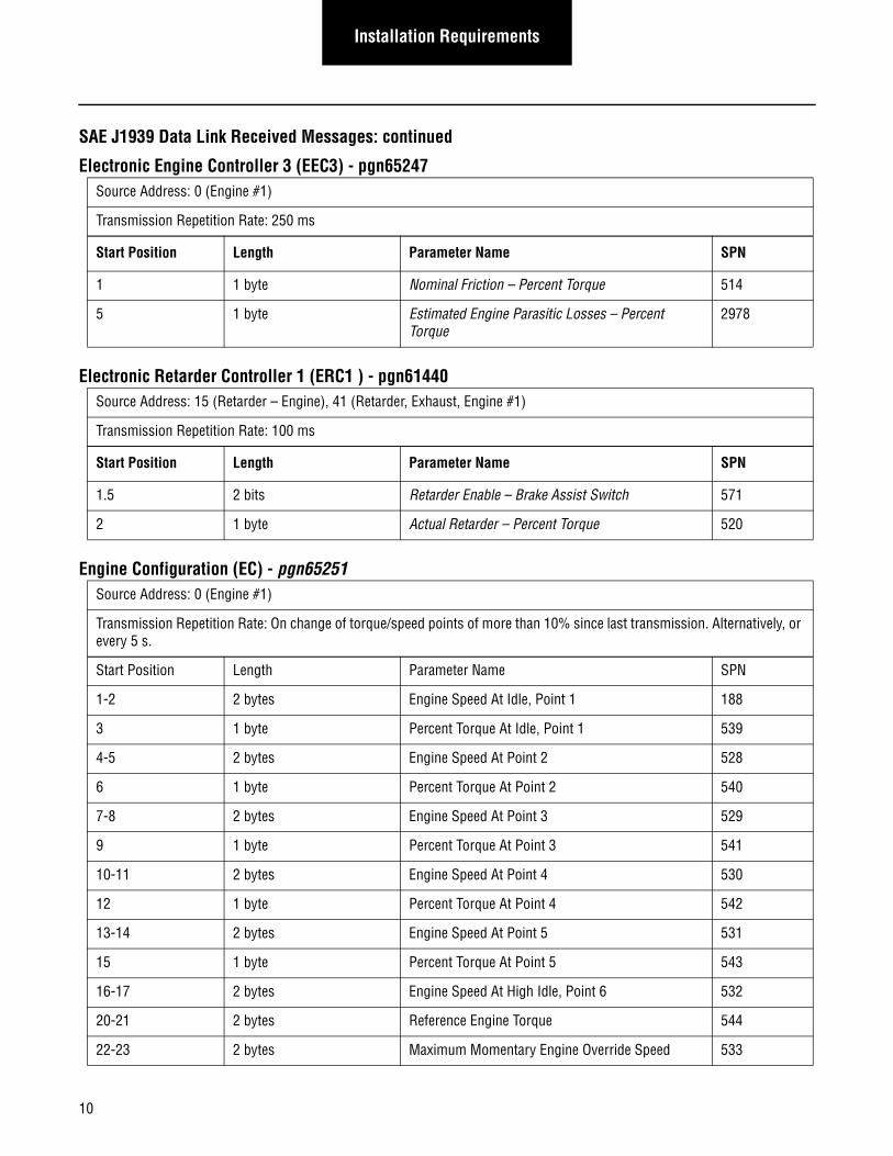
SAE J1939 Data Link Received Messages: continued
Electronic Engine Controller 3 (EEC3) - pgn65247
Electronic Retarder Controller 1 (ERC1 ) - pgn61440
Engine Configuration (EC) - pgn65251
Source Address: 0 (Engine #1)
Transmission Repetition Rate: 250 ms
Start Position Length Parameter Name SPN
1 1 byte Nominal Friction – Percent Torque 514
5 1 byte Estimated Engine Parasitic Losses – Percent Torque
2978
Source Address: 15 (Retarder – Engine), 41 (Retarder, Exhaust, Engine #1)
Transmission Repetition Rate: 100 ms
Start Position Length Parameter Name SPN
1.5 2 bits Retarder Enable – Brake Assist Switch 571
2 1 byte Actual Retarder – Percent Torque 520
Source Address: 0 (Engine #1)
Transmission Repetition Rate: On change of torque/speed points of more than 10% since last transmission. Alternatively, or every 5 s.
Start Position Length Parameter Name SPN
1-2 2 bytes Engine Speed At Idle, Point 1 188
3 1 byte Percent Torque At Idle, Point 1 539
4-5 2 bytes Engine Speed At Point 2 528
6 1 byte Percent Torque At Point 2 540
7-8 2 bytes Engine Speed At Point 3 529
9 1 byte Percent Torque At Point 3 541
10-11 2 bytes Engine Speed At Point 4 530
12 1 byte Percent Torque At Point 4 542
13-14 2 bytes Engine Speed At Point 5 531
15 1 byte Percent Torque At Point 5 543
16-17 2 bytes Engine Speed At High Idle, Point 6 532
20-21 2 bytes Reference Engine Torque 544
22-23 2 bytes Maximum Momentary Engine Override Speed 533
10
Installation RequirementsInstallation
Requirements
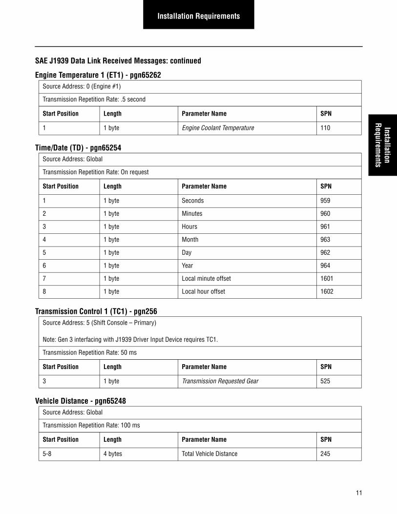
SAE J1939 Data Link Received Messages: continued
Engine Temperature 1 (ET1) - pgn65262
Time/Date (TD) - pgn65254
Transmission Control 1 (TC1) - pgn256
Vehicle Distance - pgn65248
Source Address: 0 (Engine #1)
Transmission Repetition Rate: .5 second
Start Position Length Parameter Name SPN
1 1 byte Engine Coolant Temperature 110
Source Address: Global
Transmission Repetition Rate: On request
Start Position Length Parameter Name SPN
1 1 byte Seconds 959
2 1 byte Minutes 960
3 1 byte Hours 961
4 1 byte Month 963
5 1 byte Day 962
6 1 byte Year 964
7 1 byte Local minute offset 1601
8 1 byte Local hour offset 1602
Source Address: 5 (Shift Console – Primary)
Note: Gen 3 interfacing with J1939 Driver Input Device requires TC1.
Transmission Repetition Rate: 50 ms
Start Position Length Parameter Name SPN
3 1 byte Transmission Requested Gear 525
Source Address: Global
Transmission Repetition Rate: 100 ms
Start Position Length Parameter Name SPN
5-8 4 bytes Total Vehicle Distance 245
11
Installation Requirements
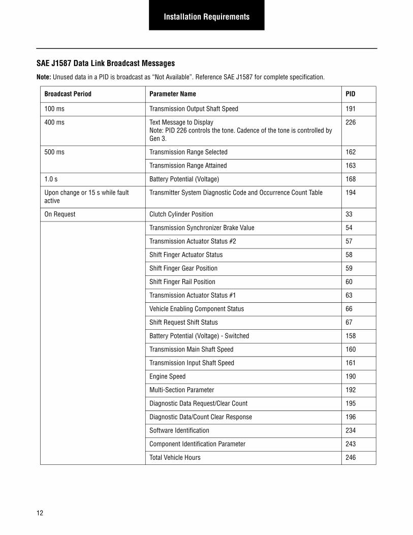
SAE J1587 Data Link Broadcast Messages
Note: Unused data in a PID is broadcast as “Not Available”. Reference SAE J1587 for complete specification.
Broadcast Period Parameter Name PID
100 ms Transmission Output Shaft Speed 191
400 ms Text Message to Display Note: PID 226 controls the tone. Cadence of the tone is controlled by Gen 3.
226
500 ms Transmission Range Selected 162
Transmission Range Attained 163
1.0 s Battery Potential (Voltage) 168
Upon change or 15 s while fault active
Transmitter System Diagnostic Code and Occurrence Count Table 194
On Request Clutch Cylinder Position 33
Transmission Synchronizer Brake Value 54
Transmission Actuator Status #2 57
Shift Finger Actuator Status 58
Shift Finger Gear Position 59
Shift Finger Rail Position 60
Transmission Actuator Status #1 63
Vehicle Enabling Component Status 66
Shift Request Shift Status 67
Battery Potential (Voltage) - Switched 158
Transmission Main Shaft Speed 160
Transmission Input Shaft Speed 161
Engine Speed 190
Multi-Section Parameter 192
Diagnostic Data Request/Clear Count 195
Diagnostic Data/Count Clear Response 196
Software Identification 234
Component Identification Parameter 243
Total Vehicle Hours 246
12
Installation RequirementsInstallation
Requirements
Service Lamp
AutoShift/UltraShift Gen 3 provide a wired service lamp output at J1-23. This output is designed to drive an incandescent lamp of 1.0 watt or less. The service lamp output will supply a positive voltage equal to the vehicle battery voltage to turn the service lamp on. The OEM must supply the service lamp minus (ground) connection.
The service lamp is used to display transmission fault information. However, this fault information is also broadcast via the SAE J1939 and J1587 data links (reference Gen 3 Data Link Requirements for detailed support). Therefore, it is optional that the OEM provide a transmission service lamp. If a service lamp is not part of the OEM Interface Design an OEM wired pigtail connector must be provided that is accessible to a service technician.
Gear Display
The OEM is responsible for supplying the Gear Display, Wiring, and its location per FMVSS.
Gear Display is required for proper operation of AutoShift/UltraShift Gen 3. Gear Display shall interface with Gen 3 by either SAE J1939 (ETC2) or J1587 (PID 226). The Gear Display offers real-time information pertaining to current engaged gear, engagement status during gear shifting, transmission synchronization during shifting, transmission fault status, diagnostic code information.
Gear Display shall adhere to the following requirements.
1. For J1587, display time of a message shall be set to 5 seconds to avoid display blanking during heavy bus loads.
2. Driver shall be able to clearly see the display from the normal driving position continuously during vehicle operation.
3. Gear Display shall be blank upon initial power up.
4. Gear Display shall be capable of displaying messages within 2 seconds of ignition key-on.
5. In order to provide real-time feedback of the selection/shifting/engagement process of transmission, the device must be able to display the received message within 75 Milliseconds.
6. Whenever bus communications are active and anytime ETC2/PID 226 message is not received within 5 seconds of the last valid message or message received contains a character not supported, the display shall be blank.
7. Whenever bus communications are not active, a “** ” shall be displayed.
8. As a minimum, Gear Display must support two character alphanumeric messages with the addition of two sets of dis-play arrows (up and down) either side of the numerals.
9. Gear Display shall be able to display all two character numeric combinations, upper case alphanumeric combinations, and special characters. See the table below for special characters.
13
Installation Requirements
Minimum Gear Display Special Character Combinations
Alert Tone
The OEM is responsible for supplying the tone module with the Eaton Shift Lever or OEM Driver Interface Device. The tone mod-ule is supplied in the Eaton Push Button Shift Control.
Alert tone shall be required for proper operation of AutoShift/UltraShift Gen 3. The alert tone shall be used to:
• Inform the operator that the transmission has not yet confirmed a Neutral request.
• Inform the operator that an invalid/improper request or operation was initiated.
• Implement the shift prompt for AutoSelect fallback mode.
• Warn of a clutch abuse situation.
The required tone information shall be conveyed from Gen 3 via SAE J1939 (ETC2) and J1587 (PID 226). The OEM is responsible for ensuring at least one annunciator tones when requested by Gen 3. Gen 3 requires an informational tone that consists of a sin-gle tone and an alert tone that is continuous until conditions change that prompted the alert.
Annunciator shall adhere to the following requirements.
• Driver shall be able to clearly hear the tone from the normal driving position continuously during vehicle operation.
• Annunciator shall be capable of responding to a message within 2 seconds of ignition key-on.
• System equipped with HVP (Park) shall be capable of responding to a message up to 2 minutes after key-off.
• In order to provide real-time feedback of the selection/shifting/engagement process of transmission, the device must respond to the received message within 75 milliseconds.
• Whenever bus communications are active and anytime ETC2/PID 226 message is not received within 5 seconds of the last valid message, annunciator shall be silent.
• Whenever bus communications are not active, annunciator shall be silent.
Display First Character (dec. / hex / char)
Second Character (dec. / hex / char) Comments
- 32 / 20 / " " 45 / 2D / "-"
32 / 20 / " " 32 / 20 / " "
** 42 / 2A / "*" 42 / 2A / "*"
14
Installation RequirementsInstallation
Requirements
Shift Input Device
Shift Input Device shall be required for proper operation of AutoShift/UltraShift Gen 3. Shift Input Device for AutoShift/UltraShift Gen3 shall be one of three defined types: analog, J1939 with hardwired Neutral Request signal, or Eaton proprietary HIL. Shift Input Device for HVP shall be an OEM supplied cable shift lever. Although the three types are available, HIL and analog are the recommended interface types. The J1939 Shift Input Device type communicates via the public J1939 link. Due to the unlimited number of components that can interface via the public J1939 link, there is an increased probability of link failure resulting in loss of communication with a J1939 Shift Input Device. This type of failure with a J1939 Shift Input Device reduces the driver’s ability to utilize all transmission modes of operation. Both the HIL and analog Shift Input Device types give the driver the utmost ability to move the truck during a J1939 link failure. An HIL Shift Input Device type shall be the only component that interfaces with the transmission via HIL.
The OEM is responsible for ensuring that the designed OEM HIL has the appropriate number of terminating resistors. The Gen 3 transmission ECU includes a terminating resistor with the HIL configuration. The second HIL terminating resistor may either be included in the Shift Input Device or part of the OEM designed HIL harness.
Contact Eaton OEM Application Engineering for Shift Input Device design and interface requirements.
Engine
Contact Eaton OEM Application Engineering for engine interface requirements.
15
Installation Requirements
Lubrication Requirements
AutoShift/UltraShift Gen 3 Transmission Gear Box Lubrication Requirements
Eaton Fuller transmissions are designed so the internal parts operate in a bath of lubricant circulated by the motion of gears and shafts. Thus, all parts will be amply lubricated if these procedures are closely followed:
When adding lubricant, types and brands of lubricant should not be mixed because of possible incompatibility.
Use clean lubricant and clean containers when filling the transmission. Containers that have been used for antifreeze or water should not be used for transmission lubricant.
Additives and friction modifiers are not recommended for use in Eaton Fuller transmissions.
The quantity for proper fill level will vary from unit to unit. The exact amount of oil depends on the transmission inclination and cooling system capacity. Oil level should be checked at room temperature.
Failure to adhere to Eaton Installation Requirements may affect transmission performance and/or warranty coverage.
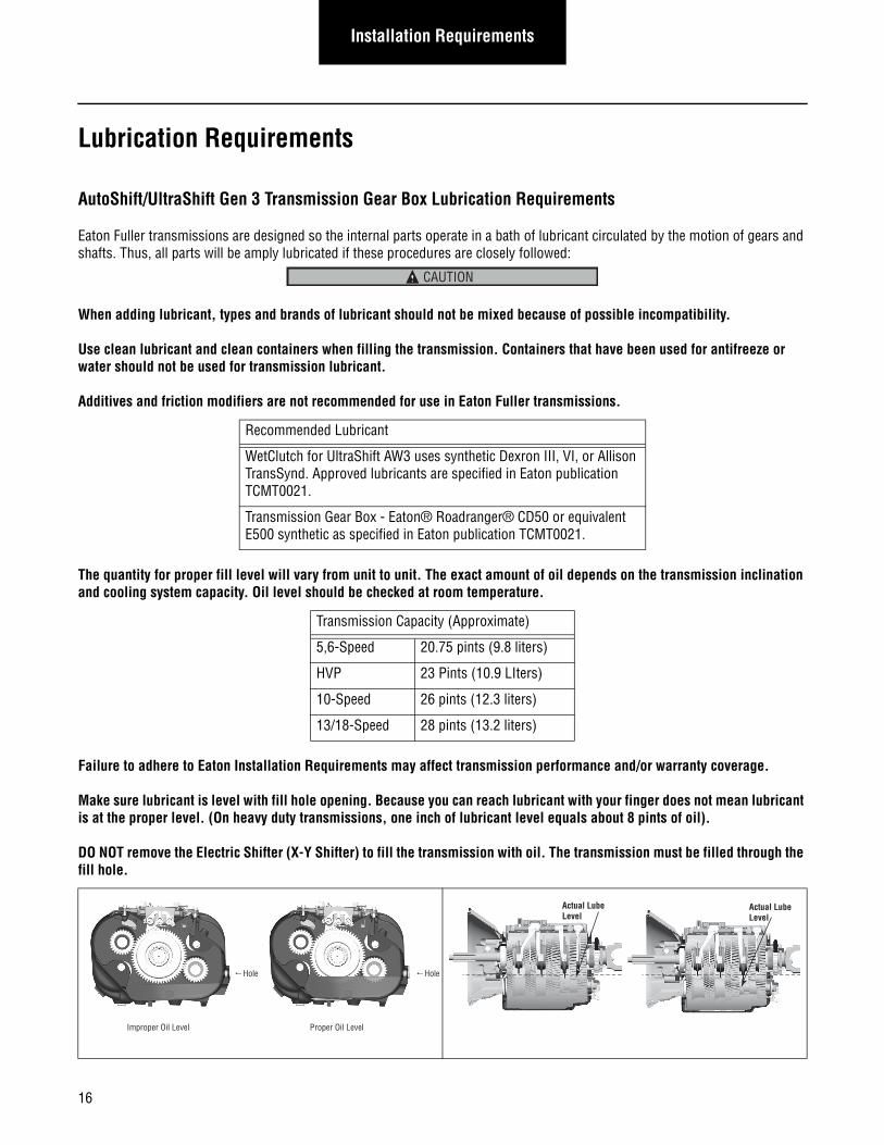
Make sure lubricant is level with fill hole opening. Because you can reach lubricant with your finger does not mean lubricant is at the proper level. (On heavy duty transmissions, one inch of lubricant level equals about 8 pints of oil).
DO NOT remove the Electric Shifter (X-Y Shifter) to fill the transmission with oil. The transmission must be filled through the fill hole.
Recommended Lubricant
WetClutch for UltraShift AW3 uses synthetic Dexron III, VI, or Allison TransSynd. Approved lubricants are specified in Eaton publication TCMT0021.
Transmission Gear Box - Eaton® Roadranger® CD50 or equivalent E500 synthetic as specified in Eaton publication TCMT0021.
Transmission Capacity (Approximate)
5,6-Speed 20.75 pints (9.8 liters)
HVP 23 Pints (10.9 LIters)
10-Speed 26 pints (12.3 liters)
13/18-Speed 28 pints (13.2 liters)
CAUTION
Improper Oil Level
Hole
Proper Oil Level
Hole
Actual LubeLevel
Actual LubeLevel
16
Installation RequirementsInstallation
Requirements
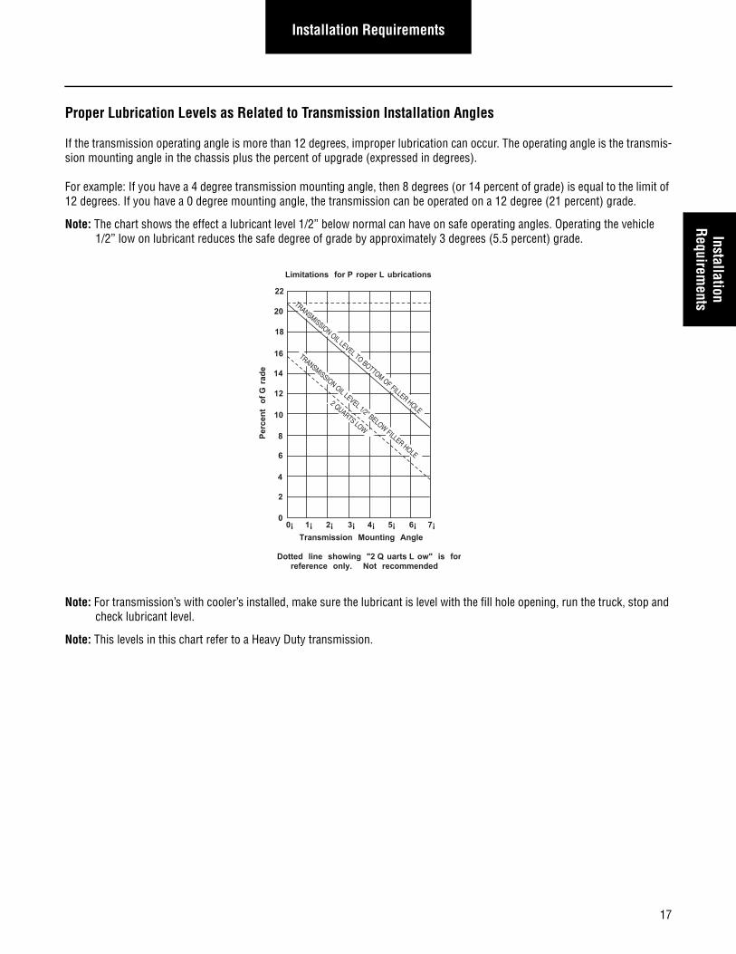
Proper Lubrication Levels as Related to Transmission Installation Angles
If the transmission operating angle is more than 12 degrees, improper lubrication can occur. The operating angle is the transmis-sion mounting angle in the chassis plus the percent of upgrade (expressed in degrees).
For example: If you have a 4 degree transmission mounting angle, then 8 degrees (or 14 percent of grade) is equal to the limit of 12 degrees. If you have a 0 degree mounting angle, the transmission can be operated on a 12 degree (21 percent) grade.
Note: The chart shows the effect a lubricant level 1/2” below normal can have on safe operating angles. Operating the vehicle 1/2” low on lubricant reduces the safe degree of grade by approximately 3 degrees (5.5 percent) grade.
Note: For transmission’s with cooler’s installed, make sure the lubricant is level with the fill hole opening, run the truck, stop and check lubricant level.
Note: This levels in this chart refer to a Heavy Duty transmission.
0¡ 1¡ 2¡ 3¡ 4¡ 5¡ 6¡ 7¡
22
20
18
16
14
12
10
8
6
4
2
0
Transmission Mounting Angle
Dotted line showing "2 Q uarts L ow" is forreference only. Not recommended
Limitations for P roper L ubrications
Pe
rce
nt
of
Gra
de
TRANSMISSION OIL LEVEL 1/2" BELOW FILLER HOLE
2 QUARTS LOW
TRANSMISSION OIL LEVEL TO BOTTOM OF FILLER HOLE
17
Installation Requirements
UltraShift AW3 WetClutch Lubrication Requirements
1. Synthetic Dexron® III, VI, or Allison TransSynd must be used in the WetClutch section of the transmission. Oil must be filled to the proper level prior to OEM shipment.
a. Make sure oil is within dipstick marks.
b. Oil should be checked at idle in neutral.
c. Oil checks can be performed when the oil temperature is 60° to 120°F. The oil level should be within the dipstick Full and Add marks.
d. The operational level should always be within the operating marks on the dipstick. The exact amount of oil depends on the transmission inclination and cooling system capacity.
e. Insufficient oil damages the pump and other components and can affect the function and reduce the life of the transmission
DO NOT OVERFILL. This causes foaming, overheating, loss of fuel economy and possibly not shifting.
When adding oil, types and brands of oil should not be mixed because of possible incompatibility.
Use clean oil and clean containers when filling the transmission. Containers that have been used for anti-freeze or water should not be used for transmission oil.
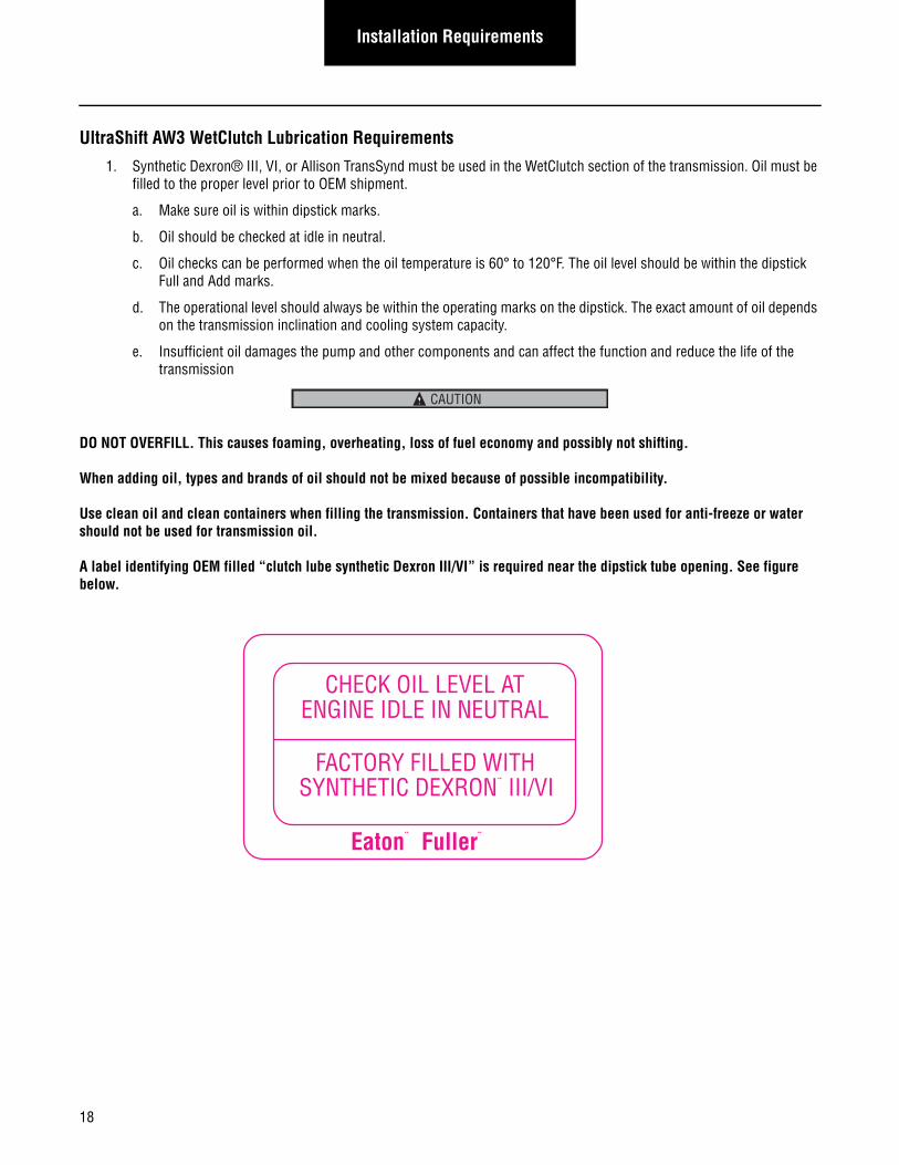
A label identifying OEM filled “clutch lube synthetic Dexron III/VI” is required near the dipstick tube opening. See figure below.
CAUTION
CHECK OIL LEVEL ATENGINE IDLE IN NEUTRAL
FACTORY FILLED WITHSYNTHETIC DEXRON¨ III/VI
Eaton¨ Fuller¨
18
Installation RequirementsInstallation
Requirements
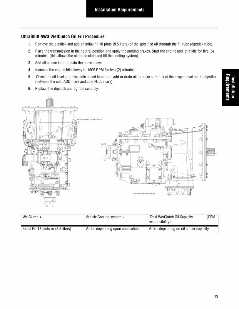
UltraShift AW3 WetClutch Oil Fill Procedure
1. Remove the dipstick and add an initial fill 18 pints (8.5 liters) of the specified oil through the fill tube (dipstick tube).
2. Place the transmission in the neutral position and apply the parking brakes. Start the engine and let it idle for five (5) minutes, (this allows the oil to circulate and fill the cooling system).
3. Add oil as needed to obtain the correct level.
4. Increase the engine idle slowly to 1500 RPM for two (2) minutes.
5. Check the oil level at normal idle speed in neutral, add or drain oil to make sure it is at the proper level on the dipstick (between the cold ADD mark and cold FULL mark).
6. Replace the dipstick and tighten securely.
WetClutch + Vehicle Cooling system = Total WetClutch Oil Capacity (OEM responsibility)
Initial Fill 18 pints or (8.5 liters) Varies depending upon application Varies depending on oil cooler capacity
WetClutch Dipstick/Fill Tube Location
Transmission Gear Box Oil Fill Plug
19
Installation Requirements
Cooler Requirements
Heavy Duty UltraShift/AutoShift Gen 3 Cooler Requirements
• Transmissions must not be operated at temperatures above 250°F [121°C]. Operation at temperatures above 250°F [121°C] causes loaded gear tooth temperatures to exceed 350°F [177°C] which will ultimately destroy the heat treat-ment of the gears. If the elevated temperature is associated with an unusual operating condition that will recur, a cooler should be added, or the capacity of the existing cooling system increased.
• The following conditions in any combination can cause operating temperatures of over 250°F (120°C):[see page 20].
• Operating consistently at high loads/slow speeds
• High ambient temperatures
• Restricted air flow around the transmission
• Exhaust system too close to the transmission
• High horsepower operation
• Engine Retarders
External oil coolers are available to reduce operating temperatures when the above conditions are encountered. Eaton Oil cooler systems must meet a minimum requirement of 3/4 I.D. cooler lines and 8 GPM. system flow @ 1500 RPM. The end user is ultimately responsible for maintaining transmission lube temperatures below 250°F [121°C].
Transmission Oil Coolers are recommended Transmission Oil Coolers are required
With engines of 350 H.P. and above With engines 400 H.P. and above and GCW’s of 90,000 lbs [40,823 kg] or greater
With engines 400 H.P. and above and 1400 lbs. ft. [1898 N•m] or Greater torque
With engines 450 H.P. and above
With engines 1500 lbs. ft. [2033 N•m] and above
20
Installation RequirementsInstallation
Requirements
UltraShift AW3 Cooler Requirements
1. A clutch cooler must be used with the Eaton UltraShift AW3 transmission. The cooler sizing must meet the require-ments specified in this document.
2. The maximum pressure drop through the transmission cooler is 10 PSI @ 8 GPM of oil flow (at normal operating tem-peratures).
3. Coolers must be sized according to the following requirements and be able to provide minimum heat extraction rates with the vehicle stationary, engine idling at normal operating temperature, and oil flow at 6 gallons per minute.
• GCW less 33,000 -- 450 BTU/Min.
• GCW greater 33,000 --700 BTU/Min.
• Severe service and GCW greater than 43,000 -- 1000 BTU/Min. Applications include refuse, tankers, construction equipment such as dump trucks, concrete mixers, and off road equipment.
4. Transmission cooler must withstand operating pressure up to 300 PSI.
5. The cooler and cooler connecting lines should be free of debris, dirt, grease, etc. before being attached to the transmis-sion. If these conditions exist, cooler lines must be flushed or cleaned.
6. The cooler must meet Eaton application guidelines and requirements in this document unless specifically approved by Eaton.
7. A minimum of SAE # 12 (3/4 inch) cooler hose or comparable tubing must be used for the Eaton UltraShift AW3 trans-mission cooler circuit.
8. Cooler connecting lines should be routed in such a way as to prevent kinks or leaks from rubbing on other components. Use high temperature protection as required to protect against heat deterioration.
21
Installation Requirements
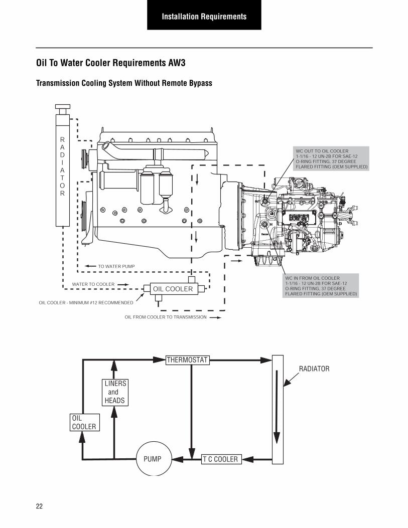
Oil To Water Cooler Requirements AW3
Transmission Cooling System Without Remote Bypass
OIL COOLER
RADIATOR
TO WATER PUMP
WATER TO COOLER
OIL FROM COOLER TO TRANSMISSION
OIL COOLER - MINIMUM #12 RECOMMENDED
WC OUT TO OIL COOLER1-1/16 - 12 UN-2B FOR SAE-12O-RING FITTING, 37 DEGREE FLARED FITTING (OEM SUPPLIED)
WC IN FROM OIL COOLER1-1/16 - 12 UN-2B FOR SAE-12O-RING FITTING, 37 DEGREE FLARED FITTING (OEM SUPPLIED)
THERMOSTAT
OILCOOLER
T C COOLERPUMP
RADIATOR
LINERS andHEADS
22
Installation RequirementsInstallation
Requirements
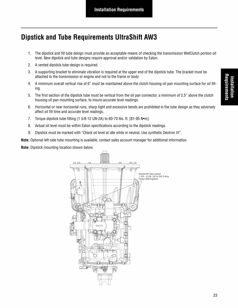
Dipstick and Tube Requirements UltraShift AW3
1. The dipstick and fill tube design must provide an acceptable means of checking the transmission WetClutch portion oil level. New dipstick and tube designs require approval and/or validation by Eaton.
2. A vented dipstick tube design is required.
3. A supporting bracket to eliminate vibration is required at the upper end of the dipstick tube. The bracket must be attached to the transmission or engine and not to the frame or body
4. A minimum overall vertical rise of 6” must be maintained above the clutch housing oil pan mounting surface for oil fill-ing.
5. The first section of the dipstick tube must be vertical from the oil pan connector, a minimum of 2.5” above the clutch housing oil pan mounting surface, to insure accurate level readings.
6. Horizontal or near horizontal runs, sharp tight and excessive bends are prohibited in the tube design as they adversely affect oil fill time and accurate level readings.
7. Torque dipstick tube fitting (1 5/8-12 UN-2A) to 60-70 lbs. ft. [81-95 N•m].
8. Actual oil level must be within Eaton specifications according to the dipstick readings.
9. Dipstick must be marked with “Check oil level at idle while in neutral. Use synthetic Dextron III”.
Note: Optional left side tube mounting is available, contact sales account manager for additional information.
Note: Dipstick mounting location shown below.
Dipstick/Fill Tube Location1 -5/8 - 12 UN - 2A For SAE O-RingFitting (OEM Supplied)
23
Installation Requirements
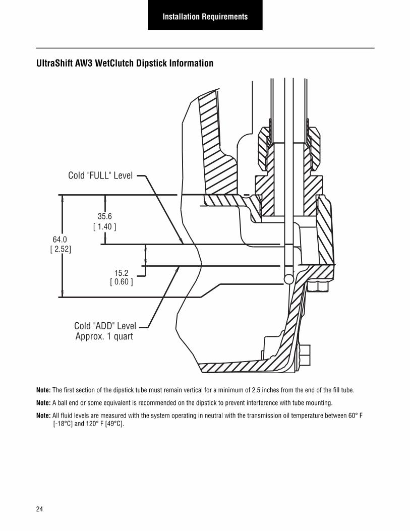
UltraShift AW3 WetClutch Dipstick Information
Note: The first section of the dipstick tube must remain vertical for a minimum of 2.5 inches from the end of the fill tube.
Note: A ball end or some equivalent is recommended on the dipstick to prevent interference with tube mounting.
Note: All fluid levels are measured with the system operating in neutral with the transmission oil temperature between 60° F [-18°C] and 120° F [49°C].
64.0[ 2.52]
35.6[ 1.40 ]
15.2[ 0.60 ]
Cold "FULL" Level
Cold "ADD" LevelApprox. 1 quart
24
25
Installation RequirementsInstallation
Requirements
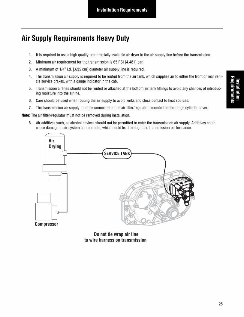
Air Supply Requirements Heavy Duty
1. It is required to use a high quality commercially available air dryer in the air supply line before the transmission.
2. Minimum air requirement for the transmission is 65 PSI [4.481] bar.
3. A minimum of 1/4” i.d. [.635 cm] diameter air supply line is required.
4. The transmission air supply is required to be routed from the air tank, which supplies air to either the front or rear vehi-cle service brakes, with a gauge indicator in the cab.
5. Transmission airlines should not be routed or attached at the bottom air tank fittings to avoid any chances of introduc-ing moisture into the airline.
6. Care should be used when routing the air supply to avoid kinks and close contact to heat sources.
7. The transmission air supply must be connected to the air filter/regulator mounted on the range cylinder cover.
Note: The air filter/regulator must not be removed during installation.
8. Air additives such, as alcohol devices should not be permitted to enter the transmission air supply. Additives could cause damage to air system components, which could lead to degraded transmission performance.
SERVICE TANK
AirDrying
Compressor
Do not tie wrap air line to wire harness on transmission
26
Installation Requirements
Engine Retarder Requirements
Heavy-Duty
An engine retarder (compression or exhaust) is required on AutoShift 10 and 18-Speed and 13-Speed UltraShift transmissions. It is recommended on the 10-Speed UltraShift transmission.
1. The transmission sends J-1939 Torque/Speed Control 1 (TSC1) torque control commands to the engine retarder (com-pression or exhaust) when deceleration assistance during a shift is required. The transmission automatically detects the retarder source address (compression or exhaust) and addresses the TSC1 accordingly. If both compression and exhaust are present, the transmission will address exhaust only.
2. The engine retarder shall respond to TSC1 control commands as indicated by Actual Retarder Percent torque within 50 msec of the TSC1 command.
3. The engine retarder shall respond to TSC1 commands regardless of the status of the engine brake control switches on the dash.
4. The engine retarder shall affect the engine deceleration rate within 250 msec to 300 msec of the request. Longer response times will adversely affect the transmission’s upshift capabilities on a grade and may limit applications to grades 8% and lower. Response times greater the 500 msec are not acceptable.
5. The engine retarder shall respond to zero percent torque control command by turning off the engine brake within 250 msec. Longer delay times to turn off may cause harsh gear engagements and loss of vehicle speed.
6. The engine shall have a minimum deceleration rate of 1000 rpm/sec with the engine retarder at 100%. The engine is disengaged from the driveline and is virtually unloaded.
7. The recommended practice is for the exhaust brake on/off switches to be wired in the engine ECM separately from the exhaust brake solenoid. Failure to comply with this recommended practice can cause Eaton AutoShift/UltraShift trans-missions to miss shifts when the exhaust brake is required. For more information contact Eaton Application Engineering and refer to the J-1939 Engine Requirements for Eaton AutomatedTransmissions.
Medium-Duty1. The transmission sends J-1939 Torque/Speed Control 1 (TSC1) torque control commands to the engine retarder (com-
pression or exhaust) when deceleration assistance during a shift is required. The transmission automatically detects the retarder source address (compression or exhaust) and addresses the TSC1 accordingly. If both compression and exhaust are present, the transmission will address exhaust only.
2. The engine retarder shall respond to TSC1 control commands as indicated by Actual Retarder Percent torque within 50 msec of the TSC1 command.
3. The engine retarder shall respond to TSC1 commands regardless of the status of the engine brake control switches on the dash.
4. The engine retarder shall respond to zero percent torque control command by turning off the engine brake within 250 msec. Longer delay times to turn off may cause harsh gear engagements and loss of vehicle speed.
5. The recommended practice is for the exhaust brake on/off switches to be wired in the engine ECM separately from the exhaust brake solenoid. Failure to comply with this recommended practice can cause Eaton AutoShift/UltraShift trans-missions to miss shifts when the exhaust brake is required. For more information contact Eaton Application Engineering and refer to the J-1939 Engine Requirements for Eaton AutomatedTransmissions.
Installation RequirementsInstallation
Requirements
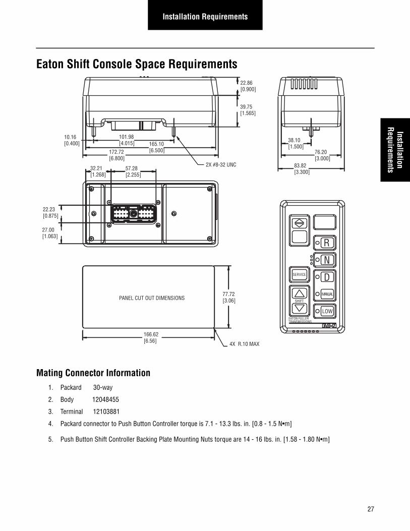
Eaton Shift Console Space Requirements
Mating Connector Information1. Packard 30-way
2. Body 12048455
3. Terminal 12103881
4. Packard connector to Push Button Controller torque is 7.1 - 13.3 lbs. in. [0.8 - 1.5 N•m]
5. Push Button Shift Controller Backing Plate Mounting Nuts torque are 14 - 16 lbs. in. [1.58 - 1.80 N•m]
10.16[0.400]
32.21[1.268]
57.28[2.255]
101.98[4.015] 165.10
[6.500]172.72[6.800]
22.86[0.900]
39.75[1.565]
38.10[1.500]
76.20[3.000]
83.82[3.300]
22.23[0.875]
27.00[1.063]
166.62[6.56]
PANEL CUT OUT DIMENSIONS
4X R.10 MAX
77.72[3.06]
SERVICE
SHIFT
EATON FULLERTRANSMISSIONS
LOW
MANUAL
D
N
R
2X #8-32 UNC
27
Installation Requirements
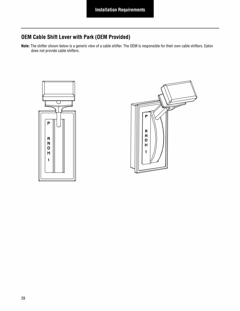
OEM Cable Shift Lever with Park (OEM Provided)Note: The shifter shown below is a generic view of a cable shifter. The OEM is responsible for their own cable shifters. Eaton
does not provide cable shifters.
28
Installation RequirementsInstallation
Requirements
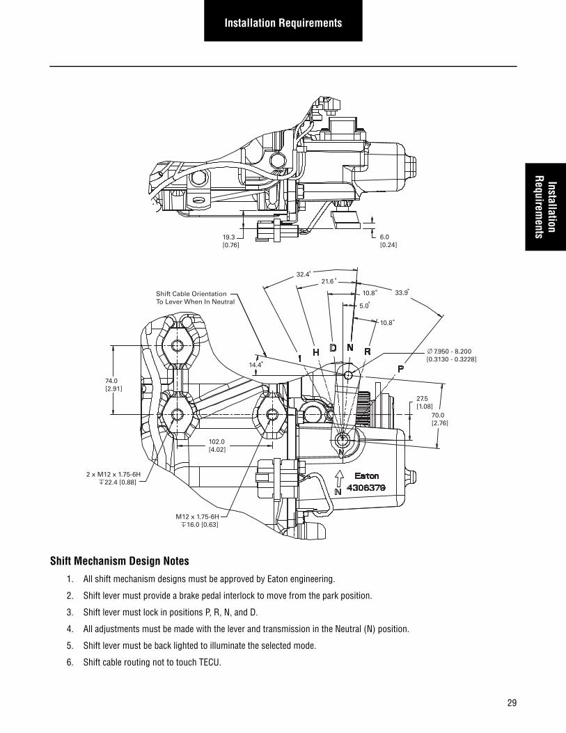
Shift Mechanism Design Notes
1. All shift mechanism designs must be approved by Eaton engineering.
2. Shift lever must provide a brake pedal interlock to move from the park position.
3. Shift lever must lock in positions P, R, N, and D.
4. All adjustments must be made with the lever and transmission in the Neutral (N) position.
5. Shift lever must be back lighted to illuminate the selected mode.
6. Shift cable routing not to touch TECU.
33.9
21.6
10.8
5.0
70.0[2.76]
27.5[1.08]
7.950 - 8.200[0.3130 - 0.3228]
19.3[0.76]
6.0[0.24]
32.4
10.8Shift Cable OrientationTo Lever When In Neutral
74.0[2.91]
14.4
2 x M12 x 1.75-6H 22.4 [0.88]
M12 x 1.75-6H 16.0 [0.63]
102.0[4.02]
29
30
Installation Requirements
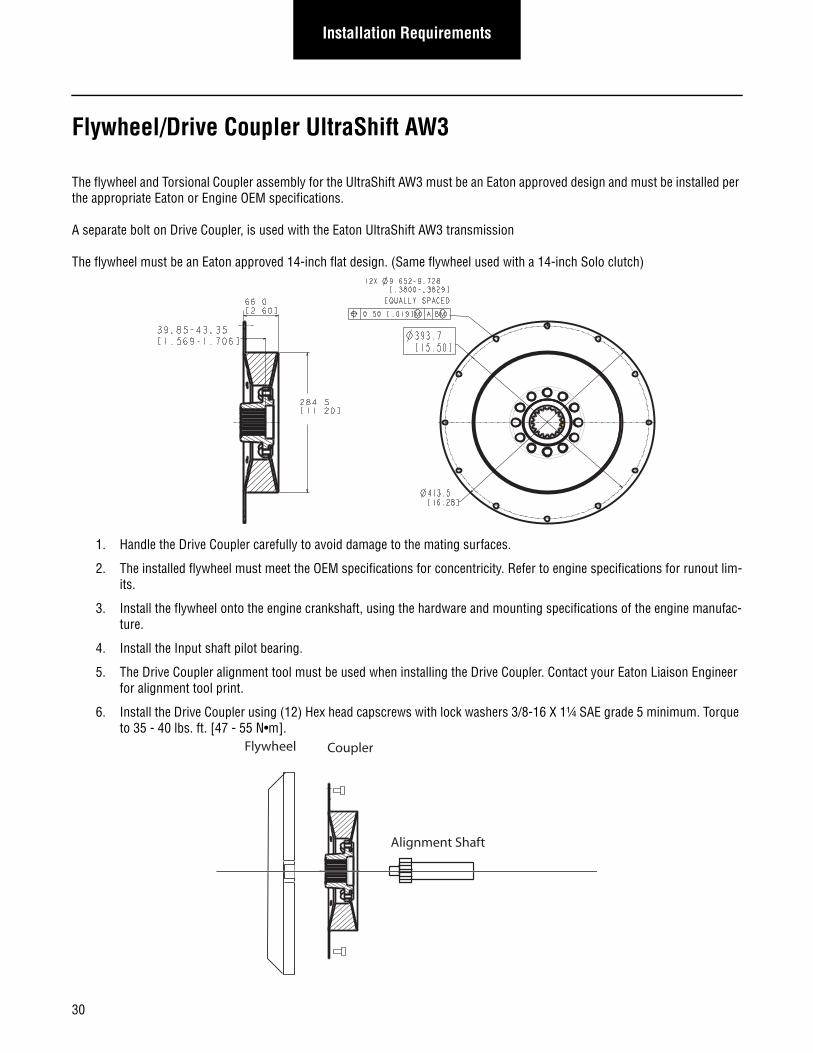
Flywheel/Drive Coupler UltraShift AW3
The flywheel and Torsional Coupler assembly for the UltraShift AW3 must be an Eaton approved design and must be installed per the appropriate Eaton or Engine OEM specifications.
A separate bolt on Drive Coupler, is used with the Eaton UltraShift AW3 transmission
The flywheel must be an Eaton approved 14-inch flat design. (Same flywheel used with a 14-inch Solo clutch)
1. Handle the Drive Coupler carefully to avoid damage to the mating surfaces.
2. The installed flywheel must meet the OEM specifications for concentricity. Refer to engine specifications for runout lim-its.
3. Install the flywheel onto the engine crankshaft, using the hardware and mounting specifications of the engine manufac-ture.
4. Install the Input shaft pilot bearing.
5. The Drive Coupler alignment tool must be used when installing the Drive Coupler. Contact your Eaton Liaison Engineer for alignment tool print.
6. Install the Drive Coupler using (12) Hex head capscrews with lock washers 3/8-16 X 1¼ SAE grade 5 minimum. Torque to 35 - 40 lbs. ft. [47 - 55 N•m].
Flywheel Coupler
Alignment Shaft
Installation RequirementsInstallation
Requirements
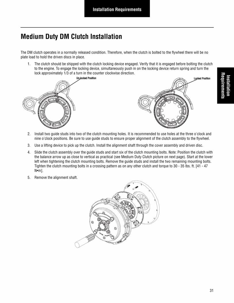
Medium Duty DM Clutch Installation
The DM clutch operates in a normally released condition. Therefore, when the clutch is bolted to the flywheel there will be no plate load to hold the driven discs in place.
1. The clutch should be shipped with the clutch locking device engaged. Verify that it is engaged before bolting the clutch to the engine. To engage the locking device, simultaneously push in on the locking device return spring and turn the lock approximately 1/3 of a turn in the counter clockwise direction.
2. Install two guide studs into two of the clutch mounting holes. It is recommended to use holes at the three o'clock and nine o'clock positions. Be sure to use guide studs to ensure proper alignment of the clutch assembly to the flywheel.
3. Use a lifting device to pick up the clutch. Install the alignment shaft through the cover assembly and driven disc.
4. Slide the clutch assembly over the guide studs and start six of the clutch mounting bolts. Note: Position the clutch with the balance arrow up as close to vertical as practical (see Medium Duty Clutch picture on next page). Start at the lower left when tightening the clutch mounting bolts. Remove the guide studs and install the two remaining mounting bolts. Tighten the clutch mounting bolts in a crossing pattern as on any other clutch and torque to 30 - 35 lbs. ft. [41 - 47 N•m].
5. Remove the alignment shaft.
Un-locked PositionUn-locked Position Locked PositionLocked Position
31
Installation Requirements
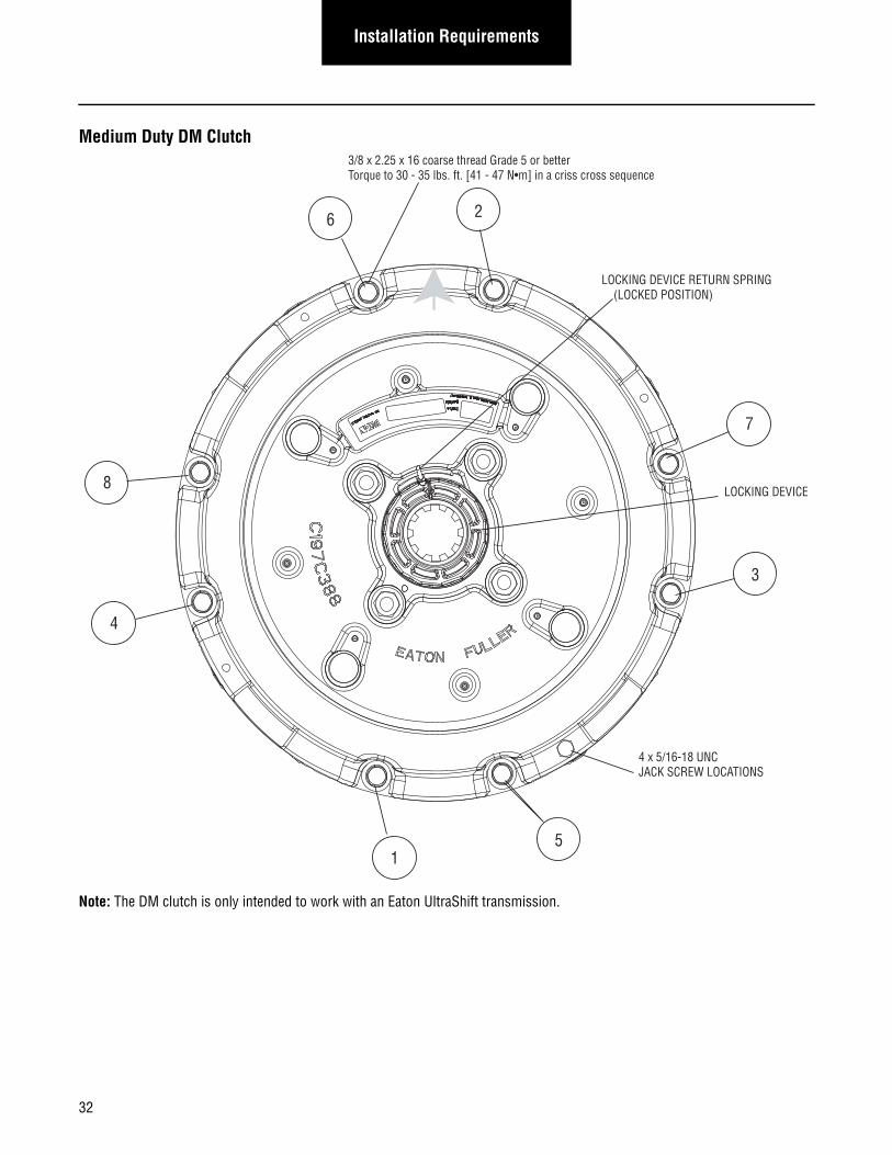
Medium Duty DM Clutch
Note: The DM clutch is only intended to work with an Eaton UltraShift transmission.
8
4
6 2
7
3
51
4 x 5/16-18 UNCJACK SCREW LOCATIONS
3/8 x 2.25 x 16 coarse thread Grade 5 or betterTorque to 30 - 35 lbs. ft. [41 - 47 N•m] in a criss cross sequence
LOCKING DEVICE RETURN SPRING (LOCKED POSITION)
LOCKING DEVICE
32
Installation RequirementsInstallation
Requirements
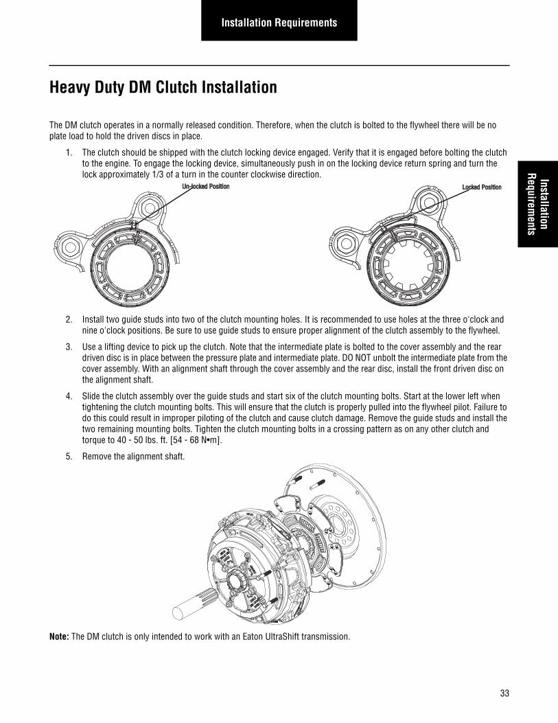
Heavy Duty DM Clutch Installation
The DM clutch operates in a normally released condition. Therefore, when the clutch is bolted to the flywheel there will be no plate load to hold the driven discs in place.
1. The clutch should be shipped with the clutch locking device engaged. Verify that it is engaged before bolting the clutch to the engine. To engage the locking device, simultaneously push in on the locking device return spring and turn the lock approximately 1/3 of a turn in the counter clockwise direction.
2. Install two guide studs into two of the clutch mounting holes. It is recommended to use holes at the three o'clock and nine o'clock positions. Be sure to use guide studs to ensure proper alignment of the clutch assembly to the flywheel.
3. Use a lifting device to pick up the clutch. Note that the intermediate plate is bolted to the cover assembly and the rear driven disc is in place between the pressure plate and intermediate plate. DO NOT unbolt the intermediate plate from the cover assembly. With an alignment shaft through the cover assembly and the rear disc, install the front driven disc on the alignment shaft.
4. Slide the clutch assembly over the guide studs and start six of the clutch mounting bolts. Start at the lower left when tightening the clutch mounting bolts. This will ensure that the clutch is properly pulled into the flywheel pilot. Failure to do this could result in improper piloting of the clutch and cause clutch damage. Remove the guide studs and install the two remaining mounting bolts. Tighten the clutch mounting bolts in a crossing pattern as on any other clutch and torque to 40 - 50 lbs. ft. [54 - 68 N•m].
5. Remove the alignment shaft.
Note: The DM clutch is only intended to work with an Eaton UltraShift transmission.
Un-locked PositionUn-locked Position Locked PositionLocked Position
33
Installation Requirements
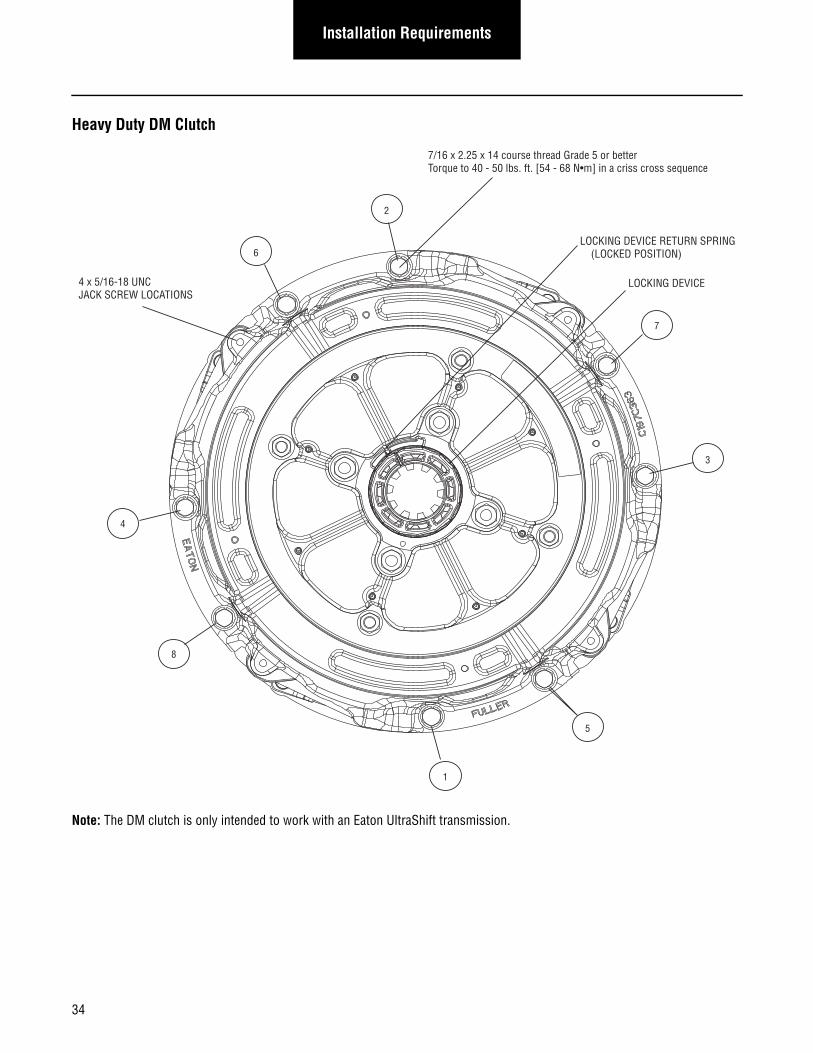
Heavy Duty DM Clutch
Note: The DM clutch is only intended to work with an Eaton UltraShift transmission.
8
4
6
2
7
3
5
1
4 x 5/16-18 UNCJACK SCREW LOCATIONS
7/16 x 2.25 x 14 course thread Grade 5 or better Torque to 40 - 50 lbs. ft. [54 - 68 N•m] in a criss cross sequence
LOCKING DEVICE RETURN SPRING (LOCKED POSITION)
LOCKING DEVICE
34
Installation RequirementsInstallation
Requirements
Transmission Mounting Requirements
Handling
Handle the transmission carefully to avoid damage to the transmission components and surrounding vehicle components.
1. Use a hoist or transmission jack that permits precise control of the transmission movement during installation.
Transmission Preparations
Always remove banding and protective wrapping from the transmission and inspect for shipping damage as soon as possible upon receiving.
2. If a thread-in electronic speedometer system is used, tighten the sensor or sensor lock nut to 35 lb- ft [47 N•m], (3/4-16 threads). If a push-in electronic speedometer system is used, Eaton P/N 14142 (O-ring) and Eaton P/N 71206 (sili-con lubricant) are used to seal the sensor.
3. To remove, or replace a rear bearing cover, output shaft seal, or output yoke/flange refer to the appropriate service man-ual on the roadranger website.
Mounting Transmission to Engine
Use the two transmission lifting eyes provided. The lifting eye position must not be changed on the transmission. Do not remove the Electric Shifter at any time.
Note: For lifting eye and sensor retaining bolt locations. [see page 90] These bolts can not be used for brackets or for any other purpose.
4. Use a two point lift chain or transmission jack with a minimum capacity of 1500 lbs.
5. Inspect the engine to transmission mating surfaces for damage or debris prior to installation. Make sure the engine fly-wheel housing face, transmission clutch housing face, input shaft, etc. are free of paint, debris, rust, and any type of damage before installation.
6. Input Shaft To Clutch Alignment: The transmission is shipped from Eaton with the transmission in gear. The transmis-sion must be in gear in order to rotate the input shaft by turning the output shaft/yoke. The transmission will automati-cally reset to the neutral position as soon as the vehicle is powered up (key switched on). In the event that the transmission is not received in gear, the input shaft will have to be manually indexed to mate up with the clutch splines.
Note: DRIVE SHAFT INSTALLATION- since the transmission is in gear until the vehicle is powered up with the key switch, use a Pull-To-Neutral-Box to disengage the transmission or rotate the axles to align the transmission prop shaft.[see page 123]
7. Adjust the lift chain or transmission jack to obtain the same relative angle as the engine. The face of the engine flywheel housing and the face of the transmission clutch housing must be parallel during installation. If the transmission is prop-erly aligned and the clutch is installed properly, very little force is required to slide the input shaft through the clutch and into the pilot bearing.
8. If interference is encountered, move the transmission away from the engine to investigate the cause. The use of exces-sive force to overcome misalignment may cause damage to the transmission input shaft and the clutch.
9. Rotate the output shaft/yoke while sliding the input shaft into the clutch to line up the splines.
10. Once the transmission is seated against the engine flywheel housing, align the clutch housing bolt holes with the engine flywheel housing bolt holes and install all capscrews and tighten finger tight.
Note: The clutch housing must be flush against the engine flywheel housing before tightening any capscrews. Do not use the capscrews to seat housing.
35
Installation Requirements
11. Tighten four capscrews at 90° intervals around the clutch housing, then tighten the remaining transmission mounting capscrews using the recommended torque specifications.
Note: UltraShift Gen 3 AW3 transmissions use a longer M10 x 1-3/4 capscrew to mount the transmission to the engine.
Note: Do not tighten any mounting capscrews until all capscrews have been installed and finger tightened. Do not remove the transmission support chain or jack until all mounting bolts have been tightened.
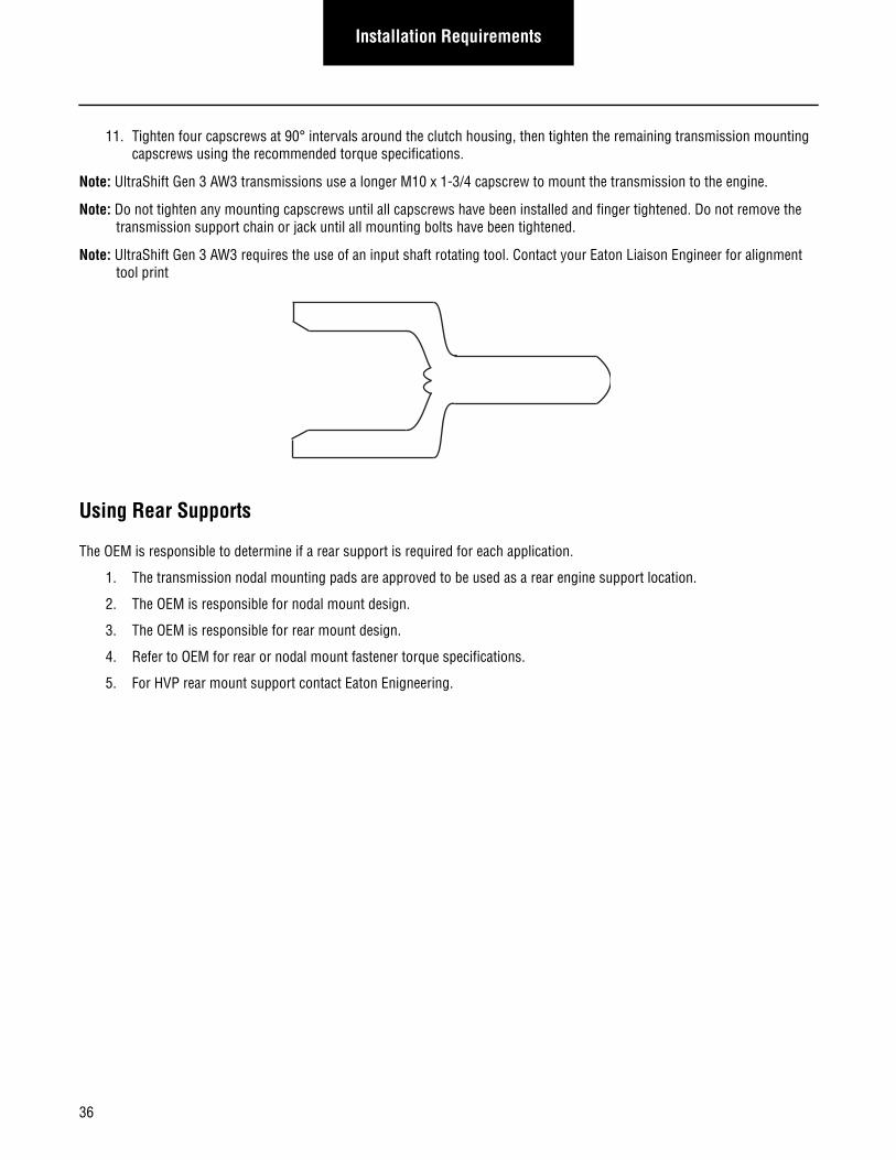
Note: UltraShift Gen 3 AW3 requires the use of an input shaft rotating tool. Contact your Eaton Liaison Engineer for alignment tool print
Using Rear Supports
The OEM is responsible to determine if a rear support is required for each application.
1. The transmission nodal mounting pads are approved to be used as a rear engine support location.
2. The OEM is responsible for nodal mount design.
3. The OEM is responsible for rear mount design.
4. Refer to OEM for rear or nodal mount fastener torque specifications.
5. For HVP rear mount support contact Eaton Enigneering.
36
Electrical RequirementsElectrical
Requirements
Cable
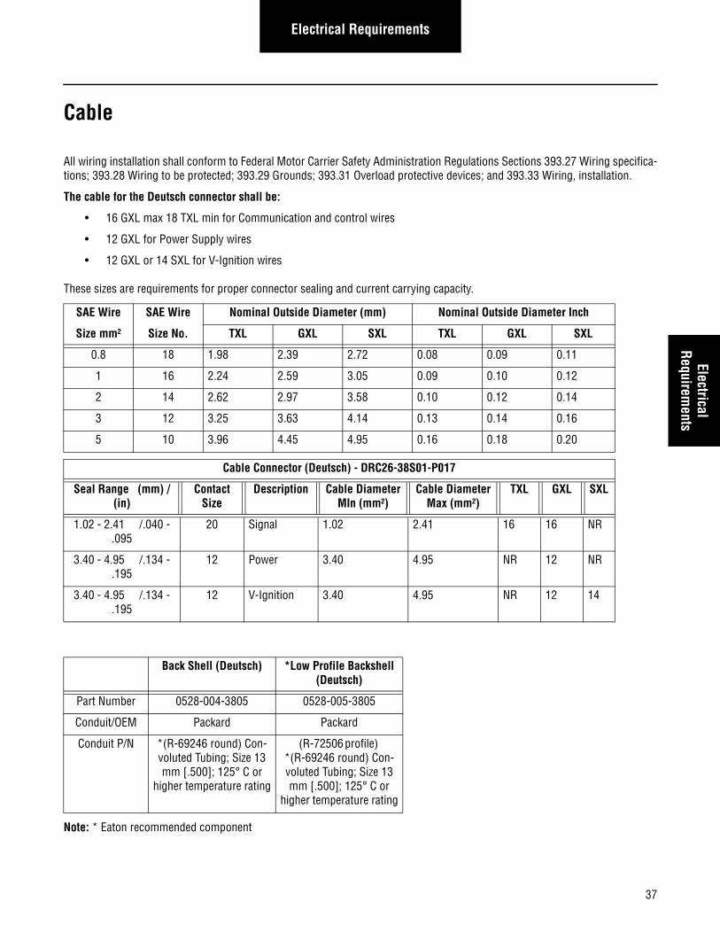
All wiring installation shall conform to Federal Motor Carrier Safety Administration Regulations Sections 393.27 Wiring specifica-tions; 393.28 Wiring to be protected; 393.29 Grounds; 393.31 Overload protective devices; and 393.33 Wiring, installation.
The cable for the Deutsch connector shall be:
• 16 GXL max 18 TXL min for Communication and control wires
• 12 GXL for Power Supply wires
• 12 GXL or 14 SXL for V-Ignition wires
These sizes are requirements for proper connector sealing and current carrying capacity.
Note: * Eaton recommended component
SAE Wire SAE Wire Nominal Outside Diameter (mm) Nominal Outside Diameter Inch
Size mm² Size No. TXL GXL SXL TXL GXL SXL
0.8 18 1.98 2.39 2.72 0.08 0.09 0.11
1 16 2.24 2.59 3.05 0.09 0.10 0.12
2 14 2.62 2.97 3.58 0.10 0.12 0.14
3 12 3.25 3.63 4.14 0.13 0.14 0.16
5 10 3.96 4.45 4.95 0.16 0.18 0.20
Cable Connector (Deutsch) - DRC26-38S01-P017
Seal Range (mm) / (in)
Contact Size
Description Cable Diameter MIn (mm²)
Cable Diameter Max (mm²)
TXL GXL SXL
1.02 - 2.41 /.040 -.095
20 Signal 1.02 2.41 16 16 NR
3.40 - 4.95 /.134 -.195
12 Power 3.40 4.95 NR 12 NR
3.40 - 4.95 /.134 -.195
12 V-Ignition 3.40 4.95 NR 12 14
Back Shell (Deutsch) *Low Profile Backshell (Deutsch)
Part Number 0528-004-3805 0528-005-3805
Conduit/OEM Packard Packard
Conduit P/N *(R-69246 round) Con-voluted Tubing; Size 13 mm [.500]; 125° C or
higher temperature rating
(R-72506 profile) *(R-69246 round) Con-voluted Tubing; Size 13 mm [.500]; 125° C or
higher temperature rating
37
Electrical Requirements
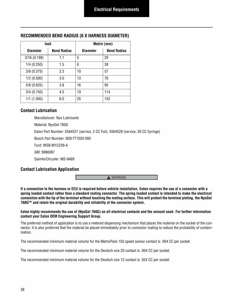
RECOMMENDED BEND RADIUS (6 X HARNESS DIAMETER)
Contact Lubrication
Manufacturer: Nye Lubricants
Material: NyoGel 760G
Eaton Part Number: 5564527 (service, 2 CC Foil), 5564528 (service, 30 CC Syringe)
Bosch Part Number: N28 FT7020-005
Ford: WSB-M1C239-A
GM: 9986087
DaimlerChrysler: MS-9469
Contact Lubrication Application
If a connection to the harness or ECU is required before vehicle installation, Eaton requires the use of a connector with a spring loaded contact rather than a standard mating connector. The spring loaded contact is intended to make the electrical connection with the tip of the terminal without touching the mating surface. This will protect the terminal plating, the NyoGel 760G™ and retain the original durability and reliability of the connector system.
Eaton highly recommends the use of (NyoGel 760G) on all electrical contacts and the amount used. For further information contact your Eaton OEM Engineering Support Group.
The preferred method of application is to use a metered dispensing mechanism that places the material on the socket of the con-nector. It is also preferred that the material be placed immediately prior to connector mating to reduce the probability of contam-ination.
The recommended minimum material volume for the MetricPack 150 speed sensor contact is .004 CC per socket.
The recommended minimum material volume for the Deutsch size 20 contact is .004 CC per socket.
The recommended minimum material volume for the Deutsch size 12 contact is .024 CC per socket.
Inch Metric (mm)
Diameter Bend Radius Diameter Bend Radius
3/16 (0.188) 1.1 5 29
1/4 (0.250) 1.5 6 38
3/8 (0.375) 2.3 10 57
1/2 (0.500) 3.0 13 76
5/8 (0.625) 3.8 16 95
3/4 (0.750) 4.5 19 114
1/1 (1.000) 6.0 25 152
WARNING
38
Electrical RequirementsElectrical
Requirements
Transmission ECU Jackscrew Torque
Connector jackscrew torque shall be 25 +/- 3 lbs. in. (2.82 +/- .33 N•m).
The Nyogel 760G material shall not be applied to the Transmission ECU 38-Way (Vehicle Interface) connector jackscrew. No anti-seize, lubricating, or other foreign compound shall be applied to the connector jackscrew threads. The use of such compounds may affect jackscrew torque and prevent proper sealing of the connector.
Vehicle Speed Sensor-VSS (Heavy Duty Only) Eaton recommends that the OEM utilize the provided bracket near the vehicle speed sensor to anchor their VSS harness to. The bracket is designed to accommodate both the transmission harness and the OEM VSS harness.
Conductor Material
Conducting material shall be stranded bare copper wire.
Connectors
Connectors shall be designed for use in the heavy-duty industry conforming to SAE J-2030 and J-1455.
Terminals
Terminals shall be sized for the correct current capacity of the circuit as stated by the manufacturer.
Terminals shall be plated with tin, nickel, gold, etc. Mating terminals shall be plated with the same material. Gold plated terminals shall be required in 5 volt dry circuits. Beryllium Copper or equivalent should be used as a base material.
Low Power Pins (size 20): Communication and Control Wires
SAE J1128 0.8 mm² wire (No. 18) TXL min, or (No. 16) GXL max
Mating socket: Deutsch Stamped and Formed, Gold Plated, #PN 1062-20-0244
Hand crimping tool - DTT-20-02
High Power Pins (size 12): Power Supply Wires
SAE J1128 2.0 mm² wire (No. 14) SXL
SAE J1128 3.0 mm² wire (No. 12) GXL
Mating socket: Deutsch Stamped and Formed, Nickel Plated, #PN 1062-12-0166
Hand crimping tool - DTT-12-00
Note: For Park sensor terminal contact Eaton Engineering.‘
Note: Recommended wire strip length is .175 inch ± .025.
Note: For tools contact Deutsch at 951-765-2250.
Ring Terminals
Terminals such as ring, bullet, spade, ect., shall be sized for the correct current capacity of the circuit as stated by the manufac-turer. Terminals shall be plated and non-insulated. Sleeves shall be insulated with a double wall shrink tubing.Sealing Dielectric grease over the top of the ring is recommended.
39
Electrical Requirements
Convoluted Conduit
Convoluted conduit must have an operating temperature of at least 257°F (125°C).
Braided Loom (Mesh) (Recommended)
Coverage: A minimum of 10, maximum of 12 picks per inch. The braid shall be woven so as to produce a tight non-slip covering over the cables. The braid shall be heat-sealed to prevent unraveling. Braid must have a minimum service temperature of 280°F (138°C).
Insulating Sleeves
Sleeves shall be constructed of a heat shrinkable, irradiated, adhesive lined, semi-rigid polyolefin. The color shall be black. Typi-cal shrinkage shall be 50% in diameter when exposed to heat (302°F) (150°C).
Tape
Adhesive tape for harness forming and spot taping shall be TESA Black Cloth Tape P/N 51006 which is supplied by Great Lakes Tape Company. The tape shall have a pressure sensitive adhesive coating on one side.
Crimping
The crimp shall be applied with a tool specified by the manufacturer of the terminal.
Terminals shall be applied according to terminal manufacturer’s specifications.
Stripping
An allowable maximum of one strand may be cut on 16 gauge or larger, no strands on 18 gauge, and no strands on 20 gauge in the crimp area.
Soldering
No terminals shall be soldered.
Splice
Splices are not allowed.
Twisted Cables
2 conductor cables shall have 12 twists/foot [.30 meters]. (16 and 18 gage cable only)
• Twisted cable on the J1939 backbone can be size 16 TXL
• Twisted cable into Deutsch DRC connector must be size 18 TXL min, or 16 GXL max
All cable lengths to multi-cavity connectors shall be cut and dressed to ensure no undue stress is on an individual wire after insertion into the connector. After insertion, all terminals shall be checked for retention.
40
Electrical RequirementsElectrical
Requirements
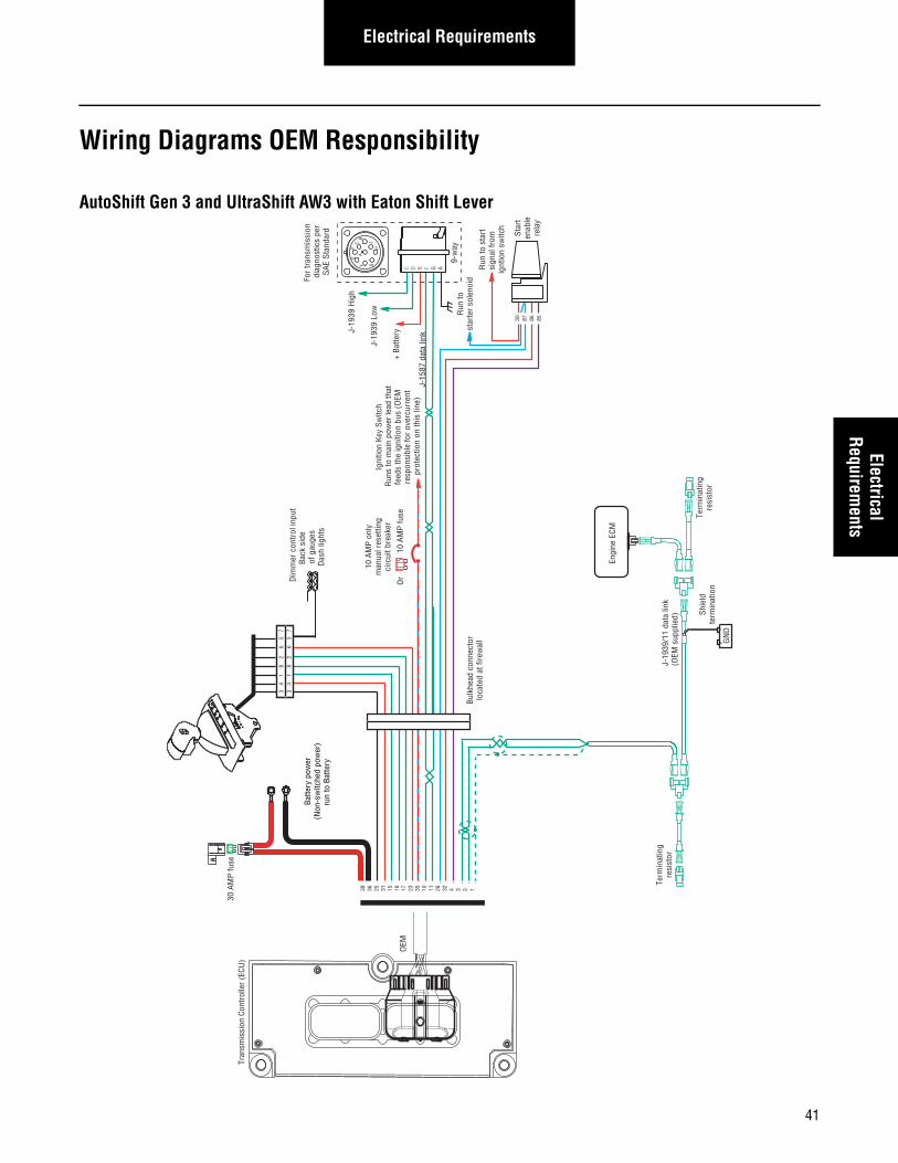
Wiring Diagrams OEM Responsibility
AutoShift Gen 3 and UltraShift AW3 with Eaton Shift Lever
Term
inat
ing
resi
stor
J-19
39/1
1 da
ta li
nk(O
EM s
uppl
ied)
GN
D+
_
Shie
ldte
rmin
atio
n
Engi
ne E
CM
+ Ba
ttery
For
tran
smis
sion
di
agno
stic
s pe
rSA
E St
anda
rd Star
ten
able
rela
y
Run
to s
tart
sign
al fr
om
ignt
ion
switc
h
Run
tost
arte
r so
leno
id
10 A
MP
only
m
anua
l res
ettin
g ci
rcui
t bre
aker
10 A
MP
fuse
Or
J-15
87 d
ata
link
30 87 86 85
C D B F G A
9-w
ay
30 A
MP
fuse
Batte
ry p
ower
(N
on-s
witc
hed
pow
er)
run
to B
atte
ry
Term
inat
ing
resi
stor
Tran
smis
sion
Con
trol
ler
(ECU
)
AF
J
E
GHD
CB
38 36 25 31 15 16 17 23 35 10 11 26 32 4 3 2 1Bu
lkhe
ad c
onne
ctor
loca
ted
at fi
rew
all
Back
sid
e of
gau
ges
Das
h lig
hts
Dim
mer
con
trol
inpu
t3
4
1
8
2
6
5
73
4
1
8
2
6
5
7
J-19
39 L
ow
J-19
39 H
igh
OEM
Igni
tion
Key
Switc
h R
uns
to m
ain
pow
er le
ad th
atfe
eds
the
igni
tion
bus
(OEM
re
spon
sibl
e fo
r ov
ercu
rren
t pr
otec
tion
on th
is li
ne)
41
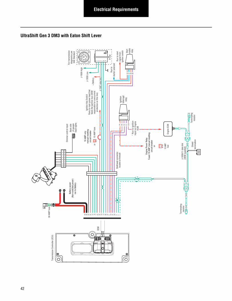
Electrical Requirements
UltraShift Gen 3 DM3 with Eaton Shift Lever
Term
inat
ing
resi
stor
J-19
39/1
1 da
ta li
nk(O
EM s
uppl
ied)
GND
+_
Shie
ldte
rmin
atio
n
Engi
ne E
CM
+ Ba
ttery
Star
ten
able
rela
y
Run
to s
tart
sign
al fr
om
ignt
ion
switc
h
Run
tost
arte
r sol
enoi
d
10 A
MP
only
man
ual r
eset
ting
circ
uit b
reak
er
10 A
MP
fuse
or
J-15
87 d
ata
link
30 87 86 85
9-w
ay
30 A
MP
fuse
Batte
ry p
ower
(Non
-sw
itche
d po
wer
)ru
n to
Bat
tery
Term
inat
ing
resi
stor
Tran
smis
sion
Con
trolle
r (EC
U)
AF
J
E
GHD
CB
38 36 25 31 15 16 17 23 35 10 11 26 32 4 22 21 20 3 2 1
Bulk
head
con
nect
orlo
cate
d at
fire
wal
l
Back
sid
e of
gau
ges
Dash
ligh
ts
Dim
mer
con
trol i
nput
Igni
tion
Inte
rrup
tre
lay
30 86 85 87 87a
* Run
to ig
nitio
nin
put o
n En
gine
ECM
3 4
1
8
2
6
5
7
3 4
1
8
2
6
5
7
Engi
ne P
ower
Rel
ayFu
sed
10 A
MP
man
ual r
eset
ting
circ
uit b
reak
eror
10 A
MP
fuse
C D B F G A
J-19
39 L
ow
J-19
39 H
igh
For t
rans
mis
sion
di
agno
stic
s pe
rSA
E St
anda
rd
OEM
Igni
tion
Key
Switc
h Ru
ns to
mai
n po
wer
lead
that
feed
s th
e ig
nitio
n bu
s (O
EM
resp
onsi
ble
for o
verc
urre
nt
prot
ectio
n on
this
line
)
42
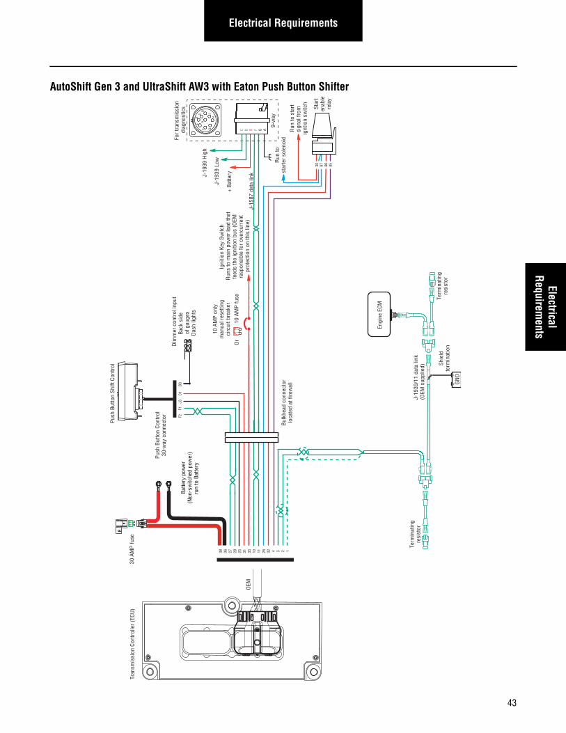
Electrical RequirementsElectrical
Requirements
AutoShift Gen 3 and UltraShift AW3 with Eaton Push Button Shifter
Term
inat
ing
resi
stor
J-19
39/1
1 da
ta li
nk(O
EM s
uppl
ied)
GN
D+
_
Shie
ldte
rmin
atio
n
Engi
ne E
CM
+ Ba
ttery
For
tran
smis
sion
di
agno
stic
s Star
ten
able
rela
y
Run
to s
tart
sign
al fr
om
ignt
ion
switc
h
Run
tost
arte
r so
leno
id
10 A
MP
only
m
anua
l res
ettin
g ci
rcui
t bre
aker
10 A
MP
fuse
Or
J-15
87 d
ata
link
30 87 86 85
9-w
ay
30 A
MP
fuse
Batte
ry p
ower
(N
on-s
witc
hed
pow
er)
run
to B
atte
ry
Term
inat
ing
resi
stor
Tran
smis
sion
Con
trol
ler
(ECU
)
AF
J
E
GHD
CB
38 36 27 28 25 31 35 10 11 26 32 4 3 2 1Bu
lkhe
ad c
onne
ctor
loca
ted
at fi
rew
all
Back
sid
e of
gau
ges
Das
h lig
hts
Dim
mer
con
trol
inpu
t
Push
But
ton
Shift
Con
trol
Push
But
ton
Cont
rol
30-w
ay c
onne
ctor F2
F
1 J
3
C1
B3
C D B F G A
J-19
39 L
ow
J-19
39 H
igh
OEM
Igni
tion
Key
Switc
h R
uns
to m
ain
pow
er le
ad th
atfe
eds
the
igni
tion
bus
(OEM
re
spon
sibl
e fo
r ov
ercu
rren
t pr
otec
tion
on th
is li
ne)
43
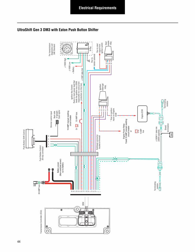
Electrical Requirements
UltraShift Gen 3 DM3 with Eaton Push Button Shifter
Term
inat
ing
resi
stor
J-19
39/1
1 da
ta li
nk(O
EM s
uppl
ied)
GND
+_
Shie
ldte
rmin
atio
n
Engi
ne E
CM
+ Ba
ttery
Star
ten
able
rela
y
Run
to s
tart
sign
al fr
om
ignt
ion
switc
h
Run
tost
arte
r sol
enoi
d
10 A
MP
man
ual r
eset
ting
circ
uit b
reak
er
10 A
MP
fuse
Or
J-15
87 d
ata
link
30 87 86 85
9-w
ay
30 A
MP
fuse
Batte
ry p
ower
(Non
-sw
itche
d po
wer
)ru
n to
Bat
tery
Term
inat
ing
resi
stor
AF
J
E
GHD
CB
38 36 27 28 25 31 35 10 11 26 32 4 22 21 20 3 2 1
Bulk
head
con
nect
orlo
cate
d at
fire
wal
l
Back
sid
e of
gau
ges
Dash
ligh
ts
Dim
mer
con
trol i
nput
Igni
tion
Inte
rrup
tre
lay
30 86 85 87 87a
*
Run
to ig
nitio
nin
put o
n En
gine
ECM
Push
But
ton
Shift
Con
trol
Push
But
ton
Cont
rol
30-w
ay c
onne
ctor F2
F
1 J
3
C1
B3
For t
rans
mis
sion
di
agno
stic
s pe
rSA
E St
anda
rd
C D B F G A
J-19
39 L
ow
J-19
39 H
igh
Engi
ne P
ower
Rel
ayFu
sed
10 A
MP
man
ual r
eset
ting
circ
uit b
reak
eror
10 A
MP
fuse
Tran
smis
sion
Con
trolle
r (EC
U)
OEM
Igni
tion
Key
Switc
h Ru
ns to
mai
n po
wer
lead
that
feed
s th
e ig
nitio
n bu
s (O
EM
resp
onsi
ble
for o
verc
urre
nt
prot
ectio
n on
this
line
)
44
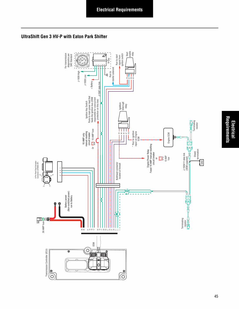
Electrical RequirementsElectrical
Requirements
UltraShift Gen 3 HV-P with Eaton Park Shifter
Term
inat
ing
resi
stor
J-19
39/1
1 da
ta li
nk(O
EM s
uppl
ied)
GND
+_
Shie
ldte
rmin
atio
n
Engi
ne E
CM
+ Ba
ttery
For t
rans
mis
sion
di
agno
stic
s pe
rSA
E St
anda
rd Star
ten
able
rela
y
Run
to s
tart
sign
al fr
om
ignt
ion
switc
h
Run
tost
arte
r sol
enoi
d
10 A
MP
only
man
ual r
eset
ting
circ
uit b
reak
er
10 A
MP
fuse
Or
J-15
87 d
ata
link
30 87 86 85
C D B F G A
9-w
ay
30 A
MP
fuse
Batte
ry p
ower
(Non
-sw
itche
d po
wer
)ru
n to
Bat
tery
Term
inat
ing
resi
stor
Tran
smis
sion
Con
trolle
r (EC
U)
AF
J
E
GHD
CB
38 36 31 15 16 17 35 10 11 26 32 4 22 21 20 3 2 1
Bulk
head
con
nect
orlo
cate
d at
fire
wal
l
J-19
39 L
ow
J-19
39 H
igh
OEM
Igni
tion
Key
Switc
h Ru
ns to
mai
n po
wer
lead
that
feed
s th
e ig
nitio
n bu
s (O
EM
resp
onsi
ble
for o
verc
urre
nt
prot
ectio
n on
this
line
)
23
41
2
3 4
1
4-Pi
n Pa
rk P
awl A
ctua
tor
Conn
ecto
r (DT
M04
-4P)
Igni
tion
Inte
rrup
tre
lay
30 86 85 87 87a
*
Run
to ig
nitio
nin
put o
n En
gine
ECM
Engi
ne P
ower
Rel
ayFu
sed
10 A
MP
man
ual r
eset
ting
circ
uit b
reak
eror
10 A
MP
fuse
45
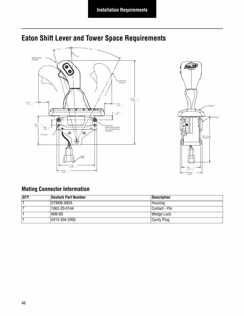
Installation Requirements
Eaton Shift Lever and Tower Space Requirements
Mating Connector InformationQTY Deutsch Part Number Description1 DTM06-08SA Housing 7 1062-20-0144 Contact - Pin1 WM-8S Wedge Lock1 0413-204-2005 Cavity Plug
( )11.0˚ ( )31.0˚
184.15-209.55[7.250-8.250]
67.6 MAX[2.66]
( )32.31.27[ ] ( )22.6
.89[ ]
( 13.2 ) [.52]
( )89.23.51[ ]
16.00.630[ ]
111.254.380[ ]
( )123.704.870[ ]
( )58.22.29[ ]
( )259.610.22[ ]
REVERSE GEARPOSITION
LOW GEARPOSITION
NEUTRAL POSITION
4
4X M6x1-6HINSERTS ARE ALLOWED 0.25 [.010] ADDITIONALTOLERANCE
4X X 8-163
2X 691900
4305447
46
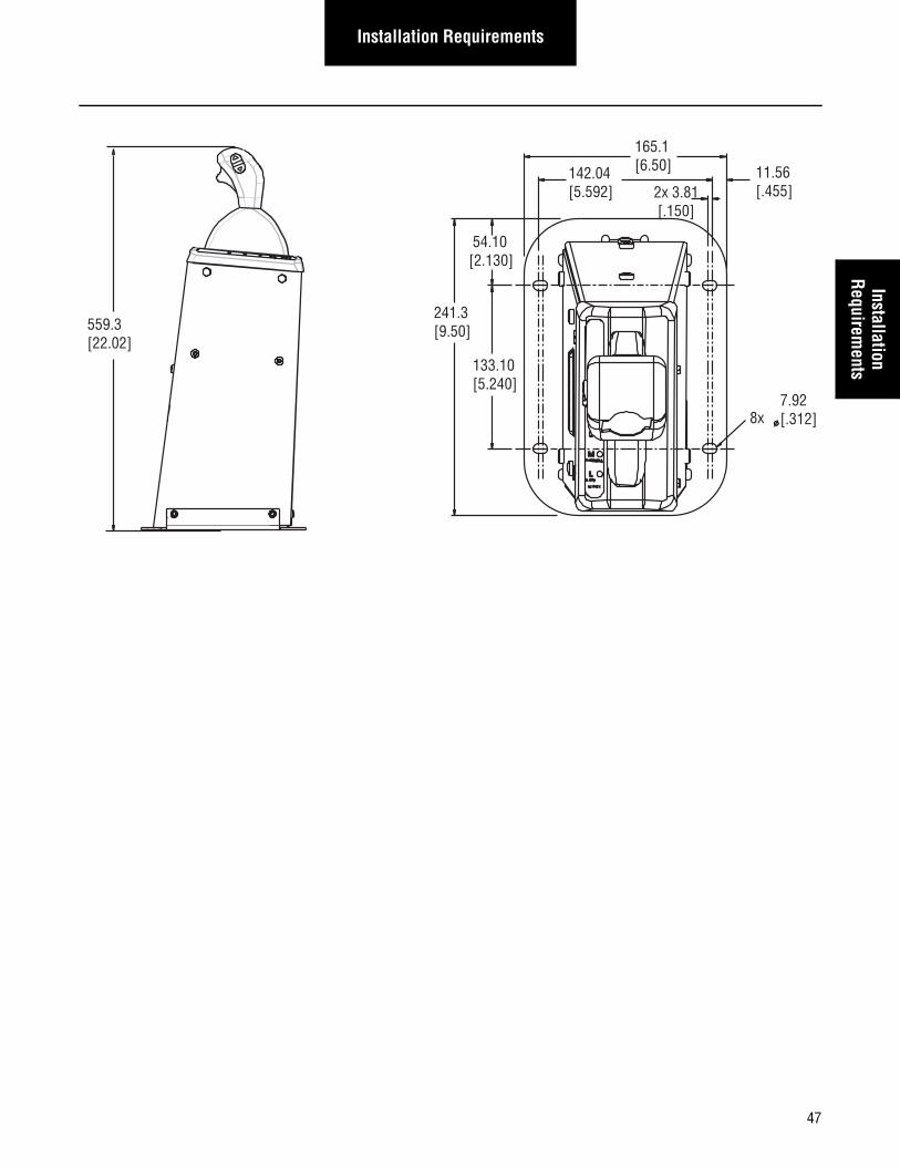
Installation RequirementsInstallation
Requirements
559.3[22.02]
241.3 [9.50]
133.10[5.240]
54.10[2.130]
165.1[6.50]142.04
[5.592]
7.92[.312]8x
11.56 [.455]2x 3.81
[.150]
47
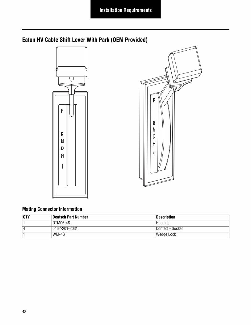
Installation Requirements
Eaton HV Cable Shift Lever With Park (OEM Provided)
Mating Connector Information
QTY Deutsch Part Number Description1 DTM06-4S Housing 4 0462-201-2031 Contact - Socket1 WM-4S Wedge Lock
48
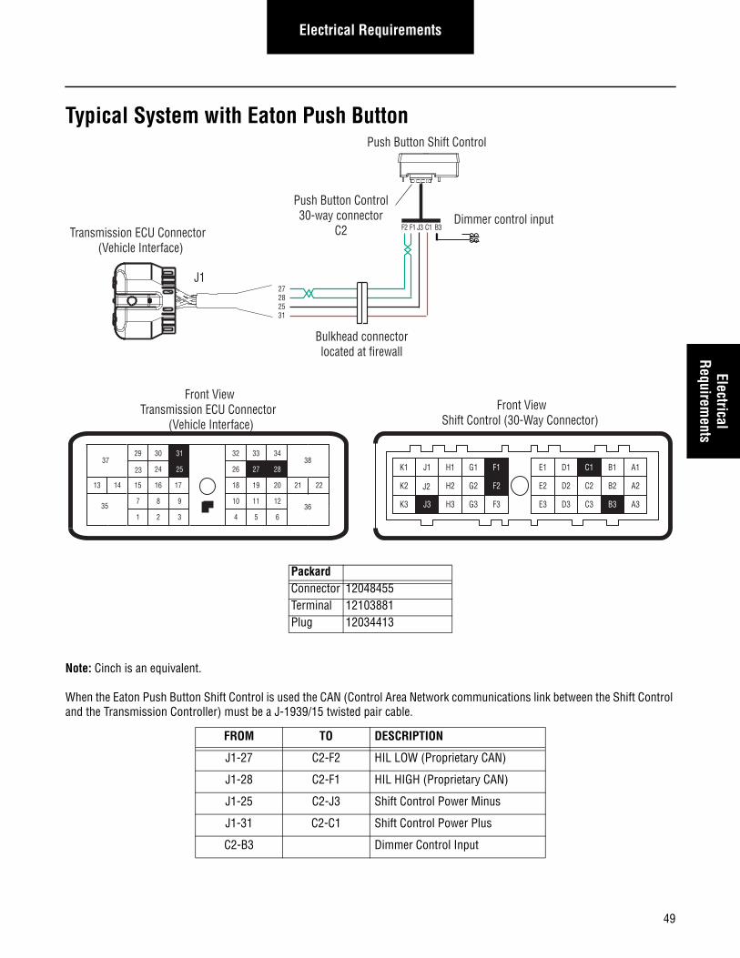
49
Electrical RequirementsElectrical
Requirements
Typical System with Eaton Push Button
Note: Cinch is an equivalent.
When the Eaton Push Button Shift Control is used the CAN (Control Area Network communications link between the Shift Control and the Transmission Controller) must be a J-1939/15 twisted pair cable.
PackardConnector 12048455Terminal 12103881Plug 12034413
FROM TO DESCRIPTION
J1-27 C2-F2 HIL LOW (Proprietary CAN)
J1-28 C2-F1 HIL HIGH (Proprietary CAN)
J1-25 C2-J3 Shift Control Power Minus
J1-31 C2-C1 Shift Control Power Plus
C2-B3 Dimmer Control Input
27282531
31
24 25
29 30
15 16
26
20
34
27 28
32 33
18 19
7
3
8 9
1 2 6
11 12
4 5
2221
38
36
37
13 14
3510
17
23
Front ViewTransmission ECU Connector
(Vehicle Interface)
J1
Dimmer control input
Push Button Shift Control
Push Button Control30-way connector
C2 F 2 F 1 J 3 C 1 B 3
Bulkhead connectorlocated at firewall
A1
A2
A3
B1
B3C3
D1
D2
D3
E1
E2
E3F3
H1
H2
H3
Front ViewShift Control (30-Way Connector)
B2C2
K3
J1K1
K2
G1
G2
G3
J2
C1
J3
F2
F1
Transmission ECU Connector (Vehicle Interface)
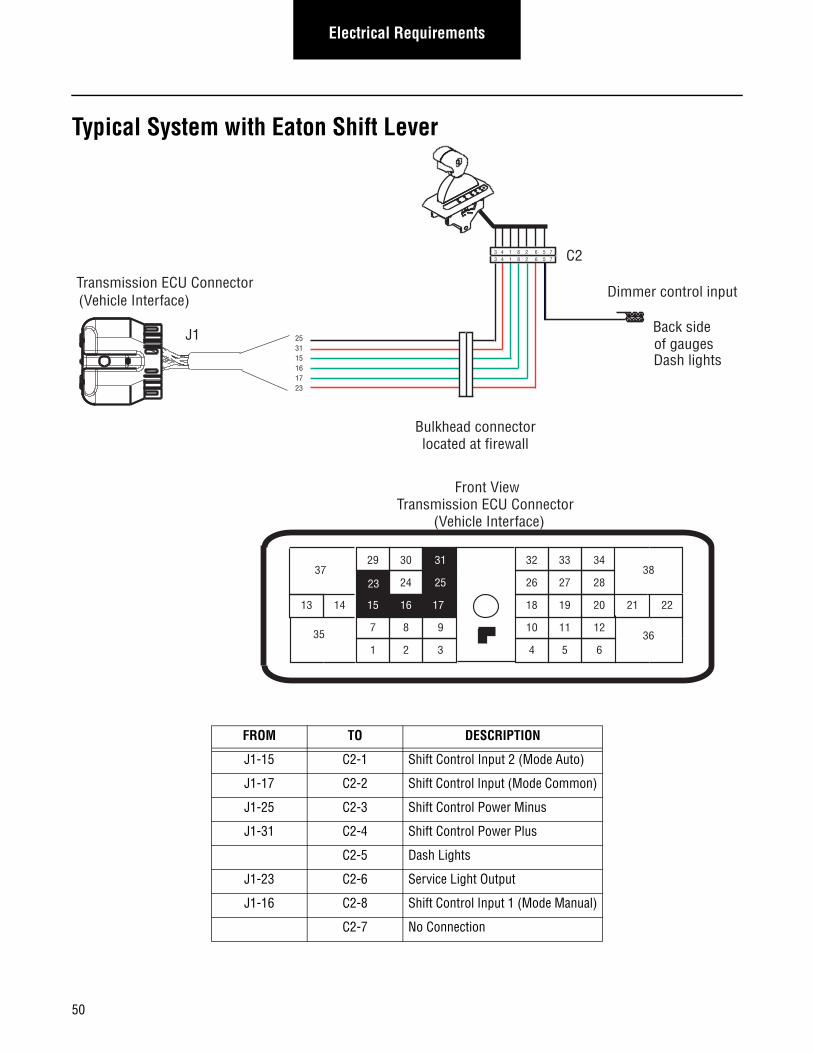
50
Electrical Requirements
Typical System with Eaton Shift Lever
FROM TO DESCRIPTION
J1-15 C2-1 Shift Control Input 2 (Mode Auto)
J1-17 C2-2 Shift Control Input (Mode Common)
J1-25 C2-3 Shift Control Power Minus
J1-31 C2-4 Shift Control Power Plus
C2-5 Dash Lights
J1-23 C2-6 Service Light Output
J1-16 C2-8 Shift Control Input 1 (Mode Manual)
C2-7 No Connection
253115161723
31
24 25
29 30
15 16
26
20
34
27 28
32 33
18 19
7
3
8 9
1 2 6
11 12
4 5
2221
38
36
37
13 14
3510
17
23
Front ViewTransmission ECU Connector
(Vehicle Interface)
J1
C2
Bulkhead connectorlocated at firewall
3 4 1 8 2 6 5 73 4 1 8 2 6 5 7
Back side of gaugesDash lights
Dimmer control inputTransmission ECU Connector (Vehicle Interface)
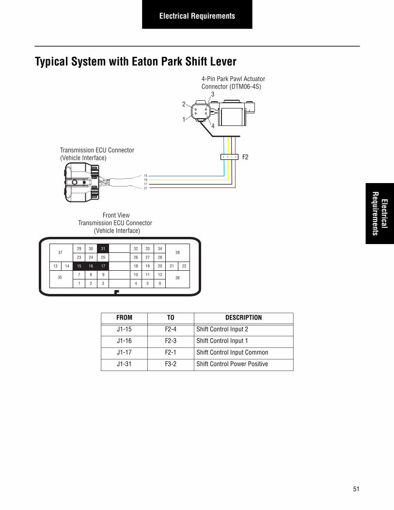
51
Electrical RequirementsElectrical
Requirements
Typical System with Eaton Park Shift Lever
FROM TO DESCRIPTION
J1-15 F2-4 Shift Control Input 2
J1-16 F2-3 Shift Control Input 1
J1-17 F2-1 Shift Control Input Common
J1-31 F3-2 Shift Control Power Positive
15161731
4 3 1 2 F2Transmission ECU Connector (Vehicle Interface)
2
3
41
4-Pin Park Pawl ActuatorConnector (DTM06-4S)
23
17
31
24 25
29 30
15 16
26
20
34
27 28
32 33
18 19
7 8 9
2
10
6
11 12
4 5
2221
38
36
37
13 14
351 3
Front ViewTransmission ECU Connector
(Vehicle Interface)
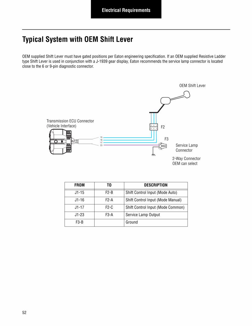
52
Electrical Requirements
Typical System with OEM Shift Lever
OEM supplied Shift Lever must have gated positions per Eaton engineering specification. If an OEM supplied Resistive Ladder type Shift Lever is used in conjunction with a J-1939 gear display, Eaton recommends the service lamp connector is located close to the 6 or 9-pin diagnostic connector.
FROM TO DESCRIPTION
J1-15 F2-B Shift Control Input (Mode Auto)
J1-16 F2-A Shift Control Input (Mode Manual)
J1-17 F2-C Shift Control Input (Mode Common)
J1-23 F3-A Service Lamp Output
F3-B Ground
15161723
B A C
B A C
OEM Shift Lever
Service LampConnector
2-Way ConnectorOEM can select
F2
F3
Transmission ECU Connector (Vehicle Interface)
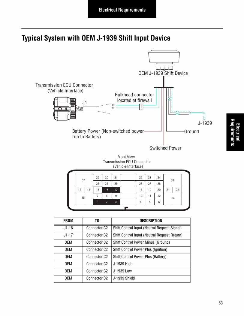
53
Electrical RequirementsElectrical
Requirements
Typical System with OEM J-1939 Shift Input Device
FROM TO DESCRIPTION
J1-16 Connector C2 Shift Control Input (Neutral Request Signal)
J1-17 Connector C2 Shift Control Input (Neutral Request Return)
OEM Connector C2 Shift Control Power Minus (Ground)
OEM Connector C2 Shift Control Power Plus (Ignition)
OEM Connector C2 Shift Control Power Plus (Battery)
OEM Connector C2 J-1939 High
OEM Connector C2 J-1939 Low
OEM Connector C2 J-1939 Shield
23
17
31
24 25
29 30
15 16
26
20
34
27 28
32 33
18 19
7 8 9
2
10
6
11 12
4 5
2221
38
36
37
13 14
351 3
Transmission ECU Connector (Vehicle Interface)
Front View
J1
OEM J-1939 Shift Device
Bulkhead connectorlocated at firewall
J-1939
Transmission ECU Connector (Vehicle Interface)
1617
Switched Power
GroundBattery Power (Non-switched powerrun to Battery)
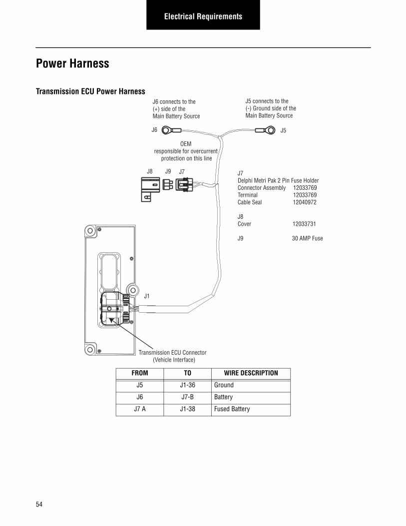
Electrical Requirements
Power Harness
Transmission ECU Power Harness
FROM TO WIRE DESCRIPTION
J5 J1-36 Ground
J6 J7-B Battery
J7 A J1-38 Fused Battery
J6 connects to the (+) side of the Main Battery Source
J5 connects to the (-) Ground side of the Main Battery Source
J6 J5
J8 J9
Transmission ECU Connector (Vehicle Interface)
J1
J7Delphi Metri Pak 2 Pin Fuse HolderConnector Assembly 12033769Terminal 12033769Cable Seal 12040972
J8Cover 12033731
J9 30 AMP Fuse
J7
OEM responsible for overcurrent
protection on this line
54
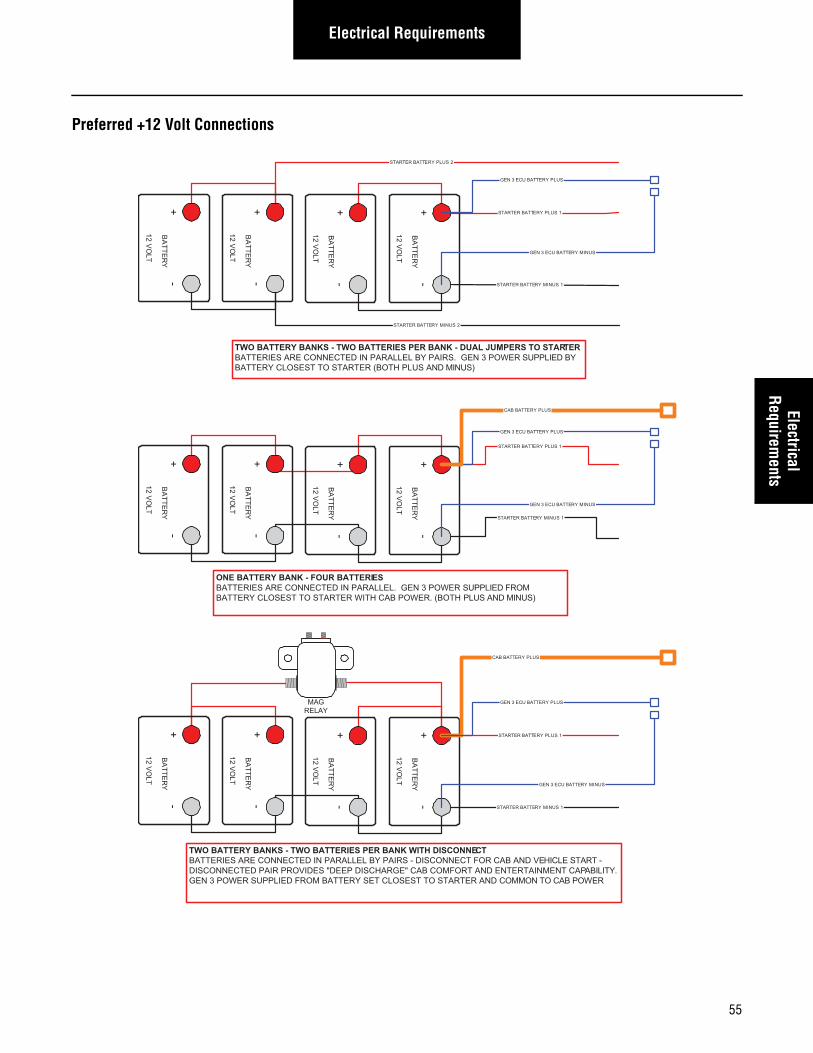
Electrical RequirementsElectrical
Requirements
Preferred +12 Volt Connections
RETRATS TTAB ERY P LUS 2
RETRATS ETTAB RY M INUS 2
RETRATS ETTAB RY M INUS 1
RETRATS TTAB ERY P LUS 1
+-
BA
TTERY
12 VO
LT
+-
BA
TTERY
12 VO
LT
+-
BA
TTERY
12 VO
LT
+-
BA
TTERY
12 VO
LT
RATS OT SREPMUJ LAUD - KNAB REP SEIRETTAB OWT - SKNAB YRETTAB OWT TERREWOP 3 NEG .SRIAP YB LELLARAP NI DETCENNOC ERA SEIRETTAB SUPPLIED BY
A SULP HTOB( RETRATS OT TSESOLC YRETTAB ND MINUS)
RETRATS ETTAB RY M INUS 1
RETRATS TTAB ERY P LUS 1
+-
BA
TTERY
12 VO
LT
+-
BA
TTERY
12 VO
LT
+-
BA
TTERY
12 VO
LT
+-
BA
TTERY
12 VO
LT
AM GLER AY
ENNOCSID HTIW KNAB REP SEIRETTAB OWT - SKNAB YRETTAB OWT CTEV DNA BAC ROF TCENNOCSID - SRIAP YB LELLARAP NI DETCENNOC ERA SEIRETTAB HICLE START -
PAC TNEMNIATRETNE DNA TROFMOC BAC "EGRAHCSID PEED" SEDIVORP RIAP DETCENNOCSID ABILITY.C DNA RETRATS OT TSESOLC TES YRETTAB MORF DEILPPUS REWOP 3 NEG OMMON TO CAB POWER
ETTAB UCE 3 NEG RY MINUS
TAB UCE 3 NEG TERY PLUS
ETTAB UCE 3 NEG RY MINUS
RETRATS ETTAB RY M INUS 1
RETRATS TTAB ERY P LUS 1
+-
BA
TTERY
12 VO
LT
+-
BA
TTERY
12 VO
LT
+-
BA
TTERY
12 VO
LT
+-
BA
TTERY
12 VO
LT
IRETTAB RUOF - KNAB YRETTAB ENO ES REWOP 3 NEG .LELLARAP NI DETCENNOC ERA SEIRETTAB SUPPLIED FROM
HTOB( .REWOP BAC HTIW RETRATS OT TSESOLC YRETTAB PLUS AND MINUS)
TAB UCE 3 NEG TERY PLUS
ETTAB UCE 3 NEG RY MINUS
TTAB BAC ERY PLUS
TAB UCE 3 NEG TERY PLUS
TTAB BAC ERY PLUS
55
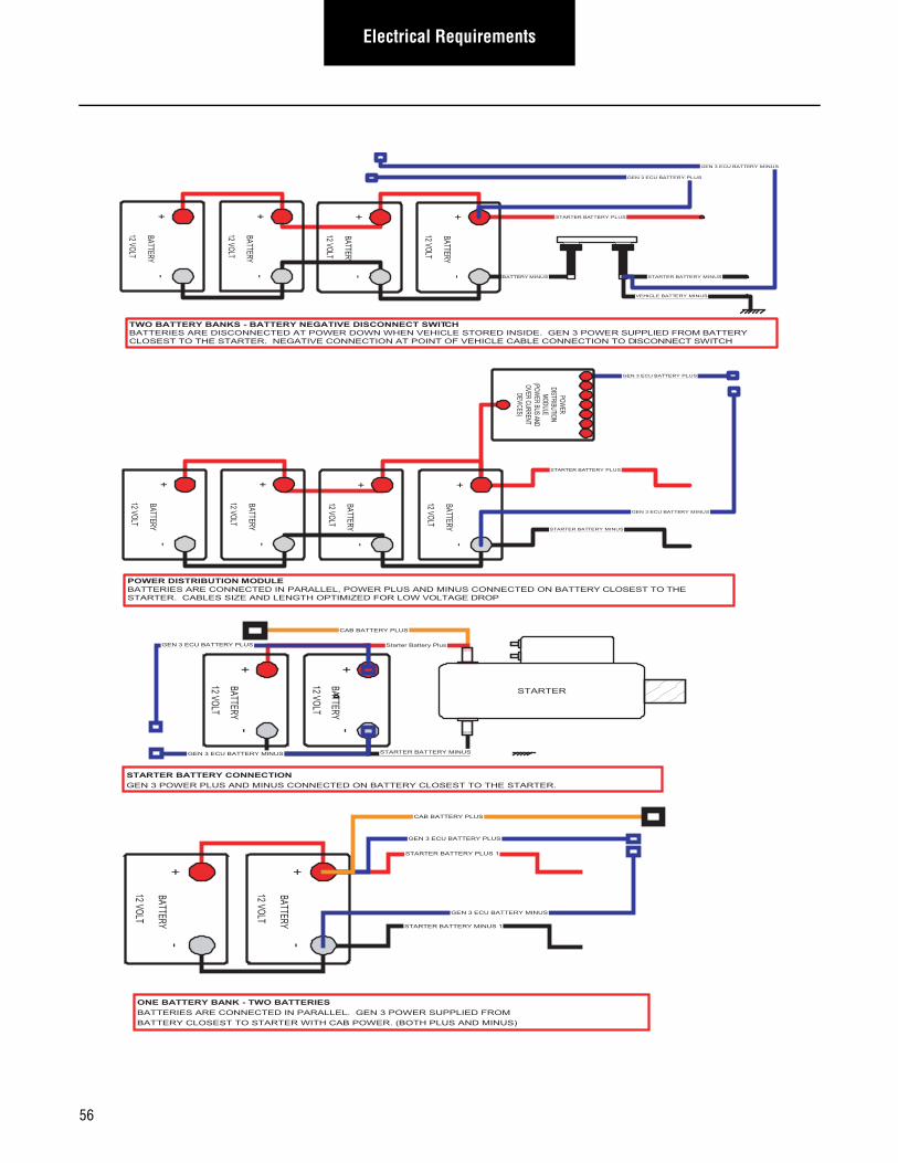
Electrical Requirements
TIWS TCENNOCSID EVITAGEN YRETTAB - SKNAB YRETTAB OWT CHEWOP 3 NEG .EDISNI DEROTS ELCIHEV NEHW NWOD REWOP TA DETCENNOCSID ERA SEIRETTAB R SUPPLIED FROM BATTERY
D OT NOITCENNOC ELBAC ELCIHEV FO TNIOP TA NOITCENNOC EVITAGEN .RETRATS EHT OT TSESOLC ISCONNECT SWITCH
YRETTAB M INUS
AB RETRATS TTERY PLUS
+-
BATTERY
12 VOLT
+-
BATTERY
12 VOLT
+-
BATTERY
12 VOLT
+-
BATTERY
12 VOLT
TAB RETRATS TERY MINUS
TTAB ELCIHEV ERY MINUS
TAB UCE 3 NEG TERY PLUS
ETTAB UCE 3 NEG RY MINUS
TAB RETRATS TERY MINUS
AB RETRATS TTERY PLUS
+-
BATTERY
12 VOLT
+-
BATTERY
12 VOLT
+-
BATTERY
12 VOLT
+-
BATTERY
12 VOLT
NOITUBIRTSID REWOP MODULETTAB NO DETCENNOC SUNIM DNA SULP REWOP ,LELLARAP NI DETCENNOC ERA SEIRETTAB ERY CLO OT TSES EHT
WOL ROF DEZIMITPO HTGNEL DNA EZIS SELBAC .RETRATS VOLTAGE DROP
TAB UCE 3 NEG TERY PLUS
ETTAB UCE 3 NEG RY MINUS
POWERDISTRIBUTION
MODULE(POW
ER BUSANDOVER CURRENT
DEVICES)
STARTER BATTERY MINUS
STARTER
CAB BATTERY PLUS
STARTER BATTERY CONNECTIONGEN 3 POWER PLUS AND MINUS CONNECTED ON BATTERY CLOSEST TO THE STARTER.
+-
BATTERY
12 VOLT
+-
BATTERY
12 VOLT
Starter Battery PlusGEN 3 ECU BATTERY PLUS
GEN 3 ECU BATTERY MINUS
STARTER BATTERY MINUS 1
STARTER BATTERY PLUS 1
+-
BATTERY
12 VOLT
+-
BATTERY
12 VOLT
ONE BATTERY BANK - TWO BATTERIESBATTERIES ARE CONNECTED IN PARALLEL. GEN 3 POWER SUPPLIED FROMBATTERY CLOSEST TO STARTER WITH CAB POWER. (BOTH PLUS AND MINUS)
GEN 3 ECU BATTERY PLUS
GEN 3 ECU BATTERY MINUS
CAB BATTERY PLUS
56
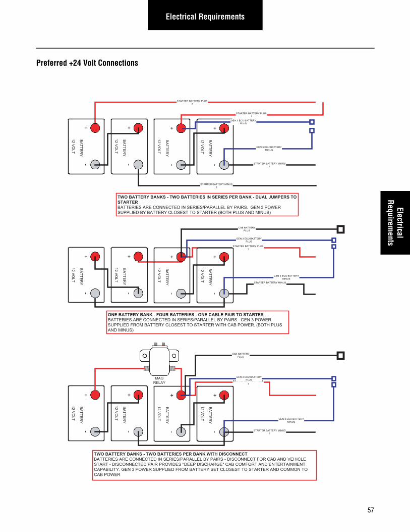
Electrical RequirementsElectrical
Requirements
Preferred +24 Volt Connections
STARTER BATTERY PLUS 2
STARTER BATTERY MINUS 2
STARTER BATTERY MINUS 1
+ -
BATTERY
12 VOLT
+ -
BATTERY
12 VOLT
+ -
BATTERY
12 VOLT
+ -
BATTERY
12 VOLT
TWO BATTERY BANKS - TWO BATTERIES IN SERIES PER BANK - DUAL JUMPERS TO STARTER BATTERIES ARE CONNECTED IN SERIES/PARALLEL BY PAIRS. GEN 3 POWER SUPPLIED BY BATTERY CLOSEST TO STARTER (BOTH PLUS AND MINUS)
+ -
BATTERY
12 VOLT
+ -
BATTERY
12 VOLT
+ -
BATTERY
12 VOLT
+ -
BATTERY
12 VOLT
MAG RELAY
TWO BATTERY BANKS - TWO BATTERIES PER BANK WITH DISCONNECT BATTERIES ARE CONNECTED IN SERIES/PARALLEL BY PAIRS - DISCONNECT FOR CAB AND VEHICLE START - DISCONNECTED PAIR PROVIDES "DEEP DISCHARGE" CAB COMFORT AND ENTERTAINMENT CAPABILITY. GEN 3 POWER SUPPLIED FROM BATTERY SET CLOSEST TO STARTER AND COMMON TO CAB POWER
GEN 3 ECU BATTERY PLUS
GEN 3 ECU BATTERY MINUS
STARTER BATTERY MINUS 1
STARTER BATTERY PLUS 1
+ -
BATTERY
12 VOLT
+ -
BATTERY
12 VOLT
+ -
BATTERY
12 VOLT
+ -
BATTERY
12 VOLT
ONE BATTERY BANK - FOUR BATTERIES - ONE CABLE PAIR TO STARTER BATTERIES ARE CONNECTED IN SERIES/PARALLEL BY PAIRS. GEN 3 POWER SUPPLIED FROM BATTERY CLOSEST TO STARTER WITH CAB POWER. (BOTH PLUS AND MINUS)
GEN 3 ECU BATTERY PLUS
GEN 3 ECU BATTERY MINUS
CAB BATTERY PLUS
STARTER BATTERY PLUS 1
STARTER BATTERY MINUS 1
STARTER BATTERY PLUS 1
GEN 3 ECU BATTERY MINUS
CAB BATTERY PLUS
GEN 3 ECU BATTERY PLUS
57
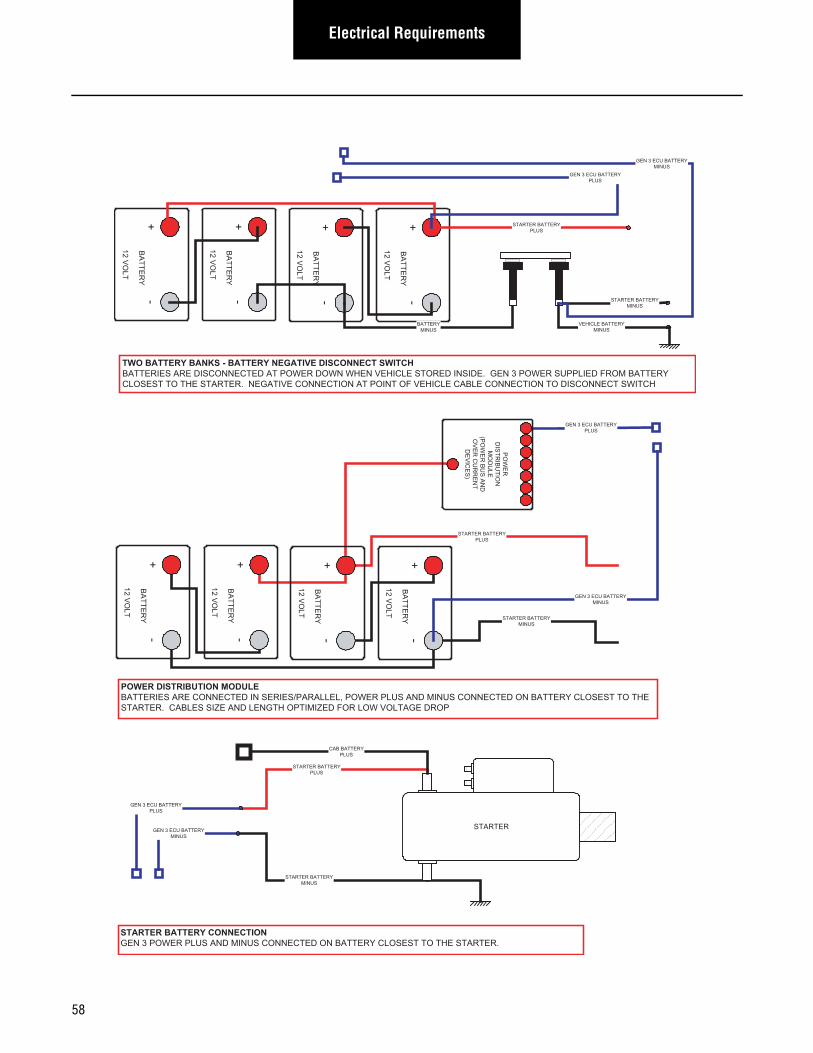
Electrical Requirements
+-
BA
TTER
Y
12 VO
LT
+-
BA
TTER
Y
12 VO
LT
+-
BA
TTER
Y
12 VO
LT
+-
BA
TTER
Y
12 VO
LT
TWO BATTERY BANKS - BATTERY NEGATIVE DISCONNECT SWITCHBATTERIES ARE DISCONNECTED AT POWER DOWN WHEN VEHICLE STORED INSIDE. GEN 3 POWER SUPPLIED FROM BATTERYCLOSEST TO THE STARTER. NEGATIVE CONNECTION AT POINT OF VEHICLE CABLE CONNECTION TO DISCONNECT SWITCH
BATTERYMINUS
STARTER BATTERYPLUS
STARTER BATTERYMINUS
VEHICLE BATTERYMINUS
GEN 3 ECU BATTERYPLUS
GEN 3 ECU BATTERYMINUS
STARTER BATTERYMINUS
STARTER BATTERYPLUS
+-
BA
TTER
Y
12 VO
LT
+-
BA
TTER
Y
12 VO
LT
+-
BA
TTER
Y
12 VO
LT
+-
BA
TTER
Y
12 VO
LT
POWER DISTRIBUTION MODULEBATTERIES ARE CONNECTED IN SERIES/PARALLEL, POWER PLUS AND MINUS CONNECTED ON BATTERY CLOSEST TO THESTARTER. CABLES SIZE AND LENGTH OPTIMIZED FOR LOW VOLTAGE DROP
GEN 3 ECU BATTERYPLUS
GEN 3 ECU BATTERYMINUS
PO
WE
RD
ISTR
IBU
TION
MO
DU
LE(P
OW
ER
BU
S A
ND
OV
ER
CU
RR
EN
TD
EV
ICE
S)
STARTER BATTERYMINUS
STARTER BATTERYPLUS
STARTER
CAB BATTERYPLUS
GEN 3 ECU BATTERYMINUS
GEN 3 ECU BATTERYPLUS
STARTER BATTERY CONNECTIONGEN 3 POWER PLUS AND MINUS CONNECTED ON BATTERY CLOSEST TO THE STARTER.
58
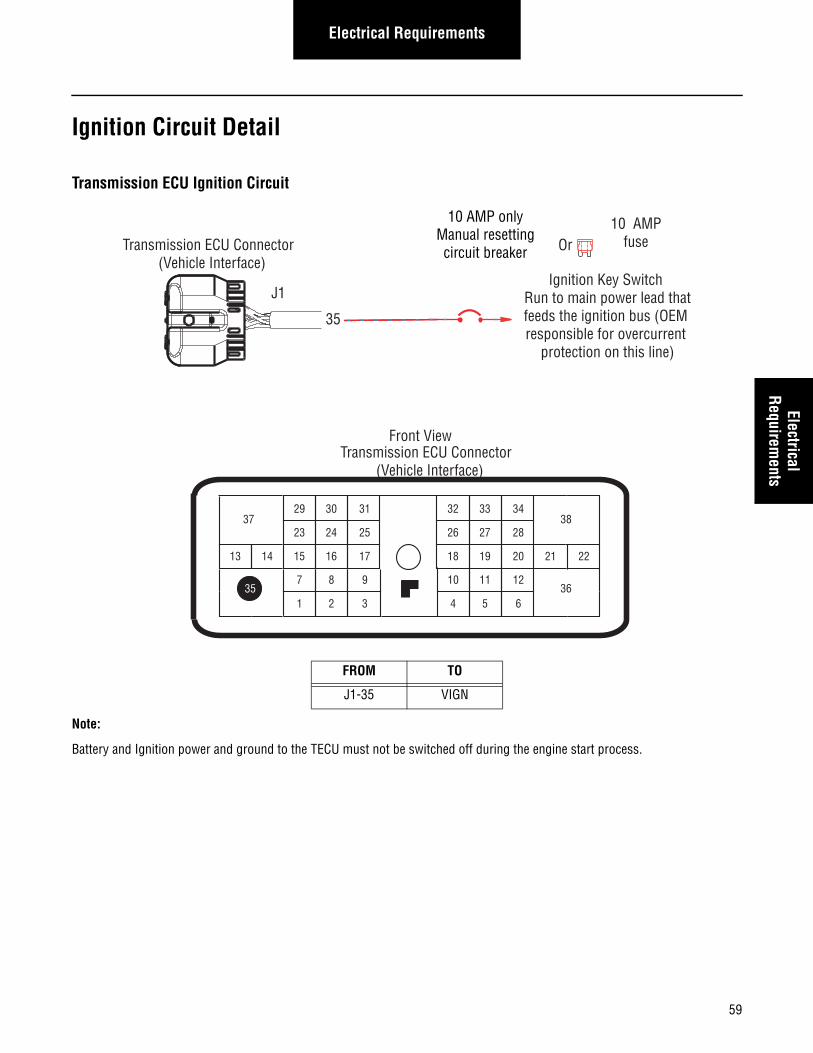
59
Electrical RequirementsElectrical
Requirements
Ignition Circuit Detail
Transmission ECU Ignition Circuit
Note:
Battery and Ignition power and ground to the TECU must not be switched off during the engine start process.
FROM TO
J1-35 VIGN
10 AMP onlyManual resettingcircuit breaker
10 AMPfuseOr
35
23
17
31
24 25
29 30
15 16
26
20
34
27 28
32 33
18 19
7
3
8 9
1 2
10
6
11 12
4 5
2221
38
36
37
13 14
35
Front ViewTransmission ECU Connector
(Vehicle Interface)
Transmission ECU Connector (Vehicle Interface)
J1Ignition Key Switch
Run to main power lead thatfeeds the ignition bus (OEM responsible for overcurrent
protection on this line)
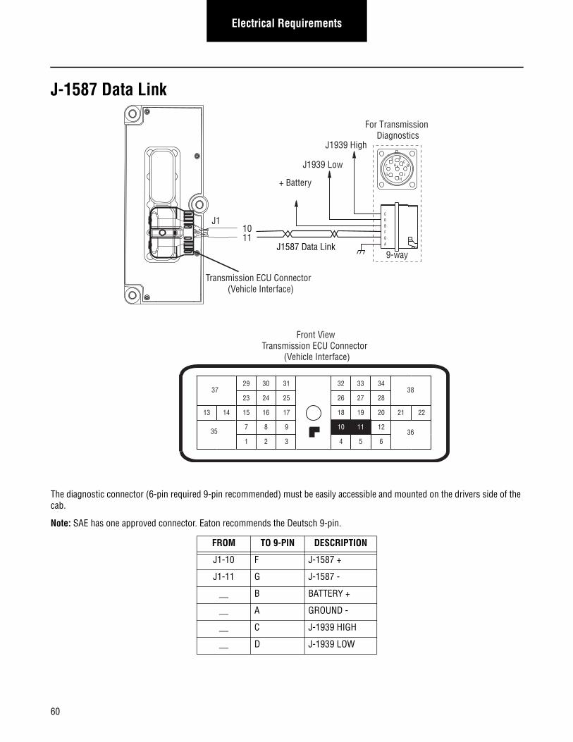
60
Electrical Requirements
J-1587 Data Link
The diagnostic connector (6-pin required 9-pin recommended) must be easily accessible and mounted on the drivers side of the cab.
Note: SAE has one approved connector. Eaton recommends the Deutsch 9-pin.
FROM TO 9-PIN DESCRIPTION
J1-10 F J-1587 +
J1-11 G J-1587 -
__ B BATTERY +
__ A GROUND -
__ C J-1939 HIGH
__ D J-1939 LOW
+ Battery
For Transmission Diagnostics
J1587 Data Link
1011
CDBFGA
9-way
AF
J
E
GH
DC
B
23
17
31
24 25
29 30
15 16
26
20
34
27 28
32 33
18 19
7
3
8 9
1 2 6
12
4 5
2221
38
36
37
13 14
3510 11
J1
Front ViewTransmission ECU Connector
(Vehicle Interface)
J1939 Low
J1939 High
Transmission ECU Connector
(Vehicle Interface)
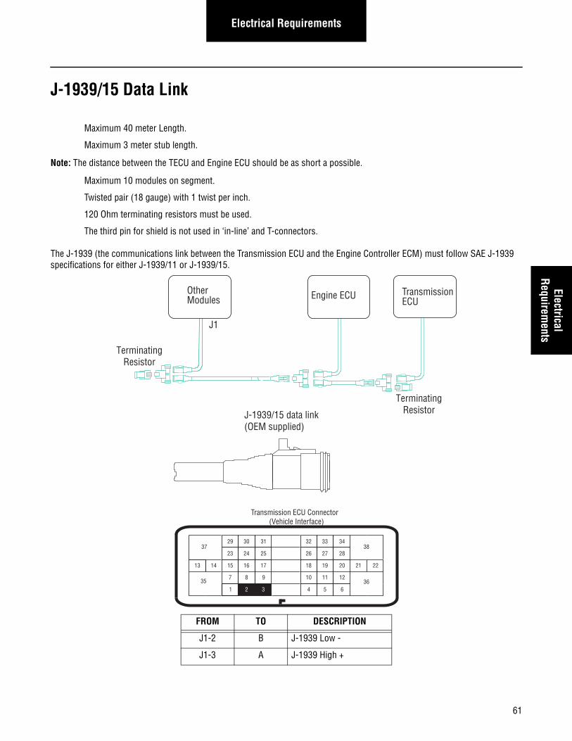
Electrical RequirementsElectrical
Requirements
J-1939/15 Data Link
Maximum 40 meter Length.
Maximum 3 meter stub length.
Note: The distance between the TECU and Engine ECU should be as short a possible.
Maximum 10 modules on segment.
Twisted pair (18 gauge) with 1 twist per inch.
120 Ohm terminating resistors must be used.
The third pin for shield is not used in ‘in-line’ and T-connectors.
The J-1939 (the communications link between the Transmission ECU and the Engine Controller ECM) must follow SAE J-1939 specifications for either J-1939/11 or J-1939/15.
FROM TO DESCRIPTION
J1-2 B J-1939 Low -
J1-3 A J-1939 High +
TerminatingResistorJ-1939/15 data link
(OEM supplied)
TerminatingResistor
Other Modules
J1
Engine ECU TransmissionECU
23
17
31
24 25
29 30
15 16
26
20
34
27 28
32 33
18 19
7 8 9
2
10
6
11 12
4 5
2221
38
36
37
13 14
351 3
Transmission ECU Connector (Vehicle Interface)
61
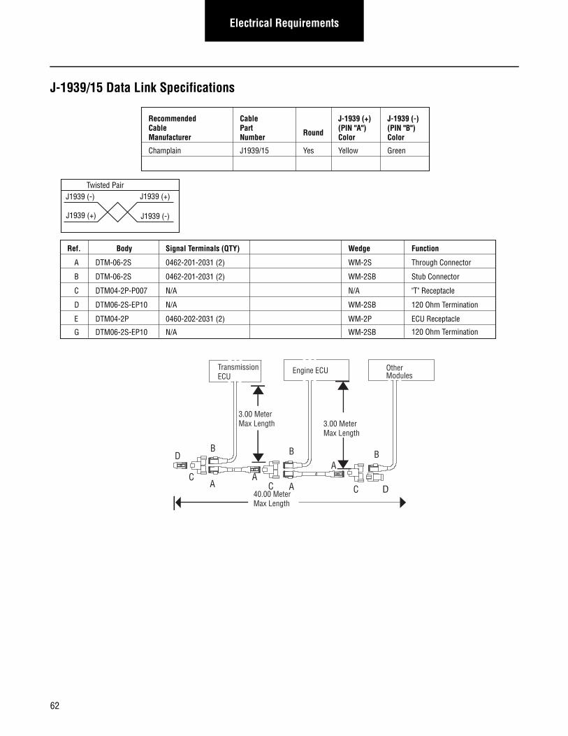
Electrical Requirements
J-1939/15 Data Link Specifications
Engine ECU
A
B
C
D
E
Ref. Body Signal Terminals (QTY)
A
D
AA
A
B B
Wedge
CC
DTM-06-2S
DTM-06-2S
DTM04-2P-P007
DTM06-2S-EP10
DTM04-2P
Function
Through Connector
Stub Connector
"T" Receptacle
120 Ohm Termination
120 Ohm Termination
ECU Receptacle
0462-201-2031 (2)
0462-201-2031 (2)
N/A
0460-202-2031 (2)
WM-2S
WM-2SB
N/A
N/A
WM-2SB
WM-2P
G DTM06-2S-EP10 N/A WM-2SB
3.00 MeterMax Length
3.00 MeterMax Length
40.00 MeterMax Length
TransmissionECU
B
C D
Other Modules
Recommended Cable Manufacturer
Cable Part Number Round
J-1939 (+)(PIN "A")Color
J-1939 (-)(PIN "B")Color
Champlain J1939/15 Yes Yellow Green
Twisted PairJ1939 (+)J1939 (-)
J1939 (-)J1939 (+)
62
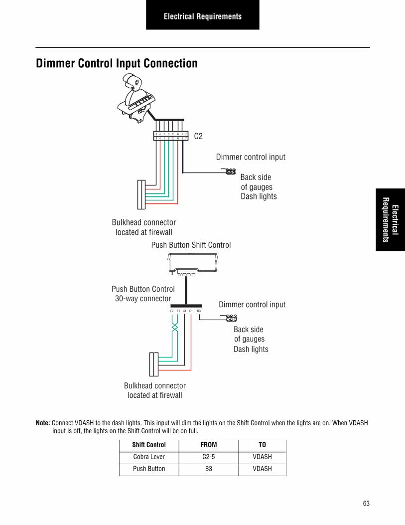
63
Electrical RequirementsElectrical
Requirements
Dimmer Control Input Connection
Note: Connect VDASH to the dash lights. This input will dim the lights on the Shift Control when the lights are on. When VDASH input is off, the lights on the Shift Control will be on full.
Shift Control FROM TO
Cobra Lever C2-5 VDASH
Push Button B3 VDASH
C2
Bulkhead connectorlocated at firewall
3 4 1 8 2 6 5 73 4 1 8 2 6 5 7
Back side of gaugesDash lights
Dimmer control input
Bulkhead connectorlocated at firewall
Back side of gaugesDash lights
Dimmer control input
Push Button Shift Control
Push Button Control30-way connector
F2 F1 J3 C1 B3
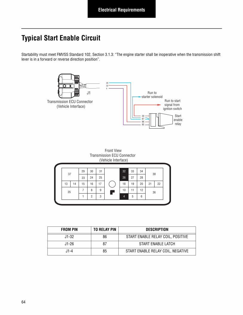
Electrical Requirements
Typical Start Enable Circuit
Startability must meet FMVSS Standard 102, Section 3.1.3: “The engine starter shall be inoperative when the transmission shift lever is in a forward or reverse direction position”.
FROM PIN TO RELAY PIN DESCRIPTION
J1-32 86 START ENABLE RELAY COIL, POSITIVE
J1-26 87 START ENABLE LATCH
J1-4 85 START ENABLE RELAY COIL, NEGATIVE
26324
31
24 25
29 30
15 16 20
34
27 28
33
18 19
7
3
8 9
1 2 6
11 12
5
2221
38
36
37
13 14
3510
26
32
4
17
23
Front ViewTransmission ECU Connector
(Vehicle Interface)
Transmission ECU Connector (Vehicle Interface)
J1
Startenablerelay
Run to startsignal from
igntion switch
30878685
Run tostarter solenoid
64
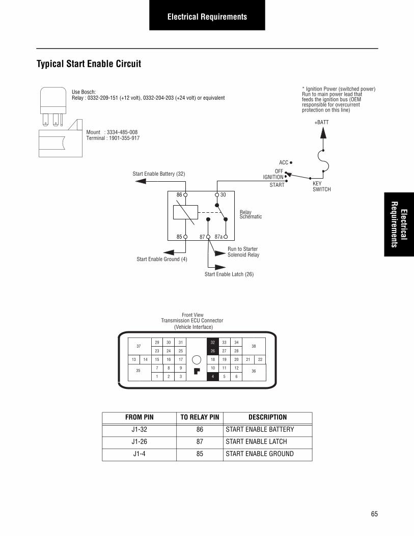
Electrical RequirementsElectrical
Requirements
Typical Start Enable Circuit
FROM PIN TO RELAY PIN DESCRIPTION
J1-32 86 START ENABLE BATTERY
J1-26 87 START ENABLE LATCH
J1-4 85 START ENABLE GROUND
Use Bosch:Relay : 0332-209-151 (+12 volt), 0332-204-203 (+24 volt) or equivalent
Mount : 3334-485-008Terminal : 1901-355-917
86 30
85 87a87
Start Enable Battery (32)
Run to StarterSolenoid Relay
+BATT
KEYSWITCH
ACC
OFF
START
Relay Schematic
Start Enable Latch (26)
Start Enable Ground (4)
Front View
23
17
31
24 25
29 30
15 16 20
34
27 28
33
18 19
7
3
8 9
1 2
10
6
11 12
5
2221
38
36
37
13 14
35
32
26
4
* Ignition Power (switched power)Run to main power lead thatfeeds the ignition bus (OEM responsible for overcurrent protection on this line)
Transmission ECU Connector (Vehicle Interface)
IGNITION
65
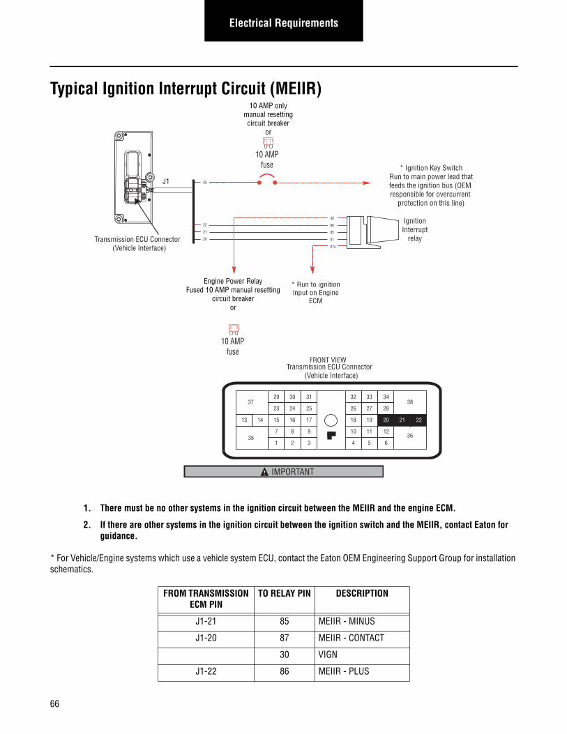
Electrical Requirements
Typical Ignition Interrupt Circuit (MEIIR)
1. There must be no other systems in the ignition circuit between the MEIIR and the engine ECM.
2. If there are other systems in the ignition circuit between the ignition switch and the MEIIR, contact Eaton for guidance.
* For Vehicle/Engine systems which use a vehicle system ECU, contact the Eaton OEM Engineering Support Group for installation schematics.
FROM TRANSMISSION ECM PIN
TO RELAY PIN DESCRIPTION
J1-21 85 MEIIR - MINUS
J1-20 87 MEIIR - CONTACT
30 VIGN
J1-22 86 MEIIR - PLUS
IgnitionInterrupt
relay
30
86
85
87
87a
* Ignition Key Switch Run to main power lead thatfeeds the ignition bus (OEM responsible for overcurrent
protection on this line)
10 AMP onlymanual resettingcircuit breaker
or
10 AMPfuse
* Run to ignitioninput on Engine
ECM
35
22
21
20
Engine Power RelayFused 10 AMP manual resetting
circuit breakeror
10 AMPfuse
Transmission ECU Connector (Vehicle Interface)
J1
FRONT VIEW
23
17
31
24 25
29 30
15 16 20
34
27 28
33
18 19
7
3
8 9
1 2
10
6
11 12
5
2221
38
36
37
13 14
35
32
26
4
Transmission ECU Connector (Vehicle Interface)
IMPORTANT
66
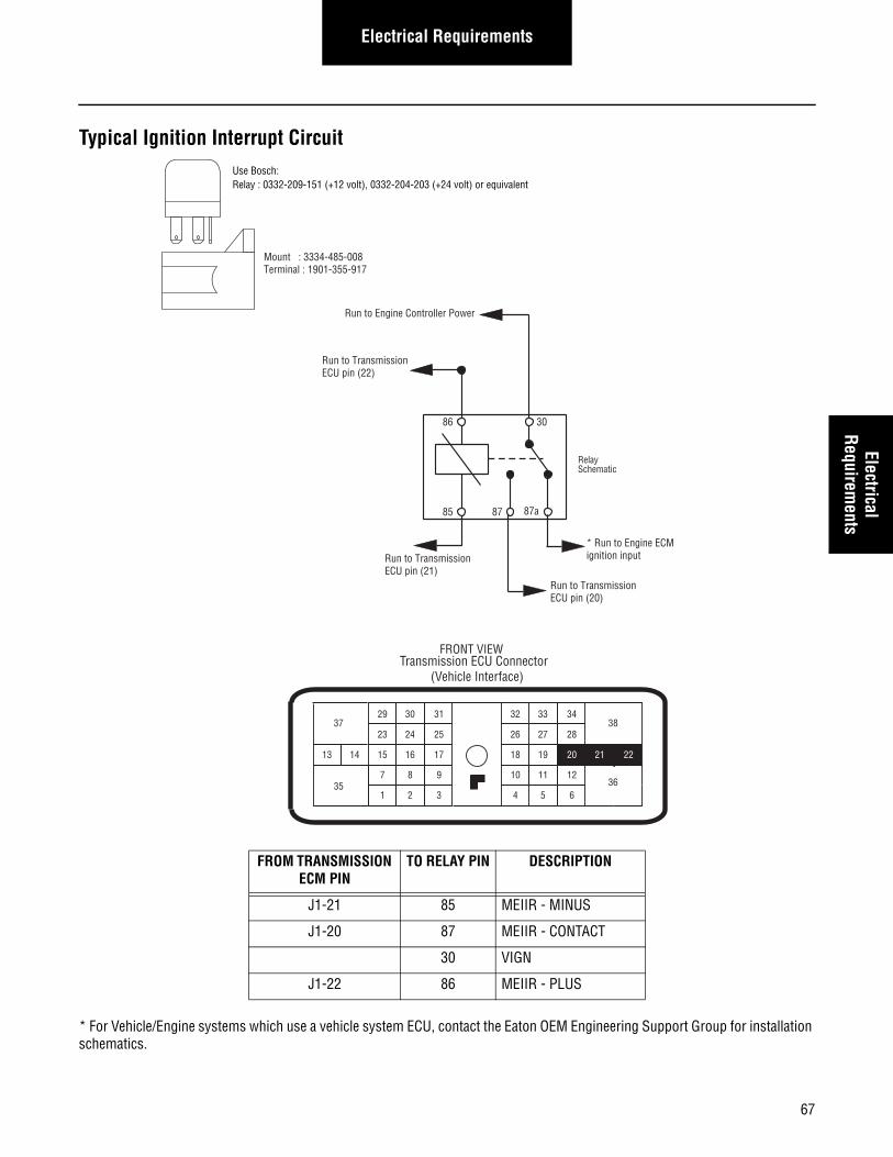
Electrical RequirementsElectrical
Requirements
Typical Ignition Interrupt Circuit
* For Vehicle/Engine systems which use a vehicle system ECU, contact the Eaton OEM Engineering Support Group for installation schematics.
FROM TRANSMISSION ECM PIN
TO RELAY PIN DESCRIPTION
J1-21 85 MEIIR - MINUS
J1-20 87 MEIIR - CONTACT
30 VIGN
J1-22 86 MEIIR - PLUS
Use Bosch:Relay : 0332-209-151 (+12 volt), 0332-204-203 (+24 volt) or equivalent
Mount : 3334-485-008Terminal : 1901-355-917
86 30
85 87a87
* Run to Engine ECMignition input
Relay Schematic
Run to TransmissionECU pin (22)
Run to Engine Controller Power
Run to TransmissionECU pin (20)
Run to TransmissionECU pin (21)
FRONT VIEW
23
17
31
24 25
29 30
15 16 20
34
27 28
33
18 19
7
3
8 9
1 2
10
6
11 12
5
2221
38
36
37
13 14
35
32
26
4
Transmission ECU Connector (Vehicle Interface)
67
Electrical Requirements
Vehicle Harness Routing
Requirements
Harness and in-line connectors shall be anchored to prevent free movement. An anchor point shall be no further than 6 in. [15.24 cm] (recommended 3 in. [7.62 cm]) from a connector. The length of an unanchored section of harness should be no more than 12 in. [30.48 cm].
Use tie wraps on harness covering only, not individual wires. Do not anchor harness with tie wraps in contact with wire insula-tion. Tie wraps shall not pull on the harness so that connector cable seals are distorted. Allow cable to exit connector body with out pulling on the connector. A bend radius of six times the harness diameter is recommended.
Recommended use of the fixed clip points on OEM harness - Fir trees, J-clips, P-clips.
Harness routing shall not interfere with oil fill plugs, sensor locations, or manufacturing fixtures.
Ensure that all connectors are fully mated and that latches are locked. All connector jackscrews must be properly torqued. To pre-vent cross threading start all capscrews and nuts by hand then use a DC torque driver.
All unused connectors require sealed mated connectors.
There should be nothing mounted to the TECU, brackets, mounting studs, or contacting the TECU case electrically or mechani-cally.
The transmission wire harness should not be tie wrapped to any cables or hoses. Anchor points on the transmission may be used as long as addition of cables or hoses do not interfere with the existing harness.
68
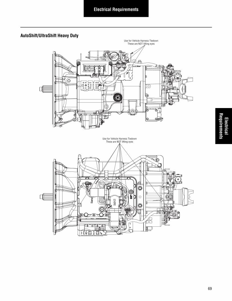
Electrical RequirementsElectrical
Requirements
AutoShift/UltraShift Heavy Duty
Use for Vehicle Harness TiedownThese are NOT lifting eyes
Use for Vehicle Harness TiedownThese are NOT lifting eyes
69
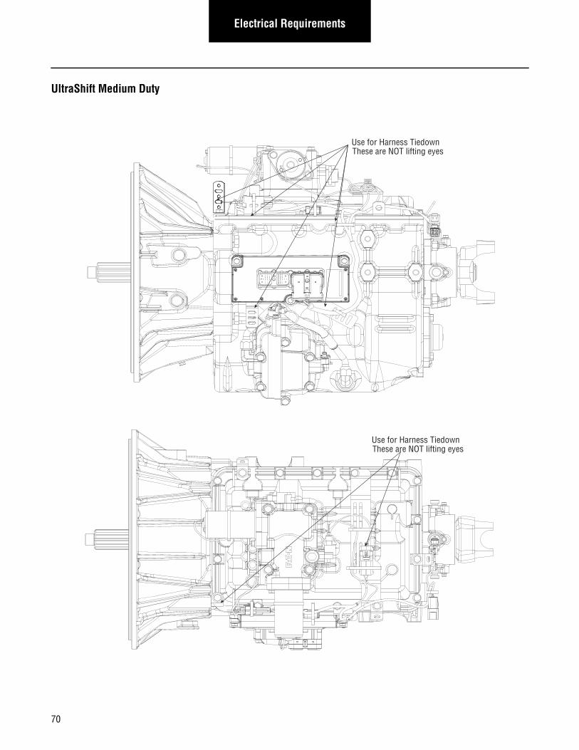
Electrical Requirements
UltraShift Medium Duty
Use for Harness TiedownThese are NOT lifting eyes
Use for Harness TiedownThese are NOT lifting eyes
70
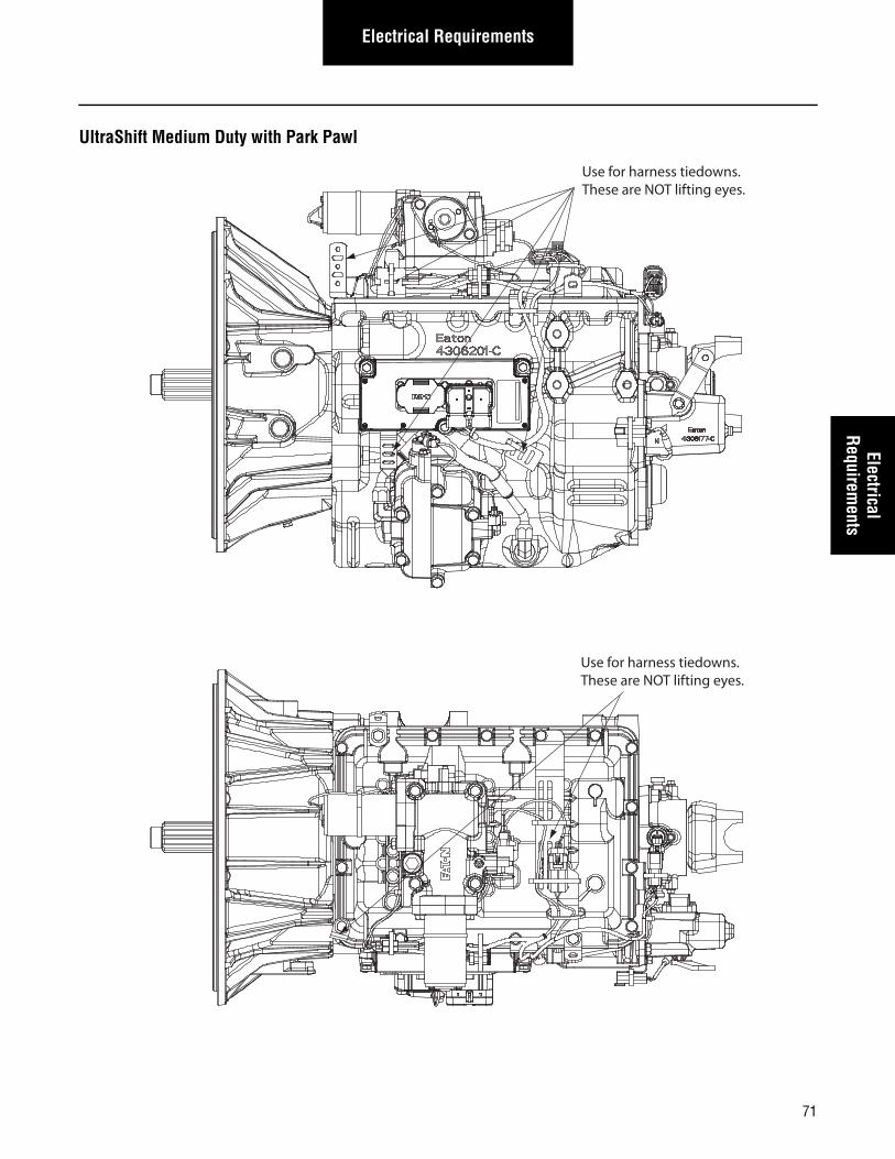
Electrical RequirementsElectrical
Requirements
UltraShift Medium Duty with Park Pawl
Use for harness tiedowns.These are NOT lifting eyes.
Use for harness tiedowns.These are NOT lifting eyes.
71
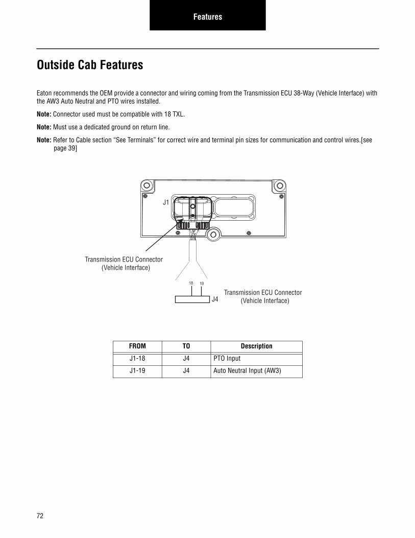
72
Features
Outside Cab Features
Eaton recommends the OEM provide a connector and wiring coming from the Transmission ECU 38-Way (Vehicle Interface) with the AW3 Auto Neutral and PTO wires installed.
Note: Connector used must be compatible with 18 TXL.
Note: Must use a dedicated ground on return line.
Note: Refer to Cable section “See Terminals” for correct wire and terminal pin sizes for communication and control wires.[see page 39]
FROM TO Description
J1-18 J4 PTO Input
J1-19 J4 Auto Neutral Input (AW3)
J1
18
Transmission ECU Connector (Vehicle Interface)
Transmission ECU Connector (Vehicle Interface)
19
J4
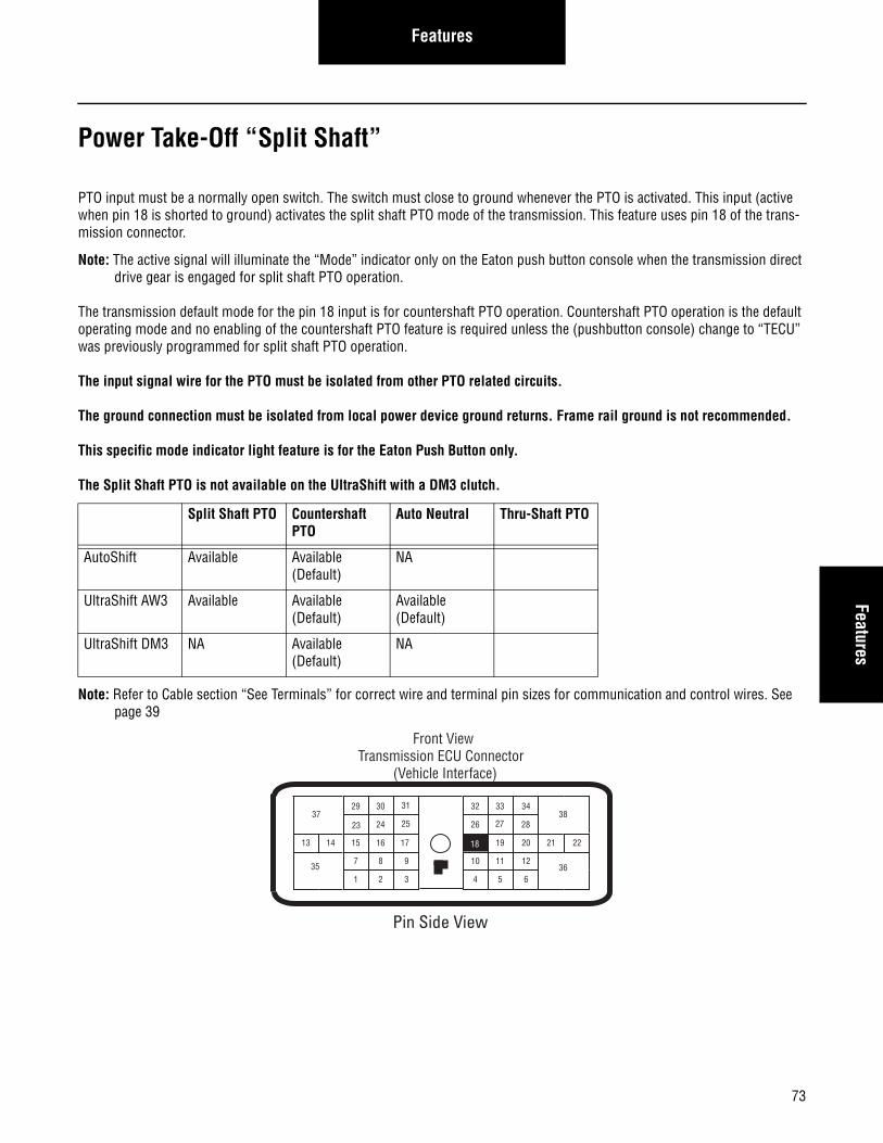
73
FeaturesFeatures
Power Take-Off “Split Shaft”
PTO input must be a normally open switch. The switch must close to ground whenever the PTO is activated. This input (active when pin 18 is shorted to ground) activates the split shaft PTO mode of the transmission. This feature uses pin 18 of the trans-mission connector.
Note: The active signal will illuminate the “Mode” indicator only on the Eaton push button console when the transmission direct drive gear is engaged for split shaft PTO operation.
The transmission default mode for the pin 18 input is for countershaft PTO operation. Countershaft PTO operation is the default operating mode and no enabling of the countershaft PTO feature is required unless the (pushbutton console) change to “TECU” was previously programmed for split shaft PTO operation.
The input signal wire for the PTO must be isolated from other PTO related circuits.
The ground connection must be isolated from local power device ground returns. Frame rail ground is not recommended.
This specific mode indicator light feature is for the Eaton Push Button only.
The Split Shaft PTO is not available on the UltraShift with a DM3 clutch.
Note: Refer to Cable section “See Terminals” for correct wire and terminal pin sizes for communication and control wires. See page 39
Split Shaft PTO Countershaft PTO
Auto Neutral Thru-Shaft PTO
AutoShift Available Available (Default)
NA
UltraShift AW3 Available Available (Default)
Available (Default)
UltraShift DM3 NA Available (Default)
NA
24
29 30
15 16
26
20
3432 33
19
7
3
8 9
1 2 6
11 12
4 5
2221
38
36
37
13 14
3510
17
23
Front ViewTransmission ECU Connector
(Vehicle Interface)
31
25 2827
18
Pin Side View
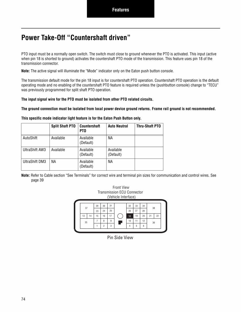
74
Features
Power Take-Off “Countershaft driven”
PTO input must be a normally open switch. The switch must close to ground whenever the PTO is activated. This input (active when pin 18 is shorted to ground) activates the countershaft PTO mode of the transmission. This feature uses pin 18 of the transmission connector.
Note: The active signal will illuminate the “Mode” indicator only on the Eaton push button console.
The transmission default mode for the pin 18 input is for countershaft PTO operation. Countershaft PTO operation is the default operating mode and no enabling of the countershaft PTO feature is required unless the (pushbutton console) change to “TECU” was previously programmed for split shaft PTO operation.
The input signal wire for the PTO must be isolated from other PTO related circuits.
The ground connection must be isolated from local power device ground returns. Frame rail ground is not recommended.
This specific mode indicator light feature is for the Eaton Push Button only.
Note: Refer to Cable section “See Terminals” for correct wire and terminal pin sizes for communication and control wires. See page 39
Split Shaft PTO Countershaft PTO
Auto Neutral Thru-Shaft PTO
AutoShift Available Available (Default)
NA
UltraShift AW3 Available Available (Default)
Available (Default)
UltraShift DM3 NA Available (Default)
NA
24
29 30
15 16
26
20
3432 33
19
7
3
8 9
1 2 6
11 12
4 5
2221
38
36
37
13 14
3510
17
23
Front ViewTransmission ECU Connector
(Vehicle Interface)
31
25 2827
18
Pin Side View
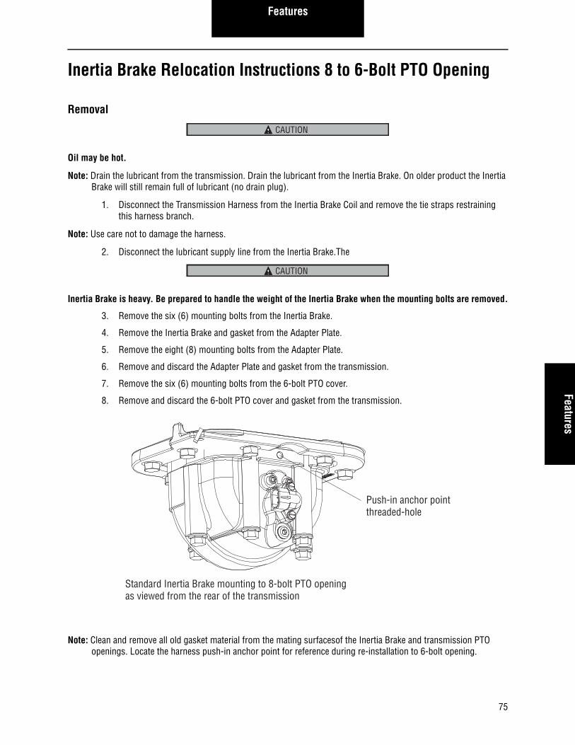
Features Features
Inertia Brake Relocation Instructions 8 to 6-Bolt PTO Opening
Removal
Oil may be hot.
Note: Drain the lubricant from the transmission. Drain the lubricant from the Inertia Brake. On older product the Inertia Brake will still remain full of lubricant (no drain plug).
1. Disconnect the Transmission Harness from the Inertia Brake Coil and remove the tie straps restraining this harness branch.
Note: Use care not to damage the harness.
2. Disconnect the lubricant supply line from the Inertia Brake.The
Inertia Brake is heavy. Be prepared to handle the weight of the Inertia Brake when the mounting bolts are removed.
3. Remove the six (6) mounting bolts from the Inertia Brake.
4. Remove the Inertia Brake and gasket from the Adapter Plate.
5. Remove the eight (8) mounting bolts from the Adapter Plate.
6. Remove and discard the Adapter Plate and gasket from the transmission.
7. Remove the six (6) mounting bolts from the 6-bolt PTO cover.
8. Remove and discard the 6-bolt PTO cover and gasket from the transmission.
Note: Clean and remove all old gasket material from the mating surfacesof the Inertia Brake and transmission PTO openings. Locate the harness push-in anchor point for reference during re-installation to 6-bolt opening.
CAUTION
CAUTION
Push-in anchor pointthreaded-hole
Standard Inertia Brake mounting to 8-bolt PTO openingas viewed from the rear of the transmission
75
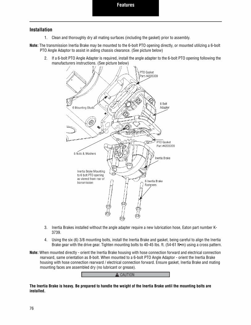
Features
Installation
1. Clean and thoroughly dry all mating surfaces (including the gasket) prior to assembly.
Note: The transmission Inertia Brake may be mounted to the 6-bolt PTO opening directly, or mounted utilizing a 6-bolt PTO Angle Adaptor to assist in aiding chassis clearance. (See picture below)
2. If a 6-bolt PTO Angle Adapter is required, install the angle adapter to the 6-bolt PTO opening following the manufacturers instructions. (See picture below)
3. Inertia Brakes installed without the angle adapter require a new lubrication hose, Eaton part number K-3739.
4. Using the six (6) 3/8 mounting bolts, install the Inertia Brake and gasket, being careful to align the Inertia Brake gear with the drive gear. Tighten mounting bolts to 40-45 lbs. ft. (54-61 N•m) using a cross pattern.
Note: When mounted directly - orient the Inertia Brake housing with hose connection forward and electrical connection rearward, same orientation as 8-bolt. When mounted to a 6-bolt PTO Angle Adaptor - orient the Inertia Brake housing with hose connection rearward / electrical connection forward. Ensure gasket, Inertia Brake and mating mounting faces are assembled dry (no lubricant or grease).
The Inertia Brake is heavy. Be prepared to handle the weight of the Inertia Brake until the mounting bolts are installed.
CAUTION
76
Features Features
5. Reconnect the lubricant supply line to the Inertia Brake and tighten to 20-22 lbs. ft. (27-30 N•m).
6. Relocation kit K-3739 is necessary to perform this next operation.
7. Connect and route the Transmission Harness to the Inertia Brake Coil. Dress the harness along the trans-mission case from the Inertia Brake up to the top of the transmission. Install the harness push-in anchor to the threaded-hole anchor point in the Inertia Brake housing. Install tie wraps every 6-10 inches. The harness should not have sharp bends or be under tension. Route harness per letter of instruction. Apply contact lubrication to jumper harness per letter of instruction.
8. Add UltraShift PTO Instruction Label to dash near PTO switch or a location in view of the driver.
9. Install the PTO to the 8-bolt PTO opening following the manufacturers instructions.
Note: Fill the transmission with lubricant.
Final Check• Make sure the mounting bolts are properly tightened.
• Make sure the lubricant supply line is properly tightened.
• Make sure the transmission is properly filled with lubricant.
• Make sure the Transmission Harness is connected and locked.
• Check for lubricant leaks after operating the vehicle.
• Check that the Inertia Brake has sufficient clearance to prevent contacting tanks, brackets, frame rails, exhaust or any other part of the vehicle. Contacting anything when stationary or moving will cause dam-age to Inertia Brake, angle adaptor or other vehicle equipment.
77
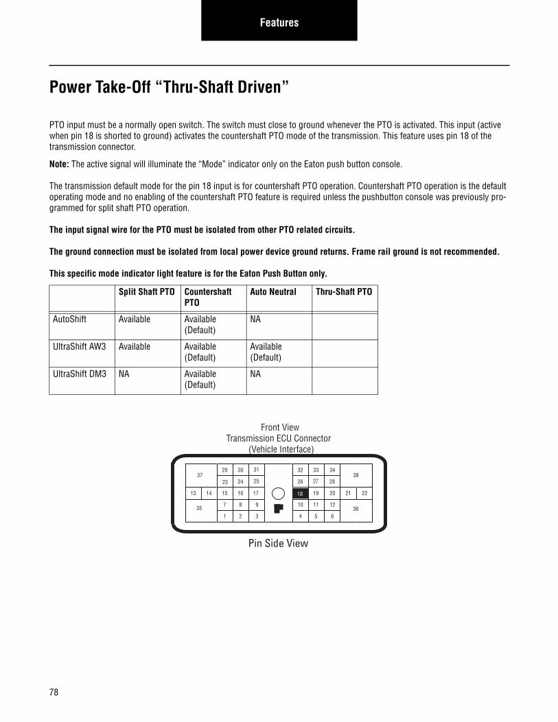
78
Features
Power Take-Off “Thru-Shaft Driven”
PTO input must be a normally open switch. The switch must close to ground whenever the PTO is activated. This input (active when pin 18 is shorted to ground) activates the countershaft PTO mode of the transmission. This feature uses pin 18 of the transmission connector.
Note: The active signal will illuminate the “Mode” indicator only on the Eaton push button console.
The transmission default mode for the pin 18 input is for countershaft PTO operation. Countershaft PTO operation is the default operating mode and no enabling of the countershaft PTO feature is required unless the pushbutton console was previously pro-grammed for split shaft PTO operation.
The input signal wire for the PTO must be isolated from other PTO related circuits.
The ground connection must be isolated from local power device ground returns. Frame rail ground is not recommended.
This specific mode indicator light feature is for the Eaton Push Button only.
Split Shaft PTO Countershaft PTO
Auto Neutral Thru-Shaft PTO
AutoShift Available Available (Default)
NA
UltraShift AW3 Available Available (Default)
Available (Default)
UltraShift DM3 NA Available (Default)
NA
24
29 30
15 16
26
20
3432 33
19
7
3
8 9
1 2 6
11 12
4 5
2221
38
36
37
13 14
3510
17
23
Front ViewTransmission ECU Connector
(Vehicle Interface)
31
25 2827
18
Pin Side View
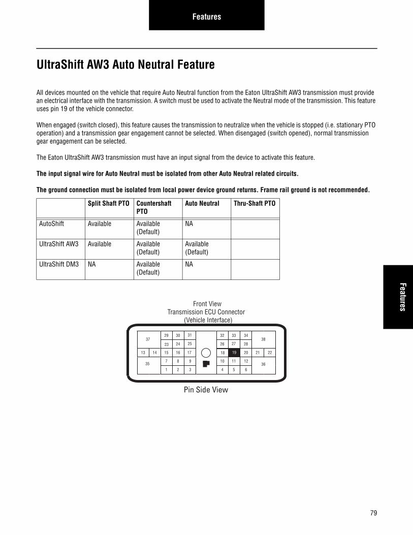
79
FeaturesFeatures
UltraShift AW3 Auto Neutral Feature
All devices mounted on the vehicle that require Auto Neutral function from the Eaton UltraShift AW3 transmission must provide an electrical interface with the transmission. A switch must be used to activate the Neutral mode of the transmission. This feature uses pin 19 of the vehicle connector.
When engaged (switch closed), this feature causes the transmission to neutralize when the vehicle is stopped (i.e. stationary PTO operation) and a transmission gear engagement cannot be selected. When disengaged (switch opened), normal transmission gear engagement can be selected.
The Eaton UltraShift AW3 transmission must have an input signal from the device to activate this feature.
The input signal wire for Auto Neutral must be isolated from other Auto Neutral related circuits.
The ground connection must be isolated from local power device ground returns. Frame rail ground is not recommended.
Split Shaft PTO Countershaft PTO
Auto Neutral Thru-Shaft PTO
AutoShift Available Available (Default)
NA
UltraShift AW3 Available Available (Default)
Available (Default)
UltraShift DM3 NA Available (Default)
NA
24
29 30
15 16
26
20
3432 33
18
7
3
8 9
1 2 6
11 12
4 5
2221
38
36
37
13 14
3510
17
23
Front ViewTransmission ECU Connector
(Vehicle Interface)
31
25 2827
19
Pin Side View
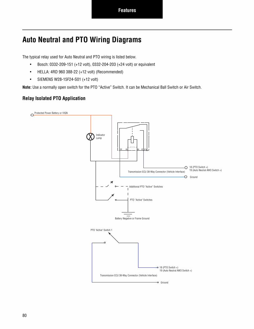
Features
Auto Neutral and PTO Wiring Diagrams
The typical relay used for Auto Neutral and PTO wiring is listed below.
• Bosch: 0332-209-151 (+12 volt), 0332-204-203 (+24 volt) or equivalent
• HELLA: 4RD 960 388-22 (+12 volt) (Recommended)
• SIEMENS W28-15F24-S01 (+12 volt)
Note: Use a normally open switch for the PTO “Active” Switch. It can be Mechanical Ball Switch or Air Switch.
Relay Isolated PTO Application
30 85 86 87 87a
X
Protected Power Battery or VIGN
Indicator Lamp
Transmission ECU 38-Way Connector (Vehicle Interface)
PTO “Active" Switches
Battery Negative or Frame Ground
18 (PTO Switch +)19 (Auto Neutral AW3 Switch +)
Ground
Additional PTO “Active” Switches
Transmission ECU 38-Way Connector (Vehicle Interface)
PTO "Active" Switch 1
18 (PTO Switch +)19 (Auto Neutral AW3 Switch +)
Ground
80
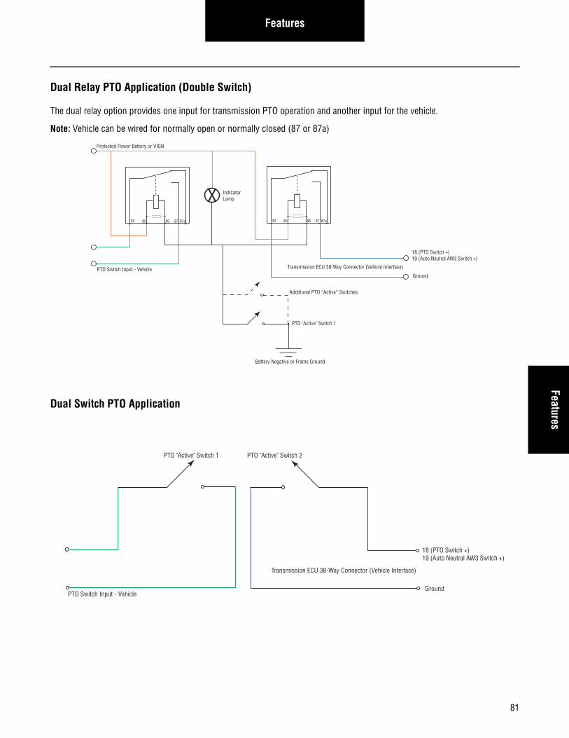
FeaturesFeatures
Dual Relay PTO Application (Double Switch)
The dual relay option provides one input for transmission PTO operation and another input for the vehicle.
Note: Vehicle can be wired for normally open or normally closed (87 or 87a)
Dual Switch PTO Application
30 85 86 87 87a30 85 86 87 87a
X
Protected Power Battery or VIGN
Indicator Lamp
PTO Switch Input - Vehicle
PTO "Active" Switch 1
Transmission ECU 38-Way Connector (Vehicle Interface)
18 (PTO Switch +)19 (Auto Neutral AW3 Switch +)
Ground
Battery Negative or Frame Ground
Additional PTO “Active” Switches
PTO Switch Input - Vehicle
Transmission ECU 38-Way Connector (Vehicle Interface)
PTO "Active" Switch 2PTO "Active" Switch 1
18 (PTO Switch +)19 (Auto Neutral AW3 Switch +)
Ground
81
Line Inspection
Line Inspection and Road Test Instructions
The checklist was developed as an installation tool for line personnel to ensure the correct operation of each vehicle and to assist the vehicle OEM to identify transmission quality related issues as well as OEM line quality issues. Used correctly, this checklist identifies transmission issues and aids in tracking the problem until corrected.
The recommended use of the checklist is as follows:1. A separate checklist should be filled out for each vehicle built with Eaton Fuller transmissions. If these checks and infor-
mation can be combined with an existing form, the Line Inspection form does not need to be used.
2. The section identified as PRE-START CHECKS should be performed prior to the initial start-up of the vehicle. This sec-tion ensures the transmission has the correct power supplies, sufficient lubricant, and correct transmission shift tables.
3. Perform any necessary corrective action prior to the dyno or road testing.
4. The DYNO/ROAD TEST section is used to verify that all transmission systems are functional and the Drivers Manual and Shift Label are supplied in the cab.
5. With a record of transmission related information and repairs made to each unit, the OEM is able to track and correct repeated quality issues.
6. A copy of the checklist should be recorded for installation history. OEM line personnel should become familiar with the checklist for the transmission prior to a scheduled build. Eaton OEM Engineering Support Group can coordinate training and information to expedite this process.
This checklist represents a generic system which can be tailored to the individual OEM to achieve the best possible method of transmission installation verification. Eaton recommends the use of this system to maintain the utmost in satisfactory operation and long service life.
Each transmission system installed at the OEM must pass the line checklist requirements per the Eaton Line Inspection Form prior to shipment from the OEM plant.
82
Line InspectionLine Inspection
Line Inspection
This transmission is equipped with a neutral interlock system that when properly installed prevents the engine from cranking with the transmission in-gear.
Failure to perform installation pre-start checks may result in the engine cranking immediately when ignition is moved to the “START” position or to the “ON” position.
To prevent undesired vehicle movement for new installations, always set the parking brake prior to turning the ignition key “ON” and also prior to attempting “START”.
Checklist Instructions/Details for the Line Inspection Forms
Refer to the line inspection form while performing the following procedures
Note: All information must be filled on the Line Inspection Form.
Pre-Start Checks1. Visually verify that the transmission ignition power supply is protected by a manual resetting 10 AMP circuit breaker or
fuse and verify that main power is protected by a 30 AMP fuse.
2. Visually verify that main power is protected by a 30 AMP fuse.
3. Verify polarity of main power connection.
4. Verify the transmission has been filled with the correct amount and type of lubricant before starting the engine. Failure to add sufficient lubricant could damage the transmission. See Lubricant Requirement section in this manual for details.
5. Turn the key switch to the “On” position and visually observe the power up procedure. Gear Display will show a solid “N” when power up is complete.
Note: Make sure Neutral is selected.
Note: The transmission will automatically reset to neutral position as soon as the vehicle is powered up (key switch on).
Improper installation of the OEM Start Enable Circuit could result in enabling the vehicle to be started in gear.
6. Start the engine and rev it above 1500 rpm. This will allow the DM clutch locking device to disengage and allow normal clutch function (UltraShift DM3 only).
Note: Failure to perform this step will set a clutch disengagement fault and inhibit transmission gear engagement.
Note: UltraShift equipped vehicles with programmable VSS Tamper Resistance options or other artificial engine speed limits which prevent reaching the required 1500 rpm may prevent proper disengagement of the clutch locking device after initial installation. These options may need to be disabled until after the clutch locking device is disengaged.
WARNING
WARNING
83
Line Inspection
Dyno/Road Test1. With Engine not running, select drive and attempt to start the engine. Repeat for each of the forward and reverse mode
positions to verify the engine will not start.
2. Verify forward and reverse gears can not be obtained without having the service brake applied (UltraShift DM3,AW3 only).
Note: The service brake input is required while selecting a starting gear. If the service brake is not applied while selecting a start-ing gear, the initial start gear will not be found and the driver will have to re-select neutral and press the brake while re-selecting the desired mode.
3. Verify all forward and reverse gears are obtained.
4. AutoShift equipped trucks, verify correct clutch adjustment and correct pedal free travel per clutch manufacturer’s spec-ifications.
5. Verify through normal operations that the transmission temperature gauge (if installed) is functional.
6. Visually verify that the gear display module is easily visible and lights up when the ignition is turned on.
Note: When testing on a dynamometer which decelerates quickly, the display module may not appear to function correctly. Should this occur, drive the vehicle off the dynamometer and note how the display functions. If it functions correctly when driving, the problem is that the dynamometer decelerates too quickly.
7. Verify through normal operation that the engine brake (if equipped) functions correctly per the manufacturer’s specifica-tions.
8. Verify that the panel lights on the Shift Input Device illuminate when the vehicle dash lights are turned on.
9. Visually check for lubricant drips or residue on the transmission and related cooler lines (if used).
10. Make sure the correct transmission Shift Label is present and that the Drivers Manual is included with the other vehicle information.
11. Verify the diagnostic connector (6-pin required 9-pin recommended) is easily accessible and mounted on the drivers side of the cab.
12. Verify that a label to alert the customer of type and brand of lubricant used in the transmission is attached to the trans-mission fill plug.
13. Verify the lube label is affixed near the dipstick tube (UltraShift AW3).
14. Clear historical fault codes by using the key switch. To do this, place the Shift Input Device in neutral and set the parking brakes. Begin with the switch in the on position. Turn the key off and back on six times within five seconds (off/on/off/on/off/on/off/on/off/on/off/on).
15. Prior to shipment of Eaton Automated Transmission Systems installed at OEM plants, the engine ECU must contain the proper configuration settings. For the proper engine configuration settings required for Eaton Automated Transmission operation refer to the “Engine Configuration Settings Installation Guide” on roadranger.com under the literature center.
84
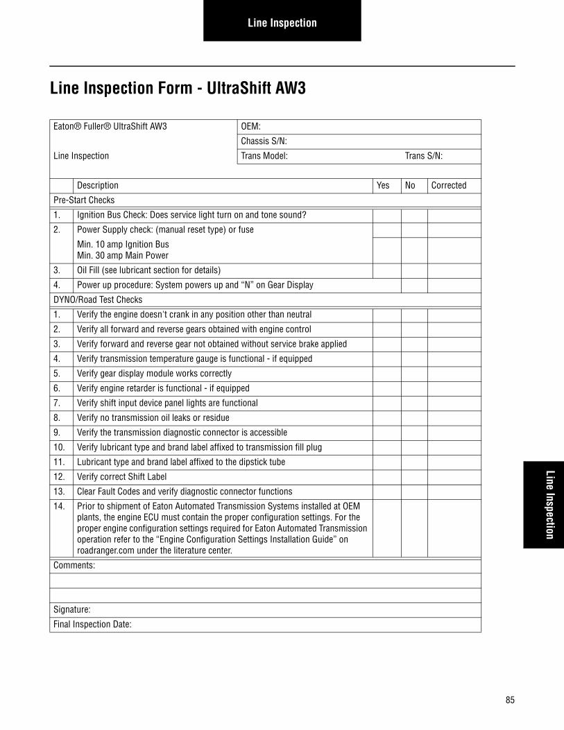
85
Line InspectionLine Inspection
Line Inspection Form - UltraShift AW3
Eaton® Fuller® UltraShift AW3 OEM:
Chassis S/N:
Line Inspection Trans Model: Trans S/N:
Description Yes No Corrected
Pre-Start Checks
1. Ignition Bus Check: Does service light turn on and tone sound?
2. Power Supply check: (manual reset type) or fuse
Min. 10 amp Ignition Bus Min. 30 amp Main Power
3. Oil Fill (see lubricant section for details)
4. Power up procedure: System powers up and “N” on Gear Display
DYNO/Road Test Checks
1. Verify the engine doesn't crank in any position other than neutral
2. Verify all forward and reverse gears obtained with engine control
3. Verify forward and reverse gear not obtained without service brake applied
4. Verify transmission temperature gauge is functional - if equipped
5. Verify gear display module works correctly
6. Verify engine retarder is functional - if equipped
7. Verify shift input device panel lights are functional
8. Verify no transmission oil leaks or residue
9. Verify the transmission diagnostic connector is accessible
10. Verify lubricant type and brand label affixed to transmission fill plug
11. Lubricant type and brand label affixed to the dipstick tube
12. Verify correct Shift Label
13. Clear Fault Codes and verify diagnostic connector functions
14. Prior to shipment of Eaton Automated Transmission Systems installed at OEM plants, the engine ECU must contain the proper configuration settings. For the proper engine configuration settings required for Eaton Automated Transmission operation refer to the “Engine Configuration Settings Installation Guide” on roadranger.com under the literature center.
Comments:
Signature:
Final Inspection Date:
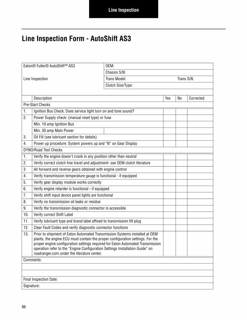
86
Line Inspection
Line Inspection Form - AutoShift AS3
Eaton® Fuller® AutoShift™ AS3 OEM:
Chassis S/N:
Line Inspection Trans Model: Trans S/N:
Clutch Size/Type:
Description Yes No Corrected
Pre-Start Checks
1. Ignition Bus Check: Does service light turn on and tone sound?
2. Power Supply check: (manual reset type) or fuse
Min. 10 amp Ignition Bus
Min. 30 amp Main Power
3. Oil Fill (see lubricant section for details)
4. Power up procedure: System powers up and “N” on Gear Display
DYNO/Road Test Checks
1. Verify the engine doesn't crank in any position other than neutral
2. Verify correct clutch free travel and adjustment- see OEM clutch literature
3 All forward and reverse gears obtained with engine control
4. Verify transmission temperature gauge is functional - if equipped
5. Verify gear display module works correctly
6. Verify engine retarder is functional - if equipped
7. Verify shift input device panel lights are functional
8. Verify no transmission oil leaks or residue
9. Verify the transmission diagnostic connector is accessible
10. Verify correct Shift Label
11. Verify lubricant type and brand label affixed to transmission fill plug
12. Clear Fault Codes and verify diagnostic connector functions
13. Prior to shipment of Eaton Automated Transmission Systems installed at OEM plants, the engine ECU must contain the proper configuration settings. For the proper engine configuration settings required for Eaton Automated Transmission operation refer to the “Engine Configuration Settings Installation Guide” on roadranger.com under the literature center.
Comments:
Final Inspection Date:
Signature:
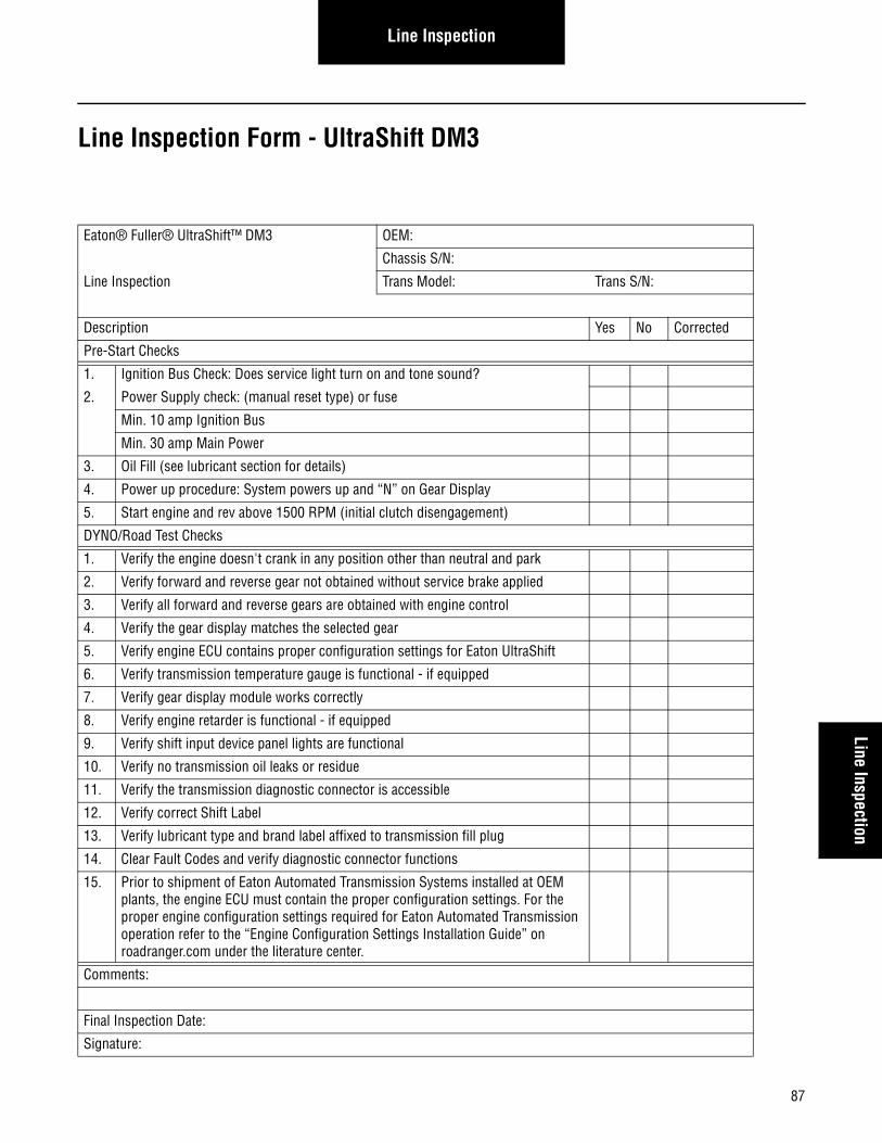
87
Line InspectionLine Inspection
Line Inspection Form - UltraShift DM3
Eaton® Fuller® UltraShift™ DM3 OEM:
Chassis S/N:
Line Inspection Trans Model: Trans S/N:
Description Yes No Corrected
Pre-Start Checks
1. Ignition Bus Check: Does service light turn on and tone sound?
2. Power Supply check: (manual reset type) or fuse
Min. 10 amp Ignition Bus
Min. 30 amp Main Power
3. Oil Fill (see lubricant section for details)
4. Power up procedure: System powers up and “N” on Gear Display
5. Start engine and rev above 1500 RPM (initial clutch disengagement)
DYNO/Road Test Checks
1. Verify the engine doesn't crank in any position other than neutral and park
2. Verify forward and reverse gear not obtained without service brake applied
3. Verify all forward and reverse gears are obtained with engine control
4. Verify the gear display matches the selected gear
5. Verify engine ECU contains proper configuration settings for Eaton UltraShift
6. Verify transmission temperature gauge is functional - if equipped
7. Verify gear display module works correctly
8. Verify engine retarder is functional - if equipped
9. Verify shift input device panel lights are functional
10. Verify no transmission oil leaks or residue
11. Verify the transmission diagnostic connector is accessible
12. Verify correct Shift Label
13. Verify lubricant type and brand label affixed to transmission fill plug
14. Clear Fault Codes and verify diagnostic connector functions
15. Prior to shipment of Eaton Automated Transmission Systems installed at OEM plants, the engine ECU must contain the proper configuration settings. For the proper engine configuration settings required for Eaton Automated Transmission operation refer to the “Engine Configuration Settings Installation Guide” on roadranger.com under the literature center.
Comments:
Final Inspection Date:
Signature:
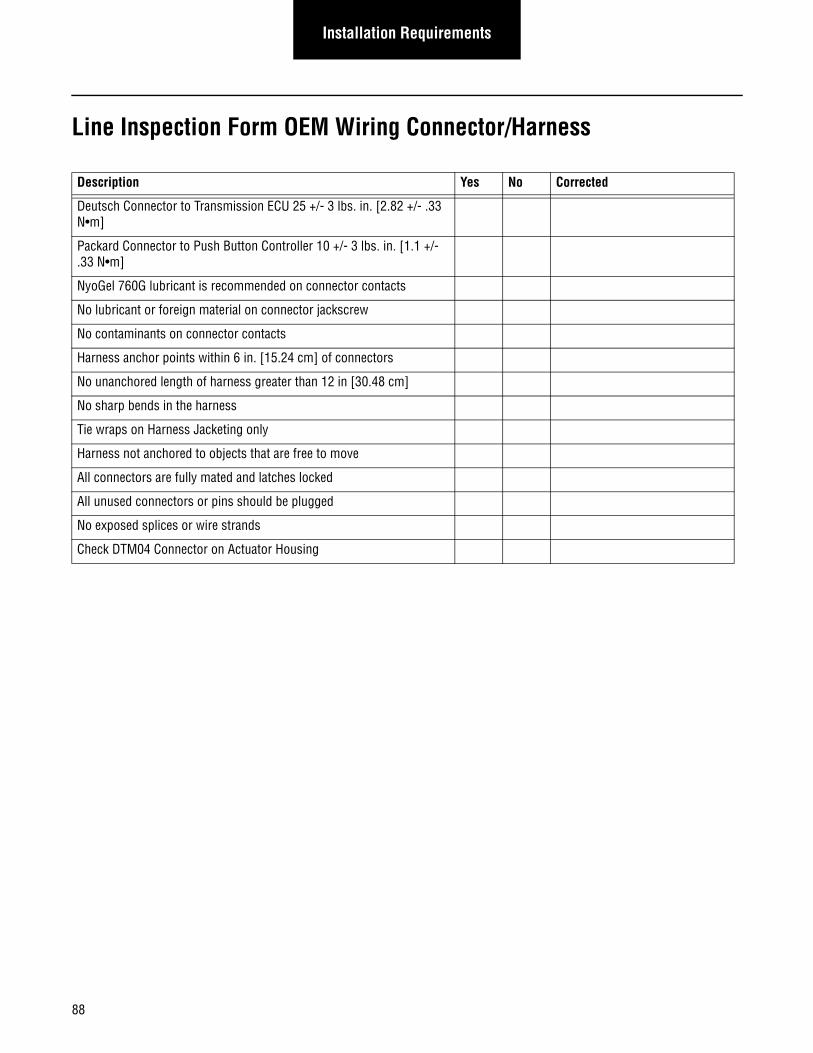
88
Installation Requirements
Line Inspection Form OEM Wiring Connector/Harness
Description Yes No Corrected
Deutsch Connector to Transmission ECU 25 +/- 3 lbs. in. [2.82 +/- .33 N•m]
Packard Connector to Push Button Controller 10 +/- 3 lbs. in. [1.1 +/- .33 N•m]
NyoGel 760G lubricant is recommended on connector contacts
No lubricant or foreign material on connector jackscrew
No contaminants on connector contacts
Harness anchor points within 6 in. [15.24 cm] of connectors
No unanchored length of harness greater than 12 in [30.48 cm]
No sharp bends in the harness
Tie wraps on Harness Jacketing only
Harness not anchored to objects that are free to move
All connectors are fully mated and latches locked
All unused connectors or pins should be plugged
No exposed splices or wire strands
Check DTM04 Connector on Actuator Housing
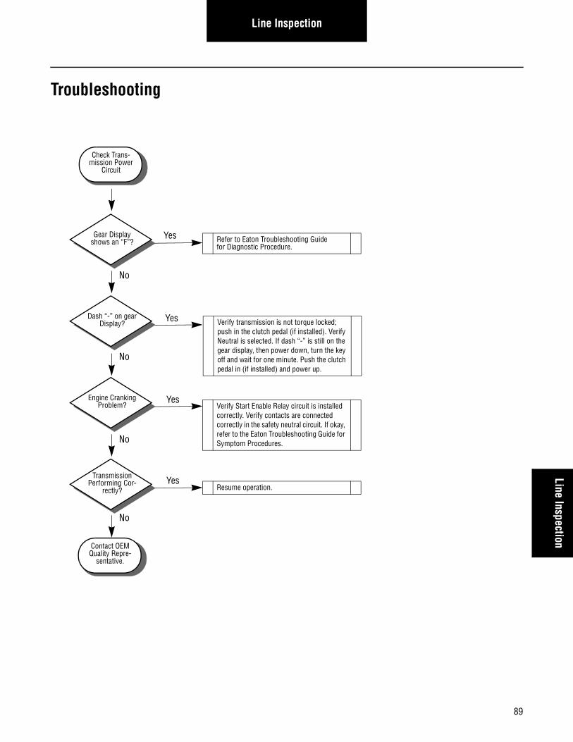
89
Line InspectionLine Inspection
Troubleshooting
Check Trans-mission Power
Circuit
Dash “-” on gear Display?
Engine Cranking Problem?
Transmission Performing Cor-
rectly?
Refer to Eaton Troubleshooting Guide for Diagnostic Procedure.
Verify transmission is not torque locked; push in the clutch pedal (if installed). Verify Neutral is selected. If dash “-” is still on the gear display, then power down, turn the key off and wait for one minute. Push the clutch pedal in (if installed) and power up.
Verify Start Enable Relay circuit is installed correctly. Verify contacts are connected correctly in the safety neutral circuit. If okay, refer to the Eaton Troubleshooting Guide for Symptom Procedures.
Resume operation.
Contact OEM Quality Repre-
sentative.
Gear Display shows an “F”?
No
No
No
No
Yes
Yes
Yes
Yes
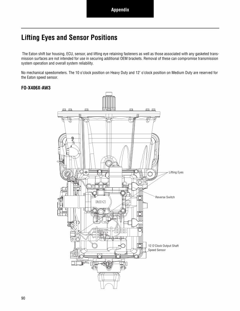
Appendix
Lifting Eyes and Sensor Positions
The Eaton shift bar housing, ECU, sensor, and lifting eye retaining fasteners as well as those associated with any gasketed trans-mission surfaces are not intended for use in securing additional OEM brackets. Removal of these can compromise transmission system operation and overall system reliability.
No mechanical speedometers. The 10 o’clock position on Heavy Duty and 12’ o’clock position on Medium Duty are reserved for the Eaton speed sensor.
FO-X406X-AW3
Lifting Eyes
Reverse Switch
12 O'Clock Output ShaftSpeed Sensor
90
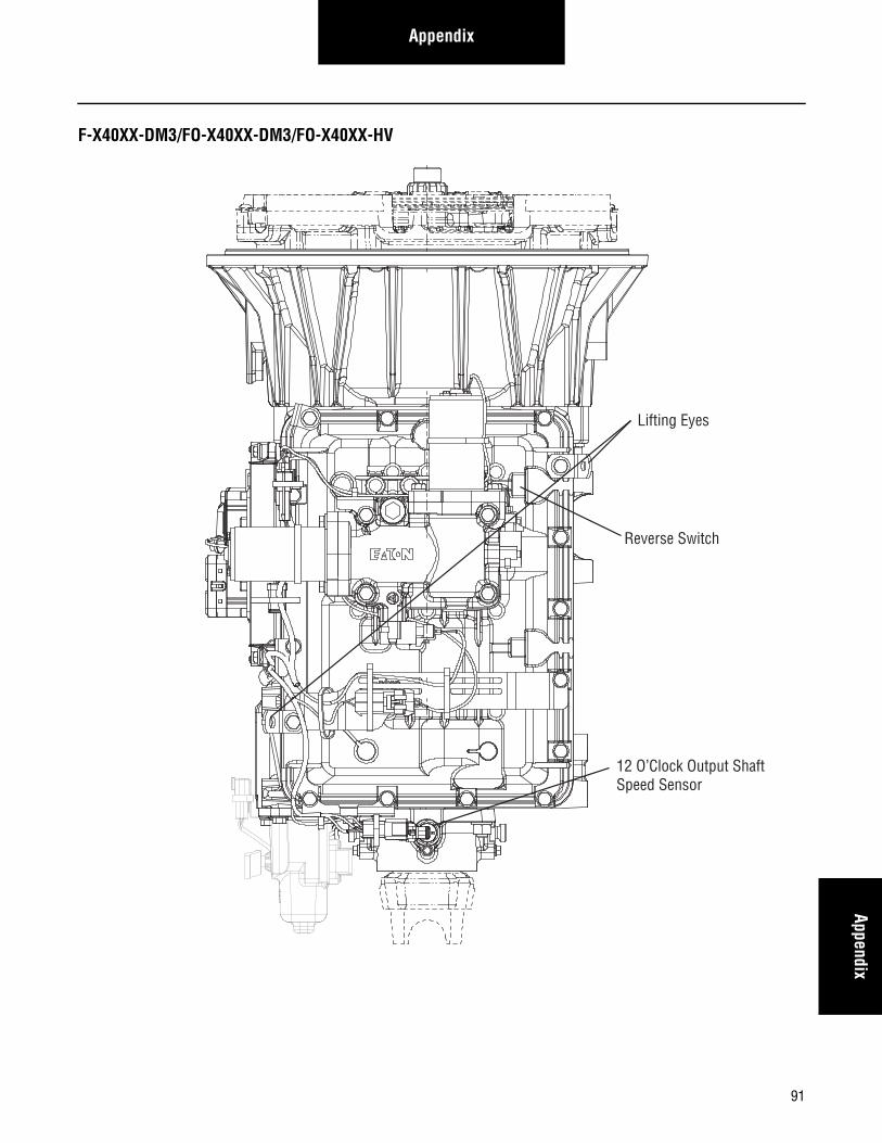
AppendixAppendix
F-X40XX-DM3/FO-X40XX-DM3/FO-X40XX-HV
Lifting Eyes
Reverse Switch
12 O’Clock Output ShaftSpeed Sensor
91
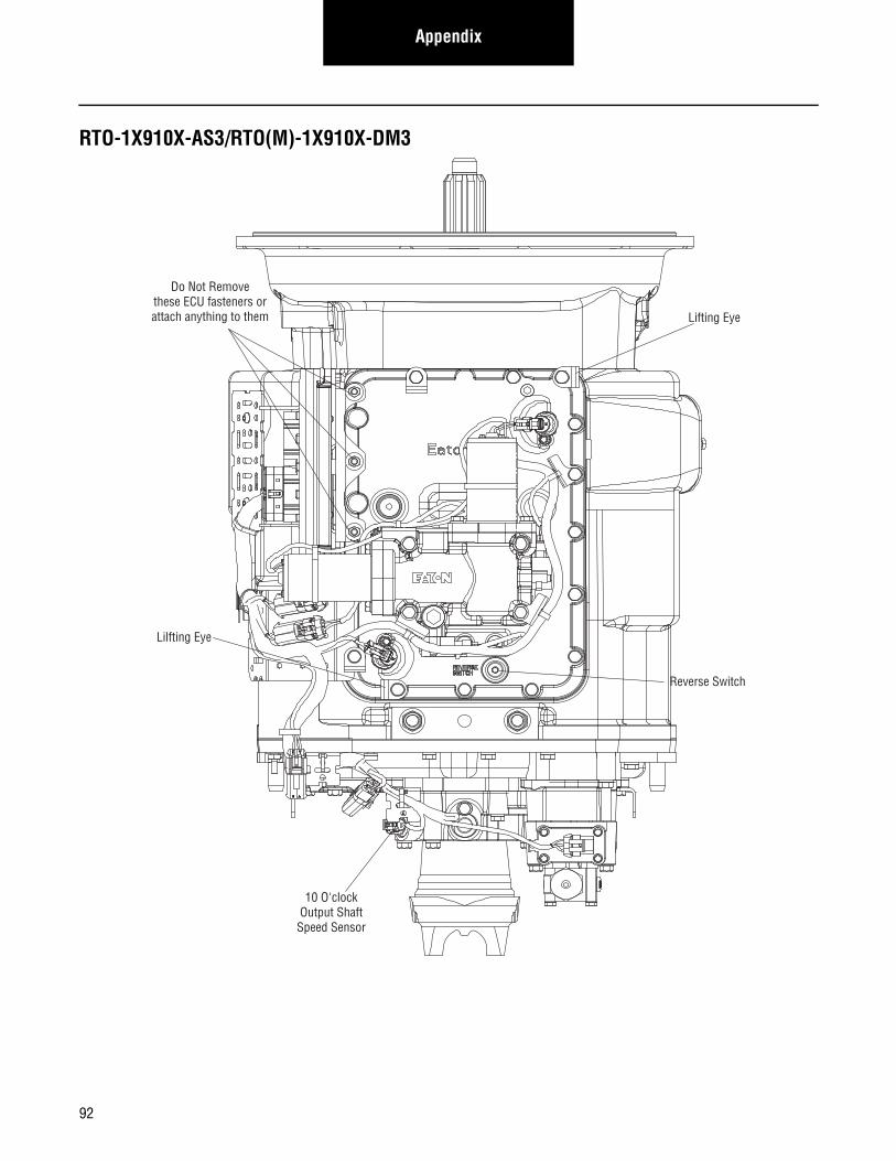
Appendix
RTO-1X910X-AS3/RTO(M)-1X910X-DM3
10 O'clockOutput ShaftSpeed Sensor
Lilfting Eye
Lifting Eye
Reverse Switch
Do Not Removethese ECU fasteners orattach anything to them
92
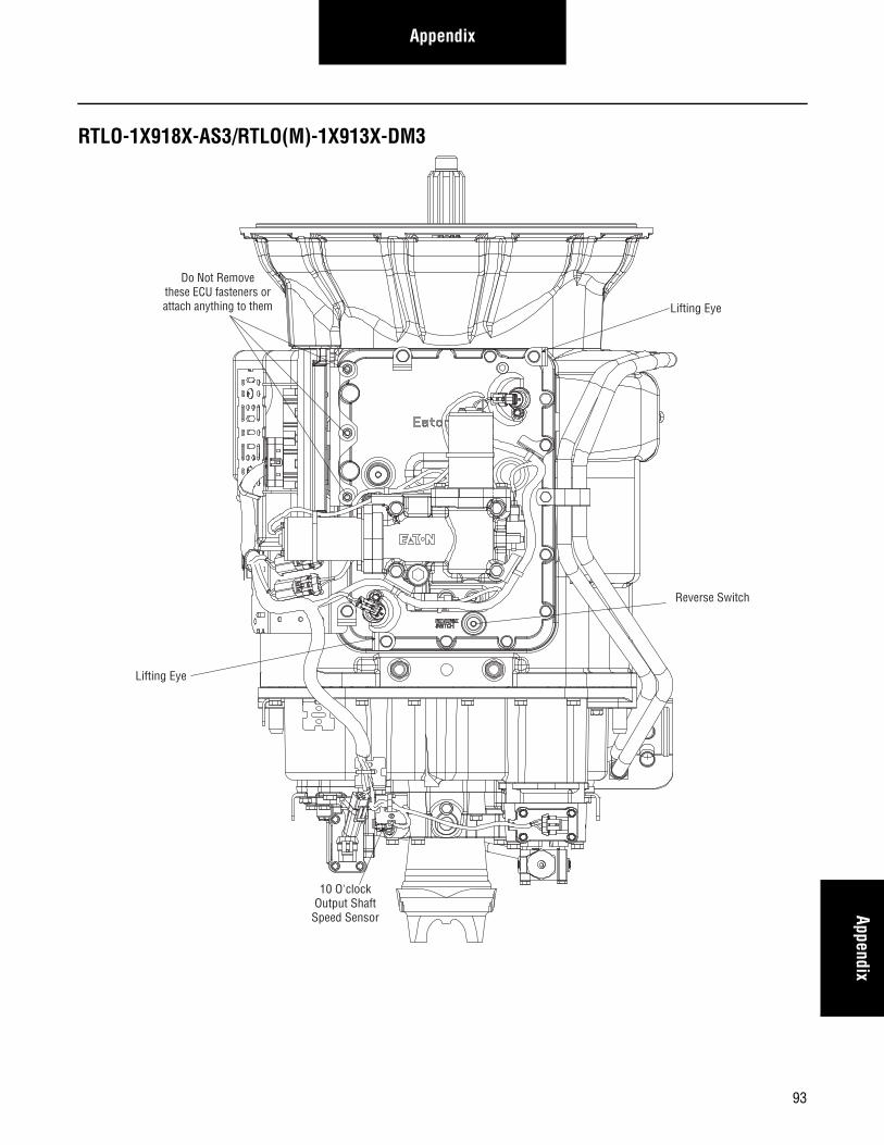
AppendixAppendix
RTLO-1X918X-AS3/RTLO(M)-1X913X-DM3
10 O'clockOutput ShaftSpeed Sensor
Lifting Eye
Lifting Eye
Reverse Switch
Do Not Removethese ECU fasteners orattach anything to them
93
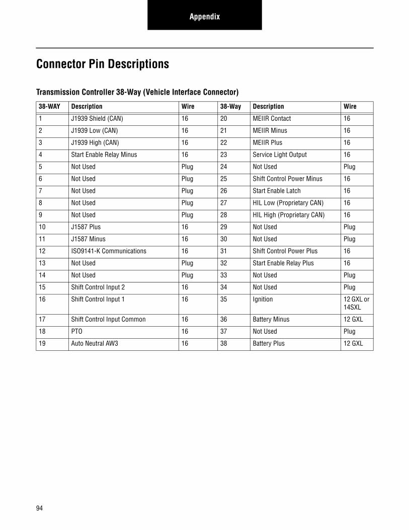
Appendix
Connector Pin Descriptions
Transmission Controller 38-Way (Vehicle Interface Connector)
38-WAY Description Wire 38-Way Description Wire
1 J1939 Shield (CAN) 16 20 MEIIR Contact 16
2 J1939 Low (CAN) 16 21 MEIIR Minus 16
3 J1939 High (CAN) 16 22 MEIIR Plus 16
4 Start Enable Relay Minus 16 23 Service Light Output 16
5 Not Used Plug 24 Not Used Plug
6 Not Used Plug 25 Shift Control Power Minus 16
7 Not Used Plug 26 Start Enable Latch 16
8 Not Used Plug 27 HIL Low (Proprietary CAN) 16
9 Not Used Plug 28 HIL High (Proprietary CAN) 16
10 J1587 Plus 16 29 Not Used Plug
11 J1587 Minus 16 30 Not Used Plug
12 ISO9141-K Communications 16 31 Shift Control Power Plus 16
13 Not Used Plug 32 Start Enable Relay Plus 16
14 Not Used Plug 33 Not Used Plug
15 Shift Control Input 2 16 34 Not Used Plug
16 Shift Control Input 1 16 35 Ignition 12 GXL or 14SXL
17 Shift Control Input Common 16 36 Battery Minus 12 GXL
18 PTO 16 37 Not Used Plug
19 Auto Neutral AW3 16 38 Battery Plus 12 GXL
94
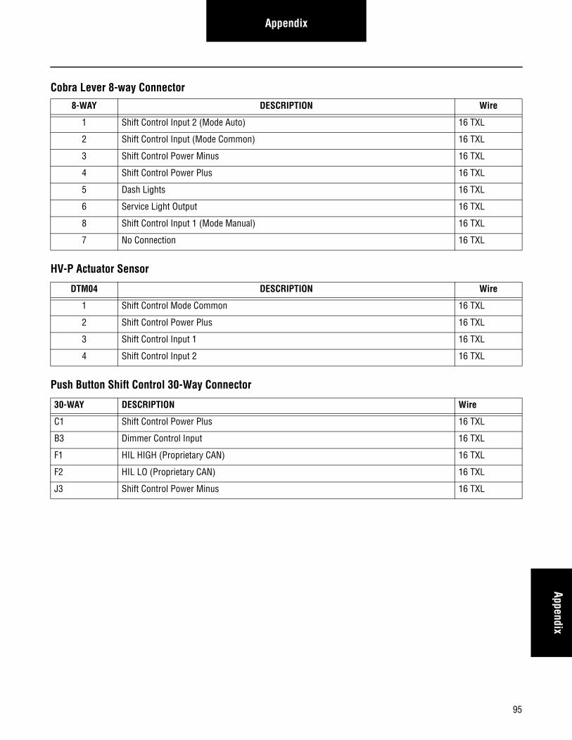
AppendixAppendix
Cobra Lever 8-way Connector
HV-P Actuator Sensor
Push Button Shift Control 30-Way Connector
8-WAY DESCRIPTION Wire
1 Shift Control Input 2 (Mode Auto) 16 TXL
2 Shift Control Input (Mode Common) 16 TXL
3 Shift Control Power Minus 16 TXL
4 Shift Control Power Plus 16 TXL
5 Dash Lights 16 TXL
6 Service Light Output 16 TXL
8 Shift Control Input 1 (Mode Manual) 16 TXL
7 No Connection 16 TXL
DTM04 DESCRIPTION Wire
1 Shift Control Mode Common 16 TXL
2 Shift Control Power Plus 16 TXL
3 Shift Control Input 1 16 TXL
4 Shift Control Input 2 16 TXL
30-WAY DESCRIPTION Wire
C1 Shift Control Power Plus 16 TXL
B3 Dimmer Control Input 16 TXL
F1 HIL HIGH (Proprietary CAN) 16 TXL
F2 HIL LO (Proprietary CAN) 16 TXL
J3 Shift Control Power Minus 16 TXL
95
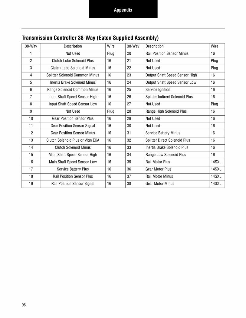
Appendix
Transmission Controller 38-Way (Eaton Supplied Assembly)38-Way Description Wire 38-Way Description Wire
1 Not Used Plug 20 Rail Position Sensor Minus 16
2 Clutch Lube Solenoid Plus 16 21 Not Used Plug
3 Clutch Lube Solenoid Minus 16 22 Not Used Plug
4 Splitter Solenoid Common Minus 16 23 Output Shaft Speed Sensor High 16
5 Inertia Brake Solenoid Minus 16 24 Output Shaft Speed Sensor Low 16
6 Range Solenoid Common Minus 16 25 Service Ignition 16
7 Input Shaft Speed Sensor High 16 26 Splitter Indirect Solenoid Plus 16
8 Input Shaft Speed Sensor Low 16 27 Not Used Plug
9 Not Used Plug 28 Range High Solenoid Plus 16
10 Gear Position Sensor Plus 16 29 Not Used 16
11 Gear Position Sensor Signal 16 30 Not Used 16
12 Gear Position Sensor Minus 16 31 Service Battery Minus 16
13 Clutch Solenoid Plus or Vign ECA 16 32 Splitter Direct Solenoid Plus 16
14 Clutch Solenoid Minus 16 33 Inertia Brake Solenoid Plus 16
15 Main Shaft Speed Sensor High 16 34 Range Low Solenoid Plus 16
16 Main Shaft Speed Sensor Low 16 35 Rail Motor Plus 14SXL
17 Service Battery Plus 16 36 Gear Motor Plus 14SXL
18 Rail Position Sensor Plus 16 37 Rail Motor Minus 14SXL
19 Rail Position Sensor Signal 16 38 Gear Motor Minus 14SXL
96
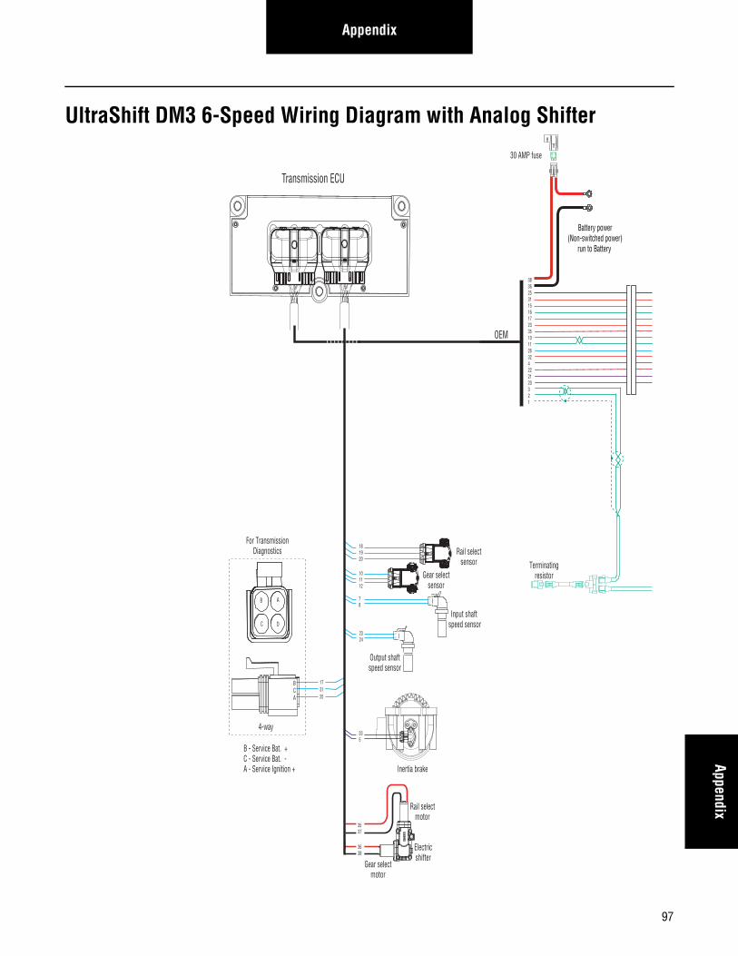
AppendixAppendix
UltraShift DM3 6-Speed Wiring Diagram with Analog Shifter
Gear selectmotor
Rail selectmotor
Electricshifter
A
B
A
B
Rail selectsensor
Gear selectsensor
Input shaft speed sensor
Output shaftspeed sensor
Inertia brake
A
B
181920
101112
78
2324
335
A
B
C
A
B
C
3537
3638
OEM
30 AMP fuse
Battery power(Non-switched power)
run to Battery
Terminatingresistor
383625311516172335101126324222120321
B
C
A
173125
D
For TransmissionDiagnostics
4-way
B - Service Bat. +C - Service Bat. -A - Service Ignition +
BCA
Transmission ECU
97
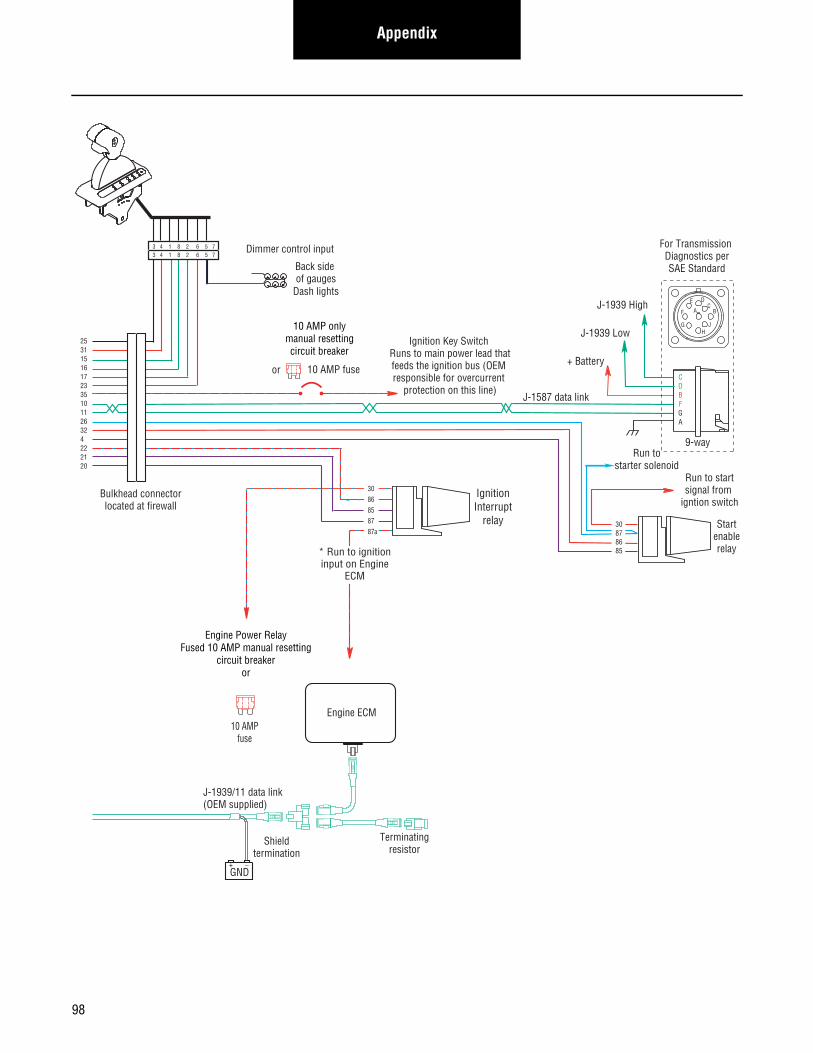
Appendix
Terminatingresistor
J-1939/11 data link(OEM supplied)
GND+ _
Shieldtermination
Engine ECM
Startenablerelay
Run to startsignal from
igntion switch
10 AMP onlymanual resettingcircuit breaker
10 AMP fuseor
J-1587 data link
30878685
Bulkhead connectorlocated at firewall
Back side of gauges
Dash lights
Dimmer control input
IgnitionInterrupt
relay
3086858787a
* Run to ignitioninput on Engine
ECM
25311516172335101126324222120
+ Battery
Run tostarter solenoid
9-way
AF
J
E
GH
DC
B
CDBFGA
J-1939 Low
J-1939 High
For Transmission Diagnostics perSAE Standard
Engine Power RelayFused 10 AMP manual resetting
circuit breakeror
10 AMPfuse
3 4 1 8 2 6 5 73 4 1 8 2 6 5 7
Ignition Key Switch Runs to main power lead thatfeeds the ignition bus (OEM responsible for overcurrent
protection on this line)
98
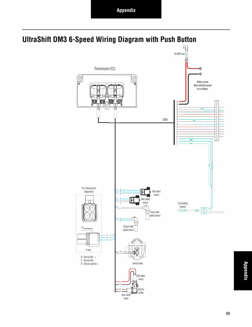
AppendixAppendix
UltraShift DM3 6-Speed Wiring Diagram with Push Button
173125
Gear selectmotor
Rail selectmotor
Electricshifter
A
B
A
B
Rail selectsensor
Gear selectsensor
Input shaft speed sensor
Output shaftspeed sensor
Inertia brake
A
B
181920
101112
78
2324
335
A
B
C
A
B
C
3537
3638
30 AMP fuse
Battery power(Non-switched power)
run to Battery
Terminatingresistor
38362728253135101126324222120321
OEM
B
C
A
D
For TransmissionDiagnostics
4-way
B - Service Bat. +C - Service Bat. -A - Service Ignition +
BCA
Transmission ECU
99
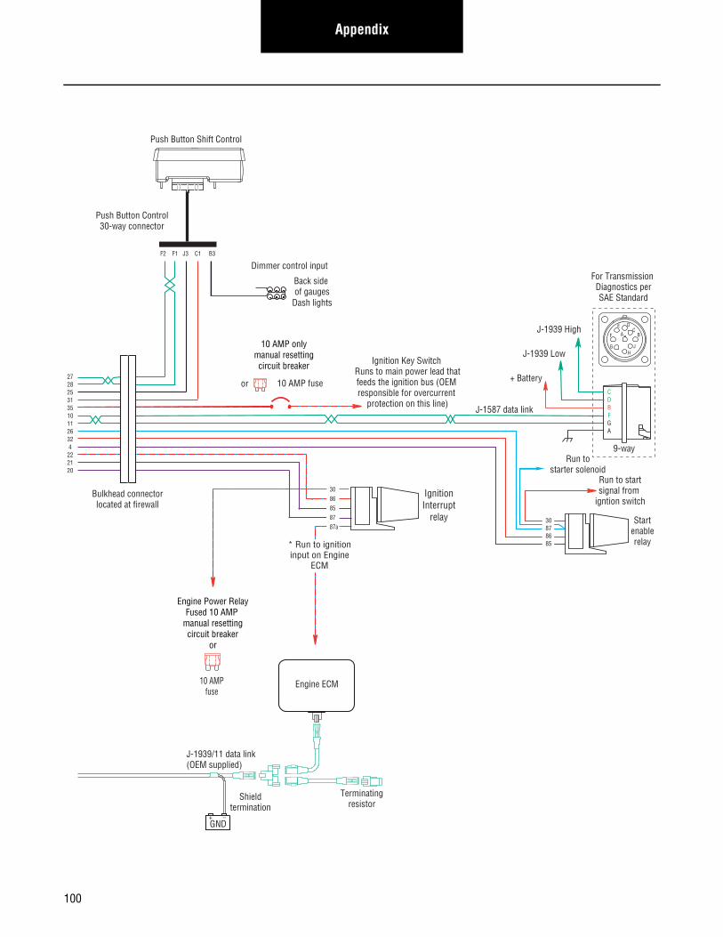
Appendix
Terminatingresistor
J-1939/11 data link(OEM supplied)
GND+ _
Shieldtermination
Engine ECM
Startenablerelay
Run to startsignal from
igntion switch
10 AMP onlymanual resettingcircuit breaker
10 AMP fuseor
J-1587 data link
30878685
Bulkhead connectorlocated at firewall
Back side of gauges
Dash lights
Dimmer control input
IgnitionInterrupt
relay
3086858787a
* Run to ignitioninput on Engine
ECM
Push Button Shift Control
Push Button Control30-way connector
F2 F1 J3 C1 B3
272825313510112632 4222120
Engine Power RelayFused 10 AMP
manual resettingcircuit breaker
or
10 AMPfuse
+ Battery
Run tostarter solenoid
9-way
AF
J
E
GH
DC
B
CDBFGA
J-1939 Low
J-1939 High
For Transmission Diagnostics perSAE Standard
Ignition Key Switch Runs to main power lead thatfeeds the ignition bus (OEM responsible for overcurrent
protection on this line)
100
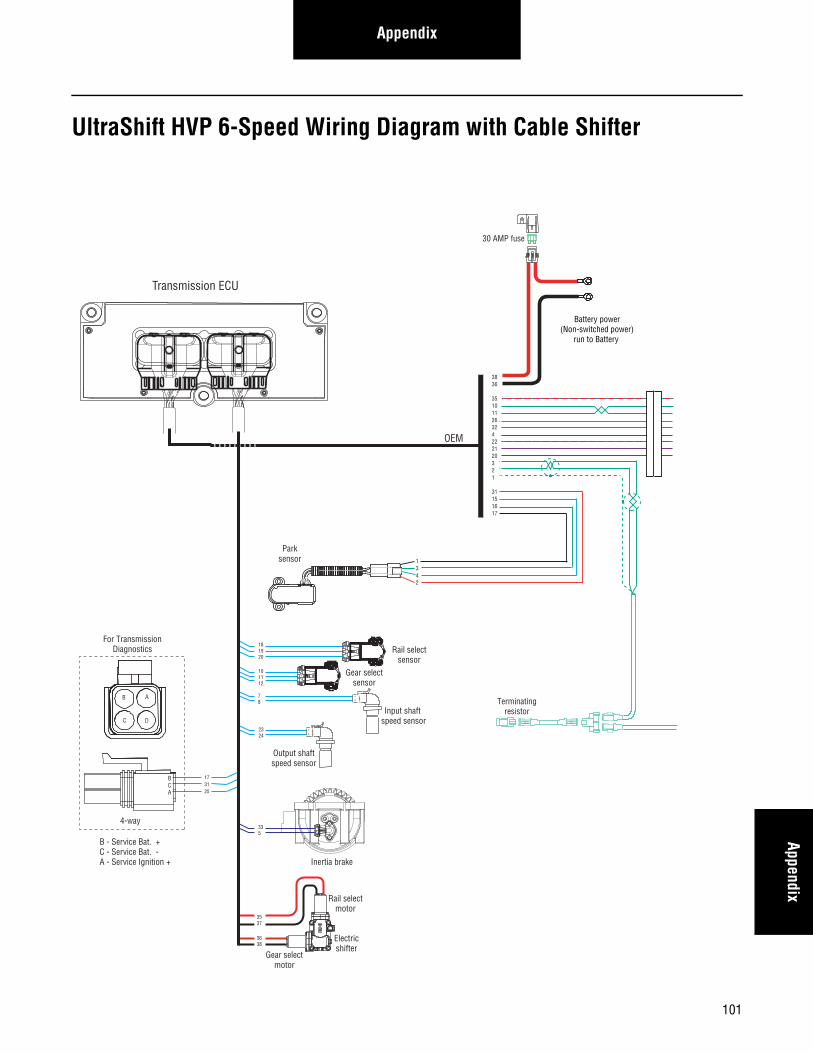
AppendixAppendix
UltraShift HVP 6-Speed Wiring Diagram with Cable Shifter
30 AMP fuse
Battery power(Non-switched power)
run to Battery
Terminatingresistor
3836
35101126324222120321
31151617
Gear selectmotor
Rail selectmotor
Electricshifter
A
B
A
B
Rail selectsensor
Gear selectsensor
Input shaft speed sensor
Output shaftspeed sensor
Inertia brake
A
B
181920
101112
78
2324
335
A
B
C
A
B
C
3537
3638
OEM
B
C
A
173125
D
For TransmissionDiagnostics
4-way
B - Service Bat. +C - Service Bat. -A - Service Ignition +
BCA
Transmission ECU
Parksensor 1
342
101
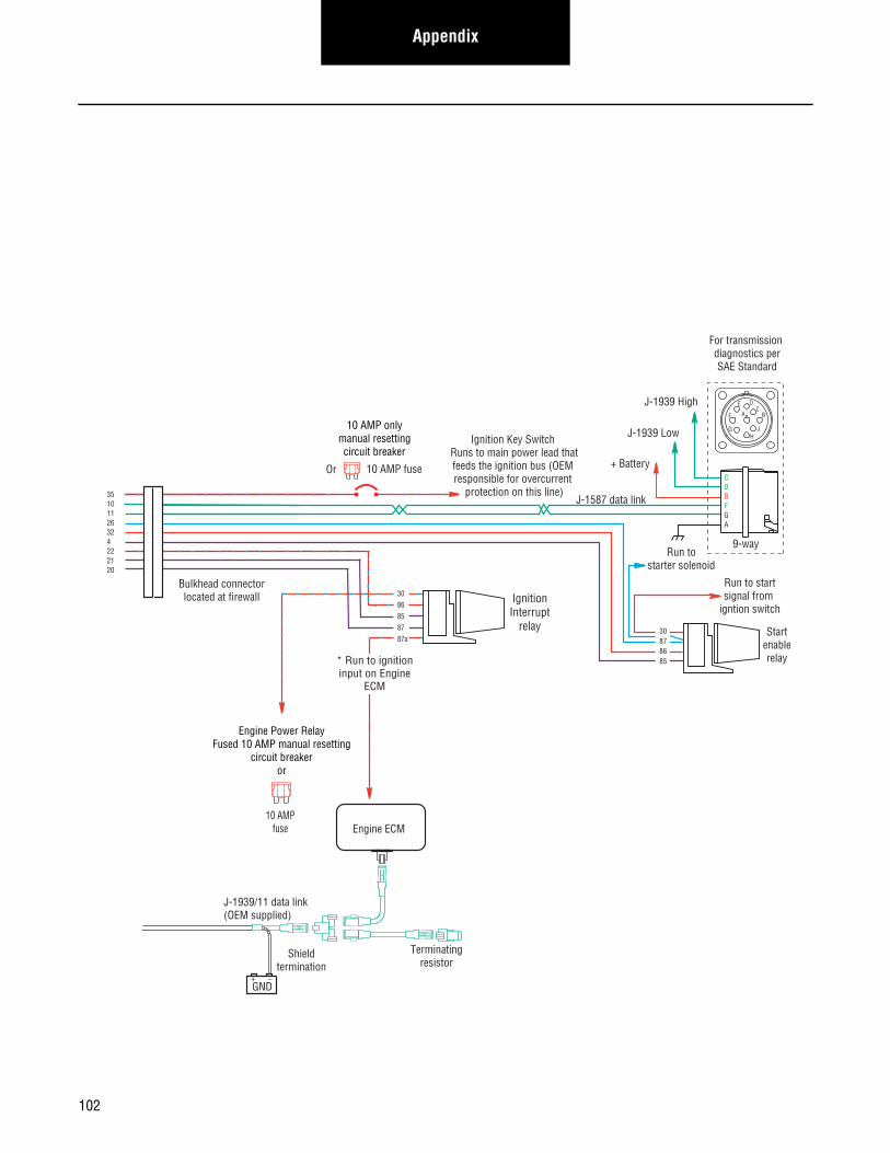
Appendix
Terminatingresistor
J-1939/11 data link(OEM supplied)
GND+ _
Shieldtermination
Engine ECM
+ Battery
For transmission diagnostics perSAE Standard
Startenablerelay
Run to startsignal from
igntion switch
Run tostarter solenoid
10 AMP onlymanual resettingcircuit breaker
10 AMP fuseOr
J-1587 data link
30878685
CDBFGA
9-way
AF
J
E
GH
DC
B
35101126324222120
Bulkhead connectorlocated at firewall
J-1939 Low
J-1939 High
Ignition Key Switch Runs to main power lead thatfeeds the ignition bus (OEM responsible for overcurrent
protection on this line)
IgnitionInterrupt
relay
3086858787a
* Run to ignitioninput on Engine
ECM
Engine Power RelayFused 10 AMP manual resetting
circuit breakeror
10 AMPfuse
102
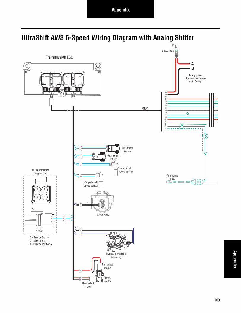
AppendixAppendix
UltraShift AW3 6-Speed Wiring Diagram with Analog Shifter
173125
Gear selectmotor
Rail selectmotor
Electricshifter
A
B
A
B
Rail selectsensor
Gear selectsensor
Input shaft speed sensor
Output shaftspeed sensor
Inertia brake
A
B
181920
101112
78
2324
335
A
B
C
A
B
C
3537
3638
Hydraulic manifoldAssembly
231314
30 AMP fuse
Battery power(Non-switched power)
run to Battery
Terminatingresistor
383625311516172335101126324321
Transmission ECU
OEM
B
C
A
D
For TransmissionDiagnostics
4-way
B - Service Bat. +C - Service Bat. -A - Service Ignition +
BCA
103
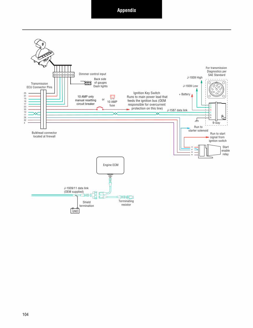
Appendix
Terminatingresistor
J-1939/11 data link(OEM supplied)
GND+ _
Shieldtermination
Engine ECM
Startenablerelay
Run to startsignal from
igntion switch
Run tostarter solenoid
10 AMP onlymanual resettingcircuit breaker
10 AMPfuse
or
J-1587 data link
30
87
86
85
Bulkhead connectorlocated at firewall
Back side of gauges
Dash lights
Dimmer control input
25311516172335101126324
TransmissionECU Connector Pins
3 4 1 8 2 6 5 73 4 1 8 2 6 5 7
+ Battery
For transmission Diagnostics perSAE Standard
CDBFGA
9-way
AF
J
E
GH
DC
BJ-1939 Low
J-1939 High
Ignition Key Switch Runs to main power lead thatfeeds the ignition bus (OEM responsible for overcurrent
protection on this line)
104
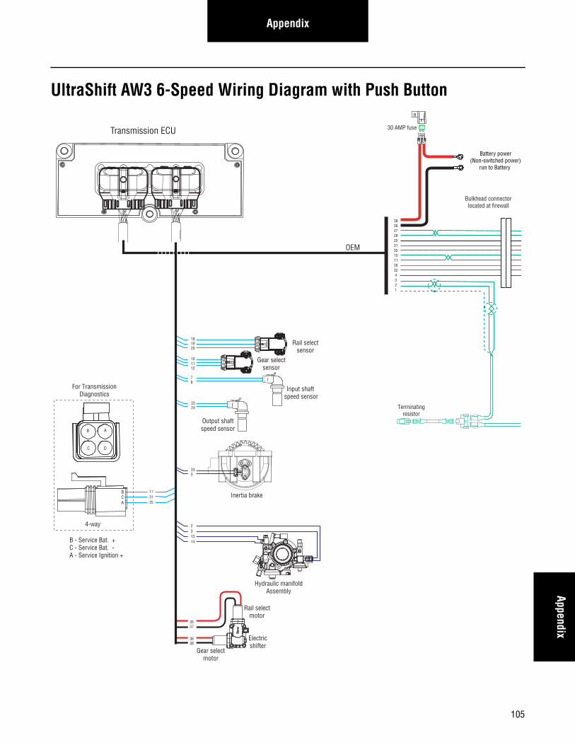
AppendixAppendix
UltraShift AW3 6-Speed Wiring Diagram with Push Button
173125
Gear selectmotor
Rail selectmotor
Electricshifter
A
B
A
B
Rail selectsensor
Gear selectsensor
Input shaft speed sensor
Output shaftspeed sensor
Inertia brake
A
B
181920
101112
78
2324
335
A
B
C
A
B
C
30 AMP fuse
Battery power(Non-switched power)
run to Battery
Terminatingresistor
3836272825313510112632 4 3 2 1
3537
3638
Bulkhead connectorlocated at firewall
Hydraulic manifoldAssembly
231314
B
C
A
D
For TransmissionDiagnostics
4-way
B - Service Bat. +C - Service Bat. -A - Service Ignition +
BCA
Transmission ECU
OEM
105
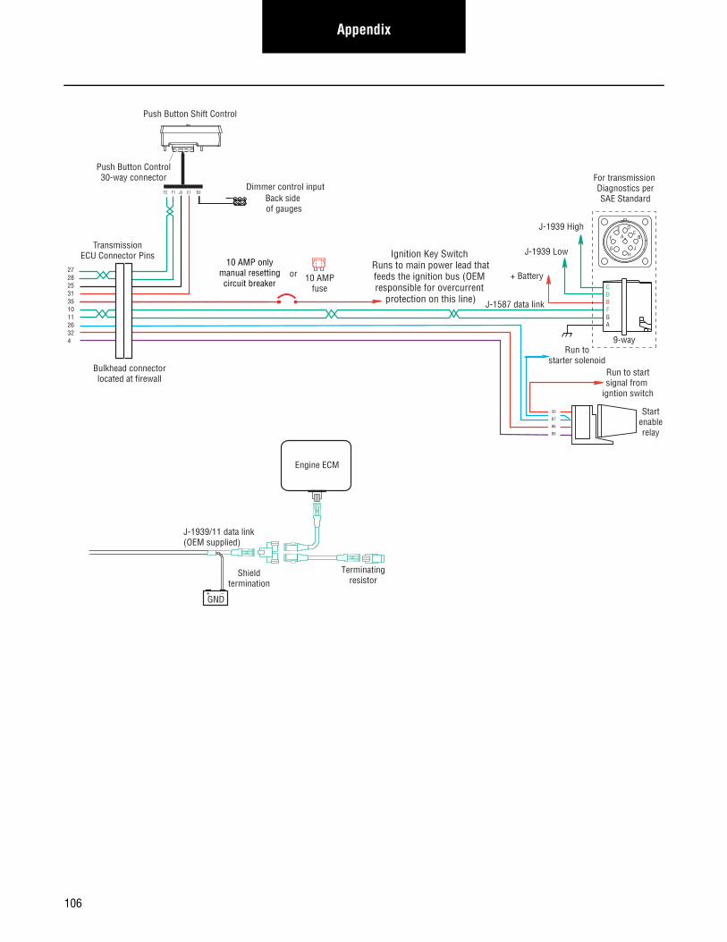
Appendix
Terminatingresistor
J-1939/11 data link(OEM supplied)
GND+ _
Shieldtermination
Engine ECM
Startenablerelay
Run to startsignal from
igntion switch
10 AMP onlymanual resettingcircuit breaker 10 AMP
fuse
or
J-1587 data link
30
87
86
85
Bulkhead connectorlocated at firewall
2728253135101126324
TransmissionECU Connector Pins
Push Button Shift Control
Push Button Control30-way connector
F2 F1 J3 C1 B3
Back side of gauges
Dimmer control input
+ Battery
For transmission Diagnostics perSAE Standard
Run tostarter solenoid
CDBFGA
9-way
AF
J
E
GH
DC
B
J-1939 Low
J-1939 High
Ignition Key Switch Runs to main power lead thatfeeds the ignition bus (OEM responsible for overcurrent
protection on this line)
106

AppendixAppendix
AutoShift 10-Speed Wiring Diagram with Analog Shifter
173125
C
B
A
Rangevalve
Gear selectmotor
Rail selectmotor
Electricshifter
A
B
A
B
Rail selectsensor
Gear selectsensor
Input shaft speed sensor
Output shaftspeed sensor
181920
101112
78
2324
A
B
C
A
B
C
30 AMP fuse
Battery power(Non-switched power)
run to Battery
Terminatingresistor
383625311516172335101126324321
3537
3638
A
B
Main shaftspeed sensor
1516
63428
Transmission ECU
OEM
B
C
A
D
For TransmissionDiagnostics
4-way
B - Service Bat. +C - Service Bat. -A - Service Ignition +
BCA
107
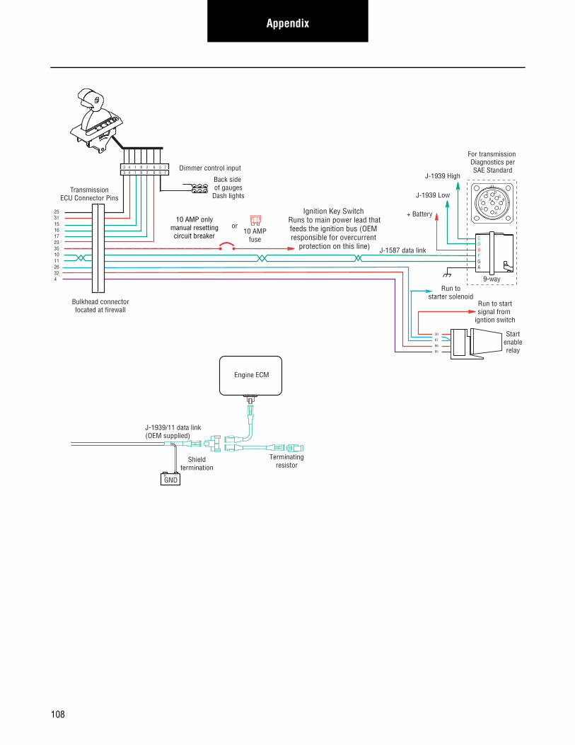
Appendix
Terminatingresistor
J-1939/11 data link(OEM supplied)
GND+ _
Shieldtermination
Engine ECM
Startenablerelay
Run to startsignal from
igntion switch
Run tostarter solenoid
10 AMP onlymanual resettingcircuit breaker
10 AMPfuse
or
J-1587 data link
30
87
86
85
Bulkhead connectorlocated at firewall
Back side of gauges
Dash lights
Dimmer control input
25311516172335101126324
TransmissionECU Connector Pins
3 4 1 8 2 6 5 73 4 1 8 2 6 5 7
+ Battery
For transmission Diagnostics perSAE Standard
CDBFGA
9-way
AF
J
E
GH
DC
BJ-1939 Low
J-1939 High
Ignition Key Switch Runs to main power lead thatfeeds the ignition bus (OEM responsible for overcurrent
protection on this line)
108
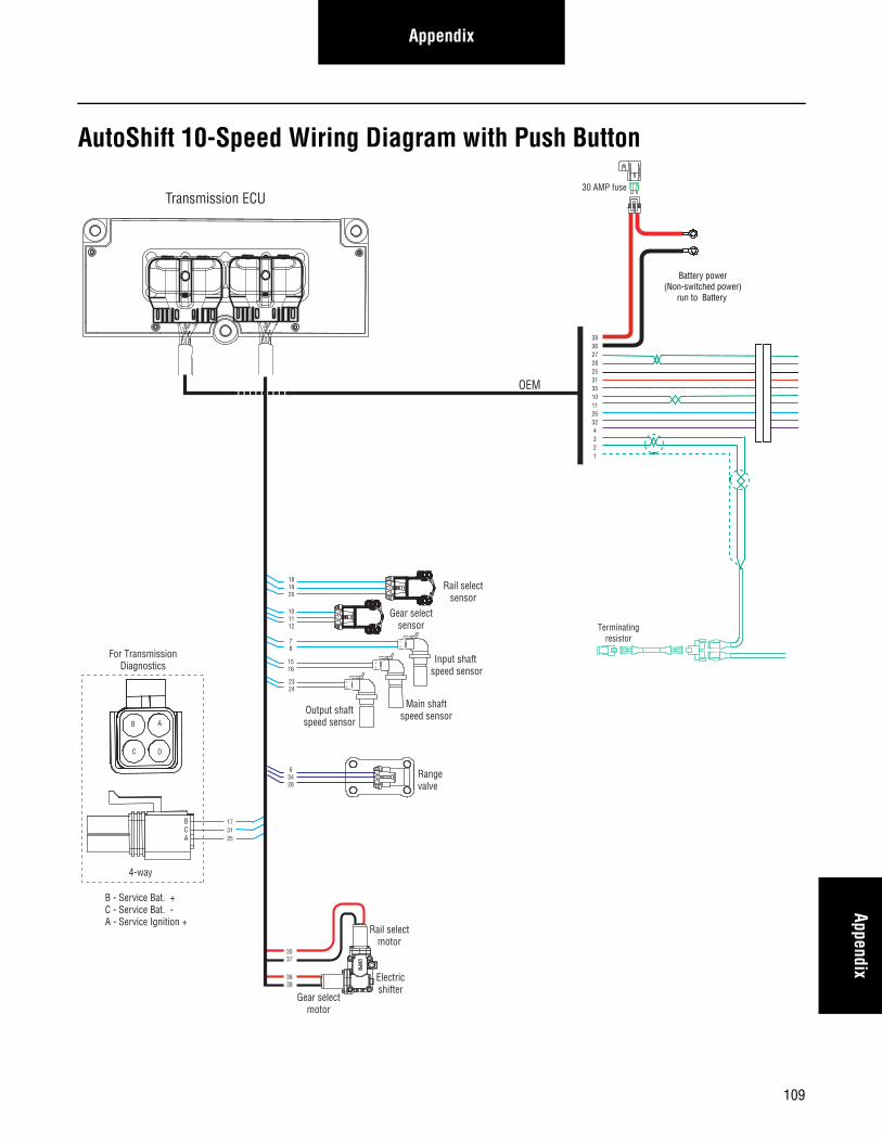
AppendixAppendix
AutoShift 10-Speed Wiring Diagram with Push Button
173125
C
B
A
Rangevalve
Gear selectmotor
Rail selectmotor
Electricshifter
A
B
A
B
Rail selectsensor
Gear selectsensor
Input shaft speed sensor
Output shaftspeed sensor
181920
101112
78
2324
A
B
C
A
B
C
30 AMP fuse
Battery power(Non-switched power)
run to Battery
Terminatingresistor
3836272825313510112632 4 3 2 1
3537
3638
A
B
Main shaftspeed sensor
1516
63428
B
C
A
D
For TransmissionDiagnostics
4-way
B - Service Bat. +C - Service Bat. -A - Service Ignition +
BCA
Transmission ECU
OEM
109
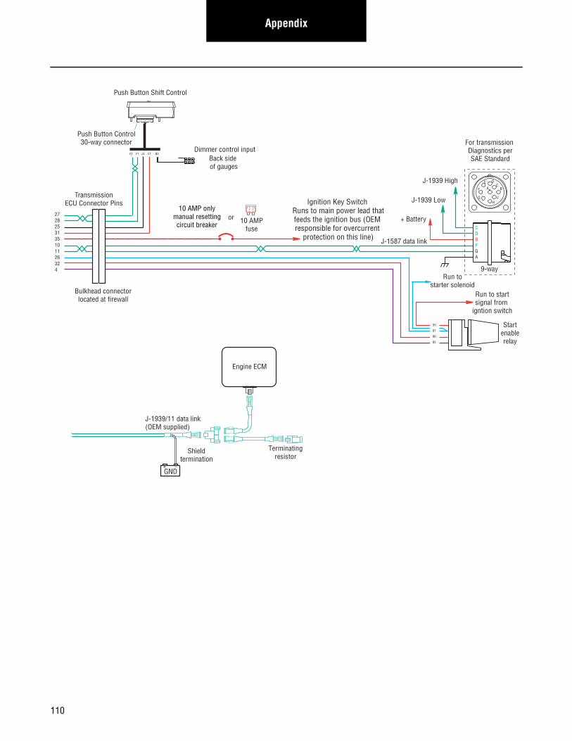
Appendix
Terminatingresistor
J-1939/11 data link(OEM supplied)
GND+ _
Shieldtermination
Engine ECM
Startenablerelay
Run to startsignal from
igntion switch
10 AMP onlymanual resettingcircuit breaker 10 AMP
fuse
or
J-1587 data link
30
87
86
85
Bulkhead connectorlocated at firewall
2728253135101126324
TransmissionECU Connector Pins
Push Button Shift Control
Push Button Control30-way connector
F2 F1 J3 C1 B3
Back side of gauges
Dimmer control input
+ Battery
For transmission Diagnostics perSAE Standard
Run tostarter solenoid
CDBFGA
9-way
AF
J
E
GH
DC
B
J-1939 Low
J-1939 High
Ignition Key Switch Runs to main power lead thatfeeds the ignition bus (OEM responsible for overcurrent
protection on this line)
110
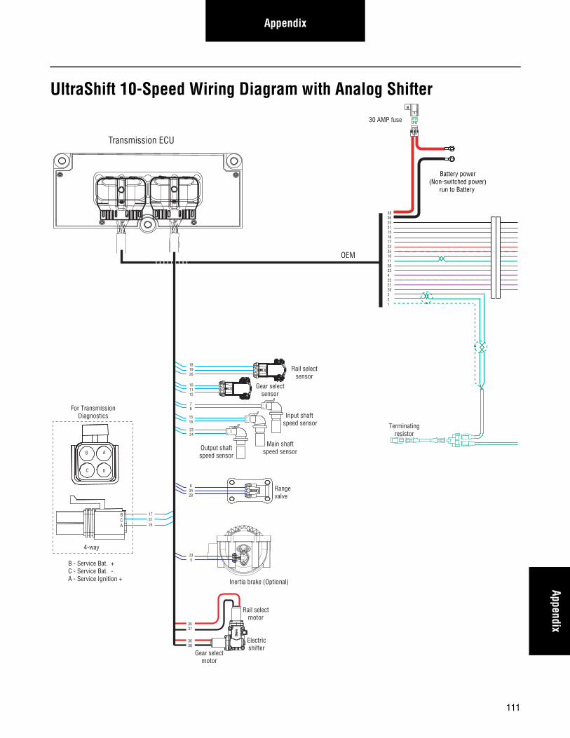
AppendixAppendix
UltraShift 10-Speed Wiring Diagram with Analog Shifter
173125
C
B
A
Rangevalve
Gear selectmotor
Rail selectmotor
Electricshifter
A
B
A
B
Rail selectsensor
Gear selectsensor
Input shaft speed sensor
Output shaftspeed sensor
Inertia brake (Optional)
A
B
181920
101112
78
2324
33 5
A
B
C
A
B
C
3537
3638
A
B
Main shaftspeed sensor
1516
63428
30 AMP fuse
Battery power(Non-switched power)
run to Battery
Terminatingresistor
383625311516172335101126324222120321
Transmission ECU
OEM
B
C
A
D
For TransmissionDiagnostics
4-way
B - Service Bat. +C - Service Bat. -A - Service Ignition +
BCA
111
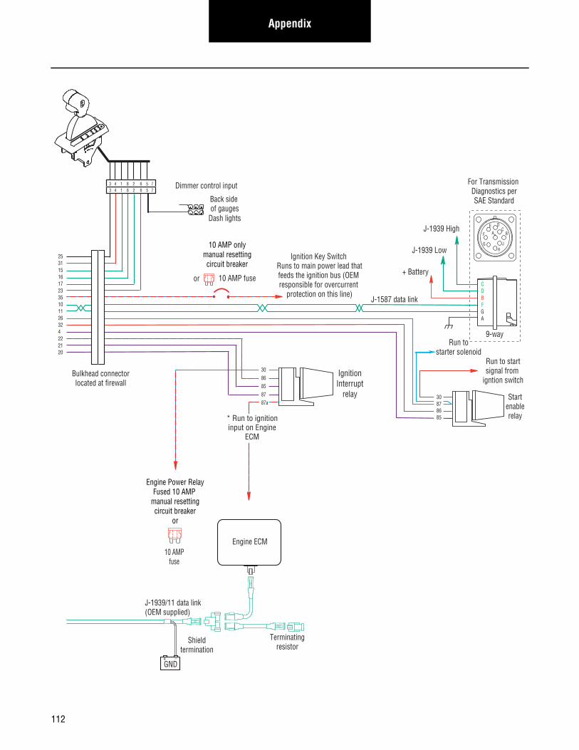
Appendix
Terminatingresistor
J-1939/11 data link(OEM supplied)
GND+ _
Shieldtermination
Engine ECM
Startenablerelay
Run to startsignal from
igntion switch
10 AMP onlymanual resettingcircuit breaker
10 AMP fuseor
J-1587 data link
30878685
Bulkhead connectorlocated at firewall
Back side of gauges
Dash lights
Dimmer control input
IgnitionInterrupt
relay
3086858787a
* Run to ignitioninput on Engine
ECM
25311516172335101126324222120
+ Battery
Run tostarter solenoid
9-way
AF
J
E
GH
DC
B
CDBFGA
J-1939 Low
J-1939 High
For Transmission Diagnostics perSAE Standard
Engine Power RelayFused 10 AMP
manual resettingcircuit breaker
or
10 AMPfuse
3 4 1 8 2 6 5 73 4 1 8 2 6 5 7
Ignition Key Switch Runs to main power lead thatfeeds the ignition bus (OEM responsible for overcurrent
protection on this line)
112
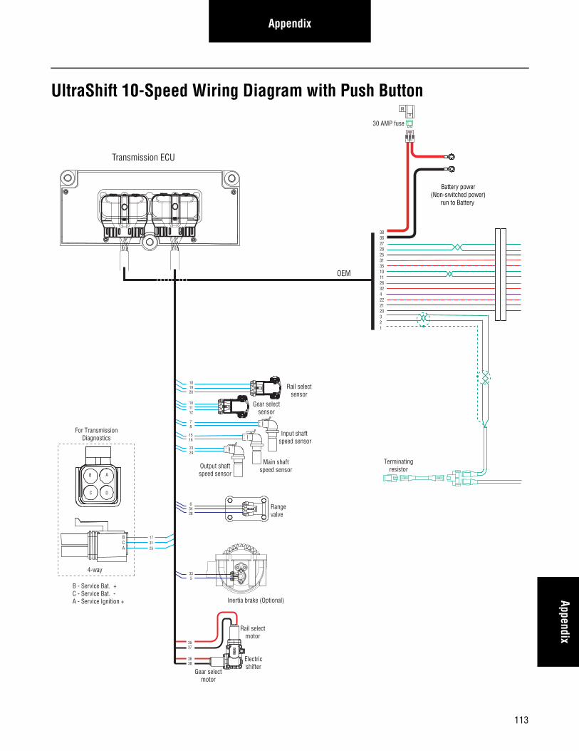
AppendixAppendix
UltraShift 10-Speed Wiring Diagram with Push Button
173125
C
B
A
Rangevalve
Gear selectmotor
Rail selectmotor
Electricshifter
A
B
A
B
Rail selectsensor
Gear selectsensor
Input shaft speed sensor
Output shaftspeed sensor
Inertia brake (Optional)
A
B
181920
101112
78
2324
33 5
A
B
C
A
B
C
3537
3638
A
B
Main shaftspeed sensor
1516
63428
30 AMP fuse
Battery power(Non-switched power)
run to Battery
Terminatingresistor
38362728253135101126324222120321
B
C
A
D
For TransmissionDiagnostics
4-way
B - Service Bat. +C - Service Bat. -A - Service Ignition +
BCA
Transmission ECU
OEM
113
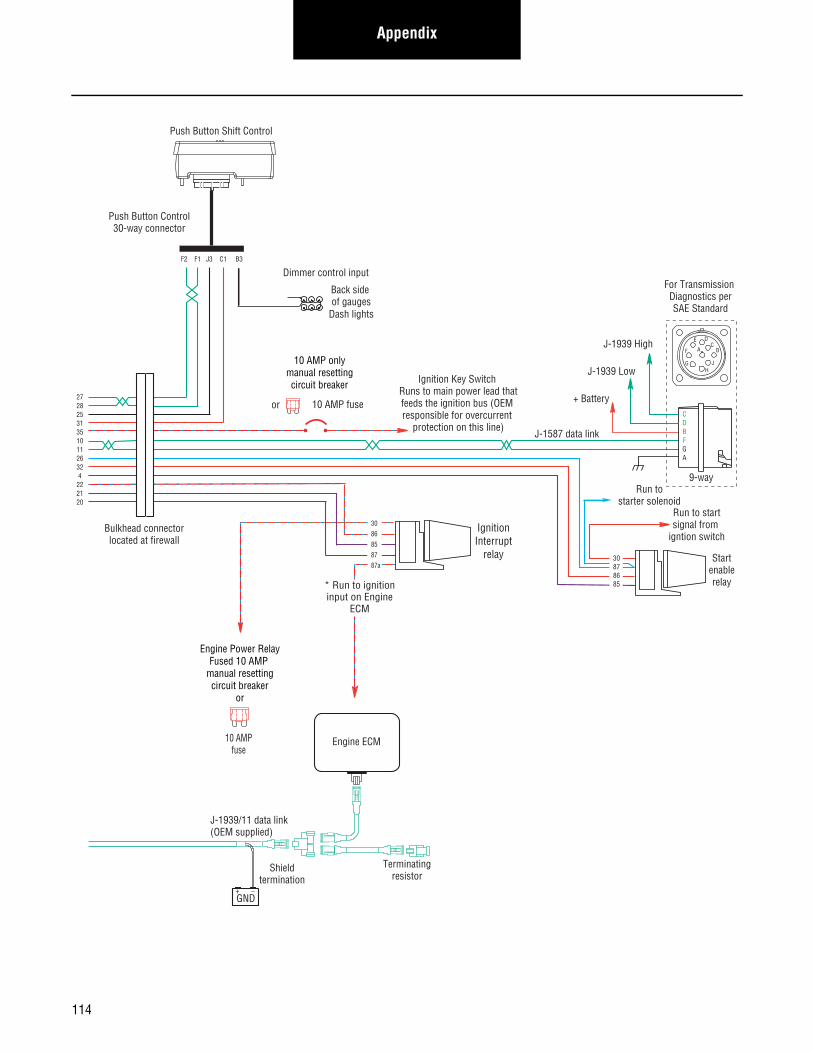
Appendix
Terminatingresistor
J-1939/11 data link(OEM supplied)
GND+ _
Shieldtermination
Engine ECM
Startenablerelay
Run to startsignal from
igntion switch
10 AMP onlymanual resettingcircuit breaker
10 AMP fuseor
J-1587 data link
30878685
Bulkhead connectorlocated at firewall
Back side of gauges
Dash lights
Dimmer control input
IgnitionInterrupt
relay
3086858787a
* Run to ignitioninput on Engine
ECM
Push Button Shift Control
Push Button Control30-way connector
F2 F1 J3 C1 B3
2728253135101126324
222120
Engine Power RelayFused 10 AMP
manual resettingcircuit breaker
or
10 AMPfuse
+ Battery
Run tostarter solenoid
9-way
AF
J
E
GH
DC
B
CDBFGA
J-1939 Low
J-1939 High
For Transmission Diagnostics perSAE Standard
Ignition Key Switch Runs to main power lead thatfeeds the ignition bus (OEM responsible for overcurrent
protection on this line)
114

AppendixAppendix
UltraShift 13-Speed Wiring Diagram with Analog Shifter
173125
C
B
A
Rangevalve
Gear selectmotor
Rail selectmotor
Electricshifter
A
B
A
B
Rail selectsensor
Gear selectsensor
Input shaft speed sensor
Output shaftspeed sensor
Inertia brakeA
B
181920
101112
78
2324
33 5
A
B
C
A
B
C
3537
3638
A
B
Main shaftspeed sensor
1516
63428
30 AMP fuse
Battery power(Non-switched power)
run to Battery
Terminatingresistor
383625311516172335101126324222120321
C
B
A
Splittervalve
43226
Transmission ECU
OEM
B
C
A
D
For TransmissionDiagnostics
4-way
B - Service Bat. +C - Service Bat. -A - Service Ignition +
BCA
115
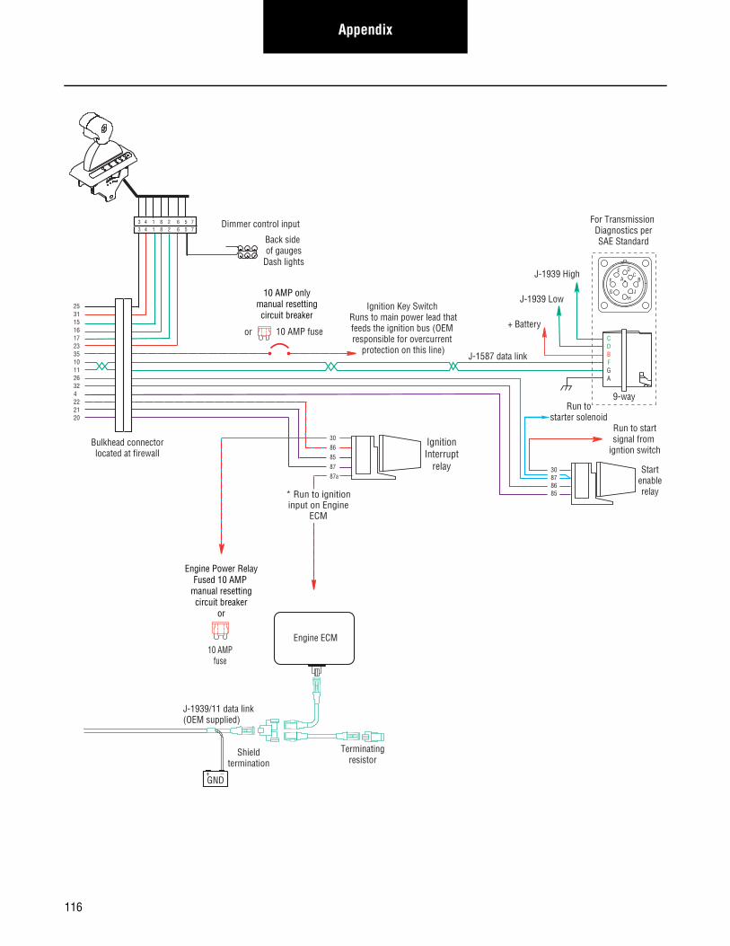
Appendix
Terminatingresistor
J-1939/11 data link(OEM supplied)
GND+ _
Shieldtermination
Engine ECM
Startenablerelay
Run to startsignal from
igntion switch
10 AMP onlymanual resettingcircuit breaker
10 AMP fuseor
J-1587 data link
30878685
Bulkhead connectorlocated at firewall
Back side of gauges
Dash lights
Dimmer control input
IgnitionInterrupt
relay
3086858787a
* Run to ignitioninput on Engine
ECM
25311516172335101126324222120
+ Battery
Run tostarter solenoid
9-way
AF
J
E
GH
DC
B
CDBFGA
J-1939 Low
J-1939 High
For Transmission Diagnostics perSAE Standard
Engine Power RelayFused 10 AMP
manual resettingcircuit breaker
or
10 AMPfuse
3 4 1 8 2 6 5 73 4 1 8 2 6 5 7
Ignition Key Switch Runs to main power lead thatfeeds the ignition bus (OEM responsible for overcurrent
protection on this line)
116

AppendixAppendix
UltraShift 13 Speed Wiring Diagram with Push Button
173125
C
B
A
Rangevalve
Gear selectmotor
Rail selectmotor
Electricshifter
A
B
A
B
Rail selectsensor
Gear selectsensor
Input shaft speed sensor
Output shaftspeed sensor
Inertia brake (Optional)
A
B
181920
101112
78
2324
33 5
A
B
C
A
B
C
3537
3638
A
B
Main shaftspeed sensor
1516
63428
30 AMP fuse
Battery power(Non-switched power)
run to Battery
Terminatingresistor
38362728253135101126324222120321
C
B
A
Splittervalve
43226
B
C
A
D
For TransmissionDiagnostics
4-way
B - Service Bat. +C - Service Bat. -A - Service Ignition +
BCA
Transmission ECU
OEM
117
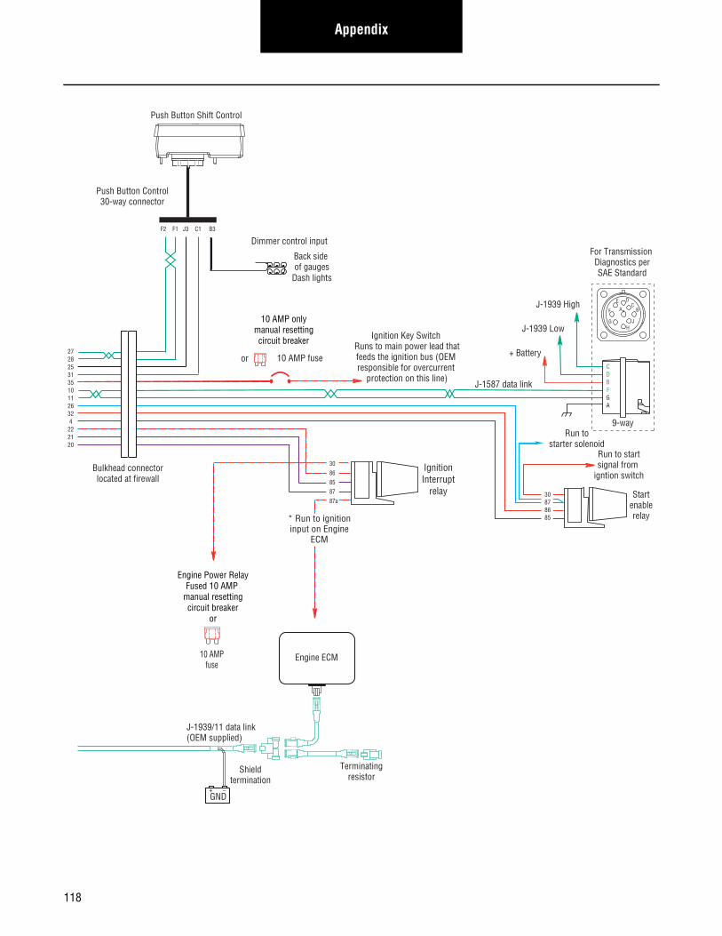
Appendix
Terminatingresistor
J-1939/11 data link(OEM supplied)
GND+ _
Shieldtermination
Engine ECM
Startenablerelay
Run to startsignal from
igntion switch
10 AMP onlymanual resettingcircuit breaker
10 AMP fuseor
J-1587 data link
30878685
Bulkhead connectorlocated at firewall
Back side of gauges
Dash lights
Dimmer control input
IgnitionInterrupt
relay
3086858787a
* Run to ignitioninput on Engine
ECM
Push Button Shift Control
Push Button Control30-way connector
F2 F1 J3 C1 B3
2728253135101126324
222120
Engine Power RelayFused 10 AMP
manual resettingcircuit breaker
or
10 AMPfuse
+ Battery
Run tostarter solenoid
9-way
AF
J
E
GH
DC
B
CDBFGA
J-1939 Low
J-1939 High
For Transmission Diagnostics perSAE Standard
Ignition Key Switch Runs to main power lead thatfeeds the ignition bus (OEM responsible for overcurrent
protection on this line)
118
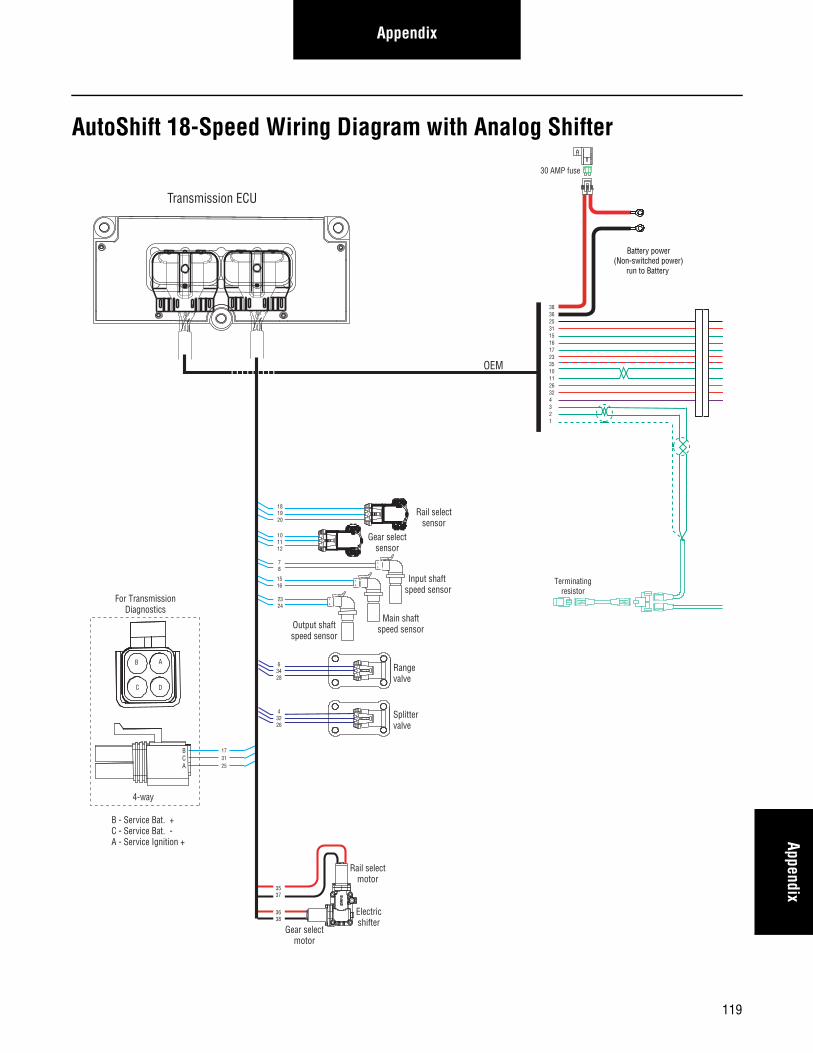
AppendixAppendix
AutoShift 18-Speed Wiring Diagram with Analog Shifter
173125
C
B
A
C
B
A
Rangevalve
Splittervalve
A
B
Main shaftspeed sensor
Gear selectmotor
Rail selectmotor
Electricshifter
A
B
A
B
Rail selectsensor
Gear selectsensor
Input shaft speed sensor
Output shaftspeed sensor
181920
101112
78
2324
A
B
C
A
B
C
30 AMP fuse
Battery power(Non-switched power)
run to Battery
Terminatingresistor
383625311516172335101126324321
3537
3638
1516
63428
43226
Transmission ECU
OEM
B
C
A
D
For TransmissionDiagnostics
4-way
B - Service Bat. +C - Service Bat. -A - Service Ignition +
BCA
119
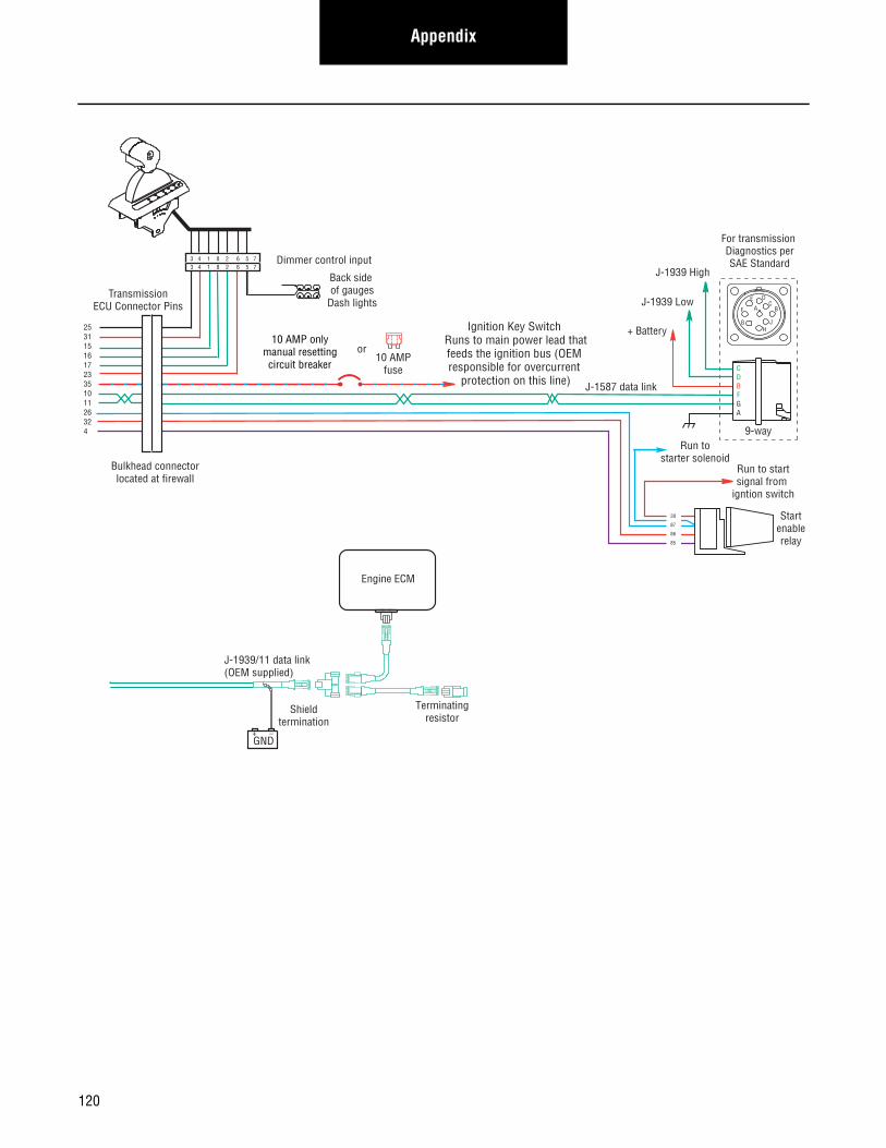
Appendix
Terminatingresistor
J-1939/11 data link(OEM supplied)
GND+ _
Shieldtermination
Engine ECM
Startenablerelay
Run to startsignal from
igntion switch
Run tostarter solenoid
10 AMP onlymanual resettingcircuit breaker
10 AMPfuse
or
J-1587 data link
30
87
86
85
Bulkhead connectorlocated at firewall
Back side of gauges
Dash lights
Dimmer control input
25311516172335101126324
TransmissionECU Connector Pins
3 4 1 8 2 6 5 73 4 1 8 2 6 5 7
+ Battery
For transmission Diagnostics perSAE Standard
CDBFGA
9-way
AF
J
E
GH
DC
BJ-1939 Low
J-1939 High
Ignition Key Switch Runs to main power lead thatfeeds the ignition bus (OEM responsible for overcurrent
protection on this line)
120

AppendixAppendix
AutoShift 18 Speed Wiring Diagram with Push Button
173125
C
B
A
C
B
A
Rangevalve
Splittervalve
A
B
Main shaftspeed sensor
Gear selectmotor
Rail selectmotor
Electricshifter
A
B
A
B
Rail selectsensor
Gear selectsensor
Input shaft speed sensor
Output shaftspeed sensor
181920
101112
78
2324
A
B
C
A
B
C
30 AMP fuse
Battery power(Non-switched power)
run to Battery
3836272825313510112632 4 3 2 1
3537
3638
1516
63428
43226
Terminatingresistor
B
C
A
D
For TransmissionDiagnostics
4-way
B - Service Bat. +C - Service Bat. -A - Service Ignition +
BCA
Transmission ECU
OEM
121
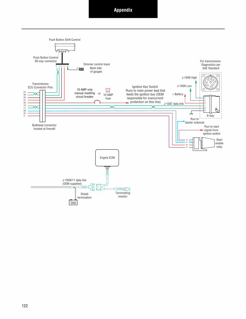
Appendix
Terminatingresistor
J-1939/11 data link(OEM supplied)
GND+ _
Shieldtermination
Engine ECM
Startenablerelay
Run to startsignal from
igntion switch
10 AMP onlymanual resettingcircuit breaker 10 AMP
fuse
or
J-1587 data link
30
87
86
85
Bulkhead connectorlocated at firewall
2728253135101126324
TransmissionECU Connector Pins
Push Button Shift Control
Push Button Control30-way connector
F2 F1 J3 C1 B3
Back side of gauges
Dimmer control input
+ Battery
For transmission Diagnostics perSAE Standard
Run tostarter solenoid
CDBFGA
9-way
AF
J
E
GH
DC
B
J-1939 Low
J-1939 High
Ignition Key Switch Runs to main power lead thatfeeds the ignition bus (OEM responsible for overcurrent
protection on this line)
122
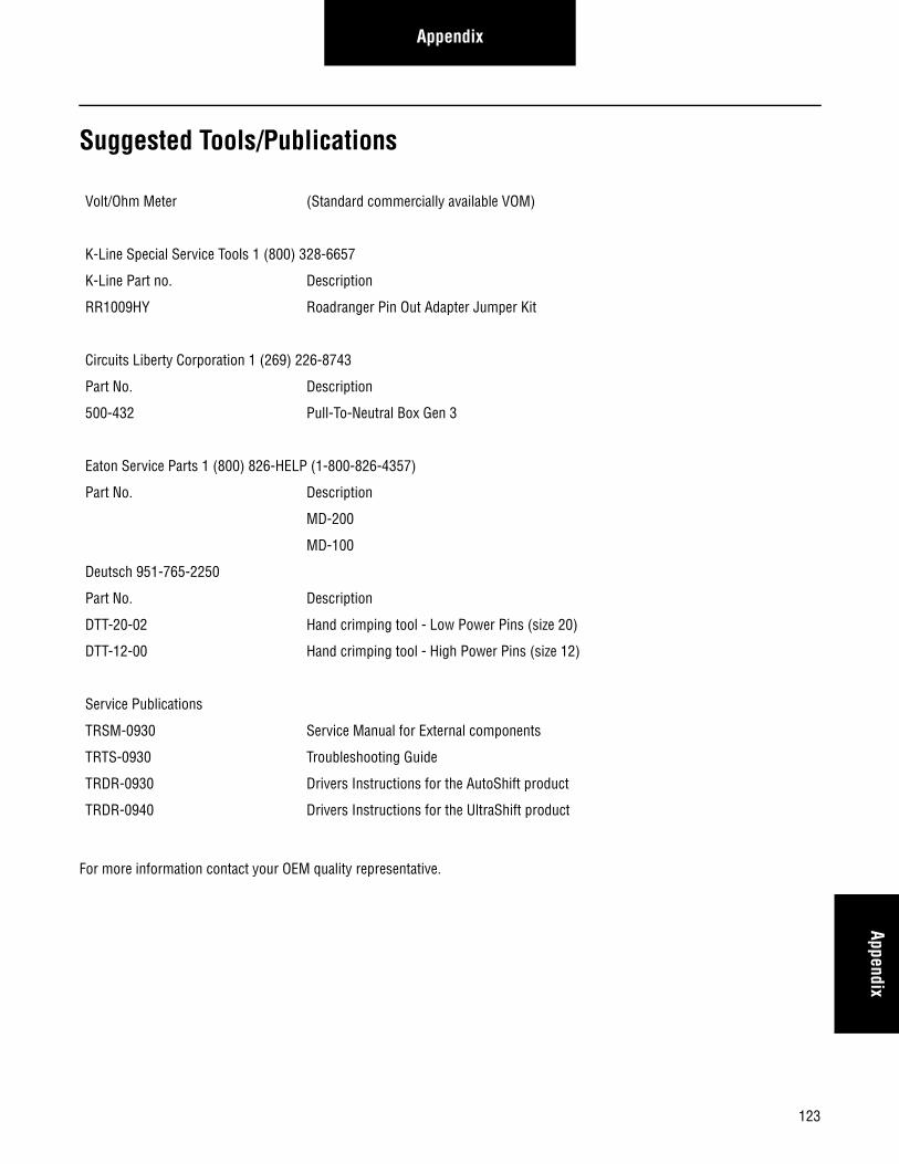
123
AppendixAppendix
Suggested Tools/Publications
For more information contact your OEM quality representative.
Volt/Ohm Meter (Standard commercially available VOM)
K-Line Special Service Tools 1 (800) 328-6657
K-Line Part no. Description
RR1009HY Roadranger Pin Out Adapter Jumper Kit
Circuits Liberty Corporation 1 (269) 226-8743
Part No. Description
500-432 Pull-To-Neutral Box Gen 3
Eaton Service Parts 1 (800) 826-HELP (1-800-826-4357)
Part No. Description
MD-200
MD-100
Deutsch 951-765-2250
Part No. Description
DTT-20-02 Hand crimping tool - Low Power Pins (size 20)
DTT-12-00 Hand crimping tool - High Power Pins (size 12)
Service Publications
TRSM-0930 Service Manual for External components
TRTS-0930 Troubleshooting Guide
TRDR-0930 Drivers Instructions for the AutoShift product
TRDR-0940 Drivers Instructions for the UltraShift product
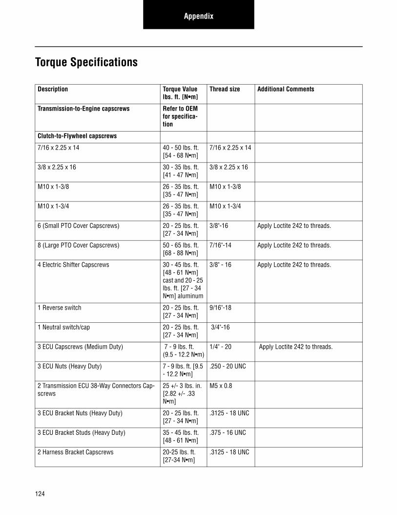
Appendix
Torque Specifications
Description Torque Value lbs. ft. [N•m]
Thread size Additional Comments
Transmission-to-Engine capscrews Refer to OEM for specifica-tion
Clutch-to-Flywheel capscrews
7/16 x 2.25 x 14 40 - 50 lbs. ft. [54 - 68 N•m]
7/16 x 2.25 x 14
3/8 x 2.25 x 16 30 - 35 lbs. ft. [41 - 47 N•m]
3/8 x 2.25 x 16
M10 x 1-3/8 26 - 35 lbs. ft. [35 - 47 N•m]
M10 x 1-3/8
M10 x 1-3/4 26 - 35 lbs. ft. [35 - 47 N•m]
M10 x 1-3/4
6 (Small PTO Cover Capscrews) 20 - 25 lbs. ft. [27 - 34 N•m]
3/8"-16 Apply Loctite 242 to threads.
8 (Large PTO Cover Capscrews) 50 - 65 lbs. ft. [68 - 88 N•m]
7/16"-14 Apply Loctite 242 to threads.
4 Electric Shifter Capscrews 30 - 45 lbs. ft. [48 - 61 N•m] cast and 20 - 25 lbs. ft. [27 - 34 N•m] aluminum
3/8" - 16 Apply Loctite 242 to threads.
1 Reverse switch 20 - 25 lbs. ft. [27 - 34 N•m]
9/16"-18
1 Neutral switch/cap 20 - 25 lbs. ft. [27 - 34 N•m]
3/4"-16
3 ECU Capscrews (Medium Duty) 7 - 9 lbs. ft. (9.5 - 12.2 N•m)
1/4" - 20 Apply Loctite 242 to threads.
3 ECU Nuts (Heavy Duty) 7 - 9 lbs. ft. [9.5 - 12.2 N•m]
.250 - 20 UNC
2 Transmission ECU 38-Way Connectors Cap-screws
25 +/- 3 lbs. in. [2.82 +/- .33 N•m]
M5 x 0.8
3 ECU Bracket Nuts (Heavy Duty) 20 - 25 lbs. ft. [27 - 34 N•m]
.3125 - 18 UNC
3 ECU Bracket Studs (Heavy Duty) 35 - 45 lbs. ft. [48 - 61 N•m]
.375 - 16 UNC
2 Harness Bracket Capscrews 20-25 lbs. ft. [27-34 N•m]
.3125 - 18 UNC
124
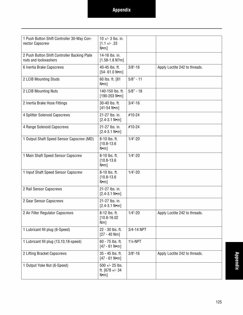
AppendixAppendix
1 Push Button Shift Controller 30-Way Con-nector Capscrew
10 +/- 3 lbs. in. [1.1 +/- .33 N•m]
2 Push Button Shift Controller Backing Plate nuts and lockwashers
14-16 lbs. in. [1.58-1.8 N?m]
6 Inertia Brake Capscrews 40-45 lbs. ft. [54- 61.0 N•m]
3/8"-16 Apply Loctite 242 to threads.
2 LCIB Mounting Studs 60 lbs. ft. [81 N•m]
5/8” - 11
2 LCIB Mounting Nuts 140-150 lbs. ft. [190-203 N•m]
5/8” - 18
2 Inertia Brake Hose Fittings 30-40 lbs. ft. [41-54 N•m]
3/4"-16
4 Splitter Solenoid Capscrews 21-27 lbs. in. [2.4-3.1 N•m]
#10-24
4 Range Solenoid Capscrews 21-27 lbs. in. [2.4-3.1 N•m]
#10-24
1 Output Shaft Speed Sensor Capscrew (MD) 8-10 lbs. ft. [10.8-13.6 N•m]
1/4"-20
1 Main Shaft Speed Sensor Capscrew 8-10 lbs. ft. [10.8-13.6 N•m]
1/4"-20
1 Input Shaft Speed Sensor Capscrew 8-10 lbs. ft. [10.8-13.6 N•m]
1/4"-20
2 Rail Sensor Capscrews 21-27 lbs. in. [2.4-3.1 N•m]
2 Gear Sensor Capscrews 21-27 lbs. in. [2.4-3.1 N•m]
2 Air Filter Regulator Capscrews 8-12 lbs. ft. [10.8-16.02 Nm]
1/4"-20 Apply Loctite 242 to threads.
1 Lubricant fill plug (6-Speed) 22 - 30 lbs. ft. [27 - 40 Nm]
3/4-14 NPT
1 Lubricant fill plug (13,10,18-speed) 60 - 75 lbs. ft. [47 - 61 N•m]
1¼-NPT
2 Lifting Bracket Capscrews 35 - 45 lbs. ft. [47 - 61 N•m]
3/8"-16 Apply Loctite 242 to threads.
1 Output Yoke Nut (6-Speed) 500 +/- 25 lbs. ft. [678 +/- 34 N•m]
125
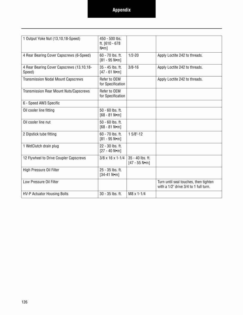
Appendix
1 Output Yoke Nut (13,10,18-Speed) 450 - 500 lbs. ft. [610 - 678 N•m]
4 Rear Bearing Cover Capscrews (6-Speed) 60 - 70 lbs. ft. [81 - 95 N•m]
1/2-20 Apply Loctite 242 to threads.
4 Rear Bearing Cover Capscrews (13,10,18-Speed)
35 - 45 lbs. ft. [47 - 61 N•m]
3/8-16 Apply Loctite 242 to threads.
Transmission Nodal Mount Capscrews Refer to OEM for Specification
Apply Loctite 242 to threads.
Transmission Rear Mount Nuts/Capscrews Refer to OEM for Specification
6 - Speed AW3 Specific
Oil cooler line fitting 50 - 60 lbs. ft. [68 - 81 N•m]
Oil cooler line nut 50 - 60 lbs. ft. [68 - 81 N•m]
2 Dipstick tube fitting 60 - 70 lbs. ft. [81 - 95 N•m]
1 5/8"-12
1 WetClutch drain plug 22 - 30 lbs. ft. [27 - 40 N•m]
12 Flywheel to Drive Coupler Capscrews 3/8 x 16 x 1-1/4 35 - 40 lbs. ft. [47 - 55 N•m]
High Pressure Oil Filter 25 - 35 lbs. ft. [34-41 N•m]
Low Pressure Oil Filter Turn until seal touches, then tighten with a 1/2" drive 3/4 to 1 full turn.
HV-P Actuator Housing Bolts 30 - 35 lbs. ft. M8 x 1-1/4
126
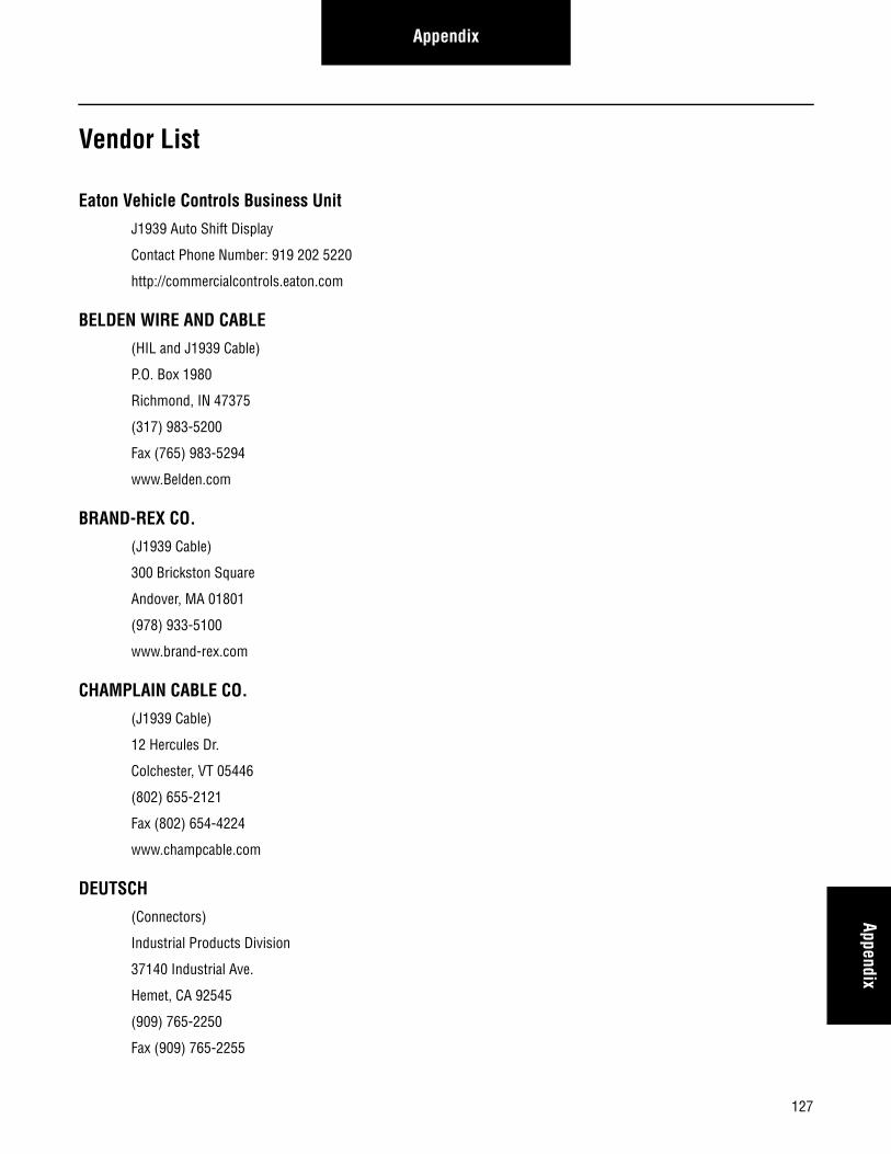
AppendixAppendix
Vendor List
Eaton Vehicle Controls Business Unit
J1939 Auto Shift Display
Contact Phone Number: 919 202 5220
http://commercialcontrols.eaton.com
BELDEN WIRE AND CABLE
(HIL and J1939 Cable)
P.O. Box 1980
Richmond, IN 47375
(317) 983-5200
Fax (765) 983-5294
www.Belden.com
BRAND-REX CO.
(J1939 Cable)
300 Brickston Square
Andover, MA 01801
(978) 933-5100
www.brand-rex.com
CHAMPLAIN CABLE CO.
(J1939 Cable)
12 Hercules Dr.
Colchester, VT 05446
(802) 655-2121
Fax (802) 654-4224
www.champcable.com
DEUTSCH
(Connectors)
Industrial Products Division
37140 Industrial Ave.
Hemet, CA 92545
(909) 765-2250
Fax (909) 765-2255
127
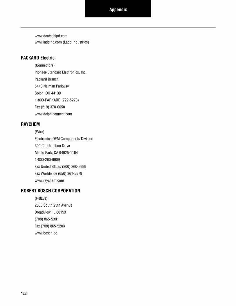
Appendix
www.deutschipd.com
www.laddinc.com (Ladd Industries)
PACKARD Electric
(Connectors)
Pioneer-Standard Electronics, Inc.
Packard Branch
5440 Naiman Parkway
Solon, OH 44139
1-800-PARKARD (722-5273)
Fax (219) 378-6650
www.delphiconnect.com
RAYCHEM
(Wire)
Electronics OEM Components Division
300 Construction Drive
Menlo Park, CA 94025-1164
1-800-260-9909
Fax United States (800) 260-9999
Fax Worldwide (650) 361-5579
www.raychem.com
ROBERT BOSCH CORPORATION
(Relays)
2800 South 25th Avenue
Broadview, IL 60153
(708) 865-5301
Fax (708) 865-5203
www.bosch.de
128

Copyright Eaton, 2014. Eaton hereby grant their customers, vendors, or distributors permission to freely copy, reproduce and/or distribute this document in printed format. It may be copied only in its entirety without any changes or modifications. THIS INFORMATION IS NOT INTENDED FOR SALE OR RESALE, AND THIS NOTICE MUST REMAIN ON ALL COPIES.
Note: Features and specifications listed in this document are subject to change without notice and represent the maximum capabilities of the software and products with all options installed. Although every attempt has been made to ensure the accuracy of information contained within, Eaton makes no representation about the completeness, correctness or accuracy and assumes no responsibility for any errors or omissions. Features and functionality may vary depending on selected options.
For spec’ing or service assistance, call 1-800-826-HELP (4357) or visit www.eaton.com/roadranger.In Mexico, call 001-800-826-4357.
EatonVehicle GroupP.O. Box 4013Kalamazoo, MI 49003 USA800-826-HELP (4357)www.eaton.com/roadranger
Printed in USA
Roadranger: Eaton and trusted partners providing the best products and services in the industry, ensuring more time on the road.