FSX Emissive Textures and How They - FSDeveloper
15
FSX Emissive Textures and How They Relate to Virtual Cockpit Lighting Bill Leaming INTRODUCTION: Ever since I began design work for the Flight Simulator franchise back when FS2002 was the current version, I’ve been on what some might call a “Crusade” to actively promote better, more engaging virtual cockpit lighting. After months of patient scouring of multiple flightsim related websites, forums and newsgroups, I slowly developed a method using emissive lightmap texturing to provide an infinitely flexible degree of backlighting for gauges placed on a gauge polygon. Now the nice folks at ACES have kindly invited me to write this article for their FSInsider website. For the benefit of those who’ve not read it, I refer readers to my seminal “white paper” entitled “VC Gauge Backlighting - A Tutorial Using Emissive Texture Lightmapping” which has been available for years at: http://www.freeflightdesign.com/tutorials/VC_Lighting_Tutorial.zip While it is now quite dated, the basic concepts described and illustrated still hold true in FSX. In that paper I listed what I consider to be the requisite steps one must follow during the development process. In actual practice of course, it is more of a interative process than it is linear, but nevertheless we need some structure to follow! 1) Strategic Planning 2) Building the “Projection Screen(s)” (polygons) 3) Creating and Applying Textures 4) Setting up the panel.cfg file 5) Lighting up the panel Preplanning your virtual cockpit for FSX is now even more important than before, since we now have many, many more options from which to choose. Where my previous article went into great detail about the “nuts and bolts” of setting up a virtual cockpit’s gauge polygon(s) as well as describing the pre-design planning that is required beforehand, my major focus in this article will be to primarily describe the changes that ACES has made for FSX, and most especially the new possibilities introduced by Service Pack 1 (SP1). However, this paper
-
Upload
khangminh22 -
Category
Documents
-
view
5 -
download
0
Transcript of FSX Emissive Textures and How They - FSDeveloper

FSX Emissive Textures and How They
Relate to Virtual Cockpit LightingBill Leaming
INTRODUCTION:
Ever since I began design work for the Flight Simulator franchise back when FS2002 was the current version, I’ve been on what some might call a “Crusade” to actively promote better, more engaging virtual cockpit lighting. After months of patient scouring of multiple flightsim related websites, forums and newsgroups, I slowly developed a method using emissive lightmap texturing to provide an infinitely flexible degree of backlighting for gauges placed on a gauge polygon. Now the nice folks at ACES have kindly invited me to write this article for their FSInsider website.
For the benefit of those who’ve not read it, I refer readers to my seminal “white paper” entitled “VC Gauge Backlighting - A Tutorial Using Emissive Texture Lightmapping” which has been available for years at: http://www.freeflightdesign.com/tutorials/VC_Lighting_Tutorial.zip
While it is now quite dated, the basic concepts described and illustrated still hold true in FSX. In that paper I listed what I consider to be the requisite steps one must follow during the development process. In actual practice of course, it is more of a interative process than it is linear, but nevertheless we need some structure to follow!
1) Strategic Planning2) Building the “Projection Screen(s)” (polygons)3) Creating and Applying Textures4) Setting up the panel.cfg file5) Lighting up the panel
Preplanning your virtual cockpit for FSX is now even more important than before, since we now have many, many more options from which to choose.
Where my previous article went into great detail about the “nuts and bolts” of setting up a virtual cockpit’s gauge polygon(s) as well as describing the pre-design planning that is required beforehand, my major focus in this article will be to primarily describe the changes that ACES has made for FSX, and most especially the new possibilities introduced by Service Pack 1 (SP1). However, this paper

would be incomplete without some example of the basic processes involved, so I will describe in brief the development of the Quest Kodiak’s Virtual Cockpit, permission for which was graciously granted by Bill Ortis of Lionheart Creations, as well as Nick Pike and Maury Pratt, the other principles involved in the project.
FS9 versus FSX:
It is important for the sake of continuity that before going any further I write about some very fundamental changes, which will have a serious impact on any techniques used in prior FS versions.
First and foremost is the question of “control.” In FS2002 and FS2004 the Alpha channel of a lightmap determined which “electrical circuit” controlled the lighting: pure white (RGB:255,255,255) assigned control to the landing light switch. Pure black (RGB:0,0,0) assigned control to any other light switch.
In FSX however, the Alpha channel has no function at all. Instead, the Material Properties assigned to the FSX Material determine whether the lighting is controlled by the panel lights switch, or by ambient light conditions, or is “on” whenever electrical power is available.
The other critically important issue is that of the gauges themselves. In previous versions of FS there were only two choices for internal gauge lighting: 1) Luminous and 2) Bright. The Luminous tag will apply the color and intensity to the tagged gauge bitmaps, based on the Luminous= entry in the panel.cfg file. The Bright tag will apply full intensity WHITE (RGB:255,255,255) to the selected gauge bitmaps.
<Image Name="GNS430trk_card.bmp" Bright="Yes"/><Image Name="LEAR_ADF_BACKGROUND.bmp" Luminous="Yes”/>
In FSX gauges however there is a new option: adding xxx_night.bmp bitmaps to the gauge’s resource. In XML gauges, all that is necessary is to add the alternate bitmaps using the same root plus _night suffix. In C gauges it is a bit more complex, but the same principle applies: at “night,” the alternate bitmaps replace the daytime bitmaps, and hence will affect the choice of color and intensity required: it must be pure, bright white (RGB:255,255,255).
For example, peeking into the default Bombardier_CRJ_700.CAB file, note that the annunciator’s XML code is:
<Image id="Image" Name="annunciator_panel_1_background.bmp">
Examining the bitmap resources included we see that there’s a special “night only” version of the bitmap called for in the XML code:
annunciator_panel_1_background.bmpannunciator_panel_1_background_night.bmp

How Emissive Backlighting Works:
Emissive backlighting is similar in concept to the light source that is required behind an LCD screen. Without that light source, the LCD screen would be very dark and difficult – if not impossible – to use. In FS, an emissive texture applied to a gauge polygon serves the same purpose. In contrast to this, any other light source, such as post lighting or overhead lighting, simply provides an increased ambient light source that illuminates the surface of an object.
FSX Emissive Material Properties:
One of the reasons why the nice folks at ACES invited me to author this article is that – while nearly all of this information is available in the SDK – it is terse almost to the point of obscurity. If you don’t already know what you’re looking for, you won’t be able to assemble all of the disparate pieces and comprehend the whole – at least – not easily.
FSX now presents the modeler with a wealth of choices in the Emissive Material Properties. To keep the reader from flipping back and forth between this article and the SDK, I will list them and provide a brief summary in this section, before going into further details of what I visualize as their “best use” in modeling practices. I will list them in the order that makes most sense from a perspective of actual use, rather than the arbitrary, unordered way they appear in the Material Editor’s drop-down pick list.
What is critical to understand at this juncture is that the first two emissive modes described apply for the most part to the “surface” of the daytime texture, whereas the new emissive mode applies behind the daytime texture, in one word: backlighting!
Additive Modes:The SDK states this about Additive lightmaps:“Light maps act like an additive mask in that anywhere on the texture where the map value is higher than pure black, the surface will be lightened above the ambient lighting value by an amount relative to the value provided. Pure black (RGB 0,0,0) must be used in the light map if no lightening is to occur. Light map values can include color to cast a colored light onto the surface.” What is important to understand is that the lightmap ADDS TO the existing daytime texture.

1) Additive – this emissive property will provide a constant light source applied to a polygon, as long as electrical power is available.
2) AdditiveNightOnly – this emissive property is similar to the above, but adds the condition that it will only illuminate at night.
3) AdditiveUserControlled – As with the Additive mode above, with the additional condition that the panel lights switch must be on.
4)
AdditiveNightOnlyUserControlled – this mode combines the conditions of all three of the modes listed above.
Blend Modes:Blending is a method of mixing the color information of a graphic object with the color information of graphic objects beneath it. What is important to understand is that the lightmap’s color and luminosity is BLENDED with the existing daytime texture.
1) Blend – this emissive property will provide a blended lightsource based on the ambient light conditions. As the ambient light decreases, the intensity of the blend increases up to the limits set by the lightmap’s luminosity.
2) BlendUserControlled – this mode is the same as above, with the additional condition that the panel lights switch must be on.
Multiply Blend Modes:These new modes are the result of feedback from developers to ACES, and restore the previous version’s emissive lightmap modes described in my earlier article. These are the emissive modes will most likely be of major interest to modeler’s and gauge developers.
1) MultiplyBlend – this emissive mode will add a lightsource behind the gauge polygon. It takes the color and lumininosity of the pixels in the emissive texture and multiplies the values of the base texture’s pixels. The brighter the lightmap’s pixels, the brighter the base texture’s pixels.

2) MultiplyBlendUserControlled – just as before, this mode assigns control to the panel lights switch.
Practical Application:Preplanning & Layout:Now that I’ve described the various emissive properties available to modelers in FSX, I’ll describe the actual application of them within an actual model’s virtual cockpit. For those who’ve already built FS9 models and are “porting them” into FSX – don’t panic! If you’ve already used the emissive lightmap technique rest assurred that your existing lightmaps will continue to work splendidly in FSX, now that ACES has added the MultiplyBlend mode to the mix.
Please note that I make no claim or pretense that what I’m about to describe is the “best practice.” What I do claim is that it is a way that is both simple, and illustrative of the techniques needed.
For the Kodiak project, I inverted some of the steps described in my previous paper. This time, I coupled the “Preplanning” and “Panel.cfg” steps, by using FS Panel Studio as a “layout” tool. FSPS now has a neat feature, which allows you to save a “screenshot” of a specific window, so that cropping and resizing a perfect “template image” is now possible!
Using notepad.exe, I added two [VcockpitXX] entries to the existing panel.cfg file, something that FSPS still cannot do on its own. Then, I selected all the gauges that the Kodiak uses, and used FSPS to arrange the gauges to “best fit” the available space of two 1024x1024 areas.
//--------------------------------------------------------[Vcockpit01]file=pan1.bmp // this is the “visible” background image 24-bit RGBsize_mm=1024,1024visible=1pixel_size=1024,1024stexture=$pan1 // this is the $dummy texture filename used in Max/Gmax//--------------------------------------------------------[Vcockpit02]file=pan2. bmp // this is the “visible” background image 24-bit RGBBackground_color=0,0,0 size_mm=1024,1024visible=1pixel_size=1024,1024stexture=$pan2 // this is the $dummy texture filename used in Max/Gmax

A Brief, But Necessary Digression:I must now take a few moments to mention a “gottcha” that factors into the topic of gauges and gauge polygons.
The chief "gottcha" that occurs with this method is that when the lights are on, the entire surface of the gauge poly loses transparency and becomes "black." The simple fix for this problem is obvious in retrospect: where there is no surface, there is no black showing!
There are several ways to overcome this problem and this an excellent example of why you need to keep this in mind during the "Strategic Planning" part of VC development:
1) apply a base texture to the poly via a panel.cfg entry (aka: cover up)2) make the gauge poly the exact size and shape of the actual gauge being
used (aka: cookie-cutter)3) move the gauge poly behind the physical panel (aka: peek-a-boo)
Moving along:
For the Kodiak project, I chose to use a combination of cover up and cookie-cutter, since all of the gauges used in the real aircraft are surface mounted, unlike most Piper aircraft that use mostly backmounted gauges. There are two ways of getting a texture on the main panel. The first uses a bitmap in the \panel folder and the second uses bitmap in the \texture folder. Where in FS9 there is no obvious advantage to either method, in FSX using the \texture folder method would allow the developer to apply bump and specular mapping if they so desired. Regardless of which of the two locations is used though, the lightmap bitmap will always be placed in the \texture folder.
NOTE: If you decide to place the VC bitmaps in the \panel folder, they MUST be 24-bit format! The panel system will not load compressed images.
[Vcockpit01]
//--------------------------------------------------------[Vcockpit01]file=pan1.bmp Background_color=0,0,0 size_mm=1024,1024visible=1pixel_size=1024,1024stexture=$pan1
For the sake of sanity, I name all bitmaps using a common “root” so that I can keep track of them. The file= entry is used to tell FSX where to find the background texture for the panel. The texture= entry defines the name of the texture that FSX will automatically create at run-time for the gauge system to use. The “lightmap” is named “pan1_L.dds”.

Here is what the pan1.bmp1 looks like after massaging the gauge layout in FS Panel Studio. Note that the main panel’s texture is divided into two sections, and all of the other gauges have been arranged carefully to maximize their display resolution in the sim, and take best advantage of the available space on the 1024x1024 area.
1 Note: I make a copy of pan1.bmp and name it $pan1.bmp for use in Max/Gmax so I can use it as a visible reference while building polygons for the VC.
[Vcockpit02]
//--------------------------------------------------------[Vcockpit02]file=pan2.bmp Background_color=0,0,0 size_mm=1024,1024visible=1pixel_size=1024,1024stexture=$pan2
Here is what pan2 looks like after arranging the gauges in FS Panel Studio. As before, maximum use is made of the 1024x1024 area available. Since the two “G1000” gauges are so “in your face,” I wanted to provide the most resolution for them to display crisply.
There’s one more part of the panel.cfg puzzle to configure before moving on to the Max/Gmax model and building the panel & gauge polys, and that is the specifications for the lighting we want.
[Color]Day=255,255,255Night=90,90,90 // color/intensity for 2d panel and vc lightmapsLuminous=180,180,180 // color/intensity for bitmaps tagged “luminous”
For the Kodiak project, I set the Night= entry to use a softer white light source, RGB:90,90,90. Had I had needed to use any of the FSX style gauges, I would have had to use RGB:255,255,255 as explained previously, and adjusted my lightmap accordingly.

Modeling the Virtual Cockpit and Gauge Polys:
Now that the necessary Preplanning & Layout is at least underway, I can move into Max/Gmax and use the two $panX textures as a design tool. I can “model the mesh to fit the gauges” so to speak.
First, I must create the FSX Materials needed in Gmax. Here is a compressed composite showing the FSX Material’s Properties and settings needed. Because it’s such a large image, I’m only going to show it once in this paper (see the last page). For the moment, I’m simply showing the relevant parts:

Now that I’ve created the FSX Material and set all the requisite properties, I can Apply it to the mesh polygons that will get their texture from that bitmap:

Since my background texture has all the elements displayed, I can then go on to build the necessary polygons to “fit” the images for the remaining parts on this texture sheet.
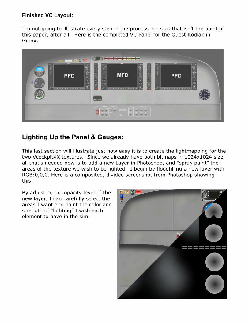
Finished VC Layout:
I’m not going to illustrate every step in the process here, as that isn’t the point of this paper, after all. Here is the completed VC Panel for the Quest Kodiak in Gmax:
Lighting Up the Panel & Gauges:
This last section will illustrate just how easy it is to create the lightmapping for the two VcockpitXX textures. Since we already have both bitmaps in 1024x1024 size, all that’s needed now is to add a new Layer in Photoshop, and “spray paint” the areas of the texture we wish to be lighted. I begin by floodfilling a new layer with RGB:0,0,0. Here is a composited, divided screenshot from Photoshop showing this:
By adjusting the opacity level of the new layer, I can carefully select the areas I want and paint the color and strength of “lighting” I wish each element to have in the sim.

The final step in the process is to save the completed lightmap in a format that FSX will recognize. In this case, since no Alpha channel is needed, I will “flip the image vertically” and Save As a DDS/DXT1 file, making sure that I add the _L suffix to the filename of course
I repeat the process for the Vcockpit02 lightmap. Since I want the “glass” part of the G1000’s to be “fully bright,” I use RGB:255,255,255 to flood fill the screen area. I also carefully highlight the “text labels” on the frame as well:

Final Results in FSX:
At last we can see the results of this easy process in its full glory in FSX, with soft, gentle on the eyes emissive backlighting…
Summary:
In this brief paper I’ve not sought to expose everything I know about FS and lighting, much of which quite honestly is proprietary to my employer, but rather to at least demonstrate that the techniques developed for FS9 models need not be abandoned like some forgotten dream.
There are many, many refinements that anyone can make to these basics. What one can achieve is limited mostly by imagination and experimentation. Some suggested possibilities for the different emissive modes are enumerated below:
1) Additive – any areas of a gauge that require full illumination during the daytime
2) AdditiveNightOnly – any areas of a gauge that require lighting only at night3) Various Blend modes – use for cabin interior walls and other parts that
require harder edged, diffuse lighting4) MultiplyBlend modes – use for fuselage exterior (logo light?) and all other
areas of the model that require soft edge, diffuse lighting.

Addendum:
FSX has not only introduced a lot of new options insofar as gauge lighting of virtual cockpits, but has added some additional options for 2d panels as well.
If you examine the new default panel.cfg files carefully, you’ll notice the BIG CHANGE right away:
[Window00]file_1024=bombardier_CRJ700_panel_background.bmpfile_1024_night=bombardier_CRJ700_panel_background_night.bmpsize_mm=1024position=7visible=1ident=MAIN_PANEL
There is now the ability to specify a “night only” version of any 2d panel bitmaps. Remembering that gauges may now also have “night only” bitmaps and you’ll begin to understand the newest “level of complexity” that’s been introduced.
What this means is that this is yet another factor that must be considered during the “Preplanning” stage of panel, gauge and model development. I’m not at all ashamed to admit that it has taken me many, many hours of experimentation to achieve even the modest level of understanding that I have, but all things considered I’d rather have all these options as not…
I’ll close this article by again thanking the great folks at ACES for inviting me to write this article. I sincerely hope that it will serve as a springboard to get my fellow developer’s creative juices flowing. There are plenty of “bread crumbs” marking the trail, but in the final analysis each person has to take up the challenge and develop their own, unique methods. Creative ingenuity is what drives this facet of flightsim development, and brings smiles of satisfaction to our user’s faces!
Some Additional Resources:http://freeflightdesign.com - great bunch of folks willing to share!http://avsim.com - MSFS Aircraft and Panel Design Forum http://flightsim.com - Panel & Gauges Forumhttp://fs2x.com - Nick Pikes’ Tutorial Sectionhttp://www.sim-outhouse.com - Panel Design & Tips